RU2547171C2 - Processing cartridge - Google Patents
Processing cartridge Download PDFInfo
- Publication number
- RU2547171C2 RU2547171C2 RU2012131978/28A RU2012131978A RU2547171C2 RU 2547171 C2 RU2547171 C2 RU 2547171C2 RU 2012131978/28 A RU2012131978/28 A RU 2012131978/28A RU 2012131978 A RU2012131978 A RU 2012131978A RU 2547171 C2 RU2547171 C2 RU 2547171C2
- Authority
- RU
- Russia
- Prior art keywords
- processing cartridge
- driving force
- hole
- photosensitive element
- solenoid valve
- Prior art date
Links
Images


Classifications
-
- G—PHYSICS
- G03—PHOTOGRAPHY; CINEMATOGRAPHY; ANALOGOUS TECHNIQUES USING WAVES OTHER THAN OPTICAL WAVES; ELECTROGRAPHY; HOLOGRAPHY
- G03G—ELECTROGRAPHY; ELECTROPHOTOGRAPHY; MAGNETOGRAPHY
- G03G21/00—Arrangements not provided for by groups G03G13/00 - G03G19/00, e.g. cleaning, elimination of residual charge
- G03G21/16—Mechanical means for facilitating the maintenance of the apparatus, e.g. modular arrangements
- G03G21/18—Mechanical means for facilitating the maintenance of the apparatus, e.g. modular arrangements using a processing cartridge, whereby the process cartridge comprises at least two image processing means in a single unit
- G03G21/1839—Means for handling the process cartridge in the apparatus body
- G03G21/1857—Means for handling the process cartridge in the apparatus body for transmitting mechanical drive power to the process cartridge, drive mechanisms, gears, couplings, braking mechanisms
- G03G21/186—Axial couplings
Abstract
Description
Область техникиTechnical field
Данное изобретение относится к устройству формирования изображения, основанному на технологии электростатической печати, а конкретнее - к обрабатывающему картриджу, используемому в подобном устройстве.This invention relates to an image forming apparatus based on electrostatic printing technology, and more particularly, to a processing cartridge used in such an apparatus.
Предпосылки создания изобретенияBACKGROUND OF THE INVENTION
Данное изобретение относится к обрабатывающему картриджу, который устанавливается с возможностью отсоединения на устройстве формирования изображения, основанном на технологии электростатической печати, при этом устройство формирования изображения может быть любым из следующих: лазерное устройство формирования изображения, устройство формирования изображения на светодиодах, копировальный или факсимильный аппарат.This invention relates to a processing cartridge that is removably mounted on an image forming apparatus based on electrostatic printing technology, wherein the image forming apparatus may be any of the following: a laser image forming apparatus, an LED image forming apparatus, a copy or fax machine.
Способ работы устройства формирования изображения, основанного на технологии электростатической печати, можно описать следующим образом: во-первых, заряды заданной величины равномерно образуются на поверхности фоточувствительного элемента при помощи блока зарядки; во-вторых, открытое электростатическое изображение образуется на поверхности фоточувствительного элемента при помощи зарядов заданной величины и подвергается экспонированию; в-третьих, на фоточувствительный элемент передается проявитель при помощи блоков проявления с тем, чтобы скрытое электростатическое изображение, находящееся на поверхности фоточувствительного элемента, могло быть проявлено; в-четвертых, проявитель, находящийся на электростатическом скрытом изображении переносится на среду для записи изображения такую, как бумага; и, наконец, после переноса проявитель, который не был полностью перенесен и находится на поверхности фоточувствительного элемента, счищается при помощи блока очистки с тем, чтобы фоточувствительный элемент мог перейти к следующей зарядке и к следующему циклу.The method of operation of an image forming apparatus based on electrostatic printing technology can be described as follows: firstly, charges of a given magnitude are uniformly formed on the surface of the photosensitive element using a charging unit; secondly, an open electrostatic image is formed on the surface of the photosensitive element using charges of a given magnitude and is exposed; thirdly, the developer is transferred to the photosensitive element by means of development blocks so that a latent electrostatic image located on the surface of the photosensitive element can be developed; fourthly, the developer located on the electrostatic latent image is transferred to an image recording medium such as paper; and finally, after the transfer, a developer that has not been completely transferred and is located on the surface of the photosensitive member is cleaned with a cleaning unit so that the photosensitive member can proceed to the next charge and to the next cycle.
Обрабатывающий картридж используется в устройстве формирования изображения. В качестве блока картриджа обрабатывающий картридж интегрирован с одним или более, чем одним из следующих компонентов: фоточувствительным элементом таким, как органический фоточувствительный барабан, и рядом компонентов, воздействующих на фоточувствительный элемент, таким как блок зарядки, блок очистки и блок проявления.A processing cartridge is used in an image forming apparatus. As a cartridge unit, the processing cartridge is integrated with one or more than one of the following components: a photosensitive element such as an organic photosensitive drum, and a number of components acting on the photosensitive element, such as a charging unit, a cleaning unit, and a developing unit.
Обрабатывающий картридж в известных технических решениях содержит две основные рамы, при этом заряжающий ролик, нож счищающего устройства и фоточувствительный элемент устанавливаются на первой основной раме; а проявитель, магнитный ролик и регулирующий нож, используемый для регулирования толщины слоя проявителя на магнитном ролике, размещаются на второй основной раме; при этом заряжающий ролик используется в качестве блока зарядки, нож счищающего устройства используется в качестве блока очистки; магнитный ролик, регулирующий нож и т.п. используются в качестве блоков проявления; а первая основная рама и вторая основная рама, в которых расположены указанные выше компоненты, смонтированы таким образом, что образуют обрабатывающий картридж как целый элемент. Обрабатывающий картридж монтируется на устройстве формирования изображения и снимается с него конечным пользователем, при этом профессиональный эксплуатационник не требуется и, следовательно, техническое обслуживание является удобным для конечных пользователей.The processing cartridge in the known technical solutions contains two main frames, the charging roller, the knife of the cleaning device and the photosensitive element are mounted on the first main frame; and the developer, the magnetic roller and the adjusting knife used to adjust the thickness of the developer layer on the magnetic roller are placed on the second main frame; wherein the charging roller is used as a charging unit, the wiper blade is used as a cleaning unit; magnetic roller, adjusting knife, etc. used as manifestation blocks; and the first main frame and the second main frame, in which the above components are located, are mounted in such a way that they form a processing cartridge as a whole element. The processing cartridge is mounted on the imaging device and removed from it by the end user, while a professional operator is not required and, therefore, maintenance is convenient for end users.
В общем случае на фоточувствительном элементе расположена деталь с отверстием, воспринимающая движущую силу, она находится в зацеплении с приводным механизмом в устройстве формирования изображения и предназначено для того, чтобы приводить фоточувствительный элемент во вращательное движение. Однако поскольку требуется, чтобы фоточувствительный элемент был установлен на устройстве формирования изображения с возможностью снятия так же, как и обрабатывающий картридж, деталь с отверстием, воспринимающую движущую силу, и приводной механизм необходимо вывести из зацепления, когда обрабатывающий картридж снимают с устройства формирования изображения, с тем, чтобы обрабатывающий картридж можно было успешно снять с устройства формирования изображения; и деталь с отверстием, воспринимающую движущую силу, и приводной механизм необходимо ввести в зацепление, когда обрабатывающий картридж устанавливают на устройстве формирования изображения для печати, с тем, чтобы фоточувствительный элемент мог успешно вращаться.In the general case, a part with a hole perceiving the driving force is located on the photosensitive member, it is engaged with the drive mechanism in the image forming apparatus, and is intended to drive the photosensitive member in rotational motion. However, since it is required that the photosensitive element be mounted on the image forming apparatus with the possibility of removal in the same way as the processing cartridge, the part with the hole receiving the driving force and the drive mechanism must be disengaged when the processing cartridge is removed from the image forming apparatus, so that the processing cartridge can be successfully removed from the image forming apparatus; and the part with the hole, perceiving the driving force, and the drive mechanism must be engaged when the processing cartridge is installed on the image forming apparatus for printing so that the photosensitive member can rotate successfully.
В китайской патентной заявке CN 200920129260.3 раскрывается обрабатывающий картридж с гибким прижимным устройством. Гибкое прижимное устройство монтируется на фоточувствительном барабане и позволяет приемнику движущей силы стабильно воспринимать движущую силу, таким образом, приемник движущей силы имеет свободный зазор в направлении оси вращения фоточувствительного барабана. Следовательно, не только приемник движущей силы имеет некоторый свободный зазор в направлении оси вращения фоточувствительного барабана и отклоняется в сторону приводного конца устройства формирования изображения для того, чтобы была возможность осуществить монтаж картриджа для тонера в направлении оси фоточувствительного барабана, но также коаксиальная передача между приемником движущей силы и фоточувствительным барабаном становится надежней, а конструкция - проще. Более того, поскольку приемник движущей силы установлен съемным образом на одном конце фоточувствительного барабана, фоточувствительный барабан становится удобным для технического обслуживания. Поскольку для различных устройств формирования изображения используются различные приемники движущей силы, но основная часть, а именно, фоточувствительный барабан, остаются одним и тем же, пользователям необходимо только заменить приемник движущей силы, но не требуется заменять фоточувствительный барабан, следовательно, уменьшается стоимость изготовления и стоимость эксплуатации. Однако вследствие гибкого прижимного устройства приемник движущей силы, а именно, деталь с отверстием, воспринимающая движущую силу, всегда находится в сжатом состоянии, когда она начинает входить в зацепление или выходить из зацепления с приводным механизмом устройства формирования изображения, следовательно, приемник движущей силы и приводной элемент для устройства формирования изображения не могут находиться на одной прямой в начале вхождения в зацепление и выхода из зацепления, поскольку внутренний объем устройства формирования изображения ограничен; следовательно, приемник движущей силы и приводной элемент устройства формирования изображения неизбежно подвергаются повреждениям, вызванным трением, когда они будут встречаться со скошенной кромкой на начальной стадии вхождения в зацепление и выхода из зацепления, и тогда ухудшается зацепление между приемником движущей силы и приводным элементом устройства формирования изображения.Chinese patent application CN 200920129260.3 discloses a processing cartridge with a flexible pressure device. The flexible pressing device is mounted on the photosensitive drum and allows the motive force receiver to stably absorb the motive force, thus, the motive force receiver has a free clearance in the direction of the axis of rotation of the photosensitive drum. Therefore, not only the driving force receiver has a certain clearance in the direction of the rotation axis of the photosensitive drum and deviates towards the drive end of the image forming apparatus so that it is possible to mount the toner cartridge in the direction of the photosensitive drum axis, but also coaxial transmission between the driving receiver the power and photosensitive drum becomes more reliable, and the design is easier. Moreover, since the driving force receiver is removably mounted at one end of the photosensitive drum, the photosensitive drum becomes convenient for maintenance. Since different driving force receivers are used for different imaging devices, but the main part, namely the photosensitive drum, remain the same, users only need to replace the driving force receiver, but it is not necessary to replace the photosensitive drum, therefore, manufacturing cost and cost are reduced operation. However, due to the flexible pressing device, the driving force receiver, namely, the part with the hole receiving the driving force, is always in a compressed state when it starts to engage or disengage from the drive mechanism of the image forming apparatus, therefore, the driving force receiver and the drive the element for the image forming device cannot be on one straight line at the beginning of the engagement and disengagement, since the internal volume of the forming device images are limited; therefore, the driving force receiver and the driving element of the image forming apparatus will inevitably suffer frictional damage when they encounter the beveled edge at the initial stage of engaging and disengaging, and then the engagement between the driving force receiver and the driving element of the image forming apparatus is deteriorated .
Краткое изложение сущности изобретенияSummary of the invention
В данном изобретении предлагается обрабатывающий картридж, который решает техническую проблему, состоящую в том, что деталь с отверстием, воспринимающая движущую силу, в традиционном обрабатывающем картридже и приводной механизм для устройства формирования изображения могут подвергаться повреждениям, вызванным трением, когда они встречаются со скошенной кромкой на начальной стадии вхождения в зацепление и выхода из зацепления, и при этом ухудшается зацепление между деталью с отверстием, воспринимающей движущую силу, в традиционном обрабатывающем картридже и приводным механизмом в устройстве формирования изображения.The present invention provides a processing cartridge that solves a technical problem in that a part with an aperture sensing a driving force in a conventional processing cartridge and a drive mechanism for an image forming apparatus can be damaged by friction when they meet with a beveled edge on the initial stage of engagement and disengagement, and at the same time, the engagement between the part with the hole perceiving the driving force deteriorates, in the traditional a processing cartridge and a drive mechanism in the image forming apparatus.
Для того, чтобы решить эту техническую задачу, в изобретении принято следующее техническое решение.In order to solve this technical problem, the following technical solution is adopted in the invention.
Данное изобретение относится к обрабатывающему картриджу, который включает корпус обрабатывающего картриджа, фоточувствительный элемент, деталь с отверстием, воспринимающую движущую силу, втягиваемый механизм и механизм управления, при этом фоточувствительный элемент установлен внутри корпуса обрабатывающего картриджа; деталь с отверстием, воспринимающая движущую силу, соединена с фоточувствительным элементом и передает движущую силу на фоточувствительный элемент; втягиваемый механизм позволяет детали с отверстием, воспринимающей движущую силу, выдвигаться и втягиваться в направлении оси фоточувствительного элемента, а механизм управления управляет выдвижением и втягиванием втягиваемого механизма.This invention relates to a processing cartridge, which includes a processing cartridge housing, a photosensitive member, a part with a hole receiving a driving force, a retractable mechanism and a control mechanism, wherein the photosensitive member is mounted inside the processing cartridge housing; a part with an aperture that receives the driving force is connected to the photosensitive member and transmits the driving force to the photosensitive member; the retractable mechanism allows the part with the hole perceiving the driving force to extend and retract in the direction of the axis of the photosensitive element, and the control mechanism controls the extension and retraction of the retractable mechanism.
Механизм управления включает первый упругий компонент и нажимной стержень, который установлен на одной стороне корпуса обрабатывающего картриджа, на той на которой расположена деталь с отверстием, воспринимающая движущую силу; нажимной стержень соединен с втягиваемым механизмом; и один конец первого упругого компонента соединен с нажимным стержнем в то время, как другой конец первого упругого компонента соединен с корпусом обрабатывающего картриджа.The control mechanism includes a first elastic component and a pressure rod, which is mounted on one side of the housing of the processing cartridge, on which the part with an aperture, which receives the driving force, is located; a push rod is connected to a retractable mechanism; and one end of the first elastic component is connected to the pressure rod while the other end of the first elastic component is connected to the body of the processing cartridge.
На одном конце нажимного стержня имеется отверстие; толкающая поверхность и втянутая поверхность выполнены на том конце нажимного стержня, на котором имеется отверстие; толкающая поверхность и втянутая поверхность различаются по высоте в направлении оси фоточувствительного элемента; и на детали с отверстием, воспринимающей движущую силу, расположен опорный элемент, который может опираться на толкающую поверхность или на втянутую поверхность.There is an opening at one end of the pressure rod; the pushing surface and the retracted surface are made at that end of the pressure rod on which there is a hole; the pushing surface and the retracted surface differ in height in the direction of the axis of the photosensitive element; and on the part with a hole perceiving the driving force, there is a support element that can rest on the pushing surface or on the retracted surface.
Механизм управления включает клапан с электромагнитным управлением, источник питания, обеспечивающий подачу электрической энергии на клапан с электромагнитным управлением, и электрическую схему, преобразующую энергию источника питания в электрическую энергию, необходимую для клапана с электромагнитным управлением; клапан с электромагнитным управлением крепится на корпусе обрабатывающего картриджа; втягиваемый механизм включает сердечник и вал, которые взаимодействуют с клапаном с электромагнитным управлением; сердечник и вал интегрированы в одно целое; деталь с отверстием, воспринимающая движущую силу расположена на одном конце вала; и один конец сердечника соединен с фоточувствительным элементом и передает движущую силу на фоточувствительный элемент.The control mechanism includes an electromagnetically controlled valve, a power source that supplies electric energy to the electromagnetically controlled valve, and an electrical circuit that converts the energy of the power source into electrical energy needed for an electromagnetically controlled valve; the solenoid valve is mounted on the body of the processing cartridge; the retractable mechanism includes a core and a shaft that interact with an electromagnetic valve; the core and shaft are integrated into one; a part with an aperture perceiving a driving force is located at one end of the shaft; and one end of the core is connected to the photosensitive member and transmits a driving force to the photosensitive member.
Клапан с электромагнитным управлением представляет собой клапан с односторонним электромагнитным управлением.The solenoid valve is a one-way solenoid valve.
Механизм управления включает оттяжку, один конец которой соединен со втягиваемым механизмом, а другой ее конец воспринимает растягивающее усилие, и оттяжка расположена на корпусе обрабатывающего картриджа.The control mechanism includes a guy, one end of which is connected to a retractable mechanism, and the other end receives a tensile force, and the guy is located on the body of the processing cartridge.
Механизм управления включает клапан с двусторонним электромагнитным управлением, источник питания для подачи электрической энергии на клапан с электромагнитным управлением и электрическую схему, преобразующую источник питания в электрическую энергию, необходимую для клапана с электромагнитным управлением; первая катушка, вторая катушка и магнит установлены на клапане с электромагнитным управлением, который неподвижно закреплен на корпусе обрабатывающего картриджа; втягиваемый механизм также включает сердечник и вал, которые взаимодействуют с клапаном с электромагнитным управлением; сердечник и вал интегрированы в одно целое; деталь с отверстием, воспринимающая движущую силу, расположена на одном конце вала; и один конец сердечника соединен с фоточувствительным элементом и передает движущую силу на фоточувствительный элемент.The control mechanism includes a two-way solenoid valve, a power source for supplying electrical energy to the solenoid valve, and an electrical circuit that converts the power source into electrical energy needed for the solenoid valve; the first coil, the second coil and the magnet are mounted on a solenoid valve, which is fixedly mounted on the body of the processing cartridge; the retractable mechanism also includes a core and a shaft that cooperate with the solenoid valve; the core and shaft are integrated into one; the part with the hole, perceiving the driving force, is located on one end of the shaft; and one end of the core is connected to the photosensitive member and transmits a driving force to the photosensitive member.
Фоточувствительный элемент и обрабатывающий картридж не скользят относительно друг друга; и один конец втягиваемого механизма соединен с фоточувствительным элементом в то время, как другой конец втягиваемого механизма соединен с деталью с отверстием, воспринимающей движущую силу.The photosensitive element and the processing cartridge do not slip relative to each other; and one end of the retractable mechanism is connected to the photosensitive element, while the other end of the retractable mechanism is connected to the part with an aperture receiving the driving force.
Фоточувствительный элемент неподвижно соединен с деталью с отверстием, воспринимающей движущую силу; и один конец втягиваемого механизма соединен с корпусом обрабатывающего картриджа в то время, как другой конец втягиваемого механизма соединен с фоточувствительным элементом или деталью с отверстием, воспринимающей движущую силу.The photosensitive element is fixedly connected to the part with an opening perceiving the driving force; and one end of the retractable mechanism is connected to the housing of the processing cartridge, while the other end of the retractable mechanism is connected to a photosensitive member or part with an opening that receives the driving force.
Втягиваемый механизм включает направляющие выемки, которые расположены на фоточувствительном элементе, и направляющие стержни, которые расположены на детали с отверстием, воспринимающей движущую силу; и направляющие стержни могут скользить по направляющим выемкам.The retractable mechanism includes guide recesses that are located on the photosensitive member, and guide rods that are located on the part with a hole that receives the driving force; and the guide rods can slide along the guide recesses.
Втягиваемый механизм также включает передающую часть; на фоточувствительном элементе также имеются сжатые стержни; и передача движущей силы между деталью с отверстием, воспринимающей движущую силу, и фоточувствительным элементом осуществляется посредством передающей части со сжатыми стержнями.The retractable mechanism also includes a transmitting part; the photosensitive element also has compressed rods; and the transmission of the driving force between the part with the hole perceiving the driving force and the photosensitive element is carried out by means of a transmitting part with compressed rods.
Устанавливается несколько сжатых стержней; а указанная передающая часть располагается между стальными пластинами между и сжатыми стержнями.Several compressed rods are installed; and the specified transmitting part is located between the steel plates between and the compressed rods.
Фоточувствительный элемент или деталь с отверстием, воспринимающая движущую силу, опирается на корпус обрабатывающего картриджа и может скользить вдоль корпуса обрабатывающего картриджа.A photosensitive member or a part with an aperture that senses a driving force is supported by the housing of the processing cartridge and can slide along the housing of the processing cartridge.
В корпусе обрабатывающего картриджа также имеются палец вала и опора; оба конца фоточувствительного элемента опираются, соответственно, при помощи пальца вала и опоры на корпус обрабатывающего картриджа; и фоточувствительный элемент может скользить относительно пальца вала и опоры.In the case of the processing cartridge there are also a shaft pin and a support; both ends of the photosensitive element are supported, respectively, by means of a shaft finger and support on the body of the processing cartridge; and the photosensitive member can slide relative to the shaft pin and support.
Втягиваемый механизм включает второй упругий элемент, который установлен между деталью с отверстием, воспринимающей движущую силу, и фоточувствительным элементом.The retractable mechanism includes a second elastic element, which is installed between the part with the hole, perceiving the driving force, and the photosensitive element.
Втягиваемый механизм включает второй упругий элемент, который установлен между деталью с отверстием, воспринимающей движущую силу и корпусом обрабатывающего картриджа.The retractable mechanism includes a second elastic element, which is installed between the part with the hole that receives the driving force and the body of the processing cartridge.
Второй упругий элемент представляет собой пружину растяжения.The second elastic element is a tension spring.
Благодаря принятию данного технического решения, вследствие добавления механизма управления для управления выдвижением и втягиванием втягиваемого механизма, выдвижением и втягиванием детали с отверстием, воспринимающей движущую силу, можно управлять, просто управляя выдвижением и втягиванием втягиваемого механизма посредством механизма управления, когда деталь с отверстием, воспринимающая движущую силу, и приводной механизм устройства формирования изображения начинают входить в зацепление и выходить из зацепления, следовательно, деталь с отверстием, воспринимающая движущую силу, и приводной механизм устройства формирования изображения могут оставаться на одной прямой линии на начальной стадии вхождения в зацепление и выхода из зацепления, следовательно, зацепление между деталью с отверстием, воспринимающей движущую силу, и приводным механизмом устройства формирования изображения не может ухудшиться от повреждений, вызванных трением при встрече со скошенной кромкой. Следовательно, этим решается техническая проблема, состоящая в том, что зацепление между деталью с отверстием, воспринимающей движущую силу, в традиционном обрабатывающем картридже, и приводным механизмом устройства формирования изображения страдает от повреждений вследствие трения при встрече со скошенной кромкой на начальной стадии вхождения в зацепление и выхода из зацепления. Более того, механизм управления имеет два режима, а именно: механическое управление и управление с помощью клапана с электромагнитным управлением, и, таким образом, пользователи могут выбрать в случае необходимости не только безопасный и надежный режим механического управления, но также они могут выбирать режим управления с помощью клапана с электромагнитным управлением в соответствии с требованием автоматического управления. В то же время в данном изобретении предлагается ряд надежных втягиваемых механизмов, и, таким образом, значительно улучшается надежность втягиваемых механизмов.Due to the adoption of this technical solution, by adding a control mechanism for controlling the extension and retraction of the retractable mechanism, the extension and retraction of the part with the hole perceiving the driving force, it is possible to control by simply controlling the extension and retraction of the retractable mechanism by the control mechanism when the part with the hole perceiving the moving force force, and the drive mechanism of the image forming apparatus begin to engage and disengage, therefore, the part with the hole that receives the driving force and the drive mechanism of the image forming device can remain on the same straight line at the initial stage of engagement and disengagement, therefore, the engagement between the part with the hole that receives the driving force and the drive mechanism of the image forming device may deteriorate from damage caused by friction when meeting a chamfered edge. Therefore, this solves the technical problem, namely, that the engagement between the part with the hole receiving the driving force in the traditional processing cartridge and the drive mechanism of the image forming apparatus suffers from damage due to friction when it meets the beveled edge at the initial stage of engagement and disengagement. Moreover, the control mechanism has two modes, namely: mechanical control and electromagnetic valve control, and thus, users can choose, if necessary, not only a safe and reliable mechanical control mode, but also they can choose a control mode by means of a valve with electromagnetic control in accordance with the requirement of automatic control. At the same time, the present invention proposes a number of reliable retractable mechanisms, and thus, the reliability of the retractable mechanisms is significantly improved.
Краткое описание чертежейBrief Description of the Drawings
Фиг.1 - стереограмма обрабатывающего картриджа согласно первому варианту выполнения данного изобретения;Figure 1 is a stereogram of a processing cartridge according to a first embodiment of the present invention;
Фиг.2 - перспективное изображение с пространственным разделением деталей обрабатывающего картриджа, представленного на Фиг.1;Figure 2 is a perspective image with a spatial separation of the parts of the processing cartridge shown in Figure 1;
Фиг.3 - стереограмма, на которой показана конструкция соединения фоточувствительного элемента с деталью с отверстием, воспринимающей движущую силу, в обрабатывающем картридже в первом варианте выполнения изобретения;Figure 3 is a stereogram showing the construction of the connection of the photosensitive element with the part with the hole that receives the driving force in the processing cartridge in the first embodiment of the invention;
Фиг.4 - стереограмма первого возможного предельного положения во время зацепления детали с отверстием, воспринимающей движущую силу, в обрабатывающем картридже и приводной головки устройства формирования изображения в том случае, когда между сжатыми стержнями не установлены стальные пластины, согласно первому варианту выполнения данного изобретения;FIG. 4 is a stereogram of a first possible limit position during engagement of a part with a hole sensing a motive force in the processing cartridge and the drive head of the image forming apparatus when no steel plates are installed between the compressed rods according to the first embodiment of the present invention;
Фиг.5 - стереограмма второго возможного предельного положения во время зацепления детали с отверстием, воспринимающей движущую силу, в обрабатывающем картридже и приводной головке устройства формирования изображения в том случае, когда между сжатыми стержнями не установлены стальные пластины, согласно первому варианту выполнения данного изобретения;FIG. 5 is a stereogram of a second possible limit position during engagement of a part with a hole sensing a driving force in the processing cartridge and the drive head of the image forming apparatus when no steel plates are installed between the compressed rods according to the first embodiment of the present invention;
Фиг.6 и 7 - схематические чертежи, иллюстрирующие взаимодействие между деталью с отверстием, воспринимающей движущую силу, и нажимным стержнем в обрабатывающем картридже, при этом на Фиг.6 показана деталь с отверстием, воспринимающая движущую силу, во втянутом состоянии, а на Фиг.7 показана деталь с отверстием, воспринимающая движущую силу, в выдвинутом состоянии;6 and 7 are schematic drawings illustrating the interaction between the part with the hole receiving the driving force and the pressure rod in the processing cartridge, and FIG. 6 shows the part with the hole receiving the driving force in the retracted state, and in FIG. 7 shows a part with an aperture perceiving a driving force in an extended state;
Фиг.8 - вид в разрезе по линии А-А обрабатывающего картриджа, показанного на Фиг.1, когда на нажимной стержень нажимают, а деталь с отверстием, воспринимающая движущую силу, находится в выдвинутом состоянии;Fig. 8 is a cross-sectional view along line AA of the processing cartridge shown in Fig. 1 when the push rod is pressed and the part with the hole sensing the driving force is in the extended state;
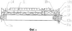
Фиг.9 - вид в разрезе по линии А-А обрабатывающего картриджа, показанного на Фиг.1, когда на нажимной стержень не нажимают, а деталь с отверстием, воспринимающая движущую силу, находится во втянутом состоянии;Fig.9 is a view in section along the line aa of the processing cartridge shown in Fig.1, when the pressure rod is not pressed, and the part with the hole, perceiving the driving force, is in the retracted state;
Фиг.10 - стереограмма детали с отверстием, воспринимающей движущую силу, в обрабатывающем картридже, представленном на Фиг.1;Figure 10 is a stereogram of a part with an aperture sensing a driving force in the processing cartridge shown in Figure 1;
Фиг.11 - стереограмма детали с отверстием, воспринимающей движущую силу, в обрабатывающем картридже, представленном на Фиг.1, после того, как на деталь с отверстием, воспринимающую движущую силу, был установлен упор;11 is a stereogram of a part with an aperture sensing a driving force in the processing cartridge shown in FIG. 1, after an emphasis has been placed on a part with an aperture sensing a motive force;
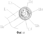
Фиг.12 - стереограмма фоточувствительного элемента для обрабатывающего картриджа, представленного на Фиг.1, в случае, когда на фоточувствительном элементе не установлена деталь с отверстием, воспринимающая движущую силу;12 is a stereogram of a photosensitive member for the processing cartridge shown in FIG. 1, in the case when a part with an aperture sensing a driving force is not mounted on the photosensitive member;
Фиг.13 - схематический чертеж, иллюстрирующий то состояние, при котором нажимной стержень заставляет фоточувствительный элемент и деталь с отверстием, воспринимающую движущую силу, выдвигаться или втягиваться, согласно второму варианту выполнения данного изобретения;FIG. 13 is a schematic drawing illustrating a state in which a pressure rod causes the photosensitive member and the part with the hole receiving the driving force to extend or retract, according to a second embodiment of the present invention;
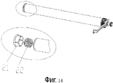
Фиг.14 - вид с частичным увеличением концевой части фоточувствительного элемента во втором варианте изобретения, в которой размещена пружина растягивания;Fig. 14 is a view with a partial enlargement of the end portion of the photosensitive member in the second embodiment of the invention, in which a tension spring is placed;
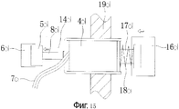
Фиг.15 - схематический чертеж, иллюстрирующий то состояние, при котором деталь с отверстием, воспринимающая движущую силу, и приводной механизм соединены друг с другом, когда третий вариант выполнения изобретения находится в состоянии с включенным электропитанием;FIG. 15 is a schematic drawing illustrating a state in which a part with an aperture sensing a driving force and a drive mechanism are connected to each other when the third embodiment of the invention is in the on state;
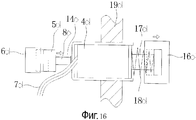
Фиг.16 - схематический чертеж, иллюстрирующий то состояние, при котором деталь с отверстием, воспринимающая движущую силу, и приводной механизм не соприкасаются друг с другом, когда третий вариант выполнения изобретения находится в состоянии с выключенным электропитанием;Fig. 16 is a schematic drawing illustrating a state in which a part with an aperture sensing a driving force and a drive mechanism are not in contact with each other when the third embodiment of the invention is in the off state;
Фиг.17 - схематическое изображение рабочей электрической схемы в третьем варианте выполнения данного изобретения;17 is a schematic illustration of a working electrical circuit in a third embodiment of the present invention;
Фиг.18 - схематическое изображение еще одной рабочей электрической схемы в третьем варианте выполнения данного изобретения;Fig. 18 is a schematic illustration of yet another working electrical circuit in a third embodiment of the present invention;
Фиг.19 - схематический чертеж, иллюстрирующий то состояние, при котором деталь с отверстием, воспринимающая движущую силу, и приводной механизм соединены друг с другом, когда четвертый вариант выполнения изобретения находится в состоянии с включенным электропитанием;Fig. 19 is a schematic drawing illustrating a state in which a part with an aperture sensing a driving force and a drive mechanism are connected to each other when the fourth embodiment of the invention is in the on state;
Фиг.20 - схематический чертеж, иллюстрирующий то состояние, при котором деталь с отверстием, воспринимающая движущую силу, и приводной механизм не соприкасаются друг с другом, когда четвертый вариант выполнения изобретения находится в состоянии с выключенным электропитанием;FIG. 20 is a schematic drawing illustrating a state in which a part with an aperture sensing a driving force and a drive mechanism do not touch each other when the fourth embodiment of the invention is in the off state;
Фиг.21 - схематическое изображение рабочей электрической схемы в четвертом варианте выполнения данного изобретения;21 is a schematic illustration of a working electrical circuit in a fourth embodiment of the present invention;
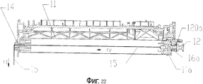
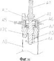
Фиг.22 - вид в разрезе пятого варианта выполнения данного изобретения;Fig. 22 is a sectional view of a fifth embodiment of the present invention;
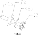
Фиг.23 - стереограмма детали с отверстием, воспринимающей движущую силу, в пятом варианте выполнения данного изобретения;23 is a stereogram of a part with an aperture sensing a driving force in a fifth embodiment of the present invention;
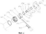
Фиг.24 - перспективное изображение с пространственным разделением деталей механизма передачи движущей силы для фоточувствительного элемента в шестом варианте выполнения изобретения;Fig is a perspective image with a spatial separation of the details of the transmission mechanism of the driving force for the photosensitive element in the sixth embodiment of the invention;
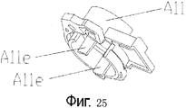
Фиг.25 - стереограмма торцевой крышки механизма передачи движущей силы для фоточувствительного элемента в шестом варианте выполнения изобретения;25 is a stereogram of an end cap of a driving force transmission mechanism for a photosensitive member in a sixth embodiment of the invention;
Фиг.26 - вид в разрезе механизма передачи движущей силы для фоточувствительного элемента в шестом варианте выполнения изобретения;FIG. 26 is a cross-sectional view of a driving force transmission mechanism for a photosensitive member in a sixth embodiment of the invention; FIG.
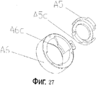
Фиг.27 - перспективное изображение с пространственным разделением деталей центрирующего кольца и направляющей втулки в механизме передачи движущей силы для фоточувствительного элемента в шестом варианте выполнения изобретения;Fig is a perspective image with a spatial separation of the parts of the centering ring and the guide sleeve in the transmission mechanism of the driving force for the photosensitive element in the sixth embodiment of the invention;
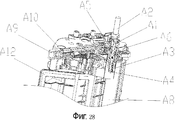
Фиг.28 - вид с частичным вырезом картриджа для тонера до того, как произойдет зацепление детали с отверстием, воспринимающей движущую силу, в механизме передачи движущей силы для фоточувствительного элемента в шестом варианте выполнения изобретения с приводной головкой в устройстве формирования изображения;Fig. 28 is a partially cutaway view of a toner cartridge before the part engages with the motive force receiving hole in the motive force transmission mechanism for the photosensitive member in the sixth embodiment of the invention with a drive head in the image forming apparatus;
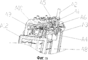
Фиг.29 - вид с частичным вырезом картриджа для тонера после того, как произойдет зацепление детали с отверстием, воспринимающей движущую силу, в механизме передачи движущей силы для фоточувствительного элемента в шестом варианте выполнения изобретения с приводной головкой в устройстве формирования изображения;Fig. 29 is a partially cutaway view of a toner cartridge after the part engages with a motive force receiving hole in the motive force transmission mechanism for the photosensitive member in the sixth embodiment of the invention with a drive head in the image forming apparatus;
Фиг.30 - стереограмма фланца фоточувствительного элемента в механизме передачи движущей силы для фоточувствительного элемента в шестом варианте выполнения изобретения; и30 is a stereogram of a flange of a photosensitive member in a driving force transmission mechanism for a photosensitive member in a sixth embodiment of the invention; and
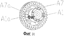
Фиг.31 - стереограмма, иллюстрирующая состояние, при котором деталь с отверстием, воспринимающая движущую силу, в механизме передачи движущей силы для фоточувствительного элемента в шестом варианте выполнения изобретения расположена внутри фланца фоточувствительного элемента.Fig. 31 is a stereogram illustrating a state in which a part with an aperture sensing a driving force in the driving force transmission mechanism for the photosensitive member in the sixth embodiment is located inside the flange of the photosensitive member.
Подробное описание предпочтительных вариантов выполненияDetailed Description of Preferred Embodiments
Первый вариант выполнения First embodiment
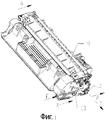
Фиг.1 представляет собой стереограмму обрабатывающего картриджа согласно предпочтительному варианту выполнения изобретения, а Фиг.2 - представляет собой перспективное изображение с пространственным разделением деталей обрабатывающего картриджа, представленного на Фиг.1. Как показано на Фиг.2, нажимной стержень 13 и первая пружина 18 расположены на одной стороне корпуса 10 обрабатывающего картриджа там, где расположена деталь 12 с отверстием, воспринимающая движущую силу; нажимной стержень 13 и первая пружина 18 образуют вместе механизм управления; нажимной стержень 13 расположен внутри направляющего паза 19 на корпусе 10 обрабатывающего картриджа и скользит взад и вперед вдоль направляющего паза 19 в направлении X; и первая пружина 18 упирается в зазор между толкающей поверхностью 13а на нажимном стержне 13 и опорной поверхностью 19а на направляющем пазе 19 и создает упругую возвращающую силу для нажимного стержня 13. Когда обрабатывающий картридж установлен на устройстве формирования изображения, толкающая поверхность 13а нажимного стержня 13 стремится удалиться от опорной поверхности 19а, когда нажимной стержень 13 находится под действием первой пружины 18; один конец нажимного стержня воспринимает приложенную снаружи силу F, которая преодолевает упругую силу первой пружины 18, и прижимной стержень 13 перемещается вдоль направления, обозначенного стрелкой X; а когда прекращается действие силы F, нажимной стержень возвращается в исходное положение, перемещаясь вдоль направления, противоположного направлению, обозначенному стрелкой X, под действием упругой возвращающей силы первой пружины 18.Figure 1 is a stereogram of a processing cartridge according to a preferred embodiment of the invention, and Figure 2 is a perspective image with a spatial separation of the parts of the processing cartridge shown in Figure 1. As shown in FIG. 2, the
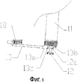
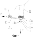
Фиг.6 и 7 представляют собой схематические чертежи, иллюстрирующие взаимодействие между деталью с отверстием, воспринимающей движущую силу, и нажимным стержнем; при этом Фиг.6 иллюстрирует состояние, при котором деталь с отверстием, воспринимающая движущую силу, втянута, а Фиг.7 иллюстрирует состояние, при котором деталь с отверстием, воспринимающая движущую силу, выдвинута. Как показано на Фиг.6 и 7, толкающая поверхность 13а и втянутая поверхность 13в выполнены на нажимном стержне 13 и расположены в виде уступа в направлении, параллельном продольному направлению нажимного стержня, а именно, в направлении X, и в направлении, параллельном оси детали с отверстием, воспринимающей движущую силу, а именно, в направлении Y; разность высот между толкающей поверхностью 13а и втянутой поверхностью 13в создаются в направлении Y; толкающая поверхность 13а расположена при меньшем значении координаты X, а втянутая поверхность 13в расположена при меньшем значении координаты Y; и между толкающей поверхностью 13а и втянутой поверхностью 13в выполнен соединительный переход посредством наклонной поверхности 13с. Как показано на Фиг.6, когда нажимной стержень 13 не нажат, вытянутая поверхность 13в служит опорой для опорного элемента 12а детали 12 с отверстием, воспринимающей движущую силу, и деталь 12 с отверстием, воспринимающая движущую силу, находится во втянутом состоянии. Как показано на Фиг.7, когда на нажимной стержень 13 давят с силой F, нажимной стержень 13 перемещается в направлении X; и в процессе этого движения опорный элемент 12а переходит их состояния опоры на втянутую поверхность 13в в состоянии опоры на толкающую поверхность 13а посредством наклонной поверхности 13с; и в процессе перехода деталь 12 с отверстием, воспринимающая движущую силу, выдвигается в направлении Y и входит в зацепление с приводным механизмом 20 устройства формирования изображения. Когда действие силы F прекращается, нажимной стержень 13 возвращается в состояние, показанное на Фиг.6.6 and 7 are schematic drawings illustrating the interaction between the part with the hole, perceiving the driving force, and the pressure rod; wherein FIG. 6 illustrates a state in which a part with an aperture sensing a driving force is retracted, and FIG. 7 illustrates a state in which a part with an aperture sensing a motive force is extended. As shown in FIGS. 6 and 7, the pushing
Далее будет показано, каким образом после прекращения действия силы F возможно втянуть деталь 12 с отверстием, воспринимающую движущую силу, чтобы гарантировать, что деталь 12 с отверстием, воспринимающая движущую силу, выйдет из зацепления с приводным механизмом устройства формирования изображения и можно будет успешно снять обрабатывающий картридж с устройства формирования изображения.Next, it will be shown how, after the termination of the force F, it is possible to retract the
Рассмотрим Фиг.8, 9, 10 и 11. Фиг.8 представляет собой вид в разрезе по линии А-А обрабатывающего картриджа, показанного на Фиг.1, когда на нажимной стержень 13 нажимают, а деталь 12 с отверстием, воспринимающая движущую силу, находится в выдвинутом состоянии; Фиг.9 представляет собой вид в разрезе по линии А-А обрабатывающего картриджа, показанного на Фиг.1, когда на нажимной стержень 13 не нажимают, а деталь 12 с отверстием, воспринимающая движущую силу, находится во втянутом состоянии; Фиг.10 представляет собой стереограмму детали 12 с отверстием, воспринимающей движущую силу, в обрабатывающем картридже; Фиг.11 представляет собой стереограмму детали 12 с отверстием, воспринимающей движущую силу, в обрабатывающем картридже, после того, как на деталь 12 с отверстием, воспринимающую движущую силу, был установлен упор 120. Как показано на Фиг.8 и 9, фоточувствительный элемент 11 опирается с возможностью вращения на основной корпус обрабатывающего картриджа; при этом фланец 11а на одном конце фоточувствительного элемента 11 опирается на палец 14 вала, а фланец 11а на другом конце фоточувствительного элемента 11 опирается на опору 17. Благодаря удерживающему действию пальца 14 вала и опоры 17 фоточувствительный элемент 11 может совершать только вращательное движение вокруг своей осевой линии в обрабатывающем картридже и не может перемещаться вдоль оси фоточувствительного элемента 11.Let us consider Figs. 8, 9, 10 and 11. Fig. 8 is a sectional view along line AA of the processing cartridge shown in Fig. 1, when the
Как показано на Фиг.8 и 9, между деталью 12 с отверстием, воспринимающей движущую силу, и фланцем 11а фоточувствительного элемента установлена вторая пружина 16, а именно, вторая пружина 16 расположена между фланцем 11а и упором 120. Вторая пружина 16 создает упругую возвращающую силу для детали 12 с отверстием, воспринимающей движущую силу, таким образом, что она вынуждает деталь 12 с отверстием, воспринимающую движущую силу, перемещается вдоль направления, противоположного направлению Y. После того, как обрабатывающий картридж установлен в устройство формирования изображения, на нажимной стержень 13 надавливают силой F; деталь 12 с отверстием, воспринимающая движущую силу, удерживается толкающей поверхностью 13а и находится в выдвинутом состоянии; и вторая пружина 16 сжата торцевыми поверхностями фланца 11а и упора 120. Когда обрабатывающий картридж снимают с устройства формирования изображения, действие силы F прекращается, нажимной стержень 13 совершает движение, возвращающее его в исходное положение, вдоль направления, противоположного направлению, показанному стрелкой X, под действием первой пружины 18, и толкающая поверхность 13а, и опорный элемент 12а постепенно выходят из зацепления; деталь 12 с отверстием, воспринимающая движущую силу, втягивается вдоль направления, противоположного направлению, показанному стрелкой Y, под действием упругой силы второй пружины 16 до тех пор, пока опорный элемент 12а не будет соприкасаться со втянутой поверхностью 13в и опираться на втянутую поверхность 13в; и, следовательно, деталь 12 с отверстием, воспринимающая движущую силу, будет находится во втянутом состоянии и будет выведено из зацепления с приводным механизмом 20 устройства формирования изображения.As shown in FIGS. 8 and 9, a
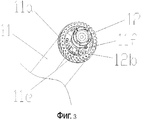
Способ соединения между деталью 12 с отверстием, воспринимающей движущую силу, и фоточувствительным элементом 11, а также процесс передачи движущей силы показаны ниже. Как показано на Фиг.10, 11, 12 и 13, передающая часть 12в, первый направляющий стержень 12 с, второй направляющий стержень 12d расположены на детали 12 с отверстием, воспринимающей движущую силу; передающая часть 12в расположена на втором направляющем стержне 12d; нагруженная выемка 11 в, первая направляющая выемка 11с, вторая направляющая выемка 11d, стальные пластины 11е и несколько сжатых стержней 11f расположены на фланце 11а фоточувствительного элемента 11; вторая направляющая выемка 11d расположена на боковых стенках сжатых стержней 11f; передающая часть 12в расположена на нагруженной выемке 11в и может входить в зацепление со сжатыми стержнями 11f; и передача движущей силы осуществляется между деталью 12 с отверстием, воспринимающей движущую силу, и фоточувствительным элементом 11 посредством передающей части 12в и сжатых стержней 11f. Когда деталь 12 с отверстием, воспринимающая движущую силу, вращается, передающая часть 12в встречает напряжение сжатых стержней 11f, и деталь 12 с отверстием, воспринимающая движущую силу, передает эту движущую силу на фоточувствительный элемент 11 посредством передающей части 12в и таким образом приводит в движение фоточувствительный элемент, который совершает вращательное движение.The connection method between the
Как показано на Фиг.8, 10 и 12, первый направляющий стержень 12 с расположен в первой направляющей выемке 11 с, второй направляющий стержень 12d расположен во второй направляющей выемке 11d; и первый направляющий стержень 12 с и второй направляющий стержень 12d могут соответственно скользить в направлении оси фоточувствительного элемента 11 (а именно, в направлении Y) в первой направляющей выемке 11 с и второй направляющей выемке 11d.As shown in Figs. 8, 10 and 12, the first guide rod 12 s is located in the first guide recess 11 s, the
Первый направляющий стрежень 12 с, второй направляющий стержень 12d, первая направляющая выемка 11 с, вторая направляющая выемка 11d, передающая часть 12в, сжатые стержни 11f и вторая пружина 16 образуют вместе втягиваемый механизм.The first guide rod 12 s, the
На Фиг.4 и 5 показаны 2 состояния, при которых возникают мертвые зоны в том случае, когда на фоточувствительном элементе 11 не устанавливаются стальные пластины 11е и когда деталь с отверстием, воспринимающая движущую силу, и приводной механизм 20 на устройстве формирования изображения находятся в зацеплении друг с другом. Как показано на Фиг.4 и 5, когда мертвые зоны возникают во время зацепления детали 12 с отверстием, воспринимающей движущую силу, и приводного механизма 20, деталь 12 с отверстием, воспринимающая движущую силу, не может осуществить нормальное зацепление с приводным механизмом 20, поскольку деталь 12 с отверстием, воспринимающая движущую силу, не может вращаться на фоточувствительном элементе 11 в указанном направлении. Эти два условия могут привести к тому, что деталь с отверстием, воспринимающая движущую силу, не сможет нормально работать.Figures 4 and 5 show 2 states in which dead zones occur when
Как показано на Фиг.3, когда деталь 12 с отверстием, воспринимающая движущую силу, расположена на фоточувствительном элементе 11, передающая часть 12в располагается между стальными пластинами, находящимися между сжатых стержней 11f. Когда деталь 12 с отверстием, воспринимающая движущую силу, находится в зацеплении с приводным механизмом 20 на устройстве формирования изображения, передающая часть 12в всегда располагается между стальными пластинами 11в с тем, чтобы была гарантия отсутствия мертвых зон, когда деталь 12 с отверстием, воспринимающая движущую силу, находится в зацеплении с приводным механизмом 20.As shown in FIG. 3, when a
Данный вариант выполнения также может быть осуществлен следующим образом: один конец пружины 16 упирается в деталь 12 с отверстием, воспринимающую движущую силу, а другой конец пружины 16 упирается в корпус 10 обрабатывающего картриджа; и деталь с отверстием, воспринимающая движущую силу, выходит из зацепления с приводным механизмом под действием упругой силы пружины.This embodiment can also be implemented as follows: one end of the
Второй вариант выполненияSecond embodiment
В описанном выше варианте выполнения только деталь 12 с отверстием, воспринимающая движущую силу, может приводиться в движение посредством нажимного стержня 13 таким образом, чтобы оно выдвигалось или втягивалось в направлении оси фоточувствительного элемента 11 с тем, чтобы войти в зацепление или выйти из зацепления с приводным механизмом 20 устройства формирования изображения. Можно понять, что втягиваемый механизм в этом варианте выполнения может быть осуществлен таким образом, что деталь 12 с отверстием, воспринимающая движущую силу, и фоточувствительный элемент 11 будут объединены в одно целое и будут выдвигаться и втягиваться вместе, а управление зацеплением и выходом из зацепления детали 12 с отверстием, воспринимающей движущую силу, и приводного механизма 20 на устройстве формирования изображения осуществляется посредством нажимного стержня 13. Те элементы конструкции, которые совпадают с элементами в первом варианте выполнения (такие, как механизм управления) не будут описываться подробно.In the embodiment described above, only a
Конструкцию и работу втягиваемого механизма можно описать следующим образом.The design and operation of the retractable mechanism can be described as follows.
Как показано на Фиг.9, палец 14 вала и опора 17 расположены на корпусе 10 обрабатывающего картриджа; фланец 11а на одном конце фоточувствительного элемента 11 опирается на палец 14 вала, а фланец 11а на другом конце фоточувствительного элемента 11 опирается на опору 17; фоточувствительный элемент 11 может перемещаться вдоль оси фоточувствительного элемента вместе с деталью 12 с отверстием, воспринимающей движущую силу. Втягиваемый механизм, приятый в этом варианте выполнения включает палец 14 вала, опору 17 и фланцы 11а на обоих концах фоточувствительного элемента 11.As shown in FIG. 9, the
Как показано на Фиг.13 и 14, торцевая крышка 21 и пружина 22 растяжения размещены на одном конце фоточувствительного элемента; деталь 12 с отверстием, воспринимающая движущую силу, расположенная на другом конце фоточувствительного элемента, установлена неподвижно на фланце 11а фоточувствительного элемента; торцевая крышка 21 устанавливается неподвижно на корпусе 10 обрабатывающего картриджа; и один конец пружины 22 растяжения крепится к торцевой крышке 21, а другой конец пружины 22 растяжения крепится к фоточувствительному элементу 11. Когда нажимной стержень 13 перемещается в направлении X и деталь 12 с отверстием, воспринимающая движущую силу, перемещается в направлении Y, она выдвигается в направлении Y вместе с фоточувствительным элементом 11 и входит в зацепление с приводным механизмом 20 устройства формирования изображения, а пружина 22 растяжения на другом конце фоточувствительного элемента 11 находится в растянутом состоянии. Когда нажимной стержень 13 возвращается в исходное состояние в направлении, противоположном направлению X, деталь 12 с отверстием, воспринимающая движущую силу, перемещается в направлении, противоположному направлению Y, вместе с фоточувствительным элементом 11 под действием пружины 22 растяжения и выходит из зацепления с приводным механизмом 20 устройства формирования изображения.As shown in FIGS. 13 and 14, the
Третий вариант выполненияThird Embodiment
Конструкция и работа втягиваемого механизма в данном варианте выполнения совпадают с теми, которые были описаны в первом и втором вариантах, и их описание не будет повторяться.The design and operation of the retractable mechanism in this embodiment are the same as those described in the first and second embodiments, and their description will not be repeated.
В данном изобретении втягивание детали с отверстием, воспринимающей движущую силу, может осуществляться не только в режиме механического надавливания, ей также можно управлять электрическим способом. Механизм управления осуществляется следующим образом.In the present invention, the retraction of a part with an opening perceiving the driving force can be carried out not only in the mechanical pressure mode, it can also be controlled electrically. The control mechanism is as follows.
Как показано на Фиг.15, в данном изобретении используется клапан 4d с односторонним электромагнитным управлением для зацепления и разъединения детали 5d с отверстием, воспринимающей движущую силу, расположенной на приводной стороне соединительного устройства 14d, и приводного механизма 6d устройства формирования изображения. Деталь 5d с отверстием, воспринимающая движущую силу, расположена на одном конце вала 8d соединительного устройства 14d, а второй конец вала 8d соединительного устройства 14d проходит сквозь полый цилиндр клапана 4d с электромагнитным управлением и может перемещаться налево или направо по отношению к клапану с электромагнитным управлением; клапан 4d с электромагнитным управлением крепится неподвижно на корпусе 19d обрабатывающего картриджа и не перемещается, когда скользит вал 8d; один конец металлического сердечника 17d и вал 8d составляют одно целое; а другой конец металлического сердечника 17d может скользить взад и вперед в выемке, выполненной на приводном конце фоточувствительного элемента 16d; металлический сердечник может принимать различные конструктивные формы и может быть выполнен в форме диска, креста, сферы и т.п., лишь бы металлический сердечник мог скользить в выемке, расположенной на приводном конце фоточувствительного элемента и соответствующей по форме сердечнику; металлический сердечник 17d может передавать движущую силу на фоточувствительной элемент 16d и вращаться вместе с фоточувствительным элементом 16d; второй упругий элемент 18d расположен между клапаном 4d с электромагнитным управлением и сердечником 17d и передает на сердечник упругую силу, возвращающую его в исходное положение; при этом упругая возвращающая в исходное положение сила используются для возвращения в исходное положение сердечника после того, как на клапан с электромагнитным управлением перестанет подаваться питание; и клапан 4d с электромагнитным управлением соединен с внешним источником питания посредством соединительного элемента 7d.As shown in FIG. 15, the present invention uses a one-
В данном варианте выполнения принят режим электромеханического управления зацеплением и отсоединением детали 5d с отверстием, воспринимающей движущую силу, и приводного механизма 6d устройства формирования изображения. Фиг.17 представляет собой электрическую схему цепи управления. Когда цепь с индуктивностью клапана с электромагнитным управлением включена, запитанная током катушка будет генерировать магнитное поле и создавать магнитную силу, приложенную к металлическому сердечнику 17d вследствие электромагнитной индукции; магнитная сила преодолевает упругую силу второго упругого элемента 18d и притягивает сердечник 17d, приближая его к клапану с электромагнитным управлением; и сердечник 17d перемещается налево вместе с валом 8d таким образом, что деталь 5d с отверстием, воспринимающая движущую силу, закрепленная на приводной стороне соединительного элемента, выдвигается при помощи вала 8d и входит в зацепление с приводным механизмом 6d устройства формирования изображения, и таким образом осуществляется передача вращающейся силы. Когда цепь клапана с электромагнитным управлением отключается, подача питания на катушку прекращается и она перестает создавать магнитное поле и, соответственно, не испытывает магнитного притяжения к металлическому сердечнику 17d, и, как показано на Фиг.16, металлический сердечник 17d приводится в движение и начинает скользить в направлении прочь от клапана с электромагнитным управлением благодаря действию упругой силы второго упругого элемента 18d; и в это время вал 8d соединительного устройства 14d тянет деталь 5d с отверстием, воспринимающую движущую силу, и она скользит в направлении клапана с электромагнитным управлением, и, таким образом, деталь 5d с отверстием, воспринимающая движущую силу, выходит из зацепления с приводным механизмом 6d устройства формирования изображения. Следовательно, зацепление и разъединение детали 5d с отверстием, воспринимающей движущую силу, и приводного механизма 6d устройства формирования изображения хорошо реализуется посредством управления путем включения и выключения цепи клапана с электромагнитным управлением.In this embodiment, the mode of electromechanical control of the engagement and disengagement of the
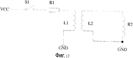
Источником рабочей мощности для клапана с электромагнитным управлением в данном варианте выполнения служит устройство формирования изображения. Поскольку рабочее напряжение, и рабочий ток клапана с электромагнитным управлением являются низкими, в цепь необходимо добавить трансформатор для понижения напряжения и увеличения тока. Как показано на Фиг.17, Vcc представляет собой источник электропитания для устройства формирования изображения; R1 - сопротивление для предупреждения короткого замыкания; R2 - полное сопротивление катушки клапана с электромагнитным управлением; L1 и L2 - соответственно, первичная и вторичная обмотки трансформатора, и включением и выключением цепи управляет переключатель S1.The source of operating power for the solenoid valve in this embodiment is an image forming apparatus. Since the operating voltage and the operating current of the solenoid valve are low, a transformer must be added to the circuit to reduce the voltage and increase the current. As shown in FIG. 17, Vcc is a power source for an image forming apparatus; R1 - resistance to prevent short circuit; R2 is the impedance of the solenoid valve coil; L1 and L2 are the primary and secondary windings of the transformer, respectively, and switch S1 controls the on and off of the circuit.
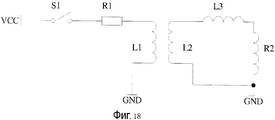
На клапан с электромагнитным управлением также может подаваться постоянный ток. Как показано на Фиг.18, в цепь необходимо добавить индуктор L3 для того, чтобы отвести переменный ток.A solenoid valve can also supply direct current. As shown in FIG. 18, an inductor L3 must be added to the circuit in order to divert the alternating current.
Переключатель S1 в данном варианте выполнения можно разместить внутри первичной обмотки цепи и его также можно разместить внутри вторичной обмотки цепи, лишь бы было возможно осуществить управление схемой управления путем включения и выключения.The switch S1 in this embodiment can be placed inside the primary winding of the circuit and it can also be placed inside the secondary winding of the circuit, so long as it is possible to control the control circuit by turning it on and off.
Четвертый вариант выполненияFourth Embodiment
В третьем варианте выполнения используется клапан с односторонним электромагнитным управлением для управления выдвижением и втягиванием детали с отверстием, воспринимающей движущую силу. В данном изобретении также можно использовать клапан с двусторонним электромагнитным управлением для достижения того же эффекта. Подробное описание еще одного варианта выполнения управления приводится ниже.In a third embodiment, a one-way solenoid valve is used to control the extension and retraction of a part with an opening that receives the driving force. A two-way solenoid valve may also be used in the present invention to achieve the same effect. A detailed description of another embodiment of the control is given below.
Как показано на Фиг.19, в данном варианте выполнения используется клапан 15d с двусторонним электромагнитным управлением для управления зацеплением и разъединением детали 5d с отверстием, воспринимающей движущую силу, расположенной на приводной стороне соединительного устройства 14d и приводного механизма 6d устройства формирования изображения. Элементы конструкции, совпадающие с элементами конструкции третьего варианта выполнения не будут описываться подробно. Различия между данным вариантом выполнения и третьим вариантом выполнения состоят в следующем: клапан с электромагнитным управлением в данном варианте выполнения образуется двумя катушками, а именно, первой катушкой 9d и второй катушкой 10d; магнит 11d установлен между двумя катушками и крепится неподвижно на клапане с электромагнитным управлением и не имеет контакта с двумя катушками; и между клапаном 15d с электромагнитным управлением и металлическим А сердечником в данном варианте выполнения не имеется другого упругого элемента. В данном варианте выполнения первая катушка 9d и вторая катушка 10d не работают одновременно; и состоянием при котором только одна катушка из двух находится в рабочем состоянии или обе катушки находятся в нерабочем состоянии можно в любой момент управлять с помощью электрической схемы, но состояние, при котором обе катушки будут работать одновременно, не может иметь место. Более того, катушки в данном варианте выполнения могут включаться мгновенно, и время включения составляет 3 секунды или менее.As shown in FIG. 19, in this embodiment, a two-
Как показано на Фиг.21, состоянием включения и выключения первой катушки 9d и второй катушки 10d можно управлять при помощи однополюсного переключателя на два направления, помещенного в электрическую схему. Когда первая катушка 9d включена, то благодаря электромагнитной индукции включенная катушка будет генерировать магнитное поле и создавать магнитную силу, приложенную к металлическому А сердечнику 17d таким образом, чтобы притянуть сердечник 17d и приблизить его к клапану с электромагнитным управлением, и, таким образом, деталь 5d с отверстием, воспринимающая движущую силу, неподвижно закрепленная на приводной стороне соединительного устройства, выдвигается посредством вала 8d и входит в зацепление с приводным механизмом 6d устройства формирования изображения. Поскольку в катушки в данном варианте выполнения питание может подаваться мгновенно, сила притяжения первой катушки 9d к металлическому сердечнику исчезнет после включения катушки. Для того, чтобы гарантировать, что деталь 5d с отверстием, воспринимающая движущую силу, продолжает находиться в плотном зацеплении с приводным механизмом 6d устройства формирования изображения, вал 8d соединительного устройства притягивается магнитом 11d на клапане с электромагнитным управлением и фиксируется в положении, при котором деталь 5d с отверстием, воспринимающая движущую силу, остается в зацеплении с приводным механизмом 6d устройства формирования изображения. Когда включается вторая катушка 10d, то благодаря электромагнитной индукции катушка, на которую падает электропитание, будет генерировать магнитное поле, но направления магнитных полей, генерируемых этими двумя катушками, будут противоположны друг другу, поскольку первая катушка 9d и вторая катушка 10d совместно используют положительный электрод источника питания. Следовательно, магнитная сила магнитного поля, создаваемого второй катушкой 10d, приложенная к металлическому сердечнику 17d, будет вынуждать соединительный элемент совершить движение, возвращающее его в исходное положение. Иными словами, как показано на Фиг.20, металлический сердечник 17d скользит в направлении удаления от клапана с электромагнитным управлением, но приводная головка скользит в направлении к клапану с электромагнитным управлением; и магнит 11d притягивает снова вал 8d и удерживает вал 8d в положении, при котором деталь 5d с отверстием, воспринимающая движущую силу, выходит из зацепления с приводным механизмом 6d устройства изображения. Следовательно, зацепление и разъединение детали 5d с отверстием, воспринимающей движущую силу, и приводного механизма 6d устройства формирования изображения успешно реализуются посредством управления включением и выключением электрической схемы клапана с электромагнитным управлением.As shown in FIG. 21, the on and off state of the
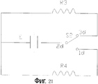
Источником электропитания для работы клапана с электромагнитным управлением в данном варианте выполнения является сухой гальванический элемент, который добавляется к обрабатывающему картриджу. Как показано на Фиг.21, Е представляет собой портативный батарейный источник питания из сухих гальванических элементов; однополюсной переключатель S2 на два направления управляет первой катушкой 9d и второй катушкой 10d, подавая электропитание, соответственно, на каждую из них; R4 и R4 представляют собой полные сопротивления, соответственно, первой катушке 9d и второй катушки 10d.The power source for operating the solenoid valve in this embodiment is a dry cell, which is added to the processing cartridge. As shown in FIG. 21, E is a portable battery pack of dry electrochemical cells; a two-pole single-pole switch S2 controls the
Данный вариант выполнения можно реализовать следующим образом: когда включается вторая катушка 10d, сердечник 17d притягивается и приближается к клапану с электромагнитным управлением; а когда включается первая катушка 9d, то создается отталкивающая сила, которая заставляет металлический сердечник 17d скользить в направлении удаления от клапана с электромагнитным управлением. Иными словами, пользователям только необходимо гарантировать, что в любой момент времени работает только одна катушка из двух, первая катушка 9d или вторая катушка 10d, или что обе катушки не работают.This embodiment can be implemented as follows: when the
Пятый вариант выполненияFifth Embodiment
Элементы конструкции в данном варианте выполнения в основном совпадают с элементами конструкции первого варианта выполнения, поэтому те элементы, которые совпадают с элементами первого варианта выполнения (такие, как втягиваемый механизм) не будут здесь описаны подробно.The structural elements in this embodiment basically coincide with the structural elements of the first embodiment, therefore, those elements that coincide with the elements of the first embodiment (such as a retractable mechanism) will not be described here in detail.
Механизм управления, принятый в данном варианте выполнения имеет следующий вид.The control mechanism adopted in this embodiment has the following form.
Фиг.22 представляет собой вид в разрезе обрабатывающего картриджа согласно данному варианту выполнения. В данном варианте выполнения оттяжка 15, проходящая сквозь палец 14 вала на корпусе 10 обрабатывающего картриджа, соединена с деталью 12 с отверстием, воспринимающей движущую силу, и может скользить в фоточувствительном элементе 11 вдоль оси фоточувствительного элемента 11; деталь 12 с отверстием, воспринимающая движущую силу, расположена на фланце 11а фоточувствительного элемента 11 (средство соединения и способ передачи движущей силы такие же, как и в первом варианте выполнения); на детали 12 с отверстием, воспринимающей движущую силу, установлен упор 120а; один конец второй пружины 16а упирается во фланец 11а, а другой конец второй пружины 16а упирается в упор 120а; и вторая пружина 16а представляет собой пружину сжатия.22 is a sectional view of a processing cartridge according to this embodiment. In this embodiment, a
Как показано на Фиг.22, когда обрабатывающий картридж устанавливается на устройстве формирования изображения, к оттяжке 15 прикладывается сила растяжения F1 в направлении, перпендикулярном направлению оси фоточувствительного элемента. Благодаря свойствам оттяжки сила растяжения F1, создаваемая оттяжкой 15, преобразуется в силу растяжения F2, действующую вдоль оси. Следовательно, растягивающая сила F2 заставляет деталь 12 с отверстием, воспринимающую движущую силу, перемещаться влево, и вторая пружина 16а находится в сжатом состоянии. Когда прекращается действие растягивающей силы F1, вторая пружина 16а возвращается в исходное состояние и заставляет деталь 12 с отверстием, воспринимающая движущую силу, перемещаться вправо и, следовательно, деталь 12 с отверстием, воспринимающая движущую силу, входит а зацепление с приводным механизмом устройства формирования изображения. Когда обрабатывающий картридж выводят из зацепления с механизмом формирования изображения, оттяжка 15 снова подвергается действию растягивающей силы F1, и деталь 12 с отверстием, воспринимающая движущую силу, вынуждена перемещаться влево и выйти из зацепления с приводным механизмом.As shown in FIG. 22, when the processing cartridge is mounted on the image forming apparatus, a tensile force F1 is applied to the
Растягивающая сила F1 в данном варианте выполнения может передаваться извне, например, посредством рукоятки обрабатывающего картриджа. Один конец оттяжки 15 соединен с рукояткой, а другой конец оттяжки 15 соединен с деталью 12 с отверстием, воспринимающей движущую силу. Когда тянут за рукоятку обрабатывающего картриджа, оттяжка 15 вытягивается вместе с рукояткой и воспринимает от рукоятки вытягивающую силу F1, и, при этом деталь с отверстием, воспринимающая движущую силу, вынуждена перемещаться влево. Когда за рукоятку обрабатывающего картриджа не тянут, на оттяжку 15 более не действует растягивающая сила F1 и вторая пружина 16а заставляет деталь 12 с отверстием, воспринимающую движущую силу, перемещаться вправо.The tensile force F1 in this embodiment can be transmitted externally, for example, by the handle of the processing cartridge. One end of the
Оттяжку 15 в данном варианте выполнения также можно разместить на корпусе 10 обрабатывающего картриджа, на который опирается фоточувствительный элемент 11.A
В данном изобретении вместо пружины можно использовать другие упругие материалы (такие, как упругая резина или упругая стальная пластина), и при этом можно достичь такого же технического эффекта. Упругие материалы и пружина известны как упругие элементы. Следовательно, первую и вторую пружины в первом варианте выполнения также можно назвать первым и вторым упругим элементами, и вторую пружину в третьем, четвертом и пятом вариантах выполнения также можно назвать вторым упругим элементом.In the present invention, other elastic materials (such as elastic rubber or elastic steel plate) can be used in place of the spring, and the same technical effect can be achieved. Elastic materials and a spring are known as elastic elements. Therefore, the first and second springs in the first embodiment can also be called the first and second elastic elements, and the second spring in the third, fourth and fifth embodiments can also be called the second elastic element.
В описанных выше вариантах выполнения проявитель размещается в обрабатывающем картридже, и в обрабатывающем картридже также имеются элементы, служащие для проявления и предназначенные для проявления фоточувствительного элемента, очищающее приспособление, заряжающее устройство и т.п. Подробное описание их не приводится.In the above-described embodiments, the developer is disposed in the processing cartridge, and the processing cartridge also has elements for developing and intended for developing the photosensitive element, a cleaning device, a charging device, and the like. A detailed description of them is not given.
Шестой вариант выполненияSixth Embodiment
Элементы конструкции в данном варианте выполнения, которые совпадают с элементами конструкции первого варианта выполнения, подробно здесь не описываются.The structural elements in this embodiment, which coincide with the structural elements of the first embodiment, are not described in detail here.
Как показано на Фиг.24-27, механизм передачи движущей силы на фоточувствительный элемент включает приводной механизм А2 (аналогичный приводной головке принтера, описанной в китайской заявке на патент CN 2010101313861), деталь А1 с отверстием, воспринимающая движущую силу, вторую пружину A3, упор А4, направляющую втулку А5, центрирующее кольцо А6, фланец А7 фоточувствительного элемента, нажимной стержень А9, первую пружину А10 и фланец А11 (аналогичный торцевой крышке, описанной в китайской заявке на патент CN 2010101313861), при этом деталь А1 с отверстием, воспринимающая движущую силу, направляющая втулка А5, центрирующее кольцо А6 и фланец А7 фоточувствительного элемента поочередно соединены друг с другом; деталь А1 с отверстием, воспринимающая движущую силу, входит в зацепление с приводным механизмом А2 и получает вращающую движущую силу от приводного механизма А2; часть A1a, передающая движущую силу, которая также расположена на детали А1 с отверстием, воспринимающей движущую силу, входит в зацепление с фланцем А7 фоточувствительного элемента и передает вращающую движущую силу от приводного механизма А2 на фланец А7 фоточувствительного элемента и обеспечивает получение фланцем А7 фоточувствительного элемента вращающей движущей силы; выступ А1в в форме диска также расположен на детали А1 с отверстием, воспринимающей движущую силу; опорный элемент А5в для детали А1 с отверстием, воспринимающей движущую силу, расположен на направляющей втулке А5; выступ А1в в форме диска располагается на опорном элементе А5в и может вращаться свободно относительно опорного элемента А5в, таким образом, что деталь А1 с отверстием, воспринимающая движущую силу, может свободно вращаться относительно направляющей втулки А5; выступ А5 с и проходящий вдоль оси ограничительный стык А5е расположены на направляющей втулке А5; опорный элемент А6с для направляющей втулки расположен на центрирующем кольце А6; выступ А5 с располагается на опорном элементе А6с для направляющей втулки; опорный элемент А6с для направляющей втулки имеет различную высоту в направлении оси фоточувствительного элемента, как показано на Фиг.27; зажимы А11е расположены на фланце А11, находятся внутри проходящего вдоль оси ограничительного стыка А5е и используется для ограничения вращательного движения направляющей втулки А5; когда опорный элемент А6с для направляющей втулки двигается относительно выступа А5 с, направляющая втулка А5 приводится в движение в направлении оси фоточувствительного элемента, и тогда деталь А1 с отверстием, воспринимающая движущую силу, приводится в движение в направлении оси фоточувствительного элемента; выступ А6в расположен на центрирующем кольце А6; ограничительная выемка А7с, предназначенная для второй пружины A3, и ограничительная выемка А7в, предназначенная для центрирующего кольца А6, расположены на фланце А7 фоточувствительного элемента; выступ А6в расположен внутри ограничительной выемке А7в, предназначенной для центрирующего кольца А6, и приводится в свободное вращение в ограничительной выемке А7в, предназначенной для центрирующего кольца А6, и тогда фоточувствительный элемент А8 может свободно вращаться относительно центрирующего кольца А6; приводной механизм А2 и деталь А1 с отверстием, воспринимающая движущую силу, находится в зацеплении друг с другом для передачи движущей силы; упор А4 расположен на одном конце детали А1 с отверстием, воспринимающей движущую силу; вторая пружина A3 расположена между упором А4 и ограничительной выемкой А7 с, предназначенной для второй пружины A3; один конец первой пружины А10 расположен на нажимном стержне А9, а другой конец первой пружины А10 расположен на картридже А12 с тонером; нажимной стержень А9 соединен с центрирующим кольцом А6; фоточувствительный элемент А8 соединен с фланцем А7 фоточувствительного элемента, а направляющая втулка А5 и деталь А1 с отверстием, воспринимающая движущую силу, соединяются с центрирующим кольцом А6 благодаря скольжению вдоль оси.As shown in Figs. 24-27, the mechanism for transmitting the driving force to the photosensitive member includes an A2 drive mechanism (similar to the printer drive head described in Chinese Patent Application CN 2010101313861), a hole part A1 receiving a driving force, a second spring A3, an abutment A4, guide sleeve A5, centering ring A6, photosensitive element flange A7, pressure rod A9, first spring A10 and flange A11 (similar to the end cap described in Chinese patent application CN 2010101313861), wherein part A1 with an opening is perceived cerned with a driving force, the guide sleeve A5, A6 and centering ring flange A7 photosensitive member are alternately connected to each other; a part A1 with an aperture, perceiving the driving force, engages with the driving mechanism A2 and receives a rotating driving force from the driving mechanism A2; the driving force transmitting part A1a, which is also located on the part A1 with the opening receiving the driving force, is engaged with the flange A7 of the photosensitive member and transfers the rotational driving force from the drive mechanism A2 to the flange A7 of the photosensitive member and ensures that the flange A7 of the photosensitive member rotates driving force; the protrusion A1B in the form of a disk is also located on the part A1 with a hole perceiving the driving force; a supporting member A5b for part A1 with an aperture sensing a driving force is located on the guide sleeve A5; a protrusion A1b in the form of a disk is located on the supporting element A5b and can rotate freely relative to the supporting element A5b, so that the part A1 with an aperture receiving the driving force can freely rotate relative to the guide sleeve A5; the protrusion A5 with and passing along the axis of the restrictive joint A5e are located on the guide sleeve A5; the supporting element A6c for the guide sleeve is located on the centering ring A6; the protrusion A5 c is located on the supporting element A6c for the guide sleeve; the support member A6c for the guide sleeve has a different height in the axis direction of the photosensitive member, as shown in FIG. the clamps A11e are located on the flange A11, are located inside the boundary joint A5e passing along the axis and are used to limit the rotational movement of the guide sleeve A5; when the support member A6c for the guide sleeve moves relative to the protrusion A5 c, the guide sleeve A5 is driven in the direction of the axis of the photosensitive member, and then the part A1 with the hole receiving the driving force is driven in the direction of the axis of the photosensitive member; the protrusion A6b is located on the centering ring A6; a restriction recess A7c for a second spring A3 and a restrictive recess A7b for a centering ring A6 are located on a flange A7 of the photosensitive member; the protrusion A6b is located inside the restrictive recess A7b, intended for the centering ring A6, and is freely rotated in the restrictive recess A7b, intended for the centering ring A6, and then the photosensitive element A8 can freely rotate relative to the centering ring A6; the drive mechanism A2 and the part A1 with the hole, perceiving the driving force, is engaged with each other to transmit the driving force; emphasis A4 is located at one end of part A1 with an aperture perceiving a driving force; the second spring A3 is located between the stop A4 and the restrictive recess A7 c, intended for the second spring A3; one end of the first spring A10 is located on the pressure rod A9, and the other end of the first spring A10 is located on the toner cartridge A12; a push rod A9 is connected to a centering ring A6; the photosensitive element A8 is connected to the flange A7 of the photosensitive element, and the guide sleeve A5 and the part A1 with the hole receiving the driving force are connected to the centering ring A6 due to sliding along the axis.
Втягиваемый механизм включает деталь А1, воспринимающую движущую силу, упор А4 и вторую пружину A3, а механизм управления включает выступ А1в в форме диска, направляющую втулку А5, центрирующее кольцо А6, нажимной стержень А9, первую пружину А10 и фланец А11.The retractable mechanism includes a part A1 receiving the driving force, a stop A4 and a second spring A3, and the control mechanism includes a protrusion A1b in the form of a disk, a guide sleeve A5, a centering ring A6, a push rod A9, a first spring A10 and a flange A11.
Процесс передачи движущей силы всего механизма передачи движущей силы в данном варианте выполнения подробно описан ниже. Как показано на Фиг.24-29, деталь А1 с отверстием, воспринимающая движущую силу, и приводной механизм А2 находятся в разъединенном состоянии во время установки картриджа 12 с тонером и еще на которое время удерживаются на расстоянии друг от друга после того, как картридж 12 с тонером установлен на место. После того, как картридж 12 с тонером установлен и когда закрыта крышка устройства, крышка устройства формирования изображения (аналогично принтеру, описанному в китайской заявке на патент CN 2010101313861) надавливает на нажимной стержень А9 и заставляет центрирующее кольцо А6, соединенное с нажимным стержнем А9, вращаться по часовой стрелке в направлении радиуса фоточувствительного элемента. Поскольку вращательное движение направляющей втулки не допускается вследствие соединения зажимов А11е на фланце АН и проходящего вдоль оси ограничительного стыка А5е направляющей втулки, направляющую втулку А5 можно привести в движение при помощи центрирующего кольца А6, если приложить осевое давление, создаваемое скошенной поверхностью А6а центрирующего кольца и скошенной поверхностью А5а направляющей втулки, при котором она будет выдвигаться вдоль оси фоточувствительного элемента, и, таким образом, деталь А1 с отверстием, воспринимающая движущую силу, расположенная на направляющей втулке А5 приводится в движение таким образом, что оно выдвигается и входит в зацепление с приводным механизмом А2, следовательно, приводной механизм А2 заставляет деталь А1 с отверстием, воспринимающую движущую силу, приводить в движение фоточувствительный барабан А8 таким образом, чтобы он вращался в направлении оси фоточувствительного барабана А8. Следовательно, как вторая пружина A3, так и первая пружина А10 находятся в сжатом состоянии, и выдвижение вдоль оси детали А1 с отверстием, воспринимающей движущую силу, в данном состоянии составляет от 3,8 до 4,8 мм по сравнению с тем, которое было в состоянии, предшествующем закрыванию крышки устройства формирования изображения. После завершения процесса печати когда открывают крышку устройства формирования изображения, прекращается действие давления, прикладываемого к нажимному стержню А9 крышкой устройства формирования изображения, и нажимной стержень А9, имеющий функцию возврата в исходное положение, отводится назад под действием силы первой пружины А10 таким образом, что он заставляет центрирующее кольцо А6 вращаться против часовой стрелки в радиальном направлении центрирующего кольца А6; осевое давление между скошенной поверхностью А6а центрирующего кольца и скошенной поверхностью А5а направляющей втулки также перестает действовать, и сжатая вторая пружина A3 возвращается в исходное состояние, и при этом заставляет деталь А1 с отверстием, воспринимающую движущую силу, втянуться и выйти из зацепления с приводным механизмом А2; и процесс печати завершен.The driving force transmission process of the entire driving force transmission mechanism in this embodiment is described in detail below. As shown in Figs. 24-29, the motive force receiving part A1 and the drive mechanism A2 are disconnected during installation of the
Как показано на Фиг.30 и 31, в данном варианте выполнения выемка А7а, предназначенная для размещения скошенной поверхности, расположена внутри фланца А7 фоточувствительного элемента. Часть A1a, передающая движущую силу, расположена в средней части выемки А7а, предназначенной для размещения скошенной поверхности, до того, как деталь А1 с отверстием, воспринимающая движущую силу, выдвинется в направлении оси фоточувствительного элемента и войдет в зацепление с приводным механизмом А2, с тем, чтобы деталь А1 с отверстием, воспринимающую движущую силу, можно было привести в движение и выдвинуть его в направлении оси фоточувствительного элемента и ввести в зацепление с приводным механизмом А2, при этом оно совмещается с приводным механизмом А2 (совмещение означает, что деталь А1 с отверстием, воспринимающая движущую силу, немного поворачивается вокруг оси), таким образом, удается избежать явления возникновения мертвых углов во время вхождения в зацепление детали А1 с отверстием, воспринимающей движущую силу, и приводного механизма.As shown in FIGS. 30 and 31, in this embodiment, a recess A7a for receiving a beveled surface is located inside the flange A7 of the photosensitive member. The driving force transmitting part A1a is located in the middle part of the recess A7a for receiving the beveled surface before the motive force receiving part A1 extends in the axis direction of the photosensitive member and engages with the drive mechanism A2, so so that part A1 with an aperture perceiving the driving force can be set in motion and extended in the direction of the axis of the photosensitive element and engaged with the drive mechanism A2, while it is combined with the drive mechanism A2 (alignment means that part A1 with the hole, which receives the driving force, rotates a little around the axis), thus, it is possible to avoid the occurrence of dead angles during the engagement of the part A1 with the hole, which receives the driving force, and the drive mechanism.
В данном изобретении обрабатывающий картридж представляет собой то же самое, что и картридж с тонером.In the present invention, the processing cartridge is the same as the toner cartridge.
Claims (19)
Applications Claiming Priority (5)
| Application Number | Priority Date | Filing Date | Title |
|---|---|---|---|
| CN201010104692A CN101846955A (en) | 2010-01-28 | 2010-01-28 | Process cartridge |
| CN201010104692.6 | 2010-01-28 | ||
| CN201010131386.1A CN102200706B (en) | 2010-03-22 | 2010-03-22 | Power transmission apparatus for photosensitive element |
| CN201010131386.1 | 2010-03-22 | ||
| PCT/CN2010/079377 WO2011091686A1 (en) | 2010-01-28 | 2010-12-02 | Cartridge |
Publications (2)
| Publication Number | Publication Date |
|---|---|
| RU2012131978A RU2012131978A (en) | 2014-03-10 |
| RU2547171C2 true RU2547171C2 (en) | 2015-04-10 |
Family
ID=44318650
Family Applications (1)
| Application Number | Title | Priority Date | Filing Date |
|---|---|---|---|
| RU2012131978/28A RU2547171C2 (en) | 2010-01-28 | 2010-12-02 | Processing cartridge |
Country Status (9)
| Country | Link |
|---|---|
| US (1) | US9176467B2 (en) |
| EP (2) | EP2530532B1 (en) |
| JP (7) | JP2013518303A (en) |
| BR (1) | BR112012018468B1 (en) |
| DE (1) | DE202010018322U1 (en) |
| ES (2) | ES2798255T3 (en) |
| PL (2) | PL2530532T3 (en) |
| RU (1) | RU2547171C2 (en) |
| WO (1) | WO2011091686A1 (en) |
Cited By (4)
| Publication number | Priority date | Publication date | Assignee | Title |
|---|---|---|---|---|
| US9599949B2 (en) | 2010-01-28 | 2017-03-21 | Zhuhai Seine Technology Co., Ltd | Photosensitive process cartridge with driving force receiver |
| US9964920B2 (en) | 2015-11-21 | 2018-05-08 | Mei Yan | Process cartridge and photosensitive drum driving component |
| US10241459B1 (en) | 2018-04-18 | 2019-03-26 | Jiangxi Yibo E-Tech Co.Ltd. | Process cartridge |
| US10416604B1 (en) | 2018-04-18 | 2019-09-17 | Jiangxi Yibo E-Tech Co.Ltd. | Process cartridge |
Families Citing this family (31)
| Publication number | Priority date | Publication date | Assignee | Title |
|---|---|---|---|---|
| JP4498407B2 (en) | 2006-12-22 | 2010-07-07 | キヤノン株式会社 | Process cartridge, electrophotographic image forming apparatus, and electrophotographic photosensitive drum unit |
| PL2530532T3 (en) * | 2010-01-28 | 2020-11-02 | Ninestar Corporation | Cartridge |
| CN103376696B (en) * | 2013-07-25 | 2015-10-21 | 珠海天威飞马打印耗材有限公司 | Torque transmission, processing box for laser printer |
| US9740163B2 (en) | 2013-09-29 | 2017-08-22 | Ninestar Corporation | Rotational force driving assembly process cartridge |
| WO2015043339A1 (en) * | 2013-09-29 | 2015-04-02 | 珠海赛纳打印科技股份有限公司 | Rotational force drive assembly and processing box |
| JP6277909B2 (en) * | 2014-03-07 | 2018-02-14 | 三菱ケミカル株式会社 | Shaft member, end member, photosensitive drum unit, developing roller unit, process cartridge |
| US9329517B2 (en) | 2014-09-30 | 2016-05-03 | Clover Technologies Group, Llc | Drive receiving member for an imaging cartridge |
| KR102144815B1 (en) | 2014-11-28 | 2020-08-14 | 캐논 가부시끼가이샤 | Cartridge, member configuring cartridge and image formation device |
| JP6552194B2 (en) * | 2014-12-26 | 2019-07-31 | キヤノン株式会社 | Image forming apparatus and unit detachably attachable to image forming apparatus |
| ES2576778B1 (en) * | 2015-01-09 | 2017-04-18 | Julián Manuel DE LA PAZ LLERGO | Coupling device for rotary motion transmission with damped adjustment |
| CN106325023B (en) * | 2015-06-19 | 2023-09-08 | 江西镭博钛电子科技有限公司 | Developing box |
| CN111258196B (en) | 2015-09-30 | 2022-11-29 | 佳能株式会社 | Drum unit, process cartridge, and image forming apparatus |
| JP6808311B2 (en) | 2015-10-14 | 2021-01-06 | キヤノン株式会社 | Electrophotographic photosensitive drum unit, cartridge, and flange member |
| US10054904B1 (en) | 2016-02-26 | 2018-08-21 | Zhongshan Kingway Image Tech Co., Ltd. | Actuating rod unit, drive unit, and process cartridge containing the same |
| US9880518B2 (en) * | 2016-02-26 | 2018-01-30 | Zhongshan Kingway Image Tech Co., Ltd. | Cartridge mounting mechanism and process cartridge thereof |
| WO2017143781A1 (en) * | 2016-02-26 | 2017-08-31 | 中山诚威科技有限公司 | Processing cartridge |
| CN107132744A (en) * | 2016-02-26 | 2017-09-05 | 中山诚威科技有限公司 | A kind of handle box |
| WO2017150741A1 (en) | 2016-03-04 | 2017-09-08 | キヤノン株式会社 | Process cartridge and image forming device |
| CN106597825B (en) * | 2016-09-21 | 2018-05-22 | 纳思达股份有限公司 | A kind of handle box |
| US9588478B1 (en) | 2016-09-30 | 2017-03-07 | Roy Fan | Drive coupling and transmitting assembly for photosensitive drum and toner cartridges |
| CN206505261U (en) | 2016-10-06 | 2017-09-19 | 江西亿铂电子科技有限公司 | A kind of controlling organization and Delevoping cartridge |
| JP6575502B2 (en) | 2016-12-22 | 2019-09-18 | 京セラドキュメントソリューションズ株式会社 | Toner container and image forming apparatus |
| EP3333634B1 (en) * | 2016-12-09 | 2019-05-15 | KYOCERA Document Solutions Inc. | Toner case and image forming apparatus |
| JP6638640B2 (en) * | 2016-12-22 | 2020-01-29 | 京セラドキュメントソリューションズ株式会社 | Toner container and image forming apparatus |
| CN108227436B (en) * | 2016-12-09 | 2021-08-13 | 京瓷办公信息系统株式会社 | Toner container and image forming apparatus |
| JP7091096B2 (en) | 2017-03-15 | 2022-06-27 | キヤノン株式会社 | Drum unit, cartridge, process cartridge and electrophotographic image forming apparatus |
| CN116414014A (en) * | 2017-12-13 | 2023-07-11 | 佳能株式会社 | Cartridge and image forming apparatus |
| CN110632836A (en) * | 2018-06-21 | 2019-12-31 | 纳思达股份有限公司 | Power receiving member and process cartridge |
| KR102201426B1 (en) * | 2019-05-02 | 2021-01-11 | 최우혁 | Index-tilting device for bic merterial |
| CN113939664A (en) | 2019-06-12 | 2022-01-14 | 佳能株式会社 | Cartridge, accessory and installation kit |
| JP6992026B2 (en) * | 2019-07-03 | 2022-01-13 | キヤノン株式会社 | Image forming device |
Citations (4)
| Publication number | Priority date | Publication date | Assignee | Title |
|---|---|---|---|---|
| US6091916A (en) * | 1998-05-22 | 2000-07-18 | Gcc Management Limited | Retractable shield for a photosensitive member |
| US6351620B1 (en) * | 1998-10-23 | 2002-02-26 | Canon Kabushiki Kaisha | Process cartridge having guide projections and image forming apparatus using same |
| CN2615707Y (en) * | 2003-03-31 | 2004-05-12 | 珠海天威飞马打印耗材有限公司 | Laser printer processing box |
| RU2302027C2 (en) * | 2004-03-31 | 2007-06-27 | Кэнон Кабусики Кайся | Processing cartridge and image creation device |
Family Cites Families (32)
| Publication number | Priority date | Publication date | Assignee | Title |
|---|---|---|---|---|
| JP3839932B2 (en) | 1996-09-26 | 2006-11-01 | キヤノン株式会社 | Process cartridge, electrophotographic image forming apparatus, electrophotographic photosensitive drum and coupling |
| JP3984999B2 (en) * | 1996-09-26 | 2007-10-03 | キヤノン株式会社 | Process cartridge and electrophotographic image forming apparatus |
| JP3689504B2 (en) * | 1996-09-26 | 2005-08-31 | キヤノン株式会社 | Electrophotographic image forming apparatus |
| JPH11109752A (en) * | 1997-09-29 | 1999-04-23 | Ricoh Co Ltd | Image forming device |
| JP2000338842A (en) * | 1999-05-28 | 2000-12-08 | Canon Inc | Electrophotographic image forming device |
| DE50111987D1 (en) * | 2000-05-17 | 2007-03-22 | Eastman Kodak Co | Replaceable cylinder elements on electrographic printing units |
| JP2002023476A (en) * | 2000-07-07 | 2002-01-23 | Canon Inc | Developing cartridge, process cartridge and electrophotographic image forming device |
| JP3812636B2 (en) * | 2000-10-06 | 2006-08-23 | セイコーエプソン株式会社 | Image forming apparatus |
| JP3671835B2 (en) * | 2000-11-13 | 2005-07-13 | ブラザー工業株式会社 | Image forming apparatus |
| JP3877964B2 (en) * | 2001-02-06 | 2007-02-07 | シャープ株式会社 | CONNECTION DEVICE, ROTATION DEVICE, AND IMAGE FORMING DEVICE USING THEM |
| JP3631155B2 (en) * | 2001-03-16 | 2005-03-23 | キヤノン株式会社 | Process cartridge attachment / detachment mechanism |
| JP3625431B2 (en) * | 2001-03-16 | 2005-03-02 | キヤノン株式会社 | Process cartridge attaching / detaching mechanism, process cartridge, and electrophotographic image forming apparatus |
| JP3684195B2 (en) * | 2001-12-28 | 2005-08-17 | キヤノン株式会社 | Process cartridge and electrophotographic image forming apparatus |
| US7457570B2 (en) * | 2004-08-06 | 2008-11-25 | Ricoh Company, Ltd. | Image forming apparatus including a magnetic brush developing system using a two-component developer comprising toner and carrier |
| KR100644662B1 (en) * | 2004-12-13 | 2006-11-10 | 삼성전자주식회사 | Electrophotographic image forming apparatus |
| JP2006227098A (en) * | 2005-02-15 | 2006-08-31 | Kyocera Mita Corp | Photoreceptor drum unit and image forming apparatus equipped with the same |
| CN100543508C (en) * | 2005-09-30 | 2009-09-23 | 鸿富锦精密工业(深圳)有限公司 | Automatic focusing numerical camera mould |
| JP2007121681A (en) * | 2005-10-28 | 2007-05-17 | Seiko Epson Corp | Image forming apparatus |
| JP4995636B2 (en) * | 2006-10-13 | 2012-08-08 | 株式会社リコー | Image forming apparatus |
| JP4444997B2 (en) * | 2006-12-11 | 2010-03-31 | キヤノン株式会社 | Process cartridge and electrophotographic image forming apparatus |
| JP4498407B2 (en) * | 2006-12-22 | 2010-07-07 | キヤノン株式会社 | Process cartridge, electrophotographic image forming apparatus, and electrophotographic photosensitive drum unit |
| JP4552972B2 (en) * | 2007-06-07 | 2010-09-29 | ブラザー工業株式会社 | Image forming apparatus |
| JP4509169B2 (en) * | 2007-11-08 | 2010-07-21 | シャープ株式会社 | Image forming apparatus |
| JP5066059B2 (en) * | 2007-11-13 | 2012-11-07 | 京セラドキュメントソリューションズ株式会社 | Traction power transmission device and image forming apparatus equipped with the same |
| JP5067156B2 (en) * | 2007-12-28 | 2012-11-07 | ブラザー工業株式会社 | Image forming apparatus |
| JP5146045B2 (en) * | 2008-03-26 | 2013-02-20 | 富士ゼロックス株式会社 | Image forming apparatus |
| JP5306050B2 (en) * | 2008-06-20 | 2013-10-02 | キヤノン株式会社 | Cartridge, coupling member attaching method, and coupling member removing method |
| CN201331672Y (en) | 2009-01-09 | 2009-10-21 | 珠海赛纳科技有限公司 | Light sensation drum for carbon powder box and carbon powder box having the light sensation drum |
| CN201532527U (en) * | 2009-10-27 | 2010-07-21 | 珠海天威飞马打印耗材有限公司 | Photosensitive drum drive assembly |
| JP5428846B2 (en) * | 2009-12-24 | 2014-02-26 | ブラザー工業株式会社 | cartridge |
| CN102200706B (en) | 2010-03-22 | 2014-08-27 | 珠海赛纳打印科技股份有限公司 | Power transmission apparatus for photosensitive element |
| PL2530532T3 (en) * | 2010-01-28 | 2020-11-02 | Ninestar Corporation | Cartridge |
-
2010
- 2010-12-02 PL PL10844463T patent/PL2530532T3/en unknown
- 2010-12-02 ES ES10844463T patent/ES2798255T3/en active Active
- 2010-12-02 RU RU2012131978/28A patent/RU2547171C2/en active
- 2010-12-02 ES ES16195088T patent/ES2874027T3/en active Active
- 2010-12-02 PL PL16195088T patent/PL3176649T3/en unknown
- 2010-12-02 EP EP10844463.9A patent/EP2530532B1/en active Active
- 2010-12-02 JP JP2012550302A patent/JP2013518303A/en active Pending
- 2010-12-02 WO PCT/CN2010/079377 patent/WO2011091686A1/en active Application Filing
- 2010-12-02 DE DE202010018322.7U patent/DE202010018322U1/en not_active Expired - Lifetime
- 2010-12-02 BR BR112012018468-7A patent/BR112012018468B1/en active IP Right Grant
- 2010-12-02 EP EP16195088.6A patent/EP3176649B1/en active Active
-
2012
- 2012-07-13 US US13/548,981 patent/US9176467B2/en active Active
-
2015
- 2015-11-19 JP JP2015226606A patent/JP6149091B2/en active Active
- 2015-11-19 JP JP2015226607A patent/JP6149092B2/en active Active
- 2015-11-19 JP JP2015226605A patent/JP6039041B2/en active Active
- 2015-11-19 JP JP2015226604A patent/JP6039040B2/en active Active
-
2017
- 2017-03-03 JP JP2017040844A patent/JP6338306B2/en active Active
-
2018
- 2018-05-07 JP JP2018089366A patent/JP6673973B2/en active Active
Patent Citations (4)
| Publication number | Priority date | Publication date | Assignee | Title |
|---|---|---|---|---|
| US6091916A (en) * | 1998-05-22 | 2000-07-18 | Gcc Management Limited | Retractable shield for a photosensitive member |
| US6351620B1 (en) * | 1998-10-23 | 2002-02-26 | Canon Kabushiki Kaisha | Process cartridge having guide projections and image forming apparatus using same |
| CN2615707Y (en) * | 2003-03-31 | 2004-05-12 | 珠海天威飞马打印耗材有限公司 | Laser printer processing box |
| RU2302027C2 (en) * | 2004-03-31 | 2007-06-27 | Кэнон Кабусики Кайся | Processing cartridge and image creation device |
Cited By (7)
| Publication number | Priority date | Publication date | Assignee | Title |
|---|---|---|---|---|
| US9599949B2 (en) | 2010-01-28 | 2017-03-21 | Zhuhai Seine Technology Co., Ltd | Photosensitive process cartridge with driving force receiver |
| US9964920B2 (en) | 2015-11-21 | 2018-05-08 | Mei Yan | Process cartridge and photosensitive drum driving component |
| US10073412B2 (en) | 2015-11-21 | 2018-09-11 | Jiangxi Leibotai E-Tech Co., Ltd. | Process cartridge and photosensitive drum driving component |
| US10503117B2 (en) | 2015-11-21 | 2019-12-10 | Aster Graphics, Inc. | Process cartridge and photosensitive drum driving component |
| US10241459B1 (en) | 2018-04-18 | 2019-03-26 | Jiangxi Yibo E-Tech Co.Ltd. | Process cartridge |
| US10338513B1 (en) | 2018-04-18 | 2019-07-02 | Jiangxi Yibo E-Tech Co., Ltd. | Process cartridge |
| US10416604B1 (en) | 2018-04-18 | 2019-09-17 | Jiangxi Yibo E-Tech Co.Ltd. | Process cartridge |
Also Published As
| Publication number | Publication date |
|---|---|
| EP2530532A1 (en) | 2012-12-05 |
| DE202010018322U9 (en) | 2015-12-17 |
| WO2011091686A1 (en) | 2011-08-04 |
| ES2798255T3 (en) | 2020-12-10 |
| JP2017102486A (en) | 2017-06-08 |
| RU2012131978A (en) | 2014-03-10 |
| JP2018124588A (en) | 2018-08-09 |
| PL3176649T3 (en) | 2021-10-25 |
| DE202010018322U1 (en) | 2015-08-07 |
| JP6149092B2 (en) | 2017-06-14 |
| EP3176649A1 (en) | 2017-06-07 |
| BR112012018468A2 (en) | 2020-08-25 |
| US20120275824A1 (en) | 2012-11-01 |
| PL2530532T3 (en) | 2020-11-02 |
| JP6149091B2 (en) | 2017-06-14 |
| EP3176649B1 (en) | 2021-03-31 |
| JP2016042197A (en) | 2016-03-31 |
| ES2874027T3 (en) | 2021-11-04 |
| JP6039040B2 (en) | 2016-12-07 |
| US9176467B2 (en) | 2015-11-03 |
| EP2530532A4 (en) | 2014-10-29 |
| JP2016040625A (en) | 2016-03-24 |
| BR112012018468B1 (en) | 2021-06-29 |
| JP2013518303A (en) | 2013-05-20 |
| JP2016026334A (en) | 2016-02-12 |
| JP6338306B2 (en) | 2018-06-06 |
| JP2016029509A (en) | 2016-03-03 |
| JP6673973B2 (en) | 2020-04-01 |
| JP6039041B2 (en) | 2016-12-07 |
| EP2530532B1 (en) | 2020-04-01 |
Similar Documents
| Publication | Publication Date | Title |
|---|---|---|
| RU2547171C2 (en) | Processing cartridge | |
| US9671742B2 (en) | Process cartridge having a control mechanism for a driving mechanism | |
| CN102141766B (en) | Processing box | |
| RU2569788C2 (en) | Developing cartridge and electrophotographic image forming device | |
| CN106773583B (en) | Control mechanism and processing box comprising same | |
| CN107918264B (en) | Control mechanism and developing box comprising same | |
| CN105511246B (en) | Processing box | |
| CN105446108B (en) | Processing box | |
| CN220894728U (en) | Drum unit and processing box | |
| CN209231721U (en) | A kind of handle box | |
| CN117590713A (en) | Drum unit and processing box |
Legal Events
| Date | Code | Title | Description |
|---|---|---|---|
| PC41 | Official registration of the transfer of exclusive right |
Effective date: 20160819 |
|
| PD4A | Correction of name of patent owner |