JP6094869B2 - Image forming apparatus - Google Patents

Image forming apparatus Download PDF

Info

Publication number
JP6094869B2
JP6094869B2 JP2013013963A JP2013013963A JP6094869B2 JP 6094869 B2 JP6094869 B2 JP 6094869B2 JP 2013013963 A JP2013013963 A JP 2013013963A JP 2013013963 A JP2013013963 A JP 2013013963A JP 6094869 B2 JP6094869 B2 JP 6094869B2
Authority
JP
Japan
Prior art keywords
image forming
forming apparatus
latent image
housing
arm
Prior art date
Legal status (The legal status is an assumption and is not a legal conclusion. Google has not performed a legal analysis and makes no representation as to the accuracy of the status listed.)
Active
Application number
JP2013013963A
Other languages
Japanese (ja)
Other versions
JP2014002354A (en
Inventor
藤田 雅也
雅也 藤田
中村 賢二
賢二 中村
Current Assignee (The listed assignees may be inaccurate. Google has not performed a legal analysis and makes no representation or warranty as to the accuracy of the list.)
Ricoh Co Ltd
Original Assignee
Ricoh Co Ltd
Priority date (The priority date is an assumption and is not a legal conclusion. Google has not performed a legal analysis and makes no representation as to the accuracy of the date listed.)
Filing date
Publication date
Application filed by Ricoh Co Ltd filed Critical Ricoh Co Ltd
Priority to JP2013013963A priority Critical patent/JP6094869B2/en
Priority to US13/860,575 priority patent/US9201385B2/en
Publication of JP2014002354A publication Critical patent/JP2014002354A/en
Application granted granted Critical
Publication of JP6094869B2 publication Critical patent/JP6094869B2/en
Active legal-status Critical Current
Anticipated expiration legal-status Critical

Links

Images

Classifications

    • GPHYSICS
    • G03PHOTOGRAPHY; CINEMATOGRAPHY; ANALOGOUS TECHNIQUES USING WAVES OTHER THAN OPTICAL WAVES; ELECTROGRAPHY; HOLOGRAPHY
    • G03GELECTROGRAPHY; ELECTROPHOTOGRAPHY; MAGNETOGRAPHY
    • G03G21/00Arrangements not provided for by groups G03G13/00 - G03G19/00, e.g. cleaning, elimination of residual charge
    • G03G21/16Mechanical means for facilitating the maintenance of the apparatus, e.g. modular arrangements
    • G03G21/1604Arrangement or disposition of the entire apparatus
    • G03G21/1623Means to access the interior of the apparatus
    • G03G21/1628Clamshell type
    • GPHYSICS
    • G03PHOTOGRAPHY; CINEMATOGRAPHY; ANALOGOUS TECHNIQUES USING WAVES OTHER THAN OPTICAL WAVES; ELECTROGRAPHY; HOLOGRAPHY
    • G03GELECTROGRAPHY; ELECTROPHOTOGRAPHY; MAGNETOGRAPHY
    • G03G21/00Arrangements not provided for by groups G03G13/00 - G03G19/00, e.g. cleaning, elimination of residual charge
    • G03G21/16Mechanical means for facilitating the maintenance of the apparatus, e.g. modular arrangements
    • G03G21/1661Mechanical means for facilitating the maintenance of the apparatus, e.g. modular arrangements means for handling parts of the apparatus in the apparatus
    • G03G21/1666Mechanical means for facilitating the maintenance of the apparatus, e.g. modular arrangements means for handling parts of the apparatus in the apparatus for the exposure unit

Landscapes

  • Physics & Mathematics (AREA)
  • General Physics & Mathematics (AREA)
  • Electrophotography Configuration And Component (AREA)

Description

本発明は、ファクシミリ、プリンタ、複写機などの画像形成装置に関するものである。   The present invention relates to an image forming apparatus such as a facsimile, a printer, and a copying machine.

従来から、中間転写体あるいは記録材搬送部材の表面移動方向に沿って複数の潜像担持体を有する、いわゆるタンデム型の画像形成装置が知られている。また、各潜像担持体の周囲には、それぞれ、潜像担持体表面を一様帯電する帯電装置、潜像担持体表面を露光して潜像を形成する潜像形成手段としての書込ヘッド、潜像担持体表面の潜像を現像する現像装置などが配置されている。   Conventionally, a so-called tandem type image forming apparatus having a plurality of latent image carriers along the surface moving direction of an intermediate transfer member or a recording material conveying member is known. Further, around each latent image carrier, a charging device that uniformly charges the surface of the latent image carrier, and a writing head as a latent image forming unit that exposes the surface of the latent image carrier to form a latent image. A developing device for developing the latent image on the surface of the latent image carrier is disposed.

特許文献1や2には、筐体に対して回動自在に設けられた保持体としての上カバーに複数の書込ヘッドを保持した画像形成装置が記載されている。上カバーは、複数の潜像担持体の配列方向における筐体の一端側を支点にして回動可能に設けられている。上カバーが筐体の開口を閉ざす閉位置にあるとき、複数の書込ヘッドは、潜像担持体表面に潜像を形成する潜像形成位置に位置し、上カバーを閉位置から開位置へと回動させると、複数の書込ヘッドが上カバーとともに移動し、潜像形成位置から退避位置へと移動する。   Patent Documents 1 and 2 describe an image forming apparatus in which a plurality of write heads are held on an upper cover as a holding body that is rotatably provided with respect to a casing. The upper cover is provided so as to be rotatable about one end side of the housing in the arrangement direction of the plurality of latent image carriers as a fulcrum. When the upper cover is in a closed position that closes the opening of the housing, the plurality of write heads are positioned at a latent image forming position for forming a latent image on the surface of the latent image carrier, and the upper cover is moved from the closed position to the open position. The plurality of writing heads move together with the upper cover and move from the latent image forming position to the retracted position.

各書込ヘッドが退避位置へ移動することにより、潜像担持体、帯電装置および現像装置を備えた作像ユニットが、鉛直上向きに引き出し可能となり、上カバーにより開放された筐体の上方開口部から作像ユニットを引き出すことができる。   As each writing head moves to the retracted position, the image forming unit including the latent image carrier, the charging device, and the developing device can be drawn vertically upward, and the upper opening of the housing that is opened by the upper cover The image forming unit can be pulled out from.

図10は、従来の画像形成装置の一例を示す概略構成図であり、(a)は、上カバー50を閉じたときの様子を示す図であり、(b)は、上カバー50を開けて、画像形成ユニットを取り出すときの様子を示す図である。
図10に示す従来の画像形成装置においては、各書込ヘッド70Y,M,C,Kを保持する保持体としての中カバー40が、上カバー50が回動自在に取り付けられた軸部材51に回動自在に取り付けられている。各書込ヘッド70Y,M,C,Kは、一端が中カバー40に揺動自在に取り付けられたアーム部材76Y,M,C,Kの他端側に回動自在に取り付けられている。また、中カバー40には、補給トナーを収納したトナーカートリッジ13Y,M,C,Kが保持されている。上カバー50と中カバー40とを図中反時計回りに回動させることで、筐体内の作像ユニット1Y,M,C,Kが露出し、筐体90の上部から取り出すことができる。
10A and 10B are schematic configuration diagrams illustrating an example of a conventional image forming apparatus. FIG. 10A is a diagram illustrating a state when the upper cover 50 is closed. FIG. 10B is a diagram illustrating the state in which the upper cover 50 is opened. FIG. 4 is a diagram showing a state when an image forming unit is taken out.
In the conventional image forming apparatus shown in FIG. 10, the middle cover 40 as a holding body for holding the writing heads 70Y, 70M, 70C, 70K is attached to the shaft member 51 to which the upper cover 50 is rotatably attached. It is pivotally attached. Each write head 70Y, M, C, K is rotatably attached to the other end of the arm member 76Y, M, C, K, one end of which is swingably attached to the middle cover 40. The middle cover 40 holds toner cartridges 13Y, 13M, 13C, and 13K containing replenishing toner. By rotating the upper cover 50 and the middle cover 40 counterclockwise in the figure, the image forming units 1Y, 1M, 1C, and 1K in the housing are exposed and can be taken out from the upper portion of the housing 90.

画像形成装置の図中左側(上カバー50の回動支点側)が壁であったり、画像形成装置よりも高さのあるものが置かれていたりした場合、図10(b)に示すように、上カバー50と中カバー40とは、90°を超えて回動できない。
図10(b)に示す領域Tは、中カバー40の回動支点側(図中左側)に配置された作像ユニット1Kを筐体90から着脱するときに作像ユニット1Kが通る幅を示している。図10(b)に示すように、上カバー50と中カバー40とが、90°を超えて回動できない場合、中カバー40の揺動支点側にある書込ヘッド70Kが上記領域Tに入ってしまう。その結果、作像ユニット1Kを筐体90から取り出すとき、書込ヘッド70Kに作像ユニット1Kが突き当り、書込ヘッド70Kが破損するおそれがある。
When the left side of the image forming apparatus (the rotation fulcrum side of the upper cover 50) is a wall or an object having a height higher than that of the image forming apparatus is placed, as shown in FIG. The upper cover 50 and the middle cover 40 cannot rotate beyond 90 °.
A region T shown in FIG. 10B indicates a width through which the image forming unit 1K passes when the image forming unit 1K disposed on the rotation fulcrum side (left side in the drawing) of the middle cover 40 is attached to and detached from the housing 90. ing. As shown in FIG. 10B, when the upper cover 50 and the middle cover 40 cannot be rotated by more than 90 °, the write head 70K on the swing fulcrum side of the middle cover 40 enters the region T. End up. As a result, when the image forming unit 1K is removed from the housing 90, the image forming unit 1K may come into contact with the write head 70K and the write head 70K may be damaged.

本発明は以上の課題に鑑みなされたものであり、その目的は、保持体が潜像担持体並び方向に対して90°を超えて揺動できない場合でも、筐体開口部から筐体内の部品を取り出すときに、潜像形成手段に部品が当接するのを抑制することができる画像形成装置を提供することである   The present invention has been made in view of the above problems, and an object of the present invention is to provide a component in the housing from the housing opening even when the holding body cannot swing more than 90 ° with respect to the alignment direction of the latent image carrier. Is to provide an image forming apparatus capable of suppressing the contact of components with the latent image forming means when taking out

上記目的を達成するために、請求項1の発明は、複数の潜像担持回転体、各潜像担持回転体に対応して設けられ上記潜像担持回転体表面に潜像を形成する複数の書込ヘッドを内部に収納し、開口部を有する筐体と、上記複数の書込ヘッドを保持し、該筐体に対して一端側を支点にして揺動可能に支持され、上記開口部を開放する開放位置に揺動することで、自らが保持している複数の潜像書込手段を潜像形成位置から退避位置へ移動させる保持体とを備えた画像形成装置において、上記保持体が、上記開放位置に位置した場合、当該画像形成装置を潜像担持回転体軸方向から見たとき、複数の書込ヘッドのうち、少なくとも上記保持体の揺動支点に最も近い位置に配置された書込ヘッドが、他の書込ヘッドを結んだラインよりも上記保持体が上記開放位置へ揺動するときの揺動方向側に位置するように構成したことを特徴とするものである。 In order to achieve the above-mentioned object, the invention of claim 1 includes a plurality of latent image carrying rotators, a plurality of latent image carrying rotators provided corresponding to each latent image carrying rotator and forming a latent image on the surface of the latent image carrying rotator. A writing head is housed inside, a housing having an opening, and the plurality of writing heads are held and supported swingably with one end side as a fulcrum with respect to the housing. In an image forming apparatus comprising: a holding body that moves a plurality of latent image writing means held by itself from a latent image forming position to a retracted position by swinging to an opening position to be opened; When the image forming apparatus is located in the open position, when viewed from the axial direction of the latent image carrier rotating body, the image forming apparatus is disposed at a position at least closest to the swing fulcrum of the holding body among the plurality of writing heads . write head, the holding member than connecting the other write head line Serial is characterized in that it has configured to be positioned in the swing direction when swung into the open position.

本発明においては、保持体を90°しか揺動させることができない場合であっても、少なくとも保持体の揺動支点に最も近い位置に配置された潜像形成手段を、筐体の一端側へ退避させることができる。よって、保持体の揺動支点側にある筐体内の部材を開口部から取り出すのに必要なスペース上(先の図10(b)の領域T上)に、少なくとも揺動支点に最も近い潜像形成手段が位置するのを抑制することができる。その結果、保持体の揺動支点側にある筐体内の部材を開口部から取り出すときに揺動支点に最も近い潜像形成手段が取り出しの邪魔になるのを抑制することができる。その結果、保持体が90°を超えて揺動できない場合でも、筐体内の部品を取り出すときに、部品が潜像形成手段にぶつかるのを抑制することができ、潜像形成手段や上記部品が破損するのを抑制することができる。   In the present invention, even when the holding body can be swung only 90 °, the latent image forming means disposed at least at the position closest to the rocking fulcrum of the holding body is moved to the one end side of the housing. Can be evacuated. Therefore, at least the latent image closest to the swing fulcrum on the space necessary for taking out the member in the casing on the swing fulcrum side of the holding body from the opening (on the region T in FIG. 10B). Positioning of the forming means can be suppressed. As a result, it is possible to prevent the latent image forming means closest to the swing fulcrum from obstructing the removal when the member in the housing on the swing fulcrum side of the holding body is taken out from the opening. As a result, even when the holder cannot swing over 90 °, it is possible to prevent the component from colliding with the latent image forming unit when the component in the housing is taken out. It is possible to suppress damage.

実施形態に係るプリンタを示す概略構成図。1 is a schematic configuration diagram illustrating a printer according to an embodiment. 同プリンタにおけるK用の作像ユニットを拡大して示す拡大構成図。FIG. 3 is an enlarged configuration diagram illustrating an enlarged image forming unit for K in the printer. 中カバーの斜視図。The perspective view of an inside cover. Y色のアーム機構の概略構成図。The schematic block diagram of the arm mechanism of Y color. K色のアーム機構の概略構成図。The schematic block diagram of a K-color arm mechanism. 書込ヘッドの感光体に対する位置決めの構成を示す斜視図。FIG. 3 is a perspective view showing a configuration for positioning a writing head with respect to a photoreceptor. 筐体内部を示す斜視図。The perspective view which shows the inside of a housing | casing. 中カバー開き始めの様子を示す図。The figure which shows a mode that a middle cover begins to open. 中カバーを、90°回転させて開いた様子を示す図。The figure which shows a mode that the inside cover was rotated 90 degrees and opened. 従来の画像形成装置の一例を示す概略構成図。1 is a schematic configuration diagram illustrating an example of a conventional image forming apparatus.

以下、本発明を適用した画像形成装置として、電子写真方式のプリンタ(以下、単にプリンタという)の一実施形態について説明する。
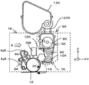
まず、本プリンタの基本的な構成について説明する。図1は、本プリンタを示す概略構成図である。同図において、このプリンタは、イエロー、マゼンタ、シアン、ブラック(以下、Y、M、C、Kと記す)のトナー像を作像するための4つの作像ユニット1Y,M,C,Kを備えている。これらは、画像形成物質として、互いに異なる色のY,M,C,Kトナーを用いるが、それ以外は同様の構成になっており、寿命到達時に交換される。Kトナー像を作像するための作像ユニット1Kを例にすると、これは図2に示されるように、潜像担持回転体たるドラム状の感光体2K、ドラムクリーニング装置3K、除電装置(不図示)、帯電装置4K、潜像形成手段としての書込ヘッド70K、現像装置5K等を備えている。作像ユニット1Kは、プリンタ本体に脱着可能であり、一度に消耗部品を交換できるようになっている。
Hereinafter, as an image forming apparatus to which the present invention is applied, an embodiment of an electrophotographic printer (hereinafter simply referred to as a printer) will be described.
First, the basic configuration of the printer will be described. FIG. 1 is a schematic configuration diagram showing the printer. In this figure, the printer includes four image forming units 1Y, M, C, and K for forming toner images of yellow, magenta, cyan, and black (hereinafter referred to as Y, M, C, and K). I have. These use Y, M, C, and K toners of different colors as the image forming material, but the other configurations are the same and are replaced when the lifetime is reached. For example, an image forming unit 1K for forming a K toner image is shown in FIG. A charging device 4K, a writing head 70K as a latent image forming means, a developing device 5K, and the like. The image forming unit 1K can be attached to and detached from the printer main body, so that consumable parts can be replaced at a time.

帯電装置4Kは、図示しない駆動手段によって図中時計周り方向に回転せしめられる感光体2Kに接触しながら図中反時計回り方向に回転する帯電ローラ4aKと、回収ローラ4bKとを具備している。そして、帯電ローラ4aKと感光体2Kとの間に放電を発生させることで、感光体2Kの表面を一様に帯電せしめる。   The charging device 4K includes a charging roller 4aK that rotates in the counterclockwise direction in the drawing while being in contact with the photosensitive member 2K that is rotated in the clockwise direction in the drawing by a driving unit (not shown), and a collection roller 4bK. Then, by generating a discharge between the charging roller 4aK and the photosensitive member 2K, the surface of the photosensitive member 2K is uniformly charged.

一様帯電せしめられた感光体2Kの表面は、書込ヘッド70Kによって露光されてK用の静電潜像を担持する。このK用の静電潜像は、図示しないKトナーを用いる現像装置7KによってKトナー像に現像される。そして、後述する中間転写ベルト16上に中間転写される。   The uniformly charged surface of the photoreceptor 2K is exposed by the writing head 70K and carries an electrostatic latent image for K. The electrostatic latent image for K is developed into a K toner image by a developing device 7K using K toner (not shown). Then, intermediate transfer is performed on an intermediate transfer belt 16 described later.

ドラムクリーニング装置3Kは、中間転写工程を経た後の感光体2K表面に付着している転写残トナーを除去する。除去された転写残トナーは、スクリュウ部材によって作像ユニット1Kのケーシングの端部まで搬送された後、ケーシングから排出されて不図示の廃トナーボトルに落とし込まれる。   The drum cleaning device 3K removes the transfer residual toner adhering to the surface of the photoreceptor 2K after the intermediate transfer process. The removed transfer residual toner is conveyed to the end of the casing of the image forming unit 1K by the screw member, and is then discharged from the casing and dropped into a waste toner bottle (not shown).

上記除電装置は、クリーニング後の感光体2Kの残留電荷を除電する。この除電により、感光体2Kの表面が初期化されて次の画像形成に備えられる。他色の作像ユニット(1Y,M,C)においても、同様にして感光体(2Y,M,C)上に(Y,M,C)トナー像が形成されて、後述する中間転写ベルト16上に中間転写される。   The static eliminator neutralizes residual charges on the photoreceptor 2K after cleaning. By this charge removal, the surface of the photoreceptor 2K is initialized and prepared for the next image formation. Similarly, in the other color image forming units (1Y, M, C), (Y, M, C) toner images are formed on the photoreceptors (2Y, M, C), and an intermediate transfer belt 16 described later. Intermediate transfer is performed on the top.

現像装置5Kは、図示しないKトナーを収容する縦長のホッパ部6Kと、現像部7Kとを有している。ホッパ部6K内には、図示しない駆動手段によって回転駆動されるアジテータ8K、これの鉛直方向下方で図示しない駆動手段によって回転駆動される撹拌パドル9K、これの鉛直方向下方で図示しない駆動手段によって回転駆動されるトナー供給ローラ10Kなどが配設されている。ホッパ部6K内のKトナーは、アジテータ8Kや撹拌パドル9Kの回転駆動によって撹拌されながら、自重によってトナー供給ローラ10Kに向けて移動する。トナー供給ローラ10Kは、金属製の芯金と、これの表面に被覆された発泡樹脂等からなるローラ部とを有しており、ホッパ部6K内のKトナーをローラ部の表面に付着させながら回転する。   The developing device 5K includes a vertically long hopper 6K that stores K toner (not shown) and a developing unit 7K. In the hopper 6K, an agitator 8K that is rotationally driven by a driving means (not shown), an agitation paddle 9K that is rotationally driven by a driving means (not shown) vertically below, and rotated by a driving means (not shown) below the vertical direction. A toner supply roller 10K to be driven is disposed. The K toner in the hopper 6K moves toward the toner supply roller 10K by its own weight while being stirred by the rotational drive of the agitator 8K and the stirring paddle 9K. The toner supply roller 10K has a metal cored bar and a roller portion made of foamed resin or the like coated on the surface of the metal core roller 10K, while adhering K toner in the hopper portion 6K to the surface of the roller portion. Rotate.

現像装置5Kの現像部7K内には、感光体2K及びトナー供給ローラ10Kに当接しながら回転する現像ローラ11Kや、これの表面に先端を当接させる薄層化ブレード12Kなどが配設されている。ホッパ部6K内のトナー供給ローラ10Kに付着したKトナーは、現像ローラ11Kとトナー供給ローラ10Kとの当接部で現像ローラ11Kの表面に供給される。供給されたKトナーは、現像ローラ11Kの回転に伴ってローラと薄層化ブレード12Kとの当接位置を通過する際に、ローラ表面上での層厚が規制される。そして、層厚規制後のKトナーは、現像ローラ11Kと感光体2Kとの当接部である現像領域において、感光体2K表面のK用の静電潜像に付着する。この付着により、K用の静電潜像がKトナー像に現像される。   In the developing unit 7K of the developing device 5K, a developing roller 11K that rotates while contacting the photoreceptor 2K and the toner supply roller 10K, and a thinning blade 12K that contacts the tip of the developing roller 11K are disposed. Yes. The K toner adhered to the toner supply roller 10K in the hopper 6K is supplied to the surface of the development roller 11K at the contact portion between the development roller 11K and the toner supply roller 10K. When the supplied K toner passes through the contact position between the roller and the thinning blade 12K as the developing roller 11K rotates, the layer thickness on the roller surface is regulated. Then, the K toner after the layer thickness regulation adheres to the electrostatic latent image for K on the surface of the photosensitive member 2K in the developing region which is a contact portion between the developing roller 11K and the photosensitive member 2K. By this adhesion, the electrostatic latent image for K is developed into a K toner image.

書込ヘッド70Kは、感光体2Kの長手方向に配列されたLEDや有機EL素子などの複数の発光素子と、感光体2Kと発光素子の間で感光体2Kの長手方向に配列されたロッドレンズとを有している。書込ヘッド70Kは、画像情報に基づいて所定の位置の発光素子を発光させ、ロッドレンズを介して感光体2Kに照射することで、感光体2Kを露光し、感光体2K上にK用の静電潜像が形成される。   The writing head 70K includes a plurality of light emitting elements such as LEDs and organic EL elements arranged in the longitudinal direction of the photoreceptor 2K, and a rod lens arranged in the longitudinal direction of the photoreceptor 2K between the photoreceptor 2K and the light emitting elements. And have. The writing head 70K emits light from a light emitting element at a predetermined position based on the image information, and irradiates the photoconductor 2K through the rod lens, thereby exposing the photoconductor 2K, and the K for K on the photoconductor 2K. An electrostatic latent image is formed.

作像ユニット1Kの鉛直方向上方には、補給トナーが収納されているトナーカートリッジ13Kが配設されている。このトナーボトル13Kと現像装置5Kとは、補給パイプ131Kにより連結され、必要に応じてトナーカートリッジ13K内の補給トナーが現像装置5Kに供給される。   A toner cartridge 13K that stores replenishment toner is disposed above the image forming unit 1K in the vertical direction. The toner bottle 13K and the developing device 5K are connected by a supply pipe 131K, and supply toner in the toner cartridge 13K is supplied to the development device 5K as necessary.

図2を用いてK用の作像ユニットについて説明したが、Y,M,C用の作像ユニット1Y,M,Cにおいても、同様のプロセスにより、感光体2Y,M,C表面にY,M,Cトナー像が形成される。   Although the image forming unit for K has been described with reference to FIG. 2, the image forming units 1Y, M, and C for Y, M, and C are also subjected to Y, M, and C on the surfaces of the photoreceptors 2Y, M, and C by a similar process. M and C toner images are formed.

先に示した図1において、作像ユニット1Y,M,C,Kの鉛直方向下方には、無端状の中間転写ベルト16を張架しながら図中反時計回り方向に無端移動せしめる転写ユニット15が配設されている。転写手段たる転写ユニット15は、中間転写ベルト16の他に、駆動ローラ17、従動ローラ18、4つの1次転写ローラ19Y,M,C,K、2次転写ローラ20、ベルトクリーニング装置21、クリーニングバックアップローラ22などを備えている。   In FIG. 1 shown above, a transfer unit 15 that moves endlessly in the counterclockwise direction in the figure while stretching an endless intermediate transfer belt 16 below the image forming units 1Y, 1M, 1C, and 1K in the vertical direction. Is arranged. In addition to the intermediate transfer belt 16, the transfer unit 15 serving as transfer means includes a driving roller 17, a driven roller 18, four primary transfer rollers 19Y, 19M, 19C, 19K, a secondary transfer roller 20, a belt cleaning device 21, a cleaning device. A backup roller 22 is provided.

中間転写ベルト16は、そのループ内側に配設された駆動ローラ17、従動ローラ18、クリーニングバックアップローラ22及び4つの1次転写ローラ19Y,M,C,Kによって張架されている。そして、図示しない駆動手段によって図中反時計回り方向に回転駆動される駆動ローラ17の回転力により、同方向に無端移動せしめられる。   The intermediate transfer belt 16 is stretched by a driving roller 17, a driven roller 18, a cleaning backup roller 22 and four primary transfer rollers 19Y, 19M, 19C, and 19K disposed inside the loop. Then, it is moved endlessly in the same direction by the rotational force of the driving roller 17 that is driven to rotate counterclockwise in the figure by a driving means (not shown).

4つの1次転写ローラ19Y,M,C,Kは、このように無端移動せしめられる中間転写ベルト16を感光体2Y,M,C,Kとの間に挟み込んでいる。この挟み込みにより、中間転写ベルト16のおもて面と、感光体2Y,M,C,Kとが当接するY,M,C,K用の1次転写ニップが形成されている。   The four primary transfer rollers 19Y, 19M, 19C, and 19K sandwich the intermediate transfer belt 16 that is moved endlessly in this manner between the photoreceptors 2Y, 2M, 2C, and 2K. By this sandwiching, primary transfer nips for Y, M, C, and K where the front surface of the intermediate transfer belt 16 and the photoreceptors 2Y, M, C, and K abut are formed.

1次転写ローラ19Y,M,C,Kには、図示しない転写バイアス電源によってそれぞれ1次転写バイアスが印加されており、これにより、感光体2Y,M,C,Kの静電潜像と、1次転写ローラ19Y,M,C,Kとの間に転写電界が形成される。なお、1次転写ローラ19Y,M,C,Kに代えて、転写チャージャーや転写ブラシなどを採用してもよい。   A primary transfer bias is applied to each of the primary transfer rollers 19Y, 19M, 19C, and 19K by a transfer bias power source (not shown), whereby the electrostatic latent images on the photoreceptors 2Y, 2M, 2C, and 2K, A transfer electric field is formed between the primary transfer rollers 19Y, 19M, 19C, and 19K. Instead of the primary transfer rollers 19Y, 19M, 19C, and 19K, a transfer charger, a transfer brush, or the like may be employed.

Y用の作像ユニット1Yの感光体2Y表面に形成されたYトナーは、感光体2Yの回転に伴って上述のY用の1次転写ニップに進入すると、転写電界やニップ圧の作用により、感光体2Y上から中間転写ベルト16上に1次転写される。このようにしてYトナー像が1次転写せしめられた中間転写ベルト16は、その無端移動に伴ってM,C,K用の1次転写ニップを通過する際に、感光体2M,C,K上のM,C,Kトナー像が、Yトナー像上に順次重ね合わせて1次転写される。この重ね合わせの1次転写により、中間転写ベルト16上には4色トナー像が形成される。   When the Y toner formed on the surface of the photoreceptor 2Y of the Y image forming unit 1Y enters the above-described primary transfer nip for Y as the photoreceptor 2Y rotates, due to the action of the transfer electric field and nip pressure, Primary transfer is performed on the intermediate transfer belt 16 from the photoreceptor 2Y. The intermediate transfer belt 16 on which the Y toner image is primarily transferred in this way passes through the primary transfer nips for M, C, and K along with the endless movement thereof, and the photoreceptors 2M, C, and K. The upper M, C, and K toner images are sequentially superimposed on the Y toner image and primarily transferred. A four-color toner image is formed on the intermediate transfer belt 16 by the primary transfer of superposition.

転写ユニット15の2次転写ローラ20は、中間転写ベルト16のループ外側に配設されて、ループ内側の従動ローラ18との間に中間転写ベルト16を挟み込んでいる。この挟み込みにより、中間転写ベルト16のおもて面と、2次転写ローラ20とが当接する2次転写ニップが形成されている。2次転写ローラ20には、図示しない転写バイアス電源によって2次転写バイアスが印加される。この印加により、2次転写ローラ20と、アース接続されている従動ローラとの間には、2次転写電界が形成される。   The secondary transfer roller 20 of the transfer unit 15 is disposed outside the loop of the intermediate transfer belt 16, and the intermediate transfer belt 16 is sandwiched between the driven roller 18 inside the loop. By this sandwiching, a secondary transfer nip where the front surface of the intermediate transfer belt 16 and the secondary transfer roller 20 abut is formed. A secondary transfer bias is applied to the secondary transfer roller 20 by a transfer bias power source (not shown). By this application, a secondary transfer electric field is formed between the secondary transfer roller 20 and the driven roller connected to the ground.

転写ユニット15の鉛直方向下方には、記録シートPを複数枚重ねた紙束の状態で収容している給紙カセット30がプリンタの筐体に対してスライド着脱可能に配設されている。この給紙カセット30は、紙束の一番上の記録シートPに給紙ローラ30aを当接させており、これを所定のタイミングで図中反時計回り方向に回転させることで、その記録シートPを給紙路31に向けて送り出す。   Below the transfer unit 15, a paper feed cassette 30 that stores a plurality of recording sheets P in a bundle of paper sheets is slidably attached to the printer housing. In the paper feed cassette 30, a paper feed roller 30a is brought into contact with the uppermost recording sheet P of the paper bundle, and the recording sheet is rotated by rotating it in a counterclockwise direction in the drawing at a predetermined timing. P is sent out toward the paper feed path 31.

給紙路31の末端付近には、レジストローラ対32が配設されている。このレジストローラ対32は、給紙カセット30から送り出された記録シートPをローラ間に挟み込むとすぐに両ローラの回転を停止させる。そして、挟み込んだ記録シートPを上述の2次転写ニップ内で中間転写ベルト16上の4色トナー像に同期させ得るタイミングで回転駆動を再開して、記録シートPを2次転写ニップに向けて送り出す。   A registration roller pair 32 is disposed near the end of the paper feed path 31. The registration roller pair 32 stops the rotation of both rollers as soon as the recording sheet P delivered from the paper feed cassette 30 is sandwiched between the rollers. Then, rotation driving is resumed at a timing at which the sandwiched recording sheet P can be synchronized with the four-color toner image on the intermediate transfer belt 16 in the above-described secondary transfer nip, and the recording sheet P is directed to the secondary transfer nip. Send it out.

2次転写ニップで記録シートPに密着せしめられた中間転写ベルト16上の4色トナー像は、2次転写電界やニップ圧の影響を受けて記録シートP上に一括2次転写され、記録シートPの白色と相まって、フルカラートナー像となる。このようにして表面にフルカラートナー像が形成された記録シートPは、2次転写ニップを通過すると、2次転写ローラ20や中間転写ベルト16から曲率分離する。そして、転写後搬送路33を経由して、後述する定着装置34に送り込まれる。   The four-color toner image on the intermediate transfer belt 16 brought into close contact with the recording sheet P at the secondary transfer nip is secondarily transferred onto the recording sheet P under the influence of the secondary transfer electric field and nip pressure, and the recording sheet. Combined with the white color of P, a full color toner image is obtained. The recording sheet P having a full-color toner image formed on the surface in this way is separated from the secondary transfer roller 20 and the intermediate transfer belt 16 by curvature when passing through the secondary transfer nip. Then, the toner is fed into a fixing device 34 described later via a post-transfer conveyance path 33.

2次転写ニップを通過した後の中間転写ベルト16には、記録シートPに転写されなかった転写残トナーが付着している。これは、中間転写ベルト16のおもて面に当接しているベルトクリーニング装置21によってベルト表面からクリーニングされる。中間転写ベルト16のループ内側に配設されたクリーニングバックアップローラ22は、ベルトクリーニング装置21によるベルトのクリーニングをループ内側からバックアップする。   Untransferred toner that has not been transferred to the recording sheet P adheres to the intermediate transfer belt 16 after passing through the secondary transfer nip. This is cleaned from the belt surface by a belt cleaning device 21 in contact with the front surface of the intermediate transfer belt 16. The cleaning backup roller 22 disposed inside the loop of the intermediate transfer belt 16 backs up the cleaning of the belt by the belt cleaning device 21 from the inside of the loop.

定着装置34は、図示しないハロゲンランプ等の発熱源を内包する定着ローラ34aと、これに所定の圧力で当接しながら回転する加圧ローラ34bとによって定着ニップを形成している。定着装置34内に送り込まれた記録シートPは、その未定着トナー像担持面を定着ローラ34aに密着させるようにして、定着ニップに挟まれる。そして、加熱や加圧の影響によってトナー像中のトナーが軟化さしめられて、フルカラー画像が定着せしめられる。   The fixing device 34 forms a fixing nip by a fixing roller 34a containing a heat source such as a halogen lamp (not shown) and a pressure roller 34b that rotates while contacting the fixing roller 34a with a predetermined pressure. The recording sheet P fed into the fixing device 34 is sandwiched between the fixing nips such that the unfixed toner image carrying surface is brought into close contact with the fixing roller 34a. Then, the toner in the toner image is softened by the influence of heating and pressurization, and the full color image is fixed.

定着装置34内から排出された記録シートPは、定着後搬送路35を経由した後、記録シートPが定着後搬送路35から排紙ローラ対36のローラ間に挟み込まれる。   After the recording sheet P discharged from the fixing device 34 passes through the post-fixing conveyance path 35, the recording sheet P is sandwiched between the post-fixing conveyance path 35 and the rollers of the paper discharge roller pair 36.

図示しないテンキー等からなる操作部に対する入力操作や、図示しないパーソナルコンピュータ等から送られてくる制御信号などにより、片面プリントモードが設定されている場合には、排紙ローラ対36に挟み込まれた記録シートPがそのまま機外へと排出される。そして、筐体の上カバー50の上面であるスタック部にスタックされる。   When the single-sided print mode is set by an input operation to an operation unit including a numeric keypad (not shown) or a control signal sent from a personal computer (not shown), the recording sandwiched between the paper discharge roller pair 36 is performed. The sheet P is discharged to the outside as it is. Then, it is stacked on the stack portion that is the upper surface of the upper cover 50 of the housing.

一方、両面プリントモードに設定されている場合には、先端側を排紙ローラ対36に挟み込まれながら搬送される記録シートPの後端側が定着後搬送路35を通り抜けると、不図示の切替爪により、定着後搬送路35の末端付近が閉鎖される。これとほぼ同時に、排紙ローラ対36が逆回転を開始する。すると、記録シートPは、今度は後端側を先頭に向けながら搬送されて、反転前搬送路400内に進入する。   On the other hand, when the double-sided printing mode is set, when the rear end side of the recording sheet P conveyed while being sandwiched between the discharge roller pair 36 passes through the post-fixing conveyance path 35, a switching claw (not shown) is provided. As a result, the vicinity of the end of the post-fixing conveyance path 35 is closed. At substantially the same time, the paper discharge roller pair 36 starts to rotate in the reverse direction. Then, the recording sheet P is conveyed while the rear end side is directed toward the head, and enters the conveyance path 400 before reversal.

排紙ローラ対36が逆回転すると記録シートPが反転前搬送路400内に進入して、鉛直方向上側から下側に向けて搬送される。そして、半円状に湾曲している反転搬送路44内に進入する。更に、その湾曲形状に沿って搬送されるのに伴って上下面が反転せしめられながら、鉛直方向上側から下側に向けての進行方向も反転して、鉛直方向下側から上側に向けて搬送される。その後、上述した給紙路31内を経て、2次転写ニップに再進入する。そして、もう一方の面にもフルカラー画像が一括2次転写された後、転写後搬送路33、定着装置34、定着後搬送路35、排紙ローラ対36を順次経由して、機外へと排出される。   When the paper discharge roller pair 36 rotates in the reverse direction, the recording sheet P enters the pre-reversal conveyance path 400 and is conveyed from the upper side to the lower side in the vertical direction. Then, it enters the reverse conveyance path 44 that is curved in a semicircular shape. Furthermore, while the upper and lower surfaces are reversed as the sheet is conveyed along the curved shape, the traveling direction from the upper side in the vertical direction to the lower side is also reversed, and conveyed from the lower side in the vertical direction toward the upper side. Is done. Thereafter, the toner enters the secondary transfer nip again through the above-described paper feed path 31. Then, after the full-color image is collectively transferred to the other surface, the post-transfer conveyance path 33, the fixing device 34, the post-fixation conveyance path 35, and the paper discharge roller pair 36 are sequentially passed to the outside. Discharged.

プリンタの筺体の上カバー50は、軸部材51を中心にして回動自在に支持されており、図中反時計回り方向に回転することで、筺体に対して開いた状態になる。そして、筺体の上部開口を大きく露出させる。   The upper cover 50 of the printer casing is supported so as to be rotatable about the shaft member 51, and is rotated in the counterclockwise direction in the drawing to be opened with respect to the casing. And the upper opening of a housing is exposed greatly.

トナーカートリッジ13Y,M,C,Kおよび書込ヘッド70Y,M,C,Kは、保持体としての中カバー40に保持されている。中カバー40も軸部材51を中心にして回動自在に支持されており、図中反時計回り方向に回転することで、筺体に対して開いた状態になり、筐体内部に配置された作像ユニット1Y,M,C,Kを露出させる。   The toner cartridges 13Y, 13M, 13C, and 13K and the write heads 70Y, 70M, 70C, and 70K are held by the middle cover 40 as a holding body. The middle cover 40 is also supported so as to be rotatable about the shaft member 51. By rotating in the counterclockwise direction in the figure, the middle cover 40 is opened with respect to the housing and is disposed inside the housing. The image units 1Y, M, C, and K are exposed.

トナーカートリッジ13Y,M,C,Kは、上カバー50を開けた状態で交換され、作像ユニット1Y,M,C,Kは、上カバー50及び中カバー40を開けた状態で交換される。   The toner cartridges 13Y, 13M, 13C, and 13K are replaced with the upper cover 50 opened, and the image forming units 1Y, 1M, 1C, and 1K are replaced with the upper cover 50 and the middle cover 40 opened.

本実施形態においては、中カバー40および上カバー50の回動の支点を、記録シートP搬送部(図中右側)側端部と反対側の端部に設けている。図中Zの位置に上カバー50および中カバー40の回動支点を設けた場合、上カバー50および中カバー40を、回動支点と反対側の端部(図中左側端部)まで設けなければ、上カバー50、中カバーを開いたとき、K色の作像ユニットを露出させることができない。このため、中カバー40が図中左右方向に長くなり、部品コストが高くなるという不具合がある。また、本実施形態においては、記録シートを縦搬送(鉛直方向に搬送)するものであり、記録シート搬送方向(鉛直方向)に対して直交し、かつ、記録シートと平行な方向(図1)から見たとき、中カバー40と定着後搬送路35とが重なってしまう。その結果、定着後搬送路35にジャムが発生したとき、中カバー40が、ジャム処理の邪魔となる場合がある。また、中カバー40が、定着後搬送路35などに干渉しないように配置する必要があり、中カバー40の構成が複雑化し、装置のコストアップに繋がる。また、上カバー50、中カバー40の図中左右方向の長さが長くなるので、装置の上方に上カバー50、中カバー40を開くスペースを大きく確保する必要も生じる。   In the present embodiment, the pivot point of rotation of the middle cover 40 and the upper cover 50 is provided at the end portion on the opposite side to the recording sheet P conveyance portion (right side in the drawing) side portion. When the rotation fulcrum of the upper cover 50 and the middle cover 40 is provided at the position Z in the figure, the upper cover 50 and the middle cover 40 must be provided to the end opposite to the rotation fulcrum (the left end in the figure). For example, when the upper cover 50 and the middle cover are opened, the K-color image forming unit cannot be exposed. For this reason, there exists a malfunction that the middle cover 40 becomes long in the left-right direction in a figure, and component cost becomes high. In this embodiment, the recording sheet is conveyed vertically (conveyed in the vertical direction), and is perpendicular to the recording sheet conveyance direction (vertical direction) and parallel to the recording sheet (FIG. 1). When viewed from above, the middle cover 40 and the post-fixing conveyance path 35 overlap. As a result, when a jam occurs in the post-fixing conveyance path 35, the middle cover 40 may interfere with the jam processing. In addition, the middle cover 40 needs to be arranged so as not to interfere with the post-fixing conveyance path 35 and the like, which complicates the configuration of the middle cover 40 and increases the cost of the apparatus. Further, since the lengths of the upper cover 50 and the middle cover 40 in the left-right direction in the drawing are increased, it is necessary to ensure a large space for opening the upper cover 50 and the middle cover 40 above the apparatus.

一方、図中左側端部の搬送部側と反対側端部に上カバー50、中カバー40の回動の支点(軸部材51)を設けることで、上カバー50、中カバー40を搬送部にまで延ばさずとも、上カバー50および中カバー40を開いたとき、作像ユニット1Y,M,C,Kを露出させることができる。これにより、上カバー50、中カバー40の回動の支点を搬送部側端部に設けた場合に比べて、上カバー50、中カバー40の長さを短くすることができ、部品コストを安価に抑えることができる。また、上カバー50、中カバー40の回動の支点を搬送部側端部に設けた場合に比べて、装置の上方の上カバー50、中カバー40を開くためのスペースを狭くすることができる。また、定着後搬送路35にジャムが発生したとき、中カバー40が、ジャム処理の邪魔となることがない。また、中カバー40が、定着後搬送路35などに干渉しないように配置する必要もなく、中カバー40の構成を単純化することができ、装置のコストアップを抑えることができる。   On the other hand, the upper cover 50 and the middle cover 40 are provided with a pivot (shaft member 51) at the end on the opposite side of the left end in the drawing to the transport unit side, so that the upper cover 50 and the middle cover 40 are used as the transport unit. Even when the upper cover 50 and the middle cover 40 are opened, the image forming units 1Y, 1M, 1C, and 1K can be exposed. Accordingly, the lengths of the upper cover 50 and the middle cover 40 can be shortened and the cost of parts can be reduced compared with the case where the pivot point of the upper cover 50 and the middle cover 40 is provided at the end on the conveyance unit side. Can be suppressed. In addition, the space for opening the upper cover 50 and the middle cover 40 above the apparatus can be made narrower than in the case where a pivot point for the rotation of the upper cover 50 and the middle cover 40 is provided at the end of the transport unit. . Further, when a jam occurs in the post-fixing conveyance path 35, the middle cover 40 does not interfere with the jam processing. Further, it is not necessary to arrange the middle cover 40 so as not to interfere with the post-fixing conveyance path 35 and the like, the configuration of the middle cover 40 can be simplified, and the cost of the apparatus can be suppressed.

次に、本実施形態の特徴点であるの中カバー40の各書込ヘッド70Y,M,C,Kの保持について説明する
図3は、中カバー40の斜視図であり、図4は、K色のアーム機構170Kの概略構成図であり、図5は、Y色のアーム機構170Yの概略構成図である。
各書込ヘッド70Y,M,C,Kは、アーム機構170Y,M,C,Kにより中カバー40に対して所定範囲内で揺動自在に保持されている。複数の書込ヘッドうち、最も中カバー40の回動の支点(軸部材51)側に配置されるK色の書込ヘッド70Kを中カバー40に対して揺動自在に保持するためのK色のアーム機構170Kは、他のY,M,C色の書込ヘッド70Y,M,Cを揺動自在に保持するためのアーム機構170Y,M,Cとは異なる構成をしている。アーム機構170Y,M,Cは、同一の構成をしている。各書込ヘッド70Y,M,C,Kは、ヘッドホルダ71Y,M,C,Kに保持されている。また、図4,図5に示すように、書込ヘッドは、バネ部材73によって感光体2方向に付勢されている。
Next, holding of the write heads 70Y, M, C, and K of the middle cover 40, which is a characteristic point of the present embodiment, will be described. FIG. 3 is a perspective view of the middle cover 40, and FIG. FIG. 5 is a schematic configuration diagram of a color arm mechanism 170K, and FIG. 5 is a schematic configuration diagram of a Y-color arm mechanism 170Y.
Each of the write heads 70Y, 70M, 70C, and 70K is held by the arm mechanisms 170Y, 170M, 170C, and 170K so as to be swingable with respect to the middle cover 40 within a predetermined range. Among the plurality of write heads, the K color for holding the K-color write head 70 </ b> K disposed closest to the pivot (shaft member 51) side of the middle cover 40 in a swingable manner with respect to the middle cover 40. This arm mechanism 170K has a different structure from the arm mechanisms 170Y, M, and C for swingably holding the other Y, M, and C writing heads 70Y, M, and C. The arm mechanisms 170Y, M, and C have the same configuration. Each write head 70Y, M, C, K is held by a head holder 71Y, M, C, K. As shown in FIGS. 4 and 5, the writing head is urged toward the photosensitive member 2 by a spring member 73.

アーム機構170Y,M,Cは、アーム部材76Y,M,C、付勢手段としてのトーションスプリング78Y,M,Cなどを有している。アーム部材76Y,M,Cの一端には、ヘッドホルダ71Y,M,Cから延びる第1回動部材72Y,M,Cが、回動自在に取り付けられている。アーム部材76Y,M,Cの他端は、中カバー40の側面に設けられた第2回動部材77Y,M,Cに回動自在に取り付けられている。   The arm mechanisms 170Y, M, and C include arm members 76Y, M, and C, torsion springs 78Y, M, and C as urging means. First rotation members 72Y, 72M, 72C extending from the head holders 71Y, 71M, 71C are rotatably attached to one end of the arm members 76Y, 76M, 76C. The other ends of the arm members 76Y, M, and C are rotatably attached to second rotating members 77Y, 77, and 77 that are provided on the side surface of the middle cover 40.

トーションスプリング78Y,M,Cは、中カバー40とアーム部材76Y,M,Cとに挟まれる形で第2回動部材77Y,M,Cに保持されている。トーションスプリング78Y,M,Cの一端は、中カバー40の側面に設けられたバネ受け部41Y,M,Cに突き当っており、他端は、アーム部材76Y,M,Cに設けられたバネ引っ掛け部79Y,M,Cに引っ掛けられている。これにより、アーム部材76Y,M,Cは、トーションスプリング78Y,78M,78Cにより、軸部材51側に付勢される。また、中カバー40には、アーム部材76Y,M,Cがトーションスプリング78Y,M,Cの付勢力により所定角度揺動すると、アーム部材76Y,M,Cと突き当って、アーム部材76Y,M,Cのトーションスプリング78Y,M,Cの付勢方向への揺動を規制する不図示の規制部が設けられている。   The torsion springs 78Y, M, C are held by the second rotating members 77Y, 77M, 77C so as to be sandwiched between the middle cover 40 and the arm members 76Y, 76M, C. One ends of the torsion springs 78Y, 78M, 78C abut against spring receiving portions 41Y, 41M, 41C provided on the side surface of the middle cover 40, and the other ends of the springs provided on the arm members 76Y, 76M, C. The hooks 79Y, M, and C are hooked. As a result, the arm members 76Y, M, C are biased toward the shaft member 51 by the torsion springs 78Y, 78M, 78C. In addition, when the arm members 76Y, M, and C are swung by a predetermined angle by the urging forces of the torsion springs 78Y, 78, and C, the arm member 76Y, M, and C are abutted against the arm member 76Y, M, and C. , C torsion springs 78 </ b> Y, M, and C are provided with restricting portions (not shown) that restrict swinging in the biasing direction.

揺動支点側アーム機構としてのK色のアーム機構170Kは、第1アーム部材101K、第2アーム部材102K、付勢手段としてのトーションスプリング103Kなどを有している。第1アーム部材101Kは、Y,M,C色のアーム部材76Y,M,Cと同様な構成をしており、一端には、ヘッドホルダ71Kから延びる第1回動部材72Kが回動自在に取り付けられている。第1アーム部材101Kの他端は、第2アーム部材102Kの中央部付近に固定された第2回動部材104Kに回動自在に取り付けられている。第2アーム部材102Kの一端は、中カバー40の側面に設けられた第3回動部材105Kに回動自在に取り付けられており、他端には、バネ受け部107Kが設けられている。   The K-color arm mechanism 170K as the swing fulcrum side arm mechanism includes a first arm member 101K, a second arm member 102K, a torsion spring 103K as an urging means, and the like. The first arm member 101K has the same configuration as the Y, M, and C color arm members 76Y, M, and C, and a first rotating member 72K extending from the head holder 71K is rotatable at one end. It is attached. The other end of the first arm member 101K is rotatably attached to a second rotating member 104K fixed near the center of the second arm member 102K. One end of the second arm member 102K is rotatably attached to a third rotating member 105K provided on the side surface of the middle cover 40, and a spring receiving portion 107K is provided at the other end.

トーションスプリング103Kは、第1アーム部材101Kと第2アーム部材102Kとに挟まれる形で第2回動部材104Kに保持されており、一端が第2アーム部材102Kに設けられたバネ受け部107Kに突き当っており、他端は、第1アーム部材101Kのバネ引っ掛け部106Kに引っ掛けられている。これにより、第1アーム部材101Kは、トーションスプリング103Kにより、軸部材51側に付勢される。また、第1アーム部材101Kがトーションスプリング103Kの付勢力により所定角度揺動すると、第1アーム部材101Kと突き当って、第1アーム部材101Kのトーションスプリング103Kの付勢方向への揺動を規制する不図示の規制部が第2アーム部材に設けられている。   The torsion spring 103K is held by the second rotating member 104K so as to be sandwiched between the first arm member 101K and the second arm member 102K, and one end of the torsion spring 103K is attached to the spring receiving portion 107K provided on the second arm member 102K. The other end is hooked on the spring hooking portion 106K of the first arm member 101K. Accordingly, the first arm member 101K is biased toward the shaft member 51 by the torsion spring 103K. Further, when the first arm member 101K swings by a predetermined angle by the biasing force of the torsion spring 103K, the first arm member 101K abuts against the first arm member 101K and the swinging of the first arm member 101K in the biasing direction of the torsion spring 103K is restricted. A regulating portion (not shown) is provided on the second arm member.

図3、図4に示すように、第2回動部材104Kは、第2アーム部材102Kと、中カバー40に設けられた円弧形状の案内孔42Kとを貫通している。   As shown in FIGS. 3 and 4, the second rotating member 104 </ b> K passes through the second arm member 102 </ b> K and an arcuate guide hole 42 </ b> K provided in the middle cover 40.

図6は、書込ヘッド70Kの感光体2Kに対する位置決めの構成を示す斜視図である。なお、Y,M,C色の書込ヘッド70Y,M,Cの感光体2Y,M,Cに対する位置決めの構成は、K色と同じ構成である。
図に示すように、作像ユニット1Kのケース53には、位置決め突起53aが設けられている。書込ヘッド70Kの感光体2Kとの対向面の長手方向(感光体軸方向:図中X方向)両端には、位置決め穴701a,701bが設けられている。図中奥側の位置決め穴701aは、位置決めの主基準となる穴で、位置決め突起とほぼ同じ直径の丸穴である。一方、図中手前側の位置決め穴701bは、位置決めの従基準となる穴であり、長手方向に延びる長穴形状となっている。
FIG. 6 is a perspective view showing a configuration for positioning the writing head 70K with respect to the photoreceptor 2K. The positioning configuration of the Y, M, and C color write heads 70Y, 70M, and 70C with respect to the photoreceptors 2Y, 2M, and 2C is the same as that for the K color.
As shown in the figure, the case 53 of the image forming unit 1K is provided with a positioning protrusion 53a. Positioning holes 701a and 701b are provided at both ends in the longitudinal direction (photosensitive member axial direction: X direction in the drawing) of the surface of the writing head 70K facing the photosensitive member 2K. A positioning hole 701a on the back side in the figure is a hole serving as a main reference for positioning, and is a round hole having substantially the same diameter as the positioning projection. On the other hand, the positioning hole 701b on the near side in the figure is a hole serving as a positioning reference, and has a long hole shape extending in the longitudinal direction.

ケース53に設けられた位置決め突起53aが、位置決め穴701a,701bに挿入されることにより、書込ヘッド70Kが感光体2Kに対して、図中Y方向、図中X方向、図中Z方向回り、図中X方向回りに位置決めされる。また、ケース53の位置決め突起53aが設けられた面501に書込ヘッド70Kの感光体対向面が当接することにより、書込ヘッド70Kが、図中Z方向、図中Y方向回りに位置決めされる。これにより、感光体2Kと書込ヘッド70Kとの位置関係が精度よく保たれ、良好な潜像を形成することができる。   When the positioning projection 53a provided on the case 53 is inserted into the positioning holes 701a and 701b, the writing head 70K is rotated in the Y direction in the drawing, the X direction in the drawing, and the Z direction in the drawing with respect to the photosensitive member 2K. In the figure, it is positioned around the X direction. Further, the writing head 70K is positioned in the Z direction in the figure and the Y direction in the figure by the contact of the surface facing the photoconductor of the writing head 70K with the surface 501 provided with the positioning projection 53a of the case 53. . Thereby, the positional relationship between the photosensitive member 2K and the writing head 70K is maintained with high accuracy, and a good latent image can be formed.

図7は、筐体内部を示す斜視図である。
筐体90は板金で構成されており、先の図4,図5および図7に示すように、筐体90の側板90a,90bには、筐体内部で書込ヘッドを案内するためのガイド部91Y,M,C,Kが設けられている。ガイド部91Y,M,C,Kは、板金の側板90a,90bを絞り加工により一部を筐体内部に突出させることで、形成されている。
FIG. 7 is a perspective view showing the inside of the housing.
The casing 90 is made of sheet metal, and as shown in FIGS. 4, 5, and 7, the side plates 90a and 90b of the casing 90 are guides for guiding the write head inside the casing. Portions 91Y, M, C, and K are provided. The guide portions 91Y, 91M, 91C, and 91K are formed by projecting part of the side plates 90a and 90b of the sheet metal into the housing by drawing.

中カバー40を揺動させて、各書込ヘッド70Y,M,C,Kを、退避位置と潜像形成位置との間を移動させるとき、これらガイド部91Y,M,C,Kにアーム部材76Y,M,C、第1アーム部材101Kから突出した被ガイド部としての第1回動部材72Y,M,C,Kが当接し、各書込ヘッド70Y,M,C,Kは、それぞれガイド部91Y,M,C,Kに案内されながら、筐体90内を移動する。   When the middle cover 40 is swung to move the write heads 70Y, 70M, 70C, and 70K between the retracted position and the latent image forming position, the arm members are moved to the guide portions 91Y, 91M, 91C, and 91K. 76Y, M, C, first rotating members 72Y, M, C, K as guided portions protruding from the first arm member 101K come into contact with each other, and each of the writing heads 70Y, 70M, 70C, 70K is a guide. The inside of the housing 90 is moved while being guided by the portions 91Y, 91M, 91C, 91K.

ガイド部91Y,M,Cは、作像ユニット1Y,M,Cに対し鉛直方向(図中Z方向)に直線形状としている。これにより、書込ヘッド70Y,M,Cが、鉛直方向(図中Z方向)に直線状に筐体90内を移動し、書込ヘッド70Y,M,Cの位置決め穴701a,701bを、作像ユニット1Y,M,Cの位置決め突起53aにスムーズに抜き差しさせることが可能となる。   The guide portions 91Y, 91M, and 91C have a linear shape in the vertical direction (Z direction in the figure) with respect to the image forming units 1Y, 1M, and 1C. As a result, the write heads 70Y, M, and C move linearly in the housing 90 in the vertical direction (Z direction in the figure), and the positioning holes 701a, 701b of the write heads 70Y, M, and C are created. It is possible to smoothly insert and remove the positioning projections 53a of the image units 1Y, 1M, and 1C.

また、ガイド部91Kは、鉛直方向(図中Z方向)に直線形状の直線部901と、軸部材51側に傾斜した傾斜部902とを有している。これにより、書込ヘッド70Kは、直線部901により鉛直方向(図中Z方向)に直線状に案内された後、傾斜部902に案内されて軸部材51側へ移動する。この場合も、潜像形成位置近くでは、書込ヘッド70Kが、鉛直方向(図中Z方向)に直線状に筐体90内を移動する。よって、書込ヘッド70Kの位置決め穴701a,701bを、作像ユニット1Kの位置決め突起53aにスムーズに抜き差しさせることが可能となる。   The guide portion 91K includes a linear portion 901 that is linear in the vertical direction (Z direction in the drawing) and an inclined portion 902 that is inclined toward the shaft member 51. Accordingly, the writing head 70K is guided linearly in the vertical direction (Z direction in the drawing) by the linear portion 901, and then is guided by the inclined portion 902 and moves toward the shaft member 51. Also in this case, near the latent image forming position, the writing head 70K moves in the housing 90 in a straight line in the vertical direction (Z direction in the figure). Therefore, the positioning holes 701a and 701b of the writing head 70K can be smoothly inserted and removed from the positioning projection 53a of the image forming unit 1K.

書込ヘッド70Y,M,C,Kが潜像形成位置にあるとき、アーム部材76Y,M,Cおよび第1アーム部材101Kは、トーションスプリング78Y,M,C、103Kによりガイド部91Y,M,C,K側に付勢されており、第1回動部材72Y,M,C,Kがガイド部91Y,M,C,Kに押し当てられている。   When the writing heads 70Y, M, C, K are in the latent image forming position, the arm members 76Y, M, C and the first arm member 101K are guided by the torsion springs 78Y, M, C, 103K with the guide portions 91Y, M, The first rotating members 72Y, M, C, and K are pressed against the guide portions 91Y, 91M, C, and K.

次に、書込ヘッド70Y,M,C,Kの移動について、図8,図9を用いて説明する。
図8は、中カバー40を開き始め(15°開いた時)の様子を示す図であり、図9は、中カバー40を、図中矢印A方向に90°回転させて、開いた様子を示す図である。
先の図1に示した状態から上カバー50を開いた後、中カバー40を開いていくと、潜像形成位置に位置していた各書込ヘッド70Y,M,C,Kは、中カバー40により退避位置へと移動していく。
Next, the movement of the write heads 70Y, 70M, 70C, 70K will be described with reference to FIGS.
FIG. 8 is a diagram showing a state in which the middle cover 40 starts to open (when it opens 15 °), and FIG. 9 shows a state in which the middle cover 40 is rotated 90 ° in the direction of arrow A in the figure and opened. FIG.
When the upper cover 50 is opened from the state shown in FIG. 1 and then the middle cover 40 is opened, each writing head 70Y, M, C, K located at the latent image forming position becomes the middle cover. 40 moves to the retracted position.

まず、Y,M,C色の書込ヘッド70Y,M,Cの移動について説明する。
中カバー40に固定された第2回動部材77Y,M,Cは、中カバー40の回動の支点である軸部材51を中心にした円弧形状の軌跡を描きながら移動する。このため、第2回動部材77Y,M,Cが、軸部材51と同じ高さに達するまでは、第2回動部材77Y,M,Cが図中右側にも移動する。その結果、書込ヘッド70Y,M,Cが筐体90内移動中、第2回動部材77Y,M,Cは、図中右方向にも移動する。一方、アーム部材76Y,M,Cは、第2回動部材77Y,M,Cに対して回動自在に支持され、かつ、トーションスプリング78Y,M,C(図3参照)により図8の左側へ付勢されているため、第2回動部材77Y,M,Cが図中右方向に移動すると、アーム部材76Y,M,Cが図中矢印B方向に揺動する。これにより、第1回動部材72Y,M,Cが鉛直方向に直線状に延びるガイド部91Y,M,Cに案内されながら直線状に移動する。また、第1回動部材72Y,M,Cは、アーム部材76Y,C,Mに対して回動自在に設けられている。よって、アーム部材76Y,M,Cが筐体内で図中矢印B方向に揺動したとき、書込ヘッド70Y,M,Cは、図中矢印C方向に揺動し、書込ヘッド70Y,M,Cの感光体との対向面が鉛直方向に対して直交する関係が維持される。その結果、書込ヘッド70Y,70M,70Cが、潜像形成位置から退避位置へ移動するとき、先の図6に示した位置決め突起53aを位置決め穴701a,701bからスムーズに抜き出すことができる。また、筐体90内部で書込ヘッド70Y,M,Cが鉛直方向(図中Z方向)直線状に移動できるので、現像装置5Kを書込ヘッド70Y,M,Cに対して近接配置しても、書込ヘッド70Y,M,C移動時に現像装置5Y,M,Cにぶつかってしまうことがない。これにより、装置のコンパクト化を図ることができる。
First, the movement of the Y, M, and C color write heads 70Y, 70M, and 70C will be described.
The second rotation members 77Y, 77M, and 77C fixed to the middle cover 40 move while drawing an arc-shaped locus centering on the shaft member 51 that is a fulcrum of rotation of the middle cover 40. For this reason, until the second rotating members 77Y, 77M, 77C reach the same height as the shaft member 51, the second rotating members 77Y, 77M, 77C move to the right side in the drawing. As a result, while the write heads 70Y, M, and C are moving in the housing 90, the second rotating members 77Y, 77, and 77 also move in the right direction in the drawing. On the other hand, the arm members 76Y, M, and C are rotatably supported with respect to the second rotating members 77Y, 77, and 77, and the left side of FIG. 8 by the torsion springs 78Y, 78, and M (see FIG. 3). Therefore, when the second rotating members 77Y, 77M, 77C move in the right direction in the drawing, the arm members 76Y, 76M, C swing in the direction of arrow B in the drawing. As a result, the first rotating members 72Y, 72M, 72C move linearly while being guided by the guide portions 91Y, 91M, 91C extending linearly in the vertical direction. The first rotation members 72Y, 72M, 72C are provided so as to be rotatable with respect to the arm members 76Y, 76C, M. Therefore, when the arm members 76Y, M, and C are swung in the direction of the arrow B in the figure, the write heads 70Y, M, and C are swung in the direction of the arrow C in the figure, and the write heads 70Y, M , C is maintained so that the surface facing the photoconductor is orthogonal to the vertical direction. As a result, when the write heads 70Y, 70M, and 70C move from the latent image forming position to the retracted position, the positioning protrusion 53a shown in FIG. 6 can be smoothly extracted from the positioning holes 701a and 701b. Further, since the write heads 70Y, M, and C can move linearly in the vertical direction (Z direction in the figure) inside the housing 90, the developing device 5K is disposed close to the write heads 70Y, M, and C. However, the developing devices 5Y, 5M, and 5C do not collide with the writing heads 70Y, 70M, and 70C when moving. Thereby, the apparatus can be made compact.

また、トーションスプリング78Y,M,Cにより、アーム部材76Y,M,Cをガイド部91Y,M,C側に付勢して、第1回動部材72Y,M,Cをガイド部91Y,91M,91Cに押し当てることで、書込ヘッド70Y,M,C移動中に中カバー40などに振動や衝撃などが加わったとき、アーム部材76Y,M,Cが筐体内で揺動するのを抑制することができる。これにより、書込ヘッド70Y,M,Cが、筐体内の部品にぶつかって破損したりするのを抑制することができる。   Further, the torsion springs 78Y, M, and C urge the arm members 76Y, M, and C toward the guide portions 91Y, M, and C, and the first rotating members 72Y, M, and C are guided to the guide portions 91Y, 91M, and 91C, respectively. By pressing against the 91C, the arm members 76Y, M, and C are prevented from swinging in the housing when vibration or impact is applied to the inner cover 40 or the like while the writing heads 70Y, 70, and C are moving. be able to. Thereby, it is possible to prevent the write heads 70Y, 70M, 70C from colliding with components in the housing and being damaged.

さらに中カバー40を回動していき、第1回動部材72Y,M,Cがガイド部91Y,M,Cから離間すると、アーム部材76Y,M,Cが不図示の規制部に突き当り、図中矢印B方向の揺動が規制される。これにより、第1回動部材72Y,M,Cがガイド部91Y,M,Cから離間した後は、アーム部材76Y,M,Cは、トーションスプリング78Y,M,Cの付勢力により不図示の規制部に押し当てられた形となる。その結果、第1回動部材72Y,M,Cがガイド部91Y,M,Cから離間後も、アーム部材76Y,M,Cが振動や衝撃などで揺動するのを抑制することができる。これにより、書込ヘッド70Y,M,Cが中カバー40の底面に突き当って、破損したりするのを抑制することができる。また、書込ヘッド70Y,M,Cを退避位置から潜像形成位置へと移動させるとき、第1回動部材72Y,M,Cが揺動するのを抑制することができ、確実にガイド部91Y,M,Cに第1回動部材72Y,M,Cを突き当てることができる。   When the middle cover 40 is further rotated, and the first rotation members 72Y, 72M, 72C are separated from the guide portions 91Y, 91M, 91C, the arm members 76Y, 76M, and C come into contact with a restriction portion (not shown), Oscillation in the middle arrow B direction is restricted. As a result, after the first rotating members 72Y, M, and C are separated from the guide portions 91Y, M, and C, the arm members 76Y, M, and C are not shown due to the urging force of the torsion springs 78Y, M, and C. The shape is pressed against the regulation section. As a result, it is possible to prevent the arm members 76Y, 76M, and C from swinging due to vibration or impact even after the first rotating members 72Y, 72M, 72C are separated from the guide portions 91Y, 91M, 91C. As a result, it is possible to prevent the write heads 70Y, M, and C from hitting the bottom surface of the middle cover 40 and being damaged. Further, when the write heads 70Y, 70M, 70C are moved from the retracted position to the latent image forming position, the first turning members 72Y, 72M, 72C can be prevented from swinging, and the guide portion can be surely provided. The first rotating members 72Y, 72M, C can be brought into contact with 91Y, M, C.

第1回動部材72Y,M,Cがガイド部91Y,M,Cから離間して、アーム部材76Y,M,Cが不図示の規制部に突き当り、図中矢印B方向の揺動が規制されると、書込ヘッド70Y,M,Cは、中カバー40の開位置への移動に伴って、図8に示す矢印C方向とは、逆方向に揺動し、書込ヘッド70Y,M,Cの感光体との対向面が鉛直方向(図中Z方向)に対して直交する関係が維持される。その結果、図9に示すように、書込ヘッド70Y,M,Cが退避位置にあるときも、書込ヘッド70Y,M,Cの感光体との対向面が鉛直下向きにあり、作像ユニット1Y,M,C,Kの交換作業時に、書込ヘッド70Y,M,Cの感光体との対向面に配置されているレンズに触れるなどしてレンズが汚れるのを抑制することができる。   The first rotation members 72Y, 72M, 72C are separated from the guide portions 91Y, 91M, 91C, the arm members 76Y, 76M, C come into contact with a restriction portion (not shown), and swinging in the direction of arrow B in the figure is restricted. Then, the write heads 70Y, M, and C swing in the direction opposite to the arrow C direction shown in FIG. The relationship that the surface facing the C photoconductor is orthogonal to the vertical direction (Z direction in the figure) is maintained. As a result, as shown in FIG. 9, even when the write heads 70Y, 70M, 70C are in the retracted position, the facing surfaces of the write heads 70Y, 70M, C with the photosensitive member are vertically downward, and the image forming unit When the 1Y, M, C, and K are exchanged, it is possible to prevent the lens from becoming dirty by touching the lens disposed on the surface of the writing head 70Y, M, or C facing the photoconductor.

中カバー40を開位置から閉位置へ移動させて、書込ヘッド70Y,M,Cを退避位置から潜像形成位置へ移動するときは、アーム部材76Y,M,Cが不図示の規制部に押し当てられ、第1回動部材72Y,M,Cがガイド部91Y,M,Cに当接する姿勢を維持した状態で移動する。よって、確実に第1回動部材72Y,M,Cがガイド部91Y,M,Cに当接する。第1回動部材72Y,M,Cがガイド部91Y,M,Cに当接した状態からさらに、中カバー40を閉めていくと、第1回動部材72Y,M,Cが、ガイド部91Y,M,C側に押し込まれる。すると、アーム部材76Y,M,Cが、ガイド部91Y,M,Cの反力によりトーションスプリング78Y,M,Cの付勢力に抗して、図8の矢印B方向と反対方向に揺動しながら、第1回動部材72Y,M,Cがガイド部91Y,M,Cに案内されながら、鉛直方向直線状に移動する。これにより、筐体内で書込ヘッド70Y,M,Cが鉛直方向下方へと真直ぐに移動し、先の図6に示す位置決め突起53aを位置決め穴701a,701bに嵌合させることができる。   When the middle cover 40 is moved from the open position to the closed position and the write heads 70Y, M, and C are moved from the retracted position to the latent image forming position, the arm members 76Y, M, and C are used as restriction portions (not shown). The first rotation members 72Y, 72M, 72C are pressed against each other and move in a state where the postures of the first rotation members 72Y, 72M, 72C contacting the guide portions 91Y, 91M, 91C are maintained. Therefore, the first rotating members 72Y, 72M, 72C abut on the guide portions 91Y, 91M, 91C reliably. When the middle cover 40 is further closed from the state in which the first rotating members 72Y, 72M, C are in contact with the guide portions 91Y, 91M, 91C, the first rotating members 72Y, 72M, 72C become the guide portions 91Y. , M, C side. Then, the arm members 76Y, M, C swing in the direction opposite to the arrow B direction in FIG. 8 against the urging force of the torsion springs 78Y, 78M, 78C by the reaction force of the guide portions 91Y, 91M, 91C. However, the first rotating members 72Y, 72M, 72C move in a straight line in the vertical direction while being guided by the guide portions 91Y, 91M, 91C. As a result, the write heads 70Y, 70M, and 70C move straightly downward in the casing, and the positioning protrusion 53a shown in FIG. 6 can be fitted into the positioning holes 701a and 701b.

次に、K色の書込ヘッド70Kの移動について説明する。
書込ヘッド70Kが潜像形成位置にあるとき、第1アーム部材101Kは、トーションスプリング103K(図3参照)により図中矢印B方向に回動する方向に付勢されている。このため、書込ヘッド70Kが潜像形成位置にあるときは、第1回動部材72Kが、ガイド部91Kの直線部901に突き当り、第2回動部材104Kは、案内孔42K(図3参照)の軸部材51側と反対側の端部に突き当っている。
Next, the movement of the K-color writing head 70K will be described.
When the writing head 70K is at the latent image forming position, the first arm member 101K is urged in a direction rotating in the arrow B direction in the figure by a torsion spring 103K (see FIG. 3). For this reason, when the writing head 70K is at the latent image forming position, the first rotating member 72K hits the linear portion 901 of the guide portion 91K, and the second rotating member 104K moves to the guide hole 42K (see FIG. 3). ) Against the end of the shaft member 51 opposite to the shaft member 51 side.

中カバー40を閉位置から開位置へ揺動させて、K色の書込ヘッド70Kを潜像形位置から退避位置に移動させるとき、中カバー40に固定された第3回動部材105Kが、中カバー40の回動の支点である軸部材51を中心にした円弧形状の軌跡を描きながら移動する。よって、書込ヘッド70Kが筐体内移動中、第3回動部材105Kが、図中右方向にも移動する。第3回動部材105Kが図中右方向に移動すると、第1アーム部材101Kがトーションスプリング103Kの付勢力により図中矢印B方向に揺動する。これにより、第1アーム部材101Kの下端に設けられた第1回動部材72Kがガイド部91Kの鉛直方向直線状に延びる直線部901に押し当てられ、第1回動部材72Kが直線部901に案内されながら移動する。また、第1アーム部材101Kの上端に設けられた第2回動部材104Kは、トーションスプリング103Kの付勢力によって、軸部材51側と反対側に付勢されることになり、第2回動部材104Kは、案内孔42Kの軸部材51側と反対側の端部に突き当った状態が維持される。これにより、書込ヘッド70K移動中に中カバー40などに振動や衝撃などが加わったとき、第1アーム部材101Kが筐体内で揺動するのを抑制することができる。これにより、書込ヘッド70Kが、筐体内の部品にぶつかって破損したりするのを抑制することができる。   When the intermediate cover 40 is swung from the closed position to the open position and the K-color writing head 70K is moved from the latent image position to the retracted position, the third rotating member 105K fixed to the intermediate cover 40 is The middle cover 40 moves while drawing an arc-shaped locus centering on the shaft member 51 which is a pivot point of rotation. Therefore, while the writing head 70K is moving in the housing, the third rotating member 105K is also moved in the right direction in the figure. When the third rotating member 105K moves in the right direction in the figure, the first arm member 101K swings in the arrow B direction in the figure by the urging force of the torsion spring 103K. Accordingly, the first rotating member 72K provided at the lower end of the first arm member 101K is pressed against the linear portion 901 extending linearly in the vertical direction of the guide portion 91K, and the first rotating member 72K is against the linear portion 901. Move while being guided. Further, the second rotating member 104K provided at the upper end of the first arm member 101K is biased to the side opposite to the shaft member 51 side by the biasing force of the torsion spring 103K, and the second rotating member The state where 104K hits the end of the guide hole 42K opposite to the shaft member 51 side is maintained. Thereby, it is possible to prevent the first arm member 101K from swinging in the housing when vibration or impact is applied to the middle cover 40 or the like while the writing head 70K is moving. Thereby, it is possible to prevent the write head 70K from being damaged by hitting a component in the housing.

また、第1回動部材72Kは、第1アーム部材101Kに対して回動自在に設けられている。よって、第1アーム部材101Kが筐体内で図中矢印B方向に回動したとき、書込ヘッド70Kは、図中矢印C方向に揺動し、書込ヘッド70Kの感光体との対向面が鉛直方向に対して直交する関係が維持される。その結果、書込ヘッド70Kが、潜像形成位置から退避位置へ移動するとき、先の図6に示した位置決め突起53aを位置決め穴701a,701bからスムーズに抜き出すことができる。また、筐体90内部で書込ヘッド70Kが鉛直方向直線状に移動できるので、現像装置5Kを書込ヘッド70Kに対して近接配置しても、書込ヘッド70K移動時に現像装置5Kにぶつかってしまうことがない。これにより、装置のコンパクト化を図ることができる。   The first rotating member 72K is provided so as to be rotatable with respect to the first arm member 101K. Therefore, when the first arm member 101K rotates in the direction of arrow B in the figure within the housing, the write head 70K swings in the direction of arrow C in the figure, and the surface of the write head 70K facing the photoconductor is The relationship orthogonal to the vertical direction is maintained. As a result, when the writing head 70K moves from the latent image forming position to the retracted position, the positioning protrusion 53a shown in FIG. 6 can be smoothly extracted from the positioning holes 701a and 701b. In addition, since the writing head 70K can move in a straight line in the vertical direction inside the housing 90, even when the developing device 5K is arranged close to the writing head 70K, it hits the developing device 5K when the writing head 70K moves. There is no end. Thereby, the apparatus can be made compact.

さらに中カバー40を回動していき、第1回動部材72Kがガイド部91Kの直線部901の上端付近(直線部901と傾斜部902との連結部)まで案内されると、第1アーム部材101Kが不図示の規制部に突き当り、図中矢印B方向の揺動が規制される。この状態からさらに中カバー40を開いていくと、書込ヘッド70Kなどの自重により第2回動部材104Kが、案内孔42Kを軸部材51側へと移動する。これにより、第2アーム部材102Kが第3回動部材105Kを支点にして図中矢印D方向に揺動し、引き続き第1回動部材72Kがガイド部91の直線部901に案内されながら移動する。   When the middle cover 40 is further rotated and the first rotating member 72K is guided to the vicinity of the upper end of the linear portion 901 of the guide portion 91K (the connecting portion between the linear portion 901 and the inclined portion 902), the first arm The member 101K hits a restriction portion (not shown), and swinging in the direction of arrow B in the figure is restricted. When the middle cover 40 is further opened from this state, the second rotating member 104K moves through the guide hole 42K toward the shaft member 51 due to its own weight such as the writing head 70K. As a result, the second arm member 102K swings in the direction of the arrow D in the figure with the third rotating member 105K as a fulcrum, and the first rotating member 72K continues to move while being guided by the linear portion 901 of the guide portion 91. .

K色においては、中カバー40に固定された第3回動部材105Kが、中カバー40の回動の支点である軸部材51を中心にした円弧形状の軌跡を描きながら移動する。第3回動部材105Kは、軸部材51との距離が近いため、K色の書込ヘッド70Kが筐体内移動中における第3回動部材105Kの図中右方向の移動量が、Y,M,C色の第2回動部材77Y,M,Cの移動量に比べて多くなる。   In the K color, the third rotating member 105K fixed to the middle cover 40 moves while drawing an arc-shaped locus centering on the shaft member 51 that is a pivot point of the middle cover 40. Since the third rotating member 105K is close to the shaft member 51, the amount of movement in the right direction of the third rotating member 105K in the drawing when the K-color writing head 70K is moving in the housing is Y, M. , C color second rotation members 77Y, M, and C move more than the moving amount.

先の図10、図11に示すように、K色のアーム機構を、Y,M,C色のアーム機構と同一構成として、書込ヘッド70Kの中カバー40に対する揺動範囲を、Y,M,C色の書込ヘッド70Y,M,Cの中カバー40に対する揺動範囲と同じにした場合、K色の書込ヘッド70Kが、筐体90内から出る前に、アーム部材が不図示の規制部に当接してしまう。その結果、K色の書込ヘッド70Kが、筐体内で図中右方向へと移動し、筐体内で鉛直方向直線状に移動させることができない。その結果、K色の現像装置5Kを書込ヘッド70Kから離して配置する必要があり、装置の小型化を図ることができない。   As shown in FIGS. 10 and 11, the K-color arm mechanism has the same structure as the Y-, M-, and C-color arm mechanisms, and the swing range of the write head 70K with respect to the middle cover 40 is Y, M. , C color write heads 70Y, M, C when the same swing range as the middle cover 40, the arm member is not shown before the K color write head 70K comes out of the housing 90. It will abut against the restricting part. As a result, the K-color writing head 70K moves in the right direction in the figure within the housing, and cannot move in the vertical straight line within the housing. As a result, it is necessary to dispose the K-color developing device 5K away from the writing head 70K, and the size of the device cannot be reduced.

一方、本実施形態においては、上述したように、第1アーム部材101Kが不図示の規制部により規制された後は、第2アーム部材102Kが図中矢印方向D方向へ移動し、書込ヘッド70Kを、中カバー40に対して図中左側へと移動させることができる。よって、第1アーム部材101Kが不図示の規制部に規制された後も、ガイド部91の直線部901に案内されながら移動させることができ、筐体内を鉛直上方直線状に書込ヘッド70Kを移動させることができる。これにより、K色の現像装置5Kを書込ヘッド70Kから離して配置する必要がなく、装置の小型化を図ることができる。   On the other hand, in the present embodiment, as described above, after the first arm member 101K is regulated by the regulating unit (not shown), the second arm member 102K moves in the arrow D direction in the drawing, and the write head 70K can be moved to the left in the figure with respect to the middle cover 40. Therefore, even after the first arm member 101K is regulated by the regulation unit (not shown), it can be moved while being guided by the linear part 901 of the guide part 91, and the writing head 70K can be linearly moved vertically upward in the housing. Can be moved. Thus, it is not necessary to dispose the K-color developing device 5K away from the writing head 70K, and the size of the device can be reduced.

さらに中カバー40を開いていくと、第3回動部材105Kを支点にして第2アーム部材102Kが矢印D方向に揺動し、第1回動部材72Kがガイド部91の直線部901から傾斜部902に案内され、書込ヘッド70Kが軸部材51側へと移動する。   When the middle cover 40 is further opened, the second arm member 102K swings in the direction of arrow D with the third rotating member 105K as a fulcrum, and the first rotating member 72K is inclined from the linear portion 901 of the guide portion 91. Guided by the section 902, the writing head 70K moves to the shaft member 51 side.

中カバー40を矢印A方向に揺動させて開いていくと、案内孔42Kの傾斜もきつくなる。ガイド部91Kが直線部901のみで傾斜部902を設けていない場合、第1回動部材72Kが、直線部901を離間すると、第2アーム部材102Kが自重で勢いよく図中矢印D方向へ回転し、第2回動部材104Kが案内孔42Kの軸部材51側端部に勢いよくぶつかり、破損するおそれがある。一方、本実施形態のように傾斜部902を設けることで、第2アーム部材102Kが自重で勢いよく矢印D方向に揺動するのを防止することができ、中カバー40の開動作に伴い徐々に書込ヘッド70Kを軸部材51側へ移動させることができる。これにより、第2回動部材104Kの破損などを防止することができる。   When the middle cover 40 is swung in the direction of arrow A and opened, the inclination of the guide hole 42K becomes tight. When the guide portion 91K is only the straight portion 901 and is not provided with the inclined portion 902, when the first rotating member 72K separates the straight portion 901, the second arm member 102K vigorously rotates in the direction of arrow D in the drawing. Then, the second rotating member 104K may hit the shaft member 51 side end of the guide hole 42K vigorously and may be damaged. On the other hand, by providing the inclined portion 902 as in the present embodiment, the second arm member 102K can be prevented from vigorously swinging in the direction of arrow D due to its own weight, and gradually with the opening operation of the middle cover 40. The writing head 70K can be moved to the shaft member 51 side. This can prevent the second rotating member 104K from being damaged.

中カバー40が、開位置まで移動すると、第2回動部材104Kが、案内孔42Kの軸部材51側端部に突き当り、第2アーム部材102Kの図中矢印D方向の揺動が規制される。   When the middle cover 40 moves to the open position, the second rotating member 104K hits the end of the guide hole 42K on the shaft member 51 side, and the swinging of the second arm member 102K in the direction of arrow D in the figure is restricted. .

このように、本実施形態においては、K色のアーム機構170を、書込ヘッド70Kを(ヘッドホルダ71を介して)保持する第1アーム部材101Kと、中カバー40に揺動自在に支持され、第1アーム部材101Kを揺動自在に支持する第2アーム部材102Kとで構成することで、書込ヘッド70Kを潜像形成位置から移動させるとき、第1アーム部材101Kが第2アーム部材102Kに対して揺動させることができ、直線状に書込ヘッド70Kを移動させることができる。そして、直線状にある程度、書込ヘッド70Kを移動させた後、第2アーム部材102Kが第3回動部材105Kを支点にして図中矢印D方向に揺動させることで、書込ヘッド70Kを軸部材51側へ退避させることができる。   Thus, in the present embodiment, the K-color arm mechanism 170 is swingably supported by the first arm member 101K that holds the write head 70K (via the head holder 71) and the middle cover 40. By configuring the first arm member 101K with the second arm member 102K that swingably supports the first arm member 101K, when the write head 70K is moved from the latent image forming position, the first arm member 101K is moved to the second arm member 102K. The writing head 70K can be moved linearly. Then, after moving the write head 70K in a straight line to some extent, the second arm member 102K swings in the direction of arrow D in the figure with the third rotating member 105K as a fulcrum, thereby causing the write head 70K to move. The shaft member 51 can be retracted.

図9に示すように、中カバー40を90°開いて、各書込ヘッド70Y,M,C,Kを退避位置に位置させたとき、中カバー40の回動支点である軸部材51に最も近い位置にあるK色の書込ヘッド70Kが、Y,M,C色の書込ヘッド70Y,M,Cよりも筐体90の一端側(軸部材51配置側)に位置する。これにより、プリンタの軸部材51側(図9の左側)が壁であったり、プリンタよりも背の高い部材が置かれていたりして、中カバー40を90°以上開けない場合であっても、K色の書込ヘッド70Kが、K色作像ユニット1Kの抜き出すときの移動領域Tから退避した位置に位置させることができる。これにより、中カバー40を90°開いてK色の作像ユニット1Kを筐体90から取り出すときに、K色の書込ヘッド70Kが取り出しの邪魔となることがなく、容易にK色の書込ヘッド70Kを筐体90から取り出すことができる。また、K色の作像ユニット1Kを交換するときに、書込ヘッド70Kが作像ユニット1Kにぶつかり、書込ヘッド70Kの破損などを抑制することができる。   As shown in FIG. 9, when the middle cover 40 is opened 90 ° and each writing head 70Y, M, C, K is positioned at the retracted position, the shaft member 51 that is the rotation fulcrum of the middle cover 40 is the most. The K-color writing head 70 </ b> K at a close position is positioned closer to one end side (shaft member 51 arrangement side) of the housing 90 than the Y, M, and C writing heads 70 </ b> Y, M, and C. Accordingly, even when the shaft cover 51 side (left side in FIG. 9) of the printer is a wall or a member taller than the printer is placed, the inner cover 40 cannot be opened more than 90 °. The K-color writing head 70K can be positioned at a position retracted from the moving region T when the K-color image forming unit 1K is extracted. As a result, when the middle cover 40 is opened 90 ° and the K-color image forming unit 1K is removed from the housing 90, the K-color writing head 70K does not obstruct the removal, and the K-color writing can be easily performed. The insertion head 70K can be taken out from the housing 90. Further, when the K-color image forming unit 1K is replaced, the write head 70K collides with the image forming unit 1K, and damage to the write head 70K can be suppressed.

さらに、中カバー40を90°開いたとき、書込ヘッド70Kが、第2アーム部材102Kの揺動の支点である第3回動部材105Kよりも筐体90の一端側(軸部材51配置側)に位置する。これにより、より作像ユニット1Kを筐体90から取り出すときの作像ユニット1Kが通る領域Tから遠ざけることができる。これにより、K色の作像ユニット1Kを交換するときに、書込ヘッド70Kが作像ユニット1Kにぶつかるのをより一層抑制することができる。   Further, when the middle cover 40 is opened by 90 °, the writing head 70K is positioned on one end side of the housing 90 (on the side where the shaft member 51 is arranged) with respect to the third rotating member 105K, which is the pivot point of the swing of the second arm member 102K. ). Thereby, the image forming unit 1K can be further away from the region T through which the image forming unit 1K passes when the image forming unit 1K is taken out from the housing 90. Thereby, when the K-color image forming unit 1K is replaced, it is possible to further suppress the writing head 70K from colliding with the image forming unit 1K.

また、書込ヘッド70Kが退避位置にあるとき、第2回動部材104Kは、案内孔42Kの軸部材51側端部に突き当り、第1回動部材72Kが傾斜部902に当接している。これにより、書込ヘッド70Kが退避位置にあるときに第2アーム部材102Kが図9の時計回り方向に揺動するのを防止することができる。よって、装置に衝撃や振動が加わっても、書込ヘッド70がこれ以上、軸部材51側に移動することがない。よって、書込ヘッド70が軸部材51にぶつかって破損したり傷ついたりするのを抑制することができる。   When the writing head 70K is in the retracted position, the second rotating member 104K hits the end of the guide hole 42K on the shaft member 51 side, and the first rotating member 72K is in contact with the inclined portion 902. Accordingly, it is possible to prevent the second arm member 102K from swinging in the clockwise direction in FIG. 9 when the write head 70K is in the retracted position. Therefore, even if an impact or vibration is applied to the apparatus, the writing head 70 does not move further to the shaft member 51 side. Therefore, the writing head 70 can be prevented from being damaged or damaged by hitting the shaft member 51.

なお、Y,M,C色のアーム機構170Y,M,CをK色のアーム機構170Kと同じ構成にして、書込ヘッド70Y,M,Cの中カバー40に対する揺動量を、軸部材51に最も近いK色の書込ヘッド70Kの中カバー40に対する揺動量を同じにし、書込ヘッド70Y,M,Cを、K色の書込ヘッドと同じ位置まで退避させる構成としないのは、以下の理由からである。すなわち、書込ヘッド70Y,M,Cの中カバー40に対する揺動量を、軸部材51に最も近いK色の書込ヘッド70Kの中カバー40に対する揺動量を同じにすると、中カバー40を閉じるとき、Y,M,C色の第1回動部材72Y,M,Cを、直線状のガイド部91Y,M,Cに突き当てることが出来なくなる。ここで、K色同様、ガイド部91Y,M,Cに傾斜部902を設けることも考えられるが、この場合、作像ユニットを抜き出すときに、傾斜部が邪魔となるおそれがある。さらに、Y,M,Cのアーム機構170の部品点数が増え、コスト高に繋がるからである。   Note that the Y, M, and C color arm mechanisms 170Y, M, and C have the same configuration as the K color arm mechanism 170K, and the swing amount of the write heads 70Y, M, and C with respect to the middle cover 40 is applied to the shaft member 51. The reason why the rocking amount with respect to the middle cover 40 of the closest K-color write head 70K is the same and the write heads 70Y, 70M, 70C are not retracted to the same position as the K-color write head is as follows. For reasons. That is, when the amount of rocking with respect to the middle cover 40 of the writing heads 70Y, M, C is the same as the amount of rocking with respect to the middle cover 40 of the K-color writing head 70K closest to the shaft member 51, the middle cover 40 is closed. , Y, M, C color first rotating members 72Y, M, C cannot be abutted against the linear guide portions 91Y, 91, 91C. Here, as in the case of the K color, it is conceivable to provide the inclined portions 902 in the guide portions 91Y, 91M, and 91C. However, in this case, when the image forming unit is extracted, the inclined portions may become an obstacle. Furthermore, the number of parts of the Y, M, and C arm mechanisms 170 increases, leading to high costs.

また、装置の構成によっては、軸部材51に2番目に近い書込ヘッド70Cも、K色の作像ユニット1Kを筐体から取り出すときの移動領域Tに入るおそれがある。この場合は、軸部材51に2番目に近い書込ヘッド70Cを、K色と同様の構成として、Y色、M色の書込ヘッド70Y,70Mよりも筐体90の一端側(軸部材51配置側)に退避させてもよい。   Further, depending on the configuration of the apparatus, the writing head 70 </ b> C that is second closest to the shaft member 51 may enter the moving region T when the K-color image forming unit 1 </ b> K is taken out of the housing. In this case, the writing head 70C that is second closest to the shaft member 51 has the same configuration as the K color, and is one end side of the housing 90 (the shaft member 51 than the Y and M writing heads 70Y and 70M. It may be retracted to the arrangement side.

中カバー40を開位置から閉位置へ移動させて、書込ヘッド70Kを退避位置から潜像形成位置へ移動するときは、第1回動部材72Kが傾斜部902に案内されながら、書込ヘッド70Kが軸部材51から離間する方向へと移動する。中カバー40をさらに閉じていき、第3回動部材105Kが、軸部材51と同じ高さの位置に到達する直前で、第1回動部材72Kがガイド部91Kの傾斜部902から離間する。さらに、中カバー40を閉じていき、第3回動部材105Kの高さが、軸部材51の高さよりも下側となり、第3回動部材105Kの図中左右方向の動きが、軸部材51から遠ざかる動きから近づく動きに切り替わると、第1回動部材72Kがガイド部91Kの直線部901に突き当る。この状態からさらに、中カバー40を閉めていくと、第1回動部材72Kが、ガイド部91Kの直線部901に押される。すると、第2回動部材104Kが、案内孔42K内を軸部材51から遠ざかる方向に移動し、第2アーム部材102Kが先の図8の矢印D方向とは逆方向に揺動し、第1回動部材72Kがガイド部91Kの直線部901に案内されながら、鉛直方向直線状に移動する。さらに中カバー40を閉めていくと、第2回動部材104Kが、案内孔42Kの軸部材51側端部とは反対側の端部に突き当る。この状態から、さらに中カバー40を閉めていくと、第1アーム部材101Kが、ガイド部91Kの直線部901によりトーションスプリング103Kの付勢力に抗して、図8の矢印B方向と反対方向に揺動する。これにより、第1回動部材72Kがガイド部91Kの直線部901に案内されながら、鉛直方向直線状に移動する。このようにして、筐体内で書込ヘッド70Kが鉛直方向下方へと真直ぐに移動し、先の図6に示す位置決め突起53aを位置決め穴701a,701bに嵌合させることができる。   When the middle cover 40 is moved from the open position to the closed position and the writing head 70K is moved from the retracted position to the latent image forming position, the first rotating member 72K is guided by the inclined portion 902 while the writing head 70K is moved. 70K moves in a direction away from the shaft member 51. The middle cover 40 is further closed, and the first rotating member 72K is separated from the inclined portion 902 of the guide portion 91K immediately before the third rotating member 105K reaches the position of the same height as the shaft member 51. Further, the middle cover 40 is closed, and the height of the third rotating member 105K becomes lower than the height of the shaft member 51, and the movement of the third rotating member 105K in the left-right direction in the figure is the shaft member 51. When the movement away from the movement is switched to the movement approaching, the first rotating member 72K hits the linear portion 901 of the guide portion 91K. When the intermediate cover 40 is further closed from this state, the first rotating member 72K is pushed by the linear portion 901 of the guide portion 91K. Then, the second rotating member 104K moves in the direction away from the shaft member 51 in the guide hole 42K, and the second arm member 102K swings in the direction opposite to the arrow D direction in FIG. The rotating member 72K moves in a straight line in the vertical direction while being guided by the linear portion 901 of the guide portion 91K. When the middle cover 40 is further closed, the second rotating member 104K comes into contact with the end of the guide hole 42K opposite to the end of the shaft member 51. When the middle cover 40 is further closed from this state, the first arm member 101K is opposed to the direction of arrow B in FIG. 8 against the urging force of the torsion spring 103K by the linear portion 901 of the guide portion 91K. Swing. Accordingly, the first rotating member 72K moves in a straight line in the vertical direction while being guided by the linear portion 901 of the guide portion 91K. In this way, the writing head 70K moves straight downward in the vertical direction within the housing, and the positioning projection 53a shown in FIG. 6 can be fitted into the positioning holes 701a and 701b.

本実施形態においては、案内孔42Kを設けて、第2回動部材104Kを案内孔42Kの端部につき当てることで、第2アーム部材102Kの揺動範囲を規制しているが、中カバー40に規制突起を設けて、第2アーム部材102Kを規制突起に突き当てることで、第2アーム部材102Kの揺動の範囲を規制してもよい。   In the present embodiment, the guide hole 42K is provided, and the swinging range of the second arm member 102K is regulated by contacting the second rotating member 104K with the end of the guide hole 42K. The swinging range of the second arm member 102K may be regulated by providing a regulating projection on the second arm member 102K and abutting the second arm member 102K against the regulating projection.

以上に説明したものは一例であり、本発明は、次の(1)〜(14)態様毎に特有の効果を奏する。
(1)
複数の感光体2などの潜像担持回転体、各潜像担持回転体に対応して設けられ上記潜像担持回転体表面に潜像を形成する複数の書込ヘッド70などの潜像形成手段を内部に収納し、開口部を有する筐体90と、上記複数の潜像形成手段を保持し、該筐体90に対して一端側を支点にして揺動可能に支持され、上記開口部を開放する開放位置に揺動することで、自らが保持している複数の潜像書込手段を潜像形成位置から退避位置へ移動させる保持体とを備えた画像形成装置において、上記保持体が、上記開放位置に位置した場合、当該画像形成装置を潜像担持回転体軸方向から見たとき、複数の潜像形成手段のうち、少なくとも上記保持体の揺動支点に最も近い位置に配置された潜像形成手段が、他の潜像形成手段を結んだラインよりも上記筐体の上記一端側に位置するように構成した。
かかる構成を備えることで、実施形態で説明したように、筐体内の部品を取り出すときに、部品が潜像形成手段にぶつかるのを抑制することができ、潜像形成手段や部品が破損するのを抑制することができる。
What has been described above is merely an example, and the present invention has specific effects for each of the following aspects (1) to (14).
(1)
Latent image forming means such as a plurality of write heads 70 provided corresponding to each latent image carrying rotator and forming a latent image on the surface of the latent image carrying rotator. Is held in a housing 90 having an opening and the plurality of latent image forming means, and is supported so as to be swingable with one end side as a fulcrum with respect to the housing 90. In an image forming apparatus comprising: a holding body that moves a plurality of latent image writing means held by itself from a latent image forming position to a retracted position by swinging to an opening position to be opened; When the image forming apparatus is located at the open position, when viewed from the axial direction of the latent image carrying rotor, the image forming apparatus is disposed at a position closest to at least the swing fulcrum of the holding body among the plurality of latent image forming means. The latent image forming means is more than the line connecting other latent image forming means. Body and configured to be positioned on the one end side.
By providing such a configuration, as described in the embodiment, when taking out the components in the housing, it is possible to prevent the components from colliding with the latent image forming unit, and the latent image forming unit and the components are damaged. Can be suppressed.

(2)
また、上記(1)に記載の態様の画像形成装置において、上記開放位置における中カバー40などの保持体の複数の感光体ドラムなどの潜像担持体の並び方向に対するの角度が90°以下である。
かかる構成を備えることで、実施形態で説明したように、90度以上、保持体が開放できない場合であっても、筐体内の部品を取り出すときに、部品が潜像形成手段にぶつかるのを抑制することができ、潜像形成手段や部品が破損するのを抑制することができる。
(2)
In the image forming apparatus according to the aspect described in (1) above, the angle of the holder such as the middle cover 40 in the open position with respect to the arrangement direction of the latent image carriers such as the plurality of photosensitive drums is 90 ° or less. is there.
By providing such a configuration, as described in the embodiment, even when the holder cannot be opened by 90 degrees or more, it is possible to prevent the component from colliding with the latent image forming unit when the component in the housing is taken out. It is possible to suppress damage to the latent image forming means and parts.

(3)
また、上記(1)または(2)に記載の態様の画像形成装置において、少なくとも上記潜像形成位置近辺では、書込ヘッド70などの潜像形成手段が上記筐体90の開口部の開口面に対して直交する方向に直線状に移動するよう構成した。
かかる構成を備えることで、実施形態で説明したように、潜像形成位置の周囲に配置される現像装置や帯電装置などを潜像形成手段に近接配置することができ、装置の小型化を図ることができる。
(3)
Further, in the image forming apparatus according to the aspect described in (1) or (2) above, at least in the vicinity of the latent image forming position, the latent image forming unit such as the write head 70 has an opening surface of the opening of the housing 90. It was configured to move linearly in a direction orthogonal to the direction.
With this configuration, as described in the embodiment, the developing device and the charging device arranged around the latent image forming position can be arranged close to the latent image forming unit, and the apparatus can be downsized. be able to.

(4)
また、上記(1)乃至(3)いずれかに記載の態様の画像形成装置において、書込ヘッド70などの複数の潜像形成手段のうち、少なくとも中カバー40などの保持体の揺動支点に最も近い位置に配置された潜像形成手段は、筐体90の開口部の開口面に対して直交する方向に直線状に移動した後、上記保持体に対して上記筐体の一端側へ向けて揺動することで、上記潜像形成位置から上記退避位置へ移動する。
かかる構成を備えることで、上記保持体を、開口部を開放する開放位置に位置させたとき、上記保持体の揺動支点に最も近い位置に配置された潜像形成手段を、他の潜像形成手段を結んだラインよりも上記筐体の一端側に位置させることができる。
(4)
Further, in the image forming apparatus according to any one of the above aspects (1) to (3), at least a swing fulcrum of the holding body such as the middle cover 40 among the plurality of latent image forming means such as the writing head 70. The latent image forming means arranged at the closest position moves linearly in a direction orthogonal to the opening surface of the opening of the housing 90 and then faces the one end side of the housing with respect to the holding body. And swings to move from the latent image forming position to the retracted position.
With this configuration, when the holding body is positioned at the open position where the opening is opened, the latent image forming means disposed at the position closest to the swinging fulcrum of the holding body is replaced with another latent image. It can be located closer to one end of the housing than the line connecting the forming means.

(5)
上記(1)乃至(4)いずれかに記載の態様の画像形成装置において、複数の書込ヘッド70などの潜像形成手段のうち、少なくとも中カバー40などの保持体の揺動支点に最も近い位置に配置された潜像形成手段は、上記保持体に対して揺動自在に支持されたアーム機構170を介して上記保持体に保持されており、この潜像形成手段の退避位置が、上記アーム機構の揺動支点に対して、上記筐体の一端側に位置するように構成した。
かかる構成を備えることで、実施形態で説明したように、アーム機構170の揺動支点よりも保持体揺動方向上流側に潜像形成手段を退避させる場合に比べて、作像ユニット1Kなどの筐体内の部品を取り出すときに通る領域Tから潜像形成手段を遠ざけることができる。これにより、筐体内の部品を取り出すときに、部品が潜像形成手段にぶつかるのをより一層抑制することができる。
(5)
In the image forming apparatus according to any one of (1) to (4), at least the latent image forming means such as the plurality of write heads 70 is closest to the swing fulcrum of the holding body such as the middle cover 40. The latent image forming means arranged at the position is held by the holding body via an arm mechanism 170 supported so as to be swingable with respect to the holding body. The arm mechanism is configured to be located on one end side of the casing with respect to the swing fulcrum of the arm mechanism.
With this configuration, as described in the embodiment, the image forming unit 1K and the like can be compared with the case where the latent image forming unit is retracted upstream of the swinging fulcrum of the arm mechanism 170 in the holding body swinging direction. The latent image forming means can be moved away from the region T through which the parts in the housing are taken out. Thereby, when taking out the component in a housing | casing, it can suppress further that a component collides with a latent image formation means.

(6)
また、上記(5)に記載の態様の画像形成装置において、複数の書込ヘッド70などの潜像形成手段のうち、少なくとも上記保持体の揺動支点に最も近い位置に配置された潜像形成手段のアーム機構170は、上記潜像形成手段を保持する第1アーム部材101Kと、中カバー40などの保持体に揺動自在に支持され、かつ、上記第1アーム部材101Kを揺動自在に支持する第2アーム部材102Kとを有する。
かかる構成を備えることで、実施形態で説明したように、潜像形成手段を潜像形成位置から退避位置へ移動させるとき、潜像形成手段を直線状に移動させた後、退避位置へ回動させるような動きを取らせることが可能となる。
(6)
Further, in the image forming apparatus according to the aspect described in (5) above, the latent image forming unit disposed at least at the position closest to the swing fulcrum of the holding body among the latent image forming units such as the plurality of write heads 70. The arm mechanism 170 of the means is swingably supported by a first arm member 101K that holds the latent image forming means and a holding body such as the intermediate cover 40, and the first arm member 101K is swingable. And a second arm member 102K to be supported.
With this configuration, as described in the embodiment, when the latent image forming unit is moved from the latent image forming position to the retracted position, the latent image forming unit is linearly moved and then rotated to the retracted position. It becomes possible to make it move like this.

(7)
また、上記(5)または(6)に記載の態様の画像形成装置において、上記アーム機構170には、上記潜像形成手段が潜像形成位置と上記退避位置との間を移動するときに、上記筐体90に設けられたガイド部91などガイド部材と当接して、ガイドされる第1回動部材72などの被ガイド部を設けた。
かかる構成を備えることで、潜像形成手段をガイド部91に案内されながら、筐体内を移動させることができる。その結果、筐体内で潜像形成手段を、直線状に移動させる構成をとらせることが可能となる。また、潜像形成手段を筐体内で位置決めする位置決め突起53aなどの位置決め部材に向けて、潜像形成手段をガイドすることも可能になり、スムーズに潜像形成手段を位置決め部材に嵌合させて、位置決めすることができる。
(7)
Further, in the image forming apparatus according to the aspect described in (5) or (6), the arm mechanism 170 includes the latent image forming unit when the latent image forming unit moves between the latent image forming position and the retracted position. Guided portions such as a first rotating member 72 to be guided are provided in contact with guide members such as the guide portion 91 provided in the housing 90.
With this configuration, the latent image forming means can be moved in the housing while being guided by the guide portion 91. As a result, the latent image forming means can be moved linearly within the housing. It is also possible to guide the latent image forming means toward a positioning member such as a positioning projection 53a for positioning the latent image forming means in the housing, and the latent image forming means can be smoothly fitted to the positioning member. Can be positioned.

(8)
また、上記(7)に記載の態様の画像形成装置において、中カバー40などの保持体の揺動支点に最も近い位置に配置された潜像形成手段をガイドするガイド部材91は、上記筐体90の開口部の開口面に対して直交する方向に延びる直交部分(本実施形態では直線部901)と、直交部分の開口面側の端から、上記筐体90の一端側に向かって傾斜するように上記開口面に延びる傾斜部分(本実施形態では傾斜部902)とを備えた。
かかる構成を備えることで、実施形態で説明したように、ガイド部材により、潜像形成手段を直線状に移動させた後、退避位置へ移動させるような動きを取らせることが可能となる。
(8)
Further, in the image forming apparatus according to the aspect described in (7) above, the guide member 91 that guides the latent image forming unit disposed at a position closest to the swing fulcrum of the holding body such as the intermediate cover 40 includes the housing. An orthogonal portion (in the present embodiment, a straight portion 901) extending in a direction orthogonal to the opening surface of the opening portion of 90, and an end portion of the orthogonal portion inclined toward the one end side of the housing 90. Thus, an inclined portion (in this embodiment, an inclined portion 902) extending to the opening surface is provided.
By providing such a configuration, as described in the embodiment, the guide member can move the latent image forming unit linearly and then move it to the retracted position.

(9)
また、上記(7)または(8)に記載の態様の画像形成装置において、第1回動部材72などの被ガイド部が、上記ガイド部材91に当接する方向に上記アーム機構170を付勢する付勢手段を設けた。
かかる構成を備えることで、実施形態で説明したように、書込ヘッド70などの潜像形成手段を潜像形成位置と退避位置との間を移動中に装置に衝撃や振動などが生じても、被ガイド部がガイド部材から離間するのを抑制することができる。これにより、潜像形成手段を潜像形成位置と退避位置との間を移動中に、潜像形成手段が筐体内の部品にぶつかるのを抑制することができる。
(9)
In the image forming apparatus according to the aspect described in (7) or (8) above, the arm mechanism 170 is urged in a direction in which a guided portion such as the first rotating member 72 abuts on the guide member 91. A biasing means was provided.
With such a configuration, as described in the embodiment, even if a latent image forming unit such as the write head 70 moves between the latent image forming position and the retracted position, an impact or vibration occurs in the apparatus. It is possible to suppress the guided portion from being separated from the guide member. Thereby, it is possible to suppress the latent image forming unit from colliding with a component in the housing while the latent image forming unit is moved between the latent image forming position and the retracted position.

(10)
また、上記(7)乃至(9)いずれかに記載の態様の画像形成装置において、上記ガイド部材91と、第1回動部材72などの被ガイド部を、上記潜像担持体軸方向両側に設けた。
かかる構成を備えることで、筐体内でより確実に潜像形成手段をガイドすることができる。
(10)
In the image forming apparatus according to any one of the above (7) to (9), the guide member 91 and the guided portions such as the first rotating member 72 are arranged on both sides in the latent image carrier axial direction. Provided.
With such a configuration, the latent image forming unit can be guided more reliably in the housing.

(11)
また、上記(4)乃至(10)いずれかに記載の態様の画像形成装置において、上記アーム機構170が所定角度を超えて揺動するのを規制する案内孔42Kなどの揺動規制手段を設けた。
かかる構成を備えることで、実施形態で説明したように、装置振動などが生じた際に、アーム機構が所定角度を超えて揺動し、書込ヘッド70が装置の部品などにぶつかるのを抑制することができる。
(11)
Further, in the image forming apparatus according to any of the above aspects (4) to (10), a swing restricting means such as a guide hole 42K for restricting the arm mechanism 170 from swinging beyond a predetermined angle is provided. It was.
By providing such a configuration, as described in the embodiment, when the device vibration or the like occurs, the arm mechanism swings beyond a predetermined angle, and the writing head 70 is prevented from colliding with the device components. can do.

(12)
また、上記(1)乃至(11)いずれかに記載の態様の画像形成装置において、作像ユニットなどの上記筐体内に配置された部材の少なくともひとつを、上記筐体90の開口部から取り出し可能に構成した。
かかる構成を備えることで、実施形態で説明したように、上記筐体内に配置された部材を容易に交換することができる。
(12)
In the image forming apparatus according to any one of the above (1) to (11), at least one member arranged in the casing such as an image forming unit can be taken out from the opening of the casing 90. Configured.
By providing such a configuration, as described in the embodiment, the members arranged in the casing can be easily replaced.

(13)
また、上記(1)乃至(12)いずれかに記載の態様の画像形成装置において、書込ヘッドなどの潜像形成手段は、潜像担持体の軸方向に複数の発光素子が配列された構成であって、上記発光素子として、LEDまたは有機EL素子を用いた。
かかる構成を備えることで、良好に潜像担持体に潜像を形成することができる。
(13)
In the image forming apparatus according to any one of (1) to (12), the latent image forming unit such as a writing head has a configuration in which a plurality of light emitting elements are arranged in the axial direction of the latent image carrier. Then, an LED or an organic EL element was used as the light emitting element.
With this configuration, it is possible to form a latent image on the latent image carrier.

(14)
また、上記(1)乃至(13)いずれかに記載の態様の画像形成装置において、上記筐体内での記録紙搬送方向が、上記筐体の開口部開口面に対して直交する方向であり、中カバー40などの保持体の揺動の支点を、上記筐体内記録紙搬送領域とは反対側の端部に設けた。
かかる構成を備えることで、実施形態で説明したように、上記筐体内記録紙搬送領域側端部に設けた構成に比べて、保持体の長さを短くでき、保持体の上方に大きなスペースを確保せずとも、保持体を開くことができる。また、保持体のコストダウンを図ることができる。さらに、記録紙搬送経路にジャムが発生したとき、保持体が、ジャム処理の邪魔となることがない。また、保持体が、記録紙搬送経路などに干渉しないように配置する必要もなく、また、中カバー40の構成を単純化することができ、コストアップを抑制することができる。
(14)
In the image forming apparatus according to any one of (1) to (13), the recording paper conveyance direction in the casing is a direction orthogonal to the opening surface of the opening of the casing. A fulcrum for swinging the holding body such as the intermediate cover 40 is provided at the end opposite to the recording paper conveyance area in the housing.
By providing such a configuration, as described in the embodiment, the length of the holding body can be shortened compared to the configuration provided at the end of the recording paper conveyance area in the housing, and a large space is provided above the holding body. Even without securing, the holding body can be opened. In addition, the cost of the holder can be reduced. Further, when a jam occurs in the recording paper conveyance path, the holding body does not interfere with the jam processing. Further, it is not necessary to dispose the holding body so as not to interfere with the recording paper conveyance path or the like, and the configuration of the middle cover 40 can be simplified, and an increase in cost can be suppressed.

1:作像ユニット
2:感光体
40:中カバー
41:ばね受け部
42:案内孔
50:上カバー
51:軸部材
53a:位置決め突起
70:書込ヘッド
71:ヘッドホルダ
72:第1回動部材
76:アーム部材
77:第2回動部材
78:トーションスプリング
79:バネ引っ掛け部
90:筐体
90a,90b:側板
91:ガイド部
101K:第1アーム部材
102K:第2アーム部材
103K:トーションスプリング
104K:第2回動部材
105K:第3回動部材
106K:バネ引っ掛け部
107K:バネ受け部
170:アーム機構
901:直線部
902:傾斜部
1: Image forming unit 2: Photoconductor 40: Middle cover 41: Spring receiving portion 42: Guide hole 50: Upper cover 51: Shaft member 53a: Positioning protrusion 70: Writing head 71: Head holder 72: First rotating member 76: Arm member 77: Second rotating member 78: Torsion spring 79: Spring hooking portion 90: Housing 90a, 90b: Side plate 91: Guide portion 101K: First arm member 102K: Second arm member 103K: Torsion spring 104K : Second rotating member 105K: third rotating member 106K: spring hooking portion 107K: spring receiving portion 170: arm mechanism 901: linear portion 902: inclined portion

特許第4781753号公報Japanese Patent No. 4781753 特開2010−271743号公報JP 2010-271743 A

Claims (14)

複数の潜像担持回転体、各潜像担持回転体に対応して設けられ上記潜像担持回転体表面に潜像を形成する複数の書込ヘッドを内部に収納し、開口部を有する筐体と、
上記複数の書込ヘッドを保持し、該筐体に対して一端側を支点にして揺動可能に支持され、上記開口部を開放する開放位置に揺動することで、自らが保持している複数の潜像書込手段を潜像形成位置から退避位置へ移動させる保持体とを備えた画像形成装置において、
上記保持体が、上記開放位置に位置した場合、当該画像形成装置を潜像担持回転体軸方向から見たとき、
複数の書込ヘッドのうち、少なくとも上記保持体の揺動支点に最も近い位置に配置された書込ヘッドが、他の書込ヘッドを結んだラインよりも上記保持体が上記開放位置へ揺動するときの揺動方向側に位置するように構成したことを特徴とする画像形成装置。
A housing having a plurality of latent image carrying rotators and a plurality of write heads provided corresponding to each latent image carrying rotator and forming a latent image on the surface of the latent image carrying rotator, and having openings. When,
Holds the plurality of write heads , is supported so as to be swingable with respect to the housing as one fulcrum, and is held by swinging to an open position that opens the opening. In an image forming apparatus comprising a holding body that moves a plurality of latent image writing means from a latent image forming position to a retracted position,
When the holder is located at the open position, when the image forming apparatus is viewed from the axial direction of the latent image carrier rotating body,
Among the plurality of write heads , at least the write head arranged at the position closest to the swing fulcrum of the holder swings the holder to the open position from the line connecting the other write heads. An image forming apparatus characterized in that the image forming apparatus is positioned on the side of the swinging direction .
請求項1の画像形成装置において、
上記開放位置における上記保持体の複数の潜像担持回転体の並び方向に対するの角度が90°以下であることを特徴とする画像形成装置。
The image forming apparatus according to claim 1.
An image forming apparatus, wherein an angle of the holding body with respect to an arrangement direction of the plurality of latent image carrying rotators in the open position is 90 ° or less.
請求項1または2の画像形成装置において、
少なくとも上記潜像形成位置近辺では、上記書込ヘッドが上記筐体の開口部の開口面に対して直交する方向に直線状に移動するよう構成したことを特徴とする画像形成装置。
The image forming apparatus according to claim 1 or 2,
At least in the vicinity of the latent image forming position, the writing head is configured to move linearly in a direction orthogonal to the opening surface of the opening of the housing.
請求項1乃至3いずれかの画像形成装置において、
複数の書込ヘッドのうち、少なくとも上記保持体の揺動支点に最も近い位置に配置された書込ヘッドは、上記筐体の開口部の開口面に対して直交する方向に直線状に移動した後、上記保持体に対して上記筐体の上記一端側へ向けて揺動することで、上記潜像形成位置から上記退避位置へ移動することを特徴とする画像形成装置。
The image forming apparatus according to any one of claims 1 to 3,
Of the plurality of write heads , at least the write head arranged at the position closest to the swing fulcrum of the holder has moved linearly in a direction perpendicular to the opening surface of the opening of the housing. Thereafter, the image forming apparatus is moved from the latent image forming position to the retracted position by swinging toward the one end side of the housing with respect to the holding body.
請求項1乃至4いずれかの画像形成装置において、
複数の書込ヘッドのうち、少なくとも上記保持体の揺動支点に最も近い位置に配置された書込ヘッドは、上記保持体に対して揺動自在に支持されたアーム機構を介して上記保持体に保持されており、
この書込ヘッドの退避位置が、上記アーム機構の揺動支点に対して、上記筐体の上記一端側に位置するように構成したことを特徴とする画像形成装置。
The image forming apparatus according to claim 1,
Among the plurality of write heads , at least the write head disposed at a position closest to the swing fulcrum of the holder is supported by the holder via an arm mechanism supported to be swingable with respect to the holder. Held in the
An image forming apparatus characterized in that the retreat position of the writing head is positioned on the one end side of the housing with respect to the swing fulcrum of the arm mechanism.
請求項5の画像形成装置において、
複数の書込ヘッドのうち、少なくとも上記保持体の揺動支点に最も近い位置に配置された書込ヘッドのアーム機構は、
上記書込ヘッドを保持する第1アーム部材と、
上記保持体に揺動自在に支持され、かつ、上記第1アーム部材を揺動自在に支持する第2アーム部材とを有することを特徴とする画像形成装置。
The image forming apparatus according to claim 5.
Among the plurality of write heads , at least the arm mechanism of the write head arranged at a position closest to the swing fulcrum of the holding body,
A first arm member for holding the writing head ;
An image forming apparatus comprising: a second arm member supported by the holding body so as to be swingable and supporting the first arm member so as to be swingable.
請求項5または6の画像形成装置において、
上記アーム機構には、上記書込ヘッドが上記潜像形成位置と上記退避位置との間を移動するときに、上記筐体に設けられたガイド部材と当接して、ガイドされる被ガイド部が設けられていることを特徴とする画像形成装置。
The image forming apparatus according to claim 5 or 6,
The arm mechanism includes a guided portion to be guided by contacting a guide member provided on the housing when the writing head moves between the latent image forming position and the retracted position. An image forming apparatus provided with the image forming apparatus.
請求項7の画像形成装置において、
上記保持体の揺動支点に最も近い位置に配置された書込ヘッドをガイドするガイド部材は、上記筐体の開口部の開口面に対して直交する方向に延びる直交部分と、該直交部分の開口面側の端から、上記筐体の一端側に向かって傾斜するように上記開口面に延びる傾斜部分とを備えたことを特徴とする画像形成装置。
The image forming apparatus according to claim 7.
The guide member for guiding the writing head disposed at a position closest to the swing fulcrum of the holding body includes an orthogonal portion extending in a direction orthogonal to the opening surface of the opening of the housing, An image forming apparatus comprising: an inclined portion extending from the end on the opening surface side toward the one end side of the casing so as to incline toward the opening surface.
請求項7または8の画像形成装置において、
上記被ガイド部が、上記ガイド部材に当接する方向に上記アーム機構を付勢する付勢手段を設けたことを特徴とする画像形成装置。
The image forming apparatus according to claim 7 or 8,
An image forming apparatus, comprising: an urging unit that urges the arm mechanism in a direction in which the guided portion is in contact with the guide member.
請求項7乃至9いずれかの画像形成装置において、
上記ガイド部材と、上記被ガイド部を、上記潜像担持回転体軸方向両側に設けたことを特徴とする画像形成装置。
The image forming apparatus according to any one of claims 7 to 9,
An image forming apparatus, wherein the guide member and the guided portion are provided on both sides of the latent image carrying rotator in the axial direction.
請求項乃至10いずれかの画像形成装置において、
上記アーム機構が所定角度を超えて揺動するのを規制する揺動規制手段を設けたことを特徴とする画像形成装置。
The image forming apparatus according to claim 5 ,
An image forming apparatus comprising a swing restricting means for restricting the arm mechanism from swinging beyond a predetermined angle.
請求項1乃至11いずれかの画像形成装置において、
上記筐体内に配置された部材の少なくともひとつを、上記筐体の開口部から取り出し可能に構成したことを特徴とする画像形成装置。
12. The image forming apparatus according to claim 1, wherein
An image forming apparatus characterized in that at least one member arranged in the casing can be taken out from an opening of the casing.
請求項1乃至12いずれかの画像形成装置において、
上記書込ヘッドは、上記潜像担持回転体の軸方向に複数の発光素子が配列された構成であって、
上記発光素子として、LEDまたは有機EL素子を用いたことを特徴とする画像形成装置。
The image forming apparatus according to claim 1.
The writing head has a configuration in which a plurality of light emitting elements are arranged in the axial direction of the latent image carrying rotator,
An image forming apparatus using an LED or an organic EL element as the light emitting element.
請求項1乃至13いずれかの画像形成装置において、
上記筐体内での記録紙搬送方向が、上記筐体の開口部開口面に対して直交する方向であり、上記保持体の揺動の支点を、上記筐体内記録紙搬送領域とは反対側の端部に設けたことを特徴とする画像形成装置。
The image forming apparatus according to claim 1,
The recording paper transport direction in the housing is a direction orthogonal to the opening surface of the opening of the housing, and the fulcrum of the swinging of the holder is opposite to the recording paper transport region in the housing. An image forming apparatus provided at an end of the image forming apparatus.
JP2013013963A 2012-05-23 2013-01-29 Image forming apparatus Active JP6094869B2 (en)

Priority Applications (2)

Application Number Priority Date Filing Date Title
JP2013013963A JP6094869B2 (en) 2012-05-23 2013-01-29 Image forming apparatus
US13/860,575 US9201385B2 (en) 2012-05-23 2013-04-11 Moving device and image forming apparatus including the moving device

Applications Claiming Priority (3)

Application Number Priority Date Filing Date Title
JP2012117882 2012-05-23
JP2013013963A JP6094869B2 (en) 2012-05-23 2013-01-29 Image forming apparatus

Publications (2)

Publication Number Publication Date
JP2014002354A JP2014002354A (en) 2014-01-09
JP6094869B2 true JP6094869B2 (en) 2017-03-15

Family

ID=49621703

Family Applications (1)

Application Number Title Priority Date Filing Date
JP2013013963A Active JP6094869B2 (en) 2012-05-23 2013-01-29 Image forming apparatus

Country Status (2)

Country Link
US (1) US9201385B2 (en)
JP (1) JP6094869B2 (en)

Families Citing this family (14)

* Cited by examiner, † Cited by third party
Publication number Priority date Publication date Assignee Title
US8768202B2 (en) * 2010-06-02 2014-07-01 Canon Kabushiki Kaisha Image forming apparatus
US9720345B2 (en) * 2010-06-02 2017-08-01 Canon Kabushiki Kaisha Image forming apparatus
US20230069503A1 (en) * 2010-06-02 2023-03-02 Canon Kabushiki Kaisha Image forming apparatus
JP5930398B2 (en) * 2012-08-07 2016-06-08 株式会社リコー Image forming apparatus
JP5962982B2 (en) * 2012-08-29 2016-08-03 株式会社リコー Image forming apparatus
JP6450626B2 (en) * 2014-05-30 2019-01-09 株式会社沖データ Image forming apparatus
US10228631B2 (en) 2016-12-15 2019-03-12 Brother Kogyo Kabushiki Kaisha Image forming apparatus, drum unit, and manufacturing method for the image forming apparatus
JP7147191B2 (en) * 2018-03-08 2022-10-05 富士フイルムビジネスイノベーション株式会社 Mobile device and image forming device
JP6787381B2 (en) * 2018-10-31 2020-11-18 富士ゼロックス株式会社 Image forming device
JP7040438B2 (en) * 2018-12-28 2022-03-23 沖電気工業株式会社 Image forming device
JP7275813B2 (en) 2019-04-25 2023-05-18 ブラザー工業株式会社 image forming device
JP7313986B2 (en) 2019-09-05 2023-07-25 東芝テック株式会社 image forming device
JP7468082B2 (en) * 2020-04-01 2024-04-16 ブラザー工業株式会社 Image forming device
US11579558B2 (en) * 2020-11-04 2023-02-14 Brother Kogyo Kabushiki Kaisha Image forming apparatus having cover with link to support exposure heads

Family Cites Families (14)

* Cited by examiner, † Cited by third party
Publication number Priority date Publication date Assignee Title
JPH05281795A (en) * 1992-03-31 1993-10-29 Tokyo Electric Co Ltd Image forming device
JP2000181164A (en) 1998-12-10 2000-06-30 Casio Electronics Co Ltd Image forming device
JP3504170B2 (en) * 1998-12-14 2004-03-08 株式会社沖データ Image forming device
JP4781753B2 (en) * 2005-08-30 2011-09-28 株式会社沖データ Image forming apparatus
JP4475310B2 (en) * 2007-09-27 2010-06-09 ブラザー工業株式会社 Image forming apparatus
JP5125487B2 (en) 2007-12-25 2013-01-23 ブラザー工業株式会社 Image forming apparatus
JP4905345B2 (en) 2007-12-27 2012-03-28 ブラザー工業株式会社 Image forming apparatus
JP5029388B2 (en) * 2008-01-24 2012-09-19 ブラザー工業株式会社 Image forming apparatus
JP5092852B2 (en) * 2008-04-04 2012-12-05 ブラザー工業株式会社 Image forming apparatus
JP4605240B2 (en) * 2008-04-04 2011-01-05 ブラザー工業株式会社 Image forming apparatus
JP5347790B2 (en) 2009-07-15 2013-11-20 カシオ電子工業株式会社 Image forming apparatus
JP5585321B2 (en) * 2010-09-03 2014-09-10 株式会社リコー Image forming apparatus
JP4803312B2 (en) 2010-09-09 2011-10-26 ブラザー工業株式会社 Image forming apparatus
JP5930398B2 (en) * 2012-08-07 2016-06-08 株式会社リコー Image forming apparatus

Also Published As

Publication number Publication date
JP2014002354A (en) 2014-01-09
US20130315625A1 (en) 2013-11-28
US9201385B2 (en) 2015-12-01

Similar Documents

Publication Publication Date Title
JP6094869B2 (en) Image forming apparatus
JP5142008B2 (en) Image forming apparatus
JP5930398B2 (en) Image forming apparatus
JP4611190B2 (en) Toner recovery device, process cartridge, and image forming apparatus
JP5945931B2 (en) Image forming apparatus
JP5060889B2 (en) Image forming apparatus
US8526848B2 (en) Electrophotographic image forming apparatus
JP2007192894A (en) Image forming unit and moving unit
JP5143674B2 (en) Toner receiving apparatus and image forming apparatus
JP2007219453A (en) Waste toner recovering apparatus and image forming apparatus
JP5158483B2 (en) Recording member transport mechanism and image forming apparatus
JP4835671B2 (en) Image forming apparatus
US9223242B2 (en) Image forming apparatus
JP2006276775A (en) Image forming apparatus
JP2011158510A (en) Image forming apparatus
JP2007164141A (en) Image forming apparatus, process unit to be mounted on it, and latent image writing device
JP4789587B2 (en) Image forming apparatus
JP5016126B2 (en) Image forming unit and moving unit
JP2006293288A (en) Image forming apparatus
JP4433330B2 (en) Image forming apparatus
JP2009116138A (en) Toner recovery device and image forming apparatus
JP5298964B2 (en) Image forming apparatus
JP5428680B2 (en) Image forming apparatus
JP2005164764A (en) Image forming apparatus
JP5218130B2 (en) Image forming apparatus

Legal Events

Date Code Title Description
A621 Written request for application examination

Free format text: JAPANESE INTERMEDIATE CODE: A621

Effective date: 20160107

A977 Report on retrieval

Free format text: JAPANESE INTERMEDIATE CODE: A971007

Effective date: 20161024

A131 Notification of reasons for refusal

Free format text: JAPANESE INTERMEDIATE CODE: A131

Effective date: 20161028

A521 Written amendment

Free format text: JAPANESE INTERMEDIATE CODE: A523

Effective date: 20161215

TRDD Decision of grant or rejection written
A01 Written decision to grant a patent or to grant a registration (utility model)

Free format text: JAPANESE INTERMEDIATE CODE: A01

Effective date: 20170120

A61 First payment of annual fees (during grant procedure)

Free format text: JAPANESE INTERMEDIATE CODE: A61

Effective date: 20170202

R151 Written notification of patent or utility model registration

Ref document number: 6094869

Country of ref document: JP

Free format text: JAPANESE INTERMEDIATE CODE: R151