EP3578211B1 - Cassette de pompage - Google Patents
Cassette de pompage Download PDFInfo
- Publication number
- EP3578211B1 EP3578211B1 EP19161594.7A EP19161594A EP3578211B1 EP 3578211 B1 EP3578211 B1 EP 3578211B1 EP 19161594 A EP19161594 A EP 19161594A EP 3578211 B1 EP3578211 B1 EP 3578211B1
- Authority
- EP
- European Patent Office
- Prior art keywords
- cassette
- fluid
- pump
- membrane
- valve
- Prior art date
- Legal status (The legal status is an assumption and is not a legal conclusion. Google has not performed a legal analysis and makes no representation as to the accuracy of the status listed.)
- Active
Links
- 238000005086 pumping Methods 0.000 title claims description 81
- 239000012530 fluid Substances 0.000 claims description 297
- 239000012528 membrane Substances 0.000 claims description 208
- 239000007788 liquid Substances 0.000 claims description 31
- 241000269799 Perca fluviatilis Species 0.000 claims description 4
- 230000001225 therapeutic effect Effects 0.000 claims description 4
- 239000007789 gas Substances 0.000 description 28
- 210000004369 blood Anatomy 0.000 description 24
- 239000008280 blood Substances 0.000 description 24
- HTTJABKRGRZYRN-UHFFFAOYSA-N Heparin Chemical compound OC1C(NC(=O)C)C(O)OC(COS(O)(=O)=O)C1OC1C(OS(O)(=O)=O)C(O)C(OC2C(C(OS(O)(=O)=O)C(OC3C(C(O)C(O)C(O3)C(O)=O)OS(O)(=O)=O)C(CO)O2)NS(O)(=O)=O)C(C(O)=O)O1 HTTJABKRGRZYRN-UHFFFAOYSA-N 0.000 description 12
- 229960002897 heparin Drugs 0.000 description 12
- 229920000669 heparin Polymers 0.000 description 12
- 238000006073 displacement reaction Methods 0.000 description 11
- 239000000463 material Substances 0.000 description 11
- 238000000034 method Methods 0.000 description 11
- 238000004891 communication Methods 0.000 description 10
- CCEKAJIANROZEO-UHFFFAOYSA-N sulfluramid Chemical group CCNS(=O)(=O)C(F)(F)C(F)(F)C(F)(F)C(F)(F)C(F)(F)C(F)(F)C(F)(F)C(F)(F)F CCEKAJIANROZEO-UHFFFAOYSA-N 0.000 description 9
- 230000008901 benefit Effects 0.000 description 7
- 238000004519 manufacturing process Methods 0.000 description 7
- 238000005259 measurement Methods 0.000 description 7
- 230000000295 complement effect Effects 0.000 description 6
- 239000000126 substance Substances 0.000 description 6
- 229920001971 elastomer Polymers 0.000 description 4
- 230000000050 nutritive effect Effects 0.000 description 4
- 230000000903 blocking effect Effects 0.000 description 3
- 210000001124 body fluid Anatomy 0.000 description 3
- 150000001875 compounds Chemical class 0.000 description 3
- 238000010276 construction Methods 0.000 description 3
- 229920001296 polysiloxane Polymers 0.000 description 3
- 238000007789 sealing Methods 0.000 description 3
- 239000007787 solid Substances 0.000 description 3
- 238000003466 welding Methods 0.000 description 3
- 206010018910 Haemolysis Diseases 0.000 description 2
- 230000001594 aberrant effect Effects 0.000 description 2
- 230000009471 action Effects 0.000 description 2
- 230000008859 change Effects 0.000 description 2
- 230000006378 damage Effects 0.000 description 2
- 230000001419 dependent effect Effects 0.000 description 2
- 238000013461 design Methods 0.000 description 2
- 239000000806 elastomer Substances 0.000 description 2
- 238000005187 foaming Methods 0.000 description 2
- 230000008588 hemolysis Effects 0.000 description 2
- 230000007246 mechanism Effects 0.000 description 2
- 235000016709 nutrition Nutrition 0.000 description 2
- 239000004033 plastic Substances 0.000 description 2
- BASFCYQUMIYNBI-UHFFFAOYSA-N platinum Chemical compound [Pt] BASFCYQUMIYNBI-UHFFFAOYSA-N 0.000 description 2
- 239000000523 sample Substances 0.000 description 2
- 239000000243 solution Substances 0.000 description 2
- 229910001220 stainless steel Inorganic materials 0.000 description 2
- 239000010935 stainless steel Substances 0.000 description 2
- OKTJSMMVPCPJKN-UHFFFAOYSA-N Carbon Chemical compound [C] OKTJSMMVPCPJKN-UHFFFAOYSA-N 0.000 description 1
- 229920002943 EPDM rubber Polymers 0.000 description 1
- JOYRKODLDBILNP-UHFFFAOYSA-N Ethyl urethane Chemical compound CCOC(N)=O JOYRKODLDBILNP-UHFFFAOYSA-N 0.000 description 1
- RTAQQCXQSZGOHL-UHFFFAOYSA-N Titanium Chemical compound [Ti] RTAQQCXQSZGOHL-UHFFFAOYSA-N 0.000 description 1
- 238000013459 approach Methods 0.000 description 1
- 230000003115 biocidal effect Effects 0.000 description 1
- 239000013060 biological fluid Substances 0.000 description 1
- 230000017531 blood circulation Effects 0.000 description 1
- -1 but not limited to Polymers 0.000 description 1
- 239000012829 chemotherapy agent Substances 0.000 description 1
- 230000006835 compression Effects 0.000 description 1
- 238000007906 compression Methods 0.000 description 1
- 238000000748 compression moulding Methods 0.000 description 1
- 230000007797 corrosion Effects 0.000 description 1
- 238000005260 corrosion Methods 0.000 description 1
- 230000001351 cycling effect Effects 0.000 description 1
- 235000015872 dietary supplement Nutrition 0.000 description 1
- 239000003814 drug Substances 0.000 description 1
- 210000003743 erythrocyte Anatomy 0.000 description 1
- 229910002804 graphite Inorganic materials 0.000 description 1
- 239000010439 graphite Substances 0.000 description 1
- 238000001631 haemodialysis Methods 0.000 description 1
- 230000000322 hemodialysis Effects 0.000 description 1
- 230000002209 hydrophobic effect Effects 0.000 description 1
- 238000007373 indentation Methods 0.000 description 1
- 238000001746 injection moulding Methods 0.000 description 1
- 150000002484 inorganic compounds Chemical class 0.000 description 1
- 229910010272 inorganic material Inorganic materials 0.000 description 1
- 229910052751 metal Inorganic materials 0.000 description 1
- 239000002184 metal Substances 0.000 description 1
- 238000012986 modification Methods 0.000 description 1
- 230000004048 modification Effects 0.000 description 1
- 238000000465 moulding Methods 0.000 description 1
- 150000002825 nitriles Chemical class 0.000 description 1
- 239000002417 nutraceutical Substances 0.000 description 1
- 235000021436 nutraceutical agent Nutrition 0.000 description 1
- 150000002894 organic compounds Chemical class 0.000 description 1
- 239000002245 particle Substances 0.000 description 1
- 229910052697 platinum Inorganic materials 0.000 description 1
- 229920002492 poly(sulfone) Polymers 0.000 description 1
- 230000037452 priming Effects 0.000 description 1
- 230000008569 process Effects 0.000 description 1
- 230000004044 response Effects 0.000 description 1
- 238000010008 shearing Methods 0.000 description 1
- 239000011343 solid material Substances 0.000 description 1
- 238000006467 substitution reaction Methods 0.000 description 1
- 239000004094 surface-active agent Substances 0.000 description 1
- 238000002560 therapeutic procedure Methods 0.000 description 1
- 229920001169 thermoplastic Polymers 0.000 description 1
- 239000004416 thermosoftening plastic Substances 0.000 description 1
- 239000010936 titanium Substances 0.000 description 1
- 229910052719 titanium Inorganic materials 0.000 description 1
- 238000011282 treatment Methods 0.000 description 1
- 238000011144 upstream manufacturing Methods 0.000 description 1
Images


Classifications
-
- A—HUMAN NECESSITIES
- A61—MEDICAL OR VETERINARY SCIENCE; HYGIENE
- A61M—DEVICES FOR INTRODUCING MEDIA INTO, OR ONTO, THE BODY; DEVICES FOR TRANSDUCING BODY MEDIA OR FOR TAKING MEDIA FROM THE BODY; DEVICES FOR PRODUCING OR ENDING SLEEP OR STUPOR
- A61M1/00—Suction or pumping devices for medical purposes; Devices for carrying-off, for treatment of, or for carrying-over, body-liquids; Drainage systems
- A61M1/14—Dialysis systems; Artificial kidneys; Blood oxygenators ; Reciprocating systems for treatment of body fluids, e.g. single needle systems for hemofiltration or pheresis
- A61M1/16—Dialysis systems; Artificial kidneys; Blood oxygenators ; Reciprocating systems for treatment of body fluids, e.g. single needle systems for hemofiltration or pheresis with membranes
-
- F—MECHANICAL ENGINEERING; LIGHTING; HEATING; WEAPONS; BLASTING
- F04—POSITIVE - DISPLACEMENT MACHINES FOR LIQUIDS; PUMPS FOR LIQUIDS OR ELASTIC FLUIDS
- F04B—POSITIVE-DISPLACEMENT MACHINES FOR LIQUIDS; PUMPS
- F04B43/00—Machines, pumps, or pumping installations having flexible working members
- F04B43/02—Machines, pumps, or pumping installations having flexible working members having plate-like flexible members, e.g. diaphragms
- F04B43/025—Machines, pumps, or pumping installations having flexible working members having plate-like flexible members, e.g. diaphragms two or more plate-like pumping members in parallel
- F04B43/026—Machines, pumps, or pumping installations having flexible working members having plate-like flexible members, e.g. diaphragms two or more plate-like pumping members in parallel each plate-like pumping flexible member working in its own pumping chamber
-
- A—HUMAN NECESSITIES
- A61—MEDICAL OR VETERINARY SCIENCE; HYGIENE
- A61M—DEVICES FOR INTRODUCING MEDIA INTO, OR ONTO, THE BODY; DEVICES FOR TRANSDUCING BODY MEDIA OR FOR TAKING MEDIA FROM THE BODY; DEVICES FOR PRODUCING OR ENDING SLEEP OR STUPOR
- A61M1/00—Suction or pumping devices for medical purposes; Devices for carrying-off, for treatment of, or for carrying-over, body-liquids; Drainage systems
- A61M1/14—Dialysis systems; Artificial kidneys; Blood oxygenators ; Reciprocating systems for treatment of body fluids, e.g. single needle systems for hemofiltration or pheresis
- A61M1/16—Dialysis systems; Artificial kidneys; Blood oxygenators ; Reciprocating systems for treatment of body fluids, e.g. single needle systems for hemofiltration or pheresis with membranes
- A61M1/1621—Constructional aspects thereof
- A61M1/1635—Constructional aspects thereof with volume chamber balancing devices between used and fresh dialysis fluid
- A61M1/1639—Constructional aspects thereof with volume chamber balancing devices between used and fresh dialysis fluid linked by membranes
-
- A—HUMAN NECESSITIES
- A61—MEDICAL OR VETERINARY SCIENCE; HYGIENE
- A61M—DEVICES FOR INTRODUCING MEDIA INTO, OR ONTO, THE BODY; DEVICES FOR TRANSDUCING BODY MEDIA OR FOR TAKING MEDIA FROM THE BODY; DEVICES FOR PRODUCING OR ENDING SLEEP OR STUPOR
- A61M1/00—Suction or pumping devices for medical purposes; Devices for carrying-off, for treatment of, or for carrying-over, body-liquids; Drainage systems
- A61M1/14—Dialysis systems; Artificial kidneys; Blood oxygenators ; Reciprocating systems for treatment of body fluids, e.g. single needle systems for hemofiltration or pheresis
- A61M1/15—Dialysis systems; Artificial kidneys; Blood oxygenators ; Reciprocating systems for treatment of body fluids, e.g. single needle systems for hemofiltration or pheresis with a cassette forming partially or totally the flow circuit for the treating fluid, e.g. the dialysate fluid circuit or the treating gas circuit
- A61M1/154—Dialysis systems; Artificial kidneys; Blood oxygenators ; Reciprocating systems for treatment of body fluids, e.g. single needle systems for hemofiltration or pheresis with a cassette forming partially or totally the flow circuit for the treating fluid, e.g. the dialysate fluid circuit or the treating gas circuit with sensing means or components thereof
-
- A—HUMAN NECESSITIES
- A61—MEDICAL OR VETERINARY SCIENCE; HYGIENE
- A61M—DEVICES FOR INTRODUCING MEDIA INTO, OR ONTO, THE BODY; DEVICES FOR TRANSDUCING BODY MEDIA OR FOR TAKING MEDIA FROM THE BODY; DEVICES FOR PRODUCING OR ENDING SLEEP OR STUPOR
- A61M1/00—Suction or pumping devices for medical purposes; Devices for carrying-off, for treatment of, or for carrying-over, body-liquids; Drainage systems
- A61M1/14—Dialysis systems; Artificial kidneys; Blood oxygenators ; Reciprocating systems for treatment of body fluids, e.g. single needle systems for hemofiltration or pheresis
- A61M1/15—Dialysis systems; Artificial kidneys; Blood oxygenators ; Reciprocating systems for treatment of body fluids, e.g. single needle systems for hemofiltration or pheresis with a cassette forming partially or totally the flow circuit for the treating fluid, e.g. the dialysate fluid circuit or the treating gas circuit
- A61M1/155—Dialysis systems; Artificial kidneys; Blood oxygenators ; Reciprocating systems for treatment of body fluids, e.g. single needle systems for hemofiltration or pheresis with a cassette forming partially or totally the flow circuit for the treating fluid, e.g. the dialysate fluid circuit or the treating gas circuit with treatment-fluid pumping means or components thereof
-
- A—HUMAN NECESSITIES
- A61—MEDICAL OR VETERINARY SCIENCE; HYGIENE
- A61M—DEVICES FOR INTRODUCING MEDIA INTO, OR ONTO, THE BODY; DEVICES FOR TRANSDUCING BODY MEDIA OR FOR TAKING MEDIA FROM THE BODY; DEVICES FOR PRODUCING OR ENDING SLEEP OR STUPOR
- A61M1/00—Suction or pumping devices for medical purposes; Devices for carrying-off, for treatment of, or for carrying-over, body-liquids; Drainage systems
- A61M1/14—Dialysis systems; Artificial kidneys; Blood oxygenators ; Reciprocating systems for treatment of body fluids, e.g. single needle systems for hemofiltration or pheresis
- A61M1/15—Dialysis systems; Artificial kidneys; Blood oxygenators ; Reciprocating systems for treatment of body fluids, e.g. single needle systems for hemofiltration or pheresis with a cassette forming partially or totally the flow circuit for the treating fluid, e.g. the dialysate fluid circuit or the treating gas circuit
- A61M1/156—Constructional details of the cassette, e.g. specific details on material or shape
- A61M1/1561—Constructional details of the cassette, e.g. specific details on material or shape at least one cassette surface or portion thereof being flexible, e.g. the cassette having a rigid base portion with preformed channels and being covered with a foil
-
- A—HUMAN NECESSITIES
- A61—MEDICAL OR VETERINARY SCIENCE; HYGIENE
- A61M—DEVICES FOR INTRODUCING MEDIA INTO, OR ONTO, THE BODY; DEVICES FOR TRANSDUCING BODY MEDIA OR FOR TAKING MEDIA FROM THE BODY; DEVICES FOR PRODUCING OR ENDING SLEEP OR STUPOR
- A61M1/00—Suction or pumping devices for medical purposes; Devices for carrying-off, for treatment of, or for carrying-over, body-liquids; Drainage systems
- A61M1/14—Dialysis systems; Artificial kidneys; Blood oxygenators ; Reciprocating systems for treatment of body fluids, e.g. single needle systems for hemofiltration or pheresis
- A61M1/15—Dialysis systems; Artificial kidneys; Blood oxygenators ; Reciprocating systems for treatment of body fluids, e.g. single needle systems for hemofiltration or pheresis with a cassette forming partially or totally the flow circuit for the treating fluid, e.g. the dialysate fluid circuit or the treating gas circuit
- A61M1/156—Constructional details of the cassette, e.g. specific details on material or shape
- A61M1/1562—Details of incorporated reservoirs
- A61M1/15625—Details of incorporated reservoirs the reservoirs acting as balance chambers
-
- A—HUMAN NECESSITIES
- A61—MEDICAL OR VETERINARY SCIENCE; HYGIENE
- A61M—DEVICES FOR INTRODUCING MEDIA INTO, OR ONTO, THE BODY; DEVICES FOR TRANSDUCING BODY MEDIA OR FOR TAKING MEDIA FROM THE BODY; DEVICES FOR PRODUCING OR ENDING SLEEP OR STUPOR
- A61M1/00—Suction or pumping devices for medical purposes; Devices for carrying-off, for treatment of, or for carrying-over, body-liquids; Drainage systems
- A61M1/14—Dialysis systems; Artificial kidneys; Blood oxygenators ; Reciprocating systems for treatment of body fluids, e.g. single needle systems for hemofiltration or pheresis
- A61M1/15—Dialysis systems; Artificial kidneys; Blood oxygenators ; Reciprocating systems for treatment of body fluids, e.g. single needle systems for hemofiltration or pheresis with a cassette forming partially or totally the flow circuit for the treating fluid, e.g. the dialysate fluid circuit or the treating gas circuit
- A61M1/156—Constructional details of the cassette, e.g. specific details on material or shape
- A61M1/1565—Details of valves
-
- A—HUMAN NECESSITIES
- A61—MEDICAL OR VETERINARY SCIENCE; HYGIENE
- A61M—DEVICES FOR INTRODUCING MEDIA INTO, OR ONTO, THE BODY; DEVICES FOR TRANSDUCING BODY MEDIA OR FOR TAKING MEDIA FROM THE BODY; DEVICES FOR PRODUCING OR ENDING SLEEP OR STUPOR
- A61M1/00—Suction or pumping devices for medical purposes; Devices for carrying-off, for treatment of, or for carrying-over, body-liquids; Drainage systems
- A61M1/14—Dialysis systems; Artificial kidneys; Blood oxygenators ; Reciprocating systems for treatment of body fluids, e.g. single needle systems for hemofiltration or pheresis
- A61M1/16—Dialysis systems; Artificial kidneys; Blood oxygenators ; Reciprocating systems for treatment of body fluids, e.g. single needle systems for hemofiltration or pheresis with membranes
- A61M1/1601—Control or regulation
- A61M1/1603—Regulation parameters
- A61M1/1605—Physical characteristics of the dialysate fluid
-
- A—HUMAN NECESSITIES
- A61—MEDICAL OR VETERINARY SCIENCE; HYGIENE
- A61M—DEVICES FOR INTRODUCING MEDIA INTO, OR ONTO, THE BODY; DEVICES FOR TRANSDUCING BODY MEDIA OR FOR TAKING MEDIA FROM THE BODY; DEVICES FOR PRODUCING OR ENDING SLEEP OR STUPOR
- A61M1/00—Suction or pumping devices for medical purposes; Devices for carrying-off, for treatment of, or for carrying-over, body-liquids; Drainage systems
- A61M1/14—Dialysis systems; Artificial kidneys; Blood oxygenators ; Reciprocating systems for treatment of body fluids, e.g. single needle systems for hemofiltration or pheresis
- A61M1/16—Dialysis systems; Artificial kidneys; Blood oxygenators ; Reciprocating systems for treatment of body fluids, e.g. single needle systems for hemofiltration or pheresis with membranes
- A61M1/1654—Dialysates therefor
- A61M1/1656—Apparatus for preparing dialysates
- A61M1/166—Heating
- A61M1/1664—Heating with temperature control
-
- A—HUMAN NECESSITIES
- A61—MEDICAL OR VETERINARY SCIENCE; HYGIENE
- A61M—DEVICES FOR INTRODUCING MEDIA INTO, OR ONTO, THE BODY; DEVICES FOR TRANSDUCING BODY MEDIA OR FOR TAKING MEDIA FROM THE BODY; DEVICES FOR PRODUCING OR ENDING SLEEP OR STUPOR
- A61M1/00—Suction or pumping devices for medical purposes; Devices for carrying-off, for treatment of, or for carrying-over, body-liquids; Drainage systems
- A61M1/14—Dialysis systems; Artificial kidneys; Blood oxygenators ; Reciprocating systems for treatment of body fluids, e.g. single needle systems for hemofiltration or pheresis
- A61M1/16—Dialysis systems; Artificial kidneys; Blood oxygenators ; Reciprocating systems for treatment of body fluids, e.g. single needle systems for hemofiltration or pheresis with membranes
- A61M1/1654—Dialysates therefor
- A61M1/1656—Apparatus for preparing dialysates
- A61M1/1666—Apparatus for preparing dialysates by dissolving solids
-
- A—HUMAN NECESSITIES
- A61—MEDICAL OR VETERINARY SCIENCE; HYGIENE
- A61M—DEVICES FOR INTRODUCING MEDIA INTO, OR ONTO, THE BODY; DEVICES FOR TRANSDUCING BODY MEDIA OR FOR TAKING MEDIA FROM THE BODY; DEVICES FOR PRODUCING OR ENDING SLEEP OR STUPOR
- A61M1/00—Suction or pumping devices for medical purposes; Devices for carrying-off, for treatment of, or for carrying-over, body-liquids; Drainage systems
- A61M1/14—Dialysis systems; Artificial kidneys; Blood oxygenators ; Reciprocating systems for treatment of body fluids, e.g. single needle systems for hemofiltration or pheresis
- A61M1/28—Peritoneal dialysis ; Other peritoneal treatment, e.g. oxygenation
- A61M1/287—Dialysates therefor
-
- A—HUMAN NECESSITIES
- A61—MEDICAL OR VETERINARY SCIENCE; HYGIENE
- A61M—DEVICES FOR INTRODUCING MEDIA INTO, OR ONTO, THE BODY; DEVICES FOR TRANSDUCING BODY MEDIA OR FOR TAKING MEDIA FROM THE BODY; DEVICES FOR PRODUCING OR ENDING SLEEP OR STUPOR
- A61M60/00—Blood pumps; Devices for mechanical circulatory actuation; Balloon pumps for circulatory assistance
- A61M60/10—Location thereof with respect to the patient's body
- A61M60/104—Extracorporeal pumps, i.e. the blood being pumped outside the patient's body
- A61M60/109—Extracorporeal pumps, i.e. the blood being pumped outside the patient's body incorporated within extracorporeal blood circuits or systems
- A61M60/113—Extracorporeal pumps, i.e. the blood being pumped outside the patient's body incorporated within extracorporeal blood circuits or systems in other functional devices, e.g. dialysers or heart-lung machines
-
- A—HUMAN NECESSITIES
- A61—MEDICAL OR VETERINARY SCIENCE; HYGIENE
- A61M—DEVICES FOR INTRODUCING MEDIA INTO, OR ONTO, THE BODY; DEVICES FOR TRANSDUCING BODY MEDIA OR FOR TAKING MEDIA FROM THE BODY; DEVICES FOR PRODUCING OR ENDING SLEEP OR STUPOR
- A61M60/00—Blood pumps; Devices for mechanical circulatory actuation; Balloon pumps for circulatory assistance
- A61M60/20—Type thereof
- A61M60/247—Positive displacement blood pumps
- A61M60/253—Positive displacement blood pumps including a displacement member directly acting on the blood
- A61M60/268—Positive displacement blood pumps including a displacement member directly acting on the blood the displacement member being flexible, e.g. membranes, diaphragms or bladders
-
- A—HUMAN NECESSITIES
- A61—MEDICAL OR VETERINARY SCIENCE; HYGIENE
- A61M—DEVICES FOR INTRODUCING MEDIA INTO, OR ONTO, THE BODY; DEVICES FOR TRANSDUCING BODY MEDIA OR FOR TAKING MEDIA FROM THE BODY; DEVICES FOR PRODUCING OR ENDING SLEEP OR STUPOR
- A61M60/00—Blood pumps; Devices for mechanical circulatory actuation; Balloon pumps for circulatory assistance
- A61M60/30—Medical purposes thereof other than the enhancement of the cardiac output
- A61M60/36—Medical purposes thereof other than the enhancement of the cardiac output for specific blood treatment; for specific therapy
- A61M60/37—Haemodialysis, haemofiltration or diafiltration
-
- A—HUMAN NECESSITIES
- A61—MEDICAL OR VETERINARY SCIENCE; HYGIENE
- A61M—DEVICES FOR INTRODUCING MEDIA INTO, OR ONTO, THE BODY; DEVICES FOR TRANSDUCING BODY MEDIA OR FOR TAKING MEDIA FROM THE BODY; DEVICES FOR PRODUCING OR ENDING SLEEP OR STUPOR
- A61M60/00—Blood pumps; Devices for mechanical circulatory actuation; Balloon pumps for circulatory assistance
- A61M60/40—Details relating to driving
- A61M60/424—Details relating to driving for positive displacement blood pumps
- A61M60/427—Details relating to driving for positive displacement blood pumps the force acting on the blood contacting member being hydraulic or pneumatic
-
- A—HUMAN NECESSITIES
- A61—MEDICAL OR VETERINARY SCIENCE; HYGIENE
- A61M—DEVICES FOR INTRODUCING MEDIA INTO, OR ONTO, THE BODY; DEVICES FOR TRANSDUCING BODY MEDIA OR FOR TAKING MEDIA FROM THE BODY; DEVICES FOR PRODUCING OR ENDING SLEEP OR STUPOR
- A61M60/00—Blood pumps; Devices for mechanical circulatory actuation; Balloon pumps for circulatory assistance
- A61M60/80—Constructional details other than related to driving
- A61M60/835—Constructional details other than related to driving of positive displacement blood pumps
- A61M60/837—Aspects of flexible displacement members, e.g. shapes or materials
-
- A—HUMAN NECESSITIES
- A61—MEDICAL OR VETERINARY SCIENCE; HYGIENE
- A61M—DEVICES FOR INTRODUCING MEDIA INTO, OR ONTO, THE BODY; DEVICES FOR TRANSDUCING BODY MEDIA OR FOR TAKING MEDIA FROM THE BODY; DEVICES FOR PRODUCING OR ENDING SLEEP OR STUPOR
- A61M60/00—Blood pumps; Devices for mechanical circulatory actuation; Balloon pumps for circulatory assistance
- A61M60/80—Constructional details other than related to driving
- A61M60/845—Constructional details other than related to driving of extracorporeal blood pumps
- A61M60/847—Constructional details other than related to driving of extracorporeal blood pumps arranged in a cassette
-
- A—HUMAN NECESSITIES
- A61—MEDICAL OR VETERINARY SCIENCE; HYGIENE
- A61M—DEVICES FOR INTRODUCING MEDIA INTO, OR ONTO, THE BODY; DEVICES FOR TRANSDUCING BODY MEDIA OR FOR TAKING MEDIA FROM THE BODY; DEVICES FOR PRODUCING OR ENDING SLEEP OR STUPOR
- A61M60/00—Blood pumps; Devices for mechanical circulatory actuation; Balloon pumps for circulatory assistance
- A61M60/80—Constructional details other than related to driving
- A61M60/845—Constructional details other than related to driving of extracorporeal blood pumps
- A61M60/849—Disposable parts
-
- A—HUMAN NECESSITIES
- A61—MEDICAL OR VETERINARY SCIENCE; HYGIENE
- A61M—DEVICES FOR INTRODUCING MEDIA INTO, OR ONTO, THE BODY; DEVICES FOR TRANSDUCING BODY MEDIA OR FOR TAKING MEDIA FROM THE BODY; DEVICES FOR PRODUCING OR ENDING SLEEP OR STUPOR
- A61M60/00—Blood pumps; Devices for mechanical circulatory actuation; Balloon pumps for circulatory assistance
- A61M60/80—Constructional details other than related to driving
- A61M60/845—Constructional details other than related to driving of extracorporeal blood pumps
- A61M60/851—Valves
-
- F—MECHANICAL ENGINEERING; LIGHTING; HEATING; WEAPONS; BLASTING
- F04—POSITIVE - DISPLACEMENT MACHINES FOR LIQUIDS; PUMPS FOR LIQUIDS OR ELASTIC FLUIDS
- F04B—POSITIVE-DISPLACEMENT MACHINES FOR LIQUIDS; PUMPS
- F04B13/00—Pumps specially modified to deliver fixed or variable measured quantities
- F04B13/02—Pumps specially modified to deliver fixed or variable measured quantities of two or more fluids at the same time
-
- F—MECHANICAL ENGINEERING; LIGHTING; HEATING; WEAPONS; BLASTING
- F04—POSITIVE - DISPLACEMENT MACHINES FOR LIQUIDS; PUMPS FOR LIQUIDS OR ELASTIC FLUIDS
- F04B—POSITIVE-DISPLACEMENT MACHINES FOR LIQUIDS; PUMPS
- F04B23/00—Pumping installations or systems
- F04B23/04—Combinations of two or more pumps
- F04B23/06—Combinations of two or more pumps the pumps being all of reciprocating positive-displacement type
-
- F—MECHANICAL ENGINEERING; LIGHTING; HEATING; WEAPONS; BLASTING
- F04—POSITIVE - DISPLACEMENT MACHINES FOR LIQUIDS; PUMPS FOR LIQUIDS OR ELASTIC FLUIDS
- F04B—POSITIVE-DISPLACEMENT MACHINES FOR LIQUIDS; PUMPS
- F04B41/00—Pumping installations or systems specially adapted for elastic fluids
- F04B41/06—Combinations of two or more pumps
-
- F—MECHANICAL ENGINEERING; LIGHTING; HEATING; WEAPONS; BLASTING
- F04—POSITIVE - DISPLACEMENT MACHINES FOR LIQUIDS; PUMPS FOR LIQUIDS OR ELASTIC FLUIDS
- F04B—POSITIVE-DISPLACEMENT MACHINES FOR LIQUIDS; PUMPS
- F04B43/00—Machines, pumps, or pumping installations having flexible working members
-
- F—MECHANICAL ENGINEERING; LIGHTING; HEATING; WEAPONS; BLASTING
- F04—POSITIVE - DISPLACEMENT MACHINES FOR LIQUIDS; PUMPS FOR LIQUIDS OR ELASTIC FLUIDS
- F04B—POSITIVE-DISPLACEMENT MACHINES FOR LIQUIDS; PUMPS
- F04B43/00—Machines, pumps, or pumping installations having flexible working members
- F04B43/02—Machines, pumps, or pumping installations having flexible working members having plate-like flexible members, e.g. diaphragms
- F04B43/06—Pumps having fluid drive
- F04B43/073—Pumps having fluid drive the actuating fluid being controlled by at least one valve
- F04B43/0733—Pumps having fluid drive the actuating fluid being controlled by at least one valve with fluid-actuated pump inlet or outlet valves; with two or more pumping chambers in series
-
- F—MECHANICAL ENGINEERING; LIGHTING; HEATING; WEAPONS; BLASTING
- F04—POSITIVE - DISPLACEMENT MACHINES FOR LIQUIDS; PUMPS FOR LIQUIDS OR ELASTIC FLUIDS
- F04B—POSITIVE-DISPLACEMENT MACHINES FOR LIQUIDS; PUMPS
- F04B43/00—Machines, pumps, or pumping installations having flexible working members
- F04B43/02—Machines, pumps, or pumping installations having flexible working members having plate-like flexible members, e.g. diaphragms
- F04B43/06—Pumps having fluid drive
- F04B43/073—Pumps having fluid drive the actuating fluid being controlled by at least one valve
- F04B43/0736—Pumps having fluid drive the actuating fluid being controlled by at least one valve with two or more pumping chambers in parallel
-
- F—MECHANICAL ENGINEERING; LIGHTING; HEATING; WEAPONS; BLASTING
- F04—POSITIVE - DISPLACEMENT MACHINES FOR LIQUIDS; PUMPS FOR LIQUIDS OR ELASTIC FLUIDS
- F04B—POSITIVE-DISPLACEMENT MACHINES FOR LIQUIDS; PUMPS
- F04B45/00—Pumps or pumping installations having flexible working members and specially adapted for elastic fluids
- F04B45/02—Pumps or pumping installations having flexible working members and specially adapted for elastic fluids having bellows
-
- F—MECHANICAL ENGINEERING; LIGHTING; HEATING; WEAPONS; BLASTING
- F04—POSITIVE - DISPLACEMENT MACHINES FOR LIQUIDS; PUMPS FOR LIQUIDS OR ELASTIC FLUIDS
- F04B—POSITIVE-DISPLACEMENT MACHINES FOR LIQUIDS; PUMPS
- F04B45/00—Pumps or pumping installations having flexible working members and specially adapted for elastic fluids
- F04B45/04—Pumps or pumping installations having flexible working members and specially adapted for elastic fluids having plate-like flexible members, e.g. diaphragms
- F04B45/053—Pumps having fluid drive
- F04B45/0536—Pumps having fluid drive the actuating fluid being controlled by one or more valves
-
- F—MECHANICAL ENGINEERING; LIGHTING; HEATING; WEAPONS; BLASTING
- F04—POSITIVE - DISPLACEMENT MACHINES FOR LIQUIDS; PUMPS FOR LIQUIDS OR ELASTIC FLUIDS
- F04B—POSITIVE-DISPLACEMENT MACHINES FOR LIQUIDS; PUMPS
- F04B49/00—Control, e.g. of pump delivery, or pump pressure of, or safety measures for, machines, pumps, or pumping installations, not otherwise provided for, or of interest apart from, groups F04B1/00 - F04B47/00
- F04B49/02—Stopping, starting, unloading or idling control
-
- F—MECHANICAL ENGINEERING; LIGHTING; HEATING; WEAPONS; BLASTING
- F04—POSITIVE - DISPLACEMENT MACHINES FOR LIQUIDS; PUMPS FOR LIQUIDS OR ELASTIC FLUIDS
- F04B—POSITIVE-DISPLACEMENT MACHINES FOR LIQUIDS; PUMPS
- F04B49/00—Control, e.g. of pump delivery, or pump pressure of, or safety measures for, machines, pumps, or pumping installations, not otherwise provided for, or of interest apart from, groups F04B1/00 - F04B47/00
- F04B49/22—Control, e.g. of pump delivery, or pump pressure of, or safety measures for, machines, pumps, or pumping installations, not otherwise provided for, or of interest apart from, groups F04B1/00 - F04B47/00 by means of valves
-
- F—MECHANICAL ENGINEERING; LIGHTING; HEATING; WEAPONS; BLASTING
- F04—POSITIVE - DISPLACEMENT MACHINES FOR LIQUIDS; PUMPS FOR LIQUIDS OR ELASTIC FLUIDS
- F04B—POSITIVE-DISPLACEMENT MACHINES FOR LIQUIDS; PUMPS
- F04B53/00—Component parts, details or accessories not provided for in, or of interest apart from, groups F04B1/00 - F04B23/00 or F04B39/00 - F04B47/00
- F04B53/06—Venting
-
- F—MECHANICAL ENGINEERING; LIGHTING; HEATING; WEAPONS; BLASTING
- F04—POSITIVE - DISPLACEMENT MACHINES FOR LIQUIDS; PUMPS FOR LIQUIDS OR ELASTIC FLUIDS
- F04B—POSITIVE-DISPLACEMENT MACHINES FOR LIQUIDS; PUMPS
- F04B53/00—Component parts, details or accessories not provided for in, or of interest apart from, groups F04B1/00 - F04B23/00 or F04B39/00 - F04B47/00
- F04B53/10—Valves; Arrangement of valves
-
- F—MECHANICAL ENGINEERING; LIGHTING; HEATING; WEAPONS; BLASTING
- F04—POSITIVE - DISPLACEMENT MACHINES FOR LIQUIDS; PUMPS FOR LIQUIDS OR ELASTIC FLUIDS
- F04B—POSITIVE-DISPLACEMENT MACHINES FOR LIQUIDS; PUMPS
- F04B53/00—Component parts, details or accessories not provided for in, or of interest apart from, groups F04B1/00 - F04B23/00 or F04B39/00 - F04B47/00
- F04B53/16—Casings; Cylinders; Cylinder liners or heads; Fluid connections
-
- F—MECHANICAL ENGINEERING; LIGHTING; HEATING; WEAPONS; BLASTING
- F04—POSITIVE - DISPLACEMENT MACHINES FOR LIQUIDS; PUMPS FOR LIQUIDS OR ELASTIC FLUIDS
- F04B—POSITIVE-DISPLACEMENT MACHINES FOR LIQUIDS; PUMPS
- F04B7/00—Piston machines or pumps characterised by having positively-driven valving
- F04B7/02—Piston machines or pumps characterised by having positively-driven valving the valving being fluid-actuated
-
- F—MECHANICAL ENGINEERING; LIGHTING; HEATING; WEAPONS; BLASTING
- F04—POSITIVE - DISPLACEMENT MACHINES FOR LIQUIDS; PUMPS FOR LIQUIDS OR ELASTIC FLUIDS
- F04B—POSITIVE-DISPLACEMENT MACHINES FOR LIQUIDS; PUMPS
- F04B9/00—Piston machines or pumps characterised by the driving or driven means to or from their working members
- F04B9/08—Piston machines or pumps characterised by the driving or driven means to or from their working members the means being fluid
- F04B9/10—Piston machines or pumps characterised by the driving or driven means to or from their working members the means being fluid the fluid being liquid
- F04B9/109—Piston machines or pumps characterised by the driving or driven means to or from their working members the means being fluid the fluid being liquid having plural pumping chambers
-
- F—MECHANICAL ENGINEERING; LIGHTING; HEATING; WEAPONS; BLASTING
- F17—STORING OR DISTRIBUTING GASES OR LIQUIDS
- F17D—PIPE-LINE SYSTEMS; PIPE-LINES
- F17D3/00—Arrangements for supervising or controlling working operations
-
- A—HUMAN NECESSITIES
- A61—MEDICAL OR VETERINARY SCIENCE; HYGIENE
- A61M—DEVICES FOR INTRODUCING MEDIA INTO, OR ONTO, THE BODY; DEVICES FOR TRANSDUCING BODY MEDIA OR FOR TAKING MEDIA FROM THE BODY; DEVICES FOR PRODUCING OR ENDING SLEEP OR STUPOR
- A61M2205/00—General characteristics of the apparatus
- A61M2205/12—General characteristics of the apparatus with interchangeable cassettes forming partially or totally the fluid circuit
- A61M2205/128—General characteristics of the apparatus with interchangeable cassettes forming partially or totally the fluid circuit with incorporated valves
-
- A—HUMAN NECESSITIES
- A61—MEDICAL OR VETERINARY SCIENCE; HYGIENE
- A61M—DEVICES FOR INTRODUCING MEDIA INTO, OR ONTO, THE BODY; DEVICES FOR TRANSDUCING BODY MEDIA OR FOR TAKING MEDIA FROM THE BODY; DEVICES FOR PRODUCING OR ENDING SLEEP OR STUPOR
- A61M2205/00—General characteristics of the apparatus
- A61M2205/33—Controlling, regulating or measuring
- A61M2205/3317—Electromagnetic, inductive or dielectric measuring means
-
- A—HUMAN NECESSITIES
- A61—MEDICAL OR VETERINARY SCIENCE; HYGIENE
- A61M—DEVICES FOR INTRODUCING MEDIA INTO, OR ONTO, THE BODY; DEVICES FOR TRANSDUCING BODY MEDIA OR FOR TAKING MEDIA FROM THE BODY; DEVICES FOR PRODUCING OR ENDING SLEEP OR STUPOR
- A61M2205/00—General characteristics of the apparatus
- A61M2205/33—Controlling, regulating or measuring
- A61M2205/3324—PH measuring means
-
- A—HUMAN NECESSITIES
- A61—MEDICAL OR VETERINARY SCIENCE; HYGIENE
- A61M—DEVICES FOR INTRODUCING MEDIA INTO, OR ONTO, THE BODY; DEVICES FOR TRANSDUCING BODY MEDIA OR FOR TAKING MEDIA FROM THE BODY; DEVICES FOR PRODUCING OR ENDING SLEEP OR STUPOR
- A61M2205/00—General characteristics of the apparatus
- A61M2205/33—Controlling, regulating or measuring
- A61M2205/3368—Temperature
-
- A—HUMAN NECESSITIES
- A61—MEDICAL OR VETERINARY SCIENCE; HYGIENE
- A61M—DEVICES FOR INTRODUCING MEDIA INTO, OR ONTO, THE BODY; DEVICES FOR TRANSDUCING BODY MEDIA OR FOR TAKING MEDIA FROM THE BODY; DEVICES FOR PRODUCING OR ENDING SLEEP OR STUPOR
- A61M60/00—Blood pumps; Devices for mechanical circulatory actuation; Balloon pumps for circulatory assistance
- A61M60/40—Details relating to driving
- A61M60/424—Details relating to driving for positive displacement blood pumps
- A61M60/427—Details relating to driving for positive displacement blood pumps the force acting on the blood contacting member being hydraulic or pneumatic
- A61M60/43—Details relating to driving for positive displacement blood pumps the force acting on the blood contacting member being hydraulic or pneumatic using vacuum at the blood pump, e.g. to accelerate filling
-
- A—HUMAN NECESSITIES
- A61—MEDICAL OR VETERINARY SCIENCE; HYGIENE
- A61M—DEVICES FOR INTRODUCING MEDIA INTO, OR ONTO, THE BODY; DEVICES FOR TRANSDUCING BODY MEDIA OR FOR TAKING MEDIA FROM THE BODY; DEVICES FOR PRODUCING OR ENDING SLEEP OR STUPOR
- A61M60/00—Blood pumps; Devices for mechanical circulatory actuation; Balloon pumps for circulatory assistance
- A61M60/80—Constructional details other than related to driving
- A61M60/855—Constructional details other than related to driving of implantable pumps or pumping devices
- A61M60/89—Valves
- A61M60/892—Active valves, i.e. actuated by an external force
-
- A—HUMAN NECESSITIES
- A61—MEDICAL OR VETERINARY SCIENCE; HYGIENE
- A61M—DEVICES FOR INTRODUCING MEDIA INTO, OR ONTO, THE BODY; DEVICES FOR TRANSDUCING BODY MEDIA OR FOR TAKING MEDIA FROM THE BODY; DEVICES FOR PRODUCING OR ENDING SLEEP OR STUPOR
- A61M60/00—Blood pumps; Devices for mechanical circulatory actuation; Balloon pumps for circulatory assistance
- A61M60/80—Constructional details other than related to driving
- A61M60/855—Constructional details other than related to driving of implantable pumps or pumping devices
- A61M60/89—Valves
- A61M60/894—Passive valves, i.e. valves actuated by the blood
-
- Y—GENERAL TAGGING OF NEW TECHNOLOGICAL DEVELOPMENTS; GENERAL TAGGING OF CROSS-SECTIONAL TECHNOLOGIES SPANNING OVER SEVERAL SECTIONS OF THE IPC; TECHNICAL SUBJECTS COVERED BY FORMER USPC CROSS-REFERENCE ART COLLECTIONS [XRACs] AND DIGESTS
- Y02—TECHNOLOGIES OR APPLICATIONS FOR MITIGATION OR ADAPTATION AGAINST CLIMATE CHANGE
- Y02A—TECHNOLOGIES FOR ADAPTATION TO CLIMATE CHANGE
- Y02A90/00—Technologies having an indirect contribution to adaptation to climate change
- Y02A90/10—Information and communication technologies [ICT] supporting adaptation to climate change, e.g. for weather forecasting or climate simulation
-
- Y—GENERAL TAGGING OF NEW TECHNOLOGICAL DEVELOPMENTS; GENERAL TAGGING OF CROSS-SECTIONAL TECHNOLOGIES SPANNING OVER SEVERAL SECTIONS OF THE IPC; TECHNICAL SUBJECTS COVERED BY FORMER USPC CROSS-REFERENCE ART COLLECTIONS [XRACs] AND DIGESTS
- Y10—TECHNICAL SUBJECTS COVERED BY FORMER USPC
- Y10T—TECHNICAL SUBJECTS COVERED BY FORMER US CLASSIFICATION
- Y10T137/00—Fluid handling
- Y10T137/0318—Processes
- Y10T137/0324—With control of flow by a condition or characteristic of a fluid
- Y10T137/0379—By fluid pressure
-
- Y—GENERAL TAGGING OF NEW TECHNOLOGICAL DEVELOPMENTS; GENERAL TAGGING OF CROSS-SECTIONAL TECHNOLOGIES SPANNING OVER SEVERAL SECTIONS OF THE IPC; TECHNICAL SUBJECTS COVERED BY FORMER USPC CROSS-REFERENCE ART COLLECTIONS [XRACs] AND DIGESTS
- Y10—TECHNICAL SUBJECTS COVERED BY FORMER USPC
- Y10T—TECHNICAL SUBJECTS COVERED BY FORMER US CLASSIFICATION
- Y10T137/00—Fluid handling
- Y10T137/2496—Self-proportioning or correlating systems
- Y10T137/2514—Self-proportioning flow systems
- Y10T137/2521—Flow comparison or differential response
-
- Y—GENERAL TAGGING OF NEW TECHNOLOGICAL DEVELOPMENTS; GENERAL TAGGING OF CROSS-SECTIONAL TECHNOLOGIES SPANNING OVER SEVERAL SECTIONS OF THE IPC; TECHNICAL SUBJECTS COVERED BY FORMER USPC CROSS-REFERENCE ART COLLECTIONS [XRACs] AND DIGESTS
- Y10—TECHNICAL SUBJECTS COVERED BY FORMER USPC
- Y10T—TECHNICAL SUBJECTS COVERED BY FORMER US CLASSIFICATION
- Y10T137/00—Fluid handling
- Y10T137/8593—Systems
- Y10T137/85978—With pump
- Y10T137/86131—Plural
- Y10T137/86139—Serial
Definitions
- the present invention relates to a pumping cassette for pumping fluid.
- a pump cassette according to claim 1.
- the cassette includes a housing having at least one fluid inlet line and at least one fluid outlet line.
- the cassette also includes at least one reciprocating pressure displacement membrane pump within the housing.
- the pressure pump pumps a fluid from the fluid inlet line to the fluid outlet line.
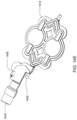
- a hollow spike is also included on the housing as well as at least one metering pump.
- the metering pump is fluidly connected to the hollow spike on the housing and to a metering pump fluid line.
- the metering pump fluid line is fluidly connected to the fluid outlet line.
- the reciprocating pressure displacement pump includes a curved rigid chamber wall and a flexible membrane attached to the rigid chamber wall.
- the flexible membrane and the rigid chamber wall define a pumping chamber.
- the cassette includes an air vent fluidly connected to the metering pump fluid line.
- the cassette includes an air filter connected to the air vent.
- the cassette housing includes a top plate, a midplate and a bottom plate.
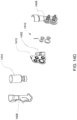
- a container attachment that includes a container support device for receiving and maintaining a container and a cassette attachment device for attaching to the spike on the cassette.
- the cassette attachment device includes a housing and needle inside the housing, the needle is in fluid communication with the container support device.
- the cassette further includes at least one valve.
- the valves include a valve housing having a membrane dividing the housing into two chambers, an actuation chamber and a liquid chamber.
- the actuation chamber has at least one aperture and the liquid chamber has at least one aperture.
- the actuation chamber includes two apertures.
- the liquid chamber includes a substantially smooth surface.
- the actuation chamber includes at least one raised feature.
- the valve is a volcano valve.
- the cassette in accordance with another aspect of the pump cassette includes a housing having at least one fluid inlet line and at least one fluid outlet line.
- the cassette also includes at least one reciprocating pressure displacement membrane pump within the housing.
- the pressure pump pumps a fluid from the fluid inlet line to the fluid outlet line.
- the cassette includes a second fluid administering system within the housing which includes a metering membrane pump, a second fluid inlet line for pumping a volume of a second fluid into the fluid outlet line, a hollow spike for fluid communication of the second fluid into the second fluid inlet line; and an air vent fluidly connected to the second fluid inlet line.
- the reciprocating pressure displacement pump includes a curved rigid chamber wall and a flexible membrane attached to the rigid chamber wall.
- the flexible membrane and the rigid chamber wall define a pumping chamber.
- the cassette housing includes a top plate, a midplate and a bottom plate.
- the cassette in accordance with another aspect of the pump cassette includes a housing having at least one blood inlet line for pumping blood from a patient and one blood outlet line for pumping blood to a dialyzer. Also, the cassette includes at least two reciprocating pressure displacement membrane pumps within the housing. The pressure pumps pump the blood from a patient to the dialyzer.
- the cassette also includes at least two valves, the valves including a housing and a membrane. The membrane divides the housing into two chambers, an actuation chamber and a liquid chamber. The actuation chamber has at least one aperture and the liquid chamber has at least two apertures. The liquid chamber includes a substantially smooth surface.
- the cassette also includes a heparin administering system within the housing.
- the heparin administering system includes a membrane pump, a heparin inlet line for pumping a volume of heparin into the blood outlet line, a hollow spike for fluid communication of heparin into the heparin inlet line, and an air filter fluidly connected to the heparin inlet line for trapping air.
- the reciprocating pressure displacement pump includes a curved rigid chamber wall and a flexible membrane attached to the rigid chamber wall.
- the flexible membrane and the rigid chamber wall define a pumping chamber.
- the cassette housing includes a top plate, a midplate and a bottom plate.
- the reciprocating pressure displacement membrane pumps includes a membrane dimpled on at least one surface.
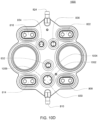
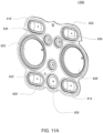
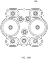
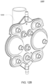
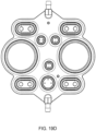
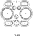
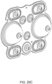
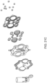
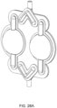
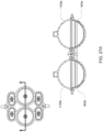
- the pumping cassette include various features, namely, pod pumps, fluid lines and in some embodiment, valves.
- the cassette embodiments shown and described in this description include exemplary and some alternate embodiments. However, any variety of cassettes is contemplated that include a similar functionality.
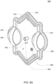
- the cassette embodiments described herein are implementations of the fluid schematics as shown in FIGS. 8A and 8B, in other embodiments, the cassette may have varying fluid paths and/or valve placement and/or pod pump placements and numbers and thus, is still within the scope of the invention.
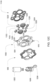
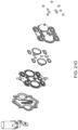
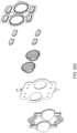
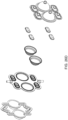
- the cassette includes a top plate, a midplate and a bottom plate. There are a variety of embodiments for each plate.
- the top plate includes pump chambers and fluid lines
- the midplate includes complementary fluid lines
- metering pumps and valves and the bottom plate includes actuation chambers (and in some embodiments, the top plate and the bottom plate include complementary portions of a balancing chamber).
- the membranes are located between the midplate and the bottom plate, however, with respect to balancing chambers, a portion of a membrane is located between the midplate and the top plate.
- Some embodiments include where the membrane is attached to the cassette, either overmolded, captured, bonded, press fit, welded in or any other process or method for attachment, however, in the exemplary embodiments, the membranes are separate from the top plate, midplate and bottom plate until the plates are assembled.
- the cassettes may be constructed of a variety of materials. Generally, in the various embodiment, the materials used are solid and non flexible. In the preferred embodiment, the plates are constructed of polysulfone, but in other embodiments, the cassettes are constructed of any other solid material and in exemplary embodiment, of any thermoplastic or thermosot.
- the cassettes are formed by placing the membranes in their correct locations, assembling the plates in order and connecting the plates.
- the plates are connected using a laser welding technique.
- the plates may be glued, mechanically fastened, strapped together, ultrasonically welded or any other mode of attaching the plates together.
- the cassette may be used to pump any type of fluid from any source to any location.
- the types of fluid include nutritive, nonnutritive, inorganic chemicals, organic chemicals, bodily fluids or any other type of fluid.
- fluid in some embodiments include a gas, thus, in some embodiments, the cassette is used to pump a gas.
- the cassette serves to pump and direct the fluid from and to the desired locations.
- outside pumps pump the fluid into the cassette and the cassette pumps the fluid out.
- the pod pumps serve to pull the fluid into the cassette and pump the fluid out of the cassette.
- valves being in different locations or additional valves are alternate embodiments of this cassette.
- the fluid lines and paths shown in the figures described above are mere examples of fluid lines and paths. Other embodiments may have more, less and/or different fluid paths. In some examples not falling within the scope of the appended claims, valves are not present in the cassette.
- the number of pod pumps described above may also vary depending on the embodiment.
- the cassette includes one.
- the cassette includes more than two pod pumps.
- the pod pumps can be single pumps or work in tandem to provide a more continuous flow. Either or both may be used in various embodiments of the cassette.
- the various fluid inlets and fluid outlets are fluid ports.
- a fluid inlet can be a fluid outlet.
- the designation of the fluid port as a fluid inlet or a fluid outlet is only for description purposes.
- the various embodiments have interchangeable fluid ports.
- the fluid ports are provided to impart particular fluid paths onto the cassette. These fluid ports are not necessarily all used all of the time; instead, the variety of fluid ports provides flexibility of use of the cassette in practice.
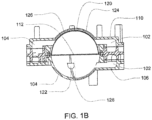
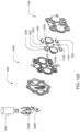
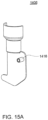
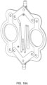
- FIG. 1A is a sectional view of an exemplary pod pump 100 that is incorporated into a fluid control or pump cassette (see also FIGS. 3 and 4 ), in accordance with an exemplary embodiment of the cassette.
- the pod pump is formed from three rigid pieces, namely a "top” plate 106, a midplate 108, and a "bottom” plate 110 (it should be noted that the terms “top” and “bottom” are relative and are used here for convenience with reference to the orientation shown in FIG. 1A ).
- the top and bottom plates 106 and 110 include generally hemispheroid portions that when assembled together define a hemispheroid chamber, which is a pod pump 100.
- a membrane 112 separates the central cavity of the pod pump into two chambers. These chambers are: the pumping chamber that receives the fluid to be pumped and an actuation chamber for receiving the control gas that pneumatically actuates the pump.
- An inlet 102 allows fluid to enter the pumping chamber, and an outlet 104 allows fluid to exit the pumping chamber.
- the inlet 102 and the outlet 104 may be formed between midplate 108 and the top plate 106.
- Pneumatic pressure is provided through a pneumatic port 114 to either force, with positive gas pressure, the membrane 112 against one wall of pod pump cavity to minimize the pumping chamber's volume, or to draw, with negative gas pressure, the membrane 112 towards the other wall of the pod pump 100 cavity to maximize the pumping chamber's volume.
- the membrane 112 is provided with a thickened rim 116, which is held tightly by a protrusion 118 in the midplate 108.
- the membrane 112 can be placed in and held by the groove 108 before the bottom plate 110 is connected (in the exemplary embodiment) to the midplate 108.
- a groove is present on the chamber wall.
- the groove acts to prevent folds in the membrane from trapping fluid in the chamber when emptying.
- FIG. 1A a cross sectional view of a reciprocating positive-displacement pump 100 in a cassette is shown.
- the pod pump 100 includes a flexible membrane 112 (also referred to as the "pump diaphragm” or “membrane") mounted where the pumping chamber (also referred to as a “liquid chamber” or “liquid pumping chamber”) wall 122 and the actuation chamber (also referred to as the "pneumatic chamber”) wall 120 meet.
- the pumping chamber also referred to as a "liquid chamber” or “liquid pumping chamber”
- actuation chamber also referred to as the "pneumatic chamber
- the membrane 112 effectively divides that interior cavity into a variable-volume pumping chamber (defined by the rigid interior surface of the pumping chamber wall 122 and a surface of the membrane 112) and a complementary variable-volume actuation chamber (defined by the rigid interior surface of the actuation chamber wall 120 and a surface of the membrane 112).
- the top portion 106 includes a fluid inlet 102 and a fluid outlet 104, both of which are in fluid communication with the pumping/liquid chamber.
- the bottom portion 110 includes an actuation or pneumatic interface 114 in fluid communication with the actuation chamber.
- the membrane 112 can be urged to move back and forth within the cavity by alternately applying negative or vent to atmosphere and positive pneumatic pressure at the pneumatic interface 114. As the membrane 112 reciprocates back and forth, the sum of the volumes of the pumping and actuation chambers remains constant.
- the application of negative or vent to atmosphere pneumatic pressure to the actuation or pneumatic interface 114 tends to withdraw the membrane 112 toward the actuation chamber wall 120 so as to expand the pumping/liquid chamber and draw fluid into the pumping chamber through the inlet 102, while the application of positive pneumatic pressure tends to push the membrane 112 toward the pumping chamber wall 122 so as to collapse the pumping chamber and expel fluid in the pumping chamber through the outlet 104.
- the interior surfaces of the pumping chamber wall 122 and the actuation chamber wall 120 limit movement of the membrane 112 as it reciprocates back and forth. In the embodiment shown in FIG.
- the interior surfaces of the pumping chamber wall 122 and the actuation chamber wall 120 are rigid, smooth, and hemispherical.
- an alternative rigid limit structure for example, a portion of a bezel used for providing pneumatic pressure and/or a set of ribs - may be used to limit the movement of the membrane as the pumping chamber approaches maximum value.
- Bezels and rib structures are described generally in United States Patent Application No. 10/697,450 entitled BEZEL ASSEMBLY FOR PNEUMATIC CONTROL filed on October 30, 2003 and published as Publication No. US 2005/0095154 (Attorney Docket No. 1062/D75) and related PCT Application No. PCT/US2004/035952 entitled BEZEL ASSEMBLY FOR
- the rigid limit structure - such as the rigid actuation chamber wall 120, a bezel, or a set of ribs - defines the shape of the membrane 112 when the pumping chamber is at its maximum value.
- the membrane 112 (when urged against the rigid limit structure) and the rigid interior surface of the pumping chamber wall 122 define a spherical pumping chamber volume when the pumping chamber volume is at a minimum.
- movement of the membrane 112 is limited by the pumping chamber wall 122 and the actuation chamber wall 120.
- the membrane 112 will move from a position limited by the actuation chamber wall 120 to a position limited by the pumping chamber wall 122.
- the membrane and the pumping chamber wall 122 define the maximum volume of the pumping chamber.
- the pumping chamber is at its minimum volume.
- the pumping chamber wall 122 and the actuation chamber wall 120 both have a hemispheroid shape so that the pumping chamber will have a spheroid shape when it is at its maximum volume.
- a pumping chamber that attains a spheroid shape - and particularly a spherical shape - at maximum volume, circulating flow may be attained throughout the pumping chamber.
- Such shapes accordingly tend to avoid stagnant pockets of fluid in the pumping chamber.
- the orientations of the inlet 102 and outlet 104 also tend to have an impact on the flow of fluid through the pumping chamber and in some embodiments, reduce the likelihood of stagnant pockets of fluid forming.
- the spherical shape and spheroid shapes in general
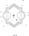
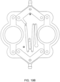
- a raised flow path 30 is shown in the pumping chamber.
- This raised flow path 30 allows for the fluid to continue flowing through the pod pumps after the membrane reaches the end of stroke.
- the raised flow path 30 minimizes the chances of the membrane causing air or fluid to be trapped in the pod pump or the membrane blocking the inlet or outlet of the pod pump which would inhibit continuous flow. Further description of the raised flow path is shown and described below with respect to FIGS. 9A-9B and FIGS. 18A-18E .
- the raised flow path 30 is shown in the exemplary embodiment having particular dimensions, however, in alternate embodiments, as seen in FIGS.
- the raised flow path 30 is narrower, or in still other embodiments, the raised flow path 30 can be any dimensions as the purpose is to control fluid flow so as to achieve a desired flow rate or behavior of the fluid.
- the dimensions shown and described here with respect to the raised flow path, the pod pumps, the valves or any other aspect are mere exemplary and alternate embodiments. Other embodiments are readily apparent.
- centrifugal pumps which apply a great deal of stress on the red blood cells
- pod pumps of the types described above which apply low shear forces and turbulence
- the inlet and outlet it is desirable for the inlet and outlet to be configured so as to avoid sharp or abrupt changes of fluid direction.
- the inlet and outlet (and the pump chamber itself) to be free of flash or burrs.
- the inlet and/or outlet may include rounded edges to help smooth out fluid flow.
- this benefit has been described with respect to whole blood, this was only for example, the cassette pumps any fluid and the benefits described with respect to shear sensitive fluids or biological fluids may apply to other fluids as well.
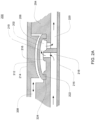
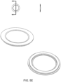
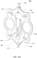
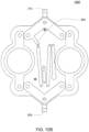
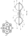
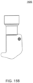
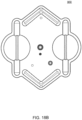
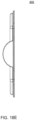
- FIGS. 1B an exemplary embodiment of a balancing pod which may be incorporated into the pump cassette is shown.
- the balancing pod is constructed similar to the pod pump described above with respect to FIG. 1A .
- a balancing pod includes two fluid balancing chambers, rather than an actuation chamber and a pumping chamber, and does not include an actuation port.
- each balancing chamber includes an inlet 102 and an outlet 104.
- a groove 126 is included on each of the balancing chamber walls 120, 122. The groove 126 is described in further detail below.
- the membrane 112 provides a seal between the two chambers.
- the balancing chambers work to balance the flow of fluid into and out of the chambers such that both chambers maintain an equal volume rate flow.
- the inlets 102 and outlets 104 for each chamber are shown to be on the same side, in other embodiments, the inlets 102 and outlets 104 for each chamber are on different sides. Also, the inlets 102 and outlets 104 can be on either side, depending on the flow path in which the balancing chamber is integrated.
- the membrane 112 includes an embodiment similar to the one described below with respect to FIG. 6A-6G .
- the membrane 112 can be over molded or otherwise constructed such that a double-ring seal is not applicable.
- the metering pump can be any pump that is capable of adding any fluid or removing any fluid.
- the fluids include but are not limited to pharmaceuticals, inorganic compounds or elements, organic compounds or elements, nutraceuticals, nutritional elements or compounds or solutions, or any other fluid capable of being pumped.
- the metering pump is a membrane pump.
- the metering pump is a smaller volume pod pump.
- the metering pump includes an inlet and an outlet, similar to a larger pod pump (as shown in FIG. 1A for example). However, the inlet and outlet are generally much smaller than a pod pump and, in one exemplary embodiment, includes a volcano valve-like raised ring around either the inlet or outlet.
- Metering pumps include a membrane, and various embodiments of a metering pump membrane are shown in FIGS. 5E-5H .
- the metering pump in some embodiments, pumps a volume of fluid out of the fluid line. Once the fluid is in the pod pump, a reference chamber, located outside the cassette, using the FMS, determines the volume that has been removed.
- this volume of fluid that has been removed will not then flow to the fluid outlet, the balance chambers or to a pod pump.
- the metering pump is used to remove a volume of fluid from a fluid line. In other embodiments, the metering pump is used to remove a volume of fluid to produce other results.
- FMS may be used to perform certain fluid management system measurements, such as, for example, measuring the volume of subject fluid pumped through the pump chamber during a stroke of the membrane or detecting air in the pumping chamber, e.g., using techniques described in U.S. Patent Nos. 4,808,161 ; 4,826,482 ; 4,976,162 ; 5,088,515 ; and 5,350,357 .
- Metering pumps are also used in various embodiments to pump a second fluid into the fluid line.
- the metering pump is used to pump a therapeutic or a compound into a fluid line.
- One embodiment uses the metering pump to pump a volume of compound into a mixing chamber in order to constitute a solution.
- the metering pumps are configured for FMS volume measurement. In other embodiments, the metering pumps are not.
- a small fixed reference air chamber is located outside of the cassette, for example, in the pneumatic manifold (not shown).
- a valve isolates the reference chamber and a second pressure sensor.
- the stroke volume of the metering pump may be precisely computed by charging the reference chamber with air, measuring the pressure, and then opening the valve to the pumping chamber.
- the volume of air on the chamber side may be computed based on the fixed volume of the reference chamber and the change in pressure when the reference chamber was connected to the pump chamber.
- the cassette includes a plurality of valves including an inlet valve and an outlet valve. Valves are used to regulate flow by opening and closing fluid lines.
- the valves included in the various embodiments of the cassette include one or more of the following: volcano valves or smooth valves. In some embodiment of the cassette, check valves may be included.
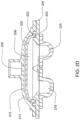
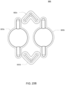
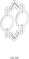
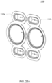
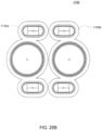
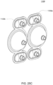
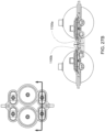
- FIGS. 2A and 2B Embodiments of the volcano valve are shown in FIGS. 2A and 2B , while an embodiment of the smooth valve is shown in FIG. 2C .
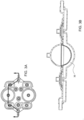
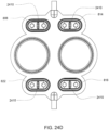
- FIGS. 3A-4B show cross sections of an exemplary embodiment of the pod pump in a cassette with an inlet and outlet valve.
- reciprocating positive-displacement pumps of the types just described may include, or may be used in conjunction with, various valves to control fluid flow through the pump.
- the reciprocating positive-displacement pump or the balancing pods may include, or be used in conjunction with, an inlet valve and/or an outlet valve.
- the valves may be passive or active.
- the membrane is urged back and forth by positive and negative pressurizations, or by positive and vent to atmosphere pressurizations, of a gas provided through the pneumatic port, which connects the actuation chamber to a pressure actuation system.
- the resulting reciprocating action of the membrane pulls fluid into the pumping chamber from the inlet (the outlet valve prevents liquid from being sucked back into the pumping chamber from the outlet) and then pushes the fluid out of the pumping chamber through the outlet (the inlet valve prevents fluid from being forced back from the inlet).
- active valves control the fluid flow through the pump(s) and the cassette.
- the active valves may be actuated by a controller in such a manner as to direct flow in a desired direction.
- a controller in such a manner as to direct flow in a desired direction.
- Such an arrangement would generally permit the controller to cause flow in either direction through the pod pump.
- the flow would normally be in a first direction, e.g., from the inlet to the outlet. At certain other times, the flow may be directed in the opposite direction, e.g., from the outlet to the inlet.
- Such reversal of flow may be employed, for example, during priming of the pump, to check for an aberrant line condition (e.g., a line occlusion, blockage, disconnect, or leak), or to clear an aberrant line condition (e.g., to try to dislodge a blockage).
- an aberrant line condition e.g., a line occlusion, blockage, disconnect, or leak
- an aberrant line condition e.g., to try to dislodge a blockage
- Pneumatic actuation of valves provides pressure control and a natural limit to the maximum pressure that may be developed in a system.
- pneumatic actuation has the added benefit of providing the opportunity to locate all the solenoid control valves on one side of the system away from the fluid paths.
- the volcano valves are pneumatically controlled valves that may be used in embodiments of the cassette.
- a membrane 202 along with the midplate 204, defines a valving chamber 206.
- Pneumatic pressure is provided through a pneumatic port 208 to either force, with positive gas pressure, the membrane 202 against a valve seat 210 to close the valve, or to draw, with negative gas pressure, or in some embodiments, with vent to atmospheric pressure, the membrane away from the valve seat 210 to open the valve.
- a control gas chamber 212 is defined by the membrane 202, the top plate 214, and the midplate 204.
- the midplate 204 has an indentation formed on it, into which the membrane 202 is placed so as to form the control gas chamber 212 on one side of the membrane 202 and the valving chamber 206 on the other side.
- the pneumatic port 208 is defined by a channel formed in the top plate 214.
- valves can be ganged together so that all the valves ganged together can be opened or closed at the same time by a single source of pneumatic pressure.
- Channels formed on the midplate 204 corresponding with fluid paths along with the bottom plate 216, define the valve inlet 218 and the valve outlet 220. Holes formed through the midplate 204 provide communication between the inlet 218 and the valving chamber 206 and between the valving chamber 206 and the outlet 220.
- the membrane 202 is provided with a thickened rim 222, which fits tightly in a groove 224 in the midplate 204.
- the membrane 202 can be placed in and held by the groove 224 before the top plate 214 is connected to the midplate 204.
- this valve design may impart benefits in manufacture.
- the top plate 214 may include additional material extending into control gas chamber 212 so as to prevent the membrane 202 from being urged too much in a direction away from the groove 224, so as to prevent the membrane's thickened rim 222 from popping out of the groove 224.
- the location of the pneumatic port 208 with respect to the control gas chamber 212 varies in the two embodiments shown in FIGS. 2A and 2B .
- FIG. 2C shows an embodiment in which the valving chamber lacks a valve seat feature. Rather, in FIG. 2C , the valve in this embodiment does not include any volcano features and thus, the valving chamber 206, i.e., the fluid side, does not include any raised features and thus is smooth. This embodiment is used in cassettes used to pump fluid sensitive to shearing.
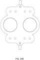
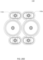
- FIG. 2D shows an embodiment in which the valving chamber has a raised area to aid in the sealing of the valving membrane.
- FIGS. 2E-2G various embodiments of the valve membrane are shown. Although some exemplary embodiments have been shown and described, in other embodiments, variations of the valve and valving membrane may be used.
- the membrane has a variable cross-sectional thickness, as shown in FIG. 4 .
- Thinner, thicker or variable thickness membranes may be used to accommodate the strength, flexural and other properties of the chosen membranes materials.
- Thinner, thicker or variable membrane wall thickness may also be used to manage the membrane thereby encouraging it to flex more easily in some areas than in other areas, thereby aiding in the management of pumping action and flow of subject fluid in the pump chamber.
- the membrane is shown having its thickest cross-sectional area closest to its center.
- the thickest and thinnest areas may be in any location on the membrane.
- the thinner cross-section may be located near the center and the thicker cross-sections located closer to the perimeter of the membrane. Still other configurations are possible.
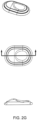
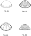
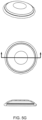
- FIGS. 5A-5D one embodiment of a membrane is shown having various surface embodiments, these include smooth ( FIG. 5A ), rings ( FIG. 5D ), ribs ( FIG. 5C ), dimples or dots ( FIG. 5B ) of variable thickness and or geometry located at various locations on the actuation and or pumping side of the membrane.
- the membrane has a tangential slope in at least one section, but in other embodiments, the membrane is completely smooth or substantially smooth.
- the membrane has a dimpled or dotted surface.
- the membrane may be made of any flexible material having a desired durability and compatibility with the subject fluid.
- the membrane can be made from any material that may flex in response to fluid, liquid or gas pressure or vacuum applied to the actuation chamber.
- the membrane material may also be chosen for particular bio-compatibility, temperature compatibility or compatibility with various subject fluids that may be pumped by the membrane or introduced to the chambers to facilitate movement of the membrane.
- the membrane is made from high elongation silicone.
- the membrane is made from any elastomer or rubber, including, but not limited to, silicone, urethane, nitrile, EPDM or any other rubber, elastomer or flexible material.
- the shape of the membrane is dependent on multiple variables. These variables include, but are not limited to: the shape of the chamber; the size of the chamber; the subject fluid characteristics; the volume of subject fluid pumped per stroke; and the means or mode of attachment of the membrane to the housing.
- the size of the membrane is dependent on multiple variables. These variables include, but are not limited to: the shape of the chamber; the size of the chamber; the subject fluid characteristics; the volume of subject fluid pumped per stroke; and the means or mode of attachment of the membrane to the housing. Thus, depending on these or other variables, the shape and size of the membrane may vary in various embodiments.
- the membrane can have any thickness. However, in some embodiments, the range of thickness is between 0.005cm (.002 inches) to 0.318cm (.125 inches). Depending on the material used for the membrane, the desired thickness may vary. In one embodiment, high elongation silicone is used in a thickness ranging from 0.038cm (.015 inches) to 0.127cm (.050 inches). However in other embodiments, the thickness may vary.
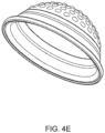
- the membrane is pre-formed to include a substantially dome-shape in at least part of the area of the membrane.
- a substantially dome-shape in at least part of the area of the membrane.
- FIG. 4E and 4F One embodiment of the dome-shaped membrane is shown in FIG. 4E and 4F . Again, the dimensions of the dome may vary based on some or more of the variables described above. However, in other embodiments, the membrane may not include a pre-formed dome shape.
- the membrane dome is formed using liquid injection molding.
- the dome may be formed by using compression molding.
- the membrane is substantially flat.
- the dome size, width or height may vary.
- the membrane may be held in place by various means and methods.
- the membrane is clamped between the portions of the cassette, and in some of these embodiments, the rim of the cassette may include features to grab the membrane.
- the membrane is clamped to the cassette using at least one bolt or another device.
- the membrane is overmolded with a piece of plastic and then the plastic is welded or otherwise attached to the cassette.
- the membrane is pinched between the mid plate described with respect to FIGS. 1A and 1B and the bottom plate.
- any method or means for attaching the membrane to the cassette can be used.
- the membrane in one alternate embodiment, is attached directly to one portion of the cassette.
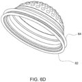
- the membrane is thicker at the edge, where the membrane is pinched by the plates, than in other areas of the membrane. In some embodiments, this thicker area is a gasket, in some embodiments an 0-ring, ring or any other shaped gasket.
- a gasket in some embodiments an 0-ring, ring or any other shaped gasket.
- the membrane is shown with two gaskets 62, 64. In some of these embodiments, the gasket(s) 62, 64 provides the attachment point of the membrane to the cassette. In other embodiments, the membrane includes more than two gaskets. Membranes with one gasket are also included in some embodiments (see FIGS. 4C-4F )
- the gasket is contiguous with the membrane. However, in other embodiments, the gasket is a separate part of the membrane. In some embodiments, the gasket is made from the same material as the membrane. However, in other embodiments, the gasket is made of a material different from the membrane. In some embodiments, the gasket is formed by over-molding a ring around the membrane. The gasket can be any shape ring or seal desired so as to complement the pod pump housing embodiment. In some embodiments, the gasket is a compression type gasket.
- a mixing pod includes a chamber for mixing.
- the mixing pod is a flexible structure, and in some embodiments, at least a section of the mixing pod is a flexible structure.
- the mixing pod can include a seal, such as an o-ring, or a membrane.
- the mixing pod can be any shape desired.
- the mixing pod is similar to a pod pump except it does not include a membrane and does not include an actuation port.
- Some embodiments of this embodiment of the mixing pod include an o-ring seal to seal the mixing pod chamber.
- the mixing pod is a spherical hollow pod with a fluid inlet and a fluid outlet.
- the chamber size can be any size desired.
- FIG. 7 is a schematic showing one embodiment of a pressure actuation system that may be used to actuate a pod pump with both positive and negative pressure, such as the pod pump shown in FIG. 1A .
- the pressure actuation system is capable of intermittently or alternately providing positive and negative pressurizations to the gas in the actuation chamber of the pod pump.
- FIG. 7 does not apply for in these embodiments, actuation of the pod pump is accomplished by applying positive pressure and vent to atmosphere (again, not shown in FIG. 7 ).
- the pod pump - including the flexible membrane, the inlet, the outlet, the pneumatic port, the pumping chamber, the actuation chamber, and possibly including an inlet check valve and an outlet check valve or other valves - is part of a larger disposable system.
- the positive-pressure reservoir provides to the actuation chamber the positive pressurization of a control gas to urge the membrane towards a position where the pumping chamber is at its minimum volume (i.e., the position where the membrane is against the rigid pumping-chamber wall).
- the negative-pressure reservoir provides to the actuation chamber the negative pressurization of the control gas to urge the membrane in the opposite direction, towards a position where the pumping chamber is at its maximum volume (i.e., the position where the membrane is against the rigid actuation-chamber wall).
- a valving mechanism is used to control fluid communication between each of these reservoirs and the actuation chamber.
- a separate valve is used for each of the reservoirs; a positive-supply valve controls fluid communication between the positive-pressure reservoir and the actuation chamber, and a negative-supply valve controls fluid communication between the negative-pressure reservoir and the actuation chamber.
- These two valves are controlled by the controller.
- a single three-way valve may be used in lieu of the two separate valves.
- the valves may be binary on-off valves or variable-restriction valves.
- the controller also receives pressure information from the three pressure transducers: an actuation-chamber pressure transducer, a positive-pressure-reservoir pressure transducer, and a negative-pressure-reservoir pressure transducer. As their names suggest, these transducers respectively measure the pressure in the actuation chamber, the positive-pressure reservoir, and the negative-pressure reservoir.
- the actuation-chamber-pressure transducer is located in a base unit but is in fluid communication with the actuation chamber through the pod pump pneumatic port. The controller monitors the pressure in the two reservoirs to ensure they are properly pressurized (either positively or negatively).
- the positive-pressure reservoir may be maintained at around 100kPa (750mmHG), while the negative-pressure reservoir may be maintained at around - 60kPa (450mmHG).
- a compressor-type pump or pumps may be used to maintain the desired pressures in these reservoirs.
- two independent compressors may be used to respectively service the reservoirs.
- Pressure in the reservoirs may be managed using a simple bang-bang control technique in which the compressor servicing the positive-pressure reservoir is turned on if the pressure in the reservoir falls below a predetermined threshold and the compressor servicing the negative-pressure reservoir is turned on if the pressure in the reservoir is above a predetermined threshold.
- the amount of hysteresis may be the same for both reservoirs or may be different. Tighter control of the pressure in the reservoirs can be achieved by reducing the size of the hysteresis band, although this will generally result in higher cycling frequencies of the compressors. If very tight control of the reservoir pressures is required or otherwise desirable for a particular application, the bang-bang technique could be replaced with a PID control technique and could use PWM signals on the compressors.
- the pressure provided by the positive-pressure reservoir is preferably strong enough-under normal conditions - to urge the membrane all the way against the rigid pumping-chamber wall.
- the negative pressure (i.e., the vacuum) provided by the negative-pressure reservoir is preferably strong enough - under normal conditions - to urge the membrane all the way against the actuation-chamber wall.
- these positive and negative pressures provided by the reservoirs are within safe enough limits that even with either the positive-supply valve or the negative-supply valve open all the way, the positive or negative pressure applied against the membrane is not so strong as to damage the pod pump or create unsafe fluid pressures (e.g., that may harm a patient receiving pumped blood or other fluid).
- pneumatic actuation systems may be used to move the membrane back and forth instead of the two-reservoir pneumatic actuation system shown in FIG. 7 , although a two-reservoir pneumatic actuation system is generally preferred.
- alternative pneumatic actuation systems may include either a single positive-pressure reservoir or a single negative-pressure reservoir along with a single supply valve and a single tank pressure sensor, particularly in combination with a resilient membrane.
- Such pneumatic actuation systems may intermittently provide either a positive gas pressure or a negative gas pressure to the actuation chamber of the pod pump.
- the pump may be operated by intermittently providing positive gas pressure to the actuation chamber, causing the membrane to move toward the pumping chamber wall and expel the contents of the pumping chamber, and releasing the gas pressure, causing the membrane to return to its relaxed position and draw fluid into the pumping chamber.
- the pump may be operated by intermittently providing negative gas pressure to the actuation chamber, causing the membrane to move toward the actuation chamber wall and draw fluid into the pumping chamber, and releasing the gas pressure, causing the membrane to return to its relaxed position and expel fluid from the pumping chamber.
- a fluid valve in the exemplary embodiment consists of a small chamber with a flexible membrane or membrane across the center dividing the chamber into a fluid half and a pneumatic half.
- the fluid valve in the exemplary embodiment, has three entry/exit ports, two on the fluid half of the chamber and one the pneumatic half of the chamber.
- the port on the pneumatic half of the chamber can supply either positive pressure or vacuum (or rather than vacuum, in some embodiments, there is a vent to atmosphere) to the chamber.
- a vacuum is applied to the pneumatic portion of the chamber, the membrane is pulled towards the pneumatic side of the chamber, clearing the fluid path and allowing fluid to flow into and out of the fluid side of the chamber.
- the membrane When positive pressure is applied to the pneumatic portion of the chamber, the membrane is pushed towards the fluid side of the chamber, blocking the fluid path and preventing fluid flow.
- the membrane In the volcano valve embodiment (as shown in FIGS. 2A-2B ) on one of the fluid ports, that port seals off first when closing the valve and the remainder of any fluid in the valve is expelled through the port without the volcano feature.
- the raised feature between the two ports allows for the membrane to seal the two ports from each other earlier in the actuation stroke (i.e., before the membrane seals the ports directly).
- pressure valves are used to operate the pumps located at different points in the flow path.
- This architecture supports pressure control by using two variable-orifice valves and a pressure sensor at each pump chamber which requires pressure control.
- one valve is connected to a high-pressure source and the other valve is connected to a low-pressure sink.
- a high-speed control loop monitors the pressure sensor and controls the valve positions to maintain the necessary pressure in the pump chamber.
- Pressure sensors are used to monitor pressure in the pneumatic portion of the chambers themselves. By alternating between positive pressure and vacuum on the pneumatic side of the chamber, the membrane is cycled back and forth across the total chamber volume. With each cycle, fluid is drawn through the upstream valve of the inlet fluid port when the pneumatics pull a vacuum on the pods. The fluid is then subsequently expelled through the outlet port and the downstream valve when the pneumatics deliver positive pressure to the pods.
- pressure pumps consist of a pair of chambers. When the two chambers are run 180 degrees out of phase from one another the flow is essentially continuous.
- pressure pod pumps which can detect end-of-stroke.
- An outer control loop determines the correct pressure values to deliver the required flow.
- Pressure pumps can run an end of stroke algorithm to detect when each stroke completes. While the membrane is moving, the measured pressure in the chamber tracks a desired sinusoidal pressure. When the membrane contacts a chamber wall, the pressure becomes constant, no longer tracking the sinusoid. This change in the pressure signal is used to detect when the stroke has ended, i.e., the end-of-stroke.
- the pressure pumps have a known volume.
- an end of stroke indicates a known volume of fluid is in the chamber.
- fluid flow may be controlled using rate equating to volume.
- FMS may be used to determine the volume of fluid pumped by the metering pumps.
- the metering pump may pump fluid without using the FMS volume measurement system, however, in the exemplary embodiments, the FMS volume measurement system is used to calculate the exact volume of fluid pumped.
- inlet and outlet as well as fluid paths are used for description purposes only. In other embodiments, an inlet can be an outlet.
- the designations give for the fluid inlets (which can also be fluid outlets), for example, first fluid outlet, second fluid outlet, merely indicate that a fluid may travel out of or into the cassette via that inlet/outlet.
- more than one inlet/outlet on the schematic is designated with an identical name. This merely describes that all of the inlet/outlets having that designation are pumped by the same metering pump or set of pod pumps (which in alternate embodiments, can be a single pod pump).
- the cassette 800 includes at least one pod pump 820, 828 and at least one metering pump 830.
- the cassette 800 also includes a fluid inlet one 810, where fluid enters the cassette from a source.
- the fluid includes a flow rate provided by the at least one pod pump 820, 828.
- the cassette 800 also includes a fluid outlet one 824 where the fluid exits the cassette 800 having a flow rate provided by one of the at least one pod pump 820, 828.
- the exemplary embodiment includes two pod pumps 820, 828, however, in alternate embodiments, one or more pod pumps are included in the cassette. In the exemplary embodiment, two pod pumps provide for steady flow.
- the metering pump 830 pumps a volume of second fluid from a second fluid source into the fluid line prior to the fluid exiting fluid outlet one 824.
- the fluid schematic of the cassette 800 shown in FIG. 8 may be embodied into various cassette apparatus.
- the various embodiments of the cassette 800 that include a fluid flow-path represented by the fluid schematic shown in FIG. 8 are not the only cassette embodiments that may incorporate this or an alternate embodiment of this fluid schematic.
- the types of valves, the order of actuation of the valves, and the number of pumps may vary in various cassette embodiments of this fluid schematic.
- the fluid enters the cassette through fluid inlet one 810 and is pumped to either a first pump fluid path 812 or a second pump fluid path 818.
- pump inlet valves 814, 808 alternately open and close, and the valve 814, 808 that is open at any given time allows the fluid into its respective fluid path 812, 818 and into the respective pod pump 828, 820.
- the respective pump inlet valve 814, 808 then closes, and the corresponding pump outlet valve 816, 822 opens.
- the fluid is pumped out of the pod pump and though fluid outlet one 824.
- both valves 808, 814 open and close at the same time. In some examples not falling within the scope of the appended claims, no valves are in the cassette.
- a metering pump 830 pumps a volume of second fluid from a source connected to the cassette 800.
- the metering pump 830 is actuated separately from the pod pumps 820, 828, thus, the metering pump 830 can pump at different rates than the pod pumps 820, 828.
- the metering pump 830 pumps a volume of second fluid from a second fluid source into the fluid line at point 826, prior to the fluid exiting fluid outlet one 824.
- the source is connected to the metering pump through a fluid line which intersects the main fluid path at point 826.
- Valves 832, 836 work to pump fluid from the second source and into the fluid line at point 826.
- the metering pump 830 is either not used or has a very different pumping pattern from the pod pumps 820, 828.
- the metering pump includes fluid management system (FMS) volumetric measurement capacity.
- the reference chamber is located outside the cassette.
- the second fluid source is a vial of liquid connected directly to a spike in the cassette.
- the spike is directly connected to the fluid line.
- the spike is connected to a tube that is connected to the second fluid source.
- the vial can contain any liquid, but in some embodiments, contains a therapeutic liquid such as heparin.
- the second fluid is a chemotherapy agent, a nutritional supplement, antibiotic or any other therapeutic whether nutritional or non-nutritive liquid.
- the fluid is pumped into the fluid inlet one 810 and to the fluid outlet one 824.
- the fluid is pumped from a source to a treatment area, which is part of a continuous flow circuit, and then flows back to the source.
- the cassette is used to pump blood from a patient, through the fluid outlet one 824 which is connected to a dialyzer. The blood then flows through the dialyzer and back to the patient through a tube.
- the embodiments of the fluid flow-path schematic shown in FIG. 8 can be embodied into a structure.
- the structure is a three plate cassette with actuating membranes. Alternate embodiments of the cassette are also described below.
- FIGS. 9A and 9B the outer side of the top plate 900 of the exemplary embodiment of the cassette is shown.
- the top plate 900 includes one half of the pod pumps 820, 828. This half is the liquid half where the source fluid will flow through.
- the two fluid paths 818, 812 are shown. These fluid paths lead to their respective pod pumps 820, 828.
- the pod pumps 820, 828 include a raised flow path 908, 910.
- the raised flow path 908, 910 allows for the fluid to continue to flow through the pod pumps 820, 828 after the membrane (not shown) reaches the end of stroke.
- the raised flow path 908, 910 minimizes the membrane causing air or fluid to be trapped in the pod pump 820, 828 or the membrane blocking the inlet or outlet of the pod pump 820, 828, which would inhibit continuous flow.
- the raised flow path 908, 910 is shown in the exemplary embodiment having particular dimensions, and in the exemplary embodiment, the dimensions are equivalent to the fluid flow paths 818, 812. However, in alternate embodiments, as seen in FIGS.
- the raised flow path 908, 910 is narrower, or in still other embodiments, the raised flow path 908, 910 can be any dimensions as the purpose is to control fluid flow so as to achieve a desired flow rate or behavior of the fluid.
- the raised flow path 908, 910 and the fluid flow paths 818, 812 have different dimensions.
- the dimensions shown and described here with respect to the raised flow path, the pod pumps, the valves or any other aspect are mere exemplary and alternate embodiments. Other embodiments are readily apparent.
- the top plate includes a spike 902 as well as a container perch 904.
- the spike 902 is hollow and is fluidly connected to the flow path.
- a needle is attached into the spike.
- a needle is connected to the container attachment (see FIG. 12C , 1206).
- the raised flow paths 908, 910 connects to the inlet flow paths 912, 916 and outlet flow paths 914, 918 of the pod pumps 820, 828.
- the raised flow paths are described in more detail above.
- the metering pump (not shown, shown in FIGS. 10C and 10D ) includes connection to an air vent 906 as well as connection to the spike's hollow path 902.
- the air vent 906 includes an air filter (not shown).
- the air filter is a particle air filter.
- the filter is a somicron hydrophobic air filter.
- the size of the filter may vary, in some instances the size will depend on desired outcome.
- the metering pump works by taking air in through the air vent 906, pumping the air to the container of second fluid (not shown) through the spike's hollow path 902 and then pumping a volume of second fluid out of the container (not shown) through the spike's hollow path 902 and into the fluid line at point 826.
- This fluid flow path for the metering pump is shown with arrows on FIG. 9C .
- FIGS. 10A and 10B the liquid side of the midplate 1000 is shown. The areas complementary to the fluid paths on the inner top plate are shown. These areas are slightly raised tracks that present a surface finish that is conducive to laser welding, which is the mode of manufacture in the exemplary embodiment.
- the fluid inlet 810 and fluid outlet 824 are also shown in this view.
- FIGS. 10C and 10D the air side of the midplate 1000 is shown according to the exemplary embodiment.
- the air side of the valve holes 808, 814, 816, 822 correspond to the holes in the fluid side of the midplate (shown in FIG. 10A ).
- membranes 1220 complete valves 808, 814, 816, 822 while membranes 1226 complete pod pumps 820, 828.
- FIG. 2E One embodiment of the valve membrane is shown in FIG. 2E . Additional embodiments of the valve membrane are shown in FIGS. 2F-2G .
- the metering pump 830 is completed by membrane 1224.
- One embodiment of the metering pump membrane is shown in FIG. 5F .
- FIGS. 5E-5H Other embodiments of the metering pump membrane are shown in FIGS. 5E-5H .
- the valves 808, 814, 816, 822, 832, 834, 836 are actuated pneumatically, and as the membrane is pulled away from the holes, liquid is drawn in, as the membrane is pushed toward the holes.
- the fluid flow is directed by the opening and closing of the valves 808, 814, 816, 822, 832, 834, 836.
- the metering pump includes three holes, 1002, 1004, 1006.
- One hole 1002 pulls air into the metering pump
- the second hole 1004 pushes air to the spike/source container and also, draws liquid from the source container
- the third hole 1006 pushes the second fluid from the metering pump 830 to the fluid line to point 826.
- Valves 832, 834, 836 actuate the second fluid metering pump.
- Valve 832 is the second fluid/spike valve
- valve 834 is the air valve
- valve 836 is the valve that controls the flow of fluid to the fluid line to area 826.
- FIGS. 11A and 11B the inner view of the bottom plate 1100 is shown.
- the inside view of the pod pumps 820, 828, the metering pump 830 and the valves 808, 814, 816, 822, 832, 834, 836 actuation/air chamber is shown.
- the pod pumps 820, 828, metering pump 830 and the valves 808, 814, 816, 822, 832, 834, 836 are actuated by a pneumatic air source.
- FIGS. 11C and 11D the outer side of the bottom plate 1100 is shown.
- the source of air is attached to this side of the cassette.
- tubes connect to the features on the valves and pumps 1102.
- the valves are ganged, and more than one valve is actuated by the same air line.
- FIGS. 12A and 12B an assembled cassette 1200 with a container/source of second fluid 1202 attached is shown.
- the container 1202 contains the source of the second fluid and is attached to the spike (not shown) by a container attachment 1206.
- the air filter 1204 is shown attached to the air vent (not shown, shown in FIG. 9A as 906).
- the container perch shown in FIG. 9A as 904 is under the container attachment 1206.
- FIGS. 12C and 12D An exploded view of the assembled cassette 1200 shown in FIGS. 12A and 12B is shown in FIGS. 12C and 12D . In these views, the exemplary embodiment of the pod pump membranes 1226 is shown.
- the exemplary embodiment includes membranes shown in FIGS. 4E and 4F .
- the gasket of the membrane provides a seal between the liquid chamber (in the top plate 900) and the air/actuation chamber (in the bottom plate 1100).
- the dimpled texture on the dome of the membranes 1226 provide, amongst other features, additional space for air and liquid to escape the chamber at the end of stroke.
- the membranes shown in FIGS. 5A, 5C or 5D may be used.
- the membranes shown in FIGS. 6A-6G may be used.
- these membranes include a double gasket 62, 64.
- the double gasket 62, 64 feature would be preferred in embodiments where both sides of the pod pump include liquid or in applications where sealing both chambers is desired.
- a rim complementary to the gasket or other feature would be added to the inner bottom plate 1100 for the gasket 62 to seal the pod pump chamber in the bottom plate 1100.
- FIG. 13A a cross sectional view of the pod pumps 820, 828 in the cassette is shown. The details of the attachment of the membrane 1226 can be seen in this view.
- the membrane 1226 gasket is pinched by the midplate 1000 and the bottom plate 1100.
- a rim on the midplate 1000 provides a feature for the gasket to seal the pod pump 820, 828 chamber located in the top plate 900.
- this cross sectional view shows the valves 834, 836 in the assembled cassette.
- the membranes 1220 are shown assembled and are held in place, in the exemplary embodiment, by being sandwiched between the midplate 1000 and the bottom plate 1100.
- this cross sectional view shows the valves 816, 822 in the assembled cassette.
- the membranes 1220 are shown assembled and are held in place, in the exemplary embodiment, by being sandwiched between the midplate 1000 and the bottom plate 1100.
- the metering pump 1400 connects to the cassette (not shown), thus it is not integral with the cassette.
- the metering pump 1400 includes a top plate 1406 and a fluid connection to the cassette 1402.
- a container 1404 is shown in the metering pump 1400.
- the container 1404 contains a liquid second fluid and will be fluidly connected to the cassette fluid paths via the fluid connection to the cassette 1402.
- the metering pump 1400 also includes a bottom plate 1408 that includes air actuation ports 1416.
- FIGS. 14C and 14D exploded views of the metering pump is shown.
- the membranes 1410 that complete the valves in the midplate 1412 are shown.
- the assembled metering pump on a cassette 1414 is shown in FIG. 14E .
- FIG. 14F shows a partially assembled metering pump on a cassette 1414, where the midplate 1408 is not covered by the top plate 1406.
- the top plate of the alternate embodiment of the metering pump contains many of the same features as seen in the top plate of the exemplary embodiment of the cassette described above with respect to the metering pump in FIGS. 9C-9D .
- the air inlet 1416 in some embodiments includes an air filter, similar to the embodiments described above.
- FIG. 15C the air flow fluid path is shown with arrows. The air is taken in through the air inlet and then pushed towards the container (not shown).
- the second fluid flow path is shown with arrows. The second fluid is pumped from the container (not shown) and out to the cassette at point 836.
- the alternate embodiment of the metering pump shown in FIGS. 14A-17D is another structural implementation of the fluid flow-path schematic shown in FIG. 8 , only the metering pump component is not integral with the cassette, rather, attached to the cassette.
- FIGS. 16A-16B the holes indicating the flow path of the fluid are shown.
- FIGS. 16C and 16D the air side of the midplate 1412 is shown.
- the air side of the valves 832, 834, 836, including the metering pump 830 are shown.
- the holes in the valves 832, 834, 836, and the metering pump 830 correspond to the valves around the metering pump in the schematic shown in FIG. 8 , and also in the exemplary embodiment of the midplate of the cassette shown in FIGS. 10A- 10C .
- the metering pump and the corresponding valves and fluid lines are outside of the cassette in this embodiment, the valves and fluid lines are similar.
- much of the description above with respect to the exemplary embodiment metering pump features is applicable to the alternate embodiment of the metering pump.
- FIGS. 17A and 17B the inner bottom plate 1408 is shown.
- the corresponding actuation sides of the valves 832, 834, 836 and metering pump 830 are shown.
- FIGS. 17C and 17D the outer bottom plate 1408 is shown with the actuation ports 1702 which providing access for the air to actuate the metering pump and the valves.
- the exemplary embodiment is one cassette embodiment that incorporates the exemplary fluid flow-path schematic shown in FIG. 8 .
- the cassette incorporates many of the same features of the exemplary embodiment, but with a slightly different structural design.
- One of these alternate embodiments is the embodiment shown in FIGS. 18A- 22B .
- FIGS. 18A-22B the corresponding numbering of the elements used with respect to FIGS. 9A-12D apply.
- the cross sections views of FIGS. 22 A and 22B correspond to FIGS. 13A and 13C respectively.
- the two embodiments vary only slightly and this variation can best be seen in FIGS. 18A-18E when compared to the exemplary embodiment in FIGS. 9A-9E .
- the raised flow path 908, 910 on the pod pumps 820, 828 in the alternate embodiment of FIGS. 18A-18E has dimensions that are a smaller than in the exemplary embodiment shown in FIG. 9A-9E .
- the fluid paths in the exemplary embodiment of FIGS. 9A-9E have more squared off edges, whereas in the alternate embodiment shown in FIGS.
- the fluid paths have more rounded edges.
- the exemplary embodiment's edges being more squared off lend to easier manufacture as the laser welding is more efficient and effective in this embodiment.
- FIGS. 23A- 27B another alternate embodiment of the cassette is shown.
- the metering pump is not incorporated or integrated into the cassette.
- a separate metering pump is connected to the cassette.
- One embodiment of a separate metering pump is described and shown with respect to FIGS. 14A-17D .
- Many of the features, i.e., the pod pumps and the fluid lines are similar to the exemplary embodiment shown in FIGS. 9A- 12D .
- FIGS. 9A-12D can be applied to FIGS. 23A-26D .
- the cross section views in the alternate embodiment shown in FIGS. 27A and 27B correspond to cross sectional views shown in FIGS. 13A and 13C respectively.
- valves 808, 814, 816, 822 Comparing the valves 808, 814, 816, 822 in FIGS. 24C-24D to the exemplary embodiment shown in FIGS. 10C- 10D as 808, 814, 816, 822, it is apparent that the valves 808, 814, 816, 822 in FIGS. 24C-24D include a raised feature 2410, whereas the valves 808, 814, 816, 822 in FIGS. 10C-10D do not.
- the valves 808, 814, 816, 822 shown in FIGS. 10C- 10D include a smooth construction and do not include any raised or textured features. Referring again to FIGS.
- the raised feature 2410 of the valves 808, 814, 816, 822 provides for a different sealing mechanism for the fluid flowing from one fluid path to the next (where each fluid path is indicated by the holes in the valves 808, 814, 816, 822).
- the alternate embodiment of the top plate 900 is shown. Again, comparing this alternate embodiment to the exemplary embodiment shown in FIGS. 9A-9B , in FIGS. 9A and 9B , the top plate 900 is one solid part. However, referring again to FIGS. 23A-23B , the top plate 900 is four separate parts 900a, 900b, 900c, 900d. In manufacture, the four plates are laser welded or ultrasonically welded individually onto the fluid side of the midplate (shown in FIGS. 24A-24B ). Other modes of manufacture are discussed above.
- FIGS. 25A-25B the alternate embodiment of the bottom plate 1100 is shown. Again, comparing this alternate embodiment to the exemplary embodiment shown in FIGS. 11A-11B , in FIGS. 11A and 11B , the bottom plate 1100 is one solid part. However, referring again to FIGS. 25A-25B , the bottom plate 1100 is two separate parts 1100a, 1100b. In manufacture, the two plates are laser welded or ultrasonically welded individually onto the air side of the midplate (shown in FIGS. 24C-24D ). Referring now to FIG. 27A , the multi-piece construction of the top plate 900a, 900b and the bottom plate 1100a, 1100b are readily shown. FIG. 27B additionally shows the separate construction of the top plate 1100a, 1100b.
- the cassette may be used to pump any type of fluid from any source to any location.
- the types of fluid include nutritive, nonnutritive, inorganic chemicals, organic chemicals, bodily fluids or any other type of fluid.
- fluid in some embodiments includes a gas, thus, in some embodiments; the cassette is used to pump a gas.
- the cassette serves to pump and direct the fluid from and to the desired locations.
- outside pumps pump the fluid into the cassette and the cassette pumps the fluid out.
- the pod pumps serve to pull the fluid into the cassette and pump the fluid out of the cassette.
- valves being in different locations or additional valves are alternate embodiments of this cassette.
- the fluid lines and paths shown in the figures described above are mere examples of fluid lines and paths. Other embodiments may have more, less and/or different fluid paths. In still other examples not falling within the scope of the appended claims, valves are not present in the cassette.
- the number of pod pumps described above may also vary depending on the embodiment.
- the cassette includes one.
- the cassette includes more than two pod pumps.
- the pod pumps can be single pumps or work in tandem to provide a more continuous flow. Either or both may be used in various embodiments of the cassette.
- inlet and outlet are used interchangeable.
- a fluid can flow "in” the outlet and "out” the inlet.
- Additional inlets/outlets can be added. Additional ports may be provided to impart particular fluid paths onto the cassette. These additional ports are not necessarily all used all of the time, instead, the variety of ports provide flexibility of use of the cassette in practice.
- the pumping cassette can be used in a myriad of applications.
- the pumping cassette is used to pump blood from a patient to a dialyzer outside of the cassette and then provide enough pumping force for the blood to travel through the dialyzer and back to the patient through a line outside of the cassette.
- the exemplary embodiment includes two pod pumps, a blood inlet, a blood outlet and a heparin metering pump.
- the valves are smooth valves as described above with respect to FIG. 2D .
- the pod pump membrane is a dimpled membrane as shown in FIG. 4E-4F .
- the blood pump cassette supports both dual-needle and single-needle operation. When operating with two needles the chambers take turns filling and delivering so the blood flow is effectively continuous in both lines. When operating with a single needle the pump will first fill both pump chambers through the arterial line and then deliver to the venous line.
- the fluid or blood inlet line is oriented on the bottom 810 and the fluid or blood outlet is on the top 824.
- the blood pump cassette may be oriented such that normal therapy flow is up through the pump chambers, exiting at the top. In this embodiment, substantially all or all air entering the blood pump cassette is pushed on toward the dialyzer. However, in other embodiments, the blood inlet line is oriented on the top.
- the metering pump is a heparin pump and is a single chamber FMS meter pump that takes measured quantities of heparin from a vial or container and delivers it into the blood circuit/fluid line. This feature allows the blood pump cassette to manage the heparin prescription.
- Some embodiments may include an air trap within the fluid lines and/or at least one sensor element.
- the sensor element can be any sensor element having a capability to determine any fluid or non fluid sensor data.
- three sensor elements are included in a single fluid line. In some embodiments, more than one fluid line includes the three sensor elements.
- two of the sensor elements are conductivity sensors and the third sensor element is a temperature sensor.
- the conductivity sensor elements and temperature sensor elements can be any conductivity or temperature sensor element in the art.
- the conductivity sensor elements are graphite posts. In other embodiments, the conductivity sensor elements are posts made from stainless steel, titanium, platinum or any other metal coated to be corrosion resistant and still be electrically conductive.
- the conductivity sensor elements will include an electrical lead that transmits the probe information to a controller or other device.
- the temperature sensor is a thermister potted in a stainless steel probe.
- a combination temperature and conductivity sensor elements is used similar to the one described in co-pending U.S. Patent Application entitled Sensor Apparatus Systems, Devices and Methods filed October 12, 2007 (DEKA-024XX).
- the metering pump can be used to administer or remove a volume of fluid. Using the FMS, this volume is measured and thus, a substantially accurate (or near substantially accurate) volume of fluid added or removed is known.
- Other embodiments of this pumping cassette include use of a different membrane or an overmolded membrane or other membranes as described above. Some of the various embodiments of the membrane are described above and shown with respect to FIGS. 4C-6G .
- the cassette may be used to pump any type of fluid from any source to any location.
- the types of fluid include nutritive, nonnutritive, inorganic chemicals, organic chemicals, bodily fluids or any other type of fluid.
- fluid in some embodiments include a gas, thus, in some embodiments, the cassette is used to pump a gas.
- the cassette serves to pump and direct the fluid from and to the desired locations.
- outside pumps pump the fluid into the cassette and the cassette pumps the fluid out.
- the pod pumps serve to pull the fluid into the cassette and pump the fluid out of the cassette.
Landscapes
- Health & Medical Sciences (AREA)
- Engineering & Computer Science (AREA)
- Heart & Thoracic Surgery (AREA)
- Public Health (AREA)
- Anesthesiology (AREA)
- Biomedical Technology (AREA)
- Hematology (AREA)
- Life Sciences & Earth Sciences (AREA)
- Animal Behavior & Ethology (AREA)
- General Health & Medical Sciences (AREA)
- Veterinary Medicine (AREA)
- Urology & Nephrology (AREA)
- Mechanical Engineering (AREA)
- Emergency Medicine (AREA)
- Vascular Medicine (AREA)
- General Engineering & Computer Science (AREA)
- Cardiology (AREA)
- Pulmonology (AREA)
- Reciprocating Pumps (AREA)
- External Artificial Organs (AREA)
- Measuring Temperature Or Quantity Of Heat (AREA)
- Measurement Of The Respiration, Hearing Ability, Form, And Blood Characteristics Of Living Organisms (AREA)
- Details Of Reciprocating Pumps (AREA)
- Investigating Or Analyzing Materials Using Thermal Means (AREA)
- Feeding, Discharge, Calcimining, Fusing, And Gas-Generation Devices (AREA)
- Apparatus Associated With Microorganisms And Enzymes (AREA)
- Liquid Crystal (AREA)
- Infusion, Injection, And Reservoir Apparatuses (AREA)
- Testing Or Calibration Of Command Recording Devices (AREA)
Claims (12)
- Cassette de pompe (800) comprenant une plaque médiane (1000) interposée entre une plaque supérieure (900) et une plaque de fond (1100), la cassette de pompe comprenant :une entrée de fluide (810) sur une première extrémité de la plaque médiane reliée à un premier trajet de fluide (812, 818), et une sortie de fluide (824) sur une seconde extrémité de la plaque médiane reliée à un second trajet de fluide, chaque dit trajet de fluide étant défini par la plaque médiane et la plaque supérieure ;une pompe patch (820, 828) comprenant une membrane de pompe souple (1226) configurée pour couvrir une ouverture dans la plaque médiane,
la membrane de pompe souple séparant une chambre de pompage entre la membrane de pompe souple et la plaque supérieure d'une chambre d'actionnement entre la membrane de pompe souple et la plaque de fond ; etune valve d'entrée (808, 814) et une valve de sortie (816, 822), chaque valve comprenant : un trou d'entrée de valve (218) et un trou de sortie de valve (220) reliant chacun un premier côté de la plaque médiane orienté vers la plaque supérieure à un second côté de la plaque médiane orienté vers la plaque de fond ; une membrane de valve (1220) configurée pour couvrir les trous d'entrée et de sortie de valve et pour séparer une chambre à gaz de commande (212) entre la membrane de valve et la plaque de fond d'une chambre à effet de valve (206) entre la membrane de valve et la plaque médiane ;dans laquelle le trou d'entrée de valve de la valve d'entrée est relié au premier trajet de fluide, et un second trou de valve de la première valve est relié à une entrée de la chambre de pompage, et le trou de sortie de valve de la valve de sortie est relié au second trajet de fluide et le trou d'entrée de valve de la valve de sortie est relié à une sortie de la chambre de pompage. - Cassette de pompe selon la revendication 1, dans laquelle la cassette comprend une pompe de dosage (830) comprenant trois valves de pompe de dosage (832, 834, 836) ; une première valve configurée pour relier la pompe de dosage à un flacon, une deuxième valve reliant la pompe de dosage à un évent, et une troisième valve reliant la pompe de dosage au trajet de fluide principal avant la sortie de la cassette de pompe.
- Cassette de pompe selon la revendication 2, dans laquelle la pompe de dosage (830) comprend des premier, deuxième et troisième trous (1002, 1004, 1006) reliant le premier côté de la plaque médiane (1000) au second côté de la plaque médiane, une membrane de pompe de dosage (1224) couvrant les trois trous et séparant une chambre de fluide entre la membrane de pompe de dosage et la plaque supérieure d'une chambre d'actionnement entre la membrane de pompe de dosage et la plaque de fond, le premier trou (1002) étant destiné à aspirer de l'air dans la pompe de dosage, le deuxième trou (1004) étant destiné à pousser de l'air jusqu'au flacon et à aspirer le liquide du flacon, et le troisième trou (1006) étant destiné à pousser le fluide de la pompe de dosage jusqu'au trajet de fluide principal.
- Cassette de pompe selon la revendication 2 ou la revendication 3, dans laquelle chaque valve (832, 834, 836) comprend deux trous de valve reliant le premier côté de la plaque médiane au second côté de la plaque médiane, et ayant une membrane de valve configurée pour couvrir les deux trous de valve et pour séparer une chambre à gaz de commande entre la membrane de valve et la plaque de fond d'une chambre à effet de valve entre la membrane de valve et la plaque médiane.
- Cassette de pompe selon l'une quelconque des revendications 2 à 4, dans laquelle la plaque supérieure comprend l'évent (906).
- Cassette de pompe selon l'une quelconque des revendications 2 à 5, dans laquelle l'évent est configuré pour être couvert par un filtre à air (1204).
- Cassette de pompe selon l'une quelconque des revendications 2 à 6, dans laquelle la cassette comprend une pointe pour liaison avec le flacon.
- Cassette de pompe selon la revendication 7, dans laquelle la première valve de pompe de dosage relie un trajet creux (902) de la pointe sur la plaque supérieure à la pompe de dosage.
- Cassette de pompe selon la revendication 8, comprenant en outre un support de récipient (904) sur la plaque supérieure.
- Cassette de pompe selon la revendication 9, dans laquelle le support de récipient est configuré pour maintenir un récipient de liquide thérapeutique (1202).
- Cassette de pompe selon la revendication 9, comprenant en outre une aiguille reliée à une fixation de récipient (1206) configurée pour pénétrer le récipient.
- Cassette de pompe selon l'une quelconque des revendications précédentes, dans laquelle la plaque de fond inclut des orifices pneumatiques pour actionner séparément les pompes et valves individuelles de la cassette.
Priority Applications (1)
| Application Number | Priority Date | Filing Date | Title |
|---|---|---|---|
| EP23212552.6A EP4302818A3 (fr) | 2007-02-27 | 2008-02-26 | Cassette de pompage |
Applications Claiming Priority (6)
| Application Number | Priority Date | Filing Date | Title |
|---|---|---|---|
| US90402407P | 2007-02-27 | 2007-02-27 | |
| US92131407P | 2007-04-02 | 2007-04-02 | |
| US11/871,680 US8273049B2 (en) | 2007-02-27 | 2007-10-12 | Pumping cassette |
| EP17155149.2A EP3189863B1 (fr) | 2007-02-27 | 2008-02-26 | Cassette de pompage |
| PCT/US2008/055000 WO2008106440A1 (fr) | 2007-02-27 | 2008-02-26 | Cassette de pompage |
| EP08730740.1A EP2131886B1 (fr) | 2007-02-27 | 2008-02-26 | Cassette de pompage |
Related Parent Applications (2)
| Application Number | Title | Priority Date | Filing Date |
|---|---|---|---|
| EP17155149.2A Division EP3189863B1 (fr) | 2007-02-27 | 2008-02-26 | Cassette de pompage |
| EP08730740.1A Division EP2131886B1 (fr) | 2007-02-27 | 2008-02-26 | Cassette de pompage |
Related Child Applications (1)
| Application Number | Title | Priority Date | Filing Date |
|---|---|---|---|
| EP23212552.6A Division EP4302818A3 (fr) | 2007-02-27 | 2008-02-26 | Cassette de pompage |
Publications (2)
| Publication Number | Publication Date |
|---|---|
| EP3578211A1 EP3578211A1 (fr) | 2019-12-11 |
| EP3578211B1 true EP3578211B1 (fr) | 2023-11-29 |
Family
ID=39714513
Family Applications (12)
| Application Number | Title | Priority Date | Filing Date |
|---|---|---|---|
| EP17155149.2A Active EP3189863B1 (fr) | 2007-02-27 | 2008-02-26 | Cassette de pompage |
| EP19161594.7A Active EP3578211B1 (fr) | 2007-02-27 | 2008-02-26 | Cassette de pompage |
| EP08730740.1A Active EP2131886B1 (fr) | 2007-02-27 | 2008-02-26 | Cassette de pompage |
| EP23212552.6A Pending EP4302818A3 (fr) | 2007-02-27 | 2008-02-26 | Cassette de pompage |
| EP08730761.7A Active EP2131893B1 (fr) | 2007-02-27 | 2008-02-26 | Systèmes et procédés de capteur de dialyse péritonéale |
| EP20184472.7A Withdrawn EP3782669A1 (fr) | 2007-02-27 | 2008-02-27 | Systèmes, dispositifs et procédés d'appareil de capteur |
| EP16199879.4A Active EP3195889B1 (fr) | 2007-02-27 | 2008-02-27 | Appareil intégré à un système de cassette pour le dialyse |
| EP18194751.6A Pending EP3492120A1 (fr) | 2007-02-27 | 2008-02-27 | Appareil intégré à système de cassette |
| EP08730871.4A Active EP2131887B1 (fr) | 2007-02-27 | 2008-02-27 | Appareil a systeme de cassettes integre |
| EP14155798.3A Active EP2735324B1 (fr) | 2007-02-27 | 2008-02-27 | Appareil intégré à un système de cassette |
| EP08730848.2A Active EP2131890B1 (fr) | 2007-02-27 | 2008-02-27 | Systemes d'appareil de detection, dispositifs et procedes |
| EP24200578.3A Pending EP4454677A2 (fr) | 2007-02-27 | 2008-02-27 | Systèmes, dispositifs et procédés d'appareil de capteur |
Family Applications Before (1)
| Application Number | Title | Priority Date | Filing Date |
|---|---|---|---|
| EP17155149.2A Active EP3189863B1 (fr) | 2007-02-27 | 2008-02-26 | Cassette de pompage |
Family Applications After (10)
| Application Number | Title | Priority Date | Filing Date |
|---|---|---|---|
| EP08730740.1A Active EP2131886B1 (fr) | 2007-02-27 | 2008-02-26 | Cassette de pompage |
| EP23212552.6A Pending EP4302818A3 (fr) | 2007-02-27 | 2008-02-26 | Cassette de pompage |
| EP08730761.7A Active EP2131893B1 (fr) | 2007-02-27 | 2008-02-26 | Systèmes et procédés de capteur de dialyse péritonéale |
| EP20184472.7A Withdrawn EP3782669A1 (fr) | 2007-02-27 | 2008-02-27 | Systèmes, dispositifs et procédés d'appareil de capteur |
| EP16199879.4A Active EP3195889B1 (fr) | 2007-02-27 | 2008-02-27 | Appareil intégré à un système de cassette pour le dialyse |
| EP18194751.6A Pending EP3492120A1 (fr) | 2007-02-27 | 2008-02-27 | Appareil intégré à système de cassette |
| EP08730871.4A Active EP2131887B1 (fr) | 2007-02-27 | 2008-02-27 | Appareil a systeme de cassettes integre |
| EP14155798.3A Active EP2735324B1 (fr) | 2007-02-27 | 2008-02-27 | Appareil intégré à un système de cassette |
| EP08730848.2A Active EP2131890B1 (fr) | 2007-02-27 | 2008-02-27 | Systemes d'appareil de detection, dispositifs et procedes |
| EP24200578.3A Pending EP4454677A2 (fr) | 2007-02-27 | 2008-02-27 | Systèmes, dispositifs et procédés d'appareil de capteur |
Country Status (10)
| Country | Link |
|---|---|
| US (21) | US20080253911A1 (fr) |
| EP (12) | EP3189863B1 (fr) |
| JP (25) | JP5174044B2 (fr) |
| KR (17) | KR101780501B1 (fr) |
| CN (4) | CN104174077B (fr) |
| AU (7) | AU2008221455B2 (fr) |
| BR (3) | BRPI0808038B8 (fr) |
| CA (10) | CA2681914C (fr) |
| MX (10) | MX2009009216A (fr) |
| WO (2) | WO2008106440A1 (fr) |
Families Citing this family (233)
| Publication number | Priority date | Publication date | Assignee | Title |
|---|---|---|---|---|
| US6877713B1 (en) | 1999-07-20 | 2005-04-12 | Deka Products Limited Partnership | Tube occluder and method for occluding collapsible tubes |
| US7544179B2 (en) | 2002-04-11 | 2009-06-09 | Deka Products Limited Partnership | System and method for delivering a target volume of fluid |
| DE10224750A1 (de) | 2002-06-04 | 2003-12-24 | Fresenius Medical Care De Gmbh | Vorrichtung zur Behandlung einer medizinischen Flüssigkeit |
| US8038639B2 (en) | 2004-11-04 | 2011-10-18 | Baxter International Inc. | Medical fluid system with flexible sheeting disposable unit |
| US20060217771A1 (en) | 2005-02-07 | 2006-09-28 | Medtronic, Inc. | Potassium monitoring |
| US7935074B2 (en) * | 2005-02-28 | 2011-05-03 | Fresenius Medical Care Holdings, Inc. | Cassette system for peritoneal dialysis machine |
| US8197231B2 (en) | 2005-07-13 | 2012-06-12 | Purity Solutions Llc | Diaphragm pump and related methods |
| US11318249B2 (en) * | 2006-02-09 | 2022-05-03 | Deka Products Limited Partnership | Infusion pump assembly |
| US20140199193A1 (en) | 2007-02-27 | 2014-07-17 | Deka Products Limited Partnership | Blood treatment systems and methods |
| US8366316B2 (en) * | 2006-04-14 | 2013-02-05 | Deka Products Limited Partnership | Sensor apparatus systems, devices and methods |
| US8292594B2 (en) | 2006-04-14 | 2012-10-23 | Deka Products Limited Partnership | Fluid pumping systems, devices and methods |
| US10537671B2 (en) | 2006-04-14 | 2020-01-21 | Deka Products Limited Partnership | Automated control mechanisms in a hemodialysis apparatus |
| US8562834B2 (en) | 2007-02-27 | 2013-10-22 | Deka Products Limited Partnership | Modular assembly for a portable hemodialysis system |
| US20080253911A1 (en) | 2007-02-27 | 2008-10-16 | Deka Products Limited Partnership | Pumping Cassette |
| US10463774B2 (en) | 2007-02-27 | 2019-11-05 | Deka Products Limited Partnership | Control systems and methods for blood or fluid handling medical devices |
| US8409441B2 (en) | 2007-02-27 | 2013-04-02 | Deka Products Limited Partnership | Blood treatment systems and methods |
| US20090107335A1 (en) | 2007-02-27 | 2009-04-30 | Deka Products Limited Partnership | Air trap for a medical infusion device |
| US8357298B2 (en) | 2007-02-27 | 2013-01-22 | Deka Products Limited Partnership | Hemodialysis systems and methods |
| US8491184B2 (en) | 2007-02-27 | 2013-07-23 | Deka Products Limited Partnership | Sensor apparatus systems, devices and methods |
| US9028691B2 (en) | 2007-02-27 | 2015-05-12 | Deka Products Limited Partnership | Blood circuit assembly for a hemodialysis system |
| US8042563B2 (en) | 2007-02-27 | 2011-10-25 | Deka Products Limited Partnership | Cassette system integrated apparatus |
| US9517295B2 (en) | 2007-02-27 | 2016-12-13 | Deka Products Limited Partnership | Blood treatment systems and methods |
| US8425471B2 (en) | 2007-02-27 | 2013-04-23 | Deka Products Limited Partnership | Reagent supply for a hemodialysis system |
| JP5385158B2 (ja) | 2007-02-27 | 2014-01-08 | デカ・プロダクツ・リミテッド・パートナーシップ | 血液透析システム |
| US8393690B2 (en) * | 2007-02-27 | 2013-03-12 | Deka Products Limited Partnership | Enclosure for a portable hemodialysis system |
| US20090007642A1 (en) * | 2007-07-05 | 2009-01-08 | Baxter International Inc. | Dialysis fluid measurement method and apparatus using conductive contacts |
| US8287724B2 (en) * | 2007-07-05 | 2012-10-16 | Baxter International Inc. | Dialysis fluid measurement systems using conductive contacts |
| WO2009028963A2 (fr) * | 2007-08-30 | 2009-03-05 | Fisher & Paykel Appliances Limited | Système de distribution d'eau à pression variable |
| US8057437B2 (en) * | 2007-08-31 | 2011-11-15 | Hospira, Inc. | Radially sealing vavle for an infusion set |
| US9308307B2 (en) | 2007-09-13 | 2016-04-12 | Fresenius Medical Care Holdings, Inc. | Manifold diaphragms |
| US8105487B2 (en) | 2007-09-25 | 2012-01-31 | Fresenius Medical Care Holdings, Inc. | Manifolds for use in conducting dialysis |
| US9358331B2 (en) | 2007-09-13 | 2016-06-07 | Fresenius Medical Care Holdings, Inc. | Portable dialysis machine with improved reservoir heating system |
| US8597505B2 (en) | 2007-09-13 | 2013-12-03 | Fresenius Medical Care Holdings, Inc. | Portable dialysis machine |
| US8240636B2 (en) | 2009-01-12 | 2012-08-14 | Fresenius Medical Care Holdings, Inc. | Valve system |
| EP2246080B1 (fr) * | 2007-10-12 | 2016-02-10 | DEKA Products Limited Partnership | Système de circulation sanguine extracorporel |
| US8771508B2 (en) * | 2008-08-27 | 2014-07-08 | Deka Products Limited Partnership | Dialyzer cartridge mounting arrangement for a hemodialysis system |
| US8863772B2 (en) | 2008-08-27 | 2014-10-21 | Deka Products Limited Partnership | Occluder for a medical infusion system |
| CA2971046C (fr) * | 2007-10-12 | 2020-04-14 | Deka Products Limited Partnership | Appareil et procedes d'hemodialyse |
| US20100056975A1 (en) * | 2008-08-27 | 2010-03-04 | Deka Products Limited Partnership | Blood line connector for a medical infusion device |
| US8114276B2 (en) | 2007-10-24 | 2012-02-14 | Baxter International Inc. | Personal hemodialysis system |
| WO2009073567A1 (fr) | 2007-11-29 | 2009-06-11 | Xcorporeal. Inc. | Système et procédé pour réaliser une hémodialyse et une hémofiltration |
| US10195330B2 (en) | 2008-01-23 | 2019-02-05 | Deka Products Limited Partnership | Medical treatment system and methods using a plurality of fluid lines |
| US11975128B2 (en) | 2008-01-23 | 2024-05-07 | Deka Products Limited Partnership | Medical treatment system and methods using a plurality of fluid lines |
| EP2254615B1 (fr) | 2008-01-23 | 2016-03-23 | DEKA Products Limited Partnership | Dispositif d'occlusion d'un écoulement de fluide et procédés d'utilisation pour des systèmes de traitement médical |
| US9078971B2 (en) | 2008-01-23 | 2015-07-14 | Deka Products Limited Partnership | Medical treatment system and methods using a plurality of fluid lines |
| US10201647B2 (en) | 2008-01-23 | 2019-02-12 | Deka Products Limited Partnership | Medical treatment system and methods using a plurality of fluid lines |
| US11738130B2 (en) | 2008-01-23 | 2023-08-29 | Deka Products Limited Partnership | Fluid line autoconnect apparatus and methods for medical treatment system |
| US11833281B2 (en) | 2008-01-23 | 2023-12-05 | Deka Products Limited Partnership | Pump cassette and methods for use in medical treatment system using a plurality of fluid lines |
| DE102008011828A1 (de) * | 2008-02-29 | 2009-09-10 | Fresenius Medical Care Deutschland Gmbh | Verfahren und Vorrichtung zum Erwärmen von Lösungen, vorzugsweise Dialyselösungen |
| US8057679B2 (en) * | 2008-07-09 | 2011-11-15 | Baxter International Inc. | Dialysis system having trending and alert generation |
| EP2350897B1 (fr) * | 2008-08-27 | 2019-10-09 | Deka Products Limited Partnership | Systèmes et procédés de traitement du sang |
| EP3586946B1 (fr) | 2008-10-07 | 2023-03-29 | Fresenius Medical Care Holdings, Inc. | Système et procédé d amorçage pour systèmes de dialyse |
| AU2009320007B2 (en) | 2008-10-30 | 2014-12-04 | Fresenius Medical Care Holdings, Inc. | Modular, portable dialysis system |
| DE102009000802A1 (de) * | 2009-02-12 | 2010-08-19 | Robert Bosch Gmbh | Überdruckventil für einen Verpackungsbehälter |
| US8192401B2 (en) | 2009-03-20 | 2012-06-05 | Fresenius Medical Care Holdings, Inc. | Medical fluid pump systems and related components and methods |
| WO2010114932A1 (fr) | 2009-03-31 | 2010-10-07 | Xcorporeal, Inc. | Ensemble réservoir modulaire pour un système d'hémodialyse et d'hémofiltration |
| JP2012533357A (ja) | 2009-07-15 | 2012-12-27 | フレゼニウス メディカル ケア ホールディングス インコーポレーテッド | 医療用流体カセットおよびその関連システムおよび方法 |
| US9211377B2 (en) | 2009-07-30 | 2015-12-15 | Tandem Diabetes Care, Inc. | Infusion pump system with disposable cartridge having pressure venting and pressure feedback |
| US8720913B2 (en) | 2009-08-11 | 2014-05-13 | Fresenius Medical Care Holdings, Inc. | Portable peritoneal dialysis carts and related systems |
| US9399091B2 (en) | 2009-09-30 | 2016-07-26 | Medtronic, Inc. | System and method to regulate ultrafiltration |
| WO2011045167A1 (fr) | 2009-10-15 | 2011-04-21 | Gambro Lundia Ab | Système à pompe à membrane |
| EP2491967B1 (fr) * | 2009-10-23 | 2016-09-07 | Asahi Kasei Medical Co., Ltd. | Dispositif de dialyse sanguine, procédé pour faire fonctionner un dispositif de dialyse sanguine, et système de retrait d'eau |
| US8460228B2 (en) * | 2009-10-27 | 2013-06-11 | Nxstage Medical Inc. | Methods, devices, and systems for parallel control of infusion device |
| EP3072545B1 (fr) * | 2009-10-30 | 2019-05-08 | DEKA Products Limited Partnership | Appareil de détection de déconnexion de dispositif d'accès intravasculaire |
| DE102009060330A1 (de) * | 2009-12-23 | 2011-06-30 | Fresenius Medical Care Deutschland GmbH, 61352 | Dialysemaschine, insbesondere Peritonealdialysemaschine |
| BR112012015669B1 (pt) * | 2009-12-24 | 2021-10-13 | Vr Medical Tech Co Ltd | Ciclizador de diálise peritoneal automático e métodos de uso |
| DE102010005745A1 (de) * | 2010-01-26 | 2011-07-28 | Fresenius Medical Care Deutschland GmbH, 61352 | Dialysemaschine |
| JP5569014B2 (ja) * | 2010-02-03 | 2014-08-13 | セイコーエプソン株式会社 | 流体輸送装置 |
| JP5908667B2 (ja) * | 2010-02-25 | 2016-04-26 | ザマ・ジャパン株式会社 | 回転絞り弁式気化器における弁軸の防塵シール構造 |
| DE102010003642A1 (de) * | 2010-03-15 | 2011-09-15 | Fresenius Medical Care Deutschland Gmbh | Kassette mit einem Sensor zur Bestimmung der Differenz eines ersten und eines zweiten Flüssigkeitsstroms |
| US8910836B2 (en) * | 2010-03-19 | 2014-12-16 | Ambrosios Kambouris | Valve assembly |
| MX347513B (es) | 2010-04-16 | 2017-04-28 | Baxter Int | Prediccion y optimizacion de terapia para terapia sanguinea de falla renal, especialmente hemodialisis en casa. |
| US9132219B2 (en) | 2010-04-16 | 2015-09-15 | Baxter International Inc. | Therapy prediction and optimization of serum potassium for renal failure blood therapy, especially home hemodialysis |
| US8845570B2 (en) | 2010-04-16 | 2014-09-30 | Baxter International Inc. | Therapy prediction and optimization for renal failure blood therapy, especially home hemodialysis |
| MX2013000212A (es) | 2010-07-07 | 2013-05-09 | Deka Products Lp | Sistema de tratamiento médico y métodos que utilizan una pluralidad de líneas de fluido. |
| BR112013001715A2 (pt) * | 2010-07-23 | 2016-05-31 | Medela Holding Ag | dispositivo de bombeamento, como para conjunto de alimentação entérica |
| JP2012075574A (ja) * | 2010-09-30 | 2012-04-19 | Terumo Corp | 自動腹膜透析装置 |
| DE102010053973A1 (de) | 2010-12-09 | 2012-06-14 | Fresenius Medical Care Deutschland Gmbh | Medizinisches Gerät mit einer Heizung |
| CN102553040B (zh) * | 2010-12-17 | 2014-07-02 | 陈庆堂 | 滤出药粉吸入器 |
| US9694125B2 (en) | 2010-12-20 | 2017-07-04 | Fresenius Medical Care Holdings, Inc. | Medical fluid cassettes and related systems and methods |
| US9624915B2 (en) | 2011-03-09 | 2017-04-18 | Fresenius Medical Care Holdings, Inc. | Medical fluid delivery sets and related systems and methods |
| CN103619372A (zh) | 2011-03-23 | 2014-03-05 | 纳科斯达格医药股份有限公司 | 腹膜透析系统、装置和方法 |
| US9861733B2 (en) | 2012-03-23 | 2018-01-09 | Nxstage Medical Inc. | Peritoneal dialysis systems, devices, and methods |
| EP3006059B1 (fr) | 2011-04-21 | 2017-09-27 | Fresenius Medical Care Holdings, Inc. | Systèmes de pompage de fluide médical et dispositifs et procédés associés |
| US9750862B2 (en) | 2011-04-29 | 2017-09-05 | Medtronic, Inc. | Adaptive system for blood fluid removal |
| US9848778B2 (en) | 2011-04-29 | 2017-12-26 | Medtronic, Inc. | Method and device to monitor patients with kidney disease |
| US9456755B2 (en) | 2011-04-29 | 2016-10-04 | Medtronic, Inc. | Method and device to monitor patients with kidney disease |
| US9999717B2 (en) | 2011-05-24 | 2018-06-19 | Deka Products Limited Partnership | Systems and methods for detecting vascular access disconnection |
| AU2012258687C1 (en) | 2011-05-24 | 2018-03-08 | Deka Products Limited Partnership | Hemodial ysis system |
| DE102011108784A1 (de) | 2011-07-29 | 2013-01-31 | Fresenius Medical Care Deutschland Gmbh | Verfahren sowie Vorrichtungen zum Überprüfen wenigstens einer Funktion einer medizinischen Funktionseinrichtung |
| ES2647775T3 (es) | 2011-08-02 | 2017-12-26 | Medtronic, Inc. | Sistema de hemodiálisis que tiene una trayectoria de flujo con un volumen distensible controlado |
| EP2744537B1 (fr) | 2011-08-16 | 2018-01-24 | Medtronic, Inc. | Système d'hémodialyse modulaire |
| US9186449B2 (en) | 2011-11-01 | 2015-11-17 | Fresenius Medical Care Holdings, Inc. | Dialysis machine support assemblies and related systems and methods |
| SG10201608220SA (en) | 2011-11-04 | 2016-11-29 | Deka Products Lp | Medical treatment system and methods using a plurality of fluid lines |
| WO2013103906A1 (fr) | 2012-01-04 | 2013-07-11 | Medtronic, Inc. | Système de filtration à étages multiples pour l'élimination d'un fluide du sang |
| CA3176668A1 (fr) * | 2012-03-15 | 2013-09-19 | Fisher & Paykel Healthcare Limited | Systeme d'humidification de gaz respiratoire |
| DE202012003948U1 (de) * | 2012-04-20 | 2012-05-15 | Bürkert Werke GmbH | Pneumatische Dosiereinheit sowie pneumatische Dosiersystem |
| US9180242B2 (en) | 2012-05-17 | 2015-11-10 | Tandem Diabetes Care, Inc. | Methods and devices for multiple fluid transfer |
| US9364655B2 (en) | 2012-05-24 | 2016-06-14 | Deka Products Limited Partnership | Flexible tubing occlusion assembly |
| US9555186B2 (en) | 2012-06-05 | 2017-01-31 | Tandem Diabetes Care, Inc. | Infusion pump system with disposable cartridge having pressure venting and pressure feedback |
| US9610392B2 (en) | 2012-06-08 | 2017-04-04 | Fresenius Medical Care Holdings, Inc. | Medical fluid cassettes and related systems and methods |
| US9500188B2 (en) | 2012-06-11 | 2016-11-22 | Fresenius Medical Care Holdings, Inc. | Medical fluid cassettes and related systems and methods |
| JP6506693B2 (ja) * | 2012-10-31 | 2019-04-24 | プルリステム リミテッド | 生物由来材料を解凍するための方法および装置 |
| US10905816B2 (en) | 2012-12-10 | 2021-02-02 | Medtronic, Inc. | Sodium management system for hemodialysis |
| AU2013201553B1 (en) * | 2012-12-13 | 2014-05-29 | Gambro Lundia Ab | Cassette for pumping a treatment solution through a dialyzer |
| CN107824233B (zh) | 2012-12-21 | 2020-06-30 | 珀金埃尔默健康科学有限公司 | 用于微流体用途的低弹性膜 |
| CN104919191B (zh) | 2012-12-21 | 2019-07-09 | 精密公司 | 流体回路及相关的制造方法 |
| US9201036B2 (en) | 2012-12-21 | 2015-12-01 | Fresenius Medical Care Holdings, Inc. | Method and system of monitoring electrolyte levels and composition using capacitance or induction |
| WO2014100725A1 (fr) | 2012-12-21 | 2014-06-26 | Micronics, Inc. | Système portable de détection par fluorescence et cartouche de microanalyse |
| US9157786B2 (en) | 2012-12-24 | 2015-10-13 | Fresenius Medical Care Holdings, Inc. | Load suspension and weighing system for a dialysis machine reservoir |
| US11565029B2 (en) | 2013-01-09 | 2023-01-31 | Medtronic, Inc. | Sorbent cartridge with electrodes |
| US9713666B2 (en) | 2013-01-09 | 2017-07-25 | Medtronic, Inc. | Recirculating dialysate fluid circuit for blood measurement |
| US9707328B2 (en) | 2013-01-09 | 2017-07-18 | Medtronic, Inc. | Sorbent cartridge to measure solute concentrations |
| US11154648B2 (en) | 2013-01-09 | 2021-10-26 | Medtronic, Inc. | Fluid circuits for sorbent cartridge with sensors |
| US10543052B2 (en) | 2013-02-01 | 2020-01-28 | Medtronic, Inc. | Portable dialysis cabinet |
| US9526822B2 (en) | 2013-02-01 | 2016-12-27 | Medtronic, Inc. | Sodium and buffer source cartridges for use in a modular controlled compliant flow path |
| US10850016B2 (en) | 2013-02-01 | 2020-12-01 | Medtronic, Inc. | Modular fluid therapy system having jumpered flow paths and systems and methods for cleaning and disinfection |
| US9623164B2 (en) | 2013-02-01 | 2017-04-18 | Medtronic, Inc. | Systems and methods for multifunctional volumetric fluid control |
| US10010663B2 (en) | 2013-02-01 | 2018-07-03 | Medtronic, Inc. | Fluid circuit for delivery of renal replacement therapies |
| US9144640B2 (en) | 2013-02-02 | 2015-09-29 | Medtronic, Inc. | Sorbent cartridge configurations for improved dialysate regeneration |
| US9827361B2 (en) | 2013-02-02 | 2017-11-28 | Medtronic, Inc. | pH buffer measurement system for hemodialysis systems |
| DE102013102397B4 (de) * | 2013-03-11 | 2020-01-02 | Bürkert Werke GmbH | Dosiersystem, Gehäuseteil für eine Dosiereinheit und Dosiereinheit |
| US9188490B2 (en) * | 2013-03-12 | 2015-11-17 | Rosemount Inc. | Thermowell insert |
| US9561323B2 (en) | 2013-03-14 | 2017-02-07 | Fresenius Medical Care Holdings, Inc. | Medical fluid cassette leak detection methods and devices |
| US9173998B2 (en) | 2013-03-14 | 2015-11-03 | Tandem Diabetes Care, Inc. | System and method for detecting occlusions in an infusion pump |
| US9180243B2 (en) | 2013-03-15 | 2015-11-10 | Tandem Diabetes Care, Inc. | Detection of infusion pump conditions |
| US9421329B2 (en) | 2013-03-15 | 2016-08-23 | Tandem Diabetes Care, Inc. | Infusion device occlusion detection system |
| JP6456911B2 (ja) * | 2013-03-15 | 2019-01-23 | デカ・プロダクツ・リミテッド・パートナーシップ | 血液処置システムおよび方法 |
| GB201305758D0 (en) * | 2013-03-28 | 2013-05-15 | Quanta Fluid Solutions Ltd | Blood Pump |
| US10386377B2 (en) | 2013-05-07 | 2019-08-20 | Micronics, Inc. | Microfluidic devices and methods for performing serum separation and blood cross-matching |
| CA2911308C (fr) | 2013-05-07 | 2021-10-19 | Micronics, Inc. | Dispositif pour la preparation et l'analyse d'acides nucleiques |
| JP6472788B2 (ja) | 2013-05-07 | 2019-02-20 | マイクロニクス, インコーポレイテッド | 粘土鉱物およびアルカリ性溶液を使用して核酸含有試料を調製するための方法 |
| EP2999500B1 (fr) | 2013-05-23 | 2017-10-11 | Turnpoint Medical Devices, Inc. | Système et procédé de commande de fluide à entraînement direct à couplage pneumatique |
| DE102013013414B3 (de) | 2013-08-09 | 2015-01-29 | Fresenius Medical Care Deutschland Gmbh | Kassettenmodul |
| DE102013013415A1 (de) | 2013-08-09 | 2015-02-12 | Fresenius Medical Care Deutschland Gmbh | Kassettenmodul |
| WO2015026542A1 (fr) | 2013-08-16 | 2015-02-26 | Baxter International Inc. | Prédiction de thérapie et optimisation du potassium sérique dans la thérapie sanguine de l'insuffisance rénale, en particulier l'hémodialyse à domicile |
| US10117985B2 (en) | 2013-08-21 | 2018-11-06 | Fresenius Medical Care Holdings, Inc. | Determining a volume of medical fluid pumped into or out of a medical fluid cassette |
| EP3102107A4 (fr) | 2013-11-04 | 2018-02-07 | Medtronic, Inc. | Procédé et dispositif pour gérer des volumes de fluides dans le corps |
| US9354640B2 (en) | 2013-11-11 | 2016-05-31 | Fresenius Medical Care Holdings, Inc. | Smart actuator for valve |
| US20150133861A1 (en) | 2013-11-11 | 2015-05-14 | Kevin P. McLennan | Thermal management system and method for medical devices |
| US20150131022A1 (en) * | 2013-11-13 | 2015-05-14 | Shenzhen China Star Optoelectronics Technology Co. Ltd. | Multiple display monitor |
| US10537875B2 (en) | 2013-11-26 | 2020-01-21 | Medtronic, Inc. | Precision recharging of sorbent materials using patient and session data |
| US9884145B2 (en) | 2013-11-26 | 2018-02-06 | Medtronic, Inc. | Parallel modules for in-line recharging of sorbents using alternate duty cycles |
| US10617349B2 (en) | 2013-11-27 | 2020-04-14 | Medtronic, Inc. | Precision dialysis monitoring and synchronization system |
| US8960010B1 (en) | 2013-12-23 | 2015-02-24 | Fresenius Medical Care Holdings, Inc. | Automatic detection and adjustment of a pressure pod diaphragm |
| NL1040590C2 (nl) * | 2014-01-07 | 2015-07-08 | Alcmair Partners B V | Leidingsysteem voor een inrichting voor het beademen van patiënten. |
| DE102014103507A1 (de) * | 2014-03-14 | 2015-09-17 | Fresenius Medical Care Deutschland Gmbh | Medizinische Funktionsvorrichtung mit einem Ventilsitz für ein remanentes Rückschlagventil |
| EP2921705B1 (fr) * | 2014-03-20 | 2018-09-05 | Annovi Reverberi S.p.A. | Groupe plaque-diaphragme pour pompes à membrane |
| CN105263542A (zh) * | 2014-04-22 | 2016-01-20 | 弗雷塞尼斯医疗保健控股公司 | 歧管膜片 |
| US12026271B2 (en) | 2014-05-27 | 2024-07-02 | Deka Products Limited Partnership | Control systems and methods for blood or fluid handling medical devices |
| US10058694B2 (en) | 2014-06-05 | 2018-08-28 | Deka Products Limited Partnership | Medical treatment system and methods using a plurality of fluid lines |
| EP3160535B1 (fr) | 2014-06-24 | 2024-10-02 | Mozarc Medical US LLC | Ensemble de régénération de dialysat modulaire |
| US10357757B2 (en) | 2014-06-24 | 2019-07-23 | Medtronic, Inc. | Stacked sorbent assembly |
| US10143795B2 (en) | 2014-08-18 | 2018-12-04 | Icu Medical, Inc. | Intravenous pole integrated power, control, and communication system and method for an infusion pump |
| EP3197518B1 (fr) * | 2014-09-25 | 2019-07-24 | NxStage Medical, Inc. | Dispositifs et systèmes de préparation de médicament et de traitement |
| KR102447625B1 (ko) * | 2014-09-26 | 2022-09-28 | 프레제니우스 메디칼 케어 홀딩스 인코퍼레이티드 | 체외 혈액 투석 기계용 압력 출력 디바이스 |
| US9903364B2 (en) * | 2014-12-05 | 2018-02-27 | Aktiebolaget Skf | Backup lubricant supply system |
| US9895479B2 (en) | 2014-12-10 | 2018-02-20 | Medtronic, Inc. | Water management system for use in dialysis |
| US10874787B2 (en) | 2014-12-10 | 2020-12-29 | Medtronic, Inc. | Degassing system for dialysis |
| US9713665B2 (en) | 2014-12-10 | 2017-07-25 | Medtronic, Inc. | Degassing system for dialysis |
| US10098993B2 (en) | 2014-12-10 | 2018-10-16 | Medtronic, Inc. | Sensing and storage system for fluid balance |
| US9931447B2 (en) * | 2014-12-16 | 2018-04-03 | Novartis Ag | Quick-opening vent valve for phaco fluidics aspiration system |
| NZ737340A (en) | 2015-05-26 | 2019-06-28 | Icu Medical Inc | Disposable infusion fluid delivery device for programmable large volume drug delivery |
| CA2985719C (fr) | 2015-06-25 | 2024-03-26 | Gambro Lundia Ab | Systeme et procede de dispositif medical comprenant une base de donnees distribuee |
| US10493220B2 (en) | 2015-07-02 | 2019-12-03 | Northgate Technologies Inc. | Gas recirculation system and method |
| US10518014B2 (en) * | 2015-10-30 | 2019-12-31 | Nxstage Medical, Inc. | Treatment fluid devices methods and systems |
| WO2017078965A1 (fr) | 2015-11-06 | 2017-05-11 | Medtronic, Inc | Optimisation de prescription de dialyse pour réduire le risque d'arythmie |
| JP7039477B2 (ja) * | 2015-11-10 | 2022-03-22 | レプリゲン・コーポレイション | 交互接線流の使い捨て濾過ユニット |
| DE102015016670A1 (de) | 2015-12-21 | 2017-06-22 | Fresenius Medical Care Deutschland Gmbh | Blutbehandlungsgerät umfassend eine Dosierleitung mit einer Membranpumpe und einem Ventil und Verfahren zur Dosierung |
| US10617809B2 (en) | 2015-12-29 | 2020-04-14 | Fresenius Medical Care Holdings, Inc. | Electrical sensor for fluids |
| US10406269B2 (en) | 2015-12-29 | 2019-09-10 | Fresenius Medical Care Holdings, Inc. | Electrical sensor for fluids |
| EP4039288A1 (fr) * | 2016-03-18 | 2022-08-10 | DEKA Products Limited Partnership | Joints de commande de pression pour actionnement de membranes de cassette de pompe |
| US20180021500A1 (en) * | 2016-04-04 | 2018-01-25 | Medtronic, Inc. | Peritoneal dialysate temperature regulation system |
| US10874790B2 (en) | 2016-08-10 | 2020-12-29 | Medtronic, Inc. | Peritoneal dialysis intracycle osmotic agent adjustment |
| US10994064B2 (en) | 2016-08-10 | 2021-05-04 | Medtronic, Inc. | Peritoneal dialysate flow path sensing |
| US10126176B2 (en) | 2016-04-21 | 2018-11-13 | Thermo Fisher Scientific (Asheville) Llc | Sensor container for mounting a temperature sensor, and associated refrigerator |
| EP3474807A4 (fr) * | 2016-06-22 | 2019-07-17 | Mego Afek Ac Ltd. | Soupape à pression variable à chambres multiples |
| DE102016009174B3 (de) * | 2016-07-29 | 2017-11-02 | W. O. M. World of Medicine GmbH | Schlauchkassette für eine peristaltische Pumpe mit elastischen Schenkeln |
| CN109563796B (zh) * | 2016-08-01 | 2022-07-05 | 沃尔布罗有限责任公司 | 流体驱动的隔膜泵 |
| WO2018031780A1 (fr) | 2016-08-10 | 2018-02-15 | Kickstart International, Inc. | Ensemble de pompe modulaire multi-étages |
| DE102016010222A1 (de) | 2016-08-20 | 2018-02-22 | Fresenius Medical Care Deutschland Gmbh | Vorrichtung und Verfahren zur Bereitstellung von Dialysierflüssigkeit und Dialysevorrichtung |
| EP3506963A1 (fr) * | 2016-09-02 | 2019-07-10 | Gambro Lundia AB | Appareil destiné à fournir la dialyse péritonéale automatisée |
| US11013843B2 (en) | 2016-09-09 | 2021-05-25 | Medtronic, Inc. | Peritoneal dialysis fluid testing system |
| US11946466B2 (en) | 2016-10-27 | 2024-04-02 | Baxter International Inc. | Medical fluid therapy machine including pneumatic pump box and accumulators therefore |
| US11299705B2 (en) | 2016-11-07 | 2022-04-12 | Deka Products Limited Partnership | System and method for creating tissue |
| US10981148B2 (en) | 2016-11-29 | 2021-04-20 | Medtronic, Inc. | Zirconium oxide module conditioning |
| DE102016015207A1 (de) * | 2016-12-21 | 2018-06-21 | Fresenius Medical Care Deutschland Gmbh | Betätigungseinrichtung und Verfahren zum Betreiben einer Betätigungseinrichtung sowie Membranpumpe mit einer Betätigungseinrichtung und einer Membranpumpeneinrichtung und eine Blutbehandlungsvorrichtung mit einer Membranpumpe |
| AU2017381172A1 (en) | 2016-12-21 | 2019-06-13 | Gambro Lundia Ab | Medical device system including information technology infrastructure having secure cluster domain supporting external domain |
| US10960381B2 (en) | 2017-06-15 | 2021-03-30 | Medtronic, Inc. | Zirconium phosphate disinfection recharging and conditioning |
| US11179516B2 (en) * | 2017-06-22 | 2021-11-23 | Baxter International Inc. | Systems and methods for incorporating patient pressure into medical fluid delivery |
| WO2018237375A1 (fr) | 2017-06-24 | 2018-12-27 | Nxstage Medical, Inc. | Procédés et systèmes de préparation et/ou de traitement de fluide de dialyse péritonéale |
| EP3691711B8 (fr) * | 2017-10-03 | 2024-08-07 | Baxter International Inc. | Ensembles modulaires de gestion de fluide médical et machines et procédés associés |
| US10722635B2 (en) * | 2017-10-03 | 2020-07-28 | Baxter International Inc. | Modular medical fluid management assemblies and associated machines and methods |
| AU2018223035A1 (en) * | 2017-10-03 | 2019-04-18 | Medtronic, Inc. | Peritoneal dialysate temperature regulation system |
| US10729839B2 (en) * | 2017-10-03 | 2020-08-04 | Baxter International Inc. | Modular medical fluid management assemblies, machines and methods |
| WO2019106674A1 (fr) * | 2017-11-29 | 2019-06-06 | Serenno Medical | Pompe à déplacement positif actionnée par pression de fluide à double soupape active |
| US11278654B2 (en) | 2017-12-07 | 2022-03-22 | Medtronic, Inc. | Pneumatic manifold for a dialysis system |
| USD872260S1 (en) * | 2017-12-11 | 2020-01-07 | Deka Products Limited Partnership | Reservoir |
| CN111511418B (zh) * | 2017-12-21 | 2023-12-19 | 甘布罗伦迪亚股份公司 | 具有二氧化碳生成和灌注的透析系统 |
| CN108204836B (zh) * | 2017-12-25 | 2020-04-17 | 宁波精致诚检测技术服务有限公司 | 一种便携式可移动的环境监测箱 |
| US11033667B2 (en) | 2018-02-02 | 2021-06-15 | Medtronic, Inc. | Sorbent manifold for a dialysis system |
| US11110215B2 (en) | 2018-02-23 | 2021-09-07 | Medtronic, Inc. | Degasser and vent manifolds for dialysis |
| US11207454B2 (en) | 2018-02-28 | 2021-12-28 | Nxstage Medical, Inc. | Fluid preparation and treatment devices methods and systems |
| EP3775553B1 (fr) | 2018-03-30 | 2023-10-04 | DEKA Products Limited Partnership | Cassettes de pompage de liquide et collecteur de distribution de pression associé, et procédés associés |
| EP3566728A1 (fr) * | 2018-05-09 | 2019-11-13 | ETH Zürich | Membranes ondulées |
| US10969031B2 (en) * | 2018-07-02 | 2021-04-06 | Xiamen Koge Micro Tech Co., Ltd. | Movable valve core and electromagnetic valve comprising the same |
| BR112020026823A2 (pt) * | 2018-07-03 | 2021-04-06 | Baxter International Inc. | Sistema e método de condicionamento de cassete descartável |
| CN108799073A (zh) * | 2018-07-25 | 2018-11-13 | 上海江浪流体机械制造有限公司 | 一种智能隔膜泵 |
| KR102346844B1 (ko) | 2018-07-25 | 2022-01-03 | 주식회사 엘지에너지솔루션 | 고분자 전해질 및 이의 제조방법 |
| US11213616B2 (en) | 2018-08-24 | 2022-01-04 | Medtronic, Inc. | Recharge solution for zirconium phosphate |
| CN109080556A (zh) * | 2018-08-28 | 2018-12-25 | 赣州蓉江新区车来养汽车养护店 | 一种汽车隔味小便装置 |
| US11806457B2 (en) | 2018-11-16 | 2023-11-07 | Mozarc Medical Us Llc | Peritoneal dialysis adequacy meaurements |
| US11806456B2 (en) | 2018-12-10 | 2023-11-07 | Mozarc Medical Us Llc | Precision peritoneal dialysis therapy based on dialysis adequacy measurements |
| JP6737373B2 (ja) * | 2019-04-05 | 2020-08-05 | ニプロ株式会社 | 圧力測定部を有する血液回路 |
| US11396417B2 (en) * | 2019-07-30 | 2022-07-26 | Voyager Products Inc. | System and method for dispensing liquids |
| US12060879B2 (en) | 2019-07-30 | 2024-08-13 | Voyager Products Inc. | System and method for dispensing liquids |
| USD939079S1 (en) | 2019-08-22 | 2021-12-21 | Icu Medical, Inc. | Infusion pump |
| WO2021091915A1 (fr) | 2019-11-05 | 2021-05-14 | Diality Inc. | Cartouche jetable et mécanisme de piste de pompe |
| CN114728114A (zh) | 2019-11-12 | 2022-07-08 | 费森尤斯医疗护理德国有限责任公司 | 血液治疗系统 |
| EP4058094A1 (fr) | 2019-11-12 | 2022-09-21 | Fresenius Medical Care Deutschland GmbH | Systèmes de traitement du sang |
| CN114728159A (zh) | 2019-11-12 | 2022-07-08 | 费森尤斯医疗护理德国有限责任公司 | 血液治疗系统 |
| EP4058093A1 (fr) | 2019-11-12 | 2022-09-21 | Fresenius Medical Care Deutschland GmbH | Systèmes de traitement du sang |
| JP2023514620A (ja) | 2020-02-20 | 2023-04-06 | デカ・プロダクツ・リミテッド・パートナーシップ | 器官維持および輸送のためのシステムならびに方法 |
| CN116538437A (zh) * | 2020-04-07 | 2023-08-04 | 添可智能科技有限公司 | 液体供给系统和残留液体清理方法 |
| US12128165B2 (en) | 2020-04-27 | 2024-10-29 | Mozarc Medical Us Llc | Dual stage degasser |
| US20240226494A9 (en) * | 2021-02-18 | 2024-07-11 | Flight Medical Innovations Ltd. | Valve cassette for a turbine mechanical ventilator method for holding airway pressure |
| IL310746A (en) | 2021-08-09 | 2024-04-01 | Deka Products Lp | System and method for organ ventilation |
| US11850344B2 (en) | 2021-08-11 | 2023-12-26 | Mozarc Medical Us Llc | Gas bubble sensor |
| US11965763B2 (en) | 2021-11-12 | 2024-04-23 | Mozarc Medical Us Llc | Determining fluid flow across rotary pump |
| US11944733B2 (en) | 2021-11-18 | 2024-04-02 | Mozarc Medical Us Llc | Sodium and bicarbonate control |
| WO2023110682A2 (fr) * | 2021-12-15 | 2023-06-22 | Norgren LLC | Système de biotraitement et collecteur de capteur associé |
| US11635134B1 (en) * | 2022-01-14 | 2023-04-25 | Zulu Pods, Inc. | Packaged oil delivery for short term lubrication |
| CN115814185A (zh) * | 2022-11-17 | 2023-03-21 | 深圳童品荟科技有限公司 | 一种吸奶器 |
Citations (1)
| Publication number | Priority date | Publication date | Assignee | Title |
|---|---|---|---|---|
| US20060195064A1 (en) * | 2005-02-28 | 2006-08-31 | Fresenius Medical Care Holdings, Inc. | Portable apparatus for peritoneal dialysis therapy |
Family Cites Families (578)
| Publication number | Priority date | Publication date | Assignee | Title |
|---|---|---|---|---|
| US356997A (en) | 1887-02-01 | Simeon gil | ||
| US4826A (en) | 1846-10-24 | Boiler fob | ||
| US482A (en) | 1837-11-25 | Improvement in spring-saddles | ||
| US1693526A (en) | 1927-06-15 | 1928-11-27 | Charles S Owens | Hinge |
| US2203859A (en) | 1936-05-28 | 1940-06-11 | Brendlin Adolf | High pressure membrane |
| US2339876A (en) | 1941-01-13 | 1944-01-25 | Pesco Products Co | Accumulator |
| US2529028A (en) | 1947-07-31 | 1950-11-07 | Landon Standard Pools | Chemical feeder |
| US2741099A (en) | 1953-02-11 | 1956-04-10 | Brewer Titchener Corp | Apparatus for indicating and controlling the temperature of products within predetermined limits |
| US2816514A (en) | 1954-09-17 | 1957-12-17 | Designers For Industry Inc | Vibratory pump |
| US3016563A (en) | 1959-03-04 | 1962-01-16 | Jong George Edward De | Combined hinge and catch |
| US3083943A (en) | 1959-07-06 | 1963-04-02 | Anbrey P Stewart Jr | Diaphragm-type valve |
| US3111125A (en) | 1961-11-06 | 1963-11-19 | Rudolf R Schulte | Drainage device |
| US3200648A (en) | 1963-02-04 | 1965-08-17 | William H Waggaman | Method and apparatus for comparing smoking properties of various cigarettes |
| US3508656A (en) | 1968-04-10 | 1970-04-28 | Milton Roy Co | Portable dialysate supply system |
| US3539081A (en) * | 1968-07-05 | 1970-11-10 | Jet Spray Cooler Inc | Valve for beverage dispensers |
| US3568214A (en) | 1968-07-24 | 1971-03-09 | Univ Utah | Artificial heart system and method of pumping blood by electromagnetically pulsed fluid |
| US3656873A (en) | 1970-11-06 | 1972-04-18 | Peter Schiff | Pulsatile by-pass blood pump |
| US3759483A (en) | 1971-05-14 | 1973-09-18 | T Baxter | Fluid actuated control valve |
| US3847408A (en) | 1971-09-13 | 1974-11-12 | J King | Single shaft sulky |
| USRE27849E (en) | 1971-11-30 | 1973-12-25 | Dynamic action valveless artifjcial heart utilizing dual fluid oscillator | |
| US3827561A (en) * | 1972-09-20 | 1974-08-06 | Milton Roy Co | Deaerator for dialysis system |
| US3882861A (en) * | 1973-09-24 | 1975-05-13 | Vital Assists | Auxiliary control for a blood pump |
| US3936729A (en) | 1974-02-28 | 1976-02-03 | Petrolite Corporation | Conductivity measurement probe |
| FR2326235A1 (fr) | 1975-10-01 | 1977-04-29 | Renault | Buse elastique a debit variable |
| AT344309B (de) | 1975-11-27 | 1978-07-10 | Felix Dr Med Unger | Kuenstliche herzkammer |
| US4083777A (en) | 1976-09-07 | 1978-04-11 | Union Carbide Corporation | Portable hemodialysis system |
| CA1119971A (fr) | 1976-09-07 | 1982-03-16 | James T. Hutchisson | Appareil d'hemodialyse avec collecteur modulaire pour le dialysat |
| DE2644584A1 (de) * | 1976-10-02 | 1978-04-06 | Klauschenz & Perrot | Vorrichtung zum dialysieren des blutes eines patienten |
| US4133312A (en) | 1976-10-13 | 1979-01-09 | Cordis Dow Corp. | Connector for attachment of blood tubing to external arteriovenous shunts and fistulas |
| US4155852A (en) * | 1976-11-19 | 1979-05-22 | Halbert Fischel | Low leakage current medical instrument |
| US4096859A (en) * | 1977-04-04 | 1978-06-27 | Agarwal Mahesh C | Apparatus for peritoneal dialysis |
| US4161264A (en) | 1977-06-17 | 1979-07-17 | Johnson Bryan E | Fluid metering and mixing device having inlet and outlet valves |
| FR2405610A1 (fr) | 1977-10-07 | 1979-05-04 | Leboeuf Lola | Dispositif a plaques chauffantes electriques pour appareil de transfusion du sang |
| IT1174707B (it) | 1978-05-03 | 1987-07-01 | Bonomini Vittorio | Rene artificiale portatile per dialisi |
| US4222127A (en) | 1978-06-02 | 1980-09-16 | Donachy And Pierce | Blood pump and method of pumping blood |
| DE2838414C2 (de) | 1978-09-02 | 1984-10-31 | Fresenius AG, 6380 Bad Homburg | Vorrichtung zur Hämodialyse und zum Entziehen von Ultrafiltrat |
| DE2843756C3 (de) | 1978-10-06 | 1988-05-26 | Klarhorst, Günter, 4800 Bielefeld | Vorrichtung zum Erzeugen eines Aerosols |
| US4266814A (en) * | 1979-03-23 | 1981-05-12 | Vfp Corporation | Plastic tube adapter |
| US4362156A (en) | 1979-04-18 | 1982-12-07 | Riverain Corporation | Intravenous infusion assembly |
| US4305702A (en) | 1979-09-17 | 1981-12-15 | Hartley E Dale | Pump with expandable chamber |
| US4282099A (en) * | 1979-12-10 | 1981-08-04 | Jones John L | Integral partitioned hemodialysis unit |
| US4490254A (en) | 1980-02-25 | 1984-12-25 | Bentley Laboratories, Inc. | Blood filter |
| FR2487679B1 (fr) | 1980-08-01 | 1985-07-12 | Hospal Sodip | Rein artificiel - regulation de la pression du liquide de dialyse |
| US4439188A (en) * | 1980-09-15 | 1984-03-27 | Baxter Travenol Laboratories, Inc. | Tube connector |
| US4386634A (en) | 1980-10-10 | 1983-06-07 | Renal Systems, Inc. | Proportioning system |
| US5782508A (en) | 1980-10-29 | 1998-07-21 | Proprietary Technologies, Inc. | Swivelable quick connector assembly |
| US5033513A (en) * | 1980-10-29 | 1991-07-23 | Proprietary Technology, Inc. | Swivelable quick connector assembly |
| US4398908A (en) | 1980-11-28 | 1983-08-16 | Siposs George G | Insulin delivery system |
| US4322054A (en) | 1980-12-29 | 1982-03-30 | Red Valve Company, Inc. | Pinch valve |
| US4369781A (en) | 1981-02-11 | 1983-01-25 | Sherwood Medical Industries Inc. | Luer connector |
| US4574876A (en) | 1981-05-11 | 1986-03-11 | Extracorporeal Medical Specialties, Inc. | Container with tapered walls for heating or cooling fluids |
| US4731072A (en) | 1981-05-11 | 1988-03-15 | Mcneilab, Inc. | Apparatus for heating or cooling fluids |
| FR2507481B1 (fr) * | 1981-06-16 | 1985-06-14 | Hospal Sodip | Rein artificiel avec circuits integres |
| JPS5855863A (ja) | 1981-09-30 | 1983-04-02 | Futaba Denjiki Kk | 過電流表示器 |
| US4411783A (en) | 1981-12-23 | 1983-10-25 | Shiley Incorporated | Arterial blood filter with improved gas venting |
| US4441357A (en) | 1982-03-04 | 1984-04-10 | Meadox Instruments, Inc. | Pressure monitoring and leak detection method and apparatus |
| JPS58169462A (ja) | 1982-03-30 | 1983-10-05 | アイシン精機株式会社 | 人工心臓駆動装置 |
| US4479761A (en) | 1982-12-28 | 1984-10-30 | Baxter Travenol Laboratories, Inc. | Actuator apparatus for a prepackaged fluid processing module having pump and valve elements operable in response to externally applied pressures |
| US4479762A (en) | 1982-12-28 | 1984-10-30 | Baxter Travenol Laboratories, Inc. | Prepackaged fluid processing module having pump and valve elements operable in response to applied pressures |
| US4479760A (en) | 1982-12-28 | 1984-10-30 | Baxter Travenol Laboratories, Inc. | Actuator apparatus for a prepackaged fluid processing module having pump and valve elements operable in response to applied pressures |
| WO1984002473A1 (fr) | 1982-12-28 | 1984-07-05 | Baxter Travenol Lab | Module de traitement de fluide preemballe possedant une pompe et des elements de soupape actionnes en reponse a l'application de pressions |
| US4623334A (en) | 1983-03-07 | 1986-11-18 | Vanderbilt University | Intravenous drug infusion apparatus |
| US4501405A (en) * | 1983-06-21 | 1985-02-26 | Bunnell Life Systems, Inc. | Frictionless valve/pump |
| JPS6030489A (ja) | 1983-07-30 | 1985-02-16 | Iwaki:Kk | ダイヤフラム・ポンプのダイヤフラム |
| DE3328744A1 (de) | 1983-08-09 | 1985-02-28 | Fresenius AG, 6380 Bad Homburg | Haemodialysevorrichtung |
| JPS6077782U (ja) | 1983-11-01 | 1985-05-30 | 山田油機製造株式会社 | ダイアフラム |
| JPS60102003U (ja) * | 1983-12-17 | 1985-07-11 | テルモ株式会社 | 体外血液循環回路用器具 |
| US4583920A (en) | 1983-12-28 | 1986-04-22 | M&T Chemicals Inc. | Positive displacement diaphragm pumps employing displacer valves |
| SE8401778L (sv) | 1984-03-30 | 1985-10-01 | Astra Tech Ab | Pump, serskilt for blod och liknande |
| CA1233363A (fr) | 1984-06-01 | 1988-03-01 | Robert E. Fischell | Pompe a diaphragme a clapet unique, a insensibilite aux conditions ambiantes amelioree |
| US4664891A (en) | 1984-07-23 | 1987-05-12 | Renal Systems, Inc. | Dialysis solution preparation from prepackaged dry chemicals |
| US4585442A (en) * | 1984-07-26 | 1986-04-29 | Ivy Medical, Inc. | Miniature intravenous infusion rate controller |
| US4680445A (en) | 1984-09-06 | 1987-07-14 | Genshiro Ogawa | Electronically-controlled heating device for infusion liquids |
| US4718022A (en) | 1985-02-21 | 1988-01-05 | Cochran Michael J | Dialysis machine which anticipates concentration changes |
| JPS61167492U (fr) | 1985-04-05 | 1986-10-17 | ||
| US4695385A (en) * | 1985-04-29 | 1987-09-22 | Colorado Medical, Inc. | Dialyzer reuse system |
| US4666598A (en) | 1985-06-25 | 1987-05-19 | Cobe Laboratories, Inc. | Apparatus for use with fluid flow transfer device |
| US5178182A (en) | 1986-03-04 | 1993-01-12 | Deka Products Limited Partnership | Valve system with removable fluid interface |
| US5575310A (en) | 1986-03-04 | 1996-11-19 | Deka Products Limited Partnership | Flow control system with volume-measuring system using a resonatable mass |
| US5088515A (en) | 1989-05-01 | 1992-02-18 | Kamen Dean L | Valve system with removable fluid interface |
| US4976162A (en) | 1987-09-03 | 1990-12-11 | Kamen Dean L | Enhanced pressure measurement flow control system |
| US4778451A (en) | 1986-03-04 | 1988-10-18 | Kamen Dean L | Flow control system using boyle's law |
| US5401342A (en) | 1986-03-04 | 1995-03-28 | Deka Products Limited Partnership | Process and energy director for ultrasonic welding and joint produced thereby |
| US4826482A (en) | 1986-03-04 | 1989-05-02 | Kamen Dean L | Enhanced pressure measurement flow control system |
| US4828543A (en) * | 1986-04-03 | 1989-05-09 | Weiss Paul I | Extracorporeal circulation apparatus |
| US5160325A (en) | 1986-10-06 | 1992-11-03 | C. R. Bard, Inc. | Catheter with novel lumens shapes |
| US4897184A (en) | 1986-10-31 | 1990-01-30 | Cobe Laboratories, Inc. | Fluid flow apparatus control and monitoring |
| JPH04845Y2 (fr) | 1986-12-29 | 1992-01-13 | ||
| US4784495A (en) | 1987-02-06 | 1988-11-15 | Gambro Ab | System for preparing a fluid intended for a medical procedure by mixing at least one concentrate in powder form with water |
| EP0288145A1 (fr) | 1987-03-17 | 1988-10-26 | Kenneth Arthur Logan | Elément de pompe à jeter pour une pompe de dialyse |
| US4927411A (en) | 1987-05-01 | 1990-05-22 | Abbott Laboratories | Drive mechanism for disposable fluid infusion pumping cassette |
| NL8701233A (nl) | 1987-05-22 | 1988-12-16 | Medistad Holland | Bloedverwarmingstoestel. |
| IL83259A (en) | 1987-07-20 | 1992-05-25 | D F Lab Ltd | Disposable cell and diaphragm pump for use of same |
| JP2513243B2 (ja) | 1987-07-24 | 1996-07-03 | 東洋紡績株式会社 | 血液ポンプ |
| US4822343A (en) | 1987-09-21 | 1989-04-18 | Louise Beiser | Blood collection device with ejectable tips |
| DE3734072A1 (de) * | 1987-10-08 | 1989-04-27 | Liba Maschf | Kettenwirkmaschine mit mittels versatzschrittmotoren verstellbaren legebarren |
| US4781535A (en) | 1987-11-13 | 1988-11-01 | Pulsafeeder, Inc. | Apparatus and method for sensing diaphragm failures in reciprocating pumps |
| US4833329A (en) | 1987-11-20 | 1989-05-23 | Mallinckrodt, Inc. | System for generating and containerizing radioisotopes |
| JPH02502976A (ja) | 1988-01-25 | 1990-09-20 | バクスター、インターナショナル、インコーポレイテッド | あらかじめスリットした注射部位および先細カニューレ |
| SE465404B (sv) * | 1988-03-03 | 1991-09-09 | Gambro Ab | Dialyssystem |
| US4863461A (en) | 1988-03-21 | 1989-09-05 | Symbion, Inc. | Artificial ventricle |
| EP0336993B1 (fr) | 1988-04-13 | 1993-07-21 | Med-Tech Inc. | Méthode de contrôle de la quantité d'eau enlevée par ultrafiltration et dispositif de contrôle pour contrôler la quantité d'eau enlevée par ultrafiltration au cours d'une hémodialyse |
| US4950235A (en) | 1988-05-10 | 1990-08-21 | Pacesetter Infusion, Ltd. | Container-side occlusion detection system for a medication infusion system |
| US4976729A (en) | 1988-08-15 | 1990-12-11 | University Of Utah Research Foundation | Elliptical artificial heart |
| US5110447A (en) * | 1988-09-12 | 1992-05-05 | Kasten, Eadie Technology Ltd. | Process and apparatus for partial upgrading of a heavy oil feedstock |
| DE3837498A1 (de) | 1988-11-04 | 1990-05-17 | Fresenius Ag | Verfahren und vorrichtung zur ultrafiltration bei der haemodialyse |
| US5074838A (en) | 1988-11-07 | 1991-12-24 | Kr Phi Yer Karl K K | Extracorporal thermo-therapy device and method for curing diseases using penetrants |
| WO1990007648A1 (fr) | 1988-12-29 | 1990-07-12 | Chang, Victor, Peter | Pompe a diaphragme |
| US5061241A (en) * | 1989-01-19 | 1991-10-29 | Stephens Jr Harry W | Rapid infusion device |
| DE3907735A1 (de) | 1989-03-10 | 1990-09-20 | Bran & Luebbe | Membranpumpe mit freischwingender metallmembran |
| IE66526B1 (en) | 1989-03-17 | 1996-01-24 | Baxter Int | A pre-slit injection site usable with a blunt cannula |
| US5167837A (en) | 1989-03-28 | 1992-12-01 | Fas-Technologies, Inc. | Filtering and dispensing system with independently activated pumps in series |
| US5046496A (en) * | 1989-04-26 | 1991-09-10 | Ppg Industries, Inc. | Sensor assembly for measuring analytes in fluids |
| US5000664A (en) | 1989-06-07 | 1991-03-19 | Abbott Laboratories | Apparatus and method to test for valve leakage in a pump assembly |
| US5702371A (en) | 1989-07-24 | 1997-12-30 | Venetec International, Inc. | Tube fitting anchoring system |
| US5242384A (en) | 1989-11-13 | 1993-09-07 | Davol, Inc. | Blood pumping and processing system |
| DE3938662A1 (de) | 1989-11-21 | 1991-07-18 | Fresenius Ag | Verfahren zur in-vivo-bestimmung von parametern der haemodialyse |
| US5062774A (en) | 1989-12-01 | 1991-11-05 | Abbott Laboratories | Solution pumping system including disposable pump cassette |
| US5125069A (en) | 1989-12-22 | 1992-06-23 | Netherlands Health Sciences | Blood warmer |
| US5110477A (en) * | 1990-02-13 | 1992-05-05 | Howard David B | Dialyzer clearance check system |
| US5278072A (en) | 1990-04-26 | 1994-01-11 | Minnesota Mining And Manufacturing Company | Calibration system and housing |
| SE9002051L (sv) | 1990-06-07 | 1992-01-07 | Astra Tech Ab | Ventilanordning och foertraengningspump |
| CN1057786A (zh) | 1990-07-06 | 1992-01-15 | 张任谦 | 隔膜泵 |
| US5351686A (en) * | 1990-10-06 | 1994-10-04 | In-Line Diagnostics Corporation | Disposable extracorporeal conduit for blood constituent monitoring |
| GB2248927B (en) | 1990-10-17 | 1994-04-20 | Danby Medical Ltd | A device for detecting air in fluid conducting tubing |
| US5105981A (en) | 1990-11-19 | 1992-04-21 | Thomas Gehman | Selectively shakeable freestanding particulate matter reservoir |
| US5098262A (en) | 1990-12-28 | 1992-03-24 | Abbott Laboratories | Solution pumping system with compressible pump cassette |
| US5308320A (en) * | 1990-12-28 | 1994-05-03 | University Of Pittsburgh Of The Commonwealth System Of Higher Education | Portable and modular cardiopulmonary bypass apparatus and associated aortic balloon catheter and associated method |
| DK8391A (da) | 1991-01-18 | 1992-07-19 | Uno Plast As | Sugepumpe til brug ved udsugning af legemsvaeske fra kropshulrum |
| US5116316A (en) | 1991-02-25 | 1992-05-26 | Baxter International Inc. | Automatic in-line reconstitution system |
| US5381510A (en) | 1991-03-15 | 1995-01-10 | In-Touch Products Co. | In-line fluid heating apparatus with gradation of heat energy from inlet to outlet |
| US5245693A (en) | 1991-03-15 | 1993-09-14 | In-Touch Products Co. | Parenteral fluid warmer apparatus and disposable cassette utilizing thin, flexible heat-exchange membrane |
| US5326476A (en) | 1991-04-19 | 1994-07-05 | Althin Medical, Inc. | Method and apparatus for kidney dialysis using machine with programmable memory |
| US5247434A (en) | 1991-04-19 | 1993-09-21 | Althin Medical, Inc. | Method and apparatus for kidney dialysis |
| US5486286A (en) * | 1991-04-19 | 1996-01-23 | Althin Medical, Inc. | Apparatus for performing a self-test of kidney dialysis membrane |
| US5902476A (en) | 1991-08-21 | 1999-05-11 | Twardowski; Zbylut J. | Artificial kidney for frequent (daily) hemodialysis |
| US5336165A (en) | 1991-08-21 | 1994-08-09 | Twardowski Zbylut J | Artificial kidney for frequent (daily) Hemodialysis |
| JPH0523123U (ja) * | 1991-09-05 | 1993-03-26 | 株式会社三陽電機製作所 | 透析液濃度測定用電極 |
| EP0610501B2 (fr) | 1991-09-10 | 2000-09-27 | Smc Kabushiki Kaisha | Dispositif de fluide sous pression |
| US5290239A (en) | 1991-09-26 | 1994-03-01 | Baxter International, Inc. | Intravenous tube safety apparatus |
| US5755683A (en) | 1995-06-07 | 1998-05-26 | Deka Products Limited Partnership | Stopcock valve |
| US5275724A (en) | 1991-12-10 | 1994-01-04 | Millipore Corporation | Connector apparatus and system |
| WO1993012825A1 (fr) | 1991-12-20 | 1993-07-08 | Abbott Laboratories | Systeme d'administration automatique de medicaments par auto-amorçage |
| IT1250558B (it) | 1991-12-30 | 1995-04-20 | Hospal Dasco Spa | Macchina per dialisi con controllo della sicurezza e relativo metodo di controllo della sicurezza. |
| US5267956A (en) | 1992-02-05 | 1993-12-07 | Alcon Surgical, Inc. | Surgical cassette |
| US5423738A (en) | 1992-03-13 | 1995-06-13 | Robinson; Thomas C. | Blood pumping and processing system |
| US5616248A (en) | 1992-04-06 | 1997-04-01 | Schal; Wilfried | Method for the preparation of hemodialysis fluids containing bicarbonate |
| US5302093A (en) | 1992-05-01 | 1994-04-12 | Mcgaw, Inc. | Disposable cassette with negative head height fluid supply and method |
| IE930532A1 (en) * | 1993-07-19 | 1995-01-25 | Elan Med Tech | Liquid material dispenser and valve |
| US5411472A (en) | 1992-07-30 | 1995-05-02 | Galen Medical, Inc. | Low trauma blood recovery system |
| US5476368A (en) | 1992-08-20 | 1995-12-19 | Ryder International Corporation | Sterile fluid pump diaphragm construction |
| US5476444A (en) | 1992-09-04 | 1995-12-19 | Idt, Inc. | Specialized perfusion protocol for whole-body hyperthermia |
| SE505801C2 (sv) | 1992-09-25 | 1997-10-13 | Atlas Copco Tools Ab | Skåp för inrymmande av elektronisk utrustning anslutbar till maskiner eller kraftverktyg |
| USD356997S (en) | 1992-09-29 | 1995-04-04 | Helmut H. Lehmann GmbH | Multi-plug connector |
| CA2146146C (fr) * | 1992-10-01 | 2003-09-23 | Robert Warren Childers | Systeme de dosage de liquide sortant d'un reservoir, et methode connexe |
| US5469070A (en) | 1992-10-16 | 1995-11-21 | Rosemount Analytical Inc. | Circuit for measuring source resistance of a sensor |
| US5274245A (en) | 1992-11-06 | 1993-12-28 | Lee Thomas E | Optical liquid level detector using dual varying light emitters |
| WO1994011093A1 (fr) | 1992-11-12 | 1994-05-26 | Althin Medical, Inc. | Procede et appareil de dialyse renale |
| DE4336336A1 (de) | 1992-11-23 | 1994-05-26 | Lang Volker | Kasetteninfusionssystem |
| DE4239937C2 (de) | 1992-11-27 | 1995-08-24 | Fresenius Ag | Verfahren zur Feststellung der Funktionsfähigkeit einer Teileinrichtung eines Hämodialysegerätes und Vorrichtung zur Durchführung dieses Verfahrens |
| US5306242A (en) | 1992-12-15 | 1994-04-26 | Abbott Laboratories | Recirculation through plural pump cassettes for a solution compounding apparatus |
| WO1994015099A1 (fr) | 1992-12-18 | 1994-07-07 | Abbott Laboratories | Systeme de pompage de solution servant a maximiser le debit tout en minimisant les pressions de pompage |
| GB2273533B (en) | 1992-12-18 | 1996-09-25 | Minnesota Mining & Mfg | Pumping cassette with integral manifold |
| WO1994016226A1 (fr) | 1992-12-30 | 1994-07-21 | Abbott Laboratories | Membrane pour un systeme de pompage de solution |
| JPH06207845A (ja) | 1993-01-11 | 1994-07-26 | Sugino Mach Ltd | ピストン燃焼室容積計測方法およびピストン燃焼室容積計測装置 |
| US5362383A (en) | 1993-01-13 | 1994-11-08 | Ecowater Systems, Inc. | Self-contained reverse osmosis electronic monitoring system |
| US5441636A (en) | 1993-02-12 | 1995-08-15 | Cobe Laboratories, Inc. | Integrated blood treatment fluid module |
| JPH06237988A (ja) | 1993-02-19 | 1994-08-30 | Aisin Seiki Co Ltd | 人工心臓ポンプ装置 |
| USD350823S (en) | 1993-02-24 | 1994-09-20 | Deka Products Limited Partnership | Rigid portion of disposable parenteral-fluid cassette |
| US5324422A (en) | 1993-03-03 | 1994-06-28 | Baxter International Inc. | User interface for automated peritoneal dialysis systems |
| US5431626A (en) * | 1993-03-03 | 1995-07-11 | Deka Products Limited Partnership | Liquid pumping mechanisms for peritoneal dialysis systems employing fluid pressure |
| JP3113886B2 (ja) * | 1993-03-03 | 2000-12-04 | デカ、プロダクツ、リミテッド、パートナーシップ | 内蔵空気隔離および除去を備えた液体分配およびポンプカセットを使用する腹膜透析システム |
| US5474683A (en) * | 1993-03-03 | 1995-12-12 | Deka Products Limited Partnership | Peritoneal dialysis systems and methods employing pneumatic pressure and temperature-corrected liquid volume measurements |
| US5350357A (en) | 1993-03-03 | 1994-09-27 | Deka Products Limited Partnership | Peritoneal dialysis systems employing a liquid distribution and pumping cassette that emulates gravity flow |
| US5438510A (en) | 1993-03-03 | 1995-08-01 | Deka Products Limited Partnership | User interface and monitoring functions for automated peritoneal dialysis systems |
| US5413566A (en) | 1993-03-16 | 1995-05-09 | Micropump Corporation | Line clamp |
| FR2702962B1 (fr) | 1993-03-22 | 1995-04-28 | Hospal Ind | Dispositif et procédé de contrôle de la balance des fluides sur un circuit extracorporel de sang. |
| USD350850S (en) * | 1993-04-20 | 1994-09-27 | Paolo Maniglio | Jewelry case |
| US5410255A (en) | 1993-05-07 | 1995-04-25 | Perma-Pipe, Inc. | Method and apparatus for detecting and distinguishing leaks using reflectometry and conductivity tests |
| US5645531A (en) | 1993-05-26 | 1997-07-08 | Quest Medical, Inc. | Constant pressure blood mixture delivery system and method |
| US5385540A (en) * | 1993-05-26 | 1995-01-31 | Quest Medical, Inc. | Cardioplegia delivery system |
| JP2576760B2 (ja) | 1993-06-08 | 1997-01-29 | 日本電気株式会社 | 微小電界放出冷陰極とその製造方法 |
| US5349896A (en) | 1993-06-14 | 1994-09-27 | W. L. Gore & Associates, Inc. | Pump diaphragm |
| US5398851A (en) | 1993-08-06 | 1995-03-21 | River Medical, Inc. | Liquid delivery device |
| US5395316A (en) * | 1993-08-11 | 1995-03-07 | Med-Pro Design, Inc. | Triple lumen catheter |
| US5441343A (en) * | 1993-09-27 | 1995-08-15 | Topometrix Corporation | Thermal sensing scanning probe microscope and method for measurement of thermal parameters of a specimen |
| GB9325591D0 (en) | 1993-12-14 | 1994-02-16 | Somerset Technical Lab Ltd | Leakage detection |
| JP2912801B2 (ja) * | 1993-10-06 | 1999-06-28 | 株式会社三陽電機製作所 | 血液透析装置 |
| US5420962A (en) | 1993-10-25 | 1995-05-30 | Bakke; Allan P. | Convection blood warming system with disposable flattened tube envelope having vent incorporating a hydrophobic filter |
| US5431627A (en) | 1993-11-12 | 1995-07-11 | Abbott Laboratories | Cassette identification system for use with a multi-program drug infusion pump |
| US5499909A (en) | 1993-11-17 | 1996-03-19 | Aisin Seiki Kabushiki Kaisha Of Kariya | Pneumatically driven micro-pump |
| US5462416A (en) * | 1993-12-22 | 1995-10-31 | Baxter International Inc. | Peristaltic pump tube cassette for blood processing systems |
| US5427509A (en) * | 1993-12-22 | 1995-06-27 | Baxter International Inc. | Peristaltic pump tube cassette with angle pump tube connectors |
| US5480294A (en) * | 1993-12-22 | 1996-01-02 | Baxter International Inc. | Peristaltic pump module having jaws for gripping a peristaltic pump tube cassett |
| US5482440A (en) | 1993-12-22 | 1996-01-09 | Baxter Int | Blood processing systems using a peristaltic pump module with valve and sensing station for operating a peristaltic pump tube cassette |
| US5680111A (en) | 1994-02-05 | 1997-10-21 | Baxter International Inc. | Dual sensor air-in-line detector |
| US5460619A (en) * | 1994-04-04 | 1995-10-24 | Esrock; Bernard S. | Disposable tubular device and method |
| CA2163968C (fr) | 1994-04-06 | 2006-05-16 | Prakash R. Keshaviah | Methode et appareil de dialyse peritoneale par impulsions de flux alternatives |
| US5441231A (en) | 1994-05-17 | 1995-08-15 | Payne; Barrett M. M. | Valve closing actuator |
| DE4421126A1 (de) * | 1994-06-16 | 1995-12-21 | Fresenius Ag | Peritonealdialysegerät |
| US5632894A (en) * | 1994-06-24 | 1997-05-27 | Gish Biomedical, Inc. | Arterial blood filter with upwardly inclining delivery inlet conduit |
| US5541344A (en) | 1994-06-30 | 1996-07-30 | G. D. Searle & Co. | Intermediates useful in a process for the preparation of azanoradamantane benzamides |
| DE19523505A1 (de) * | 1994-07-13 | 1996-01-18 | Fresenius Ag | Hämo(dia)filtrationsvorrichtung mit Filtratflußsteuerung |
| FR2723002B1 (fr) | 1994-07-26 | 1996-09-06 | Hospal Ind | Dispositif et procede pour preparer un liquide de traitement par filtration |
| US5581687A (en) | 1994-11-10 | 1996-12-03 | Baxter International Inc. | Interactive control systems for medical processing devices |
| US5593290A (en) | 1994-12-22 | 1997-01-14 | Eastman Kodak Company | Micro dispensing positive displacement pump |
| US5755275A (en) | 1995-01-25 | 1998-05-26 | Delta Temax Inc. | Tubed lamination heat transfer articles and method of manufacture |
| US5932110A (en) | 1995-02-13 | 1999-08-03 | Aksys, Ltd. | Dialysate conductivity adjustment in a batch dialysate preparation system |
| US5788851A (en) | 1995-02-13 | 1998-08-04 | Aksys, Ltd. | User interface and method for control of medical instruments, such as dialysis machines |
| US5932103A (en) | 1995-02-13 | 1999-08-03 | Aksys, Ltd. | Withdrawal of priming fluid from extracorporeal circuit of hemodialysis machines or the like |
| US5591344A (en) | 1995-02-13 | 1997-01-07 | Aksys, Ltd. | Hot water disinfection of dialysis machines, including the extracorporeal circuit thereof |
| US6153102A (en) | 1995-02-13 | 2000-11-28 | Aksys, Ltd. | Disinfection of dead-ended lines in medical instruments |
| SE9500557D0 (sv) | 1995-02-15 | 1995-02-15 | Astra Ab | Pump chamber and valve for a pumpchamber |
| US6044868A (en) | 1995-02-24 | 2000-04-04 | Arlington Industries, Inc. | Watertight fitting for flexible non-metallic conduit |
| US5640995A (en) * | 1995-03-14 | 1997-06-24 | Baxter International Inc. | Electrofluidic standard module and custom circuit board assembly |
| US5586438A (en) | 1995-03-27 | 1996-12-24 | Organ, Inc. | Portable device for preserving organs by static storage or perfusion |
| US5578012A (en) | 1995-04-24 | 1996-11-26 | Deka Products Limited Partnership | Medical fluid pump |
| US5651765A (en) | 1995-04-27 | 1997-07-29 | Avecor Cardiovascular Inc. | Blood filter with concentric pleats and method of use |
| US5839715A (en) * | 1995-05-16 | 1998-11-24 | Alaris Medical Systems, Inc. | Medical adapter having needleless valve and sharpened cannula |
| ES2094700B1 (es) * | 1995-05-30 | 1997-08-01 | Serv Reg Salud Com Madrid | Dispositivo para bombeo de sangre de forma tubular, con valvulas activas gobernado por vacio y aplicacion del mismo. |
| US5729653A (en) | 1995-06-07 | 1998-03-17 | Urosurge, Inc. | Fluid warming system |
| US6139819A (en) | 1995-06-07 | 2000-10-31 | Imarx Pharmaceutical Corp. | Targeted contrast agents for diagnostic and therapeutic use |
| US6709417B1 (en) | 1995-06-07 | 2004-03-23 | Deka Products Limited Partnership | Valve for intravenous-line flow-control system |
| US6165154A (en) | 1995-06-07 | 2000-12-26 | Deka Products Limited Partnership | Cassette for intravenous-line flow-control system |
| US5676644A (en) | 1995-06-07 | 1997-10-14 | Cobe Laboratories, Inc. | Extracorporeal blood processing methods and apparatus |
| US5609770A (en) | 1995-06-07 | 1997-03-11 | Cobe Laboratories, Inc. | Graphical operator machine interface and method for information entry and selection in a dialysis machine |
| US5650071A (en) | 1995-06-07 | 1997-07-22 | Cobe Laboratories, Inc. | Technique for priming and recirculating fluid through a dialysis machine to prepare the machine for use |
| US5772624A (en) | 1995-07-20 | 1998-06-30 | Medisystems Technology Corporation | Reusable blood lines |
| US5776098A (en) | 1995-08-03 | 1998-07-07 | Medela, Incorporated | Diaphragm pump and pump mounted in a carrying case useful in breast pumping |
| US5730720A (en) | 1995-08-18 | 1998-03-24 | Ip Scientific, Inc. | Perfusion hyperthermia treatment system and method |
| US5674190A (en) | 1995-08-28 | 1997-10-07 | Organetics, Ltd. | Extracorporeal whole body hyperthermia using alpha-stat regulation of blood pH and pCO2 |
| US5938634A (en) * | 1995-09-08 | 1999-08-17 | Baxter International Inc. | Peritoneal dialysis system with variable pressure drive |
| US5674109A (en) | 1995-09-13 | 1997-10-07 | Ebara Corporation | Apparatus and method for polishing workpiece |
| DE19534417A1 (de) * | 1995-09-16 | 1997-03-20 | Fresenius Ag | Verfahren zum Überprüfen von mindestens einem im Dialysierflüssigkeitssystem einer Vorrichtung zur extrakorporalen Blutbehandlung angeordneten Filter |
| US6331778B1 (en) | 1995-09-27 | 2001-12-18 | Leak Location Services, Inc. | Methods for detecting and locating leaks in containment facilities using electrical potential data and electrical resistance tomographic imaging techniques |
| JPH0999060A (ja) | 1995-10-04 | 1997-04-15 | Terumo Corp | 拍動型血液ポンプ |
| US5638737A (en) | 1995-11-27 | 1997-06-17 | Quest Medical, Inc. | Spline pumping assembly |
| CA2186805C (fr) | 1995-12-01 | 2001-03-27 | Christopher C. Jung | Methode et appareil de detection du niveau de liquide |
| DE19546028C2 (de) | 1995-12-09 | 2000-04-27 | Fresenius Ag | Bilanzierdisposable zum Bilanzieren von Flüssigkeiten für eine medizinische Behandlungsvorrichtung sowie eine medizinische Behandlungsvorrichtung mit einem Systemeinschub zur Aufnahme eines derartigen Bilanzierdisposables |
| US5692729A (en) | 1996-02-16 | 1997-12-02 | Vision-Sciences, Inc. | Pressure equalized flow control apparatus and method for endoscope channels |
| GB9607471D0 (en) | 1996-04-10 | 1996-06-12 | Baxter Int | Volumetric infusion pump |
| JPH09287441A (ja) * | 1996-04-25 | 1997-11-04 | Tenetsukusu:Kk | エンジンの排気処理用二次空気の制御弁 |
| US6146354A (en) | 1996-05-24 | 2000-11-14 | Horizon Medical Products | Asymmetrical multi-lumen apheresis catheter with balanced flow rates |
| JPH09327511A (ja) * | 1996-06-12 | 1997-12-22 | A S A Sangyo Kk | 腹膜透析液の回収・再生方法並びにそのための処理装置及び付属器具 |
| JP3865150B2 (ja) | 1996-09-18 | 2007-01-10 | 株式会社ジェイ・エム・エス | 血液浄化装置 |
| US6783328B2 (en) | 1996-09-30 | 2004-08-31 | Terumo Cardiovascular Systems Corporation | Method and apparatus for controlling fluid pumps |
| US6047108A (en) | 1996-10-01 | 2000-04-04 | Baxter International Inc. | Blood warming apparatus |
| US5875282A (en) | 1996-10-21 | 1999-02-23 | Gaymar Industries, Inc. | Medical apparatus for warming patient fluids |
| AU5251698A (en) | 1996-11-07 | 1998-05-29 | 21St Century Medicine, Inc. | A method for rapid cooling and warming of biological materials |
| BR9713526A (pt) | 1996-11-22 | 2000-03-21 | Therakos Inc | Cartucho integrado para regular por meio de válvula, bombear e controlar o movimento de fluidos. |
| US5882047A (en) | 1996-12-20 | 1999-03-16 | Itt Automotive, Inc. | Quick connector fluid coupling |
| JPH10196814A (ja) * | 1997-01-17 | 1998-07-31 | Aisan Ind Co Ltd | ダイアフラム式流量制御弁 |
| AU3273201A (en) | 1997-02-14 | 2001-06-04 | Nxstage Medical, Inc. | Fluid processing systems and methods using extracorporeal fluid flow panels oriented within a cartridge |
| US6589482B1 (en) | 1997-02-14 | 2003-07-08 | Nxstage Medical, Inc. | Extracorporeal circuits for performing hemofiltration employing pressure sensing without an air interface |
| US6638478B1 (en) | 1997-02-14 | 2003-10-28 | Nxstage Medical, Inc. | Synchronized volumetric fluid balancing systems and methods |
| US6852090B2 (en) | 1997-02-14 | 2005-02-08 | Nxstage Medical, Inc. | Fluid processing systems and methods using extracorporeal fluid flow panels oriented within a cartridge |
| US6673314B1 (en) * | 1997-02-14 | 2004-01-06 | Nxstage Medical, Inc. | Interactive systems and methods for supporting hemofiltration therapies |
| US6419462B1 (en) * | 1997-02-24 | 2002-07-16 | Ebara Corporation | Positive displacement type liquid-delivery apparatus |
| JP2001513675A (ja) | 1997-02-27 | 2001-09-04 | ミネソタ マイニング アンド マニュファクチャリング カンパニー | 血液のパラメタを測定するためのカセット |
| DE19708391C1 (de) | 1997-03-01 | 1998-10-22 | Fresenius Medical Care De Gmbh | Verfahren und Vorrichtung zur Ultrafiltration bei der Hämodialyse |
| US5899873A (en) | 1997-03-24 | 1999-05-04 | Quest Medical, Inc. | Biological fluid delivery system |
| US6768085B2 (en) | 2001-07-02 | 2004-07-27 | Medical Solutions, Inc. | Medical solution warming system and method of heating and maintaining medical solutions at desired temperatures |
| US6660974B2 (en) | 1997-04-07 | 2003-12-09 | Medical Solutions, Inc. | Warming system and method for heating various items utilized in surgical procedures |
| JP3580661B2 (ja) * | 1997-04-08 | 2004-10-27 | 愛三工業株式会社 | 圧力制御弁 |
| SE512266C2 (sv) | 1997-07-09 | 2000-02-21 | Gambro Med Tech Ab | Förfarande och anordning för integritetstest av ett slangset avsett för användning i en cykler för peritonealdialys |
| AU9028498A (en) | 1997-08-22 | 1999-03-16 | Deka Products Limited Partnership | System, method and cassette for mixing and delivering intravenous drugs |
| US6070761A (en) | 1997-08-22 | 2000-06-06 | Deka Products Limited Partnership | Vial loading method and apparatus for intelligent admixture and delivery of intravenous drugs |
| US6090092A (en) | 1997-12-04 | 2000-07-18 | Baxter International Inc. | Sliding reconstitution device with seal |
| US6109881A (en) | 1998-01-09 | 2000-08-29 | Snodgrass; Ocie T. | Gas driven pump for the dispensing and filtering of process fluid |
| JPH11210633A (ja) | 1998-01-30 | 1999-08-03 | Matsushita Electric Works Ltd | 吸引装置 |
| US6142164A (en) | 1998-03-09 | 2000-11-07 | Ultra Clean Technology Systems & Service, Inc. | Method and apparatus for removing leaking gas in an integrated gas panel system |
| US6325159B1 (en) | 1998-03-27 | 2001-12-04 | Hydril Company | Offshore drilling system |
| DE19814695C2 (de) * | 1998-04-01 | 2001-09-13 | Fresenius Medical Care De Gmbh | Kassette zur Förderung von Flüssigkeiten, insbesondere Dialyseflüssigkeiten, Dialysegerät und Verfahren zum Fördern, Bilanzieren, Dosieren und Beheizen eines medizinischen Fluids |
| US6343614B1 (en) | 1998-07-01 | 2002-02-05 | Deka Products Limited Partnership | System for measuring change in fluid flow rate within a line |
| US6041801A (en) | 1998-07-01 | 2000-03-28 | Deka Products Limited Partnership | System and method for measuring when fluid has stopped flowing within a line |
| US6175688B1 (en) | 1998-07-10 | 2001-01-16 | Belmont Instrument Corporation | Wearable intravenous fluid heater |
| US6331252B1 (en) | 1998-07-31 | 2001-12-18 | Baxter International Inc. | Methods for priming a blood compartment of a hemodialyzer |
| SE513522C2 (sv) | 1998-09-10 | 2000-09-25 | Gambro Ab | Anordning för övervakande av ett fluidrör |
| JP2000107283A (ja) * | 1998-10-07 | 2000-04-18 | Nissho Corp | 透析装置および洗浄プライミング方法 |
| US6695803B1 (en) | 1998-10-16 | 2004-02-24 | Mission Medical, Inc. | Blood processing system |
| US6223130B1 (en) | 1998-11-16 | 2001-04-24 | Deka Products Limited Partnership | Apparatus and method for detection of a leak in a membrane of a fluid flow control system |
| JP3997630B2 (ja) | 1998-12-03 | 2007-10-24 | ニプロ株式会社 | 医療用ポンピングカセットおよび医療用ポンピング装置 |
| CN2374187Y (zh) | 1999-01-29 | 2000-04-19 | 暨南大学 | 血液透析机 |
| DE19906317C1 (de) | 1999-02-16 | 2000-10-19 | Knf Flodos Ag Sursee | Membranpumpe |
| DE60000728T2 (de) | 1999-03-09 | 2003-08-21 | Augustine Medical, Inc. | Vorrichtung zum erwärmen von iv-flüssigkeit mit detektion der anwesenheit und ausrichtung einer kassette |
| WO2000057928A1 (fr) | 1999-03-30 | 2000-10-05 | Gambro Lundia Ab | Procede et appareil de sterilisation d'un fluide sensible a la chaleur |
| SE9901165D0 (sv) | 1999-03-30 | 1999-03-30 | Gambro Lundia Ab | Method, apparatus and components of dialysis systems |
| US6579496B1 (en) | 1999-05-25 | 2003-06-17 | Viacirq, Inc. | Apparatus for implementing hyperthermia |
| WO2003008076A1 (fr) * | 2001-07-16 | 2003-01-30 | Miox Corporation | Systeme de membrane actionne par une pompe a tete double |
| US6321597B1 (en) | 1999-05-28 | 2001-11-27 | Deka Products Limited Partnership | System and method for measuring volume of liquid in a chamber |
| DE19925297C1 (de) | 1999-06-02 | 2000-07-13 | Braun Melsungen Ag | Kartuschenhalter für eine Dialysemaschine |
| US6336911B1 (en) | 1999-06-16 | 2002-01-08 | First Circle Medical, Inc. | Thermal sensor for hyperthermia system |
| US6406452B1 (en) | 1999-06-16 | 2002-06-18 | First Circle Medical, Inc. | Bladder catheter for hyperthermia system |
| DE19928407C1 (de) | 1999-06-22 | 2000-10-26 | Fresenius Medical Care De Gmbh | Verfahren zur Bestimmung der Leistungsfähigkeit eines Dialysators einer Dialysevorrichtung und Dialysevorrichtung zur Durchführung des Verfahrens |
| JP2001009025A (ja) | 1999-06-30 | 2001-01-16 | Shibuya Kogyo Co Ltd | 個人用透析装置 |
| US6176904B1 (en) * | 1999-07-02 | 2001-01-23 | Brij M. Gupta | Blood filter |
| US6877713B1 (en) | 1999-07-20 | 2005-04-12 | Deka Products Limited Partnership | Tube occluder and method for occluding collapsible tubes |
| US6416293B1 (en) | 1999-07-20 | 2002-07-09 | Deka Products Limited Partnership | Pumping cartridge including a bypass valve and method for directing flow in a pumping cartridge |
| US6382923B1 (en) | 1999-07-20 | 2002-05-07 | Deka Products Ltd. Partnership | Pump chamber having at least one spacer for inhibiting the pumping of a gas |
| US6302653B1 (en) | 1999-07-20 | 2001-10-16 | Deka Products Limited Partnership | Methods and systems for detecting the presence of a gas in a pump and preventing a gas from being pumped from a pump |
| US6604908B1 (en) | 1999-07-20 | 2003-08-12 | Deka Products Limited Partnership | Methods and systems for pulsed delivery of fluids from a pump |
| US6905479B1 (en) | 1999-07-20 | 2005-06-14 | Deka Products Limited Partnership | Pumping cartridge having an integrated filter and method for filtering a fluid with the cartridge |
| US6171261B1 (en) | 1999-08-06 | 2001-01-09 | Becton Dickinson And Company | Specimen collection device and method of delivering fluid specimens to test tubes |
| US6481980B1 (en) | 1999-09-03 | 2002-11-19 | Baxter International Inc. | Fluid flow cassette with pressure actuated pump and valve stations |
| US20060178612A9 (en) | 1999-09-03 | 2006-08-10 | Baxter International Inc. | Blood processing systems with fluid flow cassette with a pressure actuated pump chamber and in-line air trap |
| US6284142B1 (en) | 1999-09-03 | 2001-09-04 | Baxter International Inc. | Sensing systems and methods for differentiating between different cellular blood species during extracorporeal blood separation or processing |
| US6949079B1 (en) | 1999-09-03 | 2005-09-27 | Baxter International Inc. | Programmable, fluid pressure actuated blood processing systems and methods |
| US6261065B1 (en) | 1999-09-03 | 2001-07-17 | Baxter International Inc. | System and methods for control of pumps employing electrical field sensing |
| AU776367B2 (en) * | 1999-09-03 | 2004-09-09 | Fenwal, Inc. | Systems and methods for control of pumps |
| US6270673B1 (en) | 1999-09-03 | 2001-08-07 | Baxter International Inc. | Door latching assembly for holding a fluid pressure actuated cassette during use |
| US6723062B1 (en) * | 1999-09-03 | 2004-04-20 | Baxter International Inc. | Fluid pressure actuated blood pumping systems and methods with continuous inflow and pulsatile outflow conditions |
| JP3806859B2 (ja) | 1999-09-24 | 2006-08-09 | 応研精工株式会社 | ダイヤフラムポンプ |
| US6464666B1 (en) | 1999-10-08 | 2002-10-15 | Augustine Medical, Inc. | Intravenous fluid warming cassette with stiffening member and integral handle |
| US6295918B1 (en) | 1999-10-15 | 2001-10-02 | John M. Simmons | Suspended diaphragm |
| EP1222402A1 (fr) | 1999-10-20 | 2002-07-17 | Parker Hannifin Plc | Systeme de regulation d'ecoulement fluidique |
| US6406426B1 (en) | 1999-11-03 | 2002-06-18 | Criticare Systems | Medical monitoring and alert system for use with therapeutic devices |
| US6423053B1 (en) | 2000-01-12 | 2002-07-23 | Han-Pin Lee | Releasable tube assembly |
| US6347633B1 (en) | 2000-01-14 | 2002-02-19 | First Circle Medical, Inc. | Treatment of hepatitis C using hyperthermia |
| US6497676B1 (en) | 2000-02-10 | 2002-12-24 | Baxter International | Method and apparatus for monitoring and controlling peritoneal dialysis therapy |
| EP1177801A1 (fr) | 2000-02-16 | 2002-02-06 | Teijin Limited | Dispositif pour preparer une solution de dialyse et substance chimique pulverulente servant a preparer cette derniere |
| WO2001065214A2 (fr) | 2000-02-29 | 2001-09-07 | Gen-Probe Incorporated | Procede et systeme permettant de verifier la surface d'un fluide et de la distribution d'un fluide |
| US7168334B1 (en) | 2000-05-30 | 2007-01-30 | Gambro Lundia Ab | Arrangement for measuring a property of a fluid present in a tube |
| US6752599B2 (en) * | 2000-06-09 | 2004-06-22 | Alink M, Inc. | Apparatus for photoresist delivery |
| US6595944B2 (en) | 2000-06-17 | 2003-07-22 | Fresenius Medical Care Deutschland Gmbh | Dialysis machine and method of operating a dialysis machine |
| US6517510B1 (en) | 2000-06-26 | 2003-02-11 | Gaymar Industries, Inc. | Automatic patient control device |
| US6293108B1 (en) | 2000-06-30 | 2001-09-25 | Vortex Aircon | Regenerative refrigeration system with mixed refrigerants |
| AU2001265253A1 (en) | 2000-07-07 | 2002-01-21 | First Circle Medical, Inc. | Treatment of hiv using hyperthermia |
| US6415797B1 (en) | 2000-07-07 | 2002-07-09 | First Circle Medical, Inc. | Treatment of human herpesviruses using hyperthermia |
| US6503062B1 (en) | 2000-07-10 | 2003-01-07 | Deka Products Limited Partnership | Method for regulating fluid pump pressure |
| IT1318743B1 (it) | 2000-08-08 | 2003-09-10 | Dideco Spa | Unita' pompante pulsatile per fluido, particolarmente sangue. |
| US6543814B2 (en) * | 2000-08-10 | 2003-04-08 | John M. Bartholomew | Quick connector |
| US6336003B1 (en) | 2000-09-01 | 2002-01-01 | Automatic Medical Technologies, Inc. | Max one I.V. warmer |
| US6788885B2 (en) | 2000-09-01 | 2004-09-07 | Michael Mitsunaga | System for heating instillation or transfusion liquids |
| US20020031836A1 (en) * | 2000-09-11 | 2002-03-14 | Feldstein Mark J. | Fluidics system |
| DE10046651A1 (de) * | 2000-09-20 | 2002-04-04 | Fresenius Medical Care De Gmbh | Ventil |
| IT1320264B1 (it) | 2000-09-29 | 2003-11-26 | Gambro Dasco Spa | Apparecchiatura di dialisi e metodo di verifica della funzionalita' diuna apparecchiatura di dialisi. |
| US6785934B2 (en) | 2000-10-02 | 2004-09-07 | Cornice Technologies Inc | Universal vacuum extension kit |
| JP4643815B2 (ja) * | 2000-10-04 | 2011-03-02 | テルモ株式会社 | 腹膜透析装置 |
| EP1195171B1 (fr) * | 2000-10-04 | 2012-08-15 | Terumo Kabushiki Kaisha | Appareil de dialyse péritonéale |
| AU1319102A (en) | 2000-10-12 | 2002-04-22 | Renal Solutions Inc | Devices and methods for body fluid flow control in extracorporeal fluid treatments |
| US6468241B1 (en) | 2000-10-26 | 2002-10-22 | Chf Solutions, Inc. | Artificial kidney set with electronic key |
| DE10053441B4 (de) | 2000-10-27 | 2004-04-15 | Fresenius Medical Care Deutschland Gmbh | Disposablekassette mit Dichtungsmembran sowie Ventilaktor hierfür |
| JP2004515231A (ja) * | 2000-11-03 | 2004-05-27 | クリニカル・マイクロ・センサーズ・インコーポレイテッド | バイオチップを多重化するための装置および方法 |
| US6689083B1 (en) | 2000-11-27 | 2004-02-10 | Chf Solutions, Inc. | Controller for ultrafiltration blood circuit which prevents hypotension by monitoring osmotic pressure in blood |
| JP4405664B2 (ja) * | 2000-12-28 | 2010-01-27 | 株式会社ミクニ | ダイアフラム式燃料ポンプ |
| US6814718B2 (en) | 2001-01-09 | 2004-11-09 | Rex Medical, L.P | Dialysis catheter |
| US6529775B2 (en) | 2001-01-16 | 2003-03-04 | Alsius Corporation | System and method employing indwelling RF catheter for systemic patient warming by application of dielectric heating |
| US6539172B2 (en) | 2001-01-31 | 2003-03-25 | Kabushiki Kaisha Sanko | Fluid heating device and cartridge for the same |
| DK1399193T3 (da) | 2001-02-16 | 2014-03-31 | Piedmont Renal Clinics P A | Automatiseret peritoneal-dialysesystem og fremgangsmåde med in-line-sterilisation af dialysatet |
| US6531708B1 (en) | 2001-04-16 | 2003-03-11 | Zevex, Inc. | Optical bubble detection system |
| JPWO2002094359A1 (ja) | 2001-05-23 | 2004-09-02 | 株式会社メトラン | 呼吸回路における吸気温度の測定装置 |
| DE10126134B4 (de) | 2001-05-29 | 2004-02-26 | W.E.T. Automotive Systems Ag | Flächiger Heizelement |
| US6527758B2 (en) | 2001-06-11 | 2003-03-04 | Kam Ko | Vial docking station for sliding reconstitution with diluent container |
| US7641864B2 (en) | 2001-06-15 | 2010-01-05 | Avure Technologies Incorporated | Thermal sensor connector for pressure vessel |
| JP2003000706A (ja) | 2001-06-19 | 2003-01-07 | Terumo Corp | 腹膜透析用回路 |
| US6905314B2 (en) * | 2001-10-16 | 2005-06-14 | Baxter International Inc. | Pump having flexible liner and compounding apparatus having such a pump |
| US6722865B2 (en) | 2001-09-07 | 2004-04-20 | Terumorcardiovascular Systems Corporation | Universal tube clamp assembly |
| US6868309B1 (en) | 2001-09-24 | 2005-03-15 | Aksys, Ltd. | Dialysis machine with symmetric multi-processing (SMP) control system and method of operation |
| US7241272B2 (en) | 2001-11-13 | 2007-07-10 | Baxter International Inc. | Method and composition for removing uremic toxins in dialysis processes |
| US7645253B2 (en) * | 2001-11-16 | 2010-01-12 | National Quality Care, Inc. | Wearable ultrafiltration device |
| US6608968B2 (en) | 2001-11-23 | 2003-08-19 | Allan P Bakke | Convection blood warming system with disposable flattened tube envelope incorporating paperboard “needle” for inserting envelope between heating plates and employing active and passive insulation of outlet flow path to provide normothermic fluid at zero to 600 milliliters per minute |
| US8226605B2 (en) | 2001-12-17 | 2012-07-24 | Medical Solutions, Inc. | Method and apparatus for heating solutions within intravenous lines to desired temperatures during infusion |
| ITMI20012829A1 (it) | 2001-12-28 | 2003-06-28 | Gambro Dasco Spa | Apparecchiatura e metodo di controllo in un circuito extracorporeo disangue |
| US7122210B2 (en) | 2002-01-11 | 2006-10-17 | Baxter International Inc. | Bicarbonate-based solutions for dialysis therapies |
| US7107837B2 (en) * | 2002-01-22 | 2006-09-19 | Baxter International Inc. | Capacitance fluid volume measurement |
| US6692457B2 (en) | 2002-03-01 | 2004-02-17 | Insulet Corporation | Flow condition sensor assembly for patient infusion device |
| SE0200760L (sv) * | 2002-03-14 | 2003-06-24 | Billy Nilson | Ambulatorisk membranpump |
| JP2003265599A (ja) | 2002-03-15 | 2003-09-24 | Nextier:Kk | 血液浄化システム |
| DE10212247C1 (de) | 2002-03-19 | 2003-12-18 | Fresenius Medical Care De Gmbh | Verfahren zur Bestimmung eines Behandlungsparameters an einer Hämofiltrationsvorrichtung und Hämofiltrationsvorrichtung zur Anwendung des Verfahrens |
| AUPS140902A0 (en) | 2002-03-27 | 2002-05-09 | Lazer Safe Pty Ltd | Multiple laser safety system |
| US7052480B2 (en) | 2002-04-10 | 2006-05-30 | Baxter International Inc. | Access disconnection systems and methods |
| US20040254513A1 (en) * | 2002-04-10 | 2004-12-16 | Sherwin Shang | Conductive polymer materials and applications thereof including monitoring and providing effective therapy |
| US7138088B2 (en) | 2002-04-10 | 2006-11-21 | Baxter International Inc. | Access disconnection system and methods |
| US7544179B2 (en) | 2002-04-11 | 2009-06-09 | Deka Products Limited Partnership | System and method for delivering a target volume of fluid |
| US20040109769A1 (en) | 2002-04-12 | 2004-06-10 | Bayer Aktiengesellschaft | Diaphragm pump |
| DE10216146A1 (de) | 2002-04-12 | 2003-10-30 | Bayer Ag | Membranpumpe |
| US20040136843A1 (en) * | 2002-04-12 | 2004-07-15 | Bayer Aktiengesellschaft | Diaphragm pump |
| DE10218846C1 (de) | 2002-04-27 | 2003-09-18 | Fresenius Medical Care De Gmbh | Verfahren zur Unterbrechung oder Fortführung einer extrakorporalen Blutbehandlung mit veränderten Flussraten und Vorrichtung zur extrakorporalen Blutbehandlung |
| ITMI20021028A1 (it) | 2002-05-14 | 2003-11-14 | Dideco Spa | Unita' pompante di fluido in particolare sangue |
| US6939111B2 (en) | 2002-05-24 | 2005-09-06 | Baxter International Inc. | Method and apparatus for controlling medical fluid pressure |
| EP2260889B1 (fr) * | 2002-05-24 | 2019-06-19 | Baxter International Inc. | Système de dialyse péritonéale |
| US7115228B2 (en) * | 2002-05-24 | 2006-10-03 | Baxter International Inc. | One-piece tip protector and organizer |
| US7153286B2 (en) | 2002-05-24 | 2006-12-26 | Baxter International Inc. | Automated dialysis system |
| US6929751B2 (en) | 2002-05-24 | 2005-08-16 | Baxter International Inc. | Vented medical fluid tip protector methods |
| US7175606B2 (en) | 2002-05-24 | 2007-02-13 | Baxter International Inc. | Disposable medical fluid unit having rigid frame |
| US20030220607A1 (en) * | 2002-05-24 | 2003-11-27 | Don Busby | Peritoneal dialysis apparatus |
| EP2260890B1 (fr) | 2002-05-24 | 2012-01-18 | Baxter International Inc. | Systèmes matériels, procédés et appareils d'éxecution de dialyse automatique |
| DE10224750A1 (de) * | 2002-06-04 | 2003-12-24 | Fresenius Medical Care De Gmbh | Vorrichtung zur Behandlung einer medizinischen Flüssigkeit |
| WO2003103533A2 (fr) | 2002-06-06 | 2003-12-18 | Nxstage Medical, Inc. | Controle de qualite de la derniere chance et/ou filtre air/pyrogenes destines a des systemes de transfusion |
| US20040009096A1 (en) * | 2002-06-08 | 2004-01-15 | Wellman Parris S. | Substantially inertia free hemodialysis |
| JP3971659B2 (ja) * | 2002-06-14 | 2007-09-05 | 日機装株式会社 | 透析液供給装置 |
| DE10227193B4 (de) | 2002-06-18 | 2007-05-10 | Ulman Dichtungstechnik Gmbh | Verbundmembran für Membranpumpen |
| DE10227192B4 (de) | 2002-06-18 | 2009-08-06 | Ulman Dichtungstechnik Gmbh | Verbundmembran für Membranpumpen |
| JP4133020B2 (ja) * | 2002-06-21 | 2008-08-13 | 株式会社サカエ | 加温器及びこれに用いられるセンサユニット並びに制御システム |
| US7238164B2 (en) | 2002-07-19 | 2007-07-03 | Baxter International Inc. | Systems, methods and apparatuses for pumping cassette-based therapies |
| DE60336724D1 (de) * | 2002-07-19 | 2011-05-26 | Baxter Healthcare Sa | System für die peritonealdialyse |
| JP4066242B2 (ja) * | 2002-07-25 | 2008-03-26 | テルモ株式会社 | 腹膜透析装置及びその制御方法 |
| DE50209663D1 (de) | 2002-09-02 | 2007-04-19 | Borgwarner Inc | Gehäuse für Strömungsmaschinen |
| US7175397B2 (en) | 2002-09-27 | 2007-02-13 | Pulsafeeder, Inc. | Effervescent gas bleeder apparatus |
| US20040138607A1 (en) | 2002-10-08 | 2004-07-15 | Burbank Jeffrey H. | Cartridge-based medical fluid processing system |
| JP2004147721A (ja) | 2002-10-29 | 2004-05-27 | Aisin Seiki Co Ltd | 血液ポンプ駆動装置 |
| AU2003287486A1 (en) | 2002-11-01 | 2004-06-07 | Nxstage Medical, Inc. | Functional isolation of upgradeable components to reduce risk in medical treatment devices |
| DE10256923B4 (de) * | 2002-12-05 | 2013-10-24 | Liebherr-France S.A. | Verfahren und Vorrichtung zur Bewegungsdämpfung von Hydraulikzylindern mobiler Arbeitsmaschinen |
| US7232418B2 (en) | 2003-02-07 | 2007-06-19 | Gambro Lundia Ab | Support element, an integrated module for extracorporeal blood treatment comprising the support element, an apparatus for extracorporeal blood treatment equipped with the integrated module, and an assembly process for an integrated module for extracorporeal blood treatment |
| US7247146B2 (en) * | 2003-02-07 | 2007-07-24 | Gambro Lundia Ab | Support element for an integrated blood treatment module, integrated blood treatment module and extracorporeal blood treatment apparatus equipped with said integrated module |
| US7488448B2 (en) * | 2004-03-01 | 2009-02-10 | Indian Wells Medical, Inc. | Method and apparatus for removal of gas bubbles from blood |
| US6907997B2 (en) | 2003-02-19 | 2005-06-21 | Hancor, Inc. | Water clarification system with coalescing plates |
| DE10317024A1 (de) | 2003-04-11 | 2004-11-11 | Fresenius Medical Care Deutschland Gmbh | Blutbehandlungsvorrichtung |
| WO2004105589A2 (fr) | 2003-05-28 | 2004-12-09 | Hemocleanse Technologies, Llc | Reacteur a sorbants pour systemes extracorporels de traitement du sang, pour systemes de dialyse peritoneale et autres systemes de traitement de fluide corporel |
| JP4286073B2 (ja) | 2003-06-18 | 2009-06-24 | ニプロ株式会社 | 透析器接続用カプラ |
| JP4041018B2 (ja) | 2003-06-25 | 2008-01-30 | Tdk株式会社 | 温度センサ |
| JP2005013502A (ja) | 2003-06-26 | 2005-01-20 | Aisin Seiki Co Ltd | 血液ポンプ駆動装置 |
| JP4051560B2 (ja) * | 2003-06-30 | 2008-02-27 | 澁谷工業株式会社 | 透析装置 |
| JP4278450B2 (ja) * | 2003-07-24 | 2009-06-17 | 三井金属鉱業株式会社 | 液種検知装置および液種検知方法 |
| DE602004019550D1 (de) | 2003-08-15 | 2009-04-02 | Gambro Lundia Ab | Verbindungsvorrichtung und verfahren zur verbindung von medizinischen untersystemen |
| US20050049539A1 (en) | 2003-09-03 | 2005-03-03 | O'hara Gerald P. | Control system for driving fluids through an extracorporeal blood circuit |
| JP4732726B2 (ja) | 2003-09-09 | 2011-07-27 | セイコーインスツル株式会社 | 半導体装置の製造方法 |
| GB2405934A (en) * | 2003-09-09 | 2005-03-16 | Qinetiq Ltd | Resistance strain/moisture gauge |
| US7364563B2 (en) | 2003-10-02 | 2008-04-29 | Minnetronix, Inc. | Continuous volume detection for a flexible venous reservoir in a cardiopulmonary bypass circuit |
| US6826948B1 (en) | 2003-10-09 | 2004-12-07 | Delphi Technologies, Inc. | Leak detection apparatus for a liquid circulation cooling system |
| SE0302698L (sv) | 2003-10-13 | 2005-04-14 | Gambro Lundia Ab | Anordning för genomförande av en peritonealdialys -behandling |
| US7029456B2 (en) | 2003-10-15 | 2006-04-18 | Baxter International Inc. | Medical fluid therapy flow balancing and synchronization system |
| EP1680155B2 (fr) | 2003-10-28 | 2015-11-04 | Baxter International Inc. | Machine de dialyse avec un test d'intégrité amelioré |
| US7632078B2 (en) | 2003-10-30 | 2009-12-15 | Deka Products Limited Partnership | Pump cassette bank |
| US7776006B2 (en) | 2003-11-05 | 2010-08-17 | Baxter International Inc. | Medical fluid pumping system having real time volume determination |
| US8029454B2 (en) | 2003-11-05 | 2011-10-04 | Baxter International Inc. | High convection home hemodialysis/hemofiltration and sorbent system |
| US8038639B2 (en) | 2004-11-04 | 2011-10-18 | Baxter International Inc. | Medical fluid system with flexible sheeting disposable unit |
| US7744553B2 (en) | 2003-12-16 | 2010-06-29 | Baxter International Inc. | Medical fluid therapy flow control systems and methods |
| US8672875B2 (en) | 2003-12-31 | 2014-03-18 | Carefusion 303, Inc. | Medication safety enhancement for secondary infusion |
| EP1716335B1 (fr) | 2004-01-21 | 2008-05-14 | Imi Vision Limited | Mesure de fluide au moyen d'une unite pompe du type a membrane jetable |
| CA2496646A1 (fr) | 2004-02-12 | 2005-08-12 | Flowtec Medical Inc. | Dispositif de regulation de fluides |
| JP2005253747A (ja) * | 2004-03-12 | 2005-09-22 | Medicalseed:Kk | 血液浄化装置及びその交換型血液浄化デバイスユニット |
| JP2005261558A (ja) | 2004-03-17 | 2005-09-29 | Toray Medical Co Ltd | 血液透析装置の脱血圧測定システム |
| US20050209563A1 (en) * | 2004-03-19 | 2005-09-22 | Peter Hopping | Cassette-based dialysis medical fluid therapy systems, apparatuses and methods |
| US7303540B2 (en) | 2004-04-26 | 2007-12-04 | Chf Solutions, Inc. | User interface for blood treatment device |
| WO2005123230A2 (fr) | 2004-06-09 | 2005-12-29 | Renal Solutions, Inc. | Systeme de dialyse |
| US7124996B2 (en) * | 2004-07-16 | 2006-10-24 | Cardinal Health 303, Inc. | Automatic clamp apparatus for IV infusion sets used in pump devices |
| US7407443B2 (en) * | 2004-09-07 | 2008-08-05 | Nike, Inc. | Structure of a golf club head or other ball striking device |
| US7561968B2 (en) * | 2004-10-13 | 2009-07-14 | The Boeing Company | Scale factor calibration and compensation for angular position resolver |
| US7476209B2 (en) * | 2004-12-21 | 2009-01-13 | Therakos, Inc. | Method and apparatus for collecting a blood component and performing a photopheresis treatment |
| JP2006198141A (ja) | 2005-01-20 | 2006-08-03 | Toray Medical Co Ltd | 血液体外循環装置における異常検知システム |
| GB2423241A (en) | 2005-01-25 | 2006-08-23 | Spaceace Ltd | Object sensing device associated with moving furniture |
| JP2006204343A (ja) | 2005-01-25 | 2006-08-10 | Hiroshima Univ | 補助人工心臓 |
| JP2006218130A (ja) | 2005-02-10 | 2006-08-24 | Terumo Corp | 腹膜透析装置、透析液セットおよび腹膜透析装置の制御方法 |
| SE532147C2 (sv) | 2005-02-16 | 2009-11-03 | Triomed Ab | Bärbart dialyssystem |
| US7935074B2 (en) * | 2005-02-28 | 2011-05-03 | Fresenius Medical Care Holdings, Inc. | Cassette system for peritoneal dialysis machine |
| US7563248B2 (en) * | 2005-03-17 | 2009-07-21 | Smisson-Cartledge Biomedical Llc | Infusion fluid heat exchanger and cartridge |
| EP1872054B2 (fr) | 2005-03-17 | 2022-04-13 | Nox II International, Ltd. | Reduction des emissions de mercure emanant de la combustion de charbon |
| MX2007013729A (es) * | 2005-05-06 | 2008-03-14 | Imi Vision Ltd | Maquina de dialisis. |
| DE102005024363B4 (de) | 2005-05-27 | 2012-09-20 | Fresenius Medical Care Deutschland Gmbh | Vorrichtung und Verfahren zur Förderung von Flüssigkeiten |
| US8197231B2 (en) * | 2005-07-13 | 2012-06-12 | Purity Solutions Llc | Diaphragm pump and related methods |
| US7717682B2 (en) * | 2005-07-13 | 2010-05-18 | Purity Solutions Llc | Double diaphragm pump and related methods |
| JP2007035582A (ja) | 2005-07-29 | 2007-02-08 | Time Engineering Co Ltd | 流量制御装置および燃料電池システム |
| BRPI0614083A2 (pt) | 2005-08-05 | 2011-03-09 | Nat Quality Care Inc | bomba pulsátil de canal duplo e dispositivo de rim artificial completamente portátil (rap) |
| US20070179435A1 (en) | 2005-12-21 | 2007-08-02 | Braig James R | Analyte detection system with periodic sample draw and body fluid analyzer |
| US7857506B2 (en) | 2005-12-05 | 2010-12-28 | Sencal Llc | Disposable, pre-calibrated, pre-validated sensors for use in bio-processing applications |
| MX2008010340A (es) | 2006-02-09 | 2008-11-18 | Deka Products Lp | Sistemas y metodos para el suministro de fluido. |
| JP2007215557A (ja) | 2006-02-14 | 2007-08-30 | Kawasumi Lab Inc | 着脱式体外循環回路 |
| JP5254043B2 (ja) | 2006-02-22 | 2013-08-07 | ヘンリー フォード ヘルス システム | 体外血液回路への局所クエン酸塩抗凝血剤送達システム及び方法 |
| US8469331B2 (en) * | 2006-04-07 | 2013-06-25 | Nxstage Medical, Inc. | Filtration system for preparation of fluids for medical applications |
| CN100460026C (zh) | 2006-04-12 | 2009-02-11 | 重庆山外山科技有限公司 | 医用血液透析滤过机 |
| US8292594B2 (en) | 2006-04-14 | 2012-10-23 | Deka Products Limited Partnership | Fluid pumping systems, devices and methods |
| US20080240929A1 (en) | 2007-03-30 | 2008-10-02 | Deka Products Limited Partnership | Pumping Cassette |
| US10537671B2 (en) | 2006-04-14 | 2020-01-21 | Deka Products Limited Partnership | Automated control mechanisms in a hemodialysis apparatus |
| US20140199193A1 (en) | 2007-02-27 | 2014-07-17 | Deka Products Limited Partnership | Blood treatment systems and methods |
| US8366316B2 (en) | 2006-04-14 | 2013-02-05 | Deka Products Limited Partnership | Sensor apparatus systems, devices and methods |
| AU2007244000B2 (en) | 2006-04-27 | 2013-03-14 | Gambro Lundia Ab | Remote controlled medical apparatus |
| ITRM20060232A1 (it) * | 2006-04-28 | 2007-10-29 | Blue Magic S R L | Dispositivo erogatore per impianti idraulici |
| KR20090017690A (ko) * | 2006-06-07 | 2009-02-18 | 이턴 코포레이션 | 배출 라인 체크 밸브를 갖는 탑재형 급유 증기 회수 시스템 |
| US20080287854A1 (en) | 2006-06-24 | 2008-11-20 | Jiandong Sun | Emergency-Disengagement Device for Patients Undergoing Hemodialysis |
| US20080015515A1 (en) | 2006-06-29 | 2008-01-17 | Mark Alan Hopkins | Top and bottom clamping for a surgical cassette |
| EP2046416B1 (fr) | 2006-07-14 | 2015-09-16 | Gambro Lundia AB | Appareil de traitement du sang |
| US20080058712A1 (en) | 2006-08-31 | 2008-03-06 | Plahey Kulwinder S | Peritoneal dialysis machine with dual voltage heater circuit and method of operation |
| US8870811B2 (en) | 2006-08-31 | 2014-10-28 | Fresenius Medical Care Holdings, Inc. | Peritoneal dialysis systems and related methods |
| US8926550B2 (en) | 2006-08-31 | 2015-01-06 | Fresenius Medical Care Holdings, Inc. | Data communication system for peritoneal dialysis machine |
| DE102006042336A1 (de) | 2006-09-08 | 2008-03-27 | Fresenius Medical Care Deutschland Gmbh | Vorrichtung und Verfahren zur Überwachung eines Zugangs zu einem Patienten, insbesondere eines Gefäßzugangs bei einer extrakorporalen Blutbehandlung |
| FR2907259A1 (fr) | 2006-10-13 | 2008-04-18 | St Microelectronics Sa | Realisation d'une barriere metallique dans un circuit electronique integre |
| JP2008104737A (ja) | 2006-10-26 | 2008-05-08 | Terumo Corp | 腹膜透析装置 |
| CN101206517B (zh) | 2006-12-22 | 2011-06-22 | 群康科技(深圳)有限公司 | 电脑 |
| US20080161751A1 (en) | 2006-12-29 | 2008-07-03 | Plahey Kulwinder S | Peritoneal dialysis therapy validation |
| US8226293B2 (en) | 2007-02-22 | 2012-07-24 | Medical Solutions, Inc. | Method and apparatus for measurement and control of temperature for infused liquids |
| US9028691B2 (en) | 2007-02-27 | 2015-05-12 | Deka Products Limited Partnership | Blood circuit assembly for a hemodialysis system |
| US8562834B2 (en) | 2007-02-27 | 2013-10-22 | Deka Products Limited Partnership | Modular assembly for a portable hemodialysis system |
| US10463774B2 (en) | 2007-02-27 | 2019-11-05 | Deka Products Limited Partnership | Control systems and methods for blood or fluid handling medical devices |
| US20080253911A1 (en) | 2007-02-27 | 2008-10-16 | Deka Products Limited Partnership | Pumping Cassette |
| US8491184B2 (en) | 2007-02-27 | 2013-07-23 | Deka Products Limited Partnership | Sensor apparatus systems, devices and methods |
| US8357298B2 (en) | 2007-02-27 | 2013-01-22 | Deka Products Limited Partnership | Hemodialysis systems and methods |
| US8425471B2 (en) | 2007-02-27 | 2013-04-23 | Deka Products Limited Partnership | Reagent supply for a hemodialysis system |
| KR101385448B1 (ko) | 2007-02-27 | 2014-04-15 | 삼성디스플레이 주식회사 | 소스 구동 회로 및 이를 구비한 표시 장치 |
| US20090107335A1 (en) | 2007-02-27 | 2009-04-30 | Deka Products Limited Partnership | Air trap for a medical infusion device |
| US9517295B2 (en) | 2007-02-27 | 2016-12-13 | Deka Products Limited Partnership | Blood treatment systems and methods |
| US8042563B2 (en) | 2007-02-27 | 2011-10-25 | Deka Products Limited Partnership | Cassette system integrated apparatus |
| JP5385158B2 (ja) | 2007-02-27 | 2014-01-08 | デカ・プロダクツ・リミテッド・パートナーシップ | 血液透析システム |
| US8409441B2 (en) | 2007-02-27 | 2013-04-02 | Deka Products Limited Partnership | Blood treatment systems and methods |
| US8393690B2 (en) | 2007-02-27 | 2013-03-12 | Deka Products Limited Partnership | Enclosure for a portable hemodialysis system |
| WO2008106452A1 (fr) | 2007-02-27 | 2008-09-04 | Deka Products Limited Partnership | Systèmes, dispositifs et procédés d'appareil de capteur de dialyse péritonéale |
| EP2140889A4 (fr) | 2007-04-23 | 2012-01-25 | Fundacion Para La Investigacion Biomedica Del Hospital Gregorio Maranon | Procédé et appareil d'hémodialfiltration |
| JP4513824B2 (ja) | 2007-04-26 | 2010-07-28 | 株式会社ジェイ・エム・エス | 腹膜透析装置用液体自動給排装置および該装置を使用した自動腹膜透析装置 |
| US7835074B2 (en) * | 2007-06-05 | 2010-11-16 | Sterling Lc | Mini-scope for multi-directional imaging |
| EP2002855B1 (fr) | 2007-06-14 | 2012-07-11 | RenApta B.V. | Rein artificiel |
| JP5370152B2 (ja) | 2007-06-29 | 2013-12-18 | 株式会社ジェイ・エム・エス | 血液透析装置 |
| US8512553B2 (en) | 2007-07-05 | 2013-08-20 | Baxter International Inc. | Extracorporeal dialysis ready peritoneal dialysis machine |
| US7901376B2 (en) | 2007-07-05 | 2011-03-08 | Baxter International Inc. | Dialysis cassette having multiple outlet valve |
| US7955295B2 (en) | 2007-07-05 | 2011-06-07 | Baxter International Inc. | Fluid delivery system with autoconnect features |
| US7905855B2 (en) | 2007-07-05 | 2011-03-15 | Baxter International Inc. | Dialysis system having non-invasive temperature sensing |
| US7909795B2 (en) * | 2007-07-05 | 2011-03-22 | Baxter International Inc. | Dialysis system having disposable cassette and interface therefore |
| US8496609B2 (en) | 2007-07-05 | 2013-07-30 | Baxter International Inc. | Fluid delivery system with spiked cassette |
| US7957927B2 (en) | 2007-07-05 | 2011-06-07 | Baxter International Inc. | Temperature compensation for pneumatic pumping system |
| US8330579B2 (en) | 2007-07-05 | 2012-12-11 | Baxter International Inc. | Radio-frequency auto-identification system for dialysis systems |
| US7736328B2 (en) | 2007-07-05 | 2010-06-15 | Baxter International Inc. | Dialysis system having supply container autoconnection |
| US8715235B2 (en) * | 2007-07-05 | 2014-05-06 | Baxter International Inc. | Dialysis system having disposable cassette and heated cassette interface |
| US8105266B2 (en) | 2007-07-05 | 2012-01-31 | Baxter International Inc. | Mobile dialysis system having supply container detection |
| US8764702B2 (en) | 2007-07-05 | 2014-07-01 | Baxter International Inc. | Dialysis system having dual patient line connection and prime |
| US8287724B2 (en) | 2007-07-05 | 2012-10-16 | Baxter International Inc. | Dialysis fluid measurement systems using conductive contacts |
| US7790103B2 (en) | 2007-07-05 | 2010-09-07 | Baxter International Inc. | Extended use dialysis system |
| US8057423B2 (en) | 2007-07-05 | 2011-11-15 | Baxter International Inc. | Dialysis system having disposable cassette |
| US20090007642A1 (en) | 2007-07-05 | 2009-01-08 | Baxter International Inc. | Dialysis fluid measurement method and apparatus using conductive contacts |
| US8597505B2 (en) | 2007-09-13 | 2013-12-03 | Fresenius Medical Care Holdings, Inc. | Portable dialysis machine |
| US20090076434A1 (en) | 2007-09-13 | 2009-03-19 | Mischelevich David J | Method and System for Achieving Volumetric Accuracy in Hemodialysis Systems |
| EP2231224B1 (fr) | 2007-09-19 | 2016-08-24 | Fresenius Medical Care Holdings, Inc. | Systèmes de dialyse et composants apparentés |
| US7892197B2 (en) | 2007-09-19 | 2011-02-22 | Fresenius Medical Care Holdings, Inc. | Automatic prime of an extracorporeal blood circuit |
| US7938792B2 (en) | 2007-10-01 | 2011-05-10 | Baxter International Inc. | Adaptive algorithm for access disconnect detection |
| US8444587B2 (en) | 2007-10-01 | 2013-05-21 | Baxter International Inc. | Fluid and air handling in blood and dialysis circuits |
| US7892331B2 (en) | 2007-10-01 | 2011-02-22 | Baxter International Inc. | Dialysis systems having air separation chambers with internal structures to enhance air removal |
| ES2376666T3 (es) | 2007-10-04 | 2012-03-15 | Gambro Lundia Ab | Aparato de infusión. |
| EP2246080B1 (fr) * | 2007-10-12 | 2016-02-10 | DEKA Products Limited Partnership | Système de circulation sanguine extracorporel |
| US8863772B2 (en) | 2008-08-27 | 2014-10-21 | Deka Products Limited Partnership | Occluder for a medical infusion system |
| US8771508B2 (en) | 2008-08-27 | 2014-07-08 | Deka Products Limited Partnership | Dialyzer cartridge mounting arrangement for a hemodialysis system |
| US20100056975A1 (en) | 2008-08-27 | 2010-03-04 | Deka Products Limited Partnership | Blood line connector for a medical infusion device |
| CA2971046C (fr) | 2007-10-12 | 2020-04-14 | Deka Products Limited Partnership | Appareil et procedes d'hemodialyse |
| US7887495B2 (en) | 2007-10-18 | 2011-02-15 | Boyd Lawrence M | Protective and cosmetic covering for external fixators |
| US8858787B2 (en) | 2007-10-22 | 2014-10-14 | Baxter International Inc. | Dialysis system having non-invasive fluid velocity sensing |
| US8114276B2 (en) | 2007-10-24 | 2012-02-14 | Baxter International Inc. | Personal hemodialysis system |
| US7905853B2 (en) | 2007-10-30 | 2011-03-15 | Baxter International Inc. | Dialysis system having integrated pneumatic manifold |
| US20090113335A1 (en) | 2007-10-30 | 2009-04-30 | Baxter International Inc. | Dialysis system user interface |
| US9415150B2 (en) | 2007-11-09 | 2016-08-16 | Baxter Healthcare S.A. | Balanced flow dialysis machine |
| US8038640B2 (en) | 2007-11-26 | 2011-10-18 | Purity Solutions Llc | Diaphragm pump and related systems and methods |
| JP2009125421A (ja) | 2007-11-27 | 2009-06-11 | Jms Co Ltd | 血液透析装置 |
| WO2009073567A1 (fr) | 2007-11-29 | 2009-06-11 | Xcorporeal. Inc. | Système et procédé pour réaliser une hémodialyse et une hémofiltration |
| US10195330B2 (en) | 2008-01-23 | 2019-02-05 | Deka Products Limited Partnership | Medical treatment system and methods using a plurality of fluid lines |
| US10201647B2 (en) | 2008-01-23 | 2019-02-12 | Deka Products Limited Partnership | Medical treatment system and methods using a plurality of fluid lines |
| EP2254615B1 (fr) | 2008-01-23 | 2016-03-23 | DEKA Products Limited Partnership | Dispositif d'occlusion d'un écoulement de fluide et procédés d'utilisation pour des systèmes de traitement médical |
| EP2096566B1 (fr) | 2008-02-29 | 2018-04-04 | Fresenius Medical Care Holdings, Inc. | Système de support éducatif pour machine de dialyse |
| US8945030B2 (en) | 2008-03-12 | 2015-02-03 | Bluesky Medical Group, Inc. | Negative pressure dressing and method of using same |
| EP2113266A1 (fr) | 2008-04-30 | 2009-11-04 | Gambro Lundia AB | Dispositif de dégazage |
| US20090294359A1 (en) | 2008-06-03 | 2009-12-03 | Baxter International Inc. | Priming system and method using pumping and gravity |
| EP2350897B1 (fr) | 2008-08-27 | 2019-10-09 | Deka Products Limited Partnership | Systèmes et procédés de traitement du sang |
| US20230338632A1 (en) | 2008-08-27 | 2023-10-26 | Deka Products Limited Partnership | Blood treatment systems and methods |
| EP3586946B1 (fr) | 2008-10-07 | 2023-03-29 | Fresenius Medical Care Holdings, Inc. | Système et procédé d amorçage pour systèmes de dialyse |
| US8182673B2 (en) | 2009-01-29 | 2012-05-22 | Baxter International Inc. | Drain and fill logic for automated peritoneal dialysis |
| US8142649B2 (en) | 2009-01-29 | 2012-03-27 | Baxter International Inc. | Method for optimizing tidal therapies employing ultrafiltrate trending |
| EP2438154A1 (fr) | 2009-06-02 | 2012-04-11 | Integenx Inc. | Dispositif fluidique a soupapes a membrane |
| WO2010139918A1 (fr) | 2009-06-03 | 2010-12-09 | The Technology Partnership Plc | Pompe a cavite en forme de disque |
| EP3072545B1 (fr) | 2009-10-30 | 2019-05-08 | DEKA Products Limited Partnership | Appareil de détection de déconnexion de dispositif d'accès intravasculaire |
| DE102009060330A1 (de) | 2009-12-23 | 2011-06-30 | Fresenius Medical Care Deutschland GmbH, 61352 | Dialysemaschine, insbesondere Peritonealdialysemaschine |
| BR112012015669B1 (pt) | 2009-12-24 | 2021-10-13 | Vr Medical Tech Co Ltd | Ciclizador de diálise peritoneal automático e métodos de uso |
| WO2011080187A1 (fr) | 2009-12-28 | 2011-07-07 | Gambro Lundia Ab | Procédé et dispositif de détection d'un état défectueux |
| MX2013000212A (es) | 2010-07-07 | 2013-05-09 | Deka Products Lp | Sistema de tratamiento médico y métodos que utilizan una pluralidad de líneas de fluido. |
| CN103619372A (zh) | 2011-03-23 | 2014-03-05 | 纳科斯达格医药股份有限公司 | 腹膜透析系统、装置和方法 |
| AU2012258687C1 (en) | 2011-05-24 | 2018-03-08 | Deka Products Limited Partnership | Hemodial ysis system |
| US9999717B2 (en) | 2011-05-24 | 2018-06-19 | Deka Products Limited Partnership | Systems and methods for detecting vascular access disconnection |
| WO2013012721A2 (fr) | 2011-07-15 | 2013-01-24 | Vanderbilt University | Appareil et procédés de mesure de la pression veineuse périphérique et applications de ceux-ci |
| US8906240B2 (en) | 2011-08-29 | 2014-12-09 | Fresenius Medical Care Holdings, Inc. | Early detection of low bicarbonate level |
| SG10201608220SA (en) | 2011-11-04 | 2016-11-29 | Deka Products Lp | Medical treatment system and methods using a plurality of fluid lines |
| US9364655B2 (en) | 2012-05-24 | 2016-06-14 | Deka Products Limited Partnership | Flexible tubing occlusion assembly |
| GB201210082D0 (en) | 2012-06-07 | 2012-07-25 | Consort Medical Plc | Improved syringe |
| ES2548330T3 (es) | 2012-09-28 | 2015-10-15 | Gambro Lundia Ab | Un aparato para tratamiento sanguíneo extracorpóreo y un método de control para el mismo |
| ES2546557T3 (es) | 2012-09-28 | 2015-09-24 | Gambro Lundia Ab | Un aparato y un método de control de un tratamiento sanguíneo extracorpóreo |
| JP6456911B2 (ja) | 2013-03-15 | 2019-01-23 | デカ・プロダクツ・リミテッド・パートナーシップ | 血液処置システムおよび方法 |
| US20240077069A9 (en) | 2013-03-15 | 2024-03-07 | Deka Products Limited Partnership | Blood treatment systems and methods |
| US12026271B2 (en) | 2014-05-27 | 2024-07-02 | Deka Products Limited Partnership | Control systems and methods for blood or fluid handling medical devices |
| EP3148607B1 (fr) | 2014-05-27 | 2019-07-10 | DEKA Products Limited Partnership | Systèmes de commande pour dispositifs médicaux de manipulation de sang ou de fluide |
| SG10201906182TA (en) | 2014-05-27 | 2019-08-27 | Deka Products Lp | Systems and methods for detecting vascular access disconnection |
| US10058694B2 (en) | 2014-06-05 | 2018-08-28 | Deka Products Limited Partnership | Medical treatment system and methods using a plurality of fluid lines |
| KR101694632B1 (ko) | 2015-09-11 | 2017-01-10 | 씨제이제일제당 (주) | 신규 o-포스포세린 배출 단백질 변이체 및 이를 이용한 o-포스포세린, 시스테인 및 이의 유도체의 생산방법 |
| WO2018020882A1 (fr) | 2016-07-29 | 2018-02-01 | 株式会社村田製作所 | Clapet, dispositif de commande de gaz et sphygmomanomètre |
| EP3775553B1 (fr) | 2018-03-30 | 2023-10-04 | DEKA Products Limited Partnership | Cassettes de pompage de liquide et collecteur de distribution de pression associé, et procédés associés |
| DE102018108492A1 (de) * | 2018-04-10 | 2019-10-10 | Fresenius Medical Care Deutschland Gmbh | Blutschlauchsatz, Steuer- oder Regelvorrichtung, Blutbehandlungsvorrichtung und Verfahren für die Single Needle-Behandlung |
-
2007
- 2007-10-12 US US11/871,787 patent/US20080253911A1/en not_active Abandoned
- 2007-10-12 US US11/871,828 patent/US8366655B2/en active Active
- 2007-10-12 US US11/871,712 patent/US8317492B2/en active Active
- 2007-10-12 US US11/871,680 patent/US8273049B2/en active Active
- 2007-10-12 US US11/871,793 patent/US8888470B2/en active Active
- 2007-10-12 US US11/871,803 patent/US7967022B2/en active Active
-
2008
- 2008-02-26 CA CA2681914A patent/CA2681914C/fr active Active
- 2008-02-26 KR KR1020097020133A patent/KR101780501B1/ko active IP Right Grant
- 2008-02-26 CN CN201410171980.1A patent/CN104174077B/zh active Active
- 2008-02-26 CN CN200880013766.6A patent/CN101678159B/zh active Active
- 2008-02-26 BR BRPI0808038A patent/BRPI0808038B8/pt active IP Right Grant
- 2008-02-26 EP EP17155149.2A patent/EP3189863B1/fr active Active
- 2008-02-26 MX MX2009009216A patent/MX2009009216A/es active IP Right Grant
- 2008-02-26 KR KR1020217002096A patent/KR102410172B1/ko active IP Right Grant
- 2008-02-26 MX MX2009009218A patent/MX2009009218A/es active IP Right Grant
- 2008-02-26 EP EP19161594.7A patent/EP3578211B1/fr active Active
- 2008-02-26 EP EP08730740.1A patent/EP2131886B1/fr active Active
- 2008-02-26 MX MX2014001513A patent/MX359478B/es unknown
- 2008-02-26 KR KR1020197004244A patent/KR102061802B1/ko active IP Right Grant
- 2008-02-26 CA CA2937204A patent/CA2937204C/fr active Active
- 2008-02-26 KR KR1020187020851A patent/KR101949907B1/ko active IP Right Grant
- 2008-02-26 AU AU2008221455A patent/AU2008221455B2/en active Active
- 2008-02-26 KR KR1020197038366A patent/KR102208486B1/ko active IP Right Grant
- 2008-02-26 EP EP23212552.6A patent/EP4302818A3/fr active Pending
- 2008-02-26 WO PCT/US2008/055000 patent/WO2008106440A1/fr active Application Filing
- 2008-02-26 EP EP08730761.7A patent/EP2131893B1/fr active Active
- 2008-02-26 CA CA3045352A patent/CA3045352C/fr active Active
- 2008-02-26 KR KR1020167007704A patent/KR101839941B1/ko active Application Filing
- 2008-02-26 KR KR1020187007241A patent/KR101881916B1/ko active Application Filing
- 2008-02-26 JP JP2009551803A patent/JP5174044B2/ja active Active
- 2008-02-26 CA CA3169110A patent/CA3169110A1/fr active Pending
- 2008-02-26 JP JP2009551804A patent/JP6096400B2/ja active Active
- 2008-02-26 KR KR1020147033704A patent/KR101608166B1/ko active IP Right Grant
- 2008-02-27 MX MX2009009219A patent/MX336999B/es active IP Right Grant
- 2008-02-27 MX MX2009009217A patent/MX2009009217A/es active IP Right Grant
- 2008-02-27 MX MX2013002414A patent/MX368024B/es unknown
- 2008-02-27 EP EP20184472.7A patent/EP3782669A1/fr not_active Withdrawn
- 2008-02-27 KR KR1020157009830A patent/KR101713905B1/ko active IP Right Grant
- 2008-02-27 EP EP16199879.4A patent/EP3195889B1/fr active Active
- 2008-02-27 JP JP2009552957A patent/JP5319558B2/ja active Active
- 2008-02-27 KR KR1020187020852A patent/KR101945926B1/ko active IP Right Grant
- 2008-02-27 KR KR1020197024013A patent/KR102208243B1/ko active IP Right Grant
- 2008-02-27 AU AU2008221370A patent/AU2008221370B2/en active Active
- 2008-02-27 KR KR1020097020052A patent/KR20090127144A/ko not_active Application Discontinuation
- 2008-02-27 KR KR1020177022558A patent/KR101838459B1/ko active IP Right Grant
- 2008-02-27 EP EP18194751.6A patent/EP3492120A1/fr active Pending
- 2008-02-27 BR BRPI0808040A patent/BRPI0808040B8/pt active IP Right Grant
- 2008-02-27 CN CN2008800137685A patent/CN101801432B/zh active Active
- 2008-02-27 BR BR122019010041A patent/BR122019010041B8/pt active IP Right Grant
- 2008-02-27 KR KR1020177005915A patent/KR101769500B1/ko active IP Right Grant
- 2008-02-27 WO PCT/US2008/055168 patent/WO2008106538A2/fr active Application Filing
- 2008-02-27 KR KR1020197003138A patent/KR102013245B1/ko active IP Right Grant
- 2008-02-27 KR KR1020187006665A patent/KR101881910B1/ko active IP Right Grant
- 2008-02-27 AU AU2008231167A patent/AU2008231167B2/en active Active
- 2008-02-27 EP EP08730871.4A patent/EP2131887B1/fr active Active
- 2008-02-27 CN CN201310488704.3A patent/CN103623472B/zh active Active
- 2008-02-27 EP EP14155798.3A patent/EP2735324B1/fr active Active
- 2008-02-27 CA CA2682073A patent/CA2682073C/fr active Active
- 2008-02-27 CA CA3191446A patent/CA3191446A1/fr active Pending
- 2008-02-27 EP EP08730848.2A patent/EP2131890B1/fr active Active
- 2008-02-27 CA CA3061102A patent/CA3061102C/fr active Active
- 2008-02-27 EP EP24200578.3A patent/EP4454677A2/fr active Pending
- 2008-02-27 CA CA2681916A patent/CA2681916C/fr active Active
- 2008-02-27 CA CA3177986A patent/CA3177986A1/fr active Pending
- 2008-02-27 JP JP2009551818A patent/JP5291003B2/ja active Active
- 2008-02-27 KR KR1020217002042A patent/KR102390789B1/ko active IP Right Grant
- 2008-02-27 CA CA3056513A patent/CA3056513C/fr active Active
-
2009
- 2009-08-27 MX MX2023002425A patent/MX2023002425A/es unknown
- 2009-08-27 MX MX2022006458A patent/MX2022006458A/es unknown
- 2009-08-27 MX MX2019010859A patent/MX2019010859A/es unknown
- 2009-08-27 MX MX2022006460A patent/MX2022006460A/es unknown
-
2011
- 2011-06-08 US US13/156,282 patent/US8459292B2/en active Active
-
2012
- 2012-01-17 US US13/352,250 patent/US9649418B2/en active Active
- 2012-09-21 US US13/624,460 patent/US9272082B2/en active Active
- 2012-11-26 US US13/684,995 patent/US8926294B2/en active Active
- 2012-12-26 JP JP2012282805A patent/JP5643803B2/ja active Active
-
2013
- 2013-05-17 JP JP2013105453A patent/JP2013221524A/ja active Pending
- 2013-06-06 JP JP2013119844A patent/JP5695129B2/ja active Active
- 2013-06-10 US US13/914,138 patent/US8985133B2/en active Active
-
2014
- 2014-05-21 AU AU2014202773A patent/AU2014202773B2/en active Active
- 2014-09-24 JP JP2014193586A patent/JP6001614B2/ja active Active
- 2014-10-31 JP JP2014223022A patent/JP6208111B2/ja active Active
-
2015
- 2015-01-05 US US14/589,829 patent/US9700660B2/en active Active
- 2015-02-05 JP JP2015021182A patent/JP6010151B2/ja active Active
- 2015-03-23 US US14/666,059 patent/US9951768B2/en active Active
-
2016
- 2016-02-29 US US15/056,701 patent/US9550018B2/en active Active
- 2016-07-05 JP JP2016133116A patent/JP2016195793A/ja active Pending
- 2016-09-01 JP JP2016170962A patent/JP6093083B2/ja active Active
-
2017
- 2017-01-23 US US15/413,369 patent/US10415559B2/en active Active
- 2017-02-08 AU AU2017200864A patent/AU2017200864B2/en active Active
- 2017-02-09 JP JP2017022161A patent/JP2017124186A/ja active Pending
- 2017-06-28 US US15/635,780 patent/US10077766B2/en active Active
- 2017-09-06 JP JP2017171473A patent/JP6625103B2/ja active Active
-
2018
- 2018-04-23 US US15/960,426 patent/US20180372084A1/en not_active Abandoned
- 2018-09-17 US US16/133,279 patent/US10851769B2/en active Active
- 2018-11-13 JP JP2018213006A patent/JP7009347B2/ja active Active
-
2019
- 2019-02-27 JP JP2019034022A patent/JP6701399B2/ja active Active
- 2019-09-17 US US16/573,676 patent/US11419965B2/en active Active
- 2019-11-22 AU AU2019268166A patent/AU2019268166B2/en active Active
- 2019-11-26 JP JP2019213144A patent/JP7163269B2/ja active Active
-
2020
- 2020-05-01 JP JP2020081347A patent/JP6788142B2/ja active Active
- 2020-10-29 JP JP2020181470A patent/JP6891336B2/ja active Active
- 2020-11-30 US US17/107,495 patent/US11779691B2/en active Active
-
2021
- 2021-03-03 JP JP2021033538A patent/JP7389073B2/ja active Active
- 2021-05-26 JP JP2021088320A patent/JP7155335B2/ja active Active
-
2022
- 2022-04-26 AU AU2022202714A patent/AU2022202714B2/en active Active
- 2022-10-05 JP JP2022160963A patent/JP7342226B2/ja active Active
- 2022-10-19 JP JP2022167581A patent/JP2023001146A/ja active Pending
-
2023
- 2023-08-30 JP JP2023140334A patent/JP2023165719A/ja active Pending
- 2023-09-01 US US18/460,492 patent/US12066017B2/en active Active
- 2023-11-16 JP JP2023194882A patent/JP2024003214A/ja active Pending
Patent Citations (1)
| Publication number | Priority date | Publication date | Assignee | Title |
|---|---|---|---|---|
| US20060195064A1 (en) * | 2005-02-28 | 2006-08-31 | Fresenius Medical Care Holdings, Inc. | Portable apparatus for peritoneal dialysis therapy |
Also Published As
Similar Documents
| Publication | Publication Date | Title |
|---|---|---|
| US11419965B2 (en) | Pumping cassette | |
| US20220355006A1 (en) | Pumping cassette |
Legal Events
| Date | Code | Title | Description |
|---|---|---|---|
| PUAI | Public reference made under article 153(3) epc to a published international application that has entered the european phase |
Free format text: ORIGINAL CODE: 0009012 |
|
| STAA | Information on the status of an ep patent application or granted ep patent |
Free format text: STATUS: THE APPLICATION HAS BEEN PUBLISHED |
|
| AC | Divisional application: reference to earlier application |
Ref document number: 2131886 Country of ref document: EP Kind code of ref document: P Ref document number: 3189863 Country of ref document: EP Kind code of ref document: P |
|
| AK | Designated contracting states |
Kind code of ref document: A1 Designated state(s): AT BE BG CH CY CZ DE DK EE ES FI FR GB GR HR HU IE IS IT LI LT LU LV MC MT NL NO PL PT RO SE SI SK TR |
|
| STAA | Information on the status of an ep patent application or granted ep patent |
Free format text: STATUS: REQUEST FOR EXAMINATION WAS MADE |
|
| 17P | Request for examination filed |
Effective date: 20200611 |
|
| RBV | Designated contracting states (corrected) |
Designated state(s): AT BE BG CH CY CZ DE DK EE ES FI FR GB GR HR HU IE IS IT LI LT LU LV MC MT NL NO PL PT RO SE SI SK TR |
|
| STAA | Information on the status of an ep patent application or granted ep patent |
Free format text: STATUS: EXAMINATION IS IN PROGRESS |
|
| 17Q | First examination report despatched |
Effective date: 20210826 |
|
| REG | Reference to a national code |
Ref country code: DE Ref legal event code: R079 Free format text: PREVIOUS MAIN CLASS: A61M0001100000 Ipc: A61M0001160000 Ref country code: DE Ref legal event code: R079 Ref document number: 602008064919 Country of ref document: DE Free format text: PREVIOUS MAIN CLASS: A61M0001100000 Ipc: A61M0001160000 |
|
| P01 | Opt-out of the competence of the unified patent court (upc) registered |
Effective date: 20230509 |
|
| GRAP | Despatch of communication of intention to grant a patent |
Free format text: ORIGINAL CODE: EPIDOSNIGR1 |
|
| STAA | Information on the status of an ep patent application or granted ep patent |
Free format text: STATUS: GRANT OF PATENT IS INTENDED |
|
| RIC1 | Information provided on ipc code assigned before grant |
Ipc: A61M 60/851 20210101ALI20230601BHEP Ipc: A61M 60/849 20210101ALI20230601BHEP Ipc: A61M 60/847 20210101ALI20230601BHEP Ipc: A61M 60/837 20210101ALI20230601BHEP Ipc: A61M 60/427 20210101ALI20230601BHEP Ipc: A61M 60/37 20210101ALI20230601BHEP Ipc: A61M 60/113 20210101ALI20230601BHEP Ipc: A61M 1/14 20060101ALI20230601BHEP Ipc: F04B 45/053 20060101ALI20230601BHEP Ipc: F04B 43/073 20060101ALI20230601BHEP Ipc: A61M 60/268 20210101ALI20230601BHEP Ipc: A61M 1/28 20060101ALI20230601BHEP Ipc: A61M 1/16 20060101AFI20230601BHEP |
|
| INTG | Intention to grant announced |
Effective date: 20230616 |
|
| GRAS | Grant fee paid |
Free format text: ORIGINAL CODE: EPIDOSNIGR3 |
|
| GRAA | (expected) grant |
Free format text: ORIGINAL CODE: 0009210 |
|
| STAA | Information on the status of an ep patent application or granted ep patent |
Free format text: STATUS: THE PATENT HAS BEEN GRANTED |
|
| AC | Divisional application: reference to earlier application |
Ref document number: 2131886 Country of ref document: EP Kind code of ref document: P Ref document number: 3189863 Country of ref document: EP Kind code of ref document: P |
|
| AK | Designated contracting states |
Kind code of ref document: B1 Designated state(s): AT BE BG CH CY CZ DE DK EE ES FI FR GB GR HR HU IE IS IT LI LT LU LV MC MT NL NO PL PT RO SE SI SK TR |
|
| REG | Reference to a national code |
Ref country code: GB Ref legal event code: FG4D |
|
| REG | Reference to a national code |
Ref country code: CH Ref legal event code: EP |
|
| REG | Reference to a national code |
Ref country code: DE Ref legal event code: R096 Ref document number: 602008064919 Country of ref document: DE |
|
| REG | Reference to a national code |
Ref country code: IE Ref legal event code: FG4D |
|
| REG | Reference to a national code |
Ref country code: SE Ref legal event code: TRGR |
|
| REG | Reference to a national code |
Ref country code: LT Ref legal event code: MG9D |
|
| REG | Reference to a national code |
Ref country code: NL Ref legal event code: MP Effective date: 20231129 |
|
| PG25 | Lapsed in a contracting state [announced via postgrant information from national office to epo] |
Ref country code: GR Free format text: LAPSE BECAUSE OF FAILURE TO SUBMIT A TRANSLATION OF THE DESCRIPTION OR TO PAY THE FEE WITHIN THE PRESCRIBED TIME-LIMIT Effective date: 20240301 |
|
| PG25 | Lapsed in a contracting state [announced via postgrant information from national office to epo] |
Ref country code: IS Free format text: LAPSE BECAUSE OF FAILURE TO SUBMIT A TRANSLATION OF THE DESCRIPTION OR TO PAY THE FEE WITHIN THE PRESCRIBED TIME-LIMIT Effective date: 20240329 |
|
| PG25 | Lapsed in a contracting state [announced via postgrant information from national office to epo] |
Ref country code: LT Free format text: LAPSE BECAUSE OF FAILURE TO SUBMIT A TRANSLATION OF THE DESCRIPTION OR TO PAY THE FEE WITHIN THE PRESCRIBED TIME-LIMIT Effective date: 20231129 |
|
| PG25 | Lapsed in a contracting state [announced via postgrant information from national office to epo] |
Ref country code: ES Free format text: LAPSE BECAUSE OF FAILURE TO SUBMIT A TRANSLATION OF THE DESCRIPTION OR TO PAY THE FEE WITHIN THE PRESCRIBED TIME-LIMIT Effective date: 20231129 |
|
| PG25 | Lapsed in a contracting state [announced via postgrant information from national office to epo] |
Ref country code: LT Free format text: LAPSE BECAUSE OF FAILURE TO SUBMIT A TRANSLATION OF THE DESCRIPTION OR TO PAY THE FEE WITHIN THE PRESCRIBED TIME-LIMIT Effective date: 20231129 Ref country code: IS Free format text: LAPSE BECAUSE OF FAILURE TO SUBMIT A TRANSLATION OF THE DESCRIPTION OR TO PAY THE FEE WITHIN THE PRESCRIBED TIME-LIMIT Effective date: 20240329 Ref country code: GR Free format text: LAPSE BECAUSE OF FAILURE TO SUBMIT A TRANSLATION OF THE DESCRIPTION OR TO PAY THE FEE WITHIN THE PRESCRIBED TIME-LIMIT Effective date: 20240301 Ref country code: ES Free format text: LAPSE BECAUSE OF FAILURE TO SUBMIT A TRANSLATION OF THE DESCRIPTION OR TO PAY THE FEE WITHIN THE PRESCRIBED TIME-LIMIT Effective date: 20231129 Ref country code: BG Free format text: LAPSE BECAUSE OF FAILURE TO SUBMIT A TRANSLATION OF THE DESCRIPTION OR TO PAY THE FEE WITHIN THE PRESCRIBED TIME-LIMIT Effective date: 20240229 |
|
| PGFP | Annual fee paid to national office [announced via postgrant information from national office to epo] |
Ref country code: DE Payment date: 20240228 Year of fee payment: 17 Ref country code: GB Payment date: 20240227 Year of fee payment: 17 |
|
| REG | Reference to a national code |
Ref country code: AT Ref legal event code: MK05 Ref document number: 1635460 Country of ref document: AT Kind code of ref document: T Effective date: 20231129 |
|
| PG25 | Lapsed in a contracting state [announced via postgrant information from national office to epo] |
Ref country code: NL Free format text: LAPSE BECAUSE OF FAILURE TO SUBMIT A TRANSLATION OF THE DESCRIPTION OR TO PAY THE FEE WITHIN THE PRESCRIBED TIME-LIMIT Effective date: 20231129 |
|
| PG25 | Lapsed in a contracting state [announced via postgrant information from national office to epo] |
Ref country code: PL Free format text: LAPSE BECAUSE OF FAILURE TO SUBMIT A TRANSLATION OF THE DESCRIPTION OR TO PAY THE FEE WITHIN THE PRESCRIBED TIME-LIMIT Effective date: 20231129 Ref country code: NO Free format text: LAPSE BECAUSE OF FAILURE TO SUBMIT A TRANSLATION OF THE DESCRIPTION OR TO PAY THE FEE WITHIN THE PRESCRIBED TIME-LIMIT Effective date: 20240229 Ref country code: NL Free format text: LAPSE BECAUSE OF FAILURE TO SUBMIT A TRANSLATION OF THE DESCRIPTION OR TO PAY THE FEE WITHIN THE PRESCRIBED TIME-LIMIT Effective date: 20231129 Ref country code: LV Free format text: LAPSE BECAUSE OF FAILURE TO SUBMIT A TRANSLATION OF THE DESCRIPTION OR TO PAY THE FEE WITHIN THE PRESCRIBED TIME-LIMIT Effective date: 20231129 Ref country code: HR Free format text: LAPSE BECAUSE OF FAILURE TO SUBMIT A TRANSLATION OF THE DESCRIPTION OR TO PAY THE FEE WITHIN THE PRESCRIBED TIME-LIMIT Effective date: 20231129 |
|
| PGFP | Annual fee paid to national office [announced via postgrant information from national office to epo] |
Ref country code: SE Payment date: 20240307 Year of fee payment: 17 Ref country code: FR Payment date: 20240226 Year of fee payment: 17 |
|
| PG25 | Lapsed in a contracting state [announced via postgrant information from national office to epo] |
Ref country code: DK Free format text: LAPSE BECAUSE OF FAILURE TO SUBMIT A TRANSLATION OF THE DESCRIPTION OR TO PAY THE FEE WITHIN THE PRESCRIBED TIME-LIMIT Effective date: 20231129 |
|
| PG25 | Lapsed in a contracting state [announced via postgrant information from national office to epo] |
Ref country code: AT Free format text: LAPSE BECAUSE OF FAILURE TO SUBMIT A TRANSLATION OF THE DESCRIPTION OR TO PAY THE FEE WITHIN THE PRESCRIBED TIME-LIMIT Effective date: 20231129 Ref country code: CZ Free format text: LAPSE BECAUSE OF FAILURE TO SUBMIT A TRANSLATION OF THE DESCRIPTION OR TO PAY THE FEE WITHIN THE PRESCRIBED TIME-LIMIT Effective date: 20231129 |
|
| PG25 | Lapsed in a contracting state [announced via postgrant information from national office to epo] |
Ref country code: SK Free format text: LAPSE BECAUSE OF FAILURE TO SUBMIT A TRANSLATION OF THE DESCRIPTION OR TO PAY THE FEE WITHIN THE PRESCRIBED TIME-LIMIT Effective date: 20231129 |
|
| PG25 | Lapsed in a contracting state [announced via postgrant information from national office to epo] |
Ref country code: SK Free format text: LAPSE BECAUSE OF FAILURE TO SUBMIT A TRANSLATION OF THE DESCRIPTION OR TO PAY THE FEE WITHIN THE PRESCRIBED TIME-LIMIT Effective date: 20231129 Ref country code: RO Free format text: LAPSE BECAUSE OF FAILURE TO SUBMIT A TRANSLATION OF THE DESCRIPTION OR TO PAY THE FEE WITHIN THE PRESCRIBED TIME-LIMIT Effective date: 20231129 Ref country code: IT Free format text: LAPSE BECAUSE OF FAILURE TO SUBMIT A TRANSLATION OF THE DESCRIPTION OR TO PAY THE FEE WITHIN THE PRESCRIBED TIME-LIMIT Effective date: 20231129 Ref country code: EE Free format text: LAPSE BECAUSE OF FAILURE TO SUBMIT A TRANSLATION OF THE DESCRIPTION OR TO PAY THE FEE WITHIN THE PRESCRIBED TIME-LIMIT Effective date: 20231129 Ref country code: DK Free format text: LAPSE BECAUSE OF FAILURE TO SUBMIT A TRANSLATION OF THE DESCRIPTION OR TO PAY THE FEE WITHIN THE PRESCRIBED TIME-LIMIT Effective date: 20231129 Ref country code: CZ Free format text: LAPSE BECAUSE OF FAILURE TO SUBMIT A TRANSLATION OF THE DESCRIPTION OR TO PAY THE FEE WITHIN THE PRESCRIBED TIME-LIMIT Effective date: 20231129 Ref country code: AT Free format text: LAPSE BECAUSE OF FAILURE TO SUBMIT A TRANSLATION OF THE DESCRIPTION OR TO PAY THE FEE WITHIN THE PRESCRIBED TIME-LIMIT Effective date: 20231129 |
|
| PG25 | Lapsed in a contracting state [announced via postgrant information from national office to epo] |
Ref country code: PT Free format text: LAPSE BECAUSE OF FAILURE TO SUBMIT A TRANSLATION OF THE DESCRIPTION OR TO PAY THE FEE WITHIN THE PRESCRIBED TIME-LIMIT Effective date: 20240401 |
|
| PG25 | Lapsed in a contracting state [announced via postgrant information from national office to epo] |
Ref country code: PT Free format text: LAPSE BECAUSE OF FAILURE TO SUBMIT A TRANSLATION OF THE DESCRIPTION OR TO PAY THE FEE WITHIN THE PRESCRIBED TIME-LIMIT Effective date: 20240401 |
|
| REG | Reference to a national code |
Ref country code: DE Ref legal event code: R097 Ref document number: 602008064919 Country of ref document: DE |
|
| PG25 | Lapsed in a contracting state [announced via postgrant information from national office to epo] |
Ref country code: MC Free format text: LAPSE BECAUSE OF FAILURE TO SUBMIT A TRANSLATION OF THE DESCRIPTION OR TO PAY THE FEE WITHIN THE PRESCRIBED TIME-LIMIT Effective date: 20231129 |
|
| REG | Reference to a national code |
Ref country code: CH Ref legal event code: PL |
|
| PLBE | No opposition filed within time limit |
Free format text: ORIGINAL CODE: 0009261 |
|
| STAA | Information on the status of an ep patent application or granted ep patent |
Free format text: STATUS: NO OPPOSITION FILED WITHIN TIME LIMIT |
|
| PG25 | Lapsed in a contracting state [announced via postgrant information from national office to epo] |
Ref country code: LU Free format text: LAPSE BECAUSE OF NON-PAYMENT OF DUE FEES Effective date: 20240226 |
|
| PG25 | Lapsed in a contracting state [announced via postgrant information from national office to epo] |
Ref country code: CH Free format text: LAPSE BECAUSE OF NON-PAYMENT OF DUE FEES Effective date: 20240229 |
|
| PG25 | Lapsed in a contracting state [announced via postgrant information from national office to epo] |
Ref country code: SI Free format text: LAPSE BECAUSE OF FAILURE TO SUBMIT A TRANSLATION OF THE DESCRIPTION OR TO PAY THE FEE WITHIN THE PRESCRIBED TIME-LIMIT Effective date: 20231129 |
|
| PG25 | Lapsed in a contracting state [announced via postgrant information from national office to epo] |
Ref country code: SI Free format text: LAPSE BECAUSE OF FAILURE TO SUBMIT A TRANSLATION OF THE DESCRIPTION OR TO PAY THE FEE WITHIN THE PRESCRIBED TIME-LIMIT Effective date: 20231129 Ref country code: LU Free format text: LAPSE BECAUSE OF NON-PAYMENT OF DUE FEES Effective date: 20240226 Ref country code: CH Free format text: LAPSE BECAUSE OF NON-PAYMENT OF DUE FEES Effective date: 20240229 |
|
| 26N | No opposition filed |
Effective date: 20240830 |