EP3333137B1 - Articles de verre pliables - Google Patents
Articles de verre pliables Download PDFInfo
- Publication number
- EP3333137B1 EP3333137B1 EP17193428.4A EP17193428A EP3333137B1 EP 3333137 B1 EP3333137 B1 EP 3333137B1 EP 17193428 A EP17193428 A EP 17193428A EP 3333137 B1 EP3333137 B1 EP 3333137B1
- Authority
- EP
- European Patent Office
- Prior art keywords
- glass
- layer
- primary surface
- glass element
- compressive stress
- Prior art date
- Legal status (The legal status is an assumption and is not a legal conclusion. Google has not performed a legal analysis and makes no representation as to the accuracy of the status listed.)
- Active
Links
- 239000011521 glass Substances 0.000 title claims description 485
- 239000010410 layer Substances 0.000 claims description 310
- 229920000139 polyethylene terephthalate Polymers 0.000 claims description 17
- 239000005020 polyethylene terephthalate Substances 0.000 claims description 17
- -1 polyethylene terephthalate Polymers 0.000 claims description 9
- 239000004820 Pressure-sensitive adhesive Substances 0.000 claims description 6
- UONOETXJSWQNOL-UHFFFAOYSA-N tungsten carbide Chemical compound [W+]#[C-] UONOETXJSWQNOL-UHFFFAOYSA-N 0.000 claims description 5
- 238000005452 bending Methods 0.000 description 58
- 238000000034 method Methods 0.000 description 55
- 238000005342 ion exchange Methods 0.000 description 53
- 238000012360 testing method Methods 0.000 description 49
- 239000000203 mixture Substances 0.000 description 38
- 238000005530 etching Methods 0.000 description 33
- 239000000463 material Substances 0.000 description 32
- 230000008569 process Effects 0.000 description 32
- 239000000523 sample Substances 0.000 description 25
- 238000000926 separation method Methods 0.000 description 23
- 230000000712 assembly Effects 0.000 description 15
- 238000000429 assembly Methods 0.000 description 15
- VYPSYNLAJGMNEJ-UHFFFAOYSA-N Silicium dioxide Chemical compound O=[Si]=O VYPSYNLAJGMNEJ-UHFFFAOYSA-N 0.000 description 14
- 230000008901 benefit Effects 0.000 description 14
- 230000009975 flexible effect Effects 0.000 description 14
- XOLBLPGZBRYERU-UHFFFAOYSA-N tin dioxide Chemical compound O=[Sn]=O XOLBLPGZBRYERU-UHFFFAOYSA-N 0.000 description 13
- 229910021645 metal ion Inorganic materials 0.000 description 12
- 238000009826 distribution Methods 0.000 description 11
- 230000001965 increasing effect Effects 0.000 description 11
- 238000007373 indentation Methods 0.000 description 11
- 239000000758 substrate Substances 0.000 description 11
- 229910001220 stainless steel Inorganic materials 0.000 description 10
- 239000010935 stainless steel Substances 0.000 description 10
- 238000000576 coating method Methods 0.000 description 9
- 230000009286 beneficial effect Effects 0.000 description 8
- KKCBUQHMOMHUOY-UHFFFAOYSA-N Na2O Inorganic materials [O-2].[Na+].[Na+] KKCBUQHMOMHUOY-UHFFFAOYSA-N 0.000 description 7
- PNEYBMLMFCGWSK-UHFFFAOYSA-N aluminium oxide Inorganic materials [O-2].[O-2].[O-2].[Al+3].[Al+3] PNEYBMLMFCGWSK-UHFFFAOYSA-N 0.000 description 7
- 229910052681 coesite Inorganic materials 0.000 description 7
- 229910052593 corundum Inorganic materials 0.000 description 7
- 229910052906 cristobalite Inorganic materials 0.000 description 7
- 230000006378 damage Effects 0.000 description 7
- 238000004519 manufacturing process Methods 0.000 description 7
- 230000002829 reductive effect Effects 0.000 description 7
- 239000000377 silicon dioxide Substances 0.000 description 7
- 229910052682 stishovite Inorganic materials 0.000 description 7
- 238000005728 strengthening Methods 0.000 description 7
- 229910052905 tridymite Inorganic materials 0.000 description 7
- 229910001845 yogo sapphire Inorganic materials 0.000 description 7
- 239000002253 acid Substances 0.000 description 6
- KRKNYBCHXYNGOX-UHFFFAOYSA-N citric acid Chemical compound OC(=O)CC(O)(C(O)=O)CC(O)=O KRKNYBCHXYNGOX-UHFFFAOYSA-N 0.000 description 6
- 239000011248 coating agent Substances 0.000 description 6
- 230000006835 compression Effects 0.000 description 6
- 238000007906 compression Methods 0.000 description 6
- 230000000875 corresponding effect Effects 0.000 description 6
- 238000005520 cutting process Methods 0.000 description 6
- 150000002500 ions Chemical class 0.000 description 6
- 230000003068 static effect Effects 0.000 description 6
- 230000007547 defect Effects 0.000 description 5
- 230000000670 limiting effect Effects 0.000 description 5
- 230000003287 optical effect Effects 0.000 description 5
- FGIUAXJPYTZDNR-UHFFFAOYSA-N potassium nitrate Inorganic materials [K+].[O-][N+]([O-])=O FGIUAXJPYTZDNR-UHFFFAOYSA-N 0.000 description 5
- 230000015572 biosynthetic process Effects 0.000 description 4
- 238000005253 cladding Methods 0.000 description 4
- 125000004122 cyclic group Chemical group 0.000 description 4
- 230000003247 decreasing effect Effects 0.000 description 4
- 230000001419 dependent effect Effects 0.000 description 4
- 229910003460 diamond Inorganic materials 0.000 description 4
- 239000010432 diamond Substances 0.000 description 4
- 230000000694 effects Effects 0.000 description 4
- 238000013001 point bending Methods 0.000 description 4
- 238000012545 processing Methods 0.000 description 4
- 238000004364 calculation method Methods 0.000 description 3
- 238000001816 cooling Methods 0.000 description 3
- 238000006073 displacement reaction Methods 0.000 description 3
- 230000004927 fusion Effects 0.000 description 3
- 238000007496 glass forming Methods 0.000 description 3
- 238000003475 lamination Methods 0.000 description 3
- 230000007246 mechanism Effects 0.000 description 3
- 229910001414 potassium ion Inorganic materials 0.000 description 3
- 238000005096 rolling process Methods 0.000 description 3
- 150000003839 salts Chemical class 0.000 description 3
- XLYOFNOQVPJJNP-UHFFFAOYSA-N water Chemical compound O XLYOFNOQVPJJNP-UHFFFAOYSA-N 0.000 description 3
- 239000004812 Fluorinated ethylene propylene Substances 0.000 description 2
- 241000282575 Gorilla Species 0.000 description 2
- 239000002033 PVDF binder Substances 0.000 description 2
- 239000004809 Teflon Substances 0.000 description 2
- 229920006362 Teflon® Polymers 0.000 description 2
- XLOMVQKBTHCTTD-UHFFFAOYSA-N Zinc monoxide Chemical compound [Zn]=O XLOMVQKBTHCTTD-UHFFFAOYSA-N 0.000 description 2
- MCMNRKCIXSYSNV-UHFFFAOYSA-N Zirconium dioxide Chemical compound O=[Zr]=O MCMNRKCIXSYSNV-UHFFFAOYSA-N 0.000 description 2
- 238000005299 abrasion Methods 0.000 description 2
- 229910000323 aluminium silicate Inorganic materials 0.000 description 2
- 230000000052 comparative effect Effects 0.000 description 2
- 238000013461 design Methods 0.000 description 2
- 238000011161 development Methods 0.000 description 2
- HNPSIPDUKPIQMN-UHFFFAOYSA-N dioxosilane;oxo(oxoalumanyloxy)alumane Chemical compound O=[Si]=O.O=[Al]O[Al]=O HNPSIPDUKPIQMN-UHFFFAOYSA-N 0.000 description 2
- 238000002474 experimental method Methods 0.000 description 2
- 238000009661 fatigue test Methods 0.000 description 2
- 239000011888 foil Substances 0.000 description 2
- 239000006015 fusion formed glass Substances 0.000 description 2
- 238000007542 hardness measurement Methods 0.000 description 2
- 238000010348 incorporation Methods 0.000 description 2
- 230000000977 initiatory effect Effects 0.000 description 2
- 238000010030 laminating Methods 0.000 description 2
- 238000003698 laser cutting Methods 0.000 description 2
- 230000000873 masking effect Effects 0.000 description 2
- 229910052751 metal Inorganic materials 0.000 description 2
- 239000002184 metal Substances 0.000 description 2
- 229920009441 perflouroethylene propylene Polymers 0.000 description 2
- 239000013047 polymeric layer Substances 0.000 description 2
- 229920001343 polytetrafluoroethylene Polymers 0.000 description 2
- 239000004810 polytetrafluoroethylene Substances 0.000 description 2
- 229920002981 polyvinylidene fluoride Polymers 0.000 description 2
- 238000002360 preparation method Methods 0.000 description 2
- 230000002787 reinforcement Effects 0.000 description 2
- 239000005368 silicate glass Substances 0.000 description 2
- 238000005549 size reduction Methods 0.000 description 2
- 229910001415 sodium ion Inorganic materials 0.000 description 2
- 229910052582 BN Inorganic materials 0.000 description 1
- PZNSFCLAULLKQX-UHFFFAOYSA-N Boron nitride Chemical compound N#B PZNSFCLAULLKQX-UHFFFAOYSA-N 0.000 description 1
- 101100129500 Caenorhabditis elegans max-2 gene Proteins 0.000 description 1
- 239000004698 Polyethylene Substances 0.000 description 1
- BLRPTPMANUNPDV-UHFFFAOYSA-N Silane Chemical compound [SiH4] BLRPTPMANUNPDV-UHFFFAOYSA-N 0.000 description 1
- 229910006853 SnOz Inorganic materials 0.000 description 1
- 206010041662 Splinter Diseases 0.000 description 1
- 239000000654 additive Substances 0.000 description 1
- 230000000996 additive effect Effects 0.000 description 1
- 230000002411 adverse Effects 0.000 description 1
- 239000003513 alkali Substances 0.000 description 1
- 150000001343 alkyl silanes Chemical class 0.000 description 1
- 229910002111 aluminum magnesium boride Inorganic materials 0.000 description 1
- 238000004458 analytical method Methods 0.000 description 1
- 230000003666 anti-fingerprint Effects 0.000 description 1
- 230000000845 anti-microbial effect Effects 0.000 description 1
- 230000003669 anti-smudge Effects 0.000 description 1
- 239000004599 antimicrobial Substances 0.000 description 1
- 238000013459 approach Methods 0.000 description 1
- 230000008859 change Effects 0.000 description 1
- 239000008199 coating composition Substances 0.000 description 1
- 230000008602 contraction Effects 0.000 description 1
- 230000001276 controlling effect Effects 0.000 description 1
- 230000002596 correlated effect Effects 0.000 description 1
- 230000007797 corrosion Effects 0.000 description 1
- 238000005260 corrosion Methods 0.000 description 1
- 239000006059 cover glass Substances 0.000 description 1
- 230000001351 cycling effect Effects 0.000 description 1
- 239000008367 deionised water Substances 0.000 description 1
- 229910021641 deionized water Inorganic materials 0.000 description 1
- 230000032798 delamination Effects 0.000 description 1
- 230000003111 delayed effect Effects 0.000 description 1
- 238000007456 delayed laparoscopic cholecystectomy Methods 0.000 description 1
- HQQADJVZYDDRJT-UHFFFAOYSA-N ethene;prop-1-ene Chemical group C=C.CC=C HQQADJVZYDDRJT-UHFFFAOYSA-N 0.000 description 1
- 230000003631 expected effect Effects 0.000 description 1
- 238000013213 extrapolation Methods 0.000 description 1
- NBVXSUQYWXRMNV-UHFFFAOYSA-N fluoromethane Chemical compound FC NBVXSUQYWXRMNV-UHFFFAOYSA-N 0.000 description 1
- 239000005400 gorilla glass Substances 0.000 description 1
- 238000010438 heat treatment Methods 0.000 description 1
- 230000001939 inductive effect Effects 0.000 description 1
- 239000011229 interlayer Substances 0.000 description 1
- 239000005340 laminated glass Substances 0.000 description 1
- 238000005259 measurement Methods 0.000 description 1
- 238000012986 modification Methods 0.000 description 1
- 230000004048 modification Effects 0.000 description 1
- 239000003607 modifier Substances 0.000 description 1
- CWQXQMHSOZUFJS-UHFFFAOYSA-N molybdenum disulfide Chemical compound S=[Mo]=S CWQXQMHSOZUFJS-UHFFFAOYSA-N 0.000 description 1
- 229910052982 molybdenum disulfide Inorganic materials 0.000 description 1
- 238000005457 optimization Methods 0.000 description 1
- 230000036961 partial effect Effects 0.000 description 1
- 229920000052 poly(p-xylylene) Polymers 0.000 description 1
- 229920000573 polyethylene Polymers 0.000 description 1
- 229920000642 polymer Polymers 0.000 description 1
- 239000002243 precursor Substances 0.000 description 1
- 230000009467 reduction Effects 0.000 description 1
- 238000007650 screen-printing Methods 0.000 description 1
- 230000035945 sensitivity Effects 0.000 description 1
- 229910000077 silane Inorganic materials 0.000 description 1
- ABTOQLMXBSRXSM-UHFFFAOYSA-N silicon tetrafluoride Chemical class F[Si](F)(F)F ABTOQLMXBSRXSM-UHFFFAOYSA-N 0.000 description 1
- 229920002050 silicone resin Polymers 0.000 description 1
- 239000002356 single layer Substances 0.000 description 1
- 239000000126 substance Substances 0.000 description 1
- 238000004154 testing of material Methods 0.000 description 1
- 229920001169 thermoplastic Polymers 0.000 description 1
- 239000004416 thermosoftening plastic Substances 0.000 description 1
- 229910001887 tin oxide Inorganic materials 0.000 description 1
- ITRNXVSDJBHYNJ-UHFFFAOYSA-N tungsten disulfide Chemical compound S=[W]=S ITRNXVSDJBHYNJ-UHFFFAOYSA-N 0.000 description 1
- 230000000007 visual effect Effects 0.000 description 1
- 238000005406 washing Methods 0.000 description 1
- 239000001993 wax Substances 0.000 description 1
- 239000011787 zinc oxide Substances 0.000 description 1
Images


Classifications
-
- B—PERFORMING OPERATIONS; TRANSPORTING
- B32—LAYERED PRODUCTS
- B32B—LAYERED PRODUCTS, i.e. PRODUCTS BUILT-UP OF STRATA OF FLAT OR NON-FLAT, e.g. CELLULAR OR HONEYCOMB, FORM
- B32B7/00—Layered products characterised by the relation between layers; Layered products characterised by the relative orientation of features between layers, or by the relative values of a measurable parameter between layers, i.e. products comprising layers having different physical, chemical or physicochemical properties; Layered products characterised by the interconnection of layers
- B32B7/02—Physical, chemical or physicochemical properties
- B32B7/022—Mechanical properties
-
- B—PERFORMING OPERATIONS; TRANSPORTING
- B32—LAYERED PRODUCTS
- B32B—LAYERED PRODUCTS, i.e. PRODUCTS BUILT-UP OF STRATA OF FLAT OR NON-FLAT, e.g. CELLULAR OR HONEYCOMB, FORM
- B32B17/00—Layered products essentially comprising sheet glass, or glass, slag, or like fibres
- B32B17/06—Layered products essentially comprising sheet glass, or glass, slag, or like fibres comprising glass as the main or only constituent of a layer, next to another layer of a specific material
- B32B17/10—Layered products essentially comprising sheet glass, or glass, slag, or like fibres comprising glass as the main or only constituent of a layer, next to another layer of a specific material of synthetic resin
-
- B—PERFORMING OPERATIONS; TRANSPORTING
- B32—LAYERED PRODUCTS
- B32B—LAYERED PRODUCTS, i.e. PRODUCTS BUILT-UP OF STRATA OF FLAT OR NON-FLAT, e.g. CELLULAR OR HONEYCOMB, FORM
- B32B17/00—Layered products essentially comprising sheet glass, or glass, slag, or like fibres
- B32B17/06—Layered products essentially comprising sheet glass, or glass, slag, or like fibres comprising glass as the main or only constituent of a layer, next to another layer of a specific material
- B32B17/10—Layered products essentially comprising sheet glass, or glass, slag, or like fibres comprising glass as the main or only constituent of a layer, next to another layer of a specific material of synthetic resin
- B32B17/10005—Layered products essentially comprising sheet glass, or glass, slag, or like fibres comprising glass as the main or only constituent of a layer, next to another layer of a specific material of synthetic resin laminated safety glass or glazing
- B32B17/10009—Layered products essentially comprising sheet glass, or glass, slag, or like fibres comprising glass as the main or only constituent of a layer, next to another layer of a specific material of synthetic resin laminated safety glass or glazing characterized by the number, the constitution or treatment of glass sheets
- B32B17/10082—Properties of the bulk of a glass sheet
- B32B17/101—Properties of the bulk of a glass sheet having a predetermined coefficient of thermal expansion [CTE]
-
- B—PERFORMING OPERATIONS; TRANSPORTING
- B32—LAYERED PRODUCTS
- B32B—LAYERED PRODUCTS, i.e. PRODUCTS BUILT-UP OF STRATA OF FLAT OR NON-FLAT, e.g. CELLULAR OR HONEYCOMB, FORM
- B32B17/00—Layered products essentially comprising sheet glass, or glass, slag, or like fibres
- B32B17/06—Layered products essentially comprising sheet glass, or glass, slag, or like fibres comprising glass as the main or only constituent of a layer, next to another layer of a specific material
- B32B17/10—Layered products essentially comprising sheet glass, or glass, slag, or like fibres comprising glass as the main or only constituent of a layer, next to another layer of a specific material of synthetic resin
- B32B17/10005—Layered products essentially comprising sheet glass, or glass, slag, or like fibres comprising glass as the main or only constituent of a layer, next to another layer of a specific material of synthetic resin laminated safety glass or glazing
- B32B17/10009—Layered products essentially comprising sheet glass, or glass, slag, or like fibres comprising glass as the main or only constituent of a layer, next to another layer of a specific material of synthetic resin laminated safety glass or glazing characterized by the number, the constitution or treatment of glass sheets
- B32B17/10128—Treatment of at least one glass sheet
- B32B17/10137—Chemical strengthening
-
- B—PERFORMING OPERATIONS; TRANSPORTING
- B32—LAYERED PRODUCTS
- B32B—LAYERED PRODUCTS, i.e. PRODUCTS BUILT-UP OF STRATA OF FLAT OR NON-FLAT, e.g. CELLULAR OR HONEYCOMB, FORM
- B32B27/00—Layered products comprising a layer of synthetic resin
- B32B27/36—Layered products comprising a layer of synthetic resin comprising polyesters
-
- B—PERFORMING OPERATIONS; TRANSPORTING
- B32—LAYERED PRODUCTS
- B32B—LAYERED PRODUCTS, i.e. PRODUCTS BUILT-UP OF STRATA OF FLAT OR NON-FLAT, e.g. CELLULAR OR HONEYCOMB, FORM
- B32B3/00—Layered products comprising a layer with external or internal discontinuities or unevennesses, or a layer of non-planar form; Layered products having particular features of form
- B32B3/10—Layered products comprising a layer with external or internal discontinuities or unevennesses, or a layer of non-planar form; Layered products having particular features of form characterised by a discontinuous layer, i.e. formed of separate pieces of material
- B32B3/14—Layered products comprising a layer with external or internal discontinuities or unevennesses, or a layer of non-planar form; Layered products having particular features of form characterised by a discontinuous layer, i.e. formed of separate pieces of material characterised by a face layer formed of separate pieces of material which are juxtaposed side-by-side
-
- B—PERFORMING OPERATIONS; TRANSPORTING
- B32—LAYERED PRODUCTS
- B32B—LAYERED PRODUCTS, i.e. PRODUCTS BUILT-UP OF STRATA OF FLAT OR NON-FLAT, e.g. CELLULAR OR HONEYCOMB, FORM
- B32B3/00—Layered products comprising a layer with external or internal discontinuities or unevennesses, or a layer of non-planar form; Layered products having particular features of form
- B32B3/26—Layered products comprising a layer with external or internal discontinuities or unevennesses, or a layer of non-planar form; Layered products having particular features of form characterised by a particular shape of the outline of the cross-section of a continuous layer; characterised by a layer with cavities or internal voids ; characterised by an apertured layer
- B32B3/263—Layered products comprising a layer with external or internal discontinuities or unevennesses, or a layer of non-planar form; Layered products having particular features of form characterised by a particular shape of the outline of the cross-section of a continuous layer; characterised by a layer with cavities or internal voids ; characterised by an apertured layer characterised by a layer having non-uniform thickness
-
- B—PERFORMING OPERATIONS; TRANSPORTING
- B32—LAYERED PRODUCTS
- B32B—LAYERED PRODUCTS, i.e. PRODUCTS BUILT-UP OF STRATA OF FLAT OR NON-FLAT, e.g. CELLULAR OR HONEYCOMB, FORM
- B32B37/00—Methods or apparatus for laminating, e.g. by curing or by ultrasonic bonding
- B32B37/12—Methods or apparatus for laminating, e.g. by curing or by ultrasonic bonding characterised by using adhesives
-
- B—PERFORMING OPERATIONS; TRANSPORTING
- B32—LAYERED PRODUCTS
- B32B—LAYERED PRODUCTS, i.e. PRODUCTS BUILT-UP OF STRATA OF FLAT OR NON-FLAT, e.g. CELLULAR OR HONEYCOMB, FORM
- B32B37/00—Methods or apparatus for laminating, e.g. by curing or by ultrasonic bonding
- B32B37/14—Methods or apparatus for laminating, e.g. by curing or by ultrasonic bonding characterised by the properties of the layers
- B32B37/16—Methods or apparatus for laminating, e.g. by curing or by ultrasonic bonding characterised by the properties of the layers with all layers existing as coherent layers before laminating
-
- B—PERFORMING OPERATIONS; TRANSPORTING
- B32—LAYERED PRODUCTS
- B32B—LAYERED PRODUCTS, i.e. PRODUCTS BUILT-UP OF STRATA OF FLAT OR NON-FLAT, e.g. CELLULAR OR HONEYCOMB, FORM
- B32B7/00—Layered products characterised by the relation between layers; Layered products characterised by the relative orientation of features between layers, or by the relative values of a measurable parameter between layers, i.e. products comprising layers having different physical, chemical or physicochemical properties; Layered products characterised by the interconnection of layers
- B32B7/04—Interconnection of layers
- B32B7/12—Interconnection of layers using interposed adhesives or interposed materials with bonding properties
-
- C—CHEMISTRY; METALLURGY
- C03—GLASS; MINERAL OR SLAG WOOL
- C03C—CHEMICAL COMPOSITION OF GLASSES, GLAZES OR VITREOUS ENAMELS; SURFACE TREATMENT OF GLASS; SURFACE TREATMENT OF FIBRES OR FILAMENTS MADE FROM GLASS, MINERALS OR SLAGS; JOINING GLASS TO GLASS OR OTHER MATERIALS
- C03C15/00—Surface treatment of glass, not in the form of fibres or filaments, by etching
-
- C—CHEMISTRY; METALLURGY
- C03—GLASS; MINERAL OR SLAG WOOL
- C03C—CHEMICAL COMPOSITION OF GLASSES, GLAZES OR VITREOUS ENAMELS; SURFACE TREATMENT OF GLASS; SURFACE TREATMENT OF FIBRES OR FILAMENTS MADE FROM GLASS, MINERALS OR SLAGS; JOINING GLASS TO GLASS OR OTHER MATERIALS
- C03C17/00—Surface treatment of glass, not in the form of fibres or filaments, by coating
- C03C17/28—Surface treatment of glass, not in the form of fibres or filaments, by coating with organic material
- C03C17/30—Surface treatment of glass, not in the form of fibres or filaments, by coating with organic material with silicon-containing compounds
-
- C—CHEMISTRY; METALLURGY
- C03—GLASS; MINERAL OR SLAG WOOL
- C03C—CHEMICAL COMPOSITION OF GLASSES, GLAZES OR VITREOUS ENAMELS; SURFACE TREATMENT OF GLASS; SURFACE TREATMENT OF FIBRES OR FILAMENTS MADE FROM GLASS, MINERALS OR SLAGS; JOINING GLASS TO GLASS OR OTHER MATERIALS
- C03C17/00—Surface treatment of glass, not in the form of fibres or filaments, by coating
- C03C17/28—Surface treatment of glass, not in the form of fibres or filaments, by coating with organic material
- C03C17/32—Surface treatment of glass, not in the form of fibres or filaments, by coating with organic material with synthetic or natural resins
-
- C—CHEMISTRY; METALLURGY
- C03—GLASS; MINERAL OR SLAG WOOL
- C03C—CHEMICAL COMPOSITION OF GLASSES, GLAZES OR VITREOUS ENAMELS; SURFACE TREATMENT OF GLASS; SURFACE TREATMENT OF FIBRES OR FILAMENTS MADE FROM GLASS, MINERALS OR SLAGS; JOINING GLASS TO GLASS OR OTHER MATERIALS
- C03C21/00—Treatment of glass, not in the form of fibres or filaments, by diffusing ions or metals in the surface
- C03C21/001—Treatment of glass, not in the form of fibres or filaments, by diffusing ions or metals in the surface in liquid phase, e.g. molten salts, solutions
- C03C21/002—Treatment of glass, not in the form of fibres or filaments, by diffusing ions or metals in the surface in liquid phase, e.g. molten salts, solutions to perform ion-exchange between alkali ions
-
- C—CHEMISTRY; METALLURGY
- C03—GLASS; MINERAL OR SLAG WOOL
- C03C—CHEMICAL COMPOSITION OF GLASSES, GLAZES OR VITREOUS ENAMELS; SURFACE TREATMENT OF GLASS; SURFACE TREATMENT OF FIBRES OR FILAMENTS MADE FROM GLASS, MINERALS OR SLAGS; JOINING GLASS TO GLASS OR OTHER MATERIALS
- C03C3/00—Glass compositions
- C03C3/04—Glass compositions containing silica
- C03C3/076—Glass compositions containing silica with 40% to 90% silica, by weight
- C03C3/083—Glass compositions containing silica with 40% to 90% silica, by weight containing aluminium oxide or an iron compound
-
- C—CHEMISTRY; METALLURGY
- C03—GLASS; MINERAL OR SLAG WOOL
- C03C—CHEMICAL COMPOSITION OF GLASSES, GLAZES OR VITREOUS ENAMELS; SURFACE TREATMENT OF GLASS; SURFACE TREATMENT OF FIBRES OR FILAMENTS MADE FROM GLASS, MINERALS OR SLAGS; JOINING GLASS TO GLASS OR OTHER MATERIALS
- C03C3/00—Glass compositions
- C03C3/04—Glass compositions containing silica
- C03C3/076—Glass compositions containing silica with 40% to 90% silica, by weight
- C03C3/089—Glass compositions containing silica with 40% to 90% silica, by weight containing boron
- C03C3/091—Glass compositions containing silica with 40% to 90% silica, by weight containing boron containing aluminium
-
- G—PHYSICS
- G06—COMPUTING; CALCULATING OR COUNTING
- G06F—ELECTRIC DIGITAL DATA PROCESSING
- G06F1/00—Details not covered by groups G06F3/00 - G06F13/00 and G06F21/00
- G06F1/16—Constructional details or arrangements
- G06F1/1613—Constructional details or arrangements for portable computers
- G06F1/1633—Constructional details or arrangements of portable computers not specific to the type of enclosures covered by groups G06F1/1615 - G06F1/1626
- G06F1/1637—Details related to the display arrangement, including those related to the mounting of the display in the housing
- G06F1/1652—Details related to the display arrangement, including those related to the mounting of the display in the housing the display being flexible, e.g. mimicking a sheet of paper, or rollable
-
- H—ELECTRICITY
- H05—ELECTRIC TECHNIQUES NOT OTHERWISE PROVIDED FOR
- H05K—PRINTED CIRCUITS; CASINGS OR CONSTRUCTIONAL DETAILS OF ELECTRIC APPARATUS; MANUFACTURE OF ASSEMBLAGES OF ELECTRICAL COMPONENTS
- H05K1/00—Printed circuits
- H05K1/02—Details
- H05K1/0277—Bendability or stretchability details
- H05K1/028—Bending or folding regions of flexible printed circuits
-
- H—ELECTRICITY
- H05—ELECTRIC TECHNIQUES NOT OTHERWISE PROVIDED FOR
- H05K—PRINTED CIRCUITS; CASINGS OR CONSTRUCTIONAL DETAILS OF ELECTRIC APPARATUS; MANUFACTURE OF ASSEMBLAGES OF ELECTRICAL COMPONENTS
- H05K1/00—Printed circuits
- H05K1/02—Details
- H05K1/03—Use of materials for the substrate
- H05K1/0306—Inorganic insulating substrates, e.g. ceramic, glass
-
- H—ELECTRICITY
- H05—ELECTRIC TECHNIQUES NOT OTHERWISE PROVIDED FOR
- H05K—PRINTED CIRCUITS; CASINGS OR CONSTRUCTIONAL DETAILS OF ELECTRIC APPARATUS; MANUFACTURE OF ASSEMBLAGES OF ELECTRICAL COMPONENTS
- H05K3/00—Apparatus or processes for manufacturing printed circuits
- H05K3/46—Manufacturing multilayer circuits
-
- B—PERFORMING OPERATIONS; TRANSPORTING
- B32—LAYERED PRODUCTS
- B32B—LAYERED PRODUCTS, i.e. PRODUCTS BUILT-UP OF STRATA OF FLAT OR NON-FLAT, e.g. CELLULAR OR HONEYCOMB, FORM
- B32B2255/00—Coating on the layer surface
-
- B—PERFORMING OPERATIONS; TRANSPORTING
- B32—LAYERED PRODUCTS
- B32B—LAYERED PRODUCTS, i.e. PRODUCTS BUILT-UP OF STRATA OF FLAT OR NON-FLAT, e.g. CELLULAR OR HONEYCOMB, FORM
- B32B2255/00—Coating on the layer surface
- B32B2255/26—Polymeric coating
-
- B—PERFORMING OPERATIONS; TRANSPORTING
- B32—LAYERED PRODUCTS
- B32B—LAYERED PRODUCTS, i.e. PRODUCTS BUILT-UP OF STRATA OF FLAT OR NON-FLAT, e.g. CELLULAR OR HONEYCOMB, FORM
- B32B2307/00—Properties of the layers or laminate
- B32B2307/50—Properties of the layers or laminate having particular mechanical properties
- B32B2307/51—Elastic
-
- B—PERFORMING OPERATIONS; TRANSPORTING
- B32—LAYERED PRODUCTS
- B32B—LAYERED PRODUCTS, i.e. PRODUCTS BUILT-UP OF STRATA OF FLAT OR NON-FLAT, e.g. CELLULAR OR HONEYCOMB, FORM
- B32B2307/00—Properties of the layers or laminate
- B32B2307/50—Properties of the layers or laminate having particular mechanical properties
- B32B2307/536—Hardness
-
- B—PERFORMING OPERATIONS; TRANSPORTING
- B32—LAYERED PRODUCTS
- B32B—LAYERED PRODUCTS, i.e. PRODUCTS BUILT-UP OF STRATA OF FLAT OR NON-FLAT, e.g. CELLULAR OR HONEYCOMB, FORM
- B32B2307/00—Properties of the layers or laminate
- B32B2307/50—Properties of the layers or laminate having particular mechanical properties
- B32B2307/546—Flexural strength; Flexion stiffness
-
- B—PERFORMING OPERATIONS; TRANSPORTING
- B32—LAYERED PRODUCTS
- B32B—LAYERED PRODUCTS, i.e. PRODUCTS BUILT-UP OF STRATA OF FLAT OR NON-FLAT, e.g. CELLULAR OR HONEYCOMB, FORM
- B32B2307/00—Properties of the layers or laminate
- B32B2307/50—Properties of the layers or laminate having particular mechanical properties
- B32B2307/558—Impact strength, toughness
-
- B—PERFORMING OPERATIONS; TRANSPORTING
- B32—LAYERED PRODUCTS
- B32B—LAYERED PRODUCTS, i.e. PRODUCTS BUILT-UP OF STRATA OF FLAT OR NON-FLAT, e.g. CELLULAR OR HONEYCOMB, FORM
- B32B2307/00—Properties of the layers or laminate
- B32B2307/50—Properties of the layers or laminate having particular mechanical properties
- B32B2307/582—Tearability
- B32B2307/5825—Tear resistant
-
- B—PERFORMING OPERATIONS; TRANSPORTING
- B32—LAYERED PRODUCTS
- B32B—LAYERED PRODUCTS, i.e. PRODUCTS BUILT-UP OF STRATA OF FLAT OR NON-FLAT, e.g. CELLULAR OR HONEYCOMB, FORM
- B32B2315/00—Other materials containing non-metallic inorganic compounds not provided for in groups B32B2311/00 - B32B2313/04
- B32B2315/08—Glass
-
- B—PERFORMING OPERATIONS; TRANSPORTING
- B32—LAYERED PRODUCTS
- B32B—LAYERED PRODUCTS, i.e. PRODUCTS BUILT-UP OF STRATA OF FLAT OR NON-FLAT, e.g. CELLULAR OR HONEYCOMB, FORM
- B32B2367/00—Polyesters, e.g. PET, i.e. polyethylene terephthalate
-
- B—PERFORMING OPERATIONS; TRANSPORTING
- B32—LAYERED PRODUCTS
- B32B—LAYERED PRODUCTS, i.e. PRODUCTS BUILT-UP OF STRATA OF FLAT OR NON-FLAT, e.g. CELLULAR OR HONEYCOMB, FORM
- B32B2457/00—Electrical equipment
-
- B—PERFORMING OPERATIONS; TRANSPORTING
- B32—LAYERED PRODUCTS
- B32B—LAYERED PRODUCTS, i.e. PRODUCTS BUILT-UP OF STRATA OF FLAT OR NON-FLAT, e.g. CELLULAR OR HONEYCOMB, FORM
- B32B2457/00—Electrical equipment
- B32B2457/20—Displays, e.g. liquid crystal displays, plasma displays
-
- G—PHYSICS
- G02—OPTICS
- G02F—OPTICAL DEVICES OR ARRANGEMENTS FOR THE CONTROL OF LIGHT BY MODIFICATION OF THE OPTICAL PROPERTIES OF THE MEDIA OF THE ELEMENTS INVOLVED THEREIN; NON-LINEAR OPTICS; FREQUENCY-CHANGING OF LIGHT; OPTICAL LOGIC ELEMENTS; OPTICAL ANALOGUE/DIGITAL CONVERTERS
- G02F1/00—Devices or arrangements for the control of the intensity, colour, phase, polarisation or direction of light arriving from an independent light source, e.g. switching, gating or modulating; Non-linear optics
- G02F1/01—Devices or arrangements for the control of the intensity, colour, phase, polarisation or direction of light arriving from an independent light source, e.g. switching, gating or modulating; Non-linear optics for the control of the intensity, phase, polarisation or colour
- G02F1/13—Devices or arrangements for the control of the intensity, colour, phase, polarisation or direction of light arriving from an independent light source, e.g. switching, gating or modulating; Non-linear optics for the control of the intensity, phase, polarisation or colour based on liquid crystals, e.g. single liquid crystal display cells
- G02F1/133—Constructional arrangements; Operation of liquid crystal cells; Circuit arrangements
- G02F1/1333—Constructional arrangements; Manufacturing methods
- G02F1/133305—Flexible substrates, e.g. plastics, organic film
-
- G—PHYSICS
- G09—EDUCATION; CRYPTOGRAPHY; DISPLAY; ADVERTISING; SEALS
- G09F—DISPLAYING; ADVERTISING; SIGNS; LABELS OR NAME-PLATES; SEALS
- G09F9/00—Indicating arrangements for variable information in which the information is built-up on a support by selection or combination of individual elements
- G09F9/30—Indicating arrangements for variable information in which the information is built-up on a support by selection or combination of individual elements in which the desired character or characters are formed by combining individual elements
- G09F9/301—Indicating arrangements for variable information in which the information is built-up on a support by selection or combination of individual elements in which the desired character or characters are formed by combining individual elements flexible foldable or roll-able electronic displays, e.g. thin LCD, OLED
-
- H—ELECTRICITY
- H04—ELECTRIC COMMUNICATION TECHNIQUE
- H04M—TELEPHONIC COMMUNICATION
- H04M1/00—Substation equipment, e.g. for use by subscribers
- H04M1/02—Constructional features of telephone sets
- H04M1/0202—Portable telephone sets, e.g. cordless phones, mobile phones or bar type handsets
- H04M1/026—Details of the structure or mounting of specific components
- H04M1/0266—Details of the structure or mounting of specific components for a display module assembly
- H04M1/0268—Details of the structure or mounting of specific components for a display module assembly including a flexible display panel
-
- Y—GENERAL TAGGING OF NEW TECHNOLOGICAL DEVELOPMENTS; GENERAL TAGGING OF CROSS-SECTIONAL TECHNOLOGIES SPANNING OVER SEVERAL SECTIONS OF THE IPC; TECHNICAL SUBJECTS COVERED BY FORMER USPC CROSS-REFERENCE ART COLLECTIONS [XRACs] AND DIGESTS
- Y10—TECHNICAL SUBJECTS COVERED BY FORMER USPC
- Y10T—TECHNICAL SUBJECTS COVERED BY FORMER US CLASSIFICATION
- Y10T428/00—Stock material or miscellaneous articles
- Y10T428/24—Structurally defined web or sheet [e.g., overall dimension, etc.]
- Y10T428/24942—Structurally defined web or sheet [e.g., overall dimension, etc.] including components having same physical characteristic in differing degree
-
- Y—GENERAL TAGGING OF NEW TECHNOLOGICAL DEVELOPMENTS; GENERAL TAGGING OF CROSS-SECTIONAL TECHNOLOGIES SPANNING OVER SEVERAL SECTIONS OF THE IPC; TECHNICAL SUBJECTS COVERED BY FORMER USPC CROSS-REFERENCE ART COLLECTIONS [XRACs] AND DIGESTS
- Y10—TECHNICAL SUBJECTS COVERED BY FORMER USPC
- Y10T—TECHNICAL SUBJECTS COVERED BY FORMER US CLASSIFICATION
- Y10T428/00—Stock material or miscellaneous articles
- Y10T428/26—Web or sheet containing structurally defined element or component, the element or component having a specified physical dimension
- Y10T428/266—Web or sheet containing structurally defined element or component, the element or component having a specified physical dimension of base or substrate
Definitions
- the disclosure generally relates to glass stack assemblies, elements and layers and various methods for making them. More particularly, the disclosure relates to bendable and puncture-resistant versions of these components and methods for making them.
- flexible electronic devices can provide thin, lightweight and flexible properties that offer opportunities for new applications, for example curved displays and wearable devices. Many of these flexible electronic devices require flexible substrates for holding and mounting the electronic components of these devices.
- Metal foils have some advantages including thermal stability and chemical resistance, but suffer from high cost and a lack of optical transparency.
- Polymeric foils have some advantages including resistance to fatigue failure, but suffer from marginal optical transparency, lack of thermal stability and limited hermeticity.
- a glass article comprising: a glass element having a thickness from about 50 ⁇ m to about 100 ⁇ m, the glass element further comprising: (a) a first primary surface; (b) a second primary surface; and (c) a compressive stress region extending from the first primary surface of the glass layer to a first depth in the glass element, the region defined by a compressive stress of at least about 100 MPa at the first primary surface of the layer.
- the glass element further has a maximum flaw size of less than or equal to 2 microns, less than or equal to 400 nanometers or less than or equal to 1.5 microns at the first primary surface of the glass element.
- the glass element further has a stress intensity factor (K) of less than 0.2 MPa ⁇ m
- K YE 1 ⁇ v 2 h 2 1 R ⁇ a in which Y is a geometry factor, E is the Young's modulus, v is the Poisson's ratio, h is reflective of the thickness, R is the bend radius and a is the flaw size.
- the glass element is characterized by: (a) an absence of failure when the layer is held in case of a flaw size of less than or equal to 2 microns at a bend radius of from 5 mm to 20 mm for at least 60 minutes at about 25°C and about 50% relative humidity; (b) a puncture resistance of greater than about 14.7 N (1.5 kgf) when the second primary surface of the layer is supported by (i) an approximately 25 ⁇ m thick pressure-sensitive adhesive having an elastic modulus of less than about 1 GPa and (ii) an approximately 50 ⁇ m thick polyethylene terephthalate layer having an elastic modulus of less than about 10 GPa, and the first primary surface of the layer is loaded with a tungsten carbide ball having a diameter of 1.5 mm.
- the glass articles (and the methods of making them) of the present disclosure provide mechanical reliability (e.g., in static tension and fatigue) at small bend radii as well as high puncture resistance.
- the small bend radii and puncture resistance are beneficial when the glass article is used in a foldable display, for example, one wherein one part of the display is folded over on top of another portion of the display.
- the glass article may be used as one or more of: a cover on the user-facing portion of a foldable display, a location wherein puncture resistance is particularly important; a substrate, disposed internally within the device itself, on which electronic components are disposed; or elsewhere in a foldable display device.
- the glass article may be used in a device not having a display, but one wherein a glass layer is used for its beneficial properties and is folded, in a similar manner as in a foldable display, to a tight bend radius.
- the puncture resistance is particularly beneficial when the stack assembly, glass element, and/or glass article, are used on the exterior of the device, wherein a user will interact with it.
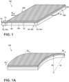
- a stack assembly 100 is depicted that includes a glass element 50.
- Glass element 50 has a glass element thickness 52, a first primary surface 54 and a second primary surface 56.
- Thickness 52 can range from about 50 ⁇ m to about 100 ⁇ m in some aspects. In other aspects, thickness 52 can range from about 60 ⁇ m to about 80 ⁇ m. Thickness 52 can also be set at other thicknesses between the foregoing ranges.
- the glass element 50 includes a glass layer 50a with a glass layer first primary surface 54a and a glass layer second primary surface 56a.
- glass layer 50a also includes edges 58b, generally configured at right angles to the primary surfaces 54a and 56a.
- Glass layer 50a is further defined by a glass layer thickness 52a.
- the glass element 50 includes one glass layer 50a.
- the glass layer thickness 52a is comparable to the glass element thickness 52 for stack assembly 100.
- glass element 50 can include two or more glass layers 50a (see, e.g., stack assembly 100c in FIG. 2 and the corresponding description).
- glass element 50 can include three glass layers 50a, each having a thickness 52a of about 8 ⁇ m.
- the thickness 52 of glass element 50 may be about 24 ⁇ m.
- glass element 50 could include other non-glass layers (e.g., compliant polymer layers) in addition to one or more glass layers 50a.
- glass layer 50a can be fabricated from alkali-free aluminosilicate, borosilicate, boroaluminosilicate, and silicate glass compositions. Glass layer 50a can also be fabricated from alkali-containing aluminosilicate, borosilicate, boroaluminosilicate, and silicate glass compositions. In certain aspects, alkaline earth modifiers can be added to any of the foregoing compositions for glass layer 50a.
- glass compositions according to the following are suitable for the glass layer 50a: SiO 2 at 64 to 69% (by mol%); Al 2 O 3 at 5 to 12%; B 2 O 3 at 8 to 23%; MgO at 0.5 to 2.5%; CaO at 1 to 9%; SrO at 0 to 5%; BaO at 0 to 5%; SnOz at 0.1 to 0.4%; ZrO 2 at 0 to 0.1%; and Na 2 O at 0 to 1%.
- the following composition is suitable for the glass layer 50a: SiO 2 at -67.4% (by mol%); Al 2 O 3 at -12.7%; B 2 O 3 at -3.7%; MgO at -2.4%; CaO at 0%; SrO at 0%; SnO 2 at -0.1%; and Na 2 O at -13.7%.
- the following composition is also suitable for the glass layer 50a: SiO 2 at 68.9% (by mol%); Al 2 O 3 at 10.3%; Na 2 O at 15.2%; MgO at 5.4 %; and SnO 2 at 0.2%.
- a composition for glass layer 50a is selected with a relatively low elastic modulus (compared to other alternative glasses).
- Lower elastic modulus in the glass layer 50a can reduce the tensile stress in the layer 50a during bending.
- Other criteria can be used to select the composition for glass layer 50a, including but not limited to ease of manufacturing to low thickness levels while minimizing the incorporation of flaws, ease of development of a compressive stress region to offset tensile stresses generated during bending, optical transparency, and corrosion resistance.
- the glass element 50 and the glass layer 50a can adopt a variety of physical forms. From a cross-sectional perspective, the element 50 and the layer 50a (or layers 50a) can be flat or planar. In some aspects, element 50 and layer 50a can be fabricated in non-rectilinear, sheet-like forms depending on the final application. As an example, a mobile display device having an elliptical display and bezel could require a glass element 50 and layer 50a having a generally elliptical, sheet-like form.
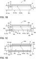
- the glass element 50 of the stack assembly 100 further includes a compressive stress region 60 that extends from the first primary surface 54a of the glass layer 50 to a first depth 62 in the glass layer 50.
- the compressive stress region 60 can be employed within the glass layer 50a to offset tensile stresses generated in the glass layer 50a upon bending, particularly tensile stresses that reach a maximum near the first primary surface 54a.
- the compressive stress region 60 can include a compressive stress of at least about 100 MPa at the first primary surface of the layer 54a. In some aspects, the compressive stress at the first primary surface 54a is from about 600 MPa to about 1000 MPa.
- the compressive stress can exceed 1000 MPa at the first primary surface 54a, up to 2000 MPa, depending on the process employed to produce the compressive stress in the glass layer 50a.
- the compressive stress can also range from about 100 MPa to about 600 MPa at the first primary surface 54a in other aspects of this disclosure.
- the compressive stress can stay constant, decrease or increase within the glass layer 50a as a function of depth from the first primary surface of the glass layer 54a down to the first depth 62.
- various compressive stress profiles can be employed in compressive stress region 60.
- the depth 62 can be set at approximately 15 ⁇ m or less from the first primary surface of the glass layer 54a. In other aspects, the depth 62 can be set such that it is approximately 1/3 of the thickness 52a of the glass layer 50a or less, or 20% of the thickness 52a of the glass layer 50a or less, from the first primary surface of the glass layer 54a.
- the glass element 50 is characterized by an absence of failure when the element is held at the bend radius 40 from about 5 mm to about 20 mm for at least 60 minutes at about 25°C and about 50% relative humidity.
- the terms "fail,” “failure” and the like refer to breakage, destruction, delamination, crack propagation or other mechanisms that leave the stack assemblies, glass articles, and glass elements of this disclosure unsuitable for their intended purpose.
- the glass element 50 is also characterized by a puncture resistance of greater than about 14.7 N (1.5 kgf) when the second primary surface 56 of the element 50 is supported by (i) an approximately 25 ⁇ m thick pressure-sensitive adhesive ("PSA") having an elastic modulus of less than about 1 GPa and (ii) an approximately 50 ⁇ m thick polyethylene terephthalate layer (“PET”) having an elastic modulus of less than about 10 GPa, and the first primary surface 54 of the element 50 is loaded with a stainless steel pin having a flat bottom with a 200 ⁇ m diameter.
- PSA pressure-sensitive adhesive
- PET polyethylene terephthalate layer
- the stainless steel pin is replaced with a new pin after a specified quantity of tests (e.g., 10 tests) to avoid bias that could result from deformation of the metal pin associated with the testing of materials possessing a higher elastic modulus (e.g., glass element 50).
- the glass element 50 is characterized by a puncture resistance of greater than about 14.7 N (1.5 kgf) at a 5% or greater failure probability within a Weibull plot.
- the glass element 50 can also be characterized by a puncture resistance of greater than about 29.4 N (3 kgf) at the Weibull characteristic strength (i.e., a 63.2% or greater).
- the glass element 50 of the stack assembly 100 can resist puncture at about 19.6 N (2 kgf) or greater, 24.5 N (2.5 kgf) or greater, 29.4 N (3 kgf) or greater, 34.3 N (3.5 kgf) or greater, 39.2 N (4 kgf) or greater, and even higher ranges.
- the glass element 50 is also characterized by a pencil hardness of greater than or equal to 8H.
- some aspects of the stack assembly 100 include a second layer 70 having a low coefficient of friction with a second layer coating thickness 72.
- the second layer 70 is disposed on the first primary surface 54 of the glass element 50.
- the second layer 70 can serve to decrease friction and/or reduce surface damage from abrasion.
- the second layer 70 can also provide a measure of safety in retaining pieces and shards of glass element 50 and/or layer 50a when the element and/or layer has been subjected to stresses in excess of its design limitations that cause failure.
- the thickness 72 of the second layer 70 can be set at 1 micrometer ( ⁇ m) or less in some aspects.
- the second layer 70 can be set at 500 nm or less, or as low as 10 nm or less for certain compositions. Further, in some aspects of stack assembly 100, an additional layer 70 can be employed on the primary surface 56 to provide a safety benefit in retaining shards of glass element 50 and/or layer 50a that have resulted from stresses in excess of their design requirements.
- Second layer 70 can employ various fluorocarbon materials that are known to have low surface energy, including thermoplastics for example, polytetrafluoroethylene (“PTFE”), fluorinated ethylene propylene (“FEP”), polyvinylidene fluoride (“PVDF”), and amorphous fluorocarbons (e.g., DuPont ® Teflon ® AF and Asahi ® Cytop ® coatings) which typically rely on mechanical interlocking mechanisms for adhesion.
- thermoplastics for example, polytetrafluoroethylene (“PTFE”), fluorinated ethylene propylene (“FEP”), polyvinylidene fluoride (“PVDF”), and amorphous fluorocarbons (e.g., DuPont ® Teflon ® AF and Asahi ® Cytop ® coatings) which typically rely on mechanical interlocking mechanisms for adhesion.
- PTFE polytetrafluoroethylene
- FEP fluor
- Second layer 70 can also be fabricated from silane-containing preparation for example, Dow Corning ® 2634 coating or other fluoro- or perfluorosilanes (e.g., alkylsilanes) which can be deposited as a monolayer or a multilayer.
- second layer 70 can include silicone resins, waxes, polyethylene (oxided) used by themselves or in conjunction with a hot-end coating for example, tin oxide, or vapor-deposited coatings for example, parylene and diamond-like coatings ("DLCs").
- Second layer 70 can also include zinc oxide, molybdenum disulfide, tungsten disulfide, hexagonal boron nitride, or aluminum magnesium boride that can be used either alone or as an additive in the foregoing coating compositions and preparations.
- stack assembly 100 can include a surface region with a controlled flaw size distribution (e.g., flaw sizes of 0.5 ⁇ m or less at the first primary surface 54a of the glass layer 50a) that also lacks the superposition of a compressive stress region.
- a controlled flaw size distribution e.g., flaw sizes of 0.5 ⁇ m or less at the first primary surface 54a of the glass layer 50a
- Equation (1) can be used to estimate the maximum tensile stresses in the stack assembly 100, particularly at the first primary surface 54 of the glass element 50, subjected to bending with a constant bend radius 40.
- a the flaw size
- Y a geometry factor (generally assumed to be 1.12 for cracks emanating from a glass edge, a typical failure mode)
- ⁇ the bending stress associated with the bending forces 42 as estimated using Equation (1).
- Equation (2) assumes that the stress along the crack face is constant, which is a reasonable assumption when the flaw size is small (e.g., ⁇ 1 ⁇ m).
- K IC When the stress intensity factor K reaches the fracture toughness of the glass element 50, K IC , instantaneous failure will occur.
- K IC For most compositions suitable for use in glass element 50, K IC is ⁇ 0.7 MPa ⁇ m.
- K threshold when K reaches a level at or above a fatigue threshold, K threshold , failure can also occur via slow, cyclic fatigue loading conditions.
- a reasonable assumption for K threshold is -0.2 MPa ⁇ m.
- K threshold can be experimentally determined and is dependent upon the overall application requirements (e.g., a higher fatigue life for a given application can increase K threshold ) .
- the stress intensity factor can be reduced by reducing the overall tensile stress level and/or the flaw size at the surface of the glass element 50.
- the tensile stress and stress intensity factor estimated through Equations (1) and (2) can be minimized through the control of the stress distribution at the first primary surface 54 of the glass element 50.
- a compressive stress profile e.g., a compressive stress region 60
- overall bending stress levels are reduced which, in turn, also reduces the stress intensity factors that can be estimated through Equation (2).
- a foldable electronic device with a foldable feature can include the stack assembly 100.
- the foldable feature for example, can be a display, printed circuit board, housing or other features associated with the electronic device.
- the stack assembly 100 can be substantially transparent.
- the stack assembly 100 can have pencil hardness, bend radius and/or puncture resistance capabilities as described in the foregoing.
- the foldable electronic device is a wearable electronic device, such as a watch, wallet or bracelet, that includes or otherwise incorporates the stack assembly 100 described according to the foregoing.
- "foldable” includes complete folding, partial folding, bending, flexing, and multiple-fold capabilities.
- the ion-exchanged metal ions have an atomic radius larger than the atomic radius of the ion-exchangeable metal ions.
- the ion-exchangeable ions e.g., Na + ions
- Ion-exchanging ions e.g., K + ions
- ion-exchanging ions for example, K + ions
- the incorporation of ion-exchanging ions can be effected by submersing the element or the layer in a molten salt bath containing ion-exchanging ions (e.g., molten KNO 3 salt).
- ion-exchanging ions e.g., molten KNO 3 salt.
- the K + ions have a larger atomic radius than the Na + ions and tend to generate local compressive stresses in the glass wherever present.
- the ion-exchanging ions can be imparted from the first primary surface 54a down to a first ion exchange depth 62a, establishing an ion exchange depth-of-layer ("DOL") for the compressive stress region 60a.
- a second compressive stress region 60a can be developed from the second primary surface 56a down to a second ion exchange depth 63a as depicted in FIG. 1C .
- Compressive stress levels within the DOL that far exceed 100 MPa can be achieved with such ion exchange processes, up to as high as 2000 MPa.
- the compressive stress levels in the compressive stress region 60a (and a second region 60a when present) can serve to offset the tensile stresses generated in the stack assembly 100a, glass element 50 and glass layer 50a generated from bending forces 42.
- some aspects of stack assembly 100a can include one or more edge compressive stress regions 59a, each defined by a compressive stress of at least 100 MPa.
- An edge compressive stress region 59a in the glass element 50 can be established from an edge 58b down to an edge depth 59b. Ion-exchanging processes similar in nature to those employed to generate the compressive stress region 60a can be deployed to generate an edge compressive stress region 59a. More specifically, the edge compressive stress region 59a can be used to offset tensile stresses generated at the edge 58b through, for example, bending of the glass element 50 across the face of the edge 58b. Alternatively, or as an addition thereto, without being bound by theory, the compress stress region 59a may offset adverse effects from an impact or abrasion event at or to the edge 58b.
- a stack assembly 100b is depicted that relies on a mismatch in the coefficient of thermal expansion ("CTE") between regions of the glass layer 50a to develop compressive stress regions 60b.
- Stack assembly 100b is similar to the stack assembly 100 depicted in FIGS. 1-1B , and like-numbered elements have comparable structure and function.
- the compressive stress regions 60b of the glass element 50 can be developed via the tailored structure of glass layer 50a which relies on CTE differences within the layer 50a itself.
- the glass layer 50a includes a core region 55a and a first and a second clad region 57a disposed on the core region 55a.
- the CTE of the core region 55a is greater than the CTE of the clad regions 57a.
- the CTE differences between the core region 55a and the clad regions 57a cause uneven volumetric contraction upon cooling, leading to the development of compressive stress regions 60b in the clad regions 57a, below the respective first and second primary surfaces 54a and 56a as shown in FIG. 1D .
- the core region 55a and the clad regions 57a are brought into intimate contact with one another at high temperatures; and regions 55a and 57a are then cooled to a low temperature such that the greater volume change of the high CTE core region 55a relative to the low CTE clad regions 57a creates the compressive stress regions 60b in the clad regions 57a.
- the core region 55a has a core region thickness 55b and the clad regions 57a have a clad thickness 57b as shown in FIG. 1D .
- maximizing the size of the core region 55a and/or its CTE relative to the size and/or CTE of the clad regions 57a can serve to increase the magnitude of the compressive stress levels observed in the compressive stress regions 60b of the stack assembly 100b.
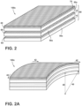
- FIG. 2 depicts a stack assembly 100c with a glass element 50 having multiple glass layers 50a (e.g., two layers 50a, three layers 50a, four layers 50a, and so on).
- the three glass layers 50a stacked together, make up the glass element 50.
- a compressive stress region 60 can be present in each layer 50a as shown in FIG. 2 .
- the layers 50a can be stacked directly together or, in some aspects, compliant interlayers can be disposed between them.
- a compressive stress region 60 is not required in all layers 50a within the glass element 50.
- a compressive stress region 60 is present in the topmost layer 50a of the element 50.
- edge compressive stress regions 59a see FIG. 1C and the corresponding description
- compressive stress regions 60a see FIG. 1C and the corresponding description
- compressive stress regions 60b see FIG. 1D and the corresponding description
- the layers 50a of the stack assembly 100c are configured to allow movement with respect to one another upon bending of the glass element 50 (see FIG. 2A ); or the layers 50a are loosely coupled to one another.
- the collective thickness of the glass element 50 obtained through the stacking of layers 50a can increase the resistance of the element 50 to puncture, as each layer 50a supports the layer above it.
- the ability of the glass layers 50a to move relative to one another during bending reduces the amount of tensile stress generated in each layer 50a upon bending to a bend radius 40. This is because the thickness of each layer 50a (rather than the thickness of element 50) is the contributing factor in generating the tensile stress, as estimated by Equation (1).
- a second layer 70 can be disposed on the first primary surface 54 of the glass element 50 (i.e., on the first primary surface of the top-most layer 50a).
- a second layer 70 employed for this purpose has a comparable structure and function to the second layer 70 outlined earlier in connection with the stack assembly 100.
- a second layer 70 may be employed: on the second primary surface of the lower-most layer 50a; and/or on one or both primary surfaces of any layer 50a in the stack assembly 100c.
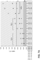
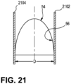
- Stack assembly 100d includes a glass structure 90 having a thickness 92 that is greater than the thickness 52a of its glass layer 50a.
- Glass layer 50a includes a first primary surface 54a and a second primary surface 56a.
- the first primary surface 54a also can extend to the first primary surface of the glass structure 90 (see FIGS. 3 and 3B ).
- a second layer 70 can be disposed on the first primary surface 54a of the glass layer 50a and glass structure 90.
- a second layer 70 employed for this purpose in the stack assembly 100d has a comparable structure and function to the second layer 70 outlined earlier in connection with the stack assembly 100.
- the glass structure 90 and the glass layer 50a of the stack assembly/glass article 100d are monolithic with regard to one another.
- the glass structure 90 can be a separate component that is bonded or otherwise joined to glass layer 50a.
- the glass layer 50a is arranged in a central region 96 of the glass structure 90, between the substantially parallel edges 98 of the glass structure.
- the glass layer 50a and central region 96 are spaced some distance from each of the parallel edges 98.
- the glass layer 50a and central region 96 can be spaced closer to one edge 98 than the other substantially parallel edge 98.
- the glass layer 50a in the stack assembly (or glass article) 100d depicted in FIGS. 3 and 3B , is essentially the same as the glass layer 50a described in the foregoing in connection with stack assemblies 100, 100a and 100b.
- the glass layer 50a employed in stack assembly 100d includes a compressive stress region 60, 60a or 60b that spans from the first primary surface 54a of the glass layer 50a down to the first depth 62a.
- the compressive stress region 60, 60a, or 60b within the glass layer 50a can also span laterally into the glass structure 90.
- the inclusion of the compressive stress region 60, 60a or 60b throughout the glass layer 50a and the glass structure 90 can provide a manufacturability benefit.
- an ion exchange process could be employed to develop the compressive stress region 60 or 60a in both the glass layer 50a and the glass structure 90 in one submersion step.
- the stack assembly 100d (or glass article) can be subjected to bending forces 42 that bend the glass layer 50a upon a constant bend radius 40. Since the thickness 52a of the glass layer 50a is generally smaller than the thickness 92 of the glass structure 90, the bending forces 42 tend to cause bending displacements in the glass layer 50a and little or no bending in the adjacent sections of the glass structure 90. As such, the bending stress and stress intensity levels are reduced at the first primary surface 54a of the glass layer 50a by virtue of minimizing the thickness 52a to levels below the thickness 92 of the glass structure 90. Nevertheless, the increased thickness 92 of the glass structure 90 provides additional puncture resistance for the majority of the stack assembly 100d (i.e., beyond that in the central region 96 containing the glass layer 50a).
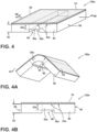
- a glass article or stack assembly 100e comprises: a glass layer 50e having a thickness 52e, a first primary surface 54e, and a second primary surface 56e.
- the first primary surface 54e also can extend to the first primary surface of the glass structure 90 (see FIGS. 4 and 4B ).
- a second layer 70 can be disposed on the first primary surface 54e of the glass layer 50e and/or on one or both primary surfaces of glass structure 90.
- a second layer 70 employed for this purpose in the stack assembly 100e has a comparable structure and function to the second layer 70 outlined earlier in connection with the stack assembly 100.
- a second layer 70 may also be disposed on the second primary surface 56e.
- the glass layer 50e is essentially the same as the glass layer 50a described in the foregoing in connection with stack assemblies 100, 100a and 100b. Furthermore, the structure and arrangement of the stack assembly 100e is similar to the stack assembly 100d described earlier in connection with FIGS. 3, 3A and 3B . However, the glass layer 50e employed in stack assembly 100e does not include a compressive stress region 60.
- the stack assembly 100e (or glass article) can be subjected to bending forces 42 that bend the glass layer 50e upon a constant bend radius 40. Since the thickness 52e of the glass layer 50e is generally smaller than the thickness 92 of the glass structure 90, the bending forces 42 tend to cause bending displacements in the glass layer 50e and little or no bending in the adjacent sections of the glass structure 90. As such, the bending stress and stress intensity levels are reduced at the first primary surface 54e of the glass layer 50e by virtue of minimizing the thickness 52e to levels below the thickness 92 of the glass structure 90.
- the increased thickness 92 of the glass structure 90 provides additional puncture resistance for the majority of the assembly (i.e., beyond that in the central region 96 containing the glass layer 50e).
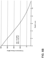
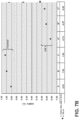
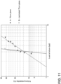
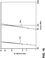
- puncture resistance and glass thickness can be correlated.
- the results in FIG. 5 were generated by measuring the puncture resistance of various glass samples having thicknesses including 116, 102, 87, 71, 60, 49, 33 and 25 ⁇ m. These glass samples were prepared by etching 130 ⁇ m-thick glass samples to the foregoing thickness levels using an etching solution having 15 vol% HF and 15 vol% HCl.
- each glass sample e.g., 116 ⁇ m thick glass, 102 ⁇ m thick glass, etc.
- a flat tip probe having a 200 ⁇ m diameter stainless steel tip was pushed into a primary surface of the glass sample opposite from the compliant layer stack. The tip was then advanced into the sample until failure (as verified by visual observation with an optical microscope) and the force at failure was measured (in units of kgf). The results from this testing were plotted in FIG. 5 .
- FIG. 5 demonstrates that the puncture resistance of the glass samples decreased from about 24.5 N (2.5 kgf) to about 3.9 N (0.4 kgf) with decreasing glass layer thickness from about 116 ⁇ m to about 25 ⁇ m, respectively.
- the puncture resistance of these glass samples was highly dependent on glass thickness.
- FIG. 5 demonstrates that the puncture resistance for the tested glass substrate sample having a thickness of about 116 ⁇ m is about 24.5 N (2.5 kgf). It is evident through extrapolation that puncture resistance levels that can exceed 29.4 N (3 kgf) can be obtained through the use of glass substrates having a thickness of 130 ⁇ m or greater.
- FIGS. 1 one aspect of stack assembly 100e (see FIGS.
- the central region 96 beneath the glass layer 50e and second primary surface 56e can be further reinforced with a generally non-compliant, polymeric layer. This reinforcement can tend to offset any reduced puncture resistance in the glass layer 50e relative to the increased puncture resistance of the glass structure 90.
- thickness 52e of the glass layer 50e is generally smaller than the thickness 92 of the glass structure 90.
- a bend radius of ⁇ 2 mm for the stack assembly 100e is feasible with a thickness 52e of approximately 20 to 25 ⁇ m.
- a selective etching process can be conducted on the stack assembly 100e.
- one step is to provide a glass structure with a substantially constant thickness equal to the thickness 92 for the glass structure 90.
- Coating materials are then applied on the second primary surface 56e of the glass structure 90 in regions adjacent to the intended central region 96 of the glass structure 90 (i.e., the region that will be etched to the thickness 52e) to protect or otherwise mask these regions during a subsequent etching step.
- these materials may be a film or ink that can be coated on the glass structure 90 by lamination or screen printing processes.
- One of ordinary skill in the art would readily understand what type of coating materials would be suitable for a particular etchant composition selected for the selective etching process for stack assembly 100e.
- etching solutions according to the foregoing (e.g., 15 vol% HF and 15 vol% HCl) can be applied to the masked, glass structure for an appropriate time to achieve the desired thickness 52e in the glass layer 50e.
- the masking materials can be peeled or otherwise stripped using a suitable stripper solution depending on the particular masking materials employed in the selective etching process.
- edges 98 can be left uncoated during the etching step or steps. As a result, these edges 98 are subjected to a light etch as the glass layer 50e is formed with a thickness 52e. This light etch to edges 98 can beneficially improve their strength.
- cutting or singling processes employed to section the glass structure before the selective etching process is employed can leave flaws and other defects within the surface of the glass structure 90. These flaws and defects can propagate and cause glass breakage during the application of stresses to the stack assembly 100e from the application environment and usage.
- the selective acid etching process by virtue of lightly etching these edges 98, can remove at least some of these flaws, thereby increasing the strength and/or fracture resistance of the edges of the stack assembly 100e.
- the glass layer 50e can be characterized by: (a) an absence of failure when the layer 50e is held at a bend radius from about 5 mm to about 20 mm for at least 60 minutes at about 25°C and about 50% relative humidity; (b) a puncture resistance of greater than about 14.7 N (1.5 kgf) when the second primary surface 56e of the layer 50e is supported by (i) an approximately 25 ⁇ m thick pressure-sensitive adhesive having an elastic modulus of less than about 1 GPa and (ii) an approximately 50 ⁇ m thick polyethylene terephthalate layer having an elastic modulus of less than about 10 GPa, and the first primary surface 54e of the layer 50e is loaded with a stainless steel pin having a flat bottom with a 200 ⁇ m diameter; and (c) a pencil hardness of greater than or equal to 8H.
- the stack assemblies 100-100e depicted in FIGS. 1-4B can be fabricated according to a method that includes the steps: forming a first glass layer 50a, 50e having a first primary surface 54a, 54e, a compressive stress region 60, 60a, 60b extending from the first primary surface 54a of the glass layer 50a to a first depth 62, 62a, 62b in the glass layer 50a (i.e., for stack assemblies 100-100d), and a final thickness 52a, 52e.
- the compressive stress region 60, 60a, 60b is defined by a compressive stress of at least about 100 MPa at the first primary surface 54a of the layer 50a.
- the method for forming stack assemblies 100-100e depicted in FIGS. 1-4B can also include the step of forming a glass element 50 having a thickness 52 from about 50 ⁇ m to about 100 ⁇ m.
- the element 50 further comprises the glass layer 50a, 50e a first primary surface 54, and a second primary surface 56.
- the glass element 50 or glass layer 50a, 50e can also characterized by: (a) an absence of failure when the element 50 or glass layer 50a, 50e is held at a bend radius 40 from about 5 mm to about 20 mm for at least 60 minutes at about 25°C and about 50% relative humidity; (b) a puncture resistance of greater than about 14.7 N (1.5 kgf) when the second primary surface 56 of the element 50 is supported by (i) an approximately 25 ⁇ m thick PSA having an elastic modulus of less than about 1 GPa and (ii) an approximately 50 ⁇ m thick PET layer having an elastic modulus of less than about 10 GPa, and the first primary surface 54, 54a, 54e of the element 50 or glass layer 50a, 50e is loaded with a stainless steel pin having a flat bottom with a 200 ⁇ m diameter; and (c) a pencil hardness of greater than or equal to 8H.
- glass element 50 or glass layer 50a, 50e can be configured to avoid failure for bend radii that range from about 5 mm to about 10 mm.
- the bend radius 40 can also be set to a range from about 5 mm to 7 mm without causing a failure in the glass element 50 or glass layer 50a, 50e according to other aspects of the method.
- the step of forming the first glass layer 50a, 50e employs one or more of the following forming processes: fusion, slot drawing, rolling, redrawing or float. Other forming processes can be employed depending on the final shape factor for the glass layer 50a, 50e and/or the intermediate dimensions of a glass precursor used for the final glass layer 50a, 50e.
- the forming process is further configured to form the glass layer 50a, 50e to the final thickness 52a, 52e and, as such, may include sub-process steps to obtain the final thickness 52a, 52e.
- the step of forming the first glass layer 50a, 50e can include a material removal process that is configured to remove material from the glass layer 50a, 50e to reach the final thickness 52a, 52e.
- a suitable etching solution can comprise 15 vol% HF and 15 vol% HCl.
- the material removal process employed to reach the final thickness 52a, 52e can be further configured to reduce the maximum flaw size in proximity to the first primary surface 54a - e.g., to 2 ⁇ m or less, 0.5 ⁇ m or less, or even lower.
- the ion-exchanging metal ions have an atomic radius that is larger than the atomic radius of the ion-exchangeable metal ions contained in the glass layer 50a.
- the submersing step includes submersing the glass layer 50a in the strengthening bath at about 400°C to about 450°C for about 15 minutes to about 180 minutes to develop the compressive stress region 60a.
- a post-ion exchange process to remove material from the surface of the glass layer 50a can provide a benefit in terms of flaw size reduction.
- a removing process can employ a light etching step to remove about 1 ⁇ m to about 5 ⁇ m from the final thickness of the glass layer 52a at the first primary surface 54a after formation of the compressive stress region 60a.
- the removing step can employ a 950 ppm F - ion (e.g., an HF acid), 0.1M citric acid etching solution for -128 minutes for this purpose.
- a reduction in the maximum flaw size in the glass layer 50a and/or the glass element 50, particularly near their surfaces can serve to reduce the stress intensity factor produced from bending the layer and/or the element.
- FIG. 6B has a similar compressive stress as a function of depth relationship as shown in FIG.
- FIG. 6B is effectively a truncated version of FIG. 6A , with the first portion removed consistent with the actual removal of material from the light etching process.
- the post-ion exchange material removal process can somewhat reduce the DOL and maximum compressive stress obtained from the ion exchange process, while at the same time providing a benefit in terms of flaw size reduction.
- the ion exchange process can be tailored to produce compressive stress and DOL levels somewhat above the targeted levels, given the expected effect from the post-ion exchange material removal process.
- the removing process can be conducted to control the flaw distribution in the compressive stress regions 60, 60a and/or 60b to a maximum flaw size of 5 ⁇ m or less at the first primary surface 54a of the glass layer 50a.
- the removing step can also be conducted such that the compressive stress regions 60, 60a and/or 60b comprise a maximum flaw size of 2.5 ⁇ m or less, or even as low as 0.4 ⁇ m or less, at the first primary surface 54a of the glass layer 50a.
- the removing step can also be conducted to control the flaw size distribution within a region of the glass layer 50a that lacks the superposition of a compressive stress region 60, 60a or 60b.
- variants of the removing process can be conducted at the edges 58b of the glass element 50 to control the flaw size distribution at the edges and within edge compressive stress regions 59a, when present (see, e.g., FIGS. 1 and 1C ).
- a method of making stack assemblies 100-100d comprises the steps: forming a first glass layer 50a having a first primary surface 54a, a compressive stress region 60 extending from the first primary surface 54a of the glass layer 50a to a first depth 62 in the glass layer 50a, and a final thickness 52a, wherein the region 60 is defined by a compressive stress of at least about 100 MPa at the first primary surface 54a of the layer 50a; and forming a glass element 50 having a thickness 52 from about 50 ⁇ m to about 100 ⁇ m, the element 50 further comprising the glass layer 50a, a first primary surface 54, and a second primary surface 56.
- the element 50 comprises one glass layer 50a.
- the steps of forming the first glass layer 50a and element 50 can include a step of forming an interim thickness (e.g., about 200 ⁇ m) that exceeds the final thickness 52a of the glass layer 50a (and thickness 52 of the element 50) using fusion, slot drawing, rolling, redrawing, float or other direct glass forming processes.
- the interim glass layer 50a (and element 50) can then be separated, cut and/or otherwise shaped into near-final part dimensions using known cutting processes (e.g., water cutting, laser cutting, etc.).
- the interim glass layer 50a (and element 50) can then be etched to a final thickness 52a (e.g., about 75 ⁇ m) according to the foregoing process steps.
- Etching to a final thickness at this stage in the process can provide a benefit in removing flaws and other defects introduced from the prior glass forming and separation/cutting steps.
- the glass layer 50a and element 50 can be subjected to process steps for forming the compressive stress region 60 including but not limited to the foregoing ion exchange process.
- a final, light etch can then be performed on the glass layer 50a and element 50 containing the compressive stress region 60 according to the prior-described process. This final, light etch can then remove any appreciable flaws and defects in the surface of the glass layer 50a and element 50 that resulted from the prior ion exchange process.
- the glass element 50 or glass layer 50a produced according to the method can be characterized by: (a) an absence of failure when the element 50 or glass layer 50a is held at a bend radius from about 5 mm to about 20 mm for at least 60 minutes at about 25°C and about 50% relative humidity; (b) a puncture resistance of greater than about 14.7 N (1.5 kgf) when the second primary surface 56, 56a of the element 50 or layer 50a is supported by (i) an approximately 25 ⁇ m thick pressure-sensitive adhesive having an elastic modulus of less than about 1 GPa and (ii) an approximately 50 ⁇ m thick polyethylene terephthalate layer having an elastic modulus of less than about 10 GPa, and the first primary surface 54, 54a of the element 50 or layer 50a is loaded with a stainless steel pin having a flat bottom with a 200 ⁇ m diameter; and (c) a pencil hardness of greater than or equal to 8H.
- the steps of forming the first glass layer 50a and element 50 to the final thickness 52a and thickness 52, respectively can be conducted by employing fusion, slot drawing, rolling, redrawing, float or other direct glass forming processes.
- the glass layer 50a (and element 50) can then be separated, cut and/or otherwise shaped into near-final part dimensions using known cutting processes (e.g., water cutting, laser cutting, etc.).
- the glass layer 50a (and element 50) can then be subjected to process steps for forming the compressive stress region 60 including but not limited to the foregoing ion exchange process.
- a final, light etch can then be performed on the glass layer 50a and element 50 containing the compressive stress region 60 according to the prior-described process. This final, light etch can then remove any appreciable flaws and defects in the surface of the glass layer 50a and element 50 that resulted from the prior ion exchange process.
- the glass element 50 or glass layer 50a produced according to the method can be characterized by: (a) an absence of failure when the element 50 or glass layer 50a is held at a bend radius from about 5 mm to about 20 mm for at least 60 minutes at about 25°C and about 50% relative humidity; (b) a puncture resistance of greater than about 14.7 N (1.5 kgf) when the second primary surface 56, 56a of the element 50 or layer 50a is supported by (i) an approximately 25 ⁇ m thick pressure-sensitive adhesive having an elastic modulus of less than about 1 GPa and (ii) an approximately 50 ⁇ m thick polyethylene terephthalate layer having an elastic modulus of less than about 10 GPa, and the first primary surface 54, 54a of the element 50 or layer 50a is loaded with a stainless steel pin having a flat bottom with a 200 ⁇ m diameter; and (c) a pencil hardness of greater than or equal to 8H.
- composition of the A group is: SiO 2 at 67.1% (by mol%); Al 2 O 3 at 6.3%; B 2 O 3 at 19.9%; MgO at 0.5%; CaO at 4.8%; SrO at 0.5%; SnO 2 at 0%; and Na 2 O at 0.9%.
- the composition of the B group is: SiO 2 at 66.7% (by mol%); Al 2 O 3 at 10.9%; B 2 O 3 at 9.7%; MgO at 2.2%; CaO at 9.1%; SrO at 0.5%; SnO 2 at 0.1%; and Na 2 O at 0%.
- the composition of the C group is: SiO 2 at 67.4% (by mol%); Al 2 O 3 at 12.7%; B 2 O 3 at 3.7%; MgO at 2.4%; CaO at 0%; SrO at 0%; SnO 2 at 0.1%; and Na 2 O at 13.7%. Equation (2) was employed to generate the estimates depicted in FIG. 7A .
- Glass layers "A,” “B” and “C” have elastic moduli of 57.4, 69.3 and 73.6 GPa, respectively. Further, glass layers "A,” “B” and “C” have a Poisson's ratio of 0.22, 0.22 and 0.23, respectively.
- stress intensity factor estimates were performed for the glass layers "A,” “B” and “C” having a thickness of 25, 50 and 100 ⁇ m and a bend radius of 3, 5 and 7 mm.
- a flaw size of 400 nanometers (nm) was assumed for all cases, as it is a typical maximum flaw size for a fusion-formed glass surface. No compressive stress region was assumed to be present in any of these glass layers.
- FIG. 7B a schematic plot of estimated stress intensity factors is provided for glass layers of three compositions, "A,” “B” and “C” (i.e., the same compositions as employed for the glass layers depicted in FIG. 7A ).
- Each of the glass layers employed in the estimates depicted in FIG. 7B was assumed to have a thickness of 50 ⁇ m and a bend radius of 5 mm.
- the "Control” (also denoted by A, B and C) group was assumed to lack a superimposed compressive stress region
- the "IOX” group also denoted by A", B” and C
- FIG. 8 a schematic plot is provided of estimated stress levels at the surface of glass layers of one particular composition, a glass composition comparable to the composition of the C group depicted in FIGS. 7A and 7B .
- Each of the glass layers employed to generate the stress estimates depicted in FIG. 8 was assumed to have a thickness of 25, 50, 75 and 100 ⁇ m and a bend radius of 5 mm. Further, some of these glass layers were assumed to lack a compressive stress region (i.e., the "Control" group) and the remaining glass layers were assumed to possess a compressive stress region having about 700 MPa of surface compression, e.g., as developed through an ion exchange process (i.e., the "IOX” group) according to a further aspect of this disclosure.
- a flaw size of 400 nm was assumed for all cases, as it is a typical maximum flaw size for a fusion-formed glass surface. Further, the safety zone (i.e., region III) was set at stress intensity safety factor of K ⁇ 0.2 MPa ⁇ m.
- a compressive stress region developed in a glass layer with an ion exchange process can significantly reduce the stress intensity levels in the glass layers observed upon bending.
- Stress intensity levels well below the region III threshold e.g., K at ⁇ 0.2 MPa ⁇ m for region III
- the Control group without a compressive stress region, was estimated to have stress intensity levels in region I for all thicknesses.
- a plot of failure puncture load data for glass layers of one composition having a thickness of 75 ⁇ m and a compressive stress region developed through an ion exchange process is provided according to an aspect of this disclosure.
- the glass composition for the samples tested in FIG. 9 was: SiO 2 at 68.9% (by mol%); Al 2 O 3 at 10.3%; Na 2 O at 15.2%; MgO at 5.4%; and SnO 2 at 0.2%. All of the glass layers tested in the experiment used to generate the data of FIG. 9 were subjected to an ion-exchange process to produce a compressive stress region with a compressive stress at the surface of about 772 MPa and a DOL of 9.6 ⁇ m.
- the glass layers were laminated to a 50 ⁇ m PET layer (having an elastic modulus of less than about 10 GPa) with a 25 ⁇ m PSA layer (having an elastic modulus of less than about 1 GPa). Puncture testing was performed on the outer glass surface.
- FIG. 9 As shown in FIG. 9 , four groups of samples were tested to develop the puncture test data. Each group corresponded to a different puncture device: a 200 ⁇ m diameter, flat bottom stainless steel punch; a 0.5 mm tungsten carbide ball; a 1.0 mm tungsten carbide ball; and a 1.5 mm tungsten carbide ball.
- the data in FIG. 9 demonstrate the sensitivity of the puncture failure load data to the particular puncture device employed in the testing. Generally, the variability in results appears to be similar for each of the devices employed. As indicated in FIG.
- a glass layer with a composition that was comparable to the glass layers tested in FIG. 9 was prepared according to an aspect of this disclosure with a compressive stress region generated through an ion exchange process was subjected to a 2-point, static fatigue bend test.
- the glass layer tested had a thickness of 75 ⁇ m and its compressive stress region was developed by submersion in a KNO 3 molten salt bath at 430°C for 30 minutes.
- the glass layer was subjected to a post-ion exchange material removal process involving an acid etch in a 950 ppm F - ion, 0.1M citric acid etching solution for about 128 minutes. Upon testing, the glass layer did not fail after being subjected to a bend radius of ⁇ 5 mm for 120 hours.
- 75 ⁇ m thick glass layer samples were prepared in accordance with the composition and ion exchange process steps of the samples tested in FIG. 9 . These samples were not laminated with any compliant layers. As-prepared, these samples were 105 x 20 x 0.075 mm. 10 samples were then arranged in a bent configuration within a static test fixture with a 10 mm plate separation (plates fabricated from Teflon ® material). The samples were then held within the fixture at 85°C under 85% relative humidity. 9 of the 10 samples have not experienced any failure modes after over two months of testing in the fixture. One sample failed during the first day of testing. Given these results and other analyses, it is believed that any samples with failure-inducing surface flaws remaining after processing can be removed through proof testing.
- 75 ⁇ m thick glass layer samples were prepared in accordance with the composition and ion exchange process steps of the samples tested in FIG. 9 , including lamination to a 50 ⁇ m PET layer with a 25 ⁇ m PSA layer. As-prepared, these samples were 105 x 20 x 0.075 mm (not including the PET/PSA layers).
- Five samples were then subjected to a clamshell cyclic fatigue test.
- the clamshell cyclic fatigue test fixture held the samples with a 10 mm plate separation under ambient temperature and humidity conditions. Each cycle involved closing the clamshell fixture while retaining the 10 mm plate separation and then fully opening the fixture such that the sample was uniform with no bend. Each of the five samples has survived over 45,000 of such cycles.
- a compressive stress region developed in a glass layer with a CTE mismatch between its core and cladding regions can significantly reduce the stress intensity levels in the glass layers observed upon bending.
- Stress intensity levels well below the region III threshold e.g., K at ⁇ 0.2 MPa ⁇ m for region III
- glass layers having a thickness of 25 and 50 ⁇ m and a bend radius of 10 mm also possessed stress intensity levels below the region III threshold.
- these particular glass layers employing a CTE mismatch approach can be employed according to aspects of the disclosure within stack assemblies and glass articles having bend radii requirements of 10 mm or more (see, e.g., stack assembly 100b in FIG. 1D and the corresponding description).
- FIG. 11 a Weibull plot of failure probability vs. puncture load data for glass layers of one composition having a thickness of 75 ⁇ m and a compressive stress region developed through an ion exchange process is provided according to an aspect of this disclosure.
- the glass composition for the samples tested was comparable to those tested in FIG. 9 .
- All of the glass layers tested in the experiment used to generate the data of FIG. 11 were subjected to an ion-exchange process to produce a compressive stress region with a compressive stress at the surface of about 772 MPa and a DOL of 9.6 ⁇ m.
- FIG. 11 consisted of glass samples laminated to a 50 ⁇ m PET layer with a 25 ⁇ m PSA layer. All puncture testing was performed on the outer glass surface of these samples, away from the PET/PSA layer stack.
- An "A" group of glass layers, as denoted by closed circle symbols in FIG. 11 consisted of glass samples that were not laminated to a PET/PSA layer stack. The puncture test results shown in FIG. 11 were generated using a 200 ⁇ m diameter, flat bottom stainless steel punch.
- the non-laminated "A" group and laminated "B” group of samples exhibited Weibull characteristic strength values (i.e., at a failure probability of 63.2% or greater) of 42.2 N (4.3 kgf) and 32.4 N (3.3 kgf), respectively. Further, all samples from both groups failed at 53.9 N (5.5 kgf) or greater.
- the Weibull modulus of the laminated "B” group is higher than the Weibull modulus of the non-laminated "A” group, indicating that variability in failure performance can be reduced by virtue of laminating the samples.
- the non-laminated "A” group demonstrated a higher average puncture failure load and Weibull characteristic strength compared to the laminated "B” group, suggesting that lamination can somewhat reduce puncture test performance, likely caused by increased local stress concentrations associated with the compliant layers in vicinity to the glass near the puncture testing tip.
- the choices and options associated with laminating stack assemblies according to aspects of this disclosure can be mindful of the potential optimization of puncture resistance variability and overall maximization of puncture resistance.
- the stress profile is comprised of two main components, the first ⁇ I being that inherently in the glass from the way it was made and/or processed, and the second ⁇ B being that induced from a bend in the glass.
- Line 1202 is a stress profile for a 75 micron thick glass element made of Corning Code 2319 (Gorilla ® Glass 2) having a compressive stress of 756 MPa and a DOL of 9.1 microns.
- a positive stress is tensile, and a compressive stress is negative.
- the inherent stress profile in the glass may vary based on different IOX conditions, glass compositions, and/or differing processing conditions when making the glass (as in the case of glass laminates described above, which may impart a compressive stress in the outer layer of the glass). In any event, the glass itself will have an inherent stress profile.
- Equation (1) tensile stress induced by the act of bending is given by Equation (1) above, and will be the maximum at the outer surface, for example first primary surface 54 of glass element 50.
- the second primary surface 56 will be in compression.
- An example of bend induced stress is shown in FIG. 13 . as line 1302.
- Line 1302 is a bend stress plot for a 75 micron thick glass element made of Corning Code 2319 (Gorilla ® Glass 2) but, for the moment, ignoring the inherent stress profile in the glass due to IOX.
- the overall stress profile in the glass will be, again, the sum of the two above-described components, or ⁇ I + ⁇ B.
- the overall stress is shown in FIG. 14 as solid line 1402, which is the sum of line 1202 inherent stress, ⁇ I, shown in short dashes, and line 1302 bend induced stress ⁇ B shown in long dashes.
- the stress at the outer surface of the glass element 50 for example primary surface 54 as shown in FIG. 1A , is shown at the left side of the plot, whereas the stress at the inner primary surface 56 is shown at the right side of the plot. As can be seen from line 1402, the stress at the inner second primary surface 56 is compressive and will limit the propagation of flaws.
- the compressive stress extends from the first primary surface 54 to a depth of a few microns.
- the amount of compressive stress at outer primary surface, and the depth below the outer primary surface to which the compressive stress extends, can be increased in a number of ways.
- the bend induced tensile stress may be made smaller.
- the bend induced stress ⁇ B can be made smaller by using a thinner glass, and/or a larger bend radius, and/or a glass with a lower modulus E, and/or a glass with a higher poissons ratio v.
- the amount of compressive stress at the outer primary surface can be increased by choosing a glass with a greater inherent compressive stress ⁇ I at the desired location as by, for example, using different IOX conditions, glass compositions, and/or differing processing conditions, as noted above in connection with the discussion on FIG. 12 .
- an important aspect of the disclosure is that at the outer primary surface, i.e., the primary surface at the outside of a bent portion of glass element 50, for example first primary surface 54 as shown in FIG. 1A , for a foldable or rollable display wherein the bend radius is ⁇ 20 mm, the sum of the inherent stress ⁇ I and the bend stress ⁇ B is less than 0 as shown by Equation (3) below. ⁇ I + ⁇ B ⁇ 0
- Equation (3) it is further beneficial to define the stress profile in the glass element so that Equation (3) is satisfied to a depth of at least 1 micron below the primary surface 54 in some examples, to a depth of at least 2 microns below the primary surface 54 in other examples, and to a depth of at least 3 microns below the primary surface 54 in still other examples.
- the IOX profile should be managed so that the stress induced from bending is contained in region 1403, i.e., is no greater than the point at which line 1402 intercepts the Y axis, to minimize failure.
- the flaw population should be managed so that flaws are containd in the region 1403, i.e., the maximum flaw depth from the glass surface does not exceed the point at which the line 1402 intercepts the X axis whereby the flaw is contained in the compressive region in the glass and will not propagate.
- the IOX profile should be managed so that the stress induced from bending is contained in region 1403, i.e., is no greater than the point at which line 1402 intercepts the Y axis, to minimize failure.
- the flaw population should be managed so that flaws are containd in the region 1403, i.e., the maximum flaw depth from the glass surface does not exceed the point at which the line 1402 intercepts the X axis whereby the flaw is contained in the compressive region in
- first primary surface 54 was shown as first primary surface 54 in the foregoing discussion, but in some examples the second primary surface 56 may be the outer primary surface instead of first primary surface 54. In other examples, for example in a tri-fold arrangement, both the first primary surface 54 and the second primary surface 56, may have portions that are an outer primary surface, i.e., are on the outside of a bent portion of the glass element 50.
- FIGS. 15 and 16 show various two point bend strength distributions.
- the two point bend values in these figures were measured by testing the samples as follows. The samples were stressed at a constant rate of 250 MPa/sec. For the two point bending protocol, see S. T. Gulati, J. Westbrook, S. Carley, H. Vepakomma, and T. Ono, "45.2: Two point bending of thin glass substrates," in SID Conf., 2011, pp. 652-654 . The environment was controlled at 50% relative humidity and 25°C. The data sets show the maximum stress at failure, and assume that the failure occurs at the minimum radius location.
- Line 1501 shows a Weibull distribution for strength of glass samples that were deep etched from 200 microns thick to 75 microns thick (no IOX or subsequent etching were performed on these samples). This set of samples shows a strength of about 850 MPa at a B10 failure probability.
- Line 1502 shows a Weibull distribution of strength of glass samples that were deep etched from 200 microns thick to 75 microns thick and then subject to IOX (but no subsequent etching). These samples show a slightly decreased strength, of about 700 MPa at a B10 failure probability, from the values for the deep-etched-only samples of Line 1501. Not wishing to be bound by theory, it appears that the IOX process reduces strength by extending flaws.
- Line 1503 shows a Weibull distribution of strength of glass samples that were deep etched from 200 microns thick to 75 microns thick, subject to IOX under the same conditions as the samples of Line 1502, and then given a subsequent light etching to remove ⁇ 2 microns of thickness from each surface.
- These samples show an increased strength, of about 1500 MPa at a B10 failure probability, with respect to each of the sample sets of Line 1501 and 1502.
- FIG. 15 thus shows the benefits of performing a light etch after the IOX.
- the light etch after IOX reduces flaw depth and blunts crack tips introduced by the IOX process itself and, thus, increases the strength of the samples.
- the cube corner test was performed on a Mitutoyo HM-200 Hardness Testing Machine with a cube corner diamond indenter tip. The test was performed on bare glass placed on the sample stage of the apparatus. The load of 10 grams force (gf) was applied and held for a dwell time of 10 seconds. The indentation was performed in 50% relative humidity and 25°C. The indent is centered in the testing sample, so that this will be the location of maximum stress (minimum radius) when testing by two point bend test. Following indentation, the samples were held in the same environment for 24 hours prior to the two point bend test as described above. The line 1601 shows a strength of about 150 MPa at a B10 failure probability.
- Line 1603 shows a Weibull distribution of strength of glass samples that were deep etched from 200 microns thickness to 75 microns thickness, were IOXed, subsequently etched to remove 2 microns thickness from each side, and then were subject to 2 point bend strength testing following a very low load 10gf contact with a cube corner diamond indenter.
- the line 1603 shows as strength of about 800 MPa at a B10 failure probability.
- Examples of glass elements according to the present disclosure are also capable of providing resistance to the formation of strength limiting flaws. This is beneficial when the glass element is used as a cover glass and subject to contact as from a user, or other contact event.
- IOX also provides resistance to the formation of strength-limiting flaws. A force of greater than 19.6 N (2kgf) is necessary to produce/initiate a crack of > 100 microns in samples of glass that have been deep-etched, IOXed, and then light etched, as discussed above.
- FIGS. 17-20 show a comparison between samples FIGS. 17 and 18 that were IOXed (subject to deep-etch, IOX, and then light etch as discussed above) and those in FIGS.
- FIG. 17 shows an IOXed sample that was subject to a 9.8 N (1 kgf) load with a Vickers diamond indenter.
- the Vickers crack initiation test was performed on a Leco Vickers Hardness Tester LV800AT. The test was performed on bare glass placed on the sample stage of the indentation apparatus. The glass was indented at increasing load until more than 50% often indents made at a given load showed the presence of strength limiting flaws. The indentation was performed under ambient conditions with an indent dwell time of 10 seconds. As seen in FIG. 17 , the indenter produced a flaw of less than 100 microns.
- FIG. 17 shows an IOXed sample that was subject to a 9.8 N (1 kgf) load with a Vickers diamond indenter.
- the Vickers crack initiation test was performed on a Leco Vickers Hardness Tester LV800AT. The test was performed on bare glass placed on the sample stage of the indentation apparatus. The glass was indented at increasing load until
- FIG. 18 shows an IOXed sample that was subject to a 19.6 N (2 kgf) load with a Vickers indenter. Similarly to FIG. 17 , the indenter produced a flaw of less than 100 microns. Accordingly, it is seen that examples of the present disclosure can withstand a 19.6 N (2 kgf) load without incurring a strength limiting flaw, i.e., a flaw of greater than 100 microns.
- FIG. 19 shows a non-IOXed glass sample that was subject to a 9.8 N (1 kgf) load with a Vickers indenter. As seen in FIG. 19 , the indenter produced a flaw of greater than 100 microns.
- FIG. 19 shows a non-IOXed glass sample that was subject to a 9.8 N (1 kgf) load with a Vickers indenter. As seen in FIG. 19 , the indenter produced a flaw of greater than 100 microns.
- FIG. 20 shows a non-IOXed glass sample that was subject to a 19.6 N (2 kgf) load with a Vickers indenter. As seen in FIG. 20 , the indenter produced a flaw of much greater than 100 microns.
- FIG. 17 shows that the IOXed glass parts are able to provide resistance to the formation of strength limiting flaws, i.e., of flaws greater than 100 microns.
- the glass element has a Vickers Hardness of from 5.39 to 6.37 kN/mm2 (550 to 650 kgf/mm2).
- Hardness including Vickers Hardness, is a measure of permanent deformation in a material. The harder a material, as evidenced by a higher Vickers Hardness number, the less the permanent deformation in the material. Accordingly, hardness is a measure of scratch and other damage resistance of the material to, for example, keys, and things of similar or lesser hardness that may come into contact with the material.
- the force to get the device to fold or bend is the force to get the device to fold or bend.
- the force necessary to close the device should not be so high as to make the user uncomfortable when closing it. Additionally, the force should not be so high as to tend to make the device want to open when it is intended to stay closed. Accordingly, the two point bend closing force should be limited. However, because the two point bend closing force also depends upon the dimension of the glass element extending along the direction of the fold line, herein called width, the forces should be normalized based on width.
- the two point bend closing force is given by Equation (4) below, which assumes that the glass will behave as if it were disposed between two parallel plates, i.e., so that it does not have a constant bending radius.
- the (1-v 2 ) term under the modulus takes into account that for a material such as glass, a stress/bend in one direction will produce a shrinking in another direction. This is typically the case for plateshaped objects.
- F wt 6 ⁇ max 2 E 1 ⁇ ⁇ 2 wherein t is the thickness of the sample in mm, w is the width in mm of the glass element along the fold line, E is the modulus of the glass material in GPa, v is the poissons ratio of the material, and wherein ⁇ max is given by the following equation (5) when using the parallel plate two point bend method.
- Equation (5) is the maximum stress in a parallel plate bend apparatus, and is different from that in Equation (1) because it accounts for the fact that the sample will not achieve a uniform constant bend radius (as was assumed for Equation (1)) in the test apparatus, but will have a smaller minimum radius.
- the minimum radius R, determined for a given plate separation can be used in Equation (1) to determine maximum stress.
- the glass element 50 may be subject to repeated bending cycles.
- the display device may be repeatedly folded and unfolded.
- the glass element 50 was disposed in a curved shape between two parallel plates 2102 and 2104 (See FIG. 21 ) having an initial separation distance D of 30 mm. The plates were then moved, while remaining parallel, so as to decrease the separation distance to a target distance, held at that target distance for about a second, and then returned to the initial separation distance of 30 mm, held at the initial separation distance for about a second, thus ending a cycle.
- the plates were moved at a rate of 38mm/s. The cycle is then repeated. The number of cycles may then be counted until the glass element fails. Although an initial separation distance D of 30 mm was chosen, in other tests, the initial separation distance may be greater or less than 30 mm. The value of 30 mm was chosen as a distance at which there would not be significant load on the glass element 50.
- the target distance can be varied so as to achieve a target bend radius that one desires to test.
- the target bend radius (being the tightest radius achieved by the glass element being tested) is equal to 0.414 times the separation distance D of the parallel plates 2102, 2104.
- first primary surface 54 makes the outer surface of the bend and contacts with the inner surfaces of the parallel plates, whereas second primary surface 56 forms the inner surface of the bend.
- first primary surface 54 When a second layer 70 is present on first primary surface 54, such would be in contact with the parallel plates. Because the thickness of second layer 70 is typically minimal (on the order of 1 micron or less) its thickness may be ignored when calculating bend radius (for first primary surface 54, as shown in FIG. 21 ) from plate separation distance D. However, to the extent that second layer 70 has any significant thickness, the plate separation distance D may be increased by twice the second layer thickness in order to achieve a desired target bend radius at the primary surface being tested (as shown in FIG. 21 , first primary surface 54). Although first primary surface 54 is shown as being the outer primary surface of the bent configuration of element 50, a similar method may be used to test bend radius and cycling with second primary surface 56 as the outer surface of the bend, as appropriate to the configuration which glass element 50 will take in an end device.
- a glass element according to one example of the present disclosure was 75 microns thick, had an IOX compressive stress of 775 MPa, and a DOL of 10 microns, and withstood over 200,000 bending cycles at a target plate separation distance D of 9 mm, as described above.
- Another glass element according to another example of the present disclosure was 75 microns thick, had an IOX compressive stress of 775 MPa, and a DOL of 10 microns, and withstood over 200,000 bending cycles at a target plate separation distance D of 8 mm, as described above. For a typical display device, passing 200,000 bending cycles is considered a suitable lifetime.
- a similar parallel plate test apparatus may be used to test a static bend radius.
- the parallel plates 2102, 2104 are set to a desired separation distance D so that 0.414 times the plate separation distance equals the desired static bend radius to be tested.
- the glass element is placed between the parallel plates so as to achieve a bent configuration as shown in FIG. 21 .
- a compressive stress region 60 in the stack assembly 100 was shown and described as extending from the first primary surface 54a into the glass layer 50a, a similar compressive stress region may be included extending from the second primary surface 56a into the glass layer 50a.
- the center of a bend radius was shown as being on the same side of the stack assembly 100 as the second primary surface 56a, such need not be the case. Instead, or in addition thereto, the center of a bend radius may be disposed on the same side of the stack assembly 100 as the first primary surface 54a.
Claims (5)
- Article en verre comprenant :un élément en verre possédant une épaisseur allant de 50 µm à 100 µm, l'élément en verre comprenant en outre :(a) une première surface primaire ;(b) une seconde surface primaire ;(c) une zone de contrainte de compression s'étendant à partir de la première surface primaire de l'élément en verre jusqu'à une première profondeur dans l'élément en verre, la zone étant définie par une contrainte de compression d'au moins 100 MPa au niveau de la première surface primaire de l'élément en verre ;(d) une taille de défaut maximale inférieure ou égale à 2 microns au niveau de la première surface primaire de l'élément en verre ; et(e) un facteur d'intensité de contrainte (K) inférieur à 0,2 MPa√m, moyennant quoi K est calculé à l'aide de la formule :dans laquelle Y est un facteur de géométrie, E est le module de Young, v est le coefficient de Poisson, h reflète l'épaisseur de l'élément en verre, R est le rayon de courbure et a est la taille du défaut,
 ledit élément en verre étant caractérisé par :(a) une absence de défaut lorsque l'élément en verre est maintenu à un rayon de courbure allant de 5 mm à 20 mm pendant 60 minutes à 25°C et 50 % d'humidité relative ;(b) une résistance à la perforation supérieure à 14,7 N (1,5 kgf) lorsque la seconde surface primaire de l'élément en verre est supportée par (i) un adhésif sensible à la pression, PSA, d'environ 25 µm d'épaisseur, possédant un module d'élasticité inférieur à 1 GPa et (ii) une couche de poly(téréphtalate d'éthylène), PET, d'environ 50 µm d'épaisseur possédant un module d'élasticité inférieur à 10 GPa et lorsque la première surface primaire de l'élément en verre est chargée avec une bille de carbure de tungstène possédant un diamètre de 1,5 mm.
 - Article selon la revendication 1,
ledit élément en verre comprenant en outre (c) une dureté au crayon supérieure ou égale à 8H ; et/ou une pluralité de couches. - Article selon la revendication 1 ou la revendication 2, ledit élément en verre possédant une dureté Vickers de 550 à 6,37 kN/mm2 (650 kgf/mm2).
- Article selon l'une quelconque des revendications 1 à 3, comprenant en outre :F/w≤0,076 N/mm, F étant la force de fermeture pour mettre l'élément en verre au rayon de courbure, et w étant la dimension de l'élément en verre dans une direction parallèle à l'axe autour duquel le verre est courbé ; et/ouune couche de réduction de coefficient de frottement disposée sur la première surface primaire de l'élément en verre.
- Dispositif électronique pliable, comprenant :un dispositif électronique possédant une caractéristique pliable,ladite caractéristique pliable comprenant l'élément en verre selon l'une quelconque des revendications 1 à 4.
Priority Applications (3)
| Application Number | Priority Date | Filing Date | Title |
|---|---|---|---|
| EP21166186.3A EP3862331A1 (fr) | 2014-01-29 | 2015-01-22 | Ensembles d'empilement de verre pliables, articles et leurs procédés de fabrication |
| EP21166187.1A EP3862332A1 (fr) | 2014-01-29 | 2015-01-22 | Ensembles d'empilement de verre pliables, articles et leurs procédés de fabrication |
| EP20174468.7A EP3744698B1 (fr) | 2014-01-29 | 2015-01-22 | Ensembles d'empilement de verre pliables, articles et leurs procédés de fabrication |
Applications Claiming Priority (5)
| Application Number | Priority Date | Filing Date | Title |
|---|---|---|---|
| US201461932924P | 2014-01-29 | 2014-01-29 | |
| US201461974732P | 2014-04-03 | 2014-04-03 | |
| US201462090604P | 2014-12-11 | 2014-12-11 | |
| EP15704140.1A EP3099643B1 (fr) | 2014-01-29 | 2015-01-22 | Verre cintrable, articles et leurs procédés de production |
| PCT/US2015/012414 WO2015116466A1 (fr) | 2014-01-29 | 2015-01-22 | Ensembles piles d'éléments en verre cintrables, articles et leurs procédés de production |
Related Parent Applications (2)
| Application Number | Title | Priority Date | Filing Date |
|---|---|---|---|
| EP15704140.1A Division EP3099643B1 (fr) | 2014-01-29 | 2015-01-22 | Verre cintrable, articles et leurs procédés de production |
| EP15704140.1A Division-Into EP3099643B1 (fr) | 2014-01-29 | 2015-01-22 | Verre cintrable, articles et leurs procédés de production |
Related Child Applications (6)
| Application Number | Title | Priority Date | Filing Date |
|---|---|---|---|
| EP21166187.1A Division-Into EP3862332A1 (fr) | 2014-01-29 | 2015-01-22 | Ensembles d'empilement de verre pliables, articles et leurs procédés de fabrication |
| EP21166187.1A Division EP3862332A1 (fr) | 2014-01-29 | 2015-01-22 | Ensembles d'empilement de verre pliables, articles et leurs procédés de fabrication |
| EP21166186.3A Division-Into EP3862331A1 (fr) | 2014-01-29 | 2015-01-22 | Ensembles d'empilement de verre pliables, articles et leurs procédés de fabrication |
| EP21166186.3A Division EP3862331A1 (fr) | 2014-01-29 | 2015-01-22 | Ensembles d'empilement de verre pliables, articles et leurs procédés de fabrication |
| EP20174468.7A Division EP3744698B1 (fr) | 2014-01-29 | 2015-01-22 | Ensembles d'empilement de verre pliables, articles et leurs procédés de fabrication |
| EP20174468.7A Division-Into EP3744698B1 (fr) | 2014-01-29 | 2015-01-22 | Ensembles d'empilement de verre pliables, articles et leurs procédés de fabrication |
Publications (2)
| Publication Number | Publication Date |
|---|---|
| EP3333137A1 EP3333137A1 (fr) | 2018-06-13 |
| EP3333137B1 true EP3333137B1 (fr) | 2023-04-05 |
Family
ID=52469315
Family Applications (7)
| Application Number | Title | Priority Date | Filing Date |
|---|---|---|---|
| EP20174468.7A Active EP3744698B1 (fr) | 2014-01-29 | 2015-01-22 | Ensembles d'empilement de verre pliables, articles et leurs procédés de fabrication |
| EP17193428.4A Active EP3333137B1 (fr) | 2014-01-29 | 2015-01-22 | Articles de verre pliables |
| EP21166186.3A Pending EP3862331A1 (fr) | 2014-01-29 | 2015-01-22 | Ensembles d'empilement de verre pliables, articles et leurs procédés de fabrication |
| EP15704139.3A Revoked EP3099642B1 (fr) | 2014-01-29 | 2015-01-22 | Ensembles d'empilements de verres cintrables, articles et leurs procédés de fabrication |
| EP21166187.1A Pending EP3862332A1 (fr) | 2014-01-29 | 2015-01-22 | Ensembles d'empilement de verre pliables, articles et leurs procédés de fabrication |
| EP15704140.1A Revoked EP3099643B1 (fr) | 2014-01-29 | 2015-01-22 | Verre cintrable, articles et leurs procédés de production |
| EP15705416.4A Revoked EP3099644B1 (fr) | 2014-01-29 | 2015-01-28 | Verre cintrable, articles et leurs procédés de fabrication |
Family Applications Before (1)
| Application Number | Title | Priority Date | Filing Date |
|---|---|---|---|
| EP20174468.7A Active EP3744698B1 (fr) | 2014-01-29 | 2015-01-22 | Ensembles d'empilement de verre pliables, articles et leurs procédés de fabrication |
Family Applications After (5)
| Application Number | Title | Priority Date | Filing Date |
|---|---|---|---|
| EP21166186.3A Pending EP3862331A1 (fr) | 2014-01-29 | 2015-01-22 | Ensembles d'empilement de verre pliables, articles et leurs procédés de fabrication |
| EP15704139.3A Revoked EP3099642B1 (fr) | 2014-01-29 | 2015-01-22 | Ensembles d'empilements de verres cintrables, articles et leurs procédés de fabrication |
| EP21166187.1A Pending EP3862332A1 (fr) | 2014-01-29 | 2015-01-22 | Ensembles d'empilement de verre pliables, articles et leurs procédés de fabrication |
| EP15704140.1A Revoked EP3099643B1 (fr) | 2014-01-29 | 2015-01-22 | Verre cintrable, articles et leurs procédés de production |
| EP15705416.4A Revoked EP3099644B1 (fr) | 2014-01-29 | 2015-01-28 | Verre cintrable, articles et leurs procédés de fabrication |
Country Status (8)
| Country | Link |
|---|---|
| US (10) | US9321677B2 (fr) |
| EP (7) | EP3744698B1 (fr) |
| JP (7) | JP6098968B2 (fr) |
| KR (11) | KR101673121B1 (fr) |
| CN (21) | CN111439935B (fr) |
| SG (3) | SG10202109444TA (fr) |
| TW (10) | TWI567032B (fr) |
| WO (3) | WO2015116465A1 (fr) |
Families Citing this family (171)
| Publication number | Priority date | Publication date | Assignee | Title |
|---|---|---|---|---|
| USD778249S1 (en) * | 2013-04-08 | 2017-02-07 | Lg Electronics Inc. | Television receiver |
| USD778248S1 (en) * | 2013-04-08 | 2017-02-07 | Lg Electronics Inc. | Television receiver |
| US9811120B2 (en) * | 2013-11-28 | 2017-11-07 | Samsung Display Co., Ltd. | Flexible display device |
| US9321677B2 (en) | 2014-01-29 | 2016-04-26 | Corning Incorporated | Bendable glass stack assemblies, articles and methods of making the same |
| USD763848S1 (en) * | 2014-07-08 | 2016-08-16 | Lg Electronics Inc. | Tablet computer |
| USD763849S1 (en) * | 2014-07-08 | 2016-08-16 | Lg Electronics Inc. | Tablet computer |
| WO2016028542A1 (fr) | 2014-08-19 | 2016-02-25 | Corning Incorporated | Ensembles empilement de verre pouvant être incurvés et leurs procédés de fabrication |
| JP6711824B2 (ja) * | 2014-11-05 | 2020-06-17 | コーニング インコーポレイテッド | 非平面状の構造的特徴および無アルカリガラス要素を有するガラス物品 |
| EP3978450A1 (fr) | 2014-11-26 | 2022-04-06 | Corning Incorporated | Feuille de verre mince et son système et procédé de formation |
| CN107428600A (zh) | 2014-12-22 | 2017-12-01 | 康宁公司 | 将单层石墨烯转移至柔性玻璃基板上 |
| CN107108353B (zh) * | 2014-12-24 | 2020-03-17 | Agc株式会社 | 电连接构件和使用了该电连接构件的层叠板 |
| US9933870B2 (en) * | 2015-03-17 | 2018-04-03 | Lg Display Co., Ltd. | Back plate member for flexible display, display apparatus including the same, and method of manufacturing the same |
| WO2016176096A1 (fr) | 2015-04-30 | 2016-11-03 | Corning Incorporated | Articles électroconducteurs à couches distinctes d'argent métallique et leurs procédés de fabrication |
| CN107636576B (zh) * | 2015-05-08 | 2021-01-29 | 东友精细化工有限公司 | 集成偏光片的触摸传感器以及有机发光显示装置 |
| KR102298419B1 (ko) * | 2015-05-18 | 2021-09-03 | 동우 화인켐 주식회사 | 표시장치 |
| KR102294298B1 (ko) * | 2015-05-19 | 2021-08-27 | 삼성디스플레이 주식회사 | 곡면 투명 기판, 이를 갖는 곡면 표시 패널 및 이의 제조 방법 |
| KR102404670B1 (ko) * | 2015-06-18 | 2022-06-07 | 삼성전자주식회사 | 디스플레이 장치 및 그를 구비하는 전자 장치 |
| CN106325728A (zh) * | 2015-06-30 | 2017-01-11 | 联想(北京)有限公司 | 电子设备及其控制方法 |
| KR102368462B1 (ko) * | 2015-08-07 | 2022-03-02 | 삼성디스플레이 주식회사 | 강화 유리의 제조 방법 및 표시 장치의 제조 방법 |
| KR102320021B1 (ko) * | 2015-09-04 | 2021-11-02 | 삼성디스플레이 주식회사 | 플렉서블 표시장치 |
| CN106502319B (zh) * | 2015-09-08 | 2022-02-22 | Lg电子株式会社 | 移动终端及其控制方法 |
| US9947882B2 (en) * | 2015-09-25 | 2018-04-17 | Apple Inc. | Electronic devices with robust flexible displays |
| PL3357307T3 (pl) * | 2015-09-28 | 2022-11-28 | LightnTec GmbH & Co. KG | Podświetlany wyświetlacz |
| DE102016218176A1 (de) | 2015-10-02 | 2017-04-06 | Schott Ag | Langzeitbiegbares Glasmaterial, sowie Verfahren zur Herstellung eines langzeitbiegbaren Glasmaterials |
| JP6886460B2 (ja) * | 2015-10-13 | 2021-06-16 | コーニング インコーポレイテッド | 屈曲性電子装置モジュール、物品及びその製造方法 |
| JP6582974B2 (ja) * | 2015-12-28 | 2019-10-02 | Agc株式会社 | カバーガラスおよびその製造方法 |
| TWI658920B (zh) | 2015-12-28 | 2019-05-11 | 曼瑟森三汽油公司 | 於建立平台上製造物件之加法製造方法及用於加法製造方法之具有特定表面化學性之金屬基材 |
| US10688756B2 (en) * | 2016-01-15 | 2020-06-23 | Corning Incorporated | Foldable electronic device assemblies and cover elements for the same |
| WO2017146866A1 (fr) * | 2016-01-29 | 2017-08-31 | Sabic Global Technologies B.V. | Ensemble couvercle pour un dispositif électronique, son procédé de fabrication et dispositif comprenant l'ensemble couvercle |
| CN108698377A (zh) * | 2016-02-05 | 2018-10-23 | 沙特基础工业全球技术有限公司 | 可折叠盖组件、制造方法及包括可折叠盖组件的设备 |
| CN109071302B (zh) | 2016-03-09 | 2022-04-26 | 康宁股份有限公司 | 复杂弯曲玻璃制品的冷成形 |
| CN108779018B (zh) * | 2016-03-17 | 2021-08-13 | 康宁股份有限公司 | 可弯曲电子器件模块、制品以及制造其的粘结方法 |
| KR102465337B1 (ko) * | 2016-04-27 | 2022-11-10 | 삼성전자주식회사 | 폴더블 디스플레이 장치 |
| US10899660B2 (en) | 2016-05-19 | 2021-01-26 | Apple Inc. | Asymmetric chemical strengthening |
| TWI655160B (zh) | 2016-05-19 | 2019-04-01 | 美商蘋果公司 | 非對稱化學強化 |
| KR102561329B1 (ko) * | 2016-06-10 | 2023-07-28 | 삼성디스플레이 주식회사 | 표시 장치 및 이의 제조 방법 |
| CN115570743A (zh) | 2016-06-28 | 2023-01-06 | 康宁公司 | 将薄强化玻璃层压到用于装饰和显示器盖应用的曲面成型塑料表面 |
| CN109416480B (zh) | 2016-07-05 | 2022-08-12 | 康宁公司 | 冷成形玻璃制品和其组装工艺 |
| KR102608263B1 (ko) * | 2016-08-10 | 2023-12-04 | 삼성디스플레이 주식회사 | 윈도우 기판 및 이를 포함하는 표시 장치 |
| DE102016215546A1 (de) * | 2016-08-18 | 2018-02-22 | Faurecia Innenraum Systeme Gmbh | Verfahren zur Herstellung eines Fahrzeuginnenverkleidungsteils und Fahrzeuginnenverkleidungsteil |
| US11419231B1 (en) | 2016-09-22 | 2022-08-16 | Apple Inc. | Forming glass covers for electronic devices |
| US11565506B2 (en) | 2016-09-23 | 2023-01-31 | Apple Inc. | Thermoformed cover glass for an electronic device |
| US10800141B2 (en) | 2016-09-23 | 2020-10-13 | Apple Inc. | Electronic device having a glass component with crack hindering internal stress regions |
| US11535551B2 (en) * | 2016-09-23 | 2022-12-27 | Apple Inc. | Thermoformed cover glass for an electronic device |
| KR102088678B1 (ko) * | 2016-10-07 | 2020-03-13 | 주식회사 엘지화학 | 곡면 접합 유리 및 곡면 접합 유리의 제조 방법 |
| JP2019532902A (ja) * | 2016-10-20 | 2019-11-14 | コーニング インコーポレイテッド | 冷間成形三次元カバーガラス物品及びこれを製造する成形プロセス |
| KR102429148B1 (ko) | 2016-10-25 | 2022-08-04 | 코닝 인코포레이티드 | 디스플레이에 냉간-성형 유리 적층 |
| US11738534B2 (en) * | 2016-10-26 | 2023-08-29 | Nitto Denko Corporation | Glass film-resin composite |
| JP7169271B2 (ja) * | 2016-10-27 | 2022-11-10 | コーニング インコーポレイテッド | 穿刺抵抗を改善するための積層体構造 |
| TWI767948B (zh) | 2016-10-31 | 2022-06-21 | 美商康寧公司 | 層狀可彎曲耐刺穿玻璃物件及製造方法 |
| KR20180051695A (ko) * | 2016-11-07 | 2018-05-17 | 삼성디스플레이 주식회사 | 유리 기판, 유리 기판의 제조 방법, 및 유리 기판을 포함하는 표시 장치 |
| KR102556478B1 (ko) * | 2016-11-23 | 2023-07-18 | 삼성디스플레이 주식회사 | 유리 굴곡 신뢰성 평가 방법 및 평가 장치 |
| KR20180063940A (ko) * | 2016-12-02 | 2018-06-14 | 삼성디스플레이 주식회사 | 저곡률로 굽힘이 가능한 플렉시블 글라스 물품 및 그 제조 방법 |
| KR20180068382A (ko) * | 2016-12-13 | 2018-06-22 | 삼성디스플레이 주식회사 | 표시 장치 및 표시 장치의 제조 방법 |
| KR20180073166A (ko) | 2016-12-22 | 2018-07-02 | 엘지디스플레이 주식회사 | 증강 현실 기기 |
| KR20180075779A (ko) * | 2016-12-26 | 2018-07-05 | 삼성디스플레이 주식회사 | 표시 장치 |
| US10712850B2 (en) | 2017-01-03 | 2020-07-14 | Corning Incorporated | Vehicle interior systems having a curved cover glass and a display or touch panel and methods for forming the same |
| US11016590B2 (en) | 2017-01-03 | 2021-05-25 | Corning Incorporated | Vehicle interior systems having a curved cover glass and display or touch panel and methods for forming the same |
| EP3507092A2 (fr) * | 2017-01-03 | 2019-07-10 | Corning Incorporated | Systèmes d'intérieur de véhicule présentant un verre de couverture incurvé et écran ou panneau tactile et leurs procédés de formation |
| CN106775114A (zh) * | 2017-01-11 | 2017-05-31 | 四川创智慧科技有限公司 | 一种采用电容触摸的人机交互戒指及其交互方法 |
| CN110446691B (zh) * | 2017-01-18 | 2022-07-08 | 康宁股份有限公司 | 具有工程应力分布的经涂覆的基于玻璃的制品及制造方法 |
| TWI749160B (zh) * | 2017-01-31 | 2021-12-11 | 美商康寧公司 | 具有工程應力分佈的塗層玻璃基底製品及包含其之消費性電子產品 |
| US10303218B2 (en) | 2017-02-01 | 2019-05-28 | Apple Inc. | Foldable cover and display for an electronic device |
| JP6794866B2 (ja) * | 2017-02-15 | 2020-12-02 | Agc株式会社 | 化学強化ガラスおよびその製造方法 |
| CN108628486A (zh) * | 2017-03-20 | 2018-10-09 | 宸鸿科技(厦门)有限公司 | 可折叠式触控显示设备及其触控装置 |
| EP3606881A4 (fr) * | 2017-04-04 | 2021-01-06 | Corning Incorporated | Structure multicouche et son procédé de fabrication |
| CN110799463B (zh) * | 2017-05-15 | 2022-09-09 | 康宁公司 | 有轮廓玻璃制品和制造有轮廓玻璃制品的方法 |
| JP6991230B2 (ja) * | 2017-06-02 | 2022-01-12 | ショット グラス テクノロジーズ (スゾウ) カンパニー リミテッド | 接触耐性の高いフレキシブル超薄ガラス |
| KR102512670B1 (ko) * | 2017-06-02 | 2023-03-21 | 쇼오트 글라스 테크놀로지스 (쑤저우) 코퍼레이션 리미티드. | 높은 접촉 저항을 갖는 가요성 초박형 유리 |
| JP2019015808A (ja) * | 2017-07-05 | 2019-01-31 | 株式会社ジャパンディスプレイ | 表示装置 |
| CN117962601A (zh) | 2017-07-18 | 2024-05-03 | 康宁公司 | 复杂弯曲玻璃制品的冷成型 |
| JP2019025902A (ja) * | 2017-07-28 | 2019-02-21 | 株式会社ダイセル | 積層体、及び前記積層体を備えたフレキシブルデバイス |
| CN107491221B (zh) * | 2017-08-31 | 2023-08-22 | 京东方科技集团股份有限公司 | 显示基板及制备方法、显示装置 |
| DE102018110500A1 (de) * | 2017-09-04 | 2019-03-07 | Schott Ag | Biegbare und/oder faltbare Artikel sowie Verfahren zur Bereitstellung von biegbaren und/oder faltbaren Artikeln |
| KR102580074B1 (ko) * | 2017-09-04 | 2023-09-18 | 쇼오트 글라스 테크놀로지스 (쑤저우) 코퍼레이션 리미티드. | 개선된 굽힘성 및 화학적 강인성을 지닌 박형 유리 |
| US11459268B2 (en) | 2017-09-12 | 2022-10-04 | Corning Incorporated | Tactile elements for deadfronted glass and methods of making the same |
| US11065960B2 (en) | 2017-09-13 | 2021-07-20 | Corning Incorporated | Curved vehicle displays |
| TW202340816A (zh) | 2017-09-13 | 2023-10-16 | 美商康寧公司 | 用於顯示器的基於光導器的無電面板、相關的方法及載具內部系統 |
| TW201918462A (zh) | 2017-10-10 | 2019-05-16 | 美商康寧公司 | 具有改善可靠性的彎曲的覆蓋玻璃的車輛內部系統及其形成方法 |
| CN111542941B (zh) | 2017-10-11 | 2023-07-04 | 康宁公司 | 具有抗冲击性和抗弯曲性的可折叠的电子装置模块 |
| CN107731102A (zh) * | 2017-10-31 | 2018-02-23 | 云谷(固安)科技有限公司 | 一种曲面显示屏的组立方法及曲面显示屏 |
| JP2019091029A (ja) * | 2017-11-10 | 2019-06-13 | 住友化学株式会社 | 複合位相差板、光学積層体、及び画像表示装置 |
| NL2020896B1 (en) | 2018-05-08 | 2019-11-14 | Corning Inc | Water-containing glass-based articles with high indentation cracking threshold |
| CN111758063B (zh) | 2017-11-21 | 2022-08-09 | 康宁公司 | 用于抬头显示器系统的非球面镜及其形成方法 |
| US11161782B2 (en) * | 2017-11-30 | 2021-11-02 | Corning Incorporated | Method of increasing IOX processability on glass articles with multiple thicknesses |
| JP7274480B2 (ja) | 2017-11-30 | 2023-05-16 | コーニング インコーポレイテッド | 曲面ミラーを成形する真空成形装置、システム及び方法 |
| US11767250B2 (en) | 2017-11-30 | 2023-09-26 | Corning Incorporated | Systems and methods for vacuum-forming aspheric mirrors |
| US11066322B2 (en) | 2017-12-01 | 2021-07-20 | Apple Inc. | Selectively heat-treated glass-ceramic for an electronic device |
| US10611666B2 (en) | 2017-12-01 | 2020-04-07 | Apple Inc. | Controlled crystallization of glass ceramics for electronic devices |
| CN110730715B (zh) * | 2017-12-20 | 2022-03-18 | 谷歌有限责任公司 | 纤维增强膜 |
| KR102252182B1 (ko) | 2018-01-10 | 2021-05-14 | 주식회사 엘지화학 | 곡면 접합 유리의 제조 방법 및 이에 의해 제조된 곡면 접합 유리 |
| KR102021094B1 (ko) * | 2018-01-31 | 2019-09-11 | 황종수 | 각 변환 가능한 디스플레이용 플라스틱 패널 |
| US20210155538A1 (en) * | 2018-02-05 | 2021-05-27 | Turkiye Sise Ve Cam Fabrikalari Anonim Sirketi | Chambered thin glass product with complex shape and with increased resistance and the production method of said glass product |
| WO2019160723A1 (fr) * | 2018-02-14 | 2019-08-22 | Corning Incorporated | Article pliable en verre comprenant un revêtement dur polymère optiquement transparent et ses procédés de fabrication |
| WO2019177952A1 (fr) | 2018-03-13 | 2019-09-19 | Corning Incorporated | Systèmes d'intérieur de véhicule ayant un verre de protection incurvé résistant à la fissuration et procédés de formation dudit verre de protection |
| TWI822743B (zh) * | 2018-03-28 | 2023-11-21 | 日商日東電工股份有限公司 | 含玻璃薄膜之調光元件 |
| DE102018110498A1 (de) | 2018-05-02 | 2019-11-07 | Schott Ag | Biegbare und/oder faltbare Artikel sowie Verfahren zur Herstellung biegbarer und/oder faltbarer Artikel |
| KR102600873B1 (ko) | 2018-05-15 | 2023-11-09 | 쇼오트 글라스 테크놀로지스 (쑤저우) 코퍼레이션 리미티드. | 특수한 챔퍼 형상과 고강도를 갖는 초박형 유리 |
| WO2019219009A1 (fr) | 2018-05-18 | 2019-11-21 | Schott Glass Technologies (Suzhou) Co. Ltd. | Verre ultramince à haute résistance à l'impact |
| US10903545B2 (en) * | 2018-05-29 | 2021-01-26 | 3D Glass Solutions, Inc. | Method of making a mechanically stabilized radio frequency transmission line device |
| US11460890B2 (en) | 2018-05-31 | 2022-10-04 | Corning Incorporated | Glass with improved drop performance |
| KR20210022045A (ko) | 2018-06-21 | 2021-03-02 | 쇼오트 글라스 테크놀로지스 (쑤저우) 코퍼레이션 리미티드. | 광학 오렌지 스킨을 갖지 않는 화학적으로 강인화된 유리 물품 및 그의 제조 방법 |
| CN109036129A (zh) * | 2018-06-28 | 2018-12-18 | 联想(北京)有限公司 | 一种折叠显示屏及其实现方法、电子设备 |
| US11639307B2 (en) | 2018-07-13 | 2023-05-02 | Apple Inc. | Patterned asymmetric chemical strengthening |
| CN112566782A (zh) | 2018-07-16 | 2021-03-26 | 康宁公司 | 具冷弯玻璃基板的车辆内部系统及其形成方法 |
| WO2020018312A1 (fr) * | 2018-07-17 | 2020-01-23 | Corning Incorporated | Verre ré-étiré présentant une meilleure résistance à la perforation |
| EP3826974A1 (fr) * | 2018-07-23 | 2021-06-02 | Corning Incorporated | Articles en verre de couvercle et d'intérieur d'automobile ayant une performance d'impact de forme de tête et une visibilité de post-rupture améliorées |
| US20210331961A1 (en) * | 2018-08-20 | 2021-10-28 | Corning Incorporated | Enhanced strength of glass by combining redraw and chemical thinning processes |
| US11420900B2 (en) | 2018-09-26 | 2022-08-23 | Apple Inc. | Localized control of bulk material properties |
| EP4269179A2 (fr) * | 2018-10-18 | 2023-11-01 | Corning Incorporated | Articles en verre renforcé présentant une performance d'impact de forme de tête améliorée et systèmes intérieurs d'automobile les incorporant |
| KR102555986B1 (ko) * | 2018-10-29 | 2023-07-14 | 삼성디스플레이 주식회사 | 윈도우 기판 및 이를 포함하는 플렉서블 표시 장치 |
| WO2020096757A1 (fr) * | 2018-11-09 | 2020-05-14 | Corning Incorporated | Couverture en verre souple avec revêtements polymères |
| TW202026257A (zh) | 2018-11-16 | 2020-07-16 | 美商康寧公司 | 用於透過蒸氣處理而強化之玻璃成分及方法 |
| KR102645189B1 (ko) | 2018-11-20 | 2024-03-08 | 삼성디스플레이 주식회사 | 표시장치 |
| JP2022509987A (ja) * | 2018-11-30 | 2022-01-25 | コーニング インコーポレイテッド | 熱的に整合した系を有する冷間成形されたガラス物品および同ガラス物品を形成するための方法 |
| KR20210097143A (ko) * | 2018-11-30 | 2021-08-06 | 코닝 인코포레이티드 | 박형 다층 적층체 |
| US11116098B2 (en) | 2018-12-10 | 2021-09-07 | Corning Incorporated | Dynamically bendable automotive interior display systems |
| WO2020123226A1 (fr) * | 2018-12-13 | 2020-06-18 | Corning Incorporated | Feuilles de verre à résistance de bord améliorée et leurs procédés de production |
| US11447416B2 (en) | 2018-12-20 | 2022-09-20 | Apple Inc. | Strengthened covers for electronic devices |
| KR20200083773A (ko) * | 2018-12-28 | 2020-07-09 | 삼성디스플레이 주식회사 | 윈도우 패널, 이를 포함하는 전자 장치, 및 윈도우 패널의 제조 방법 |
| JP7222731B2 (ja) * | 2019-01-31 | 2023-02-15 | 東芝ライフスタイル株式会社 | 冷蔵庫、ガラス部材 |
| JP7061375B2 (ja) | 2019-02-14 | 2022-04-28 | 株式会社ソフイア | 遊技機 |
| KR102068685B1 (ko) * | 2019-03-11 | 2020-01-21 | (주)유티아이 | 플렉시블 커버 윈도우 |
| KR102069040B1 (ko) * | 2019-04-15 | 2020-01-22 | (주)유티아이 | 플렉시블 커버 윈도우의 제조방법 및 이에 의해 제조된 플렉시블 커버 윈도우 |
| KR102150392B1 (ko) * | 2019-04-15 | 2020-09-02 | (주)유티아이 | 시인성이 개선된 플렉시블 커버 윈도우 |
| CN110014707B (zh) * | 2019-04-30 | 2021-01-15 | 拓米(成都)应用技术研究院有限公司 | 一种可折叠超薄玻璃盖板及其制备方法 |
| US20220306523A1 (en) * | 2019-05-03 | 2022-09-29 | Corning Incorporated | Glass article with a living hinge |
| CN114127024B (zh) | 2019-05-16 | 2023-10-24 | 康宁股份有限公司 | 具有蒸汽处理雾度抗性的玻璃组合物及其方法 |
| CN113840810A (zh) | 2019-05-17 | 2021-12-24 | 康宁股份有限公司 | 改良具有处于压应力下的区域的纹理化玻璃基板以增加玻璃基板强度的方法 |
| CN110223604A (zh) * | 2019-05-27 | 2019-09-10 | 武汉华星光电半导体显示技术有限公司 | 一种显示面板用的柔性盖板及其制备方法、显示装置 |
| KR102150391B1 (ko) * | 2019-06-12 | 2020-09-02 | (주)유티아이 | 폴딩부가 형성된 플렉시블 커버 윈도우 및 폴딩부가 형성된 플렉시블 커버 윈도우의 제조방법 |
| US11680010B2 (en) | 2019-07-09 | 2023-06-20 | Apple Inc. | Evaluation of transparent components for electronic devices |
| CN110544431B (zh) * | 2019-07-25 | 2021-02-12 | 华为技术有限公司 | 一种复合结构、柔性屏组件及折叠显示终端 |
| KR20210012896A (ko) * | 2019-07-26 | 2021-02-03 | 스미또모 가가꾸 가부시키가이샤 | 광학 적층체 및 이의 제조방법 |
| EP3771695A1 (fr) | 2019-07-31 | 2021-02-03 | Corning Incorporated | Procédé et système pour verre formé à froid |
| KR20220056211A (ko) * | 2019-08-29 | 2022-05-04 | 코닝 인코포레이티드 | 폴더블 장치, 폴더블 기판 및 그 제조방법 |
| WO2021041038A1 (fr) * | 2019-08-30 | 2021-03-04 | Corning Incorporated | Ensembles de protection d'écran |
| WO2021067180A1 (fr) * | 2019-10-01 | 2021-04-08 | Corning Incorporated | Procédés de formation d'empilements de verre-polymère pour structure optique holographique |
| CN114616214A (zh) * | 2019-10-14 | 2022-06-10 | 康宁股份有限公司 | 可折叠设备的制造方法 |
| CN114829316A (zh) * | 2019-10-14 | 2022-07-29 | 康宁股份有限公司 | 可折叠设备以及制造方法 |
| KR102111138B1 (ko) * | 2019-10-15 | 2020-05-15 | (주)유티아이 | 플렉시블 커버 윈도우의 제조방법 |
| JP2022551923A (ja) * | 2019-10-17 | 2022-12-14 | コーニング インコーポレイテッド | カバーガラスを備えた湾曲したディスプレイにおいて信頼度を高めると共に応力むらを減じるための外周の接着剤 |
| KR20210059146A (ko) | 2019-11-14 | 2021-05-25 | 삼성디스플레이 주식회사 | 폴더블 유리 기판, 및 이를 포함하는 폴더블 표시 장치 |
| CN112939452B (zh) * | 2019-12-11 | 2023-02-21 | 重庆鑫景特种玻璃有限公司 | 具有高表面压应力的超薄柔性玻璃盖板及其制备方法、平板玻璃 |
| CN111261046B (zh) * | 2020-01-22 | 2021-08-27 | 京东方科技集团股份有限公司 | 一种贴合方法以及贴合装置 |
| CN113270025A (zh) * | 2020-02-14 | 2021-08-17 | 华为技术有限公司 | 柔性屏幕盖板、柔性显示面板、柔性屏和可折叠电子设备 |
| KR102150390B1 (ko) * | 2020-02-19 | 2020-09-02 | (주)유티아이 | 플렉시블 커버 윈도우 |
| US11460892B2 (en) | 2020-03-28 | 2022-10-04 | Apple Inc. | Glass cover member for an electronic device enclosure |
| CN113453458B (zh) * | 2020-03-28 | 2023-01-31 | 苹果公司 | 用于电子设备壳体的玻璃覆盖构件 |
| US11772361B2 (en) | 2020-04-02 | 2023-10-03 | Corning Incorporated | Curved glass constructions and methods for forming same |
| GB202012825D0 (en) | 2020-05-12 | 2020-09-30 | Corning Inc | Fusion formable and steam strengthenable glass compositions with platinum compatibility |
| US11666273B2 (en) | 2020-05-20 | 2023-06-06 | Apple Inc. | Electronic device enclosure including a glass ceramic region |
| EP3915959B1 (fr) * | 2020-05-29 | 2023-10-11 | Corning Incorporated | Feuille de verre enroulable ou pliable pour systèmes intérieurs de véhicule |
| CN111689683A (zh) * | 2020-06-24 | 2020-09-22 | 联想(北京)有限公司 | 一种柔性玻璃、柔性玻璃加工方法及柔性显示屏 |
| KR20230022218A (ko) * | 2020-07-28 | 2023-02-14 | 엘피케이에프 레이저 앤드 일렉트로닉스 악티엔게젤샤프트 | 유리 기판 및 그 제조 방법 |
| KR20220014626A (ko) * | 2020-07-29 | 2022-02-07 | 엘지디스플레이 주식회사 | 플렉서블 표시 장치 |
| CN115702125A (zh) * | 2020-07-30 | 2023-02-14 | 日本电气硝子株式会社 | 强化玻璃的制造方法、及强化玻璃 |
| WO2022036665A1 (fr) * | 2020-08-21 | 2022-02-24 | Schott Glass Technologies (Suzhou) Co., Ltd. | Élément pliable |
| JP2023540935A (ja) * | 2020-08-28 | 2023-09-27 | コーニング インコーポレイテッド | 折り畳み式基板およびその製造方法 |
| CN116457198A (zh) * | 2020-09-15 | 2023-07-18 | 康宁股份有限公司 | 可折叠装置 |
| US20230312393A1 (en) * | 2020-09-24 | 2023-10-05 | Nippon Electric Glass Co., Ltd. | Tempered glass |
| TWI745229B (zh) * | 2020-11-10 | 2021-11-01 | 友達光電股份有限公司 | 可拉伸顯示器的畫素亮度補償結構 |
| CN112592075B (zh) * | 2020-12-15 | 2022-03-25 | 昆山国显光电有限公司 | 玻璃盖板、玻璃盖板制作方法及电子设备 |
| CN112635530B (zh) * | 2020-12-21 | 2022-09-16 | 武汉天马微电子有限公司 | 显示面板及显示装置 |
| CN116783152A (zh) | 2020-12-23 | 2023-09-19 | 苹果公司 | 用于电子设备的透明部件的基于激光的切割 |
| WO2022169701A1 (fr) | 2021-02-04 | 2022-08-11 | Corning Incorporated | Verres à faible module et à capacité d'échange d'ions ayant une aptitude à la fabrication améliorée |
| WO2022209923A1 (fr) | 2021-03-31 | 2022-10-06 | 富士フイルム株式会社 | Couche de protection et dispositif pliable |
| US20220367822A1 (en) * | 2021-05-13 | 2022-11-17 | Sharp Kabushiki Kaisha | Foldable display panel with improved impact resistance |
| TWI801996B (zh) * | 2021-09-08 | 2023-05-11 | 友達光電股份有限公司 | 切換曲率結構及顯示裝置 |
| CN113870723B (zh) | 2021-11-26 | 2022-02-25 | 赛德半导体有限公司 | 一种可弯折盖板、制备方法、显示面板及显示设备 |
| CN116900120B (zh) * | 2023-09-06 | 2023-12-05 | 江苏中佰纳米新材料科技有限公司 | 一种钣金柔性自动化制造设备 |
Citations (13)
| Publication number | Priority date | Publication date | Assignee | Title |
|---|---|---|---|---|
| JPS5641859A (en) | 1979-09-07 | 1981-04-18 | Teijin Ltd | Flexible glass film |
| WO2011085190A1 (fr) | 2010-01-07 | 2011-07-14 | Corning Incorporated | Feuille de verre résistante aux dommages par impact |
| US20110300908A1 (en) | 2010-06-04 | 2011-12-08 | Silvio Grespan | Thin Glass for Touch Panel Sensors and Methods Therefor |
| KR20120016906A (ko) | 2010-08-17 | 2012-02-27 | 웅진케미칼 주식회사 | 화학강화유리를 이용한 플렉시블 디스플레이 기판 |
| US20120216570A1 (en) | 2011-02-28 | 2012-08-30 | Anatoli Anatolyevich Abramov | Local strengthening of glass by ion exchange |
| WO2012151459A1 (fr) | 2011-05-05 | 2012-11-08 | Corning Incorporated | Verre à résistance élevée à l'endommagement par frottement |
| WO2012166343A2 (fr) * | 2011-05-27 | 2012-12-06 | Corning Incorporated | Dispositif feuilleté verre-matière plastique, chaîne de traitement et procédés correspondants |
| EP2532628A1 (fr) | 2009-12-11 | 2012-12-12 | Schott AG | Verre aluminosilicaté pour écran tactile |
| WO2013004473A1 (fr) * | 2011-07-04 | 2013-01-10 | Agc Glass Europe | Vitrage automobile |
| US20130083496A1 (en) | 2011-09-30 | 2013-04-04 | Jeremy C. Franklin | Flexible Electronic Devices |
| US20130273357A1 (en) | 2010-03-05 | 2013-10-17 | Carestream Health, Inc. | Transparent conductive films, articles, and methods |
| WO2013181213A1 (fr) | 2012-05-31 | 2013-12-05 | Corning Incorporated | Systèmes et méthodes de traitement à l'acide d'objets en verre |
| WO2014139147A1 (fr) | 2013-03-15 | 2014-09-18 | Schott Glass Technologies (Suzhou) Co. Ltd. | Verre ultramince souple chimiquement trempé |
Family Cites Families (180)
| Publication number | Priority date | Publication date | Assignee | Title |
|---|---|---|---|---|
| US3803762A (en) * | 1962-05-31 | 1974-04-16 | Corning Glass Works | Flexible glass body assemblies |
| US3573075A (en) * | 1964-05-05 | 1971-03-30 | Corning Glass Works | Glass-ceramic article and method |
| DE1696063B2 (de) | 1968-02-01 | 1972-07-20 | Jenaer Glaswerk Schott & Gen, 6500 Mainz | Anwendung eines austauschverfahrens von alkaliionen zur mechanischen festigkeitsverbesserung auf ein boroaluminiumsilikatglas mit einem relativ niedrigen waermeausdehnungskoeffizienten unter 60.10 hoch -7/grad c |
| JPS57153962A (en) | 1981-03-18 | 1982-09-22 | Nissan Motor Co Ltd | Control device of feed pressure to fuel injection valve |
| GB9005281D0 (en) | 1990-03-09 | 1990-05-02 | Ici Plc | Process for preparing lignocellulosic bodies |
| FR2677637B1 (fr) * | 1991-06-11 | 1994-04-15 | Saint Gobain Vitrage Internal | Procede de preparation de feuilles de verre. |
| JPH05183320A (ja) | 1991-12-26 | 1993-07-23 | Nippon Motoroola Kk | 折畳み可能なアンテナ部を有する携帯用無線装置 |
| JPH05334216A (ja) | 1992-05-28 | 1993-12-17 | Canon Inc | 通信機能付画面制御装置 |
| US5646207A (en) | 1994-03-14 | 1997-07-08 | Ppg Industries, Inc. | Aqueous sizing compositions for glass fibers providing improved whiteness in glass fiber reinforced plastics |
| DE19711459A1 (de) * | 1997-03-19 | 1998-09-24 | Flachglas Automotive Gmbh | Verfahren zur Herstellung einer gebogenen Verbundsicherheitsglasscheibe |
| DE69818541T2 (de) | 1997-04-30 | 2004-08-05 | Agfa-Gevaert | Verfahren zur Herstellung von dünnem Glas auf einer Rolle |
| JPH11158648A (ja) | 1997-11-25 | 1999-06-15 | Kitazawa Yakuhin Kk | 表面処理方法 |
| CA2316974A1 (fr) * | 1998-01-13 | 1999-07-22 | Minnesota Mining And Manufacturing Company | Procede de fabrication de films optiques multicouches |
| JP3744188B2 (ja) | 1998-03-16 | 2006-02-08 | 住友金属鉱山株式会社 | 熱線遮蔽膜形成用塗布液及び熱線遮蔽膜 |
| GB2335884A (en) | 1998-04-02 | 1999-10-06 | Cambridge Display Tech Ltd | Flexible substrates for electronic or optoelectronic devices |
| JP2000234071A (ja) | 1999-02-16 | 2000-08-29 | Tomoegawa Paper Co Ltd | 防汚剤組成物 |
| US6479395B1 (en) | 1999-11-02 | 2002-11-12 | Alien Technology Corporation | Methods for forming openings in a substrate and apparatuses with these openings and methods for creating assemblies with openings |
| US7427526B2 (en) | 1999-12-20 | 2008-09-23 | The Penn State Research Foundation | Deposited thin films and their use in separation and sacrificial layer applications |
| MXPA02009012A (es) | 2000-03-17 | 2004-10-15 | Danaflex Packaging Corp Ltd | Pelicula de empaque y metodo para elaborar una pelicula de empaque. |
| EP1245545B1 (fr) | 2001-03-30 | 2011-08-10 | Asahi Glass Company Ltd. | Plaque de verre et procédé pour la trempe de cette plaque de verre |
| US7052762B2 (en) * | 2001-05-24 | 2006-05-30 | 3M Innovative Properties Company | Low Tg multilayer optical films |
| JP3983019B2 (ja) | 2001-08-24 | 2007-09-26 | シャープ株式会社 | 埋め込み構造を有する基板の製造方法および表示装置の製造方法 |
| JP3864750B2 (ja) | 2001-10-18 | 2007-01-10 | 株式会社日立製作所 | 表示素子用基板及びそれを用いた表示素子 |
| KR20040069966A (ko) * | 2002-01-22 | 2004-08-06 | 아사히 가라스 가부시키가이샤 | 음극선관용 유리 벌브 및 그 제조 방법 |
| JP2004168584A (ja) | 2002-11-19 | 2004-06-17 | Thk Co Ltd | ガラス基板材の切断方法 |
| JP4063082B2 (ja) | 2003-01-10 | 2008-03-19 | 日本電気株式会社 | フレキシブル電子デバイスとその製造方法 |
| JP4219204B2 (ja) | 2003-03-31 | 2009-02-04 | オプトレックス株式会社 | ガラス基板の加工方法 |
| JP2005019082A (ja) | 2003-06-24 | 2005-01-20 | Totoku Electric Co Ltd | フレキシブル表示素子 |
| US7727917B2 (en) | 2003-10-24 | 2010-06-01 | Schott Ag | Lithia-alumina-silica containing glass compositions and glasses suitable for chemical tempering and articles made using the chemically tempered glass |
| JP4684601B2 (ja) * | 2004-08-26 | 2011-05-18 | 新日鐵化学株式会社 | フレキシブル積層基板の製造法 |
| EP1814713A4 (fr) * | 2004-11-09 | 2017-07-26 | Board of Regents, The University of Texas System | Fabrication et applications de rubans, feuilles et fils retors ou non de nanofibres |
| US7201965B2 (en) | 2004-12-13 | 2007-04-10 | Corning Incorporated | Glass laminate substrate having enhanced impact and static loading resistance |
| JP2006221942A (ja) * | 2005-02-10 | 2006-08-24 | Nippon Electric Glass Co Ltd | プラズマディスプレイパネル基板作製用ガラスセット |
| US8007878B2 (en) * | 2005-08-03 | 2011-08-30 | Fujifilm Corporation | Antireflection film, polarizing plate, and image display device |
| KR100831562B1 (ko) * | 2006-03-23 | 2008-05-21 | 주식회사 엘지화학 | 유연성 기판 반송용 점착제 조성물 |
| US7461564B2 (en) | 2006-10-04 | 2008-12-09 | Corning Incorporated | Method and apparatus for proof testing a sheet of brittle material |
| US8017220B2 (en) | 2006-10-04 | 2011-09-13 | Corning Incorporated | Electronic device and method of making |
| TWI363891B (en) | 2006-11-14 | 2012-05-11 | Lg Display Co Ltd | Manufacturing method of the flexible display device |
| KR101362035B1 (ko) | 2007-05-09 | 2014-02-11 | 엘지디스플레이 주식회사 | 플렉서블 표시 기판의 제조 방법 |
| US9434642B2 (en) | 2007-05-21 | 2016-09-06 | Corning Incorporated | Mechanically flexible and durable substrates |
| TWI370014B (en) | 2007-06-06 | 2012-08-11 | Eternal Chemical Co Ltd | Composite materials and composition containing the same |
| TWI424194B (zh) | 2007-07-20 | 2014-01-21 | Ind Tech Res Inst | 電子元件、顯示器及其製作方法 |
| JP5467490B2 (ja) | 2007-08-03 | 2014-04-09 | 日本電気硝子株式会社 | 強化ガラス基板の製造方法及び強化ガラス基板 |
| JP5074129B2 (ja) | 2007-08-21 | 2012-11-14 | 株式会社ジャパンディスプレイイースト | 表示装置 |
| US20090081512A1 (en) | 2007-09-25 | 2009-03-26 | William Cortez Blanchard | Micromachined electrolyte sheet, fuel cell devices utilizing such, and micromachining method for making fuel cell devices |
| JP5380025B2 (ja) | 2007-09-27 | 2014-01-08 | 富士フイルム株式会社 | 反射防止フィルム、偏光板、画像表示装置、および反射防止フィルム用透明支持体の製造方法 |
| JP5344116B2 (ja) * | 2008-01-09 | 2013-11-20 | セントラル硝子株式会社 | プラスチックフィルム挿入合せガラス |
| EP2236281B1 (fr) | 2008-01-25 | 2012-08-15 | Asahi Glass Company, Limited | Procédé de fabrication d'un composite verre/résine |
| CN101939266A (zh) * | 2008-02-05 | 2011-01-05 | 康宁股份有限公司 | 用作电子装置中的盖板的耐破损玻璃制品 |
| US8885116B2 (en) | 2008-03-31 | 2014-11-11 | Corning Incorporated | Bezel packaging for sealed glass assemblies and a glass assembly therefor |
| CN105093630A (zh) | 2008-04-24 | 2015-11-25 | 日东电工株式会社 | 透明基板 |
| EA019783B1 (ru) * | 2008-04-29 | 2014-06-30 | ДСМ АйПи АССЕТС Б.В. | Пакет из первого и второго слоёв, панель и пуленепробиваемое изделие, состоящее из пакета или панели |
| JP5183320B2 (ja) | 2008-06-27 | 2013-04-17 | Hoya株式会社 | 携帯機器用カバーガラスのガラス基材の製造方法 |
| JP5867953B2 (ja) * | 2008-06-27 | 2016-02-24 | 日本電気硝子株式会社 | 強化ガラスおよび強化用ガラス |
| WO2010019829A1 (fr) | 2008-08-13 | 2010-02-18 | Robert Stancel | Modules solaires en verre mince résistant à un impact |
| DE102008041278A1 (de) | 2008-08-15 | 2010-02-18 | Evonik Degussa Gmbh | Verwendung von Polyolefinen als Haftvermittler für die Herstellung flächiger Laminate |
| CN102123960A (zh) * | 2008-08-21 | 2011-07-13 | 康宁股份有限公司 | 用于电子设备的耐久性玻璃机壳/封罩 |
| CN101428962B (zh) * | 2008-12-04 | 2011-07-20 | 中国建筑材料科学研究总院 | 一种超薄锂铝硅酸盐玻璃的增强方法 |
| GB0823397D0 (en) | 2008-12-23 | 2009-01-28 | Eastman Kodak Co | Multilayer devices on flexible supports |
| JP2010168270A (ja) | 2008-12-26 | 2010-08-05 | Hoya Corp | ガラス基材及びその製造方法 |
| KR101436994B1 (ko) | 2009-01-23 | 2014-09-11 | 삼성전자주식회사 | 접이식 디스플레이 장치 |
| JP2010204377A (ja) * | 2009-03-03 | 2010-09-16 | Seiko Epson Corp | 電気泳動表示装置及び電子機器 |
| KR100994121B1 (ko) | 2009-03-11 | 2010-11-15 | 삼성모바일디스플레이주식회사 | 유기 발광 표시 장치 |
| DE102009017805B4 (de) * | 2009-04-20 | 2012-05-16 | Saint-Gobain Sekurit Deutschland Gmbh & Co. Kg | Transparentes Verbundglas und dessen Verwendung |
| CH700971A1 (de) | 2009-05-04 | 2010-11-15 | Albers & Co | Flexible glaselemente. |
| JP2012526040A (ja) | 2009-05-08 | 2012-10-25 | コーニング インコーポレイテッド | ポリマーの外側被覆を有するガラス物品およびその形成方法 |
| US8309233B2 (en) * | 2009-06-02 | 2012-11-13 | Integran Technologies, Inc. | Electrodeposited metallic-materials comprising cobalt on ferrous-alloy substrates |
| US7911293B2 (en) | 2009-06-26 | 2011-03-22 | Bae Systems Information And Electronic Systems Integration Inc. | Thermometer coded attenuator |
| CN101996535A (zh) * | 2009-08-25 | 2011-03-30 | 精工爱普生株式会社 | 电光学装置和电子设备 |
| JP5343770B2 (ja) * | 2009-09-03 | 2013-11-13 | 旭硝子株式会社 | 表面処理剤、表面処理剤用組成物、物品および含フッ素エーテル化合物 |
| CN102481764B (zh) | 2009-09-08 | 2014-11-05 | 旭硝子株式会社 | 玻璃/树脂层叠体、及使用其的电子设备 |
| CA2718446A1 (fr) | 2009-10-09 | 2011-04-09 | Micro Technology Co., Ltd | Procede de fabrication de substrat de verre souple, et substrat de verre souple |
| US8544317B2 (en) * | 2009-10-09 | 2013-10-01 | Taiwan Semiconductor Manufacturing Co., Ltd. | Semiconductor processing apparatus with simultaneously movable stages |
| JP5416546B2 (ja) * | 2009-10-23 | 2014-02-12 | 日東電工株式会社 | 透明基板 |
| JP5448064B2 (ja) | 2009-10-28 | 2014-03-19 | 日本電気硝子株式会社 | 強化板ガラス及びその製造方法 |
| EP2495286B1 (fr) | 2009-10-30 | 2016-03-23 | Kaneka Corporation | Composition durcissable |
| KR101156191B1 (ko) * | 2009-11-05 | 2012-06-18 | 웅진케미칼 주식회사 | 화학강화유리를 이용한 플렉시블 디스플레이 기판 |
| KR101320501B1 (ko) | 2009-11-23 | 2013-10-23 | 엘지디스플레이 주식회사 | 플렉서블 표시장치 및 그 제조 방법 |
| US8110279B2 (en) * | 2009-11-30 | 2012-02-07 | Corning Incorporated | Method for improving the edge strength of tempered glass sheet articles |
| KR101141688B1 (ko) | 2010-02-10 | 2012-05-04 | 김철하 | 케미컬 습식 식각을 통한 기판 절단 방법 |
| JP5451443B2 (ja) | 2010-02-15 | 2014-03-26 | 株式会社ジャパンディスプレイ | 電気的固体装置の製造方法 |
| CN102167507B (zh) * | 2010-02-26 | 2016-03-16 | 肖特玻璃科技(苏州)有限公司 | 用于3d紧密模压的薄锂铝硅玻璃 |
| JP5429043B2 (ja) | 2010-03-09 | 2014-02-26 | 信越化学工業株式会社 | 親水性被膜形成用光触媒塗工液およびそれを用いた親水性光触媒被膜 |
| JP2011227205A (ja) | 2010-04-16 | 2011-11-10 | Hitachi Displays Ltd | 表示装置 |
| CN102249542B (zh) | 2010-05-18 | 2015-08-19 | 肖特玻璃科技(苏州)有限公司 | 用于3d精密模压和热弯曲的碱金属铝硅酸盐玻璃 |
| TWI591029B (zh) | 2010-05-28 | 2017-07-11 | 康寧公司 | 纏繞玻璃帶的方法 |
| JP2012051777A (ja) | 2010-09-03 | 2012-03-15 | Micro Gijutsu Kenkyusho:Kk | フレキシブルガラス基板の製造方法及びフレキシブルガラス基板 |
| CN101934444A (zh) | 2010-09-13 | 2011-01-05 | 徐州华星焊材有限公司 | 高速焊丝绞合机 |
| US9434644B2 (en) | 2010-09-30 | 2016-09-06 | Avanstrate Inc. | Cover glass and method for producing cover glass |
| KR101691155B1 (ko) | 2010-10-01 | 2017-01-10 | 삼성전자주식회사 | 멀티-폴더블 디스플레이 장치 |
| JP5641859B2 (ja) | 2010-10-07 | 2014-12-17 | スタンレー電気株式会社 | ダイヤル式スイッチ |
| US20120094084A1 (en) * | 2010-10-15 | 2012-04-19 | William Keith Fisher | Chemically-strengthened glass laminates |
| US20120111056A1 (en) | 2010-11-04 | 2012-05-10 | Christopher Prest | Enhanced strengthening of glass |
| KR101930100B1 (ko) * | 2010-11-30 | 2018-12-17 | 코닝 인코포레이티드 | 압축하의 표면 및 중앙 영역을 갖는 유리 |
| US8607590B2 (en) | 2010-11-30 | 2013-12-17 | Corning Incorporated | Methods for separating glass articles from strengthened glass substrate sheets |
| WO2012075089A1 (fr) * | 2010-11-30 | 2012-06-07 | Corning Incorporated | Emballages et procédés d'emballage de feuilles de verre |
| CN102531384B (zh) * | 2010-12-29 | 2019-02-22 | 安瀚视特股份有限公司 | 玻璃盖片及其制造方法 |
| US8835007B2 (en) * | 2011-01-19 | 2014-09-16 | Nippon Electric Glass Co., Ltd. | Tempered glass and tempered glass sheet |
| KR101799520B1 (ko) | 2011-02-01 | 2017-11-21 | 삼성전자 주식회사 | 접이식 디스플레이 장치 |
| KR101211961B1 (ko) | 2011-02-01 | 2012-12-18 | 마이크로 테크놀러지 가부시키가이샤 | 박판 글라스 기판 첩합체 및 그 제조방법 |
| JP5649592B2 (ja) | 2011-02-17 | 2015-01-07 | Hoya株式会社 | 携帯電子機器用カバーガラスのガラス基板の製造方法、携帯電子機器用カバーガラスのガラス基板および携帯電子機器 |
| TWI481579B (zh) | 2011-03-16 | 2015-04-21 | Apple Inc | 薄玻璃之經控制的化學強化 |
| CN102690059B (zh) * | 2011-03-23 | 2016-08-03 | 肖特玻璃科技(苏州)有限公司 | 用于化学钢化的铝硅酸盐玻璃和玻璃陶瓷 |
| KR101151909B1 (ko) * | 2011-04-11 | 2012-05-31 | 이계영 | 내마모성 및 윤활성 코팅 조성물 |
| US9272947B2 (en) * | 2011-05-02 | 2016-03-01 | Corning Incorporated | Glass article having antireflective layer and method of making |
| US20120280368A1 (en) | 2011-05-06 | 2012-11-08 | Sean Matthew Garner | Laminated structure for semiconductor devices |
| JP5705040B2 (ja) | 2011-06-17 | 2015-04-22 | Hoya株式会社 | 携帯機器用カバーガラスの製造方法 |
| US10035331B2 (en) * | 2011-06-24 | 2018-07-31 | Corning Incorporated | Light-weight hybrid glass laminates |
| JP5002067B2 (ja) | 2011-07-01 | 2012-08-15 | Hoya株式会社 | 携帯型液晶ディスプレイ用のガラス基板及びその製造方法並びにこれを用いた携帯型液晶ディスプレイ |
| TWI591039B (zh) | 2011-07-01 | 2017-07-11 | 康寧公司 | 具高壓縮應力的離子可交換玻璃 |
| US9315412B2 (en) * | 2011-07-07 | 2016-04-19 | Corning Incorporated | Surface flaw modification for strengthening of glass articles |
| TWI572480B (zh) * | 2011-07-25 | 2017-03-01 | 康寧公司 | 經層壓及離子交換之強化玻璃疊層 |
| WO2013025491A1 (fr) | 2011-08-12 | 2013-02-21 | Kang James W | Structures d'affichage pliantes |
| TWI415809B (zh) | 2011-08-12 | 2013-11-21 | Wintek Corp | 強化玻璃單元及其製作方法以及具有強化玻璃單元的覆蓋板 |
| US10280112B2 (en) * | 2011-08-19 | 2019-05-07 | Corning Incorporated | Ion exchanged glass with high resistance to sharp contact failure and articles made therefrom |
| CN102953037B (zh) * | 2011-08-19 | 2014-12-17 | 京东方科技集团股份有限公司 | 一种超薄玻璃基板上导电膜的制备方法 |
| US8525405B2 (en) | 2011-08-19 | 2013-09-03 | Apple Inc. | Electronic devices with flexible glass polarizers |
| DE102011084132A1 (de) * | 2011-10-07 | 2013-04-11 | Schott Ag | Glasrolle |
| KR102044359B1 (ko) | 2011-10-10 | 2019-11-13 | 코닝 인코포레이티드 | 얇은 유리 시트를 충분하게 절곡하는 장치 및 방법 |
| JP5334216B2 (ja) | 2011-10-28 | 2013-11-06 | 株式会社Nsc | ガラス基板の製造方法 |
| US20130114219A1 (en) | 2011-11-08 | 2013-05-09 | Sean Matthew Garner | Opto-electronic frontplane substrate |
| JP6280503B2 (ja) * | 2011-11-09 | 2018-02-14 | コーニング インコーポレイテッド | ガラスリボンを形成するプロセス及び装置 |
| TWI612017B (zh) * | 2011-11-10 | 2018-01-21 | 康寧公司 | 玻璃的酸強化 |
| US20130127202A1 (en) * | 2011-11-23 | 2013-05-23 | Shandon Dee Hart | Strengthened Glass and Glass Laminates Having Asymmetric Impact Resistance |
| JP5712912B2 (ja) * | 2011-12-14 | 2015-05-07 | コニカミノルタ株式会社 | ディスプレイ用カバーガラス |
| JP5293908B1 (ja) | 2011-12-16 | 2013-09-18 | 旭硝子株式会社 | ディスプレイ用カバーガラス、ディスプレイ用カバーガラスの製造方法 |
| JP4932059B1 (ja) | 2011-12-16 | 2012-05-16 | 株式会社ミクロ技術研究所 | 強化ガラス、タッチパネル、及び強化ガラスの製造方法 |
| TW201329004A (zh) | 2012-01-04 | 2013-07-16 | Wintek Corp | 強化玻璃切割件、玻璃強化方法、具有強化玻璃保護的觸控顯示裝置以及有機發光二極體顯示裝置 |
| US20130196163A1 (en) | 2012-01-31 | 2013-08-01 | 3M Innovative Properties Company | Composite glass laminate and web processing apparatus |
| EP3324265B1 (fr) | 2012-02-16 | 2021-09-08 | Apple Inc. | Interverrouillage de segments souples formés à partir d'un matériau rigide |
| JP2015091737A (ja) | 2012-02-28 | 2015-05-14 | 旭硝子株式会社 | 積層強化ガラス |
| US9359251B2 (en) * | 2012-02-29 | 2016-06-07 | Corning Incorporated | Ion exchanged glasses via non-error function compressive stress profiles |
| JP2013184872A (ja) | 2012-03-09 | 2013-09-19 | Nippon Electric Glass Co Ltd | ガラス基板の端部処理方法、ガラス基板の端部処理装置及びガラス基板 |
| MY169168A (en) * | 2012-03-27 | 2019-02-20 | Nippon Sheet Glass Co Ltd | Glass sheet on which is formed coating suitable for preventing weathering and method for producing same |
| KR20130123960A (ko) | 2012-05-04 | 2013-11-13 | 주식회사 동진쎄미켐 | 강화유리 기판의 가공 방법 |
| CN102674664A (zh) * | 2012-05-31 | 2012-09-19 | 洛阳兰迪玻璃机器股份有限公司 | 一种玻璃折弯方法及其玻璃制品 |
| US9512029B2 (en) | 2012-05-31 | 2016-12-06 | Corning Incorporated | Cover glass article |
| WO2013181122A2 (fr) | 2012-05-31 | 2013-12-05 | Corning Incorporated | Verres contenant un métal de transition à ions échangeables |
| WO2013184897A1 (fr) | 2012-06-08 | 2013-12-12 | Corning Incorporated | Structures en verre stratifié présentant une haute adhérence entre le verre et la couche intermédiaire de polymère |
| US20150004390A1 (en) | 2012-06-08 | 2015-01-01 | Nippon Electric Glass Co., Ltd. | Tempered glass, tempered glass plate, and glass for tempering |
| US9611165B2 (en) | 2012-06-08 | 2017-04-04 | Corning Incorporated | Method and apparatus for bending a glass sheet and an electronic device casing |
| JP5891965B2 (ja) * | 2012-06-18 | 2016-03-23 | 旭硝子株式会社 | 脆性板の耐久試験方法、及び脆性板の耐久試験装置 |
| TW201400429A (zh) | 2012-06-18 | 2014-01-01 | Wintek Corp | 玻璃強化塗料、強化玻璃切割件及具有強化玻璃保護的觸控顯示裝置 |
| US9034442B2 (en) | 2012-11-30 | 2015-05-19 | Corning Incorporated | Strengthened borosilicate glass containers with improved damage tolerance |
| TW201402492A (zh) | 2012-07-09 | 2014-01-16 | Global Display Co Ltd | 超薄玻璃之製造方法 |
| EP2885253B1 (fr) | 2012-08-17 | 2021-06-02 | Corning Incorporated | Ultra-mince verres renforcés |
| KR101910111B1 (ko) | 2012-08-28 | 2018-10-22 | 삼성디스플레이 주식회사 | 접이식 표시 장치 |
| WO2014045809A1 (fr) | 2012-09-20 | 2014-03-27 | 旭硝子株式会社 | Procédé de fabrication de verre chimiquement renforcé |
| JP6323957B2 (ja) * | 2012-10-12 | 2018-05-16 | コーニング インコーポレイテッド | 残留強度を有する物品 |
| CN202924913U (zh) * | 2012-10-22 | 2013-05-08 | 长春光景科技有限公司 | 一种车载柔性导电玻璃组件 |
| US8854623B2 (en) | 2012-10-25 | 2014-10-07 | Corning Incorporated | Systems and methods for measuring a profile characteristic of a glass sample |
| US20140120315A1 (en) | 2012-10-25 | 2014-05-01 | Bruce Gardiner Aitken | Flexible multilayer hermetic laminate |
| TW201418182A (zh) | 2012-11-09 | 2014-05-16 | Wintek Corp | 強化玻璃結構及具有強化玻璃結構的觸控裝置 |
| KR102136376B1 (ko) | 2013-01-07 | 2020-07-22 | 코닝 인코포레이티드 | 강화 적층 유리 구조 |
| CN105008297A (zh) * | 2013-01-31 | 2015-10-28 | 康宁股份有限公司 | 假想化的玻璃及其制备方法 |
| US9714192B2 (en) | 2013-02-08 | 2017-07-25 | Corning Incorporated | Ion exchangeable glass with advantaged stress profile |
| US9516743B2 (en) | 2013-02-27 | 2016-12-06 | Apple Inc. | Electronic device with reduced-stress flexible display |
| WO2014166082A1 (fr) | 2013-04-10 | 2014-10-16 | Schott Glass Technologies (Suzhou) Co. Ltd. | Articles composites verre/feuille métallique souples et procédé de production correspondant |
| KR20150017819A (ko) | 2013-08-07 | 2015-02-23 | 삼성디스플레이 주식회사 | 윈도우 부재 및 이를 포함하는 표시장치 |
| KR102039496B1 (ko) | 2013-08-19 | 2019-11-04 | 삼성디스플레이 주식회사 | 접이식 표시 장치 |
| CN103474580A (zh) | 2013-09-09 | 2013-12-25 | 京东方科技集团股份有限公司 | 柔性有机电致发光器件的封装结构、方法、柔性显示装置 |
| KR102431126B1 (ko) * | 2013-10-14 | 2022-08-10 | 코닝 인코포레이티드 | 이온 교환 공정 및 이로부터 결과하는 화학적으로 강화된 유리 기판 |
| JP6725416B2 (ja) | 2013-11-19 | 2020-07-15 | コーニング インコーポレイテッド | 損傷抵抗性の高いイオン交換可能なガラス |
| KR102132235B1 (ko) * | 2013-11-28 | 2020-07-10 | 삼성디스플레이 주식회사 | 플렉서블 표시장치 |
| US20150166407A1 (en) | 2013-12-08 | 2015-06-18 | Saxon Glass Technologies, Inc. | Strengthened glass and methods for making utilizing electric field assist |
| US9321677B2 (en) | 2014-01-29 | 2016-04-26 | Corning Incorporated | Bendable glass stack assemblies, articles and methods of making the same |
| KR102292101B1 (ko) | 2014-03-18 | 2021-08-24 | 삼성디스플레이 주식회사 | 플렉서블 표시장치 및 그 제조방법 |
| JP6596894B2 (ja) | 2014-05-20 | 2019-10-30 | 日本電気硝子株式会社 | 強化ガラス板及びその製造方法 |
| US9670088B2 (en) | 2014-05-20 | 2017-06-06 | Corning Incorporated | Scratch resistant glass and method of making |
| US20160000210A1 (en) | 2014-07-02 | 2016-01-07 | Rory Robenalt | Tablet Sling |
| WO2016028542A1 (fr) * | 2014-08-19 | 2016-02-25 | Corning Incorporated | Ensembles empilement de verre pouvant être incurvés et leurs procédés de fabrication |
| WO2016037343A1 (fr) | 2014-09-12 | 2016-03-17 | Schott Glass Technologies (Suzhou) Co. Ltd. | Article ultramince en verre trempé chimiquement et son procédé de production |
| KR102435230B1 (ko) * | 2014-11-04 | 2022-08-23 | 코닝 인코포레이티드 | 알칼리가 없는 유리 요소를 포함하는 구부릴 수 있는 유리 제품 |
| US20170103249A1 (en) | 2015-10-09 | 2017-04-13 | Corning Incorporated | Glass-based substrate with vias and process of forming the same |
| US10688756B2 (en) * | 2016-01-15 | 2020-06-23 | Corning Incorporated | Foldable electronic device assemblies and cover elements for the same |
| US20170320769A1 (en) | 2016-05-06 | 2017-11-09 | Corning Incorporated | Glass compositions that retain high compressive stress after post-ion exchange heat treatment |
| KR102608263B1 (ko) | 2016-08-10 | 2023-12-04 | 삼성디스플레이 주식회사 | 윈도우 기판 및 이를 포함하는 표시 장치 |
| KR20180051695A (ko) | 2016-11-07 | 2018-05-17 | 삼성디스플레이 주식회사 | 유리 기판, 유리 기판의 제조 방법, 및 유리 기판을 포함하는 표시 장치 |
| KR20180075779A (ko) | 2016-12-26 | 2018-07-05 | 삼성디스플레이 주식회사 | 표시 장치 |
| JP2021533073A (ja) | 2018-08-20 | 2021-12-02 | コーニング インコーポレイテッド | ディスプレイまたはタッチパネル用に強化されたカバーガラス |
-
2015
- 2015-01-21 US US14/601,698 patent/US9321677B2/en active Active
- 2015-01-22 CN CN202010259660.7A patent/CN111439935B/zh active Active
- 2015-01-22 WO PCT/US2015/012401 patent/WO2015116465A1/fr active Application Filing
- 2015-01-22 US US14/602,299 patent/US9321678B2/en active Active
- 2015-01-22 SG SG10202109444T patent/SG10202109444TA/en unknown
- 2015-01-22 EP EP20174468.7A patent/EP3744698B1/fr active Active
- 2015-01-22 EP EP17193428.4A patent/EP3333137B1/fr active Active
- 2015-01-22 EP EP21166186.3A patent/EP3862331A1/fr active Pending
- 2015-01-22 KR KR1020167006881A patent/KR101673121B1/ko active IP Right Grant
- 2015-01-22 CN CN201810240986.8A patent/CN108395116B/zh active Active
- 2015-01-22 CN CN201810241188.7A patent/CN108328941B/zh active Active
- 2015-01-22 EP EP15704139.3A patent/EP3099642B1/fr not_active Revoked
- 2015-01-22 SG SG10201802084PA patent/SG10201802084PA/en unknown
- 2015-01-22 KR KR1020167006882A patent/KR101673122B1/ko active IP Right Grant
- 2015-01-22 CN CN201810240038.4A patent/CN108328939B/zh active Active
- 2015-01-22 CN CN201810241480.9A patent/CN108439819B/zh active Active
- 2015-01-22 SG SG10201902604WA patent/SG10201902604WA/en unknown
- 2015-01-22 CN CN201810241090.1A patent/CN108328940A/zh active Pending
- 2015-01-22 CN CN201810240939.3A patent/CN108556434B/zh active Active
- 2015-01-22 CN CN201810240957.1A patent/CN108218249B/zh active Active
- 2015-01-22 CN CN201810241009.XA patent/CN108409156A/zh active Pending
- 2015-01-22 CN CN201580002002.7A patent/CN105593185B/zh active Active
- 2015-01-22 EP EP21166187.1A patent/EP3862332A1/fr active Pending
- 2015-01-22 JP JP2016532555A patent/JP6098968B2/ja active Active
- 2015-01-22 EP EP15704140.1A patent/EP3099643B1/fr not_active Revoked
- 2015-01-22 WO PCT/US2015/012414 patent/WO2015116466A1/fr active Application Filing
- 2015-01-22 CN CN201580002005.0A patent/CN105593186B/zh active Active
- 2015-01-22 US US14/602,300 patent/US9321679B2/en active Active
- 2015-01-22 CN CN201810240023.8A patent/CN108483935A/zh active Pending
- 2015-01-22 JP JP2016532517A patent/JP6098967B2/ja active Active
- 2015-01-28 WO PCT/US2015/013234 patent/WO2015116649A1/fr active Application Filing
- 2015-01-28 JP JP2016532629A patent/JP6152533B2/ja active Active
- 2015-01-28 CN CN202110395665.7A patent/CN113105128B/zh active Active
- 2015-01-28 KR KR1020237032018A patent/KR20230140600A/ko not_active Application Discontinuation
- 2015-01-28 CN CN202110395684.XA patent/CN113105129B/zh active Active
- 2015-01-28 CN CN201580002001.2A patent/CN106061913B/zh active Active
- 2015-01-28 KR KR1020197005728A patent/KR102083133B1/ko active IP Right Grant
- 2015-01-28 KR KR1020227040850A patent/KR102581824B1/ko active IP Right Grant
- 2015-01-28 CN CN202111208305.8A patent/CN113771440B/zh active Active
- 2015-01-28 EP EP15705416.4A patent/EP3099644B1/fr not_active Revoked
- 2015-01-28 CN CN202111208455.9A patent/CN113943111B/zh active Active
- 2015-01-28 CN CN202111208760.8A patent/CN113845312B/zh active Active
- 2015-01-28 KR KR1020167006880A patent/KR101734790B1/ko active IP Right Grant
- 2015-01-28 CN CN202111208533.5A patent/CN113771441B/zh active Active
- 2015-01-28 KR KR1020217002579A patent/KR20210014743A/ko active IP Right Grant
- 2015-01-28 KR KR1020217036871A patent/KR102470918B1/ko active IP Right Grant
- 2015-01-28 KR KR1020177010821A patent/KR101818898B1/ko active IP Right Grant
- 2015-01-28 CN CN202111208507.2A patent/CN113943112B/zh active Active
- 2015-01-28 KR KR1020207005332A patent/KR102210136B1/ko active IP Right Grant
- 2015-01-28 CN CN202111202364.4A patent/CN113912301B/zh active Active
- 2015-01-28 KR KR1020187000529A patent/KR101955170B1/ko active IP Right Grant
- 2015-01-29 TW TW104103082A patent/TWI567032B/zh active
- 2015-01-29 TW TW106114898A patent/TWI615366B/zh active
- 2015-01-29 TW TW110143633A patent/TWI791333B/zh active
- 2015-01-29 TW TW109127271A patent/TWI750768B/zh active
- 2015-01-29 TW TW107142833A patent/TWI705047B/zh active
- 2015-01-29 TW TW104103084A patent/TWI570084B/zh active
- 2015-01-29 TW TW111150517A patent/TW202333948A/zh unknown
- 2015-01-29 TW TW104103083A patent/TWI567701B/zh active
- 2015-01-29 TW TW105138059A patent/TWI588111B/zh active
- 2015-01-29 TW TW107101199A patent/TWI647190B/zh active
-
2016
- 2016-03-16 US US15/072,027 patent/US9557773B2/en active Active
-
2017
- 2017-01-04 US US15/398,372 patent/US9898046B2/en active Active
- 2017-04-19 JP JP2017082688A patent/JP6479884B2/ja active Active
- 2017-12-15 US US15/843,346 patent/US10809766B2/en active Active
-
2018
- 2018-10-17 US US16/162,901 patent/US10824200B2/en active Active
-
2019
- 2019-02-06 JP JP2019019474A patent/JP6858801B2/ja active Active
-
2020
- 2020-10-05 US US17/062,978 patent/US11358372B2/en active Active
-
2021
- 2021-03-24 JP JP2021050153A patent/JP7228000B2/ja active Active
-
2022
- 2022-06-13 US US17/838,757 patent/US11745471B2/en active Active
-
2023
- 2023-02-10 JP JP2023019055A patent/JP2023053151A/ja active Pending
- 2023-08-03 US US18/229,921 patent/US20230405974A1/en active Pending
Patent Citations (14)
| Publication number | Priority date | Publication date | Assignee | Title |
|---|---|---|---|---|
| JPS5641859A (en) | 1979-09-07 | 1981-04-18 | Teijin Ltd | Flexible glass film |
| EP2532628A1 (fr) | 2009-12-11 | 2012-12-12 | Schott AG | Verre aluminosilicaté pour écran tactile |
| WO2011085190A1 (fr) | 2010-01-07 | 2011-07-14 | Corning Incorporated | Feuille de verre résistante aux dommages par impact |
| US20130273357A1 (en) | 2010-03-05 | 2013-10-17 | Carestream Health, Inc. | Transparent conductive films, articles, and methods |
| US20110300908A1 (en) | 2010-06-04 | 2011-12-08 | Silvio Grespan | Thin Glass for Touch Panel Sensors and Methods Therefor |
| KR101238214B1 (ko) * | 2010-08-17 | 2013-03-04 | 웅진케미칼 주식회사 | 화학강화유리를 이용한 플렉시블 디스플레이 기판 |
| KR20120016906A (ko) | 2010-08-17 | 2012-02-27 | 웅진케미칼 주식회사 | 화학강화유리를 이용한 플렉시블 디스플레이 기판 |
| US20120216570A1 (en) | 2011-02-28 | 2012-08-30 | Anatoli Anatolyevich Abramov | Local strengthening of glass by ion exchange |
| WO2012151459A1 (fr) | 2011-05-05 | 2012-11-08 | Corning Incorporated | Verre à résistance élevée à l'endommagement par frottement |
| WO2012166343A2 (fr) * | 2011-05-27 | 2012-12-06 | Corning Incorporated | Dispositif feuilleté verre-matière plastique, chaîne de traitement et procédés correspondants |
| WO2013004473A1 (fr) * | 2011-07-04 | 2013-01-10 | Agc Glass Europe | Vitrage automobile |
| US20130083496A1 (en) | 2011-09-30 | 2013-04-04 | Jeremy C. Franklin | Flexible Electronic Devices |
| WO2013181213A1 (fr) | 2012-05-31 | 2013-12-05 | Corning Incorporated | Systèmes et méthodes de traitement à l'acide d'objets en verre |
| WO2014139147A1 (fr) | 2013-03-15 | 2014-09-18 | Schott Glass Technologies (Suzhou) Co. Ltd. | Verre ultramince souple chimiquement trempé |
Non-Patent Citations (2)
| Title |
|---|
| C. H WANG: "Introduction to Fracture Mechanics", DEFENCE SCIENCE AND TECHNOLOGY ORGANISATION (DSTO), 1 July 1996 (1996-07-01), XP093156334, Retrieved from the Internet <URL:https://apps.dtic.mil/sti/tr/pdf/ADA319306.pdf> |
| WANG C. H.: "Introduction to Fracture Mechanics", 30 April 2010 (2010-04-30), Melbourne (AU), pages 1 - 72, XP055773096, Retrieved from the Internet <URL:https://afendirojan.files.wordpress.com/2010/04/dsto-gd-0103.pdf> [retrieved on 20210208] * |
Also Published As
Similar Documents
| Publication | Publication Date | Title |
|---|---|---|
| EP3333137B1 (fr) | Articles de verre pliables |
Legal Events
| Date | Code | Title | Description |
|---|---|---|---|
| PUAI | Public reference made under article 153(3) epc to a published international application that has entered the european phase |
Free format text: ORIGINAL CODE: 0009012 |
|
| STAA | Information on the status of an ep patent application or granted ep patent |
Free format text: STATUS: THE APPLICATION HAS BEEN PUBLISHED |
|
| AC | Divisional application: reference to earlier application |
Ref document number: 3099643 Country of ref document: EP Kind code of ref document: P |
|
| AK | Designated contracting states |
Kind code of ref document: A1 Designated state(s): AL AT BE BG CH CY CZ DE DK EE ES FI FR GB GR HR HU IE IS IT LI LT LU LV MC MK MT NL NO PL PT RO RS SE SI SK SM TR |
|
| STAA | Information on the status of an ep patent application or granted ep patent |
Free format text: STATUS: REQUEST FOR EXAMINATION WAS MADE |
|
| 17P | Request for examination filed |
Effective date: 20181031 |
|
| RBV | Designated contracting states (corrected) |
Designated state(s): AL AT BE BG CH CY CZ DE DK EE ES FI FR GB GR HR HU IE IS IT LI LT LU LV MC MK MT NL NO PL PT RO RS SE SI SK SM TR |
|
| STAA | Information on the status of an ep patent application or granted ep patent |
Free format text: STATUS: EXAMINATION IS IN PROGRESS |
|
| 17Q | First examination report despatched |
Effective date: 20190306 |
|
| STAA | Information on the status of an ep patent application or granted ep patent |
Free format text: STATUS: EXAMINATION IS IN PROGRESS |
|
| STAA | Information on the status of an ep patent application or granted ep patent |
Free format text: STATUS: EXAMINATION IS IN PROGRESS |
|
| GRAP | Despatch of communication of intention to grant a patent |
Free format text: ORIGINAL CODE: EPIDOSNIGR1 |
|
| STAA | Information on the status of an ep patent application or granted ep patent |
Free format text: STATUS: GRANT OF PATENT IS INTENDED |
|
| RIC1 | Information provided on ipc code assigned before grant |
Ipc: G09F 9/30 20060101ALI20220915BHEP Ipc: C03C 15/00 20060101ALI20220915BHEP Ipc: H04M 1/02 20060101ALI20220915BHEP Ipc: G02F 1/1333 20060101ALI20220915BHEP Ipc: G06F 1/16 20060101ALI20220915BHEP Ipc: B32B 27/36 20060101ALI20220915BHEP Ipc: B32B 17/10 20060101ALI20220915BHEP Ipc: B32B 17/06 20060101ALI20220915BHEP Ipc: C03C 21/00 20060101ALI20220915BHEP Ipc: C03C 17/32 20060101AFI20220915BHEP |
|
| INTG | Intention to grant announced |
Effective date: 20221014 |
|
| RIN1 | Information on inventor provided before grant (corrected) |
Inventor name: VENKATARAMAN, NATESAN Inventor name: VADDI, BUTCHI REDDY Inventor name: SMITH, NICHOLAS JAMES Inventor name: KUDVA, GAUTAM NARENDRA Inventor name: HU, GUANGLI Inventor name: GROSS, TIMOTHY MICHAEL Inventor name: ELLISON, ADAM JAMES Inventor name: DONOVAN, MICHAEL PATRICK Inventor name: CIMO, JOSEPH PATRICK Inventor name: CHU, POLLY WANDA Inventor name: CHANG, THERESA |
|
| GRAS | Grant fee paid |
Free format text: ORIGINAL CODE: EPIDOSNIGR3 |
|
| GRAA | (expected) grant |
Free format text: ORIGINAL CODE: 0009210 |
|
| STAA | Information on the status of an ep patent application or granted ep patent |
Free format text: STATUS: THE PATENT HAS BEEN GRANTED |
|
| AC | Divisional application: reference to earlier application |
Ref document number: 3099643 Country of ref document: EP Kind code of ref document: P |
|
| AK | Designated contracting states |
Kind code of ref document: B1 Designated state(s): AL AT BE BG CH CY CZ DE DK EE ES FI FR GB GR HR HU IE IS IT LI LT LU LV MC MK MT NL NO PL PT RO RS SE SI SK SM TR |
|
| REG | Reference to a national code |
Ref country code: GB Ref legal event code: FG4D |
|
| REG | Reference to a national code |
Ref country code: CH Ref legal event code: EP |
|
| REG | Reference to a national code |
Ref country code: AT Ref legal event code: REF Ref document number: 1558150 Country of ref document: AT Kind code of ref document: T Effective date: 20230415 |
|
| REG | Reference to a national code |
Ref country code: DE Ref legal event code: R096 Ref document number: 602015083097 Country of ref document: DE |
|
| REG | Reference to a national code |
Ref country code: IE Ref legal event code: FG4D |
|
| REG | Reference to a national code |
Ref country code: LT Ref legal event code: MG9D |
|
| REG | Reference to a national code |
Ref country code: NL Ref legal event code: MP Effective date: 20230405 |
|
| REG | Reference to a national code |
Ref country code: AT Ref legal event code: MK05 Ref document number: 1558150 Country of ref document: AT Kind code of ref document: T Effective date: 20230405 |
|
| PG25 | Lapsed in a contracting state [announced via postgrant information from national office to epo] |
Ref country code: NL Free format text: LAPSE BECAUSE OF FAILURE TO SUBMIT A TRANSLATION OF THE DESCRIPTION OR TO PAY THE FEE WITHIN THE PRESCRIBED TIME-LIMIT Effective date: 20230405 |
|
| PG25 | Lapsed in a contracting state [announced via postgrant information from national office to epo] |
Ref country code: SE Free format text: LAPSE BECAUSE OF FAILURE TO SUBMIT A TRANSLATION OF THE DESCRIPTION OR TO PAY THE FEE WITHIN THE PRESCRIBED TIME-LIMIT Effective date: 20230405 Ref country code: PT Free format text: LAPSE BECAUSE OF FAILURE TO SUBMIT A TRANSLATION OF THE DESCRIPTION OR TO PAY THE FEE WITHIN THE PRESCRIBED TIME-LIMIT Effective date: 20230807 Ref country code: NO Free format text: LAPSE BECAUSE OF FAILURE TO SUBMIT A TRANSLATION OF THE DESCRIPTION OR TO PAY THE FEE WITHIN THE PRESCRIBED TIME-LIMIT Effective date: 20230705 Ref country code: ES Free format text: LAPSE BECAUSE OF FAILURE TO SUBMIT A TRANSLATION OF THE DESCRIPTION OR TO PAY THE FEE WITHIN THE PRESCRIBED TIME-LIMIT Effective date: 20230405 Ref country code: AT Free format text: LAPSE BECAUSE OF FAILURE TO SUBMIT A TRANSLATION OF THE DESCRIPTION OR TO PAY THE FEE WITHIN THE PRESCRIBED TIME-LIMIT Effective date: 20230405 |
|
| PG25 | Lapsed in a contracting state [announced via postgrant information from national office to epo] |
Ref country code: RS Free format text: LAPSE BECAUSE OF FAILURE TO SUBMIT A TRANSLATION OF THE DESCRIPTION OR TO PAY THE FEE WITHIN THE PRESCRIBED TIME-LIMIT Effective date: 20230405 Ref country code: PL Free format text: LAPSE BECAUSE OF FAILURE TO SUBMIT A TRANSLATION OF THE DESCRIPTION OR TO PAY THE FEE WITHIN THE PRESCRIBED TIME-LIMIT Effective date: 20230405 Ref country code: LV Free format text: LAPSE BECAUSE OF FAILURE TO SUBMIT A TRANSLATION OF THE DESCRIPTION OR TO PAY THE FEE WITHIN THE PRESCRIBED TIME-LIMIT Effective date: 20230405 Ref country code: LT Free format text: LAPSE BECAUSE OF FAILURE TO SUBMIT A TRANSLATION OF THE DESCRIPTION OR TO PAY THE FEE WITHIN THE PRESCRIBED TIME-LIMIT Effective date: 20230405 Ref country code: IS Free format text: LAPSE BECAUSE OF FAILURE TO SUBMIT A TRANSLATION OF THE DESCRIPTION OR TO PAY THE FEE WITHIN THE PRESCRIBED TIME-LIMIT Effective date: 20230805 Ref country code: HR Free format text: LAPSE BECAUSE OF FAILURE TO SUBMIT A TRANSLATION OF THE DESCRIPTION OR TO PAY THE FEE WITHIN THE PRESCRIBED TIME-LIMIT Effective date: 20230405 Ref country code: GR Free format text: LAPSE BECAUSE OF FAILURE TO SUBMIT A TRANSLATION OF THE DESCRIPTION OR TO PAY THE FEE WITHIN THE PRESCRIBED TIME-LIMIT Effective date: 20230706 Ref country code: AL Free format text: LAPSE BECAUSE OF FAILURE TO SUBMIT A TRANSLATION OF THE DESCRIPTION OR TO PAY THE FEE WITHIN THE PRESCRIBED TIME-LIMIT Effective date: 20230405 |
|
| PG25 | Lapsed in a contracting state [announced via postgrant information from national office to epo] |
Ref country code: FI Free format text: LAPSE BECAUSE OF FAILURE TO SUBMIT A TRANSLATION OF THE DESCRIPTION OR TO PAY THE FEE WITHIN THE PRESCRIBED TIME-LIMIT Effective date: 20230405 |
|
| REG | Reference to a national code |
Ref country code: DE Ref legal event code: R026 Ref document number: 602015083097 Country of ref document: DE |
|
| PLBI | Opposition filed |
Free format text: ORIGINAL CODE: 0009260 |
|
| PLAB | Opposition data, opponent's data or that of the opponent's representative modified |
Free format text: ORIGINAL CODE: 0009299OPPO |
|
| PG25 | Lapsed in a contracting state [announced via postgrant information from national office to epo] |
Ref country code: SK Free format text: LAPSE BECAUSE OF FAILURE TO SUBMIT A TRANSLATION OF THE DESCRIPTION OR TO PAY THE FEE WITHIN THE PRESCRIBED TIME-LIMIT Effective date: 20230405 |
|
| PGFP | Annual fee paid to national office [announced via postgrant information from national office to epo] |
Ref country code: GB Payment date: 20231218 Year of fee payment: 10 |
|
| PLAX | Notice of opposition and request to file observation + time limit sent |
Free format text: ORIGINAL CODE: EPIDOSNOBS2 |
|
| PG25 | Lapsed in a contracting state [announced via postgrant information from national office to epo] |
Ref country code: SM Free format text: LAPSE BECAUSE OF FAILURE TO SUBMIT A TRANSLATION OF THE DESCRIPTION OR TO PAY THE FEE WITHIN THE PRESCRIBED TIME-LIMIT Effective date: 20230405 Ref country code: SK Free format text: LAPSE BECAUSE OF FAILURE TO SUBMIT A TRANSLATION OF THE DESCRIPTION OR TO PAY THE FEE WITHIN THE PRESCRIBED TIME-LIMIT Effective date: 20230405 Ref country code: RO Free format text: LAPSE BECAUSE OF FAILURE TO SUBMIT A TRANSLATION OF THE DESCRIPTION OR TO PAY THE FEE WITHIN THE PRESCRIBED TIME-LIMIT Effective date: 20230405 Ref country code: EE Free format text: LAPSE BECAUSE OF FAILURE TO SUBMIT A TRANSLATION OF THE DESCRIPTION OR TO PAY THE FEE WITHIN THE PRESCRIBED TIME-LIMIT Effective date: 20230405 Ref country code: DK Free format text: LAPSE BECAUSE OF FAILURE TO SUBMIT A TRANSLATION OF THE DESCRIPTION OR TO PAY THE FEE WITHIN THE PRESCRIBED TIME-LIMIT Effective date: 20230405 Ref country code: CZ Free format text: LAPSE BECAUSE OF FAILURE TO SUBMIT A TRANSLATION OF THE DESCRIPTION OR TO PAY THE FEE WITHIN THE PRESCRIBED TIME-LIMIT Effective date: 20230405 |
|
| PGFP | Annual fee paid to national office [announced via postgrant information from national office to epo] |
Ref country code: FR Payment date: 20231214 Year of fee payment: 10 |
|
| 26 | Opposition filed |
Opponent name: SCHOTT AG Effective date: 20240104 |
|
| R26 | Opposition filed (corrected) |
Opponent name: SCHOTT AG Effective date: 20240104 |
|
| PGFP | Annual fee paid to national office [announced via postgrant information from national office to epo] |
Ref country code: DE Payment date: 20231215 Year of fee payment: 10 |
|
| PG25 | Lapsed in a contracting state [announced via postgrant information from national office to epo] |
Ref country code: SI Free format text: LAPSE BECAUSE OF FAILURE TO SUBMIT A TRANSLATION OF THE DESCRIPTION OR TO PAY THE FEE WITHIN THE PRESCRIBED TIME-LIMIT Effective date: 20230405 |