EP3241758A1 - Véhicule aérien sans pilote entièrement protégé - Google Patents
Véhicule aérien sans pilote entièrement protégé Download PDFInfo
- Publication number
- EP3241758A1 EP3241758A1 EP15875205.5A EP15875205A EP3241758A1 EP 3241758 A1 EP3241758 A1 EP 3241758A1 EP 15875205 A EP15875205 A EP 15875205A EP 3241758 A1 EP3241758 A1 EP 3241758A1
- Authority
- EP
- European Patent Office
- Prior art keywords
- drone
- rotary wing
- middle frame
- fully protected
- protection housing
- Prior art date
- Legal status (The legal status is an assumption and is not a legal conclusion. Google has not performed a legal analysis and makes no representation as to the accuracy of the status listed.)
- Granted
Links
- 208000027418 Wounds and injury Diseases 0.000 description 4
- 230000006378 damage Effects 0.000 description 4
- 208000014674 injury Diseases 0.000 description 4
- 229920000049 Carbon (fiber) Polymers 0.000 description 2
- 239000004917 carbon fiber Substances 0.000 description 2
- 238000009434 installation Methods 0.000 description 2
- VNWKTOKETHGBQD-UHFFFAOYSA-N methane Chemical compound C VNWKTOKETHGBQD-UHFFFAOYSA-N 0.000 description 2
- 238000012986 modification Methods 0.000 description 2
- 230000004048 modification Effects 0.000 description 2
- 238000003466 welding Methods 0.000 description 2
- 230000001788 irregular Effects 0.000 description 1
- 238000009987 spinning Methods 0.000 description 1
- 230000035899 viability Effects 0.000 description 1
Images


Classifications
-
- B—PERFORMING OPERATIONS; TRANSPORTING
- B64—AIRCRAFT; AVIATION; COSMONAUTICS
- B64C—AEROPLANES; HELICOPTERS
- B64C27/00—Rotorcraft; Rotors peculiar thereto
- B64C27/006—Safety devices
-
- B—PERFORMING OPERATIONS; TRANSPORTING
- B64—AIRCRAFT; AVIATION; COSMONAUTICS
- B64C—AEROPLANES; HELICOPTERS
- B64C1/00—Fuselages; Constructional features common to fuselages, wings, stabilising surfaces or the like
- B64C1/30—Parts of fuselage relatively movable to reduce overall dimensions of aircraft
-
- B—PERFORMING OPERATIONS; TRANSPORTING
- B64—AIRCRAFT; AVIATION; COSMONAUTICS
- B64C—AEROPLANES; HELICOPTERS
- B64C27/00—Rotorcraft; Rotors peculiar thereto
- B64C27/04—Helicopters
- B64C27/08—Helicopters with two or more rotors
-
- B—PERFORMING OPERATIONS; TRANSPORTING
- B64—AIRCRAFT; AVIATION; COSMONAUTICS
- B64C—AEROPLANES; HELICOPTERS
- B64C39/00—Aircraft not otherwise provided for
- B64C39/02—Aircraft not otherwise provided for characterised by special use
- B64C39/024—Aircraft not otherwise provided for characterised by special use of the remote controlled vehicle type, i.e. RPV
-
- B—PERFORMING OPERATIONS; TRANSPORTING
- B64—AIRCRAFT; AVIATION; COSMONAUTICS
- B64U—UNMANNED AERIAL VEHICLES [UAV]; EQUIPMENT THEREFOR
- B64U20/00—Constructional aspects of UAVs
- B64U20/50—Foldable or collapsible UAVs
-
- B—PERFORMING OPERATIONS; TRANSPORTING
- B64—AIRCRAFT; AVIATION; COSMONAUTICS
- B64U—UNMANNED AERIAL VEHICLES [UAV]; EQUIPMENT THEREFOR
- B64U20/00—Constructional aspects of UAVs
- B64U20/70—Constructional aspects of the UAV body
-
- B—PERFORMING OPERATIONS; TRANSPORTING
- B64—AIRCRAFT; AVIATION; COSMONAUTICS
- B64U—UNMANNED AERIAL VEHICLES [UAV]; EQUIPMENT THEREFOR
- B64U30/00—Means for producing lift; Empennages; Arrangements thereof
- B64U30/20—Rotors; Rotor supports
- B64U30/29—Constructional aspects of rotors or rotor supports; Arrangements thereof
-
- B—PERFORMING OPERATIONS; TRANSPORTING
- B64—AIRCRAFT; AVIATION; COSMONAUTICS
- B64U—UNMANNED AERIAL VEHICLES [UAV]; EQUIPMENT THEREFOR
- B64U10/00—Type of UAV
- B64U10/10—Rotorcrafts
- B64U10/13—Flying platforms
-
- B—PERFORMING OPERATIONS; TRANSPORTING
- B64—AIRCRAFT; AVIATION; COSMONAUTICS
- B64U—UNMANNED AERIAL VEHICLES [UAV]; EQUIPMENT THEREFOR
- B64U10/00—Type of UAV
- B64U10/10—Rotorcrafts
- B64U10/13—Flying platforms
- B64U10/14—Flying platforms with four distinct rotor axes, e.g. quadcopters
-
- B—PERFORMING OPERATIONS; TRANSPORTING
- B64—AIRCRAFT; AVIATION; COSMONAUTICS
- B64U—UNMANNED AERIAL VEHICLES [UAV]; EQUIPMENT THEREFOR
- B64U30/00—Means for producing lift; Empennages; Arrangements thereof
- B64U30/20—Rotors; Rotor supports
-
- B—PERFORMING OPERATIONS; TRANSPORTING
- B64—AIRCRAFT; AVIATION; COSMONAUTICS
- B64U—UNMANNED AERIAL VEHICLES [UAV]; EQUIPMENT THEREFOR
- B64U50/00—Propulsion; Power supply
- B64U50/10—Propulsion
- B64U50/19—Propulsion using electrically powered motors
-
- B—PERFORMING OPERATIONS; TRANSPORTING
- B64—AIRCRAFT; AVIATION; COSMONAUTICS
- B64U—UNMANNED AERIAL VEHICLES [UAV]; EQUIPMENT THEREFOR
- B64U50/00—Propulsion; Power supply
- B64U50/20—Transmission of mechanical power to rotors or propellers
-
- B—PERFORMING OPERATIONS; TRANSPORTING
- B64—AIRCRAFT; AVIATION; COSMONAUTICS
- B64U—UNMANNED AERIAL VEHICLES [UAV]; EQUIPMENT THEREFOR
- B64U80/00—Transport or storage specially adapted for UAVs
-
- B—PERFORMING OPERATIONS; TRANSPORTING
- B64—AIRCRAFT; AVIATION; COSMONAUTICS
- B64U—UNMANNED AERIAL VEHICLES [UAV]; EQUIPMENT THEREFOR
- B64U80/00—Transport or storage specially adapted for UAVs
- B64U80/70—Transport or storage specially adapted for UAVs in containers
Definitions
- the present application relates to the technical field of drones and particularly to a fully protected drone.
- An unmanned aircraft is an unmanned air vehicle controlled either by a program control device thereof or by a wireless remote.
- the drone was first developed in 1940's, and was used as a target drone in military training at that time.
- the drone has a wide application, a low cost, and a high cost effectiveness, and the drone will not cause human injuries, has a strong viability and a great maneuvering performance, and is easy to use.
- the drone not only plays an extremely important role in modern warfare, but also has a broader prospect in civilian fields.
- drones have been widely applied to fields such as guard, urban management, agriculture, geology, meteorology, power, emergency rescue and disaster relief, video capture and the like.
- Figure 1 is a schematic view showing the structure of a typical drone in the conventional technology.
- the drone in the conventional technology mainly includes five parts, including a body 10, rotary wings 20, motors 30, connecting rods 40 and a landing gear 50.
- the body 10 is generally configured to have a hemispheric shape.
- Several connecting rods 40 are mounted at intervals in a circumferential direction of the body 10, and each of the connecting rods 40 extends outwards in a radial direction of the body 10.
- Each of the rotary wings 20 is connected to the respective motor 30 through a rotary wing shaft on the rotary wing 20, to form one structural body.
- the structural bodies formed by the rotary wings 20 and the motors 30 are respectively mounted on outer ends of the connecting rods 40, to connect the rotary wings 20 and the motors 30 to the body 10.
- the landing gear 50 is connected to the body 10, thus the entire drone can be supported by the landing gear 50, and flying and retrieval of the drone can be achieved by the landing gear 50.
- the rotating speed of the rotary wing 20 is equal to or greater than 10000rpm. Therefore, whether in a professional application field of the drone or for amateurs, accidents of injuries caused by the rotary wing 20 of the drone happen occasionally. That is to say, the drone in the conventional technology has a low security.
- the rotary wings 20, the motors 30, the body 10 and the landing gear 50 are located in three planes at different levels, thus the height of the drone is increased to a large extent, which is not convenient to carry the drone.
- an urgent technical issue to be addressed by the person skilled in the art is to design a fully protected drone, to improve the operation security of the drone and to assist in improving the portability of the drone.
- An object of the present application is to provide a fully protected drone, to improve the operation security and portability of the drone.
- a fully protected drone which includes a drone body and a rotary wing connected to the drone body, and further includes a protection housing connected to the drone body, the protection housing is a meshed closed housing and has a hollow cavity, and the rotary wing is mounted in the hollow cavity.
- the fully protected drone according to the present application has a protection housing, the rotary wing is mounted in the hollow cavity of the protection housing, and thus the rotary wing will not contact the human body of an operator, thus the operator can fly and retrieve the drone by hand, and a landing gear in the conventional technology is omitted, which improves the operation convenience of the rotary wing. Furthermore, since the rotary wing will not contact the human body, the operation security is improved to a large extent.
- the protection housing is configured as a meshed closed housing, and the meshed structure provides a space for the rotary wing to generate lift force, thereby ensuring the normal flight of the drone.
- the closed housing With the closed housing, a sharp tip can be avoided, which further improves the operation security and prevents the housing from causing injuries to the human body.
- the rotary wing according to the present application is mounted in the protection housing connected to the drone body, and the connecting rod is omitted, thereby not only simplifying the structure of the drone, but also reducing the overall height of the drone and improving the portability of the drone.
- the protection housing includes a top plate, a bottom plate and a middle frame, the middle frame is configured to have a U shape and is connected to the drone body through an open end of the U shape; and the top plate and the bottom plate are respectively mounted on a top surface and a bottom surface of the middle frame, to enclose the middle frame to form the hollow cavity.
- the mounting portions are arranged at intervals from one side to another side of the middle frame.
- the middle frame is detachably connected to the drone body; and the top plate and/or the bottom plate is detachably connected to the middle frame.
- the top plate and/or the bottom plate includes a plurality of first sub-plates spliced together; and the middle frame includes two side plates and an end plate connected between tail ends of the two side plates, and the side plate and/or each of the end plates includes a plurality of second sub-plates spliced together.
- the rotary wing includes a rotary wing body and a wing portion extending out from the rotary wing body, the rotary wing body is in the form of a hollow housing, and a motor is nested in the hollow housing.
- the protection housing has a hollow rate ranging from 10% to 20%.
- the meshed structure of the protection housing is in the form of a regular hexagon, and a radius of a circumscribed circle of the regular hexagon ranges from 6mm to 8mm.
- the protection housings are symmetrically arranged at two sides of the drone body, top surfaces of the protection housings at the two sides are joined with a top surface of the drone body to be flush with the top surface of the drone body, and bottom surfaces of the protection housings at the two sides are joined with a bottom surface of the drone body to be flush with the bottom surface of the drone body, to form a cuboid drone.
- Reference numerals in Figure 1 10 body, 20 rotary wing, 30 motor, 40 connecting rod, 50 landing gear, and
- Reference numerals in Figures 2 to 6 1 drone body, 2 rotary wing, 21 rotary wing body, 22 wing portion, 3 protection housing, 31 hollow cavity, 32 top plate, 321 mounting portion, 33 bottom plate, 34 middle frame, 341 side plate, 342 end plate, and 4 motor.
- a core of the present application is to provide a fully protected drone, to improve the operation security and the portability of the drone.
- the directions “up”, “down”, “left” and “right” are defined with reference to a drone body 1.
- the direction in which the drone faces the ground in a using state is defined as “down”, and the direction opposite to “down” is defined as “up”; and the direction in which the drone body 1 extends is defined as the “front and rear direction", and in a plane parallel to the drone body 1, the direction perpendicular to the front and rear direction is the “left and right direction”.
- a fully protected drone (abbreviated as drone hereinafter) is provided according to the present application, and includes a drone body 1, and a protection housing 3 and a rotary wing 2 which are connected to the drone body 1.
- the protection housing 3 is a meshed closed housing and has a hollow cavity 31.
- the rotary wing 2 is mounted in the hollow cavity 31 of the protection housing 3.
- the drone body 1 may be configured to have a hollow box-like shape, and a control element may be installed in the drone body 1 to control the drone.
- a switch may be arranged on the drone body 1 and may be electrically connected to the control element, to start and stop the drone via the switch.
- the protection housing 3 may be configured to have a meshed structure in any forms capable of being connected to the drone body 1.
- the meshed structure has various forms, may be of a regular or irregular geometrical shape, and may also in the form of other patterns and the like.
- the form of the meshed structure is not limited, as long as it can ensure that the drone has a certain hollow rate.
- the rotary wing 2 is internally mounted in the protection housing 3, an operator will not directly contact the rotary wing 2, and can fly and retrieve the drone by hand, and thus a landing gear in the conventional technology is omitted, which improves the operation convenience.
- the operator does not contact the rotary wing 2, which avoids the human body from being injured by the rotary wing 2 spinning at a high speed, thereby improving the operation security.
- the protection housing 3 is configured to have a meshed structure, and the hollow area provides an adequate space for the rotary wing 2 to generate a lift force, while meeting the requirement for griping, thereby ensuring the normal flight of the drone.
- the protection housing 3 is configured to have a closed housing structure which has no sharp corner and will not have a sharp tip which may cause injury to the human body, and the operator may hold any portions of the protection housing 3, thereby further improving the security and convenience in holding the drone.
- the rotary wing 2 is internally mounted in the protection housing 3 and is connected to the drone body 1 through the protection housing 3. Compared with the conventional technology in which the rotary wing 2 is connected above the drone body 1 through a connecting rod, the structure, in which the rotary wing 2 is internally mounted, reduces an overall height of the drone, thereby improving the portability of the drone.
- the protection housing 3 may have various structures, as described above, as long as the protection housing 3 can satisfy the installation requirement of the rotary wing 2 and has a certain hollow rate.
- the protection housing 3 may be configured as a quadrate hollow housing, or to have other forms such as circular shape, triangular shape, trapezoid and the like.
- the protection housing 3 may be configured to have an approximately quadrate structure and may include a middle frame 34, a top plate 32 and a bottom plate 33.
- the top plate 32 and the bottom plate 33 are respectively connected at a top portion and a bottom portion of the middle frame 34, to close the middle frame 34 from the top and the bottom, thereby forming a U-shaped closed frame with an end open.
- the middle space enclosed by the frame constitutes the hollow cavity 31 for installing the rotary wing 2.
- the top plate 32 and the bottom plate 33 are equivalent to a top cover and a bottom cover of the middle frame 34, and the middle frame 34 constitutes a body structure of the protection housing 3.
- the middle frame 34 may be configured in the form of U shape and specifically in the form of U shape when being viewed from the top.
- the open end of the U shape directly faces the drone body 1, and the middle frame 34 is connected to the drone body 1 through the open end of the U shape.
- two sides of the open end of the U shape correspond to a front end and a rear end of the drone body 1, and the two sides of the open end of the U shape are respectively connected to the front end and the rear end of the drone body 1 by welding, riveting, threaded connection or other manners.
- the top plate 32 may be mounted at a top surface of the middle frame 34 to cover the top of the middle frame 34, thereby closing the top of the middle frame 34.
- the bottom plate 33 may be mounted at a bottom surface of the middle frame 34, to block the bottom of the middle frame 34, thereby closing the bottom of the middle frame 34. In this way, a U-shaped frame structure with one open end is eventually formed.
- This frame structure is the protection housing 3 of the present application, and the middle cavity enclosed by the frame structure is the hollow cavity 31.
- the top plate 32 and the bottom plate 33 may be directly fixedly mounted onto the middle frame 34 and then connected to the drone body 1 through the middle frame 34.
- the top plate 32 and the bottom plate 33 may be connected to the middle frame 34 in a detachable manner, such as threaded connection and the like, and may also be fixedly connected to the middle frame 34 in a fixed manner, such as welding and the like.
- the top plate 32 and the bottom plate 33 may also be directly connected to the drone body 1 rather than via the middle frame 34.
- the middle frame 34 of the protection housing 3 is connected, through its open end, to a left side surface of the drone body 1 and thus the open end of the middle frame 34 is closed by the left side surface of the drone body 1, to form a circumferentially closed structure.
- a connecting hole location can be provided at the left side surface of the drone body 1, for example, the connecting hole location is provided at the middle of the left side surface or in each of a front end and a rear end of the left side surface, thus each of the top plate 32 and the bottom plate 33 can be connected to the drone body 1 through a respective end next to the drone body 1.
- positioning of the top plate 32 and the bottom frame 33 can also be achieved by providing the connecting hole location at the connection portion between the drone body 1 and the middle frame 34, and specifically, the connecting hole location may be provided at the open end of the middle frame 34 or at each of the front end and the rear end of the drone body 1.
- the connecting hole location may also be provided at a side surface of the middle frame 34 which is parallel to the left side surface of the drone body 1, to position another ends (i.e. the ends away from the drone body 1) of the top plate 32 and the bottom plate 33.
- the rotary wing 2 may be mounted on the top plate 32 or the bottom plate 33, and in an arrangement manner, the rotary wing 2 may be mounted on the top plate 32.
- several mounting portions 321 may be provided on the top plate 32, and the mounting potions 321 correspond to the rotary wings 2, and thus each of the rotary wings 2 may be mounted on the respective mounting portion 321.
- a part of the space in the hollow cavity 31 below the rotary wing 2 can provide a space to allow the rotary wing 2 to rotate, thereby reducing air resistance to the rotary wing 2, and allowing the rotary wing 2 to generate enough lift force; and in another aspect, during flying and retrieving the drone by hand, the operator is used to hold the lower part of the drone, thus in the case that the rotary wing 2 is mounted on the top plate 32, the contact between the rotary wing 2 and the human body can be effectively avoided, thereby ensuring an effective protection of the human body.
- a triangular connecting element may be arranged on the top of the rotary wing 2.
- the mounting portion 321 may be arranged at a position corresponding to the top plate 32, and may be specifically embodied as mounting holes corresponding to three corners of the connecting element, and then the connecting element is connected to the mounting portion 321 by a connector, such as a bolt, a pin or the like.
- the mounting portions 321 may be arranged according to the number of the rotary wings 2 and the distribution of the rotary wings 2. For example, by taking an extending direction of the drone body 1 as the front and rear direction, several of the mounting portions 321 may be arranged at intervals on the top plate 32 from front to rear. Since the middle frame 34 is connected to the drone body 1 through its open end, the arrangement of the mounting portions 321 at intervals from front to rear is the arrangement of the mounting portions 321 at intervals in a direction from one side to another side of the middle frame 34. The intervals between the individual mounting portions 321 may be equal or different. The position of individual mounting portion 321 can be adjusted by those skilled in the art according to the installation requirement of the rotary wings 2.
- connection between the middle frame 34 and the drone body 1, the connection between the top plate 32 and the middle frame 34, and the connection between the bottom plate 33 and the middle frame 34 may each be achieved in a detachable manner.
- the detachable connection refers to the connection that can be detached as required without damaging the connector, such as threaded connection, pin connection and the like.
- each of the top plate 32, the bottom plate 33 and the middle frame 34 may be configured as an integrated structure or may be configured as a separated structure that can be spliced together.
- the top plate 32 may include several first sub-plates, and the first sub-plates may be spliced to form a plate-like integrated part that can match with the drone body 1 and the middle frame 34.
- the bottom plate 33 may also include several first sub-plates, and the several first sub-plates are spliced to form an integrated plate-like structure and may be specifically arranged with reference to the top plate 32.
- the middle frame 34 may include two side plates 341 and an end plate 342 connected at tail ends of the two side plates 341.
- a head end of each of the side plates 341 is connected to the drone body 1, and the tail end of the side plate 341 refers to an end opposite to the head end.
- each of the side plates 341 may include second sub-plates configured to be spliced together
- the end plate 342 may also include second sub-plates configured to be spliced together
- the second sub-plates can be spliced as required to form a desired structure of the middle frame 34.
- the protection housing 3 can be adjusted as required, for example by adjusting the length and width of the top plate 32, the length and width of the bottom plate 33, the length, width and height of the middle frame 34, the structural form of the top plate 32, the bottom plate 33 and the middle frame 34 and the like.
- the protection housing 3 can match with the drone body 1, to mount four rotary wings 2 or other numbers of rotary wings 2, thereby effectively extending the application range of the protection housing 3 and improving the convenience in assembling and disassembling the protection housing 3.
- the top plate 32, the bottom plate 33 and the middle frame 34 may also be configured as a foldable structure or other portable structures as desired.
- the protection housing 3 may have a hollow rate of 10% to 20%.
- the hollow rate refers to the percentage of a hollow area in an overall area of the protection housing 3.
- the hollow rate is limited in the above range in the case that an overall weight of the drone, a structure stability required for fixing the motor 4 to the meshed structure, a structure ruggedness required for hand-holding the drone, and an overall flight efficiency are all considered.
- the meshed structure of the protection housing 3 may be a regular hexagonal grid pattern mesh, as shown in Figure 5 .
- the radius of a circumscribed circle of the regular hexagon is controlled between 6mm to 8mm, to meet the hollow rate.
- the regular hexagons may be arranged sequentially in the front and rear direction, and in this case, centers of the regular hexagons are on the same extending line in the front and rear direction, and a distance between each adjacent regular hexagons may be defined as d.
- d can be defined as 12mm, and correspondingly, in this case, the hollow rate is 15%, which provides a great usability.
- the meshed structure may be made of a carbon fiber plate, that is, the protection housing 3 may be made of a carbon fiber plate.
- the drone has a light weight, and thus can better meet the flight requirement in the case that the rotary wing 2 has a certain power loss.
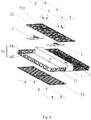
- two sides of the drone body 1 may be each provided with the protection housing 3, and the protection housings 3 at the two sides of the drone body 1 may be symmetrically arranged in the left and right direction with respect to the drone body 1, such as the drone with four rotary wings 2 as shown in Figures 2 to 4 .
- top surfaces of the two protection housings 3 at the two sides are flush with the top surface of the drone body 1, that is, the top surfaces of the two protection housings 3 and the top surface of the drone body 1 are located in the same plane.
- the bottom surfaces of the two protection housings 3 are flush with the bottom surface of the drone body 1, that is, the bottom surfaces of the two protection housings 3 and the bottom surface of the drone body 1 are located in the same plane.
- the whole drone is of a cuboid integral structure as shown in Figures 2 and 3 .
- This cuboid drone has a small thickness and easy to carry. More importantly, this structure allows the drone to subject to a small air resistance during flight, and thus the drone has a better flight ability.
- the rotary wing 2 may further include a rotary wing body 21 and several wing portions 22. Each of the wing portions 22 extends out from the rotary wing body 21.
- the rotary wing 2 shown in Figure 6 has two wing portions 22.
- the rotary wing body 21 may be in the form of a hollow casing, thus the motor 4 can be nested in the rotary wing body 21 and the rotary wing 2 and the motor 4 may form a nested structure.
- the space occupied by the motor 4 is saved to reduce the overall height of the drone; and in another aspect, the motor 4 and the rotary wing 2 form a nested integrated structure, thus it is not necessary to separately mount the motor 4, which improves the convenience in assembling and disassembling and eventually allows the drone according to the present application to have an ultra-thin structure.
- the motor 4 may be fixed at a top surface of the rotary wing body 21 by a connector such as a bolt or the like, or, the motor 4 may be hung in the rotary wing body 21.
- a connector such as a bolt or the like
- Other fixed connection manners may also be utilized to mount the motor 4, such as snap fitting or the like.
- the term “several” used herein refers to that the number is undetermined, and may be two or more than three, or may be one, and can be set as desired; terms such as “first”, “second” and the like used herein are merely intended to distinguish different components with the same or similar structures from each other, rather than define a particular order.
Applications Claiming Priority (3)
| Application Number | Priority Date | Filing Date | Title |
|---|---|---|---|
| US201562099512P | 2015-01-04 | 2015-01-04 | |
| CN201510547151.3A CN105329451B (zh) | 2015-01-04 | 2015-08-31 | 一种全保护无人机 |
| PCT/CN2015/099339 WO2016107529A1 (fr) | 2015-01-04 | 2015-12-29 | Véhicule aérien sans pilote entièrement protégé |
Publications (3)
| Publication Number | Publication Date |
|---|---|
| EP3241758A1 true EP3241758A1 (fr) | 2017-11-08 |
| EP3241758A4 EP3241758A4 (fr) | 2018-01-24 |
| EP3241758B1 EP3241758B1 (fr) | 2020-05-06 |
Family
ID=55033806
Family Applications (2)
| Application Number | Title | Priority Date | Filing Date |
|---|---|---|---|
| EP15875204.8A Active EP3241741B1 (fr) | 2015-01-04 | 2015-12-29 | Véhicule aérien sans pilote repliable |
| EP15875205.5A Active EP3241758B1 (fr) | 2015-01-04 | 2015-12-29 | Véhicule aérien sans pilote entièrement protégé |
Family Applications Before (1)
| Application Number | Title | Priority Date | Filing Date |
|---|---|---|---|
| EP15875204.8A Active EP3241741B1 (fr) | 2015-01-04 | 2015-12-29 | Véhicule aérien sans pilote repliable |
Country Status (6)
| Country | Link |
|---|---|
| US (2) | US10035589B2 (fr) |
| EP (2) | EP3241741B1 (fr) |
| JP (2) | JP6690083B2 (fr) |
| KR (2) | KR102243865B1 (fr) |
| CN (5) | CN105235891B (fr) |
| WO (2) | WO2016107528A1 (fr) |
Families Citing this family (123)
| Publication number | Priority date | Publication date | Assignee | Title |
|---|---|---|---|---|
| USD799374S1 (en) * | 2010-03-29 | 2017-10-10 | Dylan T X Zhou | Combined amphibious VTOL three way folding camera and phone drone |
| CN105235891B (zh) * | 2015-01-04 | 2020-02-14 | 北京零零无限科技有限公司 | 一种可折叠的无人机 |
| US9836053B2 (en) | 2015-01-04 | 2017-12-05 | Zero Zero Robotics Inc. | System and method for automated aerial system operation |
| US10358214B2 (en) | 2015-01-04 | 2019-07-23 | Hangzhou Zero Zro Technology Co., Ltd. | Aerial vehicle and method of operation |
| US10126745B2 (en) | 2015-01-04 | 2018-11-13 | Hangzhou Zero Zero Technology Co., Ltd. | System and method for automated aerial system operation |
| US10719080B2 (en) | 2015-01-04 | 2020-07-21 | Hangzhou Zero Zero Technology Co., Ltd. | Aerial system and detachable housing |
| WO2016112124A2 (fr) * | 2015-01-08 | 2016-07-14 | Vantage Robotics, Llc | Véhicule aérien sans pilote à protection d'hélice et capacité de survie aux impacts élevée |
| CN205989812U (zh) * | 2015-06-25 | 2017-03-01 | 瑞德利斯技术公司 | 多旋翼无人机 |
| EP4001111A3 (fr) * | 2015-11-10 | 2022-08-17 | Matternet, Inc. | Procédé et système de transport utilisant des véhicules aériens sans pilote |
| USD809969S1 (en) * | 2015-12-28 | 2018-02-13 | Beijing Zero Zero Infinity Technology Co., Ltd | Drone |
| EP3398021A4 (fr) * | 2015-12-29 | 2019-09-04 | Hangzhou Zero Zero Technology Co., Ltd. | Système et procédé d'actionnement de système d'antenne automatique |
| CN205345315U (zh) * | 2016-01-14 | 2016-06-29 | 骅星科技发展有限公司 | 新型折叠无人机 |
| EP3971084A1 (fr) | 2016-02-22 | 2022-03-23 | SZ DJI Technology Co., Ltd. | Foldable multi-rotor aerial vehicle |
| CN105667777B (zh) * | 2016-03-29 | 2018-06-22 | 普宙飞行器科技(深圳)有限公司 | 四向伸缩桨叶保护罩、动力系统以及无人飞行器 |
| CN105836120B (zh) * | 2016-03-29 | 2018-06-29 | 普宙飞行器科技(深圳)有限公司 | 两向伸缩桨叶保护罩、动力系统以及无人飞行器 |
| CN106005361B (zh) * | 2016-04-07 | 2019-06-28 | 珠海市磐石电子科技有限公司 | 航空动力单元及其飞行机架和模块化飞行器 |
| US10252795B2 (en) | 2016-04-08 | 2019-04-09 | Ecole Polytechnique Federale De Lausanne (Epfl) | Foldable aircraft with protective cage for transportation and transportability |
| WO2017187275A2 (fr) | 2016-04-24 | 2017-11-02 | Hangzhou Zero Zero Technology Co., Ltd. | Ensemble de propulsion de système aérien, et procédé d'utilisation |
| CN105947201A (zh) * | 2016-04-27 | 2016-09-21 | 乐视控股(北京)有限公司 | 一种模块化无人机及其使用方法 |
| CN105947202A (zh) * | 2016-04-28 | 2016-09-21 | 乐视控股(北京)有限公司 | 一种可折叠的无人机及其使用方法 |
| WO2017197602A1 (fr) * | 2016-05-18 | 2017-11-23 | 深圳市创客工场科技有限公司 | Aéronef à rotors multiples |
| US10974809B2 (en) | 2016-06-23 | 2021-04-13 | Sierra Nevada Corporation | Air-launched unmanned aerial vehicle |
| CN107539457B (zh) * | 2016-06-28 | 2019-11-08 | 比亚迪股份有限公司 | 无人机 |
| CN109476372A (zh) | 2016-07-12 | 2019-03-15 | 深圳市大疆创新科技有限公司 | 用于多取向飞行的系统和方法 |
| CN106005387B (zh) * | 2016-07-20 | 2018-01-05 | 朱明甫 | 一种可垂直起降式除雾霾飞行器 |
| CN206155797U (zh) * | 2016-07-27 | 2017-05-10 | 深圳亿天航科技有限公司 | 具有支撑机构的药箱及植保无人机 |
| CN106184756B (zh) * | 2016-08-18 | 2019-06-28 | 国网浙江省电力公司衢州供电公司 | 一种仿生电鳐可分离式无人机 |
| CN106094857A (zh) * | 2016-08-22 | 2016-11-09 | 京东方科技集团股份有限公司 | 无人机、穿戴设备及无人机的飞行控制方法、装置 |
| USD811264S1 (en) * | 2016-09-12 | 2018-02-27 | Hangzhou Zero Zero Technology Co., Ltd. | Unmanned aerial vehicle |
| IL247772B (en) | 2016-09-12 | 2022-05-01 | Israel Aerospace Ind Ltd | Model car system |
| CN106364660B (zh) * | 2016-10-09 | 2019-12-13 | 南昌航空大学 | 一种旋开式四旋翼飞行器 |
| WO2018087596A1 (fr) * | 2016-11-11 | 2018-05-17 | Hangzhou Zero Zero Technology Co., Ltd. | Système et procédé de commande de système aérien automatisé |
| WO2018107434A1 (fr) * | 2016-12-15 | 2018-06-21 | 深圳市大疆创新科技有限公司 | Couvercle de protection d'hélice et véhicule aérien sans pilote |
| CN106394868A (zh) * | 2016-12-22 | 2017-02-15 | 湖南文理学院 | 一种折叠式无人机机翼 |
| JP6855673B2 (ja) * | 2016-12-26 | 2021-04-07 | エスゼット ディージェイアイ テクノロジー カンパニー リミテッドSz Dji Technology Co.,Ltd | 変形可能装置 |
| CN114212249A (zh) | 2016-12-27 | 2022-03-22 | 深圳市大疆创新科技有限公司 | 多旋翼无人机 |
| WO2018120163A1 (fr) * | 2016-12-30 | 2018-07-05 | 深圳市大疆创新科技有限公司 | Aéronef à rotors multiples et procédé de déploiement et/ou de pliage de couvercle de protection d'hélice correspondant |
| US10067513B2 (en) | 2017-01-23 | 2018-09-04 | Hangzhou Zero Zero Technology Co., Ltd | Multi-camera system and method of use |
| WO2018152792A1 (fr) * | 2017-02-24 | 2018-08-30 | 深圳市大疆创新科技有限公司 | Cadre pliable, ensemble cadre et véhicule aérien sans pilote |
| CN107010198A (zh) * | 2017-04-15 | 2017-08-04 | 上海量明科技发展有限公司 | 可折叠摄像无人机及其实现方法 |
| US10600295B2 (en) * | 2017-05-05 | 2020-03-24 | Tg-17, Inc. | System and method for threat monitoring, detection, and response |
| WO2018201417A1 (fr) * | 2017-05-05 | 2018-11-08 | 深圳市大疆创新科技有限公司 | Aéronef déformable, plate-forme mobile et son procédé de fonctionnement |
| USD869334S1 (en) * | 2017-05-10 | 2019-12-10 | Airselfie Holdings Limited | Flying camera drone |
| CN107161323B (zh) * | 2017-05-19 | 2019-07-19 | 刘勇 | 一种可变翼四轴飞机 |
| US11016483B2 (en) | 2017-06-13 | 2021-05-25 | MerchSource, LLC | Drone with training mode |
| CN107215460A (zh) * | 2017-07-17 | 2017-09-29 | 西南交通大学 | 一种无人飞行器机架的旋翼及模块化的多旋翼机架 |
| USD843890S1 (en) * | 2017-08-23 | 2019-03-26 | Hunan Keyshare Information Technology Co., LTD | Unmanned aerial vehicle |
| US9957045B1 (en) * | 2017-09-03 | 2018-05-01 | Brehnden Daly | Stackable drones |
| FR3070607B1 (fr) * | 2017-09-07 | 2020-09-04 | Parrot Drones | Drone a voilure tournante comprenant une structure de drone pliable |
| USD858352S1 (en) * | 2017-10-30 | 2019-09-03 | Shenzhen Valuelink E-Commerce Co., Ltd. | Drone |
| US20200262550A1 (en) * | 2017-11-04 | 2020-08-20 | Viritose Corp. | Encapsulated Drone |
| CN107953990A (zh) * | 2017-12-25 | 2018-04-24 | 卫旭阳 | 垂直起降飞行装置及固定翼无人机 |
| GB2570294A (en) * | 2018-01-15 | 2019-07-24 | Ap Moeller Maersk As | Cylinder liner inspection |
| US10766610B2 (en) | 2018-01-22 | 2020-09-08 | Mattel, Inc. | Unmanned aerial vehicle with propeller guard |
| CN108313259A (zh) * | 2018-02-13 | 2018-07-24 | 深圳臻迪信息技术有限公司 | 一种无人机 |
| USD906170S1 (en) * | 2018-02-13 | 2020-12-29 | Skydio, Inc. | Unmanned aerial vehicle |
| CN108216629A (zh) * | 2018-02-26 | 2018-06-29 | 西北工业大学 | 一种组合式运输无人机 |
| US10351261B1 (en) * | 2018-03-05 | 2019-07-16 | Carolyn Bryant | Autonomous drone based package reception and surveillance system |
| US11794888B1 (en) * | 2018-05-18 | 2023-10-24 | Taylor & Lego Holdings, Llc. | Unmanned aerial vehicle |
| CN108773486A (zh) * | 2018-05-31 | 2018-11-09 | 江苏常探机器人有限公司 | 一种带涵道风扇复合辅翼的无后推力式复合翼飞行器 |
| CN108657423A (zh) * | 2018-05-31 | 2018-10-16 | 江苏常探机器人有限公司 | 具有垂直起降功能的舰载可折叠式双磁异探测反潜机 |
| CN108502163A (zh) * | 2018-05-31 | 2018-09-07 | 江苏常探机器人有限公司 | 带无推复合辅翼的后单涵道风扇式复合翼飞行器 |
| CN108502166A (zh) * | 2018-05-31 | 2018-09-07 | 江苏常探机器人有限公司 | 一种带涡扇推复合辅翼的无后推力式复合翼飞行器 |
| CN108528706A (zh) * | 2018-05-31 | 2018-09-14 | 江苏常探机器人有限公司 | 带太阳能附加翼的双螺旋桨复合辅翼的复合翼货运飞机 |
| CN108773484A (zh) * | 2018-05-31 | 2018-11-09 | 江苏常探机器人有限公司 | 后单涵道风扇式复合翼货运飞行器 |
| CN108545184A (zh) * | 2018-05-31 | 2018-09-18 | 江苏常探机器人有限公司 | 带太阳能附加翼的后单涵道风扇式复合翼飞行器 |
| CN108791863A (zh) * | 2018-05-31 | 2018-11-13 | 江苏常探机器人有限公司 | 带涵道风扇复合辅翼的无后推力式复合翼飞行器 |
| CN108502162A (zh) * | 2018-05-31 | 2018-09-07 | 江苏常探机器人有限公司 | 带涵道风扇复合辅翼和附加翼的无后推力式复合翼飞行器 |
| CN108791870A (zh) * | 2018-05-31 | 2018-11-13 | 江苏常探机器人有限公司 | 双涵推复合辅翼和附加翼的后单涵推式复合翼货运飞行器 |
| CN108791813A (zh) * | 2018-05-31 | 2018-11-13 | 江苏常探机器人有限公司 | 带太阳能附加翼的后单涡喷式复合翼货运飞行器 |
| CN108773483A (zh) * | 2018-05-31 | 2018-11-09 | 江苏常探机器人有限公司 | 后单涡喷式复合翼货运飞行器 |
| CN108454844A (zh) * | 2018-05-31 | 2018-08-28 | 江苏常探机器人有限公司 | 带太阳能附加翼的双螺旋桨推力复合辅翼的复合翼飞机 |
| CN108791864A (zh) * | 2018-05-31 | 2018-11-13 | 江苏常探机器人有限公司 | 带太阳能附加翼的后单涡喷式复合翼式飞行器 |
| CN108454845A (zh) * | 2018-05-31 | 2018-08-28 | 江苏常探机器人有限公司 | 带太阳能附加翼的双螺旋桨复合辅翼的复合翼载人飞机 |
| CN108502165A (zh) * | 2018-05-31 | 2018-09-07 | 江苏常探机器人有限公司 | 一种带复合型辅翼和附加翼的后单螺旋桨式复合翼飞行器 |
| CN108545183A (zh) * | 2018-05-31 | 2018-09-18 | 江苏常探机器人有限公司 | 带太阳能附加翼的后单涵道风扇式复合翼货运飞行器 |
| CN108839798A (zh) * | 2018-05-31 | 2018-11-20 | 江苏常探机器人有限公司 | 带涵道风扇复合辅翼和附加翼的无后推力式复合翼飞行器 |
| CN108657425A (zh) * | 2018-05-31 | 2018-10-16 | 江苏常探机器人有限公司 | 一种带拓展平台的复合升力飞行器 |
| CN108791804A (zh) * | 2018-05-31 | 2018-11-13 | 江苏常探机器人有限公司 | 一种带拓展平台的可折叠式复合升力飞行器 |
| CN108750087A (zh) * | 2018-05-31 | 2018-11-06 | 江苏常探机器人有限公司 | 一种带附加翼的螺推复合翼货运飞机 |
| CN108528701A (zh) * | 2018-05-31 | 2018-09-14 | 江苏常探机器人有限公司 | 一种带双涵道复合辅翼和附加翼的后单桨式复合翼飞机 |
| CN108750094A (zh) * | 2018-05-31 | 2018-11-06 | 江苏常探机器人有限公司 | 一种带附加翼的螺推复合翼飞机 |
| CN108674646A (zh) * | 2018-05-31 | 2018-10-19 | 江苏常探机器人有限公司 | 带无推复合辅翼的后单涵道风扇式复合翼货运飞行器 |
| CN108945415A (zh) * | 2018-05-31 | 2018-12-07 | 江苏常探机器人有限公司 | 带涡扇复合辅翼和附加翼的无后推力式复合翼货运飞行器 |
| CN108466693A (zh) * | 2018-05-31 | 2018-08-31 | 江苏常探机器人有限公司 | 带复合辅翼和附加翼的后单涵道风扇式复合翼货运飞机 |
| CN108639329A (zh) * | 2018-05-31 | 2018-10-12 | 江苏常探机器人有限公司 | 一种带双螺旋桨辅翼和附翼的螺推复合翼飞机 |
| CN108860591A (zh) * | 2018-05-31 | 2018-11-23 | 江苏常探机器人有限公司 | 带涡扇推复合辅翼的无后推力式复合翼货运飞行器 |
| CN108466692A (zh) * | 2018-05-31 | 2018-08-31 | 江苏常探机器人有限公司 | 带复合辅翼和附加翼的后单涵道风扇式复合翼载人飞机 |
| CN108622401A (zh) * | 2018-05-31 | 2018-10-09 | 江苏常探机器人有限公司 | 一种双螺旋桨推力复合辅翼的可折叠式复合翼飞行器 |
| CN108791865A (zh) * | 2018-05-31 | 2018-11-13 | 江苏常探机器人有限公司 | 后单涡喷式可折叠复合翼飞行器 |
| US11167836B2 (en) | 2018-06-21 | 2021-11-09 | Sierra Nevada Corporation | Devices and methods to attach composite core to a surrounding structure |
| CN108639336A (zh) * | 2018-06-29 | 2018-10-12 | 江苏常探机器人有限公司 | 一种模块化舰载可折叠超机动垂直起降可变功率预警机 |
| CN112533825A (zh) * | 2018-08-24 | 2021-03-19 | 杭州零零科技有限公司 | 用于无人空中系统的可拆卸保护结构 |
| USD865637S1 (en) * | 2018-09-06 | 2019-11-05 | AEE Aviation Technology Company | Aircraft with camera |
| CN109353487B (zh) * | 2018-10-17 | 2023-08-29 | 蔡强 | 一种机翼旋转折叠的无人机 |
| CN110001944B (zh) * | 2019-03-22 | 2024-01-05 | 深圳先进技术研究院 | 一种大型无人机 |
| US11724804B2 (en) * | 2019-04-11 | 2023-08-15 | Textron Innovations Inc. | Aircraft coupling mechanism |
| USD925399S1 (en) * | 2019-04-17 | 2021-07-20 | Shenzhen Aee Aviation Technology Co., Ltd. | Pocket drone |
| CN110154661A (zh) * | 2019-06-28 | 2019-08-23 | 龙奎 | 一种折叠旋翼的飞行汽车 |
| US11613343B1 (en) | 2019-07-12 | 2023-03-28 | Piasecki Aircraft Corporation | Unmanned flying wing aircraft having foldable and stackable wings |
| US11597515B2 (en) * | 2019-08-19 | 2023-03-07 | Epazz, Inc. | Charging/re-charging drone assembly system and apparatus |
| LT2019073A (lt) * | 2019-09-18 | 2021-03-25 | Uab "Sg Consulting Baltics & By" | Sulankstomas dronas |
| WO2021061810A1 (fr) * | 2019-09-26 | 2021-04-01 | Amazon Technologies, Inc. | Dispositifs autonomes de sécurité à domicile |
| US11097839B2 (en) * | 2019-10-09 | 2021-08-24 | Kitty Hawk Corporation | Hybrid power systems for different modes of flight |
| CN110861454B (zh) * | 2019-11-29 | 2020-12-25 | 吉林大学 | 一种可重构空潜两栖机器人 |
| US20210269174A1 (en) * | 2020-02-27 | 2021-09-02 | Greg Douglas Shuff | Drone docking port and method of use |
| USD943457S1 (en) * | 2020-03-16 | 2022-02-15 | Zero Zero Robotics Inc. | Unmanned aerial vehicle |
| USD944117S1 (en) * | 2020-03-16 | 2022-02-22 | Zero Zero Robotics Inc. | Unmanned aerial vehicle |
| USD938860S1 (en) * | 2020-05-22 | 2021-12-21 | Liying Bao | Unmanned aerial vehicle |
| JP1672470S (fr) * | 2020-06-26 | 2020-11-16 | ||
| USD985425S1 (en) * | 2020-07-24 | 2023-05-09 | Sang Hyun Lee | Drone |
| CA3202192A1 (fr) * | 2020-09-03 | 2022-03-31 | Michael Dornisch | Ensemble cellule et moteur pour aeronef sans pilote |
| JP1701070S (fr) * | 2020-12-11 | 2021-11-29 | ||
| CN114502462A (zh) * | 2020-12-28 | 2022-05-13 | 深圳市大疆创新科技有限公司 | 无人机 |
| RU204990U1 (ru) * | 2021-03-26 | 2021-06-22 | Федеральное государственное бюджетное образовательное учреждение высшего образования "Казанский национальный исследовательский технический университет им. А.Н. Туполева - КАИ" | Дрон-трансформер |
| KR102572063B1 (ko) * | 2021-04-13 | 2023-08-30 | 주식회사 유니텍코리아 | 외곽체부를 구비한 비행체 |
| CN113859569A (zh) * | 2021-10-25 | 2021-12-31 | 成都飞机工业(集团)有限责任公司 | 一种便携式蜂群无人机系统及其使用方法 |
| CN216805836U (zh) * | 2021-11-22 | 2022-06-24 | 上海峰飞航空科技有限公司 | 组合式垂起无人机 |
| USD994537S1 (en) * | 2022-03-10 | 2023-08-08 | MerchSource, LLC | Remote control flying vehicle |
| USD1015253S1 (en) * | 2022-04-15 | 2024-02-20 | Valcon Labs, Inc. | Vertical take-off and landing air vehicle |
| KR102574739B1 (ko) * | 2022-06-20 | 2023-09-07 | 라온구조안전기술(주) | 드론을 이용한 비파괴 강도측정장치 |
| KR102608605B1 (ko) | 2023-04-28 | 2023-11-30 | 이상묵 | 날개 접이식 드론 |
| KR102605131B1 (ko) | 2023-04-28 | 2023-11-23 | 이상묵 | 수송용 드론 |
Family Cites Families (77)
| Publication number | Priority date | Publication date | Assignee | Title |
|---|---|---|---|---|
| CH333967A (de) * | 1954-06-05 | 1958-11-15 | Hausser O & M | Flugspielzeug |
| US4043421A (en) * | 1975-11-12 | 1977-08-23 | Smith Lonnell E | Air car |
| US5419514A (en) * | 1993-11-15 | 1995-05-30 | Duncan; Terry A. | VTOL aircraft control method |
| US5672086A (en) * | 1994-11-23 | 1997-09-30 | Dixon; Don | Aircraft having improved auto rotation and method for remotely controlling same |
| US5890441A (en) * | 1995-09-07 | 1999-04-06 | Swinson Johnny | Horizontal and vertical take off and landing unmanned aerial vehicle |
| US6260796B1 (en) * | 1997-03-04 | 2001-07-17 | Wallace Neil Klingensmith | Multi-thrustered hover craft |
| FR2769586B1 (fr) * | 1997-10-01 | 1999-11-19 | Pierre Hardoin | Hydropal - terrestre aerien hp 02 |
| DE19745492B4 (de) * | 1997-10-15 | 2005-06-09 | Wobben, Aloys, Dipl.-Ing. | Senkrecht startendes Flugzeug |
| US7490572B2 (en) * | 1999-05-28 | 2009-02-17 | Grober David E | Autonomous, self leveling, self correcting anti-motion sickness chair, bed and table |
| GB2365392B (en) * | 2000-03-22 | 2002-07-10 | David Bernard Cassidy | Aircraft |
| US6840480B2 (en) * | 2001-09-27 | 2005-01-11 | Ernest A. Carroll | Miniature, unmanned aircraft with interchangeable data module |
| US6824095B2 (en) * | 2001-11-29 | 2004-11-30 | Youbin Mao | VSTOL vehicle |
| US20030192989A1 (en) * | 2002-04-10 | 2003-10-16 | Frank Owen | Security bulkhead and door construction |
| RU2227107C2 (ru) * | 2002-04-16 | 2004-04-20 | ООО "Мидера-К" | Способ создания подъемной силы и горизонтальной тяги аэродинамическими поверхностями |
| AUPS330502A0 (en) * | 2002-06-28 | 2002-07-25 | Kusic, Tom | Tandem powered power tilting aircraft - june 2002 |
| US6843447B2 (en) * | 2003-01-06 | 2005-01-18 | Brian H. Morgan | Vertical take-off and landing aircraft |
| US6745977B1 (en) * | 2003-08-21 | 2004-06-08 | Larry D. Long | Flying car |
| US6773321B1 (en) * | 2003-12-09 | 2004-08-10 | Raul Urquiaga | Remote control convertible toy vehicle assembly |
| US7540450B2 (en) * | 2004-07-16 | 2009-06-02 | Pratt & Whitney Canada Corp. | Aircraft propulsion system |
| EP1831073A2 (fr) * | 2004-12-22 | 2007-09-12 | Aurora Flight Sciences Corporation | Systeme et procede d'utilisation d'energie electrique stockee pour des avions a decollage et atterrissage verticaux a des fins d'amelioration de la poussee et de commande d'attitude |
| DE102004063205B3 (de) * | 2004-12-23 | 2006-05-04 | Julian Kuntz | Fluggerät mit verbesserter Beweglichkeit am Boden |
| US7159817B2 (en) * | 2005-01-13 | 2007-01-09 | Vandermey Timothy | Vertical take-off and landing (VTOL) aircraft with distributed thrust and control |
| US7267300B2 (en) * | 2005-02-25 | 2007-09-11 | The Boeing Company | Aircraft capable of vertical and short take-off and landing |
| KR100668234B1 (ko) * | 2005-04-20 | 2007-01-12 | 오원섭 | 수직이착륙기 |
| US7334755B2 (en) * | 2005-05-25 | 2008-02-26 | The Boeing Company | Tandem rotor wing and tandem fixed wing aircraft |
| US20080054121A1 (en) * | 2006-05-11 | 2008-03-06 | Urban Aeronautics Ltd. | Ducted fan VTOL vehicles |
| JP5309037B2 (ja) * | 2007-01-18 | 2013-10-09 | アールトン,ポール,イー. | 回転翼航空機 |
| US8453962B2 (en) * | 2007-02-16 | 2013-06-04 | Donald Orval Shaw | Modular flying vehicle |
| WO2009054937A2 (fr) * | 2007-10-18 | 2009-04-30 | Kevin Patrick Gordon | Plate-forme industrielle pour hélicoptère électrique/moteur à distance |
| DE102008014853B4 (de) * | 2008-03-18 | 2010-11-18 | Ascending Technologies Gmbh | Drehflügelfluggerät |
| US20110226174A1 (en) * | 2008-06-16 | 2011-09-22 | Aurora Flight Sciences Corporation | Combined submersible vessel and unmanned aerial vehicle |
| US8052081B2 (en) * | 2008-08-22 | 2011-11-08 | Draganfly Innovations Inc. | Dual rotor helicopter with tilted rotational axes |
| US8146855B2 (en) * | 2008-09-03 | 2012-04-03 | Anvar Ismailov | Unmanned air vehicle |
| DE102009001759B4 (de) * | 2009-03-23 | 2013-02-21 | Gregor Schnoell | Verriegelungssystem |
| US8473123B2 (en) * | 2010-02-18 | 2013-06-25 | Massachusetts Institute Of Technology | Programmable surface |
| US20140061376A1 (en) * | 2010-05-26 | 2014-03-06 | Aerovironment Inc | Reconfigurable battery-operated vehicle system |
| US8774982B2 (en) * | 2010-08-26 | 2014-07-08 | Leptron Industrial Robotic Helicopters, Inc. | Helicopter with multi-rotors and wireless capability |
| CN201793018U (zh) * | 2010-09-16 | 2011-04-13 | 中国计量学院 | 一种机身可伸缩的四旋翼飞行器 |
| CN101973390B (zh) * | 2010-09-25 | 2013-05-22 | 中国航天科工集团第二研究院二一〇所 | 飞行器可折叠双翼板展开机构 |
| BR112013007255B1 (pt) * | 2010-11-12 | 2021-01-19 | Sky Sapience | sistema |
| GB2490141B (en) * | 2011-04-19 | 2015-02-11 | Blue Bear Systems Res Ltd | Air Vehicle |
| US8876039B2 (en) * | 2011-05-03 | 2014-11-04 | Stark Aerospace, Inc. | Folding wing for aircraft |
| KR20120136797A (ko) * | 2011-06-10 | 2012-12-20 | 드림스페이스월드주식회사 | 무인 비행체 보호커버 |
| CN202414160U (zh) * | 2011-11-15 | 2012-09-05 | 成都飞机设计研究所 | 垂直起降变体飞行器 |
| US20130134254A1 (en) * | 2011-11-29 | 2013-05-30 | Jason Moore | UAV Fire-fighting System |
| US8946607B2 (en) * | 2011-12-13 | 2015-02-03 | The Boeing Company | Mechanisms for deploying and actuating airfoil-shaped bodies on unmanned aerial vehicles |
| CN202609080U (zh) * | 2012-03-22 | 2012-12-19 | 杨育会 | 具有伞降装置的无人旋翼飞行器 |
| CN202828091U (zh) * | 2012-07-12 | 2013-03-27 | 深圳一电科技有限公司 | 无人机及其旋翼保护装置 |
| CA2787279C (fr) * | 2012-08-29 | 2013-10-22 | Draganfly Holdings Inc. | Vehicule a mobilite aerienne et terrestre |
| US9527588B1 (en) * | 2012-09-28 | 2016-12-27 | Scott B. Rollefstad | Unmanned aircraft system (UAS) with active energy harvesting and power management |
| CN202935577U (zh) * | 2012-10-23 | 2013-05-15 | 宁波市鄞州发辉机械科技有限公司 | 一种旋翼护框架装置 |
| CN103921933A (zh) * | 2013-01-10 | 2014-07-16 | 深圳市大疆创新科技有限公司 | 飞行器变形结构及微型飞行器 |
| US9540105B2 (en) * | 2013-03-04 | 2017-01-10 | Michael Beaugavin Markov | Aerial material distribution apparatus |
| JP2014212479A (ja) * | 2013-04-19 | 2014-11-13 | ソニー株式会社 | 制御装置、制御方法及びコンピュータプログラム |
| CN103332291B (zh) * | 2013-06-14 | 2015-11-18 | 南京航空航天大学 | 一种空投六旋翼无人机折叠与展开机构 |
| CN103419942B (zh) * | 2013-09-10 | 2015-08-05 | 北京臻迪科技有限公司 | 一种无人飞行器 |
| CN203461110U (zh) * | 2013-09-10 | 2014-03-05 | 姜学海 | 异形折叠三点降落式多轴无人飞行器 |
| CN203544368U (zh) * | 2013-11-06 | 2014-04-16 | 中国民航大学 | 多旋翼无人机保护装置 |
| FR3012968B1 (fr) * | 2013-11-13 | 2016-01-08 | Parrot | Drone a voilure tournante avec helices a entrainement direct et montage rapide |
| JP5837032B2 (ja) * | 2013-12-27 | 2015-12-24 | 株式会社原子力エンジニアリング | 地上走行可能な飛行体 |
| WO2014080386A2 (fr) * | 2014-03-25 | 2014-05-30 | Alshdaifat, Wasfi | Aéro-porteuse pour service de drones |
| US9004396B1 (en) * | 2014-04-24 | 2015-04-14 | Fatdoor, Inc. | Skyteboard quadcopter and method |
| US9573683B2 (en) * | 2014-04-28 | 2017-02-21 | Arch-Aerial, Llc | Collapsible multi-rotor UAV |
| CN203829646U (zh) * | 2014-05-05 | 2014-09-17 | 林援雄 | 一种带有防护罩的多轴飞行器 |
| CN103979107B (zh) * | 2014-05-21 | 2016-01-20 | 北京理工大学 | 一种折叠式旋翼型无人机 |
| WO2015200209A1 (fr) * | 2014-06-23 | 2015-12-30 | Nixie Labs, Inc. | Véhicules aériens sans pilote portatifs, véhicules aériens sans pilote à lancement commandé, et systèmes et procédés associés |
| NL2013252B1 (en) * | 2014-07-24 | 2016-09-09 | Atmos Uav B V | Aircraft with wing-borne flight mode and hover flight mode. |
| CN204056294U (zh) * | 2014-09-12 | 2014-12-31 | 西北工业大学明德学院 | 一种折叠式四轴多旋翼飞行器 |
| KR20160041697A (ko) * | 2014-10-08 | 2016-04-18 | 한화테크윈 주식회사 | 무인 비행체 |
| CN104443411A (zh) * | 2014-10-27 | 2015-03-25 | 成都好飞机器人科技有限公司 | 具有防撞保护装置的四旋翼无人机 |
| US9550567B1 (en) * | 2014-10-27 | 2017-01-24 | Amazon Technologies, Inc. | In-flight reconfigurable hybrid unmanned aerial vehicle |
| CA2911998A1 (fr) * | 2014-11-26 | 2016-05-26 | Gilles Daigle | Vehicule aerien sans pilote |
| CN105235891B (zh) * | 2015-01-04 | 2020-02-14 | 北京零零无限科技有限公司 | 一种可折叠的无人机 |
| CN204502398U (zh) * | 2015-03-18 | 2015-07-29 | 杜文龙 | 安全飞行器 |
| KR101778851B1 (ko) * | 2015-09-11 | 2017-09-14 | 엘지전자 주식회사 | 비행체 및 비행체의 전원제어장치 |
| WO2017136776A1 (fr) * | 2016-02-05 | 2017-08-10 | Vantage Robotics, Llc | Véhicule aérien sans pilote modulaire durable |
| US10252795B2 (en) * | 2016-04-08 | 2019-04-09 | Ecole Polytechnique Federale De Lausanne (Epfl) | Foldable aircraft with protective cage for transportation and transportability |
-
2015
- 2015-08-04 CN CN201510472369.7A patent/CN105235891B/zh active Active
- 2015-08-04 CN CN201520580644.2U patent/CN204998752U/zh active Active
- 2015-08-31 CN CN201510547151.3A patent/CN105329451B/zh active Active
- 2015-08-31 CN CN201810041982.7A patent/CN108216658A/zh active Pending
- 2015-08-31 CN CN201520667976.4U patent/CN205113731U/zh active Active
- 2015-12-29 KR KR1020177020953A patent/KR102243865B1/ko active IP Right Grant
- 2015-12-29 EP EP15875204.8A patent/EP3241741B1/fr active Active
- 2015-12-29 US US15/035,934 patent/US10035589B2/en active Active
- 2015-12-29 JP JP2017553297A patent/JP6690083B2/ja active Active
- 2015-12-29 WO PCT/CN2015/099327 patent/WO2016107528A1/fr active Application Filing
- 2015-12-29 JP JP2017553296A patent/JP6690096B2/ja active Active
- 2015-12-29 KR KR1020177020826A patent/KR102328509B1/ko active IP Right Grant
- 2015-12-29 US US15/117,829 patent/US20160368596A1/en not_active Abandoned
- 2015-12-29 EP EP15875205.5A patent/EP3241758B1/fr active Active
- 2015-12-29 WO PCT/CN2015/099339 patent/WO2016107529A1/fr active Application Filing
Also Published As
| Publication number | Publication date |
|---|---|
| EP3241741A4 (fr) | 2018-01-24 |
| EP3241741B1 (fr) | 2020-12-30 |
| JP2018501154A (ja) | 2018-01-18 |
| CN105235891B (zh) | 2020-02-14 |
| JP2018501153A (ja) | 2018-01-18 |
| CN105329451A (zh) | 2016-02-17 |
| CN204998752U (zh) | 2016-01-27 |
| WO2016107529A1 (fr) | 2016-07-07 |
| CN108216658A (zh) | 2018-06-29 |
| EP3241758B1 (fr) | 2020-05-06 |
| US10035589B2 (en) | 2018-07-31 |
| CN105329451B (zh) | 2018-02-27 |
| KR102328509B1 (ko) | 2021-11-17 |
| US20160368596A1 (en) | 2016-12-22 |
| EP3241741A1 (fr) | 2017-11-08 |
| CN105235891A (zh) | 2016-01-13 |
| JP6690096B2 (ja) | 2020-04-28 |
| CN205113731U (zh) | 2016-03-30 |
| EP3241758A4 (fr) | 2018-01-24 |
| US20160340021A1 (en) | 2016-11-24 |
| KR102243865B1 (ko) | 2021-04-23 |
| JP6690083B2 (ja) | 2020-04-28 |
| KR20170102503A (ko) | 2017-09-11 |
| KR20170101958A (ko) | 2017-09-06 |
| WO2016107528A1 (fr) | 2016-07-07 |
Similar Documents
| Publication | Publication Date | Title |
|---|---|---|
| EP3241758A1 (fr) | Véhicule aérien sans pilote entièrement protégé | |
| US10358214B2 (en) | Aerial vehicle and method of operation | |
| CN106218873B (zh) | 一种无人机防坠毁保护结构 | |
| EP2772429A1 (fr) | Aéronef à quatre rotors | |
| US20230202680A1 (en) | Versatile Hybrid Drone and Nest System | |
| CN206446791U (zh) | 一种多旋翼警用无人机 | |
| CN104787321A (zh) | 旋翼臂可替换型便携式四旋翼飞行器 | |
| CN109018410A (zh) | 一种无人机用充电装置 | |
| CN216332732U (zh) | 一种无人机可伸缩全面保护装置 | |
| CN205098485U (zh) | 一种可折叠模块化无人机保护结构 | |
| CN208181404U (zh) | 起落架结构及无人机 | |
| CN214776618U (zh) | 照明无人机 | |
| CN211308964U (zh) | 一种用于航拍跟踪的警用无人机 | |
| CN218806589U (zh) | 一种无人机飞行防撞装置 | |
| CN208647162U (zh) | 一种无人机用机载天线 | |
| CN214875527U (zh) | 一种适于将尾翼连接于机身的结构 | |
| CN112644696A (zh) | 一种折叠式农业无人机挂载装置 | |
| CN216232966U (zh) | 一种防碰撞工程检测无人机 | |
| CN210162252U (zh) | 一种具有机翼保护功能的无人机 | |
| CN213620206U (zh) | 一种旋接式无人机机翼躯干 | |
| CN216468477U (zh) | 一种具有驱鸟防护功能的电力巡检无人机 | |
| CN205891206U (zh) | 一种飞碟式无人机 | |
| CN112109917A (zh) | 一种安全型无人机机翼躯干 | |
| CN211731784U (zh) | 一种折叠式旋翼无人机 | |
| CN218731515U (zh) | 一种无人机电池设备 |
Legal Events
| Date | Code | Title | Description |
|---|---|---|---|
| STAA | Information on the status of an ep patent application or granted ep patent |
Free format text: STATUS: THE INTERNATIONAL PUBLICATION HAS BEEN MADE |
|
| PUAI | Public reference made under article 153(3) epc to a published international application that has entered the european phase |
Free format text: ORIGINAL CODE: 0009012 |
|
| STAA | Information on the status of an ep patent application or granted ep patent |
Free format text: STATUS: REQUEST FOR EXAMINATION WAS MADE |
|
| 17P | Request for examination filed |
Effective date: 20170719 |
|
| AK | Designated contracting states |
Kind code of ref document: A1 Designated state(s): AL AT BE BG CH CY CZ DE DK EE ES FI FR GB GR HR HU IE IS IT LI LT LU LV MC MK MT NL NO PL PT RO RS SE SI SK SM TR |
|
| AX | Request for extension of the european patent |
Extension state: BA ME |
|
| A4 | Supplementary search report drawn up and despatched |
Effective date: 20171222 |
|
| RIC1 | Information provided on ipc code assigned before grant |
Ipc: B64C 39/02 20060101AFI20171218BHEP |
|
| DAV | Request for validation of the european patent (deleted) | ||
| DAX | Request for extension of the european patent (deleted) | ||
| REG | Reference to a national code |
Ref country code: DE Ref legal event code: R079 Ref document number: 602015052547 Country of ref document: DE Free format text: PREVIOUS MAIN CLASS: B64D0045000000 Ipc: B64C0039020000 |
|
| GRAP | Despatch of communication of intention to grant a patent |
Free format text: ORIGINAL CODE: EPIDOSNIGR1 |
|
| STAA | Information on the status of an ep patent application or granted ep patent |
Free format text: STATUS: GRANT OF PATENT IS INTENDED |
|
| RIC1 | Information provided on ipc code assigned before grant |
Ipc: B64C 39/02 20060101AFI20200107BHEP |
|
| INTG | Intention to grant announced |
Effective date: 20200130 |
|
| GRAS | Grant fee paid |
Free format text: ORIGINAL CODE: EPIDOSNIGR3 |
|
| GRAA | (expected) grant |
Free format text: ORIGINAL CODE: 0009210 |
|
| STAA | Information on the status of an ep patent application or granted ep patent |
Free format text: STATUS: THE PATENT HAS BEEN GRANTED |
|
| AK | Designated contracting states |
Kind code of ref document: B1 Designated state(s): AL AT BE BG CH CY CZ DE DK EE ES FI FR GB GR HR HU IE IS IT LI LT LU LV MC MK MT NL NO PL PT RO RS SE SI SK SM TR |
|
| REG | Reference to a national code |
Ref country code: GB Ref legal event code: FG4D |
|
| REG | Reference to a national code |
Ref country code: AT Ref legal event code: REF Ref document number: 1266354 Country of ref document: AT Kind code of ref document: T Effective date: 20200515 Ref country code: CH Ref legal event code: EP |
|
| REG | Reference to a national code |
Ref country code: IE Ref legal event code: FG4D |
|
| REG | Reference to a national code |
Ref country code: DE Ref legal event code: R096 Ref document number: 602015052547 Country of ref document: DE |
|
| REG | Reference to a national code |
Ref country code: LT Ref legal event code: MG4D |
|
| REG | Reference to a national code |
Ref country code: NL Ref legal event code: MP Effective date: 20200506 |
|
| PG25 | Lapsed in a contracting state [announced via postgrant information from national office to epo] |
Ref country code: FI Free format text: LAPSE BECAUSE OF FAILURE TO SUBMIT A TRANSLATION OF THE DESCRIPTION OR TO PAY THE FEE WITHIN THE PRESCRIBED TIME-LIMIT Effective date: 20200506 Ref country code: IS Free format text: LAPSE BECAUSE OF FAILURE TO SUBMIT A TRANSLATION OF THE DESCRIPTION OR TO PAY THE FEE WITHIN THE PRESCRIBED TIME-LIMIT Effective date: 20200906 Ref country code: NO Free format text: LAPSE BECAUSE OF FAILURE TO SUBMIT A TRANSLATION OF THE DESCRIPTION OR TO PAY THE FEE WITHIN THE PRESCRIBED TIME-LIMIT Effective date: 20200806 Ref country code: SE Free format text: LAPSE BECAUSE OF FAILURE TO SUBMIT A TRANSLATION OF THE DESCRIPTION OR TO PAY THE FEE WITHIN THE PRESCRIBED TIME-LIMIT Effective date: 20200506 Ref country code: GR Free format text: LAPSE BECAUSE OF FAILURE TO SUBMIT A TRANSLATION OF THE DESCRIPTION OR TO PAY THE FEE WITHIN THE PRESCRIBED TIME-LIMIT Effective date: 20200807 Ref country code: LT Free format text: LAPSE BECAUSE OF FAILURE TO SUBMIT A TRANSLATION OF THE DESCRIPTION OR TO PAY THE FEE WITHIN THE PRESCRIBED TIME-LIMIT Effective date: 20200506 Ref country code: PT Free format text: LAPSE BECAUSE OF FAILURE TO SUBMIT A TRANSLATION OF THE DESCRIPTION OR TO PAY THE FEE WITHIN THE PRESCRIBED TIME-LIMIT Effective date: 20200907 |
|
| PG25 | Lapsed in a contracting state [announced via postgrant information from national office to epo] |
Ref country code: LV Free format text: LAPSE BECAUSE OF FAILURE TO SUBMIT A TRANSLATION OF THE DESCRIPTION OR TO PAY THE FEE WITHIN THE PRESCRIBED TIME-LIMIT Effective date: 20200506 Ref country code: BG Free format text: LAPSE BECAUSE OF FAILURE TO SUBMIT A TRANSLATION OF THE DESCRIPTION OR TO PAY THE FEE WITHIN THE PRESCRIBED TIME-LIMIT Effective date: 20200806 Ref country code: HR Free format text: LAPSE BECAUSE OF FAILURE TO SUBMIT A TRANSLATION OF THE DESCRIPTION OR TO PAY THE FEE WITHIN THE PRESCRIBED TIME-LIMIT Effective date: 20200506 Ref country code: RS Free format text: LAPSE BECAUSE OF FAILURE TO SUBMIT A TRANSLATION OF THE DESCRIPTION OR TO PAY THE FEE WITHIN THE PRESCRIBED TIME-LIMIT Effective date: 20200506 |
|
| REG | Reference to a national code |
Ref country code: AT Ref legal event code: MK05 Ref document number: 1266354 Country of ref document: AT Kind code of ref document: T Effective date: 20200506 |
|
| PG25 | Lapsed in a contracting state [announced via postgrant information from national office to epo] |
Ref country code: NL Free format text: LAPSE BECAUSE OF FAILURE TO SUBMIT A TRANSLATION OF THE DESCRIPTION OR TO PAY THE FEE WITHIN THE PRESCRIBED TIME-LIMIT Effective date: 20200506 Ref country code: AL Free format text: LAPSE BECAUSE OF FAILURE TO SUBMIT A TRANSLATION OF THE DESCRIPTION OR TO PAY THE FEE WITHIN THE PRESCRIBED TIME-LIMIT Effective date: 20200506 |
|
| PG25 | Lapsed in a contracting state [announced via postgrant information from national office to epo] |
Ref country code: DK Free format text: LAPSE BECAUSE OF FAILURE TO SUBMIT A TRANSLATION OF THE DESCRIPTION OR TO PAY THE FEE WITHIN THE PRESCRIBED TIME-LIMIT Effective date: 20200506 Ref country code: IT Free format text: LAPSE BECAUSE OF FAILURE TO SUBMIT A TRANSLATION OF THE DESCRIPTION OR TO PAY THE FEE WITHIN THE PRESCRIBED TIME-LIMIT Effective date: 20200506 Ref country code: ES Free format text: LAPSE BECAUSE OF FAILURE TO SUBMIT A TRANSLATION OF THE DESCRIPTION OR TO PAY THE FEE WITHIN THE PRESCRIBED TIME-LIMIT Effective date: 20200506 Ref country code: CZ Free format text: LAPSE BECAUSE OF FAILURE TO SUBMIT A TRANSLATION OF THE DESCRIPTION OR TO PAY THE FEE WITHIN THE PRESCRIBED TIME-LIMIT Effective date: 20200506 Ref country code: RO Free format text: LAPSE BECAUSE OF FAILURE TO SUBMIT A TRANSLATION OF THE DESCRIPTION OR TO PAY THE FEE WITHIN THE PRESCRIBED TIME-LIMIT Effective date: 20200506 Ref country code: AT Free format text: LAPSE BECAUSE OF FAILURE TO SUBMIT A TRANSLATION OF THE DESCRIPTION OR TO PAY THE FEE WITHIN THE PRESCRIBED TIME-LIMIT Effective date: 20200506 Ref country code: SM Free format text: LAPSE BECAUSE OF FAILURE TO SUBMIT A TRANSLATION OF THE DESCRIPTION OR TO PAY THE FEE WITHIN THE PRESCRIBED TIME-LIMIT Effective date: 20200506 Ref country code: EE Free format text: LAPSE BECAUSE OF FAILURE TO SUBMIT A TRANSLATION OF THE DESCRIPTION OR TO PAY THE FEE WITHIN THE PRESCRIBED TIME-LIMIT Effective date: 20200506 |
|
| REG | Reference to a national code |
Ref country code: DE Ref legal event code: R097 Ref document number: 602015052547 Country of ref document: DE |
|
| PG25 | Lapsed in a contracting state [announced via postgrant information from national office to epo] |
Ref country code: SK Free format text: LAPSE BECAUSE OF FAILURE TO SUBMIT A TRANSLATION OF THE DESCRIPTION OR TO PAY THE FEE WITHIN THE PRESCRIBED TIME-LIMIT Effective date: 20200506 Ref country code: PL Free format text: LAPSE BECAUSE OF FAILURE TO SUBMIT A TRANSLATION OF THE DESCRIPTION OR TO PAY THE FEE WITHIN THE PRESCRIBED TIME-LIMIT Effective date: 20200506 |
|
| PLBE | No opposition filed within time limit |
Free format text: ORIGINAL CODE: 0009261 |
|
| STAA | Information on the status of an ep patent application or granted ep patent |
Free format text: STATUS: NO OPPOSITION FILED WITHIN TIME LIMIT |
|
| 26N | No opposition filed |
Effective date: 20210209 |
|
| PG25 | Lapsed in a contracting state [announced via postgrant information from national office to epo] |
Ref country code: SI Free format text: LAPSE BECAUSE OF FAILURE TO SUBMIT A TRANSLATION OF THE DESCRIPTION OR TO PAY THE FEE WITHIN THE PRESCRIBED TIME-LIMIT Effective date: 20200506 |
|
| REG | Reference to a national code |
Ref country code: CH Ref legal event code: PL |
|
| PG25 | Lapsed in a contracting state [announced via postgrant information from national office to epo] |
Ref country code: MC Free format text: LAPSE BECAUSE OF FAILURE TO SUBMIT A TRANSLATION OF THE DESCRIPTION OR TO PAY THE FEE WITHIN THE PRESCRIBED TIME-LIMIT Effective date: 20200506 |
|
| REG | Reference to a national code |
Ref country code: BE Ref legal event code: MM Effective date: 20201231 |
|
| PG25 | Lapsed in a contracting state [announced via postgrant information from national office to epo] |
Ref country code: LU Free format text: LAPSE BECAUSE OF NON-PAYMENT OF DUE FEES Effective date: 20201229 Ref country code: IE Free format text: LAPSE BECAUSE OF NON-PAYMENT OF DUE FEES Effective date: 20201229 |
|
| PG25 | Lapsed in a contracting state [announced via postgrant information from national office to epo] |
Ref country code: LI Free format text: LAPSE BECAUSE OF NON-PAYMENT OF DUE FEES Effective date: 20201231 Ref country code: CH Free format text: LAPSE BECAUSE OF NON-PAYMENT OF DUE FEES Effective date: 20201231 |
|
| PG25 | Lapsed in a contracting state [announced via postgrant information from national office to epo] |
Ref country code: TR Free format text: LAPSE BECAUSE OF FAILURE TO SUBMIT A TRANSLATION OF THE DESCRIPTION OR TO PAY THE FEE WITHIN THE PRESCRIBED TIME-LIMIT Effective date: 20200506 Ref country code: MT Free format text: LAPSE BECAUSE OF FAILURE TO SUBMIT A TRANSLATION OF THE DESCRIPTION OR TO PAY THE FEE WITHIN THE PRESCRIBED TIME-LIMIT Effective date: 20200506 Ref country code: CY Free format text: LAPSE BECAUSE OF FAILURE TO SUBMIT A TRANSLATION OF THE DESCRIPTION OR TO PAY THE FEE WITHIN THE PRESCRIBED TIME-LIMIT Effective date: 20200506 |
|
| PG25 | Lapsed in a contracting state [announced via postgrant information from national office to epo] |
Ref country code: MK Free format text: LAPSE BECAUSE OF FAILURE TO SUBMIT A TRANSLATION OF THE DESCRIPTION OR TO PAY THE FEE WITHIN THE PRESCRIBED TIME-LIMIT Effective date: 20200506 |
|
| PG25 | Lapsed in a contracting state [announced via postgrant information from national office to epo] |
Ref country code: BE Free format text: LAPSE BECAUSE OF NON-PAYMENT OF DUE FEES Effective date: 20201231 |
|
| PGFP | Annual fee paid to national office [announced via postgrant information from national office to epo] |
Ref country code: DE Payment date: 20221228 Year of fee payment: 8 |
|
| PGFP | Annual fee paid to national office [announced via postgrant information from national office to epo] |
Ref country code: GB Payment date: 20231227 Year of fee payment: 9 |
|
| PGFP | Annual fee paid to national office [announced via postgrant information from national office to epo] |
Ref country code: FR Payment date: 20231227 Year of fee payment: 9 |