EP2835534A1 - Séparateur d'huile - Google Patents
Séparateur d'huile Download PDFInfo
- Publication number
- EP2835534A1 EP2835534A1 EP13754685.9A EP13754685A EP2835534A1 EP 2835534 A1 EP2835534 A1 EP 2835534A1 EP 13754685 A EP13754685 A EP 13754685A EP 2835534 A1 EP2835534 A1 EP 2835534A1
- Authority
- EP
- European Patent Office
- Prior art keywords
- air
- oil
- inlet
- housing
- oil separator
- Prior art date
- Legal status (The legal status is an assumption and is not a legal conclusion. Google has not performed a legal analysis and makes no representation as to the accuracy of the status listed.)
- Granted
Links
- 238000005192 partition Methods 0.000 claims abstract description 40
- 239000007788 liquid Substances 0.000 claims description 162
- XLYOFNOQVPJJNP-UHFFFAOYSA-N water Substances O XLYOFNOQVPJJNP-UHFFFAOYSA-N 0.000 claims description 74
- 238000004891 communication Methods 0.000 claims description 46
- 230000004308 accommodation Effects 0.000 claims description 35
- 238000010438 heat treatment Methods 0.000 claims description 12
- 230000007246 mechanism Effects 0.000 claims description 7
- 230000002265 prevention Effects 0.000 claims description 5
- 238000001704 evaporation Methods 0.000 claims 1
- 239000003921 oil Substances 0.000 description 172
- JOYRKODLDBILNP-UHFFFAOYSA-N Ethyl urethane Chemical compound CCOC(N)=O JOYRKODLDBILNP-UHFFFAOYSA-N 0.000 description 47
- 239000006260 foam Substances 0.000 description 47
- 229910052782 aluminium Inorganic materials 0.000 description 19
- XAGFODPZIPBFFR-UHFFFAOYSA-N aluminium Chemical compound [Al] XAGFODPZIPBFFR-UHFFFAOYSA-N 0.000 description 19
- 238000010926 purge Methods 0.000 description 15
- 239000002274 desiccant Substances 0.000 description 11
- 238000007789 sealing Methods 0.000 description 6
- 230000001133 acceleration Effects 0.000 description 5
- 238000003780 insertion Methods 0.000 description 5
- 230000037431 insertion Effects 0.000 description 5
- 239000002245 particle Substances 0.000 description 5
- 230000008929 regeneration Effects 0.000 description 5
- 238000011069 regeneration method Methods 0.000 description 5
- 229910052751 metal Inorganic materials 0.000 description 4
- 239000002184 metal Substances 0.000 description 4
- 238000010276 construction Methods 0.000 description 3
- 230000008878 coupling Effects 0.000 description 3
- 238000010168 coupling process Methods 0.000 description 3
- 238000005859 coupling reaction Methods 0.000 description 3
- 238000010586 diagram Methods 0.000 description 3
- 238000007599 discharging Methods 0.000 description 3
- 238000009434 installation Methods 0.000 description 3
- 238000012986 modification Methods 0.000 description 3
- 230000004048 modification Effects 0.000 description 3
- 239000004745 nonwoven fabric Substances 0.000 description 3
- 229920006395 saturated elastomer Polymers 0.000 description 3
- 238000011144 upstream manufacturing Methods 0.000 description 3
- 238000007791 dehumidification Methods 0.000 description 2
- 230000005611 electricity Effects 0.000 description 2
- 238000000926 separation method Methods 0.000 description 2
- 230000003068 static effect Effects 0.000 description 2
- 239000000725 suspension Substances 0.000 description 2
- VYPSYNLAJGMNEJ-UHFFFAOYSA-N Silicium dioxide Chemical compound O=[Si]=O VYPSYNLAJGMNEJ-UHFFFAOYSA-N 0.000 description 1
- 229910021536 Zeolite Inorganic materials 0.000 description 1
- 238000013459 approach Methods 0.000 description 1
- 230000007547 defect Effects 0.000 description 1
- HNPSIPDUKPIQMN-UHFFFAOYSA-N dioxosilane;oxo(oxoalumanyloxy)alumane Chemical compound O=[Si]=O.O=[Al]O[Al]=O HNPSIPDUKPIQMN-UHFFFAOYSA-N 0.000 description 1
- 229920001971 elastomer Polymers 0.000 description 1
- 230000008014 freezing Effects 0.000 description 1
- 238000007710 freezing Methods 0.000 description 1
- 239000000295 fuel oil Substances 0.000 description 1
- XLYOFNOQVPJJNP-ZSJDYOACSA-N heavy water Substances [2H]O[2H] XLYOFNOQVPJJNP-ZSJDYOACSA-N 0.000 description 1
- JEIPFZHSYJVQDO-UHFFFAOYSA-N iron(III) oxide Inorganic materials O=[Fe]O[Fe]=O JEIPFZHSYJVQDO-UHFFFAOYSA-N 0.000 description 1
- 239000000314 lubricant Substances 0.000 description 1
- 230000001050 lubricating effect Effects 0.000 description 1
- 239000000463 material Substances 0.000 description 1
- 238000000034 method Methods 0.000 description 1
- 230000001172 regenerating effect Effects 0.000 description 1
- 239000000741 silica gel Substances 0.000 description 1
- 229910002027 silica gel Inorganic materials 0.000 description 1
- 230000008961 swelling Effects 0.000 description 1
- 238000012546 transfer Methods 0.000 description 1
- 239000010457 zeolite Substances 0.000 description 1
Images


Classifications
-
- F—MECHANICAL ENGINEERING; LIGHTING; HEATING; WEAPONS; BLASTING
- F01—MACHINES OR ENGINES IN GENERAL; ENGINE PLANTS IN GENERAL; STEAM ENGINES
- F01M—LUBRICATING OF MACHINES OR ENGINES IN GENERAL; LUBRICATING INTERNAL COMBUSTION ENGINES; CRANKCASE VENTILATING
- F01M11/00—Component parts, details or accessories, not provided for in, or of interest apart from, groups F01M1/00 - F01M9/00
- F01M11/08—Separating lubricant from air or fuel-air mixture before entry into cylinder
-
- F—MECHANICAL ENGINEERING; LIGHTING; HEATING; WEAPONS; BLASTING
- F04—POSITIVE - DISPLACEMENT MACHINES FOR LIQUIDS; PUMPS FOR LIQUIDS OR ELASTIC FLUIDS
- F04B—POSITIVE-DISPLACEMENT MACHINES FOR LIQUIDS; PUMPS
- F04B39/00—Component parts, details, or accessories, of pumps or pumping systems specially adapted for elastic fluids, not otherwise provided for in, or of interest apart from, groups F04B25/00 - F04B37/00
- F04B39/04—Measures to avoid lubricant contaminating the pumped fluid
-
- B—PERFORMING OPERATIONS; TRANSPORTING
- B01—PHYSICAL OR CHEMICAL PROCESSES OR APPARATUS IN GENERAL
- B01D—SEPARATION
- B01D45/00—Separating dispersed particles from gases or vapours by gravity, inertia, or centrifugal forces
- B01D45/02—Separating dispersed particles from gases or vapours by gravity, inertia, or centrifugal forces by utilising gravity
-
- B—PERFORMING OPERATIONS; TRANSPORTING
- B01—PHYSICAL OR CHEMICAL PROCESSES OR APPARATUS IN GENERAL
- B01D—SEPARATION
- B01D45/00—Separating dispersed particles from gases or vapours by gravity, inertia, or centrifugal forces
- B01D45/04—Separating dispersed particles from gases or vapours by gravity, inertia, or centrifugal forces by utilising inertia
- B01D45/08—Separating dispersed particles from gases or vapours by gravity, inertia, or centrifugal forces by utilising inertia by impingement against baffle separators
-
- F—MECHANICAL ENGINEERING; LIGHTING; HEATING; WEAPONS; BLASTING
- F01—MACHINES OR ENGINES IN GENERAL; ENGINE PLANTS IN GENERAL; STEAM ENGINES
- F01M—LUBRICATING OF MACHINES OR ENGINES IN GENERAL; LUBRICATING INTERNAL COMBUSTION ENGINES; CRANKCASE VENTILATING
- F01M13/00—Crankcase ventilating or breathing
- F01M13/04—Crankcase ventilating or breathing having means for purifying air before leaving crankcase, e.g. removing oil
-
- F—MECHANICAL ENGINEERING; LIGHTING; HEATING; WEAPONS; BLASTING
- F04—POSITIVE - DISPLACEMENT MACHINES FOR LIQUIDS; PUMPS FOR LIQUIDS OR ELASTIC FLUIDS
- F04B—POSITIVE-DISPLACEMENT MACHINES FOR LIQUIDS; PUMPS
- F04B39/00—Component parts, details, or accessories, of pumps or pumping systems specially adapted for elastic fluids, not otherwise provided for in, or of interest apart from, groups F04B25/00 - F04B37/00
- F04B39/16—Filtration; Moisture separation
-
- B—PERFORMING OPERATIONS; TRANSPORTING
- B01—PHYSICAL OR CHEMICAL PROCESSES OR APPARATUS IN GENERAL
- B01D—SEPARATION
- B01D46/00—Filters or filtering processes specially modified for separating dispersed particles from gases or vapours
- B01D46/0027—Filters or filtering processes specially modified for separating dispersed particles from gases or vapours with additional separating or treating functions
- B01D46/003—Filters or filtering processes specially modified for separating dispersed particles from gases or vapours with additional separating or treating functions including coalescing means for the separation of liquid
- B01D46/0031—Filters or filtering processes specially modified for separating dispersed particles from gases or vapours with additional separating or treating functions including coalescing means for the separation of liquid with collecting, draining means
-
- F—MECHANICAL ENGINEERING; LIGHTING; HEATING; WEAPONS; BLASTING
- F01—MACHINES OR ENGINES IN GENERAL; ENGINE PLANTS IN GENERAL; STEAM ENGINES
- F01M—LUBRICATING OF MACHINES OR ENGINES IN GENERAL; LUBRICATING INTERNAL COMBUSTION ENGINES; CRANKCASE VENTILATING
- F01M13/00—Crankcase ventilating or breathing
- F01M2013/0038—Layout of crankcase breathing systems
- F01M2013/005—Layout of crankcase breathing systems having one or more deoilers
- F01M2013/0061—Layout of crankcase breathing systems having one or more deoilers having a plurality of deoilers
- F01M2013/0072—Layout of crankcase breathing systems having one or more deoilers having a plurality of deoilers in series
-
- F—MECHANICAL ENGINEERING; LIGHTING; HEATING; WEAPONS; BLASTING
- F01—MACHINES OR ENGINES IN GENERAL; ENGINE PLANTS IN GENERAL; STEAM ENGINES
- F01M—LUBRICATING OF MACHINES OR ENGINES IN GENERAL; LUBRICATING INTERNAL COMBUSTION ENGINES; CRANKCASE VENTILATING
- F01M13/00—Crankcase ventilating or breathing
- F01M13/04—Crankcase ventilating or breathing having means for purifying air before leaving crankcase, e.g. removing oil
- F01M2013/0433—Crankcase ventilating or breathing having means for purifying air before leaving crankcase, e.g. removing oil with a deflection device, e.g. screen
-
- F—MECHANICAL ENGINEERING; LIGHTING; HEATING; WEAPONS; BLASTING
- F01—MACHINES OR ENGINES IN GENERAL; ENGINE PLANTS IN GENERAL; STEAM ENGINES
- F01M—LUBRICATING OF MACHINES OR ENGINES IN GENERAL; LUBRICATING INTERNAL COMBUSTION ENGINES; CRANKCASE VENTILATING
- F01M13/00—Crankcase ventilating or breathing
- F01M13/04—Crankcase ventilating or breathing having means for purifying air before leaving crankcase, e.g. removing oil
- F01M2013/0438—Crankcase ventilating or breathing having means for purifying air before leaving crankcase, e.g. removing oil with a filter
-
- F—MECHANICAL ENGINEERING; LIGHTING; HEATING; WEAPONS; BLASTING
- F01—MACHINES OR ENGINES IN GENERAL; ENGINE PLANTS IN GENERAL; STEAM ENGINES
- F01M—LUBRICATING OF MACHINES OR ENGINES IN GENERAL; LUBRICATING INTERNAL COMBUSTION ENGINES; CRANKCASE VENTILATING
- F01M13/00—Crankcase ventilating or breathing
- F01M13/04—Crankcase ventilating or breathing having means for purifying air before leaving crankcase, e.g. removing oil
- F01M2013/045—Crankcase ventilating or breathing having means for purifying air before leaving crankcase, e.g. removing oil using compression or decompression of the gas
-
- F—MECHANICAL ENGINEERING; LIGHTING; HEATING; WEAPONS; BLASTING
- F01—MACHINES OR ENGINES IN GENERAL; ENGINE PLANTS IN GENERAL; STEAM ENGINES
- F01M—LUBRICATING OF MACHINES OR ENGINES IN GENERAL; LUBRICATING INTERNAL COMBUSTION ENGINES; CRANKCASE VENTILATING
- F01M13/00—Crankcase ventilating or breathing
- F01M13/04—Crankcase ventilating or breathing having means for purifying air before leaving crankcase, e.g. removing oil
- F01M2013/0461—Crankcase ventilating or breathing having means for purifying air before leaving crankcase, e.g. removing oil with a labyrinth
-
- F—MECHANICAL ENGINEERING; LIGHTING; HEATING; WEAPONS; BLASTING
- F01—MACHINES OR ENGINES IN GENERAL; ENGINE PLANTS IN GENERAL; STEAM ENGINES
- F01M—LUBRICATING OF MACHINES OR ENGINES IN GENERAL; LUBRICATING INTERNAL COMBUSTION ENGINES; CRANKCASE VENTILATING
- F01M13/00—Crankcase ventilating or breathing
- F01M13/04—Crankcase ventilating or breathing having means for purifying air before leaving crankcase, e.g. removing oil
- F01M2013/0477—Crankcase ventilating or breathing having means for purifying air before leaving crankcase, e.g. removing oil by separating water or moisture
-
- F—MECHANICAL ENGINEERING; LIGHTING; HEATING; WEAPONS; BLASTING
- F01—MACHINES OR ENGINES IN GENERAL; ENGINE PLANTS IN GENERAL; STEAM ENGINES
- F01N—GAS-FLOW SILENCERS OR EXHAUST APPARATUS FOR MACHINES OR ENGINES IN GENERAL; GAS-FLOW SILENCERS OR EXHAUST APPARATUS FOR INTERNAL COMBUSTION ENGINES
- F01N3/00—Exhaust or silencing apparatus having means for purifying, rendering innocuous, or otherwise treating exhaust
- F01N3/02—Exhaust or silencing apparatus having means for purifying, rendering innocuous, or otherwise treating exhaust for cooling, or for removing solid constituents of, exhaust
- F01N3/037—Exhaust or silencing apparatus having means for purifying, rendering innocuous, or otherwise treating exhaust for cooling, or for removing solid constituents of, exhaust by means of inertial or centrifugal separators, e.g. of cyclone type, optionally combined or associated with agglomerators
Definitions
- the present invention relates to an oil separator that separates oil contained in air that has passed through equipment.
- Vehicles such as trucks, buses, and construction machines utilize compressed air sent from a compressor, which is directly connected to an engine, to control systems such as brakes and suspensions.
- the compressed air contains water, which is contained in the atmosphere, and oil for lubricating the interior of the compressor.
- an air dryer is provided downstream of the compressor in an air system for removing water and oil from the compressed air (for example, Patent Document 1).
- a filter and a desiccant such as silica gel and zeolite are provided in the air dryer.
- the air dryer performs dehumidification to remove water from compressed air and regeneration to regenerate the desiccant by removing the water absorbed by the desiccant and discharging it to the outside.
- the air discharged from the air dryer during regeneration of the desiccant contains oil together with water.
- an oil separator may be provided downstream of the compressor in the air system.
- An impingement plate-type oil separator performs gas/liquid separation by allowing air that contains water and oil to strike impingement plates provided in the housing to recover the oil from the air and discharge cleaned air (for example, Patent Document 2).
- the inside of the housing of the above-mentioned oil separator is divided into a primary chamber and a secondary chamber by a partition wall.
- a partition wall In the above-mentioned oil separator, only a small amount of oil is separated in the primary chamber so that air containing oil flows into the secondary chamber, and a large amount of oil is separated in the secondary chamber.
- more oil is stored in the secondary chamber than in the primary chamber.
- an oil separator that includes a housing including an inlet for air and an outlet for air and a plurality of expansion chambers in the housing.
- the oil separator introduces air containing oil into the housing through the inlet and causes the air to strike an impingement plate to separate oil from the introduced air, thereby recovering the oil.
- the transverse cross-sectional area of each expansion chamber is greater than the opening area of the inlet.
- a partition wall in which an orifice hole is formed is provided between the expansion chambers.
- an oil separator in accordance with another aspect of the present invention, includes a housing including an inlet for air and an outlet for air and an impingement member located in the housing.
- the oil separator introduces air containing oil into the housing through the inlet and causes the air to strike the impingement member to separate oil from the introduced air, thereby recovering the oil.
- the housing further includes an introduction portion.
- the inlet is formed in the introduction portion to be open in the horizontal direction of the housing.
- the flow path cross-sectional area of the introduction portion is smaller than the flow path cross-sectional area of the housing.
- the introduction portion has a restricting member, which restricts the separated oil from flowing back to the inlet.
- an oil separator in accordance with a further aspect of the present invention, includes a housing including an inlet for air and an outlet for air, an expansion chamber, which is located in the housing and expands air that has been introduced through the inlet, an accommodation member, and a collected liquid storage portion.
- the accommodation member is located in the housing and communicates with the expansion chamber in the vertical direction.
- the accommodation member accommodates an impingement member.
- the collected liquid storage portion is located below the accommodation member.
- the oil separator introduces air containing oil into the housing through the inlet, and causes the air to strike the impingement member to separate oil from the introduced air, thereby recovering the oil.
- the inlet and the outlet are located in an upper section of the housing.
- the oil separator is applied to an exhaust system of an air dryer.
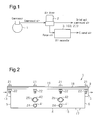
- Fig. 1 vehicles such as trucks, buses, and construction machines utilize compressed air sent from a compressor 1 to control systems such as brakes and suspensions.
- an air dryer 2 which removes oil and water in the compressed air and provides dried air, is located downstream of the compressor 1 of an air system.
- a desiccant is provided in the air dryer 2.
- the air dryer 2 performs dehumidification to remove oil and water from the compressed air, and regeneration to regenerate the desiccant by removing the oil and the water absorbed by the desiccant and discharging them to the outside.
- an oil separator 3 is provided downstream of the compressor 1 of the air system considering the burden on the environment.
- the oil separator 3 is provided in an exhaust system of the air dryer 2, and separates and recovers the oil and the water from purge air discharged during regeneration of the desiccant in the air dryer 2.
- the oil separator 3 is an impingement plate-type oil separator and includes, inside the housing, impingement plates, against which air containing oil and water strikes.
- the impingement plate-type oil separator 3 performs gas/liquid separation by allowing the air containing oil and water to strike the impingement plates. In this manner, the oil separator 3 recovers oil from air, and discharges cleaned air.
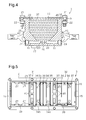
- the oil separator 3 includes a rectangular parallelepiped housing 4, which extends in the horizontal direction.
- An inlet 14 and an outlet 15 are respectively formed in a front side 5 and a rear side 6 of the housing 4.
- the front side 5 and the rear side 6 are opposed to each other in the longitudinal direction. That is, air passes through the oil separator 3 from left to right in Fig. 2 .
- a drain outlet 17, which discharges the collected liquid is formed at part of a bottom face 16 close to the rear side 6.
- the collected liquid contains oil and water separated from the air.
- an opening portion 18 is formed in the upper surface of the housing 4.
- the opening portion 18 is closed by a rectangular lid 19.
- a sealing sheet 20, which covers the entire opening portion 18, is sandwiched between the opening portion 18 and the lid 19.
- the lid 19, the sealing sheet 20, and the housing 4 are tightly secured by bolts 21 and nuts 22.
- the lid 19 restricts movement of members accommodated in the housing 4.
- a plate-like partition wall 30 is provided at a longitudinal center portion in the housing 4.
- the inside of the housing 4 is divided by the partition wall 30 into a primary expansion chamber 31 close to the inlet 14 and a secondary expansion chamber 32 close to the outlet 15 in the horizontal direction.
- the transverse cross-sectional areas of the primary expansion chamber 31 and the secondary expansion chamber 32 are each greater than the transverse cross-sectional area of the inlet 14.
- the transverse cross-sectional area here corresponds to an area of a cross-section perpendicular to the longitudinal direction of the housing 4.
- a through hole (orifice hole) 30a is formed at the upper section of the partition wall 30.
- the partition wall 30 functions as an orifice, which controls the flow of air from the primary expansion chamber 31 to the secondary expansion chamber 32 by the orifice hole 30a.
- a communication hole 33 is formed at the lower section of the partition wall 30 in the vicinity of the bottom face 16. The communication hole 33 permits the collected liquid separated from the air and recovered to pass between the expansion chambers 31, 32.
- impingement plates 34, 35 which are opposed to each other, are provided on both sides of the partition wall 30 in the housing 4.
- the first impingement plate 34 located toward the upstream end includes a first upright plate 34a, which extends from the bottom face 16 of the housing 4 to the lid 19, and a first baffle plate 34b, which extends perpendicularly from the first upright plate 34a in the longitudinal direction of the housing 4 toward the outlet 15.
- the first upright plate 34a includes a rectangular first through hole 34c, which extends in the widthwise direction of the impingement plates 34, 35, at a position lower than the joint to the first baffle plate 34b.
- the second impingement plate 35 located toward the downstream end includes a second upright plate 35a, which extends from the bottom face 16 of the housing 4 to the lid 19, and a second baffle plate 35b, which extends perpendicularly from the second upright plate 35a in the longitudinal direction of the housing 4 toward the inlet 14.
- the second upright plate 35a includes a rectangular second through hole 35c, which extends in the widthwise direction of the impingement plates 34, 35 at a position upper than the joint to the second baffle plate 35b.
- the first baffle plate 34b and the second baffle plate 35b project to obstruct the flow of air, and form an extremely narrow section 36.
- the extremely narrow section 36 is a narrow gap formed by arranging the wide surfaces of the first baffle plate 34b and the second baffle plate 35b close to each other.
- the first baffle plate 34b is located closer to the lid 19 than the second baffle plate 35b.
- the extremely narrow section 36 increases the flow velocity of the air and creates a meandering path, which further increases chances for oil and water particles to strike the plates. This causes the oil and the water to be further reliably separated from the air.
- Communication holes 33 are each formed at the lower sections of the first impingement plate 34 or the second impingement plate 35 in the vicinity of the bottom face 16. The communication holes 33 allow the liquid that has been separated from the air and recovered to pass through the communication holes 33.
- the pair of impingement plates 34, 35 is provided in the internal space of the primary expansion chamber 31, the pair of impingement plates 34, 35 is provided.
- a urethane foam 38 such as a sponge is located between the inlet 14 and the pair of impingement plates 34, 35.
- a punched metal plate 37 in which bores are formed is mounted on the side of the urethane foam 38 facing the impingement plate 34. The urethane foam 38 traps the oil and the water contained in the air.
- the pair of impingement plates 34, 35 is also provided in the internal space of the secondary expansion chamber 32.
- a crushed aluminum member 39 is located between the pair of impingement plates 34, 35 and the outlet 15. Punched metal plates 37 in which bores are formed are respectively mounted on the surfaces of the crushed aluminum member 39 facing the impingement plates 34, 35. That is, the crushed aluminum member 39 is sandwiched between the pair of punched metal plates 37. The crushed aluminum member 39 traps the oil and the water contained in the air.
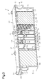
- ribs 40 which increase the strength of the housing 4, are each provided in the expansion chambers 31, 32.
- Columnar accommodation portions 23 for accommodating heating means, which are heaters 41 in this embodiment, are formed in each rib 40 at positions close to the bottom face 16.
- Insertion openings 24 for inserting the heaters 41 are formed in the outer surface of the housing 4. The insertion openings 24 are each connected to the associated accommodation portion 23.
- the heaters 41 are columnar and are each inserted in the associated accommodation portion 23 from the outer surface of the housing 4.
- the heater 41 is connected to a power supply.
- a mounting hole 25 for mounting a thermostat 42 is formed in the outer surface of the housing 4 above each insertion opening 24.
- the thermostat 42 is mounted on the mounting hole 25, and is connected to the power supply and the heater 41.
- Each thermostat 42 detects the temperature of the housing 4, and controls heating of the associated heater 41 based on the detected temperature.
- the water contained in the collected liquid that is stored at the bottom face of the housing 11 is evaporated as much as possible by heating the housing 11 with the heaters 41 so that liquid containing high concentration of oil is generated.
- the oil separator 3 is prevented from getting into a situation where the collected liquid cannot be discharged through the drain outlet 17 due to freezing of the collected liquid in cold climate areas.
- pairs of mounting grooves 27 are formed in a pair of inner walls 26, which extends in the longitudinal direction of the housing 4, as mounting structures for mounting, for example, the partition wall 30, the impingement plates 34, 35, the urethane foam 38, and the crushed aluminum member 39.
- the partition wall 30 and the impingement plates 34, 35 are inserted in the mounting grooves 27 from the opening portion 18 of the housing 4 to be mounted on the housing 4.
- the second impingement plate 35 is inserted to be mounted on the housing 4, and then the first impingement plate 34 is inserted to be mounted on the housing 4.
- the urethane foam 38 and the crushed aluminum member 39 are mounted on the housing 4 by inserting the punched metal plates 37 in the mounting grooves 27 from the opening portion 18 of the housing 4.
- the mounting positions of the partition wall 30, the impingement plates 34, 35, the urethane foam 38, and the crushed aluminum member 39 can be changed by selecting any of the mounting grooves 27.
- a combination of the partition wall 30, the impingement plates 34, 35, the urethane foam 38, and the crushed aluminum member 39 to be mounted on the housing 4 can be selected.
- the air introduced from the inlet 14 into the primary expansion chamber 31 passes through the urethane foam 38 while the oil and the water are trapped by the urethane foam 38, and then passes through the first through hole 34c of the first impingement plate 34 in the primary expansion chamber 31. At this time, the oil and the water that have struck the first upright plate 34a are separated from the air.
- the air that has passed through the first through hole 34c flows toward the extremely narrow section 36, which is formed by the first baffle plate 34b and the second baffle plate 35b, and passes through the extremely narrow section 36. At this time, the oil and the water that have struck the second upright plate 35a and the second baffle plate 35b are separated from the air.
- the air that has passed through the extremely narrow section 36 passes through the second through hole 35c of the second upright plate 35a toward the orifice hole 30a of the partition wall 30, and passes through the orifice hole 30a. At this time, the oil and the water that has struck the partition wall 30 are separated from the air.
- the air that has passed through the orifice hole 30a in the partition wall 30 passes through the first through hole 34c of the first upright plate 34a in the secondary expansion chamber 32. At this time, the oil and the water that have struck the first upright plate 34a are separated from the air.
- the air that has passed through the first through hole 34c flows toward the extremely narrow section 36, which is formed by the first baffle plate 34b and the second baffle plate 35b, and passes through the extremely narrow section 36. At this time, the oil and the water that have struck the second upright plate 35a and the second baffle plate 35b are separated from the air.
- the air that has passed through the extremely narrow section 36 passes through the second through hole 35c of the second upright plate 35a toward the crushed aluminum member 39, and passes through the crushed aluminum member 39. At this time, the air introduced into the crushed aluminum member 39 passes through the crushed aluminum member 39 while the oil and the water are further trapped by the crushed aluminum member 39, and cleaned air that does not contain oil is discharged to the outside from the outlet 15.
- the oil separator is applied to an exhaust system of an air dryer.
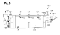
- an oil separator 103 includes a rectangular parallelepiped housing 111, which extends in the horizontal direction.
- An inlet 114 and an outlet 116 are respectively formed in a front side 112 and a rear side 113 of the housing 111.
- the front side 112 and the rear side 113 are opposed to each other in the longitudinal direction. That is, air passes through the oil separator 103 from right to left in Fig. 9 .
- support members which support a liquid communication plate 143, are provided on a bottom face 140 of the housing 111.
- Fig. 11 three support members are arranged in the widthwise direction on the inner wall in the housing 111 close to the inlet 114.
- the support column 141 is provided at the center in the widthwise direction, and the steps 142 are respectively provided on the inner walls.
- two support members are arranged in the widthwise direction on the inner wall in the housing 111 close to the outlet 116.
- the steps 142 are respectively provided on the inner walls.
- Fig. 12 three support members are arranged in the widthwise direction at the middle portion of the housing 111 between the inlet 114 and the outlet 116.
- the support column 141 is provided at the center in the widthwise direction, and the steps 142 are respectively provided on the inner walls.
- FIG. 13 two support columns 141 are arranged in the widthwise direction between the outlet 116 and the middle portion of the housing 111 between the inlet 114 and the outlet 116. Also, three support columns 141 are arranged in the widthwise direction between the middle portion and the inlet 114. In Figs. 11 to 13 , illustration of the urethane foams 133 is omitted.
- the liquid communication plate 143 is mounted on the support columns 141 and the steps 142 in a bridging manner in the housing 111.
- the section in the housing 111 above the liquid communication plate 143 functions as an expansion chamber, which permits air introduced through the inlet 114 to pass through.
- the section in the housing 111 below the liquid communication plate 143 functions as a collected liquid storage portion 145, which stores oil and water (collected liquid) separated from the air in the expansion chamber.
- the collected liquid storage portion 145 is capable of storing the collected liquid to the lower surface of the liquid communication plate 143.
- a plate-like partition wall 130 is mounted on the upper surface of the liquid communication plate 143 in the middle between the inlet 114 and the outlet 116.
- An orifice hole 130a is formed at the upper section of the partition wall 130.
- the partition wall 130 functions as an orifice with the orifice hole 130a.
- the section in the housing 111 above the liquid communication plate 143 is divided into a primary expansion chamber 131 close to the inlet 114 and a secondary expansion chamber 132 close to the outlet 116 in the horizontal direction by the partition wall 130.
- the volume of the secondary expansion chamber 132 is greater than the volume of the primary expansion chamber 131.
- the saturated vapor pressure in the secondary expansion chamber 132 is further reduced as compared to that of the primary expansion chamber 131.
- a urethane foam (such as a sponge) 133 is arranged in each of the primary expansion chamber 131 and the secondary expansion chamber 132.
- the air introduced through the inlet 114 strikes the urethane foams 133, causing the oil and the water to be separated from the air. That is, the urethane foams 133 trap the oil and the water contained in the air.
- the urethane foams 133 correspond to the impingement member.
- Liquid communication holes 144 are formed in the liquid communication plate 143.
- the liquid communication holes 144 allow the oil and the water separated in the primary expansion chamber 131 and the secondary expansion chamber 132 to pass to the collected liquid storage portion 145.
- At least one of the liquid communication holes 144 is formed corresponding to each of the expansion chambers 131, 132.
- the oil and the water separated from the air by striking the urethane foams 133 flow along the upper surface of the liquid communication plate 143 and drop through any of the liquid communication holes 144 into the collected liquid storage portion 145.
- baffle plates 146 which restrict the flow of the collected liquid stored in the collected liquid storage portion 145, are mounted on the lower surface of the liquid communication plate 143.
- the baffle plates 146 extend in the widthwise direction. The baffle plates 146 restrict the collected liquid stored in the collected liquid storage portion 145 from moving due to changes in the vehicle acceleration, thus suppressing splashing of the collected liquid.
- an opening portion 118 is formed in the upper surface of the housing 111.
- the opening portion 118 is closed by a rectangular lid 119.
- an O-ring 120 is provided along the entire circumference of the opening portion 118.
- the O-ring 120 is sandwiched between the opening portion 118 and the lid 119.
- the lid 119 and the housing 111 are tightly secured with bolts 121 and nuts 122.
- the lid 119 restricts movement of, for example, the urethane foams 133 accommodated in the housing 111.
- An accommodation portion 123 for accommodating heating means which is a heater 126 in this embodiment, is provided on the bottom face 140 in the housing 111 close to the outlet 116.
- an insertion section 124 for inserting the heater 126 opens in the rear side 113 of the housing 111.
- the heater 126 is columnar and is inserted in the accommodation portion 123 from the rear side 113.
- the heater 126 is connected to a power supply.
- a mounting hole 125 for mounting a thermostat 127 is formed in the rear side 113 of the housing 111 above the insertion section 124.
- the thermostat 127 is mounted on the mounting hole 125, and is connected to the power supply and the heater 126.
- the thermostat 127 detects the temperature of the collected liquid storage portion 145, and controls heating of the heater 126 based on the detected temperature.
- the water contained in the collected liquid that is stored at the bottom face 140 of the collected liquid storage portion 145 is evaporated as much as possible by heating the collected liquid storage portion 145 with the heater 126 so that liquid containing high concentration of oil is generated.
- An introduction portion 115 is formed at the upper section of the front side 112 of the housing 111.
- the flow path cross-sectional area of the introduction portion 115 is smaller than the flow path cross-sectional area of the housing 111.
- the inlet 114 is formed in the introduction portion 115.
- a cylindrical mounting member 151 is secured to the distal end of the inlet 114.
- the distal end of a hose 150 which is connected to the air dryer 2, is connected to the distal end of the mounting member 151.
- An L-shaped elbow member 160 is mounted to the outlet 116.
- the elbow member 160 extends in the horizontal direction from the outlet 116 and bends upward.
- the elbow member 160 is screwed to the outlet 116.
- a restricting plate 153 which restricts reverse flow of the collected liquid from the inside of the housing 111 to the inlet 114, is provided in front of the introduction portion 115.
- the restricting plate 153 extends from an inner bottom face 152 of the introduction portion 115 and stands upright into the introduction portion 115.
- the inner bottom face 152 is located above the upper surface of the liquid communication plate 143.
- a step 154 is provided on the inner end of the introduction portion 115 to form a step with respect to the liquid communication plate 143.
- the height of the step 154 restricts reverse flow of the collected liquid.
- the collected liquid splashed by changes in the vehicle acceleration and vibration is restricted from directly entering the inlet 114 by the restricting plate 153. That is, the restricting plate 153 and the step 154 function as restricting members, which restrict the collected liquid stored in the collected liquid storage portion 145 from flowing back to the inlet 114.
- Purge air discharged from the air dryer 2 is introduced to the oil separator 103.
- the purge air is air containing oil and water.
- the liquid that has struck the partition wall 130 and has been separated from the air moves along the partition wall 130, reaches the upper surface of the liquid communication plate 143, drops through the liquid communication holes 144 formed in the liquid communication plate 143 into the collected liquid storage portion 145, and is stored in the collected liquid storage portion 145.
- the liquid containing the water and the oil trapped by the urethane foam 133 moves in the urethane foam 133, reaches the upper surface of the liquid communication plate 143, drops through the liquid communication holes 144 formed in the liquid communication plate 143 into the collected liquid storage portion 145, and is stored in the collected liquid storage portion 145.
- the air that has passed through the urethane foam 133 of the secondary expansion chamber 132 becomes cleaned air containing no oil and is discharged to the outside through the outlet 116.
- the collected liquid stored in the collected liquid storage portion 145 is heated by the heater 126. This evaporates the water in the collected liquid, and therefore the collected liquid containing a high concentration of oil is discharged from the drain outlet 117.
- Vibration caused during travel of the vehicle is transmitted to the oil separator 103.
- the oil separator 103 tilts in the same manner as tilting of the vehicle.
- the collected liquid stored in the collected liquid storage portion 145 is influenced by the behavior of the vehicle.
- the step 154 is provided in addition to the restricting plate 153 provided in the introduction portion 115, if the collected liquid flows from the inside of the housing 111 toward the inlet 114 due to changes in the travel acceleration of the vehicle or inclination of the vehicle, the step 154 and the restricting plate 153 restrict the collected liquid from flowing into the inlet 114.
- the baffle plates 146 restrict the movement of the collected liquid.
- changes in the liquid surface of the collected liquid are reduced. This reduces flowing of the collected liquid into the inlet 114 from the inside of the housing 111, and suppresses splashing of the collected liquid due to liquid striking the inner wall of the housing 111.
- the restricting plate 153 is formed only in front of the inlet 114, and the sides are open, the introduction amount of the air is ensured while restricting the collected liquid from flowing into the inlet.
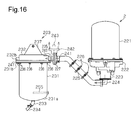
- An oil separator according to a third embodiment will now be described with reference to Figs. 16 to 20 .
- the oil separator is applied to an exhaust system of an air dryer.
- the air dryer 2 includes a cylindrical case 221 having a vertically upper end closed, and a support member 222, which closes the opening portion of the case 221 and supports the case 221.
- the connecting hose 225 is connected to an oil separator 203.
- the connecting hose 225 is secured to, for example, the chassis of a vehicle with clips 226.
- An inlet (not shown), which introduces compressed air compressed by the compressor 1, and an outlet (not shown), which discharges dried compressed air, are formed in the support member 222 of the air dryer 2.
- the oil separator 203 includes a cylindrical housing having a closed end and extending in the vertical direction, which is a case 231 in this embodiment, and a lid 232, which closes the opening portion of the case 231.
- a drain outlet 233 for draining the collected liquid that has been stored is provided at a bottom portion 231a of the case 231.
- a drain hose 234, which is used when draining the collected liquid, is connected to the drain outlet 233.
- the lid 232 has an inlet 235 for introducing the purge air from the air dryer 2 through the connecting hose 225, and an outlet 240 for discharging cleaned air from which oil has been separated.
- the inlet 235 and the outlet 240 are formed separately.
- the inlet 235 and the connecting hose 225 are connected to each other by a coupling member 227.
- the inlet 235 of the oil separator 203 is located above the connection port of the purge air discharge cover 224 in the vertical direction. Thus, the overall height of the air dryer 2 and the oil separator 203 is reduced in the vertical direction.
- An elbow member 241 which extends in the horizontal direction and bends vertically upward, is connected to the outlet 240 of the oil separator 203.
- a drip preventing member 242 and a cover 243 for preventing entry of foreign matter are mounted on the distal end of the elbow member 241.
- a mounting member 237 is formed integrally with the lid 232 of the oil separator 203 to extend upright from the lid 232.
- the mounting member 237 is secured to a chassis 238 with bolts 239.
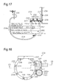
- the distal end of the drain hose 234 is hooked to a support plate 244, which is secured to, for example, the chassis of a vehicle.
- the distal end of the drain hose 234 is located above the lid 232 of the oil separator 203.
- the lid 232 has the inlet 235 and the outlet 240, which are open in the same direction.
- the connecting hose 225 is connected to the inlet 235 via the coupling member 227.
- the elbow member 241 is connected to the outlet 240. That is, the coupling member 227 and the elbow member 241 are arranged next to each other.
- the lid 232 is a cylinder having a vertically upper end closed.
- Two baffle plates 246 are provided on the inner wall of the lid 232 in the vicinity of the inlet 235 to be perpendicular to the flow direction of the purge air introduced through the inlet 235.
- the internal space of the lid 232 functions as a first expansion chamber 245, which expands the purge air introduced through the inlet 235.
- the lid 232 has a communication section 232a, which connects the inside of the case 231 to the outlet 240.
- a disk-like cover 247 which closes the case 231 and the opening portion of the lid 232, is provided between the case 231 and the lid 232.
- the cover 247 and the case 231 are fastened to the lid 232 with bolts 236. That is, the bolts 236 are fastened to threaded bores formed in a flange portion 232b provided on the lid 232. Furthermore, the threaded portions of the bolts 236 extend through through-holes formed in a flange portion 231 b provided on the case 231.
- the cover 247 has through-holes through which the threaded portions of the bolts 236 extend.
- threaded portions of the bolts 236 extend through the through-holes of the flange portion 231b of the case 231 and the through-holes of a flange portion 247a of the cover 247.
- the bolts 236 are then screwed to the threaded bores of the flange portion 232b of the lid 232 so that the lid 232, the cover 247, and the case 231 are fastened together.
- the cover 247 has a communication hole 247c, which connects the inside of the case 231 to the outlet 240.
- a cylindrical accommodation member 248 having a vertically upper end closed is secured to the cover 247 with bolts 236.
- the accommodation member 248 accommodates a urethane foam 250 such as a sponge.
- the urethane foam 250 functions as an impingement member.
- a flange portion 248a is formed at the upper edge of the accommodation member 248 and a flange portion 248b is formed at the lower edge of the accommodation member 248.
- the bolts 236 extend through the flange portion 248a formed at the upper edge of the accommodation member 248 so that the accommodation member 248 is fastened to the cover 247.
- the space formed by the cover 247 and upper surface of the accommodation member 248 functions as a second expansion chamber 251.
- the cover 247 has through holes 247b, which connect the first expansion chamber 245 to the second expansion chamber 251.
- Through holes 249a are formed at the center portion of an upper base 249 of the accommodation member 248.
- the through holes 247b of the cover 247 and the through holes 249a of the upper base 249 of the accommodation member 248 are formed at positions that are not opposed to each another.
- Through holes 248c are formed at the lower end of the side face of the accommodation member 248 to be spaced apart in the radial direction.
- a disk-like support lid 252 is secured to the flange portion 248b, which is formed at the lower edge of the accommodation member 248, with screws 253.
- the support lid 252 supports the accommodated urethane foam 250.
- the inner diameter of the support lid 252 is substantially the same as the inner diameter of the case 231.
- the support lid 252 has through holes 252a, which permit the oil and the water removed by the urethane foam 250 to drop.
- the lower section in the case 231 functions as a collected liquid storage portion 254.
- a heater 255 is arranged in the collected liquid storage portion 254. The heater 255 evaporates water by heating the collected liquid that has been stored in the collected liquid storage portion 254. Heating of the heater 255 is controlled by a non-illustrated thermostat.
- the drain hose 234 is transparent, and has a scale 234a corresponding to the volume of the collected liquid storage portion 254.
- the scale 234a is provided corresponding to the upper surface of the collected liquid storage portion 254, the upper surface of the heater 255, and the lower surface of the collected liquid storage portion 254.
- the amount of the collected liquid in the collected liquid storage portion 254 is easily grasped by visually checking the amount of the collected liquid in the drain hose 234.
- the purge air discharged from the air dryer 2 is introduced to the oil separator 203.
- the purge air contains oil and water.
- the purge air introduced through the inlet 235 strikes the baffle plates 246, is introduced into the oil separator 203 along the baffle plates 246, and expands in the first expansion chamber 245.
- the air expanded in the first expansion chamber 245 enters the second expansion chamber 251 via the through holes 247b formed in the cover 247.
- the air that has expanded in the second expansion chamber 251 enters the accommodation member 248 via the through holes 249a of the upper base 249 of the accommodation member 248.
- the oil and the water that have struck the urethane foam 250 are separated from the air.
- the liquid that contains the water and the oil trapped by the urethane foam 250 moves through the urethane foam 250.
- the liquid reaches the upper surface of the support lid 252, drops through the through holes 252a of the support lid 252 into the collected liquid storage portion 254, and is stored in the collected liquid storage portion 254.
- the collected liquid that has stored in the collected liquid storage portion 254 enters the drain hose 234 through the drain outlet 233.
- the collected liquid stored in the collected liquid storage portion 254 is heated by the heater 255. This evaporates the water in the collected liquid.
- the amount of the collected liquid stored in the collected liquid storage portion 254 can be grasped by checking the amount of the collected liquid stored in the drain hose 234. When the amount of the collected liquid approaches the upper limit, the collected liquid is drained from the collected liquid storage portion 254 through the drain hose 234.
- the oil and the water are separated from the air that has entered the accommodation member 248 from the through holes 249a in the upper base 249 of the accommodation member 248.
- the air then enters the case 231 from the through holes 248c on the side face of the accommodation member 248.
- the air that has entered the case 231 passes through the communication hole 247c of the cover 247 and the communication section 232a of the lid 232, and is discharged to the atmosphere through the outlet 240.
- the air that has entered the case 231 hardly contacts the collected liquid in the collected liquid storage portion 254, and is discharged from the outlet 240.
- the air that is discharged from the outlet 240 is cleaned air that does not contain oil.
- the sealing sheet 20 is provided between the opening portion 18 of the housing 4 and the lid 19, but the sealing sheet 20 may be omitted. It is desirable that the sealing between the opening portion 18 of the housing 4 and the lid 19 be maintained.
- the baffle plates 34b, 35b which extend to be perpendicular to the upright plates 34a, 35a, are provided.
- the baffle plates 34b, 35b do not necessarily have to be formed to be perpendicular to the upright plates 34a, 35a.
- the extremely narrow section 36 configured by the pair of baffle plates 34b, 35b is provided.
- an extremely narrow section formed by multiple pairs of baffle plates may be provided.
- the communication hole 33 is formed at the lower section of the partition wall 30.
- the drain outlet 17 is formed in each of the expansion chambers 31, 32, the communication hole 33 of the partition wall 30 may be omitted.
- the lid 19 restricts the movement of the impingement plates 34, 35, the partition wall 30, the urethane foam 38, and the crushed aluminum member 39.
- the lid 19 does not necessarily have to restrict their movement.
- the crushed aluminum member 39 is provided in the secondary expansion chamber 32, but the urethane foam 38 may be provided instead of the crushed aluminum member 39.
- members are arranged in the housing 4 in the order of the urethane foam 38, the impingement plates 34, 35, the partition wall 30 (the orifice hole 30a), the impingement plates 34, 35, and the crushed aluminum member 39.
- the arrangement of the members may be changed, some of the members may be omitted, some of the members may be increased, or a member may be changed depending on the amount of oil and water discharged from the air dryer 2 (the compressor 1).
- a partition that divides the inside of the housing 4 into the expansion chambers and a collected liquid storage portion may be provided on the bottom inner surface of the housing 4.
- the collected liquid stored at the bottom of the housing 4 is prevented from being stirred up.
- the separated oil and water are moved to the collected liquid storage portion through the gap. If there is no gap between the partition and the inner wall, communication holes are desirably formed that permit the separated oil and water to move into the collected liquid storage portion.
- the expansion chambers 31, 32 are arranged next to each other in the horizontal direction, but may be arranged next to each other in the vertical direction.
- the inlet 14 is formed in the front side 5, and the outlet 15 is formed in the rear side.
- the inlet 14 and the outlet 15 may be formed in the lid 19 on the top face or the bottom face 16.
- the size, or the capacity, of the primary expansion chamber 31 and the secondary expansion chamber 32 is substantially the same.
- the capacity of the secondary expansion chamber 32 may be greater than the capacity of the primary expansion chamber 31.
- the saturated vapor pressure in the secondary expansion chamber 32 is further reduced, allowing the oil and the water to easily condense. This increases the mass of particles of the oil and the water, allowing them to easily strike the impingement plate.
- the secondary expansion chamber 32 stores more oil and water separated from the air than the primary expansion chamber 31.
- a mounting component that is mountable to each mounting groove 27 may be limited by varying the groove width of each mounting groove 27 corresponding to the thickness of the mounting component for each mounting component.
- the mounting grooves 27 are formed on the inner wall 26 of the housing 4 as the mounting structure.
- the mounting structure is not limited to the grooves.
- an engaging structure may be employed.
- the heaters 41 are provided in the ribs 40, but the heaters 41 may be provided at positions other than the ribs 40.
- the heaters 41 are provided in the expansion chambers 31, 32, but the heater 41 may be provided in only one of the expansion chambers. Also, the number of the heaters 41 may be changed as required. Furthermore, if the heaters 41 are unnecessary, a structure without the heaters 41 may be employed.
- the oil separator 3 is provided in the exhaust system of the air dryer 2, which is downstream of the compressor 1 of the air system.
- the oil separator 3 may be provided downstream of the compressor 1 of the air system and upstream of the air dryer 2. In this case, oil and water are separated from the air containing lubricant in the compressor 1, and cleaned air is supplied to the air dryer 2. Thus, the desiccant in the air dryer 2 is prevented from being deteriorated due to the oil.
- the oil separator 3, 103, 203 are provided in the air system including the air dryer 2 in a vehicle such as trucks, buses, and construction machines.
- the oil separator 3, 103, 203 may be used in any situation as long as it is for use in separating oil from air containing oil and water.
- the oil separator may clean exhaust gas to the atmosphere from an air dryer that dries compressed air in, for example, a plant.
- a micro through hole is preferably provided that introduces the liquid stored between the inlet 114 and the restricting plate 153 into the primary expansion chamber 131.
- the restricting plate 153 is formed only in front of the inlet 114 and spaces are formed on the sides of the restricting plate 153.
- a restricting plate may be employed that is not only formed in front of the inlet 114 but that also extends sideways.
- a restricting plate 155 extends upright from the inner bottom face 152 of the introduction portion 115.
- the restricting plate 155 is located in front of the inlet 114, and includes side portions 155a, 155b, which extend sideways to the inner side walls of the housing 111.
- the height of the side portions 155a, 155b of the restricting plate 155 is approximately half the length from the inner bottom face 152 to the lid 119. That is, the side portions 155a, 155b cover the lower section of the flow path of the introduction portion 115. In this case, the collected liquid that flows from the housing 111 into the inlet 114 is reliably restricted by the restricting plate 155.
- the restricting plate 153 or 155 is provided integrally with the inner bottom face 152 of the introduction portion 115.
- a backflow prevention mechanism may be provided that increases the flow path cross-sectional area when the air is introduced through the inlet 114, and restores the size of the flow path cross-sectional area when the introduction of air through the inlet 114 is stopped.
- a restricting plate 156 having the side portions is provided in the same manner as in Fig. 14 , and a one-way urging mechanism 157 is provided between the restricting plate 156 and the inner bottom face 152 as the backflow prevention mechanism.
- the one-way urging mechanism 157 urges the restricting plate 156 toward the inlet 114 to stand vertically.
- the restricting plate 156 tilts toward the outlet 116 and increases the size of the flow path cross-sectional area.
- the collected liquid is prevented from flowing into the inlet 114 from the housing 111 while ensuring the flow path.
- the restricting plate 153 extends upright from the inner bottom face 152 of the introduction portion 115.
- the effective area of the restricting plate 153 in front of the inlet 114 is greater than the effective passage area of the inlet 114, the restricting plate 153 does not necessarily have to extend upright from the inner bottom face 152.
- the step 154 is provided so that the height of the upper surface of the liquid communication plate 143 and the height of the inner bottom face 152 of the introduction portion 115 are different.
- the step 154 may be omitted.
- the O-ring 120 is provided between the opening portion 118 of the housing 111 and the lid 119.
- the O-ring 120 may be omitted. It is desirable that the sealing between the opening portion 118 of the housing 111 and the lid 119 be maintained.
- the lid 119 restricts the movement of the urethane foams 133.
- the movement does not necessarily have to be restricted by the lid 119.
- the urethane foams 133 are provided in the primary expansion chamber 131 and the secondary expansion chamber 132.
- the urethane foams 133 may be changed or partially omitted in accordance with the amount of the oil and the water discharged from the air dryer 2 (compressor 1).
- the heater 126 heats the collected liquid storage portion 145.
- the heater 126 may directly heat the collected liquid stored in the collected liquid storage portion 145.
- the thermostat 127 is desirably located on the inner wall of the housing 111 to perform accurate temperature control. In this case, since heat transfer from the heater 126 to the collected liquid is increased, the collected liquid is efficiently heated as compared to the case in which the collected liquid is indirectly heated.
- the number of the heater 126 may be changed as required.
- the scale 234a is provided on the drain hose 234, but the scale 234a may be omitted from the drain hose 234.
- the drain hose 234 is connected to the drain outlet 233 of the case 231.
- the drain hose 234 may be omitted, and a cock may be provided on the drain outlet 233 so that the collected liquid is directly discharged from the drain outlet 233.
- the first expansion chamber 245 and the second expansion chamber 251 are provided in the oil separator 203. However, at least one of the first expansion chamber 245 and the second expansion chamber 251 may be provided.
- a member such as a nonwoven fabric filter may be arranged upstream or downstream of the urethane foam 250, or in the expansion chambers 245, 246.
- the removal rate of the oil component is increased.
- the urethane foam 250 such as a sponge or a member such as a nonwoven fabric filter may be charged with static electricity.
- the members can be charged with static electricity by a method such as utilizing the flow of dried air from the dryer.
- the urethane foam 250 such as a sponge and the member such as a nonwoven fabric filter may be formed of material that is electrically charged from the beginning. In this case, the removal rate of the oil component is further increased.
- the urethane foam 250 is employed as the impingement member, but other members such as a crushed aluminum member may be employed. Furthermore, instead of the expansion chamber having the impingement member, just an expansion chamber without the impingement member may be employed.
- the number of the heater 255 may be changed as required.
Applications Claiming Priority (4)
| Application Number | Priority Date | Filing Date | Title |
|---|---|---|---|
| JP2012040580A JP2013173124A (ja) | 2012-02-27 | 2012-02-27 | オイルセパレータ |
| JP2012106869A JP5996927B2 (ja) | 2012-05-08 | 2012-05-08 | オイルセパレータ |
| JP2012148646 | 2012-07-02 | ||
| PCT/JP2013/055187 WO2013129495A1 (fr) | 2012-02-27 | 2013-02-27 | Séparateur d'huile |
Publications (3)
| Publication Number | Publication Date |
|---|---|
| EP2835534A1 true EP2835534A1 (fr) | 2015-02-11 |
| EP2835534A4 EP2835534A4 (fr) | 2016-07-27 |
| EP2835534B1 EP2835534B1 (fr) | 2020-08-19 |
Family
ID=49082689
Family Applications (1)
| Application Number | Title | Priority Date | Filing Date |
|---|---|---|---|
| EP13754685.9A Active EP2835534B1 (fr) | 2012-02-27 | 2013-02-27 | Systeme avec sechoir a air et séparateur d'huile |
Country Status (4)
| Country | Link |
|---|---|
| US (1) | US10082057B2 (fr) |
| EP (1) | EP2835534B1 (fr) |
| CN (2) | CN104271949B (fr) |
| WO (1) | WO2013129495A1 (fr) |
Cited By (3)
| Publication number | Priority date | Publication date | Assignee | Title |
|---|---|---|---|---|
| EP3650106A1 (fr) * | 2018-11-08 | 2020-05-13 | KNORR-BREMSE Systeme für Nutzfahrzeuge GmbH | Dispositif d'élimination de polluants de gaz de purge et système pour véhicule |
| EP3650107A1 (fr) * | 2018-11-08 | 2020-05-13 | KNORR-BREMSE Systeme für Nutzfahrzeuge GmbH | Système d'élimination de polluants de gaz de purge pour véhicule |
| WO2020123328A1 (fr) * | 2018-12-10 | 2020-06-18 | Bendix Commercial Vehicle Systems Llc | Appareil et procédé de traitement d'effluents pour un système de charge de frein pneumatique de véhicule |
Families Citing this family (11)
| Publication number | Priority date | Publication date | Assignee | Title |
|---|---|---|---|---|
| JPWO2015088027A1 (ja) * | 2013-12-12 | 2017-03-16 | ナブテスコオートモーティブ株式会社 | 圧縮空気乾燥装置 |
| JPWO2015105185A1 (ja) * | 2014-01-10 | 2017-03-23 | ナブテスコオートモーティブ株式会社 | 圧縮空気乾燥装置 |
| US10099159B2 (en) | 2014-02-27 | 2018-10-16 | Nabtesco Automotive Corporation | Oil separator and drain discharge system |
| US10145278B2 (en) * | 2015-05-14 | 2018-12-04 | Toyota Boshoku Kabushiki Kaisha | Blow-by gas passage structure |
| CN105649711B (zh) * | 2016-03-02 | 2019-01-25 | 神通科技集团股份有限公司 | 纤维棉撞击式油气精分离模块 |
| US10819944B2 (en) * | 2016-12-16 | 2020-10-27 | Seagate Technology Llc | Mobile wireless drive storage for mobile phone used as car dashboard camera |
| CN106499462B (zh) * | 2016-12-27 | 2022-04-08 | 张明 | 汽车气门室机油防乳化系统 |
| US10506903B2 (en) * | 2017-09-14 | 2019-12-17 | Skitter & Squirt Adventures, Llc | System and method for vacuum-powered debris separation |
| JP7124323B2 (ja) * | 2018-01-25 | 2022-08-24 | トヨタ紡織株式会社 | オイルミストセパレータ |
| JP6722729B2 (ja) * | 2018-08-24 | 2020-07-15 | 本田技研工業株式会社 | オイルミストセパレータ |
| WO2020138393A1 (fr) * | 2018-12-28 | 2020-07-02 | ナブテスコオートモーティブ株式会社 | Système d'alimentation en air |
Family Cites Families (158)
| Publication number | Priority date | Publication date | Assignee | Title |
|---|---|---|---|---|
| US1621026A (en) * | 1923-05-24 | 1927-03-15 | Westinghouse Electric & Mfg Co | Separating device for circuit interrupters |
| US2082863A (en) * | 1935-11-11 | 1937-06-08 | Master Separator And Valve Com | Oil and gas separator |
| DE742669C (de) | 1941-08-23 | 1943-12-09 | Demag Ag | Filter fuer Gas- und Luftverdichter |
| US2776054A (en) * | 1954-02-23 | 1957-01-01 | Ruth R Newman | Grease and oil interceptor |
| US2756837A (en) * | 1954-06-28 | 1956-07-31 | Sivalls Tanks Inc | Liquid and gas separator |
| US2942691A (en) | 1956-09-27 | 1960-06-28 | Watts Regulator Co | Air line filter |
| US3000467A (en) * | 1958-03-17 | 1961-09-19 | Gen Motors Corp | Vapor separation units for internal combustion engines |
| US2966233A (en) * | 1959-04-24 | 1960-12-27 | Robert E Nelson | Exhaust condensers |
| US3075336A (en) | 1960-03-23 | 1963-01-29 | Leroy D Hays | Separator for removing oil and water from compressed air system |
| US3201924A (en) | 1962-07-24 | 1965-08-24 | Fram Corp | Gas separator/filter apparatus |
| US3432991A (en) * | 1967-04-10 | 1969-03-18 | Sauder Tank Co Inc | Method and apparatus for treating fluid streams containing gas,water and water-in-oil emulsions |
| JPS5213336U (fr) | 1975-07-18 | 1977-01-29 | ||
| JPS5265381U (fr) | 1975-11-10 | 1977-05-14 | ||
| JPS5518100Y2 (fr) | 1976-05-21 | 1980-04-25 | ||
| CH606779A5 (fr) | 1977-01-31 | 1978-11-15 | Max Bachmann | |
| US4136009A (en) | 1977-11-17 | 1979-01-23 | David Samiran | Adjustable float and filter assembly |
| GB2033247B (en) | 1978-10-18 | 1982-11-03 | Process Scient Innovations | Filter silencer for compressed gas stream |
| JPS55126919U (fr) | 1979-02-28 | 1980-09-08 | ||
| US4226726A (en) * | 1979-03-05 | 1980-10-07 | Technical Systems Co. | Desilter |
| US4298465A (en) * | 1979-06-07 | 1981-11-03 | Racor Industries, Inc. | Fuel filter and water separator apparatus |
| JPS56163918U (fr) | 1980-05-09 | 1981-12-05 | ||
| JPS57181913A (en) | 1981-05-02 | 1982-11-09 | Honda Motor Co Ltd | Heater for lubricating oil of internal combustion engine |
| JPS5864812U (ja) * | 1981-10-27 | 1983-05-02 | 本田技研工業株式会社 | 自動二輪車の気液分離装置 |
| JPS59109284A (ja) | 1982-12-13 | 1984-06-23 | Toshiba Corp | 濃縮廃液貯蔵装置 |
| US4982569A (en) | 1983-03-25 | 1991-01-08 | Ormat Turbines, Ltd. | Parallel hybrid system for generating power |
| JPS6080615A (ja) | 1983-10-12 | 1985-05-08 | Sumitomo Electric Ind Ltd | 可撓性膜製起伏堰 |
| JPS6084714U (ja) | 1983-11-16 | 1985-06-11 | 日産自動車株式会社 | ミストセパレータ |
| US4534861A (en) | 1984-04-30 | 1985-08-13 | Beckman Instruments, Inc. | Vacuum pump purging apparatus |
| US4541933A (en) * | 1984-05-14 | 1985-09-17 | Armold Clark W | Process for separation of ash from waste activated sludge |
| US4668256A (en) | 1984-11-23 | 1987-05-26 | Domnick Hunter Filters Limited | Liquid/gas separation |
| US4627406A (en) | 1984-12-05 | 1986-12-09 | Kabushiki Kaisha Tsuchiya Seisakusho | Oil separator for recycled blow-by gas |
| BR8605102A (pt) | 1985-10-21 | 1987-07-21 | Stauffer Chemical Co | Composicao fitoativa liquida e composicao herbicida liquida |
| JPS62179014U (fr) | 1986-05-02 | 1987-11-13 | ||
| JPH0218259Y2 (fr) | 1986-06-02 | 1990-05-22 | ||
| EP0285612B1 (fr) | 1986-10-13 | 1993-07-28 | SUNG, Ki Jang | Dispositif d'elimination de l'humidite dans un systeme a air comprime |
| US4892569A (en) | 1987-02-23 | 1990-01-09 | Nippon Air Brake Co., Ltd. | Compressed air pressure supply system |
| JPH0639782Y2 (ja) | 1987-11-26 | 1994-10-19 | 株式会社ナブコ | 圧縮空気圧力源装置 |
| JPH0618572Y2 (ja) | 1987-04-02 | 1994-05-18 | 日野自動車工業株式会社 | 車両用圧縮空気の浄化装置 |
| JPH0647548Y2 (ja) | 1988-01-26 | 1994-12-07 | 株式会社ナブコ | 圧縮空気圧力源 |
| CH675278A5 (fr) | 1988-02-25 | 1990-09-14 | Burckhardt Ag Maschf | |
| JPH078020Y2 (ja) | 1988-04-22 | 1995-03-01 | いすゞ自動車株式会社 | エアドライヤシステム |
| JPH0646496Y2 (ja) | 1988-09-28 | 1994-11-30 | 株式会社ナブコ | 圧縮空気源装置 |
| JPH02147212A (ja) | 1988-11-29 | 1990-06-06 | Ikeda Bussan Co Ltd | 表皮材とパッド材との一体成形品 |
| JPH0645781Y2 (ja) | 1989-02-14 | 1994-11-24 | 三洋電機株式会社 | エンジン駆動式空気調和機 |
| JPH0746342Y2 (ja) | 1989-04-04 | 1995-10-25 | 三輪精機株式会社 | 除湿器 |
| JP2670856B2 (ja) | 1989-06-28 | 1997-10-29 | 株式会社ナブコ | 圧縮空気乾燥装置 |
| JPH0359416U (fr) | 1989-10-12 | 1991-06-12 | ||
| JPH03164584A (ja) | 1989-11-20 | 1991-07-16 | Tokico Ltd | ドレン分離排出装置 |
| JPH03246149A (ja) | 1990-02-26 | 1991-11-01 | Nabco Ltd | 車両用圧力源装置 |
| JPH0751148Y2 (ja) | 1990-03-05 | 1995-11-22 | 株式会社ナブコ | 圧縮空気乾燥装置 |
| JPH0427780A (ja) | 1990-05-19 | 1992-01-30 | Matsushita Refrig Co Ltd | 冷媒ガス圧縮機 |
| US5024203A (en) | 1990-08-22 | 1991-06-18 | Sealed Power Technologies, L.P. | PCV oil separator system |
| JP2530765B2 (ja) | 1990-08-31 | 1996-09-04 | 株式会社神戸製鋼所 | 油冷式圧縮機の運転方法 |
| JPH0453174U (fr) | 1990-09-12 | 1992-05-07 | ||
| JPH0459321U (fr) * | 1990-09-28 | 1992-05-21 | ||
| JPH0470970U (fr) * | 1990-11-01 | 1992-06-23 | ||
| JPH0478481U (fr) * | 1990-11-19 | 1992-07-08 | ||
| JP2543671Y2 (ja) | 1991-03-13 | 1997-08-13 | 株式会社前田シェルサービス | 圧縮空気用フィルタ装置 |
| JPH0537628U (ja) | 1991-10-30 | 1993-05-21 | 日野自動車工業株式会社 | エアドライヤの消音装置 |
| JPH05296173A (ja) | 1992-04-14 | 1993-11-09 | Hokuetsu Kogyo Co Ltd | 油冷式回転圧縮機の自動ドレン排出装置 |
| JPH0583382U (ja) | 1992-04-15 | 1993-11-12 | いすゞ自動車株式会社 | エアコンプレッサのオイル放散防止装置 |
| DE4221885C2 (de) | 1992-07-03 | 1996-03-28 | Freudenberg Carl Fa | Flüssigkeitsabscheider |
| JP2839125B2 (ja) | 1993-05-25 | 1998-12-16 | 本田技研工業株式会社 | 水冷式内燃機関のブローバイガス還流装置 |
| JPH06346855A (ja) | 1993-06-03 | 1994-12-20 | Tsutomu Kamata | 圧縮空気の除湿装置 |
| JPH074880U (ja) | 1993-06-16 | 1995-01-24 | 株式会社ナブコ | オイルミストセパレータ |
| JPH078020U (ja) | 1993-07-08 | 1995-02-03 | 株式会社ゼクセル | センサの取付具 |
| JP2514133Y2 (ja) | 1993-08-02 | 1996-10-16 | フジ産業株式会社 | メンブランエアドライヤの制御装置及びコンプレッサに於ける除菌装置 |
| DE4339725C1 (de) * | 1993-11-22 | 1995-01-19 | Man Nutzfahrzeuge Ag | Druckluftanlage eines Fahrzeuges |
| JPH07197886A (ja) | 1993-12-28 | 1995-08-01 | Tokico Ltd | 油冷式空気圧縮機 |
| JP2835491B2 (ja) | 1994-02-18 | 1998-12-14 | 株式会社 フクハラ | エアーコンプレッサーに於ける除菌装置 |
| JPH07243318A (ja) * | 1994-02-28 | 1995-09-19 | Tsuchiya Mfg Co Ltd | オイルミストセパレ−タ |
| JPH07332810A (ja) | 1994-06-08 | 1995-12-22 | Daikin Ind Ltd | 冷凍装置用オイルミストセパレータ |
| JPH08173740A (ja) | 1994-12-27 | 1996-07-09 | Tokai Rubber Ind Ltd | ミスト除去装置 |
| JPH08233415A (ja) * | 1995-02-27 | 1996-09-13 | Daikin Ind Ltd | 油分離器 |
| JP2696500B2 (ja) | 1995-03-31 | 1998-01-14 | ヤマハ発動機株式会社 | エンジンのブローバイガス用油分離装置 |
| JPH08290027A (ja) | 1995-04-24 | 1996-11-05 | Mitsubishi Heavy Ind Ltd | ガス圧縮装置 |
| US5595588A (en) | 1995-07-24 | 1997-01-21 | Alliedsignal Truck Brake Systems Co. | Air dryer cartridge mounting system |
| JPH09177532A (ja) * | 1995-12-27 | 1997-07-08 | Sanyo Electric Co Ltd | オイルセパレータおよびそれを利用したエンジン駆動動力装置 |
| BE1010782A3 (nl) | 1996-12-03 | 1999-01-05 | Atlas Copco Airpower Nv | Compressorinstallatie met olie-afscheiding uit condensaat en daarbij gebruikte inrichting voor het afscheiden van olie uit condensaat. |
| JP3390120B2 (ja) | 1996-12-16 | 2003-03-24 | 株式会社神戸製鋼所 | 油冷式圧縮機用油分離器 |
| JP3322337B2 (ja) | 1997-04-28 | 2002-09-09 | 株式会社ナブコ | エアドライヤ |
| JPH10323529A (ja) | 1997-05-26 | 1998-12-08 | Nissan Diesel Motor Co Ltd | 圧縮空気の乾燥装置 |
| JPH11108474A (ja) | 1997-10-03 | 1999-04-23 | Mitsubishi Heavy Ind Ltd | 空気調和機 |
| US6000383A (en) | 1997-11-13 | 1999-12-14 | Gekko International L.C. | Apparatus for the treatment of crankcase emissions materials in a positive crankcase ventilation system |
| US6186128B1 (en) | 1999-05-12 | 2001-02-13 | Gekko International, L.C. | Apparatus for treatment of crankcase emissions materials in a positive crankcase ventilation system |
| JP2000045749A (ja) * | 1998-07-31 | 2000-02-15 | Tennex Corp | ブローバイガスにおけるオイルの分離装置 |
| CN1069844C (zh) | 1998-09-22 | 2001-08-22 | 王重生 | 多功能组合式压缩空气净化器 |
| US6058917A (en) * | 1999-01-14 | 2000-05-09 | Vortex Automotive Corporation | Method and apparatus for treating crankcase emissions |
| JP2000282839A (ja) | 1999-03-29 | 2000-10-10 | Suzuki Motor Corp | 自動車エンジンのマウント装置 |
| DE29908116U1 (de) | 1999-05-06 | 2000-09-28 | Hengst Walter Gmbh & Co Kg | Ölabscheider zur Entölung von Kurbelgehäuse-Entlüftungsgasen einer Brennkraftmaschine |
| WO2001052973A1 (fr) | 2000-01-20 | 2001-07-26 | Bendix Commercial Vehicle Systems Llc | Cartouche de dessiccateur d'air a filtre coalescent |
| JP4382955B2 (ja) * | 2000-03-21 | 2009-12-16 | オリオン機械株式会社 | 油水分離装置付きエアドライヤ |
| WO2001079664A1 (fr) | 2000-04-12 | 2001-10-25 | Vortex Automotive Corporaton | Procede et appareil de traitement des emissions en provenance du carter |
| JP2002097919A (ja) | 2000-09-26 | 2002-04-05 | Kubota Corp | エンジンのブリーザ装置 |
| US7014691B2 (en) * | 2000-10-23 | 2006-03-21 | Lewin Henry B | Apparatus and method for treating compressed air |
| EP1241327A1 (fr) | 2001-03-13 | 2002-09-18 | Mitsubishi Heavy Industries, Ltd. | Séparateur d'huile |
| US7008472B2 (en) | 2001-06-13 | 2006-03-07 | Bendix Commercial Vehicle Systems, Llc | Spin-on filtering oil removal cartridge |
| ITVI20010216A1 (it) | 2001-10-18 | 2003-04-18 | Virgilio Mietto | Serbatoio separatore aria/olio |
| JP4199465B2 (ja) * | 2002-02-27 | 2008-12-17 | トヨタ紡織株式会社 | 気液分離装置 |
| JP3734454B2 (ja) | 2002-04-26 | 2006-01-11 | 北越工業株式会社 | 圧縮機におけるアフタクーラドレンの排出部構造 |
| JP4400137B2 (ja) | 2003-01-07 | 2010-01-20 | パナソニック株式会社 | 密閉型電動圧縮機 |
| US7001524B2 (en) * | 2003-06-02 | 2006-02-21 | Steven Clay Moore | Method for removing scale causing chemicals in hot water systems |
| JP2005066470A (ja) | 2003-08-25 | 2005-03-17 | Hino Motors Ltd | 車両用圧縮空気の浄化装置 |
| US7285149B2 (en) | 2003-10-31 | 2007-10-23 | Bendix Commercial Vehicle Systems Llc | Oil separator for vehicle air system |
| US7306654B2 (en) | 2004-01-30 | 2007-12-11 | Ronald King | Method and apparatus for recovering water from atmospheric air |
| US7097696B2 (en) | 2004-02-27 | 2006-08-29 | Skf Usa Inc. | Dual cartridge air dryer with oil separator and readily changeable valves |
| DE102004016742B3 (de) | 2004-04-05 | 2005-09-15 | Dichtungstechnik G. Bruss Gmbh & Co. Kg | Ölabscheider und Verfahren zum Abscheiden von Öl aus den Blow-by-Gasen einer Brennkraftmaschine |
| JP4118851B2 (ja) | 2004-09-08 | 2008-07-16 | 株式会社アンレット | ミスト及び粉塵の捕集装置 |
| JP2006075814A (ja) | 2004-09-10 | 2006-03-23 | Cnk:Kk | 油中水分分離装置 |
| US8075654B2 (en) | 2004-09-21 | 2011-12-13 | Cummins Filtration Ip, Inc. | Gas-liquid separator with expansion transition flow |
| US20060248921A1 (en) | 2004-11-18 | 2006-11-09 | Hosford Christian S | Landfill gas purification and liquefaction process |
| JP4581829B2 (ja) | 2005-05-10 | 2010-11-17 | トヨタ自動車株式会社 | オイルセパレータ及びブローバイガス還元装置 |
| JP4639999B2 (ja) | 2005-07-06 | 2011-02-23 | トヨタ自動車株式会社 | 内燃機関のオイル戻し構造 |
| DE102005046810B4 (de) | 2005-09-30 | 2008-07-17 | Zander Aufbereitungstechnik Gmbh & Co. Kg | Abscheider für Flüssigkeiten, insbesondere Kondensat, aus flüssigkeitsbeladenen, komprimierten Gasen |
| JP2007162248A (ja) | 2005-12-12 | 2007-06-28 | Shin Caterpillar Mitsubishi Ltd | 作動油タンクのドレン装置 |
| US7604676B2 (en) | 2006-02-02 | 2009-10-20 | Detroit Diesel Corporation | Inertial impactor for closed crankcase ventilation |
| BRPI0700233B1 (pt) * | 2006-02-07 | 2017-04-18 | Safety-Kleen Europe Ltd | aparelho de separação para separar uma substância de um líquido, e, método para separar uma substância de um líquido |
| DE102006008516A1 (de) | 2006-02-23 | 2007-08-30 | Fev Motorentechnik Gmbh | Zylinderkopf einer Brennkraftmaschine |
| JP4169763B2 (ja) | 2006-03-20 | 2008-10-22 | 小島プレス工業株式会社 | ブローバイガス用オイルセパレータ |
| JP2007255397A (ja) | 2006-03-27 | 2007-10-04 | Mitsubishi Electric Corp | 車両用空気圧縮装置 |
| DE102006024817A1 (de) | 2006-05-29 | 2007-12-06 | Mahle International Gmbh | Zylinderkopf eines Verbrennungsmotors |
| JP4690257B2 (ja) | 2006-06-23 | 2011-06-01 | 株式会社マーレ フィルターシステムズ | オイルミストセパレータ |
| JP2008008259A (ja) * | 2006-06-30 | 2008-01-17 | Calsonic Compressor Inc | 気体圧縮機 |
| US8187370B2 (en) | 2006-07-13 | 2012-05-29 | Shi-Apd Cryogenics, Inc. | Horizontal bulk oil separator |
| DE102006041213B4 (de) | 2006-09-02 | 2017-06-29 | Mahle International Gmbh | Einrichtung zur Kurbelraumentlüftung |
| US20080105125A1 (en) | 2006-11-07 | 2008-05-08 | Lauson Robert G | Method and device for disposing of air compression system effluent |
| JP2008202894A (ja) | 2007-02-21 | 2008-09-04 | Yanmar Co Ltd | オイルセパレータ |
| US9504956B2 (en) * | 2007-03-27 | 2016-11-29 | Mycelx Technologies Corporation | Visual quality indicator for gaseous streams |
| US7708793B2 (en) | 2007-08-29 | 2010-05-04 | Bendix Commercial Vehicle Systems Llc | Purge exhaust processor |
| DE102008047447B4 (de) | 2007-09-19 | 2019-03-14 | Denso Corporation | Ölabscheider und Kältemittelkompressor mit diesem |
| JP2009109102A (ja) | 2007-10-31 | 2009-05-21 | Nippon Soken Inc | オイルセパレータおよびこれを備える冷媒圧縮機 |
| DE202007014378U1 (de) | 2007-10-12 | 2009-02-26 | Hengst Gmbh & Co.Kg | Ölnebelabscheider einer Brennkraftmaschine |
| DE102007049725A1 (de) | 2007-10-16 | 2009-04-23 | Mann + Hummel Gmbh | Ölabscheidevorrichtung, insbesondere zur Kurbelgehäuseentlüftung in einer Brennkraftmaschine |
| US7857882B1 (en) | 2007-12-13 | 2010-12-28 | Johnson Welded Products Inc. | Water and oil mist elimination apparatus for a vehicular compressed air storage system |
| CN201221882Y (zh) | 2008-05-23 | 2009-04-15 | 上海富田空调冷冻设备有限公司 | 制冷机用油分离器 |
| JP2010017823A (ja) | 2008-07-11 | 2010-01-28 | Toyota Motor Corp | オイルミスト除去装置 |
| DE102008050038A1 (de) | 2008-08-11 | 2010-02-18 | Elringklinger Ag | Partikel-Abscheidevorrichtung für eine Aerosol-Strömung |
| JP2009008096A (ja) | 2008-09-29 | 2009-01-15 | Kojima Press Co Ltd | ブローバイガス用オイルセパレータ |
| JP2010096154A (ja) * | 2008-10-20 | 2010-04-30 | Aichi Mach Ind Co Ltd | 気液分離構造 |
| US7927577B2 (en) | 2009-01-12 | 2011-04-19 | Worleyparsons Group, Inc. | Sulfur collection systems and processes with integrated degassing |
| EP2377597B1 (fr) | 2009-01-14 | 2018-05-30 | Nabtesco Automotive Corporation | Structure destinée à supprimer l'huile dans un dispositif de séchage de l'air |
| JP2011025205A (ja) | 2009-07-29 | 2011-02-10 | Nabtesco Automotive Corp | 空気乾燥装置に於ける除湿及びオイル吸着構造 |
| CN201380018Y (zh) * | 2009-04-02 | 2010-01-13 | 王长宝 | 油气分离滤芯 |
| JP2010270743A (ja) | 2009-05-22 | 2010-12-02 | Fukuhara Co Ltd | 圧縮空気より発生したドレン水の処理方法および処理装置 |
| KR101338559B1 (ko) * | 2009-07-10 | 2013-12-06 | 알파 라발 코포레이트 에이비 | 기체 세정 분리장치 |
| JP5509710B2 (ja) | 2009-07-27 | 2014-06-04 | ダイキン工業株式会社 | 空気調和機 |
| JP5542388B2 (ja) | 2009-08-11 | 2014-07-09 | ナブテスコオートモーティブ株式会社 | 空気乾燥装置 |
| JP5412231B2 (ja) | 2009-10-19 | 2014-02-12 | 本田技研工業株式会社 | ブリーザ機構付きエンジン |
| JP5504934B2 (ja) * | 2010-02-03 | 2014-05-28 | トヨタ紡織株式会社 | オイルセパレータ |
| DE102011002582B4 (de) | 2010-01-28 | 2015-10-01 | Toyota Boshoku Kabushiki Kaisha | Ölabscheider |
| US9372004B2 (en) | 2010-09-10 | 2016-06-21 | Blissfield Manufacturing Company | Filter units, filtration methods, and filtration systems |
| US8945263B2 (en) | 2010-09-10 | 2015-02-03 | Blissfield Manufacturing Company | Filter and method for grease filtration |
| US9017460B2 (en) | 2010-11-15 | 2015-04-28 | Nabtesco Automotive Corporation | Silencer, exhaust valve, valve device, air dryer, compressed air supply device for vehicle, and compressed air supply system |
| DE102010055441A1 (de) | 2010-12-21 | 2012-06-21 | GM Global Technology Operations LLC | Luftfilter für ein Kraftfahrzeug |
| CN201916154U (zh) * | 2010-12-30 | 2011-08-03 | 北京当升材料科技股份有限公司 | 一种新型空压站系统 |
| US8721771B2 (en) | 2011-01-21 | 2014-05-13 | Heartland Technology Partners Llc | Condensation plume mitigation system for exhaust stacks |
| GB2499620B (en) * | 2012-02-21 | 2019-05-22 | Caltec Production Solutions Ltd | Fluid separator |
| EP2889484B1 (fr) | 2012-07-02 | 2020-06-03 | Nabtesco Automotive Corporation | Séparateur d'huile |
-
2013
- 2013-02-27 US US14/380,847 patent/US10082057B2/en active Active
- 2013-02-27 CN CN201380010722.9A patent/CN104271949B/zh active Active
- 2013-02-27 CN CN201610592267.3A patent/CN106150978B/zh active Active
- 2013-02-27 WO PCT/JP2013/055187 patent/WO2013129495A1/fr active Application Filing
- 2013-02-27 EP EP13754685.9A patent/EP2835534B1/fr active Active
Cited By (5)
| Publication number | Priority date | Publication date | Assignee | Title |
|---|---|---|---|---|
| EP3650106A1 (fr) * | 2018-11-08 | 2020-05-13 | KNORR-BREMSE Systeme für Nutzfahrzeuge GmbH | Dispositif d'élimination de polluants de gaz de purge et système pour véhicule |
| EP3650107A1 (fr) * | 2018-11-08 | 2020-05-13 | KNORR-BREMSE Systeme für Nutzfahrzeuge GmbH | Système d'élimination de polluants de gaz de purge pour véhicule |
| WO2020094377A1 (fr) * | 2018-11-08 | 2020-05-14 | Knorr-Bremse Systeme für Nutzfahrzeuge GmbH | Système d'élimination de contaminant de gaz de purge pour un véhicule |
| WO2020094372A1 (fr) * | 2018-11-08 | 2020-05-14 | Knorr-Bremse Systeme für Nutzfahrzeuge GmbH | Dispositif et système d'élimination de contaminants de gaz de purge pour un véhicule |
| WO2020123328A1 (fr) * | 2018-12-10 | 2020-06-18 | Bendix Commercial Vehicle Systems Llc | Appareil et procédé de traitement d'effluents pour un système de charge de frein pneumatique de véhicule |
Also Published As
| Publication number | Publication date |
|---|---|
| US10082057B2 (en) | 2018-09-25 |
| CN106150978A (zh) | 2016-11-23 |
| CN104271949B (zh) | 2016-08-24 |
| WO2013129495A1 (fr) | 2013-09-06 |
| EP2835534A4 (fr) | 2016-07-27 |
| CN104271949A (zh) | 2015-01-07 |
| EP2835534B1 (fr) | 2020-08-19 |
| CN106150978B (zh) | 2020-02-28 |
| US20150040767A1 (en) | 2015-02-12 |
Similar Documents
| Publication | Publication Date | Title |
|---|---|---|
| EP2835534B1 (fr) | Systeme avec sechoir a air et séparateur d'huile | |
| US10099164B2 (en) | Oil separator | |
| JP6652587B2 (ja) | 圧縮空気供給システム | |
| EP2821605B1 (fr) | Séparateur d'huile | |
| US10815849B2 (en) | Oil separator | |
| EP2821604B1 (fr) | Séparateur d'huile | |
| JP2016186311A (ja) | オイルセパレータ | |
| JP2013234632A (ja) | オイルセパレータ | |
| JP5973185B2 (ja) | オイルセパレータ | |
| JP2017131889A (ja) | エア系統 | |
| JP6247351B2 (ja) | オイルセパレータ | |
| JP5973186B2 (ja) | オイルセパレータ | |
| JP2014008471A (ja) | オイルセパレータ | |
| JP2013234593A (ja) | オイルセパレータ | |
| JP2013173124A (ja) | オイルセパレータ |
Legal Events
| Date | Code | Title | Description |
|---|---|---|---|
| PUAI | Public reference made under article 153(3) epc to a published international application that has entered the european phase |
Free format text: ORIGINAL CODE: 0009012 |
|
| 17P | Request for examination filed |
Effective date: 20140929 |
|
| AK | Designated contracting states |
Kind code of ref document: A1 Designated state(s): AL AT BE BG CH CY CZ DE DK EE ES FI FR GB GR HR HU IE IS IT LI LT LU LV MC MK MT NL NO PL PT RO RS SE SI SK SM TR |
|
| AX | Request for extension of the european patent |
Extension state: BA ME |
|
| DAX | Request for extension of the european patent (deleted) | ||
| RIC1 | Information provided on ipc code assigned before grant |
Ipc: F04B 39/16 20060101AFI20160129BHEP Ipc: F01M 13/04 20060101ALI20160129BHEP Ipc: F01M 11/08 20060101ALI20160129BHEP Ipc: B01D 45/08 20060101ALI20160129BHEP |
|
| RA4 | Supplementary search report drawn up and despatched (corrected) |
Effective date: 20160624 |
|
| RIC1 | Information provided on ipc code assigned before grant |
Ipc: F01M 11/08 20060101ALI20160620BHEP Ipc: F01M 13/04 20060101ALI20160620BHEP Ipc: B01D 45/08 20060101ALI20160620BHEP Ipc: F04B 39/16 20060101AFI20160620BHEP |
|
| STAA | Information on the status of an ep patent application or granted ep patent |
Free format text: STATUS: EXAMINATION IS IN PROGRESS |
|
| 17Q | First examination report despatched |
Effective date: 20190722 |
|
| GRAP | Despatch of communication of intention to grant a patent |
Free format text: ORIGINAL CODE: EPIDOSNIGR1 |
|
| STAA | Information on the status of an ep patent application or granted ep patent |
Free format text: STATUS: GRANT OF PATENT IS INTENDED |
|
| INTG | Intention to grant announced |
Effective date: 20200313 |
|
| GRAS | Grant fee paid |
Free format text: ORIGINAL CODE: EPIDOSNIGR3 |
|
| GRAA | (expected) grant |
Free format text: ORIGINAL CODE: 0009210 |
|
| STAA | Information on the status of an ep patent application or granted ep patent |
Free format text: STATUS: THE PATENT HAS BEEN GRANTED |
|
| AK | Designated contracting states |
Kind code of ref document: B1 Designated state(s): AL AT BE BG CH CY CZ DE DK EE ES FI FR GB GR HR HU IE IS IT LI LT LU LV MC MK MT NL NO PL PT RO RS SE SI SK SM TR |
|
| REG | Reference to a national code |
Ref country code: GB Ref legal event code: FG4D |
|
| REG | Reference to a national code |
Ref country code: CH Ref legal event code: EP |
|
| REG | Reference to a national code |
Ref country code: DE Ref legal event code: R096 Ref document number: 602013071782 Country of ref document: DE |
|
| REG | Reference to a national code |
Ref country code: AT Ref legal event code: REF Ref document number: 1304223 Country of ref document: AT Kind code of ref document: T Effective date: 20200915 |
|
| REG | Reference to a national code |
Ref country code: IE Ref legal event code: FG4D |
|
| REG | Reference to a national code |
Ref country code: LT Ref legal event code: MG4D |
|
| REG | Reference to a national code |
Ref country code: NL Ref legal event code: MP Effective date: 20200819 |
|
| PG25 | Lapsed in a contracting state [announced via postgrant information from national office to epo] |
Ref country code: GR Free format text: LAPSE BECAUSE OF FAILURE TO SUBMIT A TRANSLATION OF THE DESCRIPTION OR TO PAY THE FEE WITHIN THE PRESCRIBED TIME-LIMIT Effective date: 20201120 Ref country code: PT Free format text: LAPSE BECAUSE OF FAILURE TO SUBMIT A TRANSLATION OF THE DESCRIPTION OR TO PAY THE FEE WITHIN THE PRESCRIBED TIME-LIMIT Effective date: 20201221 Ref country code: NO Free format text: LAPSE BECAUSE OF FAILURE TO SUBMIT A TRANSLATION OF THE DESCRIPTION OR TO PAY THE FEE WITHIN THE PRESCRIBED TIME-LIMIT Effective date: 20201119 Ref country code: FI Free format text: LAPSE BECAUSE OF FAILURE TO SUBMIT A TRANSLATION OF THE DESCRIPTION OR TO PAY THE FEE WITHIN THE PRESCRIBED TIME-LIMIT Effective date: 20200819 Ref country code: BG Free format text: LAPSE BECAUSE OF FAILURE TO SUBMIT A TRANSLATION OF THE DESCRIPTION OR TO PAY THE FEE WITHIN THE PRESCRIBED TIME-LIMIT Effective date: 20201119 Ref country code: SE Free format text: LAPSE BECAUSE OF FAILURE TO SUBMIT A TRANSLATION OF THE DESCRIPTION OR TO PAY THE FEE WITHIN THE PRESCRIBED TIME-LIMIT Effective date: 20200819 Ref country code: LT Free format text: LAPSE BECAUSE OF FAILURE TO SUBMIT A TRANSLATION OF THE DESCRIPTION OR TO PAY THE FEE WITHIN THE PRESCRIBED TIME-LIMIT Effective date: 20200819 Ref country code: HR Free format text: LAPSE BECAUSE OF FAILURE TO SUBMIT A TRANSLATION OF THE DESCRIPTION OR TO PAY THE FEE WITHIN THE PRESCRIBED TIME-LIMIT Effective date: 20200819 |
|
| REG | Reference to a national code |
Ref country code: AT Ref legal event code: MK05 Ref document number: 1304223 Country of ref document: AT Kind code of ref document: T Effective date: 20200819 |
|
| PG25 | Lapsed in a contracting state [announced via postgrant information from national office to epo] |
Ref country code: IS Free format text: LAPSE BECAUSE OF FAILURE TO SUBMIT A TRANSLATION OF THE DESCRIPTION OR TO PAY THE FEE WITHIN THE PRESCRIBED TIME-LIMIT Effective date: 20201219 Ref country code: PL Free format text: LAPSE BECAUSE OF FAILURE TO SUBMIT A TRANSLATION OF THE DESCRIPTION OR TO PAY THE FEE WITHIN THE PRESCRIBED TIME-LIMIT Effective date: 20200819 Ref country code: RS Free format text: LAPSE BECAUSE OF FAILURE TO SUBMIT A TRANSLATION OF THE DESCRIPTION OR TO PAY THE FEE WITHIN THE PRESCRIBED TIME-LIMIT Effective date: 20200819 Ref country code: LV Free format text: LAPSE BECAUSE OF FAILURE TO SUBMIT A TRANSLATION OF THE DESCRIPTION OR TO PAY THE FEE WITHIN THE PRESCRIBED TIME-LIMIT Effective date: 20200819 Ref country code: NL Free format text: LAPSE BECAUSE OF FAILURE TO SUBMIT A TRANSLATION OF THE DESCRIPTION OR TO PAY THE FEE WITHIN THE PRESCRIBED TIME-LIMIT Effective date: 20200819 |
|
| PG25 | Lapsed in a contracting state [announced via postgrant information from national office to epo] |
Ref country code: EE Free format text: LAPSE BECAUSE OF FAILURE TO SUBMIT A TRANSLATION OF THE DESCRIPTION OR TO PAY THE FEE WITHIN THE PRESCRIBED TIME-LIMIT Effective date: 20200819 Ref country code: DK Free format text: LAPSE BECAUSE OF FAILURE TO SUBMIT A TRANSLATION OF THE DESCRIPTION OR TO PAY THE FEE WITHIN THE PRESCRIBED TIME-LIMIT Effective date: 20200819 Ref country code: CZ Free format text: LAPSE BECAUSE OF FAILURE TO SUBMIT A TRANSLATION OF THE DESCRIPTION OR TO PAY THE FEE WITHIN THE PRESCRIBED TIME-LIMIT Effective date: 20200819 Ref country code: SM Free format text: LAPSE BECAUSE OF FAILURE TO SUBMIT A TRANSLATION OF THE DESCRIPTION OR TO PAY THE FEE WITHIN THE PRESCRIBED TIME-LIMIT Effective date: 20200819 Ref country code: RO Free format text: LAPSE BECAUSE OF FAILURE TO SUBMIT A TRANSLATION OF THE DESCRIPTION OR TO PAY THE FEE WITHIN THE PRESCRIBED TIME-LIMIT Effective date: 20200819 |
|
| REG | Reference to a national code |
Ref country code: DE Ref legal event code: R097 Ref document number: 602013071782 Country of ref document: DE |
|
| PG25 | Lapsed in a contracting state [announced via postgrant information from national office to epo] |
Ref country code: AT Free format text: LAPSE BECAUSE OF FAILURE TO SUBMIT A TRANSLATION OF THE DESCRIPTION OR TO PAY THE FEE WITHIN THE PRESCRIBED TIME-LIMIT Effective date: 20200819 Ref country code: AL Free format text: LAPSE BECAUSE OF FAILURE TO SUBMIT A TRANSLATION OF THE DESCRIPTION OR TO PAY THE FEE WITHIN THE PRESCRIBED TIME-LIMIT Effective date: 20200819 Ref country code: ES Free format text: LAPSE BECAUSE OF FAILURE TO SUBMIT A TRANSLATION OF THE DESCRIPTION OR TO PAY THE FEE WITHIN THE PRESCRIBED TIME-LIMIT Effective date: 20200819 |
|
| PLBE | No opposition filed within time limit |
Free format text: ORIGINAL CODE: 0009261 |
|
| STAA | Information on the status of an ep patent application or granted ep patent |
Free format text: STATUS: NO OPPOSITION FILED WITHIN TIME LIMIT |
|
| PG25 | Lapsed in a contracting state [announced via postgrant information from national office to epo] |
Ref country code: SK Free format text: LAPSE BECAUSE OF FAILURE TO SUBMIT A TRANSLATION OF THE DESCRIPTION OR TO PAY THE FEE WITHIN THE PRESCRIBED TIME-LIMIT Effective date: 20200819 |
|
| 26N | No opposition filed |
Effective date: 20210520 |
|
| PG25 | Lapsed in a contracting state [announced via postgrant information from national office to epo] |
Ref country code: IT Free format text: LAPSE BECAUSE OF FAILURE TO SUBMIT A TRANSLATION OF THE DESCRIPTION OR TO PAY THE FEE WITHIN THE PRESCRIBED TIME-LIMIT Effective date: 20200819 |
|
| PG25 | Lapsed in a contracting state [announced via postgrant information from national office to epo] |
Ref country code: SI Free format text: LAPSE BECAUSE OF FAILURE TO SUBMIT A TRANSLATION OF THE DESCRIPTION OR TO PAY THE FEE WITHIN THE PRESCRIBED TIME-LIMIT Effective date: 20200819 |
|
| PG25 | Lapsed in a contracting state [announced via postgrant information from national office to epo] |
Ref country code: MC Free format text: LAPSE BECAUSE OF FAILURE TO SUBMIT A TRANSLATION OF THE DESCRIPTION OR TO PAY THE FEE WITHIN THE PRESCRIBED TIME-LIMIT Effective date: 20200819 |
|
| REG | Reference to a national code |
Ref country code: BE Ref legal event code: MM Effective date: 20210228 |
|
| PG25 | Lapsed in a contracting state [announced via postgrant information from national office to epo] |
Ref country code: CH Free format text: LAPSE BECAUSE OF NON-PAYMENT OF DUE FEES Effective date: 20210228 Ref country code: LI Free format text: LAPSE BECAUSE OF NON-PAYMENT OF DUE FEES Effective date: 20210228 Ref country code: LU Free format text: LAPSE BECAUSE OF NON-PAYMENT OF DUE FEES Effective date: 20210227 |
|
| PG25 | Lapsed in a contracting state [announced via postgrant information from national office to epo] |
Ref country code: IE Free format text: LAPSE BECAUSE OF NON-PAYMENT OF DUE FEES Effective date: 20210227 |
|
| PG25 | Lapsed in a contracting state [announced via postgrant information from national office to epo] |
Ref country code: BE Free format text: LAPSE BECAUSE OF NON-PAYMENT OF DUE FEES Effective date: 20210228 |
|
| PGFP | Annual fee paid to national office [announced via postgrant information from national office to epo] |
Ref country code: FR Payment date: 20230221 Year of fee payment: 11 |
|
| PG25 | Lapsed in a contracting state [announced via postgrant information from national office to epo] |
Ref country code: HU Free format text: LAPSE BECAUSE OF FAILURE TO SUBMIT A TRANSLATION OF THE DESCRIPTION OR TO PAY THE FEE WITHIN THE PRESCRIBED TIME-LIMIT; INVALID AB INITIO Effective date: 20130227 |
|
| PG25 | Lapsed in a contracting state [announced via postgrant information from national office to epo] |
Ref country code: CY Free format text: LAPSE BECAUSE OF FAILURE TO SUBMIT A TRANSLATION OF THE DESCRIPTION OR TO PAY THE FEE WITHIN THE PRESCRIBED TIME-LIMIT Effective date: 20200819 |
|
| PG25 | Lapsed in a contracting state [announced via postgrant information from national office to epo] |
Ref country code: MK Free format text: LAPSE BECAUSE OF FAILURE TO SUBMIT A TRANSLATION OF THE DESCRIPTION OR TO PAY THE FEE WITHIN THE PRESCRIBED TIME-LIMIT Effective date: 20200819 |
|
| PGFP | Annual fee paid to national office [announced via postgrant information from national office to epo] |
Ref country code: DE Payment date: 20240219 Year of fee payment: 12 Ref country code: GB Payment date: 20240219 Year of fee payment: 12 |