EP2720954B1 - Contenant isolé - Google Patents
Contenant isolé Download PDFInfo
- Publication number
- EP2720954B1 EP2720954B1 EP12727745.7A EP12727745A EP2720954B1 EP 2720954 B1 EP2720954 B1 EP 2720954B1 EP 12727745 A EP12727745 A EP 12727745A EP 2720954 B1 EP2720954 B1 EP 2720954B1
- Authority
- EP
- European Patent Office
- Prior art keywords
- floor
- upright
- insulative
- side wall
- tab
- Prior art date
- Legal status (The legal status is an assumption and is not a legal conclusion. Google has not performed a legal analysis and makes no representation as to the accuracy of the status listed.)
- Active
Links
Images


Classifications
-
- B—PERFORMING OPERATIONS; TRANSPORTING
- B65—CONVEYING; PACKING; STORING; HANDLING THIN OR FILAMENTARY MATERIAL
- B65D—CONTAINERS FOR STORAGE OR TRANSPORT OF ARTICLES OR MATERIALS, e.g. BAGS, BARRELS, BOTTLES, BOXES, CANS, CARTONS, CRATES, DRUMS, JARS, TANKS, HOPPERS, FORWARDING CONTAINERS; ACCESSORIES, CLOSURES, OR FITTINGS THEREFOR; PACKAGING ELEMENTS; PACKAGES
- B65D3/00—Rigid or semi-rigid containers having bodies or peripheral walls of curved or partially-curved cross-section made by winding or bending paper without folding along defined lines
- B65D3/10—Rigid or semi-rigid containers having bodies or peripheral walls of curved or partially-curved cross-section made by winding or bending paper without folding along defined lines characterised by form of integral or permanently secured end closure
- B65D3/12—Flanged discs permanently secured, e.g. by adhesives or by heat-sealing
- B65D3/14—Discs fitting within container end and secured by bending, rolling, or folding operations
-
- B—PERFORMING OPERATIONS; TRANSPORTING
- B29—WORKING OF PLASTICS; WORKING OF SUBSTANCES IN A PLASTIC STATE IN GENERAL
- B29C—SHAPING OR JOINING OF PLASTICS; SHAPING OF MATERIAL IN A PLASTIC STATE, NOT OTHERWISE PROVIDED FOR; AFTER-TREATMENT OF THE SHAPED PRODUCTS, e.g. REPAIRING
- B29C65/00—Joining or sealing of preformed parts, e.g. welding of plastics materials; Apparatus therefor
- B29C65/02—Joining or sealing of preformed parts, e.g. welding of plastics materials; Apparatus therefor by heating, with or without pressure
-
- B—PERFORMING OPERATIONS; TRANSPORTING
- B29—WORKING OF PLASTICS; WORKING OF SUBSTANCES IN A PLASTIC STATE IN GENERAL
- B29C—SHAPING OR JOINING OF PLASTICS; SHAPING OF MATERIAL IN A PLASTIC STATE, NOT OTHERWISE PROVIDED FOR; AFTER-TREATMENT OF THE SHAPED PRODUCTS, e.g. REPAIRING
- B29C66/00—General aspects of processes or apparatus for joining preformed parts
- B29C66/01—General aspects dealing with the joint area or with the area to be joined
- B29C66/05—Particular design of joint configurations
- B29C66/10—Particular design of joint configurations particular design of the joint cross-sections
- B29C66/11—Joint cross-sections comprising a single joint-segment, i.e. one of the parts to be joined comprising a single joint-segment in the joint cross-section
- B29C66/112—Single lapped joints
- B29C66/1122—Single lap to lap joints, i.e. overlap joints
-
- B—PERFORMING OPERATIONS; TRANSPORTING
- B29—WORKING OF PLASTICS; WORKING OF SUBSTANCES IN A PLASTIC STATE IN GENERAL
- B29C—SHAPING OR JOINING OF PLASTICS; SHAPING OF MATERIAL IN A PLASTIC STATE, NOT OTHERWISE PROVIDED FOR; AFTER-TREATMENT OF THE SHAPED PRODUCTS, e.g. REPAIRING
- B29C66/00—General aspects of processes or apparatus for joining preformed parts
- B29C66/01—General aspects dealing with the joint area or with the area to be joined
- B29C66/05—Particular design of joint configurations
- B29C66/10—Particular design of joint configurations particular design of the joint cross-sections
- B29C66/12—Joint cross-sections combining only two joint-segments; Tongue and groove joints; Tenon and mortise joints; Stepped joint cross-sections
- B29C66/128—Stepped joint cross-sections
- B29C66/1282—Stepped joint cross-sections comprising at least one overlap joint-segment
-
- B—PERFORMING OPERATIONS; TRANSPORTING
- B29—WORKING OF PLASTICS; WORKING OF SUBSTANCES IN A PLASTIC STATE IN GENERAL
- B29C—SHAPING OR JOINING OF PLASTICS; SHAPING OF MATERIAL IN A PLASTIC STATE, NOT OTHERWISE PROVIDED FOR; AFTER-TREATMENT OF THE SHAPED PRODUCTS, e.g. REPAIRING
- B29C66/00—General aspects of processes or apparatus for joining preformed parts
- B29C66/01—General aspects dealing with the joint area or with the area to be joined
- B29C66/05—Particular design of joint configurations
- B29C66/10—Particular design of joint configurations particular design of the joint cross-sections
- B29C66/12—Joint cross-sections combining only two joint-segments; Tongue and groove joints; Tenon and mortise joints; Stepped joint cross-sections
- B29C66/128—Stepped joint cross-sections
- B29C66/1288—Stepped joint cross-sections comprising at least one monotone curved joint-segment
- B29C66/12881—Stepped joint cross-sections comprising at least one monotone curved joint-segment comprising at least two monotone curved joint-segments
-
- B—PERFORMING OPERATIONS; TRANSPORTING
- B29—WORKING OF PLASTICS; WORKING OF SUBSTANCES IN A PLASTIC STATE IN GENERAL
- B29C—SHAPING OR JOINING OF PLASTICS; SHAPING OF MATERIAL IN A PLASTIC STATE, NOT OTHERWISE PROVIDED FOR; AFTER-TREATMENT OF THE SHAPED PRODUCTS, e.g. REPAIRING
- B29C66/00—General aspects of processes or apparatus for joining preformed parts
- B29C66/01—General aspects dealing with the joint area or with the area to be joined
- B29C66/05—Particular design of joint configurations
- B29C66/10—Particular design of joint configurations particular design of the joint cross-sections
- B29C66/14—Particular design of joint configurations particular design of the joint cross-sections the joint having the same thickness as the thickness of the parts to be joined
-
- B—PERFORMING OPERATIONS; TRANSPORTING
- B29—WORKING OF PLASTICS; WORKING OF SUBSTANCES IN A PLASTIC STATE IN GENERAL
- B29C—SHAPING OR JOINING OF PLASTICS; SHAPING OF MATERIAL IN A PLASTIC STATE, NOT OTHERWISE PROVIDED FOR; AFTER-TREATMENT OF THE SHAPED PRODUCTS, e.g. REPAIRING
- B29C66/00—General aspects of processes or apparatus for joining preformed parts
- B29C66/40—General aspects of joining substantially flat articles, e.g. plates, sheets or web-like materials; Making flat seams in tubular or hollow articles; Joining single elements to substantially flat surfaces
- B29C66/41—Joining substantially flat articles ; Making flat seams in tubular or hollow articles
- B29C66/43—Joining a relatively small portion of the surface of said articles
- B29C66/432—Joining a relatively small portion of the surface of said articles for making tubular articles or closed loops, e.g. by joining several sheets ; for making hollow articles or hollow preforms
- B29C66/4322—Joining a relatively small portion of the surface of said articles for making tubular articles or closed loops, e.g. by joining several sheets ; for making hollow articles or hollow preforms by joining a single sheet to itself
-
- B—PERFORMING OPERATIONS; TRANSPORTING
- B29—WORKING OF PLASTICS; WORKING OF SUBSTANCES IN A PLASTIC STATE IN GENERAL
- B29C—SHAPING OR JOINING OF PLASTICS; SHAPING OF MATERIAL IN A PLASTIC STATE, NOT OTHERWISE PROVIDED FOR; AFTER-TREATMENT OF THE SHAPED PRODUCTS, e.g. REPAIRING
- B29C66/00—General aspects of processes or apparatus for joining preformed parts
- B29C66/70—General aspects of processes or apparatus for joining preformed parts characterised by the composition, physical properties or the structure of the material of the parts to be joined; Joining with non-plastics material
- B29C66/72—General aspects of processes or apparatus for joining preformed parts characterised by the composition, physical properties or the structure of the material of the parts to be joined; Joining with non-plastics material characterised by the structure of the material of the parts to be joined
- B29C66/727—General aspects of processes or apparatus for joining preformed parts characterised by the composition, physical properties or the structure of the material of the parts to be joined; Joining with non-plastics material characterised by the structure of the material of the parts to be joined being porous, e.g. foam
-
- B—PERFORMING OPERATIONS; TRANSPORTING
- B29—WORKING OF PLASTICS; WORKING OF SUBSTANCES IN A PLASTIC STATE IN GENERAL
- B29C—SHAPING OR JOINING OF PLASTICS; SHAPING OF MATERIAL IN A PLASTIC STATE, NOT OTHERWISE PROVIDED FOR; AFTER-TREATMENT OF THE SHAPED PRODUCTS, e.g. REPAIRING
- B29C66/00—General aspects of processes or apparatus for joining preformed parts
- B29C66/70—General aspects of processes or apparatus for joining preformed parts characterised by the composition, physical properties or the structure of the material of the parts to be joined; Joining with non-plastics material
- B29C66/73—General aspects of processes or apparatus for joining preformed parts characterised by the composition, physical properties or the structure of the material of the parts to be joined; Joining with non-plastics material characterised by the intensive physical properties of the material of the parts to be joined, by the optical properties of the material of the parts to be joined, by the extensive physical properties of the parts to be joined, by the state of the material of the parts to be joined or by the material of the parts to be joined being a thermoplastic or a thermoset
- B29C66/731—General aspects of processes or apparatus for joining preformed parts characterised by the composition, physical properties or the structure of the material of the parts to be joined; Joining with non-plastics material characterised by the intensive physical properties of the material of the parts to be joined, by the optical properties of the material of the parts to be joined, by the extensive physical properties of the parts to be joined, by the state of the material of the parts to be joined or by the material of the parts to be joined being a thermoplastic or a thermoset characterised by the intensive physical properties of the material of the parts to be joined
- B29C66/7313—Density
- B29C66/73132—Density of different density, i.e. the density of one of the parts to be joined being different from the density of the other part
-
- B—PERFORMING OPERATIONS; TRANSPORTING
- B31—MAKING ARTICLES OF PAPER, CARDBOARD OR MATERIAL WORKED IN A MANNER ANALOGOUS TO PAPER; WORKING PAPER, CARDBOARD OR MATERIAL WORKED IN A MANNER ANALOGOUS TO PAPER
- B31B—MAKING CONTAINERS OF PAPER, CARDBOARD OR MATERIAL WORKED IN A MANNER ANALOGOUS TO PAPER
- B31B50/00—Making rigid or semi-rigid containers, e.g. boxes or cartons
-
- B—PERFORMING OPERATIONS; TRANSPORTING
- B31—MAKING ARTICLES OF PAPER, CARDBOARD OR MATERIAL WORKED IN A MANNER ANALOGOUS TO PAPER; WORKING PAPER, CARDBOARD OR MATERIAL WORKED IN A MANNER ANALOGOUS TO PAPER
- B31F—MECHANICAL WORKING OR DEFORMATION OF PAPER, CARDBOARD OR MATERIAL WORKED IN A MANNER ANALOGOUS TO PAPER
- B31F1/00—Mechanical deformation without removing material, e.g. in combination with laminating
- B31F1/0003—Shaping by bending, folding, twisting, straightening, flattening or rim-rolling; Shaping by bending, folding or rim-rolling combined with joining; Apparatus therefor
- B31F1/0038—Rim-rolling
-
- B—PERFORMING OPERATIONS; TRANSPORTING
- B65—CONVEYING; PACKING; STORING; HANDLING THIN OR FILAMENTARY MATERIAL
- B65D—CONTAINERS FOR STORAGE OR TRANSPORT OF ARTICLES OR MATERIALS, e.g. BAGS, BARRELS, BOTTLES, BOXES, CANS, CARTONS, CRATES, DRUMS, JARS, TANKS, HOPPERS, FORWARDING CONTAINERS; ACCESSORIES, CLOSURES, OR FITTINGS THEREFOR; PACKAGING ELEMENTS; PACKAGES
- B65D3/00—Rigid or semi-rigid containers having bodies or peripheral walls of curved or partially-curved cross-section made by winding or bending paper without folding along defined lines
- B65D3/02—Rigid or semi-rigid containers having bodies or peripheral walls of curved or partially-curved cross-section made by winding or bending paper without folding along defined lines characterised by shape
- B65D3/06—Rigid or semi-rigid containers having bodies or peripheral walls of curved or partially-curved cross-section made by winding or bending paper without folding along defined lines characterised by shape essentially conical or frusto-conical
-
- B—PERFORMING OPERATIONS; TRANSPORTING
- B65—CONVEYING; PACKING; STORING; HANDLING THIN OR FILAMENTARY MATERIAL
- B65D—CONTAINERS FOR STORAGE OR TRANSPORT OF ARTICLES OR MATERIALS, e.g. BAGS, BARRELS, BOTTLES, BOXES, CANS, CARTONS, CRATES, DRUMS, JARS, TANKS, HOPPERS, FORWARDING CONTAINERS; ACCESSORIES, CLOSURES, OR FITTINGS THEREFOR; PACKAGING ELEMENTS; PACKAGES
- B65D81/00—Containers, packaging elements, or packages, for contents presenting particular transport or storage problems, or adapted to be used for non-packaging purposes after removal of contents
- B65D81/38—Containers, packaging elements, or packages, for contents presenting particular transport or storage problems, or adapted to be used for non-packaging purposes after removal of contents with thermal insulation
- B65D81/3865—Containers, packaging elements, or packages, for contents presenting particular transport or storage problems, or adapted to be used for non-packaging purposes after removal of contents with thermal insulation drinking cups or like containers
- B65D81/3874—Containers, packaging elements, or packages, for contents presenting particular transport or storage problems, or adapted to be used for non-packaging purposes after removal of contents with thermal insulation drinking cups or like containers formed of different materials, e.g. laminated or foam filling between walls
-
- B—PERFORMING OPERATIONS; TRANSPORTING
- B29—WORKING OF PLASTICS; WORKING OF SUBSTANCES IN A PLASTIC STATE IN GENERAL
- B29C—SHAPING OR JOINING OF PLASTICS; SHAPING OF MATERIAL IN A PLASTIC STATE, NOT OTHERWISE PROVIDED FOR; AFTER-TREATMENT OF THE SHAPED PRODUCTS, e.g. REPAIRING
- B29C66/00—General aspects of processes or apparatus for joining preformed parts
- B29C66/01—General aspects dealing with the joint area or with the area to be joined
- B29C66/341—Measures for intermixing the material of the joint interlayer
-
- B—PERFORMING OPERATIONS; TRANSPORTING
- B29—WORKING OF PLASTICS; WORKING OF SUBSTANCES IN A PLASTIC STATE IN GENERAL
- B29C—SHAPING OR JOINING OF PLASTICS; SHAPING OF MATERIAL IN A PLASTIC STATE, NOT OTHERWISE PROVIDED FOR; AFTER-TREATMENT OF THE SHAPED PRODUCTS, e.g. REPAIRING
- B29C66/00—General aspects of processes or apparatus for joining preformed parts
- B29C66/70—General aspects of processes or apparatus for joining preformed parts characterised by the composition, physical properties or the structure of the material of the parts to be joined; Joining with non-plastics material
- B29C66/71—General aspects of processes or apparatus for joining preformed parts characterised by the composition, physical properties or the structure of the material of the parts to be joined; Joining with non-plastics material characterised by the composition of the plastics material of the parts to be joined
-
- B—PERFORMING OPERATIONS; TRANSPORTING
- B29—WORKING OF PLASTICS; WORKING OF SUBSTANCES IN A PLASTIC STATE IN GENERAL
- B29C—SHAPING OR JOINING OF PLASTICS; SHAPING OF MATERIAL IN A PLASTIC STATE, NOT OTHERWISE PROVIDED FOR; AFTER-TREATMENT OF THE SHAPED PRODUCTS, e.g. REPAIRING
- B29C66/00—General aspects of processes or apparatus for joining preformed parts
- B29C66/70—General aspects of processes or apparatus for joining preformed parts characterised by the composition, physical properties or the structure of the material of the parts to be joined; Joining with non-plastics material
- B29C66/72—General aspects of processes or apparatus for joining preformed parts characterised by the composition, physical properties or the structure of the material of the parts to be joined; Joining with non-plastics material characterised by the structure of the material of the parts to be joined
- B29C66/723—General aspects of processes or apparatus for joining preformed parts characterised by the composition, physical properties or the structure of the material of the parts to be joined; Joining with non-plastics material characterised by the structure of the material of the parts to be joined being multi-layered
-
- B—PERFORMING OPERATIONS; TRANSPORTING
- B29—WORKING OF PLASTICS; WORKING OF SUBSTANCES IN A PLASTIC STATE IN GENERAL
- B29C—SHAPING OR JOINING OF PLASTICS; SHAPING OF MATERIAL IN A PLASTIC STATE, NOT OTHERWISE PROVIDED FOR; AFTER-TREATMENT OF THE SHAPED PRODUCTS, e.g. REPAIRING
- B29C66/00—General aspects of processes or apparatus for joining preformed parts
- B29C66/70—General aspects of processes or apparatus for joining preformed parts characterised by the composition, physical properties or the structure of the material of the parts to be joined; Joining with non-plastics material
- B29C66/73—General aspects of processes or apparatus for joining preformed parts characterised by the composition, physical properties or the structure of the material of the parts to be joined; Joining with non-plastics material characterised by the intensive physical properties of the material of the parts to be joined, by the optical properties of the material of the parts to be joined, by the extensive physical properties of the parts to be joined, by the state of the material of the parts to be joined or by the material of the parts to be joined being a thermoplastic or a thermoset
- B29C66/737—General aspects of processes or apparatus for joining preformed parts characterised by the composition, physical properties or the structure of the material of the parts to be joined; Joining with non-plastics material characterised by the intensive physical properties of the material of the parts to be joined, by the optical properties of the material of the parts to be joined, by the extensive physical properties of the parts to be joined, by the state of the material of the parts to be joined or by the material of the parts to be joined being a thermoplastic or a thermoset characterised by the state of the material of the parts to be joined
- B29C66/7371—General aspects of processes or apparatus for joining preformed parts characterised by the composition, physical properties or the structure of the material of the parts to be joined; Joining with non-plastics material characterised by the intensive physical properties of the material of the parts to be joined, by the optical properties of the material of the parts to be joined, by the extensive physical properties of the parts to be joined, by the state of the material of the parts to be joined or by the material of the parts to be joined being a thermoplastic or a thermoset characterised by the state of the material of the parts to be joined oriented or heat-shrinkable
- B29C66/73711—General aspects of processes or apparatus for joining preformed parts characterised by the composition, physical properties or the structure of the material of the parts to be joined; Joining with non-plastics material characterised by the intensive physical properties of the material of the parts to be joined, by the optical properties of the material of the parts to be joined, by the extensive physical properties of the parts to be joined, by the state of the material of the parts to be joined or by the material of the parts to be joined being a thermoplastic or a thermoset characterised by the state of the material of the parts to be joined oriented or heat-shrinkable oriented
- B29C66/73713—General aspects of processes or apparatus for joining preformed parts characterised by the composition, physical properties or the structure of the material of the parts to be joined; Joining with non-plastics material characterised by the intensive physical properties of the material of the parts to be joined, by the optical properties of the material of the parts to be joined, by the extensive physical properties of the parts to be joined, by the state of the material of the parts to be joined or by the material of the parts to be joined being a thermoplastic or a thermoset characterised by the state of the material of the parts to be joined oriented or heat-shrinkable oriented bi-axially or multi-axially
-
- B—PERFORMING OPERATIONS; TRANSPORTING
- B29—WORKING OF PLASTICS; WORKING OF SUBSTANCES IN A PLASTIC STATE IN GENERAL
- B29L—INDEXING SCHEME ASSOCIATED WITH SUBCLASS B29C, RELATING TO PARTICULAR ARTICLES
- B29L2031/00—Other particular articles
- B29L2031/712—Containers; Packaging elements or accessories, Packages
- B29L2031/7132—Bowls, Cups, Glasses
-
- B—PERFORMING OPERATIONS; TRANSPORTING
- B31—MAKING ARTICLES OF PAPER, CARDBOARD OR MATERIAL WORKED IN A MANNER ANALOGOUS TO PAPER; WORKING PAPER, CARDBOARD OR MATERIAL WORKED IN A MANNER ANALOGOUS TO PAPER
- B31B—MAKING CONTAINERS OF PAPER, CARDBOARD OR MATERIAL WORKED IN A MANNER ANALOGOUS TO PAPER
- B31B2105/00—Rigid or semi-rigid containers made by assembling separate sheets, blanks or webs
- B31B2105/002—Making boxes characterised by the shape of the blanks from which they are formed
- B31B2105/0022—Making boxes from tubular webs or blanks, e.g. with separate bottoms, including tube or bottom forming operations
-
- B—PERFORMING OPERATIONS; TRANSPORTING
- B31—MAKING ARTICLES OF PAPER, CARDBOARD OR MATERIAL WORKED IN A MANNER ANALOGOUS TO PAPER; WORKING PAPER, CARDBOARD OR MATERIAL WORKED IN A MANNER ANALOGOUS TO PAPER
- B31B—MAKING CONTAINERS OF PAPER, CARDBOARD OR MATERIAL WORKED IN A MANNER ANALOGOUS TO PAPER
- B31B2110/00—Shape of rigid or semi-rigid containers
- B31B2110/10—Shape of rigid or semi-rigid containers having a cross section of varying size or shape, e.g. conical or pyramidal
-
- B—PERFORMING OPERATIONS; TRANSPORTING
- B31—MAKING ARTICLES OF PAPER, CARDBOARD OR MATERIAL WORKED IN A MANNER ANALOGOUS TO PAPER; WORKING PAPER, CARDBOARD OR MATERIAL WORKED IN A MANNER ANALOGOUS TO PAPER
- B31B—MAKING CONTAINERS OF PAPER, CARDBOARD OR MATERIAL WORKED IN A MANNER ANALOGOUS TO PAPER
- B31B2110/00—Shape of rigid or semi-rigid containers
- B31B2110/20—Shape of rigid or semi-rigid containers having a curved cross section, e.g. circular
Definitions
- the present disclosure relates to vessels, and in particular to insulated containers, such as cups, for containing hot or cold beverages or food. More particularly, the present disclosure relates to an insulated cup formed from polymeric materials.
- a vessel in accordance with the present disclosure is configured to hold a product in an interior region.
- the vessel is an insulated container such as a drink cup, a food-storage cup, or a dessert cup.
- an insulative cup in illustrative example, includes a body having a sleeve-shaped side wall and a floor coupled to the body to cooperate with the side wall to form an interior region for storing food, liquid, or any suitable product.
- the body also includes a rolled brim coupled to an upper end of the side wall and a floor mount coupled to a lower end of the side wall and to the floor.
- the body is made of a sheet comprising an insulative cellular non-aromatic polymeric material.
- the body is made of a multi-layer sheet including a substrate layer comprising the insulative cellular non-aromatic polymeric material and an outer layer comprising a skin coupled to the substrate layer and configured to display artwork and text.
- such text and artwork are printed directly on an exterior surface of the insulative cellular non-aromatic polymeric material.
- the floor also comprises insulative cellular non-aromatic polymeric material.
- the insulative cellular non-aromatic polymer material included in the body is configured in accordance with the present disclosure to provide means for enabling localized plastic deformation in at least one selected region of the body (e.g., the side wall, the rolled brim, the floor mount, and a floor-retaining flange included in the floor mount) to provide (1) a plastically deformed first material segment having a first density in a first portion of the selected region of the body and (2) a second material segment having a relatively lower second density in an adjacent second portion of the selected region of the body.
- the more dense first material segment is thinner than the second material segment.
- the insulative cellular non-aromatic polymeric material comprises a polypropylene base resin having a high melt strength, a polypropylene copolymer or a homopolymer resin (or both), and cell-forming agents including primary and secondary nucleating agents and a blowing agent such as carbon dioxide gas that is injected into the resins to expand the resins and reduce density.
- the base resin comprises broadly distributed molecular weight polypropylene characterized by a distribution that is unimodal (not bimodal).
- the skin is coupled to an exterior surface of the insulative cellular non-aromatic polymeric material.
- the skin includes a film, an adhesive interposed between the film and the exterior surface of the insulative cellular non-aromatic polymeric material, and an ink printed on the film to provide a graphic design including artwork, text, or both.
- the film is biaxially oriented polypropylene in illustrative embodiments.
- Localized plastic deformation is provided in accordance with the present disclosure in, for example, four regions 101, 102, 103, and 104 of a body 11 of an insulative cup 10 comprising an insulative cellular non-aromatic polymeric material as suggested in Figs. 1 and 3-3D .
- a material has been plastically deformed, for example, when it has changed shape to take on a permanent set in response to exposure to an external compression load and remains in that new shape after the load has been removed.
- Insulative cup 10 disclosed herein is not a paper cup but rather a cup made of a cellular non-aromatic polymeric material with insulative qualities suitable for holding hot and cold contents.
- FIG. 1 A first example of an insulative cup 10 having four regions 101-104 where localized plastic deformation provides segments of insulative cup 10 that exhibit higher material density than neighboring segments of insulative cup 10 in accordance with the present disclosure is shown in Figs. 1 and 2-11 .
- insulative cup 10 is made using an illustrative body blank 500 shown in Figs. 12-14 .
- a cup-manufacturing process 40 that makes body blank 500 and insulative cup 10 is shown in Figs. 16-20 .
- Other example of body blanks 800, 820, 836, and 856 in accordance with the present disclosure that may be used to form insulative cups are illustrated in Figs. 21-31 .
- Figs. 32-34 A first example of an insulative cellular non-aromatic polymeric material used to form insulative cup 10 is shown in Figs. 1A and 37 .
- Fig. 38 Another example of an insulative cellular non-aromatic polymeric material in accordance with the present disclosure is shown in Fig. 38 .
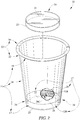
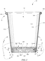
- An insulative cup 10 comprises a body 11 including a sleeve-shaped side wall 18 and a floor 20 coupled to body 11 to define an interior region 14 bounded by sleeve-shaped side wall 18 and floor 20 as shown, for example, in Fig. 1 .
- Body 11 further includes a rolled brim 16 coupled to an upper end of side wall 18 and a floor mount 17 coupled to a lower end of side wall 18 as suggested in Figs. 1-3 .
- Body 11 is formed from a strip of insulative cellular non-aromatic polymeric material as disclosed herein.
- a strip of insulative cellular non-aromatic polymeric material is configured (by application of pressure -- with or without application of heat) to provide means for enabling localized plastic deformation in at least one selected region (for example, regions 101-104) of body 11 to provide a plastically deformed first material segment having a first density located in a first portion of the selected region of body 11 and a second material segment having a second density lower than the first density located in an adjacent second portion of the selected region of body 11 without fracturing the insulative cellular non-aromatic polymeric material so that a predetermined insulative characteristic is maintained in body 11.
- a first region 101 of the selected regions of body 11 in which localized plastic deformation is enabled by the insulative cellular non-aromatic polymeric material is in sleeve-shaped side wall 18 as suggested in Figs. 1 , 3A , and 4 .
- Sleeve-shaped side wall 18 includes an upright inner tab 514, an upright outer tab 512, and an upright fence 513 extending between inner and outer tabs 514, 512 as suggested in Figs. 1 , 3 , and 4 .
- Upright inner tab 514 is arranged to extend upwardly from floor 20 and configured to provide the first material segment having the higher first density in the first region 101 of the selected regions of body 11.
- Upright outer tab 512 is arranged to extend upwardly from floor 20 and to mate with upright inner tab 514 along an interface I therebetween as suggested in Fig. 4 .
- Upright fence 513 is arranged to interconnect upright inner and outer tabs 514, 512 and surround interior region 14.
- Upright fence 513 is configured to provide the second material segment having the lower second density in the first region 101 of the selected regions of body 11 and cooperate with upright inner and outer tabs 514, 512 to form sleeve-shaped side wall 18 as suggested in Figs. 3 and 4 .
- a second region 102 of the selected regions of body 11 in which localized plastic deformation is enabled by the insulative cellular non-aromatic polymeric material is in a rolled brim 16 included in body 11 as suggested in Figs. 1 , 3B , and 6 .
- Rolled brim 16 is coupled to an upper end of sleeve-shaped side wall 18 to lie in spaced-apart relation to floor 20 and to frame an opening into interior region 14.
- Rolled brim 16 includes an inner rolled tab 164, an outer rolled tab 162, and a rolled lip 163 as suggested in Figs. 1 , 3 , and 6 .
- Inner rolled tab 164 is configured to provide the first material segment having the higher first density in the second region 102 of the selected regions of body 11.
- Inner rolled tab 164 is coupled to an upper end of upright outer tab 512 included in sleeve-shaped side wall 18.
- Outer rolled tab 162 is coupled to an upper end of upright inner tab 514 included in sleeve-shaped side wall 18 and to an outwardly facing exterior surface of inner rolled tab 164.
- Rolled lip 163 is arranged to interconnect oppositely facing side edges of each of inner and outer rolled tabs 164, 162.
- Rolled lip 163 is configured to provide the second material segment having the lower second density in the second 102 of the selected region of body 11 and cooperate with inner and outer rolled tabs 164, 162 to form rolled brim 16 as suggested in Fig. 1 .
- a third region 103 of the selected regions of body 11 in which localized plastic deformation is enabled by the insulative cellular non-aromatic polymeric material is in a floor mount 17 included in body 11 as suggested in Figs. 1 , 3C , 7, and 7A .
- Floor mount 17 is coupled to a lower end of sleeve-shaped side wall 18 to lie in spaced-apart relation to rolled brim 16 and to floor 20 to support floor 20 in a stationary position relative to sleeve-shaped side wall 18 to form interior region 14.
- Floor mount 17 includes a web-support ring 126, a floor-retaining flange 26, and a connecting web 25 extending between web-support ring 126 and floor-retaining flange 26 as suggested in Fig. 3 .
- Web-support ring 126 is coupled to the lower end of sleeve-shaped side wall 18 and configured to provide the second material segment having the lower second density in the third region 103 of the selected regions of body 11.
- Floor-retaining flange 26 is coupled to floor 20 and arranged to be surrounded by web-support ring 126 as suggested in Fig. 3 .
- Connecting web 25 is arranged to interconnect floor-retaining flange 26 and web-support ring 126.
- Connecting web 25 is configured to provide the first material segment having the higher first density in the third region 103 of the selected regions of body 11.
- Connecting web 25 is preformed in a body blank 500 in an illustrative embodiment before body blank 500 is formed to define insulative cup 10 as suggested in Figs. 16-20 .
- a fourth region 104 of the selected regions of body 11 in which localized plastic deformation is enabled by the insulative cellular non-aromatic polymeric material is in floor-retaining flange 26 of floor mount 17 as suggested in Figs. 1 , 3D , 9, 9A, and 9B .
- Floor-retaining flange 26 includes an alternating series of upright thick and thin staves arranged in side-to-side relation to extend upwardly from connecting web 25 toward interior region 14 bounded by sleeve-shaped side wall 18 and floor 20. This alternating series of thick and thin staves is preformed in a body blank 500 in an illustrative embodiment before body blank 500 is formed to define insulative cup 10 as suggested in Figs. 16-20 . As suggested in Fig.
- a first 261 of the upright thick staves is configured to include a right side edge 261R extending upwardly from web 25 toward interior region 14.
- a second 262 of the upright thick staves is configured to include a left side edge 262L arranged to extend upwardly from web 25 toward interior region 14 and lie in spaced-apart confronting relation to right side edge 261R of the first 261 of the upright thick staves.
- a first 260 of the upright thin staves is arranged to interconnect right side edge 261R of the first 261 of the upright thick staves and left side edge 262L of the second 262 of the upright thick staves and to cooperate with left and right side edges 262L, 261R to define therebetween a vertical channel 263 opening inwardly into a lower interior region 264 bounded by floor-retaining flange 26 and a horizontal platform 21 included in floor 20 and located above floor-retaining flange 26 as suggested in Fig. 7 .
- the first 260 of the upright thin staves is configured to provide the first material segment having the higher first density in the fourth region 104 of the selected regions of body 11.
- the first 261 of the upright thick staves is configured to provide the second material segment having the lower second density in the fourth region 104 of the selected regions of the body 11.
- Sleeve-shaped side wall 18 of body 11 includes a pair of tabs 514, 512 that mate to provide side wall 18 with a frustoconical shape in the illustrative embodiment shown in Figs. 1 , 3 , 3A , and 4 .
- Upright inner tab 514 of side wall 18 includes an inner surface 514i bounding a portion of interior region 14 and an outer surface 514o facing toward upright outer tab 512 as shown in Figs. 4 and 4C .
- Upright outer tab 512 includes an inner surface 512i facing toward interior region 14 and mating with outer surface 514o of upright inner tab 514 to define the interface I between upright inner and outer tabs 514, 512.
- Upright outer tab 512 further includes an outer face 512o facing away from upright inner tab 514.
- Each of inner and outer surfaces of upright inner and outer tabs 514, 512 has an arcuate shape in a horizontal cross-section as suggested in Fig. 4C and subtends an acute angle of less than 20° as suggested in Fig. 4 .
- Upright fence 513 of side wall 18 is C-shaped in a horizontal cross-section and each of upright inner and outer tabs 514, 512 has an arcuate shape in a horizontal cross-section as suggested in Fig. 4 .
- Upright fence 513 includes an upright left side edge 513L and an upright right side edge 513R that is arranged to lie in spaced-apart confronting relation to upright left side edge 513L in Fig. 4C .
- Upright outer tab 512 is configured to have the higher first density and mate with upright inner tab 514 also characterized by the higher first density to establish a bridge 512, 514 arranged to interconnect upright left and right side edges 513L, 513R of upright fence 513.
- Bridge 512, 514 is formed of plastically deformed material having the higher first density.
- Upright fence 513 of side wall 18 has an inner surface 513i bounding a portion of interior region 14 and an outer surface 513o facing away from interior region 14 and surrounding inner surface 513i of upright fence 513 as shown, or example, in Fig. 4 . Outer surface 513o cooperates with inner surface 513i of upright fence 513 to define a first thickness T1 therebetween.
- Upright inner tab 514 includes an inner surface 514i bounding a portion of interior region 14 and an outer surface 514o facing toward upright outer tab 512.
- Upright outer tab 512 includes an inner surface 512i facing toward interior region 14 and mating with outer surface 514o of upright inner tab 514 to define the interface I between upright inner and outer tabs 514, 512.
- Upright outer tab 512 further includes an outer face 512o facing away from upright inner tab 514. Inner and outer surfaces of upright inner tab 514 cooperate to define a second thickness T2I therebetween that is less than the first thickness T1. Inner and outer surfaces of upright outer tab 512 cooperate to define a third thickness T2O that is less than the first thickness T1.
- Rolled brim 16 of body 11 is coupled to an upper end of sleeve-shaped side wall 18 to lie in spaced-apart relation to floor 20 and to frame an opening into interior region 14 as suggested in Figs. 1 and 3B .
- Inner rolled tab 164 of rolled brim 16 is configured to provide the plastically deformed first material segment having the higher first density and to include oppositely facing left and right side edges.
- Rolled lip 163 of rolled brim 16 is arranged to interconnect the oppositely facing left and right side edges of inner rolled tab 164 and configured to provide the second material segment having the lower second density.
- Outer rolled tab 162 of rolled brim 16 is coupled to an outwardly facing surface of inner rolled tab 164 as suggested in Fig.
- Outer rolled tab 162 includes oppositely facing left and right side edges.
- Rolled lip 163 is arranged to interconnect the oppositely facing left and right side edges of outer rolled tab 162.
- Rolled lip 163 is C-shaped in horizontal cross-section.
- Each of inner and outer rolled tabs 164, 162 has an arcuate shape between the oppositely facing left and right side edges thereof to provide rolled brim 16 with an annular shape.
- Floor mount 17 of body 11 is coupled to a lower end of sleeve-shaped side wall 18 and to floor 20 to support floor 20 in a stationary position relative to sleeve-shaped side wall 18 to form interior region 14 as suggested in Figs. 1-3 and 3C .
- Floor mount 17 includes a floor-retaining flange 26 coupled to floor 20, a web-support ring 126 coupled to the lower end of sleeve-shaped side wall 18 and arranged to surround floor-retaining flange 26, and a connecting web 25 arranged to interconnect floor-retaining flange 26 and web-support ring 126 as suggested in Fig. 3C .
- Connecting web 25 is configured to provide the first material segment having the higher first density.
- Connecting web-support ring 126 is configured to provide the second material segment having the lower second density.
- Each of connecting web 25 and web-support ring 126 has an annular shape.
- Floor-retaining flange 26 has an annular shape.
- Each of floor-retaining flange 26, connecting web 25, and web-support ring 126 includes an inner layer having an interior surface mating with floor 20 and an overlapping outer layer mating with an exterior surface of inner layer as suggested in Figs. 3 and 7 .
- Floor 20 of insulative cup 10 includes a horizontal platform 21 bounding a portion of interior region 14 and a platform-support member 23 coupled to horizontal platform 21 as shown, for example, in Figs. 2 and 3C .
- Platform-support member 23 is ring-shaped and arranged to extend downwardly away from horizontal platform 21 and interior region 14 into a space 27 provided between floor-retaining flange 26 and the web-support ring 126 surrounding floor-retaining flange 26 to mate with each of floor-retaining flange 26 and web-support ring 126 as suggested in Figs. 3 and 7 .
- Platform-support member 23 of floor 20 has an annular shape and is arranged to surround floor-retaining flange 26 and lie in an annular space provided between horizontal platform 21 and connecting web 25 as suggested I Figs. 3 , 3C, and 3D .
- Each of floor-retaining flange 26, connecting web 25, and web-support ring 126 includes an inner layer having an interior surface mating with floor 20 and an overlapping outer layer mating with an exterior surface of inner layer as suggested in Figs. 3 and 6 .
- Inner layer of each of floor-retaining flange 26, web 25, and web-support ring 126 is arranged to mate with platform-support member 23 as suggested in Fig. 3C .
- Floor-retaining flange 26 of floor mount 17 is arranged to lie in a stationary position relative to sleeve-shaped side wall 18 and coupled to floor 20 to retain floor 20 in a stationary position relative to sleeve-shaped side wall 18 as suggested in Figs. 3 , 3C , and 7 .
- Horizontal platform 21 of floor 20 has a perimeter edge mating with an inner surface of sleeve-shaped side wall 18 and an upwardly facing top side bounding a portion of interior region 14 as suggested in Figs. 3 and 3C .
- Floor-retaining flange 26 of floor mount 17 is ring-shaped and includes an alternating series of upright thick and thin staves arranged to lie in side-to-side relation to one another to extend upwardly toward a downwardly facing underside of horizontal platform 21.
- a first 261 of the upright thick staves is configured to include a right side edge 261R extending upwardly toward the underside of horizontal platform 21.
- a second 262 of the upright thick staves is configured to include a left side edge 262L arranged to extend upwardly toward underside of horizontal platform 21 and lie in spaced-apart confronting relation to right side edge 261R of the first 261 of the upright thick staves.
- a first 260 of the upright thin staves is arranged to interconnect left and right side edges 262L, 261R and cooperate with left and right side edges 262L, 261R to define therebetween a vertical channel 263 opening inwardly into a lower interior region 264 bounded by horizontal platform 21 and floor-retaining flange 26 as suggested in Figs. 3D , 7 , and 9 .
- the first 260 of the thin staves is configured to provide the first material segment having the higher first density.
- the first 261 of the thick staves is configured to provide the second material segment having the lower second density.
- Floor-retaining flange 26 of floor mount 17 has an annular shape and is arranged to surround a vertically extending central axis CA intercepting a center point of horizontal platform 21 as suggested in Figs. 3C and 3D .
- the first 260 of the thin staves has an inner wall facing toward a portion of the vertically extending central axis CA passing through the lower interior region.
- Platform-support member 23 is arranged to surround floor-retaining flange 26 and cooperate with horizontal platform 21 to form a downwardly opening floor chamber 20C containing the alternating series of upright thick and thin staves therein.
- Each first material segment in the insulative cellular non-aromatic polymeric material has a relatively thin first thickness.
- Each companion second material segment in the insulative cellular non-aromatic polymeric material has a relatively thicker second thickness.
- Body 11 is formed from a sheet 11S of insulative cellular non-aromatic polymeric material that includes, for example, a strip of insulative cellular non-aromatic polymeric material 11S1 and a skin 11S2 coupled to one side of the strip of insulative cellular non-aromatic polymeric material 11S1 as shown in Fig. 12A .
- text and artwork or both can be printed on a film included in skin 11S2.
- Skin 11S2 may further comprise an ink layer applied to the film to locate the ink layer between the film and the strip of insulative cellular non-aromatic polymeric material.
- the skin and the ink layer are laminated to the strip of insulative cellular non-aromatic polymeric material by an adhesive layer arranged to lie between the ink layer and the insulative cellular non-aromatic polymer material.
- the skin may be biaxially oriented polypropylene.
- Insulative cellular non-aromatic polymeric material comprises, for example, a polypropylene base resin having a high melt strength, one or both of a polypropylene copolymer and homopolymer resin, and one or more cell-forming agents.
- cell-forming agents may include a primary nucleation agent, a secondary nucleation agent, and a blowing agent defined by gas means for expanding the resins and to reduce density.
- the gas means comprises carbon dioxide.
- the base resin comprises broadly distributed molecular weight polypropylene characterized by a distribution that is unimodal and not bimodal.
- An insulative cup 10 in accordance with one exemplary example of the present disclosure includes a base 12 formed to include an interior region 14 and a rolled brim 16 coupled to base 12 as shown, for example, in Fig. 1 .
- Base 12 includes a side wall 18, a support structure 19, and a floor 20 as shown in Figs. 1 , 2 , 3C , and 9 .
- Floor 20 is coupled to support structure 19 and side wall 18 to define interior region 14.
- Base 12 illustratively comprises an insulative cellular non-aromatic polymeric material that is configured (by application of pressure -- with or without application of heat) to provide means for insulating a beverage or food placed in interior region 14, forming a structure having sufficient mechanical characteristics to support the beverage or food, and providing resistance to deformation and puncture.
- insulative cup 10 is formed in an illustrative cup-manufacturing process 40.
- Side wall 18 extends between rolled brim 16 and support structure 19 as shown in Fig. 3 .
- Side wall 18 includes a top portion 22 of base 12 that is coupled to rolled brim 16 and a bottom portion 24 that is coupled to support structure 19.
- Support structure 19 is arranged to interconnect floor 20 and bottom portion 24 of side wall 18.
- brim 16, side wall 18, and support structure 19 are formed from a unitary body blank 500 shown in Fig. 12 .
- Insulative cup 10 is an assembly comprising the body blank 500 and the floor 20.
- floor 20 is mated with bottom portion 24 during cup-manufacturing process 40 to form a primary seal therebetween.
- a secondary seal may also be established between support structure 19 and floor 20.
- An insulative container may be formed with only the primary seal, only the secondary seal, or both the primary and secondary seals.
- top portion 22 of side wall 18 is arranged to extend in a downward direction 28 toward floor 20 and is coupled to bottom portion 24.
- Bottom portion 24 is arranged to extend in an opposite upward direction 30 toward rolled brim 16.
- Top portion 22 is curled during cup-manufacturing process 40 to form rolled brim 16.
- Rolled brim 16 and top portion 22 cooperate to form a mouth 32 that is arranged to open into interior region 14.
- Support structure 19 includes a floor-retaining flange 26 and a connecting web 25 as shown in Fig. 3 .
- Connecting web 25 is coupled to bottom portion 24 of side wall 18 and arranged to extend radially away from bottom portion 24 toward interior region 14.
- Floor-retaining flange 26 is coupled to connecting web 25 and is arranged to extend in upward direction 30 toward floor 20 and interior region 14. Together, floor-retaining flange 26, connecting web 25, and bottom portion 24 cooperate to define receiving well 27 therebetween.
- a portion of floor 20 is arranged to extend downwardly into receiving well 27 and be retained between floor-retaining flange 26 and bottom portion 24.
- platform-support member 23 of floor 20 extends completely into receiving well 27 and contacts connecting web 25.
- a cup 710 is similar to insulative cup 10, but a floor 720 includes a floor platform 721 and a floor ring 723 that is shorter than platform-support member 23 of insulative cup 10.
- Floor ring 723 does not extend completely into a receiving well 727 formed between a retaining flange 726, connecting web 725, and bottom portion 724. This approach allows floor 720 to be positioned during the cup-manufacturing process 40 without need for closely holding the dimensional length of floor ring 723 and reducing the chance for interference during cup-manufacturing process 40.
- floor 20 includes horizontal platform 21 and a platform-support member 23.
- Horizontal platform 21 is, for example, a flat round disc which cooperates with side wall 18 to define interior region 14 therebetween.
- Platform-support member 23 is coupled to a perimeter of horizontal platform 21 and is arranged to extend in downward direction 28 away from horizontal platform 21 toward and into receiving well 27. As a result, horizontal platform 21 is spaced apart from any surface on which insulative cup 10 rests.
- the compressibility of the insulative cellular non-aromatic polymeric material used in accordance with the present disclosure to produce insulative cup 10 allows the insulative cellular non-aromatic polymeric material to be prepared for the mechanical assembly of insulative cup 10, without limitations experienced by other polymeric materials.
- the cellular nature of the insulative cellular non-aromatic polymeric material disclosed herein provides insulative characteristics as discussed below, while susceptibility to plastic deformation permits yielding of the insulative cellular non-aromatic polymeric material without fracture.
- the plastic deformation experienced when the strip of insulative cellular non-aromatic polymeric material is subjected to a pressure load is used to form a permanent set in the insulative cellular non-aromatic polymeric material after the pressure load has been removed. In some locations, the locations of permanent set are positioned in illustrative example to provide, for example, controlled gathering of the insulative cellular non-aromatic polymeric material.
- an exemplary joint 600 between two portions 602 and 604 of insulative cellular non-aromatic polymeric material includes an interface 606.
- Interface 606 includes contact between a surface 608 of portion 602 and a surface 610 of portion 604, where the surfaces have adhered to one another to create a seal and a mechanical interlock between portions 602 and 604.
- the interface includes a melt line 612 where the non-aromatic polymeric material of each portion 602 and 604 have commingled to secure to one another.
- Portion 602 illustratively includes a structure of cells 614 that are enclosed by a non-aromatic polymeric material 624 with the cells 614 closed to encapsulate a blowing agent comprising a gas such as CO 2 , for example.
- a blowing agent comprising a gas such as CO 2 , for example.
- plastic deformation is achieved with a combination of force and heat. Heating the insulative cellular non-aromatic polymeric material may reduce the force necessary to deform the material. Localized heating results in softening that permits plastic flow, at lower forces, to accomplish the desirable permanent set. This permits deformation of the cells to achieve a thinner, denser material in localized areas in the insulative cellular non-aromatic polymeric material.
- the present disclosure provides a strip 652 of insulative cellular non-aromatic polymeric material having predominantly closed cells 614 dispersed in the insulative cellular non-aromatic polymeric material 624 that exhibits unexpected, desirable physical properties at a given material thickness.
- Such properties include, for example, insulative properties, strength/rigidity properties, and puncture resistance properties.
- the illustrative material may be provided in a form such as, for example, an insulative cellular non-aromatic polymeric material sheet, strip, tube, thread, pellet, granule or other structure that is the result of extrusion of a polymer-based formulation, as herein described, through an extruder die.
- an insulative cellular non-aromatic polymeric material may be mated with a biaxially oriented polypropylene film (i.e., film produced via a sequential biaxial stretching process involving two consecutive stretching steps conducted at two different temperatures) to establish a laminated sheet as well as a variety of final products such as cups or insulative containers, wraps, wound rolls of material, and the like.
- a biaxially oriented polypropylene film i.e., film produced via a sequential biaxial stretching process involving two consecutive stretching steps conducted at two different temperatures
- sheet 650 includes insulative cellular non-aromatic polymeric material 652 and a skin including a film 658, an ink layer 656, and an adhesive layer 654.
- ink layer 656 may be printed on film 658 prior to adhering the skin to insulative cellular non-aromatic polymeric material 652.
- film 658 comprises biaxially oriented polypropylene film.
- a sheet 660 is similar to sheet 650, but includes adhesive layer 654, ink layer 656, and film 658 on both sides of a strip of insulative cellular non-aromatic polymeric material 652.
- adhesive layer 654 ink layer 656, and film 658 on both sides of a strip of insulative cellular non-aromatic polymeric material 652.
- ink layer(s) 656 may be omitted on one or both sides.
- an insulative cup is assembled from components that are formed from a material that is insulative.
- the insulative material includes a cellular non-aromatic polymeric structure that is tough and rigid.
- the insulative cellular non-aromatic polymeric material is deformable plastically under pressure load such that the material takes a permanent set after the pressure load has been removed to create structural features facilitating formation of the insulative cup.
- orderly gathering of the material when folded or deformed is facilitated by the structure of the insulative cellular non-aromatic material.
- the insulative cellular non-aromatic polymeric material is flexible to permit the cup to be used in sub-freezing temperatures without fracturing the material.
- the term non-aromatic polymer refers to a polymer that is devoid of aromatic ring structures (e.g., phenyl groups) in its polymer chain.
- Aromatic molecules typically display enhanced hydrophobicity when compared to non-aromatic molecules. As a result, it would be expected that changing from a polystyrene-based insulative cellular polymeric material to a polypropylene-based insulative cellular polymeric material would result in a change in hydrophobicity with a concomitant, but not necessarily predictable or desirable, change in surface adsorption properties of the resulting material.
- hydrocarbon chain in polystyrene wherein alternating carbon centers are attached to phenyl groups, neighboring phenyl groups can engage in so-called pi-stacking, which is a mechanism contributing to the high intramolecular strength of polystyrene and other aromatic polymers.
- polystyrene can be either thermosetting or thermoplastic when manufactured whereas polypropylene is exclusively thermoplastic.
- surface adsorption properties, manufacturing options, and strength properties similar to those of polystyrene are sought, likely alternatives to polystyrene-based insulative cellular polymeric materials would be found in another aromatic polymer rather than in a non-aromatic polymer.
- the insulative cellular non-aromatic polymeric material is used as a substrate in a composite sheet that includes a film laminated to the insulative cellular non-aromatic polymeric material.
- the film is reverse printed before being laminated to the substrate so that the printing is visible through the film, with the film forming a protective cover over the printing.
- the insulative cellular non-aromatic polymeric material may includes one or more polypropylene materials as a base material.
- the laminated film is also polypropylene so that the entire cup may be ground up and reused in the same process.
- an insulative cellular non-aromatic polymeric material may be polypropylene-based and may be formed from a composition comprising (a) a first material comprising at least one high melt strength polypropylene resin; (b) a second material comprising at least one polypropylene resin selected from the group consisting of impact copolymers and high crystalline homopolymers; (c) at least one nucleating agent; (d) a blowing agent; and (e) a slip agent.
- a polypropylene-based insulative cellular non-aromatic polymeric material comprises a high melt strength polypropylene as a first material or base polymer resin.
- Melt strength i.e., maximum drawdown force in a tensile experiment, is essentially non-existent for linear polypropylene. Melt strength is significantly increased, however, by the presence of long-chain branching.
- the resulting high melt strength polypropylene, which contains long-chain branches, provides a balance of processability and high melt elasticity required for foaming, thermoforming, and extrusion processes.
- Suitable high melt strength polypropylenes have desirable gas retention properties, and impart desirable cell size and smooth surface finish to an insulative cellular non-aromatic polymer material, while also having an acceptable odor, if any.
- a suitable high melt strength polypropylene resin is DAPLOYTM WB140 polypropylene homopolymer (available from Borealis A/S): Property Typical Value Unit Test Method Melt Strength 36 cN ISO 16790 Melt Temperature 163 °C ISO 11357 Melt Flow Rate (230/2.16) 2.1 g/10 min ISO 1133 Flexural Modulus 1900 MPa ISO 178 Tensile Strength at Yield 40 MPa ISO 527-2 Elongation at Yield 6 % ISO 527-2 Tensile Modulus 2000 MPa ISO 527-2 Charpy impact strength, notched (+23°C) 3.0 kJ/m 2 ISO 179/1eA Charpy impact strength, notched (-20°C) 1.0 kJ/m 2 ISO 179/1eA
- a polypropylene-based insulative cellular non-aromatic polymeric material comprises a secondary polymer resin that is used in combination with the base polymer resin.
- the secondary polymer may be, for example, an impact polypropylene copolymer, a high crystalline polypropylene homopolymer, or the like as well as mixtures thereof.
- an impact polypropylene copolymer is a resin commercially available as PRO-FAX SC204TM (available from LyndellBasell Industries Holdings, B.V.).
- Exemplary homopolymers include, but are not limited to, Homo PP - INSPIRE 222, available from Braskem, and high crystalline polypropylene homopolymer, available as F020HC from Braskem. Several different secondary polymers may be used and mixed together.
- the secondary polymer may be polyethylene, low density polyethylene, linear low density polyethylene, high density polyethylene, ethylene-vinyl acetate copolymers, ethylene-ethylacrylate copolymers, ethylene-acrylic acid copolymers, and like polymers.
- non-polypropylene resin materials may affect recyclability, insulation, microwavability, impact resistance, and/or other properties of the resulting insulative cellular non-aromatic polymeric material.
- a polypropylene-based insulative cellular non-aromatic polymeric material comprises at least one nucleating agent.
- One or more nucleating agents are used to provide and control nucleation sites to promote formation of bubbles, voids or cells in the molten resin during an extrusion process.
- Suitable nucleating agents will have desirable particle size, aspect ratio and top-cut properties. Examples include, but are not limited to, talc, CaCO 3 , mica and mixtures of at least two of the foregoing.
- a polypropylene-based insulative cellular non-aromatic polymeric material comprises a blowing agent.
- Blowing agents introduce gas that expands cells in the resin mixture. Nucleating agents, in comparison, facilitate the formation of cells by providing sites at which bubbles can form. As such, nucleating agents and blowing agents work together to provide a cell-forming agent. Blowing agents act to reduce density by expanding cells in the molten resin. Blowing agents may be physical or chemical agents. Physical blowing agents are typically gases that are introduced into the molten resin via a port in the extruder.
- gaseous blowing agents include, but are not limited to, carbon dioxide, nitrogen, pentane, butane or other alkanes, mixtures of gases and the like.
- the gas may be a hydrofluorocarbon, such as 1,1,1,2-tetrafluoroethane, also known as R134a, or other haloalkane refrigerant. Selection of the blowing agent may be made to take environmental impact into consideration.
- Chemical blowing agents degrade or react at a particular temperature to decompose and produce a gas.
- Chemical blowing agents may be endothermic or exothermic.
- One illustrative example of an endothermic chemical blowing agent is citric acid or a citric acid-based material.
- One representative example is HydrocerolTM CF-40ETM (available from Clariant Corporation).
- Additional illustrative examples of chemical blowing agents include, but are not limited to, azodicarbonamide; azodiisobutyro-nitrile; benzenesulfonhydrazide; 4,4-oxybenzene sulfonylsemicarbazide; p-toluene sulfonyl semi-carbazide; barium azodicarboxylate; N,N'-dimethyl-N,N'-dinitrosoterephthalamide; trihydrazino triazine; methane; ethane; propane; n-butane; isobutane; n-pentane; isopentane; neopentane; methyl fluoride; perfluoromethane; ethyl fluoride; 1,1-difluoroethane; 1,1,1-trifluoroethane; 1,1,1,2-tetrafluoro-ethane; pentafluoro
- a polypropylene-based insulative cellular non-aromatic polymeric material comprises a slip agent.
- Slip agent is a term used to describe a general class of materials that are added to a resin mixture to reduce or eliminate so-called die drool.
- Representative examples of slip agent materials include fats or fatty acids, such as erucamide and oleamide. Combinations of two or more slip agents can be used.
- a polypropylene-based insulative cellular non-aromatic polymeric material may be formed as an insulative cellular non-aromatic polymeric material sheet by a process comprising (a) providing a first material comprising at least one high melt strength polypropylene resin; (b) providing a second material comprising at least one polypropylene resin selected from the group consisting of impact copolymers and high crystalline homopolymers; (c) mixing the first and second resins to form a resin mixture; (d) adding to the resin mixture at least one nucleating agent; (e) adding to the resin mixture a slip agent; (f) adding to the resin mixture an inert gas as a blowing agent; (g) extruding the resin mixture to form an insulative cellular non-aromatic polymer material mixture having cells therein; and (h) forming a strip of the insulative cellular non-aromatic polymer material mixture.
- an exemplary polypropylene-based insulative cellular non-aromatic polymeric material formed as an insulative cellular non-aromatic polymeric material sheet may have a thickness ranging from about 60 mil to about 80 mil.
- an exemplary polypropylene-based insulative cellular non-aromatic polymeric material formed as an insulative cellular non-aromatic polymeric material sheet may have a density ranging from about 0.15 g/cm 3 to about 0.20 g/cm 3 .
- the insulative cellular non-aromatic polymeric material is used in cup-manufacturing process 40 to produce insulative cup 10 having a region of localized plastic deformation.
- the region of localized plastic deformation may be the result of compressing the insulative cellular non-aromatic polymeric material.
- the region of localized plastic deformation has a first density in a range of about 0.3 g/cm 3 to about 0.4 g/cm 3 .
- the insulative cellular non-aromatic polymeric material surrounding the region of localized plastic deformation is uncompressed and has a second density in a range of about 0.15 g/cm 3 to about 0.20 g/cm 3 .
- the density of the insulative cellular non-aromatic polymeric material is indirectly proportional to the change in thickness of the material. As an example, if the material thickness is reduced by half, then the density in the compressed area would about double.
- an exemplary polypropylene-based insulative cellular non-aromatic polymeric material formed as a strip of insulative cellular non-aromatic polymeric material may have tensile strength in the machine direction and cross direction ranging from about 4.0 MPa to about 7.0 MPa and from about 3.0 MPa to about 6.0 MPa, respectively.
- an exemplary polypropylene-based insulative cellular non-aromatic polymeric material formed as a strip of insulative cellular non-aromatic polymeric material may have an elastic modulus in the machine direction and cross direction ranging from about 160 MPa to about 240 MPa and from about 120 MPa to about 170 MPa, respectively.
- an exemplary insulative cellular non-aromatic polymeric material formed as a strip of insulative cellular non-aromatic polymer material may have cells in the shape of oriented, stretched ovals.
- an exemplary polypropylene-based insulative cellular non-aromatic polymeric material formed as a strip of insulative cellular non-aromatic polymeric material may average cell dimensions in machine direction 67 of about 0.0362 inches (0.92 mm) in width by 0.0106 inches (0.27 mm) in height, resulting in a machine direction cell size aspect ratio of about 3.5.
- the average cell dimensions in cross direction or transverse to machine direction 67 are about 0.0204 inches (0.52 mm) in width and about 0.0106 inches (0.27 mm) in height, resulting in a cross direction cell size aspect ration of 1.94.
- the aspect ratio of foam cells is between about 1.0 and 3.0. In another example, the aspect ratio of foam cells is between about 1.0 and about 2.0.
- Insulative cup 10 includes, for example body 11 and floor 20 as shown in Fig. 1 .
- Body 11 includes side wall 18 and floor mount 17 which is coupled to floor 20 to support floor 20 in a stationary position relative to sleeve-shaped side wall 18.
- Floor mount 17 includes floor-retaining flange 26 coupled to floor 20, web-support ring 126 coupled to the lower end of sleeve-shaped side wall 18 and arranged to surround floor-retaining flange 26, and connecting web 25 arranged to interconnect floor-retaining flange 26 and web-support ring 126 as suggested in Fig. 3C .
- floor-retaining flange 26 includes an inner surface 26A and an outer surface 26B. Inner surface 26A is arranged to face toward platform-support member 23 and outer surface 26B is arranged to face opposite inner surface 26A.
- Floor-retaining flange 26 is further formed to include a series of spaced-apart depressions 518 formed in outer surface 26B.
- each depression 518 is linear having a longitudinal axis that overlies a ray emanating from a center 510 as shown in Fig. 12 .
- depressions may be angular, diamond shaped, or one or more combinations thereof.
- depressions 518 are formed in surface 26B and some cells 630 are reduced as the insulative cellular non-aromatic polymeric material is worked so that the insulative cellular non-aromatic polymeric material takes a permanent set to form the depressions 518.
- the material 624 flows in the area of material flow such that cell walls 632 of cells 630 are thinned while the skin 634 thickens in some areas.
- the tool forming depressions 518 has been heated so that there is some melting of the material 624 which causes the flow to thickened areas 634.
- side wall 18 is formed to include a side wall seam 34 during an exemplary embodiment of cup-manufacturing process 40 illustrated in Fig. 16 .
- Side wall 18 has a first wall thickness T1 which is present in both bottom portion 24 and retaining flange 26.
- Side wall 18 has a second wall thickness T2 which is present at side wall seam 34.
- thickness T2 is about equal thickness T1 as a result of compression of edges (inner and outer tabs) 514, 512 (seen in Fig. 12 ) during cup-manufacturing process 40.
- each tab 514, 512 has a third wall thickness T3 which is about 50% of thicknesses T1, T2.
- Connecting web 25 also has an illustrative third wall thickness T3 as a result of compression during cup-manufacturing process 40.
- the connecting web 25 may have a different thickness, other than thickness T3, in some embodiments.
- the extent of the compression of connecting web 25 may be different than the extent of the compression of edges 512 and 514.
- the extent of compression of one or the other of edges 512 and 514 may be different, depending on application requirements.
- a thickness T2 may be greater than thickness T1. In one example where compression does not occur, thickness T2 may be about twice thickness T1.
- just one edge is compressed. Further, in another example a portion of one or both edges is compressed.
- rolled brim 16 has a first brim dimension B1 and a relatively equal second brim dimension B2 at the side wall seam 34.
- the thickness of the material at the brim B3 is about equal to both first wall thickness T1 and second wall thickness T2.
- brim dimension B2 is about equal to brim dimension B1 as a result of compression of first and second edges 512, 514 during cup-manufacturing process 40.
- each edge 512, 514 in rolled brim 16 has a third brim thickness B3 which is about 50% of thicknesses B1, B2.
- first and second edges 512, 514 permits brim dimension B2 to match brim dimension B1, regardless of the brim geometry.
- the shape of the brim may vary from the geometry of brim 16 in other embodiments.
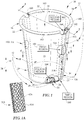
- Brim 16 is configured to serve as both a drinking brim and a sealing brim.
- an inner surface 108 of side wall 18 tangentially intersects an outer diameter 110 of brim 16 at a point 112 while an outer surface 106 terminates at brim 16.
- Transition point 112 provides a smooth transition for a flow of liquid if a user were to drink from insulative cup 10, without spilling or disrupting flow over brim 16.
- brim 16 also serves to cooperate with a retainer 114 of a lid 116 to secure lid 116 to insulative cup 10 with a liquid seal so that a user may use a drinking spout 118 of lid 116 without having liquid escape between lid 116 and brim 16.
- Retainer 114 snaps over and engages diameter 110 of brim 16 so that a flange 122 of lid 116 engages diameter 110 at a point 120 to seal lid 116 to insulative cup 10.
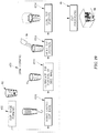
- rolled brim 16A shown in Fig. 32 has a constant thickness of insulative cellular non-aromatic polymeric material with dimensions X 1 , X 2 , and X 3 being generally equal, but with a brim thickness B4 that is greater than the brim thickness B1 of insulative cup 10.
- a larger brim thickness B4 provides clearance in the interior space 900 of brim 16A, improving the manufacturability of brim 16A by allowing clearance during brim rolling.
- a rolled brim 16B has wall thickness X 1 that is reduced and thinned during the brim rolling process that results in a reduction at X 2 and a further reduction at X 3 as shown in Fig. 33 .
- Brim 16B is relatively easier to manufacture than brim 16A and provides a brim with a brim thickness B5 that is approximately the same as brim thickness B4, but has a brim height B6 that is larger than B5. This results in additional relief in an interior space 904 of brim 16B. Brim 16B is more suitable for use with lids by providing additional contact area for sealing.
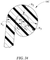
- rolled brim 16C approximates a solid brim with a first wall dimension X 1 that is reduced to X 2 , further reduced at X 3 , and rolled about itself at X 4 and X 5 as shown in Fig. 34 .
- brim 16C With heating and or compression, brim 16C provides a solid brim structure with a high rigidity due to the lack of relief in an interior space of brim 16C.
- Such a brim is suitable for drinking and provides a rigidity that assists with maintaining a snap fit lid, such as lid 116 in place during use.
- the brim thickness B7 is approximately equal to brim thickness B1 in insulative cup 10.
- Body blank 500 is formed during cup-manufacturing process 40 using a body blank 500 as suggested in Figs. 16-20 .
- Body blank 500 may be produced from a strip of insulative cellular non-aromatic polymeric material, a laminated sheet 80 as shown in Fig. 16 and discussed in further detail below, or a strip of insulative cellular non-aromatic polymeric material that has been printed on.
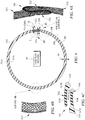
- body blank 500 is generally planar with a first side 502 and a second side 504 (seen in Fig. 12 ).
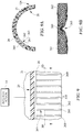
- Body blank 500 is embodied as a circular ring sector with an outer arc length S 1 that defines a first edge 506 and an inner arc length S 2 that defines a second edge 508.
- the arc length S 1 is defined by a subtended angle ⁇ in radians times the radius R 1 from an axis 510 to the edge 506.
- inner arc length S 2 has a length defined as subtended angle ⁇ in radians times the radius R 2 .
- the difference of R 1 -R 2 is a length h which is the length of two linear edges 512 and 514. Changes in R 1 , R 2 and ⁇ can will result in changes in the size of insulative cup 10.
- First linear edge 512 and second linear edge 514 each lie on a respective ray emanating from center 510.
- body blank 500 has two planar sides, 502 and 504, as well as four edges 506, 508, 512, and 514 which define the boundaries of body blank 500.
- the edges 512 and 514 may correspond to and have treatments as described below.
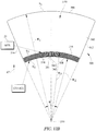
- Fold line 516 has a radius R3 measured between center 510 and a fold line 516 and fold line 516 has a length S 3 .
- R 1 is relatively greater than R 3 .
- R 3 is relatively greater than R 2 . The differences between R 1 , R 2 , and R 3 may vary depending on the application.
- Fold line 516 shown in Fig. 12 is a selected region of a strip of insulative cellular non-aromatic polymeric material that has been plastically deformed in accordance with the present disclosure (by application of pressure-- with or without application of heat) to induce a permanent set resulting in a localized area of increased density and reduced thickness.
- the thickness of the insulative cellular non-aromatic polymeric material at fold line 516 is reduced by about 50% as shown in Fig. 12 .
- the blank is formed to include a number of depressions 518 or ribs 518 positioned between the arcuate edge 508 and fold line 516 with the depressions 518 creating a discontinuity in a surface 531.
- Each depression 518 is linear having a longitudinal axis that overlies a ray emanating from center 510. As discussed above, depressions 518 promote orderly forming of floor-retaining flange 26.
- the insulative cellular non-aromatic polymer material of reduced thickness at fold line 516 ultimately serves as connecting web 25 in the illustrative insulative cup 10. As noted above, connecting web 25 promotes folding of floor-retaining flange 26 inwardly toward interior region 14.
- each depression 518 is spaced apart from each neighboring depression a first distance 551.
- first distance 551 is about 0.067 inches (1.7018 mm).
- Each depression 518 is also configured to have a first width 552.
- first width 552 is about 0.028 inches (0.7112 mm).
- Each depression 518 is also spaced apart from fold line 516 a second distance 553.
- second distance 553 is about 0.035 inches (0.889 mm).
- Depressions 518 and fold line 516 are formed by a die that cuts body blank 500 from a strip of insulative cellular non-aromatic polymeric material, laminated sheet 80, or a strip of printed-insulative cellular non-aromatic polymeric material and is formed to include punches or protrusions that reduce the thickness of the body blank 500 in particular locations during the cutting process.
- the cutting and reduction steps could be performed separately as suggested in Fig. 17 , performed simultaneously, or that multiple steps may be used to form the material.
- a first punch or protrusion could be used to reduce the thickness a first amount by applying a first pressure load.
- a second punch or protrusion could then be applied with a second pressure load greater than the first.
- the first punch or protrusion could be applied at the second pressure load. Any number of punches or protrusions may be applied at varying pressure loads, depending on the application.
- depressions 518 permit controlled gathering of floor-retaining flange 26 supporting a platform-support member 23 and horizontal platform 21.
- Floor-retaining flange 26 bends about fold line 516 to form receiving well 27 with fold line 516 forming connecting web 25.
- the absence of material in depressions 518 provides relief for the insulative cellular non-aromatic polymeric material as it is formed into floor-retaining flange 26.
- This controlled gathering can be contrasted to the bunching of material that occurs when materials that have no relief are formed into a structure having a narrower dimension. For example, in traditional paper cups, a retaining flange type will have a discontinuous surface due to uncontrolled gathering.
- Such a surface is usually worked in a secondary operation to provide an acceptable visual surface, or the uncontrolled gathering is left without further processing, with an inferior appearance.
- the approach of forming the depressions 518 in accordance with the present disclosure is an advantage of the insulative cellular non-aromatic polymeric material of the present disclosure in that the insulative cellular non-aromatic polymeric material is susceptible to plastic deformation in localized zones in response to application of pressure (with or without application of heat) to achieve a superior visual appearance.
- cup 710 is similar to insulative cup 10, but cup 710 is formed with depressions 718 formed on a surface 726A which corresponds to the surface 26A of insulative cup 10. Depressions 718 being formed on surface 726A leaves a smooth, un-interrupted surface 726B.
- Figs. 7A and 8 the interaction of retaining flange 726 and bottom portion 724 with floor ring 723 is shown as photographed to show the thickening and thinning of non-aromatic polymer material 624 and distortion of cells 614 as the cup 710 is assembled.
- insulative cup 10 is made in accordance with cup-manufacturing process 40 as shown in Figs. 16-20 .
- laminated sheet 80 is a composite formed of a strip of insulative cellular non-aromatic polymeric material 82 onto which a skin 84 is laminated from a roll 78 at a laminating stage 44.
- Roll 86 of laminated sheet 80 is fed to the cup-forming stage 45.
- Cup-forming stage 45 illustratively includes a body blank forming step 451, an optional body blank annealing step 451a, a cup-base forming step 452, and a brim-forming step 453 as shown in Fig. 16 .
- Body blank forming step 451 uses laminated sheet 80 to make a body blank 92 as shown in Fig. 17 .
- Cup-base forming step 452 uses side wall blanks 92 along with another laminated sheet 80 provided by another laminated roll 86 to form a floor blank 90, form side wall 18, and join side wall 18 to floor 20 to establish base 12 as shown in Fig. 18 .
- Brim-forming step 453 rolls top portion 22 of base 12 to form rolled brim 16 on base 12 as suggested in Fig. 19 .
- An unexpected property of laminated sheet 80 including a strip of insulative cellular non-aromatic polymeric material 82 is its ability to form noticeably smooth, crease and wrinkle free surfaces when bent to form a round article, such as insulative cup 10.
- Surface 106 is smooth and wrinkle free as is surface 108.
- the smoothness of the surfaces 106 and 108 of the present disclosure is such that the depth of creases or wrinkles naturally occurring when subjected to extension and compression forces during cup-manufacturing process 40 is less than 100 micron and even less than 5 micron in most instances. At less than 10 micron, the creases or wrinkles are not visible to the naked eye.
- Body blank forming step 451 includes a laminated-roll loading step 4511, an optional annealing step 4511a, a compressing step 4512, a cutting step 4513, a collecting scrap step 4514, and an accumulating blanks step 4515 as shown in Fig. 17 .
- Laminated-roll loading step 4511 loads laminated roll 76 onto a cutting machine such as a die cutting machine or metal-on-metal stamping machine. As a result, laminated sheet 80 is drawn into the cutting machine for processing.
- the optional annealing step 4511a heats laminated sheet 80 as it moves to the cutting machine so that stresses in the non-aromatic polymer structure of laminated sheet 80 are released to reduce creasing and wrinkling in surfaces 106 and 108 of insulative cup 10.
- Compressing step 4512 compresses portions of laminated sheet 80 to form a compressed sheet. As an example, compressing step 4512 forms fold line 516 and depressions 518 as shown in Fig. 12 .
- Cutting step 4513 cuts compressed sheet to cause body blank 92 to be cut from a blank-carrier sheet 94.
- Collecting scrap step 4514 collects blank-carrier sheet 94 after cutting step 4513 is complete so that blank-carrier sheet 94 may be recycled.
- Accumulating blanks step 4515 accumulates each body blank 92 to form a body blank stack 95 for use in cup-base forming step 452 as shown in Fig. 19 .
- Cup-base forming step 452 includes a body blanks loading step 4521A, a heating body blank step 4522A, a wrapping body blank step 4523A, a forming side wall step 4524A, a laminated-roll loading step 4521B, a cutting floor blanks step 4522B, a shaping floor step 4523B, a heating floor step 4524B, a heating body step 4525A, a wrapping body step 4526, and a floor-seam forming step 4527 as shown in Fig. 18 .
- Body blanks loading step 4521A loads body blank stack 95 into a cup-forming machine for further processing.
- Heating body blank step 4522A applies heat 96 to body blank 92.
- Wrapping body blank step 4523A wraps heated body blank 92 around a mandrel included in the cup-forming machine.
- Forming side wall step 4524A forms side wall 18 by compressing portions of side wall 18 using primary and auxiliary seam clamps included in the cup-forming machine.
- Primary and auxiliary seam clamps provide localize compression which results a portion of side wall 18 having thickness T2 and another portion having thickness T1 as shown in Fig. 4 .
- An an example, thickness T2 is about about equal to thickness T1.
- Laminated-roll loading step 4521B loads another laminated roll 76 onto the cup-forming machine to cause laminated sheet 80 to be drawn into cup-forming machine for processing.
- Cutting floor blanks step 4522B cuts laminated sheet 80 to cause floor blank 90 to be cut from a blank-carrier sheet 94. Blank-carrier sheet 94 may then be collected and recycled.
- Shaping floor step 4523B forms floor 20 by inserting floor blank 90 into the mandrel of the cup-forming machine.
- Heating floor step 4524B applies heat 96 to floor 20 at the same time heating body step 4525A applies heat 96 to side wall 18.
- Wrapping body 4526 wraps support structure 19 around platform-support member 23 of floor 20.
- Floor-seam forming step 4527 compresses floor 20 and side wall 18 to establish a floor seam or seal between floor 20 and side wall 18 to establish base 12 which is then ready for brim-forming step 453 as shown in Fig. 19 .
- cup-base forming step 452 advantageously maintains the thickness T1 of the side wall 18 as compared to a thermoforming process. Rather than heating an insulative cellular non-aromatic polymeric material and working it over a mandrel in the thermoforming process, subjecting portions of the wall of the resulting cup to thinning and potentially reducing the insulative and structural properties thereof, cup-base forming step 452 is an assembly process that does not require the entire side wall 18 to be subjected to melting temperatures. This provides the advantage of maintaining consistency in thickness T1 of side wall 18 and, thereby, consistent and superior insulating properties as compared to vessels subjected to a deep draw thermoforming process.
- Brim-forming step 453 includes a transferring cup-base step 4531, an optional lubricating top-portion step 4532, heating top-portion step 4533, and rolling top-portion step 4534 as shown in Fig. 19 .
- Transferring cup-base step 4531 transfers base 12 from a cup-base forming machine to a brim-forming machine.
- Lubricating top-portion step 4532 lubricates top portion 22 of base 12.
- Heating top-portion step 4533 applies heat 96 to top portion 22 of base 12.
- Curling top-portion step 4534 curls top portion 22 away from interior region 14 to establish rolled brim 16 and form insulative cup 10.
- Cup-packaging stage 46 includes a leak inspecting step 461, an accumulating cups step 462, and a packaging cups step 463 as shown in Fig. 20 .
- Leak inspecting step 461 inspects each insulative cup 10 formed during brim-forming step 453 for leaks. Those cups failing the leak inspection are collected and recycled owing to formation of those cups from insulative cellular non-aromatic polymeric material. Those cups passing the leak inspection are accumulated in accumulating cups step 462 to form a stack 98 of insulative cups.
- Packaging cups step 463 stores stack 98 of insulative cups for storage, use, or transportation as shown in Fig. 20 .
- a body blank 800 is shown in Figs. 21 and 22 .
- the body blank 800 takes advantage of the properties of the disclosed insulative cellular non-aromatic polymeric material when two reduced areas 802 and 804 are formed in body blank 800 to provide relief for the overlap of material when a brim, such as brim 16 is rolled on a cup.
- Body blank 800 is similar to body blank 500, with the addition of the reduced areas 802 and 804.
- areas 802 and 804 are reduced in thickness by about 50% so that when a cup is formed from body blank 800, the thickness of the brim where areas 802 and 804 overlap is approximately the same as in areas where there is no overlap.
- a body blank 820 includes reduced areas 822 and 824 along the linear sides 826 and 828 of the body blank 820 as shown in Figs. 23 and 24 .
- Reduced areas 822 and 824 are reduced in thickness by about 50% so that when reduced areas 822 and 824 are overlapped during cup-manufacturing process 40, the thickness at the overlapping seam is approximately the same as the remainder of the side wall of the cup formed from wall blank 820.
- a cup 830 includes a side wall 832 which is formed to include a number of ribs 834 extending from a reduced area 838 of side wall 832 as shown in Figs. 25-27 .
- a body blank 836 is reduced in areas 838, 840, 842, and 844 so that ribs 834 extend away from the reduced areas 838, 840, 842, and 844.
- Ribs 834 provide an air gap or spacing between a hand of user holding cup 830 and the remainder of the side wall 832, to reduce the contact area.
- Ribs 834 may also be contacted by a sleeve (not shown) placed on cup 830 to provide air gaps between the reduced areas 838, 840, 842, and 844 and the sleeve to insulate a user's hand.
- a sleeve (not shown) placed on cup 830 to provide air gaps between the reduced areas 838, 840, 842, and 844 and the sleeve to insulate a user's hand.
- a cup 850 shown in Fig. 28 includes ribs 852 formed in a side wall 854 through displacement of portions of a wall blank 856, shown in Fig. 29 , as suggested by Figs. 30 and 31 .
- insulative cellular non-aromatic polymeric material was plastically deformed to create permanent set to reduce a thickness.
- material is displaced by permitting relief when the strip of insulative cellular non-aromatic polymeric material is acted upon by pressure loads so that the material moves as suggested by Figs.
- the strip of insulative cellular non-aromatic polymeric material deforms to create depressions 864 on one side and protruding ribs 852 on the opposite side.
- the strip of insulative cellular non-aromatic polymeric material deforms such that some thinning occurs in an area 858, while the thickness of the displaced wall 860 remains approximately equal to the thickness 862 of the side wall 854.
- Protrusions 852 serve a similar purpose as ribs 834 discussed above with regard to cup 830.
- the advantage of protrusions 852 is that the thickness of side wall 854 remains generally constant while continuing to provide the insulative properties of a full thickness wall and the advantages of ribs.
- the example discussed herein may be formed of raw insulative cellular non-aromatic polymeric material or any variation of composites using the insulative cellular non-aromatic polymer material as disclosed herein. This includes embodiments that laminate one or both sides with a polymeric film.
- the cup-manufacturing process 40 described hereinabove is modified by not laminating the film layer to the substrate.
- the film layer is entirely omitted and printing may done directly on the insulative cellular non-aromatic polymeric material layer.
- the material of the present disclosure may also be formed into a deformable sheet which can be wrapped around other structures.
- a sheet of the present material may be formed and wrapped around a pipe, conduit or other structure to provide improved insulation.
- a potential feature of an insulative cup formed of insulative cellular non-aromatic polymeric material according to exemplary embodiments of the present disclosure is that the cup has low material loss. Furthermore, the material of the present disclosure may have markedly low off-gassing when subjected to heat from a conventional kitchen-type microwave oven for periods of time up to several minutes.
- an insulative cup formed of insulative cellular non-aromatic polymeric material according to the present disclosure is that the cup can be placed in and go through a conventional residential or commercial dishwasher cleaning cycle (top rack) without noticeable structural or material breakdown or adverse affect on material properties. This is in comparison to beaded expanded polystyrene cups or containers which can break down under similar cleaning processes. Accordingly, a cup made according to one aspect of the present disclosure can be cleaned and reused.
- an insulative cup formed of insulative cellular non-aromatic polymeric material is that the insulative cup and scrap material can be recycled.
- Recyclable means that a material can be added (such as regrind) back into an extrusion or other formation process without segregation of components of the material.
- an insulative cup formed the insulative cellular non-aromatic polymeric material does not have to be manipulated to remove one or more materials or components prior to re-entering the extrusion process.
- an insulative cup formed from a sheet including a printed film skin laminated to an exterior of an insulative cellular non-aromatic polymeric material may be recyclable if one does not need to separate out the film layer prior to the insulative cup being ground into particles.
- a paper-wrapped expanded polystyrene cup may not be recyclable because the polystyrene material could not practicably be used as material in forming an expanded polystyrene cup, even though the cup material may possibly formed into another product.
- an insulative cup formed from a non-expanded polystyrene material having a layer of printed film adhered thereto may be considered non-recyclable because it would require the segregation of the film layer, which would not be desirable to introduce as part of the regrind into the extrusion process.
- Recyclability of articles formed using the insulative cellular non-aromatic polymeric material of the present disclosure minimize the amount of disposable waste created.
- paper cups that typically have an extrusion coated plastic layer or a plastic lamination for liquid resistance ordinarily cannot be recycled because the different materials (paper, adhesive, film, plastic) normally cannot be practicably separated in commercial recycling operations.
- a potential feature of an insulative cup formed of insulative cellular non-aromatic polymeric material according to one aspect (a non-laminate process) of the present disclosure is that the outside (or inside or both) wall surface of the insulative cellular polypropylene sheet (prior to being formed into an insulative cup, or during cup formation, depending on the manufacturing process employed) can accept printing of high-resolution graphics.
- beaded expanded polystyrene cups have a surface which typically is not smooth enough to accept printing other than low-resolution graphics.
- uncoated paper cups also typically do not have a smooth enough surface for such high-resolution graphics.
- Paper cups have difficulty reaching insulation levels and require a designed air gap incorporated into or associated with the paper cup to achieve insulation. Such designed air gap may provided by a sleeve slid onto and over a portion of the paper cup.
- a potential feature of an insulative cup formed of insulative cellular non-aromatic polymeric material according to one aspect of the present disclosure is that it possesses unexpected strength as measured by rigidity.
- Rigidity is a measurement done at room temperature and at an elevated temperature (e.g., by filling the cup with a hot liquid) and measuring the rigidity of the material.
- the strength of the cup material is important to minimize deformation of the cup as the cup is being handled by a user.
- a potential feature of an insulative cup formed of insulative cellular non-aromatic polymeric material according to the present disclosure is that insulative cup is resistant to puncture, such as by a straw, fork, spoon, finger nail, or the like, as measured by standard impact testing, as described hereinbelow. Test materials demonstrated substantially higher impact resistance when compared to a beaded expanded polystyrene cup. As a result, an insulative cup in accordance with the present disclosure may minimize the likelihood of puncture and leakage of hot liquid.
- Insulative cup 10 of the present disclosure satisfies a long-felt need for a vessel that includes many if not all the features of insulative performance, ready for recyclability, high-quality graphics, chemical resistance, puncture resistance, frangibility resistance, stain resistance, microwavability, and resistance to leaching undesirable substances into products stored in the interior region of the drink cup as discussed above.
- Others have failed to provide a vessel that achieves combinations of these features as reflected in the appended claims. This failure is a result of the many features being associated with competitive design choices. As an example, others have created vessels that based on design choices are insulated but suffer from poor puncture resistance, lack of microwavability, and leech undesirable substances into products stored in the interior region.
- insulative cup 10 overcomes the failures of others by using an insulative cellular non-aromatic polymeric material.
- DAPLOYTM WB140 polypropylene homopolymer (available from Borealis A/S) was used as the polypropylene base resin.
- F020HC available from Braskem, a polypropylene homopolymer resin, was used as the secondary resin.
- the two resins were blended with: HydrocerolTM CF-40ETM as a primary nucleation agent, talc as a secondary nucleation agent, CO 2 as a blowing agent, a slip agent, and titanium dioxide as a colorant. Percentages were:
- the formulation was added to an extruder hopper.
- the extruder heated the formulation to form a molten resin mixture.
- To this mixture was added:
- the carbon dioxide with R134a was injected into the resin blend to expand the resin and reduce density.
- the mixture thus formed was extruded through a die head into a sheet. The sheet was then cut and formed into a cup.
- Example 1 The test results of the material formed according to Example 1 showed the material had a density of 0.1902g/cc and a nominal sheet gauge of 0.089 inches.
- Containers produced using this material filled with 12 ounces of room temperature water were heated in a FISO Microwave Station (1200 Watts) microwave oven for 2.5 min without burning or scorching or other visible effect on the cup.
- FISO Microwave Station (1200 Watts) microwave oven for 2.5 min without burning or scorching or other visible effect on the cup.
- paper cups heated in the same microwave oven scorched or burned in less than 90 seconds..
- a cup formed from the formulation noted above was used having a density of 0.1902 g/cm 3 and a wall thickness of 0.089 inches (2.2606 mm).
- a hot liquid at 200°F (93.3°C) was placed in the cup.
- the temperature measured on the outside wall of the cup was about 140.5°F (60.3°C), i.e., a 59.5°F (33°C) drop.
- the maximum temperature over a five-minute period was observed to peak at 140.5°F (60.3°C).
- Frangibility can be defined as resistance to tear or punctures causing fragmentation.
- Test results are shown in Tables 3-4 below.
- the material as formed in one exemplary embodiment of the present disclosure provides superior resistance to tear forces when compared to EPS.
- Table 3 Test Results Machine Direction (gram force) Transverse Direction (gram force) Tag Test 1 Test 2 Test 3 Test 4 Test 5 mean std dev. Test 1 Test 2 Test 3 Test 4 Test 5 mean std dev.
- An Instron instrument is used in compression mode set to 10 inches per minute travel speed.
- the cup puncture test fixture on base of Instron is used. This fixture allows the cup to fit over a shape that fits inside the cup with a top surface that is perpendicular to the travel of the Instron tester.
- the one inch diameter hole of the fixture should be positioned up.
- the portion of the Instron that moves should be fitted with a 0.300 inch (7.62 mm) diameter punch.
- the punch with the hole is aligned in the test fixture.
- the cup is placed over the fixture and the force and travel needed to puncture the cup sidewall is recorded.
- the sidewall puncture test is repeated in three evenly spaced locations while not puncture testing on the seam of the cup.
- the bottom of the cup is tested. This should be done in the same manner as the sidewall test except no fixture is used.
- the cup is just placed upside down on the base of the Instron while bringing the punch down on the center of the cup bottom.
- the material as formed in one exemplary embodiment of the present disclosure provides superior resistance to punctures when compared to EPS using the Slow Puncture Resistance Test Method as described in ASTM D-3763-86.
- the test results are shown in Tables 6-9 below.
- the formulation was added to an extruder hopper.
- the extruder heated the formulation to form a molten resin mixture.
- To this mixture was added the CO 2 to expand the resin and reduce density.
- the mixture thus formed was extruded through a die head into a strip. The strip was then cut and formed into a cup.
- test method is the same as described for rigidity testing in Example 1.
- a cup formed from the formulation noted above was used having a density of 0.18 g/cm 3 and a wall thickness of 0.074 inches (1.8796 mm).
- a hot liquid at 200°F (93.3°C) was placed in the cup.
- the temperature measured on the outside wall of the cup was about 151°F (66.1°C), i.e., a 49.0°F (27.2°C) drop.
- the maximum temperature over a five-minute period was observed to peak at 151°F (66.1°C).
- Insulation testing in the form of thermal conductivity was done.
- This test measures bulk thermal conductivity (W/m-K), measured at ambient temperature and at 93°C.
- W/m-K bulk thermal conductivity
- a ThermTest TPS 2500 S Thermal Constants Analyzer instrument was used, employing the test method of ISO/DIS 22007-2.2 and using the Low Density/High Insulating option.
- the TPS sensor #5501 (6.403 mm radius) with Kapton® insulation was used for all measurements.
- a 20 second test was done, using 0.02 Watts power. Data using points 100-200 were reported.
- Table 11 Mean Thermal Conductivity Results Temp. (°C) Mean Thermal Conductivity (W/m-K) Standard Deviation (W/m-K) 21 0.05792 0.00005 93 0.06680 0.00025
- the present disclosure relates to a container.
- a cup is described in the exemplary example; however, the container may be embodied in any of a variety of possible vessel shapes or structures or for a variety of applications, such as, but not limited to, a conventional beverage cup, storage container, bottle, or the like.
- a liquid beverage will be used as the material which can be contained by the container; however, a container in accordance with the present disclosure may hold liquids, solids, gels, combinations thereof, foodstuffs, or other material.
- a method of forming a vessel in accordance with the present disclosure may include the steps of forming a blank for a side wall of the vessel, heating first and second portions of the blank, wrapping the blank such that the first and second portions overlap, and compressing the overlapped portions while they are heated to secure the first and second portions to form a side wall.
- the blank may include an insulative cellular non-aromatic polymeric material having a non-uniform density with areas of higher density formed in the blank to define depressions in the blank.
- the method of forming a vessel may include the steps of forming a floor blank for a floor of the vessel and placing the floor blank adjacent a first end of the elongated wall, securing the floor blank to the side wall, heating the floor blank prior to securing the floor blank to the side wall, and heating a portion of the side wall which contacts the floor blank prior to securing the floor blank to the side wall.
- the method of forming a vessel may include the step of applying pressure to the floor blank and the portion of the side wall to secure the portion of the elongated wall with the floor blank.
- the method of forming a vessel may include the step of displacing a portion of the side wall that engages the floor blank to wrap the portion of the side wall around a portion of the floor blank.
- the method of forming a vessel may include the step of compressing a portion of the side wall to increase the localized density of the compressed portion to define a fold line about which the displaced portion of the side wall is displaced.
- the method of forming a vessel may include the steps of heating the entire blank for a side wall to anneal the blank and allowing the blank to cool before heating first and second portions of the blank.
- the method of forming a vessel may include the steps of forming a composite including an insulative cellular non-aromatic polymeric material, and at least one polymeric film adhered to the insulative cellular non-aromatic polymeric material, and forming the blank for the elongated wall of the vessel from the composite.
- the at least one polymeric film may include biaxially oriented polypropylene.
- the method of forming a vessel may include the step of heating composite prior to forming the blank for a side wall to release stresses in the biaxially oriented polypropylene film.
- the method of forming a vessel may include the step of applying adhesive to the floor blank prior to securing the blank to the side wall.
- the method of forming a vessel may include the steps of applying adhesive to a portion of the elongated wall which contacts the floor blank prior to securing the floor blank to the elongated wall, applying pressure to the floor blank and the portion of the side wall to secure the portion of the elongated wall with the floor blank, displacing a portion of the elongated wall that engages the floor blank to wrap the portion of the elongated wall around a portion of the floor blank, and compressing a portion of the elongated wall to increase the localized density of the compressed portion to define a fold line about which the displaced portion of the elongated wall is displaced.
Landscapes
- Mechanical Engineering (AREA)
- Engineering & Computer Science (AREA)
- Packages (AREA)
- Laminated Bodies (AREA)
- Table Devices Or Equipment (AREA)
- Shaping Of Tube Ends By Bending Or Straightening (AREA)
- Containers Having Bodies Formed In One Piece (AREA)
- Blow-Moulding Or Thermoforming Of Plastics Or The Like (AREA)
- Closures For Containers (AREA)
- Control And Other Processes For Unpacking Of Materials (AREA)
- Magnetic Resonance Imaging Apparatus (AREA)
- Prostheses (AREA)
- Rigid Containers With Two Or More Constituent Elements (AREA)
- Devices For Use In Laboratory Experiments (AREA)
- Compositions Of Macromolecular Compounds (AREA)
- Floor Finish (AREA)
- Refuge Islands, Traffic Blockers, Or Guard Fence (AREA)
- Thermal Insulation (AREA)
- Filling Or Discharging Of Gas Storage Vessels (AREA)
Claims (21)
- Tasse isolante comprenant un corps 11, comprenant une paroi latérale en forme de manchon 18 et un fond 20 couplé au corps 11 afin de définir une région intérieure délimitée par la paroi latérale en forme de manchon 18 et le fond 20, ledit corps 11 comprenant une feuille comprenant le matériau polymère non-aromatique cellulaire isolant conçu pour fournir un moyen permettant une déformation plastique localisée dans au moins une région sélectionnée du corps 11 afin de fournir un premier segment de matériau déformé plastiquement possédant une première densité située dans une première partie de la région sélectionnée du corps 11 et un second segment de matériau possédant une seconde densité inférieure à la première densité, située dans une deuxième partie adjacente de la région sélectionnée du corps 11 sans que le matériau polymère non aromatique cellulaire isolant ne se fendille afin qu'une caractéristique isolante prédéfinie soit maintenue dans le corps 11,
caractérisée en ce que le matériau polymère non aromatique cellulaire isolant comprend une résine à base de polypropylène possédant une haute résistance à la fusion, une résine d'homopolymère de polypropylène, au moins un agent de nucléation et un moyen à gaz permettant l'expansion des résines afin de réduire la densité. - Tasse isolante selon la revendication 1,(a) ledit moyen à gaz comprenant du dioxyde de carbone, ou(b) ladite résine à base de polypropylène comprenant du polypropylène à large distribution de poids moléculaire caractérisée par une distribution qui est uni-modale.
- Tasse isolante selon la revendication 1, une première desdites régions sélectionnées dudit corps 11, dans laquelle une déformation plastique localisée est rendue possible par le matériau polymère non aromatique cellulaire isolant, étant une paroi latérale en forme de manchon 18 et ladite paroi latérale en forme de manchon 18 comprenant une languette interne verticale 514 agencée pour s'étendre vers le haut depuis le fond 20 et conçue pour fournir le premier segment de matériau possédant la première densité dans la première des régions sélectionnées du corps, une languette externe verticale 512 agencée pour s'étendre vers le haut depuis le fond 20 et pour s'accoupler avec la languette interne verticale 514 le long d'une interface entre celles-ci et une enceinte verticale 513 agencée pour relier les languettes verticales interne et externe 514, 512 et pour entourer la région intérieure et conçue pour fournir le deuxième segment de matériau possédant la seconde densité dans la première des régions sélectionnées du corps et pour coopérer avec les languettes verticales interne et externe 514, 512 afin de former une paroi latérale en forme de manchon 18.
- Tasse isolante selon la revendication 3, une deuxième desdites régions sélectionnées dudit corps 11, dans laquelle la déformation plastique localisée est rendue possible par le matériau polymère non aromatique cellulaire isolant, étant dans un bord roulé 16 compris dans le corps 11 et couplé à une extrémité supérieure de la paroi latérale en forme de manchon 18 pour se trouver espacé du fond 20 et pour encadrer une ouverture dans la région intérieure et ledit bord roulé 16 comprenant une languette interne roulée 164 conçue pour fournir le premier segment de matériau dans la seconde des régions sélectionnées du corps 11 et couplée à une extrémité supérieure de la languette externe verticale 512 comprise dans la paroi latérale en forme de manchon 18, une languette externe roulée 162 couplée à une extrémité supérieure de la languette interne verticale 514 comprise dans la paroi latérale en forme de manchon 18 et à une surface extérieure orientée vers l'extérieur de la languette interne roulée 164, et une lèvre roulée 163 agencée pour relier les bords latéraux en opposition de chacune des languettes roulées externe et interne 164, 162 et conçue pour fournir le second segment de matériau possédant la seconde densité dans la deuxième de la région sélectionnée du corps 11 et coopérer avec les languettes roulées externe et interne 164, 162 pour former le bord roulé 16.
- Tasse isolante selon la revendication 4, une troisième desdites régions sélectionnées dudit corps 11, dans lequel la déformation plastique localisée est rendue possible par le matériau polymère non aromatique cellulaire isolant, étant dans un support de fond 17 compris dans le corps 11 et couplé à une extrémité inférieure de la paroi latérale en forme de manchon 18 se trouvant espacée du bord roulé 16 et du fond 20 afin de supporter le fond 20 dans une position fixe par rapport à la paroi latérale en forme de manchon 18 afin de former la région intérieure et ledit support de fond 17 comprenant un anneau de support de bande 126 couplé à l'extrémité inférieure de la paroi latérale en forme de manchon 18 et conçu pour fournir le deuxième segment de matériau possédant la seconde densité dans la troisième des régions sélectionnées dudit corps, une bride de maintien de fond 26 couplée au fond 20 et agencée pour être entourée par l'anneau de support de bande 126, et une bande 25 agencée pour relier la bride de maintien de fond 26 et l'anneau de support de bande 126 et conçue pour fournir le premier segment de matériau possédant la première densité dans la troisième des régions sélectionnées du corps et éventuellement ;une quatrième desdites régions sélectionnées du corps 11 dans laquelle une déformation plastique localisée est rendue possible par le matériau polymère non aromatique cellulaire isolant, étant dans la bride de maintien de fond 26 du support de fond 17, la bride de maintien de fond 26 comprenant une série alternée de douves verticales épaisses et minces agencées côte à côté pour s'étendre vers le haut depuis la bande 25 vers la région intérieure délimitée par la paroi latérale en forme de manchon 18 et le fond 20 , une première des douves épaisses verticales 261 étant conçue pour comprendre un bord latéral droit 261R s'étendant vers le haut depuis la bande 25 vers la région intérieure, une seconde des douves épaisses verticales 262 étant conçue pour comprendre un bord latéral gauche 262L agencé pour s'étendre vers le haut depuis la bande 25 vers la région intérieure et se trouve en vis-à-vis espacé du bord latéral droit 261R de la première des douves épaisses verticales 261, et une première des douves minces verticales 260 étant agencée pour relier le bord latéral gauche 261L de la première des douves épaisses verticales 261 et le bord latéral droit 262R de la seconde des douves épaisses verticales 262 et pour coopérer avec les bords latéraux gauche et droit afin de définir entre eux un canal vertical 263, la première des douves minces verticales 260 étant conçue pour fournir le premier segment de matériau dans la quatrième des régions sélectionnées du corps 11 et la première des douves épaisses verticales 261 étant configurée pour fournir le second segment de matériau dans la quatrième des régions sélectionnées du corps 11 et éventuellement ;(a) la première des douves minces verticales 260 se situant par rapport à la première et la seconde des douves épaisses verticales 261, 262, afin d'amener le canal vertical 263 à s'ouvrir vers l'intérieur dans une région intérieure inférieure délimitée par la bride de maintien de fond 26 et une plate-forme horizontale 21 comprise dans le fond 20 et située au-dessus de la bride de maintien de fond 26, ou ;(b) ladite première des douves minces verticales 260 se situant par rapport à la première et la seconde des douves épaisses verticales 261, 262, afin d'amener le canal vertical 263 à s'ouvrir vers l'extérieur selon une direction orientée vers l'anneau de support de bande 126.
- Tasse isolante selon la revendication 3,(i) ladite languette interne verticale 514 comprenant une surface interne 514i délimitant une partie de la région intérieure et une surface externe 514o orientée vers la languette externe verticale 512, ladite languette externe verticale 512 comprenant une surface interne 512i orientée vers la région intérieure et s'accouplant avec la surface externe 514o de la languette interne verticale 514 pour définir l'interface entre les languettes verticales interne et externe 514, 512 et la languette externe verticale 512 comprenant en outre une face externe 512o orientée à l'opposée de la languette interne verticale 514 et éventuellement ;
chacune desdites surfaces interne et externe des languettes verticale interne 514 et externe 512 possédant une forme arquée selon une coupe transversale horizontale et sous-tendant un angle aigu inférieur à 20°, ou ;(ii) ladite enceinte verticale 513 étant en forme de C selon une coupe transversale horizontale et chacune des languettes verticales interne et externe 514, 512 possédant une forme arquée selon une coupe transversale horizontale, ou ;(iii) ladite enceinte verticale 513 comprenant un bord latéral vertical gauche 513L et un bord latéral vertical droit 513R agencé de façon à être en vis-à-vis espacé du bord latéral vertical gauche 513L et la languette externe verticale 512 étant conçue pour posséder la première densité et s'accoupler avec la languette interne verticale 514 afin d'établir un pont agencé pour relier les bords latéraux verticaux gauche 513L et droit 513R de l'enceinte verticale 513 et constitué de matériau déformé plastiquement possédant la première densité, et éventuellement ;ladite enceinte verticale 513 comportant une surface interne 513i délimitant une partie de la région intérieure et une surface externe 513o orientée à l'opposé de la région intérieure et entourant la surface interne de l'enceinte verticale 513 et coopérant avec la surface interne 513i de l'enceinte verticale 513 pour définir une première épaisseur entre celles-ci, ladite languette interne verticale 514 comprenant une surface interne 514i délimitant une partie de la région intérieure et une surface externe 514o orientée vers la languette externe verticale 512, ladite languette externe verticale 512 comprenant une surface interne 512i orientée vers la région intérieure et s'accouplant avec la surface externe 514o de la languette interne verticale 514 pour définir l'interface entre les languettes verticales interne et externe 514, 512 et la languette externe verticale 512 comprenant en outre une face externe 512o orientée à l'opposé de la languette interne verticale 514 , les surfaces interne 514i et externe 514o de la languette interne verticale 514 coopérant pour définir une deuxième épaisseur entre elles qui est environ la moitié de la première épaisseur et les surfaces interne 512i et externe 512o de la languette externe verticale 512 coopérant pour définir une troisième épaisseur qui est environ la moitié de la première épaisseur. - Tasse isolante selon la revendication 1, ledit corps 11 comprenant en outre un bord roulé 16 comprenant le matériau polymère non aromatique cellulaire isolant, ledit bord roulé 16 étant couplé à une extrémité supérieure de la paroi latérale en forme de manchon 18 espacée du fond 20 et encadrant une ouverture dans la région intérieure, et ledit bord roulé 16 comprenant une languette interne roulée 164 conçue pour fournir le premier segment de matériau déformé plastiquement possédant la première densité et pour comprendre les bords latéraux gauche et droit en opposition et une lèvre roulée 163 agencée pour relier les bords latéraux gauche et droit en opposition de la languette interne roulée 164 et conçue pour fournir le second segment de matériau possédant la seconde densité.
- Tasse isolante selon la revendication 7, ledit bord roulé 16 comprenant en outre une languette externe roulée 162 couplée à une surface orientée vers l'extérieur de la languette interne roulée 164 pour fournir une coque externe recouvrant la languette interne roulée 164 et formée de matériau déformé plastiquement possédant la première densité, et éventuellement ;
ladite languette externe roulée 162 comprenant les bords latéraux gauche et droit en opposition et la lèvre roulée 163 étant agencée pour relier les bords latéraux gauche et droit en opposition de la languette externe roulée 162 et éventuellement ;ladite lèvre roulée 163 étant en forme de C selon une coupe transversale horizontale et chacune des languettes roulées interne et externe 164, 162 possédant une forme arquée entre les bords latéraux gauche et droit en opposition de celles-ci pour donner audit bord roulé 16 une forme annulaire. - Tasse isolante selon la revendication 7, ledit corps 11 comprenant en outre une paroi latérale en forme de manchon 18 comprenant le matériau polymère non aromatique cellulaire isolant et la paroi latérale en forme de manchon 18 comprenant une languette interne verticale 514 agencée pour s'étendre vers le haut depuis le fond 20 et conçue pour fournir le premier segment de matériau déformé plastiquement possédant la première densité, une languette extérieure verticale 512 agencée pour s'étendre vers le haut depuis le fond 20 et s'accoupler avec la languette interne verticale 514 le long d'une interface entre celles-ci et une enceinte verticale 513 agencée pour relier les languettes verticales interne et externe 514, 512 et entourer la région intérieure et conçue pour fournir le deuxième segment de matériau possédant la seconde densité.
- Tasse isolante selon revendication 7,(i) ledit corps 11 comprenant en outre un support de fond 17 comprenant le matériau polymère non aromatique cellulaire isolant et le support de fond 17 comprenant un anneau de support de bande 126 couplé à une extrémité inférieure de la paroi latérale en forme de manchon 18 et conçu pour fournir le deuxième segment de matériau possédant la seconde densité, une bride de maintien de fond 26 couplée au fond 20 et agencée pour être entourée par l'anneau de support de bande 126, et une bande 25 agencée pour relier la bride de maintien de fond 26 et l'anneau de support de bande 126 et conçue pour fournir le premier segment de matériau déformé plastiquement possédant la première densité, ou ;(ii) ledit corps 11 comprenant en outre une bride de maintien de fond 26 comprenant le matériau polymère non aromatique cellulaire isolant et ladite bride de maintien de fond 26 étant couplée au fond 20 et étant formée pour comprendre une série alternée de douves verticales épaisses et minces agencées côte à côté pour s'étendre vers le haut vers la région intérieure délimitée par la paroi latérale en forme de manchon 18 et le fond 20, une première des douves épaisses verticales 261 étant conçue pour comprendre un bord latéral droit 261R s'étendant vers le haut vers la région intérieure, une seconde des douves épaisses verticales 262 étant conçue pour comprendre un bord latéral gauche 262L s'étendant vers le haut vers la région intérieure et se trouvant en vis-à-vis espacé du bord latéral droit 261R de la première des douves épaisses verticales 261 et une première des douves minces verticales 260 étant agencée pour relier les bords latéraux gauche et droit pour définir entre eux un canal vertical 263, la première des douves minces verticales 260 étant conçue pour fournir le premier segment de matériau déformé plastiquement et la première des douves épaisses verticales 261 étant conçue pour fournir le deuxième segment de matériau.
- Tasse isolante selon la revendication 1, ledit corps 11 comprenant en outre un bord roulé annulaire 16 comprenant le matériau polymère non aromatique cellulaire isolant, ledit bord roulé annulaire 16 étant couplé à une extrémité supérieure annulaire de la paroi latérale en forme de manchon 18 pour se trouver espacé du fond 20 et pour encadrer une ouverture dans la région intérieure, ledit bord roulé annulaire 16 comprenant une languette roulée conçue pour fournir le premier segment de matériau déformé plastiquement possédant la première densité et pour comprendre les bords latéraux gauche et droit en opposition et ledit bord roulé annulaire 16 comprenant en outre une lèvre roulée 163 couplée à l'extrémité supérieure annulaire de la paroi latérale en forme de manchon 18 et agencée pour relier les bords latéraux gauche et droit en opposition de la languette roulée et conçue pour fournir le deuxième segment de matériau possédant la seconde densité.
- Tasse isolante selon la revendication 1, ledit corps 11 comprenant en outre un support de fond 17 comprenant le matériau polymère non aromatique cellulaire isolant, ledit support de fond 17 étant couplé à une extrémité inférieure de la paroi latérale en forme de manchon 18 et au fond 20 afin de supporter le fond 20 dans une position fixe par rapport à la paroi latérale en forme de manchon 18 pour former la région intérieure et le support de fond 17 comprenant une bride de maintien de fond 26 couplée au fond 20, un anneau de support de bande 126 couplé à l'extrémité inférieure de la paroi latérale en forme de manchon 18 et agencé pour entourer la bride de maintien de fond 26, et une bande 25 agencée pour relier la bride de maintien de fond 26 et l'anneau de support de fond 126 et conçue pour fournir le premier segment de matériau déformé plastiquement possédant la première densité, et l'anneau de support de bande 126 étant conçu pour fournir le second segment de matériau possédant la seconde densité.
- Tasse isolante selon la revendication 12,(i) ladite bande 25 et ledit anneau de web-support 126 possédant chacun une forme annulaire et éventuellement ;
ladite bride de maintien de fond 26 possédant une forme annulaire, ou ;(ii) ladite bride de maintien de fond 26, ladite bande 25, et ledit anneau de support de bande 126 comprenant chacun une couche interne dotée d'une surface intérieure s'accouplant avec le fond et une couche externe de recouvrement s'accouplant avec une surface extérieure de la couche interne, ou ;(iii) ledit fond 20 comprenant une plate-forme horizontale 21 délimitant une partie de la région intérieure et un élément de support de plate-forme 23 couplé à la plate-forme horizontale 21 et agencé pour s'étendre vers le bas s'éloignant de la région intérieure dans un espace prévu entre la bride de maintien de fond 26 et l'anneau de support de bande 126 pour s'accoupler avec chacun de la bride de maintien de fond 26 et de l'anneau de support de bande 126 et éventuellement ;(a) ledit élément de support de plateforme 23 possédant une forme annulaire et étant agencé pour entourer la bride de maintien de fond 26 et se trouvant dans un espace annulaire prévu entre la plate-forme horizontale 21 et la bande 25, ou ;(b) ladite bride de maintien de fond 26, ladite bande 25 et ledit anneau de support de bande 126 comprenant chacun une couche interne possédant une surface intérieure s'accouplant avec le fond 20 et une couche externe de recouvrement s'accouplant avec une surface extérieure de la couche interne et la couche interne de chacun de la bride de maintien de fond 26, de la bande 25 et de l'anneau de support bande 126 étant agencée pour s'accoupler avec l'élément de support de plate-forme 23,(iv) ledit corps 11 comprenant en outre une bride de maintien de fond 26 comprenant le matériau polymère non aromatique cellulaire isolant et ladite bride de maintien de fond 26 étant couplée au fond 20 et étant formée pour comprendre une série alternée de douves verticales épaisses et minces agencées côte à côté pour s'étendre vers le haut vers la région intérieure délimitée par la paroi latérale en forme de manchon 18 et le fond 20, une première des douves épaisses verticales 261 étant conçue pour comprendre un bord latéral droit 261R s'étendant vers le haut vers la région intérieure, une seconde des douves épaisses verticales 262 étant conçue pour comprendre un bord latéral gauche 262L s'étendant vers le haut vers la région intérieure et se trouvant en vis-à-vis espacé du bord latéral droit 261R de la première des douves épaisses verticales 261 et une première des douves minces verticales 260 étant agencée pour relier les bords latéraux gauche et droit pour définir entre eux un canal vertical 263, la première des douves minces verticales 260 étant conçue pour fournir le premier segment de matériau déformé plastiquement et la première des douves épaisses verticales 261 étant conçue pour fournir le deuxième segment de matériau. - Tasse isolante selon la revendication 12, ledit corps 11 comprenant en outre une paroi latérale en forme de manchon 18 comprenant le matériau polymère non aromatique cellulaire isolant et ladite paroi latérale en forme de manchon 18 comprenant une languette interne verticale 514 agencée pour s'étendre vers le haut depuis le fond 20 et conçue pour fournir le premier segment de matériau déformé plastiquement possédant la première densité, une languette externe verticale 512 agencée pour s'étendre vers le haut depuis le fond 20 et pour s'accoupler avec la languette interne verticale 514 le long d'une interface entre celles-ci et une enceinte verticale 513 agencée pour relier les languettes verticales interne et externe 514, 512 et entourer la région intérieure et conçue pour fournir le deuxième segment de matériau possédant la seconde densité.
- Tasse isolante selon la revendication 1, ledit corps 11 comprenant en outre une bride de maintien de fond 26 agencée pour se trouver dans une position fixe par rapport à la paroi latérale en forme de manchon 18 et couplée au fond 20 afin de maintenir le fond 20 dans une position fixe par rapport à la paroi latérale en forme de manchon 18, ledit fond 20 comprenant une plate-forme horizontale 21 possédant un bord de périmètre s'accouplant avec une surface interne de la paroi latérale en forme de manchon 18 et une face supérieure orientée vers le haut délimitant une partie de la région intérieure et ladite bride de maintien de fond 26 comprenant une série alternée de douves verticales épaisses et minces agencées pour se trouver côte à côté les unes aux autres pour s'étendre vers le haut vers un dessous, orienté vers le bas, de la plate-forme horizontale 21, une première desdites douves épaisses verticales 261 étant conçue pour comprendre un bord latéral droit 261R s'étendant vers le haut, vers le dessous de la plate-forme horizontale 21, une seconde des douves épaisses verticales 262 étant conçue pour comprendre un bord latéral gauche 262L agencé pour s'étendre vers le haut vers le dessous de la plate-forme horizontale 21 et se trouvant en vis-à-vis espacé du bord latéral droit 261R de la première des douves épaisses verticales 261, et une première des douves minces verticales 260 étant agencée pour relier les bords latéraux gauche et droit et coopérer avec les bords latéraux gauche et droit afin de définir entre eux un canal vertical 263, la première des douves minces 260 étant conçue pour fournir le premier segment de matériau possédant la première densité, et la première des douves épaisses 261 étant conçue pour fournir le second segment de matériau possédant la seconde densité et éventuellement ;(a) ladite première des douves minces verticales 260 se situant par rapport à la première 261 et la seconde 262 des douves épaisses verticales afin d'amener le canal vertical 263 à s'ouvrir vers l'intérieur dans une région intérieure inférieure délimitée par la plate-forme horizontale 21 et la bride de maintien de fond 26, ou ;(b) ledit corps 11 comprenant en outre un anneau de support de bande 26 couplé à une extrémité inférieure de la paroi latérale en forme de manchon 18 et agencé pour entourer la bride de maintien de fond 26 et une bande 25 disposée afin de relier l'anneau de support de bande 126 et la bride de maintien de fond 26, et la première des douves minces verticales 260 se situant par rapport à la première 261 et la seconde 262 des douves épaisses verticales afin d'amener le canal vertical 263 à s'ouvrir vers l'extérieur selon une direction orientée vers l'anneau de support de bande 126, ou ;(c) ladite bride de maintien de fond 26 possédant une forme annulaire et étant agencée pour entourer un axe central s'étendant verticalement interceptant un point central de la plate-forme horizontale 21 et la première des douves minces 260 possédant une paroi interne orientée vers une partie de l'axe central s'étendant verticalement en passant à travers la région intérieure inférieure et éventuellement ;ledit fond 20 comprenant en outre un élément de support de plate-forme 23 agencé pour entourer la bride de maintien de fond 26 et coopérer avec la plate-forme horizontale 21 pour former une cavité de fond s'ouvrant vers le bas contenant la série alternée de douves verticales épaisses et minces dans celle-ci.
- Tasse isolante selon la revendication 1, ledit corps 11 comprenant en outre une bride de maintien de fond 26 agencée pour se trouver dans une position fixe par rapport à la paroi latérale en forme de manchon 18 et couplée au fond 20 afin de maintenir le fond 20 dans une position fixe par rapport à la paroi latérale en forme de manchon 18, le fond 20 comprenant une plate-forme horizontale 21 comportant un bord de périmètre s'accouplant avec une surface interne de la paroi latérale en forme de manchon 18 et une face supérieure orientée vers le haut délimitant une partie de la région intérieure et ladite bride de maintien de fond 26 comprenant une série alternée de douves verticales épaisses et minces agencées afin de se trouver côte à côté les unes aux autres pour s'étendre vers le haut vers un dessous, orienté vers le bas, de la plate-forme horizontale 21, une première des douves épaisses verticales 261 étant conçue pour comprendre un bord latéral droit 261R s'étendant vers le haut vers le dessous de la plate-forme horizontale 21, une seconde des douves épaisses verticales 262 étant conçue pour comprendre un bord latéral gauche 262L agencée pour s'étendre vers le haut vers le dessous de la plate-forme horizontale 21 et se trouvant en vis-à-vis espacé du bord latéral droit 261R de la première des douves épaisses verticales 261, et une première des douves minces verticales 260 étant agencée pour relier les bords latéraux gauche et droit et coopérer avec les bords latéraux gauche et droit pour définir entre eux un canal vertical 263, la première des douves minces 260 étant conçue pour fournir le premier segment de matériau possédant la première densité et la première des douves épaisses 261 étant conçue pour fournir le second segment de matériau possédant la second densité,
et ledit corps 11 comprenant en outre une paroi latérale en forme de manchon 18 comprenant le matériau polymère non aromatique cellulaire isolant et ladite paroi latérale en forme de manchon 18 comprenant une languette interne verticale 514 agencée pour s'étendre vers le haut depuis le fond 20 et conçue pour fournir le premier segment de matériau déformé plastiquement possédant la première densité, une languette externe verticale 512 agencée pour s'étendre vers le haut depuis le fond 20 et pour s'accoupler avec la languette interne verticale 514 le long d'une interface entre elles, et une enceinte verticale 513 agencée pour relier les languettes verticales interne 514 et externe 512 et entourer la région intérieure et conçue pour fournir le second segment de matériau possédant la seconde densité. - Tasse isolante selon la revendication 1, le premier segment de matériau dans la feuille de matériau polymère non-aromatique cellulaire isolant possédant une première épaisseur relativement mince et le second segment de matériau dans la feuille de matériau polymère non-aromatique cellulaire isolant possédant une seconde épaisseur relativement plus épaisse.
- Tasse isolante selon la revendication 1, ledit matériau polymère non aromatique cellulaire isolant comprenant un polypropylène à large distribution de poids moléculaire caractérisé par une distribution qui est uni-modale.
- Tasse isolante selon la revendication 1, ladite première densité étant d'environ 0,350 g/cm3 et la seconde densité étant d'environ 0,175 g/cm3.
- Tasse isolante selon la revendication 1, ledit matériau polymère non aromatique cellulaire isolant étant formé pour comprendre des cellules remplies de gaz et chaque cellule étant délimitée par une paroi de cellule fournie dans le matériau polymère non aromatique cellulaire isolant et conçue pour être déformable de manière non élastique durant l'exposition à la déformation plastique localisée.
- Tasse isolante selon la revendication 1, ledit matériau polymère non aromatique cellulaire isolant comprenant un polypropylène de haute résistance à la fusion caractérisé par une ramification à longue chaîne pour fournir un équilibre prédéfini entre aptitude au traitement et élasticité de fusion élevée.
Priority Applications (1)
| Application Number | Priority Date | Filing Date | Title |
|---|---|---|---|
| EP17181231.6A EP3272665A1 (fr) | 2011-06-17 | 2012-06-07 | Contenant isolé |
Applications Claiming Priority (3)
| Application Number | Priority Date | Filing Date | Title |
|---|---|---|---|
| US201161498455P | 2011-06-17 | 2011-06-17 | |
| US201261618587P | 2012-03-30 | 2012-03-30 | |
| PCT/US2012/041395 WO2012173873A2 (fr) | 2011-06-17 | 2012-06-07 | Contenant isolé |
Related Child Applications (2)
| Application Number | Title | Priority Date | Filing Date |
|---|---|---|---|
| EP17181231.6A Division EP3272665A1 (fr) | 2011-06-17 | 2012-06-07 | Contenant isolé |
| EP17181231.6A Division-Into EP3272665A1 (fr) | 2011-06-17 | 2012-06-07 | Contenant isolé |
Publications (2)
| Publication Number | Publication Date |
|---|---|
| EP2720954A2 EP2720954A2 (fr) | 2014-04-23 |
| EP2720954B1 true EP2720954B1 (fr) | 2017-09-13 |
Family
ID=46298706
Family Applications (2)
| Application Number | Title | Priority Date | Filing Date |
|---|---|---|---|
| EP17181231.6A Withdrawn EP3272665A1 (fr) | 2011-06-17 | 2012-06-07 | Contenant isolé |
| EP12727745.7A Active EP2720954B1 (fr) | 2011-06-17 | 2012-06-07 | Contenant isolé |
Family Applications Before (1)
| Application Number | Title | Priority Date | Filing Date |
|---|---|---|---|
| EP17181231.6A Withdrawn EP3272665A1 (fr) | 2011-06-17 | 2012-06-07 | Contenant isolé |
Country Status (18)
| Country | Link |
|---|---|
| US (3) | US9758292B2 (fr) |
| EP (2) | EP3272665A1 (fr) |
| JP (1) | JP6235466B2 (fr) |
| KR (1) | KR20140045503A (fr) |
| CN (2) | CN103717500B (fr) |
| AR (1) | AR086944A1 (fr) |
| AU (1) | AU2012271047B2 (fr) |
| BR (1) | BR112013032315A2 (fr) |
| CA (1) | CA2842320C (fr) |
| DE (2) | DE112012002042T5 (fr) |
| ES (1) | ES2503890B2 (fr) |
| GB (2) | GB2539589B (fr) |
| MX (1) | MX347519B (fr) |
| RU (1) | RU2014101298A (fr) |
| SG (1) | SG10201604897XA (fr) |
| TW (1) | TW201311516A (fr) |
| UY (1) | UY34134A (fr) |
| WO (1) | WO2012173873A2 (fr) |
Cited By (1)
| Publication number | Priority date | Publication date | Assignee | Title |
|---|---|---|---|---|
| US12091523B2 (en) | 2013-08-16 | 2024-09-17 | Berry Plastics Corporation | Insulated container |
Families Citing this family (66)
| Publication number | Priority date | Publication date | Assignee | Title |
|---|---|---|---|---|
| WO2012174422A2 (fr) | 2011-06-17 | 2012-12-20 | Berry Plastics Corporation | Récipient isolé à bord moulé |
| GB2539589B (en) | 2011-06-17 | 2017-04-19 | Berry Plastics Corp | Insulated container |
| WO2012174568A2 (fr) | 2011-06-17 | 2012-12-20 | Berry Plastics Corporation | Procédé pour former un contenant isolé présentant une illustration |
| CA2842325A1 (fr) | 2011-06-17 | 2013-07-04 | Chris K. LESER | Manchon isole pour tasse |
| KR20140059255A (ko) * | 2011-08-31 | 2014-05-15 | 베리 플라스틱스 코포레이션 | 단열 용기용 고분자 재료 |
| USD738211S1 (en) * | 2012-04-27 | 2015-09-08 | The Procter & Gamble Company | Dispensing cup |
| EP2888092A4 (fr) | 2012-08-07 | 2016-03-23 | Berry Plastics Corp | Procédé et machine de formation de coupe |
| WO2014066810A1 (fr) | 2012-10-26 | 2014-05-01 | Berry Plastics Corporation | Fermeture pour récipient |
| MX2015005207A (es) | 2012-10-26 | 2016-03-21 | Berry Plastics Corp | Material polimerico para un recipiente aislado. |
| AR093943A1 (es) * | 2012-12-14 | 2015-07-01 | Berry Plastics Corp | Reborde de un envase termico |
| AR093944A1 (es) | 2012-12-14 | 2015-07-01 | Berry Plastics Corp | Troquelado para envase |
| US9840049B2 (en) | 2012-12-14 | 2017-12-12 | Berry Plastics Corporation | Cellular polymeric material |
| US9957365B2 (en) | 2013-03-13 | 2018-05-01 | Berry Plastics Corporation | Cellular polymeric material |
| US9725202B2 (en) * | 2013-03-14 | 2017-08-08 | Berry Plastics Corporation | Container |
| US9340345B2 (en) | 2013-03-14 | 2016-05-17 | Berry Plastics Corporation | Stack shoulder for insulated container |
| US9301630B2 (en) * | 2013-05-10 | 2016-04-05 | Tzer-Huang Guo | Composite cup structure |
| WO2015006772A1 (fr) | 2013-07-12 | 2015-01-15 | Berry Plastics Corporation | Matière polymère pour récipient |
| MX2016002374A (es) | 2013-08-26 | 2016-05-31 | Berry Plastics Corp | Material polimerico para un envase. |
| TW201521993A (zh) | 2013-08-30 | 2015-06-16 | Berry Plastics Corp | 用於容器之聚合材料 |
| US20150108146A1 (en) * | 2013-10-22 | 2015-04-23 | Meadwestvaco Corporation | Beverage Container |
| JP6651734B2 (ja) * | 2014-08-28 | 2020-02-19 | 大日本印刷株式会社 | 電子レンジ用紙カップ |
| JP6657659B2 (ja) * | 2014-08-28 | 2020-03-04 | 大日本印刷株式会社 | 電子レンジ用紙カップ |
| US9758655B2 (en) | 2014-09-18 | 2017-09-12 | Berry Plastics Corporation | Cellular polymeric material |
| US20160083570A1 (en) * | 2014-09-18 | 2016-03-24 | Berry Plastics Corporation | Cellular polymeric material |
| US20160082621A1 (en) * | 2014-09-23 | 2016-03-24 | Dart Container Corporation | Insulated container and methods of making and assembling |
| MX2017001871A (es) * | 2014-09-25 | 2017-06-08 | Berry Plastics Corp | Material polimerico. |
| WO2016118838A1 (fr) * | 2015-01-23 | 2016-07-28 | Berry Plastics Corporation | Matériau polymère pour contenant isotherme |
| BR112017016387B1 (pt) | 2015-02-04 | 2021-11-23 | Exxonmobil Chemical Patents Inc. | Composições de polipropileno com encruamento, resistência à fusão e pseudoplasticidade equilibrada e artigo de espuma |
| WO2016136853A1 (fr) * | 2015-02-25 | 2016-09-01 | 大日本印刷株式会社 | Récipient double et manchon extérieur utilisé dans un récipient double |
| WO2016141179A1 (fr) | 2015-03-04 | 2016-09-09 | Berry Plastics Corporation | Matière polymère pour contenant |
| EP3280767A4 (fr) | 2015-04-10 | 2018-12-05 | ExxonMobil Chemical Patents Inc. | Extrusion de polypropylènes à l'aide de peroxydes organiques |
| WO2016176672A1 (fr) | 2015-04-30 | 2016-11-03 | Berry Plastics Corporation | Fermeture de récipient |
| RU2017145014A (ru) * | 2015-05-22 | 2019-06-24 | Цсл Беринг Ленгнау Аг | Усеченные полипептиды фактора фон виллебранда для лечения гемофилии |
| JP6236411B2 (ja) * | 2015-05-22 | 2017-11-22 | 日精樹脂工業株式会社 | カップ状容器の製造方法 |
| CN104908376A (zh) * | 2015-06-01 | 2015-09-16 | 文峰 | 自然纤维片材热塑性制作方法、片材和手机壳的制作方法 |
| EP3127951B1 (fr) * | 2015-08-03 | 2019-10-09 | Borealis AG | Composition de polypropylène appropriée pour des feuilles et articles expansés |
| DE102015225799A1 (de) * | 2015-12-17 | 2017-06-22 | Ptm Packaging Tools Machinery Pte. Ltd. | Behälter und Verfahren zum Herstellen eines Behälters |
| GB2548322B (en) * | 2016-02-03 | 2018-05-09 | Bockatech Ltd | Method of forming an article |
| US10477998B2 (en) | 2016-03-01 | 2019-11-19 | Berry Plastics Corporation | Drink cup |
| CN105947343A (zh) * | 2016-06-21 | 2016-09-21 | 丁椒平 | 一种纸杯及其加工工艺 |
| WO2018056097A1 (fr) * | 2016-09-26 | 2018-03-29 | 象印マホービン株式会社 | Contenant de liquide |
| US10875076B2 (en) | 2017-02-07 | 2020-12-29 | Ball Corporation | Tapered metal cup and method of forming the same |
| US11370579B2 (en) | 2017-02-07 | 2022-06-28 | Ball Corporation | Tapered metal cup and method of forming the same |
| USD851998S1 (en) | 2017-02-28 | 2019-06-25 | Berry Plastics Corporation | Portion of a drink cup |
| US11091311B2 (en) | 2017-08-08 | 2021-08-17 | Berry Global, Inc. | Insulated container and method of making the same |
| US10562659B2 (en) * | 2017-09-08 | 2020-02-18 | Georgia-Pacific Bleached Board LLC | Heat sealable barrier coatings for paperboard |
| FR3071190B1 (fr) * | 2017-09-19 | 2021-02-19 | C E E Cie Europeenne Des Emballages Robert Schisler | Procede de fabrication de gobelets en carton recouvert de vernis biodegradable et gobelet fabrique selon le procede |
| MX2020010730A (es) * | 2018-04-13 | 2020-11-09 | Graphic Packaging Int Llc | Recipiente con caracteristicas aislantes. |
| US11945641B2 (en) | 2018-04-13 | 2024-04-02 | Graphic Packaging International, Llc | Container with insulating features |
| USD950318S1 (en) | 2018-05-24 | 2022-05-03 | Ball Corporation | Tapered cup |
| US11242180B2 (en) | 2018-05-25 | 2022-02-08 | Dart Container Corporation | Drink lid for a cup |
| USD906056S1 (en) | 2018-12-05 | 2020-12-29 | Ball Corporation | Tapered cup |
| DE102018132007A1 (de) * | 2018-12-12 | 2020-06-18 | Kulzer Gmbh | Mehrschichtwand mit mikrozellularer Struktur |
| DE102018132005B4 (de) | 2018-12-12 | 2022-06-23 | Kulzer Gmbh | Behälter mit mikrozellularer Struktur |
| JP7299032B2 (ja) * | 2019-02-07 | 2023-06-27 | デンカ株式会社 | 積層発泡シート及び成形体 |
| USD968893S1 (en) | 2019-06-24 | 2022-11-08 | Ball Corporation | Tapered cup |
| RU198347U1 (ru) * | 2019-09-05 | 2020-07-02 | Общество с ограниченной ответственностью "Центральный продовольственный рынок" | Пластиковый стакан |
| EP4273319A3 (fr) | 2019-10-21 | 2023-12-27 | Lavazza Professional UK Limited | Gobelet en papier et son procédé de formation |
| USD953811S1 (en) | 2020-02-14 | 2022-06-07 | Ball Corporation | Tapered cup |
| RU2757654C1 (ru) * | 2020-04-21 | 2021-10-19 | Максим Викторович Кулагин | Емкость, устойчивая к агрессивным средам, и способ ее получения |
| USD974845S1 (en) | 2020-07-15 | 2023-01-10 | Ball Corporation | Tapered cup |
| USD1012617S1 (en) | 2021-02-22 | 2024-01-30 | Ball Corporation | Tapered cup |
| USD1035386S1 (en) | 2021-12-08 | 2024-07-16 | Ball Corporation | Tapered cup |
| DE102022202763A1 (de) * | 2022-03-21 | 2023-09-21 | Sig Combibloc Services Ag | Mehrteiliger flüssigkeitsdichter nahrungsmittelbehälter mit randbereich, der maxima und minima einer dicke aufweist |
| CN114684446B (zh) * | 2022-04-15 | 2023-01-10 | 森钠普环保材料江苏有限公司 | 一种高强度塑料杯及其加工工艺 |
| CN116833689B (zh) * | 2023-08-21 | 2024-05-31 | 东莞市喜点电器有限公司 | 一种非圆真空容器制造方法 |
Family Cites Families (465)
| Publication number | Priority date | Publication date | Assignee | Title |
|---|---|---|---|---|
| US3344222A (en) | 1967-09-26 | Method of making containers from expandable plastic sheets | ||
| US1435120A (en) | 1920-06-19 | 1922-11-07 | Vortex Mfg Co | Paper vessel |
| US1396282A (en) * | 1920-10-23 | 1921-11-08 | Nat Paper Can Corp | Paper container |
| US1920529A (en) | 1931-07-13 | 1933-08-01 | Specialty Automatic Machine Co | Paper container |
| US1969030A (en) | 1931-12-16 | 1934-08-07 | Guardian Trust Company | Container |
| US2097899A (en) | 1935-12-05 | 1937-11-02 | David C Shepard | Method of forming containers |
| US2809776A (en) | 1956-03-29 | 1957-10-15 | Somerville Ltd | Corner lock cartons |
| US3227664A (en) | 1961-12-07 | 1966-01-04 | Du Pont | Ultramicrocellular structures of crystalline organic polymer |
| BE635255A (fr) | 1962-07-30 | |||
| US3252387A (en) | 1962-09-04 | 1966-05-24 | Owens Illinois Inc | Apparatus for fabricating tube bodies |
| US3221954A (en) | 1963-06-11 | 1965-12-07 | Haveg Industries Inc | Blow molded foamed plastic container |
| US3182882A (en) | 1963-06-18 | 1965-05-11 | American Can Co | Skived brim cup and blank therefor |
| US3312383A (en) | 1963-10-07 | 1967-04-04 | Sweetheart Cup Corp | Plastic container |
| US3290198A (en) | 1963-10-23 | 1966-12-06 | Haveg Industries Inc | Method of forming a series of unfilled containers from thermoplastic tubing |
| GB1078326A (en) | 1964-04-30 | 1967-08-09 | Robert Georges Eugene Durat | Improvements in or relating to cardboard yoghurt pots and like containers |
| GB1089561A (en) | 1964-07-09 | 1967-11-01 | Monsanto Chemicals | Improvements relating to foamed aliphatic thermoplastic resin products |
| US3327038A (en) | 1965-06-24 | 1967-06-20 | Koppers Co Inc | Extrusion die |
| US3381880A (en) | 1966-08-01 | 1968-05-07 | Phillips Petroleum Co | Carton blank |
| US3409204A (en) | 1966-08-01 | 1968-11-05 | Phillips Petroleum Co | Carton blank |
| US3547012A (en) | 1967-02-16 | 1970-12-15 | Owens Illinois Inc | Two-piece plastic container and method of making same |
| US3658615A (en) | 1967-05-09 | 1972-04-25 | Owens Illinois Inc | Two-piece plastic containers having foamed thermoplastic side wall and method of making same |
| US3468467A (en) | 1967-05-09 | 1969-09-23 | Owens Illinois Inc | Two-piece plastic container having foamed thermoplastic side wall |
| US3583624A (en) * | 1969-02-04 | 1971-06-08 | Phillips Petroleum Co | Containers and method of manufacture thereof |
| USRE28658E (en) * | 1969-11-24 | 1975-12-23 | Insulated plastic bucket | |
| US3661282A (en) | 1970-03-04 | 1972-05-09 | Scott Paper Co | Method of continously moving containers through a treatment process |
| US3733381A (en) | 1970-12-31 | 1973-05-15 | Standard Oil Co | Continuous process for making thermoformed articles of manufacture |
| US3981412A (en) | 1971-03-29 | 1976-09-21 | Asmus Richard W | Container closure |
| US4197948A (en) | 1971-12-23 | 1980-04-15 | Owens-Illinois, Inc. | Nestable foam cup |
| JPS4875671A (fr) | 1972-01-14 | 1973-10-12 | ||
| US3793283A (en) | 1972-03-16 | 1974-02-19 | Shell Oil Co | Impact-improved polypropylene compositions |
| CA1041261A (fr) | 1972-12-08 | 1978-10-31 | Ikuya Shimano | Methode de formage de receptables a partir de feuilles de resine thermoplastique moussee |
| DE2331933C3 (de) | 1973-06-26 | 1979-11-08 | Sumitomo Chemical Co., Ltd., Osaka (Japan) | Verschäumbare Formmasse und Verfahren zur Herstellung einer Propylenpolymerisatschaumstofflage |
| US3969173A (en) | 1973-11-23 | 1976-07-13 | Owens-Illinois, Inc. | Method and apparatus for fabricating thermoplastic containers |
| US3973721A (en) | 1973-12-19 | 1976-08-10 | Sekisui Jushi Kabushiki Kaisha | Packing case and apparatus for producing the same |
| US3907193A (en) | 1974-04-08 | 1975-09-23 | Autoplex Corp | Plastic folding containers and process and apparatus for making same |
| US4106397A (en) * | 1974-06-14 | 1978-08-15 | Owens-Illinois, Inc. | Pick-up head assembly for use in apparatus for fabricating thermoplastic containers |
| US4049122A (en) | 1974-10-21 | 1977-09-20 | Maxwell Earl G | Nestable non-corrosive container for pressurized beverages and processes for manufacture and handling thereof |
| US4026458A (en) | 1975-03-27 | 1977-05-31 | International Paper Company | Deep drawn paperboard container and process for making it |
| US3971696A (en) | 1975-10-01 | 1976-07-27 | The Moore & White Company | Paper web decurling apparatus |
| US4306849A (en) | 1976-03-10 | 1981-12-22 | Maryland Cup Corporation | Apparatus for providing bottom blanks for containers in a manufacturing process |
| JPS52123043A (en) | 1976-04-06 | 1977-10-15 | Mitsubishi Plastics Ind Ltd | Pallet for preventing luggage from slipping |
| US4070513A (en) | 1976-09-20 | 1978-01-24 | Owens-Illinois, Inc. | Heat seal apparatus and seamed sleeve article made thereby |
| US4349400A (en) | 1977-05-10 | 1982-09-14 | Maryland Cup Corporation | Method for manufacturing two-piece containers from filled thermoplastic sheet material |
| US4299349A (en) | 1977-05-10 | 1981-11-10 | Maryland Cup Corporation | Two-piece containers made from filled thermoplastic sheet material |
| US4214054A (en) | 1977-10-21 | 1980-07-22 | Asahi-Dow Limited | Expanded olefin polymer |
| US4171085A (en) | 1977-10-26 | 1979-10-16 | Maryland Cup Corporation | Tear tab disposable cup or container structure |
| US4284226A (en) | 1978-01-24 | 1981-08-18 | Maryland Cup Corporation | Two-piece pleated foam cup |
| US4365460A (en) | 1978-04-25 | 1982-12-28 | Maryland Cup Corporation | Method and apparatus for manufacturing foam plastic containers by use of a tubular forming mandrel |
| US4240568A (en) | 1978-06-05 | 1980-12-23 | Robert R. Pool | Attachment for liquid carrying container |
| DE2831240A1 (de) | 1978-07-15 | 1980-01-24 | Rissen Gmbh Maschf | Bechergefaess aus geschaeumtem kunststoff |
| US4288026A (en) | 1979-09-06 | 1981-09-08 | American Can Company | Container structure |
| US4298331A (en) | 1979-11-09 | 1981-11-03 | Owens-Illinois, Inc. | Container fabricating machine |
| US4310369A (en) | 1979-12-12 | 1982-01-12 | Dixico Incorporated | Apparatus and method for fabricating a flexible cylinder from multi-ply flexible web material having metal and plastic plies |
| US4300891A (en) | 1980-03-27 | 1981-11-17 | Bemiss Robert P | Apparatus for decurling a continuous web |
| EP0161597A1 (fr) | 1980-12-23 | 1985-11-21 | Maryland Cup Corporation | Procédé et appareil pour la fabrication de récipients finis en mousse |
| US4490130A (en) | 1981-08-10 | 1984-12-25 | Paper Machinery Corporation | Machine for forming seams of two-piece paper cups |
| JPS5829618A (ja) | 1981-08-18 | 1983-02-21 | Dainippon Printing Co Ltd | 紙カツプの口縁に成型リングを接着する方法 |
| US4391666A (en) | 1981-10-19 | 1983-07-05 | Owens-Illinois, Inc. | Container manufacturing machine |
| DE3271665D1 (en) * | 1982-02-02 | 1986-07-17 | Rissen Gmbh Maschf | Method of processing a thermoplastic foam web |
| US4706873A (en) | 1982-06-25 | 1987-11-17 | James River-Norwalk, Inc. | Disposable cup with sidewall pop-out |
| US4409045A (en) * | 1982-07-20 | 1983-10-11 | Maryland Cup Corporation | Method and apparatus for sealing the sidewall and bottom seam portions of two-piece containers during manufacture thereof |
| US4720023A (en) | 1982-09-29 | 1988-01-19 | Jeff Michael J | Combination insulated mug and beverage can holder |
| US4550046A (en) | 1983-06-20 | 1985-10-29 | Miller Stephen D | Insulating material |
| BE898053A (nl) | 1983-10-21 | 1984-04-24 | Bossers Johannes | Verpakkingsmateriaal, daaruit vervaardigd verpakkingselement en verpakking gevormd met een dergelijk verpakkingselement. |
| US4579275A (en) | 1984-01-23 | 1986-04-01 | Standard Oil Company (Indiana) | Containers |
| US4604324A (en) | 1984-09-28 | 1986-08-05 | Mobil Oil Corporation | Multi-layer polypropylene film structure and method of forming the same |
| US4621763A (en) | 1985-09-12 | 1986-11-11 | International Paper Company | Container end construction |
| US5160674A (en) | 1987-07-29 | 1992-11-03 | Massachusetts Institute Of Technology | Microcellular foams of semi-crystaline polymeric materials |
| US5286428A (en) | 1987-10-16 | 1994-02-15 | Sekisui Kaseihin Kogyo Kabushiki Kaisha | Polypropylene resin foamed sheet for thermoforming and process for producing the same |
| GB8726201D0 (en) * | 1987-11-09 | 1987-12-16 | Exxon Chemical Patents Inc | Adhesive foams |
| US4878970A (en) | 1988-05-27 | 1989-11-07 | Amoco Corporation | Heating of a foam cup to increase stiffness |
| US4856989A (en) | 1988-07-25 | 1989-08-15 | Uly-Pak, Inc. | Preheater for heat-sealing system for plastic containers |
| US4940736A (en) | 1988-09-12 | 1990-07-10 | Amoco Corporation | Production of low density polypropylene foam |
| JPH02129040U (fr) | 1989-03-31 | 1990-10-24 | ||
| JP2520013B2 (ja) * | 1989-04-12 | 1996-07-31 | ムサシ化成工業株式会社 | 飲料容器の断熱カバ― |
| US5078817A (en) | 1989-07-12 | 1992-01-07 | Sumitomo Bakelite Company Limited | Process for producing printed container for food packaging |
| JPH03140847A (ja) | 1989-10-27 | 1991-06-14 | Kubota Corp | 傷部形状検出方法 |
| US5116881A (en) | 1990-03-14 | 1992-05-26 | James River Corporation Of Virginia | Polypropylene foam sheets |
| US5082608A (en) | 1990-06-14 | 1992-01-21 | Owens-Illinois Plastic Products Inc. | Polystyrene foam sheet manufacture |
| US5366791A (en) | 1990-07-06 | 1994-11-22 | Paramount Packaging Corporation | Thermoformable laminate material with registered print and method of making the same |
| US5256462A (en) | 1991-02-05 | 1993-10-26 | Callahan William S | Waterproof thermal resistant packaging wrap |
| US5158986A (en) | 1991-04-05 | 1992-10-27 | Massachusetts Institute Of Technology | Microcellular thermoplastic foamed with supercritical fluid |
| JP3330963B2 (ja) | 1991-08-09 | 2002-10-07 | 石福金属興業株式会社 | 高耐蝕性チタン合金 |
| US5236963A (en) | 1991-08-23 | 1993-08-17 | Amoco Corporation | Oriented polymeric microporous films |
| JP3010847B2 (ja) | 1991-10-30 | 2000-02-21 | ダイキン工業株式会社 | 1,1−ジクロロ−2,2,2−トリフルオロエタンの製造方法 |
| JP2512641Y2 (ja) * | 1991-11-20 | 1996-10-02 | 積水化成品工業株式会社 | 発泡ポリプロピレンよりなるコップ |
| JP2767513B2 (ja) | 1992-04-13 | 1998-06-18 | 積水化成品工業株式会社 | ポリプロピレン系樹脂発泡シ−ト |
| NZ245868A (en) | 1992-05-13 | 1995-12-21 | Grace W R & Co | Producing foam sheet from polypropylene with long chain branching or from rubber modified linear polypropylene by injection of carbon dioxide into melt, and extruding |
| JP3140847B2 (ja) | 1992-06-18 | 2001-03-05 | 株式会社ジェイエスピー | 成形用プロピレン系樹脂積層発泡シート |
| JP2779882B2 (ja) | 1992-07-02 | 1998-07-23 | 積水化成品工業株式会社 | 外観美麗なポリプロピレン系樹脂発泡シ−トの製造方法 |
| US5928741A (en) | 1992-08-11 | 1999-07-27 | E. Khashoggi Industries, Llc | Laminated articles of manufacture fashioned from sheets having a highly inorganically filled organic polymer matrix |
| IT1255364B (it) | 1992-09-15 | 1995-10-31 | Himont Inc | Processo per la preparazione di manufatti in polipropilene espanso mediante produzione di granuli pre-espansi e termoformatura per sinterizzazione degli stessi |
| EP0678068A4 (fr) | 1992-11-25 | 1998-04-01 | Khashoggi E Ind | Compositions a charge elevee de substances inorganiques. |
| US5348795A (en) | 1992-12-09 | 1994-09-20 | The Dow Chemical Company | Process for making a dimensionally-stable open-cell polypropylene foam with organic blowing agents |
| US5507640A (en) | 1992-12-11 | 1996-04-16 | Amoco Corporation | Apparatus and method useful in manufacture of two piece cups |
| EP0674579B2 (fr) | 1992-12-17 | 2004-03-17 | The Dow Chemical Company | Mousse extrudee de polypropylene a alveoles ouvertes et son procede de fabrication |
| JP3345093B2 (ja) | 1993-05-11 | 2002-11-18 | 積水化学工業株式会社 | ポリオレフィン系樹脂発泡体の製造方法 |
| US5308568A (en) | 1993-05-20 | 1994-05-03 | Corning Incorporated | Extrusion die and method |
| US5414027A (en) | 1993-07-15 | 1995-05-09 | Himont Incorporated | High melt strength, propylene polymer, process for making it, and use thereof |
| JPH0761436A (ja) | 1993-08-23 | 1995-03-07 | Nippon Tetrapack Kk | 包装容器及びその成形方法 |
| US5866053A (en) | 1993-11-04 | 1999-02-02 | Massachusetts Institute Of Technology | Method for providing continuous processing of microcellular and supermicrocellular foamed materials |
| US6455150B1 (en) | 1993-12-09 | 2002-09-24 | Karen A. Sheppard | Multi-layer oriented heat sealable film structure of improved machinability |
| JP2824895B2 (ja) | 1993-12-22 | 1998-11-18 | 株式会社日本デキシー | 断熱性紙製容器及びその製造方法 |
| US5385260A (en) | 1994-01-19 | 1995-01-31 | Sherwood Industries, Inc. | Disposable cup assembly system and method |
| KR0169075B1 (ko) | 1994-01-31 | 1999-03-20 | 유미꾸라 레이이찌 | 프로필렌 중합체 수지 압출 발포체 |
| US5626339A (en) | 1994-02-03 | 1997-05-06 | Huffy Corporation | Structural foam basketball backboard with inmold graphics |
| US5445315A (en) | 1994-04-01 | 1995-08-29 | John R. Sexton | Insulated beverage receptacle holder |
| US5580588A (en) | 1994-04-14 | 1996-12-03 | Eastman Kodak Company | Apparatus for decurling a strip of photosensitive material |
| JP3047763B2 (ja) * | 1994-08-02 | 2000-06-05 | 凸版印刷株式会社 | 断熱カップ及びその製造方法 |
| US5769311A (en) | 1994-08-02 | 1998-06-23 | Toppan Printing Co., Ltd. | Heat insulating cup and method of manufacturing the same |
| JPH0867758A (ja) | 1994-08-31 | 1996-03-12 | Kanegafuchi Chem Ind Co Ltd | ポリプロピレン系樹脂発泡体およびその製法 |
| US5819507A (en) | 1994-12-05 | 1998-10-13 | Tetra Laval Holdings & Finance S.A. | Method of filling a packaging container |
| JP3644992B2 (ja) | 1994-12-05 | 2005-05-11 | 日本テトラパック株式会社 | 包装容器の充填方法 |
| US5622308A (en) | 1995-04-26 | 1997-04-22 | Toyo Ink Manufacturing Co., Ltd. | Paper container for fluid substances, and inside lid therefor |
| CN1047993C (zh) * | 1995-04-28 | 2000-01-05 | 东洋油墨制造株式会社 | 用于流体物质的纸制容器 |
| US5674630A (en) | 1995-05-08 | 1997-10-07 | Union Carbide Chemicals & Plastics Technology Corporation | Polymer compositions and cast films |
| US5547124A (en) * | 1995-07-18 | 1996-08-20 | Michael Hoerauf Maschinenfabrik Gmbh & Co. Kg | Heat insulating container |
| US5868309A (en) | 1996-07-26 | 1999-02-09 | Fort James Corporation | Carton having buckle-controlled brim curl and method and blank for forming the same |
| US5895614A (en) | 1995-08-22 | 1999-04-20 | Tenneco Protective Packaging Inc. | Method of forming a microcellular foam plank |
| US5628453A (en) | 1996-01-16 | 1997-05-13 | Packaging Resources, Inc. | Cup with thermally insulated side wall |
| EP0879262B1 (fr) | 1996-02-07 | 2000-04-26 | Convenience Food Systems B.V. | Feuille en mousse thermoformable servant a fabriquer des recipients ouverts |
| US5766709A (en) | 1996-02-23 | 1998-06-16 | James River Corporation Of Virginia | Insulated stock material and containers and methods of making the same |
| WO1997034817A1 (fr) * | 1996-03-15 | 1997-09-25 | Athena Kogyo Co., Ltd. | Recipient isolant thermique et son procede de fabrication |
| US5759624A (en) | 1996-06-14 | 1998-06-02 | Insulation Dimension Corporation | Method of making syntactic insulated containers |
| BE1010400A3 (fr) | 1996-07-02 | 1998-07-07 | Solvay | Composition a base de polyolefines et de copolymere ethylene-acetate de vinyle. |
| US5817705A (en) | 1996-10-15 | 1998-10-06 | Tenneco Protective Packaging Inc. | Short time frame process for producing extruded closed cell low density propylene polymer foams |
| US5669553A (en) | 1996-08-08 | 1997-09-23 | Sealright Co., Inc. | Insulating cup sleeve |
| US6136396A (en) | 1996-08-12 | 2000-10-24 | Tenneco Packaging Inc. | Polymeric articles having antistatic properties and methods for their manufacture |
| US6884377B1 (en) | 1996-08-27 | 2005-04-26 | Trexel, Inc. | Method and apparatus for microcellular polymer extrusion |
| ATE228421T1 (de) | 1996-08-27 | 2002-12-15 | Trexel Inc | Verfahren und vorrichtung zum extrudieren von polymerschaum, insbesondere mikrozellenschaum |
| US5713512A (en) | 1996-09-03 | 1998-02-03 | Polytainers, Inc. | Polymeric insulated container |
| GB2322100A (en) | 1997-02-18 | 1998-08-19 | Christopher Peter Devereux | Absorbent tray for packaging meat and other foods |
| US6224954B1 (en) | 1997-03-26 | 2001-05-01 | Fort James Corporation | Insulating stock material and containers and methods of making the same |
| US6218023B1 (en) | 1997-04-21 | 2001-04-17 | Montell North America, Inc. | Co-extruded laminate comprising at least one propylene graft copolymer layer |
| US5916672A (en) | 1997-04-25 | 1999-06-29 | Brunswick Corporation | Thermoplastic multi-layer composite structure |
| DE19720975A1 (de) | 1997-05-20 | 1998-11-26 | Danubia Petrochem Polymere | Polyolefinschaumstoffe hoher Wärmeformbeständigkeit |
| US6565934B1 (en) | 1997-06-06 | 2003-05-20 | Fort James Corporation | Heat insulating paper cups |
| US6416829B2 (en) | 1997-06-06 | 2002-07-09 | Fort James Corporation | Heat insulating paper cups |
| ATE356850T1 (de) | 1997-06-11 | 2007-04-15 | Dow Global Technologies Inc | Absorbierende thermoplastische strangpress- schäume |
| US6235380B1 (en) | 1997-07-24 | 2001-05-22 | Trexel, Inc. | Lamination of microcellular articles |
| US5944225A (en) | 1997-09-04 | 1999-08-31 | The Meyer Company | Insulated faucet for dispensing hot liquids |
| US6982107B1 (en) | 1997-09-15 | 2006-01-03 | 3M Innovative Properties Company | Release liner for pressure sensitive adhesives |
| FI973816A0 (fi) | 1997-09-26 | 1997-09-26 | Borealis As | Polypropen med hoeg smaeltstyrka |
| US6083611A (en) | 1997-11-12 | 2000-07-04 | Tenneco Packaging, Inc. | Roll wrap film |
| JP4778141B2 (ja) | 1997-12-19 | 2011-09-21 | トレクセル・インコーポレーテッド | 微孔性フォームの押出し/吹込み成形プロセス及びそれによって製造される製品 |
| US6231942B1 (en) | 1998-01-21 | 2001-05-15 | Trexel, Inc. | Method and apparatus for microcellular polypropylene extrusion, and polypropylene articles produced thereby |
| US6139665A (en) | 1998-03-06 | 2000-10-31 | Fort James Corporation | Method for fabricating heat insulating paper cups |
| WO1999059883A1 (fr) | 1998-05-20 | 1999-11-25 | Dai Nippon Printing Co., Ltd. | Recipient isolant |
| JP2002516210A (ja) | 1998-05-27 | 2002-06-04 | ザ ダウ ケミカル カンパニー | 熱成形可能な熱可塑性発泡シートからなる乗り物のヘッドライナー |
| EP0963827B1 (fr) | 1998-06-11 | 2002-10-23 | Jsp Corporation | Article moulé en perles de mousse de propylène expansée |
| US6379802B2 (en) | 1998-06-22 | 2002-04-30 | Honda Giken Kogyo Kabushiki Kaisha | Thermoplastic skin sheet for interior parts of automobiles and method for producing such skin sheet |
| EP0972727A1 (fr) | 1998-07-13 | 2000-01-19 | Dow Deutschland Inc. | Mousse de polymère de propylène pour l'isolation thermique de conteneurs |
| MY118653A (en) | 1998-07-16 | 2004-12-31 | Mitsui Chemicals Inc | Addition method of supercritical carbon dioxide, and production process of expanded thermoplastic resin product by making use of the addition method. |
| US6749913B2 (en) | 1998-07-17 | 2004-06-15 | Sanyo Pax Kabushiki Kaisha | Stock material for container body of insulating paper container, insulating paper container and process for making them |
| US6417240B1 (en) | 1998-08-28 | 2002-07-09 | Dow Global Technologies Inc. | Foams prepared from blends of syndiotactic polypropylenes and thermoplastic polymers |
| BR9913436A (pt) | 1998-08-28 | 2001-05-22 | Dow Chemical Co | Espuma de mistura de polìmeros |
| DE19840046A1 (de) | 1998-09-02 | 2000-03-09 | Convenience Food Sys Bv | Verpackungsmaterial mit einer Schicht aus geschäumtenm Polyolefin |
| US6521675B1 (en) | 1998-09-03 | 2003-02-18 | Bp Corporation North America Inc. | Foamed polypropylene sheet having improved appearance and a foamable polypropylene composition therefor |
| DE19840841B4 (de) * | 1998-09-07 | 2007-02-08 | Michael Hörauf Maschinenfabrik GmbH & Co. KG | Wärmeisolierender Becher |
| US6720362B1 (en) | 1998-09-17 | 2004-04-13 | The Dow Chemical Company | Perforated foams |
| KR100730682B1 (ko) | 1998-09-18 | 2007-06-22 | 다이니폰 인사츠 가부시키가이샤 | 단열 용기 |
| JP2000085852A (ja) | 1998-09-18 | 2000-03-28 | Dainippon Printing Co Ltd | 断熱容器 |
| JP2000128255A (ja) | 1998-10-27 | 2000-05-09 | Risu Pack Co Ltd | 複合カップ容器 |
| US6257485B1 (en) | 1998-11-30 | 2001-07-10 | Insulair, Inc. | Insulated cup and method of manufacture |
| CA2291607A1 (fr) | 1998-12-07 | 2000-06-07 | Anthony L. Digiesi | Conteneurs isothermes a paroi simple et a paroi double |
| US6378733B1 (en) | 1998-12-23 | 2002-04-30 | Fleurfontein Mountain Estates (Proprietary) Limited | Box |
| KR100565151B1 (ko) | 1999-02-04 | 2006-03-30 | 미쓰이 가가쿠 가부시키가이샤 | 폴리프로필렌 블록 공중합체 수지 및 제조 방법 |
| US6174930B1 (en) | 1999-04-16 | 2001-01-16 | Exxon Chemical Patents, Inc. | Foamable polypropylene polymer |
| BE1012637A3 (fr) | 1999-04-29 | 2001-01-09 | Solvay | Polyolefines et procede pour leur fabrication. |
| US6103153A (en) | 1999-06-02 | 2000-08-15 | Park; Chul B. | Production of foamed low-density polypropylene by rotational molding |
| US6613811B1 (en) | 1999-06-03 | 2003-09-02 | Trexel, Inc. | Microcellular thermoplastic elastomeric structures |
| WO2000078858A2 (fr) | 1999-06-24 | 2000-12-28 | The Dow Chemical Company | Compositions polyolefiniques a resistance superieure aux chocs |
| CA2315866A1 (fr) | 1999-08-23 | 2001-02-23 | Patrick L. Maynard (Deceased) | Methode et appareil pour produire des contenants a couche alveolaire calorifuge et pour produire un reseau de materiaux a couche alveolaire calorifuge |
| GB9921713D0 (en) | 1999-09-14 | 1999-11-17 | Windmill Plastics | A water filter cartridge |
| US6541105B1 (en) | 1999-09-16 | 2003-04-01 | Dow Global Technologies Inc. | Acoustical open-cell polylefins and process for making |
| KR100306320B1 (ko) | 1999-09-21 | 2001-10-29 | 김창석 | 열절연 종이컵의 제조장치 |
| US6142331A (en) | 1999-10-06 | 2000-11-07 | Fort James Corporation | Container with indicia covering brim, blank for making such a container, and methods for making the container and blank |
| EP1226206B1 (fr) | 1999-11-04 | 2003-10-22 | ExxonMobil Chemical Patents Inc. | Mousses de copolymere de propylene et utilisation de celles-ci |
| TW528930B (en) | 1999-11-26 | 2003-04-21 | Nitto Denko Corp | Photosensitive resin composition and porous resin |
| WO2001040374A2 (fr) | 1999-12-03 | 2001-06-07 | The Dow Chemical Company | Compositions thermoplastiques greffees et articles fabriques a partir de ces dernieres |
| US20010041236A1 (en) | 2000-01-12 | 2001-11-15 | Nobuhiro Usui | Foamed polyolefin-based resin container and process for producing the same |
| CA2397808C (fr) | 2000-01-24 | 2009-06-09 | Li-Min Tau | Composition et films associes |
| AU2001233066B2 (en) | 2000-01-26 | 2005-04-21 | International Paper Company | Low density paperboard articles |
| JP2001206335A (ja) | 2000-01-27 | 2001-07-31 | Sumitomo Chem Co Ltd | 中空ポリオレフィン系発泡樹脂容器及びその製造方法 |
| JP2001315277A (ja) | 2000-03-02 | 2001-11-13 | Sekisui Plastics Co Ltd | ポリプロピレン系樹脂積層発泡体とそれを用いた成形容器 |
| US6926507B2 (en) | 2000-03-07 | 2005-08-09 | Trexel, Inc. | Blowing agent delivery system |
| US6652933B2 (en) | 2000-03-16 | 2003-11-25 | Alpine Packaging Group, Inc. | Flexible insulated pouch |
| JP2004500998A (ja) | 2000-03-17 | 2004-01-15 | ダウ グローバル テクノロジーズ インコーポレイティド | 遮音および断熱用に有用なポリオレフィンフォーム |
| JP2001348454A (ja) | 2000-04-03 | 2001-12-18 | Sumitomo Chem Co Ltd | 熱可塑性樹脂シートおよび容器 |
| KR100838924B1 (ko) | 2000-04-26 | 2008-06-16 | 가오가부시끼가이샤 | 단열 용기 |
| JP2001310429A (ja) | 2000-04-26 | 2001-11-06 | Jsp Corp | ポリプロピレン系樹脂発泡シート積層体 |
| JP2001329099A (ja) | 2000-05-22 | 2001-11-27 | Kanegafuchi Chem Ind Co Ltd | ポリプロピレン系樹脂押出板状発泡体 |
| US6593384B2 (en) | 2000-05-25 | 2003-07-15 | Trexel, Inc. | Polymer foam processing with low blowing agent levels |
| US6468451B1 (en) | 2000-06-23 | 2002-10-22 | 3M Innovative Properties Company | Method of making a fibrillated article |
| US20030029876A1 (en) | 2000-07-17 | 2003-02-13 | Jean-Pierre Giraud | Dual wall insulated cup assembly and a method of manufacturing an insulated cup assembly |
| US6616434B1 (en) | 2000-08-10 | 2003-09-09 | Trexel, Inc. | Blowing agent metering system |
| WO2002032769A2 (fr) | 2000-10-19 | 2002-04-25 | Hanson Manufacturing Inc. | Gobelet et son couvercle |
| US6417242B1 (en) | 2000-10-23 | 2002-07-09 | Dow Global Technologies Inc. | Propylene polymer foams |
| US6852391B2 (en) | 2000-11-14 | 2005-02-08 | Sealed Air Corporation (Us) | Insulating composite materials and methods for producing and using same |
| US6596814B2 (en) | 2000-12-07 | 2003-07-22 | Sunoco Inc. (R&M) | Polypropylene film having good drawability in a wide temperature range and film properties |
| CN101531260B (zh) | 2000-12-14 | 2011-01-26 | 大日本印刷株式会社 | 微波炉用纸杯 |
| US6420024B1 (en) | 2000-12-21 | 2002-07-16 | 3M Innovative Properties Company | Charged microfibers, microfibrillated articles and use thereof |
| US6827888B2 (en) | 2001-01-23 | 2004-12-07 | Genpak Llc | Polymeric foam sheet using ambient gas blowing agent via controlled expansion |
| US6811843B2 (en) | 2001-04-05 | 2004-11-02 | Appleton Papers Inc. | Insulated beverage or food container |
| US7074466B2 (en) | 2001-04-05 | 2006-07-11 | Appleton Papers Inc. | Beverage and food containers, inwardly directed foam |
| US20020172818A1 (en) | 2001-04-05 | 2002-11-21 | Appleton Papers Inc. | Beverage and food containers and substrates |
| US7811644B2 (en) | 2001-04-05 | 2010-10-12 | Appleton Papers Inc. | Insulated beverage or food container |
| US6852381B2 (en) | 2001-06-18 | 2005-02-08 | Appleton Papers, Inc. | Insulated beverage or food container |
| US20030211310A1 (en) | 2001-06-21 | 2003-11-13 | Haas Christopher K. | Foam and method of making |
| US6536657B2 (en) | 2001-07-20 | 2003-03-25 | Fort James Corporation | Disposable thermally insulated cup and method for manufacturing the same |
| US20030108695A1 (en) | 2001-08-28 | 2003-06-12 | Freek Michael A. | Polyethylene terephthalate disposable tumblers |
| BR0212888A (pt) | 2001-10-01 | 2004-10-13 | Dow Global Technologies Inc | Artigo automotivo moldado por sopro e processo para moldar por sopro uma composição de polìmero de propileno acoplado para formar um artigo automotivo |
| JP2005527880A (ja) | 2001-10-24 | 2005-09-15 | ニック マルチメディア インク | ユーザ定義可能な画像参照ポイント |
| EP1323779A1 (fr) | 2001-12-21 | 2003-07-02 | Borealis GmbH | Feuilles en mousse de polyoléfine à spectre de propriétés améliorée |
| US7052636B2 (en) | 2002-01-15 | 2006-05-30 | 3M Innovative Properties Company | Heat treated profile extruded hook |
| JP2005519178A (ja) | 2002-03-07 | 2005-06-30 | センチネル・プロダクツ・コーポレーション | ポリプロピレンフォーム及びフォームコアの構造体 |
| JP2003292663A (ja) | 2002-04-04 | 2003-10-15 | Kanegafuchi Chem Ind Co Ltd | ポリプロピレン系樹脂押出発泡シートおよび成形体 |
| JP4011962B2 (ja) | 2002-04-26 | 2007-11-21 | 株式会社カネカ | ポリプロピレン系樹脂押出発泡シートの製造方法、製造された押出発泡シートおよび該発泡シートからなる成形体 |
| US6649666B1 (en) | 2002-05-21 | 2003-11-18 | Dow Global Technologies Inc. | Propylene polymer coupling and foams |
| US20030228336A1 (en) | 2002-06-07 | 2003-12-11 | Carla Gervasio | Cosmetic compositions and container therefor |
| US20030232210A1 (en) | 2002-06-18 | 2003-12-18 | 3M Innovative Properties Company | Ink-receptive foam article |
| JP2004018101A (ja) | 2002-06-20 | 2004-01-22 | Dainippon Printing Co Ltd | 紙カップおよびその製造方法 |
| US6779662B2 (en) | 2002-07-18 | 2004-08-24 | Polypac, Inc. | Moisture resistant coil package |
| JP4064754B2 (ja) | 2002-08-05 | 2008-03-19 | 株式会社ジェイエスピー | ポリプロピレン系樹脂発泡シート |
| US7629416B2 (en) | 2002-08-12 | 2009-12-08 | Exxonmobil Chemical Patents Inc. | Plasticized polyolefin compositions |
| US7998579B2 (en) | 2002-08-12 | 2011-08-16 | Exxonmobil Chemical Patents Inc. | Polypropylene based fibers and nonwovens |
| US8003725B2 (en) | 2002-08-12 | 2011-08-23 | Exxonmobil Chemical Patents Inc. | Plasticized hetero-phase polyolefin blends |
| US7730136B2 (en) | 2002-08-16 | 2010-06-01 | Research In Motion Limited | System and method for integrating electronic mail accounts |
| US20040038018A1 (en) | 2002-08-22 | 2004-02-26 | Trexel, Inc. | Thermoplastic elastomeric foam materials and methods of forming the same |
| JP4257826B2 (ja) | 2002-09-30 | 2009-04-22 | 株式会社ジェイエスピー | ポリプロピレン系樹脂発泡成形体の製造方法 |
| US7361720B2 (en) | 2002-10-07 | 2008-04-22 | Dow Global Technologies Inc. | Highly crystalline polypropylene with low xylene solubles |
| US6814253B2 (en) | 2002-10-15 | 2004-11-09 | Double Team Inc. | Insulating sleeve for grasping container and manufacturing method |
| US7144532B2 (en) | 2002-10-28 | 2006-12-05 | Trexel, Inc. | Blowing agent introduction systems and methods |
| CA2506861A1 (fr) | 2002-11-20 | 2004-06-03 | Ds Smith (Uk) Limited | Contenant |
| GB2395948A (en) | 2002-12-06 | 2004-06-09 | Pactiv Europ B V | Polyolefin foam |
| US7938635B2 (en) | 2002-12-20 | 2011-05-10 | The Procter & Gamble Company | Apparatus for producing a web substrate having indicia disposed thereon and elastic-like behavior imparted thereto |
| JP2004250529A (ja) | 2003-02-19 | 2004-09-09 | Nitto Denko Corp | ポリオレフィン系樹脂発泡体用組成物とその発泡体、および発泡体の製造方法 |
| US6883677B2 (en) | 2003-03-28 | 2005-04-26 | Fort James Corporation | Disposable drinking device |
| JP4297715B2 (ja) | 2003-03-31 | 2009-07-15 | ユニ・チャーム株式会社 | シール装置および前記シール装置を用いたシール方法 |
| US7056563B2 (en) | 2003-04-04 | 2006-06-06 | Weyerhaeuser Company | Hot cup made from an insulating paperboard |
| US7655296B2 (en) | 2003-04-10 | 2010-02-02 | 3M Innovative Properties Company | Ink-receptive foam article |
| US7820282B2 (en) | 2003-04-10 | 2010-10-26 | 3M Innovative Properties Company | Foam security substrate |
| JP2004330464A (ja) | 2003-04-30 | 2004-11-25 | Kanegafuchi Chem Ind Co Ltd | ポリプロピレン系樹脂発泡シートの製造方法、発泡シートおよびその成形体 |
| EP1479716A1 (fr) | 2003-05-22 | 2004-11-24 | Nmc S.A. | Mousses souples à base de polypropylène, ayant une faible densité et résistant aux températures élevées |
| US7883769B2 (en) | 2003-06-18 | 2011-02-08 | 3M Innovative Properties Company | Integrally foamed microstructured article |
| CA2531557C (fr) | 2003-07-07 | 2013-02-19 | Dow Global Technologies Inc. | Feuilles minces de polyethylene expanse |
| DE20310622U1 (de) | 2003-07-10 | 2003-11-06 | Seda S.P.A., Arzano | Behälter |
| JP4874650B2 (ja) | 2003-08-25 | 2012-02-15 | 株式会社カネカ | 耐熱性の改善された硬化性組成物 |
| JP4745057B2 (ja) | 2003-09-12 | 2011-08-10 | 株式会社カネカ | ポリプロピレン系樹脂組成物、それからなる発泡成形体およびその製造方法 |
| MXPA06003734A (es) | 2003-10-03 | 2007-03-26 | Grupo Convermex S A De C V | Metodo y aparato para producir contenedores de espuma de plastico etiquetados y productos de los mismos. |
| WO2005035639A1 (fr) | 2003-10-09 | 2005-04-21 | Mitsui Chemicals, Inc. | Mousse polyethylene a poids moleculaire ultra-eleve et son procede de production |
| JP2004168421A (ja) | 2003-10-22 | 2004-06-17 | Risu Pack Co Ltd | 包装用容器 |
| DE10350237A1 (de) | 2003-10-27 | 2005-06-02 | Cfs Kempten Gmbh | Verpackungsmaterial mit einer Schicht aus geschäumtem Polyolefin |
| US7124891B2 (en) | 2003-10-28 | 2006-10-24 | Foldware, Inc. | Nestable containers with reversibly deformable closures |
| JP2005138508A (ja) | 2003-11-07 | 2005-06-02 | Kaneka Corp | ポリプロピレン系樹脂発泡シートの製造方法 |
| US7699216B2 (en) | 2003-11-26 | 2010-04-20 | Solo Cup Operating Corporation | Two-piece insulated cup |
| US7358282B2 (en) | 2003-12-05 | 2008-04-15 | Kimberly-Clark Worldwide, Inc. | Low-density, open-cell, soft, flexible, thermoplastic, absorbent foam and method of making foam |
| US20050121457A1 (en) | 2003-12-05 | 2005-06-09 | Charles Wilson | Container wrap |
| EP1704047B1 (fr) | 2004-01-06 | 2009-09-09 | Dow Global Technologies Inc. | Feuilles de polymere multicouche |
| US6946495B2 (en) | 2004-01-28 | 2005-09-20 | Zwynenburg James L | Foamable composition using recycled or offgrade polypropylene |
| US7585557B2 (en) | 2004-02-17 | 2009-09-08 | Eastman Kodak Company | Foam core imaging element with gradient density core |
| US20050184136A1 (en) | 2004-02-24 | 2005-08-25 | Fort James Corporation | Adjustable portion cup with invertible sidewall panel |
| US7858706B2 (en) | 2004-03-17 | 2010-12-28 | Dow Global Technologies Inc. | Catalyst composition comprising shuttling agent for ethylene multi-block copolymer formation |
| US7714071B2 (en) | 2004-03-17 | 2010-05-11 | Dow Global Technologies Inc. | Polymer blends from interpolymers of ethylene/α-olefins and flexible molded articles made therefrom |
| US7687442B2 (en) | 2004-03-17 | 2010-03-30 | Dow Global Technologies Inc. | Low molecular weight ethylene/α-olefin interpolymer as base lubricant oils |
| SG151302A1 (en) | 2004-03-17 | 2009-04-30 | Dow Global Technologies Inc | Catalyst composition comprising shuttling agent for higher olefin multi- block copolymer formation |
| US7582716B2 (en) | 2004-03-17 | 2009-09-01 | Dow Global Technologies Inc. | Compositions of ethylene/α-olefin multi-block interpolymer for blown films with high hot tack |
| US7355089B2 (en) | 2004-03-17 | 2008-04-08 | Dow Global Technologies Inc. | Compositions of ethylene/α-olefin multi-block interpolymer for elastic films and laminates |
| US8816006B2 (en) | 2004-03-17 | 2014-08-26 | Dow Global Technologies Llc | Compositions of ethylene/α-olefin multi-block interpolymer suitable for films |
| US7622179B2 (en) | 2004-03-17 | 2009-11-24 | Dow Global Technologies Inc. | Three dimensional random looped structures made from interpolymers of ethylene/α-olefins and uses thereof |
| US7504347B2 (en) | 2004-03-17 | 2009-03-17 | Dow Global Technologies Inc. | Fibers made from copolymers of propylene/α-olefins |
| US7897689B2 (en) | 2004-03-17 | 2011-03-01 | Dow Global Technologies Inc. | Functionalized ethylene/α-olefin interpolymer compositions |
| US7671106B2 (en) | 2004-03-17 | 2010-03-02 | Dow Global Technologies Inc. | Cap liners, closures and gaskets from multi-block polymers |
| US8273838B2 (en) | 2004-03-17 | 2012-09-25 | Dow Global Technologies Llc | Propylene/α-olefins block interpolymers |
| US7622529B2 (en) | 2004-03-17 | 2009-11-24 | Dow Global Technologies Inc. | Polymer blends from interpolymers of ethylene/alpha-olefin with improved compatibility |
| US7803728B2 (en) | 2004-03-17 | 2010-09-28 | Dow Global Technologies Inc. | Fibers made from copolymers of ethylene/α-olefins |
| US7557147B2 (en) | 2004-03-17 | 2009-07-07 | Dow Global Technologies Inc. | Soft foams made from interpolymers of ethylene/alpha-olefins |
| US7579408B2 (en) | 2004-03-17 | 2009-08-25 | Dow Global Technologies Inc. | Thermoplastic vulcanizate comprising interpolymers of ethylene/α-olefins |
| US7741397B2 (en) | 2004-03-17 | 2010-06-22 | Dow Global Technologies, Inc. | Filled polymer compositions made from interpolymers of ethylene/α-olefins and uses thereof |
| US7863379B2 (en) | 2004-03-17 | 2011-01-04 | Dow Global Technologies Inc. | Impact modification of thermoplastics with ethylene/alpha-olefin interpolymers |
| US7608668B2 (en) | 2004-03-17 | 2009-10-27 | Dow Global Technologies Inc. | Ethylene/α-olefins block interpolymers |
| US7514517B2 (en) | 2004-03-17 | 2009-04-07 | Dow Global Technologies Inc. | Anti-blocking compositions comprising interpolymers of ethylene/α-olefins |
| WO2005090425A1 (fr) | 2004-03-17 | 2005-09-29 | Dow Global Technologies Inc. | Compositions catalytiques de formation de copolymeres d'ethlyene contenant un agent navette |
| US7662881B2 (en) | 2004-03-17 | 2010-02-16 | Dow Global Technologies Inc. | Viscosity index improver for lubricant compositions |
| US7524911B2 (en) | 2004-03-17 | 2009-04-28 | Dow Global Technologies Inc. | Adhesive and marking compositions made from interpolymers of ethylene/α-olefins |
| US8273826B2 (en) | 2006-03-15 | 2012-09-25 | Dow Global Technologies Llc | Impact modification of thermoplastics with ethylene/α-olefin interpolymers |
| US7666918B2 (en) | 2004-03-17 | 2010-02-23 | Dow Global Technologies, Inc. | Foams made from interpolymers of ethylene/α-olefins |
| US7671131B2 (en) | 2004-03-17 | 2010-03-02 | Dow Global Technologies Inc. | Interpolymers of ethylene/α-olefins blends and profiles and gaskets made therefrom |
| US7795321B2 (en) | 2004-03-17 | 2010-09-14 | Dow Global Technologies Inc. | Rheology modification of interpolymers of ethylene/α-olefins and articles made therefrom |
| US20050208245A1 (en) | 2004-03-19 | 2005-09-22 | Pepsico, Inc. | Insulated label |
| JP4739686B2 (ja) | 2004-03-23 | 2011-08-03 | ダイセル化学工業株式会社 | 無架橋ポリオレフィン系樹脂組成物及びそれを用いた発泡体 |
| US8013031B2 (en) | 2004-03-26 | 2011-09-06 | Natureworks Llc | Extruded polylactide foams blown with carbon dioxide |
| US7055715B2 (en) | 2004-04-15 | 2006-06-06 | Berry Plastics Corporation | Drink cup and lid |
| MXPA06011853A (es) | 2004-04-16 | 2007-04-16 | Advanced Plastics Technologies | Articulos mono y multi-capa y metodos de moldeo por inyeccion para fabricarlos. |
| US20060000882A1 (en) | 2004-07-01 | 2006-01-05 | Raymond Darzinskas | Cup holder |
| US7217767B2 (en) | 2004-07-06 | 2007-05-15 | Fina Technology, Inc. | Blends of polypropylene impact copolymer with other polymers |
| US20060289609A1 (en) | 2004-08-02 | 2006-12-28 | Paper Machinery Corporation | Polymeric container |
| JP2006096390A (ja) | 2004-09-29 | 2006-04-13 | Risu Pack Co Ltd | 底面にラベルまたはシートを貼付したカップ状容器、及び底面に対するラベルまたはシートの貼付方法 |
| CN101714312B (zh) | 2004-10-07 | 2012-10-10 | 特里奥凡德国有限公司及两合公司 | 用于深拉法的标签膜 |
| JP2006142008A (ja) | 2004-10-19 | 2006-06-08 | Nario Tanaka | ハンデーカバー |
| FI20041370A0 (fi) | 2004-10-22 | 2004-10-22 | Huhtamaeki Oyj | Paperikuppi ja menetelmä sen valmistamiseksi |
| CA2584080C (fr) | 2004-10-22 | 2013-03-12 | Dow Global Technologies Inc. | Mousse de polypropylene a cellules de grande taille ouvertes intrinsequement |
| US7121991B2 (en) | 2004-11-02 | 2006-10-17 | Solo Cup Operating Corporation | Bottom sealing assembly for cup forming machine |
| US7117066B2 (en) | 2004-11-02 | 2006-10-03 | Solo Cup Operating Corporation | Computer controlled cup forming machine |
| JP2006130814A (ja) | 2004-11-08 | 2006-05-25 | Kaneka Corp | ポリプロピレン系樹脂積層発泡シートおよびその成形体 |
| US7281649B2 (en) | 2004-11-19 | 2007-10-16 | Solo Cup Operating Corporation | Bottom seal for container |
| DE102004056932B4 (de) * | 2004-11-22 | 2022-07-28 | Ptm Packaging Tools Machinery Pte. Ltd. | Doppelwandiger Pappbecher und Verfahren zum Herstellen eines doppelwandigen Pappbechers |
| US20060148920A1 (en) | 2004-12-30 | 2006-07-06 | Fina Technology, Inc. | Foamed polypropylene with improved cell structure |
| US7673564B2 (en) | 2004-12-30 | 2010-03-09 | Cryovac, Inc. | Method of making a lined tray |
| US20060289610A1 (en) | 2005-01-26 | 2006-12-28 | Kling Daniel H | Insulated cup or container |
| US8076416B2 (en) | 2005-02-04 | 2011-12-13 | Exxonmobil Chemical Patents Inc. | Thermoplastic vulcanizates and their use |
| US7786216B2 (en) | 2005-03-17 | 2010-08-31 | Dow Global Technologies Inc. | Oil based blends of interpolymers of ethylene/α-olefins |
| CA2601263A1 (fr) | 2005-03-17 | 2006-10-26 | Dow Global Technologies Inc. | Joints de capsules, systemes de fermeture et joints d'etancheite produits a partir de polymeres polysequences |
| BRPI0609826B1 (pt) | 2005-03-17 | 2022-09-27 | Dow Global Technologies Inc | Composição adequada para uso em películas e laminados elásticos, camada de película elástica, laminado e artigo fabricado |
| US7910658B2 (en) | 2005-03-17 | 2011-03-22 | Dow Global Technologies Llc | Compositions of ethylene/α-olefin multi-block interpolymer for elastic films and laminates |
| KR101319131B1 (ko) | 2005-03-17 | 2013-10-17 | 다우 글로벌 테크놀로지스 엘엘씨 | 에틸렌/알파-올레핀 공중합체로부터 제조된 섬유 |
| WO2006102150A2 (fr) | 2005-03-17 | 2006-09-28 | Dow Global Technologies Inc. | Compositions adhesive et de marquage faites d'interpolymeres d'ethylene-alpha-olefines |
| US8084537B2 (en) | 2005-03-17 | 2011-12-27 | Dow Global Technologies Llc | Polymer blends from interpolymers of ethylene/α-olefin with improved compatibility |
| US7737215B2 (en) | 2005-03-17 | 2010-06-15 | Dow Global Technologies Inc. | Compositions of ethylene/α-olefin multi-block interpolymer for elastic films and laminates |
| WO2006099990A1 (fr) | 2005-03-19 | 2006-09-28 | Treofan Germany Gmbh & Co. Kg | Film d'etiquettes destine a un procede par moule de soufflage |
| US7281650B1 (en) | 2005-03-24 | 2007-10-16 | Michael Milan | Beverage cup |
| US8076381B2 (en) | 2005-04-14 | 2011-12-13 | Kaneka Corporation | Polyhydroxyalkanoate-based resin foamed particle, molded article comprising the same and process for producing the same |
| US20090068402A1 (en) | 2005-04-19 | 2009-03-12 | Kenichi Yoshida | Foamed Sheet for Reflector, Reflector, and Method for Producing Foamed Sheet for Reflector |
| ES2320591T3 (es) | 2005-05-12 | 2009-05-25 | Dow Global Technologies Inc. | Laminados extruidos termoconformados con brillo reducido. |
| US7754814B2 (en) | 2005-05-16 | 2010-07-13 | Fina Technology, Inc. | Polypropylene materials and method of preparing polypropylene materials |
| WO2006126609A1 (fr) | 2005-05-25 | 2006-11-30 | Asahi Glass Company, Limited | Mousse tendre de polyurethanne, son procede de fabrication, et feuille utilisant une mousse tendre de polyurethanne de ce type pour une utilisation en automobile |
| US7818866B2 (en) | 2005-05-27 | 2010-10-26 | Prairie Packaging, Inc. | Method of reinforcing a plastic foam cup |
| US7814647B2 (en) | 2005-05-27 | 2010-10-19 | Prairie Packaging, Inc. | Reinforced plastic foam cup, method of and apparatus for manufacturing same |
| US7624911B2 (en) | 2005-06-29 | 2009-12-01 | International Paper Co. | Container with freestanding insulating encapsulated cellulose-based substrate |
| US7513386B2 (en) | 2005-06-30 | 2009-04-07 | Dixie Consumer Products Llc | Container employing an inner liner for thermal insulation |
| ATE519812T1 (de) | 2005-07-01 | 2011-08-15 | Basell Poliolefine Srl | Propylenpolymere mit breiter molekulargewichtsverteilung |
| DE602005006559D1 (de) | 2005-08-19 | 2008-06-19 | Borealis Tech Oy | Polyolefin-Schaum |
| US20070056964A1 (en) | 2005-08-26 | 2007-03-15 | Chef'n Corporation | Portable beverage container |
| US7234629B2 (en) | 2005-09-07 | 2007-06-26 | Arcadyan Technology Corporation | Packaging box |
| US7695812B2 (en) | 2005-09-16 | 2010-04-13 | Dow Global Technologies, Inc. | Fibers made from copolymers of ethylene/α-olefins |
| US7906587B2 (en) | 2005-09-16 | 2011-03-15 | Dow Global Technologies Llc | Polymer blends from interpolymer of ethylene/α olefin with improved compatibility |
| US20070065615A1 (en) | 2005-09-16 | 2007-03-22 | Odle Roy R | Annular or tubular shaped articles of novel polymer blends |
| US20080118738A1 (en) | 2006-11-17 | 2008-05-22 | Boyer James L | Microporous materials and multi-layer articles prepared therefrom |
| JP4801408B2 (ja) | 2005-09-30 | 2011-10-26 | 東罐興業株式会社 | カップ状紙容器 |
| DE202005017057U1 (de) | 2005-10-28 | 2005-12-29 | Rotho Kunststoff Ag | Behälter für Lebensmittel |
| JP2007154172A (ja) | 2005-11-10 | 2007-06-21 | Kaneka Corp | ポリプロピレン系樹脂発泡シート、積層発泡シートおよびポリプロピレン系樹脂発泡シートの製造方法ならびにそれらの成形体 |
| CN101370873A (zh) | 2005-12-21 | 2009-02-18 | 通用电气公司 | 新型聚合物共混物的环状或管状制品 |
| ITRM20060064A1 (it) | 2006-02-07 | 2007-08-08 | Irca Spa | Sistema di controllo temperatura di elementi riscaldanti |
| US8026291B2 (en) | 2006-02-22 | 2011-09-27 | Pactiv Corporation | Expanded and extruded polyolefin foams made with methyl formate-based blowing agents |
| CN101410426B (zh) | 2006-03-29 | 2012-05-09 | 三井化学株式会社 | 丙烯类无规嵌段共聚物、含有该共聚物的树脂组合物和由其形成的成型体 |
| ES2352579T3 (es) | 2006-05-16 | 2011-02-21 | Basf Se | Películas sopladas mono y multicapa. |
| DE102006025612A1 (de) | 2006-05-24 | 2007-11-29 | Michael Hörauf Maschinenfabrik GmbH & Co. KG | Wärmeisolierender Becher |
| CN100575404C (zh) | 2006-07-13 | 2009-12-30 | 中国石油化工股份有限公司 | 一种可发性聚丙烯珠粒及其制备方法、及其发泡珠粒和发泡模塑制品 |
| BRPI0713178B1 (pt) | 2006-07-14 | 2018-06-12 | Dow Global Technologies Inc. | Estrutura composta multicamada de película- espuma |
| JP5047668B2 (ja) | 2006-09-29 | 2012-10-10 | 日本製紙株式会社 | 紙製容器およびその製造方法 |
| US8003176B2 (en) | 2006-10-04 | 2011-08-23 | 3M Innovative Properties Company | Ink receptive article |
| US8012550B2 (en) | 2006-10-04 | 2011-09-06 | 3M Innovative Properties Company | Ink receptive article |
| US7458504B2 (en) | 2006-10-12 | 2008-12-02 | Huhtamaki Consumer Packaging, Inc. | Multi walled container and method |
| EP1916673A1 (fr) | 2006-10-27 | 2008-04-30 | Borealis Technology Oy | Composition semiconductrice à base de polyoléfine |
| US8124234B2 (en) | 2006-11-01 | 2012-02-28 | Dow Global Technologies Llc | Polyurethane compositions and articles prepared therefrom, and methods for making the same |
| EP1921023A1 (fr) | 2006-11-08 | 2008-05-14 | President Packaging Industrial Corp. | Gobelet jetable |
| US8708880B2 (en) | 2006-11-15 | 2014-04-29 | Pactiv LLC | Three-layered containers and methods of making the same |
| JP2010510941A (ja) | 2006-11-28 | 2010-04-08 | エイチティーエスエス・キャピタル・エルエルシー | 飲料用容器のための抗スプラッシュ装置 |
| US7977397B2 (en) | 2006-12-14 | 2011-07-12 | Pactiv Corporation | Polymer blends of biodegradable or bio-based and synthetic polymers and foams thereof |
| US8450430B2 (en) | 2006-12-21 | 2013-05-28 | Dow Global Technologies, Llc | Functionalized olefin polymers, compositions and articles prepared therefrom, and method of making the same |
| US20080156857A1 (en) | 2006-12-28 | 2008-07-03 | Weyerhaeuser Co. | Method For Forming A Rim And Edge Seal For An Insulating Cup |
| WO2008097240A1 (fr) | 2007-02-05 | 2008-08-14 | American Fuji Seal, Inc. | Feuille de mousse thermorétractable |
| US8592014B2 (en) * | 2007-02-05 | 2013-11-26 | Grupo Convermex, S.A. De C.V. | Tri-layer food container |
| FI123026B (fi) * | 2007-03-16 | 2012-10-15 | Stora Enso Oyj | Kartonki, menetelmä sen valmistamiseksi sekä siitä tehty astia |
| US20100196610A1 (en) | 2007-05-29 | 2010-08-05 | Sheng-Shu Chang | Method of container with heat insulating surface layer |
| PL2164893T3 (pl) | 2007-05-31 | 2013-11-29 | Saudi Basic Ind Corp | Pianka polietylenowa |
| US20080302800A1 (en) | 2007-06-05 | 2008-12-11 | Shin-Jai Chou | Plastic portable heat insulation cup |
| WO2008148898A1 (fr) | 2007-06-07 | 2008-12-11 | Ulma C Y E, S. Coop. | Composition, procédé et installation pour l'obtention en continu d'une planche de mousse de nature polymère et planche ainsi obtenue |
| JP2009066856A (ja) | 2007-09-12 | 2009-04-02 | Kyugi Kofun Yugenkoshi | 断熱性紙容器の製造方法 |
| CN101855249B (zh) | 2007-09-13 | 2013-02-13 | 埃克森美孚研究工程公司 | 在线生产增塑聚合物和增塑聚合物共混物的方法 |
| US20090110855A1 (en) | 2007-10-30 | 2009-04-30 | Dixie Consumer Products Llc | Filled Polystyrene Compositions and Uses Thereof |
| JP5405735B2 (ja) | 2007-11-22 | 2014-02-05 | 株式会社カネカ | 変性ポリオレフィン系樹脂組成物 |
| JP2009138029A (ja) | 2007-12-03 | 2009-06-25 | Daicel Novafoam Ltd | オレフィン系樹脂組成物 |
| JP5076948B2 (ja) | 2008-02-14 | 2012-11-21 | 大日本印刷株式会社 | 断熱性容器及び断熱性容器の製造方法 |
| TW200936460A (en) | 2008-02-29 | 2009-09-01 | xi-qing Zhang | Cup structure and manufacturing method thereof |
| CN101538387B (zh) | 2008-03-17 | 2012-05-02 | 合肥会通中科材料有限公司 | 聚丙烯发泡材料及其生产方法 |
| JP4676575B2 (ja) | 2008-03-31 | 2011-04-27 | 日清食品ホールディングス株式会社 | 印刷用輝度インキ組成物、該輝度インキ組成物を用いた紙製容器材料および断熱性発泡紙製容器 |
| JP5302395B2 (ja) | 2008-06-20 | 2013-10-02 | ザ プロクター アンド ギャンブル カンパニー | 発泡フィルム包装 |
| DE102008031812A1 (de) | 2008-06-26 | 2009-12-31 | Michael Hörauf Maschinenfabrik GmbH & Co. KG | Verfahren und Vorrichtung zum Verpressen mehrerer Lagen eines Bechers oder einer Dose |
| US8268913B2 (en) | 2008-06-30 | 2012-09-18 | Fina Technology, Inc. | Polymeric blends and methods of using same |
| WO2010006272A1 (fr) | 2008-07-11 | 2010-01-14 | Dixie Consumer Products Llc | Coupelle isolante ayant des jonctions de largeur minimale |
| US9115276B2 (en) | 2008-07-14 | 2015-08-25 | Borealis Ag | Polyolefin composition with low CLTE |
| WO2010019146A1 (fr) | 2008-08-14 | 2010-02-18 | C2 Cups, Llc | Réceptacle à parois multiples |
| CN101352923B (zh) | 2008-08-26 | 2010-12-01 | 浙江华江科技发展有限公司 | 一种挤出物理发泡聚丙烯珠粒的制备方法 |
| CN101429309B (zh) | 2008-10-29 | 2012-04-25 | 上海赛科石油化工有限责任公司 | 一种抗冲聚丙烯组合物及其制造方法 |
| RU2481372C2 (ru) | 2008-11-07 | 2013-05-10 | Сэнт-Гобэн Перформанс Пластикс Корпорейшн | Способ формования уплотнительного кольца (варианты) |
| TW201021747A (en) | 2008-12-01 | 2010-06-16 | xi-qing Zhang | Method for producing foam cup |
| US8227547B2 (en) | 2008-12-15 | 2012-07-24 | Exxonmobil Chemical Patents Inc. | Foamable thermoplastic reactor blends and foam article therefrom |
| CN102245368A (zh) | 2008-12-17 | 2011-11-16 | 陶氏环球技术有限责任公司 | 用于制备成形泡沫体制品的连续方法 |
| CN201347706Y (zh) | 2008-12-18 | 2009-11-18 | 游龙 | 一种易于折叠的窗帘 |
| US7935740B2 (en) | 2008-12-30 | 2011-05-03 | Basell Poliolefine Italia S.R.L. | Process for producing high melt strength polypropylene |
| TWM362648U (en) | 2009-01-06 | 2009-08-11 | Shih-Ying Huang | Heat insulation container |
| US20100181328A1 (en) | 2009-01-16 | 2010-07-22 | Cook Matthew R | Protective sleeve |
| US8679604B2 (en) | 2009-01-20 | 2014-03-25 | Curwood, Inc. | Peelable film and package using same |
| JP5386186B2 (ja) * | 2009-01-30 | 2014-01-15 | 積水化成品工業株式会社 | 樹脂発泡シートの製造方法 |
| EP2414410B1 (fr) | 2009-03-31 | 2016-03-23 | Dow Global Technologies LLC | Film préparé à partir d'un interpolymère d'éthylène/alpha-oléfine hétérogène |
| JP5371094B2 (ja) | 2009-04-15 | 2013-12-18 | 株式会社ジェイエスピー | 中空発泡ブロー成形体 |
| US7998728B2 (en) | 2009-04-27 | 2011-08-16 | Ralph Rhoads | Multiple tray vermicomposter with thermal siphon airflow |
| EP2891678A1 (fr) | 2009-05-01 | 2015-07-08 | Arkema, Inc. | Concentré pour le moussage d'un fluoropolymere |
| CN101560307B (zh) | 2009-05-19 | 2011-03-30 | 四川大学 | 二步挤出成型制备低密度聚丙烯泡沫型材或珠粒的方法 |
| PL2440604T3 (pl) | 2009-06-09 | 2017-09-29 | Tarkett G.D.L. S.A. | Powłoka powierzchni wielowarstwowej z warstwą barierową |
| WO2010150500A1 (fr) | 2009-06-23 | 2010-12-29 | 凸版印刷株式会社 | Coupelle de cornue |
| ES2399074T3 (es) | 2009-06-24 | 2013-03-25 | Unilever N.V. | Envoltorio para cucuruchos de helado |
| BRPI1015570B1 (pt) | 2009-06-26 | 2021-07-06 | Cj Cheiljedang Corporation | Métodos para fabricar um artigo compreendendo uma composição de polímero ramificado de um pha e pbs e artigo |
| US20110009513A1 (en) | 2009-07-08 | 2011-01-13 | Dow Global Technologies, Inc. | Imide-Coupled Propylene-Based Polymer and Process |
| WO2011008845A1 (fr) | 2009-07-14 | 2011-01-20 | Toray Plastics (America), Inc. | Feuille de mousse de polyolefine reticulee presentant des proprietes exceptionnelles de souplesse, d'haptique, de moulabilite, de stabilite thermique et de resistance au cisaillement |
| US8298675B2 (en) | 2009-07-17 | 2012-10-30 | Honda Motor Co., Ltd. | Low gloss wood for interior trim |
| AU2009351085A1 (en) | 2009-08-14 | 2012-04-12 | Fresh Bailiwick Inc. | Thermal container, liner therefor, and liner forming dies |
| IT1395925B1 (it) | 2009-09-25 | 2012-11-02 | Novamont Spa | Poliestere biodegradabile. |
| IN2012DN02547A (fr) | 2009-09-25 | 2015-08-28 | Arkema Inc | |
| BR112012008002B1 (pt) | 2009-10-06 | 2019-08-20 | Kaneka Corporation | Partículas expandidas de resina de polipropileno, produto moldado por moldagem de espuma de resina de polipropileno e processo de produção dos mesmos |
| US20110091688A1 (en) | 2009-10-16 | 2011-04-21 | Maurer Myron J | Process for producing a shaped foam article |
| JP5803086B2 (ja) | 2009-10-31 | 2015-11-04 | キョーラク株式会社 | 発泡成形体の成形方法及び発泡成形体 |
| PL2325248T3 (pl) | 2009-11-16 | 2012-11-30 | Borealis Ag | Włókna pneumotermiczne typu melt blown z kompozycji polipropylenowych |
| JP5572364B2 (ja) | 2009-11-18 | 2014-08-13 | 積水化成品工業株式会社 | 樹脂発泡シート |
| WO2011066051A1 (fr) | 2009-11-24 | 2011-06-03 | Dow Global Technologies Inc. | Processus de formation d'un article en mousse mise en forme à double face |
| EP2338930A1 (fr) | 2009-12-23 | 2011-06-29 | Borealis AG | Qualité de film soufflé démontrant une rigidité, une transparence et un comportement au traitement supérieurs |
| EP2338931A1 (fr) | 2009-12-23 | 2011-06-29 | Borealis AG | Qualité soufflée démontrant une rigidité, une transparence et un comportement au traitement supérieurs |
| JP2011132420A (ja) | 2009-12-25 | 2011-07-07 | Sekisui Plastics Co Ltd | ポリプロピレン系樹脂発泡体の製造方法及びポリプロピレン系樹脂発泡体 |
| CN102115561B (zh) | 2009-12-30 | 2013-02-20 | 李晓丽 | 一种物理发泡聚丙烯片材 |
| US20120199641A1 (en) | 2010-01-21 | 2012-08-09 | Hsieh Albert | Heat-insulating paper cup |
| SG10201500468RA (en) | 2010-01-22 | 2015-03-30 | China Petroleum & Chemical | Propylene homopolymer having high melt strength and preparation method thereof |
| US8828170B2 (en) | 2010-03-04 | 2014-09-09 | Pactiv LLC | Apparatus and method for manufacturing reinforced containers |
| JP5602468B2 (ja) | 2010-03-24 | 2014-10-08 | 株式会社ジェイエスピー | ポリプロピレン系樹脂発泡ブロー成形体の製造方法 |
| JP5470129B2 (ja) | 2010-03-29 | 2014-04-16 | 積水化成品工業株式会社 | 樹脂発泡シート及び樹脂発泡シートの製造方法 |
| JP5555525B2 (ja) | 2010-03-31 | 2014-07-23 | 積水化成品工業株式会社 | 樹脂発泡シートの製造方法及び反射シート |
| JP4594445B1 (ja) | 2010-04-02 | 2010-12-08 | 株式会社環境経営総合研究所 | 発泡体及びその製造方法 |
| EP2386584A1 (fr) | 2010-05-11 | 2011-11-16 | Borealis AG | Composition de polypropylène adaptée au revêtement par extrusion |
| EP2386601B1 (fr) | 2010-05-11 | 2012-07-04 | Borealis AG | Polypropylène branché à une longue chaîne à grande aptitude à l'écoulement |
| CN102906182B (zh) | 2010-05-21 | 2015-12-16 | 博瑞立斯有限公司 | 组合物 |
| WO2011149706A1 (fr) | 2010-05-27 | 2011-12-01 | Dow Global Technologies Llc | Procédé de fabrication d'un article en mousse façonné |
| US20120004087A1 (en) | 2010-06-30 | 2012-01-05 | Xerox Corporation | Dynamic sheet curl/decurl actuator |
| WO2012020106A1 (fr) | 2010-08-12 | 2012-02-16 | Borealis Ag | Film de polypropylène facile à déchirer sans entaille |
| US20130140320A1 (en) * | 2010-08-18 | 2013-06-06 | Microgreen Polymers Inc. | Containers and Overwraps Comprising Thermoplastic Polymer Material, and Related Methods for Making the Same |
| US20120043374A1 (en) | 2010-08-23 | 2012-02-23 | Paper Machinery Corporation | Sidewall blank for substantially eliminating twist in deep bottom containers |
| ES2397547T3 (es) | 2010-08-27 | 2013-03-07 | Borealis Ag | Composición de polipropileno rígido con excelente alargamiento de rotura |
| MX340414B (es) | 2010-09-30 | 2016-07-06 | Dow Global Tech Llc * | Composición polimérica y capa selladora con la misma. |
| US8777046B2 (en) | 2010-10-08 | 2014-07-15 | Berry Plastics Corporation | Drink cup with rolled brim |
| BR112013010313A2 (pt) | 2010-10-28 | 2016-09-20 | Lummus Novolen Technology Gmbh | não tecido e fio de polipropileno com aditivo |
| CN102030960B (zh) | 2010-12-31 | 2013-03-13 | 浙江大学 | 含杂化长支链结构的高熔体强度聚烯烃的制备方法 |
| US8802762B2 (en) | 2011-01-17 | 2014-08-12 | Milliken & Company | Additive composition and polymer composition comprising the same |
| DE102011000399A1 (de) | 2011-01-28 | 2012-08-02 | Benecke-Kaliko Ag | Verfahren zur Herstellung einer mehrschichtigen Kunststofffolie |
| US8575252B2 (en) | 2011-02-09 | 2013-11-05 | Equistar Chemicals, Lp | Controlled rheology formulations containing high melt strength polypropylene for extrusion coating |
| US8546504B2 (en) | 2011-02-09 | 2013-10-01 | Equistar Chemicals, Lp | Extrusion processes using high melt strength polypropylene |
| US20120220730A1 (en) | 2011-02-24 | 2012-08-30 | Fina Technology, Inc. | High Melt Strength Polypropylene and Methods of Making Same |
| EP2699630A1 (fr) | 2011-04-21 | 2014-02-26 | Pactiv LLC | Couvercle jetable comprenant un composite polymère polyoléfinique et une charge minérale |
| CA2842325A1 (fr) | 2011-06-17 | 2013-07-04 | Chris K. LESER | Manchon isole pour tasse |
| WO2012174568A2 (fr) | 2011-06-17 | 2012-12-20 | Berry Plastics Corporation | Procédé pour former un contenant isolé présentant une illustration |
| WO2012174422A2 (fr) * | 2011-06-17 | 2012-12-20 | Berry Plastics Corporation | Récipient isolé à bord moulé |
| GB2539589B (en) | 2011-06-17 | 2017-04-19 | Berry Plastics Corp | Insulated container |
| KR20140059255A (ko) | 2011-08-31 | 2014-05-15 | 베리 플라스틱스 코포레이션 | 단열 용기용 고분자 재료 |
| CN102391570B (zh) | 2011-09-05 | 2013-07-31 | 浙江俊尔新材料有限公司 | 具有较低热成型温度的挤出发泡聚丙烯珠粒及其制备方法 |
| KR101196666B1 (ko) | 2011-11-15 | 2012-11-02 | 현진제업주식회사 | 발포 종이용기 및 그 발포 종이용기의 제조방법 |
| GB2485077B (en) | 2011-12-08 | 2012-10-10 | John Christopher Dabbs | Point-of-sale and re-usable box packaging |
| CN103252891A (zh) | 2012-02-21 | 2013-08-21 | 深圳富泰宏精密工业有限公司 | 具有编织纹路壳体的制造方法及制得的壳体 |
| US11292163B2 (en) | 2012-03-30 | 2022-04-05 | Mucell Extrusion, Llc | Method of forming polymeric foam and related foam articles |
| TWM445555U (zh) * | 2012-07-18 | 2013-01-21 | shi-yu Yang | 紙製容器 |
| MX2015005207A (es) | 2012-10-26 | 2016-03-21 | Berry Plastics Corp | Material polimerico para un recipiente aislado. |
| US20140167311A1 (en) | 2012-12-14 | 2014-06-19 | Berry Plastics Corporation | Container forming process |
| AR093943A1 (es) | 2012-12-14 | 2015-07-01 | Berry Plastics Corp | Reborde de un envase termico |
| US9725202B2 (en) * | 2013-03-14 | 2017-08-08 | Berry Plastics Corporation | Container |
| US9327895B2 (en) | 2013-03-15 | 2016-05-03 | Huhtamaki, Inc. | Container having embossed outer sleeve |
| WO2015024018A1 (fr) * | 2013-08-16 | 2015-02-19 | Berry Plastics Corporation | Matériau polymère pour contenant isolé |
| US20160082621A1 (en) | 2014-09-23 | 2016-03-24 | Dart Container Corporation | Insulated container and methods of making and assembling |
| US11091311B2 (en) | 2017-08-08 | 2021-08-17 | Berry Global, Inc. | Insulated container and method of making the same |
-
2012
- 2012-06-07 GB GB1616321.4A patent/GB2539589B/en active Active
- 2012-06-07 CN CN201280034350.9A patent/CN103717500B/zh not_active Expired - Fee Related
- 2012-06-07 MX MX2013014993A patent/MX347519B/es active IP Right Grant
- 2012-06-07 RU RU2014101298/12A patent/RU2014101298A/ru not_active Application Discontinuation
- 2012-06-07 CA CA2842320A patent/CA2842320C/fr active Active
- 2012-06-07 DE DE112012002042.1T patent/DE112012002042T5/de active Pending
- 2012-06-07 KR KR1020147001374A patent/KR20140045503A/ko not_active Application Discontinuation
- 2012-06-07 SG SG10201604897XA patent/SG10201604897XA/en unknown
- 2012-06-07 US US13/491,007 patent/US9758292B2/en active Active
- 2012-06-07 WO PCT/US2012/041395 patent/WO2012173873A2/fr active Application Filing
- 2012-06-07 GB GB1400762.9A patent/GB2506796B/en active Active
- 2012-06-07 DE DE202012013293.8U patent/DE202012013293U1/de not_active Expired - Lifetime
- 2012-06-07 ES ES201390099A patent/ES2503890B2/es active Active
- 2012-06-07 CN CN201511030247.9A patent/CN105600061B/zh not_active Expired - Fee Related
- 2012-06-07 AU AU2012271047A patent/AU2012271047B2/en not_active Ceased
- 2012-06-07 EP EP17181231.6A patent/EP3272665A1/fr not_active Withdrawn
- 2012-06-07 EP EP12727745.7A patent/EP2720954B1/fr active Active
- 2012-06-07 BR BR112013032315A patent/BR112013032315A2/pt not_active IP Right Cessation
- 2012-06-07 JP JP2014515882A patent/JP6235466B2/ja not_active Expired - Fee Related
- 2012-06-15 TW TW101121655A patent/TW201311516A/zh unknown
- 2012-06-15 UY UY0001034134A patent/UY34134A/es not_active Application Discontinuation
- 2012-06-15 AR ARP120102124A patent/AR086944A1/es not_active Application Discontinuation
-
2017
- 2017-07-17 US US15/651,284 patent/US10906725B2/en active Active
-
2019
- 2019-08-05 US US16/531,530 patent/US10954059B2/en active Active
Non-Patent Citations (1)
| Title |
|---|
| None * |
Cited By (1)
| Publication number | Priority date | Publication date | Assignee | Title |
|---|---|---|---|---|
| US12091523B2 (en) | 2013-08-16 | 2024-09-17 | Berry Plastics Corporation | Insulated container |
Also Published As
Similar Documents
| Publication | Publication Date | Title |
|---|---|---|
| US10954059B2 (en) | Insulated container | |
| US10654643B2 (en) | Insulated sleeve for a container | |
| US9694962B2 (en) | Process for forming an insulated container having artwork | |
| CA2845225C (fr) | Materiau polymere pour contenant isole | |
| US20210323752A1 (en) | Insulated container and method of making the same | |
| NZ619614B2 (en) | Insulated container |
Legal Events
| Date | Code | Title | Description |
|---|---|---|---|
| PUAI | Public reference made under article 153(3) epc to a published international application that has entered the european phase |
Free format text: ORIGINAL CODE: 0009012 |
|
| 17P | Request for examination filed |
Effective date: 20140116 |
|
| AK | Designated contracting states |
Kind code of ref document: A2 Designated state(s): AL AT BE BG CH CY CZ DE DK EE ES FI FR GB GR HR HU IE IS IT LI LT LU LV MC MK MT NL NO PL PT RO RS SE SI SK SM TR |
|
| DAX | Request for extension of the european patent (deleted) | ||
| GRAP | Despatch of communication of intention to grant a patent |
Free format text: ORIGINAL CODE: EPIDOSNIGR1 |
|
| STAA | Information on the status of an ep patent application or granted ep patent |
Free format text: STATUS: GRANT OF PATENT IS INTENDED |
|
| INTG | Intention to grant announced |
Effective date: 20161114 |
|
| GRAJ | Information related to disapproval of communication of intention to grant by the applicant or resumption of examination proceedings by the epo deleted |
Free format text: ORIGINAL CODE: EPIDOSDIGR1 |
|
| STAA | Information on the status of an ep patent application or granted ep patent |
Free format text: STATUS: REQUEST FOR EXAMINATION WAS MADE |
|
| GRAP | Despatch of communication of intention to grant a patent |
Free format text: ORIGINAL CODE: EPIDOSNIGR1 |
|
| STAA | Information on the status of an ep patent application or granted ep patent |
Free format text: STATUS: GRANT OF PATENT IS INTENDED |
|
| INTC | Intention to grant announced (deleted) | ||
| INTG | Intention to grant announced |
Effective date: 20170313 |
|
| GRAS | Grant fee paid |
Free format text: ORIGINAL CODE: EPIDOSNIGR3 |
|
| GRAA | (expected) grant |
Free format text: ORIGINAL CODE: 0009210 |
|
| STAA | Information on the status of an ep patent application or granted ep patent |
Free format text: STATUS: THE PATENT HAS BEEN GRANTED |
|
| RBV | Designated contracting states (corrected) |
Designated state(s): AL AT BE BG CH CY CZ DE DK EE ES FI FR GR HR HU IE IS IT LI LT LU LV MC MK MT NL NO PL PT RO RS SE SI SK SM TR |
|
| AK | Designated contracting states |
Kind code of ref document: B1 Designated state(s): AL AT BE BG CH CY CZ DE DK EE ES FI FR GR HR HU IE IS IT LI LT LU LV MC MK MT NL NO PL PT RO RS SE SI SK SM TR |
|
| REG | Reference to a national code |
Ref country code: CH Ref legal event code: EP |
|
| REG | Reference to a national code |
Ref country code: IE Ref legal event code: FG4D |
|
| REG | Reference to a national code |
Ref country code: CH Ref legal event code: NV Representative=s name: MICHELI AND CIE SA, CH |
|
| REG | Reference to a national code |
Ref country code: AT Ref legal event code: REF Ref document number: 927873 Country of ref document: AT Kind code of ref document: T Effective date: 20171015 |
|
| REG | Reference to a national code |
Ref country code: NL Ref legal event code: FP |
|
| REG | Reference to a national code |
Ref country code: SE Ref legal event code: TRGR |
|
| REG | Reference to a national code |
Ref country code: DE Ref legal event code: R096 Ref document number: 602012037278 Country of ref document: DE |
|
| REG | Reference to a national code |
Ref country code: NO Ref legal event code: T2 Effective date: 20170913 |
|
| REG | Reference to a national code |
Ref country code: LT Ref legal event code: MG4D |
|
| PG25 | Lapsed in a contracting state [announced via postgrant information from national office to epo] |
Ref country code: FI Free format text: LAPSE BECAUSE OF FAILURE TO SUBMIT A TRANSLATION OF THE DESCRIPTION OR TO PAY THE FEE WITHIN THE PRESCRIBED TIME-LIMIT Effective date: 20170913 Ref country code: LT Free format text: LAPSE BECAUSE OF FAILURE TO SUBMIT A TRANSLATION OF THE DESCRIPTION OR TO PAY THE FEE WITHIN THE PRESCRIBED TIME-LIMIT Effective date: 20170913 Ref country code: HR Free format text: LAPSE BECAUSE OF FAILURE TO SUBMIT A TRANSLATION OF THE DESCRIPTION OR TO PAY THE FEE WITHIN THE PRESCRIBED TIME-LIMIT Effective date: 20170913 |
|
| REG | Reference to a national code |
Ref country code: AT Ref legal event code: MK05 Ref document number: 927873 Country of ref document: AT Kind code of ref document: T Effective date: 20170913 |
|
| PG25 | Lapsed in a contracting state [announced via postgrant information from national office to epo] |
Ref country code: ES Free format text: LAPSE BECAUSE OF FAILURE TO SUBMIT A TRANSLATION OF THE DESCRIPTION OR TO PAY THE FEE WITHIN THE PRESCRIBED TIME-LIMIT Effective date: 20170913 Ref country code: BG Free format text: LAPSE BECAUSE OF FAILURE TO SUBMIT A TRANSLATION OF THE DESCRIPTION OR TO PAY THE FEE WITHIN THE PRESCRIBED TIME-LIMIT Effective date: 20171213 Ref country code: RS Free format text: LAPSE BECAUSE OF FAILURE TO SUBMIT A TRANSLATION OF THE DESCRIPTION OR TO PAY THE FEE WITHIN THE PRESCRIBED TIME-LIMIT Effective date: 20170913 Ref country code: GR Free format text: LAPSE BECAUSE OF FAILURE TO SUBMIT A TRANSLATION OF THE DESCRIPTION OR TO PAY THE FEE WITHIN THE PRESCRIBED TIME-LIMIT Effective date: 20171214 Ref country code: LV Free format text: LAPSE BECAUSE OF FAILURE TO SUBMIT A TRANSLATION OF THE DESCRIPTION OR TO PAY THE FEE WITHIN THE PRESCRIBED TIME-LIMIT Effective date: 20170913 |
|
| PG25 | Lapsed in a contracting state [announced via postgrant information from national office to epo] |
Ref country code: PL Free format text: LAPSE BECAUSE OF FAILURE TO SUBMIT A TRANSLATION OF THE DESCRIPTION OR TO PAY THE FEE WITHIN THE PRESCRIBED TIME-LIMIT Effective date: 20170913 Ref country code: RO Free format text: LAPSE BECAUSE OF FAILURE TO SUBMIT A TRANSLATION OF THE DESCRIPTION OR TO PAY THE FEE WITHIN THE PRESCRIBED TIME-LIMIT Effective date: 20170913 Ref country code: CZ Free format text: LAPSE BECAUSE OF FAILURE TO SUBMIT A TRANSLATION OF THE DESCRIPTION OR TO PAY THE FEE WITHIN THE PRESCRIBED TIME-LIMIT Effective date: 20170913 |
|
| PG25 | Lapsed in a contracting state [announced via postgrant information from national office to epo] |
Ref country code: SK Free format text: LAPSE BECAUSE OF FAILURE TO SUBMIT A TRANSLATION OF THE DESCRIPTION OR TO PAY THE FEE WITHIN THE PRESCRIBED TIME-LIMIT Effective date: 20170913 Ref country code: IS Free format text: LAPSE BECAUSE OF FAILURE TO SUBMIT A TRANSLATION OF THE DESCRIPTION OR TO PAY THE FEE WITHIN THE PRESCRIBED TIME-LIMIT Effective date: 20180113 Ref country code: EE Free format text: LAPSE BECAUSE OF FAILURE TO SUBMIT A TRANSLATION OF THE DESCRIPTION OR TO PAY THE FEE WITHIN THE PRESCRIBED TIME-LIMIT Effective date: 20170913 Ref country code: AT Free format text: LAPSE BECAUSE OF FAILURE TO SUBMIT A TRANSLATION OF THE DESCRIPTION OR TO PAY THE FEE WITHIN THE PRESCRIBED TIME-LIMIT Effective date: 20170913 Ref country code: SM Free format text: LAPSE BECAUSE OF FAILURE TO SUBMIT A TRANSLATION OF THE DESCRIPTION OR TO PAY THE FEE WITHIN THE PRESCRIBED TIME-LIMIT Effective date: 20170913 Ref country code: IT Free format text: LAPSE BECAUSE OF FAILURE TO SUBMIT A TRANSLATION OF THE DESCRIPTION OR TO PAY THE FEE WITHIN THE PRESCRIBED TIME-LIMIT Effective date: 20170913 |
|
| REG | Reference to a national code |
Ref country code: DE Ref legal event code: R097 Ref document number: 602012037278 Country of ref document: DE |
|
| REG | Reference to a national code |
Ref country code: FR Ref legal event code: PLFP Year of fee payment: 7 |
|
| PLBE | No opposition filed within time limit |
Free format text: ORIGINAL CODE: 0009261 |
|
| STAA | Information on the status of an ep patent application or granted ep patent |
Free format text: STATUS: NO OPPOSITION FILED WITHIN TIME LIMIT |
|
| PG25 | Lapsed in a contracting state [announced via postgrant information from national office to epo] |
Ref country code: DK Free format text: LAPSE BECAUSE OF FAILURE TO SUBMIT A TRANSLATION OF THE DESCRIPTION OR TO PAY THE FEE WITHIN THE PRESCRIBED TIME-LIMIT Effective date: 20170913 |
|
| 26N | No opposition filed |
Effective date: 20180614 |
|
| PG25 | Lapsed in a contracting state [announced via postgrant information from national office to epo] |
Ref country code: SI Free format text: LAPSE BECAUSE OF FAILURE TO SUBMIT A TRANSLATION OF THE DESCRIPTION OR TO PAY THE FEE WITHIN THE PRESCRIBED TIME-LIMIT Effective date: 20170913 |
|
| REG | Reference to a national code |
Ref country code: BE Ref legal event code: MM Effective date: 20180630 |
|
| PG25 | Lapsed in a contracting state [announced via postgrant information from national office to epo] |
Ref country code: LU Free format text: LAPSE BECAUSE OF NON-PAYMENT OF DUE FEES Effective date: 20180607 Ref country code: MC Free format text: LAPSE BECAUSE OF FAILURE TO SUBMIT A TRANSLATION OF THE DESCRIPTION OR TO PAY THE FEE WITHIN THE PRESCRIBED TIME-LIMIT Effective date: 20170913 |
|
| PG25 | Lapsed in a contracting state [announced via postgrant information from national office to epo] |
Ref country code: BE Free format text: LAPSE BECAUSE OF NON-PAYMENT OF DUE FEES Effective date: 20180630 |
|
| PG25 | Lapsed in a contracting state [announced via postgrant information from national office to epo] |
Ref country code: MT Free format text: LAPSE BECAUSE OF NON-PAYMENT OF DUE FEES Effective date: 20180607 |
|
| PG25 | Lapsed in a contracting state [announced via postgrant information from national office to epo] |
Ref country code: TR Free format text: LAPSE BECAUSE OF FAILURE TO SUBMIT A TRANSLATION OF THE DESCRIPTION OR TO PAY THE FEE WITHIN THE PRESCRIBED TIME-LIMIT Effective date: 20170913 |
|
| PG25 | Lapsed in a contracting state [announced via postgrant information from national office to epo] |
Ref country code: PT Free format text: LAPSE BECAUSE OF FAILURE TO SUBMIT A TRANSLATION OF THE DESCRIPTION OR TO PAY THE FEE WITHIN THE PRESCRIBED TIME-LIMIT Effective date: 20170913 Ref country code: HU Free format text: LAPSE BECAUSE OF FAILURE TO SUBMIT A TRANSLATION OF THE DESCRIPTION OR TO PAY THE FEE WITHIN THE PRESCRIBED TIME-LIMIT; INVALID AB INITIO Effective date: 20120607 |
|
| PG25 | Lapsed in a contracting state [announced via postgrant information from national office to epo] |
Ref country code: CY Free format text: LAPSE BECAUSE OF FAILURE TO SUBMIT A TRANSLATION OF THE DESCRIPTION OR TO PAY THE FEE WITHIN THE PRESCRIBED TIME-LIMIT Effective date: 20170913 Ref country code: MK Free format text: LAPSE BECAUSE OF NON-PAYMENT OF DUE FEES Effective date: 20170913 |
|
| PG25 | Lapsed in a contracting state [announced via postgrant information from national office to epo] |
Ref country code: AL Free format text: LAPSE BECAUSE OF FAILURE TO SUBMIT A TRANSLATION OF THE DESCRIPTION OR TO PAY THE FEE WITHIN THE PRESCRIBED TIME-LIMIT Effective date: 20170913 |
|
| P01 | Opt-out of the competence of the unified patent court (upc) registered |
Effective date: 20230420 |
|
| PGFP | Annual fee paid to national office [announced via postgrant information from national office to epo] |
Ref country code: NO Payment date: 20230620 Year of fee payment: 12 Ref country code: NL Payment date: 20230626 Year of fee payment: 12 Ref country code: IE Payment date: 20230619 Year of fee payment: 12 Ref country code: FR Payment date: 20230622 Year of fee payment: 12 Ref country code: DE Payment date: 20230627 Year of fee payment: 12 |
|
| PGFP | Annual fee paid to national office [announced via postgrant information from national office to epo] |
Ref country code: SE Payment date: 20230626 Year of fee payment: 12 |
|
| PGFP | Annual fee paid to national office [announced via postgrant information from national office to epo] |
Ref country code: CH Payment date: 20230702 Year of fee payment: 12 |