EP2138710B1 - Saddle-straddling type motor vehicle - Google Patents
Saddle-straddling type motor vehicle Download PDFInfo
- Publication number
- EP2138710B1 EP2138710B1 EP09012158A EP09012158A EP2138710B1 EP 2138710 B1 EP2138710 B1 EP 2138710B1 EP 09012158 A EP09012158 A EP 09012158A EP 09012158 A EP09012158 A EP 09012158A EP 2138710 B1 EP2138710 B1 EP 2138710B1
- Authority
- EP
- European Patent Office
- Prior art keywords
- engine
- air
- intake
- fuel injection
- injection device
- Prior art date
- Legal status (The legal status is an assumption and is not a legal conclusion. Google has not performed a legal analysis and makes no representation as to the accuracy of the status listed.)
- Active
Links
Images


Classifications
-
- F—MECHANICAL ENGINEERING; LIGHTING; HEATING; WEAPONS; BLASTING
- F02—COMBUSTION ENGINES; HOT-GAS OR COMBUSTION-PRODUCT ENGINE PLANTS
- F02M—SUPPLYING COMBUSTION ENGINES IN GENERAL WITH COMBUSTIBLE MIXTURES OR CONSTITUENTS THEREOF
- F02M69/00—Low-pressure fuel-injection apparatus ; Apparatus with both continuous and intermittent injection; Apparatus injecting different types of fuel
- F02M69/04—Injectors peculiar thereto
- F02M69/047—Injectors peculiar thereto injectors with air chambers, e.g. communicating with atmosphere for aerating the nozzles
-
- F—MECHANICAL ENGINEERING; LIGHTING; HEATING; WEAPONS; BLASTING
- F02—COMBUSTION ENGINES; HOT-GAS OR COMBUSTION-PRODUCT ENGINE PLANTS
- F02B—INTERNAL-COMBUSTION PISTON ENGINES; COMBUSTION ENGINES IN GENERAL
- F02B61/00—Adaptations of engines for driving vehicles or for driving propellers; Combinations of engines with gearing
- F02B61/02—Adaptations of engines for driving vehicles or for driving propellers; Combinations of engines with gearing for driving cycles
-
- F—MECHANICAL ENGINEERING; LIGHTING; HEATING; WEAPONS; BLASTING
- F02—COMBUSTION ENGINES; HOT-GAS OR COMBUSTION-PRODUCT ENGINE PLANTS
- F02B—INTERNAL-COMBUSTION PISTON ENGINES; COMBUSTION ENGINES IN GENERAL
- F02B75/00—Other engines
- F02B75/005—Other engines having horizontal cylinders
-
- F—MECHANICAL ENGINEERING; LIGHTING; HEATING; WEAPONS; BLASTING
- F02—COMBUSTION ENGINES; HOT-GAS OR COMBUSTION-PRODUCT ENGINE PLANTS
- F02M—SUPPLYING COMBUSTION ENGINES IN GENERAL WITH COMBUSTIBLE MIXTURES OR CONSTITUENTS THEREOF
- F02M53/00—Fuel-injection apparatus characterised by having heating, cooling or thermally-insulating means
- F02M53/04—Injectors with heating, cooling, or thermally-insulating means
- F02M53/08—Injectors with heating, cooling, or thermally-insulating means with air cooling
-
- F—MECHANICAL ENGINEERING; LIGHTING; HEATING; WEAPONS; BLASTING
- F02—COMBUSTION ENGINES; HOT-GAS OR COMBUSTION-PRODUCT ENGINE PLANTS
- F02M—SUPPLYING COMBUSTION ENGINES IN GENERAL WITH COMBUSTIBLE MIXTURES OR CONSTITUENTS THEREOF
- F02M69/00—Low-pressure fuel-injection apparatus ; Apparatus with both continuous and intermittent injection; Apparatus injecting different types of fuel
- F02M69/04—Injectors peculiar thereto
- F02M69/042—Positioning of injectors with respect to engine, e.g. in the air intake conduit
- F02M69/044—Positioning of injectors with respect to engine, e.g. in the air intake conduit for injecting into the intake conduit downstream of an air throttle valve
-
- B—PERFORMING OPERATIONS; TRANSPORTING
- B62—LAND VEHICLES FOR TRAVELLING OTHERWISE THAN ON RAILS
- B62K—CYCLES; CYCLE FRAMES; CYCLE STEERING DEVICES; RIDER-OPERATED TERMINAL CONTROLS SPECIALLY ADAPTED FOR CYCLES; CYCLE AXLE SUSPENSIONS; CYCLE SIDE-CARS, FORECARS, OR THE LIKE
- B62K2202/00—Motorised scooters
-
- F—MECHANICAL ENGINEERING; LIGHTING; HEATING; WEAPONS; BLASTING
- F02—COMBUSTION ENGINES; HOT-GAS OR COMBUSTION-PRODUCT ENGINE PLANTS
- F02B—INTERNAL-COMBUSTION PISTON ENGINES; COMBUSTION ENGINES IN GENERAL
- F02B2275/00—Other engines, components or details, not provided for in other groups of this subclass
- F02B2275/16—Indirect injection
-
- Y—GENERAL TAGGING OF NEW TECHNOLOGICAL DEVELOPMENTS; GENERAL TAGGING OF CROSS-SECTIONAL TECHNOLOGIES SPANNING OVER SEVERAL SECTIONS OF THE IPC; TECHNICAL SUBJECTS COVERED BY FORMER USPC CROSS-REFERENCE ART COLLECTIONS [XRACs] AND DIGESTS
- Y02—TECHNOLOGIES OR APPLICATIONS FOR MITIGATION OR ADAPTATION AGAINST CLIMATE CHANGE
- Y02T—CLIMATE CHANGE MITIGATION TECHNOLOGIES RELATED TO TRANSPORTATION
- Y02T10/00—Road transport of goods or passengers
- Y02T10/10—Internal combustion engine [ICE] based vehicles
- Y02T10/12—Improving ICE efficiencies
Definitions
- the present invention relates to a saddle-straddling type motor vehicle according to the preamble of independent claim 1.
- Such a saddle-straddling type motor vehicle can be taken from the prior art document JP 2000-185683 A .
- Said saddle-straddling type motor vehicle is provided with an air-cooled engine, which is exposed to the airflow when the vehicle is driven, and a main cover is provided which should protect the driver and the body frame but is also adapted to allow airflow to the air-cooled engine.
- the air-cooled engine is provided with a carburetor.
- Said carburetor is connected to an air intake port of said air-cooled engine by means of an external pipe being attached to the cylinder head of the air-cooled engine.
- Said carburetor is arranged spaced apart from the engine substantially above the cylinder head and also exposed to the airflow when the vehicle is driven.
- an internal combustion engine with a fuel injection nozzle attached to the cylinder head, in combination with an additional air supply passage and a pair of respective throttle valves, is known.
- the downstream throttle valve is fully closed in partial load range, so that the additional air supply passage connected with the fuel injection passage has to be understood as the single air supply passage for partial load.
- the specific arrangement should improve generation and configuration of the fuel spray body in partial load, so that the main suction passage can be easily adapted to high load operation performance.
- Some conventionally known motor vehicles designed to be straddled by riders such as under-bone type two-wheeled and three-wheeled motorcycles, have electronically-controlled fuel injection devices in place of carburetors in the intake systems of engines.
- the under-bone type motorcycles described in Patent Documents 1 and 2 have engines attached under the backbones.
- a fuel injection device is positioned downstream of a throttle valve, in an intake passage that communicates to an intake valve opening of the engine.
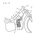
- FIG. 14 is a partial side view showing an example of a conventional under-bone type motorcycle equipped with an engine having a fuel injection device (see Patent Document 1).
- FIG. 14 shows the intake system partially in cross-section.
- the under-bone type motorcycle 1 shown in FIG. 14 has a backbone 3 that extends rearward and obliquely downward from a head pipe 2.
- the head pipe 2 turnably supports a steering shaft, with handles attached on top of the steering shaft.
- An engine 4 is positioned under the rear part of the backbone 3.
- An air cleaner 5 is positioned under the front part of the backbone 3.
- the air cleaner 5 is connected to an intake port 4a of the engine 4 through an intake pipe 6.
- a throttle body 7 is interposed in the intake pipe 6.
- the part of the intake pipe 6 that is connected to the intake port 4a is bent, and a fuel injection device 8 is attached to the bent part in such a direction that the fuel injection device 8 injects fuel toward an intake valve opening 4b.
- the fuel injection device 8 is positioned in the rear part of the intake pipe 6 above the engine 4 as distant as possible from the intake valve (the intake valve opening 4b) of the cylinder of the engine 4.
- the fuel injection device 8 is placed proximate to the cylinder head 4c of the engine 4, the temperature raised by the engine 4 heats the fuel injection device 8. This causes vapor in the fuel injected by the fuel injection device 8, causing troubles like vapor lock or breathing.
- the fuel injection device 8 is therefore separated as distant as possible from the cylinder head 4c of the engine 4.
- the fuel injection device 8 is positioned at a distance of 90 mm or more from the cylinder head 4c of the engine 4.
- the fuel injection device is usually positioned in the rear of the intake system including the intake pipe.
- the fuel injection device is then not cooled by the wind that hits the motorcycle in running.
- the fuel injection device is least likely to be cooled especially when the motorcycle is idling or running at low speed, because the motorcycle faces a lower wind.
- Patent Document 3 discloses a V-type water-cooled engine equipped with an assist air control device.
- An assist air passage branches off from a point upstream of a throttle valve and extends to the fuel injection device, with a solenoid valve provided in the course of the assist air passage to control the amount of assist air supply.
- a water-temperature sensor detects the temperature of engine cooling water and the amount of assist air supply is increased when the temperature is increased.
- Patent Documents 1 and 2 require the use of a water-cooled engine to cool the fuel injection device while the motorcycle is idling or running. Furthermore, because cooling the engine with water is not enough to sufficiently cool the fuel injection device, there is a need to use a cooling device for positively water-cooling the fuel injection device and its vicinity, which complicates the structure and increases costs.
- the V-type water-cooled engine having an assist air control device described in Patent Document 3 is complicated in structure and involves complicated control to regulate the amount of assist air supply on the basis of engine temperature. Therefore, applying the water-cooled engine with an assist air control device to a motorcycle, too, requires increased costs.
- a saddle-straddling type motor vehicle which has a fuel injection device cooled with a simple structure and at low cost to prevent formation of vapor in fuel, and which is capable of precisely controlling fuel injection.
- the fuel injection device while the motor vehicle is stopped or running at low speed, the fuel injection device is cooled by air supplied to the fuel injection device from the secondary passage, and when the motor vehicle runs, the fuel injection device is cooled by the wind that hits the cylinder head.
- the fuel injection device is thus cooled with a simple structure and at low cost. It is thus possible to prevent formation of vapor in the fuel and to provide precise control of the fuel injection.
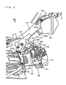
- FIG. 1 is a side view of a motorcycle according to a first embodiment of the present invention. It should be noted that, in the description below, the front, rear, left, and right indicate the directions seen from a rider seated on the seat of the motorcycle.
- the motorcycle 100 shown in FIG. 1 has an under-bone type body frame (hereinafter referred to simply as a body frame) 110.
- An air-cooled engine 120 is hung and fixed under a front part of the body frame 110.
- the body frame 110 is formed of a head pipe 111, a backbone 112, and a seat rail 113.
- a steering shaft 103 is attached to the head pipe 111 so that the steering shaft 103 can be turned to the right and left. Handles 103a are attached at the top end of the steering shaft 103.
- a front fork 102 is connected to the steering shaft 103 to rotatably support a front wheel 101.
- a fender 106 is attached to cover the front wheel 101 above and behind the front wheel 101.
- the head pipe 111 is connected to the backbone 112 that extends rearward and obliquely downward from the head pipe 111.
- the backbone 112 is aligned with the axis line of the motorcycle 100, i.e., the center line extending from the front to rear of the body.
- An air cleaner 140 is provided under the front part of the backbone 112.
- the air cleaner 140 is connected to the engine 120 through an intake pipe 141.
- a front cover 115a is extended to cover the front end of the head pile 111 and both sides of the air cleaner 140 and the engine 120.
- the seat rail113 extending rearward and obliquely upward, has its front end connected to the rear end of the backbone 112.
- a seat 114 is placed above the front part of the seat rail 113.
- a rear arm 105 is supported under the seat rail 113 with a suspension 118 interposed therebetween.
- the suspension 118 rotatably supports a rear wheel 104.
- the body frame 110 is covered by a body cover 115.
- the engine 120 is hung and fixed under the rear part of the backbone 112. The engine 120 is thus positioned approximately in the center of the wheel base of the motorcycle 100.
- the engine 120 is a naturally air-cooled, 4-stroke single-cylinder engine.
- the naturally air-cooled engine 120 can be manufactured at less cost than a water-cooled engine.
- the engine 120 has a cylinder head 121 and a cylinder block 122.
- the engine 120 is disposed so that the center axis of the cylinder in the cylinder block 122 extends approximately horizontally and the cylinder head 121 is directed toward the front of the motorcycle 100, with the crankshaft directed in the width direction (right-left direction) of the motorcycle 100.
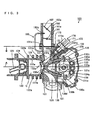
- FIG. 2 is an enlarged partially cross-sectional view of the part "X" of the motorcycle 100 of FIG. 1 .
- FIG. 2 shows the intake system of the engine partially in cross-section.
- a bracket 116 protrudes downward from each side of the rear part of the backbone 112.
- a crankcase 123 of the engine 120 has a boss 123a formed at the front end of its top wall.
- the boss 123a of the crankcase 123 is bolted to the bracket 116 with a supporting plate 117 therebetween.
- crankcase 123 The rear bottom of the crankcase 123 is bolted to a rear arm bracket (not shown) that rockably supports the rear arm 105 shown in FIG. 1 .
- the crankcase 123 contains the crankshaft and a transmission.
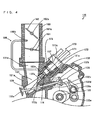
- FIG. 3 is a cross-sectional view of the right side of the engine 120 of the motorcycle 100 shown in FIG. 1 .
- FIG. 4 is an enlarged cross-sectional view of a part of the engine 120 of FIG. 3 .
- the cylinder block 122 and the cylinder head 121 shown in FIG. 3 are integrally coupled to the front wall of the crankcase 123 (see FIG. 2 ).
- a cylinder 122a is formed in the cylinder block 122.
- the central axis of the cylinder 122a is referred to as a cylinder axis line A.
- a piston 124 is slidably inserted in the cylinder 122a of the cylinder block 122.
- the piston 124 is coupled to the crankshaft (not shown) through a connecting rod 125.
- the outer periphery of the cylinder block 122 has a plurality of outwardly protruding radiation fins 122b. Heat is thus effectively radiated from the peripheral surface of the cylinder block 122.
- a head cover 121d is attached to the front side of the cylinder head 121.
- a combustion recess 121b is formed in the rear side 121a of the cylinder head 121.
- the combustion recess 121b and the piston 124 in the cylinder 122a form a combustion chamber C.
- the cylinder head 121 has an exhaust port 129 and an intake port 131.
- the upper half of the exhaust port 129 branches into two branch passages.
- the lower half of the intake port 131 branches into two branch passages.
- the combustion recess 121b has two exhaust valve openings 127 connecting the combustion chamber C and the branch passages of the exhaust port 129 and two intake valve openings 128 connecting the combustion chamber C and the branch passages of the intake port 131.
- the cross-sections of FIGS. 2 and 3 only show a single exhaust valve opening 127 on the right, a single intake valve opening 128 on the right, and a single fuel injection device 170 on the right. Fuel injection devices are provided respectively in the vicinities of the two branch passages of the intake port 131.
- the number of intake valve openings, the number of exhaust valve openings, and the number of cylinders 122a are not limited to the numbers shown in this embodiment, but the engine 120 may be provided with any numbers of intake valve openings, exhaust valve openings, and cylinders.
- the exhaust port 129 extends obliquely downward from the exhaust valve opening 127 to the bottom of the cylinder head 121. Gas in the combustion chamber C is guided toward the bottom of the cylinder head 121 through each exhaust valve opening 127 and the exhaust port 129.
- the cylinder head 121 has an exhaust valve 130 that reciprocates perpendicularly to the exhaust valve opening 127.
- the exhaust valve 130 has a valve head 130a and a valve stem 130b.
- the valve head 130a of the exhaust valve 130 opens and closes the exhaust valve opening 127.
- the valve stem 130b of the exhaust valve 130 is located under the cylinder axis line A in the cylinder head 121 and the valve stem 130b extends obliquely downward preferably at a given angle larger than 0° and smaller than 45° (e.g., 17° to 27°) with respect to the cylinder axis line A.
- a retainer 130c is attached to an end of the valve stem 130b and a spring seat 121c is formed in the cylinder head 121.
- a valve spring 130d is inserted between the retainer 130c and the spring seat 121c of the cylinder head 121. The valve spring 130d energizes the exhaust valve 130 in such a direction that the valve stem 130b is away from the exhaust valve opening 127, i.e., in such a direction that the valve head 130a closes the exhaust valve opening 127.
- the intake port 131 is bent upward from the combustion recess 121b, i.e., the intake port 131 bends from the intake valve opening 128 in a direction approximately perpendicular to the cylinder axis line A (an approximately vertical direction) and extends upward to the top of the cylinder head 121 (see FIGS. 2 and 3 ).
- the intake port 131 forms a part of an intake passage that guides outside air into the combustion chamber C.
- the intake port 131 has an external connection passage 131a that opens at the top of the cylinder head 121.
- the external connection passage 131a is connected to a throttle body 160 that also forms a part of the intake passage. Outside air is thus guided from above the cylinder head 121 into the combustion chamber C, through the throttle body 160 and the intake port 131.
- the throttle body 160 has a first throttle valve 161 and a second throttle valve 162 disposed in this order from downstream.
- the throttle body 160 is connected to the intake pipe 141 that forms the rest part of the intake passage.
- the intake pipe 141 extends up from the throttle body 160 and further extends forward and obliquely upward along the lower side of the backbone 112.
- the air cleaner 140 is situated under the front part of the backbone 112 and behind the head pipe 111 and is bolted to the backbone 112.
- the rear wall 140a of the air cleaner 140 has a connection passage 140b. One end of the intake pipe 141 is connected to the connection passage 140b of the air cleaner 140.
- the air cleaner 140 is connected to a duct 145. As shown in FIG. 1 , the duct 145 opens above the front part of the backbone 112 and behind the head pipe 111. Outside air is guided into the air cleaner 140 through the duct 145.
- the intake valve 132 is positioned approximately symmetrically to the exhaust valve 130 with respect to the cylinder axis line A.
- a retainer 132c is attached to the end of the valve stem 132b and a spring seat 121c is formed in the cylinder head 121.
- a valve spring 132d is inserted between the retainer 132c and the spring seat 121c of the cylinder head 121. The valve spring 132d energizes the intake valve 132 in such a direction that the valve stem 132b is away from the intake valve opening 128, i.e., in such a direction that the valve head 132a closes the intake valve opening 128.
- a camshaft 133 for both exhaust and intake, and having a cam 133a, is rotatably disposed between the valve spring 130d of the exhaust valve 130 and the valve spring 132d of the intake valve 132 in the cylinder head 121.
- An exhaust rocker arm 134 is disposed between the camshaft 133 and the exhaust valve 130.
- the exhaust rocker arm 134 is rotatably supported, approximately in its center, to the cylinder head 121 by an exhaust rocker shaft 134a.
- the exhaust rocker shaft 134a is supported by a boss that protrudes on the inner side of the head cover 121d of the cylinder head 121.
- An intake rocker arm 135 is disposed between the camshaft 133 and the intake valve 132.
- the intake rocker arm 135 is rotatably supported, approximately in its center, to the cylinder head 121 by an intake rocker shaft 135a.
- the intake rocker shaft 135a is supported by a boss that protrudes on the inner side of the head cover 121d of the cylinder head 121.
- One end of the exhaust rocker arm 134 and one end of the intake rocker arm 135 are in contact with the cam 133a. Therefore, as the camshaft 133 rotates, the other ends of the exhaust rocker arm 134 and the intake rocker arm 135 respectively press the ends of the valve stems 130b and 132b, thereby moving the valve stems 130b and 132b opposite the energized directions.
- the center of the camshaft 133 is displaced by a distance "a" under the cylinder axis line A.
- the angle between the intake valve 132 and the cylinder axis line A is smaller than the angle between the exhaust valve 130 and the cylinder axis line A. That is to say, the end of the intake valve 132 on the front side is closer to the cylinder axis line A than the end of the exhaust valve 130 on the front side is. This ensures larger space between the intake port 131 and the intake valve 132 in the cylinder head 121.
- the fuel injection device 170 is situated between the intake port 131 and the intake valve 132, to extend obliquely upward with respect to the engine 120.
- the larger space ensured above the intake valve 132 in the cylinder head 121 offers increased freedom in positioning the fuel injection device 170.
- the fuel injection device 170 has an injection nozzle 171, an injector 172, and a cylindrical holder 173.
- the injector 172 injects, from the injection nozzle 171, fuel supplied from a fuel tank (not shown) through a supply passage.
- the injector 172 is located in the area between the intake port 131 and the intake valve 132 and is attached to the cylinder head 121 by the holder 173 in a manner described later. That is, the fuel injection device 170 is positioned on the side of the front wall of the intake port 131.
- a fitting hole 137 communicating with the intake port 131 is formed in the front wall of the intake port 131.
- the tip of the injector 172 is inserted in the fitting hole 137 through the holder 173.
- the injection nozzle 171 at the tip of the injector 172 is thus located proximate to the intake valve opening 128.
- the part of the fitting hole 137 that communicates with the intake port 131 forms an injection passage 137a that guides injected fuel from the intake port 131 into the cylinder 122a through the intake valve opening 128.
- the intake valve 132 at the intake valve opening 128 is opened when the injector 172 injects fuel.
- the fuel is thus injected from the injection nozzle 171 directly into the cylinder 122a through the intake valve opening 128.
- the timing of injecting fuel from the injector 172 through the intake valve opening 128 is controlled by a controller, such as an ECU (Engine Control Unit).
- a controller such as an ECU (Engine Control Unit).
- the fuel injection device 170 is disposed so that the injection nozzle 171 is positioned within the region defined by connecting the front end of the valve stem 132b with the valve head 132a closing the intake valve opening 128, the intersection point of the axis of the intake valve 132 and the center line of the intake port 131, and the intersection point of the center line of the intake port 131 and the external connection passage 131a at the upstream end of the intake port 131. Also, the fuel injection device 170 is placed opposite the fender 106 shown in FIG. 1 and can be viewed from obliquely ahead of the motorcycle 100 and from the side of the motorcycle 100.
- the fuel injection device 170 in the cylinder head 121 such that the distance from the intake valve opening 128 to the tip of the injection nozzle 171 is 4.0 cm or less.
- the holder 173 has an axially extending supporting hole 173a and a cylindrical injecting port 173b that connects with the supporting hole 173a.
- the injecting port 173b has an internal diameter smaller than that of the supporting hole 173a.
- the injection nozzle 171 of the injector 172 is inserted and fitted in the supporting hole 173a of the holder 173.
- the injection nozzle 171 is thus located between the axis of the intake valve 132 and the center line of the intake port 131 and proximate to the inner front wall of the intake port 131.
- Fuel injected from the injection nozzle 171 of the injector 172 is mixed with atomizing air in the injecting port 173b and is supplied from the injecting port 173b into the combustion chamber C through the branch passage of the intake port 131.
- the outer peripheral surface of the injecting port 173b of the holder 173 has a portion of a reduced external diameter that forms a circular recess. This forms an air chamber 174 of a circular cavity between the circular recess of the holder 173 and the inner surface of the fitting hole 137.
- the air chamber 174 is connected with a downstream end opening 180a of a secondary intake passage (hereinafter referred to as a secondary passage) 180 that branches off from the throttle body 160.
- the secondary passage 180 extends upstream along the intake port 131, and the secondary passage 180 has an upstream end opening 180b that communicates with the space between the first throttle valve 161 and the second throttle valve 162 in the throttle body 160.
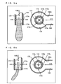
- FIG. 5a is a cross-sectional view of the injecting port 173b of the holder 173 of the embodiment.
- FIG. 5b is a cross-sectional view of the injecting port 173b of the holder 173 of FIG. 5a , but where communicating holes are positioned differently.
- FIGS. 5a and 5b show vertical cross-sections on the left and transverse cross-sections on the right.
- the holder 173 has a plurality of communicating passages 173c formed at equal angular intervals and radially passing through the wall.
- the holder 173 has four communicating passages 173c.
- the air chamber 174 thus communicates with the inside of the injecting port 173b through the plurality of communicating passages 173c.
- the air chamber 174 also communicates with the downstream end opening (connection passage) 180a of the secondary passage 180, near the injection nozzle 171 (see FIG. 3 ).
- the two communicating passages 173c located closer to the downstream end opening 180a have their axis lines inclined 45° with respect to the axis line of the downstream end opening 180a. That is to say, the communicating passages 173c are misaligned with the axis line of the downstream end opening 180a. Therefore, the downstream end opening 180a of the secondary passage 180 is directed toward the peripheral surface of the holder 173. Accordingly, air emitted from the downstream end opening 180a does not flow directly into the injecting port 173b, but it moves in the air chamber 174 and then flows into the injecting port 173b from the individual communicating passages 173c.
- a driving pulley 164 is attached to the external surface of the throttle body 160.
- the driving pulley 164 is fixed to the valve stem 162a of the second throttle valve 162 shown in FIG. 3 .
- the driving pulley 164 is coupled with one end of a throttle operating cable 166.
- the other end of the throttle operating cable 166 is coupled to a throttle grip of the handle 103a shown in FIG. 1 .
- the driving pulley 164 coupled to the second throttle valve 162 shown in FIG. 3 and the first throttle valve 161 are coupled through a link-type delay mechanism 165 shown in FIG. 2 .
- the open degree of the first throttle valve 161 and the second throttle valve 162 is controlled as follows according to variation of the load placed on the engine 120. It is thought that the amount of throttle operation made by the rider (the amount of throttle grip operation) is approximately proportional to the load placed on the engine 120.
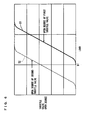
- FIG. 6 is a diagram showing a relation between the load and throttle open degree.
- FIG. 7 is a diagram showing a relation between the load and air flow rates.
- the horizontal axis shows the load placed on the engine 120 and the vertical axis shows the open degree of the first throttle valve 161 and the open degree of the second throttle valve 162.
- the solid line S1 shows a variation of the open degree of the first throttle valve 161 and the broken line S2 shows a variation of the open degree of the second throttle valve 162.
- the horizontal axis shows the load placed on the engine 120 and the vertical axis shows air flow rates in the primary passage and the secondary passage 180.
- the primary passage corresponds to the passage in the intake port 131.
- the solid line L1 shows the air flow rate in the primary passage and the broken line L2 shows the air flow rate in the secondary passage 180.
- the first throttle valve 161 located downstream is kept approximately full closed in the low-load driving region (partial load driving region) that ranges from no-load (idling) to a first load value b1.
- the wording "a throttle valve is approximately full closed” means that the throttle valve is at an angle of 5° or less with respect to the angle at which the throttle valve is in contact with the inner surface of the throttle body 160.
- the second throttle valve 162 located upstream opens and closes in accordance with the amount of throttle operation to control the sectional area of the air pass in the primary passage.
- the negative pressure in intake strokes of the engine 120 directly affects the secondary passage 180 and the total amount of air taken in from the duct 145 of the air cleaner 140 is introduced into the air chamber 174 through the throttle body 160 and the secondary passage 180.
- the air introduced in the air chamber 174 is supplied into the injecting port 173b through the communicating passages 173c shown in FIG. 5a , where the air is sufficiently mixed with fuel injected from the injection nozzle 171, while atomizing the fuel.
- the mixture gas is then supplied into the cylinder 122a from the right and left intake valve openings 128.
- the open degree of the second throttle valve 162 increases as the amount of throttle operation (load) increases. Therefore, as shown in FIG. 7 , the air flow rate in the secondary passage 180 increases as the load increases.
- a large amount of air (assist air) is supplied from the throttle body 160 to the secondary passage 180 and further to the air chamber 174 and the injecting port 173b of the fuel injection device 170. This promotes atomization of the fuel injected from the fuel injection device 170. Also, the assist air cools the tip of the injector 172 (the vicinity of the injection nozzle 171).
- the open degree of the second throttle valve 162 is controlled to supply a proper amount of assist air to the vicinity of the tip of the injector 172.
- the first throttle valve 161 is opened, and as shown in FIG. 7 , air is supplied to the fuel injection device 170 also from the primary passage.
- the assist air cools the tip of the injector 172 and atomizes injected fuel also in the normal driving region.
- the air flow rate in the secondary passage 180 decreases as shown in FIG. 7 because of a difference between the pressure in the intake port 131 and the pressure in the secondary passage 180. In the high-load driving region, the air flow rate in the secondary passage 180 is considerably lower than the air flow rate in the primary passage.
- Increasing the open degree of the first throttle valve 162 necessarily means that the motorcycle 100 runs at higher speed. Therefore, the fuel injection device 170 is naturally cooled by the head wind in running, while a small amount of assist air is supplied to the vicinity of the tip of the injector 172.
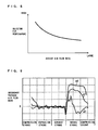
- FIG. 8 is a diagram showing a relation between the temperature at the tip of the injector 172 and the flow rate of assist air.
- FIG. 9 is a diagram showing a relation between the air flow rate in the secondary passage and engine strokes.
- the curve g1 shows an air flow rate in the secondary passage 180 that flows when the load placed on the engine 120 is smaller, i.e., when the engine 120 is idling or running with a lower load.
- the curve g2 shows an air flow rate in the secondary passage 180 that flows when the engine 120 is normally running.
- the curve g3 shows an air flow rate in the secondary passage 180 that flows when the load on the engine 120 is larger, i.e., when the engine 120 is running with a higher load (e.g., when the first throttle valve 161 and the second throttle valve 162 are full open).
- the first throttle valve 161 When the load on the engine 120 is small, the first throttle valve 161 is closed, and so all the air used to run the engine 120 in an intake stroke flows into the cylinder 122a through the secondary passage 180. Then, the assist air is supplied into the air chamber 174 and the injecting port 17 3b of the fuel injection device 170 at the flow rate shown by the curve g1. The tip of the injector 172 is thus cooled with a large amount of assist air when the motorcycle 100 is running at a low speed and is hence hit by less wind.
- assist air is supplied to the air chamber 174 and the injecting port 173b of the fuel injection device 170 at the air flow rate shown by the curve g2. That is, the amount of assist air supplied to the air chamber 174 and the injecting port 173b of the fuel injection device 170 increases in proportion to the open degree of the second throttle valve 162.
- the first throttle valve 161 When the engine 120 runs with a higher load, the first throttle valve 161 is opened and air is supplied also from the primary passage. Then, as shown by the curve g3, the flow rate of assist air supplied to the air chamber 174 and the injecting port 173b of the fuel injection device 170 decreases. In this case, the fuel injection device 170 is cooled by the head wind in running.
- FIG. 10 is a diagram showing variations of the temperature of the tip of the injector that are exhibited when the engine is stopped immediately after the motorcycle has run with a high load.
- the broken line g4 shows a variation of the injector tip temperature of the fuel injection device 8 of the conventional motorcycle 1 shown in FIG. 14
- the solid line g5 shows a variation of the tip temperature of the injector 172 of the fuel injection device 170 of the motorcycle 100 of the embodiment.
- the temperature of the tip of the injector 172 increases because the injector is heated by the engine 4 after the stop.
- the temperature of the tip of the injector 172 is kept lower because the injector 172 and its vicinity are cooled by the assist air and wind. This prevents formation of vapor in the fuel.
- assist air is guided to the air chamber 174 and the injecting port 173b of the fuel injection device 170 through the secondary passage 180 while the air-cooled engine 120 is idling or running with low load.
- This atomizes the fuel injected from the fuel injection device 170 and cools the vicinity of the tip of the injector 171 of the fuel injection device 170 while themotorcycle 100 is stopped or running at low speed.
- the fuel injection device 170 can be cooled with a simple structure and at low cost.
- effectively cooling the fuel injection device 170 in this way in idling or running removes the need to locate the fuel injection device 170 at a distance from the engine 120 to avoid heat from the engine 120. For example, there is no need to locate the fuel injection device 170 at a distance above the engine 120.
- This allows the provision of only the intake system including the throttle body 160 and the intake pipe 141 between the engine 120 and the backbone 112 thereabove. In this case, it is easy to ensure a space for the throttle body 160 between the upper wall of the cylinder head 121 and the backbone 112.
- the throttle body 160 is connected between the intake port 131 and the intake pipe 141, it is possible to take in air into the cylinder 122a through the intake valve opening 128 with a quick response to the opening/closing of the first throttle valve 161 and the second throttle valve 162 in the throttle body 160.
- the response of the engine 120 to the throttle operation is thus considerably improved.
- the mixture gas flows into the circular gap between the intake valve opening 128 and the valve head 132a of the intake valve 132 mainly through an area closer to the exhaust valve opening 127 and flows along the inner surface of the cylinder 122a and in the axial direction.
- This certainly causes tumble (vertical whirl) inthecylinder122a.
- locating the intake port 131 approximately uprightly from the intake valve opening 128 and the axis of the intake valve 132 approximately in the front-to-rear direction makes it possible to ensure a space for the fuel injection device 170 between the intake port 131 and the intake valve 132, without enlarging the cylinder head 121.
- the camshaft 133 is shifted by a distance "a" under the cylinder axis line A and the angle between the cylinder axis line A and the axis of the intake valve 132 is smaller than the angle between the cylinder axis line A and the axis of the exhaust valve 130, and the intake valve 132 is closer to the cylinder axis line A than the exhaust valve 130 is.
- This ensures a sufficient space to locate the fuel injection device 170 close to the intake valve opening 128, between the intake port 131 and the intake valve 132 in the cylinder head 121. This makes it possible to reduce fuel adhesion to the wall surface, improves the response of the engine 120 to the throttle operation, and satisfactorily enhances combustibility, without a need to enlarge the cylinder head 121.
- the portion in the throttle body 160 between the first throttle valve 160 and the second throttle valve 162 communicates with the air chamber 174 in the fuel injection device 170 through the secondary passage 180, and the first throttle valve 161 is kept approximately full closed in the low-load driving region that ranges from no-load to the first load value. Therefore, a large amount of assist air is certainly supplied into the air chamber 174 and the injecting port 173b. This sufficiently promotes fuel atomization.
- the fuel injection device 170 is positioned close to the intake valve opening 128 in the cylinder head 121 and situated so that the fuel injection device 170 does not interfere with the intake pipe 141. Therefore, the fuel injection device 170 does not interfere with the backbone 112 when the engine 120 is hung and fixed under the backbone 112. Thus, the fuel injection device 170 does not reduce freedom in hanging and fixing the engine 120 under the backbone 112.
- arranging the intake pipe 141 along the lower side of the backbone 112 and locating the fuel supply hose 176 on the same side as the intake pipe 141 simplifies the piping structure of the intake system and the fuel supply system.
- locating the engine 120 under the backbone 112 allows a rider to easily straddle the seat 114.
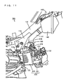
- FIG. 11 is an enlarged partially cross-sectional view showing the engine of a motorcycle according to a second embodiment of the present invention.
- FIG. 12 is a diagram showing the structure of a main part of the engine of FIG. 11 seen from the front.
- the motorcycle 200 of the embodiment has the same basic structure as the motorcycle 100 of the first embodiment except in the following respects.
- FIGS. 11 and 12 the same components as those depicted in FIGS. 1 and 2 are shown at the same reference numerals.
- a cylinder head 221 of the engine 220 has an intake port 231 that communicates with the intake valve opening 128 and that extends upward from the intake valve opening 128 approximately vertically with respect to the cylinder axis line.
- the cylinder head 221 also has an exhaust port 229 that communicates with the exhaust valve opening 127.
- a secondary passage branches off from a portion of the throttle body 160 between a first throttle valve and a second throttle valve and is connected to an injecting port of a holder attached at the tip end of the fuel injection device 270.
- the fuel injection device 270 is positioned in the cylinder head 221 to inject fuel from the side directly toward the intake valve opening 128 and the fuel injection device 270 can be viewed from the front of the motorcycle 200.
- the fuel injection device 270 has an injector 172 similar to that of the first embodiment, but the shape of the holder 273 and the position of the fitting hole formed in the cylinder head 221 differ.
- assist air supplied through the secondary passage cools the tip of the injector 172 of the fuel injection device 270. This prevents formation of vapor in the fuel injected from the fuel injection device 270 and reduces occurrence of troubles of the engine 220.
- the backbone 112 corresponds to a main frame
- the intake port 131 corresponds to an primary passage
- the exhaust port 129 corresponds to an exhaust passage
- the first throttle valve 161 corresponds to a first opening/closing mechanism
- the second throttle valve 162 corresponds to a second opening/closing mechanism
- the holders 173 and 273 correspond to a cylindrical member
- the communicating passages 173c correspond to a passage or passages.
- the positioning of the fuel injection device 170 in the cylinder head 121 is not limited to those shown in the embodiments.
- the fuel injection device 170 is positioned so that, seen from above, the tip of the injection nozzle 171 is located further forward than the rear of the top of the intake port 131.
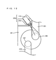
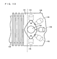
- FIG. 13 is a diagram showing examples of the positioning of the fuel injection device 170.
- FIG. 13 schematically depicts the engine 120 seen in the direction B shown in FIG. 3 (seen from above).
- the fuel injection device 170 can be located in the front area extending 180 degrees around the center axis (vertical axis) of the intake port 131.
- the fuel injection device 170 may be disposed to incline leftward and obliquely upward with respect to the intake port 131, or to incline rightward and obliquely upward with respect to the intake port 131.
- the fuel injection device 170 may be disposed to incline leftwardly frontward and obliquely upward with respect to the intake port 131, or rightwardly frontward and obliquely upward with respect to the intake port 131.
- the fuel injection device 170 is disposed, as shown by the solid line, to incline forward and obliquely upward with respect to the intake port 131.
- first throttle valve 161 and the second throttle valve 162 as the first opening/closing mechanism and the second opening/closing mechanism
- any other kinds of opening/closing mechanisms capable of controlling the area of the air passage in the throttle body 160 such as suction pistons, rotary valves, etc., may be used.
- the embodiments have described an application of the invention to a motorcycle as an example of a saddle-straddling type motor vehicle, the invention is similarly applicable also to other types of saddle-straddling type motor vehicles that a rider drives while straddling a seat, such as three-wheelers, buggy-type four-wheelers, etc.
- a cover having an air passage, through which the wind blowing in running passes may be attached in front of the engines 120, 220 of the motorcycles 100, 200 of the embodiments.
- an air passage may be formed to guide to the engine the wind blowing from ahead.
- the present invention is applicable to under-bone type two-wheeled motor vehicles, three-wheeled motor vehicles, buggy-type four-wheeled motor vehicles, and the like.
- said air-cooled engine further comprises: a throttle body extending upward from said primary passage; and a first opening/closing mechanism capable of opening and closing in said throttle body, and wherein said secondary passage branches off from a part of said throttle body that is upstream of said first opening/closing mechanism.
- said engine further comprises a second opening/closing mechanism capable of opening and closing and located, in said throttle body, upstream of the part from which said secondary passage branches off.
- said first opening/closing mechanism when no load is placed on said engine and when a load equal to or smaller than a first value is placed on said engine, said first opening/closing mechanism is approximately full closed and an open degree of said second opening/closing mechanism is controlled by an operation by a rider.
- said fuel injection device is situated to incline obliquely upward toward a front with respect to a horizontal direction.
- said cylinder head has an exhaust passage that guides burned gas outside from said combustion chamber through an exhaust valve opening
- said engine further comprises an exhaust valve provided to open and close said exhaust valve opening
- said exhaust valve is situated so that its axis is inclined obliquely downward toward the front at an angle larger than 0 degree and smaller than 45 degrees with respect to the horizontal direction.
- the embodiments further discloses a saddle-straddling type motor vehicle, comprising: an air-cooled engine attached to a body frame and having a cylinder block located on a rear side in a direction in which said motor vehicle runs and a cylinder head located on a front side in the direction in which said motor vehicle runs; a primary passage that guides air into a combustion chamber of said air-cooled engine; a fuel injection device having an injection nozzle that injects fuel in said primary passage; and a secondary passage that branches off from upstream of said primary passage and that guides air to a vicinity of said injection nozzle of said fuel injection device at least when said air-cooled engine is idling, said fuel injection device being located further forward than said cylinder block in the direction in which said motor vehicle runs.
- said air-cooled engine further comprises an intake valve located at a border between said primary passage and said combustion chamber, and said fuel injection device is situated at an incline between said primary passage and said intake valve.
- said body frame includes: a head pipe disposed approximately uprightly in a front part of said motor vehicle; and a main frame extending rearward and obliquely downward from said head pipe.
- said air-cooled engine further comprises an intake valve located in an intake valve opening at a border between said primary passage and said combustion chamber, and wherein said primary passage extends approximately uprightly from said intake valve opening, said intake valve is located so that its axis extends approximately in the front-to-rear direction, and said fuel injection device is located at an incline between said primary passage and said intake valve.
- said air-cooled engine further comprises: a throttle body extending upward from said primary passage; and a first opening/closing mechanism capable of opening and closing in said throttle body, and wherein said secondary passage branches off from a part of said throttle body that is upstream of said first opening/closing mechanism.
- said engine further comprises a second opening/closing mechanism capable of opening and closing and located, in said throttle body, upstream of the part from which said secondary passage branches off.
- said second opening/closing mechanism when no load is placed on said engine and when a load equal to or smaller than a first value is placed on said engine, said second opening/closing mechanism is approximately full closed and an open degree of said second opening/closing mechanism is controlled by an operation by a rider.
- said air-cooled engine further comprises an intake valve located in an intake valve opening at a border between said primary passage and said combustion chamber, and wherein a distance from a tip of said injection nozzle of said fuel injection device to said intake valve opening is 4 cm or less.
- said fuel injection device is situated so that at least part of said fuel injection device is exposed outside from said cylinder head.
- said fuel injection device is situated to incline obliquely upward toward a front with respect to a horizontal direction.
- said air-cooled engine further comprises an intake valve located in an intake valve opening at a border between said primary passage and said combustion chamber, and wherein said intake valve is located so that its axis is inclined obliquely upward toward a front at an angle larger than 0 degree and smaller than 45 degrees with respect to a horizontal direction.
- said cylinder head has an exhaust passage that guides burned gas outside from said combustion chamber through an exhaust valve opening
- said engine further comprises an exhaust valve provided to open and close said exhaust valve opening
- said exhaust valve is situated so that its axis is inclined obliquely downward toward the front at an angle larger than 0 degree and smaller than 45 degrees with respect to the horizontal direction.
Landscapes
- Engineering & Computer Science (AREA)
- Chemical & Material Sciences (AREA)
- Combustion & Propulsion (AREA)
- Mechanical Engineering (AREA)
- General Engineering & Computer Science (AREA)
- Cylinder Crankcases Of Internal Combustion Engines (AREA)
- Fuel-Injection Apparatus (AREA)
- Control Of Throttle Valves Provided In The Intake System Or In The Exhaust System (AREA)
- Automatic Cycles, And Cycles In General (AREA)
- Permanent Field Magnets Of Synchronous Machinery (AREA)
- Motorcycle And Bicycle Frame (AREA)
- Motor Or Generator Cooling System (AREA)
Applications Claiming Priority (2)
| Application Number | Priority Date | Filing Date | Title |
|---|---|---|---|
| JP2004101190 | 2004-03-30 | ||
| EP05727084A EP1754884A4 (en) | 2004-03-30 | 2005-03-24 | MOTOR VEHICLE OF DRIVING TYPE ON SADDLE |
Related Parent Applications (2)
| Application Number | Title | Priority Date | Filing Date |
|---|---|---|---|
| EP05727084A Division EP1754884A4 (en) | 2004-03-30 | 2005-03-24 | MOTOR VEHICLE OF DRIVING TYPE ON SADDLE |
| EP05727084.5 Division | 2005-03-24 |
Publications (2)
| Publication Number | Publication Date |
|---|---|
| EP2138710A1 EP2138710A1 (en) | 2009-12-30 |
| EP2138710B1 true EP2138710B1 (en) | 2012-02-22 |
Family
ID=35125144
Family Applications (2)
| Application Number | Title | Priority Date | Filing Date |
|---|---|---|---|
| EP09012158A Active EP2138710B1 (en) | 2004-03-30 | 2005-03-24 | Saddle-straddling type motor vehicle |
| EP05727084A Withdrawn EP1754884A4 (en) | 2004-03-30 | 2005-03-24 | MOTOR VEHICLE OF DRIVING TYPE ON SADDLE |
Family Applications After (1)
| Application Number | Title | Priority Date | Filing Date |
|---|---|---|---|
| EP05727084A Withdrawn EP1754884A4 (en) | 2004-03-30 | 2005-03-24 | MOTOR VEHICLE OF DRIVING TYPE ON SADDLE |
Country Status (10)
| Country | Link |
|---|---|
| US (1) | US7302934B2 (zh) |
| EP (2) | EP2138710B1 (zh) |
| JP (2) | JPWO2005098231A1 (zh) |
| CN (2) | CN101624955B (zh) |
| AT (1) | ATE546639T1 (zh) |
| BR (2) | BRPI0509041A (zh) |
| ES (1) | ES2380179T3 (zh) |
| MY (2) | MY138358A (zh) |
| TW (2) | TWI377148B (zh) |
| WO (1) | WO2005098231A1 (zh) |
Families Citing this family (34)
| Publication number | Priority date | Publication date | Assignee | Title |
|---|---|---|---|---|
| JP4414316B2 (ja) * | 2004-09-29 | 2010-02-10 | 本田技研工業株式会社 | 自動二輪車 |
| JP2007118628A (ja) * | 2005-10-24 | 2007-05-17 | Yamaha Motor Co Ltd | 鞍乗型車両 |
| US20090277709A1 (en) * | 2006-06-19 | 2009-11-12 | Yamaha Hatsudoki Kabushiki Kaisha | Motorcycle |
| FR2905350A1 (fr) * | 2006-09-06 | 2008-03-07 | Mecanique Generale Maison Mart | Motocyclette du type tout terrain |
| JP4821634B2 (ja) * | 2007-01-29 | 2011-11-24 | スズキ株式会社 | 自動二輪車の燃料供給装置 |
| JP2008286092A (ja) | 2007-05-17 | 2008-11-27 | Yamaha Motor Co Ltd | 自動二輪車 |
| US20080295806A1 (en) * | 2007-06-04 | 2008-12-04 | Caterpillar Inc. | Heat conducting sleeve for a fuel injector |
| JP4990058B2 (ja) * | 2007-08-01 | 2012-08-01 | 本田技研工業株式会社 | 小型車両用エンジンの燃料噴射弁取付構造 |
| JP2009202827A (ja) * | 2008-02-29 | 2009-09-10 | Yamaha Motor Co Ltd | 自動二輪車 |
| JP2010048249A (ja) * | 2008-07-22 | 2010-03-04 | Yamaha Motor Co Ltd | エンジン、区画部材及び区画部材の製造方法 |
| CN101633388B (zh) * | 2008-07-24 | 2012-09-05 | 雅马哈发动机株式会社 | 自动二轮车 |
| JP2010223210A (ja) * | 2008-07-24 | 2010-10-07 | Yamaha Motor Co Ltd | 車両用エンジンユニットおよびそれを備えた鞍乗り型車両 |
| JP2010223211A (ja) | 2008-07-24 | 2010-10-07 | Yamaha Motor Co Ltd | 車両用強制空冷式エンジンユニットおよび自動二輪車 |
| JP3153075U (ja) * | 2008-07-29 | 2009-08-20 | ヤマハ発動機株式会社 | 車両用エンジンユニットおよび鞍乗り型車両 |
| JP5302070B2 (ja) * | 2009-03-31 | 2013-10-02 | 本田技研工業株式会社 | 内燃機関の燃料噴射−吸気装置 |
| JP2012122331A (ja) * | 2009-03-31 | 2012-06-28 | Yamaha Motor Co Ltd | エンジン |
| JP5351588B2 (ja) * | 2009-03-31 | 2013-11-27 | 本田技研工業株式会社 | 内燃機関の吸気通路構造 |
| JP5484835B2 (ja) * | 2009-09-02 | 2014-05-07 | 本田技研工業株式会社 | 鞍乗り型車両の吸気構造 |
| JP5520623B2 (ja) * | 2010-01-29 | 2014-06-11 | 本田技研工業株式会社 | 燃料供給装置 |
| JP5352575B2 (ja) * | 2010-12-28 | 2013-11-27 | 本田技研工業株式会社 | Vベルト式無段変速機の冷却風取り入れ構造 |
| JP2013100780A (ja) * | 2011-11-09 | 2013-05-23 | Toyota Motor Corp | 内燃機関の制御装置 |
| WO2013073566A1 (ja) * | 2011-11-17 | 2013-05-23 | 川崎重工業株式会社 | エンジンの吸気構造及びそれを備えた自動二輪車 |
| JP2013217338A (ja) * | 2012-04-11 | 2013-10-24 | Yamaha Motor Co Ltd | 自動二輪車 |
| US9453469B2 (en) * | 2012-05-30 | 2016-09-27 | Ford Global Technologies, Llc | Method and system for adjusting engine throttles |
| US10119496B2 (en) * | 2014-04-15 | 2018-11-06 | Cummins Inc. | Cryogenic fuel injection and combustion |
| JP2017149167A (ja) * | 2014-07-04 | 2017-08-31 | ヤマハ発動機株式会社 | 鞍乗型車両 |
| JP2017149166A (ja) * | 2014-07-04 | 2017-08-31 | ヤマハ発動機株式会社 | 鞍乗型車両 |
| JP2018162747A (ja) * | 2017-03-27 | 2018-10-18 | 株式会社ケーヒン | 内燃機関制御装置 |
| CN107218150A (zh) * | 2017-06-29 | 2017-09-29 | 重庆隆鑫发动机有限公司 | 燃烧室气道结构、燃烧室进气系统及内燃机 |
| CN107575317B (zh) * | 2017-08-09 | 2019-11-26 | 浙江吉利新能源商用车有限公司 | 一种车辆发动机的温控方法及系统 |
| TWI751808B (zh) * | 2020-11-25 | 2022-01-01 | 宏佳騰動力科技股份有限公司 | 單進氣通道式進氣調節構造 |
| WO2022208829A1 (ja) * | 2021-03-31 | 2022-10-06 | 本田技研工業株式会社 | 内燃機関の吸気構造 |
| DE102022001464B4 (de) * | 2022-04-26 | 2023-11-02 | Deutz Aktiengesellschaft | Zylinderkopf für eine Brennkraftmaschine |
| SE2350638A1 (en) * | 2022-05-30 | 2023-12-01 | Husqvarna Ab | A fuel injection arrangement for hand-held powertools |
Family Cites Families (41)
| Publication number | Priority date | Publication date | Assignee | Title |
|---|---|---|---|---|
| JPS5996363A (ja) | 1982-11-22 | 1984-06-02 | シオン・樹脂工業株式会社 | 内張バンド拡大用ジヤツキ |
| JPS5996363U (ja) | 1982-12-20 | 1984-06-29 | トヨタ自動車株式会社 | 燃料噴射式エンジンのスロツトルボデイ構造 |
| JPS6036574A (ja) * | 1983-08-08 | 1985-02-25 | Gikenshiya:Kk | 塗料 |
| JPS61112773A (ja) | 1984-11-07 | 1986-05-30 | Mazda Motor Corp | 燃料噴射装置付エンジン |
| JPH02141678A (ja) | 1988-11-24 | 1990-05-31 | Mitsubishi Electric Corp | Icソケット |
| JPH02308943A (ja) * | 1989-05-24 | 1990-12-21 | Toyota Motor Corp | 多気筒空冷式内燃機関の燃料供給量制御装置 |
| JPH03237263A (ja) | 1990-02-10 | 1991-10-23 | Hitachi Ltd | エンジンの燃料噴射方法及び装置 |
| JPH04107483A (ja) | 1990-08-28 | 1992-04-08 | Tokyo Electric Co Ltd | 電子写真装置 |
| JPH0533744A (ja) | 1991-07-29 | 1993-02-09 | Mazda Motor Corp | エンジンのアシストエア制御装置 |
| JP3071260B2 (ja) | 1991-09-26 | 2000-07-31 | マツダ株式会社 | エンジンの吸気装置 |
| US5309886A (en) | 1991-09-26 | 1994-05-10 | Mazda Motor Corporation | Supercharged internal combustion engine |
| JP3271373B2 (ja) | 1993-06-21 | 2002-04-02 | 松下電器産業株式会社 | ドライエッチング方法 |
| JPH0777137A (ja) | 1993-06-25 | 1995-03-20 | Mazda Motor Corp | エンジンの燃料噴射装置 |
| JPH07247941A (ja) | 1994-03-11 | 1995-09-26 | Toyota Motor Corp | 内燃機関の燃料噴射装置 |
| JPH0821341A (ja) | 1994-07-01 | 1996-01-23 | Yamaha Motor Co Ltd | 内燃機関の燃料供給装置 |
| JP3372378B2 (ja) | 1994-12-22 | 2003-02-04 | ダイハツ工業株式会社 | 燃料噴射弁を備えた火花点火式内燃機関の構造 |
| DE69612135T2 (de) * | 1995-05-19 | 2001-09-06 | Siemens Automotive Corp., Auburn Hills | Luftunterstütztereinspritzventil und Umfassungsbuchse des Ventils |
| JPH0914102A (ja) | 1995-06-30 | 1997-01-14 | Yamaha Motor Co Ltd | 内燃エンジンの吸気装置 |
| JPH0996269A (ja) | 1995-09-29 | 1997-04-08 | Suzuki Motor Corp | 内燃機関 |
| JPH09166064A (ja) * | 1995-12-15 | 1997-06-24 | Nissan Motor Co Ltd | 内燃機関の吸気装置 |
| JP3484501B2 (ja) * | 1996-03-05 | 2004-01-06 | ヤマハ発動機株式会社 | アンダーボーン型自動二輪車のエンジン冷却構造 |
| JPH09280140A (ja) * | 1996-04-12 | 1997-10-28 | Sanshin Ind Co Ltd | 船外機用エンジンの燃料インジェクター配置構造 |
| JPH09291868A (ja) | 1996-04-26 | 1997-11-11 | Yamaha Motor Co Ltd | 燃料噴射式多気筒エンジン |
| JP4145370B2 (ja) * | 1996-06-27 | 2008-09-03 | 本田技研工業株式会社 | スクータ型車両におけるエンジン冷却構造 |
| JPH11280620A (ja) | 1998-03-26 | 1999-10-15 | Suzuki Motor Corp | エンジンの燃料供給装置 |
| JP4358367B2 (ja) | 1998-10-16 | 2009-11-04 | 本田技研工業株式会社 | 車両用車体フレームの構造及び製法 |
| JP2000204969A (ja) * | 1999-01-08 | 2000-07-25 | Yamaha Motor Co Ltd | 4サイクルv型エンジンの吸気装置 |
| JP4555413B2 (ja) | 1999-03-02 | 2010-09-29 | 本田技研工業株式会社 | バックボーン型自動二輪車における燃料噴射装置 |
| JP3568162B2 (ja) | 1999-09-03 | 2004-09-22 | 本田技研工業株式会社 | 自動二・三輪車 |
| JP2001132589A (ja) | 1999-11-01 | 2001-05-15 | Honda Motor Co Ltd | エンジンの燃料供給装置 |
| JP2001317437A (ja) * | 2000-05-09 | 2001-11-16 | Fuji Heavy Ind Ltd | エアアシストインジェクタを備えたエンジンのアシストエア通路構造 |
| CN2426441Y (zh) * | 2000-06-21 | 2001-04-11 | 中国嘉陵工业股份有限公司(集团) | 带有自然风冷发动机的二轮踏板摩托车 |
| JP4371548B2 (ja) * | 2000-07-21 | 2009-11-25 | 本田技研工業株式会社 | 自動二,三輪車におけるエンジンの吸気装置 |
| JP2002327665A (ja) * | 2001-04-27 | 2002-11-15 | Yamaha Motor Co Ltd | 4サイクルエンジン用燃料供給装置 |
| JP2003278627A (ja) | 2002-03-26 | 2003-10-02 | Kubota Corp | 燃料噴射弁を備えた火花点火式エンジン |
| JP2003013826A (ja) | 2002-05-13 | 2003-01-15 | Hitachi Ltd | エンジンの燃料供給装置 |
| AU2003275557A1 (en) | 2002-10-18 | 2004-05-25 | Yamaha Hatsudoki Kabushiki Kaisha | Engine |
| JP4250141B2 (ja) | 2002-10-25 | 2009-04-08 | ヤマハ発動機株式会社 | 自動二輪車 |
| ES2361468T3 (es) | 2002-10-25 | 2011-06-17 | Yamaha Hatsudoki Kabushiki Kaisha | Motocicleta. |
| KR100604300B1 (ko) * | 2003-04-03 | 2006-07-31 | 닛산 지도우샤 가부시키가이샤 | 내연 기관의 흡기 시스템 |
| JP2005104210A (ja) * | 2003-09-29 | 2005-04-21 | Honda Motor Co Ltd | 鞍乗り型車両 |
-
2005
- 2005-03-24 ES ES09012158T patent/ES2380179T3/es active Active
- 2005-03-24 AT AT09012158T patent/ATE546639T1/de active
- 2005-03-24 US US10/598,685 patent/US7302934B2/en not_active Expired - Fee Related
- 2005-03-24 EP EP09012158A patent/EP2138710B1/en active Active
- 2005-03-24 JP JP2006519445A patent/JPWO2005098231A1/ja active Pending
- 2005-03-24 BR BRPI0509041-5A patent/BRPI0509041A/pt not_active IP Right Cessation
- 2005-03-24 WO PCT/JP2005/005405 patent/WO2005098231A1/ja active Application Filing
- 2005-03-24 CN CN2009101596800A patent/CN101624955B/zh active Active
- 2005-03-24 EP EP05727084A patent/EP1754884A4/en not_active Withdrawn
- 2005-03-24 BR BRPI0520871-8A patent/BRPI0520871B1/pt active IP Right Grant
- 2005-03-24 CN CN200580010610A patent/CN100580243C/zh not_active Expired - Fee Related
- 2005-03-29 MY MYPI20051387A patent/MY138358A/en unknown
- 2005-03-29 MY MYPI20091136A patent/MY147727A/en unknown
- 2005-03-30 TW TW098131801A patent/TWI377148B/zh not_active IP Right Cessation
- 2005-03-30 TW TW094110020A patent/TW200602225A/zh unknown
-
2009
- 2009-03-06 JP JP2009053033A patent/JP2009133320A/ja active Pending
Also Published As
| Publication number | Publication date |
|---|---|
| MY147727A (en) | 2013-01-15 |
| CN1938514A (zh) | 2007-03-28 |
| JPWO2005098231A1 (ja) | 2008-02-28 |
| BRPI0520871B1 (pt) | 2021-04-20 |
| CN101624955B (zh) | 2012-11-28 |
| TW200602225A (en) | 2006-01-16 |
| EP2138710A1 (en) | 2009-12-30 |
| US20070175688A1 (en) | 2007-08-02 |
| TW201000354A (en) | 2010-01-01 |
| EP1754884A1 (en) | 2007-02-21 |
| US7302934B2 (en) | 2007-12-04 |
| MY138358A (en) | 2009-05-29 |
| ATE546639T1 (de) | 2012-03-15 |
| CN101624955A (zh) | 2010-01-13 |
| JP2009133320A (ja) | 2009-06-18 |
| ES2380179T3 (es) | 2012-05-09 |
| EP1754884A4 (en) | 2009-08-05 |
| CN100580243C (zh) | 2010-01-13 |
| TWI377148B (en) | 2012-11-21 |
| BRPI0509041A (pt) | 2007-08-21 |
| WO2005098231A1 (ja) | 2005-10-20 |
Similar Documents
| Publication | Publication Date | Title |
|---|---|---|
| EP2138710B1 (en) | Saddle-straddling type motor vehicle | |
| US7743741B2 (en) | Fuel injection engine and motorcycle comprising fuel injection engine | |
| US7163074B2 (en) | Motorcycle and engine for motorcycle | |
| JP5775779B2 (ja) | 内燃機関 | |
| EP2131034B1 (en) | Motor cycle | |
| JP3153075U (ja) | 車両用エンジンユニットおよび鞍乗り型車両 | |
| US5203299A (en) | Air intake system for a fuel injection type four cycle engine | |
| EP2148083B1 (en) | Straddle-type vehicle | |
| US6443117B2 (en) | Four stroke engine | |
| US9334829B2 (en) | Internal combustion engine | |
| US6752114B2 (en) | Four-cycle engine for outboard motor | |
| EP3757382A1 (en) | Straddled vehicle | |
| US9988978B2 (en) | Four-cycle multi-cylinder engine | |
| JP4250141B2 (ja) | 自動二輪車 | |
| CN109891080B (zh) | 用于两轮车辆的进气系统 | |
| JP7241235B2 (ja) | 鞍乗型車両用内燃機関の吸気装置 | |
| EP4116553A1 (en) | Intake control device for saddle-type vehicle internal combustion engine | |
| JP2024025032A (ja) | 内燃機関の油路配置構造 | |
| JP7362822B1 (ja) | 内燃機関の油路構造 | |
| JP2001193553A (ja) | エンジンの吸気装置 | |
| WO2024029021A1 (ja) | 内燃機関のシリンダブロック | |
| US20030037762A1 (en) | Fuel supply device for outboard motor | |
| JP2020051425A (ja) | 鞍乗型車両用内燃機関 | |
| JP2005002961A (ja) | エンジンの熱交換装置 |
Legal Events
| Date | Code | Title | Description |
|---|---|---|---|
| PUAI | Public reference made under article 153(3) epc to a published international application that has entered the european phase |
Free format text: ORIGINAL CODE: 0009012 |
|
| 17P | Request for examination filed |
Effective date: 20090924 |
|
| AC | Divisional application: reference to earlier application |
Ref document number: 1754884 Country of ref document: EP Kind code of ref document: P |
|
| AK | Designated contracting states |
Kind code of ref document: A1 Designated state(s): AT BE BG CH CY CZ DE DK EE ES FI FR GB GR HU IE IS IT LI LT LU MC NL PL PT RO SE SI SK TR |
|
| 17Q | First examination report despatched |
Effective date: 20100708 |
|
| GRAP | Despatch of communication of intention to grant a patent |
Free format text: ORIGINAL CODE: EPIDOSNIGR1 |
|
| GRAS | Grant fee paid |
Free format text: ORIGINAL CODE: EPIDOSNIGR3 |
|
| GRAA | (expected) grant |
Free format text: ORIGINAL CODE: 0009210 |
|
| AC | Divisional application: reference to earlier application |
Ref document number: 1754884 Country of ref document: EP Kind code of ref document: P |
|
| AK | Designated contracting states |
Kind code of ref document: B1 Designated state(s): AT BE BG CH CY CZ DE DK EE ES FI FR GB GR HU IE IS IT LI LT LU MC NL PL PT RO SE SI SK TR |
|
| REG | Reference to a national code |
Ref country code: GB Ref legal event code: FG4D |
|
| REG | Reference to a national code |
Ref country code: CH Ref legal event code: EP |
|
| REG | Reference to a national code |
Ref country code: AT Ref legal event code: REF Ref document number: 546639 Country of ref document: AT Kind code of ref document: T Effective date: 20120315 |
|
| REG | Reference to a national code |
Ref country code: IE Ref legal event code: FG4D |
|
| REG | Reference to a national code |
Ref country code: DE Ref legal event code: R096 Ref document number: 602005032858 Country of ref document: DE Effective date: 20120419 |
|
| REG | Reference to a national code |
Ref country code: ES Ref legal event code: FG2A Ref document number: 2380179 Country of ref document: ES Kind code of ref document: T3 Effective date: 20120509 |
|
| REG | Reference to a national code |
Ref country code: NL Ref legal event code: VDEP Effective date: 20120222 |
|
| LTIE | Lt: invalidation of european patent or patent extension |
Effective date: 20120222 |
|
| PG25 | Lapsed in a contracting state [announced via postgrant information from national office to epo] |
Ref country code: NL Free format text: LAPSE BECAUSE OF FAILURE TO SUBMIT A TRANSLATION OF THE DESCRIPTION OR TO PAY THE FEE WITHIN THE PRESCRIBED TIME-LIMIT Effective date: 20120222 Ref country code: LT Free format text: LAPSE BECAUSE OF FAILURE TO SUBMIT A TRANSLATION OF THE DESCRIPTION OR TO PAY THE FEE WITHIN THE PRESCRIBED TIME-LIMIT Effective date: 20120222 Ref country code: IS Free format text: LAPSE BECAUSE OF FAILURE TO SUBMIT A TRANSLATION OF THE DESCRIPTION OR TO PAY THE FEE WITHIN THE PRESCRIBED TIME-LIMIT Effective date: 20120622 |
|
| PG25 | Lapsed in a contracting state [announced via postgrant information from national office to epo] |
Ref country code: GR Free format text: LAPSE BECAUSE OF FAILURE TO SUBMIT A TRANSLATION OF THE DESCRIPTION OR TO PAY THE FEE WITHIN THE PRESCRIBED TIME-LIMIT Effective date: 20120523 Ref country code: FI Free format text: LAPSE BECAUSE OF FAILURE TO SUBMIT A TRANSLATION OF THE DESCRIPTION OR TO PAY THE FEE WITHIN THE PRESCRIBED TIME-LIMIT Effective date: 20120222 Ref country code: BE Free format text: LAPSE BECAUSE OF FAILURE TO SUBMIT A TRANSLATION OF THE DESCRIPTION OR TO PAY THE FEE WITHIN THE PRESCRIBED TIME-LIMIT Effective date: 20120222 Ref country code: PT Free format text: LAPSE BECAUSE OF FAILURE TO SUBMIT A TRANSLATION OF THE DESCRIPTION OR TO PAY THE FEE WITHIN THE PRESCRIBED TIME-LIMIT Effective date: 20120622 |
|
| REG | Reference to a national code |
Ref country code: AT Ref legal event code: MK05 Ref document number: 546639 Country of ref document: AT Kind code of ref document: T Effective date: 20120222 |
|
| PG25 | Lapsed in a contracting state [announced via postgrant information from national office to epo] |
Ref country code: CY Free format text: LAPSE BECAUSE OF FAILURE TO SUBMIT A TRANSLATION OF THE DESCRIPTION OR TO PAY THE FEE WITHIN THE PRESCRIBED TIME-LIMIT Effective date: 20120222 |
|
| PG25 | Lapsed in a contracting state [announced via postgrant information from national office to epo] |
Ref country code: MC Free format text: LAPSE BECAUSE OF NON-PAYMENT OF DUE FEES Effective date: 20120331 Ref country code: SI Free format text: LAPSE BECAUSE OF FAILURE TO SUBMIT A TRANSLATION OF THE DESCRIPTION OR TO PAY THE FEE WITHIN THE PRESCRIBED TIME-LIMIT Effective date: 20120222 Ref country code: SE Free format text: LAPSE BECAUSE OF FAILURE TO SUBMIT A TRANSLATION OF THE DESCRIPTION OR TO PAY THE FEE WITHIN THE PRESCRIBED TIME-LIMIT Effective date: 20120222 Ref country code: CZ Free format text: LAPSE BECAUSE OF FAILURE TO SUBMIT A TRANSLATION OF THE DESCRIPTION OR TO PAY THE FEE WITHIN THE PRESCRIBED TIME-LIMIT Effective date: 20120222 Ref country code: PL Free format text: LAPSE BECAUSE OF FAILURE TO SUBMIT A TRANSLATION OF THE DESCRIPTION OR TO PAY THE FEE WITHIN THE PRESCRIBED TIME-LIMIT Effective date: 20120222 Ref country code: DK Free format text: LAPSE BECAUSE OF FAILURE TO SUBMIT A TRANSLATION OF THE DESCRIPTION OR TO PAY THE FEE WITHIN THE PRESCRIBED TIME-LIMIT Effective date: 20120222 Ref country code: EE Free format text: LAPSE BECAUSE OF FAILURE TO SUBMIT A TRANSLATION OF THE DESCRIPTION OR TO PAY THE FEE WITHIN THE PRESCRIBED TIME-LIMIT Effective date: 20120222 Ref country code: RO Free format text: LAPSE BECAUSE OF FAILURE TO SUBMIT A TRANSLATION OF THE DESCRIPTION OR TO PAY THE FEE WITHIN THE PRESCRIBED TIME-LIMIT Effective date: 20120222 |
|
| REG | Reference to a national code |
Ref country code: CH Ref legal event code: PL |
|
| PG25 | Lapsed in a contracting state [announced via postgrant information from national office to epo] |
Ref country code: SK Free format text: LAPSE BECAUSE OF FAILURE TO SUBMIT A TRANSLATION OF THE DESCRIPTION OR TO PAY THE FEE WITHIN THE PRESCRIBED TIME-LIMIT Effective date: 20120222 |
|
| PLBE | No opposition filed within time limit |
Free format text: ORIGINAL CODE: 0009261 |
|
| STAA | Information on the status of an ep patent application or granted ep patent |
Free format text: STATUS: NO OPPOSITION FILED WITHIN TIME LIMIT |
|
| REG | Reference to a national code |
Ref country code: IE Ref legal event code: MM4A |
|
| 26N | No opposition filed |
Effective date: 20121123 |
|
| GBPC | Gb: european patent ceased through non-payment of renewal fee |
Effective date: 20120522 |
|
| PG25 | Lapsed in a contracting state [announced via postgrant information from national office to epo] |
Ref country code: IE Free format text: LAPSE BECAUSE OF NON-PAYMENT OF DUE FEES Effective date: 20120324 Ref country code: AT Free format text: LAPSE BECAUSE OF FAILURE TO SUBMIT A TRANSLATION OF THE DESCRIPTION OR TO PAY THE FEE WITHIN THE PRESCRIBED TIME-LIMIT Effective date: 20120222 Ref country code: CH Free format text: LAPSE BECAUSE OF NON-PAYMENT OF DUE FEES Effective date: 20120331 Ref country code: LI Free format text: LAPSE BECAUSE OF NON-PAYMENT OF DUE FEES Effective date: 20120331 |
|
| REG | Reference to a national code |
Ref country code: DE Ref legal event code: R097 Ref document number: 602005032858 Country of ref document: DE Effective date: 20121123 |
|
| PG25 | Lapsed in a contracting state [announced via postgrant information from national office to epo] |
Ref country code: GB Free format text: LAPSE BECAUSE OF NON-PAYMENT OF DUE FEES Effective date: 20120522 |
|
| PG25 | Lapsed in a contracting state [announced via postgrant information from national office to epo] |
Ref country code: BG Free format text: LAPSE BECAUSE OF FAILURE TO SUBMIT A TRANSLATION OF THE DESCRIPTION OR TO PAY THE FEE WITHIN THE PRESCRIBED TIME-LIMIT Effective date: 20120522 |
|
| PG25 | Lapsed in a contracting state [announced via postgrant information from national office to epo] |
Ref country code: LU Free format text: LAPSE BECAUSE OF NON-PAYMENT OF DUE FEES Effective date: 20120324 |
|
| PG25 | Lapsed in a contracting state [announced via postgrant information from national office to epo] |
Ref country code: HU Free format text: LAPSE BECAUSE OF FAILURE TO SUBMIT A TRANSLATION OF THE DESCRIPTION OR TO PAY THE FEE WITHIN THE PRESCRIBED TIME-LIMIT Effective date: 20050324 |
|
| REG | Reference to a national code |
Ref country code: FR Ref legal event code: PLFP Year of fee payment: 12 |
|
| REG | Reference to a national code |
Ref country code: FR Ref legal event code: PLFP Year of fee payment: 13 |
|
| REG | Reference to a national code |
Ref country code: FR Ref legal event code: PLFP Year of fee payment: 14 |
|
| PGFP | Annual fee paid to national office [announced via postgrant information from national office to epo] |
Ref country code: FR Payment date: 20230322 Year of fee payment: 19 |
|
| PGFP | Annual fee paid to national office [announced via postgrant information from national office to epo] |
Ref country code: TR Payment date: 20230323 Year of fee payment: 19 Ref country code: DE Payment date: 20230321 Year of fee payment: 19 |
|
| PGFP | Annual fee paid to national office [announced via postgrant information from national office to epo] |
Ref country code: IT Payment date: 20230328 Year of fee payment: 19 Ref country code: ES Payment date: 20230529 Year of fee payment: 19 |