EP1224606B1 - Determination of a position code - Google Patents
Determination of a position code Download PDFInfo
- Publication number
- EP1224606B1 EP1224606B1 EP00970382A EP00970382A EP1224606B1 EP 1224606 B1 EP1224606 B1 EP 1224606B1 EP 00970382 A EP00970382 A EP 00970382A EP 00970382 A EP00970382 A EP 00970382A EP 1224606 B1 EP1224606 B1 EP 1224606B1
- Authority
- EP
- European Patent Office
- Prior art keywords
- raster
- mark
- marks
- vector
- coordinates
- Prior art date
- Legal status (The legal status is an assumption and is not a legal conclusion. Google has not performed a legal analysis and makes no representation as to the accuracy of the status listed.)
- Expired - Lifetime
Links
Images


Classifications
-
- G—PHYSICS
- G06—COMPUTING; CALCULATING OR COUNTING
- G06K—GRAPHICAL DATA READING; PRESENTATION OF DATA; RECORD CARRIERS; HANDLING RECORD CARRIERS
- G06K19/00—Record carriers for use with machines and with at least a part designed to carry digital markings
- G06K19/06—Record carriers for use with machines and with at least a part designed to carry digital markings characterised by the kind of the digital marking, e.g. shape, nature, code
-
- G—PHYSICS
- G06—COMPUTING; CALCULATING OR COUNTING
- G06K—GRAPHICAL DATA READING; PRESENTATION OF DATA; RECORD CARRIERS; HANDLING RECORD CARRIERS
- G06K7/00—Methods or arrangements for sensing record carriers, e.g. for reading patterns
- G06K7/10—Methods or arrangements for sensing record carriers, e.g. for reading patterns by electromagnetic radiation, e.g. optical sensing; by corpuscular radiation
- G06K7/14—Methods or arrangements for sensing record carriers, e.g. for reading patterns by electromagnetic radiation, e.g. optical sensing; by corpuscular radiation using light without selection of wavelength, e.g. sensing reflected white light
-
- G—PHYSICS
- G06—COMPUTING; CALCULATING OR COUNTING
- G06F—ELECTRIC DIGITAL DATA PROCESSING
- G06F3/00—Input arrangements for transferring data to be processed into a form capable of being handled by the computer; Output arrangements for transferring data from processing unit to output unit, e.g. interface arrangements
- G06F3/01—Input arrangements or combined input and output arrangements for interaction between user and computer
- G06F3/03—Arrangements for converting the position or the displacement of a member into a coded form
- G06F3/0304—Detection arrangements using opto-electronic means
- G06F3/0317—Detection arrangements using opto-electronic means in co-operation with a patterned surface, e.g. absolute position or relative movement detection for an optical mouse or pen positioned with respect to a coded surface
- G06F3/0321—Detection arrangements using opto-electronic means in co-operation with a patterned surface, e.g. absolute position or relative movement detection for an optical mouse or pen positioned with respect to a coded surface by optically sensing the absolute position with respect to a regularly patterned surface forming a passive digitiser, e.g. pen optically detecting position indicative tags printed on a paper sheet
-
- G—PHYSICS
- G06—COMPUTING; CALCULATING OR COUNTING
- G06F—ELECTRIC DIGITAL DATA PROCESSING
- G06F3/00—Input arrangements for transferring data to be processed into a form capable of being handled by the computer; Output arrangements for transferring data from processing unit to output unit, e.g. interface arrangements
- G06F3/01—Input arrangements or combined input and output arrangements for interaction between user and computer
- G06F3/03—Arrangements for converting the position or the displacement of a member into a coded form
- G06F3/033—Pointing devices displaced or positioned by the user, e.g. mice, trackballs, pens or joysticks; Accessories therefor
- G06F3/0354—Pointing devices displaced or positioned by the user, e.g. mice, trackballs, pens or joysticks; Accessories therefor with detection of 2D relative movements between the device, or an operating part thereof, and a plane or surface, e.g. 2D mice, trackballs, pens or pucks
- G06F3/03545—Pens or stylus
-
- G—PHYSICS
- G06—COMPUTING; CALCULATING OR COUNTING
- G06K—GRAPHICAL DATA READING; PRESENTATION OF DATA; RECORD CARRIERS; HANDLING RECORD CARRIERS
- G06K19/00—Record carriers for use with machines and with at least a part designed to carry digital markings
- G06K19/06—Record carriers for use with machines and with at least a part designed to carry digital markings characterised by the kind of the digital marking, e.g. shape, nature, code
- G06K19/06009—Record carriers for use with machines and with at least a part designed to carry digital markings characterised by the kind of the digital marking, e.g. shape, nature, code with optically detectable marking
- G06K19/06018—Record carriers for use with machines and with at least a part designed to carry digital markings characterised by the kind of the digital marking, e.g. shape, nature, code with optically detectable marking one-dimensional coding
-
- G—PHYSICS
- G06—COMPUTING; CALCULATING OR COUNTING
- G06K—GRAPHICAL DATA READING; PRESENTATION OF DATA; RECORD CARRIERS; HANDLING RECORD CARRIERS
- G06K19/00—Record carriers for use with machines and with at least a part designed to carry digital markings
- G06K19/06—Record carriers for use with machines and with at least a part designed to carry digital markings characterised by the kind of the digital marking, e.g. shape, nature, code
- G06K19/06009—Record carriers for use with machines and with at least a part designed to carry digital markings characterised by the kind of the digital marking, e.g. shape, nature, code with optically detectable marking
- G06K19/06037—Record carriers for use with machines and with at least a part designed to carry digital markings characterised by the kind of the digital marking, e.g. shape, nature, code with optically detectable marking multi-dimensional coding
-
- G—PHYSICS
- G06—COMPUTING; CALCULATING OR COUNTING
- G06K—GRAPHICAL DATA READING; PRESENTATION OF DATA; RECORD CARRIERS; HANDLING RECORD CARRIERS
- G06K7/00—Methods or arrangements for sensing record carriers, e.g. for reading patterns
- G06K7/10—Methods or arrangements for sensing record carriers, e.g. for reading patterns by electromagnetic radiation, e.g. optical sensing; by corpuscular radiation
- G06K7/10544—Methods or arrangements for sensing record carriers, e.g. for reading patterns by electromagnetic radiation, e.g. optical sensing; by corpuscular radiation by scanning of the records by radiation in the optical part of the electromagnetic spectrum
- G06K7/10712—Fixed beam scanning
- G06K7/10722—Photodetector array or CCD scanning
-
- G—PHYSICS
- G06—COMPUTING; CALCULATING OR COUNTING
- G06K—GRAPHICAL DATA READING; PRESENTATION OF DATA; RECORD CARRIERS; HANDLING RECORD CARRIERS
- G06K7/00—Methods or arrangements for sensing record carriers, e.g. for reading patterns
- G06K7/10—Methods or arrangements for sensing record carriers, e.g. for reading patterns by electromagnetic radiation, e.g. optical sensing; by corpuscular radiation
- G06K7/14—Methods or arrangements for sensing record carriers, e.g. for reading patterns by electromagnetic radiation, e.g. optical sensing; by corpuscular radiation using light without selection of wavelength, e.g. sensing reflected white light
- G06K7/1404—Methods for optical code recognition
- G06K7/1408—Methods for optical code recognition the method being specifically adapted for the type of code
- G06K7/1417—2D bar codes
-
- G—PHYSICS
- G06—COMPUTING; CALCULATING OR COUNTING
- G06K—GRAPHICAL DATA READING; PRESENTATION OF DATA; RECORD CARRIERS; HANDLING RECORD CARRIERS
- G06K7/00—Methods or arrangements for sensing record carriers, e.g. for reading patterns
- G06K7/10—Methods or arrangements for sensing record carriers, e.g. for reading patterns by electromagnetic radiation, e.g. optical sensing; by corpuscular radiation
- G06K7/14—Methods or arrangements for sensing record carriers, e.g. for reading patterns by electromagnetic radiation, e.g. optical sensing; by corpuscular radiation using light without selection of wavelength, e.g. sensing reflected white light
- G06K7/1404—Methods for optical code recognition
- G06K7/1439—Methods for optical code recognition including a method step for retrieval of the optical code
- G06K7/1443—Methods for optical code recognition including a method step for retrieval of the optical code locating of the code in an image
-
- G—PHYSICS
- G06—COMPUTING; CALCULATING OR COUNTING
- G06K—GRAPHICAL DATA READING; PRESENTATION OF DATA; RECORD CARRIERS; HANDLING RECORD CARRIERS
- G06K7/00—Methods or arrangements for sensing record carriers, e.g. for reading patterns
- G06K7/10—Methods or arrangements for sensing record carriers, e.g. for reading patterns by electromagnetic radiation, e.g. optical sensing; by corpuscular radiation
- G06K7/14—Methods or arrangements for sensing record carriers, e.g. for reading patterns by electromagnetic radiation, e.g. optical sensing; by corpuscular radiation using light without selection of wavelength, e.g. sensing reflected white light
- G06K7/1404—Methods for optical code recognition
- G06K7/1439—Methods for optical code recognition including a method step for retrieval of the optical code
- G06K7/1456—Methods for optical code recognition including a method step for retrieval of the optical code determining the orientation of the optical code with respect to the reader and correcting therefore
-
- G—PHYSICS
- G06—COMPUTING; CALCULATING OR COUNTING
- G06V—IMAGE OR VIDEO RECOGNITION OR UNDERSTANDING
- G06V10/00—Arrangements for image or video recognition or understanding
- G06V10/10—Image acquisition
- G06V10/17—Image acquisition using hand-held instruments
-
- G—PHYSICS
- G06—COMPUTING; CALCULATING OR COUNTING
- G06V—IMAGE OR VIDEO RECOGNITION OR UNDERSTANDING
- G06V10/00—Arrangements for image or video recognition or understanding
- G06V10/10—Image acquisition
- G06V10/19—Image acquisition by sensing codes defining pattern positions
Definitions
- This invention concerns a method for determining a position code arranged on a surface. More particularly the invention concerns a method and a device for determining a virtual raster of a position code.
- US 5,852,434 describes a device for determining an absolute position.
- the device comprises a writing surface which is provided with a position-coding pattern by means of which X-Y-coordinates can be determined, a detector which can detect the position-coding pattern and a processor which, on the basis of the detected position-coding pattern, can determine the position of the detector relative to the writing surface.
- the device makes it possible for a user to enter handwritten and hand-drawn information into a computer at the same time as the information is being written/drawn on the writing surface.
- the first example is symbols, each of which is constructed of three concentric circles.
- the outer circle represents the X-coordinate and the middle circle the Y-coordinate. Both the outer circles are additionally divided into 16 parts which, depending upon whether they are filled in or not, indicate different numbers. This means that each pair of coordinates X, Y is coded by a complex symbol with a particular appearance.
- the coordinates of each point on the writing surface are given by means of bar-codes, a bar-code for the X-coordinate being shown above a bar-code for the Y-coordinate.
- a chequered pattern which can be used to code the X- and Y-coordinates is given as a third example. However, there is no explanation as to how the chequered pattern is constructed or how it can be converted into coordinates.
- a problem with the known pattern is that it is constructed of complex symbols and the smaller these symbols are made, the more difficult it is to produce the patterned writing surface and the greater the risk of incorrect position determinations, while the larger the symbols are made, the poorer the position resolution becomes.
- a further problem is that the processing of the detected position-coding pattern becomes rather complicated, due to the fact that a processor has to interpret complex symbols.
- the detector must be constructed in such a way that it can record four symbols at the same time so that it is certain to cover at least one symbol in its entirety, which is necessary in order for the position determination to be able to be carried out.
- the ratio between the required sensor surface and the surface of the position-coding pattern which defines a position is thus large.
- the position code consists of a raster and marks which are situated at each raster point.
- the marks are preferably essentially circular and are displaced relative to the raster points in one of four orthogonal directions.
- the raster is virtual and is thus invisible both to the eye and to sensors.
- the object of this invention is to provide a method and a device for determining of a virtual raster of a position code of the above-mentioned type.
- the code pattern consists of a plurality of marks with associated coordinates, each mark being located at a nominal position but displaced from the nominal position in one of a plurality of directions, depending upon the value of the mark.
- the nominal positions form raster points of the virtual raster, and the raster points are situated on raster lines which intersect at a first angle.
- an initial vector V 1,2 is determined on the basis of the coordinates m 1 , m 2 , of two marks, which initial vector extends approximately between a first and a second adjacent raster point g 1 , g 2 .
- a second vector is determined, which forms said angle with the first vector and is the same length as the first vector and extends from the second raster point approximately to a third raster point.
- the mark, which is associated with the third raster point, and its value are determined, after which the actual coordinates for the third raster point are calculated on the basis of the coordinates of the third mark and its value.
- the actual coordinates are stored and used later as the starting point for calculating the next vector.
- each vector is corrected immediately by comparison with the associated coordinates. Any error in the image caused by perspective or other distortions can be tolerated without the decoding being adversely affected.
- the initial vector is preferably determined as the vector which connects the two marks which are the least distance apart of a set of marks, the vector being extended on each side by a distance corresponding to the displacement of the marks from the associated raster point.
- the code pattern is so constructed that two adjacent marks which are situated close to each other must be on the raster line and displaced towards each other. This is utilised advantageously for determining the initial vector. Subsequently all calculations are carried out using the coordinates of the marks.
- each mark is preferably displaced along a raster line, by a distance corresponding to between 1/8 and 1/4, preferably 1/6, of the distance between two raster points. In this way the raster points can easily be determined based on the coordinates of the marks.
- the coordinates of the marks are suitably determined as the centre of gravity of the whole mark.
- the marks are usually obtained as an image on a sensor which has a plurality of pixels, each mark taking up more than one pixel on the sensor surface.
- Fig. 1 shows a part of a product in the form of a sheet of paper 1, which on at least part of its surface 2 is provided with an optically readable position-coding pattern 3 which makes possible position determination.
- the position-coding pattern comprises marks 4, which are systematically arranged across the surface 2, so that it has a "patterned" appearance.
- the sheet of paper has an X-coordinate axis and a Y-coordinate axis.
- the position determination can be carried out on the whole surface of the product. In other cases the surface which enables position determination can constitute a small part of the product.
- the pattern can, for example, be used to provide an electronic representation of information which is written or drawn on the surface.
- the electronic representation can be provided, while writing on the surface with a pen, by continuously determining the position of the pen on the sheet of paper by reading the position-coding pattern.
- the position-coding pattern comprises a virtual raster, which is thus neither visible to the eye nor can be detected directly by a device which is to determine positions on the surface, and a plurality of marks 4, each of which, depending upon its location, represents one of four values "1" to "4" as described below.
- a virtual raster which is thus neither visible to the eye nor can be detected directly by a device which is to determine positions on the surface
- a plurality of marks 4 each of which, depending upon its location, represents one of four values "1" to "4" as described below.
- the position-coding pattern is so arranged that the position of a partial surface on the total writing surface is determined unambiguously by the marks on this partial surface.
- a first and a second partial surface 5a, 5b are shown by broken lines in Fig. 1 .
- the second partial surface partly overlaps the first partial surface.
- the part of the position-coding pattern (here 4*4 marks) on the first partial surface 5a codes a first position and the part of the position-coding pattern on the second partial surface 5b codes a second position.
- the position-coding pattern is thus partly the same for the adjoining first and second positions.
- Such a position-coding pattern is called "floating" in this application.
- Each partial surface codes a specific position.
- Figs 2a-d show how a mark can be designed and how it can be located relative to its nominal position 6.
- the nominal position 6, which also can be called a raster point, is represented by the intersection of the raster lines 8.
- the mark 7 has the shape of a circular dot. A mark 7 and a raster point 6 can together be said to constitute a symbol.
- the distance between the raster lines is 300 ⁇ m and the angle between the raster lines is 90 degrees.
- Other raster intervals are possible, for example 254 ⁇ m to suit printers and scanners which often have a resolution which is a multiple of 100 dpi, which corresponds to a distance between points of 25.4 mm/100, that is 254 ⁇ m.
- the value of the mark thus depends upon where the mark is located relative to the nominal position.
- the mark is located relative to the nominal position.
- the displacement from the nominal position is the same size for all values.
- Each mark 7 is displaced relative to its nominal position 6, that is no mark is located at the nominal position. In addition, there is only one mark per nominal position and this mark is displaced relative to its nominal position. This applies to the marks which make up the pattern. There can be other marks on the surface which are not part of the pattern and thus do not contribute to the coding. Such marks can be specks of dust, unintentional points or marks and intentional marks, from for example a picture or figure on the surface. Because the position of the pattern marks on the surface is so well-defined, the pattern is unaffected by such interference.
- the marks are displaced by 50 ⁇ m relative to the nominal positions 6 along the raster lines 8.
- the displacement is preferably 1/6 of the raster interval, as it is then relatively easy to determine to which nominal position a particular mark belongs.
- the displacement should be at least approximately 1/8 of the raster interval, otherwise it becomes difficult to determine a displacement, that is the requirement for resolution becomes great.
- the displacement should be less than approximately 1/4 of the raster interval in order for it to be possible to determine to which nominal position a mark belongs.
- the displacement does not need to be along the raster line, but the marks can be positioned in separate quadrants. However, if the marks are displaced along the raster lines, the advantage is obtained that the distance between the marks has a minimum which can be used to recreate the raster lines, as described in greater detail below.
- Each mark consists of a more or less circular dot with a radius which is approximately the same size as the displacement or somewhat less.
- the radius can be 25% to 120% of the displacement. If the radius is much larger than the displacement, it can be difficult to determine the raster lines. If the radius is too small, a greater resolution is required to record the marks.
- the marks do not need to be circular or round, but any suitable shape can be used, such as square or triangular, etc.
- each mark covers a plurality of pixels on a sensor chip and, in one embodiment, the centre of gravity of these pixels is recorded or calculated and used in the subsequent processing. Therefore the precise shape of the mark is of minor significance. Thus relatively simple printing processes can be used, provided it can be ensured that the centre of gravity of the mark has the required displacement.
- Fig. 2a represents the value 1
- Fig. 2b the value 2
- Fig. 2c the value 3
- Fig. 2d the value 4.
- Each mark can thus represent one of four values "1 to 4".
- This means that the position-coding pattern can be divided into a first position code for the x-coordinate and a second position code for the y-coordinate. The division is carried out as follows: Mark value x-code y-code 1 1 1 2 0 1 3 1 0 4 0 0
- each mark is thus converted into a first value, here bit, for the x-code and a second value, here bit, for the y-code.
- bit for the x-code
- bit for the y-code
- two completely independent bit patterns are obtained by means of the pattern.
- bit patterns can be combined into a common pattern which is coded graphically by means of a plurality of marks in accordance with Fig. 2 .
- Each position is coded by means of a plurality of marks.
- 4*4 marks are used to code a position in two dimensions, that is an x-coordinate and a y-coordinate.
- the position code is constructed by means of a number series of ones and zeros, a bit series, which has the characteristic that no four-bit-long bit sequence occurs more than once in the bit series.
- the bit series is cyclic, which means that the characteristic also applies when the end of the series is connected to its beginning. A four-bit sequence has thus always an unambiguously determined position number in the bit series.
- bit series can be a maximum of 16 bits long if it is to have the characteristic described above for bit sequences of four bits. In this example, however, only a seven-bit-long bit series is used, as follows:
- This bit series contains seven unique bit sequences of four bits which code a position number in the series as follows: Position number in the series Sequence 0 0001 1 0010 2 0101 3 1010 4 0100 5 1000 6 0000
- bit series is written sequentially in columns over all the surface which is to be coded, where the left column K 0 corresponds to the x-coordinate zero (0). In one column the bit series can thus be repeated several times in succession.
- the coding is based on differences or position displacements between adjacent bit series in adjacent columns.
- the size of the difference is determined by the position number (that is the bit sequence) in the bit series with which the adjacent columns commence.
- each position on the surface is coded by a partial surface consisting of 4*4 marks in this example, there are four vertical bit sequences available and thus three differences, each with the value 0 to 6, for coding the x-coordinate.
- the pattern is divided into code windows F with the characteristic that each code window consists of 4*4 marks. There are thus four horizontal bit sequences and four vertical bit sequences available, so that three differences can be created in the x-direction and four positions can be obtained in the y-direction. These three differences and four positions code the position of the partial surface in the x-direction and the y-direction. Adjacent windows in the x-direction have a common column, see Fig. 1 .
- the first code window F 0,0 contains bit sequences from the columns K 0 , K 1 , K 2 , K 3 , and bit sequences from the rows R 0 , R 1 , R 2 , R 3 .
- the window F 1,1 contains bit sequences from the columns K 3 , K 4 , K 5 , K 6 , and the rows R 4 , R 5 , R 6 , R 7 .
- the code window can be considered to have an unlimited extent in the y-direction.
- the code window can be considered to have an unlimited extent in the x-direction.
- Such a first and second code window with unlimited extent in the y-direction and x-direction respectively together form a code window of the type shown in Fig. 1 , for example F 0,0 .
- Each window has window coordinates F x , which give the position of the window in the x-direction, and Fy, which give the position of the window in the y-direction.
- F x window coordinates
- Fy window coordinates
- K i 3 ⁇ F x
- R J 4 ⁇ F y
- the coding is carried out in such a way that for the three differences, one of the differences ⁇ 0 always has the value 1 or 2, which indicates the least significant digit S 0 for the number which represents the position of the code window in the x-direction, and both the other differences ⁇ 1 , ⁇ 2 , have values in the range 3 to 6, which indicates the two most significant digits S 1 , S 2 , for the coordinate of the code window.
- no difference can be zero for the x-coordinates, as that would result in too symmetrical a code pattern.
- the columns are coded so that the differences are as follows: (3 to 6); (3 to 6) ; (1 to 2) ; (3 to 6) ; (3 to 6) ; (1 to 2) ; (3 to 6); (3 to 6) ; (1 to 2) ; (3 to 6); (3 to 6); ...
- Each x-coordinate is thus coded by two differences ⁇ 1 , ⁇ 2 of between 3 and 6 and a subsequent difference ⁇ 0 which is 1 or 2.
- ⁇ 1 , ⁇ 2 of between 3 and 6
- ⁇ 0 which is 1 or 2.
- S 2 , S 1 , S 0 which in a mixed base directly give the position number of the code window in the x-direction, from which the x-coordinate can then be determined directly, as shown in the example below.
- the position number of the code window is: S 2 * 4 * 2 + S 1 * 2 + S 0 * 1
- the y-coordinates are coded in accordance with approximately the same principle as that used for the x-coordinates by means of code windows.
- the cyclic number series that is the same number series as is used for the x-coding, is written repeatedly in horizontal rows across the surface which is to be position coded. Precisely as for the x-coordinates, the rows are made to start in different positions, that is with different bit sequences, in the number series. For the y-coordinates, however, differences are not used, but the coordinates are coded by values which are based on the start position of the number series in each row.
- the start positions in the number series can in fact be determined for the rows which are included in the y-code for the 4*4 marks.
- the least significant digit S 0 is determined by letting this be the only digit which has a value in a particular range.
- a row of four starts in position 0 to 1 in the number series, in order to indicate that this row concerns the least significant digit S 0 in a code window, and the three other rows start in any of the positions 2 to 6 in order to indicate the other digits S 1 S 2 S 3 in the code window.
- the y-direction there is thus a series of values as follows:
- Each code window is thus coded by three values between 2 and 6 and a subsequent value between 0 and 1.
- code 5 * 5 * 5 * 2 250 position numbers in the y-direction for the code windows.
- the start position of the first number series in the first column K 0 can be calculated when the x- and y-coordinates have been determined. The above-mentioned seven different start positions for the first series can code different pages or writing surfaces of a product.
- a partial surface with 4*4 symbols which each have four values, can code 4 4*4 positions, that is 4,294,967,296 positions.
- 4 4*4 positions that is 4,294,967,296 positions.
- the redundancy consists partly in the restrictions on the size of the differences, and partly in only seven bits out of 16 being used in the position code. This latter fact can, however, be used to determine the rotational position of the partial surface. If the next bit in the bit series is added to the four-bit sequence, a five-bit sequence is obtained. The fifth bit is obtained by reading the adjacent bit immediately outside the partial surface which is being used. Such an additional bit is often easily available.
- the partial surface which is read by the sensor can have four different rotational positions, rotated through 0, 90, 180 or 270 degrees relative to the code window. In those cases where the partial surface is rotated, the reading of the code will, however, be such that the code read will be inverted and reversed in either the x-direction or the y-direction or both, in comparison to the case where it had been read at 0 degrees. This assumes, however, that a slightly different decoding of the value of the marks is used according to the table below. Mark value x-code y-code 1 0 0 2 1 0 3 1 1 4 0 1
- the above-mentioned five-bit sequence has the characteristic that it only occurs the right way round and not in inverted and reversed form in the seven-bit series. This is apparent from the fact that the bit series (0 0 0 1 0 1 0) contains only two "ones". Therefore all five-bit sequences must contain at least three zeros, which after inversion (and reversing, if any) results in three ones, which cannot occur. Thus if a five-bit sequence is found which does not have a position number in the bit series, it can be concluded that the partial surface should probably be rotated and the new position tested.
- Fig. 3 shows an example of an image with 4*4 marks which are read by a device for position determination.
- the vertical bit sequences in the x-code code the following positions in the bit series: 2 0 4 6.
- the first coded code window has the position number 0.
- the difference which lies in the range 1 to 2 and which appears in the 4*4 marks of the partial surface is the twentieth such difference.
- the position of the top left corner of the partial surface with 4*4 marks is (58,170).
- the least significant bit is defined as the digit which is the lowest in a partial surface's differences or row position number. In this way the reduction (redundancy) of the maximum useable number of coordinates is relatively small.
- each code window is coded by 4*4 marks and a number series with 7 bits is used.
- Positions can be coded by more or fewer marks. There does not need to be the same number in both directions.
- the number series can be of different length and does not need to be binary, but can be based on a different base, for example hex code. Different number series can be used for coding in the x-direction and coding in the y-direction.
- the marks can represent different numbers of values.
- a partial surface consisting of 6*6 marks and where the bit series as a maximum can consist of 2 6 bits, that is 64 bits.
- the bit series as a maximum can consist of 2 6 bits, that is 64 bits.
- a bit series consisting of 51 bits is used, and consequently 51 positions, in order to have the ability to determine the rotational position of the partial surface.
- An example of such a bit series is:
- Such a partial surface consisting of six by six marks can theoretically code 4 6*6 positions, which with the above-mentioned raster dimensions of 0.3 mm is an extremely large surface.
- the characteristic is utilised that the partial surface is enlarged to include one bit on each side of the partial surface, at least at its centre, so that for the third and fourth rows in the partial surface of 6*6 symbols, 8 symbols are read, one on each side of the partial surface, and similarly in the y-direction.
- the above-mentioned bit series which contains 51 bits has the characteristic that a bit sequence of 6 bits occurs only once and that a bit sequence of 8 bits which contains the above-mentioned bit sequence of 6 bits occurs only once and never in an inverted position or reversed and inverted.
- the rotational position of the partial surface can be determined by reading eight bits in row 3, row 4, column 3 and/or column 4. When the rotational position is known, the partial surface can be rotated to the correct position before the processing is continued.
- a method can be used which is called "shuffle".
- Each horizontal bit sequence starts in a predetermined start position. However, it is possible to displace the start position in the horizontal direction for each row, if the displacement is known. This can be carried out by each least significant bit (LSB) being allocated a separate displacement vector for the adjacent rows.
- LSB least significant bit
- the displacement vector states by how much each row is displaced in the horizontal direction. Visually it can be regarded as if the y-axis in Fig. 1 is "spiky".
- the digits 4 1 0 0 S 2 , S 1 , S 0 , S 4 ) are obtained in the mixed base, where the second digit from the right is the least significant digit, LSB.
- a similar method can be used to change the codes for the x-coordinates. However, there is less need to change the x-coordinates, as they are already relatively randomly distributed, as the difference zero is not used, in the example above.
- the mark is a dot. Naturally it can have a different appearance. It can, for example, consist of a line or an ellipse, which starts at the virtual raster point and extends from this to a particular position. Other symbols than a dot can be used, such as a square, rectangle, triangle, circle or ellipse, filled-in or not.
- the marks are used within a square partial surface for coding a position.
- the partial surface can be another shape, for example hexagonal.
- the marks do not need to be arranged along the raster lines in an orthogonal raster but can also be arranged in other manners, such as along the raster lines in a raster with 60 degree angles, etc.
- a polar coordinate system can also be used.
- Rasters in the form of triangles or hexagons can also be used, as shown in Figs 5 and 6 .
- a raster with triangles see Fig. 5 , enables each mark to be displaced in six different directions, which provides even greater possibilities, corresponding to 6 6*6 partial surface positions.
- a hexagonal raster Fig. 6
- a honeycomb pattern each mark can be displaced in three different directions along the raster lines.
- the marks do not need to be displaced along the raster lines but can be displaced in other directions, for example in order to be located each in a separate quadrant when using a square raster pattern.
- the marks can be displaced in four or more different directions, for example in six different directions along the raster lines and along lines which are at 60 degrees to the raster lines.
- the virtual raster In order for the position code to be able to be detected, it is necessary for the virtual raster to be determined. This can be carried out, in a square raster pattern, by examining the distance between different marks. The shortest distance between two marks must originate from two adjacent marks with the values 1 and 3 in the horizontal direction or 2 and 4 in the vertical direction, so that the marks lie on the same raster line between two raster points. When such a pair of marks has been detected, the associated raster points (the nominal positions) can be determined using knowledge of the distance between the raster points and the displacement of the marks from the raster points. Once two raster points have been located, additional raster points can be determined using the measured distance to other marks and from knowledge of the distance between the raster points.
- the least distance between two marks will be 200 ⁇ m, for example between marks with the values 1 and 3.
- the next smallest distance arises between, for example, marks with the values 1 and 2, and is 255 ⁇ m.
- the difference to any diagonals is also great.
- the displacement is larger than 50 ⁇ m, for example more than 75 ⁇ m (1/4), diagonals can cause problems and it can be difficult to determine to which nominal position a mark belongs.
- the least distance will be 230 ⁇ m, which does not give a very large difference to the next distance, which is then 267 ⁇ m.
- the demands on the optical reading increase.
- the marks should not cover their own raster point and should therefore not have a larger diameter than twice the displacement, that is 200%. This is, however, not critical, and a certain overlapping can be permitted, for example 240%.
- the least size is determined in the first place by the resolution of the sensor and the demands of the printing process used to produce the pattern. However, the marks should not have a smaller diameter than approximately 50% of the displacement in practice, in order to avoid problems with particles and noise in the sensor.
- FIG. 4 An embodiment of a device for position determination is shown schematically in Fig. 4 . It comprises a casing 11 which has approximately the same shape as a pen. In the short side of the casing there is an opening 12. The short side is intended to abut against or to be held a short distance from the surface on which the position determination is to be carried out.
- the casing contains essentially an optics part, an electronic circuitry part and a power supply.
- the optics part comprises at least one light-emitting diode 13 for illuminating the surface which is to be imaged and a light-sensitive area sensor 14, for example a CCD or CMOS sensor, for recording a two-dimensional image.
- the device can also contain an optical system, such as a mirror and/or lens system.
- the light-emitting diode can be an infrared light-emitting diode and the sensor can be sensitive to infrared light.
- the power supply for the device is obtained from a battery 15, which is mounted in a separate compartment in the casing.
- the electronic circuitry part contains image-processing means 16 for determining a position on the basis of the image recorded by the sensor 14 and in particular a processor unit with a processor which is programmed to read images from the sensor and carry out position determination on the basis of these images.
- the device also comprises a pen point 17, with the aid of which ordinary pigment-based writing can be written on the surface on which the position determination is to be carried out.
- the pen point 17 is extendable and retractable so that the user can control whether or not it is to be used. In certain applications the device does not need to have a pen point at all.
- the pigment-based writing is suitably of a type that is transparent to infrared light and the marks suitably absorb infrared light.
- the detection of the pattern can be carried out without the above-mentioned writing interfering with the pattern.
- the device also comprises buttons 18, by means of which the device can be activated and controlled. It has also a transceiver 19 for wireless transmission, for example using infrared light, radio waves or ultrasound, of information to and from the device.
- the device can also comprise a display 20 for displaying positions or recorded information.
- a device for recording text is described in Applicant's Swedish Patent No. 9604008-4 .
- This device can be used for position determination if it is programmed in a suitable way. If it is to be used for pigment-based writing, then it must also be given a pen point.
- the device can be divided between different physical casings, a first casing containing components which are required for recording images of the position-coding pattern and for transmitting these to components which are contained in a second casing and which carry out the position determination on the basis of the recorded image(s).
- the position determination is carried out by a processor which thus must have software for locating marks in an image and decoding them and for determining positions from the codes thus obtained.
- a person skilled in the art will be able, based on the example above, to design software which carries out position determination on the basis of an image of a part of a position-coding pattern.
- the pattern is optically readable and the sensor is therefore optical.
- the pattern can be based on a parameter other than an optical parameter.
- the sensor must of course be of a type which can read the parameter concerned. Examples of such parameters are chemical, acoustic or electromagnetic marks. Capacitive or inductive marks can also be used.
- the raster is an orthogonal grid. It can also have other forms, such as a rhombic grid, for example with 60 degree angles, a triangular or hexagonal grid, etc.
- Displacement in more or less than four directions can be used, for example displacement in three directions along a hexagonal virtual raster.
- two displacements can be used, in order to facilitate the recreation of the raster.
- a displacement in four directions is preferred, but six or eight directions are also possible within the scope of the invention.
- the longest possible cyclic number series is not used.
- a degree of redundancy is obtained which can be used in various ways, for example to carry out error correcting, replace missing or hidden marks, etc.
- a subset of the position-coding pattern is read by the sensor and an image is provided on the sensor.
- the image consists of several marks, each of which covers several pixels. Normally, according to the invention, a sensor surface is used with approximately 160 by 160 usable pixels. About 10 to 12 marks are obtained in each direction for each partial surface.which is detected by the sensor. The sensor provides a new image every tenth millisecond, that is approximately 100 images per second.
- the image which is obtained is a grey-scale image, and this image is processed using a thresholding method so that the marks are clearly distinguished.
- the centre of gravity is calculated for the marks, so that coordinates of the marks are obtained on the sensor surface, for example to an accuracy of 1/256 pixel distance.
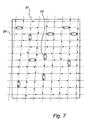
- An example of a thus-processed image is shown in Fig. 7 .
- the image now consists of a number of points with determined positions, which were obtained from the sensor image.
- the marks are not located along an orthogonal grid with an equal distance between the raster lines.
- the reason is that the image on the sensor surface is usually obtained with a certain perspective, which compresses the distance between the raster lines in one direction and also creates an angle between the raster lines.
- the marks are also displaced by 1/6 of the distance between the raster lines in any of four orthogonal directions, it is no simple task to recreate the raster lines.
- the marks can also be rotated, so that the raster lines are not usually parallel with the side edges of the sensor surface.
- Fig. 7 the horizontal raster lines 20 are compressed so that the distance between them is less than the distance between the vertical raster lines 21.
- the vertical raster lines are at an angle to each other, so that they meet in a position vertically above the sensor surface.
- horizontal and vertical is meant the positions in Fig. 7 .
- the characteristic is used that the shortest distance between two marks is the distance where the positions of the marks have the values 1 and 3 respectively in the horizontal direction, or 2 and 4 respectively in the vertical direction.
- eleven (11) such pairs of marks are encircled.
- one such pair is used as the starting point for recreating the raster.
- a pair of marks m 1 , m 2 is selected, for example close to the centre of the sensor surface, for example the pair marked by the ellipse 22.
- the distance between the marks is determined and a first vector V 1,2 is calculated, the direction of which is determined by the coordinates of the marks and the length of which is the distance between the marks multiplied by 1.5.
- the vector is calculated so that it extends through the marks and an equal distance out on each side. The ends of the vector thereby indicate the two intersections g 1 and g 2 of the raster lines.
- One of the raster points g 2 can be taken as the starting point for a second vector V 2,3 , a third vector V 2,4 , and a fourth vector V 2,4 , which are at an angle of 90 degrees, -90 degrees and 0 degrees respectively to the first vector and are the same length as the first vector.
- the third vector is placed on a first stack for possible later use and the fourth vector is placed on a second stack for possible later use.
- the actual position of the intersection g 3 of the raster is calculated, by using the value of the mark.
- the distance to the nominal position of the mark is 1/6 of the distance between the raster points.
- the value of the mark determines the direction to the raster point. In this way the raster point can be determined unambiguously.
- the vector V 2,3 is adjusted to the correct length and direction in order to fit between the raster points. In this way the intersection g 3 is validated and stored in a memory of valid raster points.
- the third vector V 2,4 , and the fourth vector V 2,5 which were placed on the stacks, can be used if the vector V 2,3 does not result in a valid raster point.
- the new valid raster point g 3 is taken as the starting point for a fifth vector V 3,6 , a sixth vector V 3,7 and a seventh vector V 3,8 , each at angles of 90 degrees, -90 degrees and 0 degrees relative to the third vector, and the sixth and seventh vectors are placed on the stack.
- the length and direction of the fifth vector are the same as for the first vector, that is the last but one determined vector (in the same direction).
- the length and direction of the second vector that is the last determined in the same direction, are used.
- the sixth mark m 6 Close to the end of the fifth vector is found the sixth mark m 6 , which has the position value 4. Using the value and coordinates of the sixth mark, the length and direction of the fifth vector are adjusted to obtain the correct length and direction. The sixth raster point is thus validated and can be stored in the raster-point memory.
- the process is continued until the new vector points to a raster point that has already been determined. Then the vector is used instead which is at a -90 degree angle relative to the preceding vector and which is at the top of the stack. If this cannot be used either, the process is continued down the stack until all the raster points have been determined. If the stack is finished, the second stack is used with vectors with zero-direction.
- an initial vector which does not consist of the vector between the mark values 1 and 3 or 2 and 4 can lead to usable results.
- the initial vector's raster points are not used as validated raster points, but these two first raster points are determined at a later stage based on validated raster points. It is thus immaterial which initial vector is used, provided a usable result is obtained.
- any angle deviations between the raster lines are of minor significance.
- the method according to the invention can be used with good results even with relatively strong perspectives and resultant oblique rasters.
- the method according to the invention is also suitable for use with rasters with angles other than 90 degrees, for example with triangular rasters.
- the third vector at -90 degrees relative to the first vector, is placed on the stack for possible later use. It is also possible to use this third vector directly after the second vector has been used, the stack being of the type first-in-first-out (FIFO) and the stack is emptied before new vectors are created. A normal stack is otherwise of the type last-in-first-out (LIFO). Other intermediate variants are also possible. It is also possible to use first the vector that is at the angle of -90 degrees and then the other.
- FIFO first-in-first-out
- LIFO last-in-first-out
- the invention has been described above with reference to a preferred embodiment of the invention.
- the method according to the invention can be used for other types of raster, such as triangular or honeycomb rasters, with minor modifications.
- the vector is calculated based on the coordinates of the marks found, but of course taking into effect the angles and distances which apply to the hexagonal raster.
- the sensor surface or the coordinates of the marks are searched starting from the top left corner of the sensor surface and going towards the right, then the next row, until a pair of coordinates with suitable characteristics has been found.
- all the distances between the marks are first calculated, before the least distance is selected.
- different initial lengths of the vector are used, depending upon whether it goes in the horizontal or vertical direction, in order to make possible decoding of a pattern with strong perspective.
- a difference in distance between the coordinates in the horizontal or vertical direction can often be determined as early as during the initial determination of the initial vector.
- the end of the vector is within the circle to which the four values of the mark correspond, there is no problem in determining the associated mark and its value. However, if the perspective is so strong that the end of the vector is far from the associated raster point, the length and the angles for creating the next vector can be adjusted until acceptable values are obtained. Alternatively, the result of the decoding of the preceding image frame can be used as the starting point for a preparatory adjustment of the perspective before decoding takes place.
Landscapes
- Engineering & Computer Science (AREA)
- Physics & Mathematics (AREA)
- Theoretical Computer Science (AREA)
- General Physics & Mathematics (AREA)
- Electromagnetism (AREA)
- General Health & Medical Sciences (AREA)
- Artificial Intelligence (AREA)
- Computer Vision & Pattern Recognition (AREA)
- Toxicology (AREA)
- Health & Medical Sciences (AREA)
- General Engineering & Computer Science (AREA)
- Human Computer Interaction (AREA)
- Multimedia (AREA)
- Editing Of Facsimile Originals (AREA)
- Image Processing (AREA)
- Length Measuring Devices By Optical Means (AREA)
- Inspection Of Paper Currency And Valuable Securities (AREA)
- Image Analysis (AREA)
- Transmission And Conversion Of Sensor Element Output (AREA)
- Communication Control (AREA)
- Record Information Processing For Printing (AREA)
- Indexing, Searching, Synchronizing, And The Amount Of Synchronization Travel Of Record Carriers (AREA)
- Vehicle Body Suspensions (AREA)
- Table Devices Or Equipment (AREA)
- Compression Of Band Width Or Redundancy In Fax (AREA)
- Control Of Position Or Direction (AREA)
- Compression, Expansion, Code Conversion, And Decoders (AREA)
- Cartons (AREA)
- Laminated Bodies (AREA)
- Error Detection And Correction (AREA)
Applications Claiming Priority (3)
| Application Number | Priority Date | Filing Date | Title |
|---|---|---|---|
| SE9903541A SE517445C2 (sv) | 1999-10-01 | 1999-10-01 | Positionsbestämning på en yta försedd med ett positionskodningsmönster |
| SE9903541 | 1999-10-01 | ||
| PCT/SE2000/001898 WO2001026034A1 (en) | 1999-10-01 | 2000-10-02 | Determination of a position code |
Publications (2)
| Publication Number | Publication Date |
|---|---|
| EP1224606A1 EP1224606A1 (en) | 2002-07-24 |
| EP1224606B1 true EP1224606B1 (en) | 2008-07-16 |
Family
ID=20417215
Family Applications (4)
| Application Number | Title | Priority Date | Filing Date |
|---|---|---|---|
| EP00970382A Expired - Lifetime EP1224606B1 (en) | 1999-10-01 | 2000-10-02 | Determination of a position code |
| EP00968278A Expired - Lifetime EP1222604B1 (en) | 1999-10-01 | 2000-10-02 | Encoded paper for optical reading |
| EP00968280A Expired - Lifetime EP1222605B1 (en) | 1999-10-01 | 2000-10-02 | Position determination - calculation |
| EP10156315A Expired - Lifetime EP2207127B1 (en) | 1999-10-01 | 2000-10-02 | Encoded paper for optical reading |
Family Applications After (3)
| Application Number | Title | Priority Date | Filing Date |
|---|---|---|---|
| EP00968278A Expired - Lifetime EP1222604B1 (en) | 1999-10-01 | 2000-10-02 | Encoded paper for optical reading |
| EP00968280A Expired - Lifetime EP1222605B1 (en) | 1999-10-01 | 2000-10-02 | Position determination - calculation |
| EP10156315A Expired - Lifetime EP2207127B1 (en) | 1999-10-01 | 2000-10-02 | Encoded paper for optical reading |
Country Status (15)
| Country | Link |
|---|---|
| US (9) | US6674427B1 (sv) |
| EP (4) | EP1224606B1 (sv) |
| JP (16) | JP2003511763A (sv) |
| KR (6) | KR100742429B1 (sv) |
| CN (5) | CN1326017C (sv) |
| AT (3) | ATE401617T1 (sv) |
| AU (3) | AU7977300A (sv) |
| BR (2) | BR0014449B1 (sv) |
| CA (3) | CA2384302A1 (sv) |
| DE (3) | DE60040472D1 (sv) |
| ES (1) | ES2341533T3 (sv) |
| MX (2) | MXPA02003309A (sv) |
| RU (3) | RU2261474C2 (sv) |
| SE (1) | SE517445C2 (sv) |
| WO (3) | WO2001026032A1 (sv) |
Families Citing this family (408)
| Publication number | Priority date | Publication date | Assignee | Title |
|---|---|---|---|---|
| US7091959B1 (en) * | 1999-03-31 | 2006-08-15 | Advanced Digital Systems, Inc. | System, computer program product, computing device, and associated methods for form identification and information manipulation |
| US6785016B1 (en) * | 1999-05-25 | 2004-08-31 | Silverbrook Research Pty Ltd. | Portable interactive printer |
| US7106888B1 (en) * | 1999-05-25 | 2006-09-12 | Silverbrook Research Pty Ltd | Signature capture via interface surface |
| US6832717B1 (en) * | 1999-05-25 | 2004-12-21 | Silverbrook Research Pty Ltd | Computer system interface surface |
| AU2002952259A0 (en) | 2002-10-25 | 2002-11-07 | Silverbrook Research Pty Ltd | Methods and apparatus |
| AU2003900983A0 (en) * | 2003-03-04 | 2003-03-20 | Silverbrook Research Pty Ltd | Methods, systems and apparatus (NPT023) |
| MXPA02002247A (es) | 1999-08-30 | 2002-09-30 | Anoto Ab | Bloc de notas. |
| US7710408B2 (en) | 1999-08-30 | 2010-05-04 | Anoto Ab | Centralized information management based upon position information |
| ATE488817T1 (de) * | 1999-09-17 | 2010-12-15 | Silverbrook Res Pty Ltd | Verfahren und system zur instruktion eines computers |
| US8136720B2 (en) * | 1999-09-17 | 2012-03-20 | Silverbrook Research Pty Ltd | Method of recording mail transactions |
| US7225979B2 (en) * | 1999-09-17 | 2007-06-05 | Silverbrook Research Pty Ltd | Methods and systems for object identification and interaction |
| US7128270B2 (en) * | 1999-09-17 | 2006-10-31 | Silverbrook Research Pty Ltd | Scanning device for coded data |
| US7108192B2 (en) * | 1999-09-17 | 2006-09-19 | Silverbrook Research Pty Ltd | Rotationally symmetric tags |
| SE517445C2 (sv) | 1999-10-01 | 2002-06-04 | Anoto Ab | Positionsbestämning på en yta försedd med ett positionskodningsmönster |
| US6993655B1 (en) * | 1999-12-20 | 2006-01-31 | Xerox Corporation | Record and related method for storing encoded information using overt code characteristics to identify covert code characteristics |
| US20030061188A1 (en) | 1999-12-23 | 2003-03-27 | Linus Wiebe | General information management system |
| US7295193B2 (en) | 1999-12-23 | 2007-11-13 | Anoto Ab | Written command |
| SE9904746L (sv) * | 1999-12-23 | 2001-06-24 | Anoto Ab | Betalningssystem |
| US6832116B1 (en) | 2000-02-16 | 2004-12-14 | Telefonaktiebolaget L M Ericsson (Publ) | Method and system for controlling an electronic utility device using an electronic reading device |
| US6885878B1 (en) * | 2000-02-16 | 2005-04-26 | Telefonaktiebolaget L M Ericsson (Publ) | Method and system for using an electronic reading device as a general application input and navigation interface |
| AU2001230255A1 (en) | 2000-02-16 | 2001-08-27 | Telefonaktiebolaget Lm Ericsson (Publ) | Printer pen |
| US6839623B1 (en) | 2000-02-16 | 2005-01-04 | Telefonaktiebolaget Lm Ericsson (Publ) | Positioning applications for an electronic reading device |
| US20010033293A1 (en) * | 2000-02-16 | 2001-10-25 | Magnus Hollstrom | Electronic pen help feedback and information retrieval |
| US6813396B1 (en) | 2000-02-16 | 2004-11-02 | Telefonatiebolaget L.M. Ericsson (Publ) | Method for sharing information between electronic reading devices |
| US6952497B1 (en) | 2000-02-16 | 2005-10-04 | Telefonaktiebolaget L M Ericsson (Publ) | Method and system for electronically recording transactions and performing security function |
| US6992655B2 (en) | 2000-02-18 | 2006-01-31 | Anoto Ab | Input unit arrangement |
| US7254839B2 (en) | 2000-03-21 | 2007-08-07 | Anoto Ab | Secured access using a coordinate system |
| SE0000949L (sv) | 2000-03-21 | 2001-09-22 | Anoto Ab | Positionsinformation |
| US7415501B2 (en) | 2000-03-21 | 2008-08-19 | Anoto Ab | Online graphical message service |
| US7143952B2 (en) | 2000-03-21 | 2006-12-05 | Anoto Ab | Apparatus and methods relating to image coding |
| US7072529B2 (en) | 2000-03-21 | 2006-07-04 | Anoto Ab | Systems and methods for information storage |
| US8418052B2 (en) | 2000-03-21 | 2013-04-09 | Anoto Aktiebolag (Anoto Ab) | Processing of documents |
| US6947033B2 (en) | 2000-03-21 | 2005-09-20 | Anoto Ab | Method and system for digitizing freehand graphics with user-selected properties |
| US6864880B2 (en) | 2000-03-21 | 2005-03-08 | Anoto Ab | Device and method for communication |
| US20060082557A1 (en) * | 2000-04-05 | 2006-04-20 | Anoto Ip Lic Hb | Combined detection of position-coding pattern and bar codes |
| US7050653B2 (en) | 2000-04-05 | 2006-05-23 | Anoto Ab | Identification of virtual raster pattern |
| US7094977B2 (en) | 2000-04-05 | 2006-08-22 | Anoto Ip Lic Handelsbolag | Method and system for information association |
| US6586688B2 (en) | 2000-04-05 | 2003-07-01 | Anoto Ab | Information-related devices and methods |
| DE60140249D1 (sv) | 2000-04-05 | 2009-12-03 | Anoto Ab | |
| US7278017B2 (en) | 2000-06-07 | 2007-10-02 | Anoto Ab | Method and device for secure wireless transmission of information |
| JP4317334B2 (ja) * | 2000-09-08 | 2009-08-19 | 株式会社リコー | 画像形成装置及び文書管理システム |
| US6958747B2 (en) | 2000-08-30 | 2005-10-25 | Anoto Ab | Method for making a product |
| US6698660B2 (en) | 2000-09-07 | 2004-03-02 | Anoto Ab | Electronic recording and communication of information |
| US6722574B2 (en) | 2000-09-07 | 2004-04-20 | Anoto Ab | Business card |
| JP4776832B2 (ja) * | 2000-10-19 | 2011-09-21 | キヤノン株式会社 | 座標入力装置、および、画像入力装置の座標板 |
| US7127682B2 (en) | 2000-11-10 | 2006-10-24 | Anoto Ab | Device and system for information management utilizing a filing appliance |
| US7167164B2 (en) | 2000-11-10 | 2007-01-23 | Anoto Ab | Recording and communication of handwritten information |
| US7333947B2 (en) | 2000-11-13 | 2008-02-19 | Anoto Ab | Network-based system |
| US7002559B2 (en) * | 2000-11-13 | 2006-02-21 | Anoto Ab | Method, system and product for information management |
| US6798907B1 (en) * | 2001-01-24 | 2004-09-28 | Advanced Digital Systems, Inc. | System, computer software product and method for transmitting and processing handwritten data |
| US20020107885A1 (en) * | 2001-02-01 | 2002-08-08 | Advanced Digital Systems, Inc. | System, computer program product, and method for capturing and processing form data |
| SE519012C2 (sv) * | 2001-04-05 | 2002-12-23 | Anoto Ab | Sätt att hantera information |
| US7649637B2 (en) | 2001-04-05 | 2010-01-19 | Anoto Ab | Method for printing a global position-coding pattern |
| US6878062B2 (en) | 2001-04-06 | 2005-04-12 | Anoto Ab | Method for performing games |
| WO2002093467A1 (en) | 2001-05-11 | 2002-11-21 | Anoto Ab | Electronic pen with actuation through removal of cap |
| US7916124B1 (en) | 2001-06-20 | 2011-03-29 | Leapfrog Enterprises, Inc. | Interactive apparatus using print media |
| SE0102210L (sv) | 2001-06-21 | 2003-02-12 | Anoto Ab | Förfarande för programstyrning |
| US7202861B2 (en) | 2001-06-25 | 2007-04-10 | Anoto Ab | Control of a unit provided with a processor |
| US6667695B2 (en) | 2001-06-25 | 2003-12-23 | Anoto Ab | Position code |
| SE519277C2 (sv) * | 2001-06-25 | 2003-02-11 | Anoto Ab | Anordning och förfarande för positionskodning och för avkodning av en positionskod |
| SE0102236L (sv) * | 2001-06-25 | 2002-12-26 | Anoto Ab | Styrning av en processorförsedd enhet |
| US6966495B2 (en) | 2001-06-26 | 2005-11-22 | Anoto Ab | Devices method and computer program for position determination |
| US7180509B2 (en) | 2001-06-26 | 2007-02-20 | Anoto Ab | Electronic pen, mounting part therefor and method of making the pen |
| SE0102253L (sv) * | 2001-06-26 | 2002-12-27 | Anoto Ab | Läspenna |
| US6732927B2 (en) | 2001-06-26 | 2004-05-11 | Anoto Ab | Method and device for data decoding |
| SE523700C2 (sv) | 2001-06-26 | 2004-05-11 | Anoto Ab | Förfarande, anordning och minnesmedium för positionsbestämning |
| US7110604B2 (en) | 2001-06-26 | 2006-09-19 | Anoto Ab | Processing of digital images |
| US20030016212A1 (en) * | 2001-06-27 | 2003-01-23 | Stefan Lynggaard | Method, computer program product and device for wireless connection |
| US7202963B2 (en) | 2001-06-28 | 2007-04-10 | Anoto Ab | Method for processing information |
| SE523112C2 (sv) * | 2001-07-05 | 2004-03-30 | Anoto Ab | Förfaringssätt för kommunikation mellan en användarenhet som har möjlighet att läsa information från en yta, och servrar som exekverar tjänster som stöder användarenheten |
| US6727896B2 (en) * | 2001-08-01 | 2004-04-27 | Microsoft Corporation | Correction of alignment and linearity errors in a stylus input system |
| US7296075B2 (en) | 2001-08-23 | 2007-11-13 | Anoto Ab | Method, apparatus and system for connecting a portable unit to a particular server unit from among a plurality of server units |
| WO2003023595A1 (en) | 2001-09-10 | 2003-03-20 | Anoto Ab | Method, computer program product and device for arranging coordinate areas relative to each other |
| US7175095B2 (en) | 2001-09-13 | 2007-02-13 | Anoto Ab | Coding pattern |
| SE520045C2 (sv) * | 2001-09-13 | 2003-05-13 | Anoto Ab | Kodningsmönster |
| US7120320B2 (en) | 2001-09-21 | 2006-10-10 | Anoto Ab | Method and apparatus for displaying a handwritten message based on position and time data |
| US7457476B2 (en) | 2001-10-03 | 2008-11-25 | Anoto Ab | Optical sensor device and a method of controlling its exposure time |
| US7145556B2 (en) | 2001-10-29 | 2006-12-05 | Anoto Ab | Method and device for decoding a position-coding pattern |
| SE0103589L (sv) * | 2001-10-29 | 2003-04-30 | Anoto Ab | Förfarande och anordning för avkodning av ett positionskodningsmönster |
| US7321692B2 (en) | 2001-11-13 | 2008-01-22 | Anoto Ab | Method, device and computer program product for processing information in a memory |
| US7283676B2 (en) | 2001-11-20 | 2007-10-16 | Anoto Ab | Method and device for identifying objects in digital images |
| US7385595B2 (en) * | 2001-11-30 | 2008-06-10 | Anoto Ab | Electronic pen and method for recording of handwritten information |
| SE520682C2 (sv) | 2001-12-06 | 2003-08-12 | Anoto Ab | Rekonstruering av ett virtuellt raster |
| US7356012B2 (en) | 2001-12-27 | 2008-04-08 | Anoto Ab | Method for transmitting information |
| US7162087B2 (en) | 2001-12-28 | 2007-01-09 | Anoto Ab | Method and apparatus for recording of electronic handwriting |
| TWI235926B (en) | 2002-01-11 | 2005-07-11 | Sonix Technology Co Ltd | A method for producing indicators and processing system, coordinate positioning system and electronic book system utilizing the indicators |
| SE0200419L (sv) * | 2002-02-12 | 2003-08-13 | Anoto Ab | Elektronisk penna samt sensorarrangemang och styranordning vid sådan |
| WO2003070472A1 (en) | 2002-02-22 | 2003-08-28 | Print-Rite.Unicorn Image Products Co. Ltd. Of Zhuhai | An intelligent ink cartridge and method for manufacturing the same |
| SE0201297D0 (sv) * | 2002-04-30 | 2002-04-30 | Anoto Ab | Information management system and a method at said system |
| US7293697B2 (en) | 2002-06-05 | 2007-11-13 | Anoto Ab | Method for managing information |
| EP1532577B1 (en) | 2002-06-18 | 2008-12-03 | Anoto AB | Position-coding pattern |
| US6915281B2 (en) * | 2002-06-30 | 2005-07-05 | Pitney Bowes Inc. | Systems and methods using a digital pen for funds accounting devices and postage meters |
| CA2952993A1 (en) | 2002-09-26 | 2004-04-08 | Kenji Yoshida | Information reproducing method, information inputting/outputting method,information reproducing device, portable information inputting/outputting device and electronic toy using dot pattern |
| RU2349956C2 (ru) * | 2002-09-26 | 2009-03-20 | Кендзи ЙОСИДА | Способ воспроизведения информации, способ ввода/вывода информации, устройство воспроизведения информации, портативное устройство ввода/вывода информации и электронная игрушка, в которой использован точечный растр |
| AU2015243058B2 (en) * | 2002-09-26 | 2018-03-22 | Kenji Yoshida | Information reproduction i/o method using dot pattern, information reproduction device, mobile information i/o device, and electronic toy |
| US7343042B2 (en) * | 2002-09-30 | 2008-03-11 | Pitney Bowes Inc. | Method and system for identifying a paper form using a digital pen |
| US7167586B2 (en) * | 2002-09-30 | 2007-01-23 | Pitney Bowes Inc. | Method and system for remote form completion |
| US7417773B2 (en) * | 2002-09-30 | 2008-08-26 | Pitney Bowes Inc. | Method and system for creating and sending a facsimile using a digital pen |
| US7082444B2 (en) | 2002-09-30 | 2006-07-25 | Pitney Bowes Inc. | Method and system for identifying a form version |
| EP1410916A1 (en) | 2002-10-18 | 2004-04-21 | Hewlett-Packard Company | Hybrid printing/pointing device |
| SE523931C2 (sv) * | 2002-10-24 | 2004-06-01 | Anoto Ab | Arrangemang och sätt i ett informations hanteringssystem som omfattar behovsstyrd generering av positionskodade underlag |
| EP1413974A1 (en) | 2002-10-24 | 2004-04-28 | Hewlett-Packard Company | Hybrid sensing techniques for position determination |
| WO2004038650A1 (en) * | 2002-10-25 | 2004-05-06 | Silverbrook Research Pty Ltd | Orientation-indicating cyclic position codes |
| WO2004051557A1 (en) * | 2002-12-03 | 2004-06-17 | Silverbrook Research Pty Ltd | Rotationally symmetric tags |
| US7133563B2 (en) | 2002-10-31 | 2006-11-07 | Microsoft Corporation | Passive embedded interaction code |
| US7116840B2 (en) * | 2002-10-31 | 2006-10-03 | Microsoft Corporation | Decoding and error correction in 2-D arrays |
| US7009594B2 (en) * | 2002-10-31 | 2006-03-07 | Microsoft Corporation | Universal computing device |
| SE0203853D0 (sv) | 2002-12-23 | 2002-12-23 | Anoto Ab | Informationskod |
| US7840492B2 (en) * | 2002-12-30 | 2010-11-23 | Pitney Bowes Inc. | Personal funds metering system and method |
| US7110576B2 (en) * | 2002-12-30 | 2006-09-19 | Pitney Bowes Inc. | System and method for authenticating a mailpiece sender |
| AU2004217403B2 (en) * | 2003-03-04 | 2007-07-26 | Silverbrook Research Pty Ltd | Symmetric tags |
| US7097094B2 (en) * | 2003-04-07 | 2006-08-29 | Silverbrook Research Pty Ltd | Electronic token redemption |
| US7991432B2 (en) * | 2003-04-07 | 2011-08-02 | Silverbrook Research Pty Ltd | Method of printing a voucher based on geographical location |
| EP1620828B1 (en) * | 2003-04-29 | 2014-12-24 | Anoto AB | Methods, apparatus, computer program and storage medium for position decoding |
| WO2004104818A1 (en) | 2003-05-26 | 2004-12-02 | Anoto Ip Lic Hb | Method for compressinga digital representation containing a page-describing code, which is sent from a computer to a printer |
| SE0301729D0 (sv) * | 2003-06-13 | 2003-06-13 | Anoto Ab | Behovsstyrd utskrift av kodningsmönster |
| JP4504369B2 (ja) * | 2003-06-13 | 2010-07-14 | アノト アクティエボラーク | コーディングパターンのオンデマンド印刷 |
| FR2856473B1 (fr) * | 2003-06-23 | 2005-12-09 | Groupe Silicomp | Procede de navigation, dispositif, systeme et programmes d'ordinateur correspondants |
| US7167166B1 (en) | 2003-08-01 | 2007-01-23 | Accenture Global Services Gmbh | Method and system for processing observation charts |
| US20050052707A1 (en) * | 2003-09-10 | 2005-03-10 | Nelson Terry M. | Location patterns and methods and apparatus for generating such patterns |
| US6962450B2 (en) * | 2003-09-10 | 2005-11-08 | Hewlett-Packard Development Company L.P. | Methods and apparatus for generating images |
| US20050052706A1 (en) * | 2003-09-10 | 2005-03-10 | Nelson Terry M. | Location patterns and methods and apparatus for generating such patterns |
| GB0321168D0 (en) * | 2003-09-10 | 2003-10-08 | Hewlett Packard Development Co | Printing of documents with position identification pattern |
| GB0321164D0 (en) * | 2003-09-10 | 2003-10-08 | Hewlett Packard Development Co | Methods,apparatus and software for printing location pattern |
| US20050052700A1 (en) * | 2003-09-10 | 2005-03-10 | Andrew Mackenzie | Printing digital documents |
| GB0321173D0 (en) * | 2003-09-10 | 2003-10-08 | Hewlett Packard Development Co | Replying to e-mails,creating and sending e-mails,and apparatus, methods and software relating to such activities |
| US20050060644A1 (en) * | 2003-09-15 | 2005-03-17 | Patterson John Douglas | Real time variable digital paper |
| US20050087610A1 (en) * | 2003-10-27 | 2005-04-28 | Adams Guy De W.B. | Visually significant marking in position encoded glyph carpets |
| SE0302884D0 (sv) * | 2003-10-31 | 2003-10-31 | Anoto Ab | Information management unit and method for controlling data flow from electronic pens |
| JP3635374B1 (ja) * | 2003-11-14 | 2005-04-06 | 有限会社Sires | デジタル情報坦体 |
| SE0303058D0 (sv) * | 2003-11-18 | 2003-11-18 | Anoto Ab | Methods and arrangemang in an information management system |
| WO2005057471A1 (en) | 2003-12-15 | 2005-06-23 | Anoto Ab | An optical system, an analysis system and a modular unit for an electronic pen |
| SE0303370D0 (sv) | 2003-12-16 | 2003-12-16 | Anoto Ab | Method, apparatus, computer program and storage medium for recording a movement of a user unit |
| US7111230B2 (en) * | 2003-12-22 | 2006-09-19 | Pitney Bowes Inc. | System and method for annotating documents |
| WO2005064530A1 (ja) * | 2003-12-25 | 2005-07-14 | Kenji Yoshida | ドットパターンを用いた情報入出力方法 |
| US7583842B2 (en) * | 2004-01-06 | 2009-09-01 | Microsoft Corporation | Enhanced approach of m-array decoding and error correction |
| US7463774B2 (en) * | 2004-01-07 | 2008-12-09 | Microsoft Corporation | Global localization by fast image matching |
| US7263224B2 (en) * | 2004-01-16 | 2007-08-28 | Microsoft Corporation | Strokes localization by m-array decoding and fast image matching |
| GB0402022D0 (en) | 2004-01-30 | 2004-03-03 | Hewlett Packard Development Co | Method of obtaining at least a portion ofa document |
| EP1569140A3 (en) | 2004-01-30 | 2006-10-25 | Hewlett-Packard Development Company, L.P. | Apparatus, methods and software for associating electronic and physical documents |
| GB2410590B (en) | 2004-01-30 | 2007-02-14 | Hewlett Packard Development Co | Physical object with memory tag and apparatus for use with such objects |
| SE0400322D0 (sv) * | 2004-02-13 | 2004-02-13 | Anoto Ab | On-demand printing of coding patterns |
| US20050271961A1 (en) * | 2004-03-05 | 2005-12-08 | Jadwin Thomas A | Substrate and near infrared absorbing toner |
| US20060067576A1 (en) | 2004-03-17 | 2006-03-30 | James Marggraff | Providing a user interface having interactive elements on a writable surface |
| US7831933B2 (en) | 2004-03-17 | 2010-11-09 | Leapfrog Enterprises, Inc. | Method and system for implementing a user interface for a device employing written graphical elements |
| US7853193B2 (en) | 2004-03-17 | 2010-12-14 | Leapfrog Enterprises, Inc. | Method and device for audibly instructing a user to interact with a function |
| US7453447B2 (en) | 2004-03-17 | 2008-11-18 | Leapfrog Enterprises, Inc. | Interactive apparatus with recording and playback capability usable with encoded writing medium |
| US20060125805A1 (en) * | 2004-03-17 | 2006-06-15 | James Marggraff | Method and system for conducting a transaction using recognized text |
| US7242466B2 (en) * | 2004-03-31 | 2007-07-10 | Microsoft Corporation | Remote pointing system, device, and methods for identifying absolute position and relative movement on an encoded surface by remote optical method |
| US8054495B2 (en) | 2004-04-07 | 2011-11-08 | Hewlett-Packard Development Company, L.P. | Digital documents, apparatus, methods and software relating to associating an identity of paper printed with digital pattern with equivalent digital documents |
| US7048198B2 (en) * | 2004-04-22 | 2006-05-23 | Microsoft Corporation | Coded pattern for an optical device and a prepared surface |
| GB2413677A (en) | 2004-04-28 | 2005-11-02 | Hewlett Packard Development Co | Digital pen and paper system using a pattern which encodes communication parameters |
| US7270277B1 (en) | 2004-05-21 | 2007-09-18 | Koziol Jeffrey E | Data encoding mark for placement in a compact area and an object carrying the data encoding mark |
| SE0401647D0 (sv) * | 2004-06-28 | 2004-06-28 | Anoto Ab | Coding and decoding of data |
| US7751585B2 (en) * | 2004-06-28 | 2010-07-06 | Microsoft Corporation | System and method for encoding high density geometric symbol set |
| JP4996461B2 (ja) * | 2004-06-28 | 2012-08-08 | アノト アクティエボラーク | データのコーディングおよび復号化 |
| SE0401687D0 (sv) * | 2004-06-30 | 2004-06-30 | Anoto Ab | Information management |
| US20080296074A1 (en) * | 2004-06-30 | 2008-12-04 | Anoto Ab | Data Management in an Electric Pen |
| US20070246539A1 (en) * | 2004-06-30 | 2007-10-25 | Anoto Ab | Data Processing in an Electric Pen |
| FR2872941B1 (fr) * | 2004-07-08 | 2006-09-22 | Imaje Sa Sa | Methode et imprimante pour le codage confidentiel d'objets |
| US7698640B2 (en) | 2004-08-04 | 2010-04-13 | Leapfrog Enterprises, Inc. | User interactive journal |
| US7240849B2 (en) * | 2004-08-27 | 2007-07-10 | Hewlett-Packard Development Company, L.P. | Glyph pattern generation and glyph pattern decoding |
| US7635090B1 (en) * | 2004-09-07 | 2009-12-22 | Expedata, Llc | Pattern generating fonts and sheets of writing material bearing such fonts |
| US8323780B1 (en) | 2004-10-08 | 2012-12-04 | Hewlett-Packard Development Company, L.P. | Ink coatings for identifying objects |
| KR20070085366A (ko) * | 2004-10-12 | 2007-08-27 | 아노토 아베 | 전자펜으로부터의 정보의 보안 관리 방법 및 시스템 |
| US20060087497A1 (en) * | 2004-10-21 | 2006-04-27 | Borgaonkar Shekhar R | Digital pen for capturing hand-drawn data |
| US7452046B2 (en) | 2004-10-27 | 2008-11-18 | Hewlett-Packard Development Company, L.P. | Method for preparing a print mask |
| GB2419720B (en) * | 2004-10-29 | 2010-04-14 | Hewlett Packard Development Co | Data encoding pattern |
| SE0402710D0 (sv) * | 2004-11-05 | 2004-11-05 | Anoto Ab | Management of internal logic for electronic pens |
| US11627944B2 (en) | 2004-11-30 | 2023-04-18 | The Regents Of The University Of California | Ultrasound case builder system and method |
| KR100628463B1 (ko) | 2004-12-13 | 2006-09-26 | 핑거시스템 주식회사 | 절대좌표 인식 시스템 및 그 방법 |
| US20060139338A1 (en) * | 2004-12-16 | 2006-06-29 | Robrecht Michael J | Transparent optical digitizer |
| US7621441B1 (en) | 2004-12-22 | 2009-11-24 | Leapfrog Enterprises | Interactive device using capacitive sensor array for joint page identification and page location determination |
| US7428990B1 (en) | 2004-12-22 | 2008-09-30 | Leapfrog Enterprises, Inc. | Capacitive sensing of media information in an interactive media device |
| CN101091185B (zh) * | 2004-12-28 | 2010-06-09 | 吉田健治 | 使用点模式的信息输入输出方法 |
| US7639876B2 (en) * | 2005-01-14 | 2009-12-29 | Advanced Digital Systems, Inc. | System and method for associating handwritten information with one or more objects |
| KR100673005B1 (ko) | 2005-02-18 | 2007-02-28 | 핑거시스템 주식회사 | 복합좌표 인식 입력장치 및 그 구동방법 |
| US7607076B2 (en) * | 2005-02-18 | 2009-10-20 | Microsoft Corporation | Embedded interaction code document |
| US8094139B2 (en) | 2005-02-23 | 2012-01-10 | Anoto Ab | Method in electronic pen, computer program product, and electronic pen |
| US7826074B1 (en) | 2005-02-25 | 2010-11-02 | Microsoft Corporation | Fast embedded interaction code printing with custom postscript commands |
| JP4556705B2 (ja) | 2005-02-28 | 2010-10-06 | 富士ゼロックス株式会社 | 2次元座標同定装置、画像形成装置及び2次元座標同定方法 |
| US20060215913A1 (en) * | 2005-03-24 | 2006-09-28 | Microsoft Corporation | Maze pattern analysis with image matching |
| JPWO2006112021A1 (ja) * | 2005-04-15 | 2008-11-27 | 吉田 健治 | ドットパターンを用いた情報入出力方法 |
| US20060242562A1 (en) * | 2005-04-22 | 2006-10-26 | Microsoft Corporation | Embedded method for embedded interaction code array |
| US7421439B2 (en) | 2005-04-22 | 2008-09-02 | Microsoft Corporation | Global metadata embedding and decoding |
| KR100624387B1 (ko) * | 2005-04-25 | 2006-09-20 | 엘지전자 주식회사 | 주행영역 지정이 가능한 로봇 시스템 |
| US8031375B2 (en) * | 2005-04-28 | 2011-10-04 | Kenji Yoshida | Information input/output method using dot pattern |
| US7646377B2 (en) * | 2005-05-06 | 2010-01-12 | 3M Innovative Properties Company | Position digitizing using an optical stylus to image a display |
| US7400777B2 (en) * | 2005-05-25 | 2008-07-15 | Microsoft Corporation | Preprocessing for information pattern analysis |
| US7720286B2 (en) * | 2005-05-25 | 2010-05-18 | Advanced Digital Systems, Inc. | System and method for associating handwritten information with one or more objects via discontinuous regions of a printed pattern |
| US7729539B2 (en) * | 2005-05-31 | 2010-06-01 | Microsoft Corporation | Fast error-correcting of embedded interaction codes |
| NO20052656D0 (no) | 2005-06-02 | 2005-06-02 | Lumex As | Geometrisk bildetransformasjon basert pa tekstlinjesoking |
| US7580576B2 (en) * | 2005-06-02 | 2009-08-25 | Microsoft Corporation | Stroke localization and binding to electronic document |
| KR100837470B1 (ko) * | 2005-06-03 | 2008-06-12 | 실버브룩 리서치 피티와이 리미티드 | 기계-판독가능한 부호화된 데이터의 판독 방법 |
| US7661592B1 (en) | 2005-06-08 | 2010-02-16 | Leapfrog Enterprises, Inc. | Interactive system including interactive apparatus and game |
| KR101236809B1 (ko) * | 2005-06-17 | 2013-02-25 | 아노토 아베 | 위치 및 정보 코드를 결합하는 방법 및 시스템 |
| JP3771252B1 (ja) | 2005-07-01 | 2006-04-26 | 健治 吉田 | ドットパターン |
| US7374087B1 (en) | 2005-07-29 | 2008-05-20 | Leapfrog Enterprises, Inc. | Method, apparatus and system for conveying cartridge notification |
| US7549596B1 (en) | 2005-07-29 | 2009-06-23 | Nvidia Corporation | Image bearing surface |
| US7922099B1 (en) | 2005-07-29 | 2011-04-12 | Leapfrog Enterprises, Inc. | System and method for associating content with an image bearing surface |
| US7817816B2 (en) * | 2005-08-17 | 2010-10-19 | Microsoft Corporation | Embedded interaction code enabled surface type identification |
| US7622182B2 (en) * | 2005-08-17 | 2009-11-24 | Microsoft Corporation | Embedded interaction code enabled display |
| AU2005209703B2 (en) * | 2005-09-13 | 2008-07-24 | Canon Kabushiki Kaisha | Grid orientation, scale, translation and modulation estimation |
| US7281664B1 (en) | 2005-10-05 | 2007-10-16 | Leapfrog Enterprises, Inc. | Method and system for hierarchical management of a plurality of regions of an encoded surface used by a pen computer |
| US7936339B2 (en) | 2005-11-01 | 2011-05-03 | Leapfrog Enterprises, Inc. | Method and system for invoking computer functionality by interaction with dynamically generated interface regions of a writing surface |
| JP4669381B2 (ja) * | 2005-12-01 | 2011-04-13 | 株式会社日立製作所 | 地図情報システム、地図情報処理方法およびそのプログラム |
| US7747544B2 (en) * | 2005-12-07 | 2010-06-29 | Pitney Bowes Inc. | Meter tape with location indicator used for unique identification |
| JP2007156219A (ja) | 2005-12-07 | 2007-06-21 | Seiko Epson Corp | 情報表示システム、情報表示装置および位置指示装置 |
| US20070138306A1 (en) * | 2005-12-19 | 2007-06-21 | Pitney Bowes Incorporated | Printed marking hidden authentication |
| JP4289350B2 (ja) | 2005-12-26 | 2009-07-01 | 富士ゼロックス株式会社 | 画像処理装置及び画像処理方法 |
| US7562822B1 (en) | 2005-12-30 | 2009-07-21 | Leapfrog Enterprises, Inc. | Methods and devices for creating and processing content |
| US8599143B1 (en) | 2006-02-06 | 2013-12-03 | Leapfrog Enterprises, Inc. | Switch configuration for detecting writing pressure in a writing device |
| JP4207049B2 (ja) | 2006-02-24 | 2009-01-14 | 富士ゼロックス株式会社 | 同定機能付き印刷物、画像生成装置、画像処理装置及びその方法 |
| TW200734933A (en) * | 2006-03-06 | 2007-09-16 | Pixart Imaging Inc | Dot-matrix pattern design and decoding method and the device thereof |
| US8086051B2 (en) * | 2006-03-06 | 2011-12-27 | Pixart Imaging Inc. | Method of decoding fetched scene on encoded dotmap and electronic device thereof |
| RU2457532C2 (ru) * | 2006-03-10 | 2012-07-27 | Кенджи Йошида | Система обработки ввода для устройства обработки информации |
| JP2007279822A (ja) * | 2006-04-03 | 2007-10-25 | Hitachi Maxell Ltd | 手書き入力システム |
| WO2007117201A1 (en) * | 2006-04-12 | 2007-10-18 | Anoto Ab | Data protection mechanism |
| TWI370413B (en) * | 2006-04-14 | 2012-08-11 | Sonix Technology Co Ltd | Graphical indicator |
| JP2007293640A (ja) * | 2006-04-26 | 2007-11-08 | Ids:Kk | 電子メールアドレス登録方法 |
| US8427344B2 (en) * | 2006-06-02 | 2013-04-23 | Anoto Ab | System and method for recalling media |
| US7445160B2 (en) * | 2006-06-14 | 2008-11-04 | Hewlett-Packard Development Company, L.P. | Position location using error correction |
| JP2009543181A (ja) | 2006-06-28 | 2009-12-03 | アノト アクティエボラーク | 電子ペンにおける動作制御およびデータ処理 |
| AU2006203027B2 (en) * | 2006-07-14 | 2009-11-19 | Canon Kabushiki Kaisha | Improved two-dimensional measurement system |
| US8261967B1 (en) | 2006-07-19 | 2012-09-11 | Leapfrog Enterprises, Inc. | Techniques for interactively coupling electronic content with printed media |
| GB2440921A (en) * | 2006-07-31 | 2008-02-20 | Hewlett Packard Development Co | A digital pen incorporating an orientation and position sensor and a display projector |
| US8714441B2 (en) | 2006-08-22 | 2014-05-06 | Eye Ear It, Llc | Systems and apparatus for expressing multimedia presentations corresponding to print media |
| WO2008024777A2 (en) | 2006-08-22 | 2008-02-28 | Eye Ear It, Llc. | Systems and apparatus for expressing multimedia presentations corresponding to print media |
| KR100841285B1 (ko) | 2006-09-18 | 2008-06-25 | 주식회사 펜래버레토리 | 표면상에 절대 위치 표시 패턴을 갖는 제조물 및 그 절대위치 표시 패턴의 형성 방법 |
| US20100220078A1 (en) * | 2006-10-05 | 2010-09-02 | Pegasus Technologies Ltd. | Digital pen system, transmitter devices, receiving devices, and methods of manufacturing and using the same |
| US8056821B2 (en) * | 2006-10-18 | 2011-11-15 | Xerox Corporation | Security marks simulating natural defects for embedding information in documents |
| WO2008048169A2 (en) * | 2006-10-20 | 2008-04-24 | Anoto Ab | Printing of coding patterns |
| JP4894451B2 (ja) * | 2006-10-24 | 2012-03-14 | 富士ゼロックス株式会社 | 画像処理装置、及びプログラム |
| JP4844351B2 (ja) | 2006-10-27 | 2011-12-28 | 富士ゼロックス株式会社 | 画像生成装置および記録媒体 |
| JP4821559B2 (ja) | 2006-10-27 | 2011-11-24 | 富士ゼロックス株式会社 | 情報生成装置、情報生成プログラム、情報生成方法、情報読取システム、電子ペン及び記録媒体 |
| JP2008113258A (ja) | 2006-10-30 | 2008-05-15 | Fuji Xerox Co Ltd | 画像生成装置、画像処理装置、及びプログラム |
| JP2008124996A (ja) * | 2006-11-15 | 2008-05-29 | Canon Inc | 画像処理装置、および画像処理方法 |
| AU2006252239B2 (en) * | 2006-12-22 | 2010-04-01 | Canon Kabushiki Kaisha | Barcode pattern |
| AU2006252254B2 (en) * | 2006-12-22 | 2009-03-05 | Canon Kabushiki Kaisha | Multiple barcode detection |
| AU2006252223B2 (en) | 2006-12-22 | 2010-07-01 | Canon Kabushiki Kaisha | Tamper Detection of Documents using Encoded Dots |
| US7847942B1 (en) | 2006-12-28 | 2010-12-07 | Leapfrog Enterprises, Inc. | Peripheral interface device for color recognition |
| KR100863814B1 (ko) * | 2006-12-29 | 2008-10-16 | 주식회사 펜래버레토리 | 표면상에 대상 표시 패턴을 갖는 제조물과 그 대상 표시패턴의 생성 방법 및 대상 정보 표시 시스템 |
| US20080192022A1 (en) * | 2007-02-08 | 2008-08-14 | Silverbrook Research Pty Ltd | Sensing device having automatic mode selection |
| KR100917918B1 (ko) * | 2007-03-16 | 2009-09-16 | 주식회사 이지시스템 | 디지털 페이퍼 및 디지털 펜을 이용하여 디지타이저 기능을제공하는 방법 및 장치 |
| US20090212120A1 (en) * | 2007-03-19 | 2009-08-27 | Yao-Hung Tsai | Graphical indicator |
| EP2130110B1 (en) * | 2007-03-23 | 2014-10-08 | Anoto AB | Printing of a position-coding pattern |
| JP4301524B2 (ja) | 2007-03-27 | 2009-07-22 | 株式会社沖データ | 印刷システム及び情報処理装置 |
| CN101681431A (zh) * | 2007-03-28 | 2010-03-24 | 阿诺托股份公司 | 电子笔的不同方面 |
| JP2008246041A (ja) * | 2007-03-30 | 2008-10-16 | Kenwood Corp | ゲームシステム、読取機器およびゲーム用操作コマンドの生成方法 |
| JP4161326B2 (ja) * | 2007-04-09 | 2008-10-08 | 健治 吉田 | ドットパターンが設けられたカード |
| US8358964B2 (en) | 2007-04-25 | 2013-01-22 | Scantron Corporation | Methods and systems for collecting responses |
| JP2008293405A (ja) | 2007-05-28 | 2008-12-04 | Fuji Xerox Co Ltd | データ入力システム |
| KR100906457B1 (ko) | 2007-05-30 | 2009-07-08 | 켄지 요시다 | 도트 패턴을 이용한 정보 입출력 방법 |
| JP4448156B2 (ja) | 2007-07-05 | 2010-04-07 | キヤノン株式会社 | 装置、方法およびプログラム |
| US8271864B2 (en) | 2007-07-10 | 2012-09-18 | Anoto Ab | Electronic representations of position-coded products in digital pen systems |
| US20100289776A1 (en) * | 2007-07-10 | 2010-11-18 | Mattias Bryborn Krus | System, software module and methods for creating a response to input by an electronic pen |
| GB2451482B (en) * | 2007-07-31 | 2012-03-14 | Hewlett Packard Development Co | Method and apparatus for reading a surface coded pattern |
| JP4420252B2 (ja) | 2007-09-14 | 2010-02-24 | 株式会社沖データ | 印刷データ生成装置 |
| US8397141B2 (en) * | 2007-09-21 | 2013-03-12 | Silverbrook Research Pty Ltd | Coding pattern comprising Reed-Solomon codewords encoded by mixed multi-pulse position modulation |
| JP2009080773A (ja) | 2007-09-27 | 2009-04-16 | Fuji Xerox Co Ltd | 筆記情報管理装置、筆記情報管理システムおよび筆記情報管理プログラム |
| US20090086226A1 (en) * | 2007-09-28 | 2009-04-02 | Oki Data Corporation | Image forming system, image processing apparatus and image processing method |
| KR100860110B1 (ko) * | 2007-10-11 | 2008-09-25 | 켄지 요시다 | 도트 패턴을 이용한 정보 입출력 방법 |
| CN105653070B (zh) * | 2007-10-19 | 2018-09-25 | 雷蛇(亚太)私人有限公司 | 无意位移之识别及其修正的方法、系统以及装置 |
| JP4308311B2 (ja) * | 2007-10-30 | 2009-08-05 | 健治 吉田 | コードパターン |
| US20100315660A1 (en) * | 2007-11-26 | 2010-12-16 | Stefan Lynggaard | Printing of position-coded documents |
| KR100904171B1 (ko) * | 2007-11-30 | 2009-06-23 | (주)아이엘에스커뮤니케이션 | 표면상 객체 인식용 코드 패턴을 갖는 제조물과 그 객체인식용 코드 패턴의 형성 방법 |
| AU2007254595B2 (en) * | 2007-12-20 | 2011-04-07 | Canon Kabushiki Kaisha | Constellation detection |
| JP2011511347A (ja) * | 2008-01-28 | 2011-04-07 | アノト アクティエボラーク | 情報をデジタル記録するデジタルペンおよび方法 |
| JP5151560B2 (ja) * | 2008-03-03 | 2013-02-27 | カシオ電子工業株式会社 | 紫外線蛍光画像可視化方法 |
| US10460085B2 (en) | 2008-03-13 | 2019-10-29 | Mattel, Inc. | Tablet computer |
| DE102008017168A1 (de) * | 2008-04-02 | 2009-10-08 | Crossmedia Solution Gmbh & Co. Kg | Verfahren zum Speichern und Auslesen von Daten |
| US8111432B2 (en) * | 2008-04-21 | 2012-02-07 | Xerox Corporation | Infrared watermarking of photographic images by matched differential black strategies |
| JP4712070B2 (ja) * | 2008-06-03 | 2011-06-29 | 株式会社沖データ | 印刷システム及び印刷装置 |
| US20090309854A1 (en) | 2008-06-13 | 2009-12-17 | Polyvision Corporation | Input devices with multiple operating modes |
| CN101609372B (zh) * | 2008-06-20 | 2012-07-04 | 义隆电子股份有限公司 | 二维点码、其解码装置及方法 |
| EP2138960A1 (en) | 2008-06-27 | 2009-12-30 | Anoto AB | A method and a device for controlling printing of graphical information |
| TWI471823B (zh) * | 2008-07-31 | 2015-02-01 | Pixart Imaging Inc | 以移動向量在微小點陣圖上決定座標的方法 |
| CN102036832B (zh) * | 2008-09-16 | 2014-05-28 | 深圳市王菱科技开发有限公司 | 可叠合电纸书册及互连共享电子数据的可调式夹持装置 |
| JP5412778B2 (ja) * | 2008-09-18 | 2014-02-12 | 富士ゼロックス株式会社 | 業務支援システム |
| TWI397013B (zh) * | 2008-09-26 | 2013-05-21 | Elan Microelectronics Corp | The dot code pattern and the dot code group pattern and the image processing circuit of the density coding type |
| US20100084478A1 (en) * | 2008-10-02 | 2010-04-08 | Silverbrook Research Pty Ltd | Coding pattern comprising columns and rows of coordinate data |
| CN101727596B (zh) * | 2008-10-13 | 2013-09-18 | 义隆电子股份有限公司 | 点码图案及处理点码图案的影像处理装置 |
| JP4291404B1 (ja) | 2008-11-14 | 2009-07-08 | 健治 吉田 | 放送制御システム |
| JP2010130463A (ja) | 2008-11-28 | 2010-06-10 | Oki Data Corp | 印刷データ生成装置、印刷装置、及び、印刷データ処理システム |
| AU2008255212A1 (en) * | 2008-12-10 | 2010-06-24 | Canon Kabushiki Kaisha | Page mark-up using printed dot barcodes |
| EP2226704B1 (en) | 2009-03-02 | 2012-05-16 | Anoto AB | A digital pen |
| JP5287485B2 (ja) * | 2009-05-11 | 2013-09-11 | 富士ゼロックス株式会社 | 情報表現画像、印刷物、画像処理装置及び画像処理プログラム |
| JP2011010161A (ja) * | 2009-06-29 | 2011-01-13 | Canon Inc | 画像形成装置、画像形成方法、プログラム |
| JP5550481B2 (ja) * | 2009-08-12 | 2014-07-16 | キヤノン株式会社 | 画像形成装置、画像形成方法、及びプログラム |
| US8799762B1 (en) * | 2009-09-24 | 2014-08-05 | Intuit Inc. | Generating forms from user-defined information |
| JP5241746B2 (ja) * | 2010-01-29 | 2013-07-17 | キヤノン株式会社 | 複数の原稿を読み取ることが可能な装置、その制御方法、プログラム |
| WO2011094214A1 (en) * | 2010-01-29 | 2011-08-04 | Scantron Corporation | Data collection and transfer techniques for scannable forms |
| CN102236811B (zh) * | 2010-05-04 | 2014-01-08 | 魏守德 | 点图像编码结构、其译码方法与电子装置 |
| JP5104904B2 (ja) * | 2010-06-02 | 2012-12-19 | 大日本印刷株式会社 | 情報処理システム及び表示処理プログラム |
| JP5744425B2 (ja) | 2010-06-25 | 2015-07-08 | キヤノン株式会社 | 出力禁止情報を抽出可能な装置、その制御方法、プログラム |
| US9576230B2 (en) * | 2010-07-06 | 2017-02-21 | Marcelo Amaral Rezende | Dot code pattern for absolute position and other information using an optical pen, process of printing the dot code, process of reading the dot code |
| EP2428874A1 (en) | 2010-07-06 | 2012-03-14 | Anoto AB | Electronic pen communication |
| EP2410406A1 (en) * | 2010-07-23 | 2012-01-25 | Anoto AB | Display with coding pattern |
| JP2012065124A (ja) | 2010-09-15 | 2012-03-29 | Fuji Xerox Co Ltd | 画像処理装置、識別装置及びプログラム |
| JP5609469B2 (ja) | 2010-09-15 | 2014-10-22 | 富士ゼロックス株式会社 | 画像処理装置、識別装置、電子筆記具及びプログラム |
| AU2010238503B2 (en) | 2010-10-29 | 2013-08-29 | Canon Kabushiki Kaisha | Two dimensional information symbol |
| JP5720182B2 (ja) | 2010-11-01 | 2015-05-20 | 富士ゼロックス株式会社 | 画像処理装置及び画像処理プログラム |
| US10620754B2 (en) * | 2010-11-22 | 2020-04-14 | 3M Innovative Properties Company | Touch-sensitive device with electrodes having location pattern included therein |
| US20120125882A1 (en) * | 2010-11-22 | 2012-05-24 | 3M Innovtive Properties Company | Method of making touch-sensitive device with electrodes having location pattern included therein |
| AU2010257220B2 (en) | 2010-12-15 | 2014-03-06 | Canon Kabushiki Kaisha | Data block offset encoding method for coordinates |
| JP5771995B2 (ja) | 2011-01-11 | 2015-09-02 | 富士ゼロックス株式会社 | 画像形成装置、出力装置、プログラム及び記録媒体 |
| EP2479650B1 (en) | 2011-01-21 | 2015-09-16 | Anoto AB | Product with coding pattern |
| NL2006520C2 (nl) * | 2011-04-01 | 2012-10-02 | Dmcards Internat Holding B V | Werkwijze en inrichting voor het produceren van gepersonaliseerde ansichtkaarten. |
| JP5793958B2 (ja) * | 2011-05-23 | 2015-10-14 | セイコーエプソン株式会社 | 入力機能付表示装置 |
| KR20130006165A (ko) * | 2011-07-08 | 2013-01-16 | 삼성전자주식회사 | 터치 인식 방법 및 이를 적용한 디스플레이 시스템 |
| JP5807433B2 (ja) * | 2011-08-03 | 2015-11-10 | 大日本印刷株式会社 | コンピュータ装置、電子ペンシステム、及びプログラム |
| JPWO2013035319A1 (ja) * | 2011-09-06 | 2015-03-23 | パナソニック株式会社 | 表示装置及び表示制御システム |
| KR20130035144A (ko) * | 2011-09-29 | 2013-04-08 | 삼성전자주식회사 | 패턴을 구비한 디스플레이 장치 및 디스플레이 장치에서 패턴 생성 방법 |
| US9566560B2 (en) | 2011-10-06 | 2017-02-14 | Illumina, Inc. | Array domains having rotated patterns |
| JP6023415B2 (ja) * | 2011-10-17 | 2016-11-09 | キヤノン株式会社 | 三次元計測装置、三次元計測装置の制御方法およびプログラム |
| US9134561B2 (en) | 2011-11-01 | 2015-09-15 | Kent Displays Incorporated | Writing tablet information recording device |
| US9081448B2 (en) | 2011-11-04 | 2015-07-14 | 3M Innovative Properties Company | Digitizer using multiple stylus sensing techniques |
| RU2473965C1 (ru) * | 2011-12-06 | 2013-01-27 | Закрытое акционерное общество "Формс технолоджи" | Способ защиты объекта от несанкционированного использования и подделки и полученное этим способом устройство |
| WO2013090494A1 (en) | 2011-12-16 | 2013-06-20 | 3M Innovative Properties Company | Optical digitizer system with position-unique photoluminescent indicia |
| CN102609748B (zh) * | 2012-01-21 | 2014-12-10 | 松翰科技股份有限公司 | 芯片的解码方法 |
| WO2013118214A1 (ja) * | 2012-02-08 | 2013-08-15 | パナソニック株式会社 | 情報表示装置 |
| WO2013121799A1 (ja) | 2012-02-17 | 2013-08-22 | パナソニック株式会社 | 表示パネル、表示装置および表示制御システム |
| JP5962056B2 (ja) | 2012-02-27 | 2016-08-03 | 富士ゼロックス株式会社 | 画像判定装置及び画像形成装置 |
| WO2013161236A1 (ja) | 2012-04-26 | 2013-10-31 | パナソニック株式会社 | 光学フィルム、表示パネルおよび表示装置 |
| CN102708349B (zh) | 2012-05-11 | 2014-11-05 | 深圳市天朗时代科技有限公司 | 一种矩阵式二维码的解码方法 |
| US11631342B1 (en) | 2012-05-25 | 2023-04-18 | The Regents Of University Of California | Embedded motion sensing technology for integration within commercial ultrasound probes |
| KR101373203B1 (ko) * | 2012-06-05 | 2014-03-12 | (주)펜제너레이션스 | 반사형 디스플레이 및 이를 이용한 전자펜 시스템 |
| US9039483B2 (en) | 2012-07-02 | 2015-05-26 | Hallmark Cards, Incorporated | Print-level sensing for interactive play with a printed image |
| CN104395912B (zh) * | 2012-07-19 | 2019-03-08 | 惠普印迪戈股份公司 | 安全特征 |
| JP5468159B2 (ja) | 2012-07-27 | 2014-04-09 | パナソニック株式会社 | 表示装置、及び表示制御システム |
| JP6064211B2 (ja) | 2012-09-04 | 2017-01-25 | パナソニックIpマネジメント株式会社 | 手書き入力システム |
| JPWO2014038118A1 (ja) | 2012-09-07 | 2016-08-08 | パナソニックIpマネジメント株式会社 | 表示装置および表示制御システム |
| US8692212B1 (en) | 2012-10-29 | 2014-04-08 | 3M Innovative Properties Company | Optical digitizer system with position-unique photoluminescent indicia |
| US10753746B2 (en) | 2012-11-29 | 2020-08-25 | 3M Innovative Properties, Inc. | Multi-mode stylus and digitizer system |
| US9958954B2 (en) | 2012-12-13 | 2018-05-01 | 3M Innovative Properties Company | System and methods for calibrating a digitizer system |
| US9001037B2 (en) * | 2013-01-08 | 2015-04-07 | Zeroplus Technology Co., Ltd. | Pointer positioning system |
| EP3543779B1 (en) | 2013-01-28 | 2023-04-05 | Samsung Display Co., Ltd. | Display device |
| US20140267016A1 (en) * | 2013-03-18 | 2014-09-18 | James Michael Stavoe | Digital interface media |
| US9056422B2 (en) | 2013-04-09 | 2015-06-16 | Massachusetts Institute Of Technology | Methods and apparatus for encoded textures |
| EP2813918A1 (en) | 2013-06-11 | 2014-12-17 | Anoto AB | Electronic pen |
| KR20150004138A (ko) | 2013-07-02 | 2015-01-12 | 삼성디스플레이 주식회사 | 위치 감지 시스템 및 그 구동 방법 |
| KR101557829B1 (ko) * | 2013-08-07 | 2015-10-06 | (주) 엠티콤 | 음성 기반 재생정보 생성 및 인식 방법 및 기록 매체 |
| TWI489352B (zh) * | 2013-08-13 | 2015-06-21 | Wistron Corp | 光學觸控定位方法、系統及光學觸控定位器 |
| US10380920B2 (en) | 2013-09-23 | 2019-08-13 | SonoSim, Inc. | System and method for augmented ultrasound simulation using flexible touch sensitive surfaces |
| US10380919B2 (en) | 2013-11-21 | 2019-08-13 | SonoSim, Inc. | System and method for extended spectrum ultrasound training using animate and inanimate training objects |
| US10088701B2 (en) * | 2013-11-01 | 2018-10-02 | Kent Displays Inc. | Electronic writing device with dot pattern recognition system |
| JP2015187830A (ja) | 2014-03-12 | 2015-10-29 | パナソニックIpマネジメント株式会社 | 表示制御システム |
| TWI529451B (zh) * | 2014-03-13 | 2016-04-11 | 友達光電股份有限公司 | 基板結構與顯示面板 |
| GB2526261B (en) | 2014-04-28 | 2017-08-02 | Gelliner Ltd | Encoded cells and cell arrays |
| US10429950B2 (en) * | 2014-07-16 | 2019-10-01 | Hewlett-Packard Development Company, L.P. | Diffusive emissive display |
| EP3175326B1 (en) * | 2014-07-30 | 2020-09-02 | Hewlett-Packard Development Company, L.P. | Detector for a display |
| WO2016054649A1 (en) * | 2014-10-03 | 2016-04-07 | Costa Larry J | Spindle mountable camera system |
| CN107113380B (zh) * | 2014-12-19 | 2020-03-06 | 惠普发展公司,有限责任合伙企业 | 一种计算系统、方法和机器可读非暂时性存储介质 |
| CN107408214B (zh) * | 2015-01-30 | 2021-07-09 | 惠普发展公司,有限责任合伙企业 | M进制循环编码 |
| US11600201B1 (en) | 2015-06-30 | 2023-03-07 | The Regents Of The University Of California | System and method for converting handheld diagnostic ultrasound systems into ultrasound training systems |
| US10127468B1 (en) * | 2015-07-17 | 2018-11-13 | Rocket Innovations, Inc. | System and method for capturing, organizing, and storing handwritten notes |
| EP3136392A1 (en) | 2015-08-25 | 2017-03-01 | Thomson Licensing | Method and system for embedding and retrieving information through marker transformation |
| EP3139132B1 (de) * | 2015-09-03 | 2020-02-19 | Hexagon Technology Center GmbH | Flächen-absolutcodierung |
| CN105335740B (zh) | 2015-10-19 | 2019-01-11 | 松翰科技股份有限公司 | 图像指标的读取方法、指标结构以及其电子装置 |
| CN105446628B (zh) * | 2015-12-31 | 2018-08-07 | 北京奇禄管理咨询有限公司 | 一种点读方法 |
| DE102016114257A1 (de) * | 2016-08-02 | 2018-02-08 | Würth - Elektronik GmbH & Co KG | Markierung zur Kennzeichnung von Produkten |
| JP6382922B2 (ja) * | 2016-12-14 | 2018-08-29 | グリッドマーク株式会社 | ドットパターン、ドットパターンが形成された媒体、ドットパターン読み取り方法、ドットパターンを用いた情報処理方法、ドットパターン読取装置、ドットパターンを用いた情報処理装置、プログラム |
| US10896628B2 (en) | 2017-01-26 | 2021-01-19 | SonoSim, Inc. | System and method for multisensory psychomotor skill training |
| CN108664867A (zh) * | 2017-04-02 | 2018-10-16 | 田雪松 | 一种基底以及基底上编码图案的处理方法和处理装置 |
| CN108664960A (zh) * | 2017-04-02 | 2018-10-16 | 田雪松 | 编码图案的处理方法及处理装置 |
| CN108664531A (zh) * | 2017-04-02 | 2018-10-16 | 田雪松 | 一种基于编码图案的位置信息获取装置和获取方法 |
| CN108665040A (zh) * | 2017-04-02 | 2018-10-16 | 田雪松 | 基于标记的编码方法 |
| CN108664148A (zh) * | 2017-04-02 | 2018-10-16 | 田雪松 | 一种点阵成像手写系统 |
| CN108664833A (zh) * | 2017-04-02 | 2018-10-16 | 田雪松 | 一种基底以及基底上编码图案的处理方法 |
| CN108665505A (zh) * | 2017-04-02 | 2018-10-16 | 田雪松 | 一种基底以及基于基底的数据处理方法 |
| CN108664150A (zh) * | 2017-04-02 | 2018-10-16 | 田雪松 | 一种信息生成方法和装置 |
| CN108664863A (zh) * | 2017-04-02 | 2018-10-16 | 田雪松 | 基于编码图案的图像数据处理系统 |
| CN108665504A (zh) * | 2017-04-02 | 2018-10-16 | 田雪松 | 基于位置编码识别的终端控制方法 |
| CN108664966A (zh) * | 2017-04-02 | 2018-10-16 | 田雪松 | 一种笔记记录方法和装置 |
| CN108664872A (zh) * | 2017-04-02 | 2018-10-16 | 田雪松 | 基于点阵识别的信息验证系统 |
| CN108664835A (zh) * | 2017-04-02 | 2018-10-16 | 田雪松 | 一种编码图案有效性的识别方法和识别装置 |
| CN108667462A (zh) * | 2017-04-02 | 2018-10-16 | 田雪松 | 位置编码的解码方法及装置 |
| CN107122067B (zh) * | 2017-05-04 | 2020-09-08 | 网易(杭州)网络有限公司 | 物理介质表面位置编解码的方法、装置和可读存储介质 |
| CN107103350B (zh) * | 2017-05-04 | 2020-06-09 | 网易(杭州)网络有限公司 | 物理介质表面多维度位置编码方法、装置和可读存储介质 |
| CN107220689B (zh) * | 2017-05-27 | 2020-03-31 | 网易(杭州)网络有限公司 | 位置编码图案生成方法、装置、设备和可读存储介质 |
| WO2019006651A1 (zh) * | 2017-07-04 | 2019-01-10 | 王勇 | 一种空间定位方法及系统 |
| KR200485305Y1 (ko) | 2017-09-11 | 2017-12-19 | (주)딥스원에듀 | 도트패턴이 형성된 패턴필름 필기용 전자펜 |
| AU2018344408B2 (en) * | 2017-10-06 | 2024-05-23 | Société des Produits Nestlé S.A. | Container, preparation machine and system using a binary code for encoding preparation information |
| EP3695274A1 (en) * | 2017-10-09 | 2020-08-19 | DuPont Electronics, Inc. | A printing form precursor and printing form having a two-dimensional code for tracking and a system for using the same |
| US10803291B2 (en) * | 2017-11-17 | 2020-10-13 | Pixart Imaging Inc. | Encoding and decoding method and information recognition device using the same |
| CN109978108A (zh) * | 2017-12-27 | 2019-07-05 | 田雪松 | 点阵编码及解码方法 |
| CN109977707A (zh) * | 2017-12-27 | 2019-07-05 | 田雪松 | 点阵编码处理系统 |
| WO2019147227A1 (en) | 2018-01-24 | 2019-08-01 | Hewlett-Packard Development Company, L.P. | Surfaces with embedded information |
| CN110232428A (zh) * | 2018-03-05 | 2019-09-13 | 中华映管股份有限公司 | 二元定位标签产生方法 |
| DE102018203620A1 (de) | 2018-03-09 | 2019-09-12 | Robert Bosch Gmbh | Entfernungsmesselement |
| CN111989687A (zh) * | 2018-04-13 | 2020-11-24 | 惠普发展公司,有限责任合伙企业 | 具有信息标记的表面 |
| JP7475621B2 (ja) | 2018-08-31 | 2024-04-30 | 株式会社タニタ | 長さ測定装置、長さ測定方法、プログラム、及び身長計 |
| KR101973155B1 (ko) | 2018-12-10 | 2019-04-26 | (주)딥스원에듀 | 도트필름, 다층광학시트 및 스마트 전자칠판 |
| KR20200080680A (ko) | 2018-12-27 | 2020-07-07 | 이재갑 | 사용성이 개선된 전자펜 |
| US11810473B2 (en) | 2019-01-29 | 2023-11-07 | The Regents Of The University Of California | Optical surface tracking for medical simulation |
| US11495142B2 (en) | 2019-01-30 | 2022-11-08 | The Regents Of The University Of California | Ultrasound trainer with internal optical tracking |
| EP3696730A1 (de) * | 2019-02-12 | 2020-08-19 | Inventio AG | Verfahren und vorrichtung zum markieren von maschinenbauteilen |
| TWI703486B (zh) * | 2019-03-12 | 2020-09-01 | 友達光電股份有限公司 | 光學式觸控面板、光學偵測器及其編解碼方法 |
| KR102069745B1 (ko) | 2019-05-14 | 2020-01-23 | (주)딥스원테크 | 패턴필름 필기용 전자펜에 체결되는 다방향 인식이 가능하도록 하는 펜팁과, 다방향 인식이 가능한 패턴필름 필기용 전자펜 |
| KR102073000B1 (ko) | 2019-06-21 | 2020-02-04 | 딥스원테크(주) | 패턴필름 필기용 전자펜 |
| DE202020103679U1 (de) * | 2020-06-25 | 2020-07-06 | Soft2Tec Gmbh | Vorrichtung zur Lage- und Positionserkennung von Markierungen und Computerprogrammprodukt |
| CN113129394B (zh) * | 2020-12-23 | 2022-09-06 | 合肥工业大学 | 一种基于区域分割编码的平行四边形编码标志及其编码方法 |
| KR102313065B1 (ko) | 2021-07-16 | 2021-10-15 | 딥스원테크(주) | 전자펜 필기용 박막형 도트패턴 필름 |
| KR20230041111A (ko) | 2021-09-16 | 2023-03-24 | 삼성디스플레이 주식회사 | 스마트 펜 및 이를 이용하는 표시 장치 |
| DE102021132112A1 (de) | 2021-12-07 | 2023-06-07 | Bayerische Motoren Werke Aktiengesellschaft | Verfahren und System zur Planung einer Route |
| KR20230112180A (ko) | 2022-01-19 | 2023-07-27 | 삼성디스플레이 주식회사 | 표시 장치 및 이를 포함하는 터치 입력 시스템 |
| FR3135414A1 (fr) | 2022-05-11 | 2023-11-17 | Saint-Gobain Glass France | Article verrier comprenant un motif de codage |
| EP4332831A1 (de) * | 2022-09-01 | 2024-03-06 | voestalpine Stahl GmbH | Flachmetallprodukt mit positionscode-muster |
Family Cites Families (174)
| Publication number | Priority date | Publication date | Assignee | Title |
|---|---|---|---|---|
| US3983366A (en) * | 1973-06-27 | 1976-09-28 | Gunn Damon M | Article sorting apparatus and method |
| US4389712A (en) | 1978-03-09 | 1983-06-21 | Itek Corporation | High information density laser image recording method and apparatus |
| US4263504A (en) * | 1979-08-01 | 1981-04-21 | Ncr Corporation | High density matrix code |
| US4494862A (en) | 1980-09-30 | 1985-01-22 | Minolta Camera Kabushiki Kaisha | Computerized information processing system equipped with copying apparatus |
| US4495646A (en) | 1982-04-20 | 1985-01-22 | Nader Gharachorloo | On-line character recognition using closed-loop detector |
| SE463896B (sv) | 1983-07-01 | 1991-02-04 | Esselte Security Syst Ab | Foerfarande och anordning foer signaturverifiering |
| JPS6143328A (ja) | 1984-08-07 | 1986-03-01 | Nippon Denki Kaigai Shijiyou Kaihatsu Kk | 光デイジタイザ |
| US4686329A (en) * | 1985-06-21 | 1987-08-11 | Advanced Robotic Technology, Inc. | Absolute position mouse |
| GB8616470D0 (en) | 1985-11-05 | 1986-08-13 | Hilton C | Optical scanner |
| EP0362970A3 (en) | 1985-11-05 | 1990-08-16 | Btg International Limited | A writing instrument for use in capturing information in drawing or writing |
| JPH0726828B2 (ja) * | 1986-04-18 | 1995-03-29 | 株式会社トプコン | 形状測定装置 |
| US5067162A (en) | 1986-06-30 | 1991-11-19 | Identix Incorporated | Method and apparatus for verifying identity using image correlation |
| US4806976A (en) | 1986-07-25 | 1989-02-21 | Minolta Camera Kabushiki Kaisha | Copy apparatus with pattern writing capability |
| GB8624808D0 (en) * | 1986-10-16 | 1986-11-19 | Laser Impressions Ltd | Identifying item of printed matter |
| US5194852A (en) | 1986-12-01 | 1993-03-16 | More Edward S | Electro-optic slate for direct entry and display and/or storage of hand-entered textual and graphic information |
| DE3880847T2 (de) | 1987-01-20 | 1993-11-18 | British Tech Group | Verfahren und Vorrichtung zur Informationsergreifung beim Zeichnen oder Schreiben. |
| DE3852153T2 (de) * | 1987-07-11 | 1995-05-11 | Hirokazu Yoshida | Verfahren zum Lesen von Blättern mit Identifikationscode. |
| US4924505A (en) * | 1987-08-03 | 1990-05-08 | Vexcel Corporation | Method of mensuration of an image on an object |
| US4887128A (en) | 1988-01-04 | 1989-12-12 | Eastman Kodak Company | Method and apparatus for reproducing documents with variable information |
| US4896029A (en) | 1988-04-08 | 1990-01-23 | United Parcel Service Of America, Inc. | Polygonal information encoding article, process and system |
| US4874936A (en) | 1988-04-08 | 1989-10-17 | United Parcel Service Of America, Inc. | Hexagonal, information encoding article, process and system |
| US4998010A (en) | 1988-04-08 | 1991-03-05 | United Parcel Service Of America, Inc. | Polygonal information encoding article, process and system |
| US4939354A (en) | 1988-05-05 | 1990-07-03 | Datacode International, Inc. | Dynamically variable machine readable binary code and method for reading and producing thereof |
| JP2945692B2 (ja) | 1988-05-27 | 1999-09-06 | コダック・リミテッド | 注釈可能なイメージを処理するデータ処理システム |
| US5012049A (en) | 1989-01-03 | 1991-04-30 | Schier J Alan | Position determining apparatus |
| US4969013A (en) | 1989-06-13 | 1990-11-06 | Eastman Kodak Company | Apparatus and method for digitizing a document for selective area treatment |
| US5051736A (en) | 1989-06-28 | 1991-09-24 | International Business Machines Corporation | Optical stylus and passive digitizing tablet data input system |
| US5410620A (en) | 1989-08-02 | 1995-04-25 | Teiryo Sangyo Co., Ltd. | Digital data reader of digital data recording sheet |
| US5063600A (en) | 1990-05-14 | 1991-11-05 | Norwood Donald D | Hybrid information management system for handwriting and text |
| CA2039652C (en) | 1990-05-30 | 1996-12-24 | Frank Zdybel, Jr. | Hardcopy lossless data storage and communications for electronic document processing systems |
| US5128525A (en) * | 1990-07-31 | 1992-07-07 | Xerox Corporation | Convolution filtering for decoding self-clocking glyph shape codes |
| CA2044404C (en) | 1990-07-31 | 1998-06-23 | Dan S. Bloomberg | Self-clocking glyph shape codes |
| US5091966A (en) | 1990-07-31 | 1992-02-25 | Xerox Corporation | Adaptive scaling for decoding spatially periodic self-clocking glyph shape codes |
| US5168147A (en) | 1990-07-31 | 1992-12-01 | Xerox Corporation | Binary image processing for decoding self-clocking glyph shape codes |
| US5905248A (en) | 1990-09-11 | 1999-05-18 | Metrologic Instruments, Inc. | System and method for carrying out information-related transactions using web documents embodying transaction enabling applets automatically launched and executed in response to reading URL-encoded symbols pointing thereto |
| US5869819A (en) | 1994-08-17 | 1999-02-09 | Metrologic Instuments Inc. | Internet-based system and method for tracking objects bearing URL-encoded bar code symbols |
| US5721348A (en) * | 1990-12-14 | 1998-02-24 | University Of Connecticut | DNA encoding PH-20 proteins |
| US5315098A (en) | 1990-12-27 | 1994-05-24 | Xerox Corporation | Methods and means for embedding machine readable digital data in halftone images |
| DE69202975T2 (de) | 1991-04-03 | 1996-02-15 | Hewlett Packard Co | Positionsbestimmende vorrichtung. |
| JP2669575B2 (ja) | 1991-04-19 | 1997-10-29 | インターナショナル・ビジネス・マシーンズ・コーポレイション | データ入力方法及び装置 |
| US5208449A (en) | 1991-09-09 | 1993-05-04 | Psc, Inc. | Portable transaction terminal |
| US5221833A (en) | 1991-12-27 | 1993-06-22 | Xerox Corporation | Methods and means for reducing bit error rates in reading self-clocking glyph codes |
| JPH05334470A (ja) | 1991-12-27 | 1993-12-17 | Xerox Corp | 自己クロッキング図形記号コード |
| US5245165A (en) | 1991-12-27 | 1993-09-14 | Xerox Corporation | Self-clocking glyph code for encoding dual bit digital values robustly |
| JP3421359B2 (ja) | 1992-03-13 | 2003-06-30 | 三洋電機株式会社 | 電話メモ装置 |
| US5477012A (en) * | 1992-04-03 | 1995-12-19 | Sekendur; Oral F. | Optical position determination |
| US5852434A (en) | 1992-04-03 | 1998-12-22 | Sekendur; Oral F. | Absolute optical position determination |
| JPH05290197A (ja) | 1992-04-06 | 1993-11-05 | Teiriyou Sangyo Kk | 二次元コ−ドシンボルマ−クの解読方法 |
| US5243149A (en) | 1992-04-10 | 1993-09-07 | International Business Machines Corp. | Method and apparatus for improving the paper interface to computing systems |
| US5235654A (en) | 1992-04-30 | 1993-08-10 | International Business Machines Corporation | Advanced data capture architecture data processing system and method for scanned images of document forms |
| US5342671A (en) | 1992-06-05 | 1994-08-30 | Eastman Kodak Company | Encoded dye receiver |
| US5289371A (en) | 1992-09-11 | 1994-02-22 | Memorylink, Inc. | System and method for routing data and communications |
| EP0670555B1 (en) | 1992-09-28 | 2000-07-26 | Olympus Optical Co., Ltd. | Medium with dot code and information recording system |
| WO1994008316A1 (en) * | 1992-09-30 | 1994-04-14 | Hewlett Packard Company | Initial track recovery in position-sensing systems that use windowing patterns |
| DE4238547A1 (de) * | 1992-11-14 | 1994-05-19 | Philips Patentverwaltung | Verfahren und Schaltungsanordnung zum Darstellen von Zeichen mit Umrandung |
| EP0670070B1 (fr) * | 1992-11-17 | 1997-01-15 | Lectra Systemes | Procede et dispositif d'acquisition et de traitement d'informations graphiques |
| US5416312A (en) | 1992-11-20 | 1995-05-16 | Cherloc | Document bearing an image or a text and provided with an indexing frame, and associated document analysis system |
| US5428805A (en) | 1992-12-22 | 1995-06-27 | Morgan; Michael W. | Method and apparatus for recognizing and performing handwritten calculations |
| US5515491A (en) | 1992-12-31 | 1996-05-07 | International Business Machines Corporation | Method and system for managing communications within a collaborative data processing system |
| JPH06266490A (ja) | 1993-03-12 | 1994-09-22 | Toshiba Corp | 情報入力装置および情報入力における位置認識システム |
| JP3262297B2 (ja) * | 1993-04-27 | 2002-03-04 | 株式会社ワコム | 光学式座標入力装置 |
| GB2280329A (en) | 1993-06-29 | 1995-01-25 | Primax Electronics Company Lim | Pen type input image scanner connected to printer port of a computer |
| US5436974A (en) * | 1993-10-12 | 1995-07-25 | Innovator Corporation | Method of encoding confidentiality markings |
| US5394487A (en) | 1993-10-27 | 1995-02-28 | International Business Machines Corporation | Forms recognition management system and method |
| JP3277052B2 (ja) * | 1993-11-19 | 2002-04-22 | シャープ株式会社 | 座標入力装置、および座標入力方法 |
| DE69432114T2 (de) | 1993-11-24 | 2003-10-30 | Canon Kk | System zum Identifizieren und Verarbeiten von Formularen |
| EP0655674B1 (en) | 1993-11-30 | 2000-03-08 | Hewlett-Packard Company | Data input apparatus |
| US5449895A (en) * | 1993-12-22 | 1995-09-12 | Xerox Corporation | Explicit synchronization for self-clocking glyph codes |
| US5453605A (en) | 1993-12-22 | 1995-09-26 | Xerox Corporation | Global addressability for self-clocking glyph codes |
| US5449896A (en) | 1993-12-22 | 1995-09-12 | Xerox Corporation | Random access techniques for use with self-clocking glyph codes |
| US5950173A (en) | 1996-10-25 | 1999-09-07 | Ipf, Inc. | System and method for delivering consumer product related information to consumers within retail environments using internet-based information servers and sales agents |
| US5918214A (en) | 1996-10-25 | 1999-06-29 | Ipf, Inc. | System and method for finding product and service related information on the internet |
| US5932863A (en) | 1994-05-25 | 1999-08-03 | Rathus; Spencer A. | Method and apparatus for accessing electric data via a familiar printed medium |
| US5537223A (en) | 1994-06-02 | 1996-07-16 | Xerox Corporation | Rotating non-rotationally symmetrical halftone dots for encoding embedded data in a hyperacuity printer |
| US5577109A (en) | 1994-06-06 | 1996-11-19 | Call Processing, Inc. | Pre-paid card system and method |
| US5897648A (en) | 1994-06-27 | 1999-04-27 | Numonics Corporation | Apparatus and method for editing electronic documents |
| US5652412A (en) | 1994-07-11 | 1997-07-29 | Sia Technology Corp. | Pen and paper information recording system |
| CN1059303C (zh) | 1994-07-25 | 2000-12-06 | 国际商业机器公司 | 在个人通讯设备的显示屏幕上标记文本的装置和方法 |
| US5784485A (en) | 1994-08-25 | 1998-07-21 | Xu; Youguang | Method and apparatus for automated pattern recognition |
| CN1121609A (zh) * | 1994-10-17 | 1996-05-01 | 余帮龙 | 框码 |
| US5661506A (en) * | 1994-11-10 | 1997-08-26 | Sia Technology Corporation | Pen and paper information recording system using an imaging pen |
| JP2952170B2 (ja) * | 1994-12-16 | 1999-09-20 | オリンパス光学工業株式会社 | 情報再生システム |
| US5572010A (en) | 1995-01-03 | 1996-11-05 | Xerox Corporation | Distributed type labeling for embedded data blocks |
| US5939703A (en) | 1995-01-03 | 1999-08-17 | Xerox Corporation | Distributed dimensional labeling for dimensional characterization of embedded data blocks |
| US5591949A (en) | 1995-01-06 | 1997-01-07 | Bernstein; Robert J. | Automatic portable account controller for remotely arranging for payment of debt to a vendor |
| FI99071C (sv) | 1995-02-15 | 1997-09-25 | Nokia Mobile Phones Ltd | Förfarande för användning av applikationer i en mobilteleapparat samt mobilteleapparat |
| DE19505578A1 (de) | 1995-02-18 | 1996-08-22 | Sel Alcatel Ag | Optisches Übertragungssystem für Kabelfernsehsignale und Video- und Telekommunikationssignale |
| US5587560A (en) | 1995-04-10 | 1996-12-24 | At&T Global Information Solutions Company | Portable handwritten data capture device and method of using |
| US5933812A (en) | 1995-04-12 | 1999-08-03 | Verifone Inc. | Portable transaction terminal system |
| US5706099A (en) * | 1995-06-05 | 1998-01-06 | Xerox Corporation | Method and apparatus for generating serpentine halftone images |
| JPH0944591A (ja) | 1995-08-03 | 1997-02-14 | Olympus Optical Co Ltd | コードシート及び情報再生装置 |
| US5640002A (en) | 1995-08-15 | 1997-06-17 | Ruppert; Jonathan Paul | Portable RF ID tag and barcode reader |
| JP3676443B2 (ja) | 1995-09-01 | 2005-07-27 | オリンパス株式会社 | 情報再生装置及び情報再生方法 |
| US6081261A (en) | 1995-11-01 | 2000-06-27 | Ricoh Corporation | Manual entry interactive paper and electronic document handling and processing system |
| CN1151542A (zh) * | 1995-11-30 | 1997-06-11 | 阎道原 | 墨块数字编码方法及其编码纸 |
| US5710420A (en) * | 1995-12-05 | 1998-01-20 | Xerox Corporation | Method for embedding and recovering machine-readable information |
| US5752152A (en) * | 1996-02-08 | 1998-05-12 | Eastman Kodak Company | Copy restrictive system |
| JP3195550B2 (ja) | 1996-03-27 | 2001-08-06 | 株式会社セイコーアイ・インフォテック | 座標読取装置及びそのステータス変換方法並びにコンピュータプログラムの記憶媒体 |
| US5842196A (en) | 1996-04-03 | 1998-11-24 | Sybase, Inc. | Database system with improved methods for updating records |
| JP3705455B2 (ja) | 1996-04-12 | 2005-10-12 | Smk株式会社 | 抵抗感圧式座標入力装置 |
| US5890177A (en) | 1996-04-24 | 1999-03-30 | International Business Machines Corporation | Method and apparatus for consolidating edits made by multiple editors working on multiple document copies |
| US5692073A (en) | 1996-05-03 | 1997-11-25 | Xerox Corporation | Formless forms and paper web using a reference-based mark extraction technique |
| US5864127A (en) | 1996-10-10 | 1999-01-26 | Xerox Corporation | Analog glyph detector and detector arrays |
| US6161211A (en) | 1996-10-28 | 2000-12-12 | Altera Corporation | Method and apparatus for automated circuit design |
| SE509327C2 (sv) | 1996-11-01 | 1999-01-11 | C Technologies Ab | Sätt och anordning för registrering av tecken med hjälp av en penna |
| US5937110A (en) | 1996-12-20 | 1999-08-10 | Xerox Corporation | Parallel propagating embedded binary sequences for characterizing objects in N-dimensional address space |
| US6594406B1 (en) | 1996-12-20 | 2003-07-15 | Xerox Corporation | Multi-level selection methods and apparatus using context identification for embedded data graphical user interfaces |
| US6327395B1 (en) * | 1996-12-20 | 2001-12-04 | Xerox Parc | Glyph address carpet methods and apparatus for providing location information in a multidimensional address space |
| US6041335A (en) | 1997-02-10 | 2000-03-21 | Merritt; Charles R. | Method of annotating a primary image with an image and for transmitting the annotated primary image |
| JP3956419B2 (ja) * | 1997-03-06 | 2007-08-08 | 凸版印刷株式会社 | Idカード作成方法、idカードおよびidカードの情報読取方法 |
| JPH10261058A (ja) * | 1997-03-21 | 1998-09-29 | Dainippon Printing Co Ltd | 2次元データコード |
| JPH10326331A (ja) | 1997-03-24 | 1998-12-08 | Olympus Optical Co Ltd | ドットコードを有する記録媒体及びコード読取装置 |
| KR100240627B1 (ko) | 1997-06-12 | 2000-01-15 | 정선종 | 인식 코드의 구조 및 그 인식 방법과 인식을 위한 코드 제어기의 구조 |
| JP2933575B2 (ja) | 1997-09-30 | 1999-08-16 | 静岡日本電気株式会社 | 無線電話機能付き携帯情報端末 |
| US6518950B1 (en) | 1997-10-07 | 2003-02-11 | Interval Research Corporation | Methods and systems for providing human/computer interfaces |
| JPH11120278A (ja) * | 1997-10-09 | 1999-04-30 | Olympus Optical Co Ltd | コードイメージ記録装置 |
| US6050490A (en) | 1997-10-31 | 2000-04-18 | Hewlett-Packard Company | Handheld writing device and related data entry system |
| US6658145B1 (en) | 1997-12-31 | 2003-12-02 | Cognex Corporation | Fast high-accuracy multi-dimensional pattern inspection |
| US6729543B1 (en) | 1998-03-06 | 2004-05-04 | Audiovelocity, Inc. | Page identification system and method |
| US6192380B1 (en) | 1998-03-31 | 2001-02-20 | Intel Corporation | Automatic web based form fill-in |
| US6345304B1 (en) | 1998-04-01 | 2002-02-05 | Xerox Corporation | Obtaining network addresses from identifiers |
| US6330976B1 (en) * | 1998-04-01 | 2001-12-18 | Xerox Corporation | Marking medium area with encoded identifier for producing action through network |
| US6985643B1 (en) | 1998-04-30 | 2006-01-10 | Anoto Group Ab | Device and method for recording hand-written information |
| US6101483A (en) | 1998-05-29 | 2000-08-08 | Symbol Technologies, Inc. | Personal shopping system portable terminal |
| US6176425B1 (en) | 1998-09-10 | 2001-01-23 | Xerox Corporation | Information management system supporting multiple electronic tags |
| US6470096B2 (en) | 1998-11-13 | 2002-10-22 | Xerox Corporation | Method for locating user interface tags in a document processing system |
| JP3372494B2 (ja) * | 1998-12-17 | 2003-02-04 | オリンパス光学工業株式会社 | 電子的撮像装置 |
| JP2000251012A (ja) | 1999-03-01 | 2000-09-14 | Hitachi Ltd | 帳票処理方法およびシステム |
| US6564252B1 (en) | 1999-03-11 | 2003-05-13 | Microsoft Corporation | Scalable storage system with unique client assignment to storage server partitions |
| US6816274B1 (en) | 1999-05-25 | 2004-11-09 | Silverbrook Research Pty Ltd | Method and system for composition and delivery of electronic mail |
| US7721948B1 (en) | 1999-05-25 | 2010-05-25 | Silverbrook Research Pty Ltd | Method and system for online payments |
| AUPQ291299A0 (en) | 1999-09-17 | 1999-10-07 | Silverbrook Research Pty Ltd | A self mapping surface and related applications |
| US6832717B1 (en) | 1999-05-25 | 2004-12-21 | Silverbrook Research Pty Ltd | Computer system interface surface |
| JP4785310B2 (ja) * | 1999-05-28 | 2011-10-05 | アノト アクティエボラーク | 情報の記録に用いられる製品 |
| SE516522C2 (sv) | 1999-05-28 | 2002-01-22 | Anoto Ab | Positionsbestämning |
| ATE469390T1 (de) | 1999-05-28 | 2010-06-15 | Anoto Ab | Positionsbestimmung |
| JP3541731B2 (ja) | 1999-06-18 | 2004-07-14 | 株式会社デンソー | 偽造判定方法、偽造判定装置及び記録媒体 |
| ATE404924T1 (de) | 1999-06-30 | 2008-08-15 | Silverbrook Res Pty Ltd | Verfahren und systeme um in inhaltsverzeichnis zu navigieren |
| US6957921B1 (en) | 1999-06-30 | 2005-10-25 | Silverbrook Research Pty Ltd | Interactive printer account |
| US7710408B2 (en) | 1999-08-30 | 2010-05-04 | Anoto Ab | Centralized information management based upon position information |
| MXPA02002247A (es) | 1999-08-30 | 2002-09-30 | Anoto Ab | Bloc de notas. |
| AU7046800A (en) | 1999-08-30 | 2001-03-26 | Anoto Ab | System and devices for electronic recording of handwritten information |
| US6341730B1 (en) | 1999-09-22 | 2002-01-29 | Xerox Corporation | Method of encoding embedded data blocks containing occlusions |
| US6419162B1 (en) | 1999-09-22 | 2002-07-16 | Xerox Corporation | Maximizing data capacity for embedded data blocks with occlusions therein |
| SE517445C2 (sv) | 1999-10-01 | 2002-06-04 | Anoto Ab | Positionsbestämning på en yta försedd med ett positionskodningsmönster |
| US6304898B1 (en) | 1999-10-13 | 2001-10-16 | Datahouse, Inc. | Method and system for creating and sending graphical email |
| CA2324000A1 (en) | 1999-11-12 | 2001-05-12 | Nortel Networks Corporation | Business method implemented on a wireless pre-paid platform of business-to-business transaction processing and billing |
| WO2001041007A2 (en) | 1999-12-02 | 2001-06-07 | Lucrates, Inc. | System and method for an internet-based consumer-to-business value cycle |
| US6678425B1 (en) | 1999-12-06 | 2004-01-13 | Xerox Corporation | Method and apparatus for decoding angular orientation of lattice codes |
| US6935562B2 (en) | 1999-12-06 | 2005-08-30 | Xerox Corporation | Operations on images having glyph carpets |
| US20010053980A1 (en) | 1999-12-16 | 2001-12-20 | Suliman Douglas M. | Method and system for blind electronic warranty registration |
| US6836555B2 (en) | 1999-12-23 | 2004-12-28 | Anoto Ab | Information management system with authenticity check |
| AU2569301A (en) | 1999-12-23 | 2001-07-09 | Anoto Ab | General information management system |
| US7295193B2 (en) | 1999-12-23 | 2007-11-13 | Anoto Ab | Written command |
| US20030061188A1 (en) | 1999-12-23 | 2003-03-27 | Linus Wiebe | General information management system |
| US20020166895A1 (en) | 1999-12-23 | 2002-11-14 | Linus Wiebe | Charge card purchase |
| US6697056B1 (en) | 2000-01-11 | 2004-02-24 | Workonce Wireless Corporation | Method and system for form recognition |
| US6661920B1 (en) | 2000-01-19 | 2003-12-09 | Palm Inc. | Method and apparatus for multiple simultaneously active data entry mechanisms on a computer system |
| DE60103020T2 (de) | 2000-02-16 | 2004-09-02 | Telefonaktiebolaget L M Ericsson (Publ) | Verfahren und system zur konfiguration und zum deblockieren einer elektronischen vorrichtung |
| EP1256044A2 (en) | 2000-02-16 | 2002-11-13 | Telefonaktiebolaget L M Ericsson (Publ) | Specially formatted paper based applications of a mobile phone |
| WO2001061450A2 (en) | 2000-02-16 | 2001-08-23 | Telefonaktiebolaget Lm Ericsson (Publ) | A system and method for operating an electronic reading device user interface |
| US6738053B1 (en) | 2000-02-16 | 2004-05-18 | Telefonaktiebolaget Lm Ericsson (Publ) | Predefined electronic pen applications in specially formatted paper |
| US7054487B2 (en) | 2000-02-18 | 2006-05-30 | Anoto Ip Lic Handelsbolag | Controlling and electronic device |
| US6992655B2 (en) | 2000-02-18 | 2006-01-31 | Anoto Ab | Input unit arrangement |
| US20020023029A1 (en) | 2000-03-06 | 2002-02-21 | Denver Andrew M. | System and method for revenue chain management |
| SE0000949L (sv) | 2000-03-21 | 2001-09-22 | Anoto Ab | Positionsinformation |
| US6586688B2 (en) | 2000-04-05 | 2003-07-01 | Anoto Ab | Information-related devices and methods |
| US6778703B1 (en) | 2000-04-19 | 2004-08-17 | International Business Machines Corporation | Form recognition using reference areas |
| US6686579B2 (en) | 2000-04-22 | 2004-02-03 | International Business Machines Corporation | Digital pen using speckle tracking |
| US6958747B2 (en) | 2000-08-30 | 2005-10-25 | Anoto Ab | Method for making a product |
| US6478232B1 (en) * | 2001-06-12 | 2002-11-12 | Frank Dowling | Compact optically readable data encoding |
| US6641053B1 (en) | 2002-10-16 | 2003-11-04 | Xerox Corp. | Foreground/background document processing with dataglyphs |
| GB2419720B (en) * | 2004-10-29 | 2010-04-14 | Hewlett Packard Development Co | Data encoding pattern |
| JP4835544B2 (ja) * | 2007-08-23 | 2011-12-14 | 船井電機株式会社 | 記録再生装置及びテレビジョン放送情報記録再生システム |
-
1999
- 1999-10-01 SE SE9903541A patent/SE517445C2/sv not_active IP Right Cessation
-
2000
- 2000-10-02 US US09/676,893 patent/US6674427B1/en not_active Expired - Lifetime
- 2000-10-02 EP EP00970382A patent/EP1224606B1/en not_active Expired - Lifetime
- 2000-10-02 BR BRPI0014449-5A patent/BR0014449B1/pt not_active IP Right Cessation
- 2000-10-02 BR BRPI0014676-5B1A patent/BR0014676B1/pt not_active IP Right Cessation
- 2000-10-02 AU AU79773/00A patent/AU7977300A/en not_active Abandoned
- 2000-10-02 CA CA002384302A patent/CA2384302A1/en not_active Abandoned
- 2000-10-02 AU AU78220/00A patent/AU772792B2/en not_active Ceased
- 2000-10-02 CA CA002384308A patent/CA2384308A1/en not_active Abandoned
- 2000-10-02 DE DE60040472T patent/DE60040472D1/de not_active Expired - Lifetime
- 2000-10-02 CA CA002673453A patent/CA2673453A1/en not_active Abandoned
- 2000-10-02 KR KR1020027004223A patent/KR100742429B1/ko not_active IP Right Cessation
- 2000-10-02 DE DE60039524T patent/DE60039524D1/de not_active Expired - Lifetime
- 2000-10-02 JP JP2001528920A patent/JP2003511763A/ja not_active Withdrawn
- 2000-10-02 JP JP2001528918A patent/JP4658427B2/ja not_active Expired - Fee Related
- 2000-10-02 KR KR1020077003951A patent/KR100840811B1/ko not_active IP Right Cessation
- 2000-10-02 AT AT00970382T patent/ATE401617T1/de not_active IP Right Cessation
- 2000-10-02 KR KR1020077028842A patent/KR100939136B1/ko active IP Right Grant
- 2000-10-02 MX MXPA02003309A patent/MXPA02003309A/es unknown
- 2000-10-02 CN CNB2004100319136A patent/CN1326017C/zh not_active Expired - Fee Related
- 2000-10-02 AT AT00968278T patent/ATE461493T1/de not_active IP Right Cessation
- 2000-10-02 KR KR1020077003950A patent/KR100815843B1/ko not_active IP Right Cessation
- 2000-10-02 EP EP00968278A patent/EP1222604B1/en not_active Expired - Lifetime
- 2000-10-02 JP JP2001528919A patent/JP4746807B2/ja not_active Expired - Fee Related
- 2000-10-02 WO PCT/SE2000/001895 patent/WO2001026032A1/en active IP Right Grant
- 2000-10-02 KR KR1020077028845A patent/KR100906520B1/ko active IP Right Grant
- 2000-10-02 AU AU78218/00A patent/AU773011B2/en not_active Ceased
- 2000-10-02 AT AT00968280T patent/ATE410744T1/de not_active IP Right Cessation
- 2000-10-02 CN CNB008135983A patent/CN1237470C/zh not_active Expired - Fee Related
- 2000-10-02 EP EP00968280A patent/EP1222605B1/en not_active Expired - Lifetime
- 2000-10-02 CN CN200610099802A patent/CN100585626C/zh not_active Expired - Fee Related
- 2000-10-02 WO PCT/SE2000/001898 patent/WO2001026034A1/en active Application Filing
- 2000-10-02 CN CNA2006100924950A patent/CN1877607A/zh active Pending
- 2000-10-02 CN CN00813597A patent/CN1377487A/zh active Pending
- 2000-10-02 ES ES00968278T patent/ES2341533T3/es not_active Expired - Lifetime
- 2000-10-02 DE DE60044031T patent/DE60044031D1/de not_active Expired - Lifetime
- 2000-10-02 US US09/676,914 patent/US6663008B1/en not_active Expired - Lifetime
- 2000-10-02 RU RU2002111668/09A patent/RU2261474C2/ru not_active IP Right Cessation
- 2000-10-02 EP EP10156315A patent/EP2207127B1/en not_active Expired - Lifetime
- 2000-10-02 WO PCT/SE2000/001897 patent/WO2001026033A1/en active IP Right Grant
- 2000-10-02 KR KR1020027004224A patent/KR100812437B1/ko active IP Right Grant
- 2000-10-02 RU RU2002111691/09A patent/RU2256225C2/ru not_active IP Right Cessation
- 2000-10-02 MX MXPA02003310A patent/MXPA02003310A/es unknown
- 2000-10-02 US US09/676,892 patent/US6548768B1/en not_active Expired - Lifetime
-
2003
- 2003-10-20 US US10/687,874 patent/US7248250B2/en not_active Expired - Lifetime
- 2003-11-18 US US10/714,894 patent/US7281668B2/en not_active Expired - Lifetime
- 2003-12-05 US US10/727,586 patent/US7172131B2/en not_active Expired - Lifetime
-
2004
- 2004-11-11 RU RU2004132981/09A patent/RU2359323C2/ru not_active IP Right Cessation
-
2005
- 2005-11-08 US US11/268,562 patent/US7588191B2/en not_active Expired - Lifetime
- 2005-12-27 JP JP2005374365A patent/JP3842283B2/ja not_active Expired - Fee Related
- 2005-12-27 JP JP2005374364A patent/JP3872499B2/ja not_active Expired - Fee Related
- 2005-12-27 JP JP2005374363A patent/JP3881365B2/ja not_active Expired - Fee Related
- 2005-12-27 JP JP2005374362A patent/JP3872498B2/ja not_active Expired - Fee Related
-
2008
- 2008-07-23 JP JP2008189559A patent/JP4778991B2/ja not_active Expired - Fee Related
-
2009
- 2009-08-06 US US12/461,303 patent/US8162220B2/en not_active Expired - Lifetime
-
2010
- 2010-03-29 JP JP2010074743A patent/JP4613251B2/ja not_active Expired - Fee Related
- 2010-04-02 JP JP2010085605A patent/JP4769901B2/ja not_active Expired - Fee Related
- 2010-11-08 JP JP2010250155A patent/JP5235970B2/ja not_active Expired - Lifetime
-
2012
- 2012-04-05 US US13/440,035 patent/US8534566B2/en not_active Expired - Fee Related
- 2012-07-12 JP JP2012156046A patent/JP5734925B2/ja not_active Expired - Fee Related
-
2013
- 2013-06-24 JP JP2013131240A patent/JP2013219821A/ja not_active Withdrawn
- 2013-11-08 JP JP2013231633A patent/JP5779629B2/ja not_active Expired - Fee Related
-
2015
- 2015-05-18 JP JP2015100611A patent/JP2015215902A/ja active Pending
-
2016
- 2016-09-27 JP JP2016188095A patent/JP2017037661A/ja active Pending
Also Published As
Similar Documents
| Publication | Publication Date | Title |
|---|---|---|
| EP1224606B1 (en) | Determination of a position code | |
| EP1188143B1 (en) | Position determination | |
| EP1405254B1 (en) | Method for achieving a position code and decoding a position code | |
| EP1269408B1 (en) | Apparatus and method for determining spatial orientation | |
| EP1269396B1 (en) | Apparatus and methods relating to images |
Legal Events
| Date | Code | Title | Description |
|---|---|---|---|
| PUAI | Public reference made under article 153(3) epc to a published international application that has entered the european phase |
Free format text: ORIGINAL CODE: 0009012 |
|
| 17P | Request for examination filed |
Effective date: 20020502 |
|
| AK | Designated contracting states |
Kind code of ref document: A1 Designated state(s): AT BE CH CY DE DK ES FI FR GB IE IT LI LU MC NL PT SE |
|
| AX | Request for extension of the european patent |
Free format text: AL PAYMENT 20020502;LT PAYMENT 20020502;LV PAYMENT 20020502;MK PAYMENT 20020502;RO PAYMENT 20020502;SI PAYMENT 20020502 |
|
| RAP1 | Party data changed (applicant data changed or rights of an application transferred) |
Owner name: ANOTO AB |
|
| RAP1 | Party data changed (applicant data changed or rights of an application transferred) |
Owner name: ANOTO IP LIC HB |
|
| 111L | Licence recorded |
Free format text: 0100 LEAPFROG ENTERPRISES INC. Effective date: 20050530 |
|
| RAP1 | Party data changed (applicant data changed or rights of an application transferred) |
Owner name: ANOTO AB |
|
| 17Q | First examination report despatched |
Effective date: 20061207 |
|
| TPAC | Observations filed by third parties |
Free format text: ORIGINAL CODE: EPIDOSNTIPA |
|
| GRAP | Despatch of communication of intention to grant a patent |
Free format text: ORIGINAL CODE: EPIDOSNIGR1 |
|
| RIC1 | Information provided on ipc code assigned before grant |
Ipc: G06K 7/10 20060101AFI20080111BHEP Ipc: G06K 19/06 20060101ALI20080111BHEP Ipc: G06K 9/18 20060101ALI20080111BHEP Ipc: G06K 1/12 20060101ALI20080111BHEP |
|
| GRAS | Grant fee paid |
Free format text: ORIGINAL CODE: EPIDOSNIGR3 |
|
| GRAA | (expected) grant |
Free format text: ORIGINAL CODE: 0009210 |
|
| AK | Designated contracting states |
Kind code of ref document: B1 Designated state(s): AT BE CH CY DE DK ES FI FR GB IE IT LI LU MC NL PT SE |
|
| AX | Request for extension of the european patent |
Extension state: AL LT LV MK RO SI |
|
| REG | Reference to a national code |
Ref country code: GB Ref legal event code: FG4D |
|
| REG | Reference to a national code |
Ref country code: CH Ref legal event code: EP |
|
| REG | Reference to a national code |
Ref country code: CH Ref legal event code: PK Free format text: ERGAENZUNG LIZENZEINTRAG: AUSSCHLIESSLICHE LIZENZ |
|
| REF | Corresponds to: |
Ref document number: 60039524 Country of ref document: DE Date of ref document: 20080828 Kind code of ref document: P |
|
| REG | Reference to a national code |
Ref country code: IE Ref legal event code: FG4D |
|
| NLV1 | Nl: lapsed or annulled due to failure to fulfill the requirements of art. 29p and 29m of the patents act | ||
| PG25 | Lapsed in a contracting state [announced via postgrant information from national office to epo] |
Ref country code: NL Free format text: LAPSE BECAUSE OF FAILURE TO SUBMIT A TRANSLATION OF THE DESCRIPTION OR TO PAY THE FEE WITHIN THE PRESCRIBED TIME-LIMIT Effective date: 20080716 Ref country code: PT Free format text: LAPSE BECAUSE OF FAILURE TO SUBMIT A TRANSLATION OF THE DESCRIPTION OR TO PAY THE FEE WITHIN THE PRESCRIBED TIME-LIMIT Effective date: 20081216 Ref country code: ES Free format text: LAPSE BECAUSE OF FAILURE TO SUBMIT A TRANSLATION OF THE DESCRIPTION OR TO PAY THE FEE WITHIN THE PRESCRIBED TIME-LIMIT Effective date: 20081027 |
|
| PG25 | Lapsed in a contracting state [announced via postgrant information from national office to epo] |
Ref country code: FI Free format text: LAPSE BECAUSE OF FAILURE TO SUBMIT A TRANSLATION OF THE DESCRIPTION OR TO PAY THE FEE WITHIN THE PRESCRIBED TIME-LIMIT Effective date: 20080716 Ref country code: AT Free format text: LAPSE BECAUSE OF FAILURE TO SUBMIT A TRANSLATION OF THE DESCRIPTION OR TO PAY THE FEE WITHIN THE PRESCRIBED TIME-LIMIT Effective date: 20080716 |
|
| PG25 | Lapsed in a contracting state [announced via postgrant information from national office to epo] |
Ref country code: BE Free format text: LAPSE BECAUSE OF FAILURE TO SUBMIT A TRANSLATION OF THE DESCRIPTION OR TO PAY THE FEE WITHIN THE PRESCRIBED TIME-LIMIT Effective date: 20080716 |
|
| PG25 | Lapsed in a contracting state [announced via postgrant information from national office to epo] |
Ref country code: DK Free format text: LAPSE BECAUSE OF FAILURE TO SUBMIT A TRANSLATION OF THE DESCRIPTION OR TO PAY THE FEE WITHIN THE PRESCRIBED TIME-LIMIT Effective date: 20080716 |
|
| PLBE | No opposition filed within time limit |
Free format text: ORIGINAL CODE: 0009261 |
|
| STAA | Information on the status of an ep patent application or granted ep patent |
Free format text: STATUS: NO OPPOSITION FILED WITHIN TIME LIMIT |
|
| PG25 | Lapsed in a contracting state [announced via postgrant information from national office to epo] |
Ref country code: MC Free format text: LAPSE BECAUSE OF NON-PAYMENT OF DUE FEES Effective date: 20081031 |
|
| REG | Reference to a national code |
Ref country code: CH Ref legal event code: PL |
|
| 26N | No opposition filed |
Effective date: 20090417 |
|
| REG | Reference to a national code |
Ref country code: IE Ref legal event code: MM4A |
|
| PG25 | Lapsed in a contracting state [announced via postgrant information from national office to epo] |
Ref country code: IT Free format text: LAPSE BECAUSE OF FAILURE TO SUBMIT A TRANSLATION OF THE DESCRIPTION OR TO PAY THE FEE WITHIN THE PRESCRIBED TIME-LIMIT Effective date: 20080716 |
|
| PG25 | Lapsed in a contracting state [announced via postgrant information from national office to epo] |
Ref country code: CH Free format text: LAPSE BECAUSE OF NON-PAYMENT OF DUE FEES Effective date: 20081031 Ref country code: LI Free format text: LAPSE BECAUSE OF NON-PAYMENT OF DUE FEES Effective date: 20081031 Ref country code: IE Free format text: LAPSE BECAUSE OF NON-PAYMENT OF DUE FEES Effective date: 20081002 |
|
| PG25 | Lapsed in a contracting state [announced via postgrant information from national office to epo] |
Ref country code: SE Free format text: LAPSE BECAUSE OF FAILURE TO SUBMIT A TRANSLATION OF THE DESCRIPTION OR TO PAY THE FEE WITHIN THE PRESCRIBED TIME-LIMIT Effective date: 20081016 |
|
| PG25 | Lapsed in a contracting state [announced via postgrant information from national office to epo] |
Ref country code: CY Free format text: LAPSE BECAUSE OF FAILURE TO SUBMIT A TRANSLATION OF THE DESCRIPTION OR TO PAY THE FEE WITHIN THE PRESCRIBED TIME-LIMIT Effective date: 20080716 Ref country code: LU Free format text: LAPSE BECAUSE OF NON-PAYMENT OF DUE FEES Effective date: 20081002 |
|
| PGFP | Annual fee paid to national office [announced via postgrant information from national office to epo] |
Ref country code: FR Payment date: 20121018 Year of fee payment: 13 Ref country code: DE Payment date: 20120927 Year of fee payment: 13 |
|
| REG | Reference to a national code |
Ref country code: FR Ref legal event code: ST Effective date: 20140630 |
|
| REG | Reference to a national code |
Ref country code: DE Ref legal event code: R119 Ref document number: 60039524 Country of ref document: DE Effective date: 20140501 |
|
| PG25 | Lapsed in a contracting state [announced via postgrant information from national office to epo] |
Ref country code: FR Free format text: LAPSE BECAUSE OF NON-PAYMENT OF DUE FEES Effective date: 20131031 Ref country code: DE Free format text: LAPSE BECAUSE OF NON-PAYMENT OF DUE FEES Effective date: 20140501 |
|
| PGFP | Annual fee paid to national office [announced via postgrant information from national office to epo] |
Ref country code: GB Payment date: 20141001 Year of fee payment: 15 |
|
| GBPC | Gb: european patent ceased through non-payment of renewal fee |
Effective date: 20151002 |
|
| PG25 | Lapsed in a contracting state [announced via postgrant information from national office to epo] |
Ref country code: GB Free format text: LAPSE BECAUSE OF NON-PAYMENT OF DUE FEES Effective date: 20151002 |