JP5275342B2 - Particle production system and particle production method - Google Patents
Particle production system and particle production method Download PDFInfo
- Publication number
- JP5275342B2 JP5275342B2 JP2010508378A JP2010508378A JP5275342B2 JP 5275342 B2 JP5275342 B2 JP 5275342B2 JP 2010508378 A JP2010508378 A JP 2010508378A JP 2010508378 A JP2010508378 A JP 2010508378A JP 5275342 B2 JP5275342 B2 JP 5275342B2
- Authority
- JP
- Japan
- Prior art keywords
- chamber
- stream
- reaction chamber
- reaction
- plasma
- Prior art date
- Legal status (The legal status is an assumption and is not a legal conclusion. Google has not performed a legal analysis and makes no representation as to the accuracy of the status listed.)
- Active
Links
- 238000004519 manufacturing process Methods 0.000 title claims abstract description 45
- 239000002245 particle Substances 0.000 title claims description 98
- 239000000463 material Substances 0.000 claims abstract description 85
- 238000000034 method Methods 0.000 claims abstract description 36
- 239000002105 nanoparticle Substances 0.000 claims abstract description 18
- 238000010791 quenching Methods 0.000 claims description 123
- 238000006243 chemical reaction Methods 0.000 claims description 103
- 239000012530 fluid Substances 0.000 claims description 97
- 239000000203 mixture Substances 0.000 claims description 93
- 230000003750 conditioning effect Effects 0.000 claims description 67
- 238000001816 cooling Methods 0.000 claims description 66
- 239000011541 reaction mixture Substances 0.000 claims description 64
- 239000007789 gas Substances 0.000 claims description 63
- 230000000171 quenching effect Effects 0.000 claims description 45
- 239000002243 precursor Substances 0.000 claims description 39
- 238000002347 injection Methods 0.000 claims description 32
- 239000007924 injection Substances 0.000 claims description 32
- 238000011084 recovery Methods 0.000 claims description 23
- 239000007788 liquid Substances 0.000 claims description 19
- 238000012545 processing Methods 0.000 claims description 11
- 230000008569 process Effects 0.000 claims description 9
- 238000001704 evaporation Methods 0.000 claims description 7
- IJGRMHOSHXDMSA-UHFFFAOYSA-N Atomic nitrogen Chemical compound N#N IJGRMHOSHXDMSA-UHFFFAOYSA-N 0.000 claims description 6
- 230000008020 evaporation Effects 0.000 claims description 5
- 229910010293 ceramic material Inorganic materials 0.000 claims description 4
- 230000001105 regulatory effect Effects 0.000 claims description 4
- 239000001307 helium Substances 0.000 claims description 3
- 229910052734 helium Inorganic materials 0.000 claims description 3
- SWQJXJOGLNCZEY-UHFFFAOYSA-N helium atom Chemical compound [He] SWQJXJOGLNCZEY-UHFFFAOYSA-N 0.000 claims description 3
- 239000011810 insulating material Substances 0.000 claims description 3
- 229910052757 nitrogen Inorganic materials 0.000 claims description 3
- 239000000843 powder Substances 0.000 abstract description 19
- 239000011858 nanopowder Substances 0.000 abstract description 9
- 239000003054 catalyst Substances 0.000 abstract 5
- 239000012018 catalyst precursor Substances 0.000 abstract 2
- 239000002086 nanomaterial Substances 0.000 abstract 2
- 238000004513 sizing Methods 0.000 abstract 1
- 238000000605 extraction Methods 0.000 description 15
- 230000015572 biosynthetic process Effects 0.000 description 12
- 230000008878 coupling Effects 0.000 description 9
- 238000010168 coupling process Methods 0.000 description 9
- 238000005859 coupling reaction Methods 0.000 description 9
- 239000000047 product Substances 0.000 description 9
- 230000007246 mechanism Effects 0.000 description 6
- 239000012071 phase Substances 0.000 description 6
- 230000008018 melting Effects 0.000 description 5
- 238000002844 melting Methods 0.000 description 5
- 239000012808 vapor phase Substances 0.000 description 5
- XKRFYHLGVUSROY-UHFFFAOYSA-N Argon Chemical compound [Ar] XKRFYHLGVUSROY-UHFFFAOYSA-N 0.000 description 4
- 239000012429 reaction media Substances 0.000 description 4
- 239000007790 solid phase Substances 0.000 description 4
- 230000002776 aggregation Effects 0.000 description 3
- 230000008859 change Effects 0.000 description 3
- 230000001143 conditioned effect Effects 0.000 description 3
- 230000007423 decrease Effects 0.000 description 3
- 238000010586 diagram Methods 0.000 description 3
- 230000000694 effects Effects 0.000 description 3
- 239000012467 final product Substances 0.000 description 3
- 238000012423 maintenance Methods 0.000 description 3
- 230000009257 reactivity Effects 0.000 description 3
- 238000005054 agglomeration Methods 0.000 description 2
- 229910052786 argon Inorganic materials 0.000 description 2
- 230000033228 biological regulation Effects 0.000 description 2
- 238000013461 design Methods 0.000 description 2
- 230000001939 inductive effect Effects 0.000 description 2
- 238000002156 mixing Methods 0.000 description 2
- 239000007787 solid Substances 0.000 description 2
- 239000000126 substance Substances 0.000 description 2
- 238000003786 synthesis reaction Methods 0.000 description 2
- 229910052582 BN Inorganic materials 0.000 description 1
- PZNSFCLAULLKQX-UHFFFAOYSA-N Boron nitride Chemical compound N#B PZNSFCLAULLKQX-UHFFFAOYSA-N 0.000 description 1
- 238000004220 aggregation Methods 0.000 description 1
- 238000013459 approach Methods 0.000 description 1
- 238000009835 boiling Methods 0.000 description 1
- 238000005345 coagulation Methods 0.000 description 1
- 230000015271 coagulation Effects 0.000 description 1
- 238000004581 coalescence Methods 0.000 description 1
- 238000002485 combustion reaction Methods 0.000 description 1
- 239000002131 composite material Substances 0.000 description 1
- 238000011109 contamination Methods 0.000 description 1
- 230000008094 contradictory effect Effects 0.000 description 1
- 230000001419 dependent effect Effects 0.000 description 1
- 239000000284 extract Substances 0.000 description 1
- 230000006872 improvement Effects 0.000 description 1
- 239000011261 inert gas Substances 0.000 description 1
- 239000012212 insulator Substances 0.000 description 1
- 238000000608 laser ablation Methods 0.000 description 1
- 239000007791 liquid phase Substances 0.000 description 1
- 230000006911 nucleation Effects 0.000 description 1
- 238000010899 nucleation Methods 0.000 description 1
- 238000005457 optimization Methods 0.000 description 1
- 238000013021 overheating Methods 0.000 description 1
- 238000004886 process control Methods 0.000 description 1
- 230000005855 radiation Effects 0.000 description 1
- 239000002994 raw material Substances 0.000 description 1
- 230000009467 reduction Effects 0.000 description 1
- 238000005070 sampling Methods 0.000 description 1
- 238000010583 slow cooling Methods 0.000 description 1
- -1 thereby Substances 0.000 description 1
- 238000007740 vapor deposition Methods 0.000 description 1
- 239000011364 vaporized material Substances 0.000 description 1
Images


Classifications
-
- F—MECHANICAL ENGINEERING; LIGHTING; HEATING; WEAPONS; BLASTING
- F28—HEAT EXCHANGE IN GENERAL
- F28C—HEAT-EXCHANGE APPARATUS, NOT PROVIDED FOR IN ANOTHER SUBCLASS, IN WHICH THE HEAT-EXCHANGE MEDIA COME INTO DIRECT CONTACT WITHOUT CHEMICAL INTERACTION
- F28C3/00—Other direct-contact heat-exchange apparatus
- F28C3/10—Other direct-contact heat-exchange apparatus one heat-exchange medium at least being a fluent solid, e.g. a particulate material
- F28C3/12—Other direct-contact heat-exchange apparatus one heat-exchange medium at least being a fluent solid, e.g. a particulate material the heat-exchange medium being a particulate material and a gas, vapour, or liquid
- F28C3/16—Other direct-contact heat-exchange apparatus one heat-exchange medium at least being a fluent solid, e.g. a particulate material the heat-exchange medium being a particulate material and a gas, vapour, or liquid the particulate material forming a bed, e.g. fluidised, on vibratory sieves
-
- F—MECHANICAL ENGINEERING; LIGHTING; HEATING; WEAPONS; BLASTING
- F28—HEAT EXCHANGE IN GENERAL
- F28D—HEAT-EXCHANGE APPARATUS, NOT PROVIDED FOR IN ANOTHER SUBCLASS, IN WHICH THE HEAT-EXCHANGE MEDIA DO NOT COME INTO DIRECT CONTACT
- F28D15/00—Heat-exchange apparatus with the intermediate heat-transfer medium in closed tubes passing into or through the conduit walls ; Heat-exchange apparatus employing intermediate heat-transfer medium or bodies
-
- A—HUMAN NECESSITIES
- A61—MEDICAL OR VETERINARY SCIENCE; HYGIENE
- A61L—METHODS OR APPARATUS FOR STERILISING MATERIALS OR OBJECTS IN GENERAL; DISINFECTION, STERILISATION OR DEODORISATION OF AIR; CHEMICAL ASPECTS OF BANDAGES, DRESSINGS, ABSORBENT PADS OR SURGICAL ARTICLES; MATERIALS FOR BANDAGES, DRESSINGS, ABSORBENT PADS OR SURGICAL ARTICLES
- A61L2/00—Methods or apparatus for disinfecting or sterilising materials or objects other than foodstuffs or contact lenses; Accessories therefor
- A61L2/16—Methods or apparatus for disinfecting or sterilising materials or objects other than foodstuffs or contact lenses; Accessories therefor using chemical substances
- A61L2/18—Liquid substances or solutions comprising solids or dissolved gases
-
- B—PERFORMING OPERATIONS; TRANSPORTING
- B01—PHYSICAL OR CHEMICAL PROCESSES OR APPARATUS IN GENERAL
- B01J—CHEMICAL OR PHYSICAL PROCESSES, e.g. CATALYSIS OR COLLOID CHEMISTRY; THEIR RELEVANT APPARATUS
- B01J19/00—Chemical, physical or physico-chemical processes in general; Their relevant apparatus
- B01J19/0006—Controlling or regulating processes
- B01J19/0013—Controlling the temperature of the process
-
- B—PERFORMING OPERATIONS; TRANSPORTING
- B01—PHYSICAL OR CHEMICAL PROCESSES OR APPARATUS IN GENERAL
- B01J—CHEMICAL OR PHYSICAL PROCESSES, e.g. CATALYSIS OR COLLOID CHEMISTRY; THEIR RELEVANT APPARATUS
- B01J19/00—Chemical, physical or physico-chemical processes in general; Their relevant apparatus
- B01J19/08—Processes employing the direct application of electric or wave energy, or particle radiation; Apparatus therefor
- B01J19/087—Processes employing the direct application of electric or wave energy, or particle radiation; Apparatus therefor employing electric or magnetic energy
- B01J19/088—Processes employing the direct application of electric or wave energy, or particle radiation; Apparatus therefor employing electric or magnetic energy giving rise to electric discharges
-
- B—PERFORMING OPERATIONS; TRANSPORTING
- B01—PHYSICAL OR CHEMICAL PROCESSES OR APPARATUS IN GENERAL
- B01J—CHEMICAL OR PHYSICAL PROCESSES, e.g. CATALYSIS OR COLLOID CHEMISTRY; THEIR RELEVANT APPARATUS
- B01J2/00—Processes or devices for granulating materials, e.g. fertilisers in general; Rendering particulate materials free flowing in general, e.g. making them hydrophobic
- B01J2/16—Processes or devices for granulating materials, e.g. fertilisers in general; Rendering particulate materials free flowing in general, e.g. making them hydrophobic by suspending the powder material in a gas, e.g. in fluidised beds or as a falling curtain
-
- B—PERFORMING OPERATIONS; TRANSPORTING
- B01—PHYSICAL OR CHEMICAL PROCESSES OR APPARATUS IN GENERAL
- B01J—CHEMICAL OR PHYSICAL PROCESSES, e.g. CATALYSIS OR COLLOID CHEMISTRY; THEIR RELEVANT APPARATUS
- B01J25/00—Catalysts of the Raney type
-
- B—PERFORMING OPERATIONS; TRANSPORTING
- B01—PHYSICAL OR CHEMICAL PROCESSES OR APPARATUS IN GENERAL
- B01J—CHEMICAL OR PHYSICAL PROCESSES, e.g. CATALYSIS OR COLLOID CHEMISTRY; THEIR RELEVANT APPARATUS
- B01J25/00—Catalysts of the Raney type
- B01J25/02—Raney nickel
-
- B01J35/56—
-
- B—PERFORMING OPERATIONS; TRANSPORTING
- B01—PHYSICAL OR CHEMICAL PROCESSES OR APPARATUS IN GENERAL
- B01J—CHEMICAL OR PHYSICAL PROCESSES, e.g. CATALYSIS OR COLLOID CHEMISTRY; THEIR RELEVANT APPARATUS
- B01J37/00—Processes, in general, for preparing catalysts; Processes, in general, for activation of catalysts
- B01J37/0009—Use of binding agents; Moulding; Pressing; Powdering; Granulating; Addition of materials ameliorating the mechanical properties of the product catalyst
- B01J37/0018—Addition of a binding agent or of material, later completely removed among others as result of heat treatment, leaching or washing,(e.g. forming of pores; protective layer, desintegrating by heat)
-
- B—PERFORMING OPERATIONS; TRANSPORTING
- B01—PHYSICAL OR CHEMICAL PROCESSES OR APPARATUS IN GENERAL
- B01J—CHEMICAL OR PHYSICAL PROCESSES, e.g. CATALYSIS OR COLLOID CHEMISTRY; THEIR RELEVANT APPARATUS
- B01J37/00—Processes, in general, for preparing catalysts; Processes, in general, for activation of catalysts
- B01J37/0009—Use of binding agents; Moulding; Pressing; Powdering; Granulating; Addition of materials ameliorating the mechanical properties of the product catalyst
- B01J37/0027—Powdering
-
- B—PERFORMING OPERATIONS; TRANSPORTING
- B01—PHYSICAL OR CHEMICAL PROCESSES OR APPARATUS IN GENERAL
- B01J—CHEMICAL OR PHYSICAL PROCESSES, e.g. CATALYSIS OR COLLOID CHEMISTRY; THEIR RELEVANT APPARATUS
- B01J37/00—Processes, in general, for preparing catalysts; Processes, in general, for activation of catalysts
- B01J37/06—Washing
-
- B—PERFORMING OPERATIONS; TRANSPORTING
- B01—PHYSICAL OR CHEMICAL PROCESSES OR APPARATUS IN GENERAL
- B01J—CHEMICAL OR PHYSICAL PROCESSES, e.g. CATALYSIS OR COLLOID CHEMISTRY; THEIR RELEVANT APPARATUS
- B01J37/00—Processes, in general, for preparing catalysts; Processes, in general, for activation of catalysts
- B01J37/34—Irradiation by, or application of, electric, magnetic or wave energy, e.g. ultrasonic waves ; Ionic sputtering; Flame or plasma spraying; Particle radiation
- B01J37/349—Irradiation by, or application of, electric, magnetic or wave energy, e.g. ultrasonic waves ; Ionic sputtering; Flame or plasma spraying; Particle radiation making use of flames, plasmas or lasers
-
- B—PERFORMING OPERATIONS; TRANSPORTING
- B22—CASTING; POWDER METALLURGY
- B22F—WORKING METALLIC POWDER; MANUFACTURE OF ARTICLES FROM METALLIC POWDER; MAKING METALLIC POWDER; APPARATUS OR DEVICES SPECIALLY ADAPTED FOR METALLIC POWDER
- B22F9/00—Making metallic powder or suspensions thereof
- B22F9/02—Making metallic powder or suspensions thereof using physical processes
- B22F9/12—Making metallic powder or suspensions thereof using physical processes starting from gaseous material
-
- F—MECHANICAL ENGINEERING; LIGHTING; HEATING; WEAPONS; BLASTING
- F28—HEAT EXCHANGE IN GENERAL
- F28F—DETAILS OF HEAT-EXCHANGE AND HEAT-TRANSFER APPARATUS, OF GENERAL APPLICATION
- F28F27/00—Control arrangements or safety devices specially adapted for heat-exchange or heat-transfer apparatus
-
- B—PERFORMING OPERATIONS; TRANSPORTING
- B01—PHYSICAL OR CHEMICAL PROCESSES OR APPARATUS IN GENERAL
- B01J—CHEMICAL OR PHYSICAL PROCESSES, e.g. CATALYSIS OR COLLOID CHEMISTRY; THEIR RELEVANT APPARATUS
- B01J2219/00—Chemical, physical or physico-chemical processes in general; Their relevant apparatus
- B01J2219/08—Processes employing the direct application of electric or wave energy, or particle radiation; Apparatus therefor
- B01J2219/0803—Processes employing the direct application of electric or wave energy, or particle radiation; Apparatus therefor employing electric or magnetic energy
- B01J2219/0805—Processes employing the direct application of electric or wave energy, or particle radiation; Apparatus therefor employing electric or magnetic energy giving rise to electric discharges
-
- B—PERFORMING OPERATIONS; TRANSPORTING
- B01—PHYSICAL OR CHEMICAL PROCESSES OR APPARATUS IN GENERAL
- B01J—CHEMICAL OR PHYSICAL PROCESSES, e.g. CATALYSIS OR COLLOID CHEMISTRY; THEIR RELEVANT APPARATUS
- B01J2219/00—Chemical, physical or physico-chemical processes in general; Their relevant apparatus
- B01J2219/08—Processes employing the direct application of electric or wave energy, or particle radiation; Apparatus therefor
- B01J2219/0873—Materials to be treated
- B01J2219/0879—Solid
-
- B—PERFORMING OPERATIONS; TRANSPORTING
- B01—PHYSICAL OR CHEMICAL PROCESSES OR APPARATUS IN GENERAL
- B01J—CHEMICAL OR PHYSICAL PROCESSES, e.g. CATALYSIS OR COLLOID CHEMISTRY; THEIR RELEVANT APPARATUS
- B01J2219/00—Chemical, physical or physico-chemical processes in general; Their relevant apparatus
- B01J2219/08—Processes employing the direct application of electric or wave energy, or particle radiation; Apparatus therefor
- B01J2219/0894—Processes carried out in the presence of a plasma
-
- B—PERFORMING OPERATIONS; TRANSPORTING
- B22—CASTING; POWDER METALLURGY
- B22F—WORKING METALLIC POWDER; MANUFACTURE OF ARTICLES FROM METALLIC POWDER; MAKING METALLIC POWDER; APPARATUS OR DEVICES SPECIALLY ADAPTED FOR METALLIC POWDER
- B22F2203/00—Controlling
- B22F2203/13—Controlling pressure
-
- B—PERFORMING OPERATIONS; TRANSPORTING
- B22—CASTING; POWDER METALLURGY
- B22F—WORKING METALLIC POWDER; MANUFACTURE OF ARTICLES FROM METALLIC POWDER; MAKING METALLIC POWDER; APPARATUS OR DEVICES SPECIALLY ADAPTED FOR METALLIC POWDER
- B22F2999/00—Aspects linked to processes or compositions used in powder metallurgy
-
- F—MECHANICAL ENGINEERING; LIGHTING; HEATING; WEAPONS; BLASTING
- F28—HEAT EXCHANGE IN GENERAL
- F28D—HEAT-EXCHANGE APPARATUS, NOT PROVIDED FOR IN ANOTHER SUBCLASS, IN WHICH THE HEAT-EXCHANGE MEDIA DO NOT COME INTO DIRECT CONTACT
- F28D7/00—Heat-exchange apparatus having stationary tubular conduit assemblies for both heat-exchange media, the media being in contact with different sides of a conduit wall
- F28D7/02—Heat-exchange apparatus having stationary tubular conduit assemblies for both heat-exchange media, the media being in contact with different sides of a conduit wall the conduits being helically coiled
- F28D7/024—Heat-exchange apparatus having stationary tubular conduit assemblies for both heat-exchange media, the media being in contact with different sides of a conduit wall the conduits being helically coiled the conduits of only one medium being helically coiled tubes, the coils having a cylindrical configuration
-
- F—MECHANICAL ENGINEERING; LIGHTING; HEATING; WEAPONS; BLASTING
- F28—HEAT EXCHANGE IN GENERAL
- F28D—HEAT-EXCHANGE APPARATUS, NOT PROVIDED FOR IN ANOTHER SUBCLASS, IN WHICH THE HEAT-EXCHANGE MEDIA DO NOT COME INTO DIRECT CONTACT
- F28D7/00—Heat-exchange apparatus having stationary tubular conduit assemblies for both heat-exchange media, the media being in contact with different sides of a conduit wall
- F28D7/08—Heat-exchange apparatus having stationary tubular conduit assemblies for both heat-exchange media, the media being in contact with different sides of a conduit wall the conduits being otherwise bent, e.g. in a serpentine or zig-zag
-
- Y—GENERAL TAGGING OF NEW TECHNOLOGICAL DEVELOPMENTS; GENERAL TAGGING OF CROSS-SECTIONAL TECHNOLOGIES SPANNING OVER SEVERAL SECTIONS OF THE IPC; TECHNICAL SUBJECTS COVERED BY FORMER USPC CROSS-REFERENCE ART COLLECTIONS [XRACs] AND DIGESTS
- Y10—TECHNICAL SUBJECTS COVERED BY FORMER USPC
- Y10S—TECHNICAL SUBJECTS COVERED BY FORMER USPC CROSS-REFERENCE ART COLLECTIONS [XRACs] AND DIGESTS
- Y10S623/00—Prosthesis, i.e. artificial body members, parts thereof, or aids and accessories therefor
- Y10S623/92—Method or apparatus for preparing or treating prosthetic
- Y10S623/923—Bone
-
- Y—GENERAL TAGGING OF NEW TECHNOLOGICAL DEVELOPMENTS; GENERAL TAGGING OF CROSS-SECTIONAL TECHNOLOGIES SPANNING OVER SEVERAL SECTIONS OF THE IPC; TECHNICAL SUBJECTS COVERED BY FORMER USPC CROSS-REFERENCE ART COLLECTIONS [XRACs] AND DIGESTS
- Y10—TECHNICAL SUBJECTS COVERED BY FORMER USPC
- Y10T—TECHNICAL SUBJECTS COVERED BY FORMER US CLASSIFICATION
- Y10T137/00—Fluid handling
- Y10T137/0318—Processes
- Y10T137/0391—Affecting flow by the addition of material or energy
-
- Y—GENERAL TAGGING OF NEW TECHNOLOGICAL DEVELOPMENTS; GENERAL TAGGING OF CROSS-SECTIONAL TECHNOLOGIES SPANNING OVER SEVERAL SECTIONS OF THE IPC; TECHNICAL SUBJECTS COVERED BY FORMER USPC CROSS-REFERENCE ART COLLECTIONS [XRACs] AND DIGESTS
- Y10—TECHNICAL SUBJECTS COVERED BY FORMER USPC
- Y10T—TECHNICAL SUBJECTS COVERED BY FORMER US CLASSIFICATION
- Y10T137/00—Fluid handling
- Y10T137/206—Flow affected by fluid contact, energy field or coanda effect [e.g., pure fluid device or system]
- Y10T137/2076—Utilizing diverse fluids
-
- Y—GENERAL TAGGING OF NEW TECHNOLOGICAL DEVELOPMENTS; GENERAL TAGGING OF CROSS-SECTIONAL TECHNOLOGIES SPANNING OVER SEVERAL SECTIONS OF THE IPC; TECHNICAL SUBJECTS COVERED BY FORMER USPC CROSS-REFERENCE ART COLLECTIONS [XRACs] AND DIGESTS
- Y10—TECHNICAL SUBJECTS COVERED BY FORMER USPC
- Y10T—TECHNICAL SUBJECTS COVERED BY FORMER US CLASSIFICATION
- Y10T156/00—Adhesive bonding and miscellaneous chemical manufacture
- Y10T156/15—Combined or convertible surface bonding means and/or assembly means
Abstract
Description
本出願は、2005年4月19日に出願され、係属中の米国特許出願番号第11/110,341号、発明の名称「HIGH THROUGHPUT DISCOVERY OF MATERIALS THROUGH VAPOR PHASE SYNTHESIS」及び2007年5月11日出願され、係属中の米国仮特許出願番号第60/928,946号、発明の名称「MATERIAL PRODUCTION SYSTEM AND METHOD」の優先権を主張し、これらは何れも、引用することによって、本願に援用される。 This application was filed on April 19, 2005, pending US patent application Ser. No. 11 / 110,341, entitled “HIGH THROUGHPUT DISCOVERY OF MATERIALS THROUGH VAPOR PHASE SYNTHESIS” and May 11, 2007. Claimed priority of pending and pending US Provisional Patent Application No. 60 / 928,946, the title of the invention "MATERIAL PRODUCTION SYSTEM AND METHOD", all of which are incorporated herein by reference. The
本発明は、気体又は気相を含む反応媒体を急冷し、均一な超微細のナノ粒子を生成する方法及び装置に関する。 The present invention relates to a method and apparatus for rapidly cooling a reaction medium containing a gas or a gas phase to produce uniform ultrafine nanoparticles.
気体又は気相粒子生成(gas or vapor phase particle production)は、人工ナノ粒子(engineered nanoparticles)を生成するための重要な技術である。粒子生成反応器(particle-producing reactor)では、基本的な生成種(basic product species)は、エネルギ供給ゾーン(energy delivery zone)から高温の反応媒体が噴出された後の非常に短時間に形成される。エネルギ供給ゾーンから反応媒体を噴出した後、更なる形成機構が最終生成物の最終的な特性を決定する。 Gas or vapor phase particle production is an important technique for producing engineered nanoparticles . The particle production reactor (particle-producing reactor), the basic product species (basic product species) are very formed in a short time after the energy supply zone (energy delivery zone) is the high temperature of the reaction medium is ejected The After ejecting the reaction medium from the energy supply zone , a further formation mechanism determines the final properties of the final product.
化学反応、例えば、前駆体物質内の核生成及び表面成長は、主にエネルギ供給の間に起こり、これらの形成機構は、噴出に続く第1の短時間においても活発に行われる。噴出後の時間(post-ejection time period)においてより支配的になるのは、バルク形成機構、例えば凝固(coagulation)及び合体(coalescence)であり、これは、既に形成された粒子に対して作用する。エネルギ供給ゾーンからの噴出に続く高温の反応媒体のあらゆる適切な条件は、所望の特性を有する最終生成物を形成するために、これらの及び他の形成機構を考慮する必要がある。ある場合、高過ぎる温度で反応混合物(reactive mixture)を維持すると、最終生成物において、余りにも凝集した粒子が生じることがある。 Chemical reactions, such as nucleation and surface growth in the precursor material, occur mainly during the energy supply, and these formation mechanisms are active even in the first short time following ejection. More dominant in the post-ejection time period are bulk formation mechanisms, such as coagulation and coalescence, which act on already formed particles. . Any suitable conditions of the hot reaction medium following ejection from the energy supply zone must take these and other formation mechanisms into account to form the final product with the desired properties. In some cases, maintaining the reactive mixture at a temperature that is too high may result in too agglomerated particles in the final product.
粒子形成に加えて、適切な条件では、生成物の形成後処理(post-formation processing)を考慮する必要がある。粒子は、一旦形成されると、放射熱損失によって急速に冷却されるが、形成後に粒子を飛沫同伴させる残留ガスは、特に、閉じ込められている場合、冷却速度が遅い。閉込め(Confinement)は、あらゆる制御環境(controlled environment)の処理システムにおいてもある程度必要であり、通常、経済的配慮のために、小さく閉じ込められた制御環境が要求される。したがって、このような処理システムは、システム内の回収点への生成物の効率的な輸送を提供するとともに、気体粒子生成物(gas-particle product)の全体の冷却のための効率的な機構を提供しなければならない。 In addition to particle formation, appropriate conditions should consider post-formation processing of the product. Once formed, the particles are rapidly cooled by radiant heat loss, but the residual gas that entrains the particles after formation, especially if confined, has a slow cooling rate. Confinement is necessary to some extent in any controlled environment processing system and usually requires a small, confined control environment for economic considerations. Thus, such a processing system provides an efficient transport of the product to a collection point within the system and an efficient mechanism for the overall cooling of the gas-particle product. Must be provided.
ガス流(gas stream)内での粒子の輸送は、粒子の飛沫同伴(entrainment)に依存し、これは、主に粒子特性(particle properties)、例えば質量、温度、密度及び粒子間反応性(inter-particle reactivity)と、気体物性(gas properties)、例えば密度、速度、温度、粘性と、合成特性(composite properties)、例えば粒子ガス反応性(particle-gas reactivity)との関数である。気体の冷却は、定義上、気体温度に影響するが、質量を除く上に列挙した他の特性も容易に変化させる。 The transport of particles within a gas stream depends on particle entrainment, which is mainly due to particle properties such as mass, temperature, density and interparticle reactivity. -particle reactivity and gas properties, such as density, velocity, temperature, viscosity, and composite properties, such as particle-gas reactivity. Gas cooling, by definition, affects gas temperature, but easily changes the other properties listed above, excluding mass.
効率的な冷却と気体粒子生成物の輸送をバランスさせる方法及び装置が望まれており、このためには、プロセスパラメータの慎重な最適化が必要である。 A method and apparatus that balances efficient cooling and transport of gaseous particle products is desired, which requires careful optimization of process parameters.
本発明の実施の形態には、反応混合物の、気相から固相への非常に急速な急冷(quenching)を確実にして、この結果、一様なナノ粒子を生成する特徴及び方法が含まれる。 Embodiments of the present invention include features and methods that ensure a very rapid quenching of the reaction mixture from the gas phase to the solid phase, resulting in uniform nanoparticles. .
本発明は、一側面として、粒子生産システム(particle production system)を提供する。粒子生産システムは、プラズマ流(plasma stream)を生成するプラズマ生成チャンバを備える。プラズマ生成チャンバには、噴射口(ejection port)を有する反応チャンバが流体的に接続されている。反応チャンバは、プラズマ生成チャンバからプラズマ流が供給され、プラズマ流によって前駆体物質を蒸発させて、プラズマ流に飛沫同伴された蒸発前駆体物質を含む反応混合物流を生成し、反応混合物流を噴射口に供給する。粒子生産システムは、更に、広い端部と、狭い端部と、反応チャンバの噴射口から離れる方向に、広い端部から狭い端部に向けて徐々に狭くなる截頭円錐面と、狭い端部に形成された冷却混合物アウトレットと、噴射口と冷却混合物アウトレット間に形成された急冷領域(quench region)とを有する急冷チャンバ(quench chamber)を備える。急冷領域は、反応チャンバの噴射口に流体的に接続され、反応チャンバの噴射口から反応混合物流が供給され、反応混合物流を冷却して、冷却混合物流を形成し、冷却混合物流を冷却混合物アウトレットに供給する。反応チャンバの噴射口には、調整流体噴射リングが配設され、調整流体噴射リングは、反応混合物流が反応チャンバの噴射口を介して流れる際に、反応混合物流に調整流体を直接流し、これによって、反応混合物流の流れを妨害して、急冷領域内に乱流を発生させ、反応混合物流を冷却して、凝縮ナノ粒子を含む冷却混合物流を形成する。 In one aspect, the present invention provides a particle production system. The particle production system includes a plasma generation chamber that generates a plasma stream. A reaction chamber having an ejection port is fluidly connected to the plasma generation chamber. The reaction chamber is supplied with a plasma stream from the plasma generation chamber, vaporizes the precursor material by the plasma stream, generates a reaction mixture stream containing the evaporated precursor material entrained in the plasma stream, and injects the reaction mixture stream Supply to mouth. The particle production system further includes a wide end, a narrow end, a frustoconical surface gradually narrowing from the wide end toward the narrow end in a direction away from the reaction chamber injection port, and a narrow end. And a quench chamber having a cooling mixture outlet formed in the chamber and a quench region formed between the jet and the cooling mixture outlet. Quenching zone is fluidly connected to the injection port of the reaction chamber, the reaction mixture stream from the injection port of the reaction chamber is supplied, the reaction mixture stream is cooled to form a cooled mixture stream, cooling the mixture cooled mixture stream Supply to the outlet. A conditioning fluid jet ring is disposed at the reaction chamber jet, and the conditioning fluid jet ring directly flows the conditioning fluid into the reaction mixture stream as the reaction mixture stream flows through the reaction chamber jet. Thereby disturbing the flow of the reaction mixture stream, generating turbulence in the quenching region, cooling the reaction mixture stream, and forming a cooled mixture stream containing condensed nanoparticles.
本発明は、他の側面として、均一な粒子を生成する粒子生成方法を提供する。粒子生成方法は、プラズマ生成チャンバ内でプラズマ流を生成するステップと、プラズマ流を前駆体物質に作用させるステップと、反応チャンバ内で、プラズマ流によって前駆体物質を蒸発させて、プラズマ流に飛沫同伴された蒸発前駆体物質を含む反応混合物流を形成するステップとを有する。反応チャンバは、プラズマ生成チャンバに流体的に接続され、噴射口を有する。反応混合物流は、噴射口を介して、急冷チャンバの急冷領域に流される。急冷チャンバは、広い端部と、狭い端部と、反応チャンバの噴射口から離れる方向に、広い端部から狭い端部に向けて徐々に狭くなる截頭円錐面と、狭い端部に形成された冷却混合物アウトレットと、噴射口と冷却混合物アウトレット間に形成された急冷領域とを有する。調整流体は、反応チャンバの噴射口に配設された調整流体噴射リングを介して流される。この調整流体は、反応混合物流が反応チャンバの噴射口を介して流れる際に、反応混合物流に直接流され、これによって、反応混合物流の流れが妨害され、急冷領域内に乱流が発生する。反応混合物流は、急冷領域内で急冷され、凝縮ナノ粒子を含む冷却混合物流が生成される。冷却混合物流は、急冷チャンバの冷却混合物アウトレットを介して流される。 In another aspect, the present invention provides a particle generation method for generating uniform particles. Particle generation method includes the steps of generating a plasma stream in the plasma generating chamber, a step for applying a plasma stream into the precursor material, in the reaction chamber, to evaporate the precursor material by the plasma stream, splashing into the plasma stream and a step of forming a reaction mixture stream comprising entrained vaporized precursor material. The reaction chamber is fluidly connected to the plasma generation chamber and has a jet. The reaction mixture stream is flowed to the quenching region of the quenching chamber via the injection port. The quench chamber is formed with a wide end, a narrow end, a frustoconical surface gradually narrowing from the wide end toward the narrow end in a direction away from the reaction chamber injection port, and a narrow end. A cooling mixture outlet and a quench zone formed between the jet and the cooling mixture outlet. The conditioning fluid is caused to flow through a conditioning fluid ejection ring disposed at the ejection port of the reaction chamber. This conditioning fluid flows directly into the reaction mixture stream as it flows through the reaction chamber jets, thereby obstructing the flow of the reaction mixture stream and creating turbulence in the quench region. . The reaction mixture stream is quenched in the quench region to produce a cooled mixture stream containing condensed nanoparticles. The chilled mixture stream is routed through the chilled chamber outlet for the chilled mixture.
好ましい実施の形態においては、急冷チャンバは、反応チャンバの周辺と截頭円錐面間に配設された環状供給部(annular supply portion)を更に備える。環状供給部は、調整流体噴射リングを介する調整流体の流れとは異なる経路に沿って、環状形状で、急冷領域に調整流体を供給する。幾つかの実施の形態においては、環状供給部は、反応チャンバの周辺に環状形状に配置された複数の供給口を備える。他の実施の形態においては、環状供給部は、反応チャンバの周辺に環状形状に配設された1つの連続する供給口を備える。 In a preferred embodiment, the quench chamber further comprises an annular supply portion disposed between the periphery of the reaction chamber and the frustoconical surface. The annular supply unit supplies the adjustment fluid to the quenching region in an annular shape along a path different from the flow of the adjustment fluid through the adjustment fluid ejection ring. In some embodiments, the annular supply comprises a plurality of supply ports arranged in an annular shape around the reaction chamber. In another embodiment, the annular supply comprises one continuous supply port disposed in an annular shape around the reaction chamber.
好ましい実施の形態においては、調整流体噴射リングは、反応混合物流の流れに略垂直な角度で、調整流体を反応混合物流に直接流す。 In a preferred embodiment, the conditioning fluid jet ring flows conditioning fluid directly to the reaction mixture stream at an angle substantially perpendicular to the reaction mixture stream flow .
幾つかの実施の形態では、調整流体は、ガスである。幾つかの実施の形態では、調整流体は、超冷却ガス(super-cooled gas)、すなわち液化ガス(liquid gas)であり、以下に限定されるわけではないが、液体窒素及び液体ヘリウムが含まれる。調整流体噴射リングを流れる調整流体の種類及び形態は、環状供給部を流れる調整流体と同じであっても異なっていてもよい。 In some embodiments, the conditioning fluid is a gas. In some embodiments, the conditioning fluid is a super-cooled gas, i.e., a liquid gas, including but not limited to liquid nitrogen and liquid helium. . The type and form of the conditioning fluid that flows through the conditioning fluid ejection ring may be the same as or different from the conditioning fluid that flows through the annular supply.
プラズマ流は、様々な方法で生成できる。なお、好ましい実施の形態では、プラズマ生成チャンバは、処理ガスを励起することによってプラズマ流を生成する。 The plasma flow can be generated in various ways . In a preferred embodiment, the plasma generation chamber generates a plasma flow by exciting the process gas.
幾つかの実施の形態では、プラズマ生成チャンバ上の前駆体供給口を介して蒸発前の前駆体物質がプラズマ生成チャンバに直接流される。これに加えて又はこれに代えて、反応チャンバ上の前駆体供給口を介して、蒸発前の前駆体物質を反応チャンバに直接流してもよい。 In some embodiments, the precursor material prior to evaporation is flowed directly into the plasma generation chamber via a precursor supply on the plasma generation chamber. In addition or alternatively, the precursor material before evaporation may flow directly to the reaction chamber via a precursor supply port on the reaction chamber.
好ましい実施の形態においては、反応チャンバは、断熱材から形成され、これによって、反応チャンバ内に熱量維持領域を形成する。これによって、反応チャンバの熱量維持領域内で、一定の期間、反応混合物流の熱量を所定の閾値レベルに維持できる。反応チャンバは、好ましくは、セラミック材料から形成される。 In a preferred embodiment, the reaction chamber is formed from a thermal insulator , thereby forming a heat retention area within the reaction chamber. Thus, in heat maintained within the region of the reaction chamber, a period of time, can maintain the heat of reaction mixture stream to a predetermined threshold level. The reaction chamber is preferably formed from a ceramic material.
好ましい実施の形態では、急冷チャンバの冷却混合物アウトレットに、導管によって回収装置が流体的に接続される。導管は、冷却混合物アウトレットと略同じ直径を有する。回収装置は、急冷領域から冷却混合物流が供給され、冷却混合物流から凝縮粒子を分離する。これらの凝縮粒子は、理想的には、ナノ粒子である。 In a preferred embodiment, the cooled mixture outlet of the quench chamber, the recovery device by a conduit is fluidly connected. The conduit has approximately the same diameter as the cooling mixture outlet. The recovery device is supplied with the cooling mixture stream from the quenching region and separates the condensed particles from the cooling mixture stream. These condensed particles are ideally nanoparticles.
以下の説明は、本発明の幾つかの実施の形態に関するものである。好ましい実施の形態について、図面を参照しながら説明する。しかしながら、本発明の範囲は、図示する実施の形態にも、説明する実施の形態にも制限されない。本発明の範囲は、特許請求の範囲の文言に基づいて、可能な限り広く解釈される。 The following description relates to some embodiments of the present invention. A preferred embodiment will be described with reference to the drawings. However, the scope of the present invention is not limited to the illustrated embodiment or the described embodiment. The scope of the invention should be construed as broadly as possible based on the language of the claims.
以下の説明では、説明の目的のために、数多くの詳細及び代替を説明する。なお、本発明が、これらの具体的詳細を使用することなく、実施できることは当業者には明らかである。他の例では、不要な詳細によって本発明の説明が不明瞭になることを避けるために、周知の構造及び機器は、ブロック図の形式で示している。 In the following description, numerous details and alternatives are set forth for purpose of explanation. It will be apparent to those skilled in the art that the present invention may be practiced without the use of these specific details. In other instances, well-known structures and devices are shown in block diagram form in order to avoid obscuring the description of the invention with unnecessary details.
この説明では、粒子(particles)及び粉末(powders)の両方について言及する。この2つの用語は、単一の「粉末」が粒子の集合を示すとの特別な記載がある場合を除き、同義である。本発明は、様々な粉末及び粒子に適用することができる。本発明の範囲に含まれる粉末としては、以下に限定されるものではないが、例えば、以下のような粉末がある。(a)平均粒径が250nm未満、アスペクト比が1〜100万のナノ構造粉末(nano-structured powders、ナノ粉末)。(b)平均粒径が1μm未満、アスペクト比が1〜100万のサブミクロン粉末(submicron powders)。(c)平均粒径が100μm未満、アスペクト比が1〜100万の超微粉末(ultra-fine powders)。(d)平均粒径が500μm未満、アスペクト比が1〜100万の微粉末(fine powders)。 This description refers to both particles and powders. The two terms are synonymous unless specifically stated that a single “powder” represents a collection of particles. The present invention can be applied to various powders and particles. The powders included in the scope of the present invention are not limited to the following, but examples thereof include the following powders. (A) Nano-structured powders (nano-structured powders) having an average particle size of less than 250 nm and an aspect ratio of 1 to 1 million. (B) Submicron powders having an average particle size of less than 1 μm and an aspect ratio of 1 to 1 million. (C) Ultra-fine powders having an average particle size of less than 100 μm and an aspect ratio of 1 to 1 million. (D) Fine powders having an average particle size of less than 500 μm and an aspect ratio of 1 to 1 million.
本発明は、添付の図面を参照する以下の詳細な記述によって容易に理解される。参照符号のようにこの説明を明瞭にするために、同様の要素には同様の符号を付す。 The present invention will be readily understood by the following detailed description with reference to the accompanying drawings. For the sake of clarity, like reference numerals, like elements are given like reference numerals.
本発明の急冷チャンバの寸法は、好ましくは、以下のような普遍的な関係を有する。広い端部の直径は、反応チャンバの噴射口の直径よりも大幅に大きく、1つ以上の調整流体供給口の直径は、噴射口の直径よりも大幅に小さく、狭窄チャンバ(constricting chamber)の狭い端部の直径は、広い端部の直径よりも大幅に小さく、噴射口の直径に略等しい。更に、環状のより小さいポートが含まれるため、噴射口の直径は、急冷チャンバの広い端部の直径よりも小さい必要がある。より詳しくは、狭窄チャンバは、好ましくは、約12インチの第1の寸法を有し、24インチの距離に亘って、第2の寸法である約2インチまで窄まっている。好ましいアスペクト比、すなわち、第1の直径対第1の端部と第2の端部間の距離は、1対3〜1対2である。 The dimensions of the quench chamber of the present invention preferably have a universal relationship as follows. The diameter of the wide end is significantly larger than the diameter of the reaction chamber jet, the diameter of one or more conditioning fluid feeds is much smaller than the diameter of the jet , and the narrowing of the constricting chamber The diameter of the end is much smaller than the diameter of the wide end and is approximately equal to the diameter of the injection port. In addition, the diameter of the injection port needs to be smaller than the diameter of the wide end of the quench chamber, since an annular smaller port is included. More particularly, the constriction chamber preferably has a first dimension of about 12 inches and is constricted to a second dimension of about 2 inches over a distance of 24 inches. The preferred aspect ratio, i.e., the distance between the first diameter and the first end and the second end, is 1 to 3 to 1: 2.
1つ以上の供給口への調整流体の流れは、好ましくは、冷却混合物アウトレットによる負の圧力差の形成によって引き起こされ、これは、狭窄チャンバを通る混合物の流れを維持することにも役立つ。この負の圧力差は、好ましくは、冷却混合物アウトレットに吸気発生器(suction generator)又は真空発生装置(vacuum formation system)を流体的に接続することによって形成される。他の実施の形態として、調整流体の能動的流入も想到されるが、この方式には、真空によってシステムに調整流体を受動的に引き込む場合と比べて、多くの短所がある。 The flow of conditioning fluid to one or more feed ports is preferably caused by the formation of a negative pressure differential by the cooling mixture outlet, which also helps maintain the flow of the mixture through the constriction chamber. This negative pressure differential is preferably formed by fluidly connecting a suction generator or a vacuum formation system to the cooling mixture outlet. As another embodiment, active flow of the conditioning fluid is also conceivable, but this approach has many disadvantages compared to passively drawing the conditioning fluid into the system by vacuum.
本発明は、好ましくは、1つ以上の供給口を介する調整流体の流れを駆動するために、圧力差を用いるので、1つ以上の供給口が組み合わされた表面積を変更すれば、調整流体の流量を変化させることができる。後述するように、幾つかの構成では、調整流体シースと反応気体蒸気の間の流量の差は、流体の調整効果に貢献する。したがって、調整流体の流量の調整によって、流量差分が提供する調整効果を最適化することができる。 The present invention preferably uses a pressure differential to drive the flow of conditioning fluid through the one or more feed ports, so that changing the surface area combined with one or more feed ports will change the flow of the conditioning fluid. The flow rate can be changed. As described below, in some configurations, the difference in flow rate between the conditioning fluid sheath and the reactive gas vapor contributes to the fluid conditioning effect. Therefore, the adjustment effect provided by the flow rate difference can be optimized by adjusting the flow rate of the adjustment fluid.
本発明の範囲内において、チャンバの狭窄を滑らかに変化させる多くの構成が想到される。好ましい実施の形態では、これらの狭窄は、流体の流れを加速し、急冷チャンバ内にベンチュリ効果による圧力差を起こすような方法で滑らかに変化される。通常、狭窄形状は、反応気体−蒸気の調整に影響する複数の要素を考慮して決定される。主に検討されるのは、2つの要素である。第1に、狭窄チャンバの第1の端部に近い領域内に、チャンバに流れ込んだ後の高温の気体−蒸気の急速な膨張を収容する十分な空間を設ける必要がある。第2に、狭窄チャンバの狭い端部に近い領域内におけるチャンバの狭窄は、気体−蒸気が冷却混合物アウトレットに流れる際に、気体−蒸気に過度の乱流が導入されないように、余り急速に行われないようにする必要がある。広い端部と狭い端部間の長さが固定されている全てのチャンバでは、これらの必要条件は、矛盾する設計課題である。しかしながら、本発明の幾つかの実施の形態は、両方の課題を満足させる設計を含む。 Within the scope of the present invention, many configurations are envisioned that smoothly change the narrowing of the chamber. In a preferred embodiment, these constrictions are smoothly changed in a manner that accelerates the fluid flow and creates a pressure differential due to the venturi effect in the quench chamber. Usually, the constriction shape is determined in consideration of a plurality of factors affecting the reaction gas-vapor adjustment. Two factors are mainly considered. First, there must be sufficient space in the region near the first end of the constriction chamber to accommodate the rapid expansion of hot gas-vapor after flowing into the chamber. Second, the constriction of the chamber in the region near the narrow end of the constriction chamber is performed too quickly so that excessive turbulence is not introduced into the gas-vapor as it flows to the cooling mixture outlet. It is necessary not to be broken. For all chambers where the length between the wide and narrow ends is fixed, these requirements are contradictory design issues. However, some embodiments of the present invention include designs that satisfy both challenges.
急冷チャンバ内における狭窄の好ましい構成では、円錐状(截頭円錐)面は、広い端部から狭い端部における冷却混合物アウトレットに向かって一定の割合で又は他の割合で窄まる。本発明の急冷チャンバは、好ましくは、薄肉シェルを備える。急冷チャンバの外面は、流体冷却装置によって冷却することができ、粒子混合気体(gas-particle mixture)から急冷チャンバ本体に吸収された熱を放散することできる。上述のように、この熱は、主に、新たに形成された粒子が急冷チャンバ内で急速に冷却されるに従って、粒子からの放射の形で急冷チャンバ本体に供給される。チャンバ本体の過熱を避けるために、好ましくは、流体冷却装置を設ける。 In a preferred configuration of constriction in the quench chamber, the conical (conical cone) surface constricts at a constant rate or at other rates from the wide end to the cooling mixture outlet at the narrow end. Quench chamber of the present invention preferably comprises a thin walled shell. The outer surface of the quenching chamber can be cooled by a fluid cooling device and can dissipate heat absorbed from the gas-particle mixture into the quenching chamber body. As mentioned above, this heat is supplied to the quench chamber body primarily in the form of radiation from the particles as the newly formed particles are rapidly cooled in the quench chamber. In order to avoid overheating of the chamber body, a fluid cooling device is preferably provided.
本発明は、燃焼式システム、プラズマ型システム、レーザアブレーションシステム及び蒸着システムを含む様々な気相粒子生産システムを考慮する。好ましい気相粒子生産システムでは、固相入力を含む広範囲な形態の原料投入を受け、ナノ粉末を含む表面積が広い形態の生成物を生成する。更に、プロセス制御によって、複数の反応パラメータを微調整して、生成する生成物構成比の精密な勾配が可能となる。 The present invention contemplates a variety of vapor phase particle production systems, including combustion systems , plasma type systems , laser ablation systems, and vapor deposition systems . A preferred gas phase particle production system receives a wide range of raw material inputs including solid phase input and produces a product with a large surface area including nanopowder. Furthermore, the process control allows fine adjustment of a plurality of reaction parameters to enable a precise gradient of the product composition to be produced.
本発明で使用される好ましい粒子生成反応器では、様々な種類及び形態の物質を処理することができる。本発明は、特に、固体、液体及び気体の形態の区別なく、物質を供給する。例示的な粒子生産システムは、後述する例示的な実施の形態に含まれるプラズマ粉末生成反応器(plasma powder production reactor)である。本発明で用いられるプラズマ反応器は、直流結合、容量結合、誘導結合及び共振結合を含むエネルギ供給のための多くの手段を有することができる。通常、気相ナノ粉末生成手段が好ましい。例示的な実施の形態では、本発明は、2005年4月19日に出願された米国特許出願番号第11/110,341号、発明の名称「HIGH THROUGHPUT DISCOVERY OF MATERIALS THROUGH VAPOR PHASE SYNTHESIS」に開示されているものと同様のナノ粉末生産システム(nano-powder production system)を使用し、この文献は、米国特許公開番号第2005−0233380A号として公開されている。このようなナノ粉末生産システムでは、ガス源から、処理ガスがプラズマ反応器に供給される。プラズマ反応器内では、処理ガスにエネルギが供給され、これによって、プラズマが形成される。このエネルギを供給するために、以下に限定されるものではないが、直流結合、容量結合、誘導結合及び共振結合を含む様々な異なる手段を用いることができる。1つ以上の材料投入装置(material dispensing device)は、少なくとも1つの材料を、好ましくは粉末状態でプラズマ反応器に導入する。プラズマ反応器内におけるプラズマと、材料投入装置によって導入された材料との混合により、反応性が非常に高く、粉末を蒸発できる高いエネルギの混合物が形成される。この蒸発粉末(vaporized powder)の混合物は、プラズマ反応器内で処理ガスの流れ方向に移動する。 In the preferred particle production reactor used in the present invention, various types and forms of materials can be processed. The present invention provides materials in particular without distinction between solid, liquid and gaseous forms. An exemplary particle production system is a plasma powder production reactor included in exemplary embodiments described below. Plasma reactor used in the present invention can have a number of means for energy supply, including a DC coupling, capacitive coupling, inductive coupling and resonant coupling. Usually, vapor phase nanopowder generating means is preferred. In an exemplary embodiment, the present invention is disclosed in US patent application Ser. No. 11 / 110,341, filed Apr. 19, 2005, entitled “HIGH THROUGHPUT DISCOVERY OF MATERIALS THROUGH VAPOR PHASE SYNTHESIS”. A nano-powder production system similar to that described is used and this document is published as US Patent Publication No. 2005-0233380A. In such a nanopowder production system, a processing gas is supplied from a gas source to a plasma reactor. Within the plasma reactor, energy is supplied to the process gas, thereby forming a plasma. A variety of different means can be used to provide this energy, including but not limited to direct current coupling, capacitive coupling, inductive coupling and resonant coupling. One or more material supply device (material dispensing device), the at least one material, preferably introduced into the plasma reactor in a powder state. The mixing of the plasma in the plasma reactor and the material introduced by the material input device forms a high energy mixture that is very reactive and can evaporate the powder. This mixture of vaporized powder moves in the direction of the process gas flow in the plasma reactor.
図1を参照して説明すると、粒子生産システム100は、プラズマ生成チャンバ125を有するプラズマ生成ユニット120を備える。プラズマ生成チャンバ125は、好ましくは、プラズマ生成ユニット120内に配設され、パワー、ガス及び前駆体物質のための複数の種類の入力を有することができる。これらの入力は、様々な供給装置によってプラズマ生成チャンバ125に供給される。
Referring to FIG. 1, the
プラズマ生成ユニット120は、プラズマ生成チャンバ125内でプラズマ流を生成する。プラズマ流は、様々な方法で生成することができる。なお、好ましい実施の形態では、処理ガス供給装置110から処理ガスがプラズマ生成チャンバ125に流され、処理ガスにエネルギが供給され、これによって、プラズマ流が生成される。好ましくは、全体的なシステムコントローラは、制御信号を処理ガス供給装置110に供給する。更に、電力供給装置(図示せず)をプラズマ生成チャンバ125に接続してもよい。好ましくは、全体的なシステムコントローラは、同様に、制御信号を電力供給装置に供給することができる。
The
反応チャンバ140は、プラズマ生成チャンバ125に流体的に接続され、プラズマ生成チャンバ125からプラズマ流が供給される。好ましい実施の形態では、反応チャンバ140の直径は、プラズマ生成チャンバ125の直径よりも大きい。
The
幾つかの実施の形態では、プラズマ生成チャンバ125は、材料供給装置130に流体的に接続され、これによって、前駆体物質、例えば粉末を、材料供給装置130からプラズマ生成チャンバ125に直接供給することができる。前駆体物質は、材料供給装置130内に貯蔵されている。材料供給導管が、好ましくは、材料供給装置130からプラズマ生成チャンバ125に接続されている。材料供給装置130は、好ましくは、材料を材料供給導管に供給する制御可能な配送装置を備える。材料供給導管は、好ましくは、気密シールを貫通し、プラズマ生成ユニット120内の選択された位置で終わっている。更に、全体的なシステムコントローラは、好ましくは、制御信号を材料供給装置130に供給する。これに加えて又はこれに代えて、材料供給装置130は、反応チャンバ140に流体的に直接接続してもよく、これによって、材料供給装置130から反応チャンバ140に前駆体物質を直接供給することができる。
In some embodiments, the
プラズマ生成チャンバ125に前駆体物質を供給する幾つかの実施の形態では、プラズマ流は、前駆体物質と混合され、反応混合物流を形成する。プラズマ生成チャンバ125と反応チャンバ140との間を接続することによって、プラズマ生成ユニット120から反応物混合物流を反応チャンバ140に供給することができる。
In some embodiments of supplying precursor material to the
幾つかの実施の形態では、反応チャンバ140の一部は、断熱材から構成され、その一部内のプラズマ流の熱量を、所定の閾値よりも高く維持する。プラズマの熱量を維持することによって、好ましくは、反応チャンバ140内のプラズマの共振時間が長くなる。幾つかの実施の形態では、反応チャンバ140の一部は、耐熱性が高い材料から構成されている。これらの実施の形態では、そのように構成された部分は、反応チャンバ140の動作中に、高温になる。幾つかの実施の形態では、反応チャンバ140の一部は、セラミック材料から構成される。好ましくは、使用される材料は、窒化ほう素である。
In some embodiments, a portion of the
反応チャンバ140内では、プラズマ流は、好ましくは、前駆体物質を蒸発させ、これによって、プラズマ流に飛沫同伴された蒸発前駆体物質を含む反応混合物流を形成する。幾つかの実施の形態では、前駆体物質のこの蒸発は、プラズマ生成チャンバ125に前駆体物質が導入されると、プラズマ生成チャンバ125内で開始される。
Within the
好ましくは、混合物流が反応チャンバ140に入ると、混合物流の熱量が閾値よりも高く維持されるように、反応チャンバ140は形成され、粒子生産システム100の動作パラメータは制御される。この維持は、反応チャンバ140内の何れかの熱量維持領域内で行われる。好ましくは、混合物流の平均熱量は、混合物流が熱量維持領域から離れるに従って低下し、その熱量は、(反応チャンバ140内では)急冷領域155に対する噴射口において最小になる。幾つかの実施の形態では、反応チャンバ140内の混合物の共振時間は、全体的なシステムコントローラによって制御された閾値時間以上である。
Preferably, as the mixture stream enters the
更に、本発明の幾つかの実施の形態では、蒸発前駆体物質が、反応チャンバ140内にある間に、混合物流内で凝固し始めるように、反応チャンバ140が構成され、粒子生産システム100の動作パラメータが選択される。他の実施の形態では、粒子生産システム100の構造及び動作パラメータは、蒸発前駆体物質が、急冷領域155内にある間に、混合物流内で凝固し始めるように選択される。
Further, in some embodiments of the present invention, the
急冷チャンバ(quench chamber)150は、反応チャンバ140の端部における噴射口を介して反応チャンバ140に流体的に接続されている。噴射口(ejection port)は、反応チャンバ140からの反応混合物流を、急冷チャンバ150の急冷領域155に供給する。好ましい実施の形態では、急冷チャンバ150は、噴射口から冷却混合物アウトレットに向かって径が徐々に狭くなる截頭円錐形状(frusto-conical shape)を有する。この図1では、広い端部が実際に開いている急冷チャンバ150を示しているが、好ましくは、急冷チャンバ150の広い端部は、流体が供給される流体ポートを除いて、閉じている。冷却混合物アウトレットは、急冷チャンバ150の狭い端部に配置され、好ましくは、冷却導管160に接続されている。急冷領域155は、急冷チャンバ150内の、反応チャンバ140の噴射口と冷却混合物アウトレット間に形成されている。好ましい実施の形態では、反応チャンバ140の周辺と急冷チャンバ150間に環状供給部(annular supply portion)が形成されている。この環状供給部は、反応チャンバ140の噴射口の周りに環状形状で配置された複数の供給インレット又は1つの連続した供給インレットを備える。環状供給部は、好ましくは、調整流体供給装置からの調整流体を、急冷領域155に供給する。好ましい実施の形態では、これらの供給インレットは、調整流体供給装置を急冷領域155に直接接続する大きさが調整可能なチャンネルであり、急冷領域155に対する調整流体の流れを制御することができる。図1において、調整ガスは、概略的に、「急冷気体」と記されたベクトルに沿って供給される。好ましい実施の形態では、調整流体は、(好ましくは、調整流体の専用の供給装置から)、気密のインレット及びアウトレットを介して、急冷領域155に供給され、ここで、調整流体は、好ましくは、反応チャンバ140からの反応混合物流と混合され、これを冷却する。
Quench chamber (quench chamber) 150 is fluidly connected to the
粒子生産システム100内の動力による流体の流れは、急冷チャンバ150の冷却混合物アウトレットに流体的に接続された冷却導管160を負圧に引く吸気発生器180、例えば、輸送真空ポンプによって駆動され、これによって、急冷領域155のアウトレットを介する質量流量(mass flow rate)が駆動される。なお、急冷領域155への動力による流体の流量は、好ましくは、全体的なシステムコントローラによって制御される。
The motive fluid flow in the
冷却導管160は、急冷領域155から粒子及び混合気体(gas mixture)が供給される。好ましくは、混合気体は、吸気発生器180によって、冷却導管160に引き込まれる。なお、幾つかの実施の形態では、抽出又は回収装置(sampling or collection device)170内の輸送ポンプ(motive pump)又は他の装置は、混合気体を引き込む輸送力(motive force)を提供する。もちろん、プラズマ生成チャンバ125及び調整流体供給装置が提供する圧力によっても、ある程度、冷却導管160への混合気体の流れを駆動することができる。
The
幾つかの実施の形態では、冷却導管160は、能動的冷却装置(active cooling system)を備える。幾つかの実施の形態では、アルゴン等の調整流体が、冷却導管160の気体入力継手(gas input couplings)に供給される。これらの幾つかの実施の形態では、調整流体は、ガスを冷却し、飛沫同伴させる。これらの幾つかの実施の形態では、調整流体は、不活性ガスである。
In some embodiments, the
冷却導管160は、急冷領域155を抽出又は回収装置170に流体的に接続する。冷却導管160は、好ましくは、気密手段によって急冷領域155に接続されている。回収装置170は、好ましくは、冷却導管160と吸気発生器180間に配設されている。回収装置170は、冷却導管160を介して冷却混合物が供給され、冷却混合物から、適切な特性を有する物質、例えば凝縮粒子を抽出又は回収し、混合物の残りを、導管によって流体的に接続された吸気発生器180に流す。更に、回収装置170は、選択された時刻に複数のサンプルを取ることができ、また、不連続にサンプルを取ることができ、随時組成が変化する気体粒子流(gas-particle stream)から、前の生成物から汚染されることなく、サンプルを取ることができる。
A
回収装置170は、様々な方法で構成することができる。一実施の形態においては、回収装置170は、抽出構造を有し、抽出構造には、少なくとも1つの埋められた開口(filled aperture)と、少なくとも1つの埋められていない開口(unfilled aperture)とが形成されている。各埋められた開口は、例えばフィルタを用いて、混合物流から粒子を回収する。抽出構造は、通過設定と回収設定との間で調整される。通過設定は、埋められていない開口が、導管、例えば冷却導管280と流体的に整列され、これにより、導管から、混合物流が埋められていない開口に供給され、混合物流の粒子含有率を事実上変えることなく、抽出構造を通過させて流すことができる。回収設定は、埋められた開口が導管と流体的に整列され、これにより、混合物流が埋められた開口に供給され、混合物流が埋められた開口を流れている間に、粒子を回収することができる。
The
抽出構造は、様々な方法によって、通過設定と回収設定との間で調整することができる。一実施の形態においては、抽出構造は、開口の環状アレーを含むディスク状構造を有し、環状アレーは、複数の埋められた開口と、複数の埋められていない開口とを含む。抽出構造は、ベースに回転可能に取り付けられており、抽出構造の回転運動によって、抽出構造が通過設定と回収設定との間で調整される。他の実施の形態においては、抽出構造は、開口の線形アレーを含む矩形の構造を有し、線形アレーは、複数の埋められた開口と、複数の埋められていない開口とを含む。抽出構造は、ベースに摺動可能に取り付けられており、抽出構造の摺動運動によって、抽出構造が通過設定と回収設定との間で調整される。 Extraction structure, by a variety of methods, can be adjusted between a passage configuration and recovery settings. In one embodiment, the extraction structure has a disk-like structure that includes an annular array of openings, the annular array including a plurality of buried openings and a plurality of unfilled openings. The extraction structure is rotatably mounted on the base, and the extraction structure is adjusted between the passage setting and the recovery setting by the rotational movement of the extraction structure. In another embodiment, the extraction structure has a rectangular structure that includes a linear array of openings, the linear array including a plurality of filled openings and a plurality of unfilled openings. The extraction structure is slidably attached to the base, and the extraction structure is adjusted between the passage setting and the recovery setting by the sliding movement of the extraction structure.
上述のように、回収装置170は、好ましくは、それを通して、吸気発生器180によって輸送力が働く。なお、幾つかの実施の形態では、回収装置170は、更なる輸送力を有する。幾つかの実施の形態では、回収装置170は、吸気発生器180によって供給される輸送力に代えて、冷却導管160に代わりの輸送力を与える。
As mentioned above, the
全体的なシステムコントローラ(図示せず)は、動作パラメータを設定する信号を、処理ガス供給装置110及び電源に送信する。処理ガス供給装置110のパラメータは、プラズマ生成チャンバ125に供給する処理ガスの速度を決定する。電源パラメータは、プラズマ生成チャンバ125に供給する電力の電圧値及び電流量を決定する。これらのパラメータは、組合せによって、プラズマ生成チャンバ125内に発生するプラズマの特性を決定する。更に、材料供給装置130は、材料の計量された流れを、材料供給導管を介してプラズマ生成チャンバ125内の導管の終端位置に供給する。これにより、チャンバ内で、材料がプラズマに曝される。材料がプラズマ生成チャンバ125に供給される速度は、好ましくは、全体的なシステムコントローラによって決定される。この速度及び他のシステムパラメータは、プラズマ生成チャンバ125内で形成される混合物流の特性を決定する。さらに、材料供給装置130を、1つの材料のみをプラズマ生成チャンバ125に1つの位置で供給するものとして説明したが、本発明の幾つかの実施の形態では、材料供給装置130は、複数の材料をプラズマ生成チャンバ125及び/又は反応チャンバ140に1つ以上の位置で供給する。
Overall system controller (not shown), a signal for setting the operating parameters transmitted to the processing
粒子生産システム100においては、粒子生産システム100を流れる材料の質量流量は、調整流体の達成可能な流量で有効な急冷(quenching)ができるように制御される。好ましくは、この速度は、プラズマ生成チャンバ125内の材料の質量流量によって制御される。具体的には、材料供給装置130及びシステムコントローラは、プラズマ流に前駆体物質を配送する質量流量を制御して、混合物流を、材料の融点の1/4の温度に、非常に急速に冷却する速度を達成する。この流量は、好ましくは、急冷領域155内で達成可能な調整流体の流量に関して、及び急冷領域155内で達成可能な乱流に関して選択される。
In the
粒子生産システム100の構成によって、急冷速度(quench rate)の観点からは、従来の技術よりも向上するが、急冷速度は、更に向上させることができる。図3及び図4は、粒子生産システム100と同様の粒子生産システムを示しているが、急冷速度を更に向上させる追加的特徴を有する。
Depending on the configuration of the
図3は、粒子生産システム300の一実施の形態を示している。粒子生産システム300において、反応混合物は、図1と同様の反応チャンバ140から急冷領域155に流れる。反応混合物が急冷領域155内を流れている間に、「急冷気体」と記された調整流体が、上述した環状供給部と同様の環状供給部を介して急冷領域155に供給される。調整流体の一部は、向きを変更され、又は別の方法で、反応チャンバ140の端部に配設されている調整流体噴射リングに供給される。この調整流体噴射リングは、反応混合物流が反応チャンバ140の噴射口を介して流れる際に、急冷気体を反応混合物流に直接流し、それによって、反応混合物流の流れを妨害し、急冷領域155内に乱流を発生させて、反応混合物を、反応チャンバ140を出てから可能な限り早い時点で冷却する。
FIG. 3 illustrates one embodiment of a
調整流体噴射リングは、様々な方法で構成することができる。好ましい実施の形態では、調整流体噴射リングは、調整流体を、反応混合物流の流れに略垂直な角度で、反応混合物流に直接流す。なお、他の流入角度も本発明の範囲に含まれる。更に、好ましい実施の形態では、調整流体噴射リングは、反応混合物の流れの周りに環状に配置された複数の噴射口、例えばノズル352、354を有する。調整流体噴射リングは、調整流体及び反応混合物内に、最終的には急冷領域155内に、高い度合の乱流を引き起こす。
The conditioning fluid ejection ring can be configured in various ways . In a preferred embodiment, the conditioning fluid injection ring flows conditioning fluid directly to the reaction mixture stream at an angle that is substantially perpendicular to the reaction mixture stream flow. Other inflow angles are also included in the scope of the present invention. Further, in a preferred embodiment, the conditioning fluid jet ring has a plurality of jets , such as
反応混合物は、反応チャンバ140から出ると、膨張し、調整流体と混合される。調整流体供給に関連するパラメータは、ノズル352、354が高い度合の乱流を生成し、反応混合物の混合を促進するように制御される。この乱流は、多くのパラメータによって決まる。好ましくは、これらのパラメータの1つ以上は、乱流の程度を制御するために調整可能である。これらの要素は、以下に限定されるものではないが、調整流体の流量及び調整流体の流路に対する何らかの変更が含まれる。
As the reaction mixture exits the
急冷領域155に入った後に、粒子形成機構が働く。粒子が凝集する度合は、冷却速度によって決まる。冷却速度は、急冷領域155内の乱流の程度によって決まる。粒子生産システム300は、好ましくは、非常に高い乱流を形成するように調整され、非常に分散した粒子を形成する。例えば、好ましい実施の形態では、急冷領域155内の流れの乱流度(turbidity)は、流れが少なくとも1000のレイノルズ数を有するようにされる。乱流は、好ましくは、反応混合物が反応チャンバ140を出た後に、混合物流温度を非常に短時間で材料の融点の1/4温度に変化させる混合物流の冷却速度を達成するように制御される。
After entering the
急冷領域155に噴射された後、冷却及び粒子形成が行われ、混合物は、急冷チャンバ150から冷却導管160に流れる。外部機器、例えば上述した吸気発生器によって発生された吸気は、好ましくは、急冷領域155からの冷却混合物を冷却導管160に移動する。冷却混合物は、抽出又は回収装置、例えば図1に関して上述した抽出又は回収装置に流される。
After being injected into the
図3では、反応チャンバ140の噴射口に配設された調整流体噴射リングを介して、及び反応チャンバ140の周辺と急冷チャンバ150間に配設された環状供給部を介して急冷領域155に供給される調整流体は、ガスである。一実施の形態においては、供給される気体は、アルゴンである。また、他の気体を使用してもよい。
In FIG. 3, the quenching
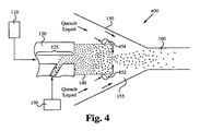
調整流体としてガスを使用することに加えて、超冷却ガス、すなわち液化ガスを調整流体として用いてもよい。調整流体は、以下に限定されるものではないが、液体窒素及び液体ヘリウムを含む。図4に示す粒子生産システム400は、調整流体を、「急冷液体」と記された液化ガスの形態で急冷領域155に供給する。好ましい実施の形態では、急冷液体は、図3に関して上述した急冷気体と同様に、反応混合物が反応チャンバ140を出る際、調整流体噴射リングを介して、反応混合物に直接流される。なお、図2〜図4に示す特徴の如何なる組合せ又は構成も本発明の範囲内にある。例えば、環状供給部を介して急冷気体を供給し、調整流体噴射リングを介して急冷液体を供給してもよい。これに代えて、調整流体噴射リングを使用しないで、環状供給部を介して急冷領域155に急冷液体を供給してもよい。
In addition to using gas as the conditioning fluid, supercooled gas, i.e., liquefied gas, may be used as the conditioning fluid. Conditioning fluids include, but are not limited to, liquid nitrogen and liquid helium. The
好ましくは、液体の温度及びその流量は、反応混合物が反応チャンバ140を出た後に、混合物流温度を非常に短時間で材料の融点の1/4温度に変化させる混合物流の冷却速度を達成する。高温の反応混合物は、急冷液体から湿気を吸収し、この結果、急冷気体のみを用いた場合に比べて、急冷速度を更に向上させる。温度及び調整液体の流量は、好ましくはシステム内の所望の質量流量に応じて、選択される。
Preferably, the temperature and flow rate of the liquid reaction mixture after leaving the
図5は、本発明の原理に基づいて、一様なナノ粒子を生成する方法500の一実施の形態を示すフローチャートである。当業者には明らかであるが、ここに説明するプロトコル、処理及び手順は、必要に応じて、継続的に繰り返してもよく、何回繰り返してもよい。更に、方法500のステップは、特定の順序で示しているが、幾つかの一定のステップを同時に実行してもよく、図に示すものとは異なる順序で実行してもよい。したがって、本発明の処理ステップは、特許請求の範囲において、明示的又は暗示的に指定している場合を除き、如何なる特定の順序にも限定されない。
FIG. 5 is a flowchart illustrating one embodiment of a
ステップ510において、プラズマ生成チャンバ内でプラズマ流を生成する。プラズマ流は、様々な方法で生成できる。なお、好ましい実施の形態では、プラズマ生成チャンバは、プラズマ生成チャンバを流れる処理ガスを励起することによって、プラズマ流を生成する。
In
ステップ520において、前駆体物質にプラズマ流を印加して、前駆体物質を蒸発させる。この前駆体物質へのプラズマ流の印加は、プラズマ生成チャンバ内で行ってもよく、及び/又はプラズマ生成チャンバに流体的に接続された反応チャンバ内で行ってもよい。何れの場合も反応チャンバ及び反応混合物流に流れるプラズマ流が反応チャンバ内で形成される。反応混合物流は、好ましくは、プラズマ流に浮遊されて運ばれる蒸発した材料を含む。
In
ステップ530において、反応混合物流が、反応チャンバの噴射口を介して、急冷チャンバの急冷領域に流れる。急冷チャンバは、広い端部と、狭い端部と、反応チャンバの噴射口から離れる方向に、広い端部から狭い端部に向けて徐々に狭くなる截頭円錐面と、狭い端部に形成された冷却混合物アウトレットと、急冷チャンバ内の噴射口と冷却混合物アウトレット間に形成された急冷領域とを備える。
In
ステップ540において、調整流体は、反応チャンバの噴射口に配設された調整流体噴射リングを介して流れる。調整流体は、反応混合物流が反応チャンバの噴射口を介して流れる際に、反応混合物流に直接流れ込み、この結果、反応混合物流の流れを妨害して、急冷領域内に乱流を発生させる。調整流体は、上述のように、好ましくは、気体又は液化ガスである。これに加えて又はこれに代えて、反応チャンバの周辺と急冷チャンバの間で配設された環状供給部を介して調整流体を供給してもよい。
In
ステップ550において、反応混合物流を急冷領域内で急速に冷却して、冷却混合物流(cooled mixture stream)を生成する。冷却混合物流は、好ましくは、凝縮ナノ粒子を含む。
In
ステップ560において、冷却混合物流は、急冷チャンバの冷却混合物アウトレットを介して、好ましくは、導管を経由して、回収装置に流れる。好ましい実施の形態では、導管は、冷却混合物アウトレットと略同じ直径を有する。
In
ステップ570において、冷却混合物流が回収装置を流れる際に、回収装置は、冷却混合物流から凝縮粒子を分離する。好ましい実施の形態では、回収装置は、1つ以上のフィルタを用いて、冷却混合物流から凝縮粒子を分離する。
In
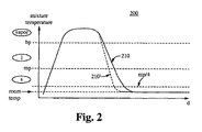
図2は、粒子生産システムの急冷速度に関する、本発明の実施の形態の特徴の意図された効果を示すグラフ200示している。グラフ200は、プラズマ生成チャンバ、例えばプラズマ生成チャンバ125に入り、蒸発し又はプラズマになり、混合され、反応チャンバ140等の反応チャンバを通り、粒子の形成を開始し、急冷領域155等の急冷領域に入るまでの時間(装置内の位置)に対する気体/材料、又は混合物の温度の例示的な変化を示している。装置内の位置とグラフ上の位置の間の関係は、図1と図2との間の垂直的な位置関係によって大まかに示している。
FIG. 2 shows a
グラフの縦軸は、混合物の温度を表している。楕円形の標識は、装置によって処理されている材料の相を示している。すなわち、一番上の楕円形が蒸気を示し、その下が液体を示し、その下が固体を示している。破線は、処理中の材料に関する臨界温度を示している。「bp」の線は、沸点を示し、「mp」の線は、融点を示している。「mp/4」の線は、材料の融点の1/4を示している。 The vertical axis of the graph represents the temperature of the mixture. The oval sign indicates the phase of the material being processed by the device. That is, the top ellipse indicates vapor, the bottom indicates liquid, and the bottom indicates solid. The dashed line indicates the critical temperature for the material being processed. The “bp” line indicates the boiling point, and the “mp” line indicates the melting point. The line “mp / 4” indicates ¼ of the melting point of the material.
プラズマ生成チャンバ125内において、温度が急速に上昇すると、材料が固相から気相に昇華する。混合物が反応チャンバ140内に移動すると、混合物の温度及び熱量は、略一定に保たれ、材料は、気相の範囲内にとどまる。更に、混合物が反応チャンバ140の端部に移動すると、温度は低下し、反応チャンバ140の下流側の端部において(反応チャンバ内の)最小限に達する。
In the
混合物は、噴射されて、急冷領域155に一旦入ると、膨張して、急速に冷却される。1つ以上の高乱流、十分低い質量流量、及び超冷却ガスによる液体急冷によって、混合物は、調整流体と十分に混合され、十分に短い時間で、「bp」、液相、「mp」、固相の一部を経由して、「mp/4」まで、円滑に急速に冷却され、望まれない凝集が回避され、均一のナノ粒子の生成が促進される。環状供給部を介する調整流体の供給の結果、線210として示す急冷速度が得られる。この急冷速度は、従来の技術からの事実上の改善であるが、調整流体噴射リング及び/又は液化ガスを使用することによって、線210’として示す更に速い急冷速度が得られる。
Once the mixture is jetted and enters quench
反応チャンバ及び急冷領域内の共振の間に、粒子が形成される。混合物は、急速に冷却されるので、凝集が起こる期間は短い。粒子と高温ガスの混合物は、調整流体と混合され続け、混合気体(mixture of gas)と粒子は、狭い端部から出て、導管に入る。本発明の幾つかの実施の形態としての高乱流急冷領域(highly turbulent quench region)及び/又は超冷却ガスの調整液体(super-cooled gas conditioning liquid)が供給される急冷領域内の急冷時間の全体は、標準的な急冷よりも非常に短い。最終的に、調整流体と混合物は、好ましくは室温において、熱平衡に達する。 Particles are formed during resonance in the reaction chamber and quench region. Because the mixture is cooled rapidly, the period of time during which agglomeration occurs is short. The mixture of particles and hot gas continues to be mixed with the conditioning fluid, and the mixture of gas and particles exit the narrow end and enter the conduit. In some embodiments of the present invention, the quench time in the quench region where a highly turbulent quench region and / or super-cooled gas conditioning liquid is supplied. The whole is much shorter than standard quenching. Finally, the conditioning fluid and mixture reach thermal equilibrium, preferably at room temperature.
このように、本発明の実施の形態の特徴は、粒子が形成され、互いに凝集することができる期間を短縮する。最終的に、この凝集の可能性の低減によって、より均一な大きさの粒子が生成され、ある場合には、より小さい大きさの粒子が生成される。これらの特徴の両方によって、分散性が高められ、表面積対体積比が高められた粒子が得られる。 Thus, a feature of embodiments of the present invention is to reduce the period during which particles can be formed and agglomerated together. Ultimately, this reduction in the likelihood of agglomeration produces more uniformly sized particles, and in some cases, smaller sized particles. Both of these features result in particles with increased dispersibility and increased surface area to volume ratio.
本発明の構造及び動作の原理を明瞭にするために、詳細を組み込んだ特定の実施の形態に関連して本発明を説明した。したがって、ここにおける特定の実施の形態及び詳細な説明は、特許請求の範囲を限定するものでhない。本発明の精神及び範囲から逸脱することなく、ここに例示した実施の形態を変更できることは当業者にとって明らかである。 In order to clarify the principles of structure and operation of the present invention, the invention has been described with reference to specific embodiments incorporating details. Accordingly, the specific embodiments and detailed description herein are not intended to limit the scope of the claims. It will be apparent to those skilled in the art that the illustrated embodiments can be modified without departing from the spirit and scope of the invention.
Claims (25)
上記プラズマ生成チャンバに流体的に接続され、噴射口を有し、上記プラズマ生成チャンバから上記プラズマ流が供給され、該プラズマ流によって前駆体物質を蒸発させて、該プラズマ流に飛沫同伴された蒸発前駆体物質を含む反応混合物流を生成し、該反応混合物流を該噴射口に供給する反応チャンバと、
広い端部と、狭い端部と、上記反応チャンバの噴射口から離れる方向に、該広い端部から該狭い端部に向けて徐々に狭くなる截頭円錐面と、該狭い端部に形成された冷却混合物アウトレットと、該噴射口と該冷却混合物アウトレット間に形成された急冷領域とを有し、該急冷領域は、該反応チャンバの噴射口に流体的に接続され、該反応チャンバの噴射口から上記反応混合物流が供給され、該反応混合物流を冷却して、冷却混合物流を形成し、該冷却混合物流を該冷却混合物アウトレットに供給する急冷チャンバと、
上記反応チャンバの噴射口に配設され、上記反応混合物流が該反応チャンバの噴射口を介して流れる際に、該反応混合物流に調整流体を直接流し、これによって、該反応混合物流の流れを妨害して、上記急冷領域内に乱流を発生させ、該反応混合物流を冷却して、凝縮ナノ粒子を含む冷却混合物流を形成する調整流体噴射リングとを備える粒子生産システム。 A plasma generation chamber for generating a plasma flow;
It is fluidly connected to the plasma generation chamber, having an injection port, the plasma stream from said plasma generation chamber is supplied by evaporating the precursor material by the plasma flow, evaporation that is entrained in the plasma stream to form a reaction mixture stream comprising a precursor material, a reaction chamber for supplying the reaction mixture stream to said injection port,
A wide end, a narrow end, in a direction away from the injection port of the reaction chamber, and gradually narrows frusto conical surface toward the narrow end of the wide end, is formed in the narrow end and a cooling mixture outlet, and a quenching zone formed between the injection port and the cooling mixture outlet, the quench region is fluidly connected to the injection port of the reaction chamber, the injection port of the reaction chamber from the above reaction mixture stream is fed, by cooling the reaction mixture stream to form a cooled mixture stream, a quench chamber for supplying the cooling mixture flows into the cooling mixture outlet,
Disposed ejection port of the reaction chamber, when the reaction mixture stream flows through the injection port of the reaction chamber, flowing a conditioning fluid directly to the reaction mixture stream, thereby, the flow of the reaction mixture stream A particle production system comprising a regulated fluid injection ring that interferes to create turbulent flow in the quench region and cool the reaction mixture stream to form a cooled mixture stream comprising condensed nanoparticles.
プラズマ生成チャンバ内でプラズマ流を生成するステップと、
上記プラズマ流を前駆体物質に作用させるステップと、
上記プラズマ生成チャンバに流体的に接続され、噴射口を有する反応チャンバ内で、上記プラズマ流によって上記前駆体物質を蒸発させて、該プラズマ流に飛沫同伴された蒸発前駆体物質を含む反応混合物流を形成するステップと、
広い端部と、狭い端部と、上記反応チャンバの噴射口から離れる方向に、該広い端部から該狭い端部に向けて徐々に狭くなる截頭円錐面と、該狭い端部に形成された冷却混合物アウトレットと、該噴射口と該冷却混合物アウトレット間に形成された急冷領域とを有する急冷チャンバの該急冷領域に、上記噴射口を介して上記反応混合物流を流すステップと、
上記反応混合物流が上記反応チャンバの噴射口を介して流れる際に、該反応チャンバの噴射口に配設された調整流体噴射リングを介して、該反応混合物流に調整流体を、上記冷却混合物アウトレットに対する負の圧力差によって直接流し、これによって、該反応混合物流の流れを妨害して、上記急冷領域内に乱流を発生させるステップと、
上記急冷領域内で上記反応混合物流を急冷して、凝縮ナノ粒子を含む冷却混合物流を形成するステップと、
上記冷却混合物流を、上記急冷チャンバの冷却混合物アウトレットを介して流すステップとを有する粒子生成方法。 In a particle generation method for generating uniform particles,
Generating a plasma stream in a plasma generation chamber;
A step of exerting said plasma stream to the precursor material,
Is fluidly connected to the plasma generation chamber, in a reaction chamber having an injection port, by evaporating the precursor material by the plasma stream, the reaction mixture stream containing entrained vaporized precursor material into the plasma stream Forming a step ;
A wide end, a narrow end, in a direction away from the injection port of the reaction chamber, and gradually narrows frusto conical surface toward the narrow end of the wide end, is formed in the narrow end and the cooled mixture outlet was, to the quenching zone of the quench chamber and a quenching zone formed between the injection port and the cooling mixture outlet, and flowing the reaction mixture stream through the injection port,
When the reaction mixture stream flows through the injection port of the reaction chamber, through a conditioning fluid injection ring disposed in the injection port of the reaction chamber, the conditioning fluid to the reaction mixture stream, the cold mixture outlet Direct flow by a negative pressure difference with respect to the flow, thereby obstructing the flow of the reaction mixture stream and generating turbulence in the quenching region;
Quenching the reaction mixture stream in the quench region to form a cooled mixture stream comprising condensed nanoparticles;
Flowing the cooled mixture stream through the cooled mixture outlet of the quench chamber.
上記環状供給部によって、上記調整流体噴射リングを介する調整流体の流れとは異なる経路に沿って、調整流体を環状形状で上記急冷領域に供給するステップを更に有する請求項12記載の粒子生成方法。 The quenching chamber further includes an annular supply unit disposed between the periphery of the reaction chamber and the frustoconical surface.
The particle generating method according to claim 12, further comprising a step of supplying the adjustment fluid in an annular shape to the quenching region along a path different from the flow of the adjustment fluid via the adjustment fluid ejection ring by the annular supply unit.
上記反応混合物流の熱量を、上記反応チャンバの熱量維持領域内に暫時維持するステップを更に有する請求項12記載の粒子生成方法。 The reaction chamber is made of a heat insulating material , thereby forming a heat quantity maintaining region in the reaction chamber,
The particle generation method according to claim 12, further comprising a step of temporarily maintaining the amount of heat of the reaction mixture stream in a heat amount maintaining region of the reaction chamber.
上記急冷領域から、上記冷却混合物流を上記回収装置に供給するステップと、
上記回収装置によって、上記冷却混合物流から凝縮粒子を分離するステップとを更に有する請求項12記載の粒子生成方法。 A recovery device is fluidly connected to the cooling mixture outlet of the quench chamber by a conduit having substantially the same diameter as the cooling mixture outlet;
Supplying the cooled mixed stream from the quenching region to the recovery device;
The particle generating method according to claim 12, further comprising a step of separating condensed particles from the cooled mixed stream by the recovery device.
Applications Claiming Priority (3)
| Application Number | Priority Date | Filing Date | Title |
|---|---|---|---|
| US92894607P | 2007-05-11 | 2007-05-11 | |
| US60/928,946 | 2007-05-11 | ||
| PCT/US2008/006003 WO2008140786A1 (en) | 2007-05-11 | 2008-05-08 | Method and apparatus for making uniform and ultrasmall nanoparticles |
Publications (2)
| Publication Number | Publication Date |
|---|---|
| JP2010526662A JP2010526662A (en) | 2010-08-05 |
| JP5275342B2 true JP5275342B2 (en) | 2013-08-28 |
Family
ID=39968475
Family Applications (13)
| Application Number | Title | Priority Date | Filing Date |
|---|---|---|---|
| JP2010508377A Pending JP2010526986A (en) | 2007-05-11 | 2008-05-08 | Heat exchanger, cooling device and cooling method |
| JP2010508378A Active JP5275342B2 (en) | 2007-05-11 | 2008-05-08 | Particle production system and particle production method |
| JP2010508374A Pending JP2010537796A (en) | 2007-05-11 | 2008-05-09 | Gas supply system and gas supply method |
| JP2010508373A Pending JP2010526661A (en) | 2007-05-11 | 2008-05-09 | Quenching chamber, condensing device and cooling method |
| JP2010508396A Pending JP2010526663A (en) | 2007-05-11 | 2008-05-09 | Compression chamber, particle production system and adjustment method |
| JP2010508398A Pending JP2010526664A (en) | 2007-05-11 | 2008-05-12 | Particle production system and fluid recirculation method |
| JP2013168600A Active JP5792776B2 (en) | 2007-05-11 | 2013-08-14 | Gas supply system and gas supply method |
| JP2013216969A Pending JP2014061518A (en) | 2007-05-11 | 2013-10-18 | Quench chamber, apparatus for condensing and method for cooling |
| JP2014047310A Pending JP2014139509A (en) | 2007-05-11 | 2014-03-11 | Heat exchanger, cooler, and cooling method |
| JP2014198187A Pending JP2014240077A (en) | 2007-05-11 | 2014-09-29 | Compression chamber, particle production system and adjustment method |
| JP2015144605A Active JP6174635B2 (en) | 2007-05-11 | 2015-07-22 | Particle production system and fluid recirculation method |
| JP2015156118A Active JP6174639B2 (en) | 2007-05-11 | 2015-08-06 | Gas supply system and gas supply method |
| JP2015204297A Expired - Fee Related JP6069454B2 (en) | 2007-05-11 | 2015-10-16 | Quenching chamber, condensing device and cooling method |
Family Applications Before (1)
| Application Number | Title | Priority Date | Filing Date |
|---|---|---|---|
| JP2010508377A Pending JP2010526986A (en) | 2007-05-11 | 2008-05-08 | Heat exchanger, cooling device and cooling method |
Family Applications After (11)
| Application Number | Title | Priority Date | Filing Date |
|---|---|---|---|
| JP2010508374A Pending JP2010537796A (en) | 2007-05-11 | 2008-05-09 | Gas supply system and gas supply method |
| JP2010508373A Pending JP2010526661A (en) | 2007-05-11 | 2008-05-09 | Quenching chamber, condensing device and cooling method |
| JP2010508396A Pending JP2010526663A (en) | 2007-05-11 | 2008-05-09 | Compression chamber, particle production system and adjustment method |
| JP2010508398A Pending JP2010526664A (en) | 2007-05-11 | 2008-05-12 | Particle production system and fluid recirculation method |
| JP2013168600A Active JP5792776B2 (en) | 2007-05-11 | 2013-08-14 | Gas supply system and gas supply method |
| JP2013216969A Pending JP2014061518A (en) | 2007-05-11 | 2013-10-18 | Quench chamber, apparatus for condensing and method for cooling |
| JP2014047310A Pending JP2014139509A (en) | 2007-05-11 | 2014-03-11 | Heat exchanger, cooler, and cooling method |
| JP2014198187A Pending JP2014240077A (en) | 2007-05-11 | 2014-09-29 | Compression chamber, particle production system and adjustment method |
| JP2015144605A Active JP6174635B2 (en) | 2007-05-11 | 2015-07-22 | Particle production system and fluid recirculation method |
| JP2015156118A Active JP6174639B2 (en) | 2007-05-11 | 2015-08-06 | Gas supply system and gas supply method |
| JP2015204297A Expired - Fee Related JP6069454B2 (en) | 2007-05-11 | 2015-10-16 | Quenching chamber, condensing device and cooling method |
Country Status (4)
| Country | Link |
|---|---|
| US (27) | US8142619B2 (en) |
| EP (6) | EP2153157A4 (en) |
| JP (13) | JP2010526986A (en) |
| WO (8) | WO2008140786A1 (en) |
Families Citing this family (82)
| Publication number | Priority date | Publication date | Assignee | Title |
|---|---|---|---|---|
| US7857972B2 (en) | 2003-09-05 | 2010-12-28 | Foret Plasma Labs, Llc | Apparatus for treating liquids with wave energy from an electrical arc |
| US8734654B2 (en) | 2001-07-16 | 2014-05-27 | Foret Plasma Labs, Llc | Method for treating a substance with wave energy from an electrical arc and a second source |
| US8764978B2 (en) | 2001-07-16 | 2014-07-01 | Foret Plasma Labs, Llc | System for treating a substance with wave energy from an electrical arc and a second source |
| US7622693B2 (en) | 2001-07-16 | 2009-11-24 | Foret Plasma Labs, Llc | Plasma whirl reactor apparatus and methods of use |
| US8981250B2 (en) | 2001-07-16 | 2015-03-17 | Foret Plasma Labs, Llc | Apparatus for treating a substance with wave energy from plasma and an electrical Arc |
| US8734643B2 (en) | 2001-07-16 | 2014-05-27 | Foret Plasma Labs, Llc | Apparatus for treating a substance with wave energy from an electrical arc and a second source |
| US7422695B2 (en) | 2003-09-05 | 2008-09-09 | Foret Plasma Labs, Llc | Treatment of fluids with wave energy from a carbon arc |
| US10188119B2 (en) | 2001-07-16 | 2019-01-29 | Foret Plasma Labs, Llc | Method for treating a substance with wave energy from plasma and an electrical arc |
| US20050195966A1 (en) * | 2004-03-03 | 2005-09-08 | Sigma Dynamics, Inc. | Method and apparatus for optimizing the results produced by a prediction model |
| EP2141120A1 (en) * | 2004-04-19 | 2010-01-06 | SDC Materials, LLC | High throughput discovery of materials through vapor phase synthesis |
| CN100392316C (en) * | 2006-03-27 | 2008-06-04 | 博奥生物有限公司 | Flow structure of controlling liquid continuously flowing in micro-pipeline |
| WO2008008104A2 (en) | 2006-04-05 | 2008-01-17 | Foret Plasma Labs, Llc | System, method and apparatus for treating liquids with wave energy from plasma |
| JP2010526986A (en) | 2007-05-11 | 2010-08-05 | エスディーシー マテリアルズ インコーポレイテッド | Heat exchanger, cooling device and cooling method |
| US8642061B2 (en) * | 2007-06-15 | 2014-02-04 | Warsaw Orthopedic, Inc. | Method of treating bone tissue |
| US8481449B1 (en) | 2007-10-15 | 2013-07-09 | SDCmaterials, Inc. | Method and system for forming plug and play oxide catalysts |
| US20110175264A1 (en) * | 2009-07-24 | 2011-07-21 | Pujari Vimal K | High Toughness Ceramic Composites |
| DE102009034773A1 (en) | 2009-07-25 | 2011-01-27 | Bayer Materialscience Ag | Process for producing chlorine by gas-phase oxidation on nanostructured ruthenium-supported catalysts |
| DE102009052430A1 (en) * | 2009-11-10 | 2011-06-01 | Brückner, Manuela | Method for cooling and cleaning of particulate or condensate-prone hot gases, involves cooling cooling surface of cooling element, particularly by liquid or gaseous cooling medium |
| US8803025B2 (en) | 2009-12-15 | 2014-08-12 | SDCmaterials, Inc. | Non-plugging D.C. plasma gun |
| US8652992B2 (en) * | 2009-12-15 | 2014-02-18 | SDCmaterials, Inc. | Pinning and affixing nano-active material |
| US8470112B1 (en) | 2009-12-15 | 2013-06-25 | SDCmaterials, Inc. | Workflow for novel composite materials |
| US20110143930A1 (en) * | 2009-12-15 | 2011-06-16 | SDCmaterials, Inc. | Tunable size of nano-active material on nano-support |
| US9039916B1 (en) | 2009-12-15 | 2015-05-26 | SDCmaterials, Inc. | In situ oxide removal, dispersal and drying for copper copper-oxide |
| US8545652B1 (en) | 2009-12-15 | 2013-10-01 | SDCmaterials, Inc. | Impact resistant material |
| US9126191B2 (en) | 2009-12-15 | 2015-09-08 | SDCmaterials, Inc. | Advanced catalysts for automotive applications |
| US8557727B2 (en) * | 2009-12-15 | 2013-10-15 | SDCmaterials, Inc. | Method of forming a catalyst with inhibited mobility of nano-active material |
| US20110144382A1 (en) * | 2009-12-15 | 2011-06-16 | SDCmaterials, Inc. | Advanced catalysts for fine chemical and pharmaceutical applications |
| US9149797B2 (en) | 2009-12-15 | 2015-10-06 | SDCmaterials, Inc. | Catalyst production method and system |
| KR101158188B1 (en) | 2010-02-01 | 2012-06-19 | 삼성전기주식회사 | Apparatus for synthesizing nano particles, and method for synthesizing the nano particles with the same |
| JP5408054B2 (en) * | 2010-06-28 | 2014-02-05 | 東ソー株式会社 | Method for producing ceramic beads having a smooth surface |
| US20120064134A1 (en) | 2010-08-06 | 2012-03-15 | Immunolight, Llc | Color enhancement utilizing up converters and down converters |
| US8422008B2 (en) | 2010-09-29 | 2013-04-16 | General Electric Company | Electrical machine component monitoring system and method |
| US8669202B2 (en) | 2011-02-23 | 2014-03-11 | SDCmaterials, Inc. | Wet chemical and plasma methods of forming stable PtPd catalysts |
| JP6023790B2 (en) * | 2011-04-28 | 2016-11-09 | ビーエーエスエフ ソシエタス・ヨーロピアBasf Se | Precious metal catalysts for oxidative dehydrogenation with low metal loading |
| KR20140071364A (en) | 2011-08-19 | 2014-06-11 | 에스디씨머티리얼스, 인코포레이티드 | Coated substrates for use in catalysis and catalytic converters and methods of coating substrates with washcoat compositions |
| US8409537B2 (en) * | 2011-08-29 | 2013-04-02 | General Electric Company | Method for removing contaminants from boron powder |
| WO2013033726A1 (en) * | 2011-09-02 | 2013-03-07 | Quinonez Carlo Joseph | Universal hardware platform and toolset for operating and fabricating microfluidic devices |
| GB2498820B (en) * | 2012-04-05 | 2014-04-16 | R B Radley & Co Ltd | Condensers |
| CN104519972B (en) * | 2012-08-03 | 2017-08-04 | 杰富意钢铁株式会社 | Crystallization separates out device and crystallization separation method |
| US9511352B2 (en) | 2012-11-21 | 2016-12-06 | SDCmaterials, Inc. | Three-way catalytic converter using nanoparticles |
| US9156025B2 (en) | 2012-11-21 | 2015-10-13 | SDCmaterials, Inc. | Three-way catalytic converter using nanoparticles |
| CN105143413B (en) | 2012-12-11 | 2017-07-04 | 弗雷特等离子实验室公司 | High-temperature reflux vortex reactor system, method and apparatus |
| KR101478286B1 (en) | 2012-12-31 | 2015-01-06 | 국민대학교산학협력단 | Manufacturing method of metal foam and metal foam manufactured thereby |
| US20140252270A1 (en) | 2013-03-06 | 2014-09-11 | SDCmaterials, Inc. | Particle-based systems for removal of pollutants from gases and liquids |
| US9699879B2 (en) | 2013-03-12 | 2017-07-04 | Foret Plasma Labs, Llc | Apparatus and method for sintering proppants |
| US20140263190A1 (en) * | 2013-03-14 | 2014-09-18 | SDCmaterials, Inc. | High-throughput particle production using a plasma system |
| EP2974560A4 (en) * | 2013-03-14 | 2016-12-07 | Sdcmaterials Inc | High-throughput particle production using a plasma system |
| US9327252B2 (en) | 2013-03-15 | 2016-05-03 | Applied Materials, Inc. | Compact device for enhancing the mixing of gaseous species |
| KR101331027B1 (en) * | 2013-04-19 | 2013-11-19 | 주식회사 셀모티브 | Manufacturing method of metal foam with uniformly distributed nano-sized pores and metal foam manufactured thereby |
| KR101514968B1 (en) * | 2013-04-24 | 2015-04-24 | 한국생산기술연구원 | Method of manufacturing amorphous metal foams using vacuum solvent extraction |
| US9586179B2 (en) | 2013-07-25 | 2017-03-07 | SDCmaterials, Inc. | Washcoats and coated substrates for catalytic converters and methods of making and using same |
| MX2016004759A (en) | 2013-10-22 | 2016-07-26 | Sdcmaterials Inc | Compositions of lean nox trap. |
| MX2016004991A (en) | 2013-10-22 | 2016-08-01 | Sdcmaterials Inc | Catalyst design for heavy-duty diesel combustion engines. |
| EP3119500A4 (en) | 2014-03-21 | 2017-12-13 | SDC Materials, Inc. | Compositions for passive nox adsorption (pna) systems |
| US9533909B2 (en) | 2014-03-31 | 2017-01-03 | Corning Incorporated | Methods and apparatus for material processing using atmospheric thermal plasma reactor |
| US9550694B2 (en) | 2014-03-31 | 2017-01-24 | Corning Incorporated | Methods and apparatus for material processing using plasma thermal source |
| US20160200618A1 (en) | 2015-01-08 | 2016-07-14 | Corning Incorporated | Method and apparatus for adding thermal energy to a glass melt |
| US10675854B2 (en) * | 2015-01-16 | 2020-06-09 | Raytheon Technologies Corporation | Additive processing apparatus and method |
| WO2016130566A2 (en) | 2015-02-11 | 2016-08-18 | SDCmaterials, Inc. | Lean nox traps, trapping materials, washcoats, and methods of making and using the same |
| US10224186B2 (en) | 2015-03-13 | 2019-03-05 | Aes Global Holdings, Pte. Ltd | Plasma source device and methods |
| DE102015004474B4 (en) * | 2015-04-08 | 2020-05-28 | Kai Klinder | Plant for the production of metal powder with a defined grain size range |
| CN104999579B (en) * | 2015-05-12 | 2018-08-28 | 青岛科技大学 | A kind of preparation method of nanocomposite |
| US9674788B2 (en) * | 2015-06-26 | 2017-06-06 | Intel IP Corporation | Devices and methods for transmit concurrency by conditioned signal combining |
| JP6590203B2 (en) * | 2015-11-12 | 2019-10-16 | パナソニックIpマネジメント株式会社 | Fine particle production apparatus and fine particle production method |
| CN105517312A (en) * | 2015-12-25 | 2016-04-20 | 中国航天空气动力技术研究院 | Super-high-enthalpy arc heater anode |
| JP6512484B2 (en) | 2016-03-25 | 2019-05-15 | パナソニックIpマネジメント株式会社 | Microparticle production apparatus and method |
| US11655270B2 (en) * | 2016-08-08 | 2023-05-23 | Dof Inc. | Method for separating collagen from liposuction effluent using supercritical process |
| US10428306B2 (en) * | 2016-08-12 | 2019-10-01 | Warsaw Orthopedic, Inc. | Method and system for tissue treatment with critical/supercritical carbon dioxide |
| TWI787215B (en) * | 2016-11-22 | 2022-12-21 | 美商W R 康格雷氏公司 | Catalysts with reduced attrition and method for manufacturing the same |
| WO2018197654A1 (en) | 2017-04-27 | 2018-11-01 | Umicore Ag & Co. Kg | Porous nanoparticle-composite-based catalysts |
| WO2018202827A1 (en) | 2017-05-04 | 2018-11-08 | Umicore Ag & Co. Kg | Plasma gun and plasma system for low melting point or low boiling point materials |
| KR20200069296A (en) | 2017-09-01 | 2020-06-16 | 솜니오 글로벌 홀딩스, 엘엘씨 | Free radical generators and methods of use |
| US10948391B2 (en) * | 2017-11-14 | 2021-03-16 | Aerodyne Microsystems Inc., a Delaware Corporation | Airborne particle detection system with orientation-dependent particle discrimination |
| WO2019131777A1 (en) * | 2017-12-28 | 2019-07-04 | 国立大学法人愛媛大学 | Device and method for forming diamond film or the like |
| JP2019122926A (en) * | 2018-01-17 | 2019-07-25 | 太平洋セメント株式会社 | Process for producing microparticle by spray pyrolysis |
| TWI647435B (en) * | 2018-01-19 | 2019-01-11 | 國立清華大學 | Thermally actuated oscillating suspended particle sensing device and suspended particle sensing method |
| US10865899B2 (en) | 2018-09-27 | 2020-12-15 | United States Of America As Represented By The Secretary Of The Navy | System and method for protecting a pressure vessel from excessive differential pressure |
| CN109250835B (en) * | 2018-11-21 | 2023-11-14 | 华北电力大学 | Gravity type supercritical water fine particle thermophoresis removing device |
| EP4081150A4 (en) * | 2019-12-24 | 2024-01-31 | Battelle Energy Alliance Llc | Laser ablation methods and systems for producing feedstock powder suitable for laser-based additive manufacturing |
| CN111397396A (en) * | 2020-03-19 | 2020-07-10 | 中国成达工程有限公司 | Powder material cooling system and cooling process thereof |
| CN111793838B (en) * | 2020-05-27 | 2021-10-08 | 崔建中 | Melt-blown cooling device applied to automatic production line of non-woven fabric |
| JP7236063B1 (en) * | 2021-11-10 | 2023-03-09 | コリア インスティチュート オブ インダストリアル テクノロジー | Inorganic powder production apparatus and production method |
Family Cites Families (708)
| Publication number | Priority date | Publication date | Assignee | Title |
|---|---|---|---|---|
| US657267A (en) * | 1900-06-05 | 1900-09-04 | Morris Epstein | Match-box. |
| US1477664A (en) | 1920-10-21 | 1923-12-18 | Harry D Rankin | Process of and apparatus for treating materials |
| US2021936A (en) | 1930-12-08 | 1935-11-26 | Univ Illinois | Removal of so2 from flue gases |
| US2284554A (en) | 1940-08-03 | 1942-05-26 | Standard Oil Dev Co | Condensation catalysts of increased activity and process of producing the same |
| US2519531A (en) | 1945-07-21 | 1950-08-22 | Lummus Co | Ejector apparatus |
| US2419042A (en) * | 1945-10-06 | 1947-04-15 | Todd Floyd | Vacuum distillation apparatus and pressure regulator therefor |
| US2562753A (en) | 1948-05-24 | 1951-07-31 | Micronizer Company | Anvil grinder |
| US2689780A (en) | 1948-12-27 | 1954-09-21 | Hall Lab Inc | Method of and apparatus for producing ammonium phosphate |
| US3181947A (en) | 1957-01-15 | 1965-05-04 | Crucible Steel Co America | Powder metallurgy processes and products |
| US3067025A (en) | 1957-04-05 | 1962-12-04 | Dow Chemical Co | Continuous production of titanium sponge |
| US3042511A (en) | 1959-02-09 | 1962-07-03 | Dow Chemical Co | Apparatus for condensation of a metal vapor |
| US3108006A (en) | 1959-07-13 | 1963-10-22 | M & T Chemicals Inc | Plating on aluminum |
| US3001402A (en) | 1959-08-06 | 1961-09-26 | Koblin Abraham | Vapor and aerosol sampler |
| US3145287A (en) | 1961-07-14 | 1964-08-18 | Metco Inc | Plasma flame generator and spray gun |
| US3179782A (en) | 1962-02-07 | 1965-04-20 | Matvay Leo | Plasma flame jet spray gun with a controlled arc region |
| US3178121A (en) | 1962-04-24 | 1965-04-13 | Du Pont | Process for comminuting grit in pigments and supersonic fluid energy mill therefor |
| BE634714A (en) | 1962-07-27 | 1900-01-01 | ||
| DE1571153A1 (en) | 1962-08-25 | 1970-08-13 | Siemens Ag | Plasma spray gun |
| NL299680A (en) | 1962-10-26 | |||
| US3309873A (en) | 1964-08-31 | 1967-03-21 | Electro Optical Systems Inc | Plasma accelerator using hall currents |
| JPS4931571B1 (en) | 1966-02-21 | 1974-08-22 | ||
| US3520656A (en) | 1966-03-30 | 1970-07-14 | Du Pont | Silicon carbide compositions |
| US3313908A (en) | 1966-08-18 | 1967-04-11 | Giannini Scient Corp | Electrical plasma-torch apparatus and method for applying coatings onto substrates |
| US3450926A (en) | 1966-10-10 | 1969-06-17 | Air Reduction | Plasma torch |
| US3401465A (en) | 1966-12-23 | 1968-09-17 | Nat Lead Co | Means for cooling solid particulate materials with fluids |
| US3457788A (en) | 1966-12-29 | 1969-07-29 | Continental Carbon Co | Apparatus for sampling carbon black |
| US3460523A (en) | 1967-08-28 | 1969-08-12 | Du Pont | Catalytic oven coating compositions |
| US3617358A (en) | 1967-09-29 | 1971-11-02 | Metco Inc | Flame spray powder and process |
| US4146654A (en) * | 1967-10-11 | 1979-03-27 | Centre National De La Recherche Scientifique | Process for making linings for friction operated apparatus |
| US3552653A (en) | 1968-01-10 | 1971-01-05 | Inoue K | Impact deposition of particulate materials |
| US3537513A (en) | 1968-03-11 | 1970-11-03 | Garrett Corp | Three-fluid heat exchanger |
| JPS4721256Y1 (en) | 1968-12-13 | 1972-07-14 | ||
| GB1307941A (en) | 1969-02-13 | 1973-02-21 | Shinku Yakin Kk | Method and an apparatus for manufacturing fine powders of metal or alloy |
| BE746396A (en) | 1969-03-05 | 1970-07-31 | Chausson Usines Sa | PROCESS FOR THE FLUXING AND BRAZING OF ALUMINUM OR ALUMINUM ALLOY PARTS TO BE ASSEMBLED AND APPLICATION OF THIS PROCESS TO THE MANUFACTURE OF RADIATORS |
| US3857744A (en) | 1970-01-19 | 1974-12-31 | Coors Porcelain Co | Method for manufacturing composite articles containing boron carbide |
| US3589351A (en) | 1970-03-16 | 1971-06-29 | Westinghouse Electric Corp | Cutting of rocks, glass and the like |
| US3743708A (en) | 1970-11-20 | 1973-07-03 | American Cyanamid Co | Submicron metal oxide particles and their process for manufacture |
| US3761360A (en) | 1971-01-20 | 1973-09-25 | Allied Chem | Re entrainment charging of preheated coal into coking chambers of a coke oven battery |
| US3676638A (en) | 1971-01-25 | 1972-07-11 | Sealectro Corp | Plasma spray device and method |
| JPS4721256U (en) * | 1971-02-27 | 1972-11-09 | ||
| US3914573A (en) | 1971-05-17 | 1975-10-21 | Geotel Inc | Coating heat softened particles by projection in a plasma stream of Mach 1 to Mach 3 velocity |
| US3752172A (en) | 1971-06-14 | 1973-08-14 | United Aircraft Corp | Jet penetration control |
| US3730827A (en) | 1971-11-22 | 1973-05-01 | Norton Research Corp Ltd | Boron carbide ballistic armor modified with copper |
| US3774442A (en) | 1972-01-05 | 1973-11-27 | Bahco Ab | Particle sampling devices |
| US3741001A (en) * | 1972-03-20 | 1973-06-26 | Nasa | Apparatus for sampling particulates in gases |
| US4369167A (en) | 1972-03-24 | 1983-01-18 | Weir Jr Alexander | Process for treating stack gases |
| US3804034A (en) * | 1972-05-09 | 1974-04-16 | Boride Prod Inc | Armor |
| US3959420A (en) * | 1972-05-23 | 1976-05-25 | Stone & Webster Engineering Corporation | Direct quench apparatus |
| JPS4931571A (en) | 1972-07-24 | 1974-03-22 | ||
| US3830756A (en) | 1972-08-04 | 1974-08-20 | Grace W R & Co | Noble metal catalysts |
| JPS4987821A (en) * | 1972-12-28 | 1974-08-22 | ||
| US3892882A (en) | 1973-05-25 | 1975-07-01 | Union Carbide Corp | Process for plasma flame spray coating in a sub-atmospheric pressure environment |
| JPS517582Y1 (en) * | 1973-06-14 | 1976-03-01 | ||
| SU493241A1 (en) | 1973-07-02 | 1975-11-28 | Московский Ордена Ленина И Ордена Трудового Красного Знамени Химикотехнологический Институт Им.Д.И.Менделеева | Ammonia synthesis catalyst |
| US3871448A (en) * | 1973-07-26 | 1975-03-18 | Vann Tool Company Inc | Packer actuated vent assembly |
| FR2245779B1 (en) | 1973-09-28 | 1978-02-10 | Cit Alcatel | |
| US3969482A (en) | 1974-04-25 | 1976-07-13 | Teller Environmental Systems, Inc. | Abatement of high concentrations of acid gas emissions |
| JPS543391B2 (en) * | 1974-05-07 | 1979-02-22 | ||
| JPS5626158Y2 (en) | 1974-07-05 | 1981-06-20 | ||
| US3959094A (en) | 1975-03-13 | 1976-05-25 | The United States Of America As Represented By The United States Energy Research And Development Administration | Electrolytic synthesis of methanol from CO2 |
| US4127760A (en) * | 1975-06-09 | 1978-11-28 | Geotel, Inc. | Electrical plasma jet torch and electrode therefor |
| MX4509E (en) | 1975-08-27 | 1982-06-02 | Engelhard Min & Chem | IMPROVED CATALYTIC COMPOSITION FOR SIMULTANEOUS OXIDATION GASCOUS HYDROCARBONS AND CARBON MONOXIDE AND REDUCE NITROGEN OXIDES |
| US4021021A (en) * | 1976-04-20 | 1977-05-03 | Us Energy | Wetter for fine dry powder |
| US4018388A (en) * | 1976-05-13 | 1977-04-19 | Andrews Norwood H | Jet-type axial pulverizer |
| JPS52165360U (en) * | 1976-06-07 | 1977-12-14 | ||
| US4252843A (en) | 1977-02-18 | 1981-02-24 | Minnesota Mining And Manufacturing Company | Process for forming a microstructured transmission and reflectance modifying coating |
| US4139497A (en) * | 1977-04-04 | 1979-02-13 | The Dow Chemical Company | Dehydrogenation catalyst tablet and method for making same |
| US4284609A (en) | 1977-07-11 | 1981-08-18 | Quad Environmental Technologies Corp. | Condensation cleaning of particulate laden gases |
| US4335080A (en) | 1977-08-01 | 1982-06-15 | Thermo Electron Corporation | Apparatus for producing selective particle sized oxide |
| US4171288A (en) | 1977-09-23 | 1979-10-16 | Engelhard Minerals & Chemicals Corporation | Catalyst compositions and the method of manufacturing them |
| US4174298A (en) | 1978-01-09 | 1979-11-13 | Uop Inc. | Activated multimetallic catalytic composite |
| US4227928A (en) | 1978-05-01 | 1980-10-14 | Kennecott Copper Corporation | Copper-boron carbide composite particle and method for its production |
| US4189925A (en) | 1978-05-08 | 1980-02-26 | Northern Illinois Gas Company | Method of storing electric power |
| JPS6037804B2 (en) * | 1979-04-11 | 1985-08-28 | 三井化学株式会社 | Method for manufacturing carrier for olefin polymerization catalyst |
| US4260649A (en) * | 1979-05-07 | 1981-04-07 | The Perkin-Elmer Corporation | Laser induced dissociative chemical gas phase processing of workpieces |
| US4248387A (en) | 1979-05-09 | 1981-02-03 | Norandy, Inc. | Method and apparatus for comminuting material in a re-entrant circulating stream mill |
| US4253917A (en) * | 1979-08-24 | 1981-03-03 | Kennecott Copper Corporation | Method for the production of copper-boron carbide composite |
| US4459327A (en) | 1979-08-24 | 1984-07-10 | Kennecott Corporation | Method for the production of copper-boron carbide composite |
| USRE32244E (en) | 1979-10-30 | 1986-09-09 | Armotek Industries, Inc. | Methods and apparatus for applying wear resistant coatings to rotogravure cylinders |
| JPS56146804U (en) | 1980-04-04 | 1981-11-05 | ||
| US4326492A (en) * | 1980-04-07 | 1982-04-27 | Runfree Enterprise, Inc. | Method and apparatus for preheating fuel |
| JPS56146804A (en) | 1980-04-10 | 1981-11-14 | Kobe Steel Ltd | Gas atomizer for molten metal |
| US4388274A (en) * | 1980-06-02 | 1983-06-14 | Xerox Corporation | Ozone collection and filtration system |
| US4344779A (en) | 1980-08-27 | 1982-08-17 | Isserlis Morris D | Air pollution control system |
| US4440733A (en) | 1980-11-06 | 1984-04-03 | California Institute Of Technology | Thermochemical generation of hydrogen and carbon dioxide |
| US4458138A (en) | 1980-12-15 | 1984-07-03 | Adrian Glenn J | Fast recovery electric fluid |
| US4436075A (en) | 1982-01-07 | 1984-03-13 | Daniel D. Bailey | Fuel pre-heat device |
| JPS58160794A (en) | 1982-03-17 | 1983-09-24 | Matsushita Electric Ind Co Ltd | Heat exchanger |
| US4513149A (en) | 1982-04-05 | 1985-04-23 | Olin Corporation | Raney nickel alloy expanded mesh hydrogenation catalysts |
| US4419331A (en) | 1982-04-12 | 1983-12-06 | Michael F. Walters | Sulphur dioxide converter and pollution arrester system |
| US4431750A (en) | 1982-05-19 | 1984-02-14 | Phillips Petroleum Company | Platinum group metal catalyst on the surface of a support and a process for preparing same |
| JPS5959410A (en) * | 1982-09-30 | 1984-04-05 | Toshiba Corp | Spheroidizing device of thermoplastic grain |
| US4506136A (en) * | 1982-10-12 | 1985-03-19 | Metco, Inc. | Plasma spray gun having a gas vortex producing nozzle |
| FR2545007B1 (en) * | 1983-04-29 | 1986-12-26 | Commissariat Energie Atomique | METHOD AND DEVICE FOR COATING A WORKPIECE BY PLASMA SPRAYING |
| JPS59227765A (en) | 1983-06-04 | 1984-12-21 | 科学技術庁金属材料技術研究所長 | Manufacture of ceramic super fine particle |
| FR2550467B1 (en) | 1983-08-08 | 1989-08-04 | Aerospatiale | METHOD AND DEVICE FOR INJECTING A FINELY DIVIDED MATERIAL INTO A HOT GAS FLOW AND APPARATUS USING THE SAME |
| SE461095B (en) | 1983-09-09 | 1990-01-08 | Berol Kemi Ab | AMINING PROCEDURE USING A RUTENIUM DOPPED NICKEL AND / OR COVOLT CATALYST |
| JPS60111890A (en) * | 1983-11-22 | 1985-06-18 | Mitsubishi Electric Corp | Meandering double tube type heat exchanger |
| JPS60175537A (en) | 1984-02-22 | 1985-09-09 | Toyota Motor Corp | Preparation of ultra-fine ceramic particles |
| US4545872A (en) | 1984-03-27 | 1985-10-08 | Texaco Inc. | Method for reducing carbon dioxide to provide a product |
| US4523981A (en) * | 1984-03-27 | 1985-06-18 | Texaco Inc. | Means and method for reducing carbon dioxide to provide a product |
| US4665296A (en) | 1984-04-28 | 1987-05-12 | Neturen Co., Ltd. | Method of and apparatus for igniting a high-frequency torch to create a high-temperature plasma of high purity |
| JPS6186815A (en) | 1984-10-05 | 1986-05-02 | Hitachi Ltd | Minute pressure controller |
| DE3445273A1 (en) | 1984-12-12 | 1986-06-19 | Wilfried 8672 Selb Müller | Heat exchanger |
| US4824624A (en) * | 1984-12-17 | 1989-04-25 | Ceradyne, Inc. | Method of manufacturing boron carbide armor tiles |
| US5006163A (en) | 1985-03-13 | 1991-04-09 | Inco Alloys International, Inc. | Turbine blade superalloy II |
| JPS61242644A (en) | 1985-04-18 | 1986-10-28 | Toyota Motor Corp | Production of catalyst for purifying exhaust gas |
| US4764283A (en) | 1985-04-24 | 1988-08-16 | Ashbrook Clifford L | Method and apparatus for treating cooling tower water |
| US4921586A (en) | 1989-03-31 | 1990-05-01 | United Technologies Corporation | Electrolysis cell and method of use |
| DE3538390A1 (en) | 1985-10-29 | 1987-04-30 | Deutsche Forsch Luft Raumfahrt | COATING FOR A SUBSTRATE AND METHOD FOR THE PRODUCTION THEREOF |
| JPS62102827A (en) | 1985-10-29 | 1987-05-13 | Natl Res Inst For Metals | Production of metallic or ceramic fine grain |
| US4609441A (en) | 1985-12-18 | 1986-09-02 | Gas Research Institute | Electrochemical reduction of aqueous carbon dioxide to methanol |
| US4751021A (en) | 1985-12-30 | 1988-06-14 | Aar Corporation | Bendable sheet material |
| DE3603511A1 (en) | 1986-02-05 | 1987-08-06 | Standard Elektrik Lorenz Ag | METHOD AND DEVICE FOR REMOVING DUST AND GASEOUS POLLUTANTS FROM EXHAUST GAS, ESPECIALLY EXHAUST GASES IN THE LIGHTWAVE LEAD PREFORMING |
| NL8600449A (en) | 1986-02-22 | 1987-09-16 | Delft Tech Hogeschool | ARMOR PLATE-COMPOSITE WITH CERAMIC COLLECTION COAT. |
| US4731517A (en) | 1986-03-13 | 1988-03-15 | Cheney Richard F | Powder atomizing methods and apparatus |
| US4885038A (en) | 1986-05-01 | 1989-12-05 | International Business Machines Corporation | Method of making multilayered ceramic structures having an internal distribution of copper-based conductors |
| US4723589A (en) | 1986-05-19 | 1988-02-09 | Westinghouse Electric Corp. | Method for making vacuum interrupter contacts by spray deposition |
| US4780591A (en) | 1986-06-13 | 1988-10-25 | The Perkin-Elmer Corporation | Plasma gun with adjustable cathode |
| US4801435A (en) | 1986-09-08 | 1989-01-31 | Plasma Holdings N.V. | Hybrid plasma reactor |
| US4982050A (en) | 1986-10-06 | 1991-01-01 | Mobil Oil Corporation | Natural gas treating system including mercury trap |
| JPH0720553B2 (en) | 1986-11-07 | 1995-03-08 | 軽質留分新用途開発技術研究組合 | Method for producing platinum-supported catalyst |
| DE3642375A1 (en) | 1986-12-11 | 1988-06-23 | Castolin Sa | METHOD FOR APPLYING AN INTERNAL COATING INTO TUBES OD. DGL. CAVITY NARROW CROSS SECTION AND PLASMA SPLASH BURNER DAFUER |
| JPS63214342A (en) | 1987-03-02 | 1988-09-07 | Natl Res Inst For Metals | Preparation of compound |
| US5269848A (en) | 1987-03-20 | 1993-12-14 | Canon Kabushiki Kaisha | Process for preparing a functional thin film by way of the chemical reaction among active species and apparatus therefor |
| US4983555A (en) | 1987-05-06 | 1991-01-08 | Coors Porcelain Company | Application of transparent polycrystalline body with high ultraviolet transmittance |
| US20020102674A1 (en) | 1987-05-20 | 2002-08-01 | David M Anderson | Stabilized microporous materials |
| US4868013A (en) * | 1987-08-21 | 1989-09-19 | Ethyl Corporation | Fluidized bed process |
| US5230844A (en) | 1987-09-04 | 1993-07-27 | Skis Rossignol, S.A. | Process for producing a complex elastic molded structure of the sandwich type |
| DE3740289A1 (en) | 1987-11-27 | 1989-06-08 | Degussa | CATALYST FOR THE SELECTIVE REDUCTION OF NITROGEN OXIDES WITH AMMONIA |
| JP2584805B2 (en) | 1987-12-19 | 1997-02-26 | 富士通株式会社 | Method for synthesizing diamond particles |
| US4869936A (en) | 1987-12-28 | 1989-09-26 | Amoco Corporation | Apparatus and process for producing high density thermal spray coatings |
| JPH01275708A (en) | 1988-04-28 | 1989-11-06 | Natl Res Inst For Metals | Production of composite superfine particles with joined structure of superfine particles of nickel and titanium nitride |
| US5041713A (en) | 1988-05-13 | 1991-08-20 | Marinelon, Inc. | Apparatus and method for applying plasma flame sprayed polymers |
| CH676681A5 (en) * | 1988-06-13 | 1991-02-28 | Battelle Memorial Institute | |
| JP2662986B2 (en) | 1988-06-24 | 1997-10-15 | 高周波熱錬株式会社 | Method for producing ultrafine tungsten or tungsten oxide particles |
| US4866240A (en) | 1988-09-08 | 1989-09-12 | Stoody Deloro Stellite, Inc. | Nozzle for plasma torch and method for introducing powder into the plasma plume of a plasma torch |
| JPH02160040A (en) | 1988-12-15 | 1990-06-20 | Mitsubishi Heavy Ind Ltd | Production of superfine particle of mineral matter |
| US4987033A (en) | 1988-12-20 | 1991-01-22 | Dynamet Technology, Inc. | Impact resistant clad composite armor and method for forming such armor |
| US5371049A (en) | 1989-01-09 | 1994-12-06 | Fmc Corporation | Ceramic composite of silicon carbide and aluminum nitride |
| US5562966A (en) | 1989-01-27 | 1996-10-08 | Science Applications International Corporation | Method of applying oxidation resistant coating on carbon fibers |
| JPH02203932A (en) | 1989-01-31 | 1990-08-13 | Idemitsu Petrochem Co Ltd | Method and apparatus for producing ultrafine particles |
| US5043548A (en) | 1989-02-08 | 1991-08-27 | General Electric Company | Axial flow laser plasma spraying |
| JP2578514B2 (en) | 1989-03-03 | 1997-02-05 | 三井石油化学工業株式会社 | Method for removing mercury from liquid hydrocarbon compounds |
| WO1990012126A1 (en) | 1989-03-31 | 1990-10-18 | Canon Kabushiki Kaisha | Method of forming polycrystalline film by chemical vapor deposition |
| US4902870A (en) | 1989-03-31 | 1990-02-20 | General Electric Company | Apparatus and method for transfer arc cleaning of a substrate in an RF plasma system |
| JPH032695A (en) | 1989-05-31 | 1991-01-09 | Nisshin Steel Co Ltd | Radiation shielding material with high heat removal efficiency |
| US5070064A (en) | 1989-08-07 | 1991-12-03 | Exxon Research And Engineering Company | Catalyst pretreatment method |
| US5187140A (en) | 1989-10-18 | 1993-02-16 | Union Carbide Chemicals & Plastics Technology Corporation | Alkylene oxide catalysts containing high silver content |
| JPH03150341A (en) | 1989-11-07 | 1991-06-26 | Onoda Cement Co Ltd | Conjugate torch type plasma generator and plasma generating method using the same |
| DE3940758A1 (en) | 1989-12-09 | 1991-06-13 | Degussa | METHOD FOR PURIFYING THE EXHAUST GAS FROM DIESEL ENGINES |
| JPH03226509A (en) | 1990-01-31 | 1991-10-07 | Sumitomo Metal Ind Ltd | Apparatus for generating plasma and manufacture of super fine particle powder |
| JPH03258332A (en) | 1990-03-06 | 1991-11-18 | Konica Corp | Method and equipment for production of emulsion |
| DE4109979C2 (en) | 1990-03-28 | 2000-03-30 | Nisshin Flour Milling Co | Process for the production of coated particles from inorganic or metallic materials |
| JPH0665772B2 (en) | 1990-03-31 | 1994-08-24 | 株式会社スリーデイコンポリサーチ | Method and device for manufacturing three-dimensional fabric |
| US5013883A (en) | 1990-05-18 | 1991-05-07 | The Perkin-Elmer Corporation | Plasma spray device with external powder feed |
| EP0586756B1 (en) | 1990-05-29 | 2002-04-17 | Sulzer Metco AG | Plasma systems for thermal spraying of powders |
| US5225656A (en) | 1990-06-20 | 1993-07-06 | General Electric Company | Injection tube for powder melting apparatus |
| US5073193A (en) * | 1990-06-26 | 1991-12-17 | The University Of British Columbia | Method of collecting plasma synthesize ceramic powders |
| US5296667A (en) | 1990-08-31 | 1994-03-22 | Flame-Spray Industries, Inc. | High velocity electric-arc spray apparatus and method of forming materials |
| JPH05503322A (en) | 1990-10-09 | 1993-06-03 | アイオワ・ステイト・ユニバーシティ・リサーチ・ファウンデーション・インコーポレイテッド | Alloy powder with stable reactivity to the environment and its manufacturing method |
| US5217746A (en) | 1990-12-13 | 1993-06-08 | Fisher-Barton Inc. | Method for minimizing decarburization and other high temperature oxygen reactions in a plasma sprayed material |
| JPH06135797A (en) | 1991-01-24 | 1994-05-17 | Idemitsu Petrochem Co Ltd | Method and device for synthesizing diamond |
| US5133190A (en) | 1991-01-25 | 1992-07-28 | Abdelmalek Fawzy T | Method and apparatus for flue gas cleaning by separation and liquefaction of sulfur dioxide and carbon dioxide |
| DE4105408C1 (en) | 1991-02-21 | 1992-09-17 | Plasma-Technik Ag, Wohlen, Ch | |
| US5369241A (en) | 1991-02-22 | 1994-11-29 | Idaho Research Foundation | Plasma production of ultra-fine ceramic carbides |
| US5330945A (en) | 1991-04-08 | 1994-07-19 | General Motors Corporation | Catalyst for treatment of diesel exhaust particulate |
| US5164945A (en) | 1991-07-01 | 1992-11-17 | Laser Centers Of America, Inc. | Laser device with intermediate refraction index layer for reduced fresnel losses |
| JP3200464B2 (en) | 1991-08-27 | 2001-08-20 | 株式会社エステック | Liquid material vaporizer |
| EP0532000B1 (en) | 1991-09-13 | 1997-07-23 | Tsuyoshi Masumoto | High strength structural member and process for producing the same |
| US5294242A (en) | 1991-09-30 | 1994-03-15 | Air Products And Chemicals | Method for making metal powders |
| JP3100084B2 (en) | 1991-11-25 | 2000-10-16 | 日清製粉株式会社 | Ultrafine particle manufacturing equipment |
| DK201791D0 (en) | 1991-12-17 | 1991-12-17 | Boerge Holm Christensen | METHOD OF COATING |
| JP2673978B2 (en) | 1991-12-26 | 1997-11-05 | 大平洋金属 株式会社 | Ultrafine particle manufacturing method and manufacturing apparatus |
| US5233153A (en) | 1992-01-10 | 1993-08-03 | Edo Corporation | Method of plasma spraying of polymer compositions onto a target surface |
| JP3229353B2 (en) | 1992-01-21 | 2001-11-19 | トヨタ自動車株式会社 | Method for producing metal oxide powder |
| US20020018815A1 (en) * | 1992-03-06 | 2002-02-14 | Sievers Robert E. | Methods and apparatus for fine particle formation |
| US5280757A (en) | 1992-04-13 | 1994-01-25 | Carter George W | Municipal solid waste disposal process |
| JPH0665772U (en) * | 1992-05-11 | 1994-09-16 | 田村 悦夫 | Exhaust heat utilization type road heating device |
| JPH05324094A (en) | 1992-05-15 | 1993-12-07 | Tlv Co Ltd | Liquid pressure controller |
| US6319599B1 (en) * | 1992-07-14 | 2001-11-20 | Theresa M. Buckley | Phase change thermal control materials, method and apparatus |
| JP3285614B2 (en) | 1992-07-30 | 2002-05-27 | 日本碍子株式会社 | Exhaust gas purification catalyst and method for producing the same |
| US5260241A (en) | 1992-08-12 | 1993-11-09 | Corning Incorporated | Controlled pore size phosphate-alumina material and method for producing same |
| JPH0665772A (en) | 1992-08-19 | 1994-03-08 | Mitsubishi Kasei Corp | Method for cleaning oil sticking material therefor |
| JP2863675B2 (en) | 1992-09-01 | 1999-03-03 | 井上 明久 | Manufacturing method of particle reinforced composite material |
| US5804155A (en) | 1992-11-19 | 1998-09-08 | Engelhard Corporation | Basic zeolites as hydrocarbon traps for diesel oxidation catalysts |
| US5338716A (en) | 1992-12-01 | 1994-08-16 | Akzo Nobel Nv | Non-oxide metal ceramic catalysts comprising metal oxide support and intermediate ceramic passivating layer |
| DE4240991A1 (en) | 1992-12-05 | 1994-06-09 | Plasma Technik Ag | Plasma spray gun |
| JP3254278B2 (en) | 1992-12-09 | 2002-02-04 | 高周波熱錬株式会社 | Method for producing mixed / composite ultrafine particles and apparatus for producing the same |
| FR2699408B1 (en) * | 1992-12-21 | 1995-03-24 | Bioland | Method for treating bone tissue and corresponding implantable biomaterials. |
| GB9302387D0 (en) | 1993-02-06 | 1993-03-24 | Osprey Metals Ltd | Production of powder |
| JPH06272012A (en) | 1993-03-19 | 1994-09-27 | Hirofumi Shimura | Formation of high functional coating film by laser-plasma hybrid thermal spraying |
| WO1994029716A1 (en) | 1993-06-10 | 1994-12-22 | Rupprecht & Patashnick Company, Inc. | Airborne particulate sampling monitor |
| JP2751136B2 (en) | 1993-07-21 | 1998-05-18 | 科学技術庁無機材質研究所長 | Method for producing self-grading composite particles |
| US5460701A (en) * | 1993-07-27 | 1995-10-24 | Nanophase Technologies Corporation | Method of making nanostructured materials |
| US5444209A (en) | 1993-08-11 | 1995-08-22 | Miller Thermal, Inc. | Dimensionally stable subsonic plasma arc spray gun with long wearing electrodes |
| US5543173A (en) | 1993-10-12 | 1996-08-06 | Aluminum Company Of America | Surface treating aluminum trihydrate powders with prehydrolized silane |
| US5408066A (en) | 1993-10-13 | 1995-04-18 | Trapani; Richard D. | Powder injection apparatus for a plasma spray gun |
| CA2118081C (en) * | 1993-10-14 | 2006-10-03 | Jacobus Swanepoel | Production of fluorocarbon compounds |
| JPH07120176A (en) | 1993-10-28 | 1995-05-12 | Toray Ind Inc | Cooling apparatus |
| JPH07130490A (en) | 1993-11-02 | 1995-05-19 | Komatsu Ltd | Plasma torch |
| JP3483282B2 (en) | 1993-11-12 | 2004-01-06 | 高周波熱錬株式会社 | Method for producing ultrafine titanium dioxide composite oxide |
| ATE183944T1 (en) | 1994-02-24 | 1999-09-15 | Fina Research | METHOD FOR PRODUCING SILICON DIOXIDE-ALUMINUM DIOXIDE SUPPORTS, METHOD FOR PRODUCING HYDROGENATION CATALYSTS AND THEIR USE FOR HYDROGENATION OF AROMATICS |
| US5392797A (en) | 1994-03-10 | 1995-02-28 | Vq Corporation | Single motive pump, clean-in-place system, for use with piping systems and with vessels |
| JPH07256116A (en) | 1994-03-25 | 1995-10-09 | Calsonic Corp | Metallic catalyst carrier of catalytic converter and production thereof |
| JPH07279648A (en) | 1994-04-05 | 1995-10-27 | Isao Yamamoto | Exhaust emission control system |
| JPH07280469A (en) * | 1994-04-14 | 1995-10-27 | Suzuki Motor Corp | Water-cooled oil cooler |
| DE4418931C2 (en) | 1994-05-31 | 1997-06-19 | Degussa | Process for separating catalyst-free working solution from the hydrogenation cycle of the anthraquinone process for the production of hydrogen peroxide |
| DE4422588C2 (en) * | 1994-06-28 | 1999-09-23 | Ald Vacuum Techn Gmbh | Process for quenching workpieces with gases and heat treatment system to carry out the process |
| US5492627A (en) | 1994-06-29 | 1996-02-20 | Minnesota Mining And Manufacturing Company | Method for separating mercury from fluids using composite articles |
| US5485941A (en) | 1994-06-30 | 1996-01-23 | Basf Corporation | Recirculation system and method for automated dosing apparatus |
| DE4423738A1 (en) | 1994-07-06 | 1996-01-11 | Basf Ag | Process and catalyst for the selective hydrogenation of butynediol to butenediol |
| US5679167A (en) | 1994-08-18 | 1997-10-21 | Sulzer Metco Ag | Plasma gun apparatus for forming dense, uniform coatings on large substrates |
| FR2724123A1 (en) * | 1994-09-07 | 1996-03-08 | Serole Bernard | DEVICE FOR STABILIZING A CONTINUOUS CHEMICAL REACTION BETWEEN SEVERAL BODIES IN A PLASMA |
| IL111063A0 (en) * | 1994-09-26 | 1994-12-29 | Plas Plasma Ltd | A method for depositing a coating onto a substrate by means of thermal spraying and an apparatus for carrying out said method |
| US5985356A (en) * | 1994-10-18 | 1999-11-16 | The Regents Of The University Of California | Combinatorial synthesis of novel materials |
| US5582807A (en) | 1994-11-04 | 1996-12-10 | Tek-Kol | Method and apparatus for removing particulate and gaseous pollutants from a gas stream |
| JPH08158033A (en) | 1994-12-02 | 1996-06-18 | Nisshin Steel Co Ltd | Production of fine-structure thick film material and device therefor |
| US5858470A (en) | 1994-12-09 | 1999-01-12 | Northwestern University | Small particle plasma spray apparatus, method and coated article |
| US5534270A (en) | 1995-02-09 | 1996-07-09 | Nanosystems Llc | Method of preparing stable drug nanoparticles |
| JPH08215576A (en) | 1995-02-16 | 1996-08-27 | Ykk Kk | Composite superfine particle, its production and catalyst for synthesis and refining of methanol using the same |
| JP3645931B2 (en) | 1995-02-16 | 2005-05-11 | Ykk株式会社 | Method for producing composite ultrafine particles |
| US5676912A (en) | 1995-02-22 | 1997-10-14 | Mobil Oil Corporation | Process for exhaust gas NOx, CO, and hydrocarbon removal |
| US7576296B2 (en) | 1995-03-14 | 2009-08-18 | Battelle Energy Alliance, Llc | Thermal synthesis apparatus |
| US5749937A (en) | 1995-03-14 | 1998-05-12 | Lockheed Idaho Technologies Company | Fast quench reactor and method |
| DE19512615A1 (en) | 1995-04-05 | 1996-10-10 | Bayer Ag | Supported catalysts containing platinum metal and process for the preparation of diaryl carbonates |
| US5510086A (en) | 1995-04-10 | 1996-04-23 | General Motors Corporation | Adcat exhaust treatment device |
| US5596973A (en) * | 1995-06-05 | 1997-01-28 | Grice; Franklin R. | Fuel expander |
| US5793013A (en) | 1995-06-07 | 1998-08-11 | Physical Sciences, Inc. | Microwave-driven plasma spraying apparatus and method for spraying |
| JP3375790B2 (en) | 1995-06-23 | 2003-02-10 | 日本碍子株式会社 | Exhaust gas purification system and exhaust gas purification method |
| US5652304A (en) | 1995-08-31 | 1997-07-29 | The Goodyear Tire & Rubber Company | Vapor phase synthesis of rubbery polymers |
| US5837959A (en) | 1995-09-28 | 1998-11-17 | Sulzer Metco (Us) Inc. | Single cathode plasma gun with powder feed along central axis of exit barrel |
| JP3806847B2 (en) | 1995-11-24 | 2006-08-09 | イーシー化学株式会社 | Powder processing method and apparatus using atmospheric pressure glow discharge plasma |
| DE69730764T2 (en) * | 1996-02-08 | 2006-01-19 | Sakai Chemical Industry Co., Ltd., Sakai | Catalyst and process for the catalytic reduction of nitrogen oxides |
| WO1997038041A1 (en) * | 1996-04-04 | 1997-10-16 | Nanophase Technologies Corporation | Siloxane star-graft polymers, ceramic powders coated therewith and method of preparing coated ceramic powders |
| US5726415A (en) | 1996-04-16 | 1998-03-10 | The Lincoln Electric Company | Gas cooled plasma torch |
| JP3193294B2 (en) | 1996-05-24 | 2001-07-30 | 財団法人ファインセラミックスセンター | Composite ceramic powder, method for producing the same, electrode for solid oxide fuel cell, and method for producing the same |
| US5723187A (en) * | 1996-06-21 | 1998-03-03 | Ford Global Technologies, Inc. | Method of bonding thermally sprayed coating to non-roughened aluminum surfaces |
| JP2000514870A (en) | 1996-07-11 | 2000-11-07 | ザ ユニバーシティー オブ シンシナティ | Electrically assisted synthesis of films and particles with precisely tuned properties |
| US6001426A (en) | 1996-07-25 | 1999-12-14 | Utron Inc. | High velocity pulsed wire-arc spray |
| US6344271B1 (en) | 1998-11-06 | 2002-02-05 | Nanoenergy Corporation | Materials and products using nanostructured non-stoichiometric substances |
| US6933331B2 (en) | 1998-05-22 | 2005-08-23 | Nanoproducts Corporation | Nanotechnology for drug delivery, contrast agents and biomedical implants |
| US5851507A (en) | 1996-09-03 | 1998-12-22 | Nanomaterials Research Corporation | Integrated thermal process for the continuous synthesis of nanoscale powders |
| US6652967B2 (en) | 2001-08-08 | 2003-11-25 | Nanoproducts Corporation | Nano-dispersed powders and methods for their manufacture |
| US6855749B1 (en) * | 1996-09-03 | 2005-02-15 | Nanoproducts Corporation | Polymer nanocomposite implants with enhanced transparency and mechanical properties for administration within humans or animals |
| US6832735B2 (en) | 2002-01-03 | 2004-12-21 | Nanoproducts Corporation | Post-processed nanoscale powders and method for such post-processing |
| US6202471B1 (en) | 1997-10-10 | 2001-03-20 | Nanomaterials Research Corporation | Low-cost multilaminate sensors |
| US5905000A (en) | 1996-09-03 | 1999-05-18 | Nanomaterials Research Corporation | Nanostructured ion conducting solid electrolytes |
| US5788738A (en) * | 1996-09-03 | 1998-08-04 | Nanomaterials Research Corporation | Method of producing nanoscale powders by quenching of vapors |
| US6569397B1 (en) | 2000-02-15 | 2003-05-27 | Tapesh Yadav | Very high purity fine powders and methods to produce such powders |
| JP3956437B2 (en) * | 1996-09-26 | 2007-08-08 | マツダ株式会社 | Exhaust gas purification catalyst |
| DE69728341T2 (en) | 1996-10-07 | 2004-12-30 | Kabushiki Kaisha Toyota Chuo Kenkyusho | Compound oxide, composite oxide carrier and catalyst |
| JP3605969B2 (en) | 1996-10-31 | 2004-12-22 | 石川島播磨重工業株式会社 | Method of producing titanium oxide film for corrosion protection and titanium oxide film for corrosion protection |
| DE69733660T2 (en) | 1996-11-04 | 2006-05-18 | Materials Modification, Inc. | MICROWAVE PLASMA CHEMICAL SYNTHESIS OF ULTRAFINE POWDER |
| US6117376A (en) | 1996-12-09 | 2000-09-12 | Merkel; Michael | Method of making foam-filled composite products |
| US6322756B1 (en) | 1996-12-31 | 2001-11-27 | Advanced Technology And Materials, Inc. | Effluent gas stream treatment system having utility for oxidation treatment of semiconductor manufacturing effluent gases |
| EP1007308B1 (en) * | 1997-02-24 | 2003-11-12 | Superior Micropowders LLC | Aerosol method and apparatus, particulate products, and electronic devices made therefrom |
| US6780350B1 (en) | 1997-02-24 | 2004-08-24 | Superior Micropowders Llc | Metal-carbon composite powders, methods for producing powders and devices fabricated from same |
| US6683783B1 (en) | 1997-03-07 | 2004-01-27 | William Marsh Rice University | Carbon fibers formed from single-wall carbon nanotubes |
| JPH10249198A (en) | 1997-03-10 | 1998-09-22 | Toyota Central Res & Dev Lab Inc | Catalyst for purifying exhaust gas and production thereof |
| US5993967A (en) | 1997-03-28 | 1999-11-30 | Nanophase Technologies Corporation | Siloxane star-graft polymers, ceramic powders coated therewith and method of preparing coated ceramic powders |
| US6093306A (en) | 1997-04-07 | 2000-07-25 | Solar Reactor Technologies Inc. | Comprehensive system for utility load leveling, hydrogen production, stack gas cleanup, greenhouse gas abatement, and methanol synthesis |
| US5989648A (en) | 1997-05-06 | 1999-11-23 | The Penn State Research Foundation | Plasma generation of supported metal catalysts |
| US5928806A (en) | 1997-05-07 | 1999-07-27 | Olah; George A. | Recycling of carbon dioxide into methyl alcohol and related oxygenates for hydrocarbons |
| US6093378A (en) | 1997-05-07 | 2000-07-25 | Engelhard Corporation | Four-way diesel exhaust catalyst and method of use |
| GB9711876D0 (en) * | 1997-06-10 | 1997-08-06 | Secr Defence | Dispersion-strengthened aluminium alloy |
| US6213049B1 (en) | 1997-06-26 | 2001-04-10 | General Electric Company | Nozzle-injector for arc plasma deposition apparatus |
| US6576906B1 (en) | 1999-10-08 | 2003-06-10 | Symyx Technologies, Inc. | Method and apparatus for screening combinatorial libraries for semiconducting properties |
| DE69805303T2 (en) | 1997-08-08 | 2002-12-19 | Abb Lummus Global Inc | METHOD FOR PRODUCING POROUS FIBER STRUCTURES |
| US20020068026A1 (en) | 1997-08-08 | 2002-06-06 | Lawrence L. Murrell | Reactor |
| DE19734910A1 (en) * | 1997-08-12 | 1999-02-18 | Windmoeller & Hoelscher | Doctor device for a rinsing inking unit of a rotary printing machine |
| DE19734974A1 (en) | 1997-08-13 | 1999-02-25 | Hoechst Ag | Production of supported catalyst for vinyl acetate production |
| JP3478468B2 (en) * | 1997-08-25 | 2003-12-15 | 電気化学工業株式会社 | Method and apparatus for producing inorganic spherical particles |
| US6482584B1 (en) | 1998-11-13 | 2002-11-19 | Regeneration Technologies, Inc. | Cyclic implant perfusion cleaning and passivation process |
| US5984997A (en) | 1997-08-29 | 1999-11-16 | Nanomaterials Research Corporation | Combustion of emulsions: A method and process for producing fine powders |
| US6514453B2 (en) | 1997-10-21 | 2003-02-04 | Nanoproducts Corporation | Thermal sensors prepared from nanostructureed powders |
| IL122015A (en) | 1997-10-22 | 2003-04-10 | Clue As | Scrubber for the treatment of flue gases |
| GB9723762D0 (en) | 1997-11-12 | 1998-01-07 | Rolls Royce Plc | A method of coating a component |
| US6012647A (en) * | 1997-12-01 | 2000-01-11 | 3M Innovative Properties Company | Apparatus and method of atomizing and vaporizing |
| DE19753738A1 (en) | 1997-12-04 | 1999-06-10 | Degussa | Process for producing a catalyst |
| KR20010033611A (en) | 1997-12-24 | 2001-04-25 | 스티븐 아이. 밀러 | Catalytic Converter System for Internal Combustion Engine Powered Vehicles |
| US6076597A (en) | 1997-12-31 | 2000-06-20 | Flowserve Management Company | Helical coil heat exchanger with removable end plates |
| GB9803554D0 (en) | 1998-02-20 | 1998-04-15 | Johnson Matthey Plc | Improvements in automotive catalysts |
| US6911412B2 (en) | 1998-02-24 | 2005-06-28 | Cabot Corporation | Composite particles for electrocatalytic applications |
| US7150920B2 (en) | 1998-02-24 | 2006-12-19 | Cabot Corporation | Metal-carbon composite powders |
| US6491423B1 (en) | 1998-03-11 | 2002-12-10 | Mc21, Incorporated | Apparatus for mixing particles into a liquid medium |
| JPH11300198A (en) | 1998-04-23 | 1999-11-02 | Hitachi Plant Eng & Constr Co Ltd | Method for controlling reaction temperature and supercritical water oxidizing device |
| US6084197A (en) | 1998-06-11 | 2000-07-04 | General Electric Company | Powder-fan plasma torch |
| US6149864A (en) * | 1998-06-25 | 2000-11-21 | Massachusetts Institute Of Technology | Supercritical fluid sterilization method |
| US6524662B2 (en) | 1998-07-10 | 2003-02-25 | Jin Jang | Method of crystallizing amorphous silicon layer and crystallizing apparatus thereof |
| US6362449B1 (en) | 1998-08-12 | 2002-03-26 | Massachusetts Institute Of Technology | Very high power microwave-induced plasma |
| US6416818B1 (en) | 1998-08-17 | 2002-07-09 | Nanophase Technologies Corporation | Compositions for forming transparent conductive nanoparticle coatings and process of preparation therefor |
| US6379419B1 (en) * | 1998-08-18 | 2002-04-30 | Noranda Inc. | Method and transferred arc plasma system for production of fine and ultrafine powders |
| US6576214B2 (en) | 2000-12-08 | 2003-06-10 | Hydrocarbon Technologies, Inc. | Catalytic direct production of hydrogen peroxide from hydrogen and oxygen feeds |
| US6214195B1 (en) | 1998-09-14 | 2001-04-10 | Nanomaterials Research Corporation | Method and device for transforming chemical compositions |
| US6531704B2 (en) * | 1998-09-14 | 2003-03-11 | Nanoproducts Corporation | Nanotechnology for engineering the performance of substances |
| US6267864B1 (en) | 1998-09-14 | 2001-07-31 | Nanomaterials Research Corporation | Field assisted transformation of chemical and material compositions |
| US6576199B1 (en) | 1998-09-18 | 2003-06-10 | Alliedsignal Inc. | Environmental control system including ozone-destroying catalytic converter having anodized and washcoat layers |
| DE19847161A1 (en) | 1998-10-14 | 2000-04-20 | Degussa | Fumed silica doped with aerosol |
| US6716525B1 (en) * | 1998-11-06 | 2004-04-06 | Tapesh Yadav | Nano-dispersed catalysts particles |
| US6395214B1 (en) * | 1998-11-30 | 2002-05-28 | Rutgers, The State University Of New Jersey | High pressure and low temperature sintering of nanophase ceramic powders |
| US6139813A (en) | 1998-12-18 | 2000-10-31 | Ford Global Technologies, Inc. | NOx trapping by metal-zirconia materials during lean-burn automotive engine operation |
| WO2000038831A1 (en) | 1998-12-31 | 2000-07-06 | Hexablock, Inc. | Magneto absorbent |
| US20010004009A1 (en) * | 1999-01-25 | 2001-06-21 | Mackelvie Winston | Drainwater heat recovery system |
| JP2000220978A (en) | 1999-01-27 | 2000-08-08 | Mitsubishi Cable Ind Ltd | Cooling storage heat exchanger |
| US6168694B1 (en) | 1999-02-04 | 2001-01-02 | Chemat Technology, Inc. | Methods for and products of processing nanostructure nitride, carbonitride and oxycarbonitride electrode power materials by utilizing sol gel technology for supercapacitor applications |
| DE19908394A1 (en) | 1999-02-26 | 2000-08-31 | Degussa | Catalyst material and process for its manufacture |
| DE19909168A1 (en) | 1999-03-03 | 2000-09-07 | Basf Ag | Process for the production of amines |
| DE10010466A1 (en) | 1999-03-05 | 2000-10-12 | Sumitomo Chemical Co | Acrylic resin film laminate for internal and external use is highly flexible and retains its transparency on dyeing, has a layer containing acrylic rubber particles in an acrylic resin and an acrylic resin-only layer |
| US6365016B1 (en) | 1999-03-17 | 2002-04-02 | General Electric Company | Method and apparatus for arc plasma deposition with evaporation of reagents |
| US6413781B1 (en) | 1999-04-06 | 2002-07-02 | Massachusetts Institute Of Technology | Thermophoretic pump and concentrator |
| BR0001560B1 (en) | 1999-04-09 | 2010-04-06 | process for producing a ceramic catalyst body and a ceramic catalyst body. | |
| JP2002542015A (en) | 1999-04-19 | 2002-12-10 | エンゲルハード・コーポレーシヨン | Catalyst composition comprising ceria and platinum group metal |
| AU5449400A (en) | 1999-05-27 | 2000-12-18 | Regents Of The University Of Michigan, The | Zeolite catalysts for selective catalytic reduction of nitric oxide by ammonia and method of making |
| US6399030B1 (en) | 1999-06-04 | 2002-06-04 | The Babcock & Wilcox Company | Combined flue gas desulfurization and carbon dioxide removal system |
| JP3940546B2 (en) | 1999-06-07 | 2007-07-04 | 株式会社東芝 | Pattern forming method and pattern forming material |
| WO2000077792A1 (en) | 1999-06-15 | 2000-12-21 | Yong Soo Kim | An effective dry etching process of actinide oxides and their mixed oxides in cf4/o2/n2 plasma |
| CN1101335C (en) * | 1999-06-16 | 2003-02-12 | 中国科学院金属研究所 | Hydrogn arc discharging method for large scale prodn. of single wall nanometer carbon tube |
| US6468490B1 (en) | 2000-06-29 | 2002-10-22 | Applied Materials, Inc. | Abatement of fluorine gas from effluent |
| US20070044513A1 (en) | 1999-08-18 | 2007-03-01 | Kear Bernard H | Shrouded-plasma process and apparatus for the production of metastable nanostructured materials |
| US6972115B1 (en) | 1999-09-03 | 2005-12-06 | American Inter-Metallics, Inc. | Apparatus and methods for the production of powders |
| US6729042B2 (en) | 2001-04-23 | 2004-05-04 | Aspen Systems, Inc. | Enhancement of fluid replacement in porous media through pressure modulation |
| US6190627B1 (en) * | 1999-11-30 | 2001-02-20 | Engelhard Corporation | Method and device for cleaning the atmosphere |
| US6452338B1 (en) | 1999-12-13 | 2002-09-17 | Semequip, Inc. | Electron beam ion source with integral low-temperature vaporizer |
| WO2001047634A1 (en) | 1999-12-28 | 2001-07-05 | Corning Incorporated | Zeolite/alumina catalyst support compositions and method of making the same |
| CN100418674C (en) * | 2000-02-10 | 2008-09-17 | 特乔尼科斯有限公司 | Plasma arc reactor for the production of fine powders |
| US7166198B2 (en) | 2000-02-10 | 2007-01-23 | South African Nuclear Energy Corporation Limited | Treatment of fluorocarbon feedstocks |
| EP1134302A1 (en) | 2000-03-17 | 2001-09-19 | Consorzio Interuniversitario per lo Sviluppo dei Sistemi a Grande Interfase, C.S.G.I | New process for the production of nanostructured solid powders and nano-particles films by compartimentalised solution thermal spraying (CSTS) |
| US7834349B2 (en) | 2000-03-29 | 2010-11-16 | Georgia Tech Research Corporation | Silicon based nanospheres and nanowires |
| AU9335001A (en) | 2000-04-10 | 2001-10-23 | Tetronics Limited | Twin plasma torch apparatus |
| US7338515B2 (en) | 2000-04-10 | 2008-03-04 | Arizant Healthcare Inc. | System, combination and method for controlling airflow in convective treatment |
| GB2358629B (en) | 2000-05-18 | 2001-12-19 | Mark William Youds | Formulae, methods and apparatus for the: treatment of; processing of; pasteurisation; dissociating water in; and the communication of: materials; |
| WO2001092694A1 (en) | 2000-06-01 | 2001-12-06 | Blue Planet Co., Ltd. | Apparatus for removing soot and nox in exhaust gas from diesel engines |
| ATE320318T1 (en) | 2000-06-30 | 2006-04-15 | Ngimat Co | METHOD FOR DEPOSITING MATERIALS |
| DE10035679A1 (en) | 2000-07-21 | 2002-01-31 | Inst Neue Mat Gemein Gmbh | Nanoscale corundum powder, sintered bodies made therefrom and process for their production |
| US6261484B1 (en) | 2000-08-11 | 2001-07-17 | The Regents Of The University Of California | Method for producing ceramic particles and agglomerates |
| JP3908447B2 (en) * | 2000-08-11 | 2007-04-25 | 株式会社荏原製作所 | Ejector |
| WO2002014854A1 (en) | 2000-08-14 | 2002-02-21 | Chevron U.S.A. Inc. | Use of microchannel reactors in combinatorial chemistry |
| JP2002088486A (en) | 2000-09-13 | 2002-03-27 | Chubu Electric Power Co Inc | High-frequency induction heat plasma apparatus |
| KR100814702B1 (en) | 2000-09-28 | 2008-03-18 | 롬 앤드 하스 캄파니 | Methods for producing unsaturated nitriles |
| EP1195196A1 (en) | 2000-10-06 | 2002-04-10 | Akzo Nobel N.V. | Catalyst carrier comprising a fibre paper impregnated with micro fibres, process for its production and its uses |
| US6862970B2 (en) | 2000-11-21 | 2005-03-08 | M Cubed Technologies, Inc. | Boron carbide composite bodies, and methods for making same |
| US6896958B1 (en) * | 2000-11-29 | 2005-05-24 | Nanophase Technologies Corporation | Substantially transparent, abrasion-resistant films containing surface-treated nanocrystalline particles |
| US6491985B2 (en) | 2000-12-20 | 2002-12-10 | Honda Giken Kogyo Kabushiki Kaisha | Method for enhancing the surface of a metal substrate |
| US6464919B2 (en) | 2000-12-22 | 2002-10-15 | Husky Injection Molding Systems, Ltd. | Device and method for temperature adjustment of an object |
| US7591957B2 (en) | 2001-01-30 | 2009-09-22 | Rapt Industries, Inc. | Method for atmospheric pressure reactive atom plasma processing for surface modification |
| US6905555B2 (en) * | 2001-02-15 | 2005-06-14 | Micell Technologies, Inc. | Methods for transferring supercritical fluids in microelectronic and other industrial processes |
| JP2002241812A (en) | 2001-02-20 | 2002-08-28 | Murata Mfg Co Ltd | Method and equipment for manufacturing metallic ultrafine particle |
| JP2002263496A (en) | 2001-03-13 | 2002-09-17 | Honda Motor Co Ltd | Catalyst composition, manufacturing method thereof and method of manufacturing carbon nanofiber |
| JP4677679B2 (en) | 2001-03-27 | 2011-04-27 | 株式会社デンソー | Characteristics adjustment method in product manufacturing process |
| DE10117457A1 (en) | 2001-04-06 | 2002-10-17 | T Mobile Deutschland Gmbh | Method for displaying standardized, large-format Internet pages with, for example, HTML protocol in one-hand-held devices with a mobile radio connection |
| US6444009B1 (en) | 2001-04-12 | 2002-09-03 | Nanotek Instruments, Inc. | Method for producing environmentally stable reactive alloy powders |
| WO2002085812A1 (en) | 2001-04-20 | 2002-10-31 | Sumitomo Electric Industries, Ltd. | Silicon nitride based composite sintered product and method for production thereof |
| US6915964B2 (en) | 2001-04-24 | 2005-07-12 | Innovative Technology, Inc. | System and process for solid-state deposition and consolidation of high velocity powder particles using thermal plastic deformation |
| US6994837B2 (en) | 2001-04-24 | 2006-02-07 | Tekna Plasma Systems, Inc. | Plasma synthesis of metal oxide nanopowder and apparatus therefor |
| US20020155059A1 (en) * | 2001-04-24 | 2002-10-24 | Tekna Plasma Systems Inc. | Plasma synthesis of titanium dioxide nanopowder and powder doping and surface modification process |
| DE10122491A1 (en) | 2001-05-10 | 2002-11-14 | Bayer Ag | Device and method for carrying out experiments in parallel |
| US6652822B2 (en) | 2001-05-17 | 2003-11-25 | The Regents Of The University Of California | Spherical boron nitride particles and method for preparing them |
| JP2002336688A (en) | 2001-05-18 | 2002-11-26 | Tdk Corp | Method for treating powder, method for manufacturing inorganic powder and apparatus for treating object to be treated |
| US6506995B1 (en) | 2001-06-21 | 2003-01-14 | General Electric Company | Conforming welding torch shroud |
| US7622693B2 (en) * | 2001-07-16 | 2009-11-24 | Foret Plasma Labs, Llc | Plasma whirl reactor apparatus and methods of use |
| CN1649802B (en) | 2001-08-02 | 2012-02-01 | 3M创新有限公司 | Ceramic materials, abrasive particles, abrasive articles, and methods of making and using the same |
| US6855426B2 (en) | 2001-08-08 | 2005-02-15 | Nanoproducts Corporation | Methods for producing composite nanoparticles |
| US6596187B2 (en) | 2001-08-29 | 2003-07-22 | Motorola, Inc. | Method of forming a nano-supported sponge catalyst on a substrate for nanotube growth |
| US6891319B2 (en) | 2001-08-29 | 2005-05-10 | Motorola, Inc. | Field emission display and methods of forming a field emission display |
| ES2247370T3 (en) | 2001-08-31 | 2006-03-01 | Apit Corp. Sa | PROCEDURE FOR MANUFACTURING POWDER OF GREAT COMPOUNDS AND DEVICE FOR CARRYING OUT THE PROCEDURE. |
| JP3543149B2 (en) | 2001-09-03 | 2004-07-14 | 島津工業有限会社 | Torch head for plasma spraying |
| US7049226B2 (en) | 2001-09-26 | 2006-05-23 | Applied Materials, Inc. | Integration of ALD tantalum nitride for copper metallization |
| KR100711687B1 (en) * | 2001-10-01 | 2007-05-02 | 엔테그리스, 아이엔씨. | Apparatus for conditioning the temperature of a fluid |
| US6693253B2 (en) | 2001-10-05 | 2004-02-17 | Universite De Sherbrooke | Multi-coil induction plasma torch for solid state power supply |
| NZ532759A (en) | 2001-10-10 | 2005-10-28 | Boehringer Ingelheim Pharma | Powder processing with pressurized gaseous fluids |
| US7008591B2 (en) * | 2001-10-17 | 2006-03-07 | Edwards Lifesciences Corporation | Supercritical fluid extraction process for tissue preparation |
| JP2003126694A (en) | 2001-10-25 | 2003-05-07 | Toyota Motor Corp | Catalyst for cleaning exhaust gas |
| WO2003040223A2 (en) * | 2001-11-03 | 2003-05-15 | Nanophase Technology Corporation | Nanostructured compositions |
| JP3854134B2 (en) | 2001-12-04 | 2006-12-06 | 本田技研工業株式会社 | Exhaust gas purification device for internal combustion engine |
| US20030108459A1 (en) | 2001-12-10 | 2003-06-12 | L. W. Wu | Nano powder production system |
| US6623559B2 (en) * | 2001-12-10 | 2003-09-23 | Nanotek Instruments, Inc. | Method for the production of semiconductor quantum particles |
| JP2003170043A (en) | 2001-12-10 | 2003-06-17 | Toyota Motor Corp | Exhaust gas treatment catalyst and production method of the same |
| US6689192B1 (en) * | 2001-12-13 | 2004-02-10 | The Regents Of The University Of California | Method for producing metallic nanoparticles |
| US6706660B2 (en) | 2001-12-18 | 2004-03-16 | Caterpillar Inc | Metal/metal oxide doped oxide catalysts having high deNOx selectivity for lean NOx exhaust aftertreatment systems |
| JP4356313B2 (en) | 2001-12-19 | 2009-11-04 | 住友金属鉱山株式会社 | Method for producing metal compound fine powder |
| US7119418B2 (en) | 2001-12-31 | 2006-10-10 | Advanced Technology Materials, Inc. | Supercritical fluid-assisted deposition of materials on semiconductor substrates |
| JP4404961B2 (en) * | 2002-01-08 | 2010-01-27 | 双葉電子工業株式会社 | A method for producing carbon nanofibers. |
| US6680279B2 (en) | 2002-01-24 | 2004-01-20 | General Motors Corporation | Nanostructured catalyst particle/catalyst carrier particle system |
| JP2003240457A (en) * | 2002-02-08 | 2003-08-27 | Toyo Radiator Co Ltd | Heat exchanger for hot-water supply |
| CA2473923C (en) * | 2002-02-15 | 2009-11-10 | Nanophase Technologies Corporation | Composite nanoparticle materials and method of making the same |
| US7220398B2 (en) * | 2002-02-19 | 2007-05-22 | Tal Materials & The Regents Of The University Of Michigan | Mixed-metal oxide particles by liquid feed flame spray pyrolysis of oxide precursors in oxygenated solvents |
| US6635357B2 (en) | 2002-02-28 | 2003-10-21 | Vladimir S. Moxson | Bulletproof lightweight metal matrix macrocomposites with controlled structure and manufacture the same |
| US7147894B2 (en) | 2002-03-25 | 2006-12-12 | The University Of North Carolina At Chapel Hill | Method for assembling nano objects |
| US6579446B1 (en) | 2002-04-04 | 2003-06-17 | Agrimond, Llc | Multi-process disinfectant delivery control system |
| US6625246B1 (en) | 2002-04-12 | 2003-09-23 | Holtec International, Inc. | System and method for transferring spent nuclear fuel from a spent nuclear fuel pool to a storage cask |
| DE10219643B4 (en) | 2002-05-02 | 2010-04-29 | Fraunhofer-Gesellschaft zur Förderung der angewandten Forschung e.V. | Process for the preparation of catalysts |
| US6953494B2 (en) | 2002-05-06 | 2005-10-11 | Nelson Jr Sidney G | Sorbents and methods for the removal of mercury from combustion gases |
| KR100483886B1 (en) * | 2002-05-17 | 2005-04-20 | (주)엔피씨 | Plasma reaction apparatus |
| US6738452B2 (en) | 2002-05-28 | 2004-05-18 | Northrop Grumman Corporation | Gasdynamically-controlled droplets as the target in a laser-plasma extreme ultraviolet light source |
| US6777639B2 (en) * | 2002-06-12 | 2004-08-17 | Nanotechnologies, Inc. | Radial pulsed arc discharge gun for synthesizing nanopowders |
| US6669823B1 (en) | 2002-06-17 | 2003-12-30 | Nanophase Technologies Corporation | Process for preparing nanostructured materials of controlled surface chemistry |
| EP1378489A1 (en) | 2002-07-03 | 2004-01-07 | Eidgenössische Technische Hochschule Zürich | Metal oxides prepared by flame spray pyrolysis |
| FR2842125B1 (en) | 2002-07-09 | 2006-03-31 | Sicat | PROCESS FOR THE PREPARATION BY BIPHASIC IMPREGNATION OF NEW CATALYSTS FOR HETEROGENEOUS CATALYSIS, AND THE USE OF SAID CATALYSTS |
| US7357910B2 (en) | 2002-07-15 | 2008-04-15 | Los Alamos National Security, Llc | Method for producing metal oxide nanoparticles |
| JP2004094738A (en) * | 2002-09-02 | 2004-03-25 | Toshiba Corp | Distributed simulation system |
| CN100441501C (en) | 2002-09-09 | 2008-12-10 | 张芬红 | System for preparing nanometer silicon nitride powder |
| US7557324B2 (en) | 2002-09-18 | 2009-07-07 | Volvo Aero Corporation | Backstream-preventing thermal spraying device |
| US6960242B2 (en) | 2002-10-02 | 2005-11-01 | The Boc Group, Inc. | CO2 recovery process for supercritical extraction |
| US6838072B1 (en) | 2002-10-02 | 2005-01-04 | The United States Of America As Represented By The United States Department Of Energy | Plasma synthesis of lithium based intercalation powders for solid polymer electrolyte batteries |
| US6902699B2 (en) * | 2002-10-02 | 2005-06-07 | The Boeing Company | Method for preparing cryomilled aluminum alloys and components extruded and forged therefrom |
| US20040065171A1 (en) | 2002-10-02 | 2004-04-08 | Hearley Andrew K. | Soild-state hydrogen storage systems |
| US20040065170A1 (en) | 2002-10-07 | 2004-04-08 | L. W. Wu | Method for producing nano-structured materials |
| DE60335394D1 (en) | 2002-10-09 | 2011-01-27 | Nat Inst For Materials Science | METHOD FOR PRODUCING A METAL FUEL WITH A HVOF SPRAYING GUN AND DEVICE FOR THERMAL SPRAYING |
| CA2500553A1 (en) | 2002-10-16 | 2004-04-29 | Conocophillips Company | A stabilized transition alumina catalyst support from boehmite and catalysts made therefrom |
| US20040077494A1 (en) | 2002-10-22 | 2004-04-22 | Labarge William J. | Method for depositing particles onto a catalytic support |
| US20060068989A1 (en) | 2002-10-28 | 2006-03-30 | Mitsubishi Rayon Co., Ltd. | Carbon-intersticed metallic palladium, palladium catalyst and method for preparation thereof, and method for producing alpha,beta-unsaturated carboxylic acid |
| US8012603B2 (en) | 2002-10-30 | 2011-09-06 | Sumitomo Chemical Company, Limited | Polymer compound and polymer light-emitting device using the same |
| WO2004046102A2 (en) | 2002-11-14 | 2004-06-03 | Catalytic Materials, Llc | Novel graphite nanocatalysts |
| GB0227081D0 (en) | 2002-11-20 | 2002-12-24 | Exxonmobil Res & Eng Co | Methods for preparing catalysts |
| AU2003304408A1 (en) | 2002-12-02 | 2005-02-25 | Jagdish Narayan | Methods of forming three-dimensional nanodot arrays in a matrix |
| US6824585B2 (en) | 2002-12-03 | 2004-11-30 | Adrian Joseph | Low cost high speed titanium and its alloy production |
| AU2003293578A1 (en) * | 2002-12-17 | 2004-07-14 | E.I. Du Pont De Nemours And Company | Method of producing nanoparticles using a evaporation-condensation process with a reaction chamber plasma reactor system |
| US7265076B2 (en) | 2002-12-26 | 2007-09-04 | Matsushita Electric Industrial Co, Ltd. | CO removal catalyst, method of producing CO removal catalyst, hydrogen purifying device and fuel cell system |
| DE10261717A1 (en) * | 2002-12-30 | 2004-07-15 | Meyer, Gerhard, Prof. Dr. | Leucite glass ceramic doped with nanoscale metal oxide powder |
| US7858185B2 (en) | 2003-09-08 | 2010-12-28 | Nantero, Inc. | High purity nanotube fabrics and films |
| JP2004233007A (en) | 2003-01-31 | 2004-08-19 | Sumitomo Chem Co Ltd | Vent gas condenser |
| CA2418836A1 (en) | 2003-02-12 | 2004-08-12 | Resorption Canada Ltd. | Multiple plasma generator hazardous waste processing system |
| JP4227816B2 (en) | 2003-02-20 | 2009-02-18 | 日本ニューマチック工業株式会社 | Powder heat treatment equipment |
| US20050126338A1 (en) | 2003-02-24 | 2005-06-16 | Nanoproducts Corporation | Zinc comprising nanoparticles and related nanotechnology |
| US20040167009A1 (en) | 2003-02-26 | 2004-08-26 | The Regents Of The University Of California, A California Corporation | Ceramic materials reinforced with metal and single-wall carbon nanotubes |
| US20040176246A1 (en) | 2003-03-05 | 2004-09-09 | 3M Innovative Properties Company | Catalyzing filters and methods of making |
| CN1514243A (en) | 2003-04-30 | 2004-07-21 | 成都夸常科技有限公司 | Method of preceeding qualitative and lor quantitative analysis against target substance its device and marker and detecting reagent box |
| DE10312494A1 (en) * | 2003-03-20 | 2004-10-07 | Association pour la Recherche et le Développement des Méthodes et Processus Industriels (Armines) | Carbon nanostructures and methods of making nanotubes, nanofibers, and carbon-based nanostructures |
| US7070342B2 (en) | 2003-03-24 | 2006-07-04 | Aurora Instruments, Inc. | Low profile system for joining optical fiber waveguides |
| JP4396811B2 (en) * | 2003-03-25 | 2010-01-13 | Tdk株式会社 | Method for producing composite particles, method for producing spherical composite particles |
| US7073559B2 (en) | 2003-07-02 | 2006-07-11 | Ati Properties, Inc. | Method for producing metal fibers |
| US20040235657A1 (en) | 2003-05-21 | 2004-11-25 | Fina Technology, Inc. | Freeze dry process for the preparation of a high surface area and high pore volume catalyst |
| WO2004112447A2 (en) | 2003-06-11 | 2004-12-23 | Nuvotec, Inc. | Inductively coupled plasma/partial oxidation reformation of carbonaceous compounds to produce fuel for energy production |
| WO2005001059A2 (en) * | 2003-06-23 | 2005-01-06 | Novasterilis Inc. | Inactivating organisms using carbon dioxide at or near its supercritical pressure and temperature conditions |
| US20070003432A1 (en) | 2004-06-17 | 2007-01-04 | Christensen Timothy W | Sterilization methods and apparatus which employ additive-containing supercritical carbon dioxide sterilant |
| TWI242465B (en) | 2003-07-21 | 2005-11-01 | Ind Tech Res Inst | Carbon nanocapsule as catalyst support |
| JP4434659B2 (en) * | 2003-08-08 | 2010-03-17 | Ihiプラント建設株式会社 | Cryogenic liquid heating method and apparatus |
| US6956007B2 (en) | 2003-08-25 | 2005-10-18 | General Motors Corporation | Noble metal catalyst |
| KR101122219B1 (en) * | 2003-08-28 | 2012-04-18 | 테크나 플라즈마 시스템 인코포레이티드 | Process for the synthesis, separation and purification of powder materials |
| RU2242532C1 (en) | 2003-09-09 | 2004-12-20 | Гуревич Сергей Александрович | Method of production of nanoparticles |
| US7217407B2 (en) * | 2003-09-11 | 2007-05-15 | E. I. Du Pont De Nemours And Company | Plasma synthesis of metal oxide nanoparticles |
| US20050119398A1 (en) | 2003-09-11 | 2005-06-02 | Lu Zhang | Plasma synthesis of metal oxide nanoparticles |
| US20050066805A1 (en) * | 2003-09-17 | 2005-03-31 | Park Andrew D. | Hard armor composite |
| US7278265B2 (en) | 2003-09-26 | 2007-10-09 | Siemens Power Generation, Inc. | Catalytic combustors |
| US6877552B1 (en) | 2003-10-14 | 2005-04-12 | Komax Systems, Inc | Static mixer-heat exchanger |
| WO2005046855A2 (en) | 2003-10-16 | 2005-05-26 | Conocophillips Company | Silica-alumina catalyst support, catalysts made therefrom and methods of making and using same |
| JP4342266B2 (en) | 2003-10-20 | 2009-10-14 | トヨタ自動車株式会社 | Decompressor |
| KR100708642B1 (en) | 2003-11-21 | 2007-04-18 | 삼성에스디아이 주식회사 | Mesoporous carbon molecular sieve and supported catalyst employing the same |
| US7282167B2 (en) | 2003-12-15 | 2007-10-16 | Quantumsphere, Inc. | Method and apparatus for forming nano-particles |
| KR100682886B1 (en) * | 2003-12-18 | 2007-02-15 | 삼성전자주식회사 | Process for preparing nanoparticles |
| US20050133121A1 (en) | 2003-12-22 | 2005-06-23 | General Electric Company | Metallic alloy nanocomposite for high-temperature structural components and methods of making |
| CN100522800C (en) | 2003-12-25 | 2009-08-05 | 三井金属矿业株式会社 | Process for producing microparticle and apparatus therefor |
| JP3912377B2 (en) | 2003-12-25 | 2007-05-09 | 日産自動車株式会社 | Method for producing exhaust gas purification catalyst powder |
| JP4564263B2 (en) | 2004-01-16 | 2010-10-20 | 日本板硝子株式会社 | Ultrafine metal particle-containing photocatalyst and method for producing the same |
| US7285312B2 (en) | 2004-01-16 | 2007-10-23 | Honeywell International, Inc. | Atomic layer deposition for turbine components |
| US7547418B2 (en) | 2004-01-23 | 2009-06-16 | Gm Global Technology Operations, Inc. | Fluidized-bed reactor system |
| US7494527B2 (en) | 2004-01-26 | 2009-02-24 | Tekna Plasma Systems Inc. | Process for plasma synthesis of rhenium nano and micro powders, and for coatings and near net shape deposits thereof and apparatus therefor |
| JP4420690B2 (en) | 2004-02-04 | 2010-02-24 | ホソカワミクロン株式会社 | Fine particle production method and fine particle production apparatus |
| JP4976642B2 (en) | 2004-02-10 | 2012-07-18 | 三井金属鉱業株式会社 | High crystalline silver powder and method for producing the same |
| US7604843B1 (en) | 2005-03-16 | 2009-10-20 | Nanosolar, Inc. | Metallic dispersion |
| EP1719555A4 (en) | 2004-02-24 | 2012-04-11 | Japan Oil Gas & Metals Jogmec | Catalyst for producing hydrocarbons, method for preparing the same, and method for producing hydrocarbons using the same |
| US6886545B1 (en) | 2004-03-05 | 2005-05-03 | Haldex Hydraulics Ab | Control scheme for exhaust gas circulation system |
| US7208126B2 (en) * | 2004-03-19 | 2007-04-24 | E. I. Du Pont De Nemours And Company | Titanium dioxide nanopowder manufacturing process |
| JP4199691B2 (en) | 2004-03-25 | 2008-12-17 | 田中貴金属工業株式会社 | catalyst |
| JP4513384B2 (en) | 2004-03-31 | 2010-07-28 | 日産自動車株式会社 | High heat-resistant exhaust gas purification catalyst and method for producing the same |
| CA2503655C (en) | 2004-04-06 | 2013-08-06 | Universite De Sherbrooke | Carbon sequestration and dry reforming process and catalysts to produce same |
| EP2141120A1 (en) | 2004-04-19 | 2010-01-06 | SDC Materials, LLC | High throughput discovery of materials through vapor phase synthesis |
| US7648676B2 (en) | 2004-04-20 | 2010-01-19 | Rti Biologics, Inc. | Process and apparatus for treating implants comprising soft tissue |
| US7547400B1 (en) | 2004-06-01 | 2009-06-16 | The United States Of America As Represented By The Secretary Of The Navy | Nanoparticle nickel zinc ferrites synthesized using reverse micelles |
| JP4624006B2 (en) | 2004-06-02 | 2011-02-02 | 財団法人電力中央研究所 | Spherical composite particle manufacturing method and manufacturing apparatus thereof |
| US7736582B2 (en) | 2004-06-10 | 2010-06-15 | Allomet Corporation | Method for consolidating tough coated hard powders |
| US20050274646A1 (en) | 2004-06-14 | 2005-12-15 | Conocophillips Company | Catalyst for hydroprocessing of Fischer-Tropsch products |
| JP4649586B2 (en) | 2004-06-16 | 2011-03-09 | 独立行政法人物質・材料研究機構 | Production method of SiC nanoparticles by nitrogen plasma |
| US7446335B2 (en) | 2004-06-18 | 2008-11-04 | Regents Of The University Of Minnesota | Process and apparatus for forming nanoparticles using radiofrequency plasmas |
| GB0413767D0 (en) * | 2004-06-21 | 2004-07-21 | Johnson Matthey Plc | Metal oxide sols |
| KR20050121426A (en) | 2004-06-22 | 2005-12-27 | 삼성에스디아이 주식회사 | Method for preparing catalyst for manufacturing carbon nano tubes |
| FR2872061B1 (en) | 2004-06-23 | 2007-04-27 | Toulouse Inst Nat Polytech | DIVIDED DIVIDED SOLID GRAIN COMPOSITION WITH CONTINUOUS ATOMIC METAL DEPOSITION AND PROCESS FOR OBTAINING THE SAME |
| US7541012B2 (en) | 2004-07-07 | 2009-06-02 | The Hong Kong University Of Science And Technology | Catalytic material and method of production thereof |
| CA2512313A1 (en) * | 2004-07-20 | 2006-01-20 | E.I. Dupont De Nemours And Company | Apparatus for making metal oxide nanopowder |
| DE102004037752A1 (en) | 2004-08-04 | 2006-03-16 | Cognis Deutschland Gmbh & Co. Kg | Equipped fibers and textile fabrics |
| EP1789689A2 (en) | 2004-08-04 | 2007-05-30 | Nanotechnologies, Inc. | Carbon and metal nanomaterial composition and synthesis |
| US7713908B2 (en) | 2004-08-30 | 2010-05-11 | Kabushiki Kaisha Toyota Chuo Kenkyusho | Porous composite metal oxide and method of producing the same |
| US8088296B2 (en) | 2004-09-01 | 2012-01-03 | Shibaura Mechatronics Corporation | Plasma processing device and plasma processing method |
| JP4640961B2 (en) | 2005-07-27 | 2011-03-02 | 株式会社日清製粉グループ本社 | Fine particle manufacturing method and apparatus |
| JP4988164B2 (en) | 2005-03-08 | 2012-08-01 | 株式会社日清製粉グループ本社 | Fine particle manufacturing method and apparatus |
| CA2771947C (en) | 2004-09-07 | 2014-05-20 | Nisshin Seifun Group Inc. | Process and apparatus for producing fine particles |
| US6996958B1 (en) * | 2004-09-10 | 2006-02-14 | Chi-Yee Yeh | Wrapping machine for paper and plastic packing |
| WO2006030642A1 (en) | 2004-09-17 | 2006-03-23 | National Institute Of Advanced Industrial Science And Technology | Nanocapsule-type structure |
| JP4560621B2 (en) | 2004-09-21 | 2010-10-13 | 国立大学法人山梨大学 | Method for producing fine particle catalyst, alloy fine particle catalyst or composite oxide fine particle catalyst, apparatus therefor, and method for using the same |
| TW200611449A (en) | 2004-09-24 | 2006-04-01 | Hon Hai Prec Ind Co Ltd | A catalyst layer of a fuel cell, a method for fabricating the same and a fuel cell utilizing the same |
| CN101076716B (en) | 2004-10-08 | 2011-04-13 | Sdc材料有限责任公司 | An apparatus for and method of sampling and collecting powders flowing in a gas stream |
| US7601671B2 (en) | 2004-10-28 | 2009-10-13 | Umicore Ag & Co. Kg | Drying method for exhaust gas catalyst |
| JP4282586B2 (en) | 2004-11-02 | 2009-06-24 | Spsシンテックス株式会社 | Nano precision sintering system |
| US7375302B2 (en) | 2004-11-16 | 2008-05-20 | Hypertherm, Inc. | Plasma arc torch having an electrode with internal passages |
| US7632775B2 (en) | 2004-11-17 | 2009-12-15 | Headwaters Technology Innovation, Llc | Multicomponent nanoparticles formed using a dispersing agent |
| US7750265B2 (en) * | 2004-11-24 | 2010-07-06 | Vladimir Belashchenko | Multi-electrode plasma system and method for thermal spraying |
| CN1647858A (en) | 2004-12-01 | 2005-08-03 | 天津大学 | Method for reducing loaded metal catalyst using low temperature plasma |
| DE102004059375A1 (en) | 2004-12-09 | 2006-06-22 | Consortium für elektrochemische Industrie GmbH | Platinum catalysts supported on nanoscale titanium dioxide, their use in hydrosilylation, a hydrosilylation process with such catalysts, and compositions containing such catalysts |
| EP1839749B1 (en) | 2004-12-14 | 2014-10-08 | Nissan Motor Co., Ltd. | Catalyst, exhaust gas clarifying catalyst, and method for producing catalyst |
| US7507495B2 (en) | 2004-12-22 | 2009-03-24 | Brookhaven Science Associates, Llc | Hydrogen absorption induced metal deposition on palladium and palladium-alloy particles |
| JP2006181484A (en) | 2004-12-27 | 2006-07-13 | Nissan Motor Co Ltd | Catalyst, exhaust gas cleaning catalyst and method for preparing the catalyst |
| US20060153728A1 (en) | 2005-01-10 | 2006-07-13 | Schoenung Julie M | Synthesis of bulk, fully dense nanostructured metals and metal matrix composites |
| US7550152B2 (en) | 2005-01-19 | 2009-06-23 | National University Of Ireland, Galway | Tissue graft scaffold made from cholecyst-derived extracellular matrix |
| ES2366917T3 (en) | 2005-01-28 | 2011-10-26 | Tekna Plasma Systems, Inc. | SYNTHESIS OF NANOPOLVES THROUGH INDUCTION PLASMA. |
| US7618919B2 (en) | 2005-01-28 | 2009-11-17 | Kabushiki Kaisha Toyota Chuo Kenkyusho | Catalyst support and method of producing the same |
| WO2006091613A2 (en) | 2005-02-24 | 2006-08-31 | Rutgers, The State University Of New Jersey | Nanocomposite ceramics and process for making the same |
| US20080307960A1 (en) | 2005-03-11 | 2008-12-18 | Hendrickson David W | Air Pollutant Removal Using Magnetic Sorbent Particles |
| US7666773B2 (en) | 2005-03-15 | 2010-02-23 | Asm International N.V. | Selective deposition of noble metal thin films |
| US7332454B2 (en) | 2005-03-16 | 2008-02-19 | Sud-Chemie Inc. | Oxidation catalyst on a substrate utilized for the purification of exhaust gases |
| JP2006260385A (en) | 2005-03-18 | 2006-09-28 | Osaka Gas Co Ltd | Pressure governor and processing method |
| US7799111B2 (en) | 2005-03-28 | 2010-09-21 | Sulzer Metco Venture Llc | Thermal spray feedstock composition |
| JP4634199B2 (en) * | 2005-03-30 | 2011-02-16 | 関東電化工業株式会社 | Surface modification method and apparatus using fluorine-containing gas |
| WO2006122794A2 (en) | 2005-05-17 | 2006-11-23 | MAX-PLANCK-Gesellschaft zur Förderung der Wissenschaften e.V. | Materials purification by treatment with hydrogen-based plasma |
| JP2006326554A (en) | 2005-05-30 | 2006-12-07 | Nissan Motor Co Ltd | Catalyst for purifying exhaust gas, and method for producing it |
| US8034441B2 (en) | 2005-07-08 | 2011-10-11 | Arkema France | Multilayer composition |
| US20070014919A1 (en) | 2005-07-15 | 2007-01-18 | Jani Hamalainen | Atomic layer deposition of noble metal oxides |
| US20070272664A1 (en) | 2005-08-04 | 2007-11-29 | Schroder Kurt A | Carbon and Metal Nanomaterial Composition and Synthesis |
| JP2007044585A (en) | 2005-08-08 | 2007-02-22 | Toyota Central Res & Dev Lab Inc | Manufacturing method of porous composite metal oxide material |
| KR100711967B1 (en) | 2005-08-08 | 2007-05-02 | 삼성전기주식회사 | Method for making silver nanoparticles and comductive ink |
| US7695705B2 (en) * | 2005-08-26 | 2010-04-13 | Ppg Industries Ohio, Inc. | Method and apparatus for the production of ultrafine silica particles from solid silica powder and related coating compositions |
| US20080026041A1 (en) | 2005-09-12 | 2008-01-31 | Argonide Corporation | Non-woven media incorporating ultrafine or nanosize powders |
| CN1931423A (en) * | 2005-09-13 | 2007-03-21 | 鸿富锦精密工业(深圳)有限公司 | Nanometer particle synthesizing apparatus and process |
| US20080031806A1 (en) | 2005-09-16 | 2008-02-07 | John Gavenonis | Continuous process for making nanocrystalline metal dioxide |
| US7342197B2 (en) | 2005-09-30 | 2008-03-11 | Phoenix Solutions Co. | Plasma torch with corrosive protected collimator |
| US8063315B2 (en) | 2005-10-06 | 2011-11-22 | Endicott Interconnect Technologies, Inc. | Circuitized substrate with conductive paste, electrical assembly including said circuitized substrate and method of making said substrate |
| US7678955B2 (en) | 2005-10-13 | 2010-03-16 | Exxonmobil Chemical Patents Inc | Porous composite materials having micro and meso/macroporosity |
| US7615097B2 (en) | 2005-10-13 | 2009-11-10 | Plasma Processes, Inc. | Nano powders, components and coatings by plasma technique |
| US7582135B2 (en) | 2005-10-17 | 2009-09-01 | Nisshin Seifun Group Inc. | Process for producing ultrafine particles |
| JP4963586B2 (en) | 2005-10-17 | 2012-06-27 | 株式会社日清製粉グループ本社 | Method for producing ultrafine particles |
| KR101193163B1 (en) | 2005-10-21 | 2012-10-19 | 삼성에스디아이 주식회사 | Catalyst for oxidizing carbon monoxide and method of producing the same |
| CN101400441B (en) | 2005-11-01 | 2014-12-31 | 日产自动车株式会社 | Catalyst for exhaust-gas purification and process for producing the same |
| US7935655B2 (en) * | 2005-11-04 | 2011-05-03 | Kent State University | Nanostructured core-shell electrocatalysts for fuel cells |
| WO2007076718A1 (en) | 2005-12-31 | 2007-07-12 | Institute Of Physics, Chinese Academy Of Sciences | A close shaped magnetic multi-layer film comprising or not comprising a metal core and the manufacture method and the application of the same |
| JP4565191B2 (en) | 2006-01-30 | 2010-10-20 | 国立大学法人山梨大学 | Fine particle catalyst production method, fine particle catalyst, and reformer |
| CA2637883C (en) | 2006-01-31 | 2015-07-07 | Regents Of The University Of Minnesota | Electrospray coating of objects |
| US7402899B1 (en) | 2006-02-03 | 2008-07-22 | Pacesetter, Inc. | Hermetically sealable silicon system and method of making same |
| JP5055788B2 (en) | 2006-02-22 | 2012-10-24 | 日産自動車株式会社 | Electrocatalyst |
| JP2007253037A (en) | 2006-03-22 | 2007-10-04 | Nissan Motor Co Ltd | Catalyst for cleaning exhaust gas and manufacturing method therefor |
| EP2022562B1 (en) | 2006-04-03 | 2021-06-09 | Nissan Motor Company Limited | Exhaust gas purifying catalyst |
| KR100807806B1 (en) * | 2006-04-04 | 2008-02-27 | 제주대학교 산학협력단 | DC arc plasmatron and the method using the same |
| WO2008008104A2 (en) | 2006-04-05 | 2008-01-17 | Foret Plasma Labs, Llc | System, method and apparatus for treating liquids with wave energy from plasma |
| FR2899594A1 (en) | 2006-04-10 | 2007-10-12 | Commissariat Energie Atomique | METHOD FOR ASSEMBLING SUBSTRATES WITH THERMAL TREATMENTS AT LOW TEMPERATURES |
| WO2008054867A2 (en) * | 2006-05-01 | 2008-05-08 | Warwick Mills, Inc. | Mosaic extremity protection system with transportable solid elements |
| US7601294B2 (en) | 2006-05-02 | 2009-10-13 | Babcock & Wilcox Technical Services Y-12, Llc | High volume production of nanostructured materials |
| US20070259768A1 (en) | 2006-05-03 | 2007-11-08 | Kear Bernard H | Nanocomposite ceramic and method for producing the same |
| EP2015859A4 (en) | 2006-05-05 | 2010-09-29 | Plascoenergy Ip Holdings Slb | A gas conditioning system |
| CA2649049A1 (en) | 2006-05-08 | 2007-11-22 | Bp Corporation North America Inc. | Process for the production of aromatic carboxylic acids in water |
| US7541309B2 (en) | 2006-05-16 | 2009-06-02 | Headwaters Technology Innovation, Llc | Reforming nanocatalysts and methods of making and using such catalysts |
| US7417008B2 (en) | 2006-05-31 | 2008-08-26 | Exxonmobil Chemical Patents Inc. | Supported polyoxometalates and process for their preparation |
| US7576031B2 (en) | 2006-06-09 | 2009-08-18 | Basf Catalysts Llc | Pt-Pd diesel oxidation catalyst with CO/HC light-off and HC storage function |
| WO2007144446A1 (en) | 2006-06-15 | 2007-12-21 | Ecocat Oy | Coating for particulate filters |
| JP4294041B2 (en) | 2006-07-31 | 2009-07-08 | 本田技研工業株式会社 | NOx purification catalyst |
| US7803210B2 (en) | 2006-08-09 | 2010-09-28 | Napra Co., Ltd. | Method for producing spherical particles having nanometer size, crystalline structure, and good sphericity |
| EP2054153B1 (en) | 2006-08-19 | 2014-01-22 | Umicore AG & Co. KG | Catalytically coated diesel particle filter, process for producing it and its use |
| KR100756025B1 (en) | 2006-08-28 | 2007-09-07 | 희성엥겔하드주식회사 | A catalyst system with three layers for purifying the exhaust gases from internal engines |
| US7776303B2 (en) | 2006-08-30 | 2010-08-17 | Ppg Industries Ohio, Inc. | Production of ultrafine metal carbide particles utilizing polymeric feed materials |
| ES2534215T3 (en) * | 2006-08-30 | 2015-04-20 | Oerlikon Metco Ag, Wohlen | Plasma spray device and a method for introducing a liquid precursor into a plasma gas system |
| US7758784B2 (en) | 2006-09-14 | 2010-07-20 | Iap Research, Inc. | Method of producing uniform blends of nano and micron powders |
| JP2008100152A (en) | 2006-10-18 | 2008-05-01 | Cataler Corp | Catalyst for cleaning exhaust gas |
| US7803295B2 (en) | 2006-11-02 | 2010-09-28 | Quantumsphere, Inc | Method and apparatus for forming nano-particles |
| JP5052291B2 (en) * | 2006-11-02 | 2012-10-17 | 株式会社日清製粉グループ本社 | Alloy fine particles and method for producing the same |
| US7878430B2 (en) | 2006-11-20 | 2011-02-01 | The University Of Western Ontario | Method and apparatus for uniformly dispersing additive particles in fine powders |
| US8030592B2 (en) | 2006-11-22 | 2011-10-04 | Reintjes Marine Surface Technologies, Llc | Apparatus and method for applying antifoulants to marine vessels |
| KR20080047950A (en) * | 2006-11-27 | 2008-05-30 | 나노스텔라 인코포레이티드 | Engine exhaust catalysts containing palladium-gold |
| US7709414B2 (en) | 2006-11-27 | 2010-05-04 | Nanostellar, Inc. | Engine exhaust catalysts containing palladium-gold |
| US8258070B2 (en) | 2006-11-27 | 2012-09-04 | WGCH Technology Limited | Engine exhaust catalysts containing palladium-gold |
| US20080125313A1 (en) | 2006-11-27 | 2008-05-29 | Fujdala Kyle L | Engine Exhaust Catalysts Containing Palladium-Gold |
| US7534738B2 (en) | 2006-11-27 | 2009-05-19 | Nanostellar, Inc. | Engine exhaust catalysts containing palladium-gold |
| EP2095055B1 (en) | 2006-12-04 | 2017-04-19 | Battelle Memorial Institute | Composite armor and method for making composite armor |
| US20100050868A1 (en) | 2006-12-11 | 2010-03-04 | Governors Of The University Of Alberta | Mercury absorption using chabazite supported metallic nanodots |
| CN100479918C (en) | 2007-01-09 | 2009-04-22 | 大连理工大学 | Method for preparing metal phosphide hydrogenation refining catalyst by using hydrogen plasma reduction method |
| US20080206562A1 (en) | 2007-01-12 | 2008-08-28 | The Regents Of The University Of California | Methods of generating supported nanocatalysts and compositions thereof |
| EP2106291A4 (en) | 2007-01-17 | 2011-10-26 | Nanostellar Inc | Engine exhaust catalysts containing palladium-gold |
| RU2009131311A (en) | 2007-01-18 | 2011-02-27 | Шелл Интернэшнл Рисерч Маатсхаппий Б.В. (NL) | CATALYST, ITS RECEIPT AND APPLICATION |
| EP1952876A1 (en) | 2007-01-25 | 2008-08-06 | Nissan Motor Co., Ltd. | Exhaust gas purifying catalyst and manufacturing method thereof |
| JP4971918B2 (en) | 2007-01-25 | 2012-07-11 | 日産自動車株式会社 | Exhaust gas purification catalyst and method for producing the same |
| WO2008092478A1 (en) | 2007-02-02 | 2008-08-07 | Plasma Technologies Ltd | Plasma spraying device and method |
| US8679291B2 (en) | 2007-03-13 | 2014-03-25 | Heartland Technology Partners Llc | Compact wastewater concentrator using waste heat |
| US8124043B2 (en) | 2007-03-16 | 2012-02-28 | Honda Motor Co., Ltd. | Method of preparing carbon nanotube containing electrodes |
| US7635218B1 (en) | 2007-04-19 | 2009-12-22 | Vortex Systems (International) Ci | Method for dust-free low pressure mixing |
| US8085894B2 (en) | 2007-04-23 | 2011-12-27 | Lawrence Livermore National Security, Llc | Swelling-resistant nuclear fuel |
| JP5125202B2 (en) | 2007-04-24 | 2013-01-23 | トヨタ自動車株式会社 | Method for producing Ni nanoparticles |
| US20080268270A1 (en) | 2007-04-30 | 2008-10-30 | Wenjie Chen | High impact polymer interlayers |
| US7772150B2 (en) | 2007-05-01 | 2010-08-10 | Ut-Battelle, Llc | Method to prepare nanoparticles on porous mediums |
| US8277631B2 (en) | 2007-05-04 | 2012-10-02 | Principle Energy Solutions, Inc. | Methods and devices for the production of hydrocarbons from carbon and hydrogen sources |
| US20080277264A1 (en) | 2007-05-10 | 2008-11-13 | Fluid-Quip, Inc. | Alcohol production using hydraulic cavitation |
| JP2010526986A (en) | 2007-05-11 | 2010-08-05 | エスディーシー マテリアルズ インコーポレイテッド | Heat exchanger, cooling device and cooling method |
| US20090010801A1 (en) | 2007-05-15 | 2009-01-08 | Murphy Oliver J | Air cleaner |
| FR2917405B1 (en) | 2007-06-18 | 2010-12-10 | Vibro Meter France | PROCESS FOR PREPARING A SINTERED CERAMIC, CERAMIC THUS OBTAINED AND IGNITION CANDLE COMPRISING SAME |
| EP2167706B1 (en) * | 2007-07-13 | 2017-11-15 | University of Southern California | Electrolysis of carbon dioxide in aqueous media to carbon monoxide and hydrogen for production of methanol |
| JP2009022895A (en) | 2007-07-20 | 2009-02-05 | Toyota Motor Corp | Powder treatment apparatus |
| JP5322524B2 (en) * | 2007-07-23 | 2013-10-23 | ホソカワミクロン株式会社 | Metal oxide production equipment |
| WO2009017479A1 (en) | 2007-07-31 | 2009-02-05 | Perry Equipment Corporation | Systems and methods for removal of heavy metal contaminants from fluids |
| US7589473B2 (en) | 2007-08-06 | 2009-09-15 | Plasma Surgical Investments, Ltd. | Pulsed plasma device and method for generating pulsed plasma |
| US8012414B2 (en) * | 2007-08-10 | 2011-09-06 | Novasterilis | Sterilization of drugs using supercritical carbon dioxide sterilant |
| US8900420B2 (en) | 2007-08-20 | 2014-12-02 | 3M Innovative Properties Company | Catalyst production process |
| US20090081092A1 (en) | 2007-09-24 | 2009-03-26 | Xiaolin David Yang | Pollutant Emission Control Sorbents and Methods of Manufacture and Use |
| US20090092887A1 (en) * | 2007-10-05 | 2009-04-09 | Quantumsphere, Inc. | Nanoparticle coated electrode and method of manufacture |
| DE102007048313B4 (en) | 2007-10-09 | 2011-07-28 | Süd-Chemie AG, 80333 | Coating of substrates while ensuring a high porosity with high abrasion resistance of the coating |
| KR100831069B1 (en) * | 2007-10-10 | 2008-05-22 | 한국과학기술원 | Nanocrater in metal nanoparticle shells and method for preparing the same |
| US8481449B1 (en) | 2007-10-15 | 2013-07-09 | SDCmaterials, Inc. | Method and system for forming plug and play oxide catalysts |
| CA2703878C (en) | 2007-10-29 | 2015-04-21 | Ict Co., Ltd. | Catalyst for removing nitrogen oxides and method for removing nitrogen oxides using the same |
| US20100183497A1 (en) | 2007-11-06 | 2010-07-22 | Quantumsphere, Inc. | System and method for ammonia synthesis |
| JP4888470B2 (en) | 2007-11-08 | 2012-02-29 | 日産自動車株式会社 | Method for producing noble metal-supported powder and exhaust gas purifying catalyst |
| US7759212B2 (en) | 2007-12-26 | 2010-07-20 | Stats Chippac, Ltd. | System-in-package having integrated passive devices and method therefor |
| RU2410402C2 (en) | 2007-12-28 | 2011-01-27 | Александр Метталинович Тишин | Porous materials with embedded nanoparticles, preparation methods and use thereof |
| JP5371247B2 (en) | 2008-01-06 | 2013-12-18 | Dowaエレクトロニクス株式会社 | Silver paint and production method thereof |
| JP5228495B2 (en) | 2008-01-11 | 2013-07-03 | 富士通セミコンダクター株式会社 | Manufacturing method of semiconductor device |
| US20120171098A1 (en) | 2008-01-22 | 2012-07-05 | Ppg Industries Ohio, Inc | Method of consolidating ultrafine metal carbide and metal boride particles and products made therefrom |
| FR2927085B1 (en) | 2008-02-04 | 2012-10-26 | Centre Nat Rech Scient | NEW MATERIAL WITH BACTERIOSTATIC PROPERTIES |
| EP2247347A4 (en) | 2008-02-08 | 2013-08-14 | Peat International Inc | Method and apparatus of treating waste |
| US20090208367A1 (en) | 2008-02-19 | 2009-08-20 | Rosario Sam Calio | Autoclavable bucketless cleaning system |
| JP2009226261A (en) | 2008-03-19 | 2009-10-08 | Fujifilm Corp | Liquid mixing method and liquid mixing apparatus |
| KR101282155B1 (en) * | 2008-03-20 | 2013-07-04 | 더 유니버시티 오브 아크론 | Ceramic nanofibers conㄱtaining nanosize metal catalyst particles and medium thereof |
| KR101407650B1 (en) | 2008-04-04 | 2014-06-13 | 성균관대학교산학협력단 | A method for preparing a nanoparticle, a nanoparticle and a lithium battery comprising an electrode comprising the nanoparticle |
| JP2009254929A (en) | 2008-04-14 | 2009-11-05 | Japan Energy Corp | Reforming catalyst for manufacturing hydrogen suitable for hydrogen manufacture at low temperature, and hydrogen manufacturing method using the catalyst |
| US8431102B2 (en) | 2008-04-16 | 2013-04-30 | The Regents Of The University Of California | Rhenium boride compounds and uses thereof |
| US8716165B2 (en) | 2008-04-30 | 2014-05-06 | Corning Incorporated | Catalysts on substrates and methods for providing the same |
| USD627900S1 (en) | 2008-05-07 | 2010-11-23 | SDCmaterials, Inc. | Glove box |
| JP5465842B2 (en) | 2008-05-23 | 2014-04-09 | トヨタ自動車株式会社 | Core-shell structure and exhaust gas-purifying catalyst including the core-shell structure |
| CN101601999B (en) | 2008-06-14 | 2012-05-23 | 比亚迪股份有限公司 | Automobile exhaust purifying catalyst and preparation method thereof |
| US20090324468A1 (en) | 2008-06-27 | 2009-12-31 | Golden Stephen J | Zero platinum group metal catalysts |
| US8475752B2 (en) | 2008-06-27 | 2013-07-02 | Basf Corporation | NOx adsorber catalyst with superior low temperature performance |
| US8168561B2 (en) | 2008-07-31 | 2012-05-01 | University Of Utah Research Foundation | Core shell catalyst |
| US20110049045A1 (en) | 2008-10-07 | 2011-03-03 | Brown University | Nanostructured sorbent materials for capturing environmental mercury vapor |
| US8484918B2 (en) * | 2008-10-15 | 2013-07-16 | Merkel Composite Technologies, Inc. | Composite structural elements and method of making same |
| KR20110089131A (en) | 2008-10-27 | 2011-08-04 | 바스프 에스이 | Method for preparing a suspension of nanoparticulate metal borides |
| TWI363357B (en) | 2008-12-09 | 2012-05-01 | Univ Nat Pingtung Sci & Tech | Method for manufacturing composite metal conductive particules |
| EP2367643A1 (en) | 2008-12-11 | 2011-09-28 | Robin Ernest Fossey | An autoclave |
| WO2010077843A2 (en) | 2008-12-29 | 2010-07-08 | Basf Catalysts Llc | Oxidation catalyst with low co and hc light-off and systems and methods |
| US8329607B2 (en) | 2009-01-16 | 2012-12-11 | Basf Corporation | Layered diesel oxidation catalyst composites |
| US8211392B2 (en) | 2009-01-16 | 2012-07-03 | Basf Corporation | Diesel oxidation catalyst composite with layer structure for carbon monoxide and hydrocarbon conversion |
| US8252258B2 (en) | 2009-01-16 | 2012-08-28 | Basf Corporation | Diesel oxidation catalyst with layer structure for improved hydrocarbon conversion |
| GB0903262D0 (en) | 2009-02-26 | 2009-04-08 | Johnson Matthey Plc | Filter |
| DE102009010711A1 (en) | 2009-02-27 | 2010-09-30 | Umicore Ag & Co. Kg | Nitrogen storage catalytic converter for use in motor vehicles in close-up position |
| WO2010104989A1 (en) | 2009-03-10 | 2010-09-16 | Calera Corporation | Systems and methods for processing co2 |
| JP5691098B2 (en) | 2009-04-24 | 2015-04-01 | 国立大学法人山梨大学 | Selective methanation catalyst for carbon monoxide, process for producing the same, and apparatus using the same |
| AU2010242747B2 (en) | 2009-05-01 | 2014-03-20 | The Regents Of The University Of Michigan | In-situ plasma/laser hybrid scheme |
| US8309489B2 (en) | 2009-06-18 | 2012-11-13 | University Of Central Florida Research Foundation, Inc. | Thermally stable nanoparticles on supports |
| CN101602018B (en) | 2009-07-23 | 2011-05-04 | 上海交通大学 | Method for preparing rare-earth element doped composite metal oxide mercury removal catalyst |
| US8758695B2 (en) | 2009-08-05 | 2014-06-24 | Basf Se | Treatment system for gasoline engine exhaust gas |
| EP2465161A2 (en) | 2009-08-14 | 2012-06-20 | The Regents Of The University Of Michigan | DIRECT THERMAL SPRAY SYNTHESIS OF Li ION BATTERY COMPONENTS |
| US8176830B1 (en) | 2009-09-24 | 2012-05-15 | Wright Materials Research Co. | Ballistic shield |
| JP5683598B2 (en) | 2009-11-12 | 2015-03-11 | ユミコア・アクチエンゲゼルシャフト・ウント・コムパニー・コマンディットゲゼルシャフトUmicore AG & Co.KG | Improved diesel oxidation catalyst |
| US8765625B2 (en) | 2009-12-10 | 2014-07-01 | Shubin, Inc. | Engine exhaust catalysts containing copper-ceria |
| US9126191B2 (en) | 2009-12-15 | 2015-09-08 | SDCmaterials, Inc. | Advanced catalysts for automotive applications |
| US9149797B2 (en) | 2009-12-15 | 2015-10-06 | SDCmaterials, Inc. | Catalyst production method and system |
| US20110144382A1 (en) | 2009-12-15 | 2011-06-16 | SDCmaterials, Inc. | Advanced catalysts for fine chemical and pharmaceutical applications |
| US8652992B2 (en) | 2009-12-15 | 2014-02-18 | SDCmaterials, Inc. | Pinning and affixing nano-active material |
| US20110143930A1 (en) | 2009-12-15 | 2011-06-16 | SDCmaterials, Inc. | Tunable size of nano-active material on nano-support |
| US8470112B1 (en) | 2009-12-15 | 2013-06-25 | SDCmaterials, Inc. | Workflow for novel composite materials |
| US8557727B2 (en) | 2009-12-15 | 2013-10-15 | SDCmaterials, Inc. | Method of forming a catalyst with inhibited mobility of nano-active material |
| US8803025B2 (en) | 2009-12-15 | 2014-08-12 | SDCmaterials, Inc. | Non-plugging D.C. plasma gun |
| US9039916B1 (en) | 2009-12-15 | 2015-05-26 | SDCmaterials, Inc. | In situ oxide removal, dispersal and drying for copper copper-oxide |
| US8545652B1 (en) | 2009-12-15 | 2013-10-01 | SDCmaterials, Inc. | Impact resistant material |
| US8124798B2 (en) | 2009-12-17 | 2012-02-28 | Lyondell Chemical Technology, Lp | Direct epoxidation catalyst and process |
| RU2012129865A (en) | 2009-12-17 | 2014-01-27 | Басф Се | MATERIAL OXIDE SUBSTRATE MATERIAL CONTAINING NANOSIZED IRON-PLATINUM GROUP METAL PARTICLES |
| GB0922195D0 (en) | 2009-12-21 | 2010-02-03 | Johnson Matthey Plc | Improvements in NOx traps |
| HUE027305T2 (en) | 2010-02-01 | 2016-10-28 | Johnson Matthey Plc | Oxidation catalyst |
| WO2011119494A1 (en) | 2010-03-22 | 2011-09-29 | The Regents Of The University Of California | Method and device to synthesize boron nitride nanotubes and related nanoparticles |
| US8080495B2 (en) | 2010-04-01 | 2011-12-20 | Cabot Corporation | Diesel oxidation catalysts |
| WO2011127095A2 (en) | 2010-04-05 | 2011-10-13 | Gonano Technologies, Inc. | Catalytic converters, insert materials for catalytic converters, and methods of making |
| US8734743B2 (en) | 2010-06-10 | 2014-05-27 | Basf Se | NOx storage catalyst with improved hydrocarbon conversion activity |
| US8895962B2 (en) | 2010-06-29 | 2014-11-25 | Nanogram Corporation | Silicon/germanium nanoparticle inks, laser pyrolysis reactors for the synthesis of nanoparticles and associated methods |
| US8349761B2 (en) * | 2010-07-27 | 2013-01-08 | Toyota Motor Engineering & Manufacturing North America, Inc. | Dual-oxide sinter resistant catalyst |
| EP2611948A2 (en) | 2010-09-01 | 2013-07-10 | Facultés Universitaires Notre-Dame de la Paix | Method for depositing nanoparticles on substrates |
| US9242242B2 (en) | 2010-09-02 | 2016-01-26 | Basf Se | Catalyst for gasoline lean burn engines with improved NO oxidation activity |
| US9120077B2 (en) | 2010-10-01 | 2015-09-01 | Basf Corporation | Surface-coated zeolite materials for diesel oxidation applications |
| US8845974B2 (en) | 2010-11-24 | 2014-09-30 | Basf Corporation | Advanced catalyzed soot filters and method of making and using the same |
| ES2793954T3 (en) | 2010-12-15 | 2020-11-17 | Sulzer Metco Us Inc | Pressure Based Liquid Feed System for Suspension Plasma Spray Coatings |
| DE102010063342A1 (en) | 2010-12-17 | 2012-06-21 | Laser Zentrum Hannover E.V. | Process for the preparation of micro-nanocombined active systems |
| GB201021887D0 (en) | 2010-12-21 | 2011-02-02 | Johnson Matthey Plc | Oxidation catalyst for a lean burn internal combustion engine |
| US8669202B2 (en) | 2011-02-23 | 2014-03-11 | SDCmaterials, Inc. | Wet chemical and plasma methods of forming stable PtPd catalysts |
| EP2495032A1 (en) | 2011-03-03 | 2012-09-05 | Umicore Ag & Co. Kg | SCR catalyst with improved hydrocarbon resistance |
| US8491860B2 (en) * | 2011-08-17 | 2013-07-23 | Ford Global Technologies, Llc | Methods and systems for an engine emission control system |
| KR20140071364A (en) | 2011-08-19 | 2014-06-11 | 에스디씨머티리얼스, 인코포레이티드 | Coated substrates for use in catalysis and catalytic converters and methods of coating substrates with washcoat compositions |
| JP5938819B2 (en) | 2011-10-06 | 2016-06-22 | ジョンソン、マッセイ、パブリック、リミテッド、カンパニーJohnson Matthey Public Limited Company | Oxidation catalyst for exhaust gas treatment |
| ES2402147B1 (en) | 2011-10-17 | 2014-03-04 | Universitat Politècnica De Catalunya | PROCEDURE FOR OBTAINING A SUBSTRATE WITH NANOCLUSTERS OF AU FIXED IN THEIR SURFACE, AND SUBSTRATE AND CATALYST OBTAINED THROUGH SUCH PROCEDURE. |
| CN102430325A (en) | 2011-11-14 | 2012-05-02 | 江苏大学 | Method for mercury removal of coal-fired flue gas |
| KR101273567B1 (en) | 2011-11-22 | 2013-06-11 | 한국과학기술연구원 | A counter electrodes for dye-sensitized solar cells and preparation method thereof |
| WO2013093597A2 (en) | 2011-12-22 | 2013-06-27 | Johnson Matthey Public Limited Company | Improved nox trap |
| PL2844388T3 (en) | 2012-04-06 | 2020-04-30 | Basf Corporation | LEAN NOx TRAP DIESEL OXIDATION CATALYST WITH HYDROCARBON STORAGE FUNCTION |
| US8920756B2 (en) | 2012-05-07 | 2014-12-30 | GM Global Technology Operations LLC | Silver promoted close-coupled NOx absorber |
| US20160030910A1 (en) | 2012-08-17 | 2016-02-04 | SDCmaterials, Inc. | High-throughput particle production using a plasma system |
| GB201219600D0 (en) | 2012-10-31 | 2012-12-12 | Johnson Matthey Plc | Catalysed soot filter |
| US9511352B2 (en) | 2012-11-21 | 2016-12-06 | SDCmaterials, Inc. | Three-way catalytic converter using nanoparticles |
| US9156025B2 (en) | 2012-11-21 | 2015-10-13 | SDCmaterials, Inc. | Three-way catalytic converter using nanoparticles |
| US8679434B1 (en) | 2013-01-28 | 2014-03-25 | Basf Corporation | Catalytic articles, systems and methods for the oxidation of nitric oxide |
| US20140252270A1 (en) | 2013-03-06 | 2014-09-11 | SDCmaterials, Inc. | Particle-based systems for removal of pollutants from gases and liquids |
| US20140263190A1 (en) | 2013-03-14 | 2014-09-18 | SDCmaterials, Inc. | High-throughput particle production using a plasma system |
| KR20150131017A (en) | 2013-03-14 | 2015-11-24 | 바스프 코포레이션 | Catalytic article with segregated washcoat and methods of making same |
| US20140369912A1 (en) | 2013-06-13 | 2014-12-18 | Basf Corporation | Integrated Supports for Emission Control Catalysts |
| US9586179B2 (en) | 2013-07-25 | 2017-03-07 | SDCmaterials, Inc. | Washcoats and coated substrates for catalytic converters and methods of making and using same |
| GB201315892D0 (en) | 2013-07-31 | 2013-10-23 | Johnson Matthey Plc | Zoned diesel oxidation catalyst |
| US20150140317A1 (en) | 2013-09-23 | 2015-05-21 | SDCmaterials, Inc. | High surface area catalyst |
| MX2016004991A (en) | 2013-10-22 | 2016-08-01 | Sdcmaterials Inc | Catalyst design for heavy-duty diesel combustion engines. |
| MX2016004759A (en) | 2013-10-22 | 2016-07-26 | Sdcmaterials Inc | Compositions of lean nox trap. |
| EP3119500A4 (en) | 2014-03-21 | 2017-12-13 | SDC Materials, Inc. | Compositions for passive nox adsorption (pna) systems |
| US20160045867A1 (en) | 2014-07-29 | 2016-02-18 | SDCmaterials, Inc. | Zone coated catalytic substrates with passive nox adsorption zones |
| WO2016018903A1 (en) | 2014-07-29 | 2016-02-04 | SDCmaterials, Inc. | Three way catalytic converter using hybrid catalytic particles |
| US20170274367A1 (en) | 2014-08-29 | 2017-09-28 | SDCmaterials, Inc. | Primer washcoats for metal substrates |
| US20170306170A1 (en) | 2014-08-29 | 2017-10-26 | SDCmaterials, Inc. | Composition comprising nanoparticles with desired sintering and melting point temperatures and methods of making thereof |
| WO2016130566A2 (en) | 2015-02-11 | 2016-08-18 | SDCmaterials, Inc. | Lean nox traps, trapping materials, washcoats, and methods of making and using the same |
| WO2016130926A2 (en) | 2015-02-13 | 2016-08-18 | SDCmaterials, Inc. | Zoned catalytic converters for gasoline engines with reduced rhodium content |
| WO2016144729A1 (en) | 2015-03-06 | 2016-09-15 | SDCmaterials, Inc. | Plasma-based production of nanoferrite particles |
| WO2016144811A1 (en) | 2015-03-06 | 2016-09-15 | SDCmaterials, Inc. | Coated magnetic particle and methods of making and using the same |
| WO2016149367A1 (en) | 2015-03-16 | 2016-09-22 | SDCmaterials, Inc. | Catalytic converters for gasoline engines with reduced rhodium content |
-
2008
- 2008-05-08 JP JP2010508377A patent/JP2010526986A/en active Pending
- 2008-05-08 JP JP2010508378A patent/JP5275342B2/en active Active
- 2008-05-08 US US12/151,766 patent/US8142619B2/en not_active Expired - Fee Related
- 2008-05-08 WO PCT/US2008/006003 patent/WO2008140786A1/en active Application Filing
- 2008-05-08 WO PCT/US2008/006002 patent/WO2008140785A1/en active Application Filing
- 2008-05-08 US US12/151,805 patent/US9173967B1/en not_active Expired - Fee Related
- 2008-05-08 WO PCT/US2008/005913 patent/WO2008143792A1/en active Application Filing
- 2008-05-08 WO PCT/US2008/006001 patent/WO2008140784A1/en active Application Filing
- 2008-05-08 US US12/151,807 patent/US8051724B1/en not_active Expired - Fee Related
- 2008-05-08 US US12/151,767 patent/US20080277092A1/en not_active Abandoned
- 2008-05-08 US US12/151,841 patent/US8945219B1/en not_active Expired - Fee Related
- 2008-05-08 US US12/151,935 patent/US9180423B2/en active Active
- 2008-05-08 US US12/151,840 patent/US8007718B1/en not_active Expired - Fee Related
- 2008-05-08 EP EP08754331.0A patent/EP2153157A4/en not_active Withdrawn
- 2008-05-08 US US12/151,765 patent/US8574408B2/en active Active
- 2008-05-08 US US12/151,932 patent/US7678419B2/en not_active Expired - Fee Related
- 2008-05-08 US US12/151,830 patent/US8893651B1/en active Active
- 2008-05-08 EP EP08754332.8A patent/EP2150971B1/en active Active
- 2008-05-09 JP JP2010508374A patent/JP2010537796A/en active Pending
- 2008-05-09 US US12/151,860 patent/US7897127B2/en active Active
- 2008-05-09 US US12/152,095 patent/US7905942B1/en not_active Expired - Fee Related
- 2008-05-09 US US12/152,109 patent/US8524631B2/en active Active
- 2008-05-09 US US12/152,096 patent/US8663571B2/en active Active
- 2008-05-09 JP JP2010508373A patent/JP2010526661A/en active Pending
- 2008-05-09 WO PCT/US2008/006088 patent/WO2008140819A1/en active Application Filing
- 2008-05-09 EP EP08754270.0A patent/EP2152453A4/en not_active Withdrawn
- 2008-05-09 WO PCT/US2008/005916 patent/WO2008140745A1/en active Application Filing
- 2008-05-09 EP EP08754395.5A patent/EP2152399A4/en not_active Withdrawn
- 2008-05-09 JP JP2010508396A patent/JP2010526663A/en active Pending
- 2008-05-09 EP EP08754269.2A patent/EP2150641B1/en active Active
- 2008-05-09 US US12/152,097 patent/US9132404B2/en active Active
- 2008-05-09 WO PCT/US2008/005917 patent/WO2008143793A1/en active Application Filing
- 2008-05-09 US US12/152,098 patent/US8076258B1/en not_active Expired - Fee Related
- 2008-05-12 WO PCT/US2008/006093 patent/WO2008140823A1/en active Application Filing
- 2008-05-12 EP EP08767680.5A patent/EP2152442A4/en not_active Withdrawn
- 2008-05-12 JP JP2010508398A patent/JP2010526664A/en active Pending
-
2010
- 2010-09-10 US US12/879,853 patent/US8956574B2/en active Active
- 2010-11-10 US US12/943,909 patent/US8604398B1/en not_active Expired - Fee Related
-
2011
- 2011-11-04 US US13/289,955 patent/US20120045373A1/en not_active Abandoned
- 2011-11-08 US US13/291,983 patent/US20120285548A1/en not_active Abandoned
-
2013
- 2013-05-31 US US13/907,667 patent/US8906316B2/en active Active
- 2013-07-30 US US13/954,614 patent/US9023754B2/en active Active
- 2013-08-14 JP JP2013168600A patent/JP5792776B2/en active Active
- 2013-10-18 JP JP2013216969A patent/JP2014061518A/en active Pending
-
2014
- 2014-01-27 US US14/165,438 patent/US9216398B2/en active Active
- 2014-03-11 JP JP2014047310A patent/JP2014139509A/en active Pending
- 2014-09-29 JP JP2014198187A patent/JP2014240077A/en active Pending
- 2014-11-14 US US14/542,377 patent/US9719727B2/en active Active
-
2015
- 2015-04-09 US US14/682,978 patent/US20150314260A1/en not_active Abandoned
- 2015-06-25 US US14/750,857 patent/US20150367331A1/en not_active Abandoned
- 2015-07-22 JP JP2015144605A patent/JP6174635B2/en active Active
- 2015-08-06 JP JP2015156118A patent/JP6174639B2/en active Active
- 2015-10-12 US US14/880,953 patent/US9599405B2/en active Active
- 2015-10-16 JP JP2015204297A patent/JP6069454B2/en not_active Expired - Fee Related
Also Published As
Similar Documents
| Publication | Publication Date | Title |
|---|---|---|
| JP5275342B2 (en) | Particle production system and particle production method | |
| TWI619672B (en) | Device and method for making particles | |
| JP7436357B2 (en) | A cost-effective production method for large quantities of ultrafine spherical powder using thruster-assisted plasma atomization | |
| WO2004056461A2 (en) | Method of producing nanoparticles using a evaporation-condensation process with a reaction chamber plasma reactor system | |
| JP2009173979A (en) | Method for feeding raw material into heating furnace | |
| US8573519B2 (en) | Process for producing nanoscale organic solid particles | |
| JP3893460B2 (en) | Homogenization method of high-frequency thermal plasma flow | |
| RU2321543C1 (en) | Titanium nanoxide synthesis method |
Legal Events
| Date | Code | Title | Description |
|---|---|---|---|
| A621 | Written request for application examination |
Free format text: JAPANESE INTERMEDIATE CODE: A621 Effective date: 20110509 |
|
| A521 | Request for written amendment filed |
Free format text: JAPANESE INTERMEDIATE CODE: A523 Effective date: 20110704 |
|
| A977 | Report on retrieval |
Free format text: JAPANESE INTERMEDIATE CODE: A971007 Effective date: 20111219 |
|
| A131 | Notification of reasons for refusal |
Free format text: JAPANESE INTERMEDIATE CODE: A131 Effective date: 20120131 |
|
| A601 | Written request for extension of time |
Free format text: JAPANESE INTERMEDIATE CODE: A601 Effective date: 20120501 |
|
| A602 | Written permission of extension of time |
Free format text: JAPANESE INTERMEDIATE CODE: A602 Effective date: 20120510 |
|
| A601 | Written request for extension of time |
Free format text: JAPANESE INTERMEDIATE CODE: A601 Effective date: 20120531 |
|
| A602 | Written permission of extension of time |
Free format text: JAPANESE INTERMEDIATE CODE: A602 Effective date: 20120607 |
|
| A601 | Written request for extension of time |
Free format text: JAPANESE INTERMEDIATE CODE: A601 Effective date: 20120702 |
|
| A602 | Written permission of extension of time |
Free format text: JAPANESE INTERMEDIATE CODE: A602 Effective date: 20120709 |
|
| A521 | Request for written amendment filed |
Free format text: JAPANESE INTERMEDIATE CODE: A523 Effective date: 20120731 |
|
| TRDD | Decision of grant or rejection written | ||
| A01 | Written decision to grant a patent or to grant a registration (utility model) |
Free format text: JAPANESE INTERMEDIATE CODE: A01 Effective date: 20130416 |
|
| A61 | First payment of annual fees (during grant procedure) |
Free format text: JAPANESE INTERMEDIATE CODE: A61 Effective date: 20130515 |
|
| R150 | Certificate of patent or registration of utility model |
Free format text: JAPANESE INTERMEDIATE CODE: R150 Ref document number: 5275342 Country of ref document: JP Free format text: JAPANESE INTERMEDIATE CODE: R150 |
|
| R250 | Receipt of annual fees |
Free format text: JAPANESE INTERMEDIATE CODE: R250 |
|
| R250 | Receipt of annual fees |
Free format text: JAPANESE INTERMEDIATE CODE: R250 |
|
| R250 | Receipt of annual fees |
Free format text: JAPANESE INTERMEDIATE CODE: R250 |
|
| R250 | Receipt of annual fees |
Free format text: JAPANESE INTERMEDIATE CODE: R250 |
|
| R250 | Receipt of annual fees |
Free format text: JAPANESE INTERMEDIATE CODE: R250 |
|
| R250 | Receipt of annual fees |
Free format text: JAPANESE INTERMEDIATE CODE: R250 |
|
| R250 | Receipt of annual fees |
Free format text: JAPANESE INTERMEDIATE CODE: R250 |
|
| R250 | Receipt of annual fees |
Free format text: JAPANESE INTERMEDIATE CODE: R250 |