EP2894240B1 - Metall/harz-verbundstruktur und verwendung eines metallelements - Google Patents
Metall/harz-verbundstruktur und verwendung eines metallelements Download PDFInfo
- Publication number
- EP2894240B1 EP2894240B1 EP14826820.4A EP14826820A EP2894240B1 EP 2894240 B1 EP2894240 B1 EP 2894240B1 EP 14826820 A EP14826820 A EP 14826820A EP 2894240 B1 EP2894240 B1 EP 2894240B1
- Authority
- EP
- European Patent Office
- Prior art keywords
- linear portions
- metal member
- metal
- resin
- composite structure
- Prior art date
- Legal status (The legal status is an assumption and is not a legal conclusion. Google has not performed a legal analysis and makes no representation as to the accuracy of the status listed.)
- Active
Links
- 229910052751 metal Inorganic materials 0.000 title claims description 329
- 239000002184 metal Substances 0.000 title claims description 328
- 239000000805 composite resin Substances 0.000 title claims description 109
- 239000002905 metal composite material Substances 0.000 title 1
- 229920005989 resin Polymers 0.000 claims description 193
- 239000011347 resin Substances 0.000 claims description 193
- 229910052782 aluminium Inorganic materials 0.000 claims description 156
- XAGFODPZIPBFFR-UHFFFAOYSA-N aluminium Chemical compound [Al] XAGFODPZIPBFFR-UHFFFAOYSA-N 0.000 claims description 156
- 230000002378 acidificating effect Effects 0.000 claims description 140
- 238000000034 method Methods 0.000 claims description 125
- 229920005992 thermoplastic resin Polymers 0.000 claims description 99
- 238000000576 coating method Methods 0.000 claims description 93
- 239000011248 coating agent Substances 0.000 claims description 90
- XLYOFNOQVPJJNP-UHFFFAOYSA-N water Substances O XLYOFNOQVPJJNP-UHFFFAOYSA-N 0.000 claims description 83
- 238000007788 roughening Methods 0.000 claims description 79
- 239000011342 resin composition Substances 0.000 claims description 64
- 238000011156 evaluation Methods 0.000 claims description 61
- 239000000463 material Substances 0.000 claims description 61
- 235000019592 roughness Nutrition 0.000 claims description 49
- 230000008569 process Effects 0.000 claims description 29
- VTLYFUHAOXGGBS-UHFFFAOYSA-N Fe3+ Chemical compound [Fe+3] VTLYFUHAOXGGBS-UHFFFAOYSA-N 0.000 claims description 26
- 229910001447 ferric ion Inorganic materials 0.000 claims description 26
- 230000003746 surface roughness Effects 0.000 claims description 25
- 238000004506 ultrasonic cleaning Methods 0.000 claims description 25
- 229920005672 polyolefin resin Polymers 0.000 claims description 20
- 150000002500 ions Chemical class 0.000 claims description 19
- 238000005520 cutting process Methods 0.000 claims description 17
- 238000002347 injection Methods 0.000 claims description 14
- 239000007924 injection Substances 0.000 claims description 14
- 239000007769 metal material Substances 0.000 claims description 14
- 229910000838 Al alloy Inorganic materials 0.000 claims description 13
- 239000002253 acid Substances 0.000 claims description 13
- XEEYBQQBJWHFJM-UHFFFAOYSA-N Iron Chemical compound [Fe] XEEYBQQBJWHFJM-UHFFFAOYSA-N 0.000 claims description 8
- 229920005668 polycarbonate resin Polymers 0.000 claims description 8
- 239000004431 polycarbonate resin Substances 0.000 claims description 8
- 239000009719 polyimide resin Substances 0.000 claims description 8
- 229920001225 polyester resin Polymers 0.000 claims description 7
- 239000004645 polyester resin Substances 0.000 claims description 7
- 229920001721 polyimide Polymers 0.000 claims description 7
- 239000004695 Polyether sulfone Substances 0.000 claims description 6
- 230000009477 glass transition Effects 0.000 claims description 6
- 229920006393 polyether sulfone Polymers 0.000 claims description 6
- 229920001643 poly(ether ketone) Polymers 0.000 claims description 5
- FYYHWMGAXLPEAU-UHFFFAOYSA-N Magnesium Chemical compound [Mg] FYYHWMGAXLPEAU-UHFFFAOYSA-N 0.000 claims description 4
- 229910000861 Mg alloy Inorganic materials 0.000 claims description 4
- 229920000122 acrylonitrile butadiene styrene Polymers 0.000 claims description 4
- 229920006026 co-polymeric resin Polymers 0.000 claims description 4
- 229910052742 iron Inorganic materials 0.000 claims description 4
- 239000011777 magnesium Substances 0.000 claims description 4
- 229910052749 magnesium Inorganic materials 0.000 claims description 4
- 229920006122 polyamide resin Polymers 0.000 claims description 4
- 239000010935 stainless steel Substances 0.000 claims description 4
- 229910001220 stainless steel Inorganic materials 0.000 claims description 4
- 239000004696 Poly ether ether ketone Substances 0.000 claims description 3
- XECAHXYUAAWDEL-UHFFFAOYSA-N acrylonitrile butadiene styrene Chemical compound C=CC=C.C=CC#N.C=CC1=CC=CC=C1 XECAHXYUAAWDEL-UHFFFAOYSA-N 0.000 claims description 3
- 239000004676 acrylonitrile butadiene styrene Substances 0.000 claims description 3
- 229920003229 poly(methyl methacrylate) Polymers 0.000 claims description 3
- 229920002285 poly(styrene-co-acrylonitrile) Polymers 0.000 claims description 3
- 229920006350 polyacrylonitrile resin Polymers 0.000 claims description 3
- 229920002530 polyetherether ketone Polymers 0.000 claims description 3
- 239000004926 polymethyl methacrylate Substances 0.000 claims description 3
- 229920005990 polystyrene resin Polymers 0.000 claims description 3
- 150000002739 metals Chemical class 0.000 claims 3
- 238000002360 preparation method Methods 0.000 description 186
- -1 polybutylene terephthalate Polymers 0.000 description 67
- 238000005530 etching Methods 0.000 description 59
- HEMHJVSKTPXQMS-UHFFFAOYSA-M Sodium hydroxide Chemical compound [OH-].[Na+] HEMHJVSKTPXQMS-UHFFFAOYSA-M 0.000 description 51
- 230000000052 comparative effect Effects 0.000 description 48
- 229920001155 polypropylene Polymers 0.000 description 34
- 239000004743 Polypropylene Substances 0.000 description 33
- 239000000945 filler Substances 0.000 description 33
- 229920000642 polymer Polymers 0.000 description 25
- 239000000126 substance Substances 0.000 description 24
- 239000003365 glass fiber Substances 0.000 description 23
- 239000000243 solution Substances 0.000 description 19
- 239000000203 mixture Substances 0.000 description 17
- 239000002245 particle Substances 0.000 description 17
- 238000005406 washing Methods 0.000 description 17
- 229910045601 alloy Inorganic materials 0.000 description 15
- 239000000956 alloy Substances 0.000 description 15
- 238000000465 moulding Methods 0.000 description 15
- 239000004697 Polyetherimide Substances 0.000 description 14
- 239000007864 aqueous solution Substances 0.000 description 14
- 229920001601 polyetherimide Polymers 0.000 description 14
- OCKGFTQIICXDQW-ZEQRLZLVSA-N 5-[(1r)-1-hydroxy-2-[4-[(2r)-2-hydroxy-2-(4-methyl-1-oxo-3h-2-benzofuran-5-yl)ethyl]piperazin-1-yl]ethyl]-4-methyl-3h-2-benzofuran-1-one Chemical compound C1=C2C(=O)OCC2=C(C)C([C@@H](O)CN2CCN(CC2)C[C@H](O)C2=CC=C3C(=O)OCC3=C2C)=C1 OCKGFTQIICXDQW-ZEQRLZLVSA-N 0.000 description 12
- GRYLNZFGIOXLOG-UHFFFAOYSA-N Nitric acid Chemical compound O[N+]([O-])=O GRYLNZFGIOXLOG-UHFFFAOYSA-N 0.000 description 12
- 229910001437 manganese ion Inorganic materials 0.000 description 12
- 229910017604 nitric acid Inorganic materials 0.000 description 12
- 238000005259 measurement Methods 0.000 description 11
- IBIKHMZPHNKTHM-RDTXWAMCSA-N merck compound 25 Chemical compound C1C[C@@H](C(O)=O)[C@H](O)CN1C(C1=C(F)C=CC=C11)=NN1C(=O)C1=C(Cl)C=CC=C1C1CC1 IBIKHMZPHNKTHM-RDTXWAMCSA-N 0.000 description 11
- OAKJQQAXSVQMHS-UHFFFAOYSA-N Hydrazine Chemical compound NN OAKJQQAXSVQMHS-UHFFFAOYSA-N 0.000 description 10
- VEXZGXHMUGYJMC-UHFFFAOYSA-N Hydrochloric acid Chemical compound Cl VEXZGXHMUGYJMC-UHFFFAOYSA-N 0.000 description 10
- 238000001746 injection moulding Methods 0.000 description 10
- 238000010586 diagram Methods 0.000 description 9
- 230000000694 effects Effects 0.000 description 9
- 238000000635 electron micrograph Methods 0.000 description 9
- 238000010438 heat treatment Methods 0.000 description 9
- 229920000098 polyolefin Polymers 0.000 description 9
- QAOWNCQODCNURD-UHFFFAOYSA-N Sulfuric acid Chemical compound OS(O)(=O)=O QAOWNCQODCNURD-UHFFFAOYSA-N 0.000 description 8
- 239000012670 alkaline solution Substances 0.000 description 8
- 239000003795 chemical substances by application Substances 0.000 description 8
- ORTQZVOHEJQUHG-UHFFFAOYSA-L copper(II) chloride Chemical compound Cl[Cu]Cl ORTQZVOHEJQUHG-UHFFFAOYSA-L 0.000 description 8
- 238000001000 micrograph Methods 0.000 description 8
- 238000002156 mixing Methods 0.000 description 8
- JPVYNHNXODAKFH-UHFFFAOYSA-N Cu2+ Chemical compound [Cu+2] JPVYNHNXODAKFH-UHFFFAOYSA-N 0.000 description 7
- 239000003921 oil Substances 0.000 description 7
- LIKMAJRDDDTEIG-UHFFFAOYSA-N 1-hexene Chemical compound CCCCC=C LIKMAJRDDDTEIG-UHFFFAOYSA-N 0.000 description 6
- WSSSPWUEQFSQQG-UHFFFAOYSA-N 4-methyl-1-pentene Chemical compound CC(C)CC=C WSSSPWUEQFSQQG-UHFFFAOYSA-N 0.000 description 6
- 238000013329 compounding Methods 0.000 description 6
- 229920000554 ionomer Polymers 0.000 description 6
- 239000004734 Polyphenylene sulfide Substances 0.000 description 5
- 150000001336 alkenes Chemical class 0.000 description 5
- 239000003822 epoxy resin Substances 0.000 description 5
- 229920000647 polyepoxide Polymers 0.000 description 5
- 229920000069 polyphenylene sulfide Polymers 0.000 description 5
- 229920002554 vinyl polymer Polymers 0.000 description 5
- 239000004925 Acrylic resin Substances 0.000 description 4
- CURLTUGMZLYLDI-UHFFFAOYSA-N Carbon dioxide Chemical compound O=C=O CURLTUGMZLYLDI-UHFFFAOYSA-N 0.000 description 4
- 229910021578 Iron(III) chloride Inorganic materials 0.000 description 4
- WAEMQWOKJMHJLA-UHFFFAOYSA-N Manganese(2+) Chemical compound [Mn+2] WAEMQWOKJMHJLA-UHFFFAOYSA-N 0.000 description 4
- NBIIXXVUZAFLBC-UHFFFAOYSA-N Phosphoric acid Chemical compound OP(O)(O)=O NBIIXXVUZAFLBC-UHFFFAOYSA-N 0.000 description 4
- 239000000654 additive Substances 0.000 description 4
- 125000004432 carbon atom Chemical group C* 0.000 description 4
- 239000002131 composite material Substances 0.000 description 4
- 238000001816 cooling Methods 0.000 description 4
- 229960003280 cupric chloride Drugs 0.000 description 4
- 238000013461 design Methods 0.000 description 4
- 238000007598 dipping method Methods 0.000 description 4
- 229920001971 elastomer Polymers 0.000 description 4
- 239000000806 elastomer Substances 0.000 description 4
- 229920006351 engineering plastic Polymers 0.000 description 4
- IKDUDTNKRLTJSI-UHFFFAOYSA-N hydrazine hydrate Chemical compound O.NN IKDUDTNKRLTJSI-UHFFFAOYSA-N 0.000 description 4
- 238000005342 ion exchange Methods 0.000 description 4
- RBTARNINKXHZNM-UHFFFAOYSA-K iron trichloride Chemical compound Cl[Fe](Cl)Cl RBTARNINKXHZNM-UHFFFAOYSA-K 0.000 description 4
- YWAKXRMUMFPDSH-UHFFFAOYSA-N pentene Chemical compound CCCC=C YWAKXRMUMFPDSH-UHFFFAOYSA-N 0.000 description 4
- 229920001707 polybutylene terephthalate Polymers 0.000 description 4
- 238000005507 spraying Methods 0.000 description 4
- 239000004711 α-olefin Substances 0.000 description 4
- QTBSBXVTEAMEQO-UHFFFAOYSA-N Acetic acid Chemical compound CC(O)=O QTBSBXVTEAMEQO-UHFFFAOYSA-N 0.000 description 3
- 229920000178 Acrylic resin Polymers 0.000 description 3
- MUBZPKHOEPUJKR-UHFFFAOYSA-N Oxalic acid Chemical compound OC(=O)C(O)=O MUBZPKHOEPUJKR-UHFFFAOYSA-N 0.000 description 3
- 229910000831 Steel Inorganic materials 0.000 description 3
- 150000001732 carboxylic acid derivatives Chemical class 0.000 description 3
- KRKNYBCHXYNGOX-UHFFFAOYSA-N citric acid Chemical compound OC(=O)CC(O)(C(O)=O)CC(O)=O KRKNYBCHXYNGOX-UHFFFAOYSA-N 0.000 description 3
- 150000001875 compounds Chemical class 0.000 description 3
- 239000004035 construction material Substances 0.000 description 3
- 229920001577 copolymer Polymers 0.000 description 3
- XTVVROIMIGLXTD-UHFFFAOYSA-N copper(II) nitrate Chemical compound [Cu+2].[O-][N+]([O-])=O.[O-][N+]([O-])=O XTVVROIMIGLXTD-UHFFFAOYSA-N 0.000 description 3
- 230000005484 gravity Effects 0.000 description 3
- RAXXELZNTBOGNW-UHFFFAOYSA-N imidazole Natural products C1=CNC=N1 RAXXELZNTBOGNW-UHFFFAOYSA-N 0.000 description 3
- 238000002844 melting Methods 0.000 description 3
- 230000008018 melting Effects 0.000 description 3
- 238000005498 polishing Methods 0.000 description 3
- 229920000573 polyethylene Polymers 0.000 description 3
- 229920005749 polyurethane resin Polymers 0.000 description 3
- 230000009467 reduction Effects 0.000 description 3
- 239000010959 steel Substances 0.000 description 3
- VXNZUUAINFGPBY-UHFFFAOYSA-N 1-Butene Chemical compound CCC=C VXNZUUAINFGPBY-UHFFFAOYSA-N 0.000 description 2
- AFFLGGQVNFXPEV-UHFFFAOYSA-N 1-decene Chemical compound CCCCCCCCC=C AFFLGGQVNFXPEV-UHFFFAOYSA-N 0.000 description 2
- CRSBERNSMYQZNG-UHFFFAOYSA-N 1-dodecene Chemical compound CCCCCCCCCCC=C CRSBERNSMYQZNG-UHFFFAOYSA-N 0.000 description 2
- GQEZCXVZFLOKMC-UHFFFAOYSA-N 1-hexadecene Chemical compound CCCCCCCCCCCCCCC=C GQEZCXVZFLOKMC-UHFFFAOYSA-N 0.000 description 2
- KWKAKUADMBZCLK-UHFFFAOYSA-N 1-octene Chemical compound CCCCCCC=C KWKAKUADMBZCLK-UHFFFAOYSA-N 0.000 description 2
- HFDVRLIODXPAHB-UHFFFAOYSA-N 1-tetradecene Chemical compound CCCCCCCCCCCCC=C HFDVRLIODXPAHB-UHFFFAOYSA-N 0.000 description 2
- YHQXBTXEYZIYOV-UHFFFAOYSA-N 3-methylbut-1-ene Chemical compound CC(C)C=C YHQXBTXEYZIYOV-UHFFFAOYSA-N 0.000 description 2
- LDTAOIUHUHHCMU-UHFFFAOYSA-N 3-methylpent-1-ene Chemical compound CCC(C)C=C LDTAOIUHUHHCMU-UHFFFAOYSA-N 0.000 description 2
- IJGRMHOSHXDMSA-UHFFFAOYSA-N Atomic nitrogen Chemical compound N#N IJGRMHOSHXDMSA-UHFFFAOYSA-N 0.000 description 2
- 229920000049 Carbon (fiber) Polymers 0.000 description 2
- RYGMFSIKBFXOCR-UHFFFAOYSA-N Copper Chemical compound [Cu] RYGMFSIKBFXOCR-UHFFFAOYSA-N 0.000 description 2
- JJLJMEJHUUYSSY-UHFFFAOYSA-L Copper hydroxide Chemical compound [OH-].[OH-].[Cu+2] JJLJMEJHUUYSSY-UHFFFAOYSA-L 0.000 description 2
- 229910000881 Cu alloy Inorganic materials 0.000 description 2
- 239000004593 Epoxy Substances 0.000 description 2
- VGGSQFUCUMXWEO-UHFFFAOYSA-N Ethene Chemical compound C=C VGGSQFUCUMXWEO-UHFFFAOYSA-N 0.000 description 2
- 239000005977 Ethylene Substances 0.000 description 2
- OFOBLEOULBTSOW-UHFFFAOYSA-N Malonic acid Chemical compound OC(=O)CC(O)=O OFOBLEOULBTSOW-UHFFFAOYSA-N 0.000 description 2
- 229910021380 Manganese Chloride Inorganic materials 0.000 description 2
- GLFNIEUTAYBVOC-UHFFFAOYSA-L Manganese chloride Chemical compound Cl[Mn]Cl GLFNIEUTAYBVOC-UHFFFAOYSA-L 0.000 description 2
- 229920002292 Nylon 6 Polymers 0.000 description 2
- 229920002302 Nylon 6,6 Polymers 0.000 description 2
- 239000004952 Polyamide Substances 0.000 description 2
- 239000004698 Polyethylene Substances 0.000 description 2
- WCUXLLCKKVVCTQ-UHFFFAOYSA-M Potassium chloride Chemical compound [Cl-].[K+] WCUXLLCKKVVCTQ-UHFFFAOYSA-M 0.000 description 2
- VYPSYNLAJGMNEJ-UHFFFAOYSA-N Silicium dioxide Chemical compound O=[Si]=O VYPSYNLAJGMNEJ-UHFFFAOYSA-N 0.000 description 2
- XUIMIQQOPSSXEZ-UHFFFAOYSA-N Silicon Chemical compound [Si] XUIMIQQOPSSXEZ-UHFFFAOYSA-N 0.000 description 2
- FAPWRFPIFSIZLT-UHFFFAOYSA-M Sodium chloride Chemical compound [Na+].[Cl-] FAPWRFPIFSIZLT-UHFFFAOYSA-M 0.000 description 2
- PPBRXRYQALVLMV-UHFFFAOYSA-N Styrene Chemical compound C=CC1=CC=CC=C1 PPBRXRYQALVLMV-UHFFFAOYSA-N 0.000 description 2
- 229920000180 alkyd Polymers 0.000 description 2
- 229910000147 aluminium phosphate Inorganic materials 0.000 description 2
- 125000003118 aryl group Chemical group 0.000 description 2
- 239000001569 carbon dioxide Substances 0.000 description 2
- 229910002092 carbon dioxide Inorganic materials 0.000 description 2
- 239000004917 carbon fiber Substances 0.000 description 2
- 238000006243 chemical reaction Methods 0.000 description 2
- 238000007334 copolymerization reaction Methods 0.000 description 2
- 229910052802 copper Inorganic materials 0.000 description 2
- 239000010949 copper Substances 0.000 description 2
- ARUVKPQLZAKDPS-UHFFFAOYSA-L copper(II) sulfate Chemical compound [Cu+2].[O-][S+2]([O-])([O-])[O-] ARUVKPQLZAKDPS-UHFFFAOYSA-L 0.000 description 2
- 229910000366 copper(II) sulfate Inorganic materials 0.000 description 2
- 229920006038 crystalline resin Polymers 0.000 description 2
- LPIQUOYDBNQMRZ-UHFFFAOYSA-N cyclopentene Chemical compound C1CC=CC1 LPIQUOYDBNQMRZ-UHFFFAOYSA-N 0.000 description 2
- 229910001873 dinitrogen Inorganic materials 0.000 description 2
- 238000003912 environmental pollution Methods 0.000 description 2
- 238000001125 extrusion Methods 0.000 description 2
- 238000010097 foam moulding Methods 0.000 description 2
- 239000007789 gas Substances 0.000 description 2
- 230000036541 health Effects 0.000 description 2
- 230000008595 infiltration Effects 0.000 description 2
- 238000001764 infiltration Methods 0.000 description 2
- 229910052500 inorganic mineral Inorganic materials 0.000 description 2
- 238000011835 investigation Methods 0.000 description 2
- VCJMYUPGQJHHFU-UHFFFAOYSA-N iron(3+);trinitrate Chemical compound [Fe+3].[O-][N+]([O-])=O.[O-][N+]([O-])=O.[O-][N+]([O-])=O VCJMYUPGQJHHFU-UHFFFAOYSA-N 0.000 description 2
- JEIPFZHSYJVQDO-UHFFFAOYSA-N iron(III) oxide Inorganic materials O=[Fe]O[Fe]=O JEIPFZHSYJVQDO-UHFFFAOYSA-N 0.000 description 2
- 238000003475 lamination Methods 0.000 description 2
- 239000007788 liquid Substances 0.000 description 2
- 229920001684 low density polyethylene Polymers 0.000 description 2
- 239000004702 low-density polyethylene Substances 0.000 description 2
- 238000003754 machining Methods 0.000 description 2
- 239000011565 manganese chloride Substances 0.000 description 2
- 235000002867 manganese chloride Nutrition 0.000 description 2
- 229940099607 manganese chloride Drugs 0.000 description 2
- MIVBAHRSNUNMPP-UHFFFAOYSA-N manganese(2+);dinitrate Chemical compound [Mn+2].[O-][N+]([O-])=O.[O-][N+]([O-])=O MIVBAHRSNUNMPP-UHFFFAOYSA-N 0.000 description 2
- ISPYRSDWRDQNSW-UHFFFAOYSA-L manganese(II) sulfate monohydrate Chemical compound O.[Mn+2].[O-]S([O-])(=O)=O ISPYRSDWRDQNSW-UHFFFAOYSA-L 0.000 description 2
- VNWKTOKETHGBQD-UHFFFAOYSA-N methane Chemical compound C VNWKTOKETHGBQD-UHFFFAOYSA-N 0.000 description 2
- BDAGIHXWWSANSR-UHFFFAOYSA-N methanoic acid Natural products OC=O BDAGIHXWWSANSR-UHFFFAOYSA-N 0.000 description 2
- 239000011707 mineral Substances 0.000 description 2
- 235000010755 mineral Nutrition 0.000 description 2
- 150000007522 mineralic acids Chemical class 0.000 description 2
- VAMFXQBUQXONLZ-UHFFFAOYSA-N n-alpha-eicosene Natural products CCCCCCCCCCCCCCCCCCC=C VAMFXQBUQXONLZ-UHFFFAOYSA-N 0.000 description 2
- JFNLZVQOOSMTJK-KNVOCYPGSA-N norbornene Chemical compound C1[C@@H]2CC[C@H]1C=C2 JFNLZVQOOSMTJK-KNVOCYPGSA-N 0.000 description 2
- CCCMONHAUSKTEQ-UHFFFAOYSA-N octadec-1-ene Chemical compound CCCCCCCCCCCCCCCCC=C CCCMONHAUSKTEQ-UHFFFAOYSA-N 0.000 description 2
- 150000007524 organic acids Chemical class 0.000 description 2
- 235000005985 organic acids Nutrition 0.000 description 2
- VLTRZXGMWDSKGL-UHFFFAOYSA-N perchloric acid Chemical compound OCl(=O)(=O)=O VLTRZXGMWDSKGL-UHFFFAOYSA-N 0.000 description 2
- 239000005011 phenolic resin Substances 0.000 description 2
- 239000000049 pigment Substances 0.000 description 2
- 229920000747 poly(lactic acid) Polymers 0.000 description 2
- 229920002492 poly(sulfone) Polymers 0.000 description 2
- 229920002647 polyamide Polymers 0.000 description 2
- 229920001610 polycaprolactone Polymers 0.000 description 2
- 239000004632 polycaprolactone Substances 0.000 description 2
- 229920001123 polycyclohexylenedimethylene terephthalate Polymers 0.000 description 2
- 239000004626 polylactic acid Substances 0.000 description 2
- 238000006116 polymerization reaction Methods 0.000 description 2
- 229920000306 polymethylpentene Polymers 0.000 description 2
- 239000011116 polymethylpentene Substances 0.000 description 2
- 229920005629 polypropylene homopolymer Polymers 0.000 description 2
- 239000004800 polyvinyl chloride Substances 0.000 description 2
- 229920000915 polyvinyl chloride Polymers 0.000 description 2
- IOLCXVTUBQKXJR-UHFFFAOYSA-M potassium bromide Chemical compound [K+].[Br-] IOLCXVTUBQKXJR-UHFFFAOYSA-M 0.000 description 2
- 230000003449 preventive effect Effects 0.000 description 2
- QQONPFPTGQHPMA-UHFFFAOYSA-N propylene Natural products CC=C QQONPFPTGQHPMA-UHFFFAOYSA-N 0.000 description 2
- 125000004805 propylene group Chemical group [H]C([H])([H])C([H])([*:1])C([H])([H])[*:2] 0.000 description 2
- 239000002994 raw material Substances 0.000 description 2
- 229910052710 silicon Inorganic materials 0.000 description 2
- 239000010703 silicon Substances 0.000 description 2
- JHJLBTNAGRQEKS-UHFFFAOYSA-M sodium bromide Chemical compound [Na+].[Br-] JHJLBTNAGRQEKS-UHFFFAOYSA-M 0.000 description 2
- 239000002904 solvent Substances 0.000 description 2
- 239000000454 talc Substances 0.000 description 2
- 229910052623 talc Inorganic materials 0.000 description 2
- 238000012360 testing method Methods 0.000 description 2
- UMGDCJDMYOKAJW-UHFFFAOYSA-N thiourea Chemical compound NC(N)=S UMGDCJDMYOKAJW-UHFFFAOYSA-N 0.000 description 2
- ONDPHDOFVYQSGI-UHFFFAOYSA-N zinc nitrate Chemical compound [Zn+2].[O-][N+]([O-])=O.[O-][N+]([O-])=O ONDPHDOFVYQSGI-UHFFFAOYSA-N 0.000 description 2
- BJEPYKJPYRNKOW-REOHCLBHSA-N (S)-malic acid Chemical compound OC(=O)[C@@H](O)CC(O)=O BJEPYKJPYRNKOW-REOHCLBHSA-N 0.000 description 1
- 229940106006 1-eicosene Drugs 0.000 description 1
- FIKTURVKRGQNQD-UHFFFAOYSA-N 1-eicosene Natural products CCCCCCCCCCCCCCCCCC=CC(O)=O FIKTURVKRGQNQD-UHFFFAOYSA-N 0.000 description 1
- RNFJDJUURJAICM-UHFFFAOYSA-N 2,2,4,4,6,6-hexaphenoxy-1,3,5-triaza-2$l^{5},4$l^{5},6$l^{5}-triphosphacyclohexa-1,3,5-triene Chemical compound N=1P(OC=2C=CC=CC=2)(OC=2C=CC=CC=2)=NP(OC=2C=CC=CC=2)(OC=2C=CC=CC=2)=NP=1(OC=1C=CC=CC=1)OC1=CC=CC=C1 RNFJDJUURJAICM-UHFFFAOYSA-N 0.000 description 1
- BMYNFMYTOJXKLE-UHFFFAOYSA-N 3-azaniumyl-2-hydroxypropanoate Chemical compound NCC(O)C(O)=O BMYNFMYTOJXKLE-UHFFFAOYSA-N 0.000 description 1
- OSWFIVFLDKOXQC-UHFFFAOYSA-N 4-(3-methoxyphenyl)aniline Chemical compound COC1=CC=CC(C=2C=CC(N)=CC=2)=C1 OSWFIVFLDKOXQC-UHFFFAOYSA-N 0.000 description 1
- PCBPVYHMZBWMAZ-UHFFFAOYSA-N 5-methylbicyclo[2.2.1]hept-2-ene Chemical compound C1C2C(C)CC1C=C2 PCBPVYHMZBWMAZ-UHFFFAOYSA-N 0.000 description 1
- 239000004953 Aliphatic polyamide Substances 0.000 description 1
- 229930185605 Bisphenol Natural products 0.000 description 1
- LSNNMFCWUKXFEE-UHFFFAOYSA-M Bisulfite Chemical compound OS([O-])=O LSNNMFCWUKXFEE-UHFFFAOYSA-M 0.000 description 1
- OKTJSMMVPCPJKN-UHFFFAOYSA-N Carbon Chemical compound [C] OKTJSMMVPCPJKN-UHFFFAOYSA-N 0.000 description 1
- 229920003043 Cellulose fiber Polymers 0.000 description 1
- 239000004801 Chlorinated PVC Substances 0.000 description 1
- 239000004709 Chlorinated polyethylene Substances 0.000 description 1
- 229920001634 Copolyester Polymers 0.000 description 1
- 229920000219 Ethylene vinyl alcohol Polymers 0.000 description 1
- 101000576320 Homo sapiens Max-binding protein MNT Proteins 0.000 description 1
- 229930194542 Keto Natural products 0.000 description 1
- HBBGRARXTFLTSG-UHFFFAOYSA-N Lithium ion Chemical compound [Li+] HBBGRARXTFLTSG-UHFFFAOYSA-N 0.000 description 1
- 229910021569 Manganese fluoride Inorganic materials 0.000 description 1
- 229920009204 Methacrylate-butadiene-styrene Polymers 0.000 description 1
- 229910002651 NO3 Inorganic materials 0.000 description 1
- CTQNGGLPUBDAKN-UHFFFAOYSA-N O-Xylene Chemical compound CC1=CC=CC=C1C CTQNGGLPUBDAKN-UHFFFAOYSA-N 0.000 description 1
- 229910019142 PO4 Inorganic materials 0.000 description 1
- 239000002033 PVDF binder Substances 0.000 description 1
- 229920002319 Poly(methyl acrylate) Polymers 0.000 description 1
- 239000004962 Polyamide-imide Substances 0.000 description 1
- 108010020346 Polyglutamic Acid Proteins 0.000 description 1
- 229920000954 Polyglycolide Polymers 0.000 description 1
- 229920000331 Polyhydroxybutyrate Polymers 0.000 description 1
- 239000004721 Polyphenylene oxide Substances 0.000 description 1
- 229920001328 Polyvinylidene chloride Polymers 0.000 description 1
- 229920006121 Polyxylylene adipamide Polymers 0.000 description 1
- KWYUFKZDYYNOTN-UHFFFAOYSA-M Potassium hydroxide Chemical compound [OH-].[K+] KWYUFKZDYYNOTN-UHFFFAOYSA-M 0.000 description 1
- XSQUKJJJFZCRTK-UHFFFAOYSA-N Urea Natural products NC(N)=O XSQUKJJJFZCRTK-UHFFFAOYSA-N 0.000 description 1
- PTFCDOFLOPIGGS-UHFFFAOYSA-N Zinc dication Chemical compound [Zn+2] PTFCDOFLOPIGGS-UHFFFAOYSA-N 0.000 description 1
- 239000011354 acetal resin Substances 0.000 description 1
- 235000011054 acetic acid Nutrition 0.000 description 1
- 150000007513 acids Chemical class 0.000 description 1
- 150000001252 acrylic acid derivatives Chemical class 0.000 description 1
- NIXOWILDQLNWCW-UHFFFAOYSA-N acrylic acid group Chemical group C(C=C)(=O)O NIXOWILDQLNWCW-UHFFFAOYSA-N 0.000 description 1
- 229920002877 acrylic styrene acrylonitrile Polymers 0.000 description 1
- 239000000853 adhesive Substances 0.000 description 1
- 230000001070 adhesive effect Effects 0.000 description 1
- 229920003231 aliphatic polyamide Polymers 0.000 description 1
- 229920003232 aliphatic polyester Polymers 0.000 description 1
- BJEPYKJPYRNKOW-UHFFFAOYSA-N alpha-hydroxysuccinic acid Natural products OC(=O)C(O)CC(O)=O BJEPYKJPYRNKOW-UHFFFAOYSA-N 0.000 description 1
- 150000001408 amides Chemical class 0.000 description 1
- 229920006127 amorphous resin Polymers 0.000 description 1
- 238000007743 anodising Methods 0.000 description 1
- 239000003963 antioxidant agent Substances 0.000 description 1
- 230000003078 antioxidant effect Effects 0.000 description 1
- 239000002216 antistatic agent Substances 0.000 description 1
- 239000004760 aramid Substances 0.000 description 1
- 229920003235 aromatic polyamide Polymers 0.000 description 1
- 239000012298 atmosphere Substances 0.000 description 1
- 150000003851 azoles Chemical class 0.000 description 1
- 239000012964 benzotriazole Substances 0.000 description 1
- 239000011230 binding agent Substances 0.000 description 1
- 229920006167 biodegradable resin Polymers 0.000 description 1
- IISBACLAFKSPIT-UHFFFAOYSA-N bisphenol A Chemical compound C=1C=C(O)C=CC=1C(C)(C)C1=CC=C(O)C=C1 IISBACLAFKSPIT-UHFFFAOYSA-N 0.000 description 1
- 238000005422 blasting Methods 0.000 description 1
- 238000012661 block copolymerization Methods 0.000 description 1
- 229910052799 carbon Inorganic materials 0.000 description 1
- 230000008859 change Effects 0.000 description 1
- 229920000457 chlorinated polyvinyl chloride Polymers 0.000 description 1
- 235000015165 citric acid Nutrition 0.000 description 1
- 239000004927 clay Substances 0.000 description 1
- 229910052570 clay Inorganic materials 0.000 description 1
- 239000008199 coating composition Substances 0.000 description 1
- 238000000748 compression moulding Methods 0.000 description 1
- 239000000356 contaminant Substances 0.000 description 1
- 239000013078 crystal Substances 0.000 description 1
- ZXIJMRYMVAMXQP-UHFFFAOYSA-N cycloheptene Chemical compound C1CCC=CCC1 ZXIJMRYMVAMXQP-UHFFFAOYSA-N 0.000 description 1
- 230000003247 decreasing effect Effects 0.000 description 1
- 238000005238 degreasing Methods 0.000 description 1
- 239000013527 degreasing agent Substances 0.000 description 1
- 238000005237 degreasing agent Methods 0.000 description 1
- 230000006866 deterioration Effects 0.000 description 1
- 238000011161 development Methods 0.000 description 1
- CTNMMTCXUUFYAP-UHFFFAOYSA-L difluoromanganese Chemical compound F[Mn]F CTNMMTCXUUFYAP-UHFFFAOYSA-L 0.000 description 1
- 238000003618 dip coating Methods 0.000 description 1
- 239000002270 dispersing agent Substances 0.000 description 1
- 239000006185 dispersion Substances 0.000 description 1
- 229940069096 dodecene Drugs 0.000 description 1
- 238000001035 drying Methods 0.000 description 1
- 238000004070 electrodeposition Methods 0.000 description 1
- 230000005674 electromagnetic induction Effects 0.000 description 1
- 238000009503 electrostatic coating Methods 0.000 description 1
- 125000000816 ethylene group Chemical group [H]C([H])([*:1])C([H])([H])[*:2] 0.000 description 1
- 229920000840 ethylene tetrafluoroethylene copolymer Polymers 0.000 description 1
- 239000003063 flame retardant Substances 0.000 description 1
- 229920002313 fluoropolymer Polymers 0.000 description 1
- 239000006260 foam Substances 0.000 description 1
- 238000005187 foaming Methods 0.000 description 1
- 239000004088 foaming agent Substances 0.000 description 1
- 235000019253 formic acid Nutrition 0.000 description 1
- WOLATMHLPFJRGC-UHFFFAOYSA-N furan-2,5-dione;styrene Chemical compound O=C1OC(=O)C=C1.C=CC1=CC=CC=C1 WOLATMHLPFJRGC-UHFFFAOYSA-N 0.000 description 1
- 239000011521 glass Substances 0.000 description 1
- 229920000578 graft copolymer Polymers 0.000 description 1
- 238000000227 grinding Methods 0.000 description 1
- 239000012760 heat stabilizer Substances 0.000 description 1
- XLYOFNOQVPJJNP-UHFFFAOYSA-M hydroxide Chemical compound [OH-] XLYOFNOQVPJJNP-UHFFFAOYSA-M 0.000 description 1
- RUTXIHLAWFEWGM-UHFFFAOYSA-H iron(3+) sulfate Chemical compound [Fe+3].[Fe+3].[O-]S([O-])(=O)=O.[O-]S([O-])(=O)=O.[O-]S([O-])(=O)=O RUTXIHLAWFEWGM-UHFFFAOYSA-H 0.000 description 1
- 229910000360 iron(III) sulfate Inorganic materials 0.000 description 1
- 150000002576 ketones Chemical class 0.000 description 1
- 238000004898 kneading Methods 0.000 description 1
- 229910001416 lithium ion Inorganic materials 0.000 description 1
- 239000000314 lubricant Substances 0.000 description 1
- 239000010721 machine oil Substances 0.000 description 1
- VZCYOOQTPOCHFL-UPHRSURJSA-N maleic acid Chemical compound OC(=O)\C=C/C(O)=O VZCYOOQTPOCHFL-UPHRSURJSA-N 0.000 description 1
- 239000011976 maleic acid Substances 0.000 description 1
- 239000001630 malic acid Substances 0.000 description 1
- 235000011090 malic acid Nutrition 0.000 description 1
- 229940071125 manganese acetate Drugs 0.000 description 1
- 229940099596 manganese sulfate Drugs 0.000 description 1
- 239000011702 manganese sulphate Substances 0.000 description 1
- 235000007079 manganese sulphate Nutrition 0.000 description 1
- UOGMEBQRZBEZQT-UHFFFAOYSA-L manganese(2+);diacetate Chemical compound [Mn+2].CC([O-])=O.CC([O-])=O UOGMEBQRZBEZQT-UHFFFAOYSA-L 0.000 description 1
- SQQMAOCOWKFBNP-UHFFFAOYSA-L manganese(II) sulfate Chemical compound [Mn+2].[O-]S([O-])(=O)=O SQQMAOCOWKFBNP-UHFFFAOYSA-L 0.000 description 1
- 238000004519 manufacturing process Methods 0.000 description 1
- 239000003607 modifier Substances 0.000 description 1
- LNOPIUAQISRISI-UHFFFAOYSA-N n'-hydroxy-2-propan-2-ylsulfonylethanimidamide Chemical compound CC(C)S(=O)(=O)CC(N)=NO LNOPIUAQISRISI-UHFFFAOYSA-N 0.000 description 1
- TVMXDCGIABBOFY-UHFFFAOYSA-N n-Octanol Natural products CCCCCCCC TVMXDCGIABBOFY-UHFFFAOYSA-N 0.000 description 1
- 229920002601 oligoester Polymers 0.000 description 1
- 239000003960 organic solvent Substances 0.000 description 1
- 235000006408 oxalic acid Nutrition 0.000 description 1
- 230000003647 oxidation Effects 0.000 description 1
- 238000007254 oxidation reaction Methods 0.000 description 1
- 239000003002 pH adjusting agent Substances 0.000 description 1
- RGSFGYAAUTVSQA-UHFFFAOYSA-N pentamethylene Natural products C1CCCC1 RGSFGYAAUTVSQA-UHFFFAOYSA-N 0.000 description 1
- 229920011301 perfluoro alkoxyl alkane Polymers 0.000 description 1
- 239000010452 phosphate Substances 0.000 description 1
- 229920003023 plastic Polymers 0.000 description 1
- 239000004033 plastic Substances 0.000 description 1
- 239000004014 plasticizer Substances 0.000 description 1
- 229920000314 poly p-methyl styrene Polymers 0.000 description 1
- 229920000083 poly(allylamine) Polymers 0.000 description 1
- 229920003207 poly(ethylene-2,6-naphthalate) Polymers 0.000 description 1
- 229920001200 poly(ethylene-vinyl acetate) Polymers 0.000 description 1
- 229920005670 poly(ethylene-vinyl chloride) Polymers 0.000 description 1
- 229920006139 poly(hexamethylene adipamide-co-hexamethylene terephthalamide) Polymers 0.000 description 1
- 229920006111 poly(hexamethylene terephthalamide) Polymers 0.000 description 1
- 229920006117 poly(hexamethylene terephthalamide)-co- polycaprolactam Polymers 0.000 description 1
- 239000005015 poly(hydroxybutyrate) Substances 0.000 description 1
- 229920000889 poly(m-phenylene isophthalamide) Polymers 0.000 description 1
- 229920006128 poly(nonamethylene terephthalamide) Polymers 0.000 description 1
- 229920003366 poly(p-phenylene terephthalamide) Polymers 0.000 description 1
- 229920002037 poly(vinyl butyral) polymer Polymers 0.000 description 1
- 229920002401 polyacrylamide Polymers 0.000 description 1
- 229920002312 polyamide-imide Polymers 0.000 description 1
- 229920001230 polyarylate Polymers 0.000 description 1
- 239000004417 polycarbonate Substances 0.000 description 1
- 238000012643 polycondensation polymerization Methods 0.000 description 1
- 229920000728 polyester Polymers 0.000 description 1
- 239000011112 polyethylene naphthalate Substances 0.000 description 1
- 229920013716 polyethylene resin Polymers 0.000 description 1
- 229920000139 polyethylene terephthalate Polymers 0.000 description 1
- 239000005020 polyethylene terephthalate Substances 0.000 description 1
- 229920002643 polyglutamic acid Polymers 0.000 description 1
- 239000004633 polyglycolic acid Substances 0.000 description 1
- 229920006124 polyolefin elastomer Polymers 0.000 description 1
- 229920006324 polyoxymethylene Polymers 0.000 description 1
- 229920001955 polyphenylene ether Polymers 0.000 description 1
- 229920006380 polyphenylene oxide Polymers 0.000 description 1
- 229920001343 polytetrafluoroethylene Polymers 0.000 description 1
- 239000004810 polytetrafluoroethylene Substances 0.000 description 1
- 229920003225 polyurethane elastomer Polymers 0.000 description 1
- 229920002689 polyvinyl acetate Polymers 0.000 description 1
- 239000011118 polyvinyl acetate Substances 0.000 description 1
- 229920001289 polyvinyl ether Polymers 0.000 description 1
- 229920002620 polyvinyl fluoride Polymers 0.000 description 1
- 239000005033 polyvinylidene chloride Substances 0.000 description 1
- 229920002981 polyvinylidene fluoride Polymers 0.000 description 1
- 239000001103 potassium chloride Substances 0.000 description 1
- 235000011164 potassium chloride Nutrition 0.000 description 1
- 239000000843 powder Substances 0.000 description 1
- 238000001556 precipitation Methods 0.000 description 1
- 238000003825 pressing Methods 0.000 description 1
- 238000002203 pretreatment Methods 0.000 description 1
- 125000002924 primary amino group Chemical group [H]N([H])* 0.000 description 1
- 238000012545 processing Methods 0.000 description 1
- 238000003672 processing method Methods 0.000 description 1
- 238000004080 punching Methods 0.000 description 1
- 238000010107 reaction injection moulding Methods 0.000 description 1
- 230000009257 reactivity Effects 0.000 description 1
- 238000007151 ring opening polymerisation reaction Methods 0.000 description 1
- 238000007761 roller coating Methods 0.000 description 1
- 150000003839 salts Chemical class 0.000 description 1
- 238000005488 sandblasting Methods 0.000 description 1
- 229920006012 semi-aromatic polyamide Polymers 0.000 description 1
- 239000000377 silicon dioxide Substances 0.000 description 1
- 125000003808 silyl group Chemical group [H][Si]([H])([H])[*] 0.000 description 1
- 239000011780 sodium chloride Substances 0.000 description 1
- AKHNMLFCWUSKQB-UHFFFAOYSA-L sodium thiosulfate Chemical compound [Na+].[Na+].[O-]S([O-])(=O)=S AKHNMLFCWUSKQB-UHFFFAOYSA-L 0.000 description 1
- 235000019345 sodium thiosulphate Nutrition 0.000 description 1
- 238000009718 spray deposition Methods 0.000 description 1
- 125000000446 sulfanediyl group Chemical group *S* 0.000 description 1
- 239000002344 surface layer Substances 0.000 description 1
- 238000004381 surface treatment Methods 0.000 description 1
- 239000004094 surface-active agent Substances 0.000 description 1
- 230000008961 swelling Effects 0.000 description 1
- XBFJAVXCNXDMBH-UHFFFAOYSA-N tetracyclo[6.2.1.1(3,6).0(2,7)]dodec-4-ene Chemical compound C1C(C23)C=CC1C3C1CC2CC1 XBFJAVXCNXDMBH-UHFFFAOYSA-N 0.000 description 1
- 150000003536 tetrazoles Chemical class 0.000 description 1
- 229920006259 thermoplastic polyimide Polymers 0.000 description 1
- VZCYOOQTPOCHFL-UHFFFAOYSA-N trans-butenedioic acid Natural products OC(=O)C=CC(O)=O VZCYOOQTPOCHFL-UHFFFAOYSA-N 0.000 description 1
- 238000001721 transfer moulding Methods 0.000 description 1
- 150000003852 triazoles Chemical class 0.000 description 1
- 125000000391 vinyl group Chemical group [H]C([*])=C([H])[H] 0.000 description 1
- 238000003466 welding Methods 0.000 description 1
- 239000008096 xylene Substances 0.000 description 1
Images


Classifications
-
- B—PERFORMING OPERATIONS; TRANSPORTING
- B32—LAYERED PRODUCTS
- B32B—LAYERED PRODUCTS, i.e. PRODUCTS BUILT-UP OF STRATA OF FLAT OR NON-FLAT, e.g. CELLULAR OR HONEYCOMB, FORM
- B32B7/00—Layered products characterised by the relation between layers; Layered products characterised by the relative orientation of features between layers, or by the relative values of a measurable parameter between layers, i.e. products comprising layers having different physical, chemical or physicochemical properties; Layered products characterised by the interconnection of layers
- B32B7/04—Interconnection of layers
-
- B—PERFORMING OPERATIONS; TRANSPORTING
- B29—WORKING OF PLASTICS; WORKING OF SUBSTANCES IN A PLASTIC STATE IN GENERAL
- B29C—SHAPING OR JOINING OF PLASTICS; SHAPING OF MATERIAL IN A PLASTIC STATE, NOT OTHERWISE PROVIDED FOR; AFTER-TREATMENT OF THE SHAPED PRODUCTS, e.g. REPAIRING
- B29C45/00—Injection moulding, i.e. forcing the required volume of moulding material through a nozzle into a closed mould; Apparatus therefor
- B29C45/14—Injection moulding, i.e. forcing the required volume of moulding material through a nozzle into a closed mould; Apparatus therefor incorporating preformed parts or layers, e.g. injection moulding around inserts or for coating articles
- B29C45/14311—Injection moulding, i.e. forcing the required volume of moulding material through a nozzle into a closed mould; Apparatus therefor incorporating preformed parts or layers, e.g. injection moulding around inserts or for coating articles using means for bonding the coating to the articles
-
- B—PERFORMING OPERATIONS; TRANSPORTING
- B32—LAYERED PRODUCTS
- B32B—LAYERED PRODUCTS, i.e. PRODUCTS BUILT-UP OF STRATA OF FLAT OR NON-FLAT, e.g. CELLULAR OR HONEYCOMB, FORM
- B32B15/00—Layered products comprising a layer of metal
- B32B15/04—Layered products comprising a layer of metal comprising metal as the main or only constituent of a layer, which is next to another layer of the same or of a different material
- B32B15/08—Layered products comprising a layer of metal comprising metal as the main or only constituent of a layer, which is next to another layer of the same or of a different material of synthetic resin
- B32B15/085—Layered products comprising a layer of metal comprising metal as the main or only constituent of a layer, which is next to another layer of the same or of a different material of synthetic resin comprising polyolefins
-
- B—PERFORMING OPERATIONS; TRANSPORTING
- B32—LAYERED PRODUCTS
- B32B—LAYERED PRODUCTS, i.e. PRODUCTS BUILT-UP OF STRATA OF FLAT OR NON-FLAT, e.g. CELLULAR OR HONEYCOMB, FORM
- B32B15/00—Layered products comprising a layer of metal
- B32B15/04—Layered products comprising a layer of metal comprising metal as the main or only constituent of a layer, which is next to another layer of the same or of a different material
- B32B15/08—Layered products comprising a layer of metal comprising metal as the main or only constituent of a layer, which is next to another layer of the same or of a different material of synthetic resin
- B32B15/09—Layered products comprising a layer of metal comprising metal as the main or only constituent of a layer, which is next to another layer of the same or of a different material of synthetic resin comprising polyesters
-
- B—PERFORMING OPERATIONS; TRANSPORTING
- B32—LAYERED PRODUCTS
- B32B—LAYERED PRODUCTS, i.e. PRODUCTS BUILT-UP OF STRATA OF FLAT OR NON-FLAT, e.g. CELLULAR OR HONEYCOMB, FORM
- B32B15/00—Layered products comprising a layer of metal
- B32B15/18—Layered products comprising a layer of metal comprising iron or steel
-
- B—PERFORMING OPERATIONS; TRANSPORTING
- B32—LAYERED PRODUCTS
- B32B—LAYERED PRODUCTS, i.e. PRODUCTS BUILT-UP OF STRATA OF FLAT OR NON-FLAT, e.g. CELLULAR OR HONEYCOMB, FORM
- B32B15/00—Layered products comprising a layer of metal
- B32B15/20—Layered products comprising a layer of metal comprising aluminium or copper
-
- B—PERFORMING OPERATIONS; TRANSPORTING
- B32—LAYERED PRODUCTS
- B32B—LAYERED PRODUCTS, i.e. PRODUCTS BUILT-UP OF STRATA OF FLAT OR NON-FLAT, e.g. CELLULAR OR HONEYCOMB, FORM
- B32B3/00—Layered products comprising a layer with external or internal discontinuities or unevennesses, or a layer of non-planar form; Layered products having particular features of form
- B32B3/26—Layered products comprising a layer with external or internal discontinuities or unevennesses, or a layer of non-planar form; Layered products having particular features of form characterised by a particular shape of the outline of the cross-section of a continuous layer; characterised by a layer with cavities or internal voids ; characterised by an apertured layer
- B32B3/263—Layered products comprising a layer with external or internal discontinuities or unevennesses, or a layer of non-planar form; Layered products having particular features of form characterised by a particular shape of the outline of the cross-section of a continuous layer; characterised by a layer with cavities or internal voids ; characterised by an apertured layer characterised by a layer having non-uniform thickness
-
- C—CHEMISTRY; METALLURGY
- C09—DYES; PAINTS; POLISHES; NATURAL RESINS; ADHESIVES; COMPOSITIONS NOT OTHERWISE PROVIDED FOR; APPLICATIONS OF MATERIALS NOT OTHERWISE PROVIDED FOR
- C09D—COATING COMPOSITIONS, e.g. PAINTS, VARNISHES OR LACQUERS; FILLING PASTES; CHEMICAL PAINT OR INK REMOVERS; INKS; CORRECTING FLUIDS; WOODSTAINS; PASTES OR SOLIDS FOR COLOURING OR PRINTING; USE OF MATERIALS THEREFOR
- C09D109/00—Coating compositions based on homopolymers or copolymers of conjugated diene hydrocarbons
- C09D109/02—Copolymers with acrylonitrile
-
- C—CHEMISTRY; METALLURGY
- C09—DYES; PAINTS; POLISHES; NATURAL RESINS; ADHESIVES; COMPOSITIONS NOT OTHERWISE PROVIDED FOR; APPLICATIONS OF MATERIALS NOT OTHERWISE PROVIDED FOR
- C09D—COATING COMPOSITIONS, e.g. PAINTS, VARNISHES OR LACQUERS; FILLING PASTES; CHEMICAL PAINT OR INK REMOVERS; INKS; CORRECTING FLUIDS; WOODSTAINS; PASTES OR SOLIDS FOR COLOURING OR PRINTING; USE OF MATERIALS THEREFOR
- C09D123/00—Coating compositions based on homopolymers or copolymers of unsaturated aliphatic hydrocarbons having only one carbon-to-carbon double bond; Coating compositions based on derivatives of such polymers
- C09D123/02—Coating compositions based on homopolymers or copolymers of unsaturated aliphatic hydrocarbons having only one carbon-to-carbon double bond; Coating compositions based on derivatives of such polymers not modified by chemical after-treatment
- C09D123/10—Homopolymers or copolymers of propene
- C09D123/12—Polypropene
-
- C—CHEMISTRY; METALLURGY
- C09—DYES; PAINTS; POLISHES; NATURAL RESINS; ADHESIVES; COMPOSITIONS NOT OTHERWISE PROVIDED FOR; APPLICATIONS OF MATERIALS NOT OTHERWISE PROVIDED FOR
- C09D—COATING COMPOSITIONS, e.g. PAINTS, VARNISHES OR LACQUERS; FILLING PASTES; CHEMICAL PAINT OR INK REMOVERS; INKS; CORRECTING FLUIDS; WOODSTAINS; PASTES OR SOLIDS FOR COLOURING OR PRINTING; USE OF MATERIALS THEREFOR
- C09D125/00—Coating compositions based on homopolymers or copolymers of compounds having one or more unsaturated aliphatic radicals, each having only one carbon-to-carbon double bond, and at least one being terminated by an aromatic carbocyclic ring; Coating compositions based on derivatives of such polymers
- C09D125/02—Homopolymers or copolymers of hydrocarbons
- C09D125/04—Homopolymers or copolymers of styrene
- C09D125/06—Polystyrene
-
- C—CHEMISTRY; METALLURGY
- C09—DYES; PAINTS; POLISHES; NATURAL RESINS; ADHESIVES; COMPOSITIONS NOT OTHERWISE PROVIDED FOR; APPLICATIONS OF MATERIALS NOT OTHERWISE PROVIDED FOR
- C09D—COATING COMPOSITIONS, e.g. PAINTS, VARNISHES OR LACQUERS; FILLING PASTES; CHEMICAL PAINT OR INK REMOVERS; INKS; CORRECTING FLUIDS; WOODSTAINS; PASTES OR SOLIDS FOR COLOURING OR PRINTING; USE OF MATERIALS THEREFOR
- C09D125/00—Coating compositions based on homopolymers or copolymers of compounds having one or more unsaturated aliphatic radicals, each having only one carbon-to-carbon double bond, and at least one being terminated by an aromatic carbocyclic ring; Coating compositions based on derivatives of such polymers
- C09D125/02—Homopolymers or copolymers of hydrocarbons
- C09D125/04—Homopolymers or copolymers of styrene
- C09D125/08—Copolymers of styrene
- C09D125/12—Copolymers of styrene with unsaturated nitriles
-
- C—CHEMISTRY; METALLURGY
- C09—DYES; PAINTS; POLISHES; NATURAL RESINS; ADHESIVES; COMPOSITIONS NOT OTHERWISE PROVIDED FOR; APPLICATIONS OF MATERIALS NOT OTHERWISE PROVIDED FOR
- C09D—COATING COMPOSITIONS, e.g. PAINTS, VARNISHES OR LACQUERS; FILLING PASTES; CHEMICAL PAINT OR INK REMOVERS; INKS; CORRECTING FLUIDS; WOODSTAINS; PASTES OR SOLIDS FOR COLOURING OR PRINTING; USE OF MATERIALS THEREFOR
- C09D133/00—Coating compositions based on homopolymers or copolymers of compounds having one or more unsaturated aliphatic radicals, each having only one carbon-to-carbon double bond, and at least one being terminated by only one carboxyl radical, or of salts, anhydrides, esters, amides, imides, or nitriles thereof; Coating compositions based on derivatives of such polymers
- C09D133/04—Homopolymers or copolymers of esters
- C09D133/06—Homopolymers or copolymers of esters of esters containing only carbon, hydrogen and oxygen, the oxygen atom being present only as part of the carboxyl radical
- C09D133/10—Homopolymers or copolymers of methacrylic acid esters
- C09D133/12—Homopolymers or copolymers of methyl methacrylate
-
- C—CHEMISTRY; METALLURGY
- C09—DYES; PAINTS; POLISHES; NATURAL RESINS; ADHESIVES; COMPOSITIONS NOT OTHERWISE PROVIDED FOR; APPLICATIONS OF MATERIALS NOT OTHERWISE PROVIDED FOR
- C09D—COATING COMPOSITIONS, e.g. PAINTS, VARNISHES OR LACQUERS; FILLING PASTES; CHEMICAL PAINT OR INK REMOVERS; INKS; CORRECTING FLUIDS; WOODSTAINS; PASTES OR SOLIDS FOR COLOURING OR PRINTING; USE OF MATERIALS THEREFOR
- C09D133/00—Coating compositions based on homopolymers or copolymers of compounds having one or more unsaturated aliphatic radicals, each having only one carbon-to-carbon double bond, and at least one being terminated by only one carboxyl radical, or of salts, anhydrides, esters, amides, imides, or nitriles thereof; Coating compositions based on derivatives of such polymers
- C09D133/18—Homopolymers or copolymers of nitriles
- C09D133/20—Homopolymers or copolymers of acrylonitrile
-
- C—CHEMISTRY; METALLURGY
- C09—DYES; PAINTS; POLISHES; NATURAL RESINS; ADHESIVES; COMPOSITIONS NOT OTHERWISE PROVIDED FOR; APPLICATIONS OF MATERIALS NOT OTHERWISE PROVIDED FOR
- C09D—COATING COMPOSITIONS, e.g. PAINTS, VARNISHES OR LACQUERS; FILLING PASTES; CHEMICAL PAINT OR INK REMOVERS; INKS; CORRECTING FLUIDS; WOODSTAINS; PASTES OR SOLIDS FOR COLOURING OR PRINTING; USE OF MATERIALS THEREFOR
- C09D167/00—Coating compositions based on polyesters obtained by reactions forming a carboxylic ester link in the main chain; Coating compositions based on derivatives of such polymers
-
- C—CHEMISTRY; METALLURGY
- C09—DYES; PAINTS; POLISHES; NATURAL RESINS; ADHESIVES; COMPOSITIONS NOT OTHERWISE PROVIDED FOR; APPLICATIONS OF MATERIALS NOT OTHERWISE PROVIDED FOR
- C09D—COATING COMPOSITIONS, e.g. PAINTS, VARNISHES OR LACQUERS; FILLING PASTES; CHEMICAL PAINT OR INK REMOVERS; INKS; CORRECTING FLUIDS; WOODSTAINS; PASTES OR SOLIDS FOR COLOURING OR PRINTING; USE OF MATERIALS THEREFOR
- C09D169/00—Coating compositions based on polycarbonates; Coating compositions based on derivatives of polycarbonates
-
- C—CHEMISTRY; METALLURGY
- C09—DYES; PAINTS; POLISHES; NATURAL RESINS; ADHESIVES; COMPOSITIONS NOT OTHERWISE PROVIDED FOR; APPLICATIONS OF MATERIALS NOT OTHERWISE PROVIDED FOR
- C09D—COATING COMPOSITIONS, e.g. PAINTS, VARNISHES OR LACQUERS; FILLING PASTES; CHEMICAL PAINT OR INK REMOVERS; INKS; CORRECTING FLUIDS; WOODSTAINS; PASTES OR SOLIDS FOR COLOURING OR PRINTING; USE OF MATERIALS THEREFOR
- C09D171/00—Coating compositions based on polyethers obtained by reactions forming an ether link in the main chain; Coating compositions based on derivatives of such polymers
-
- C—CHEMISTRY; METALLURGY
- C09—DYES; PAINTS; POLISHES; NATURAL RESINS; ADHESIVES; COMPOSITIONS NOT OTHERWISE PROVIDED FOR; APPLICATIONS OF MATERIALS NOT OTHERWISE PROVIDED FOR
- C09D—COATING COMPOSITIONS, e.g. PAINTS, VARNISHES OR LACQUERS; FILLING PASTES; CHEMICAL PAINT OR INK REMOVERS; INKS; CORRECTING FLUIDS; WOODSTAINS; PASTES OR SOLIDS FOR COLOURING OR PRINTING; USE OF MATERIALS THEREFOR
- C09D177/00—Coating compositions based on polyamides obtained by reactions forming a carboxylic amide link in the main chain; Coating compositions based on derivatives of such polymers
-
- C—CHEMISTRY; METALLURGY
- C09—DYES; PAINTS; POLISHES; NATURAL RESINS; ADHESIVES; COMPOSITIONS NOT OTHERWISE PROVIDED FOR; APPLICATIONS OF MATERIALS NOT OTHERWISE PROVIDED FOR
- C09D—COATING COMPOSITIONS, e.g. PAINTS, VARNISHES OR LACQUERS; FILLING PASTES; CHEMICAL PAINT OR INK REMOVERS; INKS; CORRECTING FLUIDS; WOODSTAINS; PASTES OR SOLIDS FOR COLOURING OR PRINTING; USE OF MATERIALS THEREFOR
- C09D179/00—Coating compositions based on macromolecular compounds obtained by reactions forming in the main chain of the macromolecule a linkage containing nitrogen, with or without oxygen, or carbon only, not provided for in groups C09D161/00 - C09D177/00
- C09D179/04—Polycondensates having nitrogen-containing heterocyclic rings in the main chain; Polyhydrazides; Polyamide acids or similar polyimide precursors
- C09D179/08—Polyimides; Polyester-imides; Polyamide-imides; Polyamide acids or similar polyimide precursors
-
- C—CHEMISTRY; METALLURGY
- C09—DYES; PAINTS; POLISHES; NATURAL RESINS; ADHESIVES; COMPOSITIONS NOT OTHERWISE PROVIDED FOR; APPLICATIONS OF MATERIALS NOT OTHERWISE PROVIDED FOR
- C09D—COATING COMPOSITIONS, e.g. PAINTS, VARNISHES OR LACQUERS; FILLING PASTES; CHEMICAL PAINT OR INK REMOVERS; INKS; CORRECTING FLUIDS; WOODSTAINS; PASTES OR SOLIDS FOR COLOURING OR PRINTING; USE OF MATERIALS THEREFOR
- C09D181/00—Coating compositions based on macromolecular compounds obtained by reactions forming in the main chain of the macromolecule a linkage containing sulfur, with or without nitrogen, oxygen, or carbon only; Coating compositions based on polysulfones; Coating compositions based on derivatives of such polymers
- C09D181/06—Polysulfones; Polyethersulfones
-
- C—CHEMISTRY; METALLURGY
- C23—COATING METALLIC MATERIAL; COATING MATERIAL WITH METALLIC MATERIAL; CHEMICAL SURFACE TREATMENT; DIFFUSION TREATMENT OF METALLIC MATERIAL; COATING BY VACUUM EVAPORATION, BY SPUTTERING, BY ION IMPLANTATION OR BY CHEMICAL VAPOUR DEPOSITION, IN GENERAL; INHIBITING CORROSION OF METALLIC MATERIAL OR INCRUSTATION IN GENERAL
- C23F—NON-MECHANICAL REMOVAL OF METALLIC MATERIAL FROM SURFACE; INHIBITING CORROSION OF METALLIC MATERIAL OR INCRUSTATION IN GENERAL; MULTI-STEP PROCESSES FOR SURFACE TREATMENT OF METALLIC MATERIAL INVOLVING AT LEAST ONE PROCESS PROVIDED FOR IN CLASS C23 AND AT LEAST ONE PROCESS COVERED BY SUBCLASS C21D OR C22F OR CLASS C25
- C23F1/00—Etching metallic material by chemical means
- C23F1/10—Etching compositions
- C23F1/14—Aqueous compositions
- C23F1/16—Acidic compositions
- C23F1/20—Acidic compositions for etching aluminium or alloys thereof
-
- B—PERFORMING OPERATIONS; TRANSPORTING
- B29—WORKING OF PLASTICS; WORKING OF SUBSTANCES IN A PLASTIC STATE IN GENERAL
- B29K—INDEXING SCHEME ASSOCIATED WITH SUBCLASSES B29B, B29C OR B29D, RELATING TO MOULDING MATERIALS OR TO MATERIALS FOR MOULDS, REINFORCEMENTS, FILLERS OR PREFORMED PARTS, e.g. INSERTS
- B29K2705/00—Use of metals, their alloys or their compounds, for preformed parts, e.g. for inserts
-
- B—PERFORMING OPERATIONS; TRANSPORTING
- B32—LAYERED PRODUCTS
- B32B—LAYERED PRODUCTS, i.e. PRODUCTS BUILT-UP OF STRATA OF FLAT OR NON-FLAT, e.g. CELLULAR OR HONEYCOMB, FORM
- B32B2262/00—Composition or structural features of fibres which form a fibrous or filamentary layer or are present as additives
- B32B2262/10—Inorganic fibres
- B32B2262/101—Glass fibres
-
- B—PERFORMING OPERATIONS; TRANSPORTING
- B32—LAYERED PRODUCTS
- B32B—LAYERED PRODUCTS, i.e. PRODUCTS BUILT-UP OF STRATA OF FLAT OR NON-FLAT, e.g. CELLULAR OR HONEYCOMB, FORM
- B32B2307/00—Properties of the layers or laminate
- B32B2307/50—Properties of the layers or laminate having particular mechanical properties
- B32B2307/538—Roughness
-
- Y—GENERAL TAGGING OF NEW TECHNOLOGICAL DEVELOPMENTS; GENERAL TAGGING OF CROSS-SECTIONAL TECHNOLOGIES SPANNING OVER SEVERAL SECTIONS OF THE IPC; TECHNICAL SUBJECTS COVERED BY FORMER USPC CROSS-REFERENCE ART COLLECTIONS [XRACs] AND DIGESTS
- Y10—TECHNICAL SUBJECTS COVERED BY FORMER USPC
- Y10T—TECHNICAL SUBJECTS COVERED BY FORMER US CLASSIFICATION
- Y10T428/00—Stock material or miscellaneous articles
- Y10T428/12—All metal or with adjacent metals
- Y10T428/12993—Surface feature [e.g., rough, mirror]
-
- Y—GENERAL TAGGING OF NEW TECHNOLOGICAL DEVELOPMENTS; GENERAL TAGGING OF CROSS-SECTIONAL TECHNOLOGIES SPANNING OVER SEVERAL SECTIONS OF THE IPC; TECHNICAL SUBJECTS COVERED BY FORMER USPC CROSS-REFERENCE ART COLLECTIONS [XRACs] AND DIGESTS
- Y10—TECHNICAL SUBJECTS COVERED BY FORMER USPC
- Y10T—TECHNICAL SUBJECTS COVERED BY FORMER US CLASSIFICATION
- Y10T428/00—Stock material or miscellaneous articles
- Y10T428/31504—Composite [nonstructural laminate]
- Y10T428/31507—Of polycarbonate
-
- Y—GENERAL TAGGING OF NEW TECHNOLOGICAL DEVELOPMENTS; GENERAL TAGGING OF CROSS-SECTIONAL TECHNOLOGIES SPANNING OVER SEVERAL SECTIONS OF THE IPC; TECHNICAL SUBJECTS COVERED BY FORMER USPC CROSS-REFERENCE ART COLLECTIONS [XRACs] AND DIGESTS
- Y10—TECHNICAL SUBJECTS COVERED BY FORMER USPC
- Y10T—TECHNICAL SUBJECTS COVERED BY FORMER US CLASSIFICATION
- Y10T428/00—Stock material or miscellaneous articles
- Y10T428/31504—Composite [nonstructural laminate]
- Y10T428/31678—Of metal
- Y10T428/31681—Next to polyester, polyamide or polyimide [e.g., alkyd, glue, or nylon, etc.]
-
- Y—GENERAL TAGGING OF NEW TECHNOLOGICAL DEVELOPMENTS; GENERAL TAGGING OF CROSS-SECTIONAL TECHNOLOGIES SPANNING OVER SEVERAL SECTIONS OF THE IPC; TECHNICAL SUBJECTS COVERED BY FORMER USPC CROSS-REFERENCE ART COLLECTIONS [XRACs] AND DIGESTS
- Y10—TECHNICAL SUBJECTS COVERED BY FORMER USPC
- Y10T—TECHNICAL SUBJECTS COVERED BY FORMER US CLASSIFICATION
- Y10T428/00—Stock material or miscellaneous articles
- Y10T428/31504—Composite [nonstructural laminate]
- Y10T428/31678—Of metal
- Y10T428/31692—Next to addition polymer from unsaturated monomers
Definitions
- the present invention relates to a metal-resin composite structure and a metal member.
- a resin is used as a substitute of metal.
- a technique of integrally bonding a metal molded article and a resin molded article to each other to manufacture a new composite component is considered.
- a technique of integrally bonding a metal molded article and a resin molded article to each other using an industrially advantageous method with high bond strength has not been put into practice.
- Patent Documents 1 to 5 As a technique of integrally bonding a metal molded article and a resin molded article to each other, a technique of bonding a metal member on which a fine concavo-convex portion is formed to an engineering plastic having a polar group which has affinity to the metal member is considered (for example, Patent Documents 1 to 5).
- Patent Documents 1 to 3 disclose techniques of dipping an aluminum alloy in an aqueous hydrazine solution to form a concave portion having a diameter of 30 nm to 300 nm on a surface of the aluminum alloy, and then bonding a polybutylene terephthalate resin (hereinafter referred to as "PBT”) or a polyphenylene sulfide resin (hereinafter referred to as "PPS”) to the treated surface.
- PBT polybutylene terephthalate resin
- PPS polyphenylene sulfide resin
- Patent Document 4 discloses a technique of anodizing an aluminum raw material in an electrolytic bath of phosphoric acid or sodium hydroxide to form an anodic oxidation coating having a concave portion with a diameter of greater than or equal to 25 nm on a surface of the aluminum raw material, and bonding an engineering plastic to the treated surface.
- Patent Document 5 discloses a technique of forming a fine concavo-convex portion or a hole on an aluminum alloy using a specific etchant, and then injecting and bonding a polyamide 6 resin, a polyamide 66 resin, or PPS to the hole.
- Patent Documents 1 to 5 an engineering plastic having a polar group is used as a resin member.
- a non-polar polyolefin resin not having affinity to a metal member examples of a case to which the above-described technique is applied include an acid-modified polyolefin resin in which a polar group is introduced into a polyolefin resin (Patent Document 6).
- Patent Document 6 an acid-modified polyolefin resin in which a polar group is introduced into a polyolefin resin.
- a lamination method, a press method, or the like has a low degree of freedom for the applicable shape and has a problem in that the performance and appearance of a metal member cannot be utilized depending on the shape of the member when the acid-modified polyolefin resin is bonded to a portion of the member other than a bonding target area.
- an oil-based coating material is used as a coating material of a metal member used for home electronics, construction materials, or automobiles.
- a water-based coating material has increased instead of the oil-based coating material from the viewpoints of reduction in environmental pollution, occupational health, and safety.
- a coating component for example, an epoxy resin, an acrylic resin, a polyester resin, or a polyurethane resin is used.
- Examples of the coating component in the related art include an water-based dispersion composition (Patent Document 7) that is obtained by a reaction of an ethylene-unsaturated carboxylic acid copolymer and an epoxy compound; a water-based rust preventive coating composition (Patent Document 8) that includes a vinyl-based copolymer having a hydrolyzable silyl group and an aminimide group, an uncured epoxy resin, and a rust preventive pigment; a water-based resin composition (Patent Document 9) in which a modifier component containing at least one compound of a diketone compound, a keto ester compound, a ketimine compound, and a benzotriazole compound, a bisphenol type epoxy resin, and a phosphate compound are used; and a water-dispersible urethane compound (Patent Document 10) that contains a dicarboxylic acid dihydrazide compound.
- Patent Document 7 water-based dispersion composition
- Patent Document 8 water-based
- Patent Documents 11 and 12 disclose the use of copper and copper alloys as metal members with resin coatings that are epoxy-based.
- the bond strength of a metal-resin composite structure obtained using any one of the methods disclosed in Patent Documents 1 to 10 is not sufficiently satisfactory.
- a non-polar thermoplastic resin such as a polyolefin resin having low affinity to a metal member, a thermoplastic resin having a high melting point which is a so-called super engineering plastic, a thermoplastic resin having a glass transition temperature of higher than or equal to 140°C, an amorphous thermoplastic resin, or a coating film formed of a water-based coating material is used as a resin member, the bond strength of the metal-resin composite structure deteriorates.
- the present invention has been made in consideration of the above-described circumstances, and an object thereof is to provide a metal-resin composite structure in which a metal member and a resin member formed of a thermoplastic resin composition can be directly bonded to each other without deterioration or the like of the resin, and the bond strength between the metal member and the resin member is excellent.
- the present inventors have investigated a configuration in which a ten point average roughness (Rz) of a surface of a metal member is adjusted in order to improve the bond strength between the metal member and a resin member formed of a thermoplastic resin composition.
- the present inventors have investigated more thoroughly on design criteria for improving the bond strength between a metal member and a resin member formed of a thermoplastic resin composition. As a result, the present inventors have found that a material ratio of the roughness profile (Rmr) of a metal member surface is effective as one of the design criteria, thereby completing the present invention.
- a metal-resin composite structure in which the bond strength between a metal member and a resin member formed of a thermoplastic resin composition is excellent can be provided.
- a metal-resin composite structure in which a resin coating film formed on a surface of a metal member is strongly bonded to the metal member surface can be provided. Further, even when the coating film is formed of a water-based coating material, due to its high coating adhesion, the metal-resin composite structure according to the present invention is excellent from the viewpoints of reduction in environmental pollution, occupational health, and safety.
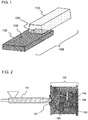
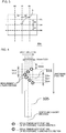
- FIG. 1 is an external view schematically showing a structural example of the metal-resin composite structure 106 according to the embodiment of the present invention.
- a metal member 103 and a resin member 105 formed of a thermoplastic resin composition (P) are bonded to each other, and the metal-resin composite structure 106 can be obtained by bonding the metal member 103 and the resin member 105 to each other.
- the metal-resin composite structure 106 is also called a coated metal member.
- a surface roughness measured according to JIS B0601 (corresponding international standard: ISO4287) satisfies the following requirements (1) and (2) at the same time:
- the resin member 105 is formed of the thermoplastic resin composition (P) containing a thermoplastic resin (A) as a resin component.
- thermoplastic resin composition (P) constituting the resin member 105 infiltrates into a concavo-convex portion formed on the surface 110 of the metal member. As a result, metal is bonded to the resin, and the metal-resin composite structure is formed.
- the concavo-convex portion suitable for improving the bond strength between the metal member 103 and the resin member 105 is formed on the surface 110 of the metal member 103. Therefore, the adhesion between the metal member 103 and the resin member 105 can be secured without using an adhesive.
- thermoplastic resin composition (P) infiltrating into the concavo-convex portion of the surface 110 of the metal member which satisfies the requirements (1) and (2) at the same time, a physical resistance force (anchor effect) is efficiently exhibited between the metal member 103 and the resin member 105, and the metal member 103 and the resin member 105 formed of the thermoplastic resin composition (P) which are usually difficult to bond can be strongly bonded to each other.
- the metal-resin composite structure 106 obtained as above can also prevent infiltration of moisture or humidity into an interface between the metal member 103 and the resin member 105. That is, air tightness and water tightness of the adhesion interface of the metal-resin composite structure 106 can be improved.
- a surface roughness measured according to JIS B0601 (corresponding international standard: ISO4287) satisfies the following requirements (1) and (2) at the same time:
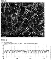
- FIG. 3 is a schematic diagram showing measurement positions which are the six linear portions in total on the surface 110 of the metal member including three arbitrary linear portions which are parallel to each other and another three arbitrary linear portions which are perpendicular to the former three linear portions.
- six linear portions B1 to B6 shown in FIG. 3 can be selected.
- the center line B1 which passes through a center portion A of a bonding portion surface 104 of the metal member 103 is selected.
- the lines B2 and B3 parallel to the center line B1 are selected.
- the center line B4 perpendicular to the center line B1 is selected, and the lines B5 and B6 perpendicular to the center line B1 and parallel to the center line B4 are selected.
- vertical distances D1 to D4 between the respective lines are, for example, 2 mm to 5 mm.
- the metal-resin composite structure 106 having an excellent bond strength can be obtained when the requirements (1) and (2) are satisfied is not necessarily clear, but is considered to be that the bonding portion surface 104 of the metal member 103 has a structure in which the anchor effect between the metal member 103 and the resin member 105 can be efficiently exhibited.
- the present inventors have investigated a configuration in which a ten point average roughness (Rz) of a surface of a metal member is adjusted in order to improve the bond strength between the metal member and a resin member formed of a thermoplastic resin composition.
- the present inventors thought that the criterion material ratio of the profile is efficient as an index indicating the sharpness of the concavo-convex portion of the metal member surface.
- a low material ratio of the profile represents high sharpness of the concavo-convex portion of the metal member surface
- a high material ratio of the profile represents low sharpness of the concavo-convex portion of the metal member surface.
- the present inventors have focused on the material ratio of the profile of a roughness curve of a metal member surface and have investigated more thoroughly. As a result, the present inventors have found that, by adjusting a material ratio of the profile of a metal member surface to be lower than or equal to a specific value, the anchor effect between the metal member 103 and the resin member 105 can be efficiently exhibited, and thus the metal-resin composite structure 106 having an excellent bond strength can be realized, thereby completing the present invention.
- the surface roughness measured according to JIS B0601 corresponding international standard: ISO4287
- JIS B0601 corresponding international standard: ISO4287
- the requirement (1C) is the same as the above-described requirement (3) .
- an average value of material ratio of the roughness profile (Rmr) on the surface 110 of the metal member 103 at a cutting level of 20% and an evaluation length of 4 mm is preferably higher than or equal to 0.1% and less than or equal to 40%, more preferably higher than or equal to 0.5% and less than or equal to 30%, still more preferably higher than or equal to 1% and less than or equal to 20%, and most preferably higher than or equal to 2% and less than or equal to 15%.
- an average value of material ratio of the roughness profile (Rmr) of the above-described six arbitrary linear portions can be adopted.
- the respective material ratio of the roughness profile (Rmr) of the surface 110 of the metal member according to the embodiment can be controlled by appropriately adjusting conditions of the roughening on the surface of the metal member 103.
- the kind and concentration of an etchant, the temperature and time of the roughening, and the timing of etching can be used as factors for controlling the respective material ratio of the roughness profile (Rmr).
- the surface roughness measured according to JIS B0601 corresponding international standard: ISO4287
- the surface roughness measured according to JIS B0601 preferably further satisfies the following requirement (2A):
- an average value of ten point average roughnesses (Rz) on the surface 110 of the metal member is preferably greater than 2 ⁇ m and less than or equal to 50 ⁇ m, more preferably greater than 5 ⁇ m and less than or equal to 45 ⁇ m, still more preferably greater than or equal to 10 ⁇ m and less than or equal to 40 ⁇ m, and particularly preferably greater than or equal to 15 ⁇ m and less than or equal to 30 ⁇ m.
- an average value of ten point average roughnesses (Rz) of the above-described six arbitrary linear portions can be adopted.
- the surface roughness measured according to JIS B0601 corresponding international standard: ISO4287
- JIS B0601 corresponding international standard: ISO4287
- an average value of mean width of the profile elements (RSm) on the surface 110 of the metal member is preferably greater than 10 ⁇ m and less than 300 ⁇ m and more preferably greater than or equal to 20 ⁇ m and less than or equal to 200 ⁇ m.
- an average value of mean width of the profile elements (RSm) of the above-described six arbitrary linear portions can be adopted.
- the ten point average roughnesses (Rz) and the mean width of the profile elements (RSm) of the surface 110 of the metal member according to the embodiment can be controlled by appropriately adjusting conditions of the roughening on the surface 110 of the metal member.
- the temperature and time of the roughening and the etching amount can be used as factors for controlling the ten point average roughnesses (Rz) and the mean width of the profile elements (RSm).
- the metal material constituting the metal member 103 is particularly limited to iron, stainless steel, aluminum, aluminum alloys, magnesium, and magnesium alloys.
- the metal material constituting the metal member 103 is not particularly limited, and examples thereof include iron, stainless steel, aluminum, aluminum alloys, magnesium, magnesium alloys, copper, and copper alloys. These metal materials may be used alone or in a combination of two or more kinds. Among these, from the viewpoints of reducing weight and obtaining high strength, aluminum (aluminum alone) and aluminum alloys are preferable, and aluminum alloys are more preferable.
- Alloy No. 1050, 1100, 2014, 2024, 3003, 5052, and 7075 which are defined according to JIS H4000 are preferably used.
- the shape of the metal member 103 is not particularly limited as long as the metal member 103 can be bonded to the resin member 105, and examples thereof include a flat shape, a curved shape, a rod shape, a cylindrical shape, and an agglomerate shape. In addition, a structure having a combination of the above-described shapes may be adopted.
- the shape of the bonding portion surface 104 which is bonded to the resin member 105 is not particularly limited, and examples thereof include a flat shape and a curved shape.
- the metal member 103 be formed of the metal material which is roughened as described below after being processed into a predetermined shape by thickness reduction processing such as plastic working by machining or pressing, punching, cutting, polishing, or electric discharge machining. In short, it is preferable that the metal member 103 be processed into a necessary shape using various processing methods.
- the surface of the metal member 103 according to the embodiment can be formed by, for example, roughening using an etchant.
- the roughening on the surface of the metal member using an etchant is performed using the related technique.
- the factors such as the kind and concentration of an etchant, the temperature and time of the roughening, and the timing of etching are highly controlled.
- the roughening method of the metal member surface according to the embodiment is not limited to the following examples.
- a thick film such as an oxide film or a hydroxide not be formed on a surface of the metal member 103 which is bonded to the resin member 105.
- the surface layer may be polished by mechanical polishing such as sand blasting, shot blasting, grinding or barrel finishing or by chemical polishing.
- this surface be treated using an aqueous alkaline solution such as an aqueous sodium hydroxide solution or an aqueous potassium hydroxide solution or be degreased.
- a treatment using an acidic etchant described below be performed at a specific timing. Specifically, it is preferable that the treatment using an acidic etchant be performed in a final step of the surface-roughening process.
- Patent Document 5 As the etchant used for the surface-roughening of the metal member which is formed of the metal material containing aluminum, Patent Document 5 described above discloses a configuration of using an alkaline etchant, a configuration of using an alkaline etchant and an acidic etchant in combination, and a configuration of roughening a metal surface using an acidic etchant and then washing the treated surface with an alkaline solution.
- the alkaline etchant is moderately reactive to the metal member and thus is preferably used from the viewpoint of workability.
- the alkaline etchant due to its moderate reactivity, the roughening degree of the metal member surface is weak, and it is difficult to form a deep concavo-convex portion.
- an alkaline etchant or an alkaline solution is used in combination after the treatment using an acidic etchant, a deep concavo-convex portion which is formed using the acidic etchant is smoothened by the alkaline etchant or the alkaline solution.
- Examples of a roughening method using the acidic etchant include treatment methods using dipping or spraying.
- the treatment temperature is preferably 20°C to 40°C
- the treatment time is 5 seconds to 350 seconds
- from the viewpoint of further uniformly roughening the metal member surface is more preferably 20 seconds to 300 seconds and particularly preferably 50 seconds to 300 seconds.
- the etching amount (dissolved amount) of the metal member 103 in the thickness direction in the case of using the acidic etchant is preferably 0.1 ⁇ m to 500 ⁇ m, more preferably 5 ⁇ m to 500 ⁇ m, and still more preferably 5 ⁇ m to 100 ⁇ m.
- the etching amount is greater than or equal to the lower limit, the bond strength between the metal member 103 and the resin member 105 can be further improved.
- the etching amount is less than or equal to the upper limit, the treatment cost can be reduced.
- the etching amount can be adjusted by the treatment temperature, the treatment time, and the like.
- the entire surface of the metal member surface may be roughened, or only a surface of the metal member which is bonded to the resin member 105 may be partially roughened.
- washing and drying be performed after the surface-roughening treatment.
- a washing method is not particularly limited, but it is preferable that dipping or washing with flowing water for a predetermined amount of time be performed.
- ultrasonic cleaning be performed to remove smut and the like formed by the treatment using the acidic etchant.
- Ultrasonic cleaning conditions are not particularly limited as long as the formed smut and the like can be removed under the conditions.
- water is preferably used as a solvent to be used, and the treatment time is preferably 1 minute to 20 minutes.
- a specific acidic etchant described below is preferably used as the etchant used for the roughening of the metal member surface. It is considered that, by performing the treatment using the specific etchant, a concavo-convex portion suitable for improving the adhesion between the metal member and the resin member containing the thermoplastic resin (A) is formed on the surface of the metal member, and due to this anchor effect, the bond strength between the metal member 103 and the resin member 105 is improved.
- an acidic etchant capable of forming a deeper concavo-convex portion on the metal member surface be used from the viewpoints of: improving the bond strength between the metal member and a resin member, which is not likely to be bonded to the metal member with an ordinary treatment, including a polyolefin resin, a thermoplastic resin having a glass transition temperature of higher than or equal to 140°C, or an amorphous thermoplastic resin; and improving the bond strength between the metal member and a coating film formed of a water-based coating material which is not likely to be bonded to the metal member with an ordinary treatment.
- the acidic etchant contains at least either ferric ions or cupric ions and an acid, and may optionally further contain manganese ions and various additives.
- the ferric ions are a component that oxidizes the metal member and can be contained in the acidic etchant by mixing a ferric ion source with the acidic etchant.
- the ferric ion source include ferric nitrate, ferric sulfate, and ferric chloride.
- ferric chloride is preferably used from the viewpoint of high solubility and low cost.
- the content of the ferric ions in the acidic etchant is preferably 0.01 mass% to 20 mass%, more preferably 0.1 mass% to 12 mass%, still more preferably 0.5 mass% to 7 mass%, even still more preferably 1 mass% to 6 mass%, and particularly preferably 1 mass% to 5 mass%.
- the content of the ferric ions is greater than or equal to the lower limit, a decrease in the roughening rate (dissolving rate) of the metal member can be prevented.
- the content of the ferric ions is less than or equal to the upper limit, the roughening rate can be appropriately maintained. Therefore, uniform roughening which is more suitable for improving the bond strength between the metal member 103 and the resin member 105 can be performed.
- the cupric ions are a component that oxidizes the metal member and can be contained in the acidic etchant by mixing a cupric ion source with the acidic etchant.
- the cupric ion source include cupric sulfate, cupric chloride, cupric nitrate, and cupric hydroxide.
- cupric sulfate or cupric chloride is preferably used from the viewpoint of high solubility and low cost.
- the content of the cupric ions in the acidic etchant is preferably 0.001 mass% to 10 mass%, more preferably 0.01 mass% to 7 mass%, still more preferably 0.05 mass% to 1 mass%, yet still more preferably 0.1 mass% to 0.8 mass%, even yet still more preferably 0.15 mass% to 0.7 mass%, and particularly preferably 0.15 mass% to 0.4 mass%.
- the content of the cupric ions is greater than or equal to the lower limit, a decrease in the roughening rate (dissolving rate) of the metal member can be prevented.
- the content of the cupric ions is less than or equal to the upper limit, the roughening rate can be appropriately maintained. Therefore, uniform roughening which is more suitable for improving the bond strength between the metal member 103 and the resin member 105 can be performed.
- the acidic etchant may contain either or both of the ferric ions and the cupric ions, but it is preferable that the acidic etchant contain both the ferric ions and the cupric ions.
- the acidic etchant containing the ferric ions and the cupric ions an excellent roughening shape which is more suitable for improving the bond strength between the metal member 103 and the resin member 105 can be easily obtained.
- the acidic etchant contains both the ferric ions and the cupric ions
- the respective contents of the ferric ions and the cupric ions be in the above-described ranges.
- the total content of the ferric ions and the cupric ions in the acidic etchant is preferably 0.011 mass% to 20 mass%, more preferably 0.1 mass% to 15 mass%, still more preferably 0.5 mass% to 10 mass%, and particularly preferably 1 mass% to 5 mass%.
- the acidic etchant may contain manganese ions.
- the manganese ions can be contained in the acidic etchant by mixing a manganese ion source with the acidic etchant.
- the manganese ion source include manganese sulfate, manganese chloride, manganese acetate, manganese fluoride, and manganese nitrate.
- manganese nitrate or manganese chloride is preferably used from the viewpoints of low cost and the like.
- the content of the manganese ions in the acidic etchant is preferably 0 mass% to 1 mass% and more preferably 0 mass% to 0.5 mass%.
- the present inventors verified that, in a case where the thermoplastic resin (A) constituting the resin member 105 was a polyolefin resin, even when the content of the manganese ions was 0 mass%, a sufficient bond strength was exhibited. That is, when a polyolefin resin is used as the thermoplastic resin (A), it is preferable that the content of the manganese ions be 0 mass%.
- the manganese ions are appropriately used in a content of the above-described upper limit or less.
- the above-described acid is a component that dissolves the metal oxidized by the ferric ions and/or the cupric ions.
- the acid include inorganic acids such as hydrochloric acid, hydrobromic acid, sulfuric acid, nitric acid, phosphoric acid, perchloric acid, and sulfamic acid; and organic acids such as sulfonic acid and carboxylic acid.
- the carboxylic acid include formic acid, acetic acid, citric acid, oxalic acid, and malic acid.
- One kind or two or more kinds of the acids can be mixed with the acidic etchant.
- sulfuric acid is preferably used from the viewpoint of substantially no odor emission and low cost.
- carboxylic acid is preferably used from the viewpoint of the uniformity of the roughening shape.
- the content of the acid in the acidic etchant is preferably 0.1 mass% to 50 mass%, more preferably 0.5 mass% to 50 mass%, still more preferably 1 mass% to 50 mass%, yet still more preferably 1 mass% to 30 mass%, even yet still more preferably 1 mass% to 25 mass%, and particularly preferably 2 mass% to 18 mass%.
- the content of the acid is greater than or equal to the lower limit, a decrease in the roughening rate (dissolving rate) of the metal can be prevented.
- the content of the acid is less than or equal to the upper limit, crystal precipitation of a metal salt at a decreased liquid temperature can be prevented, and workability can be improved.
- a surfactant for preventing unevenness in roughening caused by a surface contaminant such as a fingerprint may be added, and optionally other additives may also be added.
- the additives include halide ion sources which are added to form a deep concavo-convex portion, for example, sodium chloride, potassium chloride, sodium bromide, and potassium bromide.
- additives include thio compounds which are added to increase the roughening rate, for example, thiosulfate ions and thiourea; azoles which are added to obtain a more uniform roughening shape, for example, imidazole, triazole, and tetrazole; and a pH adjuster which is added to control a roughening reaction.
- the total content thereof in the acidic etchant is preferably 0.01 mass% to 10 mass%.
- the acidic etchant according to the embodiment can be easily prepared by dissolving the above-described respective components in ion exchange water or the like.
- the resin member 105 is formed of the thermoplastic resin composition (P).
- the thermoplastic resin composition (P) contains the thermoplastic resin (A) as the resin component and optionally further contains a filler (B). Further, the thermoplastic resin composition (P) optionally further contains other compounding agents.
- the resin member 105 being formed of only the thermoplastic resin (A) is described as the resin member 105 being formed of the thermoplastic resin composition (P).
- thermoplastic resin (A) is not particularly limited, and examples thereof include polyolefin resins, polymethacrylic resins such as polymethyl methacrylate resin, polyacrylic resins such as polymethyl acrylate resin, polystyrene resins, polyvinyl alcohol-polyvinyl chloride copolymer resins, polyvinyl acetal resins, polyvinyl butyral resins, polyvinyl formal resins, polymethyl pentene resins, maleic anhydride-styrene copolymer resins, polycarbonate resins, polyphenylene ether resins, aromatic polyether ketones such as polyether ether ketone resins and polyether ketone resins, polyester resins, polyamide resins, polyamide imide resins, polyimide resins, polyether imide resins, styrene elastomers, polyolefin elastomers, polyurethane elastomers, polyester elastomers, polyamide elastomers,
- thermoplastic resin (A) one or two or more thermoplastic resins selected from polyolefin resins, polyester resins, and polyamide resins are preferably used from the viewpoint of more efficiently obtaining the effect of improving the bond strength between the metal member 103 and the resin member 105.
- polymers obtained by polymerization of olefins can be used without any particular limitation.
- Examples of the olefins constituting the polyolefin resins include ethylene, ⁇ -olefins, and cyclic olefins.
- ⁇ -olefins examples include linear or branched ⁇ -olefins having 3 to 30 carbon atoms, preferably, 3 to 20 carbon atoms. More specific examples of the ⁇ -olefins include propylene, 1-butene, 1-pentene, 3-methyl-1-butene, 1-hexene, 4-methyl-1-pentene, 3-methyl-1-pentene, 1-octene, 1-decene, 1-dodecene, 1-tetradecene, 1-hexadecene, 1-octadecene, and 1-eicosene.
- cyclic olefins examples include cyclic olefins having 3 to 30 carbon atoms, preferably, 3 to 20 carbon atoms. More specific examples of the cyclic olefins include cyclopentene, cycloheptene, norbornene, 5-methyl-2-norbornene, tetracyclododecene, and 2-methyl-1,4,5,8-dimethano-1,2,3,4,4a,5,8,8a-octahydronaphthalen e.
- olefins constituting the polyolefin resins include ethylene, propylene, 1-butene, 1-pentene, 3-methyl-1-butene, 1-hexene, 4-methyl-1-pentene, and 3-methyl-1-pentene.
- ethylene, propylene, 1-butene, 1-hexene, or 4-methyl-1-pentene are more preferable, and ethylene or propylene is still more preferable.
- the polyolefin resins may be obtained by polymerization of one kind of the above-described olefins, or may be obtained by random copolymerization, block copolymerization, or graft copolymerization of two or more kinds of the above-described olefins.
- polyolefin resins those having a linear or branched structure may be used.
- polyester resins examples include polylactic acid, polyglycolic acid, polycaprolactone, aliphatic polyester such as polyethylene succinate, polyethylene terephthalate, polyethylene naphthalate, polybutylene terephthalate (PBT), and polycyclohexylenedimethylene terephthalate (PCT).
- aliphatic polyester such as polyethylene succinate, polyethylene terephthalate, polyethylene naphthalate, polybutylene terephthalate (PBT), and polycyclohexylenedimethylene terephthalate (PCT).
- polyamide resins examples include aliphatic polyamides by ring opening polymerization such as PA6 and PA12; polyamides by polycondensation polymerization such as PA66, PA46, PA610, PA612, and PAll; semi-aromatic polyamides such as MXD6, PA6T, PA9T, PA6T/66, PA6T/6, amorphous PA; and fully aromatic polyamides such as poly(p-phenylene terephthalamide), poly(m-phenylene terephthalamide), and poly(m-phenylene isophthalamide) and amide elastomers.
- aliphatic polyamides by ring opening polymerization such as PA6 and PA12
- polyamides by polycondensation polymerization such as PA66, PA46, PA610, PA612, and PAll
- semi-aromatic polyamides such as MXD6, PA6T, PA9T, PA6T/66, PA6T/6, amorphous PA
- fully aromatic polyamides
- thermoplastic resin (A) one or two or more thermoplastic resins selected from thermoplastic resins having a glass transition temperature of higher than or equal to 140°C and amorphous thermoplastic resins are preferably used from the viewpoint of more efficiently obtaining the effect of improving the bond strength between the metal member 103 and the resin member 105.
- thermoplastic resins having a glass transition temperature of higher than or equal to 140°C include one or two or more thermoplastic resins selected from polycarbonate resins; aromatic polyether ketones such as polyether ether ketone resins and polyether ketone resins; polyimide resins; and polyether sulfone resins.
- amorphous thermoplastic resins include one or two or more amorphous thermoplastic resins selected from polystyrene resins, polyacrylonitrile resins, styrene-acrylonitrile copolymer resins, acrylonitrile-butadiene-styrene copolymer resins (ABS resins), polymethyl methacrylate resins, and polycarbonate resins.
- the thermoplastic resin (A) In order to promote infiltration into the concavo-convex portion of the surface of the metal member 103, it is preferable that the thermoplastic resin (A) have high fluidity. Therefore, in the embodiment, MFR of the thermoplastic resin (A) which is measured according to ASTM D1238 under a condition of a load of 2.16 kg is preferably 10 g/10 min to 200 g/10 min. MFR can be measured at a temperature which is determined depending on each resin, for example, at 230°C in the case of a propylene polymer and at 190°C in the case of an ethylene polymer.
- the resin member 105 according to the embodiment may be a coating film.
- various commercially available coating materials can be used.
- the kinds of the coating materials can be broadly classified into an oil-based coating material and a water-based coating material.
- the oil-based coating material include coating materials in which a resin such as an acrylic resin, a polyolefin resin, a polyurethane resin, an epoxy resin, a phenol resin, a polyester resin, or an alkyd resin is dissolved in an organic solvent.
- the water-based coating material include a coating materials in which a resin such as an acrylic resin, an acrylic silicon resin, a polyolefin resin, a silicon resin, a polyurethane resin, an epoxy resin, a phenol resin, a polyester resin, an alkyd resin, or a biodegradable resin is suspended in water.
- the coating film may be formed of either the oil-based coating material or the water-based coating material. Since a deep concavo-convex portion is formed on the surface-roughened metal member 103, a coating resin infiltrates into the concave portion, and a coating film is formed. Therefore, the adhesion of the coating film with metal is high, and it can be expected that the coating film is not likely to be peeled off. In the embodiment, as described above, a deep concavo-convex portion is formed on the surface-roughened metal member 103.
- the metal-resin composite structure 106 according to the embodiment is excellent from the viewpoint that a coating film having high adhesion can be formed even when the water-based coating material, with which a coating film having high adhesion is not likely to be formed on the metal member surface in the related art, is used.
- thermoplastic resin composition (P) may further contain the filler (B) from the viewpoints of adjusting a difference in linear expansion coefficient between the metal member 103 and the resin member 105 and improving a mechanical strength of the resin member 105.
- one or two or more kinds can be selected from the group consisting of glass fiber, carbon fiber, carbon particles, clay, talc, silica, mineral, and cellulose fiber.
- one or two or more kinds selected from glass fiber, carbon fiber, talc, and mineral are preferably used.
- the shape of the filler (B) is not particularly limited and may be any shape, for example, fibrous, particulate, or plate-like.
- the filler (B) contain 5% to 100% of filler particles having a maximum length of longer than or equal to 10 nm and shorter than or equal to 600 ⁇ m by number fraction.
- the maximum length is more preferably longer than or equal to 30 nm and shorter than or equal to 550 ⁇ m and still more preferably longer than or equal to 50 nm and shorter than or equal to 500 ⁇ m.
- the number fraction of the filler (B) particles having a maximum length in the above-described range is preferably 10% to 100% and more preferably 20% to 100%.
- the filler (B) can easily functions in the thermoplastic resin (A) which is melted during the molding of the thermoplastic resin composition (P). Therefore, during the preparation of the metal-resin composite structure 106 described below, the filler (B) can be made to be present in the vicinity of the metal member surface at a certain ratio. Therefore, the resin which interacts with the filler (B) infiltrates into the concavo-convex portion of the metal member surface as described above and thus can obtain a stronger bond strength.
- the number fraction is within the above-described range, a sufficient number of the filler (B) particles are present in the thermoplastic resin composition (P) such that the filler (B) can act with the concavo-convex portion of the surface of the metal member 103.
- thermoplastic resin composition (P) is removed from the obtained metal-resin composite structure 106, the thermoplastic resin composition (P) is heated in an oven so as to be completely carbonized, and then the filler (B) remaining after the removal of the carbonized resin is measured with a scanning electron microscope.
- L1 to L3 in the schematic drawing of FIG.
- the maximum length of the filler (B) particles refers to: the maximum length L1 among the lengths of three sides in the case of a rectangular shape; the longer length L2 among the long-axis diameter length of a circle or the height of a cylinder in the case of a cylindrical shape; and the length L3 of the longest diameter among the long axis diameter lengths of all the cross-sections in the case of a sphere or a spheroid.
- the number of all the filler (B) particles in the electron micrograph used to measure the lengths of the filler (B) particle is counted, and the number of filler (B) particles contained in the above-describe range is calculated.
- filler (B) one kind or two or more kinds thereof may be used.
- the maximum lengths of all the kinds of the filler (B) particles are collectively obtained using the above-described method.
- the filler (B) particles may have a maximum length of greater than 600 ⁇ m before being kneaded with the thermoplastic resin (A) or may be cut and pulverized during kneading and molding such that the maximum length is within the above-described range.
- the content of the filler (B) is preferably 1 part by mass to 100 parts by mass, more preferably 5 parts by mass to 90 parts by mass, and particularly preferably 10 parts by mass to 80 parts by mass with respect to 100 parts by mass of the thermoplastic resin (A) .
- the filler (B) has an effect of controlling the linear expansion coefficient of the resin member 105 as well as an effect of improving the stiffness of the resin member 105.
- the filler (B) has an effect of controlling the linear expansion coefficient of the resin member 105 as well as an effect of improving the stiffness of the resin member 105.
- the content of the filler (B) to be within the above-described range, a decrease in toughness can be suppressed.
- thermoplastic resin composition (P) may contain other compounding agents in order to impart various functions thereto.
- the compounding agent examples include a heat stabilizer, an antioxidant, a pigment, a weather-resistant agent, a flame retardant, a plasticizer, a dispersant, a lubricant, a release agent, and an antistatic agent.
- thermoplastic resin composition (P) is not particularly limited, and the thermoplastic resin composition can be prepared using a generally well-known method. For example, the following method may be used. First, the thermoplastic resin (A), optionally the filler (B), and further optionally the other compounding agents are mixed or melt-mixed with each other using a mixing machine such as a Banbury mixer, a single screw extruder, a twin screw extruder, or a high speed twin screw extruder. As a result, the thermoplastic resin composition (P) is obtained.
- a mixing machine such as a Banbury mixer, a single screw extruder, a twin screw extruder, or a high speed twin screw extruder.
- the method of preparing the metal-resin composite structure 106 is not particularly limited, and can be obtained by bonding the thermoplastic resin composition (P) to the surface-roughened metal member 103 while molding the thermoplastic resin composition (P) to obtain a desired shape of the resin member 105.
- Examples of a molding method of the resin member 105 include resin molding methods such as injection molding, extrusion molding, hot press molding, compression molding, transfer molding, cast molding, laser welding molding, reaction injection molding (RIM molding), liquid injection molding (LIM molding), and spray forming.
- resin molding methods such as injection molding, extrusion molding, hot press molding, compression molding, transfer molding, cast molding, laser welding molding, reaction injection molding (RIM molding), liquid injection molding (LIM molding), and spray forming.
- thermoplastic resin composition (P) when a composite is formed of a metal member-thermoplastic resin composition coating in which a coating of the thermoplastic resin composition (P) is formed on the metal member 103, a method of dissolving or dispersing the thermoplastic resin composition (P) in a solvent to prepare a resin vanish and coating the metal member 103 with this resin vanish or various other coating methods can be adopted.
- the other coating method include baking coating, electrodeposition coating, electrostatic coating, powder coating, and ultraviolet curable coating.
- an injection molding method is preferably used as the method of preparing the metal-resin composite structure 106.
- the metal-resin composite structure 106 be prepared using an injection molding method of inserting the metal member 103 into a cavity of an injection mold and injecting the thermoplastic resin composition (P) into the mold.
- a method including the following processes (i) to (iii) is preferable:
- thermoplastic resin composition (P) In the step (i) of preparing the thermoplastic resin composition (P), the above-described method of preparing the thermoplastic resin composition (P) is used.
- the thermoplastic resin (A), optionally the filler (B), and further optionally the other compounding agents are mixed or melt-mixed with each other using a mixing machine such as a Banbury mixer, a single screw extruder, a twin screw extruder, or a high speed twin screw extruder.
- a mixing machine such as a Banbury mixer, a single screw extruder, a twin screw extruder, or a high speed twin screw extruder.
- thermoplastic resin composition (P) obtained in the process (i) is injected into the mold such that at least a part of the thermoplastic resin composition (P) comes into contact with a surface of the metal member 103 on which a concave portion is formed, and the injected thermoplastic resin composition (P) is solidified.
- the metal-resin composite structure 106 can be obtained by opening and releasing the mold.
- injection foam molding or rapid heat cycle molding RHCM, Heat and Cool Molding
- Examples of a method of the injection foam molding include a method of adding a chemical foaming agent to a resin; a method of directly injecting nitrogen gas or carbon dioxide gas into a cylinder portion of an injection molding machine; and a MuCell injection foaming molding method of injecting nitrogen gas or carbon dioxide gas in the supercritical state into a cylinder portion of an injection molding machine.
- a metal-resin composite structure in which a resin member is a foam body can be obtained.
- a method using counter pressure may be used, or a method using core back may also be used depending on the shape of a molded article.
- the rapid heat cycle molding can be performed by connecting the mold to a rapid heating and cooling device.
- the rapid heating and cooling device may be a commonly-used type.
- As a heating method one of methods using steam, pressurized hot water, hot water, an electric heater, and electromagnetic induction heating or a combination of plural methods thereof may be used.
- As a cooling method one of methods using cold water and cold oil or a combination thereof may be used.
- As rapid heat cycle molding conditions for example, it is preferable that an injection mold be heated at a temperature of higher than or equal to 100°C and lower than or equal to 250°C, and the injection mold be cooled after the injection of the thermoplastic resin composition (P).
- a preferable range of the mold heating temperature varies depending on the thermoplastic resin (A) constituting the thermoplastic resin composition (P).
- the mold heating temperature is preferably higher than or equal to 100°C and lower than or equal to 150°C.
- the mold heating temperature is preferably higher than or equal to 140°C and lower than or equal to 250°C.
- the mold heating temperature is preferably higher than or equal to 50°C and lower than or equal to 250°C and more preferably higher than or equal to 100°C and lower than or equal to 180°C.
- a method of forming a coating film which is used in the related art can be used without any limitation.
- the surface of the metal member 103 can coated with the above-described various coating materials using a method, for example, spray coating such as air spraying or airless spraying, dip coating, brush coating, roller coating, or coater coating.
- spray coating such as air spraying or airless spraying
- dip coating dip coating
- brush coating roller coating
- coater coating any coating material
- the metal-resin composite structure 106 according to the embodiment is applicable to various uses due to its high productivity and high degree of freedom for shape control.
- the metal-resin composite structure 106 exhibits air tightness and water tightness and thus can be preferably used according to the properties.
- Examples of the uses of the metal-resin composite structure 106 include structural components for vehicles, components mounted in vehicles, cases of electronic apparatuses, cases of home electronics, structural components, mechanical components, various components for vehicles, components for electronic apparatuses, furniture, household components such as kitchenware, medical equipment, components of construction materials, and other structural components and exterior components.
- components for vehicles include an instrument panel, a console box, a door knob, a door trim, a shift lever, pedals, a glove box, a bumper, a hood, a fender, a trunk, a door, a roof, a pillar, a seat sheet, a radiator, an oil pan, a steering wheel, an ECU box, and an electrical component.
- components of construction materials and furniture include a glass window frame, a handrail, a curtain rail, a chest of drawers, a drawer, a closet, a bookshelf, a desk, and a chair.
- examples of high-precision electronic components include a connector, a relay, and a gear.
- examples of shipping casks include a shipping container, a suitcase, and a trunk.
- the metal-resin composite structure 106 can be used for components in which the high thermal conductivity of the metal member 103 and the insulating property of the thermoplastic resin (A) are combined to optimally design heat management, for example, can be used for various home electronics.
- the home electronics include home electronics such as a refrigerator, a washing machine, a vacuum cleaner, a microwave oven, an air conditioner, an lighting device, an electric water heater, a television, a timepiece, a ventilating fan, a projector, and a speaker; and electronic information devices such as a personal computer, a mobile phone, a smartphone, a digital camera, a tablet PC, a mobile music player, a mobile game machine, a charger, and a battery.
- the surface area thereof increases by roughening the surface of the metal member 103. Therefore, the contact area between the metal member 103 and the resin member 105 increases, and the heat resistance at a contact interface can be reduced.
- Examples of other uses of the metal-resin composite structure 106 include toys, sports goods, shoes, sandals, bags, dinnerware such as a fork, a knife, a spoon, or a dish, stationery goods such as a ball-point pen, a mechanical pencil, a file, or a binder, cookware such as a frying pan, a pot, a kettle, a spatula, a ladle, a perforated ladle, a whisk, or tongs, components for lithium ion secondary batteries, and robots.
- dinnerware such as a fork, a knife, a spoon, or a dish
- stationery goods such as a ball-point pen, a mechanical pencil, a file, or a binder
- cookware such as a frying pan, a pot, a kettle, a spatula, a ladle, a perforated ladle, a whisk, or tongs
- components for lithium ion secondary batteries and robots.
- FIGS. 1 and 2 are used as drawings common to the respective examples.
- FIG. 1 is an external view schematically showing a structural example of the metal-resin composite structure 106 of the metal member 103 and the resin member 105.
- FIG. 2 is a configuration diagram schematically showing an example of a process of preparing the metal-resin composite structure 106 using the metal member 103 and the resin member 105.
- the metal member 103 which is processed into a predetermined shape and has a surface on which the bonding portion surface (surface-roughened region) 104 having a fine concavo-convex portion is formed, is installed into an injection mold 102; and the thermoplastic resin composition (P) is injected through a gate-runner 107 using an injection molding machine 101 and is integrated with the metal member 103 on which the fine concavo-convex portion is formed, thereby preparing the metal-resin composite structure 106.
- These processes are schematically shown in FIG. 2 .
- the measurement was performed on six linear portions in total on a surface of a metal member including three arbitrary linear portions which were parallel to each other and another three arbitrary linear portions which were perpendicular to the former three linear portions (refer to FIG. 4 ).
- the entire portion of the surface of the metal member 103 was roughened. Therefore, it can be understood that, even when a material ratio of the roughness profile (Rmr), a ten point average roughness (Rz), and a mean width of the profile elements (RSm) are measured regarding the bonding portion surface 104 of the metal-resin composite structure 106, the same evaluation results as those of the measurement positions shown in FIG. 4 can be obtained.
- an aluminum plate (dimension: 70 ⁇ 150 ⁇ 1 t) of Alloy No. 5052 defined in JIS H4000 was coated with a water-based coating material such that the thickness of a dried coating film was 40 ⁇ m, and the aluminum plate was dried. Next, an end portion and a back surface were also coated with the same water-based coating material. This coated metal member was dried for one day in an atmosphere of 20°C and 55% RH.
- the adhesion of the coated metal member obtained as above was measured according to JIS K 5600-5-6 (cross-cut method). Swelling was evaluated for adhesion based on the following criteria.
- An aluminum plate (thickness: 1.6 mm) of Alloy No. 5052 defined in JIS H4000 was cut into a length of 45 mm and a width of 18 mm.
- This aluminum plate was etched by being dipped in an acidic etchant 1A (30°C) having a composition shown in Table 1A for 40 seconds and being shaken. Next, the aluminum plate was washed with flowing water by ultrasonic cleaning (in water, 1 minute) and then was dried. As a result, a surface-treated metal member was obtained.
- the surface roughness of the obtained surface-treated metal member was measured using a surface roughness measuring device "SURFCOM 1400D (manufactured by Tokyo Seimitsu Co., Ltd.)".
- material ratio of the roughness profile (Rmr) at cutting levels of 10%, 20%, 30%, 40%, 50%, 60%, 70%, and 80%, ten point average roughnesses (Rz) and mean width of the profile elements (RSm) were obtained.
- Table 2A shows: Rmr (20%) values at a cutting level of 20%; the number of linear portions in which the Rmr (20%) is lower than or equal to 30%; Rmr (40%) values at a cutting level of 40%; the number of linear portions in which the Rmr (40%) is lower than or equal to 60%; Rz values and mean width of the profile elements (RSm) of the six linear portions; and an etching ratio obtained from mass ratios of the metal member before and after etching.
- FIG. 5 shows a surface roughness curve obtained from the above measurement.
- FIG. 6 shows a micrograph.
- a surface-treated metal member was obtained by performing the same treatment as that of Preparation Example 1A, except that the aluminum plate was etched for 80 seconds using an acidic etchant 2A instead of the acidic etchant 1A shown in Table 1A.
- Table 2A shows Rmr, Rz, RSm, and an etching ratio of the obtained surface-treated metal member.
- FIG. 7 shows a surface roughness curve obtained from the above measurement.
- FIG. 8 shows a micrograph.
- An aluminum plate (thickness: 1.6 mm) of Alloy No. 5052 defined in JIS H4000 was cut into a length of 45 mm and a width of 18 mm.
- This aluminum plate was etched by being dipped in an acidic etchant 1A (30°C) having a composition shown in Table 1A for 40 seconds and being shaken. Next, the aluminum was washed with flowing water (1 minute) . Next, the treated aluminum plate was dipped in an aqueous solution (25°C) of 5 mass% of sodium hydroxide, was shaken for 30 seconds, and was washed with water.
- the treated aluminum plate was dipped in an aqueous solution (25°C) of 35 mass% of nitric acid, was shaken for 30 seconds, was washed (1 minute) with flowing water, and was dried. As a result, a surface-treated metal member was obtained.
- Table 2A shows Rmr, Rz, RSm, and an etching ratio of the obtained surface-treated metal member.
- FIG. 9 shows a surface roughness curve obtained from the above measurement.
- FIG. 10 shows a micrograph.
- a surface-treated metal member was obtained by performing the same treatment as that of Preparation Example 1A, except that the aluminum plate was etched for 160 seconds using an acidic etchant 3A instead of the acidic etchant 1A shown in Table 1A.
- Table 2A shows Rmr, Rz, RSm, and an etching ratio of the obtained surface-treated metal member.
- a surface-treated metal member was obtained by performing the same treatment as that of Preparation Example 1A, except that the aluminum plate was etched for 80 seconds using an acidic etchant 3A instead of the acidic etchant 1A shown in Table 1A.
- Table 2A shows Rmr, Rz, RSm, and an etching ratio of the obtained surface-treated metal member.
- a surface-treated metal member was obtained by performing the same treatment as that of Preparation Example 1A, except that the aluminum plate was etched for 40 seconds using an acidic etchant 3A instead of the acidic etchant 1A shown in Table 1A.
- Table 2A shows an etching ratio of the obtained surface-treated metal member.
- a surface-treated metal member was obtained by performing the same treatment as that of Preparation Example 1A, except that the aluminum plate was etched for 320 seconds using an acidic etchant 4A instead of the acidic etchant 1A shown in Table 1A.
- Table 2A shows an etching ratio of the obtained surface-treated metal member.
- a surface-treated metal member was obtained by performing the same treatment as that of Preparation Example 1A, except that the aluminum plate was etched for 160 seconds using an acidic etchant 4A instead of the acidic etchant 1A shown in Table 1A.
- Table 2A shows an etching ratio of the obtained surface-treated metal member.
- a surface-treated metal member was obtained by performing the same treatment as that of Preparation Example 1A, except that the aluminum plate was etched for 80 seconds using an acidic etchant 4A instead of the acidic etchant 1A shown in Table 1A.
- Table 2A shows an etching ratio of the obtained surface-treated metal member.
- a surface-treated metal member was obtained by performing the same treatment as that of Preparation Example 1A, except that the aluminum plate was etched for 40 seconds using an acidic etchant 4A instead of the acidic etchant 1A shown in Table 1A.
- Table 2A shows an etching ratio of the obtained surface-treated metal member.
- the small dumbbell-shaped metal insert mold 102 was mounted on J85AD110H manufactured by The Japan Steel Works Ltd., and the aluminum plate (metal member 103) prepared in Preparation Example 1A was installed into the mold 102.
- thermoplastic resin composition (P) glass fiber reinforced polypropylene (V7100 manufactured by Prime Polymer Co., Ltd.; 80 parts by mass of polypropylene (MFR (230°C, load: 2.16 kg) : 18 g/10 min) and 20 parts by mass of glass fiber) was injected into the mold 102 under conditions of a cylinder temperature of 250°C, a mold temperature of 120°C, an injection rate of 25 mm/sec, a holding pressure of 80 MPa, and a pressure holding time of 10 seconds.
- MFR 230°C, load: 2.16 kg
- a metal-resin composite structure 106 was obtained using the same method as that of Example 1A, except that the aluminum plate prepared in Preparation Example 2A was installed instead of the aluminum plate prepared in Preparation Example 1A.
- Table 3A shows the evaluation results of the bond strength.
- a metal-resin composite structure 106 was obtained using the same method as that of Example 1A, except that the aluminum plate prepared in Preparation Example 4A was installed instead of the aluminum plate prepared in Preparation Example 1A.
- Table 3A shows the evaluation results of the bond strength.
- a metal-resin composite structure 106 was obtained using the same method as that of Example 1A, except that the aluminum plate prepared in Preparation Example 5A was installed instead of the aluminum plate prepared in Preparation Example 1A.
- Table 3A shows the evaluation results of the bond strength.
- a metal-resin composite structure 106 was obtained using the same method as that of Example 1A, except that the aluminum plate prepared in Preparation Example 7A was installed instead of the aluminum plate prepared in Preparation Example 1A.
- Table 3A shows the evaluation results of the bond strength.
- a metal-resin composite structure 106 was obtained using the same method as that of Example 1A, except that the aluminum plate prepared in Preparation Example 3A was installed instead of the aluminum plate prepared in Preparation Example 1A.
- Table 3A shows the evaluation results of the bond strength.
- a metal-resin composite structure 106 was obtained using the same method as that of Example 1A, except that the aluminum plate prepared in Preparation Example 6A was installed instead of the aluminum plate prepared in Preparation Example 1A.
- Table 3A shows the evaluation results of the bond strength.
- a metal-resin composite structure 106 was obtained using the same method as that of Example 1A, except that the aluminum plate prepared in Preparation Example 8A was installed instead of the aluminum plate prepared in Preparation Example 1A.
- Table 3A shows the evaluation results of the bond strength.
- a metal-resin composite structure 106 was obtained using the same method as that of Example 1A, except that the aluminum plate prepared in Preparation Example 9A was installed instead of the aluminum plate prepared in Preparation Example 1A.
- Table 3A shows the evaluation results of the bond strength.
- a metal-resin composite structure 106 was obtained using the same method as that of Example 1A, except that the aluminum plate prepared in Preparation Example 10A was installed instead of the aluminum plate prepared in Preparation Example 1A.
- Table 3A shows the evaluation results of the bond strength.
- ND represents "Not Measured”.
- Example 1A as shown in FIG. 5 , a concavo-convex portion having a sharp angle was formed on the surface of the metal member treated in Preparation Example 1A, and it is considered that, by the resin member 105 being inserted into the concavo-convex portion, the obtained metal-resin composite structure 106 obtained a high bond strength.
- Example 2A as shown in FIG. 7 , a concavo-convex portion having a sharper angle than that of FIG. 5 was formed on the surface of the metal member treated in Preparation Example 2A, and it is considered that, by the resin member being inserted into the concavo-convex portion, the obtained metal-resin composite structure 106 obtained a high bond strength.
- Comparative Example 1A as shown in FIG. 9 , a concavo-convex portion having a sufficient size was not formed on the surface of the metal member treated in Preparation Example 3A, and the obtained metal-resin composite structure 106 obtained a low bond strength.
- An aluminum plate (thickness: 1.6 mm) of Alloy No. 5052 defined in JIS H4000 was cut into a length of 45 mm and a width of 18 mm.
- This aluminum plate was etched in an etching amount shown in Table 3B by being dipped in an acidic etchant B (30°C) having a composition shown in Table 1B and being shaken. Next, the aluminum plate was washed with flowing water (1 minute) and then was dried. As a result, a surface-treated metal member was obtained.
- the etching amount was calculated from a mass difference of the aluminum component before and after the etching, the specific gravity of aluminum, and the surface area of the aluminum plate, and was controlled by the etching time. The same shall be applied to the "etching amount" described below.
- FIG. 12 shows a micrograph.
- a surface-treated metal member was obtained by performing the same treatment as that of Preparation Example 1B, except that the aluminum plate was washed by ultrasonic cleaning (in water, 1 minute) after being etched using the acidic etchant B.
- FIG. 13 shows a micrograph.
- An aluminum plate (thickness: 1.6 mm) of Alloy No. 5052 defined in JIS H4000 was cut into a length of 45 mm and a width of 18 mm.
- This aluminum plate was dipped in an alkaline etchant (35°C) having a composition shown in Table 2B, was shaken for 1 minute, and was washed (1 minute) with flowing water.
- this aluminum plate was etched in an etching amount shown in Table 3B by being dipped in an acidic etchant B (30°C) having a composition shown in Table 1B and being shaken.
- the aluminum plate was washed with flowing water (1 minute) and then was dried.
- the etching amount shown in Table 3B is the sum of the etching amount by the alkaline etchant and the etching amount by the acidic etchant B.
- An aluminum plate (thickness: 1.6 mm) of Alloy No. 5052 defined in JIS H4000 was cut into a length of 45 mm and a width of 18 mm.
- This aluminum plate was etched in an etching amount shown in Table 3B by being dipped in an alkaline etchant (35°C) having a composition shown in Table 2B and being shaken. After being washed (1 minute) with flowing water, the treated aluminum plate was dipped in an aqueous solution (25°C) of 15 mass% of nitric acid, was shaken for 60 seconds, was washed (1 minute) with flowing water, and was dried. As a result, a surface-treated metal member was obtained.
- FIG. 14 shows a micrograph.
- An aluminum plate (thickness: 1.6 mm) of Alloy No. 5052 defined in JIS H4000 was cut into a length of 45 mm and a width of 18 mm.
- This aluminum plate was dipped in the acidic etchant B (30°C) having a composition shown in Table 1B, was shaken for 1 minute, and was washed (1 minute) with flowing water.
- this aluminum plate was etched in an etching amount shown in Table 3B by being dipped in an alkaline etchant (35°C) having a composition shown in Table 2B and being shaken.
- the aluminum plate was washed with flowing water (1 minute) and then was dried.
- the etching amount shown in Table 3B is the sum of the etching amount by the acidic etchant B and the etching amount by the alkaline etchant.
- An aluminum plate (thickness: 2 mm) of Alloy No. 5052 defined in JIS H4000 was cut into a length of 110 mm and a width of 25 mm.
- This aluminum plate was etched in an etching amount shown in Table 3B by being dipped in an acidic etchant B (30°C) having a composition shown in Table 1B and being shaken.
- the aluminum plate was washed (1 minute) with flowing water.
- the treated aluminum plate was dipped in an aqueous solution (25°C) of 5 mass% of sodium hydroxide, was shaken for 30 seconds, and was washed with water.
- the treated aluminum plate was dipped in an aqueous solution (25°C) of 35 mass% of nitric acid, was shaken for 30 seconds, was washed (1 minute) with flowing water, and was dried. As a result, a surface-treated metal member was obtained.
- FIG. 15 shows a micrograph.
- the small dumbbell-shaped metal insert mold 102 was mounted on J85AD110H manufactured by The Japan Steel Works Ltd., and the aluminum plate (metal member 103) prepared in Preparation Example 1B was installed into the mold 102.
- thermoplastic resin composition (P) glass fiber reinforced polypropylene (V7100 manufactured by Prime Polymer Co., Ltd.; 80 parts by mass of polypropylene (MFR (230°C, load: 2.16 kg) : 18 g/10 min) and 20 parts by mass of glass fiber) was injected into the mold 102 under conditions of a cylinder temperature of 250°C, a mold temperature of 120°C, an injection rate of 25 mm/sec, a holding pressure of 80 MPa, and a pressure holding time of 10 seconds. As a result, a metal-resin composite structure 106 was obtained.
- Table 4B shows the evaluation results of the bond strength.
- a metal-resin composite structure 106 was obtained using the same method as that of Example 1B, except that the aluminum plate prepared in Preparation Example 2B was installed instead of the aluminum plate prepared in Preparation Example 1B.
- Table 4B shows the evaluation results of the bond strength.
- a metal-resin composite structure 106 was obtained using the same method as that of Example 1B, except that, as the thermoplastic resin composition (P), glass fiber reinforced polypropylene (L-2040P manufactured by Prime Polymer Co., Ltd.; 80 parts by mass of polypropylene (MFR (230°C, load: 2.16 kg) : 20 g/10 min) and 20 parts by mass of glass fiber) was used instead of the glass fiber reinforced polypropylene (V7100 manufactured by Prime Polymer Co., Ltd.; 80 parts by mass of polypropylene (MFR (230°C, load: 2.16 kg) : 18 g/10 min) and 20 parts by mass of glass fiber).
- Table 4B shows the evaluation results of the bond strength.
- a metal-resin composite structure 106 was obtained using the same method as that of Example 1B, except that, as the thermoplastic resin composition (P), homopolypropylene (J105G manufactured by Prime Polymer Co., Ltd., (MFR (230°C, load: 2.16 kg): 9 g/10 min)) was used instead of the glass fiber reinforced polypropylene (V7100 manufactured by Prime Polymer Co., Ltd.; 80 parts by mass of polypropylene (MFR (230°C, load: 2.16 kg) : 18 g/10 min) and 20 parts by mass of glass fiber).
- Table 4B shows the evaluation results of the bond strength.
- a metal-resin composite structure 106 was obtained using the same method as that of Example 1B, except that the aluminum plate prepared in Preparation Example 3B was installed instead of the aluminum plate prepared in Preparation Example 1B.
- Table 4B shows the evaluation results of the bond strength.
- a metal-resin composite structure 106 was obtained using the same method as that of Example 1B, except that the aluminum plate prepared in Preparation Example 4B was installed instead of the aluminum plate prepared in Preparation Example 1B.
- Table 4B shows the evaluation results of the bond strength.
- a metal-resin composite structure 106 was obtained using the same method as that of Example 1B, except that the aluminum plate prepared in Preparation Example 5B was installed instead of the aluminum plate prepared in Preparation Example 1B.
- Table 4B shows the evaluation results of the bond strength.
- a metal-resin composite structure 106 was obtained using the same method as that of Example 1B, except that the aluminum plate prepared in Preparation Example 6B was installed instead of the aluminum plate prepared in Preparation Example 1B.
- Table 4B shows the evaluation results of the bond strength.
- Example 1B as shown in FIG. 12 , a concavo-convex portion having a sharp angle was formed on the surface of the metal member 103 treated in Preparation Example 1B, and it is considered that, by the resin member 105 being inserted into the concavo-convex portion, the obtained metal-resin composite structure 106 obtained a high bond strength.
- Example 2B the metal member 103 treated in Preparation Example 1B was further washed by ultrasonic cleaning (in water, one minute) in Preparation Example 2B. Due to the above treatment, smut and the like formed on the metal surface can be removed. Therefore, as shown in FIG. 13 , a concavo-convex portion having a sharp angle was formed on the surface of the metal member 103, and it is considered that, by the resin member 105 being inserted into the concavo-convex portion, the obtained metal-resin composite structure 106 obtained a high bond strength.
- Example 3B the glass fiber reinforced polypropylene (L-2040P) having a relatively long glass fiber length was used instead of the glass fiber reinforced polypropylene (V-7100) used in Example 1B, but a high bond strength was obtained as in the case of Example 1B.
- Example 4B the homopolypropylene (J105G) was used instead of the glass fiber reinforced polypropylene (V-7100) used in Example 1B, but a high bond strength was obtained as in the case of Example 1B.
- Example 5B the same method as that of Example 1B was performed using the metal member 103 obtained in Preparation Example 3B which was surface-roughened using the acidic etchant B after being treated using the alkaline etchant, but the obtained metal-resin composite structure 106 obtained as a high bond strength as the bond strength in Example 1B.
- Comparative Example 2B the metal member, which was treated with the alkaline etchant after being etched using the acidic etchant B in Preparation Example 5B, was used.
- Comparative Example 3B the metal member, which was treated using the aqueous sodium hydroxide solution and the aqueous nitric acid solution after being etched using the acidic etchant B in Preparation Example 6B, was used. It is assumed that, as shown in FIG. 12 , a concavo-convex portion having a sharp angle was formed on the surface of the metal member due to the treatment using the acidic etchant B.
- FIG. 15 shows the shape of the metal surface of Comparative Example 3B which was treated in Preparation Example 6B.
- the small dumbbell-shaped metal insert mold 102 was mounted on J85AD110H manufactured by The Japan Steel Works Ltd., and the aluminum plate (metal member 103) prepared in Preparation Example 1B was installed into the mold 102.
- Table 1C shows the evaluation results of the bond strength.
- a metal-resin composite structure 106 was obtained using the same method as that of Example 1C, except that the aluminum plate prepared in Preparation Example 2B was installed instead of the aluminum plate prepared in Preparation Example 1B.
- Table 1C shows the evaluation results of the bond strength.
- a metal-resin composite structure 106 was obtained using the same method as that of Example 1C, except that, as the thermoplastic resin composition (P), a glass fiber reinforced polyimide resin (JGH3030 manufactured by Mitsui Chemicals Inc.; 70 parts by weight of polyimide resin having Tg of 250°C and 30 parts by mass of glass fiber) was used instead of the polyether imide resin (1100F manufactured by Saudi Basic Industries Corporation) .
- Table 1C shows the evaluation results of the bond strength.
- Table 1C shows the evaluation results of the bond strength.
- a metal-resin composite structure 106 was obtained using the same method as that of Example 1C, except that the aluminum plate prepared in Preparation Example 3B was installed instead of the aluminum plate prepared in Preparation Example 1B.
- Table 1C shows the evaluation results of the bond strength.
- a metal-resin composite structure 106 was obtained using the same method as that of Example 1C, except that the aluminum prepared in Preparation Example 4B was installed instead of the aluminum plate prepared in Preparation Example 1B.
- Table 1C shows the evaluation results of the bond strength.
- a metal-resin composite structure was obtained using the same method as that of Example 1C, except that the aluminum plate prepared in Preparation Example 5B was installed instead of the aluminum plate prepared in Preparation Example 1B.
- Table 1C shows the evaluation results of the bond strength.
- a metal-resin composite structure 106 was obtained using the same method as that of Example 1C, except that the aluminum plate prepared in Preparation Example 6B was installed instead of the aluminum plate prepared in Preparation Example 1B.
- Table 1C shows the evaluation results of the bond strength.
- Example 1C Major Component Product Name Etching Method Bond Strength [MPa]
- Example 1C Polyether Imide Resin 1100F (Manufactured by Saudi Basic Industries Corporation)
- Example 1B 11 Example 2C Polyether Imide Resin 1100F (Manufactured by Saudi Basic Industries Corporation)
- Preparation Example 2B 10 Example 3C Glass Fiber Reinforced Polyimide Resin JGH3030 (Manufactured by Mitsui Chemicals Inc.) Preparation Example 1B 17
- Example 4C Polyether Sulfone Resin 4101GL20 Manufactured by Sumitomo Chemical Co., Ltd.
- Preparation Example 1B 12 Example 5C Glass Fiber Reinforced Polycarbonate Resin GN3630H (Manufactured by Teijin Ltd.)
- Preparation Example 1B 15 Example 6C Polyether Imide Resin 1100F (Manufactured by Saudi Basic Industries Corporation)
- Preparation Example 3B 10 Comparative Example 1C Polyether Imide Resin 1100F (Man
- Example 1C as shown in FIG. 12 , a concavo-convex portion having a sharp angle was formed on the surface of the metal member 103 treated in Preparation Example 1B, and it is considered that, by the resin member 105 being inserted into the concavo-convex portion, the obtained metal-resin composite structure 106 obtained a high bond strength.
- Example 2C the metal member treated in Preparation Example 1B was further washed by ultrasonic cleaning (in water, one minute) in Preparation Example 2B. Due to the above treatment, smut and the like formed on the metal surface can be removed. Therefore, as shown in FIG. 13 , a concavo-convex portion having a sharp angle was formed on the surface of the metal member 103, and it is considered that, by the resin member 105 being inserted into the concavo-convex portion, the obtained metal-resin composite structure 106 exhibited a high bond strength.
- Example 3C the glass fiber reinforced polyimide resin (JGH3030) was used instead of the polyether imide resin (1100F) used in Example 1C, but a high bond strength was obtained as in the case of Example 1C.
- Example 4C the polyether sulfone resin (4101GL20) was used instead of the polyether imide resin (1100F) used in Example 1C, but a high bond strength was obtained as in the case of Example 1C.
- Example 5C the glass fiber reinforced polycarbonate resin (GN3630H) was used instead of the polyether imide resin (1100F) used in Example 1C, but a high bond strength was obtained as in the case of Example 1C.
- Example 6C the same method as that of Example 1C was performed using the metal member 103 obtained in Preparation Example 3B which was surface-roughened using the acidic etchant B after being treated using the alkaline etchant, but the obtained metal-resin composite structure 106 obtained as a high bond strength as the bond strength in Example 1C.
- Comparative Example 2C the metal member, which was treated with the alkaline etchant after being etched using the acidic etchant B in Preparation Example 5B, was used.
- Comparative Example 3C the metal member, which was treated using the aqueous sodium hydroxide solution and the aqueous nitric acid solution after being etched using the acidic etchant B in Preparation Example 6B, was used. It is assumed that, as shown in FIG. 12 , a concavo-convex portion having a sharp angle was formed on the surface of the metal member due to the treatment using the acidic etchant B.
- FIG. 15 shows the shape of the metal surface of Comparative Example 3C which was treated in Preparation Example 6B.
- An aluminum plate (thickness: 1 mm) of Alloy No. 5052 defined in JIS H4000 was cut into a length of 150 mm and a width of 75 mm.
- This aluminum plate was etched in an etching amount shown in Table 1D by being dipped in an acidic etchant B (30°C) having a composition shown in Table 1B and being shaken. Next, the aluminum plate was washed with flowing water (1 minute) and then was dried. As a result, a surface-treated metal member was obtained.
- the etching amount was calculated from a mass difference of the aluminum component before and after the etching, the specific gravity of aluminum, and the surface area of the aluminum plate, and was controlled by the etching time. The same shall be applied to the "etching amount" described below.
- a surface-treated metal member was obtained by performing the same treatment as that of Preparation Example 1D, except that the aluminum plate was washed by ultrasonic cleaning (in water, 1 minute) after being etched using the acidic etchant B.
- An aluminum plate (thickness: 1 mm) of Alloy No. 5052 defined in JIS H4000 was cut into a length of 150 mm and a width of 75 mm.
- This aluminum plate was dipped in an alkaline etchant (35°C) having a composition shown in Table 2B, was shaken for 1 minute, and was washed (1 minute) with flowing water.
- this aluminum plate was etched in an etching amount shown in Table 1D by being dipped in an acidic etchant B (30°C) having a composition shown in Table 1B and being shaken.
- the aluminum plate was washed with flowing water (1 minute) and then was dried.
- the etching amount shown in Table 1D is the sum of the etching amount by the alkaline etchant and the etching amount by the acidic etchant B.
- An aluminum plate (thickness: 1 mm) of Alloy No. 5052 defined in JIS H4000 was cut into a length of 150 mm and a width of 75 mm.
- This aluminum plate was etched in an etching amount shown in Table 1D by being dipped in an alkaline etchant (35°C) having a composition shown in Table 2B and being shaken. After being washed (1 minute) with flowing water, the treated aluminum plate was dipped in an aqueous solution (25°C) of 15 mass% of nitric acid, was shaken for 60 seconds, was washed (1 minute) with flowing water, and was dried. As a result, a surface-treated metal member was obtained.
- An aluminum plate (thickness: 1 mm) of Alloy No. 5052 defined in JIS H4000 was cut into a length of 150 mm and a width of 75 mm.
- This aluminum plate was dipped in the acidic etchant B (30°C) having a composition shown in Table 1B, was shaken for 1 minute, and was washed (1 minute) with flowing water.
- this aluminum plate was etched in an etching amount shown in Table 1D by being dipped in an alkaline etchant (35°C) having a composition shown in Table 2B and being shaken.
- the aluminum plate was washed with flowing water (1 minute) and then was dried.
- the etching amount shown in Table 1D is the sum of the etching amount by the acidic etchant B and the etching amount by the alkaline etchant.
- An aluminum plate (thickness: 1 mm) of Alloy No. 5052 defined in JIS H4000 was cut into a length of 150 mm and a width of 75 mm.
- This aluminum plate was etched in an etching amount shown in Table 1D by being dipped in an acidic etchant B (30°C) having a composition shown in Table 1B and being shaken. Next, the aluminum plate was washed (1 minute) with flowing water. Next, the treated aluminum plate was dipped in an aqueous solution (25°C) of 5 mass% of sodium hydroxide, was shaken for 30 seconds, and was washed with water.
- the treated aluminum plate was dipped in an aqueous solution (25°C) of 35 mass% of nitric acid, was shaken for 30 seconds, was washed (1 minute) with flowing water, and was dried. As a result, a surface-treated metal member was obtained.
- a commercially available aluminum degreasing agent "NE-6 (manufactured by Meltex Inc.)" was dissolved in water at a concentration of 15%, and the temperature thereof was controlled to 75°C.
- the aluminum plate was dipped in an aluminum degreasing bath containing this aqueous solution for 5 minutes and washed with water, and then was dipped in an aqueous solution of 1% of hydrochloric acid at 40°C for 1 minute and washed with water.
- the aluminum plate was dipped in a bath containing an aqueous solution of 1% of sodium hydroxide at 40°C for 1 minute and washed with water.
- the aluminum plate was dipped in a bath containing an aqueous solution of 1% of hydrochloric acid at 40°C for 1 minute and washed with water, was dipped in a first hydrazine treatment bath containing an aqueous solution of 2.5% of hydrazine monohydrate at 60°C for 1 minute, and was dipped in a second hydrazine treatment bath containing an aqueous solution of 0.5% of hydrazine monohydrate at 40°C for 0.5 minute and washed with water.
- the aluminum plate was dried with warm air at 40°C for 15 minutes and at 60°C for 5 minutes. As a result, a surface-treated metal member was obtained.
- FIG. 16 shows a micrograph.
- the aluminum plate prepared in Preparation Example 1D was coated with a water-based coating material such that the thickness of a dried coating film was 40 ⁇ m, and the aluminum plate was dried in an oven at 120°C. As a result, a coated metal member was obtained.
- a water-dispersible polyolefin (CHEMIPEARL (trade name) S300, manufactured by Mitsui Chemicals Inc.) was used. Table 2D shows the evaluation results of the adhesion.
- a coated metal member was obtained using the same method as that of Example 1D, except that the aluminum plate prepared in Preparation Example 2D was installed instead of the aluminum plate prepared in Preparation Example 1D.
- Table 2D shows the evaluation results of the adhesion.
- a coated metal member was obtained using the same method as that of Example 1D, except that, as the coating material, a water-dispersible polyolefin (CHEMIPEARL (trade name) M200, manufactured by Mitsui Chemicals Inc.; low density polyethylene) was used instead of the water-dispersible polyolefin (CHEMIPEARL (trade name) S300, manufactured by Mitsui Chemicals Inc.; ionomer) .
- Table 2D shows the evaluation results of the adhesion.
- a coated metal member was obtained using the same method as that of Example 1D, except that, as the coating material, a water-dispersible polyolefin (CHEMIPEARL (trade name) W310, manufactured by Mitsui Chemicals Inc.; low molecular weight polyethylene) was used instead of the water-dispersible polyolefin (CHEMIPEARL (trade name) S300, manufactured by Mitsui Chemicals Inc.; ionomer).
- Table 2D shows the evaluation results of the adhesion.
- a coated metal member was obtained using the same method as that of Example 1D, except that the aluminum plate prepared in Preparation Example 3D was installed instead of the aluminum plate prepared in Preparation Example 1D.
- Table 2D shows the evaluation results of the adhesion.
- An aluminum plate (thickness: 1 mm) of Alloy No. 5052 defined in JIS H4000 was cut into a length of 150 mm and a width of 75 mm.
- the aluminum plate was coated with a water-based coating material such that the thickness of a dried coating film was 40 ⁇ m, and the aluminum plate was dried in an oven at 120°C.
- a coated metal member was obtained.
- a water-dispersible polyolefin (CHEMIPEARL (trade name) S300, manufactured by Mitsui Chemicals Inc.; ionomer) was used.
- Table 2D shows the evaluation results of the adhesion.
- a coated metal member was obtained using the same method as that of Example 1D, except that the aluminum plate prepared in Preparation Example 4D was installed instead of the aluminum plate prepared in Preparation Example 1D.
- Table 2D shows the evaluation results of the adhesion.
- a coated metal member was obtained using the same method as that of Example 1D, except that the aluminum plate prepared in Preparation Example 5D was installed instead of the aluminum plate prepared in Preparation Example 1D.
- Table 2D shows the evaluation results of the adhesion.
- a coated metal member was obtained using the same method as that of Example 1D, except that the aluminum plate prepared in Preparation Example 6D was installed instead of the aluminum plate prepared in Preparation Example 1D.
- Table 2D shows the evaluation results of the adhesion.
- a coated metal member was obtained using the same method as that of Example 1D, except that the aluminum plate prepared in Preparation Example 7D was installed instead of the aluminum plate prepared in Preparation Example 1D.
- Table 2D shows the evaluation results of the adhesion.
- Example 1D as shown in FIG. 12 , a concavo-convex portion having a sharp angle was formed on the surface of the metal member 103 treated in Preparation Example 1D, and it is considered that, by the coating resin (resin member 105) formed of the water-dispersed polyolefin being inserted into the concavo-convex portion, the obtained coated metal member obtained high adhesion.
- Example 2D the metal member treated in Preparation Example 1D was further washed by ultrasonic cleaning (in water, one minute) in Preparation Example 2D. Due to the above treatment, smut and the like formed on the metal surface can be removed. Therefore, as shown in FIG. 13 , a concavo-convex portion having a sharp angle was formed on the surface of the metal member 103, and it is considered that, by the coating resin formed of the water-dispersed polyolefin being inserted into the concavo-convex portion, the obtained coated metal member obtained high adhesion.
- Example 3D the low density polyethylene (CHEMIPERAL M200 (trade name) manufactured by Mitsui Chemicals Inc.) having a large particle size was used instead of the ionomer (CHEMIPERAL S300 (trade name) manufactured by Mitsui Chemicals Inc.) used in Example 1D, but high adhesion was obtained as in the case of Example 1D.
- CHEMIPERAL M200 trade name
- CHEMIPERAL S300 trade name
- Example 4D the low molecular weight polyethylene (CHEMIPERAL W310 (trade name) manufactured by Mitsui Chemicals Inc.) having a large particle size was used instead of the ionomer (CHEMIPERAL S300 (trade name) manufactured by Mitsui Chemicals Inc.) used in Example 1D, but high adhesion was obtained as in the case of Example 1D.
- CHEMIPERAL W310 trade name
- CHEMIPERAL S300 trade name
- Example 5D the same method as that of Example 1D was performed using the metal member 103 obtained in Preparation Example 3D which was surface-roughened using the acidic etchant B after being treated using the alkaline etchant, but the obtained coated metal member obtained as high adhesion as the adhesion in Example 1D.
- Comparative Example 1D the resin coating formed of the water-dispersible polyolefin was formed without performing the surface treatment. As a result, somewhat high adhesion was obtained but was not sufficient.
- Comparative Example 3D the metal member, which was treated with the alkaline etchant after being etched using the acidic etchant B in Preparation Example 5D, was used.
- Comparative Example 4D the metal member, which was treated using the aqueous sodium hydroxide solution and the aqueous nitric acid solution after being etched using the acidic etchant B in Preparation Example 6D, was used. It is assumed that, as shown in FIG. 12 , a concavo-convex portion having a sharp angle was formed on the surface of the metal member due to the treatment using the acidic etchant B. However, it is considered that the concavo-convex portion deteriorated due to the treatment using the alkaline etchant or sodium hydroxide, and low adhesion was obtained.
- the metal member 103 and the resin member 105 are integrated to each other without being easily peeled off, and a high bond strength can be obtained.
- the metal-resin composite structure 106 according to the present invention can be realized in various shapes using a relatively simple method. Therefore, the contribution of the present invention to the development of the industry is significant.
- the present invention includes the following aspects.
Claims (26)
- Metall-Harz-Verbundstruktur, erhalten durch Aneinanderbinden eines Metallteils und eines Harzteils, das aus einer thermoplastischen Harzzusammensetzung gebildet ist,
wobei das Metallteil aus einem Metallmaterial gebildet ist, das eines oder zwei oder mehrere ausgewählt aus Eisen, Edelstahl, Aluminium, Aluminiumlegierungen, Magnesium oder Magnesiumlegierungen enthält,
wobei bei Betrachten von insgesamt sechs linearen Abschnitten auf einer Oberfläche des Metallteils, umfassend drei beliebige lineare Abschnitte, die parallel zueinander sind, und andere drei beliebige lineare Abschnitte, die senkrecht zu den erstgenannten drei linearen Abschnitten sind, eine gemäß JIS B0601 (entsprechend dem internationalen Standard ISO4287) gemessene Oberflächenrauheit die folgenden Erfordernisse (1) und (2) gleichzeitig erfüllt:(1) der Materialanteil des Rauheitsprofils (Rmr) eines oder mehrerer linearer Abschnitte bei einem Schneideniveau von 20 % und einer Evaluierungslänge von 4 mm kleiner oder gleich 30 % ist; und(2) die Zehn-Punkte-Durchschnittsrauheiten (Rz) aller linearen Abschnitte bei einer Evaluierungslänge von 4 mm größer als 2 µm sind. - Metall-Harz-Verbundstruktur, erhalten durch Aneinanderbinden eines Metallteils und eines Harzteils, das aus einer thermoplastischen Harzzusammensetzung gebildet ist,
wobei bei Betrachten von insgesamt sechs linearen Abschnitten auf einer Oberfläche des Metallteils, umfassend drei beliebige lineare Abschnitte, die parallel zueinander sind, und andere drei beliebige lineare Abschnitte, die senkrecht zu den erstgenannten drei linearen Abschnitten sind, eine gemäß JIS B0601 (entsprechend dem internationalen Standard ISO4287) gemessene Oberflächenrauheit die folgenden Erfordernisse (1) und (2) gleichzeitig erfüllt:(1) der Materialanteil des Rauheitsprofils (Rmr) eines oder mehrerer linearer Abschnitte bei einem Schneideniveau von 20 % und einer Evaluierungslänge von 4 mm kleiner oder gleich 30 % ist; und(2) die Zehn-Punkte-Durchschnittsrauheiten (Rz) aller linearen Abschnitte bei einer Evaluierungslänge von 4 mm größer als 2 µm sind,wobei das Harzteil ein Spritzgießkörper ist. - Metall-Harz-Verbundstruktur gemäß Anspruch 1 oder 2, wobei bei Betrachten der insgesamt sechs linearen Abschnitte auf der Oberfläche des Metallteils, umfassend drei beliebige lineare Abschnitte, die parallel zueinander sind, und andere drei beliebige lineare Abschnitte, die senkrecht zu den erstgenannten drei linearen Abschnitten sind, die gemäß JIS B0601 (entsprechend dem internationalen Standard ISO4287) gemessene Oberflächenrauheit weiterhin das folgende Erfordernis (3) erfüllt:(3) das Materialverhältnis des Rauheitsprofils (Rmr) eines oder mehrerer linearer Abschnitte bei einem Schneideniveau von 40 % und einer Evaluierungslänge von 4 mm kleiner oder gleich 60 % ist.
- Metall-Harz-Verbundstruktur gemäß einem der Ansprüche 1 bis 3,
wobei bei Betrachten der insgesamt sechs linearen Abschnitte auf der Oberfläche des Metallteils, umfassend drei beliebige lineare Abschnitte, die parallel zueinander sind, und andere drei beliebige lineare Abschnitte, die senkrecht zu den erstgenannten drei linearen Abschnitten sind, die Zehn-Punkte-Durchschnittsrauhheiten (Rz) aller linearen Abschnitte größer als 5 µm sind. - Metall-Harz-Verbundstruktur gemäß Anspruch 4, wobei bei Betrachten der insgesamt sechs linearen Abschnitte auf der Oberfläche des Metallteils, umfassend drei beliebige lineare Abschnitte, die parallel zueinander sind, und andere drei beliebige lineare Abschnitte, die senkrecht zu den erstgenannten drei linearen Abschnitten sind, die Zehn-Punkte-Durchschnittsrauhheiten (Rz) aller linearen Abschnitte größer oder gleich 15 µm sind.
- Metall-Harz-Verbundstruktur gemäß einem der Ansprüche 1 bis 5, wobei bei Betrachten der insgesamt sechs linearen Abschnitte auf der Oberfläche des Metallteils, umfassend drei beliebige lineare Abschnitte, die parallel zueinander sind, und andere drei beliebige lineare Abschnitte, die senkrecht zu den erstgenannten drei linearen Abschnitten sind, die gemäß JIS B0601 (entsprechend dem internationalen Standard ISO4287) gemessene Oberflächenrauheit weiterhin das folgende Erfordernis (4) erfüllt:(4) die mittlere Breite der Profilelemente (RSm) aller linearen Abschnitte größer als 10 µm und kleiner als 300 µm ist.
- Metall-Harz-Verbundstruktur gemäß einem der Ansprüche 1 bis 6,
wobei die Oberfläche des Metallteils aufgeraut ist, wobei das Aufrauen unter Verwendung eines sauren Ätzmittels in einem finalen Schritt des Aufrauvorgangs des Metallteils durchgeführt wird und
das saure Ätzmittel wenigstens entweder Eisen(III)- oder Kupfer(II)-Ionen und eine Säure enthält. - Metall-Harz-Verbundstruktur gemäß Anspruch 7, wobei das Metallteil mittels Ultraschallreinigung nach dem Aufrauvorgang gewaschen wird.
- Metall-Harz-Verbundstruktur gemäß einem der Ansprüche 1 bis 8, wobei das Metallteil aus einem Metallmaterial gebildet ist, das ein oder zwei oder mehrere Metalle enthält, die aus Aluminium und Aluminiumlegierungen ausgewählt sind.
- Metall-Harz-Verbundstruktur gemäß einem der Ansprüche 1 bis 9, wobei die thermoplastische Harzzusammensetzung wenigstens ein oder zwei oder mehrere thermoplastische Harze enthält, ausgewählt aus Polyolefinharzen, Polyetsterharzen und Polyamidharzen.
- Metall-Harz-Verbundstruktur gemäß einem der Ansprüche 1 bis 9, wobei die thermoplastische Harzzusammensetzung wenigstens ein oder zwei oder mehrere thermoplastische Harze enthält, ausgewählt aus Polycarbonatharzen, Polyetheretherketonharzen, Polyetherketonharzen, Polyimidharzen und Polyethersulfonharzen, die alle eine Glasübergangstemperatur von größer oder gleich 140°C aufweisen.
- Metall-Harz-Verbundstruktur gemäß einem der Ansprüche 1 bis 9, wobei die thermoplastische Harzzusammensetzung ein oder zwei oder mehrere amorphe thermoplastische Harze enthält, ausgewählt aus der Gruppe, bestehend ausgewählt aus Polystyrolharzen, Polyacrylnitrilharzen, Styrol-Acrylnitril-Coplymerharzen, Acrylnitril-Butadien-Styrol-Copolymerharzen, Polymethylmethacrylatharzen und Polycarboantharzen.
- Metall-Harz-Verbundstruktur gemäß Anspruch 1, wobei das Harzteil ein Beschichtungsfilm ist.
- Metall-Harz-Verbundstruktur gemäß Anspruch 13, wobei der Beschichtungsfilm durch Beschichten der Oberfläche des Metallteils mit einem wasserbasierten Beschichtungsmaterial erhalten wird.
- Verwendung eines Metallteils zum Bilden einer Metall-Harz-Verbundstruktur, erhalten durch Aneinanderbinden eines Metallteils und eines Harzteils, das aus einer thermoplastischen Harzzusammensetzung gebildet ist,
wobei das Metallteil aus einem Metallmaterial gebildet ist, das eines oder zwei oder mehrere ausgewählt aus Eisen, Edelstahl, Aluminium, Aluminiumlegierungen, Magnesium oder Magnesiumlegierungen enthält,
wobei bei Betrachten von insgesamt sechs linearen Abschnitten auf einer Oberfläche des Metallteils, umfassend drei beliebige lineare Abschnitte, die parallel zueinander sind, und andere drei beliebige lineare Abschnitte, die senkrecht zu den erstgenannten drei linearen Abschnitten sind, eine gemäß JIS B0601 (entsprechend dem internationalen Standard ISO4287) gemessene Oberflächenrauheit die folgenden Erfordernisse (1) und (2) gleichzeitig erfüllt:(1) der Materialanteil des Rauheitsprofils (Rmr) eines oder mehrerer linearer Abschnitte bei einem Schneideniveau von 20 % und einer Evaluierungslänge von 4 mm kleiner oder gleich 30 % ist; und(2) die Zehn-Punkte-Durchschnittsrauheiten (Rz) aller linearen Abschnitte bei einer Evaluierungslänge von 4 mm größer als 2 µm sind. - Verwendung gemäß Anspruch 15,
wobei bei Betrachten von insgesamt sechs linearen Abschnitten auf einer Oberfläche des Metallteils, umfassend drei beliebige lineare Abschnitte, die parallel zueinander sind, und andere drei beliebige lineare Abschnitte, die senkrecht zu den erstgenannten drei linearen Abschnitten sind, die gemäß JIS B0601 (entsprechend dem internationalen Standard ISO4287) gemessene Oberflächenrauheit weiterhin das folgende Erfordernis (3) erfüllt:(3) das Materialverhältnis des Rauheitsprofils (Rmr) eines oder mehrerer linearer Abschnitte bei einem Schneideniveau von 40 % und einer Evaluierungslänge von 4 mm kleiner oder gleich 60 % ist. - Verwendung gemäß Anspruch 15 oder 16, wobei bei Betrachten der insgesamt sechs linearen Abschnitte auf der Oberfläche des Metallteils, umfassend drei beliebige lineare Abschnitte, die parallel zueinander sind, und andere drei beliebige lineare Abschnitte, die senkrecht zu den erstgenannten drei linearen Abschnitten sind, die Zehn-Punkte-Durchschnittsrauhheiten (Rz) aller linearen Abschnitte größer als 5 µm sind.
- Verwendung gemäß Anspruch 17, wobei bei Betrachten der insgesamt sechs linearen Abschnitte auf der Oberfläche des Metallteils, umfassend drei beliebige lineare Abschnitte, die parallel zueinander sind, und andere drei beliebige lineare Abschnitte, die senkrecht zu den erstgenannten drei linearen Abschnitten sind, die Zehn-Punkte-Durchschnittsrauhheiten (Rz) aller linearen Abschnitte größer oder gleich 15 µm sind.
- Verwendung gemäß einem der Ansprüche 15 bis 18, wobei bei Betrachten der insgesamt sechs linearen Abschnitte auf der Oberfläche des Metallteils, umfassend drei beliebige lineare Abschnitte, die parallel zueinander sind, und andere drei beliebige lineare Abschnitte, die senkrecht zu den erstgenannten drei linearen Abschnitten sind, die gemäß JIS B0601 (entsprechend dem internationalen Standard ISO4287) gemessene Oberflächenrauheit weiterhin das folgende Erfordernis (4) erfüllt:(4) die mittlere Breite der Profilelemente (RSm) aller linearen Abschnitte größer als 10 µm und kleiner als 300 µm ist.
- Verwendung gemäß einem der Ansprüche 15 bis 19, wobei das Metallteil aus einem Metallmaterial gebildet ist, das ein oder zwei oder mehrere Metalle enthält, die aus Aluminium und Aluminiumlegierungen ausgewählt sind .
- Verwendung eines Metallteils zum Bilden einer Metall-Harz-Verbundstruktur, erhalten durch Aneinanderbinden eines Metallteils und eines Harzteils, das aus einer thermoplastischen Harzzusammensetzung gebildet ist,
wobei das Metallteil aus einem Metallmaterial, enthaltend eines oder zwei oder mehrere aus Eisen, Edelstahl, Aluminium, Aluminiumlegierungen, Magnesium oder Magnesiumlegierungen, gebildet ist,
wobei bei Betrachten von insgesamt sechs linearen Abschnitten auf einer Oberfläche des Metallteils, umfassend drei beliebige lineare Abschnitte, die parallel zueinander sind, und andere drei beliebige lineare Abschnitte, die senkrecht zu den erstgenannten drei linearen Abschnitten sind, eine gemäß JIS B0601 (entsprechend dem internationalen Standard ISO4287) gemessene Oberflächenrauheit die folgenden Erfordernisse (1) und (2) gleichzeitig erfüllt:(1) der Materialanteil des Rauheitsprofils (Rmr) eines oder mehrerer linearer Abschnitte bei einem Schneideniveau von 20 % und einer Evaluierungslänge von 4 mm kleiner oder gleich 30 % sind; und(2) die Zehn-Punkte-Durchschnittsrauheiten (Rz) aller linearen Abschnitte bei einer Evaluierungslänge von 4 mm größer als 2 µm sind. - Verwendung gemäß Anspruch 21,
wobei bei Betrachten von insgesamt sechs linearen Abschnitten auf einer Oberfläche des Metallteils, umfassend drei beliebige lineare Abschnitte, die parallel zueinander sind, und andere drei beliebige lineare Abschnitte, die senkrecht zu den erstgenannten drei linearen Abschnitten sind, die gemäß JIS B0601 (entsprechend dem internationalen Standard ISO4287) gemessene Oberflächenrauheit weiterhin das folgende Erfordernis (3) erfüllt,(3) das Materialverhältnis des Rauheitsprofils (Rmr) eines oder mehrerer linearer Abschnitte bei einem Schneideniveau von 40 % und einer Evaluierungslänge von 4 mm kleiner oder gleich 60 % ist. - Verwendung gemäß Anspruch 21 oder 22, wobei bei Betrachten der insgesamt sechs linearen Abschnitte auf der Oberfläche des Metallteils, umfassend drei beliebige lineare Abschnitte, die parallel zueinander sind, und andere drei beliebige lineare Abschnitte, die senkrecht zu den erstgenannten drei linearen Abschnitten sind, die Zehn-Punkte-Durchschnittsrauhheiten (Rz) aller linearen Abschnitte größer als 5 µm sind.
- Verwendung gemäß Anspruch 23, wobei bei Betrachten der insgesamt sechs linearen Abschnitte auf der Oberfläche des Metallteils, umfassend drei beliebige lineare Abschnitte, die parallel zueinander sind, und andere drei beliebige lineare Abschnitte, die senkrecht zu den erstgenannten drei linearen Abschnitten sind, die Zehn-Punkte-Durchschnittsrauhheiten (Rz) aller linearen Abschnitte größer oder gleich 15 µm sind.
- Verwendung gemäß einem der Ansprüche 21 bis 24, wobei bei Betrachten der insgesamt sechs linearen Abschnitte auf der Oberfläche des Metallteils, umfassend drei beliebige lineare Abschnitte, die parallel zueinander sind, und andere drei beliebige lineare Abschnitte, die senkrecht zu den erstgenannten drei linearen Abschnitten sind, die gemäß JIS B0601 (entsprechend dem internationalen Standard ISO4287) gemessene Oberflächenrauheit weiterhin das folgende Erfordernis (4) erfüllt:(4) die mittlere Breite der Profilelemente (RSm) aller linearen Abschnitte größer als 10 µm und kleiner als 300 µm ist.
- Verwendung gemäß einem der Ansprüche 21 bis 25, wobei das Metallteil aus einem Metallmaterial gebildet ist, das ein oder zwei oder mehrere Metalle, ausgewählt aus Aluminium und Aluminiumlegierungen, enthält.
Applications Claiming Priority (5)
| Application Number | Priority Date | Filing Date | Title |
|---|---|---|---|
| JP2013149031 | 2013-07-18 | ||
| JP2013166751 | 2013-08-09 | ||
| JP2013235731 | 2013-11-14 | ||
| JP2014138787 | 2014-07-04 | ||
| PCT/JP2014/069111 WO2015008847A1 (ja) | 2013-07-18 | 2014-07-17 | 金属/樹脂複合構造体および金属部材 |
Publications (3)
| Publication Number | Publication Date |
|---|---|
| EP2894240A1 EP2894240A1 (de) | 2015-07-15 |
| EP2894240A4 EP2894240A4 (de) | 2016-10-19 |
| EP2894240B1 true EP2894240B1 (de) | 2018-04-18 |
Family
ID=52346289
Family Applications (1)
| Application Number | Title | Priority Date | Filing Date |
|---|---|---|---|
| EP14826820.4A Active EP2894240B1 (de) | 2013-07-18 | 2014-07-17 | Metall/harz-verbundstruktur und verwendung eines metallelements |
Country Status (9)
| Country | Link |
|---|---|
| US (1) | US9987824B2 (de) |
| EP (1) | EP2894240B1 (de) |
| JP (2) | JP5714193B1 (de) |
| KR (1) | KR101548108B1 (de) |
| CN (2) | CN104583458B (de) |
| IN (1) | IN2015DN00995A (de) |
| MX (1) | MX366519B (de) |
| TW (1) | TWI648152B (de) |
| WO (1) | WO2015008847A1 (de) |
Families Citing this family (56)
| Publication number | Priority date | Publication date | Assignee | Title |
|---|---|---|---|---|
| US9955583B2 (en) * | 2013-07-23 | 2018-04-24 | Jx Nippon Mining & Metals Corporation | Surface-treated copper foil, copper foil with carrier, substrate, resin substrate, printed wiring board, copper clad laminate and method for producing printed wiring board |
| JP5839251B2 (ja) * | 2013-08-06 | 2016-01-06 | Dic株式会社 | 水性樹脂組成物、それを用いた積層体及び画像表示装置 |
| KR20160093899A (ko) * | 2015-01-30 | 2016-08-09 | 현대자동차주식회사 | 금속과 플라스틱 복합체 제조방법 |
| JP6552207B2 (ja) * | 2015-02-05 | 2019-07-31 | 三井化学株式会社 | ドアチェッカー用アームおよびドアチェッカー |
| JP6612512B2 (ja) * | 2015-03-31 | 2019-11-27 | 三井化学株式会社 | 金属/樹脂複合構造体および金属/樹脂複合構造体の製造方法 |
| JP2016190412A (ja) * | 2015-03-31 | 2016-11-10 | 三井化学株式会社 | 金属/樹脂複合構造体および金属/樹脂複合構造体の製造方法 |
| WO2016199100A1 (en) * | 2015-06-10 | 2016-12-15 | Sabic Global Technologies B.V. | Plastic-metal junctions and methods of making the same |
| JP6482417B2 (ja) * | 2015-07-09 | 2019-03-13 | 三井化学株式会社 | 金属/樹脂複合構造体および金属/樹脂複合構造体の製造方法 |
| JP6482416B2 (ja) * | 2015-07-09 | 2019-03-13 | 三井化学株式会社 | 金属/樹脂複合構造体および金属/樹脂複合構造体の製造方法 |
| CN104947109B (zh) * | 2015-07-09 | 2017-07-14 | 湖南城市学院 | 一种用于辅助微细超声加工的蚀刻液及其制备方法 |
| CN105128260B (zh) * | 2015-09-30 | 2017-07-21 | 东莞市科泰汽车检夹具有限公司 | 一种电子产品金属外壳及其制作方法 |
| JP6654407B2 (ja) * | 2015-11-10 | 2020-02-26 | 三井化学株式会社 | 樹脂被膜金属材料 |
| JP6867814B2 (ja) * | 2016-01-29 | 2021-05-12 | 三井化学株式会社 | 金属/樹脂複合構造体、金属/樹脂複合構造体の製造方法、ニッケルめっき化鉄鋼部材およびニッケルめっき化鉄鋼部材の製造方法 |
| US10502505B2 (en) | 2016-02-29 | 2019-12-10 | The Regents of the Univeristy of Colorado, a body corporate | Radiative cooling structures and systems |
| EP3423298B1 (de) | 2016-02-29 | 2021-07-28 | The Regents of the University of Colorado, a body corporate | Selektive strahlungskühlstruktur |
| KR101890406B1 (ko) * | 2016-05-12 | 2018-08-24 | 한국엔지니어링플라스틱 주식회사 | 금속 수지 접합체의 제조방법 |
| KR20210078578A (ko) | 2016-05-31 | 2021-06-28 | 미쯔이가가꾸가부시끼가이샤 | 금속/수지 복합 구조체, 금속 부재 및 금속 부재의 제조 방법 |
| JP6757628B2 (ja) * | 2016-08-30 | 2020-09-23 | 三井化学株式会社 | 金属/繊維強化樹脂複合構造体および金属/繊維強化樹脂複合構造体の製造方法 |
| JP6899639B2 (ja) * | 2016-09-30 | 2021-07-07 | 三井化学株式会社 | 金属/樹脂複合構造体および金属/樹脂複合構造体の製造方法 |
| FR3059151B1 (fr) * | 2016-11-21 | 2018-12-07 | Commissariat A L'energie Atomique Et Aux Energies Alternatives | Circuit electronique et son procede de fabrication |
| JP2018140559A (ja) * | 2017-02-28 | 2018-09-13 | 三井化学株式会社 | マグネシウム合金/樹脂複合構造体およびマグネシウム合金/樹脂複合構造体の製造方法 |
| JP6891264B2 (ja) | 2017-03-16 | 2021-06-18 | 株式会社カネカ | 熱可塑性樹脂系繊維強化複合材料と金属部材との接着複合体及びその製造方法 |
| JP6867844B2 (ja) * | 2017-03-29 | 2021-05-12 | 三井化学株式会社 | 金属/繊維強化プラスチック複合構造体 |
| JP7348709B2 (ja) * | 2017-04-21 | 2023-09-21 | 三井化学株式会社 | 包装体、金属部材の保存または運搬方法、および金属/樹脂複合構造体の製造方法 |
| JP7173473B2 (ja) * | 2017-06-14 | 2022-11-16 | ディーエスエム アイピー アセッツ ビー.ブイ. | 金属表面上にプラスチックオーバーモールドする方法、及びプラスチック-金属ハイブリッド部品 |
| JP7049792B2 (ja) * | 2017-07-14 | 2022-04-07 | 三井化学株式会社 | 金属/樹脂複合構造体および金属/樹脂複合構造体の製造方法 |
| JP6778334B2 (ja) | 2017-10-27 | 2020-10-28 | 三井化学株式会社 | 金属/樹脂複合構造体および金属/樹脂複合構造体の製造方法 |
| CN107747096B (zh) * | 2017-10-27 | 2019-08-23 | 东莞市慧泽凌化工科技有限公司 | 一种不锈钢表面粗化处理的方法 |
| JP6978910B2 (ja) * | 2017-11-29 | 2021-12-08 | 三菱エンジニアリングプラスチックス株式会社 | 金属接合用樹脂組成物、金属樹脂複合体およびその製造方法 |
| US20210381111A1 (en) * | 2018-02-01 | 2021-12-09 | Mitsubishi Gas Chemical Company, Inc. | Aqueous solution for surface treatment, method for producing surface-treated alloy, and composite and method for producing the same |
| KR20200096973A (ko) | 2018-02-26 | 2020-08-14 | 미쯔이가가꾸가부시끼가이샤 | 이재 접합체 및 전자 부품 수납용 하우징 |
| KR102342125B1 (ko) * | 2018-04-10 | 2021-12-22 | 디아이씨 가부시끼가이샤 | 복합 구조체 및 그 제조 방법 |
| KR20190135193A (ko) * | 2018-05-28 | 2019-12-06 | 삼성전자주식회사 | 스테인리스 스틸 및 레진의 복합체 및 그 제조 방법 |
| JP7131986B2 (ja) * | 2018-06-28 | 2022-09-06 | 三井化学株式会社 | 金属/樹脂複合構造体および金属/樹脂複合構造体の製造方法 |
| JP7131991B2 (ja) * | 2018-06-29 | 2022-09-06 | 三井化学株式会社 | 金属/樹脂複合構造体およびその製造方法 |
| US11932775B2 (en) * | 2018-07-19 | 2024-03-19 | Dow Global Technologies Llc | Weatherable and durable coating compositions |
| JP6987256B2 (ja) * | 2018-08-10 | 2021-12-22 | 三井化学株式会社 | 複合構造体および電子機器用筐体 |
| KR20210042362A (ko) | 2018-09-21 | 2021-04-19 | 미쯔이가가꾸가부시끼가이샤 | 금속/수지 복합 구조체, 금속/수지 복합 구조체의 제조 방법 및 냉각 장치 |
| JP7111579B2 (ja) * | 2018-10-22 | 2022-08-02 | 帝人株式会社 | ポリカーボネート樹脂組成物およびそれからなる樹脂金属複合成形体 |
| MX2021009077A (es) | 2019-01-29 | 2021-11-17 | Mitsui Chemicals Inc | Estructura compuesta de metal-resina a base de aluminio, elemento de metal a base de aluminio, metodo para fabricar de elemento de metal a base de aluminio y metodo para fabricar estructura compuesta de metal-resina a base de aluminio. |
| KR102601050B1 (ko) * | 2019-04-22 | 2023-11-10 | 미쯔이가가꾸가부시끼가이샤 | 전자 기기 하우징, 그의 제조 방법 및 금속 수지 복합체 |
| JP7249408B2 (ja) | 2019-05-28 | 2023-03-30 | 三井化学株式会社 | 冷却装置及び冷却装置の製造方法 |
| CN110344059A (zh) * | 2019-06-19 | 2019-10-18 | 深圳市纳明特科技发展有限公司 | 金属点蚀成孔处理方法 |
| JP2021009934A (ja) * | 2019-07-01 | 2021-01-28 | 三井化学株式会社 | 放熱性部品 |
| EP4099343A4 (de) | 2020-01-31 | 2024-02-28 | Mitsui Chemicals Inc | Element für elektrische leitung, verfahren zur herstellung eines elements für elektrische leitung, leistungswandlervorrichtung, motor, sekundärbatteriemodul und sekundärbatteriepack |
| EP4167347A1 (de) | 2020-06-15 | 2023-04-19 | Mitsui Chemicals, Inc. | Metall-harz-komplex, kühlvorrichtung, verfahren zur herstellung eines metall-harz-komplexes und sicherheitsventilstruktur |
| EP4183547A1 (de) | 2020-07-14 | 2023-05-24 | Mitsui Chemicals, Inc. | Wärmetauscher und verfahren zur herstellung eines wärmetauschers |
| JP7412565B2 (ja) | 2020-07-22 | 2024-01-12 | 三井化学株式会社 | 金属部材、金属樹脂複合体、及び金属部材の製造方法 |
| WO2022118936A1 (ja) | 2020-12-02 | 2022-06-09 | 三井化学株式会社 | 温度制御ユニット及び温度制御ユニットの製造方法 |
| CN112895294A (zh) * | 2021-01-14 | 2021-06-04 | 重庆会通科技有限公司 | 一种用于纳米注塑成型的铝合金/玻纤增强聚丙烯复合材料的制备方法 |
| KR20230155433A (ko) | 2021-03-17 | 2023-11-10 | 도소 가부시키가이샤 | 금속 부재-폴리아릴렌술파이드 수지 부재 복합체 및 그 제조 방법 |
| KR20240029047A (ko) | 2021-08-05 | 2024-03-05 | 미쯔이가가꾸가부시끼가이샤 | 항균성 금속 재료 및 항균성 물품 |
| WO2023017762A1 (ja) | 2021-08-11 | 2023-02-16 | 東ソー株式会社 | 金属部材-ポリアリーレンスルフィド部材複合体及びその製造方法 |
| JP2023059627A (ja) * | 2021-10-15 | 2023-04-27 | 日本軽金属株式会社 | 金属部材及び金属樹脂接合体並びにそれらの製造方法 |
| WO2023068186A1 (ja) | 2021-10-19 | 2023-04-27 | 東ソー株式会社 | ポリアリーレンスルフィド組成物及びその製造方法 |
| WO2024062032A1 (en) | 2022-09-23 | 2024-03-28 | Chemetall Gmbh | Metal-plastic hybrid materials with aluminum and/or alloys thereof as metal component |
Family Cites Families (27)
| Publication number | Priority date | Publication date | Assignee | Title |
|---|---|---|---|---|
| JP2515207B2 (ja) | 1992-06-05 | 1996-07-10 | 三洋化成工業株式会社 | 水系防錆塗料組成物及びその製造法 |
| JPH0841660A (ja) | 1994-07-28 | 1996-02-13 | Mitsubishi Denki Metetsukusu Kk | 樹脂被膜銅系金属板及びその製造方法 |
| JPH0846116A (ja) | 1994-07-28 | 1996-02-16 | Mitsubishi Denki Metetsukusu Kk | リードフレーム及びその製造方法 |
| JP2002003805A (ja) | 2000-06-22 | 2002-01-09 | Toyo Mooton Kk | ポリオレフィン系接着剤組成物 |
| JP2002241670A (ja) | 2001-02-14 | 2002-08-28 | Nippon Paint Co Ltd | 金属表面処理剤、金属表面処理方法および表面処理金属材料 |
| JP4662655B2 (ja) | 2001-06-20 | 2011-03-30 | 株式会社Adeka | 水性樹脂組成物 |
| DE60235407D1 (de) | 2001-12-28 | 2010-04-01 | Taisei Plas Co Ltd | Herstellungsverfahren für einen verbundwerkstoff aus aluminiumlegierung und harz |
| JP3921392B2 (ja) | 2002-02-07 | 2007-05-30 | 株式会社Adeka | 水分散型ポリウレタン組成物、その製造方法及びノンクロム処理金属塗料 |
| WO2004041532A1 (ja) | 2002-11-08 | 2004-05-21 | Taisei Plas Co., Ltd. | アルミニウム合金と樹脂の複合体とその製造方法 |
| WO2004055248A1 (ja) | 2002-12-16 | 2004-07-01 | Corona International Corporation | アルミニウム材と合成樹脂成形体の複合品及びその製造法 |
| JP2004216425A (ja) | 2003-01-15 | 2004-08-05 | Taisei Plas Co Ltd | アルミニウム合金パイプの連結継手とその製造方法 |
| JP4270444B2 (ja) | 2003-10-14 | 2009-06-03 | 大成プラス株式会社 | アルミニウム合金と樹脂の複合体とその製造方法 |
| JPWO2007138641A1 (ja) * | 2006-05-25 | 2009-10-01 | 大成プラス株式会社 | 金属と樹脂の複合体とその製造方法 |
| US8273464B2 (en) | 2006-10-16 | 2012-09-25 | Taisei Plas Co., Ltd. | Metal and resin composite and method for manufacturing same |
| WO2009084648A1 (ja) * | 2007-12-27 | 2009-07-09 | Taisei Plas Co., Ltd. | 鋼材と樹脂の複合体とその製造方法 |
| WO2009116484A1 (ja) * | 2008-03-17 | 2009-09-24 | 大成プラス株式会社 | 亜鉛系鍍金鋼板と被着材の接合体及びその製造方法 |
| JPWO2009151099A1 (ja) * | 2008-06-12 | 2011-11-17 | 日本軽金属株式会社 | アルミ・樹脂射出一体成形品及びその製造方法 |
| WO2010016485A1 (ja) * | 2008-08-06 | 2010-02-11 | 大成プラス株式会社 | 金属合金とポリアミド樹脂組成物の複合体とその製造方法 |
| JP5060460B2 (ja) * | 2008-12-12 | 2012-10-31 | 古河スカイ株式会社 | 樹脂密着性に優れた樹脂塗装アルミニウム板 |
| JP2012066383A (ja) * | 2009-01-19 | 2012-04-05 | Taisei Plas Co Ltd | 金属合金を含む接着複合体とその製造方法 |
| JP4816761B2 (ja) * | 2009-05-07 | 2011-11-16 | 横浜ゴム株式会社 | 空気入りタイヤの製造方法 |
| JP5426932B2 (ja) * | 2009-05-29 | 2014-02-26 | 大成プラス株式会社 | 金属合金と熱硬化性樹脂の複合体及びその製造方法 |
| JP2011124142A (ja) | 2009-12-11 | 2011-06-23 | Nippon Light Metal Co Ltd | アルミ・樹脂・銅複合品及びその製造方法並びに密閉型電池向け蓋部材 |
| JP5461310B2 (ja) * | 2010-06-02 | 2014-04-02 | 東洋ゴム工業株式会社 | タイヤモールド、空気入りタイヤの製造方法及び空気入りタイヤ |
| CN102672878A (zh) * | 2011-03-14 | 2012-09-19 | 鸿富锦精密工业(深圳)有限公司 | 不锈钢与树脂的复合体及其制造方法 |
| JP5531326B2 (ja) * | 2011-07-15 | 2014-06-25 | メック株式会社 | アルミニウム−樹脂複合体の製造方法 |
| JP2014040650A (ja) * | 2012-08-24 | 2014-03-06 | Yuken Industry Co Ltd | 半光沢スズめっき用酸性水系組成物および半光沢スズめっき皮膜を有する部材 |
-
2014
- 2014-07-17 IN IN995DEN2015 patent/IN2015DN00995A/en unknown
- 2014-07-17 KR KR1020157003123A patent/KR101548108B1/ko active IP Right Grant
- 2014-07-17 US US14/423,982 patent/US9987824B2/en active Active
- 2014-07-17 MX MX2015002673A patent/MX366519B/es active IP Right Grant
- 2014-07-17 CN CN201480002139.8A patent/CN104583458B/zh active Active
- 2014-07-17 WO PCT/JP2014/069111 patent/WO2015008847A1/ja active Application Filing
- 2014-07-17 CN CN201710150738.XA patent/CN106903839B/zh active Active
- 2014-07-17 JP JP2014555029A patent/JP5714193B1/ja active Active
- 2014-07-17 EP EP14826820.4A patent/EP2894240B1/de active Active
- 2014-07-18 TW TW103124711A patent/TWI648152B/zh active
-
2015
- 2015-03-10 JP JP2015047437A patent/JP6368667B2/ja active Active
Also Published As
| Publication number | Publication date |
|---|---|
| JP5714193B1 (ja) | 2015-05-07 |
| EP2894240A4 (de) | 2016-10-19 |
| JPWO2015008847A1 (ja) | 2017-03-02 |
| JP2016027189A (ja) | 2016-02-18 |
| KR101548108B1 (ko) | 2015-08-27 |
| EP2894240A1 (de) | 2015-07-15 |
| CN104583458B (zh) | 2017-04-05 |
| WO2015008847A1 (ja) | 2015-01-22 |
| CN104583458A (zh) | 2015-04-29 |
| CN106903839A (zh) | 2017-06-30 |
| MX2015002673A (es) | 2015-05-27 |
| US20150224742A1 (en) | 2015-08-13 |
| BR112015004532A2 (pt) | 2017-07-04 |
| KR20150018906A (ko) | 2015-02-24 |
| JP6368667B2 (ja) | 2018-08-01 |
| TWI648152B (zh) | 2019-01-21 |
| BR112015004532A8 (pt) | 2019-08-27 |
| MX366519B (es) | 2019-07-11 |
| IN2015DN00995A (de) | 2015-06-12 |
| TW201511939A (zh) | 2015-04-01 |
| CN106903839B (zh) | 2019-01-04 |
| US9987824B2 (en) | 2018-06-05 |
Similar Documents
| Publication | Publication Date | Title |
|---|---|---|
| EP2894240B1 (de) | Metall/harz-verbundstruktur und verwendung eines metallelements | |
| EP3466674A1 (de) | Metall-/harzverbundstruktur, metallelement und verfahren zur herstellung eines metallelements | |
| EP3045308B1 (de) | Metall/harz-verbundstruktur | |
| JP6469403B2 (ja) | 金属/樹脂複合構造体の製造方法 | |
| EP3506727B1 (de) | Gehäuse einer elektronischen vorrichtung, verfahren zur herstellung eines gehäuses einer elektronischen vorrichtung, nach einem entwicklungsplan geformte metallharzanschlussplatte und elektronische vorrichtung | |
| JP7049792B2 (ja) | 金属/樹脂複合構造体および金属/樹脂複合構造体の製造方法 | |
| JP6867814B2 (ja) | 金属/樹脂複合構造体、金属/樹脂複合構造体の製造方法、ニッケルめっき化鉄鋼部材およびニッケルめっき化鉄鋼部材の製造方法 | |
| EP4186994A1 (de) | Metallelement, metallharzverbundstoff und verfahren zur herstellung eines metallelements | |
| JP2018052017A (ja) | 金属/樹脂複合構造体および金属/樹脂複合構造体の製造方法 | |
| JP6612512B2 (ja) | 金属/樹脂複合構造体および金属/樹脂複合構造体の製造方法 | |
| JP6810538B2 (ja) | 表面粗化金属部材の製造方法および金属/樹脂複合構造体の製造方法 | |
| EP3287547A1 (de) | Verfahren zur herstellung einer metall-harz-verbundstruktur und verfahren zur herstellung eines oberflächenaufgerauten stahlelements | |
| JP6543462B2 (ja) | 摺動部品 | |
| JP6882855B2 (ja) | 表面粗化金属部材の製造方法および金属/樹脂複合構造体の製造方法 | |
| BR112015004532B1 (pt) | Estrutura de compósito de resina metálica e membro de metal |
Legal Events
| Date | Code | Title | Description |
|---|---|---|---|
| PUAI | Public reference made under article 153(3) epc to a published international application that has entered the european phase |
Free format text: ORIGINAL CODE: 0009012 |
|
| 17P | Request for examination filed |
Effective date: 20150211 |
|
| AK | Designated contracting states |
Kind code of ref document: A1 Designated state(s): AL AT BE BG CH CY CZ DE DK EE ES FI FR GB GR HR HU IE IS IT LI LT LU LV MC MK MT NL NO PL PT RO RS SE SI SK SM TR |
|
| AX | Request for extension of the european patent |
Extension state: BA ME |
|
| TPAC | Observations filed by third parties |
Free format text: ORIGINAL CODE: EPIDOSNTIPA |
|
| RA4 | Supplementary search report drawn up and despatched (corrected) |
Effective date: 20160920 |
|
| RIC1 | Information provided on ipc code assigned before grant |
Ipc: C23F 1/00 20060101AFI20160914BHEP Ipc: B32B 15/08 20060101ALI20160914BHEP Ipc: B29C 45/14 20060101ALI20160914BHEP |
|
| DAX | Request for extension of the european patent (deleted) | ||
| GRAP | Despatch of communication of intention to grant a patent |
Free format text: ORIGINAL CODE: EPIDOSNIGR1 |
|
| RIC1 | Information provided on ipc code assigned before grant |
Ipc: C23F 1/20 20060101AFI20170828BHEP Ipc: B32B 15/08 20060101ALI20170828BHEP Ipc: B29C 45/14 20060101ALI20170828BHEP Ipc: B29K 705/00 20060101ALN20170828BHEP |
|
| INTG | Intention to grant announced |
Effective date: 20170912 |
|
| GRAJ | Information related to disapproval of communication of intention to grant by the applicant or resumption of examination proceedings by the epo deleted |
Free format text: ORIGINAL CODE: EPIDOSDIGR1 |
|
| REG | Reference to a national code |
Ref country code: DE Ref legal event code: R079 Ref document number: 602014024225 Country of ref document: DE Free format text: PREVIOUS MAIN CLASS: C23F0001000000 Ipc: C23F0001200000 |
|
| INTC | Intention to grant announced (deleted) | ||
| RIN1 | Information on inventor provided before grant (corrected) |
Inventor name: TAKAMATSU HARUKA Inventor name: KONDO YUKI Inventor name: OKUMURA HIROSHI Inventor name: INOUE GORO Inventor name: KIMURA KAZUKI Inventor name: MISUMI MASAKI |
|
| GRAR | Information related to intention to grant a patent recorded |
Free format text: ORIGINAL CODE: EPIDOSNIGR71 |
|
| GRAS | Grant fee paid |
Free format text: ORIGINAL CODE: EPIDOSNIGR3 |
|
| RIC1 | Information provided on ipc code assigned before grant |
Ipc: B29K 705/00 20060101ALN20180117BHEP Ipc: B32B 15/08 20060101ALI20180117BHEP Ipc: C23F 1/20 20060101AFI20180117BHEP Ipc: B29C 45/14 20060101ALI20180117BHEP |
|
| INTG | Intention to grant announced |
Effective date: 20180206 |
|
| GRAA | (expected) grant |
Free format text: ORIGINAL CODE: 0009210 |
|
| AK | Designated contracting states |
Kind code of ref document: B1 Designated state(s): AL AT BE BG CH CY CZ DE DK EE ES FI FR GB GR HR HU IE IS IT LI LT LU LV MC MK MT NL NO PL PT RO RS SE SI SK SM TR |
|
| REG | Reference to a national code |
Ref country code: GB Ref legal event code: FG4D |
|
| REG | Reference to a national code |
Ref country code: CH Ref legal event code: EP |
|
| REG | Reference to a national code |
Ref country code: DE Ref legal event code: R096 Ref document number: 602014024225 Country of ref document: DE |
|
| REG | Reference to a national code |
Ref country code: AT Ref legal event code: REF Ref document number: 990566 Country of ref document: AT Kind code of ref document: T Effective date: 20180515 |
|
| REG | Reference to a national code |
Ref country code: IE Ref legal event code: FG4D |
|
| REG | Reference to a national code |
Ref country code: FR Ref legal event code: PLFP Year of fee payment: 5 |
|
| REG | Reference to a national code |
Ref country code: NL Ref legal event code: MP Effective date: 20180418 |
|
| REG | Reference to a national code |
Ref country code: LT Ref legal event code: MG4D |
|
| PG25 | Lapsed in a contracting state [announced via postgrant information from national office to epo] |
Ref country code: NL Free format text: LAPSE BECAUSE OF FAILURE TO SUBMIT A TRANSLATION OF THE DESCRIPTION OR TO PAY THE FEE WITHIN THE PRESCRIBED TIME-LIMIT Effective date: 20180418 |
|
| PG25 | Lapsed in a contracting state [announced via postgrant information from national office to epo] |
Ref country code: AL Free format text: LAPSE BECAUSE OF FAILURE TO SUBMIT A TRANSLATION OF THE DESCRIPTION OR TO PAY THE FEE WITHIN THE PRESCRIBED TIME-LIMIT Effective date: 20180418 Ref country code: ES Free format text: LAPSE BECAUSE OF FAILURE TO SUBMIT A TRANSLATION OF THE DESCRIPTION OR TO PAY THE FEE WITHIN THE PRESCRIBED TIME-LIMIT Effective date: 20180418 Ref country code: SE Free format text: LAPSE BECAUSE OF FAILURE TO SUBMIT A TRANSLATION OF THE DESCRIPTION OR TO PAY THE FEE WITHIN THE PRESCRIBED TIME-LIMIT Effective date: 20180418 Ref country code: NO Free format text: LAPSE BECAUSE OF FAILURE TO SUBMIT A TRANSLATION OF THE DESCRIPTION OR TO PAY THE FEE WITHIN THE PRESCRIBED TIME-LIMIT Effective date: 20180718 Ref country code: PL Free format text: LAPSE BECAUSE OF FAILURE TO SUBMIT A TRANSLATION OF THE DESCRIPTION OR TO PAY THE FEE WITHIN THE PRESCRIBED TIME-LIMIT Effective date: 20180418 Ref country code: FI Free format text: LAPSE BECAUSE OF FAILURE TO SUBMIT A TRANSLATION OF THE DESCRIPTION OR TO PAY THE FEE WITHIN THE PRESCRIBED TIME-LIMIT Effective date: 20180418 Ref country code: BG Free format text: LAPSE BECAUSE OF FAILURE TO SUBMIT A TRANSLATION OF THE DESCRIPTION OR TO PAY THE FEE WITHIN THE PRESCRIBED TIME-LIMIT Effective date: 20180718 Ref country code: LT Free format text: LAPSE BECAUSE OF FAILURE TO SUBMIT A TRANSLATION OF THE DESCRIPTION OR TO PAY THE FEE WITHIN THE PRESCRIBED TIME-LIMIT Effective date: 20180418 |
|
| PG25 | Lapsed in a contracting state [announced via postgrant information from national office to epo] |
Ref country code: GR Free format text: LAPSE BECAUSE OF FAILURE TO SUBMIT A TRANSLATION OF THE DESCRIPTION OR TO PAY THE FEE WITHIN THE PRESCRIBED TIME-LIMIT Effective date: 20180719 Ref country code: RS Free format text: LAPSE BECAUSE OF FAILURE TO SUBMIT A TRANSLATION OF THE DESCRIPTION OR TO PAY THE FEE WITHIN THE PRESCRIBED TIME-LIMIT Effective date: 20180418 Ref country code: HR Free format text: LAPSE BECAUSE OF FAILURE TO SUBMIT A TRANSLATION OF THE DESCRIPTION OR TO PAY THE FEE WITHIN THE PRESCRIBED TIME-LIMIT Effective date: 20180418 Ref country code: LV Free format text: LAPSE BECAUSE OF FAILURE TO SUBMIT A TRANSLATION OF THE DESCRIPTION OR TO PAY THE FEE WITHIN THE PRESCRIBED TIME-LIMIT Effective date: 20180418 |
|
| REG | Reference to a national code |
Ref country code: AT Ref legal event code: MK05 Ref document number: 990566 Country of ref document: AT Kind code of ref document: T Effective date: 20180418 |
|
| PG25 | Lapsed in a contracting state [announced via postgrant information from national office to epo] |
Ref country code: PT Free format text: LAPSE BECAUSE OF FAILURE TO SUBMIT A TRANSLATION OF THE DESCRIPTION OR TO PAY THE FEE WITHIN THE PRESCRIBED TIME-LIMIT Effective date: 20180820 |
|
| REG | Reference to a national code |
Ref country code: DE Ref legal event code: R097 Ref document number: 602014024225 Country of ref document: DE |
|
| PG25 | Lapsed in a contracting state [announced via postgrant information from national office to epo] |
Ref country code: RO Free format text: LAPSE BECAUSE OF FAILURE TO SUBMIT A TRANSLATION OF THE DESCRIPTION OR TO PAY THE FEE WITHIN THE PRESCRIBED TIME-LIMIT Effective date: 20180418 Ref country code: CZ Free format text: LAPSE BECAUSE OF FAILURE TO SUBMIT A TRANSLATION OF THE DESCRIPTION OR TO PAY THE FEE WITHIN THE PRESCRIBED TIME-LIMIT Effective date: 20180418 Ref country code: SK Free format text: LAPSE BECAUSE OF FAILURE TO SUBMIT A TRANSLATION OF THE DESCRIPTION OR TO PAY THE FEE WITHIN THE PRESCRIBED TIME-LIMIT Effective date: 20180418 Ref country code: EE Free format text: LAPSE BECAUSE OF FAILURE TO SUBMIT A TRANSLATION OF THE DESCRIPTION OR TO PAY THE FEE WITHIN THE PRESCRIBED TIME-LIMIT Effective date: 20180418 Ref country code: DK Free format text: LAPSE BECAUSE OF FAILURE TO SUBMIT A TRANSLATION OF THE DESCRIPTION OR TO PAY THE FEE WITHIN THE PRESCRIBED TIME-LIMIT Effective date: 20180418 Ref country code: AT Free format text: LAPSE BECAUSE OF FAILURE TO SUBMIT A TRANSLATION OF THE DESCRIPTION OR TO PAY THE FEE WITHIN THE PRESCRIBED TIME-LIMIT Effective date: 20180418 |
|
| PLBE | No opposition filed within time limit |
Free format text: ORIGINAL CODE: 0009261 |
|
| STAA | Information on the status of an ep patent application or granted ep patent |
Free format text: STATUS: NO OPPOSITION FILED WITHIN TIME LIMIT |
|
| PG25 | Lapsed in a contracting state [announced via postgrant information from national office to epo] |
Ref country code: IT Free format text: LAPSE BECAUSE OF FAILURE TO SUBMIT A TRANSLATION OF THE DESCRIPTION OR TO PAY THE FEE WITHIN THE PRESCRIBED TIME-LIMIT Effective date: 20180418 Ref country code: SM Free format text: LAPSE BECAUSE OF FAILURE TO SUBMIT A TRANSLATION OF THE DESCRIPTION OR TO PAY THE FEE WITHIN THE PRESCRIBED TIME-LIMIT Effective date: 20180418 |
|
| REG | Reference to a national code |
Ref country code: CH Ref legal event code: PL |
|
| 26N | No opposition filed |
Effective date: 20190121 |
|
| PG25 | Lapsed in a contracting state [announced via postgrant information from national office to epo] |
Ref country code: LU Free format text: LAPSE BECAUSE OF NON-PAYMENT OF DUE FEES Effective date: 20180717 Ref country code: MC Free format text: LAPSE BECAUSE OF FAILURE TO SUBMIT A TRANSLATION OF THE DESCRIPTION OR TO PAY THE FEE WITHIN THE PRESCRIBED TIME-LIMIT Effective date: 20180418 |
|
| REG | Reference to a national code |
Ref country code: BE Ref legal event code: MM Effective date: 20180731 |
|
| REG | Reference to a national code |
Ref country code: IE Ref legal event code: MM4A |
|
| PG25 | Lapsed in a contracting state [announced via postgrant information from national office to epo] |
Ref country code: IE Free format text: LAPSE BECAUSE OF NON-PAYMENT OF DUE FEES Effective date: 20180717 Ref country code: LI Free format text: LAPSE BECAUSE OF NON-PAYMENT OF DUE FEES Effective date: 20180731 Ref country code: CH Free format text: LAPSE BECAUSE OF NON-PAYMENT OF DUE FEES Effective date: 20180731 |
|
| PG25 | Lapsed in a contracting state [announced via postgrant information from national office to epo] |
Ref country code: SI Free format text: LAPSE BECAUSE OF FAILURE TO SUBMIT A TRANSLATION OF THE DESCRIPTION OR TO PAY THE FEE WITHIN THE PRESCRIBED TIME-LIMIT Effective date: 20180418 Ref country code: BE Free format text: LAPSE BECAUSE OF NON-PAYMENT OF DUE FEES Effective date: 20180731 |
|
| PG25 | Lapsed in a contracting state [announced via postgrant information from national office to epo] |
Ref country code: MT Free format text: LAPSE BECAUSE OF NON-PAYMENT OF DUE FEES Effective date: 20180717 |
|
| PG25 | Lapsed in a contracting state [announced via postgrant information from national office to epo] |
Ref country code: TR Free format text: LAPSE BECAUSE OF FAILURE TO SUBMIT A TRANSLATION OF THE DESCRIPTION OR TO PAY THE FEE WITHIN THE PRESCRIBED TIME-LIMIT Effective date: 20180418 |
|
| PG25 | Lapsed in a contracting state [announced via postgrant information from national office to epo] |
Ref country code: CY Free format text: LAPSE BECAUSE OF FAILURE TO SUBMIT A TRANSLATION OF THE DESCRIPTION OR TO PAY THE FEE WITHIN THE PRESCRIBED TIME-LIMIT Effective date: 20180418 Ref country code: HU Free format text: LAPSE BECAUSE OF FAILURE TO SUBMIT A TRANSLATION OF THE DESCRIPTION OR TO PAY THE FEE WITHIN THE PRESCRIBED TIME-LIMIT; INVALID AB INITIO Effective date: 20140717 Ref country code: MK Free format text: LAPSE BECAUSE OF NON-PAYMENT OF DUE FEES Effective date: 20180418 |
|
| PG25 | Lapsed in a contracting state [announced via postgrant information from national office to epo] |
Ref country code: IS Free format text: LAPSE BECAUSE OF FAILURE TO SUBMIT A TRANSLATION OF THE DESCRIPTION OR TO PAY THE FEE WITHIN THE PRESCRIBED TIME-LIMIT Effective date: 20180818 |
|
| PGFP | Annual fee paid to national office [announced via postgrant information from national office to epo] |
Ref country code: GB Payment date: 20230720 Year of fee payment: 10 |
|
| PGFP | Annual fee paid to national office [announced via postgrant information from national office to epo] |
Ref country code: FR Payment date: 20230726 Year of fee payment: 10 Ref country code: DE Payment date: 20230719 Year of fee payment: 10 |