EP2107430A2 - Bilderzeugungsvorrichtung - Google Patents
Bilderzeugungsvorrichtung Download PDFInfo
- Publication number
- EP2107430A2 EP2107430A2 EP09156968A EP09156968A EP2107430A2 EP 2107430 A2 EP2107430 A2 EP 2107430A2 EP 09156968 A EP09156968 A EP 09156968A EP 09156968 A EP09156968 A EP 09156968A EP 2107430 A2 EP2107430 A2 EP 2107430A2
- Authority
- EP
- European Patent Office
- Prior art keywords
- heat
- forming apparatus
- recording member
- image forming
- toner
- Prior art date
- Legal status (The legal status is an assumption and is not a legal conclusion. Google has not performed a legal analysis and makes no representation as to the accuracy of the status listed.)
- Withdrawn
Links
- 238000010438 heat treatment Methods 0.000 claims description 34
- 238000000034 method Methods 0.000 claims description 33
- 230000005855 radiation Effects 0.000 claims description 33
- 230000015572 biosynthetic process Effects 0.000 claims description 30
- 230000008569 process Effects 0.000 claims description 29
- 230000005674 electromagnetic induction Effects 0.000 claims description 22
- 230000008859 change Effects 0.000 claims description 9
- 238000012546 transfer Methods 0.000 description 141
- 230000007246 mechanism Effects 0.000 description 24
- 238000001816 cooling Methods 0.000 description 18
- 230000020169 heat generation Effects 0.000 description 16
- 230000004048 modification Effects 0.000 description 16
- 238000012986 modification Methods 0.000 description 16
- 238000004140 cleaning Methods 0.000 description 15
- 239000002184 metal Substances 0.000 description 13
- 229910052751 metal Inorganic materials 0.000 description 13
- 230000006835 compression Effects 0.000 description 11
- 238000007906 compression Methods 0.000 description 11
- 238000007639 printing Methods 0.000 description 9
- 238000000926 separation method Methods 0.000 description 9
- 239000000126 substance Substances 0.000 description 9
- 230000007423 decrease Effects 0.000 description 8
- 229920005989 resin Polymers 0.000 description 8
- 239000011347 resin Substances 0.000 description 8
- 230000037303 wrinkles Effects 0.000 description 8
- 230000003247 decreasing effect Effects 0.000 description 7
- 230000006698 induction Effects 0.000 description 7
- 230000007257 malfunction Effects 0.000 description 7
- 230000006866 deterioration Effects 0.000 description 6
- 230000009477 glass transition Effects 0.000 description 6
- 238000009434 installation Methods 0.000 description 6
- 230000008901 benefit Effects 0.000 description 5
- 229910052736 halogen Inorganic materials 0.000 description 5
- 150000002367 halogens Chemical class 0.000 description 5
- 239000000463 material Substances 0.000 description 5
- 230000003287 optical effect Effects 0.000 description 5
- 239000004065 semiconductor Substances 0.000 description 5
- 238000006073 displacement reaction Methods 0.000 description 4
- 239000000314 lubricant Substances 0.000 description 4
- -1 polyethylene Polymers 0.000 description 4
- 239000000758 substrate Substances 0.000 description 4
- 229920001169 thermoplastic Polymers 0.000 description 4
- 239000004416 thermosoftening plastic Substances 0.000 description 4
- 239000011248 coating agent Substances 0.000 description 3
- 238000000576 coating method Methods 0.000 description 3
- 239000004020 conductor Substances 0.000 description 3
- 238000001514 detection method Methods 0.000 description 3
- 238000002844 melting Methods 0.000 description 3
- 230000008018 melting Effects 0.000 description 3
- 230000002035 prolonged effect Effects 0.000 description 3
- 230000003746 surface roughness Effects 0.000 description 3
- 238000011144 upstream manufacturing Methods 0.000 description 3
- OKTJSMMVPCPJKN-UHFFFAOYSA-N Carbon Chemical compound [C] OKTJSMMVPCPJKN-UHFFFAOYSA-N 0.000 description 2
- XEEYBQQBJWHFJM-UHFFFAOYSA-N Iron Chemical group [Fe] XEEYBQQBJWHFJM-UHFFFAOYSA-N 0.000 description 2
- 239000004642 Polyimide Substances 0.000 description 2
- 229910052799 carbon Inorganic materials 0.000 description 2
- 239000003086 colorant Substances 0.000 description 2
- 229920001577 copolymer Polymers 0.000 description 2
- 230000008878 coupling Effects 0.000 description 2
- 238000010168 coupling process Methods 0.000 description 2
- 238000005859 coupling reaction Methods 0.000 description 2
- 238000011161 development Methods 0.000 description 2
- 238000009792 diffusion process Methods 0.000 description 2
- 238000005265 energy consumption Methods 0.000 description 2
- 238000007667 floating Methods 0.000 description 2
- 238000009499 grossing Methods 0.000 description 2
- 238000005338 heat storage Methods 0.000 description 2
- 239000007788 liquid Substances 0.000 description 2
- 229910052757 nitrogen Inorganic materials 0.000 description 2
- 229910052698 phosphorus Inorganic materials 0.000 description 2
- 229920001721 polyimide Polymers 0.000 description 2
- 238000012805 post-processing Methods 0.000 description 2
- 238000004804 winding Methods 0.000 description 2
- XOOUIPVCVHRTMJ-UHFFFAOYSA-L zinc stearate Chemical compound [Zn+2].CCCCCCCCCCCCCCCCCC([O-])=O.CCCCCCCCCCCCCCCCCC([O-])=O XOOUIPVCVHRTMJ-UHFFFAOYSA-L 0.000 description 2
- 235000010893 Bischofia javanica Nutrition 0.000 description 1
- 240000005220 Bischofia javanica Species 0.000 description 1
- 229910001369 Brass Inorganic materials 0.000 description 1
- 239000004952 Polyamide Substances 0.000 description 1
- 239000004695 Polyether sulfone Substances 0.000 description 1
- 239000004698 Polyethylene Substances 0.000 description 1
- 239000004743 Polypropylene Substances 0.000 description 1
- 238000003854 Surface Print Methods 0.000 description 1
- 238000010521 absorption reaction Methods 0.000 description 1
- NIXOWILDQLNWCW-UHFFFAOYSA-N acrylic acid group Chemical group C(C=C)(=O)O NIXOWILDQLNWCW-UHFFFAOYSA-N 0.000 description 1
- 239000010951 brass Substances 0.000 description 1
- 239000006229 carbon black Substances 0.000 description 1
- 238000010276 construction Methods 0.000 description 1
- 238000011109 contamination Methods 0.000 description 1
- 238000012937 correction Methods 0.000 description 1
- 208000002925 dental caries Diseases 0.000 description 1
- 230000000994 depressogenic effect Effects 0.000 description 1
- 239000000428 dust Substances 0.000 description 1
- 230000005684 electric field Effects 0.000 description 1
- 230000004907 flux Effects 0.000 description 1
- 239000003779 heat-resistant material Substances 0.000 description 1
- 238000002513 implantation Methods 0.000 description 1
- 238000003780 insertion Methods 0.000 description 1
- 230000037431 insertion Effects 0.000 description 1
- 238000009413 insulation Methods 0.000 description 1
- 150000002500 ions Chemical class 0.000 description 1
- 229910052742 iron Inorganic materials 0.000 description 1
- WABPQHHGFIMREM-UHFFFAOYSA-N lead(0) Chemical compound [Pb] WABPQHHGFIMREM-UHFFFAOYSA-N 0.000 description 1
- 239000000696 magnetic material Substances 0.000 description 1
- 238000012423 maintenance Methods 0.000 description 1
- 238000004519 manufacturing process Methods 0.000 description 1
- 230000000149 penetrating effect Effects 0.000 description 1
- 239000004033 plastic Substances 0.000 description 1
- 229920003023 plastic Polymers 0.000 description 1
- 229920001643 poly(ether ketone) Polymers 0.000 description 1
- 229920002647 polyamide Polymers 0.000 description 1
- 229920000728 polyester Polymers 0.000 description 1
- 229920006393 polyether sulfone Polymers 0.000 description 1
- 229920000573 polyethylene Polymers 0.000 description 1
- 229920000139 polyethylene terephthalate Polymers 0.000 description 1
- 239000005020 polyethylene terephthalate Substances 0.000 description 1
- 229920000098 polyolefin Polymers 0.000 description 1
- 229920001155 polypropylene Polymers 0.000 description 1
- 238000003825 pressing Methods 0.000 description 1
- 230000004044 response Effects 0.000 description 1
- 239000000779 smoke Substances 0.000 description 1
- 239000007787 solid Substances 0.000 description 1
- 150000003457 sulfones Chemical class 0.000 description 1
- 229920005992 thermoplastic resin Polymers 0.000 description 1
- 239000002918 waste heat Substances 0.000 description 1
- 239000002699 waste material Substances 0.000 description 1
- XLYOFNOQVPJJNP-UHFFFAOYSA-N water Substances O XLYOFNOQVPJJNP-UHFFFAOYSA-N 0.000 description 1
Images












Classifications
-
- G—PHYSICS
- G03—PHOTOGRAPHY; CINEMATOGRAPHY; ANALOGOUS TECHNIQUES USING WAVES OTHER THAN OPTICAL WAVES; ELECTROGRAPHY; HOLOGRAPHY
- G03G—ELECTROGRAPHY; ELECTROPHOTOGRAPHY; MAGNETOGRAPHY
- G03G15/00—Apparatus for electrographic processes using a charge pattern
- G03G15/20—Apparatus for electrographic processes using a charge pattern for fixing, e.g. by using heat
- G03G15/2003—Apparatus for electrographic processes using a charge pattern for fixing, e.g. by using heat using heat
- G03G15/2014—Apparatus for electrographic processes using a charge pattern for fixing, e.g. by using heat using heat using contact heat
- G03G15/2064—Apparatus for electrographic processes using a charge pattern for fixing, e.g. by using heat using heat using contact heat combined with pressure
-
- G—PHYSICS
- G03—PHOTOGRAPHY; CINEMATOGRAPHY; ANALOGOUS TECHNIQUES USING WAVES OTHER THAN OPTICAL WAVES; ELECTROGRAPHY; HOLOGRAPHY
- G03G—ELECTROGRAPHY; ELECTROPHOTOGRAPHY; MAGNETOGRAPHY
- G03G15/00—Apparatus for electrographic processes using a charge pattern
- G03G15/20—Apparatus for electrographic processes using a charge pattern for fixing, e.g. by using heat
- G03G15/2003—Apparatus for electrographic processes using a charge pattern for fixing, e.g. by using heat using heat
- G03G15/2007—Apparatus for electrographic processes using a charge pattern for fixing, e.g. by using heat using heat using radiant heat, e.g. infrared lamps, microwave heaters
-
- G—PHYSICS
- G03—PHOTOGRAPHY; CINEMATOGRAPHY; ANALOGOUS TECHNIQUES USING WAVES OTHER THAN OPTICAL WAVES; ELECTROGRAPHY; HOLOGRAPHY
- G03G—ELECTROGRAPHY; ELECTROPHOTOGRAPHY; MAGNETOGRAPHY
- G03G2215/00—Apparatus for electrophotographic processes
- G03G2215/20—Details of the fixing device or porcess
- G03G2215/2003—Structural features of the fixing device
- G03G2215/2006—Plurality of separate fixing areas
Definitions
- the present invention relates to an image forming apparatus, such as a copier, a printer, a plotter, a facsimile, and a complex machine combining these device, etc., having a unique fixing system.
- a fixing device is included to fix a toner image transferred onto a recording member.
- various fixing systems have been developed.
- a heat-applying roller that applies heat from a heat-applying source is generally used as a fixing roller, while a pressure-applying roller is provided opposing the fixing roller to form a nip in a heat roller system. Then, an unfixed image is cooperatively fixed onto the recording member by the fixing roller and the pressure-applying roller.
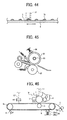
- a typical example of a conventional fixing device as the heat roller system includes a fixing roller 91 that applies heat tomelt toner on the recording member and a pressure applying roller 92 that pressure contacts the fixing roller 91 to pinch the recording member as shown in FIG. 45 .
- the fixing roller 91 is a cylindrical and includes a heat generation member 93 as a heat-applying source around a central axis thereof.
- the heat generation member 93 includes a halogen lamp or the like and generates heat upon receiving a prescribed power supply. Since the heat generation member 93 is positioned at the central axis of the fixing roller 91, an outer wall of the fixing roller is heated up to 150 to 200 degree centigrade appropriate for fixing.
- the fixing roller 91 and the pressure applying roller 92 rotate reversely and pinch a recording member having toner attracted thereonto in this situation while contacting each other. Then, the toner on the recording member is fused by the heat and fixed thereon at the nip between the fixing roller 91 and the pressure-applying roller 92.
- a recording member carrying a toner image passes through a fixing roller while receiving heat and a pressure applying roller are arranged, so that the toner image can be fixed onto the recording member as shown in the Japanese Patent Application Laid Open No. 2007-128109 .
- a fixing device simply including a heat applying system of the fixing roller consumes significant amount of energy. Because, fixing energy largely relies on heat as a problem. In addition, it especially takes a relatively long time period to increase temperature of the fixing roller suitable for fixing after a power is supplied to an image forming apparatus. Further, the above-mentioned fixing system has some disadvantages when employed in an image forming apparatus capable of feeding sheets at a high line speed.
- the Japanese Patent Application Laid Open No. 58-178385 proposes an induction heat applying fixing apparatus that arranges a core (an open magnetic path iron core) winding a coil around a common axis in a fixing member made of metal.
- the apparatus flows a high frequency current through the coil and creates a high frequency magnetic field that causes induction heat. Since the fixing member made of metal conductor itself generates heat, it rapidly increases temperature in comparison with a system using a heat generation member, such as a halogen lamp, etc., and has heat efficiency as an advantage. Further, the Japanese Patent Application Laid Open No.
- Hei9-80939 proposes a heat applying device included in an image forming apparatus that includes an exciting coil secured to a body, a film having a conductive layer traveling a magnetic field created by the exciting coil, and a heat applying device that pressure contacts an heat application objective against the film, while applying the heat thereto using a eddy current created on the conductive layer of the film to form an image using magnetic toner.
- the heat-applying device is characterized in that a magnetic field is created downstream in the rotational direction of the film within the sect ion in which the film and the heat-receiving member contact each other to heat the heat-receiving member.
- Japanese Patent Application Laid Open No. 2000-188177 proposes an electromagnetic induction heat applying apparatus having an electromagnetic induction heat applying layer that applies heat to a heat applying objective, in which a magnetic core made of magnetic material are arranged opposing the electromagnetic heat induction layer, and, a movable core capable of changing intensity of alternating magnetic field penetrating the electromagnetic heat induction layer are wound around the magnetic core.
- the present invention has been made in view of the above noted and another problems and one object of the present invention is to provide a new and noble image forming apparatus.
- a new and noble image forming apparatus includes a first fixing device that applies heat to a non fixed toner image and a second fixing device that applies pressure and fixes the non-fixed toner image onto a recording member.
- the fixing device includes a pair of rollers having at least one heat source and applies the heat to the recording member during pinching and conveying the recording member.
- the heat source generates radiation heat.
- the heat source generates electromagnetic induction heat.
- the heat source emits a laser light to the non-fixed toner image.
- the second fixing device includes a pair of opposing rollers configured to pinch and pressurize the recording member.
- the heat source includes an electromagnetic induction heating device arranged inside a loop of a conveyance belt opposing the conveyance belt.
- the electromagnetic induction heating device is divided into plural sections in a direction perpendicular to the traveling direction of the conveyance belt.
- the heat source includes a laser light generation device that generates a laser light and a laser light-scanning device that defuses and scans the laser light to the toner image electrostatically attracted to the conveyance belt.
- a beam spot diameter-changing device is provided to change a beam spot diameter of the laser beam.
- the laser light scanning device is used as an exposure device for forming a latent image on an image bearer.
- a process cartridge is provided to install an image bearer and a light path for guiding the laser light to the image bearer.
- the process cartridge includes a beam spot diameter changing device arranged on the light path and changes a diameter of the beam of the laser light.
- a versatile image forming apparatus includes fixing devices arranged in parallel employing heat and pressure applying systems capable of using toner and a recording member for a heat fixing system while suppressing energy consumption.
- the image forming apparatus can increase a brilliance performance of a toner surface and obtain an almost photographic quality saving the energy. Further, the image forming apparatus is capable of selectively using a pressure applying system in accordance with a necessity of brilliance for a sheet either manually or automatically.
- FIG. 1 four image formation sections 10a to 10d are arranged along a conveyance belt 6 (hereinafter referred to as a transfer belt 6) that carries and conveys a sheet like recording member S, such as a plain paper, a thick sheet, a post card, an OHP sheet, etc., to a transfer section.
- a conveyance belt 6 hereinafter referred to as a transfer belt 6
- a sheet like recording member S such as a plain paper, a thick sheet, a post card, an OHP sheet, etc.
- Each of the image formation sections 10a to 10d uses a different color toner for development, but includes the same configuration.
- a drum shaped photoconductive member 1 serving as an image carrier, a charge device 2 that uniformly charges the surface of the photoconductive member 1, and an exposure device 3 that emits a laser light and forms a latent image on the photoconductive member 1 with the charge are included.
- a developing device 4 that visualizes the latent image with the toner on the photoconductive member
- a transfer device 5 e.g. a tar roller 5 or the like
- a cleaning device 7 that clears the toner remaining on the photoconductive member after the transfer process.
- the exposure device includes plural light source devices 3a having a semiconductor laser, a coupling lens, an aperture or the like, a deflection device such as a polygon mirror 3b that deflects and scans the laser light transmitted from the light source, a scanning use lens 3c, and a light path folding back use mirror 3d and the like.
- the laser lights transmitted from the plural light source devices 3a are commonly deflected by the deflector 3b and execute the exposure on the photoconductive member 1 of the respective image formation sections 10a to 10d via the scanning use lens 3a and the mirror 3d, thereby latent images are formed corresponding to the colors in the image formation sections, respectively.
- the respective image formation sections 10a to 10d use color toner of yellow (Y), magenta (M), cyan (C), and black (B) develop the latent images, respective, in this order in a recording member conveyance direction.
- the thus developed color images are then superimposed sequentially on the recording member S conveyed by the transfer belt 6, thereby a multi or full-color image is formed.
- the image forming apparatus also includes a sheet feeding and conveyance device (e.g. a sheet feeding roller 8a and a register roller or the like) that conveys the recording members S stacked on the sheet feeding section (a recording member stacking section) 8 one by one in synchronism with a toner image developed by the developing devices in the image formation sections 10a to 10d toward the transfer belt 6, and fixing devices 11 and 12 that fix the toner image transferred onto the recording member S by the transfer device 5 such as a transfer roller while being conveyed by the transfer belt 6.
- a sheet feeding and conveyance device e.g. a sheet feeding roller 8a and a register roller or the like
- fixing devices 11 and 12 that fix the toner image transferred onto the recording member S by the transfer device 5 such as a transfer roller while being conveyed by the transfer belt 6.
- heat and pressure applying type-fixing devices 11 and 12 are arranged in parallel along the recording member conveyance path 9 in this order. Further, on the downstream side of the recording member conveyance path 9 of the pressure applying device 12, an ejection roller 13 and an ejection tray 14 (or a post processing device) or the like are arranged.
- the latent images formed on the respective image formation sections 10a to 10d by the exposure device 3 are developed by the respective color toner, and thereby color toner images are formed.
- the recording member S launched by the sheet feeding roller 8a from the sheet feeding section 8 is carried by the transfer belt 6 and is conveyed in synchronism with the above-mentioned development, and is further subjected to transfer process to receive transfer of the toner image.
- the recording member S with a non fixed toner passes through the heat applying device 11 and the pressure applying device 12 consecutively and is ejected onto the sheet ejection tray 14 or the like by the sheet ejection roller 13.
- toner component to be fixed by the fixing device mainly includes thermoplastic resin and thus is softened when passing through the heat applying device 11 receiving heat. Unevenness of the surface of the toner is smoothed by the surface condition of an upper roller 12a receiving pressure when passing through the pressure-applying device 12. Specifically, by finishing the roller 12a of the pressure-applying device 12 to have the minimum surface roughness, the toner surface can be more smoothed. Further, toner and a recording member S are more precisely fixed mutually by heat and pressure when passing through the heat and pressure applying devices 11 and 12 sequentially.
- the image forming apparatus employs a direct transfer system in which toner images carried on the respective photoconductive members 1 of the image formation sections 10a to 10d are transferred onto the recording members S.
- the image forming apparatus can employ an intermediate transfer system in which toner images carried on the respective photoconductive members 1 of the image formation sections 10a to 10d are transferred being superimposed on an intermediate transfer member 25 (e.g. an intermediate transfer belt) by a primary transfer device 26 (e.g. a primary transfer roller).
- the superimposed image on the intermediate transfer member 25 is then transferred onto the recording members S by a secondary transfer device 27.
- the intermediate transfer member 25 can be either a roller state or a drum state other than the belt state.
- Plural intermediate transfer members can be arranged between the photoconductive member 1 and the recording member S.
- the heat applying device 11 serving as a fixing device includes a pair of rollers.
- One of the pair of rollers has a heating source, such as an electric heater, a halogen heater, a carbon heater, etc.
- a heating source such as an electric heater, a halogen heater, a carbon heater, etc.
- the heat-applying device 11 can employ an oven system that applies radiation heat as shown in FIG. 2 .
- the toner does not contact the heat source, and heats the toner on the recording member S by means of the radiation heat from the heat source 23 as mentioned in the second embodiment indetail.
- the recording member S is conveyed by the conveyance belt 24 omitting a separation step of separating from the roller or the like.
- the second device 12 is arrangeddownstreamof the first fixing device 11 in the recording medium conveyance direction, a highly brilliant image can be obtained by passing through the smoothing step. Since the heat-applying device 11 serves as the first fixing device for softening the toner while applying heat thereto more than a melting point of the toner, the toner is effectively softened. Further, since the pressure applying device 12 serves as the second fixing device for smoothing the toner by transferring the surface condition of the roller to the toner, the toner is more effectively smoothed while suppressing consumption of energy. Because, the heat-applying device 12 does not consume power to receive heat.
- the heat applying device 11 since the heat applying device 11 include rollers opposing to each other and the roller contacts the recording member S and the toner while conducting and moving heat, the recording member S and the toner are effectively heated. Further, according to the other embodiment, since the recording member S does not contact the roller or the like and receives heat radiation in the heat applying device 12 as shown in FIG. 12 , likelihood of the recording member to wind up the roller or the like and not being separated therefrom thereby causing malfunction can be decreased or prevented.
- the upper roller 12a preferably includes the surface roughness of not more than 0.2micrometer (Ra).
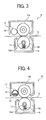
- a heat radiation device is preferably provided contacting the upper roller 12a as shown in FIG. 3 .
- a heat radiation roller 16 is provided contacting the upper roller 12a to radiate heat in air, which is transmitted from the heat-applying device 11 and stored in to the upper roller 12a via the recording member S and conveyed thereto.
- Material of the heat radiation roller 16 preferably includes higher heat conductivity than that of the upper roller 12a.
- the material of the upper roller 12a includes stainless, brass or the like is chosen as that of the heat radiation roller 16 so that heat stored in the upper roller 12a can effectively be removed.
- a heat pipe 17 contacts the upper roller 12a contacting the pressure-applying device 12 as a heat radiation roller.
- a cooling fan 52 is arranged at one end of the heat pipe 17 where an air of waste heat in the image forming apparatus flows. Since this heat pipe system provides high-speed heat conduction and is excellent in responsibility due to its operation liquid 51 encapsulated in a pipe, the heat storage in the upper roller 12a is effectively removed. Specifically, using the heat pipe as the heat radiation device, heat responsibility is excellent and the heat storage can be effective in comparison with heat movement of heat conduction.
- a cleaning blade 18 is preferably provided contacting the upper roller 12a of the pressure applying device 12 serving as a second fixing device so as to remove toner sticking to the upper roller 12a via the recording member S.
- stain sticking to the roller surface can be effectively removed, and a problem, such as a stein, etc., on the image surface caused by the toner sticking to the roller can be prevented.
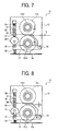
- a mechanism is preferably provided to make contact and separate the upper and lower rollers 12a and 12b.
- a lever 31 is supported by a fulcrum 40 of a casing 15 of the pressure-applying device 12 at its one end and is biased by a compression spring 33 at the other end.
- the lever supports a bearing of 12b1 of the lower roller 12b almost at its center and mounts a roller 32 contacting a cam 34 at the end.
- the cam 34 rotates as a motor, not shown, drives, the lever 31 swings.
- an arm 36 is provided being supported by plural shafts 37 and 38 being biased by a compression spring 39 arranged in the casing of the pressure-applying device 12.
- the arm 36 contacts the cam 34 via a roller 35 arranged at its tip.
- a gap G between the upper and lower rollers 12a and 12b can be changed.
- both rollers 12 and 12b pressure contact each other.
- both rollers 12a and 12b are separated from each other.
- Such a choice of contact and separation can either be designated by a printer driver or the like linking with a type of a recording member or is optionally designated via an operation panel, not shown.
- FIG. 9 Another modification of the heat-applying device 12 is described with reference to FIG. 9 , in which a pair of pressure applying rollers 12a and 12b does not contact a section where a recording member S passes.
- a bearing 12b1 of the lower roller 12b pressure contacts a casing 15 of the pressure applying device 15 being biased by the compression spring 33 to maintain a gap G previously set between the upper and lower rollers constant.
- both rollers 12 and 12b apply pressure.
- a recording member S such as a relatively thinner recording member sheet not calling for brilliance passes
- the sheet passes through the gap between both rollers 12 and 12b without receiving intensive pressure.
- the thinner recording medium S than a prescribed level can pass through the gap.
- the recording member S passes under a prescribed pressure.
- pressure can automaticallybe changed.
- the upper and lower rollers don't contact each other, damage on the roller possibly caused by pinching of alien substance can be prevented.
- a gap adjustment member 21 is provided to adjust a gap G formed between the upper and lower rollers 12a and 12b of FIG. 9 .
- a slotted hole is formed on the gap-adjusting member 21 so as to allow adjustment of a securing position of the casing with a screw 22.
- the gap is preferably adjusted in accordance with a relation between a thickness of the recording member S and the necessity brilliance?.
- the mechanism capable of changing the gap between the opposing rollers in the pressure-applying device 12 since the mechanism capable of changing the gap between the opposing rollers in the pressure-applying device 12, a relation between a thickness of the recording member S and pressure applied by the pressure-applying device can separately be adjusted and optimized.
- thermoplastic layer s preferably formed on the surface of the recording member S.
- a thermoplastic layer can include polyethylene, polyolefin such as polypropylene, and acrylic or the like.
- the material of the plastic layer can include thermoplastic layer as proposed in the Japanese Patent Application Laid Open No. 2006-189605 . According to this manner, due to the recording member S having the thermoplastic layer softened by heat applied from the heat-applying device 11, an almost photographic image quality can be obtained.
- a second embodiment is described with reference to FIG. 13 , in which a versatile image forming apparatus is provided and includes fixing devises that employ heat and pressure applying systems, respectively, arranged in parallel using toner and a recording member as used in a heat fixing system while suppressing energy consumption.
- a radiation heat application system is employed in a heat-applying device.
- a pair of rollers serving as a pressure applying type-fixing device is arranged distant so as not to contact each other so that a problem caused by the contact can be avoided.
- a fundamental configuration and an operation of the image forming apparatus are as same as that of the first embodiment described with reference to FIG. 1 .
- the second embodiment features that a heat radiation system is employed in a heat applying device 11 serving as a fixing device.
- a heat radiation system employing heat applying device includes a heat generation member 23 such as an electric heater, a halogen heater, a carbon heater, etc., as discussed in the Japanese Patent Application Laid Open No. 2003-192467 and applies radiation heat to a recording member S passing through a recording member conveyance path 9 as shown in FIG. 13B .
- a flush lamp can be used as a heat generation source for applying radiation heat.
- a conveyance belt 24 is arranged opposing the heat generation member 23.
- FIG. 14 a modification of the second embodiment of the image forming apparatus is described, in which a fundamental configuration and an operation of the image forming apparatus are as the same as that of the image forming apparatus employing an intermediate transfer system as described with reference to FIG. 12 as described in the first embodiment.
- a radiation heat system employing heat applying device 11 is arranged downstream of a second transfer device 27 of the recording member conveyance path 9 in the intermediate transfer system employing image forming apparatus.
- a pressure-applying device 12 is arranged further downstream of the radiation heat system employing heat-applying device 11.
- the heat applying device 11 and the pressure applying device 12 are arranged in parallel, a sufficient fixing performance can be obtained with fine printing quality even if toner is incompletely fixed onto the recording medium S in the heat applying device 11 as far as the toner is somewhat softened. Due to the parallel arrangement of the heat applying device 11 and the pressure applying device 12, a calorie consumed in the process of fixing toner onto the recording member decreases less than the conventional image forming apparatus which fixes with a heat applying device. Further, due to softening the toner by arranging the heat-applying device 11 upstream of the pressure-applying device 12, the image forming apparatus can use toner and a recording member as used not only in the heat application fixing system but also in the pressure application fixing system. Thus, a specification of consumable supplies can be highly versatile.
- the pressure applying device 12 includes a pair of rollers made of metal having a smooth surface, and is biased by compression springs 33 at its both ends.
- a sheet passage section for a recording member is out of touch.
- a lever 31 is arranged such that a fulcrum 40 of a casing 15 of the pressure-applying device 12 thereof supports one end, and the other end is supported by a compression spring 33.
- the lever 31 supports a bearing 12b1 of the lower roller 12b at its center.
- a protrusion is arranged at the end of the lever 31 and contacts the casing that supports the bearing 12a1 of the upper roller 12a so that a gap G between a pair of pressure applying roller can be maintained at a prescribed level.
- the gap G is narrower than the thickness of the recording member S, and accordingly, toner softened by the heat-applying device 11 is fixed under a pressurizing force.
- pair of non contact pressure applying rollers 12a and 12b by employing pair of non contact pressure applying rollers 12a and 12b, a damage on the surface of the pressure applying roller possibly caused by pinching of an alien substance or the like can be avoided and the life of the roller can be prolonged. Further, when the pair of pressure applying rollers contact (each other) while high pressure is applied, a recording member having a low rigidity tends to have wrinkle, and is sometimes torn along the wrinkle. However, since a pressure applied to the recording member is relatively small, the damage can be not serious. Thus, occurrence of the wrinkle and tearing of the recording member caused by the wrinkle can be suppressed.
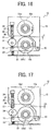
- FIG. 16 the passage section for the recording member in the pressure applying device 12 that includes the contact and separation mechanism as shown in FIGS. 7 and 8 is described. Specifically, in FIG. 7 , the upper and lower rollers 12a and 12b of the pressure-applying device 2 are contacted and separated. Whereas in FIG. 16 , both of the upper and lower rollers are always not contacted by the adj ustment of an attaching position of the arm 36. Specifically, as the cam 34 rotates, these rollers are separated from an adjacent condition of FIG. 16 to a separation condition of FIG. 17 . In the pressure applying device 12 of FIGS. 16 and 17 , when the cam 34 rotates to a position as shown in FIG.
- the gap G between the pair of pressure applying rollers 12a and 12b can be narrowed.
- the gap G is broadened.
- the gap G can be gradually changed by rotating and stopping the cam 34 at a prescribed angle.
- FIGS. 18 and 19 an exemplary configuration and an operation of still another modification of the pressure-applying device 12 are described with reference to FIGS. 18 and 19 .
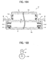
- the bearing 12b1 of the lower roller 12b of the pressure applying device 12 is depressed by the compression spring 33 and contact the casing 15 of the pressure applying device, so that a prescribed gap G between the upper and lower rollers 12a and 12b can be maintained at a prescribed level.
- a cam 41 is controlled by a motor, not shown, to rotate to either contact or separate from the bearing 12b1 of the lower roller 12b.
- the bearing 12b1 is pressurized to the casing 15 of the pressure applying device 12 by the spring 33, so that the gap G is narrowed. Further, when the cam 41 rotates to a position and contact the bearing 12b1 as shown in FIG. 19B , the bearing 12b1 is displaced downward by the cam 41 against the bias of the compression spring 33 and held, so that the position of the bearing and the gap G is broadened.
- the gap G can be changed by another mechanism other than the combination of the above-mentioned motor and the cam.
- plural mechanisms 8 are preferably arranged to stack and launch plural recording members S to a recording member conveyance path, while providing a control device, not shown, for controlling the gap G of the pair of pressure applying rollers of the pressure applying device 12 linking with a sheet feeding device 8 selected by an operator.
- the gap G of the pair of pressure applying rollers can be automatically designated in accordance with the type and the thickness.
- the type and the thickness of the recording member S stacked on the sheet-feeding device 8 can correspond to the gap G beforehand.
- the gap G can be automatically changed to be optimum in accordance with each of the recording members.
- an electrophotgraphic recording apparatus transfers a toner image sticking to an image formation carrier onto a sheet using a transfer device, and fixes and performs printing thereof using a heat-fixing device arranged on a sheet conveyance path. Also arranged are a roller to pinch the sheet having a prescribed resistance in the upstream of the fixing device, a current supplying device for supplying a constant current to the roller, and a detecting device for detecting a load voltage created when the constant current is supplied.
- control device for controlling temperature of the fixing device based on the load voltage detected by the detecting device. Specifically, in accordance with a relation between the constant current supplied and the load voltage, either a method of detecting the thickness of the recording member S or the other conventional detection method can selectively be used.
- a constant pressurizing force can be applied to the recording member S regardless of the thickness thereof.
- a problem such as wrinkle of a recording member due to application of an excessive pressurizing force, fixing malfunction due to an insufficient pressurizing force of a fixing performance, etc., can be avoided.
- the image forming apparatus capable of forming an image of multi colors as shown in FIGS. 13 and 14 , it is preferably determined based on information transmitted from a control device included in the exposure device 3, not shown, if an image to be formed on the recording member S is either a monochrome or a multi color, so that a gap G between the pair of pressure applying rollers of the pressure-applying device 12 is preferably changed to be appropriated for the respective images. Since the multi color image necessitates a more attraction amount of toner than the monochrome image and forms a thicker toner layer, the gap G is set larger when the monochrome image is formed, and smaller when the multi color image, respectively, so that a pressurizing force is appropriate for respective image patterns.
- control device that determines if the image is either monochrome or multi color and automatically changing the gap to the optimized level in accordance with a difference of the image on the recording member S, a problem of insufficient fixation due to an insufficient pressurizing force and that caused by an excessive pressurizing force can be suppressed.
- an area rate of an image transferred onto the recording member S is preferably determined based on information from the control device 3, and the gap G between the pair of pressure applying rollers of the pressure-applying device 12 can be changed to be appropriate for the images. Since the amount of toner attracting to recording member S and a thickness of the toner layer are in proportion to the image area rate, the gap G is set larger when the image area rate is not more than 50%, and smaller when not less than 50%, respectively, so that a pressurizing force is appropriated for respective image area rates. A boarder of the image area rate determining the gap can be appropriately determined in accordance with specifications of the heat applying device 11, the pressure applying device 12, and toner or the like.
- the image area rate (i.e., a printing rate) of the recording member S exceeds a prescribed level and automatically changing the gap to the optimized level in accordance with the image area rate, a problem of insufficient fixation due to an insufficient pressurizing force and that caused by an excessive pressurizing force can be suppressed.
- fixing devices employing a heat and pressure applying systems are arranged inparallel toprovide a versatile configuration that uses toner and plain paper as generally used in a heat fixing system while decreasing a start up time period and saving energy.
- both of a transfer and heat applying steps are provided along the recording member conveyance belt so as to soften the toner to be carried on the conveyance belt before a recording member is separated there from, so that an image forming apparatus can suppress toner scatter and image disturbance at the time of the toner separation.
- the pair of pressure applying rollers employing the pressure applying system of the fixing device are separated to suppress a problem of a cut or the like caused by contact of those.
- FIG. 20 the fundamental configuration and an operation of the image forming apparatus are substantially the same as the image forming apparatus of the first embodiment.
- a heat-applying device 11 that applies radiation heat as that in the second embodiment is utilized as a first fixing device.
- a transfer device 5 and a heat applying device 12 applying heat are arranged along the circumferential surface of the same recording member conveyance belt 6 (a transfer belt in FIG. 20 ).
- transfer and conveyance use conveyance belt (transfer belt) 6 is arranged above the conveyance pass 9 for the recording member S to transfer a toner image on the photoconductive members 1 of respective image formation sections 10a to 10d onto the recording member S fed from a sheet feeding section (a recording member stacking section) 8.
- the heat-applying device 11 is arranged in the vicinity of the outer circumference surface of the transfer belt 6 downstream of the image formation section 10d so as to soften the non-fixed toner on the recording member S with the radiation heat.
- the recording member S is separated from the transfer belt 6 and enters the pressure-applying device 12.
- the recording member S is then pressurized so that the toner image can be fixed onto the recording member S.
- the transfer belt 6 can be made of high heat resistant material such as PAI (polyimide), etc.
- a heat generation member (i.e., a heat generation source) 23 provided in the heat applying device 11 can employ a light emitting device such as halogen heater, etc. Otherwise, a flash-fixing device is used.
- a toner attraction plate 28 is arranged at the entrance to the heat generation member 23 to electrostatically attract toner floating from the recording member S after a transfer process in order to avoid contamination of the heat-applying device 11. Further, an air flow A is created in a gap between the toner attraction plate 28 and the heat applying device 11 in a sheet ejection direction from the recording member conveyance path 9 by a fan, not shown, so that the toner floating around the heat generation member 23 is removed from the recording member conveyance path 9.
- the recording member S tightly contacts and is conveyed by the transfer belt 6 and the tip thereof is accidentally separated therefrom by some reasons, the tip is guided by a grid state guide 29b arranged at an opening section of a casing 29a of the heat generation member 23 with a reflection plate as shown in FIGS. 21 and 22 .
- the guide 29b can employ metal wire and that with hair implantation or the like.
- a cleaning blade 20 is preferably arranged in an image forming apparatus of FIG. 20 to contact the circumference of the transfer belt 6 to remove toner transferred due to sheet jam and that directly transferred thereonto at times of color deviation and density correction operations.
- a lubricant coating device 30 for coating the transfer belt with lubricant, such as zinc stearate, etc., is preferably arranged downstream of the cleaning blade 20.
- FIG. 23 a modification of the image forming apparatus of the third embodiment is described with reference to FIG. 23 .
- the fundamental configuration and an operation of the image forming apparatus are substantially the same as the image forming apparatus of the first embodiment that employs the intermediate transfer system as shown in FIG. 12 .
- a heat applying device 11 employing a heat radiation system is arranged downstream of a secondary transfer device 27 on the recording member conveyance path 9, and a pressure applying device 12 is arranged further downstream thereof.
- the secondary transfer device 27 for the toner and heat applying device 11 are arranged to soften the toner carried on the conveyance belt 24 before the recording member S is separated therefrom, so that scatter of the toner and disturbance of an image can be avoided.
- the heat applying device 11 and the pressure applying device 12 are arranged in parallel, a calorie is less consumed in a fixing process for fixing toner onto a recording member than in a conventional image forming apparatus only using a heat applying device. Further, since the transfer and heat applying processes are executed on the circumference of the common conveyance belt (either the transfer belt 6 or the conveyance belt 24), toner is carried maintaining softness even after the heat applying process. Thus, the toner on the recording member does not electrostatically scatter and disturb an image when the recording member is separated from the conveyance belt.
- a cooling device is preferably arranged contacting the outer circumference surface of the conveyance belt (either the transfer belt 6 of FIG. 20 or the conveyance belt 24 of FIG. 23 ).
- a cooling device By contacting the cooling device with circumference surface of the conveyance belt, heat traveling from the heat-applying device 11 to the conveyance belt can be radiated.
- heat traveling from the heat-applying device 11 to the conveyance belt can be radiated.
- an outline of the image forming apparatus including the cooling device is described with reference to FIGS. 24 and 25 .
- an opposing roller 44 is arranged on the rear side of the transfer belt 6 downstream of the heat applying devices 11.
- a radiation roller 43 is provided as the cooling device to contact a section of the outer circumference surface of the belt opposing the opposing roller 44, so that heat of the transfer belt 6 is moved to the heat radiation roller 43 and is radiated into air.
- the heat radiation roller 43 is made of metal or material preferably having high heat conductivity. Since the cooling device of FIGS. 24 and 25 is made of the metal, a cooling system can save cost with a simple construction.
- the cooling device is not limited to such a roller type and can be a planar state member that contacts and scrapes the transfer belt 6.
- FIGS. 26 and 27 a modification of the image forming apparatus including the cooling device is described with reference to FIGS. 26 and 27 .
- an opposing roller 48 and a heat pipe 45 are provided downstream of the heat-applying device 11 on the transfer belt 6.
- the heat pipe 45 contacts the outer circumference surface of the transfer belt 6.
- a heat radiation fin 47 is provided at one end of the heat pipe 45 to radiate heat traveling from the transfer belt 6 to the heat pipe 45 via an operation liquid 46 into air.
- the heat pipe 45 as a cooling device, heat conveyance can be efficient and the transfer belt can be efficiently cooled down.
- thermo module 49 is arranged downstream of the heat-applying device 11 on the conveyance belt 6. Specifically, the thermo module 49 contacts the outer circumference surface of the transfer belt 6, so that heat moved from the transfer belt 6 to the thermo module 49 is radiated into air via a heat radiation section, not shown.
- An exemplary thermo module 49 is described in the Japanese Patent Application Laid Open No. 2001-267641 such that plural P and N type semiconductor elements 61 and 62 are arranged one after another as shown in FIGS. 30 and 31 .
- thermo module 49 is not limited to the above and can include various modifications.
- plural opposing rollers 44, 48, and 50 are preferably arranged as shown in FIGS. 24 to 28 .
- a contact and separation mechanism and a gap adjustment mechanism or the like are provided for the pair of pressure applying rollers 12a and 12b of the pressure applying device 12 in the image forming apparatus in this embodiment.
- the gap adjustment mechanism including the compression spring 33, the cam 41, and the motor or the like are arranged as a mechanism more precisely adjusting the gap between the pair of pressure applying rollers as described in the second embodiment.
- the gap G can be maintained at a prescribed level. For example, when the gap G is smaller than the thickness of the recording member S, toner softened by the heat-applying device 11 is fixed receiving the pressurizing force.
- the cam 41 is rotated by a driving force of a motor, not shown, either to a position of FIG. 18 so that the gap G decreases or that of FIG. 19 so that the gap G increases.
- a driving force of a motor not shown
- the gap G By always setting the gap G to be slightly smaller than the thickness of the recording member S, the same pressurizing force is applied thereto regardless of the thickness of the recording member S.
- the cam 41 can be stopped when rotated with a prescribed angle, so that the gap G is changed stepwise.
- the other method can be employed to change the gap G.
- the gap of the pair of pressure applying rollers of the pressure-applying device 12 can be changed in accordance with the thickness of the recording member S as in the second embodiment, a constant pressurizing force can be applied to the recording member.
- a problem of insufficient fixation due to an insufficient pressurizing force and that of wrinkle or the like of the recording member caused by an excessive pressurizing force can be resolved.
- the gap of the pair of pressure applying rollers is preferably changed to be a prescribed level in accordance with the selection of the sheet-feeding device 8 that feeds the recording member S.
- the optimum gap can be automatically obtained in accordance with the respective recording members.
- a detecting device for detecting a thickness of the recording member S can be provided, and the gap G can automatically be changed to the optimum value in accordance with the thickness.
- the gap is automatically changed to the optimized level in accordance with a difference of a print on the recording member S.
- heat and pressure applying devices are arranged in parallel as a fixing device as in the third embodiment.
- the heat-applying device employs an electromagnetic induction heating system so as to only apply heat to toner other than a member of the heat applying roller or a recording member in order to save energy. Further, by omitting members such as a heat applying roller, etc., intervening a magnetic field creating source included in the electromagnetic induction heating system and toner, preheat therefor can be omitted so that a start up time period can further be decreased.
- a problem such as sheet curl after its ejection, transfer malfunction in second side printing of a duplex printing operation due to decrease of moisture content during the first surface fixation can be prevented.
- a transfer step and a fixation heat-applying step by means of electromagnetic induction on the same circumference surface of the conveyance belt, an attraction force of toner to the recording member is created, Image deterioration such as toner scatter caused when the toner is separated from the conveyance belt can be prevented.
- by dividing the electromagnetic induction-heating device and controlling current to flow through respective coils in accordance with a width of the recording member needless power consumption can be suppressed saving energy.
- a section of pair of pressure applying rollers of the pressure applying device where a recording member passes through is not contacted each other and a gap is formed as in the first to third embodiments, a cut on the surface of the pair of pressure applying rollers can be suppressed, thereby life of the parts can be prolonged.
- toner is provisionally heated on the conveyance belt right after transfer of tone onto a recording member in this embodiment, a region for heating the toner on the recording member can be broader in comparison with a nip section between rollers of a conventional heat and pressure applying fixing system even if it is applied to an image forming apparatus operating at high speed at a linear speed such as more than 300mm/sec.
- temperature of the toner on the recording member is precisely increased to a glass transition level to be softened and melted, while conveying the recording member to a pair of pressure applying rollers arranged downstream of the recording member conveyance direction. Thus, a fixation malfunction can be avoided.
- an exemplary image forming apparatus includes a monochrome machine having a single image formation section 10 along a conveyance belt (a transfer belt) that carries and conveys a sheet like recording member S.
- the image formation section 10 includes a drum type photoconductive member 1 as an image bearer, a charge device 2 that uniformly charges the surface of the photoconductive member 1, and an exposure device 3 that forms a latent image on the photoconductive member 1 carrying the charge by emitting a laser light thereto. Also included are a developing device 4 that visualizes the latent image on the photoconductive member 1, a transfer device (e.g.
- a transfer roller 5 that transfers the toner image visualized on the photoconductive member 1 and conveyed by the transfer belt 6, and a cleaning device 7 that clears toner remaining on the photoconductive member after the transfer process.
- a transfer roller 5 that transfers the toner image visualized on the photoconductive member 1 and conveyed by the transfer belt 6, and a cleaning device 7 that clears toner remaining on the photoconductive member after the transfer process.
- a cleaning device 7 that clears toner remaining on the photoconductive member after the transfer process.
- the exposure device includes a light source 3a having a semiconductor laser, a coupling lens, and an aperture and the like. Also included are a deflection device (a polygon mirror or the like) 3b that deflects a laser light transmitted from each of light sources, a scanning use lens 3c, and a light path folding back use mirror 3d.
- the exposure device deflects the laser light from the light sources 3a with the deflector 3d, applies exposure to the photoconductive member 1 in the image formation section 10 via the scanning use lens 3c and the mirror 3d thereby forming a latent image.
- the developing device then develops the latent image on the photoconductive member using toner.
- the image forming apparatus also includes a sheet feeding and conveyance device that separates sheet like recording members S stacked on plural sheet feeding sections (i.e., a recording member stacking section) 8 one by one to the transfer belt 6 in synchronism with a toner image developed by the developing device 4 in the image formation section 10, and Plural fixing devices 71 and 12 that fix the toner image transferred onto the recording member S by the transfer device 5 such as a transfer roller when conveyed by the transfer belt 6.
- a sheet feeding and conveyance device that separates sheet like recording members S stacked on plural sheet feeding sections (i.e., a recording member stacking section) 8 one by one to the transfer belt 6 in synchronism with a toner image developed by the developing device 4 in the image formation section 10, and Plural fixing devices 71 and 12 that fix the toner image transferred onto the recording member S by the transfer device 5 such as a transfer roller when conveyed by the transfer belt 6.
- a first fixing device 71 employing an electromagnetic heating system, and a second fixing device 12 employing a pressurizing system are arranged in parallel in this order on the recording member conveyance path 9. Further, an ejection roller 13 and an ejection tray 14 (or a post-processing device) are arranged downstream of the pressure-applying device 12.
- the latent image formed on the photoconductive member 1 by the exposure device 3 is visualized into a toner image by the developing device 4.
- a recording member S stacked on the sheet feeding section 8 is separated one by one by the sheet feeding roller 8a and is launched into the transfer belt 6 on the conveyance path 9.
- the photoconductive member 1 pressure contacts the transfer belt 6 while being pressure contacted by the transfer device 5 to transfer the toner image onto the recording member S.
- Toner used for developing in this embodiment includes magnetic toner havingmagnetic substance 75a in resin 75b.
- Toner used for developing in this embodiment includes magnetic toner havingmagnetic substance 75a in resin 75b.
- Joule heat caused by a resistance of the magnetic substance 75a and the eddy current travels to the resin 75b and softens to toner 75, so that an attraction force of the toner 75 to the recording member S occurs.
- the electromagnetic induction-heating device 71 softens the toner at temperature of around a glass transition point.
- the recording members S is separated from the transfer belt 6 and is subjected to a pressurizing force of the pressure-applying device 12 maintaining a soft condition, so that the toner 75 is sufficiently firmly fixed onto the recording member S.
- the glass transition point (a softening point) is about 75 degree centigrade.
- toner mainly including this resin is insufficiently soften at the temperature of 70 degree centigrade and intensely scraped after ejection, the toner is peeled off from a sheet.
- a sufficient fixing intensity can be obtained by means of a combination with the fixing device of the pressurizing system.
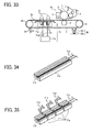
- a cleaning blade 20 and a lubricant coating device 30 are arranged on the transfer belt 6 as shown in FIGS. 32 and 33 .
- a solid lubricant 30a such as zinc stearate preferably contacts a belt surface cleaned by the cleaning blade 20 being biased by a spring 30b.
- the electromagnetic induction heating device 71 mainly includes a metal core 71a having a cross section of a letter E shape providing an opening toward the transfer belt 6, an exciting coil 71b wound around a central core section of the metal core 71a, and an exciting coil 71c that supplies an alternating current to the exciting coil 71b.
- a shield wall is provided at the periphery of the metal core 71a so as to block a (variable) magnetic flux from leaking off the opening.
- the exciting coil 71b when the ac is supplied to the exciting coil 71b, the magnetic field H repeatedly appears and disappears at the periphery as shown by an arrow.
- the exciting coil is arranged inside the transfer belt 6 at a position where the magnetic field H traverses the recording member S.
- the eddy current A occurs in the magnetic substance 75a so as to disturb a change of the magnetic field H when the variable magnetic field traverses the magnetic substance 75 in the toner.
- the Joule heat occurs and travels to soften the resin 75b.
- the toner 75 is firmly attracted to the recording member S.
- the recording member S After provisionally fixing the toner onto the recording member S with the electromagnetic induction heating device 71, the recording member S is converted to the pressure applying device 12 and is pinched and subjected to a pressurizing force between the upper and lower rollers 12a and 12b. As a result, the toner is sufficiently intensely fixed onto the recording member S when passing through the pressure-applying device 12.
- the transfer belt 6 is a two-layer type that includes a sheet like substrate layer having high heat resistivity and a surface-releasing layer overlying the substrate layer.
- the substrate layer is not limited to, but is preferably made of a semiconductor material having the thickness of from 10 to 100micrometer, preferably obtained by dispersing conductive material, such as carbon black, etc., to resin having a high heat resistivity, such as polyester, polyethylene terephthalate, polyether sulfone, polyether ketone, poly-sulfone, polyimide, polyimideamido, polyamide, etc.
- the purpose of dispersing the conductive material to the substrate layer is to apply an electric field and obtain a fine electrostatic transfer performance of transferring a toner image in the transfer process.
- the surface releasing layer preferably includes a coat layer having a high releasability having a thickness of from 0.1 top 30micrometer, such as tetrafluoro-ethylene-perfluoro-alkyl-vinylether-copolymers, polytetrafluoro-ethylene-silicon-copolymers, etc.
- a frequency of the alternating current applied to the exciting coil 71b preferably ranges from 10 to 500kHz. When more than 10kHz is used, an absorption efficiency to the magnetic substance 75a is improved. Thus, an exciting circuit 71c can be built with a cost reduced element up to 500kHz. Further, since an audible range is exceeded when 20kHz is used, noise possibly created at the time of power supply disappears. When less than 200kHz is used, loss in the exciting circuit 71c is small while noises for the periphery can be reduced.
- the metal core 71a and the exciting coil 71b are divided into plural pieces in a direction perpendicular to a traveling direction of the transfer belt 6 including respective exciting circuits 71c. Then, the electromagnetic induction-heating device 71 (the exciting coil 71b) is supplied with power where the recordingmember S passes, while not supplied to the other sections in accordance with a width of the recording member S conveyed. A number of division times and a length of the electromagnetic induction-heating device 71 are appropriately determined in accordance with the width of the recording member S.
- a dial is provided in the sheet feeding section 8 so that a size of the recording member S is manually designated.
- a detector such as a reflection type photo sensor, etc., not shown, is arranged on the recording member conveyance path 9 to automatically detect the width.
- plural electromagnetic induction heating devices 71 e.g. magnetic cores 71a winding an exciting coil 71b
- the electromagnetic induction-heating device 71 supplied with power can be switched to another in accordance with a sheet feeding speed. Whereas when the sheet feeding speed is more than the prescribed level, all of the electromagnetic induction heating devices 71 are supplied with power and precisely increase temperature of the toner on the recording member S up to a glass transition point so that the toner is softened and molten.
- the electromagnetic induction heating devices 71 supplied with power in accordance with the line speed can be precisely softened and molten to a prescribed target level in comparison with the conventional fixing system, so that waste of power can be suppressed.
- the induction heating system of this embodiment since the magnetic member 75a included in the toner 75 generates heat, only a calorie capable of softening and melting toner on the recording member S is needed, thereby further saving the power.
- the toner can also be provisionally heated and softened on an intermediate transfer member, but is more preferably done by means of a direct transfer process. Because, when the toner is provisionally heated and softened on an intermediate transfer member, the toner firmly sticks to the intermediate transfer member and is possibly hardly removed from the intermediate transfer member at the time of sheet jamming or the like. Whereas, such a problem can be prevented by the direct transfer process.
- the electromagnetic induction heating device 71 of this embodiment is applied to the intermediate transfer system, the electromagnetic induction heating device 71 and the pressure applying device 12 are preferably arranged downstream of the second transfer device 27 on the recording member conveyance path 9 as in the first to third embodiments.
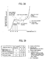
- the heat applying device 71 and the pressure applying device 12 are arranged in parallel, heat energy can be more saved than an image forming apparatus employing only a heat applying device. Further, since the heat applying device 71 employs the electromagnetic heat induction system and accordingly only heats the toner 75 excluding the recording member S, heat for the recording member can be omitted so that energy can be saved. Further, a start up time can be decreased. An exemplary relation between a start up time and power consumption in various conventional fixing systems and that in this embodiment are described in FIG. 37 .
- the recording member S Since the recording member S is not heated in the image forming apparatus of this embodiment, a problem, such as a sheet curl caused by heat traveling to the recording member (paper), a transfer malfunction caused by decrease of water content in the paper at the time of first surface printing in a duplex printing mode, etc., can be prevented. Further, since the both of the transfer and heat applying processes are executed on the common conveyance belt (the transfer belt 6), image deterioration, such as toner scattering, etc., likely occurring when the recording member S is separated from the conveyance belt can be suppressed.
- the metal core (magnetic core) 71a of the electromagnetic induction heating device 71 is divided into more than two pieces in the direction perpendicular to the belt conveyance direction in the above-mentioned image forming apparatus, and the current is selectively flown in accordance with a width of the recording member conveyed while suppressing power consumption at the non sheet feeding section, the energy can further be saved. Further, since each of the metal cores can be shortened, a shape and a size can more precisely be molded.
- a separation and contact mechanism and a gap adjusting mechanism are provided to the pair of pressure applying rollers 12a and 12b of the pressure-applying device 12.
- a mechanism capable of simply and precisely adjusting the gap between the pair of pressure applying rollers is provided as in the second embodiment described with reference to FIGS. 18 and 19 .
- a similar compression spring 33, a cam 41, and a motor or the like are provided.
- the gap G can be maintained to be a prescribed width in accordance with a rotational position of the cam secured to the shaft 42 of the motor, not shown.
- the gap G of the pair of pressure applying rollers is smaller than the thickness of the recording member S, and thus, the toner softened by the heat-applying device 11 receives a pressurizing force and is fixed onto the recording member S.
- the cam 41 is rotated by a driving force of a motor, not shown, either to a position of FIG. 18 so that the gap G of the pair of pressure applying rollers decreases or that of FIG. 19 so that the gap G thereof increases.
- a driving force of a motor not shown
- the cam 41 can be stopped when rotated with a prescribed angle, so that the gap G is changed stepwise.
- the other method can be employed to change the gap G between the pair of pressure applying rollers.
- the gap of the pair of pressure applying rollers of the pressure-applying device 12 can be changed in accordance with the thickness of the recording members as in the second embodiment, a constant pressurizing force can be applied to the recording member.
- a problem of insufficient fixation due to an insufficient pressurizing force and that of wrinkle of the recording member or the like caused by an excessive pressurizing force can be suppressed.
- the gap of the pair of pressure applying rollers can be changed to be a prescribed level in response to the selection of the sheet-feeding device that feeds the recording member S.
- the optimum gap can be automatically determined in accordance with the respective recording members.
- a detecting device for detecting a thickness of the recording member S can be provided, and the gap G can automatically be changed to the optimum value in accordance with the thickness.
- a control device that determines if a print on a recording member is either monochrome or multi color, and the optimum gap is automatically obtained in accordance with a difference of the print.
- the gap can automatically be changed to the optimized level in accordance with the image area rate.
- a fifth embodiment is described with reference to FIG. 41 , in which a heat applying device and a pressure applying device are arranged in parallel as a fixing device as in the first to fourth embodiments.
- the heat-applying device employs a laser light emission system.
- the transfer and laser light emission steps are provided on the common conveyance belt.
- toner transfer and laser light emission are executed onto the recording member on condition that the recording member tightly contacts and is fed at the same traveling speed as the conveyance belt.
- displacement of the position of the toner image transferred onto the recording member from where the laser is emitted is decreased.
- the laser is not needlessly emitted, and accordingly energy can be saved and a laser light generation device can enjoy long life.
- the toner image is transferred onto the recording member on the conveyance belt, so that a problem such as deterioration of an image caused by scattering of non-fixed toner due to an operation of electrostaticity when the recording member contacts the conveyance belt can be avoided.
- a fixing device of a pressure-applying device employing a pressure applying system is provided so as to obtain a sufficient fixing performance.
- the image forming apparatus includes a monochrome machine having the same configuration as the image forming apparatus of the fourth embodiment described with reference to FIG. 34 .
- only one image formation section (an image formation device) 10 is provided along the conveyance belt that carries and conveys a sheet like recording member S to the transfer section.
- the configuration of the image formation section 10 is as same as that of FIG. 32 .
- a laser light emission device that emits a laser light to toner on the recording member S carried on the conveyance belt is arranged downstream of the transfer device 5 as shown in FIG. 43 as a first fixing device.
- the laser light emission device and the exposure device (a laser light generation device for image formation use) 3 commonly uses a diffusing device (e.g. a polygon mirror) for laser light scanning use and exposure use.
- a diffusing device e.g. a polygon mirror
- a latent image is formed on the photoconductive member 1 using a image formation use laser light L1 emitted from a light souse device (a laser light generation device) included in the exposure device 3, and is visualized by the developing device 4 as a toner image.
- the recording member S stacked on the sheet feeding section (sheet feeding tray) 8 is separated and fed one by one by a sheet feeding roller 8a and is launched onto the transfer belt 6 arranged on the recording member conveyance path 9.
- the photoconductive member 1 receives a pressurizing force from the transfer roller 5 and pressure contacts the transfer belt 6, so that the toner image on the photoconductive member 1 is transferred onto the recording member S.
- a fixing use laser light 12 emitted by the fixing use laser light generation device 81 is diffused by the polygon mirror 3b for scanning and is reflected by a mirror 82, so that the fixing use laser light reaches a fixing point 83 on the fixing belt 6.
- the fixing use laser light 12 softens the toner 75, so that an attraction force is created between the recording member S and the toner 75 as shown in FIG. 44 .
- the fixing use laser light 12 is controlled by a control section 84 and a memory 85 only to be emitted to the toner image existing section avoiding the non-image section. In order to cover a variant of traveling speed of the transfer belt 6 or the like, the fixing use laser light 12 can be emitted to an area slightly larger than the toner existing region.
- a pressure applying device 12 having the same configuration as in the first to fourth embodiments is arranged downstream of the transfer belt 6, so that the recording member S separated from the transfer belt 6 can receive a pressurizing force from the pressure applying device 12.
- the toner softened by the laser light emission can further firmly be fixed thereonto.
- a contact and separation mechanism and a gap adjustment mechanism or the like are provided for the pair of pressure applying rollers 12a and 12b of the pressure applying device 12 in the image forming apparatus of this embodiment.
- the gap adjustment mechanism including the compression spring 33, the cam 41, and the motor or the like as illustrated in FIGS.
- the gap G can be maintained at a prescribed level.
- the gap G is smaller than the thickness of the recording member S, and the toner softened by the heat-applying device 11 is fixed receiving the pressurizing force.
- the cam 41 is rotated by a driving force of a motor, not shown, either to a position of FIG. 18 so that the gap G decreases or that of FIG. 19 so that the gap G increases.
- a driving force of a motor not shown
- the gap G By setting the gap G to be slightly smaller than the thickness of the recording member S, the same pressurizing force is applied thereto regardless of the thickness of the recording member S.
- the cam 41 can be stopped when rotated with a prescribed angle, so that the gap G is changed stepwise.
- the other method can be employed to change the gap G.
- the gap of the pair of pressure applying rollers of the pressure-applying device 12 can be changed in accordance with the thickness of the recording member S as in the second embodiment, a constant pressurizing force can be applied to the recording member.
- a problem of insufficient fixation due to an insufficient pressurizing force and that of wrinkle or the like of the recording member caused by an excessive pressurizing force can be suppressed.
- the gap of the pair of pressure applying rollers is preferably changed to be a prescribed level linking with the selection of the sheet-feeding device 8 feeding the recording member S.
- the optimum gap can be automatically determined in accordance with the respective recording members.
- a detecting device for detecting a thickness of the recording member S can be provided, and the gap G can automatically be changed to the optimum value in accordance with the thickness.
- the optimum gap can be automatically obtained in accordance with color of the print.
- the gap can automatically be changed to the optimized level in accordance with the image area rate.
- the toner transfer and the laser light fixing are executed on the common conveyance belt, displacement of the position of the toner image from where the laser is emitted is small.
- the laser light does not or slightly need to be emitted back and forth of the toner image in comparison with the conventional device, energy can be saved while the laser light generation device can enjoy long life.
- both of the heat applying device 11 (laser light emission devices 81, 82, and 3b or the like) employing the laser light emission system and the pressure applying device 12 are arranged in parallel and a pressure is applied to the toner to generate heat and softened by the laser light, a sufficient fixing performance can be obtained.
- the pressure-applying device employs a pressurizing system, power is not needed for a heater or the like, so that energy can be save. Further, since the pressure-applying device includes the configuration as described in the second embodiment, the same advantage can be obtained.
- a sixth embodiment in which the heat applying device and pressure applying device are arranged in parallel as a fixing device as in the first to fourth embodiments.
- a pressure-applying device employs a laser light emission system.
- the transfer and laser light emission steps are provided on the common conveyance belt.
- toner image transfer and laser light emission are executed onto the recording member on condition that the recording member tightly contacts and is fed at the same traveling speed as the conveyance belt.
- displacement of the position of the toner image transferred onto the recording member from where the laser is emitted is decreased.
- the laser is not needlessly emitted, and accordingly energy can be saved and a laser light generation device can have long life.
- the toner image is transferred onto the recording member on the conveyance belt, so that a problem such as deterioration of an image caused by scattering of non-fixed toner due to an operation of electrostaticity when the recording member contacts the conveyance belt can be avoided.
- a fixing device of a pressure-applying device employing a pressure applying system is provided so as to obtain a sufficient fixing performance.
- a type of toner softened and fixed by the laser light emission is not specified in the fifth embodiment.
- heat generation efficiency decreases when non-magnetic toner excluding metal is employed in comparison with magnetic toner. Then, the magnetic toner is used so that energy of the laser light emitted can efficiently be converted into heat so as to further save energy.
- a spot diameter-changing device is provided to change a spot diameter of a laser light while downsizing the image forming apparatus.
- the fundamental configuration of the image forming apparatus of this embodiment is as the same as that described with reference to FIGS. 41 to 43 .
- a latent image is formed on the photoconductive member 1 by an image formation use laser light L1 emitted from the light source (a laser light emission device) included in the exposure device 3.
- the latent image is visualized to be a toner image by the developing device 4.
- a recording member S stacked on the sheet feeding section 8 is separated one by one by the sheet feeding roller 8a and is launched into the transfer belt 6 on the conveyance path 9.
- the photoconductive member 1 receives a pressurizing force of the transfer roller 5 and pressure contacts the transfer belt 6, so that the toner image thereon is transferred onto the recording member S.
- the fixing use laser light 12 emitted by the fixing use laser light generation device 81 is diffused by the polygon mirror 3b for scanning and is reflected by the mirror, and is further emitted to the fixing point 83 on the transfer belt 6.
- the spotlight 85 of the fixing use laser light 12 is scanned in a direction perpendicular to the recording member conveyance direction, so that the fixing use laser light 12 softens the toner 75, and that an attraction force is created between the recording member S and the toner 75 as shown in FIG. 44 .
- the fixing use laser light 12 is controlled by a control section 84 and a memory 85 only to be emitted to the toner existing section avoiding the non-image section. In order to cover a variant of traveling speed of the transfer belt 6 or the like, the fixing use laser light 12 can be emitted to an area slightly larger than the toner existing region. As far as the toner 75 is magnetic, one or more component toner can be used.
- a pressure-applying device 12 is provided downstream of the transfer belt 6, so that the recording member S separated from the transfer belt 6 can receive a pressurizing force from the pressure-applying device 12.
- the toner softened by the laser light emission can further firmly be fixed thereonto.
- a contact and separation mechanism and a gap adjustment mechanism or the like are provided for the pair of pressure applying rollers 12a and 12b of the pressure applying device 12 in the image forming apparatus of this embodiment.
- the gap adjustment mechanism including the compression spring 33, the cam 41, and the motor or the like as illustrated in FIGS.
- the gap G can be maintained at a prescribed level.
- the gap G is smaller than the thickness of the recording member S, and the toner softened by the heat-applying device 11 is fixed receiving the pressurizing force.
- a laser for wiring use by the exposure device 3 and that for softening and melting the toner on the recording member S are emitted to the single polygon mirror 3b.
- the latter laser has a larger diameter than the former laser. Because, when the laser having the same spot diameter is used in the latter, the heat is readily absorbed by the recording member S at an image area edge of the outside of the image area, so that the toner 75 is hardly uniformly softened and melted up to the image area edge.
- the recording member S can be heated at the outside of the image area in the vicinity of the edge thereof, and accordingly, the heat is not provably absorbed by the recording member S at the image area edge.
- the toner can be uniformly softened and melted.
- the spot diameter is instead preferably expanded before being emitted to the toner 75 on the recording member S.
- the spot diameter can be expanded right before the recording member S.
- a curvature shape of the concave lens 84 as a laser light emission device and a distance to the transfer belt 6 are appropriately determined in accordance with the spot of the emission laser light L2. Further, even not shown, if a moving mechanism that moves the concave lens 84 in a direction of an optical axis and an insertion and releasing mechanism that inserts and releases the concave lens from the light path are provided, a spot diameter of the laser light 12 can be variably adjusted. With this configuration, when a traveling speed of the transfer belt 6 varies due to slip or the like, the spot diameter of the laser light 12 is variably adjusted, so that toner 75 is precisely softened and melted and a fixing malfunction can be prevented.
- the concave lens 84 is preferably arranged in the vicinity of the transfer section (transfer device 5) where toner is transferred onto the recording member S.
- a length of the transfer belt 6 can be short thereby downsizing the configuration.
- the concave lens 84 canbe included in a process cartridge together with a cleaning device 7, such as a cleaning brush, a cleaning blade, etc., that removes toner remaining on the photoconductive member 1 as shown in FIG. 48 , in which the concave lens is arranged in the vicinity of the cleaning device 7.
- the process cartridge 10P includes an image formation section 10, in which a photoconductive member 1, a charge device 2, a developing device 4, a cleaning device 7, and a light are included. Also included are light path for a fixing use laser light 12 and an installation section for installing the concave lens 84 arranged in the vicinity of the cleaning device 7 of the process cartridge 10P.
- a system for softening toner in the vicinity of the transfer section can be realized while enabling easy replacement of the concave lens 84 with a new necessitated due to its damage and deterioration.
- a tandem system color image forming apparatus includes a fixing device that includes a heat-applying device employing a laser light emission system (a laser light emission device) and a pressure-applying device 12.
- a laser light emission system a laser light emission device
- a pressure-applying device 12 a laser light emission system
- plural image formation sections 10a to 10d are arranged from upstream of a recording member convey direction in this order along a conveyance belt (a transfer belt) 6 that caries and conveys a recording member to a transfer position.
- the respective image formation sections are formed as process cartridges to include drum state photoconductive members 1a to 1d, charge devices 2a to 2d, developing devices 4a to 4d, and cleaning devices 7a to 7d.
- a black use process cartridge 10d arranged downstream on the transfer belt 6 includes a light path is arranged in the black use process cartridge at a position downstream of the recording medium conveyance direction for the fixing use laser light 12 to pass (i.e., on the left side of the process cartridge neighboring to the cleaning device 7d).
- the light path serves as an installation section 86 to install a concave lens 84 serving as a diffusion lens 84 for diffusing the laser light.
- a light path guide 103 is provided at a light entrance side opening formed on the light path installation section 86.
- a shield member 101 is provided as shown in FIGS. 50 and 51 to horizontally slide and shield the fixing use laser light 12. Thus, the shield member 101 is openable. Then, as shown in FIG. 51 , when the process cartridge 10d is attached to the image forming apparatus body, the shield member 101 is open by a protrusion arranged on the body side so as to allow the fixing use laser light 12 to pass through the light path installation section 86. When the process cartridge 10d is detached from the body for the purpose of maintenance or the like, the shield member 101 is moved by a spring, not shown, on the light path to close the light path guide 103.
- the light path installation section 86 is closed by the shield member 101 to protect by preventing dust from entering thereto.
- the protrusion 102 engages with and makes the shield member sliding to open the light path.
- the tandem color image forming apparatus employs the heat-applying device of the laser light emission system and the pressure-applying device 12 as a fixing device
- the apparatus can be downsized while providing a system capable of softening toner in the vicinity of the transfer section.
- the lens can be protected and readily replaced with a new when damaged or deteriorated.
- the toner since the toner is magnetic and efficiently generates heat a lot when receiving a laser light, the toner can be efficiently softened in comparison with nonmagnetic toner. Further, toner image transfer and provisional fixing thereof onto the recording member S are executed on the common conveyance belt 6, the toner image only slightly displaces from a light emission position. Thus, laser light emission does not at all or slightly needs to be emitted back and forth of the toner image supposing displacement in comparison with a conventional device, so that energy can be saved and that a laser light emission device can enjoy a long life. Since the laser light emission device and the pressure-applying device are arranged in parallel, sufficient fixing performance can be obtained by heating with the laser light and applying pressure to the toner.
- the pressure-applying device employs a pressurizing system, power is not needed unlike a heating system only employing heating device, so that energy can be saved. Further, the pressure-applying device 12 employs the above-mentioned configuration; the same advantage can be obtained. Obviously, numerous additional modifications and variations of the present invention are possible in light of the above teachings. It is therefore to be understood that within the scope of the appended claims, the present invention may be practiced other wise than as specifically described herein.
Landscapes
- Physics & Mathematics (AREA)
- General Physics & Mathematics (AREA)
- Fixing For Electrophotography (AREA)
- Control Or Security For Electrophotography (AREA)
Applications Claiming Priority (1)
| Application Number | Priority Date | Filing Date | Title |
|---|---|---|---|
| JP2008094993A JP5233369B2 (ja) | 2008-04-01 | 2008-04-01 | 画像形成装置 |
Publications (2)
| Publication Number | Publication Date |
|---|---|
| EP2107430A2 true EP2107430A2 (de) | 2009-10-07 |
| EP2107430A3 EP2107430A3 (de) | 2010-10-06 |
Family
ID=40677609
Family Applications (1)
| Application Number | Title | Priority Date | Filing Date |
|---|---|---|---|
| EP09156968A Withdrawn EP2107430A3 (de) | 2008-04-01 | 2009-03-31 | Bilderzeugungsvorrichtung |
Country Status (4)
| Country | Link |
|---|---|
| US (1) | US8213848B2 (de) |
| EP (1) | EP2107430A3 (de) |
| JP (1) | JP5233369B2 (de) |
| CN (1) | CN101551628B (de) |
Cited By (1)
| Publication number | Priority date | Publication date | Assignee | Title |
|---|---|---|---|---|
| WO2011073074A1 (en) * | 2009-12-18 | 2011-06-23 | Eastman Kodak Company | Device and method for applying and fusing a toner image on a substrate |
Families Citing this family (30)
| Publication number | Priority date | Publication date | Assignee | Title |
|---|---|---|---|---|
| US20100034567A1 (en) * | 2008-08-06 | 2010-02-11 | Kabushiki Kaisha Toshiba | Fixing device and image forming apparatus |
| US8396406B2 (en) * | 2009-12-04 | 2013-03-12 | Xerox Corporation | Apparatuses useful in printing and methods of fixing marking materials on media |
| JP5455658B2 (ja) * | 2010-01-06 | 2014-03-26 | キヤノン株式会社 | 画像形成装置 |
| JP5409433B2 (ja) * | 2010-02-23 | 2014-02-05 | 京セラドキュメントソリューションズ株式会社 | 定着装置及び画像形成装置 |
| JP2012042747A (ja) * | 2010-08-19 | 2012-03-01 | Sharp Corp | レーザー定着装置およびそれを備えた画像形成装置 |
| JP5184604B2 (ja) * | 2010-10-14 | 2013-04-17 | シャープ株式会社 | 光定着装置および画像形成装置 |
| US8265504B2 (en) * | 2010-10-28 | 2012-09-11 | Xerox Corporation | Imaging system with pressure fixing and separate thermal fixing of marking materials on media |
| JP5804360B2 (ja) | 2011-07-04 | 2015-11-04 | 株式会社リコー | 画像形成装置 |
| US9098022B2 (en) | 2012-05-02 | 2015-08-04 | Xerox Corporation | Method and apparatus for generating differential gloss image using laser energy |
| US8933977B2 (en) | 2012-06-30 | 2015-01-13 | Xerox Corporation | Methods and systems for generating differential gloss image useful for digital printing |
| US9110412B2 (en) * | 2012-06-30 | 2015-08-18 | Xerox Corporation | Methods and systems for generating differential gloss image by pre-heating marking material on a substrate |
| JP2014040324A (ja) * | 2012-07-26 | 2014-03-06 | Ricoh Co Ltd | 挟持搬送装置及び画像形成装置 |
| US9073360B2 (en) | 2012-08-29 | 2015-07-07 | Xerox Corporation | Systems and methods for printing differential gloss image on packaging |
| US9296170B2 (en) * | 2012-10-31 | 2016-03-29 | Eastman Kodak Company | Three-dimensional-structure former |
| CN104812581B (zh) * | 2012-11-14 | 2017-09-01 | 惠普发展公司,有限责任合伙企业 | 印刷机和印刷方法 |
| CN102999974B (zh) * | 2012-11-22 | 2014-12-10 | 郑州恒润科技有限公司 | 纯巾自动售卖机 |
| JP6105329B2 (ja) * | 2013-03-07 | 2017-03-29 | 京セラドキュメントソリューションズ株式会社 | 定着装置及び画像形成装置 |
| JP6160238B2 (ja) * | 2013-05-21 | 2017-07-12 | コニカミノルタ株式会社 | 画像形成装置、ローラー制御方法およびコンピュータープログラム |
| JP6052112B2 (ja) * | 2013-09-05 | 2016-12-27 | コニカミノルタ株式会社 | 画像形成装置 |
| JP2015129364A (ja) | 2013-12-03 | 2015-07-16 | 株式会社リコー | 捺染方法、捺染用インクジェットインク、捺染用電子写真トナー |
| JP6330739B2 (ja) * | 2015-06-18 | 2018-05-30 | 京セラドキュメントソリューションズ株式会社 | 定着装置及び画像形成装置 |
| JP6203901B1 (ja) * | 2016-05-11 | 2017-09-27 | 株式会社ヒットデバイス | 定着装置および定着方法 |
| JP2017157401A (ja) * | 2016-03-01 | 2017-09-07 | 富士ゼロックス株式会社 | 加熱装置および画像形成装置 |
| US10259213B2 (en) * | 2016-12-12 | 2019-04-16 | Paper Converting Machine Company | Apparatus and method for printing roll cleaning |
| JP2018100993A (ja) * | 2016-12-19 | 2018-06-28 | 京セラドキュメントソリューションズ株式会社 | 吸着部材、定着装置およびこれを備えた画像形成装置 |
| JP2019200296A (ja) * | 2018-05-16 | 2019-11-21 | 株式会社リコー | 定着装置、画像形成装置 |
| JP2020016850A (ja) | 2018-07-27 | 2020-01-30 | エイチピー プリンティング コリア カンパニー リミテッドHP Printing Korea Co., Ltd. | 画像形成システム |
| JP7238320B2 (ja) * | 2018-10-15 | 2023-03-14 | コニカミノルタ株式会社 | 画像形成装置及び光照射方法 |
| CN111077755A (zh) * | 2018-10-22 | 2020-04-28 | 联想图像(天津)科技有限公司 | 一种定影装置及其打印机 |
| JP7543672B2 (ja) * | 2020-03-27 | 2024-09-03 | 富士フイルムビジネスイノベーション株式会社 | 加熱装置と被加熱体利用装置 |
Citations (10)
| Publication number | Priority date | Publication date | Assignee | Title |
|---|---|---|---|---|
| JPS58178385A (ja) | 1982-04-13 | 1983-10-19 | Canon Inc | 高周波加熱定着方法 |
| JPH08262921A (ja) | 1995-03-28 | 1996-10-11 | Oki Data:Kk | 電子写真記録装置 |
| JP2000188177A (ja) | 1998-12-21 | 2000-07-04 | Fuji Xerox Co Ltd | 電磁誘導加熱装置及びこれを用いた画像記録装置 |
| JP2001267641A (ja) | 2000-03-14 | 2001-09-28 | Tecnisco Ltd | サーモモジュール |
| US6463250B1 (en) * | 2000-10-04 | 2002-10-08 | Nexpress Solutions Llc | Externally heated deformable fuser roller |
| JP2003192467A (ja) | 2001-12-20 | 2003-07-09 | Tkx:Kk | 開放気孔を有する多孔質材料の製造方法 |
| US20040067082A1 (en) * | 2002-09-24 | 2004-04-08 | Fuji Xerox Co., Ltd. | Fixing device, fixing method and image forming apparatus |
| JP2006003605A (ja) * | 2004-06-17 | 2006-01-05 | Konica Minolta Business Technologies Inc | 定着装置 |
| JP2006189605A (ja) | 2005-01-06 | 2006-07-20 | Fuji Photo Film Co Ltd | 電子写真用受像シートおよび電子写真プリント |
| JP2007128109A (ja) | 2007-01-21 | 2007-05-24 | Ricoh Co Ltd | 定着ローラ、該定着ローラを有する定着装置、及び該定着装置を有する画像形成装置、並びに定着ローラの製造方法 |
Family Cites Families (81)
| Publication number | Priority date | Publication date | Assignee | Title |
|---|---|---|---|---|
| US58A (en) * | 1836-10-19 | |||
| US6A (en) * | 1836-08-10 | Thomas Blanchard | Machine for forming end pieces of plank blocks for ships | |
| US63A (en) * | 1836-10-20 | Kravxiig | ||
| US4A (en) * | 1836-08-10 | Thomas Blanchard | Stock shaving or rounding machine for edges ends etc of ships' tackle-blocks | |
| US7A (en) * | 1836-08-10 | Thomas Blanchard | Machine for boring holes and cutting lanyard-scores in deadeyes | |
| JPS5443029A (en) | 1977-09-10 | 1979-04-05 | Ricoh Co Ltd | Pressure fixing toner |
| JPS56125749A (en) | 1980-03-07 | 1981-10-02 | Ricoh Co Ltd | Electrophotographic transfer paper for pressure fixing |
| JPS56128979A (en) * | 1980-03-13 | 1981-10-08 | Nec Corp | Fixing device |
| JPS57128374A (en) * | 1981-01-31 | 1982-08-09 | Mita Ind Co Ltd | Pressure fixing device |
| JPS5888772A (ja) * | 1981-11-21 | 1983-05-26 | Canon Inc | 定着装置 |
| JPS6069674A (ja) * | 1983-09-27 | 1985-04-20 | Ricoh Co Ltd | トナ−粉体像定着装置 |
| JPS6357794A (ja) | 1986-05-12 | 1988-03-12 | Shinku Lab:Kk | 金属製ダイヤフラムアセンブリの製造方法 |
| JPS6392965A (ja) | 1986-10-07 | 1988-04-23 | Fuji Xerox Co Ltd | カラ−画像出力方法 |
| US4985733A (en) | 1988-04-02 | 1991-01-15 | Ricoh Company, Ltd. | Image fixing unit for use in wet-type electrophotographic copying machine |
| DE3910459A1 (de) | 1988-04-02 | 1989-10-19 | Ricoh Kk | Bildfixierungseinheit zur verwendung in einem elektrophotographischen nasskopiergeraet |
| US4987457A (en) | 1989-01-12 | 1991-01-22 | Ricoh Company, Ltd. | Fixing method for a wet process copier |
| US5102280A (en) * | 1989-03-07 | 1992-04-07 | Ade Corporation | Robot prealigner |
| JPH0350586A (ja) | 1989-07-19 | 1991-03-05 | Canon Inc | 電子写真式複写画像及び複写方法 |
| US5155534A (en) | 1989-09-29 | 1992-10-13 | Ricoh Company, Ltd. | Apparatus for forming and developing latent electrostatic images with liquid developer and release agent |
| JP2825576B2 (ja) * | 1989-12-29 | 1998-11-18 | 株式会社リコー | ベルト転写定着装置 |
| JPH0431389A (ja) | 1990-05-25 | 1992-02-03 | Toshiba Ceramics Co Ltd | 半導体単結晶引上装置 |
| JPH0431393A (ja) | 1990-05-25 | 1992-02-03 | Hitachi Ltd | 分子線蒸着装置 |
| JPH0450982A (ja) | 1990-06-15 | 1992-02-19 | Hitachi Koki Co Ltd | トナー濃度制御装置 |
| JPH0451267A (ja) * | 1990-06-20 | 1992-02-19 | Ricoh Co Ltd | 画像形成装置 |
| JP2952605B2 (ja) * | 1990-06-20 | 1999-09-27 | 富士通株式会社 | 画像形成装置 |
| JPH04273278A (ja) * | 1991-02-28 | 1992-09-29 | Ricoh Co Ltd | 複写制御装置 |
| JPH052352A (ja) * | 1991-06-24 | 1993-01-08 | Ricoh Co Ltd | 定着装置 |
| JPH05158364A (ja) | 1991-12-03 | 1993-06-25 | Konica Corp | 光沢、非光沢と、切り替えて定着する画像形成装置 |
| JPH06138793A (ja) | 1992-08-25 | 1994-05-20 | Ricoh Co Ltd | 定着装置 |
| JPH06118835A (ja) * | 1992-10-08 | 1994-04-28 | Canon Inc | 定着装置 |
| JPH06175533A (ja) * | 1992-12-02 | 1994-06-24 | Sharp Corp | 電子写真装置 |
| JPH06266145A (ja) | 1993-03-10 | 1994-09-22 | Fuji Photo Film Co Ltd | 圧力定着型電子写真用フィルム及び圧力定着方法 |
| JPH0728357A (ja) | 1993-07-09 | 1995-01-31 | Tec Corp | 粉末現像剤及び画像形成装置 |
| JPH07168469A (ja) * | 1993-10-06 | 1995-07-04 | Hewlett Packard Co <Hp> | 電子写真印刷方法 |
| JPH07325493A (ja) | 1994-05-31 | 1995-12-12 | Canon Inc | 定着装置 |
| JPH07334041A (ja) | 1994-06-03 | 1995-12-22 | Ricoh Co Ltd | 画像形成装置 |
| JPH0980939A (ja) | 1995-09-19 | 1997-03-28 | Canon Inc | 画像形成装置の加熱装置 |
| JPH09281753A (ja) | 1996-04-10 | 1997-10-31 | Ricoh Co Ltd | トナー画像定着方法・トナー画像定着装置・画像形成ユニットおよび画像形成装置 |
| US5983048A (en) * | 1998-07-10 | 1999-11-09 | Xerox Corporation | Droop compensated fuser |
| JP2000194215A (ja) | 1998-12-28 | 2000-07-14 | Canon Inc | 定着装置 |
| KR100350986B1 (ko) * | 2000-02-21 | 2002-08-28 | 삼성전자 주식회사 | 인쇄기 및 그 정착롤러 갭 조정방법 |
| JP2001260599A (ja) | 2000-03-17 | 2001-09-25 | Ricoh Elemex Corp | 絵柄転写紙、絵柄転写紙の製法、および絵柄転写法 |
| JP2001305895A (ja) * | 2000-04-26 | 2001-11-02 | Ricoh Co Ltd | 画像形成装置 |
| JP2001337553A (ja) * | 2000-05-26 | 2001-12-07 | Hitachi Koki Co Ltd | 電子写真装置の定着装置 |
| EP1416946B1 (de) * | 2000-11-07 | 2017-12-20 | CryoLife, Inc. | Expandierbare schaumähnliche biomaterialien und verfahren |
| US6582382B2 (en) * | 2001-02-16 | 2003-06-24 | Beiersdorf, Inc. | Orthopedic supports |
| JP2003029569A (ja) * | 2001-07-16 | 2003-01-31 | Ricoh Co Ltd | 画像形成装置 |
| DE10164255A1 (de) * | 2001-12-27 | 2003-07-17 | Heidelberger Druckmasch Ag | Drei-Trommel-Wendeeinrichtung für bogenverarbeitende Maschine |
| JP2003231397A (ja) | 2002-02-07 | 2003-08-19 | Ricoh Elemex Corp | 絵柄転写紙、オーバーコート紙、絵柄転写方法およびオーバーコート方法 |
| JP4078527B2 (ja) * | 2002-03-26 | 2008-04-23 | 日本電気株式会社 | 1次元フォトニック結晶への反射防止膜の構造およびその形成方法 |
| US20030192467A1 (en) * | 2002-04-15 | 2003-10-16 | Paris Robert Burton | Automatic flag untangler |
| US6755359B2 (en) * | 2002-09-12 | 2004-06-29 | The Boeing Company | Fluid mixing injector and method |
| JP4354164B2 (ja) | 2002-09-20 | 2009-10-28 | 株式会社リコー | 画像形成装置 |
| JP4390098B2 (ja) * | 2002-10-28 | 2009-12-24 | シンジーテック株式会社 | 定着装置 |
| JP2005055516A (ja) | 2003-08-06 | 2005-03-03 | Canon Inc | レーザー定着装置 |
| JP4464632B2 (ja) | 2003-08-26 | 2010-05-19 | 賢三 有山 | 絵柄転写方法、およびオーバーコート方法 |
| US20050055516A1 (en) * | 2003-09-10 | 2005-03-10 | Menon Vijay S. | Method and apparatus for hardware data speculation to support memory optimizations |
| US20050066862A1 (en) * | 2003-09-29 | 2005-03-31 | Choi Jae Chul | Sectional table with gussets |
| US7330699B2 (en) * | 2003-10-07 | 2008-02-12 | Lucent Technologies Inc. | Method and apparatus for providing multicast services in a wireless communication environment |
| JP4241476B2 (ja) * | 2004-04-01 | 2009-03-18 | キヤノン株式会社 | 画像加熱装置及び画像形成装置 |
| JP2005352389A (ja) * | 2004-06-14 | 2005-12-22 | Canon Inc | 定着装置 |
| US20070128109A1 (en) * | 2004-06-17 | 2007-06-07 | Kuperus John H | Stabilized and lyophilized radiopharmaceutical agents for destroying tumors |
| JP2006098814A (ja) * | 2004-09-30 | 2006-04-13 | Seiko Epson Corp | 定着装置 |
| EP1653294B1 (de) | 2004-11-02 | 2013-08-21 | Ricoh Company, Ltd. | Fixierlösung, Kapsel, Fixierverfahren, Fixiervorrichtung und Bilderzeugungsvorrichtung |
| JP4603908B2 (ja) | 2005-03-09 | 2010-12-22 | キヤノン株式会社 | 画像形成装置 |
| JP4699782B2 (ja) | 2005-03-15 | 2011-06-15 | 株式会社リコー | 高周波誘電加熱定着装置及び画像形成装置 |
| FI20050384A0 (fi) * | 2005-04-14 | 2005-04-14 | Nokia Corp | Geneerisen todentamisarkkitehtuurin käyttö Internet-käytäntöavainten jakeluun matkaviestimissä |
| US20060258831A1 (en) * | 2005-05-10 | 2006-11-16 | Nigel Barksby | High molecular weight thermoplastic polyurethanes made from polyols having high secondary hydroxyl content |
| JP4413818B2 (ja) | 2005-05-20 | 2010-02-10 | 株式会社リコー | 定着液及びトナーの定着装置 |
| JP2007004034A (ja) * | 2005-06-27 | 2007-01-11 | Fuji Xerox Co Ltd | 画像定着方法、画像定着装置、及び画像形成装置 |
| JP2007041025A (ja) | 2005-07-29 | 2007-02-15 | Canon Inc | 定着装置および画像形成装置 |
| JP2007052170A (ja) * | 2005-08-17 | 2007-03-01 | Fujifilm Corp | プリント装置 |
| JP2007086747A (ja) * | 2005-08-22 | 2007-04-05 | Canon Inc | 画像形成装置 |
| US20070098469A1 (en) | 2005-10-27 | 2007-05-03 | Mie Yoshino | Fixing apparatus for nonheat fixing system, and image forming apparatus having fixing apparatus |
| JP4960630B2 (ja) | 2005-12-28 | 2012-06-27 | 株式会社リコー | 定着液、トナーの定着方法、トナーの定着装置、画像形成方法、及び画像形成装置 |
| US7386243B2 (en) * | 2006-03-07 | 2008-06-10 | Kabushiki Kaisha Toshiba | Heating apparatus and induction heating control method |
| JP4531717B2 (ja) | 2006-04-17 | 2010-08-25 | 株式会社リコー | 定着液、定着方法、定着装置、画像形成方法及び画像形成装置 |
| JP4410226B2 (ja) | 2006-08-31 | 2010-02-03 | 株式会社リコー | 定着装置及び画像形成装置 |
| JP4276269B2 (ja) | 2007-02-09 | 2009-06-10 | 株式会社リコー | 定着装置及び画像形成装置 |
| JP4948290B2 (ja) | 2007-06-29 | 2012-06-06 | 株式会社リコー | 定着装置 |
| US7657209B2 (en) * | 2007-09-24 | 2010-02-02 | Hewlett-Packard Development Company, L.P. | Apparatus for containing splashes in an ink developer |
-
2008
- 2008-04-01 JP JP2008094993A patent/JP5233369B2/ja not_active Expired - Fee Related
-
2009
- 2009-03-30 CN CN2009101282822A patent/CN101551628B/zh not_active Expired - Fee Related
- 2009-03-31 EP EP09156968A patent/EP2107430A3/de not_active Withdrawn
- 2009-04-01 US US12/385,176 patent/US8213848B2/en not_active Expired - Fee Related
Patent Citations (10)
| Publication number | Priority date | Publication date | Assignee | Title |
|---|---|---|---|---|
| JPS58178385A (ja) | 1982-04-13 | 1983-10-19 | Canon Inc | 高周波加熱定着方法 |
| JPH08262921A (ja) | 1995-03-28 | 1996-10-11 | Oki Data:Kk | 電子写真記録装置 |
| JP2000188177A (ja) | 1998-12-21 | 2000-07-04 | Fuji Xerox Co Ltd | 電磁誘導加熱装置及びこれを用いた画像記録装置 |
| JP2001267641A (ja) | 2000-03-14 | 2001-09-28 | Tecnisco Ltd | サーモモジュール |
| US6463250B1 (en) * | 2000-10-04 | 2002-10-08 | Nexpress Solutions Llc | Externally heated deformable fuser roller |
| JP2003192467A (ja) | 2001-12-20 | 2003-07-09 | Tkx:Kk | 開放気孔を有する多孔質材料の製造方法 |
| US20040067082A1 (en) * | 2002-09-24 | 2004-04-08 | Fuji Xerox Co., Ltd. | Fixing device, fixing method and image forming apparatus |
| JP2006003605A (ja) * | 2004-06-17 | 2006-01-05 | Konica Minolta Business Technologies Inc | 定着装置 |
| JP2006189605A (ja) | 2005-01-06 | 2006-07-20 | Fuji Photo Film Co Ltd | 電子写真用受像シートおよび電子写真プリント |
| JP2007128109A (ja) | 2007-01-21 | 2007-05-24 | Ricoh Co Ltd | 定着ローラ、該定着ローラを有する定着装置、及び該定着装置を有する画像形成装置、並びに定着ローラの製造方法 |
Cited By (2)
| Publication number | Priority date | Publication date | Assignee | Title |
|---|---|---|---|---|
| WO2011073074A1 (en) * | 2009-12-18 | 2011-06-23 | Eastman Kodak Company | Device and method for applying and fusing a toner image on a substrate |
| US8843048B2 (en) | 2009-12-18 | 2014-09-23 | Eastman Kodak Company | Device and method for applying and fusing a toner image on a substrate |
Also Published As
| Publication number | Publication date |
|---|---|
| US20090245896A1 (en) | 2009-10-01 |
| EP2107430A3 (de) | 2010-10-06 |
| CN101551628B (zh) | 2013-03-27 |
| JP5233369B2 (ja) | 2013-07-10 |
| CN101551628A (zh) | 2009-10-07 |
| JP2009251021A (ja) | 2009-10-29 |
| US8213848B2 (en) | 2012-07-03 |
Similar Documents
| Publication | Publication Date | Title |
|---|---|---|
| US8213848B2 (en) | Image forming apparatus including a fixing device configured to apply heat and method thereof | |
| JP5258386B2 (ja) | 画像加熱装置 | |
| US9201394B2 (en) | Image forming apparatus and air flow path therein | |
| US8676078B2 (en) | Fixing device, image forming apparatus incorporating same, and method for fixing toner image on recording medium | |
| JP4834485B2 (ja) | 転写定着装置及び画像形成装置 | |
| US7268327B2 (en) | Induction heating apparatus with magnetic flux adjusting means | |
| US8385801B2 (en) | Image heating apparatus | |
| US9069302B2 (en) | Fixing device and image forming apparatus including same | |
| US20090245897A1 (en) | Fixer, image forming apparatus including same, and fixing method | |
| KR100886280B1 (ko) | 화상 가열 장치 | |
| JP6160227B2 (ja) | 定着装置およびこれを備えた画像形成装置 | |
| US8687997B2 (en) | Image forming apparatus configured to direct cooling air flow to a fixing device roller proximate the outer side of the apparatus main body | |
| US9091975B2 (en) | Fixing device | |
| JP2007079033A (ja) | 画像加熱装置 | |
| US8503918B2 (en) | Image heating apparatus | |
| US7277108B2 (en) | Fixing apparatus | |
| US7203443B2 (en) | Fixing unit which heats heating member with induction heating, and image forming apparatus which includes the fixing unit | |
| JP2012103393A (ja) | 定着装置及び画像形成装置 | |
| JP7358816B2 (ja) | 定着装置および画像形成装置 | |
| US7254360B2 (en) | Image fixing apparatus, and, image forming apparatus having the same, and image forming process | |
| EP0905580A2 (de) | Fixiervorrichtung mit einer Heizrolle die darun eine Heizwiderstandschicht enthält | |
| EP1400872B1 (de) | Bilderzeugungsapparat mit Bandfixiergerät zur gleichzeitigen Fixierung beider Seiten eines Duplexdruckes | |
| JP2014081473A (ja) | 画像形成装置 | |
| JP2018120094A (ja) | 画像形成装置 | |
| JP4760688B2 (ja) | 定着装置及び画像形成装置 |
Legal Events
| Date | Code | Title | Description |
|---|---|---|---|
| PUAI | Public reference made under article 153(3) epc to a published international application that has entered the european phase |
Free format text: ORIGINAL CODE: 0009012 |
|
| AK | Designated contracting states |
Kind code of ref document: A2 Designated state(s): AT BE BG CH CY CZ DE DK EE ES FI FR GB GR HR HU IE IS IT LI LT LU LV MC MK MT NL NO PL PT RO SE SI SK TR |
|
| AX | Request for extension of the european patent |
Extension state: AL BA RS |
|
| PUAL | Search report despatched |
Free format text: ORIGINAL CODE: 0009013 |
|
| AK | Designated contracting states |
Kind code of ref document: A3 Designated state(s): AT BE BG CH CY CZ DE DK EE ES FI FR GB GR HR HU IE IS IT LI LT LU LV MC MK MT NL NO PL PT RO SE SI SK TR |
|
| AX | Request for extension of the european patent |
Extension state: AL BA RS |
|
| 17P | Request for examination filed |
Effective date: 20110304 |
|
| AKX | Designation fees paid |
Designated state(s): DE FR GB NL |
|
| 17Q | First examination report despatched |
Effective date: 20131113 |
|
| STAA | Information on the status of an ep patent application or granted ep patent |
Free format text: STATUS: THE APPLICATION IS DEEMED TO BE WITHDRAWN |
|
| 18D | Application deemed to be withdrawn |
Effective date: 20151001 |