EP1760784A2 - Keramikband-Verbundswerkstoffe gesintert bei niedriger Temperatur, Leuchtdiodenmodule, Beleuchtungsvorrichtungen und entsprechende Herstellungsverfahren - Google Patents
Keramikband-Verbundswerkstoffe gesintert bei niedriger Temperatur, Leuchtdiodenmodule, Beleuchtungsvorrichtungen und entsprechende Herstellungsverfahren Download PDFInfo
- Publication number
- EP1760784A2 EP1760784A2 EP06254536A EP06254536A EP1760784A2 EP 1760784 A2 EP1760784 A2 EP 1760784A2 EP 06254536 A EP06254536 A EP 06254536A EP 06254536 A EP06254536 A EP 06254536A EP 1760784 A2 EP1760784 A2 EP 1760784A2
- Authority
- EP
- European Patent Office
- Prior art keywords
- emitting diode
- ltcc
- light emitting
- tape
- composition
- Prior art date
- Legal status (The legal status is an assumption and is not a legal conclusion. Google has not performed a legal analysis and makes no representation as to the accuracy of the status listed.)
- Withdrawn
Links
Images


Classifications
-
- H—ELECTRICITY
- H01—ELECTRIC ELEMENTS
- H01L—SEMICONDUCTOR DEVICES NOT COVERED BY CLASS H10
- H01L33/00—Semiconductor devices with at least one potential-jump barrier or surface barrier specially adapted for light emission; Processes or apparatus specially adapted for the manufacture or treatment thereof or of parts thereof; Details thereof
- H01L33/48—Semiconductor devices with at least one potential-jump barrier or surface barrier specially adapted for light emission; Processes or apparatus specially adapted for the manufacture or treatment thereof or of parts thereof; Details thereof characterised by the semiconductor body packages
- H01L33/483—Containers
- H01L33/486—Containers adapted for surface mounting
-
- H—ELECTRICITY
- H01—ELECTRIC ELEMENTS
- H01B—CABLES; CONDUCTORS; INSULATORS; SELECTION OF MATERIALS FOR THEIR CONDUCTIVE, INSULATING OR DIELECTRIC PROPERTIES
- H01B3/00—Insulators or insulating bodies characterised by the insulating materials; Selection of materials for their insulating or dielectric properties
- H01B3/02—Insulators or insulating bodies characterised by the insulating materials; Selection of materials for their insulating or dielectric properties mainly consisting of inorganic substances
- H01B3/12—Insulators or insulating bodies characterised by the insulating materials; Selection of materials for their insulating or dielectric properties mainly consisting of inorganic substances ceramics
-
- C—CHEMISTRY; METALLURGY
- C03—GLASS; MINERAL OR SLAG WOOL
- C03C—CHEMICAL COMPOSITION OF GLASSES, GLAZES OR VITREOUS ENAMELS; SURFACE TREATMENT OF GLASS; SURFACE TREATMENT OF FIBRES OR FILAMENTS MADE FROM GLASS, MINERALS OR SLAGS; JOINING GLASS TO GLASS OR OTHER MATERIALS
- C03C8/00—Enamels; Glazes; Fusion seal compositions being frit compositions having non-frit additions
- C03C8/02—Frit compositions, i.e. in a powdered or comminuted form
- C03C8/10—Frit compositions, i.e. in a powdered or comminuted form containing lead
-
- C—CHEMISTRY; METALLURGY
- C04—CEMENTS; CONCRETE; ARTIFICIAL STONE; CERAMICS; REFRACTORIES
- C04B—LIME, MAGNESIA; SLAG; CEMENTS; COMPOSITIONS THEREOF, e.g. MORTARS, CONCRETE OR LIKE BUILDING MATERIALS; ARTIFICIAL STONE; CERAMICS; REFRACTORIES; TREATMENT OF NATURAL STONE
- C04B35/00—Shaped ceramic products characterised by their composition; Ceramics compositions; Processing powders of inorganic compounds preparatory to the manufacturing of ceramic products
- C04B35/01—Shaped ceramic products characterised by their composition; Ceramics compositions; Processing powders of inorganic compounds preparatory to the manufacturing of ceramic products based on oxide ceramics
- C04B35/10—Shaped ceramic products characterised by their composition; Ceramics compositions; Processing powders of inorganic compounds preparatory to the manufacturing of ceramic products based on oxide ceramics based on aluminium oxide
-
- H—ELECTRICITY
- H01—ELECTRIC ELEMENTS
- H01L—SEMICONDUCTOR DEVICES NOT COVERED BY CLASS H10
- H01L33/00—Semiconductor devices with at least one potential-jump barrier or surface barrier specially adapted for light emission; Processes or apparatus specially adapted for the manufacture or treatment thereof or of parts thereof; Details thereof
- H01L33/48—Semiconductor devices with at least one potential-jump barrier or surface barrier specially adapted for light emission; Processes or apparatus specially adapted for the manufacture or treatment thereof or of parts thereof; Details thereof characterised by the semiconductor body packages
- H01L33/64—Heat extraction or cooling elements
- H01L33/642—Heat extraction or cooling elements characterized by the shape
-
- H—ELECTRICITY
- H01—ELECTRIC ELEMENTS
- H01L—SEMICONDUCTOR DEVICES NOT COVERED BY CLASS H10
- H01L2224/00—Indexing scheme for arrangements for connecting or disconnecting semiconductor or solid-state bodies and methods related thereto as covered by H01L24/00
- H01L2224/01—Means for bonding being attached to, or being formed on, the surface to be connected, e.g. chip-to-package, die-attach, "first-level" interconnects; Manufacturing methods related thereto
- H01L2224/26—Layer connectors, e.g. plate connectors, solder or adhesive layers; Manufacturing methods related thereto
- H01L2224/31—Structure, shape, material or disposition of the layer connectors after the connecting process
- H01L2224/32—Structure, shape, material or disposition of the layer connectors after the connecting process of an individual layer connector
- H01L2224/321—Disposition
- H01L2224/32151—Disposition the layer connector connecting between a semiconductor or solid-state body and an item not being a semiconductor or solid-state body, e.g. chip-to-substrate, chip-to-passive
- H01L2224/32221—Disposition the layer connector connecting between a semiconductor or solid-state body and an item not being a semiconductor or solid-state body, e.g. chip-to-substrate, chip-to-passive the body and the item being stacked
- H01L2224/32225—Disposition the layer connector connecting between a semiconductor or solid-state body and an item not being a semiconductor or solid-state body, e.g. chip-to-substrate, chip-to-passive the body and the item being stacked the item being non-metallic, e.g. insulating substrate with or without metallisation
-
- H—ELECTRICITY
- H01—ELECTRIC ELEMENTS
- H01L—SEMICONDUCTOR DEVICES NOT COVERED BY CLASS H10
- H01L2224/00—Indexing scheme for arrangements for connecting or disconnecting semiconductor or solid-state bodies and methods related thereto as covered by H01L24/00
- H01L2224/01—Means for bonding being attached to, or being formed on, the surface to be connected, e.g. chip-to-package, die-attach, "first-level" interconnects; Manufacturing methods related thereto
- H01L2224/42—Wire connectors; Manufacturing methods related thereto
- H01L2224/44—Structure, shape, material or disposition of the wire connectors prior to the connecting process
- H01L2224/45—Structure, shape, material or disposition of the wire connectors prior to the connecting process of an individual wire connector
- H01L2224/45001—Core members of the connector
- H01L2224/45099—Material
- H01L2224/451—Material with a principal constituent of the material being a metal or a metalloid, e.g. boron (B), silicon (Si), germanium (Ge), arsenic (As), antimony (Sb), tellurium (Te) and polonium (Po), and alloys thereof
- H01L2224/45138—Material with a principal constituent of the material being a metal or a metalloid, e.g. boron (B), silicon (Si), germanium (Ge), arsenic (As), antimony (Sb), tellurium (Te) and polonium (Po), and alloys thereof the principal constituent melting at a temperature of greater than or equal to 950°C and less than 1550°C
- H01L2224/45144—Gold (Au) as principal constituent
-
- H—ELECTRICITY
- H01—ELECTRIC ELEMENTS
- H01L—SEMICONDUCTOR DEVICES NOT COVERED BY CLASS H10
- H01L2224/00—Indexing scheme for arrangements for connecting or disconnecting semiconductor or solid-state bodies and methods related thereto as covered by H01L24/00
- H01L2224/01—Means for bonding being attached to, or being formed on, the surface to be connected, e.g. chip-to-package, die-attach, "first-level" interconnects; Manufacturing methods related thereto
- H01L2224/42—Wire connectors; Manufacturing methods related thereto
- H01L2224/47—Structure, shape, material or disposition of the wire connectors after the connecting process
- H01L2224/48—Structure, shape, material or disposition of the wire connectors after the connecting process of an individual wire connector
- H01L2224/4805—Shape
- H01L2224/4809—Loop shape
- H01L2224/48091—Arched
-
- H—ELECTRICITY
- H01—ELECTRIC ELEMENTS
- H01L—SEMICONDUCTOR DEVICES NOT COVERED BY CLASS H10
- H01L2224/00—Indexing scheme for arrangements for connecting or disconnecting semiconductor or solid-state bodies and methods related thereto as covered by H01L24/00
- H01L2224/01—Means for bonding being attached to, or being formed on, the surface to be connected, e.g. chip-to-package, die-attach, "first-level" interconnects; Manufacturing methods related thereto
- H01L2224/42—Wire connectors; Manufacturing methods related thereto
- H01L2224/47—Structure, shape, material or disposition of the wire connectors after the connecting process
- H01L2224/48—Structure, shape, material or disposition of the wire connectors after the connecting process of an individual wire connector
- H01L2224/481—Disposition
- H01L2224/48151—Connecting between a semiconductor or solid-state body and an item not being a semiconductor or solid-state body, e.g. chip-to-substrate, chip-to-passive
- H01L2224/48221—Connecting between a semiconductor or solid-state body and an item not being a semiconductor or solid-state body, e.g. chip-to-substrate, chip-to-passive the body and the item being stacked
- H01L2224/48225—Connecting between a semiconductor or solid-state body and an item not being a semiconductor or solid-state body, e.g. chip-to-substrate, chip-to-passive the body and the item being stacked the item being non-metallic, e.g. insulating substrate with or without metallisation
- H01L2224/48227—Connecting between a semiconductor or solid-state body and an item not being a semiconductor or solid-state body, e.g. chip-to-substrate, chip-to-passive the body and the item being stacked the item being non-metallic, e.g. insulating substrate with or without metallisation connecting the wire to a bond pad of the item
-
- H—ELECTRICITY
- H01—ELECTRIC ELEMENTS
- H01L—SEMICONDUCTOR DEVICES NOT COVERED BY CLASS H10
- H01L2224/00—Indexing scheme for arrangements for connecting or disconnecting semiconductor or solid-state bodies and methods related thereto as covered by H01L24/00
- H01L2224/73—Means for bonding being of different types provided for in two or more of groups H01L2224/10, H01L2224/18, H01L2224/26, H01L2224/34, H01L2224/42, H01L2224/50, H01L2224/63, H01L2224/71
- H01L2224/732—Location after the connecting process
- H01L2224/73251—Location after the connecting process on different surfaces
- H01L2224/73265—Layer and wire connectors
-
- H—ELECTRICITY
- H01—ELECTRIC ELEMENTS
- H01L—SEMICONDUCTOR DEVICES NOT COVERED BY CLASS H10
- H01L25/00—Assemblies consisting of a plurality of individual semiconductor or other solid state devices ; Multistep manufacturing processes thereof
- H01L25/03—Assemblies consisting of a plurality of individual semiconductor or other solid state devices ; Multistep manufacturing processes thereof all the devices being of a type provided for in the same subgroup of groups H01L27/00 - H01L33/00, or in a single subclass of H10K, H10N, e.g. assemblies of rectifier diodes
- H01L25/04—Assemblies consisting of a plurality of individual semiconductor or other solid state devices ; Multistep manufacturing processes thereof all the devices being of a type provided for in the same subgroup of groups H01L27/00 - H01L33/00, or in a single subclass of H10K, H10N, e.g. assemblies of rectifier diodes the devices not having separate containers
- H01L25/075—Assemblies consisting of a plurality of individual semiconductor or other solid state devices ; Multistep manufacturing processes thereof all the devices being of a type provided for in the same subgroup of groups H01L27/00 - H01L33/00, or in a single subclass of H10K, H10N, e.g. assemblies of rectifier diodes the devices not having separate containers the devices being of a type provided for in group H01L33/00
- H01L25/0753—Assemblies consisting of a plurality of individual semiconductor or other solid state devices ; Multistep manufacturing processes thereof all the devices being of a type provided for in the same subgroup of groups H01L27/00 - H01L33/00, or in a single subclass of H10K, H10N, e.g. assemblies of rectifier diodes the devices not having separate containers the devices being of a type provided for in group H01L33/00 the devices being arranged next to each other
-
- H—ELECTRICITY
- H01—ELECTRIC ELEMENTS
- H01L—SEMICONDUCTOR DEVICES NOT COVERED BY CLASS H10
- H01L2924/00—Indexing scheme for arrangements or methods for connecting or disconnecting semiconductor or solid-state bodies as covered by H01L24/00
- H01L2924/01—Chemical elements
- H01L2924/01004—Beryllium [Be]
-
- H—ELECTRICITY
- H01—ELECTRIC ELEMENTS
- H01L—SEMICONDUCTOR DEVICES NOT COVERED BY CLASS H10
- H01L2924/00—Indexing scheme for arrangements or methods for connecting or disconnecting semiconductor or solid-state bodies as covered by H01L24/00
- H01L2924/01—Chemical elements
- H01L2924/01012—Magnesium [Mg]
-
- H—ELECTRICITY
- H01—ELECTRIC ELEMENTS
- H01L—SEMICONDUCTOR DEVICES NOT COVERED BY CLASS H10
- H01L2924/00—Indexing scheme for arrangements or methods for connecting or disconnecting semiconductor or solid-state bodies as covered by H01L24/00
- H01L2924/01—Chemical elements
- H01L2924/01019—Potassium [K]
-
- H—ELECTRICITY
- H01—ELECTRIC ELEMENTS
- H01L—SEMICONDUCTOR DEVICES NOT COVERED BY CLASS H10
- H01L2924/00—Indexing scheme for arrangements or methods for connecting or disconnecting semiconductor or solid-state bodies as covered by H01L24/00
- H01L2924/01—Chemical elements
- H01L2924/0102—Calcium [Ca]
-
- H—ELECTRICITY
- H01—ELECTRIC ELEMENTS
- H01L—SEMICONDUCTOR DEVICES NOT COVERED BY CLASS H10
- H01L2924/00—Indexing scheme for arrangements or methods for connecting or disconnecting semiconductor or solid-state bodies as covered by H01L24/00
- H01L2924/01—Chemical elements
- H01L2924/01025—Manganese [Mn]
-
- H—ELECTRICITY
- H01—ELECTRIC ELEMENTS
- H01L—SEMICONDUCTOR DEVICES NOT COVERED BY CLASS H10
- H01L2924/00—Indexing scheme for arrangements or methods for connecting or disconnecting semiconductor or solid-state bodies as covered by H01L24/00
- H01L2924/01—Chemical elements
- H01L2924/01046—Palladium [Pd]
-
- H—ELECTRICITY
- H01—ELECTRIC ELEMENTS
- H01L—SEMICONDUCTOR DEVICES NOT COVERED BY CLASS H10
- H01L2924/00—Indexing scheme for arrangements or methods for connecting or disconnecting semiconductor or solid-state bodies as covered by H01L24/00
- H01L2924/01—Chemical elements
- H01L2924/01055—Cesium [Cs]
-
- H—ELECTRICITY
- H01—ELECTRIC ELEMENTS
- H01L—SEMICONDUCTOR DEVICES NOT COVERED BY CLASS H10
- H01L2924/00—Indexing scheme for arrangements or methods for connecting or disconnecting semiconductor or solid-state bodies as covered by H01L24/00
- H01L2924/01—Chemical elements
- H01L2924/01057—Lanthanum [La]
-
- H—ELECTRICITY
- H01—ELECTRIC ELEMENTS
- H01L—SEMICONDUCTOR DEVICES NOT COVERED BY CLASS H10
- H01L2924/00—Indexing scheme for arrangements or methods for connecting or disconnecting semiconductor or solid-state bodies as covered by H01L24/00
- H01L2924/01—Chemical elements
- H01L2924/01063—Europium [Eu]
-
- H—ELECTRICITY
- H01—ELECTRIC ELEMENTS
- H01L—SEMICONDUCTOR DEVICES NOT COVERED BY CLASS H10
- H01L2924/00—Indexing scheme for arrangements or methods for connecting or disconnecting semiconductor or solid-state bodies as covered by H01L24/00
- H01L2924/01—Chemical elements
- H01L2924/01078—Platinum [Pt]
-
- H—ELECTRICITY
- H01—ELECTRIC ELEMENTS
- H01L—SEMICONDUCTOR DEVICES NOT COVERED BY CLASS H10
- H01L2924/00—Indexing scheme for arrangements or methods for connecting or disconnecting semiconductor or solid-state bodies as covered by H01L24/00
- H01L2924/01—Chemical elements
- H01L2924/01079—Gold [Au]
-
- H—ELECTRICITY
- H01—ELECTRIC ELEMENTS
- H01L—SEMICONDUCTOR DEVICES NOT COVERED BY CLASS H10
- H01L2924/00—Indexing scheme for arrangements or methods for connecting or disconnecting semiconductor or solid-state bodies as covered by H01L24/00
- H01L2924/095—Indexing scheme for arrangements or methods for connecting or disconnecting semiconductor or solid-state bodies as covered by H01L24/00 with a principal constituent of the material being a combination of two or more materials provided in the groups H01L2924/013 - H01L2924/0715
- H01L2924/097—Glass-ceramics, e.g. devitrified glass
- H01L2924/09701—Low temperature co-fired ceramic [LTCC]
-
- H—ELECTRICITY
- H01—ELECTRIC ELEMENTS
- H01L—SEMICONDUCTOR DEVICES NOT COVERED BY CLASS H10
- H01L2924/00—Indexing scheme for arrangements or methods for connecting or disconnecting semiconductor or solid-state bodies as covered by H01L24/00
- H01L2924/15—Details of package parts other than the semiconductor or other solid state devices to be connected
- H01L2924/151—Die mounting substrate
- H01L2924/1517—Multilayer substrate
- H01L2924/15192—Resurf arrangement of the internal vias
-
- H—ELECTRICITY
- H01—ELECTRIC ELEMENTS
- H01L—SEMICONDUCTOR DEVICES NOT COVERED BY CLASS H10
- H01L2924/00—Indexing scheme for arrangements or methods for connecting or disconnecting semiconductor or solid-state bodies as covered by H01L24/00
- H01L2924/15—Details of package parts other than the semiconductor or other solid state devices to be connected
- H01L2924/151—Die mounting substrate
- H01L2924/153—Connection portion
- H01L2924/1531—Connection portion the connection portion being formed only on the surface of the substrate opposite to the die mounting surface
- H01L2924/15311—Connection portion the connection portion being formed only on the surface of the substrate opposite to the die mounting surface being a ball array, e.g. BGA
-
- H—ELECTRICITY
- H01—ELECTRIC ELEMENTS
- H01L—SEMICONDUCTOR DEVICES NOT COVERED BY CLASS H10
- H01L2924/00—Indexing scheme for arrangements or methods for connecting or disconnecting semiconductor or solid-state bodies as covered by H01L24/00
- H01L2924/15—Details of package parts other than the semiconductor or other solid state devices to be connected
- H01L2924/181—Encapsulation
-
- H—ELECTRICITY
- H01—ELECTRIC ELEMENTS
- H01L—SEMICONDUCTOR DEVICES NOT COVERED BY CLASS H10
- H01L2924/00—Indexing scheme for arrangements or methods for connecting or disconnecting semiconductor or solid-state bodies as covered by H01L24/00
- H01L2924/19—Details of hybrid assemblies other than the semiconductor or other solid state devices to be connected
- H01L2924/1901—Structure
- H01L2924/1904—Component type
- H01L2924/19041—Component type being a capacitor
-
- H—ELECTRICITY
- H01—ELECTRIC ELEMENTS
- H01L—SEMICONDUCTOR DEVICES NOT COVERED BY CLASS H10
- H01L2924/00—Indexing scheme for arrangements or methods for connecting or disconnecting semiconductor or solid-state bodies as covered by H01L24/00
- H01L2924/19—Details of hybrid assemblies other than the semiconductor or other solid state devices to be connected
- H01L2924/191—Disposition
- H01L2924/19101—Disposition of discrete passive components
- H01L2924/19107—Disposition of discrete passive components off-chip wires
-
- H—ELECTRICITY
- H01—ELECTRIC ELEMENTS
- H01L—SEMICONDUCTOR DEVICES NOT COVERED BY CLASS H10
- H01L2924/00—Indexing scheme for arrangements or methods for connecting or disconnecting semiconductor or solid-state bodies as covered by H01L24/00
- H01L2924/30—Technical effects
- H01L2924/301—Electrical effects
- H01L2924/3011—Impedance
-
- H—ELECTRICITY
- H01—ELECTRIC ELEMENTS
- H01L—SEMICONDUCTOR DEVICES NOT COVERED BY CLASS H10
- H01L33/00—Semiconductor devices with at least one potential-jump barrier or surface barrier specially adapted for light emission; Processes or apparatus specially adapted for the manufacture or treatment thereof or of parts thereof; Details thereof
- H01L33/48—Semiconductor devices with at least one potential-jump barrier or surface barrier specially adapted for light emission; Processes or apparatus specially adapted for the manufacture or treatment thereof or of parts thereof; Details thereof characterised by the semiconductor body packages
- H01L33/62—Arrangements for conducting electric current to or from the semiconductor body, e.g. lead-frames, wire-bonds or solder balls
-
- H—ELECTRICITY
- H05—ELECTRIC TECHNIQUES NOT OTHERWISE PROVIDED FOR
- H05K—PRINTED CIRCUITS; CASINGS OR CONSTRUCTIONAL DETAILS OF ELECTRIC APPARATUS; MANUFACTURE OF ASSEMBLAGES OF ELECTRICAL COMPONENTS
- H05K1/00—Printed circuits
- H05K1/02—Details
- H05K1/03—Use of materials for the substrate
- H05K1/0306—Inorganic insulating substrates, e.g. ceramic, glass
Definitions
- This invention is related to LTCC (low temperature co-fired ceramic) tape compositions and the use of said LTCC tape in the formation of Light Emitting Diode (LED) chip carriers and modules for various lighting applications including, but not limited to, LED backlights, Liquid Crystal Display (LCD) lighting, display-related light sources, automotive lighting, decorative lighting, signage and advertisement lighting, and information display applications.
- LED Light Emitting Diode
- Solid state electronic devices can be fabricated with conjugated organic polymer layers.
- Conjugated polymer-based diodes and particularly light emitting diodes (LEDs) and light-detecting diodes are especially attractive due to their potential for use in display and sensor technology.
- This class of devices has a structure that includes a layer or film of an electrophotoactive conjugated organic polymer bounded on opposite sides by electrodes (anode and cathode) and carried on a solid substrate.
- materials for use as active layers in polymer diodes and particularly PLEDs include semiconducting conjugated polymers that exhibit photoluminescence.
- the polymers exhibit photoluminescence and are soluble and processible from solution into uniform thin films.
- the anodes of these organic polymer-based electronic devices are conventionally constructed of a relatively high work function metal. This anode serves to inject holes into the otherwise filled p-band of the semiconducting, luminescent polymer.
- Relatively low work function metals such as barium or calcium, are preferred as the cathode material in many structures.
- This low work function cathode serves to inject electrons into the otherwise empty p*-band of the semiconducting, luminescent polymer.
- the holes injected at the anode and the electrons injected at the cathode recombine radiatively within the active layer and light is emitted.
- LED lighting can commonly be characterized by on-axis luminous intensity expressed in candela. Intensity describes the flux per solid angle radiated from a source of finite area. Furthermore, flux is the total amount of light emitted from a source in all directions. For the purpose of this invention, flux will be used to describe the brightness of LEDs.
- Radiometric light is specified according to its radiant energy and power without regard for the visual effects of the radiation.
- Photometric light is specified in terms of human visible response according to the CIE standard observer response curve.
- luminous efficacy is defined as the conversion between photometric flux, expressed in lumens, and radiometric flux, expressed in watts.
- the luminous efficacy is a function of the dominant wavelength of a specific LED lighting source.
- an Indium Gallium Nitride (InGaN) LED shows increasing luminous efficacy from 85 to 600 lumens per watt corresponding to a shifting of the dominant wavelength from 470 to 560 nm.
- an Aluminum Indium Gallium Phosphide (AllnGaP) shows decreasing luminous efficacy from 580 to 800 lumens per watt corresponding to a shifting of the dominant wavelength from 580 to 640 nm.
- luminous efficacy at the peak transmittance of LED is referred to.
- LEDs Most typical prior art LEDs are designed to operate at no more than 30-60 milliwatts of electrical power. More recently, commercial LEDs capable of continuous use at one watt of input power were introduced. These LEDs use much larger semiconductor chips than previous LEDs to handle the large power. In order to dissipate heat to minimize junction temperature and maintain lighting performance, these larger chips are normally mounted to a more effective thermal conductor (such as metal slugs) than previous LED structures.
- the 5-watt LEDs are available with efficacy of 18-22 lumens per watt
- the 10-watt LEDs are available with efficacy of 60 lumens per watt.
- These 10-watt LED light devices will produce about as much light as a common 50-watt incandescent bulb and will facilitate use of LEDs for general illumination needs.
- HB LED chip carrier devices were provided in the prior art. However, they all presented different problems related to various functions, manufacturability, and cost. Functioning LED devices with equal or greater than 0.5 Watt and preferably 1 Watt power rating are still needed for lighting applications, including HB LED modules for LCD applications, which allow for the improvement in heat dissipation properties to improve the overall color quality of emitting light diode modules and increase the module life.
- the present invention has provided such materials, methods, chip carriers, and modules to allow for such an innovation in lighting technology.
- the present invention provides a light emitting diode chip carrier and a method of forming a light emitting diode chip carrier comprising: (a) providing two or more LTCC tape layers; (b) forming one or more cavities in said tape layers; and (c) providing at least two electrical vias and at least one thermal via in said tape layers; and wherein said LTCC tape layers provide a desired circuit pattern and said circuit pattern is electrically connected through said electrical vias, thus, forming a functioning chip carrier.
- the present invention further provides a light emitting diode and method of forming a light emitting diode module comprising: providing two or more LTCC tape layers; forming one or more cavities in said tape layers; providing at least two electrical vias and at least one thermal via in said tape layers; providing at least one functioning light emitting diode chip; wherein said LTCC tape layers provide a desired circuit pattern and said circuit pattern is electrically connected through said electrical vias, thus, forming a functioning chip carrier and wherein at least one functioning light emitting diode chip is mounted to said chip carrier.
- the light emitting diode module is disclosed wherein at least one thermal via is connected to a heat sink and wherein said thermal via dissipates heat released from said functioning light emitting diode chip through its connection to said heat sink.
- the LTCC tape is a "white" tape used in the formation of a LED module for use as a HB LED backlight.
- the present invention provides LTCC (low temperature co-fired ceramic) tape compositions and demonstrates the use of said LTCC tape(s) in the formation of Light-Emitting Diode (LED) chip carriers and modules for various lighting applications.
- the present invention also provides for the use of LTCC tape and LED modules in the formation of lighting devices including, but not limited to, LED devices, HB LED backlights, display-related light sources, automotive lighting, decorative lighting, signage and advertisement lighting, and information display lighting.
- This invention further relates to the material compositions and fabrication processes of chip carriers for HB LED backlight applications wherein a co-fireable LTCC with built-in cavity provides the base to mount one (white, Red, Green, or Blue) or a multiplicity of at least three (Red, Green, and Blue) LED chips or at least four (a combination among white, Red, Green and Blue) LED chips.
- the said LTCC structure also provides thermal vias which effectively dissipate the heat released from all functioning chips through their connections to a heat sink (a heat sink can be a metal core printed circuit motherboard (MCPCB)).
- the bonding to heat sink can be provided by braze, solder, or other thermally conductive glue.
- Unpigmented white color tape compositions with a variety of white color ceramic fillers are to provide mechanical strength and light reflection suitable for the HB LED chip carrier package applications.
- a variety of inorganic colored pigment is added to the tape compositions to be used as the LTCC materials.
- a family of co-fireable silver, copper, gold, silver/platinum, silver/palladium thick film compositions are to provide various functions including but not limited to circuit connections, via fill connections, thermal vias, and light reflection for the HB LED chip carrier package applications.
- the present invention further provides for novel lighting devices including: (1) thin and lightweight message displays, such as public information signs at airports, train stations, and other places; (2) status indicators, such as on/off lights on professional instruments and consumers audio/video equipment; (3) infrared LEDs in remote controls for TVs, DVDs, and VCRs; (4) clusters in traffic signals to replace ordinary light bulbs behind colored glass; (5) car indicator lights; (6) bicycle lighting; (7) calculator and measurement instrument displays; (8) red or yellow LEDs for indicator and alpha numeric displays in environments where night vision must be retained, such as in aircraft cockpits, submarine and ship bridges, astronomy observatories, and in the fields such as night time animal watching and military field use; (9) red or yellow LEDs in photographic darkrooms to provide lighting which doesn't result in unwanted exposure of films; (10) illuminations such as flashlights or torches; (11) emergency or signaling beacons and strobes
- this invention provides the means to use fewer LED lighting modules to provide equivalent or superior lighting performance, while further simplifying the fabrication process and reducing the cost.
- HB LED packages are referred to as having luminous efficacy of greater or equal to 15 lumens per watt wherein these LEDs are normally associated with a power rating of equal of greater than 0.5 watt with a preferred rating of equal or greater than 1 watt.
- This invention discloses cost-effective and simplified fabrication methods to provide a monolithic glass-ceramic chip carrier for one (white, Red, Green, or Blue) or a multiplicity of at least three (White, Red, Green, and Blue) LED chips with either a built-in circuit driver or a connection to an external circuit driver while providing passage ways for heat dissipation.
- White LED chip is used to represent these types of specific LED chip and optical material combinations, so long as they produce white light.
- GaN Gallium Nitride
- YAG Ce
- the single crystal form of YAG: Ce is considered as a scintillator rather than a phosphor.
- White LEDs can also be made by coating near UV emitting LEDs with a mixture of high efficiency Europium based red and blue emitting phosphors plus green emitting copper and aluminum doped zinc sulfide (ZnS:Cu,Al). Another option to produce white light LEDs uses no phosphors and is based on homoepitaxially grown Zinc Selenide (ZnSe) on a ZnSe substrate which simultaneously emits blue lights from its active region and yellow from the substrate.
- ZnSe Zinc Selenide
- the LTCC chip carrier package of this invention can also provide various colored light with its color enhancement and durability contributed by and not limited to the use of various types of inorganic pigments and an effective heat dissipation as discussed further in the text.
- the thermal vias directing the heat dissipation are brazed to at least one heat sink making the assembly a single piece of structure which can provide the needed functions as a HB LED package device.
- this invention provides a family of co-fireable silver and copper thick film compositions which provide various functions including but not limited to circuit connections, via fill connections, thermal vias, and light reflection for the HB LED package applications.
- Figures 1A through 1F are schematic diagrams of a chip carrier design with wire bonding with the following details:
- Figure 1A is a cross-sectional view of a chip carrier with wire bonding.
- the LTCC chip carrier is shown with a cavity surround on four sides by top tier LTCC dielectric 111.
- One LED chip is mounted at the center of the cavity with thermal vias 106 resided in the second tier LTCC dielectric 108.
- Co-fireable conductor provides terminations 103 (top tier), 110 (second tier), external termination 105 on motherboard 109, and heat spreader 114.
- the chip is connected to the second tier termination by wire bonding 113, and further connected to the external termination by wire bonding 104.
- Termination 110 is connected to termination 103 by vias 112.
- the chip is encapsulated in epoxy or other organic material 102.
- a heat sink 107 is provided and various methods can be used to attach the heat sink to the opposite side of circuit board.
- Figure 1B displays the terminations 103 which are used as pads for wire bonding.
- Figure 1C displays the cavity 115 in the top tier of a multilayer LTCC dielectric 111, with the conductive vias shown as 112.
- Figure 1D displays the conductor layout at the bottom of the cavity; conductor patterns 110 at the left and right hand side serve as either cathode or anode for chip connection whereas conductor pattern 116 provides the bonding pad for the chip and its connection to the thermal vias.
- Figure 1E displays the second tier of a multilayer LTCC dielectric 108 with a typical arrangement of thermal vias 106.
- Figure 1F displays a heat spreader 117 at the bottom of the thermal vias.
- Figures 2A through 2E are schematic diagrams of a chip carrier design with wire bonding and solder attachment with the following details:
- Figure 2A is a cross-sectional view of a chip carrier with wire bonding and soldering.
- a chip is mounted on the second tier 213 of the multilayer LTCC dielectric, wherein wire bonding 203 is used to connect the chip to electrodes 205 (including both cathode and anode) which in turn are connected through conductive vias 206 and solder 207 to the external circuitry 208 deposited on a motherboard 209.
- thermal vias 212 underneath the chip are connected to a heat spreader 211 which is brazed to a motherboard 209.
- braze joint 210 can be substituted by solder joint or a connection made with a conductive adhesive.
- Figure 2B displays the top tier of the multilayer LTCC dielectric 204 with a cavity 214.
- Figure 2C displays both cathode 205A and anode 205B at the left and right side, whereas conductor pattern 215 provides the bonding pad for the chip and its connection to the thermal vias.
- Figure 2D displays the second tier of a multilayer LTCC dielectric 213 with a typical arrangement of thermal vias 212.
- Two conductive vias 206 are displayed to indicate the electrical connection path.
- Figure 2E displays a heat spreader 211 at the bottom of the thermal vias 212 with via capture pads 216 which are soldered to the external circuit 208 on the motherboard.
- Figures 3A through 3D are schematic diagrams of a chip carrier design with LED flip chip attachment with the following details:
- Figure 3A is a cross-sectional view of a chip carrier wherein a LED flip chip 301 bonding is applied.
- a cavity is formed in the top tier of the multilayer LTCC dielectric 307 and electrode patterns are located on the surface of the cavity or in between the top tier 307 and the second tier 304 of the multilayer LTCC dielectric. Additional electrode patterns are located on the bottom surface of the second tier wherein electrode 305 is connected to the electrode 303 through the castellation via 309.
- Figure 3B displays the top tier 307 of the multilayer LTCC dielectric with a square cavity 308.
- Figure 3C displays electrode patterns 310 and 311 representing anode and cathode or vice versa. The connection is made by a conductive path 303 and a castellation via 309. The location of chip mount is depicted with a dash line border.
- Figure 3D displays the back side of Figure 3C wherein four conductive patterns 305 are connected with castellation vias 309. Furthermore, a heat spreader 306 is patterned at the center.
- Figure 4 is a schematic diagram of the LED placement at the cavity of a chip carrier wherein three LED chips, Red (R) 109, Green (G) 106, and Blue (B) 104 are placed on a thermal spreader pad 107 and connected to a common cathode 105.
- the R, G, and B chips are further connected to the anodes, respectively, 111, 112, and 114.
- the respective connecting conductor patterns 110, 113, and 102 on this surface are connected to the circuitry at other locations including different LTCC tape layer by castellation vias 101.
- Figures 5A through 5D are schematic diagrams of a chip carrier with flip chip attachment and thermal vias with the following details:
- Figure 5A is a cross-sectional view of a chip carrier wherein a flip chip 501 is bonded to a cathode 503 and an anode 511 electrode as shown in Figure 5B.
- the cavity is created in the top tier of the multilayer LTCC dielectric 502.
- the heat dissipation is provided by (1) the thermal vias 504 in the second tier of the multilayer LTCC dielectric 509, (2) a heat spreader 505, (3) the thermal vias 506 in the third tier of the multilayer LTCC dielectric 508, and (4) a heat spreader 507.
- Figure 5B displays the second tier 509 of the multilayer LTCC dielectric wherein the larger area conductive pattern presents a cathode 503 with an array of thermal vias 504.
- the anode 511 is connected to the external circuitry through a castellation via 510.
- the location of chip mount is depicted with a dash line border at the center stage of 509.
- Figure 5C displays the third tier of the multilayer LTCC dielectric 508 with a heat spreader 505.
- An array of thermal vias 506 is also created for heat dissipation.
- Castellation vias 512 are also used to connect the anode to the external circuitry.
- Figure 5D displays the bottom side of the body 508 wherein a central heat spreader 507 is used to connect the thermal vias to the heat sink by brazing wherein the conductive pads 513 are used to make the connection to the motherboard.
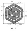
- Figure 6 displays the placement of four LED chips at the cavity surface 606 of a chip carrier. More specifically, two Green (G) 603 and 609, one Red (R) 610, and one Blue (B) 604 LED chips are placed inside the hexagonal conductor layout. Both of the G chips are connected to the common anode 602, and cathode 608. The R chip is connected to anode 601 and cathode 611. The B chip is connected to anode 605 and cathode 607. A circular area depicted by the dashed line 612 represents the location of cavity for LED chip mount.
- G Green
- R Red
- B Blue
- FIG. 7A A drawing of a typical LCD stack is provided in Figure 7A comprising six major components. These major components together with their respective elements located in sequence from the LCD viewing side are: (1) a front polarizer stack 701 comprising an anti-reflectance or anti-glare film, a viewing angle film, and a front polarizer; (2) a color filter 702 comprising a front glass, a black matrix/color filter, a common electrode, and an alignment layer; (3) a liquid crystal layer 703; (4) a TFT, thin film transistor array 704 comprising an alignment layer, a display electrode, and a rear glass; (5) a rear polarizer stack 705 comprising a rear polarizer, and a recirculating polarizer of DBEF (dual brightness enhancement film); and (6) a backlight unit 706.
- a front polarizer stack 701 comprising an anti-reflectance or anti-glare film, a viewing angle film, and a front polarizer
- a color filter 702 comprising a front
- the backlight unit 706, illustrate in Figure 7B is further comprised of a front diffuser 707, at least one layer of prism sheet of BEF (brightness enhancement film) 708, a rear diffuser 709, and a lamp and light guide 710.
- a black reflector is normally provided in 710 to enhance the brightness of the lamp.
- the current invention provides a superior alternative to the lamp by the use of a LED lighting module made with a LTCC chip carrier wherein at least one HB LED chip is mounted and its circuit integration and heat dissipation are provided respectively by thick film conductor, electrical via, and thermal via materials. This provides the benefits of stable and improved lighting performance, simplicity of fabrication of backlight units, reliability of lighting performance in the life of LCD, and overall cost.
- LED lighting module for LCD backlight application
- the said application is not limited to LCD.
- White or colored LED light applications can be easily performed by those skilled in the art with the current invention.
- the LED module of the present invention may comprise red, green, blue, white, yellow or other pigment colors, depending upon the anticipated application. Several examples are given below.
- the tape composition(s) of the present invention comprise glass, ceramic filler, and in a preferred embodiment, inorganic pigment.
- the tape composition comprises at least one glass frit, at least one white color refractory inorganic oxide, and/or other inorganic pigment, which provides the white color enhancement and/or reflection.
- inorganic colored pigment can be used at 0-10 weight % in the total inorganic substances to provide specific color such as Red, Green, or Blue for display color enhancement by the LED chip carrier.
- the weight % content of inorganic pigment may vary.
- 0.5% (weight percent based on total inorganic materials) of cobalt aluminate can be added in a glass-ceramic with an aluminum oxide refractory filler to provide a sintered ceramic body of blue color.
- a predetermined color of the LTCC chip carrier can normally be provided with 0.1 to 10.0 weight % of the corresponding pigment in a ceramic slurry composition comprising frit and refractory filler such as aluminum oxide, and preferably with 0.5 to 1.0% of a given inorganic pigment in the first embodiment.
- a ceramic slurry composition comprising frit and refractory filler such as aluminum oxide, and preferably with 0.5 to 1.0% of a given inorganic pigment in the first embodiment.
- Higher weight % content of pigment normally provide stronger color, but, the optimum weight % of the pigment content depends on the intrinsic properties of the chosen frit since it should provide proper softening and adequate flow during the process of densification or sintering.
- an optimum composition including the weight % content of a given inorganic pigment depends on the wetting power of a given molten frit on the surface of a given inorganic pigment, the ability to form a crystalline phase, particle sizes and surface reactivity of the inorganic ingredients, among other factors.
- the second embodiment of the slurry composition requires a higher weight % content of a given inorganic pigment, such as from 1 to 10 weight % preferably in the range of 1 to 4 weight %.
- One other critical property to consider when optimizing the ceramic slurry composition is the resultant mechanical strength of the fired or sintered LTCC body with flexural strength being the key strength parameter.
- one or more inorganic pigment(s) may be used in a given LTCC slurry composition to provide a family of balanced properties including but not limited to optical (light reflectivity, predetermined color), mechanical (flexural strength), chemical (resistance to environmental corrosion), and thermal (ability to conduct heat) aspects.
- a white color LTCC chip carrier to provide a LED lighting module requires adequate strength and white light reflectivity.
- Titanium dioxide, especially in the tetragonal crystalline form of rutile has a refractive index of 2.9 and is among the top candidates to provide the required optical performance.
- titanium dioxide's flexural strength is about 140 Mpa, about 50% of aluminum oxide, therefore, a volume % substitution of aluminum oxide for titanium dioxide has to be done to maintain adequate strength of the sintered body.
- a flexural strength of at least 150 Mpa is preferred. Because the remnant glass phase and microstructure in terms of crystalline phase, size, and grain boundary are all variants affecting the eventual strength of the sintered body, the LTCC slurry composition should be carefully adjusted to achieve the predetermined objective.
- a second inorganic white pigment such as zirconium dioxide, can also be added to the slurry composition.
- zirconium dioxide Although the refractive index of zirconium dioxide (2.16) is lower than titanium dioxide (2.9 for rutile or 2.49 for anatase form), its potential to enhance mechanical strength provides a significant merit. For example, various types of modified zirconium dioxide or zirconium dioxide added aluminum oxide exhibit superior flexural strength (quoted in parenthesis) as compared to a typical aluminum oxide (280 Mpa).
- yittria Y 2 O 3
- y-TZP tetragonal zirconia polycrystals
- c-TZP ceria
- ZTA zirconia toughened alumina
- Mg-PSZ magnesia-partially stabilized zirconia
- Commonly available high temperature stable inorganic pigments include but are not limited to Iron Oxide (red) such as Kroma Reds® from Elementis Pigments, Cobalt Chromite Green Spinel (green) such as Shepherdcolor's Green 410, Cobalt Chromite Blue Green Spinel (green) such as Shepherdcolor's Green 201, Cobalt Titanate Green Spinel (green) such as Shepherdcolor's Green 10G663, Chromium Aluminate (green) such as Ferro's CK14002, Chromium Cobalt Zinc (green) such as Ferro's CK14028, Cobalt Aluminate Blue Spinel (blue) such as Shepherdcolor's Blue 10K525, Cobalt Chromite Blue Green spinel (blue) such as Shepherdcolor's Blue 10K579, Cobalt Aluminum Chromite (Blue) such as Ferro's CK15069, Cobalt Aluminum Zinc (blue) such as Ferro's CK15063, Cobalt Silicon (
- pigments include but are not limited to Mason Color's 6410 Canary (yellow), 6450 Praseodymium (yellow), 6204 Victoria Green (green), 6224 Dark Green (green), 6263 Victoria (green), 6264 Victoria (green), 6306 Vivid Blue (blue), 6350 Bright Blue (blue), 6360 Willow (blue), 6389 Sapphire Blue (blue), 6003 Crimson (red), 6004 Crimson (red), 6090 Coral (red), and 6069 Dark Coral (red), among others.
- LTCC compositions include, but are not limited to: (1) co-fireability at a range of temperature such as up to 850 to 900°C with high conductivity materials such as silver, copper, gold, and other alloys such as silver/platinum or silver/palladium; (2) formation of cavity structure to provide the platform for LED chip mounting and condensation of the emitted light, this includes single chip or a multiplicity of chips of various display colors; (3) a closer TCE match of LTCC materials to the LED chips; (4) the choice of glass and refractory inorganic oxide which provide mechanical strength suitable for chip carrier application and next level module and package integration by soldering, wire bonding, and other electrical and mechanical attachment methods; (5) suitable for multilayer circuit layout to integrate with but not limit to at least one LED driver; (6) suitable for providing electrical vias for circuit connection in an otherwise insulating dielectric materials; (7) suitable for providing thermal conduction vias which are co-fireable with the dielectric materials having superior thermal conductivity than a typical organic printed circuit board substrate; and (8) suitable
- the glasses described herein are produced by conventional glass making techniques.
- the glasses were prepared in 500-1000 gram quantities. Typically, the ingredients are weighed then mixed in the desired proportions and heated in a bottom-loading furnace to form a melt in platinum alloy crucibles. Heating is conducted to a peak temperature (1300-1600°C), depending on the glass composition and for a time such that the melt becomes entirely liquid and homogeneous.
- the glass melts were quenched using a counter rotating stainless steel roller to form a 10-20 mil (254-508 ⁇ m) thick platelet of glass. Alternatively, the glass melt can be quenched by direct draining into a water bath.
- the resulting glass platelet was then milled to form a powder with its 50% volume distribution set between 1-5 microns.
- the glass powders were then formulated with filler and organic medium to cast tapes as detailed in the Examples section.
- the glass compositions shown in Table 1 represent a broad variety of glass chemistry (high amounts of glass former to low amounts of glass former).
- the glass former oxides are typically small size ions with high chemical coordination numbers such as SiO 2 , B 2 O 3 , and P 2 O 5 .
- the remaining oxides represented in the table are considered glass modifiers and intermediates.
- a refractive index in the range of 1.5 to 3.5 is preferred. These include but are not limited to the following family of materials in a descending order of their corresponding reflective index quoted in parenthesis: titanium oxide (2.64), zinc sulfite (2.37), calcium fluoantimonate (2.20), zirconium oxide (2.16), lead arsenate (2.14), antimony trioxide (2.09), tin oxide (2.04), zirconium silicate (2.00), zinc spinel (1.90), and aluminum oxide (1.62).
- Al 2 O 3 is the preferred ceramic filler since it reacts with the glass to form an Al-containing crystalline phase.
- Al 2 O 3 is very effective in providing high mechanical strength and inertness against detrimental chemical reactions.
- the flexural strength of Al 2 O 3 or TiO 2 is, respectively, 345 or 140 MPa. Therefore, alumina is chosen as the preferred filler which can be used as the sole refractory ceramic oxide or with at least one of the above oxides to provide color and/or light reflectivity while maintaining a suitable mechanic strength of the chip carrier package.
- the above filler or mixtures thereof may be added to the castable compositions used to form the tapes in an amount of 0-50 wt. % based on weight of the solids.
- Other materials such as zirconium silicate and barium titanate are also suitable ceramic filler candidates.
- different crystalline phases are expected to form after firing.
- the filler can control dielectric constant and loss over the frequency range. For example, the addition of BaTiO 3 can increase the dielectric constant significantly. A broad range of LTCC compositions is applicable.
- the ceramic filler Another function of the ceramic filler is rheological control of the entire system during firing.
- the ceramic particles limit flow of the glass by acting as a physical barrier. They also inhibit sintering of the glass and thus facilitate better burnout of the organics.
- Other fillers such as ⁇ -quartz, CaZrO 3 , mullite, cordierite, forsterite, zircon, zirconia, BaTiO 3 , CaTiO 3 , MgTiO 3 , SiO 2 , amorphous silica or mixtures thereof, may be used to modify tape performance and characteristics. It is preferred that the filler has at least a bimodal particle size distribution with D50 of the larger size filler in the range of 1.5 and 3 microns and the D50 of the smaller size filler in the range of 0.3 and 0.8 microns.
- the amount of glass relative to the amount of ceramic material is important.
- a filler range of 30% - 60% by weight is considered desirable in that sufficient densification is achieved. If the filler concentration exceeds 50% by wt., the fired structure may not be sufficiently densified and may be too porous and mechanically weak. Within the desirable glass/filler ratio, it will be apparent that, during firing, the liquid glass phase will become saturated with filler material.
- the inorganic solids For the purpose of obtaining higher densification of the composition upon firing, it is important that the inorganic solids have small particle sizes. In particular, substantially all of the particles should not exceed 15 ⁇ m and preferably not exceed 10 ⁇ m. Subject to these maximum size limitations, it is preferred that at least 50% of the particles, both glass and ceramic filler, be greater than 1 ⁇ m and less than 6 ⁇ m.
- the organic medium in which the glass and ceramic inorganic solids are dispersed is comprised of a polymeric binder which is dissolved in a volatile organic solvent and, optionally, other dissolved materials such as plasticizers, release agents, dispersing agents, stripping agents, antifoaming agents, stabilizing agents and wetting agents.
- the polymeric binder will also contain a small amount, relative to the binder polymer, of a plasticizer that serves to lower the glass transition temperature (Tg) of the binder polymer.
- a plasticizer that serves to lower the glass transition temperature (Tg) of the binder polymer.
- Tg glass transition temperature
- the choice of plasticizers is determined by the polymer that needs to be modified.
- the plasticizers that have been used in various binder systems are diethyl phthalate, dibutyl phthalate, dioctyl phthalate, butyl benzyl phthalate, alkyl phosphates, polyalkylene glycols, glycerol, poly(ethylene oxides), hydroxyethylated alkyl phenol, dialkyldithiophosphonate, polypropylene glycol dibenzoate and poly(isobutylene).
- butyl benzyl phthalate is most frequently used in acrylic polymer systems because it can be used effectively in relatively small concentrations.
- the plasticizer is used to prevent tape cracking and provide wider latitude of as-coated tape handling ability, such as blanking, printing, and lamination.
- a preferred plasticizer is BENZOFLEX® 400 manufactured by Rohm and Haas Co., which is a polypropylene glycol dibenzoate.
- the solvent component of the casting solution is chosen so as to obtain complete dissolution of the polymer and sufficiently high volatility to enable the solvent to be evaporated from the dispersion by the application of relatively low levels of heat at atmospheric pressure.
- the solvent must boil well below the boiling point or the decomposition temperature of any other additives contained in the organic medium. Thus, solvents having atmospheric boiling points below 150°C are used most frequently.
- Such solvents include acetone, xylene, methanol, ethanol, isopropanol, methyl ethyl ketone, ethyl acetate, 1,1,1-trichloroethane, tetrachloroethylene, amyl acetate, 2,2,4-triethyl pentanediol-1,3-monoisobutyrate, toluene, methylene chloride and fluorocarbons.
- Individual solvents mentioned above may not completely dissolve the binder polymers. Yet, when blended with other solvent(s), they function satisfactorily.
- a particularly preferred solvent is ethyl acetate since it avoids the use of environmentally hazardous chlorocarbons.
- a green tape for this invention is formed by casting a thin layer of a slurry dispersion of the glass, ceramic filler, polymeric binder and solvent(s) as described above onto a flexible substrate, and heating the cast layer to remove the volatile solvent.
- the green tape thickness so long as adequate drying of either volatile organic solvent(s) or water (in case of a water based organic binder system) can be achieved during the tape coating process.
- a preferable thickness range is between 5 and 30 mils (127 and 762 ⁇ m), the lower limit is to provide sufficient green strength for ease of handling and the upper limit is to provide adequate drying of the solvent during tape casting.
- the use of thicker tape minimizes the processing step whereas the use of thinner tape permits a higher degree of circuit integration within the dimensional requirements of the chip carrier.
- the solid content and viscosity of a slip are to be adjusted to coat LTCC tape of various "green" thickness, with extra care to be taken when the tape thickness exceeds 15 mils (381 ⁇ m) to assure proper drying of volatile solvent(s).
- the tape is then blanked into sheets or collected in a roll form.
- the green tape is typically used as a dielectric or insulating material for multilayer electronic circuits.
- the selected tapes are blanked with corner registration holes into sheets of dimensions ranging from 3" x 3" (7.6 cm x 7.6 cm) to 6" x 6" (15.2 cm x 15.2 cm) or larger sizes.
- These green tape sheets are typically used as the dielectric or insulating material for multilayer electronic circuits.
- via holes are formed in the green tape. This is typically done by mechanical punching. However, a sharply focused laser can also be used to volatilize the organic substance and form via holes in the green tape.
- Typical via hole sizes for electrical circuit connection range from 0.004" to 0.25" (0.1 to 6.35 mm), and typical via hole sizes for heat dissipation range from 0.010" to 0.050" (0.254 to 1.27 mm) wherein circular via holes are normally applied. It is noted that this invention also extends to via holes of other than circular shape according to the preferred design of the chip carrier structure and dimension.
- the interconnections between layers are formed by filling the via holes with a thick film conductive composition. This composition is usually applied by screen printing, stencil printing, or bladder filling. Each layer of circuitry is completed by screen printing conductor tracks.
- resistor compositions or high dielectric constant compositions may be printed on selected layer(s) to form resistive or capacitive circuit elements.
- specially formulated high dielectric constant green tapes similar to those used in the multilayer capacitor industry can be incorporated as part of the multilayer circuitry.
- the term "firing" means heating the assemblage in an oxidizing atmosphere such as air to a temperature, and for a time sufficient to pyrolyze (burn-out) all of the organic material in the layers of the assemblage and to sinter any glass, metal or dielectric material in the layers and thus densify the entire laminate.
- the furnace firing atmosphere is to be optimized for adequate organic burnout and conductor and tape sintering.
- the former process needs an oxidizing atmosphere such as air or oxygen doped nitrogen and the latter process is normally done in nitrogen with low oxygen content such as 100 ppm or below.
- a typical green tape layer may have printed thereon one or more resistor circuits and/or capacitors as well as conductive circuits.
- a typical thick film composition for use in low temperature co-fired ceramic circuits comprises, based on weight percent total thick film composition: (a) 60-90 weight percent finely divided particles selected from noble metals, alloys of noble metals and mixtures thereof; (b) one or more inorganic binders selected from (1) 0.2-20 weight percent of one or more refractory glass compositions, (2) 0.1-5 weight percent of an additional inorganic binder selected from (i) metal oxides of Zn, Mg, Co, Al, Zr, Mn, Ni, Cu, Ta, W.
- La and other "glass network- modifying" refractory metal oxides (ii) precursors of metal oxides; (iii) non-oxide borides; (iv) non-oxide silicides; and (v) mixtures thereof, and (3) mixtures thereof; dispersed in (c) 10-30 weight percent organic medium.
- a typical multilayer LTCC circuit substrate is fabricated by the use of conductive elements comprising a nonconductive LTCC ceramic substrate having a conductive pattern and connecting or non connecting via-fill conductive pattern affixed thereon formed by printing a pattern of above-described screen-printable and/or stencil-applicable paste and firing the printed and/or laminated LTCCs to effect volatization of the organic medium and liquid phase sintering of the inorganic materials and metallization.
- the multilayer LTCC circuit substrate fabrication is directed to a process for making conductors alone and/or in conjunction with via-fills comprising: (a) applying patterned thick film of the above-described screen-printable paste to a non conductive ceramic substrate, (b) drying the film at a temperature below 200°C, more commonly at or below 150°C and (c) firing the dried film to effect liquid phase sintering of the inorganic materials and metallization.
- the co-firing of metallization with LTCC must be performed in an atmosphere such as nitrogen or other reducing atmosphere with or without oxygen doping after the completion of organic burnout which occurs normally at around 450°C or below.
- the components of a typical conductor composition are discussed herein below.
- thick film conductor compositions While specific examples of thick film conductor compositions are identified here, it is understood by those skilled in the art that a multitude of thick film conductors may be used in the present invention depending upon the application and desired properties.
- silver-based inner conductor compositions useful in the present invention include Product Numbers 6142d, 6145, 6148, 6154, 6742 available from E. I. du Pont de Nemours and Company.
- Several useful via compositions include Product Numbers 6141 and 6151 also available from E. I. du Pont de Nemours and Company.
- the finely divided metals used in the invention can be those selected from noble metals, alloys of noble metals, and mixtures thereof, many of which are commercially available. Furthermore, particle size and morphology of the above-mentioned metal powders should be appropriate in screen-printing and /or stencil-applying over non-fired ceramic tape of thickness between 2 mils to 20 mils (50.8 to 508 ⁇ m) and preferably between 2 mils to 10 mils (50.8 to 254 ⁇ m) and to the laminating conditions of the composite and to the firing conditions.
- the metal powders should be no bigger than 10 ⁇ m and preferably should be below about 5 ⁇ m.
- the available particle size of the metals is from 0.1 to 10 ⁇ m for silver or copper, depending on the specific application.
- the metal powders can have either flake or non-flake morphology.
- the non-flake powders can be irregularly shaped or spherical.
- Such flake silvers have an average surface area of approximately 1 m 2 /g and solid contents of approximately 99-100% by weight.
- Non-flake silver powders typically have an average surface area to weight ratio of 0.1-2.0 m 2 /g and solid contents of approximately 99-100% by weight.
- spherical metallic powders are utilized. These spherical metallic powders, when packed, have a greater particle-to-particle contact versus flake and other shaped powders, which gives rise to a metal-to-metal contact and thus a relatively continuous flow of electrons for conduction when combined with the other components of the present invention.
- metal spherical particles allow for "tetrahedral" and/or “octrahedral” voids, wherein the specific inorganic binders of the present invention, such as metal oxides and/or glasses described below of relatively smaller sizes, may settle and upon processing the inorganic binders soften and hold the structure together in a uniform honeycomb-type structure with superior metal-to-metal contact and more continuous electron flow as compared to prior art compositions.
- spherical metallic particles with an average particle size distribution in the range of 1 to 4 microns are preferred. In another embodiment, an average particle size of 2 to 3 microns is preferred.
- the inorganic binders of the present invention are one or more inorganic binders selected from (1) 0.2-20 weight percent in the said paste composition of one or more refractory glass compositions with a logarithmic viscosity in the range of 6-7.6 at the firing temperature of said circuit, (2) 0.1-5 weight percent of an additional inorganic binder selected from (i) metal oxides, (ii) precursors of metal oxides; (iii) non-oxide borides; (iv) non-oxide silicides; and (v) mixtures thereof, and (3) mixtures thereof.
- the glass component of the conductor compositions of this invention is a high-softening point, high viscosity glass at 0.2-20 weight percent level and, preferably, at 1-15 weight percent level.
- high-softening point glass is one having a softening point of 600-950°C, preferably, 750-870°C as measured by the parallel plate viscosity measuring techniques (ASTM method).
- Typical examples of glasses can be found from any of the compositions listed in Table 1.
- the glasses are prepared by conventional glass-making techniques, by mixing the desired components in the desired proportions and heating the mixture to form a melt. As is well-known in the art, heating is conducted to a peak temperature and for a time such that the melt becomes entirely liquid and homogenous. In the present work the components are premixed in a polyethylene jar with plastic balls and melted in a platinum crucible at 1200-1400°C. The melt is heated at the peak temperature for 1-1.5 hours. The melt is then poured into cold water. The maximum temperature of the water during quenching is kept as low as possible by increasing the volume of water to melt ratio.
- the crude frit after separation from water, is freed from residual water by drying in air or displacement of water by rinsing with methanol, or other suitable method.
- the crude frit is then ball-milled for 6-7 hours in a typical container with refractory lining using alumina grinding media in water or a typical organic solvent such as isopropanol.
- the excess water or solvent is removed by decantation and the frit powder is hot air-dried.
- the dried powder is then screened through a 325 mesh screen to remove any large particles.
- the two major properties of the frits are: it aids the sintering of the conductive metal particulate matters and minimizes the intermixing of conductor materials with remnant glasses present in the LTCC ceramics.
- the metal oxides and non-oxides, such as borides and silicides, which are suitable for the practice of the invention are those which are capable of reacting with remnant glasses of the tape and increasing the viscosity of the remnant glasses when the composition of the invention is cofired with the tape, either on the surface or buried. Additionally the binders useful in the present invention should act as "sintering inhibitors" for the metal powders during firing of the system.
- Suitable inorganic oxides are those based on Zn 2+ , Mg 2+ , Co 2+ , Al 3+ , Zr 4+ , Mn 2+ , Ni 2+ , Cu 2+ , Ta 3+ , W 4+ , La 3+ and other "glass network modifying" refractory oxides and complex oxides such as copper bismuth ruthenate, and organometallic compounds such as organotitanate disclosed in U.K. Pat. No. 772,675 and U.S. Pat. No. 4,381,945 , incorporated herein, that will decompose into finely divided powders of metal oxides during the firing of the system.
- the particle size of the metal oxides or precursors should be appropriate to be used in the said paste composition for screen and/or stencil printing, thus the particle size should be no larger than 15 ⁇ m and preferably should be below 5 ⁇ m.
- the inorganic components including metal powders, glass binder, and metal oxide or non-oxide binder are typically dispersed into an organic medium by mechanical mixing to form viscous compositions called "pastes" having suitable consistency and rheology for printing.
- a wide variety of inert liquids can be used as organic medium.
- the rheological properties of the medium must be such that they lend good application properties to the composition, including: stable dispersion of solids, appropriate viscosity and thixotropy for screen printing, acceptable unfired "green” strength, appropriate wettability of the substrate and the paste solids, a good drying rate, and good firing and burn out properties.
- the organic medium is typically a solution of polymer(s) in solvent(s).
- a small amount of additives may be a part of the organic medium.
- the most frequently used polymer for this purpose is ethyl cellulose.
- Other examples of polymers include ethylhydroxyethyl cellulose, wood rosin, mixtures of ethyl cellulose and phenolic resins, polymethacrylates of lower alcohols, and monobutyl ether of ethylene glycol monoacetate can also be used.
- solvents found in thick film compositions are ester alcohols and terpenes such as alpha- or beta-terpineol or mixtures thereof with other solvents such as kerosene, dibutylphthalate, butyl carbitol, butyl carbitol acetate, hexylene glycol and high boiling alcohols and alcohol esters.
- volatile liquids for promoting rapid hardening after application on the substrate can be included in the vehicle.
- Various combinations of these and other solvents are formulated to obtain the viscosity and volatility requirements desired.
- the inorganic particles are mixed with an inert liquid medium (vehicle or medium) typically by mechanical mixing (e.g. on a roll mill) to form a paste-like composition having suitable consistency and rheology for screen printing and /or stencil applying.
- a paste-like composition having suitable consistency and rheology for screen printing and /or stencil applying.
- the latter is printed as a "thick film" on LTCC green tapes in the conventional manner.
- Any inert liquid may be used as the vehicle.
- Various organic liquids, with or without the thickening and/or stabilizing agents and/or other common additives may be used as the vehicle. The only specific criteria of the vehicle is that it must be chemically compatible to the organics present in the LTCC green tapes.
- organic liquids which can be used are the aliphatic alcohols, esters of such alcohols, for example, acetates and propionates, terpenes such as pine oil, terpineol and the like, texanol and the like, solutions of resins such as ethyl cellulose in solvents as pine oil, and the monobutyl ether of ethylene glycol monoacetate.
- the vehicle may contain volatile liquids to promote fast setting after application to the tape.
- the ratio of vehicle to solids in the dispersions can vary considerably and depends upon the manner in which the dispersion is to be applied and the kind of vehicle used and furthermore the use of the conductors are for the conductor lines and/or via-fill conductor connections. Normally to achieve good coverage the dispersions will comprise 60-98% solids and 40-2% organic medium (vehicle).
- the compositions of the present invention may, of course, be modified by the addition of other materials, which do not affect its beneficial characteristics. Such formulations are well within the skill of the art.
- the conductor composition(s) of the present invention is used with the said LTCC glass-ceramic dielectric via the method described herein.
- the thick film compositions of the present invention were prepared according to the following general methodology.
- the inorganic solids are mixed with the organic medium and dispersed with suitable equipment, such as a three-roll mill, to form a suspension, resulting in a composition for which the viscosity will be in the range of 100-200 Pascal-seconds at a shear rate of 4 sec -1 for the line conductor compositions and the corresponding value for via-fill conductors is 1000-5000 Pascal-seconds.
- the formulation was carried out in the following manner: The ingredients of the paste, minus about 2-5% of the organic components, were weighed together in a container. The components were then vigorously mixed to form a uniform blend; then the blend was passed through dispersing equipment, such as a three roll mill, to achieve a good dispersion of particles. A Hegman gauge was used to determine the state of dispersion of the particles in the paste. This instrument consists of a channel in a block of steel that is 25 ⁇ m deep (1 mil) on one end and rams up to 0" (i.e., 0-25 ⁇ m range) depth at the other end. A blade was used to draw down paste along the length of the channel.
- the composition was then applied to a substrate, in this particular case, to the "green tape".
- the "green tape” was formed by casting a 1-20 mil (25-508 ⁇ m), preferably 2-10 mil (50.8-254 ⁇ m), thin layer of a slurry dispersion of the glass and ceramic filler fine particulates, polymeric binder(s) and solvent(s) as described in the art of "tape casting” into a flexible substrate, and heating the cast layer to remove the volatile solvent.
- the tape is blanked into sheets or provided in roll form. This green tape is used as an insulating substrate for multilayer electronic circuits/devices, in place of conventional substrates, such as alumina and other refractory ceramic substrates.
- the green tape sheet is blanked with registration holes at the four corners, and via holes to connect the different layers of conductors using mechanical punching.
- the size of via holes varies depending on circuit design and property requirements.
- the interconnections of circuit between conductor track layers of the tape are typically applied by screen printing the conductive inks in the via holes.
- the conductive line compositions of the present invention were applied to a sheet of green tape, by the process of screen printing, to a wet thickness of about 10-30 ⁇ m and the via holes were filled with respective conductive via compositions.
- each layer of tape is printed with conductor lines and via holes as appropriate to the circuit design, the individual layers are collated, laminated and pressed using uniaxial or isostatic pressing die and techniques as described elsewhere in the art of tape pressing/lamination techniques. It will be recognized by those skilled in the art that in each of the laminating steps the printed tape layers must be accurate in registration so that the vias are properly connected to the appropriate conductive lines of the adjacent functional layer, and in the case of thermal vias, each via will be connected appropriately to the next one.
- Firing to effect sintering of the green tape compositions and of the inorganic binder as well as the finely divided particles of metal is preferably done in a well ventilated belt conveyor furnace or programmed box furnace with a temperature profile that will allow de-polymerization of polymers; and/or burnout of the organic matter at about 300-600°C. a period of maximum temperature of about 800-950°C. lasting about 5-20 minutes, followed by a controlled cool down cycle to prevent over-sintering and crystal growth, unwanted chemical reactions at intermediate temperatures, or substrate/fired ceramic tape fracture from too rapid cool down.
- the overall firing procedure will preferably extend over a period of between 3.5 to 5 hours, and in certain cases it could take up to 24 hours or more depending on the number of layers of green tapes laminated together and/or the thickness of the green tape layers.
- the fired thickness of the conductor can range from about 5 to about 15 ⁇ m, depending on the percent of solids, the type of screen the composition is printed with, the printer set up, and degree of sintering of the inorganic solids.
- the thickness of via conductors vary depending on the thickness of the green tape used and degree of sintering of the via composition. In order to avoid two major defects, dimpling and posting of the vias, the selection of viscosity and solid content of the composition is important. In general, increased solid content could result in posting and lower solid content will result in dimpling.
- the conductor compositions of this invention can be printed onto the green tapes, or onto other thick films either by using an automated printer or a hand printer in the conventional manner.
- automation screen printing techniques are employed, using 200 to 325 mesh screen with typically 0.5 mil (12.7 ⁇ m) emulsion thickness.
- Conventional stencil printing techniques are also can be used, particularly for filling the smaller vias of size 4-8 mils (101.6-203.2 ⁇ m).
- a frit-containing surface conductor provides a relatively higher electrical resistivity and a darker appearance. Therefore, for the purpose to provide light reflection, it is necessary to use a glass-free Ag, Au, Cu, or alloyed Ag/Pt or Ag/Pd conductor, with or without oxide binder in order to provide reflection.
- the choice of conductive powders such as Ag, Au, Cu, Pt, or Pd, particle size distribution, and packing density optimization are all important factors which contribute to the light reflectivity. Packing density optimization can be achieved by selecting conductor particles of at least one and preferably more than one average particle size.
- a co-fireable silver based thick film conductor composition is deposited onto the surface surrounding the LED chip or chips located at the build-in cavity, such as a silver composition has the following characteristics including but not limited to
- the conductor pads can be further plated to enhance the light reflectivity.
- Thermal vias are used to dissipate the heat resulting from a functional LED chip carrier package and this invention is to provide at least one and preferably a multiplicity of thermal vias to minimize the junction temperature to prolong the life of the HB LED package functions. It is further noted that the thermal vias are normally connected to heat spreader pad which can take the shape and form of a mesh pattern, a solid pattern, or any other suitable geometry.
- a metallized conductor plane be a solid or gridded geometry
- the ratio of chip bonding area to the available cavity space both affect the thermal conduction performance. It is noted that the maximum chip bonding area equal to the available cavity area provides the best thermal management.
- the substrate and cavity dimension are tailored to each chip array and sufficient space is needed to form a good die attached fillet for adequate bonding. In the case of flip chip bonding or BGA attachment, minimum space between the chip and cavity can be adopted so long as adequate electrical insulation between the anode and cathode(s) is achieved. This differs from the use of wire bonding for chip connection which needs more space in between. The effect of introducing thermal spreader will be described further in the following teaching.
- LTCC has inherently higher thermal conductivity than organic materials and the thermal conductivity can be improved with the addition of thermal vias and metallized conductor planes.
- thermal vias and metallized conductor planes There are two aspects, the thru-plane and the in-plane thermal conductivity to be addressed herein. Testing has shown an improvement in thru-plane conductivity to be 2 times or more than that of the dielectric material conductivity and an improvement in in-plane thermal conductivity by 2 to 3 times through the use of thermal vias and metallized planes. While solid metallization planes can be used in LTCC, gridded or meshed planes improve processability and they are as thermally effective as solid planes.
- the highest thru-plane thermal conductivity is obtained in the samples with the greatest possible number of thermal vias.
- the addition of any solid or gridded conductor planes does not significantly improve the thermal conductivity of a typically lower via density design, such as 12 mil (305 ⁇ m) vias on 50, 100, and 150 mil (1.27, 2.54 and 3.81 mm) centers.
- the above conductor planes significantly improve the thermal conductivity of a typically higher via density design, such as 8 mil (203.2 ⁇ m) vias on 20, 40, and 60 mil (0.51, 1.02 and 1.52 mm) centers.
- the solid or gridded conductor planes offer no improvement in thru-plane thermal conductivity.
- the addition of one internal gridded conductor plane improved the in-plane thermal conductivity by about 10 to 20%.
- gridded planes connecting thru thermal vias improve the in-plane thermal conductivity by about twice that of the configurations without conductor planes.
- Thick film brazing materials are suitable for large volume manufacturing and the attachment of heat sink to a pre-fired LTCC chip carrier. It is noted that the temperature hierarchy of the HB LED package module requires (1) the co-firing of tape, conductor, electrical via, and thermal via which takes place at highest temperature such as 850 to 900°C, (2) brazing of chip carrier to a heat sink which takes place normally at a medium temperature range between 350°C and 850°C, depending on the choice of braze materials, (3) chip bonding by flip chip or soldering, (4) gold wire bonding if necessary, and (5) applying plastic encapsulant such as epoxy or other thermal plastic organic materials.
- a brazing process normally is consisted of (1) brazing metallization, (2) brazing alloy/filler metal, (3) preparing the surface of joining component - a heat sink in this invention, (4) fixturing, (5) firing in furnace with suitable profile and atmosphere control.
- Proper thick film brazing compositions normally is consisted of a thick film adhesion layer and a thick film barrier layer.
- the DuPont thick film brazing materials include Au-based 5062 (adhesion layer), 5063 (barrier layer), and Ag/Pt-based 5081 (adhesion layer) and 5082 (barrier layer).
- the above thick film compositions provide an interface between LTCC with thermal vias and a heat sink.
- heat sink materials are available for the applications of this invention. These include but are not limited to plated alloys of Cu - W, Cu - Mo, Cu - Mo - Cu, and Al - SiC; BeO and AIN are also good candidate materials for heat sink applications.
- the heat sink may also be Al.
- Other examples include but are not limited to a metal core printed wiring (MCPWB).
- Tape compositions used in the examples were prepared by ball milling the fine inorganic powders and binders in a volatile solvent or mixtures thereof. To optimize the lamination, the ability to pattern circuits, the tape burnout properties and the fired microstructure development, the following volume % formulation of slip was found to provide advantages.
- the formulation of typical slip compositions is also shown in weight percentage, as a practical reference.
- the inorganic phase is assumed to have a specific density of 4.5 g/cc for glass and 4.0 g/cc for alumina and the organic vehicle is assumed to have a specific density of 1.1 g/cc.
- the weight % composition changes accordingly when using glass and refractory oxides for light reflection enhancement other than alumina as the specific density maybe different than those assumed in this example.
- Table 1 lists a variety of lead-containing and lead-free glass compositions suitable for the applications in this invention.
- Table 1. A List of glass compositions (in wt. %) Glass # (density) SiO 2 Al 2 O 3 PbO ZrO 2 B 2 O 3 CaO BaO MgO Na 2 O Li 2 O P 2 O 5 TiO 2 K 2 O Cs 2 O Nd 2 O 3 SrO 1 (4.72) 6.08 23.12 4.50 34.25 32.05 2 (3.06) 13.77 4.70 26.10 14.05 35.09 1.95 4.34 3 (2.66) 55.00 14.00 9.00 17.50 4.50 4 (4.54) 11.91 21.24 0.97 4.16 26.95 4.59 30.16 5 (2.80) 56.50 9.10 17.20 4.50 8.00 0.60 2.40 1.70 6(4.45) 11.84 21.12 1.31 4.14 25.44 6.16 29.99 7 (2.52) 52.00 14.00 8.50 17.50 4.75 2.00 0.25 1.00 8 (4.58) 6.27 22.79 0.93 4.64 33.76
- the above volume and weight % slip composition may vary depending on the desirable quantity of the organic solvent and/or solvent blend to obtain an effective slip milling and coating performance. More specifically, the composition for the slip must include sufficient solvent to lower the viscosity to less than 10,000 centipoise; typical viscosity ranges are 1,000 to 8,000 centipoise, depending on the target as-coated tape thickness.
- An example of a slip composition is provided in Table 2. Depending on the chosen slip viscosity, higher viscosity slip prolongs the dispersion stability for a longer period of time (normally several weeks). A stable dispersion of tape constituents is usually preserved in the as-coated tape.
- the glasses used in the Examples were melted in Pt/Rh crucibles at 1450-1600°C for about 1 hour in an electrically heated furnace. Glasses were quenched by metal roller as a preliminary step and then subjected to particle size reduction by milling. The glass particles were adjusted to a 5-7 micron mean size by milling prior to formulation as a slip. Since additional milling was utilized in the fabrication of slip, the final mean size is normally in the range of 1-3 microns. It is noted that the glass particles may also be pre-milled to a final size of 1-3 microns prior to its use as an ingredient in the slip composition.
- the percentage reflectance measurements were made using a Varian Cary 5000 uv/vis/nir spectrophotometer with a DRA-2500 diffuse reflectance accessory.
- the DRA-2500 uses a 150mm integrating sphere coated with Spectralon®. A 100 percent baseline is then collected using Spectralon® reference. The reference is then replaced by the sample and the reflectance spectrum is collected.
- a wavelength range of 800 to 250 nm was used. Both diffuse and specular components were included in the measurement.
- a four layer LTCC laminate was prepared using the following materials:
- a four layer LTCC laminate was prepared using the following materials:
- a four layer LTCC laminate was prepared using the following materials:
- the % light reflection the above blank LTCC substrate at red (650 nm), green (510 nm), or blue (475 nm) light wavelength is, respectively, 82.1 %, 81.1 % or 80.9% when measuring the top surface of the fired part with respect to how the substrate was placed on the setter for the furnace firing.
- a four layer LTCC laminate was prepared using the following materials:
- the % light reflection the above blank LTCC substrate at red (650 nm), green (510 nm), or blue (475 nm) light wavelength is, respectively, 82.8%, 82.7% or 81.9% when measuring the top surface of the fired part and 82.8%, 82.5%, or 81.6% when measuring the bottom surface of the fired part with respect to how the substrate is placed on the setter for the furnace firing.
- a four layer LTCC laminate was prepared using the following materials:
- the % light reflection the above blank LTCC substrate at red (650 nm), green (510 nm), or blue (475 nm) light wavelength is, respectively, 92.5%, 89.6% or 86.7% when measuring the top surface of the fired part and 92.3%, 88.8%, or 84.9% when measuring the bottom surface of the fired part with respect to how the substrate is placed on the setter for the furnace firing.
- a four layer LTCC laminate was prepared using the following materials:
- a four layer LTCC laminate was prepared using two layers of Tape 1 and two layers of Tape 2 wherein the green thickness of both tapes was 10 mils or 254 micrometers.
- Tape 2 as described above in Example 2 is consisted of TiO 2 which provides light reflection enhancement and was placed as the top two layers of the LTCC laminate.
- Glasses 2, 5, and 6 represent glasses that are useful in the present invention. It is noted that both lead-containing and lead-free glasses are applicable to be the inorganic binder in the preferred conductor paste compositions.
- Examples 8-14 represent examples of the present invention. All formulations are given in weight percent of the total thick film composition.
- Non-flake silver powders represented below have an average surface area to weight ratio of 0.1-2.0 m 2 /g.
- Palladium metal powders represented below have an average surface area to weight ratio of 2.0-15.0 m 2 /g.
- Platinum metal powders represented below have an average surface area to weight ratio of approximately 10m 2 /g to 30 m 2 /g.
- the average particle size distribution of the gold metal powders is in the range of 1-4 microns.
- Organo metallics 1.0 Ethyl cellulose/texanol- based medium represents the balance Silver powder SA 0.1 - 1.5 m 2 /gm
- Silver powder 53.5 Palladium powder 13.6 Copper bismuth ruthenate 5.1 Copper oxide 0.5 Ethylcellulose/terpineol- based medium represents the balance Flake Silver SA ⁇ 0.60-0.90 m 2 /gm; Tap density 4.0 -6.0 g/ml
- Silver Powder 90.9 Frit #2 1.2 Ethyl cellulose/texanol- based medium represents the balance Silver powder SA 0.1 -1.5m 2 /gm
- Gold powder 80.7 Frit #5 0.8 Ethyl cellulose/terpineol- based medium represents the balance Gold powder particle size distribution (PSD) d50 - 2-3 ⁇ m
- Ethyl cellulose/texanol- based medium represents the balance Palladium powder surface area to weight ratio (SA) ⁇ 1.1- 1.7 m 2 /gm
- Ethyl cellulose/texanol- based medium represents the balance Palladium powder SA ⁇ 1.1-1.7 m 2 /gm Platinum Powder SA ⁇ 0.7 - 1.2 m 2 /gm
- Gold powder 78.0 Frit # 17 0.7 Ethyl cellulose/terpineol- based medium represents the balance Gold powder PSD -d50 4-5 ⁇ m
- Silver Powder 51.0 Paladium 13.0 Ethyl cellulose/texanol- based medium represents the balance Silver powder has irregular shape with a D50 particle size of 2.5 ⁇ m
- the % light reflection the above metallization after co-firing with LTCC chip carrier at red (650 nm), green (510 nm), or blue (475 nm) light wavelength is, respectively, 49.4%, 42.2% or 40.7%.
- Silver Powder 57.8 Cuprous oxide 1.0 Frit#17 5.4 Ethyl cellulose/texanol- based medium represents the balance Silver powder has irregular shape with a D50 particle size of 2.5 ⁇ m
- the % light reflection the above metallization after co-firing with LTCC chip carrier at red (650 nm), green (510 nm), or blue (475 nm) light wavelength is, respectively, 67.4%, 65.7% or 64.6%.
- Silver Powder 87.6 Ethyl cellulose/texanol- based medium represents the balance Silver powder has spherical shape with a D50 particle size of 2.5 ⁇ m
- the % light reflection the above metallization after co-firing with LTCC chip carrier at red (650 nm), green (510 nm), or blue (475 nm) light wavelength is, respectively, 94.4%, 88.9% or 85.3%.
- Silver Powder 65.0 Frit #5 3.0 Ethyl cellulose/texanol- based medium represents the balance Silver powder has irregular shape with a D50 particle size of 2.5 ⁇ m
- the % light reflection the above metallization after co-firing with LTCC chip carrier at red (650 nm), green (510 nm), or blue (475 nm) light wavelength is, respectively, 94.2%, 92.0% or 91.3%.
- Silver Powder type A 26.1 Silver Powder type B 55.6 Frit #5 1.2 Ethyl cellulose/texanol- based medium represents the balance
- Each of silver powders type A or B both has irregular shape with a D50 particle size of 2.5 ⁇ m or 8.2 ⁇ m, respectively
- the % light reflection the above metallization after co-firing with LTCC chip carrier at red (650 nm), green (510 nm), or blue (475 nm) light wavelength is, respectively, 95.4%, 91.9% or 91.2%.
- Silver Powder 77.0 Ethyl cellulose/texanol- based medium represents the balance Silver powder has flake shape with a D50 particle size of 2.4 ⁇ m
- the % light reflection the above metallization after co-firing with LTCC chip carrier at red (650 nm), green (510 nm), or blue (475 nm) light wavelength is, respectively, 97.9%, 96.4% or 95.4%.
- Silver Powder 77.0 Frit #17 0.5 Ethyl cellulose/texanol- based medium represents the balance Silver powder has flake shape with a D50 particle size of 2.4 ⁇ m
- the % light reflection the above metallization after co-firing with LTCC chip carrier at red (650 nm), green (510 nm), or blue (475 nm) light wavelength is, respectively, 95.4%, 92.5% or 91.2% when silver was fired upward, and 95.0%, 91.8%, or 90.3% when silver was fired downward (i.e. facing the setter).
- Silver Powder 77.0 Ethyl cellulose/texanol- based medium represents the balance Silver powder has irregular shape with a D50 particle size of 8.2 ⁇ m
- the % light reflection the above metallization after co-firing with LTCC chip carrier at red (650 nm), green (510 nm), or blue (475 nm) light wavelength is, respectively, 98.0%, 96.3% or 95.5%.
- Silver Powder 77.0 Frit #17 0.5 Ethyl cellulose/texanol- based medium represents the balance Silver powder has irregular shape with a D50 particle size of 8.2 ⁇ m
- the % light reflection the above metallization after co-firing with LTCC chip carrier at red (650 nm), green (510 nm), or blue (475 nm) light wavelength is, respectively, 95.3%, 92.2% or 91.0% when silver was fired upward, and 94.0%, 90.4%, or 88.9% when silver was fired downward (i.e. facing the setter).
- Silver Powder 77.0 Ethyl cellulose/texanol- based medium represents the balance Silver powder has flake shape with a D50 particle size of 3.7 ⁇ m
- the % light reflection the above metallization after co-firing with LTCC chip carrier at red (650 nm), green (510 nm), or blue (475 nm) light wavelength is, respectively, 98.2%, 96.6% or 95.5%.
- Silver Powder 77.0 Frit #17 0.5 Ethyl cellulose/texanol- based medium represents the balance Silver powder has flake shape with a D50 particle size of 3.7 ⁇ m
- the % light reflection the above metallization after co-firing with LTCC chip carrier at red (650 nm), green (510 nm), or blue (475 nm) light wavelength is, respectively, 95.2%, 91.9% or 90.4% when silver was fired upward, and 95.5%, 92.4%, or 90.9% when silver was fired downward (i.e. facing the setter).
- Silver Powder 77.0 Ethyl cellulose/texanol- based medium represents the balance Silver powder has irregular shape with a D50 particle size of 8.2 ⁇ m
- the % light reflection the above metallization after co-firing with LTCC chip carrier at red (650 nm), green (510 nm), or blue (475 nm) light wavelength is, respectively, 98.7%, 97.7% or 97.0%.
- Silver Powder 77.0 Frit #17 0.5 Ethyl cellulose/texanol- based medium represents the balance Silver powder has irregular shape with a D50 particle size of 8.2 ⁇ m
- the % light reflection the above metallization after co-firing with LTCC chip carrier at red (650 nm), green (510 nm), or blue (475 nm) light wavelength is, respectively, 95.7%, 93.0% or 91.9% when silver was fired upward, and 94.8%, 91.3%, or 89.7% when silver was fired downward (i.e. facing the setter).
- Silver Powder 77.0 Ethyl cellulose/texanol- based medium represents the balance Silver powder has flake shape with a D50 particle size of 6.0 ⁇ m
- the % light reflection the above metallization after co-firing with LTCC chip carrier at red (650 nm), green (510 nm), or blue (475 nm) light wavelength is, respectively, 98.8%, 97.7% or 97.0%.
- Silver Powder 77.0 Frit #17 0.5 Ethyl cellulose/texanol- based medium represents the balance Silver powder has flake shape with a D50 particle size of 6.0 ⁇ m
- the % light reflection the above metallization after co-firing with LTCC chip carrier at red (650 nm), green (510 nm), or blue (475 nm) light wavelength is, respectively, 94.0%, 90.3% or 88.6% when silver was fired upward, and 94.9%, 91.5%, or 89.9% when silver was fired downward (i.e. facing the setter).
- Silver Powder 83.4 Platinum Powder 0.4 Metallic Oxides 0.4 Bismuth Trioxide 0.5 Ethyl cellulose/texanol- based medium represents the balance Silver powder has flake shape with a D50 particle size of 2.0 ⁇ m
- the % light reflection the above metallization after co-firing with LTCC chip carrier at red (650 nm), green (510 nm), or blue (475 nm) light wavelength is, respectively, 92.8%, 89.1 % or 87.9% when silver was fired upward, and 92.4%, 88.3%, or 86.4% when silver was fired downward (i.e. facing the setter).
- Table 3 compares the TCE and thermal conductivity of the above heat sink materials. Table 3 Joining Materials TCE, 10E-6/C Thermal Conductivity Cu-W 5 - 10 200 W/mK Cu-Mo 5 - 10 200 W/mK Cu-Mo-Cu 5 - 10 200 W/mK Al-SiC 3 - 15 150 W/mK BeO 5 - 7 260 W/mK AIN 4 - 5 200 W/mK
Applications Claiming Priority (2)
| Application Number | Priority Date | Filing Date | Title |
|---|---|---|---|
| US71327705P | 2005-09-01 | 2005-09-01 | |
| US11/510,170 US7550319B2 (en) | 2005-09-01 | 2006-08-25 | Low temperature co-fired ceramic (LTCC) tape compositions, light emitting diode (LED) modules, lighting devices and method of forming thereof |
Publications (2)
| Publication Number | Publication Date |
|---|---|
| EP1760784A2 true EP1760784A2 (de) | 2007-03-07 |
| EP1760784A3 EP1760784A3 (de) | 2010-09-22 |
Family
ID=37533268
Family Applications (1)
| Application Number | Title | Priority Date | Filing Date |
|---|---|---|---|
| EP06254536A Withdrawn EP1760784A3 (de) | 2005-09-01 | 2006-08-31 | Keramikband-Verbundswerkstoffe gesintert bei niedriger Temperatur, Leuchtdiodenmodule, Beleuchtungsvorrichtungen und entsprechende Herstellungsverfahren |
Country Status (6)
| Country | Link |
|---|---|
| US (2) | US7550319B2 (de) |
| EP (1) | EP1760784A3 (de) |
| JP (1) | JP2007129191A (de) |
| KR (2) | KR100954657B1 (de) |
| CN (1) | CN1925182A (de) |
| TW (1) | TW200715622A (de) |
Cited By (9)
| Publication number | Priority date | Publication date | Assignee | Title |
|---|---|---|---|---|
| WO2008054670A1 (en) * | 2006-10-31 | 2008-05-08 | Cree, Inc. | Integrated heat spreaders for leds and related assemblies |
| EP2184790A1 (de) * | 2008-11-10 | 2010-05-12 | Foxsemicon Integrated Technology, Inc. | Leuchtdiode und diese enthaltender Lichtquellenmodul |
| TWI424593B (zh) * | 2010-09-10 | 2014-01-21 | Ho Cheng Ind Co Ltd | Light - emitting diodes of the thermal substrate and thermal module structure |
| EP2711997A1 (de) * | 2012-09-25 | 2014-03-26 | LG Innotek Co., Ltd. | Lichtemittierende Vorrichtungsverpackung |
| EP2733755A1 (de) * | 2011-07-15 | 2014-05-21 | Mitsubishi Chemical Corporation | Leiterplatte mit möglichkeit der montage einer lichtemittierenden halbleitervorrichtung darauf, lichtemittierendes modul, beleuchtungsvorrichtung und beleuchtungssystem |
| EP2211385A3 (de) * | 2009-01-23 | 2015-11-25 | Everlight Electronics Co. Ltd. | Lichtemissionsdiodenpaket |
| WO2018013645A1 (en) * | 2016-07-15 | 2018-01-18 | 3M Innovative Properties Company | Multilayer led substrate |
| EP2304817B1 (de) * | 2008-05-23 | 2020-01-08 | Cree, Inc. | Weißlichtemittierende Baugruppe mit LED-Array |
| WO2021110333A1 (en) * | 2019-12-06 | 2021-06-10 | Osram Opto Semiconductors Gmbh | Optoelectronic device |
Families Citing this family (215)
| Publication number | Priority date | Publication date | Assignee | Title |
|---|---|---|---|---|
| US20090294159A1 (en) * | 2008-06-03 | 2009-12-03 | Kuo-Ching Chiang | Advanced print circuit board and the method of the same |
| DE102005013762C5 (de) * | 2005-03-22 | 2012-12-20 | Sew-Eurodrive Gmbh & Co. Kg | Elektronisches Gerät und Verfahren zur Bestimmung der Temperatur eines Leistungshalbleiters |
| US20070023388A1 (en) * | 2005-07-28 | 2007-02-01 | Nair Kumaran M | Conductor composition for use in LTCC photosensitive tape on substrate applications |
| KR101240650B1 (ko) * | 2006-01-18 | 2013-03-08 | 삼성디스플레이 주식회사 | 발광 다이오드 모듈, 이를 구비한 백라이트 어셈블리 및이를 구비한 표시 장치 |
| US9713258B2 (en) * | 2006-04-27 | 2017-07-18 | International Business Machines Corporation | Integrated circuit chip packaging |
| AU2007248758A1 (en) | 2006-05-02 | 2007-11-15 | Daniel Chandler | Heat removal design for LED bulbs |
| EP2013919A2 (de) | 2006-05-02 | 2009-01-14 | Superbulbs, Inc. | Verfahren für lichtdispersion und bevorzugte streuung bestimmter wellenlängen von licht für leuchtdioden und daraus hergestellte glühbirnen |
| BRPI0711150A2 (pt) * | 2006-05-02 | 2011-08-23 | Superbulbs Inc | bulbo de led de plástico |
| US8497560B2 (en) * | 2006-10-06 | 2013-07-30 | Industrial Technology Research Institute | LED package and method of assembling the same |
| US20080179618A1 (en) * | 2007-01-26 | 2008-07-31 | Ching-Tai Cheng | Ceramic led package |
| US7898811B2 (en) * | 2007-04-10 | 2011-03-01 | Raled, Inc. | Thermal management of LEDs on a printed circuit board and associated methods |
| TWM328763U (en) * | 2007-05-21 | 2008-03-11 | Univ Nat Taiwan | Structure of heat dissipation substrate |
| US7802903B1 (en) * | 2007-06-07 | 2010-09-28 | J&J Electronic, Inc. | LED festoon lighting |
| KR100877877B1 (ko) * | 2007-08-28 | 2009-01-13 | 엘지이노텍 주식회사 | 발광 소자 |
| WO2009045438A1 (en) | 2007-10-03 | 2009-04-09 | Superbulbs, Inc. | Glass led light bulbs |
| US9172012B2 (en) | 2007-10-31 | 2015-10-27 | Cree, Inc. | Multi-chip light emitter packages and related methods |
| US9666762B2 (en) | 2007-10-31 | 2017-05-30 | Cree, Inc. | Multi-chip light emitter packages and related methods |
| US9082921B2 (en) * | 2007-10-31 | 2015-07-14 | Cree, Inc. | Multi-die LED package |
| KR101491138B1 (ko) * | 2007-12-12 | 2015-02-09 | 엘지이노텍 주식회사 | 다층 기판 및 이를 구비한 발광 다이오드 모듈 |
| TW200928203A (en) * | 2007-12-24 | 2009-07-01 | Guei-Fang Chen | LED illuminating device capable of quickly dissipating heat and its manufacturing method |
| US8304660B2 (en) * | 2008-02-07 | 2012-11-06 | National Taiwan University | Fully reflective and highly thermoconductive electronic module and method of manufacturing the same |
| US20110029869A1 (en) * | 2008-02-29 | 2011-02-03 | Mclennan Hamish | Method and system responsive to intentional movement of a device |
| JP5035995B2 (ja) * | 2008-03-21 | 2012-09-26 | 株式会社小糸製作所 | 光源モジュール及び車輌用灯具 |
| EP2107347B1 (de) * | 2008-04-04 | 2016-08-31 | Sensirion AG | Flussdetektor mit Gehäuse |
| WO2009128354A1 (ja) * | 2008-04-18 | 2009-10-22 | 旭硝子株式会社 | 発光ダイオードパッケージ |
| JP5185683B2 (ja) * | 2008-04-24 | 2013-04-17 | パナソニック株式会社 | Ledモジュールの製造方法および照明器具の製造方法 |
| US8461613B2 (en) * | 2008-05-27 | 2013-06-11 | Interlight Optotech Corporation | Light emitting device |
| KR20090126991A (ko) * | 2008-06-05 | 2009-12-09 | 삼성전자주식회사 | 색필터 및 색필터를 가지는 표시 장치 |
| JP5450854B2 (ja) * | 2008-06-24 | 2014-03-26 | シャープ株式会社 | 発光装置 |
| US8198646B2 (en) * | 2008-06-24 | 2012-06-12 | Osram Opto Semiconductors Gmbh | Light emitting device and method of manufacturing a light emitting device |
| JP5345363B2 (ja) | 2008-06-24 | 2013-11-20 | シャープ株式会社 | 発光装置 |
| KR100958024B1 (ko) | 2008-08-05 | 2010-05-17 | 삼성엘이디 주식회사 | 발광 다이오드 패키지 및 그 제조방법 |
| EP2317571A1 (de) * | 2008-08-21 | 2011-05-04 | Asahi Glass Company, Limited | Lichtemittierende vorrichtung |
| US8058669B2 (en) * | 2008-08-28 | 2011-11-15 | Taiwan Semiconductor Manufacturing Company, Ltd. | Light-emitting diode integration scheme |
| DE102008046336A1 (de) * | 2008-09-09 | 2010-03-11 | Osram Gesellschaft mit beschränkter Haftung | LTCC-Schichtstapel |
| KR101018191B1 (ko) * | 2008-11-27 | 2011-02-28 | 삼성엘이디 주식회사 | 세라믹 패키지 및 이를 구비하는 헤드램프 모듈 |
| KR100909366B1 (ko) * | 2008-12-16 | 2009-07-24 | 주식회사 미소 | 방열구조 엘이디모듈 |
| JP4823300B2 (ja) * | 2008-12-17 | 2011-11-24 | 株式会社東芝 | 半導体発光装置 |
| TWI473246B (zh) * | 2008-12-30 | 2015-02-11 | Epistar Corp | 發光二極體晶粒等級封裝 |
| US8598602B2 (en) | 2009-01-12 | 2013-12-03 | Cree, Inc. | Light emitting device packages with improved heat transfer |
| US7923739B2 (en) * | 2009-06-05 | 2011-04-12 | Cree, Inc. | Solid state lighting device |
| JP2010238941A (ja) * | 2009-03-31 | 2010-10-21 | Sanyo Electric Co Ltd | 発光デバイス |
| US8405115B2 (en) * | 2009-01-28 | 2013-03-26 | Maxim Integrated Products, Inc. | Light sensor using wafer-level packaging |
| US8651711B2 (en) * | 2009-02-02 | 2014-02-18 | Apex Technologies, Inc. | Modular lighting system and method employing loosely constrained magnetic structures |
| KR20100094246A (ko) * | 2009-02-18 | 2010-08-26 | 엘지이노텍 주식회사 | 발광소자 패키지 및 그 제조방법 |
| JP2010199183A (ja) * | 2009-02-24 | 2010-09-09 | Sanyo Electric Co Ltd | 発光素子用パッケージ及びその製造方法 |
| TW201036195A (en) * | 2009-03-17 | 2010-10-01 | Wen-Jin Chen | Modular LED |
| WO2010110572A2 (ko) * | 2009-03-24 | 2010-09-30 | Kim Kang | 발광다이오드 패키지 |
| TW201037803A (en) * | 2009-04-13 | 2010-10-16 | High Conduction Scient Co Ltd | Multi-layer packaging substrate, method for making the packaging substrate, and package structure of light-emitting semiconductor |
| US20100289132A1 (en) * | 2009-05-13 | 2010-11-18 | Shih-Fu Huang | Substrate having embedded single patterned metal layer, and package applied with the same, and methods of manufacturing of the substrate and package |
| US8686445B1 (en) | 2009-06-05 | 2014-04-01 | Cree, Inc. | Solid state lighting devices and methods |
| US9111778B2 (en) | 2009-06-05 | 2015-08-18 | Cree, Inc. | Light emitting diode (LED) devices, systems, and methods |
| US8860043B2 (en) * | 2009-06-05 | 2014-10-14 | Cree, Inc. | Light emitting device packages, systems and methods |
| EP2447989B1 (de) * | 2009-06-22 | 2016-05-04 | Mitsubishi Electric Corporation | Halbleitergehäuse und montagestruktur für ein halbleitergehäuse |
| TWI411143B (en) * | 2009-06-26 | 2013-10-01 | Led package structure with a plurality of standby pads for increasing wire-bonding yield and method for manufacturing the same | |
| TWI416771B (zh) * | 2009-10-01 | 2013-11-21 | Everlight Electronics Co Ltd | 發光二極體 |
| JP5263112B2 (ja) * | 2009-10-07 | 2013-08-14 | 旭硝子株式会社 | セラミックス原料組成物 |
| US20110084372A1 (en) * | 2009-10-14 | 2011-04-14 | Advanced Semiconductor Engineering, Inc. | Package carrier, semiconductor package, and process for fabricating same |
| US8786062B2 (en) | 2009-10-14 | 2014-07-22 | Advanced Semiconductor Engineering, Inc. | Semiconductor package and process for fabricating same |
| US10290788B2 (en) * | 2009-11-24 | 2019-05-14 | Luminus Devices, Inc. | Systems and methods for managing heat from an LED |
| KR101056903B1 (ko) * | 2009-12-17 | 2011-08-12 | 주식회사 두산 | 발광소자 패키지용 기판 및 이를 이용한 발광소자 패키지 |
| KR100953857B1 (ko) | 2009-12-21 | 2010-04-20 | (주) 그로우 | Led 방열용 고속 열확산 연질실리콘 패드 일체형 pcb 및 그 제작 방법 |
| CN101710509B (zh) * | 2009-12-25 | 2011-06-15 | 彩虹集团公司 | 一种厚膜电阻器用无铅化镍电极浆料的制备方法 |
| US8704105B2 (en) * | 2009-12-31 | 2014-04-22 | E I Du Pont De Nemours And Company | Mixed-metal system conductors for LTCC (low-temperature co-fired ceramic) |
| US8569894B2 (en) | 2010-01-13 | 2013-10-29 | Advanced Semiconductor Engineering, Inc. | Semiconductor package with single sided substrate design and manufacturing methods thereof |
| US8900893B2 (en) | 2010-02-11 | 2014-12-02 | Tsmc Solid State Lighting Ltd. | Vertical LED chip package on TSV carrier |
| JP5206770B2 (ja) * | 2010-02-19 | 2013-06-12 | 旭硝子株式会社 | 発光素子搭載用基板および発光装置 |
| TWI393274B (zh) * | 2010-02-26 | 2013-04-11 | Advanced Optoelectronic Tech | 發光二極體封裝結構及其製造方法 |
| CN101791818A (zh) * | 2010-03-04 | 2010-08-04 | 中国电子科技集团公司第五十五研究所 | 一种流延法制备氧化铝陶瓷生瓷片的方法 |
| JP5640632B2 (ja) * | 2010-03-12 | 2014-12-17 | 旭硝子株式会社 | 発光装置 |
| TWI411075B (zh) | 2010-03-22 | 2013-10-01 | Advanced Semiconductor Eng | 半導體封裝件及其製造方法 |
| KR101233731B1 (ko) * | 2010-07-12 | 2013-02-18 | 김강 | Led 조명 장치 |
| WO2011118934A2 (en) * | 2010-03-23 | 2011-09-29 | Kang Kim | Light emitting diode device and lighting device using the same |
| KR101259019B1 (ko) * | 2011-02-25 | 2013-04-29 | 김강 | 발광다이오드 소자와 그 제조 방법 |
| CN102201524A (zh) * | 2010-03-24 | 2011-09-28 | 旭硝子株式会社 | 发光元件用基板及发光装置 |
| US8283681B2 (en) * | 2010-03-30 | 2012-10-09 | Sanyo Electric Co., Ltd. | Lighting device and method of manufacturing the same |
| TW201143152A (en) * | 2010-03-31 | 2011-12-01 | Asahi Glass Co Ltd | Substrate for light-emitting element and light-emitting device employing it |
| CN102235642A (zh) * | 2010-04-22 | 2011-11-09 | 富士迈半导体精密工业(上海)有限公司 | 背光模组 |
| CN102235643A (zh) * | 2010-04-22 | 2011-11-09 | 富士迈半导体精密工业(上海)有限公司 | 背光模组 |
| US9240526B2 (en) * | 2010-04-23 | 2016-01-19 | Cree, Inc. | Solid state light emitting diode packages with leadframes and ceramic material |
| US8122597B2 (en) * | 2010-05-07 | 2012-02-28 | Digital Graphics Incorporation | Method for fabricating light emitting diode signboard |
| CN201829527U (zh) * | 2010-05-31 | 2011-05-11 | 景德镇正宇奈米科技有限公司 | 具蜂巢状辐射散热装置的发光二极管结构 |
| JP5655375B2 (ja) * | 2010-05-31 | 2015-01-21 | 旭硝子株式会社 | ガラスセラミックス組成物、発光ダイオード素子用基板および発光装置。 |
| US8648359B2 (en) | 2010-06-28 | 2014-02-11 | Cree, Inc. | Light emitting devices and methods |
| US8269244B2 (en) | 2010-06-28 | 2012-09-18 | Cree, Inc. | LED package with efficient, isolated thermal path |
| KR101126548B1 (ko) * | 2010-07-13 | 2012-03-22 | 한국생산기술연구원 | 열전달 비아홀 및 열전박막을 가지는 방열기판 및 이에 대한 제조방법 |
| USD643819S1 (en) | 2010-07-16 | 2011-08-23 | Cree, Inc. | Package for light emitting diode (LED) lighting |
| US8929054B2 (en) * | 2010-07-21 | 2015-01-06 | Cleanvolt Energy, Inc. | Use of organic and organometallic high dielectric constant material for improved energy storage devices and associated methods |
| DE102010038405A1 (de) * | 2010-07-26 | 2012-01-26 | Osram Opto Semiconductors Gmbh | Elektronisches Bauelement und Verfahren zur Herstellung eines elektronischen Bauelements |
| WO2012015015A1 (ja) * | 2010-07-29 | 2012-02-02 | 旭硝子株式会社 | ガラスセラミックス組成物、発光素子用基板、および発光装置 |
| JP5734304B2 (ja) * | 2010-09-30 | 2015-06-17 | 京セラ株式会社 | 太陽電池用導電性ペーストおよびこれを用いた太陽電池素子の製造方法 |
| US8803183B2 (en) * | 2010-10-13 | 2014-08-12 | Ho Cheng Industrial Co., Ltd. | LED heat-conducting substrate and its thermal module |
| DE102011114882A1 (de) * | 2010-10-15 | 2012-04-19 | Ceramtec Gmbh | LED-Leuchte mit integriertem Treiber |
| GB2484711A (en) * | 2010-10-21 | 2012-04-25 | Optovate Ltd | Illumination Apparatus |
| CN102456810B (zh) * | 2010-10-26 | 2014-12-10 | 展晶科技(深圳)有限公司 | 发光二极管封装结构 |
| TWI425685B (zh) * | 2010-10-28 | 2014-02-01 | Advanced Optoelectronic Tech | 發光二極體封裝結構 |
| KR101049698B1 (ko) * | 2010-11-02 | 2011-07-15 | 한국세라믹기술원 | Led 어레이 모듈 및 이의 제조방법 |
| US8564000B2 (en) | 2010-11-22 | 2013-10-22 | Cree, Inc. | Light emitting devices for light emitting diodes (LEDs) |
| US8624271B2 (en) | 2010-11-22 | 2014-01-07 | Cree, Inc. | Light emitting devices |
| US9300062B2 (en) | 2010-11-22 | 2016-03-29 | Cree, Inc. | Attachment devices and methods for light emitting devices |
| US9490235B2 (en) | 2010-11-22 | 2016-11-08 | Cree, Inc. | Light emitting devices, systems, and methods |
| TWI454722B (zh) * | 2010-12-03 | 2014-10-01 | Lextar Electronics Corp | 檢測機台、檢測方法與檢測系統 |
| TWI400824B (zh) * | 2010-12-08 | 2013-07-01 | Au Optronics Corp | 光源模組及背光模組 |
| US8610140B2 (en) | 2010-12-15 | 2013-12-17 | Cree, Inc. | Light emitting diode (LED) packages, systems, devices and related methods |
| US11101408B2 (en) | 2011-02-07 | 2021-08-24 | Creeled, Inc. | Components and methods for light emitting diode (LED) lighting |
| USD679842S1 (en) | 2011-01-03 | 2013-04-09 | Cree, Inc. | High brightness LED package |
| WO2012084662A1 (en) * | 2010-12-22 | 2012-06-28 | Microconnections Sas | Circuit for a light emitting component and method of manufacturing the same |
| US8354684B2 (en) * | 2011-01-09 | 2013-01-15 | Bridgelux, Inc. | Packaging photon building blocks having only top side connections in an interconnect structure |
| US8652860B2 (en) | 2011-01-09 | 2014-02-18 | Bridgelux, Inc. | Packaging photon building blocks having only top side connections in a molded interconnect structure |
| US9130109B2 (en) * | 2011-01-20 | 2015-09-08 | Rohm Co., Ltd. | Optical apparatus |
| TW201251140A (en) | 2011-01-31 | 2012-12-16 | Cree Inc | High brightness light emitting diode (LED) packages, systems and methods with improved resin filling and high adhesion |
| JPWO2012105092A1 (ja) * | 2011-01-31 | 2014-07-03 | 三洋電機株式会社 | 発光装置用パッケージ |
| KR101184508B1 (ko) * | 2011-02-08 | 2012-09-19 | 삼성전기주식회사 | 인쇄회로기판 |
| US9716061B2 (en) * | 2011-02-18 | 2017-07-25 | 3M Innovative Properties Company | Flexible light emitting semiconductor device |
| US8643165B2 (en) * | 2011-02-23 | 2014-02-04 | Texas Instruments Incorporated | Semiconductor device having agglomerate terminals |
| CN102680912A (zh) * | 2011-03-09 | 2012-09-19 | 展晶科技(深圳)有限公司 | 光源检测装置 |
| TWI504030B (zh) * | 2011-04-07 | 2015-10-11 | A co-fired ceramic substrate having a built-in heat radiating portion, and a light emitting diode having the substrate | |
| KR101214762B1 (ko) * | 2011-04-28 | 2013-01-21 | 삼성전기주식회사 | 방열 기판 |
| US9006770B2 (en) * | 2011-05-18 | 2015-04-14 | Tsmc Solid State Lighting Ltd. | Light emitting diode carrier |
| US10211380B2 (en) * | 2011-07-21 | 2019-02-19 | Cree, Inc. | Light emitting devices and components having improved chemical resistance and related methods |
| US9596747B2 (en) * | 2011-07-22 | 2017-03-14 | Kyocera Corporation | Wiring substrate and electronic device |
| KR101891717B1 (ko) | 2011-12-22 | 2018-08-24 | 엘지이노텍 주식회사 | 발광소자 패키지 및 이를 포함하는 조명시스템 |
| US8773006B2 (en) * | 2011-08-22 | 2014-07-08 | Lg Innotek Co., Ltd. | Light emitting device package, light source module, and lighting system including the same |
| US8704433B2 (en) | 2011-08-22 | 2014-04-22 | Lg Innotek Co., Ltd. | Light emitting device package and light unit |
| US8591069B2 (en) | 2011-09-21 | 2013-11-26 | Switch Bulb Company, Inc. | LED light bulb with controlled color distribution using quantum dots |
| JP5733723B2 (ja) * | 2011-09-27 | 2015-06-10 | 岡本硝子株式会社 | 無鉛白色ガラスセラミックス基板 |
| DE102012101560B4 (de) * | 2011-10-27 | 2016-02-04 | Epcos Ag | Leuchtdiodenvorrichtung |
| CN104081112B (zh) | 2011-11-07 | 2016-03-16 | 克利公司 | 高电压阵列发光二极管(led)器件、设备和方法 |
| US10043960B2 (en) * | 2011-11-15 | 2018-08-07 | Cree, Inc. | Light emitting diode (LED) packages and related methods |
| CN103999210B (zh) * | 2011-12-22 | 2016-11-02 | 京瓷株式会社 | 布线基板以及电子装置 |
| US20130214418A1 (en) * | 2012-01-12 | 2013-08-22 | King Dragon International Inc. | Semiconductor Device Package with Slanting Structures |
| KR101849223B1 (ko) * | 2012-01-17 | 2018-04-17 | 삼성전자주식회사 | 반도체 패키지 및 그 제조 방법 |
| CN102543257B (zh) * | 2012-01-20 | 2014-05-28 | 上海玻纳电子科技有限公司 | 改性晶体硅太阳能电池用银厚膜浆料及其制备方法 |
| US10134961B2 (en) | 2012-03-30 | 2018-11-20 | Cree, Inc. | Submount based surface mount device (SMD) light emitter components and methods |
| US9735198B2 (en) | 2012-03-30 | 2017-08-15 | Cree, Inc. | Substrate based light emitter devices, components, and related methods |
| US9718993B2 (en) * | 2012-05-11 | 2017-08-01 | Keranor As | Green ceramic tapes and method for their fabrication |
| TWI469387B (zh) * | 2012-05-16 | 2015-01-11 | Ligitek Electronics Co Ltd | 發光模組 |
| US8908383B1 (en) * | 2012-05-21 | 2014-12-09 | Triquint Semiconductor, Inc. | Thermal via structures with surface features |
| CN103427012B (zh) * | 2012-05-24 | 2016-01-06 | 立碁电子工业股份有限公司 | 发光模块 |
| CN104952863B (zh) * | 2014-03-24 | 2018-05-15 | 光宝电子(广州)有限公司 | 发光结构 |
| US20150069432A1 (en) * | 2012-06-22 | 2015-03-12 | Lite-On Opto Technology (Changzhou) Co., Ltd. | Light-emitting structure |
| US20140080411A1 (en) * | 2012-09-14 | 2014-03-20 | Anand S. Konanur | Integration of a near field communication coil antenna behind a screen display for near field coupling |
| CN102910903B (zh) * | 2012-11-08 | 2015-03-25 | 中国科学院上海硅酸盐研究所 | 氧化锆基传感器的低温共烧方法 |
| TWI550920B (zh) * | 2012-12-13 | 2016-09-21 | 鴻海精密工業股份有限公司 | 發光二極體 |
| CN103058635B (zh) * | 2013-01-07 | 2014-04-16 | 晨怡(浙江)电子实业有限公司 | 一种陶瓷 led灯用陶瓷烧结方法 |
| JP2014158015A (ja) * | 2013-01-15 | 2014-08-28 | Rohm Co Ltd | 半導体装置 |
| US9380703B2 (en) * | 2013-02-20 | 2016-06-28 | Raytheon Company | Carrier board for attachment of integrated circuit to circuit board |
| KR20140112270A (ko) * | 2013-03-13 | 2014-09-23 | 삼성전자주식회사 | 방열 블록을 포함한 엑스선 발생 장치 |
| US20140268838A1 (en) * | 2013-03-13 | 2014-09-18 | Roger Kimball | Model airplane illumination system |
| JP6116949B2 (ja) * | 2013-03-14 | 2017-04-19 | 新光電気工業株式会社 | 発光素子搭載用の配線基板、発光装置、発光素子搭載用の配線基板の製造方法及び発光装置の製造方法 |
| CN105283926B (zh) * | 2013-03-15 | 2019-05-10 | 克林伏特能源有限公司 | 利用有机和有机金属高介电常数材料改进能量存储设备中的电极和电流及其改进方法 |
| JP2014216527A (ja) * | 2013-04-26 | 2014-11-17 | 京セラ株式会社 | 光照射モジュールおよび印刷装置 |
| US20140353005A1 (en) * | 2013-06-04 | 2014-12-04 | E I Du Pont De Nemours And Company | Method of making microwave and millimeterwave electronic circuits by laser patterning of unfired low temperature co-fired ceramic (ltcc) substrates |
| CN103482985B (zh) * | 2013-09-16 | 2015-02-04 | 中国科学院上海硅酸盐研究所 | 一种低温共烧陶瓷生带材料及其制备方法和应用 |
| WO2015078004A1 (zh) * | 2013-11-29 | 2015-06-04 | 广州市鸿利光电股份有限公司 | 一种chip-led的制作方法及chip-led |
| US9496297B2 (en) * | 2013-12-05 | 2016-11-15 | Optiz, Inc. | Sensor package with cooling feature and method of making same |
| CN104701190A (zh) * | 2013-12-06 | 2015-06-10 | 毅宝力科技有限公司 | 制造腔向下制作载体的系统和方法 |
| US10508059B2 (en) | 2013-12-12 | 2019-12-17 | General Electric Company | Method of depositing abradable coatings under polymer gels |
| JP6335619B2 (ja) * | 2014-01-14 | 2018-05-30 | 新光電気工業株式会社 | 配線基板及び半導体パッケージ |
| JP6316731B2 (ja) * | 2014-01-14 | 2018-04-25 | 新光電気工業株式会社 | 配線基板及びその製造方法、並びに半導体パッケージ |
| JP6317989B2 (ja) * | 2014-04-24 | 2018-04-25 | 新光電気工業株式会社 | 配線基板 |
| US9876152B2 (en) * | 2014-05-27 | 2018-01-23 | Epistar Corporation | Light emitting device with an adhered heat-dissipating structure |
| KR101631070B1 (ko) | 2014-05-30 | 2016-06-24 | 신세라믹 주식회사 | 유리프리트를 이용한 led 전등 디퓨저용 칼라 코팅 조성물 및 이를 이용한 칼라 코팅유리 |
| US20160141276A1 (en) * | 2014-11-14 | 2016-05-19 | Lite-On Opto Technology (Changzhou) Co., Ltd. | Light-emitting structure for providing predetermined whiteness |
| JP6516212B2 (ja) * | 2014-11-27 | 2019-05-22 | パナソニックIpマネジメント株式会社 | 基板装置および電子機器 |
| CN104465950A (zh) * | 2014-12-02 | 2015-03-25 | 深圳市华星光电技术有限公司 | 一种发光二极管以及发光二极管的制造方法 |
| EP3236495B1 (de) * | 2014-12-16 | 2019-09-11 | Kyocera Corporation | Schaltungssubstrat und elektronische vorrichtung |
| TWI571598B (zh) * | 2015-01-15 | 2017-02-21 | 旭德科技股份有限公司 | 照明裝置 |
| TW201631808A (zh) * | 2015-02-25 | 2016-09-01 | 隆達電子股份有限公司 | 發光二極體晶片封裝體 |
| CN107431109B (zh) * | 2015-03-11 | 2020-02-07 | 亮锐控股有限公司 | 发光设备冷却 |
| JP2016174094A (ja) * | 2015-03-17 | 2016-09-29 | 住友電工デバイス・イノベーション株式会社 | 半導体組立体 |
| US9450163B1 (en) * | 2015-05-26 | 2016-09-20 | Cree, Inc. | Surface mount device with stress mitigation measures |
| US10486332B2 (en) | 2015-06-29 | 2019-11-26 | Corning Incorporated | Manufacturing system, process, article, and furnace |
| US10766165B2 (en) | 2015-06-29 | 2020-09-08 | Corning Incorporated | Manufacturing line, process, and sintered article |
| DE202016009069U1 (de) * | 2015-06-29 | 2022-01-24 | Corning Incorporated | Fertigungslinie und gesinterter Artikel |
| CN104990020A (zh) * | 2015-08-04 | 2015-10-21 | 苏州晶品新材料股份有限公司 | 一种双面出光薄片式led汽车大灯 |
| PL3300126T3 (pl) * | 2015-08-18 | 2019-11-29 | Jiangsu Cherrity Optronics Co Ltd | Sposób procesowy pakowania wiązanego LED przy użyciu oczyszczonego fotokonwertera i system sprzętu do oczyszczania |
| JP6638282B2 (ja) * | 2015-09-25 | 2020-01-29 | 三菱マテリアル株式会社 | 冷却器付き発光モジュールおよび冷却器付き発光モジュールの製造方法 |
| WO2017091782A1 (en) * | 2015-11-24 | 2017-06-01 | Plant Pv, Inc | Fired multilayer stacks for use in integrated circuits and solar cells |
| EP3386277B1 (de) * | 2015-11-30 | 2022-07-06 | NSK Ltd. | Wärmeableitendes substrat und elektrisch angetriebene servolenkvorrichtung |
| EP3182471B1 (de) * | 2015-12-14 | 2019-06-05 | LG Electronics Inc. | Lichtquellenmodul |
| US20170356640A1 (en) * | 2016-06-10 | 2017-12-14 | Innotec, Corp. | Illumination assembly including thermal energy management |
| USD823492S1 (en) | 2016-10-04 | 2018-07-17 | Cree, Inc. | Light emitting device |
| US10804251B2 (en) * | 2016-11-22 | 2020-10-13 | Cree, Inc. | Light emitting diode (LED) devices, components and methods |
| WO2018218010A1 (en) * | 2017-05-24 | 2018-11-29 | Osram Sylvania Inc. | Lighting device modules |
| US10256218B2 (en) * | 2017-07-11 | 2019-04-09 | Samsung Electronics Co., Ltd. | Light emitting device package |
| DE102017118490A1 (de) * | 2017-08-14 | 2019-02-14 | Tdk Electronics Ag | LED Modul |
| CN107522407B (zh) * | 2017-09-06 | 2020-10-13 | 嘉兴佳利电子有限公司 | 一种防静电低温共烧陶瓷材料及其制备方法和应用 |
| CN107577085A (zh) * | 2017-10-12 | 2018-01-12 | 惠州市华星光电技术有限公司 | 一种灯条、背光模组及液晶显示器 |
| DE102017126268A1 (de) | 2017-11-09 | 2019-05-09 | Osram Opto Semiconductors Gmbh | Träger, Anordnung mit einem Substrat und einem Träger und Verfahren zum Herstellen eines Trägers |
| EP3745961A4 (de) * | 2018-01-30 | 2021-11-10 | Butterfly Network, Inc. | Verfahren und vorrichtungen zum verpacken von ultraschall-on-a-chip |
| CN108550682A (zh) * | 2018-05-15 | 2018-09-18 | 深圳市泛珠科技发展有限公司 | 一种led灯 |
| DE102018111791A1 (de) * | 2018-05-16 | 2019-11-21 | Osram Opto Semiconductors Gmbh | Optoelektronisches Bauteil |
| GB2574478B (en) * | 2018-06-08 | 2020-12-09 | Mahle Int Gmbh | Sliding element comprising a pigment |
| TWI712904B (zh) | 2018-10-18 | 2020-12-11 | 華邦電子股份有限公司 | 電子裝置及積體電路的佈局方法 |
| JP7145739B2 (ja) * | 2018-11-28 | 2022-10-03 | 京セラ株式会社 | 配線基板、電子装置および電子モジュール |
| CN109273437A (zh) * | 2018-12-04 | 2019-01-25 | 深圳市天成照明有限公司 | 热电分离的多色led灯珠 |
| CN111446353A (zh) * | 2019-01-16 | 2020-07-24 | 株式会社辉元 | 陶瓷发光二极管封装及其制造方法 |
| CN109686721A (zh) * | 2019-01-31 | 2019-04-26 | 中国电子科技集团公司第四十三研究所 | 一种低热阻的厚膜多层布线结构及其制备方法 |
| US11508641B2 (en) * | 2019-02-01 | 2022-11-22 | Toyota Motor Engineering & Manufacturing North America, Inc. | Thermally conductive and electrically insulative material |
| DE102019104436A1 (de) * | 2019-02-21 | 2020-08-27 | OSRAM Opto Semiconductors Gesellschaft mit beschränkter Haftung | Optoelektronisches bauteil und verfahren zur herstellung eines optoelektronischen bauteils |
| KR102640378B1 (ko) * | 2019-02-27 | 2024-02-23 | 페로 코포레이션 | 높은 q인자를 갖는 ltcc 유전체 조성물 및 장치 |
| JP7054429B2 (ja) * | 2019-03-13 | 2022-04-14 | 日亜化学工業株式会社 | 発光装置、発光モジュール及びその製造方法 |
| US11626448B2 (en) | 2019-03-29 | 2023-04-11 | Lumileds Llc | Fan-out light-emitting diode (LED) device substrate with embedded backplane, lighting system and method of manufacture |
| US20220320823A1 (en) * | 2019-08-09 | 2022-10-06 | Kyocera Corporation | Optical-element mounting package, electronic device, and electronic module |
| US11156346B2 (en) | 2019-11-19 | 2021-10-26 | Lumileds Llc | Fan out structure for light-emitting diode (LED) device and lighting system |
| US11777066B2 (en) | 2019-12-27 | 2023-10-03 | Lumileds Llc | Flipchip interconnected light-emitting diode package assembly |
| US11664347B2 (en) | 2020-01-07 | 2023-05-30 | Lumileds Llc | Ceramic carrier and build up carrier for light-emitting diode (LED) array |
| US11881473B2 (en) | 2020-01-09 | 2024-01-23 | Seoul Semiconductor Co., Ltd. | Display apparatus |
| DE102020103487B4 (de) | 2020-02-11 | 2022-05-12 | Koa Corporation | Verfahren zur Herstellung eines Glas-Keramik-Verbundsubstrates |
| US11476217B2 (en) | 2020-03-10 | 2022-10-18 | Lumileds Llc | Method of manufacturing an augmented LED array assembly |
| KR20220005922A (ko) | 2020-07-07 | 2022-01-14 | 삼성전자주식회사 | 디스플레이 모듈 및 그 제조 방법 |
| US11342248B2 (en) * | 2020-07-14 | 2022-05-24 | Gan Systems Inc. | Embedded die packaging for power semiconductor devices |
| US11482449B2 (en) | 2020-08-03 | 2022-10-25 | General Electric Company | Electrical component with a dielectric passivation stack |
| JP2022156320A (ja) * | 2021-03-31 | 2022-10-14 | Tdk株式会社 | 積層電子部品 |
Citations (9)
| Publication number | Priority date | Publication date | Assignee | Title |
|---|---|---|---|---|
| EP0196036A2 (de) * | 1985-03-25 | 1986-10-01 | E.I. Du Pont De Nemours And Company | Dielektrische Zusammensetzungen |
| US5326728A (en) * | 1993-02-12 | 1994-07-05 | Corning Incorporated | Lead-free enamel compositions for the decoration of low-expansion glass-ceramics |
| US6136734A (en) * | 1998-08-18 | 2000-10-24 | Advanced Ceramic X Corp. | Low-fire, low-dielectric ceramic compositions |
| US20020105001A1 (en) * | 2001-02-07 | 2002-08-08 | Strelchun Thomas Francis | Optical to electrical interconnect structure |
| WO2004045016A2 (en) * | 2002-11-12 | 2004-05-27 | Lamina Ceramics Inc. | Method and structures for enhanced temperature control of high power components on multilayer ltcc and ltcc-m boards |
| JP2004269322A (ja) * | 2003-03-10 | 2004-09-30 | Asahi Glass Co Ltd | セラミックカラー組成物、セラミックカラーペースト、セラミックカラー層付きガラス板の製造方法 |
| US20040222433A1 (en) * | 2003-05-05 | 2004-11-11 | Lamina Ceramics | Light emitting diodes packaged for high temperature operation |
| US20050139846A1 (en) * | 2003-12-26 | 2005-06-30 | Park Jung K. | High power light emitting diode package and fabrication method thereof |
| WO2005106973A1 (ja) * | 2004-04-27 | 2005-11-10 | Kyocera Corporation | 発光素子用配線基板 |
Family Cites Families (22)
| Publication number | Priority date | Publication date | Assignee | Title |
|---|---|---|---|---|
| GB772675A (en) | 1953-09-02 | 1957-04-17 | Du Pont | Adhesion promoters |
| US4381945A (en) * | 1981-08-03 | 1983-05-03 | E. I. Du Pont De Nemours And Company | Thick film conductor compositions |
| US4536535A (en) * | 1983-06-07 | 1985-08-20 | E. I. Du Pont De Nemours And Company | Castable ceramic compositions |
| US4654095A (en) * | 1985-03-25 | 1987-03-31 | E. I. Du Pont De Nemours And Company | Dielectric composition |
| US4831945A (en) * | 1987-11-25 | 1989-05-23 | Deere & Company | Opener assembly with depth gauging from a press wheel |
| US5254191A (en) * | 1990-10-04 | 1993-10-19 | E. I. Du Pont De Nemours And Company | Method for reducing shrinkage during firing of ceramic bodies |
| US5256469A (en) * | 1991-12-18 | 1993-10-26 | General Electric Company | Multi-layered, co-fired, ceramic-on-metal circuit board for microelectronic packaging |
| JPH0955459A (ja) * | 1995-06-06 | 1997-02-25 | Seiko Epson Corp | 半導体装置 |
| US6117705A (en) * | 1997-04-18 | 2000-09-12 | Amkor Technology, Inc. | Method of making integrated circuit package having adhesive bead supporting planar lid above planar substrate |
| TW524786B (en) * | 1998-01-23 | 2003-03-21 | Du Pont | Glass composition, castable dielectric composition and tape composition made therewith |
| US6217821B1 (en) * | 1999-06-02 | 2001-04-17 | E. I. Du Pont De Nemours And Company | Method of forming distortion-free circuits |
| US6455930B1 (en) * | 1999-12-13 | 2002-09-24 | Lamina Ceramics, Inc. | Integrated heat sinking packages using low temperature co-fired ceramic metal circuit board technology |
| US6867493B2 (en) * | 2000-11-15 | 2005-03-15 | Skyworks Solutions, Inc. | Structure and method for fabrication of a leadless multi-die carrier |
| JP2002246503A (ja) * | 2001-02-16 | 2002-08-30 | Philips Japan Ltd | 電子部品及びその製造方法 |
| US6548895B1 (en) * | 2001-02-21 | 2003-04-15 | Sandia Corporation | Packaging of electro-microfluidic devices |
| US6949771B2 (en) * | 2001-04-25 | 2005-09-27 | Agilent Technologies, Inc. | Light source |
| KR100419611B1 (ko) * | 2001-05-24 | 2004-02-25 | 삼성전기주식회사 | 발광다이오드 및 이를 이용한 발광장치와 그 제조방법 |
| CN100524746C (zh) * | 2001-05-26 | 2009-08-05 | 吉尔科有限公司 | 用于局部照明的高功率led模块 |
| WO2003016782A1 (en) * | 2001-08-09 | 2003-02-27 | Matsushita Electric Industrial Co., Ltd. | Led illuminator and card type led illuminating light source |
| US6835682B2 (en) * | 2002-06-04 | 2004-12-28 | E. I. Du Pont De Nemours And Company | High thermal expansion glass and tape composition |
| JP2005035864A (ja) * | 2002-10-15 | 2005-02-10 | Kenichiro Miyahara | 発光素子搭載用基板 |
| KR100550862B1 (ko) * | 2003-11-10 | 2006-02-10 | 삼성전기주식회사 | 열방출이 용이한 dc-dc 컨버터모듈 |
-
2006
- 2006-08-25 US US11/510,170 patent/US7550319B2/en not_active Expired - Fee Related
- 2006-08-31 TW TW095132205A patent/TW200715622A/zh unknown
- 2006-08-31 EP EP06254536A patent/EP1760784A3/de not_active Withdrawn
- 2006-09-01 JP JP2006238135A patent/JP2007129191A/ja active Pending
- 2006-09-01 CN CNA2006101267922A patent/CN1925182A/zh active Pending
- 2006-09-01 KR KR1020060084253A patent/KR100954657B1/ko not_active IP Right Cessation
-
2007
- 2007-12-28 KR KR1020070140022A patent/KR20080005904A/ko not_active Application Discontinuation
-
2009
- 2009-07-28 US US12/467,604 patent/US7808097B2/en not_active Expired - Fee Related
Patent Citations (9)
| Publication number | Priority date | Publication date | Assignee | Title |
|---|---|---|---|---|
| EP0196036A2 (de) * | 1985-03-25 | 1986-10-01 | E.I. Du Pont De Nemours And Company | Dielektrische Zusammensetzungen |
| US5326728A (en) * | 1993-02-12 | 1994-07-05 | Corning Incorporated | Lead-free enamel compositions for the decoration of low-expansion glass-ceramics |
| US6136734A (en) * | 1998-08-18 | 2000-10-24 | Advanced Ceramic X Corp. | Low-fire, low-dielectric ceramic compositions |
| US20020105001A1 (en) * | 2001-02-07 | 2002-08-08 | Strelchun Thomas Francis | Optical to electrical interconnect structure |
| WO2004045016A2 (en) * | 2002-11-12 | 2004-05-27 | Lamina Ceramics Inc. | Method and structures for enhanced temperature control of high power components on multilayer ltcc and ltcc-m boards |
| JP2004269322A (ja) * | 2003-03-10 | 2004-09-30 | Asahi Glass Co Ltd | セラミックカラー組成物、セラミックカラーペースト、セラミックカラー層付きガラス板の製造方法 |
| US20040222433A1 (en) * | 2003-05-05 | 2004-11-11 | Lamina Ceramics | Light emitting diodes packaged for high temperature operation |
| US20050139846A1 (en) * | 2003-12-26 | 2005-06-30 | Park Jung K. | High power light emitting diode package and fabrication method thereof |
| WO2005106973A1 (ja) * | 2004-04-27 | 2005-11-10 | Kyocera Corporation | 発光素子用配線基板 |
Cited By (18)
| Publication number | Priority date | Publication date | Assignee | Title |
|---|---|---|---|---|
| US7808013B2 (en) | 2006-10-31 | 2010-10-05 | Cree, Inc. | Integrated heat spreaders for light emitting devices (LEDs) and related assemblies |
| WO2008054670A1 (en) * | 2006-10-31 | 2008-05-08 | Cree, Inc. | Integrated heat spreaders for leds and related assemblies |
| EP2304817B1 (de) * | 2008-05-23 | 2020-01-08 | Cree, Inc. | Weißlichtemittierende Baugruppe mit LED-Array |
| EP2184790A1 (de) * | 2008-11-10 | 2010-05-12 | Foxsemicon Integrated Technology, Inc. | Leuchtdiode und diese enthaltender Lichtquellenmodul |
| EP2211385A3 (de) * | 2009-01-23 | 2015-11-25 | Everlight Electronics Co. Ltd. | Lichtemissionsdiodenpaket |
| TWI424593B (zh) * | 2010-09-10 | 2014-01-21 | Ho Cheng Ind Co Ltd | Light - emitting diodes of the thermal substrate and thermal module structure |
| EP2733755A1 (de) * | 2011-07-15 | 2014-05-21 | Mitsubishi Chemical Corporation | Leiterplatte mit möglichkeit der montage einer lichtemittierenden halbleitervorrichtung darauf, lichtemittierendes modul, beleuchtungsvorrichtung und beleuchtungssystem |
| EP2733755A4 (de) * | 2011-07-15 | 2014-06-11 | Mitsubishi Chem Corp | Leiterplatte mit möglichkeit der montage einer lichtemittierenden halbleitervorrichtung darauf, lichtemittierendes modul, beleuchtungsvorrichtung und beleuchtungssystem |
| US9332599B2 (en) | 2011-07-15 | 2016-05-03 | Mitsubishi Chemical Corporation | Circuit board for supporting semiconductor light-emitting device mounted thereon, light-emitting module, lighting apparatus, and lighting system |
| US8872195B2 (en) | 2012-09-25 | 2014-10-28 | Lg Innotek Co., Ltd. | Light emitting device package |
| US9076949B2 (en) | 2012-09-25 | 2015-07-07 | Lg Innotek Co., Ltd. | Light emitting device package |
| US8754423B2 (en) | 2012-09-25 | 2014-06-17 | Lg Innotek Co., Ltd. | Light emitting device package |
| US9831406B2 (en) | 2012-09-25 | 2017-11-28 | Lg Innotek Co., Ltd. | Light emitting device package |
| US9842975B2 (en) | 2012-09-25 | 2017-12-12 | Lg Innotek Co., Ltd. | Light emitting device package |
| EP2711997A1 (de) * | 2012-09-25 | 2014-03-26 | LG Innotek Co., Ltd. | Lichtemittierende Vorrichtungsverpackung |
| WO2018013645A1 (en) * | 2016-07-15 | 2018-01-18 | 3M Innovative Properties Company | Multilayer led substrate |
| US10818642B2 (en) | 2016-07-15 | 2020-10-27 | 3M Innovative Properties Company | Multilayer LED substrate |
| WO2021110333A1 (en) * | 2019-12-06 | 2021-06-10 | Osram Opto Semiconductors Gmbh | Optoelectronic device |
Also Published As
| Publication number | Publication date |
|---|---|
| US7808097B2 (en) | 2010-10-05 |
| JP2007129191A (ja) | 2007-05-24 |
| US20090278162A1 (en) | 2009-11-12 |
| US7550319B2 (en) | 2009-06-23 |
| KR20080005904A (ko) | 2008-01-15 |
| KR100954657B1 (ko) | 2010-04-27 |
| TW200715622A (en) | 2007-04-16 |
| EP1760784A3 (de) | 2010-09-22 |
| US20070057364A1 (en) | 2007-03-15 |
| CN1925182A (zh) | 2007-03-07 |
| KR20070026240A (ko) | 2007-03-08 |
Similar Documents
| Publication | Publication Date | Title |
|---|---|---|
| US7808097B2 (en) | Low temperature co-fired ceramic (LTCC) tape compositions, light-emitting diode (LED) modules, lighting devices and methods of forming thereof | |
| JP5071555B2 (ja) | 発光装置 | |
| US8378379B2 (en) | Substrate for mounting light-emitting element and light-emitting device | |
| JP5640632B2 (ja) | 発光装置 | |
| JP5668730B2 (ja) | 発光素子搭載基板および発光装置 | |
| EP2387083B1 (de) | Substrat zur Montage eines lichtemittierenden Elements und lichtemittierende Vorrichtung | |
| JP4804109B2 (ja) | 発光素子用配線基板および発光装置並びに発光素子用配線基板の製造方法 | |
| JP5539658B2 (ja) | 反射材およびそれを用いた反射体および発光素子搭載用基板 | |
| US9054287B2 (en) | Substrate for mounting light-emitting element, production process thereof and light-emitting device | |
| EP2448025A1 (de) | Lichtemittierende vorrichtung | |
| US8710523B2 (en) | Device chip carriers, modules, and methods of forming thereof | |
| JP2009164311A (ja) | 発光素子搭載用基板およびその製造方法およびそれを用いた発光装置 | |
| JP2012018948A (ja) | 素子用基板、発光装置及び素子用基板の製造方法 | |
| WO2012036219A1 (ja) | 発光素子用基板および発光装置 | |
| JP2011258866A (ja) | 発光素子搭載用基板および発光装置 | |
| JP2011176083A (ja) | 発光装置 | |
| JPWO2012133899A1 (ja) | 発光素子用基板および発光装置 | |
| JP2009164309A (ja) | 発光素子搭載用基板およびその製造方法およびそれを用いた発光装置 | |
| JP2011176106A (ja) | 発光素子搭載用基板およびこれを用いた発光装置 | |
| JP2011176107A (ja) | 発光素子搭載用基板およびこれを用いた発光装置 |
Legal Events
| Date | Code | Title | Description |
|---|---|---|---|
| PUAI | Public reference made under article 153(3) epc to a published international application that has entered the european phase |
Free format text: ORIGINAL CODE: 0009012 |
|
| AK | Designated contracting states |
Kind code of ref document: A2 Designated state(s): AT BE BG CH CY CZ DE DK EE ES FI FR GB GR HU IE IS IT LI LT LU LV MC NL PL PT RO SE SI SK TR |
|
| AX | Request for extension of the european patent |
Extension state: AL BA HR MK YU |
|
| RIC1 | Information provided on ipc code assigned before grant |
Ipc: C03C 8/16 20060101ALN20100329BHEP Ipc: H01L 33/62 20100101ALN20100329BHEP Ipc: H01L 25/075 20060101ALN20100329BHEP Ipc: C04B 35/10 20060101ALI20100329BHEP Ipc: C03C 8/10 20060101ALI20100329BHEP Ipc: C03C 8/08 20060101ALI20100329BHEP Ipc: H01L 33/64 20100101ALI20100329BHEP Ipc: H01L 33/48 20100101AFI20100329BHEP |
|
| PUAL | Search report despatched |
Free format text: ORIGINAL CODE: 0009013 |
|
| RIC1 | Information provided on ipc code assigned before grant |
Ipc: C03C 8/16 20060101ALN20100329BHEP Ipc: H01L 33/62 20100101ALN20100329BHEP Ipc: H01L 25/075 20060101ALN20100329BHEP Ipc: C03C 3/105 20060101ALI20100810BHEP Ipc: C03C 3/087 20060101ALI20100810BHEP Ipc: C04B 35/10 20060101ALI20100810BHEP Ipc: C03C 8/10 20060101ALI20100810BHEP Ipc: C03C 8/08 20060101ALI20100810BHEP Ipc: H01L 33/64 20100101ALI20100810BHEP Ipc: H01L 33/48 20100101AFI20100329BHEP |
|
| AK | Designated contracting states |
Kind code of ref document: A3 Designated state(s): AT BE BG CH CY CZ DE DK EE ES FI FR GB GR HU IE IS IT LI LT LU LV MC NL PL PT RO SE SI SK TR |
|
| AX | Request for extension of the european patent |
Extension state: AL BA HR MK RS |
|
| AKY | No designation fees paid | ||
| REG | Reference to a national code |
Ref country code: DE Ref legal event code: R108 Effective date: 20110426 |
|
| STAA | Information on the status of an ep patent application or granted ep patent |
Free format text: STATUS: THE APPLICATION IS DEEMED TO BE WITHDRAWN |
|
| 18D | Application deemed to be withdrawn |
Effective date: 20110323 |