EP1588995A1 - Porenbildendes material für einen porösen körper, verfahren zur herstellung des porenbildenden materials für einen porösen körper, verfahren zur herstellung eines porösen körpers, poröser körper und wabenstruktur - Google Patents
Porenbildendes material für einen porösen körper, verfahren zur herstellung des porenbildenden materials für einen porösen körper, verfahren zur herstellung eines porösen körpers, poröser körper und wabenstruktur Download PDFInfo
- Publication number
- EP1588995A1 EP1588995A1 EP05703550A EP05703550A EP1588995A1 EP 1588995 A1 EP1588995 A1 EP 1588995A1 EP 05703550 A EP05703550 A EP 05703550A EP 05703550 A EP05703550 A EP 05703550A EP 1588995 A1 EP1588995 A1 EP 1588995A1
- Authority
- EP
- European Patent Office
- Prior art keywords
- particles
- porous body
- skeleton
- inorganic
- pore forming
- Prior art date
- Legal status (The legal status is an assumption and is not a legal conclusion. Google has not performed a legal analysis and makes no representation as to the accuracy of the status listed.)
- Withdrawn
Links
Images


Classifications
-
- C—CHEMISTRY; METALLURGY
- C04—CEMENTS; CONCRETE; ARTIFICIAL STONE; CERAMICS; REFRACTORIES
- C04B—LIME, MAGNESIA; SLAG; CEMENTS; COMPOSITIONS THEREOF, e.g. MORTARS, CONCRETE OR LIKE BUILDING MATERIALS; ARTIFICIAL STONE; CERAMICS; REFRACTORIES; TREATMENT OF NATURAL STONE
- C04B35/00—Shaped ceramic products characterised by their composition; Ceramics compositions; Processing powders of inorganic compounds preparatory to the manufacturing of ceramic products
- C04B35/01—Shaped ceramic products characterised by their composition; Ceramics compositions; Processing powders of inorganic compounds preparatory to the manufacturing of ceramic products based on oxide ceramics
- C04B35/10—Shaped ceramic products characterised by their composition; Ceramics compositions; Processing powders of inorganic compounds preparatory to the manufacturing of ceramic products based on oxide ceramics based on aluminium oxide
- C04B35/111—Fine ceramics
-
- B—PERFORMING OPERATIONS; TRANSPORTING
- B22—CASTING; POWDER METALLURGY
- B22F—WORKING METALLIC POWDER; MANUFACTURE OF ARTICLES FROM METALLIC POWDER; MAKING METALLIC POWDER; APPARATUS OR DEVICES SPECIALLY ADAPTED FOR METALLIC POWDER
- B22F3/00—Manufacture of workpieces or articles from metallic powder characterised by the manner of compacting or sintering; Apparatus specially adapted therefor ; Presses and furnaces
- B22F3/10—Sintering only
- B22F3/11—Making porous workpieces or articles
-
- C—CHEMISTRY; METALLURGY
- C04—CEMENTS; CONCRETE; ARTIFICIAL STONE; CERAMICS; REFRACTORIES
- C04B—LIME, MAGNESIA; SLAG; CEMENTS; COMPOSITIONS THEREOF, e.g. MORTARS, CONCRETE OR LIKE BUILDING MATERIALS; ARTIFICIAL STONE; CERAMICS; REFRACTORIES; TREATMENT OF NATURAL STONE
- C04B20/00—Use of materials as fillers for mortars, concrete or artificial stone according to more than one of groups C04B14/00 - C04B18/00 and characterised by shape or grain distribution; Treatment of materials according to more than one of the groups C04B14/00 - C04B18/00 specially adapted to enhance their filling properties in mortars, concrete or artificial stone; Expanding or defibrillating materials
- C04B20/0016—Granular materials, e.g. microballoons
- C04B20/002—Hollow or porous granular materials
-
- C—CHEMISTRY; METALLURGY
- C04—CEMENTS; CONCRETE; ARTIFICIAL STONE; CERAMICS; REFRACTORIES
- C04B—LIME, MAGNESIA; SLAG; CEMENTS; COMPOSITIONS THEREOF, e.g. MORTARS, CONCRETE OR LIKE BUILDING MATERIALS; ARTIFICIAL STONE; CERAMICS; REFRACTORIES; TREATMENT OF NATURAL STONE
- C04B20/00—Use of materials as fillers for mortars, concrete or artificial stone according to more than one of groups C04B14/00 - C04B18/00 and characterised by shape or grain distribution; Treatment of materials according to more than one of the groups C04B14/00 - C04B18/00 specially adapted to enhance their filling properties in mortars, concrete or artificial stone; Expanding or defibrillating materials
- C04B20/10—Coating or impregnating
- C04B20/1018—Coating or impregnating with organic materials
- C04B20/1029—Macromolecular compounds
-
- C—CHEMISTRY; METALLURGY
- C04—CEMENTS; CONCRETE; ARTIFICIAL STONE; CERAMICS; REFRACTORIES
- C04B—LIME, MAGNESIA; SLAG; CEMENTS; COMPOSITIONS THEREOF, e.g. MORTARS, CONCRETE OR LIKE BUILDING MATERIALS; ARTIFICIAL STONE; CERAMICS; REFRACTORIES; TREATMENT OF NATURAL STONE
- C04B20/00—Use of materials as fillers for mortars, concrete or artificial stone according to more than one of groups C04B14/00 - C04B18/00 and characterised by shape or grain distribution; Treatment of materials according to more than one of the groups C04B14/00 - C04B18/00 specially adapted to enhance their filling properties in mortars, concrete or artificial stone; Expanding or defibrillating materials
- C04B20/10—Coating or impregnating
- C04B20/1055—Coating or impregnating with inorganic materials
-
- C—CHEMISTRY; METALLURGY
- C04—CEMENTS; CONCRETE; ARTIFICIAL STONE; CERAMICS; REFRACTORIES
- C04B—LIME, MAGNESIA; SLAG; CEMENTS; COMPOSITIONS THEREOF, e.g. MORTARS, CONCRETE OR LIKE BUILDING MATERIALS; ARTIFICIAL STONE; CERAMICS; REFRACTORIES; TREATMENT OF NATURAL STONE
- C04B35/00—Shaped ceramic products characterised by their composition; Ceramics compositions; Processing powders of inorganic compounds preparatory to the manufacturing of ceramic products
- C04B35/515—Shaped ceramic products characterised by their composition; Ceramics compositions; Processing powders of inorganic compounds preparatory to the manufacturing of ceramic products based on non-oxide ceramics
- C04B35/56—Shaped ceramic products characterised by their composition; Ceramics compositions; Processing powders of inorganic compounds preparatory to the manufacturing of ceramic products based on non-oxide ceramics based on carbides or oxycarbides
- C04B35/565—Shaped ceramic products characterised by their composition; Ceramics compositions; Processing powders of inorganic compounds preparatory to the manufacturing of ceramic products based on non-oxide ceramics based on carbides or oxycarbides based on silicon carbide
-
- C—CHEMISTRY; METALLURGY
- C04—CEMENTS; CONCRETE; ARTIFICIAL STONE; CERAMICS; REFRACTORIES
- C04B—LIME, MAGNESIA; SLAG; CEMENTS; COMPOSITIONS THEREOF, e.g. MORTARS, CONCRETE OR LIKE BUILDING MATERIALS; ARTIFICIAL STONE; CERAMICS; REFRACTORIES; TREATMENT OF NATURAL STONE
- C04B35/00—Shaped ceramic products characterised by their composition; Ceramics compositions; Processing powders of inorganic compounds preparatory to the manufacturing of ceramic products
- C04B35/622—Forming processes; Processing powders of inorganic compounds preparatory to the manufacturing of ceramic products
- C04B35/626—Preparing or treating the powders individually or as batches ; preparing or treating macroscopic reinforcing agents for ceramic products, e.g. fibres; mechanical aspects section B
- C04B35/62605—Treating the starting powders individually or as mixtures
- C04B35/62625—Wet mixtures
- C04B35/6263—Wet mixtures characterised by their solids loadings, i.e. the percentage of solids
-
- C—CHEMISTRY; METALLURGY
- C04—CEMENTS; CONCRETE; ARTIFICIAL STONE; CERAMICS; REFRACTORIES
- C04B—LIME, MAGNESIA; SLAG; CEMENTS; COMPOSITIONS THEREOF, e.g. MORTARS, CONCRETE OR LIKE BUILDING MATERIALS; ARTIFICIAL STONE; CERAMICS; REFRACTORIES; TREATMENT OF NATURAL STONE
- C04B35/00—Shaped ceramic products characterised by their composition; Ceramics compositions; Processing powders of inorganic compounds preparatory to the manufacturing of ceramic products
- C04B35/622—Forming processes; Processing powders of inorganic compounds preparatory to the manufacturing of ceramic products
- C04B35/626—Preparing or treating the powders individually or as batches ; preparing or treating macroscopic reinforcing agents for ceramic products, e.g. fibres; mechanical aspects section B
- C04B35/62605—Treating the starting powders individually or as mixtures
- C04B35/62645—Thermal treatment of powders or mixtures thereof other than sintering
-
- C—CHEMISTRY; METALLURGY
- C04—CEMENTS; CONCRETE; ARTIFICIAL STONE; CERAMICS; REFRACTORIES
- C04B—LIME, MAGNESIA; SLAG; CEMENTS; COMPOSITIONS THEREOF, e.g. MORTARS, CONCRETE OR LIKE BUILDING MATERIALS; ARTIFICIAL STONE; CERAMICS; REFRACTORIES; TREATMENT OF NATURAL STONE
- C04B35/00—Shaped ceramic products characterised by their composition; Ceramics compositions; Processing powders of inorganic compounds preparatory to the manufacturing of ceramic products
- C04B35/622—Forming processes; Processing powders of inorganic compounds preparatory to the manufacturing of ceramic products
- C04B35/626—Preparing or treating the powders individually or as batches ; preparing or treating macroscopic reinforcing agents for ceramic products, e.g. fibres; mechanical aspects section B
- C04B35/63—Preparing or treating the powders individually or as batches ; preparing or treating macroscopic reinforcing agents for ceramic products, e.g. fibres; mechanical aspects section B using additives specially adapted for forming the products, e.g.. binder binders
- C04B35/6303—Inorganic additives
- C04B35/6316—Binders based on silicon compounds
-
- C—CHEMISTRY; METALLURGY
- C04—CEMENTS; CONCRETE; ARTIFICIAL STONE; CERAMICS; REFRACTORIES
- C04B—LIME, MAGNESIA; SLAG; CEMENTS; COMPOSITIONS THEREOF, e.g. MORTARS, CONCRETE OR LIKE BUILDING MATERIALS; ARTIFICIAL STONE; CERAMICS; REFRACTORIES; TREATMENT OF NATURAL STONE
- C04B35/00—Shaped ceramic products characterised by their composition; Ceramics compositions; Processing powders of inorganic compounds preparatory to the manufacturing of ceramic products
- C04B35/71—Ceramic products containing macroscopic reinforcing agents
- C04B35/78—Ceramic products containing macroscopic reinforcing agents containing non-metallic materials
- C04B35/80—Fibres, filaments, whiskers, platelets, or the like
-
- C—CHEMISTRY; METALLURGY
- C04—CEMENTS; CONCRETE; ARTIFICIAL STONE; CERAMICS; REFRACTORIES
- C04B—LIME, MAGNESIA; SLAG; CEMENTS; COMPOSITIONS THEREOF, e.g. MORTARS, CONCRETE OR LIKE BUILDING MATERIALS; ARTIFICIAL STONE; CERAMICS; REFRACTORIES; TREATMENT OF NATURAL STONE
- C04B38/00—Porous mortars, concrete, artificial stone or ceramic ware; Preparation thereof
- C04B38/0006—Honeycomb structures
- C04B38/0016—Honeycomb structures assembled from subunits
- C04B38/0019—Honeycomb structures assembled from subunits characterised by the material used for joining separate subunits
-
- C—CHEMISTRY; METALLURGY
- C04—CEMENTS; CONCRETE; ARTIFICIAL STONE; CERAMICS; REFRACTORIES
- C04B—LIME, MAGNESIA; SLAG; CEMENTS; COMPOSITIONS THEREOF, e.g. MORTARS, CONCRETE OR LIKE BUILDING MATERIALS; ARTIFICIAL STONE; CERAMICS; REFRACTORIES; TREATMENT OF NATURAL STONE
- C04B38/00—Porous mortars, concrete, artificial stone or ceramic ware; Preparation thereof
- C04B38/009—Porous or hollow ceramic granular materials, e.g. microballoons
-
- C—CHEMISTRY; METALLURGY
- C04—CEMENTS; CONCRETE; ARTIFICIAL STONE; CERAMICS; REFRACTORIES
- C04B—LIME, MAGNESIA; SLAG; CEMENTS; COMPOSITIONS THEREOF, e.g. MORTARS, CONCRETE OR LIKE BUILDING MATERIALS; ARTIFICIAL STONE; CERAMICS; REFRACTORIES; TREATMENT OF NATURAL STONE
- C04B38/00—Porous mortars, concrete, artificial stone or ceramic ware; Preparation thereof
- C04B38/06—Porous mortars, concrete, artificial stone or ceramic ware; Preparation thereof by burning-out added substances by burning natural expanding materials or by sublimating or melting out added substances
- C04B38/063—Preparing or treating the raw materials individually or as batches
- C04B38/0635—Compounding ingredients
- C04B38/0645—Burnable, meltable, sublimable materials
- C04B38/067—Macromolecular compounds
-
- C—CHEMISTRY; METALLURGY
- C04—CEMENTS; CONCRETE; ARTIFICIAL STONE; CERAMICS; REFRACTORIES
- C04B—LIME, MAGNESIA; SLAG; CEMENTS; COMPOSITIONS THEREOF, e.g. MORTARS, CONCRETE OR LIKE BUILDING MATERIALS; ARTIFICIAL STONE; CERAMICS; REFRACTORIES; TREATMENT OF NATURAL STONE
- C04B38/00—Porous mortars, concrete, artificial stone or ceramic ware; Preparation thereof
- C04B38/06—Porous mortars, concrete, artificial stone or ceramic ware; Preparation thereof by burning-out added substances by burning natural expanding materials or by sublimating or melting out added substances
- C04B38/063—Preparing or treating the raw materials individually or as batches
- C04B38/0635—Compounding ingredients
- C04B38/069—Other materials, e.g. catalysts
-
- C—CHEMISTRY; METALLURGY
- C04—CEMENTS; CONCRETE; ARTIFICIAL STONE; CERAMICS; REFRACTORIES
- C04B—LIME, MAGNESIA; SLAG; CEMENTS; COMPOSITIONS THEREOF, e.g. MORTARS, CONCRETE OR LIKE BUILDING MATERIALS; ARTIFICIAL STONE; CERAMICS; REFRACTORIES; TREATMENT OF NATURAL STONE
- C04B38/00—Porous mortars, concrete, artificial stone or ceramic ware; Preparation thereof
- C04B38/08—Porous mortars, concrete, artificial stone or ceramic ware; Preparation thereof by adding porous substances
-
- C—CHEMISTRY; METALLURGY
- C08—ORGANIC MACROMOLECULAR COMPOUNDS; THEIR PREPARATION OR CHEMICAL WORKING-UP; COMPOSITIONS BASED THEREON
- C08J—WORKING-UP; GENERAL PROCESSES OF COMPOUNDING; AFTER-TREATMENT NOT COVERED BY SUBCLASSES C08B, C08C, C08F, C08G or C08H
- C08J9/00—Working-up of macromolecular substances to porous or cellular articles or materials; After-treatment thereof
- C08J9/0066—Use of inorganic compounding ingredients
-
- C—CHEMISTRY; METALLURGY
- C08—ORGANIC MACROMOLECULAR COMPOUNDS; THEIR PREPARATION OR CHEMICAL WORKING-UP; COMPOSITIONS BASED THEREON
- C08J—WORKING-UP; GENERAL PROCESSES OF COMPOUNDING; AFTER-TREATMENT NOT COVERED BY SUBCLASSES C08B, C08C, C08F, C08G or C08H
- C08J9/00—Working-up of macromolecular substances to porous or cellular articles or materials; After-treatment thereof
- C08J9/32—Working-up of macromolecular substances to porous or cellular articles or materials; After-treatment thereof from compositions containing microballoons, e.g. syntactic foams
-
- C—CHEMISTRY; METALLURGY
- C04—CEMENTS; CONCRETE; ARTIFICIAL STONE; CERAMICS; REFRACTORIES
- C04B—LIME, MAGNESIA; SLAG; CEMENTS; COMPOSITIONS THEREOF, e.g. MORTARS, CONCRETE OR LIKE BUILDING MATERIALS; ARTIFICIAL STONE; CERAMICS; REFRACTORIES; TREATMENT OF NATURAL STONE
- C04B2103/00—Function or property of ingredients for mortars, concrete or artificial stone
- C04B2103/42—Pore formers
-
- C—CHEMISTRY; METALLURGY
- C04—CEMENTS; CONCRETE; ARTIFICIAL STONE; CERAMICS; REFRACTORIES
- C04B—LIME, MAGNESIA; SLAG; CEMENTS; COMPOSITIONS THEREOF, e.g. MORTARS, CONCRETE OR LIKE BUILDING MATERIALS; ARTIFICIAL STONE; CERAMICS; REFRACTORIES; TREATMENT OF NATURAL STONE
- C04B2111/00—Mortars, concrete or artificial stone or mixtures to prepare them, characterised by specific function, property or use
- C04B2111/00034—Physico-chemical characteristics of the mixtures
- C04B2111/00129—Extrudable mixtures
-
- C—CHEMISTRY; METALLURGY
- C04—CEMENTS; CONCRETE; ARTIFICIAL STONE; CERAMICS; REFRACTORIES
- C04B—LIME, MAGNESIA; SLAG; CEMENTS; COMPOSITIONS THEREOF, e.g. MORTARS, CONCRETE OR LIKE BUILDING MATERIALS; ARTIFICIAL STONE; CERAMICS; REFRACTORIES; TREATMENT OF NATURAL STONE
- C04B2111/00—Mortars, concrete or artificial stone or mixtures to prepare them, characterised by specific function, property or use
- C04B2111/00474—Uses not provided for elsewhere in C04B2111/00
- C04B2111/00793—Uses not provided for elsewhere in C04B2111/00 as filters or diaphragms
-
- C—CHEMISTRY; METALLURGY
- C04—CEMENTS; CONCRETE; ARTIFICIAL STONE; CERAMICS; REFRACTORIES
- C04B—LIME, MAGNESIA; SLAG; CEMENTS; COMPOSITIONS THEREOF, e.g. MORTARS, CONCRETE OR LIKE BUILDING MATERIALS; ARTIFICIAL STONE; CERAMICS; REFRACTORIES; TREATMENT OF NATURAL STONE
- C04B2111/00—Mortars, concrete or artificial stone or mixtures to prepare them, characterised by specific function, property or use
- C04B2111/00474—Uses not provided for elsewhere in C04B2111/00
- C04B2111/0081—Uses not provided for elsewhere in C04B2111/00 as catalysts or catalyst carriers
-
- C—CHEMISTRY; METALLURGY
- C04—CEMENTS; CONCRETE; ARTIFICIAL STONE; CERAMICS; REFRACTORIES
- C04B—LIME, MAGNESIA; SLAG; CEMENTS; COMPOSITIONS THEREOF, e.g. MORTARS, CONCRETE OR LIKE BUILDING MATERIALS; ARTIFICIAL STONE; CERAMICS; REFRACTORIES; TREATMENT OF NATURAL STONE
- C04B2235/00—Aspects relating to ceramic starting mixtures or sintered ceramic products
- C04B2235/02—Composition of constituents of the starting material or of secondary phases of the final product
- C04B2235/30—Constituents and secondary phases not being of a fibrous nature
- C04B2235/32—Metal oxides, mixed metal oxides, or oxide-forming salts thereof, e.g. carbonates, nitrates, (oxy)hydroxides, chlorides
- C04B2235/3217—Aluminum oxide or oxide forming salts thereof, e.g. bauxite, alpha-alumina
-
- C—CHEMISTRY; METALLURGY
- C04—CEMENTS; CONCRETE; ARTIFICIAL STONE; CERAMICS; REFRACTORIES
- C04B—LIME, MAGNESIA; SLAG; CEMENTS; COMPOSITIONS THEREOF, e.g. MORTARS, CONCRETE OR LIKE BUILDING MATERIALS; ARTIFICIAL STONE; CERAMICS; REFRACTORIES; TREATMENT OF NATURAL STONE
- C04B2235/00—Aspects relating to ceramic starting mixtures or sintered ceramic products
- C04B2235/02—Composition of constituents of the starting material or of secondary phases of the final product
- C04B2235/30—Constituents and secondary phases not being of a fibrous nature
- C04B2235/32—Metal oxides, mixed metal oxides, or oxide-forming salts thereof, e.g. carbonates, nitrates, (oxy)hydroxides, chlorides
- C04B2235/3231—Refractory metal oxides, their mixed metal oxides, or oxide-forming salts thereof
- C04B2235/3232—Titanium oxides or titanates, e.g. rutile or anatase
-
- C—CHEMISTRY; METALLURGY
- C04—CEMENTS; CONCRETE; ARTIFICIAL STONE; CERAMICS; REFRACTORIES
- C04B—LIME, MAGNESIA; SLAG; CEMENTS; COMPOSITIONS THEREOF, e.g. MORTARS, CONCRETE OR LIKE BUILDING MATERIALS; ARTIFICIAL STONE; CERAMICS; REFRACTORIES; TREATMENT OF NATURAL STONE
- C04B2235/00—Aspects relating to ceramic starting mixtures or sintered ceramic products
- C04B2235/02—Composition of constituents of the starting material or of secondary phases of the final product
- C04B2235/30—Constituents and secondary phases not being of a fibrous nature
- C04B2235/34—Non-metal oxides, non-metal mixed oxides, or salts thereof that form the non-metal oxides upon heating, e.g. carbonates, nitrates, (oxy)hydroxides, chlorides
- C04B2235/3418—Silicon oxide, silicic acids, or oxide forming salts thereof, e.g. silica sol, fused silica, silica fume, cristobalite, quartz or flint
-
- C—CHEMISTRY; METALLURGY
- C04—CEMENTS; CONCRETE; ARTIFICIAL STONE; CERAMICS; REFRACTORIES
- C04B—LIME, MAGNESIA; SLAG; CEMENTS; COMPOSITIONS THEREOF, e.g. MORTARS, CONCRETE OR LIKE BUILDING MATERIALS; ARTIFICIAL STONE; CERAMICS; REFRACTORIES; TREATMENT OF NATURAL STONE
- C04B2235/00—Aspects relating to ceramic starting mixtures or sintered ceramic products
- C04B2235/02—Composition of constituents of the starting material or of secondary phases of the final product
- C04B2235/30—Constituents and secondary phases not being of a fibrous nature
- C04B2235/34—Non-metal oxides, non-metal mixed oxides, or salts thereof that form the non-metal oxides upon heating, e.g. carbonates, nitrates, (oxy)hydroxides, chlorides
- C04B2235/3427—Silicates other than clay, e.g. water glass
- C04B2235/3463—Alumino-silicates other than clay, e.g. mullite
-
- C—CHEMISTRY; METALLURGY
- C04—CEMENTS; CONCRETE; ARTIFICIAL STONE; CERAMICS; REFRACTORIES
- C04B—LIME, MAGNESIA; SLAG; CEMENTS; COMPOSITIONS THEREOF, e.g. MORTARS, CONCRETE OR LIKE BUILDING MATERIALS; ARTIFICIAL STONE; CERAMICS; REFRACTORIES; TREATMENT OF NATURAL STONE
- C04B2235/00—Aspects relating to ceramic starting mixtures or sintered ceramic products
- C04B2235/02—Composition of constituents of the starting material or of secondary phases of the final product
- C04B2235/30—Constituents and secondary phases not being of a fibrous nature
- C04B2235/38—Non-oxide ceramic constituents or additives
- C04B2235/3817—Carbides
- C04B2235/3826—Silicon carbides
- C04B2235/383—Alpha silicon carbide
-
- C—CHEMISTRY; METALLURGY
- C04—CEMENTS; CONCRETE; ARTIFICIAL STONE; CERAMICS; REFRACTORIES
- C04B—LIME, MAGNESIA; SLAG; CEMENTS; COMPOSITIONS THEREOF, e.g. MORTARS, CONCRETE OR LIKE BUILDING MATERIALS; ARTIFICIAL STONE; CERAMICS; REFRACTORIES; TREATMENT OF NATURAL STONE
- C04B2235/00—Aspects relating to ceramic starting mixtures or sintered ceramic products
- C04B2235/02—Composition of constituents of the starting material or of secondary phases of the final product
- C04B2235/30—Constituents and secondary phases not being of a fibrous nature
- C04B2235/38—Non-oxide ceramic constituents or additives
- C04B2235/3817—Carbides
- C04B2235/3826—Silicon carbides
- C04B2235/3834—Beta silicon carbide
-
- C—CHEMISTRY; METALLURGY
- C04—CEMENTS; CONCRETE; ARTIFICIAL STONE; CERAMICS; REFRACTORIES
- C04B—LIME, MAGNESIA; SLAG; CEMENTS; COMPOSITIONS THEREOF, e.g. MORTARS, CONCRETE OR LIKE BUILDING MATERIALS; ARTIFICIAL STONE; CERAMICS; REFRACTORIES; TREATMENT OF NATURAL STONE
- C04B2235/00—Aspects relating to ceramic starting mixtures or sintered ceramic products
- C04B2235/02—Composition of constituents of the starting material or of secondary phases of the final product
- C04B2235/30—Constituents and secondary phases not being of a fibrous nature
- C04B2235/42—Non metallic elements added as constituents or additives, e.g. sulfur, phosphor, selenium or tellurium
- C04B2235/428—Silicon
-
- C—CHEMISTRY; METALLURGY
- C04—CEMENTS; CONCRETE; ARTIFICIAL STONE; CERAMICS; REFRACTORIES
- C04B—LIME, MAGNESIA; SLAG; CEMENTS; COMPOSITIONS THEREOF, e.g. MORTARS, CONCRETE OR LIKE BUILDING MATERIALS; ARTIFICIAL STONE; CERAMICS; REFRACTORIES; TREATMENT OF NATURAL STONE
- C04B2235/00—Aspects relating to ceramic starting mixtures or sintered ceramic products
- C04B2235/02—Composition of constituents of the starting material or of secondary phases of the final product
- C04B2235/50—Constituents or additives of the starting mixture chosen for their shape or used because of their shape or their physical appearance
- C04B2235/52—Constituents or additives characterised by their shapes
- C04B2235/5208—Fibers
- C04B2235/5216—Inorganic
- C04B2235/522—Oxidic
- C04B2235/5224—Alumina or aluminates
-
- C—CHEMISTRY; METALLURGY
- C04—CEMENTS; CONCRETE; ARTIFICIAL STONE; CERAMICS; REFRACTORIES
- C04B—LIME, MAGNESIA; SLAG; CEMENTS; COMPOSITIONS THEREOF, e.g. MORTARS, CONCRETE OR LIKE BUILDING MATERIALS; ARTIFICIAL STONE; CERAMICS; REFRACTORIES; TREATMENT OF NATURAL STONE
- C04B2235/00—Aspects relating to ceramic starting mixtures or sintered ceramic products
- C04B2235/02—Composition of constituents of the starting material or of secondary phases of the final product
- C04B2235/50—Constituents or additives of the starting mixture chosen for their shape or used because of their shape or their physical appearance
- C04B2235/52—Constituents or additives characterised by their shapes
- C04B2235/5208—Fibers
- C04B2235/5216—Inorganic
- C04B2235/522—Oxidic
- C04B2235/5228—Silica and alumina, including aluminosilicates, e.g. mullite
-
- C—CHEMISTRY; METALLURGY
- C04—CEMENTS; CONCRETE; ARTIFICIAL STONE; CERAMICS; REFRACTORIES
- C04B—LIME, MAGNESIA; SLAG; CEMENTS; COMPOSITIONS THEREOF, e.g. MORTARS, CONCRETE OR LIKE BUILDING MATERIALS; ARTIFICIAL STONE; CERAMICS; REFRACTORIES; TREATMENT OF NATURAL STONE
- C04B2235/00—Aspects relating to ceramic starting mixtures or sintered ceramic products
- C04B2235/02—Composition of constituents of the starting material or of secondary phases of the final product
- C04B2235/50—Constituents or additives of the starting mixture chosen for their shape or used because of their shape or their physical appearance
- C04B2235/54—Particle size related information
- C04B2235/5418—Particle size related information expressed by the size of the particles or aggregates thereof
- C04B2235/5436—Particle size related information expressed by the size of the particles or aggregates thereof micrometer sized, i.e. from 1 to 100 micron
-
- C—CHEMISTRY; METALLURGY
- C04—CEMENTS; CONCRETE; ARTIFICIAL STONE; CERAMICS; REFRACTORIES
- C04B—LIME, MAGNESIA; SLAG; CEMENTS; COMPOSITIONS THEREOF, e.g. MORTARS, CONCRETE OR LIKE BUILDING MATERIALS; ARTIFICIAL STONE; CERAMICS; REFRACTORIES; TREATMENT OF NATURAL STONE
- C04B2235/00—Aspects relating to ceramic starting mixtures or sintered ceramic products
- C04B2235/02—Composition of constituents of the starting material or of secondary phases of the final product
- C04B2235/50—Constituents or additives of the starting mixture chosen for their shape or used because of their shape or their physical appearance
- C04B2235/54—Particle size related information
- C04B2235/5418—Particle size related information expressed by the size of the particles or aggregates thereof
- C04B2235/5445—Particle size related information expressed by the size of the particles or aggregates thereof submicron sized, i.e. from 0,1 to 1 micron
-
- C—CHEMISTRY; METALLURGY
- C04—CEMENTS; CONCRETE; ARTIFICIAL STONE; CERAMICS; REFRACTORIES
- C04B—LIME, MAGNESIA; SLAG; CEMENTS; COMPOSITIONS THEREOF, e.g. MORTARS, CONCRETE OR LIKE BUILDING MATERIALS; ARTIFICIAL STONE; CERAMICS; REFRACTORIES; TREATMENT OF NATURAL STONE
- C04B2235/00—Aspects relating to ceramic starting mixtures or sintered ceramic products
- C04B2235/60—Aspects relating to the preparation, properties or mechanical treatment of green bodies or pre-forms
- C04B2235/602—Making the green bodies or pre-forms by moulding
- C04B2235/6021—Extrusion moulding
-
- C—CHEMISTRY; METALLURGY
- C04—CEMENTS; CONCRETE; ARTIFICIAL STONE; CERAMICS; REFRACTORIES
- C04B—LIME, MAGNESIA; SLAG; CEMENTS; COMPOSITIONS THEREOF, e.g. MORTARS, CONCRETE OR LIKE BUILDING MATERIALS; ARTIFICIAL STONE; CERAMICS; REFRACTORIES; TREATMENT OF NATURAL STONE
- C04B2235/00—Aspects relating to ceramic starting mixtures or sintered ceramic products
- C04B2235/70—Aspects relating to sintered or melt-casted ceramic products
- C04B2235/74—Physical characteristics
- C04B2235/76—Crystal structural characteristics, e.g. symmetry
- C04B2235/767—Hexagonal symmetry, e.g. beta-Si3N4, beta-Sialon, alpha-SiC or hexa-ferrites
-
- C—CHEMISTRY; METALLURGY
- C04—CEMENTS; CONCRETE; ARTIFICIAL STONE; CERAMICS; REFRACTORIES
- C04B—LIME, MAGNESIA; SLAG; CEMENTS; COMPOSITIONS THEREOF, e.g. MORTARS, CONCRETE OR LIKE BUILDING MATERIALS; ARTIFICIAL STONE; CERAMICS; REFRACTORIES; TREATMENT OF NATURAL STONE
- C04B2235/00—Aspects relating to ceramic starting mixtures or sintered ceramic products
- C04B2235/70—Aspects relating to sintered or melt-casted ceramic products
- C04B2235/74—Physical characteristics
- C04B2235/77—Density
-
- C—CHEMISTRY; METALLURGY
- C04—CEMENTS; CONCRETE; ARTIFICIAL STONE; CERAMICS; REFRACTORIES
- C04B—LIME, MAGNESIA; SLAG; CEMENTS; COMPOSITIONS THEREOF, e.g. MORTARS, CONCRETE OR LIKE BUILDING MATERIALS; ARTIFICIAL STONE; CERAMICS; REFRACTORIES; TREATMENT OF NATURAL STONE
- C04B2235/00—Aspects relating to ceramic starting mixtures or sintered ceramic products
- C04B2235/70—Aspects relating to sintered or melt-casted ceramic products
- C04B2235/80—Phases present in the sintered or melt-cast ceramic products other than the main phase
-
- F—MECHANICAL ENGINEERING; LIGHTING; HEATING; WEAPONS; BLASTING
- F01—MACHINES OR ENGINES IN GENERAL; ENGINE PLANTS IN GENERAL; STEAM ENGINES
- F01N—GAS-FLOW SILENCERS OR EXHAUST APPARATUS FOR MACHINES OR ENGINES IN GENERAL; GAS-FLOW SILENCERS OR EXHAUST APPARATUS FOR INTERNAL COMBUSTION ENGINES
- F01N2450/00—Methods or apparatus for fitting, inserting or repairing different elements
- F01N2450/28—Methods or apparatus for fitting, inserting or repairing different elements by using adhesive material, e.g. cement
-
- Y—GENERAL TAGGING OF NEW TECHNOLOGICAL DEVELOPMENTS; GENERAL TAGGING OF CROSS-SECTIONAL TECHNOLOGIES SPANNING OVER SEVERAL SECTIONS OF THE IPC; TECHNICAL SUBJECTS COVERED BY FORMER USPC CROSS-REFERENCE ART COLLECTIONS [XRACs] AND DIGESTS
- Y02—TECHNOLOGIES OR APPLICATIONS FOR MITIGATION OR ADAPTATION AGAINST CLIMATE CHANGE
- Y02W—CLIMATE CHANGE MITIGATION TECHNOLOGIES RELATED TO WASTEWATER TREATMENT OR WASTE MANAGEMENT
- Y02W30/00—Technologies for solid waste management
- Y02W30/50—Reuse, recycling or recovery technologies
- Y02W30/91—Use of waste materials as fillers for mortars or concrete
-
- Y—GENERAL TAGGING OF NEW TECHNOLOGICAL DEVELOPMENTS; GENERAL TAGGING OF CROSS-SECTIONAL TECHNOLOGIES SPANNING OVER SEVERAL SECTIONS OF THE IPC; TECHNICAL SUBJECTS COVERED BY FORMER USPC CROSS-REFERENCE ART COLLECTIONS [XRACs] AND DIGESTS
- Y10—TECHNICAL SUBJECTS COVERED BY FORMER USPC
- Y10T—TECHNICAL SUBJECTS COVERED BY FORMER US CLASSIFICATION
- Y10T428/00—Stock material or miscellaneous articles
- Y10T428/12—All metal or with adjacent metals
- Y10T428/1234—Honeycomb, or with grain orientation or elongated elements in defined angular relationship in respective components [e.g., parallel, inter- secting, etc.]
-
- Y—GENERAL TAGGING OF NEW TECHNOLOGICAL DEVELOPMENTS; GENERAL TAGGING OF CROSS-SECTIONAL TECHNOLOGIES SPANNING OVER SEVERAL SECTIONS OF THE IPC; TECHNICAL SUBJECTS COVERED BY FORMER USPC CROSS-REFERENCE ART COLLECTIONS [XRACs] AND DIGESTS
- Y10—TECHNICAL SUBJECTS COVERED BY FORMER USPC
- Y10T—TECHNICAL SUBJECTS COVERED BY FORMER US CLASSIFICATION
- Y10T428/00—Stock material or miscellaneous articles
- Y10T428/13—Hollow or container type article [e.g., tube, vase, etc.]
- Y10T428/131—Glass, ceramic, or sintered, fused, fired, or calcined metal oxide or metal carbide containing [e.g., porcelain, brick, cement, etc.]
-
- Y—GENERAL TAGGING OF NEW TECHNOLOGICAL DEVELOPMENTS; GENERAL TAGGING OF CROSS-SECTIONAL TECHNOLOGIES SPANNING OVER SEVERAL SECTIONS OF THE IPC; TECHNICAL SUBJECTS COVERED BY FORMER USPC CROSS-REFERENCE ART COLLECTIONS [XRACs] AND DIGESTS
- Y10—TECHNICAL SUBJECTS COVERED BY FORMER USPC
- Y10T—TECHNICAL SUBJECTS COVERED BY FORMER US CLASSIFICATION
- Y10T428/00—Stock material or miscellaneous articles
- Y10T428/24—Structurally defined web or sheet [e.g., overall dimension, etc.]
- Y10T428/24149—Honeycomb-like
- Y10T428/24157—Filled honeycomb cells [e.g., solid substance in cavities, etc.]
-
- Y—GENERAL TAGGING OF NEW TECHNOLOGICAL DEVELOPMENTS; GENERAL TAGGING OF CROSS-SECTIONAL TECHNOLOGIES SPANNING OVER SEVERAL SECTIONS OF THE IPC; TECHNICAL SUBJECTS COVERED BY FORMER USPC CROSS-REFERENCE ART COLLECTIONS [XRACs] AND DIGESTS
- Y10—TECHNICAL SUBJECTS COVERED BY FORMER USPC
- Y10T—TECHNICAL SUBJECTS COVERED BY FORMER US CLASSIFICATION
- Y10T428/00—Stock material or miscellaneous articles
- Y10T428/249921—Web or sheet containing structurally defined element or component
- Y10T428/249953—Composite having voids in a component [e.g., porous, cellular, etc.]
- Y10T428/249955—Void-containing component partially impregnated with adjacent component
- Y10T428/249956—Void-containing component is inorganic
- Y10T428/249957—Inorganic impregnant
-
- Y—GENERAL TAGGING OF NEW TECHNOLOGICAL DEVELOPMENTS; GENERAL TAGGING OF CROSS-SECTIONAL TECHNOLOGIES SPANNING OVER SEVERAL SECTIONS OF THE IPC; TECHNICAL SUBJECTS COVERED BY FORMER USPC CROSS-REFERENCE ART COLLECTIONS [XRACs] AND DIGESTS
- Y10—TECHNICAL SUBJECTS COVERED BY FORMER USPC
- Y10T—TECHNICAL SUBJECTS COVERED BY FORMER US CLASSIFICATION
- Y10T428/00—Stock material or miscellaneous articles
- Y10T428/249921—Web or sheet containing structurally defined element or component
- Y10T428/249953—Composite having voids in a component [e.g., porous, cellular, etc.]
- Y10T428/249967—Inorganic matrix in void-containing component
-
- Y—GENERAL TAGGING OF NEW TECHNOLOGICAL DEVELOPMENTS; GENERAL TAGGING OF CROSS-SECTIONAL TECHNOLOGIES SPANNING OVER SEVERAL SECTIONS OF THE IPC; TECHNICAL SUBJECTS COVERED BY FORMER USPC CROSS-REFERENCE ART COLLECTIONS [XRACs] AND DIGESTS
- Y10—TECHNICAL SUBJECTS COVERED BY FORMER USPC
- Y10T—TECHNICAL SUBJECTS COVERED BY FORMER US CLASSIFICATION
- Y10T428/00—Stock material or miscellaneous articles
- Y10T428/249921—Web or sheet containing structurally defined element or component
- Y10T428/249953—Composite having voids in a component [e.g., porous, cellular, etc.]
- Y10T428/249971—Preformed hollow element-containing
- Y10T428/249972—Resin or rubber element
-
- Y—GENERAL TAGGING OF NEW TECHNOLOGICAL DEVELOPMENTS; GENERAL TAGGING OF CROSS-SECTIONAL TECHNOLOGIES SPANNING OVER SEVERAL SECTIONS OF THE IPC; TECHNICAL SUBJECTS COVERED BY FORMER USPC CROSS-REFERENCE ART COLLECTIONS [XRACs] AND DIGESTS
- Y10—TECHNICAL SUBJECTS COVERED BY FORMER USPC
- Y10T—TECHNICAL SUBJECTS COVERED BY FORMER US CLASSIFICATION
- Y10T428/00—Stock material or miscellaneous articles
- Y10T428/249921—Web or sheet containing structurally defined element or component
- Y10T428/249953—Composite having voids in a component [e.g., porous, cellular, etc.]
- Y10T428/249971—Preformed hollow element-containing
- Y10T428/249974—Metal- or silicon-containing element
-
- Y—GENERAL TAGGING OF NEW TECHNOLOGICAL DEVELOPMENTS; GENERAL TAGGING OF CROSS-SECTIONAL TECHNOLOGIES SPANNING OVER SEVERAL SECTIONS OF THE IPC; TECHNICAL SUBJECTS COVERED BY FORMER USPC CROSS-REFERENCE ART COLLECTIONS [XRACs] AND DIGESTS
- Y10—TECHNICAL SUBJECTS COVERED BY FORMER USPC
- Y10T—TECHNICAL SUBJECTS COVERED BY FORMER US CLASSIFICATION
- Y10T428/00—Stock material or miscellaneous articles
- Y10T428/25—Web or sheet containing structurally defined element or component and including a second component containing structurally defined particles
- Y10T428/252—Glass or ceramic [i.e., fired or glazed clay, cement, etc.] [porcelain, quartz, etc.]
-
- Y—GENERAL TAGGING OF NEW TECHNOLOGICAL DEVELOPMENTS; GENERAL TAGGING OF CROSS-SECTIONAL TECHNOLOGIES SPANNING OVER SEVERAL SECTIONS OF THE IPC; TECHNICAL SUBJECTS COVERED BY FORMER USPC CROSS-REFERENCE ART COLLECTIONS [XRACs] AND DIGESTS
- Y10—TECHNICAL SUBJECTS COVERED BY FORMER USPC
- Y10T—TECHNICAL SUBJECTS COVERED BY FORMER US CLASSIFICATION
- Y10T428/00—Stock material or miscellaneous articles
- Y10T428/25—Web or sheet containing structurally defined element or component and including a second component containing structurally defined particles
- Y10T428/254—Polymeric or resinous material
-
- Y—GENERAL TAGGING OF NEW TECHNOLOGICAL DEVELOPMENTS; GENERAL TAGGING OF CROSS-SECTIONAL TECHNOLOGIES SPANNING OVER SEVERAL SECTIONS OF THE IPC; TECHNICAL SUBJECTS COVERED BY FORMER USPC CROSS-REFERENCE ART COLLECTIONS [XRACs] AND DIGESTS
- Y10—TECHNICAL SUBJECTS COVERED BY FORMER USPC
- Y10T—TECHNICAL SUBJECTS COVERED BY FORMER US CLASSIFICATION
- Y10T428/00—Stock material or miscellaneous articles
- Y10T428/29—Coated or structually defined flake, particle, cell, strand, strand portion, rod, filament, macroscopic fiber or mass thereof
- Y10T428/2982—Particulate matter [e.g., sphere, flake, etc.]
-
- Y—GENERAL TAGGING OF NEW TECHNOLOGICAL DEVELOPMENTS; GENERAL TAGGING OF CROSS-SECTIONAL TECHNOLOGIES SPANNING OVER SEVERAL SECTIONS OF THE IPC; TECHNICAL SUBJECTS COVERED BY FORMER USPC CROSS-REFERENCE ART COLLECTIONS [XRACs] AND DIGESTS
- Y10—TECHNICAL SUBJECTS COVERED BY FORMER USPC
- Y10T—TECHNICAL SUBJECTS COVERED BY FORMER US CLASSIFICATION
- Y10T428/00—Stock material or miscellaneous articles
- Y10T428/30—Self-sustaining carbon mass or layer with impregnant or other layer
Definitions
- the present invention relates to a pore forming material for a porous body, a manufacturing method of the pore forming material for a porous body, a manufacturing method of a porous body, a porous body, and a honeycomb structural body.
- particulates such as soot and the like
- exhaust gases that are discharged from internal combustion engines of vehicles, such as buses, trucks and the like, and constructionmachines and the like
- various honeycomb structural bodies made of porous ceramics, which serve as filters for collecting particulates in exhaust gases to purify the exhaust gases.
- a method for manufacturing a porous body to be used for honeycomb structural bodies of this type for example, a method has been proposed in which: polymer particles (pore forming material for a porous body) having a pore forming function are mixed in an aggregate made of ceramics, metal and the like, and the resulting product is formed, dried, degreased and fired so that a porous body is manufactured (for example, see Patent Document 1).
- polymer particles pore forming material for a porous body having a pore forming function
- the porosity of the porous body forms a very important factor that determines the performance of a filter, and there have been strong demands for a filter having a great porosity from the viewpoints of an increased supported amount of catalyst, the collecting efficiency of fine particles, the pressure loss and the collecting time. Therefore, in order to manufacture a porous body having a great porosity by using the above-mentioned method, it is necessary to increase the content of polymer particles.
- Patent Document 1 JP-A 2003-10617
- the polymer particles are formed into porous particles (with a lower density) in an attempt to reduce the content of the polymer particles so as to prevent the cracking, the polymer particles are squashed upon applying a high pressure thereto during the forming process to cause a reduction in the pore forming function; therefore, it becomes difficult to form a porous body having desired pores.
- the present invention has been devised to solve such problems, and its object is to provide a pore forming agent for a porous body, capable of manufacturing a porous body having superior mechanical strength with pores having a predetermined size, a manufacturing method of the pore forming agent for a porous body, a manufacturing method of a porous body having superior mechanical strength, the porous body, and a honeycomb structural body using the porous body.
- a first aspect of the present invention relates to a pore forming material for a porous body comprising organic polymer particles and inorganic particles.
- the pore forming agent for a porous body in accordance with the first aspect of the present invention is desirably a material in which inorganic particles are contained in the organic polymer particles or an aggregate body of the organic polymer particles and the inorganic particles.
- the inorganic particles may be inorganic micro-balloons, and the organic polymer particles may be organic micro-balloons.
- the inorganic particles may function as a sintering aid for the porous body.
- the porosity is desirably set in a range of 10 to 70% by volume
- the volume ratio of the organic polymer to the inorganic particles is desirably set in a range of 0.1 to 250, more desirably 0.1 to 10.
- the pore forming material for a porous body is desirably formed into a spherical shape, with an average particle size in a range of 20 to 60 ⁇ m.
- the inorganic particles are desirably comprising a material of at least one kind selected from the group consisting of nitride ceramics, carbide ceramics and oxide ceramics, or a metal of at least one kind selected from the group consisting of Si, Fe and Al, or a metal compound.
- a material of at least one kind selected from the group consisting of nitride ceramics, carbide ceramics and oxide ceramics or a metal of at least one kind selected from the group consisting of Si, Fe and Al, or a metal compound.
- an oxide ceramic material is desirably used.
- the organic polymer particles are desirably a polymer of mixed monomer compositions containing a hydrophilic polymer, a multifunctional monomer and other monomers.
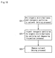
- a second aspect of the present invention relates to a manufacturing method of a pore forming agent for a porous body that comprising the steps of: mixing organic polymer particles and inorganic particles in a solvent; and, then, removing the solvent, thereby obtaining an aggregated body of the organic polymer particles and the inorganic particles.
- a third aspect of the present invention relates to a manufacturing method of a pore forming material for a porous body that comprising the steps of: forming organic micro-balloons having voids therein by carrying out polymerization in an organic solvent; and, then, mixing the organic micro-balloons and inorganic particles to carry out degassing thereon, thereby injecting the inorganic particles into the voids in the organic micro-balloons.
- a fourth aspect of the present invention relates to a manufacturing method of a pore forming material for a porous body that comprising the step of: carrying out polymerization in an organic solvent containing inorganic particles, thereby manufacturing organic polymer particles containing the inorganic particles therein.
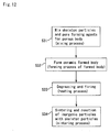
- a fifth aspect of the present invention relates to a manufacturing method of a porous body that comprising the steps of: preparing a mixture for a material for a formed body containing a pore forming material for a porous body made of an organic polymer and inorganic particles, and skeleton particles; forming a formed body from the mixture; and, then, firing the formed body.
- the particle size of the pore forming material for a porous body is desirably set in a range of 0.5 to 10.0 times the particle size of the skeleton particles, more desirably 0.5 to 5.0 times the particle size of the skeleton particles, and the firing temperature is desirably set in a range of 1000 to 2300°C.
- the skeleton particles are desirably made of particles of two kinds ormore, which have different average particle sizes, or ceramic particles, and metallic particles or semiconductor particles.
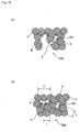
- a sixth aspect of the present invention relates to a porous body comprising skeleton particles and voids formed in the skeleton particles.
- an inorganic compound containing an element different from the skeleton particles, or a simple substance made of an element different from the skeleton particles is present at least on inner surface of the voids formed in the skeleton particles.
- a seventh aspect of the present invention relates to a porous body comprising skeleton particles and voids formed in the skeleton particles.
- a compound containing an element that is the same kind as the skeleton particles, or a simple substance made of an element that is the same kind as the skeleton particles is locally present at least on inner surface of the voids formed in the skeleton particles.
- An eighth aspect of the present invention relates to a porous body comprising skeleton particles and voids which are formed in the skeleton particles and the major diameter of said void is larger than the major diameter of the skeleton particle.
- an inorganic compound containing an element different from the skeleton particles, or a simple substance made of an element different from the skeleton particles is present at least on inner surface of the voids formed in the skeleton particles.
- a ninth aspect of the present invention relates to a porous body comprising skeleton particles and voids which are formed in the skeleton particles and the major diameter of said void is larger than the major diameter of the skeleton particle.
- a compound containing an element that is the same kind as the skeletonparticles, or a simple substancemade of an element that is the same kind as the skeleton particles is located on inner surface of said voids formed in said skeleton particles.
- the inorganic compound containing an element different from the skeleton particles, the simple substance made of an element different from the skeleton particles, the compound containing an element that is the same kind as the skeleton particles, or the simple substance made of an element that is the same kind as the skeleton particles is desirably a catalyst.
- a tenth aspect of the present invention relates to a porous body manufactured by: preparing a mixture for a material for a formed body containing a pore forming material for a porous body made of an organic polymer and inorganic particles, and skeleton particles; forming a formed body from the mixture; and, then, firing the formed body.
- the porous body desirably has a porosity in a range of 45 to 85%, more desirably 50 to 70%
- the skeleton particles are desirably made of silicon carbide particles
- the inorganic compound is desirably comprising at least one kind of material selected from the group consisting of alumina, mullite, silica, titania and silica alumina, or a compound containing Al, Si, Ti or B.
- an inorganic compound containing an element different from the skeleton particles or a simple substance made of an element different from the skeleton particles is present at a neck portion of the skeleton particles; more desirably, an inorganic compound containing an element that is different from the skeleton particles and deposited from a liquid phase or a simple substance made of an element different from the skeleton particles is present at a neck portion of the skeleton particles; and desirably, a compound containing an element that is the same kind as the skeleton particles or a simple substance made of an element that is the same kind as the skeleton particles is present at a neck portion of the skeleton particles.
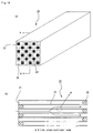
- An eleventh aspect of the present invention relates to a honeycomb structural body that comprises porous bodies each comprising skeleton particles and voids formed in the skeleton particles.
- an inorganic compound containing an element different from the skeleton particles, or a simple substance made of an element different from the skeleton particles is present at least on inner surface of the voids formed in the skeleton particles.
- a twelfth aspect of the present invention relates to a honeycomb structural body that comprises porous bodies each comprising skeleton particles and voids formed in the skeleton particles.
- a compound containing an element that is the same kind as the skeleton particles, or a simple substance made of an element that is the same kind as the skeleton particles is locally present at least on inner surface of the voids formed in the skeleton particles.
- a thirteenth aspect of the present invention relates to a honeycomb structural body that comprises porous bodies each comprising skeleton particles and voids which are formed in the skeleton particles and the major diameter of said void is larger than the major diameter of the skeleton particle.
- an inorganic compound containing an element different from the skeleton particles, or a simple substance made of an element different from the skeleton particles is present at least on inner surface of the voids formed in the skeleton particles.
- a fourteenth aspect of the present invention relates to a honeycomb structural body that comprises porous bodies each comprising skeleton particles and voids which are formed in the skeleton particles and the major diameter of said void is larger than the major diameter of the skeleton particle.
- a compound containing an element that is the same kind as the skeleton particles, or a simple substance made of an element that is the same kind as the skeleton particles is locally present at least on inner surface of the voids formed in the skeleton particles.
- the porous body has a porosity in a range of 45 to 85%, more desirably 50 to 70%.
- the skeleton particles are desirably made of silicon carbide particles, and the inorganic compound is desirably comprising at least one kind of material selected from the group consisting of alumina, mullite, silica, titania and silica alumina, or a compound containing Al, Si, Ti or B.
- an inorganic compound containing an element different from the skeleton particles or a simple substance made of an element different from the skeleton particles is present at a neck portion of the skeleton particles; more desirably, an inorganic compound containing an element that is different from the skeleton particles and deposited from a liquid phase or a simple substance made of an element different from the skeleton particles is present at a neck portion of the skeleton particles; and desirably, a compound containing an element that is the same kind as the skeleton particles or a simple substance made of an element that is the same kind as the skeleton particles is present at a neck portion of the skeleton particles.
- the inorganic compound containing an element different from the skeleton particles, the simple substance made of an element different from the skeleton particles, the compound containing an element that is the same kind as the skeleton particles, or the simple substance made of an element different from the skeleton particles is desirably a catalyst.
- a fifteenth aspect of the present invention relates to a honeycomb structural body that comprises porous bodies each of which is manufactured by: preparing a mixture for a material for a formed body containing a pore forming material for a porous body made of an organic polymer and inorganic particles, and skeleton particles; forming a formed body from the mixture; and, then, firing the formed body.
- the pore forming material for a porous body in accordance with the first aspect of the present invention comprises an organic polymer and inorganic particles, and since the inorganic particles can function as a reinforcing material of the pore forming material for a porous body, it is allowed to have higher mechanical strength in comparison with a pore forming material for a porous body made of only polymer particles.
- the above-mentioned pore forming material for a porous body when a porous body is manufactured by using the above-mentioned pore forming material for a porous body, it is possible to prevent the pore forming material for a porous body from being squashed upon forming, and even when a porous body is manufactured by using a forming method in which a high pressure is applied so as to carry out extrusion forming or the like, the above-mentioned pore forming material for a porous body according to the first aspect of the present invention makes it possible to provide a desired pore forming performance.
- the pore forming material for a porous body in accordance with the first aspect of the present invention is suitably used for manufacturing a porous body with a high porosity.
- the inorganic particles contained in the pore forming material for a porous body are alumina particles and the like, and upon using the material for manufacturing a porous body made of silicon carbide or the like, the pore forming material for a porous body is allowed to function as a sintering aid together with the pore forming function, so that it is possible to lower the firing temperature or accelerate the sintering process; thus, it becomes possible to manufacture a porous body that is superior in mechanical characteristics.
- the pore forming agent for a porous body in accordance with the present invention can be manufactured by using a relatively simple method, so that the resulting pore forming agent for a porous body provides a material used for manufacturing a porous body having superior mechanical characteristics.
- a pore forming agent for a porous body in which inorganic particles are contained in organic micro-balloons can be manufactured by using a relatively simple method, so that the resulting pore forming agent for a porous body provides a material used for manufacturing a porous body having superior mechanical characteristics, in the same manner as described above.
- a porous body of the fifth aspect of the present invention since the pore forming material for a porous body of the present invention is used, it becomes possible to suitably manufacture a porous body that has pores having a desired size and is superior in mechanical strength, even when the porous body is allowed to have a high porosity.
- the porous body in accordance with the sixth to tenth embodiments of the present invention is provided with pores having a large diameter, and in this structure, an inorganic compound containing an element different from the skeleton particles, a simple substance made of an element different from the skeleton particles, a compound containing an element that is the same kind as the skeleton particles, or a simple substance made of an element that is the same kind as the skeleton particles is present on inner surface of the voids (pore) formed in the skeleton particles; therefore, the porous body is suitably used for a honeycomb structural body and the like. The reason for this will be described later in detail.
- the honeycomb structural body in accordance with the eleventh to fourteenth aspects of the present invention is manufactured by using the porous body of the present invention; therefore, it becomes possible to provide a honeycomb structural body which has pores the diameter of which is controlled in a certain degree, and even in the case of a high porosity, it becomes possible to provide a honeycomb structural body which is free from cracks or the like, and has high strength and superior reliability.
- the pore forming material for a porous body of the present invention comprises organic polymer particles and inorganic particles.
- the pore forming material for a porous body is desirably an aggregate body of the organic polymer particles and the inorganic particles, or has a structure in which the inorganic particles are contained in the organic polymer particles.
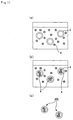
- Figs. 1(a) to 1(f), Figs. 2(a) to 2(f) and Figs. 3(a) to 3(c) are cross-sectional views each of which shows a specific example in which the pore forming agent for a porous body of the present invention is an aggregated body of the organic polymer particles and the inorganic particles.
- a plurality of organic polymer particles 2 and one inorganic particle 4 are aggregated with each other to form a porous aggregated body, and in Figs. 1(b) and 1(c) also, similar aggregated bodies 10b and 10c are formed; however, the number of the organic particles 4 is increased in the order of 1(b) and 1(c).
- the inorganic particles 4 and the organic polymer particles 2 which have approximately no hollows (voids) inside thereof, are used.
- inorganic particles having hollows therein (hereinafter, referred to as inorganic micro-balloons) 3 are used;
- the pore forming agent 10d for a porous body shown in Fig. 1(d) has a structure in which relatively smaller organic polymer particles 2 are aggregated on the periphery of a relatively large inorganic micro-balloon 3;
- the pore forming agent 10e for a porous body shown in Fig. 1(e) has a structure in which two pairs of those particles having the structure shown in Fig.
- the pore forming agent 10f for a porous body shown in Fig. 1(f) has a structure in which almost all the periphery of the inorganic micro-balloon 3 is covered with the inorganic polymer particles 2.
- this structure is defined as the following inorganic micro-balloon 5.
- the inorganic particle is used as a concept including the inorganic micro-balloon; however, when the inorganic particle is explained in parallel with the inorganic micro-balloon, it is referred to as an inorganic particle having no hollow formed therein.
- Figs. 2(a) and 2(b) show pore forming agents 20a and 20b for a porous body in which inorganic micro-balloons 3 are used
- the pore forming agent 20a for a porous body shown in Fig. 2(a) has a structure in which inorganic particles composed of inorganic micro-balloons 3 are adhered to the periphery of an aggregated body of organic polymer particles 2
- the pore forming agent 20b for a porous body shown in Fig. 2(b) has a structure in which organic polymer particles 2 are adhered to the periphery of an aggregated body constituted by inorganic micro-balloons 3.
- Figs. 2(c) to 2(f) show pore forming agents 20c to 20f for a porous body in which organic polymer particles having hollows therein (hereinafter, referred to also as organic micro-balloons) 5 are used, and the pore forming agent 20c for a porous body shown in Fig. 2(c) has a structure in which inorganic particles 4 are adhered to the periphery of an organic micro-balloon 5, and the pore forming agent 20d for a porous body shown in Fig. 2(d) has a structure in which almost all the periphery of an organic micro-balloon 5 is covered with inorganic particles 4.
- the organic polymer particle is used as a concept including the organic micro-balloon; however, when the organic polymer particle is explained in parallel with the organic micro-balloon, it is referred to as an organic particle having no hollow formed therein.
- a pore forming agent 20e for a porous body shown in Fig. 2(e) has a structure in which the organic micro-balloons 5 are adhered to the periphery of an aggregated body of inorganic particles 4, and a pore forming agent 20d for a porous body shown in Fig. 2(f) has a structure in which the inorganic particles 4 are adhered to the periphery of an aggregatedbody of the organic micro-balloons 5.
- a pore forming agent 30a for a porous body shown in Fig. 3(a) has a structure in which relatively large organic polymer particles 2 and relatively small inorganic particles 4 are combined with one another, and the inorganic particles 4 are placed in a manner so as to bury a space at which the relatively large organic polymer particles 2 are adhered to each other, and a pore forming agent 30b for a porous body shown in Fig. 3(b) has a structure in which organic polymer particles 2 and inorganic particles 4 are adhered to one another to form an aggregated body having a hollow therein.
- a pore forming agent 30c for a porous body shown in Fig. 3(c) has a structure in which organic polymer particles 2, inorganic micro-balloons 3, inorganic particles 4 and organic micro-balloons 5 are combined with one another in a mixed manner.
- the rate between the organicpolymerparticles 2 and/or the organicmicro-balloons 5 and the inorganic particles 4 and/or the inorganic micro-balloons 3 in the pore forming agent for a porous body is not particularly limited, and can be desirably varied depending on characteristics required for a porous body to be manufactured.
- the formed body containing the pore forming agent for a porous body is degreased and fired to manufacture a porous body; thus, voids (pores) are formed at portions that have been occupied by each of the pore forming agents 10a to 30c for a porous body.
- the porosity of the porous body can be adjusted, and by adjusting the size of each of the pore forming agents 10a to 30c for a porous body, the size of the pores can be adjusted.
- the lower limit value of the size of each of the pore forming agents 10a to 30c for a porous body is preferably set to 20 ⁇ m.
- the upper limit value of the size of each of the pore forming agents 10a to 30c for a porous body is preferably set to 60 ⁇ m, more preferably 40 ⁇ m.
- the inorganic particles 4 and the inorganic micro-balloons 3 are contained in the pore forming agents 10a to 30c for a porous body, a porous body in which the inorganic particles 4, the inorganic micro-balloons 3 and inorganic components and inorganic compounds generated by the inorganic micro-balloons 3 are adhered to the inside of each void (pore) in the porous body can be manufactured.
- the inorganic particles 4 and the inorganic micro-balloons 3 When the rate of the inorganic particles 4 and the inorganic micro-balloons 3 exceeds a predetermined level, the inorganic particles 4 and the inorganic micro-balloons 3 are adhered to a wall face of the void, or form a sintered body having a predetermined shape at one portion in the void to function as a reinforcing body for reinforcing the porous body (fired body) ; thus, the porous body is improved in its mechanical characteristics. Moreover, by using the inorganic micro-balloons 3, the mechanical characteristics of the porous body can be improved while the porosity is maintained at a high level; thus, it becomes possible to reduce the thermal capacity of the porous body. Since the organic components can be reduced upon forming the voids, it is possible to reduce the calorie upon manufacturing the porous body.
- the organic micro-balloons 5 since the absolute amount of organic components is small even when the pore forming material for a porous body is blended in the formed body at a high content (volume rate), it is possible to reduce the possibility of a thermal shock locally occurring due to abrupt decomposing and burning of the organic components upon firing (in particular, upon degreasing so as to remove the organic components). For this reason, it becomes possible to make the formed body (sintered body) less likely to generate cracking.
- a sintering aid may be used as the inorganic particles 4 and the inorganic micro-balloons 3, and this arrangement allows the pore forming material for a porous body to exert not only a pore forming function, but also functions as the sintering aid, to lower the firing temperature or to accelerate the firing process; thus, it becomes possible to manufacture a porous body that is superior in mechanical characteristics.
- each of the pore forming agents 10a to 30c for a porous body have high mechanical strength, the pore forming agent for a porous body is less likely to generate damage (or large deformation) even when a high pressure needs to be applied thereto so as to maintain a predetermined shape upon carrying out shape-formation processes, such as an extrusion-forming process, a press-forming process and the like, so that the shape of the pore forming agent in the formed body can be maintained.
- each of the pore forming agent 10a to 30c of a porous body is suitable for manufacturing a porous body having a porosity of 45% or more, in particular, a higher porosity of 50% or more.
- Figs. 4(a) and 4(b) as well as Figs. 5(a) to 5(c) are explanatory views that show specific examples in which the material composed of organic polymer particles containing inorganic particles is used as the pore forming agent for a porous body of the present invention.
- pore forming agents 40a and 40b for a porous body shown in Figs. 4(a) and 4(b), one or a plurality of inorganic particles 4 are contained in an organic micro-balloon 5.
- the inner space is not completely filled with inorganic particles 4 so that voids 5a still remain inside the organic micro-balloon 5.
- pore forming agents 50a and 50b for a porous body shown in Figs. 5(a) and 5(b)
- no voids remain therein, and the space formed inside the organic micro-balloon 5 is completely filled with one or a plurality of inorganic particles 4, and in a pore forming agent 50c for a porous body shown in Fig. 5(c), inorganic micro-balloons 3 are contained in the organic micro-balloon 5, and voids 5a also remain outside the inorganic micro-balloons 3.
- the numbers of the organic particles 4 and the inorganic micro-balloons 3 contained in the organic micro-balloon 5 are not particularly limited, and each of the numbers may be set to one or two or more.
- voids may remain in the organic micro-balloon 5, or the micro-balloon 5 may be filled with the inorganic particles 4 and the inorganic micro-balloons 3 so that no voids remain therein.
- pore forming agents 40a, 40b, 50a, 50b and 50c for a porous body are used to manufacture a porous body through degreasing and firing processes of the formed body containing the pore forming agent for a porous body, pores (voids) are formed in the portions where the pore forming agents 40a to 50c for a porous body have been present.
- the porosity of the porous body can be adjusted, and by adjusting the sizes of the pore forming agents 40a to 50c for a porous body, the size of the pores can be adjusted.
- the particle size of each of the pore forming agents 40a to 50c for a porous body is not particularly limited, and may be properly selected and set by taking the pore diameter of the porous body to be manufactured into consideration, and the lower limit value is preferably set to 20 ⁇ m, more preferably 60 ⁇ m.
- the inorganic particles 4 and the inorganic micro-balloons 3 are contained in the pore forming agents 40a to 50c for a porous body, it becomes possible to manufacture a porous body having a structure in which the inorganic particles 4 and the inorganic micro-balloons 3 are adhered to the inside of the pore (void).
- the inorganicparticles 4 and the inorganicmicro-balloons 3 function as reinforcing bodies that reinforce the porous body (fired body) so that the mechanical characteristics of the porous body can be improved.
- the inorganic micro-balloons 3 By using the inorganic micro-balloons 3, it becomes possible to improve the mechanical characteristics of the porous body while maintaining the porosity in a high level, and consequently to reduce the thermal capacity of the porous body. Moreover, since the organic component canbe reduced upon forming the voids, it becomes possible to reduce the quantity of heat generated upon manufacturing the porous body.
- a sintering aid may be used as the inorganic particles 4 so that the pore forming material for a porous body functions not only as a pore forming material, but also as a sintering aid; thus, it becomes possible to reduce the firing temperature or to accelerate the firing process to manufacture a porous body that is superior in mechanical characteristics.
- each of the pore forming agents 40a to 50c for a porous body has high mechanical strength, the pore forming agent for a porous body is less likely to generate damage (or large deformation) even when a high pressure needs to be applied thereto so as to maintain a predetermined shape upon carrying out shape-formation processes, such as an extrusion-forming process, a press-forming process and the like; thus, it becomes possible to maintain the shape of the pore forming agent in the formed body.
- each of the pore forming agent 40a to 50c for a porous body is suitable for manufacturing a porous body having a porosity of 45% or more, in particular, a higher porosity of 50% or more.
- Each of pore forming agents for a porous body shown in Figs. 5(a) and 5(b) has no void in the organic micro-balloon 5, and the organic micro-balloon 5 and the inorganic particle 4 are made in close-contact with each other so that the strength of the pore forming agent for a porous body is increased. Moreover, it becomes possible to prevent the occurrence of a local thermal shock due to abrupt decomposition and burning of the organic components.
- examples thereof may include alumina balloons, glass micro-balloons, shirasu balloons, fly ash balloons (FA balloons), mullite balloons and the like.
- alumina balloons are more desirably used.
- the term, "balloons”, is used as a concept including, so-called bubbles and hollow spheres, and refers to hollow particles containing pores inside thereof. Since the inorganic micro-balloons 3 have voids therein, the inorganic micro-balloons function as a pore forming agent even when used alone; however, the application of the inorganic micro-balloons 3 makes it possible to reduce the amount of the organic polymer particles. Moreover, the application of the inorganic micro-balloons to the pore forming agent for a porous body makes it possible to adjust the blend amount of the inorganic particles.
- examples of the inorganic particles 4 may include particles made of ceramics, and with respect to the particles made of ceramics, examples thereof may include particles made of nitride ceramics such as aluminum nitride, silicon nitride, boron nitride, titanium nitride and the like, carbide ceramics such as silicon carbide, zirconium carbide, titanium carbide, tantalum carbide, tungsten carbide, boron carbide (B 4 C) and the like, oxide ceramics such as alumina, zirconia, cordierite, mullite, silica and the like, and the like.
- nitride ceramics such as aluminum nitride, silicon nitride, boron nitride, titanium nitride and the like
- carbide ceramics such as silicon carbide, zirconium carbide, titanium carbide, tantalum carbide, tungsten carbide, boron carbide (B 4 C) and the like
- oxide ceramics such as
- examples thereof may include particles made of metal such as Si, Fe, Al and the like and particles made of a metal compound such as iron oxide.
- particles made of ceramics are preferably used, and particles made of oxide ceramics are more preferably used.
- examples thereof may include a polymer of a mixed monomer composition including a hydrophilic monomer, a multifunctional monomer and other monomers, and the like.
- examples thereof may include methyl(metha)acrylate, (metha)acrylonitrile, (metha)acrylamide, (metha)acrylic acid, glycidyl(metha)acrylate, 2-hydroxyethyl methacrylate, 2-hydroxypropyl methacrylate, vinylpyridine, 2-acryloyloxyethyl phthalic acid, itaconic acid, fumaric acid, dimethylaminomethyl methacrylate and the like, and preferable examples may include methyl methacrylate, (metha) acrylic acid, 2-hydroxyethyl methacrylate and the like. Each of these may be used alone, or two or more kinds of these may be used in combination.
- examples thereof may include di (metha) acrylate, tri (metha) acrylate and the like.
- the di(metha)acrylate may include ethyleneglycol di(metha)acrylate, diethyleneglycol di(metha)acrylate, triethyleneglycol di(metha)acrylate, 1,6-hexane diol di(metha)acrylate, trimethylol propane di(metha)acrylate and the like.
- the tri(metha)acrylate may include trimethylolpropane tri(metha)acrylate, ethyleneoxide-modified trimethylolpropane tri (metha) acrylate, pentaerythritol tri(metha)acrylate and the like.
- examples of the multifunctional monomer may include pentaerythritol tetra(metha)acrylate, dipentaerythritol hexa(metha)acrylate, di or triallyl compounds, such as diallyl phthalate, diallyl maleate, diallyl fumarate, diallyl succinate, triallyl isocyanurate and the like, divinyl compounds such as divinyl benzene, butadiene and the like, and the like. Each of these may be used alone, or two or more kinds of these may be used in combination.
- Examples of the other monomers may include alkyl(metha)acrylates such as ethyl(metha)acrylate, propyl (metha) acrylate, butyl (metha) acrylate, cumyl(metha)acrylate, cyclohexyl(metha)acrylate, myristyl(metha)acrylate, palmityl(metha)acrylate, stearyl(metha)acrylate and the like; aromatic vinyl monomers such as styrene, ⁇ -methylstyrene, p-methylstyrene, p-chlorostyrene and the like; vinyl esters such as vinyl acetate, vinyl propionate and the like; halogen-containing monomers such as vinyl chloride, vinylidene chloride and the like; ethylene, propylene, butadiene and the like. Each of these may be used alone, or two or more kinds of these may be used in combination.
- alkyl(metha)acrylates such as ethyl
- organic micro-balloons 5 those materials that are the same as those for the organic polymer particles 2 may be used.
- the particle size thereof is desirably set to 0.5 to 10.0 times, more desirably 0.5 to 5.0 times the skeleton particles of the porous body.
- This arrangement makes it possible to provide proper pore forming effects and consequently to increase the strength of the porous body.
- the pore forming agents 10a to 50c for a porous body are desirably designed to have a spherical shape. This arrangement allows the agents to be easily dispersed upon manufacturing the formed body, and makes it possible to suppress the pressure loss to a low level when the porous body is used as a filter for purifying exhaust gases.
- the porosity of each of the pore forming materials 10a to 50c for a porous body is desirably set to a lower limit value of 10% by volume, and an upper limit value of 70% by volume.
- the lower limit of the porosity is desirably set to 20% by volume
- the upper limit of the porosity is desirably set to 60% by volume.
- the porosity of the pore forming materials 10a to 50c for a porous body is found through the following processes: the respective constituent components of the organic polymers and the inorganic particles of the pore forming material are identified through gas chromatography, fluorescent X-ray analyses and the like, and the respective densities are calculated by using a specific gravity bottle or the like; thereafter, the organic components are burned and eliminated so that the volume of the organic polymer is calculated based upon the reduced weight corresponding to the organic components, with the rest of weight being defined as the weight of the inorganic particles; thus, the porosity can be calculated based upon the respective volumes.
- the volume ratio of the organic micro-balloons 5 to the inorganic particles 4 desirably has a lower limit value of 0.1 and an upper limit value of 250, more desirably an upper limit value of 10.
- a manufacturing method of a pore forming agent for a porous body First, a manufacturing method of a pore forming agent for a porous body made of an aggregate body of organic polymer particles and inorganic particles is explained.
- the pore forming agent for a porous body made of an aggregate body of organic polymer particles and inorganic particles is manufactured, after organic polymer particles (and/or organic micro-balloons) and inorganic particles (and/or inorganic micro-balloons) have been mixed in a solvent, the solvent is removed so that an aggregate body of the organic polymer particles and the inorganic particles is obtained.
- Fig. 6 is a flowchart that shows manufacturing processes of organic micro-balloons
- Figs. 7(a) to 7(c) are cross-sectional views that show the manufacturing processes of organic micro-balloons.
- the organic micro-balloons 5 are obtained through a monomer solution preparation process (step S1) and an organic micro-balloon formation process (step S2).
- the mixed monomer 11 made of a hydrophilic monomer, a multifunctional monomer and other monomers, is mixed with a non-polymerizable organic solvent 12 so that the mixed monomer 11 is suspended in the non-polymerizable organic solvent 12 (step S1).
- the monomer components are polymerized so that organic micro-balloons 5 containing the non-polymerizable organic solvent 5 are obtained (step S2).
- the non-polymerizable organic solvent 12 in the organic micro-balloons 5 is removed so that the organic micro-balloons 5 not containing the non-polymerizable organic solvent 12 may be obtained; alternatively, the product obtained in Fig. 7(b), as it is, may be used as a material for the pore forming agent for a porous body.
- the suspension polymerizing method is desirably used, since this method easily controls the particle size and also easily manufactures particles that include effective voids.
- commercially available organic micro-balloons, as they are, may be utilized.
- the inorganic micro-balloons 3 commercial products made of the above-mentioned compounds may be used.
- Fig. 8 is a flowchart that shows manufacturing processes of a pore forming agent for a porous body
- Figs. 9 (a) to 9(c) are cross-sectional views that show the manufacturing processes of the pore forming agent for a porous body.
- pore forming agents 10a to 30c for a porous body are obtained through a mixed slurry preparation step (step S11), a filtering process (step S12) and a degassing process (step S13).
- a slurry of the organic micro-balloons 5 containing a solvent is mixed with a slurry containing inorganic particles 4 having a predetermined concentration so that a mixed slurry containing the organic micro-balloons 5 and the inorganic particles 4 in the solvent 18 is prepared (step S11).
- a mixture of the organic micro-balloons 5 and the inorganic particles 4 is obtained through a filtering process or the like (step S12), and the mixture is immediately subjected to degassing so as to increase the cohesion thereof to prepare a pore forming agent for a porous body (step S13).
- a pore forming agent for a porous body made of an aggregate body of the inorganic micro-balloons 5 and the inorganic particles 4 is obtained; however, organic polymer particles 2 may be used in place of the organic micro-balloons 5, and a mixed material containing the inorganic micro-balloons 5 and the organic polymer particles 2 at a predetermined ratio may also be used. Moreover, inorganic micro-balloons 3 may be used in place of the inorganic particles 4, and a mixed material containing the inorganic particles 4 and the inorganic micro-balloons 3 at a predetermined ratio may also be used.
- the particle size of the pore forming agent for a porous body can be adjusted by alternating the concentration of slurry, the sizes and kinds of the respective material particles, the kinds of solvents, the temperature upon filtering, and the like. Moreover, the particle size can be also changed by repeating the above-mentioned processes. Upon repeating the above-mentioned processes, the porosity in the pore forming agent for a porous body can be changed by changing the particle size of the inorganic particles 4.
- a sol containing very fine inorganic particles such as an alumina sol, a silica sol and the like
- the resulting pore forming agent for a porous body may be put into a solution such as an alumina sol, a silica sol or the like, so that a set of processes including filtering, degassing and drying processes is repeated a plurality of times.
- pore forming agents 20c and 20d for a porous body in which a number of relatively small organic polymer particles 2 are adhered to the periphery of each of relatively large inorganic micro-balloons 3 and pore forming agents for a porous body in which a number of relatively small organic polymer particles 2 are adhered to the periphery of each of relatively large inorganic particles 4 are manufactured a material, prepared by dissolving a polymer in a solvent, is applied or sprayed onto the inorganic micro-balloons 3 (inorganic particles 4), and the resulting matter is impregnated with a solvent, and then subjected to a chemical process (such as an oxidizing process), or the resulting matter is subjected to a physical process (such as a grinding process and a pulverization process); thus, the target agents can be manufactured.
- a chemical process such as an oxidizing process
- a physical process such as a grinding process and a pulverization process
- pore forming agents 10d, 10e and 10f for a porous body in which a number of relatively small inorganic particles 4 are adhered to the periphery of each of relatively large organic micro-balloons 5 and pore forming agents for a porous body in which a number of relatively small inorganic particles 4 are adhered to the periphery of each of relatively large organic polymer particles 2 are manufactured, a material, prepared by dissolving a polymer in a solvent containing inorganic particles, such as an alumina sol, is applied or sprayed onto the organic micro-balloons 5 (organic polymer particles 2), and the resulting matter is impregnated in a solution, and then subjected to a chemical process (such as an oxidizing process), or the resulting matter is subjected to a physical process (such as a grinding process and a pulverization process); thus, the target agents can be manufactured.
- a chemical process such as an oxidizing process
- a physical process such as a grinding
- the conditions (particle size, density rates and the like) of the surface inorganic particles and the inner inorganic particles can be altered without the necessity of changing the particle size and the like of the inorganic particles and organic polymer particles in the slurry.
- the conditions (particle size, density rates and the like) of the surface inorganic particles and the inner inorganic particles can be altered.
- a pulverization process may be carried out. Furthermore, by subjecting the inorganic particles 4 to a chemical process (such as an oxidizing process) and a physical process (such as a grinding process), the weight per one inorganic particle can be reduced so that the ratio between the organic component and the inorganic component can be adjusted; thus, it becomes possible to alter the strength of the pore forming material.
- a chemical process such as an oxidizing process
- a physical process such as a grinding process
- Fig. 10 is a flowchart that shows manufacturing processes of a pore forming agent for a porous body
- Figs. 11(a) to 11(c) are cross-sectional views that show manufacturing processes of the pore forming agent for a porous body.
- the organic micro-balloons 5 are manufactured through the aforementioned steps S1 and S2. In this case, desirably, the solvent in the organic micro-balloons is preliminarily removed.
- the organic micro-balloons 5 and the inorganic particles 4 are mixed in a solvent (step S21), and degassed so that the inorganic particles 4 are injected into each of the organic micro-balloons 5 (step S22); thus, the solvent is removed (step S23) so that a pore forming agent for a porous body in which the inorganic particles 4 are contained in the organic micro-balloons 5 is obtained.
- a pore forming material 40b for a porous body can be manufactured through the following processes: a mixing process (step S21) in which, for example, as shown in Fig. 11 (a), the organic micro-balloons 5 are put into a slurry 41 containing inorganic particles 4 having a predetermined concentration to be mixed therein, an injection process (step S22) in which, as shown in Fig. 11(b), the inorganic particles 4 are injected into each of hollow polymer particles 2 in a degassed state so as to be transferred thereto, and a drying process (step S23) in which, as shown in Fig. 11(c), the resulting matter is subjected to solvent-removing and drying.
- a pore forming agent 50c for a porous body in which the inorganic micro-balloons 3 are housed in voids of the organic micro-balloons 5, as shown in Fig. 5(c), can be obtained.
- a sol containing very fine inorganic particles such as an alumina sol, a silica sol and the like, may be used.
- processes in which the organic micro-balloons 5 are put into a slurry containing inorganic particles and in which the inorganic particles 4 are transferred into the organic micro-balloons 5 and the resulting matter is dried are repeated a plurality of times.
- inorganic particles are coated with an organic polymer
- organic micro-balloons 5 upon manufacturing the organic micro-balloons 5, inorganic particles such as alumina, silica and the like are preliminarily mixed in the above-mentioned mixed monomer, and the mixed monomer is then polymerized by using a conventionally known encapsulating method so that a pore forming material for a porous body in which the inorganic particles 4 are coated with the organic polymer particles 2 (organic polymer) can be manufactured.
- a pore forming agent 10f for a porous body as shown in Fig. 1(f), that is, the method including the processes in which a material prepared by dissolving a polymer in a solvent is applied to the inorganic micro-balloons 3 (inorganic particles 4) and the resulting matter is impregnated with a solution, and then subjected to a chemical process (for example, an oxidizing process), or the resulting matter is subjected to a physical process (for example, a grinding process and a pulverization processes), a pore forming material for a porous body in which the inorganic particles 4 are coated with the organic polymer particles 2 (organic polymer) can be also manufactured.
- a chemical process for example, an oxidizing process
- a physical process for example, a grinding process and a pulverization processes
- the states (particle size, density rates and the like) of the surface inorganic particles and the inner inorganic particles can be altered without the necessity of changing the particle size and the like of the inorganic particles and organic polymer particles in the slurry.
- the states (particle size, density rates and the like) of the surface inorganic particles and the inner inorganic particles can be altered.
- a pulverization process may be carried out. Furthermore, by subjecting the inorganic particles 4 to a chemical process (such as an oxidizing process) and a physical process (such as a grinding process), the weight per one inorganic particle can be reduced so that the ratio between the organic component and the inorganic component can be adjusted; thus, it becomes possible to alter the strength of the pore forming material.
- a chemical process such as an oxidizing process
- a physical process such as a grinding process
- FIG. 12 is a flowchart that shows manufacturing processes of the porous body
- Figs. 13(a) to 13(d) are cross-sectional views that show the manufacturing processes of the porous body. Basically, even when any one of the pore forming agents for a porous body shown in Figs.
- a porous body can be manufactured through approximately the same processes; therefore, description will be given of a case in which the pore forming agent 40b for a porous body (in which a plurality of inorganic particles 4 are contained in each of the inorganic micro-balloons 5), shown in Fig. 4(b), is used.
- a porous body 130 in manufacturing process of a porous body, can be obtained through the following processes: a mixing process (step S31) in which skeleton particles and a pore forming material (made of organic polymer particles and inorganic particles) are mixed with each other, a formed-body forming process (step S32) in which a formed body 7 is formed, a heating process (step S33) in which the formed body 7 is degreased and fired so that the organic polymer particles are thermally decomposed, and a sintering process (step S34) in which the firing process is continued to carry out a sintering reaction while the reaction between the inorganic particles and the skeleton particles is accelerated.
- a mixing process step S31
- a pore forming material made of organic polymer particles and inorganic particles
- the organic polymer particles 2 forming the pore forming agent 40b for a porous body are thermally decomposed to form a gas, and this gas is released to form voids, while the inorganic component, which functions as a sintering aid for assisting the sintering process at a low temperature, accelerates the mutual sintering reaction between the skeleton particles so that a porous body, which has high mechanical strength while maintaining a high porosity, can be obtained; thus, it becomes possible to carry out the sintering process at a low temperature.
- silicon carbide particles are desirably used as the skeleton particles, and a pore forming material for a porous body containing alumina is desirably used as the pore forming material for a porous body.
- alumina contained in the pore forming material for a porous body, functions as the sintering aid to lower the firing temperature or to accelerate the sintering process; thus, it becomes possible to manufacture a porous body that is superior in mechanical characteristics.
- the pore forming material 40b for a porous body and the skeleton particles 6 are mixed.
- examples thereof may include particles made of nitride ceramics such as aluminum nitride, silicon nitride, boron nitride, titanium nitride and the like, carbide ceramics such as silicon carbide, zirconium carbide, titanium carbide, tantalum carbide, tungsten carbide, boron carbide (B 4 C) and the like, oxide ceramics such as alumina, zirconia, cordierite, mullite, silica and the like, and the like.
- silicon-containing ceramics in which metal silicon is blended in the above-mentioned ceramics and ceramics which are bonded by silicon and a silicate compound may also be used, and, for example, a material, prepared by blending metal silicon or the like in silicon carbide.
- metal such as aluminum, iron, metal silicon or the like may be used as the skeleton particles 6, or the above-mentioned ceramics and metal may be used in combination.
- a semiconductor of silicon or the like may be used as the skeleton particles 6, and the semiconductor may be used in combination with the above-mentioned ceramics.
- those which are less likely to shrink in the succeeding firing process are desirably used, and for example, those particles, prepared by combining 100 parts by weight of powder having an average particle size in a range of about 5.0 to 50 ⁇ m with 5 to 65 parts by weight of powder having an average particle size in a range of about 0.1 to 3.0 ⁇ m, are desirably used.
- the particle size of the pore forming agent for a porous body is desirably set in a range of 0. 5 to 10 times, more desirably 0.5 to 5.0 times the particle size of the skeleton particles 6.
- a porous body that is superior in performance, such as a small pressure loss and the like, as a filter, when used as a filter for purifying exhaust gases.
- a material, prepared by adding a binder, a dispersant solution and the like to the pore forming material 40b for a porous body and skeleton particles 6, if necessary, is mixed by using an attritor or the like, and sufficiently kneaded by using a kneader or the like.
- binder although not particularly limited, examples thereof may include methylcellulose, carboxy methylcellulose, hydroxy ethylcellulose, polyethylene glycol, phenol resins, epoxy resins and the like.
- dispersant solution although not particularly limited, examples thereof may include an organic solvent such as benzene or the like, alcohol such as methanol or the like, water and the like.
- the blend amount of the pore forming material 40b for a porous body is properly set depending on the porosity or the like of the porous body 10 to be manufactured, without being particularly limited, and is normally set in a range of about 10 to 200 parts by weight with respect to 100 parts by weight of the skeleton particles.
- it is desirably blended so that the organic polymer component in the pore forming material 40b for a porous body is set in a range of 5 to 50 parts by weight with respect to 100 parts by weight of the skeleton particles.
- the blend amount of the binder is normally set in a range of about 1 to 10 parts by weight with respect to 100 parts by weight of ceramic powder.
- the dispersant solution is properly blended so that the viscosity of the mixture is set within a predetermined range.
- a forming assistant may be added thereto, if necessary.
- the forming assistant although not particularly limited, examples thereof may include ethylene glycol, dextrin, fatty acid soap, polyalcohol and the like.
- a pore forming material made of only the aforementioned inorganic balloons and organic polymer, may be added thereto, if necessary.
- the above-mentioned mixture is formed to manufacture a formed body 7 made of a pore forming material 1 for a porous body and the skeleton particles 6.
- the forming process of the mixture is carried out by an extrusion-forming process or the like.
- the organic polymer particles 2 are heated to be thermally decomposed to be a gas 8 so that the organic polymer particles 2 are eliminated to form pores (voids) 9.
- the heating treatment may be carried out in divided processes including a drying process, a degreasing process and a firing process.
- the drying process may be carried out on the formed body by using a dryer, such as a microwave dryer, a hot-air dryer, a dielectric dryer, a decompression dryer, a vacuum dryer, a freeze dryer or the like.
- the conditions of the degreasing process and the firing process may be set in the same manner as those conditions conventionally used for manufacturing a porous body.
- the degreasing process may be carried out, for example, under a heating condition to a temperature in a range of about 300 to 650°C in an oxygen-containing atmosphere.
- the firing process may be carried out, for example, under a heating condition to a temperature in a range of about 1000 to 2300°C in an inert gas atmosphere such as nitrogen, argon or the like.
- the inorganic particles 4 contained in the pore forming material 40b for a porous body include a component to serve as a sintering aid, the inorganic particles 4 and a reaction product (inorganic compound) 400 resulting from the reaction between the inorganic particles 4 and the skeleton particles 6 are generated on the inner-wall surface of each pore (void) 9, as shown in Fig. 13(d).
- the inorganic particles and the like serve as a sintering aid, it becomes possible to lower the firing temperature in comparison with a case where the skeleton particles are sintered alone. Moreover, by accelerating the firing process, it becomes possible to manufacture a porous body 140 that is superior in mechanical characteristics. For example, in the case where silicon carbide powder is used as the aggregate, if alumina is used as the inorganic particles, the firing temperature (normally, about 2200°C) can be lowered to a range of about 100 to 300°C.
- FIGs. 14(a) and 14(b) are explanatory views that show another embodiment of the porous body.
- a porous body 140a shown in Fig. 14 (a), is constituted by skeleton particles 6 and voids 9 formed in the skeleton particles 6, and an inorganic compound (or a simple substance) 410 containing an element different from the skeleton particles 6 is adhered to at least a inner surface (inner wall) of the voids 9 formed in the skeleton particle 6.
- the inorganic compound (or a simple substance) 410 that contains an element different from the skeleton particles 6 firmly bonds the skeleton particles 6 to each other, even if the voids 9 are large, it becomes possible to maintain the breaking strength of the porous body 140a in a high level.
- the inorganic compound or the simple substance is referred to simply as inorganic compound.
- the inorganic compound 410 may be inorganic particles 4 contained in the pore forming agent for a porous body, or may be a product formed through the reaction between the inorganic particles 4 and the skeleton particles 6, or a product derived from the inorganic particles 4 that have been changed through a heating process or the like.
- a porous body 140b shown in Fig. 14(b), is constituted by skeleton particles 6 and voids 9, formed in the skeleton particles 6, said void has a major diameter L that is larger than a maj or diameter 1 of the skeleton particle, and an inorganic compound 410 containing an element different from the skeleton particles 6 is adhered to at least a inner surface of the void 9 formed in the skeleton particle 6 so that the inorganic compound 410 firmly bonds the skeleton particles 6 to one other.
- the porous body 140b is allowed to have a void 9 (pore) that is larger than a void that would be originally formed by the skeleton particles 6, and, for example, when this is used as a filter, a fluid, such as gas or liquid, is allowed to easily flow to lower the pressure loss.
- a fluid such as gas or liquid
- the filter is used for a long time, the fluid is filtered not only through the wall surface of the filter, but also through the inside of the wall so that the pressure loss can be reduced.
- FIGs. 15(a) and 15(b) are explanatory views that show still another embodiment of the porous body.
- a porous body 150a shown in Fig. 15(a), is constituted by skeleton particles 6 and voids 9 formed in the skeleton particles 6, and a compound containing an element that is the same kind as the skeleton particles 6, or a simple substance 420 (hereinafter, referred to as the same kind-element containing compound) composed of an element that is the same kind as the skeleton particles 6, is locally present on at least on inner surface (inner wall) of the voids 9 formed in the skeleton particles 6.
- the same kind-element containing compound 420 is locally present refers to the fact that, for example, when silicon carbide is adopted as the skeleton particles 6, SiO 2 and Si (silicon) are locally present.
- the skeleton particles 6 are composed of one kind or two ormore kinds of compounds or a simple substance
- a compound containing at least one of elements forming the above-mentioned compounds or a simple substance is locally present.
- the same kind-element containing compound 420 firmly bonds the skeleton particles to each other, even if the voids 9 are large, it is possible to maintain the breaking strength of the porous body 150a in a high level.
- a porous body 150b shown in Fig. 15(b), is constituted by skeleton particles 6 and voids 9, formed in the skeleton particles 6, said void has a major diameter L that is larger than a major diameter 1 of the skeleton particle 6, and the same kind-element containing compound 420 is locallypresent at least on inner surface of the voids 9 formed in the skeleton particles 6.
- the porous body 150b is allowed to have a void 9 (pore) that is larger than a void that would be originally formed by the skeleton particles 6, and, for example, when this is used as a filter, a fluid, such as gas or liquid, is allowed to easily flow to lower the pressure loss.
- the filter when used for a long time, the fluid is filtered not only through the wall surface of the filter, but also through the inside of the wall so that the pressure loss can be reduced. Moreover, even in the case where such large voids 9 are contained, since the same kind-element containing compound 420 firmly bonds the skeleton particles to each other, it is possible to maintain the breaking strength of the porous body 150b in a high level.
- FIGs. 16(a) to 16(c) are explanatory views that show still another embodiment of the porous body.
- a porous body 160a shown in Fig. 16(a), is designed so that an inorganic compound 410 containing an element different from the skeleton particles 6 is present at least on inner surface (inner wall) of the voids 9 formed in the skeleton particles 6(6a,6b).
- the inorganic compound 410 may be contained in the skeleton particles 6b.
- metal or a semiconductor is desirably used.
- the metal examples thereof may include aluminum, iron, silicon and the like, and with respect to the semiconductor, examples thereof may include silicon and the like.
- a porous body 160b shown in Fig. 16(b), is designed so that an inorganic compound 410 containing an element different from the skeleton particles 6 is present at least on inner surface(inner wall) of the voids 9 formed in the skeleton particles 6.
- the inner wall of the void 9 is coated with a catalyst (catalyst supporting member) 430.
- the porosity of the porous body of the present invention is desirably set in a range of 45 to 85%, more desirably 50 to 85%. Since the porosity of the porous body of the present invention is set in a range of 45 to 85%, it is possible to properly maintain the shape upon manufacturing a porous body, and consequently to manufacture the porous body without causing a reduction in the strength. Moreover, when the above-mentioned porous body is used as a filter, it becomes possible to maintain the initial pressure loss in a low level, and also to suppress an increase in the pressure loss due to deposition of the filtered matters.
- the above-mentioned porosity can be measured through conventionally knownmethods, such as a mercury inj ectionmethod, Archimedes method, ameasuringmethodusing a scanning electronic microscope (SEM), and the like.
- the major diameter of the void is desirably set in a range of 100 to 150% of the major diameter 1 of the skeleton particle.
- the voids 9 contained in the porous body only those voids the major diameter L of which is the same as the major diameter 1 of the skeleton particle or larger than the major diameter 1 of the skeleton particle are not necessarily contained, and those voids the major diameter L of which is smaller than the major diameter 1 of the skeleton particle may also be contained in a mixed manner.
- the major diameter 1 of the skeleton particle and the major diameter L of the void can be calculated through the following processes in which the porous body is observed at arbitrary 10 points thereof through an SEM system under a magnification of about 350 times so that calculations are made based upon the average value.
- the average pore diameter of the porous body is desirably set in a range of 5 to 100 ⁇ m.
- the average pore diameter of less than 5 ⁇ m tends to cause a high pressure loss.
- the average pore diameter of the porous body exceeding 100 ⁇ m causes the pore diameter to become too large, failing to completely capture particulates, when the porous body is used as a filter for an exhaust gas purifying device.
- examples thereof may include nitride ceramics such as aluminum nitride, silicon nitride, boron nitride, titanium nitride and the like; carbide ceramics such as silicon carbide, zirconium carbide, titanium carbide, tantalum carbide, tungsten carbide and the like; oxide ceramics such as alumina, zirconia, cordierite, mullite, silica and the like; metals such as Si, Fe, Al and the like; and metal compounds such as iron oxide.
- nitride ceramics such as aluminum nitride, silicon nitride, boron nitride, titanium nitride and the like
- carbide ceramics such as silicon carbide, zirconium carbide, titanium carbide, tantalum carbide, tungsten carbide and the like
- oxide ceramics such as alumina, zirconia, cordierite, mullite, silica and the like
- metals such as Si, Fe, Al and
- the inorganic compound 410 is desirably comprising at least one kind of oxide ceramics, for example, selected from the group consisting of alumina, mullite, silica, titania and silica-alumina, and is more desirably prepared as a compound containing Al, Si, Ti or B.
- oxide ceramics for example, selected from the group consisting of alumina, mullite, silica, titania and silica-alumina, and is more desirably prepared as a compound containing Al, Si, Ti or B.
- the compound containing Al, Si, Ti or B example thereof may include the above-mentioned aluminum nitride, silicon nitride, boron nitride, titanium nitride and the like. These materials allow the catalyst 430 to be easily supported thereon.
- the surface layer of the oxide ceramics is allowed to have a functional group having a polarity, such as an OH group or the like, so that upon applying a catalyst onto the porous body, an oxide catalyst (perovskite type), a catalyst supporting member (coat layer having a high specific surface area, such as alumina, titania, zirconia or the like) and a catalyst can be easily supported thereon, and the catalyst, once supported thereon, becomes less likely to be separated.
- each of these inorganic compounds itself may be a catalyst.
- the inorganic compound 410 is made of oxide ceramics, it is possible to prevent corrosion of the porous body. This is presumably because, in the case where the inorganic compound 410 is made of oxide ceramics, components contained in exhaust gases, such as sulfur, alkali metals, alkali-earth metals and the like, are preferentially reacted with the oxide ceramics, when the porous body is used as a filter for purifying exhaust gases; thus, it becomes possible to competitively prevent the skeleton particles forming the porous body from reacting with sulfur and the like in exhaust gases, and consequently to prevent the porous body from being corroded.
- exhaust gases such as sulfur, alkali metals, alkali-earth metals and the like
- the porous body of the present invention desirably has a structure in which the inorganic compound 410 or the same kind-element containing compound 420 is present at the neck portion 600 of the skeleton particles 6.
- Fig. 17(b) is a scanning electron microscopic (SEM) photograph that shows a specific shape in this case.
- SEM scanning electron microscopic
- the inorganic compound 410 is desirably prepared as a crystal compound (simple substance) that has been redeposited from a liquid phase. Since it is derived from the liquid phase, a fused solution is once gathered to the neck portion due to surface tension, and the redeposition is then allowed to progress so that the inorganic compound (simple substance) 410 is easily formed on the neck portion.
- the neck portion 600 of the skeleton particles 6 refers to one portion of inner surface of the voids formed in the skeleton particles, which corresponds to an area in the vicinity of the periphery of an interface at which the skeleton particles are made in contact with each other.
- the alumina is redeposited on the neck portion of the silicon carbide from the liquid phase, or allowed to form a composite material.
- the honeycomb structural body of the present invention comprises the above-mentioned porous body of the present invention.
- Fig. 18 is a perspective view that schematically shows one example of the honeycomb structural body of the present invention
- Fig. 19 (a) is a perspective view that schematically shows one example of a porous ceramic member (porous body) that forms the honeycomb structural body of the present invention
- Fig. 19(b) is a cross-sectional view taken along line A-A of Fig. 19(a).
- the porous ceramic member 20 has a structure in which a number of through holes 21 are placed in parallel with one another in the length direction so that a partition wall 23 that separates the through holes 21 from each other is allowed to function as a filter.
- each of the through holes 21 formed in the porous ceramic member 20 has either of its ends on the inlet-side and outlet-side of exhaust gases sealed with a plug 22; thus, exhaust gases that have entered one of the through holes 21 are allowed to flow out of another through hole 21 after always passing through the partition wall 23 that separates the corresponding through holes 21.
- the sealing material layer 13 is provided so as to prevent exhaust gases from leaking through the peripheral portion of each ceramic block 15 when the honeycomb structural body 10 is installed in an exhaust passage of an internal combustion engine.
- the porous ceramic member 20 is constituted by porous bodies 130, 140a, 140b, 150a, 150b, 160a, 160b and 160c (hereinafter, described as porous bodies 130 to 160c) as shown in the aforementioned Figs. 13 to 16.
- Fig. 20 is an enlarged cross-sectional view showing the partition wall 23 of the porous ceramic member 20.
- the partition wall is basically made of one of the aforementioned porous bodies 130 to 160c.
- the partition wall 23 is constituted by skeleton particles 6, voids 9 formed by the particles 6 and an inorganic compound 410 that is contained in the inner wall of each of the voids 9. Particulates 25 are trapped not only by the surface of the wall, but also by the inside of each of the voids 9 contained in the wall.
- the voids 9, formed in the partition wall 23 are made larger without causing a reduction in the strength.
- the honeycomb structural body 10 having the above-mentioned structure is installed in an exhaust passage in an internal combustion engine so that particulates in exhaust gases discharged from the internal combustion engine are captured by the partition wall 23 when passing through the honeycomb structural body 10; thus, the exhaust gases are purified. Since the honeycomb structural body 10 of this type has superior heat resistance and provides easy regenerating processes and the like, it has been applied to various large-size vehicles, vehicles with diesel engines, and the like.
- examples thereof may include inorganic binders, organic binders, inorganic fibers, inorganic particles for a sealing material layer, and the like.
- examples thereof may include silica sol, alumina sol, titania sol and the like. Each of these may be used alone, or two or more of these may be used in combination. Among these inorganic binders, silica sol is more desirably used.
- organic binder examples thereof may include polyvinyl alcohol, methyl cellulose, ethyl cellulose, carboxymethyl cellulose and the like. Each of these may be used alone or two or more kinds of these may be used in combination. Among these organic binders, carboxymethyl cellulose is more desirably used.
- examples thereof may include ceramic fibers such as silica-alumina, mullite, alumina, silica and the like, and the like. Each of these may be used alone or two or more kinds of these may be used in combination. Among these inorganic fibers, silica-alumina fibers are more desirably used.
- examples thereof may include carbides, nitrides and the like, and specific examples thereof may include inorganic powder or whiskers made of silicon carbide, silicon nitride, boron nitride or the like, and the like. Each of these may be used alone, or two or more kinds of these maybe used in combination.
- silicon carbide having a superior thermal conductivity is desirably used.
- the sealing material layer 14 may contain a foaming material.
- the foaming material is capable of changing the porosity of the sealing material layer 14, and consequently adjusts the thermal expansion coefficient of the sealing material layer 14.
- examples thereof may include known foaming materials, such as ammonium hydrogencarbonate, ammonium carbonate, amyl acetate, butyl acetate, diazo amino benzene and the like.
- the sealing material layer 14 may contain a resin such as a thermoplastic resin, a thermosetting resin or the like, balloons made of an inorganic substance, an organic substance or the like, and the like. These materials make it possible to control the porosity of the sealing material layer 14, and consequently to adjust the thermal expansion coefficient of the sealing material layer 14.
- a resin such as a thermoplastic resin, a thermosetting resin or the like, balloons made of an inorganic substance, an organic substance or the like, and the like.
- thermoplastic resin examples thereof may include acrylic resin, phenoxy resin, polyether sulfone, polysulfone and the like
- thermosetting resin examples thereof may include epoxy resin, phenolic resin, polyimide resin, polyester resin, bismaleimide resin, polyolefin-based resin, polyphenylene ether resin and the like.
- the shape of these resins although not particularly limited, examples thereof may include desired shapes such as a spherical shape, an elliptical shape, a cubic shape, a monothilic shape, a pillar shape, a plate shape and the like.
- the average particle size is desirably set in a range of 30 to 300 ⁇ m.
- the balloon is a concept including the bubble and the hollow sphere shape
- examples thereof may include acrylic balloons, polyester balloons and the like.
- examples thereof may include alumina balloons, glass micro-balloons, shirasu balloons, fly ash balloons (FA balloons), mullite balloons and the like.
- the shape, the average particle size and the like of these balloons are desirably set in the same manner as the above-mentioned resins.
- the shape of the ceramic block 15 is a cylindrical shape; however, in the honeycomb structural body of the present invention, not limited to the cylindrical shape, the shape of the ceramic block may be formed into a desired shape such as an elliptical pillar shape, a rectangular pillar shape or the like.
- the honeycomb structural body of the present invention may have a catalyst capable of converting CO, HC, NOx and the like in the exhaust gases, which is supported in the pores thereof.
- Fig. 21 is an enlarged cross-sectional view that shows a partition wall 23 on which a catalyst (catalyst supporting member) 420 is supported.
- the partition wall 23 is constituted by skeleton particles 6, voids 9 formed by the particles 6, an inorganic compound 410 that is contained in the inner wall of each of the voids 9 and the catalyst 430.
- Particulates 25 are trapped not only by the surface of the partition wall 23, but also by the inside of each of the voids 9 contained in the partition wall 23.
- the inorganic compound 410 and the catalyst 430 are bonded to each other so as to prevent the catalyst from separating and coming off.
- the honeycomb structural body 10 of the present invention is allowed to function as a filter capable of collecting particulates in exhaust gases, and also to function as a catalyst supportingmember capable of accelerating oxidation of the particulates and converting CO, HC, NOx and the like contained in exhaust gases.
- examples thereof may include noble metals such as platinum, palladium, rhodium and the like.
- the honeycomb structural body of the present invention in which the above-mentioned catalyst made of the noble metal is supported is allowed to function as a gas purifying device in the same manner as the conventionally known DPFs (Diesel Particulate Filters) with catalyst. Therefore, in the following description, the detailed explanation of the case in which the honeycomb structural body of the present invention also serves as a catalyst supporting member is omitted.
- any catalyst may be supported thereon as long as it can convert CO, HC, NOx and the like in the exhaust gases.
- the aperture ratio of the end face on the inlet side is the same as the aperture ratio of the end face on the outlet side; however, in the honeycomb structural body of the present invention, the two end faces are not necessarily required to have the same aperture ratio, and, for example, the aperture ratio of the end face on the inlet side may be set greater than the aperture ratio of the end face on the outlet side.
- the aperture ratio of the end face refers to a ratio of the area of the group of opened through holes to the total area of the end face, with respect to one of the end faces of the honeycomb structural body; and in the case of the honeycomb structural body 10 shown in Fig. 18, the aperture ratio is defined as a ratio of the area of the group of opened through holes to the entire surface, that is, the total area of the end face of the porous ceramic member 20.
- FIGs. 22(a) to 22(d) are cross-sectional views that schematically show a manufacturing method of the honeycomb structural body of the present invention.
- a porous ceramic member 20 is manufactured through the aforementioned manufacturing method of the porous body.
- a mouth-sealing process which injects a plug to predetermined through holes is carried out, and this is again subj ected to a drying process using a microwave drier or the like, and then subjected to a degreasing process and a firing process so that the porous ceramic member 20 is formed.
- the same material as the above-mentioned mixed composition may be used.
- a ceramic aggregated body 15a is manufactured (see Fig. 22(b)).
- an adhesive paste to form a sealing material layer 14 is applied onto the porous ceramic member 20 with a predetermined thickness, and another porous ceramic member 20 on which the adhesive paste has been applied is successively laminated thereon; thus, these processes are repeated so that a rectangular pillar-shaped ceramic aggregated body having a predetermined size is formed.
- this ceramic aggregated body is heated at a temperature in a range of 50 to 100°C for about an hour so that the adhesive paste layer is dried and solidified to form a sealing material layer 14; thus, the ceramic aggregated body 15a is manufactured, and by cutting the peripheral portion thereof into a cylindrical shape using a diamond cutter or the like, a ceramic block 15 can be formed (see Fig. 22(c)).
- the above-mentioned adhesive paste containing materials such as an inorganic binder, an organic binder, inorganic fibers and inorganic particles may be used.
- the above-mentioned adhesive paste may contain small amounts of moisture, solvents and the like; and most of such moisture, solvents and the like are normally scattered by heating and the like after application of the adhesive paste.
- the lower limit of the content of the inorganic binder is desirably set to 1% by weight, more desirably 5% by weight, on the solid component basis.
- the upper limit of the content of the inorganic binder is desirably set to 30% by weight, more desirably 15% by weight, most desirably 9% by weight on the solid component basis.
- the content of the inorganic binder of less than 1% by weight tends to cause degradation in the bonding strength; in contrast, the content exceeding 30% by weight tends to cause degradation in the thermal conductivity.
- the lower limit of the content of the above-mentioned organic binder is desirably set to 0.1% by weight, more desirably 0.2% by weight, most desirably 0.4% by weight on the solid component basis.
- the upper limit of the content of the organic binder is desirably set to 5.0% by weight, more desirably 1.0% by weight, most desirably 0.6% by weight on the solid component basis.
- the content of the organic binder of less than 0.1% by weight tends to cause a difficulty in preventing migration of the adhesive layer 14, while the content exceeding 5.0% by weight tends to cause the problem that the organic binder is burned to be lost to cause degradation in the bonding strength, when the sealing material layer 14 is exposed from high temperature.
- the lower limit of the content of the above-mentioned inorganic fibers is desirably set to 10% by weight, more desirably 20% by weight on the solid component basis.
- the upper limit of the content of the inorganic fibers is desirably set to 70% by weight, more desirably 40% by weight, most desirably 30% by weight on the solid component basis.
- the content of the inorganic fibers of less than 10% by weight tends to cause degradation in the elasticity and strength, while the content exceeding 70% by weight tends to cause degradation in the thermal conductivity and a reduction in its effects as an elastic member.
- the lower limit of the content of the above-mentioned inorganic particles for the sealing material layer is desirably set to 3% by weight, more desirably 10% by weight, most desirably 20% by weight on the solid component basis.
- the upper limit of the content of the inorganic particles for the sealing material layer is desirably set to 80% by weight, more desirably 60% by weight, most desirably 40% by weight on the solid component basis.
- the content of the inorganic particles for the sealing material layer of less than 3% by weight tends to cause a reduction in the thermal conductivity, while the content exceeding 80% by weight tends to cause degradation in the bonding strength, when the sealing material layer 14 is exposed from high temperature.
- the lower limit of the shot content of the above-mentioned inorganic fibers is desirably set to 1% by weight, while the upper limit thereof is desirably set to 10% by weight, more desirably 5% by weight, most desirably 3% by weight.
- the lower limit of the fiber length is desirably set to 1 ⁇ m, while the upper limit thereof is desirably set to 100 mm, more desirably 1000 ⁇ m, most desirably 500 ⁇ m.
- the shot content it is difficult to set the shot content to less than 1% by weight in the manufacturing, and the shot content exceeding 10% by weight tends to damage the wall faces of the porous ceramic member 20.
- the fiber length of less than 1 ⁇ m makes it difficult to form a honeycomb structural body 10 with proper elasticity, while the fiber length exceeding 100 mm might cause the inorganic fibers to tend to be pilled-state fibers and the subsequent degradation in dispersion of the inorganic particles, making it difficult to provide a thin sealing material layer 14.
- the lower limit of the particle size of the inorganic powder is desirably set to 0.01 ⁇ m, more desirably 0.1 ⁇ m.
- the upper limit of the particle size of the inorganicparticles is desirably set to 100 ⁇ m, more desirably 15 ⁇ m, most desirably 10 ⁇ m.
- the particle size of the inorganic particles of less than 0.01 ⁇ m tends to cause high costs, while the particle size of the inorganic particles exceeding 100 ⁇ m tends to cause a reduction in the filling rate and the subsequent degradation in the bonding strength and thermal conductivity.
- the adhesive paste may also contain moisture and other solvents such as acetone, alcohol and the like at a total weight of about 35 to 65% by weight in order to make the adhesive paste softer to impart the fluidity thereto so as to be easily applied, and the viscosity of the adhesive paste is desirably set in a range of 15 to 25 P ⁇ s (10000 to 20000 cps (cP)).
- a sealingmaterial layer formationprocess is carried out so as to form a sealing material layer 13 on the periphery of the ceramic block 15 (see Fig. 22(d)).
- the ceramic block 15 the peripheral portion of which has been machined into a cylindrical shape is rotated around an axis on which it is supported in the length direction.
- the rotation speed of the ceramic block 15 is desirably set in a range of 2 to 10 min -1 .
- sealing material paste is allowed to adhere to the peripheral portion of the rotating ceramic block 15.
- the same adhesive paste as described above may be used.
- the sealingmaterial paste layer thus formed is dried at a temperature of about 120°C to evaporate moisture, thereby forming a sealing material layer 13.
- the manufacturing process of the honeycomb structural body 10 of the present invention in which the sealing material layer 13 is formed on the peripheral portion of the ceramic block 15 as shown in Fig. 1 is thus completed.
- the honeycomb structural body 10 has a structure in which a plurality of porous ceramic members 20 are bound to one another through a sealing material layer 14 to constitute a ceramic block 15, with a sealing material layer 13 being formed on the peripheral portion of the ceramic block 15; alternatively, the honeycomb structural body of the present invention may be constituted by a singleporous ceramic member. In this case, no sealing material layer is present, and, for example, the single porous ceramic member itself has a cylindrical shape.
- the honeycomb structural body shown in Fig. 1 is referred to as an aggregate-type honeycomb structural body, and a honeycomb structural body to be explained below is referred to as an integral-type honeycomb structural body.
- Fig. 23 (a) is a perspective view that schematically shows a specific example of an integral-type honeycomb structural body
- Fig. 23 (b) is a cross-sectional view taken along line B-B of Fig. 23 (a).
- the honeycomb structural body 30 is made of a cylindrical body in which a large number of through holes 31 are placed in parallel with one another in the length direction with a wall portion 33 interposed therebetween, and each of the through holes 31 has its either one of the ends sealed with a plug 32 so that the wall portion 33 as a whole is allowed to function as a filter for collecting particles.
- each of the through holes 31 formed in the honeycomb structural body 30 is sealed with a plug 12 on either one of the ends on the exhaust gas inlet side and outlet side so that exhaust gases that have entered one of the through holes 31 are allowed to flow out of another through hole 31 after always passing through the corresponding wall portion 33 that separates the through holes 31.
- the porous body forming the honeycomb structural body 30 is made of the porous body of the above-mentioned specific example.
- the honeycomb structural body 30 having such a structure is installed in an exhaust passage of an internal combustion engine, and particulates in exhaust gases discharged from the internal combustion engine are captured by the wall portion 33 upon passing through the honeycomb structural body 30 so that the exhaust gases are purified.
- the honeycomb structural body 30 of this type can be also applied to various large-size vehicles, vehicles with diesel engines and the like.
- the honeycomb structural body 30, shown in Fig. 23, has a cylindrical shape; however, the honeycomb structural body 30 may be formed into any desired shape such as an elliptical pillar shape, a rectangular pillar shape or the like. Moreover, in the same manner as the honeycomb structural body 10 shown in Fig. 18, a sealing material layer may be formed on the periphery of the honeycomb structural body 30. With respect to the above-mentioned sealing material layer, although not particularly limited, for example, the same material as the sealing material layer 13 in the honeycomb structural body 10 shown in Fig. 18 may be used.
- a catalyst capable of oxidizing particulates and converting CO, HC, NOx and the like in exhaust gases may be supported in the pores of the honeycomb structural body 30.
- the same catalyst as used in the honeycomb structural body 10 shown in Fig. 11 may be used.
- the aperture ratio of the end face on the inlet side and the aperture ratio of the end face on the outlet side are set to the same value; however, in the honeycomb structural body of the present invention, the aperture ratios on the two sides are not necessarily required to have the same value, and, for example, the aperture ratio of the end face on the inlet side may be made greater than the aperture ratio of the end face on the outlet side.
- the aperture ratio of the end face refers to a ratio of the area of the group of the opened through holes to the total area of the end face on one of the sides of the honeycomb structural body.
- the manufacturing process can be carried out by using the manufacturing method of the porous body of the present invention, and in this case, no process for binding the porous bodies thus manufactured is required so that the honeycomb structural body can be manufactured through a single process.
- a mouth-sealing process which injects a plug to predetermined through holes is carried out, and this is again subjected to a drying process using a microwave drier or the like, and then subjected to a degreasing process and a firing process so that the honeycomb structural body 30 is manufactured. Thereafter, a sealing material layer may be formed on the periphery thereof, if necessary.
- a pore forming material F for a porous body made of acrylic particles having an acryl content of 80% by volume and a porosity of 20% by volume
- a pore forming material G for a porous body made of acrylic particles having an acryl content of 40% by volume and a porosity of 60% by volume
- a pore forming material H for a porous body made of acrylic particles having an acryl content of 30% by volume and a porosity of 70% by volume were respectively prepared.
- Alumina particles which were a porous structural body having a porosity of 30% and an average particle size of 40 ⁇ m, were charged into a slurry having an acryl concentration of 15% by weight so that the particles were impregnated with the acrylic component under a degassed condition, and after the slurry had been dehydrated, the particles were dried at 80°C for 3 hours to obtain a pore forming material E for a porous body.
- the average particle size of each of the pore forming materials A to H for a porous body is set to 40 ⁇ m.
- Pore forming agent for porous body Porosity (% by volume) Organic polymer (acryl) (% by volume) Inorganic Particle (alumina) (% by volume) Volume ratio organic polymer/ inorganic particle A 20 30 50 0.6 B 20 10 70 0.14 C 40 30 30 1.0 D 60 30 10 3.0 E 60 10 30 0.33 F 20 80 - - G 60 40 - - H 70 30 - - I 20 30 Silicon (50% by volume) 0.6
- Powder of ⁇ -type silicon carbide having an average particle size of 40 ⁇ m (5950 parts by weight) and powder of ⁇ -type silicon carbide having an average particle size of 0.5 ⁇ m (2550 parts by weight) were wet-mixed, and to this were further added and kneaded 600 parts by weight of an organic binder (methylcellulose) and 1800 parts by weight of water to prepare a kneaded matter.
- an organic binder methylcellulose
- the raw formed body was dried by using a microwave drier, and after this had been subjected to mouth-sealing in which predetermined through holes were filled with paste having the same composition as the raw formed body, the resulting raw formed body was again dried by using a drier, degreased at 400°C for 3 hours (temperature raising rate: 5 °C/min), and fired at 2000°C in a normal-pressure argon atmosphere for 3 hours to manufacture a porous ceramic member (porous body), as shown in Fig. 2, which was made of a silicon carbide sintered body, and had a size of 34.3 mm ⁇ 34.3 mm ⁇ 150 mm, the number of through holes of 31/cm 2 and a thickness of the partition wall of 0.3 mm.
- a porous ceramic member porous body
- a number of the porous ceramic members were bound to one another by using a heat-resistant adhesive paste prepared by adding 20 parts by weight of water to 100 parts by weight of a mixture composed of 17.6% by weight of alumina fibers having a fiber length of 20 ⁇ m, 61.0% by weight of silicon carbide particles having an average particle size of 0.6 ⁇ m, 9.1% by weight of silica sol, 2.3% by weight of carboxy methylcellulose and 10% by weight of ammonium hydrogencarbonate serving as a foaming material through the method that had been explained in the manufacturing method of the honeycomb structural body, and then cut by using a diamond cutter; thus, a cylindrical ceramic block having a diameter of 165 mm, as shown in Fig. 18, was formed.
- a heat-resistant adhesive paste prepared by adding 20 parts by weight of water to 100 parts by weight of a mixture composed of 17.6% by weight of alumina fibers having a fiber length of 20 ⁇ m, 61.0% by weight of silicon carbide particles having an average particle size of 0.6 ⁇ m, 9.
- ceramic fibers made of alumina silicate shot content: 3%, fiber length: 5 to 100 ⁇ m (23.3% by weight), which served as inorganic fibers, silicon carbide powder having an average particle size of 0.3 ⁇ m (30.2% by weight), which served as inorganic particles, silica sol (SiO 2 content in the sol: 30% by weight) (7% by weight), which served as an inorganic binder, carboxymethyl cellulose (0.5% by weight), which served as an organic binder, and water (39% by weight) were mixed and kneaded to prepare a sealing material paste.
- alumina silicate shot content: 3%, fiber length: 5 to 100 ⁇ m
- silicon carbide powder having an average particle size of 0.3 ⁇ m (30.2% by weight)
- silica sol SiO 2 content in the sol: 30% by weight
- a sealing material paste layer having a thickness of 1.0 mm was formed on the peripheral portion of the ceramic block by using the above-mentioned sealing material paste. Further, this sealing material paste layer was dried at 120°C so that a cylindrical honeycomb filter, as shown in Fig. 18, was manufactured.
- Example 2 The same processes as those of Example 1 were carried out except that the blend amounts of the powder of ⁇ -type silicon carbide (SiC coarse powder) having an average particle size of 40 ⁇ m, powder of ⁇ -type silicon carbide (SiC fine powder) having an average particle size of 0.5 ⁇ m and the pore forming material for a porous body, as well as the kind of the pore forming material for a porous body, were changed in a manner as shown in Table 2 to manufacture a honeycomb structural body.
- SiC coarse powder powder of ⁇ -type silicon carbide having an average particle size of 40 ⁇ m
- the pore forming material for a porous body as well as the kind of the pore forming material for a porous body
- Example 2 The approximately same processes as Example 1 were carried out except that ⁇ -type silicon carbide was used as SiC fine powder serving as the material.
- ⁇ -type silicon carbide was used as SiC fine powder serving as the material.
- Powder of ⁇ -type silicon carbide having an average particle size of 40 ⁇ m (5950 parts by weight) and powder of ⁇ -type silicon carbide having an average particle size of 0.5 ⁇ m (2550 parts by weight) were wet-mixed, and to this were further added and kneaded 600 parts by weight of an organic binder (methylcellulose) and 1800 parts by weight of water to prepare a kneaded matter.
- an organic binder methylcellulose
- the raw formed body was dried by using a microwave drier, and after this had been subjected to mouth-sealing in which predetermined through holes were filled with paste having the same composition as the raw formed body, the resulting raw formed body was again dried by using a drier, degreased at 400°C for 3 hours (temperature raising rate: 5 °C/min), and fired at 2000°C in a normal-pressure argon atmosphere for 3 hours to manufacture a porous ceramic member (porous body), which was made of a silicon carbide sintered body, and had a size of 34.3 mm ⁇ 34.3 mm ⁇ 150 mm, the number of through holes of 31/cm 2 and a thickness of the partition wall of 0.3 mm.
- a porous ceramic member porous body
- a number of the porous ceramic members were bound to one another by using a heat-resistant adhesive paste prepared by adding 20 parts by weight of water to 100 parts by weight of a mixture composed of 17.6% by weight of alumina fibers having a fiber length of 20 ⁇ m, 61.0% by weight of silicon carbide particles having an average particle size of 0.6 ⁇ m, 9.1% by weight of silica sol, 2.3% by weight of carboxy methylcellulose and 10% by weight of ammonium hydrogencarbonate serving as a foaming material through the method that had been explained in the manufacturing method of the honeycomb structural body, and then cut by using a diamond cutter; thus, a cylindrical ceramic block having a diameter of 165 mm, as shown in Fig. 18, was formed.
- a heat-resistant adhesive paste prepared by adding 20 parts by weight of water to 100 parts by weight of a mixture composed of 17.6% by weight of alumina fibers having a fiber length of 20 ⁇ m, 61.0% by weight of silicon carbide particles having an average particle size of 0.6 ⁇ m, 9.
- ceramic fibers made of alumina silicate shot content: 3%, fiber length: 5 to 100 ⁇ m (23.3% by weight), which served as inorganic fibers, silicon carbide powder having an average particle size of 0.3 ⁇ m (30.2% by weight), which served as inorganic particles, silica sol (SiO 2 content in the sol: 30% by weight) (7% by weight), which served as an inorganic binder, carboxymethyl cellulose (0.5% by weight), which served as an organic binder, and water (39% by weight) were mixed and kneaded to prepare a sealing material paste.
- alumina silicate shot content: 3%, fiber length: 5 to 100 ⁇ m
- silicon carbide powder having an average particle size of 0.3 ⁇ m (30.2% by weight)
- silica sol SiO 2 content in the sol: 30% by weight
- a sealing material paste layer having a thickness of 1.0 mm was formed on the peripheral portion of the ceramic block by using the above-mentioned sealing material paste. Further, this sealing material paste layer was dried at 120°C so that a cylindrical honeycomb filter, as shown in Fig. 18, was manufactured.
- Example 6 The same processes as those of Example 6 were carried out except that the blend amounts of the powder of ⁇ -type silicon carbide (SiC coarse powder) having an average particle size of 40 ⁇ m, powder of ⁇ -type silicon carbide (SiC fine powder) having an average particle size of 0. 5 ⁇ m and the pore forming material for a porous body, as well as the kind of the pore forming material for a porous body, were changed in a manner as shown in Table 2 to manufacture a honeycomb structural body.
- a pore forming material I for a porous body The same manufacturing method as that for the pore forming material A for a porous body was used except that silicon having a particle size of 0. 5 ⁇ m was adopted as the inorganic particles to manufacture a pore forming material for a porous body. This was defined as a pore forming material I for a porous body (see Table 1).
- Powder of ⁇ -type silicon carbide having an average particle size of 40 ⁇ m (SiC coarse powder) (5800 parts by weight) and Si powder having an average particle size of 4 ⁇ m (1200 parts by weight) were wet-mixed, and to this were further added and kneaded methyl cellulose, water, the pore forming material I for a porous body, glycerin and UNILOOP the amounts of which were indicated in Table 2, and the resulting kneaded matter was subjected to extrusion-forming to fabricate a raw formed body. Thereafter, the raw formed body was subjected to drying and degreasing in the same manner as Example 1, and then subjected to firing at 1450°C to manufacture a porous ceramic member (porous body); thus, a honeycomb structural body was manufactured.
- Example 2 The same processes as those of Example 1 were carried out except that the blend amounts of the powder of ⁇ -type silicon carbide (SiC coarse powder) having an average particle size of 40 ⁇ m, powder of ⁇ -type silicon carbide (SiC fine powder) having an average particle size of 0.5 ⁇ m and the pore forming material for a porous body, as well as the kind of the pore forming material for a porous body, were changed as shown in Table 2 and that the firing temperature was changed to a range from 2000°C to 2200°C; thus, a honeycomb structural body was manufactured.
- SiC coarse powder powder of ⁇ -type silicon carbide having an average particle size of 40 ⁇ m
- the pore forming material for a porous body as well as the kind of the pore forming material for a porous body
- Example 2 The same processes as those of Example 1 were carried out except that the blend amounts of the powder of ⁇ -type silicon carbide (SiC coarse powder) having an average particle size of 40 ⁇ m, powder of ⁇ -type silicon carbide (SiC fine powder) having an average particle size of 0. 5 ⁇ m and the pore forming material for a porous body, as well as the kind of the pore forming material for a porous body, were changed as shown in Table 2 and that the firing temperature was changed to a range from 2000°C to 2200°C; thus, a honeycomb structural body was manufactured.
- the manufacturing conditions of the honeycomb structural bodies according to Examples 1 to 11 and Comparative Examples 1 to 6 are shown in the following Table 2.
- each of the formed bodies of Examples 1 to 11 and Comparative Examples 1 to 6 was cut into a cubic shape having 1 cm in each side as a sample for honeycomb, and after having been made into powder, the sample was put into a calorimeter, and heated to a range of 20 to 400°C at a temperature raising rate of 5 °C/min so that the total calorie during the degreasing process was accumulated and summed.
- Table 3 The results are shown in Table 3.
- Example 1 No 50 58.7
- Example 2 No 59 53.8
- Example 3 No 60 81.7
- Example 4 No 61 91.9
- Example 5 No 70 79
- Example 6 No 50 58.7
- Example 7 No 60 53.8
- Example 8 No 59 81.7
- Example 9 No 63 91.9
- Example 10 No 68 79
- Example 11 No 50 69.1 Comparative Example 1 Yes - 105 Comparative Example 2 Yes - 114 Comparative Example 3 No 44 66.1 Comparative Example 4 Yes - 105 Comparative Example 5 Yes - 114 Comparative Example 6 No 43 66.1
Landscapes
- Chemical & Material Sciences (AREA)
- Engineering & Computer Science (AREA)
- Ceramic Engineering (AREA)
- Materials Engineering (AREA)
- Organic Chemistry (AREA)
- Structural Engineering (AREA)
- Manufacturing & Machinery (AREA)
- Inorganic Chemistry (AREA)
- Chemical Kinetics & Catalysis (AREA)
- Health & Medical Sciences (AREA)
- Medicinal Chemistry (AREA)
- Polymers & Plastics (AREA)
- Thermal Sciences (AREA)
- Physics & Mathematics (AREA)
- Mechanical Engineering (AREA)
- Filtering Materials (AREA)
- Catalysts (AREA)
- Porous Artificial Stone Or Porous Ceramic Products (AREA)
Applications Claiming Priority (3)
| Application Number | Priority Date | Filing Date | Title |
|---|---|---|---|
| JP2004006152 | 2004-01-13 | ||
| JP2004006152 | 2004-01-13 | ||
| PCT/JP2005/000311 WO2005068397A1 (ja) | 2004-01-13 | 2005-01-13 | 多孔体用造孔材、多孔体用造孔材の製造方法、多孔体の製造方法、多孔体及びハニカム構造体 |
Publications (2)
| Publication Number | Publication Date |
|---|---|
| EP1588995A1 true EP1588995A1 (de) | 2005-10-26 |
| EP1588995A4 EP1588995A4 (de) | 2008-02-20 |
Family
ID=34792129
Family Applications (1)
| Application Number | Title | Priority Date | Filing Date |
|---|---|---|---|
| EP05703550A Withdrawn EP1588995A4 (de) | 2004-01-13 | 2005-01-13 | Porenbildendes material für einen porösen körper, verfahren zur herstellung des porenbildenden materials für einen porösen körper, verfahren zur herstellung eines porösen körpers, poröser körper und wabenstruktur |
Country Status (4)
| Country | Link |
|---|---|
| US (4) | US7387829B2 (de) |
| EP (1) | EP1588995A4 (de) |
| JP (1) | JPWO2005068397A1 (de) |
| WO (1) | WO2005068397A1 (de) |
Cited By (8)
| Publication number | Priority date | Publication date | Assignee | Title |
|---|---|---|---|---|
| WO2006022341A1 (ja) | 2004-08-27 | 2006-03-02 | National University Corporation Hokkaido University | サブミクロンハニカム構造の製造法 |
| EP1808228A1 (de) * | 2004-09-02 | 2007-07-18 | Ibiden Co., Ltd. | Wabenstruktur, herstellungsverfahren dafür und abgasreinigungsvorrichtung |
| EP1818098A1 (de) * | 2004-11-26 | 2007-08-15 | Ibiden Co., Ltd. | Wabenstruktur |
| EP2006261A2 (de) * | 2006-02-22 | 2008-12-24 | Ngk Insulator, Ltd. | Poröser gegenstand auf basis von siliciumcarbid und herstellungsverfahren dafür |
| US7781053B2 (en) | 2006-02-22 | 2010-08-24 | NGX Insulators, Inc. | Porous object based on silicon carbide and process for producing the same |
| EP2597075A1 (de) | 2011-11-23 | 2013-05-29 | Stiholt, Leif | Poröser alpha-SiC-haltiger Formkörper mit durchgehend offener Porenstruktur |
| US8518855B2 (en) | 2008-03-31 | 2013-08-27 | Ibiden Co., Ltd. | Honeycomb structure |
| EP2540370A4 (de) * | 2010-02-22 | 2015-09-30 | Hitachi Metals Ltd | Keramikwabenstruktur und herstellungsverfahren dafür |
Families Citing this family (151)
| Publication number | Priority date | Publication date | Assignee | Title |
|---|---|---|---|---|
| US6669751B1 (en) * | 1999-09-29 | 2003-12-30 | Ibiden Co., Ltd. | Honeycomb filter and ceramic filter assembly |
| CN100427730C (zh) | 2002-02-05 | 2008-10-22 | 揖斐电株式会社 | 废气净化用蜂巢式过滤器、接合剂、涂布材料以及废气净化用蜂巢式过滤器的制造方法 |
| JPWO2003067042A1 (ja) * | 2002-02-05 | 2005-06-02 | イビデン株式会社 | 排気ガス浄化用ハニカムフィルタ |
| ES2300563T3 (es) * | 2002-03-04 | 2008-06-16 | Ibiden Co., Ltd. | Filtro de tipo para purificacion de gas de escape y aparato de purificacion de gas de escape. |
| EP1604724B1 (de) * | 2002-03-15 | 2008-06-25 | Ibiden Co., Ltd. | Keramikfilter zur Abgasreinigung |
| JP4229843B2 (ja) * | 2002-03-22 | 2009-02-25 | イビデン株式会社 | 排気ガス浄化用ハニカムフィルタ |
| CN1305548C (zh) * | 2002-04-09 | 2007-03-21 | 揖斐电株式会社 | 废气净化用蜂窝式过滤器 |
| US7648547B2 (en) * | 2002-04-10 | 2010-01-19 | Ibiden Co., Ltd. | Honeycomb filter for clarifying exhaust gas |
| DE60317056T2 (de) * | 2002-04-11 | 2008-07-31 | Ibiden Co., Ltd., Ogaki | Wabenfilter zur reinigung von abgas |
| WO2004024294A1 (ja) * | 2002-09-13 | 2004-03-25 | Ibiden Co., Ltd. | フィルタ |
| WO2004076027A1 (ja) | 2003-02-28 | 2004-09-10 | Ibiden Co., Ltd. | セラミックハニカム構造体 |
| CN100386505C (zh) * | 2003-05-06 | 2008-05-07 | 揖斐电株式会社 | 蜂巢式结构体 |
| ES2302299T3 (es) * | 2003-06-05 | 2008-07-01 | Ibiden Co., Ltd. | Cuerpo con estructura de panal. |
| JP4295279B2 (ja) | 2003-06-23 | 2009-07-15 | イビデン株式会社 | ハニカム構造体 |
| US20060051556A1 (en) * | 2003-09-12 | 2006-03-09 | Ibiden Co., Ltd. | Sintered ceramic compact and ceramic filter |
| ATE386581T1 (de) * | 2003-10-20 | 2008-03-15 | Ibiden Co Ltd | Wabenstruktur |
| JP4439236B2 (ja) * | 2003-10-23 | 2010-03-24 | イビデン株式会社 | ハニカム構造体 |
| US7981475B2 (en) | 2003-11-05 | 2011-07-19 | Ibiden Co., Ltd. | Manufacturing method of honeycomb structural body, and sealing material |
| WO2005044422A1 (ja) | 2003-11-07 | 2005-05-19 | Ibiden Co., Ltd. | ハニカム構造体 |
| US7387829B2 (en) | 2004-01-13 | 2008-06-17 | Ibiden Co., Ltd. | Honeycomb structure, porous body, pore forming material for the porous body, and methods for manufacturing the pore forming material, the porous body and the honeycomb structure |
| JP4698585B2 (ja) * | 2004-02-23 | 2011-06-08 | イビデン株式会社 | ハニカム構造体及び排気ガス浄化装置 |
| KR100637298B1 (ko) * | 2004-04-05 | 2006-10-24 | 이비덴 가부시키가이샤 | 벌집형 구조체, 벌집형 구조체의 제조 방법 및 배기 가스정화 장치 |
| DE602004014271D1 (de) * | 2004-05-06 | 2008-07-17 | Ibiden Co Ltd | Wabenstruktur und herstellungsverfahren dafür |
| CN101249350B (zh) * | 2004-05-18 | 2012-02-22 | 揖斐电株式会社 | 蜂窝结构体及废气净化装置 |
| PL1647790T3 (pl) * | 2004-07-01 | 2009-01-30 | Ibiden Co Ltd | Sposób wytwarzania porowatego elementu ceramicznego |
| KR100842595B1 (ko) * | 2004-08-04 | 2008-07-01 | 이비덴 가부시키가이샤 | 연속 소성로 및 이것을 이용한 다공질 세라믹 부재의 제조방법 |
| DE602005009635D1 (de) | 2004-08-04 | 2008-10-23 | Ibiden Co Ltd | Brennofen und verfahren zur herstellung eines porösen keramikglieds damit |
| WO2006013932A1 (ja) * | 2004-08-06 | 2006-02-09 | Ibiden Co., Ltd. | 焼成炉及びその焼成炉を用いた多孔質セラミック焼成体の製造方法 |
| WO2006016430A1 (ja) | 2004-08-10 | 2006-02-16 | Ibiden Co., Ltd. | 焼成炉及び該焼成炉を用いたセラミック部材の製造方法 |
| EP1677063A4 (de) * | 2004-08-25 | 2007-05-30 | Ibiden Co Ltd | KILN und Herstellungsverfahren eines porösen aus Keramik gebackenen Produktes unter Verwendung des KILN |
| JPWO2006035823A1 (ja) * | 2004-09-30 | 2008-05-15 | イビデン株式会社 | ハニカム構造体 |
| EP1795262B1 (de) | 2004-09-30 | 2010-01-27 | Ibiden Co., Ltd. | Wabenstruktur |
| DE602005015610D1 (de) * | 2004-10-12 | 2009-09-03 | Ibiden Co Ltd | Keramische wabenstruktur |
| EP1767508B1 (de) * | 2005-02-04 | 2010-02-24 | Ibiden Co., Ltd. | Keramikwabenstruktur |
| WO2006082938A1 (ja) * | 2005-02-04 | 2006-08-10 | Ibiden Co., Ltd. | セラミックハニカム構造体およびその製造方法 |
| JP2006223983A (ja) * | 2005-02-17 | 2006-08-31 | Ibiden Co Ltd | ハニカム構造体 |
| JP4812316B2 (ja) * | 2005-03-16 | 2011-11-09 | イビデン株式会社 | ハニカム構造体 |
| JPWO2006103811A1 (ja) * | 2005-03-28 | 2008-09-04 | イビデン株式会社 | ハニカム構造体 |
| JP4870559B2 (ja) | 2005-03-28 | 2012-02-08 | イビデン株式会社 | ハニカム構造体 |
| CN101146742B (zh) * | 2005-03-30 | 2013-05-01 | 揖斐电株式会社 | 含碳化硅颗粒、制造碳化硅质烧结体的方法、碳化硅质烧结体以及过滤器 |
| KR100822246B1 (ko) * | 2005-04-07 | 2008-04-16 | 이비덴 가부시키가이샤 | 허니컴 구조체 |
| EP1780187B1 (de) * | 2005-04-28 | 2010-06-09 | Ibiden Co., Ltd. | Wabenstruktur |
| JP4854664B2 (ja) * | 2005-06-06 | 2012-01-18 | イビデン株式会社 | ハニカム構造体の輸送方法 |
| CN1954137B (zh) * | 2005-07-21 | 2011-12-21 | 揖斐电株式会社 | 蜂窝结构体以及废气净化装置 |
| FR2889184B1 (fr) * | 2005-07-29 | 2007-10-19 | Saint Gobain Ct Recherches | Procede de preparation d'une structure poreuse utilisant des agents porogenes a base de silice |
| JPWO2007015550A1 (ja) * | 2005-08-03 | 2009-02-19 | イビデン株式会社 | 炭化珪素質焼成用治具及び多孔質炭化珪素体の製造方法 |
| WO2007023653A1 (ja) * | 2005-08-26 | 2007-03-01 | Ibiden Co., Ltd. | ハニカム構造体及びその製造方法 |
| WO2007037222A1 (ja) * | 2005-09-28 | 2007-04-05 | Ibiden Co., Ltd. | ハニカムフィルタ |
| JPWO2007039991A1 (ja) * | 2005-10-05 | 2009-04-16 | イビデン株式会社 | 押出成形用金型及び多孔質セラミック部材の製造方法 |
| JPWO2007043245A1 (ja) * | 2005-10-12 | 2009-04-16 | イビデン株式会社 | ハニカムユニット及びハニカム構造体 |
| CN101061293B (zh) * | 2005-11-18 | 2011-12-21 | 揖斐电株式会社 | 蜂窝结构体 |
| JP5127450B2 (ja) * | 2005-11-18 | 2013-01-23 | イビデン株式会社 | ハニカム構造体 |
| CN101312809A (zh) * | 2005-12-26 | 2008-11-26 | 揖斐电株式会社 | 蜂窝结构体的制造方法 |
| WO2007074528A1 (ja) * | 2005-12-27 | 2007-07-05 | Ibiden Co., Ltd. | 脱脂用治具、セラミック成形体の脱脂方法、及び、ハニカム構造体の製造方法 |
| US20070254206A1 (en) * | 2006-01-17 | 2007-11-01 | Gillan Edward G | Methods for production of metals on carbon nitride powders and composites and their use as catalysts in fuel cell electrochemistry |
| JPWO2007086183A1 (ja) * | 2006-01-27 | 2009-06-18 | イビデン株式会社 | ハニカム構造体及びその製造方法 |
| WO2007086143A1 (ja) * | 2006-01-30 | 2007-08-02 | Ibiden Co., Ltd. | ハニカム構造体の検査方法、及び、ハニカム構造体の製造方法 |
| JP5042505B2 (ja) * | 2006-02-07 | 2012-10-03 | 日本碍子株式会社 | 目封止ハニカム構造体 |
| WO2007094075A1 (ja) * | 2006-02-17 | 2007-08-23 | Ibiden Co., Ltd. | 乾燥用治具組立装置、乾燥用治具分解装置、乾燥用治具循環装置、セラミック成形体の乾燥方法、及び、ハニカム構造体の製造方法 |
| WO2007097056A1 (ja) * | 2006-02-23 | 2007-08-30 | Ibiden Co., Ltd. | ハニカム構造体および排ガス浄化装置 |
| WO2007097000A1 (ja) * | 2006-02-24 | 2007-08-30 | Ibiden Co., Ltd. | ハニカム成形体用封口装置、封止材ペーストの充填方法、及び、ハニカム構造体の製造方法 |
| WO2007096986A1 (ja) | 2006-02-24 | 2007-08-30 | Ibiden Co., Ltd. | 端面加熱装置、ハニカム集合体の端面乾燥方法、及び、ハニカム構造体の製造方法 |
| WO2007097004A1 (ja) * | 2006-02-24 | 2007-08-30 | Ibiden Co., Ltd. | 湿式混合機、湿式混合方法及びハニカム構造体の製造方法 |
| DE602006002244D1 (de) * | 2006-02-28 | 2008-09-25 | Ibiden Co Ltd | Trageelement für Trocknung, Trocknungsverfahren eines Presslings mit Wabenstruktur, und Verfahren zur Herstellung eines Wabenkörpers. |
| WO2007102216A1 (ja) * | 2006-03-08 | 2007-09-13 | Ibiden Co., Ltd. | 脱脂炉投入装置、及び、ハニカム構造体の製造方法 |
| WO2007102217A1 (ja) * | 2006-03-08 | 2007-09-13 | Ibiden Co., Ltd. | 焼成体用冷却機、焼成炉、セラミック焼成体の冷却方法、及び、ハニカム構造体の製造方法 |
| WO2007108076A1 (ja) * | 2006-03-17 | 2007-09-27 | Ibiden Co., Ltd. | 乾燥装置、セラミック成形体の乾燥方法及びハニカム構造体の製造方法 |
| EP2006269A4 (de) * | 2006-03-20 | 2013-01-16 | Ngk Insulators Ltd | Poröses siliciumcarbid und herstellungsverfahren dafür |
| JPWO2007111281A1 (ja) * | 2006-03-23 | 2009-08-13 | 日本碍子株式会社 | ハニカム構造体及びその製造方法、並びに接合材 |
| JP4863904B2 (ja) * | 2006-03-31 | 2012-01-25 | イビデン株式会社 | ハニカム構造体およびその製造方法 |
| WO2007116529A1 (ja) * | 2006-04-11 | 2007-10-18 | Ibiden Co., Ltd. | 成形体切断装置、セラミック成形体の切断方法、及び、ハニカム構造体の製造方法 |
| WO2007122680A1 (ja) * | 2006-04-13 | 2007-11-01 | Ibiden Co., Ltd. | 押出成形機、押出成形方法及びハニカム構造体の製造方法 |
| WO2007122707A1 (ja) * | 2006-04-19 | 2007-11-01 | Ibiden Co., Ltd. | ハニカム構造体の製造方法 |
| WO2007122715A1 (ja) * | 2006-04-20 | 2007-11-01 | Ibiden Co., Ltd. | ハニカム焼成体の検査方法、及び、ハニカム構造体の製造方法 |
| WO2007122716A1 (ja) * | 2006-04-20 | 2007-11-01 | Ibiden Co., Ltd. | 搬送装置、及び、ハニカム構造体の製造方法 |
| WO2007129391A1 (ja) * | 2006-05-01 | 2007-11-15 | Ibiden Co., Ltd. | 焼成用治具組立装置、焼成用治具分解装置、循環装置、セラミック成形体の焼成方法、及び、ハニカム構造体の製造方法 |
| WO2007129399A1 (ja) * | 2006-05-08 | 2007-11-15 | Ibiden Co., Ltd. | ハニカム構造体の製造方法、ハニカム成形体受取機及びハニカム成形体取出機 |
| WO2007132530A1 (ja) * | 2006-05-17 | 2007-11-22 | Ibiden Co., Ltd. | ハニカム成形体用端面処理装置、ハニカム成形体の封止方法、及び、ハニカム構造体の製造方法 |
| WO2007138701A1 (ja) * | 2006-05-31 | 2007-12-06 | Ibiden Co., Ltd. | 把持装置、及び、ハニカム構造体の製造方法 |
| EP1880817A1 (de) * | 2006-06-05 | 2008-01-23 | Ibiden Co., Ltd. | Verfahren zum Schneiden von einer Wabenstruktur |
| JP2007331978A (ja) * | 2006-06-15 | 2007-12-27 | Shin Etsu Chem Co Ltd | 押出成形又は射出成形用の組成物及び成形体の製造方法 |
| FR2902423B1 (fr) * | 2006-06-19 | 2008-09-12 | Saint Gobain Ct Recherches | Ciment de jointoiement pour filtre a particules. |
| FR2902424B1 (fr) * | 2006-06-19 | 2008-10-17 | Saint Gobain Ct Recherches | Ciment de jointoiement a spheres creuses pour filtre a particules. |
| DE602006005804D1 (de) * | 2006-07-07 | 2009-04-30 | Ibiden Co Ltd | Apparat und Verfahren zur Bearbeitung der Endfläche eines Wabenkörpers und Verfahren zur Herstellung eines Wabenkörpers |
| JP4681519B2 (ja) * | 2006-09-12 | 2011-05-11 | 日本特殊陶業株式会社 | 多孔質シート製造方法 |
| WO2008032391A1 (fr) * | 2006-09-14 | 2008-03-20 | Ibiden Co., Ltd. | Procédé de production d'une structure en nid d'abeille et composition de matière première pour nid d'abeille calciné |
| WO2008032390A1 (fr) * | 2006-09-14 | 2008-03-20 | Ibiden Co., Ltd. | Procédé de production d'une structure en nid d'abeille |
| PL1900709T3 (pl) * | 2006-09-14 | 2010-11-30 | Ibiden Co Ltd | Sposób wytwarzania korpusu o strukturze plastra miodu i kompozycja materiałowa do wypalanego korpusu o strukturze plastra miodu |
| EP2070892B1 (de) * | 2006-09-25 | 2015-02-25 | Hitachi Metals, Limited | Verfahren zur herstellung einer wabenstruktur aus keramik |
| FR2906159B1 (fr) * | 2006-09-27 | 2008-10-31 | Saint Gobain Ct Recherches | Element monolithique a coins renforces pour la filtration de particules |
| CN100493715C (zh) * | 2006-10-16 | 2009-06-03 | 华东理工大学 | 一种整体式催化剂活性涂层的制备方法 |
| WO2008047404A1 (fr) * | 2006-10-16 | 2008-04-24 | Ibiden Co., Ltd. | Support de montage pour structure alvéolaire et dispositif d'inspection pour structure alvéolaire |
| WO2008090625A1 (ja) * | 2007-01-26 | 2008-07-31 | Ibiden Co., Ltd. | 外周層形成装置及びハニカム構造体の製造方法 |
| FR2911869B1 (fr) * | 2007-01-29 | 2011-05-20 | Saint Gobain Ct Recherches | Procede de fabrication d'un corps poreux ceramique a base de sic |
| WO2008099450A1 (ja) * | 2007-02-09 | 2008-08-21 | Ibiden Co., Ltd. | ハニカム構造体および排気ガス処理装置 |
| WO2008099454A1 (ja) * | 2007-02-09 | 2008-08-21 | Ibiden Co., Ltd. | ハニカム構造体および排気ガス処理装置 |
| JP5241235B2 (ja) * | 2007-02-28 | 2013-07-17 | イビデン株式会社 | ハニカム構造体の製造方法 |
| JPWO2008105082A1 (ja) * | 2007-02-28 | 2010-06-03 | イビデン株式会社 | ハニカム構造体 |
| WO2008105081A1 (ja) * | 2007-02-28 | 2008-09-04 | Ibiden Co., Ltd. | ハニカムフィルタ |
| CN101687719A (zh) * | 2007-03-20 | 2010-03-31 | 康宁股份有限公司 | 用于陶瓷过滤器的低收缩性堵塞混合物,堵塞的蜂窝体过滤器及其制造方法 |
| JP5164575B2 (ja) * | 2007-03-29 | 2013-03-21 | イビデン株式会社 | ハニカム構造体、ハニカム構造体の製造方法、排ガス浄化装置及び排ガス浄化装置の製造方法 |
| ATE532760T1 (de) * | 2007-03-29 | 2011-11-15 | Ibiden Co Ltd | Wabenstruktur und zugehöriges herstellungsverfahren |
| WO2008126333A1 (ja) * | 2007-03-30 | 2008-10-23 | Ibiden Co., Ltd. | ハニカム構造体 |
| JP5063604B2 (ja) * | 2007-03-30 | 2012-10-31 | イビデン株式会社 | ハニカムフィルタ |
| WO2008126334A1 (ja) * | 2007-03-30 | 2008-10-23 | Ibiden Co., Ltd. | ハニカム構造体の製造方法 |
| JPWO2008126335A1 (ja) * | 2007-03-30 | 2010-07-22 | イビデン株式会社 | ハニカム構造体及びハニカム構造体の製造方法 |
| JPWO2008126321A1 (ja) * | 2007-03-30 | 2010-07-22 | イビデン株式会社 | 排ガス浄化システム |
| WO2008126330A1 (ja) * | 2007-03-30 | 2008-10-23 | Ibiden Co., Ltd. | ハニカム構造体 |
| WO2008126332A1 (ja) | 2007-03-30 | 2008-10-23 | Ibiden Co., Ltd. | ハニカムフィルタ |
| WO2008126320A1 (ja) * | 2007-03-30 | 2008-10-23 | Ibiden Co., Ltd. | ハニカム構造体の製造方法 |
| WO2008136078A1 (ja) * | 2007-04-20 | 2008-11-13 | Ibiden Co., Ltd. | ハニカムフィルタ |
| CN101687132B (zh) * | 2007-05-04 | 2012-09-05 | 陶氏环球技术公司 | 改进的蜂窝式过滤器 |
| WO2008139581A1 (ja) * | 2007-05-09 | 2008-11-20 | Ibiden Co., Ltd. | 炭化ケイ素焼成用原料の製造方法、及び、ハニカム構造体の製造方法 |
| US7855163B2 (en) * | 2007-05-14 | 2010-12-21 | Geo2 Technologies, Inc. | Low coefficient of thermal expansion bonding system for a high porosity ceramic body and methods of manufacture |
| US7781372B2 (en) * | 2007-07-31 | 2010-08-24 | GE02 Technologies, Inc. | Fiber-based ceramic substrate and method of fabricating the same |
| WO2008139608A1 (ja) * | 2007-05-14 | 2008-11-20 | Ibiden Co., Ltd. | ハニカム構造体及び該ハニカム構造体の製造方法 |
| US7767257B2 (en) * | 2007-05-31 | 2010-08-03 | Corning Incorporated | Method for preparing a porous inorganic coating on a porous support using certain pore formers |
| WO2008149435A1 (ja) * | 2007-06-06 | 2008-12-11 | Ibiden Co., Ltd. | 焼成用治具及びハニカム構造体の製造方法 |
| WO2008155856A1 (ja) | 2007-06-21 | 2008-12-24 | Ibiden Co., Ltd. | ハニカム構造体、及び、ハニカム構造体の製造方法 |
| WO2009020835A2 (en) | 2007-08-03 | 2009-02-12 | Errcive, Inc. | Porous bodies and methods |
| EP2025658A1 (de) | 2007-08-08 | 2009-02-18 | Imerys Ceramics France | Poröse Keramikkörper und Herstellungsverfahren dafür |
| JP5180835B2 (ja) * | 2007-10-31 | 2013-04-10 | イビデン株式会社 | ハニカム構造体用梱包体、及び、ハニカム構造体の輸送方法 |
| WO2009066388A1 (ja) * | 2007-11-21 | 2009-05-28 | Ibiden Co., Ltd. | ハニカム構造体及びハニカム構造体の製造方法 |
| EP2231523A2 (de) * | 2007-12-19 | 2010-09-29 | Saint-Gobain Ceramics & Plastics, Inc. | Aluminiumhydrataggregate |
| WO2009101683A1 (ja) | 2008-02-13 | 2009-08-20 | Ibiden Co., Ltd. | ハニカム構造体の製造方法 |
| WO2009101682A1 (ja) | 2008-02-13 | 2009-08-20 | Ibiden Co., Ltd. | ハニカム構造体、排ガス浄化装置、及び、ハニカム構造体の製造方法 |
| JPWO2009107230A1 (ja) * | 2008-02-29 | 2011-06-30 | イビデン株式会社 | ハニカム構造体用シール材、ハニカム構造体、及び、ハニカム構造体の製造方法 |
| WO2009118813A1 (ja) * | 2008-03-24 | 2009-10-01 | イビデン株式会社 | ハニカム構造体及びハニカム構造体の製造方法 |
| WO2009118814A1 (ja) * | 2008-03-24 | 2009-10-01 | イビデン株式会社 | ハニカムフィルタ |
| WO2009118862A1 (ja) * | 2008-03-27 | 2009-10-01 | イビデン株式会社 | ハニカム構造体の製造方法 |
| FR2936512B1 (fr) * | 2008-09-30 | 2010-09-17 | Saint Gobain Ct Recherches | Procede de fabrication d'un materiau poreux en sic. |
| FR2937971B1 (fr) * | 2008-10-30 | 2011-08-26 | Saint Gobain Ct Recherches | Corps assemble avec un ciment durci macroporeux |
| JP5506220B2 (ja) * | 2009-03-26 | 2014-05-28 | 日本碍子株式会社 | セラミックハニカム構造体 |
| US8277743B1 (en) | 2009-04-08 | 2012-10-02 | Errcive, Inc. | Substrate fabrication |
| US8359829B1 (en) | 2009-06-25 | 2013-01-29 | Ramberg Charles E | Powertrain controls |
| US9833932B1 (en) | 2010-06-30 | 2017-12-05 | Charles E. Ramberg | Layered structures |
| JP5926375B2 (ja) * | 2012-05-14 | 2016-05-25 | イビデン株式会社 | ハニカム構造体の製造方法 |
| US9499442B1 (en) * | 2013-03-15 | 2016-11-22 | Ibiden Co., Ltd. | Method for manufacturing aluminum-titanate-based ceramic honeycomb structure |
| US8974722B1 (en) * | 2013-03-15 | 2015-03-10 | Ibiden Co., Ltd. | Method for manufacturing aluminum-titanate-based ceramic honeycomb structure |
| US9908260B2 (en) | 2013-05-20 | 2018-03-06 | Corning Incorporated | Porous ceramic article and method of manufacturing the same |
| US9376347B2 (en) | 2013-05-20 | 2016-06-28 | Corning Incorporated | Porous ceramic article and method of manufacturing the same |
| US9623360B2 (en) * | 2013-05-20 | 2017-04-18 | Corning Incorporated | Porous ceramic article and method of manufacturing the same |
| KR101576052B1 (ko) * | 2014-03-27 | 2015-12-09 | 연세대학교 산학협력단 | 다공성 중공 이산화티타늄 나노입자를 포함하는 이산화탄소 분리막 및 이의 제조방법 |
| MX2018014812A (es) | 2016-05-31 | 2019-03-14 | Corning Inc | Articulo poroso y metodo para la fabricacion del mismo. |
| KR101814459B1 (ko) * | 2016-08-16 | 2018-01-04 | 희성촉매 주식회사 | 알킬 방향족 화합물 제조용 고형 촉매 캐리어로서 필터 구조체 |
| JP2019029384A (ja) * | 2017-07-25 | 2019-02-21 | 新光電気工業株式会社 | セラミックス混合物、多孔質体及びその製造方法、静電チャック及びその製造方法、基板固定装置 |
| EP3673996A4 (de) * | 2017-09-21 | 2020-10-07 | Cataler Corporation | Katalysator zur abgasreinigung |
| US11591265B2 (en) | 2017-10-31 | 2023-02-28 | Corning Incorporated | Batch compositions comprising pre-reacted inorganic particles and methods of manufacture of green bodies therefrom |
| US10561989B1 (en) | 2018-09-10 | 2020-02-18 | Tenneco Automotive Operating Company Inc. | Water separation device for engine exhaust gas |
| WO2022015991A1 (en) * | 2020-07-15 | 2022-01-20 | Acryl8, LLC | Channeled porous filter for controlled-release of fluids |
| CN115160633A (zh) * | 2022-06-09 | 2022-10-11 | 内蒙古工业大学 | 一种以固体颗粒为主导的聚合物多孔材料微观结构的调控方法 |
Citations (11)
| Publication number | Priority date | Publication date | Assignee | Title |
|---|---|---|---|---|
| JPH01167281A (ja) * | 1987-12-22 | 1989-06-30 | Kanebo Ltd | セラミツクス原料 |
| JPH0656554A (ja) * | 1992-08-05 | 1994-03-01 | Murata Mfg Co Ltd | 多孔質電極の製造方法 |
| JPH07223879A (ja) * | 1994-02-07 | 1995-08-22 | Kanebo Ltd | セラミックス原料 |
| EP0736503A1 (de) * | 1995-04-05 | 1996-10-09 | Nippondenso Co., Ltd. | Abgasreinigungsfilter und Verfahren zu dessen Herstellung |
| JP2002274947A (ja) * | 2001-03-16 | 2002-09-25 | Ibiden Co Ltd | 多孔質炭化珪素焼結体及びその製造方法、ディーゼルパティキュレートフィルタ |
| WO2002096827A1 (fr) * | 2001-05-31 | 2002-12-05 | Ibiden Co., Ltd. | Corps fritte ceramique poreux et procede permettant sa production, et filtre a gasoil particulaire |
| JP2003210922A (ja) * | 2002-01-23 | 2003-07-29 | Ibiden Co Ltd | セラミックハニカムフィルタ |
| JP2003236384A (ja) * | 2002-02-12 | 2003-08-26 | Asahi Glass Co Ltd | 窒化ケイ素質フィルタおよびその製造方法 |
| EP1375454A1 (de) * | 2001-03-30 | 2004-01-02 | Ngk Insulators, Ltd. | Auf siliciumcarbid basierender poröser körper und verfahren zur herstellung desselben |
| EP1375525A2 (de) * | 2001-03-14 | 2004-01-02 | Sekisui Chemical Co., Ltd. | Hohle polymerteilchen, verfahren zur herstellung von hohlen polymerteilchen, poröses keramikfilter und verfahren zur herstellung eines porösen keramikfilters |
| EP1398081A1 (de) * | 2002-09-13 | 2004-03-17 | Toyota Jidosha Kabushiki Kaisha | Filterkatalysator für die Reinigung von Dieselabgasen und Herstellungsverfahren dafür |
Family Cites Families (76)
| Publication number | Priority date | Publication date | Assignee | Title |
|---|---|---|---|---|
| US2006A (en) * | 1841-03-16 | Clamp for crimping leather | ||
| US2005A (en) * | 1841-03-16 | Improvement in the manner of constructing molds for casting butt-hinges | ||
| US2004A (en) * | 1841-03-12 | Improvement in the manner of constructing and propelling steam-vessels | ||
| US4613643A (en) * | 1984-02-09 | 1986-09-23 | Tokuyama Soda Kabushiki Kaisha | Porous sheet |
| JPS60166436A (ja) * | 1984-02-10 | 1985-08-29 | Tokuyama Soda Co Ltd | 多孔性シ−トの製造方法 |
| JP2788061B2 (ja) | 1989-05-26 | 1998-08-20 | 鐘紡株式会社 | 焼成用治具及びその製造方法 |
| JPH08301672A (ja) | 1995-05-01 | 1996-11-19 | Shin Etsu Chem Co Ltd | 多孔質焼結体用粉末の製造方法 |
| EP1382443B1 (de) * | 1996-01-12 | 2013-04-24 | Ibiden Co., Ltd. | Abgasreinigungsfilter |
| US5930994A (en) * | 1996-07-02 | 1999-08-03 | Ibiden Co., Ltd. | Reverse cleaning regeneration type exhaust emission control device and method of regenerating the same |
| JPH11171663A (ja) | 1997-12-16 | 1999-06-29 | Asahi Glass Co Ltd | セラミックス多孔体の製造方法 |
| JP2000167329A (ja) * | 1998-09-30 | 2000-06-20 | Ibiden Co Ltd | 排気ガス浄化装置の再生システム |
| JP2002530175A (ja) * | 1998-11-20 | 2002-09-17 | コーニンクレッカ フィリップス エレクトロニクス エヌ ヴィ | コードレス走査ヘッドの充電器を備える超音波診断イメージングシステム |
| JP4642955B2 (ja) * | 1999-06-23 | 2011-03-02 | イビデン株式会社 | 触媒担体およびその製造方法 |
| US6669751B1 (en) * | 1999-09-29 | 2003-12-30 | Ibiden Co., Ltd. | Honeycomb filter and ceramic filter assembly |
| JP2001329830A (ja) * | 2000-03-15 | 2001-11-30 | Ibiden Co Ltd | 排気ガス浄化フィルタの再生装置及びフィルタ再生方法、排気ガス浄化フィルタの再生プログラム及びそのプログラムを格納する記録媒体 |
| JP2002070531A (ja) | 2000-08-24 | 2002-03-08 | Ibiden Co Ltd | 排気ガス浄化装置、排気ガス浄化装置のケーシング構造 |
| US7234296B2 (en) * | 2001-03-22 | 2007-06-26 | Ibiden Co., Ltd. | Exhaust gas cleanup apparatus |
| JP2002326881A (ja) | 2001-04-27 | 2002-11-12 | Hitachi Metals Ltd | 多孔質セラミックスの製造方法 |
| JP4991057B2 (ja) | 2001-07-05 | 2012-08-01 | 積水化学工業株式会社 | 多孔質セラミックフィルタの製造方法 |
| CN100427730C (zh) | 2002-02-05 | 2008-10-22 | 揖斐电株式会社 | 废气净化用蜂巢式过滤器、接合剂、涂布材料以及废气净化用蜂巢式过滤器的制造方法 |
| JPWO2003067042A1 (ja) | 2002-02-05 | 2005-06-02 | イビデン株式会社 | 排気ガス浄化用ハニカムフィルタ |
| ES2300563T3 (es) | 2002-03-04 | 2008-06-16 | Ibiden Co., Ltd. | Filtro de tipo para purificacion de gas de escape y aparato de purificacion de gas de escape. |
| JP3999001B2 (ja) | 2002-03-08 | 2007-10-31 | 日本碍子株式会社 | ハニカム構造体及びそれを収納してなるキャニング構造体 |
| JP4229843B2 (ja) | 2002-03-22 | 2009-02-25 | イビデン株式会社 | 排気ガス浄化用ハニカムフィルタ |
| JP4303599B2 (ja) | 2002-03-25 | 2009-07-29 | イビデン株式会社 | 排ガス浄化用フィルタ |
| EP1493722B1 (de) * | 2002-03-29 | 2008-05-14 | Ngk Insulators, Ltd. | Auf siliciumcarbid basierendes poröses material und herstellungsverfahren dafür |
| JP4227347B2 (ja) | 2002-03-29 | 2009-02-18 | 日本碍子株式会社 | 多孔質材料及びその製造方法 |
| EP1829595A1 (de) | 2002-03-29 | 2007-09-05 | Ibiden Co., Ltd. | Keramikfilter und Abgasentgiftungseinheit |
| CN1305548C (zh) | 2002-04-09 | 2007-03-21 | 揖斐电株式会社 | 废气净化用蜂窝式过滤器 |
| US7648547B2 (en) | 2002-04-10 | 2010-01-19 | Ibiden Co., Ltd. | Honeycomb filter for clarifying exhaust gas |
| DE60317056T2 (de) | 2002-04-11 | 2008-07-31 | Ibiden Co., Ltd., Ogaki | Wabenfilter zur reinigung von abgas |
| JP3743936B2 (ja) * | 2002-06-21 | 2006-02-08 | 順亮 野村 | 角度調節可能ゴルフクラブ |
| JP3876311B2 (ja) | 2002-08-28 | 2007-01-31 | 独立行政法人物質・材料研究機構 | セラミックス多孔体の製造方法 |
| WO2004024294A1 (ja) | 2002-09-13 | 2004-03-25 | Ibiden Co., Ltd. | フィルタ |
| CN100345611C (zh) * | 2002-09-13 | 2007-10-31 | 揖斐电株式会社 | 蜂窝状结构体 |
| EP1550646A4 (de) * | 2002-10-07 | 2006-04-26 | Ibiden Co Ltd | Wabenstrukturkörper |
| WO2004031100A1 (ja) | 2002-10-07 | 2004-04-15 | Ibiden Co., Ltd. | ハニカム構造体 |
| WO2004076027A1 (ja) | 2003-02-28 | 2004-09-10 | Ibiden Co., Ltd. | セラミックハニカム構造体 |
| CN100386505C (zh) | 2003-05-06 | 2008-05-07 | 揖斐电株式会社 | 蜂巢式结构体 |
| DE10320807A1 (de) * | 2003-05-08 | 2004-12-02 | Trojan Technologies Inc., London | Gehäuse zur Aufnahme eines Lichtsensors sowie Vorrichtung zum Erfassen einer UV-Strahlung |
| ES2302299T3 (es) | 2003-06-05 | 2008-07-01 | Ibiden Co., Ltd. | Cuerpo con estructura de panal. |
| KR100679190B1 (ko) | 2003-06-23 | 2007-02-06 | 이비덴 가부시키가이샤 | 벌집형 구조체 |
| JP4295279B2 (ja) | 2003-06-23 | 2009-07-15 | イビデン株式会社 | ハニカム構造体 |
| US20060051556A1 (en) * | 2003-09-12 | 2006-03-09 | Ibiden Co., Ltd. | Sintered ceramic compact and ceramic filter |
| ATE386581T1 (de) | 2003-10-20 | 2008-03-15 | Ibiden Co Ltd | Wabenstruktur |
| JP4439236B2 (ja) | 2003-10-23 | 2010-03-24 | イビデン株式会社 | ハニカム構造体 |
| EP1790623B1 (de) | 2003-11-12 | 2009-05-13 | Ibiden Co., Ltd. | Verfahren zur Herstellung der Keramikstruktur |
| WO2005064128A1 (ja) * | 2003-12-25 | 2005-07-14 | Ibiden Co., Ltd. | 排気ガス浄化装置および排気ガス浄化装置の再生方法 |
| US7387829B2 (en) | 2004-01-13 | 2008-06-17 | Ibiden Co., Ltd. | Honeycomb structure, porous body, pore forming material for the porous body, and methods for manufacturing the pore forming material, the porous body and the honeycomb structure |
| JP4698585B2 (ja) * | 2004-02-23 | 2011-06-08 | イビデン株式会社 | ハニカム構造体及び排気ガス浄化装置 |
| KR100637298B1 (ko) * | 2004-04-05 | 2006-10-24 | 이비덴 가부시키가이샤 | 벌집형 구조체, 벌집형 구조체의 제조 방법 및 배기 가스정화 장치 |
| DE602004014271D1 (de) * | 2004-05-06 | 2008-07-17 | Ibiden Co Ltd | Wabenstruktur und herstellungsverfahren dafür |
| CN101249350B (zh) * | 2004-05-18 | 2012-02-22 | 揖斐电株式会社 | 蜂窝结构体及废气净化装置 |
| PL1647790T3 (pl) * | 2004-07-01 | 2009-01-30 | Ibiden Co Ltd | Sposób wytwarzania porowatego elementu ceramicznego |
| DE602005009635D1 (de) * | 2004-08-04 | 2008-10-23 | Ibiden Co Ltd | Brennofen und verfahren zur herstellung eines porösen keramikglieds damit |
| KR100842595B1 (ko) * | 2004-08-04 | 2008-07-01 | 이비덴 가부시키가이샤 | 연속 소성로 및 이것을 이용한 다공질 세라믹 부재의 제조방법 |
| DE602005015610D1 (de) * | 2004-10-12 | 2009-09-03 | Ibiden Co Ltd | Keramische wabenstruktur |
| KR100820619B1 (ko) | 2004-12-28 | 2008-04-08 | 이비덴 가부시키가이샤 | 필터 및 필터 집합체 |
| KR100692942B1 (ko) * | 2005-02-01 | 2007-03-12 | 이비덴 가부시키가이샤 | 허니컴 구조체 |
| EP1767508B1 (de) | 2005-02-04 | 2010-02-24 | Ibiden Co., Ltd. | Keramikwabenstruktur |
| WO2006082938A1 (ja) | 2005-02-04 | 2006-08-10 | Ibiden Co., Ltd. | セラミックハニカム構造体およびその製造方法 |
| JP2006223983A (ja) * | 2005-02-17 | 2006-08-31 | Ibiden Co Ltd | ハニカム構造体 |
| JP4812316B2 (ja) * | 2005-03-16 | 2011-11-09 | イビデン株式会社 | ハニカム構造体 |
| JP4717670B2 (ja) * | 2005-03-24 | 2011-07-06 | 双葉電子工業株式会社 | 乾燥剤及びこれを用いた電界発光素子。 |
| JPWO2006103811A1 (ja) * | 2005-03-28 | 2008-09-04 | イビデン株式会社 | ハニカム構造体 |
| JP4870559B2 (ja) * | 2005-03-28 | 2012-02-08 | イビデン株式会社 | ハニカム構造体 |
| JP4666593B2 (ja) * | 2005-03-28 | 2011-04-06 | 日本碍子株式会社 | ハニカム構造体 |
| CN101146742B (zh) * | 2005-03-30 | 2013-05-01 | 揖斐电株式会社 | 含碳化硅颗粒、制造碳化硅质烧结体的方法、碳化硅质烧结体以及过滤器 |
| KR100822246B1 (ko) * | 2005-04-07 | 2008-04-16 | 이비덴 가부시키가이샤 | 허니컴 구조체 |
| JP2006289237A (ja) * | 2005-04-08 | 2006-10-26 | Ibiden Co Ltd | ハニカム構造体 |
| JP2006336525A (ja) * | 2005-06-01 | 2006-12-14 | Toyota Motor Corp | 電磁駆動弁 |
| WO2007023653A1 (ja) | 2005-08-26 | 2007-03-01 | Ibiden Co., Ltd. | ハニカム構造体及びその製造方法 |
| WO2007037222A1 (ja) | 2005-09-28 | 2007-04-05 | Ibiden Co., Ltd. | ハニカムフィルタ |
| JPWO2007043245A1 (ja) * | 2005-10-12 | 2009-04-16 | イビデン株式会社 | ハニカムユニット及びハニカム構造体 |
| JPWO2007086183A1 (ja) * | 2006-01-27 | 2009-06-18 | イビデン株式会社 | ハニカム構造体及びその製造方法 |
| WO2007097056A1 (ja) * | 2006-02-23 | 2007-08-30 | Ibiden Co., Ltd. | ハニカム構造体および排ガス浄化装置 |
-
2005
- 2005-01-12 US US11/033,151 patent/US7387829B2/en active Active
- 2005-01-13 EP EP05703550A patent/EP1588995A4/de not_active Withdrawn
- 2005-01-13 WO PCT/JP2005/000311 patent/WO2005068397A1/ja not_active Application Discontinuation
- 2005-01-13 JP JP2005517057A patent/JPWO2005068397A1/ja active Pending
- 2005-07-06 US US11/174,726 patent/US7396586B2/en not_active Expired - Fee Related
-
2006
- 2006-06-12 US US11/450,460 patent/US7473465B2/en active Active
-
2007
- 2007-01-23 US US11/626,158 patent/US20070116908A1/en not_active Abandoned
Patent Citations (11)
| Publication number | Priority date | Publication date | Assignee | Title |
|---|---|---|---|---|
| JPH01167281A (ja) * | 1987-12-22 | 1989-06-30 | Kanebo Ltd | セラミツクス原料 |
| JPH0656554A (ja) * | 1992-08-05 | 1994-03-01 | Murata Mfg Co Ltd | 多孔質電極の製造方法 |
| JPH07223879A (ja) * | 1994-02-07 | 1995-08-22 | Kanebo Ltd | セラミックス原料 |
| EP0736503A1 (de) * | 1995-04-05 | 1996-10-09 | Nippondenso Co., Ltd. | Abgasreinigungsfilter und Verfahren zu dessen Herstellung |
| EP1375525A2 (de) * | 2001-03-14 | 2004-01-02 | Sekisui Chemical Co., Ltd. | Hohle polymerteilchen, verfahren zur herstellung von hohlen polymerteilchen, poröses keramikfilter und verfahren zur herstellung eines porösen keramikfilters |
| JP2002274947A (ja) * | 2001-03-16 | 2002-09-25 | Ibiden Co Ltd | 多孔質炭化珪素焼結体及びその製造方法、ディーゼルパティキュレートフィルタ |
| EP1375454A1 (de) * | 2001-03-30 | 2004-01-02 | Ngk Insulators, Ltd. | Auf siliciumcarbid basierender poröser körper und verfahren zur herstellung desselben |
| WO2002096827A1 (fr) * | 2001-05-31 | 2002-12-05 | Ibiden Co., Ltd. | Corps fritte ceramique poreux et procede permettant sa production, et filtre a gasoil particulaire |
| JP2003210922A (ja) * | 2002-01-23 | 2003-07-29 | Ibiden Co Ltd | セラミックハニカムフィルタ |
| JP2003236384A (ja) * | 2002-02-12 | 2003-08-26 | Asahi Glass Co Ltd | 窒化ケイ素質フィルタおよびその製造方法 |
| EP1398081A1 (de) * | 2002-09-13 | 2004-03-17 | Toyota Jidosha Kabushiki Kaisha | Filterkatalysator für die Reinigung von Dieselabgasen und Herstellungsverfahren dafür |
Non-Patent Citations (1)
| Title |
|---|
| See also references of WO2005068397A1 * |
Cited By (19)
| Publication number | Priority date | Publication date | Assignee | Title |
|---|---|---|---|---|
| EP1783162A4 (de) * | 2004-08-27 | 2010-03-17 | Univ Hokkaido Nat Univ Corp | Verfahren zur herstellung von submikrowabenstrukturen |
| EP1783162A1 (de) * | 2004-08-27 | 2007-05-09 | National University Corporation Hokkaido University | Verfahren zur herstellung von submikrowabenstrukturen |
| WO2006022341A1 (ja) | 2004-08-27 | 2006-03-02 | National University Corporation Hokkaido University | サブミクロンハニカム構造の製造法 |
| EP1808228A1 (de) * | 2004-09-02 | 2007-07-18 | Ibiden Co., Ltd. | Wabenstruktur, herstellungsverfahren dafür und abgasreinigungsvorrichtung |
| US7833936B2 (en) | 2004-09-02 | 2010-11-16 | Ibiden Co., Ltd. | Honeycomb structure, method for producing the same, and exhaust emission purification apparatus |
| EP1808228A4 (de) * | 2004-09-02 | 2008-02-13 | Ibiden Co Ltd | Wabenstruktur, herstellungsverfahren dafür und abgasreinigungsvorrichtung |
| EP1818098A4 (de) * | 2004-11-26 | 2008-02-06 | Ibiden Co Ltd | Wabenstruktur |
| US7540898B2 (en) | 2004-11-26 | 2009-06-02 | Ibiden Co., Ltd. | Honeycomb structured body |
| EP1818098A1 (de) * | 2004-11-26 | 2007-08-15 | Ibiden Co., Ltd. | Wabenstruktur |
| EP2006261A4 (de) * | 2006-02-22 | 2010-03-17 | Ngk Insulators Ltd | Poröser gegenstand auf basis von siliciumcarbid und herstellungsverfahren dafür |
| EP2006261A2 (de) * | 2006-02-22 | 2008-12-24 | Ngk Insulator, Ltd. | Poröser gegenstand auf basis von siliciumcarbid und herstellungsverfahren dafür |
| US7781053B2 (en) | 2006-02-22 | 2010-08-24 | NGX Insulators, Inc. | Porous object based on silicon carbide and process for producing the same |
| US7824765B2 (en) | 2006-02-22 | 2010-11-02 | Ngk Insulators, Ltd. | Porous object based on silicon carbide and process for producing the same |
| US8518855B2 (en) | 2008-03-31 | 2013-08-27 | Ibiden Co., Ltd. | Honeycomb structure |
| EP2540370A4 (de) * | 2010-02-22 | 2015-09-30 | Hitachi Metals Ltd | Keramikwabenstruktur und herstellungsverfahren dafür |
| EP3120916A3 (de) * | 2010-02-22 | 2017-04-12 | Hitachi Metals, Ltd. | Keramikwabenstruktur und deren herstellungsverfahren |
| EP2597075A1 (de) | 2011-11-23 | 2013-05-29 | Stiholt, Leif | Poröser alpha-SiC-haltiger Formkörper mit durchgehend offener Porenstruktur |
| WO2013076045A1 (de) | 2011-11-23 | 2013-05-30 | Stiholt, Leif | Poröser alpha-sic-haltiger formkörper mit durchgehend offener porenstruktur |
| US9636620B2 (en) | 2011-11-23 | 2017-05-02 | Leif Stiholt | Porous alpha-SiC-containing shaped body having a contiguous open pore structure |
Also Published As
| Publication number | Publication date |
|---|---|
| EP1588995A4 (de) | 2008-02-20 |
| US20070116908A1 (en) | 2007-05-24 |
| US20060154021A1 (en) | 2006-07-13 |
| US20060228521A1 (en) | 2006-10-12 |
| JPWO2005068397A1 (ja) | 2007-12-27 |
| WO2005068397A1 (ja) | 2005-07-28 |
| US7396586B2 (en) | 2008-07-08 |
| US7473465B2 (en) | 2009-01-06 |
| US20050161849A1 (en) | 2005-07-28 |
| US7387829B2 (en) | 2008-06-17 |
Similar Documents
| Publication | Publication Date | Title |
|---|---|---|
| EP1588995A1 (de) | Porenbildendes material für einen porösen körper, verfahren zur herstellung des porenbildenden materials für einen porösen körper, verfahren zur herstellung eines porösen körpers, poröser körper und wabenstruktur | |
| JP5001009B2 (ja) | セラミックハニカム構造体 | |
| US8128722B2 (en) | Honeycomb filter for purifying exhaust gases, adhesive, coating material, and manufacturing method of honeycomb filter for purifying exhaust gases | |
| JP4386830B2 (ja) | 排気ガス浄化用ハニカムフィルタ | |
| JP4437085B2 (ja) | ハニカム構造体 | |
| EP1493904B1 (de) | Wabenfilter zum reinigen von abgas | |
| JP4437084B2 (ja) | ハニカム構造体 | |
| US8323557B2 (en) | Method for manufacturing honeycomb structure | |
| WO2005026074A1 (ja) | セラミック焼結体およびセラミックフィルタ | |
| WO2005108328A1 (ja) | ハニカム構造体及びその製造方法 | |
| WO2004076027A1 (ja) | セラミックハニカム構造体 | |
| WO2006035823A1 (ja) | ハニカム構造体 | |
| WO2006035822A1 (ja) | ハニカム構造体 | |
| JP2005296936A (ja) | セラミックハニカムフィルタ及び排気ガス浄化装置 |
Legal Events
| Date | Code | Title | Description |
|---|---|---|---|
| PUAI | Public reference made under article 153(3) epc to a published international application that has entered the european phase |
Free format text: ORIGINAL CODE: 0009012 |
|
| 17P | Request for examination filed |
Effective date: 20050504 |
|
| AK | Designated contracting states |
Kind code of ref document: A1 Designated state(s): AT BE BG CH CY CZ DE DK EE ES FI FR GB GR HU IE IS IT LI LT LU MC NL PL PT RO SE SI SK TR |
|
| AX | Request for extension of the european patent |
Extension state: AL BA HR LV MK YU |
|
| DAX | Request for extension of the european patent (deleted) | ||
| RIC1 | Information provided on ipc code assigned before grant |
Ipc: C04B 38/00 20060101ALI20070529BHEP Ipc: C04B 20/00 20060101ALI20070529BHEP Ipc: B01D 39/20 20060101ALI20070529BHEP Ipc: B01J 35/04 20060101ALI20070529BHEP Ipc: C04B 38/06 20060101AFI20050802BHEP |
|
| A4 | Supplementary search report drawn up and despatched |
Effective date: 20080123 |
|
| 17Q | First examination report despatched |
Effective date: 20090422 |
|
| STAA | Information on the status of an ep patent application or granted ep patent |
Free format text: STATUS: THE APPLICATION IS DEEMED TO BE WITHDRAWN |
|
| 18D | Application deemed to be withdrawn |
Effective date: 20160322 |