EP1398081A1 - Filterkatalysator für die Reinigung von Dieselabgasen und Herstellungsverfahren dafür - Google Patents
Filterkatalysator für die Reinigung von Dieselabgasen und Herstellungsverfahren dafür Download PDFInfo
- Publication number
- EP1398081A1 EP1398081A1 EP20030020190 EP03020190A EP1398081A1 EP 1398081 A1 EP1398081 A1 EP 1398081A1 EP 20030020190 EP20030020190 EP 20030020190 EP 03020190 A EP03020190 A EP 03020190A EP 1398081 A1 EP1398081 A1 EP 1398081A1
- Authority
- EP
- European Patent Office
- Prior art keywords
- filter
- catalyst
- catalytic layer
- cellular walls
- exhaust gases
- Prior art date
- Legal status (The legal status is an assumption and is not a legal conclusion. Google has not performed a legal analysis and makes no representation as to the accuracy of the status listed.)
- Granted
Links
- 239000003054 catalyst Substances 0.000 title claims abstract description 105
- 239000007789 gas Substances 0.000 title claims abstract description 60
- 238000004519 manufacturing process Methods 0.000 title claims description 9
- 230000003197 catalytic effect Effects 0.000 claims abstract description 108
- 239000011148 porous material Substances 0.000 claims abstract description 81
- 230000001413 cellular effect Effects 0.000 claims abstract description 73
- 239000002245 particle Substances 0.000 claims abstract description 44
- 239000004615 ingredient Substances 0.000 claims abstract description 28
- 239000000843 powder Substances 0.000 claims description 36
- 238000000576 coating method Methods 0.000 claims description 27
- 239000002594 sorbent Substances 0.000 claims description 27
- 239000011248 coating agent Substances 0.000 claims description 25
- 239000002002 slurry Substances 0.000 claims description 22
- MCMNRKCIXSYSNV-UHFFFAOYSA-N Zirconium dioxide Chemical compound O=[Zr]=O MCMNRKCIXSYSNV-UHFFFAOYSA-N 0.000 claims description 20
- 238000011144 upstream manufacturing Methods 0.000 claims description 15
- 229910000510 noble metal Inorganic materials 0.000 claims description 7
- 229910052783 alkali metal Inorganic materials 0.000 claims description 5
- 150000001340 alkali metals Chemical class 0.000 claims description 5
- 229910052784 alkaline earth metal Inorganic materials 0.000 claims description 5
- 229910052761 rare earth metal Inorganic materials 0.000 claims description 4
- CETPSERCERDGAM-UHFFFAOYSA-N ceric oxide Chemical compound O=[Ce]=O CETPSERCERDGAM-UHFFFAOYSA-N 0.000 claims description 3
- 229910000422 cerium(IV) oxide Inorganic materials 0.000 claims description 3
- 238000000746 purification Methods 0.000 abstract description 14
- 239000010410 layer Substances 0.000 description 77
- 230000000052 comparative effect Effects 0.000 description 18
- 239000011247 coating layer Substances 0.000 description 17
- 230000008021 deposition Effects 0.000 description 17
- PNEYBMLMFCGWSK-UHFFFAOYSA-N aluminium oxide Inorganic materials [O-2].[O-2].[O-2].[Al+3].[Al+3] PNEYBMLMFCGWSK-UHFFFAOYSA-N 0.000 description 16
- 230000001172 regenerating effect Effects 0.000 description 14
- 239000000758 substrate Substances 0.000 description 14
- BASFCYQUMIYNBI-UHFFFAOYSA-N platinum Chemical compound [Pt] BASFCYQUMIYNBI-UHFFFAOYSA-N 0.000 description 12
- GWEVSGVZZGPLCZ-UHFFFAOYSA-N Titan oxide Chemical compound O=[Ti]=O GWEVSGVZZGPLCZ-UHFFFAOYSA-N 0.000 description 10
- 238000011068 loading method Methods 0.000 description 10
- 238000000034 method Methods 0.000 description 10
- 238000007254 oxidation reaction Methods 0.000 description 10
- 238000006555 catalytic reaction Methods 0.000 description 9
- 230000006866 deterioration Effects 0.000 description 9
- 239000000203 mixture Substances 0.000 description 9
- VYPSYNLAJGMNEJ-UHFFFAOYSA-N Silicium dioxide Chemical compound O=[Si]=O VYPSYNLAJGMNEJ-UHFFFAOYSA-N 0.000 description 8
- 238000001354 calcination Methods 0.000 description 8
- 230000003647 oxidation Effects 0.000 description 8
- 229910052697 platinum Inorganic materials 0.000 description 8
- 238000006243 chemical reaction Methods 0.000 description 7
- 230000002349 favourable effect Effects 0.000 description 7
- 239000002131 composite material Substances 0.000 description 6
- 229910052878 cordierite Inorganic materials 0.000 description 6
- JSKIRARMQDRGJZ-UHFFFAOYSA-N dimagnesium dioxido-bis[(1-oxido-3-oxo-2,4,6,8,9-pentaoxa-1,3-disila-5,7-dialuminabicyclo[3.3.1]nonan-7-yl)oxy]silane Chemical compound [Mg++].[Mg++].[O-][Si]([O-])(O[Al]1O[Al]2O[Si](=O)O[Si]([O-])(O1)O2)O[Al]1O[Al]2O[Si](=O)O[Si]([O-])(O1)O2 JSKIRARMQDRGJZ-UHFFFAOYSA-N 0.000 description 6
- 230000000694 effects Effects 0.000 description 6
- 230000035945 sensitivity Effects 0.000 description 6
- 238000001514 detection method Methods 0.000 description 5
- 238000001035 drying Methods 0.000 description 5
- 229910052700 potassium Inorganic materials 0.000 description 5
- 229910018879 Pt—Pd Inorganic materials 0.000 description 4
- 239000010419 fine particle Substances 0.000 description 4
- 239000000377 silicon dioxide Substances 0.000 description 4
- 239000011230 binding agent Substances 0.000 description 3
- 239000000463 material Substances 0.000 description 3
- 238000002156 mixing Methods 0.000 description 3
- 230000008929 regeneration Effects 0.000 description 3
- 238000011069 regeneration method Methods 0.000 description 3
- XLYOFNOQVPJJNP-UHFFFAOYSA-N water Substances O XLYOFNOQVPJJNP-UHFFFAOYSA-N 0.000 description 3
- 239000005995 Aluminium silicate Substances 0.000 description 2
- CPLXHLVBOLITMK-UHFFFAOYSA-N Magnesium oxide Chemical compound [Mg]=O CPLXHLVBOLITMK-UHFFFAOYSA-N 0.000 description 2
- 229910002651 NO3 Inorganic materials 0.000 description 2
- NHNBFGGVMKEFGY-UHFFFAOYSA-N Nitrate Chemical compound [O-][N+]([O-])=O NHNBFGGVMKEFGY-UHFFFAOYSA-N 0.000 description 2
- 235000012211 aluminium silicate Nutrition 0.000 description 2
- 239000007864 aqueous solution Substances 0.000 description 2
- 230000006399 behavior Effects 0.000 description 2
- 230000033228 biological regulation Effects 0.000 description 2
- 239000000919 ceramic Substances 0.000 description 2
- 238000011161 development Methods 0.000 description 2
- 230000018109 developmental process Effects 0.000 description 2
- 239000002283 diesel fuel Substances 0.000 description 2
- 238000004090 dissolution Methods 0.000 description 2
- 238000005516 engineering process Methods 0.000 description 2
- 238000005470 impregnation Methods 0.000 description 2
- NLYAJNPCOHFWQQ-UHFFFAOYSA-N kaolin Chemical compound O.O.O=[Al]O[Si](=O)O[Si](=O)O[Al]=O NLYAJNPCOHFWQQ-UHFFFAOYSA-N 0.000 description 2
- 229910052751 metal Inorganic materials 0.000 description 2
- 239000002184 metal Substances 0.000 description 2
- 229910052763 palladium Inorganic materials 0.000 description 2
- KDLHZDBZIXYQEI-UHFFFAOYSA-N palladium Substances [Pd] KDLHZDBZIXYQEI-UHFFFAOYSA-N 0.000 description 2
- 239000000779 smoke Substances 0.000 description 2
- 239000000243 solution Substances 0.000 description 2
- 239000000454 talc Substances 0.000 description 2
- 229910052623 talc Inorganic materials 0.000 description 2
- 238000012360 testing method Methods 0.000 description 2
- 230000008646 thermal stress Effects 0.000 description 2
- QTBSBXVTEAMEQO-UHFFFAOYSA-M Acetate Chemical compound CC([O-])=O QTBSBXVTEAMEQO-UHFFFAOYSA-M 0.000 description 1
- OKTJSMMVPCPJKN-UHFFFAOYSA-N Carbon Chemical compound [C] OKTJSMMVPCPJKN-UHFFFAOYSA-N 0.000 description 1
- 239000004215 Carbon black (E152) Substances 0.000 description 1
- 229910052779 Neodymium Inorganic materials 0.000 description 1
- 229910052777 Praseodymium Inorganic materials 0.000 description 1
- 229920002472 Starch Polymers 0.000 description 1
- 238000010521 absorption reaction Methods 0.000 description 1
- 229910052788 barium Inorganic materials 0.000 description 1
- 230000015572 biosynthetic process Effects 0.000 description 1
- 238000007664 blowing Methods 0.000 description 1
- 229910052792 caesium Inorganic materials 0.000 description 1
- 229910052791 calcium Inorganic materials 0.000 description 1
- 239000003638 chemical reducing agent Substances 0.000 description 1
- 229910052681 coesite Inorganic materials 0.000 description 1
- 230000010485 coping Effects 0.000 description 1
- 229910052593 corundum Inorganic materials 0.000 description 1
- 229910052906 cristobalite Inorganic materials 0.000 description 1
- 230000007423 decrease Effects 0.000 description 1
- 230000003247 decreasing effect Effects 0.000 description 1
- 238000007598 dipping method Methods 0.000 description 1
- 238000011156 evaluation Methods 0.000 description 1
- 239000000446 fuel Substances 0.000 description 1
- 229930195733 hydrocarbon Natural products 0.000 description 1
- 150000002430 hydrocarbons Chemical class 0.000 description 1
- 229910052744 lithium Inorganic materials 0.000 description 1
- 229910052749 magnesium Inorganic materials 0.000 description 1
- 239000000395 magnesium oxide Substances 0.000 description 1
- 150000002739 metals Chemical class 0.000 description 1
- 238000001000 micrograph Methods 0.000 description 1
- 239000011812 mixed powder Substances 0.000 description 1
- 238000012986 modification Methods 0.000 description 1
- 230000004048 modification Effects 0.000 description 1
- GPNDARIEYHPYAY-UHFFFAOYSA-N palladium(ii) nitrate Chemical compound [Pd+2].[O-][N+]([O-])=O.[O-][N+]([O-])=O GPNDARIEYHPYAY-UHFFFAOYSA-N 0.000 description 1
- 238000012545 processing Methods 0.000 description 1
- 230000001105 regulatory effect Effects 0.000 description 1
- 239000011347 resin Substances 0.000 description 1
- 229920005989 resin Polymers 0.000 description 1
- 229910052703 rhodium Inorganic materials 0.000 description 1
- 239000010948 rhodium Substances 0.000 description 1
- 230000000630 rising effect Effects 0.000 description 1
- 229910052706 scandium Inorganic materials 0.000 description 1
- 229910052708 sodium Inorganic materials 0.000 description 1
- 239000006104 solid solution Substances 0.000 description 1
- 239000008107 starch Substances 0.000 description 1
- 235000019698 starch Nutrition 0.000 description 1
- 229910052682 stishovite Inorganic materials 0.000 description 1
- 229910052712 strontium Inorganic materials 0.000 description 1
- 150000003467 sulfuric acid derivatives Chemical class 0.000 description 1
- 229910052905 tridymite Inorganic materials 0.000 description 1
- 239000002023 wood Substances 0.000 description 1
- 229910001845 yogo sapphire Inorganic materials 0.000 description 1
- 229910052727 yttrium Inorganic materials 0.000 description 1
Images


Classifications
-
- B—PERFORMING OPERATIONS; TRANSPORTING
- B01—PHYSICAL OR CHEMICAL PROCESSES OR APPARATUS IN GENERAL
- B01J—CHEMICAL OR PHYSICAL PROCESSES, e.g. CATALYSIS OR COLLOID CHEMISTRY; THEIR RELEVANT APPARATUS
- B01J35/00—Catalysts, in general, characterised by their form or physical properties
- B01J35/50—Catalysts, in general, characterised by their form or physical properties characterised by their shape or configuration
- B01J35/56—Foraminous structures having flow-through passages or channels, e.g. grids or three-dimensional monoliths
-
- B—PERFORMING OPERATIONS; TRANSPORTING
- B01—PHYSICAL OR CHEMICAL PROCESSES OR APPARATUS IN GENERAL
- B01D—SEPARATION
- B01D53/00—Separation of gases or vapours; Recovering vapours of volatile solvents from gases; Chemical or biological purification of waste gases, e.g. engine exhaust gases, smoke, fumes, flue gases, aerosols
- B01D53/34—Chemical or biological purification of waste gases
- B01D53/92—Chemical or biological purification of waste gases of engine exhaust gases
- B01D53/94—Chemical or biological purification of waste gases of engine exhaust gases by catalytic processes
- B01D53/9445—Simultaneously removing carbon monoxide, hydrocarbons or nitrogen oxides making use of three-way catalysts [TWC] or four-way-catalysts [FWC]
- B01D53/945—Simultaneously removing carbon monoxide, hydrocarbons or nitrogen oxides making use of three-way catalysts [TWC] or four-way-catalysts [FWC] characterised by a specific catalyst
-
- B—PERFORMING OPERATIONS; TRANSPORTING
- B01—PHYSICAL OR CHEMICAL PROCESSES OR APPARATUS IN GENERAL
- B01D—SEPARATION
- B01D53/00—Separation of gases or vapours; Recovering vapours of volatile solvents from gases; Chemical or biological purification of waste gases, e.g. engine exhaust gases, smoke, fumes, flue gases, aerosols
- B01D53/34—Chemical or biological purification of waste gases
- B01D53/92—Chemical or biological purification of waste gases of engine exhaust gases
- B01D53/94—Chemical or biological purification of waste gases of engine exhaust gases by catalytic processes
- B01D53/9404—Removing only nitrogen compounds
- B01D53/9409—Nitrogen oxides
- B01D53/9413—Processes characterised by a specific catalyst
- B01D53/9422—Processes characterised by a specific catalyst for removing nitrogen oxides by NOx storage or reduction by cyclic switching between lean and rich exhaust gases (LNT, NSC, NSR)
-
- B—PERFORMING OPERATIONS; TRANSPORTING
- B01—PHYSICAL OR CHEMICAL PROCESSES OR APPARATUS IN GENERAL
- B01J—CHEMICAL OR PHYSICAL PROCESSES, e.g. CATALYSIS OR COLLOID CHEMISTRY; THEIR RELEVANT APPARATUS
- B01J23/00—Catalysts comprising metals or metal oxides or hydroxides, not provided for in group B01J21/00
- B01J23/38—Catalysts comprising metals or metal oxides or hydroxides, not provided for in group B01J21/00 of noble metals
- B01J23/54—Catalysts comprising metals or metal oxides or hydroxides, not provided for in group B01J21/00 of noble metals combined with metals, oxides or hydroxides provided for in groups B01J23/02 - B01J23/36
- B01J23/56—Platinum group metals
- B01J23/58—Platinum group metals with alkali- or alkaline earth metals
-
- B—PERFORMING OPERATIONS; TRANSPORTING
- B01—PHYSICAL OR CHEMICAL PROCESSES OR APPARATUS IN GENERAL
- B01J—CHEMICAL OR PHYSICAL PROCESSES, e.g. CATALYSIS OR COLLOID CHEMISTRY; THEIR RELEVANT APPARATUS
- B01J37/00—Processes, in general, for preparing catalysts; Processes, in general, for activation of catalysts
- B01J37/02—Impregnation, coating or precipitation
- B01J37/024—Multiple impregnation or coating
- B01J37/0244—Coatings comprising several layers
-
- C—CHEMISTRY; METALLURGY
- C04—CEMENTS; CONCRETE; ARTIFICIAL STONE; CERAMICS; REFRACTORIES
- C04B—LIME, MAGNESIA; SLAG; CEMENTS; COMPOSITIONS THEREOF, e.g. MORTARS, CONCRETE OR LIKE BUILDING MATERIALS; ARTIFICIAL STONE; CERAMICS; REFRACTORIES; TREATMENT OF NATURAL STONE
- C04B38/00—Porous mortars, concrete, artificial stone or ceramic ware; Preparation thereof
- C04B38/0006—Honeycomb structures
-
- F—MECHANICAL ENGINEERING; LIGHTING; HEATING; WEAPONS; BLASTING
- F01—MACHINES OR ENGINES IN GENERAL; ENGINE PLANTS IN GENERAL; STEAM ENGINES
- F01N—GAS-FLOW SILENCERS OR EXHAUST APPARATUS FOR MACHINES OR ENGINES IN GENERAL; GAS-FLOW SILENCERS OR EXHAUST APPARATUS FOR INTERNAL COMBUSTION ENGINES
- F01N3/00—Exhaust or silencing apparatus having means for purifying, rendering innocuous, or otherwise treating exhaust
- F01N3/02—Exhaust or silencing apparatus having means for purifying, rendering innocuous, or otherwise treating exhaust for cooling, or for removing solid constituents of, exhaust
- F01N3/021—Exhaust or silencing apparatus having means for purifying, rendering innocuous, or otherwise treating exhaust for cooling, or for removing solid constituents of, exhaust by means of filters
- F01N3/022—Exhaust or silencing apparatus having means for purifying, rendering innocuous, or otherwise treating exhaust for cooling, or for removing solid constituents of, exhaust by means of filters characterised by specially adapted filtering structure, e.g. honeycomb, mesh or fibrous
- F01N3/0222—Exhaust or silencing apparatus having means for purifying, rendering innocuous, or otherwise treating exhaust for cooling, or for removing solid constituents of, exhaust by means of filters characterised by specially adapted filtering structure, e.g. honeycomb, mesh or fibrous the structure being monolithic, e.g. honeycombs
-
- F—MECHANICAL ENGINEERING; LIGHTING; HEATING; WEAPONS; BLASTING
- F01—MACHINES OR ENGINES IN GENERAL; ENGINE PLANTS IN GENERAL; STEAM ENGINES
- F01N—GAS-FLOW SILENCERS OR EXHAUST APPARATUS FOR MACHINES OR ENGINES IN GENERAL; GAS-FLOW SILENCERS OR EXHAUST APPARATUS FOR INTERNAL COMBUSTION ENGINES
- F01N3/00—Exhaust or silencing apparatus having means for purifying, rendering innocuous, or otherwise treating exhaust
- F01N3/02—Exhaust or silencing apparatus having means for purifying, rendering innocuous, or otherwise treating exhaust for cooling, or for removing solid constituents of, exhaust
- F01N3/021—Exhaust or silencing apparatus having means for purifying, rendering innocuous, or otherwise treating exhaust for cooling, or for removing solid constituents of, exhaust by means of filters
- F01N3/033—Exhaust or silencing apparatus having means for purifying, rendering innocuous, or otherwise treating exhaust for cooling, or for removing solid constituents of, exhaust by means of filters in combination with other devices
- F01N3/035—Exhaust or silencing apparatus having means for purifying, rendering innocuous, or otherwise treating exhaust for cooling, or for removing solid constituents of, exhaust by means of filters in combination with other devices with catalytic reactors, e.g. catalysed diesel particulate filters
-
- B—PERFORMING OPERATIONS; TRANSPORTING
- B01—PHYSICAL OR CHEMICAL PROCESSES OR APPARATUS IN GENERAL
- B01D—SEPARATION
- B01D2255/00—Catalysts
- B01D2255/10—Noble metals or compounds thereof
- B01D2255/102—Platinum group metals
- B01D2255/1021—Platinum
-
- B—PERFORMING OPERATIONS; TRANSPORTING
- B01—PHYSICAL OR CHEMICAL PROCESSES OR APPARATUS IN GENERAL
- B01D—SEPARATION
- B01D2255/00—Catalysts
- B01D2255/10—Noble metals or compounds thereof
- B01D2255/102—Platinum group metals
- B01D2255/1023—Palladium
-
- B—PERFORMING OPERATIONS; TRANSPORTING
- B01—PHYSICAL OR CHEMICAL PROCESSES OR APPARATUS IN GENERAL
- B01D—SEPARATION
- B01D2255/00—Catalysts
- B01D2255/20—Metals or compounds thereof
- B01D2255/202—Alkali metals
-
- B—PERFORMING OPERATIONS; TRANSPORTING
- B01—PHYSICAL OR CHEMICAL PROCESSES OR APPARATUS IN GENERAL
- B01D—SEPARATION
- B01D2255/00—Catalysts
- B01D2255/20—Metals or compounds thereof
- B01D2255/204—Alkaline earth metals
-
- B—PERFORMING OPERATIONS; TRANSPORTING
- B01—PHYSICAL OR CHEMICAL PROCESSES OR APPARATUS IN GENERAL
- B01D—SEPARATION
- B01D2255/00—Catalysts
- B01D2255/90—Physical characteristics of catalysts
- B01D2255/91—NOx-storage component incorporated in the catalyst
-
- B—PERFORMING OPERATIONS; TRANSPORTING
- B01—PHYSICAL OR CHEMICAL PROCESSES OR APPARATUS IN GENERAL
- B01D—SEPARATION
- B01D2255/00—Catalysts
- B01D2255/90—Physical characteristics of catalysts
- B01D2255/92—Dimensions
- B01D2255/9202—Linear dimensions
-
- B—PERFORMING OPERATIONS; TRANSPORTING
- B01—PHYSICAL OR CHEMICAL PROCESSES OR APPARATUS IN GENERAL
- B01J—CHEMICAL OR PHYSICAL PROCESSES, e.g. CATALYSIS OR COLLOID CHEMISTRY; THEIR RELEVANT APPARATUS
- B01J37/00—Processes, in general, for preparing catalysts; Processes, in general, for activation of catalysts
- B01J37/02—Impregnation, coating or precipitation
- B01J37/024—Multiple impregnation or coating
- B01J37/0242—Coating followed by impregnation
-
- B—PERFORMING OPERATIONS; TRANSPORTING
- B01—PHYSICAL OR CHEMICAL PROCESSES OR APPARATUS IN GENERAL
- B01J—CHEMICAL OR PHYSICAL PROCESSES, e.g. CATALYSIS OR COLLOID CHEMISTRY; THEIR RELEVANT APPARATUS
- B01J37/00—Processes, in general, for preparing catalysts; Processes, in general, for activation of catalysts
- B01J37/02—Impregnation, coating or precipitation
- B01J37/024—Multiple impregnation or coating
- B01J37/0248—Coatings comprising impregnated particles
-
- C—CHEMISTRY; METALLURGY
- C04—CEMENTS; CONCRETE; ARTIFICIAL STONE; CERAMICS; REFRACTORIES
- C04B—LIME, MAGNESIA; SLAG; CEMENTS; COMPOSITIONS THEREOF, e.g. MORTARS, CONCRETE OR LIKE BUILDING MATERIALS; ARTIFICIAL STONE; CERAMICS; REFRACTORIES; TREATMENT OF NATURAL STONE
- C04B2111/00—Mortars, concrete or artificial stone or mixtures to prepare them, characterised by specific function, property or use
- C04B2111/00474—Uses not provided for elsewhere in C04B2111/00
- C04B2111/00793—Uses not provided for elsewhere in C04B2111/00 as filters or diaphragms
-
- C—CHEMISTRY; METALLURGY
- C04—CEMENTS; CONCRETE; ARTIFICIAL STONE; CERAMICS; REFRACTORIES
- C04B—LIME, MAGNESIA; SLAG; CEMENTS; COMPOSITIONS THEREOF, e.g. MORTARS, CONCRETE OR LIKE BUILDING MATERIALS; ARTIFICIAL STONE; CERAMICS; REFRACTORIES; TREATMENT OF NATURAL STONE
- C04B2111/00—Mortars, concrete or artificial stone or mixtures to prepare them, characterised by specific function, property or use
- C04B2111/00474—Uses not provided for elsewhere in C04B2111/00
- C04B2111/0081—Uses not provided for elsewhere in C04B2111/00 as catalysts or catalyst carriers
-
- Y—GENERAL TAGGING OF NEW TECHNOLOGICAL DEVELOPMENTS; GENERAL TAGGING OF CROSS-SECTIONAL TECHNOLOGIES SPANNING OVER SEVERAL SECTIONS OF THE IPC; TECHNICAL SUBJECTS COVERED BY FORMER USPC CROSS-REFERENCE ART COLLECTIONS [XRACs] AND DIGESTS
- Y02—TECHNOLOGIES OR APPLICATIONS FOR MITIGATION OR ADAPTATION AGAINST CLIMATE CHANGE
- Y02T—CLIMATE CHANGE MITIGATION TECHNOLOGIES RELATED TO TRANSPORTATION
- Y02T10/00—Road transport of goods or passengers
- Y02T10/10—Internal combustion engine [ICE] based vehicles
- Y02T10/12—Improving ICE efficiencies
Definitions
- the present invention relates to a filter catalyst for purifying exhaust gases containing particulates, such as those emitted from diesel engines, and a manufacturing method thereof.
- particulates i.e., particulate matters, such as carbonaceous fine particles, sulfuric fine particles like sulfates, and high-molecular weight hydrocarbon fine particles, hereinafter collectively referred to as "PMs"
- the exhaust-gas purifying apparatuses can be roughly divided into trapping (or wall-flow) exhaust-gas purifying apparatuses and open (or straight flow) exhaust-gas purifying apparatuses.
- clogged honeycomb structures made from ceramic i.e. diesel PMs filters, hereinafter referred to as "DPFs"
- the honeycomb structures are clogged at the opposite openings of cells in a checkered manner alternately, for instance.
- the DPFs comprise inlet cells clogged on the downstream side of the exhaust gases, outlet cells clogged neighboring the inlet cells and clogged on the upstream side of the exhaust gases, and filter cellular walls demarcating the inlet cells and the outlet cells.
- the exhaust gases are filtered by the pores of the filter cellular walls to collect PMs.
- continuously regenerative DPFs have been developed recently.
- a coating layer comprising alumina is formed on the surface of the filter cellulr walls of the DPFs, and a catalytic ingredient such as platinum (Pt) is loaded on the coating layer.
- a catalytic ingredient such as platinum (Pt) is loaded on the coating layer.
- the continuously regenerative DPFs have an advantage that the thermal stress onto the DPFs is so less that the DPFs are inhibited from being damaged.
- Japanese Unexamined Patent Publication (KOKAI) No. 9-173,866 discloses such a continuously regenerative DPFs with a filter cellular wall on which a porous coating layer comprising activated alumina with a particle diameter larger than the average pore diameter of the filter cellular wall is formed, and the inside of the pore is coated with activated alumina with a particle diameter less than the average pore diameter of the filter cellular wall and further, catalytic ingredients are loaded thereon.
- the continuously regenerative DPFs it is possible to make the pressure loss relative small to the increase of specific surface area of the porous coating layer.
- Japanese Unexamined Patent Publication (KOKAI) No. 9-220,423 discloses such a continuously regenerative DPFs whose filter cellular wall exhibits a porosity of from 40 to 65% and an average pore diameter of from 5 to 35 ⁇ m, and whose coating layer is formed of a porous oxide.
- the porous oxide particles with a diameter less than the average pore diameter of the filter cellular wall occupy 90% by weight or more.
- Japanese Unexamined Patent Publication (KOKAI) No. 6-159,037 discloses a continuously regenerative DPF whose coating layer is further loaded with an NO x sorbent. With the arrangement, NO x can be sorbed in the NO x sorbent. Consequently, when a reducing agent such as diesel oil is sprayed, it is possible to reduce the sorbed NO x to purify.
- continuously regenerative DPFs have a problem with the limited activity. Specifically, it is impossible to increase the loading amount of catalytic ingredient because the coating amount of the coating layer is limited in view of the pressure loss. On the other hand, when a large amount of catalytic ingredient is loaded on a thin loading layer, the loading density of catalytic ingredient is enlarged so that the granular growth of catalytic ingredient occurs at high temperatures. As a result, continuously regeneration DPFs are deteriorated in terms of the durability.
- the coating layer is formed by wash-coating the slurry prepared from a blended powder of alumina with a large particle diameter and a small diameter on the DPFs.
- the amount of coating is reduced in order to inhibit the increase of the pressure loss, the loading density of catalytic ingredient is enlarged so that the granular growth of catalytic ingredient occurs. As a result, the durability of the continuously regenerative DPFs deteriorates.
- the reaction such as solid solution of the NO x sorbent to a filter substrate material leads the problem that the ability of the NO x purification is deteriorated.
- the reaction of the NO x sorbent to a filter substrate material can be suppressed, but, because of the choke of pores the probability of catalytic reaction of the NO x sorbent to exhaust gases is decreased, and the ability of NO x purification is also deteriorated.
- the oxidation reaction of PMs proceeds smoothly because the probability of catalytic reaction of catalytic ingredients to PMs is high and the heat retaining property is well.
- It is an object of the present invention is to improve the PMs purification ability and to suppress the deterioration of the sensitivity for detection of pressure loss.
- a filter catalyst for purifying exhaust gases according to the present invention can achieve the aforementioned object.
- the present filter catalyst for purifying exhaust gases comprises:
- the second catalyst support is loaded on the layer formed by the first catalyst support. It is further desirable that the porosity of the filter cellular walls is from 60 to 80%.
- the catalytic layer contains an NO x sorbent which is selected from alkali metals, alkali earth metals or rare-earth elements, or an NO x -absorbing member which adsorbs NO x under low temperatures and release NO x under high temperatures, and is loaded at least on one of the first and the second catalyst supports.
- an NO x sorbent which is selected from alkali metals, alkali earth metals or rare-earth elements, or an NO x -absorbing member which adsorbs NO x under low temperatures and release NO x under high temperatures, and is loaded at least on one of the first and the second catalyst supports.
- a manufacturing method of a filter catalyst for purifying exhaust gases comprises steps of; preparing a honeycomb structure including; inlet cells clogged on the downstream side of the exhaust gases; outlet cells neighboring the inlet cells and clogged on the upstream side of the exhaust gases; and filter cellular walls demarcating the inlet cells and outlet cells, and having pores of an average pore diameter of from 20 to 40 um; forming a first catalytic layer on the filter cellular walls by wash-coating a slurry including mainly the porous oxide with an average particle diameter of 1 ⁇ m or less; and forming a second catalytic layer on the filter cellular walls by wash-coating a slurry including mainly the porous oxide with an average particle diameter within a range from 1/20 to 1/2 of the average pore diameter of the filter cellular walls.
- the filter catalyst for purifying exhaust gases of the present invention can enhance the purification ability for PMs and can suppress the deterioration of sensitivity for the pressure loss.
- a honeycomb structure which includes the filter cellular walls having pores of average pore diameter of from 20 to 40 ⁇ m is used, and the catalytic layer including the first catalyst support consisting of the porous oxide with an average particle diameter of 1 ⁇ m or less, the second catalyst support consisting of the porous oxide with an average particle diameter within a range of from 1/20 to 1/2 of the average pore diameter of the filter cellular walls and a catalytic ingredient being formed on the filter cellular walls.
- the first catalyst support has an average particle diameter of 1 ⁇ m or less, which is extremely fine compared with the average pore diameter of the filter cellular walls (i.e.
- the first catalyst support enters easily into the pores of filter cellular walls to form a thin coating layer on the inside surface of pore when the filter cellular walls are wash-coated. Therefore, it is possible to suppress the increase of pressure loss and deterioration of PMs collecting rate by regulating the amount of coating. Moreover, since the probability of catalytic reaction of catalytic ingredient to PMs becomes high, the purification ability for PMs is improved. In addition, since the probability of catalytic reaction of catalytic ingredient to harmful gas component becomes high, the purification ability for HC, CO and NO x is also improved.
- the average particle diameter of the second catalyst support is larger than that of the first catalytic support and is within the range of from 1/20 to 1/2 of the average pore diameter of the filter cellular walls, which means the second catalyst support has relative large particle diameter of from 1 to 20 ⁇ m.
- the second catalytic support is hard to enter into pores with diameter of 20 ⁇ m or less, and is apt to distribute on the filter cellular walls or on the inside surface of the pores with a large pore diameter.
- the total catalyst support forms an uneven catalytic layer which is thick where the second catalyst support exists and thin where it does not exist.
- the loading density of catalytic ingredient becomes low where the second catalyst support forms partly thick parts of the catalytic layer. Therefore, when the NO x sorbent is loaded thereon, it is possible to suppress the reaction of NO x sorbent to the filter cellular walls. As a result, the durability of purification ability is improved as compared with the case of homogenous loading density of catalytic ingredient.
- the average pore diameter of filter cellular walls can be calculated from the image processing for microphotograph of the cross-sections.
- the honeycomb structure comprises inlet cells clogged on the downstream side of the exhaust gases, outlet cells neighboring the inlet cells and clogged on the upstream side of the exhaust gases and filter cellular walls demarcating the inlet cells and the outlet cells.
- the aforementioned honeycomb structure can be manufactured out of heat-resistant ceramics such as cordierite. It can be manufactured, for example, by preparing the clayed slurry including mainly the powder of cordierite, forming it by extruder and calcining. It is also possible to blend the powder of alumina, magnesia or silica instead of the powder of cordierite so that the composition of the powder becomes that of cordierite.
- the honeycomb structure by clogging the one opening cell at one side in a checkered manner alternately with the same clayed slurry or like that, and, at the other side, clogging the opening of the cell neighboring the cell which has been clogged at one side, and after that, fixing the clogging member by means of calcining or so.
- pores with an average pore diameter of from 20 to 40 ⁇ m on the filter cellular walls by blending inflammable powder like carbon powder, wood powder, starch or resin powder in the slurry mentioned above and burning them away as the honeycomb structure is calcining. It is possible to control the pore diameter and the porosity by adjusting the particle diameter and the additional amount of the inflammable powder.
- the inlet cells and the outlet cells are connected with these pores and PMs are collected in the pores, but the gases can pass through these pores from the inlet cells to outlet cells.
- the average pore diameter of the filter cellular walls is less than 20 ⁇ m, because the pores with a small diameter are clogged by the particles of the first catalyst support. If the average pore diameter of the filter cellular walls exceeds 40 ⁇ m, it is sometimes impossible to use practically, since the strength of honeycomb structure is lowered.
- the porosity should be from 60 to 80%. If the porosity is set in this range, the increase of pressure loss can be suppressed even though 100 ⁇ 200g/L of catalytic layer is formed, and the deterioration of the strength can also be suppressed. Moreover, it is possible to collect PMs more efficiently.
- the catalyst layer comprising the first and the second catalyst supports and a catalytic ingredient is formed on the filter cellular walls and the inside surface of pores.
- the first and the second catalyst supports comprise porous oxides for which Al 2 O 3 , ZrO 2 , CeO 2 , TiO 2 and SiO 2 or composite oxide of these oxides can be used.
- the second catalyst support is less than this range, the effect of the uneven formation can be obtained very little.
- the first catalyst support is less than this range, since the possibility of catalytic reaction of the catalytic ingredient to PMs becomes small, the purification ability for PMs is lowered.
- the slurry comprising the oxide powder or the composite oxide powder together with water and binder component like alumina-sol may be coated on the filter cellular walls and burned.
- ordinary dipping can be used, although, it is desirable that the pores of the filter cellular walls should be forced to be filled with the slurry by air blowing or suction and the remains of the slurry in the pores should be removed.
- the first catalyst support has particles with an average diameter of 1 ⁇ m or less and the second catalyst support has particles with an average diameter within a range from 1/20 to 1/2 of the average pore diameter of the filter cellular walls.
- the second catalyst support comprises the particles which are too large to enter into the pores with a diameter of 20 ⁇ m or less, it adheres partly on the filter cellular walls and on the inside surface of the pores with a relatively large diameter. Thus an uneven catalytic layer is formed, which is thin where the second catalyst does not exist and is thick where it exists.
- catalytic layer It is favorable to form from 100 to 200g of catalytic layer per 1L of honeycomb structure.
- the catalytic layer is less than 100g/L, deterioration of the durability for ability to sorb NO x is inevitable when an NO x sorbent is coated on.
- it exceeds 200g/L it is impractical because the pressure loss becomes too large.
- the first catalytic layer is formed on the filter cellular walls by wash-coating the slurry which mainly includes the first catalyst support whose particle diameter is 1 ⁇ m or less and, next, the second catalytic layer is formed on the filter cellular walls by wash-coating the slurry which mainly includes the second catalyst support whose particle diameter is within the range from 1/20 to 1/2 of the average pore diameter of the filter cellular walls.
- the first catalytic layer is formed, fine particles of the first catalyst support adhere on the surface of the filter cellular walls and almost of the inside surface of the pores.
- the second catalytic layer When the second catalytic layer is formed, it is suppressed that particles of second catalyst support enter into the pore having a diameter of 20 ⁇ m or less, because the particles of second catalyst support is large and furthermore first catalyst layer formed in the pores makes the diameter of the pores smaller. Therefore the second catalyst support is distributed partly on the surface of the first catalytic layer at the filter cellular walls and at the inside of the large pores and forms uneven surfaces.
- the amount of coating of the first catalytic layer is from 30 to 150g per 1L of honeycomb structure. If the amount of the first catalytic layer is less than 30g/L, the deterioration of durability for the ability to sorb NO x is inevitable when NO x sorbent is coated on, and if it exceeds 150g/L, small pores are clogged and the pressure loss rises. On the other hand, it is favorable that the amount of coating of the second catalytic layer is from 30 to 150g per 1L of honeycomb structure. If the amount of the second catalytic layer is less than 30g/L, the effect of the uneven surface cannot be obtained. If it exceeds 150g/L, small pores are clogged and the pressure loss then rises rapidly. For the reason mentioned above, it is favorable that the amount of the first and the second catalytic layers in total is from 100 to 200g per 1L of honeycomb structure.
- the catalytic ingredient can be utilized as the catalytic ingredient as long as it can reduce NO x by catalytic reaction and in addition enhance the oxidation for PMs.
- at least one or more catalytic ingredients selected from noble metals like platinum group such as Pt, Rh or Pd it is favorable that the amount of noble metals to be loaded is within the range of 1 to 5g per 1L volume of honeycomb structure. If the amount of loading is less than this range, it is too inactive to use practically, while the amount more than this range is loaded, activity will saturate and, it costs high.
- the noble metals can be loaded on the coating layer comprising the powder of oxide or the composite oxide by an absorption method or an impregnating method, using with the solution in which nitrate of noble metals or the like is dissolved. Otherwise the catalytic layer can be formed with the powder of oxide or the composite oxide on which noble metals are loaded in advance.
- the catalytic layer should contain the NO x sorbent, which is selected from alkali metals, alkali earth metals or rare-earth elements, and is loaded on at least one of the first and the second catalyst supports. If the catalytic layer contains the NO x sorbent, since NO 2 produced by the oxidation of catalytic ingredient can be sorbed in the NO x sorbent, the purification activity for NO x is further improved. It is possible to choose for the NO x sorbent from alkali metals like K, Na, Cs or Li, alkali earth metals like Ba, Ca, Mg or Sr or rare-earth elements like Sc, Y, Pr or Nd. It is desirable particularly to choose at least one kind selected from alkali metals or alkali earth metals, whose ability to sorb NO x are outstandingly high.
- the NO x sorbent which is selected from alkali metals, alkali earth metals or rare-earth elements
- the amount of loading for the NO x sorbent is within the range of 0.15 to 0.45 mol per 1L volume of honeycomb structure.
- the amount of loading is smaller than this range, it is too inactive to use practically.
- the amount larger than this range is loaded, since the NO x sorbent covers the noble metals, the catalytic activity is deteriorated.
- the NO x sorbent can be loaded on the coating layer comprising the first and the second catalyst supports by the impregnating method or so on, using with the solution in which acetate or nitrate is dissolved.
- the catalytic layer can be formed with the powder of oxide or the composite oxides on which the NO x sorbent is loaded in advance.
- the NO x sorbent should be loaded at least on the second catalyst support. Since the catalytic layer is thick at the part where the second catalyst support exists, the reaction of the NO x sorbent to the filter cellular walls can be suppressed and the durability of purification ability for NO x is improved.
- the catalytic layer contains an NO x -adsorbing member which adsorbs NO x under low temperatures and releases the NO x under high temperatures.
- NO in the exhaust gases is adsorbed as NO 2 in the NO x -adsorbing member and, in the high temperature range, the oxidation-purification for PMs are enhanced by NO 2 released from the NO x -adsorbing member.
- zirconia powder or the powder of CeO 2 on which rare metals are loaded, for this NO x - adsorbing member.
- a straight honeycomb-shaped substrate which had a diameter of 129mm, a length of 150mm and a volume of about 2,000cm 3 and comprised square-shaped cells in a quantity of 300 cells/inch 2 was prepared.
- the substrate had a porosity of 65% and pores with an average pore diameter of 23 ⁇ m.
- stable and shape-retaining creamy paste was prepared by mixing predetermined amounts of organic binder and water with the powder of cordierite composition comprising alumina, talc, kaolin and silica.
- upstream plugs were formed, using a paste injector (dispenser) with a certain length of pipe, to clog alterative cells just like checker manner at the end surface of the upstream side of the substrate.
- downstream plugs were formed at the end surface of the downstream side of the substrate by clogging the cells that did not have upstream plugs.
- the substrate was calcined at 1,400 °C , and a honeycomb structure having inlet-side cells and outlet-side cells was formed.
- a coating layer was formed on the resulting honeycomb structure by wash-coating the slurry including mainly alumina powder whose average particle diameter was 0.5 ⁇ m, drying it at 110 °C , and thereafter calcining it at 450 °C .
- the number of coating processes several honeycomb structures with various amounts of coating were manufactured. Meanwhile, with alumina powder whose average particle diameter was 3 ⁇ m, several other honeycomb structures with various amounts of coating were manufactured in the same manner.
- honeycomb structures with various amounts of coating and, for a comparison, the one without coating were installed respectively in an exhaust system of a 2L-diessel engine. Then the exhaust gas with an inlet gas temperature of 200°C was flowed under the condition of 1600rpm ⁇ 30Nm, and the pressure losses were measured when 0.5g of PMs per 1L of honeycomb structure was deposited.
- Fig.7 shows the results as the relative values where the pressure loss obtained without the coating layer was defined as 100.
- the coating amount is less than 80g/L, the pressure loss is independent on the particle diameter of alumina powder, although, as the coating amount exceeds it, the pressure loss increases rapidly for the alumina powder with large particles. Accordingly, when the coating amount is set to be 150g/L, it is preferred that the coating amount is 75g/L for each of the powders with average particle diameters of 0.5 ⁇ m and 3 ⁇ m, respectively. Thus the condition was determined so for the example 1.
- Fig.1 illustrates a cross-sectional view of the filter catalyst for purifying exhaust gases of the present example and an enlarged cross-sectional view of the main portion of the filter catalyst.
- This filter catalyst for purifying exhaust gases comprises a honeycomb structure 1, the first catalytic layer 2 and the second catalytic layer 3, which are formed on the filter cellular walls 12 of the honeycomb structure 1.
- the honeycomb structure 1 comprises the inlet cells 10 clogged on the downstream side of the exhaust gases, outlet cells 11 neighboring the inlet cells 10 and clogged on the upstream side of the exhaust gases, filter cellular walls 12 demarcating the inlet cells 10 and the outlet 11 cells.
- the first catalytic layer 2 is formed almost homogeneously on the surface of the filter cellular walls 12, the inside surface of small pores 13 and the inside surface of large pores 14.
- the second catalytic layer 3 is formed, as upper layers of the first catalytic layer 2, on the surface of filter cellular walls 12 and the inside surface of large pores 14, but is scarcely formed on the inside surface of small pores 13.
- a straight honeycomb-shaped substrate which had a diameter of 129mm, a length of 150mm and a volume of about 2,000cm 3 and comprised squared-shaped cells in a quantity of 300 cells/inch 2 was prepared.
- the substrate had a porosity of 65% and pores with an average pore diameter of 23 ⁇ m.
- stable and shape-retaining creamy paste was prepared by mixing predetermined amounts of organic binder and water with the powder of cordierite composition comprising alumina, talc, kaolin and silica.
- upstream plugs were formed, using a paste injector (dispenser) with a certain length of pipe, to clog alterative cells just like checker manner at the end surface of the upstream side of the substrate.
- downstream plugs were formed at the end surface of the downstream side of substrate by clogging the cells that did not have upstream plugs 15. Thereafter the substrate was calcined at 1,400°C, the honeycomb structure 1 which had inlet cells 10 and outlet cells 11 was formed.
- the slurry which mainly included the powder of first catalyst support having an average particle diameter of 0.5 ⁇ m whose main compositions were alumina, titania and zirconia was flowed in the inlet cells 10 and the outlet cells 11, and the honeycomb structure 1 was wash-coated with it. Thereafter, by drying it at 110°C and calcining it at 450°C, the first catalytic layer 2 was formed on the honeycomb structure 1. The first catalytic layer 2 was formed in 75g per 1L of the honeycomb structure 1.
- the slurry which included mainly the powder of second catalyst support having an average particle diameter of 3 ⁇ m whose main compositions were alumina, titania and zirconia was flowed in the inlet cells 10 and the outlet cells 11, and the honeycomb structure 1 was wash-coated with it. Thereafter, by drying it at 110°C and calcining it at 450°C, the second catalytic layer 3 was formed on the honeycomb structure 1. The second catalytic layer 3 was formed in 75g per 1L of the honeycomb structure 1.
- Pt, Li, Ba and K were loaded respectively by means of the impregnation method.
- the amounts of loading per 1L of the honeycomb structure 1 for Pt, Li, Ba and K were 3g, 0.2 mol, 0.1 mol and 0.05 mol, respectively.
- the powder of first catalyst support having an average diameter of 0.5 ⁇ m adheres almost homogeneous onto the surface of filter cellular walls 12, the inside surface of small pores 13 and of large pores 14. Thereby a thin and homogeneous first catalytic layer 2 is formed.
- the slurry for the second catalytic support having an average diameter of 3 ⁇ m is coated, since it can hardly enter into the small pores 13, it adheres to the surface of first catalytic layer 2 at the surface of filter cellular walls 12 and the inside surface of the large pores 14. As a result, the catalytic layer 3 whose shape is convex can be formed.
- the filter catalyst for purifying exhaust gases for example 2 was prepared in the same manner as example 1 except that the slurry was flowed only in the outlet cells 11 when the second catalytic layer 3 was formed, and the second catalytic layer 3 was formed in 50g per 1L of the honeycomb structure 1.
- the filter catalyst for purifying exhaust gases has the same constitution as shown in Fig.2 except that the second catalytic layer 3 is not formed on the surface of the filter cellular walls 12 of the inlet cells 10.
- Pt-Pd-loaded zirconia is the NO x -adsorbing member, which is the zirconia powder on which Pt-Pd composite metal is loaded by impregnating with colloidal platinum and aqueous solution of palladium nitrate.
- Pt and Pd were loaded in an amount of 1.5g per 1L of the honeycomb structure 1, respectively.
- the slurry including mainly the powder of second catalyst support having an average particle diameter of 3 ⁇ m whose main compositions were alumina, titania and zirconia was flowed in the outlet cells 11, as in example 2, and the honeycomb structure 1 having the first catalytic layer 2 was wash-coated with it. Thereafter, by drying it at 110°C and calcining it at 450°C, the second catalytic layer 3 was formed on the honeycomb structure 1. The second catalytic layer 3 was formed in 50g per 1L of the honeycomb structure 1.
- Pt, Li, Ba and K were loaded respectively on the second catalytic layer 3 by means of the impregnation method in which aqueous solution was flowed only in the outlet calls 11.
- the loaded amounts, on the second catalytic layer 3, per 1L of the honeycomb structure 1 for Pt, Li, Ba and K were 3g, 0.2 mol, 0.1 mol and 0.05 mol, respectively.
- the filter catalyst for purifying exhaust gases for comparative example 1 was prepared in the same manner as example 1 except that the powder of the second catalyst support with an average particle diameter of 3 ⁇ m was used to form the first catalytic layer 2 and the powder of the first catalyst support with an average particle diameter of 0.5 ⁇ m was used to form the second catalytic layer 3.
- the filter catalyst for purifying exhaust gases for comparative example 2 was prepared in the same manner as example 1 except that the first catalytic layer 2 was formed in 150g per 1L of the honeycomb structure 1 but the second catalytic layer 3 was not formed.
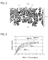
- the filter catalyst for purifying exhaust gases for examples 1, 2 and comparative examples 1, 2 were installed respectively in an exhaust system of a 2L-dissel engine. Then the exhaust gas was flowed under the condition of 2450rpmx 52Nm, lean steady, an amount of smoke of 6.5% which was measured by a smoke meter and the inlet gas temperature of 300 °C, and the behavior of the pressure loss and the amount of collected PMs were measured. The relations between the amount of collected PMs and the pressure loss, and between the amount of collected PMs and PMs collecting ratio were shown in Fig.3 and Fig.4, respectively.
- the curve of catalyst for each example is more like straight lines as compared with that for each comparative example and, since the pressure loss is approximately proportional to the amount of collected PMs, the deterioration of the sensitivity for the pressure loss detection for catalyst of each example is suppressed as compared with that for each comparative example. It is also found from Fg.4 that the catalyst for each example has a high PMs collecting ratio as compared with that for each comparative example.
- the present invention of the filter catalyst for purifying exhaust gases makes it possible to collect PMs efficiently. Moreover, since it has a high sensitivity for pressure loss detection, it is also possible to estimate the amount of PMs deposition by detecting the pressure loss. Hence it is possible to burn PMs deposition away while its amount is small, by the regeneration process in such a manner as streaming high temperature exhaust gases when the pressure loss exceeds a reference value. Thereby, it is preventable that the continuously regenerative DPFs become high temperature in burning and the failures like damage by dissolution of substrate occur.
- the filter catalyst for purifying exhaust gases for examples 1 to 3 and comparative examples 1, 2 were installed respectively in an exhaust system of a 2L-dissel engine. Then, after running 200km under 11 Lap mode (i.e. inlet gas temperature of 220 ⁇ 370°C), the PMs oxidation ratio was calculated from the weight difference between amounts of PMs in the inlet gas minus PMs in the outlet gas and the deposited PMs remaining. The results are shown in Fig.5.
- the filter catalyst for purifying exhaust gases for examples 1 to 3 and comparative examples 1, 2 were installed respectively in an exhaust system of a 2L-dissel engine. Consecutively, after a heat duration in which the exhaust gas at 650°C was flowed for 50 hrs, the exhaust gas in which light oil was added was flowed under the condition of 2900rpm ⁇ 80Nm and the inlet gas temperature of 300°C, and the amount of sorbed NO x was measured for each. The results obtained are shown Fig.6. It should be noted that diesel oil was so added that the fuel consumption deterioration rate was to be 3 %.
- Fig.5 clarifies that the catalyst for each example shows high PMs oxidation ratio as compared with that for each comparative example, and excels in purification ability for PMs.
- the PMs oxidation ability for example 2 is higher than that for example 1. It is considered that, since the second catalytic layer 3 was not formed on the surface of inlet cells 10, the amount of PMs flowing into the pores of the filter cellular walls 12 increased and the possibility for catalytic reaction of the catalytic ingredient to the collected PMs was enhanced.
- the PMs oxidation ratio for example 3 is further larger than that for example 2, it is considered that PMs were oxidized also by NO 2 released from the NO x -adsorbing catalyst (Pt-Pd loaded zirconia).
- the amount of sorbed NO x after duration for catalyst of example 1 is larger than that of each comparative example. It can be considered that, since the catalytic layer is thick where the second catalytic layer 3 is formed, the reaction of NO x sorbent to the filter cellular walls is suppressed.
- the NO x -sorbing abilities for example 2 and example 3 are inferior to that for example 1. It is considered that the coating amounts of the second catalytic layer 3 for example 2 and 3 were less than that for example 1.
Landscapes
- Chemical & Material Sciences (AREA)
- Engineering & Computer Science (AREA)
- Chemical Kinetics & Catalysis (AREA)
- Combustion & Propulsion (AREA)
- Materials Engineering (AREA)
- Organic Chemistry (AREA)
- Environmental & Geological Engineering (AREA)
- Mechanical Engineering (AREA)
- General Engineering & Computer Science (AREA)
- Health & Medical Sciences (AREA)
- Biomedical Technology (AREA)
- Ceramic Engineering (AREA)
- Analytical Chemistry (AREA)
- General Chemical & Material Sciences (AREA)
- Oil, Petroleum & Natural Gas (AREA)
- Structural Engineering (AREA)
- Catalysts (AREA)
- Exhaust Gas Treatment By Means Of Catalyst (AREA)
Applications Claiming Priority (2)
| Application Number | Priority Date | Filing Date | Title |
|---|---|---|---|
| JP2002268245A JP3874270B2 (ja) | 2002-09-13 | 2002-09-13 | 排ガス浄化フィルタ触媒及びその製造方法 |
| JP2002268245 | 2002-09-13 |
Publications (2)
| Publication Number | Publication Date |
|---|---|
| EP1398081A1 true EP1398081A1 (de) | 2004-03-17 |
| EP1398081B1 EP1398081B1 (de) | 2007-02-21 |
Family
ID=31884809
Family Applications (1)
| Application Number | Title | Priority Date | Filing Date |
|---|---|---|---|
| EP03020190A Expired - Lifetime EP1398081B1 (de) | 2002-09-13 | 2003-09-05 | Filterkatalysator für die Reinigung von Dieselabgasen und Herstellungsverfahren dafür |
Country Status (6)
| Country | Link |
|---|---|
| US (1) | US7306771B2 (de) |
| EP (1) | EP1398081B1 (de) |
| JP (1) | JP3874270B2 (de) |
| KR (1) | KR100545299B1 (de) |
| CN (1) | CN1309940C (de) |
| DE (1) | DE60311930T2 (de) |
Cited By (18)
| Publication number | Priority date | Publication date | Assignee | Title |
|---|---|---|---|---|
| EP1576998A2 (de) * | 2004-03-17 | 2005-09-21 | Kabushiki Kaisha Toyota Chuo Kenkyusho | Abgasfilter, Verfahren zu dessen Herstellung, und Vorrichtung zum Behandeln von Abgas unter Verwendung des Abgasfilters |
| EP1588995A1 (de) * | 2004-01-13 | 2005-10-26 | Ibiden Co., Ltd. | Porenbildendes material für einen porösen körper, verfahren zur herstellung des porenbildenden materials für einen porösen körper, verfahren zur herstellung eines porösen körpers, poröser körper und wabenstruktur |
| EP1624164A1 (de) * | 2004-08-05 | 2006-02-08 | Hitachi, Ltd. | Filter zur Reinigung von Abgasen einer Dieselbrennkraftmaschine und dessen Herstelungsverfahren und Abgasreinigungsvorrichtung |
| WO2006021336A1 (de) * | 2004-08-21 | 2006-03-02 | Umicore Ag & Co. Kg | Verfahren zum beschichten eines wandflussfilters mit feinteiligen feststoffen und damit erhaltenes filter und seine verwendung |
| EP1649924A2 (de) * | 2004-10-21 | 2006-04-26 | Toyota Jidosha Kabushiki Kaisha | Katalysator zur Reinigung von Abgasen und Verfahren zu seiner Herstellung |
| EP1657410A2 (de) | 2004-11-11 | 2006-05-17 | Cataler Corporation | Filterkatalysator |
| WO2006137558A1 (en) * | 2005-06-20 | 2006-12-28 | Toyota Jidosha Kabushiki Kaisha | Catalyst for purifying exhaust gases and process for producing the same |
| WO2007058867A1 (en) * | 2005-11-10 | 2007-05-24 | Basf Catalysts Llc | Diesel particulate filters having ultra-thin catalyzed oxidation coatings |
| EP1920834A1 (de) * | 2005-08-31 | 2008-05-14 | Ngk Insulators, Ltd. | Wabenkatalysator und herstellungsverfahren dafür |
| EP1920839A1 (de) * | 2005-08-31 | 2008-05-14 | Ngk Insulators, Ltd. | Katalytische wabenstruktur, vorbeschichteter träger zur erzeugung einer katalytischen wabenstruktur und verfahren zur herstellung einer katalytischen wabenstruktur |
| EP1935489A1 (de) * | 2005-08-31 | 2008-06-25 | Ngk Insulators, Ltd. | Wabenförmiger katalytischer körper und zugehöriges herstellungsverfahren |
| WO2009079590A1 (en) * | 2007-12-18 | 2009-06-25 | Basf Catalysts Llc | Catalyzed soot filter manufacture and systems |
| WO2009079250A1 (en) * | 2007-12-18 | 2009-06-25 | Basf Catalysts Llc | Passivation-free coating process for catalytic soot filters |
| EP2324904A3 (de) * | 2009-11-18 | 2012-10-17 | NGK Insulators, Ltd. | Katalysatorträgerfilter und Abgasreinigungssystem |
| US8465703B2 (en) | 2004-02-10 | 2013-06-18 | Cataler Corporation | Filter catalyst and method of analyzing a catalytic layer thereof |
| WO2015022399A3 (en) * | 2013-08-14 | 2015-07-02 | Dinex A/S | Coated particle filter |
| CN107073396A (zh) * | 2014-10-17 | 2017-08-18 | 株式会社科特拉 | 废气净化装置 |
| DE102012016561B4 (de) * | 2012-08-22 | 2019-05-16 | Airbus Defence and Space GmbH | Luftfahrzeug-Brennstoffzellensystem sowie Verwendung desselben |
Families Citing this family (61)
| Publication number | Priority date | Publication date | Assignee | Title |
|---|---|---|---|---|
| JP4805676B2 (ja) * | 2003-07-25 | 2011-11-02 | 日本碍子株式会社 | セラミックス多孔質体及びその透過性能評価方法 |
| US7229597B2 (en) | 2003-08-05 | 2007-06-12 | Basfd Catalysts Llc | Catalyzed SCR filter and emission treatment system |
| JP4429756B2 (ja) * | 2004-02-10 | 2010-03-10 | 株式会社キャタラー | フィルタ触媒 |
| KR100766357B1 (ko) * | 2004-03-23 | 2007-10-15 | 니뽄 가이시 가부시키가이샤 | 세라믹 필터 |
| EP1768766A1 (de) * | 2004-06-05 | 2007-04-04 | Umicore AG & Co. KG | Partikelfilter mit einer katalytischen beschichtung |
| DE102004040549B4 (de) * | 2004-08-21 | 2017-03-23 | Umicore Ag & Co. Kg | Katalytisch beschichtetes Partikelfilter und seine Verwendung |
| DE102004040551A1 (de) * | 2004-08-21 | 2006-02-23 | Umicore Ag & Co. Kg | Verfahren zur Beschichtung eines Wandflußfilters mit einer Beschichtungszusammensetzung |
| FR2875149B1 (fr) * | 2004-09-15 | 2006-12-15 | Rhodia Chimie Sa | Procede de fabrication d'un filtre a particules catalyse et filtre ainsi obtenu |
| CA2583778A1 (en) * | 2004-10-14 | 2006-04-27 | Catalytic Solutions, Inc. | Platinum group metal-free catalysts for reducing the ignition temperature of particulates on a diesel particulate filter |
| JP2006110485A (ja) * | 2004-10-15 | 2006-04-27 | Johnson Matthey Japan Inc | 排気ガス触媒およびそれを用いた排気ガス処理装置 |
| WO2006103963A1 (ja) * | 2005-03-29 | 2006-10-05 | Ngk Insulators, Ltd. | ハニカム構造体 |
| JP4963799B2 (ja) * | 2005-06-13 | 2012-06-27 | 株式会社キャタラー | 排ガス浄化用触媒 |
| JP4907108B2 (ja) * | 2005-06-28 | 2012-03-28 | 株式会社キャタラー | スラリーの粘度の調整方法および排ガス浄化触媒用コーティングスラリー |
| JP4844029B2 (ja) * | 2005-07-14 | 2011-12-21 | トヨタ自動車株式会社 | 排気浄化装置 |
| JP4785470B2 (ja) * | 2005-09-08 | 2011-10-05 | 本田技研工業株式会社 | 排ガス浄化フィルタおよびその製造方法 |
| JP2009519814A (ja) * | 2005-12-16 | 2009-05-21 | コーニング インコーポレイテッド | 圧力降下の低い被覆ディーゼル排ガスフィルタ |
| JP5233026B2 (ja) * | 2006-03-06 | 2013-07-10 | Dowaエレクトロニクス株式会社 | Dpfの製造法 |
| JP2007275704A (ja) * | 2006-04-03 | 2007-10-25 | Johnson Matthey Japan Inc | 排気ガス触媒およびそれを用いた排気ガス処理装置 |
| WO2007136148A1 (en) * | 2006-05-24 | 2007-11-29 | Sk Energy Co., Ltd. | Exhaust gas purifying device for diesel engine with exhaust gas recirculation line |
| KR100766725B1 (ko) | 2006-05-24 | 2007-10-12 | 에스케이에너지 주식회사 | 배기가스 재순환 라인을 구비한 디젤 엔진의 배기가스 정화장치 |
| KR20090045214A (ko) * | 2006-06-29 | 2009-05-07 | 우미코레 아게 운트 코 카게 | 삼원 촉매 |
| JP2008023501A (ja) * | 2006-07-25 | 2008-02-07 | Toyota Motor Corp | 排ガス浄化用触媒 |
| JP5444716B2 (ja) * | 2006-11-30 | 2014-03-19 | 日立金属株式会社 | セラミックハニカムフィルタ及びその製造方法 |
| EP2111286B2 (de) * | 2007-01-31 | 2022-04-27 | BASF Corporation | Gaskatalysator mit waben mit porösen wänden |
| JP4793316B2 (ja) * | 2007-04-20 | 2011-10-12 | トヨタ自動車株式会社 | 硫黄吸蔵触媒 |
| JP5150132B2 (ja) * | 2007-04-27 | 2013-02-20 | 日本碍子株式会社 | ハニカムフィルタシステム |
| FR2916366B1 (fr) * | 2007-05-23 | 2009-11-27 | Saint Gobain Ct Recherches | Filtre a particules texture pour applications catalytiques |
| ATE457813T1 (de) * | 2007-09-28 | 2010-03-15 | Umicore Ag & Co Kg | Entfernung von partikeln aus dem abgas von mit überwiegend stöchiometrischem luft/kraftstoff- gemisch betriebenen verbrennungsmotoren |
| FR2921848B1 (fr) * | 2007-10-08 | 2011-03-18 | Saint Gobain Ct Recherches | Structure de purification texturee incorporant un systeme de catalyse electrochimique |
| EP2065575B1 (de) * | 2007-11-29 | 2012-08-15 | Corning Incorporated | Wandfluss-Wabenfilter mit hoher Speicherkapazität und geringem Gegendruck |
| EP2222618A2 (de) * | 2007-11-30 | 2010-09-01 | Corning Incorporated | Zusammensetzungen zum aufbringen auf wabensubstrate |
| KR101621983B1 (ko) * | 2008-02-05 | 2016-05-31 | 바스프 코포레이션 | 미립자 트랩을 갖는 가솔린 엔진 배출물 처리 시스템 |
| JP5291966B2 (ja) * | 2008-03-25 | 2013-09-18 | 日本碍子株式会社 | 触媒担持フィルタ |
| JP5604046B2 (ja) * | 2008-03-28 | 2014-10-08 | 日本碍子株式会社 | ハニカム構造体 |
| CN104759274A (zh) * | 2008-04-23 | 2015-07-08 | 同和电子科技有限公司 | 废气净化催化剂用复合氧化物及其用途 |
| JP2009287402A (ja) * | 2008-05-27 | 2009-12-10 | Nissan Motor Co Ltd | 排気浄化用フィルタ及び排気浄化装置 |
| JP5208886B2 (ja) * | 2008-09-03 | 2013-06-12 | 日本碍子株式会社 | 触媒担持フィルタ |
| KR101427912B1 (ko) * | 2008-10-31 | 2014-08-11 | 현대자동차 주식회사 | 촉매여과필터 |
| WO2010110011A1 (ja) | 2009-03-26 | 2010-09-30 | 日本碍子株式会社 | ハニカムフィルタ及びハニカムフィルタの製造方法 |
| JP5794981B2 (ja) * | 2009-05-29 | 2015-10-14 | コーニング インコーポレイテッド | 低すす堆積コーティングを有する微粒子フィルター |
| US8889587B2 (en) * | 2009-08-31 | 2014-11-18 | General Electric Company | Catalyst and method of manufacture |
| US8978360B2 (en) * | 2009-09-15 | 2015-03-17 | Ford Global Technologies, Llc | Hydrocarbon and NOx trap |
| JP5518518B2 (ja) * | 2010-02-15 | 2014-06-11 | 日本碍子株式会社 | ハニカムフィルタの製造方法 |
| US8815189B2 (en) | 2010-04-19 | 2014-08-26 | Basf Corporation | Gasoline engine emissions treatment systems having particulate filters |
| MY163935A (en) * | 2010-05-05 | 2017-11-15 | Basf Corp | Catalyzed soot filter and emissions treatment systems and methods |
| DE102011109034A1 (de) * | 2011-06-16 | 2012-12-20 | Mann + Hummel Gmbh | Keramischer Körper mit variabler Porosität und Verfahren zur Herstellung |
| JP2013017992A (ja) * | 2011-06-17 | 2013-01-31 | Dowa Electronics Materials Co Ltd | 触媒担持型ディーゼルパティキュレートフィルター、およびその製造方法 |
| JP5787031B2 (ja) * | 2012-03-30 | 2015-09-30 | トヨタ自動車株式会社 | パティキュレートフィルタ |
| DE102013013973A1 (de) | 2013-08-23 | 2015-02-26 | Clariant Produkte (Deutschland) Gmbh | Partikelfilter zur Reinigung von Abgasen, Abgasreinigungssystem und Verfahren zur Reinigung von Abgas |
| EP3045227B1 (de) * | 2013-09-11 | 2019-12-11 | Mitsui Mining & Smelting Co., Ltd | Abgasreinigungskatalysator |
| US20180325800A1 (en) | 2014-12-18 | 2018-11-15 | L'oreal | Compositions and methods for improving the appearance of the skin |
| US10835479B2 (en) | 2015-12-31 | 2020-11-17 | L'oreal | Systems and methods for improving the appearance of the skin |
| JP6542690B2 (ja) * | 2016-02-12 | 2019-07-10 | トヨタ自動車株式会社 | フィルタ触媒の製造方法 |
| JP6297767B2 (ja) * | 2016-03-24 | 2018-03-20 | 株式会社キャタラー | 排ガス浄化装置 |
| JP6407349B1 (ja) * | 2017-05-11 | 2018-10-17 | 株式会社キャタラー | 排ガス浄化触媒装置 |
| DE102018127957A1 (de) * | 2018-11-08 | 2020-05-14 | Umicore Ag & Co. Kg | Partikelfilter mit mehreren Beschichtungen |
| JP7118919B2 (ja) * | 2019-03-29 | 2022-08-16 | 株式会社Soken | 排ガス浄化フィルタ |
| JP7127606B2 (ja) * | 2019-04-24 | 2022-08-30 | 株式会社デンソー | 排ガス浄化フィルタ |
| JP6947200B2 (ja) * | 2019-05-15 | 2021-10-13 | 株式会社デンソー | 排ガス浄化フィルタ |
| JP7002503B2 (ja) * | 2019-07-29 | 2022-02-04 | 株式会社Soken | 排ガス浄化フィルタ |
| DE102020203924A1 (de) * | 2020-03-26 | 2021-09-30 | Hug Engineering Ag | Formkörper, Verbundkörper, Verfahren zur Herstellung eines Formkörpers und Verfahren zur Herstellung eines Verbundkörpers |
Citations (6)
| Publication number | Priority date | Publication date | Assignee | Title |
|---|---|---|---|---|
| EP0766993A2 (de) * | 1995-10-02 | 1997-04-09 | Toyota Jidosha Kabushiki Kaisha | Filter zur Reinigung von Abgasen |
| JPH09158710A (ja) * | 1995-12-08 | 1997-06-17 | Nippon Soken Inc | ディーゼル排ガス浄化フィルタ |
| JPH09173866A (ja) * | 1995-12-28 | 1997-07-08 | Nippon Soken Inc | ディーゼル排ガス浄化フィルタ |
| EP0834343A1 (de) * | 1996-10-03 | 1998-04-08 | Kabushiki Kaisha Toyota Chuo Kenkyusho | Filter zur Reinigung von Abgasen |
| WO2000001463A1 (en) * | 1998-07-07 | 2000-01-13 | Silentor Notox A/S | Diesel exhaust gas filter |
| DE10048511A1 (de) * | 2000-09-29 | 2002-04-18 | Omg Ag & Co Kg | Verfahren zur Verminderung von Kohlenmonoxid, Kohlenwasserstoffen und Partikel im mageren Abgas von Verbrennungsmotoren |
Family Cites Families (7)
| Publication number | Priority date | Publication date | Assignee | Title |
|---|---|---|---|---|
| JPS5742317A (en) * | 1980-08-28 | 1982-03-09 | Ngk Insulators Ltd | Ceramic honeycomb filter |
| JP2722987B2 (ja) | 1992-09-28 | 1998-03-09 | トヨタ自動車株式会社 | 内燃機関の排気浄化装置 |
| JP3560408B2 (ja) | 1996-02-15 | 2004-09-02 | 株式会社日本自動車部品総合研究所 | ディーゼル排ガス浄化フィルタおよびその製造方法 |
| JP3874443B2 (ja) | 1996-04-12 | 2007-01-31 | 株式会社日本自動車部品総合研究所 | パティキュレート捕集用フィルタ |
| US6440895B1 (en) * | 1998-07-27 | 2002-08-27 | Battelle Memorial Institute | Catalyst, method of making, and reactions using the catalyst |
| JP4907756B2 (ja) | 2000-02-29 | 2012-04-04 | イビデン株式会社 | 排ガス浄化用触媒およびその製造方法 |
| US6777370B2 (en) * | 2001-04-13 | 2004-08-17 | Engelhard Corporation | SOx tolerant NOx trap catalysts and methods of making and using the same |
-
2002
- 2002-09-13 JP JP2002268245A patent/JP3874270B2/ja not_active Expired - Fee Related
-
2003
- 2003-09-05 EP EP03020190A patent/EP1398081B1/de not_active Expired - Lifetime
- 2003-09-05 DE DE60311930T patent/DE60311930T2/de not_active Expired - Fee Related
- 2003-09-08 KR KR1020030062533A patent/KR100545299B1/ko not_active IP Right Cessation
- 2003-09-12 US US10/660,707 patent/US7306771B2/en not_active Expired - Fee Related
- 2003-09-15 CN CNB031569501A patent/CN1309940C/zh not_active Expired - Fee Related
Patent Citations (6)
| Publication number | Priority date | Publication date | Assignee | Title |
|---|---|---|---|---|
| EP0766993A2 (de) * | 1995-10-02 | 1997-04-09 | Toyota Jidosha Kabushiki Kaisha | Filter zur Reinigung von Abgasen |
| JPH09158710A (ja) * | 1995-12-08 | 1997-06-17 | Nippon Soken Inc | ディーゼル排ガス浄化フィルタ |
| JPH09173866A (ja) * | 1995-12-28 | 1997-07-08 | Nippon Soken Inc | ディーゼル排ガス浄化フィルタ |
| EP0834343A1 (de) * | 1996-10-03 | 1998-04-08 | Kabushiki Kaisha Toyota Chuo Kenkyusho | Filter zur Reinigung von Abgasen |
| WO2000001463A1 (en) * | 1998-07-07 | 2000-01-13 | Silentor Notox A/S | Diesel exhaust gas filter |
| DE10048511A1 (de) * | 2000-09-29 | 2002-04-18 | Omg Ag & Co Kg | Verfahren zur Verminderung von Kohlenmonoxid, Kohlenwasserstoffen und Partikel im mageren Abgas von Verbrennungsmotoren |
Non-Patent Citations (1)
| Title |
|---|
| PATENT ABSTRACTS OF JAPAN vol. 1997, no. 10 31 October 1997 (1997-10-31) * |
Cited By (34)
| Publication number | Priority date | Publication date | Assignee | Title |
|---|---|---|---|---|
| EP1588995A4 (de) * | 2004-01-13 | 2008-02-20 | Ibiden Co Ltd | Porenbildendes material für einen porösen körper, verfahren zur herstellung des porenbildenden materials für einen porösen körper, verfahren zur herstellung eines porösen körpers, poröser körper und wabenstruktur |
| EP1588995A1 (de) * | 2004-01-13 | 2005-10-26 | Ibiden Co., Ltd. | Porenbildendes material für einen porösen körper, verfahren zur herstellung des porenbildenden materials für einen porösen körper, verfahren zur herstellung eines porösen körpers, poröser körper und wabenstruktur |
| US7473465B2 (en) | 2004-01-13 | 2009-01-06 | Ibiden Co., Ltd. | Honeycomb structure, porous body, pore forming material for the porous body, and methods for manufacturing the pore forming material, the porous body and the honeycomb structure |
| US7396586B2 (en) | 2004-01-13 | 2008-07-08 | Ibiden Co., Ltd. | Pore forming material for porous body, manufacturing method of pore forming material for porous body, manufacturing method of porous body, porous body, and honeycomb structural body |
| US7387829B2 (en) | 2004-01-13 | 2008-06-17 | Ibiden Co., Ltd. | Honeycomb structure, porous body, pore forming material for the porous body, and methods for manufacturing the pore forming material, the porous body and the honeycomb structure |
| US8465703B2 (en) | 2004-02-10 | 2013-06-18 | Cataler Corporation | Filter catalyst and method of analyzing a catalytic layer thereof |
| EP1576998A3 (de) * | 2004-03-17 | 2006-05-17 | Kabushiki Kaisha Toyota Chuo Kenkyusho | Abgasfilter, Verfahren zu dessen Herstellung, und Vorrichtung zum Behandeln von Abgas unter Verwendung des Abgasfilters |
| EP1576998A2 (de) * | 2004-03-17 | 2005-09-21 | Kabushiki Kaisha Toyota Chuo Kenkyusho | Abgasfilter, Verfahren zu dessen Herstellung, und Vorrichtung zum Behandeln von Abgas unter Verwendung des Abgasfilters |
| EP1624164A1 (de) * | 2004-08-05 | 2006-02-08 | Hitachi, Ltd. | Filter zur Reinigung von Abgasen einer Dieselbrennkraftmaschine und dessen Herstelungsverfahren und Abgasreinigungsvorrichtung |
| WO2006021336A1 (de) * | 2004-08-21 | 2006-03-02 | Umicore Ag & Co. Kg | Verfahren zum beschichten eines wandflussfilters mit feinteiligen feststoffen und damit erhaltenes filter und seine verwendung |
| EP1649924A3 (de) * | 2004-10-21 | 2006-09-13 | Toyota Jidosha Kabushiki Kaisha | Katalysator zur Reinigung von Abgasen und Verfahren zu seiner Herstellung |
| EP1649924A2 (de) * | 2004-10-21 | 2006-04-26 | Toyota Jidosha Kabushiki Kaisha | Katalysator zur Reinigung von Abgasen und Verfahren zu seiner Herstellung |
| EP1657410A3 (de) * | 2004-11-11 | 2006-08-16 | Cataler Corporation | Filterkatalysator |
| EP1657410A2 (de) | 2004-11-11 | 2006-05-17 | Cataler Corporation | Filterkatalysator |
| US7781371B2 (en) | 2004-11-11 | 2010-08-24 | Cataler Corporation | Filter catalyst |
| WO2006137558A1 (en) * | 2005-06-20 | 2006-12-28 | Toyota Jidosha Kabushiki Kaisha | Catalyst for purifying exhaust gases and process for producing the same |
| EP1935489A4 (de) * | 2005-08-31 | 2012-01-25 | Ngk Insulators Ltd | Wabenförmiger katalytischer körper und zugehöriges herstellungsverfahren |
| EP1920834A1 (de) * | 2005-08-31 | 2008-05-14 | Ngk Insulators, Ltd. | Wabenkatalysator und herstellungsverfahren dafür |
| EP1920839A1 (de) * | 2005-08-31 | 2008-05-14 | Ngk Insulators, Ltd. | Katalytische wabenstruktur, vorbeschichteter träger zur erzeugung einer katalytischen wabenstruktur und verfahren zur herstellung einer katalytischen wabenstruktur |
| EP1935489A1 (de) * | 2005-08-31 | 2008-06-25 | Ngk Insulators, Ltd. | Wabenförmiger katalytischer körper und zugehöriges herstellungsverfahren |
| EP1920839A4 (de) * | 2005-08-31 | 2012-01-25 | Ngk Insulators Ltd | Katalytische wabenstruktur, vorbeschichteter träger zur erzeugung einer katalytischen wabenstruktur und verfahren zur herstellung einer katalytischen wabenstruktur |
| EP1920834A4 (de) * | 2005-08-31 | 2012-01-25 | Ngk Insulators Ltd | Wabenkatalysator und herstellungsverfahren dafür |
| US8119075B2 (en) | 2005-11-10 | 2012-02-21 | Basf Corporation | Diesel particulate filters having ultra-thin catalyzed oxidation coatings |
| WO2007058867A1 (en) * | 2005-11-10 | 2007-05-24 | Basf Catalysts Llc | Diesel particulate filters having ultra-thin catalyzed oxidation coatings |
| US8038956B2 (en) | 2007-12-18 | 2011-10-18 | Basf Corporation | Catalyzed soot filter manufacture and systems |
| WO2009079250A1 (en) * | 2007-12-18 | 2009-06-25 | Basf Catalysts Llc | Passivation-free coating process for catalytic soot filters |
| US8114354B2 (en) | 2007-12-18 | 2012-02-14 | Basf Corporation | Catalyzed soot filter manufacture and systems |
| WO2009079590A1 (en) * | 2007-12-18 | 2009-06-25 | Basf Catalysts Llc | Catalyzed soot filter manufacture and systems |
| EP2324904A3 (de) * | 2009-11-18 | 2012-10-17 | NGK Insulators, Ltd. | Katalysatorträgerfilter und Abgasreinigungssystem |
| DE102012016561B4 (de) * | 2012-08-22 | 2019-05-16 | Airbus Defence and Space GmbH | Luftfahrzeug-Brennstoffzellensystem sowie Verwendung desselben |
| WO2015022399A3 (en) * | 2013-08-14 | 2015-07-02 | Dinex A/S | Coated particle filter |
| US10258978B2 (en) | 2013-08-14 | 2019-04-16 | Dinex A/S | Multilayer coated particle filter |
| CN107073396A (zh) * | 2014-10-17 | 2017-08-18 | 株式会社科特拉 | 废气净化装置 |
| EP3207978A4 (de) * | 2014-10-17 | 2017-10-25 | Cataler Corporation | Abgasreinigungsvorrichtung |
Also Published As
| Publication number | Publication date |
|---|---|
| JP2004105792A (ja) | 2004-04-08 |
| DE60311930T2 (de) | 2007-10-25 |
| KR100545299B1 (ko) | 2006-01-24 |
| CN1490500A (zh) | 2004-04-21 |
| JP3874270B2 (ja) | 2007-01-31 |
| DE60311930D1 (de) | 2007-04-05 |
| US7306771B2 (en) | 2007-12-11 |
| US20040053781A1 (en) | 2004-03-18 |
| EP1398081B1 (de) | 2007-02-21 |
| CN1309940C (zh) | 2007-04-11 |
| KR20040024483A (ko) | 2004-03-20 |
Similar Documents
| Publication | Publication Date | Title |
|---|---|---|
| EP1398081B1 (de) | Filterkatalysator für die Reinigung von Dieselabgasen und Herstellungsverfahren dafür | |
| JP6727260B2 (ja) | ガソリン微粒子フィルターを有するガソリンエンジン排出処理システム | |
| JP5909191B2 (ja) | 帯状触媒スートフィルタ | |
| JP4628676B2 (ja) | 内燃機関排ガス浄化用触媒、その製法および内燃機関排ガスの浄化方法 | |
| US7797931B2 (en) | Catalyst composition for diesel particulate filter | |
| KR101717802B1 (ko) | 가솔린 엔진 배기 가스용 처리 시스템 | |
| US11865497B2 (en) | Monometallic rhodium-containing four-way conversion catalysts for gasoline engine emissions treatment systems | |
| EP3494295B1 (de) | Vier-wege-umwandlung katalysatoren für systeme zur behandlung von benzinmotoremissionen | |
| US7517830B2 (en) | Substrate for exhaust-gas purifying filter catalyst | |
| EP2002879A2 (de) | Abgasemissionssteuerungskatalysator und abgasemissionssteuersystem | |
| EP3636340B1 (de) | Katalysator zur abgasreinigung | |
| WO2020203198A1 (ja) | 排気浄化フィルタ | |
| EP3566763B1 (de) | Wabenstrukturfilter | |
| CN101091916A (zh) | 用于柴油微粒过滤器的催化剂组合物 | |
| JP2006159020A (ja) | 排ガス浄化フィルタ及び排ガス浄化触媒 | |
| JP2003161137A (ja) | パティキュレートフィルタ |
Legal Events
| Date | Code | Title | Description |
|---|---|---|---|
| PUAI | Public reference made under article 153(3) epc to a published international application that has entered the european phase |
Free format text: ORIGINAL CODE: 0009012 |
|
| 17P | Request for examination filed |
Effective date: 20030905 |
|
| AK | Designated contracting states |
Kind code of ref document: A1 Designated state(s): AT BE BG CH CY CZ DE DK EE ES FI FR GB GR HU IE IT LI LU MC NL PT RO SE SI SK TR |
|
| AX | Request for extension of the european patent |
Extension state: AL LT LV MK |
|
| 17Q | First examination report despatched |
Effective date: 20040423 |
|
| AKX | Designation fees paid |
Designated state(s): DE FR GB IT |
|
| GRAP | Despatch of communication of intention to grant a patent |
Free format text: ORIGINAL CODE: EPIDOSNIGR1 |
|
| GRAS | Grant fee paid |
Free format text: ORIGINAL CODE: EPIDOSNIGR3 |
|
| GRAA | (expected) grant |
Free format text: ORIGINAL CODE: 0009210 |
|
| AK | Designated contracting states |
Kind code of ref document: B1 Designated state(s): DE FR GB IT |
|
| REG | Reference to a national code |
Ref country code: GB Ref legal event code: FG4D |
|
| REF | Corresponds to: |
Ref document number: 60311930 Country of ref document: DE Date of ref document: 20070405 Kind code of ref document: P |
|
| ET | Fr: translation filed | ||
| PLBE | No opposition filed within time limit |
Free format text: ORIGINAL CODE: 0009261 |
|
| STAA | Information on the status of an ep patent application or granted ep patent |
Free format text: STATUS: NO OPPOSITION FILED WITHIN TIME LIMIT |
|
| 26N | No opposition filed |
Effective date: 20071122 |
|
| PGFP | Annual fee paid to national office [announced via postgrant information from national office to epo] |
Ref country code: FR Payment date: 20080915 Year of fee payment: 6 |
|
| PGFP | Annual fee paid to national office [announced via postgrant information from national office to epo] |
Ref country code: GB Payment date: 20080910 Year of fee payment: 6 |
|
| PGFP | Annual fee paid to national office [announced via postgrant information from national office to epo] |
Ref country code: DE Payment date: 20080919 Year of fee payment: 6 |
|
| PGFP | Annual fee paid to national office [announced via postgrant information from national office to epo] |
Ref country code: IT Payment date: 20080927 Year of fee payment: 6 |
|
| GBPC | Gb: european patent ceased through non-payment of renewal fee |
Effective date: 20090905 |
|
| REG | Reference to a national code |
Ref country code: FR Ref legal event code: ST Effective date: 20100531 |
|
| PG25 | Lapsed in a contracting state [announced via postgrant information from national office to epo] |
Ref country code: FR Free format text: LAPSE BECAUSE OF NON-PAYMENT OF DUE FEES Effective date: 20090930 Ref country code: DE Free format text: LAPSE BECAUSE OF NON-PAYMENT OF DUE FEES Effective date: 20100401 |
|
| PG25 | Lapsed in a contracting state [announced via postgrant information from national office to epo] |
Ref country code: GB Free format text: LAPSE BECAUSE OF NON-PAYMENT OF DUE FEES Effective date: 20090905 |
|
| PG25 | Lapsed in a contracting state [announced via postgrant information from national office to epo] |
Ref country code: IT Free format text: LAPSE BECAUSE OF NON-PAYMENT OF DUE FEES Effective date: 20090905 |