EP1582258A2 - Katalysatorpulver, Verfahren zu dessen Herstellung, und Abgasreinigungskatalysator - Google Patents
Katalysatorpulver, Verfahren zu dessen Herstellung, und Abgasreinigungskatalysator Download PDFInfo
- Publication number
- EP1582258A2 EP1582258A2 EP05006251A EP05006251A EP1582258A2 EP 1582258 A2 EP1582258 A2 EP 1582258A2 EP 05006251 A EP05006251 A EP 05006251A EP 05006251 A EP05006251 A EP 05006251A EP 1582258 A2 EP1582258 A2 EP 1582258A2
- Authority
- EP
- European Patent Office
- Prior art keywords
- metal particle
- catalyst powder
- noble metal
- carrier
- transition metal
- Prior art date
- Legal status (The legal status is an assumption and is not a legal conclusion. Google has not performed a legal analysis and makes no representation as to the accuracy of the status listed.)
- Withdrawn
Links
Images




Classifications
-
- B—PERFORMING OPERATIONS; TRANSPORTING
- B01—PHYSICAL OR CHEMICAL PROCESSES OR APPARATUS IN GENERAL
- B01J—CHEMICAL OR PHYSICAL PROCESSES, e.g. CATALYSIS OR COLLOID CHEMISTRY; THEIR RELEVANT APPARATUS
- B01J23/00—Catalysts comprising metals or metal oxides or hydroxides, not provided for in group B01J21/00
- B01J23/70—Catalysts comprising metals or metal oxides or hydroxides, not provided for in group B01J21/00 of the iron group metals or copper
- B01J23/89—Catalysts comprising metals or metal oxides or hydroxides, not provided for in group B01J21/00 of the iron group metals or copper combined with noble metals
- B01J23/8933—Catalysts comprising metals or metal oxides or hydroxides, not provided for in group B01J21/00 of the iron group metals or copper combined with noble metals also combined with metals, or metal oxides or hydroxides provided for in groups B01J23/02 - B01J23/36
- B01J23/894—Catalysts comprising metals or metal oxides or hydroxides, not provided for in group B01J21/00 of the iron group metals or copper combined with noble metals also combined with metals, or metal oxides or hydroxides provided for in groups B01J23/02 - B01J23/36 with rare earths or actinides
-
- B—PERFORMING OPERATIONS; TRANSPORTING
- B01—PHYSICAL OR CHEMICAL PROCESSES OR APPARATUS IN GENERAL
- B01J—CHEMICAL OR PHYSICAL PROCESSES, e.g. CATALYSIS OR COLLOID CHEMISTRY; THEIR RELEVANT APPARATUS
- B01J35/00—Catalysts, in general, characterised by their form or physical properties
- B01J35/40—Catalysts, in general, characterised by their form or physical properties characterised by dimensions, e.g. grain size
- B01J35/45—Nanoparticles
-
- B—PERFORMING OPERATIONS; TRANSPORTING
- B01—PHYSICAL OR CHEMICAL PROCESSES OR APPARATUS IN GENERAL
- B01J—CHEMICAL OR PHYSICAL PROCESSES, e.g. CATALYSIS OR COLLOID CHEMISTRY; THEIR RELEVANT APPARATUS
- B01J37/00—Processes, in general, for preparing catalysts; Processes, in general, for activation of catalysts
- B01J37/02—Impregnation, coating or precipitation
- B01J37/03—Precipitation; Co-precipitation
- B01J37/031—Precipitation
-
- B—PERFORMING OPERATIONS; TRANSPORTING
- B01—PHYSICAL OR CHEMICAL PROCESSES OR APPARATUS IN GENERAL
- B01J—CHEMICAL OR PHYSICAL PROCESSES, e.g. CATALYSIS OR COLLOID CHEMISTRY; THEIR RELEVANT APPARATUS
- B01J37/00—Processes, in general, for preparing catalysts; Processes, in general, for activation of catalysts
- B01J37/02—Impregnation, coating or precipitation
- B01J37/03—Precipitation; Co-precipitation
- B01J37/031—Precipitation
- B01J37/035—Precipitation on carriers
Definitions
- the present invention relates to catalyst powder suitable for an exhaust gas purifying catalyst which purifies exhaust gas discharged from an internal combustion engine, and to a method of producing the catalyst powder.
- an exhaust gas purifying catalyst there is one which carries, as catalyst activators, noble metal such as platinum (Pt) and palladium (Pd) and transition metal such as cobalt (Co) and cerium (Ce) on a carrier formed of a porous body of alumina (Al 2 O 3 ) or the like.
- catalyst activators noble metal such as platinum (Pt) and palladium (Pd) and transition metal such as cobalt (Co) and cerium (Ce) on a carrier formed of a porous body of alumina (Al 2 O 3 ) or the like.
- the catalyst activators such as the noble metal and the transition metal are first dissolved in pure water to make an aqueous solution, the carrier is immersed in the aqueous solution to adsorb the noble metal and the like onto the carrier, followed by drying and baking, thereby preparing catalyst powder.
- an adsorption site on a surface of the carrier is limited, and accordingly, there have been limitations on an improvement of dispersivity of the catalyst activators on the carrier surface. Therefore, the catalyst activators cannot be highly dispersed, and it has been thus impossible to obtain a high catalytic activity.
- a method of enhancing the catalytic activity in which the catalyst activators such as the noble metal carried on the carrier is atomized to increase specific surface areas thereof.
- a method of producing the catalyst powder in which the catalyst activators are prepared in micelles by use of a reversed micelle method (microemulsion) (Japanese Patent Laid-Open Publication No. 2000-42411).
- a micelle containing the noble metal therein and a micelle containing the other element such as the transition metal therein are individually prepared.
- the respective micelles individually prepared are dropped in a solution containing aluminum isopropoxide as a carrier precursor, and an obtained solution is subjected to hydrolysis, the baking and the like, thereby preparing the catalyst powder.
- noble metal particles and transition metal particles are prepared in the separate micelles in advance and solutions containing the respective reversed micelles are mixed together to prepare the catalyst powder, a case occurs where the noble metal and the transition metal do not exist in one reversed micelle. Then, when the noble metal particles and the transition metal particles are carried on the carrier, a contact ratio of the noble metal particles and the transition metal particles is lowered to a great extent. Accordingly, an improvement of exhaust gas purification performance by the contact of the noble metal and the transition metal is not brought about, and an effect of adding the transition metal will not be exerted sufficiently. Specifically, even if the noble metal particles and the transition metal particles are highly dispersed on the carrier, the transition metal does not contact the noble metal, and accordingly, it becomes difficult for the transition metal to exert the exhaust gas purification performance.
- the noble metal particles exist singly on the carrier, and accordingly, sintering of the noble metal becomes prone to occur when the catalyst powder is exposed to high temperature conditions. Moreover, when the noble metal particles exist singly on the carrier, the carrier and the noble metal become prone to form a composite oxide. Accordingly, the related art has had a possibility that the catalytic activity is significantly lowered.
- the present invention has been made in order to solve the foregoing problems. It is an object of the present invention to provide catalyst powder excellent in heat resistance and high in the catalytic activity, a method of producing the catalyst powder, and an exhaust gas purifying catalyst using the catalyst powder.
- the first aspect of the present invention provides catalyst powder comprising: a porous carrier; and a noble metal particle and a transition metal particle, which are carried on the carrier, wherein at least a part of the transition metal particle contacts the noble metal particle, is bound with the carrier to form a composite compound, or forms a composite particle together with the noble metal particle.
- the second aspect of the present invention provides a method of producing catalyst powder comprising: precipitating a carrier in a reversed micelle; and precipitating at least one of a noble metal particle and a transition metal particle in the reversed micelle in which the carrier is precipitated.
- the third aspect of the present invention provides a method of producing catalyst powder comprising: preparing a reversed micellar solution having a reversed micelle which contains a carrier precursor solution therein; precipitating a carrier in the reversed micelle by mixing a precipitant into the reversed micellar solution; after the carrier is precipitated, mixing a noble metal salt aqueous solution and a transition metal salt aqueous solution into the reversed micellar solution; and precipitating at least any one of a noble metal particle and a transition metal particle in the reversed micelle by mixing a reducing agent into the reversed micellar solution.
- the fourth aspect of the present invention provides a method of producing catalyst powder comprising: preparing a reversed micellar solution having a reversed micelle which contains water therein; precipitating a carrier in the reversed micelle by mixing metal alkoxide which is a carrier precursor into the reversed micellar solution; after the carrier is precipitated, mixing a noble metal salt aqueous solution and a transition metal salt aqueous solution into the reversed micellar solution; and precipitating at least any one of a noble metal particle and a transition metal particle in the reversed micelle by mixing a reducing agent into the reversed micellar solution.
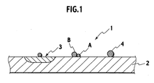
- FIG. 1 shows catalyst powder according to an embodiment of the present invention.
- Catalyst powder 1 of the present invention carries noble metal particles A and transition metal particles B on a single porous carrier 2, and the noble metal and the transition metal partially contact each other. Specifically, at least a part of the transition metal particle B contacts the noble metal particle A, is bound with the carrier 2 to form a composite compound 3, or forms a composite particle 4 together with the noble metal particles A. Note that, though description is made as “on the carrier”, this implies both "on the surface of the carrier” and “in the inside of the carrier”. Note that the transition metal exists in a state of a composite compound, metal (zero-valence), an alloy or the like as well as a simple oxide.
- the noble metal and the transition metal are made to contact each other and evenly dispersed on the single carrier 2, and an intrinsic catalytic activity of the noble metal is thus enhanced.
- Detailed reasons why the catalytic activity of the noble metal is enhanced are unknown.
- reaction gas reaches the transition metal also in the stoichiometric range, though the transition metal usually has a low catalytic activity singly. Then the transition metal and the reaction gas contact each other, and the transition metal turns to a reduced state where the catalytic activity is easily obtained. Therefore, it is conceived that the catalytic activity makes a quantum improvement with the above-described configuration in comparison with the case of using the noble metal singly.
- a particle diameter of the noble metal particles A range from 0.1 nm to 10 nm and that a particle diameter of the transition metal particles B range from 1 nm to 50 nm.
- the catalytic activity can be enhanced sufficiently.
- a more preferable particle diameter of the noble metal particles A ranges from 0.1 nm to 6.0 nm, and that a more preferable particle diameter of the transition metal particles B ranges from 1 nm to 35 nm.
- the noble metal be at least one or more elements selected from the group consisting of ruthenium (Ru), rhodium (Rh), palladium (Pd), silver (Ag), iridium (Ir), platinum (Pt) and gold (Au).
- Ru ruthenium
- Rh palladium
- Ir iridium
- Pt platinum
- Au gold
- Pt, Rh and Pd are preferable, and Pt is particularly preferable.
- two or more of these may be used as the noble metal, and for example, a combination of Pt-Rh or Pd-Rh is preferable.
- the transition metal be at least one or more elements selected from the group consisting of iron (Fe), cobalt (Co), nickel (Ni), copper (Cu) and manganese (Mn).
- Fe, Co and Ni are preferable, and Co is particularly preferable.
- reasons why Co is preferable are unknown, it is conceived that, because Co particularly takes various valences among the transition metals, Co has a function to enhance the catalytic activity of the noble metal by changing the valence of its own and supplying electrons to the noble metal.
- transition metal two or more of these may be used as the transition metal, and for example, Fe-Co, Fe-Ni or the like can be used as a combination.
- precursors of the transition metals, which are mixed at the time of producing the catalyst powder be same kind of salt, such as nitrate thereof.
- Ce-Zr, La-Ce or the like can be used as a combination.
- the carrier 2 be formed of at least one or more compounds selected from the group consisting of alumina, ceria, titania, zirconia and silica, and that the carrier 2 be the porous body.
- the carrier 2 be the porous body.
- the catalyst powder of the present invention is produced by use of a reversed micelle method.
- the production method of the present invention is characterized by including a first step of first precipitating the carrier in a reversed micelle, and a second step of precipitating, after the first step, the noble metal particle and the transition metal particle in the reversed micelle in which the carrier is precipitated.
- the carrier, the noble metal particle and the transition metal particle are precipitated in the single reversed micelle, and accordingly, the noble metal particle and the transition metal particle become easy to contact each other, and the transition metal and the carrier becomes easy to form the composite compound.
- the carrier is first precipitated in the reversed micelle, and the noble metal particle and the transition metal particle are then precipitated therein. Accordingly, the noble metal and the transition metal become easy to turn to a mutual contact state. As a result, highly active catalyst powder can be obtained.
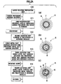
- a solution is prepared, in which a surfactant is dissolved in an organic solvent (Step S10).
- an aqueous solution is added, in which the carrier precursor is dissolved, and a mixture thus obtained is agitated (Step S11).
- a surfactant 6 is arrayed on the periphery of a spherical droplet with a diameter of approximately 20 nm, and in an aqueous phase in an inside of the droplet, a reversed micelle 5 containing an aqueous solution 7 which contains the carrier precursor is formed.
- Step S12 a precipitant is added to the mixed solution containing the reversed micelle, and an obtained mixture is agitated.
- the precipitant enters into the reversed micelle, the carrier precursor is insolubilized to become the carrier particle, and as shown in Illustration (b), a carrier particle 8 is precipitated in the reversed micelle 5.
- an aqueous solution containing noble metal salt as a precursor of the noble metal particle and transition metal salt as a precursor of the transition metal particle is added, and an obtained mixture is agitated (Step S 13).
- the noble metal salt aqueous solution and the transition metal salt aqueous solution enter into the reversed micelle 5.
- Step S 14 a reducing agent is added to the mixed solution containing the reversed micelle, and an obtained mixture is agitated.
- the reducing agent enters into the reversed micelle 5, and reduces the noble metal salt and the transition metal salt.
- Illustration (c) the noble metal particles A and the transition metal particles B are attached onto the outer periphery of the carrier particle 8 in the reversed micelle 5.
- Step S15 alcohol is added to the mixed solution containing the reversed micelle, and an obtained mixture is agitated.
- the alcohol methanol and the like
- the droplet cannot maintain a shape thereof in the organic solvent. Accordingly, the reversed micelle decays.
- a composite compound is obtained, in which the noble metal particles A and the transition metal particles B are attached onto the outer periphery of the carrier particle 8.
- the composite compound thus obtained is filtered by means of a membrane filter, and is then cleaned by use of alcohol and water.
- impurities (surfactant and the like) contained in such a precipitate are removed (Step S16).
- the composite compound thus processed is dried (Step S17), and is then baked in airflow (Step S18).
- the above-described catalyst powder can be obtained, in which the noble metal particles A and the transition metal particles B surely contact each other.
- the diameter of the reversed micelle formed by using the reversed micelle method is substantially determined by a ratio of the surfactant and the water contained in the reversed micelle. Accordingly, in the case of preparing the reversed micellar solution, it is preferable to set a molar ratio RW ([water]/[surfactant]) of the water to the surfactant within a range of 5 to 30, and particularly, within a range of 10 to 20. Note that the water here also includes water molecules contained in hydrates in the metal salts. The reason why the molar ratio RW is regulated within the above-described range is as follows.
- the catalyst powder was prepared with the molar ratio RW (water/surfactant) set at 20 unless otherwise specified.
- the carrier precursor is precipitated in the reversed micelle. Accordingly, in comparison with the conventional carrier produced without using the reversed micelle method, catalyst can be obtained, in which not only the specific surface area is large but also the lowering of the specific surface area is small under high temperature conditions and the heat resistance is excellent. In general, it is preferable that the specific surface area of the carrier be large. However, in the conventional carrier, the specific surface area is significantly decreased under the high temperature conditions when the specific surface area concerned is large. Accordingly, the catalyst activators simultaneously carried aggregate, and the activity of the catalyst powder is lowered.
- a carrier capable of maintaining a large specific surface area even at the high temperature.
- the specific surface area be 150 m 2 /g or more after the carrier is baked for 3 hours in airflow of 600 °C, and the specific surface area of 200 m 2 /g or more is particularly preferable.
- the specific surface area of the carrier produced by the production method of the present invention is 200 m 2 /g or more even when the carrier is baked under the above-described conditions. Accordingly, the aggregation of the noble metal particles and the transition metal particles can be restricted, and the catalytic activity at the time of producing the catalyst powder can be maintained.
- the noble metal salt aqueous solution and the transition metal salt aqueous solution are mixed into the reversed micellar solution, and then the noble metal and the transition metal are simultaneously precipitated in the single reversed micelle.
- the simultaneous precipitation is performed in such a way, the noble metal and the transition metal are attached onto the carrier surface in the reversed micelle, and the noble metal and the transition metal are evenly dispersed on the carrier. Accordingly, a contact area of the noble metal and the transition metal is increased to enhance the catalytic activity, and therefore, it is preferable that the noble metal and the transition metal be precipitated simultaneously.
- the step of precipitating the noble metal particles and the transition metal particles is not limited to the method of precipitating the noble metal and the transition metal simultaneously.
- a method may be adopted, in which the noble metal salt aqueous solution is first mixed into the reversed micellar solution, a reducing agent is then mixed thereinto to precipitate the noble metal, and next, the transition metal salt aqueous solution is mixed into the reversed micellar solution, and a reducing agent is then mixed thereinto to precipitate the transition metal.
- a method may be adopted, in which the transition metal salt aqueous solution is first mixed into the reversed micellar solution to precipitate the transition metal, and next, the noble metal salt aqueous solution is then mixed thereinto to precipitate the noble metal.
- the carrier, the noble metal and the transition metal are mixed together, and the noble metal and the transition metal are precipitated. Accordingly, the catalyst powder can be obtained, in which the noble metal and the transition metal are evenly carried on the carrier.
- the compounds for the purpose of enhancing the heat resistances of the carrier and the noble metal, can be precipitated in the reversed micelle.
- the compounds may be carried in the reversed micelle simultaneously by use of salts of the same elements, or the compounds can be sequentially carried therein one by one.
- the compounds can also be carried in a manner that the catalyst powder obtained by the above-described production method is impregnated in an aqueous solution in which the compounds concerned, each containing at least one or more elements selected from the group consisting of Ce, Nd, Pr, La, Zr, Ba and Mg, is dissolved, followed by baking.
- the precipitant is added to the reversed micelle containing the carrier precursor solution therein, thereby precipitating the carrier.
- the carrier can be precipitated in the reversed micelle by using, as the carrier precursor, a metal alkoxide which causes hydrolysis instantaneously after contacting water.
- the surfactant is first dissolved in the organic solvent, thereby preparing a mixed solution.
- water is added to the mixed solution, and a reversed micelle containing only the water therein is formed.
- a solution of the metal alkoxide (aluminum isopropoxide and the like) is added to the reversed micellar solution thus obtained.
- the metal alkoxide enters into the reversed micelle, and reacts with the water in the reversed micelle, and the carrier is thus precipitated in the reversed micelle. Steps that follow are similar to the steps shown in FIG. 2A and FIG. 2B.
- the metal alkoxide it is preferable to dissolve the metal alkoxide in the organic solvent such as cyclohexane.
- organic solvent of the reversed micellar solution usable are cyclohexane, methylcyclohexane, cycloheptane, heptanol, octanol, dodecyl alcohol, cetyl alcohol, isooctane, n -heptane, n -hexane, n -decane, benzene, toluene, xylene, and the like.
- a mixed solution of two or more of these solvents may be used.
- surfactant of the reversed micellar solution usable are polyoxyethylene nonylphenyl ether, magnesium laurate, zinc caprate, zinc myristate, sodium phenylstearate, aluminum dicaprylate, tetraisoamylammonium thiocyanate, n -octadecyltri- n -butylammonium formate, n -amyltri- n -butylammonium iodide, sodium bis(2-ethylhexyl)succinate, sodium dinonylnaphthalenesulfonate, calcium cetylsulfate, dodecylamine oleate, dodecylamine propionate, cetyltrimethylammonium bromide, stearyltrimethylammonium bromide, cetyltrimethylammonium chloride, stearyltrimethylammonium chloride, dodecyltrimethylammonium bromide,
- the carrier precursor usable are aluminum nitrate, cerium nitrate, titanium tetraisopropoxide, tetraethyl orthosilicate, aluminum isopropoxide, and the like.
- aluminum nitrate and cerium nitrate, aluminum nitrate and lanthanum nitrate, and the like may be used in a mixed manner.
- the noble metal salt usable are a dinitrodiammine platinum (II) nitrate solution, a hexachloroplatinate (IV) acid solution, a hexaammine platinum (IV) tetrachloride solution, a palladium chloride solution, a palladium nitrate solution, a dinitrodiammine palladium dichloride solution, a rhodium chloride solution, a rhodium nitrate solution, a ruthenium chloride solution, a ruthenium nitrate solution, a hexachloroiridium acid solution, and the like.
- TMAH tetramethylammonium hydroxide
- sodium hydroxide sodium hydroxide
- reducing agent usable are hydrazine, sodium thiosulfate, citric acid, sodium citrate, L-ascorbic acid, sodium borohydride, formic acid, formaldehyde, methanol, ethanol, ethylene, vitamin B, and the like. Moreover, two or more of these may be used in a mixed manner.
- the catalyst powder produced by the above-described method of producing catalyst powder for the exhaust gas purifying catalyst.
- the exhaust gas purifying catalyst is exposed to such high temperature conditions ranging from 500 °C to 600 °C. Accordingly, the lowering of the purification performance is prone to occur.
- the particles of the activators are evenly dispersed on the carrier, and the high heat resistance is imparted thereto. Hence, the catalytic activity at the time of production can be maintained during use thereof for a long period.
- Example 1 aluminum isopropoxide was used as the carrier precursor, and platinum and cobalt were reduced simultaneously, thereby preparing catalyst powder.
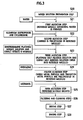
- Step S20 5000 ml of cyclohexane was added as the solvent to 330 g of polyethylene glycol-mono-4-nonylphenyl ether as the surfactant, and thus a solution containing 0.15 mol/L of the surfactant was prepared (Step S20). Moreover, pure water was added to the solution, and a reversed micellar solution containing water therein was prepared (Step S21).
- a mixed solution in which 0.60 g of a dinitrodiamine platinum nitrate solution (platinum concentration: 8.46% by weight) and 1.3 g of cobalt nitrate 6-hydrate powder were dissolved as the noble metal and the transition metal, respectively, into pure water. An obtained mixture was then agitated for approximately two hours. In such a way, a reversed micelle containing aluminum hydroxide therein, and further containing platinum salt and cobalt salt, was prepared (Step S23).
- Step S25 500 ml of methanol was added to the reversed micellar solution, and an obtained mixture was agitated for approximately two hours.
- the reversed micelle thus decays, and platinum, cobalt and the carrier were deposited (Step S25).
- the deposit was filtered to be separated from the solvent, and a deposit thus obtained was cleaned by alcohol and pure water, thereby removing impurities such as an extra surfactant (Step S26).
- the deposit was dried at 100 °C for 12 hours (Step S27), followed by baking at 400 °C in airflow (Step S28). In such a way, catalyst powder was obtained, in which Pt of 1.00% by weight and Co of 5.00% by weight were carried with respect to 1 g of Al 2 O 3 .
- Example 2 aluminum nitrate was used as the carrier precursor, and platinum and cobalt were reduced simultaneously, thereby preparing catalyst powder.
- Step S30 5000 ml of cyclohexane was added as the solvent to 330 g of polyethylene glycol-mono-4-nonylphenyl ether as the surfactant, and a solution containing 0.15 mol/L of the surfactant was prepared (Step S30). An obtained mixture was agitated, and an aqueous solution was added thereto, in which 36.8 g of aluminum nitrate 9-hydrate was dissolved in pure water, thereby preparing a reversed micellar solution (Step S31).
- Step S33 to Step S38 which follow were performed in a similar way to Step S23 to Step S28 which are shown in FIG. 4.
- catalyst powder was obtained, in which Pt of 1.00% by weight and Co of 5.00% by weight were carried with respect to 1 g of Al 2 O 3 .
- an adding amount of the aluminum nitrate is equal in molar mass to the aluminum isopropoxide of Example 1, and that an adding amount of the ammonia water of 25% was set at an amount with which the aluminum nitrate can be sufficiently precipitated.
- Example 3 steps were basically executed in a similar way to Example 1.
- Example 3 is different from Example 1 in Step S23 and Step S24.
- Step S23 and S24 here, only the dinitrodiamine platinum nitrate solution and the pure water were first added to the reversed micellar solution, sodium borohydride of which molar number was three times as much as that of platinum thus added was then added thereto, and an obtained mixture was agitated for approximately two hours, thereby reducing platinum ions.
- Example 4 steps were basically executed in a similar way to Example 2.
- Example 4 is different from Example 2 in Step 531.
- Step S31 aluminum nitrate 9-hydrate and cerium nitrate were mixed to prepare an aqueous solution, and a reversed micelle containing aluminum nitrate and cerium nitrate therein was prepared. Steps that follow were performed in a similar way to Example 2.
- a mass ratio of the aluminum nitrate 9-hydrate and the cerium nitrate was set at 9: 1 in conversion to oxides of aluminum and cerium.
- catalyst powder of Example 4 was obtained, in which Pt of 1.00% by weight and Co of 5.00% by weight were individually carried with respect to 0.9 g of Al 2 O 3 and 0.1 g of CeO 2 .
- an adding amount of the ammonia water of 25% was set at an amount with which the aluminum nitrate and the cerium nitrate can be sufficiently subjected to hydrolysis.
- Example 5 steps were basically executed in a similar way to Example 2.
- Example 5 is different from Example 2 in Step S31.
- Step S31 here, aluminum nitrate 9-hydrate and lanthanum nitrate were mixed to prepare an aqueous solution, and a reversed micelle containing aluminum nitrate and lanthanum nitrate therein was prepared. Steps that follow were performed in a similar way to Example 2.
- a mass ratio of the aluminum nitrate 9-hydrate and the lanthanum nitrate was set at 20: 1 in conversion to oxides of aluminum and lanthanum.
- catalyst powder of Example 5 was obtained, in which Pt of 1.00% by weight and Co of 5.00% by weight were individually carried with respect to 0.95 g of Al 2 O 3 and 0.05 g of La 2 O 3 .
- an adding amount of the ammonia water of 25% was set at an amount with which the aluminum nitrate and the lanthanum nitrate can be sufficiently subjected to hydrolysis.
- Example 6 cerium acetate was impregnated and carried with respect to 1 g of the catalyst powder obtained in Example 1 such that 5.00% by weight was carried as cerium. Thereafter, the catalyst powder was aspirated and filtered, and was then dried at 150 °C for 12 hours, followed by baking at 400 °C for an hour, thereby obtaining catalyst powder of Example 6.
- Example 7 steps were basically executed in a similar way to Example 1.
- Example 7 is different from Example 1 in Step S23.
- Step S23 here, the dinitrodiamine platinum nitrate solution and a rhodium nitrate solution were mixed into the reversed micellar solution such that Pt of 1.00% by weight and Rh of 0.20% by weight were carried with respect to 1 g of Al 2 O 3 , and instead of the cobalt nitrate, zirconium nitrate equal thereto in molar mass was added.
- Example 8 steps were basically executed in a similar way to Example 1.
- Example 8 is different from Example 1 in Step S23.
- Step S23 instead of the dinitrodiamine platinum nitrate solution, a palladium nitrate solution was mixed into the reversed micellar solution such that Pd of 0.500% by weight was carried with respect to 1 g of Al 2 O 3 , and instead of the cobalt nitrate, iron nitrate equal thereto in molar mass was added.
- Example 9 steps were basically executed in a similar way to Example 1.
- Example 9 is different from Example 1 in Step S23.
- Step S23 here, the dinitrodiamine platinum nitrate solution was mixed into the reversed micellar solution such that Pt of 0.30% by weight was carried with respect to 1 g of Al 2 O 3 .
- Example 10 steps were basically executed in a similar way to Example 1.
- Example 10 is different from Example 1 in Step S22.
- Step S22 instead of the aluminum isopropoxide, tetraethyl orthosilicate was mixed into the reversed micellar solution such that Pt of 1.00% by weight and Co of 5.00% by weight were carried with respect to 1 g of SiO 2 .
- Example 11 steps were basically executed in a similar way to Example 1.
- Example 11 is different from Example 1 in Step S22.
- Step S22 instead of the aluminum isopropoxide, titanium tetraisopropoxide was mixed into the reversed micellar solution such that Pt of 1.00% by weight and Co of 5.00% by weight were carried with respect to 1 g of TiO 2 .
- Catalyst powder of Comparative example 1 was prepared by steps shown in FIG. 5.
- a solution was prepared, in which 0.61 g of dinitrodiamine platinum nitrate solution (platinum concentration: 8.46% by weight) and pure water were added together and agitated sufficiently.
- the Al 2 O 3 powder on which the cobalt was carried was added, and an obtained mixture was agitated for approximately an hour. Subsequently, the mixture was dried at 150 °C for 12 hours, and then baked in airflow of 400 °C for an hour, and AL 2 O 3 powder was thus obtained, on which Pt of 1.00% by weight and Co of 5.00% by weight were carried.
- Catalyst powder of Comparative example 2 was prepared by a method of a conventional technology as shown in FIG. 6.
- cyclohexane was added to polyethylene glycol (5) mono-4-nonylphenyl ether, and a solution containing 0.15 mol/L of the surfactant was prepared.
- a dinitrodiamine platinum nitrate solution platinum concentration: 8.46% by weight
- platinum concentration: 8.46% by weight platinum concentration: 8.46% by weight
- hydrazine was added to the reversed micellar solution, an obtained mixture was agitated for approximately two hours, and a reversed micellar solution containing platinum particles was thus prepared.
- cyclohexane was added to polyethylene glycol (5) mono-4-nonylphenyl ether, and a solution containing 0.15 mol/L of the surfactant was prepared.
- cobalt nitrate 6-hydrate was added as the transition metal, an obtained mixture was agitated, and a reversed micellar solution containing transition metal salt was thus prepared.
- ammonia water of 25% was added to the reversed micellar solution, an obtained mixture was agitated for approximately two hours, and a reversed micellar solution containing cobalt particles was thus prepared.
- the reversed micellar solution containing the platinum particles and the reversed micellar solution containing the cobalt particles were dropped into a mixed solution of cyclohexane and aluminum isopropoxide, and an obtained solution was agitated for approximately two hours. Subsequently, methanol was added to the solution, and an obtained mixture was agitated for approximately two hours. The reversed micelle thus decays, and platinum, cobalt and the carrier were deposited. Furthermore, the deposit was filtered to be separated from the solvent, and a deposit thus obtained was cleaned by alcohol and pure water, thereby removing impurities such as an extra surfactant. The deposit was then dried at 100 °C for 12 hours, followed by baking in airflow of 400 °C. In such a way, catalyst powder was obtained, in which Pt of 1.00% by weight and Co of 5.00% by weight were carried with respect to 1 g of Al 2 O 3 .
- each 50 g of the catalyst powder, 10 g of boehmite and 157 g of a 10% nitric acid solution were put into an alumina-made magnetic pot, and shaken and milled together with alumina balls, and slurry was thus obtained.
- a durability test to be described below was performed for each obtained catalyst, and purification performance thereof was evaluated.
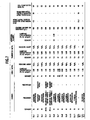
- each catalyst was evaluated under conditions where a flow rate of the reaction gas was 40 L/min and temperature of the reaction gas was 300 °C. Moreover, a ratio of a NOx concentration at the inlet of each catalyst and a NOx concentration at an outlet thereof was measured when these concentrations were stabilized, and based on the ratio, a NOx purification rate (%) was calculated. Compositions of the respective catalyst powders and evaluation results thereof are shown in FIG. 7.
- Example 1 to Example 7 exhibit high NOx purification rates, which are 51 % or more, because the catalyst powders carried Pt of 1.00% by weight and Co, Fe, Zr and the like of 5.00% by weight on the carrier.
- NOx purification rates of both thereof after the durability tests indicate low values which are 44% or less though the carrying concentrations of Pt and Co were set at 1.00% by weight and 5.00% by weight, respectively, in a similar way to Example 1 to Example 7. From the above, it was proven that the NOx purification rates in Comparative examples were lower. The reason for this is conceived as follows.
- Example 10 and Example 11 in which the platinum and the cobalt were carried on SiO 2 and TiO 2 respectively, higher NOx purification rates than that of Comparative example 1 were obtained. Accordingly, it is conceived that the catalyst is highly heat-resistant even in the case of using the above-described compounds as the carrier.
- the carrier precursor is mixed into the reversed micellar solution, and the carrier precursor in the reversed micelle was deposited, thereby preparing the carrier. Accordingly, the specific surface area of the carrier of this embodiment becomes larger than that of the conventional carrier.
- Al 2 O 3 shown below which was used for each catalyst powder of Example 1 and Comparative example 1, was evaluated in the following manner. For such evaluations, the alumina for each of Example 1 and Comparative example 1 was baked at 400 °C, 600 °C and 800 °C, and specific surface areas of each alumina after baking was measured.
- a measurement device (Micromeritics FlowSorb III 2305 made by Shimadzu Corporation) was used, and the measurements were performed by an N 2 gas adsorption method in accordance with the BET method. Note that a volume of a cell used in the measurements was set at 4.8 cm 3 .
- Table 2 shows BET specific surface areas of Al 2 O 3 in Example 1 and Comparative example 1. These results are graphed in FIG. 8. Baking temperature (°C) BET specific surface area (m 2 /g) Example 400 290 600 255 800 210 Comparative example 400 180 600 140 800 100
- the respective particle diameters of the noble metal particles and the transition metal particles were measured by the TEM-EDX measurement.
- the respective catalyst powders ones baked at 800 °C in the air atmosphere for three hours were used.
- the respective catalyst powders were first subjected to an inclusion treatment by epoxy resin, and after the epoxy resin was cured, extremely thin slices were prepared by ultramicrotome. Using the prepared slices, dispersed states of crystal particles were investigated by means of a transmission electron microscope (TEM, HF-2000 made by Hitachi, Ltd.). At this time, acceleration voltage was set at 200 kv.
- TEM transmission electron microscope
- Contrast portions in images thus obtained were focused to specify types of the metals, and particle diameters of the respective metals specified were measured.
- the particle diameter of platinum was 4.5 nm, and the particle diameter of cobalt was 30 nm.
- the particle diameter of platinum was 11.1 nm, and the particle diameter of cobalt was 55 nm. Also from the above, it is understood that the catalyst of the present invention can restrict the aggregation of the noble metal even under the high temperature conditions, and can maintain good performance.
Landscapes
- Chemical & Material Sciences (AREA)
- Engineering & Computer Science (AREA)
- Materials Engineering (AREA)
- Organic Chemistry (AREA)
- Chemical Kinetics & Catalysis (AREA)
- Catalysts (AREA)
- Exhaust Gas Treatment By Means Of Catalyst (AREA)
Applications Claiming Priority (2)
| Application Number | Priority Date | Filing Date | Title |
|---|---|---|---|
| JP2004106667A JP4513384B2 (ja) | 2004-03-31 | 2004-03-31 | 高耐熱性排ガス浄化用触媒及びその製造方法 |
| JP2004106667 | 2004-03-31 |
Publications (2)
| Publication Number | Publication Date |
|---|---|
| EP1582258A2 true EP1582258A2 (de) | 2005-10-05 |
| EP1582258A3 EP1582258A3 (de) | 2006-03-22 |
Family
ID=34880088
Family Applications (1)
| Application Number | Title | Priority Date | Filing Date |
|---|---|---|---|
| EP05006251A Withdrawn EP1582258A3 (de) | 2004-03-31 | 2005-03-22 | Katalysatorpulver, Verfahren zu dessen Herstellung, und Abgasreinigungskatalysator |
Country Status (3)
| Country | Link |
|---|---|
| US (1) | US7674744B2 (de) |
| EP (1) | EP1582258A3 (de) |
| JP (1) | JP4513384B2 (de) |
Cited By (2)
| Publication number | Priority date | Publication date | Assignee | Title |
|---|---|---|---|---|
| WO2006016249A1 (en) * | 2004-08-06 | 2006-02-16 | Nissan Motor Co., Ltd. | Catalyst and method for manufacturing a catalyst for use in exhaust emission control |
| EP1720654A1 (de) * | 2004-02-24 | 2006-11-15 | Nissan Motor Company, Limited | Katalysatorpulver, abgasreinigungskatalysator und verfahren zur herstellung des katalysatorpulvers |
Families Citing this family (50)
| Publication number | Priority date | Publication date | Assignee | Title |
|---|---|---|---|---|
| JP3912377B2 (ja) | 2003-12-25 | 2007-05-09 | 日産自動車株式会社 | 排ガス浄化用触媒粉末の製造方法 |
| JP4547930B2 (ja) | 2004-02-17 | 2010-09-22 | 日産自動車株式会社 | 触媒、触媒の調製方法及び排ガス浄化用触媒 |
| JP4513372B2 (ja) * | 2004-03-23 | 2010-07-28 | 日産自動車株式会社 | 排ガス浄化用触媒及び排ガス浄化触媒 |
| US20050233380A1 (en) * | 2004-04-19 | 2005-10-20 | Sdc Materials, Llc. | High throughput discovery of materials through vapor phase synthesis |
| GB0515276D0 (en) * | 2005-07-26 | 2005-08-31 | Accentus Plc | Catalyst |
| JP4956130B2 (ja) * | 2006-10-05 | 2012-06-20 | 日産自動車株式会社 | 排ガス浄化用触媒 |
| US20080125312A1 (en) * | 2006-11-22 | 2008-05-29 | Honda Motor Co., Ltd. | Method of Modifying Properties of Nanoparticles |
| JP4935604B2 (ja) * | 2006-11-27 | 2012-05-23 | 住友化学株式会社 | 担持酸化ルテニウムの製造方法 |
| CN101284232B (zh) * | 2007-04-13 | 2013-01-16 | 微宏动力系统(湖州)有限公司 | 甲烷溴氧化制溴甲烷及其转化制碳氢化合物的催化剂 |
| JP5661989B2 (ja) * | 2007-04-20 | 2015-01-28 | 日産自動車株式会社 | 高耐熱性触媒及びその製造方法 |
| US9173967B1 (en) | 2007-05-11 | 2015-11-03 | SDCmaterials, Inc. | System for and method of processing soft tissue and skin with fluids using temperature and pressure changes |
| KR101504776B1 (ko) * | 2007-07-19 | 2015-03-20 | 도다 고교 가부시끼가이샤 | 탄화수소를 분해하는 촉매, 상기 촉매를 이용한 혼합 개질 가스의 제조 방법 및 연료 전지 시스템 |
| JP4849034B2 (ja) * | 2007-08-08 | 2011-12-28 | マツダ株式会社 | 触媒付パティキュレートフィルタ |
| US8507401B1 (en) | 2007-10-15 | 2013-08-13 | SDCmaterials, Inc. | Method and system for forming plug and play metal catalysts |
| EP2221104B1 (de) * | 2007-12-14 | 2021-08-18 | Nissan Motor Co., Ltd. | Reinigungskatalysator |
| US8507403B2 (en) * | 2008-06-27 | 2013-08-13 | Cabot Corporation | Process for producing exhaust treatment catalyst powders, and their use |
| CN102076412B (zh) * | 2008-07-04 | 2013-04-24 | 日产自动车株式会社 | 废气净化用催化剂 |
| JP5526502B2 (ja) * | 2008-07-16 | 2014-06-18 | 日産自動車株式会社 | 排気ガス浄化用触媒及びその製造方法 |
| WO2010013574A1 (ja) * | 2008-07-31 | 2010-02-04 | 日産自動車株式会社 | 排気ガス浄化触媒 |
| CN104353457B (zh) * | 2008-09-02 | 2017-05-24 | 日产自动车株式会社 | 废气净化用催化剂及其制造方法 |
| US20100121100A1 (en) * | 2008-11-12 | 2010-05-13 | Daniel Travis Shay | Supported palladium-gold catalysts and preparation of vinyl acetate therewith |
| CN102341172A (zh) * | 2009-03-04 | 2012-02-01 | 日产自动车株式会社 | 废气净化催化剂及其制造方法 |
| BRPI1011498A2 (pt) | 2009-11-17 | 2016-03-22 | Nissan Motor | catalisador de purificação de gás de exaustão e método de fabricação para o mesmo |
| US9126191B2 (en) | 2009-12-15 | 2015-09-08 | SDCmaterials, Inc. | Advanced catalysts for automotive applications |
| US20110143930A1 (en) * | 2009-12-15 | 2011-06-16 | SDCmaterials, Inc. | Tunable size of nano-active material on nano-support |
| US8557727B2 (en) | 2009-12-15 | 2013-10-15 | SDCmaterials, Inc. | Method of forming a catalyst with inhibited mobility of nano-active material |
| US8652992B2 (en) | 2009-12-15 | 2014-02-18 | SDCmaterials, Inc. | Pinning and affixing nano-active material |
| US9039916B1 (en) | 2009-12-15 | 2015-05-26 | SDCmaterials, Inc. | In situ oxide removal, dispersal and drying for copper copper-oxide |
| US9149797B2 (en) * | 2009-12-15 | 2015-10-06 | SDCmaterials, Inc. | Catalyst production method and system |
| EP2512656A4 (de) * | 2009-12-15 | 2014-05-28 | Sdcmaterails Inc | Fortschrittliche katalysatoren für feinchemie- und pharmazieanwendungen |
| US8803025B2 (en) | 2009-12-15 | 2014-08-12 | SDCmaterials, Inc. | Non-plugging D.C. plasma gun |
| US8273682B2 (en) * | 2009-12-16 | 2012-09-25 | Lyondell Chemical Technology, L.P. | Preparation of palladium-gold catalyst |
| US8507720B2 (en) * | 2010-01-29 | 2013-08-13 | Lyondell Chemical Technology, L.P. | Titania-alumina supported palladium catalyst |
| US8329611B2 (en) * | 2009-12-16 | 2012-12-11 | Lyondell Chemical Technology, L,P. | Titania-containing extrudate |
| US8669202B2 (en) * | 2011-02-23 | 2014-03-11 | SDCmaterials, Inc. | Wet chemical and plasma methods of forming stable PtPd catalysts |
| BR112014003781A2 (pt) | 2011-08-19 | 2017-03-21 | Sdcmaterials Inc | substratos revestidos para uso em catalisadores e conversores catalíticos e métodos para revestir substratos com composições de revestimento por imersão |
| US8691335B2 (en) * | 2012-02-08 | 2014-04-08 | Empire Technology Development, Llc | Coating a substance with graphene |
| US9517434B2 (en) | 2012-02-15 | 2016-12-13 | Toyota Jidosha Kabushika Kaisha | Catalyst system for exhaust gas purification utilizing base metals, and controlling method therefor |
| JP5769666B2 (ja) * | 2012-06-04 | 2015-08-26 | 株式会社豊田中央研究所 | 排ガス浄化用触媒 |
| US9156025B2 (en) | 2012-11-21 | 2015-10-13 | SDCmaterials, Inc. | Three-way catalytic converter using nanoparticles |
| US9511352B2 (en) | 2012-11-21 | 2016-12-06 | SDCmaterials, Inc. | Three-way catalytic converter using nanoparticles |
| GB2508511B (en) * | 2012-11-30 | 2017-02-22 | Johnson Matthey Plc | Bimetallic catalyst |
| CN103007945B (zh) * | 2012-12-24 | 2015-06-03 | 南京大学 | 负载型铜镍合金纳米颗粒催化剂及其制法和在甲烷二氧化碳重整制合成气中的应用 |
| US9266092B2 (en) | 2013-01-24 | 2016-02-23 | Basf Corporation | Automotive catalyst composites having a two-metal layer |
| JP2015024355A (ja) * | 2013-07-24 | 2015-02-05 | ダイハツ工業株式会社 | 排ガス浄化用触媒 |
| US9586179B2 (en) | 2013-07-25 | 2017-03-07 | SDCmaterials, Inc. | Washcoats and coated substrates for catalytic converters and methods of making and using same |
| CN106061600A (zh) | 2013-10-22 | 2016-10-26 | Sdc材料公司 | 用于重型柴油机的催化剂设计 |
| MX2016004759A (es) | 2013-10-22 | 2016-07-26 | Sdcmaterials Inc | Composiciones para trampas de oxidos de nitrogeno (nox) pobres. |
| US9687811B2 (en) | 2014-03-21 | 2017-06-27 | SDCmaterials, Inc. | Compositions for passive NOx adsorption (PNA) systems and methods of making and using same |
| KR102817278B1 (ko) * | 2019-10-11 | 2025-06-05 | 현대자동차 주식회사 | 질소 산화물 제거용 촉매 및 이의 제조방법 |
Citations (2)
| Publication number | Priority date | Publication date | Assignee | Title |
|---|---|---|---|---|
| US6083467A (en) * | 1997-02-05 | 2000-07-04 | Toyota Jidosha Kabushiki Kaisha | Exhaust gas purifying catalyst and process for producing the same |
| WO2005079982A1 (en) * | 2004-02-24 | 2005-09-01 | Nissan Motor Co., Ltd. | Catalyst powder, exhaust gas purifying catalyst, and method of producing the catalyst powder |
Family Cites Families (146)
| Publication number | Priority date | Publication date | Assignee | Title |
|---|---|---|---|---|
| US2980662A (en) * | 1956-11-27 | 1961-04-18 | Sun Oil Co | Manufacture of olefin polymers |
| US3388077A (en) * | 1963-04-01 | 1968-06-11 | Universal Oil Prod Co | Catalyst for treatment of combustible waste products |
| US3255020A (en) * | 1963-08-23 | 1966-06-07 | Air Prod & Chem | System for packaging |
| US3266477A (en) * | 1964-04-15 | 1966-08-16 | Du Pont | Self-cleaning cooking apparatus |
| US3271322A (en) * | 1964-06-30 | 1966-09-06 | Du Pont | Catalytic surface |
| US3357916A (en) | 1965-06-25 | 1967-12-12 | Mobil Oil Corp | Catalytic reactor for the conversion of hydrocarbons employing high space velocities |
| US3478329A (en) | 1965-10-13 | 1969-11-11 | Rudnay Andre E De | Process for the recording and reproducing of information data on recording carriers,and recording carrier therefor |
| US3531329A (en) * | 1966-11-07 | 1970-09-29 | Gulf Research Development Co | Fuel cell anode composition and method of preparation |
| US3649566A (en) * | 1970-01-12 | 1972-03-14 | Universal Oil Prod Co | Dehydrogenation catalysts containing platinum rhenium a group vi transition metal and an alkali or alkaline earth metal |
| JPS6038179B2 (ja) | 1977-08-26 | 1985-08-30 | 松下電器産業株式会社 | 排ガス浄化用触媒体 |
| US4374046A (en) * | 1979-06-08 | 1983-02-15 | Uop Inc. | Hydrocarbon dehydrogenation method and nonacidic multimetallic catalytic composite for use therein |
| JPS5610334A (en) * | 1979-07-06 | 1981-02-02 | Toyota Motor Corp | Catalyst for cleaning up exhaust gas and manufacture of said catalyst |
| JPS5610333A (en) * | 1979-07-06 | 1981-02-02 | Toyota Motor Corp | Catalyst for cleaning up exhaust gas and manufacture of said catalyst |
| US4255290A (en) * | 1979-08-10 | 1981-03-10 | Uop Inc. | Nonacidic multimetallic catalytic composite |
| US4255289A (en) * | 1979-12-26 | 1981-03-10 | Exxon Research & Engineering Co. | Process for the preparation of magnetic catalysts |
| JPS56102940A (en) * | 1980-01-18 | 1981-08-17 | Toyota Motor Corp | Catalyst for cleaning exhaust gas |
| DE3161354D1 (en) * | 1980-03-24 | 1983-12-15 | Ytkemiska Inst | A liquid suspension of particles of a metal belonging to the platinum group, and a method for the manufacture of such a suspension |
| US4758418A (en) * | 1980-07-29 | 1988-07-19 | Union Carbide Corporation | Process for combusting solid sulfur-containing material |
| US4495304A (en) * | 1980-07-29 | 1985-01-22 | Atlantic Richfield Company | Catalyst for conversion of hydrocarbons |
| JPS5891318A (ja) * | 1981-11-24 | 1983-05-31 | Kato Hatsujo Kaisha Ltd | 排気ガス触媒コンバ−タ−における弾性支持部材 |
| NL8201396A (nl) | 1982-04-01 | 1983-11-01 | Dow Chemical Nederland | Zilver katalysator en een werkwijze voor de bereiding daarvan. |
| US4440874A (en) * | 1982-04-14 | 1984-04-03 | Engelhard Corporation | Catalyst composition and method for its manufacture |
| GB2142253A (en) * | 1983-06-27 | 1985-01-16 | Johnson Matthey Plc | Exhaust gas purification catalysts |
| DE3423605A1 (de) * | 1984-06-27 | 1986-01-09 | W.C. Heraeus Gmbh, 6450 Hanau | Verbundelektrode, verfahren zu ihrer herstellung und ihre anwendung |
| US4585752A (en) * | 1984-08-15 | 1986-04-29 | W. R. Grace & Co. | Catalyst composition for ultra high temperature operation |
| CA1247074A (en) * | 1985-01-31 | 1988-12-20 | Chung-Zong Wan | Three-way catalysts of improved efficiency |
| US4714693A (en) | 1986-04-03 | 1987-12-22 | Uop Inc. | Method of making a catalyst composition comprising uniform size metal components on carrier |
| JPS62269751A (ja) | 1986-05-16 | 1987-11-24 | Nippon Engeruharudo Kk | 白金−銅合金電極触媒およびそれを使用した酸電解質燃料電池用電極 |
| DE3778645D1 (de) | 1986-09-10 | 1992-06-04 | Hitachi Ltd | Methode der katalytischen verbrennung mit waermebestaendigem katalysator. |
| US4904633A (en) * | 1986-12-18 | 1990-02-27 | Nippon Shokubai Kagaku Kogyo Co., Ltd. | Catalyst for purifying exhaust gas and method for production thereof |
| DE3809226C2 (de) * | 1987-03-20 | 1994-10-27 | Toshiba Kawasaki Kk | Hochtemperatur-Verbrennungskatalysator und Verfahren zu seiner Herstellung |
| US4839146A (en) * | 1987-04-15 | 1989-06-13 | General Motors Corporation | Catalyst for simultaneous NO decomposition and CO oxidation under cycled operating conditions |
| JP2680597B2 (ja) * | 1988-03-14 | 1997-11-19 | マツダ株式会社 | 排気ガス浄化用触媒 |
| JP2651544B2 (ja) | 1988-09-06 | 1997-09-10 | カルソニック株式会社 | 触媒担体の製造方法 |
| DE3830850A1 (de) * | 1988-09-10 | 1990-03-22 | Gutec Gmbh | Verfahren zur entfernung des nitrit- und/oder nitratgehaltes in wasser |
| US4945116A (en) | 1988-12-29 | 1990-07-31 | Uop | Fischer-Tropsch synthesis process employing a moderated ruthenium catalyst |
| JP2634669B2 (ja) | 1989-06-01 | 1997-07-30 | 日産自動車株式会社 | 金属ハニカム触媒装置 |
| DE4009575A1 (de) * | 1989-06-22 | 1991-01-03 | Gutec Gmbh | Traegerkatalysator zur oxidation von kohlenmonoxid |
| DE3934513C2 (de) * | 1989-10-17 | 1996-06-13 | Brueckner Trockentechnik Gmbh | Abluftreinigungsanlage |
| GB9010709D0 (en) * | 1990-05-12 | 1990-07-04 | Johnson Matthey Plc | Catalytic reduction |
| JP3251009B2 (ja) | 1990-10-19 | 2002-01-28 | 株式会社豊田中央研究所 | 排気ガス浄化用触媒 |
| JP2848970B2 (ja) * | 1990-12-21 | 1999-01-20 | 日本碍子株式会社 | ハニカムヒーター及び触媒コンバーター |
| US5378142A (en) * | 1991-04-12 | 1995-01-03 | Engelhard Corporation | Combustion process using catalysts containing binary oxides |
| JP2979809B2 (ja) * | 1992-01-10 | 1999-11-15 | 日産自動車株式会社 | 排ガス浄化用触媒及びその製造方法 |
| JP3010921B2 (ja) * | 1992-08-27 | 2000-02-21 | 日産自動車株式会社 | 内燃機関の触媒劣化診断装置 |
| US5446003A (en) * | 1993-01-12 | 1995-08-29 | Philip Morris Incorporated | Production of supported particulate catalyst suitable for use in a vapor phase reactor |
| US6284201B1 (en) * | 1993-02-10 | 2001-09-04 | Alfred Buck | Apparatus for the catalytic purification of flowing gases, in particular exhaust gases of internal combustion engines |
| JP3185448B2 (ja) * | 1993-03-11 | 2001-07-09 | 日産自動車株式会社 | 排気ガス浄化用触媒 |
| US5395406A (en) * | 1993-05-11 | 1995-03-07 | Exxon Research And Engineering Company | Structurally modified alumina supports, and heat transfer solids for high temperature fluidized bed reactions |
| JP3063517B2 (ja) * | 1994-03-14 | 2000-07-12 | 日産自動車株式会社 | 内燃機関の排気浄化装置 |
| EP0762926B1 (de) | 1994-06-01 | 2000-06-28 | ASEC Manufacturing Company | Verfahren zur herstellung von legierten metallkatalysatoren zur nox-entfernung aus verbrennungsmotorabgasen mit sauerstoffüberschuss |
| JP2998575B2 (ja) * | 1994-10-20 | 2000-01-11 | 日産自動車株式会社 | 内燃機関の触媒劣化診断装置 |
| US5911961A (en) * | 1994-12-06 | 1999-06-15 | Ict Co., Ltd. | Catalyst for purification of diesel engine exhaust gas |
| EP0727248B1 (de) * | 1995-02-17 | 1998-08-19 | ICT Co., Ltd. | Katalysator zur Reinigung von Dieselmotorabgas |
| DE19606863A1 (de) | 1995-02-24 | 1996-08-29 | Mazda Motor | Katalysator zur Abgasreinigung |
| JP3799651B2 (ja) | 1995-04-28 | 2006-07-19 | マツダ株式会社 | 排気ガス浄化用触媒 |
| US6069111A (en) * | 1995-06-02 | 2000-05-30 | Nissan Motor Co., Ltd. | Catalysts for the purification of exhaust gas and method of manufacturing thereof |
| US5814577A (en) * | 1995-10-09 | 1998-09-29 | Samsung Electro-Mechanics Co., Ltd. | Catalyst and fabrication method of same for purifying exhaust gases of automobile |
| US5916839A (en) * | 1995-10-13 | 1999-06-29 | Samsung Electro-Mechanics Co., Ltd. | Catalyst for purifying automobile exhausts |
| JP3498453B2 (ja) * | 1995-11-27 | 2004-02-16 | 日産自動車株式会社 | 排気ガス浄化用触媒及びその製造方法 |
| KR100231746B1 (ko) | 1996-05-31 | 1999-11-15 | 하나와 요시카즈 | 배기 가스 촉매용 캐리어 본체 |
| JP3956437B2 (ja) * | 1996-09-26 | 2007-08-08 | マツダ株式会社 | 排気ガス浄化用触媒 |
| DE69728341T2 (de) | 1996-10-07 | 2004-12-30 | Kabushiki Kaisha Toyota Chuo Kenkyusho | Verbundoxid, Verbundoxidträger und Katalysator |
| TW377306B (en) * | 1996-12-16 | 1999-12-21 | Asahi Chemical Ind | Noble metal support |
| JP3610720B2 (ja) * | 1997-03-03 | 2005-01-19 | 日産自動車株式会社 | メタル触媒担体の構造 |
| JP3961609B2 (ja) * | 1997-04-09 | 2007-08-22 | カルソニックカンセイ株式会社 | 内燃機関用触媒コンバータの金属触媒担体 |
| US6180075B1 (en) * | 1997-04-09 | 2001-01-30 | Degussa-H{umlaut over (u)}ls Aktiengesellschaft | Exhaust gas catalyst |
| US6047544A (en) * | 1997-08-20 | 2000-04-11 | Nissan Motor Co., Ltd. | Engine exhaust gas purification catalyst and exhaust gas purifier |
| JP4019523B2 (ja) | 1997-11-20 | 2007-12-12 | 日産自動車株式会社 | 内燃機関における排気浄化用触媒装置 |
| DE19756880A1 (de) * | 1997-12-19 | 1999-07-01 | Degussa | Anodenkatalysator für Brennstoffzellen mit Polymerelektrolyt-Membranen |
| JP3956273B2 (ja) * | 1997-12-22 | 2007-08-08 | トヨタ自動車株式会社 | 排ガス浄化用触媒とその製造方法及び排ガス浄化方法 |
| US6107239A (en) * | 1998-01-19 | 2000-08-22 | Luchuang Environment Protection Science Co. Ltd. | Heat resistant metallic oxide catalyst for reducing pollution emission |
| US6221804B1 (en) | 1998-01-27 | 2001-04-24 | Mazda Motor Corporation | Catalyst for purifying exhaust gas and manufacturing method thereof |
| US6967183B2 (en) | 1998-08-27 | 2005-11-22 | Cabot Corporation | Electrocatalyst powders, methods for producing powders and devices fabricated from same |
| JP3749391B2 (ja) * | 1998-03-04 | 2006-02-22 | トヨタ自動車株式会社 | 排ガス浄化用触媒及びその製造方法 |
| US6110862A (en) * | 1998-05-07 | 2000-08-29 | Engelhard Corporation | Catalytic material having improved conversion performance |
| JP2000001119A (ja) | 1998-06-17 | 2000-01-07 | Calsonic Corp | 自動車用空気調和装置 |
| JP3771053B2 (ja) | 1998-06-30 | 2006-04-26 | 独立行政法人科学技術振興機構 | 排ガス浄化用触媒構造体 |
| JP3722990B2 (ja) * | 1998-08-04 | 2005-11-30 | トヨタ自動車株式会社 | 酸素吸蔵能のある触媒の製造方法 |
| EP0994243B1 (de) * | 1998-10-14 | 2005-01-26 | Nissan Motor Co., Ltd. | Abgasreinigungseinrichtung |
| EP1020223A3 (de) * | 1999-01-12 | 2001-09-12 | Kabushiki Kaisha Toyota Chuo Kenkyusho | Poröser Stoff, seine Hertellung, Katalysator enthaltend diesen Stoff und Verfahren zur Reinigung von Abgasen |
| US6335305B1 (en) * | 1999-01-18 | 2002-01-01 | Kabushiki Kaisha Toyota Chuo Kenkyusho | Catalyst for purifying exhaust gas |
| JP4252152B2 (ja) | 1999-03-29 | 2009-04-08 | トヨタ自動車株式会社 | 排気ガス浄化用触媒の製造方法 |
| JP2000296339A (ja) | 1999-04-13 | 2000-10-24 | Toyota Motor Corp | 複合金属コロイドとその製造方法及び排ガス浄化用触媒とその製造方法 |
| US6103207A (en) * | 1999-04-26 | 2000-08-15 | Ford Global Technologies, Inc. | Treating diesel exhaust with a catalytic particulate mixture |
| FR2792851B1 (fr) | 1999-04-29 | 2002-04-05 | Inst Francais Du Petrole | Catalyseur a base de metal noble faiblement disperse et son utilisation pour la conversion de charges hydrocarbonees |
| DE60042991D1 (de) * | 1999-07-09 | 2009-11-05 | Nissan Motor | Abgasreinigungskatalysator und Verfahren zu seiner Herstellung |
| JP3489049B2 (ja) * | 1999-07-15 | 2004-01-19 | 日産自動車株式会社 | 排気ガス浄化用触媒 |
| JP3859940B2 (ja) | 1999-08-06 | 2006-12-20 | 日産自動車株式会社 | 排気ガス浄化用触媒及びその製造方法 |
| JP3724708B2 (ja) * | 1999-11-26 | 2005-12-07 | 日産自動車株式会社 | 排気ガス浄化用触媒 |
| JP2001170454A (ja) * | 1999-12-15 | 2001-06-26 | Nissan Motor Co Ltd | 排気ガス浄化システム及び排気ガス浄化用触媒 |
| JP3664019B2 (ja) * | 1999-12-27 | 2005-06-22 | 日産自動車株式会社 | 触媒コンバータ |
| JP2001198466A (ja) | 2000-01-17 | 2001-07-24 | Toyota Motor Corp | 排気ガス浄化用触媒及びその製造方法 |
| JP2001269578A (ja) * | 2000-01-19 | 2001-10-02 | Toyota Motor Corp | 排気ガス浄化用触媒 |
| JP3489048B2 (ja) * | 2000-02-01 | 2004-01-19 | 日産自動車株式会社 | 排気ガス浄化用触媒 |
| JP2001224963A (ja) | 2000-02-16 | 2001-08-21 | Nissan Motor Co Ltd | 触媒組成物、その製造方法及びその使用方法 |
| JP3777589B2 (ja) * | 2000-02-28 | 2006-05-24 | 日産自動車株式会社 | 排気ガス浄化用触媒および排気ガス浄化用触媒の製造方法 |
| JP3704701B2 (ja) * | 2000-04-25 | 2005-10-12 | 日産自動車株式会社 | 排気ガス浄化用触媒 |
| JP3904802B2 (ja) * | 2000-04-26 | 2007-04-11 | 日産自動車株式会社 | 排気ガス浄化用触媒及びその製造方法 |
| JP4712207B2 (ja) * | 2000-07-21 | 2011-06-29 | 三洋電機株式会社 | 半導体装置の製造方法 |
| JP2002066335A (ja) * | 2000-08-24 | 2002-03-05 | Toyota Central Res & Dev Lab Inc | 貴金属分散アルミナ粒子とその製造方法及び排ガス浄化用触媒 |
| US7081431B2 (en) * | 2000-09-08 | 2006-07-25 | Toyota Jidosha Kabushiki Kaisha | NOx absorbent and absorption reduction-type NOx purifying catalyst |
| US6729125B2 (en) * | 2000-09-19 | 2004-05-04 | Nissan Motor Co., Ltd. | Exhaust gas purifying system |
| JP3893867B2 (ja) | 2000-09-29 | 2007-03-14 | トヨタ自動車株式会社 | 排気ガス浄化用触媒及びその製造方法 |
| GB0030170D0 (en) * | 2000-12-11 | 2001-01-24 | Norske Stats Oljeselskap | Fischer-tropsch catalyst |
| JP2002233755A (ja) * | 2001-02-08 | 2002-08-20 | Toyota Central Res & Dev Lab Inc | 飽和炭化水素酸化用触媒 |
| EP1254711A1 (de) * | 2001-05-05 | 2002-11-06 | OMG AG & Co. KG | Edelmetallhaltiger Trägerkatalysator und Verfahren zu seiner Herstellung |
| JP2002355558A (ja) | 2001-06-01 | 2002-12-10 | National Institute Of Advanced Industrial & Technology | ホルムアルデヒドの酸化除去方法 |
| JP2002361086A (ja) | 2001-06-04 | 2002-12-17 | Nippon Shokubai Co Ltd | カルボン酸エステル合成用触媒及びカルボン酸エステルの製造方法 |
| JP3845274B2 (ja) * | 2001-06-26 | 2006-11-15 | ダイハツ工業株式会社 | 排ガス浄化用触媒 |
| JP4035654B2 (ja) * | 2001-06-29 | 2008-01-23 | 株式会社デンソー | 触媒粒子およびその製造方法 |
| JP2003144923A (ja) | 2001-08-29 | 2003-05-20 | Toyota Motor Corp | 排気ガス浄化用触媒 |
| JP2003164764A (ja) * | 2001-09-21 | 2003-06-10 | Katsuhiko Wakabayashi | 一酸化炭素酸化用触媒、その製造方法及び一酸化炭素の酸化方法 |
| US7150861B2 (en) | 2001-09-28 | 2006-12-19 | Nippon Shokubai Co., Ltd. | Catalyst for purification of exhaust gases and process for purification of exhaust gases |
| JP4348928B2 (ja) * | 2001-10-10 | 2009-10-21 | トヨタ自動車株式会社 | 排気ガス浄化用触媒及びその製造方法 |
| JP2003126694A (ja) | 2001-10-25 | 2003-05-07 | Toyota Motor Corp | 排ガス浄化用触媒 |
| US6764665B2 (en) * | 2001-10-26 | 2004-07-20 | Engelhard Corporation | Layered catalyst composite |
| JP3855266B2 (ja) * | 2001-11-01 | 2006-12-06 | 日産自動車株式会社 | 排気ガス浄化用触媒 |
| JP2003181290A (ja) | 2001-12-14 | 2003-07-02 | Toyota Motor Corp | 排気ガス浄化用触媒及びその製造方法 |
| JP3965676B2 (ja) * | 2001-12-27 | 2007-08-29 | 日産自動車株式会社 | 排ガス浄化用触媒及び排ガス浄化システム |
| JP3915694B2 (ja) * | 2002-01-24 | 2007-05-16 | 日産自動車株式会社 | 排気ガス浄化用触媒及びその製造方法 |
| US6680279B2 (en) * | 2002-01-24 | 2004-01-20 | General Motors Corporation | Nanostructured catalyst particle/catalyst carrier particle system |
| EP2322267B1 (de) * | 2002-02-01 | 2017-08-23 | Cataler Corporation | Katalysator zur Reinigung von Abgasen |
| JP4244648B2 (ja) * | 2002-02-19 | 2009-03-25 | 日産自動車株式会社 | 排気ガス浄化装置 |
| JP2003290667A (ja) | 2002-04-02 | 2003-10-14 | Toyota Motor Corp | 触媒の製造方法 |
| JP2003290658A (ja) | 2002-04-02 | 2003-10-14 | Toyota Motor Corp | 排気ガス浄化用触媒及びその製造方法 |
| JP4618968B2 (ja) | 2002-04-25 | 2011-01-26 | トヨタ自動車株式会社 | 触媒装置 |
| JP4019357B2 (ja) * | 2002-05-02 | 2007-12-12 | 日産自動車株式会社 | 排気ガス浄化用触媒粉末の製造方法及び排気ガス浄化触媒の製造方法 |
| JP2004016838A (ja) | 2002-06-12 | 2004-01-22 | Toyota Central Res & Dev Lab Inc | 排ガス浄化用触媒とその製造方法及び使用方法 |
| JP4311918B2 (ja) * | 2002-07-09 | 2009-08-12 | ダイハツ工業株式会社 | ペロブスカイト型複合酸化物の製造方法 |
| JP2004082000A (ja) | 2002-08-27 | 2004-03-18 | Toyota Motor Corp | 排ガス浄化触媒 |
| JP2004116332A (ja) * | 2002-09-25 | 2004-04-15 | Nissan Motor Co Ltd | 内燃機関の排気浄化装置 |
| US7041866B1 (en) * | 2002-10-08 | 2006-05-09 | Uop Llc | Solid-acid isomerization catalyst and process |
| JP3812565B2 (ja) | 2002-11-14 | 2006-08-23 | マツダ株式会社 | 排気ガス浄化用触媒材料、及びその製造方法 |
| JP4195319B2 (ja) | 2003-03-11 | 2008-12-10 | トヨタ自動車株式会社 | 多元系金属コロイドを用いて製造される触媒 |
| WO2004083290A2 (en) * | 2003-03-17 | 2004-09-30 | University Of Rochester | Core-shell magnetic nanoparticles and nanocomposite materials formed therefrom |
| JP2005021880A (ja) | 2003-06-13 | 2005-01-27 | Nissan Motor Co Ltd | 排ガス浄化用触媒及び排ガス浄化用触媒システム |
| JP4590937B2 (ja) | 2003-07-02 | 2010-12-01 | 日産自動車株式会社 | 電極触媒およびその製造方法 |
| US6956007B2 (en) | 2003-08-25 | 2005-10-18 | General Motors Corporation | Noble metal catalyst |
| JP4381071B2 (ja) | 2003-09-05 | 2009-12-09 | 三菱重工業株式会社 | 排ガス処理用触媒の製造方法 |
| JP3912377B2 (ja) | 2003-12-25 | 2007-05-09 | 日産自動車株式会社 | 排ガス浄化用触媒粉末の製造方法 |
| JP2005185969A (ja) * | 2003-12-25 | 2005-07-14 | Nissan Motor Co Ltd | 高耐熱性触媒及びその製造方法 |
| JP4547930B2 (ja) * | 2004-02-17 | 2010-09-22 | 日産自動車株式会社 | 触媒、触媒の調製方法及び排ガス浄化用触媒 |
| JP4513372B2 (ja) * | 2004-03-23 | 2010-07-28 | 日産自動車株式会社 | 排ガス浄化用触媒及び排ガス浄化触媒 |
| JP4329607B2 (ja) | 2004-04-21 | 2009-09-09 | トヨタ自動車株式会社 | 排ガス浄化触媒及びその製造方法 |
| US7605108B2 (en) | 2004-07-08 | 2009-10-20 | Nissan Motor Co., Ltd. | Catalyst, exhaust gas purification catalyst, and method for manufacturing same |
-
2004
- 2004-03-31 JP JP2004106667A patent/JP4513384B2/ja not_active Expired - Fee Related
-
2005
- 2005-03-15 US US11/079,377 patent/US7674744B2/en active Active
- 2005-03-22 EP EP05006251A patent/EP1582258A3/de not_active Withdrawn
Patent Citations (2)
| Publication number | Priority date | Publication date | Assignee | Title |
|---|---|---|---|---|
| US6083467A (en) * | 1997-02-05 | 2000-07-04 | Toyota Jidosha Kabushiki Kaisha | Exhaust gas purifying catalyst and process for producing the same |
| WO2005079982A1 (en) * | 2004-02-24 | 2005-09-01 | Nissan Motor Co., Ltd. | Catalyst powder, exhaust gas purifying catalyst, and method of producing the catalyst powder |
Cited By (2)
| Publication number | Priority date | Publication date | Assignee | Title |
|---|---|---|---|---|
| EP1720654A1 (de) * | 2004-02-24 | 2006-11-15 | Nissan Motor Company, Limited | Katalysatorpulver, abgasreinigungskatalysator und verfahren zur herstellung des katalysatorpulvers |
| WO2006016249A1 (en) * | 2004-08-06 | 2006-02-16 | Nissan Motor Co., Ltd. | Catalyst and method for manufacturing a catalyst for use in exhaust emission control |
Also Published As
| Publication number | Publication date |
|---|---|
| JP4513384B2 (ja) | 2010-07-28 |
| JP2005288307A (ja) | 2005-10-20 |
| US7674744B2 (en) | 2010-03-09 |
| EP1582258A3 (de) | 2006-03-22 |
| US20050221978A1 (en) | 2005-10-06 |
Similar Documents
| Publication | Publication Date | Title |
|---|---|---|
| US7674744B2 (en) | Catalyst powder, method of producing the catalyst powder, and exhaust gas purifying catalyst | |
| US7601670B2 (en) | Catalyst powder, exhaust gas purifying catalyst, and method of producing the catalyst powder | |
| JP3912377B2 (ja) | 排ガス浄化用触媒粉末の製造方法 | |
| EP2050497B1 (de) | Abgasreinigungskatalysator und methode zur herstellung desselben | |
| KR101010070B1 (ko) | 배기 가스 정화 촉매 및 그의 제조 방법 | |
| EP1839749B1 (de) | Katalysator, abgasreinigungskatalysator und katalysatorherstellungsverfahren | |
| US7202194B2 (en) | Oxygen storage material, process for its preparation and its application in a catalyst | |
| JP4547935B2 (ja) | 排ガス浄化用触媒、排ガス浄化触媒、及び触媒の製造方法 | |
| US20040186016A1 (en) | Oxygen storage material, process for its preparation and its application in a catalyst | |
| CN102341172A (zh) | 废气净化催化剂及其制造方法 | |
| EP3250321A1 (de) | Rhodiumhaltige katalysatoren für autoabgasbehandlung | |
| US20070167319A1 (en) | Heat-resistive catalyst and production method thereof | |
| JP2006326554A (ja) | 排気ガス浄化用触媒及びその製造方法 | |
| JP2006181484A (ja) | 触媒、排ガス浄化触媒、及び触媒の製造方法 | |
| JP5332131B2 (ja) | 排ガス浄化触媒及びその製造方法 | |
| EP1722889A1 (de) | Abgasreinigungskatalysator, metalloxidpartikel und herstellungsprozess dafür | |
| JP6050703B2 (ja) | 排ガス浄化用触媒 | |
| JP2005262126A (ja) | 触媒担体、その調製方法及び触媒の調製方法 | |
| JP3855994B2 (ja) | 触媒及びその製造方法 | |
| JP2006021141A (ja) | 排ガス浄化用触媒及びその調製方法 | |
| JP2006320797A (ja) | 触媒及びその製造方法 | |
| JPH06106062A (ja) | 排ガス浄化用触媒及びその製造方法 | |
| JP2022096327A (ja) | 排気ガス浄化触媒 | |
| JP2007050382A (ja) | 排ガス浄化触媒 | |
| JP2007029863A (ja) | 排気ガス浄化用触媒 |
Legal Events
| Date | Code | Title | Description |
|---|---|---|---|
| PUAI | Public reference made under article 153(3) epc to a published international application that has entered the european phase |
Free format text: ORIGINAL CODE: 0009012 |
|
| 17P | Request for examination filed |
Effective date: 20050322 |
|
| AK | Designated contracting states |
Kind code of ref document: A2 Designated state(s): AT BE BG CH CY CZ DE DK EE ES FI FR GB GR HU IE IS IT LI LT LU MC NL PL PT RO SE SI SK TR |
|
| AX | Request for extension of the european patent |
Extension state: AL BA HR LV MK YU |
|
| PUAL | Search report despatched |
Free format text: ORIGINAL CODE: 0009013 |
|
| AK | Designated contracting states |
Kind code of ref document: A3 Designated state(s): AT BE BG CH CY CZ DE DK EE ES FI FR GB GR HU IE IS IT LI LT LU MC NL PL PT RO SE SI SK TR |
|
| AX | Request for extension of the european patent |
Extension state: AL BA HR LV MK YU |
|
| AKX | Designation fees paid |
Designated state(s): DE FR GB |
|
| 17Q | First examination report despatched |
Effective date: 20091002 |
|
| STAA | Information on the status of an ep patent application or granted ep patent |
Free format text: STATUS: THE APPLICATION IS DEEMED TO BE WITHDRAWN |
|
| 18D | Application deemed to be withdrawn |
Effective date: 20170624 |