EP1270308A2 - Commande automatique d'arrêt moteur en fonction de l'état de freinage - Google Patents
Commande automatique d'arrêt moteur en fonction de l'état de freinage Download PDFInfo
- Publication number
- EP1270308A2 EP1270308A2 EP02014243A EP02014243A EP1270308A2 EP 1270308 A2 EP1270308 A2 EP 1270308A2 EP 02014243 A EP02014243 A EP 02014243A EP 02014243 A EP02014243 A EP 02014243A EP 1270308 A2 EP1270308 A2 EP 1270308A2
- Authority
- EP
- European Patent Office
- Prior art keywords
- engine
- negative pressure
- brake
- braking operation
- booster negative
- Prior art date
- Legal status (The legal status is an assumption and is not a legal conclusion. Google has not performed a legal analysis and makes no representation as to the accuracy of the status listed.)
- Granted
Links
- 238000001514 detection method Methods 0.000 title 1
- 230000000881 depressing effect Effects 0.000 claims description 105
- 230000008859 change Effects 0.000 claims description 12
- 230000001133 acceleration Effects 0.000 claims description 6
- 230000003247 decreasing effect Effects 0.000 abstract description 6
- 230000001276 controlling effect Effects 0.000 description 43
- 230000005540 biological transmission Effects 0.000 description 29
- 239000000446 fuel Substances 0.000 description 29
- 239000007858 starting material Substances 0.000 description 15
- 238000000034 method Methods 0.000 description 10
- 230000009467 reduction Effects 0.000 description 9
- 230000008569 process Effects 0.000 description 6
- 238000005086 pumping Methods 0.000 description 6
- 230000007246 mechanism Effects 0.000 description 5
- 230000002596 correlated effect Effects 0.000 description 4
- 239000012530 fluid Substances 0.000 description 4
- 230000003466 anti-cipated effect Effects 0.000 description 3
- 230000007812 deficiency Effects 0.000 description 3
- 230000000994 depressogenic effect Effects 0.000 description 3
- 230000002411 adverse Effects 0.000 description 2
- 238000010586 diagram Methods 0.000 description 2
- 230000006870 function Effects 0.000 description 2
- 230000015654 memory Effects 0.000 description 2
- 238000012986 modification Methods 0.000 description 2
- 230000004048 modification Effects 0.000 description 2
- 238000010248 power generation Methods 0.000 description 2
- 238000012887 quadratic function Methods 0.000 description 2
- 238000004364 calculation method Methods 0.000 description 1
- 230000003111 delayed effect Effects 0.000 description 1
- 230000006866 deterioration Effects 0.000 description 1
- 230000009365 direct transmission Effects 0.000 description 1
- 230000000694 effects Effects 0.000 description 1
- 238000005516 engineering process Methods 0.000 description 1
- 238000012544 monitoring process Methods 0.000 description 1
- 230000007935 neutral effect Effects 0.000 description 1
- 230000001737 promoting effect Effects 0.000 description 1
- 238000011084 recovery Methods 0.000 description 1
- 230000002040 relaxant effect Effects 0.000 description 1
- 230000000452 restraining effect Effects 0.000 description 1
- 238000005070 sampling Methods 0.000 description 1
Images


Classifications
-
- B—PERFORMING OPERATIONS; TRANSPORTING
- B60—VEHICLES IN GENERAL
- B60W—CONJOINT CONTROL OF VEHICLE SUB-UNITS OF DIFFERENT TYPE OR DIFFERENT FUNCTION; CONTROL SYSTEMS SPECIALLY ADAPTED FOR HYBRID VEHICLES; ROAD VEHICLE DRIVE CONTROL SYSTEMS FOR PURPOSES NOT RELATED TO THE CONTROL OF A PARTICULAR SUB-UNIT
- B60W10/00—Conjoint control of vehicle sub-units of different type or different function
- B60W10/04—Conjoint control of vehicle sub-units of different type or different function including control of propulsion units
- B60W10/06—Conjoint control of vehicle sub-units of different type or different function including control of propulsion units including control of combustion engines
-
- B—PERFORMING OPERATIONS; TRANSPORTING
- B60—VEHICLES IN GENERAL
- B60W—CONJOINT CONTROL OF VEHICLE SUB-UNITS OF DIFFERENT TYPE OR DIFFERENT FUNCTION; CONTROL SYSTEMS SPECIALLY ADAPTED FOR HYBRID VEHICLES; ROAD VEHICLE DRIVE CONTROL SYSTEMS FOR PURPOSES NOT RELATED TO THE CONTROL OF A PARTICULAR SUB-UNIT
- B60W10/00—Conjoint control of vehicle sub-units of different type or different function
- B60W10/18—Conjoint control of vehicle sub-units of different type or different function including control of braking systems
-
- B—PERFORMING OPERATIONS; TRANSPORTING
- B60—VEHICLES IN GENERAL
- B60W—CONJOINT CONTROL OF VEHICLE SUB-UNITS OF DIFFERENT TYPE OR DIFFERENT FUNCTION; CONTROL SYSTEMS SPECIALLY ADAPTED FOR HYBRID VEHICLES; ROAD VEHICLE DRIVE CONTROL SYSTEMS FOR PURPOSES NOT RELATED TO THE CONTROL OF A PARTICULAR SUB-UNIT
- B60W30/00—Purposes of road vehicle drive control systems not related to the control of a particular sub-unit, e.g. of systems using conjoint control of vehicle sub-units
- B60W30/18—Propelling the vehicle
- B60W30/18009—Propelling the vehicle related to particular drive situations
- B60W30/18018—Start-stop drive, e.g. in a traffic jam
-
- B—PERFORMING OPERATIONS; TRANSPORTING
- B60—VEHICLES IN GENERAL
- B60W—CONJOINT CONTROL OF VEHICLE SUB-UNITS OF DIFFERENT TYPE OR DIFFERENT FUNCTION; CONTROL SYSTEMS SPECIALLY ADAPTED FOR HYBRID VEHICLES; ROAD VEHICLE DRIVE CONTROL SYSTEMS FOR PURPOSES NOT RELATED TO THE CONTROL OF A PARTICULAR SUB-UNIT
- B60W50/00—Details of control systems for road vehicle drive control not related to the control of a particular sub-unit, e.g. process diagnostic or vehicle driver interfaces
- B60W50/0097—Predicting future conditions
-
- F—MECHANICAL ENGINEERING; LIGHTING; HEATING; WEAPONS; BLASTING
- F02—COMBUSTION ENGINES; HOT-GAS OR COMBUSTION-PRODUCT ENGINE PLANTS
- F02D—CONTROLLING COMBUSTION ENGINES
- F02D41/00—Electrical control of supply of combustible mixture or its constituents
- F02D41/02—Circuit arrangements for generating control signals
- F02D41/021—Introducing corrections for particular conditions exterior to the engine
- F02D41/0215—Introducing corrections for particular conditions exterior to the engine in relation with elements of the transmission
- F02D41/022—Introducing corrections for particular conditions exterior to the engine in relation with elements of the transmission in relation with the clutch status
-
- F—MECHANICAL ENGINEERING; LIGHTING; HEATING; WEAPONS; BLASTING
- F02—COMBUSTION ENGINES; HOT-GAS OR COMBUSTION-PRODUCT ENGINE PLANTS
- F02N—STARTING OF COMBUSTION ENGINES; STARTING AIDS FOR SUCH ENGINES, NOT OTHERWISE PROVIDED FOR
- F02N11/00—Starting of engines by means of electric motors
- F02N11/08—Circuits or control means specially adapted for starting of engines
- F02N11/0814—Circuits or control means specially adapted for starting of engines comprising means for controlling automatic idle-start-stop
- F02N11/0818—Conditions for starting or stopping the engine or for deactivating the idle-start-stop mode
- F02N11/0833—Vehicle conditions
- F02N11/0837—Environmental conditions thereof, e.g. traffic, weather or road conditions
-
- F—MECHANICAL ENGINEERING; LIGHTING; HEATING; WEAPONS; BLASTING
- F02—COMBUSTION ENGINES; HOT-GAS OR COMBUSTION-PRODUCT ENGINE PLANTS
- F02N—STARTING OF COMBUSTION ENGINES; STARTING AIDS FOR SUCH ENGINES, NOT OTHERWISE PROVIDED FOR
- F02N11/00—Starting of engines by means of electric motors
- F02N11/08—Circuits or control means specially adapted for starting of engines
- F02N11/0814—Circuits or control means specially adapted for starting of engines comprising means for controlling automatic idle-start-stop
- F02N11/0818—Conditions for starting or stopping the engine or for deactivating the idle-start-stop mode
- F02N11/0833—Vehicle conditions
- F02N11/084—State of vehicle accessories, e.g. air condition or power steering
-
- F—MECHANICAL ENGINEERING; LIGHTING; HEATING; WEAPONS; BLASTING
- F02—COMBUSTION ENGINES; HOT-GAS OR COMBUSTION-PRODUCT ENGINE PLANTS
- F02N—STARTING OF COMBUSTION ENGINES; STARTING AIDS FOR SUCH ENGINES, NOT OTHERWISE PROVIDED FOR
- F02N11/00—Starting of engines by means of electric motors
- F02N11/08—Circuits or control means specially adapted for starting of engines
- F02N11/0814—Circuits or control means specially adapted for starting of engines comprising means for controlling automatic idle-start-stop
- F02N11/0844—Circuits or control means specially adapted for starting of engines comprising means for controlling automatic idle-start-stop with means for restarting the engine directly after an engine stop request, e.g. caused by change of driver mind
-
- B—PERFORMING OPERATIONS; TRANSPORTING
- B60—VEHICLES IN GENERAL
- B60W—CONJOINT CONTROL OF VEHICLE SUB-UNITS OF DIFFERENT TYPE OR DIFFERENT FUNCTION; CONTROL SYSTEMS SPECIALLY ADAPTED FOR HYBRID VEHICLES; ROAD VEHICLE DRIVE CONTROL SYSTEMS FOR PURPOSES NOT RELATED TO THE CONTROL OF A PARTICULAR SUB-UNIT
- B60W2510/00—Input parameters relating to a particular sub-units
- B60W2510/18—Braking system
- B60W2510/182—Brake pressure, e.g. of fluid or between pad and disc
-
- B—PERFORMING OPERATIONS; TRANSPORTING
- B60—VEHICLES IN GENERAL
- B60W—CONJOINT CONTROL OF VEHICLE SUB-UNITS OF DIFFERENT TYPE OR DIFFERENT FUNCTION; CONTROL SYSTEMS SPECIALLY ADAPTED FOR HYBRID VEHICLES; ROAD VEHICLE DRIVE CONTROL SYSTEMS FOR PURPOSES NOT RELATED TO THE CONTROL OF A PARTICULAR SUB-UNIT
- B60W2520/00—Input parameters relating to overall vehicle dynamics
- B60W2520/10—Longitudinal speed
-
- B—PERFORMING OPERATIONS; TRANSPORTING
- B60—VEHICLES IN GENERAL
- B60W—CONJOINT CONTROL OF VEHICLE SUB-UNITS OF DIFFERENT TYPE OR DIFFERENT FUNCTION; CONTROL SYSTEMS SPECIALLY ADAPTED FOR HYBRID VEHICLES; ROAD VEHICLE DRIVE CONTROL SYSTEMS FOR PURPOSES NOT RELATED TO THE CONTROL OF A PARTICULAR SUB-UNIT
- B60W2540/00—Input parameters relating to occupants
- B60W2540/12—Brake pedal position
-
- B—PERFORMING OPERATIONS; TRANSPORTING
- B60—VEHICLES IN GENERAL
- B60W—CONJOINT CONTROL OF VEHICLE SUB-UNITS OF DIFFERENT TYPE OR DIFFERENT FUNCTION; CONTROL SYSTEMS SPECIALLY ADAPTED FOR HYBRID VEHICLES; ROAD VEHICLE DRIVE CONTROL SYSTEMS FOR PURPOSES NOT RELATED TO THE CONTROL OF A PARTICULAR SUB-UNIT
- B60W2552/00—Input parameters relating to infrastructure
- B60W2552/15—Road slope, i.e. the inclination of a road segment in the longitudinal direction
-
- B—PERFORMING OPERATIONS; TRANSPORTING
- B60—VEHICLES IN GENERAL
- B60W—CONJOINT CONTROL OF VEHICLE SUB-UNITS OF DIFFERENT TYPE OR DIFFERENT FUNCTION; CONTROL SYSTEMS SPECIALLY ADAPTED FOR HYBRID VEHICLES; ROAD VEHICLE DRIVE CONTROL SYSTEMS FOR PURPOSES NOT RELATED TO THE CONTROL OF A PARTICULAR SUB-UNIT
- B60W2710/00—Output or target parameters relating to a particular sub-units
- B60W2710/18—Braking system
- B60W2710/182—Brake pressure, e.g. of fluid or between pad and disc
-
- F—MECHANICAL ENGINEERING; LIGHTING; HEATING; WEAPONS; BLASTING
- F02—COMBUSTION ENGINES; HOT-GAS OR COMBUSTION-PRODUCT ENGINE PLANTS
- F02D—CONTROLLING COMBUSTION ENGINES
- F02D2250/00—Engine control related to specific problems or objectives
- F02D2250/41—Control to generate negative pressure in the intake manifold, e.g. for fuel vapor purging or brake booster
-
- F—MECHANICAL ENGINEERING; LIGHTING; HEATING; WEAPONS; BLASTING
- F02—COMBUSTION ENGINES; HOT-GAS OR COMBUSTION-PRODUCT ENGINE PLANTS
- F02D—CONTROLLING COMBUSTION ENGINES
- F02D41/00—Electrical control of supply of combustible mixture or its constituents
- F02D41/02—Circuit arrangements for generating control signals
- F02D41/04—Introducing corrections for particular operating conditions
- F02D41/042—Introducing corrections for particular operating conditions for stopping the engine
-
- F—MECHANICAL ENGINEERING; LIGHTING; HEATING; WEAPONS; BLASTING
- F02—COMBUSTION ENGINES; HOT-GAS OR COMBUSTION-PRODUCT ENGINE PLANTS
- F02N—STARTING OF COMBUSTION ENGINES; STARTING AIDS FOR SUCH ENGINES, NOT OTHERWISE PROVIDED FOR
- F02N2200/00—Parameters used for control of starting apparatus
- F02N2200/08—Parameters used for control of starting apparatus said parameters being related to the vehicle or its components
- F02N2200/0807—Brake booster state
-
- F—MECHANICAL ENGINEERING; LIGHTING; HEATING; WEAPONS; BLASTING
- F02—COMBUSTION ENGINES; HOT-GAS OR COMBUSTION-PRODUCT ENGINE PLANTS
- F02N—STARTING OF COMBUSTION ENGINES; STARTING AIDS FOR SUCH ENGINES, NOT OTHERWISE PROVIDED FOR
- F02N2200/00—Parameters used for control of starting apparatus
- F02N2200/10—Parameters used for control of starting apparatus said parameters being related to driver demands or status
- F02N2200/102—Brake pedal position
-
- F—MECHANICAL ENGINEERING; LIGHTING; HEATING; WEAPONS; BLASTING
- F02—COMBUSTION ENGINES; HOT-GAS OR COMBUSTION-PRODUCT ENGINE PLANTS
- F02N—STARTING OF COMBUSTION ENGINES; STARTING AIDS FOR SUCH ENGINES, NOT OTHERWISE PROVIDED FOR
- F02N2200/00—Parameters used for control of starting apparatus
- F02N2200/12—Parameters used for control of starting apparatus said parameters being related to the vehicle exterior
- F02N2200/124—Information about road conditions, e.g. road inclination or surface
-
- F—MECHANICAL ENGINEERING; LIGHTING; HEATING; WEAPONS; BLASTING
- F02—COMBUSTION ENGINES; HOT-GAS OR COMBUSTION-PRODUCT ENGINE PLANTS
- F02N—STARTING OF COMBUSTION ENGINES; STARTING AIDS FOR SUCH ENGINES, NOT OTHERWISE PROVIDED FOR
- F02N2300/00—Control related aspects of engine starting
- F02N2300/20—Control related aspects of engine starting characterised by the control method
- F02N2300/2006—Control related aspects of engine starting characterised by the control method using prediction of future conditions
-
- Y—GENERAL TAGGING OF NEW TECHNOLOGICAL DEVELOPMENTS; GENERAL TAGGING OF CROSS-SECTIONAL TECHNOLOGIES SPANNING OVER SEVERAL SECTIONS OF THE IPC; TECHNICAL SUBJECTS COVERED BY FORMER USPC CROSS-REFERENCE ART COLLECTIONS [XRACs] AND DIGESTS
- Y02—TECHNOLOGIES OR APPLICATIONS FOR MITIGATION OR ADAPTATION AGAINST CLIMATE CHANGE
- Y02T—CLIMATE CHANGE MITIGATION TECHNOLOGIES RELATED TO TRANSPORTATION
- Y02T10/00—Road transport of goods or passengers
- Y02T10/10—Internal combustion engine [ICE] based vehicles
- Y02T10/40—Engine management systems
Definitions
- the present invention relates to an engine control system for a vehicle.
- the system has an idling stop and automatic restart feature.
- JP-A-58-166165 discloses an engine control system that engages a lock-up clutch of a torque converter and stops fuel supply to the engine when the vehicle in a deceleration and vehicle speed is reduced gradually. As a result, the engine is kept in rotation by directly connecting a crankshaft of the engine and an automatic transmission. It is possible to improve fuel economy.
- JP-A-8-189395 has proposed an engine automatic starting and stopping system for reducing an amount of fuel consumption more than the above-described conventional technology by carrying out a control of cutting fuel while bringing a clutch into a connected state during a time period of establishing an automatic stopping condition of an engine even in the case in which a fuel cut control condition is not established and automatically stopping the engine by releasing the clutch when a clutch releasing condition is established during the time period of establishing the automatic stopping condition of the engine.
- the engine is automatically stopped in running and therefore, when there is used a brake apparatus for carrying out assistance with negative pressure of an intake pipe of the engine as a power source, operability of the brake is deteriorated in running when the engine is being stopped.
- negative pressure of the brake apparatus can be ensured without operating an electric negative pressure pump by detecting booster negative pressure of the brake apparatus and ensuring the brake negative pressure by restarting the engine when the negative pressure becomes equal to or smaller than a predetermined value.
- an automatic engine stop and start system has negative pressure detecting means for detecting a negative pressure for assisting a brake booster, braking operation detecting means for detecting a braking operation of a driver, and an engine controller for automatically stopping or starting the engine under establishment of a predetermined condition of the engine based on an input signal.
- the engine controller automatically starts the engine when it is determined that there is carried out a predetermined braking operation for bringing about, as a result, a situation in which the booster negative pressure is estimated to be smaller than a predetermined threshold based on the booster negative pressure and the braking operation.
- the combination of the booster negative pressure and the braking operation is checked with previously stored memory information, it is determined whether the combination is accompanied by a concern of bringing about a reduction in the booster negative pressure effecting adverse influence on the braking operation and when there is the concern, the engine is restarted.
- the booster negative pressure is provided with a value sufficiently withstanding a certain kind of the braking operation, in the case in which there is a possibility of effecting adverse influence on the braking operation by carrying out the predetermined braking operation (for example, rapid braking or high speed repeated braking)
- the engine is restarted and therefore, the engine can be restarted before the booster negative pressure is reduced as a result of the predetermined braking operation.
- the engine can swiftly be restarted before the booster negative pressure is actually reduced and a deterioration in the braking operation can be prevented.
- a controller automatically start the engine when there is carried out an operation in which a brake depressing amount is equal to or larger than a predetermined value as the predetermined braking operation under a situation in which the booster negative pressure is equal to or smaller than a predetermined value. That is, under the situation in which the booster negative pressure is reduced to some degree, the engine is restarted with respect to the brake depressing operation having a deep depression significantly reducing the booster negative pressure. Therefore, even when the brake depressing amount is increased, a drawback by delay in restarting the engine can be resolved.
- the controller may automatically start the engine when there is carried out an operation in which a rate of changing a brake depressing amount is equal to or larger than a predetermined value as the predetermined braking operation under a situation in which the booster negative pressure is equal to or smaller than a predetermined value.
- the controller may automatically start the engine when there is carried out an operation in which an accumulated change amount of a brake depressing amount during an immediately proximate predetermined time period is equal to or larger than a predetermined value as the predetermined braking operation under a situation in which the booster negative pressure is equal to or smaller than a predetermined value.
- the accumulated amount is brought into a close positive correlated relationship with an amount of reducing the booster negative pressure and therefore, when the accumulated change amount of the brake depressing amount significantly consuming the booster negative pressure is large in the state in which the booster negative pressure is proximate to the engine restarting limit, by restarting the engine with respect to the braking operation, swift engine restarting can be realized and a drawback caused by a delay in restarting the engine can be resolved.
- the controller may estimate the booster negative pressure when the brake depressing amount is made to be smaller than a current value thereof by a predetermined amount from the current booster negative pressure and the current brake depressing amount.
- the controller may start the engine when the estimated booster negative pressure is smaller than the predetermined threshold.
- the booster negative pressure in stopping the engine is mostly consumed and the driver feels a strange feeling in depressing the brake.
- the strange feeling in depressing the brake thereafter can be resolved swiftly.
- an automatic engine stop and start system has negative pressure detecting means for detecting a negative pressure of a negative pressure source generated by an engine or an apparatus driven by the engine and supplied to a brake booster for assisting a braking operation, master cylinder pressure detecting means for detecting a pressure of a brake master cylinder, braking operation detecting means for detecting the braking operation of a driver, and a controller for automatically stopping or starting the engine under establishment of a predetermined condition of the engine based on an input signal.
- the controller automatically starts the engine when it is determined that there is carried out a predetermined braking operation for bringing about.
- the constitution is preferable to a system that does not have a booster negative pressure detecting sensor.
- the booster negative pressure is estimated by the negative pressure of the negative pressure source (for example, negative pressure at an intake pipe (also referred to as intake negative pressure)), the brake operating state and the hydraulic pressure of the master cylinder. Further, there is calculated an amount of consuming the booster negative pressure by the braking operation in stopping the engine thereafter from the estimated value of the booster negative pressure, thereby, the booster negative pressure in stopping the engine can be estimated.
- the amount of consuming the booster negative pressure is estimated based on an amount of changing the brake depressing amount in stopping the engine.
- the booster negative pressure in stopping the engine is estimated from the amount and the booster negative pressure immediately before stopping the engine.
- the braking operation detecting means may comprise a brake depressing amount sensor.
- the system may further include vehicle speed detecting means for detecting a vehicle speed.
- the controller may adjust the predetermined threshold in accordance with the vehicle speed. That is, the smaller the vehicle speed, the smaller the braking force necessary for the braking operation and therefore, when the predetermined threshold is changed to provide a positive correlated relationship with the vehicle speed, fuel cost can be promoted by restraining to restart the engine when the vehicle speed is small.
- an automatic engine stop and start system has a brake system having a brake booster for assisting a braking operation of a driver by using a negative pressure generated by an engine or an apparatus driven by the engine, and a controller for automatically stopping or starting the engine under establishment of a predetermined condition of the engine based on an input signal.
- the system further comprises downward road detecting means for detecting that a vehicle runs on a downward road. The controller prohibits the engine from being stopped in running on the downward road.
- the downward road detecting means may determine the downward road when a detected inclination of the vehicle is larger than a predetermined inclination threshold. Thereby, downhill (downward road) is determined by the inclination of the vehicle and therefore, the downhill can firmly be determined.
- the downward road detecting means may detect the downward road based on a detected running acceleration and a detected brake depressing amount.
- the deceleration degree of the vehicle becomes smaller in the case of the downward road. Further, in the case of a steep downward road, even when the brake is operated, there is a case of accelerating the vehicle. According to the constitution, based on the above-described fact, the downward road is detected by the amount of depressing the brake and a rate of changing the vehicle speed and therefore, a vehicle inclination sensor is not needed and the constitution can be simplified.
- the system may further comprise vehicle speed detecting means for detecting a vehicle speed.
- the controller predominantly prohibits the automatic stopping of the engine when the vehicle speed falls in a predetermined range after restarting the engine in running the vehicle. That is, when automatic stopping of the engine is prohibited during a time period after restarting the engine in running the vehicle for ensuring the brake negative pressure until the vehicle is stopped, frequent stopping and restarting of the engine is prevented and drive feeling can be promoted.
- the system may further comprise hydraulic pressure controlling means capable of controlling a brake hydraulic pressure, wherein the controller generates a braking force by directly controlling the brake hydraulic pressure by instructing the brake hydraulic pressure controlling means when information with regard to a failure in starting the engine is inputted after instructing to start the engine.
- the information with regard to the failure in starting the engine can be determined, for example, by the fact that the booster negative pressure is equal to or smaller than a predetermined value after elapse of a predetermined time period from instructing to restart the engine. That is, according to the constitution, when the engine fails to restart by some cause although the engine is instructed to restart, in the case of carrying out the braking operation, the vehicle is firmly stopped by directly controlling the brake hydraulic pressure and therefore, reliability in braking can further be promoted. Further, in controlling the brake hydraulic pressure, there can be driven a hydraulic actuator used in ABS, traction control, brake assisting or the like.
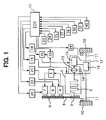
- Fig. 1 shows a constitution of an automatic engine stop and start system of the first embodiment.
- An engine 1 has a crankshaft 2, and a crank pulley 3 attached to an end of the crankshaft 2.
- the crankshaft 2 drives a generator 4 such as an alternator.
- a battery 5 is charged by power generated by the generator 4.
- the crankshaft 2 drives a compressor 6 for an air-conditioner.
- a starter 7 is operative to start the engine 1.
- the crank pulley 3 is connected with pulleys attached on the generator 4, the compressor 6, and the starter 7 via a single piece of a belt 8.
- the pulleys and the belt 8 form a power transmission mechanism 9 that is a normally engaged type and has more or less flexibility.
- the belt 8 may be replaced with a chain or the like constituting a functionally equivalent transmission device.
- the starter 7 may be a starter-generator that can works either a starter and a generator.
- the crankshaft 2 is operatively connected with Left and right drive wheels 10 and 10 via left and right axles 11 and 11, and an automatic transmission 12.
- the automatic transmission 12 is well known type, and has a hydraulic type torque converter 13 having a pump and a turbine, a transmission 14, and a final stage speed reducing gear train 15.
- the transmission 14 comprises a plurality of gear trains, and hydraulic clutches.
- the final gear train 15 includes a differential gear train.
- the automatic transmission 12 is provided with a lock-up clutch 16 in parallel with the torque converter 13.
- the lock-up clutch 16 provides direct transmission means for carrying out transmission directly and mechanically by shortcircuiting the torque converter 13 such that power loss of the torque converter 13 by fluid is reduced in a steady-state running state at high speed.
- the transmission 14 can be controlled to a neutral state arbitrarily by transmission controlling means, mentioned later.
- the automatic transmission 12 may be an automatic transmission having a constitution in which a transmission state between the crankshaft and the drive wheel can be controlled at least in two states of a directly connected state and a state of cutting torque transmitted from the drive wheel in the direction of the crankshaft by electronic controlling means regardless of a constitution having the hydraulic type torque converter 13.
- the automatic transmission 12 including the transmission of the normally engaged type may be constituted by a structure of cutting torque from the drive wheel in the direction of the crankshaft at a specific speed change stage or a structure connected in series with a control clutch of an electromagnetic clutch or the like controllable by electronic controlling means before or after a constitution in correspondence with the transmission 14 for controlling the transmission state between the crankshaft 2 and the drive wheel 10 to a directly connected or cut state by the clutch.
- An electronic control unit (ECU) 17 for automatically stopping and restarting the engine is mounted on the vehicle.
- the ECU 17 provides a controller.
- the ECU 17 outputs instruction signals for automatically stopping or restarting the engine 1.
- the ECU 17 is constituted by at least one piece of microprocessor, memories of ROM and RAM and the like connected thereto, a clock device, input/output ports and the like similar to normal ECU.
- the ECU 17 carries out operation based on signals inputted from detecting means of sensors, switches and the like, and maps set by ROM and the like.
- the ECU 17 outputs the instruction signals in accordance with a result of the operation. Therefore, the ECU 17 is inputted with signals indicating operational states of the engine 1 and the vehicle from detecting means provided at the respective portions of the vehicle and the engine 1.
- the ECU 17 outputs the instruction signals of the result of the operation to related controlling means constituting individual driving devices of a number of apparatus.
- controlling means for driving desired apparatus by receiving the instruction of the ECU 17 as follows.
- Numeral 18 designates controlling means for the automatic transmission 12.
- the controlling means 18 controls the automatic transmission 12 by outputting instruction to a hydraulic control mechanism 35. Similar to the normal constitution, the controlling means 18 can switch gear trains of the transmission 14 by operating hydraulic clutches and the like at inside of the automatic transmission 12.
- the controlling means 18 carries out connecting and disconnecting control of the lock-up clutch 16 constituting the direct transmitting means by receiving instruction from the ECU 17 at any time. In the case of using the above-described series connected control clutch, the controlling means 18 provides means for connecting and disconnecting the control clutch.
- Numeral 19 designates controlling means of the engine 1 for controlling operating conditions such as fuel supply and ignition timing.
- Numeral 20 designates controlling means of the starter 7. The controlling means 20 and the starter 7 are arranged so that the starter 7 carries out restarting operation by driving the crankshaft 2, even in the case in which the engine 1 is not completely stopped.
- Numeral 21 designates controlling means for controlling an amount of a power generation of the generator 4.
- the power generation of the generator 4 can be controlled thereby.
- controlling means 22 of the compressor 6 that is needed when the air-conditioner is used. By operating the controlling means described above, load acting on the crankshaft 2 can be increased or decreased temporarily.
- Fig. 1 exemplifies several detecting means for detecting signals indicating the operational states of the engine 1 and the vehicle, which are necessary for the ECU 17 for carrying out such a control.
- Numeral 23 designates a vehicle speed sensor for detecting a vehicle speed VS.
- Numeral 24 designates a brake depressing amount sensor for detecting a brake depressing amount BS.
- the brake depressing amount sensor provides brake depressing amount detecting means for detecting a depressing amount of a brake pedal, not illustrated, operated by a driver of the vehicle.
- the brake depressing amount sensor 24 also provides braking operation detecting means.
- the brake depressing amount sensor 24 is replaceable with a sensor that detects a brake depressing amount, a brake depressing angle, or a magnitude of force of depressing brake.
- Numeral 25 designates detecting means of a depressing amount AS of an accelerator pedal operated by the driver.
- the depressing amount is replaceable with an accelerator opening degree. According to the first example, it is not necessary to accurately detect the depressing amount of the accelerator pedal, it is sufficient when it can be detected whether the depressing amount exceeds a predetermined amount or not. Therefore, an accelerator switch operable to the accelerator pedal, can be the detecting means 25
- Numeral 27 designates turn signal detecting means for detecting operation of a turn signal lamp.
- a pair of turn signal switches can be used as the turn signal detecting means 27. That is, the detecting means may be connected such that an electric signal is inputted to the ECU 17 when either of the left and right turn signal switches 27 is made ON.
- Numeral 28 designates road inclination angle detecting means for detecting an inclination angle of a road on which a vehicle runs. For example, there can be provided a switch made ON when an inclination angle of a pendulum capable of freely pivoting exceeds a predetermined value at a pertinent location of the vehicle to assign to the purpose.
- Numeral 30 designates detecting means for detecting an operational state of a parking brake.
- the detecting means may be a switch made ON when the parking brake is brought into an engaged state and therefore, a switch of this kind provided in the normal vehicle may be connected to the ECU 17 as it is as a sensor.
- Numeral 31 designates detecting means 31 for detecting a revolution number of the engine 1.
- an engine speed NE For example, when the engine 1 is a spark ignition engine such as a gasoline engine, the engine speed NE can be calculated by counting a number of pulses of ignition signals generated within unit time by the ECU 17.
- Numeral 33 designates an electric hydraulic pump that is communicated with the hydraulic control mechanism 35.
- the pump 33 is driven by a motor powered by the battery 5 under control of the ECU 17.
- the ECU 17 controls the pump 33 in order to ensure operational hydraulic pressure of the hydraulic control mechanism 35 during the engine 1 is stopped.
- a brake system 34 uses intake negative pressure of the engine when the engine 1 is rotated.
- the operational hydraulic pressure of the hydraulic control mechanism 35 is supplied by a hydraulic pump, not illustrated, attached to the crankshaft 2 of the engine 1, when the engine 1 is rotated.
- a detecting means may be attached, which is capable of directly detecting the operational state that can be indirectly detected by the above-described detecting means.
- a sensor for directly detecting a state of connecting and disconnecting the lock-up clutch 16 and the like can be provided as necessary.
- controlling means for controlling to connect and disconnect fuel supply to the engine 1, controlling means for controlling to make an ignition device ON-OFF and the like are provided. Control of cutting fuel supply, recovering fuel supply and the like carried out by these controlling means, is carried out by controlling the engine controlling means 19 by the ECU 17. Therefore, these controlling means are included in parts of the engine controlling means 19.
- Numeral 40 designates a pressure sensor for detecting negative pressure PB of a brake booster, not illustrated, included in the brake system 34, which is also referred to as a booster negative pressure sensor.
- a usual vacuum assist system is used in the brake system 34.
- the brake system 34 of the vacuum assist system is provided with the brake booster supplied with the negative pressure. If the brake pedal is operated, the negative pressure of the brake booster drives a master cylinder. Then, the master cylinder supplies hydraulic pressure to wheel cylinders via brake fluid conduits. The wheel cylinders brake the wheels.
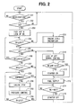
- the electronic ECU 17 determines that the vehicle is brought into the decelerated state at step 201 and the operation proceeds to step 202.
- step 202 it is detected that the accelerator switch (AS) 25 is brought into an OFF state.
- the operation proceeds to step 203 and the ECU 17 controls the engine controlling means 19 to instruct fuel cut and fuel recovery prohibition at the engine 1.
- the ECU 17 controls the transmission controlling means 18 to make the lock-up clutch 16 (or a control clutch or the like in correspondence therewith as described above) of the automatic transmission 12 ON (connected state) to continue to rotate the crankshaft 2 of the engine 1 which does not generate torque by cutting fuel supply by being conversely driven by the drive wheel 10 and the axle 11.
- the operation returns to before step 201 and repeats the determination.
- step 204 it is determined whether brake depressing speed BV calculated at the ECU 17 based on a detected signal of the brake depressing amount detecting means 24, is equal to or smaller than a predetermined value BVT.
- a predetermined value BVT a predetermined value
- the operation proceeds to an engine stall preventing subroutine program 220 and when the determination is YES, it is confirmed again at step 205 that the accelerator switch 25 is made OFF (accelerating operation is not carried out), thereafter, the operation proceeds to step 206 and it is determined whether the engine speed NE is equal to or larger than a predetermined engine speed Nlimit.
- step 210 the lock-up clutch 15 is made OFF (opened state), and a transmission control is resumed to a normal control. Thereafter, when the engine speed NE is equal to or larger than Nlimit in determination at step 211 (YES), the operation proceeds to step 213, fuel supply is restarted and the engine is restarted only thereby.
- the engine speed NE is equal to or smaller than Nlimit (NO) at step 211
- the operation proceeds to step 212, the starter 7 is driven. Thereafter, the engine 1 is restarted with restarting of fuel supply.
- step 214 it is determined that whether the engine speed NE becomes equal to or larger than a predetermined value NST that indicates the engine start is completed. Then, the operation proceeds to step 215 and the starter 7 is made to stop driving.
- Nlimit is a predetermined value having the following meaning.
- the engine speed passes through a resonance region until the engine speed is reduced and the engine is stopped and therefore, at such an occasion, there is generated vibration unpleasant for a passenger having large amplitude by resonance of the engine and the vehicle body of the vehicle.
- Nlimit refers to an engine speed produced by adding a maximum engine speed of the resonance region and an amount of reducing the engine speed anticipated during a time lag from establishing an engine stopping condition until a control of stopping the engine is actually started.
- the operation returns to before step 204 and the determination is repeated.
- the deceleration is progressed in the state of cutting fuel and the engine speed is also reduced.
- step 207 it is determined whether the depressing amount BS of the brake is equal to or larger than a first predetermined value, in this case, engine speed stopping threshold S1.
- the first predetermined value is a value anticipated to depress the accelerator pedal when the driver stops the vehicle and is set as, for example, a value capable of controlling creep torque which is generated when the accelerator pedal is not depressed.
- determination is YES (equal to or larger than the predetermined value) at step 207, it is determined that the driver intends to stop the vehicle and the operation proceeds to step 230.
- step 230 it is determined whether the road is downhill, that is, a downward road and when the road is downward road, the operation proceeds to step 210 and the engine is restarted.
- the intake negative pressure is always supplied to the brake booster and therefore, stop of supply thereof can be avoided. Therefore, there can previously be prevented occurrence of a drawback that the booster negative pressure is significantly consumed by the braking operation when the vehicle runs on the downward road, the booster negative pressure is reduced to exceed a necessary level and the control operation is deteriorated.
- step 230 determination of the downward road in step 230 (downward road detecting means according to the invention), is carried out as follows. It can be readily understood that the determination steps can easily be carried out in a current automobile and therefore, illustration of a flowchart will be omitted.
- a first determining method is to determine the downward road when the road inclination angle detected by the road inclination angle detecting means 28 is equal to or larger than a predetermined value.
- road inclination angle detecting means 28 per se of this kind for detecting the inclination angle of a free oscillating pendulum by a noncontact limit switch or the like and therefore, a specific explanation thereof will be omitted.
- a second determining method is to determine the downward road based on running acceleration VACC and a brake depressing amount BS when a deceleration rate is less than a predetermined value despite that the brake depressing amount is equal to or larger than a predetermined amount. That is, there is previously stored a map showing a relationship among the running acceleration VACC, the brake depressing amount BS and an inclination angle (refer to Fig. 15, Fig. 16) and the inclination angle is calculated by putting the detected running acceleration VACC and the brake depressing amount BS to the map. Thereby, the inclination angle sensor can be omitted.
- step 208 the ECU 17 carries out an engine stopping processing and proceeds to step 250.
- a subroutine program for the engine rotation stopping processing shown in step 230 corresponds to automatic stopping of the engine according to the invention.
- the ECU 17 carries out a subroutine for ensuring the negative pressure (also referred to as booster negative pressure, brake negative pressure) of the brake booster.
- the depressing amount BS of the brake is equal to or smaller than a second predetermined value, engine restarting threshold S1 in this case.
- the second predetermined value S2 is set as a value equal to or smaller than the first predetermined value S1.
- the accelerator switch 25 is made ON, that is, the driver depresses the accelerator pedal at step 205
- the depressing amount of the brake becomes equal to or smaller than the first predetermined value S1 (NO) in the determination at step 207
- the determination at step 209 after carrying out the engine rotation stopping processing becomes YES (the brake depressing amount is equal to or smaller than the second predetermined value S2)
- the operation proceeds to step 210 for increasing the engine speed by supplying fuel and restarting the engine 1 again.
- step 210 the ECU 17 immediately makes OFF the lock-up clutch 16 (or means in place thereof) via the transmission controlling mean 18 and stops maintaining to rotate the crankshaft 2 by the axle 11 to thereby enable to freely rotate the crankshaft 2. Simultaneously therewith, the control of the transmission 14 of the automatic transmission 12 by the transmission controlling means 18 is recovered to the normal control mode. Further, at step 211, it is determined whether the engine speed NE at that occasion is larger than the constant value Nlimit. When the engine speed NE is not larger (NO), at step 212 the ECU 17 starts the starter 7 by the starter controlling mean 20, drives to rotate the crankshaft 2 via the belt 8 and restarts the engine 1 by restarting supply of fuel by the engine controlling means 19 at step 213. When the engine speed NE is equal to or larger than Nlimit (YES) in the determination of step 211, the engine 1 is restarted by only restarting supply of fuel without driving the starter 7.
- Nlimit YES
- the automatic stopping and restarting control apparatus basically avoids consumption of fuel by cutting fuel in the decelerated state of the vehicle and maintains rotation of the engine by rotation of the axle for a small time period before the vehicle is completely stopped by connecting the crankshaft of the engine and the axle.
- the depressing amount of the brake by the driver is equal to or larger than the first predetermined value S1, except the case of rapid braking in which the brake depressing speed is high, swift stopping processing of the engine rotation is carried out by estimating that the driver intends to stop the vehicle, when the depressing amount of the brake is reduced to be equal to or smaller than the second predetermined value S2, supply of fuel is restarted by estimating that the driver intends to reaccelerate the vehicle, restraint of the crankshaft by the axle is released, the starter is operated and the engine is rotated by a predetermined rotational number or more.
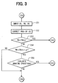
- step 251 based on input signals from the vehicle speed sensor 23, the brake depressing amount sensor (braking operation detecting means) 24 and the booster negative pressure sensor 40, the vehicle speed VS, the booster negative pressure PB and the braking operation BS are detected.
- a booster negative pressure threshold PBth is corrected based on a map for previously storing a relationship between the booster negative pressure threshold PBth and the vehicle speed VS. A description will be given later of a specific example of the braking operation to be detected.
- step 253 it is investigated whether the detected booster negative pressure PB is smaller than the threshold PBth (step 253).
- the operation proceeds to step 210 and the engine is restarted immediately without taking a consideration on the braking operation. Otherwise, it is investigated whether the detected booster negative pressure PB is smaller than the threshold PBth+ ⁇ (step 254).
- the operation proceeds to step 255, otherwise, proceeds to step 209.
- Notation ⁇ designates a predetermined small value.
- a braking operation within a predetermined period is evaluated whether it lowers the booster negative pressure to the booster negative pressure threshold PBth. For instance, it is investigated whether there is carried out the braking operation with a concern that the booster negative pressure PB may become lower than the booster negative pressure threshold PBth. If such a braking operation is carried out, the operation proceeds to step 210 and the engine is restarted, otherwise, the operation proceeds to step 209.
- the operation proceeds to step 210 when the booster negative pressure PB and the brake depressing amount are read at the step 252 and a difference x between a detected value at current time and a detected value at preceding time of the brake depressing amount is equal to or larger than a predetermined value.
- the preceding time value of the brake depressing amount is set to a value of the brake depressing amount at a time point at which a change in the brake depressing amount therebefore reflects to a change in the booster negative pressure PB and it is not necessarily needed that the preceding time value is a preceding time value of the routine of step 250. That is, the preceding time value is to be a value of the brake depressing amount detected a predetermined time period before the current value.
- a temporary reducing amount (which will recover soon) ⁇ PB of the booster negative pressure PB immediately after respective braking operation by the respective braking operation is stored to a map of the respective braking operation. Further, there is calculated a current time value of the reducing amount ⁇ PB of the booster negative pressure PB by the braking operation detected at current time and the current time value is subtracted from the current time value PB of the booster negative pressure PB detected at current time and a next anticipated value (PB- ⁇ PB) of the booster negative pressure PB is estimated.
- (PB- ⁇ PB) becomes smaller than PBth, it is determined that there is carried out the braking operation specified at step 255, the operation proceeds to step 210 and the engine is restarted. Thereby, a deficiency in assisting the braking operation by reducing the booster negative pressure PB can be avoided.
- a rate of changing the brake depressing amount that is, the brake depressing amount is equal to or larger than a predetermined value
- the booster negative pressure PB when the booster negative pressure PB is slightly larger than the booster negative pressure threshold PBth and the rate of changing the brake depressing amount is equal to or larger than the predetermined value, the booster negative pressure PB becomes lower than the booster negative pressure threshold PBth immediately thereafter and therefore, the engine is restarted immediately prior to an actual reduction in the booster negative pressure PB. Thereby, there can be avoided a deficiency in assisting the braking operation by reducing the booster negative pressure PB.
- the rate of changing the brake depressing amount can be calculated.
- the routine of Fig. 3 is carried out at respective constant time period, the difference between the two value becomes a value in proportion to a rate of changing the brake depressing amount with no need of dividing the difference by the time difference and therefore, the value may be used.
- the automatic starting is instructed when under a situation in which the booster negative pressure is equal to or smaller than a predetermined value, an accumulated value of changing the brake depressing amount in an immediately proximate predetermined period of time is equal to or larger than a predetermined value as predetermined braking operation.
- the accumulated amount of the brake depressing amount at the immediately proximate period of time (particularly, an accumulated amount of the braking depressing amount during a time period in which the accumulated amount is not reflected to a detected value of a booster negative pressure sensor), is brought into a close positive correlated relationship with an amount of reducing the booster negative pressure thereafter and therefore, when the accumulated change amount of the brake depressing amount significantly consuming the booster negative pressure is large in a state in which the booster negative pressure is proximate to an engine restarting limit, by restarting the engine for the braking operation, swift engine restarting can be realized and a drawback caused by a delay in restarting the engine can be resolved. Specifically, an absolute value of the change in the brake depressing amount immediately therebefore is summed up and when the summed-up value exceeds a predetermined value, the engine may be restarted.
- a conventional control for automatically stopping the engine the driver may feel a strange feeling due to an insufficient negative pressure.
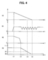
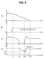
- the vehicle is run by a pattern as shown by Fig. 4.
- the vehicle is run in a steady-state running until time t1, and is in deceleration from time t1.
- the engine is stopped at time t2 by an automatic engine stopping function.
- the booster negative pressure PB is decreased after the engine is stopped.
- PT indicates a lower limit negative pressure for operating the brake sufficiently
- P0 is an atmospheric pressure.
- the vehicle is completely stopped at time t4.
- booster negative pressure PB is reduced.
- the brake negative pressure sufficient for operating the brake cannot be ensured after time t3.
- the driver may feel a strange feeling in the braking operation due to an insufficient negative pressure PB.
- the driver is prevented from the strange feeling in the braking operation, because the insufficiency of the booster negative pressure is effectively avoided.
- Fig. 6 at a stage of PBth+ ⁇ before the booster negative pressure PB reaches the PT, it is determined whether the engine is to be restarted in accordance with the braking operation state of the driver. The engine is restarted at time t21. The engine speed NE is increased before the booster negative pressure is lowered below the sufficient negative pressure PT, because the instruction for restarting the engine is generated in advance enough.
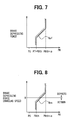
- Fig. 7 through Fig. 10 illustrate alternative relationships between various braking operation information and a change in the booster negative pressure after elapse of a predetermined delay time period thereby.
- the engine is restarted when the booster negative pressure PB is equal to or smaller than PBth+ ⁇ and brake depressing force BF is equal to or larger than a predetermined value.
- the boundary Bpf for determining a restarting is defined as shown in Fig. 7. If both of the brake depressing force and the booster negative pressure enter a hatched area, the engine is restarted.
- Fig. 8 the engine is restarted when the booster negative pressure PB is equal to or smaller than PBth+ ⁇ and brake depressing force changing speed is equal to or larger than a predetermined value.
- the boundary Bps for determining a restarting is defined as shown in Fig. 8. If both of the brake depressing force changing speed and the booster negative pressure enter a hatched area, the engine is restarted.
- Fig. 9 the engine is restarted when the booster negative pressure PB is equal to or smaller than PBth+ ⁇ and the brake depressing amount BS is equal to or larger than a predetermined value.
- the boundary Bpb for determining a restarting is defined as shown in Fig. 9. If both of the brake depressing amount BS and the booster negative pressure PB enter a hatched area, the engine is restarted.
- Fig. 10 the engine is restarted when the booster negative pressure PB is equal to or smaller than PBth+ ⁇ and speed of changing the brake depressing amount BS is equal to or larger than a predetermined value.
- the boundary Bpc for determining a restarting is defined as shown in Fig. 10. If both of the brake depressing amount changing speed and the booster negative pressure enter a hatched area, the engine is restarted.
- Fig. 11 it is determined whether the brake depressing amount BS is equal to or larger than a predetermined value BSth.
- the operation jumps to step 254.
- the brake depressing amount is equal to or larger than the predetermined value, at step 257, there is calculated an estimated booster negative pressure PBE when the brake depressing amount is relaxed from a current value by a predetermined amount, here, constituted by a constant value.
- the calculation may be carried out by putting the brake depressing amount or the booster negative pressure to a map previously storing a correlated relationship among the related parameters.
- the estimated booster negative pressure PBE is smaller than the predetermined threshold PBth.
- the estimated booster negative pressure PBE is smaller than the threshold PBth, it is determined that there is a possibility of reducing the booster negative pressure more than the predetermined threshold PBth when relief of the pumping operation is carried out again immediately thereafter and the engine is restarted to prepare therefore. Otherwise the operation proceeds to step 254.
- the strange feeling in depressing the brake again thereafter can be resolved a little earlier.
- the booster negative pressure PBE when the brake is relaxed to a brake depressing amount BS0 in depressing the brake.
- the engine is restarted. Thereby, there can be prevented a reduction in the negative pressure when the brake is temporarily relaxed and is rapidly depressed.
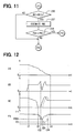
- Figs. 12 shows operating conditions between a case of using the above-described estimated booster negative pressure PBE (solid lines) and a case of not using the estimated booster negative pressure PBE (broken lines). Incidentally, there is carried out pumping operation in both of the cases.
- the estimated booster negative pressure PBE reaches to the threshold PBth at time t22, then the ECU 17 restarts the engine. As a result, the engine speed NE quickly recovered to prevent excessive drop of the booster negative pressure.
- the booster negative pressure PB may drops below the threshold PBth from t23 to t24.
- numeral 40 in Fig. 1 designates a hydraulic pressure sensor for detecting a hydraulic pressure PF of brake fluid in a brake master cylinder and an intake pressure sensor for detecting an intake pressure PM of the engine.
- Fig. 13 is an alternative process for the step 250 in Fig. 1.
- the intake pressure PM, the hydraulic pressure PF and the brake depressing amount BS are detected at step 261.
- the booster negative pressure PBE before stopping the engine is estimated at step 262.
- the booster negative pressure PBE is estimated by looking up a predetermined map based on the intake pressure PM, the hydraulic pressure PF and the brake depressing amount BS.
- Fig. 14 is a map that shows a relationship among the booster negative pressure PB, the hydraulic pressure PF and the brake depressing amount BS.
- an amount of consuming the booster negative pressure PB by accumulating a variation in the brake depressing amount at and after calculating the booster negative pressure PBE before stopping the engine is calculated based on the previously stored map showing the relationship between the booster negative pressure PB and a change in the brake depressing amount BS as step 263. It is determined whether a value produced by accumulating an amount which has been consumed and subtracting the amount from the booster negative pressure PBE before stopping the engine is smaller than the predetermined threshold PBth at step 264. When the value is smaller, the operation proceeds to step 210 and the engine is restarted, otherwise, the operation proceeds to step 209.
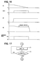
- the vehicle speed VS is detected after the engine has been restarted.
- the operation returns to step 271.
- the process circulates the steps 271 and 272 for certain period, the engine is prohibited from being stopped. Otherwise, the process returns to the step 201.
- Fig. 18 shows operating conditions under a control of the fourth embodiment.
- the engine is operated to stop rotation at time t5.
- the engine is restarted at time t6.
- the engine may be stopped at time t61 due to the operating condition.
- the engine is kept running during the vehicle speed VS is in a predetermined intermediate range VSR. Therefore, the engine is stopped at time t7 that is significantly later than the conventional time t61.
- the engine stopping condition is established by finishing the downward road in which the booster negative pressure is ensured after restarting the engine
- the vehicle speed falls in the predetermined intermediate range VSR
- the engine is prohibited from being stopped.
- promotion of fuel cost is achieved by automatically stopping and restarting the engine while resolving the deficiency in the booster negative pressure PB as swiftly as possible, there is conceivable a case in which restarting of the engine is not realized by a failure in the starter or the like, or a case in which restarting of the engine is abnormally delayed.
- the booster negative pressure is further reduced by the braking operation in stopping the engine.
- step 100 it is investigated whether the engine is instructed to restart due to a determination in the step 250.
- the engine has been instructed to restart, it is investigated whether an elapse time period TR after the engine has been instructed to restart, exceeds a predetermined threshold Tth at step 102.
- the elapse time period TR is set to a time period sufficient for the booster negative pressure PB to be necessarily larger than a second booster negative pressure threshold PBth2 when the engine has normally been restarted.
- the booster negative pressure PB is smaller than the second booster negative pressure threshold PBth2 at step 104.
- the booster negative pressure PB is smaller than the second booster negative pressure threshold PBth2
- the ECU 17 determines a direct braking hydraulic pressure in accordance with the brake depressing amount BS at step 108.
- the determined direct braking hydraulic pressure is instructed to, for example, a hydraulic pressure control apparatus for traction control.
- the hydraulic pressure control apparatus is included in the brake system 34.
- the hydraulic pressure control apparatus for traction control generates necessary braking hydraulic pressure in the master cylinder or the wheel cylinder of the brake.
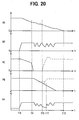
- Fig. 20 shows operating conditions under a control of the fifth embodiment.
- the driver operates the brake from time t8.
- the engine is instructed to stop rotation at time t9.
- the ECU 17 instructs restarting the engine at time t10.
- the engine can not be restarted, therefore, the booster negative pressure PB is continuously decreased.
- the ECU 17 instructs to increase brake fluid pressure directly by the hydraulic control device such as the traction control apparatus from time t11. Therefore, even if the booster negative pressure PB is not recovered, the vehicle can be stopped under an assist of the direct braking hydraulic pressure supplied from time t11 to t12.
- the direct braking hydraulic pressure may be calculated by putting the brake depressing amount BS to a previously stored map such as a map shown in Fig. 21.
- the map shows a relationship between the direct braking hydraulic pressure and the brake depressing amount.
- a hydraulic pressure control apparatus for ABS or brake assist may be used as the hydraulic pressure control apparatus for directly controlling the brake pressure.
- the direct braking hydraulic pressure control per se in ABS or traction control has already been well known and therefore, illustration of the hydraulic pressure circuit diagram will be omitted.
Landscapes
- Engineering & Computer Science (AREA)
- Chemical & Material Sciences (AREA)
- Combustion & Propulsion (AREA)
- Mechanical Engineering (AREA)
- General Engineering & Computer Science (AREA)
- Transportation (AREA)
- Automation & Control Theory (AREA)
- Environmental & Geological Engineering (AREA)
- Atmospheric Sciences (AREA)
- Toxicology (AREA)
- Life Sciences & Earth Sciences (AREA)
- Health & Medical Sciences (AREA)
- Human Computer Interaction (AREA)
- Control Of Vehicle Engines Or Engines For Specific Uses (AREA)
- Output Control And Ontrol Of Special Type Engine (AREA)
- Valves And Accessory Devices For Braking Systems (AREA)
- Control Of Driving Devices And Active Controlling Of Vehicle (AREA)
Priority Applications (1)
| Application Number | Priority Date | Filing Date | Title |
|---|---|---|---|
| EP06010431A EP1726824B1 (fr) | 2001-06-27 | 2002-06-26 | Système automatisé de démarrage et arrêt d'un moteur thermique |
Applications Claiming Priority (2)
| Application Number | Priority Date | Filing Date | Title |
|---|---|---|---|
| JP2001195204 | 2001-06-27 | ||
| JP2001195204A JP4552365B2 (ja) | 2001-06-27 | 2001-06-27 | エンジン自動停止再始動装置 |
Related Child Applications (1)
| Application Number | Title | Priority Date | Filing Date |
|---|---|---|---|
| EP06010431A Division EP1726824B1 (fr) | 2001-06-27 | 2002-06-26 | Système automatisé de démarrage et arrêt d'un moteur thermique |
Publications (3)
| Publication Number | Publication Date |
|---|---|
| EP1270308A2 true EP1270308A2 (fr) | 2003-01-02 |
| EP1270308A3 EP1270308A3 (fr) | 2004-04-14 |
| EP1270308B1 EP1270308B1 (fr) | 2007-12-05 |
Family
ID=19033225
Family Applications (2)
| Application Number | Title | Priority Date | Filing Date |
|---|---|---|---|
| EP02014243A Expired - Lifetime EP1270308B1 (fr) | 2001-06-27 | 2002-06-26 | Commande automatique d'arrêt moteur en fonction de l'état de freinage |
| EP06010431A Expired - Lifetime EP1726824B1 (fr) | 2001-06-27 | 2002-06-26 | Système automatisé de démarrage et arrêt d'un moteur thermique |
Family Applications After (1)
| Application Number | Title | Priority Date | Filing Date |
|---|---|---|---|
| EP06010431A Expired - Lifetime EP1726824B1 (fr) | 2001-06-27 | 2002-06-26 | Système automatisé de démarrage et arrêt d'un moteur thermique |
Country Status (4)
| Country | Link |
|---|---|
| US (1) | US6754579B2 (fr) |
| EP (2) | EP1270308B1 (fr) |
| JP (1) | JP4552365B2 (fr) |
| DE (2) | DE60238724D1 (fr) |
Cited By (12)
| Publication number | Priority date | Publication date | Assignee | Title |
|---|---|---|---|---|
| WO2004083627A1 (fr) * | 2003-03-20 | 2004-09-30 | Robert Bosch Gmbh | Procede de commande d'un moteur a combustion interne |
| FR2857411A1 (fr) * | 2003-07-10 | 2005-01-14 | Bosch Gmbh Robert | Procede et appareil de commande pour gerer le fonctionnement d'un moteur a combustion interne |
| WO2007006453A1 (fr) * | 2005-07-07 | 2007-01-18 | Gm Global Technology Operations, Inc. | Procede pour calculer la depression dans le servofrein d'un vehicule a moteur a allumage commande |
| WO2009130157A1 (fr) * | 2008-04-22 | 2009-10-29 | Continental Automotive Gmbh | Procédé et dispositif pour commander un moteur à combustion interne d'un véhicule automobile équipé d'un système d'arrêt/démarrage automatique |
| DE102009027337A1 (de) | 2009-06-30 | 2011-01-05 | Ford Global Technologies, LLC, Dearborn | Verfahren zum Schätzen des in einem Kraftfahrzeug-Bremskraftverstärker herrschenden Unterdrucks sowie Stopp-Start-Steuereinrichtung |
| WO2012042341A1 (fr) * | 2010-09-30 | 2012-04-05 | Toyota Jidosha Kabushiki Kaisha | Boîtier électronique de commande de véhicule |
| WO2014064524A1 (fr) * | 2012-10-24 | 2014-05-01 | Toyota Jidosha Kabushiki Kaisha | Dispositif et procédé de commande de marche sur l'erre pour véhicule |
| EP2808520A4 (fr) * | 2012-01-23 | 2016-04-20 | Toyota Motor Co Ltd | Dispositif de commande de redémarrage d'un moteur thermique, véhicule et procédé de commande de véhicule |
| DE102015219943B3 (de) * | 2015-10-14 | 2017-01-26 | Ford Global Technologies, Llc | Verfahren zum Bestimmen des Drucks in einem Bremskraftverstärker sowie Start-Stopp-Steuereinrichtung |
| DE102015219944A1 (de) | 2015-10-14 | 2017-04-20 | Ford Global Technologies, Llc | Verfahren zum Ansteuern einer elektrischen Vakuumpumpe eines Bremskraftverstärkers |
| DE102016218681A1 (de) | 2016-09-28 | 2018-03-29 | Ford Global Technologies, Llc | Verfahren zum Betreiben eines hydraulischen Bremssystems eines Kraftfahrzeugs sowie hydraulisches Bremssystem für ein Kraftfahrzeug |
| EP2666995A4 (fr) * | 2011-01-21 | 2018-04-25 | Toyota Jidosha Kabushiki Kaisha | Dispositif de commande de véhicule |
Families Citing this family (93)
| Publication number | Priority date | Publication date | Assignee | Title |
|---|---|---|---|---|
| DE10317501B4 (de) * | 2003-04-16 | 2015-06-03 | Daimler Ag | Verfahren zum Betrieb eines Kraftfahrzeugs |
| JP4121126B2 (ja) * | 2003-08-21 | 2008-07-23 | 本田技研工業株式会社 | 燃料噴射制御装置 |
| DE10357933A1 (de) * | 2003-12-11 | 2005-07-07 | Daimlerchrysler Ag | Verfahren zum selbsttätigen Start eines Verbrennungsmotors |
| US7970527B2 (en) * | 2004-11-01 | 2011-06-28 | Fujitsu Ten Limited | Engine start control apparatus and engine start control method |
| DE102005046607A1 (de) * | 2005-09-29 | 2007-04-05 | Robert Bosch Gmbh | Vorrichtung und Verfahren zur Betätigung einer Feststellbremse eines Fahrzeugs |
| US20070087898A1 (en) * | 2005-10-18 | 2007-04-19 | Siemens Vdo Automotive Corporation | Passive Start with invalid brake ON-OFF switch state |
| JP4765914B2 (ja) * | 2006-03-07 | 2011-09-07 | 日産自動車株式会社 | 車両用パワートレーンの制御装置 |
| JP4766330B2 (ja) * | 2006-11-22 | 2011-09-07 | スズキ株式会社 | エンジンの自動停止始動制御装置 |
| US7878053B2 (en) * | 2006-12-22 | 2011-02-01 | Gm Global Technology Operations, Inc. | Engine off brake booster leak diagnostic systems and methods |
| DE102007016985B4 (de) * | 2007-04-10 | 2016-09-15 | Bayerische Motoren Werke Aktiengesellschaft | Verfahren zur Steuerung eines automatischen Abschaltvorgangs einer Antriebseinheit in einem Kraftfahrzeug |
| JP4365427B2 (ja) | 2007-04-20 | 2009-11-18 | 富士通テン株式会社 | エコラン制御装置、エコラン制御システム及び制御方法 |
| JP5144169B2 (ja) * | 2007-08-17 | 2013-02-13 | 本田技研工業株式会社 | コージェネレーション装置 |
| JP4916983B2 (ja) * | 2007-09-19 | 2012-04-18 | 富士重工業株式会社 | エンジンの制御装置 |
| DE102008060350A1 (de) * | 2008-12-03 | 2010-06-10 | Bayerische Motoren Werke Aktiengesellschaft | Verfahren zum automatischen Abschalten einer Brennkraftmaschine |
| DE102008061790A1 (de) * | 2008-12-11 | 2010-07-08 | Bayerische Motoren Werke Aktiengesellschaft | Verfahren zum automatischen Abschalten und Starten einer Brennkraftmaschine |
| US9002600B2 (en) * | 2009-01-02 | 2015-04-07 | Ford Global Technologies, Llc | Methods and systems for engine shut-down control |
| CN103350700B (zh) * | 2009-01-08 | 2016-01-20 | 株式会社小松制作所 | 车辆速度推算装置及牵引控制装置 |
| DE102009011281A1 (de) * | 2009-03-02 | 2010-09-09 | Dr.Ing.H.C.F.Porsche Aktiengesellschaft | Verfahren zum Betreiben einer Brennkraftmaschine |
| US8627797B2 (en) * | 2009-06-11 | 2014-01-14 | Illinois Tool Works Inc. | Automatic start and stop of a portable engine driven power source |
| JP2011001925A (ja) * | 2009-06-22 | 2011-01-06 | Daihatsu Motor Co Ltd | アイドルストップ制御装置 |
| US8795135B2 (en) * | 2009-09-01 | 2014-08-05 | Ford Global Technologies, Llc | Method for controlling an engine during a restart |
| US8401768B2 (en) * | 2009-09-01 | 2013-03-19 | Ford Global Technologies, Llc | System and method for restarting an engine |
| DE112009005307T5 (de) * | 2009-10-09 | 2012-11-22 | Toyota Jidosha Kabushiki Kaisha | Fahrzeugsteuersystem |
| US8744732B2 (en) * | 2009-12-28 | 2014-06-03 | Kawasaki Jukogyo Kabushiki Kaisha | Vehicle and engine controlling method |
| JP5403267B2 (ja) * | 2010-02-15 | 2014-01-29 | 三菱自動車工業株式会社 | 内燃機関の制御装置 |
| JP5477137B2 (ja) * | 2010-04-15 | 2014-04-23 | 株式会社デンソー | エンジン自動停止再始動制御装置 |
| JP2011226316A (ja) * | 2010-04-15 | 2011-11-10 | Denso Corp | 車両制御装置 |
| US8192328B2 (en) * | 2010-04-30 | 2012-06-05 | Ford Global Technologies, Llc | Methods and systems for assisted direct start control |
| JP2012006511A (ja) * | 2010-06-25 | 2012-01-12 | Advics Co Ltd | ブースター負圧の推定方法及び車両の制御装置 |
| US8414456B2 (en) | 2010-07-09 | 2013-04-09 | Ford Global Technologies, Llc | Method for starting an engine |
| US8864623B2 (en) | 2010-07-09 | 2014-10-21 | Ford Global Technologies, Llc | Method for controlling a transmission coupled to an engine that may be automatically stopped |
| US8328687B2 (en) | 2010-07-09 | 2012-12-11 | Ford Global Technologies, Llc | Method for controlling an engine that may be automatically stopped |
| EP2597291A1 (fr) * | 2010-07-23 | 2013-05-29 | Nissan Motor Co., Ltd | Dispositif d'arrêt automatique et procédé d'arrêt automatique de moteur |
| JP5776153B2 (ja) * | 2010-08-30 | 2015-09-09 | 株式会社アドヴィックス | 車両の制御装置及び車両の制御方法 |
| WO2012029513A1 (fr) * | 2010-09-01 | 2012-03-08 | 日産自動車株式会社 | Dispositif de commande pour véhicule |
| JP5402901B2 (ja) * | 2010-09-30 | 2014-01-29 | 株式会社デンソー | エンジン制御装置 |
| JP5682258B2 (ja) * | 2010-11-24 | 2015-03-11 | トヨタ自動車株式会社 | 車両制御装置 |
| DE102010061383B4 (de) * | 2010-12-21 | 2019-10-24 | Dr. Ing. H.C. F. Porsche Aktiengesellschaft | Verfahren zur Steuerung eines Schubbetriebes eines Kraftfahrzeugs |
| EP2657096B1 (fr) * | 2010-12-24 | 2019-07-24 | Toyota Jidosha Kabushiki Kaisha | Véhicule hybride |
| US20120191317A1 (en) * | 2011-01-24 | 2012-07-26 | Armin Mueller-Lerwe | Method and Device for Controlling the Operation of an Internal Combustion Engine |
| WO2012111062A1 (fr) * | 2011-02-14 | 2012-08-23 | トヨタ自動車株式会社 | Dispositif de commande de véhicule |
| GB2489209B (en) * | 2011-03-15 | 2013-09-04 | Jaguar Cars | Motor vehicle and method of control thereof |
| US9121380B2 (en) | 2011-04-07 | 2015-09-01 | Remy Technologies, Llc | Starter machine system and method |
| WO2012139129A2 (fr) | 2011-04-07 | 2012-10-11 | Remy Technologies, Llc | Système et procédé de machine de démarreur |
| US8960153B2 (en) * | 2011-05-10 | 2015-02-24 | Ford Global Technologies, Llc | Method and system for controlling engine vacuum production |
| US8468879B2 (en) | 2011-06-16 | 2013-06-25 | Ford Global Technologies, Llc | Method and system for diagnosing a vacuum system |
| US8959910B2 (en) | 2011-06-16 | 2015-02-24 | Ford Global Technologies, Llc | Method and system for determining conditions of an air filter |
| US8567239B2 (en) | 2011-06-16 | 2013-10-29 | Ford Global Technologies, Llc | Method and system for determining vacuum leaks |
| US8862355B2 (en) * | 2011-06-22 | 2014-10-14 | Ford Global Technologies, Llc | Method and system for engine control |
| US8374742B2 (en) | 2011-09-16 | 2013-02-12 | Ford Global Technologies, Llc | Turbocharger launch control |
| JP2013071521A (ja) * | 2011-09-27 | 2013-04-22 | Advics Co Ltd | 駐車ブレーキ制御装置 |
| US8353266B2 (en) | 2011-11-02 | 2013-01-15 | Ford Global Technologies, Llc | Engine throttle control with brake booster |
| US8641152B2 (en) | 2011-11-07 | 2014-02-04 | Ford Global Technologies, Llc | Method and system for brake control |
| JP2013117216A (ja) * | 2011-12-05 | 2013-06-13 | Nissan Motor Co Ltd | 車両のエンジン自動制御装置 |
| JP2013117215A (ja) * | 2011-12-05 | 2013-06-13 | Nissan Motor Co Ltd | 車両のエンジン自動制御装置 |
| JP5870660B2 (ja) * | 2011-12-06 | 2016-03-01 | 日産自動車株式会社 | 車両のエンジン自動制御装置 |
| JP2013119776A (ja) * | 2011-12-06 | 2013-06-17 | Nissan Motor Co Ltd | 車両のエンジン自動制御装置 |
| JP5704253B2 (ja) * | 2011-12-15 | 2015-04-22 | トヨタ自動車株式会社 | アイドリングストップ制御装置、車両、および、車両制御方法 |
| JP5896730B2 (ja) * | 2011-12-27 | 2016-03-30 | 富士重工業株式会社 | ハイブリッド車両の制御装置 |
| JP5853690B2 (ja) | 2011-12-28 | 2016-02-09 | 日産自動車株式会社 | 車両のエンジン自動停止制御装置 |
| JP5737203B2 (ja) * | 2012-02-02 | 2015-06-17 | 株式会社デンソー | エンジン制御装置 |
| US8872369B2 (en) | 2012-02-24 | 2014-10-28 | Remy Technologies, Llc | Starter machine system and method |
| US8860235B2 (en) | 2012-02-24 | 2014-10-14 | Remy Technologies, Llc | Starter machine system and method |
| US8829845B2 (en) | 2012-02-28 | 2014-09-09 | Remy Technologies, Llc | Starter machine system and method |
| JP5716695B2 (ja) * | 2012-03-05 | 2015-05-13 | 株式会社デンソー | ハイブリッド車の制御装置 |
| JP5990947B2 (ja) * | 2012-03-13 | 2016-09-14 | 日産自動車株式会社 | 車両制御装置 |
| CN104169149B (zh) * | 2012-03-16 | 2016-12-21 | 日产自动车株式会社 | 混合动力驱动电动汽车的驱动控制装置以及驱动控制方法 |
| US8843296B2 (en) | 2012-03-21 | 2014-09-23 | Ford Global Technologies, Llc | Method and system for engine air control |
| US8733190B2 (en) | 2012-04-25 | 2014-05-27 | Remy Technologies, Llc | Starter machine system and method |
| US9604644B2 (en) | 2012-08-08 | 2017-03-28 | Toyota Jidosha Kabushiki Kaisha | Running control system for vehicle |
| US9366216B2 (en) * | 2012-09-14 | 2016-06-14 | Ford Global Technologies, Llc | User interface for automatic start-stop system and method of controlling the same |
| WO2014068719A1 (fr) * | 2012-10-31 | 2014-05-08 | トヨタ自動車株式会社 | Organe de commande de déplacement de véhicule |
| JP5924242B2 (ja) * | 2012-11-16 | 2016-05-25 | トヨタ自動車株式会社 | アイドルストップ制御装置及びアイドルストップ制御方法 |
| FR2998667B1 (fr) * | 2012-11-29 | 2014-12-26 | Renault Sa | "procede d'estimation de la pression dans un reservoir a depression d'un servofrein" |
| US10144083B2 (en) | 2013-02-22 | 2018-12-04 | Illinois Tool Works Inc. | Multi-operator engine driven welder system |
| JP6241122B2 (ja) * | 2013-08-09 | 2017-12-06 | 日産自動車株式会社 | 車両の制御装置 |
| JP2015044462A (ja) * | 2013-08-27 | 2015-03-12 | 株式会社デンソー | ハイブリッド車の制御装置 |
| US9327707B2 (en) * | 2014-03-11 | 2016-05-03 | GM Global Technology Operations LLC | Method and apparatus for controlling a powertrain system during coasting |
| US9951738B2 (en) * | 2014-03-11 | 2018-04-24 | Voyomotive, Llc | Method of signaling an engine stop or start request |
| JP6142854B2 (ja) * | 2014-08-20 | 2017-06-07 | トヨタ自動車株式会社 | 車両制御装置及び車両制御方法 |
| JP2016097884A (ja) * | 2014-11-25 | 2016-05-30 | 本田技研工業株式会社 | 車両用エアコン制御装置 |
| US10466974B2 (en) * | 2015-04-14 | 2019-11-05 | Microsoft Technology Licensing, Llc | Independent expression animations |
| JP6414335B2 (ja) * | 2015-07-23 | 2018-10-31 | 日産自動車株式会社 | エンジン制御方法及び車両走行制御装置 |
| US10421457B2 (en) * | 2016-05-03 | 2019-09-24 | Ford Global Technologies, Llc | Method for operating an automatic start/stop system in a vehicle utilizing a torque converter |
| US9850965B2 (en) | 2016-05-03 | 2017-12-26 | Ford Global Technologies, Llc | Method for operating an automatic start/stop system in a vehicle utilizing a fluid launch clutch |
| JP6711130B2 (ja) * | 2016-05-19 | 2020-06-17 | スズキ株式会社 | 車両のエンジン自動停止再始動装置 |
| US10024291B1 (en) * | 2017-05-17 | 2018-07-17 | Ford Global Technologies, Llc | Engine start and stop control |
| DE102017222930A1 (de) * | 2017-12-15 | 2019-06-19 | Zf Friedrichshafen Ag | Verfahren zum Betreiben eines Antriebsstrangs eines Kraftfahrzeugs |
| JP6936275B2 (ja) * | 2019-04-22 | 2021-09-15 | 本田技研工業株式会社 | 車両 |
| JP7114195B2 (ja) * | 2019-09-30 | 2022-08-08 | ダイハツ工業株式会社 | ハイブリッド車両の制御装置 |
| JP7188350B2 (ja) * | 2019-10-08 | 2022-12-13 | トヨタ自動車株式会社 | 車両 |
| US11338676B2 (en) * | 2020-06-09 | 2022-05-24 | GM Global Technology Operations LLC | Load sensing system for a vehicle and method of inhibiting vehicle movement based on sensed load |
| US11794715B2 (en) * | 2020-09-28 | 2023-10-24 | Ford Global Technologies, Llc | Brake assist during vehicle one pedal drive |
Citations (3)
| Publication number | Priority date | Publication date | Assignee | Title |
|---|---|---|---|---|
| JPS5830438A (ja) | 1981-08-19 | 1983-02-22 | Nissan Motor Co Ltd | 自動車用エンジンの燃料制御装置 |
| JPS58166165A (ja) | 1982-03-26 | 1983-10-01 | Toyota Motor Corp | 車輌用自動変速機の制御方法 |
| JPH08189395A (ja) | 1994-12-29 | 1996-07-23 | Suzuki Motor Corp | エンジンの自動始動停止装置 |
Family Cites Families (22)
| Publication number | Priority date | Publication date | Assignee | Title |
|---|---|---|---|---|
| JPS5319317Y2 (fr) * | 1973-05-24 | 1978-05-23 | ||
| DE2943563A1 (de) * | 1979-10-27 | 1981-05-07 | Volkswagenwerk Ag | Antrieb, insbesondere fuer kraftfahrzeuge, mit einer brennkraftmaschine und einem automatischen getriebe |
| JPS5823250A (ja) * | 1981-07-31 | 1983-02-10 | Toyota Motor Corp | エンジン自動停止始動の制御方法 |
| JPS59164252A (ja) * | 1983-03-04 | 1984-09-17 | Toyota Motor Corp | ブレ−キブ−スタの負圧供給装置 |
| JP3409715B2 (ja) * | 1998-10-30 | 2003-05-26 | トヨタ自動車株式会社 | 内燃機関 |
| JP2000095097A (ja) * | 1998-09-22 | 2000-04-04 | Aisin Seiki Co Ltd | エンジンの負圧制御装置 |
| JP3675193B2 (ja) * | 1998-09-28 | 2005-07-27 | トヨタ自動車株式会社 | 車両のエンジン自動停止・再始動制御装置 |
| EP0990793B1 (fr) | 1998-09-28 | 2004-08-25 | Toyota Jidosha Kabushiki Kaisha | Dispositif d'arrêt et de redémarrage pour moteur de véhicule |
| JP2000310133A (ja) * | 1999-04-26 | 2000-11-07 | Toyota Motor Corp | エンジンの自動停止始動装置 |
| JP2000204994A (ja) * | 1999-01-18 | 2000-07-25 | Daihatsu Motor Co Ltd | エンジンの自動停止制御装置 |
| JP2000257462A (ja) * | 1999-03-09 | 2000-09-19 | Honda Motor Co Ltd | ハイブリッド車両のエンジン制御装置 |
| JP3651307B2 (ja) * | 1999-04-26 | 2005-05-25 | トヨタ自動車株式会社 | エンジンの自動停止始動装置 |
| JP3807145B2 (ja) * | 1999-04-30 | 2006-08-09 | トヨタ自動車株式会社 | 車両のエンジン再始動の制御装置 |
| JP2001012272A (ja) * | 1999-06-29 | 2001-01-16 | Toyota Motor Corp | 内燃機関の自動停止・始動装置 |
| JP3709746B2 (ja) * | 1999-08-03 | 2005-10-26 | 株式会社デンソー | エンジンの自動制御装置 |
| JP2001107769A (ja) * | 1999-10-04 | 2001-04-17 | Honda Motor Co Ltd | エンジン制御装置 |
| JP4180752B2 (ja) * | 1999-10-27 | 2008-11-12 | 三菱ふそうトラック・バス株式会社 | 路面勾配に基づくエンジン出力制御装置 |
| JP3684965B2 (ja) * | 1999-12-06 | 2005-08-17 | トヨタ自動車株式会社 | 車両制御装置 |
| JP4332962B2 (ja) * | 1999-12-13 | 2009-09-16 | トヨタ自動車株式会社 | 車両用ブレーキシステム |
| JP3885449B2 (ja) * | 2000-02-21 | 2007-02-21 | 日産自動車株式会社 | 車両のエンジン自動停止再始動装置 |
| JP3829567B2 (ja) * | 2000-02-21 | 2006-10-04 | 日産自動車株式会社 | 車両のエンジン自動停止再始動装置 |
| FR2816891B1 (fr) * | 2000-11-20 | 2003-02-28 | Peugeot Citroen Automobiles Sa | Systeme de commande de demarrage et d'arret automatique d'un moteur thermique de vehicule |
-
2001
- 2001-06-27 JP JP2001195204A patent/JP4552365B2/ja not_active Expired - Lifetime
-
2002
- 2002-06-26 DE DE60238724T patent/DE60238724D1/de not_active Expired - Lifetime
- 2002-06-26 DE DE60223871T patent/DE60223871T2/de not_active Expired - Lifetime
- 2002-06-26 US US10/179,271 patent/US6754579B2/en not_active Expired - Lifetime
- 2002-06-26 EP EP02014243A patent/EP1270308B1/fr not_active Expired - Lifetime
- 2002-06-26 EP EP06010431A patent/EP1726824B1/fr not_active Expired - Lifetime
Patent Citations (3)
| Publication number | Priority date | Publication date | Assignee | Title |
|---|---|---|---|---|
| JPS5830438A (ja) | 1981-08-19 | 1983-02-22 | Nissan Motor Co Ltd | 自動車用エンジンの燃料制御装置 |
| JPS58166165A (ja) | 1982-03-26 | 1983-10-01 | Toyota Motor Corp | 車輌用自動変速機の制御方法 |
| JPH08189395A (ja) | 1994-12-29 | 1996-07-23 | Suzuki Motor Corp | エンジンの自動始動停止装置 |
Cited By (19)
| Publication number | Priority date | Publication date | Assignee | Title |
|---|---|---|---|---|
| WO2004083627A1 (fr) * | 2003-03-20 | 2004-09-30 | Robert Bosch Gmbh | Procede de commande d'un moteur a combustion interne |
| FR2857411A1 (fr) * | 2003-07-10 | 2005-01-14 | Bosch Gmbh Robert | Procede et appareil de commande pour gerer le fonctionnement d'un moteur a combustion interne |
| WO2007006453A1 (fr) * | 2005-07-07 | 2007-01-18 | Gm Global Technology Operations, Inc. | Procede pour calculer la depression dans le servofrein d'un vehicule a moteur a allumage commande |
| CN101242977B (zh) * | 2005-07-07 | 2012-06-13 | Gm全球科技运作股份有限公司 | 用于计算带有汽油机的汽车的制动力放大器中低压的方法 |
| WO2009130157A1 (fr) * | 2008-04-22 | 2009-10-29 | Continental Automotive Gmbh | Procédé et dispositif pour commander un moteur à combustion interne d'un véhicule automobile équipé d'un système d'arrêt/démarrage automatique |
| DE102009027337A1 (de) | 2009-06-30 | 2011-01-05 | Ford Global Technologies, LLC, Dearborn | Verfahren zum Schätzen des in einem Kraftfahrzeug-Bremskraftverstärker herrschenden Unterdrucks sowie Stopp-Start-Steuereinrichtung |
| DE102009027337B4 (de) * | 2009-06-30 | 2017-03-23 | Ford Global Technologies, Llc | Verfahren zum Schätzen des in einem Kraftfahrzeug-Bremskraftverstärker herrschenden Unterdrucks sowie Stopp-Start-Steuereinrichtung |
| US9500155B2 (en) | 2010-09-30 | 2016-11-22 | Toyota Jidosha Kabushiki Kaisha | Vehicle controller |
| CN103124843B (zh) * | 2010-09-30 | 2016-03-09 | 丰田自动车株式会社 | 车辆控制器 |
| CN103124843A (zh) * | 2010-09-30 | 2013-05-29 | 丰田自动车株式会社 | 车辆控制器 |
| WO2012042341A1 (fr) * | 2010-09-30 | 2012-04-05 | Toyota Jidosha Kabushiki Kaisha | Boîtier électronique de commande de véhicule |
| EP2666995A4 (fr) * | 2011-01-21 | 2018-04-25 | Toyota Jidosha Kabushiki Kaisha | Dispositif de commande de véhicule |
| EP2808520A4 (fr) * | 2012-01-23 | 2016-04-20 | Toyota Motor Co Ltd | Dispositif de commande de redémarrage d'un moteur thermique, véhicule et procédé de commande de véhicule |
| WO2014064524A1 (fr) * | 2012-10-24 | 2014-05-01 | Toyota Jidosha Kabushiki Kaisha | Dispositif et procédé de commande de marche sur l'erre pour véhicule |
| CN104487299A (zh) * | 2012-10-24 | 2015-04-01 | 丰田自动车株式会社 | 用于车辆的惯性滑行控制的设备和方法 |
| DE102015219943B3 (de) * | 2015-10-14 | 2017-01-26 | Ford Global Technologies, Llc | Verfahren zum Bestimmen des Drucks in einem Bremskraftverstärker sowie Start-Stopp-Steuereinrichtung |
| DE102015219944A1 (de) | 2015-10-14 | 2017-04-20 | Ford Global Technologies, Llc | Verfahren zum Ansteuern einer elektrischen Vakuumpumpe eines Bremskraftverstärkers |
| DE102016218681A1 (de) | 2016-09-28 | 2018-03-29 | Ford Global Technologies, Llc | Verfahren zum Betreiben eines hydraulischen Bremssystems eines Kraftfahrzeugs sowie hydraulisches Bremssystem für ein Kraftfahrzeug |
| DE102016218681B4 (de) * | 2016-09-28 | 2021-03-18 | Ford Global Technologies, Llc | Verfahren zum Betreiben eines hydraulischen Bremssystems eines Kraftfahrzeugs sowie hydraulisches Bremssystem für ein Kraftfahrzeug |
Also Published As
| Publication number | Publication date |
|---|---|
| EP1726824B1 (fr) | 2010-12-22 |
| EP1270308A3 (fr) | 2004-04-14 |
| DE60223871D1 (de) | 2008-01-17 |
| DE60223871T2 (de) | 2008-10-23 |
| EP1270308B1 (fr) | 2007-12-05 |
| JP2003013768A (ja) | 2003-01-15 |
| JP4552365B2 (ja) | 2010-09-29 |
| US20030004635A1 (en) | 2003-01-02 |
| US6754579B2 (en) | 2004-06-22 |
| EP1726824A3 (fr) | 2007-12-26 |
| EP1726824A2 (fr) | 2006-11-29 |
| DE60238724D1 (de) | 2011-02-03 |
Similar Documents
| Publication | Publication Date | Title |
|---|---|---|
| EP1726824B1 (fr) | Système automatisé de démarrage et arrêt d'un moteur thermique | |
| JP4735713B2 (ja) | エンジン制御装置 | |
| US8042632B2 (en) | Creep mode propulsion for stop-start hybrid vehicles | |
| JP4051870B2 (ja) | エンジンの自動停止始動制御装置 | |
| US6190284B1 (en) | Engine stop control system for vehicle | |
| US6335573B1 (en) | Engine control apparatus | |
| US6334834B1 (en) | Automatic engine stop control system for vehicles | |
| US6702718B2 (en) | Engine control apparatus | |
| US9701310B2 (en) | Control apparatus for vehicle | |
| US6401012B1 (en) | Vehicle control apparatus | |
| JP3612938B2 (ja) | 車両用内燃機関の自動停止始動装置 | |
| US9562480B2 (en) | Automatic engine-stop control device for vehicle | |
| US20050140208A1 (en) | Brake system for idle stop vehicle | |
| US20190118820A1 (en) | Vehicle control apparatus | |
| EP3499010B1 (fr) | Procédé et dispositif de commande de véhicule comprenant une fonction stop and go au ralenti | |
| JP3900826B2 (ja) | エンジン自動停止始動装置 | |
| KR101665279B1 (ko) | 하이브리드 차량의 고장 판정 장치 및 그 고장 판정 방법 | |
| JP2003065106A (ja) | 動力出力装置および電気自動車 | |
| JP3807024B2 (ja) | 車両用複合駆動システムの制御装置 | |
| JP6454884B2 (ja) | 車両のエンジン自動停止制御装置 | |
| JP4329268B2 (ja) | エンジン制御装置 | |
| JP3775117B2 (ja) | エンジン自動停止車両 | |
| JP3837949B2 (ja) | エンジンの自動停止始動装置 | |
| JP6041573B2 (ja) | 車両用制御装置 | |
| WO2017119189A1 (fr) | Dispositif de commande de véhicule |
Legal Events
| Date | Code | Title | Description |
|---|---|---|---|
| PUAI | Public reference made under article 153(3) epc to a published international application that has entered the european phase |
Free format text: ORIGINAL CODE: 0009012 |
|
| AK | Designated contracting states |
Kind code of ref document: A2 Designated state(s): AT BE CH CY DE DK ES FI FR GB GR IE IT LI LU MC NL PT SE TR |
|
| AX | Request for extension of the european patent |
Free format text: AL;LT;LV;MK;RO;SI |
|
| RIC1 | Information provided on ipc code assigned before grant |
Ipc: 7F 02N 11/08 A Ipc: 7B 60K 41/20 B Ipc: 7B 60T 13/72 B |
|
| PUAL | Search report despatched |
Free format text: ORIGINAL CODE: 0009013 |
|
| 17P | Request for examination filed |
Effective date: 20040205 |
|
| AK | Designated contracting states |
Kind code of ref document: A3 Designated state(s): AT BE CH CY DE DK ES FI FR GB GR IE IT LI LU MC NL PT SE TR |
|
| AX | Request for extension of the european patent |
Extension state: AL LT LV MK RO SI |
|
| AKX | Designation fees paid |
Designated state(s): DE FR GB |
|
| RIC1 | Information provided on ipc code assigned before grant |
Ipc: F02N 11/08 20060101AFI20070425BHEP Ipc: B60W 10/08 20060101ALN20070425BHEP Ipc: B60W 10/06 20060101ALN20070425BHEP Ipc: B60T 13/72 20060101ALN20070425BHEP Ipc: B60W 30/18 20060101ALN20070425BHEP |
|
| GRAP | Despatch of communication of intention to grant a patent |
Free format text: ORIGINAL CODE: EPIDOSNIGR1 |
|
| GRAS | Grant fee paid |
Free format text: ORIGINAL CODE: EPIDOSNIGR3 |
|
| GRAA | (expected) grant |
Free format text: ORIGINAL CODE: 0009210 |
|
| AK | Designated contracting states |
Kind code of ref document: B1 Designated state(s): DE FR GB |
|
| REG | Reference to a national code |
Ref country code: GB Ref legal event code: FG4D |
|
| REF | Corresponds to: |
Ref document number: 60223871 Country of ref document: DE Date of ref document: 20080117 Kind code of ref document: P |
|
| ET | Fr: translation filed | ||
| PLBE | No opposition filed within time limit |
Free format text: ORIGINAL CODE: 0009261 |
|
| STAA | Information on the status of an ep patent application or granted ep patent |
Free format text: STATUS: NO OPPOSITION FILED WITHIN TIME LIMIT |
|
| 26N | No opposition filed |
Effective date: 20080908 |
|
| REG | Reference to a national code |
Ref country code: FR Ref legal event code: PLFP Year of fee payment: 15 |
|
| REG | Reference to a national code |
Ref country code: FR Ref legal event code: PLFP Year of fee payment: 16 |
|
| REG | Reference to a national code |
Ref country code: FR Ref legal event code: PLFP Year of fee payment: 17 |
|
| PGFP | Annual fee paid to national office [announced via postgrant information from national office to epo] |
Ref country code: DE Payment date: 20210618 Year of fee payment: 20 Ref country code: FR Payment date: 20210622 Year of fee payment: 20 |
|
| PGFP | Annual fee paid to national office [announced via postgrant information from national office to epo] |
Ref country code: GB Payment date: 20210625 Year of fee payment: 20 |
|
| REG | Reference to a national code |
Ref country code: DE Ref legal event code: R071 Ref document number: 60223871 Country of ref document: DE |
|
| REG | Reference to a national code |
Ref country code: GB Ref legal event code: PE20 Expiry date: 20220625 |
|
| PG25 | Lapsed in a contracting state [announced via postgrant information from national office to epo] |
Ref country code: GB Free format text: LAPSE BECAUSE OF EXPIRATION OF PROTECTION Effective date: 20220625 |