EP0712784A2 - Behälter aus Folienmaterial und Zuschnitt zur Herstellung desselben - Google Patents
Behälter aus Folienmaterial und Zuschnitt zur Herstellung desselben Download PDFInfo
- Publication number
- EP0712784A2 EP0712784A2 EP96100892A EP96100892A EP0712784A2 EP 0712784 A2 EP0712784 A2 EP 0712784A2 EP 96100892 A EP96100892 A EP 96100892A EP 96100892 A EP96100892 A EP 96100892A EP 0712784 A2 EP0712784 A2 EP 0712784A2
- Authority
- EP
- European Patent Office
- Prior art keywords
- flaps
- box
- width
- blank
- flap
- Prior art date
- Legal status (The legal status is an assumption and is not a legal conclusion. Google has not performed a legal analysis and makes no representation as to the accuracy of the status listed.)
- Granted
Links
Images


Classifications
-
- B—PERFORMING OPERATIONS; TRANSPORTING
- B65—CONVEYING; PACKING; STORING; HANDLING THIN OR FILAMENTARY MATERIAL
- B65D—CONTAINERS FOR STORAGE OR TRANSPORT OF ARTICLES OR MATERIALS, e.g. BAGS, BARRELS, BOTTLES, BOXES, CANS, CARTONS, CRATES, DRUMS, JARS, TANKS, HOPPERS, FORWARDING CONTAINERS; ACCESSORIES, CLOSURES, OR FITTINGS THEREFOR; PACKAGING ELEMENTS; PACKAGES
- B65D5/00—Rigid or semi-rigid containers of polygonal cross-section, e.g. boxes, cartons or trays, formed by folding or erecting one or more blanks made of paper
- B65D5/02—Rigid or semi-rigid containers of polygonal cross-section, e.g. boxes, cartons or trays, formed by folding or erecting one or more blanks made of paper by folding or erecting a single blank to form a tubular body with or without subsequent folding operations, or the addition of separate elements, to close the ends of the body
- B65D5/10—Rigid or semi-rigid containers of polygonal cross-section, e.g. boxes, cartons or trays, formed by folding or erecting one or more blanks made of paper by folding or erecting a single blank to form a tubular body with or without subsequent folding operations, or the addition of separate elements, to close the ends of the body with end closures formed by inward-folding of self-locking flaps hinged to tubular body
-
- B—PERFORMING OPERATIONS; TRANSPORTING
- B65—CONVEYING; PACKING; STORING; HANDLING THIN OR FILAMENTARY MATERIAL
- B65D—CONTAINERS FOR STORAGE OR TRANSPORT OF ARTICLES OR MATERIALS, e.g. BAGS, BARRELS, BOTTLES, BOXES, CANS, CARTONS, CRATES, DRUMS, JARS, TANKS, HOPPERS, FORWARDING CONTAINERS; ACCESSORIES, CLOSURES, OR FITTINGS THEREFOR; PACKAGING ELEMENTS; PACKAGES
- B65D5/00—Rigid or semi-rigid containers of polygonal cross-section, e.g. boxes, cartons or trays, formed by folding or erecting one or more blanks made of paper
- B65D5/02—Rigid or semi-rigid containers of polygonal cross-section, e.g. boxes, cartons or trays, formed by folding or erecting one or more blanks made of paper by folding or erecting a single blank to form a tubular body with or without subsequent folding operations, or the addition of separate elements, to close the ends of the body
- B65D5/0227—Rigid or semi-rigid containers of polygonal cross-section, e.g. boxes, cartons or trays, formed by folding or erecting one or more blanks made of paper by folding or erecting a single blank to form a tubular body with or without subsequent folding operations, or the addition of separate elements, to close the ends of the body with end closures formed by inward folding of flaps and securing them by heat-sealing, by applying adhesive to the flaps or by staples
-
- B—PERFORMING OPERATIONS; TRANSPORTING
- B65—CONVEYING; PACKING; STORING; HANDLING THIN OR FILAMENTARY MATERIAL
- B65D—CONTAINERS FOR STORAGE OR TRANSPORT OF ARTICLES OR MATERIALS, e.g. BAGS, BARRELS, BOTTLES, BOXES, CANS, CARTONS, CRATES, DRUMS, JARS, TANKS, HOPPERS, FORWARDING CONTAINERS; ACCESSORIES, CLOSURES, OR FITTINGS THEREFOR; PACKAGING ELEMENTS; PACKAGES
- B65D5/00—Rigid or semi-rigid containers of polygonal cross-section, e.g. boxes, cartons or trays, formed by folding or erecting one or more blanks made of paper
- B65D5/001—Rigid or semi-rigid containers of polygonal cross-section, e.g. boxes, cartons or trays, formed by folding or erecting one or more blanks made of paper stackable
-
- B—PERFORMING OPERATIONS; TRANSPORTING
- B65—CONVEYING; PACKING; STORING; HANDLING THIN OR FILAMENTARY MATERIAL
- B65D—CONTAINERS FOR STORAGE OR TRANSPORT OF ARTICLES OR MATERIALS, e.g. BAGS, BARRELS, BOTTLES, BOXES, CANS, CARTONS, CRATES, DRUMS, JARS, TANKS, HOPPERS, FORWARDING CONTAINERS; ACCESSORIES, CLOSURES, OR FITTINGS THEREFOR; PACKAGING ELEMENTS; PACKAGES
- B65D5/00—Rigid or semi-rigid containers of polygonal cross-section, e.g. boxes, cartons or trays, formed by folding or erecting one or more blanks made of paper
- B65D5/02—Rigid or semi-rigid containers of polygonal cross-section, e.g. boxes, cartons or trays, formed by folding or erecting one or more blanks made of paper by folding or erecting a single blank to form a tubular body with or without subsequent folding operations, or the addition of separate elements, to close the ends of the body
- B65D5/029—Rigid or semi-rigid containers of polygonal cross-section, e.g. boxes, cartons or trays, formed by folding or erecting one or more blanks made of paper by folding or erecting a single blank to form a tubular body with or without subsequent folding operations, or the addition of separate elements, to close the ends of the body the tubular body presenting a special shape
-
- B—PERFORMING OPERATIONS; TRANSPORTING
- B31—MAKING ARTICLES OF PAPER, CARDBOARD OR MATERIAL WORKED IN A MANNER ANALOGOUS TO PAPER; WORKING PAPER, CARDBOARD OR MATERIAL WORKED IN A MANNER ANALOGOUS TO PAPER
- B31B—MAKING CONTAINERS OF PAPER, CARDBOARD OR MATERIAL WORKED IN A MANNER ANALOGOUS TO PAPER
- B31B50/00—Making rigid or semi-rigid containers, e.g. boxes or cartons
- B31B50/26—Folding sheets, blanks or webs
- B31B50/28—Folding sheets, blanks or webs around mandrels, e.g. for forming bottoms
-
- B—PERFORMING OPERATIONS; TRANSPORTING
- B31—MAKING ARTICLES OF PAPER, CARDBOARD OR MATERIAL WORKED IN A MANNER ANALOGOUS TO PAPER; WORKING PAPER, CARDBOARD OR MATERIAL WORKED IN A MANNER ANALOGOUS TO PAPER
- B31B—MAKING CONTAINERS OF PAPER, CARDBOARD OR MATERIAL WORKED IN A MANNER ANALOGOUS TO PAPER
- B31B50/00—Making rigid or semi-rigid containers, e.g. boxes or cartons
- B31B50/26—Folding sheets, blanks or webs
- B31B50/44—Folding sheets, blanks or webs by plungers moving through folding dies
-
- B—PERFORMING OPERATIONS; TRANSPORTING
- B65—CONVEYING; PACKING; STORING; HANDLING THIN OR FILAMENTARY MATERIAL
- B65D—CONTAINERS FOR STORAGE OR TRANSPORT OF ARTICLES OR MATERIALS, e.g. BAGS, BARRELS, BOTTLES, BOXES, CANS, CARTONS, CRATES, DRUMS, JARS, TANKS, HOPPERS, FORWARDING CONTAINERS; ACCESSORIES, CLOSURES, OR FITTINGS THEREFOR; PACKAGING ELEMENTS; PACKAGES
- B65D2301/00—Details of blanks
- B65D2301/10—Blanks mutually positioned to minimise waste material upon cutting out the individual blank from a continuous or large sheet
Definitions
- the present invention relates to boxes of cardboard, corrugated cardboard or similar sheet material, as well as the blanks of such material for the production of said boxes and a machine for producing said boxes from said blanks.
- Such cases are used to package objects or groups of objects which are introduced therein by the cover which remains open, the closing of said cover being carried out only after introduction of said objects.
- the section of the load constituted by said objects or groups of objects is square or rectangular and adapts exactly to that of the box in which said load is introduced, so that said load is not firmly held in said box by the lateral faces thereof and that the corners of said box are protruding and empty.
- said load can move inside the box, causing instability raising handling and loading difficulties on board a means of transport.
- the protruding corners of the box are exposed to external aggressions and can be easily torn, which affects the presentation and protection of the packaged products.
- the empty corners of the box constitute a waste of sheet material, since they are useless.
- US-A-4 308 029 proposes to place an object to be packed inside said mandrel and to wind up the blank, under tension and with elastic deformation of two opposite lateral faces of the checkout.
- a package with a square section is obtained, the faces of which are exactly tangent to the walls of said object.
- the box of sheet material such as cardboard or corrugated cardboard, comprising square or rectangular lateral faces two by two connected by a fold line, said fold lines being parallel to each other, is remarkable in that it comprises at least five lateral faces.
- said box has, parallel to its bottom, a quadrangular section with cut corners. It can have eight faces and have a rectangular section with four cut corners. It may also have only six side faces, the four corners also being cut. Alternatively, the box according to the invention may have six side faces, with only two consecutive cut corners. According to another variant, the box of the invention has eight lateral faces and it has a square section with four cut corners. In the latter case, the eight side faces may be identical.
- the box according to the invention has, parallel to its bottom, a triangular section with cut corners. It can have five side faces and have a triangular section with two cut corners. It can also have six lateral faces and have a triangular section at the three cut corners.
- a blank of sheet material such as cardboard or corrugated cardboard intended for the production of the box according to the present invention and comprising a series of rectangular or square shutters connected to each other by first parallel fold lines to each other and a first set of lateral flaps arranged on one side of said series of flaps, connected thereto by second fold lines perpendicular to said first fold lines and intended to form - at least partially the bottom of said box is remarkable in that said suite has at least five components.
- this blank further comprises a second set of lateral flaps arranged on the other side of said series of flaps, connected to the latter by third fold lines perpendicular to said first fold lines and intended to form at least partially the cover of said box.
- Some flaps may not have side flaps of said first set and / or of said second set.
- At least one flap of said first set and / or of the second set has, at least in the vicinity of said second or third corresponding fold line, the shape of the section of the box obtained from said blank.
- Two flaps, respectively of said first and second sets of flaps, connected to the same flap, may be identical or different in shape.
- a flap comprising neither flap of said first set, nor flap of said second set comprises, on the other hand, a stud on its edge being on the side of said first set of flaps and a notch on its edge being on the side of said second set of flaps, so that when two boxes obtained from two such identical blanks are superimposed the stud of the lower box enters the notch of the box superior. The boxes thus obtained are then easily stackable.
- the flaps of said first and second sets which are on the outside when the box is formed, have complementary shapes such that when two such boxes are superimposed, the flaps of said first set of the lower case fit into the flaps of said second set of the upper case.
- At least one flap of said first set and / or of said second set comprises at least one folding tab capable of being fixed to a flap, when the body is formed from said blank.
- the machine of the type recalled above is remarkable in that said mandrel has at least five faces and in that said means for supporting, bringing together and pressing said intermediate flap comprise a pressure plate comprising two faces rigidly linked together, the first of said faces corresponding to said intermediate flap and the second to a first flap adjacent to said intermediate flap, said first and second faces of the pressure plate defining a first dihedral such that, when said first face is applied against said face of the corresponding mandrel, said second face which is applied against the face of said mandrel corresponds to said first adjacent flap, the edge of said first dihedron then being in coincidence with the edge of said mandrel determined by said faces corresponding to said mandrel.
- said pressure plate to have a third face rigidly connected to said first and second faces of said plate, and corresponding to the second flap adjacent to said intermediate flap, said first and third faces of the pressure plate determining a second dihedral such that, when said first and second faces are applied against said faces of the mandrel which correspond to them, said third face is applied against the face of said mandrel corresponding to said adjacent second flap, the edge of said second dihedron being then in coincidence with the edge of said mandrel determined by said corresponding faces of said mandrel.
- said means for winding said series of flaps around the mandrel comprise a movable assembly comprising tilting arms.
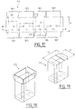
- Figure 1 shows, flat, a blank of sheet material for the manufacture of a first embodiment of a box according to the present invention.
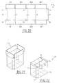
- Figures 2 and 3 show in perspective the box obtained from the blank of Figure 1, the cover of said box being respectively shown open ( Figure 2) and closed ( Figure 3).
- FIG. 4 illustrates, in cross section parallel to its bottom, a use of the box of FIGS. 2 and 3.
- FIGs 5,6 and 7 schematically illustrate the process of forming the box of Figure 2 from the blank of Figure 1.
- Figures 8,10 and 12 are schematic elevational views of a machine for the manufacture of the box of Figure 2, from the blank of Figure 1, at different stages of this manufacture.
- Figures 9, 11 and 13 are schematic top views corresponding respectively to Figures 8, 10 and 12.
- Figures 14, 15 and 16 schematically illustrate in partial side views, perpendicular to Figures 8, 10 and 12, the closure of the bottom of the box of Figures 2 and 3.
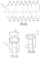
- Figures 17,20,23,26,29,32,35,38,41,44,47,50,53 and 56 show, flat, respectively, variants of blanks according to the present invention.
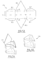
- Figures 18,21,24,27,30,33,36,39,45,48,51,54 and 57 show, in perspective, the boxes obtained respectively from the blanks of Figures 17,20,23,26,29 , 32,35,38,44, 47,50,53 and 56, said cases having their lid open.
- Figures 19,22,25,28,31,34,37,40,42,46,49,52,55 and 58 show, in perspective, the cases obtained respectively from the blanks of Figures 17,20,23, 26,29,32,35,38, 41,44,47,50,53 and 56, said cases having their lid closed.
- FIG. 43 is an end view of the box of FIG. 42, obtained from the blank of FIG. 41.
- the blank F1 of sheet material, for example of cardboard or corrugated cardboard, shown in FIG. 1 comprises a series of eight rectangular flaps aligned 1 to 8, two by two connected by preformed and parallel fold lines 9 to 15. Along the free edge of the end flap 1 of said series of flaps is arranged a tongue 16 connected to said end flap 1 by a fold line 17, parallel to the fold lines 9 to 15.
- each flap 1,3,5 and 7 are respectively provided with flaps 18.1, 18.3, 18.5, 18.7 and 19.1, 19.3, 19.5 and 19.7.
- Each side flap 18.1, 18.3, 18.5, 18.7 is articulated to the corresponding flap 1,3,5 or 7 by a preformed fold line 20.1, 20.3, 20.5 or 20.7. These fold lines 20.1, 20.3, 20.5 and 20.7 are aligned and perpendicular to the fold lines 9 to 15 and 17.
- each side flap 19.1, 19.3, 19.5, 19.7 is articulated to the corresponding 1,3,5,7 flap by a preformed fold line 21.1, 21.3, 21.5 or 21.7.
- the fold lines 21.1, 21.3, 21.5 and 21.7 are aligned and perpendicular to the fold lines 9 to 15 and 17.
- the flaps 2,4,6 and 8 have no lateral flap.
- the rectangular shutters 1 to 8 all have the same height h .
- the two flaps 1 and 5 are identical to each other and have a width l .
- the two flaps 3 and 7 are identical to each other and have a width L, greater than l .
- the four flaps 2,4,6 and 8 are identical to each other and have a width e less than l .
- the height h is greater than L.
- the blank F1 is intended to form, by winding and securing the flaps 1 to 8 and securing the flaps 18.1, 18.3, 18.5, 18.7, 19.1, 19.3, 19.5 and 19.7 - as described below in more detail with regard to Figures 5 to 16 - the box C1 shown in Figure 3.
- the box C1 has a height equal to h , a length L1 and a width l1 . It has the general appearance of a rectangular section box with four cut corners.
- the large side faces are formed by the flaps 3 and 7, while the small side faces are formed by the flaps 1 and 5, the flaps 2,4,6 and 8 forming the cut corners of said box C1 .
- the bottom of the box C1 is constituted by the flaps 18.1, 18.3, 18.5 and 18.7, while the cover of said box C1 is constituted by the flaps 19.1, 19.3, 19.5 and 19.7.
- the four flaps 18.1, 18.5, 19.1 and 19.5 are identical and rectangular. They have a length equal to the width l of the flaps 1 and 5.
- the flaps 18.3, 18.7, 19.3 and 19.7 are identical to each other. They have a length equal to the length L1 of the box C1 and a width l1 / 2 equal to half the width l1 of the latter.
- the flaps 18.3, 18.7, 19.3 and 19.7, the length L1 of which is greater than the width L of the corresponding flaps 3 and 7, are connected to the said flaps by a converging part whose inclined edges 22 have a length a equal to the width e of the flaps 2,4,6 and 8.
- each of said flaps 18.3, 18.7, 19.3 and 19.7 corresponds in shape to half of the section of the body C1.
- FIG 4 there is illustrated, in cross section, an application of the box C1 to the packaging of six bottles B separated by a dividing spider S. It can be seen that, thanks to the cut corners corresponding to the flaps 2.4 , 6 and 8, the end bottles B are well maintained, since these cut corners pitch the latter. These corners, not very protruding, are relatively little vulnerable to external aggressions.
- a / 2b of sheet material is used at each corner. If the faces 2,4,6 and 8 are inclined at 45 ° with respect to the faces 1,3,5,7, this proportion is equal to 1 / ⁇ 2, that is to say equal to 70%. The result is, for each corner, a material saving equal to 30%.
- the box C1 has eight lateral edges, corresponding respectively to the fold lines 9 to 17, which gives it greater compressive strength than that of a box with rectangular section.
- FIGS. 8 to 16 a machine is schematically illustrated allowing the manufacture of the box C1, with open lid, as shown in FIG. 2.
- FIGS. 8 to 16 are, for the sake of clarity, deliberately partial and simplified and they do not each include only the elements necessary for understanding the manufacturing phases they illustrate.
- the machine of FIGS. 8 to 16 comprises a mandrel 23 (shown on a larger scale in FIGS. 5 to 7), the external shape of which corresponds to the internal shape of the box C1 to be obtained from the blank F1.
- the section of the mandrel 23 is rectangular with cut sides.
- the length of the mandrel 23 may be different from the height h of the box C1.
- the mandrel 23 may be full or only made up of a reinforcement delimiting its edges, as shown in said Figures 5 to 7.
- said mandrel 23 was made up of profiles 24 (seen at the end in Figures 5 to 7), parallel and of rectangular section with a cut corner, defining lateral support faces 25 to 32 for the flaps of the blank F1, folding edges 33 to 40 corresponding to the fold lines between said flaps, and a front support face 41 for the flaps 18.1, 18.3, 18.5 and 18.7, the contour of said bearing face 41 forming fold edges corresponding to the fold lines of said flaps 18.1, 18.3, 18.5 and 18.7.
- FIGS. 5 to 7 the process of positioning the blank F1 relative to the mandrel 23 is illustrated diagrammatically, when it is desired to apply the intermediate flap 3 against the corresponding lower face 25 of the mandrel 23.
- a blank F1 is brought in the vicinity of the mandrel 23, so that its flap 3 is disposed at least approximately opposite the bearing face. 25.
- the lateral positioning of said flap 3 relative to said face 25 is sought as precise as possible, it may occur that a lateral offset ⁇ appears between the flap 3 and said bearing face 25.
- the flap 3 is brought closer to the bearing face 25 by means of a pressure plate 42, the profile of which is concave and which, transversely to the mandrel 23, has a face 43 superimposable on the face 25 of said mandrel, a face 44 superimposed on the face 26 of the mandrel 23 and a face 45 superimposed on the face 32 of the latter, the faces 43 and 44 being connected one to the other by an edge 46 superimposable on the edge 34, while the faces 43 and 45 are connected to each other by an edge 47 superimposed on the edge 33.
- the formation of the box C1 can be continued by winding the blank F1 around said mandrel (see the dotted lines in Figure 8) .
- the flaps 1,5,6,7,8 are respectively applied against the faces 31,27,28,29 and 30 and the tongue 16 is folded back on the face 30 (before or after the flap 8) . It is therefore possible to secure the tongue 16 and the flap 8, for example by gluing.
- the flaps 18.1 and 18.5 are folded around the edges of the front face 41 of the mandrel 23 corresponding respectively to the fold lines 20.1 and 20.5, to come to bear against said corresponding front face 41 of the mandrel 23.
- the flaps 18.3 and 18.7 are folded around the edges of the front face 41 of the mandrel 23 respectively corresponding to the fold lines 20.3 and 20.7 and applied against the flaps 18.1 and 18.5 already folded, so that said flaps 18.1, 18.3, 18.5 and 18.7 may be made integral with each other, for example by gluing.
- this box C1 To fill this box C1, it is released from the mandrel 23 and it is made to rest on its bottom consisting of integral flaps 18.1, 18.3, 18.5 and 18.7.
- the box C1 can be closed by folding the flaps 19.1 and 19.5, respectively around the fold lines 21.1 and 21.5, then by folding the flaps 19.3 and 19.7 on the folded flaps 19.1 and 19.5, and finally by securing said flaps 19.1 , 19.3, 19.5 and 19.7, for example by gluing.
- This machine comprises a frame 50 with respect to which the mandrel 23 and the pressure plate 42 are mounted. It further comprises a device (not shown), of any known type, making it possible to take one by one of the blanks F1 in a store to bring them under the mandrel 23. Glueers 51, 52 and 53, mounted on the frame 50, make it possible to deposit lines of adhesive 54, 55, 56, respectively on the tongue 16 and on the flaps 18.1 and 18.5, during the supply of a blank F1 under the mandrel 23.
- the blank F1 is arranged, already glued, under the mandrel 23 in the position shown in FIG. 5, above the pressure plate 42, driven by a jack 57, carried by the frame 50.
- the machine comprises a mechanism comprising a movable assembly 58 which can be raised or lowered by means of a jack 59, bearing on the frame 50.
- the moving element 58 comprises two articulated arms 6O and 61, for example respectively driven by a linkage 62 connected to the frame 50 and by a cam 63 mounted on said frame.
- Actuators 64 to 67 are mounted on the frame 50 and can fold the flaps 18.1, 18.5, 18.7 and 18.3 respectively.
- Pressers 68 and 69 are provided for applying the tongue 16 and the flap 8 against the face 30 of the mandrel 23.
- the blank F1 then takes, relative to the mandrel 23, successively the relative positions illustrated by FIGS. 6 and 7.
- the rise of the moving assembly 58 continuing, the arms 60 and 61 respectively press the flaps 5,6 and 1 against the corresponding faces 27, 28 and 31 of the mandrel 23 (see FIGS. 10 and 11).
- the presser 68 then applies the tongue 16 against the face 30 of the mandrel, after which the other presser 69 applies the flap 8 against the tongue 16 and the face 30. Thanks to the line of adhesive 54, the flap 8 is therefore secured of the tongue 16 (see Figures 12 and 13).
- the actuators 64 and 65 fold the flaps 18.1 and 18.5 against the front face 41 of the mandrel 23 (FIG. 11), after which the actuators 66 and 67 respectively apply the flap 18.7 (FIG. 15) then the flap 18.3 (FIG. 16) against the folded back flaps 18.1 and 18.5. Thanks to the adhesive lines 55 and 56, the flaps 18.1, 18.3, 18.5 and 18.7 are joined to each other to form the bottom of the box C1.
- Figures 17,20,23,26,29,32,35,38 and 41 respectively show blanks of sheet material F2 to F10 capable of forming boxes of rectangular section with cut corners, like box C1.
- the blanks F2, F3, F5 to F9 of Figures 17,20,26,29,32,35, and 38 we find the continuation of the eight rectangular shutters aligned 1 to 8, two by two connected by the preformed fold lines and parallel 9 to 15 and bordered by fold lines 20.1, 20.3, 20.5, 20.7, 21.1, 21.3, 21.5 and 21.7, as described above with reference to Figure 1.
- the flaps 18.1, 18.3, 18.5, 18.7 and 19.1, 19.3, 19.5 and 19.7 have different shapes, so that the boxes obtained C2, C3 and C5 to C9 are different from the box C1, although, having the same rectangular section with corners cut.
- the series of aligned rectangular flaps 1 to 8 is also different, so that the corresponding boxes C4 and C10 are different from the box C1, although of similar section.
- boxes C2 to C10 can be obtained by using the machine described with reference to FIGS. 5 to 16, possibly by adapting the position and / or the number of glueers 51 to 53, actuators 64 to 67 and pressers 68.69.
- the flaps 18.3, 18.7, 19.3 and 19.7 are identical and rectangular. They have a length equal to the width L of the flaps 3 and 7 and a width equal to half of l1.
- the flaps 18.1, 18.5, 19.1 and 19.5 are identical to each other and each of them has a length equal to 11. These are the flaps 18.1, 18.5, 19.1 and 19.5 which therefore comprise, in the vicinity of their fold line with the corresponding flaps, the widening provided by the inclined edges 22, these having the length a .
- the blank F3 of FIG. 20 is identical to the blank F2 of FIG. F2, except as regards the free edges of the flaps 2,4,6,8 and of the tongue 16.
- the free edges of said flaps and of said directed tongue on the side of the flaps 18.1, 18.3, 18.5 and 18.7 have notches 70, while those directed on the side of the flaps 19.1, 19.3, 19.5 and 19.7 have projections 71.
- the box C3 has slots 73 and at its upper part of the pins 74. When two boxes C3 are superimposed, the pins 74 of the lower box penetrate into the slots 73 of the upper box, so that said boxes are held laterally with respect to one another.
- the flaps 2 to 8 and the flaps 18.3, 18.5, 18.7, 19.3, 19.5 and 19.7 of the blank F4 of FIG. 23 are identical to those of the blank F1 of FIG. 1.
- the flap 1, the tongue 16 and the flaps 18.1 and 19.1 have been deleted and replaced by two rectangular flaps 1.1 and 1.2, respectively secured to the outer edges of flaps 2 and 9, along the fold lines 9 and 75.
- At each of the flaps 1.1 and 1.2 are associated respectively with rectangular flaps 18.11, 19.11 and 18.72, 19.72.
- the flaps 1.1 and 1.2 and the flaps 18.11, 19.11, 18.72 and 19.72 have a width l2 greater than the half width l of the flap 5.
- the flaps 1.1 and 1.2 and the flaps 18.11 , 19.11, 18.72 and 19.72 are superimposed along an overlapping area 76, along which they can be joined, for example by gluing.
- the flaps 1 to 8, the tongue 16, the flaps 18.1, 18.3, 18.5, 18.7, 19.1 and 19.5 are identical to those of the blank F1 in FIG. 1.
- the flaps 18.3 and 18.7 have tabs 77.
- the flaps 19.3 and 19.7 have a shape which corresponds to the section of the body C5.
- the inclined edges 22 and 78 of the cut corners of the flap 19.7 have tabs 79.
- the legs 77 and 79 therefore constitute reinforcements, connecting the bottom and the cover of the box C5 to the side wall thereof.
- a handle 80 on the flap 19.7 said handle 80 being accessible through a slot 81 provided in the flap 19.3 when the latter is folded over the flap 19.7 and secured to it.
- the flaps 1 to 8, the tongue 16 and the flaps 18.1, 18.3, 18.5 and 18.7 are identical to those of the blank F2 in FIG. 17.
- the flaps 19.1, 19.3, 19.5 and 19.7 have a small width and all have inclined edges 22.
- the box C6 comprises a cover consisting only of a peripheral edge 82, delimiting a central opening 83.
- the blank F7 in FIG. 32 has flaps 1 to 8, a tongue 16 and flaps 18.1, 18.3, 18.5 and 18.7 similar to those of the blank F1 in FIG. 1.
- the flaps 19.1 and 19.5 are rectangular, of length equal to the width l of the flaps 1 and 7, but of small width.
- the flaps 19.3 and 19.7 have inclined widening edges 22, but their width is less than 11/2.
- said flaps 19.3 and 19.7 have tabs 84.
- the body C7 has a cover consisting of a peripheral edge 85 defining a central opening 86, the tabs 84, after folding and gluing, securing said cover lateral faces of said box corresponding to flaps 1 and 5.
- each flap 18.1, 18.5, 19.1, 19.5 comprises, in the vicinity of its fold line and connection to the corresponding flap, a widening zone with inclined edges 22, then a narrowing zone with the inclined edges 87, in opposite directions at edges 22, and finally an area 88 of constant length.
- Each flap 18.3, 18.7, 19.3 and 19.7 comprises, in the vicinity of its fold line and connection to the corresponding flap, a zone 89 of constant width, then a widening zone with inclined edges 90 and finally a zone 91 of length constant.
- the total width of the flaps 18.3, 18.7, 19.3 and 19.7 is equal to half of l1 and their length, at the level of the constant-length portion 91, is equal to L1.
- the box C8 obtained from the blank F8 is shown in FIGS. 36 and 37.
- the flaps 1 to 8, the tongue 16 and the flaps 18.1, 18.5, 19.1 and 19.5 are similar to those of the blank F2 in FIG. 17.
- the width of the said flaps is less than the half of l1 .
- the flaps 18.3, 18.7, 19.3 and 19.7 are identical to each other. They comprise, in the vicinity of their fold line and of connection to the corresponding flap, a rectangular part 92, then a narrowing part 93, with inclined edges 94.
- the width of these latter flaps is equal to half of l1 .
- the manufacture of the blanks F9 is economical in sheet material, since two blanks F9 can be nested one inside the other, with longitudinal offset.
- FIG. 41 there is shown a blank F10 in which the series of flaps 1 to 8 is such that the height h thereof is less than the width L of flaps 3 and 7, unlike what has been shown for the blanks F1 to F9, previously described.
- the flaps 18.1 and 18.5 are substantially similar to those of the blank F2 of Figure 17, while the flaps 18.3 and 18.7 are substantially similar to those of the blank F1 of Figure 1.
- the flaps 19.1, 19.3, 19.5 and 19.7 are substantially similar to those of the blank F2 of FIG. 17.
- the lateral edges of the flaps 19.3 and 19.7 include notches 95.
- the bottom of the box C10 is formed by the folding down and fixing of the flaps 18.1 and 18.5 on the flaps 18.3 and 18.7, previously folded down, so that said flaps 18.1 and 18.5 are projecting with respect to the latter.
- the cover of the box C10 is formed by the folding and fixing of the flaps 19.3 and 19.7 on the flaps 19.1 and 19.5, previously folded down, so that said flaps 19.3 and 19.7, projecting with respect to the flaps 19.1 and 19.5, form cavities 96 at the ends of said box.
- the shape of said cavities 96 corresponds to that of flaps 18.1 and 18.5.
- the projections formed by the flaps 18.1 and 18.5 of the bottom of the upper box are received in the cavities 96 of the cover of the lower box, so that the cooperation of the projections 18.1 and 18.5 and cavities 96 ensures the vertical stability of said boxes.
- This stability is further reinforced by the fact that the flaps 2,4,6,8 include the projections 71 and the notches 70 of the blank F3 in FIG. 20, so that the body C10 has pins 74 and the recesses 73 similar to those of the box C3, favoring the stacking of said boxes C10.
- the flaps 1 and 5 of the blanks F1 to F10 described above have been deleted.
- the flap 8 is linked to the flap 2 and it carries the tongue 16.
- the box C11 has a hexagonal and no longer octagonal section.
- Triangular flaps 18.2, 18.4, 18.6, 18.8, 19.2, 19.4, 19.6 and 19.8 are arranged at the ends of the flaps 2, 4, 6 and 8.
- the flaps 18.3, 18.7, 19.3 and 19.7 are trapezoidal.
- box C11 the corners are largely cut, resulting in the total removal, with respect to boxes C1 to C10, of the side faces corresponding to the flaps 1 and 5.
- Box C12 in Figures 48 and 49 has only two consecutive cut corners.
- the corresponding blank F12 comprises the same series of flaps 8,2,3,4,6,7 as the blank F11, but, after formation of the box C12, the flaps 6 and 8 are orthogonal to the flap 7. These components 6 and 8 have no flaps.
- the flaps 2,3,4 and 7 have flaps 18.2, 18.3, 18.4, 18.7, 19.2, 19.3, 19.4 and 19.7 capable of forming the bottom and the cover of the C12 box.
- the blank F13 of FIG. 50 comprises a series of eight identical flaps 1 to 8, to which are associated, respectively, trapezoidal flaps 18.1 to 18.8 and 19.1 to 19.8.
- the box C13 obtained from the blank F13 therefore has an octagonal section corresponding to a square section with the four corners cut.
- Octagonal plates 97 are provided for the box C13 to form the bottom and the cover, respectively in cooperation with the flaps 18.1 to 18.8 and 19.1 to 19.8.
- the blank F14 in FIG. 53 comprises a series of five flaps 3 to 7, the tongue 16 being linked to the first flap 3.
- the box C14 therefore has a triangular section with two cut corners.
- the flap 5 carries flaps 18.5 and 19.5 of substantially corresponding triangular shape comprising at their base inclined sides 22, to adapt to the lateral faces corresponding to the flaps 4 and 6.
- the flaps 3 and 7 have flaps 18.3, 18.7 and 19.3, 19.7 intended to serve as a support for the flaps 18.5 and 19.5 and to form the bottom and the cover of the box C14.
- the blank F15 in Figure 56 is similar to the blank F14 in Figure 53, but has an additional flap 8 and the tip of the flaps 18.5 and 19.5 is cut.
- the C15 box therefore has a triangular section with three cut corners.
- a handle 80 is provided on the flap 8.
- the boxes C11 to C15 can be obtained by winding the blanks F11 to F15 around mandrels 23 of shape corresponding to the section of said boxes , this winding being carried out in cooperation with a pressure plate 42, the profile of which corresponds to that of two and, preferably three, consecutive faces of said mandrel.
Priority Applications (2)
| Application Number | Priority Date | Filing Date | Title |
|---|---|---|---|
| EP99111929A EP0965441B1 (de) | 1990-07-24 | 1991-07-17 | Vorrichtung und Verfahren zur Herstellung von Behältern aus Folienmaterial |
| EP99111930A EP0965528B1 (de) | 1990-07-24 | 1991-07-17 | Behälter aus Folienmaterial und Zuschnitte zur Herstellung derselben |
Applications Claiming Priority (4)
| Application Number | Priority Date | Filing Date | Title |
|---|---|---|---|
| FR9009457 | 1990-07-24 | ||
| FR909009457A FR2665137B1 (fr) | 1990-07-24 | 1990-07-24 | Caisses en une matiere en feuille, flans et machine pour la realisation de telles caisses. |
| EP93110403A EP0570023B1 (de) | 1990-07-24 | 1991-07-17 | Behälter aus Folienmaterial und Zuschnitt zur Herstellung desselben |
| EP91402004A EP0468860B1 (de) | 1990-07-24 | 1991-07-17 | Vorrichtung und Verfahren zur Herstellung von Behältern aus Folienmaterial |
Related Parent Applications (2)
| Application Number | Title | Priority Date | Filing Date |
|---|---|---|---|
| EP93110403.8 Division | 1991-07-17 | ||
| EP93110403A Division EP0570023B1 (de) | 1990-07-24 | 1991-07-17 | Behälter aus Folienmaterial und Zuschnitt zur Herstellung desselben |
Related Child Applications (2)
| Application Number | Title | Priority Date | Filing Date |
|---|---|---|---|
| EP99111929A Division EP0965441B1 (de) | 1990-07-24 | 1991-07-17 | Vorrichtung und Verfahren zur Herstellung von Behältern aus Folienmaterial |
| EP99111930A Division EP0965528B1 (de) | 1990-07-24 | 1991-07-17 | Behälter aus Folienmaterial und Zuschnitte zur Herstellung derselben |
Publications (3)
| Publication Number | Publication Date |
|---|---|
| EP0712784A2 true EP0712784A2 (de) | 1996-05-22 |
| EP0712784A3 EP0712784A3 (de) | 1996-07-31 |
| EP0712784B1 EP0712784B1 (de) | 2000-02-09 |
Family
ID=9399056
Family Applications (5)
| Application Number | Title | Priority Date | Filing Date |
|---|---|---|---|
| EP96100892A Expired - Lifetime EP0712784B1 (de) | 1990-07-24 | 1991-07-17 | Behälter aus Folienmaterial und Zuschnitt zur Herstellung desselben |
| EP91402004A Expired - Lifetime EP0468860B1 (de) | 1990-07-24 | 1991-07-17 | Vorrichtung und Verfahren zur Herstellung von Behältern aus Folienmaterial |
| EP93110403A Expired - Lifetime EP0570023B1 (de) | 1990-07-24 | 1991-07-17 | Behälter aus Folienmaterial und Zuschnitt zur Herstellung desselben |
| EP99111930A Revoked EP0965528B1 (de) | 1990-07-24 | 1991-07-17 | Behälter aus Folienmaterial und Zuschnitte zur Herstellung derselben |
| EP99111929A Expired - Lifetime EP0965441B1 (de) | 1990-07-24 | 1991-07-17 | Vorrichtung und Verfahren zur Herstellung von Behältern aus Folienmaterial |
Family Applications After (4)
| Application Number | Title | Priority Date | Filing Date |
|---|---|---|---|
| EP91402004A Expired - Lifetime EP0468860B1 (de) | 1990-07-24 | 1991-07-17 | Vorrichtung und Verfahren zur Herstellung von Behältern aus Folienmaterial |
| EP93110403A Expired - Lifetime EP0570023B1 (de) | 1990-07-24 | 1991-07-17 | Behälter aus Folienmaterial und Zuschnitt zur Herstellung desselben |
| EP99111930A Revoked EP0965528B1 (de) | 1990-07-24 | 1991-07-17 | Behälter aus Folienmaterial und Zuschnitte zur Herstellung derselben |
| EP99111929A Expired - Lifetime EP0965441B1 (de) | 1990-07-24 | 1991-07-17 | Vorrichtung und Verfahren zur Herstellung von Behältern aus Folienmaterial |
Country Status (20)
| Country | Link |
|---|---|
| US (1) | US5147271A (de) |
| EP (5) | EP0712784B1 (de) |
| JP (4) | JP3304991B2 (de) |
| KR (1) | KR100194302B1 (de) |
| AT (5) | ATE142158T1 (de) |
| CA (1) | CA2047497C (de) |
| DE (7) | DE69132906T2 (de) |
| DK (2) | DK0570023T3 (de) |
| ES (5) | ES2168823T3 (de) |
| FI (1) | FI97356C (de) |
| FR (1) | FR2665137B1 (de) |
| GR (1) | GR3021122T3 (de) |
| HK (2) | HK27897A (de) |
| HU (1) | HU219570B (de) |
| IE (1) | IE68598B1 (de) |
| IL (1) | IL98736A (de) |
| NO (1) | NO304642B1 (de) |
| NZ (1) | NZ238824A (de) |
| OA (1) | OA09385A (de) |
| PT (1) | PT98423B (de) |
Cited By (4)
| Publication number | Priority date | Publication date | Assignee | Title |
|---|---|---|---|---|
| FR2762586A1 (fr) * | 1997-04-24 | 1998-10-30 | Otor Sa | Emballage, ensemble de flans, procede et dispositif pour le conditionnement d'un article ou d'un lot d'articles de volume indetermine |
| EP0891931A1 (de) * | 1997-07-09 | 1999-01-20 | G.D S.p.A. | Verpackung für Zigarettenpackungen |
| WO2000056610A2 (de) * | 1999-03-23 | 2000-09-28 | Focke & Co. (Gmbh & Co.) | Packung nach art einer zigarettenstange |
| US6216871B1 (en) | 1996-10-11 | 2001-04-17 | Otor | Package and method for packaging of batches of articles of undetermined volume |
Families Citing this family (125)
| Publication number | Priority date | Publication date | Assignee | Title |
|---|---|---|---|---|
| FR2690414B1 (fr) * | 1992-04-24 | 1996-04-05 | Otor Sa | Caisse a section polygonale en une matiere en feuille et flan pour la realisation d'une telle caisse. |
| FR2690415B1 (fr) * | 1992-04-24 | 1996-02-02 | Otor Sa | Emballage a section polygonale en une matiere en feuille et flan pour la realisation d'un tel emballage. |
| FR2690416B1 (fr) * | 1992-04-24 | 1996-03-08 | Otor Sa | Boite en carton ou analogue, notamment destinee a contenir des pots pour produits laitiers, et flan pour la realisation d'une telle boite. |
| FR2699892B1 (fr) * | 1992-12-28 | 1995-03-17 | Otor Sa | Emballage à section polygonale en une matière en feuille, notamment pour bouteilles, flan et machine pour un tel emballage. |
| US5400955A (en) * | 1993-02-05 | 1995-03-28 | Otor | Box formed from a sheet material, blank |
| FR2704204B1 (fr) * | 1993-04-21 | 1995-07-13 | Otor Sa | Flan, procede de decoupe de flan, et barquette en feuille de carton ondule. |
| FR2704834B1 (fr) * | 1993-05-04 | 1995-08-18 | Otor Sa | Récipient gerbable réalisé en une matière en feuille, telle que carton ou carton ondulé, et flan pour sa réalisation. |
| DE4327681C2 (de) * | 1993-08-13 | 1996-10-10 | Reemtsma H F & Ph | Gebindekarton |
| DE4336021A1 (de) * | 1993-10-22 | 1995-04-27 | Packmaster System Entwicklung | Verpackungsmaterialzuschnitt sowie Verpackung |
| FR2723338B1 (fr) * | 1994-08-05 | 1996-10-04 | Otor Emballage | Dispositif et procede pour la realisation d'une caisse a partir d'un flan |
| US5437388A (en) * | 1994-12-05 | 1995-08-01 | Macmillan Bloedel Packaging, Inc. | Container |
| US5656006A (en) * | 1995-01-13 | 1997-08-12 | Swf Machinery, Inc. | Method and apparatus for forming a work object |
| FR2743780B1 (fr) * | 1996-01-22 | 1998-04-17 | Otor Sa | Ensemble de decoupes, boite, procede et machine pour la fabrication de boite a partir d'un tel ensemble de decoupes |
| FR2743779B1 (fr) | 1996-01-22 | 1998-04-17 | Otor Sa | Ensemble de decoupes pour caisse d'emballage formant presentoir et caisse obtenue avec un tel ensemble |
| ES2142189B1 (es) * | 1996-03-04 | 2000-11-01 | Assidoman Iberoamericana Sa | Perfeccionamientos introducidos en maquinas para armar contenedores ligeros. |
| US5697548A (en) * | 1996-04-08 | 1997-12-16 | The Mead Corporation | Tray-style carton having reinforced side walls |
| FR2775658B1 (fr) * | 1998-03-03 | 2000-06-16 | Otor Sa | Procede et machine pour la realisation d'une caisse octogonale a coins coupes en matiere en feuille |
| US6106450A (en) * | 1998-06-01 | 2000-08-22 | Georgia-Pacific Corporation | Apparatus and method for set-up of a non-rectangular container from a knocked-down-flat (KDF) precursor |
| WO2000046110A1 (en) * | 1999-02-02 | 2000-08-10 | Hammervest Limited | Stackable cardboard package with reinforced corners |
| US6358191B1 (en) | 1999-08-27 | 2002-03-19 | The Mead Corporation | System and method for flexible control and adjustment of a box forming machine |
| US20020029547A1 (en) * | 2000-06-30 | 2002-03-14 | Jaime Lopez Silanes Perez | Mold-design and improvement of an automatic expansible side paperboard bag folding and gluing machine |
| FR2829421B1 (fr) * | 2001-09-12 | 2004-01-16 | Otor Sa | Machine et procede pour la realisation d'une caisse avec mandrin ajustable |
| US20050075230A1 (en) * | 2003-10-07 | 2005-04-07 | James Moshier | Method and apparatus for forming multi-sided containers |
| US20050079966A1 (en) * | 2003-10-08 | 2005-04-14 | James Moshier | Positioning apparatus for container forming machine |
| WO2005051772A2 (fr) | 2003-11-25 | 2005-06-09 | Otor | Plateau emboitable, flan, emballage correspondant et machine de formation d’un tel plateau |
| FR2872488B1 (fr) * | 2004-06-30 | 2007-10-12 | Otor Sa | Plateau emboitable a fond biseaute avec poignee rembordee, flan correspondant et machine de formation d'un tel plateau |
| DE202004011165U1 (de) * | 2004-07-15 | 2005-12-01 | Henkel Kgaa | Pulverdichte Verpackung |
| US7350670B2 (en) * | 2004-09-30 | 2008-04-01 | Smurfit-Stone Container Enterprises, Inc. | Bag-in-box container |
| US8024910B2 (en) * | 2004-11-05 | 2011-09-27 | Smurfit-Stone Container Enterprises, Inc. | Methods and apparatus for forming a container |
| JP4677827B2 (ja) * | 2005-05-24 | 2011-04-27 | 凸版印刷株式会社 | 単紙を用いたバッグインボックス用外装箱およびその製造装置 |
| FR2887529B1 (fr) * | 2005-06-23 | 2007-10-05 | Otor Sa | Boite en carton ondule a volets ajoures et ensemble de decoupes pour obtenir une telle boite |
| US7717838B2 (en) * | 2005-12-16 | 2010-05-18 | Smurfit-Stone Container Enterprises, Inc. | Blank and methods and apparatus for forming a dispenser case from the blank |
| US7857743B2 (en) * | 2006-03-29 | 2010-12-28 | Smurfit-Stone Container Enterprises, Inc. | Blank, apparatus and method for constructing container |
| JP4698496B2 (ja) * | 2006-06-16 | 2011-06-08 | サントリーホールディングス株式会社 | 容器の箱詰め方法と箱詰め装置 |
| US8133163B2 (en) * | 2006-10-03 | 2012-03-13 | Smurfit-Stone Container Enterprises, Inc. | Apparatus for forming a barrel from a blank |
| KR100888759B1 (ko) * | 2007-06-08 | 2009-03-17 | 주식회사 제팩 | 포장용 박스 및 박스제조용 블랭크 |
| KR100833968B1 (ko) | 2007-07-03 | 2008-05-30 | 김주영 | 전개 시트 접착 방법 및 전개 시트 접착 장치 |
| FR2921638B1 (fr) * | 2007-09-28 | 2014-08-08 | Otor Sa | Ensemble de decoupes,boite et procede pour la fabrication de boite a partir d'un tel ensemble de decoupes |
| US8128547B2 (en) * | 2007-10-10 | 2012-03-06 | Smurfit-Stone Container Enterprises, Inc. | Methods and machines for forming a polygonal container |
| US8011564B2 (en) * | 2007-10-11 | 2011-09-06 | Georgia-Pacific Corrugated Llc | Easy opening carton having improved stacking strength |
| WO2009064663A1 (en) | 2007-11-13 | 2009-05-22 | Georgia-Pacific Corrugated Llc | Improved stacking strength carton with an easy opening feature |
| FR2927015B1 (fr) * | 2008-02-04 | 2010-03-05 | Otor Sa | Procede et dispositif pour la realisation de boites a partir d'un ensemble de decoupes |
| FR2929597B1 (fr) * | 2008-04-04 | 2010-05-14 | Otor Sa | Ensemble de decoupes en carton, boite et procede de formation de boite avec de telles decoupes |
| US8087569B2 (en) * | 2008-04-25 | 2012-01-03 | Georgia-Pacific Corrugated Llc | Polygonal tray having reinforced corners |
| US8820618B2 (en) | 2008-05-07 | 2014-09-02 | Rock-Tenn Shared Services, Llc | Reinforced polygonal containers and blanks for making the same |
| US9764524B2 (en) | 2008-05-07 | 2017-09-19 | Westrock Shared Services, Llc | Reinforced polygonal containers and blanks for making the same |
| US8579778B2 (en) * | 2010-05-14 | 2013-11-12 | Rock-Tenn Shared Services, Llc | Machine and method for forming reinforced polygonal containers from blanks |
| US8105223B2 (en) | 2008-05-07 | 2012-01-31 | Smurfit-Stone Container Enterprises, Inc. | Machine and method for forming reinforced polygonal containers from blanks |
| US8827142B2 (en) | 2008-05-07 | 2014-09-09 | Rock-Tenn Shared Services, Llc | Reinforced polygonal containers and blanks of sheet material for making the same |
| US7935041B2 (en) * | 2008-08-25 | 2011-05-03 | Smurfit-Stone Container Enterprises, Inc. | Container with inner reinforcement and method and system of manufacturing |
| JP5075073B2 (ja) * | 2008-09-25 | 2012-11-14 | レンゴー株式会社 | ラップラウンドケース |
| JP2010188606A (ja) | 2009-02-18 | 2010-09-02 | Kobe Steel Ltd | 溶接ワイヤ包装用箱の隅部折り込み方法 |
| JP5541589B2 (ja) * | 2009-03-23 | 2014-07-09 | レンゴー株式会社 | ケースの組立方法およびその装置 |
| JP2010240981A (ja) * | 2009-04-06 | 2010-10-28 | Masao Inoue | カートン形成装置及びカートン形成方法 |
| JP2010240980A (ja) * | 2009-04-06 | 2010-10-28 | Masao Inoue | カートン形成装置及びカートン形成方法 |
| US9022913B2 (en) * | 2009-11-02 | 2015-05-05 | Rock-Tenn Shared Services, Llc | Methods and a machine for forming a container from a blank |
| US8844797B2 (en) * | 2009-11-11 | 2014-09-30 | Rock-Tenn Shared Services, Llc | Liquid dispensing containers and blanks for making the same |
| BR112012021442B1 (pt) | 2010-02-26 | 2020-11-17 | Monsanto Technology Llc | conjunto de contentor para armazenar, despachar, e/ou distribuir fluidos |
| CA2740243C (en) | 2010-05-13 | 2017-09-19 | Douglas Machine Inc. | Continuous motion case former |
| US10196170B2 (en) | 2010-09-03 | 2019-02-05 | Georgia-Pacific Corrugated Llc | Reinforced packing container |
| US8851362B2 (en) | 2010-09-03 | 2014-10-07 | Georgia-Pacific Corrugated Llc | Packing container |
| US20120061456A1 (en) * | 2010-09-10 | 2012-03-15 | Orange County Container Group LLC | Carton with improved strength sidewall panels |
| US9409367B2 (en) | 2010-10-26 | 2016-08-09 | Westrock Shared Services, Llc | Machine for forming multiple types of containers |
| JP5918473B2 (ja) * | 2011-03-25 | 2016-05-18 | 岩谷産業株式会社 | 包装箱 |
| JP2012210960A (ja) * | 2011-03-31 | 2012-11-01 | Kao Corp | ダンボール箱 |
| US8800854B2 (en) | 2011-06-24 | 2014-08-12 | Rock-Tenn Shared Services, Llc | Reinforcing support assemblies for a container and method of making same |
| EP2540644B1 (de) | 2011-06-30 | 2014-03-19 | The Procter and Gamble Company | Windelverpackung, die als eine Wickelauflage geeignet ist |
| EP2540637B1 (de) | 2011-06-30 | 2014-04-30 | The Procter and Gamble Company | Verpackung mit flexiblen Verpackungen für absorbierbare Artikel |
| WO2013006812A2 (en) * | 2011-07-07 | 2013-01-10 | Swart Peter W | Packaging for plumbing fixtures |
| JP5834641B2 (ja) * | 2011-09-02 | 2015-12-24 | 凸版印刷株式会社 | 包装用箱 |
| JP2013193754A (ja) * | 2012-03-19 | 2013-09-30 | Nippon Tokan Package Kk | ラップアラウンドケース |
| DE102012204658A1 (de) * | 2012-03-22 | 2013-09-26 | Mondi Ag | Kartonzuschnitt zur Herstellung eines Behälters |
| DE202012101401U1 (de) * | 2012-04-17 | 2013-04-18 | Mayr-Melnhof Karton Ag | Faltschachtel und Zuschnitt hierfür |
| JP5946702B2 (ja) * | 2012-06-04 | 2016-07-06 | 日本トーカンパッケージ株式会社 | 連結箱 |
| FR2992294B1 (fr) * | 2012-06-20 | 2015-07-31 | Otor Sa | Caisse en matiere de feuille de carton, flan ou ensemble de flans, procede et dispositif pour former une telle caisse |
| JP2014005072A (ja) * | 2012-06-27 | 2014-01-16 | Rengo Co Ltd | 商品の包装方法 |
| JP6003302B2 (ja) * | 2012-07-05 | 2016-10-05 | 凸版印刷株式会社 | 包装用箱 |
| US9486972B2 (en) | 2012-09-12 | 2016-11-08 | Wexxar Packaging, Inc. | Bulk bin former apparatus and method |
| JP2014069838A (ja) * | 2012-09-28 | 2014-04-21 | Nippon Tokan Package Kk | 包装箱 |
| JP2014069839A (ja) * | 2012-09-28 | 2014-04-21 | Nippon Tokan Package Kk | 包装箱 |
| CA2830279C (en) * | 2012-10-19 | 2020-10-20 | Rock-Tenn Shared Services, Llc | Container forming apparatus and method |
| US11433634B2 (en) | 2012-10-19 | 2022-09-06 | Westrock Shared Services, Llc | Container forming apparatus and method |
| FR2998275B1 (fr) * | 2012-11-21 | 2015-05-15 | Otor Sa | Boite en carton avec languette de centrage, flan, ensemble de flans et procede pour la realisation d'une telle boite. |
| MX364004B (es) | 2013-01-09 | 2019-04-10 | Georgia Pacific Corrugated Llc | Carton reforzado. |
| JP5987706B2 (ja) * | 2013-01-25 | 2016-09-07 | 富士ゼロックス株式会社 | 収納箱 |
| JP5987705B2 (ja) * | 2013-01-25 | 2016-09-07 | 富士ゼロックス株式会社 | 収納箱 |
| HUE035624T2 (en) * | 2013-07-23 | 2018-05-28 | Mayr Melnhof Karton Ag | Packaging and cutout for packaging |
| WO2015010727A1 (de) * | 2013-07-23 | 2015-01-29 | Mayr-Melnhof Karton Ag | Verpackung und zuschnitt hierfür |
| JP6174421B2 (ja) * | 2013-08-26 | 2017-08-02 | 日本トーカンパッケージ株式会社 | 包装箱 |
| US9701087B2 (en) | 2013-09-06 | 2017-07-11 | Westrock Shared Services, Llc | Methods and machine for forming a container from a blank using a pre-fold mandrel section |
| US9878512B2 (en) * | 2013-09-06 | 2018-01-30 | Westrock Shared Services, Llc | Methods and machine for forming a shipping and display container from a blank assembly using a pre-fold mandrel section |
| CN103600512A (zh) * | 2013-11-27 | 2014-02-26 | 深圳九星印刷包装集团有限公司 | 一种纸盒折叠装置 |
| JP5504386B1 (ja) * | 2014-01-20 | 2014-05-28 | 大王パッケージ株式会社 | 包装箱用シート及び包装箱 |
| JP6430126B2 (ja) * | 2014-02-20 | 2018-11-28 | 株式会社共和 | 折り畳みシートの製函方法及びその装置 |
| US10052837B2 (en) * | 2014-06-18 | 2018-08-21 | Westrock Shared Services, Llc | Methods and a machine for forming a container from a blank using a rotatable glue panel folder |
| PL3180254T3 (pl) | 2014-07-31 | 2019-01-31 | G.D Societa' Per Azioni | Sztywne pudełko do wyrobów do palenia i odpowiedni sposób wytwarzania |
| US20160039551A1 (en) * | 2014-08-11 | 2016-02-11 | Rock-Tenn Shared Services, Llc | Manually operated tray forming machine and method of using same |
| US9469432B2 (en) | 2014-11-04 | 2016-10-18 | Westrock Shared Services, Llc | Reinforced containers and blanks for making the same |
| FR3028798B1 (fr) * | 2014-11-20 | 2017-01-06 | Otor Sa | Procede et machine pour la formation d'une caisse par depose sur un support en v. |
| US10556396B2 (en) * | 2014-12-19 | 2020-02-11 | Westrock Shared Services, Llc | Methods and a machine for forming a shelf-ready shipper display system |
| USD784806S1 (en) | 2015-01-16 | 2017-04-25 | Georgia-Pacific Corrugated Llc | Box |
| CN104816859B (zh) * | 2015-04-29 | 2017-04-12 | 江苏远翔物联科技有限公司 | 一种右预压定位装置 |
| CN104828631B (zh) * | 2015-04-29 | 2017-03-22 | 江苏远翔物联科技有限公司 | 一种预压定位装置 |
| US9919830B2 (en) * | 2015-06-30 | 2018-03-20 | Westrock Shared Services, Llc | Container with a reinforcement structure and method of forming the same |
| US10987889B2 (en) | 2015-09-21 | 2021-04-27 | Westrock Shared Services, Llc | Methods and machine for forming a shipping container with an article retaining web |
| JP6350622B2 (ja) * | 2015-09-25 | 2018-07-04 | 王子ホールディングス株式会社 | 包装箱 |
| GB2550125A (en) * | 2016-05-06 | 2017-11-15 | Ds Smith Packaging Ltd | Box and blank therefor |
| FR3057201B1 (fr) * | 2016-10-11 | 2018-11-02 | Ds Smith Packaging France | Procede et dispositif de mise en forme d’un flan autour d’un mandrin. |
| FR3057203B1 (fr) * | 2016-10-11 | 2021-11-19 | Ds Smith Packaging France | Procede et dispositif d’encollage d’un flan. |
| FR3059650B1 (fr) | 2016-12-01 | 2019-10-18 | Florence Chevalier | Decoupes pour emballage primaire et/ou secondaire et/ou tertiaire et emballage obtenu avec de telles decoupes |
| MX2019009902A (es) | 2017-04-17 | 2020-02-05 | Georgia Pacific Corrugated Llc | Recipiente de multiples lados reforzado. |
| CN110891870B (zh) | 2017-04-28 | 2022-03-01 | 梅尔-梅能纸箱公司 | 包装及用于包装的坯料 |
| US11084618B2 (en) | 2017-04-28 | 2021-08-10 | Mayr-Melnhof Karton Ag | Packaging and blank therefor |
| RU2731941C1 (ru) | 2017-04-28 | 2020-09-09 | Майр-Мельнхоф Картон Аг | Упаковка и заготовка для нее |
| US10899101B2 (en) | 2018-04-10 | 2021-01-26 | Westrock Shared Services, Llc | Machine and methods for attaching retaining web to container blank |
| JP7201383B2 (ja) * | 2018-05-18 | 2023-01-10 | レンゴー株式会社 | 周壁可変収納箱 |
| US11548727B2 (en) * | 2018-07-17 | 2023-01-10 | Christopher E. Boyea | Transformative extender and method thereof |
| US10913231B2 (en) * | 2018-10-10 | 2021-02-09 | International Paper Company | Machine for forming containers |
| US11319151B2 (en) | 2019-02-08 | 2022-05-03 | Abb Schweiz Ag | Automated storage and retrieval system |
| JP6729733B1 (ja) * | 2019-02-28 | 2020-07-22 | 王子ホールディングス株式会社 | ブランクシートの製造方法 |
| JP7298422B2 (ja) * | 2019-09-27 | 2023-06-27 | 王子ホールディングス株式会社 | 包装箱 |
| CN111716816B (zh) * | 2020-05-25 | 2021-06-15 | 南京航空航天大学 | 一种连杆推挤式阶梯型纸盒包装纸的贴合装置及方法 |
| GB2596532A (en) | 2020-06-29 | 2022-01-05 | Ds Smith Corrugated Packaging Ltd | 6-sided box and blank therefor |
| EP3932818A1 (de) * | 2020-06-29 | 2022-01-05 | The Procter & Gamble Company | Kasten mit abgeschrägten ecken |
| CN112318936B (zh) * | 2020-11-03 | 2021-07-16 | 安徽亚泰包装科技股份有限公司 | 一种瓦楞纸包装盒成型制作方法 |
Citations (3)
| Publication number | Priority date | Publication date | Assignee | Title |
|---|---|---|---|---|
| US2967655A (en) * | 1958-05-19 | 1961-01-10 | Massillon Container Co | Polygonal carton |
| FR82619E (fr) * | 1962-09-24 | 1964-03-20 | Emballage pour produits de forme ronde | |
| US4702408A (en) * | 1986-05-23 | 1987-10-27 | The Mead Corporation | Bulk bin |
Family Cites Families (22)
| Publication number | Priority date | Publication date | Assignee | Title |
|---|---|---|---|---|
| FR706923A (fr) * | 1930-11-18 | 1931-07-01 | Boîte d'emballage notamment pour oranges | |
| US2114052A (en) * | 1936-04-22 | 1938-04-12 | Jr Gerard M Kincade | Container |
| GB489340A (en) * | 1937-01-22 | 1938-07-22 | Bank Of The Manhattan Company | Improvements in or relating to merchandising packages |
| US3000496A (en) * | 1958-10-29 | 1961-09-19 | Crown Zellerbach Corp | Recessed bottom container |
| US3638848A (en) * | 1970-02-20 | 1972-02-01 | Corning Glass Works | Carton for bulbous articles |
| CH575317A5 (de) * | 1973-06-16 | 1976-05-14 | Unilever Nv | |
| US3884352A (en) * | 1974-06-10 | 1975-05-20 | Container Corp | Book mailer |
| FR2276230A1 (fr) * | 1974-06-24 | 1976-01-23 | Neyret Roger | Ebauche tubulaire de corps de boite, et corps de boite obtenu a partir de cette ebauche |
| FR2311717A1 (fr) * | 1975-05-23 | 1976-12-17 | Lafarge Emballage | Emballage tel que caisse |
| DK146287C (da) | 1976-10-18 | 1984-01-30 | Radiometer As | Fremgangsmaade til deoxygenering af et blodproevemateriale og kapillarroer til anvendelse ved fremgangsmaaden |
| US4053290A (en) * | 1976-10-18 | 1977-10-11 | Monsanto Company | Fiber bed separator |
| FR2384604A1 (fr) * | 1977-03-23 | 1978-10-20 | Puechberty Georges | Dispositif pour la mise en forme d'une matiere en bande |
| JPS54154936U (de) * | 1978-04-17 | 1979-10-27 | ||
| CH627414A5 (de) | 1978-04-21 | 1982-01-15 | Sig Schweiz Industrieges | Einrichtung zur herstellung von packungshuelsen aus folienzuschnitten. |
| FR2440827A1 (fr) * | 1978-11-10 | 1980-06-06 | Embadac | Procede et machine pour fabriquer un element tubulaire notamment pour la formation de boites |
| US4283001A (en) * | 1979-11-09 | 1981-08-11 | American Can Company | Tubular carton with polygonal cross-section |
| US4349345A (en) * | 1980-09-15 | 1982-09-14 | Paper Machinery Corporation | Blank wrapping mechanism for non-cylindrical container-making machines |
| US4386729A (en) * | 1981-03-23 | 1983-06-07 | International Paper Company | Self-locking design for octagonal container |
| DE3522614A1 (de) * | 1985-06-25 | 1987-01-15 | Focke & Co | Verfahren und vorrichtung zum herstellen von packungen mit abgeschraegten oder abgerundeten laengskanten |
| DE3541821A1 (de) | 1985-11-27 | 1987-06-04 | Bosch Gmbh Robert | Vorrichtung zum formen von huelsen fuer verpackungsbehaelter |
| JPS63307935A (ja) * | 1987-06-09 | 1988-12-15 | レンゴ−株式会社 | 箱の組立方法およびその装置 |
| FR2629012B1 (fr) * | 1988-03-22 | 1994-01-14 | Embal Systems | Procede et machine pour la realisation de caisses a section polygonale en une matiere en feuille et caisses ainsi obtenues |
-
1990
- 1990-07-24 FR FR909009457A patent/FR2665137B1/fr not_active Expired - Lifetime
-
1991
- 1991-07-03 NZ NZ238824A patent/NZ238824A/en not_active IP Right Cessation
- 1991-07-04 IL IL9873691A patent/IL98736A/en not_active IP Right Cessation
- 1991-07-09 US US07/727,117 patent/US5147271A/en not_active Expired - Lifetime
- 1991-07-10 IE IE241791A patent/IE68598B1/en not_active IP Right Cessation
- 1991-07-17 EP EP96100892A patent/EP0712784B1/de not_active Expired - Lifetime
- 1991-07-17 ES ES99111930T patent/ES2168823T3/es not_active Expired - Lifetime
- 1991-07-17 DE DE69132906T patent/DE69132906T2/de not_active Expired - Lifetime
- 1991-07-17 ES ES91402004T patent/ES2051569T3/es not_active Expired - Lifetime
- 1991-07-17 DE DE69131986T patent/DE69131986T2/de not_active Expired - Fee Related
- 1991-07-17 EP EP91402004A patent/EP0468860B1/de not_active Expired - Lifetime
- 1991-07-17 ES ES93110403T patent/ES2092190T3/es not_active Expired - Lifetime
- 1991-07-17 DE DE9116739U patent/DE9116739U1/de not_active Expired - Lifetime
- 1991-07-17 DE DE199191402004T patent/DE468860T1/de active Pending
- 1991-07-17 DE DE69121910T patent/DE69121910T2/de not_active Expired - Lifetime
- 1991-07-17 ES ES96100892T patent/ES2142508T3/es not_active Expired - Lifetime
- 1991-07-17 AT AT93110403T patent/ATE142158T1/de not_active IP Right Cessation
- 1991-07-17 ES ES99111929T patent/ES2168822T3/es not_active Expired - Lifetime
- 1991-07-17 DK DK93110403.8T patent/DK0570023T3/da active
- 1991-07-17 DE DE69101604T patent/DE69101604T2/de not_active Expired - Lifetime
- 1991-07-17 EP EP93110403A patent/EP0570023B1/de not_active Expired - Lifetime
- 1991-07-17 DE DE69132907T patent/DE69132907T2/de not_active Revoked
- 1991-07-17 AT AT99111930T patent/ATE211699T1/de not_active IP Right Cessation
- 1991-07-17 EP EP99111930A patent/EP0965528B1/de not_active Revoked
- 1991-07-17 DK DK91402004.5T patent/DK0468860T3/da active
- 1991-07-17 AT AT96100892T patent/ATE189658T1/de not_active IP Right Cessation
- 1991-07-17 AT AT99111929T patent/ATE211680T1/de not_active IP Right Cessation
- 1991-07-17 EP EP99111929A patent/EP0965441B1/de not_active Expired - Lifetime
- 1991-07-17 AT AT91402004T patent/ATE103870T1/de not_active IP Right Cessation
- 1991-07-22 CA CA002047497A patent/CA2047497C/fr not_active Expired - Lifetime
- 1991-07-23 NO NO912873A patent/NO304642B1/no not_active IP Right Cessation
- 1991-07-23 HU HU468/91A patent/HU219570B/hu unknown
- 1991-07-23 PT PT98423A patent/PT98423B/pt not_active IP Right Cessation
- 1991-07-23 JP JP18227491A patent/JP3304991B2/ja not_active Expired - Lifetime
- 1991-07-24 FI FI913549A patent/FI97356C/fi not_active IP Right Cessation
- 1991-07-24 KR KR1019910012673A patent/KR100194302B1/ko not_active IP Right Cessation
- 1991-07-24 OA OA60050A patent/OA09385A/xx unknown
-
1996
- 1996-09-20 GR GR960402488T patent/GR3021122T3/el unknown
-
1997
- 1997-03-06 HK HK27897A patent/HK27897A/xx not_active IP Right Cessation
- 1997-07-18 HK HK97101576A patent/HK1000065A1/xx not_active IP Right Cessation
-
1999
- 1999-02-04 JP JP02753499A patent/JP3631033B2/ja not_active Expired - Lifetime
- 1999-02-04 JP JP02759799A patent/JP3634654B2/ja not_active Expired - Lifetime
-
2004
- 2004-09-28 JP JP2004281576A patent/JP2005008280A/ja active Pending
Patent Citations (3)
| Publication number | Priority date | Publication date | Assignee | Title |
|---|---|---|---|---|
| US2967655A (en) * | 1958-05-19 | 1961-01-10 | Massillon Container Co | Polygonal carton |
| FR82619E (fr) * | 1962-09-24 | 1964-03-20 | Emballage pour produits de forme ronde | |
| US4702408A (en) * | 1986-05-23 | 1987-10-27 | The Mead Corporation | Bulk bin |
Cited By (8)
| Publication number | Priority date | Publication date | Assignee | Title |
|---|---|---|---|---|
| US6216871B1 (en) | 1996-10-11 | 2001-04-17 | Otor | Package and method for packaging of batches of articles of undetermined volume |
| FR2762586A1 (fr) * | 1997-04-24 | 1998-10-30 | Otor Sa | Emballage, ensemble de flans, procede et dispositif pour le conditionnement d'un article ou d'un lot d'articles de volume indetermine |
| US6264034B1 (en) | 1997-04-24 | 2001-07-24 | Otor | Package, assembly of blanks, method and device for packaging an articles or a group of articles of indefinite volume |
| EP0891931A1 (de) * | 1997-07-09 | 1999-01-20 | G.D S.p.A. | Verpackung für Zigarettenpackungen |
| US6021893A (en) * | 1997-07-09 | 2000-02-08 | G.D. S.P.A. | Carton for packets of cigarettes |
| WO2000056610A2 (de) * | 1999-03-23 | 2000-09-28 | Focke & Co. (Gmbh & Co.) | Packung nach art einer zigarettenstange |
| WO2000056610A3 (de) * | 1999-03-23 | 2001-04-26 | Focke & Co | Packung nach art einer zigarettenstange |
| EP1449791A1 (de) * | 1999-03-23 | 2004-08-25 | Focke & Co. (GmbH & Co.) | Packung und Zuschnitt |
Also Published As
Similar Documents
| Publication | Publication Date | Title |
|---|---|---|
| EP0570023B1 (de) | Behälter aus Folienmaterial und Zuschnitt zur Herstellung desselben | |
| EP0549837B1 (de) | Faltschachtel aus Karton sowie Zuschnitte und Maschine zur Erstellung dieser Schachtel | |
| EP0876281B1 (de) | Satz von zuschnitten und behältern,sowie verfahren und maschine zum herstellen von behältern ausgehend von einem solchen satz von zuschnitten | |
| CA1326153C (fr) | Procede et machine pour la realisation de caisses a section polygonale en une matiere en feuille et caisses ainsi obtenues | |
| FR2687634A1 (fr) | Procede et flan pour la realisation d'une caisse autour d'une charge, et caisse ainsi obtenue. | |
| EP0605268B1 (de) | Verpackung mit vieleckigem Querschnitt aus Blattmaterial, insbesondere für Flaschen, Zuschnitt und Maschine für eine solche Verpackung | |
| EP0206966B1 (de) | Mit einem Tragband und einer Aushöhlung versehener geschlossener Behälter, um das Tragen zu vereinfachen | |
| EP0028995A1 (de) | Verpackung für pharmazeutische Ampullen oder dgl. | |
| CA1323000C (fr) | Flan de matiere en feuille, procede et dispositif pour la realisation d'un croisillon destine au compartimentage d'un recipient et croisillon de compartimentage ainsi obtenu | |
| EP0904235B1 (de) | Verfahren zur herstellung einer verpackung mit einem aufsteckbaren deckel aus einem zuschnitt | |
| FR2692233A1 (fr) | Emballage de type fourreau pour un groupe d'objets tels que des contenants primaires. | |
| FR2792290A1 (fr) | Ensemble de decoupes, caisse, procede et machine pour la fabrication de caisse a partir d'un tel ensemble | |
| EP0494023A1 (de) | Maschine zum Vorformen und Leimen von Pappenschachteln | |
| FR2695103A1 (fr) | Plateau d'emballage d'une pluralité d'objets et flan pour sa réalisation. | |
| FR2656591A1 (fr) | Boite modulaire et empilable. | |
| FR2780703A1 (fr) | Contenant en un materiau semi-rigide pour le conditionnement d'objets divers et flan pour sa realisation | |
| CA2057765A1 (fr) | Caisse en une matiere en feuille, flan et machine pour la realisation d'une telle caisse | |
| FR2775658A1 (fr) | Procede et machine pour la realisation d'une caisse octogonale a coins coupes en matiere en feuille | |
| FR2784656A1 (fr) | Cartonnage d'emballage a contenance variable et procede pour sa mise en oeuvre | |
| FR2681836A1 (fr) | Boite en carton dite a montage automatique. | |
| FR2583719A1 (fr) | Cadre de portance pour plateau alveole, flan propre a la realisation d'un tel cadre de portance, et emballage a plateau(x) alveole(s) le mettant en oeuvre, notamment pour le conditionnement de fruits | |
| FR2639921A1 (fr) | Emballage parallelepipedique | |
| FR3091857A3 (fr) | Boîte pliante | |
| CH425612A (fr) | Boîte à parois en caissons et trottoir plat | |
| FR2591564A2 (fr) | Perfectionnement aux emballages composites a lien et cavite de prehension a eriger en fourreau ou etui |
Legal Events
| Date | Code | Title | Description |
|---|---|---|---|
| PUAI | Public reference made under article 153(3) epc to a published international application that has entered the european phase |
Free format text: ORIGINAL CODE: 0009012 |
|
| AC | Divisional application: reference to earlier application |
Ref document number: 570023 Country of ref document: EP |
|
| AK | Designated contracting states |
Kind code of ref document: A2 Designated state(s): AT BE CH DE DK ES GB GR IT LI LU NL SE |
|
| PUAL | Search report despatched |
Free format text: ORIGINAL CODE: 0009013 |
|
| AK | Designated contracting states |
Kind code of ref document: A3 Designated state(s): AT BE CH DE DK ES GB GR IT LI LU NL SE |
|
| 17P | Request for examination filed |
Effective date: 19961023 |
|
| 17Q | First examination report despatched |
Effective date: 19980305 |
|
| GRAG | Despatch of communication of intention to grant |
Free format text: ORIGINAL CODE: EPIDOS AGRA |
|
| GRAG | Despatch of communication of intention to grant |
Free format text: ORIGINAL CODE: EPIDOS AGRA |
|
| GRAH | Despatch of communication of intention to grant a patent |
Free format text: ORIGINAL CODE: EPIDOS IGRA |
|
| GRAH | Despatch of communication of intention to grant a patent |
Free format text: ORIGINAL CODE: EPIDOS IGRA |
|
| GRAA | (expected) grant |
Free format text: ORIGINAL CODE: 0009210 |
|
| AC | Divisional application: reference to earlier application |
Ref document number: 570023 Country of ref document: EP Ref document number: 468860 Country of ref document: EP |
|
| AK | Designated contracting states |
Kind code of ref document: B1 Designated state(s): AT BE CH DE DK ES GB GR IT LI LU NL SE |
|
| PG25 | Lapsed in a contracting state [announced via postgrant information from national office to epo] |
Ref country code: IT Free format text: LAPSE BECAUSE OF FAILURE TO SUBMIT A TRANSLATION OF THE DESCRIPTION OR TO PAY THE FEE WITHIN THE PRESCRIBED TIME-LIMIT;WARNING: LAPSES OF ITALIAN PATENTS WITH EFFECTIVE DATE BEFORE 2007 MAY HAVE OCCURRED AT ANY TIME BEFORE 2007. THE CORRECT EFFECTIVE DATE MAY BE DIFFERENT FROM THE ONE RECORDED. Effective date: 20000209 Ref country code: GR Free format text: LAPSE BECAUSE OF NON-PAYMENT OF DUE FEES Effective date: 20000209 |
|
| REF | Corresponds to: |
Ref document number: 189658 Country of ref document: AT Date of ref document: 20000215 Kind code of ref document: T |
|
| REG | Reference to a national code |
Ref country code: CH Ref legal event code: EP |
|
| REG | Reference to a national code |
Ref country code: CH Ref legal event code: NV Representative=s name: JOHN P. MUNZINGER INGENIEUR-CONSEIL |
|
| REF | Corresponds to: |
Ref document number: 69131986 Country of ref document: DE Date of ref document: 20000316 |
|
| REG | Reference to a national code |
Ref country code: ES Ref legal event code: FG2A Ref document number: 2142508 Country of ref document: ES Kind code of ref document: T3 |
|
| PG25 | Lapsed in a contracting state [announced via postgrant information from national office to epo] |
Ref country code: SE Free format text: LAPSE BECAUSE OF FAILURE TO SUBMIT A TRANSLATION OF THE DESCRIPTION OR TO PAY THE FEE WITHIN THE PRESCRIBED TIME-LIMIT Effective date: 20000509 Ref country code: DK Free format text: LAPSE BECAUSE OF FAILURE TO SUBMIT A TRANSLATION OF THE DESCRIPTION OR TO PAY THE FEE WITHIN THE PRESCRIBED TIME-LIMIT Effective date: 20000509 |
|
| GBT | Gb: translation of ep patent filed (gb section 77(6)(a)/1977) |
Effective date: 20000427 |
|
| PGFP | Annual fee paid to national office [announced via postgrant information from national office to epo] |
Ref country code: AT Payment date: 20000627 Year of fee payment: 10 |
|
| PGFP | Annual fee paid to national office [announced via postgrant information from national office to epo] |
Ref country code: NL Payment date: 20000629 Year of fee payment: 10 Ref country code: GB Payment date: 20000629 Year of fee payment: 10 Ref country code: CH Payment date: 20000629 Year of fee payment: 10 |
|
| PGFP | Annual fee paid to national office [announced via postgrant information from national office to epo] |
Ref country code: DE Payment date: 20000705 Year of fee payment: 10 |
|
| EN | Fr: translation not filed | ||
| PG25 | Lapsed in a contracting state [announced via postgrant information from national office to epo] |
Ref country code: LU Free format text: LAPSE BECAUSE OF NON-PAYMENT OF DUE FEES Effective date: 20000717 |
|
| PGFP | Annual fee paid to national office [announced via postgrant information from national office to epo] |
Ref country code: ES Payment date: 20000717 Year of fee payment: 10 |
|
| EN4 | Fr: notification of non filing translation in an earlier bopi is erroneous | ||
| PGFP | Annual fee paid to national office [announced via postgrant information from national office to epo] |
Ref country code: BE Payment date: 20000816 Year of fee payment: 10 |
|
| PLBE | No opposition filed within time limit |
Free format text: ORIGINAL CODE: 0009261 |
|
| STAA | Information on the status of an ep patent application or granted ep patent |
Free format text: STATUS: NO OPPOSITION FILED WITHIN TIME LIMIT |
|
| 26N | No opposition filed | ||
| PG25 | Lapsed in a contracting state [announced via postgrant information from national office to epo] |
Ref country code: GB Free format text: LAPSE BECAUSE OF NON-PAYMENT OF DUE FEES Effective date: 20010717 Ref country code: AT Free format text: LAPSE BECAUSE OF NON-PAYMENT OF DUE FEES Effective date: 20010717 |
|
| PG25 | Lapsed in a contracting state [announced via postgrant information from national office to epo] |
Ref country code: ES Free format text: LAPSE BECAUSE OF NON-PAYMENT OF DUE FEES Effective date: 20010718 |
|
| PG25 | Lapsed in a contracting state [announced via postgrant information from national office to epo] |
Ref country code: LI Free format text: LAPSE BECAUSE OF NON-PAYMENT OF DUE FEES Effective date: 20010731 Ref country code: CH Free format text: LAPSE BECAUSE OF NON-PAYMENT OF DUE FEES Effective date: 20010731 Ref country code: BE Free format text: LAPSE BECAUSE OF NON-PAYMENT OF DUE FEES Effective date: 20010731 |
|
| BERE | Be: lapsed |
Effective date: 20010731 |
|
| PG25 | Lapsed in a contracting state [announced via postgrant information from national office to epo] |
Ref country code: NL Free format text: LAPSE BECAUSE OF NON-PAYMENT OF DUE FEES Effective date: 20020201 |
|
| GBPC | Gb: european patent ceased through non-payment of renewal fee |
Effective date: 20010717 |
|
| REG | Reference to a national code |
Ref country code: CH Ref legal event code: PL |
|
| NLV4 | Nl: lapsed or anulled due to non-payment of the annual fee |
Effective date: 20020201 |
|
| PG25 | Lapsed in a contracting state [announced via postgrant information from national office to epo] |
Ref country code: DE Free format text: LAPSE BECAUSE OF NON-PAYMENT OF DUE FEES Effective date: 20020501 |
|
| REG | Reference to a national code |
Ref country code: ES Ref legal event code: FD2A Effective date: 20020810 |