WO2012147576A1 - 磁性材料及びコイル部品 - Google Patents
磁性材料及びコイル部品 Download PDFInfo
- Publication number
- WO2012147576A1 WO2012147576A1 PCT/JP2012/060408 JP2012060408W WO2012147576A1 WO 2012147576 A1 WO2012147576 A1 WO 2012147576A1 JP 2012060408 W JP2012060408 W JP 2012060408W WO 2012147576 A1 WO2012147576 A1 WO 2012147576A1
- Authority
- WO
- WIPO (PCT)
- Prior art keywords
- magnetic material
- magnetic
- oxide film
- particles
- metal particles
- Prior art date
- Legal status (The legal status is an assumption and is not a legal conclusion. Google has not performed a legal analysis and makes no representation as to the accuracy of the status listed.)
- Ceased
Links
Images


Classifications
-
- B—PERFORMING OPERATIONS; TRANSPORTING
- B22—CASTING; POWDER METALLURGY
- B22F—WORKING METALLIC POWDER; MANUFACTURE OF ARTICLES FROM METALLIC POWDER; MAKING METALLIC POWDER; APPARATUS OR DEVICES SPECIALLY ADAPTED FOR METALLIC POWDER
- B22F1/00—Metallic powder; Treatment of metallic powder, e.g. to facilitate working or to improve properties
- B22F1/10—Metallic powder containing lubricating or binding agents; Metallic powder containing organic material
- B22F1/102—Metallic powder coated with organic material
-
- H—ELECTRICITY
- H01—ELECTRIC ELEMENTS
- H01F—MAGNETS; INDUCTANCES; TRANSFORMERS; SELECTION OF MATERIALS FOR THEIR MAGNETIC PROPERTIES
- H01F1/00—Magnets or magnetic bodies characterised by the magnetic materials therefor; Selection of materials for their magnetic properties
- H01F1/01—Magnets or magnetic bodies characterised by the magnetic materials therefor; Selection of materials for their magnetic properties of inorganic materials
- H01F1/03—Magnets or magnetic bodies characterised by the magnetic materials therefor; Selection of materials for their magnetic properties of inorganic materials characterised by their coercivity
- H01F1/12—Magnets or magnetic bodies characterised by the magnetic materials therefor; Selection of materials for their magnetic properties of inorganic materials characterised by their coercivity of soft-magnetic materials
- H01F1/14—Magnets or magnetic bodies characterised by the magnetic materials therefor; Selection of materials for their magnetic properties of inorganic materials characterised by their coercivity of soft-magnetic materials metals or alloys
- H01F1/147—Alloys characterised by their composition
- H01F1/14766—Fe-Si based alloys
-
- B—PERFORMING OPERATIONS; TRANSPORTING
- B22—CASTING; POWDER METALLURGY
- B22F—WORKING METALLIC POWDER; MANUFACTURE OF ARTICLES FROM METALLIC POWDER; MAKING METALLIC POWDER; APPARATUS OR DEVICES SPECIALLY ADAPTED FOR METALLIC POWDER
- B22F1/00—Metallic powder; Treatment of metallic powder, e.g. to facilitate working or to improve properties
- B22F1/14—Treatment of metallic powder
- B22F1/145—Chemical treatment, e.g. passivation or decarburisation
-
- B—PERFORMING OPERATIONS; TRANSPORTING
- B22—CASTING; POWDER METALLURGY
- B22F—WORKING METALLIC POWDER; MANUFACTURE OF ARTICLES FROM METALLIC POWDER; MAKING METALLIC POWDER; APPARATUS OR DEVICES SPECIALLY ADAPTED FOR METALLIC POWDER
- B22F1/00—Metallic powder; Treatment of metallic powder, e.g. to facilitate working or to improve properties
- B22F1/16—Metallic particles coated with a non-metal
-
- C—CHEMISTRY; METALLURGY
- C22—METALLURGY; FERROUS OR NON-FERROUS ALLOYS; TREATMENT OF ALLOYS OR NON-FERROUS METALS
- C22C—ALLOYS
- C22C38/00—Ferrous alloys, e.g. steel alloys
- C22C38/02—Ferrous alloys, e.g. steel alloys containing silicon
-
- C—CHEMISTRY; METALLURGY
- C22—METALLURGY; FERROUS OR NON-FERROUS ALLOYS; TREATMENT OF ALLOYS OR NON-FERROUS METALS
- C22C—ALLOYS
- C22C38/00—Ferrous alloys, e.g. steel alloys
- C22C38/18—Ferrous alloys, e.g. steel alloys containing chromium
-
- H—ELECTRICITY
- H01—ELECTRIC ELEMENTS
- H01F—MAGNETS; INDUCTANCES; TRANSFORMERS; SELECTION OF MATERIALS FOR THEIR MAGNETIC PROPERTIES
- H01F1/00—Magnets or magnetic bodies characterised by the magnetic materials therefor; Selection of materials for their magnetic properties
- H01F1/01—Magnets or magnetic bodies characterised by the magnetic materials therefor; Selection of materials for their magnetic properties of inorganic materials
-
- H—ELECTRICITY
- H01—ELECTRIC ELEMENTS
- H01F—MAGNETS; INDUCTANCES; TRANSFORMERS; SELECTION OF MATERIALS FOR THEIR MAGNETIC PROPERTIES
- H01F1/00—Magnets or magnetic bodies characterised by the magnetic materials therefor; Selection of materials for their magnetic properties
- H01F1/01—Magnets or magnetic bodies characterised by the magnetic materials therefor; Selection of materials for their magnetic properties of inorganic materials
- H01F1/03—Magnets or magnetic bodies characterised by the magnetic materials therefor; Selection of materials for their magnetic properties of inorganic materials characterised by their coercivity
- H01F1/12—Magnets or magnetic bodies characterised by the magnetic materials therefor; Selection of materials for their magnetic properties of inorganic materials characterised by their coercivity of soft-magnetic materials
- H01F1/14—Magnets or magnetic bodies characterised by the magnetic materials therefor; Selection of materials for their magnetic properties of inorganic materials characterised by their coercivity of soft-magnetic materials metals or alloys
- H01F1/20—Magnets or magnetic bodies characterised by the magnetic materials therefor; Selection of materials for their magnetic properties of inorganic materials characterised by their coercivity of soft-magnetic materials metals or alloys in the form of particles, e.g. powder
- H01F1/22—Magnets or magnetic bodies characterised by the magnetic materials therefor; Selection of materials for their magnetic properties of inorganic materials characterised by their coercivity of soft-magnetic materials metals or alloys in the form of particles, e.g. powder pressed, sintered, or bound together
- H01F1/24—Magnets or magnetic bodies characterised by the magnetic materials therefor; Selection of materials for their magnetic properties of inorganic materials characterised by their coercivity of soft-magnetic materials metals or alloys in the form of particles, e.g. powder pressed, sintered, or bound together the particles being insulated
-
- H—ELECTRICITY
- H01—ELECTRIC ELEMENTS
- H01F—MAGNETS; INDUCTANCES; TRANSFORMERS; SELECTION OF MATERIALS FOR THEIR MAGNETIC PROPERTIES
- H01F1/00—Magnets or magnetic bodies characterised by the magnetic materials therefor; Selection of materials for their magnetic properties
- H01F1/01—Magnets or magnetic bodies characterised by the magnetic materials therefor; Selection of materials for their magnetic properties of inorganic materials
- H01F1/03—Magnets or magnetic bodies characterised by the magnetic materials therefor; Selection of materials for their magnetic properties of inorganic materials characterised by their coercivity
- H01F1/12—Magnets or magnetic bodies characterised by the magnetic materials therefor; Selection of materials for their magnetic properties of inorganic materials characterised by their coercivity of soft-magnetic materials
- H01F1/14—Magnets or magnetic bodies characterised by the magnetic materials therefor; Selection of materials for their magnetic properties of inorganic materials characterised by their coercivity of soft-magnetic materials metals or alloys
- H01F1/20—Magnets or magnetic bodies characterised by the magnetic materials therefor; Selection of materials for their magnetic properties of inorganic materials characterised by their coercivity of soft-magnetic materials metals or alloys in the form of particles, e.g. powder
- H01F1/22—Magnets or magnetic bodies characterised by the magnetic materials therefor; Selection of materials for their magnetic properties of inorganic materials characterised by their coercivity of soft-magnetic materials metals or alloys in the form of particles, e.g. powder pressed, sintered, or bound together
- H01F1/24—Magnets or magnetic bodies characterised by the magnetic materials therefor; Selection of materials for their magnetic properties of inorganic materials characterised by their coercivity of soft-magnetic materials metals or alloys in the form of particles, e.g. powder pressed, sintered, or bound together the particles being insulated
- H01F1/26—Magnets or magnetic bodies characterised by the magnetic materials therefor; Selection of materials for their magnetic properties of inorganic materials characterised by their coercivity of soft-magnetic materials metals or alloys in the form of particles, e.g. powder pressed, sintered, or bound together the particles being insulated by macromolecular organic substances
-
- H—ELECTRICITY
- H01—ELECTRIC ELEMENTS
- H01F—MAGNETS; INDUCTANCES; TRANSFORMERS; SELECTION OF MATERIALS FOR THEIR MAGNETIC PROPERTIES
- H01F1/00—Magnets or magnetic bodies characterised by the magnetic materials therefor; Selection of materials for their magnetic properties
- H01F1/01—Magnets or magnetic bodies characterised by the magnetic materials therefor; Selection of materials for their magnetic properties of inorganic materials
- H01F1/03—Magnets or magnetic bodies characterised by the magnetic materials therefor; Selection of materials for their magnetic properties of inorganic materials characterised by their coercivity
- H01F1/12—Magnets or magnetic bodies characterised by the magnetic materials therefor; Selection of materials for their magnetic properties of inorganic materials characterised by their coercivity of soft-magnetic materials
- H01F1/33—Magnets or magnetic bodies characterised by the magnetic materials therefor; Selection of materials for their magnetic properties of inorganic materials characterised by their coercivity of soft-magnetic materials mixtures of metallic and non-metallic particles; metallic particles having oxide skin
-
- H—ELECTRICITY
- H01—ELECTRIC ELEMENTS
- H01F—MAGNETS; INDUCTANCES; TRANSFORMERS; SELECTION OF MATERIALS FOR THEIR MAGNETIC PROPERTIES
- H01F17/00—Fixed inductances of the signal type
- H01F17/04—Fixed inductances of the signal type with magnetic core
-
- H—ELECTRICITY
- H01—ELECTRIC ELEMENTS
- H01F—MAGNETS; INDUCTANCES; TRANSFORMERS; SELECTION OF MATERIALS FOR THEIR MAGNETIC PROPERTIES
- H01F41/00—Apparatus or processes specially adapted for manufacturing or assembling magnets, inductances or transformers; Apparatus or processes specially adapted for manufacturing materials characterised by their magnetic properties
- H01F41/02—Apparatus or processes specially adapted for manufacturing or assembling magnets, inductances or transformers; Apparatus or processes specially adapted for manufacturing materials characterised by their magnetic properties for manufacturing cores, coils, or magnets
- H01F41/0206—Manufacturing of magnetic cores by mechanical means
- H01F41/0246—Manufacturing of magnetic circuits by moulding or by pressing powder
-
- H—ELECTRICITY
- H01—ELECTRIC ELEMENTS
- H01F—MAGNETS; INDUCTANCES; TRANSFORMERS; SELECTION OF MATERIALS FOR THEIR MAGNETIC PROPERTIES
- H01F1/00—Magnets or magnetic bodies characterised by the magnetic materials therefor; Selection of materials for their magnetic properties
- H01F1/01—Magnets or magnetic bodies characterised by the magnetic materials therefor; Selection of materials for their magnetic properties of inorganic materials
- H01F1/03—Magnets or magnetic bodies characterised by the magnetic materials therefor; Selection of materials for their magnetic properties of inorganic materials characterised by their coercivity
- H01F1/12—Magnets or magnetic bodies characterised by the magnetic materials therefor; Selection of materials for their magnetic properties of inorganic materials characterised by their coercivity of soft-magnetic materials
- H01F1/14—Magnets or magnetic bodies characterised by the magnetic materials therefor; Selection of materials for their magnetic properties of inorganic materials characterised by their coercivity of soft-magnetic materials metals or alloys
- H01F1/20—Magnets or magnetic bodies characterised by the magnetic materials therefor; Selection of materials for their magnetic properties of inorganic materials characterised by their coercivity of soft-magnetic materials metals or alloys in the form of particles, e.g. powder
- H01F1/22—Magnets or magnetic bodies characterised by the magnetic materials therefor; Selection of materials for their magnetic properties of inorganic materials characterised by their coercivity of soft-magnetic materials metals or alloys in the form of particles, e.g. powder pressed, sintered, or bound together
Definitions
- the present invention relates to a magnetic material and a coil component that can be used mainly as a magnetic core in a coil, an inductor, or the like.
- a coil component such as an inductor, a choke coil, or a transformer has a magnetic material and a coil formed inside or on the surface of the magnetic material.
- Ferrites such as Ni—Cu—Zn ferrite have been generally used as the magnetic material.
- this type of coil component has been required to have a large current (meaning a higher rated current), and in order to satisfy this requirement, the magnetic material has been changed from a conventional ferrite to an Fe-based alloy. Switching is being considered.
- Patent Document 1 as a method for producing a magnetic part in a laminated type coil component, a magnetic layer formed of a magnetic paste containing a glass component in addition to a Fe—Cr—Si alloy particle group and a conductive pattern are laminated. Then, after firing in a nitrogen atmosphere (in a reducing atmosphere), a method is disclosed in which the fired product is impregnated with a thermosetting resin.
- Patent Document 1 a sufficient magnetic permeability cannot be obtained because a composite structure of metal powder and resin is adopted to ensure insulation.
- low-temperature heat treatment is required for maintaining the resin, the Ag electrode is not densified, and sufficient L and Rdc characteristics cannot be obtained.
- the present invention has an object to provide a magnetic material and a coil component that improve reliability characteristics such as high temperature load, moisture resistance, and water absorption while improving magnetic permeability and resistance insulation resistance.
- the magnetic material of the present invention includes a plurality of metal particles made of Fe-Si-M soft magnetic alloy (where M is a metal element that is more easily oxidized than Fe), and an oxide film formed on the surface of the metal particles. With.
- This oxide film is made of an oxide of the soft magnetic alloy itself.
- the magnetic material has a coupling portion through an oxide film formed on the surface of an adjacent metal particle and a coupling portion between metal particles in a portion where no oxide film exists.
- a resin material is filled in at least a part of the voids generated by the accumulation of the metal particles.
- a resin material is filled in a region having an area of 15% or more of the non-existing region of the metal particles and the oxide film observed in the cross-sectional view of the magnetic material.
- the resin material is selected from the group consisting of a silicone resin, an epoxy resin, a phenol resin, a silicate resin, a urethane resin, an imide resin, an acrylic resin, a polyester resin, and a polyethylene resin. It consists of at least one kind.
- a coil component including the above-described magnetic material and a coil formed inside or on the surface of the magnetic material is also provided.
- a highly reliable magnetic material having both high magnetic permeability and high insulation resistance, low water absorption, and high reliability is provided.
- FIG. 7 is an enlarged sectional view taken along line S11-S11 in FIG.
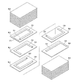
- FIG. 7 is an exploded view of the component main body shown in FIG. 6. It is sectional drawing which represents typically the fine structure of the magnetic material in a comparative example.
- the magnetic material is formed of a particle compact in which predetermined particles are accumulated in a predetermined bonding mode.
- the magnetic material is an article that plays the role of a magnetic path in a magnetic component such as a coil / inductor, and typically takes the form of a magnetic core in a coil.
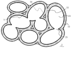
- FIG. 1 is a cross-sectional view schematically showing the fine structure of the magnetic material of the present invention.
- the magnetic material 1 is microscopically grasped as an aggregate formed by joining a large number of originally independent metal particles 11, and each metal particle 11 is at least a part of its periphery.
- the oxide film 12 is formed almost entirely, and the insulating property of the magnetic material 1 is ensured by the oxide film 12.
- Adjacent metal particles 11 constitute a magnetic material 1 having a fixed shape mainly by bonding oxide films 12 around each metal particle 11.
- a single magnetic particle or a combination of several magnetic particles is dispersed in a cured organic resin matrix, or a single magnetic particle or A material in which a combination of several magnetic particles is dispersed has been used.
- the magnetic material 1 includes a resin material.
- the magnetic material 1 merely exists so as to fill the gaps between the metal particles, and the coupling elements that form the magnetic material 1 are the above-described two types of couplings 21, 22. Even if the portion where the resin material is present is excluded from the magnetic material 1, it is possible to find a continuous structure by the two types of bonds 21 and 22 described above. In this invention, it is preferable that the matrix which consists of a glass component does not exist substantially.
- Each metal particle 11 is mainly composed of a specific soft magnetic alloy.
- the metal particles 11 are made of a Fe—Si—M soft magnetic alloy.
- M is a metal element that is easier to oxidize than Fe, and typically includes Cr (chromium), Al (aluminum), Ti (titanium), and preferably Cr or Al.
- the Si content is preferably 0.5 to 7.0 wt%, more preferably 2.0 to 5.0 wt%.
- a high Si content is preferable in terms of high resistance and high magnetic permeability, and a low Si content provides good moldability, and the above preferable range is proposed in consideration of these.
- the chromium content is preferably 2.0 to 15 wt%, and more preferably 3.0 to 6.0 wt%.
- the presence of chromium is preferable in that it forms a passive state during heat treatment to suppress excessive oxidation and develop strength and insulation resistance.
- the Si content is preferably 1.5 to 12 wt%.
- a high Si content is preferable in terms of high resistance and high magnetic permeability, and a low Si content provides good moldability, and the above preferable range is proposed in consideration of these.
- the soft magnetic alloy is an Fe—Si—Al alloy
- the aluminum content is preferably 2.0 to 8 wt%.
- the difference between Cr and Al is as follows.
- the whole amount of an alloy component is described as 100 wt%.
- the composition of the oxide film is excluded from the calculation of the preferable content.
- the soft magnetic alloy is an Fe—Si—M alloy
- the balance other than Si and M is preferably iron except for inevitable impurities.
- the metal that may be contained in addition to Fe, Si, and M include magnesium, calcium, titanium, manganese, cobalt, nickel, copper, and the like, and examples of the nonmetal include phosphorus, sulfur, and carbon.
- the alloy constituting each metal particle 11 in the magnetic material for example, a cross section of the magnetic material 1 is photographed using a scanning electron microscope (SEM), and the chemical composition thereof is energy dispersive X-ray analysis (EDS). It can be calculated by the ZAF method.
- SEM scanning electron microscope
- EDS energy dispersive X-ray analysis
- the magnetic material of the present invention can be manufactured by forming metal particles made of the above-mentioned predetermined soft magnetic alloy and performing a heat treatment.
- the metal particles as the raw material hereinafter also referred to as “raw material particles” itself, as well as the portion of the raw metal particles in the form of metal.
- a heat treatment is performed so that a part of the film is oxidized to form an oxide film 12.
- the oxide film 12 consists of the oxide of the alloy particle which comprises the metal particle 11, and the surface part of the metal particle 11 is mainly oxidized.
- oxides other than the oxide formed by oxidizing the metal particles 11, such as silica and phosphoric acid compounds, are not included in the magnetic material of the present invention.
- An oxide film 12 is formed on at least a part of the periphery of each metal particle 11 constituting the magnetic material 1.
- the oxide film 12 may be formed at the stage of raw material particles before the magnetic material 1 is formed, or the oxide film may not be present at the stage of raw material particles or may be extremely small, and an oxide film may be generated in the molding process. .
- the presence of the oxide film 12 can be recognized as a difference in contrast (brightness) in a photographed image of about 3000 times by a scanning electron microscope (SEM). The presence of the oxide film 12 ensures the insulation of the magnetic material as a whole.
- the oxide film 12 contains more metal M element than iron element in terms of mole.
- the raw material particles for obtaining the magnetic material contain as little iron oxide as possible or as little iron oxide as possible so that the magnetic material 1 is made.
- the surface portion of the alloy is oxidized by heat treatment or the like. By such treatment, the metal M that is more easily oxidized than iron is selectively oxidized, and as a result, the molar ratio of the metal M contained in the oxide film 12 is relatively larger than that of iron. Since the oxide film 12 contains more metal M element than iron element, there is an advantage that excessive oxidation of the alloy particles is suppressed.
- the method for measuring the chemical composition of the oxide film 12 in the magnetic material 1 is as follows. First, the cross section is exposed by breaking the magnetic material 1 or the like. Next, a smooth surface is produced by ion milling or the like and photographed with a scanning electron microscope (SEM), and the chemical composition of the oxide film 12 is calculated by the ZAF method in energy dispersive X-ray analysis (EDS).
- SEM scanning electron microscope
- the content of the metal M in the oxide film 12 is preferably 1.0 to 5.0 mol, more preferably 1.0 to 2.5 mol, and still more preferably 1.0 mol with respect to 1 mol of iron. ⁇ 1.7 mol.
- a high content is preferable in terms of suppressing excessive oxidation, and a low content is preferable in terms of sintering between metal particles.
- a method such as heat treatment in a weak oxidizing atmosphere can be mentioned, and conversely, in order to increase the content, for example, a heat treatment in a strong oxidizing atmosphere, etc. The method is mentioned.
- the bonds between the particles are mainly bonds 22 between the oxide films 12.
- the presence of the bonds 22 between the oxide films 12 can be clearly seen, for example, by visually confirming that the oxide films 12 of the adjacent metal particles 11 are in the same phase in an SEM observation image magnified about 3000 times. Judgment can be made.
- the presence of the bond 22 between the oxide coatings 12 improves the mechanical strength and insulation. It is preferable that the oxide films 12 of the adjacent metal particles 11 are bonded to each other over the entire magnetic material 1, but if even a part is bonded, the corresponding mechanical strength and insulation can be improved, Such a form is also an embodiment of the present invention.
- the bonds 21 between the metal particles 11 may also exist partially without the bonds between the oxide films 12 being partly interposed. Furthermore, the form (not shown) in which the adjacent metal particles 11 are merely in physical contact or approach without the connection between the oxide films 12 and the connection between the metal particles 11 is partially present. There may be.
- heat treatment may be performed at a predetermined temperature, which will be described later, in an atmosphere in which oxygen is present (eg, in air) when the magnetic material 1 is manufactured. Can be mentioned.
- the bonds 22 between the oxide films 12 not only the bonds 22 between the oxide films 12 but also the bonds 21 between the metal particles 11 exist.
- the bonding 22 between the oxide films 12 described above for example, in an SEM observation image magnified about 3000 times, it is visually recognized that adjacent metal particles 11 have bonding points while maintaining the same phase.
- the existence of the bond 21 between the metal particles 11 can be clearly determined.
- the presence of the coupling 21 between the metal particles 11 further improves the magnetic permeability.
- the temperature and the oxygen partial pressure are adjusted as described later in the heat treatment for manufacturing the magnetic material 1. Or adjusting the molding density when the magnetic material 1 is obtained from the raw material particles.
- the temperature in the heat treatment it is possible to propose a degree to which the metal particles 11 are bonded to each other and oxides are not easily generated. A specific preferred temperature range will be described later.
- the oxygen partial pressure may be, for example, the oxygen partial pressure in the air, and the lower the oxygen partial pressure, the less likely the oxide is formed, and as a result, the metal particles 11 are more likely to bond.
- the magnetic material of the present invention can be manufactured by molding metal particles made of a predetermined alloy. At that time, adjacent metal particles are bonded mainly through an oxide film, and partially bonded without an oxide film, whereby a particle molded body having a desired shape as a whole can be obtained.
- the metal particles (raw material particles) used as the raw material in the production of the magnetic material of the present invention are preferably particles made of an Fe—M—Si alloy, more preferably an Fe—Cr—Si alloy.
- the alloy composition of the raw material particles is reflected in the alloy composition in the finally obtained magnetic material. Therefore, the alloy composition of the raw material particles can be appropriately selected according to the alloy composition of the magnetic material to be finally obtained, and the preferred composition range is the same as the preferred composition range of the magnetic material described above.
- Individual raw material particles may be covered with an oxide film. In other words, each raw material particle may be composed of a predetermined soft magnetic alloy in the central portion and an oxide film formed by oxidizing the soft magnetic alloy in at least a part of the periphery thereof.
- the size of each raw material particle is substantially equal to the size of the particles constituting the magnetic material 1 in the finally obtained magnetic material.
- d50 is preferably 2 to 30 ⁇ m, more preferably 2 to 20 ⁇ m in consideration of the magnetic permeability and intra-granular eddy current loss, and a more preferable lower limit of d50 is 5 ⁇ m.
- the d50 of the raw material particles can be measured by a measuring device using laser diffraction / scattering.
- the raw material particles are, for example, particles manufactured by an atomizing method.
- the magnetic material 1 includes not only the coupling portion 22 through the oxide film 12 but also the coupling portion 21 between the metal particles 11. Therefore, an oxide film may be present on the raw material particles, but it is preferable that the raw material particles do not exist excessively. Particles produced by the atomization method are preferred in that the oxide film is relatively small.
- the ratio of the alloy core to the oxide film in the raw material particles can be quantified as follows.
- the value is preferably 0.2 or more.
- the upper limit of the value is not particularly limited, and may be 0.6, for example, from the viewpoint of ease of production, and the upper limit is preferably 0.3.
- means for increasing the value include a heat treatment in a reducing atmosphere and a chemical treatment such as removal of a surface oxide layer with an acid.
- Examples of the reduction treatment include holding at 750 to 850 ° C. for 0.5 to 1.5 hours in an atmosphere containing 25 to 35% hydrogen in nitrogen or argon.
- Examples of the oxidation treatment include holding in air at 400 to 600 ° C. for 0.5 to 1.5 hours.
- a known method for producing alloy particles may be employed.
- an organic resin As a binder, it is preferable to add an organic resin as a binder.
- the organic resin it is preferable to use an organic resin made of PVA resin, butyral resin, vinyl resin or the like having a thermal decomposition temperature of 500 ° C. or less because the binder hardly remains after heat treatment.
- a known lubricant may be added during molding. Examples of the lubricant include organic acid salts, and specific examples include zinc stearate and calcium stearate.
- the amount of the lubricant is preferably 0 to 1.5 parts by weight, more preferably 0.1 to 1.0 parts by weight, and still more preferably 0.15 to 0.45 with respect to 100 parts by weight of the raw material particles.
- Parts by weight particularly preferably 0.15 to 0.25 parts by weight.
- a lubricant amount of zero means that no lubricant is used.
- a binder and / or lubricant is optionally added to the raw material particles and stirred, and then formed into a desired shape. In molding, for example, a pressure of 2 to 20 ton / cm 2 is applied, and a molding temperature is set to 20 to 120 ° C., for example.
- the heat treatment is preferably performed in an oxidizing atmosphere. More specifically, the oxygen concentration during heating is preferably 1% or more, which facilitates the formation of both bonds 22 between oxide films and bonds 21 between metals. Although the upper limit of the oxygen concentration is not particularly defined, the oxygen concentration in the air (about 21%) can be given in consideration of the manufacturing cost.
- the heating temperature is preferably 600 ° C. or higher from the viewpoint of facilitating the formation of the oxide film 12 and the formation of bonds between the oxide films 12, and the oxidation is moderately suppressed to maintain the presence of the bond 21 between the metals. From the viewpoint of increasing the magnetic permeability, the temperature is preferably 900 ° C. or lower. The heating temperature is more preferably 700 to 800 ° C.
- the heating time is preferably 0.5 to 3 hours. It is considered that the mechanism through which the bond 21 via the oxide film 12 and the bond 21 between the metal particles are generated is similar to the so-called ceramic sintering at a temperature higher than about 600 ° C., for example. That is, according to the new knowledge of the present inventors, in this heat treatment, (A) the oxide film is sufficiently in contact with the oxidizing atmosphere, and the metal element is supplied from the metal particles as needed, so that the oxide film itself grows. And (B) that adjacent oxide films are in direct contact with each other and the substances constituting the oxide film are interdiffused. Therefore, it is preferable that a thermosetting resin, silicone, or the like that can remain in a high temperature range of 600 ° C. or higher is substantially absent during the heat treatment.
- the obtained magnetic material 1 has voids 30 inside thereof. At least a part of the gap 30 is filled with a resin material.
- the resin material for example, the magnetic material 1 is immersed in a liquid material of the resin material such as a liquid resin material or a solution of the resin material to reduce the pressure of the manufacturing system, or the liquid material of the resin material described above
- the magnetic material 1 may be applied and soaked in the gap 30 near the surface.
- Filling the gap 30 of the magnetic material 1 with the resin material 31 has the advantage of increasing strength and suppressing hygroscopicity. Specifically, it is difficult for moisture to enter the magnetic material under high humidity. Resistance is less likely to drop.
- the resin material 31 examples include organic resins, silicone resins, and the like, and preferably silicone resins, epoxy resins, phenol resins, silicate resins, urethane resins, imide resins, acrylic resins. It consists of at least 1 sort (s) chosen from the group which consists of resin, polyester-type resin, and polyethylene-type resin.
- the resin material is filled so as to occupy a predetermined ratio or more of voids generated in the magnetic material.
- the degree of filling of the resin material is quantified by mirror polishing of the multilayer inductor to be measured, ion milling (CP), and scanning electron microscope (SEM) observation. Specifically, this is performed as follows. First, the object to be measured is polished so that the cross section in the thickness direction is exposed through the center of the laminate. The vicinity of the product center of the obtained cross section is photographed at a magnification of 3000 using a scanning electron microscope (SEM) to obtain a secondary electron image and a composition image.
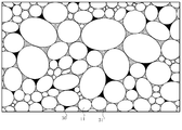
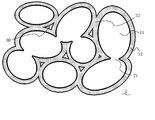
- FIG. 2 is a schematic view of the obtained image.
- a difference in contrast occurs in the composition image due to a difference in constituent elements.
- the metal particles 11, oxide film (not shown), resin material filling portion 31, and void 30 are identified in descending order of brightness.
- the ratio of calculation of the area of the void 30 with respect to the area corresponding to the non-existing region of the metal particles 11 and the oxide film tree is calculated, and this ratio is defined as the porosity.
- the resin filling rate (%) is calculated as (100 ⁇ porosity).
- the resin filling rate is preferably 15% or more from the viewpoint of more effectively achieving the effects of the present invention.
- such a magnetic material made of the magnetic material 1 can be used as a component of various electronic components.
- the coil may be formed by using the magnetic material of the present invention as a core and winding an insulating coated conductor around the core.
- a green sheet containing the above-described raw material particles is formed by a known method, and after a conductive paste having a predetermined pattern is formed thereon by printing or the like, it is formed by laminating and pressing the printed green sheet, By performing heat treatment under the above-described conditions, an inductor (coil component) formed by forming a coil inside the magnetic material of the present invention made of a particle compact can also be obtained.
- various coil components can be obtained by forming a coil inside or on the surface using the magnetic material of the present invention.
- the coil component may be of various mounting forms such as surface mounting type and through-hole mounting type, and means for obtaining the coil component from the magnetic material, including means for configuring the coil component of those mounting forms, Any known manufacturing technique in the field can be appropriately adopted.
- an example of a form in which the coil component is a multilayer inductor will be introduced in the embodiments described later.
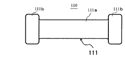
- FIG. 3 is a side view showing an appearance of an example of the magnetic material according to the present invention.
- FIG. 4 is a transparent side view showing a part of an example of the coil component.
- FIG. 5 is a longitudinal sectional view showing the internal structure of the coil component shown in FIG.
- a magnetic material 110 shown in FIG. 3 is used as a magnetic core for winding a coil of a wire-wound chip inductor.
- the drum-shaped magnetic core 111 is disposed in parallel with a mounting surface of a circuit board or the like, and is disposed at a plate-shaped core portion 111a for winding a coil, and opposite ends of the core portion 111a.
- a pair of flanges 111b is provided, and the appearance is a drum shape.
- the end of the coil is electrically connected to the external conductor film 114 formed on the surface of the flange 111b.
- the wire-wound chip inductor 120 as the coil component has the above-described magnetic core 111 and a pair of plate-shaped magnetic cores 112 (not shown).
- the magnetic core 111 and the plate-like magnetic core 112 are made of the magnetic material 110 of the present invention.
- the plate-shaped magnetic core 112 connects the flanges 111b and 111b of the magnetic core 111, respectively.
- a pair of external conductor films 114 are formed on the mounting surface of the flange 111b of the magnetic core 111, respectively.
- a coil 115 made of an insulation coated conductor is wound around the core portion 111a of the magnetic core 111 to form a winding portion 115a, and both end portions 115b are respectively formed on the external conductor film 114 on the mounting surface of the flange portion 111b. It is thermocompression bonded.
- the external conductor film 114 includes a baked conductor layer 114a formed on the surface of the magnetic material 110, a Ni plated layer 114b and a Sn plated layer 114c stacked on the baked conductor layer 114a.
- the plate-like magnetic core 112 described above is bonded to the flanges 111b and 111b of the magnetic core 111 with a resin adhesive.
- the external conductor film 114 is formed on the surface of the magnetic material 110, and the end of the magnetic core is connected to the external conductor film 114.
- the external conductor film 114 is formed by baking a paste obtained by adding glass to silver onto the magnetic material 110 at a predetermined temperature.
- the gap of the magnetic material in the magnetic core 111 is filled with the resin material.
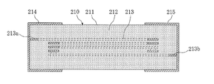
- FIG. 6 is an external perspective view of the multilayer inductor.
- FIG. 7 is an enlarged sectional view taken along line S11-S11 in FIG.
- FIG. 8 is an exploded view of the component main body shown in FIG.
- the multilayer inductor 210 manufactured in this example has a length L of about 3.2 mm, a width W of about 1.6 mm, a height H of about 0.8 mm, and the overall shape is a rectangular parallelepiped. is doing.
- the multilayer inductor 210 includes a rectangular parallelepiped component main body 211 and a pair of external terminals 214 and 215 provided at both ends in the length direction of the component main body 211.
- the component main body 211 has a rectangular parallelepiped magnetic body portion 212 and a spiral coil portion 213 covered with the magnetic body portion 212, and one end of the coil portion 213. Is connected to the external terminal 214, and the other end is connected to the external terminal 215.
- the magnetic body portion 212 has a structure in which a total of 20 magnetic layers ML1 to ML6 are integrated, has a length of about 3.2 mm, a width of about 1.6 mm, The height is about 0.8 mm.
- Each of the magnetic layers ML1 to ML6 has a length of about 3.2 mm, a width of about 1.6 mm, and a thickness of about 40 ⁇ m.
- the coil section 213 has a structure in which a total of five coil segments CS1 to CS5 and a total of four relay segments IS1 to IS4 connecting the coil segments CS1 to CS5 are spirally integrated. The number is about 3.5.
- the coil portion 213 is made of Ag particles having a d50 of 5 ⁇ m as a raw material.
- the four coil segments CS1 to CS4 have a U shape, and the one coil segment CS5 has a strip shape.
- Each coil segment CS1 to CS5 has a thickness of about 20 ⁇ m and a width of about 0.2 mm. It is.
- the uppermost coil segment CS1 has a continuous L-shaped lead portion LS1 used for connection to the external terminal 214, and the lowermost coil segment CS5 is used for connection to the external terminal 15.
- An L-shaped lead portion LS2 is continuously provided.
- Each of the relay segments IS1 to IS4 has a column shape penetrating the magnetic layers ML1 to ML4, and each has a diameter of about 15 ⁇ m.
- Each external terminal 214 and 215 extends to each end face in the length direction of the component main body 211 and four side faces in the vicinity of the end face, and has a thickness of about 20 ⁇ m.
- One external terminal 214 is connected to the edge of the lead portion LS1 of the uppermost coil segment CS1, and the other external terminal 215 is connected to the edge of the lead portion LS2 of the lowermost coil segment CS5.
- the external terminals 214 and 215 are made of Ag particles having a d50 of 5 ⁇ m as a raw material.
- the multilayer inductor 210 In the production of the multilayer inductor 210, a doctor blade is used as a coating machine, a magnetic paste prepared in advance is applied to the surface of a plastic base film (not shown), and this is heated using a hot air dryer.
- the first to sixth sheets corresponding to the magnetic layers ML1 to ML6 (see FIG. 8) and having a size suitable for multi-cavity were produced by drying at about 80 ° C. for about 5 minutes.
- the raw material particles are 85 wt%, butyl carbitol (solvent) is 13 wt%, and polyvinyl butyral (binder) is 2 wt%.
- a punching machine was used to perforate the first sheet corresponding to the magnetic layer ML1, and through holes corresponding to the relay segment IS1 were formed in a predetermined arrangement.
- through holes corresponding to the relay segments IS2 to IS4 were formed in a predetermined arrangement in the second to fourth sheets corresponding to the magnetic layers ML2 to ML4, respectively.
- a conductor paste prepared in advance is printed on the surface of the first sheet corresponding to the magnetic layer ML1, and this is printed using a hot air dryer or the like at about 80 ° C. for about 5 minutes.
- the first printed layer corresponding to the coil segment CS1 was prepared in a predetermined arrangement.
- second to fifth printing layers corresponding to the coil segments CS2 to CS5 were formed in a predetermined arrangement on the surfaces of the second to fifth sheets corresponding to the magnetic layers ML2 to ML5.
- the composition of the conductive paste is 85 wt% Ag raw material, 13 wt% butyl carbitol (solvent), and 2 wt% polyvinyl butyral (binder).
- the through holes having a predetermined arrangement formed in each of the first to fourth sheets corresponding to the magnetic layers ML1 to ML4 are located at positions overlapping the end portions of the first to fourth printing layers having the predetermined arrangement.
- a part of the conductor paste was filled in each through hole to form first to fourth filling portions corresponding to the relay segments IS1 to IS4.
- a large number of pre-heat-treated chips were heat-treated in a lump in an air atmosphere using a firing furnace or the like.
- This heat treatment includes a binder removal process and an oxide film formation process.
- the binder removal process was performed under conditions of about 300 ° C. and about 1 hour
- the oxide film formation process was performed under conditions of about 750 ° C. and about 2 hours.
- the above-described conductor paste is applied to both ends in the length direction of the component body 211, and this is baked using a baking furnace under conditions of about 600 ° C. and about 1 hour,
- the external terminals 214 and 215 were manufactured by eliminating the solvent and the binder and sintering the Ag particles by the baking treatment.
- the resin material was cured by immersing the obtained multilayer inductor in a solution containing each resin material to fill the voids with the resin material, and then heat treating at 150 ° C. for 60 minutes.
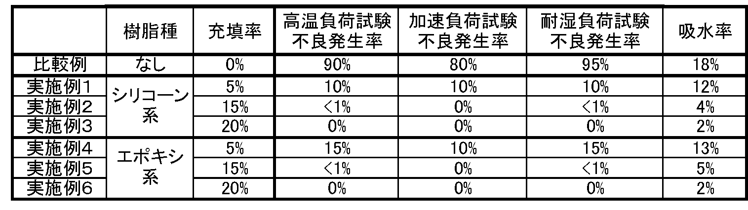
- Table 1 shows the types of resin materials and the degree of filling. The degree of filling was controlled by adjusting the resin concentration and viscosity.
- silicone type is a resin having the following basic structure (1)
- epoxy type is a resin having the following basic structure (2).
- FIG. 6 is a schematic cross-sectional view of a magnetic material layer of a comparative example.
- the resin material is not filled in the non-existing regions of the metal particles 11 and the oxide film 12, and the void 30 is formed.
- the water absorption rate of the magnetic material portion was measured as follows. The water absorption was determined by dividing the difference between the water absorption mass and the total dry mass when the sample was immersed in boiling water for 3 hours by the total dry mass. Table 1 summarizes the manufacturing conditions, the incidence of defects, and the measurement results of water absorption.
Landscapes
- Engineering & Computer Science (AREA)
- Chemical & Material Sciences (AREA)
- Power Engineering (AREA)
- Dispersion Chemistry (AREA)
- Organic Chemistry (AREA)
- Metallurgy (AREA)
- Mechanical Engineering (AREA)
- Materials Engineering (AREA)
- Physics & Mathematics (AREA)
- Spectroscopy & Molecular Physics (AREA)
- Manufacturing & Machinery (AREA)
- General Chemical & Material Sciences (AREA)
- Chemical Kinetics & Catalysis (AREA)
- Microelectronics & Electronic Packaging (AREA)
- Electromagnetism (AREA)
- Soft Magnetic Materials (AREA)
- Coils Or Transformers For Communication (AREA)
Abstract
Description
本発明の磁性材料は、Fe-Si-M系軟磁性合金(但し、MはFeより酸化し易い金属元素である。)からなる複数の金属粒子と、金属粒子の表面に形成された酸化被膜とを備える。この酸化被膜は軟磁性合金自身の酸化物からなる。磁性材料は、隣接する金属粒子表面に形成された酸化被膜を介しての結合部および酸化被膜が存在しない部分における金属粒子どうしの結合部を有する。そして、前記金属粒子の集積により生じた空隙の少なくとも一部には樹脂材料が充填されている。
本発明によれば、磁性材料は所定の粒子が所定の結合様式で集積されてなる粒子成形体からなる。
本発明において、磁性材料はコイル・インダクタ等の磁性部品における磁路の役割を担う物品であり、典型的にはコイルにおける磁心などの形態をとる。
熱処理は酸化雰囲気下で行うことが好ましい。より具体的には、加熱中の酸素濃度は好ましくは1%以上であり、これにより、酸化被膜どうしの結合22および金属どうしの結合21が両方とも生成しやすくなる。酸素濃度の上限は特に定められるものではないが、製造コスト等を考慮して空気中の酸素濃度(約21%)を挙げることができる。加熱温度については、酸化被膜12を生成して酸化被膜12どうしの結合を生成させやすくする観点からは好ましくは600℃以上であり、酸化を適度に抑制して金属どうしの結合21の存在を維持して透磁率を高める観点からは好ましくは900℃以下である。加熱温度はより好ましくは700~800℃である。酸化被膜12どうしの結合22および金属どうしの結合21を両方とも生成させやすくする観点からは、加熱時間は好ましくは0.5~3時間である。酸化被膜12を介した結合および金属粒子どうしの結合21が生じるメカニズムは、例えば600℃程度より高温域における、いわゆるセラミックスの焼結と似たようなメカニズムであると考察される。すなわち、本発明者らの新知見によれば、この熱処理においては、(A)酸化被膜が十分に酸化雰囲気に接するとともに金属元素が金属粒子から随時供給されることにより酸化被膜自体が成長すること、ならびに、(B)隣接する酸化被膜どうしが直接接して酸化被膜を構成する物質が相互拡散すること、が重要である。よって、600℃以上の高温域において残存し得る熱硬化性樹脂やシリコーンなどは熱処理の際に実質的に存在しないことが好ましい。
[実施例1~6]
アトマイズ法で製造されたCr4.5wt%、Si3.5wt%、残部Feの組成をもち、平均粒径d50が6μmである市販の合金粉末を原料粒子として用いた。この合金粉末の集合体表面をXPSで分析し、上述のFeMetal/(FeMetal+FeOxide)を算出したところ、0.25であった。
図6は、積層インダクタの外観斜視図である。図7は、図6のS11-S11線に沿う拡大断面図である。図8は、図6に示した部品本体の分解図である。この実施例で製造した積層インダクタ210は、図6において、長さLが約3.2mmで、幅Wが約1.6mmで、高さHが約0.8mmで、全体が直方体形状を成している。この積層インダクタ210は、直方体形状の部品本体211と、該部品本体211の長さ方向の両端部に設けられた1対の外部端子214及び215とを有している。部品本体211は、図7に示したように、直方体形状の磁性体部212と、該磁性体部212によって覆われた螺旋状のコイル部213とを有しており、該コイル部213の一端は外部端子214に接続し他端は外部端子215に接続している。磁性体部212は、図8に示したように、計20層の磁性体層ML1~ML6が一体化した構造を有し、長さが約3.2mmで、幅が約1.6mmで、高さが約0.8mmである。各磁性体層ML1~ML6の長さは約3.2mmで、幅は約1.6mmで、厚さは約40μmである。コイル部213は、計5個のコイルセグメントCS1~CS5と、該コイルセグメントCS1~CS5を接続する計4個の中継セグメントIS1~IS4とが、螺旋状に一体化した構造を有し、その巻き数は約3.5である。このコイル部213は、d50が5μmのAg粒子を原料とする。

樹脂材料の充填を行わなかったことを除いて、実施例と同様に積層インダクタを製造した。図6は比較例の磁性材料層の模式断面図である。この磁性材料2では、金属粒子11および酸化被膜12の非存在領域には樹脂材料が充填されず、空隙30になっている。
各実施例、比較例の積層インダクタについて、L=1.0uH、Q(1MHz)=30、Rdc=0.1Ωにおいて、以下の信頼性試験に供した。(n=100)
(1)高温負荷試験:85℃、0.8A印加、1000時間
(2)加速負荷試験:85℃、1.2A印加、300時間
(3)耐湿負荷試験:60℃、湿度95%、0.8A印加、300時間
各試験終了後、LもしくはQが初期値の70%以下に低下したものを不良とした。
Claims (4)
- Fe-Si-M系軟磁性合金(但し、MはFeより酸化し易い金属元素である。)からなる複数の金属粒子と、前記金属粒子の表面に形成された前記軟磁性合金の酸化物からなる酸化被膜とを備え、隣接する金属粒子表面に形成された酸化被膜を介しての結合部および酸化被膜が存在しない部分における金属粒子どうしの結合部を有し、前記金属粒子の集積により生じた空隙の少なくとも一部には樹脂材料が充填されている、磁性材料。
- 当該磁性材料の断面図において観察される、前記金属粒子及び酸化被膜の非存在領域の15%以上の面積の領域に樹脂材料が充填されている、請求項1記載の磁性材料。
- 前記樹脂材料が、シリコーン系樹脂、エポキシ系樹脂、フェノール系樹脂、シリケート系樹脂、ウレタン系樹脂、イミド系樹脂、アクリル系樹脂、ポリエステル系樹脂およびポリエチレン系樹脂からなる群から選ばれる少なくとも1種からなる請求項1又は2記載の磁性材料。
- 請求項1~3のいずれかに記載の磁性材料と、前記磁性材料の内部または表面に形成されたコイルと、を備えるコイル部品。
Priority Applications (3)
| Application Number | Priority Date | Filing Date | Title |
|---|---|---|---|
| CN201280020327.4A CN103503088B (zh) | 2011-04-27 | 2012-04-18 | 磁性材料及线圈零件 |
| KR1020137026362A KR20130126737A (ko) | 2011-04-27 | 2012-04-18 | 자성 재료 및 코일 부품 |
| US14/114,138 US9287026B2 (en) | 2011-04-27 | 2012-04-18 | Magnetic material and coil component |
Applications Claiming Priority (4)
| Application Number | Priority Date | Filing Date | Title |
|---|---|---|---|
| JP2011100095 | 2011-04-27 | ||
| JP2011-100095 | 2011-04-27 | ||
| JP2012068445A JP2012238841A (ja) | 2011-04-27 | 2012-03-23 | 磁性材料及びコイル部品 |
| JP2012-068445 | 2012-03-23 |
Publications (1)
| Publication Number | Publication Date |
|---|---|
| WO2012147576A1 true WO2012147576A1 (ja) | 2012-11-01 |
Family
ID=47072097
Family Applications (1)
| Application Number | Title | Priority Date | Filing Date |
|---|---|---|---|
| PCT/JP2012/060408 Ceased WO2012147576A1 (ja) | 2011-04-27 | 2012-04-18 | 磁性材料及びコイル部品 |
Country Status (6)
| Country | Link |
|---|---|
| US (1) | US9287026B2 (ja) |
| JP (1) | JP2012238841A (ja) |
| KR (1) | KR20130126737A (ja) |
| CN (1) | CN103503088B (ja) |
| TW (1) | TWI453774B (ja) |
| WO (1) | WO2012147576A1 (ja) |
Cited By (1)
| Publication number | Priority date | Publication date | Assignee | Title |
|---|---|---|---|---|
| US11651880B2 (en) | 2019-03-27 | 2023-05-16 | Tdk Corporation | Composite particle, core, and inductor element |
Families Citing this family (39)
| Publication number | Priority date | Publication date | Assignee | Title |
|---|---|---|---|---|
| CN103636101A (zh) * | 2011-06-30 | 2014-03-12 | 佩西蒙技术公司 | 结构化的磁性材料 |
| DE102013200229B4 (de) * | 2013-01-10 | 2024-06-06 | Robert Bosch Gmbh | Verfahren zum Herstellen eines weichmagnetischen Verbundwerkstoffs |
| JP6326207B2 (ja) * | 2013-09-20 | 2018-05-16 | 太陽誘電株式会社 | 磁性体およびそれを用いた電子部品 |
| JP6252605B2 (ja) * | 2014-01-31 | 2017-12-27 | 株式会社村田製作所 | 電子部品及びその製造方法 |
| KR102195949B1 (ko) | 2014-03-10 | 2020-12-28 | 히타치 긴조쿠 가부시키가이샤 | 자심, 코일 부품 및 자심의 제조 방법 |
| TWI644330B (zh) | 2014-03-13 | 2018-12-11 | 日商日立金屬股份有限公司 | 磁心、線圈部件及磁心的製造方法 |
| KR20160145665A (ko) | 2014-04-18 | 2016-12-20 | 도꼬가부시끼가이샤 | 금속 자성 재료 및 전자 부품 |
| KR101558095B1 (ko) * | 2014-06-24 | 2015-10-06 | 삼성전기주식회사 | 적층 전자부품 |
| DE112015003386T5 (de) * | 2014-07-22 | 2017-03-30 | Panasonic Intellectual Property Management Co., Ltd. | Magnetisches Verbundmaterial, Spulenkomponente, die dasselbe verwendet und Herstellungsverfahren für das magnetische Verbundmaterial |
| JP6522462B2 (ja) * | 2014-08-30 | 2019-05-29 | 太陽誘電株式会社 | コイル部品 |
| JP6457838B2 (ja) | 2015-02-27 | 2019-01-23 | 太陽誘電株式会社 | 磁性体及びそれを含む電子部品 |
| JP6428416B2 (ja) | 2015-03-20 | 2018-11-28 | 株式会社村田製作所 | 金属磁性材料及び電子部品 |
| JP6545992B2 (ja) * | 2015-03-31 | 2019-07-17 | 太陽誘電株式会社 | 磁性体及びそれを含む電子部品 |
| JP2017004992A (ja) * | 2015-06-04 | 2017-01-05 | 株式会社神戸製鋼所 | 圧粉磁心用混合粉末および圧粉磁心 |
| CN104934180B (zh) * | 2015-06-19 | 2017-06-23 | 浙江大学 | 一种高饱和磁通密度高磁导率软磁复合材料的制备方法 |
| JP6583627B2 (ja) * | 2015-11-30 | 2019-10-02 | Tdk株式会社 | コイル部品 |
| CN113628857B (zh) * | 2016-02-01 | 2024-03-08 | 株式会社村田制作所 | 线圈部件及其制造方法 |
| CN108028122B (zh) | 2016-02-01 | 2020-06-30 | 株式会社村田制作所 | 电子部件和其制造方法 |
| JP6738635B2 (ja) * | 2016-03-31 | 2020-08-12 | 太陽誘電株式会社 | コイル部品 |
| US10622129B2 (en) * | 2016-06-30 | 2020-04-14 | Taiyo Yuden Co., Ltd. | Magnetic material and electronic component |
| KR102004805B1 (ko) | 2017-10-18 | 2019-07-29 | 삼성전기주식회사 | 코일 전자 부품 |
| JP7145610B2 (ja) * | 2017-12-27 | 2022-10-03 | Tdk株式会社 | 積層コイル型電子部品 |
| JP7426191B2 (ja) * | 2018-09-27 | 2024-02-01 | 太陽誘電株式会社 | 軟磁性金属粒子を含む磁性基体及び当該磁性基体を含む電子部品 |
| JP7387269B2 (ja) * | 2019-02-28 | 2023-11-28 | 太陽誘電株式会社 | 磁性体及びその製造方法、並びに磁性体を用いたコイル部品及びそれを載せた回路基板 |
| JP7304727B2 (ja) * | 2019-04-03 | 2023-07-07 | 株式会社トーキン | 複合磁性体及びその製造方法 |
| JP7078016B2 (ja) * | 2019-06-17 | 2022-05-31 | 株式会社村田製作所 | インダクタ部品 |
| JP7268520B2 (ja) | 2019-07-25 | 2023-05-08 | セイコーエプソン株式会社 | 磁性粉末、磁性粉末の製造方法、圧粉磁心およびコイル部品 |
| CN112391077A (zh) * | 2019-08-19 | 2021-02-23 | 肥特补科技股份有限公司 | 绝缘软磁油墨、绝缘软磁膜及绝缘软磁膜积层电路板 |
| TWI706855B (zh) * | 2019-08-19 | 2020-10-11 | 肥特補科技股份有限公司 | 電磁防護構件 |
| JP7371423B2 (ja) * | 2019-09-30 | 2023-10-31 | 株式会社村田製作所 | コイル部品 |
| JP7375469B2 (ja) | 2019-10-30 | 2023-11-08 | セイコーエプソン株式会社 | 絶縁体被覆磁性合金粉末粒子、圧粉磁心、およびコイル部品 |
| CN110931237B (zh) * | 2019-12-06 | 2021-07-02 | 武汉科技大学 | 一种高电阻率高机械强度的软磁粉末材料的制备方法 |
| KR102237022B1 (ko) * | 2020-08-07 | 2021-04-08 | 주식회사 포스코 | 연자성 철계 분말 및 그 제조방법, 연자성 부품 |
| JP7499668B2 (ja) | 2020-10-02 | 2024-06-14 | Tdk株式会社 | 積層コイル部品 |
| JP7480012B2 (ja) | 2020-10-02 | 2024-05-09 | Tdk株式会社 | 積層コイル部品 |
| JP2022093144A (ja) * | 2020-12-11 | 2022-06-23 | 太陽誘電株式会社 | コイル部品及びその製造方法 |
| KR102568396B1 (ko) * | 2021-05-21 | 2023-08-18 | 에스케이씨 주식회사 | 이동 수단용 무선 충전 장치 및 이에 사용되는 자성 복합체 |
| JP7444146B2 (ja) * | 2021-08-05 | 2024-03-06 | 株式会社村田製作所 | コイル部品 |
| CN119920563A (zh) * | 2024-12-25 | 2025-05-02 | 东莞顺络电子有限公司 | 一种磁性体结构及其制备方法和电子设备 |
Citations (7)
| Publication number | Priority date | Publication date | Assignee | Title |
|---|---|---|---|---|
| JPH0974011A (ja) * | 1995-09-07 | 1997-03-18 | Tdk Corp | 圧粉コアおよびその製造方法 |
| JP2000030925A (ja) * | 1998-07-14 | 2000-01-28 | Daido Steel Co Ltd | 圧粉磁芯およびその製造方法 |
| JP2001118725A (ja) * | 1999-10-21 | 2001-04-27 | Denso Corp | 軟磁性材およびそれを用いた電磁アクチュエータ |
| JP2007299871A (ja) * | 2006-04-28 | 2007-11-15 | Matsushita Electric Ind Co Ltd | 複合磁性体の製造方法およびそれを用いて得られた複合磁性体 |
| JP2009010180A (ja) * | 2007-06-28 | 2009-01-15 | Kobe Steel Ltd | 軟磁性粉体、軟磁性成形体およびそれらの製造方法 |
| JP2009088496A (ja) * | 2007-09-12 | 2009-04-23 | Seiko Epson Corp | 酸化物被覆軟磁性粉末の製造方法、酸化物被覆軟磁性粉末、圧粉磁心および磁性素子 |
| WO2009128425A1 (ja) * | 2008-04-15 | 2009-10-22 | 東邦亜鉛株式会社 | 複合磁性材料およびその製造方法 |
Family Cites Families (77)
| Publication number | Priority date | Publication date | Assignee | Title |
|---|---|---|---|---|
| US2193768A (en) | 1932-02-06 | 1940-03-12 | Kinzoku Zairyo Kenkyusho | Magnetic alloys |
| US4129444A (en) | 1973-01-15 | 1978-12-12 | Cabot Corporation | Power metallurgy compacts and products of high performance alloys |
| JPH0834154B2 (ja) | 1986-11-06 | 1996-03-29 | ソニー株式会社 | 軟磁性薄膜 |
| EP0406580B1 (en) * | 1989-06-09 | 1996-09-04 | Matsushita Electric Industrial Co., Ltd. | A composite material and a method for producing the same |
| JPH04147903A (ja) | 1990-10-12 | 1992-05-21 | Tokin Corp | 形状異方性軟磁性合金粉末とその製造方法 |
| JPH04346204A (ja) | 1991-05-23 | 1992-12-02 | Matsushita Electric Ind Co Ltd | 複合材料及びその製造方法 |
| JP3688732B2 (ja) | 1993-06-29 | 2005-08-31 | 株式会社東芝 | 平面型磁気素子および非晶質磁性薄膜 |
| JPH07201570A (ja) | 1993-12-28 | 1995-08-04 | Matsushita Electric Ind Co Ltd | 厚膜積層インダクタ |
| JP3483012B2 (ja) | 1994-07-01 | 2004-01-06 | 新光電気工業株式会社 | セラミック基板製造用焼結体、セラミック基板およびその製造方法 |
| JP3423569B2 (ja) | 1997-02-28 | 2003-07-07 | 太陽誘電株式会社 | 積層電子部品とその特性調整方法 |
| US6051324A (en) | 1997-09-15 | 2000-04-18 | Lockheed Martin Energy Research Corporation | Composite of ceramic-coated magnetic alloy particles |
| US6764643B2 (en) | 1998-09-24 | 2004-07-20 | Masato Sagawa | Powder compaction method |
| JP3039538B1 (ja) | 1998-11-02 | 2000-05-08 | 株式会社村田製作所 | 積層型インダクタ |
| US6392525B1 (en) | 1998-12-28 | 2002-05-21 | Matsushita Electric Industrial Co., Ltd. | Magnetic element and method of manufacturing the same |
| JP2001011563A (ja) | 1999-06-29 | 2001-01-16 | Matsushita Electric Ind Co Ltd | 複合磁性材料の製造方法 |
| JP2001044037A (ja) | 1999-08-03 | 2001-02-16 | Taiyo Yuden Co Ltd | 積層インダクタ |
| JP4684461B2 (ja) | 2000-04-28 | 2011-05-18 | パナソニック株式会社 | 磁性素子の製造方法 |
| JP4683178B2 (ja) | 2001-03-12 | 2011-05-11 | 株式会社安川電機 | 軟質磁性材料およびその製造方法 |
| JP2002313672A (ja) | 2001-04-13 | 2002-10-25 | Murata Mfg Co Ltd | 積層型セラミック電子部品およびその製造方法ならびにセラミックペーストおよびその製造方法 |
| JP2002313620A (ja) | 2001-04-13 | 2002-10-25 | Toyota Motor Corp | 絶縁皮膜を有する軟磁性粉末及びそれを用いた軟磁性成形体並びにそれらの製造方法 |
| US7282103B2 (en) | 2002-04-05 | 2007-10-16 | Nippon Steel Corporation | Iron-base amorphous alloy thin strip excellent in soft magnetic properties, iron core manufactured by using said thin strip, and mother alloy for producing rapidly cooled and solidified thin strip |
| JP3861288B2 (ja) | 2002-10-25 | 2006-12-20 | 株式会社デンソー | 軟磁性材料の製造方法 |
| JP4265358B2 (ja) | 2003-10-03 | 2009-05-20 | パナソニック株式会社 | 複合焼結磁性材の製造方法 |
| JP2005150257A (ja) | 2003-11-12 | 2005-06-09 | Fuji Electric Holdings Co Ltd | 複合磁性粒子および複合磁性材料 |
| JP4457682B2 (ja) | 2004-01-30 | 2010-04-28 | 住友電気工業株式会社 | 圧粉磁心およびその製造方法 |
| JP5196704B2 (ja) | 2004-03-12 | 2013-05-15 | 京セラ株式会社 | フェライト焼結体の製造方法 |
| JP2005286145A (ja) | 2004-03-30 | 2005-10-13 | Sumitomo Electric Ind Ltd | 軟磁性材料の製造方法、軟磁性粉末および圧粉磁心 |
| JP4548035B2 (ja) | 2004-08-05 | 2010-09-22 | 株式会社デンソー | 軟磁性材の製造方法 |
| EP1788588B1 (en) * | 2004-09-01 | 2015-08-26 | Sumitomo Electric Industries, Ltd. | Soft magnetic material, dust core and method for producing dust core |
| CA2578861A1 (en) | 2004-09-06 | 2006-03-16 | Mitsubishi Materials Pmg Corporation | Method for producing soft magnetic metal powder coated with mg-containing oxide film and method for producing composite soft magnetic material using said powder |
| WO2006073029A1 (ja) | 2005-01-07 | 2006-07-13 | Murata Manufacturing Co., Ltd. | 電子部品及び電子部品製造方法 |
| ATE395708T1 (de) | 2005-01-07 | 2008-05-15 | Murata Manufacturing Co | Laminierte spule |
| JP4613622B2 (ja) | 2005-01-20 | 2011-01-19 | 住友電気工業株式会社 | 軟磁性材料および圧粉磁心 |
| JP4650073B2 (ja) | 2005-04-15 | 2011-03-16 | 住友電気工業株式会社 | 軟磁性材料の製造方法、軟磁性材料および圧粉磁心 |
| JP4736526B2 (ja) | 2005-05-11 | 2011-07-27 | パナソニック株式会社 | コモンモードノイズフィルタ |
| JP2007019134A (ja) | 2005-07-06 | 2007-01-25 | Matsushita Electric Ind Co Ltd | 複合磁性材料の製造方法 |
| JP4794929B2 (ja) | 2005-07-15 | 2011-10-19 | 東光株式会社 | 大電流用積層型インダクタの製造方法 |
| WO2007049692A1 (ja) | 2005-10-27 | 2007-05-03 | Kabushiki Kaisha Toshiba | 平面磁気素子およびそれを用いた電源icパッケージ |
| JP2007123703A (ja) | 2005-10-31 | 2007-05-17 | Mitsubishi Materials Pmg Corp | Si酸化膜被覆軟磁性粉末 |
| GB2432966A (en) | 2005-11-25 | 2007-06-06 | Seiko Epson Corp | Dye-sensitised electrochemical cell |
| JP2007157983A (ja) | 2005-12-05 | 2007-06-21 | Taiyo Yuden Co Ltd | 積層インダクタ |
| TWI277107B (en) | 2006-01-11 | 2007-03-21 | Delta Electronics Inc | Embedded inductor structure and manufacturing method thereof |
| JP4509186B2 (ja) | 2006-01-31 | 2010-07-21 | 日立金属株式会社 | 積層部品及びこれを用いたモジュール |
| JP4802795B2 (ja) | 2006-03-23 | 2011-10-26 | Tdk株式会社 | 磁性粒子及びその製造方法 |
| US7994889B2 (en) | 2006-06-01 | 2011-08-09 | Taiyo Yuden Co., Ltd. | Multilayer inductor |
| WO2007148455A1 (ja) | 2006-06-20 | 2007-12-27 | Murata Manufacturing Co., Ltd. | 積層コイル部品 |
| CN101529535B (zh) | 2006-07-05 | 2012-05-23 | 日立金属株式会社 | 层叠部件 |
| JP2008028162A (ja) | 2006-07-21 | 2008-02-07 | Sumitomo Electric Ind Ltd | 軟磁性材料の製造方法、軟磁性材料、および圧粉磁心 |
| JP4585493B2 (ja) | 2006-08-07 | 2010-11-24 | 株式会社東芝 | 絶縁性磁性材料の製造方法 |
| JP2008169439A (ja) | 2007-01-12 | 2008-07-24 | Toyota Motor Corp | 磁性粉末、圧粉磁心、電動機およびリアクトル |
| JP5099480B2 (ja) | 2007-02-09 | 2012-12-19 | 日立金属株式会社 | 軟磁性金属粉末、圧粉体、および軟磁性金属粉末の製造方法 |
| TW200845057A (en) | 2007-05-11 | 2008-11-16 | Delta Electronics Inc | Inductor |
| CN101308719A (zh) | 2007-05-16 | 2008-11-19 | 台达电子工业股份有限公司 | 电感元件 |
| JP5368686B2 (ja) | 2007-09-11 | 2013-12-18 | 住友電気工業株式会社 | 軟磁性材料、圧粉磁心、軟磁性材料の製造方法、および圧粉磁心の製造方法 |
| JP2009088502A (ja) | 2007-09-12 | 2009-04-23 | Seiko Epson Corp | 酸化物被覆軟磁性粉末の製造方法、酸化物被覆軟磁性粉末、圧粉磁心および磁性素子 |
| TW200919498A (en) | 2007-10-19 | 2009-05-01 | Delta Electronics Inc | Inductor and core thereof |
| US20090143216A1 (en) | 2007-12-03 | 2009-06-04 | General Electric Company | Composition and method |
| US8339227B2 (en) | 2007-12-12 | 2012-12-25 | Panasonic Corporation | Inductance part and method for manufacturing the same |
| WO2009128427A1 (ja) | 2008-04-15 | 2009-10-22 | 東邦亜鉛株式会社 | 複合磁性材料の製造方法および複合磁性材料 |
| EP2131373B1 (de) | 2008-06-05 | 2016-11-02 | TRIDELTA Weichferrite GmbH | Weichmagnetischer Werkstoff und Verfahren zur Herstellung von Gegenständen aus diesem weichmagnetischen Werkstoff |
| JP2010018823A (ja) | 2008-07-08 | 2010-01-28 | Canon Electronics Inc | 複合型金属成形体およびその製造方法ならびにこれを用いた電磁駆動装置および光量調整装置 |
| CN102113069B (zh) | 2008-07-30 | 2013-03-27 | 太阳诱电株式会社 | 叠层电感器、其制造方法和叠层扼流线圈 |
| US8416049B2 (en) | 2008-10-14 | 2013-04-09 | Panasonic Corporation | Multilayered ceramic component and manufacturing method thereof |
| JPWO2010084812A1 (ja) | 2009-01-22 | 2012-07-19 | 住友電気工業株式会社 | 冶金用粉末の製造方法、圧粉磁心の製造方法、圧粉磁心およびコイル部品 |
| CN102341869A (zh) | 2009-03-09 | 2012-02-01 | 松下电器产业株式会社 | 压粉磁芯及使用该压粉磁芯的磁性元件 |
| TWI407462B (zh) | 2009-05-15 | 2013-09-01 | Cyntec Co Ltd | 電感器及其製作方法 |
| JP5650928B2 (ja) | 2009-06-30 | 2015-01-07 | 住友電気工業株式会社 | 軟磁性材料、成形体、圧粉磁心、電磁部品、軟磁性材料の製造方法および圧粉磁心の製造方法 |
| TWM388724U (en) | 2010-02-25 | 2010-09-11 | Inpaq Technology Co Ltd | Chip type multilayer inductor |
| JP4866971B2 (ja) | 2010-04-30 | 2012-02-01 | 太陽誘電株式会社 | コイル型電子部品およびその製造方法 |
| US8723634B2 (en) | 2010-04-30 | 2014-05-13 | Taiyo Yuden Co., Ltd. | Coil-type electronic component and its manufacturing method |
| WO2011145582A1 (ja) | 2010-05-19 | 2011-11-24 | 住友電気工業株式会社 | 圧粉磁心及びその製造方法 |
| JP4906972B1 (ja) * | 2011-04-27 | 2012-03-28 | 太陽誘電株式会社 | 磁性材料およびそれを用いたコイル部品 |
| JP2012238840A (ja) * | 2011-04-27 | 2012-12-06 | Taiyo Yuden Co Ltd | 積層インダクタ |
| JP5997424B2 (ja) | 2011-07-22 | 2016-09-28 | 住友電気工業株式会社 | 圧粉磁心の製造方法 |
| JP6091744B2 (ja) | 2011-10-28 | 2017-03-08 | 太陽誘電株式会社 | コイル型電子部品 |
| JP5960971B2 (ja) | 2011-11-17 | 2016-08-02 | 太陽誘電株式会社 | 積層インダクタ |
| JP2013131578A (ja) | 2011-12-20 | 2013-07-04 | Taiyo Yuden Co Ltd | 積層コモンモードチョークコイル |
-
2012
- 2012-03-23 JP JP2012068445A patent/JP2012238841A/ja active Pending
- 2012-04-06 TW TW101112339A patent/TWI453774B/zh active
- 2012-04-18 WO PCT/JP2012/060408 patent/WO2012147576A1/ja not_active Ceased
- 2012-04-18 KR KR1020137026362A patent/KR20130126737A/ko not_active Abandoned
- 2012-04-18 CN CN201280020327.4A patent/CN103503088B/zh active Active
- 2012-04-18 US US14/114,138 patent/US9287026B2/en active Active
Patent Citations (7)
| Publication number | Priority date | Publication date | Assignee | Title |
|---|---|---|---|---|
| JPH0974011A (ja) * | 1995-09-07 | 1997-03-18 | Tdk Corp | 圧粉コアおよびその製造方法 |
| JP2000030925A (ja) * | 1998-07-14 | 2000-01-28 | Daido Steel Co Ltd | 圧粉磁芯およびその製造方法 |
| JP2001118725A (ja) * | 1999-10-21 | 2001-04-27 | Denso Corp | 軟磁性材およびそれを用いた電磁アクチュエータ |
| JP2007299871A (ja) * | 2006-04-28 | 2007-11-15 | Matsushita Electric Ind Co Ltd | 複合磁性体の製造方法およびそれを用いて得られた複合磁性体 |
| JP2009010180A (ja) * | 2007-06-28 | 2009-01-15 | Kobe Steel Ltd | 軟磁性粉体、軟磁性成形体およびそれらの製造方法 |
| JP2009088496A (ja) * | 2007-09-12 | 2009-04-23 | Seiko Epson Corp | 酸化物被覆軟磁性粉末の製造方法、酸化物被覆軟磁性粉末、圧粉磁心および磁性素子 |
| WO2009128425A1 (ja) * | 2008-04-15 | 2009-10-22 | 東邦亜鉛株式会社 | 複合磁性材料およびその製造方法 |
Cited By (1)
| Publication number | Priority date | Publication date | Assignee | Title |
|---|---|---|---|---|
| US11651880B2 (en) | 2019-03-27 | 2023-05-16 | Tdk Corporation | Composite particle, core, and inductor element |
Also Published As
| Publication number | Publication date |
|---|---|
| CN103503088A (zh) | 2014-01-08 |
| KR20130126737A (ko) | 2013-11-20 |
| CN103503088B (zh) | 2016-11-23 |
| US20140132383A1 (en) | 2014-05-15 |
| TW201303918A (zh) | 2013-01-16 |
| JP2012238841A (ja) | 2012-12-06 |
| TWI453774B (zh) | 2014-09-21 |
| US9287026B2 (en) | 2016-03-15 |
Similar Documents
| Publication | Publication Date | Title |
|---|---|---|
| WO2012147576A1 (ja) | 磁性材料及びコイル部品 | |
| JP5883437B2 (ja) | 磁性材料およびそれを用いたコイル部品 | |
| JP2012238840A (ja) | 積層インダクタ | |
| JP5980493B2 (ja) | コイル部品 | |
| KR101490772B1 (ko) | 자성 재료 및 코일 부품 | |
| US8362866B2 (en) | Coil component | |
| JP5129893B1 (ja) | 磁性材料およびコイル部品 | |
| JP6553279B2 (ja) | 積層インダクタ | |
| HK1176738B (en) | Magnetic material and coil component using the same |
Legal Events
| Date | Code | Title | Description |
|---|---|---|---|
| 121 | Ep: the epo has been informed by wipo that ep was designated in this application |
Ref document number: 12777740 Country of ref document: EP Kind code of ref document: A1 |
|
| ENP | Entry into the national phase |
Ref document number: 20137026362 Country of ref document: KR Kind code of ref document: A |
|
| NENP | Non-entry into the national phase |
Ref country code: DE |
|
| WWE | Wipo information: entry into national phase |
Ref document number: 14114138 Country of ref document: US |
|
| 122 | Ep: pct application non-entry in european phase |
Ref document number: 12777740 Country of ref document: EP Kind code of ref document: A1 |