RU2653625C2 - Surgical suturing instrument with electric power supply - Google Patents
Surgical suturing instrument with electric power supply Download PDFInfo
- Publication number
- RU2653625C2 RU2653625C2 RU2015148663A RU2015148663A RU2653625C2 RU 2653625 C2 RU2653625 C2 RU 2653625C2 RU 2015148663 A RU2015148663 A RU 2015148663A RU 2015148663 A RU2015148663 A RU 2015148663A RU 2653625 C2 RU2653625 C2 RU 2653625C2
- Authority
- RU
- Russia
- Prior art keywords
- drive
- surgical instrument
- end effector
- gear
- handle
- Prior art date
Links
- 230000005540 biological transmission Effects 0.000 claims abstract description 199
- 239000012636 effector Substances 0.000 claims description 361
- 230000007246 mechanism Effects 0.000 claims description 94
- 230000003993 interaction Effects 0.000 claims description 77
- 230000009471 action Effects 0.000 claims description 19
- 238000000605 extraction Methods 0.000 claims description 7
- 239000003814 drug Substances 0.000 abstract 2
- 239000000126 substance Substances 0.000 abstract 1
- 230000033001 locomotion Effects 0.000 description 166
- 239000007858 starting material Substances 0.000 description 67
- 238000013461 design Methods 0.000 description 61
- 238000005520 cutting process Methods 0.000 description 51
- 230000004913 activation Effects 0.000 description 47
- 238000000034 method Methods 0.000 description 44
- 230000006870 function Effects 0.000 description 42
- 238000007514 turning Methods 0.000 description 42
- 230000003213 activating effect Effects 0.000 description 37
- 238000004891 communication Methods 0.000 description 37
- 239000004744 fabric Substances 0.000 description 37
- 238000012546 transfer Methods 0.000 description 27
- 238000010168 coupling process Methods 0.000 description 25
- 230000008878 coupling Effects 0.000 description 24
- 238000005859 coupling reaction Methods 0.000 description 24
- 210000002105 tongue Anatomy 0.000 description 22
- 230000036961 partial effect Effects 0.000 description 19
- 230000002441 reversible effect Effects 0.000 description 17
- 230000006835 compression Effects 0.000 description 14
- 238000007906 compression Methods 0.000 description 14
- 238000006073 displacement reaction Methods 0.000 description 12
- 230000001360 synchronised effect Effects 0.000 description 12
- 238000012986 modification Methods 0.000 description 11
- 230000004048 modification Effects 0.000 description 11
- 238000003825 pressing Methods 0.000 description 11
- 230000008901 benefit Effects 0.000 description 10
- 230000008859 change Effects 0.000 description 10
- 238000010586 diagram Methods 0.000 description 10
- 210000000936 intestine Anatomy 0.000 description 10
- 239000000463 material Substances 0.000 description 10
- 230000004044 response Effects 0.000 description 10
- 238000000926 separation method Methods 0.000 description 10
- 230000008569 process Effects 0.000 description 9
- 238000003860 storage Methods 0.000 description 9
- 238000010276 construction Methods 0.000 description 8
- 238000001356 surgical procedure Methods 0.000 description 8
- 230000000670 limiting effect Effects 0.000 description 7
- 230000007935 neutral effect Effects 0.000 description 7
- 230000002093 peripheral effect Effects 0.000 description 7
- 239000012190 activator Substances 0.000 description 6
- 238000004519 manufacturing process Methods 0.000 description 6
- 239000004033 plastic Substances 0.000 description 6
- 230000005855 radiation Effects 0.000 description 6
- 230000001954 sterilising effect Effects 0.000 description 6
- 238000004659 sterilization and disinfection Methods 0.000 description 6
- 229910052799 carbon Inorganic materials 0.000 description 5
- 229910052782 aluminium Inorganic materials 0.000 description 4
- XAGFODPZIPBFFR-UHFFFAOYSA-N aluminium Chemical compound [Al] XAGFODPZIPBFFR-UHFFFAOYSA-N 0.000 description 4
- 230000003872 anastomosis Effects 0.000 description 4
- 230000000712 assembly Effects 0.000 description 4
- 238000000429 assembly Methods 0.000 description 4
- 210000001035 gastrointestinal tract Anatomy 0.000 description 4
- 238000009434 installation Methods 0.000 description 4
- 229910001416 lithium ion Inorganic materials 0.000 description 4
- 230000013011 mating Effects 0.000 description 4
- 238000012545 processing Methods 0.000 description 4
- 230000002829 reductive effect Effects 0.000 description 4
- 230000008093 supporting effect Effects 0.000 description 4
- 238000004804 winding Methods 0.000 description 4
- HBBGRARXTFLTSG-UHFFFAOYSA-N Lithium ion Chemical compound [Li+] HBBGRARXTFLTSG-UHFFFAOYSA-N 0.000 description 3
- 244000273256 Phragmites communis Species 0.000 description 3
- 235000014676 Phragmites communis Nutrition 0.000 description 3
- 230000001133 acceleration Effects 0.000 description 3
- 230000000903 blocking effect Effects 0.000 description 3
- 239000003990 capacitor Substances 0.000 description 3
- 238000004140 cleaning Methods 0.000 description 3
- 238000001514 detection method Methods 0.000 description 3
- 238000009826 distribution Methods 0.000 description 3
- 230000006698 induction Effects 0.000 description 3
- 238000011068 loading method Methods 0.000 description 3
- 229920000642 polymer Polymers 0.000 description 3
- 239000004065 semiconductor Substances 0.000 description 3
- 230000007958 sleep Effects 0.000 description 3
- 125000006850 spacer group Chemical group 0.000 description 3
- 238000012360 testing method Methods 0.000 description 3
- 230000008719 thickening Effects 0.000 description 3
- 210000003813 thumb Anatomy 0.000 description 3
- 230000007704 transition Effects 0.000 description 3
- 229920001621 AMOLED Polymers 0.000 description 2
- 229920004943 Delrin® Polymers 0.000 description 2
- 239000004677 Nylon Substances 0.000 description 2
- 238000007792 addition Methods 0.000 description 2
- 239000000853 adhesive Substances 0.000 description 2
- 230000001070 adhesive effect Effects 0.000 description 2
- 230000015572 biosynthetic process Effects 0.000 description 2
- 238000004364 calculation method Methods 0.000 description 2
- 239000010941 cobalt Substances 0.000 description 2
- 229910017052 cobalt Inorganic materials 0.000 description 2
- GUTLYIVDDKVIGB-UHFFFAOYSA-N cobalt atom Chemical compound [Co] GUTLYIVDDKVIGB-UHFFFAOYSA-N 0.000 description 2
- 210000001072 colon Anatomy 0.000 description 2
- 239000003086 colorant Substances 0.000 description 2
- 238000004590 computer program Methods 0.000 description 2
- 239000013078 crystal Substances 0.000 description 2
- 238000002224 dissection Methods 0.000 description 2
- 230000006266 hibernation Effects 0.000 description 2
- 230000001976 improved effect Effects 0.000 description 2
- 238000003780 insertion Methods 0.000 description 2
- 230000037431 insertion Effects 0.000 description 2
- 230000014759 maintenance of location Effects 0.000 description 2
- 239000011159 matrix material Substances 0.000 description 2
- 229910052751 metal Inorganic materials 0.000 description 2
- 239000002184 metal Substances 0.000 description 2
- 239000007769 metal material Substances 0.000 description 2
- 238000012544 monitoring process Methods 0.000 description 2
- 229920001778 nylon Polymers 0.000 description 2
- 238000002360 preparation method Methods 0.000 description 2
- 230000008054 signal transmission Effects 0.000 description 2
- 230000011664 signaling Effects 0.000 description 2
- 230000000007 visual effect Effects 0.000 description 2
- 241000894006 Bacteria Species 0.000 description 1
- 229910001369 Brass Inorganic materials 0.000 description 1
- 229910000906 Bronze Inorganic materials 0.000 description 1
- OKTJSMMVPCPJKN-UHFFFAOYSA-N Carbon Chemical compound [C] OKTJSMMVPCPJKN-UHFFFAOYSA-N 0.000 description 1
- RYGMFSIKBFXOCR-UHFFFAOYSA-N Copper Chemical compound [Cu] RYGMFSIKBFXOCR-UHFFFAOYSA-N 0.000 description 1
- IAYPIBMASNFSPL-UHFFFAOYSA-N Ethylene oxide Chemical compound C1CO1 IAYPIBMASNFSPL-UHFFFAOYSA-N 0.000 description 1
- WHXSMMKQMYFTQS-UHFFFAOYSA-N Lithium Chemical compound [Li] WHXSMMKQMYFTQS-UHFFFAOYSA-N 0.000 description 1
- 206010033101 Otorrhoea Diseases 0.000 description 1
- 229910000831 Steel Inorganic materials 0.000 description 1
- 239000004775 Tyvek Substances 0.000 description 1
- 229920000690 Tyvek Polymers 0.000 description 1
- 230000006978 adaptation Effects 0.000 description 1
- 238000004026 adhesive bonding Methods 0.000 description 1
- 238000013459 approach Methods 0.000 description 1
- 238000003491 array Methods 0.000 description 1
- 238000005452 bending Methods 0.000 description 1
- 239000010951 brass Substances 0.000 description 1
- 238000005219 brazing Methods 0.000 description 1
- 239000010974 bronze Substances 0.000 description 1
- 238000004422 calculation algorithm Methods 0.000 description 1
- 230000015556 catabolic process Effects 0.000 description 1
- 238000006243 chemical reaction Methods 0.000 description 1
- 230000000295 complement effect Effects 0.000 description 1
- 229910052802 copper Inorganic materials 0.000 description 1
- 239000010949 copper Substances 0.000 description 1
- KUNSUQLRTQLHQQ-UHFFFAOYSA-N copper tin Chemical compound [Cu].[Sn] KUNSUQLRTQLHQQ-UHFFFAOYSA-N 0.000 description 1
- 238000012937 correction Methods 0.000 description 1
- 238000004132 cross linking Methods 0.000 description 1
- 230000002939 deleterious effect Effects 0.000 description 1
- 230000005611 electricity Effects 0.000 description 1
- 238000005516 engineering process Methods 0.000 description 1
- 238000011156 evaluation Methods 0.000 description 1
- 230000007717 exclusion Effects 0.000 description 1
- 238000001125 extrusion Methods 0.000 description 1
- 239000010408 film Substances 0.000 description 1
- 210000003811 finger Anatomy 0.000 description 1
- 235000013305 food Nutrition 0.000 description 1
- 239000012634 fragment Substances 0.000 description 1
- 210000004247 hand Anatomy 0.000 description 1
- 230000017525 heat dissipation Effects 0.000 description 1
- 230000002439 hemostatic effect Effects 0.000 description 1
- 230000010354 integration Effects 0.000 description 1
- 230000002452 interceptive effect Effects 0.000 description 1
- 230000000968 intestinal effect Effects 0.000 description 1
- 150000002500 ions Chemical class 0.000 description 1
- 238000005304 joining Methods 0.000 description 1
- 239000004973 liquid crystal related substance Substances 0.000 description 1
- 229910052744 lithium Inorganic materials 0.000 description 1
- 238000003754 machining Methods 0.000 description 1
- 238000005259 measurement Methods 0.000 description 1
- 239000013081 microcrystal Substances 0.000 description 1
- 239000000203 mixture Substances 0.000 description 1
- 239000003607 modifier Substances 0.000 description 1
- 239000002991 molded plastic Substances 0.000 description 1
- 238000003032 molecular docking Methods 0.000 description 1
- 238000002355 open surgical procedure Methods 0.000 description 1
- 230000003287 optical effect Effects 0.000 description 1
- 230000035515 penetration Effects 0.000 description 1
- 230000001737 promoting effect Effects 0.000 description 1
- 210000000664 rectum Anatomy 0.000 description 1
- 238000004064 recycling Methods 0.000 description 1
- 230000001105 regulatory effect Effects 0.000 description 1
- 238000004353 relayed correlation spectroscopy Methods 0.000 description 1
- 230000000284 resting effect Effects 0.000 description 1
- 238000005070 sampling Methods 0.000 description 1
- 238000009958 sewing Methods 0.000 description 1
- 238000010008 shearing Methods 0.000 description 1
- 150000003384 small molecules Chemical class 0.000 description 1
- 229910001220 stainless steel Inorganic materials 0.000 description 1
- 239000010935 stainless steel Substances 0.000 description 1
- 230000003068 static effect Effects 0.000 description 1
- 239000010959 steel Substances 0.000 description 1
- 238000011477 surgical intervention Methods 0.000 description 1
- 239000010409 thin film Substances 0.000 description 1
- 208000037816 tissue injury Diseases 0.000 description 1
- 230000001960 triggered effect Effects 0.000 description 1
- 238000012795 verification Methods 0.000 description 1
- 239000013585 weight reducing agent Substances 0.000 description 1
- 238000003466 welding Methods 0.000 description 1
- 229910000859 α-Fe Inorganic materials 0.000 description 1
Images


Classifications
-
- A—HUMAN NECESSITIES
- A61—MEDICAL OR VETERINARY SCIENCE; HYGIENE
- A61B—DIAGNOSIS; SURGERY; IDENTIFICATION
- A61B17/00—Surgical instruments, devices or methods, e.g. tourniquets
- A61B17/068—Surgical staplers, e.g. containing multiple staples or clamps
-
- A—HUMAN NECESSITIES
- A61—MEDICAL OR VETERINARY SCIENCE; HYGIENE
- A61B—DIAGNOSIS; SURGERY; IDENTIFICATION
- A61B17/00—Surgical instruments, devices or methods, e.g. tourniquets
- A61B17/068—Surgical staplers, e.g. containing multiple staples or clamps
- A61B17/0682—Surgical staplers, e.g. containing multiple staples or clamps for applying U-shaped staples or clamps, e.g. without a forming anvil
- A61B17/0686—Surgical staplers, e.g. containing multiple staples or clamps for applying U-shaped staples or clamps, e.g. without a forming anvil having a forming anvil staying below the tissue during stapling
-
- A—HUMAN NECESSITIES
- A61—MEDICAL OR VETERINARY SCIENCE; HYGIENE
- A61B—DIAGNOSIS; SURGERY; IDENTIFICATION
- A61B17/00—Surgical instruments, devices or methods, e.g. tourniquets
- A61B17/068—Surgical staplers, e.g. containing multiple staples or clamps
- A61B17/072—Surgical staplers, e.g. containing multiple staples or clamps for applying a row of staples in a single action, e.g. the staples being applied simultaneously
- A61B17/07207—Surgical staplers, e.g. containing multiple staples or clamps for applying a row of staples in a single action, e.g. the staples being applied simultaneously the staples being applied sequentially
-
- A—HUMAN NECESSITIES
- A61—MEDICAL OR VETERINARY SCIENCE; HYGIENE
- A61B—DIAGNOSIS; SURGERY; IDENTIFICATION
- A61B17/00—Surgical instruments, devices or methods, e.g. tourniquets
- A61B17/11—Surgical instruments, devices or methods, e.g. tourniquets for performing anastomosis; Buttons for anastomosis
- A61B17/115—Staplers for performing anastomosis in a single operation
- A61B17/1155—Circular staplers comprising a plurality of staples
-
- A—HUMAN NECESSITIES
- A61—MEDICAL OR VETERINARY SCIENCE; HYGIENE
- A61B—DIAGNOSIS; SURGERY; IDENTIFICATION
- A61B17/00—Surgical instruments, devices or methods, e.g. tourniquets
- A61B17/28—Surgical forceps
- A61B17/2812—Surgical forceps with a single pivotal connection
- A61B17/282—Jaws
-
- A—HUMAN NECESSITIES
- A61—MEDICAL OR VETERINARY SCIENCE; HYGIENE
- A61B—DIAGNOSIS; SURGERY; IDENTIFICATION
- A61B17/00—Surgical instruments, devices or methods, e.g. tourniquets
- A61B2017/00017—Electrical control of surgical instruments
-
- A—HUMAN NECESSITIES
- A61—MEDICAL OR VETERINARY SCIENCE; HYGIENE
- A61B—DIAGNOSIS; SURGERY; IDENTIFICATION
- A61B17/00—Surgical instruments, devices or methods, e.g. tourniquets
- A61B2017/00017—Electrical control of surgical instruments
- A61B2017/00115—Electrical control of surgical instruments with audible or visual output
-
- A—HUMAN NECESSITIES
- A61—MEDICAL OR VETERINARY SCIENCE; HYGIENE
- A61B—DIAGNOSIS; SURGERY; IDENTIFICATION
- A61B17/00—Surgical instruments, devices or methods, e.g. tourniquets
- A61B2017/00017—Electrical control of surgical instruments
- A61B2017/00199—Electrical control of surgical instruments with a console, e.g. a control panel with a display
-
- A—HUMAN NECESSITIES
- A61—MEDICAL OR VETERINARY SCIENCE; HYGIENE
- A61B—DIAGNOSIS; SURGERY; IDENTIFICATION
- A61B17/00—Surgical instruments, devices or methods, e.g. tourniquets
- A61B2017/0023—Surgical instruments, devices or methods, e.g. tourniquets disposable
-
- A—HUMAN NECESSITIES
- A61—MEDICAL OR VETERINARY SCIENCE; HYGIENE
- A61B—DIAGNOSIS; SURGERY; IDENTIFICATION
- A61B17/00—Surgical instruments, devices or methods, e.g. tourniquets
- A61B2017/00367—Details of actuation of instruments, e.g. relations between pushing buttons, or the like, and activation of the tool, working tip, or the like
- A61B2017/00389—Button or wheel for performing multiple functions, e.g. rotation of shaft and end effector
- A61B2017/00393—Button or wheel for performing multiple functions, e.g. rotation of shaft and end effector with means for switching between functions
-
- A—HUMAN NECESSITIES
- A61—MEDICAL OR VETERINARY SCIENCE; HYGIENE
- A61B—DIAGNOSIS; SURGERY; IDENTIFICATION
- A61B17/00—Surgical instruments, devices or methods, e.g. tourniquets
- A61B2017/00367—Details of actuation of instruments, e.g. relations between pushing buttons, or the like, and activation of the tool, working tip, or the like
- A61B2017/00398—Details of actuation of instruments, e.g. relations between pushing buttons, or the like, and activation of the tool, working tip, or the like using powered actuators, e.g. stepper motors, solenoids
-
- A—HUMAN NECESSITIES
- A61—MEDICAL OR VETERINARY SCIENCE; HYGIENE
- A61B—DIAGNOSIS; SURGERY; IDENTIFICATION
- A61B17/00—Surgical instruments, devices or methods, e.g. tourniquets
- A61B2017/0046—Surgical instruments, devices or methods, e.g. tourniquets with a releasable handle; with handle and operating part separable
- A61B2017/00464—Surgical instruments, devices or methods, e.g. tourniquets with a releasable handle; with handle and operating part separable for use with different instruments
-
- A—HUMAN NECESSITIES
- A61—MEDICAL OR VETERINARY SCIENCE; HYGIENE
- A61B—DIAGNOSIS; SURGERY; IDENTIFICATION
- A61B17/00—Surgical instruments, devices or methods, e.g. tourniquets
- A61B2017/0046—Surgical instruments, devices or methods, e.g. tourniquets with a releasable handle; with handle and operating part separable
- A61B2017/00473—Distal part, e.g. tip or head
-
- A—HUMAN NECESSITIES
- A61—MEDICAL OR VETERINARY SCIENCE; HYGIENE
- A61B—DIAGNOSIS; SURGERY; IDENTIFICATION
- A61B17/00—Surgical instruments, devices or methods, e.g. tourniquets
- A61B2017/00477—Coupling
-
- A—HUMAN NECESSITIES
- A61—MEDICAL OR VETERINARY SCIENCE; HYGIENE
- A61B—DIAGNOSIS; SURGERY; IDENTIFICATION
- A61B17/00—Surgical instruments, devices or methods, e.g. tourniquets
- A61B2017/00681—Aspects not otherwise provided for
- A61B2017/00734—Aspects not otherwise provided for battery operated
-
- A—HUMAN NECESSITIES
- A61—MEDICAL OR VETERINARY SCIENCE; HYGIENE
- A61B—DIAGNOSIS; SURGERY; IDENTIFICATION
- A61B17/00—Surgical instruments, devices or methods, e.g. tourniquets
- A61B17/068—Surgical staplers, e.g. containing multiple staples or clamps
- A61B2017/0688—Packages or dispensers for surgical staplers
-
- A—HUMAN NECESSITIES
- A61—MEDICAL OR VETERINARY SCIENCE; HYGIENE
- A61B—DIAGNOSIS; SURGERY; IDENTIFICATION
- A61B17/00—Surgical instruments, devices or methods, e.g. tourniquets
- A61B17/068—Surgical staplers, e.g. containing multiple staples or clamps
- A61B17/072—Surgical staplers, e.g. containing multiple staples or clamps for applying a row of staples in a single action, e.g. the staples being applied simultaneously
- A61B2017/07214—Stapler heads
- A61B2017/07221—Stapler heads curved
-
- A—HUMAN NECESSITIES
- A61—MEDICAL OR VETERINARY SCIENCE; HYGIENE
- A61B—DIAGNOSIS; SURGERY; IDENTIFICATION
- A61B17/00—Surgical instruments, devices or methods, e.g. tourniquets
- A61B17/068—Surgical staplers, e.g. containing multiple staples or clamps
- A61B17/072—Surgical staplers, e.g. containing multiple staples or clamps for applying a row of staples in a single action, e.g. the staples being applied simultaneously
- A61B2017/07214—Stapler heads
- A61B2017/07235—Stapler heads containing different staples, e.g. staples of different shapes, sizes or materials
-
- A—HUMAN NECESSITIES
- A61—MEDICAL OR VETERINARY SCIENCE; HYGIENE
- A61B—DIAGNOSIS; SURGERY; IDENTIFICATION
- A61B17/00—Surgical instruments, devices or methods, e.g. tourniquets
- A61B17/068—Surgical staplers, e.g. containing multiple staples or clamps
- A61B17/072—Surgical staplers, e.g. containing multiple staples or clamps for applying a row of staples in a single action, e.g. the staples being applied simultaneously
- A61B2017/07214—Stapler heads
- A61B2017/07242—Stapler heads achieving different staple heights during the same shot, e.g. using an anvil anvil having different heights or staples of different sizes
-
- A—HUMAN NECESSITIES
- A61—MEDICAL OR VETERINARY SCIENCE; HYGIENE
- A61B—DIAGNOSIS; SURGERY; IDENTIFICATION
- A61B17/00—Surgical instruments, devices or methods, e.g. tourniquets
- A61B17/068—Surgical staplers, e.g. containing multiple staples or clamps
- A61B17/072—Surgical staplers, e.g. containing multiple staples or clamps for applying a row of staples in a single action, e.g. the staples being applied simultaneously
- A61B2017/07214—Stapler heads
- A61B2017/0725—Stapler heads with settable gap between anvil and cartridge, e.g. for different staple heights at different shots
-
- A—HUMAN NECESSITIES
- A61—MEDICAL OR VETERINARY SCIENCE; HYGIENE
- A61B—DIAGNOSIS; SURGERY; IDENTIFICATION
- A61B17/00—Surgical instruments, devices or methods, e.g. tourniquets
- A61B17/28—Surgical forceps
- A61B17/29—Forceps for use in minimally invasive surgery
- A61B2017/2901—Details of shaft
- A61B2017/2902—Details of shaft characterized by features of the actuating rod
- A61B2017/2903—Details of shaft characterized by features of the actuating rod transferring rotary motion
-
- A—HUMAN NECESSITIES
- A61—MEDICAL OR VETERINARY SCIENCE; HYGIENE
- A61B—DIAGNOSIS; SURGERY; IDENTIFICATION
- A61B17/00—Surgical instruments, devices or methods, e.g. tourniquets
- A61B17/28—Surgical forceps
- A61B17/29—Forceps for use in minimally invasive surgery
- A61B17/2909—Handles
- A61B2017/2912—Handles transmission of forces to actuating rod or piston
- A61B2017/2919—Handles transmission of forces to actuating rod or piston details of linkages or pivot points
- A61B2017/2922—Handles transmission of forces to actuating rod or piston details of linkages or pivot points toggle linkages
-
- A—HUMAN NECESSITIES
- A61—MEDICAL OR VETERINARY SCIENCE; HYGIENE
- A61B—DIAGNOSIS; SURGERY; IDENTIFICATION
- A61B17/00—Surgical instruments, devices or methods, e.g. tourniquets
- A61B17/28—Surgical forceps
- A61B17/29—Forceps for use in minimally invasive surgery
- A61B17/2909—Handles
- A61B2017/2912—Handles transmission of forces to actuating rod or piston
- A61B2017/2923—Toothed members, e.g. rack and pinion
-
- A—HUMAN NECESSITIES
- A61—MEDICAL OR VETERINARY SCIENCE; HYGIENE
- A61B—DIAGNOSIS; SURGERY; IDENTIFICATION
- A61B17/00—Surgical instruments, devices or methods, e.g. tourniquets
- A61B17/28—Surgical forceps
- A61B17/29—Forceps for use in minimally invasive surgery
- A61B2017/2926—Details of heads or jaws
- A61B2017/2932—Transmission of forces to jaw members
- A61B2017/2933—Transmission of forces to jaw members camming or guiding means
- A61B2017/2936—Pins in guiding slots
-
- A—HUMAN NECESSITIES
- A61—MEDICAL OR VETERINARY SCIENCE; HYGIENE
- A61B—DIAGNOSIS; SURGERY; IDENTIFICATION
- A61B17/00—Surgical instruments, devices or methods, e.g. tourniquets
- A61B17/28—Surgical forceps
- A61B17/29—Forceps for use in minimally invasive surgery
- A61B2017/2926—Details of heads or jaws
- A61B2017/2932—Transmission of forces to jaw members
- A61B2017/2943—Toothed members, e.g. rack and pinion
-
- A—HUMAN NECESSITIES
- A61—MEDICAL OR VETERINARY SCIENCE; HYGIENE
- A61B—DIAGNOSIS; SURGERY; IDENTIFICATION
- A61B17/00—Surgical instruments, devices or methods, e.g. tourniquets
- A61B17/28—Surgical forceps
- A61B17/29—Forceps for use in minimally invasive surgery
- A61B2017/2946—Locking means
-
- A—HUMAN NECESSITIES
- A61—MEDICAL OR VETERINARY SCIENCE; HYGIENE
- A61B—DIAGNOSIS; SURGERY; IDENTIFICATION
- A61B90/00—Instruments, implements or accessories specially adapted for surgery or diagnosis and not covered by any of the groups A61B1/00 - A61B50/00, e.g. for luxation treatment or for protecting wound edges
- A61B90/03—Automatic limiting or abutting means, e.g. for safety
- A61B2090/038—Automatic limiting or abutting means, e.g. for safety during shipment
-
- A—HUMAN NECESSITIES
- A61—MEDICAL OR VETERINARY SCIENCE; HYGIENE
- A61B—DIAGNOSIS; SURGERY; IDENTIFICATION
- A61B90/00—Instruments, implements or accessories specially adapted for surgery or diagnosis and not covered by any of the groups A61B1/00 - A61B50/00, e.g. for luxation treatment or for protecting wound edges
- A61B90/08—Accessories or related features not otherwise provided for
- A61B2090/0807—Indication means
- A61B2090/0811—Indication means for the position of a particular part of an instrument with respect to the rest of the instrument, e.g. position of the anvil of a stapling instrument
-
- A—HUMAN NECESSITIES
- A61—MEDICAL OR VETERINARY SCIENCE; HYGIENE
- A61B—DIAGNOSIS; SURGERY; IDENTIFICATION
- A61B34/00—Computer-aided surgery; Manipulators or robots specially adapted for use in surgery
- A61B34/30—Surgical robots
-
- Y—GENERAL TAGGING OF NEW TECHNOLOGICAL DEVELOPMENTS; GENERAL TAGGING OF CROSS-SECTIONAL TECHNOLOGIES SPANNING OVER SEVERAL SECTIONS OF THE IPC; TECHNICAL SUBJECTS COVERED BY FORMER USPC CROSS-REFERENCE ART COLLECTIONS [XRACs] AND DIGESTS
- Y02—TECHNOLOGIES OR APPLICATIONS FOR MITIGATION OR ADAPTATION AGAINST CLIMATE CHANGE
- Y02A—TECHNOLOGIES FOR ADAPTATION TO CLIMATE CHANGE
- Y02A90/00—Technologies having an indirect contribution to adaptation to climate change
- Y02A90/10—Information and communication technologies [ICT] supporting adaptation to climate change, e.g. for weather forecasting or climate simulation
Abstract
Description
ПЕРЕКРЕСТНАЯ ССЫЛКА НА СМЕЖНЫЕ ЗАЯВКИCROSS REFERENCE TO RELATED APPLICATIONS
Настоящая безусловная заявка на патент испрашивает приоритет в соответствии с §119(e) ст. 35 Свода законов США по предварительной заявке на патент США № 61/812,365 «ХИРУРГИЧЕСКИЙ ИНСТРУМЕНТ С МНОЖЕСТВОМ ФУНКЦИЙ, ОСУЩЕСТВЛЯЕМЫХ ОДНИМ ДВИГАТЕЛЕМ», поданной 16 апреля 2013 года, которая полностью включена в настоящий документ путем ссылки. Настоящая безусловная заявка на патент также испрашивает приоритет в соответствии с §119(e) ст. 35 Свода законов США по предварительной заявке на патент США № 61/812,376 «ЛИНЕЙНЫЙ РЕЖУЩИЙ ИНСТРУМЕНТ С ПРИВОДОМ», поданной 16 апреля 2013 года, которая полностью включена в настоящий документ путем ссылки. Настоящая безусловная заявка на патент также испрашивает приоритет в соответствии с §119(e) ст. 35 Свода законов США по предварительной заявке на патент США № 61/812,382 «ЛИНЕЙНЫЙ РЕЖУЩИЙ ИНСТРУМЕНТ С ДВИГАТЕЛЕМ И ПИСТОЛЕТНОЙ РУКОЯТКОЙ», поданной 16 апреля 2013 года, которая полностью включена в настоящий документ путем ссылки. Настоящая безусловная заявка на патент испрашивает приоритет в соответствии с §119(e) ст. 35 Свода законов США по предварительной заявке на патент США № 61/812,385 «РУКОЯТКА ХИРУРГИЧЕСКОГО ИНСТРУМЕНТА С МНОЖЕСТВОМ АКТИВИРУЮЩИХ ДВИГАТЕЛЕЙ И С УПРАВЛЕНИЕМ ДВИГАТЕЛЯМИ», поданной 16 апреля 2013 года, которая полностью включена в настоящий документ путем ссылки. Настоящая безусловная заявка на патент также испрашивает приоритет в соответствии с §119(e) ст. 35 Свода законов США по предварительной заявке на патент США № 61/812,372 «ХИРУРГИЧЕСКИЙ ИНСТРУМЕНТ С МНОЖЕСТВОМ ФУНКЦИЙ, ОСУЩЕСТВЛЯЕМЫХ ОДНИМ ДВИГАТЕЛЕМ», поданной 16 апреля 2013 года, которая полностью включена в настоящий документ путем ссылки.This unconditional patent application claims priority in accordance with §119 (e) of Art. 35 of the US Code of provisional application for US patent No. 61 / 812,365 "SURGICAL INSTRUMENT WITH MANY FUNCTIONS IMPLEMENTED BY ONE ENGINE", filed April 16, 2013, which is fully incorporated herein by reference. This unconditional patent application also claims priority in accordance with §119 (e) of Art. 35 of the US Code of provisional application for US patent No. 61 / 812,376 "LINEAR CUTTING TOOL WITH A DRIVE", filed April 16, 2013, which is fully incorporated herein by reference. This unconditional patent application also claims priority in accordance with §119 (e) of Art. 35 of the US Code of provisional application for US patent No. 61 / 812,382 "LINEAR CUTTING TOOL WITH ENGINE AND GUN HANDLE", filed April 16, 2013, which is fully incorporated herein by reference. This unconditional patent application claims priority in accordance with §119 (e) of Art. 35 of the US Code of provisional application for US patent No. 61 / 812,385 "HANDLE OF A SURGICAL INSTRUMENT WITH MANY ACTIVATING ENGINES AND ENGINE CONTROLLED", filed April 16, 2013, which is incorporated herein by reference in its entirety. This unconditional patent application also claims priority in accordance with §119 (e) of Art. 35 of the US Code of provisional application for US patent No. 61 / 812,372 "SURGICAL INSTRUMENT WITH MANY FUNCTIONS IMPLEMENTED BY ONE ENGINE", filed April 16, 2013, which is fully incorporated herein by reference.
ПРЕДПОСЫЛКИ СОЗДАНИЯ ИЗОБРЕТЕНИЯBACKGROUND OF THE INVENTION
Различные формы изобретения относятся к хирургическим инструментам, а в различных вариантах осуществления - к хирургическим режущим и сшивающим инструментам и кассетам со скобками для них, которые выполнены с возможностью рассечения и сшивания ткани скобками.Various forms of the invention relate to surgical instruments, and in various embodiments, to surgical cutting and stapling instruments and cassettes with brackets for them, which are configured to dissect and staple tissue with brackets.
КРАТКОЕ ОПИСАНИЕ ЧЕРТЕЖЕЙBRIEF DESCRIPTION OF THE DRAWINGS
Различные элементы и преимущества настоящего изобретения, а также способы их достижения станут более очевидны, а само изобретение станет более понятным путем ссылки на следующее описание вариантов осуществления настоящего изобретения в совокупности с сопроводительными рисунками, причем:Various elements and advantages of the present invention, as well as methods for their achievement, will become more apparent, and the invention itself will become more clear by reference to the following description of embodiments of the present invention in conjunction with the accompanying drawings, moreover:
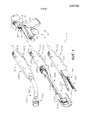
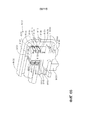
на ФИГ. 1 представлен вид в перспективе модульной хирургической системы, содержащей хирургический инструмент с приводом и три взаимозаменяемых концевых эффектора;in FIG. 1 is a perspective view of a modular surgical system comprising a surgical instrument with a drive and three interchangeable end effectors;
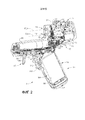
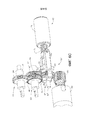
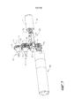
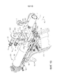
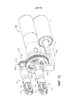
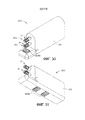
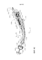
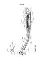
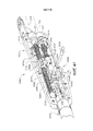
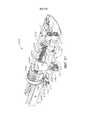
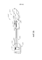
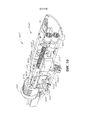
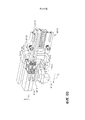
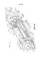
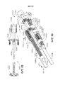
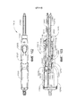
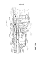
на ФИГ. 2 представлен вид сбоку в перспективе хирургического инструмента с приводом, причем участок корпуса рукоятки удален для ясности;in FIG. 2 is a perspective side view of a surgical instrument with a drive, the portion of the handle body removed for clarity;
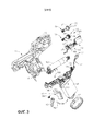
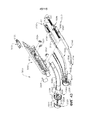
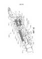
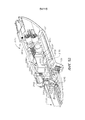
на ФИГ. 3 представлен частичный вид с пространственным разделением компонентов узла хирургического инструмента, изображенного на ФИГ. 2;in FIG. 3 is a partial exploded view of the components of the surgical instrument assembly of FIG. 2;
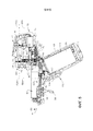
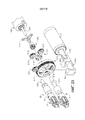
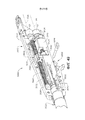
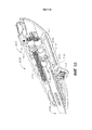
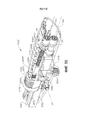
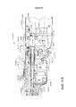
на ФИГ. 4 представлен другой вид с пространственным разделением компонентов хирургического инструмента, изображенного на ФИГ. 2 и 3;in FIG. 4 presents another view with a spatial separation of the components of the surgical instrument depicted in FIG. 2 and 3;
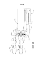
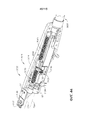
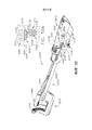
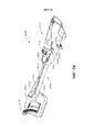
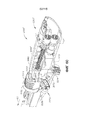
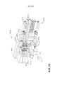
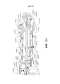
на ФИГ. 5 представлен вид сбоку в вертикальной проекции хирургического инструмента с приводом, причем участок корпуса рукоятки удален;in FIG. 5 is a side elevational view of a surgical instrument with a drive, the handle body portion being removed;
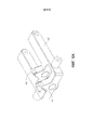
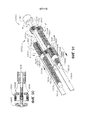
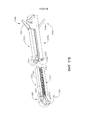
на ФИГ. 6 представлен вид в перспективе электроприводной системы и узла трансмиссии, причем узел трансмиссии находится в первом приводном положении, при этом активация двигателя приведет к активации первой приводной системы хирургического инструмента, изображенного на ФИГ. 2-5;in FIG. 6 is a perspective view of an electric drive system and a transmission assembly, wherein the transmission assembly is in a first drive position, and activation of the engine will activate the first drive system of the surgical instrument shown in FIG. 2-5;
на ФИГ. 6A представлен вид в перспективе альтернативной передаточной каретки с блокирующими механизмами;in FIG. 6A is a perspective view of an alternative transmission carriage with locking mechanisms;
на ФИГ. 6B представлен вид в перспективе электроприводной системы и узла трансмиссии, включающего в себя передаточную каретку, изображенную на ФИГ. 6A, причем узел трансмиссии находится в первом приводном положении, при этом активация двигателя приведет к активации первой приводной системы, а вторая приводная система заблокирована блокирующими механизмами;in FIG. 6B is a perspective view of an electric drive system and a transmission assembly including a transmission carriage shown in FIG. 6A, wherein the transmission unit is in the first drive position, wherein activating the engine will activate the first drive system, and the second drive system is blocked by locking mechanisms;
на ФИГ. 6C представлен вид в перспективе электроприводной системы и узла трансмиссии, изображенных на ФИГ. 6B, причем узел трансмиссии находится во втором приводном положении, при этом активация двигателя приведет к активации второй приводной системы, а первая приводная система заблокирована блокирующими механизмами;in FIG. 6C is a perspective view of an electric drive system and a transmission assembly shown in FIG. 6B, wherein the transmission unit is in the second drive position, wherein activating the engine will activate the second drive system, and the first drive system is blocked by locking mechanisms;
на ФИГ. 7 представлен еще один вид в перспективе электроприводной системы и узла трансмиссии, изображенных на ФИГ. 6, причем узел трансмиссии находится во втором приводном положении, при этом активация двигателя приведет к активации второй приводной системы;in FIG. 7 is yet another perspective view of the electric drive system and transmission assembly shown in FIG. 6, wherein the transmission unit is in the second drive position, wherein activation of the engine will activate the second drive system;
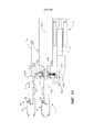
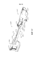
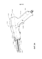
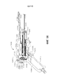
на ФИГ. 8 представлен вид сбоку в вертикальной проекции другого хирургического инструмента с приводом, причем участок корпуса рукоятки и другие его участки опущены для ясности;in FIG. 8 is a side elevational view of another surgical instrument with a drive, wherein a portion of the handle body and other portions thereof are omitted for clarity;
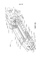
на ФИГ. 9 представлен вид в перспективе двигателя, узла трансмиссии и первой и второй приводных систем хирургического инструмента, изображенного на ФИГ. 8, причем узел трансмиссии находится в первом приводном положении;in FIG. 9 is a perspective view of an engine, transmission assembly, and first and second drive systems of a surgical instrument shown in FIG. 8, wherein the transmission assembly is in a first drive position;
на ФИГ. 10 представлен вид в поперечном сечении в вертикальной проекции двигателя, узла трансмиссии и первой и второй приводных систем, изображенных на ФИГ. 9, причем узел трансмиссии находится в первом приводном положении;in FIG. 10 is a cross-sectional elevational view of an engine, a transmission assembly, and first and second drive systems shown in FIG. 9, wherein the transmission assembly is in a first drive position;
на ФИГ. 11 представлен другой вид в перспективе двигателя, узла трансмиссии и первой и второй приводных систем, изображенных на ФИГ. 9 и 10, причем узел трансмиссии находится во втором приводном положении;in FIG. 11 is a different perspective view of an engine, a transmission assembly, and first and second drive systems shown in FIG. 9 and 10, wherein the transmission unit is in a second drive position;
на ФИГ. 12 представлен еще один вид в поперечном сечении в вертикальной проекции двигателя, узла трансмиссии и первой и второй приводных систем, изображенных на ФИГ. 9-11, причем узел трансмиссии находится во втором приводном положении;in FIG. 12 is yet another cross-sectional view in vertical view of the engine, transmission assembly, and first and second drive systems shown in FIG. 9-11, wherein the transmission unit is in a second drive position;
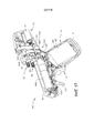
на ФИГ. 13 представлен частичный вид сзади в перспективе участка другого хирургического инструмента с приводом;in FIG. 13 is a partial rear perspective view of a portion of another surgical instrument with a drive;
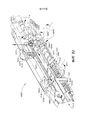
на ФИГ. 14 представлен вид сбоку в вертикальной проекции двигателя, узла трансмиссии и первой и второй приводных систем хирургического инструмента, изображенного на ФИГ. 13;in FIG. 14 is a side elevational view of the engine, transmission assembly, and the first and second drive systems of the surgical instrument of FIG. 13;
на ФИГ. 15 представлен вид в поперечном сечении узла трансмиссии хирургического инструмента, изображенного на ФИГ. 13 и 14, в первом положении привода;in FIG. 15 is a cross-sectional view of the transmission assembly of the surgical instrument shown in FIG. 13 and 14, in a first position of the actuator;
на ФИГ. 16 представлен другой вид в поперечном сечении узла трансмиссии хирургического инструмента, изображенного на ФИГ. 13-15, во втором положении привода;in FIG. 16 is another cross-sectional view of the transmission assembly of the surgical instrument of FIG. 13-15, in the second position of the drive;
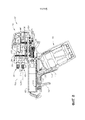
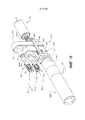
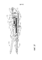
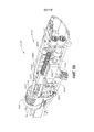
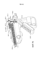
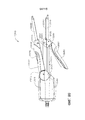
на ФИГ. 17 представлен вид в перспективе другой конструкции хирургического инструмента с приводом, причем участок корпуса удален для ясности;in FIG. 17 is a perspective view of another construction of a surgical surgical instrument with a drive, the body portion being removed for clarity;
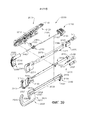
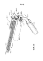
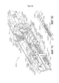
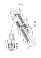
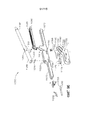
на ФИГ. 18 представлен вид в перспективе двигателя, узла трансмиссии и первой и второй приводных систем хирургического инструмента, изображенного на ФИГ. 17;in FIG. 18 is a perspective view of an engine, a transmission assembly, and first and second drive systems of a surgical instrument of FIG. 17;
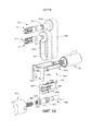
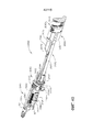
на ФИГ. 19 представлен общий вид с пространственным разделением компонентов двигателя, узла трансмиссии и первой и второй приводных систем, изображенных на ФИГ. 18;in FIG. 19 is a perspective view of a spatial separation of engine components, a transmission assembly, and first and second drive systems shown in FIG. eighteen;
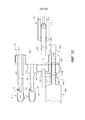
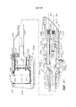
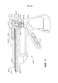
на ФИГ. 20 представлен вид в поперечном сечении участков двигателя, узла трансмиссии и первой и второй приводных систем, изображенных на ФИГ. 18 и 19, причем узел передаточного вала находится в первом приводном положении;in FIG. 20 is a cross-sectional view of portions of an engine, a transmission assembly, and first and second drive systems shown in FIG. 18 and 19, wherein the transmission shaft assembly is in a first drive position;
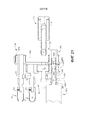
на ФИГ. 21 представлен другой вид в поперечном сечении участков двигателя, узла трансмиссии и первой и второй приводных систем, изображенных на ФИГ. 20, причем узел передаточного стержня находится в первом приводном положении;in FIG. 21 is a different cross-sectional view of portions of an engine, a transmission assembly, and first and second drive systems shown in FIG. 20, wherein the transmission rod assembly is in a first drive position;
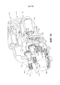
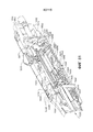
на ФИГ. 22 представлен вид в перспективе другого двигателя, узла трансмиссии и первой и второй приводных систем одной формы хирургического инструмента настоящего изобретения;in FIG. 22 is a perspective view of another engine, transmission assembly, and first and second drive systems of one form of surgical instrument of the present invention;
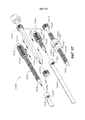
на ФИГ. 23 представлен общий вид с пространственным разделением компонентов двигателя, узла трансмиссии и первой и второй приводных систем, изображенных на ФИГ. 22;in FIG. 23 is a perspective view of a spatial separation of engine components, a transmission assembly, and first and second drive systems shown in FIG. 22;
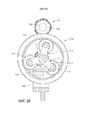
на ФИГ. 24 представлен вид в поперечном сечении двигателя, узла трансмиссии и первой и второй приводных систем, изображенных на ФИГ. 22 и 23, причем узел трансмиссии находится в первом приводном положении;in FIG. 24 is a cross-sectional view of an engine, a transmission assembly, and first and second drive systems shown in FIG. 22 and 23, wherein the transmission unit is in a first drive position;
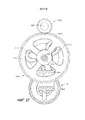
на ФИГ. 25 представлен еще один вид в поперечном сечении двигателя, узла трансмиссии и первой и второй приводных систем, изображенных на ФИГ. 22-24, причем узел трансмиссии находится во втором приводном положении;in FIG. 25 is another cross-sectional view of an engine, a transmission assembly, and first and second drive systems shown in FIG. 22-24, wherein the transmission assembly is in a second drive position;
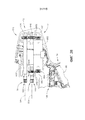
на ФИГ. 26 представлен еще один вид в поперечном сечении двигателя и узла трансмиссии, изображенных на ФИГ. 22-25, причем узел трансмиссии находится в первом приводном положении;in FIG. 26 is yet another cross-sectional view of the engine and transmission assembly of FIG. 22-25, wherein the transmission assembly is in a first drive position;
на ФИГ. 27 представлен еще один вид в поперечном сечении двигателя и узла трансмиссии, изображенных на ФИГ. 22-26, причем узел трансмиссии находится во втором приводном положении;in FIG. 27 is another cross-sectional view of an engine and a transmission assembly shown in FIG. 22-26, and the transmission unit is in the second drive position;
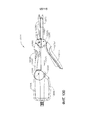
на ФИГ. 28 представлен вид сбоку в вертикальной проекции участка другого хирургического инструмента с приводом, причем участок корпуса удален для ясности;in FIG. 28 is a side elevational view of a portion of another surgical instrument with a drive, the portion of the body removed for clarity;
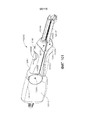
на ФИГ. 29 представлен вид в перспективе участка другого хирургического инструмента с приводом, причем участок корпуса удален для ясности;in FIG. 29 is a perspective view of a portion of another surgical instrument with a drive, the portion of the body removed for clarity;
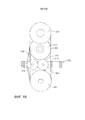
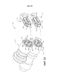
на ФИГ. 30 представлен вид спереди в перспективе блока с приводом с первой и второй системами вращательных приводов;in FIG. 30 is a front perspective view of a drive unit with first and second rotary drive systems;
на ФИГ. 31 представлен вид в перспективе блока с приводом, изображенного на ФИГ. 30;in FIG. 31 is a perspective view of the drive unit shown in FIG. thirty;
на ФИГ. 32 представлен вид в перспективе блока с приводом, изображенного на ФИГ. 31 и 32, с которого удален корпус;in FIG. 32 is a perspective view of the drive unit shown in FIG. 31 and 32, from which the housing is removed;
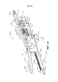
на ФИГ. 33 представлен общий вид с пространственным разделением компонентов механической соединительной системы для функционального соединения друг с другом четырех вращательных приводных валов; in FIG. 33 is a perspective view of the spatial separation of the components of a mechanical coupling system for the functional interconnection of four rotational drive shafts;
на ФИГ. 34 представлен вид спереди в перспективе хирургического концевого эффектора, причем участок корпуса концевого эффектора удалена для ясности; in FIG. 34 is a front perspective view of a surgical end effector, wherein a portion of the end effector body is removed for clarity;
на ФИГ. 35 представлен другой вид спереди в перспективе хирургического концевого эффектора, изображенного на ФИГ. 34, причем участки закрывающей системы и нижней бранши опущены для ясности; in FIG. 35 is another front perspective view of the surgical end effector of FIG. 34, wherein portions of the closure system and lower jaw are omitted for clarity;
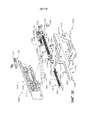
на ФИГ. 36 представлен общий вид в перспективе с пространственным разделением компонентов хирургического концевого эффектора, изображенного на ФИГ. 34 и 35;in FIG. 36 is a perspective perspective view of the spatial separation of the components of the surgical end effector shown in FIG. 34 and 35;
на ФИГ. 37 представлен вид в вертикальной проекции сбоку хирургического концевого эффектора, изображенного на ФИГ. 33-36, причем участок корпуса опущен для ясности;in FIG. 37 is a side elevational view of the surgical end effector shown in FIG. 33-36, with a portion of the body omitted for clarity;
на ФИГ. 38 представлен вид в перспективе сбоку слева другой конструкции концевого эффектора, причем участок корпуса концевого эффектора опущен для ясности;in FIG. 38 is a left side perspective view of another end effector design, a portion of the end effector housing being omitted for clarity;
на ФИГ. 39 представлен общий вид с пространственным разделением компонентов концевого эффектора, изображенного на ФИГ. 38; in FIG. 39 is a perspective view of the spatial separation of the components of the end effector shown in FIG. 38;
на ФИГ. 40 представлен вид в перспективе сбоку конструкции концевого эффектора, изображенного на ФИГ. 37 и 38, причем другой участок концевого эффектора опущен для ясности;in FIG. 40 is a perspective side view of the structure of the end effector shown in FIG. 37 and 38, wherein another portion of the end effector is omitted for clarity;
на ФИГ. 41 представлен вид в поперечном сечении конструкции концевого эффектора, представленного на ФИГ. 38-40;in FIG. 41 is a cross-sectional view of an end effector structure shown in FIG. 38-40;
на ФИГ. 42 представлен вид в поперечном сечении в перспективе другого варианта осуществления хирургического концевого эффектора;in FIG. 42 is a cross-sectional perspective view of another embodiment of a surgical end effector;
на ФИГ. 43 представлен частичный общий вид с пространственным разделением компонентов хирургического концевого эффектора, представленного на ФИГ. 42;in FIG. 43 is a partial general view with a spatial separation of the components of the surgical end effector shown in FIG. 42;
на ФИГ. 44 представлен другой частичный вид в перспективе участка хирургического концевого эффектора, изображенного на ФИГ. 42 и 43;in FIG. 44 is another partial perspective view of a portion of the surgical end effector of FIG. 42 and 43;
на ФИГ. 45 представлен другой вид в поперечном сечении хирургического концевого эффектора, представленного на ФИГ. 42-44;in FIG. 45 is another cross-sectional view of the surgical end effector of FIG. 42-44;
на ФИГ. 46 представлен вид в перспективе конструкции концевого эффектора с узлом высвобождения привода; in FIG. 46 is a perspective view of an end effector structure with a drive release assembly;
на ФИГ. 47 представлен частичный вид в перспективе хирургического концевого эффектора, изображенного на ФИГ. 46, некоторые участки которого опущены для ясности и проксимальный участок приводного механизма закрывающей системы отсоединена от дистального участка приводного механизма закрывающей системы;in FIG. 47 is a partial perspective view of the surgical end effector of FIG. 46, some portions of which are omitted for clarity and the proximal portion of the drive mechanism of the closing system is disconnected from the distal portion of the drive mechanism of the closing system;
на ФИГ. 48 представлен частичный вид в перспективе хирургического концевого эффектора, изображенного на ФИГ. 46 и 47, причем его участки опущены для ясности, дистальный соединительный элемент установлен в паз проксимального соединительного элемента, а соединительный штифт привода удален из них;in FIG. 48 is a partial perspective view of the surgical end effector of FIG. 46 and 47, whereby its portions are omitted for clarity, the distal connecting element is installed in the groove of the proximal connecting element, and the connecting pin of the drive is removed from them;
на ФИГ. 49 представлен другой частичный вид в перспективе хирургического концевого эффектора, изображенного на ФИГ. 48, демонстрирующий участки пусковой системы концевого эффектора;in FIG. 49 is another partial perspective view of the surgical end effector of FIG. 48, showing portions of the starting system of the end effector;
на ФИГ. 50 представлен вид в перспективе другой конструкции хирургического концевого эффектора;in FIG. 50 is a perspective view of another construction of a surgical end effector;
на ФИГ. 50A представлен увеличенный вид участка хирургического концевого эффектора, показанного на ФИГ. 50; in FIG. 50A is an enlarged view of a portion of the surgical end effector shown in FIG. fifty;
на ФИГ. 51 представлен вид в перспективе участка концевого эффектора, изображенного на ФИГ. 50, причем участок корпуса опущен для ясности;in FIG. 51 is a perspective view of a portion of the end effector shown in FIG. 50, wherein a portion of the housing is omitted for clarity;
на ФИГ. 52 представлен еще один вид в перспективе концевого эффектора, изображенного на ФИГ. 50 и 51, причем участки корпуса и закрывающей системы опущены для ясности; in FIG. 52 is yet another perspective view of the end effector shown in FIG. 50 and 51, with portions of the housing and closure system omitted for clarity;
на ФИГ. 53 представлен другой вид в перспективе концевого эффектора, изображенного на ФИГ. 50-52, причем участки закрывающей системы и участок корпуса опущены для ясности;in FIG. 53 is a different perspective view of the end effector shown in FIG. 50-52, the portions of the closing system and the portion of the housing omitted for clarity;
на ФИГ. 54 представлен вид в перспективе другого концевого эффектора, который оборудован узлом высвобождения привода; in FIG. 54 is a perspective view of another end effector that is equipped with a drive release assembly;
на ФИГ. 55 показан вид сбоку в вертикальной проекции концевого эффектора, изображенного на ФИГ. 54;in FIG. 55 is a side elevational view of the end effector shown in FIG. 54;
на ФИГ. 56 представлен вид в перспективе участка концевого эффектора, изображенного на ФИГ. 54 и 55, причем участок корпуса концевого эффектора опущен для ясности;in FIG. 56 is a perspective view of a portion of the end effector shown in FIG. 54 and 55, wherein the portion of the end effector casing is omitted for clarity;
на ФИГ. 57 представлен другой вид в перспективе концевого эффектора, показанного на ФИГ. 54-56, на котором головка инструмента находится в закрытом положении;in FIG. 57 is a different perspective view of the end effector shown in FIG. 54-56, on which the tool head is in the closed position;
на ФИГ. 58 представлен другой частичный вид в перспективе концевого эффектора, изображенного на ФИГ. 57, причем участок корпуса концевого эффектора опущен для ясности; in FIG. 58 is another partial perspective view of the end effector shown in FIG. 57, wherein a portion of the end effector casing is omitted for clarity;
на ФИГ. 59 представлен другой вид в перспективе концевого эффектора, изображенного на ФИГ. 58, причем соединительный штифт привода удален;in FIG. 59 is a different perspective view of the end effector shown in FIG. 58, the drive connecting pin being removed;
на ФИГ. 60 представлен другой вид в перспективе концевого эффектора, изображенного на ФИГ. 59, с удаленным соединительным штифтом привода и узлом балки закрывающего привода, перемещенным проксимально для открытия головки инструмента; in FIG. 60 is another perspective view of the end effector shown in FIG. 59, with the drive actuator pin removed and the beam assembly of the closing actuator displaced proximally to open the tool head;
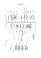
на ФИГ. 61 представлена блок-схема модульного хирургического инструмента с приводом, содержащего рукояточный участок и стволовой участок;in FIG. 61 is a block diagram of a modular surgical instrument with a drive comprising a grip portion and a stem portion;
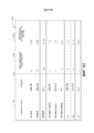
на ФИГ. 62 представлена таблица, демонстрирующая общее время выполнения рабочего такта и требования по нагрузочному току для различных операций различных стволов устройства;in FIG. 62 is a table showing the total execution time of the working cycle and the requirements for the load current for various operations of various device trunks;
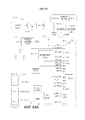
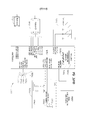
на ФИГ. 63, которая разделена на ФИГ. 63-A и 63-B, представлена подробная схема электрической системы в рукояточном участке модульного хирургического инструмента с приводом;in FIG. 63, which is divided into FIG. 63-A and 63-B, presents a detailed diagram of the electrical system in the handle section of a modular surgical instrument with a drive;
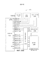
на ФИГ. 64 представлена блок-схема электрической системы рукояточного и стволового участков модульного хирургического инструмента с приводом;in FIG. 64 is a block diagram of an electric system of a grip and stem sections of a modular surgical instrument with a drive;
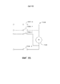
на ФИГ. 65 показана механическая переключательная система управления движениями для устранения микропроцессорного управления функциями двигателя;in FIG. 65 shows a mechanical switching motion control system for eliminating microprocessor control of engine functions;
на ФИГ. 66 представлен вид в перспективе соединительной конструкции, содержащей корпус соединителя и пару гнезд внутри корпуса соединителя в соответствии с различными вариантами осуществления настоящего изобретения;in FIG. 66 is a perspective view of a connecting structure comprising a connector housing and a pair of sockets within a connector housing in accordance with various embodiments of the present invention;
на ФИГ. 67 представлен вид в поперечном сечении в перспективе соединительной конструкции, изображенной на ФИГ. 66, представляющий пару приводных элементов, отсоединенных от пары гнезд, и дополнительно показывающий соединительную конструкцию в незаблокированной конфигурации в соответствии с различными вариантами осуществления настоящего изобретения;in FIG. 67 is a perspective cross-sectional view of the connecting structure shown in FIG. 66, representing a pair of drive elements disconnected from a pair of sockets, and further showing a connecting structure in an unlocked configuration in accordance with various embodiments of the present invention;
на ФИГ. 68 представлен вид в поперечном сечении в перспективе соединительной конструкции, изображенной на ФИГ. 66, показывающий пару приводных элементов, соединенных с парой гнезд, и дополнительно показывающий соединительную конструкцию в заблокированной конфигурации в соответствии с различными вариантами осуществления настоящего изобретения;in FIG. 68 is a perspective cross-sectional view of the connecting structure shown in FIG. 66, showing a pair of drive elements coupled to a pair of sockets, and further showing a connecting structure in a locked configuration in accordance with various embodiments of the present invention;
на ФИГ. 69 представлен вид в поперечном сечении в перспективе соединительной конструкции, изображенной на ФИГ. 66, показывающий пару приводных элементов, соединенных с парой гнезд, и дополнительно показывающий соединительную конструкцию в незаблокированной конфигурации в соответствии с различными вариантами осуществления настоящего изобретения;in FIG. 69 is a perspective cross-sectional view of the connecting structure shown in FIG. 66, showing a pair of drive elements coupled to a pair of sockets, and further showing a connecting structure in an unlocked configuration in accordance with various embodiments of the present invention;
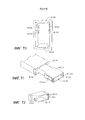
на ФИГ. 70 представлен вид в перспективе вставки соединительной конструкции, изображенной на ФИГ. 66, в соответствии с различными вариантами осуществления настоящего изобретения;in FIG. 70 is a perspective view of the insert of the connecting structure shown in FIG. 66, in accordance with various embodiments of the present invention;
на ФИГ. 71 представлен вид в перспективе гнезда соединительной конструкции, изображенной на ФИГ. 66, в соответствии с различными вариантами осуществления настоящего изобретения;in FIG. 71 is a perspective view of a socket of the connecting structure shown in FIG. 66, in accordance with various embodiments of the present invention;
на ФИГ. 72 представлен вид в перспективе защелки соединительной конструкции, изображенной на ФИГ. 66, в соответствии с различными вариантами осуществления настоящего изобретения;in FIG. 72 is a perspective view of a latch of the connecting structure shown in FIG. 66, in accordance with various embodiments of the present invention;
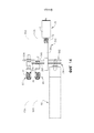
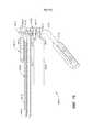
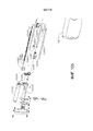
на ФИГ. 73 представлен вид в поперечном сечении в вертикальной проекции хирургического концевого эффектора-насадки для применения с рукояткой хирургического инструмента в соответствии с различными вариантами осуществления настоящего изобретения;in FIG. 73 is a cross-sectional elevational view of a surgical end effector nozzle for use with a surgical instrument handle in accordance with various embodiments of the present invention;
на ФИГ. 74 представлен вид в перспективе с пространственным разделением компонентов приводных систем хирургического концевого эффектора-насадки, изображенной на ФИГ. 73, в соответствии с различными вариантами осуществления настоящего изобретения;in FIG. 74 is a perspective view with a spatial separation of the components of the drive systems of the surgical end effector nozzle shown in FIG. 73, in accordance with various embodiments of the present invention;
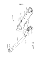
на ФИГ. 75 представлен вид в перспективе рукоятки для хирургического инструмента, причем рукоятка содержит приводную систему, имеющую первый выходной приводной узел и второй выходной приводной узел в соответствии с различными вариантами осуществления настоящего изобретения;in FIG. 75 is a perspective view of a handle for a surgical instrument, the handle comprising a drive system having a first output drive unit and a second output drive unit in accordance with various embodiments of the present invention;
на ФИГ. 76 представлен вид в перспективе приводной системы, изображенной на ФИГ. 75, в соответствии с различными вариантами осуществления настоящего изобретения;in FIG. 76 is a perspective view of the drive system shown in FIG. 75, in accordance with various embodiments of the present invention;
на ФИГ. 77 представлен вид в поперечном сечении в вертикальной проекции рукоятки, изображенной на ФИГ. 75, показывающий приводную систему, взаимодействующую с первым выходным приводным узлом и высвобожденную от второго выходного приводного узла в соответствии с различными вариантами осуществления настоящего изобретения; in FIG. 77 is a cross-sectional elevational view of the handle depicted in FIG. 75, showing a drive system cooperating with a first output drive unit and released from a second output drive unit in accordance with various embodiments of the present invention;
на ФИГ. 78 представлен вид в поперечном сечении в вертикальной проекции приводной системы, изображенной на ФИГ. 75, демонстрирующий приводную систему, взаимодействующую со вторым выходным приводным узлом и высвобожденную из взаимодействия с первым выходным приводным узлом в соответствии с различными вариантами осуществления настоящего изобретения;in FIG. 78 is a cross-sectional elevational view of the drive system shown in FIG. 75, showing a drive system cooperating with a second output drive unit and released from interaction with a first output drive unit in accordance with various embodiments of the present invention;
на ФИГ. 79 представлен частичный вид в поперечном сечении в перспективе хирургического инструмента, включающего в себя поворачиваемый приводной вал, закрывающий привод, приводимый в действие упомянутым приводным валом, и пусковой привод, приводимый в действие упомянутым приводным валом, причем закрывающий привод показан в частично открытой конфигурации, а пусковой привод показан в не запущенной конфигурации;in FIG. 79 is a partial cross-sectional perspective view of a surgical instrument including a rotatable drive shaft closing a drive driven by said drive shaft and a trigger drive driven by said drive shaft, wherein the closing drive is shown in a partially open configuration, and the starter drive is shown in a non-running configuration;
на ФИГ. 80 представлен вид в перспективе поворачиваемого приводного вала, изображенного на ФИГ. 79;in FIG. 80 is a perspective view of a rotatable drive shaft shown in FIG. 79;
на ФИГ. 81 представлен частичный вид в поперечном сечении в перспективе хирургического инструмента, изображенного на ФИГ. 79, с закрывающим приводом в открытой конфигурации и пусковым приводом в не запущенной конфигурации;in FIG. 81 is a partial cross-sectional perspective view of the surgical instrument of FIG. 79, with a closing drive in an open configuration and a starting drive in a non-running configuration;
на ФИГ. 82 представлен частичный вид в поперечном сечении в перспективе хирургического инструмента, изображенного на ФИГ. 79, с закрывающим приводом в закрытой конфигурации и пусковым приводом в не запущенной конфигурации;in FIG. 82 is a partial cross-sectional perspective view of the surgical instrument of FIG. 79, with a closing drive in a closed configuration and a starting drive in a non-running configuration;
на ФИГ. 83 представлен частичный вид в поперечном сечении в перспективе хирургического инструмента, изображенного на ФИГ. 79, с закрывающим приводом в закрытой конфигурации и пусковым приводом в запущенной конфигурации;in FIG. 83 is a partial cross-sectional perspective view of the surgical instrument of FIG. 79, with a closing drive in a closed configuration and a starting drive in a running configuration;
на ФИГ. 84 представлен частичный вид в поперечном сечении в перспективе хирургического инструмента, изображенного на ФИГ. 79, с пусковым приводом в оттянутой конфигурации и закрывающим приводом в процессе повторного открытия;in FIG. 84 is a partial cross-sectional perspective view of the surgical instrument of FIG. 79, with a start-up drive in a drawn configuration and a closing drive during re-opening;
на ФИГ. 85 представлен частичный вид в поперечном сечении концевого эффектора и ствола хирургического инструмента, изображенных в закрытой, не запущенной конфигурации;in FIG. 85 is a partial cross-sectional view of the end effector and the trunk of a surgical instrument, depicted in a closed, not running configuration;
на ФИГ. 86 представлен вид в перспективе трансмиссии для работы с хирургическим инструментом, изображенным на ФИГ. 85, в конфигурации, соответствующей конфигурации, показанной на ФИГ. 85;in FIG. 86 is a perspective view of a transmission for use with the surgical instrument depicted in FIG. 85, in a configuration corresponding to the configuration shown in FIG. 85;
на ФИГ. 87 представлен вид с пространственным разделением компонентов трансмиссии, показанной на ФИГ. 86;in FIG. 87 is an exploded view of the transmission components shown in FIG. 86;
на ФИГ. 88 представлен частичный вид в поперечном сечении концевого эффектора и ствола, представленного на ФИГ. 85, изображенных в открытой, не запущенной конфигурации;in FIG. 88 is a partial cross-sectional view of an end effector and a barrel shown in FIG. 85, depicted in an open, not running configuration;
на ФИГ. 89 представлен вид в перспективе трансмиссии, изображенной на ФИГ. 86, в конфигурации, соответствующей конфигурации, показанной на ФИГ. 88;in FIG. 89 is a perspective view of the transmission depicted in FIG. 86, in a configuration corresponding to the configuration shown in FIG. 88;
на ФИГ. 90 представлен частичный вид в поперечном сечении концевого эффектора и ствола, изображенного на ФИГ. 85, показанных в закрытой, не запущенной конфигурации;in FIG. 90 is a partial cross-sectional view of the end effector and the barrel shown in FIG. 85 shown in a closed, not running configuration;
на ФИГ. 91 представлен вид в перспективе трансмиссии, изображенной на ФИГ. 86, в конфигурации, соответствующей конфигурации, показанной на ФИГ. 90;in FIG. 91 is a perspective view of the transmission of FIG. 86, in a configuration corresponding to the configuration shown in FIG. 90;
на ФИГ. 92 представлен частичный вид в поперечном сечении концевого эффектора и ствола, изображенного на ФИГ. 85, показанных в закрытой, запущенной конфигурации;in FIG. 92 is a partial cross-sectional view of the end effector and the barrel shown in FIG. 85 shown in a closed, running configuration;
на ФИГ. 93 представлен вид в перспективе трансмиссии, изображенной на ФИГ. 86, в конфигурации, соответствующей конфигурации, показанной на ФИГ. 92;in FIG. 93 is a perspective view of the transmission depicted in FIG. 86, in a configuration corresponding to the configuration shown in FIG. 92;
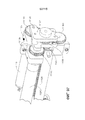
на ФИГ. 94 представлен вид в перспективе хирургического сшивающего инструмента в соответствии с по меньшей мере одним вариантом осуществления;in FIG. 94 is a perspective view of a surgical stapling instrument in accordance with at least one embodiment;
на ФИГ. 95 представлен вид с пространственным разделением компонентов рукоятки хирургического сшивающего инструмента, изображенного на ФИГ. 94;in FIG. 95 is an exploded view of the components of the handle of the surgical stapling instrument shown in FIG. 94;
на ФИГ. 96 представлен вид с пространственным разделением компонентов концевого эффектора хирургического сшивающего инструмента, изображенного на ФИГ. 94;in FIG. 96 is a perspective view of the components of the end effector of the surgical stapling instrument shown in FIG. 94;
на ФИГ. 97 представлен вид в перспективе двигателя и узла зубчатых колес хирургического сшивающего инструмента, изображенного на ФИГ. 94;in FIG. 97 is a perspective view of the engine and gear assembly of the surgical stapling instrument of FIG. 94;
на ФИГ. 98 представлен вид в вертикальной проекции в поперечном сечении хирургического сшивающего инструмента, изображенного на ФИГ. 94;in FIG. 98 is a cross-sectional elevational view of the surgical stapling instrument of FIG. 94;
на ФИГ. 99 представлен вид в перспективе хирургического сшивающего инструмента в соответствии с по меньшей мере одним вариантом осуществления, изображенным в открытом, незафиксированном состоянии;in FIG. 99 is a perspective view of a surgical stapling instrument in accordance with at least one embodiment depicted in an open, unfixed state;
на ФИГ. 100 представлен вид в перспективе хирургического сшивающего инструмента, изображенного на ФИГ. 99, в закрытом незафиксированном состоянии;in FIG. 100 is a perspective view of the surgical stapling instrument of FIG. 99, in a closed, unsecured state;
на ФИГ. 101 представлен вид в перспективе хирургического сшивающего инструмента, изображенного на ФИГ. 99, в закрытом зафиксированном состоянии;in FIG. 101 is a perspective view of the surgical stapling instrument of FIG. 99, in a closed, locked state;
на ФИГ. 102 представлен вид в горизонтальной проекции хирургического сшивающего инструмента, изображенного на ФИГ. 99;in FIG. 102 is a horizontal perspective view of the surgical stapling instrument shown in FIG. 99;
на ФИГ. 103 представлен вид в поперечном сечении хирургического сшивающего инструмента, изображенного на ФИГ. 99;in FIG. 103 is a cross-sectional view of the surgical stapling instrument of FIG. 99;
на ФИГ. 104 представлен подробный вид в поперечном сечении хирургического сшивающего инструмента, изображенного на ФИГ. 99;in FIG. 104 is a detailed cross-sectional view of the surgical stapling instrument of FIG. 99;
на ФИГ. 105 представлен вид с пространственным разделением компонентов пускового привода хирургического сшивающего инструмента, изображенного на ФИГ. 99;in FIG. 105 is an exploded view of the components of the starting drive of the surgical stapling instrument shown in FIG. 99;
на ФИГ. 106 представлен вид с пространственным разделением компонентов закрывающего привода хирургического сшивающего инструмента, изображенного на ФИГ. 99;in FIG. 106 is an exploded view of the components of the closure drive of the surgical stapling instrument of FIG. 99;
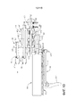
на ФИГ. 107 представлен вид в поперечном сечении хирургического сшивающего инструмента в соответствии с по меньшей мере одним вариантом осуществления, содержащим рукоятку, ствол и концевой эффектор;in FIG. 107 is a cross-sectional view of a surgical stapling instrument in accordance with at least one embodiment comprising a handle, a barrel, and an end effector;
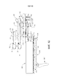
на ФИГ. 108 представлен вид в поперечном сечении рукоятки хирургического сшивающего инструмента, изображенного на ФИГ. 107, показанного в открытой конфигурации;in FIG. 108 is a cross-sectional view of the handle of the surgical stapling instrument of FIG. 107 shown in an open configuration;
на ФИГ. 109 представлен вид в поперечном сечении рукоятки хирургического сшивающего инструмента, изображенного на ФИГ. 107, показанного в закрытой конфигурации;in FIG. 109 is a cross-sectional view of the handle of the surgical stapling instrument shown in FIG. 107 shown in a closed configuration;
на ФИГ. 110 представлен вид в перспективе рукоятки хирургического сшивающего инструмента, изображенного на ФИГ. 107, причем некоторые компоненты удалены;in FIG. 110 is a perspective view of the handle of the surgical stapling instrument of FIG. 107, with some components removed;
на ФИГ. 111 представлен вид в перспективе хирургического сшивающего инструмента в соответствии с по меньшей мере одним вариантом осуществления, содержащим рукоятку и ствол;in FIG. 111 is a perspective view of a surgical stapling instrument in accordance with at least one embodiment comprising a handle and a barrel;
на ФИГ. 112 представлен вид в перспективе хирургического сшивающего инструмента, изображенного на ФИГ. 111, причем рукоятка отделена от ствола;in FIG. 112 is a perspective view of the surgical stapling instrument of FIG. 111, the handle being separate from the barrel;
на ФИГ. 113 представлен вид с пространственным разделением компонентов хирургического сшивающего инструмента, изображенного на ФИГ. 111;in FIG. 113 is a perspective view of the components of the surgical stapling instrument shown in FIG. 111;
на ФИГ. 114 представлен частичный вид в поперечном сечении рукоятки, изображенной на ФИГ. 111, демонстрирующий трансмиссию, функционально взаимодействующую с закрывающей системой хирургического сшивающего инструмента, изображенного на ФИГ. 111;in FIG. 114 is a partial cross-sectional view of the handle depicted in FIG. 111, showing a transmission operably interacting with the closure system of the surgical stapling instrument of FIG. 111;
на ФИГ. 115 представлен частичный вид в поперечном сечении рукоятки, изображенной на ФИГ. 111, показывающий трансмиссию, изображенную на ФИГ. 114, функционально взаимодействующую с пусковой системой хирургического сшивающего инструмента, изображенного на ФИГ. 111;in FIG. 115 is a partial cross-sectional view of the handle depicted in FIG. 111, showing the transmission depicted in FIG. 114, operatively interacting with the trigger system of the surgical stapling instrument shown in FIG. 111;
на ФИГ. 116 представлен вид с пространственным разделением компонентов трансмиссии, показанной на ФИГ. 114;in FIG. 116 is an exploded view of the transmission components shown in FIG. 114;
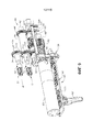
на ФИГ. 117 представлен вид в перспективе хирургического сшивающего инструмента в соответствии с по меньшей мере одним вариантом осуществления, причем некоторые компоненты удалены и показаны в открытой конфигурации;in FIG. 117 is a perspective view of a surgical stapling instrument in accordance with at least one embodiment, some components removed and shown in an open configuration;
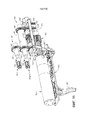
на ФИГ. 118 представлен вид в перспективе хирургического сшивающего инструмента, изображенного на ФИГ. 117, причем некоторые компоненты удалены и показаны в закрытой конфигурации;in FIG. 118 is a perspective view of the surgical stapling instrument of FIG. 117, some components removed and shown in a closed configuration;
на ФИГ. 119 представлен вид в перспективе другой конструкции концевого эффектора и варианта осуществления блока скоб к нему перед установкой блока скоб в концевой эффектор;in FIG. 119 is a perspective view of another construction of the end effector and an embodiment of the block of brackets to it before installing the block of brackets in the end effector;
на ФИГ. 120 представлен еще один вид в перспективе концевого эффектора и блока скоб, изображенных на ФИГ. 119, причем блок скоб установлен в концевой эффектор; иin FIG. 120 is yet another perspective view of an end effector and a block of staples shown in FIG. 119, the block of brackets mounted in the end effector; and
на ФИГ. 121 представлен другой вид в перспективе концевого эффектора и блока скоб, изображенных на ФИГ. 120, причем элемент держателя блока скоб с него удален.in FIG. 121 is another perspective view of an end effector and a block of staples shown in FIG. 120, wherein the element of the bracket block holder is removed from it.
Соответствующие элементы на разных видах обозначаются соответствующими условными обозначениями. Иллюстрации, прилагаемые к настоящей заявке, предназначены исключительно для демонстрации предпочтительных вариантов осуществления изобретения, они не должны толковаться как ограничивающие объем настоящего изобретения.Corresponding elements in different views are indicated by the corresponding symbols. The illustrations appended to this application are intended solely to demonstrate preferred embodiments of the invention, and should not be construed as limiting the scope of the present invention.
ПОДРОБНОЕ ОПИСАНИЕ ИЗОБРЕТЕНИЯDETAILED DESCRIPTION OF THE INVENTION
Заявителю настоящей заявки принадлежат нижеуказанные заявки на патенты, поданные 1 марта 2013 г., каждая из которых полностью включена в настоящий документ путем ссылки:The applicant of this application owns the following patent applications filed March 1, 2013, each of which is fully incorporated into this document by reference:
- заявка на патент США с серийным № 13/782 295, озаглавленная «ШАРНИРНО ПОВОРАЧИВАЕМЫЕ ХИРУРГИЧЕСКИЕ ИНСТРУМЕНТЫ С ПРОВОДЯЩИМИ ДОРОЖКАМИ ДЛЯ ПЕРЕДАЧИ СИГНАЛА»; - US Patent Application Serial No. 13/782 295, entitled “HINGED SURGICAL SURGERY TOOLS FOR SIGNAL TRANSMISSION”;
- заявка на патент США с серийным № 13/782 323, озаглавленная «ВРАЩАЮЩИЕСЯ ШАРНИРНЫЕ СОЧЛЕНЕНИЯ С ЭЛЕКТРОПИТАНИЕМ ДЛЯ ХИРУРГИЧЕСКИХ ИНСТРУМЕНТОВ»; - US Patent Application Serial No. 13/782 323, entitled “ROTATING HINGED ARTICLES WITH POWER SUPPLIES FOR SURGICAL INSTRUMENTS”;
- заявка на патент США с серийным № 13/782 338, озаглавленная «МЕХАНИЗМЫ ДИСКОВОГО ПЕРЕКЛЮЧАТЕЛЯ ДЛЯ ХИРУРГИЧЕСКИХ ИНСТРУМЕНТОВ»; - US Patent Application Serial No. 13/782 338, entitled “DISC SWITCH MECHANISMS FOR SURGICAL INSTRUMENTS”;
- заявка на патент США с серийным № 13/782 499, озаглавленная «ЭЛЕКТРОМЕХАНИЧЕСКОЕ ХИРУРГИЧЕСКОЕ УСТРОЙСТВО С МЕХАНИЗМОМ СИГНАЛЬНОГО РЕЛЕ»; - US Patent Application Serial No. 13/782 499, entitled "ELECTROMECHANICAL SURGICAL DEVICE WITH SIGNAL RELAY MECHANISM";
- заявка на патент США с серийным № 13/782 460, озаглавленная «МНОГОПРОЦЕССОРНАЯ СИСТЕМА УПРАВЛЕНИЯ ДВИГАТЕЛЕМ ДЛЯ МОДУЛЬНЫХ ХИРУРГИЧЕСКИХ ИНСТРУМЕНТОВ»; - US patent application serial number 13/782 460, entitled "MULTI-PROCESSOR ENGINE CONTROL SYSTEM FOR MODULAR SURGICAL INSTRUMENTS";
- заявка на патент США с серийным № 13/782 358, озаглавленная «УЗЛЫ РЫЧАЖНОГО ПЕРЕКЛЮЧАТЕЛЯ ДЛЯ ХИРУРГИЧЕСКИХ ИНСТРУМЕНТОВ»; - US Patent Application Serial No. 13/782 358, entitled “KNOBS FOR KNOB SWITCH FOR SURGICAL INSTRUMENTS”;
- заявка на патент США с серийным № 13/782 481, озаглавленная «КОНЦЕВОЙ ЭФФЕКТОР, ВЫПРЯМЛЯЕМЫЙ С ПОМОЩЬЮ ДАТЧИКА ВО ВРЕМЯ ИЗВЛЕЧЕНИЯ ЧЕРЕЗ ТРОКАР»; - US Patent Application Serial No. 13/782 481, entitled “END EFFECTOR RECTIFIED BY THE SENSOR DURING EXTRACTION THROUGH A TROCAR”;
- заявка на патент США с серийным № 13/782 518, озаглавленная «СПОСОБЫ УПРАВЛЕНИЯ ХИРУРГИЧЕСКИМИ ИНСТРУМЕНТАМИ СО СЪЕМНЫМИ РАБОЧИМИ ЧАСТЯМИ»; - US Patent Application Serial No. 13/782 518, entitled “METHODS FOR MANAGING SURGICAL INSTRUMENTS WITH REMOVABLE WORKING PARTS”;
- заявка на патент США с серийным № 13/782 375, озаглавленная «ВРАЩАЮЩИЕСЯ ХИРУРГИЧЕСКИЕ ИНСТРУМЕНТЫ С ЭЛЕКТРОПИТАНИЕМ С МНОЖЕСТВОМ СТЕПЕНЕЙ СВОБОДЫ»; и - US Patent Application Serial No. 13/782 375, entitled “ROTATING SURGICAL INSTRUMENTS WITH POWER SUPPLIES WITH MANY DEGREES OF FREEDOM”; and
- заявка на патент США с серийным № 13/782 536, озаглавленная «МЯГКИЙ ОГРАНИЧИТЕЛЬ ХОДА ДЛЯ ХИРУРГИЧЕСКОГО ИНСТРУМЕНТА», которые полностью включены в настоящий документ путем ссылки.- US Patent Application Serial No. 13/782 536, entitled “SOFT SURGICAL RESTRICTOR FOR SURGICAL INSTRUMENT”, which are incorporated herein by reference in their entirety.
Заявителю настоящей заявки также принадлежат нижеуказанные заявки на патенты, поданные 14 марта 2013 г., каждая из которых полностью включена в настоящий документ путем ссылки:The applicant of this application also owns the following patent applications filed March 14, 2013, each of which is fully incorporated into this document by reference:
- заявка на патент США с серийным № 13/803 097, озаглавленная «ШАРНИРНЫЙ ХИРУРГИЧЕСКИЙ ИНСТРУМЕНТ, СОДЕРЖАЩИЙ ПУСКОВОЙ ПРИВОД»;- US Patent Application Serial No. 13/803 097, entitled “HINGED SURGICAL INSTRUMENT CONTAINING THE START-UP DRIVE”;
- заявка на патент США с серийным 13/803 193, озаглавленная «УСТРОЙСТВА УПРАВЛЕНИЯ ДЛЯ ПРИВОДНОГО ЭЛЕМЕНТА ХИРУРГИЧЕСКОГО ИНСТРУМЕНТА»; - US Patent Application Serial 13/803 193, entitled “CONTROL DEVICES FOR DRIVING ELEMENT OF A SURGICAL INSTRUMENT”;
- заявка на патент США с серийным № 13/803 053, озаглавленная «ВЗАИМОЗАМЕНЯЕМЫЕ УЗЛЫ ВАЛОВ ДЛЯ ИСПОЛЬЗОВАНИЯ С ХИРУРГИЧЕСКИМ ИНСТРУМЕНТОМ»;- US Patent Application Serial No. 13/803 053, entitled “INTERCHANGEABLE SHAFT ASSEMBLIES FOR USE WITH SURGICAL INSTRUMENT”;
- заявка на патент США с порядковым № 13/803 086, озаглавленная «ШАРНИРНЫЙ ХИРУРГИЧЕСКИЙ ИНСТРУМЕНТ, СОДЕРЖАЩИЙ ФИКСАТОР ШАРНИРА»;- US Patent Application Serial No. 13/803 086, entitled “HINGED SURGICAL TOOL CONTAINING A HINGE LOCK”;
- заявка на патент США с серийным № 13/803 210, озаглавленная «КОМПОНОВКА ДАТЧИКА ДЛЯ СИСТЕМЫ АБСОЛЮТНОГО ПОЗИЦИОНИРОВАНИЯ ДЛЯ ХИРУРГИЧЕСКИХ ИНСТРУМЕНТОВ»;- US Patent Application Serial No. 13/803 210, entitled “SENSOR DESIGN FOR ABSOLUTE POSITIONING SYSTEM FOR SURGICAL INSTRUMENTS”;
- заявка на патент США с серийным № 13/803 148, озаглавленная «МНОГОФУНКЦИОНАЛЬНЫЙ ДВИГАТЕЛЬ ДЛЯ ХИРУРГИЧЕСКИХ ИНСТРУМЕНТОВ»;- US Patent Application Serial No. 13/803 148, entitled “MULTIFUNCTIONAL ENGINE FOR SURGICAL INSTRUMENTS”;
- заявка на патент США с серийным № 13/803 066, озаглавленная «КОНСТРУКЦИЯ БЛОКИРОВКИ ПРИВОДНОЙ СИСТЕМЫ ДЛЯ МОДУЛЬНЫХ ХИРУРГИЧЕСКИХ ИНСТРУМЕНТОВ»;- US Patent Application Serial No. 13/803 066, entitled “DESIGN LOCKING DRIVE SYSTEM FOR MODULAR SURGICAL INSTRUMENTS”;
- заявка на патент США с серийным № 13/803 117, озаглавленная «СИСТЕМА УПРАВЛЕНИЯ ШАРНИРНЫМИ СОЕДИНЕНИЯМИ ДЛЯ ШАРНИРНЫХ ХИРУРГИЧЕСКИХ ИНСТРУМЕНТОВ»;- US Patent Application Serial No. 13/803 117, entitled “HINGED CONTROL SYSTEM FOR HINGED SURGICAL INSTRUMENTS”;
- заявка на патент США сер. № 13/803,130, озаглавленная «КОНСТРУКЦИИ АВТОРЕГУЛИРОВКИ ПРИВОДНОГО МЕХАНИЗМА ДЛЯ МОДУЛЬНЫХ ХИРУРГИЧЕСКИХ ИНСТРУМЕНТОВ»; и- US patent application Ser. No. 13 / 803,130, entitled “AUTO ADJUSTMENT STRUCTURES OF THE DRIVE MECHANISM FOR MODULAR SURGICAL INSTRUMENTS”; and
- заявка на патент США сер. № 13/803,159, озаглавленная «СПОСОБ И СИСТЕМА ДЛЯ РАБОТЫ С ХИРУРГИЧЕСКИМ ИНСТРУМЕНТОМ».- US patent application Ser. No. 13 / 803,159, entitled “METHOD AND SYSTEM FOR WORKING WITH SURGICAL INSTRUMENT”.
Заявителю настоящей заявки принадлежат нижеуказанные заявки на патенты, поданные 25 марта 2014 г., каждая из которых полностью включена в настоящий документ путем ссылки:The applicant of this application owns the following patent applications filed March 25, 2014, each of which is fully incorporated into this document by reference:
заявка на патент США сер. № 14/226,106, озаглавленная «СИСТЕМЫ УПРАВЛЕНИЯ РАСПРЕДЕЛЕНИЕМ ЭЛЕКТРОПИТАНИЯ ДЛЯ ХИРУРГИЧЕСКИХ ИНСТРУМЕНТОВ»;US Patent Application Ser. No. 14 / 226.106, entitled “POWER DISTRIBUTION MANAGEMENT SYSTEMS FOR SURGICAL INSTRUMENTS”;
заявка на патент США сер. № 14/226,099, озаглавленная «СХЕМА ПРОВЕРКИ СТЕРИЛИЗАЦИИ»;US Patent Application Ser. No. 14 / 226,099, entitled “STERILIZATION CHECK DIAGRAM”;
заявка на патент США сер. № 14/226,094, озаглавленная «ПРОВЕРКА ЧИСЛА ЗАМЕН БАТАРЕИ/КОЛИЧЕСТВА ПРОЦЕДУР»;US Patent Application Ser. No. 14 / 226,094, entitled “CHECK THE NUMBER OF REPLACEMENT OF THE BATTERY / NUMBER OF PROCEDURES”;
заявка на патент США сер. № 14/226,117, озаглавленная «РАСПРЕДЕЛЕНИЕ ПИТАНИЯ ПРИ ПОМОЩИ ВАРИАНТОВ СПЯЩЕГО РЕЖИМА СЕГМЕНТИРОВАННОЙ СХЕМЫ И УПРАВЛЕНИЯ ВЫХОДОМ ИЗ СПЯЩЕГО РЕЖИМА»;US Patent Application Ser. No. 14 / 226,117, entitled “POWER DISTRIBUTION BY USING THE SLEEPING MODE OF THE SEGMENTED SCHEME AND MANAGING THE EXIT FROM THE SLEEPING MODE”;
заявка на патент США сер. № 14/226,075, озаглавленная «ХИРУРГИЧЕСКИЙ ИНСТРУМЕНТ С МОДУЛЬНЫМ ЭЛЕКТРОПИТАНИЕМ И С ОТСОЕДИНЯЕМЫМИ УЗЛАМИ СТВОЛА»;US Patent Application Ser. No. 14 / 226.075, entitled “SURGICAL INSTRUMENT WITH MODULAR POWER SUPPLIES AND WITH REMOVABLE STEM ASSEMBLIES”;
заявка на патент США сер. № 14/226,093, озаглавленная «АЛГОРИТМЫ ОБРАТНОЙ СВЯЗИ ДЛЯ РУЧНЫХ АВАРИЙНЫХ СИСТЕМ ХИРУРГИЧЕСКИХ ИНСТРУМЕНТОВ»;US Patent Application Ser. No. 14 / 226,093, entitled “FEEDBACK ALGORITHMS FOR MANUAL EMERGENCY SYSTEMS OF SURGICAL INSTRUMENTS”;
заявка на патент США сер. № 14/226,116, озаглавленная «ХИРУРГИЧЕСКИЙ ИНСТРУМЕНТ, ИСПОЛЬЗУЮЩИЙ АДАПТАЦИЮ ПО ДАТЧИКАМ»;US Patent Application Ser. No. 14 / 226,116, entitled “SURGICAL INSTRUMENT USING ADAPTATION BY SENSORS”;
заявка на патент США сер. № 14/226,071, озаглавленная «СХЕМА УПРАВЛЕНИЯ ХИРУРГИЧЕСКИМ ИНСТРУМЕНТОМ, ИМЕЮЩАЯ ПРОЦЕССОР БЕЗОПАСНОСТИ»;US Patent Application Ser. No. 14 / 226.071, entitled “SURGICAL INSTRUMENT MANAGEMENT SCHEME WITH A SAFETY PROCESSOR”;
заявка на патент США сер. № 14/226 097, озаглавленная «ХИРУРГИЧЕСКИЙ ИНСТРУМЕНТ, СОДЕРЖАЩИЙ ИНТЕРАКТИВНЫЕ СИСТЕМЫ»;US Patent Application Ser. No. 14/226 097, entitled “SURGICAL INSTRUMENT CONTAINING INTERACTIVE SYSTEMS”;
заявка на патент США сер. № 14/226 126, озаглавленная «СТЫКОВОЧНЫЕ СИСТЕМЫ ДЛЯ ПРИМЕНЕНИЯ С ХИРУРГИЧЕСКИМИ ИНСТРУМЕНТАМИ»;US Patent Application Ser. No. 14/226 126, entitled “DOCKING SYSTEMS FOR USE WITH SURGICAL INSTRUMENTS”;
заявка на патент США сер. № 14/226,133, озаглавленная «МОДУЛЬНАЯ СИСТЕМА ХИРУРГИЧЕСКОГО ИНСТРУМЕНТА»;US Patent Application Ser. No. 14 / 226,133, entitled “MODULAR SURGICAL INSTRUMENT SYSTEM”;
заявка на патент США сер. № 14/226,081, озаглавленная «СИСТЕМЫ И СПОСОБЫ УПРАВЛЕНИЯ СЕГМЕНТИРОВАННОЙ СХЕМОЙ»;US Patent Application Ser. No. 14 / 226,081, entitled “SYSTEMS AND METHODS FOR MANAGING A SEGMENTED DIAGRAM”;
заявка на патент США сер. № 14/226,076, озаглавленная «РАСПРЕДЕЛЕНИЕ ПИТАНИЯ ПРИ ПОМОЩИ СЕГМЕНТИРОВАННОЙ СХЕМЫ И ЗАЩИТА С ПЕРЕМЕННЫМ НАПРЯЖЕНИЕМ»;US Patent Application Ser. No. 14 / 226,076, entitled “POWER DISTRIBUTION BY MEANS OF A SEGMENTED DIAGRAM AND VARIABLE VOLTAGE PROTECTION”;
заявка на патент США с сер. № 14/226,111, озаглавленная «СИСТЕМА ХИРУРГИЧЕСКОГО СШИВАЮЩЕГО ИНСТРУМЕНТА»; иUS patent application Ser. No. 14 / 226,111, entitled “SYSTEM OF SURGICAL STAPLING INSTRUMENT”; and
заявка на патент США сер. № 14/226,125, озаглавленная «ХИРУРГИЧЕСКИЙ ИНСТРУМЕНТ, СОДЕРЖАЩИЙ ПОВОРАЧИВАЕМЫЙ СТВОЛ».US Patent Application Ser. No. 14 / 226.125, entitled “SURGICAL INSTRUMENT CONTAINING A TURNING BAR”.
Заявителю настоящей заявки также принадлежат нижеуказанные заявки на патенты, поданные в тот же день, причем каждая из них полностью включена в настоящий документ путем ссылки:The applicant of this application also owns the following patent applications filed on the same day, each of which is fully incorporated into this document by reference:
- заявка на патент США сер. № ___________, озаглавленная «ХИРУРГИЧЕСКИЕ ИНСТРУМЕНТЫ С ПРИВОДОМ С БЛОКИРУЕМЫМИ ДВОЙНЫМИ ПРИВОДНЫМИ ВАЛАМИ», досье патентного поверенного № END7406USNP/140054;- US patent application Ser. No. ___________, entitled “SURGICAL INSTRUMENTS WITH A DRIVE WITH LOCKED DOUBLE DRIVE SHAFT”, dossier of the patent attorney No. END7406USNP / 140054;
- заявка на патент США сер. № __________________, озаглавленная «ХИРУРГИЧЕСКИЙ ИНСТРУМЕНТ, СОДЕРЖАЩИЙ ЗАКРЫВАЮЩИЙ ПРИВОД И ПУСКОВОЙ ПРИВОД, УПРАВЛЯЕМЫЕ ОДНИМ ВРАЩАЮЩИМСЯ ВНЕШНИМ УСТРОЙСТВОМ», досье патентного поверенного № END7407USNP/140055;- US patent application Ser. No. __________________, entitled “SURGICAL INSTRUMENT CONTAINING A CLOSING DRIVE AND START-UP DRIVE CONTROLLED BY ONE ROTATING EXTERNAL DEVICE”, Patent Attorney File No. END7007US;
- заявка на патент США сер. № ___________, озаглавленная «СТВОЛ ХИРУРГИЧЕСКОГО ИНСТРУМЕНТА, СОДЕРЖАЩИЙ ПЕРЕКЛЮЧАТЕЛИ ДЛЯ УПРАВЛЕНИЯ РАБОТОЙ ХИРУРГИЧЕСКОГО ИНСТРУМЕНТА», досье патентного поверенного № END7408USNP/140056;- US patent application Ser. No. ___________, entitled “BARRING OF A SURGICAL INSTRUMENT CONTAINING SWITCHES FOR MANAGING THE WORK OF A SURGICAL INSTRUMENT”, dossier of the patent attorney No. END7408USNP / 140056;
- заявка на патент США сер. № ___________, озаглавленная «ЛИНЕЙНЫЙ ХИРУРГИЧЕСКИЙ СШИВАЮЩИЙ ИНСТРУМЕНТ С ЭЛЕКТРОПИТАНИЕМ», досье патентного поверенного № END7409USNP/140057;- US patent application Ser. No. ___________, entitled “LINEAR SURGICAL STAPLING TOOL WITH POWER SUPPLY”, file of patent attorney No. END7409USNP / 140057;
- заявка на патент США сер. № ___________, озаглавленная «КОНСТРУКЦИЯ ТРАНСМИССИИ ДЛЯ ХИРУРГИЧЕСКОГО ИНСТРУМЕНТА», досье патентного поверенного № END7410USNP/140058;- US patent application Ser. No. ___________, entitled “TRANSMISSION DESIGN FOR SURGICAL INSTRUMENT”, file of the patent attorney No. END7410USNP / 140058;
- заявка на патент США сер. № ___________, озаглавленная «МОДУЛЬНЫЕ ХИРУРГИЧЕСКИЕ ИНСТРУМЕНТЫ С ПРИВОДОМ С ВЫРАВНИВАЮЩИМИ ЭЛЕМЕНТАМИ ДЛЯ ВЫРАВНИВАНИЯ ВРАЩАТЕЛЬНЫХ ПРИВОДНЫХ ВАЛОВ С ВАЛАМИ ХИРУРГИЧЕСКОГО КОНЦЕВОГО ЭФФЕКТОРА», досье патентного поверенного № END7411USNP/140059;- US patent application Ser. No. ___________, entitled “MODULAR SURGICAL INSTRUMENTS WITH A DRIVE WITH LEVELING ELEMENTS FOR ALIGNING A ROTARY DRIVE SHAFT WITH A SHAFT OF A SURGICAL END EFFECTOR”, No. 11 EN1400;
- заявка на патент США сер. № ___________, озаглавленная «КОНСТРУКЦИЯ ДЛЯ ОТСОЕДИНЕНИЯ ПРИВОДНОЙ СИСТЕМЫ ДЛЯ ХИРУРГИЧЕСКОГО ИНСТРУМЕНТА», досье патентного поверенного № END7413USNP/140061; и- US patent application Ser. No. ___________, entitled “DESIGN FOR DISCONNECTING THE DRIVE SYSTEM FOR A SURGICAL INSTRUMENT”, dossier of the patent attorney No. END7413USNP / 140061; and
- заявка на патент США сер. № ___________, озаглавленная «МОДУЛЬНЫЕ ХИРУРГИЧЕСКИЕ ИНСТРУМЕНТЫ С ПРИВОДОМ С КОНСТРУКЦИЯМИ ДЛЯ УКАЗАНИЯ СОСТОЯНИЯ», досье патентного поверенного № END7414USNP/140062.- US patent application Ser. No. ___________, entitled “MODULAR SURGICAL INSTRUMENTS WITH A DRIVE WITH STRUCTURES FOR INDICATING THE CONDITION”, file of the patent attorney No. END7414USNP / 140062.
Для обеспечения полного понимания принципов работы конструкции, функционирования, производства и применения устройств и способов, описанных в настоящем документе, приводится описание некоторых примеров вариантов осуществления. Один или более примеров данных вариантов осуществления показаны на сопроводительных рисунках. Обычным специалистам в данной области будет понятно, что устройства и способы, конкретно описанные в настоящем документе и проиллюстрированные на сопроводительных рисунках, представляют собой не имеющие ограничительного характера примеры осуществления и что объем различных вариантов осуществления настоящего изобретения определен только формулой изобретения. Особенности, показанные или описанные в связи с одним примером осуществления, можно комбинировать с особенностями других вариантов осуществления. Предполагается, что объем настоящего изобретения включает такие модификации и варианты.To provide a complete understanding of the principles of operation of the design, operation, production and use of the devices and methods described herein, some examples of embodiments are described. One or more examples of these embodiments are shown in the accompanying drawings. It will be understood by those of ordinary skill in the art that the devices and methods specifically described herein and illustrated in the accompanying drawings are non-limiting embodiments and that the scope of various embodiments of the present invention is defined solely by the claims. Features shown or described in connection with one embodiment may be combined with features of other embodiments. It is intended that the scope of the present invention include such modifications and variations.
В настоящем описании ссылка на «различные варианты осуществления», «некоторые варианты осуществления», «один вариант осуществления», «вариант осуществления» или т.п. означает, что конкретная особенность, конструкция или характеристика, описанные в связи с вариантом осуществления, включены по меньшей мере в один вариант осуществления настоящего изобретения. Таким образом, фразы «в различных вариантах осуществления», «в некоторых вариантах осуществления», «в одном варианте осуществления» или «в варианте осуществления» или т. п. в настоящем описании не обязательно относятся к одному и тому же варианту осуществления. Более того, конкретные особенности, конструкции или характеристики можно скомбинировать любым подходящим способом в одном или более вариантах осуществления. Таким образом, конкретные особенности, конструкции или характеристики, проиллюстрированные или описанные в связи с одним вариантом осуществления, можно без ограничений полностью или частично скомбинировать с особенностями, конструкциями или характеристиками одного или более других вариантов осуществления. Предполагается, что объем настоящего изобретения включает такие модификации и варианты.In the present description, a reference to “various embodiments”, “some embodiments”, “one embodiment”, “embodiment” or the like. means that a particular feature, design, or characteristic described in connection with an embodiment is included in at least one embodiment of the present invention. Thus, the phrases “in various embodiments”, “in some embodiments”, “in one embodiment” or “in an embodiment”, or the like, in the present description do not necessarily refer to the same embodiment. Moreover, specific features, structures, or characteristics may be combined in any suitable manner in one or more embodiments. Thus, specific features, structures, or characteristics illustrated or described in connection with one embodiment may, without limitation, be combined in whole or in part with the features, structures, or characteristics of one or more other embodiments. It is intended that the scope of the present invention include such modifications and variations.
Термины «проксимальный» и «дистальный» в настоящем документе определяются относительно врача, управляющего рукояткой хирургического инструмента. Термин «проксимальный» относится к части, лежащей ближе к врачу, а термин «дистальный» относится к части, удаленной от врача. Предлагается также для удобства и ясности применительно к рисункам использовать в настоящем документе такие пространственные термины, как «вертикальный», «горизонтальный», «вверх» и «вниз». Тем не менее, поскольку использование хирургических инструментов предполагает множество ориентаций и положений, указанные термины не следует толковать как ограничивающие и (или) абсолютные.The terms "proximal" and "distal" in this document are defined with respect to the physician managing the handle of the surgical instrument. The term "proximal" refers to the part lying closer to the doctor, and the term "distal" refers to the part removed from the doctor. It is also proposed to use spatial terms such as “vertical”, “horizontal”, “up” and “down” in relation to the drawings for convenience and clarity. However, since the use of surgical instruments involves many orientations and provisions, these terms should not be interpreted as limiting and (or) absolute.
При лапароскопических манипуляциях и хирургических операциях с минимальным вмешательством используются различные типичные приспособления и методы. Однако специалисты в данной области смогут оценить по достоинству различные методы и приспособления, описанные в данном документе, которые могут быть использованы в многочисленных хирургических процедурах и сферах применения, включая, например, те, что связаны с открытыми хирургическими манипуляциями. Углубляясь в настоящее подробное описание, специалисты в данной области также смогут оценить, что различные аппараты, представленные в данном документе, могут вставляться в тело человека любым способом, как то через естественное отверстие, через разрез или прокол в ткани и т.д. Рабочие блоки или блоки концевого эффектора инструментов могут вставляться напрямую в тело человека или могут вставляться через приспособления для доступа, оснащенные рабочим желобом, через который могут продвигаться концевой эффектор и удлиненный ствол хирургического аппарата. In laparoscopic manipulations and surgical operations with minimal intervention, various typical devices and methods are used. However, specialists in this field will be able to appreciate the various methods and devices described in this document, which can be used in numerous surgical procedures and applications, including, for example, those associated with open surgical procedures. Going deeper into this detailed description, those skilled in the art will also be able to appreciate that the various apparatuses presented in this document can be inserted into the human body in any way, such as through a natural hole, through an incision or puncture in the tissue, etc. The working blocks or blocks of the end effector of the instruments can be inserted directly into the human body or can be inserted through access devices equipped with a working chute through which the end effector and the elongated trunk of the surgical apparatus can be advanced.
Обращаясь к рисункам, на которых аналогичные цифры обозначают аналогичные компоненты, на ФИГ. 1 представлена модульная система хирургического инструмента, по существу обозначенная пунктом 2, которая в одной форме включает в себя хирургический инструмент 10 с приводом, который может использоваться в сочетании с различными хирургическими концевыми эффекторами, например, концевыми эффекторами 1000, 2000 и 3000. В показанном варианте осуществления хирургический инструмент с электродвигателем 10 включает корпус 12, состоящий из рукоятки 14, выполненной с возможностью захвата, манипулирования и активирования врачом. По ходу настоящего подробного описания будет понятно, что различные уникальные и новые конструкции приводных систем, представленные в сочетании с рукояткой 14, а также различные конструкции концевых эффекторов, описанные в настоящем документе, также могут эффективно применяться в сочетании с роботизированными хирургическими инструментами. Таким образом, термин «корпус» также может относиться к корпусу или сходному участку роботизированной системы, которая может размещать в себе или иным образом функционально удерживать различные формы приводных систем, представленных в настоящем документе, и которая может быть выполнена с возможностью генерации управляющих движений, пригодных для использования при активации конструкций концевых эффекторов, описанных в настоящем документе, и их соответствующих эквивалентных структур. Термин «рама» может относиться к части ручного хирургического инструмента. Термин «рама» также может представлять собой участок системы с приводом двигателя или хирургического инструмента с роботизированным управлением и/или участок роботизированной системы, которая может применяться для функционального управления хирургическим инструментом. Например, конструкции приводных систем и конструкции концевых эффекторов, описанные в настоящем документе, могут применяться с различными роботизированными системами, инструментами, компонентами и способами, изложенными в заявке на патент США сер. № 13/118,241, озаглавленной «ХИРУРГИЧЕСКИЕ СШИВАЮЩИЕ ИНСТРУМЕНТЫ С ПОВОРАЧИВАЕМЫМИ КОНСТРУКЦИЯМИ ДЛЯ УСТАНОВКИ СКОБ», в настоящее время опубликованной заявке на патент США № 2012/0298719, которая полностью включена в настоящий документ путем ссылки. Turning to the drawings, in which similar numbers denote similar components, in FIG. 1 shows a modular surgical instrument system, essentially indicated by
Как показано на ФИГ. 2-5, рукоятка 14 может содержать пару корпусных сегментов 16 и 18 рукоятки, которые могут быть соединены винтами, защелками, адгезивом и т. п. В показанной конструкции корпусные сегменты 16 и 18 рукоятки в совокупности образуют участок 19 пистолетной рукоятки, которую можно захватывать рукой и которой может манипулировать врач. Как будет дополнительно описано более подробно, рукоятка 14 функционально удерживает в себе две вращательные приводные системы 20, 40, выполненные с возможностью генерации и приложения различных управляющих движений к соответствующим участкам приводных валов соединенного с ними конкретного концевого эффектора. Первая вращательная приводная система 20 может, например, применяться для приложения «закрывающих» движений к соответствующей конструкции закрывающего приводного вала, функционально удерживаемой в концевом эффекторе, и вторая вращательная приводная система 40 может применяться для приложения «пусковых» движений к соответствующей конструкции пускового приводного вала в присоединенном к ней концевом эффекторе.As shown in FIG. 2-5, the
Первая и вторая вращательные приводные системы 20, 40 приводятся в действие двигателем 80 через уникальный новый «сдвигаемый» узел 60 трансмиссии, который по существу переключает питание/движение между двумя силовыми блоками. Первая вращательная приводная система 20 содержит первый вращательный приводной вал 22, удерживаемый с возможностью поворота в корпусе 12 рукоятки 14 и образующий ось первого приводного вала «FDA-FDA». Первая приводная шестерня 24 закреплена шпонкой или иным образом присоединена без возможности поворота к первому вращательному приводному валу 22 для поворота вместе с ним вокруг оси первого приводного вала FDA-FDA. Аналогично, вторая вращательная приводная система 40 содержит второй вращательный приводной вал 42, удерживаемый с возможностью поворота в корпусе 12 рукоятки 14 и образующий ось второго приводного вала «SDA-SDA». По меньшей мере в одной конструкции ось второго приводного вала SDA-SDA смещена, параллельна или по существу параллельна оси первого приводного вала FDA-FDA. В данном контексте термин «смещена» означает, что оси первого и второго приводных валов, например, не совпадают. Второй вращательный приводной вал 42 имеет вторую приводную шестерню 44, которая закреплена шпонкой или иным образом присоединена без возможности поворота ко второму вращательному приводному валу 42 для поворота вместе с ним вокруг оси второго приводного вала SDA-SDA. Кроме того, второй приводной вал 42 имеет промежуточную приводную шестерню 46, установленную на него с возможностью поворота так, что промежуточная приводная шестерня 46 может свободно поворачиваться на втором вращательном приводном валу 42 вокруг оси второго приводного вала SDA-SDA.The first and second
Как показано на ФИГ. 2-5, в одной форме двигатель 80 содержит выходной вал 81 двигателя, к которому без возможности поворота прикреплена приводная шестерня 82 двигателя. Приводная шестерня 82 двигателя выполнена с возможностью зацепляющего «функционального» взаимодействия с узлом 60 трансмиссии, что будет дополнительно подробно описано ниже. По меньшей мере в одной форме узел 60 трансмиссии включает в себя передаточную каретку 62, удерживаемую с возможностью продвижения по оси между приводной шестерней 82 и шестернями 44 и 46 на втором вращательном приводном валу 42. Например, передаточная каретка 62 может быть установлена с возможностью скольжения на опорный вал 63, установленный в корпусе 12 на кронштейн 61 вала таким образом, чтобы линия действия передаточной каретки была перпендикулярна блоку шестерен вращательных приводных систем. Кронштейн 61 вала выполнен с возможностью жесткой поддержки в пазах или иных элементах внутри корпуса 10. Передающая каретка 62 включает в себя шестерню каретки 64, удерживаемую с возможностью поворота на опорном валу 63, и выполненную с возможностью избирательного зубчатого взаимодействия с шестернями 44 и 46, находясь при этом в приводном взаимодействии с приводной шестерней 82. В конструкции, представленной на ФИГ. 2-5, передаточная каретка 62 функционально прикреплена у сдвигателю или «механизму сдвигания» 70, выполненному с возможностью сдвигания передаточной каретки 62 по оси между «первым приводным положением» и «вторым приводным положением». Например, в одной форме механизм сдвигания 70 включает в себя сдвигающий соленоид 71, удерживаемый внутри корпуса 12 рукоятки 14. Сдвигающий соленоид 71 может представлять собой соленоид с двумя устойчивыми положениями или, например, может представлять собой «двухпозиционный подпружиненный» соленоид. Показанная конструкция, например, включает в себя пружину 72, которая смещает передаточную каретку 62 в дистальном направлении «DD» в первое приводное положение, причем шестерня 64 каретки находится в зубчатом взаимодействии с промежуточной приводной шестерней 46, и также находится в зубчатом соединении с приводной шестерней 82. В этом первом приводном положении активация двигателя 80 приведет к повороту шестерней 82, 46 и 24, что в итоге приведет к повороту первого приводного вала 22. Как будет дополнительно подробно описано далее, сдвигающий соленоид 71 может активироваться пусковым крючком 90, установленным с возможностью поворота на корпусе 12 рукоятки 14, как показано на ФИГ. 2 и 5. В показанном варианте осуществления пусковой крючок 90 поддерживается с возможностью поворота на стволе 92 пускового крючка, установленном в рукоятке 14. Пусковой крючок 90 обычно смещен в неактивированное положение посредством пружины 94 пускового крючка. См. ФИГ. 3. Пусковой крючок 90 установлен с возможностью функциональной активации пускового переключателя 96, функционально установленного на узле 100 платы со схемой управления. В представленном варианте осуществления активация пускового крючка 90 приводит к активации сдвигающего соленоида 71. Как описано ниже более подробно применительно к ФИГ. 61, 63, 64, процессор 7024 рукоятки подает приводной сигнал на сдвигающий соленоид 7032 (71). Таким образом, снова возвращаясь к ФИГ. 2-5, активация пускового крючка 90 приводит к тому, что сдвигающий соленоид 71 тянет передаточную каретку 62 в проксимальном направлении «PD», таким образом переводя шестерню 64 каретки в зубчатое взаимодействие со второй приводной шестерней 44. См. ФИГ. 7. Активация двигателя 80 в то время, когда шестерня 64 каретки находится в зубчатом взаимодействии с приводной шестерней 82 и второй приводной шестерней 44, приведет к повороту второго приводного вала 42 вокруг оси второго приводного вала «SDA». Как можно видеть также на ФИГ. 2-5, сдвигаемый узел 60 трансмиссии также может включать в себя индикаторную систему 74, которая включает в себя пару переключателей 75 и 76, функционально связанных с платой управления 100, а также со световым индикатором 77 трансмиссии. Переключатели 75, 76 предназначены для обнаружения положения передаточной каретки 62, в результате которого управляющая система активирует световой индикатор 77 в зависимости от положения передаточной каретки 62. Например, энергообеспечение на световой индикатор 77 может подаваться, когда передаточная каретка 62 находится в первом приводном положении. Это дает врачу указание на то, что активация двигателя 80 приведет к активации первой приводной системы 20.As shown in FIG. 2-5, in one form, the
Различные хирургические инструменты, описанные в настоящем документе, также могут включать в себя узел 60’ трансмиссии, который по существу идентичен узлу 60 трансмиссии, но также включает в себя блокирующий узел или механизм (в целом обозначенный пунктом 65) для блокировки первой и второй приводной систем 20, 40 для предотвращения их случайного срабатывания, когда такое срабатывание не предусмотрено. Например, на ФИГ. 6A показана альтернативная передаточная каретка 62’, которая включает в себя первый фиксирующий элемент 66 привода и второй фиксирующий элемент привода 68. Первый фиксирующий элемент 66 привода содержит первый взаимодействующий с шестерней элемент или зуб на передаточной каретке 62’, который размещен с возможностью зубчатого взаимодействия со второй приводной шестерней 44, когда шестерня 64 каретки находится в приводном взаимодействии с промежуточной шестерней 46 (т. е. когда узел 60’ трансмиссии находится в первом приводном положении). См. ФИГ. 6B. Следовательно, когда узел 60’ трансмиссии находится в первом приводном положении, первый фиксирующий элемент 66 привода находится в зубчатом взаимодействии со второй приводной шестерней 44, предотвращая ее относительный поворот, когда первый приводной вал 22 поворачивается описанным выше способом. Аналогично, когда узел 60’ трансмиссии находится во втором приводном положении (т. е., шестерня 64 каретки находится в зубчатом взаимодействии со второй приводной шестерней 44), второй фиксирующий элемент 68 привода находится в зубчатом взаимодействии с промежуточной приводной шестерней 46. См. ФИГ. 6C. Следовательно, когда узел трансмиссии 60’ находится во втором приводном положении, второй фиксирующий элемент 68 привода предотвращает поворот промежуточной шестерни 46, также предотвращая поворот первой приводной шестерни 24. По этой причине, когда врач приводит в действие двигатель 80 для активации первой приводной системы 20, вторая приводная система 40 заблокирована на месте. Аналогично, когда врач приводит в действие вторую приводную систему 40, первая приводная система 20 заблокирована на месте.Various surgical instruments described herein may also include a transmission unit 60 ', which is substantially identical to the
Систему управления двигателем 80, как описано ниже в настоящем документе применительно к ФИГ. 61, 63, 64, можно запрограммировать таким образом, чтобы она всегда останавливалась в такой ориентации, когда один зуб шестерен 42, 44 был расположен вертикально или в ином заданном положении, в зависимости от ориентации другой соответствующей шестерни. Этот элемент призван избежать сопряжения между зубцами шестерен при сдвигании. При сдвигании блокирующие элементы также сдвигаются и блокируют положение не поворачивающегося блока шестерен. При применении в сочетании с концевым эффектором, включающим в себя конструкцию с кассетой/упором или другую зажимающую конструкцию, еще одним преимуществом от блокирования не поворачивающегося (т.е. без электропитания) блока шестерен является удерживание зажима/упора в стабильном положении при пуске.The
Двигатель 80 может представлять собой приводной щеточный двигатель постоянного тока с максимальной скоростью поворота, например, приблизительно 25 000 оборотов в минуту. В других конфигурациях двигатель может включать в себя бесщеточный двигатель, беспроводной двигатель, синхронный двигатель, шаговый двигатель или любой другой подходящий электрический двигатель, включая двигатели, которые могут быть пригодны к автоклавной стерилизации. Двигатель 80 может получать электропитание от источника питания 84, который в одной форме может содержать блок питания 86, хранящийся с возможностью извлечения в рукоятке 14. Например, как видно на ФИГ. 2-5, блок питания 86 может быть размещен с возможностью извлечения внутри участка пистолетной рукоятки 19 рукоятки 14. Чтобы получить доступ к блоку питания 86, врач снимает съемный колпачок 17, прикрепленный к участку пистолетной рукоятки 19. Блок питания 86 может функционально вмещать в себя несколько батарей (не показаны). Каждая батарея может представлять собой, например, литий-ионную («LI») или другую подходящую батарею. Блок питания 86 предназначен для съемного функционального соединения с узлом 100 платы схемы управления, который также функционально соединен с двигателем 80 и установлен внутри рукоятки 14. В качестве источника питания хирургического инструмента может применяться ряд последовательно подсоединенных элементов питания. Кроме этого, источник питания 84 может быть сменным и/или перезаряжаемым и, по меньшей мере в одном варианте, может включать в себя, например, батареи CR123. Двигатель 80 может активироваться «пусковым переключателем-качели» 110, установленным с возможностью поворота к участку 19 пистолетной части рукоятки 14. Пусковой переключатель-качели 110 выполнен с возможностью активации первого переключателя 112 двигателя, функционально соединенного с платой управления 100. Первый переключатель 112 двигателя может представлять собой нажимной переключатель, приводимый в действие путем поворота пускового переключателя-качели 110 с введением его с ним в контакт. Активация первого переключателя 112 двигателя приводит к активации двигателя 80 так, что приводная шестерня 82 поворачивается в первом вращательном направлении. Второй переключатель 114 двигателя также соединен с платой схемы 100 и установлен с возможностью избирательного контакта с пусковым переключателем-качели 110. Активация второго переключателя 114 двигателя приводит к активации двигателя 80 так, что приводная шестерня 82 поворачивается во втором направлении. Например, в процессе применения полярность напряжения, обеспечиваемая источником питания 84, позволяет электрическому двигателю 80 работать в направлении по часовой стрелке, причем полярность напряжения, приложенная к электрическому двигателю батареей, может быть изменена на обратную для работы электрического двигателя 80 в направлении против часовой стрелки. Как и в других формах, описанных в настоящем документе, рукоятка 14 также может включать в себя датчик, выполненный с возможностью обнаруживать направления, в которых перемещаются приводные системы. Один конкретный вариант осуществления двигателя 80 описан в настоящем документе применительно к ФИГ. 61, 63, 64, где описан бесщеточный двигатель постоянного тока 7038. Двигатель постоянного тока 7038 может быть пригодным для автоклавирования.The
На ФИГ. 8-12 представлена другая форма хирургического инструмента 10’, которая может быть идентична хирургическому инструменту 10, за исключением указанных ниже отличий. Компоненты хирургического инструмента 10’, такие же, как компоненты вышеописанного хирургического инструмента 10, будут обозначены теми же номерами. Компоненты хирургического инструмента 10’, которые могут быть сходны в работе, но не идентичны соответствующим компонентам хирургического инструмента 10, будут обозначаться теми же номерами компонентов в сочетании “’’’ или в некоторых случаях “””. Как можно видеть, например, на ФИГ. 8, ось первого приводного вала «FDA» смещена и параллельна или по существу параллельна оси второго приводного вала «SDA». Как показано, например, на ФИГ. 9, узел 60 трансмиссии и, более конкретно, передаточная каретка 62” может быть выполнена с возможностью сдвигания вручную посредством тягового узла 120, функционально соединенного с пусковым крючком 90’. Как можно видеть, например, на этой ФИГ. 9, тяговый узел 120 включает в себя первую тягу 122 трансмиссии, которая функционально соединена с пусковым крючком 90’, проходит по оси и функционально соединена с вилкой 124 трансмиссии. Вилка 124 трансмиссии имеет подвижное штифтовое соединение с передаточной кареткой 62”. Таким образом, приведение в действие пускового крючка 90’ приводит к осевому перемещению передаточной каретки 62”. Следовательно, понятно, что тяговый узел 120 по существу осуществляет активирующее движение, аналогично движению сдвигающего соленоида 71, который был описан выше. В контексте такого варианта осуществления, применительно к движению передаточной каретки 62”, термин «сдвигаемый вручную» относится к перемещению передаточной каретки между первым и вторым приводным положениями без применения электричества или иных устройств питания, за исключением нажатия на пусковой крючок 90’.In FIG. 8-12 show another form of surgical instrument 10 ’, which may be identical to
Как видно также на ФИГ. 8-12, вторая приводная шестерня 44’ отделена от промежуточной шестерни 46’ на втором приводном валу 42’ посредством разделителя 45. Вторая приводная шестерня 44’ закреплена шпонкой или иным способом прикреплена без возможности поворота ко второму приводному валу 42’, тогда как промежуточная приводная шестерня 46’ установлена с возможностью поворота на второй приводной вал 42’ и свободно поворачивается относительно него. В одной форме, например, дистальная приводная шестерня 130 удерживается в зубчатом взаимодействии с промежуточной приводной шестерней 46’. Аналогично, проксимальная приводная шестерня 136 удерживается в зубчатом взаимодействии со второй приводной шестерней 44’. Однако в такой конструкции передаточная каретка 62” также включает в себя расположенный по центру узел 140 передаточных шестерен, функционально соединенный с передаточной кареткой 62’ с возможностью продвижения по оси вместе с ней. Как показано на ФИГ. 8-12, узел 140 передаточных шестерен включает в себя расположенную по центру сдвигающую приводную шестерню 142, которая находится в скользящем зубчатом взаимодействии с приводной шестерней 82 двигателя. Следовательно, поворот приводной шестерни 82 двигателя приводит к повороту сдвигающей приводной шестерни 142. Кроме этого, к сдвигающей приводной шестерне 142 присоединена проходящая проксимально коническая приводная шестерня 144, предназначенная для избирательного зубчатого взаимодействия с гнездом 146 проксимальной шестерни, прикрепленным к проксимальной приводной шестерне 136. Аналогично, проходящая дистально коническая приводная шестерня 148 предназначена для избирательного зубчатого взаимодействия с гнездом 150 дистальной шестерни, прикрепленным к дистальной приводной шестерне 130.As can also be seen in FIG. 8-12, the second drive gear 44 'is separated from the intermediate gear 46' on the second drive shaft 42 'by a
Когда врач желает активировать первую приводную систему 20, врач перемещает пусковой крючок 90’ для перемещения вдоль оси узел 140 передаточных шестерен, вводя проходящую дистально коническую приводную шестерню 148 в прилегающее зубчатое взаимодействие с гнездом 150 дистальной шестерни, прикрепленным к дистальной приводной шестерне 130. См. ФИГ. 8-10. В этом положении работа двигателя 80 приведет к повороту приводной шестерни 82 двигателя, сдвигающей приводной шестерни 142, дистальной приводной шестерни 130, промежуточной приводной шестерни 46’, первой приводной шестерни 24 и первого приводного вала 22. Когда врач желает активировать вторую приводную систему 40, врач перемещает пусковой крючок 90’ в положение, показанное на ФИГ. 11 и 12, таким образом вводя проходящую проксимально коническую приводную шестерню 144 в прилегающее зубчатое взаимодействие с гнездом 146 проксимальной шестерни, прикрепленным к проксимальной приводной шестерне 136. В этом положении работа двигателя 80 приведет к повороту приводной шестерни 82, сдвигающей приводной шестерни 142, проксимальной приводной шестерни 136, второй приводной шестерни 44’ и второго приводного вала 42’. Как можно видеть также на ФИГ. 8-12, можно применять датчики 152 и 154 для детектирования положения передаточной каретки 62”, что будет дополнительно подробно описано ниже. Например, датчики 152 и 154 могут быть реализованы в виде датчиков Холла 7028, описанных ниже применительно к ФИГ. 61, 63, 64.When the doctor desires to activate the
На ФИГ. 13-16 представлена другая форма хирургического инструмента 310 с приводом, которая может быть идентична хирургическому инструменту 10, за исключением указанных ниже отличий. Компоненты хирургического инструмента 310, такие же, как компоненты вышеописанного хирургического инструмента 10, будут обозначены теми же номерами. В такой конструкции первая и вторая приводные системы 20, 40 приводятся в действие двигателем 80 посредством уникального и нового «сдвигаемого» узла 360 трансмиссии. Первая приводная система 20 включает в себя первый приводной вал 22, который имеет первый приводной шкив 324, закрепленный на нем шпонкой или иным способом без возможности поворота. Аналогично, вторая приводная система 40 включает в себя второй приводной вал 42, который имеет второй приводной шкив 344, закрепленный на нем шпонкой или иным способом без возможности поворота. Как можно видеть, например, на ФИГ. 14, ось первого приводного вала «FDA» смещена и параллельна или по существу параллельна оси второго приводного вала «SDA».In FIG. 13-16, another form of a
Как показано на ФИГ. 13-16, в одной форме двигатель 80 включает в себя первый шкив 382 двигателя, прикрепленный без возможности поворота с валом двигателя 80. Первый шкив 382 двигателя приводит в движение первый приводной ремень 385, который принимается на первом приводном шкиве 324. Кроме этого, второй шкив 384 двигателя установлен без возможности поворота к валу двигателя и функционально удерживает на себе второй приводной ремень 387. Второй приводной ремень 387 также принимается на втором приводном шкиве 344 на втором приводном валу 42. Первый и второй приводные ремни 385, 387 могут представлять собой, например, V-образные ремни.As shown in FIG. 13-16, in one form, the
Инструмент 310 также включает в себя узел 360 трансмиссии, содержащий передаточную каретку 362, установленную с возможностью продвижения по оси внутри корпуса инструмента. Передаточная каретка 362 функционально взаимодействует с промежуточной кареткой 374, удерживаемой с возможностью латерального перемещения в ответ на контакт с передаточной кареткой 362 в процессе перемещения передаточной каретки 362 по оси посредством сдвигающего соленоида 71. Вспомогательная каретка 374 включает в себя первый вспомогательный шкив 375 и второй вспомогательный шкив 376, установленные на ней. В показанном варианте осуществления пружина 72 смещает передаточную каретку 362 в дистальном направлении «DD» в первое приводное положение, в котором передаточная каретка 362 заставляет вспомогательную каретку 374 переместиться в первое латеральное положение «FLD», и это приводит к тому, что первый вспомогательный шкив 375 удаляет слабину первого приводного ремня 385. В этом положении второй вспомогательный шкив 376 размещен за пределами взаимодействия со вторым приводным ремнем 387. Следовательно, работа двигателя 80 будет приводить к повороту первого приводного вала 22. Хотя второй шкив 384 двигателя также будет поворачиваться при активации двигателя 80, слабина второго приводного ремня 387 предотвращает передачу этого вращательного движения на второй приводной шкив 344. Таким образом, вращательное движение не будет передано на вторую приводную систему 40. Как описывалось выше, сдвигающий соленоид 71 может активироваться пусковым крючком 90. Однако в альтернативных конструкциях сдвигающий соленоид 71 также можно заменить активируемым вручную тяговым узлом, например, описанного выше типа. В представленном варианте осуществления активация пускового крючка 90 заставляет сдвигающий соленоид 71 тянуть передаточную каретку 362 в проксимальном направлении «PD», таким образом смещая вспомогательную каретку 374 латерально во втором латеральном направлении «SLD» и вводя второй вспомогательный шкив 376 в контакт со вторым приводным ремнем 387 для устранения его слабины. Такое латеральное перемещение вспомогательной каретки 374 также перемещает первой вспомогательный шкив 375 за пределы взаимодействия с первым приводным ремнем 385, допуская ослабление первого приводного ремня 385. Следовательно, в этом втором приводном положении активация двигателя 80 приводит к активации второй приводной системы 40. Слабина первого приводного ремня 385 препятствует передаче вращательного движения на первую приводную систему 20.
Узел 360 трансмиссии может обеспечить ряд очевидных преимуществ. Например, применение V-образных ремней устраняет необходимость в сцепляющихся шестернях и выравнивании шестерней механизмом сцепления. Более того, такую конструкцию трансмиссии можно активировать и деактивировать под нагрузкой. Кроме этого, для высвобождения из взаимодействия и взаимодействия с узлом 360 трансмиссии требуется небольшое смещение.
На ФИГ. 17-21 представлена другая форма хирургического инструмента 410 с приводом, которая может быть идентична хирургическому инструменту 10, за исключением указанных ниже отличий. Компоненты хирургического инструмента 410, такие же как компоненты вышеописанного хирургического инструмента 10, будут обозначены теми же номерами. В такой конструкции первая и вторая приводные системы 20, 40 приводятся в действие двигателем 480 посредством уникального и нового «сдвигаемого» узла 460 трансмиссии. Первая приводная система 20 включает в себя первый приводной вал 22, который имеет первый приводной шкив 424, закрепленный на нем шпонкой или иным способом без возможности поворота. Аналогично, вторая приводная система 40 включает в себя второй приводной вал 42, который имеет второй приводной шкив 444, закрепленный на нем шпонкой или иным способом без возможности поворота. Как можно видеть, например, на ФИГ. 18, ось первого приводного вала «FDA» смещена и параллельна или по существу параллельна оси второго приводного вала «SDA».In FIG. 17-21, another form of a
Как показано на ФИГ. 19, в одной форме двигатель 480 включает в себя шлицованный приводной вал 481, выполненный с возможностью вдвигаемого взаимодействия с узлом передаточного вала 490, выполненного с возможностью взаимодействия с передаточной кареткой 462 так, что осевое перемещение передаточной каретки 462 приводит к осевому перемещению узла передаточного вала 490 на шлицованном приводном валу 481. Как можно видеть на ФИГ. 19, внутри узла передаточного вала 490 имеется шлицованный канал 491 для вдвигаемого и функционального получения в нем шлицованного приводного вала 481. Кроме этого, на дистальном конце узла передаточного вала 490 сформировано дистальное соединительное кольцо 492. Дистальное соединительное кольцо 492 выполнено с кольцевой канавкой 493, которая выполнена с возможностью принимать в ней двух противолежащих штифтов 465 вилки, прикрепленных к вилочному участку 464 передаточной каретки 462. Такая конструкция служит для соединения передаточной каретки 462 с узлом передаточного вала 490, с возможностью для узла передаточного вала 490 поворачиваться относительно передаточной каретки 462.As shown in FIG. 19, in one form, the
Как показано на ФИГ. 19, первый шкив 482 двигателя предназначен для избирательного приводного соединения с узлом передаточного вала 490. Как видно, например, на ФИГ. 19, узел передаточного вала 490 имеет опорное кольцо 494, образованное на его проксимальном конце, размер которого позволяет его принимать с возможностью скольжения и поворота в канале 483 первого шкива 482 двигателя. Кроме этого, первый шкив 482 двигателя также включает в себя звездообразную проксимальную приводную полость 488, выполненную с возможностью зубчатого взаимодействия с имеющей комплементарную форму приводной частью 495, сформированной на узле передаточного вала 490. Первый шкив 482 двигателя приводит в движение первый приводной ремень 485, который также принимается на первом приводном шкиве 424. Хирургический инструмент 410 также включает в себя второй шкив 484 двигателя, имеющий канал 489 звездообразной формы, выполненный с возможностью зубчатого взаимодействия с вводимой в него приводной частью 495 узла передаточного вала 490. На втором шкиве 484 двигателя функционально удерживается второй приводной ремень 487, который также принимается на втором приводном шкиве 444.As shown in FIG. 19, the
Как указано выше, инструмент 410 также включает в себя узел 460 трансмиссии, включающий в себя передаточную каретку 462, удерживаемую внутри корпуса инструмента с возможностью продвижения по оси. Передаточная каретка 462 функционально взаимодействует с узлом передаточного вала 490, также перемещая узел передаточного вала 490 вдоль оси, тогда как узел передаточного вала 490 остается во взаимодействии с валом 481 двигателя. На ФИГ. 20 показан сдвигающий соленоид 71 в неактивированном положении. Как видно на этой ФИГ. 20, передаточная каретка 462 переместила узел передаточного вала 490 в крайнее проксимальное положение, которое также может быть названо «первым приводным положением», в котором приводная часть 495 находится в приводном взаимодействии со звездообразным каналом 488 в первом шкиве 482 двигателя. Таким образом, поворот вала 481 двигателя приведет к повороту узла передаточного вала 490 и первого шкива 482 двигателя. Поворот первого шкива 482 двигателя приведет к повороту первого приводного ремня 485, которое в итоге приведет к повороту первого приводного вала 22. Когда узел передаточного вала 490 находится в первом приводном положении, узел передаточного вала 490 свободно поворачивается относительно второго шкива 484 двигателя. Следовательно, когда активируется первая приводная система 20, вторая приводная система 40 остается неактивированной. При активации сдвигающего соленоида 71 с переходом в положение, показанное на ФИГ. 21 (путем активации пускового крючка 90), передаточная каретка 462 перемещает узел передаточного вала 490 в крайнее дистальное положение на валу 481 двигателя, которое также может быть названо «вторым приводным положением». Как видно на ФИГ. 21, когда узел передаточного вала 490 переходит во второе приводное положение, его приводной участок 495 входит в зубчатое взаимодействие со звездообразным каналом 489 во втором шкиве 484 двигателя. Следовательно, поворот вала 481 двигателя будет приводить к повороту второго шкива 484 двигателя. Поворот второго шкива 484 двигателя приведет к повороту второго приводного ремня 487, которое приведет к повороту второго приводного вала 42. В этом втором приводном положении узел передаточного вала 490 свободно поворачивается внутри первого шкива 482 двигателя. Следовательно, когда активируется вторая приводная система 40, первая приводная система 20 будет не активирована.As indicated above, the
На ФИГ. 22-27 представлены другой двигатель, узел трансмиссии и первая и вторая приводные системы, которые могут применяться с различными хирургическими инструментами, описанными в настоящем документе. Показанная конструкция включает в себя двигатель 580, имеющий вал 581 двигателя. См. Рис. 23 и 24. Приводная шестерня 582 двигателя или «центральная шестерня» 582 прикреплена без возможности поворота к валу 581 двигателя для поворота вместе с ним. Конструкция дополнительно включает в себя 570 узел планетарных шестерней, включающий в себя три планетарные шестерни 572, удерживаемые с возможностью поворота между дистальным несущим кронштейном 573 и проксимальным несущим кронштейном 574. Проксимальный несущий кронштейн 574 удерживается на втулочной части центральной шестерни 582, так что центральная шестерня 582 может поворачиваться относительно проксимального несущего кронштейна 574. Дистальный несущий кронштейн 573 присоединен ко второму приводному валу 542 второй приводной системы 40 таким образом, что поворот дистального несущего кронштейна 573 будет приводить к повороту второго приводного вала 542 второй приводной системы 40. Три планетарные шестерни 572 удерживаются в зубчатом взаимодействии с узлом 575 кольцевой шестерни. Более конкретно, планетарные шестерни 572 находятся в зубчатом взаимодействии с внутренней кольцевой шестерней 576 узла 575 кольцевой шестерни. Узел 575 кольцевой шестерни дополнительно включает в себя внешнюю кольцевую шестерню 577, находящуюся в зубчатом взаимодействии с первой приводной шестерней 524, соединенной с первым приводным валом 522 первой приводной системы 20. Как можно видеть, например, на ФИГ. 24, ось первого приводного вала «FDA» смещена и параллельна или по существу параллельна оси второго приводного вала «SDA».In FIG. 22-27 show another engine, a transmission assembly, and first and second drive systems that can be used with the various surgical instruments described herein. The design shown includes an
Как видно на ФИГ. 23, конструкция дополнительно включает в себя соленоид 71, с которым может приводиться в действие пусковым крючком различными способами, описанными в настоящем документе. В этой конструкции узел 560 трансмиссии прикреплен к валу 73 соленоида 71. На ФИГ. 24 показан узел 560 трансмиссии в первом положении привода. В одной форме узел 560 трансмиссии включает в себя блокирующий узел, по существу обозначенный номером 590, который содержит первый или проксимальный участок 592 фиксирующего утолщения и вторую или дистальную часть 594 фиксирующего утолщения на узле 560 трансмиссии. Как видно на этой ФИГ. 24, узел 560 трансмиссии расположен таким образом, что проксимальный участок 592 фиксирующего утолщения находится во взаимодействии с проксимальным несущим кронштейном 574. В таком первом приводном положении проксимальный участок 592 фиксирующего утолщения препятствует повороту узла 570 планетарных шестерней как единого целого с центральной шестерней 582. Однако поворот центральной шестерни 582 приводит к повороту планетарных шестерней 572. Поворот планетарных шестерней 572 приводит к повороту узла 575 кольцевой шестерни. Поворот узла 575 кольцевой шестерни приводит к повороту первой приводной шестерни 524 и первого приводного вала 522. Поскольку поворот проксимального несущего кронштейна 574 предотвращается, поворот дистального несущего кронштейна 573 также предотвращается. Следовательно, поворот второго приводного вала 544 также предотвращается, в то время как первый приводной вал 522 поворачивается. Для смещения соленоида 71 (и прикрепленного к нему узла 560 трансмиссии) в это «первое приводное положение» можно применять пружину (не показана). Когда врач желает активировать вторую приводную систему 40, можно активировать соленоид 71 посредством пускового крючка, как описано выше, и переместить вал 73 соленоида в положение, показанное на ФИГ. 25. Когда узел трансмиссии 560 находится в этом «втором пусковом положении», дистальный участок 594 фиксирующего утолщения входит в удерживающее взаимодействие с узлом 575 кольцевой шестерни, предотвращается его поворот. Таким образом, при повороте центральной шестерни 582 держатель планетарных шестерен (т. е. дистальный несущий кронштейн 573 и проксимальный несущий кронштейн 574) также будет поворачиваться. Планетарные шестерни 572 будут поворачиваться внутри зафиксированной внутренней кольцевой шестерни 576. Такое вращательное движение будет передаваться на второй приводной вал 542, в то время как первый приводной вал 522 останется неактивированным.As seen in FIG. 23, the structure further includes a
На ФИГ. 28 показана другая форма хирургического инструмента 610 с приводом, которая может быть идентична хирургическому инструменту 10, за исключением указанных ниже отличий. Компоненты хирургического инструмента 610, такие же, как компоненты вышеописанного хирургического инструмента 10, будут обозначены теми же номерами. Как можно видеть, например, на ФИГ. 28, ось первого приводного вала «FDA» смещена и параллельна или по существу параллельна оси второго приводного вала «SDA». Такая конструкция содержит двигатель 680, который имеет два независимо активируемых вала 681, 683 двигателя. Двигатель 680 может управляться посредством различных типов конструкции пускового крючка, описанных в настоящем документе, так, чтобы активация пускового крючка одним способом заставляла двигатель 680 поворачивать первый вал 681 двигателя, а активация пускового крючка другим способом заставляла двигатель 680 поворачивать второй вал 683 двигателя. В такой конструкции первая шестерня 682 двигателя установлена на первый вал 681 двигателя и удерживается в зубчатом взаимодействии с промежуточной шестерней 646. Промежуточная шестерня 646 функционально удерживается в зубчатом взаимодействии с первой приводной шестерней 624, установленной на первый приводной вал 622 первой приводной системы 620. Следовательно, активация первого вала 681 двигателя будет приводить к активации первой приводной системы 620. Аналогично, вторая шестерня 684 двигателя установлена на втором валу 683 двигателя и удерживается в зубчатом взаимодействии со второй приводной шестерней 644, установленной на втором приводном валу 642 второй приводной системы 640. По этой причине активация второго вала 683 двигателя будет приводить к активации второй приводной системы 640.In FIG. 28 shows another form of a
На ФИГ. 29 показана другая форма хирургического инструмента 710 с приводом, которая может быть идентична хирургическому инструменту 10, за исключением указанных ниже отличий. Компоненты хирургического инструмента 710, такие же как компоненты вышеописанного хирургического инструмента 10, будут обозначены теми же номерами. Как можно видеть, например, на ФИГ. 29, ось первого приводного вала «FDA» смещена и параллельна или по существу параллельна оси второго приводного вала «SDA». В такой конструкции первая и вторая приводные системы 720, 740 приводятся в действие двигателем 780 посредством уникального и нового «переключаемого» узла 760 трансмиссии. Первая приводная система 720 включает в себя первый приводной вал 722, который имеет первую приводную шестерню 724, закрепленную на нем шпонкой или иным способом без возможности поворота. Аналогично, вторая приводная система 740 включает в себя второй приводной вал 742, который имеет вторую приводную шестерню 744, закрепленную на нем шпонкой или иным способом без возможности поворота. Двигатель 780 включает в себя шестерню 782 двигателя, прикрепленную без возможности поворота к валу 781 двигателя 780.In FIG. 29 shows another form of a
В представленном варианте осуществления второй двигатель 750 применяется для сдвигания узла 760 трансмиссии, как будет дополнительно подробно описано ниже. Второй двигатель 750 может управляться, например, посредством различных конструкций пускового крючка и переключателей, описанных в настоящем документе. Второй двигатель 750 может управляться способом, сходным с управлением двигателем 7038, как описано ниже более подробно применительно к ФИГ. 61, 63, 64. Как видно на ФИГ. 29, первый передающий шкив 753 соединен шпонкой или иным образом прикреплен без возможности поворота к валу 752 двигателя. Первый поворотный вал 754 установлен с возможностью поворота внутри корпуса 12 рукоятки 14. Первый поворотный вал образует ось поворота «PA». Второй передающий шкив 755 установлен без возможности поворота на первом поворотном валу 754, и передающий ремень 756 установлен на первый и второй передающие шкивы 753, 755. В одной форме сдвигаемый узел 760 трансмиссии включает в себя передающую тягу 762, прикрепленную к первому поворотному валу 754. Кроме этого, к передающей тяге 762 прикреплен вспомогательный вал 763, на котором функционально установлена промежуточная шестерня 764. Сдвигаемый узел 760 трансмиссии выполнен с возможностью перемещения между первым приводным положением и вторым приводным положением. Для перемещения сдвигаемого узла 760 трансмиссии в первое приводное положение врач активирует второй двигатель 750 для вращения поворотного вала 763 и промежуточной шестерни 764 вокруг оси поворота PA, так что она входит в зубчатое взаимодействие с шестерней 782 двигателя и первой приводной шестерней 724. В этом положении активация двигателя 780 приведет к активации первой приводной системы 720. Когда врач желает активировать вторую приводную систему 740, он активирует второй двигатель 750 для поворота промежуточной шестерни 764 вокруг оси поворота PA с введением в зубчатое взаимодействие с шестерней 782 двигателя и второй приводной шестерней 744. В этом положении активация двигателя 780 приводит к активации второй приводной системы 740. Одним из преимуществ, обеспечиваемых такой конструкцией, является то, что точная ориентация шестерен не требуется. При отклонении промежуточной шестерни 764 в нужное положение она может поворачиваться и автоматически находить сопрягающийся зубец.In the illustrated embodiment, the
На ФИГ. 30-32 представлен новый уникальный блок двигателей 800, который можно устанавливать в корпусах описанных в настоящем документе типов. Блок двигателей 800 может включать в себя отдельную конструкцию-кожух 801, функционально удерживающую первый двигатель 802 с первым валом 803 двигателя, которые образуют первую приводную систему 804. Блок двигателей 800 может включать в себя второй двигатель 805 со вторым валом 806 двигателя, которые образуют вторую приводную систему 807. Как можно видеть, например, на ФИГ. 8, ось первого приводного вала «FDA» смещена и параллельна или по существу параллельна оси второго приводного вала «SDA». Блок 800 может дополнительно включать в себя узел 808 платы со схемой управления, которая контактирует с 808A, которая функционально соединяется с соответствующими контактами на узле платы, установленном или иным образом удерживаемом внутри корпуса инструмента, и сообщаются с системой управления инструмента. Корпус дополнительно может включать в себя электрические контакты 808B, выполненные с возможностью функционального соединения с соответствующими электрическими контактами на присоединенном к нему концевом эффекторе.In FIG. 30-32, a new unique 800 engine block is presented that can be installed in the enclosures of the types described herein. The
Как показано на ФИГ. 1, модульная хирургическая система 2 может включать в себя различные иные конструкции хирургических концевых эффекторов 1000, 2000 и 3000, которые могут использоваться в сочетании с различными описанными в настоящем документе хирургическими инструментами. Как будет дополнительно подробно описано ниже, каждый из концевых эффекторов 1000, 2000, 3000 включает в себя две отдельные «первую и вторую приводные системы концевого эффектора», выполненные с возможностью функционального соединения с первой и второй приводными системами хирургического инструмента, чтобы принимать от них управляющие движения. Каждая приводная система концевого эффектора выполнена с возможностью линейного перемещения соответствующих активирующих компонентов концевого эффектора из первых или начальных линейных положений во вторые или конечные линейные положения в ответ на приложение соответствующих вращательных движений к приводным системам концевого эффектора хирургическим инструментом, к которому концевой эффектор функционально прикреплен. Активирующие компоненты концевого эффектора прилагают линейные активирующие движения к различным компонентам концевого эффектора, расположенные в инструментальной головной части концевого эффектора, с целью выполнения различных хирургических процедур. Как будет дополнительно подробно описано ниже, в концевых эффекторах применяются уникальные компоненты и системы, помогающие врачу соединить первый и второй приводные валы хирургического инструмента с соответствующими приводными валами концевого эффектора. Поскольку четыре приводных вала соединяются вместе по существу одновременно, можно применять различные соединительные конструкции и средства управления, чтобы валы оказались в верных положениях или «приблизительно верных положениях», что будет способствовать такому одновременному соединению приводных систем.As shown in FIG. 1, modular
Как показано на ФИГ. 33, одну форму механической соединительной системы 50 можно применять для способствования одновременному разъемному и функциональному соединению двух приводных систем в хирургическом инструменте с соответствующими «ведомыми» валами в концевых эффекторах. Соединительная система 50 может содержать штырьковые соединители, которые могут прикрепляться к приводным валам в хирургическом инструменте, и соответствующие гнездовые соединители, прикрепленные к ведомым валам в хирургическом концевом эффекторе. Например, на ФИГ. 9 показаны штырьковые соединители 51, прикрепленные к первому и второму приводным валам 22, 42 посредством зажимных винтов 52. Снова обращаясь к ФИГ. 33, каждый из штырьковых соединителей 51 выполнен с возможностью получения с передачей приводного усилия в соответствующих гнездовых соединителях 57, которые также могут быть прикреплены к приводным валам внутри концевого эффектора. В одной форме каждый штырьковый соединитель 51 включает в себя по меньшей мере три приводных ребра 53, равномерно распределенных вокруг центрального участка 54 штырькового соединителя 51. В показанном варианте осуществления, например, пять приводных ребер 53 равномерно распределены вокруг центрального участка 54. Каждое приводное ребро 53 имеет заостренный дистальный конец 55. Каждое приводное ребро 53 может быть выполнено с несколько закругленными краями 56 для способствования их вставке в соответствующие желоба 58 гнезд внутри гнездового соединителя 57. Каждый желоб 58 гнезда имеет конусовидный проксимальный входной участок 59 для способствования вставке в него соответствующего приводного ребра 53. Заостренный дистальный конец 55 каждого приводного ребра 53 в сочетании с конусовидным входом 59 каждого из желобов 58 гнезда будет компенсировать некоторую невыровненность между штырьковым соединителем 51 и соответствующим гнездовым соединителем 57 в процессе соединения. Кроме того, закругленные края 57 на заостренном дистальном конце 55 также помогают скользящей вставке штырькового соединителя 51 в соответствующий гнездовой соединитель 58.As shown in FIG. 33, one form of
В одной форме по меньшей мере один из штырьковых соединителей 51 прикреплен с возможностью перемещения к соответствующему первому или второму приводному валу хирургического инструмента или соответствующему ему первому или второму ведомому валу хирургического концевого эффектора. Более конкретно, штырьковый соединитель 51 может быть прикреплен с возможностью радиального или углового продвижения к валу на «первую заданную величину радиального перемещения» по валу. Это может быть реализовано, например, посредством конструкции со шпонкой и шпоночным пазом, размер которых относительно друг друга способствует некоторой величине радиального или углового продвижения штырькового соединителя 51 по валу. Иными словами, например, на валу может быть образована или иным образом установлена на него шпонка, размер которой меньше соответствующего шпоночного паза, образованного в штырьковом соединителе 51 так, что шпонка может двигаться внутри шпоночного паза и устанавливать первую заданную величину радиального продвижения. Эта первая заданная величина радиального продвижения предпочтительно является достаточной для передвижения соединителя назад или вперед. Для штырькового соединителя 51 с пятью ребрами 53, например, первая заданная величина радиального продвижения может составлять, например, 5-37 градусов. Могут существовать варианты осуществления, в которых первый заданный диапазон радиального продвижения может составлять менее 5°, а предпочтительно, например, не более 4°. Такой диапазон радиального или углового продвижения может быть достаточным, если, например, соответствующий гнездовой соединитель 57 жестко зафиксирован на соответствующем приводном валу и иначе не способен ни к какому радиальному продвижению. Однако если и штырьковый, и гнездовой соединители имеют способность к радиальному или угловому продвижению, такой диапазон можно уменьшить на 50%, обеспечивая каждому соединителю (штырьковому и соответствующему гнездовому соединителю) диапазон продвижения приблизительно 3-16 градусов. Величина радиального или углового продвижения, на которую гнездовой соединитель 57 может перемещаться на соответствующем валу, в настоящем документе может называться «второй заданной величиной радиального продвижения». Гнездовые соединители 57 также могут прикрепляться к соответствующим приводным валам конструкцией со шпонкой и шпоночным пазом, как описано выше, что обеспечивает желаемую вторую заданную величину радиального продвижения. Могут существовать варианты осуществления, в которых второй заданный диапазон радиального продвижения может составлять менее 5°, а предпочтительно, например, не более 4°.In one form, at least one of the
Возможны различные комбинации и конструкции установки штырьковых соединителей и гнездовых соединителей. Например, один или оба штырьковых соединителя могут быть установлены с возможностью перемещения к соответствующим приводным валам хирургического инструмента (или ведомым валам хирургического концевого эффектора) различными способами, описанными в настоящем документе Аналогично, один или оба гнездовых соединителя могут быть установлены с возможностью перемещения к соответствующим ведомым валам концевого эффектора (или приводным валам хирургического инструмента) различными способами, описанными в настоящем документе. Например, на одном из первого и второго приводных валов штырьковый соединитель может быть установлен с возможностью перемещения. Другой штырьковый соединитель, прикрепленный к другому приводному валу, может быть установлен на нем без возможности перемещения. Гнездовой соединитель на ведомом валу, который соответствует подвижно установленному штырьковому соединителю, может быть прикреплен к ведомому валу без возможности перемещения, а гнездовой соединитель, установленный на другой ведомый вал и соответствующий закрепленному без возможности перемещения соединителю, может быть установлен на ведомому валу с возможностью перемещения. Таким образом, один из штырькового и гнездового соединителей «соединительной пары» выполнен с возможностью перемещения. Термин «соединительная пара» обозначает штырьковый соединитель и соответствующий гнездовой соединитель, которые выполнены с возможностью соединения вместе с целью функционального соединения приводного вала хирургического инструмента с соответствующим ведомым валом концевого эффектора. В других конструкциях и штырьковый соединитель, и гнездовой соединитель соединительной пары могут быть соединены с соответствующими валами с возможностью перемещения.Various combinations and mounting designs of pin connectors and female connectors are possible. For example, one or both pin connectors can be mounted to move to the respective drive shafts of the surgical instrument (or the driven shafts of the surgical end effector) in various ways described herein. Similarly, one or both of the female connectors can be mounted to move to the corresponding slaves. end effector shafts (or surgical instrument drive shafts) in various manners described herein. For example, on one of the first and second drive shafts, the pin connector may be movably mounted. Another pin connector, attached to another drive shaft, can be mounted on it without the possibility of movement. The female connector on the driven shaft, which corresponds to the movably mounted pin connector, can be attached to the driven shaft without the possibility of movement, and the female connector mounted on another driven shaft and corresponding to the connector fixed without the possibility of movement can be mounted on the driven shaft. Thus, one of the pin and female connectors of the "connecting pair" is made with the possibility of movement. The term "connecting pair" means a pin connector and a corresponding female connector, which are configured to be connected together for the purpose of functional connection of the surgical shaft of the surgical instrument with the corresponding driven shaft of the end effector. In other designs, both the pin coupler and the female coupler of the connecting pair may be movably coupled to respective shafts.
Такая конструкция соединителей служит, например, для создания небольшого углового запаса между соединительными компонентами, чтобы компоненты могли немного поворачиваться для достаточного выравнивания, что позволяет одновременно выровнять соединительные компоненты, прикрепленные к двум отдельным вращательным приводным механизмам. Кроме того, возможно наличие достаточного бокового зазора или запаса в приводных механизмах для обеспечения процесса соединения. Такой боковой зазор или запас может быть реализован формированием шпонок и шпоночных пазов в шестернях, соединителях и/или сопрягающих валах с целью способствования возможности такого небольшого поворота компонентов. Кроме этого, применительно к различным сдвигаемым узлам трансмиссии можно применять переключающую конструкцию, которая может активировать двигатель и вызывать небольшой поворот приводных валов с целью соединения.Such a design of the connectors serves, for example, to create a small angular margin between the connecting components, so that the components can be rotated a little for sufficient alignment, which allows you to simultaneously align the connecting components attached to two separate rotary drive mechanisms. In addition, there may be sufficient lateral clearance or margin in the drive mechanisms to facilitate the joining process. Such a lateral clearance or margin can be realized by forming keys and keyways in the gears, connectors and / or mating shafts in order to facilitate the possibility of such a small rotation of the components. In addition, in relation to various movable transmission assemblies, a switching structure can be applied that can activate the engine and cause a slight rotation of the drive shafts for the purpose of connection.
Этот и другие способы управления можно применять для того, чтобы обеспечить нахождение приводных валов в хирургических инструментах в нужных положениях, что способствует их соединению с соответствующими приводными валами в концевых эффекторах. Эта уникальная новая система 50 механического соединения служит для обеспечения дополнительной гибкости в процессе соединения, позволяя соединить приводные валы в том случае, когда имеется некоторая невыровненность между соответствующими валами. Следует понимать, что хотя в различных вариантах осуществления, описанных в настоящем документе, показаны штырьковые соединители 51, прикрепленные к приводным валам внутри хирургического инструмента, и гнездовые соединители 58, прикрепленные к приводным валам концевого эффектора, штырьковые соединители 51 могут быть прикреплены к приводным валам концевого эффектора, а гнездовые соединители 58 могут быть прикреплены к приводным валам инструмента.This and other control methods can be applied in order to ensure that the drive shafts in the surgical instruments are in the desired positions, which facilitates their connection with the corresponding drive shafts in the end effectors. This unique new
На ФИГ. 34-37 представлен хирургический концевой эффектор 1000, содержащий хирургический режущий и сшивающий инструмент того типа, который обычно называется «открытым линейным» сшивающим инструментом. Различные формы таких открытых линейных сшивающих устройств описаны, например, патенте США № 5,415,334, озаглавленная «ХИРУРГИЧЕСКИЙ СШИВАЮЩИЙ ИНСТРУМЕНТ И КАССЕТА СО СКОБКАМИ», и в патенте США № 8,561,870, озаглавленном «ХИРУРГИЧЕСКИЙ СШИВАЮЩИЙ ИНСТРУМЕНТ», все содержимое которых включается в настоящий документ путем ссылки. Концевой эффектор 1000 содержит корпус 1010 концевого эффектора, который может быть изготовлен из корпусных сегментов 1012, 1014, соединенных вместе с возможностью извлечения винтами, захватами, защелками и т.п. Из корпуса 1010 концевого эффектора выступают нижняя бранша 1020 и верхняя бранша 1040, которые в совокупности могут образовывать инструментальную головку 1004 концевого эффектора. Нижняя бранша 1020 содержит раму 1022 нижней бранши, выполненную с возможностью функционального удерживания внутри нее кассеты 1060 с хирургическими скобками. Такие кассеты с хирургическими скобками хорошо известны специалистам в данной области и, следовательно, не будут описываться подробно в настоящем документе. Если коротко, кассета с хирургическими скобками 1060 может содержать корпус кассеты 1062, в котором выполнены ряды гнезд 1066 для скоб с боковых сторон от продольного паза 1068, расположенного по центру корпуса кассеты 1062. Паз 1068 выполнен с возможностью обеспечения продольного продвижения по нему режущего элемента 1090, как будет дополнительно подробно описано далее. Хирургическая скоба или скобы (не показаны) удерживаются в гнездах 1066 для скоб на выталкивающих скобы элементах (не показаны), которые выполнены с возможностью перемещения вверх внутри соответствующего гнезда 1066 в процессе пуска. Кассета 1060 со скобками может быть выполнена с возможностью удаления из рамы 1022 нижней бранши и замены другой, неизрасходованной кассетой, создавая возможность многоразового использования концевого эффектора 1000. Однако концевой эффектор 1000 также может быть предназначен для одноразового применения.In FIG. 34-37 illustrates a
Как показано на ФИГ. 36, рама 1022 нижней бранши может быть выполнена из металлического материала и иметь U-образную дистальную часть 1024, выполненную с возможностью принимать кассету 1060 с хирургическими скобками. Боковые стенки 1026 U-образного дистального участка 1024 могут иметь дистальный конец 1028, выполненный с возможностью высвобождаемого и удерживающего взаимодействия с участком кассеты 1060 с хирургическими скобками. Корпус 1062 кассеты со скобками может также иметь элементы 1064 взаимодействия, выполненные с возможностью разъемного взаимодействия с выступающими участками 1030 стенки рамы 1022 нижней бранши. Концевой эффектор 1000 дополнительно содержит верхнюю браншу 1040, включающую участок упора 1042. Участок упора 1042 может включать в себя нижнюю сторону (не показана) со множеством углублений для формирования скоб на ней. Верхняя бранша 1040 дополнительно включает в себя проксимальный участок корпуса 1044, имеющий дистальный штифт 1046 поворотного механизма, проходящий через него. Концы дистального штифта 1046 поворотного механизма, латерально выступающие из проксимального конца проксимального участка 1044 корпуса принимаются с возможностью поворота в отверстиях 1032 поворотного механизма в нижней бранше 1020. Штифт 1046 поворотного механизма образует ось крепления AA-AA, вокруг которой вращается проксимальный конец верхней бранши 1040 относительно нижней бранши 1020 так, что участок упора 1042 выполнен с возможностью перемещения между открытым положением, отстоящим от кассеты 1060 со скобками, установленной в нижней бранше 1020, и закрытым положением, смежным с кассетой 1060 со скобками и/или тканью, расположенной между ними. Концевой эффектор 1000 может дополнительно включать в себя поперечную ось 1050 поворота, входящую в карманы 1034, образованные в выступающих стенках 1030 нижней бранши 1020, и установленную внутри отверстий 1016 в частях корпуса 1012, 1014. Ось поворота 1050 может служить осью поворота или поверхностью, вокруг которой вращается участок 1042 упора.As shown in FIG. 36, the
Перемещением участка 1042 упора между открытым и закрытым положениями управляет первая приводная система концевого эффектора, также называемая здесь закрывающей системой концевого эффектора 1070. В одном варианте, например, закрывающая система концевого эффектора 1070 включает в себя челнок закрытия 1072, проходящий вокруг проксимального участка корпуса 1024 нижней бранши 1020. Челнок закрытия 1072 может также называться «первым исполнительным механизмом концевого эффектора». Челнок закрытия 1072 может включать в себя U-образный участок, включающий в себя дистальные выступающие стенки 1074 и проксимальные выступающие стенки 1076. Каждая дистальная выступающая стенка 1074 включает в себя дугообразный криволинейный паз 1078, выполненный с возможностью принимать соответствующий участок штифта криволинейного сечения 1048, прикрепленного к верхней бранше 1040. Таким образом, осевое или линейное перемещение челнока закрытия 1072 относительно нижней бранши 1020 вызывает вращение верхней бранши 1040 на оси поворота 1050 и вокруг оси крепления AA-AA посредством взаимодействия штифта криволинейного сечения 1048 в криволинейных пазах 1078. The movement of the
В различных вариантах закрывающая система 1070 включает в себя поворотный ствол 1080 закрытия концевого эффектора с резьбой и дистальный концевой участок 1082, удерживаемый с возможностью поворота внутри корпуса 1010 концевого эффектора. Ствол 1080 закрытия концевого эффектора образует ось ствола закрытия CSA-CSA. См. ФИГ. 37. Гнездовой соединитель 57 присоединен к проксимальному концу ствола закрытия 1080, чтобы способствовать соединению ствола закрытия 1080 со штырьковым соединителем 51, прикрепленным к первому приводному валу в хирургическом инструменте. Закрывающая система 1070 дополнительно включает гайку закрытия 1084, устанавливаемую с помощью резьбы на ствол закрытия 1080. Гайка закрытия 1084 выполнена с возможностью установки в монтажных пазах 1077 в выступающих стенках 1076 челнока закрытия 1072. Таким образом, поворот ствола закрытия 1080 в первом направлении заставляет гайку закрытия 1084 выталкивать челнок закрытия 1072 в дистальном направлении DD. Перемещение челнока закрытия 1072 в дистальном направлении DD приводит к шарнирному перемещению верхней бранши 1040 из открытого положения в закрытое. Аналогично, перемещение челнока закрытия 1084 в проксимальном направлении PD приведет к перемещению верхней бранши 1040 из закрытого положения назад в открытое.In various embodiments, the
Концевой эффектор 1000 дополнительно включает в себя вторую приводную систему концевого эффектора, также называемую в настоящем документе пусковой системой 1100 для перемещения режущего ткань элемента 1090 и узла 1092 клиновидных салазок между начальным и конечным положениями. Когда узел 1092 клиновидных салазок выталкивается дистально через кассету 1060 с хирургическими скобками, узел 1092 клиновидных салазок функционально взаимодействует с выталкивателями в кассете 1060, на которой удерживаются хирургические скобы. По мере дистального выталкивания узел клиновидных салазок 1092 выталкиватели перемещаются вверх в соответствующих углублениях, чтобы вытолкнуть скобы, удерживаемые там, в формирующее взаимодействие с нижней стороной участка упора 1042 верхней бранши 1040. В одном варианте пусковая система 1100 дополнительно включает поворотный пусковой ствол 1102 с резьбой, удерживаемый с возможностью поворота на корпусе концевого эффектора 1010. Пусковой ствол 1102 образует ось пускового ствола FSA-FSA, параллельную или по существу параллельную оси ствола закрытия CSA-CSA. См., например, ФИГ. 37. Пусковой ствол 1102 включает дистальный концевой участок 1104, удерживаемый с возможностью поворота на монтажном блоке 1106, установленном в корпусе 1010 концевого эффектора. Гнездовой соединитель 57 присоединен к проксимальному концу пускового ствола 1102, чтобы способствовать соединению пускового ствола 1102 со штырьковым соединителем 51, прикрепленным ко второму приводному валу в хирургическом инструменте. Пусковая система 1100 дополнительно включает пусковую гайку 1110, устанавливаемую с помощью резьбы на пусковой ствол 1102. Таким образом, поворот пускового ствола 1102 приводит к осевому перемещению пусковой гайки 1110 в корпусе концевого эффектора 1010. В одном варианте режущий ткань элемент 1090 и узел клиновидных салазок 1092 соединен с пусковой гайкой 1110 пусковой штангой или пусковыми штангами 1112. Пусковая штанга или штанги могут также называться в настоящем документе «вторым исполнительным механизмом концевого эффектора», линейно или по оси перемещаемым в ответ на активацию системы пуска. Таким образом, поворот пускового ствола 1102 в первом направлении будет выталкивать пусковую гайку 1110, пусковую(ые) штангу(и) 1112, режущий ткань элемент 1090 и узел клиновидных салазок 1092 в дистальном направлении DD из, например, начального положения (ФИГ. 35) в конечное положение, в котором режущий ткань элемент 1090 и узел клиновидных салазок 1092 вытолкнуты к дистальному концу кассеты с хирургическими скобками 1060. Поворот пускового ствола 1102 в противоположном направлении будет выталкивать пусковую гайку 1110, пусковую(ые) штангу(и) 1112, режущий ткань элемент 1090 и узел клиновидных салазок 1092 в проксимальном направлении PD из их соответствующих конечных положений назад в их соответствующие начальные положения. В некоторых вариантах осуществления узел клиновидных салазок может оставаться на дистальном конце кассеты с хирургическими скобками и не возвращаться с режущим ткань элементом 1090 в начальное положение. В других вариантах осуществления режущий ткань элемент и элемент узла клиновидных салазок могут оставаться на дистальном конце элемента кассеты со скобками.The
Концевой эффектор 1000 может также быть оснащен различными датчиками, соединенными с контактной пластиной 1120 концевого эффектора, установленной в корпусе 1010 концевого эффектора. Контактная пластина 1120 может быть расположена в корпусе 1020 концевого эффектора так, что когда концевой эффектор 1000 функционально соединен с хирургическим инструментом, контактная пластина 1120 концевого эффектора электрически соединена с контактной пластиной 30 хирургического инструмента, установленной в корпусе хирургического инструмента 12. См., например, ФИГ. 1. Как показано на ФИГ. 34, датчик закрытия 1122 может быть установлен в корпусе концевого эффектора 1010 и электрически соединен с контактной пластиной концевого эффектора 1120 так, что когда концевой эффектор 1000 функционально соединен с хирургическим инструментом, датчик закрытия 1122 обменивается данными с системой управления хирургического инструмента. Датчик закрытия 1122 может включать датчик Холла 7028, как показано ниже, например, в связи с ФИГ. 61, 63, выполненный с возможностью обнаружения положения выступа переключателя 1086 на гайке закрытия 1084. Кроме того, пусковой датчик 1124 может также устанавливаться в корпусе концевого эффектора 1010, чтобы обнаруживать наличие пусковой штанги 1112. Пусковой датчик 1112 может включать датчик Холла 7028, как показано ниже, например, в связи с ФИГ. 61, 63 и быть электрически соединенным с контактной пластиной концевого эффектора 1120 для конечной связи с системой управления хирургического инструмента, такой как процессор рукоятки 7024, более подробно описанный ниже в связи с ФИГ. 61, 63, 64.The
Ниже описано применение концевого эффектора 1000 в соединении с хирургическим инструментом 10. Однако следует понимать, что концевой эффектор 1000 может быть функционально соединен с различными другими описанными в настоящем документе конструкциями хирургических инструментов. Перед использованием ствол закрытия 1080 и пусковой ствол 1102 «зафиксированы» или расположены в их соответствующих начальных положениях, чтобы способствовать прикреплению к первому и второму приводным валам 22, 42, соответственно. Например, чтобы соединить концевой эффектор 1000 с хирургическим инструментом 10, врач перемещает концевой эффектор 1000 в положение, в котором ось ствола закрытия CA-CA выровнена по оси с осью первого приводного вала FDA-FDA, а ось пускового ствола FSA-FSA выровнена по оси с осью второго приводного вала SDA-SDA. Гнездовой соединитель 57 на стволе закрытия 1080 вступает в функциональное взаимодействие со штырьковым соединителем 51 на первом приводном валу 22. Аналогично, гнездовой соединитель 57 на пусковом стволе 1102 вступает в функциональное взаимодействие со штырьковым соединителем 51 на втором приводном валу 42. Таким образом, находясь в этом положении, ствол закрытия 1080 функционально соединен с первым приводным валом 22, а пусковой ствол 1102 функционально соединен со вторым приводным валом 42. Контактная пластина 1120 концевого эффектора функционально соединена с контактной пластиной 30 хирургического инструмента так, что датчики 1122, 1124 (и любые другие датчики в пределах концевого эффектора 1000) находятся в функциональной связи с системой управления хирургического инструмента. Чтобы удержать концевой эффектор 1000 в соединенном функциональном взаимодействии с хирургическим инструментом 10, концевой эффектор 1000 включает в себя защелку 1130 ограничителя, прикрепленную к корпусу концевого эффектора 1010 и выполненную с возможностью разъемного взаимодействия с участком корпуса 12 инструмента. Защелка 1130 ограничителя может включать в себя удерживающий выступ 1132, который может разъемно взаимодействовать с полостью 15 ограничителя, образованной в корпусе 12. См. рис. 1.The following describes the use of the
При соединении вместе датчик закрытия 1122 обнаруживает положение гайки закрытия 1084, а пусковой датчик 1124 обнаруживает положение пусковой штанги 1112. Эта информация направляется системе управления хирургического инструмента. Кроме того, врач может подтвердить, что сдвигаемый узел трансмиссии (или ее передаточная каретка 62) находится в первом приводном положении. Это может быть подтверждено активацией светового индикатора 77 на корпусе 12, как описано выше. Если сдвигаемый узел трансмиссии 60 не находится в своем первом приводном положении, врач может активировать пусковой крючок 92, чтобы переместить каретку передачи 62 в первое приводное положение так, что активация пускового переключателя-качели 110 для активации двигателя 80 приведет к активации первой приводной системы 20. Если закрывающая система 1070 и пусковая система 1100 находятся в своих соответствующих начальных положениях, а в концевом эффекторе 1000 правильно установлена неизрасходованная кассета со скобками 1060, врач может расположить бранши 1020, 1040 относительно целевой ткани, которую необходимо разрезать и сшить скобками. Врач может закрыть верхнюю браншу 1040, активируя пусковой переключатель-качели 110, чтобы включить двигатель 80 и повернуть первый приводной вал 22. После того как целевая ткань будет зажата между верхней браншей 1040 и кассетой 1060 с хирургическими скобками в нижней бранше 1020, врач сможет активировать пусковой крючок 92, чтобы сдвинуть каретку передачи 62 в ее второе приводное положение так, что активация двигателя 80 приведет к повороту второго приводного вала 42. Когда каретка передачи 62 передвинута во второе приводное положение, врач может еще раз активировать пусковой переключатель-качели 110, чтобы активировать вторую приводную систему 40 и чтобы пусковая система 1100 в концевом эффекторе 1000 вытолкнула режущий ткань элемент 1090 и узел клиновидных салазок 1092 дистально через кассету 1060 с хирургическими скобками. Поскольку режущий ткань элемент 1090 и узел клиновидных салазок 1092 выталкиваются дистально, целевая ткань, зажатая между браншами 1020, 1040, разрезается и сшивается скобками. После того как режущий ткань элемент 1090 и узел клиновидных салазок 1092 вытолкнуты в их крайние дистальные положения в кассете 1060 с хирургическими скобками, врач может активировать пусковой переключатель-качели 110, чтобы изменить направление вращения двигателя на противоположное и вернуть пусковую систему 1100 в ее начальное положение.When connected together, the
При использовании концевого эффектора 1000 и другого концевого эффектора и хирургических инструментов, описанных в настоящем документе и имеющих аналогичные конструкции браншей, могут возникнуть сложности с надлежащей очисткой углублений упора на его нижней стороне. Кроме того, углубления упора могут истираться, стачиваться или просто изнашиваться со временем, становясь малопригодными для дальнейшего использования. Кроме того, в зависимости от применения, загрузка и удаление кассеты с хирургическими скобками может быть связана с затруднениями. На ФИГ. 119-121 изображен «комплект скоб» одноразового применения 1300, который может решить некоторые или даже все из указанных проблем.When using the
На ФИГ. 119 показан участок концевого эффектора 1000’, который может быть аналогичным по конструкции и использованию, например, концевому эффектору 1000, а также другим раскрытым здесь концевым эффекторам, за исключением описанных ниже конкретных различий. Как представлено на ФИГ. 119, верхняя бранша 1240 включает в себя открытый дистальный конец 1243. Верхняя бранша 1240 может быть выполнена из металлического материала и иметь U-образную форму, если смотреть с дистального конца, и включать два выступающих внутрь и расположенных друг напротив друга удерживающих выступа 1245. Концевой эффектор 1000’ дополнительно включает раму нижней бранши 1222, аналогичную, например, описанной в настоящем документе раме нижней бранши 1222. Как представлено на ФИГ. 119, рама 1222 нижней бранши также имеет открытый дистальный конец 1223.In FIG. 119 shows a portion of the end effector 1000 ’, which may be similar in design and use to, for example, the
Также согласно ФИГ. 119, один вариант комплекта 1300 скоб для одноразового применения включает в себя упор 1302, имеющий поверхность для формирования скоб 1304, включающий множество образованных в ней углублений для формирования скоб (не изображены). Комплект 1300 скоб дополнительно включает кассету 1310 со скобками, имеющую платформу кассеты 1312, расположенную напротив нижней поверхности для формирования скоб 1304 упора 1302. Кассета 1310 со скобками может быть аналогична другим кассетам со скобками, более подробно описанным в настоящем документе, и может функционально удерживать в себе множество хирургических скоб. Комплект 1300 скоб дополнительно включает в себя одноразовый элемент для хранения 1320, имеющий размеры и форму, подходящие для фрикционного взаимодействия с упором 1302 и кассетой 1310 со скобками таким образом, чтобы удерживать выравнивание между углублениями для скоб в нижней поверхности для формировании скоб 1304 и скоб (не показаны) в кассете 1310 со скобками перед их применением. Удерживающий элемент 1320 может также включать в себя разделитель 1322, проходящий между упором 1302 и кассетой 1310 со скобками. Удерживающий элемент может, например, быть сформован из пластмассы или другого подходящего полимерного материала, а разделительная подкладка 1322 может быть изготовлен из металла. Разделительная подкладка 1322 может удерживаться за счет трения в пазе или другом удерживающем элементе, образованном в удерживающем элементе 1320.Also according to FIG. 119, one embodiment of the single
Как показано на ФИГ. 120, комплект 1300 скоб устанавливается путем выравнивания упора 1302 с открытым дистальным концом 1243 в верхней бранше 1240, при этом кассета 1310 со скобками выравнивается с открытым дистальным концом 1245 на раме нижней бранши 1222. После этого комплект скоб 1300 перемещают в проксимальном направлении PD в положение, показанное на ФИГ. 120. Удерживающие выступы 1245 служат для удерживания упора 1302 в верхней бранше 1240. Концевой эффектор 1000’ может также включать в себя активируемый вручную элемент 1340 защелки, который может перемещаться из нефиксированного положения (ФИГ. 119) в зафиксированное положение (ФИГ. 121). Например, в зафиксированном положении элемент 1340 защелки удерживает упор 1302 в верхней бранше 1240, а кассету 1310 со скобками - в раме нижней бранши 1222. Например, элемент 1340 защелки может включать в себя выполненное с возможностью перемещения верхнее плечо 1342 защелки, выполненное с возможностью разъемного взаимодействия с участком (например, выступом, стопором, буртом или другим удерживающим элементом или элементами), образованными на проксимальном конце упора 1302. Аналогично, элемент 1340 защелки может включать в себя выполненный с возможностью перемещения нижнее плечо 1344 защелки, выполненное с возможностью разъемного взаимодействия с участком (например, выступом, стопором, буртом или другим удерживающим элементом или элементами), образованными на кассете 1310 со скобками. Верхнее и нижнее плечи 1342, 1344 защелки могут шарнирно или иным образом удерживаться с возможностью перемещения на концевом эффекторе 1000’ для избирательного перемещения между зафиксированным и незафиксированным положениями. В различных вариантах верхнее и нижнее плечи 1342, 1344 защелки могут, как правило, смещаться в зафиксированное положение пружиной или пружинами (не показаны). В таких конструкциях врач может вставить комплект скоб 1300 в верхнюю браншу 1240 и раму нижней бранши 1222. При контакте проксимального конца упора 1302 с верхним плечом 1342 защелки, верхнее плечо 1342 защелки вращается или перемещается, чтобы позволить установить упор 1302 на место. Как только упор установлен на место, верхнее плечо 1342 защелки смещается в фиксирующее взаимодействие с упором 1302 (в случае применения пружины или смещающего элемента). В альтернативных конструкциях верхнее плечо 1342 защелки может перемещаться в зафиксированное положение вручную. Аналогично, при контакте проксимального конца кассеты 1310 со скобками с нижним плечом 1344 защелки, нижнее плечо 1344 защелки вращается или перемещается, чтобы позволить кассете 1310 со скобками встать на место. Как только кассета 1310 со скобками встанет на место, нижнее плечо 1344 защелки смещается в фиксирующее взаимодействие с кассетой 1310 со скобками, чтобы удерживать ее на месте (в случае применения пружины или смещающей конструкции). В альтернативных вариантах осуществления нижнее плечо 1344 защелки может перемещаться в зафиксированное положение вручную. После установки комплекта скоб 1300 и фиксации или иного прикрепления упора 1302 и кассеты 1310 со скобками к концевому эффектору 1000’ врач может удалить узел 1320 элемента для хранения. См., например, ФИГ. 121. После использования комплекта скоб 1300 врач может установить удерживающий элемент 1320 на место, в дистальные концы упора 1302 и кассеты 1310 со скобками. Это может быть выполнено путем выравнивания открытого конца удерживающего элемента 1320 и последующего введения с усилием удерживающего элемента 1320 обратно во фрикционное взаимодействие с упором 1302 и кассетой 1310 со скобками. После установки дистальных концов упора 1302 и кассеты 1310 со скобками в удерживающий элемент 1320 врач может переместить верхний и нижний плечи 1342, 1344 защелки в их незафиксированные положения, чтобы получить возможность извлечь комплект 1300 скоб из верхней бранши 1240 и рамы 1222 нижней бранши. После этого комплект 1300 скоб можно утилизировать единым блоком. В других ситуациях врач может отдельно удалить упор 1302 и кассету 1310 со скобками из концевого эффектора 1000’ без первоначальной установки удерживающего элемента 1320.As shown in FIG. 120, a set of
На ФИГ. 38-41 представлен хирургический концевой эффектор 2000, содержащий хирургический режущий и сшивающий инструмент. Он относится к типу инструментов, обычно называемому «изогнутый режуще-сживающий инструмент». Различные варианты таких сшивающих устройств описаны, например, в Патенте США № 6,988,650, озаглавленном МЕХАНИЗМ ПРОДВИЖЕНИЯ РЫЧАГА УДЕРЖИВАЮЩЕГО ШТИФТА ДЛЯ ИЗОГНУТОГО РЕЖУЩЕ-СШИВАЮЩЕГО ИНСТРУМЕНТА, и Патенте США № 7,134,587, озаглавленном ПЛЕЧО ОТТЯГИВАНИЯ СКАЛЬПЕЛЯ ДЛЯ ИЗОГНУТОГО РЕЖУЩЕ-СШИВАЮЩЕГО ИНСТРУМЕНТА, которые включены в данное описание в полном объеме посредством ссылки. Концевой эффектор 2000 содержит корпус концевого эффектора 2010, который может быть изготовлен из сегментов 2012, 2014 корпуса, соединенных между собой с возможностью извлечения с помощью винтов, утолщений, защелкивающихся элементов и т.д. Из корпуса концевого эффектора 2010 выступает удлиненный узел 2020 рамы, прерывающийся на головке 2002 инструмента концевого эффектора. В одном варианте узел 2020 рамы содержит пару разделенных в пространстве распорок или пластин 2022 рамы, которые устойчиво прикреплены к корпусу 2010 и выступают из него дистально. С-образная опорная конструкция 2024 прикреплена к дистальному концу пластин 2022 рамы. Термин «С-образный» используется во всем описании для указания на вогнутую форму опорной конструкции 2024 и модуля кассеты с хирургическими скобками 2060. С-образная конструкция способствует улучшенной функциональности, и термин «С-образный» в данном описании следует понимать как включающий в себя множество вогнутых форм, которые аналогичным образом улучшают функциональность хирургических сшивающих и режущих инструментов. Опорная конструкция 2024 прикреплена к пластинам 2022 рамы заклепкой 2023 буртика и стволами 2026, которые проходят от опорной конструкции 2024 в соответствующие отверстия для их приема в пластинах 2022 рамы. В различных вариантах опорная конструкция 2024 может быть образована в виде одной детали. Конкретнее, опорная конструкция 2024 может быть образована из экструдированного алюминиевого материала. При формировании опорной конструкции 2024 таким образом не требуется применения множества частей, и связанная с этим стоимость изготовления и сборки значительно снижается. Кроме того, считается, что унитарная конструкция опорной конструкции 2024 повышает общую стабильность концевого эффектора 2000. Кроме того, унитарная экструдированная конструкция опорной конструкции 2024 обеспечивает уменьшение массы, облегчение стерилизации, поскольку облучение кобальтовым источником обеспечивает эффективное проникновение через экструдированный алюминий, а также уменьшение травмирования тканей благодаря более гладкой наружной поверхности, достигаемой путем экструзии.In FIG. 38-41 present a
Концевой эффектор 2000 дополнительно включает первую приводную систему концевого эффектора, также называемую закрывающей системой концевого эффектора 2070, и вторую приводную систему концевого эффектора, также упоминаемую в настоящем документе как пусковая система 2100. В одном варианте, например, закрывающая система 2070 концевого эффектора включает в себя узел 2072 закрывающего ригеля, имеющий размеры, необходимые для скользящей установки между распорками 2022 рамы для осевого перемещения между ними. Узел 2072 закрывающего ригеля может также упоминаться как первый исполнительный механизм концевого эффектора. У него открытая нижняя часть, выполненная с возможностью скользящей установки в нее узла 2112 пусковой штанги пусковой системы 2100, как будет более подробно описано ниже. В одном варианте, например, узел 2072 закрывающего ригеля является сформованным пластмассовым элементом, имеющим форму, подходящую для перемещений и функций, которые будут дополнительно описаны ниже. Изготовление узла 2072 закрывающего ригеля из пластмассы позволяет сократить производственные издержки, а также уменьшить массу концевого эффектора 2000. Кроме того, возможно упрощение стерилизации концевого эффектора 2000 облучением из кобальтового источника, поскольку излучение легче проникает через пластмассу, чем через нержавеющую сталь. В альтернативном варианте конструкции узел 2072 закрывающего ригеля может быть выполнен из экструдированного алюминия с последующей машинной обработкой для изготовления требуемых в окончательной конструкции элементов. Хотя конструкция узла закрывающего ригеля из экструдированного алюминия может быть не настолько простой в производстве, как пластмассовый компонент, она все же обеспечит такие же преимущества (т.е. устранение компонентов, облегчение сборки, меньшая масса, легче стерилизовать).The
Узел 2072 закрывающего ригеля включает изогнутый дистальный конец 2074, имеющий размеры, позволяющие его принимать между боковыми стенками 2027 опорной конструкции 2024. Изогнутый дистальный конец 2074 имеет размеры и форму, позволяющие его принимать и удерживать в корпусе 2062 кассеты модуля 2060 кассеты. В различных вариантах проксимальный конец узла 2072 закрывающего ригеля соединен с гайкой закрытия 2084, устанавливаемой посредством резьбы на ствол закрытия 2080. Ствол закрытия 2080 образует ось ствола закрытия CSA-CSA и имеет гнездовой соединитель 57, присоединенный к его проксимальному концу, чтобы способствовать соединению ствола закрытия 2080 со штырьковым соединителем 51, прикрепленным к первому приводному валу хирургического инструмента. Поворот ствола закрытия 2080 в первом направлении приводит к тому, что гайка закрытия 2084 выталкивает узел 2072 закрывающего ригеля в дистальном направлении DD. Поворот ствола закрытия 2080 в противоположном направлении аналогично приводит к проксимальному перемещению гайки закрытия 2084 и узла 2072 закрывающего ригеля.The
Как указано выше, дистальный конец 2074 узла 2072 закрывающего ригеля выполнен с возможностью функционального удерживания в нем корпуса 2062 кассеты модуля 2060 кассеты. Модуль 2060 кассеты включает множество хирургических скоб (не показаны) на выталкивателе скоб (не показан), который при выдвижении по оси выталкивает хирургические скобы из их соответствующих углублений 2066, расположенных с каждой стороны паза 1068, который выполнен с возможностью обеспечения прохождения через него элемента 2115 скальпеля. Модуль 2060 кассеты может, например, быть в чем-то аналогичным модулям кассеты, описанным, например, в патентах США №№ 6,988,650 и 7,134,587, которые полностью включены посредством ссылки в данное описание, за исключением указанных отличий. Концевой эффектор 2000 можно утилизировать после однократного применения, или концевой эффектор 2000 может использоваться многократно путем замены использованного модуля кассеты в ходе выполняемой операции или в рамках подготовки к новой операции после повторной стерилизации.As indicated above, the
Концевой эффектор 2000 дополнительно включает пусковую систему 2100, включающую узел 2112 пусковой штанги, который выполнен с возможностью скользящей установки в открытую нижнюю часть узла 2072 закрывающего ригеля. См. ФИГ. 39. В одном варианте пусковая система 2100 дополнительно включает пусковой ствол 2102, который на дистальном конце 2104 имеет нарезанную резьбу, а проксимальный участок 2106 имеет квадратное поперечное сечение. Дистальный конец 2104 с резьбой принимается с возможностью ввинчивания в пусковой гайке 2110 с резьбой, прикрепленной к проксимальному концу узла 2112 пусковой штанга. Пусковая гайка 2110 с резьбой имеет размеры, позволяющей ее принимать с возможностью скольжения в осевой полости 2085 узла 2084 гайки закрытия. См. ФИГ. 41. Такая конструкция позволяет пусковой гайке 2110 выдвигаться по оси с узлом 2084 гайки закрытия, когда концевой эффектор 2000 перемещен в закрытое положение, а затем перемещаться по оси относительно гайки закрытия 2084 и узла 2072 закрывающего ригеля при активации пусковой системы 2100. Пусковой ствол 2102 образует ось пускового ствола FSA-FSA, параллельную или по существу параллельную оси ствола закрытия CSA-CSA. См., например, ФИГ. 41. На ФИГ. 39 и 41 также видно, что проксимальный участок 2106 пускового ствола 2102 принимается с возможностью скольжения в удлиненном канале 2105 в гнездовом соединителе 57’, который во всем остальном идентичен описанному здесь гнездовому соединителю. Удлиненный канал 2105 имеет квадратное поперечное сечение, размер которого позволяет скользяще устанавливать в него проксимальную часть 2106 пускового ствола 2102. Такая конструкция позволяет пусковому стержню 2102 перемещаться по оси относительно охватывающего торцевого соединителя 57’ с возможным вращением вместе с охватывающим торцевым соединителем 57’. Таким образом, когда узел 2072 закрывающего ригеля выдвигается в дистальном направлении «DD» после активации первой приводной системы в хирургическом инструменте, пусковая гайка 2110 будет двигаться в дистальном направлении «DD» в узле гайки закрытия 2084. Проксимальная часть 2106 пускового ствола 2102 будет двигаться по оси в канале 2105 в гнездовом соединителе 57’, в то же время оставаясь во взаимодействии с ним. После этого активация второй приводной системы в одном направлении поворота в хирургическом инструменте, функционально соединенном с охватывающим торцевым соединителем 57’, будет приводить к вращению пускового ствола 2102, приводя к движению узла 2112 пусковой штанги в дистальном направлении DD. По мере перемещения узла 2112 пусковой штанги в дистальном направлении держатель скальпеля 2115 выдвигается дистально через модуль 2060 кассеты. Активация второй приводной системы во втором направлении поворота приводит к перемещению узла 2112 пусковой штанги в проксимальном направлении « PD ».The
Дистальный конец узла 2112 пусковой штанги включает приводной элемент 2114 и элемент 2115 скальпеля, дистально выступающий из него. Как видно на ФИГ. 39, элемент 2115 скальпеля принимается с возможностью, скольжения в участке 2142 упора узла 2140 упора, выполненном с возможностью установки в изогнутый участок 2025 упора опорной конструкции 2024. Более подробная информация относительно узла 2140 упора приведена в патентах США №№ 6,988,650 и 7,134,587. Концевой эффектор 2000 может также включать в себя предохранительный механизм 2150 блокировки (ФИГ. 39) для предотвращения пуска ранее запущенного модуля 2060 кассеты. Более подробное описание взаимодействия между модулем 2060 кассеты и предохранительным механизмом блокировки приведено в патентах США №№ 6,988,650 и 7,134,587.The distal end of the
Концевой эффектор 2000 также включает в себя приводной механизм 2160 штифта тканевого фиксатора. Приводной механизм 2160 штифта тканевого фиксатора включает в себя седловидный ползунок 2162, расположенный в верхнем участке 2010 корпуса. Ползунок 2162 шарнирно подсоединен к приводу 2163 штока толкателя, удерживаемым с возможностью скольжения внутри корпуса 2010. Привод 2163 штока толкателя ограничен в продольном перемещении вдоль длинной оси концевого эффектора 2000. Привод 2163 штока толкателя подсоединен к штоку 2164 толкателя кольцевым желобом 2165 на штоке 2164 толкателя, который защелкивается в паз 2166 привода 2163 штока толкателя. См. ФИГ. 41. Дистальный конец штока 2164 толкателя содержит кольцевой желоб 2167, который взаимосвязан с канавкой 2172 в проксимальном конце муфты 2170, которая прикреплена к модулю 2160 кассеты (лучше всего показан на ФИГ. 41). Дистальный конец муфты 2170 содержит желоб 2174 для взаимосвязи с кольцевым пазом 2182 на удерживающем штифте 2180. Ручное перемещение ползунка 2162 приводит к перемещению штока 2164 толкателя. Дистальное перемещение или проксимальное втягивание штока 2164 толкателя приводит к соответствующему перемещению удерживающего штифта 2180. Механизм активации 2160 удерживающего штифта 2180 также функционально взаимодействует с узлом 2072 закрывающего ригеля так, что активация закрывающей системы 2070 приводит к автоматическому дистальному перемещению удерживающего штифта 2180, если он уже не был перемещен вручную в крайнее проксимальное положение. При продвижении удерживающего штифта 2180 он проходит через корпус 2062 кассеты в узел 2140 упора, чтобы, таким образом, захватить ткань между модулем 2060 кассеты и узлом 2140 упора.The
В одном варианте приводной механизм 2160 удерживающего штифта включает в себя направляющую вилку 2190, с возможностью поворота или шарнирно удерживаемую в корпусе 2010 посредством шарнирного штифта 2192. Узел 2072 закрывающего ригеля дополнительно включает в себя стержни или выступы 2073, проходящие латерально с обеих сторон узла 2072 закрывающего ригеля в корпусе 2010. Эти стержни 2073 принимаются с возможностью скольжения в соответствующие дугообразные пазы 2194 в вилке 2190. Вилка 2190 содержит штифты 2196 криволинейного сечения, расположенные так, чтобы толкать криволинейные поверхности 2168 привода 2163 штока толкателя. Вилка 2190 не прикреплена непосредственно к удерживающему штифту 2180, так что хирург может решить выдвинуть удерживающий штифт 2180 вручную. Удерживающий штифт 2180 выдвинется автоматически, если хирург решит не использовать удерживающий штифт 2180, когда узел 2072 закрывающего ригеля выдвигается дистально в закрытое положение. Хирург должен втянуть удерживающий штифт 2180 вручную. При такой конструкции приводного механизма 2160 удерживающего штифта возможно закрытие и втягивание удерживающего штифта 2180 вручную. Если хирург не закрывает удерживающий штифт 21280 вручную, имеющийся приводной механизм 2160 удерживающего штифта сделает это автоматически во время зажатия инструмента. Более подробная информация относительно активации и применения удерживающего штифта приведена в патентах США №№ 6,988,650 и 7,134,587.In one embodiment, the retaining
Концевой эффектор 2000 может также быть оснащен различными датчиками, соединенными с контактной пластиной 2120 концевого эффектора, установленной в корпусе 2010 концевого эффектора. Например, концевой эффектор 2000 может включать в себя датчик закрытия 2122, установленный в корпусе 2010 концевого эффектора и электрически соединенный с контактной пластиной 2120 концевого эффектора так, что когда концевой эффектор 2000 функционально соединен с хирургическим инструментом, датчик закрытия 2122 обменивается данными с системой управления хирургического инструмента. Датчик закрытия 2122 может включать датчик Холла 7028, как показано ниже в связи с ФИГ. 61, 63, выполненный с возможностью обнаружения положения выступа переключателя 2086 на гайке закрытия 21084. См. ФИГ. 40. Кроме того, пусковой датчик 2124 может также быть установлен в корпусе 2010 концевого эффектора и выполнен с возможностью обнаружения местонахождения пусковой гайки 2110 в гайке закрытия 2084. Пусковой датчик 2124 может включать датчик Холла 7028, как описано ниже в связи с ФИГ. 61, 63 и быть электрически соединенным с контактной пластиной 2120 концевого эффектора для конечной связи с системой управления хирургического инструмента, как описано выше. Контактная пластина 2120 может быть расположена в корпусе 2020 концевого эффектора так, что когда концевой эффектор 2000 функционально соединен с хирургическим инструментом, контактная пластина 2120 концевого эффектора электрически соединена с контактной пластиной 30 хирургического инструмента, установленной в корпусе 12 хирургического инструмента, как описано выше.The
Ниже описано применение концевого эффектора 2000 в связи с хирургическим инструментом 10. Однако следует понимать, что концевой эффектор 2000 может быть функционально соединен с различными другими описанными в настоящем документе конструкциями хирургических инструментов. Перед использованием ствол закрытия 2080 и пусковой ствол 2102 «зафиксированы» или расположены в их начальных положениях, чтобы способствовать прикреплению к первому и второму приводным валам 22, 42 соответственно. Например, чтобы соединить концевой эффектор 2000 с хирургическим инструментом 10, врач перемещает концевой эффектор 2000 в положение, в котором ось ствола закрытия CSA-CSA выровнена по оси с осью первого приводного вала FDA-FDA, а ось пускового ствола FSA-FSA выровнена по оси с осью второго приводного вала SDA-SDA. Гнездовой соединитель 57 на стволе закрытия 2080 вступает в функциональное взаимодействие со штырьковым соединителем 51 на первом приводном валу 22. Аналогично, гнездовой соединитель 57’ на пусковом стволе 2102 вступает в функциональное взаимодействие со штырьковым соединителем 51 на втором приводном валу 42. Таким образом, находясь в этом положении, ствол закрытия 2080 функционально соединен с первым приводным валом 22, а пусковой ствол 2102 функционально соединен со вторым приводным валом 42. Контактная пластина 1120 концевого эффектора функционально соединена с контактной пластиной 30 хирургического инструмента так, что датчики в пределах концевого эффектора 2000 находятся в функциональной связи с системой управления хирургического инструмента. Чтобы удержать концевой эффектор 2000 в соединенном функциональном взаимодействии с хирургическим инструментом 10, концевой эффектор 2000 включает фиксатор 2130 ограничителя, прикрепленный к корпусу концевого эффектора 2010 и выполненный с возможностью разъемного взаимодействия с участком корпуса инструмента 12. Защелка 2130 ограничителя может включать в себя удерживающий выступ 2132, который может разъемно взаимодействовать с полостью 15 ограничителя, образованной в корпусе 12. См. фиг. 1. При соединении вместе датчик закрытия 2122 обнаруживает положение гайки закрытия 2084, а пусковой датчик 2124 обнаруживает положение пусковой гайки 2110. Эта информация направляется системе управления хирургического инструмента. Кроме того, врач может подтвердить, что сдвигаемый узел трансмиссии (или ее передаточная каретка 62) находится в первом приводном положении. Это может быть подтверждено активацией светового индикатора 77 на корпусе 12, как описано выше. Если сдвигаемый узел трансмиссии 60 не находится в своем первом приводном положении, врач может активировать пусковой крючок 92, чтобы переместить каретку передачи 62 в первое приводное положение так, что активация пускового переключателя-качели 110 для активации двигателя 80 приведет к активации первой приводной системы 20. Если закрывающая система 2070 и пусковая система 2100 находятся в своих соответствующих начальных положениях, а в концевом эффекторе 2000 правильно установлен неизрасходованный модуль 2060 кассеты со скобками, врач может активировать закрывающую систему 2070, чтобы захватить целевую ткань между модулем 2060 кассеты и узлом 2140 упора.The use of the
Врач может переместить в дистальном направлении узел 2072 закрывающего ригеля, воздействуя на пусковой переключатель-качели 110, чтобы включить двигатель 80 и повернуть первый приводной вал 22. Эта активация приводит к перемещению модуля 2060 кассеты к узлу упора 2140 для зажатия находящейся между ними целевой ткани. По мере перемещения 2072 закрывающего ригеля дистально взаимодействие стержней 2073 и вилки 2190 будет вызывать активацию приводного механизма 2160 штифта тканевого фиксатора, выталкивающий удерживающий штифт 2180 дистально через участок 2161 платформы и через узел 2140 упора в находящееся там углубление 2141 штифта (см. ФИГ. 41). Удерживающий штифт 2180 служит для захвата целевой ткани между узлом 2140 упора и модулем 2060 кассеты. После того, как целевая ткань будет зажата между узлом 2140 упора и модулем 2060 кассеты, врач сможет активировать пусковой крючок 92, чтобы сдвинуть каретку передачи 62 в ее второе приводное положение, так что активация двигателя 80 приведет к повороту второго приводного вала 42. Когда каретка передачи 62 перемещается во второе приводное положение, врач может еще раз активировать пусковой переключатель-качели 110, чтобы активировать вторую приводную систему 40 и пусковая система 2100 в концевом эффекторе 2000 вытолкнет дистально узел 2112 пусковой штанги, который также выталкивает элемент 2115 скальпеля дистально через модуль 2060 кассеты, разрезая целевую ткань, зажатую между узлом 2140 упора и модулем 2060 кассеты. По мере перемещения узла 2112 пусковой штанги дистально приводной элемент 2114 также выталкивает хирургические скобы, удерживаемые в модуле 2060 кассеты, из модуля 2060 кассеты через целевую ткань и в формирующий контакт с узлом 2140 упора. После завершения действия разрезания и сшивания врач может активировать пусковой переключатель-качели 110, чтобы изменить направление вращения двигателя на противоположное и вернуть пусковую систему 2100 в ее начальное положение. Затем с помощью пускового крючка 92 врач может вернуть каретку передачи 62 в ее первое приводное положение, так что активация пускового переключателя-качели 110 в противоположном направлении приведет к тому, что двигатель 80 будет поворачиваться в обратном направлении, возвращая узел 2073 закрывающего ригеля в его начальное положение. По мере перемещения узла 2073 закрывающего ригеля в проксимальном направлении вилка 2190 может взаимодействовать с приводным механизмом 2160 штифта тканевого фиксатора для отведения удерживающего штифта 2180 в его начальное положение. В альтернативном варианте врач может вручную оттянуть удерживающий штифт 2180 в его начальное положение, используя седловидный ползунок 2162. Врач может оттянуть удерживающий штифт 2180 в его начальное положение до активации закрывающей системы 2070, чтобы вернуть закрывающий ригель 2072 в его начальное положение. Более подробная информация относительно использования изогнутого режуще-сживающего инструмента приведена в патентах США №№ 6,988,650 и 7,134,587.The doctor can distally move the
На ФИГ. 42-45 изображен хирургический концевой эффектор 3000, содержащий хирургический режущий и сшивающий инструмент. Он относится к типу инструментов, обычно называемому «круговой хирургический сшивающий инструмент». При некоторых видах хирургических вмешательств использование хирургических сшивающих инструментов является предпочтительным способом соединения тканей. Таким образом, были разработаны специальным образом конфигурированные хирургические сшивающие инструменты для данных сфер применения. Например, существуют внутри просветные или круговые сшивающие инструменты для выполнения хирургических операций на нижних отделах толстой кишки, где участки нижних отделов толстой кишки соединяют вместе после иссечения пораженного сегмента. Круговые сшивающие инструменты, используемые для выполнения таких операций, раскрыты, например, в патентах США №№ 5,104,025; 5,205,459; 5,285,945; 5,309,927; 8,353,439; и 8,360,297, содержание каждого из которых в полном объеме включено в настоящий документ путем ссылки.In FIG. 42-45 depict a
Как видно на ФИГ. 42, концевой эффектор 3000 содержит корпус 3010 концевого эффектора, который может быть изготовлен из сегментов корпуса 3012, 3014, соединенных между собой с возможностью извлечения с помощью винтов, утолщений, защелкивающихся элементов и т.д. Из корпуса 3010 концевого эффектора выступает узел 3020 удлиненного ствола. Узел 3020 удлиненного ствола выполнен с возможностью функциональной поддержки и взаимодействия с круговой головкой 3300 инструмента и упором 3320. В приведенных выше в качестве примеров патентах США указано, что в данной области известно множество различных конструкций круговой кассеты со скобками и упора. Например, как показано на ФИГ. 43, головка 3300 кругового сшивающего инструмента может включать в себя элемент 3302 корпуса, который удерживает узел опоры кассеты в виде кругового узла 3304 выталкивателя скоб, выполненного с возможностью стыковки с круговой кассетой 3306 со скобками и выталкивания находящихся там скоб в формирующий контакт с нижней поверхностью 3326 формирования скоб упора 3320. Круговой элемент 3308 скальпеля также размещается в центре узла 3304 выталкивателя скоб. Проксимальный конец элемента корпуса 3302 может быть соединен с внешним трубчатым кожухом 3022 дугообразного узла стержня 3020 при помощи дистального элемента соединительной муфты 3024. Упор 3320 включает в себя круговой корпусный участок 3322, имеющий ствол упора 3324 для прикрепления к нему троакара. Корпус 3322 упора имеет нижнюю поверхность формирования скоб 3326 и может также иметь колпак 3328, прикрепленный к его дистальному концу. Ствол 3324 упора может быть также оснащен парой удерживающих зажимов троакара или листовыми пружинами 3330, которые служат для разъемного удержания троакара 3042 в удерживающем взаимодействии со стволом упора 3324, как будет более подробно рассмотрено ниже.As seen in FIG. 42, the
В одном варианте узел 3020 ствола включает в себя компрессионный ствол 3030, дистальный участок 3032 компрессионного ствола и узел 3040 стяжного хомута, которые функционально удерживаются во внешнем трубчатом колпаке 3022. Кончик 3042 троакара прикреплен к дистальному концу узла 3040 стяжного хомута крепежными элементами 3041. Как известно, кончик 3042 троакара может быть вставлен в ствол 3324 упора 3320 и удерживаться во взаимодействии с удерживающими зажимами троакара 3330.In one embodiment, the
Хирургический концевой эффектор 3000 дополнительно включает в себя закрывающую систему 3070 и пусковую систему 3100. По меньшей мере в одном варианте закрывающая система 3070 включает в себя узел гайки закрытия 3084, прикрепленный к проксимальному концу стяжного хомута 3040. Как видно на ФИГ. 42 и 43, узел гайки закрытия 3084 включает в себя проксимальный соединитель 3085, прикрепленный к проксимальному концу стяжного хомута 3040 крепежным элементом 3087. закрывающая система 3070 дополнительно включает в себя ствол закрытия с резьбой 3080, находящийся в резьбовом соединении с гайкой закрытия 3084. Ствол закрытия 3080 образует ось ствола закрытия CSA-CSA и имеет гнездовой соединитель 57, присоединенный к его проксимальному концу, чтобы способствовать соединению ствола закрытия 3080 со штырьковым соединителем 51, прикрепленным к первому приводному валу хирургического инструмента. Поворот ствола закрытия 3080 в первом направлении приводит к тому, что гайка закрытия 3084 выталкивает узел 3040 стяжного хомута в дистальном направлении DD. Поворот ствола закрытия 3080 в противоположном направлении аналогично приводит к проксимальному перемещению гайки закрытия 3084 и узла 3040 стяжного хомута.The
Как видно на ФИГ. 43, дистальный участок 3032 компрессионного ствола соединен с узлом 3304 выталкивателя скоб. Таким образом, осевое перемещение ствола 3030 сжатия внутри внешнего трубчатого чехла 3022 воздействует на узел 3304 выталкивателя скоб для осевого перемещения внутри элемента 3302 корпуса. Осевым перемещением компрессионного ствола 3030 управляет пусковая система 3100. В одном варианте пусковая система 3100 включает пусковой ствол с резьбой 3102, находящийся в резьбовом соединении со снабженной резьбой пусковой гайкой 3110, прикрепленной к проксимальному концу компрессионного ствола 3030. Пусковой ствол 3102 образует ось пускового ствола FSA-FSA, параллельную или по существу параллельную оси ствола закрытия CSA-CSA. См., например, ФИГ. 44 и 45. Проксимальный конец пускового ствола 3102 имеет присоединенный к нему гнездовой соединитель 57, чтобы способствовать соединению пускового ствола 3102 со штырьковым соединителем 51, прикрепленным ко второму приводному валу хирургического инструмента. Активация второй приводной системы хирургического инструмента в одном направлении вращения будет обеспечивать вращение пускового ствола 3102 в первом направлении, чтобы таким образом выталкивать компрессионный ствол 3030 в дистальном направлении «DD». По мере перемещения компрессионного ствола 3030 в дистальном направлении «DD» узел 3304 кругового выталкивателя скоб выталкивается дистально для выталкивания хирургически скоб из кассеты 3306 со скобками в формирующий контакт с нижней стороной 3326 корпуса 3322 упора. Кроме того, круговой элемент 3308 скальпеля выталкивается сквозь ткань, зажатую между корпусом 3322 упора и кассетой 3306 со скобками. Активация второй приводной системы во втором направлении поворота приводит к перемещению компрессионного ствола 3030 в проксимальном направлении «PD».As seen in FIG. 43, the
Концевой эффектор 3000 может также быть оснащен различными датчиками, соединенными с контактной пластиной 3120 концевого эффектора, установленной в корпусе 3010 концевого эффектора. Например, концевой эффектор 3000 может включать в себя датчик(и) закрытия 3122, установленный(ые) в корпусе 3010 концевого эффектора и электрически соединенный(ые) с контактной пластиной 3120 концевого эффектора так, что когда концевой эффектор 3000 функционально соединен с хирургическим инструментом, датчик(и) закрытия 3122 обменивается(ются) данными с системой управления хирургического инструмента. Датчик(и) закрытия 3122 может(гут) включать в себя датчики Холла 7028, как описано ниже в связи с ФИГ. 61, 63, выполненные с возможностью обнаружения положения гайки закрытия 3084. См. ФИГ. 44. Кроме того, пусковой(ые) датчик(и) 3124 может(гут) также быть установлен(ы) в корпусе 3010 концевого эффектора и выполнен(ы) с возможностью обнаружения местонахождения пусковой гайки 3110 в гайке закрытия 3084. Пусковой(ые) датчик(и) 3124 может(гут) также включать в себя датчики Холла 7028, как описано ниже в связи с ФИГ. 61, 63, и быть электрически соединенным(и) с контактной пластиной 3120 концевого эффектора для конечной связи с системой управления хирургического инструмента, такой как процессор 7024 рукоятки, например, описанный ниже в связи с ФИГ. 61, 63, 64. Контактная пластина 3120 может быть расположена в корпусе 3020 концевого эффектора так, что когда концевой эффектор 3000 функционально соединен с хирургическим инструментом, контактная пластина 3120 концевого эффектора электрически соединена с контактной пластиной 30 хирургического инструмента, установленной в корпусе 12 хирургического инструмента, как описано выше.The
Ниже описано применение концевого эффектора 3000 в связи с хирургическим инструментом 10. Однако следует понимать, что концевой эффектор 3000 может быть функционально соединен с различными другими описанными в настоящем документе конструкциями хирургических инструментов. Перед использованием ствол закрытия 3080 и пусковой ствол 3102 «зафиксированы» или расположены в их начальных положениях, чтобы способствовать прикреплению к первому и второму приводным валам 22, 42 соответственно. Например, чтобы соединить концевой эффектор 3000 с хирургическим инструментом 10, врач перемещает концевой эффектор 3000 в положение, в котором ось ствола закрытия CSA-CSA выровнена по оси с осью первого приводного вала FDA-FDA, а ось пускового ствола FSA-FSA выровнена по оси с осью второго приводного вала SDA-SDA. Гнездовой соединитель 57 на стволе закрытия 3080 вступает в функциональное взаимодействие со штырьковым соединителем 51 на первом приводном валу 22. Аналогично, гнездовой соединитель 57 на пусковом стволе 3102 вступает в функциональное взаимодействие со штырьковым соединителем 51 на втором приводном валу 42. Таким образом, находясь в этом положении, ствол закрытия 3080 функционально соединен с первым приводным валом 22, а пусковой ствол 3102 функционально соединен со вторым приводным валом 42. Контактная пластина 3120 концевого эффектора функционально соединена с контактной пластиной 30 хирургического инструмента так, что датчики 3122, 3124 в пределах концевого эффектора 3000 находятся в функциональной связи с системой управления хирургического инструмента. Чтобы удержать концевой эффектор 3000 в соединенном функциональном взаимодействии с хирургическим инструментом 10, концевой эффектор 3000 включает в себя защелку 3130 ограничителя, прикрепленную к корпусу концевого эффектора 3010 и выполненный с возможностью разъемного взаимодействия с участком корпуса 12 инструмента. Защелка 3130 ограничителя может включать в себя удерживающий выступ 3132, который может разъемно взаимодействовать с полостью 15 ограничителя, образованной в корпусе 12. См. фиг. 1. При соединении вместе датчик закрытия 3122 обнаруживает положение гайки закрытия 3084, а пусковой датчик 3124 обнаруживает положение пусковой гайки 3110. Эта информация направляется системе управления хирургического инструмента. Кроме того, врач может подтвердить, что сдвигаемый узел трансмиссии (или ее передаточная каретка 62) находится в первом приводном положении. Это может быть подтверждено активацией светового индикатора 77 на корпусе 12, как описано выше. Если сдвигаемый узел трансмиссии 60 не находится в своем первом приводном положении, врач может активировать пусковой крючок 92, чтобы переместить каретку передачи 62 в первое приводное положение так, что активация пускового переключателя-качели 110 для активации двигателя 80 приведет к активации первой приводной системы 20. Если закрывающая система 3070 и пусковая система 3100 находятся в своих соответствующих начальных положениях, а в концевом эффекторе 3000 правильно установлен непустой модуль кассеты со скобками, концевой эффектор 3000 готов к использованию.The use of the
Как известно, при выполнении анастомоза с помощью кругового сшивающего инструмента сшивание скобками кишки может осуществляться с использованием обычного хирургического сшивающего инструмента путем размещения множества рядов скоб по обе стороны целевого участка (т. е. образца) кишки. Целевой участок, как правило, разрезается одновременно со сшиванием скобками. После удаления целевого образца врач вставляет упор 3320 в проксимальную часть кишки, проксимально по отношению к линии скоб. Это может быть выполнено путем введения корпуса 3322 упора в разрез, выполненный в проксимальном участке кишки, либо упор 3320 может быть введен трансанально путем установки упора 3320 на дистальном конце концевого эффектора 3000 и введения инструмента через прямую кишку. Затем врач прикрепляет ствол 3324 упора к кончику 3042 троакара концевого эффектора 3000 и вставляет упор 3320 в дистальный участок кишки. Затем врач может с помощью нити или другого обычного сшивающего приспособления прикрепить дистальный конец проксимального участка кишки к стволу 3324 упора, а также связать прикрепить проксимальный конец дистального участка кишки вокруг ствола 3324 упора с помощью другой нити.As you know, when performing an anastomosis using a circular stapling instrument, staple stapling of the intestine can be carried out using a conventional surgical stapling instrument by placing a plurality of rows of staples on both sides of the target area (i.e., sample) of the intestine. The target area, as a rule, is cut simultaneously with stitching with brackets. After removal of the target sample, the doctor inserts an
Затем врач может перемещать в проксимальном направлении узел 3040 стяжного хомута, кончик 3042 троакара и прикрепленный к нему упор 3320, воздействуя на пусковой переключатель-качели 110, чтобы включить двигатель 80 и запустить вращение первого приводного вала 22. Эта активация приводит к перемещению упора 3320 к кассете 3306, находящейся в элементе корпуса 3302 головки 3300 сшивающего инструмента, чтобы закрыть зазор между ними, и, таким образом, взаимодействует с проксимальным концом дистального участка кишки и дистальным концом проксимального участка кишки в зазоре между ними. Врач продолжает активировать первую приводную систему 20, пока не будет достигнута требуемая степень сжатия ткани. Как только участки кишки будут зажаты между узлом 3320 упора и головкой 3300 сшивающего инструмента, врач может активировать пусковой крючок 92, чтобы передвинуть каретку передачи 62 в ее второе приводное положение, так что активация двигателя 80 приведет к повороту второго приводного вала 42. Когда каретка передачи 62 передвинута во второе приводное положение, врач может еще раз воздействовать на пусковой переключатель-качели 110, чтобы активировать вторую приводную систему 40, и чтобы пусковая система 3100 в концевом эффекторе 3000 вытолкнула дистально компрессионный ствол 3030, что также приведет к выталкиванию дистально узла 3304 кругового выталкивателя скоб и кругового элемента 3308 скальпеля. Такие действия служат для разрезания зажатых частей кишки и выталкивания хирургических скоб через оба зажатых конца кишки, таким образом соединяя участки кишки и формируя трубчатый канал. В то же время по мере выталкивания и формирования скоб циркулярный нож 3308 выталкивают через концы ткани кишечника, обрезая концы смежно с внутренним рядом скоб. После этого врач может извлечь концевой эффектор 3000 из кишечника и завершить анастомоз.The doctor can then move the
На ФИГ. 46-49 показан другой хирургический концевой эффектор 3000’, который может быть схож с описанным выше хирургическим концевым эффектором 3000, за исключением рассмотренных ниже отличий. Эти компоненты хирургического концевого эффектора 3000’, которые идентичны компонентам вышеописанного хирургического концевого эффектора 3000, будут обозначены теми же номерами элементов. Эти компоненты хирургического концевого эффектора 3000’, которые могут быть сходны в работе, но не идентичны соответствующим компонентам хирургического концевого эффектора 3000, будут обозначаться теми же номерами компонентов в сочетании с “’’. Как видно на ФИГ. 46-49, хирургический концевой эффектор 3000’ включает в себя узел расцепления привода, который в целом обозначен номером позиции 3090 и преимущественно выполнен с предоставлением врачу возможности высвободить дистальный участок приводного механизма от проксимального участка приводного механизма.In FIG. 46-49 show another 3000 ’surgical end effector, which may be similar to the 3000 surgical end effector described above, except for the differences discussed below. These components of the surgical end effector 3000 ’, which are identical to the components of the above described
В представленном варианте осуществления узел 3090 высвобождения привода используется совместно с закрывающей системой 3070’, таким образом, в случае случайного заедания или иного ограничения работоспособности дистального участка закрывающей системы врач может быстро механически отсоединить дистальный участок приводного механизма от проксимального участка приводного механизма закрывающей системы механическим путем. Точнее и со ссылкой на ФИГ. 47 узел стяжного хомута 3040 и кончик троакара 3042 (см. ФИГ. 42, 43 и 45) могут именоваться «дистальный участок приводного механизма» 3092 закрывающей системы 3070’, а закрывающий ствол 3080 и узел 3084 закрывающей гайки могут, например, именоваться «проксимальный участок приводного механизма» 3094 закрывающей системы 3070’. Как показано на ФИГ. 47, одна форма узла 3090 высвобождения привода включает в себя дистальный соединительный элемент 3095, прикрепленный к проксимальному концу узла стяжного хомута 3040. Дистальный соединительный элемент 3095 может быть прикреплен к узлу стяжного хомута 3040 путем установки с натягом, адгезивного соединения, низкотемпературной пайки, сварки и т.п., или любой комбинации таких крепежных конфигураций. Размер дистального соединительного элемента 3095 позволяет его принимать с возможностью скольжения внутри паза 3097 в проксимальном соединительном элементе 3085’, прикрепленном к узлу 3084 закрывающей гайки. Дистальный соединительный элемент 3095 включает в себя дистальное отверстие 3096, проходящее через него и выполненное с возможностью совмещения по оси с проксимальным отверстием 3098 в проксимальном соединительном элементе 3085’ при размещении дистального соединительного элемента 3095 внутри паза 3097. См. ФИГ. 48. Узел 3090 высвобождения привода дополнительно содержит соединительный штифт 3099 привода, размер которого позволяет его принимать внутри совмещенных по оси отверстий 3096, 3098, надежно соединяя дистальный соединительный элемент 3095 с проксимальным соединительным элементом 3085’. Другими словами, соединительный штифт 3099 привода служит для механического соединения дистальной части приводного механизма 3092 с проксимальной частью приводного механизма 3094 с возможностью высвобождения. Соединительный штифт 3099 привода проходит вдоль оси соединения CA-CA, поперечной оси ствола закрытия CSA. Для обеспечения зазора, необходимого для перемещения соединительного штифта 3099 привода по оси относительно пусковой гайки 3110, в пусковой гайке 3110 предусмотрен осевой паз 3111. Как видно на ФИГ. 46, участок 3014’ корпуса концевого эффектора снабжен проходящим по оси зазором 3016, способствующим перемещению соединительного штифта 3099 привода по оси при активации закрывающей системы 3070’. Такая конфигурация позволяет врачу быстро отсоединить дистальный участок приводного механизма 3092 от проксимального участка приводного механизма 3094 в любой момент во время применения концевого эффектора 3000’ путем удаления или вытягивания соединительного штифта 3099 привода в поперечном направлении из отверстий 3096, 3098, что позволяет высвободить дистальный соединительный элемент 3095 от проксимального соединительного элемента 3085’.In the illustrated embodiment, the
Хотя узел 3090 высвобождения привода описан применительно к закрывающей системе 3070’ концевого эффектора 3000’, в альтернативном варианте узел высвобождения привода может применяться вместе с пусковой системой 3100 концевого эффектора 3000’. В других конфигурациях узел 3090 высвобождения привода может быть связан с закрывающей системой, и второй узел высвобождения привода может быть связан с пусковой системой. Таким образом, один или оба проксимальных участка приводного механизма могут быть выборочно механически отсоединены от их соответствующих дистальных участков приводного механизма. Дополнительно такой узел высвобождения привода может эффективно использоваться вместе с системами закрытия и/или пуска по меньшей мере некоторых других хирургических концевых эффекторов, описанных здесь, включая, без ограничений, например, концевой эффектор 1000 и концевой эффектор 2000 и их соответствующие эквивалентные конфигурации.Although the
На ФИГ. 50-53 показан другой хирургический концевой эффектор 2000’, который может быть идентичен с описанным выше хирургическим концевым эффектором 2000, за исключением рассмотренных ниже отличий. Эти компоненты хирургического концевого эффектора 2000’, которые идентичны компонентам вышеописанного хирургического концевого эффектора 2000, будут обозначены теми же номерами элементов. Эти компоненты хирургического концевого эффектора 2000’, которые могут быть сходны в работе, но не идентичны соответствующим компонентам хирургического концевого эффектора 2000, будут обозначаться теми же номерами компонентов в сочетании с “’’. Как показано на ФИГ. 51-53, хирургический концевой эффектор 2000’ может быть обеспечен индикаторными конструкциями для обеспечения визуальной индикации статуса срабатывания систем закрытия и пуска.In FIG. 50-53 show another 2000 ’surgical end effector, which may be identical to the 2000 surgical end effector described above, except for the differences discussed below. These components of the surgical end effector 2000 ’, which are identical to the components of the above described
Конкретнее и со ссылкой на ФИГ. 51 и 52, закрывающая система 2070 включает в себя узел статуса закрывающей системы, по существу обозначенный как 2090. В одной форме, например, узел статуса закрывающей системы 2090 включает в себя элемент индикации закрытия 2092, прикрепленный к или иначе проходящий от закрывающей гайки 2084’. Узел статуса закрывающей системы 2090 дополнительно включает в себя окошко индикации закрытия 2094 или отверстие в корпусе 2010 концевого эффектора так, что врач может оценить положение элемента индикации закрытия 2092, наблюдая за элементом индикации закрытия 2092 через окошко индикации закрытия 2094. Аналогично этому, пусковая система 2100’ может включать в себя узел статуса пусковой системы, по существу обозначенный как 2130. В одной форме, например, узел 2130 статуса пусковой системы включает в себя элемент индикации пуска 2132, прикрепленный к или иначе проходящий от пусковой гайки 2110’. Узел статуса пусковой системы 2130 дополнительно включает в себя окошко индикации пуска или отверстие 2134 в корпусе 2010 концевого эффектора так, что врач может оценить положение элемента индикации пуска 2132, наблюдая за элементом индикации пуска 2132 через окошко индикации пуска 2134.More specifically and with reference to FIG. 51 and 52, the
Узел статуса закрывающей системы 2090 и узел статуса пусковой системы 2130 показывают механическое состояние закрывающей системы 2070 и пусковой системы 2100. Врач может по существу следить за механическим состоянием дистального конца концевого эффектора, но иногда он покрыт или загорожен тканью. Механическое состояние проксимального участка концевого эффектора невозможно увидеть без конструкции окошка или выступающего индикатора. Кроме того, цветовая маркировка на наружной поверхности ствола и/или на индикаторе также может применяться для уведомления врача о полном закрытии или запуске концевого эффектора (например, индикатор полностью на зеленом цветовом поле - полное закрытие). Например, на элемент индикации закрытия 2092 может быть нанесена отметка закрытия 2093, видимая через окошко индикации закрытия 2094. Кроме того, корпус 2010 может иметь первое устройство индикации закрытия 2095 и второе устройство индикации закрытия 2096 рядом с окошком индикации закрытия 2094 для оценки положения индикатора закрытия 2092. Например, первое устройство индикации закрытия 2095 может содержать первый ригель первого цвета (например, оранжевый, красный и т.п.), и второе устройство индикации закрытия может содержать ригель или сегмент второго цвета, который отличается от первого цвета (например, зеленый). При совмещении отметки закрытия 2093 на элементе индикации закрытия 2092 с самым проксимальным концом ригеля первого устройства индикации закрытия 2095 (это положение обозначено номером элемента 2097 на ФИГ. 50) врач может видеть, что закрывающая система 2070 находится в неактивированном положении. При расположении отметки закрытия 2093 в пределах ригеля первого устройства индикации закрытия 2095 врач может видеть, что закрывающая система 2070 частично активирована, но не активирована полностью или полностью не закрыта. При совмещении отметки закрытия 2093 со вторым устройством индикации закрытия 2096 (обозначено номером элемента 2098 на ФИГ. 50) врач может видеть, что закрывающая система 2070 полностью активирована или находится в полностью закрытом положении.The status node of the
Аналогично этому, на элемент индикации пуска 2132 может быть нанесена отметка пуска 2133, видимая через окошко индикации пуска 2134. Кроме того, сегмент 2014’ корпуса может иметь первое устройство индикации пуска 2135 и второе устройство индикации пуска 2136 рядом с окошком индикации пуска 2134 для оценки положения индикатора пуска 2132. Например, первое устройство индикации пуска 2135 может содержать первый пусковой ригель первого цвета пуска (например, оранжевый, красный и т.п.), и второе устройство индикации пуска может содержать второй пусковой ригель или сегмент второго цвета пуска, отличающегося от первого цвета пуска (например, зеленый). При совмещении отметки пуска 2133 на элементе индикации пуска 2132 с самым проксимальным концом ригеля первого устройства индикации пуска 2135 (это положение представлено номером элемента 2137 на ФИГ. 50) врач может видеть, что пусковая система 2100 находится в неактивированном положении. При выравнивании отметки пуска 2133 в пределах ригеля первого устройства индикации пуска 2135 врач может видеть, что пусковая система 2100 частично активирована, но не полностью активирована или не полностью запущена. При выравнивании отметки пуска 2133 со вторым устройством индикации пуска 2136 (обозначено номером элемента 2138 на ФИГ. 50) врач может видеть, что пусковая система 2170 полностью активирована или полностью запущена. Таким образом, врач может определить степень срабатывания систем закрытия и пуска, наблюдая за положением индикаторов через соответствующие окошки.Likewise, a
В альтернативной конфигурации окна индикации 2094 и 2134 могут быть предусмотрены в корпусе концевого эффектора 2010’ так, что когда закрывающая система 2070 и пусковая система 2100’ находятся в стартовом или неактивированном положении, соответствующие индикаторы 2092, 2132 могут быть полностью видны через окошки индикации 2094, 2134, соответственно. При срабатывании закрывающей системы 2070 и пусковой системы 2100’ их индикаторы 2092, 2132 перемещаются за пределы окошка индикации 2094, 2134. Затем врач может оценить степень активации каждой из систем 2070, 2100’, проверив насколько индикаторы 2092, 2132 видны через окошки 2094, 2134.In an alternative configuration,
Узел статуса закрывающей системы 2090 и узел статуса пусковой системы 2130 отражают механическое состояние закрывающей системы 2070 и пусковой системы 2100, независимо от того прикреплен ли концевой эффектор 2000’ к рукоятке или корпусу хирургического инструмента или нет. Если концевой эффектор 2000 прикреплен к рукоятке или корпусу, узел статуса закрывающей системы 2090 и узел статуса пусковой системы 2130 позволят врачу определить механическое состояние этих систем по первичной или вторичной проверке статуса, показанного на рукоятке или корпусе хирургического инструмента. Узел статуса закрывающей системы 2090 и узел статуса пусковой системы 2130 также служат для первичной проверки, когда концевой эффектор 2000’ отсоединен от рукоятки или корпуса хирургического инструмента. Дополнительно такие узлы статуса закрывающей системы и статуса пусковой системы могут эффективно использоваться вместе с системами закрытия и/или пуска по меньшей мере в некоторых других хирургических концевых эффекторах, описанных в настоящем документе, включая, но, без ограничений, например, концевой эффектор 1000 и концевой эффектор 3000, и их соответствующие эквивалентные конфигурации.The status node of the
На ФИГ. 54-60 показан другой хирургический концевой эффектор 2000’’, который может быть идентичен с описанным выше хирургическим концевым эффектором 2000’, за исключением рассмотренных ниже отличий. Компоненты хирургического концевого эффектора 2000”, такие же, как компоненты описанного выше хирургического концевого эффектора 2000’ и/или концевого эффектора 2000, будут обозначены теми же номерами элементов. Компоненты хирургического концевого эффектора 2000”, которые могут быть сходны в работе, но не идентичны соответствующим компонентам хирургического концевого эффектора 2000’ и/или 2000, будут обозначаться теми же номерами компонентов в сочетании с “’’’. Как показано на ФИГ. 54-60, хирургический концевой эффектор 2000” включает в себя узел высвобождения привода, по существу обозначенный как 2200, и преимущественно выполнен с предоставлением врачу возможности высвободить дистальный участок приводного механизма от проксимального участка приводного механизма.In FIG. 54-60 show another 2000 ’’ surgical end effector, which may be identical to the 2000 ’surgical end effector described above, except for the differences discussed below. The components of the 2000 ”surgical end effector, the same as the components of the above described surgical end effector 2000’ and / or
В представленном варианте осуществления узел 2200 высвобождения привода используется вместе с закрывающей системой 2070” концевого эффектора 2000”, таким образом, в случае случайного заедания или иного ограничения работоспособности дистального участка закрывающей системы врач может быстро механически отсоединить дистальный участок приводного механизма от проксимального участка приводного механизма закрывающей системы. Точнее и со ссылкой на ФИГ. 56 узел закрывающего ригеля 2072 может также именоваться «дистальным участком приводного механизма» 2202 закрывающей системы 2070”, а закрывающий ствол 2080 и узел 2084” закрывающей гайки могут, например, именоваться «проксимальным участком приводного механизма» 2204 закрывающей системы 2070”. Как показано на ФИГ. 59, узел 2084” закрывающей гайки, будучи по существу идентичным описанным выше узлам 2084, 2084’ закрывающих гаек, предусмотрен в двух частях. Конкретнее, узел 2084” закрывающей гайки включает в себя верхний резьбовой 2210, выполненный с возможностью резьбового взаимодействия с закрывающим стволом 2080, и нижний участок 2214, обеспечивающий перемещение пусковой гайки 2110 в нем по оси, как описано выше. Нижний участок 2214 узла 2084” закрывающей гайки прикреплен непосредственно к узлу закрывающего ригеля 2072 и включает в себя элемент индикации закрытия 2092”, работающий по тому же принципу, что и описанный выше индикатор закрытия 2092.In the illustrated embodiment, the
По меньшей мере в одной форме узел 2200 высвобождения привода включает в себя соединительный штифт 2220 привода, служащий для присоединения нижнего участка 2214 узла 2084” закрывающей гайки к верхнему участку 2210. Как показано на ФИГ. 59, например, верхний участок 2210 узла 2084” закрывающей гайки включает в себя сегмент 2212 паза в виде ласточкиного хвоста, выполненный с возможностью выравнивания со вторым сегментом паза в виде ласточкиного хвоста 2216 на нижнем участке 2214 узла 2084” закрывающей гайки. При совмещении первого и второго сегментов 2212, 2216 паза в виде ласточкиного хвоста, как показано на ФИГ. 59, они образуют отверстие 2215, в которое может вставляться участок 2222 цилиндра соединительного штифта 2220 привода для соединения вместе верхнего и нижнего участков 2010 и 2014, как показано на ФИГ. 56. Другими словами, соединительный штифт 2220 привода служит для механического соединения дистального участка приводного механизма 2202 с проксимальным участком приводного механизма 2204 закрывающей системы 2070” с возможностью высвобождения. Соединительный штифт 2220 привода проходит вдоль оси соединения CA-CA, поперечной оси ствола закрытия CSA. См. ФИГ. 56. Для обеспечения зазора, необходимого для перемещения соединительного штифта 2220 привода по оси вместе с узлом 2084” закрывающей гайки, в сегменте корпуса 2014” корпуса 2010” концевого эффектора предусмотрен проходящий по оси паз 2224. Такая конфигурация позволяет врачу быстро отсоединить дистальный участок 2202 приводного механизма от проксимального участка 2204 приводного механизма в любой момент в процессе использования концевого эффектора 2000” путем извлечения или вытягивания соединительного штифта 2220 привода в поперечном направлении из отверстия 2215, образованного сегментами 2212, 2216 паза в виде ласточкина хвоста. После извлечения соединительного штифта 2220 привода из отверстия 2215 нижний участок 2214 узла закрытия 2084” может перемещаться относительно верхнего участка 2212, таким образом позволяя высвободить ткань из положения между модулем 2060 кассеты и узлом 2140 упора.In at least one form, the
На ФИГ. 54-56 представлен концевой эффектор 2000” в «открытом» положении перед применением. Как показано на этих ФИГ. 54-56, например, модуль 2060 кассеты установлен и готов к применению. На ФИГ. 57 и 58 представлен концевой эффектор 2000 в закрытом состоянии. Другими словами, закрывающий ригель 2080 повернут к узлу 2084” закрывающей гайки в дистальном направлении DD. Поскольку нижний участок 2214 узла 2084” закрывающей гайки прикреплен к верхнему участку 2210 посредством соединительного штифта 2220 привода, узел 2072 закрывающего ригеля (поскольку он прикреплен к нижнему участку 2214) также перемещается дистально в закрытое положение для захвата целевой ткани между модулем 2260 кассеты и узлом 2140 упора. Как обсуждается выше, при дистальном перемещении седловидной кнопки-ползунка 2162 на корпусе 2010” удерживающий штифт проходит через корпус кассеты в узел 2140 упора, зажимая, таким образом, ткань между модулем 2060 кассеты и узлом 2140 упора. Как подробно обсуждается выше, при дистальном перемещении узла 2084” закрывающей гайки пусковая гайка 2110 также перемещается дистально, что заставляет проксимальный участок 2106 пускового ствола 2102 выйти из удлиненного канала внутри гнездового соединителя 57’. См. ФИГ. 58. На ФИГ. 59 показан соединительный штифт 2220 привода, извлеченный из отверстия 2215, образованного сегментами 2212, 2216 паза в виде ласточкина хвоста. После извлечения соединительного штифта 2220 привода из отверстия 2215 проксимальный участок 2202 приводного механизма (узел 2072 закрывающего ригеля) может быть перемещен в проксимальном направлении «PD» путем проксимального перемещения седловидной кнопки-ползунка 2162. Такое перемещение кнопки 2162 переместит узел 2072 закрывающего ригеля, нижний участок 2014 узла закрывающей гайки 2084”, пусковую гайку 2110 и узел 2112т пускового ригеля, а также будет удерживать штифт в проксимальном положении. Такое перемещение позволит высвободить ткань из положения между модулем 2060 кассеты и узлом 2140 упора.In FIG. 54-56 show the 2000 ”end effector in the“ open ”position before use. As shown in these FIGS. 54-56, for example, the
на ФИГ. 61 представлена блок-схема модульного хирургического инструмента 7000 с приводом, содержащего рукояточный участок 7002 и стволовой участок 7004; Модульный хирургический инструмент 7000 с приводом является характерным представителем модульной системы хирургического инструмента, по существу обозначенной пунктом 2, которая в одной форме включает в себя хирургический инструмент 10 с приводом, который может использоваться в сочетании с различными хирургическими концевыми эффекторами, такими как, например, концевые эффекторы 1000, 2000 и 3000, как показано на ФИГ. 1. Учитывая приведенное выше детальное описание различных функциональных и операционных аспектов модульного хирургического инструмента 10 с приводом, для краткости и ясности изложения эти детали не будут повторяться в последующем описании, относящемся к ФИГ. 61-64. Кроме этого, описание ФИГ. 61-64 будет сконцентрировано главным образом на функциональных и операционных аспектах электрических систем и подсистем модульного хирургического инструмента 7000 с приводом, которые могут быть приложены полностью или частично к вышеизложенному описанию модульного хирургического инструмента с приводом.in FIG. 61 is a block diagram of a modular
Соответственно, как показано на ФИГ. 61, модульный хирургический инструмент 7000 с приводом, содержит рукояточный участок 7002 и стволовой участок 7004. Рукояточный и стволовой участки 7002, 7004 содержат соответствующие электрические подсистемы 7006, 7008, электрически соединенные посредством коммуникационных связей и интерфейса 7010 питающего устройства. Компоненты электрической подсистемы 7006 рукояточного участка 7002 удерживаются на вышеописанной плате управления 100. Коммуникационные связи и интерфейс 7010 питающего устройства выполнены так, что возможен свободный обмен электрическими сигналами и питанием между рукояточным участком 7002 и стволовым участком 7004.Accordingly, as shown in FIG. 61, a modular
В представленном примере электрическая подсистема 7006 рукояточного участка 7002 электрически соединена с различными электрическими элементами 7012 и дисплеем 7014. В одном варианте дисплей 7014 представляет собой дисплей на органических светодиодах (OLED), однако не следует ограничивать дисплей 7014 этим контекстом. Электрическая подсистема 7008 стволового участка 7004 имеет электрическое соединение с различными электрическими элементами 7016, которые будут описаны ниже более подробно.In the presented example, the
В одном аспекте электрическая подсистема 7006 рукояточного участка 7002 содержит соленоидный толкатель 7018, акселерометр 7020, контроллер/драйвер 7022 двигателя, процессор 7024 рукоятки и регулятор напряжения 7026, и выполнена с возможностью принимать входные сигналы от множества переключателей 7028. Хотя в представленном варианте осуществления переключатели 7028 обозначены как переключатели на датчике Холла, переключатели 7028 не имеют ограничений в этом контексте. В различных аспектах датчики Холла или переключатели 7028 могут располагаться в участке концевого эффектора инструмента, стволе и/или рукоятке.In one aspect, the
В одном аспекте электрическая подсистема 7006 рукояточного участка 7002 выполнена с возможностью принимать сигналы от соленоида 7032, датчика 7034 положения зажима, переключателя 7036 пускового положения, двигателя 7038, батареи 7040, платы 7042 интерфейса OLED, переключателя 7044 открытия, переключателя 7046 закрытия и пускового переключателя 7048. В одном аспекте двигатель 7038 представляет собой бесщеточный двигатель постоянного тока, хотя в различных аспектах двигатель не имеет ограничений в этом контексте. Тем не менее описание двигателя 7038 может быть приложено к вышеописанным двигателям 80, 480, 580, 680, 750 и 780. Соленоид 7032 является характерным примером ранее описанного сдвигающего соленоида 71.In one aspect, the
В одном аспекте электрическая подсистема 7008 стволового участка 7004 содержит процессор 7030 ствола. Электрическая подсистема 7008 ствола выполнена с возможностью принимать сигналы от различных переключателей и датчиков, размещенных в участке концевого эффектора инструмента, и указывающих состояние зажимных браншей и режущего элемента в концевом эффекторе. Как показано на ФИГ. 61, электрическая подсистема 7008 ствола выполнена с возможностью принимать сигналы от переключателя 7050 открытого состояния зажима, переключателя 7052 закрытого состояния зажима, переключателя 7054 состояния начала пуска и переключателя 7056 состояния конца пуска, которые указывают состояние зажима и режущего элемента.In one aspect, the
В одном аспекте процессор 7024 рукоятки может представлять собой микроконтроллер общего назначения, подходящий для применения в медицинских и хирургических инструментах, и включающий в себя средства управления движениями. В одном варианте процессор 7024 рукоятки может представлять собой микроконтроллер TM4C123BH6ZRB производства Texas Instruments. Процессор 7024 рукоятки может содержать, среди других элементов, 32-битное процессорное ядро ARM® Cortex™-M4 80 МГц с системным таймером (SysTick), интегрированным встроенным векторным контроллером прерываний (NVIC), активизирующим контроллером прерываний (WIC) с пропусканием по таймеру, блоком защиты памяти (MPU), модулем обработки операций с плавающей точкой (FPU) одинарной точности, соответствующий стандарту IEEE754, встроенными макрокомандами трассировки и портом трассировки, блоком управления системой (SCB) и набором инструкций thumb-2. Процессор 7024 рукоятки может содержать встроенную в интегральную схему память, такую как 256 КБ одноцикловой флеш-памяти с частотой до 40 МГц. Может быть предусмотрен буфер предвыборки для повышения производительности выше 40 МГц. Дополнительная память включает в себя 32 кБ одноцикловой статической ОЗУ с произвольной выборкой (SRAM), внутренняя ПЗУ с загруженным программным обеспечением TivaWare™ for C Series, 2 кБ перепрограммируемого ПЗУ, среди других элементов, таких как два модуля контроллерной сети (Controller Area Network, CAN), использующих протокол CAN версии 2.0 часть A/B со скоростью передачи до 1 Мбит/с.In one aspect, the
В одном аспекте процессор 7024 рукоятки может содержать передовые средства интеграции с последовательной передачей данных, включая восемь универсальных асинхронных приемников/передатчиков (UART) с поддержкой IrDA 9 бит, и ISO 7816 (одна схема UART со статусом модема и управлением потоком данных модема). Предусмотрены четыре модуля синхронного последовательного интерфейса (Synchronous Serial Interface, SSI) для поддержки работы с синхронными последовательными интерфейсами Freescale SPI, MICROWIRE или Texas Instruments. Кроме этого, шесть модулей Inter-Integrated Circuit (I2C) обеспечивают, например, стандартную (100 кбит/с) и быструю (400 кбит/с) передачу и поддержку отправки и приема данных в качестве ведущего или ведомого устройства.In one aspect, the
В одном аспекте процессор 7024 рукоятки также содержит 32-канальный конфигурируемый контроллер μDMA ARM PrimeCell®, позволяющий снять с процессора Cortex™-M4 задачи по передаче данных, что дает возможность более эффективно применять процессор и имеющуюся пропускную способность шины. Функция поддержки работы с аналоговыми сигналами включает в себя, например, два 12-битных аналогово-цифровых конвертера (АЦП) с 24 аналоговыми входными каналами и частотой дискретизации один миллион измерений/с, три аналоговых компаратора, 16 цифровых компараторов и один встроенный в микросхему регулятор напряжения.In one aspect, the
В одном аспекте процессор рукоятки 7024 также имеет передовую функцию управления движениями, такую как восемь генераторных блоков широтно-импульсной модуляции (ШИМ), причем каждый с одним 16-битным счетчиком, двумя ШИМ-компараторами, генератором сигнала для ШИМ, генератором временных пауз и селектором прерывания/АЦП-триггера. Предусмотрены восемь аварийных вводов ШИМ для прекращения работы с малой задержкой. Предусмотрены два модуля интерфейса импульсных датчиков положения (quadrature encoder interface, QEI) с позиционным интегратором для отслеживания положения датчиков и регистрации скорости с использованием встроенного таймера.In one aspect, the
В одном аспекте предусмотрены два совместимых с ARM FiRM сторожевых таймера, а также шесть 32-битных таймеров общего назначения (до двенадцати 16-битных). Предусмотрены шесть широких 64-битных таймеров общего назначения (до двенадцати 32-битных), а также, например, 12 16/32-битных и 12 32/64-битных контактов захвата/сравнения/ШИМ (capture compare PWM, CCP). Могут быть предусмотрены до 120 входов/выходов общего назначения (GPIO), в зависимости от конфигурации, с программируемым контролем прерываний GPIO и конфигурации контактов и высокой степенью гибкости при мультиплексировании контактов. Процессор 7024 рукоятки также содержит маломощный модуль гибернации с резервным питанием от батареи и часами реального времени. Предусмотрены множество источников сигналов времени для часов микроконтроллерной системы, и включают в себя прецизионный осциллятор (PIOSC), главный осциллятор (MOSC), внешний осциллятор 32,768 кГц для модуля гибернации и внутренний осциллятор 30 кГц.In one aspect, two ARM FiRM-compatible watchdog timers are provided, as well as six general purpose 32-bit timers (up to twelve 16-bit). There are six wide 64-bit general purpose timers (up to twelve 32-bit), as well as, for example, 12 16/32-bit and 12 32/64-bit capture / compare / PWM contacts (capture compare PWM, CCP). Up to 120 general purpose inputs / outputs (GPIOs) can be provided, depending on configuration, with programmable control of GPIO interrupts and contact configurations and a high degree of flexibility for multiplexing contacts. The
В одном аспекте акселерометр 7020 электрической подсистемы 7006 рукояточного участка 7002 может представлять собой датчик движения на основе микроэлектромеханической системы (MEMS). Как известно, технология MEMS сочетает компьютеры с миниатюрными механическими устройствами, такими как датчики, вентили, шестерни, зеркала и исполнительные механизмы, встроенные в полупроводниковые чипы. В одном примере акселерометр 7020 на основе технологии MEMS может представлять собой сверхмаломощный 8-битный трехосевой цифровой акселерометр, например, такой как LIS331DLM производства STMicroelectronics.In one aspect, the
В одном аспекте акселерометр 7020, такой как LIS331DLM, может представлять собой сверхмаломощный высокоэффективный трехосевой линейный акселерометр, относящийся к «нано» семейству, со стандартным выводом через цифровой последовательный интерфейс I2C/SPI, подходящий для сообщения с процессором 7024 рукоятки. Акселерометр 7020 может характеризоваться рабочими режимами со сверхнизким потреблением питания, что обеспечивает передовые возможности экономии питания и высокотехнологичные функции спящего режима - выхода из спящего режима. Акселерометр 7020 может включать в себя динамические выбираемые пользователем полные шкалы ±2g/±4g/±8g и способен измерять ускорения с частотой выходных данных, например, от 0,5 Гц до 400 Гц.In one aspect, the 7020 accelerometer, such as the LIS331DLM, can be an ultra-low-power, high-performance, three-axis linear accelerometer belonging to the nano family, with standard output via an I2C / SPI digital serial interface, suitable for communicating with the
В одном аспекте акселерометр 7020 может включать в себя функцию самопроверки, позволяющую пользователю проверять функционирование датчика при конечном применении. Акселерометр 7020 может быть выполнен с возможностью генерации сигнала прерывания в результате событий инерционной активизации/свободного падения, а также в зависимости от положения самого инструмента. Пороги и временные параметры генераторов прерываний могут программироваться на ходу.In one aspect, the
В одном аспекте контроллер/драйвер 7022 двигателя может представлять собой трехфазный бесщеточный контроллер постоянного тока (BLDC) и драйвер на канальных МОП-транзисторах (MOSFET), такой как, например, контроллер/драйвер A3930 производства Allegro. Контроллер/драйвер 7022 3-фазного бесщеточного двигателя постоянного тока можно применять с N-канальными МОП-транзисторами с внешним питанием, например, с целью приведения в действие BLDC-двигателя 7038. В одном варианте контроллер/драйвер 7022 двигателя может включать схему, необходимую для эффективной трехфазной электроприводной системы. В одном варианте контроллер/драйвер 7022 двигателя содержит регулятор накачки заряда для обеспечения адекватного (>10 В) напряжения запирания вентиля для напряжений батареи до 7 В и позволяет контроллеру/драйверу 7022 двигателя работать при сниженном напряжении запирания вентиля, при напряжении батареи вплоть до 5,5 В. Рассеивание мощности в регуляторе накачки заряда можно свести к минимуму путем переключения из режима удвоения напряжения при низком подаваемом напряжении в режим сброса при номинальном рабочем напряжении 14 В. В одном аспекте для обеспечения необходимого для работы N-канальных МОП-транзисторов напряжения, более высокого, чем напряжение батареи, используется форсирующий конденсатор. Внутренний генератор накачки заряда для привода верхнего плеча обеспечивает работу с постоянным током (100% рабочий цикл).In one aspect, the motor controller /
Максимальный ток нагрузки регулирует внутренняя схема управления ШИМ-током фиксированной частоты. Предел пикового нагрузочного тока можно задать подбором входного референтного напряжения и внешнего измерительного резистора. Частоту ШИМ можно задать при помощи выбранной пользователем резисторно-емкостной (RC) тайминговой сети. Для дополнительной гибкости ввод ШИМ можно применять для контроля скорости и вращающего момента, позволяя внутренней схеме управления током задать предел по максимальному току.The maximum load current is regulated by an internal fixed frequency PWM current control circuit. The peak load current limit can be set by selecting the input reference voltage and an external measuring resistor. The PWM frequency can be set using a user-selected resistive-capacitive (RC) timing network. For added flexibility, PWM input can be used to control speed and torque, allowing the internal current control circuit to set a limit on the maximum current.
Эффективность работы контроллера/драйвера 7022 двигателя можно повысить, используя синхронное детектирование. Силовые МОП-транзисторы защищены от пробоя интегрированной схемой контроля критического потенциала с бестоковой паузой. Бестоковую паузу можно задать при помощи одного внешнего резистора.The efficiency of the motor controller /
В одном аспекте контроллер/драйвер 7022 двигателя указывает на логическую ошибку в результате комбинации всех нулей на вводах от датчиков Холла. Другие особенности контроллера/драйвера 7022 двигателя включают в себя высокотоковый трехфазный механизм затвора для N-канальных МОП-транзисторов, синхронное детектирование, защита от поперечной проводимости, накачка заряда и накачка заряда с прерыванием для 100% ШИМ, интегрированная схема коммутационного декодера, работа в диапазоне напряжений от 5,5 до 50 В, диагностический выход, обеспечение подачи питания +5 В на датчики Холла и режим сна с низким потреблением тока.In one aspect, the motor controller /
В одном аспекте модульный хирургический инструмент 7000 с приводом оснащен бесщеточным электродвигателем постоянного тока 7038 (BLDC-двигатель, BL-двигатель), также именуемым электродвигателем с электронной коммутацией (ECM, EC-двигатель). Одним из таких двигателей является BLDC-двигатель B0610H4314 производства Portescap. BLDC-двигатель B0610H4314 может быть автоклавируемым. BLDC-двигатель 7038 представляет собой синхронный двигатель с электропитанием от источника постоянного тока через интегрированный инверторный/импульсный блок питания, который генерирует переменный электрический сигнал для приведения в действие двигателя, такой как драйвер/контроллер 7022 двигателя, описанный в вышеприведенных абзацах. В этом контексте переменный ток не предполагает синусоидальной формы волны, а предполагает двунаправленный ток без ограничений на форму волны. Дополнительные датчики и электронные компоненты управляют выходной амплитудой и формой волны инвертора (и, таким образом, процентом/эффективностью использования шины постоянного тока) и частоту (т.е. скорость ротора).In one aspect, the 7000 modular surgical instrument with a drive is equipped with a 7038 brushless DC motor (BLDC motor, BL motor), also referred to as electronically commutated electric motor (ECM, EC motor). One such engine is the Portescap BLDC motor B0610H4314. The BLDC motor B0610H4314 can be autoclavable. The
Роторная часть BLDC-двигателя 7038 представляет собой синхронный двигатель с постоянным магнитом, но в других аспектах BLDC-двигатели также могут представлять собой вентильно-индукторные или индукционные двигатели. Хотя некоторые бесщеточные двигатели постоянного тока можно описать как шаговые двигатели, термин «шаговый двигатель» обычно применяют к двигателям, которые выполнены с возможностью работы в режиме, в котором их часто останавливают с определенным угловым положением ротора.The rotor portion of the
В одном аспекте контроллер/драйвер 7022 BLDC-двигателя должен управлять поворотом ротора. Соответственно, контроллер/драйвер 7022 BLDC-двигателя нуждается в каких-то механизмах определения ориентации/положения ротора (относительно катушек статора). В одном варианте роторная часть BLDC-двигателя 7038 выполнена с датчиками Холла или преобразователем углового положения, чтобы напрямую измерять положение ротора. В других вариантах, чтобы вывести положение ротора, измеряют обратную электродвижущую силу (ЭДС) в пассивных катушках, что устраняет необходимость в отдельных датчиках Холла и, таким образом, их часто называют бездатчиковыми контроллерами.In one aspect, the BLDC motor controller /
В одном аспекте контроллер/драйвер 7022 BLDC-двигателя имеет 3 двусторонних вывода (т.е. трехфазный выход с регулируемой частотой), которыми управляет логическая схема. В других, более простых контроллерах, могу использоваться компараторы для определения опережения для выходной фазы, тогда как в более передовых контроллерах используется микроконтроллер для контроля ускорения, управления скоростью и для тонкой настройки эффективности.In one aspect, the BLDC motor controller /
Исполнительные механизмы, генерирующие линейное движение, называются линейными двигателями. Преимущество линейных двигателей состоит в том, что они могут генерировать линейное движение без необходимости в трансмиссионной системе, такой как «шар и ходовой винт», «реечно-шестереночная передача», кулачок, шестерни или ремни, которые были бы необходимы для роторных двигателей. Известно, что трансмиссионные системы уменьшают скорость реакции и снижают точность. Прямой привод, BLDC-двигатель 7038, может содержать имеющий пазы статор с магнитными зубцами и перемещающийся исполнительный механизм, который содержит постоянные магниты и катушечные обмотки. Для получения линейного движения контроллер/драйвер 7022 BLDC-двигателя возбуждает катушечные обмотки в исполнительном механизме, вызывая взаимодействие магнитных полей, приводящее к линейному движению.Linear actuators are called linear motors. The advantage of linear motors is that they can generate linear motion without the need for a transmission system, such as a ball and spindle, rack and pinion gear, cam, gears or belts, which would be necessary for rotary engines. Transmission systems are known to reduce the reaction rate and decrease accuracy. The direct drive, the
В одном аспекте BLDC-двигатель 7038 представляет собой бесщеточный двигатель постоянного тока Portescap BO610, который обеспечивает комбинацию долговечности, эффективности, вращающего момента и скорости в кожухе, подходящем для применения в модульном хирургическом инструменте 7000 с приводом. Такие BLDC-двигатели 7038 обеспечивают подходящую интенсивность вращающего момента, скорость, управление положением и длительный срок службы. В беспазовом BLDC-двигателе 7038 применяется не содержащая железа цилиндрическая катушка, выполненная с помощью той же методики намотки, как в не содержащих железо двигателях постоянного тока. Пазовые BLDC-двигатели 7038 также можно подвергать автоклавированию. Пазовый BLDC-двигатель 7038 может включать в себя статор, состоящий из уложенных стальных пластин с обмотками, помещенными в прорези, которые вырезаны по оси вдоль внутренней периферии. Бесщеточный пазовый BLDC-двигатель 7038 постоянного тока обеспечивает высокую интенсивность вращающего момента и рассеивания тепла, а также высокое ускорение. Трехфазная конфигурация BLDC-двигателя 7038 включает в себя соединения по схеме «звезда», датчики Холла, а подаваемое напряжение составляет 4,5-24 В. Корпус BLDC-двигателя 7038 может быть изготовлен из материала 303SS, а ствол может быть изготовлен из материала 17-4ph.In one aspect, the 7038 BLDC motor is a Portescap BO610 brushless DC motor that provides a combination of durability, efficiency, torque, and speed in a housing suitable for use in a 7000 modular surgical instrument with a drive. These 7038 BLDC motors provide the right torque intensity, speed, position control and long life. The 7038 baseless BLDC motor uses an iron-free cylindrical coil made using the same winding technique as iron-free DC motors. 7038 grooved BLDC motors can also be autoclaved. The slotted
В одном аспекте переключатели 7028 на датчиках Холла могут представлять собой датчики Холла, продаваемые под торговым наименованием BU520245G, и представляющие собой униполярные датчики Холла на интегральной микросхеме. Такие датчики работают в диапазоне напряжения питания 2,4-3,6 В. In one aspect, the
В одном аспекте в регуляторе напряжения 7026 вместо обычного проходного PNP транзистора используется проходной элемент p-канальной МОП-структуры. Поскольку проходной элемент p-канальной МОП-структуры ведет себя как резистор низкого номинала, малое падение напряжения, как правило, 415 мВ при нагрузочном токе 50 A, является прямо пропорциональным нагрузочному току. Низкий ток покоя (обычно 3,2 мкА) стабилен по всему диапазону выходного тока нагрузки (от 0 мА до 50 мА).In one aspect, in the
В одном аспекте регулятор напряжения 7026 представляет собой регулятор с малым падением напряжения (LDO), такой как LDO-регулятор напряжения TPS71533 производства Texas Instruments. Такие LDO-регуляторы напряжения 7026 обладают такими преимуществами, как высокое входное напряжение, малое падение напряжения, работа при низком уровне питания и миниатюрный корпус. Регулятор напряжения 7026 может работать при входном диапазоне от 2,5 В до 24 В и стабилен с любым конденсатором (≥0,47 мкФ). Малое падение напряжения и низкий ток покоя позволяют работать при чрезвычайно низком уровне питания, и, следовательно, регулятор напряжения 7026 подходит для питания интегральных схем, управляющих батареями. В частности, регулятор напряжения 7026 включается, как только прилагаемое напряжение достигает минимального входного напряжения, и быстро становится доступным выходное напряжение для питания постоянно работающих заряжающих батареи интегральных схем рукояточного участка 7002.In one aspect,
В одном аспекте батарея 7040 представляет собой литий-ион-полимерную (LIPO) батарею; полимер-литий-ионные или более часто литий-полимерные батареи (сокращенные названия Li-poly, Li-Pol, LiPo, LIP, PLI или LiP) являются перезаряжаемыми (аккумуляторными) батареями. LIPO-батарея 7040 может содержать несколько идентичных аккумуляторных ячеек, подключенных параллельно для увеличения токовой емкости, и часто они предлагаются в виде последовательно подключаемых «блоков» для увеличения общего доступного напряжения.In one aspect, the
Дополнительное питание для модульного хирургического инструмента 7000 с приводом может обеспечивать шаговый преобразователь пост.ток-пост.ток 7058 (ФИГ. 63-A), оптимизированный для сфер применения с высокой плотностью мощности, таких как семейство TPS6217X производства Texas Instruments. Может применяться высокая частота переключений, как правило, 2,25 МГц, чтобы позволять применение малых катушек индуктивности и обеспечивать быстрый нестационарный ответ, а также высокая точность выходного напряжения в результате использования топологии DCS-Control™.An additional power supply for the 7000 modular surgical instrument with a drive can be provided by a 7058 DC / DC step converter (FIG. 63-A) optimized for high power density applications such as the Texas Instruments TPS6217X family. A high switching frequency, typically 2.25 MHz, can be applied to allow the use of small inductors and to provide a fast unsteady response, as well as high accuracy of the output voltage as a result of using DCS-Control ™ topology.
Благодаря широкому диапазону рабочих входных напряжений от 3 до 17 В синхронный шаговый конвертер пост.ток-пост.ток 7058 (ФИГ. 63-A) хорошо подходит для системы модульного хирургического инструмента 7000 с приводом с электропитанием от литий-ионной или иной батареи, а также от промежуточных шин питания 12В. В одном аспекте синхронный шаговый конвертер пост.ток-пост.ток 7058 поддерживает непрерывный выходной ток 0,5A при выходных напряжениях от 0,9В до 6В (в режиме 100% коэффициента использования).Due to the wide range of operating input voltages from 3 to 17 V, the synchronous step-by-step DC-to-DC converter 7058 (FIG. 63-A) is well suited for a 7000 modular surgical instrument system powered by a lithium-ion or other battery, and also from intermediate buses of food 12B. In one aspect, the 7058 synchronous step-by-step constant-current converter supports a continuous output current of 0.5A at output voltages from 0.9V to 6V (in 100% utilization mode).
Также возможно задание последовательности переключения питания путем конфигурирования контактов Enable и Power Good со свободным стоком. В режиме экономии питания синхронный шаговый конвертер пост.ток-пост.ток 7058 (ФИГ. 63-A) демонстрирует ток покоя приблизительно 17 мкА при входном напряжении VIN. Режим экономии энергии включается автоматически и беспрепятственно, если нагрузка низкая, и по всему диапазону нагрузок поддерживается высокая эффективность. В режиме отключения синхронный шаговый конвертер пост.ток-пост.ток 7058 выключается, и потребление тока в отключенном состоянии составляет менее 2 мA.It is also possible to set the power switching sequence by configuring the Enable and Power Good contacts with free drain. In the power saving mode, the synchronous step-by-step constant-current / constant-current converter 7058 (FIG. 63-A) shows a quiescent current of approximately 17 μA at the input voltage VIN. Energy saving mode is automatically and unobstructed if the load is low and high efficiency is maintained throughout the load range. In shutdown mode, the synchronous step-by-step DC /
В одном аспекте OLED-интерфейс 7042 представляет собой интерфейс с OLED-дисплеем 7014. OLED-дисплей 7014 содержит органические светодиоды, в которых излучающий электролюминесцентный слой представляет собой пленку из органической композиции, которая изучает свет под действием электрического тока. Этот слой органического полупроводника расположен между двумя электродами, причем, как правило, по меньшей мере один из этих электродов является прозрачным. OLED-дисплей 7014 может включать в себя диоды OLED из двух основных семейств: на основе низкомолекулярных соединений и на основе полимеров. Добавление мобильных ионов к OLED позволяет получить светоизлучающую электрохимическую ячейку (LEC), которая имеет несколько иной режим функционирования. В OLED-дисплее 7014 можно использовать схему адресации либо с пассивной матрицей (PMOLED), либо с активной матрицей. Для диодов OLED с активной матрицей (AMOLED) требуется сборочная плата с тонкопленочными транзисторами для включения и выключения каждого индивидуального пикселя, однако они позволяют получить более высокое разрешение и дисплеи большего размера. В одном варианте OLED-дисплей 7014 работает без подсветки. Следовательно, он может отображать более глубокие уровни черного цвета, и дисплей может быть тоньше и легче, чем жидкокристаллический дисплей (ЖКД), что делает его идеально подходящим для применения в рукояточном участке 7002 модульного хирургического инструмента с приводом 7000.In one aspect, the
В одном аспекте процессор 7030 ствола из электрической подсистемы 7008 стволового участка 7004 может быть выполнен в виде сверхмаломощного 16-битного микроконтроллера для смешанных сигналов, такого как сверхмаломощный микроконтроллер MSP430FR5738 производства Texas Instruments. Процессор 7030 ствола представляет собой сверхмаломощный микроконтроллер, состоящий из нескольких устройств, имеющих встроенную ферритовую (FRAM) энергонезависимую память, сверхмаломощный 16-битный ЦП MSP430 и дополнительные периферические устройства, ориентированные на разные сферы применения. Архитектура, FRAM и периферические устройства в сочетании с семью маломощными режимами оптимизированы для достижения увеличения срока службы батареи в сферах портативных устройств и беспроводной связи. FRAM представляет собой новую энергонезависимую память, сочетающую скорость, универсальность и долговечность статической оперативной памяти (SRAM) со стабильностью и надежностью флэш-памяти, все это при низком суммарном потреблении питания. Периферические устройства включают в себя среди других элементов, 10-битный аналого-цифровой преобразователь, 16-канальный компаратор с возможностями генерации опорного напряжения и функциями гистерезиса, три улучшенных последовательных канала с поддержкой протоколов I2C, SPI или UART, внутренний прямой доступ к памяти (DMA), аппаратный умножитель, часы реального времени, пять 16-битных таймеров.In one aspect, the
Процессор 7030 ствола включает в себя 16-битную архитектуру RISC, часы с частотой до 24 МГц, работает в широком диапазоне напряжений питания от 2 В до 3,6 В, и оптимизирован для сверхнизкой мощности. Процессор 7030 ствола также включает в себя интеллектуальную цифровую периферию, сверхнизкомощную ферроэлектрическую оперативную память и до 16 кБ энергонезависимой памяти. Встроенный микроконтроллер обеспечивает запись при сверхнизкой мощности, быстрый цикл записи 125 нс на слово, 16 кБ за 1 мс, и включает в себя встроенный модуль кодирования и коррекции ошибок (ECC) и модуль защиты памяти (MPU).The
После приведенного описания электрической системы, подсистем и компонентов рукояточного и стволового участков 7002, 7004 модульного хирургического инструмента 7000 с приводом, будут описаны функциональные аспекты системы управления. Соответственно, при работе электрическая подсистема 7006 рукояточного участка 7002 выполнена с возможностью принимать сигналы от переключателя 7044 открытия, переключателя 7046 закрытия и переключателя 7048 пуска, удерживаемых на корпусе рукояточного участка 7002. При приеме сигнала от переключателя 7046 закрытия процессор 7024 рукоятки приводит в действие двигатель 7038, запуская закрывание плеча зажима. После закрытия зажима переключатель 7052 закрытого состояния зажима в концевом эффекторе посылает сигнал процессору 7030 ствола, который передает информацию о состоянии плеча зажима процессору 7024 рукоятки посредством интерфейса 7010 коммуникационных связей и питания.After the description of the electrical system, subsystems and components of the grip and
После зажатия намеченной ткани можно активировать переключатель 7048 пуска для генерации сигнала, принимаемого процессором 7024 рукоятки. В ответ на это процессор 7024 рукоятки активирует передаточную каретку во второе приводное положение так, что активация двигателя 7038 приведет к повороту второго приводного вала, как подробно описано выше применительно к ФИГ. 1-8. После размещения режущего элемента переключатель 7054 состояния начала пуска, расположенный в концевом эффекторе, посылает сигнал, указывающий положение режущего элемента, процессору 7030 ствола, который передает данные о положении обратно процессору 7024 рукоятки через интерфейс 7010 коммуникационных связей и питания.After clamping the target fabric, the
Активация первого переключателя 7048 снова посылает сигнал процессору 7038 рукоятки, который в ответ активирует вторую приводную систему и пусковую систему в концевом эффекторе для выталкивания режущего ткань элемента и узла клиновидных салазок в дистальном направлении через кассету с хирургическими скобками. Как только режущий ткань элемент и узел клиновидных салазок вытолкнуты в крайние дистальные положения в хирургической кассете со скобками, переключатель 7056 конца пуска посылает сигнал процессору 7030 ствола, который передает информацию о положении процессору 7024 рукоятки через интерфейс 7010. Теперь можно активировать переключатель 7048 пуска для отправки сигнала процессору 7024 рукоятки, который приводит в действие двигатель 7038, вызывая обратный поворот, для возврата пусковой системы в исходное положение.The activation of the
Активация переключателя 7044 открытия снова посылает сигнал процессору 7024 рукоятки, который приводит в действие двигатель 7038, открывая зажим. После открытия зажима переключатель 7050 открытого состояния зажима в концевом эффекторе посылает сигнал процессору 7030 ствола, который передает информацию о положении зажима процессору 7024 рукоятки. Переключатель 7034 положения зажима и переключатель 7036 пускового положения подают процессору 7024 рукоятки сигналы, указывающие соответствующие положения плеча зажима и режущего элемента.Activating the
На ФИГ. 62 представлена таблица 7060, демонстрирующая общее время выполнения рабочего такта и требования по нагрузочному току для различных операций различных валов устройства; В первом столбце 7062 слева перечислены круговые, профилированные и TLC-устройства/стволы. Такие устройства/стволы сравниваются в трех разных операциях закрытия, открытия и пуска, как показано во втором столбце 7064. В третьем столбце 7066 представлено общее время в секундах, необходимое для того, чтобы устройство/ствол, перечисленное в первом столбце 7063, совершило один такт. В четвертом столбце 7068 перечислены требования по нагрузочному току в амперах, чтобы устройства/стволы, перечисленные в первом столбце 7062, выполнили операцию, перечисленную во втором столбце 7064, в течение полного такта, как указано в третьем столбце 7066. Как указано на схеме, закрытие и открытие плеча зажима у каждого из устройств, перечисленных в первом столбце 7062, требует приблизительно одинакового времени. В случае пусковой операции круговое устройство/ствол требует наибольшего нагрузочного тока 15,69 A, а TLC-устройство/ствол требует наименьшего нагрузочного тока 0,69 A.In FIG. 62 is a table 7060 showing the total runtime of the operating cycle and the requirements for the load current for various operations of various shafts of the device; The
На ФИГ. 63-A представлена детальная схема электрической системы рукояточного участка 7002 модульного хирургического инструмента 7000 с приводом; Как показано на ФИГ. 63-A, регулятор напряжения 7026 и преобразователь пост.ток-пост.ток 7058 обеспечивают рабочие напряжения для электрической системы. Регулятор напряжения 7026 регулирует напряжение батареи 7040. Процессор 7024 рукоятки принимает входные сигналы от акселерометра 7020. Логическая схема VSS-ON/OFF Logic 7086 обеспечивает входное напряжение на процессоре 7024 рукоятки и входной сигнал VSS на преобразователь пост.ток-пост. ток (DC-DC converter) 7058.In FIG. 63-A is a detailed diagram of the electrical system of the
Трехцветный светодиод 7072 электрически соединен с процессором 7024 рукоятки. Процессор 7024 рукоятки подает питание на красный, синий или зеленый светодиод 7072 для обеспечения визуальной обратной связи.The three-
Три датчика Холла 7028 U10, U11, U12 имеют три отдельных выхода U1_Hall1, U1_Hall2, U1_Hall3 датчиков Холла, которые соединяются с процессором 7024 рукоятки, как показано. Выход U1_Hall3 активирует находящийся на плате светодиод 7088. В одном аспекте выходы U1_Hall1, U1_Hall2, U1_Hall3 датчиков Холла и сигнала ANALOG_CLAMP соединяются с процессором 7024 для определения положения плеча зажима и режущего элемента на участке концевого эффектора модульного хирургического инструмента 7000 с приводом или положения других элементов инструмента 7000.Three
Пользовательский переключатель 7070 представляет собой характерный пример вышеописанного «крючка-тумблера» 110, который установлен с возможностью поворота на участке пистолетной части рукоятки. Пользовательский переключатель 7070 функционирует с возможностью активации первого переключателя 7044 двигателя, функционально соединенного с процессором 7024 рукоятки. Первый переключатель 7044 двигателя может представлять собой нажимной переключатель, приводимый в действие путем поворота пользовательского переключателя 7070 с введением его с ним в контакт. Активация первого переключателя 7044 двигателя приводит к активации двигателя 7038 так, что приводная шестерня поворачивается в первом направлении вращения. Второй переключатель 7046 двигателя также соединен с процессором 7024 рукоятки и установлен с возможностью избирательного контакта с пользовательским переключателем 7070. Активация второго переключателя 7046 двигателя приводит к активации двигателя 7038 так, что приводная шестерня поворачивается во втором направлении. Пусковой переключатель 7048 соединен с процессором 7024 рукоятки. Активация пускового переключателя 7048 приводит к осевому перемещению передаточной каретки и выдвижению режущего элемента, как описано выше.The
К процессору 7024 рукоятки также присоединен вход Joint Test Action Group (JTAG) 7074. Вход JTAG 7074 представляет собой соответствующий стандарту IEEE 1149.1 порт тестового доступа и архитектуру периферийного сканирования, разработанную для отладочных портов интегральных схем (ИС). Процессор 7024 рукоятки задействует JTAG 7074 для выполнения отладочных операций, таких как пошаговое выполнение и установка контрольных точек.The Joint Test Action Group (JTAG) 7074 input is also connected to the
Универсальный асинхронный интерфейс (UART) 7076 соединен с процессором 7024 рукоятки. UART 7076 преобразует данные между параллельной и последовательной формами. UART 7076 часто применяют в сочетании с коммуникационными стандартами, такими как EIA, RS-232, RS-422 или RS-485. Слово «универсальный» указывает, что формат данных и скорость передачи можно настраивать. Уровни электрических сигналов и способы (такие как дифференциальная передача и т.п.) обрабатываются схемой формирователя, внешней по отношению к UART 7076. UART 7076 может представлять собой отдельную интегральную схему (или ее часть), применяемую для последовательной коммуникационной связи через последовательный порт процессора 1024 рукоятки. UART 7076 может быть включен в процессор 1024 рукоятки.The Universal Asynchronous Interface (UART) 7076 is connected to the
Описание остальных функциональных и операционных аспектов электрической подсистемы 7006 рукояточного участка 7002 модульного хирургического инструмента 7000 с приводом будет далее излагаться применительно к ФИГ. 63B. Как показано, процессор 7024 рукоятки обеспечивает сигнал, активирующий соленоид 7032. Модуль 7078 ствола передает сигналы о положении SHAFT _IDO, SHAFT_ID1, CLAMP_HOME и FIRE_HOME процессору 7024 рукоятки. Модуль положения 7080 шестерен подает сигнал о положении зажима и режущего элемента процессору 7024 рукоятки. Информация о положениях, обеспечиваемая модулем 7078 ствола и модулем 7080 положения шестерен, позволяет процессору 7024 рукоятки должным образом активировать двигатель 7038 при приеме от пользовательского переключателя 7070 сигналов на открытие зажима, закрытие зажима и/или запуск режущего элемента.A description of the remaining functional and operational aspects of the
Контроллер 7022 двигателя получает команды от процессора 7024 рукоятки и обеспечивает команды МОП-транзисторному драйверу 7084, который активирует трехфазный BLDC-двигатель 7038 (ФИГ. 61). Как описывалось выше, контроллер 7022 BLDC-двигателя должен направлять поворот ротора. Соответственно, контроллер/драйвер 7022 BLDC-двигателя определяет положение/ориентацию ротора относительно катушек статора. Соответственно, роторная часть BLDC-двигателя 7038 выполнена с датчиками Холла 7028, чтобы напрямую измерять положение ротора. Контроллер 7022 BLDC-двигателя имеет 3 двусторонних выхода (т.е. трехфазный выход с регулируемой частотой), которыми управляет логическая схема.The
Соответственно, как описано на ФИГ. 61, 63-A, 63-B и 64, система управления двигателем, содержащая контроллер 7022 двигателя, драйвер 7084 двигателя, датчики Холла 7028 для определения положения двигателя в сочетании с модулем 7080 положения шестерней и/или модулем 7078 валов, может быть выполнена с возможностью синхронизации шестерен так, что штырьковые соединители в рукояточном участке легко соединяются с гнездовыми соединителями в стволовом участке хирургических инструментов, описанных в настоящем документе. Хотя в одном случае, например, могут быть предусмотрены определенные допуски для облегчения смещения или шпоночного соединения, система управления двигателем выполнена с возможностью отслеживания положения шестерней, чтобы не допустить остановки шестерен в таком положении, которое не позволит сдвинуть друг относительно друга или установить два поворотных шпоночных соединения. В другом случае двигатель может быть выполнен с возможностью медленного дискретного поворота в процессе установки или сдвига для устранения любых небольших проблем рассинхронизации. Те же самые проблемы могут возникнуть в примере, описанном применительно к ФИГ. 6, когда инструмент сдвигается между двумя приводами, а не только при установке новых концевых эффекторов. Такую ситуацию можно разрешить путем надлежащей синхронизации шестерен с использованием системы управления двигателем, описанной применительно к ФИГ. 61, 63A, 63B и 64. В других случаях могут использоваться преобразователи, отслеживающие повороты шестерен/стволов.Accordingly, as described in FIG. 61, 63-A, 63-B and 64, an engine management system comprising an
На ФИГ. 64 представлена блок-схема электрической системы рукояточного и стволового участков модульного хирургического инструмента с приводом. Как показано на ФИГ. 64, процессор 7024 рукоятки получает входные сигналы от переключателя 7044 открытия, переключателя 7046 закрытия, пускового переключателя 7048, переключателя 7034 положения зажима и переключателя 7036 пускового положения. Кроме того, процессор 7024 рукоятки принимает входные сигналы от переключателя 7090 исходного положения зажима и переключателя 7092 исходного пускового положения из модуля 7078 стволов. На основе различных комбинаций входных сигналов переключателей процессор 7024 рукоятки обеспечивает надлежащие команды двигателю 7038 и соленоиду 7032. Схема 7088 мониторинга батареи отслеживает входное электропитание процессора 7024 рукоятки относительно земли. Процессор 7024 рукоятки управляет трехцветным светодиодом 7072. Акселерометр 7020 подает входные сигналы ориентации по трем осям процессору 7024 рукоятки для определения различных параметров, таких как ориентация инструмента 7000 и того, не роняли ли инструмент 7000. Регулятор напряжения 7026 обеспечивает регулируемую подачу электропитания в систему. Модуль 7094 определения тока предназначен для анализа тока, проходящего от блока питания.In FIG. 64 is a block diagram of the electrical system of the grip and stem sections of a modular surgical instrument with a drive. As shown in FIG. 64, the
На ФИГ. 65 показана механическая переключательная система управления движениями 7095 для избавления от микропроцессорного управления функциями двигателя; В системе, описанной применительно к ФИГ. 61-64, для управления работой двигателя 7038 используется микропроцессор, такой как процессор 7024 рукоятки. Процессор 7024 рукоятки исполняет управляющий алгоритм на основе различных состояний переключателей, установленных в инструменте 7000. Это требует применения процессора 7024 рукоятки и соответствующих идентификационных функций для обеспечения управления разными концевыми эффекторами.In FIG. 65 shows a mechanical motion
Однако, как показано на ФИГ. 65, для управления двигателем 7038 можно применять альтернативную методику, которая устраняет необходимость в процессоре 7024 рукоятки путем помещения связанных с движениями переключателей 7096A, 7096B, 7096C, 7096D в ствол концевого эффектора. Переключатели 7096A-D в этом случае выполнены с возможностью включения и отключения определенных функций двигателя 7038 или изменения направления вращения двигателя 7038 в зависимости от того, где находятся определенные компоненты концевого эффектора. В одном варианте переключатель, который указывает на полное выдвижение режущего элемента, можно использовать для переключения функций двигателя 7038 с целью изменения направления вращения и отведения режущего элемента. В другом варианте переключатели 7096A-D могут быть выполнены с возможностью обнаружения давления или силы так, что простое закрытие упора на ткани подавало бы сигнал, включающий/выключающий сигнал на закрывающий двигатель 7038, останавливая закрывающее движение.However, as shown in FIG. 65, an alternative technique can be applied to control the 7038 engine that eliminates the need for a
В различных вариантах хирургический инструмент может включать в себя рукоятку, электродвигатель, расположенный внутри рукоятки, ствол, выполненный с возможностью прикрепления к рукоятке, и концевой эффектор, проходящий от ствола, причем электродвигатель выполнен с возможностью обуславливания функции концевого эффектора на концевом эффекторе. В некоторых вариантах хирургический инструмент может включать в себя систему управления, содержащую один или более датчиков, и микропроцессор, который может принимать входные сигналы от датчиков, отслеживать работу хирургического инструмента и приводить в действие электродвигатель для выполнения функций концевого эффектора на основании входных сигналов от датчиков. По меньшей мере в одном таком варианте осуществления рукоятка хирургического инструмента может использоваться более чем с одним стволом. Например, на рукоятке могут быть собраны ствол для линейного сшивания или ствол для кругового сшивания. Рукоятка может включать в себя по меньшей мере один датчик, выполненный с возможностью обнаружения типа ствола, собранного на ней, и передачи этой информации микропроцессору. Микропроцессор может отличным образом приводить в действие электродвигатель в ответ на входящие сигналы от датчиков, в зависимости от типа ствола, собранного на рукоятке. Например, если электродвигатель выполнен с возможностью приводить в действие закрывающую систему концевого эффектора, микропроцессор будет поворачивать электродвигатель в первом направлении, чтобы закрыть упор ствола кругового сшивающего инструмента, и во втором, или противоположном направлении, чтобы закрыть упор ствола линейного сшивающего инструмента. Предусмотрены другие системы управления, в которых аналогичное функциональное управление электродвигателем может достигаться без применения микропроцессора. По меньшей мере в одном таком варианте стволы и/или рукоятка хирургического инструмента могут включать в себя переключатели, которые могут по-разному приводит в действие хирургический инструмент, в зависимости от типа ствола, собранного на рукоятке.In various embodiments, the surgical instrument may include a handle, an electric motor located inside the handle, a barrel adapted to attach to the handle, and an end effector extending from the barrel, the electric motor being configured to determine the function of the end effector at the end effector. In some embodiments, the surgical instrument may include a control system comprising one or more sensors, and a microprocessor that can receive input from the sensors, monitor the operation of the surgical instrument, and drive an electric motor to act as an end effector based on input from the sensors. In at least one such embodiment, a surgical instrument handle may be used with more than one barrel. For example, a trunk for linear stitching or a trunk for circular stitching can be assembled on the handle. The handle may include at least one sensor configured to detect the type of barrel assembled on it and transmit this information to the microprocessor. The microprocessor can perfectly drive the electric motor in response to incoming signals from the sensors, depending on the type of barrel assembled on the handle. For example, if the electric motor is capable of driving the end effector closure system, the microprocessor will rotate the electric motor in the first direction to close the stop of the barrel of the circular stapling tool, and in the second or opposite direction to close the stop of the trunk of the linear stapling tool. Other control systems are provided in which a similar functional motor control can be achieved without the use of a microprocessor. In at least one such embodiment, the trunks and / or handle of the surgical instrument may include switches that may actuate the surgical instrument in different ways, depending on the type of trunk assembled on the handle.
В различных вариантах система хирургического инструмента может включать в себя источник питания, первый двигатель, выполненный с возможностью осуществления первой функции концевого эффектора, второй двигатель, выполненный с возможностью осуществления второй функции концевого эффектора, и управляющую систему переключателей, выполненную с возможностью избирательного соединения источника питания с первым двигателем и вторым двигателем под действием управляющей системы переключателей. В различных вариантах такая система хирургического инструмента может не включать в себя микропроцессор. Первый двигатель может представлять собой закрывающий двигатель закрывающей системы, выполненный с возможностью закрытия упора концевого эффектора, а второй двигатель может представлять собой пусковой двигатель из пусковой системы, выполненный с возможностью выпускания скоб из кассеты со скобками концевого эффектора. Управляющая система переключателей может включать в себя переключатель закрывающего спускового механизма, который при закрытии может закрывать закрывающую питающую схему, которая соединяет источник питания с закрывающим двигателем. Управляющая система может дополнительно включать в себя переключатель конца такта закрывания, который может открываться закрывающей системой, когда упор находится в полностью закрытом положении, и открывать закрывающую схему питания, останавливая закрывающий двигатель и закрывающий привод. Управляющая система переключателей может также включать в себя переключатель пускового крючка, который может быть частью пусковой схемы питания, соединяющей источник питания с пусковым двигателем. В различных ситуациях пусковая схема питания по умолчанию может быть разомкнута, что может предотвращать приведение в действие пускового двигателя, прежде чем будет замкнута пусковая схема питания. Следовательно, одно замыкание пускового крючка не может замкнуть пусковую питающую схему и привести в действие пусковой двигатель. Пусковая схема питания дополнительно может включать в себя второй переключатель конца закрывающего такта, который может замыкаться закрывающей системой, когда упор находится в полностью закрытом положении. Замыкание пускового переключателя и второго переключателя конца закрывающего такта могут замкнуть пусковую питающую схему и привести в действие пусковой двигатель. Управляющая схема может дополнительно включать в себя переключатель конца пускового такта, который может размыкаться пусковым приводом, когда пусковой привод достигает конца пускового такта. Размыкание переключателя конца пускового такта может размыкать пусковую питающую схему и останавливать пусковой двигатель. Управляющая система может дополнительно включать в себя второй переключатель конца пускового такта, который может замыкаться пусковым приводом и замыкать реверсивную пусковую питающую схему, которая обращает полярность питания, прилагаемого к пусковому двигателю, и приводит в действие пусковой двигатель в противоположном направлении и оттягивает пусковой привод. Для замыкания реверсивной пусковой схемы питания также может требоваться, чтобы переключатель пускового крючка находился в закрытом положении. Когда пусковой привод достигает полностью оттянутого положения, он может замыкать проксимальный пусковой переключатель. Замыкание проксимального пускового переключателя может замыкать реверсивную закрывающую схему питания, которая может обращать полярность питания, прилагаемого к закрывающему двигателю, и приводит в действие закрывающий двигатель в противоположном направлении, открывая упор. Для замыкания реверсивной закрывающей схемы питания также может требоваться, чтобы переключатель закрывающего крючка находился в закрытом положении. Когда упор достигает полностью открытого положения, упор может размыкать проксимальный закрывающий переключатель, который может размыкать реверсивную закрывающую схему питания и останавливать закрывающий двигатель. Это лишь один пример.In various embodiments, the surgical instrument system may include a power source, a first engine configured to perform a first end effector function, a second engine configured to perform a second end effector function, and a control switch system configured to selectively connect the power source to the first engine and the second engine under the action of the control system of the switches. In various embodiments, such a surgical instrument system may not include a microprocessor. The first engine may be a closing motor of the closing system, configured to close the stop of the end effector, and the second engine may be a starting motor from the starting system, configured to release brackets from the cartridge with brackets of the end effector. The control system of the switches may include a switch of the closing trigger, which, when closed, can close the closing power circuit that connects the power source to the closing motor. The control system may further include a closing stroke end switch that can be opened by the closing system when the stop is in the fully closed position, and open the closing power circuit, stopping the closing motor and closing drive. The switch control system may also include a trigger switch, which may be part of a power trigger circuit connecting the power source to the starter motor. In various situations, the default starter circuit may be open, which may prevent the starter motor from being actuated before the starter circuit is closed. Therefore, one shorting of the starting hook cannot close the starting supply circuit and actuating the starting motor. The starter power circuit may further include a second end stroke closing switch, which may be closed by the closing system when the stop is in the fully closed position. Closing the start switch and the second switch of the end of the closing cycle can close the starting supply circuit and actuate the starting motor. The control circuit may further include an end-of-start switch, which may be opened by the start-up drive when the start-up drive reaches the end of the start-up cycle. Opening the end-of-start switch can open the starting power circuit and stop the starting motor. The control system may further include a second start-up end switch, which can be closed by the start-up drive and close the reversible start-up power circuit, which reverses the polarity of the power applied to the start-up motor, and drives the start-up motor in the opposite direction and pulls the start-up drive. Closing the reversing starter power circuit may also require the trigger switch to be in the closed position. When the trigger actuator reaches the fully extended position, it can close the proximal trigger switch. Closing the proximal start switch can close the reversible closing power circuit, which can reverse the polarity of the power supplied to the closing motor, and actuates the closing motor in the opposite direction, opening the stop. Closing the reversible closing power circuit may also require the closing hook switch to be in the closed position. When the stop reaches the fully open position, the stop can open the proximal closing switch, which can open the reversible closing power circuit and stop the closing motor. This is just one example.
В различных вариантах, как описано в настоящем документе, рукоятка хирургического инструмента может использоваться с несколькими разными узлами стволов, которые можно избирательно прикреплять к рукоятке. В некоторых вариантах, что также описано в настоящем документе, рукоятка может быть выполнена с возможностью обнаружения типа ствола, собранного на рукоятке, и работа рукоятки может определяться управляющей схемой, содержащейся внутри рукоятки. Например, рукоятка может включать в себя микропроцессор и по меньшей мере один модуль памяти, в котором могут храниться и выполняться множество рабочих программ, каждая из которых выполнена с возможностью приведения в действие определенного узла ствола. Предусмотрены другие варианты осуществления, в которых рукоятка не включает в себя системы управления; вместо этого каждый узел ствола может содержать собственную систему управления. Например, первый узел ствола может содержать первую систему управления, второй узел ствола может содержать вторую систему управления, и так далее. В различных вариантах рукоятка может содержать электродвигатель, источник питания, такой как батарея и/или входной кабель и, например, электрическую схему, выполненную с возможностью приведения в действие электрического двигателя на основе управляющих входных сигналов от прикрепленного узла ствола. Рукоятка может дополнительно содержать исполнительный механизм, который в сочетании с системой управления ствола может управлять электродвигателем. В различных вариантах рукоятка может не содержать дополнительных управляющих логических схем и/или микропроцессора, например, для управления электродвигателем. За исключением рукояточного исполнительного механизма, система управления в узле ствола, прикрепленном к рукоятке, может включать в себя управляющую логику, необходимую для приведения в действие электрического двигателя. В различных вариантах управляющая система узла ствола может включать в себя микропроцессор, тогда как в других вариантах она может не содержать его. В некоторых вариантах первая управляющая система первого узла ствола может включать в себя первый микропроцессор, вторая управляющая система второго узла ствола может включать в себя второй микропроцессор и т.д. В различных вариантах рукоятка может включать в себя первый электродвигатель, такой как закрывающий двигатель, и второй электродвигатель, такой как пусковой двигатель, причем управляющая система в прикрепленном узле ствола может приводить в действие закрывающий двигатель и пусковой двигатель. В некоторых вариантах рукоятка может содержать закрывающий исполнительный механизм и пусковой исполнительный механизм. За исключением закрывающего исполнительного механизма и пускового исполнительного механизма, система управления в узле ствола, прикрепленном к рукоятке, может включать в себя управляющую логику, необходимую для приведения в действие закрывающего двигателя и пускового двигателя. В различных вариантах рукоятка может включать в себя интерфейс ствола, а каждый узел ствола может включать в себя интерфейс рукоятки, выполненный с возможностью взаимодействия с интерфейсом ствола. Интерфейс ствола может включать в себя электрический разъем, выполненный с возможностью взаимодействия с электрическим разъемом интерфейса рукоятки, когда узел ствола собирается на рукоятке. По меньшей мере в одном варианте осуществления каждый разъем может содержать только один электрический контакт, и при сопряжении образуется только один канал управления между рукояткой и узлом ствола. В других вариантах каждый разъем может содержать два электрических контакта, которые формируют две сопряженные пары при прикреплении узла ствола к рукоятке. В таких вариантах могут присутствовать только двух каналов управления между рукояткой и узлом ствола. Предусмотрены и другие варианты осуществления, в которых между рукояткой и узлом ствола присутствует более двух каналов управления.In various embodiments, as described herein, the handle of a surgical instrument can be used with several different stem assemblies that can be selectively attached to the handle. In some embodiments, which is also described herein, the handle may be configured to detect the type of barrel assembled on the handle, and the operation of the handle may be determined by a control circuit contained within the handle. For example, the handle may include a microprocessor and at least one memory module in which a plurality of work programs can be stored and executed, each of which is configured to actuate a specific trunk assembly. Other embodiments are provided in which the handle does not include control systems; instead, each barrel assembly may contain its own control system. For example, the first barrel assembly may comprise a first control system, the second barrel assembly may comprise a second control system, and so on. In various embodiments, the handle may comprise an electric motor, a power source, such as a battery and / or input cable, and, for example, an electrical circuit configured to drive an electric motor based on control input signals from an attached barrel assembly. The handle may further comprise an actuator which, in combination with the barrel control system, can control the electric motor. In various embodiments, the handle may not contain additional control logic circuits and / or a microprocessor, for example, to control an electric motor. With the exception of the grip actuator, the control system in the shaft assembly attached to the grip may include the control logic necessary to drive the electric motor. In various embodiments, the control system of the barrel assembly may include a microprocessor, while in other embodiments it may not contain it. In some embodiments, the first control system of the first barrel assembly may include a first microprocessor, the second control system of the second barrel assembly may include a second microprocessor, etc. In various embodiments, the handle may include a first electric motor, such as a closing motor, and a second electric motor, such as a starting motor, wherein the control system in the attached shaft assembly may actuate the closing motor and the starting motor. In some embodiments, the handle may comprise a closing actuator and a trigger actuator. With the exception of the closing actuator and the starting actuator, the control system in the shaft assembly attached to the handle may include the control logic necessary to actuate the closing engine and the starting engine. In various embodiments, the handle may include a barrel interface, and each barrel assembly may include a handle interface configured to interact with the barrel interface. The barrel interface may include an electrical connector configured to interact with the electrical connector of the handle interface when the barrel assembly is assembled on the handle. In at least one embodiment, each connector may contain only one electrical contact, and when paired, only one control channel is formed between the handle and the barrel assembly. In other embodiments, each connector may comprise two electrical contacts that form two paired pairs when attaching the barrel assembly to the handle. In such embodiments, only two control channels may be present between the handle and the barrel assembly. Other embodiments are provided in which there are more than two control channels between the handle and the barrel assembly.
В различных вариантах прикрепляемые хирургические концевые эффекторы могут быть совместимы с рукояткой хирургического инструмента. Например, хирургический концевой эффектор может присоединяться к рукоятке хирургического инструмента и может подавать и/или реализовывать приводное движение, инициированное в рукоятке хирургического инструмента. Как показано на ФИГ. 73 и 74, хирургический концевой эффектор 8010 может представлять собой один из нескольких хирургических концевых эффекторов, которые могут быть совместимы с рукояткой 8000 хирургического инструмента. Разнообразные другие хирургические концевые эффекторы описаны в тексте настоящего описания и представлены на соответствующих ФИГ. 73 и 74. Читателю следует понимать, что эти разнообразные, различающиеся хирургические концевые эффекторы, описанные и представленные в настоящем документе, могут быть совместимы, например, с одной и той же рукояткой хирургического инструмента и/или могут быть совместимы с более чем одним типом рукояток хирургических инструментов.In various embodiments, attachable surgical end effectors may be compatible with the handle of a surgical instrument. For example, a surgical end effector may be attached to the handle of a surgical instrument and may feed and / or implement a drive movement initiated in the handle of a surgical instrument. As shown in FIG. 73 and 74,
Рукоятка 8000 может включать в себя приводные системы, которые, например, могут быть выполнены с возможностью передачи приводного движения от рукоятки 8000 хирургического инструмента к компоненту, узлу и/или системе концевого эффектора 8010. Например, рукоятка 8000 может включать в себя первую приводную систему 8002a и вторую приводную систему 8004a. В некоторых вариантах одна из приводных систем 8002a, 8004a может быть выполнена, например, с возможностью подачи закрывающего приводного движения к узлу браншей концевого эффектора 8010 (ФИГ. 73), а одна из приводных систем 8002a, 8004a может быть выполнена, например, с возможностью подачи пускового приводного движения на пусковой элемент в концевом эффекторе 8010. Приводные системы 8002a, 8004a могут быть выполнены с возможностью передачи линейного движения, смещения и/или поступательного перемещения от рукоятки 8000 к концевому эффектору 8010. В различных вариантах первая приводная система 8002a может включать в себя приводную штангу 8006, которая может быть выполнена с возможностью поступательного перемещения и/или линейного смещения после активации первой приводной системы 8002a. Аналогично, вторая приводная система 8004a может включать в себя приводную штангу 8008, которая может быть выполнена с возможностью поступательного перемещения и/или линейного смещения после активации второй приводной системы 8004a.The
В различных вариантах узел концевого эффектора 8010 может включать в себя первую приводную систему 8002b, которая может соответствовать, например, первой приводной системе 8002a рукоятки 8000, и также может включать в себя вторую приводную систему 8004b, которая может соответствовать, например, второй приводной системе 8004a рукоятки 8000. В различных вариантах первая приводная система 8002b в концевом эффекторе 8010 может включать в себя приводной элемент 8012, который может быть функционально и с возможностью высвобождения соединен, например, с приводной штангой 8006 первой приводной системы 8002a рукоятки 8000, и может быть, например, выполнен с возможностью принимать линейное движение от приводной штанги 8006. Кроме того, вторая приводная система 8004b в концевом эффекторе 8010 может включать в себя приводной элемент 8014, который может быть функционально и с возможностью высвобождения соединен, например, с приводной штангой 8008 второй приводной системы 8004a рукоятки 8000, и может быть, например, выполнен с возможностью принимать линейное движение от приводной штанги 8008.In various embodiments, the
В различных вариантах рукоятка 8000 и/или концевой эффектор 8010 могут включать в себя соединительную конструкцию, выполненную с возможностью осуществления разъемного соединения, например, приводной штанги 8006 с приводным элементом 8012, и/или, например, приводной штанги 8008 с приводным элементом 8014. Иными словами, соединительная конструкция может соединять первую приводную систему 8002a рукоятки 8000 с первой приводной системой 8002b концевого эффектора 8010 и вторую приводную систему 8004a рукоятки 8000 со второй приводной системой 8004b концевого эффектора 8010, так что приводное усилие, инициированное в рукоятке 8000 хирургического инструмента, может передавать к соответствующей приводной системе 8002b, 8004b прикрепленного хирургического концевого эффектора 8010. Хотя хирургическая система, представленная на ФИГ. 73 и 74, включает в себя пару приводных систем 8002a, 8004a в рукоятке 8000 и соответствующую пару приводных систем 8002b, 8004b в концевом эффекторе 8010, читателю следует понимать, что различные соединительные конструкции, описанные в настоящем документе, также можно использовать в хирургическом концевом эффекторе и/или рукоятке, содержащей, например, одну приводную систему или более двух приводных систем.In various embodiments, the
В различных вариантах соединительная конструкция для прикрепления приводной системы в рукоятке хирургического инструмента к приводной системе в прикрепленном концевом эффекторе может включать в себя фиксатор, который может быть выполнен с возможностью удерживания и закрепления соединения между соответствующими приводными системами рукоятки и концевого эффектора. Как описано в настоящем документе более подробно, фиксатор может быть подпружиненным и может быть соединен, например, со спусковым механизмом, выполненным с возможностью функционального преодоления смещения пружины, например, для разблокировки, открытия и/или высвобождения соединительной конструкции. В различных вариантах соединительная конструкция может включать в себя независимые и/или отдельные соединительные механизмы и/или сочленения для каждой приводной системы 8002b, 8004b в хирургическом концевом эффекторе 8010. В таких вариантах одну из приводных систем 8002b, 8004b можно активировать без активации другой приводной системы 8002b, 8004b. В других вариантах приводные системы 8002b, 8004b можно активировать, например, одновременно и/или параллельно.In various embodiments, the connecting structure for attaching the drive system in the handle of the surgical instrument to the drive system in the attached end effector may include a latch that can be configured to hold and secure the connection between the respective drive systems of the handle and the end effector. As described in more detail herein, the latch may be spring loaded and may be coupled, for example, to a release mechanism configured to functionally overcome spring bias, for example, to unlock, open and / or release the connecting structure. In various embodiments, the connecting structure may include independent and / or separate connecting mechanisms and / or joints for each
На ФИГ. 66-72 представлена соединительная конструкция 8100 для применения в хирургическом концевом эффекторе. Например, хирургический концевой эффектор может быть прикреплен к рукоятке 8170 (ФИГ. 67-69) хирургического инструмента, посредством соединительной конструкции 8100. В различных вариантах соединительная конструкция 8100 может включать в себя корпус или раму 8102 соединителя. Корпус 8102 соединителя может располагаться, например, внутри проксимального крепежного участка концевого эффектора. Кроме того, корпус 8102 соединителя может включать в себя, например, каретку 8104, которая может быть выполнена с возможностью перемещения, например, относительно корпуса 8102 соединителя. Например, корпус 8102 соединителя может включать в себя канал 8103, размер и конструкция которого подходят для приема в нем каретки 8104 с возможностью скольжения и/или сдвига. Например, каретка 8104 может быть заключена в корпус 8102 соединителя так, что каретка 8104 удерживается с возможностью перемещения в канале 8103 и может перемещаться и/или скользить внутри канала 8103. Канал 8103 может, например, направлять и/или ограничивать перемещение каретки 8014 относительно корпуса 8102. В некоторых вариантах каретка 8104 может иметь наклонную поверхность, такую как уклон или клин 8106, который может дополнительно, например, направлять и/или способствовать перемещению каретки 8104.In FIG. 66-72 show the 8100 connection design for use in a surgical end effector. For example, the surgical end effector may be attached to the handle 8170 (FIG. 67-69) of the surgical instrument, through the connecting
В различных вариантах соединительная конструкция 8100 может включать в себя спусковой механизм 8120, находящийся в скользящем взаимодействии с уклоном 8106 каретки 8104. Например, спусковой механизм 8120 может включать в себя наклонную поверхность 8122, выполненную с возможностью скольжения вдоль уклона 8106 каретки 8104 при перемещении спускового механизма 8120, например, между первым, или неактивированным положением (ФИГ. 68) и вторым, или активированным, положением (ФИГ. 67 и 69). В некоторых вариантах соединительная конструкция 8100 может включать в себя направляющую, такую как направляющие шины 8110, которые могут быть расположены и иметь конструкцию, подходящую для направления спускового механизма 8120, например, между первым, неактивированным положением и вторым, активированным положением. Например, корпус 8102 соединителя может включать в себя пару направляющих шин 8110, которые могут образовывать активационную траекторию для спускового механизма 8120.In various embodiments, the connecting
В различных вариантах, когда спусковой механизм 8120 перемещается по активационной траектории, образованной по меньшей мере одной направляющей шиной 8110 в направлении D1 (ФИГ. 67 и 69) из неактивированного положения (ФИГ. 68) в активированное положение (ФИГ. 67 и 69), например, каретка 8104 может сдвигаться вниз или в направлении D3 (ФИГ. 67 и 69) внутри канала 8103 посредством наклонной поверхности 8122 спускового механизма 8120 и уклона 8106 каретки 8104. Соответственно, активация спускового механизма 8120 может сдвигать каретку 8104, например, относительно корпуса 8102 соединителя, спускового механизма 8120 и/или различных других компонентов, узлов и/или систем соединительной конструкции 8100.In various embodiments, when the
В различных вариантах при перемещении спускового механизма 8120 вдоль по меньшей мере одной направляющей шины 8110 в направлении D2 (ФИГ. 68) из активированного положения (ФИГ. 67 и 69) в неактивированное положение (ФИГ. 68), например, каретка 8104 может сдвигаться вверх или в направлении D4 (ФИГ. 68) внутри канала 8103 посредством наклонной поверхности 8122 спускового механизма 8120 и уклона 8106 каретки 8104. Соответственно, активация спускового механизма 8120 может влиять на перемещение каретки 8104, например, относительно корпуса 8102 соединителя. В некоторых вариантах пружина и/или иной смещающий механизм может быть выполнен с возможностью смещения каретки 8104 и/или спускового механизма 8120 к заданному положению, например, относительно канала 8103 и/или корпуса 8102 соединителя.In various embodiments, when the
Как показано на ФИГ. 66, в различных вариантах в корпусе 8102 соединителя и/или концевом эффекторе может быть образован паз 8112. Размер паза 8112 может быть пригоден для приема в нем, например, приводного элемента 8172 рукоятки 8170 хирургического инструмента. В некоторых вариантах в корпусе 8102 соединителя может быть выполнена пара пазов 8112, и каждый паз 8112 может быть выполнена, например, с возможностью принимать в нем один из приводных элементов 8172 рукоятки 8170. Как описано в настоящем документе более подробно, приводные элементы 8172 могут быть соединены и/или иным образом приводимы в движение приводной системой в рукоятке 8170. Например, каждый приводной элемент 8172 может иметь соединение и/или иным образом приводиться в движение линейным исполнительным механизмом приводной системы в рукоятке 8170, которая может быть выполнена с возможностью поступательного перемещения и подачи линейного приводного движения на соответствующую приводную систему в концевом эффекторе.As shown in FIG. 66, in various embodiments, a
В различных вариантах каретка 8104 также может быть выполнена с возможностью перемещения и/или сдвига относительно гнезда 8130 приводного элемента соединительной конструкции 8100. Гнездо 8130 приводного элемента может быть выполнено с возможностью принимать, например, один из приводных элементов 8172 рукоятки 8170. Как показано главным образом на ФИГ. 71, гнездо 8103 может включать в себя отверстие 8136, размер и/или конструкция которого подходят для приема в нем компонента приводной системы рукоятки 8170. Например, как показано главным образом на ФИГ. 67, отверстие 8136 может быть выполнено с возможностью принимать в нем дистальный участок приводной штанги 8172. В таких вариантах, когда приводная штанга 8172 закреплена внутри отверстия 8136 в гнезде 8130, как описано в настоящем документе более подробно, гнездо 8130 может иметь возможность передачи приводной силы от рукоятки 8170 к хирургическому концевому эффектору, например, посредством взаимодействия приводной штанги 8172 и гнезда 8130.In various embodiments, the
Как показано на ФИГ. 67, приводная штанга 8172 может, например, включать в себя фаску 8176 и желоб или углубление 8174, которые могут способствовать взаимодействию и/или блокировке приводной штанги 8172 в гнезде 8130. В различных вариантах гнездо приводного элемента 8130 может быть закреплено и/или зафиксировано, например, внутри концевого эффектора и/или внутри корпуса 8102 соединителя, и каретка 8104 может быть выполнена с возможностью перемещения и/или сдвига относительно и/или в области гнезда 8130 при скольжении каретки 8104 внутри канала 8103 корпуса 8102 соединителя.As shown in FIG. 67, the
Как показано главным образом на ФИГ. 71, гнездо 8130 может включать в себя по меньшей мере один гибкий язычок 8132a, 8132b. Гибкий язычок 8132a, 8132b может смещаться внутрь к отверстию 8136 и/или может включать в себя, например, смещающийся внутрь зубец. В некоторых вариантах гибкий язычок 8132a, 8132b может включать в себя, например, зубец 8133, выполненный с возможностью взаимодействия с желобом 8174 в приводной штанге 8172, когда приводная штанга 8172 вставляется в отверстие 8136 гнезда 8130. Например, фаска 8176 приводной штанги 8172 может проходить мимо зубца 8133 внутри отверстия 8136 гнезда и может разгибать или отклонять язычок 8132 наружу от отверстия 8136. По мере того, как приводная штанга 8172 продолжает входить в отверстие 8136 гнезда 8130, зубец 8136 язычка 8132a, 8132b может входить во взаимодействие или захватывать желоб 8174 в приводной штанге 8172. В таких вариантах взаимодействие зубца 8136 и желоба 8174 позволяет, например, удерживать с возможностью высвобождения приводную штангу 8172 внутри гнезда 8130.As shown mainly in FIG. 71,
В различных вариантах гнездо 8130 может включать в себя выемку 8134, выполненную с возможностью введения в нее, например, пружины 8150. В других вариантах гнездо 8136 может включать в себя несколько углублений 8134, и соединительная конструкция 8100 может включать в себя, например, более чем одну пружину 8150. Более того, в некоторых вариантах гнездо 8130 может включать в себя более одного гибкого язычка 8132a, 8132b. Например, гнездо 8130 может включать в себя пару латерально расположенных язычков 8132a, 8132b. Первый язычок 8132a может быть расположен, например, на первой боковой стороне гнезда 8130, а второй язычок 8132b может быть расположен, например, на второй боковой стороне гнезда 8130. В некоторых вариантах язычки 8132a, 8132b могут, например, отклоняться наружу от отверстия 8136 для обеспечения входа приводной штанги 8172. В других вариантах гнездо 8130 может, например, не включать в себя отклоняющегося внутрь язычка и/или может включать в себя более двух язычков.In various embodiments,
В различных вариантах соединительная конструкция 8100 также может включать в себя фиксатор или гильзу 8140, который может быть расположен с возможностью перемещения относительно гнезда 8130. Например, фиксатор 8140 может включать в себя отверстие 8142 (ФИГ. 72), размер и конструкция которого подходят для по меньшей мере частичного заключения в себе по меньшей мере участка гнезда 8130. Например, фиксатор 8140 может располагаться вокруг гнезда 8130 и может располагаться, например, с возможностью перемещения относительно язычков 8132a, 8132b гнезда 8130. В различных вариантах пружина 8150 может находиться, например, между участком гнезда 8130 и участком фиксатора 8140, так что пружина 8150 может смещать фиксатор 8140 к фиксирующему гнездо положению (ФИГ. 68). Например, пружина 8150 может смещать фиксатор 8140 в фиксирующее гнездо положение (ФИГ. 68), в котором фиксатор 8140 располагается так, что окружает и/или ограничивает отгибание язычка(ов) 8132a, 8132b наружу.In various embodiments, the connecting
В различных вариантах, когда фиксатор 8140 расположен так, что ограничивает и/или предотвращает отгибание наружу язычка(ов) 8132a, 8132b, т.е. в фиксирующем гнездо положении, смещение язычка(ов) 8132a, 8132b наружу от отверстия 8136 может быть ограничено так, что язычок(и) 8132a, 8132b, например, может(ут) блокировать и/или иным образом предотвращать вход и/или высвобождение приводной штанги 8172 относительно отверстия 8136 в гнезде 8130. Кроме того, когда спусковой механизм 8120 перемещается из неактивированного положения (ФИГ. 68) в активированное положение (ФИГ. 67 и 69), фиксатор 8140 может, например, преодолеть смещающее действие пружины 8150 и может переместиться из фиксирующего гнездо положения (ФИГ. 68) в нефиксированное положение (ФИГ. 67 и 69). В нефиксированном положении фиксатор 8140 можно сдвинуть от гибкого язычка(ов) 8132a, 8132b так, что гибкий язычок(и) 8132a, 8132b, например, можно будет отогнуть наружу и гнездо 8130, например, может принять приводную штангу 8172.In various embodiments, when the
В различных вариантах фиксатор 8140 может содержать утолщение или выступ 8144. Кроме того, как показано главным образом на ФИГ. 70, каретка 8104 в корпусе 8102 соединителя может включать в себя смещающий элемент 8108. Смещающий элемент 8108 может включать в себя, например, уклон или наклонную поверхность, которая может быть выполнена с возможностью перемещения выступа 8144 и, следовательно, фиксатора 8140, например, между первым или фиксирующим гнездо положением (ФИГ. 67 и 69) и вторым или нефиксированным положением (ФИГ. 68). Например, когда движение спускового механизма 8120 заставляет каретку 8104 двигаться относительно корпуса 8102 соединителя и гнезда 8130, как описано в настоящем документе, выступ 8144 может скользить по наклонной поверхности смещающего элемента 8108 так, что фиксатор 8140 будет перемещаться относительно гибкого язычка 8132 гнезда 8130. В таких вариантах активация спускового механизма 8120 позволяет преодолеть смещающее действие пружины 8150 и оттянуть фиксатор 8140 из фиксирующего гнездо положения вокруг гибкого язычка(ов) 8132 гнезда 8130 в нефиксированное положение. В таких вариантах при оттягивании фиксатора 8140 гибкий язычок(и) 8132 может получить возможность отогнуться и/или взаимодействовать с приводной штангой 8172. Кроме этого, когда спусковой механизм не активирован, пружина 8150 может смещать фиксатор 8140 в положение относительно и/или в области гибкого язычка(ов) 8132a, 8132b так, что отгибание язычка(ов) 8132a, 8132b и, следовательно, взаимодействие с приводной штангой 8172, например, ограничивается или предотвращается.In various embodiments, the
В некоторых вариантах фиксатор 8140 может включать в себя пару латерально противоположных выступов 8144, которые могут находиться в скользящем взаимодействии с латерально противоположными смещающими элементами 8108 каретки 8104. Кроме того, в тех случаях, в которых соединительная конструкция 8100 соединяет более одной приводной системы между рукояткой 8170 и хирургическим концевым эффектором, например, каретка 8104 может включать в себя множество смещающих элементов 8108 и/или множество пар смещающих элементов 8108. Например, каждое гнездо 8130 может включать в себя пару латерально расположенных выступов 8144, а каретка 8104 может включать в себя, например, по смещающему элементу 8108 на каждый выступ 8144.In some embodiments, the
Как показано главным образом на ФИГ. 68, перед активацией спускового механизма 8120 и/или после высвобождения спускового механизма 8120, спусковой механизм 8120 может располагаться в дистальном, неактивированном положении, каретка 8104 может располагаться в поднятом положении относительно корпуса 8102 соединителя, а фиксатор 8140 может располагаться в фиксирующем гнездо положении. В такой конфигурации фиксатор 8140 может, например, предотвращать вход и/или взаимодействие приводной штанги 8172 с гнездом 8130. В различных вариантах пружина(ы) 8150 и/или иной пружинный и/или смещающий элемент может, например, смещать спусковой механизм 8120 в неактивированное положение, каретку 8104 - в поднятое положение и/или фиксатор 8140 - в фиксирующее гнездо положение. Для соединения и/или прикрепления одной из приводных штанг 8172 к одному из гнезд 8130, как показано на ФИГ. 67, спусковой механизм 8120 можно перевести в проксимальное, активированное положение, что позволяет, например, сместить каретку 8104 в опущенное положение, что может сдвигать фиксатор 8140 в нефиксированное положение. В такой конфигурации приводная штанга 8172, например, может быть выполнена с возможностью входить в гнездо 8130 или принимать ее в нем.As shown mainly in FIG. 68, before activating the
Далее, если высвободить спусковой механизм 8120, как показано на ФИГ. 68, например, пружина(ы) 8150 может(ут) сместить спусковой механизм 8120 обратно в дистальное, неактивированное положение, может(ут) сместить каретку 8104 обратно в поднятое положение и может(ут) сместить фиксатор 8140 обратно в фиксирующее гнездо положение. Соответственно, приводной элемент 8172 может быть заблокирован во взаимодействии с гнездом 8130, поскольку фиксатор 8140 может предотвращать отгибание наружу гибких язычков 8132a, 8132b и, следовательно, может, например, закрепить приводной элемент 8172 внутри гнезда 8130. Соответственно, как показано на ФИГ. 69, для отсоединения приводного элемента 8172 от гнезда 8130, спусковой механизм 8120 можно снова переместить в проксимальное, активированное положение, что может, например, сдвинуть каретку 8104 в опущенное положение, что может сдвинуть фиксатор 8140 в нефиксированное положение. В такой конфигурации, т.е. когда гнездо 8130 не зафиксировано, приводной элемент 8172, например, можно удалить из гнезда 8130.Further, if the
В различных вариантах хирургический инструмент может включать в себя приводную систему, соединенную с двигателем. В некоторых вариантах двигатель и приводная система могут влиять на различные хирургические функции. Например, двигатель и приводная система, например, могут влиять на открытие и/или закрытие хирургического концевого эффектора и могут влиять на разрезающий и/или пусковой такт. В некоторых вариантах двигатель и приводная система могут влиять на множество отдельных хирургических функций. Например, открытие и закрытие хирургического концевого эффектора могут быть разделены и отличны от разрезания и/или выпуска крепежных элементов из хирургического концевого эффектора. В таких вариантах приводная система может включать в себя узел трансмиссии и/или захвата, который, например, может сдвигать приводную систему для взаимодействия с разными выходными системами.In various embodiments, the surgical instrument may include a drive system coupled to the engine. In some embodiments, the engine and drive system may affect various surgical functions. For example, an engine and a drive system, for example, can affect the opening and / or closing of a surgical end effector and can affect a cutting and / or starting cycle. In some embodiments, the engine and drive system may affect many distinct surgical functions. For example, opening and closing of a surgical end effector may be separate and distinct from cutting and / or releasing fasteners from a surgical end effector. In such embodiments, the drive system may include a transmission and / or gripper assembly, which, for example, can shift the drive system to interact with different output systems.
В различных вариантах хирургический инструмент может включать в себя приводную систему, содержащую множество выходных стволов, и сцепление для переключения между разными выходными стволами. В некоторых вариантах выходные стволы могут соответствовать разным хирургическим функциям. Например, первый выходной ствол может соответствовать движению закрытия концевого эффектора, а второй выходной ствол может соответствовать пусковому движению концевого эффектора. В различных вариантах приводная система может переключаться, например, между соединением с первым выходным стволом и вторым выходным стволом так, что хирургические функции являются разделенными, отличающимися и/или независимыми. Например, движение закрытия концевого эффектора может быть отделено и отлично от пускового движения концевого эффектора. Например, может быть предпочтительным начинать закрывающее движение, а по завершению закрывающего движения начинать отдельное пусковое движение. Более того, может быть предпочтительно управлять и/или осуществлять независимые закрывающее движение и пусковое движение посредством одной приводной системы, которая может быть соединена, например, с одним электродвигателем. В других вариантах первый выходной вал и второй выходной вал могут быть функционально соединены, и различные хирургические функции и/или движения могут происходить, например, одновременно и/или по меньшей мере частично одновременно.In various embodiments, a surgical instrument may include a drive system comprising a plurality of output shafts and a clutch for switching between different output shafts. In some embodiments, the output trunks may correspond to different surgical functions. For example, the first output barrel may correspond to the closing movement of the end effector, and the second output barrel may correspond to the starting movement of the end effector. In various embodiments, the drive system may be switched, for example, between the connection with the first output shaft and the second output shaft so that the surgical functions are divided, different and / or independent. For example, the closing movement of the end effector can be separated and different from the starting movement of the end effector. For example, it may be preferable to start a closing movement, and at the end of the closing movement to start a separate starting movement. Moreover, it may be preferable to control and / or carry out an independent closing motion and a starting motion by means of a single drive system, which can be connected, for example, with one electric motor. In other embodiments, the first output shaft and the second output shaft may be operatively connected, and various surgical functions and / or movements may occur, for example, simultaneously and / or at least partially simultaneously.
Как показано на ФИГ. 75-78, рукоятка 8600 хирургического инструмента может включать в себя приводную систему 8602, которая может включать в себя, например, первую выходную приводную систему 8610 и вторую выходную приводную систему 8620. В различных вариантах, при прикреплении концевого эффектора к рукоятке 8600 первая выходная приводная система 8610 может соединяться с первой приводной системой в прикрепленном концевом эффекторе, а вторая выходная приводная система 8620 может соединяться со второй приводной системой в прикрепленном концевом эффекторе. Первая выходная приводная система 8610 может влиять на первую хирургическую функцию, такую как сжатие бранш концевого эффектора, а вторая выходная приводная система 8620 может влиять на вторую хирургическую функцию, такую как запуск движения пускового элемента по концевому эффектору. В других вариантах хирургические функции, относящиеся к первой выходной приводной системе 8610 и второй выходной приводной системе 8620, могут, например, изменяться на обратную и/или меняться иным образом.As shown in FIG. 75-78, the
В различных вариантах приводная система 8602 может включать в себя узел двигателя, который может включать в себя электродвигатель 8640 и ствол 8642 двигателя. Приводная шестерня 8644 может быть установлена, например, на стволе 8642 двигателя, так что электродвигатель 8640 осуществляет и/или влияет на поворот приводной шестерни 8644. В различных вариантах первая выходная приводная система 8610 может включать в себя первый приводной вал 8612 и первую ведомую шестерню 8612. Первая ведомая шестерня 8614 может быть установлена на первом приводном валу 8612, например, так, что поворот первой ведомой шестерни 8614 влияет на вращение первого приводного вала 8612. В различных вариантах, линейный исполнительный механизм 8616 может быть расположен при помощи резьбы на первом приводном валу 8612, и поворот первого приводного вала 8612 может влиять, например, на линейное перемещение линейного исполнительного механизма 8616. Более того, в различных вариантах вторая выходная приводная система 8620 может включать в себя второй приводной вал 8622 и вторую ведомую шестерню 8624. Вторая ведомая шестерня 8624 может быть установлена на втором приводном валу 8622, например, так, что поворот второй ведомой шестерни 8624 влияет на вращение второго приводного вала 8622. В различных вариантах, линейный исполнительный механизм 8626 может быть расположен при помощи резьбы на втором приводном валу 8624, и поворот второго приводного вала 8624 может влиять, например, на линейное смещение линейного исполнительного механизм 8626.In various embodiments, the
В различных вариантах приводная система 8602 может дополнительно содержать узел 8648 трансмиссии или сдвигателя. Узел 8648 сдвигателя может быть выполнен с возможностью сдвигать взаимодействие приводной шестерни 8644, например, между первой выходной приводной системой 8610 и второй выходной приводной системой 8620. В некоторых вариантах узел сдвигателя 8648 может включать в себя сдвигающую шестерню 8652, которая может, например, находиться в зубчатом взаимодействии с приводной шестерней 8644. Кроме этого, сдвигающая шестерня 8652 может быть выполнена, например, с возможностью сдвигания или перемещения в пределах диапазона положений, и она может оставаться в зубчатом взаимодействии с приводной шестерней 8644 при перемещении сдвигающей шестерни 8652 в пределах этого диапазона положений.In various embodiments, the
Например, сдвигающая шестерня 8652 может входить во взаимодействие и/или выходить из взаимодействия с по меньшей мере одной из первой ведомой шестерни 8614 и/или второй ведомой шестерни 8624. В различных вариантах сдвигающая шестерня 8652 может входить в зубчатое взаимодействие со второй приводной шестерней 8624 второй выходной приводной системы 8620. Например, в первом положении (ФИГ. 78) диапазона положений сдвигающая шестерня 8652 может высвобождаться от второй ведомой шестерни 8624, а, например, во втором положении (ФИГ. 77) диапазона положений сдвигающая шестерня 8652 может входить во взаимодействие со второй ведомой шестерней 8624. В тех случаях, когда сдвигающая шестерня 8652 взаимодействует со второй приводной шестерней 8624, сдвигающая шестерня 8652 может передавать усилие от приводной шестерни 8644 на вторую ведомую шестерню 8624 так, что двигатель 8640 может влиять на хирургическую функцию посредством, например, второй выходной приводной системы 8620. Кроме того, в вариантах, когда сдвигающая шестерня 8652 высвобождается от второй ведомой шестерни 8624, поворот двигателя 8640, например, не может передаваться ко второй выходной приводной системе 8620.For example, the
В различных вариантах узел переключения 8648 дополнительно может содержать промежуточную и/или передаточную шестерню 8654. Передаточная шестерня 8642 может быть выполнена с возможностью передачи приводного усилия от сдвигающей шестерни 8652, например, к первой ведомой шестерне 8614. В различных вариантах передаточная шестерня 8654 может находиться в зубчатом взаимодействии, например, с первой ведомой шестерней 8614 так, что поворот передаточной шестерни 8654 передается на первую ведомую шестерню 8614. Кроме того, в различных вариантах сдвигающая шестерня 8652 может входить и/или выходить из взаимодействия с передаточной шестерней 8654. Например, в первом положении (ФИГ. 78) диапазона положений сдвигающая шестерня 8652 может высвобождаться от передаточной шестерни 8654, а, например, во втором положении (ФИГ. 77) из диапазона положений сдвигающая шестерня 8652 высвобождаться от передаточной шестерни 8654. В вариантах, когда сдвигающая шестерня 8652 взаимодействует с передаточной шестерней 8654, сдвигающая шестерня 8652 может передавать усилие от приводной шестерни 8644 на первую ведомую шестерню 8614 через передаточную шестерню 8654. В таких вариантах двигатель 8640 может влиять на хирургическую функцию, например, посредством первой выходной приводной системы 8610. Кроме того, в вариантах, когда сдвигающая шестерня 8652 высвобождается от передаточной шестерни 8654, поворот двигателя 8640, например, не может передаваться к первой выходной приводной системе 8610.In various embodiments, the
В различных вариантах передаточная шестерня 8654 может быть установлена с возможностью поворота на второй приводной вал 8622 второй выходной приводной системы 8620. Например, передаточная шестерня 8654 может быть выполнена с возможностью поворота относительно второго приводного вала 8622, не влияя при этом на поворот второго приводного вала 8622 и присоединенной к нему второй ведомой шестерни 8624. В различных вариантах узел переключения 8648 может включать в себя держатель или кольцо 8650, которое может по меньшей мере частично окружать сдвигающую шестерню 8652. Держатель 8650 может располагаться, например, вокруг сдвигающей шестерни 8652, так что перемещение держателя 8650 может приводить к перемещению сдвигающей шестерни 8652.In various embodiments, the
В различных вариантах рукоятка 8600 и/или сдвигающий узел 8648 дополнительно может включать в себя спусковой механизм или собачку 8630. Собачка 8630 может быть выполнена с возможностью сдвига держателя 8650 и/или сдвигающей шестерни 8652 в пределах диапазона положений. Например, собачка 8630 может представлять собой спусковой механизм, проходящий от рукоятки 8600, и может взаимодействовать с держателем 8650 и/или сдвигающей шестерней 8652. В различных вариантах держатель 8650 может включать в себя штифт 8656, который может проходить от держателя 8640 в отверстие 8638 (ФИГ. 75) в собачке 8630. Например, собачка 8630 может включать в себя плечо 8632 и/или пару плеч 8632, соединенных с осью поворота 8634 на рукоятке 8600. Собачка 8630 может, например, поворачиваться вокруг оси поворота 8634, и поворот плеча(ей) 8632 может приводить к перемещению штифта 8656 держателя 8560. Перемещение держателя 8650 позволяет сдвигать сдвигающую шестерню 8652, например, между первым положением (ФИГ. 78) и вторым положением (ФИГ. 77).In various embodiments, the
В различных вариантах перемещение держателя 8650 может быть ограничено так, что сдвигающая шестерня 8652 будет двигаться вдоль продольной оси по диапазону положений. Кроме этого, рабочий ход поворота и/или диапазон перемещения собачки 8630 может быть, например, фиксированным и/или ограниченным так, что сдвигающая шестерня 8652 будет оставаться в пределах диапазона положений в процессе поворота собачки 8630. Более того, отверстие 8638 (ФИГ. 75) в собачке 8630 может быть выполнено и/или сконструировано таким образом, чтобы оставлять и/или удерживать сдвигающую шестерню 8652 в пределах диапазона положений и/или в выравнивании, например, со второй ведомой шестерней 8624 и/или передаточной шестерней 8654. В различных вариантах рукоятка 8600 может включать в себя пружину или иной смещающий механизм для смещения сдвигающей шестерни 8652 в первое или во второе положение. В некоторых вариантах рукоятка 8600 может включать в себя ограничительный механизм с двумя устойчивыми состояниями для удерживания сдвигающей шестерни 8652 в первом положении или втором положении. В ситуации, когда сдвигающая шестерня 8652 находится между первым и вторым положениями, этот ограничительный механизм с двумя устойчивыми состояниями может быть динамически неустойчивым и может действовать на сдвигающую шестерню 8652, переводя ее в первое положение или во второе положение. В альтернативном варианте осуществления сдвигающая шестерня 8652 может смещаться в промежуточное положение, в котором сдвигающая шестерня 8652 может, например, одновременно взаимодействовать с первой выходной приводной системой 8610 и со второй выходной приводной системой 8620. В качестве дополнения или альтернативы, рукоятка 8600 может включать в себя блокиратор и/или стопор для удерживания сдвигающей шестерни 8652, например, в одном из первого или второго положений.In various embodiments, the movement of the
Хирургический инструмент может включать в себя поворачиваемый приводной вал, выполненный с возможностью приведения в действие закрывающего привода и пускового привода хирургического инструмента. Как показано на ФИГ. 79-84, хирургический инструмент 10000 может включать в себя поворачиваемый приводной вал 10020, закрывающий привод 10030 и пусковой привод 10040. Как будет описано ниже более подробно, приводной вал 10020 может включать в себя первую резьбу 10024, выполненную с возможностью приведения в действие закрывающего привода 10030, и вторую резьбу 10026, выполненную с возможностью приведения в действие пускового привода 10040. В различных случаях инструмент 10000 могут представлять собой, например, круговой сшивающий инструмент.The surgical instrument may include a rotatable drive shaft configured to actuate the closing actuator and the trigger actuator of the surgical instrument. As shown in FIG. 79-84, a
Хирургический инструмент 10000 может содержать раму 10002 и средства для генерации вращательных движений. В некоторых вариантах вращательное движение может создаваться, например, заводной ручкой с ручным приводом, а в различных других вариантах вращательное движение может создаваться электродвигателем. В любом случае сгенерированное вращательное движение может быть передано на вращательный входной вал 10010. Входной вал 10010 может включать в себя проксимальный подшипниковый участок 10011 и дистальный подшипниковый участок 10013, которые удерживаются с возможностью поворота рамой 10002. В различных вариантах проксимальная подшипниковая часть 10011 и/или дистальная подшипниковая часть 10013 могут удерживаться непосредственно рамой 10002, тогда как в некоторых вариантах проксимальная подшипниковая часть 10011 и/или дистальная подшипниковая часть 10013 может включать в себя подшипник, расположенный между входным валом 10010 и рамой 10002. Входной вал 10010 может дополнительно включать в себя шестерню 10012, которая установлена и/или закреплена шпонкой на входном валу 10010 так, что когда входной вал 10010 поворачивается в направлении A (ФИГ. 79), шестерня 10012 также поворачивается в направлении A. Соответственно, когда входной вал 10010 поворачивается во втором направлении, т. е., направлении A’ (ФИГ. 82), шестерня 10012 также поворачивается в направлении A’.
Как показано преимущественно на ФИГ. 79 и 80, приводной вал 10020 может включать в себя проксимальный конец 10021 и дистальный конец 10023. Проксимальный конец 10021 и дистальный конец 10023 могут удерживаться с возможностью поворота рамой 10002. В различных вариантах проксимальный конец 10021 и/или дистальный конец 10023 может удерживаться непосредственно рамой 10002, тогда как в некоторых вариантах проксимальный конец 10021 и/или дистальный конец 10023 может включать в себя подшипник, расположенный между приводным валом 10020 и рамой 10002. Шестерня 10022 может быть установлена и/или закреплена шпонкой на проксимальном конце 10021 приводного вала 10020. Шестерня 10022 находится в зубчатом взаимодействии с шестерней 10012 так, что когда входной вал 10010 поворачивается в направлении A, приводной вал 10020 поворачивается в направлении B. Соответственно, как показано на ФИГ. 81, когда входной вал 10010 поворачивается в направлении A’, приводной вал 10020 поворачивается в направлении B’.As shown primarily in FIG. 79 and 80, the
Как показано на ФИГ. 79, система 10030 закрывающего привода может включать в себя закрывающий штифт 10032, взаимодействующий с первой резьбой 10024 приводного вала 10020. Система 10030 закрывающего привода может дополнительно содержать закрывающий элемент 10033, выполненный с возможностью поступательного перемещения. Закрывающий штифт 10032 расположен внутри отверстия, образованного в проксимальном конце закрывающего элемента 10033. Закрывающий штифт 10032 может включать в себя первый конец, расположенный внутри желоба, образованного первой резьбой 10024. При повороте приводного вала 10020 боковая стенка желоба может входить в контакт с первым концом закрывающего штифта 10032 и обеспечивать смещение закрывающего штифта 10032 проксимально или дистально в зависимости от направления поворота приводного вала 10020. Например, при повороте приводного вала 10020 в направлении B (ФИГ. 79) закрывающий штифт 10032 может смещаться или поступательно перемещаться дистально, как указано в направлении D. Соответственно, при повороте приводного вала 10020 в направлении B’ (ФИГ. 82) закрывающий штифт 10032 может смещаться или поступательно перемещаться проксимально, как указано в направлении P. Закрывающий штифт 10032 может плотно приниматься в отверстии, образованном в закрывающем элементе 10033 так, что смещение или поступательное перемещение закрывающего штифта 10032 сообщается закрывающему элементу 10033. Читателю следует понимать, что закрывающий штифт 10032 и закрывающий элемент 10033 ограничены в возможности поворота относительно рамы 10002 так, что поворот приводного вала 10020 преобразуется в поступательное перемещение закрывающего штифта 10032 и закрывающего элемента 10033.As shown in FIG. 79, the
Как преимущественно показано на ФИГ. 80, первая резьба 10024 проходит вдоль первой длины 10025 приводного вала 10020. В некоторых случаях первая резьба 10024 может проходить вдоль всей длины приводного вала 10020, тогда как в других обстоятельствах первая резьба 10024 может проходить вдоль участка, длина которого меньше, чем вся длина приводного вала 10020. Первая резьба 10024 может включать в себя проксимальный участок, смежный с проксимальным концом 10021 приводного вала 10020, и дистальный участок, смежный с дистальным концом 10023 приводного вала 10020. Когда закрывающий штифт 10032 находится в дистальном участке первой резьбы 10024, как показано на ФИГ. 81, закрывающий элемент 10033 может располагать упор хирургического инструмента 10000 в открытом положении. При повороте приводного вала 10020 в направлении B’ закрывающий штифт 10032 может поступательно перемещаться до тех пор, пока закрывающий штифт 10032 не достигнет проксимального участка первой резьбы 10024, как показано на ФИГ. 82. При перемещении закрывающего штифта 10032 проксимально закрывающий штифт 10032 может вытягивать закрывающий элемент 10033 и упор проксимально. При достижении закрывающим штифтом 10032 проксимального участка первой резьбы 10024 упор может быть в полностью закрытом положении.As predominantly shown in FIG. 80, the
В дополнение к указанному выше, закрывающий привод 10030 может приводиться в действие, чтобы перемещать упор хирургического инструмента 10000 в подходящее положение относительно кассеты со скобками. В различных вариантах хирургический инструмент 10000 может включать в себя исполнительный механизм, который может приводиться в действие в первом направлении для поворота входного вала 10010 в направлении A и приводного вала 10020 в направлении B, и во втором направлении для поворота входного вала 10010 в направлении A’ и приводного вала 10020 в направлении B’. В различных вариантах хирургический инструмент 10000 может включать в себя исполнительный механизм, выполненный с возможностью поворачивать входной вал 10010 в направлении A и приводной вал 10020 в направлении B при приведении в действие, и второй исполнительный механизм, выполненный с возможностью поворачивать входной вал 10010 в направлении A’ и приводной вал 10020 в направлении B’ при приведении в действие. В любом случае пользователь хирургического инструмента 10000 может по мере необходимости перемещать упор хирургического инструмента 10000 к кассете со скобками и от нее для получения желаемого зазора между упором и кассетой со скобками. Такой желаемый зазор может создаваться или не создаваться, когда упор находится в полностью закрытом положении.In addition to the above, the closing
В дополнение к указанному выше, хирургический инструмент 10000 может включать в себя захват, выполненный с возможностью принимать и удерживать с возможностью высвобождения приводной штифт 10032 при переходе закрывающей системы 10030 в полностью закрытую конфигурацию. Как показано преимущественно на ФИГ. 81 и 82, хирургический инструмент 10000 может включать в себя захватывающий ригель 10073, содержащий захватное отверстие 10077, образованное в нем. При выдвижении приводного штифта 10032 проксимально приводной штифт 10032 может выравниваться с захватным отверстием 10077, а затем по меньшей мере частично заходит в него. Захватный штифт 10032 может смещаться к захватывающему ригелю 10073 под действием пружины 10035, расположенной между закрывающим элементом 10033 и кольцевой головкой 10037, проходящей вокруг захватного штифта 10032. При расположении захватного штифта 10032 дистально относительно захватного отверстия 10077 пружина 10035 может смещать приводной штифт 10032 к захватывающему ригелю 10073. При перемещении захватного штифта 10032 проксимально посредством поворота приводного винта 10020 и его выравнивании с захватным отверстием 10077 пружина 10035 может перемещать приводной штифт 10032 вверх в захватное отверстие 10077. Приводной штифт 10032 может перемещаться вверх посредством пружины 10035 до тех пор, пока головка приводного штифта 10032 не вступит в контакт с захватывающим ригелем 10073. В частности, перемещение приводного штифта 10032 к захватному отверстию 10077 может вызывать высвобождение приводного штифта 10032 из функционального взаимодействия с первой резьбой 10024. Таким образом, закрывающая система 10030 может быть дезактивирована при достижении приводным штифтом 10032 захватного отверстия 10077 так, что при последующем повороте приводной вал 10020 не перемещает приводной штифт 10032, закрывающий элемент 10033 и упор, находящиеся в функциональном взаимодействии с ним, по меньшей мере до тех пор, пока приводной штифт 10032 повторно не вступит во взаимодействие с первой резьбой 10024, как дополнительно описано ниже.In addition to the above, the
Как сказано выше, вход приводного штифта 10032 в захватное отверстие 10077 захватывающего ригеля 10073 может означать окончание закрывающего такта закрывающей системы 10030 и полностью закрытое положение упора. В различных вариантах захватывающий ригель 10073 может не быть выполнен с возможностью перемещения относительно рамы 10002, и захватное отверстие 10077 может определять границы неподвижного положения. В других вариантах захватывающий ригель 10073 может быть выполнен с возможностью перемещения относительно рамы 10002. В таких вариантах конечное, закрытое положение упора будет зависеть от положения захватного отверстия 10077. Таким образом, зазор между упором и кассетой со скобками хирургического инструмента 10000 будет зависеть от положения захватного отверстия 10077. Как по существу показано на ФИГ. 79, хирургический инструмент 10000 может дополнительно содержать систему 10070 регулирования зазора, выполненную с возможностью перемещать захватывающий ригель 10073. Система регулирования зазора 10070 может содержать поворачиваемую ручку 10072 и приводную шестерню 10071, взаимодействующую с поворачиваемой ручкой 10072. Захватывающий ригель 10073 может включать в себя рейку 10075, проходящую от него и содержащую множество зубьев. Приводная шестерня 10071 имеет зубчатое взаимодействие с рейкой 10075 так, что при повороте ручки 10072 в первом направлении рейка 10075 может выталкивать захватывающий ригель 10073 дистально, и при повороте ручки 10072 во втором направлении, противоположном первому направлению, рейка 10075 может выталкивать захватывающий ригель 10073 проксимально. При перемещении захватывающего ригеля 10073 дистально захватное отверстие 10077 может располагаться так, что между упором и кассетой со скобками образуется больший зазор, когда закрывающий привод 10030 находится в полностью закрытом положении. При перемещении захватывающего ригеля 10073 проксимально захватное отверстие 10077 может располагаться так, что между упором и кассетой со скобками образуется меньший зазор, когда закрывающий привод 10030 находится в полностью закрытом положении. В различных вариантах захватное отверстие 10077 может быть выполнено с возможностью установки в пределах диапазона положений, способного вместить диапазон расстояний между упором и кассетой со скобками хирургического инструмента 10000.As stated above, the entry of the
В различных вариантах система 10070 регулирования зазора может содержать фиксирующий элемент ручки, выполненный с возможностью высвобождения удерживать ручку 10072 на месте. Например, рама 10002 может включать в себя фиксирующий выступ 10004, проходящий от нее и который может приниматься в одном или более фиксирующих отверстиях 10074, образованных в ручке 10072. Фиксирующие отверстия 10074 могут быть расположены вдоль кольцевой траектории. Каждое фиксирующее отверстие 10074 может соответствовать заданному положению 10030 закрывающего привода и заданному расстоянию зазора между упором и кассетой со скобками хирургического инструмента 10000. Например, при расположении фиксирующего выступа 10004 в первом фиксирующем отверстии 10074 закрывающий привод 10030 удерживается в первом заданном положении, и соответственно упор удерживается на первом заданном расстоянии от кассеты со скобками. Для перемещения ручки 10072 во второе заданное положение ручка 10072 может подниматься от рамы 10002 так, что фиксирующий выступ 10004 больше не будет расположен в первом фиксирующем отверстии 10074, поворачиваться с выталкиванием рейки 10075 и захватывающего ригеля 10073 и затем перемещаться к раме 10002 так, что фиксирующий выступ 10004 входит во второе фиксирующее отверстие 10074, образованное в ручке 10072. При расположении фиксирующего выступа 10004 во втором фиксирующем отверстии 10074 закрывающий привод 10030 может удерживаться во втором заданном положении, и, соответственно, упор может удерживаться на втором заданном расстоянии от кассеты со скобками, отличающемся от первого заданного расстояния. Для перемещения ручки 10072 в третье заданное положение ручка 10072 может подниматься от рамы 10002 так, что фиксирующий выступ 10004 больше не будет расположен в первом или втором фиксирующем отверстии 10074, поворачиваться с выталкиванием рейки 10075 и захватывающего ригеля 10073 и затем перемещаться к раме 10002 так, что фиксирующий выступ 10004 входит в третье фиксирующее отверстие 10074, образованное в ручке 10072. При расположении фиксирующего выступа 10004 в третьем фиксирующем отверстии 10074 закрывающий привод 10030 может удерживаться в третьем заданном положении, и соответственно упор удерживается на третьем заданном расстоянии от кассеты со скобками, отличающемся от первого и второго заданных расстояний. Система 10070 регулирования зазора может дополнительно включать в себя смещающий элемент, выполненный с возможностью смещать ручку 10072 к раме 10002. Например, система 10070 регулирования зазора может включать в себя пружину 10076, расположенную между корпусом 10002 и приводной шестерней 10071, например, выполненной с возможностью смещать фиксирующее отверстие 10074 во взаимодействие с фиксирующим выступом 10004.In various embodiments, the
В отдельных вариантах пользователь хирургического инструмента 10000 может определить положение закрывающей системы 10030, наблюдая за положением упора. Однако в некоторых вариантах упор нельзя увидеть в пределах хирургического поля. Как преимущественно показано на ФИГ. 79, хирургический инструмент 10000 может дополнительно содержать систему 10050 указания положения упора, выполненную с возможностью указания положения упора. Система 10050 указания положения упора может включать в себя окошко 10058, образованное в раме 10002, и поворотный элемент 10051, который можно наблюдать через окошко 10058. Поворотный элемент 10051 может включать в себя шарнир 10052, установленный с возможностью поворота на раме 10002, приводной конец 10054 и дисплейный конец 10056. Поворотный элемент 10051 может быть выполнен с возможностью перемещения между первым положением (ФИГ. 81), указывающим на то, что упор находится в полностью открытом положении, вторым положением (ФИГ. 82), указывающим на то, что упор находится в полностью закрытом положении, и диапазоном положений между первым положением и вторым положением, отражающими ряд положений упора. Закрывающая система 10030 может быть выполнена с возможностью входить в контакт с приводным концом 10054 поворотного элемента 10051 с целью перемещения поворотного элемента 10051. При перемещении приводного штифта 10032 проксимально посредством приводного вала 10020, как преимущественно показано на ФИГ. 82, приводной штифт 10032 может вытягивать закрывающий элемент 10033 проксимально так, что буртик 10036, образованный на закрывающем элементе 10033, может взаимодействовать с приводным концом 10054 поворотного элемента 10051 и поворачивать поворотный элемент 10051 вокруг шарнира 10052. Поворот поворотного элемента 10051 заставляет дисплейный конец 10056 перемещаться в пределах окошка 10058, указывая положение упора. Чтобы способствовать наблюдению рама 10002 и/или окошко 10058 могут включать в себя одну или более пограничных отметок 10059, которые могут указывать положение упора. Например, при совмещении дисплейного конца 10056 поворотного элемента 10051 с проксимальной пограничной отметкой 10059 (ФИГ. 81) пользователь может определить, что упор находится в открытом положении, и при выравнивании дисплейного конца 10056 с дистальной пограничной отметкой 10059 (ФИГ. 82) пользователь может определить, что упор находится в закрытом положении. Если дисплейный конец 10056 расположен в промежутке между проксимальной и дистальной пограничными отметками 10059 пользователь может предположить, что упор находится в положении между открытым положением и закрытым положением. Дополнительные пограничные отметки 10059 между проксимальной и дистальной пограничными отметками 10059 могут использоваться для указания дополнительных положений упора. При перемещении закрывающего элемента 10033 дистально для открытия упора (ФИГ. 84) поворотный элемент 10051 может поворачиваться обратно в первое положение и вновь выравниваться с проксимальной пограничной отметкой 10059. Система 10050 указания положения может дополнительно включать в себя смещающий элемент, например, такой как пружина, выполненный с возможностью смещать поворотный элемент 10051 в первое положение.In certain embodiments, the user of the
Как сказано выше, закрывающую систему 10030 хирургического инструмента 10000 можно при приведении в действие, чтобы расположить упор хирургического инструмента 10000 относительно кассеты со скобками. Во время работы закрывающей системы 10030 пусковая система 10040 может не работать. Пусковая система 10040 может быть выполнена без возможности функционального взаимодействия с приводным стволом 10020 до тех пор, пока закрывающий привод 10030 не достигнет полностью закрытого положения. Хирургический инструмент 10000 может включать в себя переключатель, например, такой как переключатель 10060, выполненный с возможностью переключать хирургический инструмент между режимом закрытия упора и режимом выталкивания скоб. Закрывающий привод 10030 может дополнительно включать в себя переключающий штифт 10031, проходящий от проксимального конца закрывающего элемента 10033. Сравнив ФИГ. 81 и 82, читатель поймет, что переключающий штифт 10031 взаимодействует с переключателем 10060 при выдвижении закрывающего штифта 10032 проксимально для закрытия упора. Переключатель 10060 может быть установлен с возможностью поворота на раме 10002 вокруг шарнира 10062 и может включать в себя один или более плеч 10064, проходящих от него. Переключающий штифт 10031 может входить в контакт с плечами 10064 и поворачивать переключатель 10060 вокруг шарнира 10062 при достижении приводным штифтом 10032 полностью закрытого положения. Переключатель 10060 может дополнительно содержать плечо 10066, проходящее от него и выполненное с возможностью толкать пусковую гайку 10042 пускового привода 10040 в функциональное взаимодействие с приводным стволом 10020, при повороте переключателя 10060 вокруг шарнира 10062. Конкретнее, по меньшей мере в одном случае плечо 10066 может быть выполнен с возможностью дистально смещать толкающую штангу 10044, которая в свою очередь толкает пусковую гайку 10042 на вторую резьбу 10026. В этот момент приводной штифт 10032 и закрывающая система 10030 могут не взаимодействовать с первой резьбой 10024 благодаря захватному отверстию 10077, описанному выше, и пусковая гайка 10042 и пусковая система 10040 могут вступить во взаимодействие со второй резьбой 10026.As mentioned above, the
В дополнение к указанному выше, пусковая гайка 10042 может содержать резьбовое отверстие 10041, образованное в ней, которое может входить в резьбовое взаимодействие со второй резьбой 10026. Во время приведения в действие 10030 закрывающего привода, в дополнение к указанному выше, пусковая гайка 10042 может располагаться проксимально относительно второй резьбы 10026 так, что резьбовое отверстие 10041 не находится в резьбовом взаимодействии со второй резьбой 10026. В таких обстоятельствах пусковая гайка 10042 может оставаться не задействованной во время поворота приводного вала 10020 с целью приведения в действие закрывающей системы 10030. При смещении пусковой гайки 10042 дистально, в дополнение к указанному выше, резьбовое отверстие 10041 может вступить в резьбовое взаимодействие со второй резьбой 10026. После вступления пусковой гайки 10042 в резьбовое взаимодействие со второй резьбой 10026 поворот приводного вала 10020 в направлении B’ (ФИГ. 82) обуславливает смещение пусковой гайки 10042 дистально. Пусковая гайка 10042 может включать в себя один или более противовращательных элементов, например, таких как фланцы 10043, которые могут взаимодействовать с возможностью скольжения с рамой 10002 для предотвращения поворота пусковой гайки 10042 вместе с приводным стволом 10020. Пусковой привод 10040 может дополнительно включать в себя пусковой элемент, соединенный с пусковой гайкой 10042, который может проталкиваться дистально посредством пусковой гайки 10042. Пусковой элемент может быть выполнен с возможностью выталкивать скоб из кассеты со скобками. При достижении пусковой гайкой 10042 дистального конца второй резьбы 10026 пусковая гайка 10042 может высвобождаться из резьбового взаимодействия со второй резьбой 10026, причем дополнительный поворот приводного вала 10020 в направлении B’ может больше не выдвигать вперед пусковую гайку 10042.In addition to the above, the starting
Как преимущественно показано на ФИГ. 82 и 83, хирургический инструмент 10000 может дополнительно содержать исполнительный механизм 10047 обратного действия, расположенный на дистальном конце второй резьбы 10026. Пусковая гайка 10042 может быть выполнена с возможностью входить в контакт с исполнительным механизмом 10047 обратного действия и смещать исполнительный механизм 10047 обратного действия дистально при достижении пусковой гайкой 10042 дистального конца второй резьбы 10026. Смещающий элемент, например, такой как пружина 10048, может быть расположен между исполнительным механизмом 10047 обратного действия и рамой 10002 и может быть выполнен с возможностью препятствовать дистальному перемещению исполнительного механизма 10047 обратного действия. Дистальное перемещение исполнительного механизма 10047 обратного действия может обуславливать сжатие пружины 10048, как показано на ФИГ. 83, и прикладывать к пусковой гайке 10042 проксимальное смещающее усилие. При повороте приводного вала 10020 в направлении B проксимальное смещающее усилие, прикладываемое к пусковой гайке 10042, обеспечивает повторное вступление резьбового отверстия 10041 пусковой гайки 10042 во взаимодействие со второй резьбой 10026, и пусковая гайка 10042 может перемещаться проксимально, как показано на ФИГ. 84. Проксимальное перемещение пусковой гайки 10042 может перемещать пусковой элемент проксимально. При проксимальном перемещении пусковая гайка 10042 может смещать толкающую штангу 10044 так, что толкающая штанга 10044 вступает в контакт с рычагом 10066 переключателя 10060 и поворачивает выключатель 10060 в противоположном направлении, назад в выключенное положение. В этот момент пусковая гайка 10042 высвобождается из резьбового взаимодействия со второй резьбой 10026, и последующий поворот приводного вала 10020 в направлении B не вызывает дальнейшего смещения пусковой гайки 10042 проксимально. В этот момент пусковая гайка 10042 возвращается в положение холостого хода.As predominantly shown in FIG. 82 and 83, the
При повороте переключателя 10060 назад в исходное положение, в дополнение к указанному выше, плечи 10064 переключателя 10060 могут толкать переключающий штифт 10031 и закрывающий элемент 10033 дистально. Дистальное перемещение переключающего штифта 10031 и закрывающего элемента 10033 может смещать приводной штифт 10032 из захватного отверстия 10077, образованного в захватывающем ригеле 10073. При выходе приводного штифта 10032 из захватного отверстия 10077 приводной штифт 10032 может перемещаться вниз, против смещающего усилия пружины 10035, скользя под захватывающим ригелем 10073. Перемещение приводного штифта 10032 вниз может обуславливать повторное вступление приводного штифта 10032 во взаимодействие с первой резьбой 10024. Последующий поворот приводного вала 10020 в направлении B сместит приводной штифт 10032 и закрывающий элемент 10033 дистально с открытием упора хирургического инструмента 10000. В этот момент хирургический инструмент 10000 будет перенастроен для последующего применения. В различных вариантах кассета со скобками может быть заменена и/или перезагружена, и хирургический инструмент 10000 может снова использоваться.When turning the
Читателю следует понимать из вышеизложенного, что приводной винт 10020 может смещать приводной штифт 10032 с целью приведения в действие закрывающего привода 10030 и пусковой гайки 10042 с целью приведения в действие пускового привода 10040. В дополнение к указанному выше, приводной винт 10020 может смещать приводной штифт 10032 вдоль первой длины 10025 приводного винта 10020. Аналогично, приводной винт 10020 может смещать пусковую гайку 10042 вдоль второй длины 10027 приводного винта 10020. Первая длина 10025 может образовывать такт закрытия закрывающей системы 10030, и вторая длина 10027 может образовывать пусковой такт пускового такта 10040. Первая длина 10025 может быть больше, чем вторая длина 10027, хотя в некоторых вариантах вторая длина 10027 может быть больше, чем первая длина 10025. В процессе применения пусковая гайка 10042 может пропускать закрывающий штифт 10032. Например, при перемещении закрывающего штифта 10032 проксимально с целью закрытия упора пусковая гайка 10042 может пропускать закрывающий штифт 10032, когда пусковая гайка 10042 находится в положении холостого хода. Аналогично, пусковая гайка 10042, находясь в положении холостого хода, может пропускать закрывающий штифт 10032 при перемещении закрывающего штифта 10032 дистально с целью открытия упора. Для способствования этому относительному перемещению пусковая гайка 10042 может включать в себя отверстие, например, такое как сквозной паз 10046, образованный в ней, который может пропускать через себя закрывающий штифт 10032 при перемещении закрывающего штифта 10032 относительно пусковой гайки 10042. Такое отверстие, образованное в пусковой гайке 10042, также позволяет пусковой гайке 10042 скользить по закрывающему штифту 10032 в различных других вариантах осуществления.The reader should understand from the foregoing that the
В дополнение к указанному выше, первая длина 10025 и вторая длина 10027 могут по меньшей мере частично накладываться друг на друга. Более того, первая резьба 10024 и вторая резьба 10026 могут по меньшей мере частично накладываться друг на друга. Первая резьба 10024 и вторая резьба 10026 могут быть образованы на одном и том же участке приводного винта 10020. Первая резьба 10024 и вторая резьба 10026 могут существенно различаться так, что закрывающий штифт 10032 не может следовать по второй резьбе 10026, и так, что пусковая гайка 10042 не может следовать по первой резьбе 10024. Например, первая резьба 10024 может включать в себя шаг первой резьбы, и вторая резьба 10026 может включать в себя шаг второй резьбы, отличающийся от шага первой резьбы. Шаг первой резьбы первой резьбы 10024 может быть, а может и не быть постоянным. В случае если шаг первой резьбы является постоянным, закрывающий штифт 10032 и упор, функционального взаимодействующие с первой резьбой 10024, будут перемещаться с постоянной скоростью на всем протяжении закрывающего такта при данной скорости поворота приводного вала 10020. В случае если шаг первой резьбы не является постоянным, закрывающий штифт 10032 и упор будут перемещаться с различными скоростями во время закрывающего такта при данной скорости поворота приводного вала 10020. Например, дистальный участок первой резьбы 10024 может включать в себя шаг резьбы большего размера, чем шаг резьбы проксимального участка первой резьбы 10024. В таких обстоятельствах упор будет быстро перемещаться от открытого положения и значительно медленнее при приближении к закрытому положению при данной скорости поворота приводного вала 10020. Такая конфигурация обеспечит быстрое перемещение упора в положение вплотную к ткани, расположенной между упором и кассетой со скобками, и затем, после вступления упора во взаимодействие с тканью, медленное перемещение, чтобы уменьшить возможность чрезмерного сжатия ткани. В различных других вариантах дистальный участок первой резьбы 10024 может включать в себя шаг резьбы меньшего размера, чем шаг резьбы проксимального участка первой резьбы 10024. В любом случае шаг резьбы может изменяться в промежутке между концами первой резьбы 10024. Такое изменение может быть линейным и/или нелинейным.In addition to the above, the
В дополнение к указанному выше, шаг второй резьбы второй резьбы 10026 может быть, а может и не быть постоянным. В случае если шаг второй резьбы является постоянным, пусковая гайка 10042 и пусковой элемент, функционального взаимодействующие со второй резьбой 10026, будут перемещаться с постоянной скоростью на всем протяжении закрывающего такта при данной скорости поворота приводного вала 10020. В случае если шаг второй резьбы не является постоянным, пусковая гайка 10042 и пусковой элемент будут перемещаться с различными скоростями во время пускового такта при данной скорости поворота приводного вала 10020. Например, дистальный участок второй резьбы 10026 может включать в себя шаг резьбы меньшего размера, чем шаг резьбы проксимального участка второй резьбы 10026. В таких обстоятельствах пусковой элемент будет перемещаться медленнее в конце пускового такта при данной скорости поворота приводного вала 10020. Такая конфигурация обеспечит замедление пускового элемента при достижении им конечного этапа способа формирования скоб. Более того, такая конфигурация позволяет генерировать больший момент в конце пускового такта, что соотносится с окончанием способа формирования скоб. В различных других вариантах дистальный участок второй резьбы 10026 может включать в себя шаг резьбы большего размера, чем шаг резьбы проксимального участка второй резьбы 10026. В любом случае шаг резьбы может изменяться в промежутке между концами второй резьбы 10026. Такое изменение может быть линейным и/или нелинейным.In addition to the above, the second thread pitch of the
Как показано на ФИГ. 86-93, хирургический инструмент 10500 может включать в себя ствол 10504 и концевой эффектор 10505. Концевой эффектор 10505 может включать в себя кассету со скобками 10506 и упор 10508, выполненный с возможностью перемещения. Хирургический инструмент 10500 может включать в себя закрывающий привод, включая закрывающий элемент, выполненный с возможностью функционального взаимодействия с упором 10504, и пусковой привод, включая пусковой элемент, выполненный с возможностью размещения скоб из кассеты 10506 со скобками. Хирургический инструмент 10500 может включать в себя средства для генерирования вращательного движения, например, такие как ручной кривошип и/или электрический двигатель. Вращательное движение может передаваться на входной вал 10510. Хирургический инструмент 10500 может включать в себя трансмиссию 10502, выполненную с возможностью избирательно передавать поворот входного вала 10510 закрывающему приводу и пусковому приводу, как дополнительно описано ниже.As shown in FIG. 86-93, a
Входной вал 10510 может включать в себя входную шестерню 10512, установленную на нем и/или закрепленную шпонкой и вращающуюся вместе с входным стволом 10510. Входной вал 10510 может удерживаться с возможностью поворота рамой хирургического инструмента 10500 посредством проксимального конца 10511 и дистального конца 10519. Входная шестерня 10512 может находиться в зубчатом взаимодействии с промежуточной шестерней 10522, установленной на промежуточном стволе 10520 и/или закрепленной шпонкой. Таким образом, при повороте входного вала 10510 и входной шестерни 10512 в направлении A (ФИГ. 89) промежуточный ствол 10520 и промежуточная шестерня 10522 поворачиваются в направлении B (ФИГ. 89). Аналогично указанному выше, промежуточный ствол 10520 может удерживаться с возможностью поворота рамой хирургического инструмента посредством проксимального конца 10521 и дистального конца 10529. Промежуточный ствол 10520 может дополнительно включать в себя резьбовой участок 10524, который может находиться в резьбовом взаимодействии с фиксатором 10526 сдвигателя. Как преимущественно показано на ФИГ. 87, фиксатор 10526 сдвигателя может включать в себя одно или более резьбовых отверстий 10527, находящихся в резьбовом взаимодействии с резьбовым участком 10524. При повороте промежуточного ствола 10520 в направлении B, как преимущественно показано на ФИГ. 89, промежуточный ствол 10520 может смещать фиксатор 10526 сдвигателя проксимально.The
В дополнение к указанному выше, фиксатор 10526 сдвигателя может включать в себя паз 10528 шестерни, образованный в нем. Входной вал 10510 может дополнительно включать в себя скользящую шестерню 10516, установленную на нем с возможностью скольжения и расположенную в пазу 10528 шестерни. При перемещении фиксатора 10526 сдвигателя проксимально посредством промежуточного ствола 10520, как указано выше, фиксатор 10526 сдвигателя может толкать скользящую шестерню 10516 проксимально вдоль сцепленного участка 10514 входного вала. Как преимущественно показано на ФИГ. 87, скользящая шестерня 10516 может включать в себя отверстие 10517, образованное в ней и включающее в себя, например, одну или более плоских поверхностей, выровненных с соответствующими плоскими поверхностями на сцепленном участке 10514 входного вала. Плоские поверхности отверстия 10517 и сцепленного участка 10514 входного вала могут позволить скользящей шестерне 10516 скользить продольно вдоль входного вала 10510 и, кроме того, взаимодействуют, что передавать поворотное движение от скользящей шестерни 10516 приводному стволу 10510 и наоборот. Как будет более подробно описано ниже, фиксатор 10526 сдвигателя может перемещать скользящую шестерню 10516 через первый диапазон положений, в котором скользящая шестерня 10516 взаимодействует со стволом закрытия 10530, второй диапазон положений, в котором скользящая шестерня 10516 взаимодействует с пусковым стволом 10540, и нейтральное положение или диапазон нейтральных положений между первым диапазоном и вторым диапазоном положений, в котором скользящая шестерня 10516 не взаимодействует ни с закрывающим стволом 10530, ни с пусковым стволом 10540.In addition to the above, the
В дополнение к указанному выше, на ФИГ. 85 отображен упор 10508 концевого эффектора 10505 в полностью закрытом положении и пусковой шкив 10548 в неактивированном положении. На ФИГ. 86 отображена трансмиссия 10502 в конфигурации, соответствующей конфигурации концевого эффектора 10505, представленной на ФИГ. 85. Конкретнее, скользящая шестерня 10516 находится в нейтральном положении или положении холостого хода и не взаимодействует функционально со стволом закрытия 10530 закрывающего привода или пусковым стволом 10540 пускового привода. Когда скользящая шестерня 10516 находится в нейтральном положении, скользящая шестерня 10516 расположена между закрывающей шестерней 10532, установленной на закрывающем стволе 10530 и/или сцепленной с ним, и пусковой шестерней 10542, установленной на пусковом стволе 10540 и/или сцепленной с ним. Более того, скользящая шестерня 10516 не взаимодействует с закрывающей шестерней 10532 или пусковой шестерней 10542, когда скользящая шестерня 10516 находится в положении холостого хода. Для перемещения упора 10508 в открытое положение и/или высвобождения упора 10508 от концевого эффектора 10505, как показано на ФИГ. 88, входной вал 10510 может поворачиваться в направлении A, как показано на ФИГ. 89. Как указано выше, поворот входного вала 10510 в направлении A может поворачивать промежуточный вал 10520 в направлении B и перемещать фиксатор 10526 сдвигателя проксимально. При перемещении фиксатора 10526 сдвигателя проксимально фиксатор 10526 сдвигателя вводит скользящую шестерню 10516 в функциональное взаимодействие с закрывающей шестерней 10532. В этот момент продолжающийся поворот входного вала 10510 в направлении A может передаваться стволу закрытия 10530 посредством зубчатого взаимодействия скользящей шестерни 10516 и закрывающей шестерни 10532. При зубчатом взаимодействии скользящей шестерни 10516 с закрывающей шестерней 10532 поворот входного вала 10510 в направлении A будет поворачивать выходной вал 10530 в направлении C, как показано на ФИГ. 89. Закрывающий привод может дополнительно включать в себя закрывающую гайку 10536, содержащую образованное в ней резьбовое отверстие 10537, которая находится в резьбовом взаимодействии с резьбовым участком 10534 ствола закрытия 10530. Закрывающая гайка 10536 может включать в себя один или более противовращательных элементов, взаимодействующих с возможностью скольжения с рамой хирургического инструмента, которые, например, могут препятствовать повороту закрывающей гайки 10536 вместе со стволом закрытия 10530 так, что поворотное движение ствола закрытия 10530 может преобразоваться в продольное перемещение закрывающей гайки 10536. Закрывающая система может дополнительно включать в себя закрывающий элемент 10538, проходящий от закрывающей гайки 10536, которая может взаимодействовать с упором 10508. При повороте ствола закрытия 10530 в направлении C, как показано на ФИГ. 89, закрывающая гайка 10536 и закрывающий элемент 10538 могут выдвигаться дистально, перемещая упор 10508 в открытое положение.In addition to the above, in FIG. 85 depicts a
В дополнение к указанному выше, на ФИГ. 89 отображена трансмиссия 10502 в конфигурации закрытия, то есть в конфигурации, в которой упор 10508 может открываться и закрываться. При зубчатом взаимодействии скользящей шестерни 10516 с закрывающей шестерней 10532 входной вал 10510 будет непосредственно приводить в действие ствол закрытия 10530. Одновременно, входной вал 10510 будет непосредственно приводить в действие промежуточный вал 10520 благодаря зубчатому взаимодействию между входной шестерней 10512 и промежуточной шестерней 10522. Кроме того, при зубчатом взаимодействии скользящей шестерни 10516 с закрывающей шестерней 10532 скользящая шестерня 10516 не имеет зубчатого взаимодействия с пусковой шестерней 10542 и, как таковой, входной вал 10510 не будет приводить в действие пусковой ствол 10540, когда трансмиссия 10502 находится в закрывающей конфигурации. In addition to the above, in FIG. 89,
После перемещения упора 10508 в открытое положение и/или отсоединения от закрывающего элемента 10538, в дополнение к указанному выше, ткань может быть расположена между упором 10508 и кассетой со скобками 10506. Затем, как показано на ФИГ. 90 и 91, упор 10508 может перемещаться в закрытое положение посредством поворота входного вала 10510 в противоположном направлении, то есть в направлении A’, при этом ствол закрытия 10530 будет поворачиваться в противоположном направлении, то есть в направлении C’, перемещая закрывающую гайку 10536, закрывающий элемент 10538 и упор 10508 проксимально. Входной вал 10510 также будет поворачивать промежуточный вал 10520 в противоположном направлении, то есть в направлении B’, при повороте входного вала 10510 в направлении A’. При повороте промежуточного вала 10520 в направлении B’, промежуточный вал 10520 смещает фиксатор 10526 сдвигателя и скользящую шестерню 10516 дистально. Фиксатор 10526 сдвигателя может толкать скользящую шестерню 10516 дистально до высвобождения скользящей шестерни 10516 из зубчатого взаимодействия с закрывающей шестерней 10532 и возвращения скользящей шестерни 10516 в положение холостого хода. Дополнительный поворот промежуточного ствола 10520 в направлении B’ заставляет фиксатор 10526 сдвигателя смещать скользящую шестерню 10516 дистально до введения скользящей шестерни 10516 в зубчатое взаимодействие с пусковой шестерней 10542. В этот момент, как показано на ФИГ. 92 и 93, входной вал 10510 может непосредственно приводить в действие пусковой ствол 10540. Затем, входной вал 10510 может поворачивать пусковой ствол 10540 в направлении D’ при вращении входного вала 10510 в направлении A’. Пусковая система может дополнительно содержать пусковую гайку 10546, включающую в себя резьбовое отверстие 10547, которое находится в резьбовом взаимодействии с резьбовым участком 10544 ствола закрытия 10540. При вращении пускового ствола 10410 в направлении A’ пусковой ствол 10540 может выдвигать пусковую гайку 10546 дистально. Пусковая гайка 10546 может включать в себя один или более противовращательных элементов, взаимодействующих с возможностью скольжения с рамой хирургического инструмента так, что пусковая гайка 10546 не поворачивается вместе с пусковым стволом 10540, и так, что поворотное движение пускового ствола 10540 может преобразоваться в продольное перемещение пусковой гайки 10546. Пусковой привод может дополнительно включать в себя пусковой элемент 10548, проходящий от пусковой гайки 10546 и выдвигающийся дистально для выталкивания скоб из кассеты со скобками 10506. На протяжении всего пускового такта пусковой системы фиксатор 10526 сдвигателя непрерывно выдвигает скользящую шестерню 10516 дистально. Пусковой такт может быть завершен, когда фиксатор 10526 сдвигателя выдвигает скользящую шестерню 10516 дистально в точку, в которой скользящая шестерня 10516 больше не находится в резьбовом взаимодействии с пусковым валом 10542. В этот момент пусковой элемент 10548 может находиться в полностью активированном положении.After moving the
В дополнение к указанному выше, на ФИГ. 93 представлена трансмиссия 10502 в пусковой конфигурации, то есть в конфигурации, в которой пусковой элемент 10548 может выдвигаться и втягиваться. При зубчатом взаимодействии скользящей шестерни 10516 с пусковой шестерней 10542 входной вал 10510 будет непосредственно приводить в действие пусковой ствол 10540. Одновременно, входной вал 10510 будет непосредственно приводить в действие промежуточный вал 10520 благодаря зубчатому взаимодействию между входной шестерней 10512 и промежуточной шестерней 10522. Кроме того, при зубчатом взаимодействии скользящей шестерни 10516 с пусковой шестерней 10542 скользящая шестерня 10516 не имеет зубчатого взаимодействия с закрывающей шестерней 10532 и, следовательно, входной вал 10510 не будет приводить в действие ствол закрытия 10530, когда трансмиссия 10502 находится в пусковой конфигурации. In addition to the above, in FIG. 93 shows a
Для втягивания пускового элемента 10548 входной вал 10510 может поворачиваться в направлении A, поворачивая промежуточный ствол 10520 в направлении B, смещая фиксатор 10526 сдвигателя проксимально и повторно вводя скользящую шестерню 10516 во взаимодействие с пусковой шестерней 10542. В этот момент непрерывный поворот входного вала 10510 в направлении A будет поворачивать пусковой ствол 10540 в направлении, противоположном направлению D’, смещение пусковой гайки 10546 проксимально и втягивать пусковой элемент 10548. При повороте пусковой шестерни 10542 посредством скользящей шестерни 10516 фиксатор 10526 сдвигателя продолжает вытягивать скользящую шестерню 10516 проксимально до высвобождения скользящей шестерни 10516 из зубчатого взаимодействия с пусковой шестерней 10542 и достижения скользящей шестерней 10516 положения холостого хода. В этот момент непрерывный поворот входного вала 10510 в направлении A будет продолжать смещение фиксатора 10526 сдвигателя и скользящей шестерни 10516 проксимально и повторное введение скользящей шестерни 10516 во взаимодействие с закрывающей шестерней 10532 для повторного открытия упора 10508.To retract the
На ФИГ. 94-98 показан хирургический инструмент 11010, выполненный с возможностью сшивания и/или рассечения ткани. Хирургический инструмент 11010 может включать в себя пистолетную рукоятку 11015. Рукоятка 11015 включает в себя первый участок 11020 рукоятки, образующий продольную ось 11030, от которого могут проходить бранши 11070 и 11090. Рукоятка 11015 включает в себя второй участок рукоятки, то есть захват 11040 рукоятки, образующий ось 11050 второго участка. Ось 11050 второго участка образует угол 11060 с продольной осью 11030. В различных вариантах угол 11060 может представлять собой любой подходящий угол, например, такой как равный приблизительно 120 градусов. Бранша 11070 может содержать канал кассеты, включающий в себя отверстие, выполненное с возможностью извлечения принимать кассету 11080 со скобками. Кассета 11080 со скобками может включать в себя множество скоб, хранящихся с возможностью извлечения в полостях для скоб, расположенных по меньшей мере в два продольных ряда, по одному с каждой стороны канала, по которому продвигается скальпель для рассечения ткани, как подробно описано ниже. По меньшей мере в одном случае три продольных ряда полостей для скоб могут быть расположены на первой стороне канала для скальпеля, притом что три продольных ряда полостей для скоб могут быть расположены на второй стороне канала для скальпеля. Бранша 11090 может содержать упор, выполненный с возможностью поворачиваться в положение, противоположное и соосное с кассетой 11080 со скобками так, что углубления, образованные в упоре 11090 могут принимать и формировать скобы, выталкиваемые из кассеты 11080 со скобками. На ФИГ. 98 представлен упор 11090 в открытом положении, а на ФИГ. 94 представлен упор 11090 в закрытом положении. Хотя это не показано, предусматриваются варианты осуществления, в которых бранша, включающая в себя кассету 11080 со скобками, выполнена с возможностью поворота относительно упора 11090. В любом случае, как будет более подробно описано ниже, рукоятка 11015 может дополнительно включать в себя закрывающую кнопку 11065 (ФИГ. 98), выполненную с возможностью приведения в действие закрывающей системы, которая перемещает упор 11090 между открытым и закрытым положениями, и пусковую кнопку 11055, выполненную с возможностью действия на пусковую систему, которая выталкивает скобы из кассеты 11080 со скобками. Закрывающая кнопка 11065 может быть расположена и сконструирована на рукоятке 11015, например, так, что пользователь может легко дотянуться до нее большим пальцем руки, удерживающей рукоятку 11015, тогда как пусковая кнопка 11055 может быть расположена и сконструирована так, что пользователь может легко дотянуться до нее указательным пальцем руки, удерживающей рукоятку 11015.In FIG. 94-98 show a
В дополнение к указанному выше, упор 11090 может перемещаться к кассете 11080 со скобками и от нее во время применения. В различных вариантах закрывающая кнопка 11065 может включать в себя двунаправленный переключатель. При нажатии закрывающей кнопки 11065 в первом направлении закрывающая система хирургического инструмента 11010 может перемещать упор 11090 к кассете 11080 со скобками, и при нажатии закрывающей кнопки 11065 во втором направлении закрывающая система может перемещать упор 11090 от кассеты 11080 со скобками. Как преимущественно показано на ФИГ. 95 и 97, закрывающая система может включать в себя закрывающий двигатель 11110, выполненный с возможностью перемещать упор 11090. Закрывающий двигатель 11110 может включать в себя проходящий от него ствол закрытия 11130, выполненный с возможностью поворота, к которому может быть прикреплена первая закрывающая шестерня 11140. Закрывающий двигатель 11110 может поворачивать ствол закрытия 11130, и ствол закрытия 11130 может поворачивать первую закрывающую шестерню 11140. Первая закрывающая шестерня 11140 может находиться в зубчатом взаимодействии с промежуточной шестерней 11150, которая, в свою очередь, может находиться в зубчатом взаимодействии с приводной шестерней 11160 закрывающего ходового винта. Приводная шестерня 11160 закрывающего ходового винта прикреплена к закрывающему ходовому винту 11170. При повороте первой закрывающей шестерни 11140 посредством ствола закрытия 11130 первая закрывающая шестерня 11140 может поворачивать промежуточную шестерню 11150, промежуточная шестерня 11150 может поворачивать приводную шестерню 11160 закрывающего ходового винта, и приводная шестерня 11160 закрывающего ходового винта может поворачивать закрывающий ходовой винт 11170.In addition to the above, the
Как преимущественно показано на ФИГ. 97, ствол закрытия 11130, первая закрывающая шестерня 11140, промежуточная шестерня 11150 и приводная шестерня 11160 закрывающего ходового винта могут удерживаться с возможностью поворота на фиксаторе 11125 двигателя, закрепленного внутри участка 11120 рукоятки. Закрывающий ходовой винт 11170 может включать в себя первый конец, который также удерживается с возможностью поворота на фиксаторе 11125 двигателя, и/или второй конец, который удерживается с возможностью поворота на корпусе 11015 рукоятки. Закрывающий ходовой винт 11170 может дополнительно содержать резьбовой участок между первым концом и вторым концом. Закрывающая система может дополнительно содержать закрывающий фиксатор 11175 (ФИГ. 96), который может включать в себя резьбовое отверстие 11176, находящееся в резьбовом взаимодействии с резьбовым участком закрывающего ходового винта 11170. Поворот закрывающего фиксатора 11175 может быть ограничен закрывающим ходовым винтом 11170 так, что при вращении закрывающего ходового винта 11170, закрывающий ходовой винт 11170 может смещать закрывающий фиксатор 11175 проксимально или дистально в зависимости от направления поворота закрывающего ходового винта 11170. Например, при повороте закрывающего ходового винта 11170 в первом направлении закрывающий ходовой винт 11170 может смещать закрывающий фиксатор 11175 дистально, и при повороте закрывающего ходового винта 11170 во втором, или противоположном, направлении закрывающий ходовой винт 11170 может смещать закрывающий фиксатор 11175 проксимально. Как преимущественно показано на ФИГ. 96, закрывающий фиксатор 11175 может быть установлен на элементе фиксатора в форме закрывающего канала 11180, проходящего вдоль внешней стороны канала 11170 кассеты. В различных вариантах закрывающий канал 11180 может быть заключен внутри участка 11120 рукоятки, тогда как в некоторых вариантах закрывающий канал 11180 может выступать из участка 11120 рукоятки. Закрывающий канал 11180 может содержать приблизительно U-образный канал, если смотреть с конца, и может включать в себя противоположные боковые стенки 11182. Каждая боковая стенка 11182 может включать в себя образованный в ней криволинейный паз 11190. Как будет дополнительно подробно описано ниже, криволинейные пазы 11190 могут быть выполнены с возможностью взаимодействия с упором 11090 и перемещения упора 11090 относительно кассеты 11080 со скобками.As predominantly shown in FIG. 97, a
В дополнение к указанному выше, закрывающий канал 11180 охватывает канал 11070 кассеты так, что канал 11070 кассеты оказывается вставленным в U-образную форму закрывающего канала 11180. Как преимущественно показано на ФИГ. 96, канал 11070 кассеты может включать в себя удлиненные пазы 11195, образованные в нем, и закрывающий канал 11180 может включать в себя штифты, проходящие вовнутрь в удлиненные пазы 11195. Штифты закрывающего канала и удлиненные пазы 11195 могут ограничивать движение закрывающего канала 11180 так, что закрывающий канал 11180 поступательно перемещается относительно канала 11070 кассеты вдоль продольного пути. Поступательное перемещение закрывающего канала 11180 обуславливает поворот упора 11090. Упор 11090 может быть подсоединен к закрывающему каналу 11180 посредством дистального закрывающего штифта 11210, проходящего через криволинейные отверстия 11211 упора, образованные в упоре 11090, и криволинейные пазы 11190, образованные в закрывающем канале 11180. Каждый криволинейный паз 11190 может включать первый, или дистальный, конец 11191 и второй, или проксимальный, конец 11192. Каждый криволинейный паз 11190 может дополнительно включать в себя первую, или проксимальную, выталкивающую поверхность 11193 и вторую, или дистальную, выталкивающую поверхность 11194. Когда закрывающая система находится в открытой конфигурации, и упор 11090 находится в открытом положении, закрывающий канал 11180 может находиться в первом, или не выдвинутом, положении, и дистальный закрывающий штифт 11210 может находиться в первых, или дистальных, концах 11191 криволинейных пазов 11190. При выдвижении закрывающего канала 11180 дистально с целью перемещения упора 11090 к кассете 11080 со скобками первая выталкивающая поверхность 11193 может входить во взаимодействие с дистальным закрывающим штифтом 11210 и толкать дистальный закрывающий штифт 11210 вниз к кассете 11080 со скобками. Когда закрывающая поверхность находится в закрытой конфигурации и упор 11090 находится в закрытом положении противоположно кассете 11080 со скобками, закрывающий канал 11180 может находиться во втором, или полностью выдвинутом, положении, и дистальный закрывающий штифт 11210 может находиться во вторых, проксимальных концах 11192 криволинейных пазов 11190.In addition to the above, the
Каждый криволинейный паз 11190 может иметь изогнутую, или дугообразную, траекторию. Первая выталкивающая поверхность 11193 может содержать первую дугообразную поверхность, и вторая выталкивающая поверхность 11194 может содержать вторую дугообразную поверхность. В различных вариантах каждый криволинейный паз 11190 может включать в себя по меньшей мере один изогнутый участок и по меньшей мере прямолинейный участок. По меньшей мере в одном случае каждая первая выталкивающая поверхность 11193 может содержать плоскую поверхность на дистальном конце 11191 криволинейного паза 11190. Плоская поверхность может содержать вертикальную поверхность, перпендикулярную, или по меньшей мере по существу перпендикулярную, продольно оси 11030 инструмента 11010. Такая плоская поверхность может выступать в качестве стопора, при этом может потребоваться усилие исходной величины для смещения закрывающего штифта 11210 в дугообразный участок криволинейного паза 11190. В некоторых вариантах каждая первая выталкивающая поверхность 11193 может содержать плоскую поверхность 11196 на проксимальном конце 11192 криволинейного паза 11190. Каждая плоская поверхность 11196 может содержать горизонтальную поверхность, параллельную, или по меньшей мере по существу параллельную, продольной оси 11030. Плоские поверхности 11196 могут обеспечивать большое передаточное отношение между закрывающим каналом 11180 и упором 11090. В различных примерах первые выталкивающие поверхности 11193 могут прилагать незначительное передаточное отношение на закрывающий штифт 11210, когда закрывающий штифт 11210 находится в дистальных концах 11191 пазов 11190; однако при скольжении закрывающего штифта 11210 по криволинейным пазам 11190 к проксимальным концам 11192 передаточное отношение, прикладываемое к закрывающему штифту 11210 первыми сопряженными поверхностями 11193, может увеличиваться. Когда закрывающий штифт 11210 входит в проксимальные концы 11192, передаточное отношение, прикладываемое первыми выталкивающими поверхностями 11193, может достигать максимума и быть определенно больше, чем передаточное отношение, прикладываемое первыми выталкивающими поверхностями 11193, когда закрывающий штифт 11210 находится в дистальных концах 11191 криволинейных пазов 11190. Тем не менее, когда дистальные концы 11191 могут прикладывать меньшее передаточное отношение к закрывающему штифту 11210, дистальные концы 11191 могут быстро смещать закрывающий штифт 11210 относительно кассеты 11080. При выдвижении закрывающего канала 11180 дистально и увеличении передаточного отношения, прикладываемого к закрывающему штифту 11210, как описано выше, первые выталкивающие поверхности 11193 перемещают упор 11090 медленнее при данной скорости закрывающего канала 11180.Each
Как показано на ФИГ. 96, канал 11070 кассеты может дополнительно включать в себя образованные в нем дистальные закрывающие пазы 11215, которые могут быть выполнены с возможностью принимать дистальный закрывающий штифт 11210 при приближении упора 11090 к закрытому положению. Дистальные закрывающие пазы 11215 являются по существу вертикальными и могут включать в себя открытые концы в верхней части канала 11070 кассеты, а их противоположные концы могут быть закрытыми. Открытые концы пазов 11215 могут быть шире, чем их закрытые концы. В различных вариантах закрывающий штифт 11210 может входить в контакт с закрытыми концами закрывающих пазов 11215 при достижении упором 11090 закрытого положения. В таких вариантах закрытые концы закрывающих пазов 11215 могут останавливать перемещение упора 11090. В некоторых вариантах упор 11090 может входить в контакт с кассетой 11080 со скобками, когда упор 11090 находится в своем закрытом положении. По меньшей мере в одном случае упор 11090 выполнен с возможностью поворота вокруг шарнирного штифта 11200 до вступления дистального конца 11091 упора 11090 в контакт с дистальным концом 11081 кассеты 11080 со скобками. Как показано на ФИГ. 98, дистальный закрывающий штифт 11210, перемещающий упор 11090, расположен дистально относительно шарнирного штифта 11220. Таким образом, закрывающее усилие, прикладываемое к упору 11090 закрывающим приводом, воздействует дистально относительно шарнира, соединяющего упор 11090 с каналом 11070 кассеты с возможностью поворота. Таким образом, открывающие усилие, прикладываемое к упору 11090 закрывающим приводом, прикладывается дистально относительно шарнира, соединяющего упор 11090 с каналом 11070 кассеты с возможностью поворота.As shown in FIG. 96,
Как сказано выше, рукоятка 11015 может включать в себя закрывающую кнопку 11065, выполненную с возможностью приводить в действие закрывающей системы хирургического инструмента 11010. Перемещение закрывающей кнопки 11065 может обнаруживаться, например, датчиком или переключателем. При нажатии закрывающей кнопки 11065 закрывающий переключатель 11285 может быть активирован, или замкнут, при этом питание направляется к закрывающему двигателю 11110. В таких вариантах переключатель 11285 может замыкать цепь, подающую электропитание на закрывающий двигатель 11110. В различных вариантах хирургический инструмент 11010 может включать в себя, например, микропроцессор. В таких вариантах закрывающий переключатель 11285 может находиться в связи для передачи сигнала с микропроцессором, и, после закрытия закрывающего переключателя 11285 микропроцессор может функционально связывать подачу электропитания на закрывающий двигатель 11110. В любом случае, первая полярность напряжения может прикладываться к закрывающему двигателю 11110 с целью поворота закрывающего выходного ствола 11130 в первом направлении и закрытия упора 11090, и, кроме того, вторая, или противоположная, полярность напряжения может прикладываться к закрывающему двигателю 11110 с целью поворота закрывающего выходного ствола 11130 во втором, или противоположном, направлении и открытия упора 11090.As mentioned above, the
В различных вариантах хирургический инструмент 11010 может быть выполнен так, что пользователь хирургического инструмента 11010 должен удерживать закрывающую кнопку 11065 во вдавленном состоянии до достижения закрывающим приводом полностью закрытой конфигурации. В случае высвобождения закрывающей кнопки 11065 микропроцессор может остановить закрывающий двигатель 11110. Альтернативно микропроцессор может изменить направление закрывающего двигателя 11110 в случае высвобождения закрывающей кнопки 11065 до перехода закрывающего привода в полностью закрытую конфигурацию. После перехода закрывающего привода в полностью закрытую конфигурацию микропроцессор может остановить закрывающий двигатель 11110. В различных вариантах, как подробно описано ниже, хирургический инструмент 11010 может содержать датчик закрытия 11300 (ФИГ. 96 и 98), выполненный с возможностью обнаруживать достижение закрывающей системой полностью закрытой конфигурации. Датчик закрытия 11300 может быть находиться в связи для передачи сигнала с микропроцессором, который может отсоединять подачу электропитания на закрывающий двигатель 11110 в случае получения микропроцессором от датчика закрытия 11300 сигнала о закрытии упора 11090. В различных вариантах повторное нажатие закрывающей кнопки 11065 после перехода закрывающей системы в закрытую конфигурацию, но перед приведением в действие пусковой системы, может воздействовать на микропроцессор с изменением направления закрывающего двигателя 11110 и повторным открытием упора 11090. В некоторых вариантах микропроцессор может повторно отрыть упор 11090, переведя его в полностью открытое положение, в других вариантах микропроцессор может повторно открыть упор 11090, переведя его в частично открытое положение.In various embodiments, the
По существу после закрытия упора 11090 пусковая система хирургического инструмента 11010 может быть приведена в действие. Как преимущественно показано на ФИГ. 95 и 97, пусковая система может включать в себя пусковой двигатель 11120. Пусковой двигатель 11120 может быть расположен смежно с закрывающим двигателем 11110. Закрывающий двигатель 11110 может проходить вдоль первой продольной оси двигателя, и пусковой двигатель 11120 может проходить вдоль второй продольной оси двигателя, параллельной, или по существу параллельной, первой оси двигателя. Первая продольная ось двигателя и вторая продольная ось двигателя могут быть параллельны продольной оси 11030 хирургического инструмента 11010. Закрывающий двигатель 11110 может быть расположен на первой стороне продольной оси 11030, а пусковой двигатель 11120 может быть расположен на второй стороне продольной оси 11030. В таких вариантах первая продольная ось двигателя может проходить вдоль первой стороны продольной оси 11030 и вторая продольная ось двигателя может проходить вдоль второй стороны продольной оси 11030. В различных вариантах первая продольная ось двигателя может проходить через центр ствола закрытия 11130. Аналогично указанному выше, пусковой двигатель 11120 может включать в себя проходящий от него поворачиваемый пусковой ствол 11230. Также аналогично указанному выше, вторая продольная ось двигателя может проходить через центр пускового ствола 11230.Essentially, after closing the
В дополнение к описанному выше, первая пусковая шестерня 11240 может быть установлена на пусковом стволе 11230. Первая пусковая шестерня 11240 находится в зубчатом взаимодействии с приводной шестерней 11250 пускового ходового винта, установленной на пусковом ходовом винте 11260. При повороте пускового ствола 11230 посредством двигателя 11120 пусковой ствол 11230 может поворачивать первую пусковую шестерню 11240, первая пусковая шестерня 11240 может поворачивать приводную шестерню 11250 пускового ходового винта, и приводная шестерня 11250 пускового ходового винта может поворачивать пусковой ходовой винт 11260. Как преимущественно показано на ФИГ. 97, пусковой ствол 11230, первая пусковая шестерня 11240, приводная гайка 11250 пускового ходового винта и/или пусковой ходовой винт 11260 могут удерживаться на фиксаторе 11125 двигателя с возможностью поворота. Первая пусковая шестерня 11240 и приводная шестерня 11250 пускового ходового винта могут быть расположены между фиксатором 11125 двигателя и первой пластиной 11126 фиксатора. Первая пластина 11126 фиксатора может быть установлена на фиксаторе 11125 двигателя и может также удерживать с возможностью поворота, пусковой ствол 11230, первую пусковую шестерню 11240, приводную шестерню 11250 пускового ходового винта и/или пусковой ходовой винт 11260. В различных вариантах хирургический инструмент 11010 может дополнительно содержать вторую пластину 11127 фиксатора, которая может быть установлена на первой пластине 11126 фиксатора. Аналогично указанному выше, первая закрывающая шестерня 11140, промежуточная шестерня 11150 и приводная шестерня 11160 закрывающего ходового винта могут быть расположены между первой пластиной 11126 фиксатора и второй пластиной 11127 фиксатора. В различных вариантах первая пластина 11126 фиксатора и/или вторая пластина 11127 фиксатора могут удерживать с возможностью поворота ствол закрытия 11130, первую закрывающую шестерню 11140, промежуточную шестерню 11150, приводную шестерню 11160 закрывающего ходового винта и/или закрывающий ходовой винт 11170.In addition to the above, the
Конфигурация двигателя и шестерни, описанная выше, позволяет сэкономить пространство внутри рукоятки 11015 хирургического инструмента 11010. Как указано выше и как преимущественно показано на ФИГ. 97, закрывающий двигатель 11110 и пусковой двигатель 11120 расположены на фиксаторе 11125 двигателя. Закрывающий двигатель 11110 расположен на одной стороне с пусковым двигателем 11120, несколько проксимальнее его. Расположение одного двигателя проксимально относительно другого обеспечивает пространство для двух блоков шестерен, причем один блок шестерен расположен за другим блоком шестерен. Например, блок закрывающих шестерен, содержащий первую закрывающую шестерню 11140, закрывающую промежуточную шестерню 11150 и приводную шестерню 11160 закрывающего ходового винта, расположен проксимальнее блока пусковых шестерен, содержащего первую пусковую шестерню 11240 и приводную шестерню 11250 пускового ходового винта. Благодаря тому, что стволы двигателя проходят проксимально от браншей, и основной корпус двигателя проходит дистально к браншам, в рукоятке 11015 образуется пространство и позволяет укоротить рукоятку 11015 за счет параллельного выравнивания основного корпуса двигателей 11110 и 11120 вдоль других частей внутри рукоятки 11015.The configuration of the engine and gear described above allows you to save space inside the
В дополнение к указанному выше, конструкция блоков закрывающих и пусковых шестерен также обеспечивает экономию пространства. В варианте осуществления, представленном на ФИГ. 97, закрывающий двигатель 11110 приводит в действие три шестерни, тогда как пусковой двигатель 11120 приводит в действие две шестерни; однако блок закрывающих шестерен и блок пусковых шестерен могут включать в себя любое подходящее число шестерен. Добавление третьей шестерни, то есть закрывающей промежуточной шестерни 11150 в блок закрывающих шестерен обеспечивает смещение закрывающего ходового винта 11170 вниз относительно пускового ходового винта 11260 так, что отдельные ходовые винты могут поворачиваться вокруг различных осей. Кроме того, третья шестерня устраняет необходимость в шестернях с большим диаметром для смещения осей ходовых винтов, таким образом, внешний диаметр пространства, необходимого для блоков шестерен, и объем рукоятки 11015 можно уменьшить.In addition to the above, the design of the blocks of the closing and starting gears also saves space. In the embodiment shown in FIG. 97, a
Как преимущественно показано на ФИГ. 98, закрывающий ходовой винт 11170 может проходить вдоль первой продольной оси ствола, и пусковой ходовой винт 11260 может проходить вдоль второй продольной оси ствола. Первая продольная ось ствола и вторая продольная ось ствола могут быть параллельны продольной оси 11030 хирургического инструмента 11010. Первая продольная ось ствола или вторая продольная ось ствола могут располагаться на одной прямой с продольной осью 11030. В различных вариантах пусковой ходовой винт 11260 может проходить вдоль продольной оси 11030, и вторая продольная ось ствола может располагаться на одной прямой с продольной осью 11030. В таких вариантах, закрывающий ходовой винт 11170 и первая продольная ось ствола могут быть смещены относительно продольной оси 11030.As predominantly shown in FIG. 98, the
В дополнение к указанному выше, пусковой ходовой винт 11260 может включать в себя, например, первый конец, удерживаемый с возможностью поворота на фиксаторе 11125 двигателя, второй конец, удерживаемый с возможностью поворота на рукоятке 11015, и резьбовой участок, проходящий между первым концом и вторым концом. Пусковой ходовой винт 11260 может располагаться в U-образной форме канала 11070 кассеты над закрывающим ходовым винтом 11170. Как преимущественно показано на ФИГ. 95, пусковой привод может дополнительно содержать пусковой фиксатор 11265, который может включать в себя резьбовое отверстие 11266, находящееся в резьбовом взаимодействии с резьбовым участком пускового ходового винта 11260. Поворот закрывающего фиксатора 11265 может быть ограничено пусковым ходовым винтом 11260 так, что при повороте пускового ходового винта закрывающий ходовой винт 11260 может поступательно перемещать пусковой фиксатор 11265 проксимально или дистально в зависимости от направления поворота пускового ходового винта 11260 посредством пускового двигателя 11120. Например, при повороте пускового ходового винта 11260 в первом направлении пусковой ходовой винт 11260 может смещать пусковой фиксатор 11265 дистально, и при повороте пускового ходового 11260 во втором направлении пусковой ходовой винт 11260 может смещать пусковой фиксатор 11265 проксимально. Как подробно описано ниже, пусковой фиксатор 11265 может выдвигаться дистально, чтобы выталкивать скобы, хранящиеся с возможностью извлечения в кассете 11080 со скобками, и/или рассекает ткань, зажатую между кассетой 11080 со скобками и упором 11090.In addition to the above, the starting
В дополнение к указанному выше, пусковой фиксатор 11265 может быть зафиксирована на фиксаторе 11270 толкателя так, что фиксатор 11270 толкателя поступательно перемещается вместе с пусковым фиксатором 11265. Пусковая система может дополнительно включать в себя пусковые клинья 11280, прикрепленные к и проходящие дистально от фиксатора 11270 толкателя. Каждый из пусковых клиньев 11280 может включать в себя по меньшей мере одну криволинейную поверхность на своем дистальном конце, которая может быть выполнена с возможностью выталкивания скоб из кассеты 11080 со скобками. Пусковая система может дополнительно содержать фиксатор 11281 скальпеля, выполненный с возможностью скольжения вдоль пусковых клиньев 11280. В различных вариантах начальное дистальное перемещение пускового фиксатора 11265 может не передаваться фиксатору 11281 скальпеля; однако при дальнейшем выдвижении пускового фиксатора 11265 дистально фиксатор 11270 толкателя может входить во взаимодействие, например, с фиксатором 11281 скальпеля, и толкать фиксатор 11281 скальпеля и установленный на нем скальпель 11282 дистально. В других вариантах фиксатор 11281 скальпеля может быть установлен на пусковых клиньях 11280 так, что фиксатор 11281 скальпеля и скальпель 11282 перемещаются вместе с пусковыми клиньями 11280 на протяжении всего перемещения пусковых клиньев 11280. Пусковой фиксатор 11265, фиксатор 11270 толкателя, пусковые клинья 11280, фиксатор 11281 скальпеля и скальпель 11282 могут образовывать узел фиксатора толкателя и скальпеля. В любом случае, пусковые клинья 11280 и скальпель 11282 могут перемещаться дистально с целью одновременного выталкивания скоб, хранящихся внутри кассеты 11080 со скобками, и рассечения ткани, зажатой между кассетой 11080 со скобками и упором 11090. Криволинейные поверхности пусковых клиньев 11280 могут быть расположены дистально относительно режущей поверхности скальпеля 11282 так, что сшивание ткани, зажатой между кассетой 11080 со скобками, и упором 11090, скобками может происходить до ее рассечения.In addition to the above, the
Как указано выше, закрывающая кнопка 11065 при нажатии взаимодействует с закрывающим переключателем 11285 для подачи питания на закрывающий двигатель 11110. Аналогично этому, пусковая кнопка 11055 при нажатии вступает во взаимодействие с пусковым переключателем 11290 для подачи питания на пусковой двигатель 11120. В различных вариантах пусковой переключатель 11290 может замыкать силовую цепь, подающую электропитание на пусковой двигатель 11120. В некоторых вариантах пусковой переключатель 11290 может быть находиться в связи для передачи сигнала с микропроцессором хирургического инструмента 11010, и после закрытия пускового переключателя 11290 микропроцессор может функционально подключать подачу электропитания к пусковому двигателю 11120. В любом случае первая полярность напряжения может прикладываться к пусковому двигателю 11120 с целью поворота пускового выходного ствола 11230 в первом направлении и выдвижения пускового узла дистально, и вторая, или противоположная, полярность напряжения может прикладываться к пусковому двигателю 11120 с целью поворота пускового выходного ствола 11230 во втором, или противоположном, направлении и втягивания пускового узла. В различных вариантах пусковая кнопка 11055 может включать в себя двунаправленный переключатель, выполненный с возможностью приводить в действие пусковой двигатель 11120 в первом направлении при нажатии пусковой кнопки 11055 в первом направлении, и во втором направлении при нажатии пусковой кнопки 11055 во втором направлении.As indicated above, the
Как указано выше, пусковая система может быть активирована после достаточного закрытия упора 11090 посредством закрывающей системы. В различных вариантах упор 11090 может быть достаточно закрыт при достижении им полностью закрытого положения. Хирургический инструмент 11010 может быть выполнен с возможностью обнаруживать достижение упором 11090 полностью закрытого положения. Как преимущественно показано на ФИГ. 98, хирургический инструмент 11010 может включать в себя датчик закрытия 11300, выполненный с возможностью обнаруживать достижение закрывающим каналом 11180 конца закрывающего такта, и, таким образом, обнаруживать нахождение упора 11090 в закрытом положении. Датчик закрытия 11300 может быть расположен на дистальном конце закрывающего ходового винта 11170 или смежно с ним. По меньшей мере в одном варианте датчик закрытия 11300 может содержать датчик приближения, выполненный с возможностью воспринимать приближение и/или соприкосновение закрывающего канала 11180 с датчиком закрытия 11300. Аналогично указанному выше, датчик закрытия 11300 может находиться в связи для передачи сигнала с микропроцессором хирургического инструмента 11010. После приема микропроцессором сигнала от датчика закрытия 11300 о том, что закрывающий канал 11180 достиг полностью выдвинутого положения, и упор 11090 находится в закрытом положении, микропроцессор может разрешить активирование пусковой системы. Кроме того, микропроцессор может не допускать активирования пусковой системы до тех пор, пока микропроцессор не примет такой сигнал от датчика 11300 закрытия. В таких вариантах микропроцессор может избирательно подавать питание от источника питания на пусковой двигатель 11120, или избирательно управлять питанием, подаваемым на пусковой двигатель 11120, на основе входного сигнала от датчика 11300 закрытия. И наконец, во всех вариантах осуществления пусковой переключатель 11290 не может инициировать пусковой такт до закрытия инструмента.As indicated above, the trigger system can be activated after the
Предусмотрены некоторые варианты осуществления, в которых пусковая система хирургического инструмента 11010 может быть приведена в действие, даже если закрывающая система находится в частично закрытой конфигурации, и упор 11090 находится в частично закрытом положении. По меньшей мере в одном варианте осуществления пусковой узел хирургического инструмента 11010 может быть выполнен с возможностью взаимодействия с упором 11090 и перемещения упора 11090 в полностью закрытое положение при выдвижении пускового узла дистально с целью выталкивания скоб, хранящихся в кассете 11080 со скобками. Например, скальпель 11282 может включать в себя кулачковый элемент, выполненный с возможностью взаимодействия с упором 11090 при выдвижении скальпеля 11282 дистально, в результате чего упор 11090 перемещается в полностью закрытое положение. Скальпель 11282 также может включать в себя второй кулачковый элемент, выполненный с возможностью взаимодействия с каналом 11070 кассеты. Кулачковые элементы могут быть выполнены с возможностью устанавливать упор 11090 относительно кассеты 11080 со скобками и задавать размер зазора для ткани между ними. По меньшей мере в одном случае скальпель 11282 может содержать двутавровый профиль, смещенный дистально для задания зазора для ткани, выталкивания скоб из кассеты 11080 со скобками и рассечения ткани.Some embodiments are provided in which the trigger system of the
Хирургический инструмент 11010 может включать в себя датчик, выполненный с возможностью обнаруживать завершение пусковой системой пускового такта. По меньшей мере в одном случае хирургический инструмент 11010 может включать в себя датчик, например, такой как энкодер, который может быть выполнен с возможностью регистрации и подсчета числа поворотов пускового ходового винта 11260. Такой датчик может находиться в связи с микропроцессором хирургического инструмента 11010 для передачи сигнала. Микропроцессор может быть выполнен с возможностью подсчета числа поворотов пускового ходового винта 11260 и после совершения пусковым ходовым винтом 11260 числа оборотов, достаточного для выталкивания всех скоб из кассеты 11080 со скобками, микропроцессор может приостановить подачу питания на пусковой двигатель 11120 для установки пускового ходового винта 11260. В некоторых вариантах микропроцессор может менять полярность напряжения, прикладываемого к пусковому двигателю 11120, для автоматического втягивания пускового узла после выталкивания всех скоб пусковым узлом.
Как указано выше, хирургический инструмент 11010 может включать в себя источник питания. Источник питания может включать в себя источник питания, расположенный вне рукоятки 11015, и кабель, который может, например, проходить в рукоятку 11015. Источник питания может включать в себя по меньшей мере одну батарею, содержащуюся в рукоятке 11015. Батарея может быть расположена в первом участке 11020 рукоятки и/или в захвате 11040 рукоятки. Предполагается, что батареи, шестерни, двигатели и вращающиеся стволы могут быть объединены в один узел, выполненный с возможностью отделения от остальной рукоятки 11015. Такой блок может быть выполнен с возможностью очистки и стерилизации.As indicated above, the
В различных вариантах хирургический инструмент 11010 может включать в себя один или более индикаторов, выполненных с возможностью указания состояния хирургического инструмента 11010. По меньшей мере в одном таком варианте осуществления хирургический инструмент 11010 может включать в себя, например, светодиод 11100. Для передачи сигнала о состоянии хирургического инструмента пользователю светодиод 11100 может светиться различными цветами во время различных рабочих состояний хирургического инструмента 11010. Например, светодиод 11100 может светиться первым цветом при подаче питания на хирургический инструмент 11010 и отсутствии неиспользованной кассеты 11080 со скобками в канале 11070 кассеты. Хирургический инструмент 11010 может включать в себя один или более датчиков, выполненных с возможностью обнаруживать наличие кассеты 11080 со скобками в канале 11070 кассеты и выталкивания скоб из кассеты 11080 со скобками. Светодиод 11100 может светиться вторым цветом при подаче питания на хирургический инструмент 11010 и расположения неизрасходованной кассеты 11080 со скобками в канале 11070 кассеты. Светодиод 11010 может светиться третьим цветом при подаче питания на инструмент 11010, загрузке неизрасходованной кассеты 11080 со скобками в канал 11070 кассеты и нахождении упора 11090 в закрытом положении. Такой третий цвет может указывать на то, что хирургический инструмент 11010 готов к активации скоб из кассеты 11080 со скобками. Светодиод 11100 может светиться четвертым цветом после начала пускового процесса. Светодиод может светиться пятым цветом после завершения пускового процесса. Это только один пример осуществления. Любое подходящее количество цветов может применяться для указания любого подходящего числа состояний хирургического инструмента 11010. Помимо применения одного или более светодиодов для передачи сигнала о состоянии хирургического инструмента допускается применение других индикаторов.In various embodiments, the
В процессе применения пользователь хирургического инструмента 11010 может сначала загрузить кассету 11080 со скобками в хирургический инструмент 11010, поместив кассету 11080 со скобками в канал 11070 кассеты. Загрузка кассеты 11080 в канал 11070 кассеты может вызвать изменение цвета светодиода 11100 с первого цвета на второй цвет. Пользователь может ухватиться за захват 11040 рукоятки и при помощи большого пальца руки активировать закрывающий переключатель 11065 чтобы открыть упор 11090 хирургического инструмента 11010 с целью размещения кассеты 11080 со скобками внутри канала 11070 кассеты. Затем пользователь может установить кассету 11080 со скобками с одной стороны ткани, требующей сшивания скобками и рассечения, и упор 11090 с противоположной стороны ткани. Удерживая закрывающую кнопку 11065 большим пальцем руки, пользователь может закрыть хирургический инструмент 11010. Высвобождение закрывающей кнопки 11065 до завершения закрывающего такта может привести к повторному открытию упора 11090 и позволить пользователю, при необходимости, переместить хирургический инструмент 11010. Пользователь обладает преимуществом использования открытого линейного режущего инструмента с выполненными с возможностью поворота браншами без необходимости сборки частей линейного режущего инструмента. Пользователь может дополнительно использовать преимущества пистолетной рукоятки.In use, the user of the
При перемещении упора 11090 в полностью закрытое положение закрывающий канал 11080 может входить в контакт с датчиком 11300 закрытия, и датчик 11300 закрытия может передавать микропроцессору сигнал о необходимости приведения в действие пускового переключателя 11290. В этот момент светодиод 11100 может светиться третьим цветом, указывая на то, что хирургический инструмент 11010 заряжен, закрыт и готов к пуску. Затем, пользователь может нажать пусковую кнопку 11055, которая взаимодействует с пусковым переключателем 11290 и воздействует пусковой переключатель 11290 с подачей питания на пусковой двигатель 11120. При подаче питания пусковой двигатель 11120 поворачивает пусковой ствол 11230, который, в свою очередь, вращает первую пусковую шестерню 11240 и приводную шестерню 11250 пускового ходового винта. Приводная шестерня пускового ходового винта 11250 поворачивает пусковой ходовой винт 11260. Резьба пускового ходового винта 11260 взаимодействует и прикладывает усилие к внутренней резьбе, образованной в пусковом фиксаторе 11265, для перемещения пускового фиксатора 11265 дистально. Пусковой фиксатор 11265 перемещает фиксатор 11270 толкателя дистально, отводя пусковые клинья 11280 дистально. Криволинейные поверхности 11305 на дистальном конце пусковых клиньев 11280 поднимают скобы, хранящиеся в кассете со скобками 11080, к упору 11090, и упор 11090 может формировать скобы, закрепляя ткань. Фиксатор 11270 толкателя взаимодействует с блоком 11281 скальпеля для проталкивания фиксатора 11281 скальпеля и скальпеля 11282 дистально для рассечения сшитой скобками ткани. После завершения пускового такта направление поворота пускового двигателя 11120 может быть изменено на обратное с целью возвращения фиксатора 11270 толкателя, фиксатора 11281 скальпеля, пусковых клиньев 11280 и скальпеля 11282 в исходное состояние. Хирургический инструмент 11010 может включать в себя кнопку и/или переключатель, автоматически дающий команду микропроцессору втягивать пусковой узел, даже если пусковой такт еще не завершен. В некоторых вариантах пусковой узел может быть выполнен без возможности втягивания. В любом случае пользователь может открыть хирургический инструмент 11010 путем нажатия закрывающей кнопки 11065. Закрывающая кнопка 11065 может взаимодействовать с закрывающим переключателем 11285 и подавать питание на закрывающий двигатель 11110. Закрывающий двигатель 11110 может работать в обратном направлении для втягивания закрывающего канала 11180 проксимально с целью повторного открытия упора 11090 хирургического инструмента 11010. Светодиод 11100 может светиться четвертым цветом, указывающим на то, что кассета использована и процедура завершена.When the
Хирургический сшивающий инструмент 12010 показан на ФИГ. 99-106. Инструмент 12010 может включать в себя рукоятку 12015, закрывающий привод, содержащий фиксатор 12050 закрытия, выполненный с возможностью сжимать ткань между кассетой 12080 со скобками и упором 12090, и пусковой привод, выполненный с возможностью выталкивать скобы из кассеты 12080 со скобками и рассекать ткань. На ФИГ. 99 отображен инструмент 12010 в открытом, разблокированном состоянии. Когда инструмент 12010 находится в открытом, разблокированном состоянии, упор 12090 вращается от кассеты 12080 со скобками. В различных вариантах упор 12090 может вращаться относительно кассеты 12080 со скобками в широкоугольном диапазоне так, что упор 12090 и кассета 12080 со скобками легко могут быть установлены на противоположных сторонах ткани. На ФИГ. 100 отображен инструмент 12010 в закрытом, разблокированном состоянии. Когда инструмент 12010 находится в закрытом, разблокированном состоянии, упор 12090 поворачивается к кассете 12080 со скобками в закрытое положение напротив кассеты 12080 со скобками. В различных вариантах закрытое положение упора 12090 может зависеть от толщины ткани, расположенной между упором 12090 и кассетой 12080 со скобками. Например, упор 12090 может достигать закрытого положения дальше от кассеты 12080 со скобками, в случае когда ткань, расположенная между упором 12090 и кассетой 12080 со скобками, толще по сравнению с теми случаями, когда ткань тоньше. На ФИГ. 101 отображен инструмент 12010 в закрытом, заблокированном состоянии. Когда инструмент 12010 в закрытом, заблокированном состоянии, фиксатор 12050 закрытия взаимодействует с упором 12090, и фиксирует положение упора 12090 относительно кассеты 12080 со скобками. В этот момент, как подробно описано ниже, пусковой привод хирургического инструмента 12010 может быть активирован с целью выталкивания скоб из кассеты 12080 со скобками и рассечения ткани.
Как показано преимущественно на ФИГ. 106, хирургический инструмент 12010 может включать раму 12020, направленную от рукоятки 12015. Рама 12020 может включать в себя канал 12022 рамы, образованный в ней и выполненный с возможностью принимать и/или удерживать канал 12070 кассеты. Канал 12070 кассеты может включать проксимальный конец и дистальный конец. Проксимальный конец канала 12070 кассеты может быть подсоединен к раме 12020. Дистальный конец канала 12070 кассеты может быть выполнен с возможностью извлечения принимать кассету 12080. Канал 12022 рамы может включать в себя шарнирные отверстия 12207, образованные на его противоположных сторонах. Шарнирный штифт 12205 может удерживаться в шарнирных отверстиях 12207 и может проходить между сторонами канала 12022. Фиксатор 12050 закрытия может включать в себя раму 12051 фиксатора, содержащую планки 12052 фиксатора. Планки 12052 фиксатора могут быть установлены с возможностью поворота на раму 12020 при помощи шарнирного штифта 12205, который может проходить через шарнирные отверстия 12206, образованные в планках 12052 фиксатора. В различных вариантах шарнирные отверстия 12206, 12207 и шарнирный штифт 12205 могут образовывать неподвижную ось 12208, вокруг которой может поворачиваться фиксатор 12050 закрытия. Фиксатор 12050 закрытия может дополнительно включать в себя корпус 12057 фиксатора, установленный на планки 12052 фиксатора. При перемещении корпуса 12057 фиксатора пользователем хирургического инструмента 12010 корпус 12057 фиксатора может перемещать планки 12052 фиксатора. Эксплуатация фиксатора 12050 закрытия подробно описана ниже.As shown primarily in FIG. 106, the
В дополнение к указанному выше упор 12090 может включать в себя проксимальный конец и дистальный конец. Дистальный конец упора 12090 может включать в себя множество углублений для формирования скоб, выполненных с возможностью выравнивания или совмещения с полостями для скоб, образованными в кассете 12080 для скоб, когда упор 12090 в закрытом положении. Проксимальный конец упора 12090 может быть подсоединен к раме 12020 с возможностью поворота. Упор 12090 может включать в себя шарнирное отверстие 12201, которое может быть выравнено с шарнирными отверстиями 12202, образованными в канале 12207 кассеты, и шарнирным отверстием 12203, образованным в раме 12020. Шарнирный штифт 12200 может проходить через шарнирные отверстия 12201, 12202 и 12203 и может соединять с возможностью поворота упор 12090 с каналом 12207 кассеты. В различных вариантах шарнирные отверстия 12201, 12202 и 12203 и шарнирный штифт 12200 могут образовывать неподвижную ось, вокруг которой может поворачиваться упор 12090. В некоторых вариантах шарнирные отверстия 12201, 12202 и/или 12203 могут быть продольно вытянутыми, например, так, что шарнирный штифт 12200 может скользить в шарнирных отверстиях 12201, 12202 и/или 12203. В таких вариантах упор 12090 может поворачиваться вокруг оси относительно канала 12070 кассеты, и, кроме того, поступательно перемещаться относительно канала 12070 кассеты. Упор 12090 может дополнительно включать в себя установленный на него корпус 12097 упора. При перемещении корпуса 12097 упора пользователем хирургического инструмента 12010 корпус 12097 упора может перемещать упор 12090 так, что упор 12090 может поворачиваться между открытым положением (ФИГ. 99) и закрытым положением (ФИГ. 100).In addition to the foregoing, the
В дополнение к указанному выше, упор 12090 может дополнительно включать в себя защелкивающий штифт 12210. Упор 12090 может включать в себя отверстия 12211 защелкивающего штифта, и корпус 12097 упора может включать в себя отверстия 12212 защелкивающего штифта, выполненные с возможностью принимать и удерживать защелкивающий штифт 12210. После перемещения упора 12090 в закрытое положение или положение, смежное с закрытым положением, защелка 12050 может взаимодействовать с защелкивающим штифтом 12210 и вытягивать упор 12090 к кассете 12080 со скобками. В различных вариантах каждая планка 12052 защелки 12050 может включать в себя плечо 12053 защелки, выполненное с возможностью взаимодействия с защелкивающим штифтом 12210. Защелка 12050 может поворачиваться между разблокированным положением (ФИГ. 100), в котором плечи 12053 защелки не взаимодействуют с защелкивающим штифтом 12210, и заблокированным положением (ФИГ. 101). При перемещении защелки 12050 между разблокированным положением и заблокированным положением рычаги 12053 защелки могут взаимодействовать с защелкивающим штифтом 12210 и перемещать упор 12090 к кассете 12080 со скобками. Каждое плечо 12053 защелки может включать в себя криволинейную поверхность, выполненную с возможностью контакта с защелкивающим штифтом 12210. Криволинейные поверхности могут быть выполнены с возможностью толкать и направлять защелкивающий штифт 12210 к кассете 12080 со скобками. При достижении защелкой 12050 заблокированного положения защелкивающий штифт 12210 оказывается захваченным в пазах 12054 защелки, образованных в планках 12052 защелки. Пазы 12054 защелки могут быть по меньшей мере частично образованы плечами 12053 защелки. Противоположные стороны пазов 12054 защелки могут включать в себя несущие поверхности, которые могут быть выполнены с возможностью взаимодействия с защелкивающим штифтом 12210 и подъема упора 12090 от кассеты 12080 со скобками при повороте защелки 12050 между заблокированным положением и разблокированным положением с целью открытия инструмента 12010, как дополнительно подробно описано ниже.In addition to the above, the
Как указано выше, упор 12090 может быть перемещен к кассете 12080 со скобками. В различных вариантах перемещение упора 12090 к кассете 12080 со скобками может быть остановлено, когда дистальный конец упора 12090 вступает в контакт с дистальным концом кассеты 12080 со скобками. В некоторых вариантах перемещение упора 12090 может быть остановлено при соприкосновении защелкивающего штифта 12210 с каналом 12070 кассеты. Канал 12070 кассеты может включать в себя образованные в нем пазы 12215, выполненные с возможностью принимать защелкивающий штифт 12210. Каждый паз 12215 может включать в себя обращенный вверх открытый конец, через который защелкивающий штифт 12210 может входить в паз 12215, и, кроме того, закрытый конец. В различных вариантах защелкивающий штифт 12210 может входить в контакт с закрытыми концами пазов 12215 при достижении упором 12090 закрытого положения. В некоторых вариантах защелкивающий штифт 12210 может не входить в контакт с закрытыми концами пазов 12215, если между упором 12090 и кассетой 12080 со скобками располагается толстая ткань. По меньшей мере в одном варианте упор 12090 может дополнительно включать в себя ограничительный штифт 12095. Ограничительный штифт 12095 может быть установлен и может удерживаться на упоре 12090 посредством образованных в нем отверстий 12096 для штифта. Ограничительный штифт 12095 может быть выполнен с возможностью входить в контакт с каналом 12070 кассеты и останавливать перемещение упора 12090 к кассете 12080 со скобками. Аналогично указанному выше, канал 12070 кассеты может дополнительно включать в себя образованные в нем ограничительные отверстия 12075, которые могут быть выполнены с возможностью принимать ограничительный штифт 12095. Каждый ограничительный паз 12075 может включать в себя обращенный вверх открытый конец, через который ограничительный штифт 12095 может заходить в ограничительный паз 12275, и, кроме того, закрытый конец. В различных вариантах ограничительный штифт 12095 может входить в контакт с закрытыми концами ограничительных пазов 12075 при достижении упором 12090 закрытого положения. В некоторых вариантах ограничительный штифт 12095 может не входить в контакт с закрытыми концами ограничительных пазов 12075, если между упором 12090 и кассетой 12080 со скобками располагается толстая ткань.As indicated above, the
Как указано выше, канал 12070 кассеты может быть установлен на раме 12020. В различных вариантах канал 12070 кассеты может быть жестко и неподвижно установлен на раме 12020. В таких вариантах канал 12070 кассеты может не быть выполнен без возможности перемещения относительно рамы 12020 и/или рукоятки 12015. В некоторых вариантах канал 12070 кассеты может быть соединен с рамой 12020 с возможностью поворота. По меньшей мере в одном таком варианте канал 12070 кассеты может включать образованные в нем шарнирные отверстия 12202, которые могут быть выполнены с возможностью принимать шарнирный штифт 12200. В таких обстоятельствах как упор 12090, так и канал 12070 кассеты могут быть выполнены с возможностью поворота относительно рамы 12020 вокруг шарнирного штифта 12200. Защелка 12050 может удерживать упор 12090 и канал 12070 кассеты на месте при взаимодействии защелки 12050 с защелкивающим штифтом 12210.As indicated above, the
В некоторых вариантах, в дополнение к указанному выше, инструмент 12010 может включать в себя один или более датчиков, выполненных с возможностью обнаруживать нахождение упора 12090 в закрытом положении. По меньшей мере в одном варианте инструмент 12010 может включать в себя датчик давления, расположенный между рамой 12020 и каналом 12070 кассеты. Датчик давления может быть установлен, например, на канале 12022 рамы или дне канала 12070 кассеты. Если датчик давления установлен на дне канала 12070 кассеты, датчик давления может входить в контакт с каналом 12022 рамы при перемещении канала 12070 кассеты к каналу 12022 рамы. Канал 12070 кассеты может перемещаться к каналу 12022 рамы, если канал 12070 кассеты выполнен с возможностью поворота относительно канала 12022 рамы, как указано выше. Кроме этого или вместо указанного выше, канал 12070 кассеты может перемещаться к каналу 12022 рамы, если канал 12070 кассеты сгибается к каналу 12022 рамы. Канал 12070 кассеты может сгибаться к каналу 12022 рамы при возникновении сжимающей нагрузки между упором 12090 и каналом 12070 кассеты. Сжимающая нагрузка между упором 12090 и каналом 12070 кассеты может возникнуть при перемещении упора 12090 в закрытое положение и/или при перемещении упора 12090 к каналу 12070 кассеты посредством защелки 12050. При проталкивании упора 12090 к каналу 12070 кассеты и/или при применении фиксатора 12050 для вытягивания упора 12090 к каналу 12070 кассеты канал 12070 кассеты может упираться в шарнирный штифт 12205. В различных вариантах канал 12070 кассеты может включать в себя образованный в нем паз или желоб 12209, который может быть выполнен с возможностью принимать шарнирный штифт 12205. В любом случае, датчик давления может быть выполнен с возможностью обнаруживать давление или усилие, прикладываемое к каналу 12070 кассеты. Датчик давления может находиться в связи с микропроцессором хирургического инструмента 12010 для передачи сигнала. Если давление или усилие, обнаруживаемое датчиком давления, превышает пороговое значение, микропроцессор может разрешить активирование пусковой системы инструмента 12010 для приведения в действие. Перед тем как давление или усилие превысит пороговое значение, микропроцессор может предупредить пользователя хирургического инструмента 12010 о том, что упор 12090 не может быть закрыт, или по в достаточной мере закрыт, при попытке пользователя привести в действие пусковую систему. Кроме этого или вместо предупреждения микропроцессор может препятствовать приведению в действие пусковой системы инструмента 12010, если давление или усилие, обнаруживаемое датчиком давления, не превышает порогового значения.In some embodiments, in addition to the above,
В некоторых вариантах, в дополнение к указанному выше, инструмент 12010 может включать в себя один или более датчиков, выполненных с возможностью обнаруживать, находится ли защелка 12050 в заблокированном положении. По меньшей мере в одном варианте инструмент 12010 может включать в себя датчик 12025, расположенный между рамой 12020 и каналом 12070 кассеты. Датчик 12025 может быть установлен, например, на канале 12022 рамы или на дне канала 12070 кассеты. Если датчик 12025 установлен на дне канала 12070 кассеты, защелка 12050 может взаимодействовать с датчиком 12025 при перемещении защелки 12050 из разблокированного положения в заблокированное положение. Датчик 12025 может находиться в связи с микропроцессором хирургического инструмента 12010 для передачи сигнала. При обнаружении датчиком 12025 того, что защелка 12050 находится в заблокированном положении, микропроцессор может разрешить приведение в действие пусковой системы инструмента 12010. Перед тем как датчик 12025 обнаруживает, что защелка 12050 находится в заблокированном положении, микропроцессор может предупреждать пользователя хирургического инструмента 12010 о том, что упор 12090 не может быть закрыт, или в достаточной мере закрыт, при попытке пользователя привести в действие пусковую систему. Кроме этого или вместо такого предупреждения микропроцессор может предотвращать приведение в действие пусковой системы инструмента 12010, если защелка 12050 не обнаруживается в заблокированном положении. В различных вариантах датчик 12025 может представлять собой, например, датчик ближней локации. В конкретных вариантах датчик 12025 может представлять собой, например, датчик Холла. По меньшей мере в одном таком варианте защелка 12050 может включать в себя по меньшей мере один магнитный элемент, например, такой как постоянный магнит, который может обнаруживаться датчиком Холла. В различных вариантах для фиксации датчика 12025 может применяться, например, кронштейн 12026.In some embodiments, in addition to the above,
Как показано преимущественно на ФИГ. 105, пусковая система хирургического инструмента 12010 может включать в себя пусковой двигатель 12120, выполненный с возможностью поворота пускового ствола 12230. Пусковой двигатель 12120 может быть установлен на раме 12125 двигателя внутри рукоятки 12015 хирургического инструмента 12010 так, что пусковой ствол 12230 проходит дистально. Пусковая система может дополнительно содержать фиксатор шестерен, включающий в себя, во-первых, первую пусковую шестерню 12240, установленную на закрывающем стволе 12230, и, во-вторых, шестерню 12250 ходового винта, установленную на ходовом винте 12260. Первая пусковая шестерня 12240 может находиться в зубчатом взаимодействием с шестерней 12250 ходового винта так, что при вращении первой пусковой шестерни 12240 посредством пускового ствола 12230 первая пусковая шестерня 12240 может поворачивать шестерню 12250 ходового винта, и шестерня 12250 ходового винта может поворачивать ходовой винт 12260. Как преимущественно показано на ФИГ. 104, ходовой винт 12260 может содержать первый конец 12261, установленный с возможностью поворота 12250 в отверстии, образованном в фиксаторе 12125 двигателя, и второй конец 12263, удерживаемый с возможностью поворота в подшипнике, установленном на участке 12264 подшипника рукоятки 12015. Ходовой винт 12260 может дополнительно включать в себя резьбовой участок 12262, проходящий между первым концом 12261 и вторым концом 12263. Пусковая система может дополнительно содержать пусковую гайку 12265, находящуюся в резьбовом взаимодействии с резьбовым участком 12262 ходового винта 12260. Вращение пусковой гайки 12265 может быть ограничено ходовым винтом 12260 так, что при повороте ходового винта 12260 в первом направлении посредством пускового двигателя 12120 ходовой винт 12260 может выдвигать пусковую гайку 12265 дистально и, соответственно, при повороте ходового винта 12260 во втором, или противоположном, направлении посредством пускового двигателя 12120 ходовой винт 12260 может втягивать пусковую гайку 12265 проксимально.As shown primarily in FIG. 105, the starting system of the
В дополнение к указанному выше, пусковая гайка 12265 может быть установлена на пусковой фиксатор 12270, который может поступательно перемещаться с пусковой гайкой 12265. В различных вариантах пусковая гайка 12265 и пусковой фиксатор 12270 могут представлять собой единое целое. Аналогично указанному выше, пусковая система может дополнительно включать в себя проходящие от нее пусковые штанги 12280, поступательно перемещающиеся вместе с пусковой гайкой 12265 и пусковым блоком 12270. В различных вариантах пусковая гайка 12265, пусковой фиксатор 12270 и пусковые штанги 12280 могут образовывать пусковой узел, поступательно перемещаемый проксимально и/или дистально посредством ходового винта 12160. При выдвижении пускового узла дистально посредством ходового винта 12260 пусковые штанги 12280 могут заходить в кассету 12080 со скобками и выталкивать скобы из нее. Пусковая система может дополнительно содержать фиксатор 12281 скальпеля и установленный на нем держатель 12282 скальпеля, проходящий от фиксатора 12281 скальпеля. При выдвижении пускового фиксатора 12270 дистально пусковые штанги 12280 могут взаимодействовать с фиксатором 12281 скальпеля и выдвигать фиксатор 12281 скальпеля и держатель 12282 скальпеля дистально. В различных вариантах пусковой фиксатор 12270 может перемещаться относительно фиксатора 12281 скальпеля на начальном этапе пускового такта и затем перемещаться вместе с ним на заключительном этапе пускового такта. По меньшей мере в одном таком случае пусковые штанги 12280 могут скользить через пазы, образованные в фиксаторе 12281 скальпеля, до тех пор, пока одна или более рельефных поверхностей, проходящих от пусковых штанг 12280, не вступит в контакт с блоком 12281 скальпеля и не протолкнет фиксатор 12281 скальпеля дистально с пусковыми штангами 12280. В различных вариантах пусковой узел может дополнительно включать в себя фиксатор 12281 скальпеля и держатель 12282 скальпеля, которые могут перемещаться одновременно с пусковым фиксатором 12270 и пусковыми штангами 12280. В любом случае, при выдвижении держателя 12282 скальпеля дистально режущий край 12283 держателя 12282 скальпеля может рассекать ткань, зажатую между упором 12090 и кассетой 12080 со скобками. Содержание патента США № 4,633,874, озаглавленного «ХИРУРГИЧЕСКИЙ СШИВАЮЩИЙ ИНСТРУМЕНТ С МЕХАНИЗМОМ БЛОКИРОВКИ БРАНШИ И ОДНОРАЗОВЫМ ДОЗАТОРОМ», выданного 6 января 1987 г., в полном объеме включен в настоящий документ путем ссылки.In addition to the above, the starting
Как показано преимущественно на ФИГ. 106, пусковая система хирургического инструмента 12010 может включать в себя пусковую кнопку 12055 и пусковой переключатель 12290. Когда пользователь хирургического инструмента 12010 нажимает кнопку пуска 12055, кнопка пуска 12055 может входить в контакт с пусковым переключателем 12290 и замыкать пусковую схему, которая может приводить в действие пусковой двигатель 12120. Когда пользователь хирургического инструмента 12010 отпускает пусковую кнопку 12055, пусковая схема может размыкаться и подача питания на пусковой двигатель 12120 может прекращаться. Пусковую кнопку 12055 можно нажать повторно, снова приводя в действие пусковой двигатель 12120. В некоторых вариантах пусковая кнопка 12055 может иметь двухходовой переключатель, который при нажатии в первом направлении может приводить в действие пусковой двигатель 12120 в первом направлении, а при нажатии во втором направлении может приводить в действие пусковой двигатель 12120 во втором, или противоположном направлении. Пусковой переключатель 12090 и/или любая подходящая конструкция пусковых переключателей может находиться в связи для передачи сигнала с микропроцессором хирургического инструмента 12010, который может быть выполнен с возможностью управления подачей питания на пусковой двигатель 12120. В некоторых вариантах в дополнение к указанному выше микропроцессор может игнорировать сигналы от пусковой кнопки 12055 до тех пор, пока датчик 12025 не обнаружит, что защелка 12050 закрыта. В любом случае пусковую кнопку 12055 можно нажать в первом направлении для выдвигания пусковых штанг 12280 и скальпеля 12282 дистально, и можно нажать во втором направлении для втягивания пусковых штанг 12280 и скальпеля 12282 проксимально. В некоторых вариантах осуществления хирургический инструмент 12010 может включать в себя пусковую кнопку и переключатель, выполненные с возможностью приведения в действие пускового двигателя 12120 в первом направлении, и втягивающую кнопку и переключатель, выполненные с возможностью приведения в действие пускового двигателя 12120 во втором направлении. После втягивания пусковых штанг 12280 и скальпеля 12282 защелку 12050 можно переместить из зафиксированного положения в незафиксированное положение, высвобождая плечи 12053 защелки от штифта 12210 защелки. Далее упор 12090 может вращаться от кассеты 12080 со скобками и возвращать хирургический инструмент 12010 в открытое, незафиксированное состояние. Аналогично указанному выше, хирургический инструмент 12010 может включать в себя один или несколько индикаторов, таких как, например, светодиод 12100, выполненный с возможностью указания статуса хирургического инструмента 12010. Светодиод 12100 может находиться в связи для передачи сигнала с микропроцессором хирургического инструмента 12010, и может работать подобно тому, как описано, например, применительно к светодиоду 11100. Светодиод 12100 может удерживаться на месте, например, посредством кронштейна 12101.As shown primarily in FIG. 106, the trigger system of the
В различных вариантах инструмент 12010 может включать в себя систему пусковой блокировки, которая может блокировать выдвижение скальпеля 12282 и/или пусковых штанг 12280, если упор 12090 не находится в закрытом или в достаточной мере закрытом положении. Как показано на ФИГ. 104 и 106, инструмент 12010 может содержать смещающий элемент 12400 установленный, например, на канале 12070 кассеты и способный смещать скальпель 12282 во взаимодействие с фиксирующим участком рукоятки 12015. При повороте упора 12090 в закрытое положение, упор 12090 может толкать скальпель 12282 вниз от фиксирующего участка, против действия смещающей силы смещающего элемента 12400. В этот момент скальпель 12282 можно выдвинуть дистально. Аналогично, инструмент 12010 может включать в себя смещающий элемент, способный смещать пусковые штанги 12280 во взаимодействие с фиксирующим участком рукоятки 12015, причем упор 12090 может высвобождать пусковые штанги 12280 от фиксирующего участка при перемещении упора 12090 в закрытое положение.In various embodiments,
Хирургический инструмент 12010 может содержать закрывающую систему с ручным приводом и пусковую систему сшивания скобками с приводом. Участок 12040 рукоятки 12015 может захватываться одной рукой пользователя хирургического инструмента 12010, а манипулирование упором 12090 и защелкой 12050 можно осуществлять другой рукой. В процессе закрытия защелки 12050, по меньшей мере в одном варианте осуществления, пользователь может двигать одну из своих рук в общем направлении своей другой руки, что может уменьшать непредвиденное или случайное перемещение хирургического инструмента 12010. Хирургический инструмент 12010 получать электропитание от любого подходящего источника питания. Например, электрический кабель может проходить от внешнего источника питания внутрь рукоятки 12015. В некоторых вариантах батарея может храниться, например, в рукоятке 12015.
Хирургический сшивающий инструмент 13010 показан на ФИГ. 107-110. На ФИГ. 107 представлен вид сбоку хирургического инструмента 13010, причем некоторые компоненты удалены, а другие показаны в поперечном разрезе. Инструмент 13010 может содержать рукоятку 13015, первый исполнительный механизм 13020, второй исполнительный механизм 13030, узел ствола 13040 и концевой эффектор 13012, включающий в себя упор 13050 и кассету 13055 со скобками. Стволовой участок 13040 и упор 13050 могут работать, как показано и описано в патенте США № 5,704,534, озаглавленном «УЗЕЛ ШАРНИРА ДЛЯ ХИРУРГИЧЕСКИХ ИНСТРУМЕНТОВ», выданном 6 января 1998 г. Описание патента США № 5,704,534, озаглавленного «УЗЕЛ ШАРНИРА ДЛЯ ХИРУРГИЧЕСКИХ ИНСТРУМЕНТОВ», выданного 6 января 1998 г., полностью включено в настоящий документ путем ссылки. Электрический входной кабель 13018 может соединять инструмент 13010 с внешним источником питания. По меньшей мере в одном варианте осуществления внешний источник питания может представлять собой генератор, например, генератор GEN11 производства Ethicon Energy, г. Цинциннати, штат Огайо, США. В различных вариантах осуществления внешний источник питания может содержать преобразователь переменного тока в постоянный. В некоторых вариантах инструмент 13010 может получать электропитание от внутренней батареи, таких как батареи, показанные и описанные в патенте США № 8,210,411, озаглавленном «ХИРУРГИЧЕСКИЙ РАЗРЕЗАЮЩИЙ ИНСТРУМЕНТ С ПРИВОДОМ», выданном 3 июля 2012 г. Описание патента США 8,210,411, озаглавленного «ХИРУРГИЧЕСКИЙ РЕЖУЩИЙ ИНСТРУМЕНТ С ПРИВОДОМ», выданного 3 июля 2012 г., полностью включено в настоящий документ путем ссылки. A
В различных вариантах осуществления, как показано главным образом на ФИГ. 107, упор 13050 концевого эффектора 13012 может быть выполнен с возможностью перемещения между открытым положением, как показано на ФИГ. 107, и закрытым положением, в котором упор 13050 примыкает или соприкасается с кассетой 13055 со скобками, как дополнительно описано ниже более подробно. По меньшей мере в одном таком варианте кассета 13055 со скобками может быть выполнена без возможности поворота относительно упора 13050. В некоторых не показанных вариантах кассета 13055 со скобками может быть выполнена с возможностью поворота относительно упора 13050. По меньшей мере в одном таком варианте упор 13050 может быть выполнен без возможности поворота относительно кассеты 13055 со скобками. В любом случае пользователь инструмента 13010 может манипулировать концевым эффектором 13012 для того, чтобы разместить ткань T между упором 13050 и кассетой 13055. После подходящего размещения ткани T между упором 13050 и кассетой 13055 со скобками пользователь может потянуть первый исполнительный механизм 13020 и активировать закрывающую систему инструмента 13010. Закрывающая система может переместить упор 13050 относительно кассеты 13055 со скобками. Например, первый исполнительный механизм 13020 можно потянуть к участку пистолетной рукоятки 13016 рукоятки 13015 для закрытия упора 13050, как дополнительно описано ниже более подробно.In various embodiments, implementation, as shown mainly in FIG. 107, the
Закрывающий привод может включать в себя закрывающий двигатель 13105 (ФИГ. 110), выполненный с возможностью перемещения упора 13050. Закрывающий двигатель 13105 можно прикрепить к рукоятке 13015, например, посредством кронштейна 13101 двигателя. Сжимание первого исполнительного механизма 13020 из открытого положения (ФИГ. 108) в закрытое положение (ФИГ. 109) может подавать питание на закрывающий двигатель 13105. Как показано главным образом на ФИГ. 110, закрывающий двигатель 13105 может включать в себя поворачиваемый выходной ствол, функционально взаимодействующий с закрывающим ходовым винтом 13110. Когда закрывающий двигатель 13105 поворачивает выходной ствол в первом направлении, выходной ствол может поворачивать закрывающий ходовой винт 13110 в первом направлении. Закрывающий ходовой винт 13110 может функционально удерживаться внутри рукоятки 13015 с возможностью поворота и может включать в себя резьбовой участок. Закрывающий привод также может дополнительно содержать закрывающую гайку, находящуюся в резьбовом взаимодействии с резьбовым участком закрывающего ходового винта 13110. Закрывающая гайка может не иметь возможности поворота вместе с закрывающим ходовым винтом 13110 так, что вращательное движение закрывающего ходового винта 13110 может поступательно перемещать закрывающую гайку. Закрывающая гайка может входить в контакт или может быть образована заодно с закрывающей вилкой 13120. Когда закрывающий двигатель 13015 поворачивается в первом направлении, закрывающий ходовой винт 13110 может выдвигать закрывающую вилку 13120 дистально. В различных вариантах осуществления закрывающая вилка 13120 может удерживаться с возможностью скольжения внутри рукоятки 13015 посредством направляющих 13122, проходящих от рукоятки 13015, которые ограничивают перемещение закрывающей вилки 13120 траекторией вдоль продольной оси. Такая ось может быть параллельной, по существу параллельной, коллинеарной или по существу коллинеарной продольной оси, образованной узлом 13040 ствола. Закрывающий привод дополнительно может содержать закрывающую трубку 13125, проходящую дистально от закрывающей вилки 13120. Закрывающая трубка 13125 также может быть частью узла ствола 13040 и может поступательно перемещаться относительно рамы узла 13040 ствола. При дистальном выдвигании закрывающей вилки 13120 посредством закрывающего ходового винта 13110, закрывающая вилка 13120 может выдвигать дистально закрывающую трубку 13125. Дистальный конец закрывающей трубки 13125 может входить в функциональное взаимодействие с упором 13050 так, что когда закрывающая трубка 13125 выдвигается дистально, эта закрывающая трубка 13125 может толкать упор 13050 из открытого положения в закрытое положение. В патенте США № 5,704,534, озаглавленном «ШАРНИРНЫЙ УЗЕЛ ДЛЯ ХИРУРГИЧЕСКИХ ИНСТРУМЕНТОВ», выданном 6 января 1998 года, описывается закрывающая система с ручным приводом.The closing actuator may include a closing motor 13105 (FIG. 110) configured to move the
По меньшей мере в одной форме инструмент 13010 может включать в себя переключатель закрывающей системы, расположенный в рукоятке 13015, который может замыкаться при перемещении первого исполнительного механизма 13020 из открытого положения (ФИГ. 108) в закрытое положение (ФИГ. 109). В некоторых вариантах переключатель закрывающей системы может замыкаться, когда первый исполнительный механизм 13020 находится в закрытом положении (ФИГ. 109). В любом случае, когда переключатель закрывающей системы замкнут, схема питания закрывающей системы может быть замкнута и подавать электроэнергию к закрывающему двигателю 13105 с целью поворота закрывающего двигателя 13105 в первом направлении, как описывалось выше. В некоторых вариантах хирургический инструмент 13010 может включать в себя микропроцессор и, аналогично указанному выше, переключатель закрывающей системы может находиться в связи для передачи сигнала с микропроцессором. Когда переключатель закрывающей системы посылает микропроцессору сигнал, указывающий на то, что первый исполнительный механизм 13020 закрыт, микропроцессор может подавать питание на закрывающий двигатель 13105 для приведения в действие закрывающего двигателя 13105 в первом направлении и перемещения упора 13050 к закрытому положению. В различных вариантах осуществления закрывающий двигатель 13105 может перемещать упор 13050 к закрытому положению до тех пор, пока первый исполнительный механизм 13020 является по меньшей мере частично активированным, и пока переключатель закрывающей системы находится в замкнутом состоянии. Когда пользователь высвобождает первый исполнительный механизм 13020, и первый исполнительный механизм 13020 возвращается в неактивированное положение, переключатель закрывающей системы может размыкаться, и подача питания на закрывающий двигатель 13105 может прерываться. Такие варианты могут оставлять упор 13050 в частично закрытом положении. При повторной активации первого исполнительного механизма 13020 и замыкании переключателя закрывающей системы питание снова может подаваться на закрывающий двигатель 13105 для перемещения упора 13050 к закрытому положению. В свете вышеизложенного пользователь хирургического инструмента 13010 может активировать первый исполнительный механизм 13020 и подождать, пока закрывающий двигатель 13105 переведет упор 13050 в полностью закрытое положение.In at least one form,
По меньшей мере в одной форме перемещение первого исполнительного механизма 13020 может быть пропорциональным перемещению упора 13050. Первый исполнительный механизм 13020 может перемещаться через первый, или относящийся к активатору, диапазон движения при переходе между открытым положением (ФИГ. 108) и закрытым положением (ФИГ. 109). Аналогично, упор 13050 может перемещаться через второй или относящийся к упору диапазон движения при перемещении между открытым положением (ФИГ. 107) и закрытым положением. Диапазон движения исполнительного механизма может соответствовать диапазону движения упора. В качестве примера, диапазон движения исполнительного механизма может быть равным диапазону движения упора. Например, диапазон движения исполнительного механизма может составлять приблизительно 30 градусов, и диапазон движения упора может составлять приблизительно 30 градусов. В таких вариантах упор 13050 может находиться в своем полностью открытом положении, когда первый исполнительный механизм 13020 находится в своем полностью открытом положении, упор 13050 может быть повернут на 10 градусов к своему закрытому положению, когда первый исполнительный механизм 13020 повернут на 10 градусов к своему закрытому положению, упор 13050 может быть повернут на 20 градусов к своему закрытому положению, когда первый исполнительный механизм 13020 повернут на 20 градусов к своему закрытому положению и т.д. Такое прямо пропорциональное перемещение первого исполнительного механизма 13020 и упора 13050 может дать пользователю инструмента 13010 чувство положения упора 13050 относительно кассеты 13055 со скобками в том случае, когда упор 13050 скрыт от взгляда в операционном поле.In at least one form, the movement of the
В дополнение к указанному выше, упор 13050 может реагировать как на закрывающее, так и на открывающее движения первого исполнительного механизма 13020. Например, при перемещении первого исполнительного механизма 13020 на 10 градусов к пистолетной рукоятке 13016 упор 13050 может переместиться на 10 градусов к кассете 13055 со скобками, а при перемещении первого исполнительного механизма 13020 на 10 градусов от пистолетной рукоятки 13016 упор 13050 может перемещаться на 10 градусов от кассеты 13055 со скобками. Хотя движение первого исполнительного механизма 13020 и движение упора 13050 могут быть прямо пропорциональными в соотношении 1:1, другие соотношения также возможны. Например, движение первого исполнительного механизма 13020 и движение упора 13050 могут быть прямо пропорциональными, например, в соотношении 2:1. В таких вариантах осуществления упор 13050 переместится на 1 градус относительно кассеты 13055 со скобками при перемещении первого исполнительного механизма 13020 на 2 градуса относительно пистолетной рукоятки 13016. Кроме этого, в таких случаях диапазон движения первого исполнительного механизма 13020 может быть вдвое большим, чем диапазон движения упора 13050. В другом варианте осуществления движение первого исполнительного механизма 13020 и движение упора 13050 могут быть прямо пропорциональными, например, в соотношении 1:2. В таких вариантах осуществления упор 13050 переместится на 2 градуса относительно кассеты 13055 со скобками при перемещении первого исполнительного механизма 13020 на 1 градус относительно пистолетной рукоятки 13016. Кроме этого, в таких случаях диапазон движения первого исполнительного механизма 13020 может быть вдвое меньшим, чем диапазон движения упора 13050. В различных вариантах осуществления движение первого исполнительного механизма 13020 может быть линейно пропорциональным движению упора 13050. В других вариантах осуществления движение первого исполнительного механизма 13020 может быть нелинейно пропорциональным движению упора 13050. Независимо от используемого соотношения, такие варианты осуществления могут быть возможны благодаря, например, применению потенциометра, который может оценивать поворот первого исполнительного механизма 13020, что будет дополнительно описано ниже более подробно.In addition to the above, the
В дополнение к указанному выше, как показано на ФИГ. 108-110, закрывающая система инструмента 13010 может содержать ползунковый потенциометр 13090, который может обнаруживать перемещение первого исполнительного механизма 13020. Первый исполнительный механизм 13020 может быть установлен с возможностью поворота на рукоятку 13015, например, посредством шарнира 13021. Первый исполнительный механизм 13020 может содержать шестереночный участок 13070, который содержит несколько шестереночных зубцов, проходящих по окружности вокруг шарнира 13021. Дополнительно к вышеизложенному, при повороте первого исполнительного механизма 13020 проксимально к пистолетной рукоятке 13016 шестереночный участок 13070 может поворачиваться дистально. Соответственно, при повороте первого исполнительного механизма 13020 дистально от пистолетной рукоятки 13016 шестереночный участок 13070 может поворачиваться проксимально. Закрывающая система может дополнительно содержать рейку 13080 закрывающей вилки, удерживаемую с возможностью скольжения внутри рукоятки 13015. Рейка 13080 закрывающей вилки может содержать продольный набор зубцов, проходящих вдоль ее нижней поверхности, которые обращены к шестереночному участку 13070 первого исполнительного механизма 13020. Шестереночный участок 13070 первого исполнительного механизма 13020 может находиться в зацепляющем взаимодействии с набором зубцов, выполненных в рейке 13080 закрывающей вилки так, что при повороте первого исполнительного механизма 13020 вокруг шарнира 13021 первый исполнительный механизм 13020 может смещать рейку 13080 закрывающей вилки проксимально или дистально, в зависимости от направления поворота первого исполнительного механизма 13020. Например, при повороте первого исполнительного механизма 13020 в сторону пистолетной рукоятки 13016 первый исполнительный механизм 13020 может смещать рейку 13080 закрывающей вилки дистально. Соответственно, при повороте первого исполнительного механизма 13020 от пистолетной рукоятки 13016 первый исполнительный механизм 13020 может смещать рейку 13080 закрывающей вилки проксимально. Рукоятка 13015 может включать в себя направляющий паз, образованный в ней, который может быть выполнен с возможностью скользящего удерживания рейки 13080 закрывающей вилки и ограничения перемещения рейки 13080 закрывающей вилки траекторией, образованной вдоль продольной оси. Такая продольная ось может быть параллельной, по существу параллельной, коллинеарной или по существу коллинеарной продольной оси узла 13040 ствола.In addition to the above, as shown in FIG. 108-110, the
Рейка 13080 закрывающей вилки может включать в себя обнаруживаемый элемент 13081, установленный на ней. Обнаруживаемый элемент 13081 может содержать магнитный элемент, например, постоянный магнит. Обнаруживаемый элемент 13081 может быть выполнен с возможностью поступательного перемещения внутри продольного паза 13091, образованного в ползунковом потенциометре 13090, при перемещении рейки 13080 закрывающей вилки внутри рукоятки 13015. Ползунковый потенциометр 13090 может быть выполнен с возможностью обнаружения положения обнаруживаемого элемента 13081 внутри продольного паза 13091 и передачи этого положения микропроцессору хирургического инструмента 13010. Например, когда первый исполнительный механизм 13020 находится в открытом, неактивированном положении (ФИГ. 108), обнаруживаемый элемент 13081 может находиться на проксимальном конце продольного паза 13091, и потенциометр 13090 может передавать микропроцессору сигнал, указывающий микропроцессору, что первый исполнительный механизм 13020 находится в открытом положении. Используя эту информацию, микропроцессор может поддерживать упор 13050 в открытом положении. При повороте первого исполнительного механизма 13020 к пистолетной рукоятке 13016 обнаруживаемый элемент 13081 может скользить в дистальном направлении внутри продольного паза 13091. Потенциометр 13090 может передать микропроцессору сигнал или множество сигналов, которые могут указывать положение первого исполнительного механизма 13020. В ответ на такой сигнал или множество сигналов микропроцессор может приводить в действие закрывающий двигатель 13105 для перемещения упора 13055 в положение, соответствующее положению первого исполнительного механизма 13020. Когда первый исполнительный механизм 13020 находится в закрытом, полностью активированном положении (ФИГ. 109), обнаруживаемый элемент 13081 может находиться на дистальном конце продольного паза 13091, и потенциометр 13090 может передавать микропроцессору сигнал, указывающий микропроцессору, что первый исполнительный механизм 13020 находится в закрытом положении. Используя эту информацию, микропроцессор может перемещать упор 13050 в закрытое положение.The
Когда первый исполнительный механизм 13020 тянут так, что он по существу смежен с пистолетной рукояткой 13016 рукоятки 13015, как описано выше, рейка 13080 закрывающей вилки перемещается в крайнее дистальное положение. Когда рейка 13080 закрывающей вилки находится в крайнем дистальном положении, освобождающая закрывающую систему кнопка 13140 может входить в контакт с рейкой 13080 закрывающей вилки и удерживать с возможностью высвобождения рейку 13080 закрывающей вилки в крайнем дистальном положении, в результате чего упор 13050 удерживается в закрытом положении с возможностью высвобождения. Как показано главным образом на ФИГ. 108, освобождающая закрывающую систему кнопка 13140 может быть установлена на рукоятке 13015 с возможностью поворота вокруг шарнира 13141. Высвобождающая закрывающую систему кнопка 13140 может включать в себя фиксирующее плечо 13142, проходящее от нее. Когда первый исполнительный механизм 13120 находится в неактивированном положении, и рейка 13080 закрывающей вилки находится в крайнем проксимальном положении, фиксирующее плечо 13142 может располагаться над и/или примыкать к верхней поверхности рейки 13080 закрывающей вилки. В таком положении рейка 13080 закрывающей вилки может скользить относительно фиксирующего плеча 13142. В некоторых ситуациях фиксирующее плечо 13142 может смещаться к верхней поверхности рейки 13080 закрывающей вилки. Как будет описано ниже более подробно, инструмент 13010 может дополнительно содержать фиксирующий элемент 13290, выполненный для удерживания с возможностью высвобождения первого исполнительного механизма 13020 и второго исполнительного механизма 13030 в неактивированной конфигурации, представленной на ФИГ. 108. Между блокиратором 13290 и пусковой кнопкой 13140 может располагаться пружина 13150, которая может смещать с возможностью поворота высвобождающую закрывающую систему кнопку 13140 вокруг шарнира 13141 и располагать фиксирующее плечо 13142 вплотную к верхней поверхности рейки 13080 закрывающей вилки. В различных вариантах осуществления фиксирующий элемент 13290 может включать в себя проксимальный выступ 13296, а высвобождающая закрывающую систему кнопка 13140 может включать в себя дистальный выступ 13146, которые могут быть выполнены с возможностью удерживания и выравнивания пружины 13150 в положении между фиксирующим элементом 13290 и высвобождающей закрывающую систему кнопкой 13140. При повороте первого исполнительного механизма 13020 в активированное положение, как показано на ФИГ. 109, рейка 13080 закрывающей вилки может находиться в крайнем дистальном положении, и фиксирующее плечо 13142 может сдвигаться или падать в вырез 13082, сформированный в проксимальном конце рейки 13080 закрывающей вилки. Более того, при перемещении первого исполнительного механизма 13020 в закрытое, или активированное положение, показанное на ФИГ. 109 и 110, первый исполнительный механизм 13020 может толкать фиксирующий элемент 13290 проксимально и поворачивать фиксирующий элемент 13290 вокруг шарнира 13214. По меньшей мере в одном варианте осуществления первый исполнительный механизм 13020 может включать в себя проходящий от него выступ 13025 активатора, выполненный с возможностью взаимодействия с дистальным выступом 13295, отходящим от фиксирующего элемента 13290. Такое движение фиксирующего элемента 13290 может сжимать пружину 13150 между фиксирующим элементом 13290 и высвобождающей закрывающую систему кнопкой 13140 и увеличивать смещающую силу, прикладываемую к высвобождающей закрывающую систему кнопке 13140. Как только фиксирующее плечо 13142 взаимодействует с вырезом 13082, рейка 13080 закрывающей вилки может лишиться возможности перемещения или по меньшей мере существенного перемещения в проксимальном направлении или дистальном направлении.When the
Как описано выше, первый исполнительный механизм 13020 и второй исполнительный механизм 13030 могут удерживаться с возможностью освобождения и/или смещаться в неактивированное положение, показанное на ФИГ. 108. Инструмент 13010 может включать в себя возвратную пружину 13210, включающую в себя первый конец, соединенный с шарниром 13214, и второй конец, соединенный с пружинной опорой 13034, проходящей от второго исполнительного механизма 13030. Второй исполнительный механизм 13030 может быть установлен на рукоятке 13015 с возможностью поворота вокруг шарнира 13021, и возвратная пружина 13210 может прикладывать смещающее усилие ко второму исполнительному механизму 13030 для поворота второго активатора 13030 вокруг шарнира 13021. Фиксирующий элемент 13290 может останавливать поворот второго исполнительного механизма 13030 вокруг шарнира 13021. Более конкретно, пружина 13150, действие которой состоит во введении освобождающей закрывающую систему кнопки 13140 во взаимодействие с рейкой 13080 закрывающей вилки, также может толкать фиксирующий элемент 13290 дистально так, что фиксирующее плечо 13292 фиксирующего элемента 13290 будет находиться позади буртика 13032, выполненного на втором исполнительном механизме 13030, который может ограничивать поворот второго исполнительного механизма 13030 и удерживать второй исполнительный механизм 13030 в неактивированном положении, как показано на ФИГ. 108. Как показано преимущественно на ФИГ. 110, второй исполнительный механизм 13030 может содержать буртик 13031, который может быть выполнен с возможностью упора в шестереночный участок 13070 первого исполнительного механизма 13020 и перемещения первого исполнительного механизма 13020 в неактивированное положение (ФИГ. 108). Когда первый исполнительный механизм 13020 поворачивается в сторону активированного положения (ФИГ. 109), первый исполнительный механизм 13020 может по меньшей мере частично поворачивать второй исполнительный механизм 13030 в сторону пистолетной рукоятки 13016 против действия смещающей силы, создаваемой пружиной 13210. Фактически, активация первого исполнительного механизма 13020 может делать второй исполнительный механизм 13030 доступным для пользователя хирургического инструмента 13010. До активации первого активатора 13020 второй исполнительный механизм 13030 может быть недоступен для пользователя. В любом случае, читатель помнит, что активация первого исполнительного механизма 13020 толкает фиксирующий элемент 13295 проксимально. Такое проксимальное движение фиксирующего элемента 13295 может смещать фиксирующий элемент 13295 из положения позади буртика 13032, образованного во втором исполнительном механизме 13030.As described above, the
Как только первый исполнительный механизм 13020 переместился и был заблокирован в полностью активированном положении (ФИГ. 109), и упор 13050 переместился в закрытое положение, как описано выше, инструмент 13010 можно использовать для сшивания ткани, находящейся между упором 13050 и кассетой 13055 со скобками. Если пользователь не удовлетворен расположением ткани между упором 13050 и кассетой 13055 со скобками, пользователь может разблокировать упор 13050, нажав высвобождающую закрывающую систему кнопку 13140. При нажатии на высвобождающую закрывающую систему кнопку 13140 фиксирующее плечо 13142 высвобождающей закрывающую систему кнопки 13140 может повернуться вверх из прорези 13082, что может позволить рейке 13080 закрывающей вилки переместиться проксимально. Кроме этого возвратная пружина 13210 может вернуть первый исполнительный механизм 13120 и второй исполнительный механизм 13130 в неактивированные положения, показанные на ФИГ. 109 и, благодаря зубчатому взаимодействию между шестереночным участком 13070 и рейкой 13080 закрывающей вилки, возвратная пружина 13210 может вернуть рейку 13080 закрывающей вилки обратно в проксимальное положение. Такое движение рейки 13080 закрывающей вилки можно обнаруживать ползунковым потенциометром 13090, который может передать микропроцессору инструмента 13010 сигнал, что первый исполнительный механизм 13020 вернулся в неактивированное положение, и что упор 13050 следует вернуть в открытое положение. В результате микропроцессор может заставить закрывающий двигатель 13105 вращаться во втором направлении, перемещать закрывающую гайку закрывающей системы проксимально и оттягивать закрывающую трубку 13125 проксимально, в результате чего упор 13050 вернется в открытое положение. Далее пользователь может изменить положение упора 13050 и кассеты 13055 со скобками и снова закрыть упор 13050, повторно активируя первый исполнительный механизм 13020. В различных вариантах осуществления микропроцессор инструмента 13010 может быть выполнен с возможностью игнорирования входных сигналов от второго исполнительного механизма 13030 до тех пор, пока потенциометр 13090 не обнаружит, что упор 13050 находится в закрытом или по существу закрытом положении.As soon as the
Когда пользователь удовлетворен положением упора 13050 и кассеты 13055 со скобками, дополнительно к вышеизложенному, пользователь может потянуть второй исполнительный механизм 13030 в закрытое или активированное положение так, что он будет в непосредственной близости к первому исполнительному механизму 13020. Активация второго исполнительного механизма 13030 может приводить к нажатию или замыканию пускового переключателя 13180 в рукоятке 13015. В различных вариантах осуществления пусковой переключатель 13180 может удерживаться крепежным элементом 13102 двигателя, который также может быть выполнен с возможностью удерживания закрывающего двигателя 13105 и/или пускового двигателя 13100. Замыкание пускового переключателя 13180 может приводить в действие пусковой двигатель 13100. В некоторых вариантах пусковой переключатель 13180 может находиться в связи для передачи сигнала с микропроцессором хирургического инструмента 13010. Когда микропроцессор получает от пускового переключателя 13180 сигнал, что второй исполнительный механизм 13030 в достаточной мере активирован, микропроцессор может подать сигнал на пусковой двигатель 13100. В различных вариантах осуществления замыкание пускового переключателя 13180 может соединять пусковой двигатель 13100 непосредственно с источником питания постоянного или переменного тока, предназначенным для приведения в действие пускового двигателя 13100. По меньшей мере в одном варианте осуществления пусковой переключатель 13180 может быть расположен так, что пусковой переключатель 13180 не будет замыкаться до тех пор, пока второй исполнительный механизм 13030 не достигнет полностью закрытого положения. Как показано преимущественно на ФИГ. 110, поворот второго исполнительного механизма 13030 можно остановить в полностью закрытом положении, когда он войдет в контакт с первым исполнительным механизмом 13020. По меньшей мере в одном таком варианте осуществления первый исполнительный механизм 13020 может содержать стопорное углубление 13023, выполненное с возможностью принимать в нем стопорный выступ 13033, проходящий от второго исполнительного механизма 13030, при достижении вторым исполнительным механизмом 13030 закрытого положения.When the user is satisfied with the position of the
Пусковой двигатель 13100 может включать в себя вращательный выходной ствол, который функционально взаимодействует с пусковым ходовым винтом 13190 пусковой системы. Когда пусковой двигатель 13100 приводится в действие с вращением его выходного ствола в первом направлении, выходной ствол может поворачивать пусковой ходовой винт 13190 в первом направлении. Когда пусковой двигатель 13100 приводится в действие с вращением его выходного ствола во втором, противоположном направлении, выходной ствол может поворачивать пусковой ходовой винт 13190 во втором направлении. Пусковая система может дополнительно содержать пусковую гайку, находящуюся в резьбовом взаимодействии с резьбовым участком пускового ходового винта 13190. Пусковая гайка может не иметь возможности вращения вместе с пусковым ходовым винтом 13190 так, что вращение пускового ходового винта 13190 позволяет поступательно перемещать пусковую гайку проксимально или дистально в зависимости от направления вращения пускового ходового винта 13190. Пусковая система может дополнительно содержать пусковой ствол 13220, функционально подсоединенный к пусковой гайке, который может смещаться с пусковой гайкой. Пусковая система может также содержать держатель скальпеля 13200 и выпускающие скобы пусковые полоски, которые проходят дистально от пускового ствола 13220. При вращении пускового двигателя 13020 в первом направлении пусковой ходовой винт 13190 может смещать пусковую гайку, пусковой ствол 13220, держатель скальпеля 13200 и пусковые полоски дистально, выталкивая скобы из кассеты 13055 со скобками и разрезая ткань, находящуюся между упором 13050 и кассетой 13055 со скобками. Как только скальпель 13200 и пусковые полоски достигают конца своего хода, микропроцессор может поворачивать пусковой двигатель 13100 во втором, противоположном направлении, возвращая скальпель 13200 и дорожки в их исходное положение. В различных вариантах осуществления инструмент 13010 может включать в себя датчик конца хода, находящийся в связи для передачи сигнала с микропроцессором для передачи сигнала, и подающий микропроцессору сигнал, что пусковой привод достиг конца пускового хода, и что пусковой такт следует выполнить в обратном направлении. Такой датчик конца хода может располагаться, например, в упоре 13050 и/или в кассете 13055 со скобками. В некоторых вариантах осуществления датчик углового положения, функционально соединенный с пусковым двигателем 13100, может определить, что пусковой двигатель 13100 совершил достаточное количество оборотов, чтобы скальпель 13200 и пусковые полоски достигли конца своего хода, и может подать сигнал микропроцессору, что пусковую систему необходимо оттянуть.Starting
Однако после активации второго исполнительного механизма 13030 инструмент 13010 находится в пусковом состоянии, и микропроцессор может быть выполнен с возможностью игнорирования любых входных сигналов от первого исполнительного механизма 13020 и/или ползункового потенциометра 13090, пока пусковая система не вернется в исходное положение. В различных вариантах осуществления инструмент 13010 может включать в себя кнопку отмены, которая при нажатии может посылать микропроцессору сигнал, что пусковой узел следует немедленно оттянуть. По меньшей мере в одном таком варианте пусковая последовательность может быть остановлена при нажатии высвобождающей закрывающую систему кнопки 13140. Как указано выше, нажатие высвобождающей закрывающую систему кнопки 13140 перемещает рейку 13080 закрывающей вилки проксимально, что в свою очередь перемещает обнаруживаемый элемент 13081 проксимально. Проксимальное перемещение обнаруживаемого элемента 13081 может обнаруживаться ползунковым потенциометром 13090, который может подавать микропроцессору сигнал изменить направление поворота пускового двигателя 13100 для втягивания пускового узла и/или приведения в действие закрывающий двигатель 13105 для открытия упора 13050.However, after activating the
Инструмент 13010 также может включать в себя один или более индикаторов, таких как, например, светодиод 13300, выполненных с возможностью указания рабочего состояния инструмента 13010. В различных вариантах светодиод 13300 может работать, например, аналогично светодиоду 11100. Инструмент 13010 также обладает способностью к шарнирному повороту концевого эффектора 13012. Это осуществляется посредством ручки 13240 шарнира, как описано в патенте США № 5,704,534. Ручной поворот узла 13040 ствола также описывается в патенте США № 5,704,534.
В модульной конструкции инструмента 13010 узел 13040 ствола и концевой эффектор 13012 могут быть одноразовыми, и могут крепиться к рукоятке 13015 многоразового использования. В другом варианте осуществления упор 13050 и кассета 13055 со скобками являются одноразовыми, а узел 13040 ствола и рукоятка 13015 допускают многоразовое использование. В различных вариантах осуществления концевой эффектор 13012, в том числе, упор 13015, узел 13040 ствола и рукоятка 13015, могут быть многоразового использования, а кассета 13055 со скобками может быть сменной.In the modular design of the
На ФИГ. 111 представлен вид в перспективе хирургического сшивающего инструмента 14010. Инструмент 14010 может содержать исполнительный механизм или рукоятку 14020, стволовой участок 14030, трубчатый кожух 14040 кассеты и упор 14050. Инструмент 14010 может дополнительно включать в себя закрывающую систему, выполненную с возможностью перемещения упора 14050 между открытым положением и закрытым положением. Исполнительный механизм 14020 может содержать поворотную закрывающую ручку 14075, которая может приводить в действие закрывающую систему, как дополнительно описано ниже более подробно. Инструмент 14010 также может включать в себя пусковую систему, выполненную с возможностью выталкивания скоб, которые хранятся с возможностью извлечения в кожухе 14040 кассеты. Исполнительный механизм 14020 может дополнительно содержать пусковой крючок активации 14070, который может приводить в действие систему пуска, как дополнительно описано ниже более подробно. Стволовая часть 14030, кожух 14040 кассеты и упор 14050 могут работать способом, аналогичным показанному и описанному в патенте США № 5,292,053, под названием «ХИРУРГИЧЕСКИЙ СШИВАЮЩИЙ ИНСТРУМЕНТ ДЛЯ АНАСТОМОЗА», выданном 8 марта 1994 г. Описание патента США № 5,292,053, озаглавленного «ХИРУРГИЧЕСКИЙ СШИВАЮЩИЙ ИНСТРУМЕНТ ДЛЯ АНАСТОМОЗА», выданного 8 марта 1994 г., полностью включено в настоящий документ путем ссылки.In FIG. 111 is a perspective view of a
В дополнение к вышеизложенному исполнительный механизм 14020 может включать в себя трансмиссию 14000 и кнопку 14060 ползунка, выполненную с возможностью приводить в действие трансмиссию 14000. Кнопка 14060 ползунка выполнена с возможностью перемещения между дистальным положением (ФИГ. 115), которое ближе к кожуху 14040 кассеты, и проксимальным положением (ФИГ. 114), которое дальше от кожуха 14040 кассеты. Когда кнопка 14060 ползунка находится в проксимальном положении, исполнительный механизм 14020 находится в первом рабочем режиме, или режиме закрывания, и может перемещать упор 14050 к кожуху 14040 кассеты и от него. Когда кнопка 14060 ползунка находится в дистальном положении, исполнительный механизм 14020 находится во втором рабочем режиме, или режиме пуска, и может выталкивать скобы из кожуха 14040 кассеты к упору 14050. Когда исполнительный механизм 14020 находится в режиме закрывания, поворотную закрывающую ручку 14075 можно поворачивать вокруг продольной оси, проходящей через исполнительный механизм 14020, перемещая упор 14050 проксимально или дистально, в зависимости от направления поворота закрывающей ручки 14075. Когда исполнительный механизм 14020 находится в пусковом режиме, пусковой крючок 14070 можно повернуть проксимально для выталкивания скоб из кожуха 14040 кассеты. Закрывающая система и пусковая система подробно описаны далее.In addition to the above, the
Исполнительный механизм 14020 может содержать электродвигатель, такой как двигатель 14090 (ФИГ. 113-115), который может приводить в действие закрывающий привод и пусковой привод посредством трансмиссии 14000. Двигатель 14090 может удерживаться внутри корпуса 14080 исполнительного механизма 14020. Как показано главным образом на ФИГ. 113, корпус исполнительного механизма 14080 может содержать две половины, правую половину 14080a корпуса исполнительного механизма и левую половину 14080b корпуса исполнительного механизма. Половины 14080a и 14080b корпуса исполнительного механизма могут соединяться винтами, хотя при сборке корпуса 14080 исполнительного механизма можно использовать любые подходящие крепежные элементы и/или адгезив. Двигатель 14090 может удерживаться между половинами 14080a и 14080b корпуса исполнительного механизма, и может включать в себя поворачиваемый ствол 14100, отходящий от него дистально. В некоторых вариантах осуществления исполнительный механизм 14020 может содержать опору 14101 двигателя, расположенную внутри корпуса 14080 и выполненную с возможностью удерживания корпуса 14100 двигателя и предотвращения поворота корпуса двигателя относительно корпуса 14080 исполнительного механизма. В различных вариантах поворачиваемый ствол 14100 может содержать прикрепленную к нему удлинительную часть 14110. Стержень 14100 и удлинительная часть 14110 могут быть соединены с возможностью поворота так, что они могут поворачиваться вместе.The
В дополнение к вышеизложенному, как показано преимущественно на ФИГ. 116, удлинительная часть 14110 может содержать цилиндрический или по меньшей мере по существу цилиндрический основной элемент 14111 и плоский участок 14120, образованный на дистальном конце 14113 удлинительной части 14110. Цилиндрический основной элемент 14111 удлинительной части 14110 может удерживаться с возможностью поворота внутри корпуса 14080 исполнительного механизма посредством подшипника 14105. Дистальный конец 14113 удлинительной части 14110 может располагаться внутри отверстия 14114, образованного в ползунке 14115. Ползунок 14115, как будет дополнительно описано более подробно ниже, является частью трансмиссии 14000, и может переключаться между проксимальным положением (ФИГ. 114), в котором ползунок 14115 передает вращательное движение двигателя 14090 к закрывающей системе, и дистальным положением (ФИГ. 115), в котором ползунок 14115 передает вращательное движение двигателя 14090 к системе пуска. При перемещении ползунка 14115 между проксимальным положением (ФИГ. 114) и дистальным положением (ФИГ. 115) ползунок 14115 может скользить относительно удлинительной части 14110. Отверстие 14114, образованное в ползунке 14115, может образовывать периметр, соответствующий или по меньшей мере по существу соответствующий периметру дистального конца 14113 удлинительной части 14110, так что, во-первых, удлинительная часть 14110 и ползунок 14115 соединены друг с другом с возможностью поворота и, во-вторых, ползунок 14115 может поступательно перемещаться относительно удлинительной части 14110. По меньшей мере в одном варианте осуществления отверстие 14114 ползунка имеет цилиндрический участок 14116, соответствующий цилиндрическому основному элементу 14111 удлинительной части 14110, и плоский участок 14117, соответствующий плоскому участку 14120 на дистальном конце 14113 ползунка 14115.In addition to the foregoing, as shown primarily in FIG. 116, the
В дополнение к указанному выше, ползунок 14115 может иметь трубчатую или по существу трубчатую конструкцию. Ползунок 14115 может иметь дистальный конец 14118 и множество наружных расположенных по окружности шлиц 14130, проходящих вокруг внешней поверхности дистального конца 14118, которые могут функционально взаимодействовать с пусковым приводом, как показано на ФИГ. 115. Ползунок 14115 может содержать множество внутренних расположенных по окружности шлиц 14140, образованных в дистальном конце отверстия 14114 ползунка, которые могут функционально взаимодействовать с закрывающим приводом, как показано на ФИГ. 114. Ползунок 14115 может являться частью узла 14150 ползунка. Как показано преимущественно на ФИГ. 116, узел 14150 ползунка может дополнительно содержать верхний опорный подшипник 14160, нижний опорный подшипник 14170, кнопку 14060 ползунка и пружину 14180 ползунка. Верхний опорный подшипник 14160 и нижний опорный подшипник 14170 в совокупности образуют опорный подшипник скольжения, который может, во-первых, удерживать ползунок 14115 достаточно неплотно так, что ползунок 14115 может поворачиваться внутри опорного подшипника, и, во-вторых, смещать ползунок 14115 проксимально и дистально. Как показано главным образом на ФИГ. 116, ползунок 14115 может иметь отходящие от него дистальный фланец 14121 и проксимальный фланец 14122, между которыми может образовываться углубление 14123, образованное с возможностью плотно принимать в нем опорный подшипник. При нажатии кнопки 14060 ползунка дистально опорный подшипник может упираться в дистальный фланец 14121 и толкать ползунок 14115 дистально. Соответственно, при нажатии кнопки 14060 ползунка проксимально опорный подшипник может упираться в проксимальный фланец 14122 и толкать ползунок 14115 проксимально.In addition to the above,
Узел стержня 14150 может содержать предохранитель, выполненный с возможностью удерживания ползунка 14115 на одном месте с возможностью освобождения. Как показано главным образом на ФИГ. 116, кнопка 14060 ползунка может содержать фланец 14181, который может избирательно входить в первое углубление, образованное на первом или проксимальном конце продольного паза в корпусе 14080 исполнительного механизма и во второе углубление, образованное на втором или дистальном конце продольного паза. Когда фланец 14181 взаимодействует с проксимальным углублением, фланец 14181 может удерживать узел 14150 ползунка в проксимальном положении, в котором ползунок 14115 и закрывающий привод функционально взаимодействуют с двигателем 14090. Когда фланец 14181 взаимодействует с дистальным углублением, фланец 14181 может удерживать узел 14150 ползунка в дистальном положении, в котором ползунок 14115 и пусковой привод функционально взаимодействуют с двигателем 14090. Верхний опорный подшипник 14160 может включать в себя отверстие 14161 подшипника, выполненное с возможностью скользяще принимать в нем ствол 14061 кнопки 14060. Кнопку 14060 можно вдавить вниз, внутрь отверстия 14161 подшипника, для высвобождения фланца 14181 от корпуса 14080 исполнительного механизма. Как только фланец 14181 высвобожден от корпуса 14080 исполнительного механизма, кнопка 14060 может войти внутрь продольного паза в корпусе 14080 исполнительного механизма и перемещать ползунок 14115 между проксимальным и дистальным положениями. Пружина 14180 может быть выполнена с возможностью смещения фланца 14181 в сторону корпуса 14080 исполнительного механизма и, когда пользователь хирургического инструмента 14010 отпускает кнопку 14060, пружина 14180 может снова смещать кнопку 14060 вверх, во взаимодействие с корпусом 14080 исполнительного механизма.The
Когда узел 14150 ползунка находится в проксимальном положении, в дополнение к вышеизложенному, ползунок 14115 входит во взаимодействие с закрывающей гайкой 14190 закрывающего привода. Закрывающая гайка 14190 включает в себя удлиненную трубчатую конструкцию, включающую в себя образованные на ее проксимальном конце внешние шлицы 14200 закрывающей гайки. Когда ползунок 14115 находится в проксимальном положении, внутренние шлицы 14140 ползунка 14115 входят в зубчатое взаимодействие с внешними шлицами 14200 закрывающей гайки 14190 так, что при повороте ползунка 14115 двигателем 14090 закрывающая гайка 14190 поворачивается посредством ползунка 14115. Закрывающая гайка 14190 может удерживаться с возможностью поворота внутри корпуса 14080 исполнительного механизма посредством одного или нескольких подшипников, например, подшипником скольжения 14220, который удерживает с возможностью поворота дистальный конец закрывающей гайки 14190. Подшипник скольжения 14220 закрывающей гайки может быть образован из, например, делрина, нейлона, меди, латуни, бронзы и/или углерода. В некоторых вариантах подшипник 14220 закрывающей гайки может представлять собой, например, шариковый подшипник или роликовый подшипник. В различных вариантах подшипник 14220 закрывающей гайки может быть выполнен заодно с корпусом 14080 исполнительного механизма.When the
Закрывающая гайка 14190 может содержать продольный канал 14191. Закрывающая система может дополнительно содержать закрывающий шток 14230, который может по меньшей мере частично располагаться внутри продольного канала 14191. На закрывающем штоке 14230 может содержаться резьба 14231, находящаяся в резьбовом соединении с резьбой 14210 закрывающей гайки, образованной в продольном канале 14191. Закрывающий шток 14230 может не иметь возможности поворота вместе с закрывающей гайкой 14190, так что при повороте закрывающей гайки 14190 в первом направлении посредством двигателя 14090 закрывающий шток 14230 может поступательно перемещаться закрывающей гайкой 14190 проксимально. Как показано на ФИГ. 115, закрывающий шток 14230 может проксимально перемещаться внутри продольного канала 14191 закрывающей гайки 14190. Аналогично, когда закрывающая гайка 14190 поворачивается в противоположном втором направлении посредством двигателя 14090, закрывающий шток 14230 может поступательно перемещаться посредством закрывающей гайки 14190 дистально. Как будет более подробно описано ниже, закрывающий шток 14230 может функционально взаимодействовать с упором 14050 так, что при проксимальном движении закрывающего штока 14230 упор 14050 может перемещаться в сторону кожуха 14040 кассеты. Соответственно, при дистальном движении закрывающего штока 14230 упор 14050 может перемещаться от кожуха 14040 кассеты. В различных вариантах осуществления длину закрывающего хода закрывающей системы можно измерять между открытым положением и закрытым положением упора 14050. Закрывающий шток 14230 может иметь длину, по меньшей мере равную длине закрывающего хода, чтобы соответствовать ей.The
Как описано выше, кнопка 14060 исполнительного механизма 14020 выполнена с возможностью перемещения между проксимальным положением (ФИГ. 114), в котором трансмиссия 14000 соединена с закрывающим приводом, и дистальным положением (ФИГ. 115), в котором трансмиссия 14000 соединена с пусковым приводом. Таким образом, трансмиссию 14000 можно использовать для избирательного соединения закрывающего привода и пускового привода с двигателем 14090. Когда пользователь хирургического инструмента 14010 удовлетворен положением упора 14050 относительно кожуха 14040 кассеты, пользователь может сместить кнопку 14060 дистально, как показано на ФИГ. 115, чтобы высвободить ползунок 14115 от закрывающего привода и установить взаимодействие ползунка 14115 с пусковым приводом. Когда ползунок 14115 скользит дистально, внутренние шлицы 14140 ползунка 14115 отсоединяются от внешних шлиц 14200 закрывающей гайки 14190 так, что последующий поворот ползунка 14115 более не передается на закрывающую гайку 14190 и закрывающую систему. Параллельно с высвобождением ползунка от закрывающей системы, ползунок 14115 может входить во взаимодействие с пусковой системой. В альтернативном варианте осуществления ползунок 14115 может высвобождаться от закрывающей системы при дистальном смещении ползунка 14115, и благодаря дополнительному дистальному смещению ползунка 14115, ползунок 14115 может войти во взаимодействие с системой пуска. В таких ситуациях трансмиссия 14000 не может одновременно функционально соединять с двигателем 14090 и закрывающую систему, и систему пуска. В любом случае, пусковая система может включать в себя пусковую гайку 14260, которая может взаимодействовать с ползунком 14115 при дистальном перемещении ползунка 14115.As described above, the
В дополнение к указанному выше, как показано преимущественно на ФИГ. 116, пусковая гайка 14260 может включать в себя образованное в ней отверстие 14261, которое может быть выполнено с возможностью принимать в себя дистальный конец 14118 ползунка 14115 при выдвигании ползунка 14115 в его дистальное положение (ФИГ. 115). Отверстие 14261 пусковой гайки может включать в себя шлицы 14270 пусковой гайки, образованные по ее внутренней окружности, которые могут сцепляться со шлицами 14130, расположенными по внешней окружности ползунка 14115. Когда шлицы 14130 внешней окружности ползунка 14115 взаимодействуют со шлицами 14270 пусковой гайки 14260, ползунок 14115 может соединяться с возможностью поворота с пусковой гайкой 14260 так, что поворот ползунка 14115 передается на пусковую гайку 14260. Исполнительный механизм 14020 дополнительно может содержать подшипник 14275 пусковой гайки, удерживающий с возможностью поворота 14260. Подшипник 14275 пусковой гайки может представлять собой игольчатый подшипник, подшипник из делрина, нейлона и/или иного пластика, металлический подшипник, или он может являться, например, частью корпуса 14080 исполнительного механизма. Пусковая гайка 14260 дополнительно может содержать внутреннюю резьбу 14272, образованную на дистальной внутренней поверхности отверстия 14261 пусковой гайки. Пусковая система может дополнительно содержать пусковую трубку 14280, находящуюся в резьбовом взаимодействии с внутренней резьбой 14272 пусковой гайки 14260.In addition to the above, as shown primarily in FIG. 116, the starting
В различных вариантах, в дополнение к указанному выше, пусковая трубка 14280 может включать в себя резьбу 14281, образованную на ее наружной поверхности, которая находится в резьбовом соединении с внутренней резьбой 14272. Пусковая трубка 14280 может не иметь возможности поворота вместе с пусковой гайкой 14260 так, что при повороте пусковой гайки 14260 посредством двигателя 14090 и ползунка 14115 пусковая гайка 14260 может поступательно перемещать пусковую трубку 14280. Например, при повороте пусковой гайки 14260 в первом направлении пусковая трубка 14280 может смещаться посредством пусковой гайки 14260 дистально, а при повороте пусковой гайки 14260 во втором, противоположном направлении, пусковая трубка 14280 может смещаться посредством пусковой гайки 14260 проксимально. По меньшей мере часть пусковой трубки 14280 может располагаться внутри отверстия 14261, образованного в пусковой гайке 14260. При проксимальном смещении пусковой трубки 14280, пусковая трубка 14280 может перемещаться внутри отверстия 14261 проксимально. При дистальном смещении пусковой трубки 14280, пусковая трубка 14280 может перемещаться внутри отверстия 14261 дистально. Как будет более подробно описано ниже, пусковая трубка 14280 может быть функционально подсоединена к пусковому элементу, способным выталкивать скобы из корпуса 14040 кассеты при выдвижении пусковой трубки 14280 дистально. Пусковая трубка 14280 может втягивать пусковой элемент, когда пусковая трубка 14280 перемещается проксимально. Пусковая трубка 14280 может быть достаточно длинной, чтобы обеспечить пусковой ход пускового элемента при перемещении пускового элемента между неактивированным и активированным положениями. В различных вариантах резьбовой участок пусковой трубки 14280 является более коротким, чем резьбовой участок закрывающего штока 14230. В таких обстоятельствах пусковой такт может быть короче, чем закрывающий такт. В других вариантах резьбовой участок пусковой трубки 14280 может иметь ту же длину, что и резьбовой участок закрывающего штока 14230. В таких вариантах пусковой такт может иметь такую же длину, как закрывающий такт. В некоторых вариантах резьбовой участок пусковой трубки 14280 является более длинным, чем резьбовой участок закрывающего штока 14230. В таких обстоятельствах пусковой такт может быть длиннее, чем закрывающий такт.In various embodiments, in addition to the above, the
В дополнение к указанному выше, исполнительный механизм 14020 и стволовой участок 14030 могут представлять собой единую систему. В различных вариантах исполнительный механизм 14020 и стволовой участок 14030 могут представлять собой единый узел. В некоторых вариантах исполнительный механизм 14020 может разбираться от стволового участка 14030. На ФИГ. 34 представлен вид в перспективе хирургического сшивающего инструмента 14010, представляющий исполнительный механизм 14020 разобранным от стволового участка 14030. Инструмент 14010 может содержать один или более фиксирующих элементов или защелок, выполненных с возможностью разъемного удерживания стволового участка 14030 на исполнительном механизме 14020. Например, исполнительный механизм 14020 может включать в себя на своих противоположных сторонах защелки 14025, выполненные с возможностью разъемного удерживания стволового участка 14030 на исполнительном механизме 14020. Защелки 14025 могут скользить между первым положением, в котором они взаимодействуют со стволовым участком 14030, и вторым положением, в котором они высвобождены от стволового участка 14030. Как более подробно описано ниже, исполнительный механизм 14020 и стволовой участок 14030 могут содержать участки закрывающей системы, которые функционально собираются вместе при сборке стволового участка 14030 с исполнительным механизмом 14020. Аналогично, исполнительный механизм 14020 и стволовой участок 14030 могут содержать участки пусковой системы, которые функционально собираются вместе при сборке стволового участка 14030 с активатором 14020.In addition to the above, the
В дополнение к указанному выше, как показано преимущественно на ФИГ. 113, закрывающая система дополнительно может содержать закрывающую фиксаторную деталь 14240, присоединенную к дистальному концу закрывающего штока 14230. В различных вариантах винт может блокировать закрывающую фиксаторную деталь 14240 на закрывающем штоке 14230 так, что закрывающая фиксаторная деталь 14240 поступательно перемещается дистально при поступательном перемещении закрывающего штока 14230 дистально и, соответственно, поступательно перемещается проксимально при поступательном перемещении закрывающего штока 14230 проксимально. Закрывающая фиксаторная деталь 14240 может содержать один или более боковых выступов, которые могут входить в желоба корпуса 14080 исполнительного механизма для выравнивания закрывающей фиксаторной детали 14240 и закрывающего штока 14230. Боковые выступы могут также предотвращать поворот закрывающего штока 14230 и закрывающей фиксаторной детали 14240, когда закрывающий шток 14230 двигается посредством закрывающей гайки 14190, как описано выше. Закрывающая фиксаторная деталь 14240 может содержать выходной элемент закрывающего привода исполнительного механизма 14020 и может быть прикреплена к входному элементу закрывающего привода стволового участка 14030. Входной элемент закрывающего привода стволового участка 14030 может содержать вторую фиксаторную деталь 14250, которая может прикрепляться к закрывающей фиксаторной детали 14240 при сборке стволового участка 14030 на исполнительном механизме 14020. Закрывающая фиксаторная деталь 14240 может толкать вторую фиксаторную деталь 14250 дистально при дистальном выдвижении закрывающей фиксаторной детали 14240 закрывающим штоком 14230; соответственно, закрывающая фиксаторная деталь 14240 может тянуть вторую фиксаторную деталь 14250 проксимально при проксимальном втягивании закрывающей фиксаторной детали 14240 закрывающим штоком 14230.In addition to the above, as shown primarily in FIG. 113, the closure system may further comprise a
Участок закрывающего привода стволового участка 14030 дополнительно может содержать одну или более стяжных хомутов 14252 и 14253, которые крепятся ко второй фиксаторной детали 14250 и проходят от нее. Стяжные хомуты 14252 и 14253 могут крепиться ко второй фиксаторной детали 14250 так, что вторая фиксаторная деталь 14250 может толкать стяжные хомуты 14252, 14253 дистально при выдвижении второй фиксаторной детали 14250 дистально посредством закрывающей фиксаторной детали 14240 и, соответственно, так, что вторая фиксаторная деталь 14250 может тянуть стяжные хомуты 14252, 14253 проксимально при проксимальном втягивании второй фиксаторной детали 14250 посредством закрывающей фиксаторной детали 14240. В различных вариантах стволовой участок 14030 может быть изогнутым и по меньшей мере в одном варианте осуществления может включать в себя изогнутый корпус 14031 ствола, проходящий от проксимального крепежного элемента 14032 корпуса. В некоторых вариантах стяжные хомуты 14252 и 14253 могут быть гибкими, чтобы приспосабливаться к изогнутой траектории участка закрывающего привода стволового участка 14030. Участок закрывающего привода стволового участка 14030 может дополнительно содержать крепежный участок, или троакар 14258, прикрепленный к стяжным хомутам 14253 и 14253. Троакар 14258 может крепиться к стяжным хомутам 14252, 14253 так, что троакар 14258 выдвигается и втягивается вместе со стяжными хомутами 14252, 14253. Троакар 14258 может содержать дистальный конец, который может быть выполнен с возможностью разъемного взаимодействия с упором 14050 так, что упор 14050 выдвигается и втягивается вместе с троакаром 14258, когда упор 14050 собран на троакаре 14258. В вышеупомянутом патенте США №. 5,292,503 это описывается более подробно.The closing drive portion of the
В дополнение к указанному выше, как показано главным образом на ФИГ. 113, пусковая система дополнительно может содержать пусковую фиксаторную деталь 14290, присоединенную к дистальному концу пусковой трубки 14280. В различных вариантах винт может блокировать пусковую фиксаторную деталь 14290 на пусковой трубке 14280 так, что пусковая фиксаторная деталь 14290 поступательно перемещается дистально при поступательном перемещении пусковой трубки 14280 дистально и, соответственно, поступательно перемещается проксимально при поступательно перемещении пусковой трубки 14280 проксимально. Пусковая фиксаторная деталь 14290 может содержать один или более боковых выступов, которые входят в желоба 14080 корпуса исполнительного механизма для выравнивания пусковой фиксаторной детали 14290 и пусковой трубки 14280. Боковые выступы могут также предотвращать поворот пусковой трубки 14280 и пусковой фиксаторной детали 14290, когда пусковая трубка 14280 двигается посредством пусковой гайки 14260, как описано выше. Пусковая фиксаторная деталь 14290 может содержать выходной элемент пускового привода исполнительного механизма 14020 и может быть прикреплена к входному элементу пускового привода стволового участка 14030. Входной элемент пускового привода стволового участка 14030 может содержать вторую фиксаторную деталь 14300, которая может прикрепляться к пусковой фиксаторной детали 14290 при сборке стволового участка 14030 на исполнительном механизме 14020. Пусковая фиксаторная деталь 14290 может сопрягаться по принципу язычок-в-желоб со второй пусковой фиксаторной деталью 14300. В собранном состоянии пусковая фиксаторная деталь 14290 может толкать вторую фиксаторную деталь 14300 дистально при дистальном выдвижении пусковой фиксаторной детали 14290 пусковой трубкой 14280; соответственно, пусковая фиксаторная деталь 14290 может тянуть вторую фиксаторную деталь 14300 проксимально при проксимальном втягивании пусковой фиксаторной детали 14290 пусковой трубкой 14280.In addition to the above, as shown mainly in FIG. 113, the trigger system may further comprise a
Пусковой привод дополнительно может содержать выталкиватель 14310 скоб, соединенный со второй фиксаторной деталью 14300 так, что выталкиватель 14310 скоб перемещается проксимально и дистально вместе со второй фиксаторной деталью 14300. При перемещении выталкивателя 14310 скоб дистально посредством второй фиксаторной детали 14300 выталкиватель 14310 скоб может выталкивать скобы из корпуса 14040 кассеты. В различных вариантах вторая фиксаторная деталь 14300 может дистально выдвигать скальпель 14320 вместе с выталкивателем 14310 скоб для разрезания ткани, захваченной между упором 14050 и корпусом 14040 кассеты. Вторая фиксаторная деталь 14300 может втягивать выталкиватель 14310 скоб и скальпель 14320 проксимально при проксимальном втягивании второй фиксаторной детали 14300 посредством пусковой фиксаторной детали 14290.The trigger actuator may further comprise a
В дополнение к указанному выше можно отметить, что части закрывающей системы, содержащей закрывающую гайку 14190 и закрывающий шток 14230, а также части пусковой системы, содержащей пусковую гайку 14260 и пусковую трубку 14280, могут быть концентрическими и встроенными. Пусковую гайку 14260 и пусковую трубку 14280 можно считать внешним механизмом, а закрывающую гайку 14190 и закрывающий шток 14 230 можно считать внутренним механизмом. Вместе с ползунком 14115, закрывающая гайка 14190, закрывающий шток 14230, пусковая гайка 14260 и пусковая трубка 14280 могут образовывать трансмиссию 14000. Концентрическая и встроенная конструкция трансмиссии 14000 позволяет уменьшить место, занимаемое закрывающими системами и системами пуска, и создать исполнительный механизм 14020 меньшего размера, более удобный для удерживания. Такая конструкция также позволяет внешнему механизму служить опорой и обеспечивать несущие поверхности для перемещающихся частей внутреннего механизма. В представленном варианте осуществления поступательно перемещающиеся элементы внутреннего механизма показаны более длинными, чем поступательно перемещающиеся элементы внешнего механизма. Закрывающий шток 14230, например, может иметь длину порядка пяти сантиметров (два дюйма), а пусковая трубка 14280 может иметь длину, например, порядка двух с половиной сантиметров (один дюйм); однако можно использовать любую подходящую длину. Более длинные перемещающиеся элементы подходят, если требуется более длинная дистанция перемещения. В представленных вариантах внутренний механизм или закрывающий привод может двигать нагрузку на большее расстояние, чем внешний механизм или пусковой привод. Иными словами, закрывающий привод может двигать нагрузку дальше, чем пусковой привод.In addition to the above, it can be noted that parts of the closing system comprising the closing
Как описано выше, исполнительный механизм 14020 и стволовой участок 14030 разработаны с возможностью удобной сборки. Пусковая фиксаторная деталь 14290 имеет полукруглый выступ на конце дистально выступающего фланца. Этот полукруглый выступ входит в полукруглый желоб на проксимальном конце второй пусковой фиксаторной детали 14300. Поскольку соединение происходит по полукруглой поверхности, соединить пусковую фиксаторную деталь 14290 со второй пусковой фиксаторной деталью 14300 можно путем перемещения пусковой фиксаторной детали 14290 ко второй пусковой фиксаторной детали 14300 в направлении, поперечном или перпендикулярном общей продольной оси этих деталей. Соединение деталей закрывающего узла также облегчено, по существу, таким же способом. Например, закрывающая фиксаторная деталь 14240 может содержать дистально проходящий фланец. На дистальном конце этого фланца имеется полукруглый выступ, проходящий от по существу полукруглой части закрывающей фиксаторной детали 14240. Кольцевой желоб на проксимальном участке второй фиксаторной детали 14250 принимает этот полукруглый выступ и прикрепляет закрывающую фиксаторную деталь 14240 ко второй фиксаторной детали 14250. Учитывая полукруглую форму закрывающей фиксаторной детали 14240, закрывающую фиксаторную деталь 14240 и вторую фиксаторную деталь 14250 можно собирать и разбирать путем поступательного перемещения, поперечного или перпендикулярного общей продольной оси этих деталей, что способствует быстрому соединению и отсоединению стволового участка 14030 и исполнительного механизма 14020.As described above, the
Как по существу показано на ФИГ. 113, пусковой механизм 14070 и закрывающая ручка 14075 дополнительно показаны с пространственным разделением компонентов, чтобы лучше видеть их взаимодействие с соседними деталями. Закрывающая ручка 14075 выполнена с возможностью поворота в первом направлении, по часовой стрелке, и во втором направлении, против часовой стрелки. При повороте закрывающей ручки 14075 в первом направлении, закрывающая ручка 14075 может входить в контакт и замыкать первый переключатель, а при повороте закрывающей ручки 14075 во втором направлении закрывающая ручка 14075 может входить в контакт и замыкать второй переключатель. При замыкании первого переключателя замыкающей ручкой 14075 на двигатель 14090 может быть подано питание и он может работать в первом направлении, а при замыкании второго переключателя закрывающей ручкой, на двигатель 14090 может быть подано питание и он может работать во втором направлении. При работе двигателя 14090 в первом направлении двигатель 14090 может двигать закрывающий шток 14230 дистально, чтобы перемещать упор 14050 от корпуса 14040 кассеты, а при работе двигателя 14090 во втором направлении двигатель 14090 может двигать закрывающий шток 14230 проксимально, чтобы перемещать упор 14050 к корпусу 14040 кассеты. Закрывающая ручка 14075 может быть выполнена с возможностью установки в центральном или нейтральном положении, в котором ни первый переключатель, ни второй переключатель не замкнуты, и двигатель 14090 не реагирует на закрывающую ручку 14075. В различных вариантах инструмент 14010 может содержать по меньшей мере одну пружину, такую как, например, пружина 14076, выполненная с возможностью смещения закрывающей ручки 14075, например, в нейтральное положение.As essentially shown in FIG. 113, the
Если обратиться к пусковому крючку 14070, пусковой механизм 14070 шарнирно соединен с корпусом 14080 исполнительного механизма с возможностью поворота, и подпружинен торсионной пружиной 14071, которая переводит пусковой механизм 14070 в положение, повернутое от корпуса 14080 исполнительного механизма. Пусковой переключатель 14305, расположенный вблизи пускового механизма 14070, находится в положении, позволяющем ему входить в контакт с пусковым механизмом 14070, когда пусковой механизм 14070 поворачивается к корпусу 14080 исполнительного механизма против действия торсионной пружины 14071. Пусковой механизм 14070 может замыкать пусковой переключатель 14305 при активации пускового механизма 14070. При замыкании пускового переключателя 14305 двигатель 14090 может работать в первом направлении, выдвигая пусковую трубку 14280 и выталкиватель 14310 скоб дистально. При высвобождении пускового механизма 14070 торсионная пружина 14071 может перемещать пусковой механизм 14070 обратно в неактивированное положение, выводя его из контакта с пусковым переключателем 14305. В этот момент пусковой переключатель 14305 может быть не замкнут, и двигатель 14090 может не реагировать на пусковой механизм 14070. В различных вариантах инструмент 14010 дополнительно может содержать предохранительную защелку 14320, шарнирно соединенную с возможностью поворота с корпусом 14080 исполнительного механизма, и которая может поворачиваться между заблокированным положением, в котором пусковой механизм 14070 не может быть активирован, и вторым положением, в котором пусковой механизм 14070 может быть активирован для замыкания пускового переключателя 14035. В любом случае двигатель 14090 может работать во втором направлении, втягивая пусковую трубку 14280 и выталкиватель 14310 скоб. В некоторых вариантах двигатель 14090 можно переключать между первым направлением поворота и вторым направлением поворота, когда пусковая система достигает конца своего пускового такта. В некоторых вариантах исполнительный механизм 14020 дополнительно может содержать кнопку реверса и переключатель, которые могут приводиться в действие для работы двигателя 14090 во втором направлении.Turning to the
В свете вышеизложенного, ниже предлагается способ использования инструмента 14010, хотя можно использовать любой подходящий способ. Кроме этого, выше описано, что исполнительный механизм 14020 способен предоставить два выхода, а стволовой участок 14030 способен принять два входа для выполнения двух функций. Эти функции описаны как функция закрывания и функция пуска, но изобретение этим не ограничивается. Функции могут включать в себя любые подходящие функции, такие как, например, функция шарнирного поворота. Для применения исполнительного механизма 14020 в различных вариантах пользователь сначала может собрать исполнительный механизм 14020 с стволовым участком 14030, перемещая исполнительный механизм 14020 в сторону стволового участка 14030 перпендикулярно продольной оси исполнительного механизма 14020, как видно на ФИГ. 112. Пользователь может выровнять открытую сторону проксимального конца стволового участка 14030 с открытой стороной дистальной части исполнительного механизма 14020 и соединить эти детали вместе. Такая сборка позволяет соединить закрывающую и пусковую фиксаторные детали, как описано выше. Как также описано выше, защелки 14025 на активаторе 14020 могут захватывать буртики на корпусе 14032 стволового участка и удерживать исполнительный механизм 14020 и стволовой участок 14030 вместе с возможностью высвобождения. После сборки исполнительного механизма 14020 и стволового участка 14030 пользователь может перевести узел 14150 ползунка в первое положение, чтобы применить первую нужную функцию хирургического инструмента и прикрепленной части. Как описано выше, для перемещения узла 14150 ползунка в первое положение можно использовать кнопку 14060.In light of the foregoing, a method for using
Как показано главным образом на ФИГ. 114, внутренние шлицы 14140 на ползунке 14115 могут взаимодействовать с внешними шлицами 14200 закрывающей гайки 14190, когда узел 14150 ползунка находится в первом положении. Далее пользователь может повернуть закрывающую ручку 14075, чтобы расположить упор 14050 относительно корпуса 14040 кассеты. Как описано выше, закрывающую ручку 14075 можно поворачивать в первом направлении, замыкая первый закрывающий переключатель и перемещая упор 14050 от корпуса 14040 кассеты, и во втором направлении, замыкая второй закрывающий переключатель и перемещая упор 14050 к корпусу 14040 кассеты. В некоторых вариантах замыкание первого закрывающего переключателя может приводить к замыканию схемы, приводящей в действие двигатель 14090 в первом направлении и, соответственно, замыкание второго закрывающего переключателя может приводить к замыканию схемы, приводящей в действие двигатель 14090 во втором направлении. В некоторых вариантах первый закрывающий переключатель и второй закрывающий переключатель могут обмениваться данными с микропроцессором хирургического инструмента 14010, который может управлять подачей электропитания, включая полярностью подаваемого электропитания, к двигателю 14090 на основе входного сигнала от первого закрывающего переключателя и второго закрывающего переключателя. Как описано выше, двигатель 14090 может поворачивать поворачиваемый ствол 14100, удлинительную часть 14110, ползунок 14115 и, благодаря конструкции трансмиссии 14000, закрывающую гайку 14190. Как описано выше, закрывающая гайка 14190 находится в резьбовом взаимодействии с закрывающим штоком 14230, который перемещает упор 14050 проксимально и дистально. Альтернативно закрывающий шток 14230 может выполнять какую-либо иную функцию.As shown mainly in FIG. 114, the
Когда узел 14150 ползунка находится в первом, проксимальном положении, как показано на ФИГ. 114, двигатель 14090 может реагировать на закрывающую ручку 14075, но не на пусковой механизм 14070. По меньшей мере в одном варианте нижний опорный подшипник 14170 узла 14150 ползунка может входить в контакт и замыкать первый переключатель 14340 трансмиссии, когда узел 14150 ползунка находится в первом положении. В различных вариантах первый переключатель 14340 трансмиссии может обмениваться данными с микропроцессором хирургического инструмента 14010, который может быть выполнен с возможностью игнорировать входной сигнал от пускового переключателя 14305, когда первый переключатель 14340 трансмиссии замкнут. В таких обстоятельствах пользователь хирургического инструмента 14010 может нажать пусковой механизм 14070, но двигатель 14090 не отреагирует на это. Вместо этого, в таких обстоятельствах двигатель 14090 реагирует на первый и второй закрывающие переключатели, активируемые закрывающей ручкой 14075 для перемещения упора 14050. При перемещении узла 14150 ползунка во второе, или дистальное положение, как показано на ФИГ. 115, нижний опорный подшипник 14170 высвобождается из взаимодействия с первым переключателем 14340 трансмиссии, и первый переключатель 14340 трансмиссии возвращается в разомкнутое состояние. При перемещении узла 14150 ползунка во второе, или дистальное положение, нижний опорный подшипник 14170 может входить в контакт и замыкать второй переключатель 14350 трансмиссии. В различных вариантах второй переключатель 14350 трансмиссии может обмениваться данными с микропроцессором хирургического инструмента 14010, который может быть выполнен с возможностью игнорировать входной сигнал от закрывающей ручки 14075, когда второй переключатель 14350 трансмиссии замкнут. В таких обстоятельствах пользователь хирургического инструмента 14010 может повернуть закрывающую ручку 14075, но двигатель 14090 не отреагирует на это. Вместо этого в таких обстоятельствах двигатель 14090 реагирует на пусковой переключатель 14305, активируемый пусковым крючком 14070.When the
Для перемещения узла 14150 ползунка из первого положения во второе положение, как описано выше, пользователь может нажать кнопку 14060 ползунка, чтобы высвободить кнопку 14060 от стопора и переместить узел 14150 ползунка дистально во второе положение. В таких обстоятельствах ползунок 14115 может высвободиться из взаимодействия с закрывающей гайкой 14160 и входить во взаимодействие с пусковой гайкой 14260. Более конкретно, внутренние шлицы 14140 на ползунке 14115 могут высвободиться из взаимодействия с внешними шлицами 14200 на закрывающей гайке 14190 и, более того, внешние шлицы 14130 ползунка 14150 могут вступить во взаимодействие с внутренними шлицами 14270 пусковой гайки 14260. В этот момент пользователь может повернуть предохранительную защелку 14320 в разблокированное положение, чтобы подготовить пусковой механизм 14070 к пуску. Пользователь может запустить пусковую систему, повернув пусковой механизм 14070 против часовой стрелки, как показано на ФИГ. 115 в сторону корпуса 14080 исполнительного механизма. Как описано выше, пусковой механизм 14070 может вступить в контакт с пусковым переключателем 14305, который может подавать электропитание на двигатель 14090. Аналогично первой конфигурации трансмиссии 14000, двигатель 14090 может поворачивать поворачиваемый ствол 14100, удлинительную часть 14110 и ползунок 14115; однако во второй конфигурации трансмиссии 14000 ползунок 14115 поворачивает пусковую гайку 14260 и поступательно перемещает пусковую трубку 14280.To move the
В различных вариантах электропитание на инструмент 14010 может подаваться от внешнего источника питания. В некоторых вариантах можно использовать одну или более батарей, расположенных внутри исполнительного механизма 14020. Батареи могут представлять собой, например, литиевые аккумуляторные батареи. В некоторых вариантах батареи и двигатель 14090 могут располагаться в герметичном съемном корпусе, который может допускать очистку, стерилизацию и многоразовое использование.In various embodiments, power to the
После использования исполнительного механизма 14020 в ходе хирургической операции пользователь может разобрать исполнительный механизм 14020 от стволового участка 14030. Для разборки исполнительного механизма 14020 от стволового участка 14030 пользователь может нажать на защелки 14025. После этого исполнительный механизм 14020 может подвергаться очистке, стерилизации и многократному использованию или утилизации. Аналогично, стволовой участок 14030 может подвергаться очистке, стерилизации и многократному использованию или утилизации. В случае многократного использования стволового участка 14030 в корпус 14040 кассеты можно повторно загрузить скобы. В некоторых вариантах корпус 14040 кассеты может включать в себя сменную кассету, которую можно использовать для повторной загрузки скоб. В различных вариантах различные части исполнительного механизма 14020 также могут быть объединены в герметизированном, разделенном на отсеки модуле, который можно легко вставить в корпус 14080 исполнительного механизма и удалить из него. Например, двигатель 14090, поворачиваемый ствол 14100, удлинительная часть 14110, узел 14150 ползунка, закрывающая гайка 14190, закрывающий шток 14230, пусковая гайка 14260 и пусковая трубка 14280 могут быть объединены в модульный узел, который может быть извлечен из корпуса 14080 исполнительного механизма. Кроме этого, детали исполнительного механизма 14020 могут входить в отдельные собираемые модули. Например, электронные части исполнительного механизма 14020, такие как двигатель 14090 и батарея, могут составлять один модуль, а механические узлы, содержащие вращающиеся и/или перемещающиеся части, могут составлять второй модуль. В таких обстоятельствах первый модуль можно стерилизовать способами, отличными от второго модуля. Такие ситуации могут способствовать применению для второго модуля, например, гамма-излучения, которое может не подходить для стерилизации первого модуля.After using the
Предусмотрены различные дополнения к исполнительному механизму 14020. Например, функции микропроцессора можно использовать для обнаружения положений конца рабочего хода закрывающей и/или пусковой системы и подачи двигателю 14090 сигнала на остановку закрывающего такта и/или пускового такта. Функции микропроцессора также можно использовать для определения типа узла ствола, который прикреплен к исполнительному механизму 14020. Например, исполнительный механизм 14020 может включать в себя датчик, находящийся в связи для передачи сигнала с микропроцессором в исполнительном механизме 14020, сигнализирующий, что к исполнительному механизму 14020 присоединен стволовой узел кругового сшивающего инструмента или что к исполнительному механизму 14020 присоединен стволовой узел линейного сшивающего инструмента. Предусматривается, что исполнительный механизм 14020 может обеспечить питание многих типов хирургических инструментов, требующих, например, по меньшей мере одного или, возможно, двух входных продольных движений. В различных вариантах исполнительный механизм 14020 может обеспечивать работу, например, кругового сшивающего инструмента, линейного сшивающего инструмента, прямоугольного сшивающего инструмента, ножниц, зажимов и/или других типов хирургических инструментов.Various additions to the
Дополнительные модификации исполнительного механизма 14020 включают в себя использование нескольких двигателей так, что можно увеличить число функций, которые может применять исполнительный механизм 14020. Некоторые модификации исполнительного механизма 14020 включают в себя выполнение более чем двух функций с использованием одного двигателя. Например, предусмотрена третья позиция узла 14150 ползунка, в которой третья функция реализуется третьим встроенным механизмом. В некоторых вариантах, в дополнение к указанному выше, узел 14150 ползунка может иметь третье положение, например, положение покоя или нейтральное положение, в котором двигатель 14090 не реализует никакой функции.Additional modifications to the
Дополнительные модификации могут включать в себя применение электрических и/или магнитных способов поступательного перемещения ползунка 14115 из одной позиции в другую. Например, для перемещения ползунка 14115 из одной позиции в другую может использоваться соленоид. Пружина может предварительно переводить ползунок 14115 в исходное положение, а подача питания на соленоид может перемещать ползунок 14115 из исходного положения во второе положение.Additional modifications may include the use of electrical and / or magnetic methods for translating the
Хирургический сшивающий инструмент 15010 показан на ФИГ. 117 и 118. Аналогично указанному выше, инструмент 15010 может содержать рукоятку, закрывающую систему, выполненную с возможностью перемещения упора 15090 между открытым положением (ФИГ. 117) и закрытым положением (ФИГ. 118) относительно кассеты 15080 со скобками и, кроме этого, пусковую систему, выполненную с возможностью размещения скоб из кассеты 15080 со скобками и разрезания ткани, захваченной между упором 15090 и кассетой 15080 со скобками. Корпус рукоятки хирургического инструмента на ФИГ. 117 и 118 удален, чтобы показать содержащиеся внутри компоненты. Также аналогично указанному выше, закрывающая система инструмента 15010 может содержать закрывающий двигатель 15110, закрывающий блок шестерен, содержащий шестерню 15160 винта закрывающего привода, функционально соединенную с закрывающим двигателем 15110, и винт 15170 закрывающего привода, функционально соединенный с шестерней 15160 винта закрывающего привода. В различных вариантах закрывающий двигатель 15110 может удерживаться рамой 15125 двигателя, которая кроме этого может удерживать с возможностью поворота шестерню 15160 винта закрывающего привода и ходовой винт 15170 закрывающего привода. Закрывающая система дополнительно может включать в себя закрывающую кнопку 15065, выполненную с возможностью входить в контакт и замыкать закрывающий переключатель 15285, который при замыкании может приводить в действие закрывающий двигатель 15110. В некоторых вариантах, в дополнение к указанному выше, закрывающая кнопка 15065 может быть выполнена с возможностью входить в контакт с закрывающим переключателем, выполненным с возможностью приводить в действие закрывающий двигатель 15110 в первом направлении и закрывать упор 15090, и открывающим переключателем, выполненным с возможностью приводить в действие закрывающий двигатель 15110 во втором направлении и открывать упор 15090.
В дополнение к указанному выше, закрывающая система также может содержать каретку 15180, выполненную с возможностью взаимодействия с упором 15090 и перемещения упора 15090 между открытым положением (ФИГ. 117) и закрытым положением (ФИГ. 118). Каретка 15180 может включать в себя участок 15175 резьбовой гайки, имеющий резьбовое соединение с резьбовой частью ходового винта 15170 закрывающего привода. Каретка 15180 может не иметь возможности поворота вместе с ходовым винтом 15170 закрывающего привода так, что поворот ходового винта 15170 закрывающего привода может поступательно перемещать каретку 15180 проксимально и дистально, в зависимости от направления поворота ходового винта 15170 закрывающего привода. При повороте ходового винта 15170 закрывающего привода в первом направлении посредством закрывающего двигателя 15110, ходовой винт 15170 закрывающего привода может смещать каретку 15180 дистально, закрывая упор 15090. Соответственно, при повороте ходового винта 15170 закрывающего привода во втором, противоположном направлении посредством закрывающего двигателя 15110, ходовой винт 15170 закрывающего привода может смещать каретку 15180 проксимально, открывая упор 15090. Каретка 15180 может по меньшей мере частично располагаться вокруг канала 15070 кассеты, и в различных вариантах может фиксироваться с возможностью скольжения к каналу 15070 кассеты. Как показано преимущественно на ФИГ. 118, канал 15070 кассеты может включать в себя один или более пазов 15195, образованных в его противоположных сторонах, которые выполнены с возможностью принимать с возможностью скольжения один или более выступов 15185, проходящих внутрь от каретки 15080. В других ситуациях канал 15070 может содержать выступы 15185, а каретка 15080 может содержать пазы 15195. В любом случае пазы 15195 и выступы 15185 могут быть выполнены с возможностью ограничения перемещения каретки 15180, например, по продольной или по существу продольной траектории.In addition to the above, the closing system may also include a
Каретка 15080 может перемещаться из первого, проксимального положения (ФИГ. 117) во второе, дистальное положение (ФИГ. 118) для закрывания упора 15090. Каретка 15080 может включать в себя поперечную планку 15081, выполненную с возможностью входить в контакт и перемещения упора 15090 при перемещении каретки 15080 относительно упора 15090. В различных вариантах упор 15090 может быть соединен с каналом 15070 кассеты с возможностью поворота вокруг шарнира 15200, и упор 15090 может вращаться вокруг шарнира 15200 посредством поперечной планки 15081 каретки. Более конкретно, поперечная планка 15181 каретки может быть выполнена с возможностью входить в контакт с верхней или кулачковой поверхностью 15092 упора 15090 и скользить по этой верхней поверхности 15092 по мере того как каретка 15080 перемещается дистально для поворота упора 15090 в сторону кассеты 15080, расположенной внутри канала 15070 кассеты. В некоторых вариантах дистальный конец 15091 упора 15090 может входить в контакт с дистальным концом 15081 кассеты 15080, когда упор 15090 достигает полностью закрытого положения. Каретка 15180 может дистально выдвигаться до тех пор, пока не достигнет своего крайнего дистального положения, и/или упор 15090 не достигнет своего полностью закрытого положения, показанного на ФИГ. 118. В различных обстоятельствах каретка 15180 может входить в контакт и замыкать датчик конца рабочего хода при достижении кареткой 15180 крайнего дистального положения. В некоторых вариантах датчик конца рабочего хода может находиться в связи для передачи сигнала с микропроцессором хирургического инструмента 15010. При замыкании датчика конца рабочего хода кареткой 15180, микропроцессор может прерывать подачу питания на закрывающий двигатель 15110 и останавливать выдвигание каретки 15180.The
Как описано выше, поперечная планка 15181 каретки 15180 может двигать по кулачку упор 15090 к кассете 15080 со скобками, толкая кулачковую поверхность 15092 вниз. Упор 15090 дополнительно может содержать защелкивающий штифт 15210, проходящий от его боковых сторон, который может приниматься в пазах 15215, образованных в боковых сторонах канала 15070 кассеты, при повороте упора 15090 к кассете 15080 со скобками. В различных вариантах защелкивающий штифт 15210 может входить в контакт с закрытыми концами пазов 15215, например, при достижении упором 15090 закрытого положения. В некоторых вариантах упор 15090 может находиться в закрытом положении, а защелкивающий штифт 15210 может не контактировать с закрытыми концами пазов 15215. В некоторых вариантах закрывающая система может содержать один или более фиксаторов 15190, выполненных с возможностью взаимодействия с защелкивающим штифтом 15210 и/или перемещения упора 15090 ближе к кассете 15080 со скобками. Защелки 15190 могут соединяться с возможностью поворота с каналом 15070 кассеты при помощи шарнирного штифта 15191, и могут поворачиваться вокруг оси шарнира, взаимодействуя с защелкивающим штифтом 15210. В некоторых вариантах защелки 15190 могут захватывать защелкивающий штифт 15210 и размещать защелкивающий штифт 15210 вплотную к закрытым концам пазов 15215. Каждая защелка 15190 может содержать плечо 15192 защелки, которое может скользить по защелкивающему штифту 15210 и толкать защелкивающий штифт 15210 вниз при повороте защелки 15190 дистально в закрытое положение. Каждое плечо защелки 15192 может образовывать по меньшей мере часть паза 15193 защелки, которая может быть выполнена с возможностью принимать защелкивающий штифт 15210 при перемещении защелок 15190 в активированные положения. Плечи 15192 защелок и закрытые концы пазов 15215 в процессе взаимодействия могут захватывать и/или удерживать защелкивающий штифт 15210 в нужном положении.As described above, the
В дополнение к указанному выше, защелки 15190 могут перемещаться между незафиксированным положением (ФИГ. 117) и зафиксированным положением (ФИГ. 118) посредством каретки 15180 при дистальном выдвигании каретки 15180. Защелки 15190 могут перемещать упор 15090 в полностью закрытое положения на то расстояние, на которое упор 15090 не перемещен в полностью закрытое положение посредством поперечной планки 15181. В различных вариантах каретка 15180 может включать в себя дистальные кулачковые поверхности 15182, которые могут взаимодействовать с защелками 15190 при выдвижении каретки 15180 дистально. По меньшей мере в одном таком варианте каждая кулачковая поверхность 15182 может содержать, например, косую или наклонную поверхность. При повороте ходового винта 15170 закрывающего привода во втором направлении и проксимальном втягивании каретки 15180 посредством ходового винта 15170 закрывающего привода защелки 15190 могут вернуться в неактивированные положения. В различных вариантах инструмент 15010 может дополнительно содержать, например, одну или несколько смещающих пружин 15195, которые могут быть выполнены с возможностью поворота защелок 15190 в проксимальном направлении, когда дистальные кулачковые поверхности 15182 втягиваются от защелок 15190. Каждая защелка 15190 может включать в себя отверстие 15194, образованное с возможностью принимать первый конец пружины 15195. Второй конец каждой пружины 15195 может соединяться с пружинной опорой 15079, проходящей от канала 15070 кассеты. При дистальном повороте защелок 15190 из незафиксированного положения в зафиксированное положение посредством каретки 15180, как описано выше, пружины 15195 могут упруго растягиваться так, что при втягивании каретки 15180 пружины 15195 могу упруго вернуться в исходное состояние, таким образом прикладывая к защелкам 15090 усилие, например, через отверстия 15194. В любом случае, когда защелки 15190 вернулись в незафиксированное положение, упор 15090 можно снова переместить относительно кассеты 15080 со скобками.In addition to the above, the
Как описано выше, поперечная планка 15181 каретки 15180 может входить в контакт с кулачковой поверхностью 15092 упора 15090 и поворачивать упор 15090 в сторону кассеты 15080 со скобками. Каретка 15180 также может быть выполнена с возможностью поворота упора 15090 от кассеты 15080 со скобками. По меньшей мере в одном таком варианте на упоре 15090 может быть образована вторая кулачковая поверхность 15093, которая может входить в контакт с поперечной планкой 15181 каретки 15080 при проксимальном перемещении каретки 15080 ходовым винтом 15170 закрывающего привода. Следует понимать, что закрывающая кулачковая поверхность 15092 может быть образована на первой стороне от шарнирного штифта 15200, а открывающая кулачковая поверхность 15093 может быть образована на второй, противоположной стороне от шарнирного штифта 15200. Открывающая кулачковая поверхность 15093 может проходить под углом относительно закрывающей кулачковой поверхности 15092. В различных вариантах поперечная планка 15181 может входить в контакт и скользить относительно открывающей кулачковой поверхности 15093 при втягивании каретки 15180. Открывающая кулачковая поверхность 15093 может быть выполнена так, что степень или величина открытия упора 15090 относительно кассеты 15080 со скобками зависит от расстояния, на которое поперечная планка 15181 втягивается в проксимальном направлении. Например, если поперечная планка 15181 втягивается проксимальнее шарнира 15200 на первое расстояние, поперечная планка 15181 может вращать упор 15090 вверх, от кассеты 15080 со скобками, на первую величину, а если поперечная планка 15181 втягивается проксимальнее шарнира 14200 на второе расстояние, большее чем первое расстояние, то поперечная планка 15181 может вращать упор 15090 вверх, от кассеты 15080 со скобками, на вторую величину, большую, чем первая величина.As described above, the
Вышеописанная закрывающая система может позволить пользователю хирургического инструмента вращать упор 15090 между открытым и закрытым положением без необходимости ручных манипуляций с упором 15090. Вышеописанная закрывающая система также может фиксировать или блокировать упор 15090 в закрытом положении автоматически, не требуя применения отдельного исполнительного механизма. Если пользователь не удовлетворен положением ткани между упором 15090 и кассетой 15080 со скобками, когда упор 15090 находится в закрытом положении, пользователь снова может открыть упор 15090, изменить положение упора 15090 и кассеты 15080 со скобками относительно ткани, а затем снова закрыть упор 15090. Пользователь может открывать и закрывать упор 15090 столько раз, сколько нужно, прежде чем активировать пусковую систему инструмента 15010. Пусковая система может содержать пусковой двигатель 15120, установленный на раме 15125 двигателя, узел шестерен пускового привода, функционально соединенный с пусковым двигателем 15120, и содержащий пусковую шестерню 15240, шестерню 15250 ходового винта пускового привода и ходовой винт 15260 пускового привода. Аналогично указанному выше, узел шестерен пускового привода и/или ходовой винт 15260 пускового привода могут удерживаться с возможностью поворота на раме 15125 двигателя. Пусковой привод дополнительно может содержать пусковой механизм 15055, выполненный с возможностью замыкания пускового переключателя 15290 при нажатии пускового механизма 15055 с целью приведения в действие пускового двигателя 15120. При приведении в действие пускового двигателя 15120 в первом направлении с поворотом ходового винта 15260 пускового привода в первом направлении, пусковой привод может размещать скобы, хранящиеся с возможностью извлечения в кассете 15080 со скобками, и разрезать ткань, захваченную между упором 15090 и кассетой 15080 со скобками. При приведении в действие пускового двигателя 15120 во втором направлении с поворотом ходового винта 15260 пускового привода во втором, противоположном направлении, пусковой привод может втягиваться. После этого упор 15090 можно снова открыть для удаления ткани из пространства между упором 15090 и кассетой со скобками 15080. В некоторых вариантах может быть не нужно втягивать пусковой привод для открытия упора 15090. В таких вариантах пусковой привод может не взаимодействовать с упором 15090 при своем дистальном выдвижении. По меньшей мере в одном таком варианте пусковой привод может входить в кассету 15080 со скобками и выталкивать из нее скобы, а режущая кромка скальпеля может продвигаться между кассетой 15080 со скобками и упором 15090 и разрезать ткань. Пусковой привод может не блокировать упор 15090 в закрытом положении, хотя предусмотрены варианты осуществления, в которых пусковой привод может блокировать упор 15090 в закрытом положении. В таких вариантах осуществления, например, может использоваться двутавровый элемент, который может взаимодействовать с упором 15090 и кассетой со скобками 15080 и удерживать их в нужном положении относительно друг друга по мере дистального продвижения двутаврового элемента.The closure system described above can allow the surgical instrument user to rotate the
Инструмент 15010 может получать питание от внешнего источника питания и/или внутреннего источника питания. Кабель может входить в корпус 15080 исполнительного механизма и подавать питание, например, от внешнего источника питания. Одна или более батарей, таких как, например, батарея 15400, могут располагаться внутри рукоятки инструмента 15010, подавая питание, например, от внутреннего источника. Инструмент 15010 дополнительно может содержать один или более индикаторов, таких как, например, светодиодный индикатор 15100, которые могут указывать рабочее состояние инструмента 15010. Светодиодный индикатор 15100 может работать аналогичным или сходным образом, что и, например, вышеописанный Светодиодный индикатор 11100. Светодиодный индикатор 15100 может находиться в связи для передачи сигнала с микроконтроллером инструмента 15010, который может располагаться, например, на печатной плате 15500.
В предыдущих хирургических инструментах использовалась закрывающая система с ручным приводом, выполненная с возможностью перемещения упора между открытым положением и закрытым положением. В различных вариантах осуществления, описанных в настоящем документе, используется закрывающая система с приводом, выполненная с возможностью перемещения упора между открытым положением и закрытым положением относительно фиксированной кассеты со скобками. Предусмотрены и другие варианты осуществления, в которых упор может быть фиксированным, а закрывающая система с приводом может перемещать кассету со скобками между закрытым и открытым положениями. В любом случае двигатель закрывающей системы может задавать тканевый зазор между упором и кассетой со скобками. В различных вариантах закрывающая система хирургического инструмента является отдельной и отличной от пусковой системы. В других вариантах осуществления закрывающая и пусковая системы могут представлять собой единое целое. Когда закрывающая система и пусковая система раздельны и различаются, пользователь хирургического инструмента может оценить положение упора и кассеты со скобками относительно сшиваемой и разрезаемой ткани перед запуском пусковой системы.Previous surgical instruments used a closing system with a manual drive, made with the possibility of moving the stop between the open position and the closed position. In various embodiments described herein, an actuating closure system is used configured to move a stop between an open position and a closed position relative to a fixed cassette with brackets. Other embodiments are provided in which the stop can be fixed and the closing system with a drive can move the cassette with brackets between the closed and open positions. In any case, the engine of the closing system can define a fabric gap between the stop and the cassette with brackets. In various embodiments, the surgical instrument closure system is separate and distinct from the launch system. In other embodiments, the closing and starting systems may be a single unit. When the closing system and the launch system are separate and different, the user of the surgical instrument can evaluate the position of the stop and the cassette with brackets relative to the stitched and cut tissue before starting the launch system.
Как описано выше, пусковой эффектор хирургического инструмента, такой как, например, пусковой эффектор 1000, может быть выполнен с возможностью зажимания ткани между своей браншей 1040 упора и кассетой 1060 со скобками. Когда бранша 1040 упора находится в закрытом положении, между браншей 1040 упора и кассетой 1060 со скобками образуется зазор для ткани. В некоторых вариантах концевой эффектор 1000 может подходить для применения с тонкой тканью, толстой тканью и тканью промежуточной толщины между тонкой и толстой тканью. Наиболее тонкая и наиболее толстая ткань, к работе с которыми подходит концевой эффектор 1000, могут образовывать диапазон толщины ткани для концевого эффектора 1000. В различных вариантах система хирургического инструмента может включать в себя рукоятку и несколько концевых эффекторов, которые могут быть присоединены к рукоятке, причем один или более концевых эффекторов могут иметь разные диапазоны толщины ткани. Например, первый концевой эффектор может иметь первый диапазон толщины ткани, а второй концевой эффектор может иметь второй диапазон толщины ткани, отличный от первого диапазона толщины ткани. В некоторых вариантах первый диапазон толщины ткани и второй диапазон толщины ткани могут быть раздельными, тогда как в других вариантах первый диапазон толщины ткани и второй диапазон толщины ткани могут частично перекрываться. Системы хирургических инструментов могут использовать любое подходящее количество концевых эффекторов, имеющих разные диапазоны толщины ткани, причем некоторые из диапазонов толщины ткани могут по меньшей мере частично перекрываться, а другие диапазоны толщины ткани могут совершенно не перекрываться.As described above, a trigger effector of a surgical instrument, such as, for example,
В различных вариантах, в дополнение к указанному выше, кассета со скобками концевого эффектора, такая как, например, кассета 1060 со скобками концевого эффектора 1000, может быть сменной. В различных вариантах кассета 1060 со скобками может быть выполнена с возможностью съемной фиксации внутри нижней бранши 1020 концевого эффектора 1000. После съемной фиксации платформа или контактирующая с тканью поверхность кассеты 1060 со скобками может не перемещаться или по меньшей мере существенно не перемещаться относительно нижней бранши 1020. Таким образом, при движении бранши 1040 упора в сторону закрытого положения между браншей 1040 упора и поверхностью платформы кассеты 1060 со скобками может образовываться фиксированное расстояние или тканевый зазор. Для изменения этого фиксированного расстояния кассету 1060 со скобками можно удалить из нижней бранши 1020, и можно зафиксировать внутри нижней бранши 1020 другую кассету со скобками с возможностью высвобождения. Поверхность платформы другой кассеты со скобками может быть выполнена с возможностью образования тканевого зазора, отличного от зазора, обеспечиваемого кассетой 1060 со скобками. Предусмотрены варианты осуществления, в которых система хирургического инструмента включает в себя рукоятку, множество концевых эффекторов, которые могут быть собраны на рукоятке, и множество кассет со скобками, которые могут быть вставлены с возможностью замены в концевые эффекторы. Такой вариант осуществления позволяет пользователю выбрать концевой эффектор, пригодный для использования с некоторым диапазоном толщины ткани, а кассета со скобками, выбранная для применения с концевым эффектором, позволяет отрегулировать или точно настроить толщину ткани, которую может сшить концевой эффектор. В некоторых вариантах первая кассета со скобками системы хирургического инструмента может включать в себя первый тип скоб, а вторая кассета со скобками может включать в себя второй тип скоб. Например, первая кассета со скобками может включать в себя скобы, имеющие первую высоту в несформированном, или неактивированном, состоянии, а вторая кассета со скобками может включать в себя скобы, имеющие вторую высоту в несформированном, или неактивированном, состоянии, отличную от первой высоты.In various embodiments, in addition to the above, the cassette with brackets of the end effector, such as, for example, the
Полное описание:Full description:
патента США № 5,403,312, озаглавленного «ЭЛЕКТРОХИРУРГИЧЕСКОЕ ГЕМОСТАТИЧЕСКОЕ УСТРОЙСТВО», выданного 4 апреля 1995;US patent No. 5,403,312, entitled "ELECTROSURGICAL HEMOSTATIC DEVICE", issued April 4, 1995;
патента США № 7,000,818, озаглавленного «ХИРУРГИЧЕСКИЙ СШИВАЮЩИЙ ИНСТРУМЕНТ, ИМЕЮЩИЙ РАЗДЕЛЬНЫЕ ОБОСОБЛЕННЫЕ ЗАКРЫВАЮЩУЮ И ПУСКОВУЮ СИСТЕМЫ», выданного 21 февраля 2006 г.;US Patent No. 7,000,818, entitled “SURGICAL STAPLING INSTRUMENT HAVING SEPARATE SEPARATED CLOSING AND STARTING SYSTEMS”, issued February 21, 2006;
патента США № 7,422,139, озаглавленного «ХИРУРГИЧЕСКИЙ РЕЖУЩИЙ И СШИВАЮЩИЙ ИНСТРУМЕНТ С ПРИВОДОМ И ТАКТИЛЬНОЙ ОБРАТНОЙ СВЯЗЬЮ», выданного 9 сентября 2008 г.;US Patent No. 7,422,139, entitled “SURGICAL CUTTING AND STITCHING TOOL WITH DRIVE AND TACTICAL FEEDBACK”, issued September 9, 2008;
патента США № 7,464,849, озаглавленного «ЭЛЕКТРОМЕХАНИЧЕСКИЙ ХИРУРГИЧЕСКИЙ ИНСТРУМЕНТ С ЗАКРЫВАЮЩЕЙ СИСТЕМОЙ И КОМПОНЕНТАМИ ВЫРАВНИВАНИЯ УПОРА», выданного 16 декабря 2008 г.;US patent No. 7,464,849, entitled "ELECTROMECHANICAL SURGICAL INSTRUMENT WITH A CLOSING SYSTEM AND COMPONENTS OF ALIGNMENT OF SUPPORT", issued December 16, 2008;
патента США № 7,670,334, озаглавленного «ХИРУРГИЧЕСКИЙ ИНСТРУМЕНТ, ИМЕЮЩИЙ ШАРНИРНЫЙ КОНЦЕВОЙ ЭФФЕКТОР», выданного 2 марта 2010 г.;US patent No. 7,670,334, entitled "SURGICAL INSTRUMENT HAVING A HINGED END EFFECTOR", issued March 2, 2010;
патента США № 7,753,245, озаглавленного «ХИРУРГИЧЕСКИЕ СШИВАЮЩИЕ ИНСТРУМЕНТЫ», выданного 13 июля 2010 г.;US Patent No. 7,753,245, entitled "SURGICAL BINDING INSTRUMENTS", issued July 13, 2010;
патента США № 8,393,514, озаглавленного «ИЗБИРАТЕЛЬНО ФУНКЦИОНИРУЮЩАЯ ИМПЛАНТИРУЕМАЯ КАССЕТА С КРЕПЕЖНЫМИ ЭЛЕМЕНТАМИ», выданного 12 марта 2013 г.;US patent No. 8,393,514, entitled "SELECTIVELY FUNCTIONING IMPLANTABLE CARTRIDGE WITH FASTENING ELEMENTS", issued March 12, 2013;
заявки на патент США с сер. № 11/343,803, озаглавленной «ХИРУРГИЧЕСКИЙ ИНСТРУМЕНТ С ВОЗМОЖНОСТЬЮ ЗАПИСИ», поданной 31 января 2006 г., в настоящее время патент США № 7,845,537;US patent application Ser. No. 11 / 343,803, entitled “SURGICAL TOOL WITH RECORDING POSSIBILITY”, filed January 31, 2006, currently US Patent No. 7,845,537;
заявки на патент США № 12/031,573, озаглавленной «ХИРУРГИЧЕСКИЙ РЕЖУЩИЙ И СШИВАЮЩИЙ ИНСТРУМЕНТ, ИМЕЮЩИЙ РЧ-ЭЛЕКТРОДЫ», поданной 14 февраля 2008 г.;US Patent Application No. 12 / 031,573, entitled “SURGICAL CUTTING AND STITCHING TOOL HAVING RF ELECTRODES”, filed February 14, 2008;
заявки на патент США с сер. № 12/031,873, озаглавленной «КОНЦЕВЫЕ ЭФФЕКТОРЫ ДЛЯ ХИРУРГИЧЕСКОГО РЕЖУЩЕГО И СШИВАЮЩЕГО ИНСТРУМЕНТА», поданной 15 февраля 2008 г., в настоящее время патент США № 7,980,443;US patent application Ser. No. 12 / 031,873, entitled “END EFFECTORS FOR SURGICAL CUTTING AND BINDING INSTRUMENT”, filed February 15, 2008, currently US Patent No. 7,980,443;
заявки на патент США с сер. № 12/235,782, озаглавленной «ХИРУРГИЧЕСКИЙ РЕЖУЩИЙ ИНСТРУМЕНТ С ПРИВОДОМ», поданной 23 сентября 2008 г., в настоящее время патент США № 8,210,411;US patent application Ser. No. 12 / 235,782, entitled “SURGICAL CUTTING TOOL WITH A DRIVE”, filed September 23, 2008, currently US Patent No. 8,210,411;
заявки на патент США с сер. № 12/249,117, озаглавленной «ХИРУРГИЧЕСКИЙ РЕЖУЩИЙ И СШИВАЮЩИЙ АППАРАТ С ЭЛЕКТРОПИТАНИЕМ И ВОЗМОЖНОСТЬЮ РУЧНОГО ВТЯГИВАНИЯ ПУСКОВОЙ СИСТЕМЫ», поданной 10 октября 2008 г., в настоящее время патент США № 8,608,045;US patent application Ser. No. 12 / 249,117, entitled “SURGICAL CUTTING AND STITCHING MACHINE WITH POWER SUPPLY AND THE POSSIBILITY OF MANUALLY RETRIEVING THE STARTING SYSTEM”, filed October 10, 2008, US Patent No. 8,608,045;
заявки на патент США с сер. № 12/647,100, озаглавленной «ХИРУРГИЧЕСКИЙ РЕЖУЩИЙ ИНСТРУМЕНТ С ПРИВОДОМ И ЭЛЕКТРИЧЕСКИМ ИСПОЛНИТЕЛЬНЫМ УЗЛОМ УПРАВЛЕНИЯ ИСПОЛНИТЕЛЬНЫМ МЕХАНИЗМОМ», поданной 24 декабря 2009 г., в настоящее время патент США № 8,220,688;US patent application Ser. No. 12 / 647,100, entitled "SURGICAL CUTTING TOOL WITH A DRIVE AND ELECTRICAL EXECUTIVE CONTROL UNIT FOR THE EXECUTIVE MECHANISM" filed December 24, 2009, US Patent No. 8,220,688;
заявки на патент США с сер. № 12/893,461, озаглавленной «КАССЕТА СО СКОБКАМИ», поданной 29 сентября 2012 г., в настоящее время публикация заявки на патент США № 2012/0074198;US patent application Ser. No. 12 / 893,461, entitled “BRACKET CASSETTE”, filed September 29, 2012, the current publication of US patent application No. 2012/0074198;
заявки на патент США с сер. № 13/036,647, озаглавленной «ХИРУРГИЧЕСКИЙ СШИВАЮЩИЙ ИНСТРУМЕНТ», поданной 28 февраля 2011 г., в настоящее время патент США № 8,561,870;US patent application Ser. No. 13 / 036,647, entitled “SURGICAL STAPLING TOOL”, filed February 28, 2011, currently US Patent No. 8,561,870;
заявки на патент США с сер. № 13/118,241, озаглавленной «ХИРУРГИЧЕСКИЕ СШИВАЮЩИЕ ИНСТРУМЕНТЫ С ПОВОРАЧИВАЕМЫМИ КОНФИГУРАЦИЯМИ ДЛЯ РАЗМЕЩЕНИЯ СКОБ», в настоящее время публикация заявки на патент США № 2012/0298719;US patent application Ser. No. 13 / 118,241, entitled “SURGICAL STAPLING INSTRUMENTS WITH TURNING CONFIGURATIONS FOR PLACING BRACKETS”, currently published US patent application No. 2012/0298719;
заявки на патент США с сер. № 13/524,049, озаглавленной «ШАРНИРНО ПОВОРАЧИВАЕМЫЙ ХИРУРГИЧЕСКИЙ ИНСТРУМЕНТ, СОДЕРЖАЩИЙ ПУСКОВОЙ ПРИВОД», поданной 15 июня 2012 г., в настоящее время публикация заявки на патент США № 2013/0334278;US patent application Ser. No. 13 / 524,049, entitled “HINGED TURNING SURGICAL INSTRUMENT CONTAINING THE START-UP DRIVE”, filed June 15, 2012, currently published US patent application No. 2013/0334278;
заявки на патент США с сер. № 13/800,025, озаглавленной «СИСТЕМА ДАТЧИКА ТОЛЩИНЫ ТКАНИ В КАССЕТЕ СО СКОБКАМИ», поданной 13 марта 2013 г.;US patent application Ser. No. 13 / 800,025, entitled “FABRIC THICKNESS SENSOR SYSTEM IN THE CARTRIDGE WITH BRACKETS”, filed March 13, 2013;
заявки на патент США с сер. № 13/800 067, озаглавленной «СИСТЕМА ДАТЧИКА ТОЛЩИНЫ ТКАНИ В КАССЕТЕ СО СКОБКАМИ», поданной 13 марта 2013 г.;US patent application Ser. No. 13/800 067, entitled “FABRIC THICKNESS SENSOR SYSTEM IN CARTRIDGE WITH BRACKETS”, filed March 13, 2013;
публикации заявки на патент США № 2007/0175955, озаглавленной «ХИРУРГИЧЕСКИЙ РЕЖУЩИЙ И СШИВАЮЩИЙ ИНСТРУМЕНТ С МЕХАНИЗМОМ БЛОКИРОВКИ ЗАКРЫВАЮЩЕГО СПУСКОВОГО МЕХАНИЗМА», поданной 31 января 2006 г.; иUS Patent Application Publication No. 2007/0175955, entitled “SURGICAL CUTTING AND STITCHING TOOL WITH LOCKING CLOSURE LOCKING MECHANISM”, filed January 31, 2006; and
публикации заявки на патент США № 2010/0264194, озаглавленной «ХИРУРГИЧЕСКИЙ СШИВАЮЩИЙ ИНСТРУМЕНТ С ШАРНИРНО ПОВОРАЧИВАЕМЫМ КОНЦЕВЫМ ЭФФЕКТОРОМ», поданной 22 апреля 2010 г., в настоящее время патент США № 8,308,040, включено в настоящий документ путем ссылки.US Patent Application Publication No. 2010/0264194, entitled “SURGICAL STAPLING TOOL WITH HINGE-TAPING END EFFECTOR”, filed April 22, 2010, currently US Patent No. 8,308,040, incorporated herein by reference.
Как описано ранее, датчики могут быть выполнены с возможностью обнаружения и сбора данных, связанных с хирургическим устройством. Процессор обрабатывает данные, полученные от датчика(ов).As described previously, the sensors may be configured to detect and collect data associated with a surgical device. The processor processes the data received from the sensor (s).
Процессор может быть выполнен с возможностью исполнения команд функциональной логики. Процессор может представлять собой любой из нескольких одноядерных или многоядерных процессоров, известных в данной области техники. Память может представлять собой энергозависимое или энергонезависимое устройство хранения, выполненное с возможностью хранения постоянной и временной (рабочей) копии команд функциональной логики.The processor may be configured to execute functional logic instructions. A processor may be any of several single core or multi core processors known in the art. The memory may be a volatile or non-volatile storage device configured to store a permanent and temporary (working) copy of the functional logic commands.
В различных вариантах осуществления функциональная логика может быть выполнена с возможностью обработки данных, связанных с движениями, как описано выше. В различных вариантах осуществления функциональная логика может быть выполнена с возможностью выполнения первичной обработки и передачи данных в компьютер, содержащий приложение для определения и генерации инструкций. Для этих вариантов осуществления функциональная логика может быть дополнительно выполнена с возможностью приема информации от главного компьютера и передачи данных обратной связи в главный компьютер. В альтернативных вариантах осуществления функциональная логика может быть выполнена с возможностью принятия на себя более важной роли в приеме информации и формировании обратной связи. В любом случае, независимо от того, выполняет ли функциональная логика это самостоятельно или, реагируя на инструкции компьютера, функциональная логика может быть дополнительно выполнена с возможностью управления и передачи данных обратной связи пользователю.In various embodiments, the implementation of the functional logic may be configured to process data associated with the movements, as described above. In various embodiments, functional logic may be configured to perform primary processing and data transmission to a computer containing an application for determining and generating instructions. For these embodiments, the functional logic may be further configured to receive information from the host computer and transmit feedback data to the host computer. In alternative embodiments, the functional logic may be configured to assume a more important role in receiving information and generating feedback. In any case, regardless of whether the functional logic does this on its own or, in response to computer instructions, the functional logic can be further performed with the ability to control and transmit feedback data to the user.
В различных вариантах осуществления функциональная логика может быть реализована в инструкциях, поддерживаемых архитектурой системы команд (ISA) процессора, или на языках более высокого уровня, компилируемых в поддерживаемую архитектуру ISA. Функциональная логика может содержать один или более логических блоков или модулей. Функциональная логика может быть реализована объектно-ориентированным способом. Функциональная логика может быть выполнена с возможностью исполнения многозадачным и/или многопоточным способом. В других вариантах осуществления функциональная логика может быть реализована в аппаратном обеспечении, таком как вентильная матрица.In various embodiments, functional logic may be implemented in instructions supported by the processor instruction system architecture (ISA), or in higher-level languages compiled into a supported ISA architecture. Functional logic may contain one or more logical blocks or modules. Functional logic can be implemented in an object-oriented manner. Functional logic may be configured to be executed in a multi-tasking and / or multi-threaded manner. In other embodiments, functional logic may be implemented in hardware such as a gate array.
В различных вариантах осуществления коммуникационный интерфейс может быть выполнен с возможностью облегчения коммуникации между периферическим устройством и компьютерной системой. Коммуникация может включать в себя передачу собранных биометрических данных, связанных с положением, позой и/или движением части(ей) тела пользователя на главный компьютер, и передачу данных, связанных с тактильной обратной связью от главного компьютера к периферийному устройству. В различных вариантах осуществления коммуникационный интерфейс может представлять собой проводной или беспроводной коммуникационный интерфейс. Например, проводной коммуникационный интерфейс может включать в себя, без ограничений, интерфейс универсальной последовательной шины (Universal Serial Bus, USB). Например, беспроводной коммуникационный интерфейс может включать в себя, без ограничений, интерфейс Bluetooth.In various embodiments, the communication interface may be configured to facilitate communication between the peripheral device and the computer system. Communication may include transmitting the collected biometric data related to the position, posture and / or movement of the body part (s) of the user to the host computer, and transmitting tactile feedback from the host computer to the peripheral device. In various embodiments, the communication interface may be a wired or wireless communication interface. For example, a wired communication interface may include, but is not limited to, a universal serial bus (USB) interface. For example, a wireless communication interface may include, without limitation, a Bluetooth interface.
В различных вариантах осуществления процессор может быть заключен в один корпус с функциональной логикой. В различных вариантах осуществления процессор может быть установлен в один корпус вместе с функциональной логикой с образованием однокорпусной системы (System-in-Package, SiP). В различных вариантах осуществления процессор может быть интегрирован в один кристалл интегральной схемы с функциональной логикой. В различных вариантах осуществления процессор может быть установлен вместе с функциональной логикой с образованием однокристальной системы (System on Chip, SoC).In various embodiments, the processor may be enclosed in a single package with functional logic. In various embodiments, the processor may be installed in a single package along with functional logic to form a single-case system (System-in-Package, SiP). In various embodiments, the processor may be integrated into a single integrated circuit chip with functional logic. In various embodiments, the processor may be installed together with the functional logic to form a single-chip system (System on Chip, SoC).
Различные варианты осуществления могут быть описаны в настоящем документе в общем контексте исполняемых инструкций для компьютера, такие как программное обеспечение, программные модули и/или подсистемы, исполняемые процессором. По существу, программное обеспечение, программные модули и/или подсистемы включают в себя любой программный элемент, созданный для выполнения конкретных операций или реализации определенных абстрактных типов данных. Программное обеспечение, программные модули и/или подсистемы могут включать в себя процедуры, программы, объекты, компоненты, структуры данных и т.п., выполняющие конкретные задачи и реализующие определенные абстрактные типы данных. Реализация компонентов и методов программного обеспечения, программных модулей и/или подсистем может храниться и/или передаваться посредством какой-либо формы машиночитаемого носителя. В этом отношении машиночитаемый носитель может представлять собой любой существующий носитель или носители для хранения информации, доступные для компьютерного устройства. Некоторые варианты осуществления также могут использоваться в распределенных вычислительных средах, в которых операции выполняются одним или несколькими удаленными устройствами, соединенными коммуникационной сетью. В распределенной вычислительной среде программное обеспечение, программные модули и/или подсистемы могут размещаться как в локальных, так и в удаленных компьютерных хранилищах, включая устройства памяти. Для хранения информации и инструкций, исполняемых процессором, можно применять оперативное запоминающее устройство (ОЗУ) или другое динамическое устройство хранения. Память также можно использовать для хранения временных переменных или другой промежуточной информации при выполнении инструкций, исполняемых процессором.Various embodiments may be described herein in the general context of executable instructions for a computer, such as software, program modules, and / or subsystems executed by a processor. Essentially, software, program modules and / or subsystems include any program element that is designed to perform specific operations or implement certain abstract data types. Software, program modules and / or subsystems may include procedures, programs, objects, components, data structures, and the like, performing specific tasks and implementing certain abstract data types. The implementation of software components and methods, software modules and / or subsystems may be stored and / or transmitted through some form of computer-readable medium. In this regard, the computer-readable medium may be any existing information storage medium or media available for a computer device. Some embodiments may also be used in distributed computing environments in which operations are performed by one or more remote devices connected by a communications network. In a distributed computing environment, software, program modules, and / or subsystems can be located in both local and remote computer storages, including memory devices. To store information and instructions executed by the processor, you can use random access memory (RAM) or other dynamic storage device. Memory can also be used to store temporary variables or other intermediate information when executing instructions executed by the processor.
Хотя некоторые варианты осуществления могут быть показаны и описаны как содержащие функциональные компоненты, программное обеспечение, подсистемы и/или модули, выполняющие различные операции, следует понимать, что такие компоненты или модули могут быть реализованы при помощи одного или более аппаратных компонентов, программных компонентов и/или их сочетания. Функциональные компоненты, программное обеспечение, подсистемы и/или модули могут быть реализованы, например, посредством логики (например, инструкций, данных и/или кода), предназначенной для исполнения логическим устройством (например, процессором). Такая логика может храниться на одном или нескольких машиночитаемых носителях, внутренних или внешних по отношению к логическому устройству. В других вариантах осуществления функциональные компоненты, такие как программное обеспечение, двигатели и/или модули, могут быть реализованы элементами аппаратного обеспечения, которые могут включать в себя процессоры, микропроцессоры, схемы, элементы схем (например, транзисторы, резисторы, конденсаторы, индукционные катушки и т.д.), интегральные схемы, специализированные интегральные схемы (СИС), программируемые логические устройства (ПЛУ), процессоры для обработки цифровых сигналов (DSP), программируемые пользователем вентильные матрицы (ППВМ), логические вентили, регистры, полупроводниковые устройства, кристаллы, микрокристаллы, наборы кристаллов и т. д.Although some embodiments may be shown and described as containing functional components, software, subsystems and / or modules performing various operations, it should be understood that such components or modules may be implemented using one or more hardware components, software components and / or combinations thereof. Functional components, software, subsystems and / or modules can be implemented, for example, through logic (e.g. instructions, data and / or code) intended for execution by a logical device (e.g., processor). Such logic may be stored on one or more computer-readable media, internal or external to the logical device. In other embodiments, functional components, such as software, motors, and / or modules, may be implemented by hardware elements, which may include processors, microprocessors, circuits, circuit elements (e.g., transistors, resistors, capacitors, induction coils, and etc.), integrated circuits, specialized integrated circuits (SIS), programmable logic devices (PLU), processors for processing digital signals (DSP), user-programmable gate arrays tsy (PPVM), logic gates, registers, semiconductor devices, crystals, microcrystals, sets of crystals, etc.
Примеры программного обеспечения, подсистем и/или модулей могут включать в себя программные компоненты, программы, приложения, компьютерные программы, прикладные программы, системные программы, машинные программы, программное обеспечение операционных систем, промежуточное программное обеспечение, встроенное программное обеспечение, программные модули, стандартные программы, подпрограммы, функции, методы, процедуры, программные интерфейсы, интерфейсы прикладного программирования (API), наборы инструкций, вычислительный код, компьютерный код, сегменты кода, сегменты компьютерного кода, слова, значения, символы или любые их комбинации. Выбор реализации варианта осуществления с использованием аппаратных элементов и/или программных элементов может зависеть от любого числа факторов, таких как нужная скорость вычислений, величина мощности, устойчивость к нагреву, бюджет вычислительного цикла, скорость ввода данных, скорость вывода данных, ресурсы памяти, скорость шины данных и другие ограничения конструкции или производительности.Examples of software, subsystems and / or modules may include software components, programs, applications, computer programs, application programs, system programs, machine programs, operating system software, middleware, firmware, program modules, standard programs , routines, functions, methods, procedures, program interfaces, application programming interfaces (APIs), instruction sets, computational code, computer th code, code segments, computer code segments, words, values, symbols, or any combination thereof. The choice of implementation of an embodiment using hardware elements and / or program elements may depend on any number of factors, such as the desired computation speed, power value, heat resistance, computational cycle budget, data input rate, data output rate, memory resources, bus speed data and other design or performance limitations.
Один или более модулей, описанных в настоящем документе, могут содержать одно или более встроенных приложений, реализованных в качестве встроенной программы, программного обеспечения, аппаратного обеспечения или любой их комбинации. Один или более модулей, описанных в настоящем документе, могут содержать различные исполняемые модули, такие как программное обеспечение, программы, данные, драйверы, интерфейсы прикладных программ и так далее. Встроенное программное обеспечение может храниться в памяти контроллера 2016 и/или контроллера 2022, которая может содержать энергонезависимую память, например, доступную только для чтения память с побитовым маскированием (ПЗУ) или флеш-память. В различных вариантах хранение встроенной программы в ПЗУ может высвободить флэш-память. Энергонезависимая память может содержать другие типы памяти, в том числе, например, программируемое ПЗУ (ППЗУ), стираемое программируемое ПЗУ (СППЗУ), электрически стираемое программируемое ПЗУ (ЭСППЗУ) или оперативное запоминающее устройство (ОЗУ) с резервированием от аккумуляторной батареи, например динамическое ЗУ (ДЗУ), динамическую оперативную память c удвоенной скоростью передачи данных и/или синхронную динамическую оперативную память.One or more of the modules described herein may comprise one or more embedded applications implemented as firmware, software, hardware, or any combination thereof. One or more of the modules described herein may comprise various executable modules, such as software, programs, data, drivers, application interfaces, and so on. The firmware may be stored in the memory of the controller 2016 and / or
В некоторых случаях различные варианты осуществления могут быть реализованы в виде промышленного изделия. Промышленное изделие может включать в себя машиночитаемый носитель информации, способный хранить логику, инструкции и/или данные для выполнения различных операций одного или более вариантов осуществления. Например, в различных вариантах осуществления, производственное изделие может представлять собой магнитный диск, оптический диск, флеш-память или встроенное ПО, содержащее инструкции компьютерной программы, подходящие для выполнения процессором общего назначения или специализированным процессором. Однако указанные примеры осуществления изобретения не ограничиваются данной областью использования.In some cases, various embodiments may be implemented as an industrial product. An industrial product may include a computer-readable storage medium capable of storing logic, instructions and / or data for performing various operations of one or more embodiments. For example, in various embodiments, the manufacturing product may be a magnetic disk, optical disk, flash memory, or firmware containing computer program instructions suitable for execution by a general purpose processor or a specialized processor. However, these embodiments of the invention are not limited to this field of use.
Функции различных функциональных элементов, логических блоков, модулей и элементов схем, описанные в настоящем документе, могут быть реализованы в общем контексте исполняемых компьютером инструкций, таких как программное обеспечение, управляющие модули, логика и/или логические модули, выполняемые процессором. По существу, программное обеспечение, управляющие модули, логика и/или логические модули представляют собой любой программный элемент, предназначенный для выполнения конкретных операций. Программное обеспечение, управляющие модули и/или логические модули могут содержать процедуры, программы, объекты, компоненты, структуры данных и т. п., выполняющие конкретные задачи и реализующие определенные абстрактные типы данных. Реализация программного обеспечения, управляющих модулей, логики и/или логических модулей и методов может храниться и/или передаваться посредством какой-либо формы машиночитаемого носителя. В этом отношении машиночитаемый носитель может представлять собой любой существующий носитель или носители для хранения информации, доступные для компьютерного устройства. Некоторые варианты осуществления также могут использоваться в распределенных вычислительных средах, в которых операции выполняются одним или несколькими удаленными устройствами, соединенными коммуникационной сетью. В распределенной вычислительной среде программное обеспечение, управляющие модули логика и/или логические модули могут размещаться как в локальных, так и в удаленных компьютерных хранилищах, включая в устройствах памяти.The functions of various functional elements, logic blocks, modules, and circuit elements described herein may be implemented in the general context of computer-executable instructions, such as software, control modules, logic, and / or logic modules, executed by a processor. Essentially, software, control modules, logic, and / or logic modules are any software element designed to perform specific operations. Software, control modules, and / or logical modules may contain procedures, programs, objects, components, data structures, etc. that perform specific tasks and implement certain abstract data types. The implementation of software, control modules, logic, and / or logic modules and methods may be stored and / or transmitted through some form of computer-readable medium. In this regard, the computer-readable medium may be any existing information storage medium or media available for a computer device. Some embodiments may also be used in distributed computing environments in which operations are performed by one or more remote devices connected by a communications network. In a distributed computing environment, software, logic control modules, and / or logic modules can be located in both local and remote computer storages, including memory devices.
Кроме того, следует понимать, что варианты осуществления, описанные в настоящем документе, показывают примеры реализации, и что функциональные элементы, логические блоки, модули и элементы схем могут быть реализованы различными другими способами, также согласующимися с описанными вариантами осуществления. Кроме того, операции, выполняемые такими функциональными элементами, логическими блоками, модулями и элементами схем, могут объединяться и/или разделяться в конкретной реализации, и могут выполняться большим или меньшим числом компонентов или модулей. Как будет очевидно специалисту в данной области при чтении настоящего изложения, каждый из описанных и показанных в настоящем документе индивидуальных вариантов осуществления имеет дискретные компоненты и особенности, которые могут быть легко отделены или объединены с элементами любого из других нескольких аспектов, не отступая от сферы действия настоящего изобретения. Любой описанный способ может осуществляться в описанном порядке событий или в любом другом логически возможном порядке.Furthermore, it should be understood that the embodiments described herein show implementation examples, and that functional elements, logic blocks, modules, and circuit elements can be implemented in various other ways that are also consistent with the described embodiments. In addition, operations performed by such functional elements, logic blocks, modules, and circuit elements may be combined and / or shared in a particular implementation, and may be performed by a larger or smaller number of components or modules. As will be apparent to one of ordinary skill in the art while reading this summary, each of the individual embodiments described and shown herein has discrete components and features that can be easily separated or combined with elements of any of the other several aspects without departing from the scope of the present inventions. Any described method can be carried out in the described order of events or in any other logically possible order.
Следует заметить, что любые ссылки на фразы «один вариант осуществления» или «вариант осуществления» означают, что конкретный элемент, структура или характеристика, описанные в связи с этим вариантом осуществления, содержится по меньшей мере в одном варианте осуществления. Все фразы «в одном варианте осуществления» или «в одном аспекте», появляющиеся в данной спецификации, не обязательно относятся к одному варианту осуществления.It should be noted that any reference to the phrases “one embodiment” or “embodiment” means that the particular element, structure, or characteristic described in connection with this embodiment is contained in at least one embodiment. All phrases “in one embodiment” or “in one aspect” appearing in this specification do not necessarily refer to one embodiment.
Если иное не указано специально, следует понимать, что такие термины как «обработка», «вычисление», «расчет», «определение» и т.п., относятся к действию и/или процессам компьютера или вычислительной системы, или сходного электронного компьютерного устройства, такого как процессор общего назначения, процессор цифровых сигналов (DSP), специализированная интегральная схема (ASIC), программируемая пользователем вентильная матрица (FPGA) или другое программируемое логическое устройство, логический элемент на дискретных компонентах или транзисторах, дискретные аппаратные компоненты или любое их сочетание, каковое устройство предназначено для выполнения функций, описанных в настоящем документе, и которое осуществляет манипуляции и/или преобразования данных, представленных в виде физических величин (например, электронных) внутри регистров и/или памяти в другие данные, сходным образом представленные внутри памяти, регистров или иных устройств для хранения, передачи и отображения информации. Unless otherwise specifically indicated, it should be understood that terms such as “processing”, “calculation”, “calculation”, “determination”, etc., refer to the action and / or processes of a computer or computer system, or similar electronic computer devices such as a general-purpose processor, digital signal processor (DSP), application-specific integrated circuit (ASIC), field programmable gate array (FPGA) or other programmable logic device, logic element on discrete components, or a transistor oh, discrete hardware components or any combination of them, which device is designed to perform the functions described in this document, and which manipulates and / or converts data presented in the form of physical quantities (for example, electronic) inside the registers and / or memory into other data similarly presented inside the memory, registers or other devices for storing, transmitting and displaying information.
Следует отметить, что варианты осуществления могут быть описаны выражениями «соединенный» и «подсоединенный», а также их производными. Такие термины не являются синонимами. Например, некоторые варианты осуществления могут описываться с использованием терминов «подсоединенный» и/или «соединенный», указывающих на то, что два или более элемента находятся в непосредственном физическом или электрическом контакте друг с другом. Однако термин «сочлененный» также может обозначать, что два или более элемента косвенно контактируют друг с другом, но все же взаимодействуют или кооперируют свою работу друг с другом. Применительно к программным элементам, например, термин «соединенный» может относиться к интерфейсам, интерфейсам сообщений, интерфейсам прикладного программирования (API), обмену сообщениями и т.п.It should be noted that embodiments can be described by the terms “connected” and “connected”, as well as their derivatives. Such terms are not synonymous. For example, some embodiments may be described using the terms “connected” and / or “connected”, indicating that two or more elements are in direct physical or electrical contact with each other. However, the term “articulated” can also mean that two or more elements are indirectly in contact with each other, but still interact or coordinate their work with each other. For software elements, for example, the term “connected” may refer to interfaces, message interfaces, application programming interfaces (APIs), messaging, and the like.
Следует учитывать, что любой патент, публикация или другой материал описания, полностью или частично включенный в настоящий документ путем ссылки, включены в него только в той степени, в которой включенный материал не противоречит существующим определениям, заявлениям или другим материалам описания, представленным в настоящем описании. Таким образом, в необходимой степени раскрытие, как явно представлено в настоящем документе, имеет преимущество перед любым противоречащим материалом, включенным в настоящий документ путем ссылки. Любой материал или его часть, указанная как включенная в настоящий документ путем ссылки, но противоречащая существующим определениям, положениям или другому материалу описания, представленному в настоящем документе, будет включена в настоящий документ только в той мере, в которой между включенным материалом и существующим материалом описания не возникает противоречий.It should be borne in mind that any patent, publication or other description material, fully or partially incorporated herein by reference, is included in it only to the extent that the included material does not contradict the existing definitions, claims or other description materials presented in the present description . Thus, to the extent necessary, the disclosure, as explicitly presented herein, takes precedence over any conflicting material incorporated herein by reference. Any material or part thereof, indicated as incorporated herein by reference, but contrary to existing definitions, provisions, or other description material presented herein, will be included in this document only to the extent that between the included material and the existing description material no contradictions arise.
Описанные варианты осуществления имеют применение в обычных эндоскопических и открытых хирургических приборах, а также применяются при автоматических операциях.The described embodiments are used in conventional endoscopic and open surgical instruments, and are also used in automatic operations.
Варианты устройств, описанные здесь, могут быть разработаны для утилизации после однократного использования, или для многократного использования. Варианты устройств, в одном или обоих случаях, могут подготавливаться для повторного использования. Подготовка для повторного применения может включать любую комбинацию стадий разборки устройства, затем очистки или замены конкретных фрагментов и последующей повторной сборки. В частности, варианты устройств могут быть разобраны для замены любого количества конкретных деталей или частей в любой комбинации. После очистки и (или) замены определенных деталей устройство можно собрать для последующего использования в специальном отделении, выполняющем подготовку к повторному использованию или силами хирургической бригады перед проведением хирургического вмешательства. Специалистам в данной области будет понятно, что подготовка устройства к повторному применению может включать различные методики разборки, чистки/замены и повторной сборки. Применение таких методик, а также полученное восстановленное устройство входят в объем настоящей заявки.The device options described herein may be designed for disposal after a single use, or for repeated use. Variants of devices, in one or both cases, can be prepared for reuse. Preparation for reuse may include any combination of the steps of disassembling the device, then cleaning or replacing specific fragments and subsequent reassembly. In particular, device variants may be disassembled to replace any number of specific parts or parts in any combination. After cleaning and (or) replacing certain parts, the device can be assembled for subsequent use in a special department that prepares for reuse or by the surgical team before surgery. Those skilled in the art will understand that preparing a device for reuse may include various disassembly, cleaning / replacing, and reassembly techniques. The use of such techniques, as well as the resulting reconditioned device are included in the scope of this application.
В качестве примера, описанные здесь варианты могут быть осуществлены до операции. Во-первых, новый или использованный инструмент может быть получен и при необходимости обработан. Прибор может быть стерилизован. Согласно одному способу стерилизации инструмент помещают в закрытый и герметичный контейнер, например пластиковый пакет или пакет Тайвек (TYVEK). Контейнер и прибор могут помещаться в поле излучения, которое может проникнуть в контейнер, например, гамма-излучение, рентгеновские лучи или электроны высоких энергий. Излучение способно убить бактерии, находящиеся на поверхности устройства и в емкости. Стерилизованный инструмент может быть сохранен в стерильном контейнере. Герметичный контейнер может держать инструмент стерильным, пока не возникнет необходимость его использования в медицинском учреждении. Устройство также можно стерилизовать с применением любой другой методики, известной в данной области, включая, среди прочего, бета- или гамма-излучение, этиленоксид или пар.By way of example, the options described herein may be practiced prior to surgery. Firstly, a new or used tool can be obtained and processed if necessary. The device can be sterilized. According to one sterilization method, the instrument is placed in a closed and sealed container, for example a plastic bag or a Tyvek bag (TYVEK). The container and the device can be placed in a radiation field that can penetrate into the container, for example, gamma radiation, X-rays or high-energy electrons. Radiation can kill bacteria on the surface of the device and in the tank. The sterilized instrument can be stored in a sterile container. A sealed container can keep the instrument sterile until it becomes necessary to use it in a medical facility. The device can also be sterilized using any other technique known in the art, including, but not limited to, beta or gamma radiation, ethylene oxide or steam.
Специалисту в данной области будет понятно, что описанные в настоящем документе компоненты (например, операции), устройства, объекты и сопровождающее их описание применяются в качестве примеров для концептуальной ясности и что допускаются различные модификации конфигурации. Следовательно, приведенные в настоящем документе конкретные примеры и сопроводительное описание считаются представителями их более общих классов. Как правило, применение любого конкретного примера считается представляющим его класс, и не исключение конкретных компонентов (например, операций), устройств и объектов не следует считать ограничивающими.One skilled in the art will understand that the components described herein (eg, operations), devices, objects, and the accompanying description are used as examples for conceptual clarity and that various configuration modifications are allowed. Consequently, the specific examples and accompanying descriptions given in this document are considered to be representatives of their more general classes. As a rule, the application of any particular example is considered to be representative of its class, and the exclusion of specific components (eg, operations), devices, and objects should not be considered limiting.
В отношении применения по существу любых случаев множественного и/или единственного числа для терминов в настоящем документе, специалисты в данной области могут изменять множественное на единственное и/или единственное на множественное в соответствии с требованиями контекста и/или сферой применения. Различные комбинации единственного/множественного числа для ясности в настоящем документе явным образом не указаны.With regard to the use of essentially any cases of the plural and / or singular for terms herein, those skilled in the art may change the plural to the singular and / or singular to the plural in accordance with the requirements of the context and / or scope. The various singular / plural combinations are not expressly indicated herein for clarity.
Описанный в настоящем документе объект изобретения иногда иллюстрирует различные компоненты, содержащиеся внутри различных других компонентов или соединенные с ними. Следует понимать, что такие показанные архитектуры являются лишь примерами и что фактически могут быть реализованы многие другие архитектуры с такой же функциональностью. В концептуальном смысле любая конфигурация компонентов для достижения такой же функциональности практически «связывается» так, чтобы достичь желаемой функциональности. Таким образом, любые два компонента, скомбинированные в настоящем документе для достижения конкретной функциональности, могут рассматриваться как «связанные» друг с другом так, чтобы достигалась желаемая функциональность, независимо от архитектур или промежуточных компонентов. Аналогичным образом любые два компонента, соединенные таким образом, можно рассматривать как «функционально соединенные» или «функционально связанные» друг с другом для достижения желаемой функциональности, и любые два компонента, которые могут быть связаны таким образом, также могут рассматриваться как «функционально соединяемые» друг с другом для достижения желаемой функциональности. Конкретные примеры функционально соединяемых компонентов включают, помимо прочего, физически сопрягаемые, и/или физически взаимодействующие компоненты, и/или беспроводное взаимодействующие, и/или логически взаимодействующие, и/или логически взаимодействующие компоненты.The subject matter described herein sometimes illustrates various components contained within or connected to various other components. It should be understood that such architectures shown are merely examples and that many other architectures with the same functionality may actually be implemented. In a conceptual sense, any configuration of components to achieve the same functionality is practically “connected” in such a way as to achieve the desired functionality. Thus, any two components combined in this document to achieve specific functionality can be considered as “connected” to each other so that the desired functionality is achieved, regardless of architecture or intermediate components. Similarly, any two components connected in this way can be considered as “functionally connected” or “functionally connected” to each other to achieve the desired functionality, and any two components that can be connected in this way can also be considered as “functionally connected” each other to achieve the desired functionality. Specific examples of functionally coupled components include, but are not limited to, physically mating and / or physically interacting components and / or wireless interacting and / or logically interacting and / or logically interacting components.
Некоторые аспекты могут быть описаны выражениями «сочлененный» и «соединенный», а также их производными. Следует понимать, что такие термины не являются синонимами. Например, некоторые аспекты могут описываться с использованием термина «соединенный», обозначающего, что два или более элемента находятся в непосредственном физическом или электрическом контакте друг с другом. В другом примере, некоторые аспекты могут описываться с использованием термина «сочлененный», обозначающего, что два или более элемента находятся в непосредственном физическом или электрическом контакте. Однако термин «сочлененный» также может обозначать, что два или более элемента косвенно контактируют друг с другом, но все же взаимодействуют или кооперируют свою работу друг с другом.Some aspects can be described by the terms “articulated” and “connected”, as well as their derivatives. It should be understood that such terms are not synonymous. For example, some aspects may be described using the term “connected”, meaning that two or more elements are in direct physical or electrical contact with each other. In another example, some aspects may be described using the term “articulated,” meaning that two or more elements are in direct physical or electrical contact. However, the term “articulated” can also mean that two or more elements are indirectly in contact with each other, but still interact or coordinate their work with each other.
В некоторых примерах, один или более компонентов могут быть описаны в настоящем документе как «выполненный с возможностью», «выполненный для», «функционирующий/функциональный для», «приспособленный/адаптированный», «способный», «согласующийся/соответствующий» и т.д. Специалистам в данной области техники будет понятно, что термин может охватывать активные и/или неактивные компоненты и/или компоненты в режиме ожидания, если в контексте не требуется иное.In some examples, one or more of the components may be described herein as “configured”, “made for,” “functioning / functional for,” “adapted / adapted,” “capable,” “consistent / relevant,” and so on. .d. Those skilled in the art will understand that the term may encompass active and / or inactive components and / or components in standby mode, unless the context requires otherwise.
Хотя были показаны и описаны конкретные аспекты настоящего объекта изобретения, описанного в этом документе, специалистам в данной области техники будет очевидно, что на основании описанных в настоящем документе способов могут быть выполнены изменения и модификации, и такие изменения и модификации не будут являться отхождением от объекта изобретения, описанного в настоящем документе, и его расширенных аспектов, а, следовательно, прилагаемые пункты формулы изобретения призваны охватить все такие изменения и модификации, которые составляют истинную сущность и объем объекта изобретения, описанного в настоящем документе. Специалистам в данной области техники будет понятно, что в общем термины, используемые в настоящем документе, и особенно в прилагаемых пунктах формулы изобретения (например, основное содержание прилагаемых пунктов формулы изобретения), как правило, подразумевают их использование в «открытом» смысле (например, термин «в том числе» должен интерпретироваться как «в том числе без ограничения», термин «имеющий» должен интерпретироваться как «имеющий по меньшей мере», термин «содержит» должен интерпретироваться как «содержит без ограничения» и т.д.). К тому же специалистам в данной области техники будет понятно, что если в конкретной мере подразумевается использование ссылки на представленный пункт формулы изобретения, то такое предназначение будет явно изложено в таком пункте формулы изобретения, а в отсутствии такой ссылки такое предназначение не подразумевается. Например, для простоты понимания, заметим, что в следующей прилагаемой формуле изобретения могут применяться вступительные фразы «по меньшей мере один» или «один и более» с целью представления изложения пункта формулы изобретения. Однако использование таких фраз не должно восприниматься как указание на то, что введение упоминания в единственном числе относит любой конкретный пункт формулы изобретения, содержащий такое упоминание, только к пунктам, содержащим только одно такое упоминание, даже если тот же пункт включает в себя вводные фразы «один или более» или «по меньшей мере один», и упоминание в единственном числе следует обычно интерпретировать как означающее «по меньшей мере один» или «один или более»; это же относится и к упоминаниям с использованием определений «этот», «данный» и «настоящий».Although specific aspects of the present subject matter described in this document have been shown and described, it will be apparent to those skilled in the art that based on the methods described herein, changes and modifications can be made and such changes and modifications will not constitute a departure from the subject the invention described herein, and its extended aspects, and therefore the appended claims, are intended to cover all such changes and modifications as are yayut true spirit and scope of the object of the invention described herein. Those skilled in the art will understand that in general terms used in this document, and especially in the appended claims (eg, the main content of the appended claims), generally imply their use in an “open” sense (for example, the term “including” should be interpreted as “including without limitation”, the term “having” should be interpreted as “having at least”, the term “containing” should be interpreted as “containing without limitation I ", etc.). In addition, it will be understood by those skilled in the art that if, to a specific extent, reference is made to the presented claims, such a purpose will be explicitly stated in such a claim, and in the absence of such a reference, such a purpose is not implied. For example, for ease of understanding, note that the following appended claims may use introductory phrases of “at least one” or “one or more” to represent the claims. However, the use of such phrases should not be taken as an indication that the introduction of the singular refers to any specific claim containing such a reference only to paragraphs containing only one such reference, even if the same paragraph includes the introductory phrases “ one or more ”or“ at least one ”, and the singular should generally be interpreted as meaning“ at least one ”or“ one or more ”; the same applies to references using the definitions of “this,” “given,” and “present.”
Кроме того, даже если определенное количество представленного изложения пункта формулы изобретения цитируется явно, специалистам в данной области техники будет понятно, что такое цитирование, как правило, должно быть интерпретировано в виду по меньшей мере, приведенного количества (например, простое цитирование фразы «два изложения» без других модификаторов, как правило, означает, по меньшей мере, два изложения или два или более изложений). Кроме того, в случаях использования традиционных аналогов фразы «по меньшей мере, один из A, B, C и т.д.» как правило подразумевается, что специалисты в данной области техники смогут понять традиционность аналогии (например, «система, имеющая по меньшей мере один из A, B, и C» будет содержать, без ограничения, системы, которые имеют только А, только B, только C, и B вместе, и А и С вместе, и В и С вместе и/или А, В, и С вместе и т.д.). В случаях использования традиционных аналогов фразы «по меньшей мере один из A, B или C и т.д.» как правило подразумевается, что специалисты в данной области техники смогут понять традиционность аналогии (например, «система, имеющая по меньшей мере один из A, B или C» будет содержать, без ограничения, системы, которые имеют только А, только B, только C, и B вместе, и А и С вместе, и В и С вместе и/или А, В, и С вместе и т.д.). Кроме того, специалистам в данной области техники будет понятно, что, как правило, дизъюнктивное слово и/или фраза, представляя два или более альтернативных термина, будь то в описании изобретения, формуле изобретения или на чертежах, должна быть понята, как имеющая в виду возможности включения одного из терминов, любого из терминов или обоих этих терминов, если контекст не требует иного. Например, фраза «A или B» обычно будет подразумевать включение возможностей «A» или «B» или «A и B».In addition, even if a certain amount of the presented claim is cited explicitly, it will be understood by those skilled in the art that such citation should generally be interpreted in view of at least the amount quoted (for example, simply quoting the phrase “two statements "Without other modifiers, as a rule, means at least two statements or two or more statements). In addition, in cases of using traditional analogs, the phrases “at least one of A, B, C, etc.,” as a rule, imply that specialists in the art will be able to understand the traditional analogy (for example, “a system having at least at least one of A, B, and C ”will contain, without limitation, systems that have only A, only B, only C, and B together, and A and C together, and B and C together and / or A, B , and C together, etc.). In cases where traditional analogs are used, the phrases “at least one of A, B or C, etc.” generally imply that those skilled in the art will be able to understand the traditional analogy (for example, “a system having at least one of A , B or C ”will contain, without limitation, systems that have only A, only B, only C, and B together, and A and C together, and B and C together and / or A, B, and C together and etc.). In addition, it will be understood by those skilled in the art that, as a rule, a disjunctive word and / or phrase, representing two or more alternative terms, whether in the description of the invention, claims or in the drawings, should be understood as meaning the possibility of including one of the terms, any of the terms, or both of these terms, unless the context requires otherwise. For example, the phrase “A or B” will usually mean the inclusion of the capabilities “A” or “B” or “A and B”.
В отношении прилагаемых пунктов формулы изобретения специалисты в данной области поймут, что упомянутые в них операции могут по существу выполняться в любом порядке. Также, хотя различные операционные потоки представлены в виде последовательности (-ей), следует понимать, что различные операции могут выполняться в другом порядке, отличном от показанного, или же могут выполняться одновременно. Примеры таких альтернативных порядков могут включать в себя перекрывающийся, перемежающийся, прерываемый, перестраиваемый, инкрементный, предварительный, дополнительный, одновременный, обратный или другие варианты порядка, если контекст не требует иного. Более того, предполагается, что такие термины как «чувствительный к», «связанный с» или другие прилагательные, связанные с прошедшим временем, по существу не исключают таких вариантов, если контекст не требует иного.With respect to the appended claims, those skilled in the art will understand that the operations referred to therein can essentially be performed in any order. Also, although various operating flows are presented as a sequence (s), it should be understood that various operations may be performed in a different order than that shown, or may be performed simultaneously. Examples of such alternative orders may include overlapping, intermittent, interruptible, tunable, incremental, preliminary, additional, simultaneous, reverse, or other variants of the order, unless the context requires otherwise. Moreover, it is assumed that terms such as “sensitive to”, “associated with” or other adjectives related to the past tense essentially do not exclude such options, unless the context requires otherwise.
В целом использование описанных в настоящем документе принципов настоящего изобретения обеспечивает получение множества преимуществ. Представленное выше описание одного или более вариантов осуществления было представлено для целей иллюстрации и описания. Считается, что описание не является исчерпывающим или ограничивающим точной раскрытым вариантом. В свете всего вышесказанного возможны модификации и варианты. Один или более вариантов осуществления были выбраны и описаны для иллюстрации принципов и способов практической реализации, посредством чего позволяя специалисту в данной области использовать различные варианты осуществления изобретения, а также с различными модификациями, соответствующими конкретной предполагаемой сфере применения. Предполагается, что полный объем изобретения определен в прилагаемых пунктах формулы изобретения.In general, the use of the principles of the present invention described herein provides many advantages. The above description of one or more embodiments has been presented for purposes of illustration and description. It is believed that the description is not exhaustive or limiting the exact disclosed option. In light of the foregoing, modifications and variations are possible. One or more embodiments have been selected and described to illustrate the principles and methods of practical implementation, whereby a person skilled in the art can use various embodiments of the invention, as well as various modifications corresponding to the particular intended field of application. It is assumed that the full scope of the invention is defined in the attached claims.
Claims (69)
Applications Claiming Priority (19)
| Application Number | Priority Date | Filing Date | Title |
|---|---|---|---|
| US201361812372P | 2013-04-16 | 2013-04-16 | |
| US201361812382P | 2013-04-16 | 2013-04-16 | |
| US201361812385P | 2013-04-16 | 2013-04-16 | |
| US201361812376P | 2013-04-16 | 2013-04-16 | |
| US201361812365P | 2013-04-16 | 2013-04-16 | |
| US61/812,365 | 2013-04-16 | ||
| US61/812,385 | 2013-04-16 | ||
| US61/812,382 | 2013-04-16 | ||
| US61/812,372 | 2013-04-16 | ||
| US61/812,376 | 2013-04-16 | ||
| US14/248,595 US9844368B2 (en) | 2013-04-16 | 2014-04-09 | Surgical system comprising first and second drive systems |
| US14/248,584 US9801626B2 (en) | 2013-04-16 | 2014-04-09 | Modular motor driven surgical instruments with alignment features for aligning rotary drive shafts with surgical end effector shafts |
| US14/248,587 US9867612B2 (en) | 2013-04-16 | 2014-04-09 | Powered surgical stapler |
| US14/248,588 US10405857B2 (en) | 2013-04-16 | 2014-04-09 | Powered linear surgical stapler |
| US14/248,591 US10149680B2 (en) | 2013-04-16 | 2014-04-09 | Surgical instrument comprising a gap setting system |
| US14/248,581 US9649110B2 (en) | 2013-04-16 | 2014-04-09 | Surgical instrument comprising a closing drive and a firing drive operated from the same rotatable output |
| US14/248,586 US10136887B2 (en) | 2013-04-16 | 2014-04-09 | Drive system decoupling arrangement for a surgical instrument |
| US14/248,587 | 2014-04-09 | ||
| PCT/US2014/033899 WO2014172214A2 (en) | 2013-04-16 | 2014-04-12 | Powered surgical stapler |
Publications (3)
| Publication Number | Publication Date |
|---|---|
| RU2015148663A RU2015148663A (en) | 2017-05-22 |
| RU2015148663A3 RU2015148663A3 (en) | 2018-03-20 |
| RU2653625C2 true RU2653625C2 (en) | 2018-05-11 |
Family
ID=71995727
Family Applications (6)
| Application Number | Title | Priority Date | Filing Date |
|---|---|---|---|
| RU2015148783A RU2677531C2 (en) | 2013-04-16 | 2014-04-12 | Linear surgical stapling instrument with electric power supply |
| RU2015148779A RU2690895C2 (en) | 2013-04-16 | 2014-04-12 | End effector for use with a surgical instrument |
| RU2015148980A RU2665132C2 (en) | 2013-04-16 | 2014-04-12 | Drive system decoupling arrangement for surgical instrument |
| RU2015148781A RU2676439C2 (en) | 2013-04-16 | 2014-04-12 | Surgical instrument system (options) and mechanical connecting system for removable connection of double rotary drive shafts of surgical instrument |
| RU2015148784A RU2678366C2 (en) | 2013-04-16 | 2014-04-12 | Surgical instrument system (options) |
| RU2015148663A RU2653625C2 (en) | 2013-04-16 | 2014-04-12 | Surgical suturing instrument with electric power supply |
Family Applications Before (5)
| Application Number | Title | Priority Date | Filing Date |
|---|---|---|---|
| RU2015148783A RU2677531C2 (en) | 2013-04-16 | 2014-04-12 | Linear surgical stapling instrument with electric power supply |
| RU2015148779A RU2690895C2 (en) | 2013-04-16 | 2014-04-12 | End effector for use with a surgical instrument |
| RU2015148980A RU2665132C2 (en) | 2013-04-16 | 2014-04-12 | Drive system decoupling arrangement for surgical instrument |
| RU2015148781A RU2676439C2 (en) | 2013-04-16 | 2014-04-12 | Surgical instrument system (options) and mechanical connecting system for removable connection of double rotary drive shafts of surgical instrument |
| RU2015148784A RU2678366C2 (en) | 2013-04-16 | 2014-04-12 | Surgical instrument system (options) |
Country Status (8)
| Country | Link |
|---|---|
| US (14) | US9867612B2 (en) |
| EP (17) | EP2792308B1 (en) |
| JP (6) | JP6411462B2 (en) |
| CN (6) | CN105324084B (en) |
| MX (6) | MX2015014562A (en) |
| PL (1) | PL2792320T3 (en) |
| RU (6) | RU2677531C2 (en) |
| WO (9) | WO2014172208A1 (en) |
Families Citing this family (1114)
| Publication number | Priority date | Publication date | Assignee | Title |
|---|---|---|---|---|
| US20070084897A1 (en) | 2003-05-20 | 2007-04-19 | Shelton Frederick E Iv | Articulating surgical stapling instrument incorporating a two-piece e-beam firing mechanism |
| US9060770B2 (en) | 2003-05-20 | 2015-06-23 | Ethicon Endo-Surgery, Inc. | Robotically-driven surgical instrument with E-beam driver |
| US8182501B2 (en) | 2004-02-27 | 2012-05-22 | Ethicon Endo-Surgery, Inc. | Ultrasonic surgical shears and method for sealing a blood vessel using same |
| US11896225B2 (en) | 2004-07-28 | 2024-02-13 | Cilag Gmbh International | Staple cartridge comprising a pan |
| US8215531B2 (en) | 2004-07-28 | 2012-07-10 | Ethicon Endo-Surgery, Inc. | Surgical stapling instrument having a medical substance dispenser |
| EP3162309B1 (en) | 2004-10-08 | 2022-10-26 | Ethicon LLC | Ultrasonic surgical instrument |
| US11246590B2 (en) | 2005-08-31 | 2022-02-15 | Cilag Gmbh International | Staple cartridge including staple drivers having different unfired heights |
| US7934630B2 (en) | 2005-08-31 | 2011-05-03 | Ethicon Endo-Surgery, Inc. | Staple cartridges for forming staples having differing formed staple heights |
| US7669746B2 (en) | 2005-08-31 | 2010-03-02 | Ethicon Endo-Surgery, Inc. | Staple cartridges for forming staples having differing formed staple heights |
| US7673781B2 (en) | 2005-08-31 | 2010-03-09 | Ethicon Endo-Surgery, Inc. | Surgical stapling device with staple driver that supports multiple wire diameter staples |
| US9237891B2 (en) | 2005-08-31 | 2016-01-19 | Ethicon Endo-Surgery, Inc. | Robotically-controlled surgical stapling devices that produce formed staples having different lengths |
| US11484312B2 (en) | 2005-08-31 | 2022-11-01 | Cilag Gmbh International | Staple cartridge comprising a staple driver arrangement |
| US10159482B2 (en) | 2005-08-31 | 2018-12-25 | Ethicon Llc | Fastener cartridge assembly comprising a fixed anvil and different staple heights |
| US20070191713A1 (en) | 2005-10-14 | 2007-08-16 | Eichmann Stephen E | Ultrasonic device for cutting and coagulating |
| US20070106317A1 (en) | 2005-11-09 | 2007-05-10 | Shelton Frederick E Iv | Hydraulically and electrically actuated articulation joints for surgical instruments |
| US8628518B2 (en) | 2005-12-30 | 2014-01-14 | Intuitive Surgical Operations, Inc. | Wireless force sensor on a distal portion of a surgical instrument and method |
| US7621930B2 (en) | 2006-01-20 | 2009-11-24 | Ethicon Endo-Surgery, Inc. | Ultrasound medical instrument having a medical ultrasonic blade |
| US9861359B2 (en) | 2006-01-31 | 2018-01-09 | Ethicon Llc | Powered surgical instruments with firing system lockout arrangements |
| US7753904B2 (en) | 2006-01-31 | 2010-07-13 | Ethicon Endo-Surgery, Inc. | Endoscopic surgical instrument with a handle that can articulate with respect to the shaft |
| US11793518B2 (en) | 2006-01-31 | 2023-10-24 | Cilag Gmbh International | Powered surgical instruments with firing system lockout arrangements |
| US20110006101A1 (en) | 2009-02-06 | 2011-01-13 | EthiconEndo-Surgery, Inc. | Motor driven surgical fastener device with cutting member lockout arrangements |
| US20110024477A1 (en) | 2009-02-06 | 2011-02-03 | Hall Steven G | Driven Surgical Stapler Improvements |
| US11278279B2 (en) | 2006-01-31 | 2022-03-22 | Cilag Gmbh International | Surgical instrument assembly |
| US8186555B2 (en) | 2006-01-31 | 2012-05-29 | Ethicon Endo-Surgery, Inc. | Motor-driven surgical cutting and fastening instrument with mechanical closure system |
| US8820603B2 (en) | 2006-01-31 | 2014-09-02 | Ethicon Endo-Surgery, Inc. | Accessing data stored in a memory of a surgical instrument |
| US20110290856A1 (en) | 2006-01-31 | 2011-12-01 | Ethicon Endo-Surgery, Inc. | Robotically-controlled surgical instrument with force-feedback capabilities |
| US7845537B2 (en) | 2006-01-31 | 2010-12-07 | Ethicon Endo-Surgery, Inc. | Surgical instrument having recording capabilities |
| US8708213B2 (en) | 2006-01-31 | 2014-04-29 | Ethicon Endo-Surgery, Inc. | Surgical instrument having a feedback system |
| US11224427B2 (en) | 2006-01-31 | 2022-01-18 | Cilag Gmbh International | Surgical stapling system including a console and retraction assembly |
| US20120292367A1 (en) | 2006-01-31 | 2012-11-22 | Ethicon Endo-Surgery, Inc. | Robotically-controlled end effector |
| US8992422B2 (en) | 2006-03-23 | 2015-03-31 | Ethicon Endo-Surgery, Inc. | Robotically-controlled endoscopic accessory channel |
| US20070225562A1 (en) | 2006-03-23 | 2007-09-27 | Ethicon Endo-Surgery, Inc. | Articulating endoscopic accessory channel |
| US7552854B2 (en) | 2006-05-19 | 2009-06-30 | Applied Medical Resources Corporation | Surgical stapler with firing lock mechanism |
| US8322455B2 (en) | 2006-06-27 | 2012-12-04 | Ethicon Endo-Surgery, Inc. | Manually driven surgical cutting and fastening instrument |
| US8348131B2 (en) | 2006-09-29 | 2013-01-08 | Ethicon Endo-Surgery, Inc. | Surgical stapling instrument with mechanical indicator to show levels of tissue compression |
| US10130359B2 (en) | 2006-09-29 | 2018-11-20 | Ethicon Llc | Method for forming a staple |
| US10568652B2 (en) | 2006-09-29 | 2020-02-25 | Ethicon Llc | Surgical staples having attached drivers of different heights and stapling instruments for deploying the same |
| US8684253B2 (en) | 2007-01-10 | 2014-04-01 | Ethicon Endo-Surgery, Inc. | Surgical instrument with wireless communication between a control unit of a robotic system and remote sensor |
| US8652120B2 (en) | 2007-01-10 | 2014-02-18 | Ethicon Endo-Surgery, Inc. | Surgical instrument with wireless communication between control unit and sensor transponders |
| US11291441B2 (en) | 2007-01-10 | 2022-04-05 | Cilag Gmbh International | Surgical instrument with wireless communication between control unit and remote sensor |
| US8540128B2 (en) | 2007-01-11 | 2013-09-24 | Ethicon Endo-Surgery, Inc. | Surgical stapling device with a curved end effector |
| US11039836B2 (en) | 2007-01-11 | 2021-06-22 | Cilag Gmbh International | Staple cartridge for use with a surgical stapling instrument |
| US8727197B2 (en) | 2007-03-15 | 2014-05-20 | Ethicon Endo-Surgery, Inc. | Staple cartridge cavity configuration with cooperative surgical staple |
| US8911460B2 (en) | 2007-03-22 | 2014-12-16 | Ethicon Endo-Surgery, Inc. | Ultrasonic surgical instruments |
| US8057498B2 (en) | 2007-11-30 | 2011-11-15 | Ethicon Endo-Surgery, Inc. | Ultrasonic surgical instrument blades |
| US8893946B2 (en) | 2007-03-28 | 2014-11-25 | Ethicon Endo-Surgery, Inc. | Laparoscopic tissue thickness and clamp load measuring devices |
| US11564682B2 (en) | 2007-06-04 | 2023-01-31 | Cilag Gmbh International | Surgical stapler device |
| US8931682B2 (en) | 2007-06-04 | 2015-01-13 | Ethicon Endo-Surgery, Inc. | Robotically-controlled shaft based rotary drive systems for surgical instruments |
| US7753245B2 (en) | 2007-06-22 | 2010-07-13 | Ethicon Endo-Surgery, Inc. | Surgical stapling instruments |
| US8308040B2 (en) | 2007-06-22 | 2012-11-13 | Ethicon Endo-Surgery, Inc. | Surgical stapling instrument with an articulatable end effector |
| US11849941B2 (en) | 2007-06-29 | 2023-12-26 | Cilag Gmbh International | Staple cartridge having staple cavities extending at a transverse angle relative to a longitudinal cartridge axis |
| US8808319B2 (en) | 2007-07-27 | 2014-08-19 | Ethicon Endo-Surgery, Inc. | Surgical instruments |
| US8523889B2 (en) | 2007-07-27 | 2013-09-03 | Ethicon Endo-Surgery, Inc. | Ultrasonic end effectors with increased active length |
| US8430898B2 (en) | 2007-07-31 | 2013-04-30 | Ethicon Endo-Surgery, Inc. | Ultrasonic surgical instruments |
| US8512365B2 (en) | 2007-07-31 | 2013-08-20 | Ethicon Endo-Surgery, Inc. | Surgical instruments |
| US9044261B2 (en) | 2007-07-31 | 2015-06-02 | Ethicon Endo-Surgery, Inc. | Temperature controlled ultrasonic surgical instruments |
| EP2796102B1 (en) | 2007-10-05 | 2018-03-14 | Ethicon LLC | Ergonomic surgical instruments |
| US10010339B2 (en) | 2007-11-30 | 2018-07-03 | Ethicon Llc | Ultrasonic surgical blades |
| US8561870B2 (en) | 2008-02-13 | 2013-10-22 | Ethicon Endo-Surgery, Inc. | Surgical stapling instrument |
| US8636736B2 (en) | 2008-02-14 | 2014-01-28 | Ethicon Endo-Surgery, Inc. | Motorized surgical cutting and fastening instrument |
| US8573465B2 (en) | 2008-02-14 | 2013-11-05 | Ethicon Endo-Surgery, Inc. | Robotically-controlled surgical end effector system with rotary actuated closure systems |
| US7819298B2 (en) | 2008-02-14 | 2010-10-26 | Ethicon Endo-Surgery, Inc. | Surgical stapling apparatus with control features operable with one hand |
| US7866527B2 (en) | 2008-02-14 | 2011-01-11 | Ethicon Endo-Surgery, Inc. | Surgical stapling apparatus with interlockable firing system |
| RU2493788C2 (en) | 2008-02-14 | 2013-09-27 | Этикон Эндо-Серджери, Инк. | Surgical cutting and fixing instrument, which has radio-frequency electrodes |
| US9179912B2 (en) | 2008-02-14 | 2015-11-10 | Ethicon Endo-Surgery, Inc. | Robotically-controlled motorized surgical cutting and fastening instrument |
| US8758391B2 (en) | 2008-02-14 | 2014-06-24 | Ethicon Endo-Surgery, Inc. | Interchangeable tools for surgical instruments |
| US8657174B2 (en) | 2008-02-14 | 2014-02-25 | Ethicon Endo-Surgery, Inc. | Motorized surgical cutting and fastening instrument having handle based power source |
| US20130153641A1 (en) | 2008-02-15 | 2013-06-20 | Ethicon Endo-Surgery, Inc. | Releasable layer of material and surgical end effector having the same |
| US20090206131A1 (en) | 2008-02-15 | 2009-08-20 | Ethicon Endo-Surgery, Inc. | End effector coupling arrangements for a surgical cutting and stapling instrument |
| US11272927B2 (en) | 2008-02-15 | 2022-03-15 | Cilag Gmbh International | Layer arrangements for surgical staple cartridges |
| PL3476312T3 (en) | 2008-09-19 | 2024-03-11 | Ethicon Llc | Surgical stapler with apparatus for adjusting staple height |
| US7954686B2 (en) | 2008-09-19 | 2011-06-07 | Ethicon Endo-Surgery, Inc. | Surgical stapler with apparatus for adjusting staple height |
| US9005230B2 (en) | 2008-09-23 | 2015-04-14 | Ethicon Endo-Surgery, Inc. | Motorized surgical instrument |
| US9386983B2 (en) | 2008-09-23 | 2016-07-12 | Ethicon Endo-Surgery, Llc | Robotically-controlled motorized surgical instrument |
| US8210411B2 (en) | 2008-09-23 | 2012-07-03 | Ethicon Endo-Surgery, Inc. | Motor-driven surgical cutting instrument |
| US11648005B2 (en) | 2008-09-23 | 2023-05-16 | Cilag Gmbh International | Robotically-controlled motorized surgical instrument with an end effector |
| US8608045B2 (en) | 2008-10-10 | 2013-12-17 | Ethicon Endo-Sugery, Inc. | Powered surgical cutting and stapling apparatus with manually retractable firing system |
| US8517239B2 (en) | 2009-02-05 | 2013-08-27 | Ethicon Endo-Surgery, Inc. | Surgical stapling instrument comprising a magnetic element driver |
| CA2751664A1 (en) | 2009-02-06 | 2010-08-12 | Ethicon Endo-Surgery, Inc. | Driven surgical stapler improvements |
| US8444036B2 (en) | 2009-02-06 | 2013-05-21 | Ethicon Endo-Surgery, Inc. | Motor driven surgical fastener device with mechanisms for adjusting a tissue gap within the end effector |
| US8334635B2 (en) | 2009-06-24 | 2012-12-18 | Ethicon Endo-Surgery, Inc. | Transducer arrangements for ultrasonic surgical instruments |
| US8663220B2 (en) | 2009-07-15 | 2014-03-04 | Ethicon Endo-Surgery, Inc. | Ultrasonic surgical instruments |
| US11090104B2 (en) | 2009-10-09 | 2021-08-17 | Cilag Gmbh International | Surgical generator for ultrasonic and electrosurgical devices |
| US8851354B2 (en) | 2009-12-24 | 2014-10-07 | Ethicon Endo-Surgery, Inc. | Surgical cutting instrument that analyzes tissue thickness |
| US8220688B2 (en) | 2009-12-24 | 2012-07-17 | Ethicon Endo-Surgery, Inc. | Motor-driven surgical cutting instrument with electric actuator directional control assembly |
| US8608046B2 (en) | 2010-01-07 | 2013-12-17 | Ethicon Endo-Surgery, Inc. | Test device for a surgical tool |
| US8486096B2 (en) | 2010-02-11 | 2013-07-16 | Ethicon Endo-Surgery, Inc. | Dual purpose surgical instrument for cutting and coagulating tissue |
| US8951272B2 (en) | 2010-02-11 | 2015-02-10 | Ethicon Endo-Surgery, Inc. | Seal arrangements for ultrasonically powered surgical instruments |
| GB2480498A (en) | 2010-05-21 | 2011-11-23 | Ethicon Endo Surgery Inc | Medical device comprising RF circuitry |
| US8783543B2 (en) | 2010-07-30 | 2014-07-22 | Ethicon Endo-Surgery, Inc. | Tissue acquisition arrangements and methods for surgical stapling devices |
| US8360296B2 (en) | 2010-09-09 | 2013-01-29 | Ethicon Endo-Surgery, Inc. | Surgical stapling head assembly with firing lockout for a surgical stapler |
| US8632525B2 (en) | 2010-09-17 | 2014-01-21 | Ethicon Endo-Surgery, Inc. | Power control arrangements for surgical instruments and batteries |
| US9289212B2 (en) | 2010-09-17 | 2016-03-22 | Ethicon Endo-Surgery, Inc. | Surgical instruments and batteries for surgical instruments |
| US8733613B2 (en) | 2010-09-29 | 2014-05-27 | Ethicon Endo-Surgery, Inc. | Staple cartridge |
| CN103140178B (en) | 2010-09-30 | 2015-09-23 | 伊西康内外科公司 | Comprise the closure system keeping matrix and alignment matrix |
| US9277919B2 (en) | 2010-09-30 | 2016-03-08 | Ethicon Endo-Surgery, Llc | Tissue thickness compensator comprising fibers to produce a resilient load |
| US9320523B2 (en) | 2012-03-28 | 2016-04-26 | Ethicon Endo-Surgery, Llc | Tissue thickness compensator comprising tissue ingrowth features |
| US9414838B2 (en) | 2012-03-28 | 2016-08-16 | Ethicon Endo-Surgery, Llc | Tissue thickness compensator comprised of a plurality of materials |
| US9861361B2 (en) | 2010-09-30 | 2018-01-09 | Ethicon Llc | Releasable tissue thickness compensator and fastener cartridge having the same |
| US9839420B2 (en) | 2010-09-30 | 2017-12-12 | Ethicon Llc | Tissue thickness compensator comprising at least one medicament |
| US9220501B2 (en) | 2010-09-30 | 2015-12-29 | Ethicon Endo-Surgery, Inc. | Tissue thickness compensators |
| US9314246B2 (en) | 2010-09-30 | 2016-04-19 | Ethicon Endo-Surgery, Llc | Tissue stapler having a thickness compensator incorporating an anti-inflammatory agent |
| US11812965B2 (en) | 2010-09-30 | 2023-11-14 | Cilag Gmbh International | Layer of material for a surgical end effector |
| US10945731B2 (en) | 2010-09-30 | 2021-03-16 | Ethicon Llc | Tissue thickness compensator comprising controlled release and expansion |
| US9301753B2 (en) | 2010-09-30 | 2016-04-05 | Ethicon Endo-Surgery, Llc | Expandable tissue thickness compensator |
| US9332974B2 (en) | 2010-09-30 | 2016-05-10 | Ethicon Endo-Surgery, Llc | Layered tissue thickness compensator |
| US9517063B2 (en) | 2012-03-28 | 2016-12-13 | Ethicon Endo-Surgery, Llc | Movable member for use with a tissue thickness compensator |
| US9629814B2 (en) | 2010-09-30 | 2017-04-25 | Ethicon Endo-Surgery, Llc | Tissue thickness compensator configured to redistribute compressive forces |
| US11298125B2 (en) | 2010-09-30 | 2022-04-12 | Cilag Gmbh International | Tissue stapler having a thickness compensator |
| US9307989B2 (en) | 2012-03-28 | 2016-04-12 | Ethicon Endo-Surgery, Llc | Tissue stapler having a thickness compensator incorportating a hydrophobic agent |
| US11925354B2 (en) | 2010-09-30 | 2024-03-12 | Cilag Gmbh International | Staple cartridge comprising staples positioned within a compressible portion thereof |
| US9364233B2 (en) | 2010-09-30 | 2016-06-14 | Ethicon Endo-Surgery, Llc | Tissue thickness compensators for circular surgical staplers |
| US9295464B2 (en) | 2010-09-30 | 2016-03-29 | Ethicon Endo-Surgery, Inc. | Surgical stapler anvil comprising a plurality of forming pockets |
| US20120080498A1 (en) | 2010-09-30 | 2012-04-05 | Ethicon Endo-Surgery, Inc. | Curved end effector for a stapling instrument |
| US8695866B2 (en) | 2010-10-01 | 2014-04-15 | Ethicon Endo-Surgery, Inc. | Surgical instrument having a power control circuit |
| US8827903B2 (en) | 2011-03-14 | 2014-09-09 | Ethicon Endo-Surgery, Inc. | Modular tool heads for use with circular surgical instruments |
| RU2606493C2 (en) | 2011-04-29 | 2017-01-10 | Этикон Эндо-Серджери, Инк. | Staple cartridge, containing staples, located inside its compressible part |
| EP2524774A3 (en) | 2011-05-19 | 2014-11-05 | Black & Decker Inc. | Electronic switching module for a power tool |
| US9072535B2 (en) | 2011-05-27 | 2015-07-07 | Ethicon Endo-Surgery, Inc. | Surgical stapling instruments with rotatable staple deployment arrangements |
| US11207064B2 (en) | 2011-05-27 | 2021-12-28 | Cilag Gmbh International | Automated end effector component reloading system for use with a robotic system |
| US9050084B2 (en) | 2011-09-23 | 2015-06-09 | Ethicon Endo-Surgery, Inc. | Staple cartridge including collapsible deck arrangement |
| US20130123776A1 (en) | 2011-10-24 | 2013-05-16 | Ethicon Endo-Surgery, Inc. | Battery shut-off algorithm in a battery powered device |
| US9044230B2 (en) | 2012-02-13 | 2015-06-02 | Ethicon Endo-Surgery, Inc. | Surgical cutting and fastening instrument with apparatus for determining cartridge and firing motion status |
| CN103291844A (en) * | 2012-03-02 | 2013-09-11 | 博世电动工具(中国)有限公司 | Electric tool and transmission device thereof |
| US10245042B2 (en) * | 2012-03-13 | 2019-04-02 | Medtronic Xomed, Inc. | Check valve vented sterilizable powered surgical handpiece |
| US9078653B2 (en) | 2012-03-26 | 2015-07-14 | Ethicon Endo-Surgery, Inc. | Surgical stapling device with lockout system for preventing actuation in the absence of an installed staple cartridge |
| US9198662B2 (en) | 2012-03-28 | 2015-12-01 | Ethicon Endo-Surgery, Inc. | Tissue thickness compensator having improved visibility |
| CN104334098B (en) | 2012-03-28 | 2017-03-22 | 伊西康内外科公司 | Tissue thickness compensator comprising capsules defining a low pressure environment |
| MX353040B (en) | 2012-03-28 | 2017-12-18 | Ethicon Endo Surgery Inc | Retainer assembly including a tissue thickness compensator. |
| CN104321024B (en) | 2012-03-28 | 2017-05-24 | 伊西康内外科公司 | Tissue thickness compensator comprising a plurality of layers |
| KR101687088B1 (en) * | 2012-04-27 | 2016-12-15 | 쿠카 레보라토리즈 게엠베하 | Robotic surgery system and surgical instrument |
| US11871901B2 (en) | 2012-05-20 | 2024-01-16 | Cilag Gmbh International | Method for situational awareness for surgical network or surgical network connected device capable of adjusting function based on a sensed situation or usage |
| US9101358B2 (en) | 2012-06-15 | 2015-08-11 | Ethicon Endo-Surgery, Inc. | Articulatable surgical instrument comprising a firing drive |
| US9364220B2 (en) | 2012-06-19 | 2016-06-14 | Covidien Lp | Apparatus for endoscopic procedures |
| US9289256B2 (en) | 2012-06-28 | 2016-03-22 | Ethicon Endo-Surgery, Llc | Surgical end effectors having angled tissue-contacting surfaces |
| US20140005640A1 (en) | 2012-06-28 | 2014-01-02 | Ethicon Endo-Surgery, Inc. | Surgical end effector jaw and electrode configurations |
| US9125662B2 (en) | 2012-06-28 | 2015-09-08 | Ethicon Endo-Surgery, Inc. | Multi-axis articulating and rotating surgical tools |
| US9408606B2 (en) | 2012-06-28 | 2016-08-09 | Ethicon Endo-Surgery, Llc | Robotically powered surgical device with manually-actuatable reversing system |
| US9649111B2 (en) | 2012-06-28 | 2017-05-16 | Ethicon Endo-Surgery, Llc | Replaceable clip cartridge for a clip applier |
| US11202631B2 (en) | 2012-06-28 | 2021-12-21 | Cilag Gmbh International | Stapling assembly comprising a firing lockout |
| US20140001231A1 (en) | 2012-06-28 | 2014-01-02 | Ethicon Endo-Surgery, Inc. | Firing system lockout arrangements for surgical instruments |
| BR112014032776B1 (en) | 2012-06-28 | 2021-09-08 | Ethicon Endo-Surgery, Inc | SURGICAL INSTRUMENT SYSTEM AND SURGICAL KIT FOR USE WITH A SURGICAL INSTRUMENT SYSTEM |
| US20140005705A1 (en) | 2012-06-29 | 2014-01-02 | Ethicon Endo-Surgery, Inc. | Surgical instruments with articulating shafts |
| US9101385B2 (en) | 2012-06-28 | 2015-08-11 | Ethicon Endo-Surgery, Inc. | Electrode connections for rotary driven surgical tools |
| US9561038B2 (en) | 2012-06-28 | 2017-02-07 | Ethicon Endo-Surgery, Llc | Interchangeable clip applier |
| RU2636861C2 (en) | 2012-06-28 | 2017-11-28 | Этикон Эндо-Серджери, Инк. | Blocking of empty cassette with clips |
| US9028494B2 (en) | 2012-06-28 | 2015-05-12 | Ethicon Endo-Surgery, Inc. | Interchangeable end effector coupling arrangement |
| US20140005718A1 (en) | 2012-06-28 | 2014-01-02 | Ethicon Endo-Surgery, Inc. | Multi-functional powered surgical device with external dissection features |
| US9072536B2 (en) | 2012-06-28 | 2015-07-07 | Ethicon Endo-Surgery, Inc. | Differential locking arrangements for rotary powered surgical instruments |
| US9393037B2 (en) | 2012-06-29 | 2016-07-19 | Ethicon Endo-Surgery, Llc | Surgical instruments with articulating shafts |
| US9820768B2 (en) | 2012-06-29 | 2017-11-21 | Ethicon Llc | Ultrasonic surgical instruments with control mechanisms |
| US9408622B2 (en) | 2012-06-29 | 2016-08-09 | Ethicon Endo-Surgery, Llc | Surgical instruments with articulating shafts |
| US9386985B2 (en) | 2012-10-15 | 2016-07-12 | Ethicon Endo-Surgery, Llc | Surgical cutting instrument |
| US20140171979A1 (en) | 2012-12-13 | 2014-06-19 | Ethicon Endo-Surgery, Inc. | Surgical Needle with Steps and Flats |
| US20140207124A1 (en) | 2013-01-23 | 2014-07-24 | Ethicon Endo-Surgery, Inc. | Surgical instrument with selectable integral or external power source |
| US9386984B2 (en) | 2013-02-08 | 2016-07-12 | Ethicon Endo-Surgery, Llc | Staple cartridge comprising a releasable cover |
| MX364729B (en) | 2013-03-01 | 2019-05-06 | Ethicon Endo Surgery Inc | Surgical instrument with a soft stop. |
| US9554794B2 (en) | 2013-03-01 | 2017-01-31 | Ethicon Endo-Surgery, Llc | Multiple processor motor control for modular surgical instruments |
| RU2672520C2 (en) | 2013-03-01 | 2018-11-15 | Этикон Эндо-Серджери, Инк. | Hingedly turnable surgical instruments with conducting ways for signal transfer |
| US20140263552A1 (en) | 2013-03-13 | 2014-09-18 | Ethicon Endo-Surgery, Inc. | Staple cartridge tissue thickness sensor system |
| US10226273B2 (en) | 2013-03-14 | 2019-03-12 | Ethicon Llc | Mechanical fasteners for use with surgical energy devices |
| US9872683B2 (en) | 2013-03-14 | 2018-01-23 | Applied Medical Resources Corporation | Surgical stapler with partial pockets |
| US9883860B2 (en) | 2013-03-14 | 2018-02-06 | Ethicon Llc | Interchangeable shaft assemblies for use with a surgical instrument |
| US9629629B2 (en) | 2013-03-14 | 2017-04-25 | Ethicon Endo-Surgey, LLC | Control systems for surgical instruments |
| KR102649677B1 (en) | 2013-03-15 | 2024-03-21 | 어플라이드 메디컬 리소시스 코포레이션 | Surgical stapler having actuation mechanism with rotatable shaft |
| US9788830B2 (en) | 2014-06-06 | 2017-10-17 | Ethicon Llc | Needle cartridge with cage |
| EP4129207A1 (en) | 2013-03-15 | 2023-02-08 | Applied Medical Resources Corporation | Surgical stapler with expandable jaw |
| US9795384B2 (en) | 2013-03-27 | 2017-10-24 | Ethicon Llc | Fastener cartridge comprising a tissue thickness compensator and a gap setting element |
| US9332984B2 (en) | 2013-03-27 | 2016-05-10 | Ethicon Endo-Surgery, Llc | Fastener cartridge assemblies |
| US9572577B2 (en) | 2013-03-27 | 2017-02-21 | Ethicon Endo-Surgery, Llc | Fastener cartridge comprising a tissue thickness compensator including openings therein |
| BR112015026109B1 (en) | 2013-04-16 | 2022-02-22 | Ethicon Endo-Surgery, Inc | surgical instrument |
| US9867612B2 (en) | 2013-04-16 | 2018-01-16 | Ethicon Llc | Powered surgical stapler |
| US9574644B2 (en) | 2013-05-30 | 2017-02-21 | Ethicon Endo-Surgery, Llc | Power module for use with a surgical instrument |
| RU2678363C2 (en) | 2013-08-23 | 2019-01-28 | ЭТИКОН ЭНДО-СЕРДЖЕРИ, ЭлЭлСи | Firing member retraction devices for powered surgical instruments |
| US9510828B2 (en) | 2013-08-23 | 2016-12-06 | Ethicon Endo-Surgery, Llc | Conductor arrangements for electrically powered surgical instruments with rotatable end effectors |
| US20150083772A1 (en) * | 2013-09-23 | 2015-03-26 | Ethicon Endo-Surgery, Inc. | Surgical stapler with rotary cam drive and return |
| US9713469B2 (en) * | 2013-09-23 | 2017-07-25 | Ethicon Llc | Surgical stapler with rotary cam drive |
| US10980542B2 (en) * | 2016-11-14 | 2021-04-20 | Ethicon Llc | Circular surgical stapler with recessed deck |
| US10709452B2 (en) | 2013-09-23 | 2020-07-14 | Ethicon Llc | Methods and systems for performing circular stapling |
| CN110063762B (en) | 2013-11-04 | 2022-04-15 | 柯惠Lp公司 | Surgical fastener applying apparatus |
| CN105682567B (en) | 2013-11-04 | 2021-09-10 | 柯惠Lp公司 | Surgical fastener applying apparatus |
| EP3065649A1 (en) | 2013-11-04 | 2016-09-14 | Covidien LP | Surgical fastener applying apparatus |
| FR3013206B1 (en) * | 2013-11-18 | 2015-12-11 | Galiana Jean Marc | MULTIFUNCTIONAL RECHARGEABLE AND DISPOSABLE SURGICAL DEVICE |
| GB2521229A (en) | 2013-12-16 | 2015-06-17 | Ethicon Endo Surgery Inc | Medical device |
| WO2015095727A2 (en) | 2013-12-20 | 2015-06-25 | Barnet Corbin | Surgical system and related methods |
| US9724092B2 (en) | 2013-12-23 | 2017-08-08 | Ethicon Llc | Modular surgical instruments |
| US9642620B2 (en) | 2013-12-23 | 2017-05-09 | Ethicon Endo-Surgery, Llc | Surgical cutting and stapling instruments with articulatable end effectors |
| US9763662B2 (en) | 2013-12-23 | 2017-09-19 | Ethicon Llc | Fastener cartridge comprising a firing member configured to directly engage and eject fasteners from the fastener cartridge |
| US9839428B2 (en) | 2013-12-23 | 2017-12-12 | Ethicon Llc | Surgical cutting and stapling instruments with independent jaw control features |
| US20150173756A1 (en) | 2013-12-23 | 2015-06-25 | Ethicon Endo-Surgery, Inc. | Surgical cutting and stapling methods |
| US9681870B2 (en) | 2013-12-23 | 2017-06-20 | Ethicon Llc | Articulatable surgical instruments with separate and distinct closing and firing systems |
| US9962161B2 (en) | 2014-02-12 | 2018-05-08 | Ethicon Llc | Deliverable surgical instrument |
| US9884456B2 (en) | 2014-02-24 | 2018-02-06 | Ethicon Llc | Implantable layers and methods for altering one or more properties of implantable layers for use with fastening instruments |
| JP6462004B2 (en) | 2014-02-24 | 2019-01-30 | エシコン エルエルシー | Fastening system with launcher lockout |
| US10013049B2 (en) | 2014-03-26 | 2018-07-03 | Ethicon Llc | Power management through sleep options of segmented circuit and wake up control |
| US20150272582A1 (en) | 2014-03-26 | 2015-10-01 | Ethicon Endo-Surgery, Inc. | Power management control systems for surgical instruments |
| US20180132850A1 (en) * | 2014-03-26 | 2018-05-17 | Ethicon Llc | Surgical instrument comprising a sensor system |
| US9820738B2 (en) | 2014-03-26 | 2017-11-21 | Ethicon Llc | Surgical instrument comprising interactive systems |
| US9913642B2 (en) | 2014-03-26 | 2018-03-13 | Ethicon Llc | Surgical instrument comprising a sensor system |
| BR112016021943B1 (en) | 2014-03-26 | 2022-06-14 | Ethicon Endo-Surgery, Llc | SURGICAL INSTRUMENT FOR USE BY AN OPERATOR IN A SURGICAL PROCEDURE |
| US9737355B2 (en) | 2014-03-31 | 2017-08-22 | Ethicon Llc | Controlling impedance rise in electrosurgical medical devices |
| JP6725426B2 (en) * | 2014-03-31 | 2020-07-15 | インテュイティブ サージカル オペレーションズ, インコーポレイテッド | Surgical instrument with shiftable transmission |
| US10561422B2 (en) | 2014-04-16 | 2020-02-18 | Ethicon Llc | Fastener cartridge comprising deployable tissue engaging members |
| CN106456176B (en) | 2014-04-16 | 2019-06-28 | 伊西康内外科有限责任公司 | Fastener cartridge including the extension with various configuration |
| BR112016023825B1 (en) | 2014-04-16 | 2022-08-02 | Ethicon Endo-Surgery, Llc | STAPLE CARTRIDGE FOR USE WITH A SURGICAL STAPLER AND STAPLE CARTRIDGE FOR USE WITH A SURGICAL INSTRUMENT |
| BR112016023807B1 (en) | 2014-04-16 | 2022-07-12 | Ethicon Endo-Surgery, Llc | CARTRIDGE SET OF FASTENERS FOR USE WITH A SURGICAL INSTRUMENT |
| US20150297223A1 (en) | 2014-04-16 | 2015-10-22 | Ethicon Endo-Surgery, Inc. | Fastener cartridges including extensions having different configurations |
| US10426476B2 (en) | 2014-09-26 | 2019-10-01 | Ethicon Llc | Circular fastener cartridges for applying radially expandable fastener lines |
| CN110680437B (en) | 2014-05-15 | 2023-01-31 | 柯惠Lp公司 | Surgical fastener applying apparatus |
| US9901341B2 (en) | 2014-05-16 | 2018-02-27 | Covidien Lp | Surgical instrument |
| US9474522B2 (en) | 2014-06-06 | 2016-10-25 | Ethicon Endo-Surgery, Llc | Jawed receiver for needle cartridge |
| EP3785644B1 (en) | 2014-06-11 | 2023-11-01 | Applied Medical Resources Corporation | Surgical stapler with circumferential firing |
| US10045781B2 (en) | 2014-06-13 | 2018-08-14 | Ethicon Llc | Closure lockout systems for surgical instruments |
| US9987099B2 (en) | 2014-06-18 | 2018-06-05 | Covidien Lp | Disposable housings for encasing handle assemblies |
| US9730694B2 (en) * | 2014-07-01 | 2017-08-15 | Covidien Lp | Loading unit including shipping assembly |
| US11311294B2 (en) | 2014-09-05 | 2022-04-26 | Cilag Gmbh International | Powered medical device including measurement of closure state of jaws |
| US9788836B2 (en) | 2014-09-05 | 2017-10-17 | Ethicon Llc | Multiple motor control for powered medical device |
| BR112017004361B1 (en) | 2014-09-05 | 2023-04-11 | Ethicon Llc | ELECTRONIC SYSTEM FOR A SURGICAL INSTRUMENT |
| EP4272688A3 (en) | 2014-09-15 | 2024-02-21 | Applied Medical Resources Corporation | Surgical stapler with self-adjusting staple height |
| US10105142B2 (en) | 2014-09-18 | 2018-10-23 | Ethicon Llc | Surgical stapler with plurality of cutting elements |
| US11523821B2 (en) | 2014-09-26 | 2022-12-13 | Cilag Gmbh International | Method for creating a flexible staple line |
| BR112017005981B1 (en) | 2014-09-26 | 2022-09-06 | Ethicon, Llc | ANCHOR MATERIAL FOR USE WITH A SURGICAL STAPLE CARTRIDGE AND SURGICAL STAPLE CARTRIDGE FOR USE WITH A SURGICAL INSTRUMENT |
| US10076325B2 (en) | 2014-10-13 | 2018-09-18 | Ethicon Llc | Surgical stapling apparatus comprising a tissue stop |
| US9924944B2 (en) | 2014-10-16 | 2018-03-27 | Ethicon Llc | Staple cartridge comprising an adjunct material |
| US10226254B2 (en) * | 2014-10-21 | 2019-03-12 | Covidien Lp | Adapter, extension, and connector assemblies for surgical devices |
| US10517594B2 (en) | 2014-10-29 | 2019-12-31 | Ethicon Llc | Cartridge assemblies for surgical staplers |
| US11141153B2 (en) | 2014-10-29 | 2021-10-12 | Cilag Gmbh International | Staple cartridges comprising driver arrangements |
| US10085735B2 (en) * | 2014-10-29 | 2018-10-02 | Smith & Nephew, Inc. | Modular tissue repair kit and devices and method related thereto |
| US11504192B2 (en) | 2014-10-30 | 2022-11-22 | Cilag Gmbh International | Method of hub communication with surgical instrument systems |
| US9844376B2 (en) | 2014-11-06 | 2017-12-19 | Ethicon Llc | Staple cartridge comprising a releasable adjunct material |
| CN104367361B (en) * | 2014-11-14 | 2017-01-25 | 常州海尔斯医疗器械科技有限公司 | Disposable intelligent alimentary canal anastomat and application method thereof |
| US9375853B1 (en) * | 2014-12-03 | 2016-06-28 | Google Inc. | Methods and systems to provide feedback based on a motion per path metric indicative of an effect of motion associated with components of a robotic device |
| US10736636B2 (en) | 2014-12-10 | 2020-08-11 | Ethicon Llc | Articulatable surgical instrument system |
| US10117649B2 (en) | 2014-12-18 | 2018-11-06 | Ethicon Llc | Surgical instrument assembly comprising a lockable articulation system |
| US10188385B2 (en) * | 2014-12-18 | 2019-01-29 | Ethicon Llc | Surgical instrument system comprising lockable systems |
| BR112017012996B1 (en) | 2014-12-18 | 2022-11-08 | Ethicon Llc | SURGICAL INSTRUMENT WITH AN ANvil WHICH IS SELECTIVELY MOVABLE ABOUT AN IMMOVABLE GEOMETRIC AXIS DIFFERENT FROM A STAPLE CARTRIDGE |
| US10004501B2 (en) | 2014-12-18 | 2018-06-26 | Ethicon Llc | Surgical instruments with improved closure arrangements |
| BR112017012924B1 (en) * | 2014-12-18 | 2022-06-14 | Ethicon Llc | SURGICAL INSTRUMENT |
| US9987000B2 (en) | 2014-12-18 | 2018-06-05 | Ethicon Llc | Surgical instrument assembly comprising a flexible articulation system |
| US9844374B2 (en) | 2014-12-18 | 2017-12-19 | Ethicon Llc | Surgical instrument systems comprising an articulatable end effector and means for adjusting the firing stroke of a firing member |
| US10085748B2 (en) | 2014-12-18 | 2018-10-02 | Ethicon Llc | Locking arrangements for detachable shaft assemblies with articulatable surgical end effectors |
| US9844375B2 (en) | 2014-12-18 | 2017-12-19 | Ethicon Llc | Drive arrangements for articulatable surgical instruments |
| US10159524B2 (en) | 2014-12-22 | 2018-12-25 | Ethicon Llc | High power battery powered RF amplifier topology |
| US10039549B2 (en) * | 2015-01-07 | 2018-08-07 | Covidien Lp | Loading unit retention clip for surgical stapling instrument |
| WO2016126946A1 (en) | 2015-02-04 | 2016-08-11 | Smith & Nephew, Inc. | Articulating needle |
| US10111665B2 (en) * | 2015-02-19 | 2018-10-30 | Covidien Lp | Electromechanical surgical systems |
| US10039545B2 (en) | 2015-02-23 | 2018-08-07 | Covidien Lp | Double fire stapling |
| US10085749B2 (en) | 2015-02-26 | 2018-10-02 | Covidien Lp | Surgical apparatus with conductor strain relief |
| US10130367B2 (en) | 2015-02-26 | 2018-11-20 | Covidien Lp | Surgical apparatus |
| US9993258B2 (en) * | 2015-02-27 | 2018-06-12 | Ethicon Llc | Adaptable surgical instrument handle |
| US10180463B2 (en) | 2015-02-27 | 2019-01-15 | Ethicon Llc | Surgical apparatus configured to assess whether a performance parameter of the surgical apparatus is within an acceptable performance band |
| US10182816B2 (en) | 2015-02-27 | 2019-01-22 | Ethicon Llc | Charging system that enables emergency resolutions for charging a battery |
| US11154301B2 (en) | 2015-02-27 | 2021-10-26 | Cilag Gmbh International | Modular stapling assembly |
| US10617412B2 (en) * | 2015-03-06 | 2020-04-14 | Ethicon Llc | System for detecting the mis-insertion of a staple cartridge into a surgical stapler |
| US9901342B2 (en) | 2015-03-06 | 2018-02-27 | Ethicon Endo-Surgery, Llc | Signal and power communication system positioned on a rotatable shaft |
| US9924961B2 (en) | 2015-03-06 | 2018-03-27 | Ethicon Endo-Surgery, Llc | Interactive feedback system for powered surgical instruments |
| JP2020121162A (en) | 2015-03-06 | 2020-08-13 | エシコン エルエルシーEthicon LLC | Time dependent evaluation of sensor data to determine stability element, creep element and viscoelastic element of measurement |
| US10548504B2 (en) | 2015-03-06 | 2020-02-04 | Ethicon Llc | Overlaid multi sensor radio frequency (RF) electrode system to measure tissue compression |
| US10045776B2 (en) * | 2015-03-06 | 2018-08-14 | Ethicon Llc | Control techniques and sub-processor contained within modular shaft with select control processing from handle |
| US10441279B2 (en) | 2015-03-06 | 2019-10-15 | Ethicon Llc | Multiple level thresholds to modify operation of powered surgical instruments |
| US9808246B2 (en) | 2015-03-06 | 2017-11-07 | Ethicon Endo-Surgery, Llc | Method of operating a powered surgical instrument |
| US10245033B2 (en) | 2015-03-06 | 2019-04-02 | Ethicon Llc | Surgical instrument comprising a lockable battery housing |
| US9993248B2 (en) | 2015-03-06 | 2018-06-12 | Ethicon Endo-Surgery, Llc | Smart sensors with local signal processing |
| US9895148B2 (en) | 2015-03-06 | 2018-02-20 | Ethicon Endo-Surgery, Llc | Monitoring speed control and precision incrementing of motor for powered surgical instruments |
| US10687806B2 (en) | 2015-03-06 | 2020-06-23 | Ethicon Llc | Adaptive tissue compression techniques to adjust closure rates for multiple tissue types |
| BR112017020806B1 (en) * | 2015-03-31 | 2022-08-16 | Ethicon Llc | SURGICAL STAPLING INSTRUMENT |
| US10213201B2 (en) * | 2015-03-31 | 2019-02-26 | Ethicon Llc | Stapling end effector configured to compensate for an uneven gap between a first jaw and a second jaw |
| US10463368B2 (en) | 2015-04-10 | 2019-11-05 | Covidien Lp | Endoscopic stapler |
| GB201506710D0 (en) * | 2015-04-21 | 2015-06-03 | Cambridge Medical Robotics Ltd | Load cells in an instrument drive |
| US10022120B2 (en) | 2015-05-26 | 2018-07-17 | Ethicon Llc | Surgical needle with recessed features |
| US10172615B2 (en) | 2015-05-27 | 2019-01-08 | Covidien Lp | Multi-fire push rod stapling device |
| US10349941B2 (en) | 2015-05-27 | 2019-07-16 | Covidien Lp | Multi-fire lead screw stapling device |
| US9987001B2 (en) | 2015-06-12 | 2018-06-05 | Covidien Lp | Surgical anastomosis apparatus |
| FR3037269B1 (en) * | 2015-06-12 | 2017-07-14 | Robocath | MOVEMENT TRANSMISSION CHAIN BETWEEN ACTUATORS AND A DRIVE MEMBER BASE OF A MOBILE ELEMENT |
| US9839419B2 (en) * | 2015-06-16 | 2017-12-12 | Ethicon Endo-Surgery, Llc | Suturing instrument with jaw having integral cartridge component |
| US9782164B2 (en) * | 2015-06-16 | 2017-10-10 | Ethicon Endo-Surgery, Llc | Suturing instrument with multi-mode cartridges |
| US9888914B2 (en) | 2015-06-16 | 2018-02-13 | Ethicon Endo-Surgery, Llc | Suturing instrument with motorized needle drive |
| US11020140B2 (en) | 2015-06-17 | 2021-06-01 | Cilag Gmbh International | Ultrasonic surgical blade for use with ultrasonic surgical instruments |
| RU2717936C2 (en) | 2015-06-18 | 2020-03-26 | ЭТИКОН ЭлЭлСи | Design of double-hinged drive system for surgical instruments with possibility of articulated turn |
| US10182818B2 (en) | 2015-06-18 | 2019-01-22 | Ethicon Llc | Surgical end effectors with positive jaw opening arrangements |
| US10456134B2 (en) | 2015-06-26 | 2019-10-29 | Ethicon Llc | Surgical stapler with reversible motor |
| US10517602B2 (en) | 2015-06-26 | 2019-12-31 | Ethicon Llc | Surgical stapler with reversible polarity |
| US10405855B2 (en) * | 2015-06-26 | 2019-09-10 | Ethicon Llc | Firing circuit for surgical stapler |
| US10188386B2 (en) * | 2015-06-26 | 2019-01-29 | Ethicon Llc | Surgical stapler with anvil state indicator |
| US10271841B2 (en) * | 2015-06-26 | 2019-04-30 | Ethicon Llc | Bailout assembly for surgical stapler |
| US10265066B2 (en) | 2015-06-26 | 2019-04-23 | Ethicon Llc | Surgical stapler with incomplete firing indicator |
| US10905415B2 (en) * | 2015-06-26 | 2021-02-02 | Ethicon Llc | Surgical stapler with electromechanical lockout |
| US10357303B2 (en) | 2015-06-30 | 2019-07-23 | Ethicon Llc | Translatable outer tube for sealing using shielded lap chole dissector |
| ITUB20151790A1 (en) * | 2015-07-02 | 2017-01-02 | J M C S R L | SURGICAL SUTURATOR |
| US10064622B2 (en) | 2015-07-29 | 2018-09-04 | Covidien Lp | Surgical stapling loading unit with stroke counter and lockout |
| JP6838043B2 (en) * | 2015-07-30 | 2021-03-03 | エシコン エルエルシーEthicon LLC | Surgical instruments with a system that allows optional tissue crossing |
| CN108135602B (en) * | 2015-07-30 | 2021-04-23 | 伊西康有限责任公司 | Surgical instrument comprising a system for ensuring correct sequential operation of the surgical instrument |
| US10045782B2 (en) | 2015-07-30 | 2018-08-14 | Covidien Lp | Surgical stapling loading unit with stroke counter and lockout |
| US11154300B2 (en) | 2015-07-30 | 2021-10-26 | Cilag Gmbh International | Surgical instrument comprising separate tissue securing and tissue cutting systems |
| US10194913B2 (en) * | 2015-07-30 | 2019-02-05 | Ethicon Llc | Surgical instrument comprising systems for assuring the proper sequential operation of the surgical instrument |
| KR102639672B1 (en) | 2015-08-06 | 2024-02-23 | 어플라이드 메디컬 리소시스 코포레이션 | Surgical stapler with locking articulation joint |
| US11058425B2 (en) | 2015-08-17 | 2021-07-13 | Ethicon Llc | Implantable layers for a surgical instrument |
| US10213203B2 (en) | 2015-08-26 | 2019-02-26 | Ethicon Llc | Staple cartridge assembly without a bottom cover |
| CN108348233B (en) | 2015-08-26 | 2021-05-07 | 伊西康有限责任公司 | Surgical staple strip for allowing changing staple characteristics and achieving easy cartridge loading |
| US10172619B2 (en) | 2015-09-02 | 2019-01-08 | Ethicon Llc | Surgical staple driver arrays |
| MX2022006191A (en) | 2015-09-02 | 2022-06-16 | Ethicon Llc | Surgical staple configurations with camming surfaces located between portions supporting surgical staples. |
| DE102015115559A1 (en) * | 2015-09-15 | 2017-03-16 | Karl Storz Gmbh & Co. Kg | Manipulation system and handling device for surgical instruments |
| US10363036B2 (en) | 2015-09-23 | 2019-07-30 | Ethicon Llc | Surgical stapler having force-based motor control |
| US10085751B2 (en) | 2015-09-23 | 2018-10-02 | Ethicon Llc | Surgical stapler having temperature-based motor control |
| US10076326B2 (en) | 2015-09-23 | 2018-09-18 | Ethicon Llc | Surgical stapler having current mirror-based motor control |
| US10105139B2 (en) | 2015-09-23 | 2018-10-23 | Ethicon Llc | Surgical stapler having downstream current-based motor control |
| US10327769B2 (en) * | 2015-09-23 | 2019-06-25 | Ethicon Llc | Surgical stapler having motor control based on a drive system component |
| US10238386B2 (en) | 2015-09-23 | 2019-03-26 | Ethicon Llc | Surgical stapler having motor control based on an electrical parameter related to a motor current |
| US10299878B2 (en) | 2015-09-25 | 2019-05-28 | Ethicon Llc | Implantable adjunct systems for determining adjunct skew |
| CN108024835B (en) * | 2015-09-25 | 2021-08-31 | 柯惠Lp公司 | Robotic surgical assembly and instrument drive connector therefor |
| US10639111B2 (en) * | 2015-09-25 | 2020-05-05 | Covidien Lp | Surgical robotic assemblies and instrument adapters thereof |
| JP6768061B2 (en) * | 2015-09-25 | 2020-10-14 | コヴィディエン リミテッド パートナーシップ | Robot Surgical Assembly and its electromechanical instruments |
| US10182813B2 (en) * | 2015-09-29 | 2019-01-22 | Ethicon Llc | Surgical stapling instrument with shaft release, powered firing, and powered articulation |
| US20170086829A1 (en) | 2015-09-30 | 2017-03-30 | Ethicon Endo-Surgery, Llc | Compressible adjunct with intermediate supporting structures |
| US11890015B2 (en) | 2015-09-30 | 2024-02-06 | Cilag Gmbh International | Compressible adjunct with crossing spacer fibers |
| US10751108B2 (en) | 2015-09-30 | 2020-08-25 | Ethicon Llc | Protection techniques for generator for digitally generating electrosurgical and ultrasonic electrical signal waveforms |
| US10603039B2 (en) | 2015-09-30 | 2020-03-31 | Ethicon Llc | Progressively releasable implantable adjunct for use with a surgical stapling instrument |
| US10980539B2 (en) | 2015-09-30 | 2021-04-20 | Ethicon Llc | Implantable adjunct comprising bonded layers |
| US10213204B2 (en) | 2015-10-02 | 2019-02-26 | Covidien Lp | Micro surgical instrument and loading unit for use therewith |
| US10959771B2 (en) | 2015-10-16 | 2021-03-30 | Ethicon Llc | Suction and irrigation sealing grasper |
| US10595930B2 (en) | 2015-10-16 | 2020-03-24 | Ethicon Llc | Electrode wiping surgical device |
| EP3364885B1 (en) * | 2015-10-20 | 2020-12-02 | Covidien LP | Circular stapler with tissue gap indicator assembly |
| DE102015013923A1 (en) * | 2015-10-21 | 2017-04-27 | Karl Storz Gmbh & Co. Kg | Microsurgical instrument, handle and motor block for a microsurgical instrument |
| US10772632B2 (en) | 2015-10-28 | 2020-09-15 | Covidien Lp | Surgical stapling device with triple leg staples |
| US10939952B2 (en) * | 2015-11-06 | 2021-03-09 | Covidien Lp | Adapter, extension, and connector assemblies for surgical devices |
| US10390831B2 (en) * | 2015-11-10 | 2019-08-27 | Covidien Lp | Endoscopic reposable surgical clip applier |
| US10595864B2 (en) | 2015-11-24 | 2020-03-24 | Covidien Lp | Adapter assembly for interconnecting electromechanical surgical devices and surgical loading units, and surgical systems thereof |
| US10271836B2 (en) * | 2015-12-01 | 2019-04-30 | Covidien Lp | Powered endoscopic suturing device |
| US10111660B2 (en) | 2015-12-03 | 2018-10-30 | Covidien Lp | Surgical stapler flexible distal tip |
| USD800306S1 (en) | 2015-12-10 | 2017-10-17 | Ethicon Llc | Surgical suturing device |
| CN105596046B (en) * | 2015-12-22 | 2018-05-08 | 苏州英途康医疗科技有限公司 | Stapler |
| CN105395232B (en) | 2015-12-22 | 2019-02-15 | 苏州英途康医疗科技有限公司 | Electronic stapler |
| CN105476678B (en) * | 2015-12-22 | 2018-11-09 | 苏州英途康医疗科技有限公司 | Linear incision stapler |
| CN105411642B (en) | 2015-12-22 | 2018-09-11 | 苏州英途康医疗科技有限公司 | Electronic stapler and its closure, firing control method |
| US10253847B2 (en) | 2015-12-22 | 2019-04-09 | Covidien Lp | Electromechanical surgical devices with single motor drives and adapter assemblies therfor |
| CN105411641B (en) * | 2015-12-22 | 2018-07-06 | 苏州英途康医疗科技有限公司 | Stapler |
| US10959806B2 (en) | 2015-12-30 | 2021-03-30 | Ethicon Llc | Energized medical device with reusable handle |
| US10265068B2 (en) * | 2015-12-30 | 2019-04-23 | Ethicon Llc | Surgical instruments with separable motors and motor control circuits |
| US10368865B2 (en) | 2015-12-30 | 2019-08-06 | Ethicon Llc | Mechanisms for compensating for drivetrain failure in powered surgical instruments |
| US10292704B2 (en) | 2015-12-30 | 2019-05-21 | Ethicon Llc | Mechanisms for compensating for battery pack failure in powered surgical instruments |
| CN105496486B (en) * | 2015-12-30 | 2018-10-30 | 山东大学齐鲁医院(青岛) | A kind of stapler with drive adjusting device |
| US10561474B2 (en) * | 2015-12-31 | 2020-02-18 | Ethicon Llc | Surgical stapler with end of stroke indicator |
| US10045780B2 (en) | 2015-12-31 | 2018-08-14 | Ethicon Llc | Method of applying staples in lower anterior bowel resection |
| US10610219B2 (en) | 2015-12-31 | 2020-04-07 | Ethicon Llc | Surgical stapler with curved outer surface on anvil |
| US10258334B2 (en) | 2015-12-31 | 2019-04-16 | Ethicon Llc | Surgical stapler with variable height drivers for uniform staple formation |
| US10966717B2 (en) | 2016-01-07 | 2021-04-06 | Covidien Lp | Surgical fastener apparatus |
| US10660623B2 (en) | 2016-01-15 | 2020-05-26 | Covidien Lp | Centering mechanism for articulation joint |
| US11229471B2 (en) | 2016-01-15 | 2022-01-25 | Cilag Gmbh International | Modular battery powered handheld surgical instrument with selective application of energy based on tissue characterization |
| CN105496488B (en) * | 2016-02-03 | 2018-09-21 | 苏州英途康医疗科技有限公司 | Electronic stapler |
| CN105476679B (en) * | 2016-02-06 | 2018-07-17 | 苏州英途康医疗科技有限公司 | Linear incision anastomat nail storehouse component and linear incision stapler |
| US10245029B2 (en) | 2016-02-09 | 2019-04-02 | Ethicon Llc | Surgical instrument with articulating and axially translatable end effector |
| CN108882932B (en) | 2016-02-09 | 2021-07-23 | 伊西康有限责任公司 | Surgical instrument with asymmetric articulation configuration |
| US11213293B2 (en) | 2016-02-09 | 2022-01-04 | Cilag Gmbh International | Articulatable surgical instruments with single articulation link arrangements |
| US10398439B2 (en) * | 2016-02-10 | 2019-09-03 | Covidien Lp | Adapter, extension, and connector assemblies for surgical devices |
| US10349937B2 (en) | 2016-02-10 | 2019-07-16 | Covidien Lp | Surgical stapler with articulation locking mechanism |
| US10420559B2 (en) | 2016-02-11 | 2019-09-24 | Covidien Lp | Surgical stapler with small diameter endoscopic portion |
| US11224426B2 (en) | 2016-02-12 | 2022-01-18 | Cilag Gmbh International | Mechanisms for compensating for drivetrain failure in powered surgical instruments |
| US10448948B2 (en) | 2016-02-12 | 2019-10-22 | Ethicon Llc | Mechanisms for compensating for drivetrain failure in powered surgical instruments |
| US10258331B2 (en) | 2016-02-12 | 2019-04-16 | Ethicon Llc | Mechanisms for compensating for drivetrain failure in powered surgical instruments |
| JP2017170586A (en) * | 2016-03-25 | 2017-09-28 | セイコーエプソン株式会社 | End effector, robot and robot control device |
| DE102016105789A1 (en) * | 2016-03-30 | 2017-10-05 | Aesculap Ag | Sensory encoder system |
| CN109219405B (en) * | 2016-04-01 | 2022-05-24 | 伊西康有限责任公司 | Surgical stapling system |
| CN109219400B (en) * | 2016-04-01 | 2021-07-16 | 伊西康有限责任公司 | Surgical stapling system including a display including a reorientable display field |
| US10307159B2 (en) | 2016-04-01 | 2019-06-04 | Ethicon Llc | Surgical instrument handle assembly with reconfigurable grip portion |
| JP6932716B2 (en) * | 2016-04-01 | 2021-09-08 | エシコン エルエルシーEthicon LLC | Surgical instrument with shift mechanism |
| JP6965265B2 (en) * | 2016-04-01 | 2021-11-10 | エシコン エルエルシーEthicon LLC | Surgical staple fastening system with tissue compression lockout |
| US10675021B2 (en) | 2016-04-01 | 2020-06-09 | Ethicon Llc | Circular stapling system comprising rotary firing system |
| US11284890B2 (en) | 2016-04-01 | 2022-03-29 | Cilag Gmbh International | Circular stapling system comprising an incisable tissue support |
| CN109310418B (en) * | 2016-04-01 | 2021-08-20 | 伊西康有限责任公司 | Surgical instrument handle assembly with reconfigurable gripping portion |
| US10376263B2 (en) | 2016-04-01 | 2019-08-13 | Ethicon Llc | Anvil modification members for surgical staplers |
| CN109310432B (en) * | 2016-04-01 | 2021-08-24 | 伊西康有限责任公司 | Surgical stapling system including jaw attachment lockout |
| JP7010837B2 (en) | 2016-04-01 | 2022-01-26 | エシコン エルエルシー | Surgical staple system configured to provide selective cutting of tissue |
| CN109219406B (en) * | 2016-04-01 | 2021-07-20 | 伊西康有限责任公司 | Surgical stapling system including spent cartridge lockout |
| CN109219399B (en) * | 2016-04-01 | 2022-05-03 | 伊西康有限责任公司 | Surgical stapling instrument |
| CN109219403B (en) * | 2016-04-01 | 2021-06-11 | 伊西康有限责任公司 | Surgical cutting and stapling end effector with anvil concentric drive member |
| US10617413B2 (en) | 2016-04-01 | 2020-04-14 | Ethicon Llc | Closure system arrangements for surgical cutting and stapling devices with separate and distinct firing shafts |
| JP6995773B2 (en) * | 2016-04-01 | 2022-01-17 | エシコン エルエルシー | Modular surgical staple fastening system with display |
| ES2878152T3 (en) | 2016-04-12 | 2021-11-18 | Applied Med Resources | Articulating Mechanism Surgical Stapler |
| JP6941117B2 (en) | 2016-04-12 | 2021-09-29 | アプライド メディカル リソーシーズ コーポレイション | Replaceable shaft assembly for surgical staplers |
| JP6965268B2 (en) | 2016-04-12 | 2021-11-10 | アプライド メディカル リソーシーズ コーポレイション | Surgical stapler with electric handle |
| WO2017181153A1 (en) | 2016-04-14 | 2017-10-19 | Transenterix Surgical, Inc. | Electromechanical surgical system inlcuding linearly driven instrument roll |
| US11607239B2 (en) | 2016-04-15 | 2023-03-21 | Cilag Gmbh International | Systems and methods for controlling a surgical stapling and cutting instrument |
| US11179150B2 (en) | 2016-04-15 | 2021-11-23 | Cilag Gmbh International | Systems and methods for controlling a surgical stapling and cutting instrument |
| US10405859B2 (en) | 2016-04-15 | 2019-09-10 | Ethicon Llc | Surgical instrument with adjustable stop/start control during a firing motion |
| US10828028B2 (en) | 2016-04-15 | 2020-11-10 | Ethicon Llc | Surgical instrument with multiple program responses during a firing motion |
| US10456137B2 (en) | 2016-04-15 | 2019-10-29 | Ethicon Llc | Staple formation detection mechanisms |
| US10492783B2 (en) * | 2016-04-15 | 2019-12-03 | Ethicon, Llc | Surgical instrument with improved stop/start control during a firing motion |
| US10335145B2 (en) | 2016-04-15 | 2019-07-02 | Ethicon Llc | Modular surgical instrument with configurable operating mode |
| US10357247B2 (en) | 2016-04-15 | 2019-07-23 | Ethicon Llc | Surgical instrument with multiple program responses during a firing motion |
| US10426467B2 (en) | 2016-04-15 | 2019-10-01 | Ethicon Llc | Surgical instrument with detection sensors |
| US11317917B2 (en) | 2016-04-18 | 2022-05-03 | Cilag Gmbh International | Surgical stapling system comprising a lockable firing assembly |
| US20170296173A1 (en) | 2016-04-18 | 2017-10-19 | Ethicon Endo-Surgery, Llc | Method for operating a surgical instrument |
| US10368867B2 (en) | 2016-04-18 | 2019-08-06 | Ethicon Llc | Surgical instrument comprising a lockout |
| US10856934B2 (en) | 2016-04-29 | 2020-12-08 | Ethicon Llc | Electrosurgical instrument with electrically conductive gap setting and tissue engaging members |
| US10987156B2 (en) | 2016-04-29 | 2021-04-27 | Ethicon Llc | Electrosurgical instrument with electrically conductive gap setting member and electrically insulative tissue engaging members |
| US10456193B2 (en) | 2016-05-03 | 2019-10-29 | Ethicon Llc | Medical device with a bilateral jaw configuration for nerve stimulation |
| US10561419B2 (en) | 2016-05-04 | 2020-02-18 | Covidien Lp | Powered end effector assembly with pivotable channel |
| US10736637B2 (en) * | 2016-05-10 | 2020-08-11 | Covidien Lp | Brake for adapter assemblies for surgical devices |
| US11065022B2 (en) | 2016-05-17 | 2021-07-20 | Covidien Lp | Cutting member for a surgical instrument |
| DE102016208541A1 (en) * | 2016-05-18 | 2017-11-23 | Olympus Winter & Ibe Gmbh | Surgical instrument, in particular electrosurgical instrument |
| US11179211B2 (en) | 2016-05-26 | 2021-11-23 | Covidien Lp | Robotic surgical assemblies |
| USD850617S1 (en) | 2016-06-24 | 2019-06-04 | Ethicon Llc | Surgical fastener cartridge |
| USD822206S1 (en) | 2016-06-24 | 2018-07-03 | Ethicon Llc | Surgical fastener |
| US10893863B2 (en) | 2016-06-24 | 2021-01-19 | Ethicon Llc | Staple cartridge comprising offset longitudinal staple rows |
| JP6957532B2 (en) | 2016-06-24 | 2021-11-02 | エシコン エルエルシーEthicon LLC | Staple cartridges including wire staples and punched staples |
| USD826405S1 (en) | 2016-06-24 | 2018-08-21 | Ethicon Llc | Surgical fastener |
| USD847989S1 (en) | 2016-06-24 | 2019-05-07 | Ethicon Llc | Surgical fastener cartridge |
| GB201611306D0 (en) | 2016-06-29 | 2016-08-10 | Norwegian Univ Of Science And Tech (Ntnu) | Surgical stapler and a method of stapling tissue |
| US10245064B2 (en) | 2016-07-12 | 2019-04-02 | Ethicon Llc | Ultrasonic surgical instrument with piezoelectric central lumen transducer |
| GB2595785B (en) * | 2016-07-29 | 2022-05-25 | Cmr Surgical Ltd | Drive transfer |
| GB2552541A (en) | 2016-07-29 | 2018-01-31 | Cambridge Medical Robotics Ltd | Drive transfer |
| GB2554070B (en) | 2016-09-14 | 2021-11-10 | Cmr Surgical Ltd | Packaging insert |
| US10736702B2 (en) * | 2016-08-16 | 2020-08-11 | Ethicon Llc | Activating and rotating surgical end effectors |
| US10500000B2 (en) | 2016-08-16 | 2019-12-10 | Ethicon Llc | Surgical tool with manual control of end effector jaws |
| USD847990S1 (en) | 2016-08-16 | 2019-05-07 | Ethicon Llc | Surgical instrument |
| US10363035B2 (en) * | 2016-08-16 | 2019-07-30 | Ethicon Llc | Stapler tool with rotary drive lockout |
| US10478256B2 (en) * | 2016-08-16 | 2019-11-19 | Ethicon Llc | Robotics tool bailouts |
| US10736649B2 (en) | 2016-08-25 | 2020-08-11 | Ethicon Llc | Electrical and thermal connections for ultrasonic transducer |
| US10952759B2 (en) * | 2016-08-25 | 2021-03-23 | Ethicon Llc | Tissue loading of a surgical instrument |
| BR112019005674B1 (en) * | 2016-09-23 | 2023-01-24 | U.S. Patent Innovations Llc | ROBOTIC SURGICAL SYSTEM |
| US10751117B2 (en) | 2016-09-23 | 2020-08-25 | Ethicon Llc | Electrosurgical instrument with fluid diverter |
| US10390834B2 (en) * | 2016-09-27 | 2019-08-27 | Ethicon Llc | Circular surgical staplers with isolating sleeves stored inside anvil |
| CN106333720B (en) * | 2016-10-14 | 2019-02-15 | 苏州英途康医疗科技有限公司 | Intelligent hysteroscope stapler |
| KR101838188B1 (en) * | 2016-10-31 | 2018-03-13 | 비앤알(주) | Circular Stapler |
| US11642126B2 (en) | 2016-11-04 | 2023-05-09 | Covidien Lp | Surgical stapling apparatus with tissue pockets |
| US10631857B2 (en) | 2016-11-04 | 2020-04-28 | Covidien Lp | Loading unit for surgical instruments with low profile pushers |
| US10492784B2 (en) | 2016-11-08 | 2019-12-03 | Covidien Lp | Surgical tool assembly with compact firing assembly |
| US10603041B2 (en) * | 2016-11-14 | 2020-03-31 | Ethicon Llc | Circular surgical stapler with angularly asymmetric deck features |
| US10463371B2 (en) | 2016-11-29 | 2019-11-05 | Covidien Lp | Reload assembly with spent reload indicator |
| US10398460B2 (en) | 2016-12-20 | 2019-09-03 | Ethicon Llc | Robotic endocutter drivetrain with bailout and manual opening |
| US10405932B2 (en) * | 2016-12-20 | 2019-09-10 | Ethicon Llc | Robotic endocutter drivetrain with bailout and manual opening |
| US10898186B2 (en) | 2016-12-21 | 2021-01-26 | Ethicon Llc | Staple forming pocket arrangements comprising primary sidewalls and pocket sidewalls |
| US10993715B2 (en) | 2016-12-21 | 2021-05-04 | Ethicon Llc | Staple cartridge comprising staples with different clamping breadths |
| US10687810B2 (en) | 2016-12-21 | 2020-06-23 | Ethicon Llc | Stepped staple cartridge with tissue retention and gap setting features |
| US10471282B2 (en) | 2016-12-21 | 2019-11-12 | Ethicon Llc | Ultrasonic robotic tool actuation |
| JP7066715B2 (en) * | 2016-12-21 | 2022-05-13 | エシコン エルエルシー | Surgical end effector and adjustable launcher for it |
| US11134942B2 (en) | 2016-12-21 | 2021-10-05 | Cilag Gmbh International | Surgical stapling instruments and staple-forming anvils |
| JP7010956B2 (en) | 2016-12-21 | 2022-01-26 | エシコン エルエルシー | How to staple tissue |
| US20180168615A1 (en) | 2016-12-21 | 2018-06-21 | Ethicon Endo-Surgery, Llc | Method of deforming staples from two different types of staple cartridges with the same surgical stapling instrument |
| US20180168633A1 (en) | 2016-12-21 | 2018-06-21 | Ethicon Endo-Surgery, Llc | Surgical stapling instruments and staple-forming anvils |
| US10835247B2 (en) | 2016-12-21 | 2020-11-17 | Ethicon Llc | Lockout arrangements for surgical end effectors |
| BR112019011947A2 (en) | 2016-12-21 | 2019-10-29 | Ethicon Llc | surgical stapling systems |
| US11684367B2 (en) | 2016-12-21 | 2023-06-27 | Cilag Gmbh International | Stepped assembly having and end-of-life indicator |
| US10888322B2 (en) | 2016-12-21 | 2021-01-12 | Ethicon Llc | Surgical instrument comprising a cutting member |
| US10758230B2 (en) | 2016-12-21 | 2020-09-01 | Ethicon Llc | Surgical instrument with primary and safety processors |
| US20180168650A1 (en) | 2016-12-21 | 2018-06-21 | Ethicon Endo-Surgery, Llc | Connection portions for disposable loading units for surgical stapling instruments |
| JP7102409B2 (en) * | 2016-12-21 | 2022-07-19 | エシコン エルエルシー | Shaft assembly with manually operable retracting system for use with motorized surgical instrument systems |
| US10835245B2 (en) | 2016-12-21 | 2020-11-17 | Ethicon Llc | Method for attaching a shaft assembly to a surgical instrument and, alternatively, to a surgical robot |
| US11419606B2 (en) | 2016-12-21 | 2022-08-23 | Cilag Gmbh International | Shaft assembly comprising a clutch configured to adapt the output of a rotary firing member to two different systems |
| US10141682B2 (en) * | 2016-12-21 | 2018-11-27 | Teledyne Instruments, Inc. | Subsea electrical connector with removable ROV mating tool |
| CN110099638B (en) * | 2016-12-21 | 2022-08-02 | 爱惜康有限责任公司 | Firing member pin configuration |
| US10736629B2 (en) | 2016-12-21 | 2020-08-11 | Ethicon Llc | Surgical tool assemblies with clutching arrangements for shifting between closure systems with closure stroke reduction features and articulation and firing systems |
| US10426471B2 (en) | 2016-12-21 | 2019-10-01 | Ethicon Llc | Surgical instrument with multiple failure response modes |
| US10856868B2 (en) | 2016-12-21 | 2020-12-08 | Ethicon Llc | Firing member pin configurations |
| US20180168577A1 (en) | 2016-12-21 | 2018-06-21 | Ethicon Endo-Surgery, Llc | Axially movable closure system arrangements for applying closure motions to jaws of surgical instruments |
| CN110167462B (en) * | 2016-12-21 | 2022-05-31 | 爱惜康有限责任公司 | Surgical tool assembly with clutching arrangement for transitioning between a closure system with a closure travel reduction feature and an articulation and firing system |
| US11179155B2 (en) | 2016-12-21 | 2021-11-23 | Cilag Gmbh International | Anvil arrangements for surgical staplers |
| US10945727B2 (en) | 2016-12-21 | 2021-03-16 | Ethicon Llc | Staple cartridge with deformable driver retention features |
| MX2019007299A (en) * | 2016-12-21 | 2019-10-15 | Ethicon Llc | Method for attaching a shaft assembly to a surgical instrument and, alternatively, to a surgical robot. |
| US10695055B2 (en) | 2016-12-21 | 2020-06-30 | Ethicon Llc | Firing assembly comprising a lockout |
| US10537325B2 (en) | 2016-12-21 | 2020-01-21 | Ethicon Llc | Staple forming pocket arrangement to accommodate different types of staples |
| JP7106540B2 (en) | 2016-12-21 | 2022-07-26 | エシコン エルエルシー | Articulatable Surgical End Effector with Asymmetric Shaft Mechanism |
| CN110099619B (en) | 2016-12-21 | 2022-07-15 | 爱惜康有限责任公司 | Lockout device for surgical end effector and replaceable tool assembly |
| US10709901B2 (en) | 2017-01-05 | 2020-07-14 | Covidien Lp | Implantable fasteners, applicators, and methods for brachytherapy |
| USD865964S1 (en) | 2017-01-05 | 2019-11-05 | Ethicon Llc | Handle for electrosurgical instrument |
| US10952767B2 (en) | 2017-02-06 | 2021-03-23 | Covidien Lp | Connector clip for securing an introducer to a surgical fastener applying apparatus |
| US11033325B2 (en) | 2017-02-16 | 2021-06-15 | Cilag Gmbh International | Electrosurgical instrument with telescoping suction port and debris cleaner |
| US11523833B2 (en) * | 2017-02-17 | 2022-12-13 | Globus Medical, Inc. | Surgical rotary tool |
| US20180235618A1 (en) | 2017-02-22 | 2018-08-23 | Covidien Lp | Loading unit for surgical instruments with low profile pushers |
| US10849621B2 (en) | 2017-02-23 | 2020-12-01 | Covidien Lp | Surgical stapler with small diameter endoscopic portion |
| US11350915B2 (en) | 2017-02-23 | 2022-06-07 | Covidien Lp | Surgical stapler with small diameter endoscopic portion |
| US20180242967A1 (en) | 2017-02-26 | 2018-08-30 | Endoevolution, Llc | Apparatus and method for minimally invasive suturing |
| US10299790B2 (en) | 2017-03-03 | 2019-05-28 | Covidien Lp | Adapter with centering mechanism for articulation joint |
| US10799284B2 (en) | 2017-03-15 | 2020-10-13 | Ethicon Llc | Electrosurgical instrument with textured jaws |
| US10660641B2 (en) | 2017-03-16 | 2020-05-26 | Covidien Lp | Adapter with centering mechanism for articulation joint |
| US11497546B2 (en) | 2017-03-31 | 2022-11-15 | Cilag Gmbh International | Area ratios of patterned coatings on RF electrodes to reduce sticking |
| US11497560B2 (en) | 2017-04-28 | 2022-11-15 | Biosense Webster (Israel) Ltd. | Wireless tool with accelerometer for selective power saving |
| US11324502B2 (en) | 2017-05-02 | 2022-05-10 | Covidien Lp | Surgical loading unit including an articulating end effector |
| US10603035B2 (en) | 2017-05-02 | 2020-03-31 | Covidien Lp | Surgical loading unit including an articulating end effector |
| US10524784B2 (en) | 2017-05-05 | 2020-01-07 | Covidien Lp | Surgical staples with expandable backspan |
| US10390826B2 (en) | 2017-05-08 | 2019-08-27 | Covidien Lp | Surgical stapling device with elongated tool assembly and methods of use |
| EP3629942B1 (en) * | 2017-05-24 | 2022-12-28 | Senuysal, Hilal | A continuous stapling instrument |
| US10420551B2 (en) | 2017-05-30 | 2019-09-24 | Covidien Lp | Authentication and information system for reusable surgical instruments |
| US10478185B2 (en) | 2017-06-02 | 2019-11-19 | Covidien Lp | Tool assembly with minimal dead space |
| US10881399B2 (en) | 2017-06-20 | 2021-01-05 | Ethicon Llc | Techniques for adaptive control of motor velocity of a surgical stapling and cutting instrument |
| USD879808S1 (en) | 2017-06-20 | 2020-03-31 | Ethicon Llc | Display panel with graphical user interface |
| US10624633B2 (en) | 2017-06-20 | 2020-04-21 | Ethicon Llc | Systems and methods for controlling motor velocity of a surgical stapling and cutting instrument |
| US10888321B2 (en) | 2017-06-20 | 2021-01-12 | Ethicon Llc | Systems and methods for controlling velocity of a displacement member of a surgical stapling and cutting instrument |
| US11071554B2 (en) | 2017-06-20 | 2021-07-27 | Cilag Gmbh International | Closed loop feedback control of motor velocity of a surgical stapling and cutting instrument based on magnitude of velocity error measurements |
| US10646220B2 (en) | 2017-06-20 | 2020-05-12 | Ethicon Llc | Systems and methods for controlling displacement member velocity for a surgical instrument |
| US10327767B2 (en) | 2017-06-20 | 2019-06-25 | Ethicon Llc | Control of motor velocity of a surgical stapling and cutting instrument based on angle of articulation |
| USD879809S1 (en) | 2017-06-20 | 2020-03-31 | Ethicon Llc | Display panel with changeable graphical user interface |
| US10779820B2 (en) | 2017-06-20 | 2020-09-22 | Ethicon Llc | Systems and methods for controlling motor speed according to user input for a surgical instrument |
| USD890784S1 (en) | 2017-06-20 | 2020-07-21 | Ethicon Llc | Display panel with changeable graphical user interface |
| US10307170B2 (en) | 2017-06-20 | 2019-06-04 | Ethicon Llc | Method for closed loop control of motor velocity of a surgical stapling and cutting instrument |
| US10980537B2 (en) | 2017-06-20 | 2021-04-20 | Ethicon Llc | Closed loop feedback control of motor velocity of a surgical stapling and cutting instrument based on measured time over a specified number of shaft rotations |
| US10368864B2 (en) | 2017-06-20 | 2019-08-06 | Ethicon Llc | Systems and methods for controlling displaying motor velocity for a surgical instrument |
| US10881396B2 (en) | 2017-06-20 | 2021-01-05 | Ethicon Llc | Surgical instrument with variable duration trigger arrangement |
| US10390841B2 (en) | 2017-06-20 | 2019-08-27 | Ethicon Llc | Control of motor velocity of a surgical stapling and cutting instrument based on angle of articulation |
| US11382638B2 (en) | 2017-06-20 | 2022-07-12 | Cilag Gmbh International | Closed loop feedback control of motor velocity of a surgical stapling and cutting instrument based on measured time over a specified displacement distance |
| US10813639B2 (en) | 2017-06-20 | 2020-10-27 | Ethicon Llc | Closed loop feedback control of motor velocity of a surgical stapling and cutting instrument based on system conditions |
| US11517325B2 (en) | 2017-06-20 | 2022-12-06 | Cilag Gmbh International | Closed loop feedback control of motor velocity of a surgical stapling and cutting instrument based on measured displacement distance traveled over a specified time interval |
| US11653914B2 (en) | 2017-06-20 | 2023-05-23 | Cilag Gmbh International | Systems and methods for controlling motor velocity of a surgical stapling and cutting instrument according to articulation angle of end effector |
| US11090046B2 (en) | 2017-06-20 | 2021-08-17 | Cilag Gmbh International | Systems and methods for controlling displacement member motion of a surgical stapling and cutting instrument |
| US10993716B2 (en) | 2017-06-27 | 2021-05-04 | Ethicon Llc | Surgical anvil arrangements |
| WO2019003031A1 (en) | 2017-06-27 | 2019-01-03 | Ethicon Llc | Surgical anvil arrangements |
| US10772629B2 (en) | 2017-06-27 | 2020-09-15 | Ethicon Llc | Surgical anvil arrangements |
| US11266405B2 (en) | 2017-06-27 | 2022-03-08 | Cilag Gmbh International | Surgical anvil manufacturing methods |
| US10828029B2 (en) * | 2017-06-27 | 2020-11-10 | Ethicon Llc | Surgical stapler with independently actuated drivers to provide varying staple heights |
| US11324503B2 (en) | 2017-06-27 | 2022-05-10 | Cilag Gmbh International | Surgical firing member arrangements |
| US10631859B2 (en) | 2017-06-27 | 2020-04-28 | Ethicon Llc | Articulation systems for surgical instruments |
| US10888324B2 (en) | 2017-06-27 | 2021-01-12 | Ethicon Llc | Powered surgical instrument with independent selectively applied rotary and linear drivetrains |
| US10667812B2 (en) * | 2017-06-27 | 2020-06-02 | Ethicon Llc | Modular powered electrical connection for surgical instrument with features to prevent electrical discharge |
| US11071548B2 (en) * | 2017-06-27 | 2021-07-27 | Cilag Gmbh International | Powered circular stapler with reciprocating drive member to provide independent stapling and cutting of tissue |
| US10856869B2 (en) | 2017-06-27 | 2020-12-08 | Ethicon Llc | Surgical anvil arrangements |
| EP4070740A1 (en) | 2017-06-28 | 2022-10-12 | Cilag GmbH International | Surgical instrument comprising selectively actuatable rotatable couplers |
| CN110831515B (en) * | 2017-06-28 | 2023-12-05 | 爱惜康有限责任公司 | Surgical instrument including shaft with closure tube feature |
| US11389161B2 (en) | 2017-06-28 | 2022-07-19 | Cilag Gmbh International | Surgical instrument comprising selectively actuatable rotatable couplers |
| US11564686B2 (en) | 2017-06-28 | 2023-01-31 | Cilag Gmbh International | Surgical shaft assemblies with flexible interfaces |
| US11246592B2 (en) | 2017-06-28 | 2022-02-15 | Cilag Gmbh International | Surgical instrument comprising an articulation system lockable to a frame |
| USD854151S1 (en) | 2017-06-28 | 2019-07-16 | Ethicon Llc | Surgical instrument shaft |
| US10903685B2 (en) | 2017-06-28 | 2021-01-26 | Ethicon Llc | Surgical shaft assemblies with slip ring assemblies forming capacitive channels |
| USD906355S1 (en) | 2017-06-28 | 2020-12-29 | Ethicon Llc | Display screen or portion thereof with a graphical user interface for a surgical instrument |
| US11259805B2 (en) | 2017-06-28 | 2022-03-01 | Cilag Gmbh International | Surgical instrument comprising firing member supports |
| USD851762S1 (en) | 2017-06-28 | 2019-06-18 | Ethicon Llc | Anvil |
| US11298128B2 (en) | 2017-06-28 | 2022-04-12 | Cilag Gmbh International | Surgical system couplable with staple cartridge and radio frequency cartridge, and method of using same |
| US10211586B2 (en) | 2017-06-28 | 2019-02-19 | Ethicon Llc | Surgical shaft assemblies with watertight housings |
| US10716614B2 (en) | 2017-06-28 | 2020-07-21 | Ethicon Llc | Surgical shaft assemblies with slip ring assemblies with increased contact pressure |
| US10758232B2 (en) | 2017-06-28 | 2020-09-01 | Ethicon Llc | Surgical instrument with positive jaw opening features |
| US10603117B2 (en) * | 2017-06-28 | 2020-03-31 | Ethicon Llc | Articulation state detection mechanisms |
| USD869655S1 (en) | 2017-06-28 | 2019-12-10 | Ethicon Llc | Surgical fastener cartridge |
| US10765427B2 (en) | 2017-06-28 | 2020-09-08 | Ethicon Llc | Method for articulating a surgical instrument |
| CN110799135B (en) * | 2017-06-28 | 2023-02-28 | 爱惜康有限责任公司 | Jaw retainer arrangement for retaining pivotable surgical instrument jaw in pivotable retaining engagement with second surgical instrument jaw |
| US11007022B2 (en) | 2017-06-29 | 2021-05-18 | Ethicon Llc | Closed loop velocity control techniques based on sensed tissue parameters for robotic surgical instrument |
| US10398434B2 (en) | 2017-06-29 | 2019-09-03 | Ethicon Llc | Closed loop velocity control of closure member for robotic surgical instrument |
| US10898183B2 (en) * | 2017-06-29 | 2021-01-26 | Ethicon Llc | Robotic surgical instrument with closed loop feedback techniques for advancement of closure member during firing |
| US10258418B2 (en) | 2017-06-29 | 2019-04-16 | Ethicon Llc | System for controlling articulation forces |
| US10932772B2 (en) | 2017-06-29 | 2021-03-02 | Ethicon Llc | Methods for closed loop velocity control for robotic surgical instrument |
| GB201711177D0 (en) * | 2017-07-12 | 2017-08-23 | Depuy Ireland Ultd Co | Surgical tool release mechanism |
| US11944300B2 (en) | 2017-08-03 | 2024-04-02 | Cilag Gmbh International | Method for operating a surgical system bailout |
| US11471155B2 (en) | 2017-08-03 | 2022-10-18 | Cilag Gmbh International | Surgical system bailout |
| US11304695B2 (en) | 2017-08-03 | 2022-04-19 | Cilag Gmbh International | Surgical system shaft interconnection |
| JP7230000B2 (en) * | 2017-08-03 | 2023-02-28 | エシコン エルエルシー | surgical system bailout |
| US10624636B2 (en) | 2017-08-23 | 2020-04-21 | Covidien Lp | Surgical stapling device with floating staple cartridge |
| US10806452B2 (en) | 2017-08-24 | 2020-10-20 | Covidien Lp | Loading unit for a surgical stapling instrument |
| US11331099B2 (en) | 2017-09-01 | 2022-05-17 | Rev Medica, Inc. | Surgical stapler with removable power pack and interchangeable battery pack |
| US10695060B2 (en) | 2017-09-01 | 2020-06-30 | RevMedica, Inc. | Loadable power pack for surgical instruments |
| US10966720B2 (en) | 2017-09-01 | 2021-04-06 | RevMedica, Inc. | Surgical stapler with removable power pack |
| US11058428B2 (en) * | 2017-09-27 | 2021-07-13 | Cilag Gmbh International | Circular stapling instrument with asymmetric molded shroud components |
| US11033323B2 (en) | 2017-09-29 | 2021-06-15 | Cilag Gmbh International | Systems and methods for managing fluid and suction in electrosurgical systems |
| USD917500S1 (en) | 2017-09-29 | 2021-04-27 | Ethicon Llc | Display screen or portion thereof with graphical user interface |
| US11399829B2 (en) | 2017-09-29 | 2022-08-02 | Cilag Gmbh International | Systems and methods of initiating a power shutdown mode for a surgical instrument |
| US11490951B2 (en) | 2017-09-29 | 2022-11-08 | Cilag Gmbh International | Saline contact with electrodes |
| US10796471B2 (en) | 2017-09-29 | 2020-10-06 | Ethicon Llc | Systems and methods of displaying a knife position for a surgical instrument |
| US10765429B2 (en) | 2017-09-29 | 2020-09-08 | Ethicon Llc | Systems and methods for providing alerts according to the operational state of a surgical instrument |
| USD907648S1 (en) | 2017-09-29 | 2021-01-12 | Ethicon Llc | Display screen or portion thereof with animated graphical user interface |
| US10729501B2 (en) * | 2017-09-29 | 2020-08-04 | Ethicon Llc | Systems and methods for language selection of a surgical instrument |
| USD907647S1 (en) | 2017-09-29 | 2021-01-12 | Ethicon Llc | Display screen or portion thereof with animated graphical user interface |
| US10743872B2 (en) | 2017-09-29 | 2020-08-18 | Ethicon Llc | System and methods for controlling a display of a surgical instrument |
| US11484358B2 (en) | 2017-09-29 | 2022-11-01 | Cilag Gmbh International | Flexible electrosurgical instrument |
| US11446104B2 (en) * | 2017-10-26 | 2022-09-20 | Cilag Gmbh International | Manual release assembly for robotic surgical tool |
| CN107693069A (en) * | 2017-10-27 | 2018-02-16 | 无锡贝恩外科器械有限公司 | A kind of disposable hysteroscope linear cutting anastomat |
| EP3476330B1 (en) | 2017-10-30 | 2021-01-20 | Ethicon LLC | Surgical instrument systems comprising feedback mechanisms |
| US11229436B2 (en) | 2017-10-30 | 2022-01-25 | Cilag Gmbh International | Surgical system comprising a surgical tool and a surgical hub |
| US11564756B2 (en) | 2017-10-30 | 2023-01-31 | Cilag Gmbh International | Method of hub communication with surgical instrument systems |
| EP3476305B1 (en) | 2017-10-30 | 2022-09-21 | Ethicon LLC | Adaptive control programs for a surgical system comprising more than one type of cartridge |
| US11911045B2 (en) | 2017-10-30 | 2024-02-27 | Cllag GmbH International | Method for operating a powered articulating multi-clip applier |
| US20190125320A1 (en) * | 2017-10-30 | 2019-05-02 | Ethicon Llc | Control system arrangements for a modular surgical instrument |
| US11510741B2 (en) | 2017-10-30 | 2022-11-29 | Cilag Gmbh International | Method for producing a surgical instrument comprising a smart electrical system |
| US11406390B2 (en) | 2017-10-30 | 2022-08-09 | Cilag Gmbh International | Clip applier comprising interchangeable clip reloads |
| US11129634B2 (en) * | 2017-10-30 | 2021-09-28 | Cilag Gmbh International | Surgical instrument with rotary drive selectively actuating multiple end effector functions |
| EP3476326A1 (en) | 2017-10-30 | 2019-05-01 | Ethicon LLC | Control system arrangements for a modular surgical instrument |
| EP3476302A3 (en) | 2017-10-30 | 2019-07-31 | Ethicon LLC | Surgical suturing instrument comprising a non-circular needle |
| EP3476306A3 (en) | 2017-10-30 | 2019-11-20 | Ethicon LLC | Surgical instrument systems comprising handle arrangements |
| US11317919B2 (en) | 2017-10-30 | 2022-05-03 | Cilag Gmbh International | Clip applier comprising a clip crimping system |
| JP2021500996A (en) | 2017-10-30 | 2021-01-14 | エシコン エルエルシーEthicon LLC | Surgical instrument with shift mechanism |
| US11291510B2 (en) | 2017-10-30 | 2022-04-05 | Cilag Gmbh International | Method of hub communication with surgical instrument systems |
| US11134944B2 (en) | 2017-10-30 | 2021-10-05 | Cilag Gmbh International | Surgical stapler knife motion controls |
| US11116485B2 (en) | 2017-10-30 | 2021-09-14 | Cilag Gmbh International | Surgical instrument with modular power sources |
| US11801098B2 (en) | 2017-10-30 | 2023-10-31 | Cilag Gmbh International | Method of hub communication with surgical instrument systems |
| WO2019089296A1 (en) | 2017-10-30 | 2019-05-09 | Ethicon Llc | Surgical instrument systems comprising feedback mechanisms |
| EP3932343A1 (en) | 2017-10-30 | 2022-01-05 | Ethicon LLC | Surgical instrument comprising an adaptive electrical system |
| EP3476315B1 (en) | 2017-10-30 | 2021-12-01 | Ethicon LLC | Surgical clip applier comprising adaptive control in response to a strain gauge circuit |
| EP3476332A1 (en) | 2017-10-30 | 2019-05-01 | Ethicon LLC | Surgical dissectors and manufacturing techniques |
| US11090075B2 (en) | 2017-10-30 | 2021-08-17 | Cilag Gmbh International | Articulation features for surgical end effector |
| EP3477654A1 (en) | 2017-10-30 | 2019-05-01 | Ethicon LLC | Electrical power output control based on mechanical forces |
| EP3476325A1 (en) | 2017-10-30 | 2019-05-01 | Ethicon LLC | Surgical suturing instrument configured to manipulate tissue using mechanical and electrical power |
| EP3476329B1 (en) | 2017-10-30 | 2022-06-22 | Ethicon LLC | Surgical instruments comprising a system for articulation and rotation compensation |
| US10932804B2 (en) | 2017-10-30 | 2021-03-02 | Ethicon Llc | Surgical instrument with sensor and/or control systems |
| US11311342B2 (en) | 2017-10-30 | 2022-04-26 | Cilag Gmbh International | Method for communicating with surgical instrument systems |
| EP3476303A3 (en) | 2017-10-30 | 2019-06-26 | Ethicon LLC | Reactive algorithm for surgical system |
| EP3476301A1 (en) | 2017-10-30 | 2019-05-01 | Ethicon LLC | Surgical suturing instrument |
| EP3476348A3 (en) | 2017-10-30 | 2019-07-31 | Ethicon LLC | Surgical dissectors configured to apply mechanical and electrical energy |
| EP3488801B1 (en) | 2017-10-30 | 2021-07-14 | Ethicon LLC | Surgical instruments comprising a lockable end effector socket |
| US10779903B2 (en) | 2017-10-31 | 2020-09-22 | Ethicon Llc | Positive shaft rotation lock activated by jaw closure |
| US10842490B2 (en) | 2017-10-31 | 2020-11-24 | Ethicon Llc | Cartridge body design with force reduction based on firing completion |
| US10925603B2 (en) | 2017-11-14 | 2021-02-23 | Covidien Lp | Reload with articulation stabilization system |
| US10675107B2 (en) | 2017-11-15 | 2020-06-09 | Intuitive Surgical Operations, Inc. | Surgical instrument end effector with integral FBG |
| US10863987B2 (en) | 2017-11-16 | 2020-12-15 | Covidien Lp | Surgical instrument with imaging device |
| US10863988B2 (en) | 2017-11-29 | 2020-12-15 | Intuitive Surgical Operations, Inc. | Surgical instrument with lockout mechanism |
| CN109207536B (en) * | 2017-12-08 | 2021-12-03 | 北大方正集团有限公司 | Method for increasing content of milbemycin A3 in milbemycin fermentation product |
| US10722236B2 (en) * | 2017-12-12 | 2020-07-28 | Covidien Lp | Endoscopic reposable surgical clip applier |
| US10779825B2 (en) | 2017-12-15 | 2020-09-22 | Ethicon Llc | Adapters with end effector position sensing and control arrangements for use in connection with electromechanical surgical instruments |
| US10743875B2 (en) | 2017-12-15 | 2020-08-18 | Ethicon Llc | Surgical end effectors with jaw stiffener arrangements configured to permit monitoring of firing member |
| US10966718B2 (en) | 2017-12-15 | 2021-04-06 | Ethicon Llc | Dynamic clamping assemblies with improved wear characteristics for use in connection with electromechanical surgical instruments |
| US11006955B2 (en) | 2017-12-15 | 2021-05-18 | Ethicon Llc | End effectors with positive jaw opening features for use with adapters for electromechanical surgical instruments |
| US11033267B2 (en) | 2017-12-15 | 2021-06-15 | Ethicon Llc | Systems and methods of controlling a clamping member firing rate of a surgical instrument |
| US10779826B2 (en) | 2017-12-15 | 2020-09-22 | Ethicon Llc | Methods of operating surgical end effectors |
| US10743874B2 (en) | 2017-12-15 | 2020-08-18 | Ethicon Llc | Sealed adapters for use with electromechanical surgical instruments |
| US11197670B2 (en) | 2017-12-15 | 2021-12-14 | Cilag Gmbh International | Surgical end effectors with pivotal jaws configured to touch at their respective distal ends when fully closed |
| US11071543B2 (en) | 2017-12-15 | 2021-07-27 | Cilag Gmbh International | Surgical end effectors with clamping assemblies configured to increase jaw aperture ranges |
| US10687813B2 (en) | 2017-12-15 | 2020-06-23 | Ethicon Llc | Adapters with firing stroke sensing arrangements for use in connection with electromechanical surgical instruments |
| US10828033B2 (en) | 2017-12-15 | 2020-11-10 | Ethicon Llc | Handheld electromechanical surgical instruments with improved motor control arrangements for positioning components of an adapter coupled thereto |
| US10869666B2 (en) | 2017-12-15 | 2020-12-22 | Ethicon Llc | Adapters with control systems for controlling multiple motors of an electromechanical surgical instrument |
| US10835330B2 (en) | 2017-12-19 | 2020-11-17 | Ethicon Llc | Method for determining the position of a rotatable jaw of a surgical instrument attachment assembly |
| US10716565B2 (en) | 2017-12-19 | 2020-07-21 | Ethicon Llc | Surgical instruments with dual articulation drivers |
| US11020112B2 (en) | 2017-12-19 | 2021-06-01 | Ethicon Llc | Surgical tools configured for interchangeable use with different controller interfaces |
| USD910847S1 (en) | 2017-12-19 | 2021-02-16 | Ethicon Llc | Surgical instrument assembly |
| US11045270B2 (en) | 2017-12-19 | 2021-06-29 | Cilag Gmbh International | Robotic attachment comprising exterior drive actuator |
| US10729509B2 (en) | 2017-12-19 | 2020-08-04 | Ethicon Llc | Surgical instrument comprising closure and firing locking mechanism |
| US11129680B2 (en) | 2017-12-21 | 2021-09-28 | Cilag Gmbh International | Surgical instrument comprising a projector |
| US11076853B2 (en) | 2017-12-21 | 2021-08-03 | Cilag Gmbh International | Systems and methods of displaying a knife position during transection for a surgical instrument |
| US20190192147A1 (en) | 2017-12-21 | 2019-06-27 | Ethicon Llc | Surgical instrument comprising an articulatable distal head |
| US11311290B2 (en) | 2017-12-21 | 2022-04-26 | Cilag Gmbh International | Surgical instrument comprising an end effector dampener |
| CN108042165B (en) * | 2017-12-25 | 2019-07-23 | 苏州英途康医疗科技有限公司 | Adapter and hysteroscope stapler for hysteroscope stapler |
| US20190201027A1 (en) | 2017-12-28 | 2019-07-04 | Ethicon Llc | Surgical instrument with acoustic-based motor control |
| US11389164B2 (en) | 2017-12-28 | 2022-07-19 | Cilag Gmbh International | Method of using reinforced flexible circuits with multiple sensors to optimize performance of radio frequency devices |
| US11291495B2 (en) | 2017-12-28 | 2022-04-05 | Cilag Gmbh International | Interruption of energy due to inadvertent capacitive coupling |
| US11324557B2 (en) | 2017-12-28 | 2022-05-10 | Cilag Gmbh International | Surgical instrument with a sensing array |
| US10695081B2 (en) | 2017-12-28 | 2020-06-30 | Ethicon Llc | Controlling a surgical instrument according to sensed closure parameters |
| US11147607B2 (en) | 2017-12-28 | 2021-10-19 | Cilag Gmbh International | Bipolar combination device that automatically adjusts pressure based on energy modality |
| US11308075B2 (en) | 2017-12-28 | 2022-04-19 | Cilag Gmbh International | Surgical network, instrument, and cloud responses based on validation of received dataset and authentication of its source and integrity |
| US11051876B2 (en) | 2017-12-28 | 2021-07-06 | Cilag Gmbh International | Surgical evacuation flow paths |
| US11832840B2 (en) | 2017-12-28 | 2023-12-05 | Cilag Gmbh International | Surgical instrument having a flexible circuit |
| US11857152B2 (en) | 2017-12-28 | 2024-01-02 | Cilag Gmbh International | Surgical hub spatial awareness to determine devices in operating theater |
| US11937769B2 (en) | 2017-12-28 | 2024-03-26 | Cilag Gmbh International | Method of hub communication, processing, storage and display |
| US11559307B2 (en) | 2017-12-28 | 2023-01-24 | Cilag Gmbh International | Method of robotic hub communication, detection, and control |
| US11076921B2 (en) | 2017-12-28 | 2021-08-03 | Cilag Gmbh International | Adaptive control program updates for surgical hubs |
| US11602393B2 (en) | 2017-12-28 | 2023-03-14 | Cilag Gmbh International | Surgical evacuation sensing and generator control |
| US11419667B2 (en) | 2017-12-28 | 2022-08-23 | Cilag Gmbh International | Ultrasonic energy device which varies pressure applied by clamp arm to provide threshold control pressure at a cut progression location |
| US11284936B2 (en) | 2017-12-28 | 2022-03-29 | Cilag Gmbh International | Surgical instrument having a flexible electrode |
| US10849697B2 (en) | 2017-12-28 | 2020-12-01 | Ethicon Llc | Cloud interface for coupled surgical devices |
| US11202570B2 (en) | 2017-12-28 | 2021-12-21 | Cilag Gmbh International | Communication hub and storage device for storing parameters and status of a surgical device to be shared with cloud based analytics systems |
| US11304699B2 (en) | 2017-12-28 | 2022-04-19 | Cilag Gmbh International | Method for adaptive control schemes for surgical network control and interaction |
| US11464535B2 (en) | 2017-12-28 | 2022-10-11 | Cilag Gmbh International | Detection of end effector emersion in liquid |
| US11540855B2 (en) | 2017-12-28 | 2023-01-03 | Cilag Gmbh International | Controlling activation of an ultrasonic surgical instrument according to the presence of tissue |
| US10943454B2 (en) | 2017-12-28 | 2021-03-09 | Ethicon Llc | Detection and escalation of security responses of surgical instruments to increasing severity threats |
| US11179208B2 (en) | 2017-12-28 | 2021-11-23 | Cilag Gmbh International | Cloud-based medical analytics for security and authentication trends and reactive measures |
| US11423007B2 (en) | 2017-12-28 | 2022-08-23 | Cilag Gmbh International | Adjustment of device control programs based on stratified contextual data in addition to the data |
| JP2021509059A (en) * | 2017-12-28 | 2021-03-18 | エシコン エルエルシーEthicon LLC | Surgical instrument with button circuit |
| US11234756B2 (en) | 2017-12-28 | 2022-02-01 | Cilag Gmbh International | Powered surgical tool with predefined adjustable control algorithm for controlling end effector parameter |
| US11786251B2 (en) | 2017-12-28 | 2023-10-17 | Cilag Gmbh International | Method for adaptive control schemes for surgical network control and interaction |
| US10758310B2 (en) | 2017-12-28 | 2020-09-01 | Ethicon Llc | Wireless pairing of a surgical device with another device within a sterile surgical field based on the usage and situational awareness of devices |
| US11771487B2 (en) | 2017-12-28 | 2023-10-03 | Cilag Gmbh International | Mechanisms for controlling different electromechanical systems of an electrosurgical instrument |
| US11160605B2 (en) | 2017-12-28 | 2021-11-02 | Cilag Gmbh International | Surgical evacuation sensing and motor control |
| US11253315B2 (en) | 2017-12-28 | 2022-02-22 | Cilag Gmbh International | Increasing radio frequency to create pad-less monopolar loop |
| US11696760B2 (en) | 2017-12-28 | 2023-07-11 | Cilag Gmbh International | Safety systems for smart powered surgical stapling |
| US11464559B2 (en) | 2017-12-28 | 2022-10-11 | Cilag Gmbh International | Estimating state of ultrasonic end effector and control system therefor |
| US11432885B2 (en) | 2017-12-28 | 2022-09-06 | Cilag Gmbh International | Sensing arrangements for robot-assisted surgical platforms |
| US20190201034A1 (en) * | 2017-12-28 | 2019-07-04 | Ethicon Llc | Powered stapling device configured to adjust force, advancement speed, and overall stroke of cutting member based on sensed parameter of firing or clamping |
| US11278281B2 (en) | 2017-12-28 | 2022-03-22 | Cilag Gmbh International | Interactive surgical system |
| US11596291B2 (en) | 2017-12-28 | 2023-03-07 | Cilag Gmbh International | Method of compressing tissue within a stapling device and simultaneously displaying of the location of the tissue within the jaws |
| US11132462B2 (en) | 2017-12-28 | 2021-09-28 | Cilag Gmbh International | Data stripping method to interrogate patient records and create anonymized record |
| US11832899B2 (en) | 2017-12-28 | 2023-12-05 | Cilag Gmbh International | Surgical systems with autonomously adjustable control programs |
| US11317937B2 (en) | 2018-03-08 | 2022-05-03 | Cilag Gmbh International | Determining the state of an ultrasonic end effector |
| US11364075B2 (en) | 2017-12-28 | 2022-06-21 | Cilag Gmbh International | Radio frequency energy device for delivering combined electrical signals |
| US11633237B2 (en) | 2017-12-28 | 2023-04-25 | Cilag Gmbh International | Usage and technique analysis of surgeon / staff performance against a baseline to optimize device utilization and performance for both current and future procedures |
| US11529187B2 (en) | 2017-12-28 | 2022-12-20 | Cilag Gmbh International | Surgical evacuation sensor arrangements |
| US11311306B2 (en) | 2017-12-28 | 2022-04-26 | Cilag Gmbh International | Surgical systems for detecting end effector tissue distribution irregularities |
| US11100631B2 (en) | 2017-12-28 | 2021-08-24 | Cilag Gmbh International | Use of laser light and red-green-blue coloration to determine properties of back scattered light |
| US11109866B2 (en) | 2017-12-28 | 2021-09-07 | Cilag Gmbh International | Method for circular stapler control algorithm adjustment based on situational awareness |
| US20190201142A1 (en) | 2017-12-28 | 2019-07-04 | Ethicon Llc | Automatic tool adjustments for robot-assisted surgical platforms |
| US10932872B2 (en) | 2017-12-28 | 2021-03-02 | Ethicon Llc | Cloud-based medical analytics for linking of local usage trends with the resource acquisition behaviors of larger data set |
| US11045591B2 (en) | 2017-12-28 | 2021-06-29 | Cilag Gmbh International | Dual in-series large and small droplet filters |
| US11266468B2 (en) | 2017-12-28 | 2022-03-08 | Cilag Gmbh International | Cooperative utilization of data derived from secondary sources by intelligent surgical hubs |
| US10944728B2 (en) | 2017-12-28 | 2021-03-09 | Ethicon Llc | Interactive surgical systems with encrypted communication capabilities |
| US11273001B2 (en) | 2017-12-28 | 2022-03-15 | Cilag Gmbh International | Surgical hub and modular device response adjustment based on situational awareness |
| US11896443B2 (en) | 2017-12-28 | 2024-02-13 | Cilag Gmbh International | Control of a surgical system through a surgical barrier |
| US11069012B2 (en) | 2017-12-28 | 2021-07-20 | Cilag Gmbh International | Interactive surgical systems with condition handling of devices and data capabilities |
| US10755813B2 (en) | 2017-12-28 | 2020-08-25 | Ethicon Llc | Communication of smoke evacuation system parameters to hub or cloud in smoke evacuation module for interactive surgical platform |
| US11304763B2 (en) | 2017-12-28 | 2022-04-19 | Cilag Gmbh International | Image capturing of the areas outside the abdomen to improve placement and control of a surgical device in use |
| US11096693B2 (en) | 2017-12-28 | 2021-08-24 | Cilag Gmbh International | Adjustment of staple height of at least one row of staples based on the sensed tissue thickness or force in closing |
| US11786245B2 (en) | 2017-12-28 | 2023-10-17 | Cilag Gmbh International | Surgical systems with prioritized data transmission capabilities |
| US11666331B2 (en) | 2017-12-28 | 2023-06-06 | Cilag Gmbh International | Systems for detecting proximity of surgical end effector to cancerous tissue |
| US11576677B2 (en) | 2017-12-28 | 2023-02-14 | Cilag Gmbh International | Method of hub communication, processing, display, and cloud analytics |
| US11744604B2 (en) | 2017-12-28 | 2023-09-05 | Cilag Gmbh International | Surgical instrument with a hardware-only control circuit |
| US10892899B2 (en) | 2017-12-28 | 2021-01-12 | Ethicon Llc | Self describing data packets generated at an issuing instrument |
| US11903601B2 (en) | 2017-12-28 | 2024-02-20 | Cilag Gmbh International | Surgical instrument comprising a plurality of drive systems |
| US11419630B2 (en) | 2017-12-28 | 2022-08-23 | Cilag Gmbh International | Surgical system distributed processing |
| US10987178B2 (en) | 2017-12-28 | 2021-04-27 | Ethicon Llc | Surgical hub control arrangements |
| US11659023B2 (en) | 2017-12-28 | 2023-05-23 | Cilag Gmbh International | Method of hub communication |
| US11166772B2 (en) | 2017-12-28 | 2021-11-09 | Cilag Gmbh International | Surgical hub coordination of control and communication of operating room devices |
| US11612444B2 (en) | 2017-12-28 | 2023-03-28 | Cilag Gmbh International | Adjustment of a surgical device function based on situational awareness |
| US11026751B2 (en) | 2017-12-28 | 2021-06-08 | Cilag Gmbh International | Display of alignment of staple cartridge to prior linear staple line |
| US20190201113A1 (en) | 2017-12-28 | 2019-07-04 | Ethicon Llc | Controls for robot-assisted surgical platforms |
| US11589888B2 (en) | 2017-12-28 | 2023-02-28 | Cilag Gmbh International | Method for controlling smart energy devices |
| US11446052B2 (en) | 2017-12-28 | 2022-09-20 | Cilag Gmbh International | Variation of radio frequency and ultrasonic power level in cooperation with varying clamp arm pressure to achieve predefined heat flux or power applied to tissue |
| US11864728B2 (en) | 2017-12-28 | 2024-01-09 | Cilag Gmbh International | Characterization of tissue irregularities through the use of mono-chromatic light refractivity |
| US11896322B2 (en) | 2017-12-28 | 2024-02-13 | Cilag Gmbh International | Sensing the patient position and contact utilizing the mono-polar return pad electrode to provide situational awareness to the hub |
| US20190201042A1 (en) | 2017-12-28 | 2019-07-04 | Ethicon Llc | Determining the state of an ultrasonic electromechanical system according to frequency shift |
| US11571234B2 (en) | 2017-12-28 | 2023-02-07 | Cilag Gmbh International | Temperature control of ultrasonic end effector and control system therefor |
| US11410259B2 (en) | 2017-12-28 | 2022-08-09 | Cilag Gmbh International | Adaptive control program updates for surgical devices |
| US11818052B2 (en) | 2017-12-28 | 2023-11-14 | Cilag Gmbh International | Surgical network determination of prioritization of communication, interaction, or processing based on system or device needs |
| US11304745B2 (en) | 2017-12-28 | 2022-04-19 | Cilag Gmbh International | Surgical evacuation sensing and display |
| US11424027B2 (en) | 2017-12-28 | 2022-08-23 | Cilag Gmbh International | Method for operating surgical instrument systems |
| US11559308B2 (en) | 2017-12-28 | 2023-01-24 | Cilag Gmbh International | Method for smart energy device infrastructure |
| US11678881B2 (en) | 2017-12-28 | 2023-06-20 | Cilag Gmbh International | Spatial awareness of surgical hubs in operating rooms |
| US11257589B2 (en) | 2017-12-28 | 2022-02-22 | Cilag Gmbh International | Real-time analysis of comprehensive cost of all instrumentation used in surgery utilizing data fluidity to track instruments through stocking and in-house processes |
| US10892995B2 (en) | 2017-12-28 | 2021-01-12 | Ethicon Llc | Surgical network determination of prioritization of communication, interaction, or processing based on system or device needs |
| US11304720B2 (en) | 2017-12-28 | 2022-04-19 | Cilag Gmbh International | Activation of energy devices |
| US11056244B2 (en) | 2017-12-28 | 2021-07-06 | Cilag Gmbh International | Automated data scaling, alignment, and organizing based on predefined parameters within surgical networks |
| US10966791B2 (en) | 2017-12-28 | 2021-04-06 | Ethicon Llc | Cloud-based medical analytics for medical facility segmented individualization of instrument function |
| US20190200997A1 (en) * | 2017-12-28 | 2019-07-04 | Ethicon Llc | Stapling device with both compulsory and discretionary lockouts based on sensed parameters |
| US11376002B2 (en) | 2017-12-28 | 2022-07-05 | Cilag Gmbh International | Surgical instrument cartridge sensor assemblies |
| GB201800696D0 (en) * | 2018-01-16 | 2018-02-28 | Depuy Ireland Ultd Co | Replaceable battery unit for a surgical power tool |
| US10945732B2 (en) | 2018-01-17 | 2021-03-16 | Covidien Lp | Surgical stapler with self-returning assembly |
| WO2019157500A2 (en) | 2018-02-12 | 2019-08-15 | Intuitive Surgical, Inc. | Surgical instrument with lockout mechanism |
| US10695140B2 (en) * | 2018-02-15 | 2020-06-30 | Ethicon Llc | Near field communication between a surgical instrument and a robotic surgical system |
| CN111757707A (en) | 2018-02-26 | 2020-10-09 | 直观外科手术操作公司 | Surgical instrument with lockout mechanism |
| US20190261982A1 (en) * | 2018-02-27 | 2019-08-29 | Covidien Lp | Powered stapler having varying staple heights and sizes |
| KR20200126409A (en) | 2018-02-27 | 2020-11-06 | 어플라이드 메디컬 리소시스 코포레이션 | Surgical stapler with electric handle |
| CA3090020A1 (en) | 2018-03-02 | 2019-09-06 | Covidien Lp | Surgical stapling instrument |
| US11534196B2 (en) | 2018-03-08 | 2022-12-27 | Cilag Gmbh International | Using spectroscopy to determine device use state in combo instrument |
| US11259830B2 (en) | 2018-03-08 | 2022-03-01 | Cilag Gmbh International | Methods for controlling temperature in ultrasonic device |
| US11589915B2 (en) | 2018-03-08 | 2023-02-28 | Cilag Gmbh International | In-the-jaw classifier based on a model |
| US10973520B2 (en) | 2018-03-28 | 2021-04-13 | Ethicon Llc | Surgical staple cartridge with firing member driven camming assembly that has an onboard tissue cutting feature |
| US20190298353A1 (en) | 2018-03-28 | 2019-10-03 | Ethicon Llc | Surgical stapling devices with asymmetric closure features |
| US11129611B2 (en) | 2018-03-28 | 2021-09-28 | Cilag Gmbh International | Surgical staplers with arrangements for maintaining a firing member thereof in a locked configuration unless a compatible cartridge has been installed therein |
| US11471156B2 (en) | 2018-03-28 | 2022-10-18 | Cilag Gmbh International | Surgical stapling devices with improved rotary driven closure systems |
| US11219453B2 (en) | 2018-03-28 | 2022-01-11 | Cilag Gmbh International | Surgical stapling devices with cartridge compatible closure and firing lockout arrangements |
| US11207067B2 (en) | 2018-03-28 | 2021-12-28 | Cilag Gmbh International | Surgical stapling device with separate rotary driven closure and firing systems and firing member that engages both jaws while firing |
| US11278280B2 (en) | 2018-03-28 | 2022-03-22 | Cilag Gmbh International | Surgical instrument comprising a jaw closure lockout |
| US11589865B2 (en) * | 2018-03-28 | 2023-02-28 | Cilag Gmbh International | Methods for controlling a powered surgical stapler that has separate rotary closure and firing systems |
| US11090047B2 (en) | 2018-03-28 | 2021-08-17 | Cilag Gmbh International | Surgical instrument comprising an adaptive control system |
| US11096688B2 (en) | 2018-03-28 | 2021-08-24 | Cilag Gmbh International | Rotary driven firing members with different anvil and channel engagement features |
| US11071441B2 (en) * | 2018-04-20 | 2021-07-27 | Verb Surgical Inc. | Surgical robotic tool multi-motor actuator and controller |
| DE102018111234B3 (en) * | 2018-05-09 | 2019-08-29 | Otto Bock Healthcare Products Gmbh | Orthopedic aid |
| US20210113282A1 (en) * | 2018-05-09 | 2021-04-22 | Covidien Lp | Surgical robotic systems |
| US20210205043A1 (en) * | 2018-05-25 | 2021-07-08 | Intuitive Surgical Operations, Inc. | Fiber bragg grating end effector force sensor |
| US20190365360A1 (en) * | 2018-06-05 | 2019-12-05 | Transmed7, Llc | Soft and hard tissue excisional devices and methods |
| CN110623697A (en) * | 2018-06-21 | 2019-12-31 | 北京博辉瑞进生物科技有限公司 | Single-motor electric surgical instrument handheld assembly and electric surgical instrument |
| US10849622B2 (en) | 2018-06-21 | 2020-12-01 | Covidien Lp | Articulated stapling with fire lock |
| US20190388085A1 (en) * | 2018-06-21 | 2019-12-26 | Covidien Lp | Power endo stitch |
| US11272948B2 (en) * | 2018-07-10 | 2022-03-15 | Covidien Lp | Hand-held surgical instruments |
| US11197665B2 (en) | 2018-08-06 | 2021-12-14 | Covidien Lp | Needle reload device for use with endostitch device |
| US10736631B2 (en) * | 2018-08-07 | 2020-08-11 | Covidien Lp | End effector with staple cartridge ejector |
| US20200054321A1 (en) | 2018-08-20 | 2020-02-20 | Ethicon Llc | Surgical instruments with progressive jaw closure arrangements |
| US11045192B2 (en) | 2018-08-20 | 2021-06-29 | Cilag Gmbh International | Fabricating techniques for surgical stapler anvils |
| US11207065B2 (en) | 2018-08-20 | 2021-12-28 | Cilag Gmbh International | Method for fabricating surgical stapler anvils |
| US10842492B2 (en) | 2018-08-20 | 2020-11-24 | Ethicon Llc | Powered articulatable surgical instruments with clutching and locking arrangements for linking an articulation drive system to a firing drive system |
| US11324501B2 (en) | 2018-08-20 | 2022-05-10 | Cilag Gmbh International | Surgical stapling devices with improved closure members |
| US10779821B2 (en) | 2018-08-20 | 2020-09-22 | Ethicon Llc | Surgical stapler anvils with tissue stop features configured to avoid tissue pinch |
| US10856870B2 (en) | 2018-08-20 | 2020-12-08 | Ethicon Llc | Switching arrangements for motor powered articulatable surgical instruments |
| US10912559B2 (en) | 2018-08-20 | 2021-02-09 | Ethicon Llc | Reinforced deformable anvil tip for surgical stapler anvil |
| US11253256B2 (en) | 2018-08-20 | 2022-02-22 | Cilag Gmbh International | Articulatable motor powered surgical instruments with dedicated articulation motor arrangements |
| US11291440B2 (en) | 2018-08-20 | 2022-04-05 | Cilag Gmbh International | Method for operating a powered articulatable surgical instrument |
| US11039834B2 (en) | 2018-08-20 | 2021-06-22 | Cilag Gmbh International | Surgical stapler anvils with staple directing protrusions and tissue stability features |
| US11083458B2 (en) | 2018-08-20 | 2021-08-10 | Cilag Gmbh International | Powered surgical instruments with clutching arrangements to convert linear drive motions to rotary drive motions |
| USD914878S1 (en) | 2018-08-20 | 2021-03-30 | Ethicon Llc | Surgical instrument anvil |
| US11260538B2 (en) * | 2018-08-22 | 2022-03-01 | Flexiv Ltd. | Robot training system including a motion bar |
| EP3840669B1 (en) * | 2018-08-24 | 2024-04-17 | Covidien LP | Powered circular stapling device |
| CN109009264A (en) * | 2018-08-24 | 2018-12-18 | 微创(上海)医疗机器人有限公司 | Snakelike surgical instrument |
| JP6745306B2 (en) * | 2018-08-28 | 2020-08-26 | 株式会社メディカロイド | Adapter and connection method |
| US10849620B2 (en) | 2018-09-14 | 2020-12-01 | Covidien Lp | Connector mechanisms for surgical stapling instruments |
| US11389159B2 (en) * | 2018-09-21 | 2022-07-19 | Covidien Lp | Powered surgical tack applier |
| US11871924B2 (en) * | 2018-09-21 | 2024-01-16 | Covidien Lp | Hand-held surgical instruments |
| US11395655B2 (en) | 2019-12-06 | 2022-07-26 | Covidien Lp | Hand-held surgical instruments |
| US11510669B2 (en) | 2020-09-29 | 2022-11-29 | Covidien Lp | Hand-held surgical instruments |
| US11090051B2 (en) | 2018-10-23 | 2021-08-17 | Covidien Lp | Surgical stapling device with floating staple cartridge |
| US11419665B2 (en) | 2018-10-26 | 2022-08-23 | Covidien Lp | Electrosurgical forceps |
| US11197673B2 (en) | 2018-10-30 | 2021-12-14 | Covidien Lp | Surgical stapling instruments and end effector assemblies thereof |
| USD895112S1 (en) | 2018-11-15 | 2020-09-01 | Ethicon Llc | Laparoscopic bipolar electrosurgical device |
| US11944301B2 (en) | 2018-12-21 | 2024-04-02 | Intuitive Surgical Operations, Inc. | Surgical instruments having a reinforced staple cartridge |
| US11806015B2 (en) | 2018-12-21 | 2023-11-07 | Intuitive Surgical Operations, Inc. | Surgical instruments having mechanisms for identifying and/or deactivating stapler cartridges |
| US11857188B2 (en) | 2018-12-21 | 2024-01-02 | Intuitive Surgical Operations, Inc. | Articulation assemblies for surgical instruments |
| USD926318S1 (en) * | 2018-12-28 | 2021-07-27 | Cilag Gmbh International | Surgical stapler deck with tissue engagement recess features |
| USD926317S1 (en) | 2018-12-28 | 2021-07-27 | Cilag Gmbh International | Surgical stapler deck with tissue engagement cleat features |
| US10912563B2 (en) | 2019-01-02 | 2021-02-09 | Covidien Lp | Stapling device including tool assembly stabilizing member |
| CN111466983B (en) * | 2019-01-24 | 2021-05-14 | 苏州英途康医疗科技有限公司 | Anastomat handle system and anastomat |
| CN111466974B (en) * | 2019-01-24 | 2021-05-14 | 苏州英途康医疗科技有限公司 | Surgical instrument and linear stapler |
| US11304743B2 (en) | 2019-01-30 | 2022-04-19 | Covidien Lp | Electrosurgical forceps |
| US11510725B2 (en) | 2019-01-30 | 2022-11-29 | Covidien Lp | Electrosurgical forceps |
| US11497545B2 (en) | 2019-02-14 | 2022-11-15 | Covidien Lp | Electrosurgical forceps |
| US11357503B2 (en) | 2019-02-19 | 2022-06-14 | Cilag Gmbh International | Staple cartridge retainers with frangible retention features and methods of using same |
| US11317915B2 (en) | 2019-02-19 | 2022-05-03 | Cilag Gmbh International | Universal cartridge based key feature that unlocks multiple lockout arrangements in different surgical staplers |
| US11369377B2 (en) | 2019-02-19 | 2022-06-28 | Cilag Gmbh International | Surgical stapling assembly with cartridge based retainer configured to unlock a firing lockout |
| US11272931B2 (en) | 2019-02-19 | 2022-03-15 | Cilag Gmbh International | Dual cam cartridge based feature for unlocking a surgical stapler lockout |
| US11464511B2 (en) | 2019-02-19 | 2022-10-11 | Cilag Gmbh International | Surgical staple cartridges with movable authentication key arrangements |
| AU2020227757A1 (en) | 2019-02-27 | 2021-08-19 | Applied Medical Resources Corporation | Surgical stapling instrument having a two-position lockout mechanism |
| US11344297B2 (en) | 2019-02-28 | 2022-05-31 | Covidien Lp | Surgical stapling device with independently movable jaws |
| US11337701B2 (en) * | 2019-03-01 | 2022-05-24 | Covidien Lp | Devices and methods for assembling adapter assemblies |
| TWM579415U (en) | 2019-03-08 | 2019-06-11 | 華碩電腦股份有限公司 | Function assembly and electronic device including the same |
| US11259808B2 (en) | 2019-03-13 | 2022-03-01 | Covidien Lp | Tool assemblies with a gap locking member |
| US11696761B2 (en) | 2019-03-25 | 2023-07-11 | Cilag Gmbh International | Firing drive arrangements for surgical systems |
| US11147551B2 (en) | 2019-03-25 | 2021-10-19 | Cilag Gmbh International | Firing drive arrangements for surgical systems |
| US11172929B2 (en) | 2019-03-25 | 2021-11-16 | Cilag Gmbh International | Articulation drive arrangements for surgical systems |
| US11147553B2 (en) | 2019-03-25 | 2021-10-19 | Cilag Gmbh International | Firing drive arrangements for surgical systems |
| AU2020253285A1 (en) | 2019-03-29 | 2021-09-30 | Applied Medical Resources Corporation | Reload cover for surgical stapling system |
| US11284892B2 (en) | 2019-04-01 | 2022-03-29 | Covidien Lp | Loading unit and adapter with modified coupling assembly |
| US11284893B2 (en) | 2019-04-02 | 2022-03-29 | Covidien Lp | Stapling device with articulating tool assembly |
| US11241228B2 (en) | 2019-04-05 | 2022-02-08 | Covidien Lp | Surgical instrument including an adapter assembly and an articulating surgical loading unit |
| CN113710170A (en) | 2019-04-15 | 2021-11-26 | 直观外科手术操作公司 | Staple cartridge for surgical instrument |
| CN109998617A (en) * | 2019-04-29 | 2019-07-12 | 上海博洽医疗器械有限公司 | Multiduty hysteroscope surgical instruments |
| US20200345356A1 (en) | 2019-04-30 | 2020-11-05 | Ethicon Llc | Intelligent firing associated with a surgical instrument |
| US11426251B2 (en) | 2019-04-30 | 2022-08-30 | Cilag Gmbh International | Articulation directional lights on a surgical instrument |
| US20200345359A1 (en) | 2019-04-30 | 2020-11-05 | Ethicon Llc | Tissue stop for a surgical instrument |
| US11903581B2 (en) | 2019-04-30 | 2024-02-20 | Cilag Gmbh International | Methods for stapling tissue using a surgical instrument |
| US11471157B2 (en) | 2019-04-30 | 2022-10-18 | Cilag Gmbh International | Articulation control mapping for a surgical instrument |
| US11452528B2 (en) | 2019-04-30 | 2022-09-27 | Cilag Gmbh International | Articulation actuators for a surgical instrument |
| US11253254B2 (en) | 2019-04-30 | 2022-02-22 | Cilag Gmbh International | Shaft rotation actuator on a surgical instrument |
| US11432816B2 (en) | 2019-04-30 | 2022-09-06 | Cilag Gmbh International | Articulation pin for a surgical instrument |
| US11648009B2 (en) | 2019-04-30 | 2023-05-16 | Cilag Gmbh International | Rotatable jaw tip for a surgical instrument |
| US20200345357A1 (en) | 2019-04-30 | 2020-11-05 | Ethicon Llc | Intelligent firing associated with a surgical instrument |
| WO2020221355A1 (en) * | 2019-05-01 | 2020-11-05 | 江苏风和医疗器材股份有限公司 | Driving device, surgical instrument, and operation method thereof |
| CN112006738B (en) * | 2019-05-29 | 2024-03-22 | 苏州英途康医疗科技有限公司 | End effector and linear stapler |
| CA3139541A1 (en) | 2019-05-31 | 2020-12-03 | Covidien Lp | Circular stapling device |
| US11896224B2 (en) | 2019-05-31 | 2024-02-13 | Intuitive Surgical Operations, Inc. | Staple cartridge for a surgical instrument |
| USD952144S1 (en) | 2019-06-25 | 2022-05-17 | Cilag Gmbh International | Surgical staple cartridge retainer with firing system authentication key |
| USD964564S1 (en) | 2019-06-25 | 2022-09-20 | Cilag Gmbh International | Surgical staple cartridge retainer with a closure system authentication key |
| USD950728S1 (en) | 2019-06-25 | 2022-05-03 | Cilag Gmbh International | Surgical staple cartridge |
| US11278362B2 (en) * | 2019-06-27 | 2022-03-22 | Cilag Gmbh International | Surgical instrument drive systems |
| US11607278B2 (en) | 2019-06-27 | 2023-03-21 | Cilag Gmbh International | Cooperative robotic surgical systems |
| US11376083B2 (en) | 2019-06-27 | 2022-07-05 | Cilag Gmbh International | Determining robotic surgical assembly coupling status |
| US11547468B2 (en) | 2019-06-27 | 2023-01-10 | Cilag Gmbh International | Robotic surgical system with safety and cooperative sensing control |
| US11376082B2 (en) | 2019-06-27 | 2022-07-05 | Cilag Gmbh International | Robotic surgical system with local sensing of functional parameters based on measurements of multiple physical inputs |
| US11207146B2 (en) | 2019-06-27 | 2021-12-28 | Cilag Gmbh International | Surgical instrument drive systems with cable-tightening system |
| US11723729B2 (en) | 2019-06-27 | 2023-08-15 | Cilag Gmbh International | Robotic surgical assembly coupling safety mechanisms |
| US11612445B2 (en) | 2019-06-27 | 2023-03-28 | Cilag Gmbh International | Cooperative operation of robotic arms |
| US11399906B2 (en) | 2019-06-27 | 2022-08-02 | Cilag Gmbh International | Robotic surgical system for controlling close operation of end-effectors |
| US11413102B2 (en) | 2019-06-27 | 2022-08-16 | Cilag Gmbh International | Multi-access port for surgical robotic systems |
| US11369443B2 (en) | 2019-06-27 | 2022-06-28 | Cilag Gmbh International | Method of using a surgical modular robotic assembly |
| US11219455B2 (en) | 2019-06-28 | 2022-01-11 | Cilag Gmbh International | Surgical instrument including a lockout key |
| US11497492B2 (en) | 2019-06-28 | 2022-11-15 | Cilag Gmbh International | Surgical instrument including an articulation lock |
| US11853835B2 (en) | 2019-06-28 | 2023-12-26 | Cilag Gmbh International | RFID identification systems for surgical instruments |
| US11553971B2 (en) | 2019-06-28 | 2023-01-17 | Cilag Gmbh International | Surgical RFID assemblies for display and communication |
| US11464601B2 (en) | 2019-06-28 | 2022-10-11 | Cilag Gmbh International | Surgical instrument comprising an RFID system for tracking a movable component |
| US11241235B2 (en) | 2019-06-28 | 2022-02-08 | Cilag Gmbh International | Method of using multiple RFID chips with a surgical assembly |
| US11298127B2 (en) | 2019-06-28 | 2022-04-12 | Cilag GmbH Interational | Surgical stapling system having a lockout mechanism for an incompatible cartridge |
| US11771419B2 (en) | 2019-06-28 | 2023-10-03 | Cilag Gmbh International | Packaging for a replaceable component of a surgical stapling system |
| US11638587B2 (en) | 2019-06-28 | 2023-05-02 | Cilag Gmbh International | RFID identification systems for surgical instruments |
| US11051807B2 (en) | 2019-06-28 | 2021-07-06 | Cilag Gmbh International | Packaging assembly including a particulate trap |
| US11259803B2 (en) | 2019-06-28 | 2022-03-01 | Cilag Gmbh International | Surgical stapling system having an information encryption protocol |
| US11361176B2 (en) | 2019-06-28 | 2022-06-14 | Cilag Gmbh International | Surgical RFID assemblies for compatibility detection |
| US11376098B2 (en) | 2019-06-28 | 2022-07-05 | Cilag Gmbh International | Surgical instrument system comprising an RFID system |
| US11660163B2 (en) | 2019-06-28 | 2023-05-30 | Cilag Gmbh International | Surgical system with RFID tags for updating motor assembly parameters |
| US11523822B2 (en) | 2019-06-28 | 2022-12-13 | Cilag Gmbh International | Battery pack including a circuit interrupter |
| US11291451B2 (en) | 2019-06-28 | 2022-04-05 | Cilag Gmbh International | Surgical instrument with battery compatibility verification functionality |
| US11298132B2 (en) | 2019-06-28 | 2022-04-12 | Cilag GmbH Inlernational | Staple cartridge including a honeycomb extension |
| US11627959B2 (en) | 2019-06-28 | 2023-04-18 | Cilag Gmbh International | Surgical instruments including manual and powered system lockouts |
| US11684434B2 (en) | 2019-06-28 | 2023-06-27 | Cilag Gmbh International | Surgical RFID assemblies for instrument operational setting control |
| US11399837B2 (en) | 2019-06-28 | 2022-08-02 | Cilag Gmbh International | Mechanisms for motor control adjustments of a motorized surgical instrument |
| US11246678B2 (en) | 2019-06-28 | 2022-02-15 | Cilag Gmbh International | Surgical stapling system having a frangible RFID tag |
| US11426167B2 (en) | 2019-06-28 | 2022-08-30 | Cilag Gmbh International | Mechanisms for proper anvil attachment surgical stapling head assembly |
| US11478241B2 (en) | 2019-06-28 | 2022-10-25 | Cilag Gmbh International | Staple cartridge including projections |
| US11224497B2 (en) | 2019-06-28 | 2022-01-18 | Cilag Gmbh International | Surgical systems with multiple RFID tags |
| US11786325B2 (en) | 2019-07-02 | 2023-10-17 | Intuitive Surgical Operations, Inc. | Remotely controlling a system using video |
| EP3998960A4 (en) | 2019-07-19 | 2022-12-14 | Revmedica, Inc. | Surgical stapler with removable power pack |
| WO2021017079A1 (en) * | 2019-07-31 | 2021-02-04 | Covidien Lp | Hand-held electromechanical surgical instruments |
| US11224424B2 (en) | 2019-08-02 | 2022-01-18 | Covidien Lp | Linear stapling device with vertically movable knife |
| CN114206227A (en) | 2019-08-02 | 2022-03-18 | 柯惠有限合伙公司 | Surgical stapling device with bending tool assembly |
| US20220330938A1 (en) * | 2019-08-29 | 2022-10-20 | Touchstone International Medical Science Co., Ltd. | Closure driving mechanism and surgical stapler |
| TWI731413B (en) * | 2019-09-11 | 2021-06-21 | 茂達電子股份有限公司 | Motor driving device having lock protection mode |
| CN110613489B (en) * | 2019-09-23 | 2020-08-21 | 宋勇 | Endoscopic surgical instrument |
| US11406385B2 (en) | 2019-10-11 | 2022-08-09 | Covidien Lp | Stapling device with a gap locking member |
| US20220346790A1 (en) * | 2019-10-18 | 2022-11-03 | Intuitive Surgical Operations, Inc. | Surgical instrument with adjustable jaws |
| CN114727818A (en) | 2019-11-01 | 2022-07-08 | 柯惠有限合伙公司 | Surgical stapling device with blade lock |
| US11123068B2 (en) | 2019-11-08 | 2021-09-21 | Covidien Lp | Surgical staple cartridge |
| WO2021105997A1 (en) | 2019-11-28 | 2021-06-03 | Microbot Medical Ltd. | Modular robotic system for driving movement of surgical tools |
| US11707274B2 (en) | 2019-12-06 | 2023-07-25 | Covidien Lp | Articulating mechanism for surgical instrument |
| US11109862B2 (en) | 2019-12-12 | 2021-09-07 | Covidien Lp | Surgical stapling device with flexible shaft |
| US11737747B2 (en) | 2019-12-17 | 2023-08-29 | Covidien Lp | Hand-held surgical instruments |
| WO2021120046A1 (en) | 2019-12-18 | 2021-06-24 | Covidien Lp | Surgical stapling device with shipping cap |
| US11576672B2 (en) | 2019-12-19 | 2023-02-14 | Cilag Gmbh International | Surgical instrument comprising a closure system including a closure member and an opening member driven by a drive screw |
| US11559304B2 (en) | 2019-12-19 | 2023-01-24 | Cilag Gmbh International | Surgical instrument comprising a rapid closure mechanism |
| US11607219B2 (en) | 2019-12-19 | 2023-03-21 | Cilag Gmbh International | Staple cartridge comprising a detachable tissue cutting knife |
| US11304696B2 (en) | 2019-12-19 | 2022-04-19 | Cilag Gmbh International | Surgical instrument comprising a powered articulation system |
| US11529137B2 (en) | 2019-12-19 | 2022-12-20 | Cilag Gmbh International | Staple cartridge comprising driver retention members |
| US11234698B2 (en) | 2019-12-19 | 2022-02-01 | Cilag Gmbh International | Stapling system comprising a clamp lockout and a firing lockout |
| US11464512B2 (en) | 2019-12-19 | 2022-10-11 | Cilag Gmbh International | Staple cartridge comprising a curved deck surface |
| US20210186501A1 (en) | 2019-12-19 | 2021-06-24 | Ethicon Llc | Staple cartridge comprising a deployable knife |
| US11911032B2 (en) | 2019-12-19 | 2024-02-27 | Cilag Gmbh International | Staple cartridge comprising a seating cam |
| US11931033B2 (en) | 2019-12-19 | 2024-03-19 | Cilag Gmbh International | Staple cartridge comprising a latch lockout |
| US11701111B2 (en) | 2019-12-19 | 2023-07-18 | Cilag Gmbh International | Method for operating a surgical stapling instrument |
| US11529139B2 (en) | 2019-12-19 | 2022-12-20 | Cilag Gmbh International | Motor driven surgical instrument |
| US11291447B2 (en) | 2019-12-19 | 2022-04-05 | Cilag Gmbh International | Stapling instrument comprising independent jaw closing and staple firing systems |
| US11844520B2 (en) | 2019-12-19 | 2023-12-19 | Cilag Gmbh International | Staple cartridge comprising driver retention members |
| US11504122B2 (en) | 2019-12-19 | 2022-11-22 | Cilag Gmbh International | Surgical instrument comprising a nested firing member |
| US11446029B2 (en) | 2019-12-19 | 2022-09-20 | Cilag Gmbh International | Staple cartridge comprising projections extending from a curved deck surface |
| US11660089B2 (en) | 2019-12-30 | 2023-05-30 | Cilag Gmbh International | Surgical instrument comprising a sensing system |
| US11684412B2 (en) | 2019-12-30 | 2023-06-27 | Cilag Gmbh International | Surgical instrument with rotatable and articulatable surgical end effector |
| US11944366B2 (en) | 2019-12-30 | 2024-04-02 | Cilag Gmbh International | Asymmetric segmented ultrasonic support pad for cooperative engagement with a movable RF electrode |
| US11937863B2 (en) | 2019-12-30 | 2024-03-26 | Cilag Gmbh International | Deflectable electrode with variable compression bias along the length of the deflectable electrode |
| US11786291B2 (en) | 2019-12-30 | 2023-10-17 | Cilag Gmbh International | Deflectable support of RF energy electrode with respect to opposing ultrasonic blade |
| US20210196266A1 (en) | 2019-12-30 | 2021-07-01 | Ethicon Llc | Surgical instrument comprising a control system responsive to software configurations |
| US20210196270A1 (en) | 2019-12-30 | 2021-07-01 | Ethicon Llc | Surgical instrument comprising a flex circuit |
| US11812957B2 (en) | 2019-12-30 | 2023-11-14 | Cilag Gmbh International | Surgical instrument comprising a signal interference resolution system |
| US11696776B2 (en) | 2019-12-30 | 2023-07-11 | Cilag Gmbh International | Articulatable surgical instrument |
| US11759251B2 (en) | 2019-12-30 | 2023-09-19 | Cilag Gmbh International | Control program adaptation based on device status and user input |
| US11452525B2 (en) | 2019-12-30 | 2022-09-27 | Cilag Gmbh International | Surgical instrument comprising an adjustment system |
| US20210196357A1 (en) | 2019-12-30 | 2021-07-01 | Ethicon Llc | Electrosurgical instrument with asynchronous energizing electrodes |
| US20210196267A1 (en) | 2019-12-30 | 2021-07-01 | Ethicon Llc | Surgical instrument comprising an orientation detection system |
| US20210196362A1 (en) | 2019-12-30 | 2021-07-01 | Ethicon Llc | Electrosurgical end effectors with thermally insulative and thermally conductive portions |
| US11779387B2 (en) | 2019-12-30 | 2023-10-10 | Cilag Gmbh International | Clamp arm jaw to minimize tissue sticking and improve tissue control |
| US20210196269A1 (en) | 2019-12-30 | 2021-07-01 | Ethicon Llc | Surgical instrument comprising a feedback control circuit |
| US20210196363A1 (en) | 2019-12-30 | 2021-07-01 | Ethicon Llc | Electrosurgical instrument with electrodes operable in bipolar and monopolar modes |
| US11779329B2 (en) | 2019-12-30 | 2023-10-10 | Cilag Gmbh International | Surgical instrument comprising a flex circuit including a sensor system |
| US11950797B2 (en) | 2019-12-30 | 2024-04-09 | Cilag Gmbh International | Deflectable electrode with higher distal bias relative to proximal bias |
| US11642129B2 (en) | 2020-01-15 | 2023-05-09 | Intuitive Surgical Operations, Inc. | Staple cartridge and drive member for surgical instrument |
| US11278282B2 (en) | 2020-01-31 | 2022-03-22 | Covidien Lp | Stapling device with selective cutting |
| US11452524B2 (en) | 2020-01-31 | 2022-09-27 | Covidien Lp | Surgical stapling device with lockout |
| WO2021159483A1 (en) | 2020-02-14 | 2021-08-19 | Covidien Lp | Cartridge holder for surgical staples and having ridges in peripheral walls for gripping tissue |
| US11622767B2 (en) | 2020-02-19 | 2023-04-11 | Covidien Lp | Sealed trocar assembly for stapling device |
| US11779343B2 (en) | 2020-02-26 | 2023-10-10 | Covidien Lp | Staple reload assembly with releasable knife |
| US11344301B2 (en) | 2020-03-02 | 2022-05-31 | Covidien Lp | Surgical stapling device with replaceable reload assembly |
| US11344302B2 (en) | 2020-03-05 | 2022-05-31 | Covidien Lp | Articulation mechanism for surgical stapling device |
| US11707278B2 (en) | 2020-03-06 | 2023-07-25 | Covidien Lp | Surgical stapler tool assembly to minimize bleeding |
| US11246593B2 (en) | 2020-03-06 | 2022-02-15 | Covidien Lp | Staple cartridge |
| US11357505B2 (en) | 2020-03-10 | 2022-06-14 | Covidien Lp | Surgical stapling apparatus with firing lockout mechanism |
| US11317911B2 (en) | 2020-03-10 | 2022-05-03 | Covidien Lp | Tool assembly with replaceable cartridge assembly |
| US11406383B2 (en) | 2020-03-17 | 2022-08-09 | Covidien Lp | Fire assisted powered EGIA handle |
| US11331098B2 (en) | 2020-04-01 | 2022-05-17 | Covidien Lp | Sled detection device |
| US11426159B2 (en) | 2020-04-01 | 2022-08-30 | Covidien Lp | Sled detection device |
| US11504117B2 (en) | 2020-04-02 | 2022-11-22 | Covidien Lp | Hand-held surgical instruments |
| WO2021225922A1 (en) * | 2020-05-08 | 2021-11-11 | Covidien Lp | Surgical robotic systems |
| US11937794B2 (en) | 2020-05-11 | 2024-03-26 | Covidien Lp | Powered handle assembly for surgical devices |
| US11191537B1 (en) | 2020-05-12 | 2021-12-07 | Covidien Lp | Stapling device with continuously parallel jaws |
| US11406387B2 (en) | 2020-05-12 | 2022-08-09 | Covidien Lp | Surgical stapling device with replaceable staple cartridge |
| US11653925B2 (en) | 2020-05-21 | 2023-05-23 | Covidien Lp | Tissue relaxation monitoring for optimized tissue stapling |
| US11547405B2 (en) * | 2020-05-22 | 2023-01-10 | Covidien Lp | Surgical stapling device |
| US11534167B2 (en) | 2020-05-28 | 2022-12-27 | Covidien Lp | Electrotaxis-conducive stapling |
| USD974560S1 (en) | 2020-06-02 | 2023-01-03 | Cilag Gmbh International | Staple cartridge |
| USD975278S1 (en) | 2020-06-02 | 2023-01-10 | Cilag Gmbh International | Staple cartridge |
| USD975850S1 (en) | 2020-06-02 | 2023-01-17 | Cilag Gmbh International | Staple cartridge |
| USD966512S1 (en) | 2020-06-02 | 2022-10-11 | Cilag Gmbh International | Staple cartridge |
| USD967421S1 (en) | 2020-06-02 | 2022-10-18 | Cilag Gmbh International | Staple cartridge |
| USD976401S1 (en) | 2020-06-02 | 2023-01-24 | Cilag Gmbh International | Staple cartridge |
| USD975851S1 (en) | 2020-06-02 | 2023-01-17 | Cilag Gmbh International | Staple cartridge |
| US11191538B1 (en) | 2020-06-08 | 2021-12-07 | Covidien Lp | Surgical stapling device with parallel jaw closure |
| US11744584B2 (en) | 2020-06-09 | 2023-09-05 | Covidien Lp | Alignment pin assembly for surgical stapler |
| US20210386424A1 (en) * | 2020-06-10 | 2021-12-16 | Covidien Lp | Sealed electrical connection between surgical loading unit and adapter |
| US20230255627A1 (en) * | 2020-06-12 | 2023-08-17 | Covidien Lp | Curved surgical stapling device |
| US11833675B2 (en) * | 2020-06-22 | 2023-12-05 | Cilag Gmbh International | Structural exoskeleton for robotic surgical tool |
| US11844517B2 (en) | 2020-06-25 | 2023-12-19 | Covidien Lp | Linear stapling device with continuously parallel jaws |
| US11324500B2 (en) | 2020-06-30 | 2022-05-10 | Covidien Lp | Surgical stapling device |
| US11517305B2 (en) | 2020-07-09 | 2022-12-06 | Covidien Lp | Contoured staple pusher |
| US11446028B2 (en) | 2020-07-09 | 2022-09-20 | Covidien Lp | Tool assembly with pivotable clamping beam |
| US11553921B2 (en) | 2020-07-15 | 2023-01-17 | Covidien Lp | Surgical stapling device with flexible shaft |
| US20220015761A1 (en) * | 2020-07-16 | 2022-01-20 | Ethicon Llc | Firing circuit and control algorithm for surgical stapler |
| US11737748B2 (en) | 2020-07-28 | 2023-08-29 | Cilag Gmbh International | Surgical instruments with double spherical articulation joints with pivotable links |
| US11266402B2 (en) | 2020-07-30 | 2022-03-08 | Covidien Lp | Sensing curved tip for surgical stapling instruments |
| TWM604078U (en) * | 2020-07-30 | 2020-11-11 | 第一傳動科技股份有限公司 | Electric push rod with wire protection mechanism |
| US11439392B2 (en) | 2020-08-03 | 2022-09-13 | Covidien Lp | Surgical stapling device and fastener for pathological exam |
| CN114052809B (en) * | 2020-08-04 | 2022-12-23 | 苏州英途康医疗科技有限公司 | Electric anastomat, handle low-power-consumption control method and device thereof, and storage medium |
| US11395654B2 (en) | 2020-08-07 | 2022-07-26 | Covidien Lp | Surgical stapling device with articulation braking assembly |
| US11627966B2 (en) | 2020-08-26 | 2023-04-18 | Covidien Lp | Surgical stapling device |
| US11602342B2 (en) | 2020-08-27 | 2023-03-14 | Covidien Lp | Surgical stapling device with laser probe |
| US11678878B2 (en) | 2020-09-16 | 2023-06-20 | Covidien Lp | Articulation mechanism for surgical stapling device |
| US11801054B2 (en) | 2020-09-22 | 2023-10-31 | Covidien Lp | Surgical stapler with oval tool assembly |
| USD915163S1 (en) | 2020-09-25 | 2021-04-06 | James Reynolds | Staple punch |
| CN112206561A (en) * | 2020-09-28 | 2021-01-12 | 郭爱堂 | Can clean clear bits device of tiny clastic intelligence of filter screen |
| US11660092B2 (en) | 2020-09-29 | 2023-05-30 | Covidien Lp | Adapter for securing loading units to handle assemblies of surgical stapling instruments |
| US11712509B2 (en) | 2020-10-02 | 2023-08-01 | Covidien Lp | Seal assembly for circular stapling instrument |
| US11911030B2 (en) * | 2020-10-02 | 2024-02-27 | Cilag Gmbh International | Communication capability of a surgical device with component |
| US11406384B2 (en) | 2020-10-05 | 2022-08-09 | Covidien Lp | Stapling device with drive assembly stop member |
| US11576674B2 (en) | 2020-10-06 | 2023-02-14 | Covidien Lp | Surgical stapling device with articulation lock assembly |
| US11779330B2 (en) | 2020-10-29 | 2023-10-10 | Cilag Gmbh International | Surgical instrument comprising a jaw alignment system |
| US20220133303A1 (en) | 2020-10-29 | 2022-05-05 | Ethicon Llc | Surgical instrument comprising sealable interface |
| US11844518B2 (en) | 2020-10-29 | 2023-12-19 | Cilag Gmbh International | Method for operating a surgical instrument |
| USD1013170S1 (en) | 2020-10-29 | 2024-01-30 | Cilag Gmbh International | Surgical instrument assembly |
| US11517390B2 (en) | 2020-10-29 | 2022-12-06 | Cilag Gmbh International | Surgical instrument comprising a limited travel switch |
| AU2021369828A1 (en) | 2020-10-29 | 2023-06-01 | Applied Medical Resources Corporation | Surgical stapler having a powered handle |
| US11452526B2 (en) | 2020-10-29 | 2022-09-27 | Cilag Gmbh International | Surgical instrument comprising a staged voltage regulation start-up system |
| US11617577B2 (en) | 2020-10-29 | 2023-04-04 | Cilag Gmbh International | Surgical instrument comprising a sensor configured to sense whether an articulation drive of the surgical instrument is actuatable |
| USD980425S1 (en) | 2020-10-29 | 2023-03-07 | Cilag Gmbh International | Surgical instrument assembly |
| US20220133300A1 (en) | 2020-10-29 | 2022-05-05 | Ethicon Llc | Surgical instrument comprising a stowed closure actuator stop |
| US11896217B2 (en) | 2020-10-29 | 2024-02-13 | Cilag Gmbh International | Surgical instrument comprising an articulation lock |
| US11717289B2 (en) | 2020-10-29 | 2023-08-08 | Cilag Gmbh International | Surgical instrument comprising an indicator which indicates that an articulation drive is actuatable |
| KR20230096077A (en) | 2020-10-29 | 2023-06-29 | 어플라이드 메디컬 리소시스 코포레이션 | Working Shaft Retaining Mechanism for Surgical Stapler |
| US11534259B2 (en) | 2020-10-29 | 2022-12-27 | Cilag Gmbh International | Surgical instrument comprising an articulation indicator |
| US11931025B2 (en) | 2020-10-29 | 2024-03-19 | Cilag Gmbh International | Surgical instrument comprising a releasable closure drive lock |
| US11890007B2 (en) | 2020-11-18 | 2024-02-06 | Covidien Lp | Stapling device with flex cable and tensioning mechanism |
| US11627967B2 (en) | 2020-11-23 | 2023-04-18 | Covidien Lp | Trans-anastomotic insertion device |
| CN114552277A (en) * | 2020-11-24 | 2022-05-27 | 台达电子工业股份有限公司 | Charging gun |
| US11653915B2 (en) | 2020-12-02 | 2023-05-23 | Cilag Gmbh International | Surgical instruments with sled location detection and adjustment features |
| US11678882B2 (en) | 2020-12-02 | 2023-06-20 | Cilag Gmbh International | Surgical instruments with interactive features to remedy incidental sled movements |
| US11849943B2 (en) | 2020-12-02 | 2023-12-26 | Cilag Gmbh International | Surgical instrument with cartridge release mechanisms |
| US11744581B2 (en) | 2020-12-02 | 2023-09-05 | Cilag Gmbh International | Powered surgical instruments with multi-phase tissue treatment |
| US11653920B2 (en) | 2020-12-02 | 2023-05-23 | Cilag Gmbh International | Powered surgical instruments with communication interfaces through sterile barrier |
| US11737751B2 (en) | 2020-12-02 | 2023-08-29 | Cilag Gmbh International | Devices and methods of managing energy dissipated within sterile barriers of surgical instrument housings |
| US11944296B2 (en) | 2020-12-02 | 2024-04-02 | Cilag Gmbh International | Powered surgical instruments with external connectors |
| US11890010B2 (en) | 2020-12-02 | 2024-02-06 | Cllag GmbH International | Dual-sided reinforced reload for surgical instruments |
| US11627960B2 (en) | 2020-12-02 | 2023-04-18 | Cilag Gmbh International | Powered surgical instruments with smart reload with separately attachable exteriorly mounted wiring connections |
| CN112617928B (en) * | 2020-12-04 | 2021-11-19 | 苏州法兰克曼医疗器械有限公司 | Anastomat with cutter driving mechanism capable of cutting in arc shape |
| US11737774B2 (en) | 2020-12-04 | 2023-08-29 | Covidien Lp | Surgical instrument with articulation assembly |
| US11819200B2 (en) | 2020-12-15 | 2023-11-21 | Covidien Lp | Surgical instrument with articulation assembly |
| US11802609B2 (en) * | 2020-12-15 | 2023-10-31 | Covidien Lp | Handle assemblies for hand-held surgical instruments |
| US11553914B2 (en) | 2020-12-22 | 2023-01-17 | Covidien Lp | Surgical stapling device with parallel jaw closure |
| US11744582B2 (en) | 2021-01-05 | 2023-09-05 | Covidien Lp | Surgical stapling device with firing lockout mechanism |
| US11759206B2 (en) | 2021-01-05 | 2023-09-19 | Covidien Lp | Surgical stapling device with firing lockout mechanism |
| US11877750B2 (en) | 2021-01-21 | 2024-01-23 | Covidien Lp | Surgical stapler with powered and manual functions |
| US11517313B2 (en) | 2021-01-27 | 2022-12-06 | Covidien Lp | Surgical stapling device with laminated drive member |
| US11759207B2 (en) | 2021-01-27 | 2023-09-19 | Covidien Lp | Surgical stapling apparatus with adjustable height clamping member |
| US11786241B2 (en) | 2021-02-16 | 2023-10-17 | Covidien Lp | Surgical stapling device including a hydraulic staple formation mechanism |
| KR20230146582A (en) * | 2021-02-17 | 2023-10-19 | 아우리스 헬스, 인코포레이티드 | Instrument roll control |
| CN112890899B (en) * | 2021-02-19 | 2022-02-08 | 苏州法兰克曼医疗器械有限公司 | High-safety cutting anastomat with blocking mechanism |
| US11751869B2 (en) | 2021-02-26 | 2023-09-12 | Cilag Gmbh International | Monitoring of multiple sensors over time to detect moving characteristics of tissue |
| US11925349B2 (en) | 2021-02-26 | 2024-03-12 | Cilag Gmbh International | Adjustment to transfer parameters to improve available power |
| US11730473B2 (en) | 2021-02-26 | 2023-08-22 | Cilag Gmbh International | Monitoring of manufacturing life-cycle |
| US20220273303A1 (en) | 2021-02-26 | 2022-09-01 | Ethicon Llc | Staple cartridge comrising a sensing array and a temperature control system |
| US11812964B2 (en) | 2021-02-26 | 2023-11-14 | Cilag Gmbh International | Staple cartridge comprising a power management circuit |
| US11701113B2 (en) | 2021-02-26 | 2023-07-18 | Cilag Gmbh International | Stapling instrument comprising a separate power antenna and a data transfer antenna |
| US11744583B2 (en) | 2021-02-26 | 2023-09-05 | Cilag Gmbh International | Distal communication array to tune frequency of RF systems |
| US11793514B2 (en) | 2021-02-26 | 2023-10-24 | Cilag Gmbh International | Staple cartridge comprising sensor array which may be embedded in cartridge body |
| US11749877B2 (en) | 2021-02-26 | 2023-09-05 | Cilag Gmbh International | Stapling instrument comprising a signal antenna |
| US20220273294A1 (en) | 2021-02-26 | 2022-09-01 | Cilag Gmbh International | Surgical instrument system comprising a power transfer coil |
| US11696757B2 (en) | 2021-02-26 | 2023-07-11 | Cilag Gmbh International | Monitoring of internal systems to detect and track cartridge motion status |
| US11723657B2 (en) | 2021-02-26 | 2023-08-15 | Cilag Gmbh International | Adjustable communication based on available bandwidth and power capacity |
| US11950779B2 (en) | 2021-02-26 | 2024-04-09 | Cilag Gmbh International | Method of powering and communicating with a staple cartridge |
| US11950777B2 (en) | 2021-02-26 | 2024-04-09 | Cilag Gmbh International | Staple cartridge comprising an information access control system |
| CN113048210B (en) * | 2021-03-10 | 2022-03-15 | 极限人工智能有限公司 | Structure module for multi-shaft transmission torque and push-pull force transmission |
| US11717300B2 (en) | 2021-03-11 | 2023-08-08 | Covidien Lp | Surgical stapling apparatus with integrated visualization |
| US11826042B2 (en) | 2021-03-22 | 2023-11-28 | Cilag Gmbh International | Surgical instrument comprising a firing drive including a selectable leverage mechanism |
| US11826012B2 (en) | 2021-03-22 | 2023-11-28 | Cilag Gmbh International | Stapling instrument comprising a pulsed motor-driven firing rack |
| US11723658B2 (en) | 2021-03-22 | 2023-08-15 | Cilag Gmbh International | Staple cartridge comprising a firing lockout |
| US11737749B2 (en) | 2021-03-22 | 2023-08-29 | Cilag Gmbh International | Surgical stapling instrument comprising a retraction system |
| US11759202B2 (en) | 2021-03-22 | 2023-09-19 | Cilag Gmbh International | Staple cartridge comprising an implantable layer |
| US11717291B2 (en) | 2021-03-22 | 2023-08-08 | Cilag Gmbh International | Staple cartridge comprising staples configured to apply different tissue compression |
| US11806011B2 (en) | 2021-03-22 | 2023-11-07 | Cilag Gmbh International | Stapling instrument comprising tissue compression systems |
| US11786243B2 (en) | 2021-03-24 | 2023-10-17 | Cilag Gmbh International | Firing members having flexible portions for adapting to a load during a surgical firing stroke |
| US11832816B2 (en) | 2021-03-24 | 2023-12-05 | Cilag Gmbh International | Surgical stapling assembly comprising nonplanar staples and planar staples |
| US11903582B2 (en) | 2021-03-24 | 2024-02-20 | Cilag Gmbh International | Leveraging surfaces for cartridge installation |
| US11786239B2 (en) | 2021-03-24 | 2023-10-17 | Cilag Gmbh International | Surgical instrument articulation joint arrangements comprising multiple moving linkage features |
| US11793516B2 (en) | 2021-03-24 | 2023-10-24 | Cilag Gmbh International | Surgical staple cartridge comprising longitudinal support beam |
| US11896218B2 (en) | 2021-03-24 | 2024-02-13 | Cilag Gmbh International | Method of using a powered stapling device |
| US11849945B2 (en) | 2021-03-24 | 2023-12-26 | Cilag Gmbh International | Rotary-driven surgical stapling assembly comprising eccentrically driven firing member |
| US11896219B2 (en) | 2021-03-24 | 2024-02-13 | Cilag Gmbh International | Mating features between drivers and underside of a cartridge deck |
| US11849944B2 (en) | 2021-03-24 | 2023-12-26 | Cilag Gmbh International | Drivers for fastener cartridge assemblies having rotary drive screws |
| US11744603B2 (en) | 2021-03-24 | 2023-09-05 | Cilag Gmbh International | Multi-axis pivot joints for surgical instruments and methods for manufacturing same |
| US11857183B2 (en) | 2021-03-24 | 2024-01-02 | Cilag Gmbh International | Stapling assembly components having metal substrates and plastic bodies |
| US11944336B2 (en) | 2021-03-24 | 2024-04-02 | Cilag Gmbh International | Joint arrangements for multi-planar alignment and support of operational drive shafts in articulatable surgical instruments |
| US11497495B2 (en) | 2021-03-31 | 2022-11-15 | Covidien Lp | Continuous stapler strip for use with a surgical stapling device |
| US11666330B2 (en) | 2021-04-05 | 2023-06-06 | Covidien Lp | Surgical stapling device with lockout mechanism |
| CN113081086B (en) * | 2021-04-27 | 2022-04-01 | 极限人工智能有限公司 | Auxiliary surgical instrument |
| US20220346860A1 (en) | 2021-04-30 | 2022-11-03 | Cilag Gmbh International | Surgical systems configured to control therapeutic energy application to tissue based on cartridge and tissue parameters |
| US20220346784A1 (en) | 2021-04-30 | 2022-11-03 | Cilag Gmbh International | Surgical instrument comprising a closure bar and a firing bar |
| US11918275B2 (en) | 2021-04-30 | 2024-03-05 | Cilag Gmbh International | Electrosurgical adaptation techniques of energy modality for combination electrosurgical instruments based on shorting or tissue impedance irregularity |
| US20220346861A1 (en) | 2021-04-30 | 2022-11-03 | Cilag Gmbh International | Surgical systems configured to cooperatively control end effector function and application of therapeutic energy |
| US20220346853A1 (en) | 2021-04-30 | 2022-11-03 | Cilag Gmbh International | Electrosurgical techniques for sealing, short circuit detection, and system determination of power level |
| US20220346785A1 (en) | 2021-04-30 | 2022-11-03 | Cilag Gmbh International | Surgical instrument comprising end effector with energy sensitive resistance elements |
| US11857184B2 (en) | 2021-04-30 | 2024-01-02 | Cilag Gmbh International | Surgical instrument comprising a rotation-driven and translation-driven tissue cutting knife |
| US20220346773A1 (en) | 2021-04-30 | 2022-11-03 | Cilag Gmbh International | Surgical staple for use with combination electrosurgical instruments |
| US11931035B2 (en) | 2021-04-30 | 2024-03-19 | Cilag Gmbh International | Articulation system for surgical instrument |
| US20220346859A1 (en) | 2021-04-30 | 2022-11-03 | Cilag Gmbh International | Surgical instrument comprising independently activatable segmented electrodes |
| US20220346781A1 (en) | 2021-04-30 | 2022-11-03 | Cilag Gmbh International | Staple cartridge comprising staple drivers and stability supports |
| US11826043B2 (en) | 2021-04-30 | 2023-11-28 | Cilag Gmbh International | Staple cartridge comprising formation support features |
| US20220346787A1 (en) | 2021-04-30 | 2022-11-03 | Cilag Gmbh International | Interchangeable end effector reloads |
| US11944295B2 (en) | 2021-04-30 | 2024-04-02 | Cilag Gmbh International | Surgical instrument comprising end effector with longitudinal sealing step |
| US20220346786A1 (en) | 2021-04-30 | 2022-11-03 | Cilag Gmbh International | Shaft system for surgical instrument |
| US11553920B2 (en) | 2021-05-03 | 2023-01-17 | Covidien Lp | Trocar retainer assembly for surgical stapler |
| JP2024516156A (en) * | 2021-05-03 | 2024-04-12 | コヴィディエン リミテッド パートナーシップ | Motor position control and method for a robotically assisted sealing tool - Patents.com |
| US11576670B2 (en) | 2021-05-06 | 2023-02-14 | Covidien Lp | Surgical stapling device with optimized drive assembly |
| EP4178458A1 (en) | 2021-05-10 | 2023-05-17 | Cilag GmbH International | System of surgical staple cartridges comprising absorbable staples |
| US20220354489A1 (en) | 2021-05-10 | 2022-11-10 | Cilag Gmbh International | Absorbable staple comprising strain limiting features |
| WO2022238841A2 (en) | 2021-05-10 | 2022-11-17 | Cilag Gmbh International | Packaging assemblies for surgical staple cartridges containing bioabsorbable staples |
| WO2022238844A1 (en) | 2021-05-10 | 2022-11-17 | Cilag Gmbh International | Absorbable surgical staple comprising a coating |
| EP4188238A1 (en) | 2021-05-10 | 2023-06-07 | Cilag GmbH International | Bioabsorbable staple comprising mechanisms for slowing the absorption of the staple |
| US20220370065A1 (en) | 2021-05-10 | 2022-11-24 | Cilag Gmbh International | Dissimilar staple cartridges with different bioabsorbable components |
| US11490894B1 (en) | 2021-05-12 | 2022-11-08 | Covidien Lp | Surgical device with grease filter |
| US11642131B2 (en) | 2021-05-17 | 2023-05-09 | Covidien Lp | Devices and methods for shortening a rectal stump during a lower anterior resection procedure |
| US11812956B2 (en) | 2021-05-18 | 2023-11-14 | Covidien Lp | Dual firing radial stapling device |
| US11696755B2 (en) | 2021-05-19 | 2023-07-11 | Covidien Lp | Surgical stapling device with reload assembly removal lockout |
| US11612400B2 (en) | 2021-05-24 | 2023-03-28 | Covidien Lp | Trocar assembly with bearing assembly for load sharing |
| US11510673B1 (en) | 2021-05-25 | 2022-11-29 | Covidien Lp | Powered stapling device with manual retraction |
| US11771423B2 (en) | 2021-05-25 | 2023-10-03 | Covidien Lp | Powered stapling device with manual retraction |
| US11701119B2 (en) | 2021-05-26 | 2023-07-18 | Covidien Lp | Powered stapling device with rack release |
| WO2022249099A1 (en) | 2021-05-28 | 2022-12-01 | Cilag Gmbh International | Stapling instrument comprising a firing lockout |
| US11826047B2 (en) | 2021-05-28 | 2023-11-28 | Cilag Gmbh International | Stapling instrument comprising jaw mounts |
| EP4181797A1 (en) | 2021-05-28 | 2023-05-24 | Cilag GmbH International | Stapling instrument comprising an articulation control display |
| WO2022249086A1 (en) | 2021-05-28 | 2022-12-01 | Cilag Gmbh International | Stapling instrument comprising jaw mounts |
| BR112023023286A2 (en) | 2021-05-28 | 2024-01-30 | Cilag Gmbh Int | CLIPPING INSTRUMENT COMPRISING A MOUNTED DRIVE AXIS ORIENTATION SENSOR |
| WO2022249088A1 (en) | 2021-05-28 | 2022-12-01 | Cilag Gmbh International | Stapling instrument comprising a staple cartridge insertion stop |
| WO2022249094A1 (en) | 2021-05-28 | 2022-12-01 | Cilag Gmbh International | Stapling instrument comprising a control system that controls a firiing stroke length |
| US11576675B2 (en) | 2021-06-07 | 2023-02-14 | Covidien Lp | Staple cartridge with knife |
| US11617579B2 (en) | 2021-06-29 | 2023-04-04 | Covidien Lp | Ultra low profile surgical stapling instrument for tissue resections |
| US11707275B2 (en) | 2021-06-29 | 2023-07-25 | Covidien Lp | Asymmetrical surgical stapling device |
| US11771432B2 (en) * | 2021-06-29 | 2023-10-03 | Covidien Lp | Stapling and cutting to default values in the event of strain gauge data integrity loss |
| US11931026B2 (en) | 2021-06-30 | 2024-03-19 | Cilag Gmbh International | Staple cartridge replacement |
| US11602344B2 (en) | 2021-06-30 | 2023-03-14 | Covidien Lp | Surgical stapling apparatus with firing lockout assembly |
| US11737759B2 (en) | 2021-08-05 | 2023-08-29 | Covidien Lp | Surgical stapling device accommodating prolapsed tissue |
| US11540831B1 (en) | 2021-08-12 | 2023-01-03 | Covidien Lp | Staple cartridge with actuation sled detection |
| US11779334B2 (en) | 2021-08-19 | 2023-10-10 | Covidien Lp | Surgical stapling device including a manual retraction assembly |
| US11707277B2 (en) | 2021-08-20 | 2023-07-25 | Covidien Lp | Articulating surgical stapling apparatus with pivotable knife bar guide assembly |
| US11576671B1 (en) | 2021-08-20 | 2023-02-14 | Covidien Lp | Small diameter linear surgical stapling apparatus |
| US11883028B2 (en) | 2021-09-08 | 2024-01-30 | Covidien Lp | Systems and methods for post-operative anastomotic leak detection |
| US11864761B2 (en) | 2021-09-14 | 2024-01-09 | Covidien Lp | Surgical instrument with illumination mechanism |
| US11660094B2 (en) | 2021-09-29 | 2023-05-30 | Covidien Lp | Surgical fastening instrument with two-part surgical fasteners |
| US11653922B2 (en) | 2021-09-29 | 2023-05-23 | Covidien Lp | Surgical stapling device with firing lockout mechanism |
| US11849949B2 (en) | 2021-09-30 | 2023-12-26 | Covidien Lp | Surgical stapling device with firing lockout member |
| US11717299B2 (en) | 2021-10-12 | 2023-08-08 | Covidien Lp | Surgical stapling device with probiotics |
| US20230121658A1 (en) | 2021-10-18 | 2023-04-20 | Cilag Gmbh International | Row-to-row staple array variations |
| US11957337B2 (en) | 2021-10-18 | 2024-04-16 | Cilag Gmbh International | Surgical stapling assembly with offset ramped drive surfaces |
| US20230121835A1 (en) | 2021-10-18 | 2023-04-20 | Cilag Gmbh International | Anvil comprising an arrangement of forming pockets proximal to tissue stop |
| US11877745B2 (en) | 2021-10-18 | 2024-01-23 | Cilag Gmbh International | Surgical stapling assembly having longitudinally-repeating staple leg clusters |
| US11937816B2 (en) | 2021-10-28 | 2024-03-26 | Cilag Gmbh International | Electrical lead arrangements for surgical instruments |
| US20230135282A1 (en) | 2021-10-28 | 2023-05-04 | Cilag Gmbh International | Staple cartridge identification systems |
| US20230138743A1 (en) | 2021-10-28 | 2023-05-04 | Cilag Gmbh International | Method and device for transmitting uart communications over a security short range wireless communication |
| US20230135811A1 (en) | 2021-10-28 | 2023-05-04 | Cilag Gmbh International | Surgical instrument cartridge with unique resistor for surgical instrument identification |
| US20230134883A1 (en) | 2021-10-28 | 2023-05-04 | Cilag Gmbh International | Alternate means to establish resistive load force |
| US20230138314A1 (en) | 2021-10-28 | 2023-05-04 | Cilag Gmbh International | Surgical device with internal communication that combines multiple signals per wire |
| US11957342B2 (en) | 2021-11-01 | 2024-04-16 | Cilag Gmbh International | Devices, systems, and methods for detecting tissue and foreign objects during a surgical operation |
| CN114259270B (en) * | 2021-12-23 | 2023-06-30 | 苏州贝诺医疗器械有限公司 | Electric anastomat with firing degree display function |
| WO2023170680A1 (en) | 2022-03-08 | 2023-09-14 | Equashield Medical Ltd | Fluid transfer station in a robotic pharmaceutical preparation system |
| US20230301675A1 (en) * | 2022-03-25 | 2023-09-28 | Cilag Gmbh International | Surgical stapler features for stapling variable thickness tissue |
| WO2024023682A1 (en) * | 2022-07-25 | 2024-02-01 | Covidien Lp | Powered surgical stapling device with end effector articulation |
Citations (4)
| Publication number | Priority date | Publication date | Assignee | Title |
|---|---|---|---|---|
| JP2002085415A (en) * | 2000-09-19 | 2002-03-26 | Inprest Co Ltd | Surgical stapler |
| US20020193808A1 (en) * | 2000-01-05 | 2002-12-19 | Belef W. Martin | Apparatus and methods for delivering a closure device |
| EP2329773A1 (en) * | 2009-12-02 | 2011-06-08 | Tyco Healthcare Group LP | Adapters for use between surgical handle assembly and surgical end effector |
| RU2447850C2 (en) * | 2006-01-31 | 2012-04-20 | Этикон Эндо-Серджери, Инк. | Electronic interlocks and surgical stapler comprising electronic interlocks |
Family Cites Families (6003)
| Publication number | Priority date | Publication date | Assignee | Title |
|---|---|---|---|---|
| US1314601A (en) | 1919-09-02 | Flexible shaft | ||
| US1306107A (en) | 1919-06-10 | Assigotob to amebxcak | ||
| US66052A (en) | 1867-06-25 | smith | ||
| US2120951A (en) | 1938-06-14 | Steering repeater compass | ||
| DE273689C (en) | 1913-08-07 | 1914-05-08 | ||
| US662587A (en) | 1900-05-18 | 1900-11-27 | Charles Chandler Blake | Insulated support for electric conductors. |
| US670748A (en) | 1900-10-25 | 1901-03-26 | Paul Weddeler | Flexible shafting. |
| US719487A (en) | 1901-09-16 | 1903-02-03 | William E Minor | Dilator. |
| US804229A (en) | 1904-07-27 | 1905-11-14 | Thomas C Hutchinson | Forceps and the like. |
| FR5738E (en) | 1905-02-11 | 1906-08-08 | Georges Robert Maurice Sweetin | Process for extracting copper from its ores |
| US903739A (en) | 1908-07-30 | 1908-11-10 | William Lesemann | Gearing. |
| US951393A (en) | 1909-04-06 | 1910-03-08 | John N Hahn | Staple. |
| US988650A (en) | 1910-07-26 | 1911-04-04 | Harry E Norris | Explosive-engine. |
| FR459743A (en) | 1912-09-14 | 1913-11-12 | Bariquant Et Marre Des Atel | Flexible transmission |
| US1082105A (en) | 1912-10-17 | 1913-12-23 | George A Anderson | Releasable driving mechanism. |
| US1075556A (en) | 1913-05-12 | 1913-10-14 | American Carbon & Battery Company | Battery. |
| US1188721A (en) | 1915-05-05 | 1916-06-27 | Frank Bittner | Pipe-wrench. |
| US1466128A (en) | 1921-11-28 | 1923-08-28 | Baker Bros | Drill-press control |
| US1677337A (en) | 1924-09-27 | 1928-07-17 | Thomas E Grove | Antrum drill |
| US1849427A (en) | 1927-10-17 | 1932-03-15 | Westminster Tool And Electric | Handle of tools driven by flexible shafts |
| US1794907A (en) | 1929-07-19 | 1931-03-03 | Joseph N Kelly | Worm and gear |
| US1944116A (en) | 1930-05-26 | 1934-01-16 | Edward A Stratman | Lever locking device |
| US1954048A (en) | 1931-01-06 | 1934-04-10 | Jeffrey Mfg Co | Tool holder |
| US2028635A (en) | 1933-09-11 | 1936-01-21 | Wappler Frederick Charles | Forcipated surgical instrument |
| US2037727A (en) | 1934-12-27 | 1936-04-21 | United Shoe Machinery Corp | Fastening |
| US2132295A (en) | 1937-05-05 | 1938-10-04 | Hawkins Earl | Stapling device |
| US2211117A (en) | 1937-09-06 | 1940-08-13 | Rieter Joh Jacob & Cie Ag | Device for drawing rovings in speeders and spinning machines |
| US2161632A (en) | 1937-12-20 | 1939-06-06 | Martin L Nattenheimer | Fastening device |
| US2214870A (en) | 1938-08-10 | 1940-09-17 | William J West | Siding cutter |
| US2224108A (en) | 1939-04-15 | 1940-12-03 | Ingersoll Milling Machine Co | Machine tool |
| US2224882A (en) | 1939-08-01 | 1940-12-17 | Herbert G Peck | Umbrella |
| US2329440A (en) | 1941-04-02 | 1943-09-14 | Bocjl Corp | Fastener |
| US2318379A (en) | 1941-04-17 | 1943-05-04 | Walter S Davis | Suture package |
| US2406389A (en) | 1942-11-30 | 1946-08-27 | Lee Engineering Res Corp | Electric motor |
| US2420552A (en) | 1942-12-05 | 1947-05-13 | Gen Electric | Driving mechanism |
| US2377581A (en) | 1944-03-09 | 1945-06-05 | Matthew J Shaffrey | Divided nut construction |
| US2441096A (en) | 1944-09-04 | 1948-05-04 | Singer Mfg Co | Control means for portable electric tools |
| US2448741A (en) | 1945-04-25 | 1948-09-07 | American Cystoscope Makers Inc | Endoscopic surgical instrument |
| US2578686A (en) | 1945-04-27 | 1951-12-18 | Tubing Appliance Co Inc | Open-sided-socket ratchet wrench |
| US2450527A (en) | 1945-10-27 | 1948-10-05 | P & V Quicklocking Co | Semiautomatic coupling |
| US2507872A (en) | 1946-01-18 | 1950-05-16 | Unsinger Ap Corp | Implement or toolholder |
| US2491872A (en) | 1946-06-15 | 1949-12-20 | Int Resistance Co | Liquid cooled resistor |
| US2526902A (en) | 1947-07-31 | 1950-10-24 | Norman C Rublee | Insulating staple |
| US2527256A (en) | 1947-11-07 | 1950-10-24 | Earle R Jackson | Connector for brushes, brooms, and the like |
| FR999646A (en) | 1949-11-16 | 1952-02-04 | Cable clamp device | |
| US2742955A (en) | 1951-01-13 | 1956-04-24 | Richard A Dominguez | Collapsible seat structure |
| US2638901A (en) | 1951-07-30 | 1953-05-19 | Everett D Sugarbaker | Surgical clamp |
| US2701489A (en) | 1951-09-12 | 1955-02-08 | Leonard C Osborn | Cam-actuated slidable jaw wrench |
| US2674149A (en) | 1952-03-01 | 1954-04-06 | Jerry S Benson | Multiple pronged fastener device with spreading means |
| US2711461A (en) | 1953-12-24 | 1955-06-21 | Singer Mfg Co | Portable electric tool handle assemblies |
| US2724289A (en) | 1954-04-27 | 1955-11-22 | Janette Electric Mfg Co | Coupling apparatus |
| US2804848A (en) | 1954-09-30 | 1957-09-03 | Chicago Pneumatic Tool Co | Drilling apparatus |
| FR1112936A (en) | 1954-10-20 | 1956-03-20 | Electric motor and three-speed control enclosed in a sheath | |
| US2887004A (en) | 1954-11-04 | 1959-05-19 | William H Stewart | Staple having flat depressed head with reinforcing ridge |
| US2825178A (en) | 1955-10-07 | 1958-03-04 | Havilah S Hawkins | Articulated toy set of building blocks |
| US2808482A (en) | 1956-04-12 | 1957-10-01 | Miniature Switch Corp | Toggle switch construction |
| US2853074A (en) | 1956-06-15 | 1958-09-23 | Edward A Olson | Stapling instrument for surgical purposes |
| US2856192A (en) | 1956-10-29 | 1958-10-14 | Hi Shear Rivet Tool Company | Collet with spring jaws |
| US3060972A (en) | 1957-08-22 | 1962-10-30 | Bausch & Lomb | Flexible tube structures |
| US3972734A (en) | 1957-12-27 | 1976-08-03 | Catalyst Research Corporation | Thermal deferred action battery |
| US2959974A (en) | 1958-05-28 | 1960-11-15 | Melvin H Emrick | Forward and reverse friction drive tapping attachment |
| DE1775926U (en) | 1958-06-11 | 1958-10-16 | Rudolf W Dipl Ing Ihmig | BALLPOINT REFILL. |
| US2957353A (en) | 1958-08-26 | 1960-10-25 | Teleflex Inc | Connector |
| US3032769A (en) | 1959-08-18 | 1962-05-08 | John R Palmer | Method of making a bracket |
| US3078465A (en) | 1959-09-09 | 1963-02-26 | Bobrov Boris Sergueevitch | Instrument for stitching gastric stump |
| US3080564A (en) | 1959-09-10 | 1963-03-12 | Strekopitov Alexey Alexeevich | Instrument for stitching hollow organs |
| GB939929A (en) | 1959-10-30 | 1963-10-16 | Vasilii Fedotovich Goodov | Instrument for stitching blood vessels, intestines, bronchi and other soft tissues |
| US3079606A (en) | 1960-01-04 | 1963-03-05 | Bobrov Boris Sergeevich | Instrument for placing lateral gastrointestinal anastomoses |
| US3075062A (en) | 1960-02-02 | 1963-01-22 | J B T Instr Inc | Toggle switch |
| US3035256A (en) | 1960-02-02 | 1962-05-15 | Thompson Ramo Wooldridge Inc | Remote frequency indicator |
| US4034143A (en) | 1960-02-24 | 1977-07-05 | Catalyst Research Corporation | Thermal deferred action battery with interconnecting, foldable electrodes |
| SU143738A1 (en) | 1960-06-15 | 1960-11-30 | А.А. Стрекопытов | Method of suturing lung tissue by double-sided immersion sutures |
| US3026744A (en) | 1960-07-14 | 1962-03-27 | Cutler Hammer Inc | Motor operated and overriding manual drive for rotatable shaft operated devices |
| US3204731A (en) | 1961-05-26 | 1965-09-07 | Gardner Denver Co | Positive engaging jaw clutch or brake |
| US3187308A (en) | 1961-07-03 | 1965-06-01 | Gen Electric | Information storage system for microwave computer |
| US3157308A (en) | 1961-09-05 | 1964-11-17 | Clark Mfg Co J L | Canister type container and method of making the same |
| US3196869A (en) | 1962-06-13 | 1965-07-27 | William M Scholl | Buttress pad and method of making the same |
| US3166072A (en) | 1962-10-22 | 1965-01-19 | Jr John T Sullivan | Barbed clips |
| US3180236A (en) | 1962-12-20 | 1965-04-27 | Beckett Harcum Co | Fluid motor construction |
| US3266494A (en) | 1963-08-26 | 1966-08-16 | Possis Machine Corp | Powered forceps |
| US3317105A (en) | 1964-03-25 | 1967-05-02 | Niiex Khirurgicheskoi Apparatu | Instrument for placing lateral intestinal anastomoses |
| US3269630A (en) | 1964-04-30 | 1966-08-30 | Fleischer Harry | Stapling instrument |
| US3269631A (en) | 1964-06-19 | 1966-08-30 | Takaro Timothy | Surgical stapler |
| US3359978A (en) | 1964-10-26 | 1967-12-26 | Jr Raymond M Smith | Guide needle for flexible catheters |
| US3317103A (en) | 1965-05-03 | 1967-05-02 | Cullen | Apparatus for handling hose or similar elongate members |
| US3275211A (en) | 1965-05-10 | 1966-09-27 | United States Surgical Corp | Surgical stapler with replaceable cartridge |
| US3357296A (en) | 1965-05-14 | 1967-12-12 | Keuneth W Lefever | Staple fastener |
| US3315863A (en) | 1965-07-06 | 1967-04-25 | United States Surgical Corp | Medical instrument |
| US3726755A (en) | 1966-09-29 | 1973-04-10 | Owens Corning Fiberglass Corp | High-strength foam material |
| US3509629A (en) | 1966-10-01 | 1970-05-05 | Mitsubishi Electric Corp | Portable and adjustable contra-angle dental instrument |
| GB1210522A (en) | 1966-10-10 | 1970-10-28 | United States Surgical Corp | Instrument for placing lateral gastro-intestinal anastomoses |
| US3494533A (en) | 1966-10-10 | 1970-02-10 | United States Surgical Corp | Surgical stapler for stitching body organs |
| US3490675A (en) | 1966-10-10 | 1970-01-20 | United States Surgical Corp | Instrument for placing lateral gastrointestinal anastomoses |
| US3377893A (en) | 1967-03-06 | 1968-04-16 | John A. Shorb | Wrench having pivoted jaws adjustable by a lockable exterior camming sleeve |
| US3499591A (en) | 1967-06-23 | 1970-03-10 | United States Surgical Corp | Instrument for placing lateral gastro-intestinal anastomoses |
| US3480193A (en) | 1967-09-15 | 1969-11-25 | Robert E Ralston | Power-operable fastener applying device |
| DE1791114B1 (en) | 1967-09-19 | 1971-12-02 | Vnii Chirurgitscheskoj Apparat | Surgical device for stapling tissues |
| US3503396A (en) | 1967-09-21 | 1970-03-31 | American Hospital Supply Corp | Atraumatic surgical clamp |
| GB1217159A (en) | 1967-12-05 | 1970-12-31 | Coventry Gauge & Tool Co Ltd | Torque limiting device |
| US3583393A (en) | 1967-12-26 | 1971-06-08 | Olympus Optical Co | Bendable tube assembly |
| JPS4711908Y1 (en) | 1968-01-18 | 1972-05-02 | ||
| DE1775926A1 (en) | 1968-08-28 | 1972-01-27 | Ver Deutsche Metallwerke Ag | Verfaerkungen for plastic Bowden cable guide hoses without wire reinforcement |
| US3568675A (en) | 1968-08-30 | 1971-03-09 | Clyde B Harvey | Fistula and penetrating wound dressing |
| US3551987A (en) | 1968-09-12 | 1971-01-05 | Jack E Wilkinson | Stapling clamp for gastrointestinal surgery |
| US4369013A (en) | 1969-02-13 | 1983-01-18 | Velo-Bind, Inc. | Bookbinding strips |
| US3640317A (en) | 1969-03-21 | 1972-02-08 | Jack Panfili | Clip for closing fragile stuffed casings |
| US3661339A (en) | 1969-03-27 | 1972-05-09 | Nippon Kogaku Kk | Film rewinding mechanism for cameras |
| US3572159A (en) | 1969-06-12 | 1971-03-23 | Teleflex Inc | Motion transmitting remote control assembly |
| US3635394A (en) | 1969-07-30 | 1972-01-18 | Rohe Scientific Corp | Automated clinical laboratory |
| US3604561A (en) | 1969-08-07 | 1971-09-14 | Codman & Shurtleff | Multiple stapler cartridge |
| US3643851A (en) | 1969-08-25 | 1972-02-22 | United States Surgical Corp | Skin stapler |
| US3688966A (en) | 1969-11-10 | 1972-09-05 | Spotnails | Magazine and feed assembly for a fastener-driving tool |
| US3709221A (en) | 1969-11-21 | 1973-01-09 | Pall Corp | Microporous nonadherent surgical dressing |
| US3598943A (en) | 1969-12-01 | 1971-08-10 | Illinois Tool Works | Actuator assembly for toggle switch |
| US3744495A (en) | 1970-01-02 | 1973-07-10 | M Johnson | Method of securing prolapsed vagina in cattle |
| US3608549A (en) | 1970-01-15 | 1971-09-28 | Merrill Edward Wilson | Method of administering drugs and capsule therefor |
| US3662939A (en) | 1970-02-26 | 1972-05-16 | United States Surgical Corp | Surgical stapler for skin and fascia |
| FR2084475A5 (en) | 1970-03-16 | 1971-12-17 | Brumlik George | |
| US3618842A (en) | 1970-03-20 | 1971-11-09 | United States Surgical Corp | Surgical stapling cartridge with cylindrical driving cams |
| US3902247A (en) | 1970-05-15 | 1975-09-02 | Siemens Ag | Device for operating dental hand pieces |
| US3638652A (en) | 1970-06-01 | 1972-02-01 | James L Kelley | Surgical instrument for intraluminal anastomosis |
| US3695646A (en) | 1970-06-18 | 1972-10-03 | Metal Matic Inc | Ball and socket pipe joint with clip spring |
| US3685250A (en) | 1970-07-09 | 1972-08-22 | Woodman Co | Cam interrupted sealing jaws for product stripping |
| US3661666A (en) | 1970-08-06 | 1972-05-09 | Philip Morris Inc | Method for making swab applicators |
| US3650453A (en) | 1970-08-13 | 1972-03-21 | United States Surgical Corp | Staple cartridge with drive belt |
| US3740994A (en) | 1970-10-13 | 1973-06-26 | Surgical Corp | Three stage medical instrument |
| US3717294A (en) | 1970-12-14 | 1973-02-20 | Surgical Corp | Cartridge and powering instrument for stapling skin and fascia |
| US3837555A (en) | 1970-12-14 | 1974-09-24 | Surgical Corp | Powering instrument for stapling skin and fascia |
| US3799151A (en) | 1970-12-21 | 1974-03-26 | Olympus Optical Co | Controllably bendable tube of an endoscope |
| US3727904A (en) | 1971-03-12 | 1973-04-17 | E Gabbey | Concentricity coil for screw threads |
| US3746002A (en) | 1971-04-29 | 1973-07-17 | J Haller | Atraumatic surgical clamp |
| US3724237A (en) | 1971-06-07 | 1973-04-03 | Black & Decker Mfg Co | Attachment coupling for power tool |
| US3836171A (en) | 1971-07-07 | 1974-09-17 | Tokai Rika Co Ltd | Safety belt locking device |
| CA960189A (en) | 1971-07-12 | 1974-12-31 | Hilti Aktiengesellschaft | Nail holder assembly |
| US3752161A (en) | 1971-08-02 | 1973-08-14 | Minnesota Mining & Mfg | Fluid operated surgical tool |
| US3747692A (en) | 1971-08-30 | 1973-07-24 | Parrott Bell Seltzer Park & Gi | Stonesetter{40 s hand tool |
| US3851196A (en) | 1971-09-08 | 1974-11-26 | Xynetics Inc | Plural axis linear motor structure |
| US3747603A (en) | 1971-11-03 | 1973-07-24 | B Adler | Cervical dilators |
| US3883624A (en) | 1971-11-18 | 1975-05-13 | Grandview Ind Limited | Recovery and utilization of scrap in production of foamed thermoplastic polymeric products |
| US3734207A (en) | 1971-12-27 | 1973-05-22 | M Fishbein | Battery powered orthopedic cutting tool |
| US3751902A (en) | 1972-02-22 | 1973-08-14 | Emhart Corp | Apparatus for installing insulation on a staple |
| US3940844A (en) | 1972-02-22 | 1976-03-02 | Pci Group, Inc. | Method of installing an insulating sleeve on a staple |
| US4198734A (en) | 1972-04-04 | 1980-04-22 | Brumlik George C | Self-gripping devices with flexible self-gripping means and method |
| GB1339394A (en) | 1972-04-06 | 1973-12-05 | Vnii Khirurgicheskoi Apparatur | Dies for surgical stapling instruments |
| JPS5212039B2 (en) | 1972-04-14 | 1977-04-04 | ||
| USRE28932E (en) | 1972-09-29 | 1976-08-17 | United States Surgical Corporation | Surgical stapling instrument |
| US3819100A (en) | 1972-09-29 | 1974-06-25 | United States Surgical Corp | Surgical stapling instrument |
| US3892228A (en) | 1972-10-06 | 1975-07-01 | Olympus Optical Co | Apparatus for adjusting the flexing of the bending section of an endoscope |
| US3821919A (en) | 1972-11-10 | 1974-07-02 | Illinois Tool Works | Staple |
| US3887393A (en) | 1972-12-15 | 1975-06-03 | Bell & Howell Co | Battery holder assembly |
| JPS5140421B2 (en) | 1973-01-12 | 1976-11-04 | ||
| US3959879A (en) | 1973-02-26 | 1976-06-01 | Rockwell International Corporation | Electrically powered grass trimmer |
| US3944163A (en) | 1973-03-24 | 1976-03-16 | Kabushiki Kaisha Tokai Rika Denki Seisakusho | Seat belt retractor |
| US3826978A (en) | 1973-04-03 | 1974-07-30 | Dynalysis Of Princeton | Waveguide refractometer |
| US3863940A (en) | 1973-04-04 | 1975-02-04 | Philip T Cummings | Wide opening collet |
| US3808452A (en) | 1973-06-04 | 1974-04-30 | Gte Automatic Electric Lab Inc | Power supply system having redundant d. c. power supplies |
| SU511939A1 (en) | 1973-07-13 | 1976-04-30 | Центральная Научно-Исследовательская Лаборатория При 4-М Главном Управлении | Apparatus for imposing arcuate suture on the greater curvature of the stomach |
| JPS5033988U (en) | 1973-07-21 | 1975-04-11 | ||
| JPS5333899B2 (en) | 1973-08-17 | 1978-09-18 | ||
| US3885491A (en) | 1973-12-21 | 1975-05-27 | Illinois Tool Works | Locking staple |
| JPS552966Y2 (en) | 1974-02-08 | 1980-01-24 | ||
| JPS543B2 (en) | 1974-02-28 | 1979-01-05 | ||
| US3952747A (en) | 1974-03-28 | 1976-04-27 | Kimmell Jr Garman O | Filter and filter insertion instrument |
| US3863639A (en) | 1974-04-04 | 1975-02-04 | Richard N Kleaveland | Disposable visceral retainer |
| CA1015829A (en) | 1974-05-23 | 1977-08-16 | Kurt Pokrandt | Current sensing circuitry |
| US4459519A (en) | 1974-06-24 | 1984-07-10 | General Electric Company | Electronically commutated motor systems and control therefor |
| US4169990A (en) | 1974-06-24 | 1979-10-02 | General Electric Company | Electronically commutated motor |
| US3894174A (en) | 1974-07-03 | 1975-07-08 | Emhart Corp | Insulated staple and method of making the same |
| US3973179A (en) | 1974-08-23 | 1976-08-03 | The Black And Decker Manufacturing Company | Modular cordless tools |
| DE2442260A1 (en) | 1974-09-04 | 1976-03-18 | Bosch Gmbh Robert | CRAFT MACHINE |
| US3955581A (en) | 1974-10-18 | 1976-05-11 | United States Surgical Corporation | Three-stage surgical instrument |
| DE2530261C2 (en) | 1974-10-22 | 1986-10-23 | Asea S.p.A., Mailand/Milano | Programming device for a manipulator |
| US4129059A (en) | 1974-11-07 | 1978-12-12 | Eck William F Van | Staple-type fastener |
| US3950686A (en) | 1974-12-11 | 1976-04-13 | Trw Inc. | Series redundant drive system |
| US3999110A (en) | 1975-02-06 | 1976-12-21 | The Black And Decker Manufacturing Company | Battery pack and latch |
| GB1491083A (en) | 1975-03-19 | 1977-11-09 | Newage Kitchens Ltd | Joint assemblies |
| US4108211A (en) | 1975-04-28 | 1978-08-22 | Fuji Photo Optical Co., Ltd. | Articulated, four-way bendable tube structure |
| SU566574A1 (en) | 1975-05-04 | 1977-07-30 | Всесоюзный научно-исследовательский и испытательный институт медицинской техники | Apparatus for applying linear agraffe suture on organs and tissue |
| US4185701A (en) | 1975-05-19 | 1980-01-29 | Sps Technologies, Inc. | Tightening apparatus |
| US4060089A (en) | 1975-09-03 | 1977-11-29 | United States Surgical Corporation | Surgical fastening method and device therefor |
| US4027746A (en) | 1975-09-05 | 1977-06-07 | Shimano Industrial Company, Limited | Center-pull type caliper brake for a bicycle |
| US4085337A (en) | 1975-10-07 | 1978-04-18 | Moeller Wolfgang W | Electric drill multi-functional apparatus |
| JPS607357B2 (en) | 1976-06-02 | 1985-02-23 | 株式会社日立ホームテック | sheathed heater |
| DE2628508A1 (en) | 1976-06-25 | 1977-12-29 | Hilti Ag | SWIVEL NUT WITH TWO U-SHAPED DISCS |
| US4054108A (en) | 1976-08-02 | 1977-10-18 | General Motors Corporation | Internal combustion engine |
| US4100820A (en) | 1976-09-13 | 1978-07-18 | Joel Evett | Shift lever and integral handbrake apparatus |
| AU518664B2 (en) | 1976-10-08 | 1981-10-15 | K. Jarvik Robert | Surgical' clip applicator |
| US4127227A (en) | 1976-10-08 | 1978-11-28 | United States Surgical Corporation | Wide fascia staple cartridge |
| US4226242A (en) | 1977-09-13 | 1980-10-07 | United States Surgical Corporation | Repeating hemostatic clip applying instruments and multi-clip cartridges therefor |
| DE2649052C2 (en) | 1976-10-28 | 1979-01-25 | Roland Offsetmaschinenfabrik Faber & Schleicher Ag, 6050 Offenbach | Device for switching off the bearing play on printing cylinders of printing machines, in particular rotary offset printing machines |
| SU674747A1 (en) | 1976-11-24 | 1979-07-25 | Всесоюзный научно-исследовательский и испытательный институт медицинской техники | Apparatus for mechanical suturing of tissues |
| FR2446509A1 (en) | 1977-04-29 | 1980-08-08 | Garret Roger | PROGRAMMER |
| SU728848A1 (en) | 1977-05-24 | 1980-04-25 | Всесоюзный научно-исследовательский и испытательный институт медицинской техники | Surgical suturing arrangement |
| US4304236A (en) | 1977-05-26 | 1981-12-08 | United States Surgical Corporation | Stapling instrument having an anvil-carrying part of particular geometric shape |
| US4573468A (en) | 1977-05-26 | 1986-03-04 | United States Surgical Corporation | Hollow body organ stapling instrument and disposable cartridge employing relief vents |
| US4135517A (en) | 1977-07-21 | 1979-01-23 | Minnesota Mining And Manufacturing Company | Femoral prosthesis trial fitting device |
| US4452376A (en) | 1977-08-05 | 1984-06-05 | Charles H. Klieman | Hemostatic clip applicator |
| CA1124605A (en) | 1977-08-05 | 1982-06-01 | Charles H. Klieman | Surgical stapler |
| USD261356S (en) | 1977-09-07 | 1981-10-20 | Ofrex Group Limited | Strip of insulated cable clips |
| US5133727A (en) | 1990-05-10 | 1992-07-28 | Symbiosis Corporation | Radial jaw biopsy forceps |
| US6264617B1 (en) | 1977-09-12 | 2001-07-24 | Symbiosis Corporation | Radial jaw biopsy forceps |
| US4154122A (en) | 1977-09-16 | 1979-05-15 | Severin Hubert J | Hand-powered tool |
| US4106620A (en) | 1977-10-03 | 1978-08-15 | Brimmer Frances M | Surgical blade dispenser |
| JPS6060024B2 (en) | 1977-10-19 | 1985-12-27 | 株式会社日立製作所 | Engine control method |
| US4203444A (en) | 1977-11-07 | 1980-05-20 | Dyonics, Inc. | Surgical instrument suitable for closed surgery such as of the knee |
| US4241861A (en) | 1977-12-20 | 1980-12-30 | Fleischer Harry N | Scissor-type surgical stapler |
| US4160857A (en) | 1978-02-16 | 1979-07-10 | Codman & Shurtleff, Inc. | Canister and removable battery pack unit therefor |
| US4900303A (en) | 1978-03-10 | 1990-02-13 | Lemelson Jerome H | Dispensing catheter and method |
| US4190042A (en) | 1978-03-16 | 1980-02-26 | Manfred Sinnreich | Surgical retractor for endoscopes |
| US4207898A (en) | 1978-03-27 | 1980-06-17 | Senco Products, Inc. | Intralumenal anastomosis surgical stapling instrument |
| US4321002A (en) | 1978-03-27 | 1982-03-23 | Minnesota Mining And Manufacturing Company | Medical stapling device |
| US4274304A (en) | 1978-03-29 | 1981-06-23 | Cooper Industries, Inc. | In-line reversing mechanism |
| US4198982A (en) | 1978-03-31 | 1980-04-22 | Memorial Hospital For Cancer And Allied Diseases | Surgical stapling instrument and method |
| SU1036324A1 (en) | 1978-03-31 | 1983-08-23 | Всесоюзный научно-исследовательский и испытательный институт медицинской техники | Surgical suturing device |
| GB2024012B (en) | 1978-04-10 | 1982-07-28 | Johnson & Johnson | Oxygen-generating surgical dressing |
| US4180285A (en) | 1978-05-11 | 1979-12-25 | Reneau Bobby J | Articulated ball connector for use with pipeline |
| DE2839990C2 (en) | 1978-09-14 | 1980-05-14 | Audi Nsu Auto Union Ag, 7107 Neckarsulm | Method for remelt hardening the surface of a workpiece rotating about its axis of rotation, which surface is at a different distance from the axis of rotation |
| US4321746A (en) | 1978-11-01 | 1982-03-30 | White Consolidated Industries, Inc. | Tool changer for vertical boring machine |
| SU886897A1 (en) | 1978-12-25 | 1981-12-07 | Всесоюзный Научно-Исследовательский Институт Медицинской Техники | Surgical apparatus for applying side gastroenterostomy |
| SE419421B (en) | 1979-03-16 | 1981-08-03 | Ove Larson | RESIDENTIAL ARM IN SPECIAL ROBOT ARM |
| US4340331A (en) | 1979-03-26 | 1982-07-20 | Savino Dominick J | Staple and anviless stapling apparatus therefor |
| SU886900A1 (en) | 1979-03-26 | 1981-12-07 | Всесоюзный научно-исследовательский и испытательный институт медицинской техники | Surgical apparatus for applying line sutures |
| JPS55138634A (en) | 1979-04-16 | 1980-10-29 | Kansai Electric Power Co Inc:The | Fault diagnosis apparatus of apparatus |
| US4512038A (en) | 1979-04-27 | 1985-04-23 | University Of Medicine And Dentistry Of New Jersey | Bio-absorbable composite tissue scaffold |
| US4261244A (en) | 1979-05-14 | 1981-04-14 | Senco Products, Inc. | Surgical staple |
| US4274398A (en) | 1979-05-14 | 1981-06-23 | Scott Jr Frank B | Surgical retractor utilizing elastic tubes frictionally held in spaced notches |
| US4289131A (en) | 1979-05-17 | 1981-09-15 | Ergo Instruments, Inc. | Surgical power tool |
| US4272662A (en) | 1979-05-21 | 1981-06-09 | C & K Components, Inc. | Toggle switch with shaped wire spring contact |
| US4275813A (en) | 1979-06-04 | 1981-06-30 | United States Surgical Corporation | Coherent surgical staple array |
| US4272002A (en) | 1979-07-23 | 1981-06-09 | Lawrence M. Smith | Internal surgical stapler |
| US4296654A (en) | 1979-08-20 | 1981-10-27 | Mercer Albert E | Adjustable angled socket wrench extension |
| US4250436A (en) | 1979-09-24 | 1981-02-10 | The Singer Company | Motor braking arrangement and method |
| US4357940A (en) | 1979-12-13 | 1982-11-09 | Detroit Neurosurgical Foundation | Tissue pneumatic separator structure |
| SU1022703A1 (en) | 1979-12-20 | 1983-06-15 | Всесоюзный научно-исследовательский и испытательный институт медицинской техники | Device for correcting and fixing vertebral column of patients ill with scoliosis surgical apparatus for applying compression sutures |
| US4278091A (en) | 1980-02-01 | 1981-07-14 | Howmedica, Inc. | Soft tissue retainer for use with bone implants, especially bone staples |
| CA1205525A (en) | 1980-02-01 | 1986-06-03 | Russell H. Taggart | Current detector |
| US4429695A (en) | 1980-02-05 | 1984-02-07 | United States Surgical Corporation | Surgical instruments |
| US4376380A (en) | 1980-02-05 | 1983-03-15 | John D. Brush & Co., Inc. | Combination lock |
| AU534210B2 (en) | 1980-02-05 | 1984-01-12 | United States Surgical Corporation | Surgical staples |
| JPS56112235A (en) | 1980-02-07 | 1981-09-04 | Vnii Ispytatel Med Tech | Surgical suturing implement for suturing staple |
| JPS56113007A (en) | 1980-02-08 | 1981-09-05 | Toyota Motor Corp | Exhaust gas purifier for internal combustion engine |
| SU1042742A1 (en) | 1980-02-08 | 1983-09-23 | Всесоюзный Научно-Исследовательский Институт Клинической И Экспериментальной Хирургии | Surgical suturing apparatus for application of linear suture |
| US4368731A (en) | 1980-02-12 | 1983-01-18 | Schramm Heinrich W | Pistol-type syringe |
| US4396139A (en) | 1980-02-15 | 1983-08-02 | Technalytics, Inc. | Surgical stapling system, apparatus and staple |
| US4317451A (en) | 1980-02-19 | 1982-03-02 | Ethicon, Inc. | Plastic surgical staple |
| US4319576A (en) * | 1980-02-26 | 1982-03-16 | Senco Products, Inc. | Intralumenal anastomosis surgical stapling instrument |
| US4312363A (en) | 1980-02-26 | 1982-01-26 | Senco Products, Inc. | Surgical tissue thickness measuring instrument |
| US4289133A (en) | 1980-02-28 | 1981-09-15 | Senco Products, Inc. | Cut-through backup washer for the scalpel of an intraluminal surgical stapling instrument |
| US4361057A (en) | 1980-02-28 | 1982-11-30 | John Sigan | Handlebar adjusting device |
| US4296881A (en) | 1980-04-03 | 1981-10-27 | Sukoo Lee | Surgical stapler using cartridge |
| US4428376A (en) | 1980-05-02 | 1984-01-31 | Ethicon Inc. | Plastic surgical staple |
| US4331277A (en) | 1980-05-23 | 1982-05-25 | United States Surgical Corporation | Self-contained gas powered surgical stapler |
| US5445604A (en) | 1980-05-22 | 1995-08-29 | Smith & Nephew Associated Companies, Ltd. | Wound dressing with conformable elastomeric wound contact layer |
| US4293604A (en) | 1980-07-11 | 1981-10-06 | Minnesota Mining And Manufacturing Company | Flocked three-dimensional network mat |
| US4380312A (en) | 1980-07-17 | 1983-04-19 | Minnesota Mining And Manufacturing Company | Stapling tool |
| US4606343A (en) | 1980-08-18 | 1986-08-19 | United States Surgical Corporation | Self-powered surgical fastening instrument |
| US4328839A (en) | 1980-09-19 | 1982-05-11 | Drilling Development, Inc. | Flexible drill pipe |
| US4353371A (en) | 1980-09-24 | 1982-10-12 | Cosman Eric R | Longitudinally, side-biting, bipolar coagulating, surgical instrument |
| DE3036217C2 (en) | 1980-09-25 | 1986-12-18 | Siemens AG, 1000 Berlin und 8000 München | Remote-controlled medical device |
| US4349028A (en) | 1980-10-03 | 1982-09-14 | United States Surgical Corporation | Surgical stapling apparatus having self-contained pneumatic system for completing manually initiated motion sequence |
| AU542936B2 (en) | 1980-10-17 | 1985-03-28 | United States Surgical Corporation | Self centering staple |
| JPS5778844A (en) | 1980-11-04 | 1982-05-17 | Kogyo Gijutsuin | Lasre knife |
| US4430997A (en) | 1980-11-19 | 1984-02-14 | Ethicon, Inc. | Multiple clip applier |
| US4500024A (en) | 1980-11-19 | 1985-02-19 | Ethicon, Inc. | Multiple clip applier |
| US4347450A (en) | 1980-12-10 | 1982-08-31 | Colligan Wallace M | Portable power tool |
| SU1235495A1 (en) | 1980-12-29 | 1986-06-07 | Всесоюзный научно-исследовательский и испытательный институт медицинской техники | Apparatus for placing compression anastomoses |
| US4451743A (en) | 1980-12-29 | 1984-05-29 | Citizen Watch Company Limited | DC-to-DC Voltage converter |
| US4382326A (en) | 1981-01-19 | 1983-05-10 | Minnesota Mining & Manufacturing Company | Staple supporting and staple removing strip |
| US4409057A (en) | 1981-01-19 | 1983-10-11 | Minnesota Mining & Manufacturing Company | Staple supporting and removing strip |
| US4394613A (en) | 1981-01-19 | 1983-07-19 | California Institute Of Technology | Full-charge indicator for battery chargers |
| US4348603A (en) | 1981-01-29 | 1982-09-07 | Black & Decker Inc. | Printed-circuit board and trigger-switch arrangement for a portable electric tool |
| FR2499395A1 (en) | 1981-02-10 | 1982-08-13 | Amphoux Andre | DEFORMABLE CONDUIT SUCH AS GAS FLUID SUCTION ARM |
| FR2499782A1 (en) | 1981-02-11 | 1982-08-13 | Faiveley Sa | METHOD FOR ADJUSTING THE POWER SUPPLY OF A DC MOTOR AND DEVICE FOR IMPLEMENTING SAID METHOD |
| US4379457A (en) | 1981-02-17 | 1983-04-12 | United States Surgical Corporation | Indicator for surgical stapler |
| US4350151A (en) | 1981-03-12 | 1982-09-21 | Lone Star Medical Products, Inc. | Expanding dilator |
| SU1009439A1 (en) | 1981-03-24 | 1983-04-07 | Предприятие П/Я Р-6094 | Surgical suturing device for application of anastomosis on digestive tract |
| US4389963A (en) | 1981-03-26 | 1983-06-28 | Pearson Richard W | Apparatus and method for monitoring periodic dispensation of pills |
| US4526174A (en) | 1981-03-27 | 1985-07-02 | Minnesota Mining And Manufacturing Company | Staple and cartridge for use in a tissue stapling device and a tissue closing method |
| SU982676A1 (en) | 1981-04-07 | 1982-12-23 | Всесоюзный научно-исследовательский и испытательный институт медицинской техники | Surgical cramp |
| DE3115192C2 (en) | 1981-04-15 | 1983-05-19 | Christian Prof. Dr.med. 2400 Lübeck Krüger | Medical instrument |
| US4406621A (en) | 1981-05-04 | 1983-09-27 | Young Dental Manufacturing Company, Inc. | Coupling ensemble for dental handpiece |
| US4383634A (en) | 1981-05-26 | 1983-05-17 | United States Surgical Corporation | Surgical stapler apparatus with pivotally mounted actuator assemblies |
| JPS57211361A (en) | 1981-06-23 | 1982-12-25 | Terumo Corp | Liquid injecting apparatus |
| US4485816A (en) | 1981-06-25 | 1984-12-04 | Alchemia | Shape-memory surgical staple apparatus and method for use in surgical suturing |
| US4421264A (en) | 1981-06-26 | 1983-12-20 | International Business Machines Corporation | Variable thickness set compensation for stapler |
| US4486928A (en) | 1981-07-09 | 1984-12-11 | Magnavox Government And Industrial Electronics Company | Apparatus for tool storage and selection |
| FR2509490B1 (en) | 1981-07-09 | 1985-02-22 | Tractel Sa | RELEASE MECHANISM FOR TRACTION EQUIPMENT ACTING ON A CABLE THROUGH IT |
| US4373147A (en) | 1981-07-23 | 1983-02-08 | General Signal Corporation | Torque compensated electric motor |
| US4475679A (en) | 1981-08-07 | 1984-10-09 | Fleury Jr George J | Multi-staple cartridge for surgical staplers |
| US4632290A (en) | 1981-08-17 | 1986-12-30 | United States Surgical Corporation | Surgical stapler apparatus |
| US4417890A (en) | 1981-08-17 | 1983-11-29 | Baxter Travenol Laboratories, Inc. | Antibacterial closure |
| US4576167A (en) | 1981-09-03 | 1986-03-18 | United States Surgical Corporation | Surgical stapler apparatus with curved shaft |
| US4461305A (en) | 1981-09-04 | 1984-07-24 | Cibley Leonard J | Automated biopsy device |
| JPS5844033A (en) | 1981-09-11 | 1983-03-14 | 富士写真光機株式会社 | Adaptor type treating tool introducing apparatus for endoscope |
| US4402445A (en) | 1981-10-09 | 1983-09-06 | United States Surgical Corporation | Surgical fastener and means for applying same |
| JPS5861747A (en) | 1981-10-08 | 1983-04-12 | 馬渕 健一 | Beauty tool |
| EP0077526B1 (en) | 1981-10-15 | 1987-09-16 | Olympus Optical Co., Ltd. | Endoscope system with an electric bending mechanism |
| US4483562A (en) | 1981-10-16 | 1984-11-20 | Arnold Schoolman | Locking flexible shaft device with live distal end attachment |
| US4809695A (en) | 1981-10-21 | 1989-03-07 | Owen M. Gwathmey | Suturing assembly and method |
| US4416276A (en) | 1981-10-26 | 1983-11-22 | Valleylab, Inc. | Adaptive, return electrode monitoring system |
| US4415112A (en) | 1981-10-27 | 1983-11-15 | United States Surgical Corporation | Surgical stapling assembly having resiliently mounted anvil |
| JPS5878639A (en) | 1981-11-04 | 1983-05-12 | オリンパス光学工業株式会社 | Endoscope |
| US4423456A (en) | 1981-11-13 | 1983-12-27 | Medtronic, Inc. | Battery reversal protection |
| JPS5887494U (en) | 1981-12-05 | 1983-06-14 | 株式会社モリタ製作所 | Speed control device for small medical motors |
| US4442964A (en) | 1981-12-07 | 1984-04-17 | Senco Products, Inc. | Pressure sensitive and working-gap controlled surgical stapling instrument |
| US4471781A (en) | 1982-02-03 | 1984-09-18 | Ethicon, Inc. | Surgical instrument with rotatable front housing and latch mechanism |
| US4586502A (en) | 1982-02-03 | 1986-05-06 | Ethicon, Inc. | Surgical instrument actuator with non-collinear hydraulic pistons |
| US4448194A (en) | 1982-02-03 | 1984-05-15 | Ethicon, Inc. | Full stroke compelling mechanism for surgical instrument with drum drive |
| US4724840A (en) | 1982-02-03 | 1988-02-16 | Ethicon, Inc. | Surgical fastener applier with rotatable front housing and laterally extending curved needle for guiding a flexible pusher |
| US4471780A (en) | 1982-02-05 | 1984-09-18 | Ethicon, Inc. | Multiple ligating clip applier instrument |
| US4478220A (en) | 1982-02-05 | 1984-10-23 | Ethicon, Inc. | Ligating clip cartridge |
| US4480641A (en) | 1982-02-05 | 1984-11-06 | Ethicon, Inc. | Tip configuration for a ligating clip applier |
| DE3204532C2 (en) | 1982-02-10 | 1983-12-08 | B. Braun Melsungen Ag, 3508 Melsungen | Surgical skin staple |
| SU1114405A1 (en) | 1982-02-23 | 1984-09-23 | Всесоюзный научно-исследовательский и испытательный институт медицинской техники | Surgical suturing apparatus for placing compression anastomoses on the organs of digestive tract |
| US4425915A (en) | 1982-02-26 | 1984-01-17 | Ethicon, Inc. | Surgical clip applier with in-line cartridge and interruptable biased feeder |
| DE3210466A1 (en) | 1982-03-22 | 1983-09-29 | Peter Dipl.-Kfm. Dr. 6230 Frankfurt Gschaider | Method and device for carrying out handling processes |
| USD278081S (en) | 1982-04-02 | 1985-03-19 | United States Surgical Corporation | Linear anastomosis surgical staple cartridge |
| US4408692A (en) | 1982-04-12 | 1983-10-11 | The Kendall Company | Sterile cover for instrument |
| US4664305A (en) | 1982-05-04 | 1987-05-12 | Blake Joseph W Iii | Surgical stapler |
| JPS58201360A (en) | 1982-05-19 | 1983-11-24 | Nec Corp | Manufacture of semiconductor device |
| US4473077A (en) | 1982-05-28 | 1984-09-25 | United States Surgical Corporation | Surgical stapler apparatus with flexible shaft |
| US4485817A (en) | 1982-05-28 | 1984-12-04 | United States Surgical Corporation | Surgical stapler apparatus with flexible shaft |
| US4467805A (en) | 1982-08-25 | 1984-08-28 | Mamoru Fukuda | Skin closure stapling device for surgical procedures |
| US4488523A (en) | 1982-09-24 | 1984-12-18 | United States Surgical Corporation | Flexible, hydraulically actuated device for applying surgical fasteners |
| JPS5949356U (en) | 1982-09-25 | 1984-04-02 | 新正工業株式会社 | Cassette type battery case |
| US4476864A (en) | 1982-09-29 | 1984-10-16 | Jirayr Tezel | Combined multiple punch and single punch hair transplant cutting device |
| FR2534801A1 (en) | 1982-10-21 | 1984-04-27 | Claracq Michel | DEVICE FOR PARTIALLY OCCLUDING A VESSEL, PARTICULARLY OF THE CAUDAL CAVE VEIN, AND CONSTITUENT PART THEREOF |
| US4604786A (en) | 1982-11-05 | 1986-08-12 | The Grigoleit Company | Method of making a composite article including a body having a decorative metal plate attached thereto |
| US4790225A (en) | 1982-11-24 | 1988-12-13 | Panduit Corp. | Dispenser of discrete cable ties provided on a continuous ribbon of cable ties |
| US4676245A (en) | 1983-02-09 | 1987-06-30 | Mamoru Fukuda | Interlocking surgical staple assembly |
| JPS59163608A (en) | 1983-03-08 | 1984-09-14 | Hitachi Koki Co Ltd | Jigsaw |
| JPS59168848A (en) | 1983-03-11 | 1984-09-22 | エチコン・インコ−ポレ−テツド | Antiseptic surgical apparatus made of nonmetal having affinity to organism |
| US4652820A (en) | 1983-03-23 | 1987-03-24 | North American Philips Corporation | Combined position sensor and magnetic motor or bearing |
| US4506671A (en) | 1983-03-30 | 1985-03-26 | United States Surgical Corporation | Apparatus for applying two-part surgical fasteners |
| US4569346A (en) | 1983-03-30 | 1986-02-11 | United States Surgical Corporation | Safety apparatus for surgical occluding and cutting device |
| US4556058A (en) | 1983-08-17 | 1985-12-03 | United States Surgical Corporation | Apparatus for ligation and division with fixed jaws |
| US4481458A (en) | 1983-04-11 | 1984-11-06 | Levitt-Safety Limited | Miners lamp power pack |
| US4530357A (en) | 1983-04-18 | 1985-07-23 | Pawloski James A | Fluid actuated orthopedic tool |
| GB2138298B (en) | 1983-04-21 | 1986-11-05 | Hundon Forge Ltd | Pellet implanter |
| US4522327A (en) | 1983-05-18 | 1985-06-11 | United States Surgical Corporation | Surgical fastener applying apparatus |
| JPS59226738A (en) | 1983-06-03 | 1984-12-19 | Toyota Motor Corp | Controlling apparatus for driving by change of gear ratio of auxiliary transmission |
| US4527724A (en) | 1983-06-10 | 1985-07-09 | Senmed, Inc. | Disposable linear surgical stapling instrument |
| US4532927A (en) | 1983-06-20 | 1985-08-06 | Ethicon, Inc. | Two-piece tissue fastener with non-reentry bent leg staple and retaining receiver |
| GR81919B (en) | 1983-06-20 | 1984-12-12 | Ethicon Inc | |
| US4548202A (en) | 1983-06-20 | 1985-10-22 | Ethicon, Inc. | Mesh tissue fasteners |
| US4693248A (en) | 1983-06-20 | 1987-09-15 | Ethicon, Inc. | Two-piece tissue fastener with deformable retaining receiver |
| US4573469A (en) | 1983-06-20 | 1986-03-04 | Ethicon, Inc. | Two-piece tissue fastener with coinable leg staple and retaining receiver and method and instrument for applying same |
| US4531522A (en) | 1983-06-20 | 1985-07-30 | Ethicon, Inc. | Two-piece tissue fastener with locking top and method for applying same |
| DE3325282C2 (en) | 1983-07-13 | 1986-09-25 | Howmedica International, Inc., 2301 Schönkirchen | Procedure for charging an accumulator |
| SU1175891A1 (en) | 1983-08-16 | 1985-08-30 | Предприятие П/Я А-7840 | Device for moulding articles |
| US4944443A (en) | 1988-04-22 | 1990-07-31 | Innovative Surgical Devices, Inc. | Surgical suturing instrument and method |
| US4669647A (en) | 1983-08-26 | 1987-06-02 | Technalytics, Inc. | Surgical stapler |
| US4589416A (en) | 1983-10-04 | 1986-05-20 | United States Surgical Corporation | Surgical fastener retainer member assembly |
| US4530453A (en) | 1983-10-04 | 1985-07-23 | United States Surgical Corporation | Surgical fastener applying apparatus |
| US4667674A (en) | 1983-10-04 | 1987-05-26 | United States Surgical Corporation | Surgical fastener exhibiting improved hemostasis |
| US4505414A (en) | 1983-10-12 | 1985-03-19 | Filipi Charles J | Expandable anvil surgical stapler |
| US4610383A (en) | 1983-10-14 | 1986-09-09 | Senmed, Inc. | Disposable linear surgical stapler |
| US4571213A (en) | 1983-11-17 | 1986-02-18 | Nikko Co., Ltd. | Direction-converting device for a toy car |
| JPS60113007A (en) | 1983-11-24 | 1985-06-19 | Nissan Motor Co Ltd | Control device of intake and exhaust valve in internal- combustion engine |
| US4565109A (en) | 1983-12-27 | 1986-01-21 | Tsay Chi Chour | Instantaneous direction changing rotation mechanism |
| US4576165A (en) | 1984-01-23 | 1986-03-18 | United States Surgical Corporation | Surgical ligation and cutting device with safety means |
| US4635638A (en) | 1984-02-07 | 1987-01-13 | Galil Advanced Technologies Ltd. | Power-driven gripping tool particularly useful as a suturing device |
| US4589870A (en) | 1984-02-21 | 1986-05-20 | Indicon, Inc. | Incremental actuator for syringe |
| USD287278S (en) | 1984-02-21 | 1986-12-16 | Senmed, Inc. | Flexible surgical stapler |
| JPS60137406U (en) | 1984-02-24 | 1985-09-11 | シ−アイ化成株式会社 | magnetic sheet |
| US4600037A (en) | 1984-03-19 | 1986-07-15 | Texas Eastern Drilling Systems, Inc. | Flexible drill pipe |
| US4612933A (en) | 1984-03-30 | 1986-09-23 | Senmed, Inc. | Multiple-load cartridge assembly for a linear surgical stapling instrument |
| US4608980A (en) | 1984-04-13 | 1986-09-02 | Osada Electric Co., Ltd. | Laser hand piece |
| US4619391A (en) | 1984-04-18 | 1986-10-28 | Acme United Corporation | Surgical stapling instrument |
| US4607638A (en) | 1984-04-20 | 1986-08-26 | Design Standards Corporation | Surgical staples |
| JPS60232124A (en) | 1984-05-04 | 1985-11-18 | 旭光学工業株式会社 | Curving operation apparatus of endoscope |
| US5002553A (en) | 1984-05-14 | 1991-03-26 | Surgical Systems & Instruments, Inc. | Atherectomy system with a clutch |
| US4894051A (en) | 1984-05-14 | 1990-01-16 | Surgical Systems & Instruments, Inc. | Atherectomy system with a biasing sleeve and method of using the same |
| US4628636A (en) | 1984-05-18 | 1986-12-16 | Holmes-Hally Industries, Inc. | Garage door operator mechanism |
| US5464013A (en) | 1984-05-25 | 1995-11-07 | Lemelson; Jerome H. | Medical scanning and treatment system and method |
| US4781186A (en) | 1984-05-30 | 1988-11-01 | Devices For Vascular Intervention, Inc. | Atherectomy device having a flexible housing |
| GB8417562D0 (en) | 1984-07-10 | 1984-08-15 | Surgical Design Services | Fasteners |
| US4591085A (en) | 1984-07-16 | 1986-05-27 | Ethicon, Inc. | Surgical instrument for applying fasteners, said instrument having an improved trigger interlocking mechanism (Case VI) |
| IN165375B (en) | 1984-07-16 | 1989-10-07 | Ethicon Inc | |
| US4607636A (en) | 1984-07-16 | 1986-08-26 | Ethicon, Inc. | Surgical instrument for applying fasteners having tissue locking means for maintaining the tissue in the instrument while applying the fasteners (case I) |
| US4605004A (en) | 1984-07-16 | 1986-08-12 | Ethicon, Inc. | Surgical instrument for applying fasteners said instrument including force supporting means (case IV) |
| US4741336A (en) | 1984-07-16 | 1988-05-03 | Ethicon, Inc. | Shaped staples and slotted receivers (case VII) |
| DE3426173A1 (en) | 1984-07-16 | 1986-01-23 | Hilti Ag, Schaan | DRIVING DEVICE FOR FASTENING ELEMENTS, LIKE NAILS, CLIPS AND THE LIKE |
| US4585153A (en) | 1984-07-16 | 1986-04-29 | Ethicon, Inc. | Surgical instrument for applying two-piece fasteners comprising frictionally held U-shaped staples and receivers (Case III) |
| DE3427329A1 (en) | 1984-07-25 | 1986-01-30 | Mannesmann Kienzle GmbH, 7730 Villingen-Schwenningen | METHOD FOR POSITIONING A SWITCH ASSOCIATED WITH A SPEED LIMITER |
| US4655222A (en) | 1984-07-30 | 1987-04-07 | Ethicon, Inc. | Coated surgical staple |
| US4671445A (en) | 1984-08-09 | 1987-06-09 | Baxter Travenol Laboratories, Inc. | Flexible surgical stapler assembly |
| US4754909A (en) | 1984-08-09 | 1988-07-05 | Barker John M | Flexible stapler |
| US4560915A (en) | 1984-08-23 | 1985-12-24 | Wen Products, Inc. | Electronic charging circuit for battery operated appliances |
| US4589582A (en) | 1984-08-23 | 1986-05-20 | Senmed, Inc. | Cartridge and driver assembly for a surgical stapling instrument |
| IL73079A (en) | 1984-09-26 | 1989-01-31 | Porat Michael | Gripper means for medical instruments |
| USD286180S (en) | 1984-10-16 | 1986-10-14 | United States Surgical Corporation | Surgical fastener |
| US4580712A (en) | 1984-10-19 | 1986-04-08 | United States Surgical Corporation | Surgical fastener applying apparatus with progressive application of fastener |
| US4605001A (en) | 1984-10-19 | 1986-08-12 | Senmed, Inc. | Surgical stapling instrument with dual staple height mechanism |
| US4633874A (en) | 1984-10-19 | 1987-01-06 | Senmed, Inc. | Surgical stapling instrument with jaw latching mechanism and disposable staple cartridge |
| US4767044A (en) | 1984-10-19 | 1988-08-30 | United States Surgical Corporation | Surgical fastener applying apparatus |
| US4608981A (en) | 1984-10-19 | 1986-09-02 | Senmed, Inc. | Surgical stapling instrument with staple height adjusting mechanism |
| US4573622A (en) | 1984-10-19 | 1986-03-04 | United States Surgical Corporation | Surgical fastener applying apparatus with variable fastener arrays |
| US4633861A (en) | 1984-10-19 | 1987-01-06 | Senmed, Inc. | Surgical stapling instrument with jaw clamping mechanism |
| US4566620A (en) | 1984-10-19 | 1986-01-28 | United States Surgical Corporation | Articulated surgical fastener applying apparatus |
| IT1180106B (en) | 1984-11-05 | 1987-09-23 | Olivetti & Co Spa | CIRCUIT FOR PILOTING ELECTRIC MOTORS OF TABULATION SELECTION AND INTERLINE OF A ELECTRONIC WRITING MACHINE |
| US4949707A (en) | 1984-11-08 | 1990-08-21 | Minnesota Scientific, Inc. | Retractor apparatus |
| US4787387A (en) | 1984-11-08 | 1988-11-29 | American Cyanamid Company | Surgical closure element |
| DE3543096A1 (en) | 1984-12-05 | 1986-06-05 | Olympus Optical Co., Ltd., Tokio/Tokyo | DEVICE FOR THE CRUSHING OF STONES, LIKE KIDNEY AND GALLET STONES OR THE LIKE |
| US4646722A (en) | 1984-12-10 | 1987-03-03 | Opielab, Inc. | Protective endoscope sheath and method of installing same |
| SU1271497A1 (en) | 1985-01-07 | 1986-11-23 | Научно-производственное объединение "Мединструмент" | Apparatus for bringing together the wound edges |
| US4828542A (en) | 1986-08-29 | 1989-05-09 | Twin Rivers Engineering | Foam substrate and micropackaged active ingredient particle composite dispensing materials |
| US4671278A (en) | 1985-01-14 | 1987-06-09 | Thomas J. Fogarty | Scalp hemostatic clip and dispenser therefor |
| US4641076A (en) | 1985-01-23 | 1987-02-03 | Hall Surgical-Division Of Zimmer, Inc. | Method and apparatus for sterilizing and charging batteries |
| US4705038A (en) | 1985-01-23 | 1987-11-10 | Dyonics, Inc. | Surgical system for powered instruments |
| US4643173A (en) | 1985-01-29 | 1987-02-17 | Bell John H | Heated traction belt |
| JPS61129692U (en) | 1985-02-02 | 1986-08-14 | ||
| US4651734A (en) | 1985-02-08 | 1987-03-24 | The United States Of America As Represented By The United States Department Of Energy | Electrosurgical device for both mechanical cutting and coagulation of bleeding |
| JPH0663165B2 (en) | 1985-11-20 | 1994-08-17 | ユニ・チヤ−ム株式会社 | Nonwoven fabric manufacturing method and apparatus |
| US4569469A (en) | 1985-02-15 | 1986-02-11 | Minnesota Mining And Manufacturing Company | Bone stapler cartridge |
| IL74405A0 (en) | 1985-02-21 | 1985-05-31 | Moshe Meller | Illuminated dental drill |
| JPS61209647A (en) | 1985-03-14 | 1986-09-17 | 須广 久善 | Incision opening retractor for connecting blood vessel |
| JPS635697Y2 (en) | 1985-04-04 | 1988-02-17 | ||
| JPS61235446A (en) | 1985-04-11 | 1986-10-20 | Karupu Kogyo Kk | Jacket tube for industrial robot |
| SU1377052A1 (en) | 1985-04-17 | 1988-02-28 | Всесоюзный онкологический научный центр | Arrangement for connecting hollow organs |
| US4833937A (en) | 1985-04-22 | 1989-05-30 | Shimano Industrial Company Limited | Adjusting device for a control cable for a bicycle |
| US4807628A (en) | 1985-04-26 | 1989-02-28 | Edward Weck & Company, Inc. | Method and apparatus for storing, dispensing, and applying surgical staples |
| DE3515659C1 (en) | 1985-05-02 | 1986-08-28 | Goetze Ag, 5093 Burscheid | Piston ring |
| US4671280A (en) | 1985-05-13 | 1987-06-09 | Ethicon, Inc. | Surgical fastening device and method for manufacture |
| US5012411A (en) | 1985-07-23 | 1991-04-30 | Charles J. Policastro | Apparatus for monitoring, storing and transmitting detected physiological information |
| US4642618A (en) | 1985-07-23 | 1987-02-10 | Ibm Corporation | Tool failure detector |
| US4665916A (en) | 1985-08-09 | 1987-05-19 | United States Surgical Corporation | Surgical stapler apparatus |
| US4643731A (en) | 1985-08-16 | 1987-02-17 | Alza Corporation | Means for providing instant agent from agent dispensing system |
| US4750488A (en) | 1986-05-19 | 1988-06-14 | Sonomed Technology, Inc. | Vibration apparatus preferably for endoscopic ultrasonic aspirator |
| US4750902A (en) | 1985-08-28 | 1988-06-14 | Sonomed Technology, Inc. | Endoscopic ultrasonic aspirators |
| US4728020A (en) | 1985-08-30 | 1988-03-01 | United States Surgical Corporation | Articulated surgical fastener applying apparatus |
| SE457228B (en) | 1985-09-10 | 1988-12-12 | Vnii Ispytatel Med Tech | SURGICAL INSTRUMENT FOR APPLICATION OF LINERABLE HANGING SEWINGS |
| SU1377053A1 (en) | 1985-10-02 | 1988-02-28 | В. Г. Сахаутдинов, Р. А. Талипов, Р. М. Халиков и 3. X. Гарифуллин | Surgical suturing apparatus |
| US4610250A (en) | 1985-10-08 | 1986-09-09 | United States Surgical Corporation | Two-part surgical fastener for fascia wound approximation |
| US4715520A (en) | 1985-10-10 | 1987-12-29 | United States Surgical Corporation | Surgical fastener applying apparatus with tissue edge control |
| US4721099A (en) | 1985-10-30 | 1988-01-26 | Kabushiki Kaisha Machida Seisakusho | Operating mechanism for bendable section of endoscope |
| DE3671185D1 (en) | 1985-12-06 | 1990-06-21 | Desoutter Ltd | TWO-SPEED TRANSMISSION. |
| SU1333319A2 (en) | 1985-12-10 | 1987-08-30 | Петрозаводский государственный университет им.О.В.Куусинена | Suture appliance for hollow organs |
| US4634419A (en) | 1985-12-13 | 1987-01-06 | Cooper Lasersonics, Inc. | Angulated ultrasonic surgical handpieces and method for their production |
| USD297764S (en) | 1985-12-18 | 1988-09-20 | Ethicon, Inc. | Surgical staple cartridge |
| US4679719A (en) | 1985-12-27 | 1987-07-14 | Senco Products, Inc. | Electronic control for a pneumatic fastener driving tool |
| USD286442S (en) | 1985-12-31 | 1986-10-28 | United States Surgical Corporation | Surgical fastener |
| US4763669A (en) | 1986-01-09 | 1988-08-16 | Jaeger John C | Surgical instrument with adjustable angle of operation |
| US4728876A (en) | 1986-02-19 | 1988-03-01 | Minnesota Mining And Manufacturing Company | Orthopedic drive assembly |
| US4672964A (en) | 1986-02-21 | 1987-06-16 | Dee Robert N | Scalpel with universally adjustable blade |
| US4662555A (en) | 1986-03-11 | 1987-05-05 | Edward Weck & Company, Inc. | Surgical stapler |
| US4675944A (en) | 1986-03-17 | 1987-06-30 | Wells Daryl F | Pneumatic meat saw |
| JPS62221897A (en) | 1986-03-24 | 1987-09-29 | Mitsubishi Electric Corp | Motor control apparatus |
| US4903697A (en) | 1986-03-27 | 1990-02-27 | Semion Resnick | Cartridge assembly for a surgical stapling instrument |
| US4700703A (en) | 1986-03-27 | 1987-10-20 | Semion Resnick | Cartridge assembly for a surgical stapling instrument |
| US4909789A (en) | 1986-03-28 | 1990-03-20 | Olympus Optical Co., Ltd. | Observation assisting forceps |
| US4827911A (en) | 1986-04-02 | 1989-05-09 | Cooper Lasersonics, Inc. | Method and apparatus for ultrasonic surgical fragmentation and removal of tissue |
| US4988334A (en) | 1986-04-09 | 1991-01-29 | Valleylab, Inc. | Ultrasonic surgical system with aspiration tubulation connector |
| US4747820A (en) | 1986-04-09 | 1988-05-31 | Cooper Lasersonics, Inc. | Irrigation/aspiration manifold and fittings for ultrasonic surgical aspiration system |
| JPS62170011U (en) | 1986-04-16 | 1987-10-28 | ||
| WO1987006448A1 (en) | 1986-04-21 | 1987-11-05 | Finanzaktiengesellschaft Globe Control | Anastomosis process and device |
| SU1561964A1 (en) | 1986-04-24 | 1990-05-07 | Благовещенский государственный медицинский институт | Surgical suturing apparatus |
| US4688555A (en) | 1986-04-25 | 1987-08-25 | Circon Corporation | Endoscope with cable compensating mechanism |
| US4691703A (en) | 1986-04-25 | 1987-09-08 | Board Of Regents, University Of Washington | Thermal cautery system |
| EP0251444A1 (en) | 1986-04-30 | 1988-01-07 | Minnesota Mining And Manufacturing Company | Anvil assembly |
| FR2598905B1 (en) | 1986-05-22 | 1993-08-13 | Chevalier Jean Michel | DEVICE FOR INTERRUPTING THE CIRCULATION OF A FLUID IN A FLEXIBLE WALL CONDUIT, IN PARTICULAR A HOLLOW VISCERE AND CLIP ASSEMBLY COMPRISING THIS DEVICE |
| US4709120A (en) | 1986-06-06 | 1987-11-24 | Pearson Dean C | Underground utility equipment vault |
| USD298967S (en) | 1986-06-09 | 1988-12-13 | Ethicon, Inc. | Surgical staple cartridge |
| US5190544A (en) | 1986-06-23 | 1993-03-02 | Pfizer Hospital Products Group, Inc. | Modular femoral fixation system |
| US4744363A (en) | 1986-07-07 | 1988-05-17 | Hasson Harrith M | Intra-abdominal organ stabilizer, retractor and tissue manipulator |
| DE8620714U1 (en) | 1986-08-01 | 1986-11-20 | C. & E. Fein Gmbh & Co, 7000 Stuttgart, De | |
| US4727308A (en) | 1986-08-28 | 1988-02-23 | International Business Machines Corporation | FET power converter with reduced switching loss |
| US4743214A (en) | 1986-09-03 | 1988-05-10 | Tai Cheng Yang | Steering control for toy electric vehicles |
| US4875486A (en) | 1986-09-04 | 1989-10-24 | Advanced Techtronics, Inc. | Instrument and method for non-invasive in vivo testing for body fluid constituents |
| US4890613A (en) | 1986-09-19 | 1990-01-02 | Ethicon, Inc. | Two piece internal organ fastener |
| US4752024A (en) | 1986-10-17 | 1988-06-21 | Green David T | Surgical fastener and surgical stapling apparatus |
| US4893622A (en) | 1986-10-17 | 1990-01-16 | United States Surgical Corporation | Method of stapling tubular body organs |
| CH674058A5 (en) | 1986-10-22 | 1990-04-30 | Festo Kg | |
| US4933843A (en) | 1986-11-06 | 1990-06-12 | Storz Instrument Company | Control system for ophthalmic surgical instruments |
| US4970656A (en) | 1986-11-07 | 1990-11-13 | Alcon Laboratories, Inc. | Analog drive for ultrasonic probe with tunable phase angle |
| US4954960A (en) | 1986-11-07 | 1990-09-04 | Alcon Laboratories | Linear power control for ultrasonic probe with tuned reactance |
| JPH0418209Y2 (en) | 1986-11-14 | 1992-04-23 | ||
| JPH0755222B2 (en) | 1986-12-12 | 1995-06-14 | オリンパス光学工業株式会社 | Treatment tool |
| SE457680B (en) | 1987-01-15 | 1989-01-16 | Toecksfors Verkstads Ab | ELECTRONIC SWITCH INCLUDING ONE IN A MUCH MOVABLE MANUAL |
| US4832158A (en) | 1987-01-20 | 1989-05-23 | Delaware Capital Formation, Inc. | Elevator system having microprocessor-based door operator |
| US4865030A (en) | 1987-01-21 | 1989-09-12 | American Medical Systems, Inc. | Apparatus for removal of objects from body passages |
| WO1988006021A1 (en) | 1987-02-10 | 1988-08-25 | Vaso Products Australia Pty. Limited | Venous cuff applicator, cartridge and cuff |
| US4873977A (en) | 1987-02-11 | 1989-10-17 | Odis L. Avant | Stapling method and apparatus for vesicle-urethral re-anastomosis following retropubic prostatectomy and other tubular anastomosis |
| US4719917A (en) | 1987-02-17 | 1988-01-19 | Minnesota Mining And Manufacturing Company | Surgical staple |
| US5217478A (en) | 1987-02-18 | 1993-06-08 | Linvatec Corporation | Arthroscopic surgical instrument drive system |
| GB8704265D0 (en) | 1987-02-24 | 1987-04-01 | Yang T H | Manual electric tools(1) |
| US4950268A (en) | 1987-02-27 | 1990-08-21 | Xintec Corporation | Laser driver and control circuit |
| DE3807004A1 (en) | 1987-03-02 | 1988-09-15 | Olympus Optical Co | ULTRASONIC TREATMENT DEVICE |
| DE3709067A1 (en) | 1987-03-19 | 1988-09-29 | Ewald Hensler | Medical, especially surgical, instrument |
| US5001649A (en) | 1987-04-06 | 1991-03-19 | Alcon Laboratories, Inc. | Linear power control for ultrasonic probe with tuned reactance |
| US4777780A (en) | 1987-04-21 | 1988-10-18 | United States Surgical Corporation | Method for forming a sealed sterile package |
| US4730726A (en) | 1987-04-21 | 1988-03-15 | United States Surgical Corporation | Sealed sterile package |
| SU1443874A1 (en) | 1987-04-23 | 1988-12-15 | Всесоюзный научно-исследовательский и испытательный институт медицинской техники | Surgical apparatus for applying compression anastomoses |
| JPS63270040A (en) | 1987-04-28 | 1988-11-08 | Haruo Takase | Suturing method and device in surgical operation |
| US4941623A (en) | 1987-05-12 | 1990-07-17 | United States Surgical Corporation | Stapling process and device for use on the mesentery of the abdomen |
| US5542949A (en) | 1987-05-14 | 1996-08-06 | Yoon; Inbae | Multifunctional clip applier instrument |
| US4928699A (en) | 1987-05-18 | 1990-05-29 | Olympus Optical Co., Ltd. | Ultrasonic diagnosis device |
| US4838859A (en) | 1987-05-19 | 1989-06-13 | Steve Strassmann | Steerable catheter |
| US5158222A (en) | 1987-05-26 | 1992-10-27 | United States Surgical Corp. | Surgical stapler apparatus |
| US5285944A (en) | 1987-05-26 | 1994-02-15 | United States Surgical Corporation | Surgical stapler apparatus |
| USD309350S (en) | 1987-06-01 | 1990-07-17 | Pfizer Hospital Products Group, Inc. | Surgical sternotomy band tightening instrument |
| US4844068A (en) | 1987-06-05 | 1989-07-04 | Ethicon, Inc. | Bariatric surgical instrument |
| US4761326A (en) | 1987-06-09 | 1988-08-02 | Precision Fabrics Group, Inc. | Foam coated CSR/surgical instrument wrap fabric |
| SU1475611A1 (en) | 1987-06-10 | 1989-04-30 | Предприятие П/Я А-3697 | Device for joining tubular organs |
| US4930503A (en) | 1987-06-11 | 1990-06-05 | Pruitt J Crayton | Stapling process and device for use on the mesenteries of the abdomen |
| US4848637A (en) | 1987-06-11 | 1989-07-18 | Pruitt J Crayton | Staple device for use on the mesenteries of the abdomen |
| US5027834A (en) | 1987-06-11 | 1991-07-02 | United States Surgical Corporation | Stapling process for use on the mesenteries of the abdomen |
| JPS63318824A (en) | 1987-06-22 | 1988-12-27 | Oki Electric Ind Co Ltd | Capacity coupled rotary coupler |
| US4773420A (en) | 1987-06-22 | 1988-09-27 | U.S. Surgical Corporation | Purse string applicator |
| DE3723310A1 (en) | 1987-07-15 | 1989-01-26 | John Urquhart | PHARMACEUTICAL PREPARATION AND METHOD FOR THE PRODUCTION THEREOF |
| US4817643A (en) | 1987-07-30 | 1989-04-04 | Olson Mary Lou C | Chinese finger cuff dental floss |
| US4821939A (en) | 1987-09-02 | 1989-04-18 | United States Surgical Corporation | Staple cartridge and an anvilless surgical stapler |
| US5158567A (en) | 1987-09-02 | 1992-10-27 | United States Surgical Corporation | One-piece surgical staple |
| SU1509051A1 (en) | 1987-09-14 | 1989-09-23 | Институт прикладной физики АН СССР | Appliance for suturing organs |
| GB2209673B (en) | 1987-09-15 | 1991-06-12 | Wallace Ltd H G | Catheter and cannula assembly |
| US5025559A (en) | 1987-09-29 | 1991-06-25 | Food Industry Equipment International, Inc. | Pneumatic control system for meat trimming knife |
| US5015227A (en) | 1987-09-30 | 1991-05-14 | Valleylab Inc. | Apparatus for providing enhanced tissue fragmentation and/or hemostasis |
| US4931047A (en) | 1987-09-30 | 1990-06-05 | Cavitron, Inc. | Method and apparatus for providing enhanced tissue fragmentation and/or hemostasis |
| US4921479A (en) | 1987-10-02 | 1990-05-01 | Joseph Grayzel | Catheter sheath with longitudinal seam |
| US4834096A (en) | 1987-10-26 | 1989-05-30 | Edward Weck Incorporated | Plastic ligating clips |
| US4805617A (en) | 1987-11-05 | 1989-02-21 | Ethicon, Inc. | Surgical fastening systems made from polymeric materials |
| US4830855A (en) | 1987-11-13 | 1989-05-16 | Landec Labs, Inc. | Temperature-controlled active agent dispenser |
| FR2622429A1 (en) | 1987-11-16 | 1989-05-05 | Blagoveschensky G | SURGICAL SUTURE APPARATUS |
| GB2212433B (en) | 1987-11-16 | 1992-07-29 | Canon Kk | A sheet stapler |
| US5106627A (en) | 1987-11-17 | 1992-04-21 | Brown University Research Foundation | Neurological therapy devices |
| US5018515A (en) | 1987-12-14 | 1991-05-28 | The Kendall Company | See through absorbent dressing |
| US5062491A (en) | 1987-12-23 | 1991-11-05 | Honda Giken Kogyo Kabushiki Kaisha | Apparatus for controlling nut runner |
| US4834720A (en) | 1987-12-24 | 1989-05-30 | Becton, Dickinson And Company | Implantable port septum |
| US4951860A (en) | 1987-12-28 | 1990-08-28 | Edward Weck & Co. | Method and apparatus for storing, dispensing and applying surgical staples |
| US4819853A (en) | 1987-12-31 | 1989-04-11 | United States Surgical Corporation | Surgical fastener cartridge |
| US5383881A (en) | 1989-07-18 | 1995-01-24 | United States Surgical Corporation | Safety device for use with endoscopic instrumentation |
| US5084057A (en) | 1989-07-18 | 1992-01-28 | United States Surgical Corporation | Apparatus and method for applying surgical clips in laparoscopic or endoscopic procedures |
| GB8800909D0 (en) | 1988-01-15 | 1988-02-17 | Ethicon Inc | Gas powered surgical stapler |
| US5100420A (en) | 1989-07-18 | 1992-03-31 | United States Surgical Corporation | Apparatus and method for applying surgical clips in laparoscopic or endoscopic procedures |
| US5197970A (en) | 1988-01-15 | 1993-03-30 | United States Surgical Corporation | Surgical clip applicator |
| US5030226A (en) | 1988-01-15 | 1991-07-09 | United States Surgical Corporation | Surgical clip applicator |
| JPH01182196A (en) | 1988-01-18 | 1989-07-20 | Sanshin Ind Co Ltd | Auxiliary shift device |
| DE3805179A1 (en) | 1988-02-19 | 1989-08-31 | Wolf Gmbh Richard | DEVICE WITH A ROTATING DRIVEN SURGICAL INSTRUMENT |
| US5060658A (en) | 1988-02-23 | 1991-10-29 | Vance Products Incorporated | Fine-needle aspiration cell sampling apparatus |
| US4860644A (en) | 1988-02-29 | 1989-08-29 | Donaldson Company, Inc. | Articulatable fume exhauster trunk |
| US4827552A (en) | 1988-03-14 | 1989-05-09 | Better Health Concepts, Inc. | Rotary electric toothbrush |
| FR2628488B1 (en) | 1988-03-14 | 1990-12-28 | Ecia Equip Composants Ind Auto | QUICK ATTACHMENT OF THE IMPROVED BAYONET TYPE |
| US4862891A (en) | 1988-03-14 | 1989-09-05 | Canyon Medical Products | Device for sequential percutaneous dilation |
| US4790314A (en) | 1988-03-16 | 1988-12-13 | Kenneth Weaver | Orifice dilator |
| US4805823A (en) | 1988-03-18 | 1989-02-21 | Ethicon, Inc. | Pocket configuration for internal organ staplers |
| US4856078A (en) | 1988-03-23 | 1989-08-08 | Zenith Electronics Corporation | DC fan speed control |
| FR2631396B1 (en) | 1988-05-11 | 1991-01-04 | Marot Jacques | ASSEMBLY DEVICE FOR REMOVABLE OR MODULAR ELEMENTS |
| US4933800A (en) | 1988-06-03 | 1990-06-12 | Yang Tai Her | Motor overload detection with predetermined rotation reversal |
| US4880015A (en) | 1988-06-03 | 1989-11-14 | Nierman David M | Biopsy forceps |
| GB2220919B (en) | 1988-06-10 | 1992-04-08 | Seikosha Kk | Automatic feeder |
| JPH01313783A (en) | 1988-06-14 | 1989-12-19 | Philips Kk | Measuring circuit for capacity of battery |
| US5193731A (en) | 1988-07-01 | 1993-03-16 | United States Surgical Corporation | Anastomosis surgical stapling instrument |
| KR920001244Y1 (en) | 1988-07-06 | 1992-02-20 | 이재희 | Stapler |
| US5185717A (en) | 1988-08-05 | 1993-02-09 | Ryoichi Mori | Tamper resistant module having logical elements arranged in multiple layers on the outer surface of a substrate to protect stored information |
| US5444113A (en) | 1988-08-08 | 1995-08-22 | Ecopol, Llc | End use applications of biodegradable polymers |
| ES2011110A6 (en) | 1988-09-02 | 1989-12-16 | Lopez Hervas Pedro | Hydraulic device with flexible body for surgical anastomosts |
| CA1327424C (en) | 1988-09-16 | 1994-03-08 | James C. Armour | Compact tampon applicator |
| DE3831607A1 (en) | 1988-09-17 | 1990-03-22 | Haubold Kihlberg Gmbh | STRIKE DEVICE OPERATED BY COMPRESSED AIR WITH BLEEDING VALVE FOR THE MAIN VALVE |
| US5024671A (en) | 1988-09-19 | 1991-06-18 | Baxter International Inc. | Microporous vascular graft |
| US5071052A (en) | 1988-09-22 | 1991-12-10 | United States Surgical Corporation | Surgical fastening apparatus with activation lockout |
| US5024652A (en) | 1988-09-23 | 1991-06-18 | Dumenek Vladimir A | Ophthalmological device |
| DE3832528C1 (en) | 1988-09-24 | 1989-11-16 | Fresenius Ag, 6380 Bad Homburg, De | |
| US4869415A (en) | 1988-09-26 | 1989-09-26 | Ethicon, Inc. | Energy storage means for a surgical stapler |
| US4948327A (en) | 1988-09-28 | 1990-08-14 | Crupi Jr Theodore P | Towing apparatus for coupling to towed vehicle undercarriage |
| CA1308782C (en) | 1988-10-13 | 1992-10-13 | Gyrus Medical Limited | Screening and monitoring instrument |
| JP2625176B2 (en) | 1988-10-14 | 1997-07-02 | 株式会社テック | Rechargeable electric razor |
| US4892244A (en) | 1988-11-07 | 1990-01-09 | Ethicon, Inc. | Surgical stapler cartridge lockout device |
| US4962681A (en) | 1988-11-09 | 1990-10-16 | Yang Tai Her | Modular manual electric appliance |
| ES2078231T3 (en) | 1988-11-11 | 1995-12-16 | United States Surgical Corp | SURGERY INSTRUMENT. |
| US5197648A (en) | 1988-11-29 | 1993-03-30 | Gingold Bruce S | Surgical stapling apparatus |
| US4915100A (en) | 1988-12-19 | 1990-04-10 | United States Surgical Corporation | Surgical stapler apparatus with tissue shield |
| US4986808A (en) | 1988-12-20 | 1991-01-22 | Valleylab, Inc. | Magnetostrictive transducer |
| US4978333A (en) | 1988-12-20 | 1990-12-18 | Valleylab, Inc. | Resonator for surgical handpiece |
| US5098360A (en) | 1988-12-26 | 1992-03-24 | Tochigifujisangyo Kabushiki Kaisha | Differential gear with limited slip and locking mechanism |
| US5108368A (en) | 1990-01-04 | 1992-04-28 | Pilot Cardiovascular System, Inc. | Steerable medical device |
| US5111987A (en) | 1989-01-23 | 1992-05-12 | Moeinzadeh Manssour H | Semi-disposable surgical stapler |
| US5089606A (en) | 1989-01-24 | 1992-02-18 | Minnesota Mining And Manufacturing Company | Water-insoluble polysaccharide hydrogel foam for medical applications |
| US4919679A (en) | 1989-01-31 | 1990-04-24 | Osteonics Corp. | Femoral stem surgical instrument system |
| US5077506A (en) | 1989-02-03 | 1991-12-31 | Dyonics, Inc. | Microprocessor controlled arthroscopic surgical system |
| US5061269A (en) | 1989-02-07 | 1991-10-29 | Joseph J. Berke | Surgical rongeur power grip structure and method |
| EP0548998A1 (en) | 1989-02-22 | 1993-06-30 | United States Surgical Corporation | Skin fastener |
| US4930674A (en) | 1989-02-24 | 1990-06-05 | Abiomed, Inc. | Surgical stapler |
| US5186711A (en) | 1989-03-07 | 1993-02-16 | Albert Einstein College Of Medicine Of Yeshiva University | Hemostasis apparatus and method |
| US5522817A (en) | 1989-03-31 | 1996-06-04 | United States Surgical Corporation | Absorbable surgical fastener with bone penetrating elements |
| US5062563A (en) | 1989-04-10 | 1991-11-05 | United States Surgical Corporation | Fascia stapler |
| US5104397A (en) | 1989-04-14 | 1992-04-14 | Codman & Shurtleff, Inc. | Multi-position latching mechanism for forceps |
| US5038247A (en) | 1989-04-17 | 1991-08-06 | Delco Electronics Corporation | Method and apparatus for inductive load control with current simulation |
| US5119009A (en) | 1989-04-20 | 1992-06-02 | Motorola, Inc. | Lithium battery deactivator |
| US5164652A (en) | 1989-04-21 | 1992-11-17 | Motorola, Inc. | Method and apparatus for determining battery type and modifying operating characteristics |
| US6200320B1 (en) | 1989-04-24 | 2001-03-13 | Gary Karlin Michelson | Surgical rongeur |
| US5009661A (en) | 1989-04-24 | 1991-04-23 | Michelson Gary K | Protective mechanism for surgical rongeurs |
| JP2722132B2 (en) | 1989-05-03 | 1998-03-04 | 日機装株式会社 | Device and method for alleviating stenosis from the lumen |
| SU1708312A1 (en) | 1989-05-16 | 1992-01-30 | Всесоюзный научно-исследовательский и испытательный институт медицинской техники | Surgical apparatus for suturing bone tissue |
| US5222976A (en) | 1989-05-16 | 1993-06-29 | Inbae Yoon | Suture devices particularly useful in endoscopic surgery |
| US5106008A (en) | 1989-05-26 | 1992-04-21 | United States Surgical Corporation | Locking mechanism for a surgical fastening apparatus |
| US5505363A (en) | 1989-05-26 | 1996-04-09 | United States Surgical Corporation | Surgical staples with plated anvils |
| US5040715B1 (en) | 1989-05-26 | 1994-04-05 | United States Surgical Corp | Apparatus and method for placing staples in laparoscopic or endoscopic procedures |
| US4978049A (en) | 1989-05-26 | 1990-12-18 | United States Surgical Corporation | Three staple drive member |
| US5104400A (en) | 1989-05-26 | 1992-04-14 | Impra, Inc. | Blood vessel patch |
| US5100422A (en) | 1989-05-26 | 1992-03-31 | Impra, Inc. | Blood vessel patch |
| US5413268A (en) | 1989-05-26 | 1995-05-09 | United States Surgical Corporation | Apparatus and method for placing stables in laparoscopic or endoscopic procedures |
| US5031814A (en) | 1989-05-26 | 1991-07-16 | United States Surgical Corporation | Locking mechanism for surgical fastening apparatus |
| US5318221A (en) | 1989-05-26 | 1994-06-07 | United States Surgical Corporation | Apparatus and method for placing staples in laparoscopic or endoscopic procedures |
| US4955959A (en) | 1989-05-26 | 1990-09-11 | United States Surgical Corporation | Locking mechanism for a surgical fastening apparatus |
| US5035040A (en) | 1989-05-30 | 1991-07-30 | Duo-Fast Corporation | Hog ring fastener, tool and methods |
| US5151102A (en) | 1989-05-31 | 1992-09-29 | Kyocera Corporation | Blood vessel coagulation/stanching device |
| JPH034831A (en) | 1989-06-01 | 1991-01-10 | Toshiba Corp | Endoscope device |
| US4946067A (en) | 1989-06-07 | 1990-08-07 | Wickes Manufacturing Company | Inflation valve with actuating lever interlock |
| US4987049A (en) | 1989-07-21 | 1991-01-22 | Konica Corporation | Image-receiving element for heat transfer type dye image |
| AU614401B2 (en) | 1989-07-24 | 1991-08-29 | Ming-Long Her | Diving case massager |
| USD327323S (en) | 1989-08-02 | 1992-06-23 | Ethicon,Inc. | Combination skin stapler and rotating head |
| US6004330A (en) | 1989-08-16 | 1999-12-21 | Medtronic, Inc. | Device or apparatus for manipulating matter |
| US4932960A (en) | 1989-09-01 | 1990-06-12 | United States Surgical Corporation | Absorbable surgical fastener |
| DE3929575A1 (en) | 1989-09-06 | 1991-03-07 | Vascomed Kathetertech | DILATATION CATHETER FOR EXTENDING BLOOD VESSELS WITH MOTOR DRIVE |
| US5155941A (en) | 1989-09-18 | 1992-10-20 | Olympus Optical Co., Ltd. | Industrial endoscope system having a rotary treatment member |
| US4965709A (en) | 1989-09-25 | 1990-10-23 | General Electric Company | Switching converter with pseudo-resonant DC link |
| US4984564A (en) | 1989-09-27 | 1991-01-15 | Frank Yuen | Surgical retractor device |
| CH677728A5 (en) | 1989-10-17 | 1991-06-28 | Bieffe Medital Sa | |
| US5264218A (en) | 1989-10-25 | 1993-11-23 | C. R. Bard, Inc. | Modifiable, semi-permeable, wound dressing |
| GB8924806D0 (en) | 1989-11-03 | 1989-12-20 | Neoligaments Ltd | Prosthectic ligament system |
| US5239981A (en) | 1989-11-16 | 1993-08-31 | Effner Biomet Gmbh | Film covering to protect a surgical instrument and an endoscope to be used with the film covering |
| US5176677A (en) | 1989-11-17 | 1993-01-05 | Sonokinetics Group | Endoscopic ultrasonic rotary electro-cauterizing aspirator |
| JPH0737603Y2 (en) | 1989-11-30 | 1995-08-30 | 晴夫 高瀬 | Surgical suture instrument |
| US5098004A (en) | 1989-12-19 | 1992-03-24 | Duo-Fast Corporation | Fastener driving tool |
| JPH0527929Y2 (en) | 1989-12-19 | 1993-07-16 | ||
| US5156609A (en) | 1989-12-26 | 1992-10-20 | Nakao Naomi L | Endoscopic stapling device and method |
| US5109722A (en) | 1990-01-12 | 1992-05-05 | The Toro Company | Self-detenting transmission shift key |
| US5195968A (en) | 1990-02-02 | 1993-03-23 | Ingemar Lundquist | Catheter steering mechanism |
| US6033378A (en) | 1990-02-02 | 2000-03-07 | Ep Technologies, Inc. | Catheter steering mechanism |
| AU7082091A (en) | 1990-02-13 | 1991-08-15 | Ethicon Inc. | Rotating head skin stapler |
| US5100042A (en) | 1990-03-05 | 1992-03-31 | United States Surgical Corporation | Surgical fastener apparatus |
| US5217457A (en) | 1990-03-15 | 1993-06-08 | Valleylab Inc. | Enhanced electrosurgical apparatus |
| US5244462A (en) | 1990-03-15 | 1993-09-14 | Valleylab Inc. | Electrosurgical apparatus |
| US5088997A (en) | 1990-03-15 | 1992-02-18 | Valleylab, Inc. | Gas coagulation device |
| US5014899A (en) | 1990-03-30 | 1991-05-14 | United States Surgical Corporation | Surgical stapling apparatus |
| SU1722476A1 (en) | 1990-04-02 | 1992-03-30 | Свердловский Филиал Научно-Производственного Объединения "Фтизиопульмонология" | Appliance for temporary occlusion of tubular organs |
| US5005754A (en) | 1990-04-04 | 1991-04-09 | Ethicon, Inc. | Bladder and mandrel for use with surgical stapler |
| US5002543A (en) | 1990-04-09 | 1991-03-26 | Bradshaw Anthony J | Steerable intramedullary fracture reduction device |
| US5343391A (en) | 1990-04-10 | 1994-08-30 | Mushabac David R | Device for obtaining three dimensional contour data and for operating on a patient and related method |
| US5124990A (en) | 1990-05-08 | 1992-06-23 | Caterpillar Inc. | Diagnostic hardware for serial datalink |
| US5431645A (en) | 1990-05-10 | 1995-07-11 | Symbiosis Corporation | Remotely activated endoscopic tools such as endoscopic biopsy forceps |
| US5454378A (en) | 1993-02-11 | 1995-10-03 | Symbiosis Corporation | Biopsy forceps having a detachable proximal handle and distal jaws |
| US5613499A (en) | 1990-05-10 | 1997-03-25 | Symbiosis Corporation | Endoscopic biopsy forceps jaws and instruments incorporating same |
| US5331971A (en) | 1990-05-10 | 1994-07-26 | Symbiosis Corporation | Endoscopic surgical instruments |
| US5086401A (en) | 1990-05-11 | 1992-02-04 | International Business Machines Corporation | Image-directed robotic system for precise robotic surgery including redundant consistency checking |
| AU630294B2 (en) | 1990-05-11 | 1992-10-22 | Sumitomo Bakelite Company Limited | Surgical ultrasonic horn |
| US5290271A (en) | 1990-05-14 | 1994-03-01 | Jernberg Gary R | Surgical implant and method for controlled release of chemotherapeutic agents |
| US5116349A (en) | 1990-05-23 | 1992-05-26 | United States Surgical Corporation | Surgical fastener apparatus |
| US5396635A (en) | 1990-06-01 | 1995-03-07 | Vadem Corporation | Power conservation apparatus having multiple power reduction levels dependent upon the activity of the computer system |
| US5074454A (en) | 1990-06-04 | 1991-12-24 | Peters Ronald L | Surgical stapler |
| US5342395A (en) | 1990-07-06 | 1994-08-30 | American Cyanamid Co. | Absorbable surgical repair devices |
| NL9001564A (en) | 1990-07-09 | 1992-02-03 | Optische Ind De Oude Delft Nv | BODY CONTAINABLE TUBE EQUIPPED WITH A MANIPULATOR. |
| SU1752361A1 (en) | 1990-07-10 | 1992-08-07 | Производственное Объединение "Челябинский Тракторный Завод Им.В.И.Ленина" | Surgical sutural material |
| RU2008830C1 (en) | 1990-07-13 | 1994-03-15 | Константин Алексеевич Додонов | Electrosurgical apparatus |
| US5163598A (en) | 1990-07-23 | 1992-11-17 | Rudolph Peters | Sternum stapling apparatus |
| US5033552A (en) | 1990-07-24 | 1991-07-23 | Hu Cheng Te | Multi-function electric tool |
| US5234447A (en) | 1990-08-28 | 1993-08-10 | Robert L. Kaster | Side-to-end vascular anastomotic staple apparatus |
| US5094247A (en) | 1990-08-31 | 1992-03-10 | Cordis Corporation | Biopsy forceps with handle having a flexible coupling |
| US5389102A (en) | 1990-09-13 | 1995-02-14 | United States Surgical Corporation | Apparatus and method for subcuticular stapling of body tissue |
| US5156614A (en) | 1990-09-17 | 1992-10-20 | United States Surgical Corporation | Apparatus for applying two-part surgical fasteners |
| US5253793A (en) | 1990-09-17 | 1993-10-19 | United States Surgical Corporation | Apparatus for applying two-part surgical fasteners |
| US5156315A (en) | 1990-09-17 | 1992-10-20 | United States Surgical Corporation | Arcuate apparatus for applying two-part surgical fasteners |
| US5653373A (en) | 1990-09-17 | 1997-08-05 | United States Surgical Corporation | Arcuate apparatus for applying two-part surgical fasteners |
| US5104025A (en) | 1990-09-28 | 1992-04-14 | Ethicon, Inc. | Intraluminal anastomotic surgical stapler with detached anvil |
| US5080556A (en) | 1990-09-28 | 1992-01-14 | General Electric Company | Thermal seal for a gas turbine spacer disc |
| DE9117288U1 (en) | 1990-10-05 | 1999-10-21 | United States Surgical Corp | Surgical stapling instrument |
| US5088979A (en) | 1990-10-11 | 1992-02-18 | Wilson-Cook Medical Inc. | Method for esophageal invagination and devices useful therein |
| US5042707A (en) | 1990-10-16 | 1991-08-27 | Taheri Syde A | Intravascular stapler, and method of operating same |
| USD330699S (en) | 1990-10-19 | 1992-11-03 | W. W. Cross, Inc. | Insulated staple |
| FR2668361A1 (en) | 1990-10-30 | 1992-04-30 | Mai Christian | OSTEOSYNTHESIS CLIP AND PLATE WITH SELF-RETENTIVE DYNAMIC COMPRESSION. |
| US5344454A (en) | 1991-07-24 | 1994-09-06 | Baxter International Inc. | Closed porous chambers for implanting tissue in a host |
| US5658307A (en) | 1990-11-07 | 1997-08-19 | Exconde; Primo D. | Method of using a surgical dissector instrument |
| GB9025131D0 (en) | 1990-11-19 | 1991-01-02 | Ofrex Group Holdings Plc | Improvements in or relating to a stapling machine |
| US5129570A (en) | 1990-11-30 | 1992-07-14 | Ethicon, Inc. | Surgical stapler |
| US5470009A (en) | 1990-12-06 | 1995-11-28 | United States Surgical Corporation | Surgical fastening apparatus with locking mechanism |
| CA2055943C (en) | 1990-12-06 | 2003-09-23 | Daniel P. Rodak | Surgical fastening apparatus with locking mechanism |
| USRE36720E (en) | 1990-12-13 | 2000-05-30 | United States Surgical Corporation | Apparatus and method for applying latchless surgical clips |
| US5209747A (en) | 1990-12-13 | 1993-05-11 | Knoepfler Dennis J | Adjustable angle medical forceps |
| US5122156A (en) | 1990-12-14 | 1992-06-16 | United States Surgical Corporation | Apparatus for securement and attachment of body organs |
| US7384417B2 (en) | 1990-12-14 | 2008-06-10 | Cucin Robert L | Air-powered tissue-aspiration instrument system employing curved bipolar-type electro-cauterizing dual cannula assembly |
| US5141144A (en) | 1990-12-18 | 1992-08-25 | Minnesota Mining And Manufacturing Company | Stapler and firing device |
| US5083695A (en) | 1990-12-18 | 1992-01-28 | Minnesota Mining And Manufacturing Company | Stapler and firing device |
| JP3310668B2 (en) | 1990-12-18 | 2002-08-05 | ユナイテッド ステイツ サージカル コーポレイション | Safety device for surgical stapler cartridge |
| CA2055985A1 (en) | 1990-12-20 | 1992-06-21 | Daniel Shichman | Fascia clip |
| US5195505A (en) | 1990-12-27 | 1993-03-23 | United States Surgical Corporation | Surgical retractor |
| EP0566694A1 (en) | 1991-01-09 | 1993-10-27 | EndoMedix Corporation | Method and device for intracorporeal liquidization of tissue and/or intracorporeal fragmentation of calculi during endoscopic surgical procedures |
| US5354303A (en) | 1991-01-09 | 1994-10-11 | Endomedix Corporation | Devices for enclosing, manipulating, debulking and removing tissue through minimal incisions |
| US5222963A (en) | 1991-01-17 | 1993-06-29 | Ethicon, Inc. | Pull-through circular anastomosic intraluminal stapler with absorbable fastener means |
| US5188111A (en) | 1991-01-18 | 1993-02-23 | Catheter Research, Inc. | Device for seeking an area of interest within a body |
| US5425355A (en) | 1991-01-28 | 1995-06-20 | Laserscope | Energy discharging surgical probe and surgical process having distal energy application without concomitant proximal movement |
| US5342385A (en) | 1991-02-05 | 1994-08-30 | Norelli Robert A | Fluid-expandable surgical retractor |
| CA2060635A1 (en) | 1991-02-12 | 1992-08-13 | Keith D'alessio | Bioabsorbable medical implants |
| US5690675A (en) | 1991-02-13 | 1997-11-25 | Fusion Medical Technologies, Inc. | Methods for sealing of staples and other fasteners in tissue |
| US5168605A (en) | 1991-02-15 | 1992-12-08 | Russell Bartlett | Method and apparatus for securing a tarp |
| US5329923A (en) | 1991-02-15 | 1994-07-19 | Lundquist Ingemar H | Torquable catheter |
| DE4104755A1 (en) | 1991-02-15 | 1992-08-20 | Heidmueller Harald | SURGICAL INSTRUMENT |
| AU1102192A (en) | 1991-02-19 | 1992-08-27 | Ethicon Inc. | Surgical staple for insertion into tissue |
| US5571285A (en) | 1991-02-19 | 1996-11-05 | Ethicon, Inc. | Surgical staple for insertion into tissue |
| US5324489A (en) | 1991-03-04 | 1994-06-28 | Johnson & Johnson Medical, Inc. | Medical instrument sterilization container with a contaminant plug |
| US5219111A (en) | 1991-03-11 | 1993-06-15 | Ethicon, Inc. | Pneumatically actuated linear stapling device |
| US5445155A (en) | 1991-03-13 | 1995-08-29 | Scimed Life Systems Incorporated | Intravascular imaging apparatus and methods for use and manufacture |
| US5438997A (en) | 1991-03-13 | 1995-08-08 | Sieben; Wayne | Intravascular imaging apparatus and methods for use and manufacture |
| US5353798A (en) | 1991-03-13 | 1994-10-11 | Scimed Life Systems, Incorporated | Intravascular imaging apparatus and methods for use and manufacture |
| US5336232A (en) | 1991-03-14 | 1994-08-09 | United States Surgical Corporation | Approximating apparatus for surgical jaw structure and method of using the same |
| CA2061885A1 (en) | 1991-03-14 | 1992-09-15 | David T. Green | Approximating apparatus for surgical jaw structure |
| JP2760666B2 (en) | 1991-03-15 | 1998-06-04 | 株式会社東芝 | Method and apparatus for controlling PWM converter |
| US5217453A (en) | 1991-03-18 | 1993-06-08 | Wilk Peter J | Automated surgical system and apparatus |
| US5170925A (en) | 1991-03-18 | 1992-12-15 | Ethicon, Inc. | Laparoscopic stapler with knife means |
| SU1814161A1 (en) | 1991-03-19 | 1993-05-07 | Penzen Nii Elektronno Mekh Pri | Electric motor |
| USD338729S (en) | 1991-03-22 | 1993-08-24 | Ethicon, Inc. | Linear surgical stapler |
| US5171253A (en) | 1991-03-22 | 1992-12-15 | Klieman Charles H | Velcro-like closure system with absorbable suture materials for absorbable hemostatic clips and surgical strips |
| US5065929A (en) | 1991-04-01 | 1991-11-19 | Ethicon, Inc. | Surgical stapler with locking means |
| US5359993A (en) | 1992-12-31 | 1994-11-01 | Symbiosis Corporation | Apparatus for counting the number of times a medical instrument has been used |
| US5470010A (en) | 1991-04-04 | 1995-11-28 | Ethicon, Inc. | Multiple fire endoscopic stapling mechanism |
| US5171249A (en) | 1991-04-04 | 1992-12-15 | Ethicon, Inc. | Endoscopic multiple ligating clip applier |
| US5171247A (en) | 1991-04-04 | 1992-12-15 | Ethicon, Inc. | Endoscopic multiple ligating clip applier with rotating shaft |
| US5246156A (en) | 1991-09-12 | 1993-09-21 | Ethicon, Inc. | Multiple fire endoscopic stapling mechanism |
| JPH05226945A (en) | 1991-04-09 | 1993-09-03 | Olympus Optical Co Ltd | Voltage current conversion circuit and differential amplifier circuit having same circuit |
| JPH05208014A (en) | 1991-04-10 | 1993-08-20 | Olympus Optical Co Ltd | Treating tool |
| US5297714A (en) | 1991-04-17 | 1994-03-29 | Ethicon, Inc. | Surgical staple with modified "B" shaped configuration |
| US5339799A (en) | 1991-04-23 | 1994-08-23 | Olympus Optical Co., Ltd. | Medical system for reproducing a state of contact of the treatment section in the operation unit |
| US5338317A (en) | 1991-05-03 | 1994-08-16 | Vance Products Incorporated | Rotational surgical instrument handle |
| US5257713A (en) | 1991-05-07 | 1993-11-02 | United States Surgical Corporation | Surgical fastening device |
| US5413267A (en) | 1991-05-14 | 1995-05-09 | United States Surgical Corporation | Surgical stapler with spent cartridge sensing and lockout means |
| AU671685B2 (en) | 1991-05-14 | 1996-09-05 | United States Surgical Corporation | Surgical stapler with spent cartridge sensing and lockout means |
| US5137198A (en) * | 1991-05-16 | 1992-08-11 | Ethicon, Inc. | Fast closure device for linear surgical stapling instrument |
| DE4116343A1 (en) | 1991-05-18 | 1992-11-19 | Bosch Gmbh Robert | HAND-MADE ELECTRIC TOOL, ESPECIALLY DRILLING MACHINE |
| US5181514A (en) | 1991-05-21 | 1993-01-26 | Hewlett-Packard Company | Transducer positioning system |
| FI93607C (en) | 1991-05-24 | 1995-05-10 | John Koivukangas | Cutting Remedy |
| JP2581082Y2 (en) | 1991-05-24 | 1998-09-17 | 三洋電機株式会社 | Battery device |
| US5361752A (en) | 1991-05-29 | 1994-11-08 | Origin Medsystems, Inc. | Retraction apparatus and methods for endoscopic surgery |
| US5527264A (en) | 1991-05-29 | 1996-06-18 | Origin Medsystem, Inc. | Methods of using endoscopic inflatable retraction devices |
| US5370134A (en) | 1991-05-29 | 1994-12-06 | Orgin Medsystems, Inc. | Method and apparatus for body structure manipulation and dissection |
| US5258010A (en) | 1991-05-30 | 1993-11-02 | United States Surgical Corporation | Anvilless surgical apparatus for applying surgical fasteners |
| US5190517A (en) | 1991-06-06 | 1993-03-02 | Valleylab Inc. | Electrosurgical and ultrasonic surgical system |
| US5221036A (en) | 1991-06-11 | 1993-06-22 | Haruo Takase | Surgical stapler |
| US5190560A (en) | 1991-06-20 | 1993-03-02 | Woods John B | Instrument for ligation and castration |
| US5262678A (en) | 1991-06-21 | 1993-11-16 | Lutron Electronics Co., Inc. | Wallbox-mountable switch and dimmer |
| US5268622A (en) | 1991-06-27 | 1993-12-07 | Stryker Corporation | DC powered surgical handpiece having a motor control circuit |
| US5207697A (en) | 1991-06-27 | 1993-05-04 | Stryker Corporation | Battery powered surgical handpiece |
| US5735290A (en) | 1993-02-22 | 1998-04-07 | Heartport, Inc. | Methods and systems for performing thoracoscopic coronary bypass and other procedures |
| US5176688A (en) | 1991-07-17 | 1993-01-05 | Perinchery Narayan | Stone extractor and method |
| US5261877A (en) | 1991-07-22 | 1993-11-16 | Dow Corning Wright | Method of performing a thrombectomy procedure |
| US5190657A (en) | 1991-07-22 | 1993-03-02 | Lydall, Inc. | Blood filter and method of filtration |
| US5173133A (en) | 1991-07-23 | 1992-12-22 | United States Surgical Corporation | Method for annealing stapler anvils |
| US5187422A (en) | 1991-07-31 | 1993-02-16 | Stryker Corporation | Charger for batteries of different type |
| US5391180A (en) | 1991-08-05 | 1995-02-21 | United States Surgical Corporation | Articulating endoscopic surgical apparatus |
| US5383888A (en) | 1992-02-12 | 1995-01-24 | United States Surgical Corporation | Articulating endoscopic surgical apparatus |
| US5490819A (en) | 1991-08-05 | 1996-02-13 | United States Surgical Corporation | Articulating endoscopic surgical apparatus |
| AU2063592A (en) | 1991-08-09 | 1993-02-11 | Emerson Electric Co. | Cordless power tool |
| US5282829A (en) | 1991-08-15 | 1994-02-01 | United States Surgical Corporation | Hollow body implants |
| US5302148A (en) | 1991-08-16 | 1994-04-12 | Ted Heinz | Rotatable demountable blocks of several shapes on a central elastic anchor |
| US5333773A (en) | 1991-08-23 | 1994-08-02 | Ethicon, Inc. | Sealing means for endoscopic surgical anastomosis stapling instrument |
| US5350104A (en) | 1991-08-23 | 1994-09-27 | Ethicon, Inc. | Sealing means for endoscopic surgical anastomosis stapling instrument |
| GR920100358A (en) | 1991-08-23 | 1993-06-07 | Ethicon Inc | Surgical anastomosis stapling instrument. |
| US5259835A (en) | 1991-08-29 | 1993-11-09 | Tri-Point Medical L.P. | Wound closure means and method using flowable adhesive |
| US5263973A (en) | 1991-08-30 | 1993-11-23 | Cook Melvin S | Surgical stapling method |
| US5142932A (en) | 1991-09-04 | 1992-09-01 | The United States Of America As Represented By The Administrator Of The National Aeronautics And Space Administration | Flexible robotic arm |
| US5200280A (en) | 1991-09-05 | 1993-04-06 | Black & Decker Inc. | Terminal cover for a battery pack |
| IT1251206B (en) | 1991-09-18 | 1995-05-04 | Magneti Marelli Spa | ELECTRICAL SYSTEM OF A MOTOR VEHICLE, INCLUDING AT LEAST A SUPER CAPACITOR. |
| US5476479A (en) | 1991-09-26 | 1995-12-19 | United States Surgical Corporation | Handle for endoscopic surgical instruments and jaw structure |
| CA2075319C (en) | 1991-09-26 | 1998-06-30 | Ernie Aranyi | Handle for surgical instruments |
| US5431654A (en) | 1991-09-30 | 1995-07-11 | Stryker Corporation | Bone cement injector |
| US5220269A (en) | 1991-10-04 | 1993-06-15 | Innova Electronics Corporation | Power supply unit |
| US5369565A (en) | 1991-10-04 | 1994-11-29 | Innova Electronics Corp. | Modular power supply system |
| JP2817749B2 (en) | 1991-10-07 | 1998-10-30 | 三菱電機株式会社 | Laser processing equipment |
| US5292503A (en) | 1991-10-09 | 1994-03-08 | General Electric Company | Stable water in oil emulsions |
| US5697909A (en) | 1992-01-07 | 1997-12-16 | Arthrocare Corporation | Methods and apparatus for surgical cutting |
| USD348930S (en) | 1991-10-11 | 1994-07-19 | Ethicon, Inc. | Endoscopic stapler |
| USD347474S (en) | 1991-10-11 | 1994-05-31 | Ethicon, Inc. | Endoscopic stapler |
| US5275608A (en) | 1991-10-16 | 1994-01-04 | Implemed, Inc. | Generic endoscopic instrument |
| CA2075141C (en) | 1991-10-17 | 1998-06-30 | Donald A. Morin | Anvil for surgical staplers |
| US5478003A (en) | 1991-10-18 | 1995-12-26 | United States Surgical Corporation | Surgical apparatus |
| CA2078794C (en) | 1991-10-18 | 1998-10-06 | Frank J. Viola | Locking device for an apparatus for applying surgical fasteners |
| US5474223A (en) | 1991-10-18 | 1995-12-12 | United States Surgical Corporation | Surgical fastener applying apparatus |
| US5497933A (en) | 1991-10-18 | 1996-03-12 | United States Surgical Corporation | Apparatus and method for applying surgical staples to attach an object to body tissue |
| US5307976A (en) | 1991-10-18 | 1994-05-03 | Ethicon, Inc. | Linear stapling mechanism with cutting means |
| US5326013A (en) | 1991-10-18 | 1994-07-05 | United States Surgical Corporation | Self contained gas powered surgical apparatus |
| US5366134A (en) | 1991-10-18 | 1994-11-22 | United States Surgical Corporation | Surgical fastening apparatus |
| US5308576A (en) | 1991-10-18 | 1994-05-03 | United States Surgical Corporation | Injection molded anvils |
| US5395312A (en) | 1991-10-18 | 1995-03-07 | Desai; Ashvin | Surgical tool |
| US5431322A (en) | 1991-10-18 | 1995-07-11 | United States Surgical Corporation | Self contained gas powered surgical apparatus |
| US5579978A (en) | 1991-10-18 | 1996-12-03 | United States Surgical Corporation | Apparatus for applying surgical fasteners |
| US5312023A (en) | 1991-10-18 | 1994-05-17 | United States Surgical Corporation | Self contained gas powered surgical apparatus |
| AU660712B2 (en) | 1991-10-18 | 1995-07-06 | United States Surgical Corporation | Apparatus for applying surgical fasteners |
| US5711472A (en) | 1991-10-18 | 1998-01-27 | United States Surgical Corporation | Self contained gas powered surgical apparatus |
| US5397046A (en) | 1991-10-18 | 1995-03-14 | United States Surgical Corporation | Lockout mechanism for surgical apparatus |
| US5364001A (en) | 1991-10-18 | 1994-11-15 | United States Surgical Corporation | Self contained gas powered surgical apparatus |
| US5332142A (en) | 1991-10-18 | 1994-07-26 | Ethicon, Inc. | Linear stapling mechanism with cutting means |
| DE537571T1 (en) | 1991-10-18 | 1993-10-14 | United States Surgical Corp | Device for attaching surgical fasteners. |
| US5356064A (en) | 1991-10-18 | 1994-10-18 | United States Surgical Corporation | Apparatus and method for applying surgical staples to attach an object to body tissue |
| US6250532B1 (en) | 1991-10-18 | 2001-06-26 | United States Surgical Corporation | Surgical stapling apparatus |
| AU657364B2 (en) | 1991-10-18 | 1995-03-09 | United States Surgical Corporation | Self contained gas powered surgical apparatus |
| US5443198A (en) | 1991-10-18 | 1995-08-22 | United States Surgical Corporation | Surgical fastener applying apparatus |
| CA2075227C (en) | 1991-10-18 | 2004-02-10 | Robert J. Geiste | Surgical fastening apparatus with shipping interlock |
| US5289963A (en) | 1991-10-18 | 1994-03-01 | United States Surgical Corporation | Apparatus and method for applying surgical staples to attach an object to body tissue |
| EP0540461A1 (en) | 1991-10-29 | 1993-05-05 | SULZER Medizinaltechnik AG | Sterile puncturing apparatus for blood vessels with non-sterile ultrasound probe and device for preparing the apparatus |
| US5197649A (en) | 1991-10-29 | 1993-03-30 | The Trustees Of Columbia University In The City Of New York | Gastrointestinal endoscoptic stapler |
| EP0541950B1 (en) | 1991-10-30 | 2004-03-10 | Sherwood Services AG | Stapling device comprising malleable, bioabsorbable, plastic staples |
| US5290310A (en) | 1991-10-30 | 1994-03-01 | Howmedica, Inc. | Hemostatic implant introducer |
| US5350400A (en) | 1991-10-30 | 1994-09-27 | American Cyanamid Company | Malleable, bioabsorbable, plastic staple; and method and apparatus for deforming such staple |
| US5240163A (en) | 1991-10-30 | 1993-08-31 | American Cyanamid Company | Linear surgical stapling instrument |
| JPH05123325A (en) | 1991-11-01 | 1993-05-21 | Olympus Optical Co Ltd | Treating tool |
| US5713896A (en) | 1991-11-01 | 1998-02-03 | Medical Scientific, Inc. | Impedance feedback electrosurgical system |
| US5665085A (en) | 1991-11-01 | 1997-09-09 | Medical Scientific, Inc. | Electrosurgical cutting tool |
| DE69232781T2 (en) | 1991-11-01 | 2003-08-07 | Medical Scient Inc | ELECTROSURGICAL CUTTING TOOL |
| US5531744A (en) | 1991-11-01 | 1996-07-02 | Medical Scientific, Inc. | Alternative current pathways for bipolar surgical cutting tool |
| US5741271A (en) | 1991-11-05 | 1998-04-21 | Nakao; Naomi L. | Surgical retrieval assembly and associated method |
| US5395034A (en) | 1991-11-07 | 1995-03-07 | American Cyanamid Co. | Linear surgical stapling instrument |
| US5383874A (en) | 1991-11-08 | 1995-01-24 | Ep Technologies, Inc. | Systems for identifying catheters and monitoring their use |
| ATE241938T1 (en) | 1991-11-08 | 2003-06-15 | Boston Scient Ltd | ABLATION ELECTRODE WITH INSULATED TEMPERATURE MEASUREMENT ELEMENT |
| US5476481A (en) | 1991-11-15 | 1995-12-19 | Robert Ley | Electrotherapy apparatus with superimposed AC fields |
| RU2069981C1 (en) | 1991-11-15 | 1996-12-10 | Ялмар Яковлевич Татти | Surgical suture appliance |
| US5242456A (en) | 1991-11-21 | 1993-09-07 | Kensey Nash Corporation | Apparatus and methods for clamping tissue and reflecting the same |
| US5173053A (en) | 1991-11-26 | 1992-12-22 | Caterpillar Inc. | Electrical connector for an electromechanical device |
| US5439467A (en) | 1991-12-03 | 1995-08-08 | Vesica Medical, Inc. | Suture passer |
| US5458579A (en) | 1991-12-31 | 1995-10-17 | Technalytics, Inc. | Mechanical trocar insertion apparatus |
| WO1993013704A1 (en) | 1992-01-09 | 1993-07-22 | Endomedix Corporation | Bi-directional miniscope |
| US5433721A (en) | 1992-01-17 | 1995-07-18 | Ethicon, Inc. | Endoscopic instrument having a torsionally stiff drive shaft for applying fasteners to tissue |
| US5383880A (en) | 1992-01-17 | 1995-01-24 | Ethicon, Inc. | Endoscopic surgical system with sensing means |
| DE69331789T2 (en) | 1992-01-21 | 2003-03-13 | Stanford Res Inst Int | Endoscopic surgical instrument |
| EP0623008A1 (en) | 1992-01-21 | 1994-11-09 | Valleylab, Inc. | Electrosurgical control for a trocar |
| US5631973A (en) | 1994-05-05 | 1997-05-20 | Sri International | Method for telemanipulation with telepresence |
| US6963792B1 (en) | 1992-01-21 | 2005-11-08 | Sri International | Surgical method |
| US5284128A (en) | 1992-01-24 | 1994-02-08 | Applied Medical Resources Corporation | Surgical manipulator |
| AU3610693A (en) | 1992-02-07 | 1993-09-03 | Nakao, Naomi | Endoscope with disposable insertion member |
| KR950700131A (en) | 1992-02-07 | 1995-01-16 | 알렌 제이. 스피겔 | Ultrasonic Piezoelectric Crystal Transducer Control Systems for Monitoring Electrical and Electronic Control Loops and Their Combination Systems (ULTRASONIC SURGICAL APPARATUS) |
| US5271543A (en) | 1992-02-07 | 1993-12-21 | Ethicon, Inc. | Surgical anastomosis stapling instrument with flexible support shaft and anvil adjusting mechanism |
| US5348259A (en) | 1992-02-10 | 1994-09-20 | Massachusetts Institute Of Technology | Flexible, articulable column |
| US5514157A (en) | 1992-02-12 | 1996-05-07 | United States Surgical Corporation | Articulating endoscopic surgical apparatus |
| CA2117379C (en) | 1992-02-14 | 1999-11-16 | Kypriacos A. Athanasiou | Multi-phase bioerodible implant/carrier and method of manufacturing and using same |
| US5350355A (en) | 1992-02-14 | 1994-09-27 | Automated Medical Instruments, Inc. | Automated surgical instrument |
| US5626595A (en) | 1992-02-14 | 1997-05-06 | Automated Medical Instruments, Inc. | Automated surgical instrument |
| US5261922A (en) | 1992-02-20 | 1993-11-16 | Hood Larry L | Improved ultrasonic knife |
| US5282806A (en) | 1992-08-21 | 1994-02-01 | Habley Medical Technology Corporation | Endoscopic surgical instrument having a removable, rotatable, end effector assembly |
| CA2089999A1 (en) | 1992-02-24 | 1993-08-25 | H. Jonathan Tovey | Resilient arm mesh deployer |
| US5658238A (en) | 1992-02-25 | 1997-08-19 | Olympus Optical Co., Ltd. | Endoscope apparatus capable of being switched to a mode in which a curvature operating lever is returned and to a mode in which the curvature operating lever is not returned |
| US5282826A (en) | 1992-03-05 | 1994-02-01 | Quadtello Corporation | Dissector for endoscopic and laparoscopic use |
| US5352235A (en) | 1992-03-16 | 1994-10-04 | Tibor Koros | Laparoscopic grasper and cutter |
| GR1002537B (en) | 1992-03-30 | 1997-01-27 | Ethicon Inc. | Surgical staple for insertion into tissue. |
| US5281216A (en) | 1992-03-31 | 1994-01-25 | Valleylab, Inc. | Electrosurgical bipolar treating apparatus |
| US5484095A (en) | 1992-03-31 | 1996-01-16 | United States Surgical Corporation | Apparatus for endoscopically applying staples individually to body tissue |
| US5223675A (en) | 1992-04-02 | 1993-06-29 | Taft Anthony W | Cable fastener |
| DE4211230C2 (en) | 1992-04-03 | 1997-06-26 | Ivoclar Ag | Rechargeable light curing device |
| US5314424A (en) | 1992-04-06 | 1994-05-24 | United States Surgical Corporation | Surgical instrument locking mechanism |
| US5411481A (en) | 1992-04-08 | 1995-05-02 | American Cyanamid Co. | Surgical purse string suturing instrument and method |
| US5672945A (en) | 1992-04-13 | 1997-09-30 | Smith & Nephew Endoscopy, Inc. | Motor controlled surgical system and method having self clearing motor control |
| WO1993020886A1 (en) | 1992-04-13 | 1993-10-28 | Ep Technologies, Inc. | Articulated systems for cardiac ablation |
| FR2689749B1 (en) | 1992-04-13 | 1994-07-22 | Toledano Haviv | FLEXIBLE SURGICAL STAPLING INSTRUMENT FOR CIRCULAR ANASTOMOSES. |
| US5602449A (en) | 1992-04-13 | 1997-02-11 | Smith & Nephew Endoscopy, Inc. | Motor controlled surgical system and method having positional control |
| US5563481A (en) | 1992-04-13 | 1996-10-08 | Smith & Nephew Endoscopy, Inc. | Brushless motor |
| US5314466A (en) | 1992-04-13 | 1994-05-24 | Ep Technologies, Inc. | Articulated unidirectional microwave antenna systems for cardiac ablation |
| US5236440A (en) | 1992-04-14 | 1993-08-17 | American Cyanamid Company | Surgical fastener |
| DK50592A (en) | 1992-04-15 | 1993-10-16 | Jane Noeglebaek Christensen | BACENTIAL TRAINING APPARATUS |
| US5355897A (en) | 1992-04-16 | 1994-10-18 | Ethicon, Inc. | Method of performing a pyloroplasty/pylorectomy using a stapler having a shield |
| US5603318A (en) | 1992-04-21 | 1997-02-18 | University Of Utah Research Foundation | Apparatus and method for photogrammetric surgical localization |
| US5417203A (en) | 1992-04-23 | 1995-05-23 | United States Surgical Corporation | Articulating endoscopic surgical apparatus |
| US5443463A (en) | 1992-05-01 | 1995-08-22 | Vesta Medical, Inc. | Coagulating forceps |
| US5261135A (en) | 1992-05-01 | 1993-11-16 | Mitchell Brent R | Screw gun router for drywall installation |
| GR1002336B (en) | 1992-05-06 | 1996-05-21 | Ethicon Inc. | Endoscopic surgical apparatus capable of ligation and division. |
| US5242457A (en) | 1992-05-08 | 1993-09-07 | Ethicon, Inc. | Surgical instrument and staples for applying purse string sutures |
| US5211655A (en) | 1992-05-08 | 1993-05-18 | Hasson Harrith M | Multiple use forceps for endoscopy |
| US5484451A (en) | 1992-05-08 | 1996-01-16 | Ethicon, Inc. | Endoscopic surgical instrument and staples for applying purse string sutures |
| US5258007A (en) | 1992-05-14 | 1993-11-02 | Robert F. Spetzler | Powered surgical instrument |
| US5344059A (en) | 1992-05-19 | 1994-09-06 | United States Surgical Corporation | Surgical apparatus and anvil delivery system therefor |
| JPH0630945A (en) | 1992-05-19 | 1994-02-08 | Olympus Optical Co Ltd | Suturing apparatus |
| US5389098A (en) | 1992-05-19 | 1995-02-14 | Olympus Optical Co., Ltd. | Surgical device for stapling and/or fastening body tissues |
| US5405378A (en) | 1992-05-20 | 1995-04-11 | Strecker; Ernst P. | Device with a prosthesis implantable in the body of a patient |
| US5197966A (en) | 1992-05-22 | 1993-03-30 | Sommerkamp T Greg | Radiodorsal buttress blade plate implant for repairing distal radius fractures |
| US5192288A (en) | 1992-05-26 | 1993-03-09 | Origin Medsystems, Inc. | Surgical clip applier |
| JPH0647050A (en) | 1992-06-04 | 1994-02-22 | Olympus Optical Co Ltd | Tissue suture and ligature device |
| US5658300A (en) | 1992-06-04 | 1997-08-19 | Olympus Optical Co., Ltd. | Tissue fixing surgical instrument, tissue-fixing device, and method of fixing tissues |
| US5906625A (en) | 1992-06-04 | 1999-05-25 | Olympus Optical Co., Ltd. | Tissue-fixing surgical instrument, tissue-fixing device, and method of fixing tissue |
| US5236424A (en) | 1992-06-05 | 1993-08-17 | Cardiac Pathways Corporation | Catheter with retractable cannula for delivering a plurality of chemicals |
| US5389072A (en) | 1992-06-05 | 1995-02-14 | Mircor Biomedical, Inc. | Mechanism for manipulating a tool and flexible elongate device using the same |
| US5279416A (en) | 1992-06-05 | 1994-01-18 | Edward Weck Incorporated | Ligating device cartridge with separable retainer |
| JP3442423B2 (en) | 1992-06-05 | 2003-09-02 | 積水化学工業株式会社 | Simple corset and simple corset stuck body |
| US5361902A (en) | 1992-06-05 | 1994-11-08 | Leonard Bloom | Surgical blade dispenser and disposal system for use during an operating procedure and method thereof |
| US7928281B2 (en) | 1992-06-19 | 2011-04-19 | Arizant Technologies Llc | Wound covering |
| US5263629A (en) | 1992-06-29 | 1993-11-23 | Ethicon, Inc. | Method and apparatus for achieving hemostasis along a staple line |
| US5341807A (en) | 1992-06-30 | 1994-08-30 | American Cardiac Ablation Co., Inc. | Ablation catheter positioning system |
| US5258012A (en) | 1992-06-30 | 1993-11-02 | Ethicon, Inc. | Surgical fasteners |
| US5221281A (en) | 1992-06-30 | 1993-06-22 | Valleylab Inc. | Electrosurgical tubular trocar |
| US5258009A (en) | 1992-06-30 | 1993-11-02 | American Cyanamid Company | Malleable, bioabsorbable,plastic staple having a knotted configuration; and method and apparatus for deforming such staple |
| US5368606A (en) | 1992-07-02 | 1994-11-29 | Marlow Surgical Technologies, Inc. | Endoscopic instrument system |
| JP3217463B2 (en) | 1992-07-07 | 2001-10-09 | 住友大阪セメント株式会社 | Fiber end face interferometer |
| US5222975A (en) | 1992-07-13 | 1993-06-29 | Lawrence Crainich | Surgical staples |
| US5360428A (en) | 1992-07-22 | 1994-11-01 | Hutchinson Jr William B | Laparoscopic instrument with electrical cutting wires |
| US5313967A (en) | 1992-07-24 | 1994-05-24 | Medtronic, Inc. | Helical guidewire |
| US5258008A (en) | 1992-07-29 | 1993-11-02 | Wilk Peter J | Surgical stapling device and associated method |
| US5330486A (en) | 1992-07-29 | 1994-07-19 | Wilk Peter J | Laparoscopic or endoscopic anastomosis technique and associated instruments |
| US5511564A (en) | 1992-07-29 | 1996-04-30 | Valleylab Inc. | Laparoscopic stretching instrument and associated method |
| US5524180A (en) | 1992-08-10 | 1996-06-04 | Computer Motion, Inc. | Automated endoscope system for optimal positioning |
| US5657429A (en) | 1992-08-10 | 1997-08-12 | Computer Motion, Inc. | Automated endoscope system optimal positioning |
| US5762458A (en) | 1996-02-20 | 1998-06-09 | Computer Motion, Inc. | Method and apparatus for performing minimally invasive cardiac procedures |
| WO1994004938A1 (en) | 1992-08-14 | 1994-03-03 | British Telecommunications Public Limited Company | Position location system |
| US5375588A (en) | 1992-08-17 | 1994-12-27 | Yoon; Inbae | Method and apparatus for use in endoscopic procedures |
| US5291133A (en) | 1992-08-24 | 1994-03-01 | General Motors Corporation | Multi-bit encoder signal conditioning circuit having common mode disturbance compensation |
| US5308358A (en) | 1992-08-25 | 1994-05-03 | Bond Albert L | Rigid-shaft surgical instruments that can be disassembled for improved cleaning |
| DE4228909C2 (en) | 1992-08-28 | 1994-06-09 | Ethicon Gmbh | Endoscopic instrument for the application of ligature binders and ligature binders |
| US5308353A (en) | 1992-08-31 | 1994-05-03 | Merrimac Industries, Inc. | Surgical suturing device |
| US5630782A (en) | 1992-09-01 | 1997-05-20 | Adair; Edwin L. | Sterilizable endoscope with separable auxiliary assembly |
| WO1994005200A1 (en) | 1992-09-01 | 1994-03-17 | Adair Edwin Lloyd | Sterilizable endoscope with separable disposable tube assembly |
| CA2104345A1 (en) | 1992-09-02 | 1994-03-03 | David T. Green | Surgical clamp apparatus |
| US5368215A (en) | 1992-09-08 | 1994-11-29 | United States Surgical Corporation | Surgical apparatus and detachable anvil rod therefor |
| US5285381A (en) | 1992-09-09 | 1994-02-08 | Vanderbilt University | Multiple control-point control system and method of use |
| US5772597A (en) | 1992-09-14 | 1998-06-30 | Sextant Medical Corporation | Surgical tool end effector |
| CA2437773C (en) | 1992-09-21 | 2005-02-22 | United States Surgical Corporation | Device for applying a meniscal staple |
| US5485952A (en) | 1992-09-23 | 1996-01-23 | United States Surgical Corporation | Apparatus for applying surgical fasteners |
| US5465819A (en) | 1992-09-29 | 1995-11-14 | Borg-Warner Automotive, Inc. | Power transmitting assembly |
| US5281400A (en) | 1992-09-30 | 1994-01-25 | Carr Metal Products | Plastic autoclave tray and lid combination |
| US5573169A (en) | 1992-10-02 | 1996-11-12 | United States Surgical Corporation | Apparatus for applying two-part surgical fasteners in laparoscopic or endoscopic procedures |
| US5423471A (en) | 1992-10-02 | 1995-06-13 | United States Surgical Corporation | Apparatus for applying two-part surgical fasteners in laparoscopic or endoscopic procedures |
| US5383460A (en) | 1992-10-05 | 1995-01-24 | Cardiovascular Imaging Systems, Inc. | Method and apparatus for ultrasound imaging and atherectomy |
| US5569161A (en) | 1992-10-08 | 1996-10-29 | Wendell V. Ebling | Endoscope with sterile sleeve |
| US5626587A (en) | 1992-10-09 | 1997-05-06 | Ethicon Endo-Surgery, Inc. | Method for operating a surgical instrument |
| US5601224A (en) | 1992-10-09 | 1997-02-11 | Ethicon, Inc. | Surgical instrument |
| US5662662A (en) | 1992-10-09 | 1997-09-02 | Ethicon Endo-Surgery, Inc. | Surgical instrument and method |
| US5374277A (en) | 1992-10-09 | 1994-12-20 | Ethicon, Inc. | Surgical instrument |
| US5286253A (en) | 1992-10-09 | 1994-02-15 | Linvatec Corporation | Angled rotating surgical instrument |
| US5330502A (en) | 1992-10-09 | 1994-07-19 | Ethicon, Inc. | Rotational endoscopic mechanism with jointed drive mechanism |
| US5431323A (en) | 1992-10-09 | 1995-07-11 | Ethicon, Inc. | Endoscopic surgical instrument with pivotable and rotatable staple cartridge |
| US5381943A (en) | 1992-10-09 | 1995-01-17 | Ethicon, Inc. | Endoscopic surgical stapling instrument with pivotable and rotatable staple cartridge |
| US5222945A (en) | 1992-10-13 | 1993-06-29 | Basnight Robert W | Hypodermic syringe with protective shield |
| US5350391A (en) | 1992-10-19 | 1994-09-27 | Benedetto Iacovelli | Laparoscopic instruments |
| US5718548A (en) | 1992-10-20 | 1998-02-17 | Clipmaster Corporation Pty Ltd | Staple assembly |
| CA2108605A1 (en) | 1992-10-21 | 1994-04-22 | Nagabhushanam Totakura | Bioabsorbable foam pledget |
| US5309927A (en) | 1992-10-22 | 1994-05-10 | Ethicon, Inc. | Circular stapler tissue retention spring method |
| US5578052A (en) | 1992-10-27 | 1996-11-26 | Koros; Tibor | Insulated laparoscopic grasper with removable shaft |
| US5259366A (en) | 1992-11-03 | 1993-11-09 | Boris Reydel | Method of using a catheter-sleeve assembly for an endoscope |
| US5409498A (en) | 1992-11-05 | 1995-04-25 | Ethicon, Inc. | Rotatable articulating endoscopic fastening instrument |
| GB2272159A (en) | 1992-11-10 | 1994-05-11 | Andreas G Constantinides | Surgical/diagnostic aid |
| IL103737A (en) | 1992-11-13 | 1997-02-18 | Technion Res & Dev Foundation | Stapler device particularly useful in medical suturing |
| US5441483A (en) | 1992-11-16 | 1995-08-15 | Avitall; Boaz | Catheter deflection control |
| US5389104A (en) | 1992-11-18 | 1995-02-14 | Symbiosis Corporation | Arthroscopic surgical instruments |
| US5346504A (en) | 1992-11-19 | 1994-09-13 | Ethicon, Inc. | Intraluminal manipulator with a head having articulating links |
| US5372602A (en) | 1992-11-30 | 1994-12-13 | Device For Vascular Intervention, Inc. | Method of removing plaque using catheter cutter with torque control |
| WO1994012108A1 (en) | 1992-11-30 | 1994-06-09 | Valleylab, Inc. | An ultrasonic surgical handpiece and an energy initiator to maintain the vibration and linear dynamics |
| US5769640A (en) | 1992-12-02 | 1998-06-23 | Cybernet Systems Corporation | Method and system for simulating medical procedures including virtual reality and control method and system for use therein |
| US5333422A (en) | 1992-12-02 | 1994-08-02 | The United States Of America As Represented By The United States Department Of Energy | Lightweight extendable and retractable pole |
| US5400267A (en) | 1992-12-08 | 1995-03-21 | Hemostatix Corporation | Local in-device memory feature for electrically powered medical equipment |
| US5356006A (en) | 1992-12-16 | 1994-10-18 | Ethicon, Inc. | Sterile package for surgical devices |
| US5330487A (en) | 1992-12-17 | 1994-07-19 | Tfi Acquistion Corp. | Drive mechanism for surgical instruments |
| JP3042816B2 (en) | 1992-12-18 | 2000-05-22 | 矢崎総業株式会社 | Power supply connector |
| US5403312A (en) | 1993-07-22 | 1995-04-04 | Ethicon, Inc. | Electrosurgical hemostatic device |
| US5558671A (en) | 1993-07-22 | 1996-09-24 | Yates; David C. | Impedance feedback monitor for electrosurgical instrument |
| US5807393A (en) | 1992-12-22 | 1998-09-15 | Ethicon Endo-Surgery, Inc. | Surgical tissue treating device with locking mechanism |
| FR2699806B1 (en) | 1992-12-30 | 1995-03-24 | Duthoit Francois | Instrument, intended in particular to allow the extraction of pathological venous sections such as varicose veins. |
| EP0604789A1 (en) | 1992-12-31 | 1994-07-06 | K. Widmann Ag | Surgical clamping element for making a purse string |
| US5313935A (en) | 1992-12-31 | 1994-05-24 | Symbiosis Corporation | Apparatus for counting the number of times a surgical instrument has been used |
| US5236269A (en) | 1993-01-14 | 1993-08-17 | Mattel, Inc. | Battery-powered dispenser for hot melt adhesive |
| US5468253A (en) | 1993-01-21 | 1995-11-21 | Ethicon, Inc. | Elastomeric medical device |
| US5358510A (en) | 1993-01-26 | 1994-10-25 | Ethicon, Inc. | Two part surgical fastener |
| JP2857555B2 (en) | 1993-01-27 | 1999-02-17 | 三菱電機株式会社 | Electric power steering device |
| CA2114282A1 (en) | 1993-01-28 | 1994-07-29 | Lothar Schilder | Multi-layered implant |
| US5304204A (en) | 1993-02-09 | 1994-04-19 | Ethicon, Inc. | Receiverless surgical fasteners |
| US5336229A (en) | 1993-02-09 | 1994-08-09 | Laparomed Corporation | Dual ligating and dividing apparatus |
| US5383895A (en) | 1993-02-10 | 1995-01-24 | Unisurge, Inc. | Endoscopic surgical grasper and method |
| US5263937A (en) | 1993-02-11 | 1993-11-23 | Shipp John I | Trocar with profile to reduce insertion force |
| US5553624A (en) | 1993-02-11 | 1996-09-10 | Symbiosis Corporation | Endoscopic biopsy forceps jaws and instruments incorporating same |
| US5342381A (en) | 1993-02-11 | 1994-08-30 | Everest Medical Corporation | Combination bipolar scissors and forceps instrument |
| JPH06237937A (en) | 1993-02-12 | 1994-08-30 | Olympus Optical Co Ltd | Suturing device for surgery |
| US5403276A (en) | 1993-02-16 | 1995-04-04 | Danek Medical, Inc. | Apparatus for minimally invasive tissue removal |
| DE4304571A1 (en) | 1993-02-16 | 1994-08-18 | Mdc Med Diagnostic Computing | Procedures for planning and controlling a surgical procedure |
| US5613937A (en) | 1993-02-22 | 1997-03-25 | Heartport, Inc. | Method of retracting heart tissue in closed-chest heart surgery using endo-scopic retraction |
| JPH08502438A (en) | 1993-02-22 | 1996-03-19 | ヴァリーラブ・インコーポレーテッド | Laparoscopic distraction tension retractor device and method |
| US5643294A (en) | 1993-03-01 | 1997-07-01 | United States Surgical Corporation | Surgical apparatus having an increased range of operability |
| US5749968A (en) | 1993-03-01 | 1998-05-12 | Focal, Inc. | Device for priming for improved adherence of gels to substrates |
| BR9405840A (en) | 1993-03-02 | 2000-04-18 | Holobeam | Stapling device, surgical staple, process for insertion and stapling of surgical staple in the tissue and to effect hemostasis in the tissue. |
| US5342396A (en) | 1993-03-02 | 1994-08-30 | Cook Melvin S | Staples |
| US5336130A (en) | 1993-03-04 | 1994-08-09 | Metal-Fab, Inc. | Adjustable exhauster arm assembly |
| DE4306786C1 (en) | 1993-03-04 | 1994-02-10 | Wolfgang Daum | Hand-type surgical manipulator for areas hard to reach - has distal components actuated by fingers via Bowden cables |
| US5431676A (en) | 1993-03-05 | 1995-07-11 | Innerdyne Medical, Inc. | Trocar system having expandable port |
| US5397324A (en) | 1993-03-10 | 1995-03-14 | Carroll; Brendan J. | Surgical stapler instrument and method for vascular hemostasis |
| DE4308454A1 (en) | 1993-03-17 | 1994-09-22 | Ferdinand Dr Koeckerling | Surgical suture clip, in particular tobacco pouch suture clip |
| US5360305A (en) | 1993-03-19 | 1994-11-01 | Duo-Fast Corporation | Clinch staples and method of manufacturing and applying clinch staples |
| US5343382A (en) | 1993-04-05 | 1994-08-30 | Delco Electronics Corp. | Adaptive current control |
| US5312329A (en) | 1993-04-07 | 1994-05-17 | Valleylab Inc. | Piezo ultrasonic and electrosurgical handpiece |
| US5456917A (en) | 1993-04-12 | 1995-10-10 | Cambridge Scientific, Inc. | Method for making a bioerodible material for the sustained release of a medicament and the material made from the method |
| US5303606A (en) | 1993-04-15 | 1994-04-19 | Kokinda Mark A | Anti-backlash nut having a free floating insert for applying an axial force to a lead screw |
| US5370645A (en) | 1993-04-19 | 1994-12-06 | Valleylab Inc. | Electrosurgical processor and method of use |
| USD352780S (en) | 1993-04-19 | 1994-11-22 | Valleylab Inc. | Combined suction, irrigation and electrosurgical handle |
| ES2109539T3 (en) | 1993-04-20 | 1998-01-16 | United States Surgical Corp | SURGICAL STAPLER. |
| US5540375A (en) | 1993-04-20 | 1996-07-30 | United States Surgical Corporation | Endoscopic stapler |
| CA2121861A1 (en) | 1993-04-23 | 1994-10-24 | William D. Fox | Mechanical morcellator |
| US5467911A (en) | 1993-04-27 | 1995-11-21 | Olympus Optical Co., Ltd. | Surgical device for stapling and fastening body tissues |
| ATE153231T1 (en) | 1993-04-27 | 1997-06-15 | American Cyanamid Co | AUTOMATIC LAPAROSCOPIC APPLICATOR FOR LIVING CLIPS |
| JPH06304176A (en) | 1993-04-27 | 1994-11-01 | Olympus Optical Co Ltd | Suturing and ligating device |
| US5431668A (en) | 1993-04-29 | 1995-07-11 | Ethicon, Inc. | Ligating clip applier |
| US5407293A (en) | 1993-04-29 | 1995-04-18 | Crainich; Lawrence | Coupling apparatus for medical instrument |
| US5464300A (en) | 1993-04-29 | 1995-11-07 | Crainich; Lawrence | Medical instrument and coupling apparatus for same |
| US5447265A (en) | 1993-04-30 | 1995-09-05 | Minnesota Mining And Manufacturing Company | Laparoscopic surgical instrument with a mechanism for preventing its entry into the abdominal cavity once it is depleted and removed from the abdominal cavity |
| US6716232B1 (en) | 1993-04-30 | 2004-04-06 | United States Surgical Corporation | Surgical instrument having an articulated jaw structure and a detachable knife |
| EP0696179B1 (en) | 1993-04-30 | 1998-10-28 | United States Surgical Corporation | Surgical instrument having an articulated jaw structure |
| GB9309151D0 (en) | 1993-05-04 | 1993-06-16 | Zeneca Ltd | Syringes and syringe pumps |
| GB9309142D0 (en) | 1993-05-04 | 1993-06-16 | Gyrus Medical Ltd | Laparoscopic instrument |
| US5415334A (en) | 1993-05-05 | 1995-05-16 | Ethicon Endo-Surgery | Surgical stapler and staple cartridge |
| US5364003A (en) | 1993-05-05 | 1994-11-15 | Ethicon Endo-Surgery | Staple cartridge for a surgical stapler |
| US5509918A (en) | 1993-05-11 | 1996-04-23 | David Romano | Method and apparatus for drilling a curved bore in an object |
| US5449370A (en) | 1993-05-12 | 1995-09-12 | Ethicon, Inc. | Blunt tipped ultrasonic trocar |
| US5352229A (en) | 1993-05-12 | 1994-10-04 | Marlowe Goble E | Arbor press staple and washer and method for its use |
| US6406472B1 (en) | 1993-05-14 | 2002-06-18 | Sri International, Inc. | Remote center positioner |
| US5549621A (en) | 1993-05-14 | 1996-08-27 | Byron C. Sutherland | Apparatus and method for performing vertical banded gastroplasty |
| JP2665052B2 (en) | 1993-05-14 | 1997-10-22 | エスアールアイ インターナショナル | Remote center positioning device |
| US5791231A (en) | 1993-05-17 | 1998-08-11 | Endorobotics Corporation | Surgical robotic system and hydraulic actuator therefor |
| JPH06327684A (en) | 1993-05-19 | 1994-11-29 | Olympus Optical Co Ltd | Surgical suture instrument |
| CA2124109A1 (en) | 1993-05-24 | 1994-11-25 | Mark T. Byrne | Endoscopic surgical instrument with electromagnetic sensor |
| JP3172977B2 (en) | 1993-05-26 | 2001-06-04 | 富士重工業株式会社 | In-vehicle battery capacity meter |
| US5601604A (en) | 1993-05-27 | 1997-02-11 | Inamed Development Co. | Universal gastric band |
| US5404870A (en) | 1993-05-28 | 1995-04-11 | Ethicon, Inc. | Method of using a transanal inserter |
| US5489290A (en) | 1993-05-28 | 1996-02-06 | Snowden-Pencer, Inc. | Flush port for endoscopic surgical instruments |
| US5381649A (en) | 1993-06-04 | 1995-01-17 | Webb; Stephen A. | Medical staple forming die and punch |
| US5443197A (en) | 1993-06-16 | 1995-08-22 | United States Surgical Corporation | Locking mechanism for a skin stapler cartridge |
| RU2066128C1 (en) | 1993-06-21 | 1996-09-10 | Иван Александрович Корольков | Surgical suture appliance |
| US5409703A (en) | 1993-06-24 | 1995-04-25 | Carrington Laboratories, Inc. | Dried hydrogel from hydrophilic-hygroscopic polymer |
| US5341724A (en) | 1993-06-28 | 1994-08-30 | Bronislav Vatel | Pneumatic telescoping cylinder and method |
| US6063025A (en) | 1993-07-09 | 2000-05-16 | Bioenterics Corporation | Apparatus for holding intestines out of an operative field |
| US5651762A (en) | 1993-07-09 | 1997-07-29 | Bridges; Doye R. | Apparatus for holding intestines out of an operative field |
| GB9314391D0 (en) | 1993-07-12 | 1993-08-25 | Gyrus Medical Ltd | A radio frequency oscillator and an electrosurgical generator incorporating such an oscillator |
| DE4323585A1 (en) | 1993-07-14 | 1995-01-19 | Delma Elektro Med App | Bipolar high-frequency surgical instrument |
| US5478354A (en) | 1993-07-14 | 1995-12-26 | United States Surgical Corporation | Wound closing apparatus and method |
| DE4323815C2 (en) | 1993-07-15 | 1997-09-25 | Siemens Ag | Method and device for the hygienic preparation of medical, in particular dental, instruments |
| DE9310601U1 (en) | 1993-07-15 | 1993-09-02 | Siemens Ag | Cassette for holding medical, in particular dental, instruments |
| US5501654A (en) | 1993-07-15 | 1996-03-26 | Ethicon, Inc. | Endoscopic instrument having articulating element |
| US5805140A (en) | 1993-07-16 | 1998-09-08 | Immersion Corporation | High bandwidth force feedback interface using voice coils and flexures |
| EP0710089B1 (en) | 1993-07-21 | 2001-12-05 | Charles H. Klieman | Surgical instrument for endoscopic and general surgery |
| US5792165A (en) | 1993-07-21 | 1998-08-11 | Charles H. Klieman | Endoscopic instrument with detachable end effector |
| US5582617A (en) | 1993-07-21 | 1996-12-10 | Charles H. Klieman | Surgical instrument for endoscopic and general surgery |
| US5827323A (en) | 1993-07-21 | 1998-10-27 | Charles H. Klieman | Surgical instrument for endoscopic and general surgery |
| US5817093A (en) | 1993-07-22 | 1998-10-06 | Ethicon Endo-Surgery, Inc. | Impedance feedback monitor with query electrode for electrosurgical instrument |
| US5810811A (en) | 1993-07-22 | 1998-09-22 | Ethicon Endo-Surgery, Inc. | Electrosurgical hemostatic device |
| US5688270A (en) | 1993-07-22 | 1997-11-18 | Ethicon Endo-Surgery,Inc. | Electrosurgical hemostatic device with recessed and/or offset electrodes |
| US5709680A (en) | 1993-07-22 | 1998-01-20 | Ethicon Endo-Surgery, Inc. | Electrosurgical hemostatic device |
| US5693051A (en) | 1993-07-22 | 1997-12-02 | Ethicon Endo-Surgery, Inc. | Electrosurgical hemostatic device with adaptive electrodes |
| GR940100335A (en) | 1993-07-22 | 1996-05-22 | Ethicon Inc. | Electrosurgical device for placing staples. |
| US5372596A (en) | 1993-07-27 | 1994-12-13 | Valleylab Inc. | Apparatus for leakage control and method for its use |
| JPH079622U (en) | 1993-07-27 | 1995-02-10 | 和光化成工業株式会社 | Vehicle sun visor holder structure |
| US5441494A (en) | 1993-07-29 | 1995-08-15 | Ethicon, Inc. | Manipulable hand for laparoscopy |
| US5503320A (en) | 1993-08-19 | 1996-04-02 | United States Surgical Corporation | Surgical apparatus with indicator |
| US5447417A (en) | 1993-08-31 | 1995-09-05 | Valleylab Inc. | Self-adjusting pump head and safety manifold cartridge for a peristaltic pump |
| USD357981S (en) | 1993-09-01 | 1995-05-02 | United States Surgical Corporation | Surgical stapler |
| DE4432596A1 (en) | 1993-09-16 | 1995-03-23 | Whitaker Corp | Modular electrical contact arrangement |
| US5441193A (en) | 1993-09-23 | 1995-08-15 | United States Surgical Corporation | Surgical fastener applying apparatus with resilient film |
| EP0677297B1 (en) | 1993-09-24 | 2000-12-13 | Takiron Co. Ltd. | Implantation material |
| US5419766A (en) | 1993-09-28 | 1995-05-30 | Critikon, Inc. | Catheter with stick protection |
| US5405344A (en) | 1993-09-30 | 1995-04-11 | Ethicon, Inc. | Articulable socket joint assembly for an endoscopic instrument for surgical fastner track therefor |
| CA2133159A1 (en) | 1993-09-30 | 1995-03-31 | Eric J. Butterfield | Surgical instrument having improved manipulating means |
| DE4333983A1 (en) | 1993-10-05 | 1995-04-06 | Delma Elektro Med App | High frequency electrosurgical instrument |
| US5542594A (en) | 1993-10-06 | 1996-08-06 | United States Surgical Corporation | Surgical stapling apparatus with biocompatible surgical fabric |
| US5496312A (en) | 1993-10-07 | 1996-03-05 | Valleylab Inc. | Impedance and temperature generator control |
| US6210403B1 (en) | 1993-10-07 | 2001-04-03 | Sherwood Services Ag | Automatic control for energy from an electrosurgical generator |
| CA2132917C (en) | 1993-10-07 | 2004-12-14 | John Charles Robertson | Circular anastomosis device |
| US5439155A (en) | 1993-10-07 | 1995-08-08 | United States Surgical Corporation | Cartridge for surgical fastener applying apparatus |
| US5560532A (en) | 1993-10-08 | 1996-10-01 | United States Surgical Corporation | Apparatus and method for applying surgical staples to body tissue |
| US5487499A (en) | 1993-10-08 | 1996-01-30 | United States Surgical Corporation | Surgical apparatus for applying surgical fasteners including a counter |
| US5725554A (en) | 1993-10-08 | 1998-03-10 | Richard-Allan Medical Industries, Inc. | Surgical staple and stapler |
| US5607436A (en) | 1993-10-08 | 1997-03-04 | United States Surgical Corporation | Apparatus for applying surgical clips |
| US5562682A (en) | 1993-10-08 | 1996-10-08 | Richard-Allan Medical Industries, Inc. | Surgical Instrument with adjustable arms |
| RU2098025C1 (en) | 1993-10-11 | 1997-12-10 | Аркадий Вениаминович Дубровский | Rotary device |
| US5556416A (en) | 1993-10-12 | 1996-09-17 | Valleylab, Inc. | Endoscopic instrument |
| US5724025A (en) | 1993-10-21 | 1998-03-03 | Tavori; Itzchak | Portable vital signs monitor |
| US5427298A (en) | 1993-10-28 | 1995-06-27 | Tegtmeier; C. Allen | Method and apparatus for indicating quantity of fasteners in a fastening device |
| US5571100B1 (en) | 1993-11-01 | 1998-01-06 | Gyrus Medical Ltd | Electrosurgical apparatus |
| GB9322464D0 (en) | 1993-11-01 | 1993-12-22 | Gyrus Medical Ltd | Electrosurgical apparatus |
| JP3414455B2 (en) | 1993-11-02 | 2003-06-09 | オリンパス光学工業株式会社 | Suture device |
| US5376095A (en) | 1993-11-04 | 1994-12-27 | Ethicon Endo-Surgery | Endoscopic multi-fire flat stapler with low profile |
| US5531305A (en) | 1993-11-05 | 1996-07-02 | Borg-Warner Automotive, Inc. | Synchronizer clutch assembly for multiple ratio gearing |
| US5487377A (en) | 1993-11-05 | 1996-01-30 | Clinical Innovation Associates, Inc. | Uterine manipulator and manipulator tip assembly |
| US5658298A (en) | 1993-11-09 | 1997-08-19 | Inamed Development Company | Laparoscopic tool |
| US5503635A (en) | 1993-11-12 | 1996-04-02 | United States Surgical Corporation | Apparatus and method for performing compressional anastomoses |
| US5562690A (en) | 1993-11-12 | 1996-10-08 | United States Surgical Corporation | Apparatus and method for performing compressional anastomoses |
| US5449355A (en) | 1993-11-24 | 1995-09-12 | Valleylab Inc. | Retrograde tissue splitter and method |
| US5633374A (en) | 1993-11-26 | 1997-05-27 | The Upjohn Company | Pyrimidine, cyanoguanidines as K-channel blockers |
| DE4340707C2 (en) | 1993-11-30 | 1997-03-27 | Wolf Gmbh Richard | manipulator |
| US5514129A (en) | 1993-12-03 | 1996-05-07 | Valleylab Inc. | Automatic bipolar control for an electrosurgical generator |
| US5405073A (en) | 1993-12-06 | 1995-04-11 | Ethicon, Inc. | Flexible support shaft assembly |
| US5465894A (en) | 1993-12-06 | 1995-11-14 | Ethicon, Inc. | Surgical stapling instrument with articulated stapling head assembly on rotatable and flexible support shaft |
| US5543695A (en) | 1993-12-15 | 1996-08-06 | Stryker Corporation | Medical instrument with programmable torque control |
| US5743456A (en) | 1993-12-16 | 1998-04-28 | Stryker Corporation | Hand actuable surgical handpiece |
| US5470008A (en) | 1993-12-20 | 1995-11-28 | United States Surgical Corporation | Apparatus for applying surgical fasteners |
| US5422567A (en) | 1993-12-27 | 1995-06-06 | Valleylab Inc. | High frequency power measurement |
| US5564658A (en) | 1993-12-29 | 1996-10-15 | B-Line Systems, Inc. | Support system for data transmission lines |
| US5643293A (en) | 1993-12-29 | 1997-07-01 | Olympus Optical Co., Ltd. | Suturing instrument |
| EP0737045A1 (en) | 1993-12-30 | 1996-10-16 | Valleylab, Inc. | Bipolar ultrasonic surgery |
| US5441191A (en) | 1993-12-30 | 1995-08-15 | Linden; Gerald E. | Indicating "staples low" in a paper stapler |
| US5782397A (en) | 1994-01-04 | 1998-07-21 | Alpha Surgical Technologies, Inc. | Stapling device |
| US5437681A (en) | 1994-01-13 | 1995-08-01 | Suturtek Inc. | Suturing instrument with thread management |
| US5452837A (en) | 1994-01-21 | 1995-09-26 | Ethicon Endo-Surgery, Inc. | Surgical stapler with tissue gripping ridge |
| US5382247A (en) | 1994-01-21 | 1995-01-17 | Valleylab Inc. | Technique for electrosurgical tips and method of manufacture and use |
| JP2925036B2 (en) | 1994-01-31 | 1999-07-26 | ヴァリーラブ・インコーポレーテッド | Telescopic telescopic bipolar electrode for non-invasive therapy |
| US5465895A (en) | 1994-02-03 | 1995-11-14 | Ethicon Endo-Surgery, Inc. | Surgical stapler instrument |
| US5597107A (en) | 1994-02-03 | 1997-01-28 | Ethicon Endo-Surgery, Inc. | Surgical stapler instrument |
| US5487500A (en) | 1994-02-03 | 1996-01-30 | Ethicon Endo-Surgery, Inc. | Surgical stapler instrument |
| US5452836A (en) | 1994-02-07 | 1995-09-26 | Ethicon Endo-Surgery, Inc. | Surgical stapling instrument with improved jaw closure and staple firing actuator mechanism |
| US5503638A (en) | 1994-02-10 | 1996-04-02 | Bio-Vascular, Inc. | Soft tissue stapling buttress |
| US5527320A (en) | 1994-02-10 | 1996-06-18 | Pilling Weck Inc. | Surgical clip applying instrument |
| US5413107A (en) | 1994-02-16 | 1995-05-09 | Tetrad Corporation | Ultrasonic probe having articulated structure and rotatable transducer head |
| US5507773A (en) | 1994-02-18 | 1996-04-16 | Ethicon Endo-Surgery | Cable-actuated jaw assembly for surgical instruments |
| US5431666A (en) | 1994-02-24 | 1995-07-11 | Lasersurge, Inc. | Surgical suture instrument |
| JPH0833642A (en) | 1994-02-25 | 1996-02-06 | Ethicon Endo Surgery Inc | Improved anvil receiving port for surgical stapler |
| WO1995023557A1 (en) | 1994-03-01 | 1995-09-08 | United States Surgical Corporation | Surgical stapler with anvil sensor and lockout |
| CA2143560C (en) | 1994-03-02 | 2007-01-16 | Mark Fogelberg | Sterile occlusion fasteners and instrument and method for their placement |
| US5445142A (en) | 1994-03-15 | 1995-08-29 | Ethicon Endo-Surgery, Inc. | Surgical trocars having optical tips defining one or more viewing ports |
| CA2144211C (en) | 1994-03-16 | 2005-05-24 | David T. Green | Surgical instruments useful for endoscopic spinal procedures |
| DE9404459U1 (en) | 1994-03-16 | 1994-07-14 | Renz Chr Gmbh & Co | Device for packaging binding elements |
| US5484398A (en) | 1994-03-17 | 1996-01-16 | Valleylab Inc. | Methods of making and using ultrasonic handpiece |
| JP3421117B2 (en) | 1994-03-17 | 2003-06-30 | テルモ株式会社 | Surgical instruments |
| US5561881A (en) | 1994-03-22 | 1996-10-08 | U.S. Philips Corporation | Electric toothbrush |
| RU2052979C1 (en) | 1994-03-22 | 1996-01-27 | Товарищество с ограниченной ответственностью "Дипы" ЛТД | Apparatus for application of clamping clips and magazine for suturing staples or clamping clips |
| US5472442A (en) | 1994-03-23 | 1995-12-05 | Valleylab Inc. | Moveable switchable electrosurgical handpiece |
| US5860581A (en) | 1994-03-24 | 1999-01-19 | United States Surgical Corporation | Anvil for circular stapler |
| US5541376A (en) | 1994-03-28 | 1996-07-30 | Valleylab Inc | Switch and connector |
| CA2145723A1 (en) | 1994-03-30 | 1995-10-01 | Steven W. Hamblin | Surgical stapling instrument with remotely articulated stapling head assembly on rotatable support shaft |
| US5695524A (en) | 1994-04-05 | 1997-12-09 | Tracor Aerospace, Inc. | Constant width, adjustable grip, staple apparatus and method |
| US5715987A (en) | 1994-04-05 | 1998-02-10 | Tracor Incorporated | Constant width, adjustable grip, staple apparatus and method |
| CA2144818C (en) | 1994-04-07 | 2006-07-11 | Henry Bolanos | Graduated anvil for surgical stapling instruments |
| US5415335A (en) | 1994-04-07 | 1995-05-16 | Ethicon Endo-Surgery | Surgical stapler cartridge containing lockout mechanism |
| US5626979A (en) | 1994-04-08 | 1997-05-06 | Sony Corporation | Battery device and electronic equipment employing the battery device as power source |
| US5653677A (en) | 1994-04-12 | 1997-08-05 | Fuji Photo Optical Co. Ltd | Electronic endoscope apparatus with imaging unit separable therefrom |
| JPH07285089A (en) | 1994-04-14 | 1995-10-31 | Mitsubishi Heavy Ind Ltd | Pentadactylic hand arm mechanism |
| US5529235A (en) | 1994-04-28 | 1996-06-25 | Ethicon Endo-Surgery, Inc. | Identification device for surgical instrument |
| US5489058A (en) | 1994-05-02 | 1996-02-06 | Minnesota Mining And Manufacturing Company | Surgical stapler with mechanisms for reducing the firing force |
| US5470007A (en) | 1994-05-02 | 1995-11-28 | Minnesota Mining And Manufacturing Company | Laparoscopic stapler with overload sensor and interlock |
| US5628446A (en) | 1994-05-05 | 1997-05-13 | United States Surgical Corporation | Self-contained powered surgical apparatus |
| CA2148667A1 (en) | 1994-05-05 | 1995-11-06 | Carlo A. Mililli | Self-contained powered surgical apparatus |
| US5474566A (en) | 1994-05-05 | 1995-12-12 | United States Surgical Corporation | Self-contained powered surgical apparatus |
| US5498164A (en) | 1994-05-09 | 1996-03-12 | Ward; Mark C. | Automotive steering column electrical connector |
| US5843021A (en) | 1994-05-09 | 1998-12-01 | Somnus Medical Technologies, Inc. | Cell necrosis apparatus |
| US5782749A (en) | 1994-05-10 | 1998-07-21 | Riza; Erol D. | Laparoscopic surgical instrument with adjustable grip |
| US5480409A (en) | 1994-05-10 | 1996-01-02 | Riza; Erol D. | Laparoscopic surgical instrument |
| US6704210B1 (en) | 1994-05-20 | 2004-03-09 | Medtronic, Inc. | Bioprothesis film strip for surgical stapler and method of attaching the same |
| US5454827A (en) | 1994-05-24 | 1995-10-03 | Aust; Gilbert M. | Surgical instrument |
| USRE38335E1 (en) | 1994-05-24 | 2003-11-25 | Endius Incorporated | Surgical instrument |
| ES2135012T3 (en) | 1994-05-30 | 1999-10-16 | Canon Kk | RECHARGEABLE BATTERIES. |
| US5814057A (en) | 1994-06-03 | 1998-09-29 | Gunze Limited | Supporting element for staple region |
| GB9411429D0 (en) | 1994-06-08 | 1994-07-27 | Seton Healthcare Group Plc | Wound dressings |
| US5553675A (en) | 1994-06-10 | 1996-09-10 | Minnesota Mining And Manufacturing Company | Orthopedic surgical device |
| US5522831A (en) | 1994-06-13 | 1996-06-04 | Dennis R. Sleister | Incising trocar and cannula assembly |
| US5473204A (en) | 1994-06-16 | 1995-12-05 | Temple; Thomas D. | Time delay switch |
| US5881943A (en) | 1994-06-17 | 1999-03-16 | Heartport, Inc. | Surgical anastomosis apparatus and method thereof |
| CA2192819A1 (en) | 1994-06-17 | 1995-12-28 | Christopher Francis Heck | Surgical stapling instrument and method thereof |
| US5732872A (en) | 1994-06-17 | 1998-03-31 | Heartport, Inc. | Surgical stapling instrument |
| US5800429A (en) | 1994-06-24 | 1998-09-01 | Somnus Medical Technologies, Inc. | Noninvasive apparatus for ablating turbinates |
| US5807376A (en) | 1994-06-24 | 1998-09-15 | United States Surgical Corporation | Apparatus and method for performing surgical tasks during laparoscopic procedures |
| US5558665A (en) | 1994-06-24 | 1996-09-24 | Archimedes Surgical, Inc. | Surgical instrument and method for intraluminal retraction of an anatomic structure |
| DE19523332C2 (en) | 1994-06-27 | 1998-05-28 | Ricoh Kk | Battery disposal and collection device |
| DE4422621C1 (en) | 1994-06-28 | 1995-08-31 | Aesculap Ag | Surgical instrument for gripping, transporting or fixing objects |
| GB9413070D0 (en) | 1994-06-29 | 1994-08-17 | Gyrus Medical Ltd | Electrosurgical apparatus |
| US5833695A (en) | 1994-07-13 | 1998-11-10 | Yoon; Inbae | Surgical stapling system and method of applying staples from multiple staple cartridges |
| US5551622A (en) | 1994-07-13 | 1996-09-03 | Yoon; Inbae | Surgical stapler |
| US5623582A (en) | 1994-07-14 | 1997-04-22 | Immersion Human Interface Corporation | Computer interface or control input device for laparoscopic surgical instrument and other elongated mechanical objects |
| US5629577A (en) | 1994-07-15 | 1997-05-13 | Micro Medical Devices | Miniature linear motion actuator |
| US5533521A (en) | 1994-07-15 | 1996-07-09 | United States Surgical Corporation | Interchangeable tissue measuring device |
| US5712460A (en) | 1994-07-19 | 1998-01-27 | Linvatec Corporation | Multi-function surgical device control system |
| US5583114A (en) | 1994-07-27 | 1996-12-10 | Minnesota Mining And Manufacturing Company | Adhesive sealant composition |
| US5544802A (en) | 1994-07-27 | 1996-08-13 | Crainich; Lawrence | Surgical staple and stapler device therefor |
| US5582907A (en) | 1994-07-28 | 1996-12-10 | Pall Corporation | Melt-blown fibrous web |
| DE9412228U1 (en) | 1994-07-28 | 1994-09-22 | Loctite Europa Eeig | Peristaltic pump for precise dosing of small amounts of liquid |
| AU694225B2 (en) | 1994-08-02 | 1998-07-16 | Ethicon Endo-Surgery, Inc. | Ultrasonic hemostatic and cutting instrument |
| RU2104671C1 (en) | 1994-08-03 | 1998-02-20 | Виктор Алексеевич Липатов | Surgical suturing device |
| EP0699418A1 (en) | 1994-08-05 | 1996-03-06 | United States Surgical Corporation | Self-contained powered surgical apparatus |
| US5507426A (en) | 1994-08-05 | 1996-04-16 | United States Surgical Corporation | Apparatus for applying surgical fasteners |
| US5779130A (en) | 1994-08-05 | 1998-07-14 | United States Surgical Corporation | Self-contained powered surgical apparatus |
| JPH0860708A (en) | 1994-08-10 | 1996-03-05 | Karl Schaeff Gmbh & Co Mas Fab | Civil engineering car |
| US5509916A (en) | 1994-08-12 | 1996-04-23 | Valleylab Inc. | Laser-assisted electrosurgery system |
| US5480089A (en) | 1994-08-19 | 1996-01-02 | United States Surgical Corporation | Surgical stapler apparatus with improved staple pockets |
| CA2146508C (en) | 1994-08-25 | 2006-11-14 | Robert H. Schnut | Anvil for circular stapler |
| US6120433A (en) | 1994-09-01 | 2000-09-19 | Olympus Optical Co., Ltd. | Surgical manipulator system |
| JPH08136626A (en) | 1994-09-16 | 1996-05-31 | Seiko Epson Corp | Residual capacity meter for battery, and method for calculating residual capacity of battery |
| US5569284A (en) | 1994-09-23 | 1996-10-29 | United States Surgical Corporation | Morcellator |
| US5609601A (en) | 1994-09-23 | 1997-03-11 | United States Surgical Corporation | Endoscopic surgical apparatus with rotation lock |
| DE4434864C2 (en) | 1994-09-29 | 1997-06-19 | United States Surgical Corp | Surgical staple applicator with interchangeable staple magazine |
| US5916225A (en) | 1994-09-29 | 1999-06-29 | Surgical Sense, Inc. | Hernia mesh patch |
| US5571116A (en) | 1994-10-02 | 1996-11-05 | United States Surgical Corporation | Non-invasive treatment of gastroesophageal reflux disease |
| US5685474A (en) | 1994-10-04 | 1997-11-11 | United States Surgical Corporation | Tactile indicator for surgical instrument |
| US5901895A (en) | 1994-10-05 | 1999-05-11 | United States Surgical Corporation | Articulating apparatus for applying surgical fasteners to body tissue |
| US5797538A (en) | 1994-10-05 | 1998-08-25 | United States Surgical Corporation | Articulating apparatus for applying surgical fasteners to body tissue |
| US5540374A (en) | 1994-10-06 | 1996-07-30 | Minnesota Mining And Manufacturing Company | Bone stapler cartridge |
| EP0705571A1 (en) | 1994-10-07 | 1996-04-10 | United States Surgical Corporation | Self-contained powered surgical apparatus |
| US5571090A (en) | 1994-10-07 | 1996-11-05 | United States Surgical Corporation | Vascular suturing apparatus |
| US5575805A (en) | 1994-10-07 | 1996-11-19 | Li Medical Technologies, Inc. | Variable tip-pressure surgical grasper |
| CA2157744C (en) | 1994-10-07 | 2005-08-23 | Charles R. Sherts | Endoscopic vascular suturing apparatus |
| US5718714A (en) | 1994-10-11 | 1998-02-17 | Circon Corporation | Surgical instrument with removable shaft assembly |
| CN1163558A (en) | 1994-10-11 | 1997-10-29 | 查尔斯·H·克利曼 | Endoscopic instrument with detachable end effector |
| US5591170A (en) | 1994-10-14 | 1997-01-07 | Genesis Orthopedics | Intramedullary bone cutting saw |
| AU706434B2 (en) | 1994-10-18 | 1999-06-17 | Ethicon Inc. | Injectable liquid copolymers for soft tissue repair and augmentation |
| US5599852A (en) | 1994-10-18 | 1997-02-04 | Ethicon, Inc. | Injectable microdispersions for soft tissue repair and augmentation |
| US5549627A (en) | 1994-10-21 | 1996-08-27 | Kieturakis; Maciej J. | Surgical instruments and method for applying progressive intracorporeal traction |
| US5752973A (en) | 1994-10-18 | 1998-05-19 | Archimedes Surgical, Inc. | Endoscopic surgical gripping instrument with universal joint jaw coupler |
| US5620454A (en) | 1994-10-25 | 1997-04-15 | Becton, Dickinson And Company | Guarded surgical scalpel |
| USD381077S (en) | 1994-10-25 | 1997-07-15 | Ethicon Endo-Surgery | Multifunctional surgical stapling instrument |
| US5575789A (en) | 1994-10-27 | 1996-11-19 | Valleylab Inc. | Energizable surgical tool safety device and method |
| US5549637A (en) | 1994-11-10 | 1996-08-27 | Crainich; Lawrence | Articulated medical instrument |
| JPH08136628A (en) | 1994-11-11 | 1996-05-31 | Fujitsu Ltd | Device for monitoring capacity of battery |
| US5989244A (en) | 1994-11-15 | 1999-11-23 | Gregory; Kenton W. | Method of use of a sheet of elastin or elastin-based material |
| US5891558A (en) | 1994-11-22 | 1999-04-06 | Tissue Engineering, Inc. | Biopolymer foams for use in tissue repair and reconstruction |
| US5709934A (en) | 1994-11-22 | 1998-01-20 | Tissue Engineering, Inc. | Bipolymer foams having extracellular matrix particulates |
| US6206897B1 (en) | 1994-12-02 | 2001-03-27 | Ethicon, Inc. | Enhanced visualization of the latching mechanism of latching surgical devices |
| US5868760A (en) | 1994-12-07 | 1999-02-09 | Mcguckin, Jr.; James F. | Method and apparatus for endolumenally resectioning tissue |
| US7235089B1 (en) | 1994-12-07 | 2007-06-26 | Boston Scientific Corporation | Surgical apparatus and method |
| US5636779A (en) | 1994-12-13 | 1997-06-10 | United States Surgical Corporation | Apparatus for applying surgical fasteners |
| US5988479A (en) | 1994-12-13 | 1999-11-23 | United States Surgical Corporation | Apparatus for applying surgical fasteners |
| US5569270A (en) | 1994-12-13 | 1996-10-29 | Weng; Edward E. | Laparoscopic surgical instrument |
| JPH08164141A (en) | 1994-12-13 | 1996-06-25 | Olympus Optical Co Ltd | Treating tool |
| US5541489A (en) | 1994-12-15 | 1996-07-30 | Intel Corporation | Smart battery power availability feature based on battery-specific characteristics |
| US5713505A (en) | 1996-05-13 | 1998-02-03 | Ethicon Endo-Surgery, Inc. | Articulation transmission mechanism for surgical instruments |
| US5632432A (en) | 1994-12-19 | 1997-05-27 | Ethicon Endo-Surgery, Inc. | Surgical instrument |
| US5704534A (en) | 1994-12-19 | 1998-01-06 | Ethicon Endo-Surgery, Inc. | Articulation assembly for surgical instruments |
| US5492671A (en) | 1994-12-20 | 1996-02-20 | Zimmer, Inc. | Sterilization case and method of sterilization |
| GB9425781D0 (en) | 1994-12-21 | 1995-02-22 | Gyrus Medical Ltd | Electrosurgical instrument |
| US5613966A (en) | 1994-12-21 | 1997-03-25 | Valleylab Inc | System and method for accessory rate control |
| US5628743A (en) | 1994-12-21 | 1997-05-13 | Valleylab Inc. | Dual mode ultrasonic surgical apparatus |
| AU701320B2 (en) | 1994-12-22 | 1999-01-28 | Ethicon Endo-Surgery, Inc. | Impedance feedback monitor with query electrode for electrosurgical instrument |
| US5695494A (en) | 1994-12-22 | 1997-12-09 | Valleylab Inc | Rem output stage topology |
| US5620452A (en) | 1994-12-22 | 1997-04-15 | Yoon; Inbae | Surgical clip with ductile tissue penetrating members |
| US5713895A (en) | 1994-12-30 | 1998-02-03 | Valleylab Inc | Partially coated electrodes |
| US5466020A (en) | 1994-12-30 | 1995-11-14 | Valleylab Inc. | Bayonet connector for surgical handpiece |
| US6430298B1 (en) | 1995-01-13 | 2002-08-06 | Lonnie Joe Kettl | Microphone mounting structure for a sound amplifying respirator and/or bubble suit |
| US5637110A (en) | 1995-01-31 | 1997-06-10 | Stryker Corporation | Electrocautery surgical tool with relatively pivoted tissue engaging jaws |
| CA2168404C (en) | 1995-02-01 | 2007-07-10 | Dale Schulze | Surgical instrument with expandable cutting element |
| AU4763296A (en) | 1995-02-03 | 1996-08-21 | Inbae Yoon | Cannula with distal end valve |
| USD372086S (en) | 1995-02-03 | 1996-07-23 | Valleylab Inc. | Aspirator attachment for a surgical device |
| EP0806914B1 (en) | 1995-02-03 | 2001-09-19 | Sherwood Services AG | Electrosurgical aspirator combined with a pencil |
| US5669907A (en) | 1995-02-10 | 1997-09-23 | Valleylab Inc. | Plasma enhanced bipolar electrosurgical system |
| EP0726632B1 (en) | 1995-02-10 | 2000-10-25 | The Raymond Corporation | Lift truck with internal temperature monitor and system |
| US6409722B1 (en) | 1998-07-07 | 2002-06-25 | Medtronic, Inc. | Apparatus and method for creating, maintaining, and controlling a virtual electrode used for the ablation of tissue |
| US6110187A (en) | 1995-02-24 | 2000-08-29 | Heartport, Inc. | Device and method for minimizing heart displacements during a beating heart surgical procedure |
| US5695504A (en) | 1995-02-24 | 1997-12-09 | Heartport, Inc. | Devices and methods for performing a vascular anastomosis |
| US5735445A (en) | 1995-03-07 | 1998-04-07 | United States Surgical Corporation | Surgical stapler |
| US6213999B1 (en) | 1995-03-07 | 2001-04-10 | Sherwood Services Ag | Surgical gas plasma ignition apparatus and method |
| US5669904A (en) | 1995-03-07 | 1997-09-23 | Valleylab Inc. | Surgical gas plasma ignition apparatus and method |
| US5681341A (en) | 1995-03-14 | 1997-10-28 | Origin Medsystems, Inc. | Flexible lifting apparatus |
| DE19509115C2 (en) | 1995-03-16 | 1997-11-27 | Deutsche Forsch Luft Raumfahrt | Surgical device for preparing an anastomosis using minimally invasive surgical techniques |
| DE19509116C2 (en) | 1995-03-16 | 2000-01-05 | Deutsch Zentr Luft & Raumfahrt | Flexible structure |
| US5575799A (en) | 1995-03-30 | 1996-11-19 | United States Surgical Corporation | Articulating surgical apparatus |
| US5599350A (en) | 1995-04-03 | 1997-02-04 | Ethicon Endo-Surgery, Inc. | Electrosurgical clamping device with coagulation feedback |
| US5618307A (en) | 1995-04-03 | 1997-04-08 | Heartport, Inc. | Clamp assembly and method of use |
| US6056735A (en) | 1996-04-04 | 2000-05-02 | Olympus Optical Co., Ltd. | Ultrasound treatment system |
| US5619992A (en) | 1995-04-06 | 1997-04-15 | Guthrie; Robert B. | Methods and apparatus for inhibiting contamination of reusable pulse oximetry sensors |
| US6669690B1 (en) | 1995-04-06 | 2003-12-30 | Olympus Optical Co., Ltd. | Ultrasound treatment system |
| US5624452A (en) | 1995-04-07 | 1997-04-29 | Ethicon Endo-Surgery, Inc. | Hemostatic surgical cutting or stapling instrument |
| JPH08289895A (en) | 1995-04-21 | 1996-11-05 | Olympus Optical Co Ltd | Suture device |
| JPH10513390A (en) | 1995-04-21 | 1998-12-22 | ダブリュ.エル.ゴア アンド アソシエイツ,インコーポレイティド | Surgical pledget dispensing and feeding system |
| US5553765A (en) | 1995-04-28 | 1996-09-10 | Ethicon Endo-Surgery, Inc. | Surgical stapler with improved operating lever mounting arrangement |
| US5657417A (en) | 1995-05-02 | 1997-08-12 | Burndy Corporation | Control for battery powered tool |
| US5773991A (en) | 1995-05-02 | 1998-06-30 | Texas Instruments Incorporated | Motor current sense circuit using H bridge circuits |
| JP3795100B2 (en) | 1995-05-08 | 2006-07-12 | 株式会社伊垣医療設計 | Medical suture material |
| JP3526487B2 (en) | 1995-05-08 | 2004-05-17 | 株式会社伊垣医療設計 | Medical sutures |
| JP3446394B2 (en) | 1995-05-11 | 2003-09-16 | 大同特殊鋼株式会社 | Precipitation hardening stainless steel |
| AU5741296A (en) | 1995-05-12 | 1996-11-29 | Rodney C. Perkins | Translumenal circumferential injector |
| US5540705A (en) | 1995-05-19 | 1996-07-30 | Suturtek, Inc. | Suturing instrument with thread management |
| US6123241A (en) | 1995-05-23 | 2000-09-26 | Applied Tool Development Corporation | Internal combustion powered tool |
| US5678748A (en) | 1995-05-24 | 1997-10-21 | Vir Engineering | Surgical stapler with improved safety mechanism |
| US5630540A (en) | 1995-05-24 | 1997-05-20 | United States Surgical Corporation | Surgical staple and staple drive member |
| US5720744A (en) | 1995-06-06 | 1998-02-24 | Valleylab Inc | Control system for neurosurgery |
| US5628745A (en) | 1995-06-06 | 1997-05-13 | Bek; Robin B. | Exit spark control for an electrosurgical generator |
| US5599344A (en) | 1995-06-06 | 1997-02-04 | Valleylab Inc. | Control apparatus for electrosurgical generator power output |
| EP0836433A1 (en) | 1995-06-06 | 1998-04-22 | Valleylab, Inc. | Digital waveform generation for electrosurgical generators |
| WO1996039086A1 (en) | 1995-06-06 | 1996-12-12 | Valleylab Inc. | Power control for an electrosurgical generator |
| US5614887A (en) | 1995-06-07 | 1997-03-25 | Buchbinder; Dale | Patient monitoring system and method thereof |
| US5649956A (en) | 1995-06-07 | 1997-07-22 | Sri International | System and method for releasably holding a surgical instrument |
| US5667864A (en) | 1995-06-07 | 1997-09-16 | Landoll; Leo M. | Absorbant laminates and method of making same |
| US5814038A (en) | 1995-06-07 | 1998-09-29 | Sri International | Surgical manipulator for a telerobotic system |
| US5620326A (en) | 1995-06-09 | 1997-04-15 | Simulab Corporation | Anatomical simulator for videoendoscopic surgical training |
| DE19521257C2 (en) | 1995-06-10 | 1999-01-28 | Winter & Ibe Olympus | Surgical forceps |
| FR2735350B1 (en) | 1995-06-15 | 1997-12-26 | Maurice Lanzoni | DEVICE FOR DEVELOPING EFFORTS OF A CUTTER |
| US5849011A (en) | 1995-06-19 | 1998-12-15 | Vidamed, Inc. | Medical device with trigger actuation assembly |
| EP0833593B2 (en) | 1995-06-23 | 2004-07-28 | Gyrus Medical Limited | An electrosurgical instrument |
| US6015406A (en) | 1996-01-09 | 2000-01-18 | Gyrus Medical Limited | Electrosurgical instrument |
| US6780180B1 (en) | 1995-06-23 | 2004-08-24 | Gyrus Medical Limited | Electrosurgical instrument |
| CN1095641C (en) | 1995-06-23 | 2002-12-11 | 盖拉斯医疗有限公司 | Electrosurgical instrument |
| US6293942B1 (en) | 1995-06-23 | 2001-09-25 | Gyrus Medical Limited | Electrosurgical generator method |
| GB9600377D0 (en) | 1996-01-09 | 1996-03-13 | Gyrus Medical Ltd | Electrosurgical instrument |
| GB9526627D0 (en) | 1995-12-29 | 1996-02-28 | Gyrus Medical Ltd | An electrosurgical instrument and an electrosurgical electrode assembly |
| GB9604770D0 (en) | 1995-06-23 | 1996-05-08 | Gyrus Medical Ltd | An electrosurgical generator and system |
| US6185356B1 (en) | 1995-06-27 | 2001-02-06 | Lumitex, Inc. | Protective cover for a lighting device |
| US6077280A (en) | 1995-06-29 | 2000-06-20 | Thomas Jefferson University | Surgical clamp |
| US5902312A (en) | 1995-07-03 | 1999-05-11 | Frater; Dirk A. | System for mounting bolster material on tissue staplers |
| US5878607A (en) | 1995-07-06 | 1999-03-09 | Johnson & Johnson Professional, Inc. | Surgical cast cutter |
| USRE38708E1 (en) | 1995-07-11 | 2005-03-01 | United States Surgical Corporation | Disposable loading unit for surgical stapler |
| US5752644A (en) | 1995-07-11 | 1998-05-19 | United States Surgical Corporation | Disposable loading unit for surgical stapler |
| US5591187A (en) | 1995-07-14 | 1997-01-07 | Dekel; Moshe | Laparoscopic tissue retrieval device and method |
| US5706998A (en) | 1995-07-17 | 1998-01-13 | United States Surgical Corporation | Surgical stapler with alignment pin locking mechanism |
| US6447518B1 (en) | 1995-07-18 | 2002-09-10 | William R. Krause | Flexible shaft components |
| US5749896A (en) | 1995-07-18 | 1998-05-12 | Cook; Melvin S. | Staple overlap |
| JPH11509752A (en) | 1995-07-18 | 1999-08-31 | エドワーズ,ガーランド,ユー. | Flexible shaft |
| US5810855A (en) | 1995-07-21 | 1998-09-22 | Gore Enterprise Holdings, Inc. | Endoscopic device and method for reinforcing surgical staples |
| US5702409A (en) | 1995-07-21 | 1997-12-30 | W. L. Gore & Associates, Inc. | Device and method for reinforcing surgical staples |
| US5556020A (en) | 1995-07-21 | 1996-09-17 | Hou; Chang F. | Power staple gun |
| JP3264607B2 (en) | 1995-07-28 | 2002-03-11 | 株式会社モリタ製作所 | Motor control device for dental handpiece |
| US6023638A (en) | 1995-07-28 | 2000-02-08 | Scimed Life Systems, Inc. | System and method for conducting electrophysiological testing using high-voltage energy pulses to stun tissue |
| US5810846A (en) | 1995-08-03 | 1998-09-22 | United States Surgical Corporation | Vascular hole closure |
| RU2110965C1 (en) | 1995-08-03 | 1998-05-20 | Ярослав Петрович Кулик | Apparatus for laparoscopic interventions |
| US5549583A (en) | 1995-08-04 | 1996-08-27 | Adam Spence Corporation | Surgical connector |
| US5611709A (en) | 1995-08-10 | 1997-03-18 | Valleylab Inc | Method and assembly of member and terminal |
| US5715988A (en) | 1995-08-14 | 1998-02-10 | United States Surgical Corporation | Surgical stapler with lockout mechanism |
| US5718359A (en) | 1995-08-14 | 1998-02-17 | United States Of America Surgical Corporation | Surgical stapler with lockout mechanism |
| US5839639A (en) | 1995-08-17 | 1998-11-24 | Lasersurge, Inc. | Collapsible anvil assembly and applicator instrument |
| US5931853A (en) | 1995-08-25 | 1999-08-03 | Mcewen; James A. | Physiologic tourniquet with safety circuit |
| US6032849A (en) | 1995-08-28 | 2000-03-07 | United States Surgical | Surgical stapler |
| US5782396A (en) | 1995-08-28 | 1998-07-21 | United States Surgical Corporation | Surgical stapler |
| US5762256A (en) | 1995-08-28 | 1998-06-09 | United States Surgical Corporation | Surgical stapler |
| US5574431A (en) | 1995-08-29 | 1996-11-12 | Checkpoint Systems, Inc. | Deactivateable security tag |
| US5664404A (en) | 1995-08-31 | 1997-09-09 | Ethicon, Inc. | Automatic zipper package winding and packaging machine |
| US5891094A (en) | 1995-09-07 | 1999-04-06 | Innerdyne, Inc. | System for direct heating of fluid solution in a hollow body organ and methods |
| US5667526A (en) | 1995-09-07 | 1997-09-16 | Levin; John M. | Tissue retaining clamp |
| US6075441A (en) | 1996-09-05 | 2000-06-13 | Key-Trak, Inc. | Inventoriable-object control and tracking system |
| DE19534043A1 (en) | 1995-09-14 | 1997-03-20 | Carisius Christensen Gmbh Dr | Surgical machine with inductively stored electric energy driven electric motor |
| DE19534112A1 (en) | 1995-09-14 | 1997-03-20 | Wolf Gmbh Richard | Endoscopic instrument with steerable distal end |
| JP3132991B2 (en) | 1995-09-18 | 2001-02-05 | ウエスト電気株式会社 | Variable illumination angle flash device |
| US5704087A (en) | 1995-09-19 | 1998-01-06 | Strub; Richard | Dental care apparatus and technique |
| US5827271A (en) | 1995-09-19 | 1998-10-27 | Valleylab | Energy delivery system for vessel sealing |
| US5776130A (en) | 1995-09-19 | 1998-07-07 | Valleylab, Inc. | Vascular tissue sealing pressure control |
| US5814055A (en) | 1995-09-19 | 1998-09-29 | Ethicon Endo-Surgery, Inc. | Surgical clamping mechanism |
| US5662667A (en) | 1995-09-19 | 1997-09-02 | Ethicon Endo-Surgery, Inc. | Surgical clamping mechanism |
| US5797959A (en) | 1995-09-21 | 1998-08-25 | United States Surgical Corporation | Surgical apparatus with articulating jaw structure |
| DE19535179A1 (en) | 1995-09-22 | 1997-03-27 | Wolf Gmbh Richard | Angled pipe and process for its manufacture |
| US5797927A (en) | 1995-09-22 | 1998-08-25 | Yoon; Inbae | Combined tissue clamping and suturing instrument |
| US5772659A (en) | 1995-09-26 | 1998-06-30 | Valleylab Inc. | Electrosurgical generator power control circuit and method |
| US5702387A (en) | 1995-09-27 | 1997-12-30 | Valleylab Inc | Coated electrosurgical electrode |
| US5732821A (en) | 1995-09-28 | 1998-03-31 | Biomet, Inc. | System for sterilizing medical devices |
| US5707392A (en) | 1995-09-29 | 1998-01-13 | Symbiosis Corporation | Hermaphroditic stamped forceps jaw for disposable endoscopic biopsy forceps and method of making the same |
| US5796188A (en) | 1995-10-05 | 1998-08-18 | Xomed Surgical Products, Inc. | Battery-powered medical instrument with power booster |
| US5804726A (en) | 1995-10-16 | 1998-09-08 | Mtd Products Inc. | Acoustic signature analysis for a noisy enviroment |
| US5653721A (en) | 1995-10-19 | 1997-08-05 | Ethicon Endo-Surgery, Inc. | Override mechanism for an actuator on a surgical instrument |
| US5809441A (en) | 1995-10-19 | 1998-09-15 | Case Corporation | Apparatus and method of neutral start control of a power transmission |
| US5697542A (en) | 1995-10-19 | 1997-12-16 | Ethicon Endo-Surgery, Inc. | Endoscopic surgical stapler with compact profile |
| US5839369A (en) | 1995-10-20 | 1998-11-24 | Eastman Kodak Company | Method of controlled laser imaging of zirconia alloy ceramic lithographic member to provide localized melting in exposed areas |
| US5700270A (en) | 1995-10-20 | 1997-12-23 | United States Surgical Corporation | Surgical clip applier |
| US5997552A (en) | 1995-10-20 | 1999-12-07 | United States Surgical Corporation | Meniscal fastener applying device |
| GB9521772D0 (en) | 1995-10-24 | 1996-01-03 | Gyrus Medical Ltd | An electrosurgical instrument |
| CA2188738A1 (en) | 1995-10-27 | 1997-04-28 | Lisa W. Heaton | Surgical stapler having interchangeable loading units |
| US5651491A (en) | 1995-10-27 | 1997-07-29 | United States Surgical Corporation | Surgical stapler having interchangeable loading units |
| US5941442A (en) | 1995-10-27 | 1999-08-24 | United States Surgical | Surgical stapler |
| US5804936A (en) | 1995-10-31 | 1998-09-08 | Smith & Nephew, Inc. | Motor controlled surgical system |
| US5827298A (en) | 1995-11-17 | 1998-10-27 | Innovasive Devices, Inc. | Surgical fastening system and method for using the same |
| US5860953A (en) | 1995-11-21 | 1999-01-19 | Catheter Imaging Systems, Inc. | Steerable catheter having disposable module and sterilizable handle and method of connecting same |
| JPH09149941A (en) | 1995-12-01 | 1997-06-10 | Tokai Rika Co Ltd | Sensor for intra-corporeal medical instrument |
| US5658281A (en) | 1995-12-04 | 1997-08-19 | Valleylab Inc | Bipolar electrosurgical scissors and method of manufacture |
| US5656917A (en) | 1995-12-14 | 1997-08-12 | Motorola, Inc. | Battery identification apparatus and associated method |
| US5638582A (en) | 1995-12-20 | 1997-06-17 | Flexible Steel Lacing Company | Belt fastener with pre-set staples |
| US5865638A (en) | 1995-12-21 | 1999-02-02 | Alcoa Fujikura Ltd. | Electrical connector |
| US5971916A (en) | 1995-12-27 | 1999-10-26 | Koren; Arie | Video camera cover |
| BR9612395A (en) | 1995-12-29 | 1999-07-13 | Gyrus Medical Ltd | Electrosurgical instrument and an electrosurgical electrode set |
| US6090106A (en) | 1996-01-09 | 2000-07-18 | Gyrus Medical Limited | Electrosurgical instrument |
| US6013076A (en) | 1996-01-09 | 2000-01-11 | Gyrus Medical Limited | Electrosurgical instrument |
| GB9600354D0 (en) | 1996-01-09 | 1996-03-13 | Gyrus Medical Ltd | Electrosurgical instrument |
| US5755717A (en) | 1996-01-16 | 1998-05-26 | Ethicon Endo-Surgery, Inc. | Electrosurgical clamping device with improved coagulation feedback |
| US5738648A (en) | 1996-01-23 | 1998-04-14 | Valleylab Inc | Method and apparatus for a valve and irrigator |
| US6015417A (en) | 1996-01-25 | 2000-01-18 | Reynolds, Jr.; Walker | Surgical fastener |
| DE19603889C2 (en) | 1996-02-03 | 1999-05-06 | Aesculap Ag & Co Kg | Surgical application device |
| US20070244496A1 (en) | 1996-02-07 | 2007-10-18 | Hellenkamp Johann F | Automatic surgical device and control assembly for cutting a cornea |
| US7166117B2 (en) | 1996-02-07 | 2007-01-23 | Hellenkamp Johann F | Automatic surgical device and control assembly for cutting a cornea |
| GB9602580D0 (en) | 1996-02-08 | 1996-04-10 | Dual Voltage Ltd | Plastics flexible core |
| US5624398A (en) | 1996-02-08 | 1997-04-29 | Symbiosis Corporation | Endoscopic robotic surgical tools and methods |
| US5620289A (en) | 1996-02-09 | 1997-04-15 | Curry; Rinda M. | Colored staples |
| JP2000507119A (en) | 1996-02-13 | 2000-06-13 | イマジン メディカル インコーポレイティド | Surgical access device and method of configuring a surgical access device |
| US5749889A (en) | 1996-02-13 | 1998-05-12 | Imagyn Medical, Inc. | Method and apparatus for performing biopsy |
| US5713128A (en) | 1996-02-16 | 1998-02-03 | Valleylab Inc | Electrosurgical pad apparatus and method of manufacture |
| US5762255A (en) | 1996-02-20 | 1998-06-09 | Richard-Allan Medical Industries, Inc. | Surgical instrument with improvement safety lockout mechanisms |
| CA2197614C (en) | 1996-02-20 | 2002-07-02 | Charles S. Taylor | Surgical instruments and procedures for stabilizing the beating heart during coronary artery bypass graft surgery |
| US6436107B1 (en) | 1996-02-20 | 2002-08-20 | Computer Motion, Inc. | Method and apparatus for performing minimally invasive surgical procedures |
| US6063095A (en) | 1996-02-20 | 2000-05-16 | Computer Motion, Inc. | Method and apparatus for performing minimally invasive surgical procedures |
| US6010054A (en) | 1996-02-20 | 2000-01-04 | Imagyn Medical Technologies | Linear stapling instrument with improved staple cartridge |
| US5820009A (en) | 1996-02-20 | 1998-10-13 | Richard-Allan Medical Industries, Inc. | Articulated surgical instrument with improved jaw closure mechanism |
| US5855583A (en) | 1996-02-20 | 1999-01-05 | Computer Motion, Inc. | Method and apparatus for performing minimally invasive cardiac procedures |
| US5894843A (en) | 1996-02-20 | 1999-04-20 | Cardiothoracic Systems, Inc. | Surgical method for stabilizing the beating heart during coronary artery bypass graft surgery |
| US6699177B1 (en) | 1996-02-20 | 2004-03-02 | Computer Motion, Inc. | Method and apparatus for performing minimally invasive surgical procedures |
| US5797537A (en) | 1996-02-20 | 1998-08-25 | Richard-Allan Medical Industries, Inc. | Articulated surgical instrument with improved firing mechanism |
| US5725536A (en) | 1996-02-20 | 1998-03-10 | Richard-Allen Medical Industries, Inc. | Articulated surgical instrument with improved articulation control mechanism |
| US6402780B2 (en) | 1996-02-23 | 2002-06-11 | Cardiovascular Technologies, L.L.C. | Means and method of replacing a heart valve in a minimally invasive manner |
| US5800379A (en) | 1996-02-23 | 1998-09-01 | Sommus Medical Technologies, Inc. | Method for ablating interior sections of the tongue |
| US5868664A (en) | 1996-02-23 | 1999-02-09 | Envision Medical Corporation | Electrically isolated sterilizable endoscopic video camera head |
| US5716370A (en) | 1996-02-23 | 1998-02-10 | Williamson, Iv; Warren | Means for replacing a heart valve in a minimally invasive manner |
| US5891160A (en) | 1996-02-23 | 1999-04-06 | Cardiovascular Technologies, Llc | Fastener delivery and deployment mechanism and method for placing the fastener in minimally invasive surgery |
| DE29603447U1 (en) | 1996-02-26 | 1996-04-18 | Aesculap Ag | Drilling machine for surgical purposes |
| US6099537A (en) | 1996-02-26 | 2000-08-08 | Olympus Optical Co., Ltd. | Medical treatment instrument |
| US5951575A (en) | 1996-03-01 | 1999-09-14 | Heartport, Inc. | Apparatus and methods for rotationally deploying needles |
| US5810721A (en) | 1996-03-04 | 1998-09-22 | Heartport, Inc. | Soft tissue retractor and method for providing surgical access |
| US5673842A (en) | 1996-03-05 | 1997-10-07 | Ethicon Endo-Surgery | Surgical stapler with locking mechanism |
| US5605272A (en) | 1996-03-12 | 1997-02-25 | Ethicon Endo-Surgery, Inc. | Trigger mechanism for surgical instruments |
| US5697543A (en) | 1996-03-12 | 1997-12-16 | Ethicon Endo-Surgery, Inc. | Linear stapler with improved firing stroke |
| US5810240A (en) | 1996-03-15 | 1998-09-22 | United States Surgical Corporation | Surgical fastener applying device |
| US5732859A (en) | 1996-03-20 | 1998-03-31 | Leblanc; Kevin A. | Apparatus for pressing garments |
| IL117607A0 (en) | 1996-03-21 | 1996-07-23 | Dev Of Advanced Medical Produc | Surgical stapler and method of surgical fastening |
| WO1997035533A1 (en) | 1996-03-25 | 1997-10-02 | Enrico Nicolo | Surgical mesh prosthetic material and methods of use |
| US5747953A (en) | 1996-03-29 | 1998-05-05 | Stryker Corporation | Cordless, battery operated surical tool |
| US5772099A (en) | 1996-04-01 | 1998-06-30 | United States Surgical Corporation | Surgical fastening apparatus with alignment pin |
| USD416089S (en) | 1996-04-08 | 1999-11-02 | Richard-Allan Medical Industries, Inc. | Endoscopic linear stapling and dividing surgical instrument |
| US5728121A (en) | 1996-04-17 | 1998-03-17 | Teleflex Medical, Inc. | Surgical grasper devices |
| US5785232A (en) | 1996-04-17 | 1998-07-28 | Vir Engineering | Surgical stapler |
| US6149660A (en) | 1996-04-22 | 2000-11-21 | Vnus Medical Technologies, Inc. | Method and apparatus for delivery of an appliance in a vessel |
| US5836503A (en) | 1996-04-22 | 1998-11-17 | United States Surgical Corporation | Insertion device for surgical apparatus |
| JP3791856B2 (en) | 1996-04-26 | 2006-06-28 | オリンパス株式会社 | Medical suture device |
| US6050472A (en) | 1996-04-26 | 2000-04-18 | Olympus Optical Co., Ltd. | Surgical anastomosis stapler |
| US5928137A (en) | 1996-05-03 | 1999-07-27 | Green; Philip S. | System and method for endoscopic imaging and endosurgery |
| US6221007B1 (en) | 1996-05-03 | 2001-04-24 | Philip S. Green | System and method for endoscopic imaging and endosurgery |
| US5741305A (en) | 1996-05-06 | 1998-04-21 | Physio-Control Corporation | Keyed self-latching battery pack for a portable defibrillator |
| DE19618291A1 (en) | 1996-05-07 | 1998-01-29 | Storz Karl Gmbh & Co | Instrument with a bendable handle |
| US5823066A (en) | 1996-05-13 | 1998-10-20 | Ethicon Endo-Surgery, Inc. | Articulation transmission mechanism for surgical instruments |
| US5792135A (en) | 1996-05-20 | 1998-08-11 | Intuitive Surgical, Inc. | Articulated surgical instrument for performing minimally invasive surgery with enhanced dexterity and sensitivity |
| US5797900A (en) | 1996-05-20 | 1998-08-25 | Intuitive Surgical, Inc. | Wrist mechanism for surgical instrument for performing minimally invasive surgery with enhanced dexterity and sensitivity |
| US5772379A (en) | 1996-05-24 | 1998-06-30 | Evensen; Kenneth | Self-filling staple fastener |
| JPH09323068A (en) | 1996-06-07 | 1997-12-16 | Chowa Kogyo Kk | Method for controlling phase difference of eccentric weight for excitation and mechanism for controlling the same phase |
| US6119913A (en) | 1996-06-14 | 2000-09-19 | Boston Scientific Corporation | Endoscopic stapler |
| GB2314274A (en) | 1996-06-20 | 1997-12-24 | Gyrus Medical Ltd | Electrode construction for an electrosurgical instrument |
| US5735874A (en) | 1996-06-21 | 1998-04-07 | Ethicon Endo-Surgery, Inc. | Variable position handle locking mechanism |
| US6911916B1 (en) | 1996-06-24 | 2005-06-28 | The Cleveland Clinic Foundation | Method and apparatus for accessing medical data over a network |
| US5736271A (en) | 1996-06-28 | 1998-04-07 | Telxon Corporation | Battery pack for portable electronic device |
| US5853366A (en) | 1996-07-08 | 1998-12-29 | Kelsey, Inc. | Marker element for interstitial treatment and localizing device and method using same |
| US5782748A (en) | 1996-07-10 | 1998-07-21 | Symbiosis Corporation | Endoscopic surgical instruments having detachable proximal and distal portions |
| US5732712A (en) | 1996-07-12 | 1998-03-31 | Adair; Edwin L. | Sterile encapsulated operating room video monitor and video monitor support device |
| US5812188A (en) | 1996-07-12 | 1998-09-22 | Adair; Edwin L. | Sterile encapsulated endoscopic video monitor |
| US5765565A (en) | 1996-07-12 | 1998-06-16 | Adair; Edwin L. | Sterile encapsulated operating room video monitor and video monitor support device |
| US5957831A (en) | 1996-07-12 | 1999-09-28 | Adair; Edwin L. | Sterile encapsulated endoscopic video monitor |
| US5702408A (en) | 1996-07-17 | 1997-12-30 | Ethicon Endo-Surgery, Inc. | Articulating surgical instrument |
| US6440146B2 (en) | 1996-07-23 | 2002-08-27 | United States Surgical Corporation | Anastomosis instrument and method |
| US6083234A (en) | 1996-07-23 | 2000-07-04 | Surgical Dynamics, Inc. | Anastomosis instrument and method |
| US6024748A (en) | 1996-07-23 | 2000-02-15 | United States Surgical Corporation | Singleshot anastomosis instrument with detachable loading unit and method |
| US5785647A (en) | 1996-07-31 | 1998-07-28 | United States Surgical Corporation | Surgical instruments useful for spinal surgery |
| US6054142A (en) | 1996-08-01 | 2000-04-25 | Cyto Therapeutics, Inc. | Biocompatible devices with foam scaffolds |
| JP3752737B2 (en) | 1996-08-12 | 2006-03-08 | トヨタ自動車株式会社 | Angular velocity detector |
| US6017354A (en) | 1996-08-15 | 2000-01-25 | Stryker Corporation | Integrated system for powered surgical tools |
| US5830598A (en) | 1996-08-15 | 1998-11-03 | Ericsson Inc. | Battery pack incorporating battery pack contact assembly and method |
| USD393067S (en) | 1996-08-27 | 1998-03-31 | Valleylab Inc. | Electrosurgical pencil |
| US5997528A (en) | 1996-08-29 | 1999-12-07 | Bausch & Lomb Surgical, Inc. | Surgical system providing automatic reconfiguration |
| US5873885A (en) | 1996-08-29 | 1999-02-23 | Storz Instrument Company | Surgical handpiece |
| US6065679A (en) | 1996-09-06 | 2000-05-23 | Ivi Checkmate Inc. | Modular transaction terminal |
| US6364888B1 (en) | 1996-09-09 | 2002-04-02 | Intuitive Surgical, Inc. | Alignment of master and slave in a minimally invasive surgical apparatus |
| US5730758A (en) | 1996-09-12 | 1998-03-24 | Allgeyer; Dean O. | Staple and staple applicator for use in skin fixation of catheters |
| US20050143769A1 (en) | 2002-08-19 | 2005-06-30 | White Jeffrey S. | Ultrasonic dissector |
| US5833696A (en) | 1996-10-03 | 1998-11-10 | United States Surgical Corporation | Apparatus for applying surgical clips |
| US6036667A (en) | 1996-10-04 | 2000-03-14 | United States Surgical Corporation | Ultrasonic dissection and coagulation system |
| US6109500A (en) | 1996-10-04 | 2000-08-29 | United States Surgical Corporation | Lockout mechanism for a surgical stapler |
| US5843132A (en) | 1996-10-07 | 1998-12-01 | Ilvento; Joseph P. | Self-contained, self-powered temporary intravenous pacing catheter assembly |
| US5904647A (en) | 1996-10-08 | 1999-05-18 | Asahi Kogyo Kabushiki Kaisha | Treatment accessories for an endoscope |
| US5851179A (en) | 1996-10-10 | 1998-12-22 | Nellcor Puritan Bennett Incorporated | Pulse oximeter sensor with articulating head |
| JP3091420B2 (en) | 1996-10-18 | 2000-09-25 | 株式会社貝印刃物開発センター | Endoscope treatment tool |
| US5752965A (en) | 1996-10-21 | 1998-05-19 | Bio-Vascular, Inc. | Apparatus and method for producing a reinforced surgical fastener suture line |
| US5769892A (en) | 1996-10-22 | 1998-06-23 | Mitroflow International Inc. | Surgical stapler sleeve for reinforcing staple lines |
| US6043626A (en) | 1996-10-29 | 2000-03-28 | Ericsson Inc. | Auxiliary battery holder with multicharger functionality |
| US6162537A (en) | 1996-11-12 | 2000-12-19 | Solutia Inc. | Implantable fibers and medical articles |
| CA2271928C (en) | 1996-11-15 | 2005-07-12 | Michael Stuart Gardner | Ear tag applicator |
| US6033105A (en) | 1996-11-15 | 2000-03-07 | Barker; Donald | Integrated bone cement mixing and dispensing system |
| US6165184A (en) | 1996-11-18 | 2000-12-26 | Smith & Nephew, Inc. | Systems methods and instruments for minimally invasive surgery |
| AU742708B2 (en) | 1996-11-18 | 2002-01-10 | Ethicon Endo-Surgery, Inc. | Systems, methods, and instruments for minimally invasive surgery |
| US6159224A (en) | 1996-11-27 | 2000-12-12 | Yoon; Inbae | Multiple needle suturing instrument and method |
| US5993466A (en) | 1997-06-17 | 1999-11-30 | Yoon; Inbae | Suturing instrument with multiple rotatably mounted spreadable needle holders |
| FR2756574B1 (en) | 1996-11-29 | 1999-01-08 | Staubli Lyon | SELECTION DEVICE, THREE POSITION WEAPON MECHANICS AND WEAVING MACHINE EQUIPPED WITH SUCH WEAPON MECHANICS |
| US6165188A (en) | 1996-12-02 | 2000-12-26 | Angiotrax, Inc. | Apparatus for percutaneously performing myocardial revascularization having controlled cutting depth and methods of use |
| US5899915A (en) | 1996-12-02 | 1999-05-04 | Angiotrax, Inc. | Apparatus and method for intraoperatively performing surgery |
| US6102926A (en) | 1996-12-02 | 2000-08-15 | Angiotrax, Inc. | Apparatus for percutaneously performing myocardial revascularization having means for sensing tissue parameters and methods of use |
| US5766186A (en) | 1996-12-03 | 1998-06-16 | Simon Fraser University | Suturing device |
| US6162211A (en) | 1996-12-05 | 2000-12-19 | Thermolase Corporation | Skin enhancement using laser light |
| CA2224366C (en) | 1996-12-11 | 2006-10-31 | Ethicon, Inc. | Meniscal repair device |
| US7963913B2 (en) | 1996-12-12 | 2011-06-21 | Intuitive Surgical Operations, Inc. | Instrument interface of a robotic surgical system |
| US6132368A (en) | 1996-12-12 | 2000-10-17 | Intuitive Surgical, Inc. | Multi-component telepresence system and method |
| US8206406B2 (en) | 1996-12-12 | 2012-06-26 | Intuitive Surgical Operations, Inc. | Disposable sterile surgical adaptor |
| US6331181B1 (en) | 1998-12-08 | 2001-12-18 | Intuitive Surgical, Inc. | Surgical robotic tools, data architecture, and use |
| US6019780A (en) | 1996-12-17 | 2000-02-01 | Tnco, Inc. | Dual pin and groove pivot for micro-instrument |
| GB9626512D0 (en) | 1996-12-20 | 1997-02-05 | Gyrus Medical Ltd | An improved electrosurgical generator and system |
| US5966126A (en) | 1996-12-23 | 1999-10-12 | Szabo; Andrew J. | Graphic user interface for database system |
| IL119883A0 (en) | 1996-12-23 | 1997-03-18 | Dev Of Advanced Medical Produc | Connector of rod posts in surgical stapler apparatus |
| US6063098A (en) | 1996-12-23 | 2000-05-16 | Houser; Kevin | Articulable ultrasonic surgical apparatus |
| US5849023A (en) | 1996-12-27 | 1998-12-15 | Mericle; Robert William | Disposable remote flexible drive cutting apparatus |
| US6007521A (en) | 1997-01-07 | 1999-12-28 | Bidwell; Robert E. | Drainage catheter system |
| DE19700402C2 (en) | 1997-01-08 | 1999-12-30 | Ferdinand Peer | Instrument to compensate for hand tremors when manipulating fine structures |
| US5931847A (en) | 1997-01-09 | 1999-08-03 | Ethicon Endo-Surgery, Inc. | Surgical cutting instrument with improved cutting edge |
| US6074401A (en) | 1997-01-09 | 2000-06-13 | Coalescent Surgical, Inc. | Pinned retainer surgical fasteners, instruments and methods for minimally invasive vascular and endoscopic surgery |
| US5769748A (en) | 1997-01-16 | 1998-06-23 | Hughes Electronics Corporation | Gimbal employing differential combination of offset drives |
| JPH10200699A (en) | 1997-01-16 | 1998-07-31 | Ricoh Co Ltd | Servo controller in scanner of image formation device |
| GB2323744B (en) | 1997-01-17 | 1999-03-24 | Connell Anne O | Method of supporting unknown addresses in an interface for data transmission in an asynchronous transfer mode |
| US6485667B1 (en) | 1997-01-17 | 2002-11-26 | Rayonier Products And Financial Services Company | Process for making a soft, strong, absorbent material for use in absorbent articles |
| US5784934A (en) | 1997-01-30 | 1998-07-28 | Shinano Pneumatic Industries, Inc. | Ratchet wrench with pivotable head |
| US5908402A (en) | 1997-02-03 | 1999-06-01 | Valleylab | Method and apparatus for detecting tube occlusion in argon electrosurgery system |
| US6545384B1 (en) | 1997-02-07 | 2003-04-08 | Sri International | Electroactive polymer devices |
| US6376971B1 (en) | 1997-02-07 | 2002-04-23 | Sri International | Electroactive polymer electrodes |
| US5899824A (en) | 1997-02-12 | 1999-05-04 | Accudart Corporation | Snap-fit dart and adapter |
| US5732749A (en) | 1997-02-14 | 1998-03-31 | Albany International Corp. | Pin seam for laminated integrally woven papermaker's fabric |
| US5797637A (en) | 1997-02-21 | 1998-08-25 | Ervin; Scott P. | Roll mover and method of using |
| DE19707373C1 (en) | 1997-02-25 | 1998-02-05 | Storz Karl Gmbh & Co | Releasable connection of two tube shaft instruments or instrument parts |
| US5907211A (en) | 1997-02-28 | 1999-05-25 | Massachusetts Institute Of Technology | High-efficiency, large stroke electromechanical actuator |
| IT1291164B1 (en) | 1997-03-04 | 1998-12-29 | Coral Spa | UNIVERSAL DUCT FOR THE CONVEYANCE OF HARMFUL SMOKES OR GAS FROM A WORKING PLACE. |
| DE69836817T2 (en) | 1997-03-05 | 2007-10-11 | The Trustees Of Columbia University In The City Of New York | ELECTROTHERMIC DEVICE FOR WELDING AND JOINING OR CUTTING TISSUE |
| US5810821A (en) | 1997-03-28 | 1998-09-22 | Biomet Inc. | Bone fixation screw system |
| DK0922435T3 (en) | 1997-03-31 | 2008-01-02 | Igaki Iryo Sekkei Kk | Suture holder for use in medical treatment |
| US6050172A (en) | 1997-04-04 | 2000-04-18 | Emhart Glass S.A. | Pneumatically operated mechanism |
| US5843169A (en) | 1997-04-08 | 1998-12-01 | Taheri; Syde A. | Apparatus and method for stapling graft material to a blood vessel wall while preserving the patency of orifices |
| US5846254A (en) | 1997-04-08 | 1998-12-08 | Ethicon Endo-Surgery, Inc. | Surgical instrument for forming a knot |
| US6033399A (en) | 1997-04-09 | 2000-03-07 | Valleylab, Inc. | Electrosurgical generator with adaptive power control |
| US6270916B1 (en) | 1997-04-10 | 2001-08-07 | Alcatel | Complete discharge device for lithium battery |
| USD462437S1 (en) | 1997-04-14 | 2002-09-03 | Baxter International Inc. | Manually operable irrigation surgical instrument |
| RU2144791C1 (en) | 1997-04-14 | 2000-01-27 | Дубровский Аркадий Вениаминович | Gently sloping turning device |
| TW473600B (en) | 1997-04-15 | 2002-01-21 | Swagelok Co | Tube fitting, rear ferrule for a two ferrule tube fitting and ferrule for a tube fitting and a non-flared tube fitting |
| US5919198A (en) | 1997-04-17 | 1999-07-06 | Ethicon Endo-Surgery, Inc. | Disposable cartridge with drivers |
| DE29720616U1 (en) | 1997-04-18 | 1998-08-20 | Kaltenbach & Voigt | Handpiece for medical purposes, in particular for a medical or dental treatment facility, preferably for machining a tooth root canal |
| GB9708268D0 (en) | 1997-04-24 | 1997-06-18 | Gyrus Medical Ltd | An electrosurgical instrument |
| US5893878A (en) | 1997-04-24 | 1999-04-13 | Pierce; Javin | Micro traumatic tissue manipulator apparatus |
| JPH10296660A (en) | 1997-04-25 | 1998-11-10 | Hitachi Koki Co Ltd | Battery type portable tool |
| US5906577A (en) | 1997-04-30 | 1999-05-25 | University Of Massachusetts | Device, surgical access port, and method of retracting an incision into an opening and providing a channel through the incision |
| US6157169A (en) | 1997-04-30 | 2000-12-05 | Samsung Electronics Co., Ltd. | Monitoring technique for accurately determining residual capacity of a battery |
| US6037724A (en) | 1997-05-01 | 2000-03-14 | Osteomed Corporation | Electronic controlled surgical power tool |
| US6017358A (en) | 1997-05-01 | 2000-01-25 | Inbae Yoon | Surgical instrument with multiple rotatably mounted offset end effectors |
| US6867248B1 (en) | 1997-05-12 | 2005-03-15 | Metabolix, Inc. | Polyhydroxyalkanoate compositions having controlled degradation rates |
| USH1904H (en) | 1997-05-14 | 2000-10-03 | Ethicon Endo-Surgery, Inc. | Electrosurgical hemostatic method and device |
| USH2037H1 (en) | 1997-05-14 | 2002-07-02 | David C. Yates | Electrosurgical hemostatic device including an anvil |
| US7048716B1 (en) | 1997-05-15 | 2006-05-23 | Stanford University | MR-compatible devices |
| US5817091A (en) | 1997-05-20 | 1998-10-06 | Medical Scientific, Inc. | Electrosurgical device having a visible indicator |
| DE19721076A1 (en) | 1997-05-20 | 1998-11-26 | Trw Repa Gmbh | Method for producing a rope section with a fastening element for a vehicle occupant restraint system, and rope section produced with this method |
| US5997952A (en) | 1997-05-23 | 1999-12-07 | The Dow Chemical Company | Fast-setting latex coating and formulations |
| US5899914A (en) | 1997-06-11 | 1999-05-04 | Endius Incorporated | Surgical instrument |
| US5851212A (en) | 1997-06-11 | 1998-12-22 | Endius Incorporated | Surgical instrument |
| US6231565B1 (en) | 1997-06-18 | 2001-05-15 | United States Surgical Corporation | Robotic arm DLUs for performing surgical tasks |
| US5947996A (en) | 1997-06-23 | 1999-09-07 | Medicor Corporation | Yoke for surgical instrument |
| US5849020A (en) | 1997-06-30 | 1998-12-15 | Ethicon Endo-Surgery, Inc. | Inductively coupled electrosurgical instrument |
| US5951552A (en) | 1997-06-30 | 1999-09-14 | Ethicon Endo-Surgery, Inc. | Capacitively coupled cordless electrosurgical instrument |
| US7021878B1 (en) | 1997-07-03 | 2006-04-04 | Trackers Company | Categorizing fasteners and construction connectors using visual identifiers |
| US6049145A (en) | 1997-07-07 | 2000-04-11 | Motorola, Inc. | Tamper proof safety circuit |
| FR2765794B1 (en) | 1997-07-11 | 1999-09-03 | Joel Bardeau | DRAINAGE DEVICE, PARTICULARLY FOR COVERING |
| US6338737B1 (en) | 1997-07-17 | 2002-01-15 | Haviv Toledano | Flexible annular stapler for closed surgery of hollow organs |
| GB2327352A (en) | 1997-07-18 | 1999-01-27 | Gyrus Medical Ltd | Electrosurgical instrument |
| US6923803B2 (en) | 1999-01-15 | 2005-08-02 | Gyrus Medical Limited | Electrosurgical system and method |
| WO1999003407A1 (en) | 1997-07-18 | 1999-01-28 | Gyrus Medical Limited | An electrosurgical instrument |
| CA2297078A1 (en) | 1997-07-18 | 1999-01-28 | Nigel Mark Goble | An electrosurgical instrument |
| GB9900964D0 (en) | 1999-01-15 | 1999-03-10 | Gyrus Medical Ltd | An electrosurgical system |
| US7278994B2 (en) | 1997-07-18 | 2007-10-09 | Gyrus Medical Limited | Electrosurgical instrument |
| US5937951A (en) | 1997-07-18 | 1999-08-17 | Ethicon Endo-Surgery, Inc. | Skin stapler with rack and pinion staple feed mechanism |
| DE69824851T2 (en) | 1997-07-18 | 2005-07-21 | Gyrus Medical Ltd., St. Mellons | AN ELECTRO-SURGICAL INSTRUMENT |
| EP1003585A1 (en) | 1997-07-24 | 2000-05-31 | McGuckin, James F., Jr. | Stationary central tunnel dialysis catheter with optional separable sheath |
| US5948030A (en) | 1997-07-25 | 1999-09-07 | General Motors Corporation | Steering angle determaination method and apparatus |
| US6532958B1 (en) | 1997-07-25 | 2003-03-18 | Minnesota Innovative Technologies & Instruments Corporation | Automated control and conservation of supplemental respiratory oxygen |
| WO1999005167A1 (en) | 1997-07-25 | 1999-02-04 | University Of Massachusetts | Designed protein pores as components for biosensors |
| US6371114B1 (en) | 1998-07-24 | 2002-04-16 | Minnesota Innovative Technologies & Instruments Corporation | Control device for supplying supplemental respiratory oxygen |
| EP0998318B1 (en) | 1997-07-25 | 2005-04-27 | Minnesota Innovative Technologies & Instruments Corporation (MITI) | Control device for supplying supplemental respiratory oxygen |
| AU728803B2 (en) | 1997-07-29 | 2001-01-18 | Thomas & Betts International, Inc. | Improved cable tie dispensing apparatus |
| JP3811291B2 (en) | 1998-07-02 | 2006-08-16 | オリンパス株式会社 | Endoscope system |
| US5878938A (en) | 1997-08-11 | 1999-03-09 | Ethicon Endo-Surgery, Inc. | Surgical stapler with improved locking mechanism |
| US6024750A (en) | 1997-08-14 | 2000-02-15 | United States Surgical | Ultrasonic curved blade |
| US5904702A (en) | 1997-08-14 | 1999-05-18 | University Of Massachusetts | Instrument for thoracic surgical procedures |
| US6024764A (en) | 1997-08-19 | 2000-02-15 | Intermedics, Inc. | Apparatus for imparting physician-determined shapes to implantable tubular devices |
| US6211626B1 (en) | 1997-08-26 | 2001-04-03 | Color Kinetics, Incorporated | Illumination components |
| US6083223A (en) | 1997-08-28 | 2000-07-04 | Baker; James A. | Methods and apparatus for welding blood vessels |
| AUPO889497A0 (en) | 1997-09-01 | 1997-09-25 | N.J. Phillips Pty. Limited | An applicator |
| US6731976B2 (en) | 1997-09-03 | 2004-05-04 | Medtronic, Inc. | Device and method to measure and communicate body parameters |
| US6267761B1 (en) | 1997-09-09 | 2001-07-31 | Sherwood Services Ag | Apparatus and method for sealing and cutting tissue |
| CA2303194C (en) | 1997-09-10 | 2006-04-11 | James Gilbert Chandler | Bipolar instrument for vessel fusion |
| AU9478498A (en) | 1997-09-11 | 1999-03-29 | Genzyme Corporation | Articulating endoscopic implant rotator surgical apparatus and method for using same |
| US6017356A (en) | 1997-09-19 | 2000-01-25 | Ethicon Endo-Surgery Inc. | Method for using a trocar for penetration and skin incision |
| US6214001B1 (en) | 1997-09-19 | 2001-04-10 | Oratec Interventions, Inc. | Electrocauterizing tool for orthopedic shave devices |
| EP2362283B1 (en) | 1997-09-19 | 2015-11-25 | Massachusetts Institute Of Technology | Robotic apparatus |
| US20040236352A1 (en) | 1997-09-22 | 2004-11-25 | Yulun Wang | Method and apparatus for performing minimally invasive cardiac procedures |
| US5865361A (en) | 1997-09-23 | 1999-02-02 | United States Surgical Corporation | Surgical stapling apparatus |
| US5921956A (en) | 1997-09-24 | 1999-07-13 | Smith & Nephew, Inc. | Surgical instrument |
| DE69832408T2 (en) | 1997-09-29 | 2006-09-28 | Boston Scientific Ltd., St. Michael | GUIDANCE CATHETER FOR INTRAVASCULAR PICTURE GENERATION |
| US6173074B1 (en) | 1997-09-30 | 2001-01-09 | Lucent Technologies, Inc. | Acoustic signature recognition and identification |
| US6174318B1 (en) | 1998-04-23 | 2001-01-16 | Scimed Life Systems, Inc. | Basket with one or more moveable legs |
| DE69831342T2 (en) | 1997-10-02 | 2006-06-29 | Boston Scientific Ltd., St. Michael | DEVICE FOR INTRODUCING FIBER MATERIALS IN THE BODY |
| GB2329840C (en) | 1997-10-03 | 2007-10-05 | Johnson & Johnson Medical | Biopolymer sponge tubes |
| US5944172A (en) | 1997-10-06 | 1999-08-31 | Allen-Bradley Company, Llc | Biasing assembly for a switching device |
| US6293941B1 (en) | 1997-10-06 | 2001-09-25 | Somnus Medical Technologies, Inc. | Method and apparatus for impedance measurement in a multi-channel electro-surgical generator |
| US5984949A (en) | 1997-10-06 | 1999-11-16 | Levin; John M. | Tissue hooks and tools for applying same |
| US7030904B2 (en) | 1997-10-06 | 2006-04-18 | Micro-Medical Devices, Inc. | Reduced area imaging device incorporated within wireless endoscopic devices |
| AU1187899A (en) | 1997-10-09 | 1999-05-03 | Camran Nezhat | Methods and systems for organ resection |
| US6206894B1 (en) | 1997-10-09 | 2001-03-27 | Ethicon Endo-Surgery, Inc. | Electrically powered needle holder to assist in suturing |
| US5947984A (en) | 1997-10-10 | 1999-09-07 | Ethicon Endo-Surger, Inc. | Ultrasonic clamp coagulator apparatus having force limiting clamping mechanism |
| US6171316B1 (en) | 1997-10-10 | 2001-01-09 | Origin Medsystems, Inc. | Endoscopic surgical instrument for rotational manipulation |
| US5893835A (en) | 1997-10-10 | 1999-04-13 | Ethicon Endo-Surgery, Inc. | Ultrasonic clamp coagulator apparatus having dual rotational positioning |
| US6241723B1 (en) | 1997-10-15 | 2001-06-05 | Team Medical Llc | Electrosurgical system |
| US6224617B1 (en) | 1997-10-17 | 2001-05-01 | Angiotrax, Inc. | Methods and apparatus for defibrillating a heart refractory to electrical stimuli |
| US6511468B1 (en) | 1997-10-17 | 2003-01-28 | Micro Therapeutics, Inc. | Device and method for controlling injection of liquid embolic composition |
| US6117148A (en) | 1997-10-17 | 2000-09-12 | Ravo; Biagio | Intraluminal anastomotic device |
| US6142149A (en) | 1997-10-23 | 2000-11-07 | Steen; Scot Kenneth | Oximetry device, open oxygen delivery system oximetry device and method of controlling oxygen saturation |
| US5903117A (en) | 1997-10-28 | 1999-05-11 | Xomed Surgical Products, Inc. | Method and adaptor for connecting a powered surgical instrument to a medical console |
| JP4121615B2 (en) | 1997-10-31 | 2008-07-23 | オリンパス株式会社 | Endoscope |
| US6086600A (en) | 1997-11-03 | 2000-07-11 | Symbiosis Corporation | Flexible endoscopic surgical instrument for invagination and fundoplication |
| US6050996A (en) | 1997-11-12 | 2000-04-18 | Sherwood Services Ag | Bipolar electrosurgical instrument with replaceable electrodes |
| US6187003B1 (en) | 1997-11-12 | 2001-02-13 | Sherwood Services Ag | Bipolar electrosurgical instrument for sealing vessels |
| US7435249B2 (en) | 1997-11-12 | 2008-10-14 | Covidien Ag | Electrosurgical instruments which reduces collateral damage to adjacent tissue |
| US5946978A (en) | 1997-11-13 | 1999-09-07 | Shimano Inc. | Cable adjustment device |
| US6228083B1 (en) | 1997-11-14 | 2001-05-08 | Sherwood Services Ag | Laparoscopic bipolar electrosurgical instrument |
| FR2771145B1 (en) | 1997-11-19 | 2000-02-25 | Car X | FLEXIBLE SHEATH WITH BELLOWS FOR ARTICULATED JOINT AND TOOLS FOR PLACING THIS SHEATH |
| US6010513A (en) | 1997-11-26 | 2000-01-04 | Bionx Implants Oy | Device for installing a tissue fastener |
| US6273876B1 (en) | 1997-12-05 | 2001-08-14 | Intratherapeutics, Inc. | Catheter segments having circumferential supports with axial projection |
| US6254642B1 (en) | 1997-12-09 | 2001-07-03 | Thomas V. Taylor | Perorally insertable gastroesophageal anti-reflux valve prosthesis and tool for implantation thereof |
| US6068627A (en) | 1997-12-10 | 2000-05-30 | Valleylab, Inc. | Smart recognition apparatus and method |
| US6171330B1 (en) | 1997-12-15 | 2001-01-09 | Sofradim Production | Pneumatic surgical instrument for the distribution and placement of connecting or fastening means |
| US6248116B1 (en) | 1997-12-16 | 2001-06-19 | B. Braun Celsa | Medical treatment of a diseased anatomical duct |
| US6472784B2 (en) | 1997-12-16 | 2002-10-29 | Fred N. Miekka | Methods and apparatus for increasing power of permanent magnet motors |
| US6228089B1 (en) | 1997-12-19 | 2001-05-08 | Depuy International Limited | Device for positioning and guiding a surgical instrument during orthopaedic interventions |
| EP0923907A1 (en) | 1997-12-19 | 1999-06-23 | Gyrus Medical Limited | An electrosurgical instrument |
| US6055062A (en) | 1997-12-19 | 2000-04-25 | Hewlett-Packard Company | Electronic printer having wireless power and communications connections to accessory units |
| JPH11178833A (en) | 1997-12-24 | 1999-07-06 | Olympus Optical Co Ltd | Ultrasonic treatment implement |
| US6033427A (en) | 1998-01-07 | 2000-03-07 | Lee; Benjamin I. | Method and device for percutaneous sealing of internal puncture sites |
| US6620166B1 (en) | 1998-01-09 | 2003-09-16 | Ethicon, Inc. | Suture buttress system |
| US6156056A (en) | 1998-01-09 | 2000-12-05 | Ethicon, Inc. | Suture buttress |
| US6245081B1 (en) | 1998-01-09 | 2001-06-12 | Steven M. Bowman | Suture buttress |
| GB2336214A (en) | 1998-01-16 | 1999-10-13 | David William Taylor | Preventionof multiple use of limited use devices |
| US6200311B1 (en) | 1998-01-20 | 2001-03-13 | Eclipse Surgical Technologies, Inc. | Minimally invasive TMR device |
| US6072299A (en) | 1998-01-26 | 2000-06-06 | Medtronic Physio-Control Manufacturing Corp. | Smart battery with maintenance and testing functions |
| US6096074A (en) | 1998-01-27 | 2000-08-01 | United States Surgical | Stapling apparatus and method for heart valve replacement |
| US6228454B1 (en) | 1998-02-02 | 2001-05-08 | Fort James Corporation | Sheet material having weakness zones and a system for dispensing the material |
| US6296640B1 (en) | 1998-02-06 | 2001-10-02 | Ethicon Endo-Surgery, Inc. | RF bipolar end effector for use in electrosurgical instruments |
| US6165175A (en) | 1999-02-02 | 2000-12-26 | Ethicon Endo-Surgery, Inc. | RF bipolar mesentery takedown device including improved bipolar end effector |
| US6457625B1 (en) | 1998-02-17 | 2002-10-01 | Bionx Implants, Oy | Device for installing a tissue fastener |
| US7052499B2 (en) | 1998-02-18 | 2006-05-30 | Walter Lorenz Surgical, Inc. | Method and apparatus for bone fracture fixation |
| US6645201B1 (en) | 1998-02-19 | 2003-11-11 | Curon Medical, Inc. | Systems and methods for treating dysfunctions in the intestines and rectum |
| US7090683B2 (en) | 1998-02-24 | 2006-08-15 | Hansen Medical, Inc. | Flexible instrument |
| US6843793B2 (en) | 1998-02-24 | 2005-01-18 | Endovia Medical, Inc. | Surgical instrument |
| US7713190B2 (en) | 1998-02-24 | 2010-05-11 | Hansen Medical, Inc. | Flexible instrument |
| US7214230B2 (en) | 1998-02-24 | 2007-05-08 | Hansen Medical, Inc. | Flexible instrument |
| US7169141B2 (en) | 1998-02-24 | 2007-01-30 | Hansen Medical, Inc. | Surgical instrument |
| US7789875B2 (en) | 1998-02-24 | 2010-09-07 | Hansen Medical, Inc. | Surgical instruments |
| US20020087048A1 (en) | 1998-02-24 | 2002-07-04 | Brock David L. | Flexible instrument |
| US6554844B2 (en) | 1998-02-24 | 2003-04-29 | Endovia Medical, Inc. | Surgical instrument |
| US7775972B2 (en) | 1998-02-24 | 2010-08-17 | Hansen Medical, Inc. | Flexible instrument |
| US8414598B2 (en) | 1998-02-24 | 2013-04-09 | Hansen Medical, Inc. | Flexible instrument |
| US6183442B1 (en) | 1998-03-02 | 2001-02-06 | Board Of Regents Of The University Of Texas System | Tissue penetrating device and methods for using same |
| US5909062A (en) | 1998-03-10 | 1999-06-01 | Krietzman; Mark Howard | Secondary power supply for use with handheld illumination devices |
| RU2141279C1 (en) | 1998-03-11 | 1999-11-20 | Кондратюк Георгий Константинович | Multipurpose attachment |
| US6099551A (en) | 1998-03-12 | 2000-08-08 | Shelhigh, Inc. | Pericardial strip and stapler assembly for dividing and sealing visceral tissues and method of use thereof |
| US7491232B2 (en) | 1998-09-18 | 2009-02-17 | Aptus Endosystems, Inc. | Catheter-based fastener implantation apparatus and methods with implantation force resolution |
| US6042601A (en) | 1998-03-18 | 2000-03-28 | United States Surgical Corporation | Apparatus for vascular hole closure |
| US6592538B1 (en) | 1998-03-20 | 2003-07-15 | New York Society For The Ruptured And Crippled Maintaining The Hospital For Special Surgery | Dynamic orthopedic braces |
| US20020025921A1 (en) | 1999-07-26 | 2002-02-28 | Petito George D. | Composition and method for growing, protecting, and healing tissues and cells |
| GB9807303D0 (en) | 1998-04-03 | 1998-06-03 | Gyrus Medical Ltd | An electrode assembly for an electrosurgical instrument |
| WO1999048430A1 (en) | 1998-03-26 | 1999-09-30 | Gyrus Medical Limited | An electrosurgical instrument |
| US6656215B1 (en) | 2000-11-16 | 2003-12-02 | Cordis Corporation | Stent graft having an improved means for attaching a stent to a graft |
| GB2335858A (en) | 1998-04-03 | 1999-10-06 | Gyrus Medical Ltd | Resectoscope having pivoting electrode assembly |
| US6347241B2 (en) | 1999-02-02 | 2002-02-12 | Senorx, Inc. | Ultrasonic and x-ray detectable biopsy site marker and apparatus for applying it |
| US6482217B1 (en) | 1998-04-10 | 2002-11-19 | Endicor Medical, Inc. | Neuro thrombectomy catheter |
| US6001112A (en) | 1998-04-10 | 1999-12-14 | Endicor Medical, Inc. | Rotational atherectomy device |
| US6249076B1 (en) | 1998-04-14 | 2001-06-19 | Massachusetts Institute Of Technology | Conducting polymer actuator |
| US6047861A (en) | 1998-04-15 | 2000-04-11 | Vir Engineering, Inc. | Two component fluid dispenser |
| FR2777443B1 (en) | 1998-04-21 | 2000-06-30 | Tornier Sa | ANCILLARY FOR THE PLACEMENT AND REMOVAL OF AN IMPLANT AND MORE PARTICULARLY A SUTURE ANCHOR |
| US6450989B2 (en) | 1998-04-27 | 2002-09-17 | Artemis Medical, Inc. | Dilating and support apparatus with disease inhibitors and methods for use |
| US6023641A (en) | 1998-04-29 | 2000-02-08 | Medtronic, Inc. | Power consumption reduction in medical devices employing multiple digital signal processors |
| US6003517A (en) | 1998-04-30 | 1999-12-21 | Ethicon Endo-Surgery, Inc. | Method for using an electrosurgical device on lung tissue |
| US6010520A (en) | 1998-05-01 | 2000-01-04 | Pattison; C. Phillip | Double tapered esophageal dilator |
| US6030384A (en) | 1998-05-01 | 2000-02-29 | Nezhat; Camran | Bipolar surgical instruments having focused electrical fields |
| US6514252B2 (en) | 1998-05-01 | 2003-02-04 | Perfect Surgical Techniques, Inc. | Bipolar surgical instruments having focused electrical fields |
| US6171305B1 (en) | 1998-05-05 | 2001-01-09 | Cardiac Pacemakers, Inc. | RF ablation apparatus and method having high output impedance drivers |
| US6558378B2 (en) | 1998-05-05 | 2003-05-06 | Cardiac Pacemakers, Inc. | RF ablation system and method having automatic temperature control |
| US6517566B1 (en) | 1998-05-11 | 2003-02-11 | Surgical Connections, Inc. | Devices and methods for treating e.g. urinary stress incontinence |
| US6062360A (en) | 1998-05-13 | 2000-05-16 | Brunswick Corporation | Synchronizer for a gear shift mechanism for a marine propulsion system |
| US6039126A (en) | 1998-05-15 | 2000-03-21 | Hsieh; An-Fu | Multi-usage electric tool with angle-changeable grip |
| US6165929A (en) | 1998-05-18 | 2000-12-26 | Phillips Petroleum Company | Compositions that can produce polymers |
| US6261679B1 (en) | 1998-05-22 | 2001-07-17 | Kimberly-Clark Worldwide, Inc. | Fibrous absorbent material and methods of making the same |
| US20050283188A1 (en) | 1998-05-29 | 2005-12-22 | By-Pass, Inc. | Vascular closure device |
| JP2002516696A (en) | 1998-05-29 | 2002-06-11 | バイ−パス・インク. | Methods and devices for vascular surgery |
| US6309403B1 (en) | 1998-06-01 | 2001-10-30 | Board Of Trustees Operating Michigan State University | Dexterous articulated linkage for surgical applications |
| AU761192B2 (en) | 1998-06-10 | 2003-05-29 | Converge Medical, Inc. | Sutureless anastomosis systems |
| JP3331172B2 (en) | 1998-06-12 | 2002-10-07 | 旭光学工業株式会社 | Endoscope foreign matter collection tool |
| JP2000002228A (en) | 1998-06-12 | 2000-01-07 | Chuo Spring Co Ltd | Terminal end structure of pull cable |
| US6601749B2 (en) | 1998-06-19 | 2003-08-05 | Scimed Life Systems, Inc. | Multi fire full thickness resectioning device |
| US6126058A (en) | 1998-06-19 | 2000-10-03 | Scimed Life Systems, Inc. | Method and device for full thickness resectioning of an organ |
| US6478210B2 (en) | 2000-10-25 | 2002-11-12 | Scimed Life Systems, Inc. | Method and device for full thickness resectioning of an organ |
| US6629630B2 (en) | 1998-06-19 | 2003-10-07 | Scimed Life Systems, Inc. | Non-circular resection device and endoscope |
| US6585144B2 (en) | 1998-06-19 | 2003-07-01 | Acimed Life Systems, Inc. | Integrated surgical staple retainer for a full thickness resectioning device |
| US6018227A (en) | 1998-06-22 | 2000-01-25 | Stryker Corporation | Battery charger especially useful with sterilizable, rechargeable battery packs |
| US5941890A (en) | 1998-06-26 | 1999-08-24 | Ethicon Endo-Surgery, Inc. | Implantable surgical marker |
| CA2276313C (en) | 1998-06-29 | 2008-01-29 | Ethicon Endo-Surgery, Inc. | Balanced ultrasonic blade including a plurality of balance asymmetries |
| US6309400B2 (en) | 1998-06-29 | 2001-10-30 | Ethicon Endo-Surgery, Inc. | Curved ultrasonic blade having a trapezoidal cross section |
| CA2276316C (en) | 1998-06-29 | 2008-02-12 | Ethicon Endo-Surgery, Inc. | Method of balancing asymmetric ultrasonic surgical blades |
| US6066132A (en) | 1998-06-30 | 2000-05-23 | Ethicon, Inc. | Articulating endometrial ablation device |
| US6228098B1 (en) | 1998-07-10 | 2001-05-08 | General Surgical Innovations, Inc. | Apparatus and method for surgical fastening |
| US6352503B1 (en) | 1998-07-17 | 2002-03-05 | Olympus Optical Co., Ltd. | Endoscopic surgery apparatus |
| JP3806518B2 (en) | 1998-07-17 | 2006-08-09 | オリンパス株式会社 | Endoscopic treatment device |
| US5977746A (en) | 1998-07-21 | 1999-11-02 | Stryker Corporation | Rechargeable battery pack and method for manufacturing same |
| JP2000055752A (en) | 1998-08-03 | 2000-02-25 | Kayaba Ind Co Ltd | Torque detecting device |
| WO2000007503A1 (en) | 1998-08-04 | 2000-02-17 | Intuitive Surgical, Inc. | Manipulator positioning linkage for robotic surgery |
| EP1104313A2 (en) | 1998-08-14 | 2001-06-06 | Verigen Transplantation Service International (VTSI) AG | Methods, instruments and materials for chondrocyte cell transplantation |
| US6818018B1 (en) | 1998-08-14 | 2004-11-16 | Incept Llc | In situ polymerizable hydrogels |
| DE19836950B4 (en) | 1998-08-17 | 2004-09-02 | Deutsches Zentrum für Luft- und Raumfahrt e.V. | Surgical instrument in the form of a suturing device |
| DE19837258A1 (en) | 1998-08-17 | 2000-03-02 | Deutsch Zentr Luft & Raumfahrt | Device for operating a surgical instrument for anastomosis of hollow organs |
| US6554798B1 (en) | 1998-08-18 | 2003-04-29 | Medtronic Minimed, Inc. | External infusion device with remote programming, bolus estimator and/or vibration alarm capabilities |
| US6050989A (en) | 1998-08-24 | 2000-04-18 | Linvatec Corporation | Angularly adjustable powered surgical handpiece |
| US6458147B1 (en) | 1998-11-06 | 2002-10-01 | Neomend, Inc. | Compositions, systems, and methods for arresting or controlling bleeding or fluid leakage in body tissue |
| USH2086H1 (en) | 1998-08-31 | 2003-10-07 | Kimberly-Clark Worldwide | Fine particle liquid filtration media |
| US6726651B1 (en) | 1999-08-04 | 2004-04-27 | Cardeon Corporation | Method and apparatus for differentially perfusing a patient during cardiopulmonary bypass |
| US6131790A (en) | 1998-09-02 | 2000-10-17 | Piraka; Hadi A. | Surgical stapler and cartridge |
| DE19840163A1 (en) | 1998-09-03 | 2000-03-16 | Webasto Karosseriesysteme | Drive device and method for adjusting a vehicle part |
| US6924781B1 (en) | 1998-09-11 | 2005-08-02 | Visible Tech-Knowledgy, Inc. | Smart electronic label employing electronic ink |
| FR2783429B1 (en) | 1998-09-18 | 2002-04-12 | Imedex Biomateriaux | BICOMPOSITE COLLAGENIC MATERIAL, ITS OBTAINING PROCESS AND ITS THERAPEUTIC APPLICATIONS |
| US6402748B1 (en) | 1998-09-23 | 2002-06-11 | Sherwood Services Ag | Electrosurgical device having a dielectrical seal |
| US6445530B1 (en) | 1998-09-25 | 2002-09-03 | Seagate Technology Llc | Class AB H-bridge using current sensing MOSFETs |
| JP3766552B2 (en) | 1998-10-01 | 2006-04-12 | 富士写真フイルム株式会社 | Film unit with lens with data imprinting device |
| US6262216B1 (en) | 1998-10-13 | 2001-07-17 | Affymetrix, Inc. | Functionalized silicon compounds and methods for their synthesis and use |
| US6245084B1 (en) | 1998-10-20 | 2001-06-12 | Promex, Inc. | System for controlling a motor driven surgical cutting instrument |
| DE69940706D1 (en) | 1998-10-23 | 2009-05-20 | Covidien Ag | Endoscopic bipolar electrosurgical forceps |
| ES2251260T3 (en) | 1998-10-23 | 2006-04-16 | Sherwood Services Ag | FORCEPS OF OBTURATION OF OPEN GLASSES WITH MEMBER OF BUMPER. |
| US6398779B1 (en) | 1998-10-23 | 2002-06-04 | Sherwood Services Ag | Vessel sealing system |
| US7267677B2 (en) | 1998-10-23 | 2007-09-11 | Sherwood Services Ag | Vessel sealing instrument |
| US7137980B2 (en) | 1998-10-23 | 2006-11-21 | Sherwood Services Ag | Method and system for controlling output of RF medical generator |
| US5951574A (en) | 1998-10-23 | 1999-09-14 | Ethicon Endo-Surgery, Inc. | Multiple clip applier having a split feeding mechanism |
| EP1123051A4 (en) | 1998-10-23 | 2003-01-02 | Applied Med Resources | Surgical grasper with inserts and method of using same |
| JP4463424B2 (en) | 1998-10-23 | 2010-05-19 | ボストン サイエンティフィック リミテッド | Improved system and method for intraluminal imaging processing |
| US6270508B1 (en) | 1998-10-26 | 2001-08-07 | Charles H. Klieman | End effector and instrument for endoscopic and general surgery needle control |
| JP2000210299A (en) | 1999-01-20 | 2000-08-02 | Olympus Optical Co Ltd | Surgical operation instrument |
| DE19851291A1 (en) | 1998-11-06 | 2000-01-05 | Siemens Ag | Data input unit suitable for use in operating theatre |
| JP3034508B1 (en) | 1998-11-12 | 2000-04-17 | 本田技研工業株式会社 | Motor drive |
| US6249105B1 (en) | 1998-11-13 | 2001-06-19 | Neal Andrews | System and method for detecting performance components of a battery pack |
| US6887710B2 (en) | 1998-11-13 | 2005-05-03 | Mesosystems Technology, Inc. | Robust system for screening mail for biological agents |
| US6398726B1 (en) | 1998-11-20 | 2002-06-04 | Intuitive Surgical, Inc. | Stabilizer for robotic beating-heart surgery |
| US6459926B1 (en) | 1998-11-20 | 2002-10-01 | Intuitive Surgical, Inc. | Repositioning and reorientation of master/slave relationship in minimally invasive telesurgery |
| US6659939B2 (en) | 1998-11-20 | 2003-12-09 | Intuitive Surgical, Inc. | Cooperative minimally invasive telesurgical system |
| US6102271A (en) | 1998-11-23 | 2000-08-15 | Ethicon Endo-Surgery, Inc. | Circular stapler for hemorrhoidal surgery |
| US6142933A (en) | 1998-11-23 | 2000-11-07 | Ethicon Endo-Surgery, Inc. | Anoscope for hemorrhoidal surgery |
| US6200330B1 (en) | 1998-11-23 | 2001-03-13 | Theodore V. Benderev | Systems for securing sutures, grafts and soft tissue to bone and periosteum |
| WO2000030557A1 (en) | 1998-11-23 | 2000-06-02 | Microdexterity Systems, Inc. | Surgical manipulator |
| US6167185A (en) | 1998-11-24 | 2000-12-26 | Jds Fitel Inc. | Adjustable optical attenuator |
| US7537564B2 (en) | 1998-12-01 | 2009-05-26 | Atropos Limited | Wound retractor device |
| JP2000171730A (en) | 1998-12-08 | 2000-06-23 | Olympus Optical Co Ltd | Battery type portable endoscopic device |
| US6309397B1 (en) | 1999-12-02 | 2001-10-30 | Sri International | Accessories for minimally invasive robotic surgery and methods |
| US7125403B2 (en) | 1998-12-08 | 2006-10-24 | Intuitive Surgical | In vivo accessories for minimally invasive robotic surgery |
| JP4233656B2 (en) | 1998-12-11 | 2009-03-04 | ジョンソン・エンド・ジョンソン株式会社 | Automatic anastomosis instrument and guide balloon attachable to the anastomosis instrument |
| US6828902B2 (en) | 1998-12-14 | 2004-12-07 | Soundcraft, Inc. | Wireless data input to RFID reader |
| US6126670A (en) | 1998-12-16 | 2000-10-03 | Medtronic, Inc. | Cordless surgical handpiece with disposable battery; and method |
| US6887244B1 (en) | 1998-12-16 | 2005-05-03 | Medtronic, Inc. | Cordless surgical handpiece with disposable battery; and method |
| DE19858512C1 (en) | 1998-12-18 | 2000-05-25 | Storz Karl Gmbh & Co Kg | Bipolar medical instrument for minimally invasive surgery for endoscopic operations; has mutually insulated leads passing through tubular shaft to conductor elements on linked jaw parts |
| DE19860444C2 (en) | 1998-12-28 | 2001-03-29 | Storz Karl Gmbh & Co Kg | Handle for a medical tubular shaft instrument |
| DE19860611C1 (en) | 1998-12-29 | 2000-03-23 | Fraunhofer Ges Forschung | Particulate polymer foam product molding process for impact resisting cushions, models, prototypes, involving shaping and microwave fusing of foam particles in evacuated bag |
| US6147135A (en) | 1998-12-31 | 2000-11-14 | Ethicon, Inc. | Fabrication of biocompatible polymeric composites |
| US6806867B1 (en) | 1998-12-31 | 2004-10-19 | A.T.X. International, Inc. | Palm pad system |
| US6113618A (en) | 1999-01-13 | 2000-09-05 | Stryker Corporation | Surgical saw with spring-loaded, low-noise cutting blade |
| US7001380B2 (en) | 1999-01-15 | 2006-02-21 | Gyrus Medical Limited | Electrosurgical system and method |
| US20040030333A1 (en) | 1999-01-15 | 2004-02-12 | Gyrus Medical Ltd. | Electrosurgical system and method |
| US6554861B2 (en) | 1999-01-19 | 2003-04-29 | Gyrus Ent L.L.C. | Otologic prosthesis |
| US6273252B1 (en) | 1999-01-20 | 2001-08-14 | Burke H. Mitchell | Protective covering for a hand-held device |
| ES2153313B1 (en) | 1999-01-21 | 2001-11-16 | Biomed S A | APPARATUS FOR THE GUIDED APPLICATION OF A RETRACTABLE CLAMP FOR THE PRECUTE CLOSURE OF ORIFICES, INCISIONS OR LACERATIONS IN VESSELS, DUCTS OR ANATOMICAL STRUCTURES, HUMAN RETRACTABLE AND PROCEDURE FOR APPLICATION. |
| US6394998B1 (en) | 1999-01-22 | 2002-05-28 | Intuitive Surgical, Inc. | Surgical tools for use in minimally invasive telesurgical applications |
| US8529588B2 (en) | 1999-01-25 | 2013-09-10 | Applied Medical Resources Corporation | Multiple clip applier apparatus and method |
| DE19905085A1 (en) | 1999-01-29 | 2000-08-03 | Black & Decker Inc N D Ges D S | Battery operated, hand-held power tool |
| US6387113B1 (en) | 1999-02-02 | 2002-05-14 | Biomet, Inc. | Method and apparatus for repairing a torn meniscus |
| US6174309B1 (en) | 1999-02-11 | 2001-01-16 | Medical Scientific, Inc. | Seal & cut electrosurgical instrument |
| DE19906191A1 (en) | 1999-02-15 | 2000-08-17 | Ingo F Herrmann | Mouldable endoscope for transmitting light and images with supplementary device has non-round cross section along longitudinal section for inserting in human or animal body opening |
| US6295888B1 (en) | 1999-02-16 | 2001-10-02 | Shimano Inc. | Gear indicator for a bicycle |
| US6083242A (en) | 1999-02-17 | 2000-07-04 | Holobeam, Inc. | Surgical staples with deformation zones of non-uniform cross section |
| US6065919A (en) | 1999-02-18 | 2000-05-23 | Peck; Philip D. | Self-tapping screw with an improved thread design |
| USD429252S (en) | 1999-02-22 | 2000-08-08 | 3Com Corporation | Computer icon for a display screen |
| US6806808B1 (en) | 1999-02-26 | 2004-10-19 | Sri International | Wireless event-recording device with identification codes |
| GB9905211D0 (en) | 1999-03-05 | 1999-04-28 | Gyrus Medical Ltd | Electrosurgery system and instrument |
| GB9905210D0 (en) | 1999-03-05 | 1999-04-28 | Gyrus Medical Ltd | Electrosurgical system |
| US6398781B1 (en) | 1999-03-05 | 2002-06-04 | Gyrus Medical Limited | Electrosurgery system |
| US6582427B1 (en) | 1999-03-05 | 2003-06-24 | Gyrus Medical Limited | Electrosurgery system |
| GB9905209D0 (en) | 1999-03-05 | 1999-04-28 | Gyrus Medical Ltd | Electrosurgery system |
| US20020022836A1 (en) | 1999-03-05 | 2002-02-21 | Gyrus Medical Limited | Electrosurgery system |
| US6666875B1 (en) | 1999-03-05 | 2003-12-23 | Olympus Optical Co., Ltd. | Surgical apparatus permitting recharge of battery-driven surgical instrument in noncontact state |
| US6190386B1 (en) | 1999-03-09 | 2001-02-20 | Everest Medical Corporation | Electrosurgical forceps with needle electrodes |
| US6159146A (en) | 1999-03-12 | 2000-12-12 | El Gazayerli; Mohamed Mounir | Method and apparatus for minimally-invasive fundoplication |
| US6179776B1 (en) | 1999-03-12 | 2001-01-30 | Scimed Life Systems, Inc. | Controllable endoscopic sheath apparatus and related method of use |
| US6512360B1 (en) | 1999-03-15 | 2003-01-28 | Amiteq Co., Ltd | Self-induction-type stroke sensor |
| DE19912038C1 (en) | 1999-03-17 | 2001-01-25 | Storz Karl Gmbh & Co Kg | Handle for a medical instrument |
| JP2000271141A (en) | 1999-03-23 | 2000-10-03 | Olympus Optical Co Ltd | Operation device |
| ATE376433T1 (en) | 1999-03-25 | 2007-11-15 | Metabolix Inc | MEDICAL DEVICES AND USES OF POLYHYDROXYALKANOATE POLYMERS |
| US6186957B1 (en) | 1999-03-30 | 2001-02-13 | Michael W. Milam | Stethoscope cover |
| US6416486B1 (en) | 1999-03-31 | 2002-07-09 | Ethicon Endo-Surgery, Inc. | Ultrasonic surgical device having an embedding surface and a coagulating surface |
| US6120462A (en) | 1999-03-31 | 2000-09-19 | Ethicon Endo-Surgery, Inc. | Control method for an automated surgical biopsy device |
| AU4187800A (en) | 1999-03-31 | 2000-10-16 | Peter L. Rosenblatt | Systems and methods for soft tissue reconstruction |
| US6086544A (en) | 1999-03-31 | 2000-07-11 | Ethicon Endo-Surgery, Inc. | Control apparatus for an automated surgical biopsy device |
| JP2000287987A (en) | 1999-04-01 | 2000-10-17 | Olympus Optical Co Ltd | Chargeable battery type medical treatment apparatus |
| DE19915291A1 (en) | 1999-04-03 | 2000-10-05 | Gardena Kress & Kastner Gmbh | Pipe connector comprises two connecting sections and locking sleeve which can be slid back to undo joint, sleeve and one part of the coupling having stops which fit into sockets on other part to lock connector together |
| US6228084B1 (en) | 1999-04-06 | 2001-05-08 | Kirwan Surgical Products, Inc. | Electro-surgical forceps having recessed irrigation channel |
| US6565554B1 (en) | 1999-04-07 | 2003-05-20 | Intuitive Surgical, Inc. | Friction compensation in a minimally invasive surgical apparatus |
| US6594552B1 (en) | 1999-04-07 | 2003-07-15 | Intuitive Surgical, Inc. | Grip strength with tactile feedback for robotic surgery |
| US6424885B1 (en) | 1999-04-07 | 2002-07-23 | Intuitive Surgical, Inc. | Camera referenced control in a minimally invasive surgical apparatus |
| US7666204B2 (en) | 1999-04-09 | 2010-02-23 | Evalve, Inc. | Multi-catheter steerable guiding system and methods of use |
| WO2000060995A2 (en) | 1999-04-09 | 2000-10-19 | Evalve, Inc. | Methods and apparatus for cardiac valve repair |
| US10327743B2 (en) | 1999-04-09 | 2019-06-25 | Evalve, Inc. | Device and methods for endoscopic annuloplasty |
| US6182673B1 (en) | 1999-04-12 | 2001-02-06 | Mike Kindermann Marketing/Vertriebs Gmbh | Dump facility for cassette sewage tanks |
| US6308089B1 (en) | 1999-04-14 | 2001-10-23 | O.B. Scientific, Inc. | Limited use medical probe |
| US6689153B1 (en) | 1999-04-16 | 2004-02-10 | Orthopaedic Biosystems Ltd, Inc. | Methods and apparatus for a coated anchoring device and/or suture |
| US6248117B1 (en) | 1999-04-16 | 2001-06-19 | Vital Access Corp | Anastomosis apparatus for use in intraluminally directed vascular anastomosis |
| US7160311B2 (en) | 1999-04-16 | 2007-01-09 | Integrated Vascular Interventional Technologies, L.C. (Ivit Lc) | Locking compression plate anastomosis apparatus |
| JP2000304153A (en) | 1999-04-19 | 2000-11-02 | Honda Motor Co Ltd | Electromagnet actuator driving device |
| US6319510B1 (en) | 1999-04-20 | 2001-11-20 | Alayne Yates | Gum pad for delivery of medication to mucosal tissues |
| US6325805B1 (en) | 1999-04-23 | 2001-12-04 | Sdgi Holdings, Inc. | Shape memory alloy staple |
| US20050222665A1 (en) | 1999-04-23 | 2005-10-06 | Ernest Aranyi | Endovascular fastener applicator |
| US6181105B1 (en) | 1999-04-26 | 2001-01-30 | Exonix Corporation | Self contained transportable power source maintenance and charge |
| TNSN00086A1 (en) | 1999-04-26 | 2002-05-30 | Int Paper Co | INDUCTION SEALING JAW |
| EP1055397B1 (en) | 1999-04-29 | 2001-05-23 | Karl Storz GmbH & Co. KG | Medical instrument for preparing tissue |
| US6383201B1 (en) | 1999-05-14 | 2002-05-07 | Tennison S. Dong | Surgical prosthesis for repairing a hernia |
| JP4503725B2 (en) | 1999-05-17 | 2010-07-14 | オリンパス株式会社 | Endoscopic treatment device |
| AU5150600A (en) | 1999-05-18 | 2000-12-05 | Vascular Innovations, Inc. | Tissue punch |
| US6921412B1 (en) | 1999-05-18 | 2005-07-26 | Cryolife, Inc. | Self-supporting, shaped, three-dimensional biopolymeric materials and methods |
| GB9911954D0 (en) | 1999-05-21 | 1999-07-21 | Gyrus Medical Ltd | Electrosurgery system and instrument |
| US6547786B1 (en) | 1999-05-21 | 2003-04-15 | Gyrus Medical | Electrosurgery system and instrument |
| GB9911956D0 (en) | 1999-05-21 | 1999-07-21 | Gyrus Medical Ltd | Electrosurgery system and method |
| US6762339B1 (en) | 1999-05-21 | 2004-07-13 | 3M Innovative Properties Company | Hydrophilic polypropylene fibers having antimicrobial activity |
| US6063020A (en) | 1999-05-21 | 2000-05-16 | Datex-Ohmeda, Inc. | Heater door safety interlock for infant warming apparatus |
| US6454781B1 (en) | 1999-05-26 | 2002-09-24 | Ethicon Endo-Surgery, Inc. | Feedback control in an ultrasonic surgical instrument for improved tissue effects |
| DE19924311A1 (en) | 1999-05-27 | 2000-11-30 | Walter A Rau | Clip cutting device to cut body tissue and place staple on at least one side of cut line; has clamp head with staples and pressure plate part, with collagen and fibrin fleece underlay covering staples |
| US6409724B1 (en) | 1999-05-28 | 2002-06-25 | Gyrus Medical Limited | Electrosurgical instrument |
| GB9912625D0 (en) | 1999-05-28 | 1999-07-28 | Gyrus Medical Ltd | An electrosurgical generator and system |
| GB9912627D0 (en) | 1999-05-28 | 1999-07-28 | Gyrus Medical Ltd | An electrosurgical instrument |
| US8025199B2 (en) | 2004-02-23 | 2011-09-27 | Tyco Healthcare Group Lp | Surgical cutting and stapling device |
| US6491201B1 (en) | 2000-02-22 | 2002-12-10 | Power Medical Interventions, Inc. | Fluid delivery mechanism for use with anastomosing, stapling, and resecting instruments |
| US6793652B1 (en) | 1999-06-02 | 2004-09-21 | Power Medical Interventions, Inc. | Electro-mechanical surgical device |
| US6981941B2 (en) | 1999-06-02 | 2006-01-03 | Power Medical Interventions | Electro-mechanical surgical device |
| US7695485B2 (en) | 2001-11-30 | 2010-04-13 | Power Medical Interventions, Llc | Surgical device |
| US8229549B2 (en) | 2004-07-09 | 2012-07-24 | Tyco Healthcare Group Lp | Surgical imaging device |
| US8241322B2 (en) | 2005-07-27 | 2012-08-14 | Tyco Healthcare Group Lp | Surgical device |
| US6517565B1 (en) | 1999-06-02 | 2003-02-11 | Power Medical Interventions, Inc. | Carriage assembly for controlling a steering wire steering mechanism within a flexible shaft |
| US6716233B1 (en) | 1999-06-02 | 2004-04-06 | Power Medical Interventions, Inc. | Electromechanical driver and remote surgical instrument attachment having computer assisted control capabilities |
| US8262560B2 (en) | 2001-04-20 | 2012-09-11 | Tyco Healthcare Group Lp | Imaging device for use with a surgical device |
| US6264087B1 (en) | 1999-07-12 | 2001-07-24 | Powermed, Inc. | Expanding parallel jaw device for use with an electromechanical driver device |
| US6443973B1 (en) | 1999-06-02 | 2002-09-03 | Power Medical Interventions, Inc. | Electromechanical driver device for use with anastomosing, stapling, and resecting instruments |
| US7951071B2 (en) | 1999-06-02 | 2011-05-31 | Tyco Healthcare Group Lp | Moisture-detecting shaft for use with an electro-mechanical surgical device |
| US7032798B2 (en) | 1999-06-02 | 2006-04-25 | Power Medical Interventions, Inc. | Electro-mechanical surgical device |
| US6315184B1 (en) | 1999-06-02 | 2001-11-13 | Powermed, Inc. | Stapling device for use with an electromechanical driver device for use with anastomosing, stapling, and resecting instruments |
| US6223833B1 (en) | 1999-06-03 | 2001-05-01 | One World Technologies, Inc. | Spindle lock and chipping mechanism for hammer drill |
| EP1058177A1 (en) | 1999-06-04 | 2000-12-06 | Alps Electric Co., Ltd. | Input device for game machine |
| GB9913652D0 (en) | 1999-06-11 | 1999-08-11 | Gyrus Medical Ltd | An electrosurgical generator |
| US6273902B1 (en) | 1999-06-18 | 2001-08-14 | Novare Surgical Systems, Inc. | Surgical clamp having replaceable pad |
| SE519023C2 (en) | 1999-06-21 | 2002-12-23 | Micromuscle Ab | Catheter-borne microsurgical tool kit |
| US6494888B1 (en) | 1999-06-22 | 2002-12-17 | Ndo Surgical, Inc. | Tissue reconfiguration |
| US7637905B2 (en) | 2003-01-15 | 2009-12-29 | Usgi Medical, Inc. | Endoluminal tool deployment system |
| FR2795301B1 (en) | 1999-06-25 | 2001-08-31 | Prec | ENDOSCOPIC SURGERY INSTRUMENT |
| US6257351B1 (en) | 1999-06-29 | 2001-07-10 | Microaire Surgical Instruments, Inc. | Powered surgical instrument having locking systems and a clutch mechanism |
| US6488196B1 (en) | 1999-06-30 | 2002-12-03 | Axya Medical, Inc. | Surgical stapler and method of applying plastic staples to body tissue |
| US6175290B1 (en) | 1999-06-30 | 2001-01-16 | Gt Development Corporation | Contactless stalk mounted control switch |
| US6306424B1 (en) | 1999-06-30 | 2001-10-23 | Ethicon, Inc. | Foam composite for the repair or regeneration of tissue |
| US6333029B1 (en) | 1999-06-30 | 2001-12-25 | Ethicon, Inc. | Porous tissue scaffoldings for the repair of regeneration of tissue |
| US6355699B1 (en) | 1999-06-30 | 2002-03-12 | Ethicon, Inc. | Process for manufacturing biomedical foams |
| US6325810B1 (en) | 1999-06-30 | 2001-12-04 | Ethicon, Inc. | Foam buttress for stapling apparatus |
| US6104304A (en) | 1999-07-06 | 2000-08-15 | Conexant Systems, Inc. | Self-test and status reporting system for microcontroller-controlled devices |
| US6117158A (en) | 1999-07-07 | 2000-09-12 | Ethicon Endo-Surgery, Inc. | Ratchet release mechanism for hand held instruments |
| JP3293802B2 (en) | 1999-07-07 | 2002-06-17 | エスエムシー株式会社 | Chuck with position detection function |
| US6168605B1 (en) | 1999-07-08 | 2001-01-02 | Ethicon Endo-Surgery, Inc. | Curved laparoscopic scissor having arcs of curvature |
| JP2001035827A (en) | 1999-07-16 | 2001-02-09 | Memc Kk | High concentration ozone water, preparation method thereof and cleaning method using the same |
| RU2161450C1 (en) | 1999-07-22 | 2001-01-10 | Каншин Николай Николаевич | Surgical suturing device |
| US6402766B2 (en) | 1999-07-23 | 2002-06-11 | Ethicon, Inc. | Graft fixation device combination |
| US6436110B2 (en) | 1999-07-23 | 2002-08-20 | Ethicon, Inc. | Method of securing a graft using a graft fixation device |
| US20050154406A1 (en) | 1999-07-28 | 2005-07-14 | Cardica, Inc. | Method for anastomosing vessels |
| US7682368B1 (en) | 1999-07-28 | 2010-03-23 | Cardica, Inc. | Anastomosis tool actuated with stored energy |
| US7285131B1 (en) | 1999-07-28 | 2007-10-23 | Cardica, Inc. | System for performing anastomosis |
| US6391038B2 (en) | 1999-07-28 | 2002-05-21 | Cardica, Inc. | Anastomosis system and method for controlling a tissue site |
| US7063712B2 (en) | 2001-04-27 | 2006-06-20 | Cardica, Inc. | Anastomosis method |
| US7766924B1 (en) | 1999-07-28 | 2010-08-03 | Cardica, Inc. | System for performing anastomosis |
| DE19935725C2 (en) | 1999-07-29 | 2003-11-13 | Wolf Gmbh Richard | Medical instrument, especially a rectoscope |
| DE19935904C1 (en) | 1999-07-30 | 2001-07-12 | Karlsruhe Forschzent | Applicator tip of a surgical applicator for placing clips / clips for the connection of tissue |
| US20020116063A1 (en) | 1999-08-02 | 2002-08-22 | Bruno Giannetti | Kit for chondrocyte cell transplantation |
| CA2380111A1 (en) | 1999-08-03 | 2001-02-08 | Smith & Nephew, Inc. | Controlled release implantable devices |
| US6788018B1 (en) | 1999-08-03 | 2004-09-07 | Intuitive Surgical, Inc. | Ceiling and floor mounted surgical robot set-up arms |
| US6527785B2 (en) | 1999-08-03 | 2003-03-04 | Onux Medical, Inc. | Surgical suturing instrument and method of use |
| US6767352B2 (en) | 1999-08-03 | 2004-07-27 | Onux Medical, Inc. | Surgical suturing instrument and method of use |
| IT1307263B1 (en) | 1999-08-05 | 2001-10-30 | Sorin Biomedica Cardio Spa | ANGIOPLASTIC STENT WITH RESTENOSIS ANTAGONIST ACTION, RELATED KIT AND COMPONENTS. |
| AU6519100A (en) | 1999-08-05 | 2001-03-05 | Biocardia, Inc. | A system and method for delivering thermally sensitive and reverse-thermal gelation matrials |
| US6596296B1 (en) | 1999-08-06 | 2003-07-22 | Board Of Regents, The University Of Texas System | Drug releasing biodegradable fiber implant |
| US6358197B1 (en) | 1999-08-13 | 2002-03-19 | Enteric Medical Technologies, Inc. | Apparatus for forming implants in gastrointestinal tract and kit for use therewith |
| US6666860B1 (en) | 1999-08-24 | 2003-12-23 | Olympus Optical Co., Ltd. | Electric treatment system |
| JP2001069758A (en) | 1999-08-26 | 2001-03-16 | Asahi Optical Co Ltd | Power supply unit for endoscope |
| DE19941859C2 (en) | 1999-09-02 | 2002-06-13 | Siemens Audiologische Technik | Digital hearing aid |
| US6611793B1 (en) | 1999-09-07 | 2003-08-26 | Scimed Life Systems, Inc. | Systems and methods to identify and disable re-use single use devices based on detecting environmental changes |
| US6237604B1 (en) | 1999-09-07 | 2001-05-29 | Scimed Life Systems, Inc. | Systems and methods for preventing automatic identification of re-used single use devices |
| US6387092B1 (en) | 1999-09-07 | 2002-05-14 | Scimed Life Systems, Inc. | Systems and methods to identify and disable re-used single use devices based on time elapsed from first therapeutic use |
| ATE363235T1 (en) | 1999-09-09 | 2007-06-15 | Tuebingen Scient Medical Gmbh | SURGICAL INSTRUMENT FOR MINIMALLY INVASIVE PROCEDURES |
| US6077290A (en) | 1999-09-10 | 2000-06-20 | Tnco, Incorporated | Endoscopic instrument with removable front end |
| US6104162A (en) | 1999-09-11 | 2000-08-15 | Sainsbury; Simon R. | Method and apparatus for multi-power source for power tools |
| US7267679B2 (en) | 1999-09-13 | 2007-09-11 | Rex Medical, L.P | Vascular hole closure device |
| US7662161B2 (en) | 1999-09-13 | 2010-02-16 | Rex Medical, L.P | Vascular hole closure device |
| US6317616B1 (en) | 1999-09-15 | 2001-11-13 | Neil David Glossop | Method and system to facilitate image guided surgery |
| US6636412B2 (en) | 1999-09-17 | 2003-10-21 | Taser International, Inc. | Hand-held stun gun for incapacitating a human target |
| US7075770B1 (en) | 1999-09-17 | 2006-07-11 | Taser International, Inc. | Less lethal weapons and methods for halting locomotion |
| US6356072B1 (en) | 1999-09-24 | 2002-03-12 | Jacob Chass | Hall effect sensor of displacement of magnetic core |
| JP2001087272A (en) | 1999-09-24 | 2001-04-03 | Motoko Iwabuchi | Automatic suturing unit for excising living body tissue |
| US6358224B1 (en) | 1999-09-24 | 2002-03-19 | Tyco Healthcare Group Lp | Irrigation system for endoscopic surgery |
| US6325811B1 (en) | 1999-10-05 | 2001-12-04 | Ethicon Endo-Surgery, Inc. | Blades with functional balance asymmetries for use with ultrasonic surgical instruments |
| CA2322061A1 (en) | 1999-10-05 | 2001-04-05 | Anil K. Nalagatla | Stapling instrument having two staple forming surfaces |
| US6458142B1 (en) | 1999-10-05 | 2002-10-01 | Ethicon Endo-Surgery, Inc. | Force limiting mechanism for an ultrasonic surgical instrument |
| US6206903B1 (en) | 1999-10-08 | 2001-03-27 | Intuitive Surgical, Inc. | Surgical tool with mechanical advantage |
| US6312435B1 (en) | 1999-10-08 | 2001-11-06 | Intuitive Surgical, Inc. | Surgical instrument with extended reach for use in minimally invasive surgery |
| JP4385112B2 (en) | 1999-10-14 | 2009-12-16 | アトロポス・リミテッド | Wound retractor |
| EP1092487A3 (en) | 1999-10-15 | 2004-08-25 | Gustav Klauke GmbH | Pressing tool with pressure jaws |
| US7887535B2 (en) | 1999-10-18 | 2011-02-15 | Covidien Ag | Vessel sealing wave jaw |
| US6320123B1 (en) | 1999-10-20 | 2001-11-20 | Steven S. Reimers | System and method for shielding electrical components from electromagnetic waves |
| US6749560B1 (en) | 1999-10-26 | 2004-06-15 | Circon Corporation | Endoscope shaft with slotted tube |
| US6780151B2 (en) | 1999-10-26 | 2004-08-24 | Acmi Corporation | Flexible ureteropyeloscope |
| US6471659B2 (en) | 1999-12-27 | 2002-10-29 | Neothermia Corporation | Minimally invasive intact recovery of tissue |
| EP1095627A1 (en) | 1999-10-27 | 2001-05-02 | Everest Medical Corporation | Electrosurgical probe for surface treatment |
| DE19951940C2 (en) | 1999-10-28 | 2001-11-29 | Karlsruhe Forschzent | Clamping device that can be used endoscopically |
| US6716215B1 (en) | 1999-10-29 | 2004-04-06 | Image-Guided Neurologics | Cranial drill with sterile barrier |
| SE515391C2 (en) | 1999-11-08 | 2001-07-23 | Tagmaster Ab | Identification tag and reader with interference protection |
| DE19954497C1 (en) | 1999-11-11 | 2001-04-19 | Norbert Lemke | Electrical apparatus operating device for use in sterile area uses magnetic field device within sterile device cooperating with magnetic field sensor outside sterile area |
| US6666846B1 (en) | 1999-11-12 | 2003-12-23 | Edwards Lifesciences Corporation | Medical device introducer and obturator and methods of use |
| DE19955412A1 (en) | 1999-11-18 | 2001-05-23 | Hilti Ag | Drilling and chiseling device |
| GB9927338D0 (en) | 1999-11-18 | 2000-01-12 | Gyrus Medical Ltd | Electrosurgical system |
| US6482063B1 (en) | 1999-11-18 | 2002-11-19 | Charles Raymond Frigard | Articulating blocks toy |
| US6592572B1 (en) | 1999-11-22 | 2003-07-15 | Olympus Optical Co., Ltd. | Surgical operation apparatus |
| US6324339B1 (en) | 1999-11-29 | 2001-11-27 | Eveready Battery Company, Inc. | Battery pack including input and output waveform modification capability |
| US6494896B1 (en) | 1999-11-30 | 2002-12-17 | Closure Medical Corporation | Applicator for laparoscopic or endoscopic surgery |
| US20020022810A1 (en) | 1999-12-07 | 2002-02-21 | Alex Urich | Non-linear flow restrictor for a medical aspiration system |
| US6184655B1 (en) | 1999-12-10 | 2001-02-06 | Stryker Corporation | Battery charging system with internal power manager |
| US6736825B2 (en) | 1999-12-14 | 2004-05-18 | Integrated Vascular Interventional Technologies, L C (Ivit Lc) | Paired expandable anastomosis devices and related methods |
| US6352532B1 (en) | 1999-12-14 | 2002-03-05 | Ethicon Endo-Surgery, Inc. | Active load control of ultrasonic surgical instruments |
| TW429637B (en) | 1999-12-17 | 2001-04-11 | Synergy Scientech Corp | Electrical energy storage device |
| US6428487B1 (en) | 1999-12-17 | 2002-08-06 | Ethicon Endo-Surgery, Inc. | Surgical biopsy system with remote control for selecting an operational mode |
| US6432065B1 (en) | 1999-12-17 | 2002-08-13 | Ethicon Endo-Surgery, Inc. | Method for using a surgical biopsy system with remote control for selecting and operational mode |
| USD535657S1 (en) | 1999-12-20 | 2007-01-23 | Apple Computer, Inc. | User interface for computer display |
| US6254619B1 (en) | 1999-12-28 | 2001-07-03 | Antoine Garabet | Microkeratome |
| US6197042B1 (en) | 2000-01-05 | 2001-03-06 | Medical Technology Group, Inc. | Vascular sheath with puncture site closure apparatus and methods of use |
| US6364828B1 (en) | 2000-01-06 | 2002-04-02 | Hubert K. Yeung | Elongated flexible inspection neck |
| RU2181566C2 (en) | 2000-01-10 | 2002-04-27 | Дубровский Аркадий Вениаминович | Controllable pivoting mechanism |
| US6361546B1 (en) | 2000-01-13 | 2002-03-26 | Endotex Interventional Systems, Inc. | Deployable recoverable vascular filter and methods for use |
| US6770078B2 (en) | 2000-01-14 | 2004-08-03 | Peter M. Bonutti | Movable knee implant and methods therefor |
| US8221402B2 (en) | 2000-01-19 | 2012-07-17 | Medtronic, Inc. | Method for guiding a medical device |
| US6699214B2 (en) | 2000-01-19 | 2004-03-02 | Scimed Life Systems, Inc. | Shear-sensitive injectable delivery system |
| CA2397949C (en) | 2000-01-20 | 2009-04-21 | Bioaccess, Inc. | A method and apparatus for introducing a non-sterile component into a sterile device |
| HU225908B1 (en) | 2000-01-24 | 2007-12-28 | Ethicon Endo Surgery Europe | Surgical circular stapling head |
| US6193129B1 (en) | 2000-01-24 | 2001-02-27 | Ethicon Endo-Surgery, Inc. | Cutting blade for a surgical anastomosis stapling instrument |
| DE10003020C2 (en) | 2000-01-25 | 2001-12-06 | Aesculap Ag & Co Kg | Bipolar barrel instrument |
| US6377011B1 (en) | 2000-01-26 | 2002-04-23 | Massachusetts Institute Of Technology | Force feedback user interface for minimally invasive surgical simulator and teleoperator and other similar apparatus |
| US20010034530A1 (en) | 2000-01-27 | 2001-10-25 | Malackowski Donald W. | Surgery system |
| JP2001208655A (en) | 2000-01-28 | 2001-08-03 | Rion Co Ltd | Failure diagnostic method and its apparatus |
| US6429611B1 (en) | 2000-01-28 | 2002-08-06 | Hui Li | Rotary and linear motor |
| DE10004264C2 (en) | 2000-02-01 | 2002-06-13 | Storz Karl Gmbh & Co Kg | Device for the intracorporeal, minimally invasive treatment of a patient |
| GB0002666D0 (en) | 2000-02-04 | 2000-03-29 | Univ London | Blockade of voltage dependent sodium channels |
| WO2001056455A2 (en) | 2000-02-04 | 2001-08-09 | Imagyn Medical Technologies California, Inc. | Surgical clip applier |
| US20040181219A1 (en) | 2000-02-08 | 2004-09-16 | Gyrus Medical Limited | Electrosurgical instrument and an electrosugery system including such an instrument |
| GB0223348D0 (en) | 2002-10-08 | 2002-11-13 | Gyrus Medical Ltd | A surgical instrument |
| GB0002849D0 (en) | 2000-02-08 | 2000-03-29 | Gyrus Medical Ltd | An electrosurgical instrument and an electosurgery system including such an instrument |
| US6758846B2 (en) | 2000-02-08 | 2004-07-06 | Gyrus Medical Limited | Electrosurgical instrument and an electrosurgery system including such an instrument |
| US20040068307A1 (en) | 2000-02-08 | 2004-04-08 | Gyrus Medical Limited | Surgical instrument |
| US6756705B2 (en) | 2000-02-10 | 2004-06-29 | Tri-Tech., Inc | Linear stepper motor |
| US7963964B2 (en) | 2000-02-10 | 2011-06-21 | Santilli Albert N | Surgical clamp assembly with electrodes |
| US6589164B1 (en) | 2000-02-15 | 2003-07-08 | Transvascular, Inc. | Sterility barriers for insertion of non-sterile apparatus into catheters or other medical devices |
| US6911033B2 (en) | 2001-08-21 | 2005-06-28 | Microline Pentax Inc. | Medical clip applying device |
| US6306149B1 (en) | 2000-02-15 | 2001-10-23 | Microline, Inc. | Medical clip device with cyclical pusher mechanism |
| US6569171B2 (en) | 2001-02-28 | 2003-05-27 | Microline, Inc. | Safety locking mechanism for a medical clip device |
| DE10007919C2 (en) | 2000-02-21 | 2003-07-17 | Wolf Gmbh Richard | Forceps for free preparation of tissue in a body cavity |
| US7335199B2 (en) | 2000-02-22 | 2008-02-26 | Rhytec Limited | Tissue resurfacing |
| US7770773B2 (en) | 2005-07-27 | 2010-08-10 | Power Medical Interventions, Llc | Surgical device |
| US8016855B2 (en) | 2002-01-08 | 2011-09-13 | Tyco Healthcare Group Lp | Surgical device |
| US6533157B1 (en) | 2000-02-22 | 2003-03-18 | Power Medical Interventions, Inc. | Tissue stapling attachment for use with an electromechanical driver device |
| AU2001238556A1 (en) | 2000-02-22 | 2001-09-03 | Power medical intervention, Inc. | An electromechanical driver and remote surgical instrument attachment having computer assisted control capabilities |
| US6629974B2 (en) | 2000-02-22 | 2003-10-07 | Gyrus Medical Limited | Tissue treatment method |
| GB0004179D0 (en) | 2000-02-22 | 2000-04-12 | Gyrus Medical Ltd | Tissue resurfacing |
| US6488197B1 (en) | 2000-02-22 | 2002-12-03 | Power Medical Interventions, Inc. | Fluid delivery device for use with anastomosing resecting and stapling instruments |
| US6348061B1 (en) | 2000-02-22 | 2002-02-19 | Powermed, Inc. | Vessel and lumen expander attachment for use with an electromechanical driver device |
| US6723091B2 (en) | 2000-02-22 | 2004-04-20 | Gyrus Medical Limited | Tissue resurfacing |
| US6603050B2 (en) | 2000-02-23 | 2003-08-05 | Uxb International, Inc. | Destruction of energetic materials |
| US6582441B1 (en) | 2000-02-24 | 2003-06-24 | Advanced Bionics Corporation | Surgical insertion tool |
| WO2001062173A2 (en) | 2000-02-25 | 2001-08-30 | The Board Of Trustees Of The Leland Stanford Junior University | Methods and apparatuses for maintaining a trajectory in sterotaxi for tracking a target inside a body |
| US6273897B1 (en) | 2000-02-29 | 2001-08-14 | Ethicon, Inc. | Surgical bettress and surgical stapling apparatus |
| US6901927B2 (en) | 2000-03-04 | 2005-06-07 | Emphasys Medical, Inc. | Methods and devices for use in performing pulmonary procedures |
| US6763307B2 (en) | 2000-03-06 | 2004-07-13 | Bioseek, Inc. | Patient classification |
| US6953461B2 (en) | 2002-05-16 | 2005-10-11 | Tissuelink Medical, Inc. | Fluid-assisted medical devices, systems and methods |
| CA2718633C (en) | 2000-03-06 | 2013-01-08 | Tyco Healthcare Group Lp | Apparatus and method for performing a bypass procedure in a digestive system |
| US6423079B1 (en) | 2000-03-07 | 2002-07-23 | Blake, Iii Joseph W | Repeating multi-clip applier |
| USD455758S1 (en) | 2000-03-08 | 2002-04-16 | Ethicon Endo-Surgery, Inc. | Operational mode icon for a display screen of a control unit for a surgical device |
| GB0005897D0 (en) | 2000-03-10 | 2000-05-03 | Black & Decker Inc | Power tool |
| US6663623B1 (en) | 2000-03-13 | 2003-12-16 | Olympus Optical Co., Ltd. | Electric surgical operation apparatus |
| US6525499B2 (en) | 2000-03-15 | 2003-02-25 | Keihin Corporation | System for controlling vehicle power sliding door |
| AU3952501A (en) | 2000-03-16 | 2001-09-24 | Medigus Ltd | Fundoplication apparatus and method |
| US7819799B2 (en) | 2000-03-16 | 2010-10-26 | Immersion Medical, Inc. | System and method for controlling force applied to and manipulation of medical instruments |
| IL138632A (en) | 2000-09-21 | 2008-06-05 | Minelu Zonnenschein | Multiple view endoscopes |
| IL139788A (en) | 2000-11-20 | 2006-10-05 | Minelu Zonnenschein | Stapler for endoscopes |
| US6510854B2 (en) | 2000-03-16 | 2003-01-28 | Gyrus Medical Limited | Method of treatment of prostatic adenoma |
| US6770070B1 (en) | 2000-03-17 | 2004-08-03 | Rita Medical Systems, Inc. | Lung treatment apparatus and method |
| US9314339B2 (en) | 2000-03-27 | 2016-04-19 | Formae, Inc. | Implants for replacing cartilage, with negatively-charged hydrogel surfaces and flexible matrix reinforcement |
| DE10015398A1 (en) | 2000-03-28 | 2001-10-11 | Bosch Gmbh Robert | Electrical device, especially hand-held tool, has connection point for transfer of information via information link for evaluation in power supply unit |
| JP2001276091A (en) | 2000-03-29 | 2001-10-09 | Toshiba Corp | Medical manipulator |
| US6778846B1 (en) | 2000-03-30 | 2004-08-17 | Medtronic, Inc. | Method of guiding a medical device and system regarding same |
| US6802822B1 (en) | 2000-03-31 | 2004-10-12 | 3M Innovative Properties Company | Dispenser for an adhesive tissue sealant having a flexible link |
| AU2001251134B2 (en) | 2000-03-31 | 2006-02-02 | Angiodynamics, Inc. | Tissue biopsy and treatment apparatus and method |
| JP2001275941A (en) | 2000-03-31 | 2001-10-09 | Olympus Optical Co Ltd | Motor-driven bending endoscopic apparatus |
| EP1662972A4 (en) | 2000-04-03 | 2010-08-25 | Intuitive Surgical Inc | Activated polymer articulated instruments and methods of insertion |
| US6837846B2 (en) | 2000-04-03 | 2005-01-04 | Neo Guide Systems, Inc. | Endoscope having a guide tube |
| US8888688B2 (en) | 2000-04-03 | 2014-11-18 | Intuitive Surgical Operations, Inc. | Connector device for a controllable instrument |
| US6858005B2 (en) | 2000-04-03 | 2005-02-22 | Neo Guide Systems, Inc. | Tendon-driven endoscope and methods of insertion |
| US6984203B2 (en) | 2000-04-03 | 2006-01-10 | Neoguide Systems, Inc. | Endoscope with adjacently positioned guiding apparatus |
| IL135571A0 (en) | 2000-04-10 | 2001-05-20 | Doron Adler | Minimal invasive surgery imaging system |
| US6517528B1 (en) | 2000-04-13 | 2003-02-11 | Scimed Life Systems, Inc. | Magnetic catheter drive shaft clutch |
| JP4716594B2 (en) | 2000-04-17 | 2011-07-06 | オリンパス株式会社 | Endoscope |
| USD445745S1 (en) | 2000-04-18 | 2001-07-31 | Honda Giken Kogyo Kabushiki Kaisha | Indicator icon for a vehicle display screen |
| US6415542B1 (en) | 2000-04-19 | 2002-07-09 | International Business Machines Corporation | Location-based firearm discharge prevention |
| US6905498B2 (en) | 2000-04-27 | 2005-06-14 | Atricure Inc. | Transmural ablation device with EKG sensor and pacing electrode |
| US6527735B1 (en) | 2000-04-27 | 2003-03-04 | Renaltech International Llc | Method of peritoneal dialysis |
| RU2187249C2 (en) | 2000-04-27 | 2002-08-20 | Общество с ограниченной ответственностью "ЭНДОМЕДИУМ+" | Surgical instrument |
| EP1278471B1 (en) | 2000-04-27 | 2005-06-15 | Medtronic, Inc. | Vibration sensitive ablation apparatus |
| US6412639B1 (en) | 2000-04-28 | 2002-07-02 | Closure Medical Corporation | Medical procedure kit having medical adhesive |
| US6387114B2 (en) | 2000-04-28 | 2002-05-14 | Scimed Life Systems, Inc. | Gastrointestinal compression clips |
| DE10058796A1 (en) | 2000-05-09 | 2001-11-15 | Heidelberger Druckmasch Ag | Saddle stitcher with separate drives |
| FR2808674B1 (en) | 2000-05-12 | 2002-08-02 | Cie Euro Etude Rech Paroscopie | GASTROPLASTY RING WITH GRIPPED LEGS |
| US6305891B1 (en) | 2000-05-15 | 2001-10-23 | Mark S. Burlingame | Fastening device and a spacer, and a method of using the same |
| US6361542B1 (en) | 2000-05-17 | 2002-03-26 | Prism Enterprises, Inc. | Obstetrical vacuum extractor cup with force measuring capabilities |
| US6485503B2 (en) | 2000-05-19 | 2002-11-26 | Coapt Systems, Inc. | Multi-point tissue tension distribution device, a brow and face lift variation, and a method of tissue approximation using the device |
| US7172615B2 (en) | 2000-05-19 | 2007-02-06 | Coapt Systems, Inc. | Remotely anchored tissue fixation device |
| US7510566B2 (en) | 2000-05-19 | 2009-03-31 | Coapt Systems, Inc. | Multi-point tissue tension distribution device and method, a chin lift variation |
| US6419695B1 (en) | 2000-05-22 | 2002-07-16 | Shlomo Gabbay | Cardiac prosthesis for helping improve operation of a heart valve |
| US6805273B2 (en) | 2002-11-04 | 2004-10-19 | Federico Bilotti | Surgical stapling instrument |
| DE10026683C2 (en) | 2000-05-30 | 2003-07-10 | Ethicon Endo Surgery Europe | Surgical stapling device |
| AU2001275112A1 (en) | 2000-06-01 | 2001-12-11 | Allegrix, Inc. | Systems and methods for application service provision |
| US6602262B2 (en) | 2000-06-02 | 2003-08-05 | Scimed Life Systems, Inc. | Medical device having linear to rotation control |
| US6306423B1 (en) | 2000-06-02 | 2001-10-23 | Allergan Sales, Inc. | Neurotoxin implant |
| US6883199B1 (en) | 2000-06-06 | 2005-04-26 | Koninklijke Philips Electronics, N.V. | Short-life power toothbrush for trial use |
| WO2001093766A1 (en) | 2000-06-07 | 2001-12-13 | Stereotaxis, Inc. | Guide for medical devices |
| GB0014059D0 (en) | 2000-06-09 | 2000-08-02 | Chumas Paul D | Method and apparatus |
| GB0014120D0 (en) | 2000-06-10 | 2000-08-02 | Sinton Richard T | Hand instrument |
| US6492785B1 (en) | 2000-06-27 | 2002-12-10 | Deere & Company | Variable current limit control for vehicle electric drive system |
| DE10031436A1 (en) | 2000-06-28 | 2002-01-10 | Alexander Von Fuchs | Anti-slip protection for a housing head of medical instruments |
| US6863694B1 (en) | 2000-07-03 | 2005-03-08 | Osteotech, Inc. | Osteogenic implants derived from bone |
| JP3789733B2 (en) | 2000-07-06 | 2006-06-28 | アルプス電気株式会社 | Compound operation switch |
| DE10033344B4 (en) | 2000-07-08 | 2011-04-07 | Robert Bosch Gmbh | Method and device for evaluating a sensor signal |
| US6660008B1 (en) | 2001-06-07 | 2003-12-09 | Opus Medical, Inc. | Method and apparatus for attaching connective tissues to bone using a suture anchoring device |
| JP3897962B2 (en) | 2000-07-19 | 2007-03-28 | 株式会社モリタ製作所 | Identification-type instrument body, identification-type adapter, identification-type tube, and medical device using these |
| US20100241137A1 (en) | 2000-07-20 | 2010-09-23 | Mark Doyle | Hand-actuated articulating surgical tool |
| US6607475B2 (en) | 2000-07-20 | 2003-08-19 | Tiva Medical, Inc. | Hand-actuated articulating surgical tool |
| EP1303222A1 (en) | 2000-07-21 | 2003-04-23 | Atropos Limited | A cannula |
| US6447799B1 (en) | 2000-07-24 | 2002-09-10 | Joseph M. Ullman | Thromboplastic system |
| WO2002032335A1 (en) | 2000-07-25 | 2002-04-25 | Rita Medical Systems Inc. | Apparatus for detecting and treating tumors using localized impedance measurement |
| US6494882B1 (en) | 2000-07-25 | 2002-12-17 | Verimetra, Inc. | Cutting instrument having integrated sensors |
| US6902560B1 (en) | 2000-07-27 | 2005-06-07 | Intuitive Surgical, Inc. | Roll-pitch-roll surgical tool |
| US6392854B1 (en) | 2000-07-27 | 2002-05-21 | Motorola, Inc. | Method and system for testing continuity of a motor and associated drive circuitry |
| US6746443B1 (en) | 2000-07-27 | 2004-06-08 | Intuitive Surgical Inc. | Roll-pitch-roll surgical tool |
| US6585664B2 (en) | 2000-08-02 | 2003-07-01 | Ethicon Endo-Surgery, Inc. | Calibration method for an automated surgical biopsy device |
| US8366787B2 (en) | 2000-08-04 | 2013-02-05 | Depuy Products, Inc. | Hybrid biologic-synthetic bioabsorbable scaffolds |
| JP5162782B2 (en) | 2000-08-07 | 2013-03-13 | 株式会社小松製作所 | Work machine display |
| JP2002054903A (en) | 2000-08-10 | 2002-02-20 | Nippon Densan Corp | Displacement detecting device |
| JP2002051974A (en) | 2000-08-14 | 2002-02-19 | Fuji Photo Optical Co Ltd | Endoscope manipulator |
| US6572629B2 (en) | 2000-08-17 | 2003-06-03 | Johns Hopkins University | Gastric reduction endoscopy |
| GB0020461D0 (en) | 2000-08-18 | 2000-10-11 | Oliver Crispin Consulting Ltd | Improvements in and relating to the robotic positioning of a work tool to a sensor |
| US6533723B1 (en) | 2000-08-25 | 2003-03-18 | Ge Marquette Medical Systems, Inc. | Multiple-link cable management apparatus |
| AU2001288462A1 (en) | 2000-08-30 | 2002-03-13 | Cerebral Vascular Applications Inc. | Medical instrument |
| US6876850B2 (en) | 2000-08-30 | 2005-04-05 | Sony Corporation | Communication apparatus and communication method |
| US20040093024A1 (en) | 2000-09-01 | 2004-05-13 | James Lousararian | Advanced wound site management systems and methods |
| US6767356B2 (en) | 2000-09-01 | 2004-07-27 | Angiolink Corporation | Advanced wound site management systems and methods |
| GB0021799D0 (en) | 2000-09-05 | 2000-10-18 | Gyrus Medical Ltd | Electrosurgery system |
| US20020029032A1 (en) | 2000-09-07 | 2002-03-07 | Eva Arkin | Fluorescent surgical hardware and surgical supplies for improved visualization |
| JP2004508092A (en) | 2000-09-08 | 2004-03-18 | コールマン ジェイムス イー | Surgical stapler |
| JP2002078674A (en) | 2000-09-08 | 2002-03-19 | Fuji Photo Optical Co Ltd | Curved surface structure of endoscope |
| US6712773B1 (en) | 2000-09-11 | 2004-03-30 | Tyco Healthcare Group Lp | Biopsy system |
| DE60129997T2 (en) | 2000-09-24 | 2008-05-08 | Medtronic, Inc., Minneapolis | MOTOR CONTROL SYSTEM FOR A SURGICAL HANDPIECE |
| WO2002026143A1 (en) | 2000-09-27 | 2002-04-04 | Applied Medical Resources | Surgical apparatus with detachable handle assembly |
| JP4014792B2 (en) | 2000-09-29 | 2007-11-28 | 株式会社東芝 | manipulator |
| US6755843B2 (en) | 2000-09-29 | 2004-06-29 | Olympus Optical Co., Ltd. | Endoscopic suturing device |
| MXPA03003003A (en) | 2000-10-04 | 2003-07-14 | Synthes Ag | Device for supplying an electro-pen with electrical energy. |
| US7007176B2 (en) | 2000-10-10 | 2006-02-28 | Primarion, Inc. | System and method for highly phased power regulation using adaptive compensation control |
| US6817508B1 (en) | 2000-10-13 | 2004-11-16 | Tyco Healthcare Group, Lp | Surgical stapling device |
| WO2003079909A2 (en) | 2002-03-19 | 2003-10-02 | Tyco Healthcare Group, Lp | Surgical fastener applying apparatus |
| US7407076B2 (en) | 2000-10-13 | 2008-08-05 | Tyco Healthcare Group Lp | Surgical stapling device |
| WO2002030297A2 (en) | 2000-10-13 | 2002-04-18 | Tyco Healthcare Group Lp | Surgical fastener applying apparatus |
| US7334717B2 (en) | 2001-10-05 | 2008-02-26 | Tyco Healthcare Group Lp | Surgical fastener applying apparatus |
| US6551333B2 (en) | 2000-10-19 | 2003-04-22 | Ethicon Endo-Surgery, Inc. | Method for attaching hernia mesh |
| US7485124B2 (en) | 2000-10-19 | 2009-02-03 | Ethicon Endo-Surgery, Inc. | Surgical instrument having a fastener delivery mechanism |
| US6773438B1 (en) | 2000-10-19 | 2004-08-10 | Ethicon Endo-Surgery | Surgical instrument having a rotary lockout mechanism |
| DE60142978D1 (en) | 2000-10-19 | 2010-10-14 | Applied Med Resources | SURGICAL ACCESSORY AND METHOD |
| US20040267310A1 (en) | 2000-10-20 | 2004-12-30 | Racenet David C | Directionally biased staple and anvil assembly for forming the staple |
| US6945981B2 (en) | 2000-10-20 | 2005-09-20 | Ethicon-Endo Surgery, Inc. | Finger operated switch for controlling a surgical handpiece |
| US7273483B2 (en) | 2000-10-20 | 2007-09-25 | Ethicon Endo-Surgery, Inc. | Apparatus and method for alerting generator functions in an ultrasonic surgical system |
| US6908472B2 (en) | 2000-10-20 | 2005-06-21 | Ethicon Endo-Surgery, Inc. | Apparatus and method for altering generator functions in an ultrasonic surgical system |
| US7665995B2 (en) | 2000-10-23 | 2010-02-23 | Toly Christopher C | Medical training simulator including contact-less sensors |
| US6913608B2 (en) | 2000-10-23 | 2005-07-05 | Viacor, Inc. | Automated annular plication for mitral valve repair |
| US6656177B2 (en) | 2000-10-23 | 2003-12-02 | Csaba Truckai | Electrosurgical systems and techniques for sealing tissue |
| US6500176B1 (en) | 2000-10-23 | 2002-12-31 | Csaba Truckai | Electrosurgical systems and techniques for sealing tissue |
| US20020188287A1 (en) | 2001-05-21 | 2002-12-12 | Roni Zvuloni | Apparatus and method for cryosurgery within a body cavity |
| US6605090B1 (en) | 2000-10-25 | 2003-08-12 | Sdgi Holdings, Inc. | Non-metallic implant devices and intra-operative methods for assembly and fixation |
| US6793661B2 (en) | 2000-10-30 | 2004-09-21 | Vision Sciences, Inc. | Endoscopic sheath assemblies having longitudinal expansion inhibiting mechanisms |
| US6843789B2 (en) | 2000-10-31 | 2005-01-18 | Gyrus Medical Limited | Electrosurgical system |
| US20030139741A1 (en) | 2000-10-31 | 2003-07-24 | Gyrus Medical Limited | Surgical instrument |
| GB0026586D0 (en) | 2000-10-31 | 2000-12-13 | Gyrus Medical Ltd | An electrosurgical system |
| FR2815842B1 (en) | 2000-10-31 | 2003-05-09 | Assist Publ Hopitaux De Paris | MECHANICAL STAPLER FOR RECTUM SURGERY |
| US6893435B2 (en) | 2000-10-31 | 2005-05-17 | Gyrus Medical Limited | Electrosurgical system |
| JP2002149860A (en) | 2000-11-07 | 2002-05-24 | Japan Institute Of Plant Maintenance | Maintenance and management method for facility in manufacturing business and maintenance and management support system |
| JP2002143078A (en) | 2000-11-08 | 2002-05-21 | Olympus Optical Co Ltd | Outside tube for endoscope |
| US6506197B1 (en) | 2000-11-15 | 2003-01-14 | Ethicon, Inc. | Surgical method for affixing a valve to a heart using a looped suture combination |
| US6749600B1 (en) | 2000-11-15 | 2004-06-15 | Impulse Dynamics N.V. | Braided splittable catheter sheath |
| JP3822433B2 (en) | 2000-11-16 | 2006-09-20 | オリンパス株式会社 | TREATMENT TOOL, TREATMENT TOOL CONTROL DEVICE AND MEDICAL TREATMENT SYSTEM |
| US6498480B1 (en) | 2000-11-22 | 2002-12-24 | Wabash Technologies, Inc. | Magnetic non-contacting rotary transducer |
| US6520971B1 (en) | 2000-11-27 | 2003-02-18 | Scimed Life Systems, Inc. | Full thickness resection device control handle |
| US8286845B2 (en) | 2000-11-27 | 2012-10-16 | Boston Scientific Scimed, Inc. | Full thickness resection device control handle |
| US6821282B2 (en) | 2000-11-27 | 2004-11-23 | Scimed Life Systems, Inc. | Full thickness resection device control handle |
| JP2002159500A (en) | 2000-11-28 | 2002-06-04 | Koseki Ika Kk | Ligament fixing system |
| US6899915B2 (en) | 2000-11-29 | 2005-05-31 | President And Fellows Of Harvard College | Methods and compositions for culturing a biological tooth |
| US7081114B2 (en) | 2000-11-29 | 2006-07-25 | St. Jude Medical, Atrial Fibrillation Division, Inc. | Electrophysiology/ablation catheter having lariat configuration of variable radius |
| US6398795B1 (en) | 2000-11-30 | 2002-06-04 | Scimed Life Systems, Inc. | Stapling and cutting in resectioning for full thickness resection devices |
| JP2002170622A (en) | 2000-11-30 | 2002-06-14 | Sumitomo Wiring Syst Ltd | Connector |
| US6439446B1 (en) | 2000-12-01 | 2002-08-27 | Stephen J. Perry | Safety lockout for actuator shaft |
| US6569085B2 (en) | 2001-08-16 | 2003-05-27 | Syntheon, Llc | Methods and apparatus for delivering a medical instrument over an endoscope while the endoscope is in a body lumen |
| US20020138086A1 (en) | 2000-12-06 | 2002-09-26 | Robert Sixto | Surgical clips particularly useful in the endoluminal treatment of gastroesophageal reflux disease (GERD) |
| US6588931B2 (en) | 2000-12-07 | 2003-07-08 | Delphi Technologies, Inc. | Temperature sensor with flexible circuit substrate |
| DE60138643D1 (en) | 2000-12-08 | 2009-06-18 | Osteotech Inc | IMPLANT FOR ORTHOPEDIC APPLICATIONS |
| US6406440B1 (en) | 2000-12-21 | 2002-06-18 | Ethicon Endo-Surgery, Inc. | Specimen retrieval bag |
| US20020127265A1 (en) | 2000-12-21 | 2002-09-12 | Bowman Steven M. | Use of reinforced foam implants with enhanced integrity for soft tissue repair and regeneration |
| US6599323B2 (en) | 2000-12-21 | 2003-07-29 | Ethicon, Inc. | Reinforced tissue implants and methods of manufacture and use |
| US6852330B2 (en) | 2000-12-21 | 2005-02-08 | Depuy Mitek, Inc. | Reinforced foam implants with enhanced integrity for soft tissue repair and regeneration |
| CA2365376C (en) | 2000-12-21 | 2006-03-28 | Ethicon, Inc. | Use of reinforced foam implants with enhanced integrity for soft tissue repair and regeneration |
| US20020185514A1 (en) | 2000-12-22 | 2002-12-12 | Shane Adams | Control module for flywheel operated hand tool |
| US6503259B2 (en) | 2000-12-27 | 2003-01-07 | Ethicon, Inc. | Expandable anastomotic device |
| KR100498302B1 (en) | 2000-12-27 | 2005-07-01 | 엘지전자 주식회사 | Copacity variable motor for linear compressor |
| US6840938B1 (en) | 2000-12-29 | 2005-01-11 | Intuitive Surgical, Inc. | Bipolar cauterizing instrument |
| US7041868B2 (en) | 2000-12-29 | 2006-05-09 | Kimberly-Clark Worldwide, Inc. | Bioabsorbable wound dressing |
| US6482200B2 (en) | 2001-01-03 | 2002-11-19 | Ronald D. Shippert | Cautery apparatus and method |
| WO2002053808A1 (en) | 2001-01-03 | 2002-07-11 | Wen Lu | Stable conjugated polymer electrochromic devices incorporating ionic liquids |
| EP1349492A2 (en) | 2001-01-04 | 2003-10-08 | Medtronic, Inc. | Implantable medical device with sensor |
| US20020105534A1 (en) | 2001-01-04 | 2002-08-08 | Edward Balassanian | Universal media bar for controlling different types of media |
| US20020133131A1 (en) | 2001-01-09 | 2002-09-19 | Krishnakumar Rangachari | Absorbent material incorporating synthetic fibers and process for making the material |
| US7037314B2 (en) | 2001-01-09 | 2006-05-02 | Armstrong David N | Multiple band ligator and anoscope system and method for using same |
| EP1399201B1 (en) | 2001-01-11 | 2012-04-11 | Given Imaging Ltd. | Device for in-vivo procedures |
| US6439439B1 (en) | 2001-01-12 | 2002-08-27 | Telios Orthopedic Systems, Inc. | Bone cement delivery apparatus and hand-held fluent material dispensing apparatus |
| US6494885B1 (en) | 2001-01-17 | 2002-12-17 | Avtar S. Dhindsa | Endoscopic stone extraction device with rotatable basket |
| US6695774B2 (en) | 2001-01-19 | 2004-02-24 | Endactive, Inc. | Apparatus and method for controlling endoscopic instruments |
| JP4121730B2 (en) | 2001-01-19 | 2008-07-23 | 富士通コンポーネント株式会社 | Pointing device and portable information device |
| US6620161B2 (en) | 2001-01-24 | 2003-09-16 | Ethicon, Inc. | Electrosurgical instrument with an operational sequencing element |
| WO2002058568A1 (en) | 2001-01-24 | 2002-08-01 | Tyco Healthcare Group Lp | Anastomosis instrument and method for performing same |
| US6626834B2 (en) | 2001-01-25 | 2003-09-30 | Shane Dunne | Spiral scanner with electronic control |
| US20020111624A1 (en) | 2001-01-26 | 2002-08-15 | Witt David A. | Coagulating electrosurgical instrument with tissue dam |
| US20020134811A1 (en) | 2001-01-29 | 2002-09-26 | Senco Products, Inc. | Multi-mode power tool utilizing attachment |
| WO2002060653A2 (en) | 2001-01-29 | 2002-08-08 | The Acrobot Company Limited | Active-constraint robots |
| US20020103494A1 (en) | 2001-01-31 | 2002-08-01 | Pacey John Allen | Percutaneous cannula delvery system for hernia patch |
| EP1359851B1 (en) | 2001-01-31 | 2010-09-22 | Rex Medical, Inc. | Apparatus for stapling and resectioning gastro-edophageal tissue |
| US6997931B2 (en) | 2001-02-02 | 2006-02-14 | Lsi Solutions, Inc. | System for endoscopic suturing |
| US8313496B2 (en) | 2001-02-02 | 2012-11-20 | Lsi Solutions, Inc. | System for endoscopic suturing |
| US9050192B2 (en) | 2001-02-05 | 2015-06-09 | Formae, Inc. | Cartilage repair implant with soft bearing surface and flexible anchoring device |
| JP3939158B2 (en) | 2001-02-06 | 2007-07-04 | オリンパス株式会社 | Endoscope device |
| US6723109B2 (en) | 2001-02-07 | 2004-04-20 | Karl Storz Endoscopy-America, Inc. | Deployable surgical clamp with delivery/retrieval device and actuator |
| US6302743B1 (en) | 2001-02-09 | 2001-10-16 | Pen-Li Chiu | Electric outlet assembly with rotary receptacles |
| US7766894B2 (en) | 2001-02-15 | 2010-08-03 | Hansen Medical, Inc. | Coaxial catheter system |
| US20030135204A1 (en) | 2001-02-15 | 2003-07-17 | Endo Via Medical, Inc. | Robotically controlled medical instrument with a flexible section |
| US7699835B2 (en) | 2001-02-15 | 2010-04-20 | Hansen Medical, Inc. | Robotically controlled surgical instruments |
| EP3097863A1 (en) | 2001-02-15 | 2016-11-30 | Hansen Medical, Inc. | Flexible instrument |
| US7008433B2 (en) | 2001-02-15 | 2006-03-07 | Depuy Acromed, Inc. | Vertebroplasty injection device |
| AU2002251958A1 (en) | 2001-02-15 | 2002-09-04 | Brock Rogers Surgical, Inc. | Surgical master/slave system |
| DE10108732A1 (en) | 2001-02-23 | 2002-09-05 | Philips Corp Intellectual Pty | Device with a magnetic position sensor |
| US6533784B2 (en) | 2001-02-24 | 2003-03-18 | Csaba Truckai | Electrosurgical working end for transecting and sealing tissue |
| DE60115192T2 (en) | 2001-02-26 | 2006-08-10 | Ethicon, Inc. | Biocompatible composite foam |
| US6775575B2 (en) | 2001-02-26 | 2004-08-10 | D. Bommi Bommannan | System and method for reducing post-surgical complications |
| ES2328087T3 (en) | 2001-02-27 | 2009-11-06 | Tyco Healthcare Group Lp | EXTERNAL MIXING ASSEMBLY. |
| USD454951S1 (en) | 2001-02-27 | 2002-03-26 | Visionary Biomedical, Inc. | Steerable catheter |
| US7139016B2 (en) | 2001-02-28 | 2006-11-21 | Eastman Kodak Company | Intra-oral camera system with chair-mounted display |
| US6682527B2 (en) | 2001-03-13 | 2004-01-27 | Perfect Surgical Techniques, Inc. | Method and system for heating tissue with a bipolar instrument |
| US6582387B2 (en) | 2001-03-20 | 2003-06-24 | Therox, Inc. | System for enriching a bodily fluid with a gas |
| US20020135474A1 (en) | 2001-03-21 | 2002-09-26 | Sylliassen Douglas G. | Method and device for sensor-based power management of a consumer electronic device |
| US6802844B2 (en) | 2001-03-26 | 2004-10-12 | Nuvasive, Inc | Spinal alignment apparatus and methods |
| US7605826B2 (en) | 2001-03-27 | 2009-10-20 | Siemens Corporate Research, Inc. | Augmented reality guided instrument positioning with depth determining graphics |
| JP2002282269A (en) | 2001-03-28 | 2002-10-02 | Gc Corp | Pin for fixing dental tissue regenerated membrane |
| US7097644B2 (en) | 2001-03-30 | 2006-08-29 | Ethicon Endo-Surgery, Inc. | Medical device with improved wall construction |
| US6861954B2 (en) | 2001-03-30 | 2005-03-01 | Bruce H. Levin | Tracking medical products with integrated circuits |
| US20030181900A1 (en) | 2002-03-25 | 2003-09-25 | Long Gary L. | Endoscopic ablation system with a plurality of electrodes |
| US6769590B2 (en) | 2001-04-02 | 2004-08-03 | Susan E. Vresh | Luminal anastomotic device and method |
| CA2662557C (en) | 2001-04-03 | 2011-03-22 | Tyco Healthcare Group Lp | Surgical stapling device |
| US6605669B2 (en) | 2001-04-03 | 2003-08-12 | E. I. Du Pont De Nemours And Company | Radiation-curable coating compounds |
| WO2002080802A2 (en) | 2001-04-05 | 2002-10-17 | John Martin Heasley | General field isolation rubber dam |
| US7090673B2 (en) | 2001-04-06 | 2006-08-15 | Sherwood Services Ag | Vessel sealer and divider |
| DE60139815D1 (en) | 2001-04-06 | 2009-10-15 | Covidien Ag | Device for sealing and dividing a vessel with non-conductive end stop |
| US7101372B2 (en) | 2001-04-06 | 2006-09-05 | Sherwood Sevices Ag | Vessel sealer and divider |
| US7101371B2 (en) | 2001-04-06 | 2006-09-05 | Dycus Sean T | Vessel sealer and divider |
| DE10117597C1 (en) | 2001-04-07 | 2002-11-28 | Itt Mfg Enterprises Inc | Switch |
| US6638285B2 (en) | 2001-04-16 | 2003-10-28 | Shlomo Gabbay | Biological tissue strip and system and method to seal tissue |
| JP2002314298A (en) | 2001-04-18 | 2002-10-25 | Matsushita Electric Ind Co Ltd | Device for packaging electronic component |
| US6783524B2 (en) | 2001-04-19 | 2004-08-31 | Intuitive Surgical, Inc. | Robotic surgical tool with ultrasound cauterizing and cutting instrument |
| US7367973B2 (en) | 2003-06-30 | 2008-05-06 | Intuitive Surgical, Inc. | Electro-surgical instrument with replaceable end-effectors and inhibited surface conduction |
| US7824401B2 (en) | 2004-10-08 | 2010-11-02 | Intuitive Surgical Operations, Inc. | Robotic tool with wristed monopolar electrosurgical end effectors |
| US6994708B2 (en) | 2001-04-19 | 2006-02-07 | Intuitive Surgical | Robotic tool with monopolar electro-surgical scissors |
| US20040110439A1 (en) | 2001-04-20 | 2004-06-10 | Chaikof Elliot L | Native protein mimetic fibers, fiber networks and fabrics for medical use |
| US6620111B2 (en) | 2001-04-20 | 2003-09-16 | Ethicon Endo-Surgery, Inc. | Surgical biopsy device having automatic rotation of the probe for taking multiple samples |
| WO2002085218A2 (en) | 2001-04-20 | 2002-10-31 | Power Medical Interventions, Inc. | Bipolar or ultrasonic surgical device |
| WO2002085254A1 (en) | 2001-04-20 | 2002-10-31 | The Research Foundation Of State University Of Newyork | Apparatus and method for fixation of vascular grafts |
| US7578825B2 (en) | 2004-04-19 | 2009-08-25 | Acumed Llc | Placement of fasteners into bone |
| WO2002087586A1 (en) | 2001-04-26 | 2002-11-07 | Control Delivery Systems, Inc. | Sustained release drug delivery system containing codrugs |
| US20020188170A1 (en) | 2001-04-27 | 2002-12-12 | Santamore William P. | Prevention of myocardial infarction induced ventricular expansion and remodeling |
| US20020158593A1 (en) | 2001-04-27 | 2002-10-31 | Henderson Jeffery L. | Circuit for controlling dynamic braking of a motor shaft in a power tool |
| US7225959B2 (en) | 2001-04-30 | 2007-06-05 | Black & Decker, Inc. | Portable, battery-powered air compressor for a pneumatic tool system |
| US6586898B2 (en) | 2001-05-01 | 2003-07-01 | Magnon Engineering, Inc. | Systems and methods of electric motor control |
| US6535764B2 (en) | 2001-05-01 | 2003-03-18 | Intrapace, Inc. | Gastric treatment and diagnosis device and method |
| NZ511444A (en) | 2001-05-01 | 2004-01-30 | Deep Video Imaging Ltd | Information display |
| US6913579B2 (en) | 2001-05-01 | 2005-07-05 | Surgrx, Inc. | Electrosurgical working end and method for obtaining tissue samples for biopsy |
| DE10121305A1 (en) | 2001-05-02 | 2002-12-12 | Ethicon Endo Surgery Europe | Surgical instrument |
| US6349868B1 (en) | 2001-05-03 | 2002-02-26 | Chris A. Mattingly | Multipurpose stapler |
| ATE412372T1 (en) | 2001-05-06 | 2008-11-15 | Stereotaxis Inc | CATHETER ADVANCEMENT SYSTEM |
| US6592597B2 (en) | 2001-05-07 | 2003-07-15 | Ethicon Endo-Surgery, Inc. | Adhesive for attaching buttress material to a surgical fastening device |
| US6503257B2 (en) | 2001-05-07 | 2003-01-07 | Ethicon Endo-Surgery, Inc. | Method for releasing buttress material attached to a surgical fastening device |
| CA2445392C (en) | 2001-05-10 | 2011-04-26 | Rita Medical Systems, Inc. | Rf tissue ablation apparatus and method |
| US6827725B2 (en) | 2001-05-10 | 2004-12-07 | Gyrus Medical Limited | Surgical instrument |
| US6588277B2 (en) | 2001-05-21 | 2003-07-08 | Ethicon Endo-Surgery | Method for detecting transverse mode vibrations in an ultrasonic hand piece/blade |
| US6630047B2 (en) | 2001-05-21 | 2003-10-07 | 3M Innovative Properties Company | Fluoropolymer bonding composition and method |
| US20050010158A1 (en) | 2001-05-24 | 2005-01-13 | Brugger James M. | Drop-in blood treatment cartridge with filter |
| US20020177848A1 (en) | 2001-05-24 | 2002-11-28 | Csaba Truckai | Electrosurgical working end for sealing tissue |
| US6766957B2 (en) | 2001-05-25 | 2004-07-27 | Sony Corporation | Optical device for bar-code reading, method for manufacturing an optical device, and light projection/receiving package |
| US6558400B2 (en) | 2001-05-30 | 2003-05-06 | Satiety, Inc. | Obesity treatment tools and methods |
| IES20010547A2 (en) | 2001-06-07 | 2002-12-11 | Christy Cummins | Surgical Staple |
| ATE451068T1 (en) | 2001-06-07 | 2009-12-15 | Kaltenbach & Voigt | MEDICAL OR DENTAL MEDICAL INSTRUMENT AND/OR SUPPLY DEVICE AND/OR CARE DEVICE FOR THE MEDICAL OR DENTAL MEDICAL INSTRUMENT |
| US11134978B2 (en) | 2016-01-15 | 2021-10-05 | Cilag Gmbh International | Modular battery powered handheld surgical instrument with self-diagnosing control switches for reusable handle assembly |
| US7025774B2 (en) | 2001-06-12 | 2006-04-11 | Pelikan Technologies, Inc. | Tissue penetration device |
| US7371403B2 (en) | 2002-06-14 | 2008-05-13 | Providence Health System-Oregon | Wound dressing and method for controlling severe, life-threatening bleeding |
| CN101623206B (en) | 2001-06-14 | 2012-09-26 | 苏太克股份有限公司 | Apparatus and method for surgical suturing with thread management |
| US20030040670A1 (en) | 2001-06-15 | 2003-02-27 | Assaf Govari | Method for measuring temperature and of adjusting for temperature sensitivity with a medical device having a position sensor |
| DE20121753U1 (en) | 2001-06-15 | 2003-04-17 | Bema Gmbh & Co Kg Endochirurgi | Handle for a surgical instrument comprises a locking device having a sliding element attached to one handle part and axially moving in a clamping housing attached to the other handle part |
| USD465226S1 (en) | 2001-06-18 | 2002-11-05 | Bellsouth Intellecutal Property Corporation | Display screen with a user interface icon |
| AU2002315397A1 (en) | 2001-06-20 | 2003-01-08 | Power Medical Interventions, Inc. | A method and system for integrated medical tracking |
| US7000911B2 (en) | 2001-06-22 | 2006-02-21 | Delaware Capital Formation, Inc. | Motor pack for automated machinery |
| CA2814512C (en) * | 2001-06-22 | 2015-12-29 | Tyco Healthcare Group Lp | Electro-mechanical surgical device with data memory unit |
| US6726706B2 (en) | 2001-06-26 | 2004-04-27 | Steven Dominguez | Suture tape and method for use |
| WO2003001987A2 (en) | 2001-06-29 | 2003-01-09 | Intuitive Surgical, Inc. | Platform link wrist mechanism |
| US6817974B2 (en) | 2001-06-29 | 2004-11-16 | Intuitive Surgical, Inc. | Surgical tool having positively positionable tendon-actuated multi-disk wrist joint |
| US20060199999A1 (en) | 2001-06-29 | 2006-09-07 | Intuitive Surgical Inc. | Cardiac tissue ablation instrument with flexible wrist |
| US20050182298A1 (en) | 2002-12-06 | 2005-08-18 | Intuitive Surgical Inc. | Cardiac tissue ablation instrument with flexible wrist |
| US20060178556A1 (en) | 2001-06-29 | 2006-08-10 | Intuitive Surgical, Inc. | Articulate and swapable endoscope for a surgical robot |
| US7607189B2 (en) | 2004-07-14 | 2009-10-27 | Colgate-Palmolive | Oral care implement |
| US20040243147A1 (en) | 2001-07-03 | 2004-12-02 | Lipow Kenneth I. | Surgical robot and robotic controller |
| JP3646162B2 (en) | 2001-07-04 | 2005-05-11 | 独立行政法人産業技術総合研究所 | Transplant for cartilage tissue regeneration |
| CN2488482Y (en) | 2001-07-05 | 2002-05-01 | 天津市华志计算机应用有限公司 | Joint locking mechanism for mechanical arm |
| US7887553B2 (en) | 2001-07-09 | 2011-02-15 | Tyco Healthcare Group Lp | Right angle clip applier apparatus and method |
| US6696814B2 (en) | 2001-07-09 | 2004-02-24 | Tyco Electronics Corporation | Microprocessor for controlling the speed and frequency of a motor shaft in a power tool |
| US7056123B2 (en) | 2001-07-16 | 2006-06-06 | Immersion Corporation | Interface apparatus with cable-driven force feedback and grounded actuators |
| US20050027307A1 (en) | 2001-07-16 | 2005-02-03 | Schwartz Herbert Eugene | Unitary surgical device and method |
| US8025896B2 (en) | 2001-07-16 | 2011-09-27 | Depuy Products, Inc. | Porous extracellular matrix scaffold and method |
| US7361195B2 (en) | 2001-07-16 | 2008-04-22 | Depuy Products, Inc. | Cartilage repair apparatus and method |
| DE50109817D1 (en) | 2001-07-19 | 2006-06-22 | Hilti Ag | Bolt setting tool with setting depth control |
| IL144446A0 (en) | 2001-07-19 | 2002-05-23 | Prochon Biotech Ltd | Plasma protein matrices and methods for their preparation |
| US7510534B2 (en) | 2001-07-20 | 2009-03-31 | Ethicon Endo-Surgery, Inc. | Method for operating biopsy device |
| JP3646163B2 (en) | 2001-07-31 | 2005-05-11 | 国立大学法人 東京大学 | Active forceps |
| DE20112837U1 (en) | 2001-08-02 | 2001-10-04 | Aesculap Ag & Co Kg | Forceps or tweezers shaped surgical instrument |
| WO2003013374A1 (en) | 2001-08-06 | 2003-02-20 | Penn State Research Foundation | Multifunctional tool and method for minimally invasive surgery |
| US6744385B2 (en) | 2001-08-07 | 2004-06-01 | Namiki Seimitsu Houseki Kabushiki Kaisha | Magnetic micro-encoder and micro motor |
| DE60216676T2 (en) | 2001-08-07 | 2007-10-04 | Universitair Medisch Centrum Utrecht | Device for connecting a surgical device with a stable base |
| DE60239812D1 (en) | 2001-08-08 | 2011-06-01 | Stryker Corp | SURGICAL TOOL SYSTEM WITH COMPONENTS THAT CARRY OUT AN INDUCTIVE DATA TRANSFER |
| US6592608B2 (en) | 2001-12-07 | 2003-07-15 | Biopsy Sciences, Llc | Bioabsorbable sealant |
| IES20010748A2 (en) | 2001-08-09 | 2003-02-19 | Christy Cummins | Surgical Stapling Device and Method |
| DE10139153A1 (en) | 2001-08-09 | 2003-02-27 | Ingo F Herrmann | Disposable endoscope sheath |
| DE50207516D1 (en) | 2001-08-10 | 2006-08-24 | Roche Diagnostics Gmbh | PROCESS FOR PRODUCING PROTEIN-LOADED MICROPARTICLES |
| JP3926119B2 (en) | 2001-08-10 | 2007-06-06 | 株式会社東芝 | Medical manipulator |
| US6705503B1 (en) | 2001-08-20 | 2004-03-16 | Tricord Solutions, Inc. | Electrical motor driven nail gun |
| US6692507B2 (en) | 2001-08-23 | 2004-02-17 | Scimed Life Systems, Inc. | Impermanent biocompatible fastener |
| US7563862B2 (en) | 2001-08-24 | 2009-07-21 | Neuren Pharmaceuticals Limited | Neural regeneration peptides and methods for their use in treatment of brain damage |
| US6808525B2 (en) | 2001-08-27 | 2004-10-26 | Gyrus Medical, Inc. | Bipolar electrosurgical hook probe for cutting and coagulating tissue |
| US7282048B2 (en) | 2001-08-27 | 2007-10-16 | Gyrus Medical Limited | Electrosurgical generator and system |
| WO2004078051A2 (en) | 2001-08-27 | 2004-09-16 | Gyrus Medial Limited | Electrosurgical system |
| DE60239778D1 (en) | 2001-08-27 | 2011-06-01 | Gyrus Medical Ltd | Electrosurgical device |
| US7344532B2 (en) | 2001-08-27 | 2008-03-18 | Gyrus Medical Limited | Electrosurgical generator and system |
| GB0425051D0 (en) | 2004-11-12 | 2004-12-15 | Gyrus Medical Ltd | Electrosurgical generator and system |
| US6929641B2 (en) | 2001-08-27 | 2005-08-16 | Gyrus Medical Limited | Electrosurgical system |
| US6966907B2 (en) | 2001-08-27 | 2005-11-22 | Gyrus Medical Limited | Electrosurgical generator and system |
| US6629988B2 (en) | 2001-08-28 | 2003-10-07 | Ethicon, Inc. | Composite staple for completing an anastomosis |
| US6755338B2 (en) | 2001-08-29 | 2004-06-29 | Cerebral Vascular Applications, Inc. | Medical instrument |
| US20030045835A1 (en) | 2001-08-30 | 2003-03-06 | Vascular Solutions, Inc. | Method and apparatus for coagulation and closure of pseudoaneurysms |
| NL1018874C2 (en) | 2001-09-03 | 2003-03-05 | Michel Petronella Hub Vleugels | Surgical instrument. |
| US6747121B2 (en) | 2001-09-05 | 2004-06-08 | Synthes (Usa) | Poly(L-lactide-co-glycolide) copolymers, methods for making and using same, and devices containing same |
| JP2003070804A (en) | 2001-09-05 | 2003-03-11 | Olympus Optical Co Ltd | Remote medical support system |
| JP4857504B2 (en) | 2001-09-10 | 2012-01-18 | マックス株式会社 | Electric stapler staple detection mechanism |
| KR100431690B1 (en) | 2001-09-12 | 2004-05-17 | 김중한 | Apparatus for binding wire |
| US6802843B2 (en) | 2001-09-13 | 2004-10-12 | Csaba Truckai | Electrosurgical working end with resistive gradient electrodes |
| US6799669B2 (en) | 2001-09-13 | 2004-10-05 | Siemens Vdo Automotive Corporation | Dynamic clutch control |
| US6773409B2 (en) | 2001-09-19 | 2004-08-10 | Surgrx Llc | Surgical system for applying ultrasonic energy to tissue |
| US6955864B1 (en) | 2001-09-21 | 2005-10-18 | Defibtech, Llc | Medical device battery pack with active status indication |
| GB2379878B (en) | 2001-09-21 | 2004-11-10 | Gyrus Medical Ltd | Electrosurgical system and method |
| DE10147145C2 (en) | 2001-09-25 | 2003-12-18 | Kunz Reiner | Multi-function instrument for micro-invasive surgery |
| US6587750B2 (en) | 2001-09-25 | 2003-07-01 | Intuitive Surgical, Inc. | Removable infinite roll master grip handle and touch sensor for robotic surgery |
| US6578751B2 (en) | 2001-09-26 | 2003-06-17 | Scimed Life Systems, Inc. | Method of sequentially firing staples using springs and a rotary or linear shutter |
| JP3557186B2 (en) | 2001-09-26 | 2004-08-25 | 三洋電機株式会社 | DC-DC converter |
| US7108701B2 (en) | 2001-09-28 | 2006-09-19 | Ethicon, Inc. | Drug releasing anastomosis devices and methods for treating anastomotic sites |
| CN100450456C (en) | 2001-09-28 | 2009-01-14 | 锐达医疗系统公司 | Impedance controlled tissue ablation apparatus and method |
| SE523684C2 (en) | 2001-10-04 | 2004-05-11 | Isaberg Rapid Ab | Control device for a drive motor in a stapler |
| US6957758B2 (en) | 2001-10-05 | 2005-10-25 | Tyco Healthcare Group, Lp | Tilt top anvil for a surgical fastener device |
| MXPA04003162A (en) | 2001-10-05 | 2005-01-25 | Surmodics Inc | Particle immobilized coatings and uses thereof. |
| US8281973B2 (en) | 2001-10-05 | 2012-10-09 | Tyco Healthcare Group Lp | Surgical stapling device |
| US6835173B2 (en) | 2001-10-05 | 2004-12-28 | Scimed Life Systems, Inc. | Robotic endoscope |
| JP4245480B2 (en) | 2001-10-05 | 2009-03-25 | タイコ ヘルスケア グループ エルピー | Surgical stapling apparatus and method |
| US6770027B2 (en) | 2001-10-05 | 2004-08-03 | Scimed Life Systems, Inc. | Robotic endoscope with wireless interface |
| US6929644B2 (en) | 2001-10-22 | 2005-08-16 | Surgrx Inc. | Electrosurgical jaw structure for controlled energy delivery |
| US7070597B2 (en) | 2001-10-18 | 2006-07-04 | Surgrx, Inc. | Electrosurgical working end for controlled energy delivery |
| US7464847B2 (en) | 2005-06-03 | 2008-12-16 | Tyco Healthcare Group Lp | Surgical stapler with timer and feedback display |
| US7052454B2 (en) | 2001-10-20 | 2006-05-30 | Applied Medical Resources Corporation | Sealed surgical access device |
| US10285694B2 (en) | 2001-10-20 | 2019-05-14 | Covidien Lp | Surgical stapler with timer and feedback display |
| US7011657B2 (en) | 2001-10-22 | 2006-03-14 | Surgrx, Inc. | Jaw structure for electrosurgical instrument and method of use |
| US7125409B2 (en) | 2001-10-22 | 2006-10-24 | Surgrx, Inc. | Electrosurgical working end for controlled energy delivery |
| US7041102B2 (en) | 2001-10-22 | 2006-05-09 | Surgrx, Inc. | Electrosurgical working end with replaceable cartridges |
| US6770072B1 (en) | 2001-10-22 | 2004-08-03 | Surgrx, Inc. | Electrosurgical jaw structure for controlled energy delivery |
| US6905497B2 (en) | 2001-10-22 | 2005-06-14 | Surgrx, Inc. | Jaw structure for electrosurgical instrument |
| US20030216732A1 (en) | 2002-05-20 | 2003-11-20 | Csaba Truckai | Medical instrument with thermochromic or piezochromic surface indicators |
| US6926716B2 (en) | 2001-11-09 | 2005-08-09 | Surgrx Inc. | Electrosurgical instrument |
| US7083619B2 (en) | 2001-10-22 | 2006-08-01 | Surgrx, Inc. | Electrosurgical instrument and method of use |
| CN1571989B (en) | 2001-10-23 | 2012-04-04 | 伊梅森公司 | Method of using tactile feedback to deliver silent status information to a user of an electronic device |
| US6677687B2 (en) | 2001-10-23 | 2004-01-13 | Sun Microsystems, Inc. | System for distributing power in CPCI computer architecture |
| US20060020336A1 (en) | 2001-10-23 | 2006-01-26 | Liddicoat John R | Automated annular plication for mitral valve repair |
| FR2831417B1 (en) | 2001-10-30 | 2004-08-06 | Eurosurgical | SURGICAL INSTRUMENT |
| JP2003135473A (en) | 2001-11-01 | 2003-05-13 | Mizuho Co Ltd | Active forceps for endoscopic surgery |
| AUPR865901A0 (en) | 2001-11-02 | 2002-01-24 | Poly Systems Pty Ltd | Projectile firing device |
| US6716223B2 (en) | 2001-11-09 | 2004-04-06 | Micrus Corporation | Reloadable sheath for catheter system for deploying vasoocclusive devices |
| US8089509B2 (en) | 2001-11-09 | 2012-01-03 | Karl Storz Imaging, Inc. | Programmable camera control unit with updatable program |
| FR2832262A1 (en) | 2001-11-09 | 2003-05-16 | France Telecom | METHOD AND DEVICE FOR SUPPLYING ELECTRICAL ENERGY TO AN APPARATUS |
| US6471106B1 (en) | 2001-11-15 | 2002-10-29 | Intellectual Property Llc | Apparatus and method for restricting the discharge of fasteners from a tool |
| US6993200B2 (en) | 2001-11-20 | 2006-01-31 | Sony Corporation | System and method for effectively rendering high dynamic range images |
| US6997935B2 (en) | 2001-11-20 | 2006-02-14 | Advanced Medical Optics, Inc. | Resonant converter tuning for maintaining substantially constant phaco handpiece power under increased load |
| GB2382226A (en) | 2001-11-20 | 2003-05-21 | Black & Decker Inc | Switch mechanism for a power tool |
| JP2003164066A (en) | 2001-11-21 | 2003-06-06 | Hitachi Koki Co Ltd | Battery pack |
| US6605078B2 (en) | 2001-11-26 | 2003-08-12 | Scimed Life Systems, Inc. | Full thickness resection device |
| US6671185B2 (en) | 2001-11-28 | 2003-12-30 | Landon Duval | Intelligent fasteners |
| DE10158246C1 (en) | 2001-11-28 | 2003-08-21 | Ethicon Endo Surgery Europe | Surgical stapling instrument |
| US20070073389A1 (en) | 2001-11-28 | 2007-03-29 | Aptus Endosystems, Inc. | Endovascular aneurysm devices, systems, and methods |
| US9320503B2 (en) | 2001-11-28 | 2016-04-26 | Medtronic Vascular, Inc. | Devices, system, and methods for guiding an operative tool into an interior body region |
| ATE479529T1 (en) | 2001-11-29 | 2010-09-15 | Max Co Ltd | ELECTRIC STAPLER |
| US7591818B2 (en) | 2001-12-04 | 2009-09-22 | Endoscopic Technologies, Inc. | Cardiac ablation devices and methods |
| CA2466812C (en) | 2001-12-04 | 2012-04-03 | Michael P. Whitman | System and method for calibrating a surgical instrument |
| US7542807B2 (en) | 2001-12-04 | 2009-06-02 | Endoscopic Technologies, Inc. | Conduction block verification probe and method of use |
| US10098640B2 (en) | 2001-12-04 | 2018-10-16 | Atricure, Inc. | Left atrial appendage devices and methods |
| US20050090837A1 (en) | 2003-03-25 | 2005-04-28 | Sixto Robert Jr. | Endoscopic surgical instrument having a force limiting actuator |
| US7918867B2 (en) | 2001-12-07 | 2011-04-05 | Abbott Laboratories | Suture trimmer |
| US20030121586A1 (en) | 2001-12-11 | 2003-07-03 | 3M Innovative Properties Company | Tack-on-pressure films for temporary surface protection and surface modification |
| GB2383006A (en) | 2001-12-13 | 2003-06-18 | Black & Decker Inc | Mechanism for use in a power tool and a power tool including such a mechanism |
| US20030114851A1 (en) | 2001-12-13 | 2003-06-19 | Csaba Truckai | Electrosurgical jaws for controlled application of clamping pressure |
| US6723087B2 (en) | 2001-12-14 | 2004-04-20 | Medtronic, Inc. | Apparatus and method for performing surgery on a patient |
| US7122028B2 (en) | 2001-12-19 | 2006-10-17 | Allegiance Corporation | Reconfiguration surgical apparatus |
| US6974462B2 (en) | 2001-12-19 | 2005-12-13 | Boston Scientific Scimed, Inc. | Surgical anchor implantation device |
| US6939358B2 (en) | 2001-12-20 | 2005-09-06 | Gore Enterprise Holdings, Inc. | Apparatus and method for applying reinforcement material to a surgical stapler |
| JP4230915B2 (en) | 2001-12-21 | 2009-02-25 | シムチャ ミロ | Annuloplasty ring transplantation system |
| US7729742B2 (en) | 2001-12-21 | 2010-06-01 | Biosense, Inc. | Wireless position sensor |
| RU2225170C2 (en) | 2001-12-25 | 2004-03-10 | Дубровский Аркадий Вениаминович | Instrument having rotation device |
| WO2003055402A1 (en) | 2001-12-27 | 2003-07-10 | Gyrus Group Plc | A surgical instrument |
| US20060264929A1 (en) | 2001-12-27 | 2006-11-23 | Gyrus Group Plc | Surgical system |
| US6942662B2 (en) | 2001-12-27 | 2005-09-13 | Gyrus Group Plc | Surgical Instrument |
| GB0130975D0 (en) | 2001-12-27 | 2002-02-13 | Gyrus Group Plc | A surgical instrument |
| GB0425842D0 (en) | 2004-11-24 | 2004-12-29 | Gyrus Group Plc | An electrosurgical instrument |
| US6729119B2 (en) | 2001-12-28 | 2004-05-04 | The Schnipke Family Limited Liability Company | Robotic loader for surgical stapling cartridge |
| US6913594B2 (en) | 2001-12-31 | 2005-07-05 | Biosense Webster, Inc. | Dual-function catheter handle |
| US6602252B2 (en) | 2002-01-03 | 2003-08-05 | Starion Instruments Corporation | Combined dissecting, cauterizing, and stapling device |
| US6740030B2 (en) | 2002-01-04 | 2004-05-25 | Vision Sciences, Inc. | Endoscope assemblies having working channels with reduced bending and stretching resistance |
| WO2003059151A2 (en) | 2002-01-09 | 2003-07-24 | Neoguide Systems, Inc. | Apparatus and method for endoscopic colectomy |
| US20030163085A1 (en) | 2002-01-16 | 2003-08-28 | Tanner Howard M. | Catheter hand-piece apparatus and method of using the same |
| WO2003061104A1 (en) | 2002-01-16 | 2003-07-24 | Toyota Jidosha Kabushiki Kaisha | Voltage converter control apparatus, voltage conversion method, storage medium, program, drive system, and vehicle having the drive system |
| US6869435B2 (en) | 2002-01-17 | 2005-03-22 | Blake, Iii John W | Repeating multi-clip applier |
| US6999821B2 (en) | 2002-01-18 | 2006-02-14 | Pacesetter, Inc. | Body implantable lead including one or more conductive polymer electrodes and methods for fabricating same |
| US7091412B2 (en) | 2002-03-04 | 2006-08-15 | Nanoset, Llc | Magnetically shielded assembly |
| US6676660B2 (en) | 2002-01-23 | 2004-01-13 | Ethicon Endo-Surgery, Inc. | Feedback light apparatus and method for use with an electrosurgical instrument |
| DE10203282A1 (en) | 2002-01-29 | 2003-08-21 | Behrens Ag Friedrich Joh | Fasteners and process for its manufacture |
| US7530985B2 (en) | 2002-01-30 | 2009-05-12 | Olympus Corporation | Endoscopic suturing system |
| CN100518621C (en) | 2002-01-30 | 2009-07-29 | 能量医学介入公司 | Surgical imaging device |
| US20030149406A1 (en) | 2002-02-07 | 2003-08-07 | Lucie Martineau | Multi-layer dressing as medical drug delivery system |
| US7501198B2 (en) | 2002-02-07 | 2009-03-10 | Linvatec Corporation | Sterile transfer battery container |
| CA2475737C (en) | 2002-02-13 | 2010-08-10 | Applied Medical Resources Corporation | Tissue fusion/welder apparatus and method |
| EP1336392A1 (en) | 2002-02-14 | 2003-08-20 | John S. Geis | Body vessel support and catheter system |
| US7494499B2 (en) | 2002-02-15 | 2009-02-24 | Olympus Corporation | Surgical therapeutic instrument |
| US6524180B1 (en) | 2002-02-19 | 2003-02-25 | Maury Simms | Adjustable duct assembly for fume and dust removal |
| CN101898004A (en) | 2002-02-20 | 2010-12-01 | 21世纪国际新技术株式会社 | The device of drug administration |
| US6646307B1 (en) | 2002-02-21 | 2003-11-11 | Advanced Micro Devices, Inc. | MOSFET having a double gate |
| US7400752B2 (en) | 2002-02-21 | 2008-07-15 | Alcon Manufacturing, Ltd. | Video overlay system for surgical apparatus |
| US7197965B1 (en) | 2002-02-25 | 2007-04-03 | Anderson Steven P | Hinged socket wrench speed handle |
| US6847190B2 (en) | 2002-02-26 | 2005-01-25 | Linvatec Corporation | Method and apparatus for charging sterilizable rechargeable batteries |
| US6747300B2 (en) | 2002-03-04 | 2004-06-08 | Ternational Rectifier Corporation | H-bridge drive utilizing a pair of high and low side MOSFETs in a common insulation housing |
| US7206626B2 (en) | 2002-03-06 | 2007-04-17 | Z-Kat, Inc. | System and method for haptic sculpting of physical objects |
| US8010180B2 (en) | 2002-03-06 | 2011-08-30 | Mako Surgical Corp. | Haptic guidance system and method |
| US7831292B2 (en) | 2002-03-06 | 2010-11-09 | Mako Surgical Corp. | Guidance system and method for surgical procedures with improved feedback |
| USD473239S1 (en) | 2002-03-08 | 2003-04-15 | Dca Design International Limited | Portion of a display panel with a computer icon image |
| US7289139B2 (en) | 2002-03-12 | 2007-10-30 | Karl Storz Imaging, Inc. | Endoscope reader |
| GB0206208D0 (en) | 2002-03-15 | 2002-05-01 | Gyrus Medical Ltd | A surgical instrument |
| US7660988B2 (en) | 2002-03-18 | 2010-02-09 | Cognomina, Inc. | Electronic notary |
| US7193519B2 (en) | 2002-03-18 | 2007-03-20 | Optim, Inc. | Reusable instruments and related systems and methods |
| USD484595S1 (en) | 2002-03-22 | 2003-12-30 | Gyrus Ent L.L.C. | Surgical tool blade holder |
| US7247161B2 (en) | 2002-03-22 | 2007-07-24 | Gyrus Ent L.L.C. | Powered surgical apparatus, method of manufacturing powered surgical apparatus, and method of using powered surgical apparatus |
| USD478986S1 (en) | 2002-03-22 | 2003-08-26 | Gyrus Ent L.L.C. | Surgical tool |
| USD478665S1 (en) | 2002-03-22 | 2003-08-19 | Gyrus Ent L.L.C. | Disposable trigger |
| USD484596S1 (en) | 2002-03-22 | 2003-12-30 | Gyrus Ent L.L.C. | Surgical tool blade holder |
| USD484243S1 (en) | 2002-03-22 | 2003-12-23 | Gyrus Ent L.L.C. | Surgical tool blade holder |
| USD484977S1 (en) | 2002-03-22 | 2004-01-06 | Gyrus Ent L.L.C. | Surgical tool blade holder |
| US7137981B2 (en) | 2002-03-25 | 2006-11-21 | Ethicon Endo-Surgery, Inc. | Endoscopic ablation system with a distally mounted image sensor |
| US6991146B2 (en) | 2002-03-25 | 2006-01-31 | Design Circle, Inc. | Stapler having detached base |
| JP4071642B2 (en) | 2002-03-25 | 2008-04-02 | 株式会社リコー | Paper processing apparatus and image forming system |
| US7128748B2 (en) | 2002-03-26 | 2006-10-31 | Synovis Life Technologies, Inc. | Circular stapler buttress combination |
| AU2002246427B2 (en) | 2002-04-09 | 2008-10-09 | Jae Hwang Kim | Indwelling fecal diverting device |
| JP2003300416A (en) | 2002-04-10 | 2003-10-21 | Kyowa Sangyo Kk | Vehicle sunvisor |
| WO2003086206A1 (en) | 2002-04-11 | 2003-10-23 | Tyco Healthcare Group, Lp | Surgical stapling apparatus including an anvil and cartridge each having cooperating mating surfaces |
| US7846149B2 (en) | 2002-04-15 | 2010-12-07 | Tyco Healthcare Group Lp | Instrument introducer |
| AU2003230933B2 (en) | 2002-04-15 | 2008-01-10 | Cook Biotech Incorporated | Apparatus and method for producing a reinforced surgical staple line |
| ES2622453T3 (en) | 2002-04-16 | 2017-07-06 | Covidien Lp | Surgical stapler and method |
| US7547287B2 (en) | 2002-04-19 | 2009-06-16 | Pelikan Technologies, Inc. | Method and apparatus for penetrating tissue |
| AU2003272191B2 (en) | 2002-04-22 | 2008-07-03 | Abreu, Marcio Marc Aurelio Martins | Apparatus and method for measuring biologic parameters |
| US6846811B2 (en) | 2002-04-22 | 2005-01-25 | Wisconsin Alumni Research Foundation | (20S) 1α-hydroxy-2α-methyl and 2β-methyl-19-nor-vitamin D3 and their uses |
| US8241308B2 (en) | 2002-04-24 | 2012-08-14 | Boston Scientific Scimed, Inc. | Tissue fastening devices and processes that promote tissue adhesion |
| US7141055B2 (en) | 2002-04-24 | 2006-11-28 | Surgical Connections, Inc. | Resection and anastomosis devices and methods |
| WO2003090628A1 (en) | 2002-04-25 | 2003-11-06 | Terumo Kabushiki Kaisha | Organism tissue suturing apparatus |
| ES2377483T3 (en) | 2002-04-25 | 2012-03-28 | Tyco Healthcare Group Lp | Surgical instruments that include microelectromechanical systems (MEMS) |
| US7161580B2 (en) | 2002-04-25 | 2007-01-09 | Immersion Corporation | Haptic feedback using rotary harmonic moving mass |
| US6692692B2 (en) | 2002-04-29 | 2004-02-17 | Eric J. Stetzel | Dental drill sterilization through application of high amperage current |
| US6969385B2 (en) | 2002-05-01 | 2005-11-29 | Manuel Ricardo Moreyra | Wrist with decoupled motion transmission |
| AU2003228858A1 (en) | 2002-05-02 | 2003-11-17 | Scimed Life Systems, Inc. | Energetically-controlled delivery of biologically active material from an implanted medical device |
| US7674270B2 (en) | 2002-05-02 | 2010-03-09 | Laparocision, Inc | Apparatus for positioning a medical instrument |
| JP4350646B2 (en) | 2002-05-08 | 2009-10-21 | ラディ・メディカル・システムズ・アクチェボラーグ | Decomposable medical sealing device |
| US7215517B2 (en) | 2002-05-08 | 2007-05-08 | Seiko Epson Corporation | Constant-voltage switching power supply provided with overvoltage output protecting circuit, and electronic apparatus provided with overvoltage protecting circuit |
| KR100624572B1 (en) | 2002-05-09 | 2006-09-19 | 도시유키 가메야마 | Cartridge for stapler and stapler |
| ES2357565T3 (en) | 2002-05-10 | 2011-04-27 | Tyco Healthcare Group Lp | SURGICAL STAPLERING DEVICE THAT HAS AN APPLICATOR ASSEMBLY OF WOUND CLOSURE. |
| AU2003239408B2 (en) | 2002-05-10 | 2008-09-04 | Covidien Lp | Wound closure material applicator and stapler |
| US6736854B2 (en) | 2002-05-10 | 2004-05-18 | C. R. Bard, Inc. | Prosthetic repair fabric with erosion resistant edge |
| DE60307820T2 (en) | 2002-05-10 | 2007-03-29 | Tyco Healthcare Group Lp, Norwalk | ELECTRO-SURGICAL CLAMP DEVICE |
| TWI237916B (en) | 2002-05-13 | 2005-08-11 | Sun Bridge Corp | Cordless device system |
| WO2003094747A1 (en) | 2002-05-13 | 2003-11-20 | Tyco Healthcare Group, Lp | Surgical stapler and disposable loading unit having different size staples |
| US20040158261A1 (en) | 2002-05-15 | 2004-08-12 | Vu Dinh Q. | Endoscopic device for spill-proof laparoscopic ovarian cystectomy |
| US20040254455A1 (en) | 2002-05-15 | 2004-12-16 | Iddan Gavriel J. | Magneic switch for use in a system that includes an in-vivo device, and method of use thereof |
| MXPA04011420A (en) | 2002-05-16 | 2005-02-17 | Scott Lab Inc | System and method for permitting sterile operation of a sedation and analgesia system. |
| US7968569B2 (en) | 2002-05-17 | 2011-06-28 | Celgene Corporation | Methods for treatment of multiple myeloma using 3-(4-amino-1-oxo-1,3-dihydro-isoindol-2-yl)-piperidine-2,6-dione |
| US7967839B2 (en) | 2002-05-20 | 2011-06-28 | Rocky Mountain Biosystems, Inc. | Electromagnetic treatment of tissues and cells |
| US8147421B2 (en) | 2003-01-15 | 2012-04-03 | Nuvasive, Inc. | System and methods for determining nerve direction to a surgical instrument |
| US6638297B1 (en) | 2002-05-30 | 2003-10-28 | Ethicon Endo-Surgery, Inc. | Surgical staple |
| US6769594B2 (en) | 2002-05-31 | 2004-08-03 | Tyco Healthcare Group, Lp | End-to-end anastomosis instrument and method for performing same |
| US7004174B2 (en) | 2002-05-31 | 2006-02-28 | Neothermia Corporation | Electrosurgery with infiltration anesthesia |
| US6543456B1 (en) | 2002-05-31 | 2003-04-08 | Ethicon Endo-Surgery, Inc. | Method for minimally invasive surgery in the digestive system |
| US7056330B2 (en) | 2002-05-31 | 2006-06-06 | Ethicon Endo-Surgery, Inc. | Method for applying tissue fastener |
| US6989034B2 (en) | 2002-05-31 | 2006-01-24 | Ethicon, Inc. | Attachment of absorbable tissue scaffolds to fixation devices |
| US20030225439A1 (en) | 2002-05-31 | 2003-12-04 | Cook Alonzo D. | Implantable product with improved aqueous interface characteristics and method for making and using same |
| WO2008033873A2 (en) | 2006-09-12 | 2008-03-20 | Vidacare Corporation | Medical procedures trays and related methods |
| US6861142B1 (en) | 2002-06-06 | 2005-03-01 | Hills, Inc. | Controlling the dissolution of dissolvable polymer components in plural component fibers |
| EP1369208B1 (en) | 2002-06-07 | 2008-04-23 | Black & Decker Inc. | A power tool provided with a locking mechanism |
| US6790173B2 (en) | 2002-06-13 | 2004-09-14 | Usgi Medical, Inc. | Shape lockable apparatus and method for advancing an instrument through unsupported anatomy |
| US20050137454A1 (en) | 2002-06-13 | 2005-06-23 | Usgi Medical Corp. | Shape lockable apparatus and method for advancing an instrument through unsupported anatomy |
| US7166133B2 (en) | 2002-06-13 | 2007-01-23 | Kensey Nash Corporation | Devices and methods for treating defects in the tissue of a living being |
| ATE347316T1 (en) | 2002-06-14 | 2006-12-15 | Power Med Interventions Inc | DEVICE FOR CLAMPING, CUTTING AND STAPING TISSUE TOGETHER |
| US7717873B2 (en) | 2002-06-14 | 2010-05-18 | Mcneil-Ppc, Inc. | Applicator device for suppositories and the like |
| EP1719461B1 (en) | 2002-06-17 | 2009-06-03 | Tyco Healthcare Group Lp | Annular support structures |
| ES2327768T3 (en) | 2002-06-17 | 2009-11-03 | Tyco Healthcare Group Lp | ANNULAR SUPPORT STRUCTURES. |
| US7063671B2 (en) | 2002-06-21 | 2006-06-20 | Boston Scientific Scimed, Inc. | Electronically activated capture device |
| US20030234194A1 (en) | 2002-06-21 | 2003-12-25 | Clark Dan Warren | Protective shield for a patient control unit |
| US6635838B1 (en) | 2002-06-24 | 2003-10-21 | Brent A. Kornelson | Switch actuating device and method of mounting same |
| RU2284160C2 (en) | 2002-06-24 | 2006-09-27 | Аркадий Вениаминович Дубровский | Device for rotating remote control instrument |
| US6726705B2 (en) | 2002-06-25 | 2004-04-27 | Incisive Surgical, Inc. | Mechanical method and apparatus for bilateral tissue fastening |
| US7112214B2 (en) | 2002-06-25 | 2006-09-26 | Incisive Surgical, Inc. | Dynamic bioabsorbable fastener for use in wound closure |
| US7699856B2 (en) | 2002-06-27 | 2010-04-20 | Van Wyk Robert A | Method, apparatus, and kit for thermal suture cutting |
| US9126317B2 (en) | 2002-06-27 | 2015-09-08 | Snap-On Incorporated | Tool apparatus system and method of use |
| GB2390024B (en) | 2002-06-27 | 2005-09-21 | Gyrus Medical Ltd | Electrosurgical system |
| US7220260B2 (en) | 2002-06-27 | 2007-05-22 | Gyrus Medical Limited | Electrosurgical system |
| AUPS322702A0 (en) | 2002-06-28 | 2002-07-18 | Cochlear Limited | Cochlear implant electrode array |
| US8287561B2 (en) | 2002-06-28 | 2012-10-16 | Boston Scientific Scimed, Inc. | Balloon-type actuator for surgical applications |
| US7033356B2 (en) | 2002-07-02 | 2006-04-25 | Gyrus Medical, Inc. | Bipolar electrosurgical instrument for cutting desiccating and sealing tissue |
| US20040006340A1 (en) | 2002-07-02 | 2004-01-08 | Gyrus Medical, Inc. | Bipolar electrosurgical instrument for cutting, desiccating and sealing tissue |
| AU2003249547A1 (en) | 2002-07-03 | 2004-01-23 | Christy Cummins | Surgical stapling device |
| US6932218B2 (en) | 2002-07-03 | 2005-08-23 | Monica Rich Kosann Photography Llc | Folding photo case |
| US20040006335A1 (en) | 2002-07-08 | 2004-01-08 | Garrison Lawrence L. | Cauterizing surgical saw |
| US7029439B2 (en) | 2002-07-09 | 2006-04-18 | Welch Allyn, Inc. | Medical diagnostic instrument |
| US7035762B2 (en) | 2002-07-11 | 2006-04-25 | Alcatel Canada Inc. | System and method for tracking utilization data for an electronic device |
| AU2003237588A1 (en) | 2002-07-11 | 2004-02-02 | Sightline Technologies Ltd. | Piston-actuated endoscopic steering system |
| US20040166169A1 (en) | 2002-07-15 | 2004-08-26 | Prasanna Malaviya | Porous extracellular matrix scaffold and method |
| US20040006860A1 (en) | 2002-07-15 | 2004-01-15 | Haytayan Harry M. | Method and apparatus for attaching structural components with fasteners |
| US7769427B2 (en) | 2002-07-16 | 2010-08-03 | Magnetics, Inc. | Apparatus and method for catheter guidance control and imaging |
| US7054696B2 (en) | 2002-07-18 | 2006-05-30 | Black & Decker Inc. | System and method for data retrieval in AC power tools via an AC line cord |
| AU2003261238A1 (en) | 2002-07-22 | 2004-02-09 | Aspen Aerogels, Inc. | Polyimide aerogels, carbon aerogels, and metal carbide aerogels and methods of making same |
| IL150853A0 (en) | 2002-07-22 | 2003-02-12 | Niti Medical Technologies Ltd | Imppoved intussusception and anastomosis apparatus |
| JP4046569B2 (en) | 2002-07-30 | 2008-02-13 | オリンパス株式会社 | Surgical instrument |
| JP4063166B2 (en) | 2002-07-31 | 2008-03-19 | 日産自動車株式会社 | Electric motor control device |
| US8016881B2 (en) | 2002-07-31 | 2011-09-13 | Icon Interventional Systems, Inc. | Sutures and surgical staples for anastamoses, wound closures, and surgical closures |
| ES2364043T3 (en) | 2002-07-31 | 2011-08-23 | Tyco Healthcare Group Lp | TOOL COATING ELEMENT AND COATING DEPLOYMENT DEVICE. |
| US7179223B2 (en) | 2002-08-06 | 2007-02-20 | Olympus Optical Co., Ltd. | Endoscope apparatus having an internal channel |
| US6969395B2 (en) | 2002-08-07 | 2005-11-29 | Boston Scientific Scimed, Inc. | Electroactive polymer actuated medical devices |
| JP4142369B2 (en) | 2002-08-07 | 2008-09-03 | オリンパス株式会社 | Endoscopic treatment system |
| US6720734B2 (en) | 2002-08-08 | 2004-04-13 | Datex-Ohmeda, Inc. | Oximeter with nulled op-amp current feedback |
| US9271753B2 (en) | 2002-08-08 | 2016-03-01 | Atropos Limited | Surgical device |
| WO2004014244A2 (en) | 2002-08-13 | 2004-02-19 | Microbotics Corporation | Microsurgical robot system |
| US6863668B2 (en) | 2002-08-16 | 2005-03-08 | Edwards Lifesciences Corporation | Articulation mechanism for medical devices |
| US20040044295A1 (en) | 2002-08-19 | 2004-03-04 | Orthosoft Inc. | Graphical user interface for computer-assisted surgery |
| IL159830A0 (en) | 2002-08-21 | 2004-07-25 | Neothermia Corp | Minimally invasive intact recovery of tissue |
| US7494460B2 (en) | 2002-08-21 | 2009-02-24 | Medtronic, Inc. | Methods and apparatus providing suction-assisted tissue engagement through a minimally invasive incision |
| WO2004019803A1 (en) | 2002-08-28 | 2004-03-11 | Heribert Schmid | Dental treatment system |
| US20040044364A1 (en) | 2002-08-29 | 2004-03-04 | Devries Robert | Tissue fasteners and related deployment systems and methods |
| US6784775B2 (en) | 2002-08-29 | 2004-08-31 | Ljm Associates, Inc. | Proximity safety switch suitable for use in a hair dryer for disabling operation |
| US6981978B2 (en) | 2002-08-30 | 2006-01-03 | Satiety, Inc. | Methods and devices for maintaining a space occupying device in a relatively fixed location within a stomach |
| US7174636B2 (en) | 2002-09-04 | 2007-02-13 | Scimed Life Systems, Inc. | Method of making an embolic filter |
| DE10240719B4 (en) | 2002-09-04 | 2006-01-19 | Hilti Ag | Electric hand tool with soft start |
| AU2003263099A1 (en) | 2002-09-06 | 2004-03-29 | C.R. Bard, Inc. | External endoscopic accessory control system |
| US20040049121A1 (en) | 2002-09-06 | 2004-03-11 | Uri Yaron | Positioning system for neurological procedures in the brain |
| AU2003270549A1 (en) | 2002-09-09 | 2004-03-29 | Brian Kelleher | Device and method for endoluminal therapy |
| US6925849B2 (en) | 2002-09-10 | 2005-08-09 | Acco Brands, Inc. | Stapler anvil |
| US8298161B2 (en) | 2002-09-12 | 2012-10-30 | Intuitive Surgical Operations, Inc. | Shape-transferring cannula system and method of use |
| US6895176B2 (en) | 2002-09-12 | 2005-05-17 | General Electric Company | Method and apparatus for controlling electronically commutated motor operating characteristics |
| US7096972B2 (en) | 2002-09-17 | 2006-08-29 | Orozco Jr Efrem | Hammer drill attachment |
| JP3680050B2 (en) | 2002-09-18 | 2005-08-10 | 株式会社東芝 | Medical manipulator and control method thereof |
| KR100450086B1 (en) | 2002-09-18 | 2004-09-30 | 삼성테크윈 주식회사 | Means for containing batteries |
| GB0221707D0 (en) | 2002-09-18 | 2002-10-30 | Gyrus Medical Ltd | Electrical system |
| US7033378B2 (en) | 2002-09-20 | 2006-04-25 | Id, Llc | Surgical fastener, particularly for the endoluminal treatment of gastroesophageal reflux disease (GERD) |
| US7001408B2 (en) | 2002-09-20 | 2006-02-21 | Ethicon Endo-Surgery,Inc. | Surgical device with expandable member |
| US8454628B2 (en) | 2002-09-20 | 2013-06-04 | Syntheon, Llc | Surgical fastener aligning instrument particularly for transoral treatment of gastroesophageal reflux disease |
| US7256695B2 (en) | 2002-09-23 | 2007-08-14 | Microstrain, Inc. | Remotely powered and remotely interrogated wireless digital sensor telemetry system |
| US6814154B2 (en) | 2002-09-23 | 2004-11-09 | Wen San Chou | Power tool having automatically selective driving direction |
| US20060111723A1 (en) | 2002-09-26 | 2006-05-25 | Chapolini Robert J | Orthopedic medical device with unitary components |
| US8100823B2 (en) | 2002-09-27 | 2012-01-24 | Surgitech, Llc | Surgical file system with a visualization instrument |
| AU2002368279A1 (en) | 2002-09-27 | 2004-05-04 | Aesculap Ag And Co. Kg | Set of instruments for performing a surgical operation |
| JP2006500986A (en) | 2002-09-30 | 2006-01-12 | サイトライン テクノロジーズ リミテッド | Endoscopic tool driven by piston |
| US7326203B2 (en) | 2002-09-30 | 2008-02-05 | Depuy Acromed, Inc. | Device for advancing a functional element through tissue |
| US7087054B2 (en) | 2002-10-01 | 2006-08-08 | Surgrx, Inc. | Electrosurgical instrument and method of use |
| US20040068161A1 (en) | 2002-10-02 | 2004-04-08 | Couvillon Lucien Alfred | Thrombolysis catheter |
| US20040068224A1 (en) | 2002-10-02 | 2004-04-08 | Couvillon Lucien Alfred | Electroactive polymer actuated medication infusion pumps |
| JP4049217B2 (en) | 2002-10-02 | 2008-02-20 | イーメックス株式会社 | Conductive polymer molded article and apparatus using laminate |
| US6836611B2 (en) | 2002-10-03 | 2004-12-28 | J. W. Speaker Corporation | Light guide and lateral illuminator |
| DE60315846T2 (en) | 2002-10-04 | 2008-05-21 | Tyco Healthcare Group Lp, Norwalk | ASSEMBLY OF SURGICAL CLIP TOOL |
| EP3225177B1 (en) | 2002-10-04 | 2019-09-18 | Covidien LP | Pneumatic powered surgical stapling device |
| WO2004032762A1 (en) | 2002-10-04 | 2004-04-22 | Tyco Healthcare Group, Lp | Tool assembly for a surgical stapling device |
| AU2012268848B2 (en) | 2002-10-04 | 2016-01-28 | Covidien Lp | Surgical stapler with universal articulation and tissue pre-clamp |
| US7083626B2 (en) | 2002-10-04 | 2006-08-01 | Applied Medical Resources Corporation | Surgical access device with pendent valve |
| US7135027B2 (en) | 2002-10-04 | 2006-11-14 | Baxter International, Inc. | Devices and methods for mixing and extruding medically useful compositions |
| CA2501049C (en) | 2002-10-04 | 2012-01-03 | Tyco Healthcare Group Lp | Surgical stapling device |
| EP1915955B1 (en) | 2002-10-04 | 2011-09-21 | Tyco Healthcare Group, LP | Surgical stapler with universal articulation and tissue pre-clamp |
| US7276068B2 (en) | 2002-10-04 | 2007-10-02 | Sherwood Services Ag | Vessel sealing instrument with electrical cutting mechanism |
| US7041088B2 (en) | 2002-10-11 | 2006-05-09 | Ethicon, Inc. | Medical devices having durable and lubricious polymeric coating |
| US20040070369A1 (en) | 2002-10-11 | 2004-04-15 | Makita Corporation | Adapters for battery chargers |
| US6958035B2 (en) | 2002-10-15 | 2005-10-25 | Dusa Pharmaceuticals, Inc | Medical device sheath apparatus and method of making and using same |
| US7023159B2 (en) | 2002-10-18 | 2006-04-04 | Black & Decker Inc. | Method and device for braking a motor |
| US8100872B2 (en) | 2002-10-23 | 2012-01-24 | Tyco Healthcare Group Lp | Medical dressing containing antimicrobial agent |
| US20040092992A1 (en) | 2002-10-23 | 2004-05-13 | Kenneth Adams | Disposable battery powered rotary tissue cutting instruments and methods therefor |
| JP2006512427A (en) | 2002-10-28 | 2006-04-13 | タイコ ヘルスケア グループ エルピー | Fast-curing composition |
| JP4086621B2 (en) | 2002-10-28 | 2008-05-14 | 株式会社トップ | Surgical instrument handle structure |
| US6923093B2 (en) | 2002-10-29 | 2005-08-02 | Rizwan Ullah | Tool drive system |
| US20040085180A1 (en) | 2002-10-30 | 2004-05-06 | Cyntec Co., Ltd. | Current sensor, its production substrate, and its production process |
| US7083620B2 (en) | 2002-10-30 | 2006-08-01 | Medtronic, Inc. | Electrosurgical hemostat |
| US20090149871A9 (en) | 2002-11-01 | 2009-06-11 | Jonathan Kagan | Devices and methods for treating morbid obesity |
| US7037344B2 (en) | 2002-11-01 | 2006-05-02 | Valentx, Inc. | Apparatus and methods for treatment of morbid obesity |
| US8142515B2 (en) | 2002-11-04 | 2012-03-27 | Sofradim Production | Prosthesis for reinforcement of tissue structures |
| US20040218451A1 (en) | 2002-11-05 | 2004-11-04 | Said Joe P. | Accessible user interface and navigation system and method |
| US6884392B2 (en) | 2002-11-12 | 2005-04-26 | Minntech Corporation | Apparatus and method for steam reprocessing flexible endoscopes |
| US6951562B2 (en) | 2002-11-13 | 2005-10-04 | Ralph Fritz Zwirnmann | Adjustable length tap and method for drilling and tapping a bore in bone |
| WO2004045374A2 (en) | 2002-11-14 | 2004-06-03 | Ethicon Endo-Surgery, Inc. | Methods and devices for detecting tissue cells |
| US20050256452A1 (en) | 2002-11-15 | 2005-11-17 | Demarchi Thomas | Steerable vascular sheath |
| DE10253572A1 (en) | 2002-11-15 | 2004-07-29 | Vega Grieshaber Kg | Wireless communication |
| US7211092B2 (en) | 2002-11-19 | 2007-05-01 | Pilling Weck Incorporated | Automated-feed surgical clip applier and related methods |
| DE60331463D1 (en) | 2002-11-22 | 2010-04-08 | Tyco Healthcare | Medical system with pods |
| CN1486667A (en) | 2002-11-22 | 2004-04-07 | Endoscope system with disposable sheath | |
| DE10257760A1 (en) | 2002-11-26 | 2004-06-17 | Stefan Koscher | Surgical instrument |
| US20040101822A1 (en) | 2002-11-26 | 2004-05-27 | Ulrich Wiesner | Fluorescent silica-based nanoparticles |
| US20040102783A1 (en) | 2002-11-27 | 2004-05-27 | Sutterlin Chester E. | Powered Kerrison-like Rongeur system |
| US6801009B2 (en) | 2002-11-27 | 2004-10-05 | Siemens Vdo Automotive Inc. | Current limitation process of brush and brushless DC motors during severe voltage changes |
| CA2507803C (en) | 2002-11-29 | 2012-12-04 | John R. Liddicoat | Apparatus and method for manipulating tissue |
| WO2004050133A2 (en) | 2002-12-05 | 2004-06-17 | Cardio Incorporated | Layered bioresorbable implant |
| US7386365B2 (en) | 2004-05-04 | 2008-06-10 | Intuitive Surgical, Inc. | Tool grip calibration for robotic surgery |
| KR100486596B1 (en) | 2002-12-06 | 2005-05-03 | 엘지전자 주식회사 | Apparatus and control method for driving of reciprocating compressor |
| JP3686947B2 (en) | 2002-12-09 | 2005-08-24 | 国立大学法人 東京大学 | High-rigid forceps tip structure for active forceps and active forceps including the same |
| US7718556B2 (en) | 2002-12-16 | 2010-05-18 | Gunze Limited | Medical film |
| WO2004058079A2 (en) | 2002-12-17 | 2004-07-15 | Applied Medical Resources Corporation | Surgical staple-clip and applier |
| US20040122419A1 (en) | 2002-12-18 | 2004-06-24 | Ceramoptec Industries, Inc. | Medical device recognition system with write-back feature |
| US7119534B2 (en) | 2002-12-18 | 2006-10-10 | Koninklijke Philips Electronics N.V. | Magnetic position sensor |
| US20040147909A1 (en) | 2002-12-20 | 2004-07-29 | Gyrus Ent L.L.C. | Surgical instrument |
| US7682686B2 (en) | 2002-12-20 | 2010-03-23 | The Procter & Gamble Company | Tufted fibrous web |
| US7343920B2 (en) | 2002-12-20 | 2008-03-18 | Toby E Bruce | Connective tissue repair system |
| US7348763B1 (en) | 2002-12-20 | 2008-03-25 | Linvatec Corporation | Method for utilizing temperature to determine a battery state |
| US7249267B2 (en) | 2002-12-21 | 2007-07-24 | Power-One, Inc. | Method and system for communicating filter compensation coefficients for a digital power control system |
| US20040119185A1 (en) | 2002-12-23 | 2004-06-24 | Chen Ching Hsi | Method for manufacturing opened-cell plastic foams |
| US7131445B2 (en) | 2002-12-23 | 2006-11-07 | Gyrus Medical Limited | Electrosurgical method and apparatus |
| US6931830B2 (en) | 2002-12-23 | 2005-08-23 | Chase Liao | Method of forming a wire package |
| GB0230055D0 (en) | 2002-12-23 | 2003-01-29 | Gyrus Medical Ltd | Electrosurgical method and apparatus |
| US6863924B2 (en) | 2002-12-23 | 2005-03-08 | Kimberly-Clark Worldwide, Inc. | Method of making an absorbent composite |
| US20040186349A1 (en) | 2002-12-24 | 2004-09-23 | Usgi Medical Corp. | Apparatus and methods for achieving endoluminal access |
| JP4160381B2 (en) | 2002-12-27 | 2008-10-01 | ローム株式会社 | Electronic device having audio output device |
| JP2004208922A (en) | 2002-12-27 | 2004-07-29 | Olympus Corp | Medical apparatus, medical manipulator and control process for medical apparatus |
| US7455687B2 (en) | 2002-12-30 | 2008-11-25 | Advanced Cardiovascular Systems, Inc. | Polymer link hybrid stent |
| US7914561B2 (en) | 2002-12-31 | 2011-03-29 | Depuy Spine, Inc. | Resilient bone plate and screw system allowing bi-directional assembly |
| JP2004209042A (en) | 2003-01-06 | 2004-07-29 | Olympus Corp | Ultrasonic treatment apparatus |
| GB0426648D0 (en) | 2004-12-03 | 2005-01-05 | Gyrus Medical Ltd | An electrosurgical generator |
| WO2004062516A1 (en) | 2003-01-09 | 2004-07-29 | Gyrus Medical Limited | An electrosurgical generator |
| US7195627B2 (en) | 2003-01-09 | 2007-03-27 | Gyrus Medical Limited | Electrosurgical generator |
| US7287682B1 (en) | 2003-01-20 | 2007-10-30 | Hazem Ezzat | Surgical device and method |
| TWI225129B (en) | 2003-01-21 | 2004-12-11 | Honda Motor Co Ltd | Transmission |
| US20040143297A1 (en) | 2003-01-21 | 2004-07-22 | Maynard Ramsey | Advanced automatic external defibrillator powered by alternative and optionally multiple electrical power sources and a new business method for single use AED distribution and refurbishment |
| US6960220B2 (en) | 2003-01-22 | 2005-11-01 | Cardia, Inc. | Hoop design for occlusion device |
| US6821284B2 (en) | 2003-01-22 | 2004-11-23 | Novare Surgical Systems, Inc. | Surgical clamp inserts with micro-tractive surfaces |
| US6852122B2 (en) | 2003-01-23 | 2005-02-08 | Cordis Corporation | Coated endovascular AAA device |
| US20040225186A1 (en) | 2003-01-29 | 2004-11-11 | Horne Guy E. | Composite flexible endoscope insertion shaft with tubular substructure |
| US7341591B2 (en) | 2003-01-30 | 2008-03-11 | Depuy Spine, Inc. | Anterior buttress staple |
| EP1442720A1 (en) | 2003-01-31 | 2004-08-04 | Tre Esse Progettazione Biomedica S.r.l | Apparatus for the maneuvering of flexible catheters in the human cardiovascular system |
| JP2004229976A (en) | 2003-01-31 | 2004-08-19 | Nippon Zeon Co Ltd | Forceps type electrical operative instrument |
| EP2263833B1 (en) | 2003-02-05 | 2012-01-18 | Makita Corporation | Power tool with a torque limiter using only rotational angle detecting means |
| US20090318557A1 (en) | 2003-12-22 | 2009-12-24 | Stockel Richard F | Dermatological compositions |
| US7041196B2 (en) | 2003-02-06 | 2006-05-09 | The Procter & Gamble Company | Process for making a fibrous structure comprising cellulosic and synthetic fibers |
| US7067038B2 (en) | 2003-02-06 | 2006-06-27 | The Procter & Gamble Company | Process for making unitary fibrous structure comprising randomly distributed cellulosic fibers and non-randomly distributed synthetic fibers |
| EP2196288B1 (en) | 2003-02-07 | 2011-11-23 | MAX Kabushiki Kaisha | Staple Refill, Stapler |
| WO2004071284A1 (en) | 2003-02-11 | 2004-08-26 | Olympus Corporation | Overtube, producing method and placing method of the same, and method of treating intra-abdominal cavity |
| CN100442622C (en) | 2003-02-18 | 2008-12-10 | 美商波特-凯博公司 | Over current protective amperage control for battery of electric tool |
| DE602004012972T2 (en) | 2003-02-20 | 2009-06-10 | Covidien Ag | MOTION DETECTOR FOR CHECKING THE ELECTROSURGICAL OUTPUT |
| US20040167572A1 (en) | 2003-02-20 | 2004-08-26 | Roth Noah M. | Coated medical devices |
| US7083615B2 (en) | 2003-02-24 | 2006-08-01 | Intuitive Surgical Inc | Surgical tool having electrocautery energy supply conductor with inhibited current leakage |
| JP4361082B2 (en) | 2003-02-25 | 2009-11-11 | トリア ビューティ インコーポレイテッド | Built-in diode laser dermatological treatment device |
| EP2604215B1 (en) | 2003-02-25 | 2017-10-11 | Tria Beauty, Inc. | Eye-safe dermatologic treatment apparatus and method |
| JP4231707B2 (en) | 2003-02-25 | 2009-03-04 | オリンパス株式会社 | Capsule medical device |
| AU2004216206B2 (en) | 2003-02-25 | 2008-06-12 | Devicor Medical Products, Inc. | Biopsy device with variable speed cutter advance |
| CA2877504C (en) | 2003-02-25 | 2017-07-25 | Bennie Thompson | Biopsy device with variable speed cutter advance |
| US7476237B2 (en) | 2003-02-27 | 2009-01-13 | Olympus Corporation | Surgical instrument |
| MXPA05009485A (en) | 2003-03-04 | 2005-10-26 | Norton Healthcare Ltd | Medicament dispensing device with a display indicative of the state of an internal medicament reservoir. |
| CA2515239A1 (en) | 2003-03-04 | 2004-10-21 | Steven P. Anderson | Hinged socket wrench speed handle |
| WO2004078050A2 (en) | 2003-03-05 | 2004-09-16 | Gyrus Medical Limited | Electrosurgical generator and system |
| US8197837B2 (en) | 2003-03-07 | 2012-06-12 | Depuy Mitek, Inc. | Method of preparation of bioabsorbable porous reinforced tissue implants and implants thereof |
| US7368124B2 (en) | 2003-03-07 | 2008-05-06 | Depuy Mitek, Inc. | Method of preparation of bioabsorbable porous reinforced tissue implants and implants thereof |
| IL154814A0 (en) | 2003-03-09 | 2003-10-31 | Edward G Shifrin | Sternal closure system, method and apparatus therefor |
| FR2852226B1 (en) | 2003-03-10 | 2005-07-15 | Univ Grenoble 1 | LOCALIZED MEDICAL INSTRUMENT WITH ORIENTABLE SCREEN |
| US7126879B2 (en) | 2003-03-10 | 2006-10-24 | Healthtrac Systems, Inc. | Medication package and method |
| FR2852210B1 (en) | 2003-03-12 | 2005-04-15 | Lafuma Sa | DEVICE FOR BACKPACKING A LOAD AND ADJUSTING ITS POSITION |
| US20060064086A1 (en) | 2003-03-13 | 2006-03-23 | Darren Odom | Bipolar forceps with multiple electrode array end effector assembly |
| WO2004082462A2 (en) | 2003-03-17 | 2004-09-30 | Tyco Healthcare Group, Lp | Endoscopic tissue removal apparatus and method |
| CA2433205A1 (en) | 2003-03-18 | 2004-09-18 | James Alexander Keenan | Drug delivery, bodily fluid drainage, and biopsy device with enhanced ultrasonic visibility |
| US6928902B1 (en) | 2003-03-20 | 2005-08-16 | Luis P. Eyssallenne | Air powered wrench device with pivotable head and method of using |
| US20060041188A1 (en) | 2003-03-25 | 2006-02-23 | Dirusso Carlo A | Flexible endoscope |
| US20040193189A1 (en) | 2003-03-25 | 2004-09-30 | Kortenbach Juergen A. | Passive surgical clip |
| DE602004030891D1 (en) | 2003-03-26 | 2011-02-17 | Tyco Healthcare | IN SPRING SAVED ENERGY WITH CONTROLLED RELEASE |
| US7014640B2 (en) | 2003-03-28 | 2006-03-21 | Depuy Products, Inc. | Bone graft delivery device and method of use |
| DE10314072B4 (en) | 2003-03-28 | 2009-01-15 | Aesculap Ag | Surgical instrument |
| JP3944108B2 (en) | 2003-03-31 | 2007-07-11 | 株式会社東芝 | Power transmission mechanism and manipulator for medical manipulator |
| JP3752494B2 (en) | 2003-03-31 | 2006-03-08 | 株式会社東芝 | Master-slave manipulator, control device and control method thereof |
| US7295893B2 (en) | 2003-03-31 | 2007-11-13 | Kabushiki Kaisha Toshiba | Manipulator and its control apparatus and method |
| US7527632B2 (en) | 2003-03-31 | 2009-05-05 | Cordis Corporation | Modified delivery device for coated medical devices |
| DE10314827B3 (en) | 2003-04-01 | 2004-04-22 | Tuebingen Scientific Surgical Products Gmbh | Surgical instrument used in minimal invasive surgery comprises an effector-operating gear train having a push bar displaceably arranged in a tubular shaft and lying in contact with a push bolt interacting with an engaging element |
| DE10324844A1 (en) | 2003-04-01 | 2004-12-23 | Tuebingen Scientific Surgical Products Gmbh | Surgical instrument with instrument handle and zero point adjustment |
| DE10330604A1 (en) | 2003-04-01 | 2004-10-28 | Tuebingen Scientific Surgical Products Gmbh | Surgical instrument |
| US7591783B2 (en) | 2003-04-01 | 2009-09-22 | Boston Scientific Scimed, Inc. | Articulation joint for video endoscope |
| US20040197375A1 (en) | 2003-04-02 | 2004-10-07 | Alireza Rezania | Composite scaffolds seeded with mammalian cells |
| US20040199181A1 (en) | 2003-04-02 | 2004-10-07 | Knodel Bryan D. | Surgical device for anastomosis |
| US20040243163A1 (en) | 2003-04-02 | 2004-12-02 | Gyrus Ent L.L.C | Surgical instrument |
| US20070010702A1 (en) | 2003-04-08 | 2007-01-11 | Xingwu Wang | Medical device with low magnetic susceptibility |
| US20040204735A1 (en) | 2003-04-11 | 2004-10-14 | Shiroff Jason Alan | Subcutaneous dissection tool incorporating pharmacological agent delivery |
| US6754959B1 (en) | 2003-04-15 | 2004-06-29 | Guiette, Iii William E. | Hand-held, cartridge-actuated cutter |
| US20050116673A1 (en) | 2003-04-18 | 2005-06-02 | Rensselaer Polytechnic Institute | Methods and systems for controlling the operation of a tool |
| ES2397136T3 (en) | 2003-04-23 | 2013-03-05 | Otsuka Pharmaceutical Factory, Inc. | Plastic ampoule filled with a solution of a drug and procedure for its production |
| CN100515381C (en) | 2003-04-23 | 2009-07-22 | 株式会社大塚制药工厂 | Drug solution filling plastic ampoule and production method therefor |
| EP1619996B1 (en) | 2003-04-25 | 2012-12-05 | Applied Medical Resources Corporation | Steerable kink-resistant sheath |
| US20040243151A1 (en) | 2003-04-29 | 2004-12-02 | Demmy Todd L. | Surgical stapling device with dissecting tip |
| TWI231076B (en) | 2003-04-29 | 2005-04-11 | Univ Nat Chiao Tung | Evanescent-field optical amplifiers and lasers |
| US9597078B2 (en) | 2003-04-29 | 2017-03-21 | Covidien Lp | Surgical stapling device with dissecting tip |
| US8714429B2 (en) | 2003-04-29 | 2014-05-06 | Covidien Lp | Dissecting tip for surgical stapler |
| RU32984U1 (en) | 2003-04-30 | 2003-10-10 | Институт экспериментальной ветеринарии Сибири и Дальнего Востока СО РАСХН | CUTIMETER |
| US8128624B2 (en) | 2003-05-01 | 2012-03-06 | Covidien Ag | Electrosurgical instrument that directs energy delivery and protects adjacent tissue |
| US7160299B2 (en) | 2003-05-01 | 2007-01-09 | Sherwood Services Ag | Method of fusing biomaterials with radiofrequency energy |
| ATE359101T1 (en) | 2003-05-06 | 2007-05-15 | Enpath Medical Inc | ROTATING LINE INSERTER |
| JP4391762B2 (en) | 2003-05-08 | 2009-12-24 | オリンパス株式会社 | Surgical instrument |
| AU2003243219B2 (en) | 2003-05-09 | 2009-10-29 | Covidien Lp | Anastomotic staple with fluid dispensing capillary |
| US6722550B1 (en) | 2003-05-09 | 2004-04-20 | Illinois Tool Works Inc. | Fuel level indicator for combustion tools |
| US7404449B2 (en) | 2003-05-12 | 2008-07-29 | Bermingham Construction Limited | Pile driving control apparatus and pile driving system |
| US7025775B2 (en) | 2003-05-15 | 2006-04-11 | Applied Medical Resources Corporation | Surgical instrument with removable shaft apparatus and method |
| US7431694B2 (en) | 2003-05-16 | 2008-10-07 | Ethicon Endo-Surgery, Inc. | Method of guiding medical devices |
| US7615003B2 (en) | 2005-05-13 | 2009-11-10 | Ethicon Endo-Surgery, Inc. | Track for medical devices |
| US7815565B2 (en) | 2003-05-16 | 2010-10-19 | Ethicon Endo-Surgery, Inc. | Endcap for use with an endoscope |
| US7561637B2 (en) | 2003-05-19 | 2009-07-14 | Telefonaktiebolaget L M Ericsson (Publ) | Determination of a channel estimate of a transmission channel |
| US20070084897A1 (en) | 2003-05-20 | 2007-04-19 | Shelton Frederick E Iv | Articulating surgical stapling instrument incorporating a two-piece e-beam firing mechanism |
| US7380695B2 (en) | 2003-05-20 | 2008-06-03 | Ethicon Endo-Surgery, Inc. | Surgical stapling instrument having a single lockout mechanism for prevention of firing |
| US7140528B2 (en) | 2003-05-20 | 2006-11-28 | Ethicon Endo-Surgery, Inc. | Surgical stapling instrument having an electroactive polymer actuated single lockout mechanism for prevention of firing |
| US7000818B2 (en) | 2003-05-20 | 2006-02-21 | Ethicon, Endo-Surger, Inc. | Surgical stapling instrument having separate distinct closing and firing systems |
| US7380696B2 (en) | 2003-05-20 | 2008-06-03 | Ethicon Endo-Surgery, Inc. | Articulating surgical stapling instrument incorporating a two-piece E-beam firing mechanism |
| US6988649B2 (en) | 2003-05-20 | 2006-01-24 | Ethicon Endo-Surgery, Inc. | Surgical stapling instrument having a spent cartridge lockout |
| US9060770B2 (en) | 2003-05-20 | 2015-06-23 | Ethicon Endo-Surgery, Inc. | Robotically-driven surgical instrument with E-beam driver |
| US7044352B2 (en) | 2003-05-20 | 2006-05-16 | Ethicon Endo-Surgery, Inc. | Surgical stapling instrument having a single lockout mechanism for prevention of firing |
| US7143923B2 (en) | 2003-05-20 | 2006-12-05 | Ethicon Endo-Surgery, Inc. | Surgical stapling instrument having a firing lockout for an unclosed anvil |
| US20070010838A1 (en) | 2003-05-20 | 2007-01-11 | Shelton Frederick E Iv | Surgical stapling instrument having a firing lockout for an unclosed anvil |
| US7286850B2 (en) | 2003-05-20 | 2007-10-23 | Agere Systems Inc. | Wireless communication module system and method for performing a wireless communication |
| USD502994S1 (en) | 2003-05-21 | 2005-03-15 | Blake, Iii Joseph W | Repeating multi-clip applier |
| US7090637B2 (en) | 2003-05-23 | 2006-08-15 | Novare Surgical Systems, Inc. | Articulating mechanism for remote manipulation of a surgical or diagnostic tool |
| US8100824B2 (en) | 2003-05-23 | 2012-01-24 | Intuitive Surgical Operations, Inc. | Tool with articulation lock |
| US7410483B2 (en) | 2003-05-23 | 2008-08-12 | Novare Surgical Systems, Inc. | Hand-actuated device for remote manipulation of a grasping tool |
| NL1023532C2 (en) | 2003-05-26 | 2004-11-29 | Innosource B V | Speed control for a brushless DC motor. |
| US7583063B2 (en) | 2003-05-27 | 2009-09-01 | Pratt & Whitney Canada Corp. | Architecture for electric machine |
| US6965183B2 (en) | 2003-05-27 | 2005-11-15 | Pratt & Whitney Canada Corp. | Architecture for electric machine |
| US6921397B2 (en) | 2003-05-27 | 2005-07-26 | Cardia, Inc. | Flexible delivery device |
| US7413563B2 (en) | 2003-05-27 | 2008-08-19 | Cardia, Inc. | Flexible medical device |
| ATE363860T1 (en) | 2003-05-28 | 2007-06-15 | Koninkl Philips Electronics Nv | DEVICE WITH A MOVABLE COT FOR EXAMINING PERSONS |
| DE10325393B3 (en) | 2003-05-28 | 2005-01-05 | Karl Storz Gmbh & Co. Kg | retractor |
| JP3521910B1 (en) | 2003-05-29 | 2004-04-26 | 清輝 司馬 | External forceps channel device for endoscope |
| US6796921B1 (en) | 2003-05-30 | 2004-09-28 | One World Technologies Limited | Three speed rotary power tool |
| US7346344B2 (en) | 2003-05-30 | 2008-03-18 | Aol Llc, A Delaware Limited Liability Company | Identity-based wireless device configuration |
| US20040247415A1 (en) | 2003-06-04 | 2004-12-09 | Mangone Peter G. | Slotted fastener and fastening method |
| US8007511B2 (en) | 2003-06-06 | 2011-08-30 | Hansen Medical, Inc. | Surgical instrument design |
| WO2004110553A1 (en) | 2003-06-09 | 2004-12-23 | The University Of Cincinnati | Actuation mechanisms for a heart actuation device |
| US7043852B2 (en) | 2003-06-09 | 2006-05-16 | Mitutoyo Corporation | Measuring instrument |
| WO2005006939A2 (en) | 2003-06-11 | 2005-01-27 | Pelikan Technologies, Inc. | Method and apparatus for body fluid sampling and analyte sensing |
| US7597693B2 (en) | 2003-06-13 | 2009-10-06 | Covidien Ag | Vessel sealer and divider for use with small trocars and cannulas |
| DE10326677A1 (en) | 2003-06-13 | 2005-01-20 | Zf Friedrichshafen Ag | planetary gear |
| US20060052824A1 (en) | 2003-06-16 | 2006-03-09 | Ransick Mark H | Surgical implant |
| US7862546B2 (en) | 2003-06-16 | 2011-01-04 | Ethicon Endo-Surgery, Inc. | Subcutaneous self attaching injection port with integral moveable retention members |
| US20060052825A1 (en) | 2003-06-16 | 2006-03-09 | Ransick Mark H | Surgical implant alloy |
| US7905902B2 (en) | 2003-06-16 | 2011-03-15 | Ethicon Endo-Surgery, Inc. | Surgical implant with preferential corrosion zone |
| US20040254590A1 (en) | 2003-06-16 | 2004-12-16 | Hoffman Gary H. | Method and instrument for the performance of stapled anastamoses |
| US7494039B2 (en) | 2003-06-17 | 2009-02-24 | Tyco Healthcare Group Lp | Surgical stapling device |
| EP2474272B1 (en) | 2003-06-17 | 2020-11-04 | Covidien LP | Surgical stapling device |
| AU2012200594B2 (en) | 2003-06-17 | 2014-03-27 | Covidien Lp | Surgical stapling device |
| US20040260315A1 (en) | 2003-06-17 | 2004-12-23 | Dell Jeffrey R. | Expandable tissue support member and method of forming the support member |
| US7038421B2 (en) | 2003-06-17 | 2006-05-02 | International Business Machines Corporation | Method and system for multiple servo motor control |
| ES2551683T3 (en) | 2003-06-20 | 2015-11-23 | Covidien Lp | Surgical stapling instrument |
| WO2004112652A2 (en) | 2003-06-20 | 2004-12-29 | Medtronic Vascular, Inc. | Device, system, and method for contracting tissue in a mammalian body |
| JP4665432B2 (en) | 2003-06-20 | 2011-04-06 | 日立工機株式会社 | Combustion power tool |
| US20060154546A1 (en) | 2003-06-25 | 2006-07-13 | Andover Coated Products, Inc. | Air permeable pressure-sensitive adhesive tapes |
| GB0314863D0 (en) | 2003-06-26 | 2003-07-30 | Univ Dundee | Medical apparatus and method |
| SE526852C2 (en) | 2003-06-26 | 2005-11-08 | Kongsberg Automotive Ab | Method and arrangement for controlling DC motor |
| DE10328934B4 (en) | 2003-06-27 | 2005-06-02 | Christoph Zepf | Motor drive for surgical instruments |
| JP2005013573A (en) | 2003-06-27 | 2005-01-20 | Olympus Corp | Electronic endoscope system |
| US6998816B2 (en) | 2003-06-30 | 2006-02-14 | Sony Electronics Inc. | System and method for reducing external battery capacity requirement for a wireless card |
| US9002518B2 (en) | 2003-06-30 | 2015-04-07 | Intuitive Surgical Operations, Inc. | Maximum torque driving of robotic surgical tools in robotic surgical systems |
| DE102004063606B4 (en) | 2004-02-20 | 2015-10-22 | Carl Zeiss Meditec Ag | Holding device, in particular for a medical-optical instrument, with a device for active vibration damping |
| US8226715B2 (en) | 2003-06-30 | 2012-07-24 | Depuy Mitek, Inc. | Scaffold for connective tissue repair |
| US7042184B2 (en) | 2003-07-08 | 2006-05-09 | Board Of Regents Of The University Of Nebraska | Microrobot for surgical applications |
| US20050010213A1 (en) | 2003-07-08 | 2005-01-13 | Depuy Spine, Inc. | Attachment mechanism for surgical instrument |
| US7126303B2 (en) | 2003-07-08 | 2006-10-24 | Board Of Regents Of The University Of Nebraska | Robot for surgical applications |
| US7147648B2 (en) | 2003-07-08 | 2006-12-12 | Board Of Supervisors Of Louisiana State University And Agricultural And Mechanical College | Device for cutting and holding a cornea during a transplant procedure |
| US7213736B2 (en) | 2003-07-09 | 2007-05-08 | Ethicon Endo-Surgery, Inc. | Surgical stapling instrument incorporating an electroactive polymer actuated firing bar track through an articulation joint |
| US7111769B2 (en) | 2003-07-09 | 2006-09-26 | Ethicon Endo-Surgery, Inc. | Surgical instrument incorporating an articulation mechanism having rotation about the longitudinal axis |
| US6786382B1 (en) | 2003-07-09 | 2004-09-07 | Ethicon Endo-Surgery, Inc. | Surgical stapling instrument incorporating an articulation joint for a firing bar track |
| US6981628B2 (en) | 2003-07-09 | 2006-01-03 | Ethicon Endo-Surgery, Inc. | Surgical instrument with a lateral-moving articulation control |
| US6964363B2 (en) | 2003-07-09 | 2005-11-15 | Ethicon Endo-Surgery, Inc. | Surgical stapling instrument having articulation joint support plates for supporting a firing bar |
| US7055731B2 (en) | 2003-07-09 | 2006-06-06 | Ethicon Endo-Surgery Inc. | Surgical stapling instrument incorporating a tapered firing bar for increased flexibility around the articulation joint |
| US7066879B2 (en) | 2003-07-15 | 2006-06-27 | The Trustees Of Columbia University In The City Of New York | Insertable device and system for minimal access procedure |
| DE50301234D1 (en) | 2003-07-15 | 2005-10-27 | Univ Dundee | Medical gripping and / or cutting instrument |
| US7931695B2 (en) | 2003-07-15 | 2011-04-26 | Kensey Nash Corporation | Compliant osteosynthesis fixation plate |
| KR100582697B1 (en) | 2003-07-16 | 2006-05-23 | 동경 엘렉트론 주식회사 | Transportation apparatus and drive mechanism |
| WO2005009216A2 (en) | 2003-07-16 | 2005-02-03 | Tyco Healthcare Group, Lp | Surgical stapling device with tissue tensioner |
| DE102004034462A1 (en) | 2003-07-17 | 2005-02-03 | Asmo Co., Ltd. | Device and method for engine control |
| TW200507885A (en) | 2003-07-17 | 2005-03-01 | Gunze Kk | Suture prosthetic material for automatic sewing device |
| JP4124041B2 (en) | 2003-07-18 | 2008-07-23 | 日立工機株式会社 | DC power supply with charging function |
| US7354398B2 (en) | 2003-07-18 | 2008-04-08 | Pentax Corporation | Capsule-type device and capsule-type device controlling system |
| US7712182B2 (en) | 2003-07-25 | 2010-05-11 | Milwaukee Electric Tool Corporation | Air flow-producing device, such as a vacuum cleaner or a blower |
| US6949196B2 (en) | 2003-07-28 | 2005-09-27 | Fkos, Llc | Methods and systems for improved dosing of a chemical treatment, such as chlorine dioxide, into a fluid stream, such as a wastewater stream |
| US7121773B2 (en) | 2003-08-01 | 2006-10-17 | Nitto Kohki Co., Ltd. | Electric drill apparatus |
| US20050032511A1 (en) | 2003-08-07 | 2005-02-10 | Cardiac Pacemakers, Inc. | Wireless firmware download to an external device |
| JP4472395B2 (en) | 2003-08-07 | 2010-06-02 | オリンパス株式会社 | Ultrasonic surgery system |
| FI120333B (en) | 2003-08-20 | 2009-09-30 | Bioretec Oy | A porous medical device and a method of making it |
| US7313430B2 (en) | 2003-08-28 | 2007-12-25 | Medtronic Navigation, Inc. | Method and apparatus for performing stereotactic surgery |
| JP3853807B2 (en) | 2003-08-28 | 2006-12-06 | 本田技研工業株式会社 | Sound vibration analysis apparatus, sound vibration analysis method, computer-readable recording medium recording sound vibration analysis program, and program for sound vibration analysis |
| US7686201B2 (en) | 2003-09-01 | 2010-03-30 | Tyco Healthcare Group Lp | Circular stapler for hemorrhoid operations |
| CA2439536A1 (en) | 2003-09-04 | 2005-03-04 | Jacek Krzyzanowski | Variations of biopsy jaw and clevis and method of manufacture |
| JP4190983B2 (en) | 2003-09-04 | 2008-12-03 | ジョンソン・エンド・ジョンソン株式会社 | Staple device |
| US7205959B2 (en) | 2003-09-09 | 2007-04-17 | Sony Ericsson Mobile Communications Ab | Multi-layered displays providing different focal lengths with optically shiftable viewing formats and terminals incorporating the same |
| JP4722849B2 (en) | 2003-09-12 | 2011-07-13 | マイルストーン サイアンティフィック インク | Drug injection device that identifies tissue using pressure sensing |
| US20050058890A1 (en) | 2003-09-15 | 2005-03-17 | Kenneth Brazell | Removable battery pack for a portable electric power tool |
| ES2366188T5 (en) | 2003-09-15 | 2017-07-11 | Apollo Endosurgery, Inc | Implantable device fixation system |
| US7901381B2 (en) | 2003-09-15 | 2011-03-08 | Allergan, Inc. | Implantable device fastening system and methods of use |
| US8278941B2 (en) | 2003-09-16 | 2012-10-02 | Cardiomems, Inc. | Strain monitoring system and apparatus |
| US20050059997A1 (en) | 2003-09-17 | 2005-03-17 | Bauman Ann M. | Circular stapler buttress |
| US7547312B2 (en) | 2003-09-17 | 2009-06-16 | Gore Enterprise Holdings, Inc. | Circular stapler buttress |
| US20090325859A1 (en) | 2003-09-19 | 2009-12-31 | Northwestern University | Citric acid polymers |
| US7094202B2 (en) | 2003-09-29 | 2006-08-22 | Ethicon Endo-Surgery, Inc. | Method of operating an endoscopic device with one hand |
| DE20321118U1 (en) | 2003-09-29 | 2005-12-22 | Robert Bosch Gmbh | Cordless drill/driver, comprising spring supported switch extending across full front of handle |
| US7434715B2 (en) | 2003-09-29 | 2008-10-14 | Ethicon Endo-Surgery, Inc. | Surgical stapling instrument having multistroke firing with opening lockout |
| US6905057B2 (en) | 2003-09-29 | 2005-06-14 | Ethicon Endo-Surgery, Inc. | Surgical stapling instrument incorporating a firing mechanism having a linked rack transmission |
| US7303108B2 (en) | 2003-09-29 | 2007-12-04 | Ethicon Endo-Surgery, Inc. | Surgical stapling instrument incorporating a multi-stroke firing mechanism with a flexible rack |
| US6959852B2 (en) | 2003-09-29 | 2005-11-01 | Ethicon Endo-Surgery, Inc. | Surgical stapling instrument with multistroke firing incorporating an anti-backup mechanism |
| US7364061B2 (en) | 2003-09-29 | 2008-04-29 | Ethicon Endo-Surgery, Inc. | Surgical stapling instrument incorporating a multistroke firing position indicator and retraction mechanism |
| US7000819B2 (en) | 2003-09-29 | 2006-02-21 | Ethicon Endo-Surgery, Inc. | Surgical stapling instrument having multistroke firing incorporating a traction-biased ratcheting mechanism |
| US7083075B2 (en) | 2003-09-29 | 2006-08-01 | Ethicon Endo-Surgery, Inc. | Multi-stroke mechanism with automatic end of stroke retraction |
| US20050070929A1 (en) | 2003-09-30 | 2005-03-31 | Dalessandro David A. | Apparatus and method for attaching a surgical buttress to a stapling apparatus |
| JP4296894B2 (en) | 2003-09-30 | 2009-07-15 | 東海ゴム工業株式会社 | Fluid transfer tube bracket |
| US20050075561A1 (en) | 2003-10-01 | 2005-04-07 | Lucent Medical Systems, Inc. | Method and apparatus for indicating an encountered obstacle during insertion of a medical device |
| US7202576B1 (en) | 2003-10-03 | 2007-04-10 | American Power Conversion Corporation | Uninterruptible power supply systems and enclosures |
| US7556647B2 (en) | 2003-10-08 | 2009-07-07 | Arbor Surgical Technologies, Inc. | Attachment device and methods of using the same |
| US7097650B2 (en) | 2003-10-14 | 2006-08-29 | Satiety, Inc. | System for tissue approximation and fixation |
| US7914543B2 (en) | 2003-10-14 | 2011-03-29 | Satiety, Inc. | Single fold device for tissue fixation |
| US7533906B2 (en) | 2003-10-14 | 2009-05-19 | Water Pik, Inc. | Rotatable and pivotable connector |
| US20060161050A1 (en) | 2003-10-15 | 2006-07-20 | John Butler | A surgical sealing device |
| US7029435B2 (en) | 2003-10-16 | 2006-04-18 | Granit Medical Innovation, Llc | Endoscope having multiple working segments |
| ES2380921T3 (en) | 2003-10-17 | 2012-05-21 | Tyco Healthcare Group Lp | Surgical stapling device |
| US7296722B2 (en) | 2003-10-17 | 2007-11-20 | Tyco Healthcare Group Lp | Surgical fastener applying apparatus with controlled beam deflection |
| US10041822B2 (en) | 2007-10-05 | 2018-08-07 | Covidien Lp | Methods to shorten calibration times for powered devices |
| WO2005037329A2 (en) | 2003-10-17 | 2005-04-28 | Tyco Healthcare Group, Lp | Surgical stapling device with independent tip rotation |
| US9055943B2 (en) | 2007-09-21 | 2015-06-16 | Covidien Lp | Hand held surgical handle assembly, surgical adapters for use between surgical handle assembly and surgical end effectors, and methods of use |
| US10588629B2 (en) | 2009-11-20 | 2020-03-17 | Covidien Lp | Surgical console and hand-held surgical device |
| USD509589S1 (en) | 2003-10-17 | 2005-09-13 | Tyco Healthcare Group, Lp | Handle for surgical instrument |
| US10022123B2 (en) | 2012-07-09 | 2018-07-17 | Covidien Lp | Surgical adapter assemblies for use between surgical handle assembly and surgical end effectors |
| US20090090763A1 (en) * | 2007-10-05 | 2009-04-09 | Tyco Healthcare Group Lp | Powered surgical stapling device |
| US9113880B2 (en) | 2007-10-05 | 2015-08-25 | Covidien Lp | Internal backbone structural chassis for a surgical device |
| US10105140B2 (en) | 2009-11-20 | 2018-10-23 | Covidien Lp | Surgical console and hand-held surgical device |
| US7840253B2 (en) | 2003-10-17 | 2010-11-23 | Medtronic Navigation, Inc. | Method and apparatus for surgical navigation |
| USD509297S1 (en) | 2003-10-17 | 2005-09-06 | Tyco Healthcare Group, Lp | Surgical instrument |
| US8968276B2 (en) | 2007-09-21 | 2015-03-03 | Covidien Lp | Hand held surgical handle assembly, surgical adapters for use between surgical handle assembly and surgical end effectors, and methods of use |
| US20050090817A1 (en) | 2003-10-22 | 2005-04-28 | Scimed Life Systems, Inc. | Bendable endoscopic bipolar device |
| US7556814B2 (en) | 2003-10-23 | 2009-07-07 | Karp Nelson M | Immunogenic compositions comprising UV-irradiated, psoralen-inactivated, desialated human immunodeficiency virus (HIV) devoid of CD55 and CD59 in the viral membrane |
| CA2542849C (en) | 2003-10-23 | 2013-08-20 | Sherwood Services Ag | Redundant temperature monitoring in electrosurgical systems for safety mitigation |
| US7190147B2 (en) | 2003-10-24 | 2007-03-13 | Eagle-Picher Technologies, Llc | Battery with complete discharge device |
| WO2005039835A1 (en) | 2003-10-24 | 2005-05-06 | The University Of Western Ontario | Force reflective robotic control system and minimally invasive surgical device |
| BRPI0415985A (en) | 2003-10-28 | 2007-01-23 | Ibex Ind Ltd | electric hand tool |
| US7147650B2 (en) | 2003-10-30 | 2006-12-12 | Woojin Lee | Surgical instrument |
| US7338513B2 (en) | 2003-10-30 | 2008-03-04 | Cambridge Endoscopic Devices, Inc. | Surgical instrument |
| US7842028B2 (en) | 2005-04-14 | 2010-11-30 | Cambridge Endoscopic Devices, Inc. | Surgical instrument guide device |
| BRPI0416114A (en) | 2003-10-30 | 2007-01-02 | Mcneil Ppc Inc | composite materials comprising metal charged nanoparticles |
| US7686826B2 (en) | 2003-10-30 | 2010-03-30 | Cambridge Endoscopic Devices, Inc. | Surgical instrument |
| JP2005131164A (en) | 2003-10-31 | 2005-05-26 | Olympus Corp | External channel for endoscope |
| JP2005131211A (en) | 2003-10-31 | 2005-05-26 | Olympus Corp | Externally mounted channel for endoscope |
| JP2005131163A (en) | 2003-10-31 | 2005-05-26 | Olympus Corp | External channel for endoscope |
| JP2005131173A (en) | 2003-10-31 | 2005-05-26 | Olympus Corp | Externally mounted channel for endoscope |
| JP2005131212A (en) | 2003-10-31 | 2005-05-26 | Olympus Corp | External channel for endoscope and endoscope device |
| US20050096683A1 (en) | 2003-11-01 | 2005-05-05 | Medtronic, Inc. | Using thinner laminations to reduce operating temperature in a high speed hand-held surgical power tool |
| JP2005137423A (en) | 2003-11-04 | 2005-06-02 | Olympus Corp | External channel for endoscope and branch member for external channel |
| US7397364B2 (en) | 2003-11-11 | 2008-07-08 | Biosense Webster, Inc. | Digital wireless position sensor |
| AU2004289336B2 (en) | 2003-11-12 | 2010-07-29 | Applied Medical Resources Corporation | Surgical instrument having jaw spines |
| US6899593B1 (en) | 2003-11-18 | 2005-05-31 | Dieter Moeller | Grinding apparatus for blending defects on turbine blades and associated method of use |
| EP1695229A4 (en) | 2003-11-18 | 2007-05-09 | Robert M Ii Burke | System for regulating access to and distributing content in a network |
| DE10353846A1 (en) | 2003-11-18 | 2005-06-16 | Maquet Gmbh & Co. Kg | Method of preparation of equipment intended for the performance of medical or surgical procedures |
| JP4594612B2 (en) | 2003-11-27 | 2010-12-08 | オリンパス株式会社 | Insertion aid |
| GB0327904D0 (en) | 2003-12-02 | 2004-01-07 | Qinetiq Ltd | Gear change mechanism |
| US8257393B2 (en) | 2003-12-04 | 2012-09-04 | Ethicon, Inc. | Active suture for the delivery of therapeutic fluids |
| US8389588B2 (en) | 2003-12-04 | 2013-03-05 | Kensey Nash Corporation | Bi-phasic compressed porous reinforcement materials suitable for implant |
| US8133500B2 (en) | 2003-12-04 | 2012-03-13 | Kensey Nash Bvf Technology, Llc | Compressed high density fibrous polymers suitable for implant |
| GB2408936B (en) | 2003-12-09 | 2007-07-18 | Gyrus Group Plc | A surgical instrument |
| US7439354B2 (en) | 2003-12-11 | 2008-10-21 | E.I. Du Pont De Nemours And Company | Process for preparing amide acetals |
| US7378817B2 (en) | 2003-12-12 | 2008-05-27 | Microsoft Corporation | Inductive power adapter |
| US7375493B2 (en) | 2003-12-12 | 2008-05-20 | Microsoft Corporation | Inductive battery charger |
| CA2548335A1 (en) | 2003-12-12 | 2005-06-30 | Automated Merchandising Systems Inc. | Adjustable storage rack for a vending machine |
| US20050131457A1 (en) | 2003-12-15 | 2005-06-16 | Ethicon, Inc. | Variable stiffness shaft |
| JP4460890B2 (en) | 2003-12-15 | 2010-05-12 | 衛 光石 | Multi-DOF manipulator |
| US7604118B2 (en) | 2003-12-15 | 2009-10-20 | Panasonic Corporation | Puncture needle cartridge and lancet for blood collection |
| US8221424B2 (en) | 2004-12-20 | 2012-07-17 | Spinascope, Inc. | Surgical instrument for orthopedic surgery |
| EP1701672A4 (en) | 2003-12-19 | 2011-04-27 | Osteotech Inc | Tissue-derived mesh for orthopedic regeneration |
| US7091191B2 (en) | 2003-12-19 | 2006-08-15 | Ethicon, Inc. | Modified hyaluronic acid for use in musculoskeletal tissue repair |
| JP4552435B2 (en) | 2003-12-22 | 2010-09-29 | 住友化学株式会社 | Oxime production method |
| US7742036B2 (en) | 2003-12-22 | 2010-06-22 | Immersion Corporation | System and method for controlling haptic devices having multiple operational modes |
| US8590764B2 (en) | 2003-12-24 | 2013-11-26 | Boston Scientific Scimed, Inc. | Circumferential full thickness resectioning device |
| JP4398716B2 (en) | 2003-12-24 | 2010-01-13 | 呉羽テック株式会社 | Highly stretchable nonwoven fabric provided with a clear embossed pattern and method for producing the same |
| CN1634601A (en) | 2003-12-26 | 2005-07-06 | 吉林省中立实业有限公司 | Method for sterilizing medical appliance |
| US7618427B2 (en) | 2003-12-29 | 2009-11-17 | Ethicon Endo-Surgery, Inc. | Device and method for intralumenal anastomosis |
| US7549563B2 (en) | 2003-12-30 | 2009-06-23 | Ethicon Endo-Surgery, Inc. | Rotating curved cutter stapler |
| US7134587B2 (en) | 2003-12-30 | 2006-11-14 | Ethicon Endo-Surgery, Inc. | Knife retraction arm for a curved cutter stapler |
| US20050139636A1 (en) | 2003-12-30 | 2005-06-30 | Schwemberger Richard F. | Replaceable cartridge module for a surgical stapling and cutting instrument |
| US7207472B2 (en) | 2003-12-30 | 2007-04-24 | Ethicon Endo-Surgery, Inc. | Cartridge with locking knife for a curved cutter stapler |
| US6988650B2 (en) | 2003-12-30 | 2006-01-24 | Ethicon Endo-Surgery, Inc. | Retaining pin lever advancement mechanism for a curved cutter stapler |
| US7766207B2 (en) | 2003-12-30 | 2010-08-03 | Ethicon Endo-Surgery, Inc. | Articulating curved cutter stapler |
| US7204404B2 (en) | 2003-12-30 | 2007-04-17 | Ethicon Endo-Surgery, Inc. | Slotted pins guiding knife in a curved cutter stapler |
| US7147140B2 (en) | 2003-12-30 | 2006-12-12 | Ethicon Endo - Surgery, Inc. | Cartridge retainer for a curved cutter stapler |
| US7147139B2 (en) | 2003-12-30 | 2006-12-12 | Ethicon Endo-Surgery, Inc | Closure plate lockout for a curved cutter stapler |
| US20050143759A1 (en) | 2003-12-30 | 2005-06-30 | Kelly William D. | Curved cutter stapler shaped for male pelvis |
| US20050191936A1 (en) | 2004-01-07 | 2005-09-01 | Marine Jon C. | Doll |
| US6995729B2 (en) | 2004-01-09 | 2006-02-07 | Biosense Webster, Inc. | Transponder with overlapping coil antennas on a common core |
| TWI228850B (en) | 2004-01-14 | 2005-03-01 | Asia Optical Co Inc | Laser driver circuit for burst mode and making method thereof |
| GB2410161B (en) | 2004-01-16 | 2008-09-03 | Btg Int Ltd | Method and system for calculating and verifying the integrity of data in data transmission system |
| WO2005076640A1 (en) | 2004-01-16 | 2005-08-18 | U.S. Thermoelectric Consortium | Wireless communications apparatus and method |
| US7219980B2 (en) | 2004-01-21 | 2007-05-22 | Silverbrook Research Pty Ltd | Printhead assembly with removable cover |
| JP2005211455A (en) | 2004-01-30 | 2005-08-11 | Olympus Corp | Surgical excision apparatus |
| US20050171522A1 (en) | 2004-01-30 | 2005-08-04 | Christopherson Mark A. | Transurethral needle ablation system with needle position indicator |
| US7204835B2 (en) | 2004-02-02 | 2007-04-17 | Gyrus Medical, Inc. | Surgical instrument |
| US20050177176A1 (en) | 2004-02-05 | 2005-08-11 | Craig Gerbi | Single-fold system for tissue approximation and fixation |
| DE102004005709A1 (en) | 2004-02-05 | 2005-08-25 | Polydiagnost Gmbh | Endoscope with a flexible probe |
| JP4845382B2 (en) | 2004-02-06 | 2011-12-28 | キヤノン株式会社 | Image processing apparatus, control method therefor, computer program, and computer-readable storage medium |
| US11395865B2 (en) | 2004-02-09 | 2022-07-26 | DePuy Synthes Products, Inc. | Scaffolds with viable tissue |
| KR100855957B1 (en) | 2004-02-09 | 2008-09-02 | 삼성전자주식회사 | Solid state image sensing device compensating brightness of the side display area and driving method thereof |
| ATE534426T1 (en) | 2004-02-10 | 2011-12-15 | Synecor Llc | INTRAVASCULAR DELIVERY SYSTEM FOR THERAPEUTIC AGENTS |
| US7979137B2 (en) | 2004-02-11 | 2011-07-12 | Ethicon, Inc. | System and method for nerve stimulation |
| GB0403020D0 (en) | 2004-02-11 | 2004-03-17 | Pa Consulting Services | Portable charging device |
| EP1720606B1 (en) | 2004-02-12 | 2011-08-17 | Ndi Medical, LLC | Portable assemblies and systems for providing functional or therapeutic neuromuscular stimulation |
| US20100191292A1 (en) | 2004-02-17 | 2010-07-29 | Demeo Joseph | Oriented polymer implantable device and process for making same |
| US7225963B2 (en) | 2004-02-17 | 2007-06-05 | Tyco Healthcare Group Lp | Surgical stapling apparatus with locking mechanism |
| ES2286725T3 (en) | 2004-02-17 | 2007-12-01 | Tyco Healthcare Group Lp | SURGICAL STAPLING APPARATUS. |
| DE602005000938T2 (en) | 2004-02-17 | 2008-01-17 | Tyco Healthcare Group Lp, Norwalk | Surgical stapler with locking mechanism |
| US7886952B2 (en) | 2004-02-17 | 2011-02-15 | Tyco Healthcare Group Lp | Surgical stapling apparatus with locking mechanism |
| DE602005000891T2 (en) | 2004-02-17 | 2008-01-17 | Tyco Healthcare Group Lp, Norwalk | Surgical stapler with locking mechanism |
| WO2005079675A2 (en) | 2004-02-17 | 2005-09-01 | Cook Biotech Incorporated | Medical devices and methods for applying bolster material |
| US7086267B2 (en) | 2004-02-18 | 2006-08-08 | Frank W. Dworak | Metal-forming die and method for manufacturing same |
| US6953138B1 (en) | 2004-02-18 | 2005-10-11 | Frank W. Dworak | Surgical stapler anvil with nested staple forming pockets |
| US20050182443A1 (en) | 2004-02-18 | 2005-08-18 | Closure Medical Corporation | Adhesive-containing wound closure device and method |
| US20050187545A1 (en) | 2004-02-20 | 2005-08-25 | Hooven Michael D. | Magnetic catheter ablation device and method |
| US8046049B2 (en) | 2004-02-23 | 2011-10-25 | Biosense Webster, Inc. | Robotically guided catheter |
| US20050186240A1 (en) | 2004-02-23 | 2005-08-25 | Ringeisen Timothy A. | Gel suitable for implantation and delivery system |
| GB2411527B (en) | 2004-02-26 | 2006-06-28 | Itt Mfg Enterprises Inc | Electrical connector |
| JP2005279253A (en) | 2004-03-02 | 2005-10-13 | Olympus Corp | Endoscope |
| US20050209614A1 (en) | 2004-03-04 | 2005-09-22 | Fenter Felix W | Anastomosis apparatus and methods with computer-aided, automated features |
| US7972298B2 (en) | 2004-03-05 | 2011-07-05 | Hansen Medical, Inc. | Robotic catheter system |
| US20060100610A1 (en) | 2004-03-05 | 2006-05-11 | Wallace Daniel T | Methods using a robotic catheter system |
| US8052636B2 (en) | 2004-03-05 | 2011-11-08 | Hansen Medical, Inc. | Robotic catheter system and methods |
| US8449560B2 (en) | 2004-03-09 | 2013-05-28 | Satiety, Inc. | Devices and methods for placement of partitions within a hollow body organ |
| US9028511B2 (en) | 2004-03-09 | 2015-05-12 | Ethicon Endo-Surgery, Inc. | Devices and methods for placement of partitions within a hollow body organ |
| US8252009B2 (en) | 2004-03-09 | 2012-08-28 | Ethicon Endo-Surgery, Inc. | Devices and methods for placement of partitions within a hollow body organ |
| EP1723913A1 (en) | 2004-03-10 | 2006-11-22 | Olympus Corporation | Treatment tool for surgery |
| EP1722705A2 (en) | 2004-03-10 | 2006-11-22 | Depuy International Limited | Orthopaedic operating systems, methods, implants and instruments |
| JP4610934B2 (en) | 2004-06-03 | 2011-01-12 | オリンパス株式会社 | Surgical instrument |
| US7066944B2 (en) | 2004-03-11 | 2006-06-27 | Laufer Michael D | Surgical fastening system |
| GB2412232A (en) | 2004-03-15 | 2005-09-21 | Ims Nanofabrication Gmbh | Particle-optical projection system |
| US7118528B1 (en) | 2004-03-16 | 2006-10-10 | Gregory Piskun | Hemorrhoids treatment method and associated instrument assembly including anoscope and cofunctioning tissue occlusion device |
| BRPI0508168B8 (en) | 2004-03-18 | 2021-06-22 | Kimberly Clark Co | device to treat urinary incontinence |
| FI20040415A (en) | 2004-03-18 | 2005-09-19 | Stora Enso Oyj | Prepared food packaging and process for its preparation |
| ES2400050T3 (en) | 2004-03-19 | 2013-04-05 | Covidien Lp | Anvil set with improved cutting ring |
| US8181840B2 (en) | 2004-03-19 | 2012-05-22 | Tyco Healthcare Group Lp | Tissue tensioner assembly and approximation mechanism for surgical stapling device |
| US7093492B2 (en) | 2004-03-19 | 2006-08-22 | Mechworks Systems Inc. | Configurable vibration sensor |
| US7625388B2 (en) | 2004-03-22 | 2009-12-01 | Alcon, Inc. | Method of controlling a surgical system based on a load on the cutting tip of a handpiece |
| CA2560323C (en) | 2004-03-22 | 2014-01-07 | Bodymedia, Inc. | Non-invasive temperature monitoring device |
| JP4727158B2 (en) | 2004-03-23 | 2011-07-20 | オリンパス株式会社 | Endoscope system |
| DE102004014011A1 (en) | 2004-03-23 | 2005-10-20 | Airtec Pneumatic Gmbh | Multifunctional therapy device for shock wave or massage therapy comprises a module with a housing containing a rear and a front cylinder head and a cylinder tube, a piston, a control unit, a piston rod, and an adaptable treatment head |
| TWI234339B (en) | 2004-03-25 | 2005-06-11 | Richtek Techohnology Corp | High-efficiency voltage transformer |
| EP1584300A3 (en) | 2004-03-30 | 2006-07-05 | Kabushiki Kaisha Toshiba | Manipulator apparatus |
| DE102004015667B3 (en) | 2004-03-31 | 2006-01-19 | Sutter Medizintechnik Gmbh | Bipolar double jointed instrument |
| EP1584418B1 (en) | 2004-04-02 | 2008-05-07 | BLACK & DECKER INC. | Fastening tool with mode selector switch |
| US7331403B2 (en) | 2004-04-02 | 2008-02-19 | Black & Decker Inc. | Lock-out for activation arm mechanism in a power tool |
| US7036680B1 (en) | 2004-04-07 | 2006-05-02 | Avery Dennison Corporation | Device for dispensing plastic fasteners |
| JP2005296412A (en) | 2004-04-13 | 2005-10-27 | Olympus Corp | Endoscopic treatment apparatus |
| US7566300B2 (en) | 2004-04-15 | 2009-07-28 | Wilson-Cook Medical, Inc. | Endoscopic surgical access devices and methods of articulating an external accessory channel |
| US6960107B1 (en) | 2004-04-16 | 2005-11-01 | Brunswick Corporation | Marine transmission with a cone clutch used for direct transfer of torque |
| US7361168B2 (en) | 2004-04-21 | 2008-04-22 | Acclarent, Inc. | Implantable device and methods for delivering drugs and other substances to treat sinusitis and other disorders |
| US7758612B2 (en) | 2004-04-27 | 2010-07-20 | Tyco Healthcare Group Lp | Surgery delivery device and mesh anchor |
| US7377918B2 (en) | 2004-04-28 | 2008-05-27 | Gyrus Medical Limited | Electrosurgical method and apparatus |
| US7151455B2 (en) | 2004-04-30 | 2006-12-19 | Kimberly-Clark Worldwide, Inc. | Activating a data tag by load or orientation or user control |
| US7948381B2 (en) | 2004-04-30 | 2011-05-24 | Binforma Group Limited Liability Company | Reversibly deactivating a radio frequency identification data tag |
| US7098794B2 (en) | 2004-04-30 | 2006-08-29 | Kimberly-Clark Worldwide, Inc. | Deactivating a data tag for user privacy or tamper-evident packaging |
| US7336183B2 (en) | 2004-04-30 | 2008-02-26 | Kimberly-Clark Worldwide, Inc. | Decommissioning an electronic data tag |
| WO2005110243A2 (en) | 2004-05-03 | 2005-11-24 | Ams Research Corporation | Surgical implants and related methods |
| US7348875B2 (en) | 2004-05-04 | 2008-03-25 | Battelle Memorial Institute | Semi-passive radio frequency identification (RFID) tag with active beacon |
| US7445630B2 (en) | 2004-05-05 | 2008-11-04 | Direct Flow Medical, Inc. | Method of in situ formation of translumenally deployable heart valve support |
| US20050251063A1 (en) | 2004-05-07 | 2005-11-10 | Raghuveer Basude | Safety device for sampling tissue |
| EP1750595A4 (en) | 2004-05-07 | 2008-10-22 | Valentx Inc | Devices and methods for attaching an endolumenal gastrointestinal implant |
| US7736374B2 (en) | 2004-05-07 | 2010-06-15 | Usgi Medical, Inc. | Tissue manipulation and securement system |
| US8333764B2 (en) | 2004-05-12 | 2012-12-18 | Medtronic, Inc. | Device and method for determining tissue thickness and creating cardiac ablation lesions |
| US8251891B2 (en) | 2004-05-14 | 2012-08-28 | Nathan Moskowitz | Totally wireless electronically embedded action-ended endoscope utilizing differential directional illumination with digitally controlled mirrors and/or prisms |
| JP2005328882A (en) | 2004-05-18 | 2005-12-02 | Olympus Corp | Treatment instrument for endoscope, and endoscopic system |
| US7158032B2 (en) | 2004-05-20 | 2007-01-02 | Xerox Corporation | Diagnosis of programmable modules |
| GB2414185A (en) | 2004-05-20 | 2005-11-23 | Gyrus Medical Ltd | Morcellating device using cutting electrodes on end-face of tube |
| US7260431B2 (en) | 2004-05-20 | 2007-08-21 | Cardiac Pacemakers, Inc. | Combined remodeling control therapy and anti-remodeling therapy by implantable cardiac device |
| JP2005335432A (en) | 2004-05-24 | 2005-12-08 | Nissan Motor Co Ltd | Rear wheel steering control device |
| IES20040368A2 (en) | 2004-05-25 | 2005-11-30 | James E Coleman | Surgical stapler |
| US7450991B2 (en) | 2004-05-28 | 2008-11-11 | Advanced Neuromodulation Systems, Inc. | Systems and methods used to reserve a constant battery capacity |
| US7828808B2 (en) | 2004-06-07 | 2010-11-09 | Novare Surgical Systems, Inc. | Link systems and articulation mechanisms for remote manipulation of surgical or diagnostic tools |
| DE102004027850A1 (en) | 2004-06-08 | 2006-01-05 | Henke-Sass Wolf Gmbh | Bendable section of an introducer tube of an endoscope and method for its manufacture |
| US7695493B2 (en) | 2004-06-09 | 2010-04-13 | Usgi Medical, Inc. | System for optimizing anchoring force |
| US7446131B1 (en) | 2004-06-10 | 2008-11-04 | The United States Of America As Represented By The Secretary Of Agriculture | Porous polymeric matrices made of natural polymers and synthetic polymers and optionally at least one cation and methods of making |
| US8663245B2 (en) | 2004-06-18 | 2014-03-04 | Medtronic, Inc. | Device for occlusion of a left atrial appendage |
| GB2415140A (en) | 2004-06-18 | 2005-12-21 | Gyrus Medical Ltd | A surgical instrument |
| US20050283226A1 (en) | 2004-06-18 | 2005-12-22 | Scimed Life Systems, Inc. | Medical devices |
| US7331406B2 (en) | 2004-06-21 | 2008-02-19 | Duraspin Products Llc | Apparatus for controlling a fastener driving tool, with user-adjustable torque limiting control |
| USD530339S1 (en) | 2004-06-23 | 2006-10-17 | Cellco Partnership | Animated icon for a cellularly communicative electronic device |
| USD511525S1 (en) | 2004-06-24 | 2005-11-15 | Verizon Wireless | Icon for the display screen of a cellulary communicative electronic device |
| US7229408B2 (en) | 2004-06-30 | 2007-06-12 | Ethicon, Inc. | Low profile surgical retractor |
| US7367485B2 (en) | 2004-06-30 | 2008-05-06 | Ethicon Endo-Surgery, Inc. | Surgical stapling instrument incorporating a multistroke firing mechanism having a rotary transmission |
| WO2006005061A2 (en) | 2004-06-30 | 2006-01-12 | Sitzmann James V | Medical devices for minimally invasive surgeries and other internal procedures |
| US7059508B2 (en) | 2004-06-30 | 2006-06-13 | Ethicon Endo-Surgery, Inc. | Surgical stapling instrument incorporating an uneven multistroke firing mechanism having a rotary transmission |
| EP3278763B1 (en) | 2004-07-02 | 2020-08-05 | Discus Dental, LLC | Illumination system for dentistry applications |
| US7443547B2 (en) | 2004-07-03 | 2008-10-28 | Science Forge, Inc. | Portable electronic faxing, scanning, copying, and printing device |
| US7966236B2 (en) | 2004-07-07 | 2011-06-21 | Ubs Financial Services Inc. | Method and system for real time margin calculation |
| US7485133B2 (en) | 2004-07-14 | 2009-02-03 | Warsaw Orthopedic, Inc. | Force diffusion spinal hook |
| JP4257270B2 (en) | 2004-07-14 | 2009-04-22 | オリンパス株式会社 | Biological tissue suturing method and biological tissue suturing device |
| US20060020258A1 (en) | 2004-07-20 | 2006-01-26 | Medtronic, Inc. | Surgical apparatus with a manually actuatable assembly and a method of operating same |
| JP4596844B2 (en) | 2004-07-23 | 2010-12-15 | テルモ株式会社 | Medical article and ordering system for medical article |
| RU42750U1 (en) | 2004-07-26 | 2004-12-20 | Альбертин Сергей Викторович | DEVICE FOR DOSED SUBMISSION OF SUBSTANCES |
| WO2006014881A2 (en) | 2004-07-26 | 2006-02-09 | Van Lue Stephen J | Surgical stapler with magnetically secured components |
| US8075476B2 (en) | 2004-07-27 | 2011-12-13 | Intuitive Surgical Operations, Inc. | Cannula system and method of use |
| US7407074B2 (en) | 2004-07-28 | 2008-08-05 | Ethicon Endo-Surgery, Inc. | Electroactive polymer-based actuation mechanism for multi-fire surgical fastening instrument |
| US7407077B2 (en) | 2004-07-28 | 2008-08-05 | Ethicon Endo-Surgery, Inc. | Electroactive polymer-based actuation mechanism for linear surgical stapler |
| US8905977B2 (en) | 2004-07-28 | 2014-12-09 | Ethicon Endo-Surgery, Inc. | Surgical stapling instrument having an electroactive polymer actuated medical substance dispenser |
| US8057508B2 (en) | 2004-07-28 | 2011-11-15 | Ethicon Endo-Surgery, Inc. | Surgical instrument incorporating an electrically actuated articulation locking mechanism |
| US7487899B2 (en) | 2004-07-28 | 2009-02-10 | Ethicon Endo-Surgery, Inc. | Surgical instrument incorporating EAP complete firing system lockout mechanism |
| US7147138B2 (en) | 2004-07-28 | 2006-12-12 | Ethicon Endo-Surgery, Inc. | Surgical stapling instrument having an electroactive polymer actuated buttress deployment mechanism |
| CA2512948C (en) | 2004-07-28 | 2013-10-01 | Ethicon Endo-Surgery, Inc. | Surgical stapling instrument having an electroactive polymer actuated medical substance dispenser |
| AU2005203215B2 (en) | 2004-07-28 | 2011-06-09 | Ethicon Endo-Surgery, Inc. | Surgical instrument incorporating an electrically actuated pivoting articulation mechanism |
| US7143925B2 (en) | 2004-07-28 | 2006-12-05 | Ethicon Endo-Surgery, Inc. | Surgical instrument incorporating EAP blocking lockout mechanism |
| US7506790B2 (en) | 2004-07-28 | 2009-03-24 | Ethicon Endo-Surgery, Inc. | Surgical instrument incorporating an electrically actuated articulation mechanism |
| US7410086B2 (en) | 2004-07-28 | 2008-08-12 | Ethicon Endo-Surgery, Inc. | Electroactive polymer-based actuation mechanism for circular stapler |
| US8215531B2 (en) | 2004-07-28 | 2012-07-10 | Ethicon Endo-Surgery, Inc. | Surgical stapling instrument having a medical substance dispenser |
| US7354447B2 (en) | 2005-11-10 | 2008-04-08 | Ethicon Endo-Surgery, Inc. | Disposable loading unit and surgical instruments including same |
| US20060025812A1 (en) | 2004-07-28 | 2006-02-02 | Ethicon Endo-Surgery, Inc. | Surgical instrument incorporating an electrically actuated pivoting articulation mechanism |
| US7862579B2 (en) | 2004-07-28 | 2011-01-04 | Ethicon Endo-Surgery, Inc. | Electroactive polymer-based articulation mechanism for grasper |
| US7143926B2 (en) | 2005-02-07 | 2006-12-05 | Ethicon Endo-Surgery, Inc. | Surgical stapling instrument incorporating a multi-stroke firing mechanism with return spring rotary manual retraction system |
| US7857183B2 (en) | 2004-07-28 | 2010-12-28 | Ethicon Endo-Surgery, Inc. | Surgical instrument incorporating an electrically actuated articulation mechanism |
| US7513408B2 (en) | 2004-07-28 | 2009-04-07 | Ethicon Endo-Surgery, Inc. | Multiple firing stroke surgical instrument incorporating electroactive polymer anti-backup mechanism |
| DE102004038414A1 (en) | 2004-07-30 | 2006-03-23 | Aesculap Ag & Co. Kg | Surgical machine and method for operating a surgical machine |
| US7210609B2 (en) | 2004-07-30 | 2007-05-01 | Tools For Surgery, Llc | Stapling apparatus having a curved anvil and driver |
| DE102004038415A1 (en) | 2004-07-30 | 2006-03-23 | Aesculap Ag & Co. Kg | Surgical machine and method for controlling and / or regulating a surgical machine |
| DE202004012389U1 (en) | 2004-07-30 | 2004-09-30 | Aesculap Ag & Co. Kg | Surgical machine has brushless electric motor with space vector pulse width modulation control using rotor position sensing by reverse EMF during coil disconnection |
| ATE508753T1 (en) | 2004-08-06 | 2011-05-15 | Genentech Inc | ASSAY AND METHODS USING BIOMARKERS |
| CN2716900Y (en) | 2004-08-09 | 2005-08-10 | 陈永 | Novel feeling mouse |
| US7779737B2 (en) | 2004-08-12 | 2010-08-24 | The Chisel Works, LLC. | Multi-axis panel saw |
| WO2006023578A2 (en) | 2004-08-17 | 2006-03-02 | Tyco Healthcare Group, Lp | Stapling support structures |
| EP2143740B1 (en) | 2004-08-19 | 2013-06-19 | Covidien LP | Water-swellable copolymers and articles and coating made therefrom |
| DE102004041871B4 (en) | 2004-08-27 | 2014-01-30 | W.O.M. World Of Medicine Ag | Method for producing an autoclavable remote control and autoclavable remote control |
| US7182239B1 (en) | 2004-08-27 | 2007-02-27 | Myers Stephan R | Segmented introducer device for a circular surgical stapler |
| US7553275B2 (en) | 2004-08-31 | 2009-06-30 | Surgical Solutions Llc | Medical device with articulating shaft |
| US8657808B2 (en) | 2004-08-31 | 2014-02-25 | Medtronic, Inc. | Surgical apparatus including a hand-activated, cable assembly and method of using same |
| DE102004042886A1 (en) | 2004-09-04 | 2006-03-30 | Roche Diagnostics Gmbh | Lancet device for creating a puncture wound |
| WO2006029092A1 (en) | 2004-09-05 | 2006-03-16 | Gateway Plastics, Inc. | Closure for a container |
| US7128254B2 (en) | 2004-09-07 | 2006-10-31 | Ethicon Endo-Surgery, Inc. | Surgical stapling instrument incorporating a multistroke firing mechanism having a rotary slip-clutch transmission |
| JP4879900B2 (en) | 2004-09-10 | 2012-02-22 | エシコン・エンド−サージェリィ・インコーポレイテッド | Surgical stapling instrument |
| KR100646762B1 (en) | 2004-09-10 | 2006-11-23 | 인하대학교 산학협력단 | A staple for operation and a stapler for operation provided with the same |
| US7162758B2 (en) | 2004-09-14 | 2007-01-16 | Skinner Lyle J | Multipurpose gripping tool |
| CA2581009C (en) | 2004-09-15 | 2011-10-04 | Synthes (U.S.A.) | Calibrating device |
| JP2006081687A (en) | 2004-09-15 | 2006-03-30 | Max Co Ltd | Medical stapler |
| US7391164B2 (en) | 2004-09-15 | 2008-06-24 | Research In Motion Limited | Visual notification methods for candy-bar type cellphones |
| US8123764B2 (en) | 2004-09-20 | 2012-02-28 | Endoevolution, Llc | Apparatus and method for minimally invasive suturing |
| US7540872B2 (en) | 2004-09-21 | 2009-06-02 | Covidien Ag | Articulating bipolar electrosurgical instrument |
| GB0519252D0 (en) | 2005-09-21 | 2005-10-26 | Dezac Ltd | Laser hair removal device |
| US7336184B2 (en) | 2004-09-24 | 2008-02-26 | Intel Corporation | Inertially controlled switch and RFID tag |
| ES2581558T3 (en) | 2004-09-30 | 2016-09-06 | Covalon Technologies Inc. | Non-adhesive elastic jelly matrices |
| WO2006039129A2 (en) | 2004-09-30 | 2006-04-13 | Cytori Therapeutics, Inc. | Methods for making and using composites, polymer scaffolds, and composite scaffolds |
| US10646292B2 (en) | 2004-09-30 | 2020-05-12 | Intuitive Surgical Operations, Inc. | Electro-mechanical strap stack in robotic arms |
| US9261172B2 (en) | 2004-09-30 | 2016-02-16 | Intuitive Surgical Operations, Inc. | Multi-ply strap drive trains for surgical robotic arms |
| BRPI0419120B8 (en) | 2004-09-30 | 2021-06-22 | Ethicon Endo Surgery Inc | surgical stapling instrument |
| US20120016239A1 (en) | 2004-10-06 | 2012-01-19 | Guided Therapy Systems, Llc | Systems for cosmetic treatment |
| USD541418S1 (en) | 2004-10-06 | 2007-04-24 | Sherwood Services Ag | Lung sealing device |
| FR2876020B1 (en) | 2004-10-06 | 2007-03-09 | Sofradim Production Sa | APPARATUS FOR STORAGE, DISTRIBUTION AND INSTALLATION OF SURGICAL ATTACHES |
| US7819886B2 (en) | 2004-10-08 | 2010-10-26 | Tyco Healthcare Group Lp | Endoscopic surgical clip applier |
| EP2957235B1 (en) | 2004-10-08 | 2019-02-20 | Covidien LP | An endoscopic surgical clip applier |
| CA2809110A1 (en) | 2004-10-08 | 2006-04-20 | Tyco Healthcare Group Lp | Apparatus for applying surgical clips |
| US9763668B2 (en) | 2004-10-08 | 2017-09-19 | Covidien Lp | Endoscopic surgical clip applier |
| EP3162309B1 (en) | 2004-10-08 | 2022-10-26 | Ethicon LLC | Ultrasonic surgical instrument |
| US8409222B2 (en) | 2004-10-08 | 2013-04-02 | Covidien Lp | Endoscopic surgical clip applier |
| WO2006044581A2 (en) | 2004-10-13 | 2006-04-27 | Medtronic, Inc. | Single-use transurethral needle ablation device |
| US8257356B2 (en) | 2004-10-15 | 2012-09-04 | Baxano, Inc. | Guidewire exchange systems to treat spinal stenosis |
| US20100331883A1 (en) | 2004-10-15 | 2010-12-30 | Schmitz Gregory P | Access and tissue modification systems and methods |
| US8372094B2 (en) | 2004-10-15 | 2013-02-12 | Covidien Lp | Seal element for anastomosis |
| US7455682B2 (en) | 2004-10-18 | 2008-11-25 | Tyco Healthcare Group Lp | Structure containing wound treatment material |
| US7938307B2 (en) | 2004-10-18 | 2011-05-10 | Tyco Healthcare Group Lp | Support structures and methods of using the same |
| JP4589399B2 (en) | 2004-10-18 | 2010-12-01 | ブラック アンド デッカー インク | Cordless power supply system |
| AU2005295476B2 (en) | 2004-10-18 | 2011-03-24 | Covidien Lp | Extraluminal sealant applicator and method |
| US7717313B2 (en) | 2004-10-18 | 2010-05-18 | Tyco Healthcare Group Lp | Surgical apparatus and structure for applying sprayable wound treatment material |
| CA2584022C (en) | 2004-10-18 | 2013-12-10 | Tyco Healthcare Group Lp | Surgical fasteners coated with wound treatment materials |
| AU2005295477B2 (en) | 2004-10-18 | 2011-11-24 | Covidien Lp | Structure for applying sprayable wound treatment material |
| ES2539933T3 (en) | 2004-10-18 | 2015-07-07 | Covidien Lp | Apparatus for applying material for the treatment of wounds using needles that penetrate the tissues |
| US7845536B2 (en) | 2004-10-18 | 2010-12-07 | Tyco Healthcare Group Lp | Annular adhesive structure |
| EP2441396B1 (en) | 2004-10-18 | 2015-01-21 | Covidien LP | Annular adhesive structure |
| US9070068B2 (en) | 2004-10-19 | 2015-06-30 | Michael E. Coveley | Passive tamper-resistant seal and applications therefor |
| DE102004052204A1 (en) | 2004-10-19 | 2006-05-04 | Karl Storz Gmbh & Co. Kg | Deflectible endoscopic instrument |
| CN101137402B (en) | 2004-10-20 | 2012-01-11 | 伊西康公司 | Reinforced absorbable multilayered fabric for use in medical devices and its preparation thereof |
| US8128662B2 (en) | 2004-10-20 | 2012-03-06 | Vertiflex, Inc. | Minimally invasive tooling for delivery of interspinous spacer |
| ATE554717T1 (en) | 2004-10-20 | 2012-05-15 | Atricure Inc | SURGICAL CLAMP |
| US20060087746A1 (en) | 2004-10-22 | 2006-04-27 | Kenneth Lipow | Remote augmented motor-sensory interface for surgery |
| US9463012B2 (en) | 2004-10-26 | 2016-10-11 | P Tech, Llc | Apparatus for guiding and positioning an implant |
| US20060086032A1 (en) | 2004-10-27 | 2006-04-27 | Joseph Valencic | Weapon and input device to record information |
| WO2006050524A1 (en) | 2004-11-02 | 2006-05-11 | Medtronic, Inc. | Techniques for data retention upon detection of an event in an implantable medical device |
| US20060097699A1 (en) | 2004-11-05 | 2006-05-11 | Mathews Associates, Inc. | State of charge indicator for battery |
| US20060106369A1 (en) | 2004-11-12 | 2006-05-18 | Desai Jaydev P | Haptic interface for force reflection in manipulation tasks |
| KR20060046933A (en) | 2004-11-12 | 2006-05-18 | 노틸러스효성 주식회사 | Multi-protecting device of personal identification number-pad module |
| CN2738962Y (en) | 2004-11-15 | 2005-11-09 | 胡建坤 | Electric shaver and electric shaver with charger |
| US20060226957A1 (en) | 2004-11-15 | 2006-10-12 | Miller Ronald H | Health care operating system with radio frequency information transfer |
| US7641671B2 (en) | 2004-11-22 | 2010-01-05 | Design Standards Corporation | Closing assemblies for clamping device |
| US7492261B2 (en) | 2004-11-22 | 2009-02-17 | Warsaw Orthopedic, Inc. | Control system for an RFID-based system for assembling and verifying outbound surgical equipment corresponding to a particular surgery |
| US9700334B2 (en) | 2004-11-23 | 2017-07-11 | Intuitive Surgical Operations, Inc. | Articulating mechanisms and link systems with torque transmission in remote manipulation of instruments and tools |
| US7182763B2 (en) | 2004-11-23 | 2007-02-27 | Instrasurgical, Llc | Wound closure device |
| EP1838223A2 (en) | 2004-11-23 | 2007-10-03 | Novare Surgical Systems, Inc. | Articulating mechanisms and link systems with torque transmission in remote manipulation of instruments and tools |
| GB0425843D0 (en) | 2004-11-24 | 2004-12-29 | Gyrus Group Plc | An electrosurgical instrument |
| CA2526541C (en) | 2004-12-01 | 2013-09-03 | Tyco Healthcare Group Lp | Novel biomaterial drug delivery and surface modification compositions |
| US7255012B2 (en) | 2004-12-01 | 2007-08-14 | Rosemount Inc. | Process fluid flow device with variable orifice |
| JP2006158525A (en) | 2004-12-03 | 2006-06-22 | Olympus Medical Systems Corp | Ultrasonic surgical apparatus, and method of driving ultrasonic treatment instrument |
| US7121446B2 (en) | 2004-12-13 | 2006-10-17 | Niti Medical Technologies Ltd. | Palm-size surgical stapler for single hand operation |
| US7328829B2 (en) | 2004-12-13 | 2008-02-12 | Niti Medical Technologies Ltd. | Palm size surgical stapler for single hand operation |
| US7568619B2 (en) | 2004-12-15 | 2009-08-04 | Alcon, Inc. | System and method for identifying and controlling ophthalmic surgical devices and components |
| US7384403B2 (en) | 2004-12-17 | 2008-06-10 | Depuy Products, Inc. | Wireless communication system for transmitting information from a medical device |
| US7678121B1 (en) | 2004-12-23 | 2010-03-16 | Cardica, Inc. | Surgical stapling tool |
| US7896869B2 (en) | 2004-12-29 | 2011-03-01 | Depuy Products, Inc. | System and method for ensuring proper medical instrument use in an operating room |
| US7611474B2 (en) | 2004-12-29 | 2009-11-03 | Ethicon Endo-Surgery, Inc. | Core sampling biopsy device with short coupled MRI-compatible driver |
| US20060142772A1 (en) | 2004-12-29 | 2006-06-29 | Ralph James D | Surgical fasteners and related implant devices having bioabsorbable components |
| US7419321B2 (en) | 2005-01-05 | 2008-09-02 | Misha Tereschouk | Hand applicator of encapsulated liquids |
| US8182422B2 (en) | 2005-12-13 | 2012-05-22 | Avantis Medical Systems, Inc. | Endoscope having detachable imaging device and method of using |
| US7118020B2 (en) | 2005-01-05 | 2006-10-10 | Chung-Heng Lee | Stapler |
| US7686804B2 (en) | 2005-01-14 | 2010-03-30 | Covidien Ag | Vessel sealer and divider with rotating sealer and cutter |
| US7713542B2 (en) | 2005-01-14 | 2010-05-11 | Ada Foundation | Three dimensional cell protector/pore architecture formation for bone and tissue constructs |
| JP4681961B2 (en) | 2005-01-14 | 2011-05-11 | オリンパスメディカルシステムズ株式会社 | Surgical instrument |
| US20060161185A1 (en) | 2005-01-14 | 2006-07-20 | Usgi Medical Inc. | Methods and apparatus for transmitting force to an end effector over an elongate member |
| JP4847475B2 (en) | 2005-01-26 | 2011-12-28 | ▲蘇▼州天臣国▲際▼医▲療▼科技有限公司 | Stapling head with rotating blade for surgical stapler |
| US20060167471A1 (en) | 2005-01-27 | 2006-07-27 | Vector Surgical | Surgical marker |
| US20060173470A1 (en) | 2005-01-31 | 2006-08-03 | Oray B N | Surgical fastener buttress material |
| US20060176031A1 (en) | 2005-02-04 | 2006-08-10 | Ess Technology, Inc. | Dual output switching regulator and method of operation |
| US8007440B2 (en) | 2005-02-08 | 2011-08-30 | Volcano Corporation | Apparatus and methods for low-cost intravascular ultrasound imaging and for crossing severe vascular occlusions |
| WO2006086223A2 (en) | 2005-02-08 | 2006-08-17 | Blue Belt Technologies, Inc. | Augmented reality device and method |
| WO2006085389A1 (en) | 2005-02-09 | 2006-08-17 | Johnson & Johnson Kabushiki Kaisha | Stapling instrument |
| EP1690638A1 (en) | 2005-02-09 | 2006-08-16 | BLACK & DECKER INC. | Power tool gear-train and torque overload clutch therefor |
| US7706853B2 (en) | 2005-02-10 | 2010-04-27 | Terumo Cardiovascular Systems Corporation | Near infrared spectroscopy device with reusable portion |
| JP2006218129A (en) | 2005-02-10 | 2006-08-24 | Olympus Corp | Surgery supporting system |
| EP1854170B8 (en) | 2005-02-11 | 2018-10-17 | Meggitt SA | Microstrip patch antenna for high temperature environments |
| GB2423199B (en) | 2005-02-11 | 2009-05-13 | Pa Consulting Services | Power supply systems for electrical devices |
| JP2006218228A (en) | 2005-02-14 | 2006-08-24 | Olympus Corp | Battery unit, battery device having the same, medical instrument and endoscope |
| US20060180633A1 (en) | 2005-02-17 | 2006-08-17 | Tyco Healthcare Group, Lp | Surgical staple |
| US7572285B2 (en) | 2005-02-18 | 2009-08-11 | Smiths Medical Asd, Inc. | System for providing actuated optimal inflation to multiple temperature regulated blankets and method therefor |
| US7780054B2 (en) | 2005-02-18 | 2010-08-24 | Ethicon Endo-Surgery, Inc. | Surgical instrument with laterally moved shaft actuator coupled to pivoting articulation joint |
| US7559452B2 (en) | 2005-02-18 | 2009-07-14 | Ethicon Endo-Surgery, Inc. | Surgical instrument having fluid actuated opposing jaws |
| US20060289602A1 (en) | 2005-06-23 | 2006-12-28 | Ethicon Endo-Surgery, Inc. | Surgical instrument with articulating shaft with double pivot closure and single pivot frame ground |
| US7559450B2 (en) | 2005-02-18 | 2009-07-14 | Ethicon Endo-Surgery, Inc. | Surgical instrument incorporating a fluid transfer controlled articulation mechanism |
| US7784662B2 (en) | 2005-02-18 | 2010-08-31 | Ethicon Endo-Surgery, Inc. | Surgical instrument with articulating shaft with single pivot closure and double pivot frame ground |
| US7654431B2 (en) | 2005-02-18 | 2010-02-02 | Ethicon Endo-Surgery, Inc. | Surgical instrument with guided laterally moving articulation member |
| US7878981B2 (en) | 2005-03-01 | 2011-02-01 | Checkpoint Surgical, Llc | Systems and methods for intra-operative stimulation |
| GB2423931B (en) | 2005-03-03 | 2009-08-26 | Michael John Radley Young | Ultrasonic cutting tool |
| US7785302B2 (en) | 2005-03-04 | 2010-08-31 | C. R. Bard, Inc. | Access port identification systems and methods |
| US7674263B2 (en) | 2005-03-04 | 2010-03-09 | Gyrus Ent, L.L.C. | Surgical instrument and method |
| US7699846B2 (en) | 2005-03-04 | 2010-04-20 | Gyrus Ent L.L.C. | Surgical instrument and method |
| US20060206100A1 (en) | 2005-03-09 | 2006-09-14 | Brasseler Usa Medical Llc | Surgical apparatus and power module for same, and a method of preparing a surgical apparatus |
| US20060217729A1 (en) | 2005-03-09 | 2006-09-28 | Brasseler Usa Medical Llc | Surgical apparatus and tools for same |
| US20060201989A1 (en) | 2005-03-11 | 2006-09-14 | Ojeda Herminio F | Surgical anvil and system for deploying the same |
| US7064509B1 (en) | 2005-03-14 | 2006-06-20 | Visteon Global Technologies, Inc. | Apparatus for DC motor position detection with capacitive ripple current extraction |
| US20070203510A1 (en) | 2006-02-28 | 2007-08-30 | Bettuchi Michael J | Annular disk for reduction of anastomotic tension and methods of using the same |
| US7942890B2 (en) | 2005-03-15 | 2011-05-17 | Tyco Healthcare Group Lp | Anastomosis composite gasket |
| AU2012200178B2 (en) | 2005-03-15 | 2013-07-11 | Covidien Lp | Anastomosis composite gasket |
| US9364229B2 (en) | 2005-03-15 | 2016-06-14 | Covidien Lp | Circular anastomosis structures |
| US7431230B2 (en) | 2005-03-16 | 2008-10-07 | Medtronic Ps Medical, Inc. | Apparatus and method for bone morselization for surgical grafting |
| CN2785249Y (en) | 2005-03-16 | 2006-05-31 | 刘文辉 | H bridge power module bypassing circuit in H bridge series connection voltage type inverter |
| WO2006102124A2 (en) | 2005-03-17 | 2006-09-28 | Stryker Corporation | Surgical tool arrangement |
| US7784663B2 (en) | 2005-03-17 | 2010-08-31 | Ethicon Endo-Surgery, Inc. | Surgical stapling instrument having load sensing control circuitry |
| JP4887838B2 (en) | 2005-03-18 | 2012-02-29 | 株式会社ジェイ・エム・エス | Method for producing porous body and porous body using the same |
| US7116100B1 (en) | 2005-03-21 | 2006-10-03 | Hr Textron, Inc. | Position sensing for moveable mechanical systems and associated methods and apparatus |
| CN2796654Y (en) | 2005-03-21 | 2006-07-19 | 强生(上海)医疗器材有限公司 | Linear cutting and suturing instrument |
| EP1861022A2 (en) | 2005-03-22 | 2007-12-05 | Atropos Limited | A surgical instrument |
| US20060252993A1 (en) | 2005-03-23 | 2006-11-09 | Freed David I | Medical devices and systems |
| US7670337B2 (en) | 2005-03-25 | 2010-03-02 | Boston Scientific Scimed, Inc. | Ablation probe having a plurality of arrays of electrodes |
| US7918848B2 (en) | 2005-03-25 | 2011-04-05 | Maquet Cardiovascular, Llc | Tissue welding and cutting apparatus and method |
| JP2006271697A (en) | 2005-03-29 | 2006-10-12 | Fujinon Corp | Electronic endoscope |
| ATE543455T1 (en) | 2005-03-29 | 2012-02-15 | Toshiba Kk | MANIPULATOR |
| US9138226B2 (en) | 2005-03-30 | 2015-09-22 | Covidien Lp | Cartridge assembly for a surgical stapling device |
| US8945095B2 (en) | 2005-03-30 | 2015-02-03 | Intuitive Surgical Operations, Inc. | Force and torque sensing for surgical instruments |
| JP4857585B2 (en) | 2005-04-04 | 2012-01-18 | 日立工機株式会社 | Cordless power tool |
| US7780055B2 (en) | 2005-04-06 | 2010-08-24 | Tyco Healthcare Group Lp | Loading unit having drive assembly locking mechanism |
| US7408310B2 (en) | 2005-04-08 | 2008-08-05 | Lg Electronics Inc. | Apparatus for controlling driving of reciprocating compressor and method thereof |
| US7211979B2 (en) | 2005-04-13 | 2007-05-01 | The Broad Of Trustees Of The Leland Stanford Junior University | Torque-position transformer for task control of position controlled robots |
| US7731724B2 (en) | 2005-04-14 | 2010-06-08 | Ethicon Endo-Surgery, Inc. | Surgical clip advancement and alignment mechanism |
| US7297149B2 (en) | 2005-04-14 | 2007-11-20 | Ethicon Endo-Surgery, Inc. | Surgical clip applier methods |
| US7699860B2 (en) | 2005-04-14 | 2010-04-20 | Ethicon Endo-Surgery, Inc. | Surgical clip |
| US8523882B2 (en) | 2005-04-14 | 2013-09-03 | Ethicon Endo-Surgery, Inc. | Clip advancer mechanism with alignment features |
| US8038686B2 (en) | 2005-04-14 | 2011-10-18 | Ethicon Endo-Surgery, Inc. | Clip applier configured to prevent clip fallout |
| US9204830B2 (en) | 2005-04-15 | 2015-12-08 | Surgisense Corporation | Surgical instruments with sensors for detecting tissue properties, and system using such instruments |
| JP4892546B2 (en) | 2005-04-16 | 2012-03-07 | アエスキュラップ アーゲー | Surgical machine and method for controlling and / or adjusting surgical machine |
| EP2727547B1 (en) | 2005-04-21 | 2020-11-18 | Boston Scientific Scimed, Inc. | Devices for energy delivery |
| US20080206186A1 (en) | 2005-04-26 | 2008-08-28 | Rimon Therapeutics Ltd. | Pro-Angiogenic Polymer Scaffolds |
| US8268344B2 (en) | 2005-04-27 | 2012-09-18 | The Regents Of The University Of Michigan | Particle-containing complex porous materials |
| US7837694B2 (en) | 2005-04-28 | 2010-11-23 | Warsaw Orthopedic, Inc. | Method and apparatus for surgical instrument identification |
| US20060244460A1 (en) | 2005-04-29 | 2006-11-02 | Weaver Jeffrey S | System and method for battery management |
| US8084001B2 (en) | 2005-05-02 | 2011-12-27 | Cornell Research Foundation, Inc. | Photoluminescent silica-based sensors and methods of use |
| DE102005020377B4 (en) | 2005-05-02 | 2021-08-12 | Robert Bosch Gmbh | Method for operating an electric machine tool |
| US20100100124A1 (en) | 2005-05-05 | 2010-04-22 | Tyco Healthcare Group Lp | Bioabsorbable surgical composition |
| US20100016888A1 (en) | 2005-05-05 | 2010-01-21 | Allison Calabrese | Surgical Gasket |
| US20090177226A1 (en) | 2005-05-05 | 2009-07-09 | Jon Reinprecht | Bioabsorbable Surgical Compositions |
| US20100012703A1 (en) | 2005-05-05 | 2010-01-21 | Allison Calabrese | Surgical Gasket |
| US7418078B2 (en) | 2005-05-06 | 2008-08-26 | Siemens Medical Solutions Usa, Inc. | Spot-size effect reduction |
| US20060252990A1 (en) | 2005-05-06 | 2006-11-09 | Melissa Kubach | Systems and methods for endoscope integrity testing |
| US7806871B2 (en) | 2005-05-09 | 2010-10-05 | Boston Scientific Scimed, Inc. | Method and device for tissue removal and for delivery of a therapeutic agent or bulking agent |
| NZ563249A (en) | 2005-05-10 | 2010-08-27 | Carefusion 303 Inc | Medication safety system featuring a multiplexed RFID interrogator panel |
| JP4339275B2 (en) | 2005-05-12 | 2009-10-07 | 株式会社エスティック | Method and apparatus for controlling impact type screw fastening device |
| US20060258904A1 (en) | 2005-05-13 | 2006-11-16 | David Stefanchik | Feeding tube and track |
| US7648457B2 (en) | 2005-05-13 | 2010-01-19 | Ethicon Endo-Surgery, Inc. | Method of positioning a device on an endoscope |
| US8108072B2 (en) | 2007-09-30 | 2012-01-31 | Intuitive Surgical Operations, Inc. | Methods and systems for robotic instrument tool tracking with adaptive fusion of kinematics information and image information |
| RU2430692C2 (en) | 2005-05-17 | 2011-10-10 | Этикон Эндо-Серджери, Инк. | Surgical stapler with plastic closing plate |
| DE102006023187B4 (en) | 2005-05-17 | 2020-02-27 | Milwaukee Electric Tool Corp. | Method for operating a battery charger and a combination comprising a battery and a battery charger |
| DE102005000062A1 (en) | 2005-05-18 | 2006-11-23 | Hilti Ag | Electrically operated tacker |
| US7415827B2 (en) | 2005-05-18 | 2008-08-26 | United Technologies Corporation | Arrangement for controlling fluid jets injected into a fluid stream |
| US20060263444A1 (en) | 2005-05-19 | 2006-11-23 | Xintian Ming | Antimicrobial composition |
| US8840876B2 (en) | 2005-05-19 | 2014-09-23 | Ethicon, Inc. | Antimicrobial polymer compositions and the use thereof |
| US7682561B2 (en) | 2005-05-19 | 2010-03-23 | Sage Products, Inc. | Needleless hub disinfection device and method |
| US8157815B2 (en) | 2005-05-20 | 2012-04-17 | Neotract, Inc. | Integrated handle assembly for anchor delivery system |
| US7758594B2 (en) | 2005-05-20 | 2010-07-20 | Neotract, Inc. | Devices, systems and methods for treating benign prostatic hyperplasia and other conditions |
| US20060264832A1 (en) | 2005-05-20 | 2006-11-23 | Medtronic, Inc. | User interface for a portable therapy delivery device |
| US20060261763A1 (en) | 2005-05-23 | 2006-11-23 | Masco Corporation | Brushed motor position control based upon back current detection |
| AU2006251051B2 (en) | 2005-05-25 | 2009-07-16 | Gyrus Medical, Inc. | A surgical instrument |
| US20060271042A1 (en) | 2005-05-26 | 2006-11-30 | Gyrus Medical, Inc. | Cutting and coagulating electrosurgical forceps having cam controlled jaw closure |
| JP2006334029A (en) | 2005-05-31 | 2006-12-14 | Olympus Medical Systems Corp | Surgical operation apparatus |
| DE202005009061U1 (en) | 2005-05-31 | 2006-10-12 | Karl Storz Gmbh & Co. Kg | Clip and clip setter for closing blood vessels |
| US7722610B2 (en) | 2005-06-02 | 2010-05-25 | Tyco Healthcare Group Lp | Multiple coil staple and staple applier |
| US20060291981A1 (en) | 2005-06-02 | 2006-12-28 | Viola Frank J | Expandable backspan staple |
| US7909191B2 (en) | 2005-06-03 | 2011-03-22 | Greatbatch Ltd. | Connectable instrument trays for creating a modular case |
| US20060276726A1 (en) | 2005-06-03 | 2006-12-07 | Holsten Henry E | Tissue tension detection system |
| US7717312B2 (en) | 2005-06-03 | 2010-05-18 | Tyco Healthcare Group Lp | Surgical instruments employing sensors |
| WO2007142625A2 (en) | 2006-06-02 | 2007-12-13 | Tyco Healthcare Group Lp | Surgical stapler with timer and feedback display |
| US11291443B2 (en) | 2005-06-03 | 2022-04-05 | Covidien Lp | Surgical stapler with timer and feedback display |
| AU2006255303B2 (en) | 2005-06-03 | 2011-12-15 | Covidien Lp | Battery powered surgical instrument |
| AU2012203035B2 (en) | 2005-06-03 | 2014-10-23 | Covidien Lp | Surgical stapler with timer and feedback display |
| CA2611585C (en) | 2005-06-06 | 2012-08-14 | Lutron Electronics Co., Inc. | Method and apparatus for quiet variable motor speed control |
| US7824579B2 (en) | 2005-06-07 | 2010-11-02 | E. I. Du Pont De Nemours And Company | Aluminum thick film composition(s), electrode(s), semiconductor device(s) and methods of making thereof |
| TW200642841A (en) | 2005-06-08 | 2006-12-16 | Nanoforce Technologies Corp | After glow lighting film having UV filtering and explosion-proof |
| US7265374B2 (en) | 2005-06-10 | 2007-09-04 | Arima Computer Corporation | Light emitting semiconductor device |
| US7295907B2 (en) | 2005-06-14 | 2007-11-13 | Trw Automotive U.S. Llc | Recovery of calibrated center steering position after loss of battery power |
| EP1736112B1 (en) | 2005-06-20 | 2011-08-17 | Heribert Schmid | Medical device |
| US7655003B2 (en) | 2005-06-22 | 2010-02-02 | Smith & Nephew, Inc. | Electrosurgical power control |
| KR101525372B1 (en) | 2005-06-28 | 2015-06-09 | 스트리커 코포레이션 | Control assembly for a motorized surgical tool able to operate in a sleep mode or an active mode |
| KR100846472B1 (en) | 2005-06-29 | 2008-07-17 | 엘지전자 주식회사 | Linear Motor |
| US7898198B2 (en) | 2005-06-29 | 2011-03-01 | Drs Test & Energy Management, Llc | Torque controller in an electric motor |
| US20070005002A1 (en) | 2005-06-30 | 2007-01-04 | Intuitive Surgical Inc. | Robotic surgical instruments for irrigation, aspiration, and blowing |
| JP2008544814A (en) | 2005-06-30 | 2008-12-11 | インテュイティブ サージカル, インコーポレイテッド | Indicators for tool status and communication in multi-arm robot telesurgery |
| USD605201S1 (en) | 2005-07-01 | 2009-12-01 | Roche Diagnostics Operations, Inc. | Image for a risk evaluation system for a portion of a computer screen |
| US20080312686A1 (en) | 2005-07-01 | 2008-12-18 | Abbott Laboratories | Antimicrobial closure element and closure element applier |
| US7709136B2 (en) | 2005-07-01 | 2010-05-04 | Perimeter Technologies Incorporated | Battery pack assembly |
| KR100751733B1 (en) | 2005-07-07 | 2007-08-24 | 한국과학기술연구원 | Method of preparing porous polymer scaffold for tissue engineering using gel spinning technique |
| JP4879645B2 (en) | 2005-07-12 | 2012-02-22 | ローム株式会社 | Motor drive device and electric apparatus using the same |
| US7837685B2 (en) | 2005-07-13 | 2010-11-23 | Covidien Ag | Switch mechanisms for safe activation of energy on an electrosurgical instrument |
| US8409175B2 (en) | 2005-07-20 | 2013-04-02 | Woojin Lee | Surgical instrument guide device |
| WO2007014215A2 (en) | 2005-07-22 | 2007-02-01 | Berg Howard K | Ultrasonic scalpel device |
| JP4756943B2 (en) | 2005-07-22 | 2011-08-24 | オリンパス株式会社 | Endoscopic suturing device |
| US7554343B2 (en) | 2005-07-25 | 2009-06-30 | Piezoinnovations | Ultrasonic transducer control method and system |
| US7597699B2 (en) | 2005-07-25 | 2009-10-06 | Rogers William G | Motorized surgical handpiece |
| US7479608B2 (en) | 2006-05-19 | 2009-01-20 | Ethicon Endo-Surgery, Inc. | Force switch |
| US8123523B2 (en) | 2005-07-26 | 2012-02-28 | Angstrom Manufacturing, Inc. | Prophy angle and adapter |
| US8627995B2 (en) | 2006-05-19 | 2014-01-14 | Ethicon Endo-Sugery, Inc. | Electrically self-powered surgical instrument with cryptographic identification of interchangeable part |
| US8627993B2 (en) | 2007-02-12 | 2014-01-14 | Ethicon Endo-Surgery, Inc. | Active braking electrical surgical instrument and method for braking such an instrument |
| US9554803B2 (en) | 2005-07-26 | 2017-01-31 | Ethicon Endo-Surgery, Llc | Electrically self-powered surgical instrument with manual release |
| US8038046B2 (en) | 2006-05-19 | 2011-10-18 | Ethicon Endo-Surgery, Inc. | Electrical surgical instrument with optimized power supply and drive |
| US8679154B2 (en) | 2007-01-12 | 2014-03-25 | Ethicon Endo-Surgery, Inc. | Adjustable compression staple and method for stapling with adjustable compression |
| JP4336386B2 (en) | 2005-07-26 | 2009-09-30 | エシコン エンド−サージェリー,インク. | Surgical stapling and cutting device and method of using the device |
| US7959050B2 (en) | 2005-07-26 | 2011-06-14 | Ethicon Endo-Surgery, Inc | Electrically self-powered surgical instrument with manual release |
| US8579176B2 (en) | 2005-07-26 | 2013-11-12 | Ethicon Endo-Surgery, Inc. | Surgical stapling and cutting device and method for using the device |
| US9662116B2 (en) | 2006-05-19 | 2017-05-30 | Ethicon, Llc | Electrically self-powered surgical instrument with cryptographic identification of interchangeable part |
| WO2007014354A2 (en) | 2005-07-27 | 2007-02-01 | Power Medical Interventions, Inc. | Staple pocket arrangement for surgical stapler |
| EP1912570B1 (en) | 2005-07-27 | 2014-10-08 | Covidien LP | Shaft, e.g., for an electro-mechanical surgical device |
| CA2617120C (en) | 2005-07-27 | 2014-10-07 | Power Medical Interventions, Inc. | System and method for forming staple pockets of a surgical stapler |
| EP1909692B1 (en) | 2005-07-29 | 2015-03-04 | Gore Enterprise Holdings, Inc. | Highly porous self-cohered web materials having haemostatic properties |
| US7655584B2 (en) | 2005-07-29 | 2010-02-02 | Gore Enterprise Holdings, Inc. | Highly porous self-cohered web materials |
| US7655288B2 (en) | 2005-07-29 | 2010-02-02 | Gore Enterprise Holdings, Inc. | Composite self-cohered web materials |
| US8048503B2 (en) | 2005-07-29 | 2011-11-01 | Gore Enterprise Holdings, Inc. | Highly porous self-cohered web materials |
| US7604668B2 (en) | 2005-07-29 | 2009-10-20 | Gore Enterprise Holdings, Inc. | Composite self-cohered web materials |
| US20070027551A1 (en) | 2005-07-29 | 2007-02-01 | Farnsworth Ted R | Composite self-cohered web materials |
| US20070026040A1 (en) | 2005-07-29 | 2007-02-01 | Crawley Jerald M | Composite self-cohered web materials |
| US20070155010A1 (en) | 2005-07-29 | 2007-07-05 | Farnsworth Ted R | Highly porous self-cohered fibrous tissue engineering scaffold |
| US20070026039A1 (en) | 2005-07-29 | 2007-02-01 | Drumheller Paul D | Composite self-cohered web materials |
| US20070027468A1 (en) | 2005-08-01 | 2007-02-01 | Wales Kenneth S | Surgical instrument with an articulating shaft locking mechanism |
| EP1909746B1 (en) | 2005-08-01 | 2019-01-30 | Laboratorios Miret, S.A. | Preservative systems comprising cationic surfactants |
| JP4675709B2 (en) | 2005-08-03 | 2011-04-27 | 株式会社リコー | Optical scanning apparatus and image forming apparatus |
| US7641092B2 (en) | 2005-08-05 | 2010-01-05 | Ethicon Endo - Surgery, Inc. | Swing gate for device lockout in a curved cutter stapler |
| US7559937B2 (en) | 2005-08-09 | 2009-07-14 | Towertech Research Group | Surgical fastener apparatus and reinforcing material |
| US7101187B1 (en) | 2005-08-11 | 2006-09-05 | Protex International Corp. | Rotatable electrical connector |
| US8579178B2 (en) | 2005-08-15 | 2013-11-12 | Covidien Lp | Surgical stapling instruments including a cartridge having multiple staples sizes |
| US7407075B2 (en) | 2005-08-15 | 2008-08-05 | Tyco Healthcare Group Lp | Staple cartridge having multiple staple sizes for a surgical stapling instrument |
| US7401721B2 (en) | 2005-08-15 | 2008-07-22 | Tyco Healthcare Group Lp | Surgical stapling instruments including a cartridge having multiple staple sizes |
| US7398908B2 (en) | 2005-08-15 | 2008-07-15 | Tyco Healthcare Group Lp | Surgical stapling instruments including a cartridge having multiple staple sizes |
| US7388484B2 (en) | 2005-08-16 | 2008-06-17 | Honeywell International Inc. | Conductive tamper switch for security devices |
| DE102005038919A1 (en) | 2005-08-17 | 2007-03-15 | BSH Bosch und Siemens Hausgeräte GmbH | Electric motor kitchen appliance with electrical or electronic interlock |
| JP4402629B2 (en) | 2005-08-19 | 2010-01-20 | オリンパスメディカルシステムズ株式会社 | Ultrasonic coagulation and incision device |
| US8657814B2 (en) | 2005-08-22 | 2014-02-25 | Medtronic Ablation Frontiers Llc | User interface for tissue ablation system |
| CA2620196A1 (en) | 2005-08-24 | 2007-03-01 | Traxtal Inc. | System, method and devices for navigated flexible endoscopy |
| US20070049951A1 (en) | 2005-08-25 | 2007-03-01 | Microline Pentax Inc. | Apparatus alignment device |
| US7828794B2 (en) | 2005-08-25 | 2010-11-09 | Covidien Ag | Handheld electrosurgical apparatus for controlling operating room equipment |
| US20080177392A1 (en) | 2005-08-30 | 2008-07-24 | Williams Michael S | Closed system artificial intervertebral disc |
| US7500979B2 (en) | 2005-08-31 | 2009-03-10 | Ethicon Endo-Surgery, Inc. | Surgical stapling device with multiple stacked actuator wedge cams for driving staple drivers |
| US11246590B2 (en) | 2005-08-31 | 2022-02-15 | Cilag Gmbh International | Staple cartridge including staple drivers having different unfired heights |
| US9237891B2 (en) | 2005-08-31 | 2016-01-19 | Ethicon Endo-Surgery, Inc. | Robotically-controlled surgical stapling devices that produce formed staples having different lengths |
| US8800838B2 (en) | 2005-08-31 | 2014-08-12 | Ethicon Endo-Surgery, Inc. | Robotically-controlled cable-based surgical end effectors |
| US7934630B2 (en) | 2005-08-31 | 2011-05-03 | Ethicon Endo-Surgery, Inc. | Staple cartridges for forming staples having differing formed staple heights |
| US7673781B2 (en) | 2005-08-31 | 2010-03-09 | Ethicon Endo-Surgery, Inc. | Surgical stapling device with staple driver that supports multiple wire diameter staples |
| US7669746B2 (en) | 2005-08-31 | 2010-03-02 | Ethicon Endo-Surgery, Inc. | Staple cartridges for forming staples having differing formed staple heights |
| US10159482B2 (en) | 2005-08-31 | 2018-12-25 | Ethicon Llc | Fastener cartridge assembly comprising a fixed anvil and different staple heights |
| CN2815700Y (en) | 2005-09-01 | 2006-09-13 | 煜日升电子(深圳)有限公司 | Electric book binding machine |
| US20070051375A1 (en) | 2005-09-06 | 2007-03-08 | Milliman Keith L | Instrument introducer |
| US7778004B2 (en) | 2005-09-13 | 2010-08-17 | Taser International, Inc. | Systems and methods for modular electronic weaponry |
| US20070135803A1 (en) | 2005-09-14 | 2007-06-14 | Amir Belson | Methods and apparatus for performing transluminal and other procedures |
| US7407078B2 (en) | 2005-09-21 | 2008-08-05 | Ehthicon Endo-Surgery, Inc. | Surgical stapling instrument having force controlled spacing end effector |
| CA2520413C (en) | 2005-09-21 | 2016-10-11 | Sherwood Services Ag | Bipolar forceps with multiple electrode array end effector assembly |
| US7467740B2 (en) | 2005-09-21 | 2008-12-23 | Ethicon Endo-Surgery, Inc. | Surgical stapling instruments having flexible channel and anvil features for adjustable staple heights |
| CN101304696A (en) | 2005-09-21 | 2008-11-12 | Bhc药业有限公司 | Cutting instrument |
| EP1767163A1 (en) | 2005-09-22 | 2007-03-28 | Sherwood Services AG | Bipolar forceps with multiple electrode array end effector assembly |
| US7772725B2 (en) | 2005-09-22 | 2010-08-10 | Eastman Kodak Company | Apparatus and method for current control in H-Bridge load drivers |
| US7691106B2 (en) | 2005-09-23 | 2010-04-06 | Synvasive Technology, Inc. | Transverse acting surgical saw blade |
| JP4190530B2 (en) | 2005-09-26 | 2008-12-03 | オリンパスメディカルシステムズ株式会社 | Ultrasonic diagnostic equipment |
| US7451904B2 (en) | 2005-09-26 | 2008-11-18 | Ethicon Endo-Surgery, Inc. | Surgical stapling instrument having end effector gripping surfaces |
| JP2007097252A (en) | 2005-09-27 | 2007-04-12 | Nayuta:Kk | Power unit and its bidirectional step-up/step-down converter |
| JP4927371B2 (en) | 2005-09-28 | 2012-05-09 | 興和株式会社 | Intraocular lens |
| US8079950B2 (en) | 2005-09-29 | 2011-12-20 | Intuitive Surgical Operations, Inc. | Autofocus and/or autoscaling in telesurgery |
| US7357287B2 (en) | 2005-09-29 | 2008-04-15 | Ethicon Endo-Surgery, Inc. | Surgical stapling instrument having preloaded firing assistance mechanism |
| US7846161B2 (en) | 2005-09-30 | 2010-12-07 | Covidien Ag | Insulating boot for electrosurgical forceps |
| DE102005047320A1 (en) | 2005-09-30 | 2007-04-05 | Biotronik Crm Patent Ag | Detector for atrial flicker and flutter |
| AU2006222756B2 (en) | 2005-09-30 | 2012-09-27 | Ethicon Endo-Surgery, Inc. | Electroactive polymer-based articulation mechanism for linear surgical stapler |
| US7722607B2 (en) | 2005-09-30 | 2010-05-25 | Covidien Ag | In-line vessel sealer and divider |
| US20080190989A1 (en) | 2005-10-03 | 2008-08-14 | Crews Samuel T | Endoscopic plication device and method |
| US9055942B2 (en) | 2005-10-03 | 2015-06-16 | Boston Scienctific Scimed, Inc. | Endoscopic plication devices and methods |
| US20070078484A1 (en) | 2005-10-03 | 2007-04-05 | Joseph Talarico | Gentle touch surgical instrument and method of using same |
| US7641091B2 (en) | 2005-10-04 | 2010-01-05 | Tyco Healthcare Group Lp | Staple drive assembly |
| US7635074B2 (en) | 2005-10-04 | 2009-12-22 | Tyco Healthcare Group Lp | Staple drive assembly |
| US8096459B2 (en) | 2005-10-11 | 2012-01-17 | Ethicon Endo-Surgery, Inc. | Surgical stapler with an end effector support |
| CA2563147C (en) | 2005-10-14 | 2014-09-23 | Tyco Healthcare Group Lp | Surgical stapling device |
| EP1933730B1 (en) | 2005-10-14 | 2010-02-24 | Applied Medical Resources Corporation | Split hoop wound retractor with gel pad |
| AU2006228045B2 (en) | 2005-10-14 | 2011-11-24 | Covidien Lp | Apparatus for laparoscopic or endoscopic procedures |
| US8266232B2 (en) | 2005-10-15 | 2012-09-11 | International Business Machines Corporation | Hardware processing of commands within virtual client computing environment |
| US20080086034A1 (en) | 2006-08-29 | 2008-04-10 | Baxano, Inc. | Tissue Access Guidewire System and Method |
| US20070173870A2 (en) | 2005-10-18 | 2007-07-26 | Jaime Zacharias | Precision Surgical System |
| US7966269B2 (en) | 2005-10-20 | 2011-06-21 | Bauer James D | Intelligent human-machine interface |
| CA2626793C (en) | 2005-10-21 | 2016-02-16 | Stryker Corporation | System and method for recharging a battery exposed to a harsh environment |
| US20070244471A1 (en) | 2005-10-21 | 2007-10-18 | Don Malackowski | System and method for managing the operation of a battery powered surgical tool and the battery used to power the tool |
| US20070103437A1 (en) | 2005-10-26 | 2007-05-10 | Outland Research, Llc | Haptic metering for minimally invasive medical procedures |
| US8080004B2 (en) | 2005-10-26 | 2011-12-20 | Earl Downey | Laparoscopic surgical instrument |
| US7850623B2 (en) | 2005-10-27 | 2010-12-14 | Boston Scientific Scimed, Inc. | Elongate medical device with continuous reinforcement member |
| EP1780867B1 (en) | 2005-10-28 | 2016-11-30 | Black & Decker Inc. | Battery pack for cordless power tools |
| EP2919295B1 (en) | 2005-10-31 | 2018-08-29 | Black & Decker, Inc. | Method of arranging the components of a battery pack |
| US7656131B2 (en) | 2005-10-31 | 2010-02-02 | Black & Decker Inc. | Methods of charging battery packs for cordless power tool systems |
| EP1780937A1 (en) | 2005-11-01 | 2007-05-02 | Black & Decker, Inc. | Method and system for authenticating a smart battery system |
| US20070102472A1 (en) | 2005-11-04 | 2007-05-10 | Ethicon Endo-Surgery, Inc. | Electrosurgical stapling instrument with disposable severing / stapling unit |
| US7607557B2 (en) | 2005-11-04 | 2009-10-27 | Ethicon Endo-Surgery, Inc. | Surgical stapling instruments structured for pump-assisted delivery of medical agents |
| US7673783B2 (en) | 2005-11-04 | 2010-03-09 | Ethicon Endo-Surgery, Inc. | Surgical stapling instruments structured for delivery of medical agents |
| US8182444B2 (en) | 2005-11-04 | 2012-05-22 | Medrad, Inc. | Delivery of agents such as cells to tissue |
| US7328828B2 (en) | 2005-11-04 | 2008-02-12 | Ethicon Endo-Surgery, Inc, | Lockout mechanisms and surgical instruments including same |
| US20070106113A1 (en) | 2005-11-07 | 2007-05-10 | Biagio Ravo | Combination endoscopic operative delivery system |
| US20070106317A1 (en) | 2005-11-09 | 2007-05-10 | Shelton Frederick E Iv | Hydraulically and electrically actuated articulation joints for surgical instruments |
| US7799039B2 (en) | 2005-11-09 | 2010-09-21 | Ethicon Endo-Surgery, Inc. | Surgical instrument having a hydraulically actuated end effector |
| US7673780B2 (en) | 2005-11-09 | 2010-03-09 | Ethicon Endo-Surgery, Inc. | Articulation joint with improved moment arm extension for articulating an end effector of a surgical instrument |
| CN2868212Y (en) | 2005-11-11 | 2007-02-14 | 钟李宽 | Random-replaceable laparoscope surgical forceps |
| JP4827498B2 (en) | 2005-11-11 | 2011-11-30 | キヤノン株式会社 | Layout method and apparatus |
| WO2007059233A2 (en) | 2005-11-15 | 2007-05-24 | Johns Hopkins University | An active cannula for bio-sensing and surgical intervention |
| EP1785703B1 (en) | 2005-11-15 | 2011-12-21 | Mettler-Toledo AG | Method for monitoring and/or determining the condition of a force measuring device and force measuring device |
| US7272002B2 (en) | 2005-11-16 | 2007-09-18 | Adc Dsl Systems, Inc. | Auxiliary cooling methods and systems for electrical device housings |
| US20090216113A1 (en) | 2005-11-17 | 2009-08-27 | Eric Meier | Apparatus and Methods for Using an Electromagnetic Transponder in Orthopedic Procedures |
| US20070118115A1 (en) | 2005-11-22 | 2007-05-24 | Sherwood Services Ag | Bipolar electrosurgical sealing instrument having an improved tissue gripping device |
| US7896895B2 (en) | 2005-11-23 | 2011-03-01 | Ethicon Endo-Surgery, Inc. | Surgical clip and applier device and method of use |
| US7651017B2 (en) | 2005-11-23 | 2010-01-26 | Ethicon Endo-Surgery, Inc. | Surgical stapler with a bendable end effector |
| US7246734B2 (en) | 2005-12-05 | 2007-07-24 | Ethicon Endo-Surgery, Inc. | Rotary hydraulic pump actuated multi-stroke surgical instrument |
| DE102005058107A1 (en) | 2005-12-05 | 2007-07-26 | Müller, Erich Johann, Dr. med. | Surgical processing tool |
| JP5283509B2 (en) | 2005-12-07 | 2013-09-04 | ラモット・アット・テル・アビブ・ユニバーシテイ・リミテッド | Drug delivery composite structure |
| US8498691B2 (en) | 2005-12-09 | 2013-07-30 | Hansen Medical, Inc. | Robotic catheter system and methods |
| US8190238B2 (en) | 2005-12-09 | 2012-05-29 | Hansen Medical, Inc. | Robotic catheter system and methods |
| US20070135686A1 (en) | 2005-12-14 | 2007-06-14 | Pruitt John C Jr | Tools and methods for epicardial access |
| CN2868208Y (en) | 2005-12-14 | 2007-02-14 | 苏州天臣国际医疗科技有限公司 | Tubular binding instrument having automatic safety unit |
| US8672922B2 (en) | 2005-12-20 | 2014-03-18 | Intuitive Surgical Operations, Inc. | Wireless communication in a robotic surgical system |
| US7955322B2 (en) | 2005-12-20 | 2011-06-07 | Intuitive Surgical Operations, Inc. | Wireless communication in a robotic surgical system |
| US7464845B2 (en) | 2005-12-22 | 2008-12-16 | Welcome Co., Ltd. | Hand-held staple gun having a safety device |
| RU61114U1 (en) | 2005-12-23 | 2007-02-27 | Мирзакарим Санакулович Норбеков | DEVICE FOR THE DEVELOPMENT OF BRAIN ACTIVITY |
| EP1967305B1 (en) | 2005-12-26 | 2014-11-26 | Nitto Kohki Co., Ltd. | Portable drilling machine |
| US20100145146A1 (en) | 2005-12-28 | 2010-06-10 | Envisionier Medical Technologies, Inc. | Endoscopic digital recording system with removable screen and storage device |
| WO2007074430A1 (en) | 2005-12-28 | 2007-07-05 | Given Imaging Ltd. | Device, system and method for activation of an in vivo device |
| US7553173B2 (en) | 2005-12-30 | 2009-06-30 | Click, Inc. | Vehicle connector lockout apparatus and method of using same |
| TWI288526B (en) | 2005-12-30 | 2007-10-11 | Yen Sun Technology Corp | Speed transmission control circuit of a brushless DC motor |
| US7930065B2 (en) | 2005-12-30 | 2011-04-19 | Intuitive Surgical Operations, Inc. | Robotic surgery system including position sensors using fiber bragg gratings |
| US7481824B2 (en) | 2005-12-30 | 2009-01-27 | Ethicon Endo-Surgery, Inc. | Surgical instrument with bending articulation controlled articulation pivot joint |
| US8628518B2 (en) | 2005-12-30 | 2014-01-14 | Intuitive Surgical Operations, Inc. | Wireless force sensor on a distal portion of a surgical instrument and method |
| USD552623S1 (en) | 2006-01-04 | 2007-10-09 | Microsoft Corporation | User interface for a portion of a display screen |
| US7835823B2 (en) | 2006-01-05 | 2010-11-16 | Intuitive Surgical Operations, Inc. | Method for tracking and reporting usage events to determine when preventive maintenance is due for a medical robotic system |
| JP4597871B2 (en) | 2006-01-05 | 2010-12-15 | 富士フイルム株式会社 | Digital camera |
| US7955257B2 (en) | 2006-01-05 | 2011-06-07 | Depuy Spine, Inc. | Non-rigid surgical retractor |
| US8202535B2 (en) | 2006-01-06 | 2012-06-19 | Acelrx Pharmaceuticals, Inc. | Small-volume oral transmucosal dosage forms |
| US7670334B2 (en) | 2006-01-10 | 2010-03-02 | Ethicon Endo-Surgery, Inc. | Surgical instrument having an articulating end effector |
| KR100752548B1 (en) | 2006-01-10 | 2007-08-29 | (주)이앤아이 | Hybrid motor and controlling apparatus and method controlling thereof |
| DE102006001677B3 (en) | 2006-01-12 | 2007-05-03 | Gebr. Brasseler Gmbh & Co. Kg | Surgical connection device e.g. for removable connection of hand piece to surgical instrument, has recess in which coupling part of instrument can be inserted and at wall on inside of recess resting recess is provided |
| WO2007080783A1 (en) | 2006-01-13 | 2007-07-19 | Olympus Medical Systems Corp. | Rotary self-running endoscope system, program, and method of driving rotary self-running endoscope system |
| US20120064483A1 (en) | 2010-09-13 | 2012-03-15 | Kevin Lint | Hard-wired and wireless system with footswitch for operating a dental or medical treatment apparatus |
| US20070173872A1 (en) | 2006-01-23 | 2007-07-26 | Ethicon Endo-Surgery, Inc. | Surgical instrument for cutting and coagulating patient tissue |
| US20070173813A1 (en) | 2006-01-24 | 2007-07-26 | Sherwood Services Ag | System and method for tissue sealing |
| US8147485B2 (en) | 2006-01-24 | 2012-04-03 | Covidien Ag | System and method for tissue sealing |
| CA2574934C (en) | 2006-01-24 | 2015-12-29 | Sherwood Services Ag | System and method for closed loop monitoring of monopolar electrosurgical apparatus |
| US20070198039A1 (en) | 2006-01-27 | 2007-08-23 | Wilson-Cook Medical, Inc. | Intragastric device for treating obesity |
| US7705559B2 (en) | 2006-01-27 | 2010-04-27 | Stryker Corporation | Aseptic battery with a removal cell cluster, the cell cluster configured for charging in a socket that receives a sterilizable battery |
| CA2640148C (en) | 2006-01-27 | 2014-09-09 | Suturtek Incorporated | Apparatus and method for tissue closure |
| US20110290856A1 (en) | 2006-01-31 | 2011-12-01 | Ethicon Endo-Surgery, Inc. | Robotically-controlled surgical instrument with force-feedback capabilities |
| US8186555B2 (en) | 2006-01-31 | 2012-05-29 | Ethicon Endo-Surgery, Inc. | Motor-driven surgical cutting and fastening instrument with mechanical closure system |
| US8161977B2 (en) | 2006-01-31 | 2012-04-24 | Ethicon Endo-Surgery, Inc. | Accessing data stored in a memory of a surgical instrument |
| GB2435214B (en) | 2006-01-31 | 2010-01-20 | Michael John Radley Young | Ultrasonic Cutting Tool |
| US20120292367A1 (en) | 2006-01-31 | 2012-11-22 | Ethicon Endo-Surgery, Inc. | Robotically-controlled end effector |
| US7464849B2 (en) | 2006-01-31 | 2008-12-16 | Ethicon Endo-Surgery, Inc. | Electro-mechanical surgical instrument with closure system and anvil alignment components |
| US7766210B2 (en) | 2006-01-31 | 2010-08-03 | Ethicon Endo-Surgery, Inc. | Motor-driven surgical cutting and fastening instrument with user feedback system |
| US7575144B2 (en) | 2006-01-31 | 2009-08-18 | Ethicon Endo-Surgery, Inc. | Surgical fastener and cutter with single cable actuator |
| US7464846B2 (en) | 2006-01-31 | 2008-12-16 | Ethicon Endo-Surgery, Inc. | Surgical instrument having a removable battery |
| US7845537B2 (en) | 2006-01-31 | 2010-12-07 | Ethicon Endo-Surgery, Inc. | Surgical instrument having recording capabilities |
| US7422139B2 (en) | 2006-01-31 | 2008-09-09 | Ethicon Endo-Surgery, Inc. | Motor-driven surgical cutting fastening instrument with tactile position feedback |
| US7770775B2 (en) | 2006-01-31 | 2010-08-10 | Ethicon Endo-Surgery, Inc. | Motor-driven surgical cutting and fastening instrument with adaptive user feedback |
| US8820603B2 (en) | 2006-01-31 | 2014-09-02 | Ethicon Endo-Surgery, Inc. | Accessing data stored in a memory of a surgical instrument |
| US20070175951A1 (en) | 2006-01-31 | 2007-08-02 | Shelton Frederick E Iv | Gearing selector for a powered surgical cutting and fastening instrument |
| US20110006101A1 (en) | 2009-02-06 | 2011-01-13 | EthiconEndo-Surgery, Inc. | Motor driven surgical fastener device with cutting member lockout arrangements |
| US20110024477A1 (en) | 2009-02-06 | 2011-02-03 | Hall Steven G | Driven Surgical Stapler Improvements |
| US7753904B2 (en) | 2006-01-31 | 2010-07-13 | Ethicon Endo-Surgery, Inc. | Endoscopic surgical instrument with a handle that can articulate with respect to the shaft |
| US11278279B2 (en) | 2006-01-31 | 2022-03-22 | Cilag Gmbh International | Surgical instrument assembly |
| US11224427B2 (en) | 2006-01-31 | 2022-01-18 | Cilag Gmbh International | Surgical stapling system including a console and retraction assembly |
| US9861359B2 (en) | 2006-01-31 | 2018-01-09 | Ethicon Llc | Powered surgical instruments with firing system lockout arrangements |
| US7568603B2 (en) | 2006-01-31 | 2009-08-04 | Ethicon Endo-Surgery, Inc. | Motor-driven surgical cutting and fastening instrument with articulatable end effector |
| US8708213B2 (en) | 2006-01-31 | 2014-04-29 | Ethicon Endo-Surgery, Inc. | Surgical instrument having a feedback system |
| US20070175950A1 (en) | 2006-01-31 | 2007-08-02 | Shelton Frederick E Iv | Disposable staple cartridge having an anvil with tissue locator for use with a surgical cutting and fastening instrument and modular end effector system therefor |
| US8763879B2 (en) | 2006-01-31 | 2014-07-01 | Ethicon Endo-Surgery, Inc. | Accessing data stored in a memory of surgical instrument |
| US7416101B2 (en) | 2006-01-31 | 2008-08-26 | Ethicon Endo-Surgery, Inc. | Motor-driven surgical cutting and fastening instrument with loading force feedback |
| US7891531B1 (en) | 2006-01-31 | 2011-02-22 | Ward Gary L | Sub-miniature surgical staple cartridge |
| US20070175955A1 (en) | 2006-01-31 | 2007-08-02 | Shelton Frederick E Iv | Surgical cutting and fastening instrument with closure trigger locking mechanism |
| US11793518B2 (en) | 2006-01-31 | 2023-10-24 | Cilag Gmbh International | Powered surgical instruments with firing system lockout arrangements |
| US7422138B2 (en) | 2006-02-01 | 2008-09-09 | Ethicon Endo-Surgery, Inc. | Elliptical intraluminal surgical stapler for anastomosis |
| US7595642B2 (en) | 2006-02-01 | 2009-09-29 | Qualcomm Incorporated | Battery management system for determining battery charge sufficiency for a task |
| US8062236B2 (en) | 2006-02-02 | 2011-11-22 | Tyco Healthcare Group, Lp | Method and system to determine an optimal tissue compression time to implant a surgical element |
| US9629626B2 (en) | 2006-02-02 | 2017-04-25 | Covidien Lp | Mechanically tuned buttress material to assist with proper formation of surgical element in diseased tissue |
| EP1837041A1 (en) | 2006-03-20 | 2007-09-26 | Tissuemed Limited | Tissue-adhesive materials |
| EP1815950A1 (en) | 2006-02-03 | 2007-08-08 | The European Atomic Energy Community (EURATOM), represented by the European Commission | Robotic surgical system for performing minimally invasive medical procedures |
| GB0602192D0 (en) | 2006-02-03 | 2006-03-15 | Tissuemed Ltd | Tissue-adhesive materials |
| WO2007092852A2 (en) | 2006-02-06 | 2007-08-16 | Mynosys Cellular Devices, Inc. | Microsurgical cutting instruments |
| US20070185545A1 (en) | 2006-02-06 | 2007-08-09 | Medtronic Emergency Response Systems, Inc. | Post-download patient data protection in a medical device |
| DE102006005998B4 (en) | 2006-02-08 | 2008-05-08 | Schnier, Dietmar, Dr. | Nut with at least two parts |
| US20070190110A1 (en) | 2006-02-10 | 2007-08-16 | Pameijer Cornelis H | Agents and devices for providing blood clotting functions to wounds |
| US7854735B2 (en) | 2006-02-16 | 2010-12-21 | Ethicon Endo-Surgery, Inc. | Energy-based medical treatment system and method |
| WO2007098220A2 (en) | 2006-02-20 | 2007-08-30 | Black & Decker Inc. | Dc motor with dual commutator bar set and selectable series and parallel connected coils |
| US20070208375A1 (en) | 2006-02-23 | 2007-09-06 | Kouji Nishizawa | Surgical device |
| JP4910423B2 (en) | 2006-02-27 | 2012-04-04 | ソニー株式会社 | Battery pack, electronic device, and battery remaining amount detection method |
| US8500628B2 (en) | 2006-02-28 | 2013-08-06 | Olympus Endo Technology America, Inc. | Rotate-to-advance catheterization system |
| US20070208359A1 (en) | 2006-03-01 | 2007-09-06 | Hoffman Douglas B | Method for stapling tissue |
| US20070207010A1 (en) | 2006-03-03 | 2007-09-06 | Roni Caspi | Split nut with magnetic coupling |
| US8706316B1 (en) | 2006-03-14 | 2014-04-22 | Snap-On Incorporated | Method and system for enhanced scanner user interface |
| US7955380B2 (en) | 2006-03-17 | 2011-06-07 | Medtronic Vascular, Inc. | Prosthesis fixation apparatus and methods |
| US7771396B2 (en) | 2006-03-22 | 2010-08-10 | Ethicon Endo-Surgery, Inc. | Intubation device for enteral feeding |
| US8992422B2 (en) | 2006-03-23 | 2015-03-31 | Ethicon Endo-Surgery, Inc. | Robotically-controlled endoscopic accessory channel |
| US8348959B2 (en) | 2006-03-23 | 2013-01-08 | Symmetry Medical Manufacturing, Inc. | Angled surgical driver |
| US20070225562A1 (en) | 2006-03-23 | 2007-09-27 | Ethicon Endo-Surgery, Inc. | Articulating endoscopic accessory channel |
| US20110163146A1 (en) | 2006-03-23 | 2011-07-07 | Ortiz Mark S | Surgical Stapling And Cuttting Device |
| US8721630B2 (en) | 2006-03-23 | 2014-05-13 | Ethicon Endo-Surgery, Inc. | Methods and devices for controlling articulation |
| JP4689511B2 (en) | 2006-03-24 | 2011-05-25 | 株式会社エヌ・ティ・ティ・ドコモ | Portable base station equipment |
| US9675375B2 (en) | 2006-03-29 | 2017-06-13 | Ethicon Llc | Ultrasonic surgical system and method |
| US20070270660A1 (en) | 2006-03-29 | 2007-11-22 | Caylor Edward J Iii | System and method for determining a location of an orthopaedic medical device |
| DE602007007741D1 (en) | 2006-03-31 | 2010-08-26 | Lonati Spa | ROUND KNITTING MACHINE FOR SWEATWEAR OR THE SAME |
| WO2007123770A2 (en) | 2006-03-31 | 2007-11-01 | Automated Medical Instruments, Inc. | System and method for advancing, orienting, and immobilizing on internal body tissue a catheter or therapeutic device |
| US20090020958A1 (en) | 2006-03-31 | 2009-01-22 | Soul David F | Methods and apparatus for operating an internal combustion engine |
| US7836400B2 (en) | 2006-03-31 | 2010-11-16 | Research In Motion Limited | Snooze support for event reminders |
| US7635922B2 (en) | 2006-04-03 | 2009-12-22 | C.E. Niehoff & Co. | Power control system and method |
| JP4102409B2 (en) | 2006-04-03 | 2008-06-18 | オリンパス株式会社 | Suture and ligature applier |
| US8915842B2 (en) | 2008-07-14 | 2014-12-23 | Ethicon Endo-Surgery, Inc. | Methods and devices for maintaining visibility and providing irrigation and/or suction during surgical procedures |
| US8926506B2 (en) | 2009-03-06 | 2015-01-06 | Ethicon Endo-Surgery, Inc. | Methods and devices for providing access into a body cavity |
| US20100081883A1 (en) | 2008-09-30 | 2010-04-01 | Ethicon Endo-Surgery, Inc. | Methods and devices for performing gastroplasties using a multiple port access device |
| US9005116B2 (en) | 2006-04-05 | 2015-04-14 | Ethicon Endo-Surgery, Inc. | Access device |
| US8485970B2 (en) | 2008-09-30 | 2013-07-16 | Ethicon Endo-Surgery, Inc. | Surgical access device |
| CA2648283A1 (en) | 2006-04-07 | 2007-10-18 | Societe De Commercialisation Des Produits De La Recherche Appliquee Socp Ra Sciences Et Genie S.E.C. | Integrated cement delivery system for bone augmentation procedures and methods |
| EP2004246B1 (en) | 2006-04-11 | 2012-09-12 | Tyco Healthcare Group LP | Wound dressings with anti-microbial and zinc-containing agents |
| KR101019341B1 (en) | 2006-04-11 | 2011-03-07 | 닛본 세이고 가부시끼가이샤 | Electric power steering device and method of assembling the same |
| KR100739165B1 (en) | 2006-04-13 | 2007-07-13 | 엘지전자 주식회사 | Driving control apparatus and method for linear compressor |
| US7741273B2 (en) | 2006-04-13 | 2010-06-22 | Warsaw Orthopedic, Inc. | Drug depot implant designs |
| US20070243227A1 (en) | 2006-04-14 | 2007-10-18 | Michael Gertner | Coatings for surgical staplers |
| US7450010B1 (en) | 2006-04-17 | 2008-11-11 | Tc License Ltd. | RFID mutual authentication verification session |
| US8267849B2 (en) | 2006-04-18 | 2012-09-18 | Wazer David E | Radioactive therapeutic fastening instrument |
| AU2007250136B2 (en) | 2006-04-20 | 2011-05-26 | Illinois Tool Works Inc. | Fastener-driving tool having trigger control mechanism for alternatively permitting bump firing and sequential firing modes of operation |
| US8518024B2 (en) | 2006-04-24 | 2013-08-27 | Transenterix, Inc. | System and method for multi-instrument surgical access using a single access port |
| US20070246505A1 (en) | 2006-04-24 | 2007-10-25 | Medical Ventures Inc. | Surgical buttress assemblies and methods of uses thereof |
| US7278563B1 (en) | 2006-04-25 | 2007-10-09 | Green David T | Surgical instrument for progressively stapling and incising tissue |
| US7650185B2 (en) | 2006-04-25 | 2010-01-19 | Cardiac Pacemakers, Inc. | System and method for walking an implantable medical device from a sleep state |
| JP4566943B2 (en) | 2006-04-26 | 2010-10-20 | 株式会社マキタ | Charger |
| EP2021522A2 (en) | 2006-04-28 | 2009-02-11 | Biomagnesium Systems Ltd. | Biodegradable magnesium alloys and uses thereof |
| JP2009535161A (en) | 2006-04-29 | 2009-10-01 | ボード・オブ・リージエンツ,ザ・ユニバーシテイ・オブ・テキサス・システム | Device for use in transmural and intraluminal surgery |
| WO2007131110A2 (en) | 2006-05-03 | 2007-11-15 | Raptor Ridge, Llc | Systems and methods of tissue closure |
| US20070260132A1 (en) | 2006-05-04 | 2007-11-08 | Sterling Bernhard B | Method and apparatus for processing signals reflecting physiological characteristics from multiple sensors |
| US20070262592A1 (en) | 2006-05-08 | 2007-11-15 | Shih-Ming Hwang | Mounting plate for lock and lock therewith |
| WO2007129121A1 (en) | 2006-05-08 | 2007-11-15 | Tayside Health Board | Device and method for improved surgical suturing |
| JP2007306710A (en) | 2006-05-11 | 2007-11-22 | Mitsubishi Electric Corp | Motor-driven power steering system |
| JP4829005B2 (en) | 2006-05-12 | 2011-11-30 | テルモ株式会社 | manipulator |
| JP4584186B2 (en) | 2006-05-15 | 2010-11-17 | トヨタ自動車株式会社 | Failure diagnosis method and failure diagnosis apparatus |
| US7552854B2 (en) | 2006-05-19 | 2009-06-30 | Applied Medical Resources Corporation | Surgical stapler with firing lock mechanism |
| EP2529672B1 (en) | 2006-05-19 | 2018-09-05 | Ethicon Endo-Surgery, Inc. | Surgical instrument |
| US9492237B2 (en) | 2006-05-19 | 2016-11-15 | Mako Surgical Corp. | Method and apparatus for controlling a haptic device |
| EP3181063B1 (en) | 2006-05-19 | 2019-09-11 | Ethicon Endo-Surgery, Inc. | Surgical device |
| CA3079707C (en) | 2006-05-19 | 2022-12-06 | Ethicon Endo-Surgery, Inc. | Electrical surgical instrument |
| US8105350B2 (en) | 2006-05-23 | 2012-01-31 | Cambridge Endoscopic Devices, Inc. | Surgical instrument |
| US7586289B2 (en) | 2006-05-23 | 2009-09-08 | Ultralife Corporation | Complete discharge device |
| US20070275035A1 (en) | 2006-05-24 | 2007-11-29 | Microchips, Inc. | Minimally Invasive Medical Implant Devices for Controlled Drug Delivery |
| WO2007140331A2 (en) | 2006-05-25 | 2007-12-06 | Medtronic, Inc. | Methods of using high intensity focused ultrasound to form an ablated tissue area containing a plurality of lesions |
| US20070276409A1 (en) | 2006-05-25 | 2007-11-29 | Ethicon Endo-Surgery, Inc. | Endoscopic gastric restriction methods and devices |
| US20090188964A1 (en) | 2006-06-01 | 2009-07-30 | Boris Orlov | Membrane augmentation, such as of for treatment of cardiac valves, and fastening devices for membrane augmentation |
| US7530984B2 (en) | 2006-06-05 | 2009-05-12 | Medigus Ltd. | Transgastric method for carrying out a partial fundoplication |
| IL176133A0 (en) | 2006-06-05 | 2006-10-05 | Medigus Ltd | Stapler |
| US7615067B2 (en) | 2006-06-05 | 2009-11-10 | Cambridge Endoscopic Devices, Inc. | Surgical instrument |
| US8551076B2 (en) | 2006-06-13 | 2013-10-08 | Intuitive Surgical Operations, Inc. | Retrograde instrument |
| US20070286892A1 (en) | 2006-06-13 | 2007-12-13 | Uri Herzberg | Compositions and methods for preventing or reducing postoperative ileus and gastric stasis in mammals |
| EP2038712B2 (en) | 2006-06-13 | 2019-08-28 | Intuitive Surgical Operations, Inc. | Control system configured to compensate for non-ideal actuator-to-joint linkage characteristics in a medical robotic system |
| US9561045B2 (en) | 2006-06-13 | 2017-02-07 | Intuitive Surgical Operations, Inc. | Tool with rotation lock |
| US8062211B2 (en) | 2006-06-13 | 2011-11-22 | Intuitive Surgical Operations, Inc. | Retrograde instrument |
| DE202007003114U1 (en) | 2006-06-13 | 2007-06-21 | Olympus Winter & Ibe Gmbh | Medical forceps has a removable tool that fits into a retaining sleeve that has a snap action element that prevents rotation |
| WO2007147058A2 (en) | 2006-06-14 | 2007-12-21 | Cornova, Inc. | Method and apparatus for identifying and treating myocardial infarction |
| CA2655431C (en) | 2006-06-14 | 2014-10-21 | Benny Hon Bun Yeung | Surgical manipulator |
| US8560047B2 (en) | 2006-06-16 | 2013-10-15 | Board Of Regents Of The University Of Nebraska | Method and apparatus for computer aided surgery |
| AU2007261046A1 (en) | 2006-06-20 | 2007-12-27 | Aortx, Inc. | Torque shaft and torque drive |
| DE502006006482C5 (en) | 2006-06-21 | 2017-08-17 | Steffpa Gmbh | DEVICE FOR INTRODUCING AND POSITIONING SURGICAL INSTRUMENTS |
| US9579088B2 (en) | 2007-02-20 | 2017-02-28 | Board Of Regents Of The University Of Nebraska | Methods, systems, and devices for surgical visualization and device manipulation |
| US8974440B2 (en) | 2007-08-15 | 2015-03-10 | Board Of Regents Of The University Of Nebraska | Modular and cooperative medical devices and related systems and methods |
| US8974542B2 (en) | 2006-06-27 | 2015-03-10 | University of Pittsburgh—of the Commonwealth System of Higher Education | Biodegradable elastomeric patch for treating cardiac or cardiovascular conditions |
| US8322455B2 (en) | 2006-06-27 | 2012-12-04 | Ethicon Endo-Surgery, Inc. | Manually driven surgical cutting and fastening instrument |
| EP2140818B1 (en) | 2006-06-29 | 2013-05-22 | University Of Dundee | Medical instrument for grasping an object, in particular needle holder |
| US9718190B2 (en) | 2006-06-29 | 2017-08-01 | Intuitive Surgical Operations, Inc. | Tool position and identification indicator displayed in a boundary area of a computer display screen |
| US20080200835A1 (en) | 2006-06-30 | 2008-08-21 | Monson Gavin M | Energy Biopsy Device for Tissue Penetration and Hemostasis |
| US7391173B2 (en) | 2006-06-30 | 2008-06-24 | Intuitive Surgical, Inc | Mechanically decoupled capstan drive |
| US9492192B2 (en) | 2006-06-30 | 2016-11-15 | Atheromed, Inc. | Atherectomy devices, systems, and methods |
| US20080003196A1 (en) | 2006-06-30 | 2008-01-03 | Jonn Jerry Y | Absorbable cyanoacrylate compositions |
| WO2008003560A1 (en) | 2006-07-03 | 2008-01-10 | Novo Nordisk A/S | Coupling for injection devices |
| JP4157574B2 (en) | 2006-07-04 | 2008-10-01 | オリンパスメディカルシステムズ株式会社 | Surgical instrument |
| US8193129B2 (en) | 2006-07-06 | 2012-06-05 | Nippon Oil Corporation | Refrigerator oil, compressor oil composition, hydraulic fluid composition, metalworking fluid composition, heat treatment oil composition, lubricant composition for machine tool and lubricant composition |
| DE602006010845D1 (en) | 2006-07-07 | 2010-01-14 | Ethicon Endo Surgery Inc | Surgical stapling device |
| US7776037B2 (en) | 2006-07-07 | 2010-08-17 | Covidien Ag | System and method for controlling electrode gap during tissue sealing |
| DE602006017990D1 (en) | 2006-07-07 | 2010-12-16 | Ethicon Endo Surgery Inc | Surgical stapling applicator and stapling cartridge and staple for such a device |
| DE102006031971A1 (en) | 2006-07-11 | 2008-01-17 | Karl Storz Gmbh & Co. Kg | Medical instrument |
| US7993360B2 (en) | 2006-07-11 | 2011-08-09 | Arthrex, Inc. | Rotary shaver with improved connection between flexible and rigid rotatable tubes |
| CA2592221C (en) | 2006-07-11 | 2014-10-07 | Tyco Healthcare Group Lp | Skin staples with thermal properties |
| FR2903696B1 (en) | 2006-07-12 | 2011-02-11 | Provence Technologies | PROCESS FOR PURIFYING DIAMINOPHENOTHIAZIUM COMPOUNDS |
| RU61122U1 (en) | 2006-07-14 | 2007-02-27 | Нина Васильевна Гайгерова | SURGICAL STAPER |
| IL176889A0 (en) | 2006-07-16 | 2006-10-31 | Medigus Ltd | Devices and methods for treating morbid obesity |
| WO2008011351A2 (en) | 2006-07-19 | 2008-01-24 | Boston Scientific Scimed, Inc. | Apparatus for tissue resection |
| DE102007020583B4 (en) | 2006-07-19 | 2012-10-11 | Erbe Elektromedizin Gmbh | Electrode device with an impedance measuring device and method for producing such an electrode device |
| US7748632B2 (en) | 2006-07-25 | 2010-07-06 | Hand Held Products, Inc. | Portable data terminal and battery therefor |
| WO2008013863A2 (en) | 2006-07-26 | 2008-01-31 | Cytori Therapeutics, Inc. | Generation of adipose tissue and adipocytes |
| US7740159B2 (en) | 2006-08-02 | 2010-06-22 | Ethicon Endo-Surgery, Inc. | Pneumatically powered surgical cutting and fastening instrument with a variable control of the actuating rate of firing with mechanical power assist |
| US20080029575A1 (en) | 2006-08-02 | 2008-02-07 | Shelton Frederick E | Surgical cutting and fastening instrument with distally mounted pneumatically powered rotary drive member |
| US20080029574A1 (en) | 2006-08-02 | 2008-02-07 | Shelton Frederick E | Pneumatically powered surgical cutting and fastening instrument with actuator at distal end |
| US20080030170A1 (en) | 2006-08-03 | 2008-02-07 | Bruno Dacquay | Safety charging system for surgical hand piece |
| JP4755047B2 (en) | 2006-08-08 | 2011-08-24 | テルモ株式会社 | Working mechanism and manipulator |
| JP2010500130A (en) | 2006-08-09 | 2010-01-07 | コヒーレックス メディカル インコーポレイテッド | Device for reducing the size of internal tissue pores |
| US20080042861A1 (en) | 2006-08-16 | 2008-02-21 | Bruno Dacquay | Safety battery meter system for surgical hand piece |
| US7708758B2 (en) | 2006-08-16 | 2010-05-04 | Cambridge Endoscopic Devices, Inc. | Surgical instrument |
| CN200942099Y (en) | 2006-08-17 | 2007-09-05 | 苏州天臣国际医疗科技有限公司 | Insurance mechanism for binding instrument |
| DE102006038515A1 (en) | 2006-08-17 | 2008-02-21 | Karl Storz Gmbh & Co. Kg | Medical tubular shaft instrument |
| US7674253B2 (en) | 2006-08-18 | 2010-03-09 | Kensey Nash Corporation | Catheter for conducting a procedure within a lumen, duct or organ of a living being |
| US20080051833A1 (en) | 2006-08-25 | 2008-02-28 | Vincent Gramuglia | Suture passer and method of passing suture material |
| US20080196253A1 (en) | 2006-08-28 | 2008-08-21 | Richard Simon Ezra | Precision knife and blade dispenser for the same |
| US20080125749A1 (en) | 2006-08-29 | 2008-05-29 | Boston Scientific Scimed, Inc. | Self-powered medical devices |
| JP4834074B2 (en) | 2006-08-30 | 2011-12-07 | ローム株式会社 | Motor drive circuit, motor unit, and electronic equipment using the same |
| DE102006041951B4 (en) | 2006-08-30 | 2022-05-05 | Deltatech Controls Usa, Llc | Switch |
| US8323789B2 (en) | 2006-08-31 | 2012-12-04 | Cambridge Enterprise Limited | Nanomaterial polymer compositions and uses thereof |
| US20080071328A1 (en) | 2006-09-06 | 2008-03-20 | Medtronic, Inc. | Initiating medical system communications |
| US8982195B2 (en) | 2006-09-07 | 2015-03-17 | Abbott Medical Optics Inc. | Digital video capture system and method with customizable graphical overlay |
| US20080065153A1 (en) | 2006-09-08 | 2008-03-13 | Warsaw Orthopedic, Inc. | Surgical staple |
| US20080064920A1 (en) | 2006-09-08 | 2008-03-13 | Ethicon Endo-Surgery, Inc. | Medical drive system for providing motion to at least a portion of a medical apparatus |
| US8403196B2 (en) | 2006-09-08 | 2013-03-26 | Covidien Lp | Dissection tip and introducer for surgical instrument |
| US8136711B2 (en) | 2006-09-08 | 2012-03-20 | Tyco Healthcare Group Lp | Dissection tip and introducer for surgical instrument |
| ATE440549T1 (en) | 2006-09-08 | 2009-09-15 | Ethicon Endo Surgery Inc | SURGICAL INSTRUMENT AND ACTUATING DEVICE FOR TRANSMITTING MOTION THEREFOR |
| US8794496B2 (en) | 2006-09-11 | 2014-08-05 | Covidien Lp | Rotating knob locking mechanism for surgical stapling device |
| CN100464715C (en) | 2006-09-11 | 2009-03-04 | 苏州天臣国际医疗科技有限公司 | Surgical binding instrument binding mechanism |
| JP5148092B2 (en) | 2006-09-11 | 2013-02-20 | オリンパスメディカルシステムズ株式会社 | Energy surgical device |
| US8944069B2 (en) | 2006-09-12 | 2015-02-03 | Vidacare Corporation | Assemblies for coupling intraosseous (IO) devices to powered drivers |
| US7648519B2 (en) | 2006-09-13 | 2010-01-19 | Cambridge Endoscopic Devices, Inc. | Surgical instrument |
| EP1900336B1 (en) | 2006-09-15 | 2010-06-09 | BrainLAB AG | Device and method for measuring geometric properties of medical tools, in particular for automated verification, calibration and gauging of tools for computer assisted surgery |
| US7887755B2 (en) | 2006-09-20 | 2011-02-15 | Binforma Group Limited Liability Company | Packaging closures integrated with disposable RFID devices |
| US7780663B2 (en) | 2006-09-22 | 2010-08-24 | Ethicon Endo-Surgery, Inc. | End effector coatings for electrosurgical instruments |
| US10130359B2 (en) | 2006-09-29 | 2018-11-20 | Ethicon Llc | Method for forming a staple |
| US20200038018A1 (en) | 2006-09-29 | 2020-02-06 | Ethicon Llc | End effector for use with a surgical fastening instrument |
| US20110087276A1 (en) | 2009-10-09 | 2011-04-14 | Ethicon Endo-Surgery, Inc. | Method for forming a staple |
| US10568652B2 (en) | 2006-09-29 | 2020-02-25 | Ethicon Llc | Surgical staples having attached drivers of different heights and stapling instruments for deploying the same |
| US8348131B2 (en) | 2006-09-29 | 2013-01-08 | Ethicon Endo-Surgery, Inc. | Surgical stapling instrument with mechanical indicator to show levels of tissue compression |
| US20080082114A1 (en) | 2006-09-29 | 2008-04-03 | Mckenna Robert H | Adhesive Mechanical Fastener for Lumen Creation Utilizing Tissue Necrosing Means |
| US20100133317A1 (en) | 2006-09-29 | 2010-06-03 | Shelton Iv Frederick E | Motor-Driven Surgical Cutting And Fastening Instrument with Tactile Position Feedback |
| US20190269402A1 (en) | 2006-09-29 | 2019-09-05 | Ethicon Llc | Surgical staple having a deformable member with a non-circular cross-sectional geometry |
| US20080081948A1 (en) | 2006-10-03 | 2008-04-03 | Ethicon Endo-Surgery, Inc. | Apparatus for cleaning a distal scope end of a medical viewing scope |
| US8708210B2 (en) | 2006-10-05 | 2014-04-29 | Covidien Lp | Method and force-limiting handle mechanism for a surgical instrument |
| DE102006047204B4 (en) | 2006-10-05 | 2015-04-23 | Erbe Elektromedizin Gmbh | Tubular shaft instrument |
| US8372090B2 (en) | 2006-10-05 | 2013-02-12 | Covidien Lp | Flexible endoscopic stitching devices |
| EP2083702B1 (en) | 2006-10-05 | 2019-02-13 | Covidien LP | Axial stitching device |
| AU2007307082B2 (en) | 2006-10-06 | 2013-01-24 | Covidien Lp | Endoscopic vessel sealer and divider having a flexible articulating shaft |
| US7866525B2 (en) | 2006-10-06 | 2011-01-11 | Tyco Healthcare Group Lp | Surgical instrument having a plastic surface |
| US8807414B2 (en) | 2006-10-06 | 2014-08-19 | Covidien Lp | System and method for non-contact electronic articulation sensing |
| CN101273908A (en) | 2006-10-06 | 2008-10-01 | 伊西康内外科公司 | Devices for reduction of post operative ileus |
| DE602006007712D1 (en) | 2006-10-06 | 2009-08-20 | Ethicon Endo Surgery Inc | Improvements in an applicator for attaching anastomotic rings |
| US8475453B2 (en) | 2006-10-06 | 2013-07-02 | Covidien Lp | Endoscopic vessel sealer and divider having a flexible articulating shaft |
| US20080086078A1 (en) | 2006-10-06 | 2008-04-10 | Powell Darrel M | Devices for reduction of post operative ileus |
| US7637410B2 (en) | 2006-10-06 | 2009-12-29 | Tyco Healthcare Group Lp | Surgical instrument including a locking assembly |
| US8733614B2 (en) | 2006-10-06 | 2014-05-27 | Covidien Lp | End effector identification by mechanical features |
| US20080085296A1 (en) | 2006-10-06 | 2008-04-10 | Powell Darrel M | Methods for reduction of post operative ileus. |
| US7967178B2 (en) | 2006-10-06 | 2011-06-28 | Tyco Healthcare Group Lp | Grasping jaw mechanism |
| US7481348B2 (en) | 2006-10-06 | 2009-01-27 | Tyco Healthcare Group Lp | Surgical instrument with articulating tool assembly |
| DE102006047882B3 (en) | 2006-10-10 | 2007-08-02 | Rasmussen Gmbh | Pluggable connection arrangement for hose and pipe or tube, uses leaf-spring ring for latching into annular groove |
| US7736254B2 (en) | 2006-10-12 | 2010-06-15 | Intuitive Surgical Operations, Inc. | Compact cable tension tender device |
| ATE470399T1 (en) | 2006-10-13 | 2010-06-15 | Terumo Corp | MANIPULATOR |
| CA2605135C (en) | 2006-10-17 | 2014-12-30 | Tyco Healthcare Group Lp | Apparatus for applying surgical clips |
| US7862502B2 (en) | 2006-10-20 | 2011-01-04 | Ellipse Technologies, Inc. | Method and apparatus for adjusting a gastrointestinal restriction device |
| US8226635B2 (en) | 2006-10-23 | 2012-07-24 | Boston Scientific Scimed, Inc. | Device for circulating heated fluid |
| EP1915963A1 (en) | 2006-10-25 | 2008-04-30 | The European Atomic Energy Community (EURATOM), represented by the European Commission | Force estimation for a minimally invasive robotic surgery system |
| JP5085996B2 (en) | 2006-10-25 | 2012-11-28 | テルモ株式会社 | Manipulator system |
| JP5198014B2 (en) | 2006-10-25 | 2013-05-15 | テルモ株式会社 | Medical manipulator |
| US8157793B2 (en) | 2006-10-25 | 2012-04-17 | Terumo Kabushiki Kaisha | Manipulator for medical use |
| US7845533B2 (en) | 2007-06-22 | 2010-12-07 | Tyco Healthcare Group Lp | Detachable buttress material retention systems for use with a surgical stapling device |
| ES2627615T3 (en) | 2006-10-26 | 2017-07-28 | Covidien Lp | Device that uses alloys with shape memory for buttress connection |
| US7828854B2 (en) | 2006-10-31 | 2010-11-09 | Ethicon, Inc. | Implantable repair device |
| WO2008053454A1 (en) | 2006-11-03 | 2008-05-08 | Koninklijke Philips Electronics, N.V. | System and method for maintaining performance of battery-operated toothbrushes |
| US20080129253A1 (en) | 2006-11-03 | 2008-06-05 | Advanced Desalination Inc. | Battery energy reclamation apparatus and method thereby |
| US8822934B2 (en) | 2006-11-03 | 2014-09-02 | Accuray Incorporated | Collimator changer |
| JP2008114339A (en) | 2006-11-06 | 2008-05-22 | Terumo Corp | Manipulator |
| SE530262C2 (en) | 2006-11-08 | 2008-04-15 | Atlas Copco Tools Ab | Power tool with interchangeable gear unit |
| US7708180B2 (en) | 2006-11-09 | 2010-05-04 | Ethicon Endo-Surgery, Inc. | Surgical fastening device with initiator impregnation of a matrix or buttress to improve adhesive application |
| US7780685B2 (en) | 2006-11-09 | 2010-08-24 | Ethicon Endo-Surgery, Inc. | Adhesive and mechanical fastener |
| US7946453B2 (en) | 2006-11-09 | 2011-05-24 | Ethicon Endo-Surgery, Inc. | Surgical band fluid media dispenser |
| US7721930B2 (en) | 2006-11-10 | 2010-05-25 | Thicon Endo-Surgery, Inc. | Disposable cartridge with adhesive for use with a stapling device |
| US8834498B2 (en) | 2006-11-10 | 2014-09-16 | Ethicon Endo-Surgery, Inc. | Method and device for effecting anastomosis of hollow organ structures using adhesive and fasteners |
| US20080114250A1 (en) | 2006-11-10 | 2008-05-15 | Penrith Corporation | Transducer array imaging system |
| US7935130B2 (en) | 2006-11-16 | 2011-05-03 | Intuitive Surgical Operations, Inc. | Two-piece end-effectors for robotic surgical tools |
| US9011439B2 (en) | 2006-11-20 | 2015-04-21 | Poly-Med, Inc. | Selectively absorbable/biodegradable, fibrous composite constructs and applications thereof |
| WO2008061566A1 (en) | 2006-11-23 | 2008-05-29 | Tte Germany Gmbh | Power failure detection circuit |
| CN200984209Y (en) | 2006-11-24 | 2007-12-05 | 苏州天臣国际医疗科技有限公司 | Nail anvil molding groove of the chirurgery binding instrument |
| US20080140159A1 (en) | 2006-12-06 | 2008-06-12 | Transoma Medical, Inc. | Implantable device for monitoring biological signals |
| US8114100B2 (en) | 2006-12-06 | 2012-02-14 | Ethicon Endo-Surgery, Inc. | Safety fastener for tissue apposition |
| WO2008073362A2 (en) | 2006-12-08 | 2008-06-19 | Bovie Medical | Forceps for performing endoscopic surgery |
| US7871440B2 (en) | 2006-12-11 | 2011-01-18 | Depuy Products, Inc. | Unitary surgical device and method |
| US20080308504A1 (en) | 2006-12-12 | 2008-12-18 | Hallan Matthew J | Element loading mechanism and method |
| US8062306B2 (en) | 2006-12-14 | 2011-11-22 | Ethicon Endo-Surgery, Inc. | Manually articulating devices |
| CN200991269Y (en) | 2006-12-20 | 2007-12-19 | 张红 | Reload-unit structure of alimentary tract stapler |
| PT2094173T (en) | 2006-12-21 | 2016-07-11 | Doheny Eye Inst | Disposable vitrectomy handpiece |
| US7434716B2 (en) | 2006-12-21 | 2008-10-14 | Tyco Healthcare Group Lp | Staple driver for articulating surgical stapler |
| WO2008078879A1 (en) | 2006-12-22 | 2008-07-03 | Hyun Duk Uhm | Structure of staple magazine having permanent magnet |
| US8292801B2 (en) | 2006-12-22 | 2012-10-23 | Olympus Medical Systems Corp. | Surgical treatment apparatus |
| JP2008154804A (en) | 2006-12-25 | 2008-07-10 | Cyber Firm Inc | Device for discriminating living body condition, and laser blood flowmeter |
| CN201001747Y (en) | 2006-12-25 | 2008-01-09 | 苏州天臣国际医疗科技有限公司 | Illuminable round tubular surgical operation binding instrument |
| ES1070456Y (en) | 2007-01-02 | 2009-11-25 | La Torre Martinez Ruben De | CLAMP CLAMP WITH SECURITY AND IDENTIFICATION SYSTEM |
| CN201029899Y (en) | 2007-01-05 | 2008-03-05 | 苏州天臣国际医疗科技有限公司 | Micro-wound surgery side stitching apparatus |
| US7954682B2 (en) | 2007-01-10 | 2011-06-07 | Ethicon Endo-Surgery, Inc. | Surgical instrument with elements to communicate between control unit and end effector |
| US7900805B2 (en) | 2007-01-10 | 2011-03-08 | Ethicon Endo-Surgery, Inc. | Surgical instrument with enhanced battery performance |
| US8652120B2 (en) | 2007-01-10 | 2014-02-18 | Ethicon Endo-Surgery, Inc. | Surgical instrument with wireless communication between control unit and sensor transponders |
| US20110174861A1 (en) | 2007-01-10 | 2011-07-21 | Shelton Iv Frederick E | Surgical Instrument With Wireless Communication Between Control Unit and Remote Sensor |
| US7721931B2 (en) | 2007-01-10 | 2010-05-25 | Ethicon Endo-Surgery, Inc. | Prevention of cartridge reuse in a surgical instrument |
| US8459520B2 (en) | 2007-01-10 | 2013-06-11 | Ethicon Endo-Surgery, Inc. | Surgical instrument with wireless communication between control unit and remote sensor |
| US7738971B2 (en) | 2007-01-10 | 2010-06-15 | Ethicon Endo-Surgery, Inc. | Post-sterilization programming of surgical instruments |
| US8684253B2 (en) | 2007-01-10 | 2014-04-01 | Ethicon Endo-Surgery, Inc. | Surgical instrument with wireless communication between a control unit of a robotic system and remote sensor |
| US11291441B2 (en) | 2007-01-10 | 2022-04-05 | Cilag Gmbh International | Surgical instrument with wireless communication between control unit and remote sensor |
| US7721936B2 (en) | 2007-01-10 | 2010-05-25 | Ethicon Endo-Surgery, Inc. | Interlock and surgical instrument including same |
| US8540128B2 (en) | 2007-01-11 | 2013-09-24 | Ethicon Endo-Surgery, Inc. | Surgical stapling device with a curved end effector |
| US11039836B2 (en) | 2007-01-11 | 2021-06-22 | Cilag Gmbh International | Staple cartridge for use with a surgical stapling instrument |
| US20080169328A1 (en) | 2007-01-11 | 2008-07-17 | Shelton Frederick E | Buttress material for use with a surgical stapler |
| US20220061862A1 (en) | 2007-01-11 | 2022-03-03 | Cilag Gmbh International | Surgical stapling device with a curved end effector |
| AU2011218702B2 (en) | 2007-01-12 | 2013-06-06 | Ethicon Endo-Surgery, Inc | Adjustable compression staple and method for stapling with adjustable compression |
| WO2008089404A2 (en) | 2007-01-19 | 2008-07-24 | Synovis Life Technologies, Inc. | Circular stapler anvil introducer |
| CN101611524B (en) | 2007-01-25 | 2013-12-11 | 永备电池有限公司 | Portable power supply |
| US7753246B2 (en) | 2007-01-31 | 2010-07-13 | Tyco Healthcare Group Lp | Surgical instrument with replaceable loading unit |
| US7950562B2 (en) | 2007-01-31 | 2011-05-31 | Tyco Healthcare Group Lp | Surgical instrument with replaceable loading unit |
| US20110125149A1 (en) | 2007-02-06 | 2011-05-26 | Rizk El-Galley | Universal surgical function control system |
| US7789883B2 (en) | 2007-02-14 | 2010-09-07 | Olympus Medical Systems Corp. | Curative treatment system, curative treatment device, and treatment method for living tissue using energy |
| US20080200933A1 (en) | 2007-02-15 | 2008-08-21 | Bakos Gregory J | Surgical devices and methods for forming an anastomosis between organs by gaining access thereto through a natural orifice in the body |
| WO2008101228A2 (en) | 2007-02-15 | 2008-08-21 | Hansen Medical, Inc. | Robotic medical instrument system |
| US20080200755A1 (en) | 2007-02-15 | 2008-08-21 | Bakos Gregory J | Method and device for retrieving suture tags |
| US20080200911A1 (en) | 2007-02-15 | 2008-08-21 | Long Gary L | Electrical ablation apparatus, system, and method |
| US20080200934A1 (en) | 2007-02-15 | 2008-08-21 | Fox William D | Surgical devices and methods using magnetic force to form an anastomosis |
| US7655004B2 (en) | 2007-02-15 | 2010-02-02 | Ethicon Endo-Surgery, Inc. | Electroporation ablation apparatus, system, and method |
| US7430675B2 (en) | 2007-02-16 | 2008-09-30 | Apple Inc. | Anticipatory power management for battery-powered electronic device |
| US20080200762A1 (en) | 2007-02-16 | 2008-08-21 | Stokes Michael J | Flexible endoscope shapelock |
| US20080196419A1 (en) | 2007-02-16 | 2008-08-21 | Serge Dube | Build-up monitoring system for refrigerated enclosures |
| EP1961433A1 (en) | 2007-02-20 | 2008-08-27 | National University of Ireland Galway | Porous substrates for implantation |
| US7681725B2 (en) | 2007-02-23 | 2010-03-23 | The Procter And Gamble Company | Container with ability to transfer a material to container content |
| US9265559B2 (en) | 2007-02-25 | 2016-02-23 | Avent, Inc. | Electrosurgical method |
| US7682367B2 (en) | 2007-02-28 | 2010-03-23 | Tyco Healthcare Group Lp | Surgical stapling apparatus |
| JP5096020B2 (en) | 2007-03-02 | 2012-12-12 | オリエンタルモーター株式会社 | Inductance load control device |
| EP1983312B1 (en) | 2007-03-05 | 2018-02-28 | LG Electronics Inc. | Automatic Liquid Dispenser And Refrigerator With The Same |
| US9888924B2 (en) | 2007-03-06 | 2018-02-13 | Covidien Lp | Wound closure material |
| US20100076489A1 (en) | 2007-03-06 | 2010-03-25 | Joshua Stopek | Wound closure material |
| JP2010520025A (en) | 2007-03-06 | 2010-06-10 | タイコ ヘルスケア グループ リミテッド パートナーシップ | Surgical stapling device |
| US8529819B2 (en) | 2007-03-06 | 2013-09-10 | Covidien Lp | Wound closure material |
| US8011555B2 (en) | 2007-03-06 | 2011-09-06 | Tyco Healthcare Group Lp | Surgical stapling apparatus |
| US8011550B2 (en) | 2009-03-31 | 2011-09-06 | Tyco Healthcare Group Lp | Surgical stapling apparatus |
| US7815662B2 (en) | 2007-03-08 | 2010-10-19 | Ethicon Endo-Surgery, Inc. | Surgical suture anchors and deployment device |
| US7533790B1 (en) | 2007-03-08 | 2009-05-19 | Cardica, Inc. | Surgical stapler |
| US20110016960A1 (en) | 2007-03-13 | 2011-01-27 | Franck Debrailly | Device For Detecting Angular Position, Electric Motor, Steering Column And Reduction Gear |
| US20100318085A1 (en) | 2007-03-13 | 2010-12-16 | Smith & Nephew, Inc. | Internal fixation devices |
| US20150127021A1 (en) | 2007-03-13 | 2015-05-07 | Longevity Surgical, Inc. | Devices for reconfiguring a portion of the gastrointestinal tract |
| EP1969919B1 (en) | 2007-03-14 | 2012-01-18 | Robert Bosch Gmbh | Hedge cutting or trimming apparatus |
| US8727197B2 (en) | 2007-03-15 | 2014-05-20 | Ethicon Endo-Surgery, Inc. | Staple cartridge cavity configuration with cooperative surgical staple |
| US7431188B1 (en) | 2007-03-15 | 2008-10-07 | Tyco Healthcare Group Lp | Surgical stapling apparatus with powered articulation |
| US7422136B1 (en) | 2007-03-15 | 2008-09-09 | Tyco Healthcare Group Lp | Powered surgical stapling device |
| US20110052660A1 (en) | 2007-03-16 | 2011-03-03 | Board Of Regents Of The University Of Texas System | Ceramic scaffolds for bone repair |
| JP4916011B2 (en) | 2007-03-20 | 2012-04-11 | 株式会社日立製作所 | Master / slave manipulator system |
| US8308725B2 (en) | 2007-03-20 | 2012-11-13 | Minos Medical | Reverse sealing and dissection instrument |
| US7776065B2 (en) | 2007-03-20 | 2010-08-17 | Symmetry Medical New Bedford Inc | End effector mechanism for a surgical instrument |
| US8226675B2 (en) | 2007-03-22 | 2012-07-24 | Ethicon Endo-Surgery, Inc. | Surgical instruments |
| US8911460B2 (en) | 2007-03-22 | 2014-12-16 | Ethicon Endo-Surgery, Inc. | Ultrasonic surgical instruments |
| US8142461B2 (en) | 2007-03-22 | 2012-03-27 | Ethicon Endo-Surgery, Inc. | Surgical instruments |
| US20080234709A1 (en) | 2007-03-22 | 2008-09-25 | Houser Kevin L | Ultrasonic surgical instrument and cartilage and bone shaping blades therefor |
| EP3195814A1 (en) | 2007-03-22 | 2017-07-26 | Covidien LP | Apparatus for forming variable height surgical fasteners |
| US8142200B2 (en) | 2007-03-26 | 2012-03-27 | Liposonix, Inc. | Slip ring spacer and method for its use |
| US8608745B2 (en) | 2007-03-26 | 2013-12-17 | DePuy Synthes Products, LLC | System, apparatus, and method for cutting bone during an orthopaedic surgical procedure |
| ES2645490T3 (en) | 2007-03-26 | 2017-12-05 | Covidien Lp | Endoscopic surgical clip applier |
| US7490749B2 (en) | 2007-03-28 | 2009-02-17 | Ethicon Endo-Surgery, Inc. | Surgical stapling and cutting instrument with manually retractable firing member |
| US8893946B2 (en) | 2007-03-28 | 2014-11-25 | Ethicon Endo-Surgery, Inc. | Laparoscopic tissue thickness and clamp load measuring devices |
| US8056787B2 (en) | 2007-03-28 | 2011-11-15 | Ethicon Endo-Surgery, Inc. | Surgical stapling and cutting instrument with travel-indicating retraction member |
| US20080243088A1 (en) | 2007-03-28 | 2008-10-02 | Docusys, Inc. | Radio frequency identification drug delivery device and monitoring system |
| US8496153B2 (en) | 2007-03-29 | 2013-07-30 | Covidien Lp | Anvil-mounted dissecting tip for surgical stapling device |
| US7630841B2 (en) | 2007-03-30 | 2009-12-08 | Texas Instruments Incorporated | Supervising and sequencing commonly driven power supplies with digital information |
| US8377044B2 (en) | 2007-03-30 | 2013-02-19 | Ethicon Endo-Surgery, Inc. | Detachable end effectors |
| WO2008121294A1 (en) | 2007-03-30 | 2008-10-09 | Pnavel Systems, Inc. | Laparoscopic port assembly |
| US7923144B2 (en) | 2007-03-31 | 2011-04-12 | Tesla Motors, Inc. | Tunable frangible battery pack system |
| USD570868S1 (en) | 2007-04-02 | 2008-06-10 | Tokyo Electron Limited | Computer generated image for a display panel or screen |
| US20080242939A1 (en) | 2007-04-02 | 2008-10-02 | William Johnston | Retractor system for internal in-situ assembly during laparoscopic surgery |
| JP5006093B2 (en) | 2007-04-03 | 2012-08-22 | テルモ株式会社 | Manipulator system and control device |
| JP5090045B2 (en) | 2007-04-03 | 2012-12-05 | テルモ株式会社 | Manipulator and control method thereof |
| JP4728996B2 (en) | 2007-04-04 | 2011-07-20 | 三菱電機株式会社 | Particle beam therapy apparatus and particle beam irradiation dose calculation method |
| US20080249608A1 (en) | 2007-04-04 | 2008-10-09 | Vipul Dave | Bioabsorbable Polymer, Bioabsorbable Composite Stents |
| FR2914554B1 (en) | 2007-04-05 | 2009-07-17 | Germitec Soc Par Actions Simpl | METHOD OF MONITORING THE USE OF A MEDICAL DEVICE. |
| US20090270895A1 (en) | 2007-04-06 | 2009-10-29 | Interlace Medical, Inc. | Low advance ratio, high reciprocation rate tissue removal device |
| WO2008124748A1 (en) | 2007-04-09 | 2008-10-16 | Adrian Edward Park | Frame device |
| US8006885B2 (en) | 2007-04-09 | 2011-08-30 | Tyco Healthcare Group Lp | Surgical stapling apparatus with powered retraction |
| US20080255420A1 (en) | 2007-04-10 | 2008-10-16 | Cambridge Endoscopic Devices, Inc. | Surgical instrument |
| US8506580B2 (en) | 2007-04-11 | 2013-08-13 | Covidien Lp | Surgical clip applier |
| USD582934S1 (en) | 2007-04-13 | 2008-12-16 | Samsung Electronics Co., Ltd. | Transitional video image display for portable phone |
| US8800837B2 (en) | 2007-04-13 | 2014-08-12 | Covidien Lp | Powered surgical instrument |
| US20080255663A1 (en) | 2007-04-13 | 2008-10-16 | Akpek Esen K | Artificial Cornea and Method of Making Same |
| US20080255413A1 (en) | 2007-04-13 | 2008-10-16 | Michael Zemlok | Powered surgical instrument |
| US7950560B2 (en) | 2007-04-13 | 2011-05-31 | Tyco Healthcare Group Lp | Powered surgical instrument |
| EP2142113B1 (en) | 2007-04-16 | 2023-01-11 | Smith & Nephew, Inc. | Powered surgical system |
| US7708182B2 (en) | 2007-04-17 | 2010-05-04 | Tyco Healthcare Group Lp | Flexible endoluminal surgical instrument |
| US7839109B2 (en) | 2007-04-17 | 2010-11-23 | Lutron Electronics Co., Inc. | Method of controlling a motorized window treatment |
| US8323271B2 (en) | 2007-04-20 | 2012-12-04 | Doheny Eye Institute | Sterile surgical tray |
| EP2136746B1 (en) | 2007-04-20 | 2012-12-19 | Doheny Eye Institute | Independent surgical center |
| DE102007019409B3 (en) | 2007-04-23 | 2008-11-13 | Lösomat Schraubtechnik Neef Gmbh | power wrench |
| JP4668946B2 (en) | 2007-04-25 | 2011-04-13 | 株式会社デンソー | On-vehicle air conditioner operation unit and on-vehicle air conditioner control apparatus using the same |
| EP1986123A1 (en) | 2007-04-27 | 2008-10-29 | Italdata Ingegneria Dell'Idea S.p.A. | Data survey device, integrated with an anti-tamper system |
| US8028882B2 (en) | 2007-05-01 | 2011-10-04 | Tyco Healthcare Group | Anvil position detector for a surgical stapler |
| US7823760B2 (en) | 2007-05-01 | 2010-11-02 | Tyco Healthcare Group Lp | Powered surgical stapling device platform |
| US8486047B2 (en) | 2007-05-03 | 2013-07-16 | Covidien Lp | Packaged medical device |
| CA2685717C (en) | 2007-05-07 | 2015-08-11 | Tyco Healthcare Group Lp | Variable size-uniform compression staple assembly |
| JP2007289715A (en) | 2007-05-07 | 2007-11-08 | Olympus Corp | Ultrasonic diagnostic and therapeutic system |
| US20080281332A1 (en) | 2007-05-07 | 2008-11-13 | Warsaw Orthopedic, Inc. | Surgical screwdriver |
| US20080281171A1 (en) | 2007-05-08 | 2008-11-13 | Abbott Diabetes Care, Inc. | Analyte monitoring system and methods |
| US7931660B2 (en) | 2007-05-10 | 2011-04-26 | Tyco Healthcare Group Lp | Powered tacker instrument |
| JP4348714B2 (en) | 2007-05-10 | 2009-10-21 | シャープ株式会社 | Data transmission system and data transmission method |
| WO2008141288A1 (en) | 2007-05-12 | 2008-11-20 | Barosense, Inc. | Devices and methods for stomach partitioning |
| DE102007023585B4 (en) | 2007-05-16 | 2009-08-20 | Esab Cutting Systems Gmbh | Device and method for calibrating swivel units, in particular on cutting machines |
| US7810691B2 (en) | 2007-05-16 | 2010-10-12 | The Invention Science Fund I, Llc | Gentle touch surgical stapler |
| US7832611B2 (en) | 2007-05-16 | 2010-11-16 | The Invention Science Fund I, Llc | Steerable surgical stapler |
| US7823761B2 (en) | 2007-05-16 | 2010-11-02 | The Invention Science Fund I, Llc | Maneuverable surgical stapler |
| US9545258B2 (en) | 2007-05-17 | 2017-01-17 | Boston Scientific Scimed, Inc. | Tissue aperture securing and sealing apparatuses and related methods of use |
| US8910846B2 (en) | 2007-05-17 | 2014-12-16 | Covidien Lp | Gear driven knife drive mechanism |
| US7981102B2 (en) | 2007-05-21 | 2011-07-19 | Asante Solutions, Inc. | Removable controller for an infusion pump |
| US20080293910A1 (en) | 2007-05-24 | 2008-11-27 | Tyco Healthcare Group Lp | Adhesive formulatiions |
| US8038045B2 (en) | 2007-05-25 | 2011-10-18 | Tyco Healthcare Group Lp | Staple buttress retention system |
| US7946101B1 (en) | 2007-05-30 | 2011-05-24 | Walgreen Co. | Method and system for verification of contents of a multi-cell, multi-product blister pack |
| US7810693B2 (en) | 2007-05-30 | 2010-10-12 | Ethicon Endo-Surgery, Inc. | Surgical stapling and cutting instrument with articulatable end effector |
| US7549564B2 (en) | 2007-06-22 | 2009-06-23 | Ethicon Endo-Surgery, Inc. | Surgical stapling instrument with an articulating end effector |
| US20080297287A1 (en) | 2007-05-30 | 2008-12-04 | Magnetecs, Inc. | Magnetic linear actuator for deployable catheter tools |
| US7798386B2 (en) | 2007-05-30 | 2010-09-21 | Ethicon Endo-Surgery, Inc. | Surgical instrument articulation joint cover |
| US8157145B2 (en) | 2007-05-31 | 2012-04-17 | Ethicon Endo-Surgery, Inc. | Pneumatically powered surgical cutting and fastening instrument with electrical feedback |
| US20080296346A1 (en) | 2007-05-31 | 2008-12-04 | Shelton Iv Frederick E | Pneumatically powered surgical cutting and fastening instrument with electrical control and recording mechanisms |
| US7939152B2 (en) | 2007-06-01 | 2011-05-10 | M-Tech Corporation | Heat-shrinkable anti-fomitic device |
| KR101349639B1 (en) | 2007-06-04 | 2014-01-09 | 타이코 일렉트로닉스 저팬 지.케이. | A memory card and a SIM card mounting socket having a sensing switch |
| US20080298784A1 (en) | 2007-06-04 | 2008-12-04 | Mark Allen Kastner | Method of Sensing Speed of Electric Motors and Generators |
| US8931682B2 (en) | 2007-06-04 | 2015-01-13 | Ethicon Endo-Surgery, Inc. | Robotically-controlled shaft based rotary drive systems for surgical instruments |
| US8534528B2 (en) | 2007-06-04 | 2013-09-17 | Ethicon Endo-Surgery, Inc. | Surgical instrument having a multiple rate directional switching mechanism |
| US7819299B2 (en) | 2007-06-04 | 2010-10-26 | Ethicon Endo-Surgery, Inc. | Surgical instrument having a common trigger for actuating an end effector closing system and a staple firing system |
| US7905380B2 (en) | 2007-06-04 | 2011-03-15 | Ethicon Endo-Surgery, Inc. | Surgical instrument having a multiple rate directional switching mechanism |
| US7832408B2 (en) | 2007-06-04 | 2010-11-16 | Ethicon Endo-Surgery, Inc. | Surgical instrument having a directional switching mechanism |
| US7780309B2 (en) | 2007-06-05 | 2010-08-24 | Eveready Battery Company, Inc. | Preparedness flashlight |
| US8016841B2 (en) | 2007-06-11 | 2011-09-13 | Novus Scientific Pte. Ltd. | Mesh implant with an interlocking knitted structure |
| US8899460B2 (en) | 2007-06-12 | 2014-12-02 | Black & Decker Inc. | Magazine assembly for nailer |
| JP2008307383A (en) | 2007-06-12 | 2008-12-25 | Tyco Healthcare Group Lp | Surgical fastener |
| US8945148B2 (en) | 2007-06-13 | 2015-02-03 | Intuitive Surgical Operations, Inc. | Surgical system instrument manipulator |
| US8620473B2 (en) | 2007-06-13 | 2013-12-31 | Intuitive Surgical Operations, Inc. | Medical robotic system with coupled control modes |
| US7950561B2 (en) | 2007-06-18 | 2011-05-31 | Tyco Healthcare Group Lp | Structure for attachment of buttress material to anvils and cartridges of surgical staplers |
| US7665646B2 (en) | 2007-06-18 | 2010-02-23 | Tyco Healthcare Group Lp | Interlocking buttress material retention system |
| US7731072B2 (en) | 2007-06-18 | 2010-06-08 | Ethicon Endo-Surgery, Inc. | Surgical stapling and cutting instrument with improved anvil opening features |
| USD578644S1 (en) | 2007-06-20 | 2008-10-14 | Abbott Laboratories | Medical device delivery handle |
| EP2164553B8 (en) | 2007-06-22 | 2018-05-16 | Medical Components, Inc. | Hub for a tearaway sheath assembly with hemostasis valve |
| US8308040B2 (en) | 2007-06-22 | 2012-11-13 | Ethicon Endo-Surgery, Inc. | Surgical stapling instrument with an articulatable end effector |
| US7658311B2 (en) | 2007-06-22 | 2010-02-09 | Ethicon Endo-Surgery, Inc. | Surgical stapling instrument with a geared return mechanism |
| US7597229B2 (en) | 2007-06-22 | 2009-10-06 | Ethicon Endo-Surgery, Inc. | End effector closure system for a surgical stapling instrument |
| US7604150B2 (en) | 2007-06-22 | 2009-10-20 | Ethicon Endo-Surgery, Inc. | Surgical stapling instrument with an anti-back up mechanism |
| US7441685B1 (en) | 2007-06-22 | 2008-10-28 | Ethicon Endo-Surgery, Inc. | Surgical stapling instrument with a return mechanism |
| US7753245B2 (en) | 2007-06-22 | 2010-07-13 | Ethicon Endo-Surgery, Inc. | Surgical stapling instruments |
| US8062330B2 (en) | 2007-06-27 | 2011-11-22 | Tyco Healthcare Group Lp | Buttress and surgical stapling apparatus |
| US20090004455A1 (en) | 2007-06-27 | 2009-01-01 | Philippe Gravagna | Reinforced composite implant |
| US10219832B2 (en) | 2007-06-29 | 2019-03-05 | Actuated Medical, Inc. | Device and method for less forceful tissue puncture |
| CN101873834B (en) | 2007-06-29 | 2012-12-05 | 伊西康内外科公司 | Washer for use with a surgical stapling instrument |
| CA2698728C (en) | 2007-06-29 | 2016-08-02 | Ethicon Endo-Surgery, Inc. | Washer for use with a surgical stapling instrument |
| US8093572B2 (en) | 2007-06-29 | 2012-01-10 | Accuray Incorporated | Integrated variable-aperture collimator and fixed-aperture collimator |
| DE102007031008A1 (en) | 2007-07-04 | 2009-01-08 | Braun Gmbh | Device with electrical device and charging station |
| US7600663B2 (en) | 2007-07-05 | 2009-10-13 | Green David T | Apparatus for stapling and incising tissue |
| US8758366B2 (en) | 2007-07-09 | 2014-06-24 | Neotract, Inc. | Multi-actuating trigger anchor delivery system |
| US9492278B2 (en) | 2007-07-10 | 2016-11-15 | Warsaw Orthopedic, Inc. | Delivery system |
| US8348972B2 (en) | 2007-07-11 | 2013-01-08 | Covidien Lp | Surgical staple with augmented compression area |
| US7967791B2 (en) | 2007-07-23 | 2011-06-28 | Ethicon Endo-Surgery, Inc. | Surgical access device |
| JP2009028157A (en) | 2007-07-25 | 2009-02-12 | Terumo Corp | Medical manipulator system |
| US9539061B2 (en) | 2007-07-25 | 2017-01-10 | Karl Storz Gmbh & Co. Kg | Medical manipulator and welding method |
| KR101540920B1 (en) | 2007-07-26 | 2015-08-03 | 사노피 파스퇴르 리미티드 | Antigen-adjuvant compositions and methods |
| US8808319B2 (en) | 2007-07-27 | 2014-08-19 | Ethicon Endo-Surgery, Inc. | Surgical instruments |
| JP5042738B2 (en) | 2007-07-30 | 2012-10-03 | テルモ株式会社 | Working mechanism and cleaning method of medical manipulator |
| US8430898B2 (en) | 2007-07-31 | 2013-04-30 | Ethicon Endo-Surgery, Inc. | Ultrasonic surgical instruments |
| US9044261B2 (en) | 2007-07-31 | 2015-06-02 | Ethicon Endo-Surgery, Inc. | Temperature controlled ultrasonic surgical instruments |
| US7829416B2 (en) | 2007-08-07 | 2010-11-09 | Panasonic Corporation | Silicon carbide semiconductor device and method for producing the same |
| US7747146B2 (en) | 2007-08-08 | 2010-06-29 | Allegro Microsystems, Inc. | Motor controller having a multifunction port |
| US7787256B2 (en) | 2007-08-10 | 2010-08-31 | Gore Enterprise Holdings, Inc. | Tamper respondent system |
| US20090048589A1 (en) | 2007-08-14 | 2009-02-19 | Tomoyuki Takashino | Treatment device and treatment method for living tissue |
| WO2009023801A1 (en) | 2007-08-14 | 2009-02-19 | Hansen Medical, Inc. | Robotic instrument systems and methods utilizing optical fiber sensor |
| US8202549B2 (en) | 2007-08-14 | 2012-06-19 | The Regents Of The University Of California | Mesocellular oxide foams as hemostatic compositions and methods of use |
| US7556185B2 (en) | 2007-08-15 | 2009-07-07 | Tyco Healthcare Group Lp | Surgical instrument with flexible drive mechanism |
| US7714334B2 (en) | 2007-08-16 | 2010-05-11 | Lin Peter P W | Polarless surface mounting light emitting diode |
| US8165663B2 (en) | 2007-10-03 | 2012-04-24 | The Invention Science Fund I, Llc | Vasculature and lymphatic system imaging and ablation |
| US9005238B2 (en) | 2007-08-23 | 2015-04-14 | Covidien Lp | Endoscopic surgical devices |
| JP2009050288A (en) | 2007-08-23 | 2009-03-12 | Terumo Corp | Work mechanism of medical manipulator |
| US8465515B2 (en) | 2007-08-29 | 2013-06-18 | Ethicon Endo-Surgery, Inc. | Tissue retractors |
| US7967181B2 (en) | 2007-08-29 | 2011-06-28 | Tyco Healthcare Group Lp | Rotary knife cutting systems |
| KR101387404B1 (en) | 2007-08-30 | 2014-04-21 | 삼성전자주식회사 | Apparatus of controlling digital image processing apparatus and method thereof |
| US8262655B2 (en) | 2007-11-21 | 2012-09-11 | Ethicon Endo-Surgery, Inc. | Bipolar forceps |
| US8061576B2 (en) | 2007-08-31 | 2011-11-22 | Tyco Healthcare Group Lp | Surgical instrument |
| US7624902B2 (en) | 2007-08-31 | 2009-12-01 | Tyco Healthcare Group Lp | Surgical stapling apparatus |
| US8579897B2 (en) | 2007-11-21 | 2013-11-12 | Ethicon Endo-Surgery, Inc. | Bipolar forceps |
| JP2009056164A (en) | 2007-08-31 | 2009-03-19 | Terumo Corp | Medical manipulator system |
| FR2920683B1 (en) | 2007-09-06 | 2010-02-12 | Pellenc Sa | MULTIPURPOSE ELECTROPORTATIVE DEVICES. |
| US7988026B2 (en) | 2007-09-06 | 2011-08-02 | Cardica, Inc. | Endocutter with staple feed |
| US9168039B1 (en) | 2007-09-06 | 2015-10-27 | Cardica, Inc. | Surgical stapler with staples of different sizes |
| GB2452720A (en) | 2007-09-11 | 2009-03-18 | Ethicon Inc | Wound dressing with an antimicrobial absorbent layer and an apertured cover sheet |
| US8556151B2 (en) | 2007-09-11 | 2013-10-15 | Covidien Lp | Articulating joint for surgical instruments |
| US8257386B2 (en) | 2007-09-11 | 2012-09-04 | Cambridge Endoscopic Devices, Inc. | Surgical instrument |
| US8317790B2 (en) | 2007-09-14 | 2012-11-27 | W. L. Gore & Associates, Inc. | Surgical staple line reinforcements |
| EP2039302A3 (en) | 2007-09-18 | 2009-06-10 | Ethicon Endo-Surgery, Inc. | Devices for reduction of post operative ileus |
| US20090076506A1 (en) | 2007-09-18 | 2009-03-19 | Surgrx, Inc. | Electrosurgical instrument and method |
| US7513407B1 (en) | 2007-09-20 | 2009-04-07 | Acuman Power Tools Corp. | Counterforce-counteracting device for a nailer |
| AU2008302043B2 (en) | 2007-09-21 | 2013-06-27 | Covidien Lp | Surgical device |
| US9023014B2 (en) | 2007-09-21 | 2015-05-05 | Covidien Lp | Quick connect assembly for use between surgical handle assembly and surgical accessories |
| EP2233081B2 (en) | 2007-09-21 | 2018-03-28 | Covidien LP | Surgical device |
| US9597080B2 (en) | 2007-09-24 | 2017-03-21 | Covidien Lp | Insertion shroud for surgical instrument |
| US8678263B2 (en) | 2007-09-24 | 2014-03-25 | Covidien Lp | Materials delivery system for stapling device |
| US8721666B2 (en) | 2007-09-26 | 2014-05-13 | Ethicon, Inc. | Method of facial reconstructive surgery using a self-anchoring tissue lifting device |
| US20090088659A1 (en) | 2007-09-27 | 2009-04-02 | Immersion Corporation | Biological Sensing With Haptic Feedback |
| US20090132400A1 (en) | 2007-09-28 | 2009-05-21 | Verizon Services Organization Inc. | Data metering |
| US7703653B2 (en) | 2007-09-28 | 2010-04-27 | Tyco Healthcare Group Lp | Articulation mechanism for surgical instrument |
| US8224484B2 (en) | 2007-09-30 | 2012-07-17 | Intuitive Surgical Operations, Inc. | Methods of user interface with alternate tool mode for robotic surgical tools |
| US8084969B2 (en) | 2007-10-01 | 2011-12-27 | Allegro Microsystems, Inc. | Hall-effect based linear motor controller |
| US9707003B2 (en) | 2007-10-02 | 2017-07-18 | Covidien Lp | Articulating surgical instrument |
| US8285367B2 (en) | 2007-10-05 | 2012-10-09 | The Invention Science Fund I, Llc | Vasculature and lymphatic system imaging and ablation associated with a reservoir |
| US7945798B2 (en) | 2007-10-03 | 2011-05-17 | Lenovo (Singapore) Pte. Ltd. | Battery pack for portable computer |
| US10779818B2 (en) | 2007-10-05 | 2020-09-22 | Covidien Lp | Powered surgical stapling device |
| US8517241B2 (en) | 2010-04-16 | 2013-08-27 | Covidien Lp | Hand-held surgical devices |
| US20130214025A1 (en) | 2007-10-05 | 2013-08-22 | Covidien Lp | Powered surgical stapling device |
| US8967443B2 (en) | 2007-10-05 | 2015-03-03 | Covidien Lp | Method and apparatus for determining parameters of linear motion in a surgical instrument |
| US10498269B2 (en) | 2007-10-05 | 2019-12-03 | Covidien Lp | Powered surgical stapling device |
| CA2640345C (en) * | 2007-10-05 | 2017-11-07 | Tyco Healthcare Group Lp | Surgical stapler having an articulation mechanism |
| US8960520B2 (en) | 2007-10-05 | 2015-02-24 | Covidien Lp | Method and apparatus for determining parameters of linear motion in a surgical instrument |
| US20110022032A1 (en) | 2007-10-05 | 2011-01-27 | Tyco Healthcare Group Lp | Battery ejection design for a surgical device |
| US10500309B2 (en) | 2007-10-05 | 2019-12-10 | Cook Biotech Incorporated | Absorbable adhesives and their formulation for use in medical applications |
| US10271844B2 (en) | 2009-04-27 | 2019-04-30 | Covidien Lp | Surgical stapling apparatus employing a predictive stapling algorithm |
| US8012170B2 (en) | 2009-04-27 | 2011-09-06 | Tyco Healthcare Group Lp | Device and method for controlling compression of tissue |
| US20120289979A1 (en) | 2007-10-08 | 2012-11-15 | Sherif Eskaros | Apparatus for Supplying Surgical Staple Line Reinforcement |
| WO2009048589A1 (en) | 2007-10-08 | 2009-04-16 | Gore Enterprise Holdings, Inc. | Apparatus for supplying surgical staple line reinforcement |
| US8044536B2 (en) | 2007-10-10 | 2011-10-25 | Ams Research Corporation | Powering devices having low and high voltage circuits |
| US8992409B2 (en) | 2007-10-11 | 2015-03-31 | Peter Forsell | Method for controlling flow in a bodily organ |
| US20090099579A1 (en) | 2007-10-16 | 2009-04-16 | Tyco Healthcare Group Lp | Self-adherent implants and methods of preparation |
| EP2214589B1 (en) | 2007-10-17 | 2014-04-23 | Davol, Inc. | Fixating means between a mesh and mesh deployment means especially useful for hernia repair surgeries |
| CN101188900B (en) | 2007-10-17 | 2011-07-20 | 廖云峰 | Medical diagnosis X ray high-frequency and high-voltage generator based on dual-bed and dual-tube |
| US7945792B2 (en) | 2007-10-17 | 2011-05-17 | Spansion Llc | Tamper reactive memory device to secure data from tamper attacks |
| EP2052678A1 (en) | 2007-10-24 | 2009-04-29 | F. Hoffmann-Roche AG | Medical system with monitoring of consumables |
| CN101203085B (en) | 2007-10-30 | 2011-08-10 | 杨扬 | X ray high frequency high voltage generator for medical use diagnose |
| US8142425B2 (en) | 2007-10-30 | 2012-03-27 | Hemostatix Medical Techs, LLC | Hemostatic surgical blade, system and method of blade manufacture |
| US20090118762A1 (en) | 2007-10-31 | 2009-05-07 | Lawrence Crainch | Disposable cartridge for use in a gastric volume reduction procedure |
| JP5011067B2 (en) | 2007-10-31 | 2012-08-29 | 株式会社東芝 | Manipulator system |
| US7922063B2 (en) | 2007-10-31 | 2011-04-12 | Tyco Healthcare Group, Lp | Powered surgical instrument |
| JP5364255B2 (en) | 2007-10-31 | 2013-12-11 | テルモ株式会社 | Medical manipulator |
| US20090112234A1 (en) | 2007-10-31 | 2009-04-30 | Lawrence Crainich | Reloadable laparoscopic fastener deploying device for use in a gastric volume reduction procedure |
| US8790684B2 (en) | 2007-10-31 | 2014-07-29 | Cordis Corporation | Vascular closure device |
| KR100877721B1 (en) | 2007-11-05 | 2009-01-07 | (주)건양트루넷 | Apparatus for rivetting |
| US7954687B2 (en) | 2007-11-06 | 2011-06-07 | Tyco Healthcare Group Lp | Coated surgical staples and an illuminated staple cartridge for a surgical stapling instrument |
| US7954685B2 (en) | 2007-11-06 | 2011-06-07 | Tyco Healthcare Group Lp | Articulation and firing force mechanisms |
| JP2009115640A (en) | 2007-11-07 | 2009-05-28 | Honda Motor Co Ltd | Navigation apparatus |
| US20100267662A1 (en) | 2007-11-08 | 2010-10-21 | Ceapro, Inc. | Avenanthramide-containing compositions |
| US8425600B2 (en) | 2007-11-14 | 2013-04-23 | G. Patrick Maxwell | Interfaced medical implant assembly |
| US8125168B2 (en) | 2007-11-19 | 2012-02-28 | Honeywell International Inc. | Motor having controllable torque |
| US20090131819A1 (en) | 2007-11-20 | 2009-05-21 | Ritchie Paul G | User Interface On Biopsy Device |
| WO2009067649A2 (en) | 2007-11-21 | 2009-05-28 | Ethicon Endo-Surgery, Inc. | Bipolar forceps having a cutting element |
| GB0722820D0 (en) | 2007-11-21 | 2008-01-02 | Smith & Nephew | Vacuum assisted wound dressing |
| US8808274B2 (en) | 2007-11-21 | 2014-08-19 | Smith & Nephew Plc | Wound dressing |
| EP3254650B1 (en) | 2007-11-21 | 2020-01-08 | Smith & Nephew plc | Wound dressing |
| US8457757B2 (en) | 2007-11-26 | 2013-06-04 | Micro Transponder, Inc. | Implantable transponder systems and methods |
| US7791009B2 (en) | 2007-11-27 | 2010-09-07 | University Of Washington | Eliminating illumination crosstalk while using multiple imaging devices with plural scanning devices, each coupled to an optical fiber |
| DE102007057033A1 (en) | 2007-11-27 | 2009-05-28 | Robert Bosch Gmbh | Electrically drivable hand tool machine |
| US8377059B2 (en) | 2007-11-28 | 2013-02-19 | Covidien Ag | Cordless medical cauterization and cutting device |
| JP5283209B2 (en) | 2007-11-29 | 2013-09-04 | マニー株式会社 | Medical staples |
| US20090143855A1 (en) | 2007-11-29 | 2009-06-04 | Boston Scientific Scimed, Inc. | Medical Device Including Drug-Loaded Fibers |
| WO2009073577A2 (en) | 2007-11-29 | 2009-06-11 | Surgiquest, Inc. | Surgical instruments with improved dexterity for use in minimally invasive surgical procedures |
| JP5377944B2 (en) | 2007-11-30 | 2013-12-25 | 住友ベークライト株式会社 | Gastrostomy sheath, sheathed dilator, gastrostomy sheath with insertion aid, gastrostomy catheter kit |
| US8061014B2 (en) | 2007-12-03 | 2011-11-22 | Covidien Ag | Method of assembling a cordless hand-held ultrasonic cautery cutting device |
| US9314261B2 (en) | 2007-12-03 | 2016-04-19 | Covidien Ag | Battery-powered hand-held ultrasonic surgical cautery cutting device |
| US8334468B2 (en) | 2008-11-06 | 2012-12-18 | Covidien Ag | Method of switching a cordless hand-held ultrasonic cautery cutting device |
| US8419758B2 (en) | 2007-12-03 | 2013-04-16 | Covidien Ag | Cordless hand-held ultrasonic cautery cutting device |
| US9107690B2 (en) | 2007-12-03 | 2015-08-18 | Covidien Ag | Battery-powered hand-held ultrasonic surgical cautery cutting device |
| US9017355B2 (en) | 2007-12-03 | 2015-04-28 | Covidien Ag | Battery-powered hand-held ultrasonic surgical cautery cutting device |
| US8435257B2 (en) | 2007-12-03 | 2013-05-07 | Covidien Ag | Cordless hand-held ultrasonic cautery cutting device and method |
| US7772720B2 (en) | 2007-12-03 | 2010-08-10 | Spx Corporation | Supercapacitor and charger for secondary power |
| US8663262B2 (en) | 2007-12-03 | 2014-03-04 | Covidien Ag | Battery assembly for battery-powered surgical instruments |
| US8319002B2 (en) | 2007-12-06 | 2012-11-27 | Nanosys, Inc. | Nanostructure-enhanced platelet binding and hemostatic structures |
| WO2009073815A1 (en) | 2007-12-06 | 2009-06-11 | Cpair, Inc. | Cpr system with feed back instruction |
| JP5235394B2 (en) | 2007-12-06 | 2013-07-10 | 株式会社ハーモニック・エイディ | Switchable rotary drive |
| US8180458B2 (en) | 2007-12-17 | 2012-05-15 | Thermage, Inc. | Method and apparatus for digital signal processing for radio frequency surgery measurements |
| JP5722630B2 (en) | 2007-12-21 | 2015-05-27 | スミス アンド ネフュー インコーポレーテッドSmith & Nephew,Inc. | Surgical drill sight |
| US8352004B2 (en) | 2007-12-21 | 2013-01-08 | Covidien Lp | Medical sensor and technique for using the same |
| JP5071103B2 (en) | 2007-12-29 | 2012-11-14 | ブラザー工業株式会社 | Display body and display body structure |
| US20090171147A1 (en) | 2007-12-31 | 2009-07-02 | Woojin Lee | Surgical instrument |
| TWI348086B (en) | 2008-01-02 | 2011-09-01 | Mstar Semiconductor Inc | Dc power converter and mode-switching method |
| US8727199B2 (en) | 2008-01-03 | 2014-05-20 | Covidien Lp | Surgical stapler |
| US9192376B2 (en) | 2008-01-04 | 2015-11-24 | Luis Jose Almodovar | Rotational driver |
| JP5116490B2 (en) | 2008-01-08 | 2013-01-09 | 株式会社マキタ | Motor control device and electric tool using the same |
| US8647258B2 (en) | 2008-01-10 | 2014-02-11 | Covidien Lp | Apparatus for endoscopic procedures |
| US8771169B2 (en) | 2008-01-10 | 2014-07-08 | Covidien Lp | Imaging system for a surgical device |
| US8031069B2 (en) | 2008-01-14 | 2011-10-04 | Oded Yair Cohn | Electronic security seal and system |
| US20090181290A1 (en) | 2008-01-14 | 2009-07-16 | Travis Baldwin | System and Method for an Automated Battery Arrangement |
| US8490851B2 (en) | 2008-01-15 | 2013-07-23 | Covidien Lp | Surgical stapling apparatus |
| WO2009091497A2 (en) | 2008-01-16 | 2009-07-23 | John Hyoung Kim | Minimally invasive surgical instrument |
| CA2713132C (en) | 2008-01-25 | 2017-01-03 | Smith & Nephew Plc | Multilayer scaffold with different pore sizes |
| US8192350B2 (en) | 2008-01-28 | 2012-06-05 | Ethicon Endo-Surgery, Inc. | Methods and devices for measuring impedance in a gastric restriction system |
| US8521273B2 (en) | 2008-01-29 | 2013-08-27 | Gilbert H. KLIMAN | Drug delivery devices, kits and methods therefor |
| WO2009096858A1 (en) | 2008-01-29 | 2009-08-06 | Milux Holding Sa | Method and instrument for treating obesity |
| US20090192534A1 (en) | 2008-01-29 | 2009-07-30 | Ethicon Endo-Surgery, Inc. | Sensor trigger |
| US8006365B2 (en) | 2008-01-30 | 2011-08-30 | Easylap Ltd. | Device and method for applying rotary tacks |
| JP4672031B2 (en) | 2008-01-31 | 2011-04-20 | オリンパスメディカルシステムズ株式会社 | Medical instruments |
| CN101219648B (en) | 2008-01-31 | 2010-12-08 | 北京经纬恒润科技有限公司 | Car lamp steering driving mechanism |
| US20100249947A1 (en) | 2009-03-27 | 2010-09-30 | Evera Medical, Inc. | Porous implant with effective extensibility and methods of forming an implant |
| US8870867B2 (en) | 2008-02-06 | 2014-10-28 | Aesculap Ag | Articulable electrosurgical instrument with a stabilizable articulation actuator |
| US20090198272A1 (en) | 2008-02-06 | 2009-08-06 | Lawrence Kerver | Method and apparatus for articulating the wrist of a laparoscopic grasping instrument |
| US8114345B2 (en) | 2008-02-08 | 2012-02-14 | Ethicon Endo-Surgery, Inc. | System and method of sterilizing an implantable medical device |
| US7766209B2 (en) | 2008-02-13 | 2010-08-03 | Ethicon Endo-Surgery, Inc. | Surgical stapling instrument with improved firing trigger arrangement |
| US8453908B2 (en) | 2008-02-13 | 2013-06-04 | Ethicon Endo-Surgery, Inc. | Surgical stapling instrument with improved firing trigger arrangement |
| US8561870B2 (en) | 2008-02-13 | 2013-10-22 | Ethicon Endo-Surgery, Inc. | Surgical stapling instrument |
| US8540133B2 (en) | 2008-09-19 | 2013-09-24 | Ethicon Endo-Surgery, Inc. | Staple cartridge |
| US7793812B2 (en) | 2008-02-14 | 2010-09-14 | Ethicon Endo-Surgery, Inc. | Disposable motor-driven loading unit for use with a surgical cutting and stapling apparatus |
| US8584919B2 (en) | 2008-02-14 | 2013-11-19 | Ethicon Endo-Sugery, Inc. | Surgical stapling apparatus with load-sensitive firing mechanism |
| US9179912B2 (en) | 2008-02-14 | 2015-11-10 | Ethicon Endo-Surgery, Inc. | Robotically-controlled motorized surgical cutting and fastening instrument |
| US7810692B2 (en) | 2008-02-14 | 2010-10-12 | Ethicon Endo-Surgery, Inc. | Disposable loading unit with firing indicator |
| US20090206133A1 (en) | 2008-02-14 | 2009-08-20 | Ethicon Endo-Surgery, Inc. | Articulatable loading units for surgical stapling and cutting instruments |
| US7819297B2 (en) | 2008-02-14 | 2010-10-26 | Ethicon Endo-Surgery, Inc. | Surgical stapling apparatus with reprocessible handle assembly |
| US7857185B2 (en) | 2008-02-14 | 2010-12-28 | Ethicon Endo-Surgery, Inc. | Disposable loading unit for surgical stapling apparatus |
| US8622274B2 (en) | 2008-02-14 | 2014-01-07 | Ethicon Endo-Surgery, Inc. | Motorized cutting and fastening instrument having control circuit for optimizing battery usage |
| US7819296B2 (en) * | 2008-02-14 | 2010-10-26 | Ethicon Endo-Surgery, Inc. | Surgical stapling apparatus with retractable firing systems |
| US7866527B2 (en) | 2008-02-14 | 2011-01-11 | Ethicon Endo-Surgery, Inc. | Surgical stapling apparatus with interlockable firing system |
| US8657174B2 (en) | 2008-02-14 | 2014-02-25 | Ethicon Endo-Surgery, Inc. | Motorized surgical cutting and fastening instrument having handle based power source |
| RU2493788C2 (en) | 2008-02-14 | 2013-09-27 | Этикон Эндо-Серджери, Инк. | Surgical cutting and fixing instrument, which has radio-frequency electrodes |
| US8636736B2 (en) | 2008-02-14 | 2014-01-28 | Ethicon Endo-Surgery, Inc. | Motorized surgical cutting and fastening instrument |
| US8459525B2 (en) | 2008-02-14 | 2013-06-11 | Ethicon Endo-Sugery, Inc. | Motorized surgical cutting and fastening instrument having a magnetic drive train torque limiting device |
| US7913891B2 (en) | 2008-02-14 | 2011-03-29 | Ethicon Endo-Surgery, Inc. | Disposable loading unit with user feedback features and surgical instrument for use therewith |
| US8752749B2 (en) | 2008-02-14 | 2014-06-17 | Ethicon Endo-Surgery, Inc. | Robotically-controlled disposable motor-driven loading unit |
| US7861906B2 (en) | 2008-02-14 | 2011-01-04 | Ethicon Endo-Surgery, Inc. | Surgical stapling apparatus with articulatable components |
| US8758391B2 (en) | 2008-02-14 | 2014-06-24 | Ethicon Endo-Surgery, Inc. | Interchangeable tools for surgical instruments |
| BRPI0903064B8 (en) | 2008-02-14 | 2021-06-22 | Ethicon Endo Surgery Inc | Motor driven surgical cutting and clamping instrument with control circuit to optimize battery usage |
| US8573465B2 (en) | 2008-02-14 | 2013-11-05 | Ethicon Endo-Surgery, Inc. | Robotically-controlled surgical end effector system with rotary actuated closure systems |
| US7819298B2 (en) | 2008-02-14 | 2010-10-26 | Ethicon Endo-Surgery, Inc. | Surgical stapling apparatus with control features operable with one hand |
| US11272927B2 (en) | 2008-02-15 | 2022-03-15 | Cilag Gmbh International | Layer arrangements for surgical staple cartridges |
| US8047100B2 (en) | 2008-02-15 | 2011-11-01 | Black & Decker Inc. | Tool assembly having telescoping fastener support |
| US7959051B2 (en) | 2008-02-15 | 2011-06-14 | Ethicon Endo-Surgery, Inc. | Closure systems for a surgical cutting and stapling instrument |
| US20090206131A1 (en) | 2008-02-15 | 2009-08-20 | Ethicon Endo-Surgery, Inc. | End effector coupling arrangements for a surgical cutting and stapling instrument |
| US20090206137A1 (en) | 2008-02-15 | 2009-08-20 | Ethicon Endo-Surgery, Inc. | Disposable loading units for a surgical cutting and stapling instrument |
| US20130153641A1 (en) | 2008-02-15 | 2013-06-20 | Ethicon Endo-Surgery, Inc. | Releasable layer of material and surgical end effector having the same |
| WO2009105158A2 (en) | 2008-02-15 | 2009-08-27 | Interventional & Surgical Innovations, Llc. | Surgical instrument for grasping and cutting tissue |
| US8608044B2 (en) | 2008-02-15 | 2013-12-17 | Ethicon Endo-Surgery, Inc. | Feedback and lockout mechanism for surgical instrument |
| US7980443B2 (en) | 2008-02-15 | 2011-07-19 | Ethicon Endo-Surgery, Inc. | End effectors for a surgical cutting and stapling instrument |
| RU2488359C2 (en) | 2008-02-15 | 2013-07-27 | Этикон Эндо-Серджери, Инк. | Supporting material with activated binding substance |
| US20090206126A1 (en) | 2008-02-15 | 2009-08-20 | Ethicon Endo-Surgery, Inc. | Buttress material with alignment and retention features for use with surgical end effectors |
| US8864750B2 (en) | 2008-02-18 | 2014-10-21 | Texas Scottish Rite Hospital For Children | Tool and method for external fixation strut adjustment |
| JP5377991B2 (en) | 2008-02-26 | 2013-12-25 | テルモ株式会社 | manipulator |
| JP2009207260A (en) | 2008-02-27 | 2009-09-10 | Denso Corp | Motor controller |
| US8733611B2 (en) | 2008-03-12 | 2014-05-27 | Covidien Lp | Ratcheting mechanism for surgical stapling device |
| US8118206B2 (en) | 2008-03-15 | 2012-02-21 | Surgisense Corporation | Sensing adjunct for surgical staplers |
| US20090234273A1 (en) | 2008-03-17 | 2009-09-17 | Alfred Intoccia | Surgical trocar with feedback |
| US8020741B2 (en) | 2008-03-18 | 2011-09-20 | Barosense, Inc. | Endoscopic stapling devices and methods |
| US8491581B2 (en) | 2008-03-19 | 2013-07-23 | Covidien Ag | Method for powering a surgical instrument |
| US8328802B2 (en) | 2008-03-19 | 2012-12-11 | Covidien Ag | Cordless medical cauterization and cutting device |
| US8197501B2 (en) | 2008-03-20 | 2012-06-12 | Medtronic Xomed, Inc. | Control for a powered surgical instrument |
| JP2009226028A (en) | 2008-03-24 | 2009-10-08 | Terumo Corp | Manipulator |
| US8136713B2 (en) | 2008-03-25 | 2012-03-20 | Tyco Healthcare Group Lp | Surgical stapling instrument having transducer effecting vibrations |
| CN101981885B (en) | 2008-03-25 | 2013-07-10 | 上海贝尔股份有限公司 | Methods and entities using IPSEC ESP to support security functionality for UDP-based OMA enablers |
| US20090247901A1 (en) | 2008-03-25 | 2009-10-01 | Brian Zimmer | Latching side removal spacer |
| US20090242610A1 (en) | 2008-03-26 | 2009-10-01 | Shelton Iv Frederick E | Disposable loading unit and surgical instruments including same |
| US8684962B2 (en) | 2008-03-27 | 2014-04-01 | St. Jude Medical, Atrial Fibrillation Division, Inc. | Robotic catheter device cartridge |
| US8317744B2 (en) | 2008-03-27 | 2012-11-27 | St. Jude Medical, Atrial Fibrillation Division, Inc. | Robotic catheter manipulator assembly |
| US20090248100A1 (en) | 2008-03-28 | 2009-10-01 | Defibtech, Llc | System and Method for Conditioning a Lithium Battery in an Automatic External Defibrillator |
| US8808164B2 (en) | 2008-03-28 | 2014-08-19 | Intuitive Surgical Operations, Inc. | Controlling a robotic surgical tool with a display monitor |
| US9895813B2 (en) | 2008-03-31 | 2018-02-20 | Intuitive Surgical Operations, Inc. | Force and torque sensing in a surgical robot setup arm |
| US7843158B2 (en) | 2008-03-31 | 2010-11-30 | Intuitive Surgical Operations, Inc. | Medical robotic system adapted to inhibit motions resulting in excessive end effector forces |
| JP2009240605A (en) | 2008-03-31 | 2009-10-22 | Gc Corp | Cell engineering support and its manufacturing method |
| US10368838B2 (en) | 2008-03-31 | 2019-08-06 | Intuitive Surgical Operations, Inc. | Surgical tools for laser marking and laser cutting |
| EP2881050B1 (en) | 2008-03-31 | 2023-02-22 | Applied Medical Resources Corporation | Electrosurgical system with means for determining the end of a treatment based on a phase angle |
| US7886743B2 (en) | 2008-03-31 | 2011-02-15 | Intuitive Surgical Operations, Inc. | Sterile drape interface for robotic surgical instrument |
| US20090247368A1 (en) | 2008-03-31 | 2009-10-01 | Boson Technology Co., Ltd. | Sports health care apparatus with physiological monitoring function |
| FR2929544B1 (en) | 2008-04-02 | 2010-09-03 | Facom | AUTONOMOUS PORTABLE ELECTRICAL APPARATUS WITH ELECTRIC POWER SUPPLY BLOCK LOCKING. |
| US8534527B2 (en) | 2008-04-03 | 2013-09-17 | Black & Decker Inc. | Cordless framing nailer |
| JP5301867B2 (en) | 2008-04-07 | 2013-09-25 | オリンパスメディカルシステムズ株式会社 | Medical manipulator system |
| JP5145103B2 (en) | 2008-04-08 | 2013-02-13 | ローム株式会社 | Inverter, control circuit thereof, control method, and liquid crystal display device using the same |
| DE102008018158A1 (en) | 2008-04-10 | 2009-10-15 | Aesculap Ag | Ligature clip magazine and bearing body for use in this |
| US8231040B2 (en) | 2008-04-14 | 2012-07-31 | Tyco Healthcare Group Lp | Variable compression surgical fastener cartridge |
| US8100310B2 (en) | 2008-04-14 | 2012-01-24 | Tyco Healthcare Group Lp | Variable compression surgical fastener apparatus |
| US20090255974A1 (en) | 2008-04-14 | 2009-10-15 | Tyco Healthcare Group Lp | Single loop surgical fastener apparatus for applying variable compression |
| US8231041B2 (en) | 2008-04-14 | 2012-07-31 | Tyco Healthcare Group Lp | Variable compression surgical fastener cartridge |
| US7926691B2 (en) | 2008-04-14 | 2011-04-19 | Tyco Healthcare Group, L.P. | Variable compression surgical fastener cartridge |
| US8170241B2 (en) | 2008-04-17 | 2012-05-01 | Intouch Technologies, Inc. | Mobile tele-presence system with a microphone system |
| US20090261141A1 (en) | 2008-04-18 | 2009-10-22 | Stratton Lawrence D | Ergonomic stapler and method for setting staples |
| US8021375B2 (en) | 2008-04-21 | 2011-09-20 | Conmed Corporation | Surgical clip applicator |
| US20090262078A1 (en) | 2008-04-21 | 2009-10-22 | David Pizzi | Cellular phone with special sensor functions |
| US8357158B2 (en) | 2008-04-22 | 2013-01-22 | Covidien Lp | Jaw closure detection system |
| US8028884B2 (en) | 2008-04-22 | 2011-10-04 | Tyco Healthcare Group Lp | Cartridge for applying varying amounts of tissue compression |
| EP2283784B1 (en) | 2008-04-30 | 2016-06-22 | Educational Foundation Jichi Medical University | Surgical system for natural orifice transluminal endoscopic surgery (notes) |
| EP2502595B1 (en) | 2008-05-05 | 2014-10-01 | Stryker Corporation | Control console for a surgical tool, the console capable of reading data from a memory integral with the tool from the console terminals over which power is sourced to the tool |
| US7997468B2 (en) | 2008-05-05 | 2011-08-16 | Tyco Healthcare Group Lp | Surgical instrument with clamp |
| CA2665017A1 (en) | 2008-05-05 | 2009-11-05 | Tyco Healthcare Group Lp | Surgical instrument with sequential clamping and cutting |
| EP3858416B1 (en) | 2008-05-06 | 2023-11-01 | Corindus, Inc. | Catheter system |
| DE102008001664B4 (en) | 2008-05-08 | 2015-07-30 | Deutsches Zentrum für Luft- und Raumfahrt e.V. | Medical robot and method for meeting the performance requirement of a medical robot |
| US8091756B2 (en) | 2008-05-09 | 2012-01-10 | Tyco Healthcare Group Lp | Varying tissue compression using take-up component |
| US9016541B2 (en) | 2008-05-09 | 2015-04-28 | Covidien Lp | Varying tissue compression with an anvil configuration |
| US8186556B2 (en) | 2008-05-09 | 2012-05-29 | Tyco Healthcare Group Lp | Variable compression surgical fastener apparatus |
| JP5145113B2 (en) | 2008-05-09 | 2013-02-13 | Hoya株式会社 | Endoscope operation part |
| US8308659B2 (en) | 2008-05-09 | 2012-11-13 | Greatbatch Ltd. | Bi-directional sheath deflection mechanism |
| US8006577B2 (en) | 2008-05-09 | 2011-08-30 | The Schnipke Family, LLC | Method and apparatus for testing for the presence of excess drivers in a surgical cartridge |
| US8967446B2 (en) | 2008-05-09 | 2015-03-03 | Covidien Lp | Variable compression surgical fastener cartridge |
| US8464922B2 (en) | 2008-05-09 | 2013-06-18 | Covidien Lp | Variable compression surgical fastener cartridge |
| US8795308B2 (en) | 2008-05-09 | 2014-08-05 | Elmer Valin | Laparoscopic gastric and intestinal trocar |
| DE102008024438A1 (en) | 2008-05-14 | 2009-11-19 | Aesculap Ag | Surgical drive unit, surgical instrument and surgical drive system |
| US8409079B2 (en) | 2008-05-14 | 2013-04-02 | Olympus Medical Systems Corp. | Electric bending operation device and medical treatment system including electric bending operation device |
| US8273404B2 (en) | 2008-05-19 | 2012-09-25 | Cordis Corporation | Extraction of solvents from drug containing polymer reservoirs |
| US20090290016A1 (en) | 2008-05-20 | 2009-11-26 | Hoya Corporation | Endoscope system |
| DE112009001239T5 (en) | 2008-05-21 | 2011-04-07 | Cook Biotech, Inc., West Lafayette | Apparatus and methods for attaching reinforcing materials to surgical fasteners |
| US7922061B2 (en) | 2008-05-21 | 2011-04-12 | Ethicon Endo-Surgery, Inc. | Surgical instrument with automatically reconfigurable articulating end effector |
| EP2285305A2 (en) | 2008-05-27 | 2011-02-23 | Maquet Cardiovascular LLC | Surgical instrument and method |
| US8179705B2 (en) | 2008-05-27 | 2012-05-15 | Power-One, Inc. | Apparatus and method of optimizing power system efficiency using a power loss model |
| US8771260B2 (en) | 2008-05-30 | 2014-07-08 | Ethicon Endo-Surgery, Inc. | Actuating and articulating surgical device |
| EP3085773B1 (en) | 2008-05-30 | 2020-03-18 | XBiotech, Inc | Uses of il-1 alpha antibodies |
| US8016176B2 (en) | 2008-06-04 | 2011-09-13 | Tyco Healthcare Group, Lp | Surgical stapling instrument with independent sequential firing |
| US8403926B2 (en) | 2008-06-05 | 2013-03-26 | Ethicon Endo-Surgery, Inc. | Manually articulating devices |
| US20090306639A1 (en) | 2008-06-06 | 2009-12-10 | Galil Medical Ltd. | Cryoprobe incorporating electronic module, and system utilizing same |
| US7942303B2 (en) | 2008-06-06 | 2011-05-17 | Tyco Healthcare Group Lp | Knife lockout mechanisms for surgical instrument |
| US8701959B2 (en) | 2008-06-06 | 2014-04-22 | Covidien Lp | Mechanically pivoting cartridge channel for surgical instrument |
| US7789283B2 (en) | 2008-06-06 | 2010-09-07 | Tyco Healthcare Group Lp | Knife/firing rod connection for surgical instrument |
| US8739417B2 (en) | 2008-06-10 | 2014-06-03 | Makita Corporation | Circular saw |
| US20110091515A1 (en) | 2008-06-12 | 2011-04-21 | Ramot At Tel-Aviv University Ltd. | Drug-eluting medical devices |
| US20090308907A1 (en) | 2008-06-12 | 2009-12-17 | Nalagatla Anil K | Partially reusable surgical stapler |
| US8267951B2 (en) | 2008-06-12 | 2012-09-18 | Ncontact Surgical, Inc. | Dissecting cannula and methods of use thereof |
| RU2500360C2 (en) | 2008-06-12 | 2013-12-10 | Этикон Эндо-Серджери, Инк. | Surgical apparatus for application of staples with reusable components |
| US8628545B2 (en) | 2008-06-13 | 2014-01-14 | Covidien Lp | Endoscopic stitching devices |
| US9396669B2 (en) | 2008-06-16 | 2016-07-19 | Microsoft Technology Licensing, Llc | Surgical procedure capture, modelling, and editing interactive playback |
| US11083364B2 (en) | 2008-06-17 | 2021-08-10 | Apollo Endosurgery Us, Inc. | Endoscopic tissue grasping systems and methods |
| US20140100558A1 (en) | 2012-10-05 | 2014-04-10 | Gregory P. Schmitz | Micro-articulated surgical instruments using micro gear actuation |
| US7543730B1 (en) | 2008-06-24 | 2009-06-09 | Tyco Healthcare Group Lp | Segmented drive member for surgical instruments |
| DE102008002641A1 (en) | 2008-06-25 | 2009-12-31 | Biotronik Vi Patent Ag | Fiber strand and implantable support body with a fiber strand |
| US8414469B2 (en) | 2008-06-27 | 2013-04-09 | Intuitive Surgical Operations, Inc. | Medical robotic system having entry guide controller with instrument tip velocity limiting |
| US9179832B2 (en) | 2008-06-27 | 2015-11-10 | Intuitive Surgical Operations, Inc. | Medical robotic system with image referenced camera control using partitionable orientational and translational modes |
| US8011551B2 (en) | 2008-07-01 | 2011-09-06 | Tyco Healthcare Group Lp | Retraction mechanism with clutch-less drive for use with a surgical apparatus |
| US20100005035A1 (en) | 2008-07-02 | 2010-01-07 | Cake Financial Corporation | Systems and Methods for a Cross-Linked Investment Trading Platform |
| DE102008040061A1 (en) | 2008-07-02 | 2010-01-07 | Robert Bosch Gmbh | Power tool |
| US8206482B2 (en) | 2008-07-04 | 2012-06-26 | Emerson Electric Co. | Vacuum appliance filter assemblies and associated vacuum systems |
| JP2011527611A (en) | 2008-07-08 | 2011-11-04 | パワー メディカル インターベンションズ, エルエルシー | Surgical attachment for use with robotic surgical systems |
| DE102008040341A1 (en) | 2008-07-11 | 2010-01-14 | Robert Bosch Gmbh | Accumulator with several accumulator cells |
| US8888792B2 (en) | 2008-07-14 | 2014-11-18 | Ethicon Endo-Surgery, Inc. | Tissue apposition clip application devices and methods |
| US8834465B2 (en) | 2008-07-15 | 2014-09-16 | Immersion Corporation | Modular tool with signal feedback |
| US8487487B2 (en) | 2008-07-15 | 2013-07-16 | Ethicon Endo-Surgery, Inc. | Magnetostrictive actuator of a medical ultrasound transducer assembly, and a medical ultrasound handpiece and a medical ultrasound system having such actuator |
| US8771270B2 (en) | 2008-07-16 | 2014-07-08 | Intuitive Surgical Operations, Inc. | Bipolar cautery instrument |
| US9204923B2 (en) | 2008-07-16 | 2015-12-08 | Intuitive Surgical Operations, Inc. | Medical instrument electronically energized using drive cables |
| US9186221B2 (en) | 2008-07-16 | 2015-11-17 | Intuitive Surgical Operations Inc. | Backend mechanism for four-cable wrist |
| US8074858B2 (en) | 2008-07-17 | 2011-12-13 | Tyco Healthcare Group Lp | Surgical retraction mechanism |
| WO2010011661A1 (en) | 2008-07-21 | 2010-01-28 | Atricure, Inc. | Apparatus and methods for occluding an anatomical structure |
| US20110101794A1 (en) | 2008-07-21 | 2011-05-05 | Kirk Schroeder | Portable Power Supply Device |
| KR101662621B1 (en) | 2008-07-22 | 2016-10-05 | 엘에스아이 코포레이션 | Methods and apparatus for programming multiple program values per signal level in flash memories |
| US20100022824A1 (en) | 2008-07-22 | 2010-01-28 | Cybulski James S | Tissue modification devices and methods of using the same |
| US9061392B2 (en) | 2008-07-25 | 2015-06-23 | Sylvain Forgues | Controlled electro-pneumatic power tools and interactive consumable |
| US20100023024A1 (en) | 2008-07-25 | 2010-01-28 | Zeiner Mark S | Reloadable laparoscopic fastener deploying device with disposable cartridge for use in a gastric volume reduction procedure |
| US20110088921A1 (en) | 2008-07-25 | 2011-04-21 | Sylvain Forgues | Pneumatic hand tool rotational speed control method and portable apparatus |
| US8317437B2 (en) | 2008-08-01 | 2012-11-27 | The Boeing Company | Adaptive positive feed drilling system |
| US8801752B2 (en) | 2008-08-04 | 2014-08-12 | Covidien Lp | Articulating surgical device |
| US8968355B2 (en) | 2008-08-04 | 2015-03-03 | Covidien Lp | Articulating surgical device |
| US9089360B2 (en) | 2008-08-06 | 2015-07-28 | Ethicon Endo-Surgery, Inc. | Devices and techniques for cutting and coagulating tissue |
| US8058771B2 (en) | 2008-08-06 | 2011-11-15 | Ethicon Endo-Surgery, Inc. | Ultrasonic device for cutting and coagulating with stepped output |
| US20100036370A1 (en) | 2008-08-07 | 2010-02-11 | Al Mirel | Electrosurgical instrument jaw structure with cutting tip |
| US8109426B2 (en) | 2008-08-12 | 2012-02-07 | Tyco Healthcare Group Lp | Surgical tilt anvil assembly |
| US8413661B2 (en) | 2008-08-14 | 2013-04-09 | Ethicon, Inc. | Methods and devices for treatment of obstructive sleep apnea |
| US8211125B2 (en) | 2008-08-15 | 2012-07-03 | Ethicon Endo-Surgery, Inc. | Sterile appliance delivery device for endoscopic procedures |
| US8465475B2 (en) | 2008-08-18 | 2013-06-18 | Intuitive Surgical Operations, Inc. | Instrument with multiple articulation locks |
| US8454551B2 (en) | 2008-08-22 | 2013-06-04 | Zevex, Inc. | Removable adapter for phacoemulsification handpiece having irrigation and aspiration fluid paths |
| US7954688B2 (en) | 2008-08-22 | 2011-06-07 | Medtronic, Inc. | Endovascular stapling apparatus and methods of use |
| US8532747B2 (en) | 2008-08-22 | 2013-09-10 | Devicor Medical Products, Inc. | Biopsy marker delivery device |
| US8465502B2 (en) | 2008-08-25 | 2013-06-18 | Covidien Lp | Surgical clip applier and method of assembly |
| JP2010054718A (en) | 2008-08-27 | 2010-03-11 | Sony Corp | Display device |
| US9358015B2 (en) | 2008-08-29 | 2016-06-07 | Covidien Lp | Endoscopic surgical clip applier with wedge plate |
| US8409223B2 (en) | 2008-08-29 | 2013-04-02 | Covidien Lp | Endoscopic surgical clip applier with clip retention |
| US8834353B2 (en) | 2008-09-02 | 2014-09-16 | Olympus Medical Systems Corp. | Medical manipulator, treatment system, and treatment method |
| US8113405B2 (en) | 2008-09-03 | 2012-02-14 | Tyco Healthcare Group, Lp | Surgical instrument with indicator |
| US20100051668A1 (en) | 2008-09-03 | 2010-03-04 | Milliman Keith L | Surgical instrument with indicator |
| US20100057118A1 (en) | 2008-09-03 | 2010-03-04 | Dietz Timothy G | Ultrasonic surgical blade |
| WO2010028332A2 (en) | 2008-09-08 | 2010-03-11 | Mayo Foundation For Medical Education And Research | Devices, kits and methods for surgical fastening |
| US20110230713A1 (en) | 2008-09-09 | 2011-09-22 | Olympus Winter & Ibe Gmbh | Laparoscope with adjustable shaft |
| US8808294B2 (en) | 2008-09-09 | 2014-08-19 | William Casey Fox | Method and apparatus for a multiple transition temperature implant |
| JP5089537B2 (en) | 2008-09-10 | 2012-12-05 | 三菱電機株式会社 | Failure diagnosis device for electric blower and electric device equipped with the same |
| CN101669833A (en) | 2008-09-11 | 2010-03-17 | 苏州天臣国际医疗科技有限公司 | Automatic purse-string device |
| US8047236B2 (en) | 2008-09-12 | 2011-11-01 | Boston Scientific Scimed, Inc. | Flexible conduit with locking element |
| JP5583672B2 (en) | 2008-09-12 | 2014-09-03 | エシコン・エンド−サージェリィ・インコーポレイテッド | Ultrasonic device that can be operated with fingertips |
| EP2163209A1 (en) | 2008-09-15 | 2010-03-17 | Zhiqiang Weng | Lockout mechanism for a surgical stapler |
| US8083120B2 (en) | 2008-09-18 | 2011-12-27 | Ethicon Endo-Surgery, Inc. | End effector for use with a surgical cutting and stapling instrument |
| US8290883B2 (en) | 2008-09-18 | 2012-10-16 | Honda Motor Co., Ltd. | Learning system and learning method comprising an event list database |
| US20100069942A1 (en) | 2008-09-18 | 2010-03-18 | Ethicon Endo-Surgery, Inc. | Surgical instrument with apparatus for measuring elapsed time between actions |
| US7837080B2 (en) | 2008-09-18 | 2010-11-23 | Ethicon Endo-Surgery, Inc. | Surgical stapling instrument with device for indicating when the instrument has cut through tissue |
| BRPI0903919B8 (en) | 2008-09-19 | 2021-06-22 | Ethicon Endo Surgery Inc | staple cartridge and surgical stapler |
| BRPI0904975B1 (en) | 2008-09-19 | 2019-09-10 | Ethicon Endo Surgery Inc | surgical stapler |
| US7954686B2 (en) | 2008-09-19 | 2011-06-07 | Ethicon Endo-Surgery, Inc. | Surgical stapler with apparatus for adjusting staple height |
| US8210411B2 (en) | 2008-09-23 | 2012-07-03 | Ethicon Endo-Surgery, Inc. | Motor-driven surgical cutting instrument |
| US7896214B2 (en) | 2008-09-23 | 2011-03-01 | Tyco Healthcare Group Lp | Tissue stop for surgical instrument |
| US8360298B2 (en) | 2008-09-23 | 2013-01-29 | Covidien Lp | Surgical instrument and loading unit for use therewith |
| US9327061B2 (en) | 2008-09-23 | 2016-05-03 | Senorx, Inc. | Porous bioabsorbable implant |
| US9050083B2 (en) | 2008-09-23 | 2015-06-09 | Ethicon Endo-Surgery, Inc. | Motorized surgical instrument |
| US8628544B2 (en) | 2008-09-23 | 2014-01-14 | Covidien Lp | Knife bar for surgical instrument |
| US9005230B2 (en) | 2008-09-23 | 2015-04-14 | Ethicon Endo-Surgery, Inc. | Motorized surgical instrument |
| US7988028B2 (en) | 2008-09-23 | 2011-08-02 | Tyco Healthcare Group Lp | Surgical instrument having an asymmetric dynamic clamping member |
| US9386983B2 (en) | 2008-09-23 | 2016-07-12 | Ethicon Endo-Surgery, Llc | Robotically-controlled motorized surgical instrument |
| US8215532B2 (en) | 2008-09-23 | 2012-07-10 | Tyco Healthcare Group Lp | Tissue stop for surgical instrument |
| JP2010075242A (en) | 2008-09-24 | 2010-04-08 | Terumo Corp | Medical manipulator |
| US9259274B2 (en) | 2008-09-30 | 2016-02-16 | Intuitive Surgical Operations, Inc. | Passive preload and capstan drive for surgical instruments |
| US9339342B2 (en) | 2008-09-30 | 2016-05-17 | Intuitive Surgical Operations, Inc. | Instrument interface |
| JP5475262B2 (en) | 2008-10-01 | 2014-04-16 | テルモ株式会社 | Medical manipulator |
| US8608045B2 (en) | 2008-10-10 | 2013-12-17 | Ethicon Endo-Sugery, Inc. | Powered surgical cutting and stapling apparatus with manually retractable firing system |
| US8808308B2 (en) | 2008-10-13 | 2014-08-19 | Alcon Research, Ltd. | Automated intraocular lens injector device |
| US8020743B2 (en) | 2008-10-15 | 2011-09-20 | Ethicon Endo-Surgery, Inc. | Powered articulatable surgical cutting and fastening instrument with flexible drive member |
| US20100094340A1 (en) | 2008-10-15 | 2010-04-15 | Tyco Healthcare Group Lp | Coating compositions |
| US8287487B2 (en) | 2008-10-15 | 2012-10-16 | Asante Solutions, Inc. | Infusion pump system and methods |
| JP2010098844A (en) | 2008-10-16 | 2010-04-30 | Toyota Motor Corp | Power supply system of vehicle |
| US7918377B2 (en) | 2008-10-16 | 2011-04-05 | Ethicon Endo-Surgery, Inc. | Surgical stapling instrument with apparatus for providing anvil position feedback |
| US20100100123A1 (en) | 2008-10-17 | 2010-04-22 | Confluent Surgical, Inc. | Hemostatic implant |
| US9889230B2 (en) | 2008-10-17 | 2018-02-13 | Covidien Lp | Hemostatic implant |
| US8063619B2 (en) | 2008-10-20 | 2011-11-22 | Dell Products L.P. | System and method for powering an information handling system in multiple power states |
| US8996165B2 (en) | 2008-10-21 | 2015-03-31 | Intouch Technologies, Inc. | Telepresence robot with a camera boom |
| US9370341B2 (en) | 2008-10-23 | 2016-06-21 | Covidien Lp | Surgical retrieval apparatus |
| CN101721236A (en) | 2008-10-29 | 2010-06-09 | 苏州天臣国际医疗科技有限公司 | Surgical cutting and binding apparatus |
| US8561617B2 (en) | 2008-10-30 | 2013-10-22 | Ethicon, Inc. | Implant systems and methods for treating obstructive sleep apnea |
| KR101075363B1 (en) | 2008-10-31 | 2011-10-19 | 정창욱 | Surgical Robot System Having Tool for Minimally Invasive Surgery |
| CA2739872A1 (en) | 2008-10-31 | 2010-05-06 | Dsm Ip Assets B.V. | A method for preparing a starter culture |
| US8231042B2 (en) | 2008-11-06 | 2012-07-31 | Tyco Healthcare Group Lp | Surgical stapler |
| AU2009312482A1 (en) | 2008-11-07 | 2010-05-14 | Sofradim Production | Medical implant including a 3D mesh of oxidized cellulose and a collagen sponge |
| US7934631B2 (en) | 2008-11-10 | 2011-05-03 | Barosense, Inc. | Multi-fire stapling systems and methods for delivering arrays of staples |
| US20110009694A1 (en) | 2009-07-10 | 2011-01-13 | Schultz Eric E | Hand-held minimally dimensioned diagnostic device having integrated distal end visualization |
| WO2010057018A2 (en) | 2008-11-14 | 2010-05-20 | Cole Isolation Technique, Llc | Follicular dissection device and method |
| US8657821B2 (en) | 2008-11-14 | 2014-02-25 | Revascular Therapeutics Inc. | Method and system for reversibly controlled drilling of luminal occlusions |
| JP5212039B2 (en) | 2008-11-18 | 2013-06-19 | 宇部興産株式会社 | Fiber mixed papermaking board and manufacturing method thereof |
| US7886951B2 (en) | 2008-11-24 | 2011-02-15 | Tyco Healthcare Group Lp | Pouch used to deliver medication when ruptured |
| TWI414713B (en) | 2008-11-24 | 2013-11-11 | Everlight Electronics Co Ltd | Led lamp device manufacturing method |
| US8157834B2 (en) | 2008-11-25 | 2012-04-17 | Ethicon Endo-Surgery, Inc. | Rotational coupling device for surgical instrument with flexible actuators |
| CN101756727A (en) | 2008-11-27 | 2010-06-30 | 苏州天臣国际医疗科技有限公司 | Nail barn of linear type cutting closer |
| US8539866B2 (en) | 2008-12-01 | 2013-09-24 | Castrax, L.L.C. | Method and apparatus to remove cast from an individual |
| USD600712S1 (en) | 2008-12-02 | 2009-09-22 | Microsoft Corporation | Icon for a display screen |
| GB0822110D0 (en) | 2008-12-03 | 2009-01-07 | Angiomed Ag | Catheter sheath for implant delivery |
| GB2466180B (en) | 2008-12-05 | 2013-07-10 | Surgical Innovations Ltd | Surgical instrument, handle for a surgical instrument and surgical instrument system |
| US8348837B2 (en) | 2008-12-09 | 2013-01-08 | Covidien Lp | Anoscope |
| US8034363B2 (en) | 2008-12-11 | 2011-10-11 | Advanced Technologies And Regenerative Medicine, Llc. | Sustained release systems of ascorbic acid phosphate |
| US20100331856A1 (en) | 2008-12-12 | 2010-12-30 | Hansen Medical Inc. | Multiple flexible and steerable elongate instruments for minimally invasive operations |
| USD607010S1 (en) | 2008-12-12 | 2009-12-29 | Microsoft Corporation | Icon for a portion of a display screen |
| US8060250B2 (en) | 2008-12-15 | 2011-11-15 | GM Global Technology Operations LLC | Joint-space impedance control for tendon-driven manipulators |
| US20100147921A1 (en) | 2008-12-16 | 2010-06-17 | Lee Olson | Surgical Apparatus Including Surgical Buttress |
| US8245594B2 (en) | 2008-12-23 | 2012-08-21 | Intuitive Surgical Operations, Inc. | Roll joint and method for a surgical apparatus |
| US8770460B2 (en) | 2008-12-23 | 2014-07-08 | George E. Belzer | Shield for surgical stapler and method of use |
| US8374723B2 (en) | 2008-12-31 | 2013-02-12 | Intuitive Surgical Operations, Inc. | Obtaining force information in a minimally invasive surgical procedure |
| US8632539B2 (en) | 2009-01-14 | 2014-01-21 | Covidien Lp | Vessel sealer and divider |
| US8281974B2 (en) | 2009-01-14 | 2012-10-09 | Tyco Healthcare, Group LP | Surgical stapler with suture locator |
| WO2010083110A1 (en) | 2009-01-16 | 2010-07-22 | Rhaphis Medical, Inc. | Surgical suturing latch |
| US20130268062A1 (en) | 2012-04-05 | 2013-10-10 | Zeus Industrial Products, Inc. | Composite prosthetic devices |
| US20100180711A1 (en) | 2009-01-19 | 2010-07-22 | Comau, Inc. | Robotic end effector system and method |
| US20100191262A1 (en) | 2009-01-26 | 2010-07-29 | Harris Jason L | Surgical stapler for applying a large staple through small delivery port and a method of using the stapler to secure a tissue fold |
| US8833219B2 (en) | 2009-01-26 | 2014-09-16 | Illinois Tool Works Inc. | Wire saw |
| US9713468B2 (en) | 2009-01-26 | 2017-07-25 | Ethicon Endo-Surgery, Inc. | Surgical stapler for applying a large staple through a small delivery port and a method of using the stapler to secure a tissue fold |
| US20120330329A1 (en) | 2011-06-21 | 2012-12-27 | Harris Jason L | Methods of forming a laparoscopic greater curvature plication using a surgical stapler |
| US20110278343A1 (en) | 2009-01-29 | 2011-11-17 | Cardica, Inc. | Clamping of Hybrid Surgical Instrument |
| US8228048B2 (en) | 2009-01-30 | 2012-07-24 | Hewlett-Packard Development Company, L.P. | Method and system of regulating voltages |
| US8037591B2 (en) | 2009-02-02 | 2011-10-18 | Ethicon Endo-Surgery, Inc. | Surgical scissors |
| WO2010090292A2 (en) | 2009-02-03 | 2010-08-12 | Terumo Kabushiki Kaisha | Medical manipulator |
| US8485413B2 (en) | 2009-02-05 | 2013-07-16 | Ethicon Endo-Surgery, Inc. | Surgical stapling instrument comprising an articulation joint |
| US8414577B2 (en) | 2009-02-05 | 2013-04-09 | Ethicon Endo-Surgery, Inc. | Surgical instruments and components for use in sterile environments |
| US8517239B2 (en) | 2009-02-05 | 2013-08-27 | Ethicon Endo-Surgery, Inc. | Surgical stapling instrument comprising a magnetic element driver |
| US20100193566A1 (en) | 2009-02-05 | 2010-08-05 | Ethicon Endo-Surgery, Inc. | Surgical stapling instrument |
| US8397971B2 (en) | 2009-02-05 | 2013-03-19 | Ethicon Endo-Surgery, Inc. | Sterilizable surgical instrument |
| CA2751664A1 (en) | 2009-02-06 | 2010-08-12 | Ethicon Endo-Surgery, Inc. | Driven surgical stapler improvements |
| US8444036B2 (en) | 2009-02-06 | 2013-05-21 | Ethicon Endo-Surgery, Inc. | Motor driven surgical fastener device with mechanisms for adjusting a tissue gap within the end effector |
| US20120007442A1 (en) | 2009-02-06 | 2012-01-12 | Mark Rhodes | Rotary data and power transfer system |
| US20110024478A1 (en) | 2009-02-06 | 2011-02-03 | Shelton Iv Frederick E | Driven Surgical Stapler Improvements |
| US8245899B2 (en) | 2009-02-06 | 2012-08-21 | Ethicon Endo-Surgery, Inc. | Driven surgical stapler improvements |
| USD622286S1 (en) | 2009-02-11 | 2010-08-24 | Ricoh Company, Ltd. | Portion of liquid crystal panel with icon image |
| US20120010636A1 (en) | 2009-02-11 | 2012-01-12 | Nanyang Technological University | Multi-layered surgical prosthesis |
| US8708211B2 (en) | 2009-02-12 | 2014-04-29 | Covidien Lp | Powered surgical instrument with secondary circuit board |
| US9220598B2 (en) | 2009-02-12 | 2015-12-29 | Warsaw Orthopedic, Inc. | Delivery systems, tools, and methods of use |
| US20100204717A1 (en) | 2009-02-12 | 2010-08-12 | Cardica, Inc. | Surgical Device for Multiple Clip Application |
| US8690776B2 (en) | 2009-02-17 | 2014-04-08 | Inneroptic Technology, Inc. | Systems, methods, apparatuses, and computer-readable media for image guided surgery |
| US20100298636A1 (en) | 2009-02-19 | 2010-11-25 | Salvatore Castro | Flexible rigidizing instruments |
| US8349987B2 (en) | 2009-02-19 | 2013-01-08 | Covidien Lp | Adhesive formulations |
| JP2010193994A (en) | 2009-02-24 | 2010-09-09 | Fujifilm Corp | Clip package, multiple clip system, and mechanism for preventing mismatch of the multiple clip system |
| WO2010098871A2 (en) | 2009-02-26 | 2010-09-02 | Amir Belson | Improved apparatus and methods for hybrid endoscopic and laparoscopic surgery |
| US8393516B2 (en) | 2009-02-26 | 2013-03-12 | Covidien Lp | Surgical stapling apparatus with curved cartridge and anvil assemblies |
| DE102009012175A1 (en) | 2009-02-27 | 2010-09-02 | Andreas Stihl Ag & Co. Kg | Electrical appliance with a battery pack |
| US9030169B2 (en) | 2009-03-03 | 2015-05-12 | Robert Bosch Gmbh | Battery system and method for system state of charge determination |
| JP5431749B2 (en) | 2009-03-04 | 2014-03-05 | テルモ株式会社 | Medical manipulator |
| US8858547B2 (en) | 2009-03-05 | 2014-10-14 | Intuitive Surgical Operations, Inc. | Cut and seal instrument |
| US20100228250A1 (en) | 2009-03-05 | 2010-09-09 | Intuitive Surgical Operations, Inc. | Cut and seal instrument |
| US8418073B2 (en) | 2009-03-09 | 2013-04-09 | Intuitive Surgical Operations, Inc. | User interfaces for electrosurgical tools in robotic surgical systems |
| US8423182B2 (en) | 2009-03-09 | 2013-04-16 | Intuitive Surgical Operations, Inc. | Adaptable integrated energy control system for electrosurgical tools in robotic surgical systems |
| US8317071B1 (en) | 2009-03-09 | 2012-11-27 | Cardica, Inc. | Endocutter with auto-feed buttress |
| US8397973B1 (en) | 2009-03-09 | 2013-03-19 | Cardica, Inc. | Wide handle for true multi-fire surgical stapler |
| US8356740B1 (en) | 2009-03-09 | 2013-01-22 | Cardica, Inc. | Controlling compression applied to tissue by surgical tool |
| US7918376B1 (en) | 2009-03-09 | 2011-04-05 | Cardica, Inc. | Articulated surgical instrument |
| US8120301B2 (en) | 2009-03-09 | 2012-02-21 | Intuitive Surgical Operations, Inc. | Ergonomic surgeon control console in robotic surgical systems |
| US8007370B2 (en) | 2009-03-10 | 2011-08-30 | Cobra Golf, Inc. | Metal injection molded putter |
| JP5177683B2 (en) | 2009-03-12 | 2013-04-03 | 株式会社リコー | Image reading apparatus and copying machine |
| JP4875117B2 (en) | 2009-03-13 | 2012-02-15 | 株式会社東芝 | Image processing device |
| DE102009013034B4 (en) | 2009-03-16 | 2015-11-19 | Olympus Winter & Ibe Gmbh | Autoclavable charging device for an energy store of a surgical instrument and method for charging a rechargeable energy store in an autoclaved surgical instrument or for an autoclaved surgical instrument |
| US8366719B2 (en) | 2009-03-18 | 2013-02-05 | Integrated Spinal Concepts, Inc. | Image-guided minimal-step placement of screw into bone |
| US8066167B2 (en) | 2009-03-23 | 2011-11-29 | Ethicon Endo-Surgery, Inc. | Circular surgical stapling instrument with anvil locking system |
| EP2410935B1 (en) | 2009-03-27 | 2019-11-13 | Endosphere Surgical, Inc. | Cannula with integrated camera and illumination |
| JP5292155B2 (en) | 2009-03-27 | 2013-09-18 | Tdkラムダ株式会社 | Power supply control device, power supply device, and power supply control method |
| US20100249497A1 (en) | 2009-03-30 | 2010-09-30 | Peine William J | Surgical instrument |
| US8110208B1 (en) | 2009-03-30 | 2012-02-07 | Biolife, L.L.C. | Hemostatic compositions for arresting blood flow from an open wound or surgical site |
| US8092443B2 (en) | 2009-03-30 | 2012-01-10 | Medtronic, Inc. | Element for implantation with medical device |
| US7967179B2 (en) | 2009-03-31 | 2011-06-28 | Tyco Healthcare Group Lp | Center cinch and release of buttress material |
| US8365972B2 (en) | 2009-03-31 | 2013-02-05 | Covidien Lp | Surgical stapling apparatus |
| US9486215B2 (en) | 2009-03-31 | 2016-11-08 | Covidien Lp | Surgical stapling apparatus |
| JP2010239817A (en) | 2009-03-31 | 2010-10-21 | Brother Ind Ltd | Information display device |
| US8348126B2 (en) | 2009-03-31 | 2013-01-08 | Covidien Lp | Crimp and release of suture holding buttress material |
| US8016178B2 (en) | 2009-03-31 | 2011-09-13 | Tyco Healthcare Group Lp | Surgical stapling apparatus |
| US7988027B2 (en) | 2009-03-31 | 2011-08-02 | Tyco Healthcare Group Lp | Crimp and release of suture holding buttress material |
| US8945163B2 (en) | 2009-04-01 | 2015-02-03 | Ethicon Endo-Surgery, Inc. | Methods and devices for cutting and fastening tissue |
| US9277969B2 (en) | 2009-04-01 | 2016-03-08 | Covidien Lp | Microwave ablation system with user-controlled ablation size and method of use |
| KR101132659B1 (en) | 2009-04-02 | 2012-04-02 | 한국과학기술원 | A Laparoscopic Surgical Instrument with 4 Degree of Freedom |
| WO2010114635A2 (en) | 2009-04-03 | 2010-10-07 | Romans Matthew L | Absorbable surgical staple |
| CA2757822C (en) | 2009-04-03 | 2017-10-17 | The Board Of Trustees Of The Leland Stanford Junior University | Surgical device and method |
| FR2943906B1 (en) | 2009-04-03 | 2013-03-22 | Univ Pierre Et Marie Curie Paris 6 | SURGICAL INSTRUMENT. |
| US9050176B2 (en) | 2009-04-03 | 2015-06-09 | Biomerix Corporation | At least partially resorbable reticulated elastomeric matrix elements and methods of making same |
| EP2413838A4 (en) | 2009-04-03 | 2012-09-19 | Biomerix Corp | At least partially resorbable reticulated elastomeric matrix elements and methods of making same |
| US8419635B2 (en) | 2009-04-08 | 2013-04-16 | Ethicon Endo-Surgery, Inc. | Surgical access device having removable and replaceable components |
| US8257251B2 (en) | 2009-04-08 | 2012-09-04 | Ethicon Endo-Surgery, Inc. | Methods and devices for providing access into a body cavity |
| US8444549B2 (en) | 2009-04-16 | 2013-05-21 | Covidien Lp | Self-steering endoscopic device |
| US8414569B2 (en) | 2009-04-17 | 2013-04-09 | Domain Surgical, Inc. | Method of treatment with multi-mode surgical tool |
| US9131977B2 (en) | 2009-04-17 | 2015-09-15 | Domain Surgical, Inc. | Layered ferromagnetic coated conductor thermal surgical tool |
| US20100274160A1 (en) | 2009-04-22 | 2010-10-28 | Chie Yachi | Switching structure and surgical equipment |
| WO2010121356A1 (en) | 2009-04-24 | 2010-10-28 | Storefront.Com Online Inc. | Automated battery and data delivery system |
| CA2777467A1 (en) | 2009-04-27 | 2010-11-04 | Intersect Ent, Inc. | Devices and methods for treating pain associated with tonsillectomies |
| WO2010124785A1 (en) | 2009-04-29 | 2010-11-04 | Erbe Elektromedizin Gmbh | Hf surgery generator and method for operating an hf surgery generator |
| WO2010126129A1 (en) | 2009-04-30 | 2010-11-04 | テルモ株式会社 | Medical manipulator |
| US9192430B2 (en) | 2009-05-01 | 2015-11-24 | Covidien Lp | Electrosurgical instrument with time limit circuit |
| US8631992B1 (en) | 2009-05-03 | 2014-01-21 | Cardica, Inc. | Feeder belt with padded staples for true multi-fire surgical stapler |
| US9038881B1 (en) | 2009-05-05 | 2015-05-26 | Cardica, Inc. | Feeder belt actuation mechanism for true multi-fire surgical stapler |
| US8167898B1 (en) | 2009-05-05 | 2012-05-01 | Cardica, Inc. | Flexible cutter for surgical stapler |
| US8365975B1 (en) | 2009-05-05 | 2013-02-05 | Cardica, Inc. | Cam-controlled knife for surgical instrument |
| US8328064B2 (en) | 2009-05-06 | 2012-12-11 | Covidien Lp | Pin locking mechanism for a surgical instrument |
| US8523881B2 (en) | 2010-07-26 | 2013-09-03 | Valtech Cardio, Ltd. | Multiple anchor delivery tool |
| US8127976B2 (en) | 2009-05-08 | 2012-03-06 | Tyco Healthcare Group Lp | Stapler cartridge and channel interlock |
| US8324585B2 (en) | 2009-05-11 | 2012-12-04 | General Electric Company | Digital image detector |
| US20100292540A1 (en) | 2009-05-12 | 2010-11-18 | Hess Christopher J | Surgical retractor and method |
| US8728099B2 (en) | 2009-05-12 | 2014-05-20 | Ethicon, Inc. | Surgical fasteners, applicator instruments, and methods for deploying surgical fasteners |
| JP5428515B2 (en) | 2009-05-15 | 2014-02-26 | マックス株式会社 | Electric stapler and motor driving method of electric stapler |
| US9023069B2 (en) | 2009-05-18 | 2015-05-05 | Covidien Lp | Attachable clamp for use with surgical instruments |
| US8308043B2 (en) | 2009-05-19 | 2012-11-13 | Covidien Lp | Recognition of interchangeable component of a device |
| WO2010134913A1 (en) | 2009-05-20 | 2010-11-25 | California Institute Of Technology | Endoscope and system and method of operation thereof |
| CN102448389B (en) | 2009-05-26 | 2014-10-15 | 捷迈公司 | Handheld tool for driving a bone pin into a fractured bone |
| US9004339B1 (en) | 2009-05-26 | 2015-04-14 | Cardica, Inc. | Cartridgizable feeder belt for surgical stapler |
| SG176213A1 (en) | 2009-05-29 | 2011-12-29 | Univ Nanyang Tech | Robotic system for flexible endoscopy |
| US8070034B1 (en) | 2009-05-29 | 2011-12-06 | Cardica, Inc. | Surgical stapler with angled staple bays |
| US8418909B2 (en) | 2009-06-02 | 2013-04-16 | Covidien Lp | Surgical instrument and method for performing a resection |
| US8056789B1 (en) | 2009-06-03 | 2011-11-15 | Cardica, Inc. | Staple and feeder belt configurations for surgical stapler |
| US9383881B2 (en) | 2009-06-03 | 2016-07-05 | Synaptics Incorporated | Input device and method with pressure-sensitive layer |
| US8132706B2 (en) | 2009-06-05 | 2012-03-13 | Tyco Healthcare Group Lp | Surgical stapling apparatus having articulation mechanism |
| US20100310623A1 (en) | 2009-06-05 | 2010-12-09 | Laurencin Cato T | Synergetic functionalized spiral-in-tubular bone scaffolds |
| US9086875B2 (en) | 2009-06-05 | 2015-07-21 | Qualcomm Incorporated | Controlling power consumption of a mobile device based on gesture recognition |
| US8821514B2 (en) | 2009-06-08 | 2014-09-02 | Covidien Lp | Powered tack applier |
| CH701320B1 (en) | 2009-06-16 | 2013-10-15 | Frii S A | A device for resection treatments / endoscopic tissue removal. |
| US8827134B2 (en) | 2009-06-19 | 2014-09-09 | Covidien Lp | Flexible surgical stapler with motor in the head |
| US8701960B1 (en) | 2009-06-22 | 2014-04-22 | Cardica, Inc. | Surgical stapler with reduced clamp gap for insertion |
| US8087562B1 (en) | 2009-06-22 | 2012-01-03 | Cardica, Inc. | Anvil for surgical instrument |
| USD604325S1 (en) | 2009-06-26 | 2009-11-17 | Microsoft Corporation | Animated image for a portion of a display screen |
| US9463260B2 (en) | 2009-06-29 | 2016-10-11 | Covidien Lp | Self-sealing compositions |
| US8784404B2 (en) | 2009-06-29 | 2014-07-22 | Carefusion 2200, Inc. | Flexible wrist-type element and methods of manufacture and use thereof |
| KR101180665B1 (en) | 2009-07-03 | 2012-09-07 | 주식회사 이턴 | Hybrid surgical robot system and control method thereof |
| CN101944753A (en) | 2009-07-03 | 2011-01-12 | 株式会社尼康 | Electronic equipment, supply capability control method and electric current supply method |
| CN101940844A (en) | 2009-07-03 | 2011-01-12 | 林翠琼 | Analog dog tail oscillator |
| WO2011006009A1 (en) | 2009-07-08 | 2011-01-13 | Edge Systems Corporation | Devices, systems and methods for treating the skin using time-release substances |
| US8276802B2 (en) | 2009-07-11 | 2012-10-02 | Tyco Healthcare Group Lp | Surgical instrument with double cartridge and anvil assemblies |
| US8146790B2 (en) | 2009-07-11 | 2012-04-03 | Tyco Healthcare Group Lp | Surgical instrument with safety mechanism |
| AU2010273651B2 (en) | 2009-07-15 | 2015-12-03 | Ethicon Endo-Surgery, Inc. | Electrosurgery generator for ultrasonic surgical instruments |
| US8343150B2 (en) | 2009-07-15 | 2013-01-01 | Covidien Lp | Mechanical cycling of seal pressure coupled with energy for tissue fusion |
| US20110011916A1 (en) | 2009-07-16 | 2011-01-20 | New York University | Anastomosis device |
| US8328062B2 (en) | 2009-07-21 | 2012-12-11 | Covidien Lp | Surgical instrument with curvilinear tissue-contacting surfaces |
| USD606992S1 (en) | 2009-07-21 | 2009-12-29 | Micro-Star Int'l Co., Ltd. | Laptop computer |
| US8143520B2 (en) | 2009-07-22 | 2012-03-27 | Paul Cutler | Universal wall plate thermometer |
| US8205779B2 (en) | 2009-07-23 | 2012-06-26 | Tyco Healthcare Group Lp | Surgical stapler with tactile feedback system |
| US20110021871A1 (en) | 2009-07-27 | 2011-01-27 | Gerry Berkelaar | Laparoscopic surgical instrument |
| JP5440766B2 (en) | 2009-07-29 | 2014-03-12 | 日立工機株式会社 | Impact tools |
| US20110025311A1 (en) | 2009-07-29 | 2011-02-03 | Logitech Europe S.A. | Magnetic rotary system for input devices |
| US9314908B2 (en) | 2009-07-29 | 2016-04-19 | Hitachi Koki Co., Ltd. | Impact tool |
| FR2948594B1 (en) | 2009-07-31 | 2012-07-20 | Dexterite Surgical | ERGONOMIC AND SEMI-AUTOMATIC MANIPULATOR AND INSTRUMENT APPLICATIONS FOR MINI-INVASIVE SURGERY |
| EP2281506B1 (en) | 2009-08-03 | 2013-01-16 | Fico Mirrors, S.A. | Method and system for determining an individual's state of attention |
| US8968358B2 (en) | 2009-08-05 | 2015-03-03 | Covidien Lp | Blunt tissue dissection surgical instrument jaw designs |
| US8172004B2 (en) | 2009-08-05 | 2012-05-08 | Techtronic Power Tools Technology Limited | Automatic transmission for a power tool |
| US10383629B2 (en) | 2009-08-10 | 2019-08-20 | Covidien Lp | System and method for preventing reprocessing of a powered surgical instrument |
| US8955732B2 (en) | 2009-08-11 | 2015-02-17 | Covidien Lp | Surgical stapling apparatus |
| US20110036891A1 (en) | 2009-08-11 | 2011-02-17 | Tyco Healthcare Group Lp | Surgical stapler with visual positional indicator |
| US8360299B2 (en) | 2009-08-11 | 2013-01-29 | Covidien Lp | Surgical stapling apparatus |
| US8276801B2 (en) | 2011-02-01 | 2012-10-02 | Tyco Healthcare Group Lp | Surgical stapling apparatus |
| DE202009011312U1 (en) | 2009-08-11 | 2010-12-23 | C. & E. Fein Gmbh | Hand tool with an oscillation drive |
| US8459524B2 (en) | 2009-08-14 | 2013-06-11 | Covidien Lp | Tissue fastening system for a medical device |
| US9114245B2 (en) | 2009-08-14 | 2015-08-25 | Ethicon Endo-Surgery, Inc. | Ultrasonic surgical apparatus and methods for use thereof |
| US8733612B2 (en) | 2009-08-17 | 2014-05-27 | Covidien Lp | Safety method for powered surgical instruments |
| US8342378B2 (en) | 2009-08-17 | 2013-01-01 | Covidien Lp | One handed stapler |
| US20110046667A1 (en) | 2009-08-17 | 2011-02-24 | Patrick John Culligan | Apparatus for housing a plurality of needles and method of use therefor |
| US9271718B2 (en) | 2009-08-18 | 2016-03-01 | Karl Storz Gmbh & Co. Kg | Suturing and ligating method |
| US9265500B2 (en) | 2009-08-19 | 2016-02-23 | Covidien Lp | Surgical staple |
| US8387848B2 (en) | 2009-08-20 | 2013-03-05 | Covidien Lp | Surgical staple |
| US8162965B2 (en) | 2009-09-09 | 2012-04-24 | Tyco Healthcare Group Lp | Low profile cutting assembly with a return spring |
| US8258745B2 (en) | 2009-09-10 | 2012-09-04 | Syntheon, Llc | Surgical sterilizer with integrated battery charging device |
| JP2011079510A (en) | 2009-09-10 | 2011-04-21 | Makita Corp | Electric vehicle |
| TWI394362B (en) | 2009-09-11 | 2013-04-21 | Anpec Electronics Corp | Method of driving dc motor and related circuit for avoiding reverse current |
| US20110066156A1 (en) | 2009-09-14 | 2011-03-17 | Warsaw Orthopedic, Inc. | Surgical Tool |
| US9168144B2 (en) | 2009-09-14 | 2015-10-27 | Evgeny Rivin | Prosthesis for replacement of cartilage |
| US8974932B2 (en) | 2009-09-14 | 2015-03-10 | Warsaw Orthopedic, Inc. | Battery powered surgical tool with guide wire |
| DE102009041329A1 (en) | 2009-09-15 | 2011-03-24 | Celon Ag Medical Instruments | Combined Ultrasonic and HF Surgical System |
| DE102009042411A1 (en) | 2009-09-21 | 2011-03-31 | Richard Wolf Gmbh | Medical instrument |
| WO2011039839A1 (en) | 2009-09-29 | 2011-04-07 | オリンパス株式会社 | Endoscope system |
| JP2011072574A (en) | 2009-09-30 | 2011-04-14 | Terumo Corp | Medical manipulator |
| WO2011041488A2 (en) | 2009-09-30 | 2011-04-07 | Mayo Foundation For Medical Education And Research | Tissue capture and occlusion systems and methods |
| US8470355B2 (en) | 2009-10-01 | 2013-06-25 | Covidien Lp | Mesh implant |
| US20110082538A1 (en) | 2009-10-01 | 2011-04-07 | Jonathan Dahlgren | Medical device, kit and method for constricting tissue or a bodily orifice, for example, a mitral valve |
| US8970507B2 (en) | 2009-10-02 | 2015-03-03 | Blackberry Limited | Method of waking up and a portable electronic device configured to perform the same |
| US8257634B2 (en) | 2009-10-06 | 2012-09-04 | Tyco Healthcare Group Lp | Actuation sled having a curved guide member and method |
| US8430892B2 (en) | 2009-10-06 | 2013-04-30 | Covidien Lp | Surgical clip applier having a wireless clip counter |
| US8236011B2 (en) | 2009-10-06 | 2012-08-07 | Ethicon Endo-Surgery, Inc. | Method for deploying fasteners for use in a gastric volume reduction procedure |
| US10194904B2 (en) | 2009-10-08 | 2019-02-05 | Covidien Lp | Surgical staple and method of use |
| US9474540B2 (en) | 2009-10-08 | 2016-10-25 | Ethicon-Endo-Surgery, Inc. | Laparoscopic device with compound angulation |
| US8496154B2 (en) | 2009-10-08 | 2013-07-30 | Covidien Lp | Pair of double staple pusher in triple row stapler |
| US10441345B2 (en) | 2009-10-09 | 2019-10-15 | Ethicon Llc | Surgical generator for ultrasonic and electrosurgical devices |
| US8986302B2 (en) | 2009-10-09 | 2015-03-24 | Ethicon Endo-Surgery, Inc. | Surgical generator for ultrasonic and electrosurgical devices |
| US10172669B2 (en) | 2009-10-09 | 2019-01-08 | Ethicon Llc | Surgical instrument comprising an energy trigger lockout |
| AU2010303390B2 (en) | 2009-10-09 | 2015-05-14 | Ethicon Endo-Surgery, Inc. | Surgical instrument |
| US9168054B2 (en) | 2009-10-09 | 2015-10-27 | Ethicon Endo-Surgery, Inc. | Surgical generator for ultrasonic and electrosurgical devices |
| US8152041B2 (en) | 2009-10-14 | 2012-04-10 | Tyco Healthcare Group Lp | Varying tissue compression aided by elastic members |
| US9693772B2 (en) | 2009-10-15 | 2017-07-04 | Covidien Lp | Staple line reinforcement for anvil and cartridge |
| US10293553B2 (en) | 2009-10-15 | 2019-05-21 | Covidien Lp | Buttress brachytherapy and integrated staple line markers for margin identification |
| US8157151B2 (en) | 2009-10-15 | 2012-04-17 | Tyco Healthcare Group Lp | Staple line reinforcement for anvil and cartridge |
| US9610080B2 (en) | 2009-10-15 | 2017-04-04 | Covidien Lp | Staple line reinforcement for anvil and cartridge |
| US20150231409A1 (en) | 2009-10-15 | 2015-08-20 | Covidien Lp | Buttress brachytherapy and integrated staple line markers for margin identification |
| US8038693B2 (en) | 2009-10-21 | 2011-10-18 | Tyco Healthcare Group Ip | Methods for ultrasonic tissue sensing and feedback |
| US8523042B2 (en) | 2009-10-21 | 2013-09-03 | The General Hospital Corporation | Apparatus and method for preserving a tissue margin |
| US20110095064A1 (en) | 2009-10-22 | 2011-04-28 | Taylor Walter J | Fuel level monitoring system for combustion-powered tools |
| US8430292B2 (en) | 2009-10-28 | 2013-04-30 | Covidien Lp | Surgical fastening apparatus |
| US8322590B2 (en) | 2009-10-28 | 2012-12-04 | Covidien Lp | Surgical stapling instrument |
| US8413872B2 (en) | 2009-10-28 | 2013-04-09 | Covidien Lp | Surgical fastening apparatus |
| JPWO2011052391A1 (en) | 2009-10-28 | 2013-03-21 | オリンパスメディカルシステムズ株式会社 | Medical device |
| WO2011052349A1 (en) | 2009-10-28 | 2011-05-05 | オリンパスメディカルシステムズ株式会社 | High-frequency surgery device and surgery control method |
| JP2013509261A (en) | 2009-10-29 | 2013-03-14 | プロシディアン・インコーポレイテッド | Bone grafting material |
| US8657175B2 (en) | 2009-10-29 | 2014-02-25 | Medigus Ltd. | Medical device comprising alignment systems for bringing two portions into alignment |
| US8398633B2 (en) | 2009-10-30 | 2013-03-19 | Covidien Lp | Jaw roll joint |
| US8357161B2 (en) | 2009-10-30 | 2013-01-22 | Covidien Lp | Coaxial drive |
| US8225979B2 (en) | 2009-10-30 | 2012-07-24 | Tyco Healthcare Group Lp | Locking shipping wedge |
| WO2011055244A1 (en) | 2009-11-04 | 2011-05-12 | Koninklijke Philips Electronics N.V. | Disposable tip with sheath |
| US8418907B2 (en) | 2009-11-05 | 2013-04-16 | Covidien Lp | Surgical stapler having cartridge with adjustable cam mechanism |
| US20110112517A1 (en) | 2009-11-06 | 2011-05-12 | Peine Willliam J | Surgical instrument |
| US20110112530A1 (en) | 2009-11-06 | 2011-05-12 | Keller Craig A | Battery Powered Electrosurgery |
| US8162138B2 (en) | 2009-11-09 | 2012-04-24 | Containmed, Inc. | Universal surgical fastener sterilization caddy |
| US8186558B2 (en) | 2009-11-10 | 2012-05-29 | Tyco Healthcare Group Lp | Locking mechanism for use with loading units |
| EP2498710B1 (en) | 2009-11-13 | 2018-05-16 | Intuitive Surgical Operations, Inc. | Motor interface for parallel drive shafts within an independently rotating member |
| WO2011060311A2 (en) | 2009-11-13 | 2011-05-19 | Intuitive Surgical Operations, Inc. | End effector with redundant closing mechanisms |
| US20110118708A1 (en) | 2009-11-13 | 2011-05-19 | Intuitive Surgical Operations, Inc. | Double universal joint |
| CN113967039A (en) | 2009-11-13 | 2022-01-25 | 直观外科手术操作公司 | Surgical tool with compact wrist |
| US8622275B2 (en) | 2009-11-19 | 2014-01-07 | Ethicon Endo-Surgery, Inc. | Circular stapler introducer with rigid distal end portion |
| US8235272B2 (en) | 2009-11-20 | 2012-08-07 | Tyco Healthcare Group Lp | Surgical stapling device with captive anvil |
| JP5211022B2 (en) | 2009-11-30 | 2013-06-12 | 株式会社日立製作所 | Lithium ion secondary battery |
| JP5073733B2 (en) | 2009-11-30 | 2012-11-14 | シャープ株式会社 | Storage battery forced discharge mechanism and safety switch device |
| US8167622B2 (en) | 2009-12-02 | 2012-05-01 | Mig Technology Inc. | Power plug with a freely rotatable delivery point |
| DE102009060987A1 (en) | 2009-12-07 | 2011-06-09 | Deutsches Zentrum für Luft- und Raumfahrt e.V. | Surgical manipulation instrument |
| US8136712B2 (en) | 2009-12-10 | 2012-03-20 | Ethicon Endo-Surgery, Inc. | Surgical stapler with discrete staple height adjustment and tactile feedback |
| FR2953752B1 (en) | 2009-12-11 | 2012-01-20 | Prospection & Inventions | INTERNAL COMBUSTION ENGINE FIXING TOOL WITH SINGLE CHAMBER OPENING AND CLOSING |
| CN101716090A (en) | 2009-12-15 | 2010-06-02 | 李东瑞 | Nut cap of tubular anastomat |
| DE102009059196A1 (en) | 2009-12-17 | 2011-06-22 | Aesculap AG, 78532 | Surgical system for connecting body tissue |
| GB2476461A (en) | 2009-12-22 | 2011-06-29 | Neosurgical Ltd | Laparoscopic surgical device with jaws biased closed |
| DE102009060495A1 (en) | 2009-12-23 | 2011-06-30 | Karl Storz GmbH & Co. KG, 78532 | Holding device for medical instruments |
| US8220688B2 (en) | 2009-12-24 | 2012-07-17 | Ethicon Endo-Surgery, Inc. | Motor-driven surgical cutting instrument with electric actuator directional control assembly |
| US8851354B2 (en) | 2009-12-24 | 2014-10-07 | Ethicon Endo-Surgery, Inc. | Surgical cutting instrument that analyzes tissue thickness |
| US8267300B2 (en) | 2009-12-30 | 2012-09-18 | Ethicon Endo-Surgery, Inc. | Dampening device for endoscopic surgical stapler |
| US8714430B2 (en) | 2009-12-31 | 2014-05-06 | Covidien Lp | Indicator for surgical stapler |
| US8561871B2 (en) | 2009-12-31 | 2013-10-22 | Covidien Lp | Indicators for surgical staplers |
| US8261958B1 (en) | 2010-01-06 | 2012-09-11 | Cardica, Inc. | Stapler cartridge with staples frangibly affixed thereto |
| US9475180B2 (en) | 2010-01-07 | 2016-10-25 | Black & Decker Inc. | Power tool having rotary input control |
| EP2521832B1 (en) | 2010-01-07 | 2020-03-25 | Black & Decker, Inc. | Power screwdriver having rotary input control |
| US8608046B2 (en) | 2010-01-07 | 2013-12-17 | Ethicon Endo-Surgery, Inc. | Test device for a surgical tool |
| US20110173536A1 (en) | 2010-01-12 | 2011-07-14 | Mark Allan Payne | System and method for facilitating on-site stain removal |
| US8313509B2 (en) | 2010-01-19 | 2012-11-20 | Covidien Lp | Suture and retainer assembly and SULU |
| EP2525740A4 (en) | 2010-01-21 | 2016-01-20 | Orthalign Inc | Systems and methods for joint replacement |
| US8469254B2 (en) | 2010-01-22 | 2013-06-25 | Covidien Lp | Surgical instrument having a drive assembly |
| EP2526883A4 (en) | 2010-01-22 | 2017-07-12 | Olympus Corporation | Treatment tool, treatment device, and treatment method |
| US10911515B2 (en) | 2012-05-24 | 2021-02-02 | Deka Products Limited Partnership | System, method, and apparatus for electronic patient care |
| CA2786480C (en) | 2010-01-26 | 2018-01-16 | Novolap Medical Ltd. | Articulating medical instrument |
| US8322901B2 (en) | 2010-01-28 | 2012-12-04 | Michelotti William M | Illuminated vehicle wheel with bearing seal slip ring assembly |
| US9510925B2 (en) | 2010-02-02 | 2016-12-06 | Covidien Lp | Surgical meshes |
| US8328061B2 (en) | 2010-02-02 | 2012-12-11 | Covidien Lp | Surgical instrument for joining tissue |
| AU2011213616B2 (en) | 2010-02-08 | 2013-08-15 | Microchips, Inc. | Low-permeability, laser-activated drug delivery device |
| JP5461221B2 (en) | 2010-02-12 | 2014-04-02 | 株式会社マキタ | Electric tool powered by multiple battery packs |
| JP5432761B2 (en) | 2010-02-12 | 2014-03-05 | 株式会社マキタ | Electric tool powered by multiple battery packs |
| US20110199225A1 (en) | 2010-02-15 | 2011-08-18 | Honeywell International Inc. | Use of token switch to indicate unauthorized manipulation of a protected device |
| CN101779977B (en) | 2010-02-25 | 2011-12-14 | 上海创亿医疗器械技术有限公司 | Nail bin for surgical linear cut stapler |
| US8672209B2 (en) | 2010-02-25 | 2014-03-18 | Design Standards Corporation | Laproscopic stapler |
| US8403945B2 (en) | 2010-02-25 | 2013-03-26 | Covidien Lp | Articulating endoscopic surgical clip applier |
| EP2538841A2 (en) | 2010-02-26 | 2013-01-02 | Myskin, Inc. | Analytic methods of tissue evaluation |
| US8403832B2 (en) | 2010-02-26 | 2013-03-26 | Covidien Lp | Drive mechanism for articulation of a surgical instrument |
| US9610412B2 (en) | 2010-03-02 | 2017-04-04 | Covidien Lp | Internally pressurized medical devices |
| US20110218400A1 (en) | 2010-03-05 | 2011-09-08 | Tyco Healthcare Group Lp | Surgical instrument with integrated wireless camera |
| US20110218550A1 (en) | 2010-03-08 | 2011-09-08 | Tyco Healthcare Group Lp | System and method for determining and adjusting positioning and orientation of a surgical device |
| DE102010002702A1 (en) | 2010-03-09 | 2011-09-15 | Robert Bosch Gmbh | Electrical appliance, in particular electric hand tool |
| US8864761B2 (en) | 2010-03-10 | 2014-10-21 | Covidien Lp | System and method for determining proximity relative to a critical structure |
| AU2011200961B2 (en) | 2010-03-12 | 2014-05-29 | Covidien Lp | Method and apparatus for determining parameters of linear motion in a surgical instrument |
| CN102802554B (en) | 2010-03-15 | 2015-12-16 | 卡尔·施托尔茨两合公司 | Manipulator for medical use |
| US8575880B2 (en) | 2010-03-17 | 2013-11-05 | Alan Lyndon Grantz | Direct current motor with independently driven and switchable stators |
| US8288984B2 (en) | 2010-03-17 | 2012-10-16 | Tai-Her Yang | DC brushless motor drive circuit with speed variable-voltage |
| DE102010003339B4 (en) | 2010-03-26 | 2012-02-02 | Leica Microsystems (Schweiz) Ag | Sterile control unit with touch screen |
| US20110172495A1 (en) | 2010-03-26 | 2011-07-14 | Armstrong David N | Surgical retractor |
| US8696665B2 (en) | 2010-03-26 | 2014-04-15 | Ethicon Endo-Surgery, Inc. | Surgical cutting and sealing instrument with reduced firing force |
| DE102010013150A1 (en) | 2010-03-27 | 2011-09-29 | Volkswagen Ag | Device for thermal insulation of e.g. lead acid battery utilized in engine component of hybrid car, has battery arranged at distance from inner surfaces of base part, side panel and upper part of housing |
| US20110241597A1 (en) | 2010-03-30 | 2011-10-06 | Lin Engineering | H-bridge drive circuit for step motor control |
| EP2554128B1 (en) | 2010-03-30 | 2020-03-18 | Karl Storz SE & Co. KG | Medical manipulator system |
| US8074859B2 (en) | 2010-03-31 | 2011-12-13 | Tyco Healthcare Group Lp | Surgical instrument |
| US8894654B2 (en) | 2010-03-31 | 2014-11-25 | Smart Medical Devices, Inc. | Depth controllable and measurable medical driver devices and methods of use |
| CN201719298U (en) | 2010-04-01 | 2011-01-26 | 江苏瑞安贝医疗器械有限公司 | Free handle anti-dropping mechanism for straight line cutting anastomat |
| USD667018S1 (en) | 2010-04-02 | 2012-09-11 | Kewaunee Scientific Corporation | Display screen of a biological safety cabinet with graphical user interface |
| WO2011127137A1 (en) | 2010-04-06 | 2011-10-13 | Pavel Menn | Articulating steerable clip applier for laparoscopic procedures |
| US8348127B2 (en) | 2010-04-07 | 2013-01-08 | Covidien Lp | Surgical fastener applying apparatus |
| US9722334B2 (en) | 2010-04-07 | 2017-08-01 | Black & Decker Inc. | Power tool with light unit |
| US8662370B2 (en) | 2010-04-08 | 2014-03-04 | Hidehisa Thomas Takei | Introducer system and assembly for surgical staplers |
| US8961504B2 (en) | 2010-04-09 | 2015-02-24 | Covidien Lp | Optical hydrology arrays and system and method for monitoring water displacement during treatment of patient tissue |
| US8597295B2 (en) | 2010-04-12 | 2013-12-03 | Covidien Lp | Surgical instrument with non-contact electrical coupling |
| US8834518B2 (en) | 2010-04-12 | 2014-09-16 | Ethicon Endo-Surgery, Inc. | Electrosurgical cutting and sealing instruments with cam-actuated jaws |
| ES2387255T3 (en) | 2010-04-14 | 2012-09-19 | Tuebingen Scientific Medical Gmbh | Surgical instrument with elastically movable instrument head |
| US8734831B2 (en) | 2010-04-16 | 2014-05-27 | Snu R&Db Foundation | Method for manufacturing a porous ceramic scaffold having an organic/inorganic hybrid coating layer containing a bioactive factor |
| IT1399603B1 (en) | 2010-04-26 | 2013-04-26 | Scuola Superiore Di Studi Universitari E Di Perfez | ROBOTIC SYSTEM FOR MINIMUM INVASIVE SURGERY INTERVENTIONS |
| US9451938B2 (en) | 2010-04-27 | 2016-09-27 | DePuy Synthes Products, Inc. | Insertion instrument for anchor assembly |
| ES2697515T3 (en) | 2010-04-29 | 2019-01-24 | Ethicon Llc | High density self-retaining sutures |
| US20110271186A1 (en) | 2010-04-30 | 2011-11-03 | John Colin Owens | Visual audio mixing system and method thereof |
| US8562592B2 (en) | 2010-05-07 | 2013-10-22 | Ethicon Endo-Surgery, Inc. | Compound angle laparoscopic methods and devices |
| US20110275901A1 (en) | 2010-05-07 | 2011-11-10 | Ethicon Endo-Surgery, Inc. | Laparoscopic devices with articulating end effectors |
| US20110276083A1 (en) | 2010-05-07 | 2011-11-10 | Ethicon Endo-Surgery, Inc. | Bendable shaft for handle positioning |
| US9226760B2 (en) | 2010-05-07 | 2016-01-05 | Ethicon Endo-Surgery, Inc. | Laparoscopic devices with flexible actuation mechanisms |
| US8646674B2 (en) | 2010-05-11 | 2014-02-11 | Ethicon Endo-Surgery, Inc. | Methods and apparatus for delivering tissue treatment compositions to stapled tissue |
| US8464925B2 (en) | 2010-05-11 | 2013-06-18 | Ethicon Endo-Surgery, Inc. | Methods and apparatus for delivering tissue treatment compositions to stapled tissue |
| CN101828940A (en) | 2010-05-12 | 2010-09-15 | 苏州天臣国际医疗科技有限公司 | Flexural linear closed cutter |
| US8603077B2 (en) | 2010-05-14 | 2013-12-10 | Intuitive Surgical Operations, Inc. | Force transmission for robotic surgical instrument |
| US8685020B2 (en) | 2010-05-17 | 2014-04-01 | Ethicon Endo-Surgery, Inc. | Surgical instruments and end effectors therefor |
| US8958860B2 (en) | 2010-05-17 | 2015-02-17 | Covidien Lp | Optical sensors for intraoperative procedures |
| JP5085684B2 (en) | 2010-05-19 | 2012-11-28 | オリンパスメディカルシステムズ株式会社 | Treatment instrument system and manipulator system |
| JP5534327B2 (en) | 2010-05-19 | 2014-06-25 | 日立工機株式会社 | Electric tool |
| DE102010029100A1 (en) | 2010-05-19 | 2011-11-24 | Osram Gesellschaft mit beschränkter Haftung | Circuit arrangement for operating at least one discharge lamp and at least one LED |
| US20110285507A1 (en) | 2010-05-21 | 2011-11-24 | Nelson Erik T | Tamper Detection RFID Tape |
| US20110293690A1 (en) | 2010-05-27 | 2011-12-01 | Tyco Healthcare Group Lp | Biodegradable Polymer Encapsulated Microsphere Particulate Film and Method of Making Thereof |
| US9091588B2 (en) | 2010-05-28 | 2015-07-28 | Prognost Systems Gmbh | System and method of mechanical fault detection based on signature detection |
| US20110292258A1 (en) | 2010-05-28 | 2011-12-01 | C2Cure, Inc. | Two sensor imaging systems |
| USD666209S1 (en) | 2010-06-05 | 2012-08-28 | Apple Inc. | Display screen or portion thereof with graphical user interface |
| US9144455B2 (en) | 2010-06-07 | 2015-09-29 | Just Right Surgical, Llc | Low power tissue sealing device and method |
| CN101856250B (en) | 2010-06-07 | 2011-08-31 | 常州威克医疗器械有限公司 | Disposable automatic safety circular anastomat |
| KR101095099B1 (en) | 2010-06-07 | 2011-12-16 | 삼성전기주식회사 | Flat type vibration motor |
| FR2961087B1 (en) | 2010-06-09 | 2013-06-28 | Allflex Europ | TOOL FOR SAMPLING AN ANIMAL TISSUE SAMPLE. |
| US8795276B2 (en) | 2010-06-09 | 2014-08-05 | Ethicon Endo-Surgery, Inc. | Electrosurgical instrument employing a plurality of electrodes |
| WO2011156776A2 (en) | 2010-06-10 | 2011-12-15 | The Regents Of The University Of California | Smart electric vehicle (ev) charging and grid integration apparatus and methods |
| US8825164B2 (en) | 2010-06-11 | 2014-09-02 | Enteromedics Inc. | Neural modulation devices and methods |
| US20120130217A1 (en) | 2010-11-23 | 2012-05-24 | Kauphusman James V | Medical devices having electrodes mounted thereon and methods of manufacturing therefor |
| US8596515B2 (en) | 2010-06-18 | 2013-12-03 | Covidien Lp | Staple position sensor system |
| US20110313894A1 (en) | 2010-06-18 | 2011-12-22 | Dye Alan W | System and Method for Surgical Pack Manufacture, Monitoring, and Tracking |
| US8302323B2 (en) | 2010-06-21 | 2012-11-06 | Confluent Surgical, Inc. | Hemostatic patch |
| KR20110139127A (en) | 2010-06-21 | 2011-12-28 | 엔비전 에너지 (덴마크) 에이피에스 | A wind turbine and a shaft for a wind turbine |
| US9028495B2 (en) | 2010-06-23 | 2015-05-12 | Covidien Lp | Surgical instrument with a separable coaxial joint |
| US8366559B2 (en) | 2010-06-23 | 2013-02-05 | Lenkbar, Llc | Cannulated flexible drive shaft |
| US9226799B2 (en) | 2010-06-23 | 2016-01-05 | Mako Surgical Corp. | Inertially tracked objects |
| USD650789S1 (en) | 2010-06-25 | 2011-12-20 | Microsoft Corporation | Display screen with in-process indicator |
| US20110315413A1 (en) | 2010-06-25 | 2011-12-29 | Mako Surgical Corp. | Kit-Of Parts for Multi-Functional Tool, Drive Unit, and Operating Members |
| US20120004636A1 (en) | 2010-07-02 | 2012-01-05 | Denny Lo | Hemostatic fibrous material |
| KR101143469B1 (en) | 2010-07-02 | 2012-05-08 | 에스케이하이닉스 주식회사 | Output enable signal generation circuit of semiconductor memory |
| US20120008880A1 (en) | 2010-07-06 | 2012-01-12 | Landy Toth | Isolation system for a mobile computing device |
| EP2405439B1 (en) | 2010-07-07 | 2013-01-23 | Crocus Technology S.A. | Magnetic device with optimized heat confinement |
| US9149324B2 (en) | 2010-07-08 | 2015-10-06 | Ethicon Endo-Surgery, Inc. | Surgical instrument comprising an articulatable end effector |
| WO2012006306A2 (en) | 2010-07-08 | 2012-01-12 | Ethicon Endo-Surgery, Inc. | Surgical instrument comprising an articulatable end effector |
| WO2012149480A2 (en) | 2011-04-29 | 2012-11-01 | University Of Southern California | Systems and methods for in vitro and in vivo imaging of cells on a substrate |
| US8453906B2 (en) | 2010-07-14 | 2013-06-04 | Ethicon Endo-Surgery, Inc. | Surgical instruments with electrodes |
| JP2012023847A (en) | 2010-07-14 | 2012-02-02 | Panasonic Electric Works Co Ltd | Rechargeable electrical apparatus |
| US20120016413A1 (en) | 2010-07-14 | 2012-01-19 | Ethicon Endo-Surgery, Inc. | Surgical fastening devices comprising rivets |
| US8439246B1 (en) | 2010-07-20 | 2013-05-14 | Cardica, Inc. | Surgical stapler with cartridge-adjustable clamp gap |
| US8663270B2 (en) | 2010-07-23 | 2014-03-04 | Conmed Corporation | Jaw movement mechanism and method for a surgical tool |
| US8840609B2 (en) | 2010-07-23 | 2014-09-23 | Conmed Corporation | Tissue fusion system and method of performing a functional verification test |
| US8979843B2 (en) | 2010-07-23 | 2015-03-17 | Ethicon Endo-Surgery, Inc. | Electrosurgical cutting and sealing instrument |
| US9011437B2 (en) | 2010-07-23 | 2015-04-21 | Ethicon Endo-Surgery, Inc. | Electrosurgical cutting and sealing instrument |
| WO2012013577A1 (en) | 2010-07-26 | 2012-02-02 | Laboratorios Miret, S.A. | Composition for coating medical devices containing lae and a polycationic amphoteric polymer |
| US8968337B2 (en) | 2010-07-28 | 2015-03-03 | Covidien Lp | Articulating clip applier |
| US8403946B2 (en) | 2010-07-28 | 2013-03-26 | Covidien Lp | Articulating clip applier cartridge |
| JP5686236B2 (en) | 2010-07-30 | 2015-03-18 | 日立工機株式会社 | Electric tools and electric tools for screw tightening |
| US8672207B2 (en) * | 2010-07-30 | 2014-03-18 | Ethicon Endo-Surgery, Inc. | Transwall visualization arrangements and methods for surgical circular staplers |
| US8789740B2 (en) | 2010-07-30 | 2014-07-29 | Ethicon Endo-Surgery, Inc. | Linear cutting and stapling device with selectively disengageable cutting member |
| US8783543B2 (en) | 2010-07-30 | 2014-07-22 | Ethicon Endo-Surgery, Inc. | Tissue acquisition arrangements and methods for surgical stapling devices |
| US8900267B2 (en) | 2010-08-05 | 2014-12-02 | Microline Surgical, Inc. | Articulable surgical instrument |
| JP5881606B2 (en) | 2010-08-06 | 2016-03-09 | 大日本住友製薬株式会社 | Preparation for spinal cord injury treatment |
| CN102378503A (en) | 2010-08-06 | 2012-03-14 | 鸿富锦精密工业(深圳)有限公司 | Electronic device combination |
| US8852199B2 (en) | 2010-08-06 | 2014-10-07 | Abyrx, Inc. | Method and device for handling bone adhesives |
| US8675820B2 (en) | 2010-08-10 | 2014-03-18 | Varian Medical Systems, Inc. | Electronic conical collimator verification |
| EP2417925B1 (en) | 2010-08-12 | 2016-12-07 | Immersion Corporation | Electrosurgical tool having tactile feedback |
| CN101912284B (en) | 2010-08-13 | 2012-07-18 | 李东瑞 | Arc-shaped cutting anastomat |
| US8298233B2 (en) | 2010-08-20 | 2012-10-30 | Tyco Healthcare Group Lp | Surgical instrument configured for use with interchangeable hand grips |
| CA2945596C (en) | 2010-08-25 | 2018-12-04 | Covidien Ag | Battery-powered hand-held ultrasonic surgical cautery cutting device |
| EP2613724A1 (en) | 2010-09-07 | 2013-07-17 | Boston Scientific Scimed, Inc. | Self-powered ablation catheter for renal denervation |
| US8360296B2 (en) | 2010-09-09 | 2013-01-29 | Ethicon Endo-Surgery, Inc. | Surgical stapling head assembly with firing lockout for a surgical stapler |
| JPWO2012036296A1 (en) | 2010-09-17 | 2014-02-03 | ユニバーサル・バイオ・リサーチ株式会社 | Cartridge and automatic analyzer |
| US9289212B2 (en) | 2010-09-17 | 2016-03-22 | Ethicon Endo-Surgery, Inc. | Surgical instruments and batteries for surgical instruments |
| US8632525B2 (en) | 2010-09-17 | 2014-01-21 | Ethicon Endo-Surgery, Inc. | Power control arrangements for surgical instruments and batteries |
| US20130131651A1 (en) | 2010-09-24 | 2013-05-23 | Ethicon Endo-Surgery, Inc. | Features providing linear actuation through articulation joint in surgical instrument |
| US9402682B2 (en) | 2010-09-24 | 2016-08-02 | Ethicon Endo-Surgery, Llc | Articulation joint features for articulating surgical device |
| US9545253B2 (en) | 2010-09-24 | 2017-01-17 | Ethicon Endo-Surgery, Llc | Surgical instrument with contained dual helix actuator assembly |
| US20120078244A1 (en) | 2010-09-24 | 2012-03-29 | Worrell Barry C | Control features for articulating surgical device |
| US8733613B2 (en) | 2010-09-29 | 2014-05-27 | Ethicon Endo-Surgery, Inc. | Staple cartridge |
| EP3632308B1 (en) | 2010-09-29 | 2023-12-06 | Dexcom, Inc. | Advanced continuous analyte monitoring system |
| US9861361B2 (en) | 2010-09-30 | 2018-01-09 | Ethicon Llc | Releasable tissue thickness compensator and fastener cartridge having the same |
| US8893949B2 (en) | 2010-09-30 | 2014-11-25 | Ethicon Endo-Surgery, Inc. | Surgical stapler with floating anvil |
| US11298125B2 (en) | 2010-09-30 | 2022-04-12 | Cilag Gmbh International | Tissue stapler having a thickness compensator |
| JP5902177B2 (en) | 2010-09-30 | 2016-04-13 | エシコン・エンド−サージェリィ・インコーポレイテッドEthicon Endo−Surgery,Inc. | Implantable fastener cartridge including support retainer |
| US10945731B2 (en) | 2010-09-30 | 2021-03-16 | Ethicon Llc | Tissue thickness compensator comprising controlled release and expansion |
| US9629814B2 (en) | 2010-09-30 | 2017-04-25 | Ethicon Endo-Surgery, Llc | Tissue thickness compensator configured to redistribute compressive forces |
| CN102440813B (en) | 2010-09-30 | 2013-05-08 | 上海创亿医疗器械技术有限公司 | Endoscopic surgical cutting anastomat with chain joints |
| RU2599335C2 (en) | 2010-09-30 | 2016-10-10 | Этикон Эндо-Серджери, Инк. | Surgical suturing instrument with compact joint control facilities |
| US9320523B2 (en) | 2012-03-28 | 2016-04-26 | Ethicon Endo-Surgery, Llc | Tissue thickness compensator comprising tissue ingrowth features |
| US8740034B2 (en) | 2010-09-30 | 2014-06-03 | Ethicon Endo-Surgery, Inc. | Surgical stapling instrument with interchangeable staple cartridge arrangements |
| US9301753B2 (en) | 2010-09-30 | 2016-04-05 | Ethicon Endo-Surgery, Llc | Expandable tissue thickness compensator |
| US9314246B2 (en) | 2010-09-30 | 2016-04-19 | Ethicon Endo-Surgery, Llc | Tissue stapler having a thickness compensator incorporating an anti-inflammatory agent |
| US9220501B2 (en) | 2010-09-30 | 2015-12-29 | Ethicon Endo-Surgery, Inc. | Tissue thickness compensators |
| AU2011307293B2 (en) | 2010-09-30 | 2014-02-06 | Ethicon Endo-Surgery, Inc. | Compressible fastener cartridge |
| US9517063B2 (en) | 2012-03-28 | 2016-12-13 | Ethicon Endo-Surgery, Llc | Movable member for use with a tissue thickness compensator |
| CN103140178B (en) | 2010-09-30 | 2015-09-23 | 伊西康内外科公司 | Comprise the closure system keeping matrix and alignment matrix |
| US9277919B2 (en) | 2010-09-30 | 2016-03-08 | Ethicon Endo-Surgery, Llc | Tissue thickness compensator comprising fibers to produce a resilient load |
| US20120248169A1 (en) | 2010-09-30 | 2012-10-04 | Ethicon Endo-Surgery, Inc. | Methods for forming tissue thickness compensator arrangements for surgical staplers |
| PL2621365T3 (en) | 2010-09-30 | 2016-12-30 | Surgical stapling instrument with interchangeable staple cartridge arrangements | |
| US11812965B2 (en) | 2010-09-30 | 2023-11-14 | Cilag Gmbh International | Layer of material for a surgical end effector |
| US9839420B2 (en) | 2010-09-30 | 2017-12-12 | Ethicon Llc | Tissue thickness compensator comprising at least one medicament |
| JP5917527B2 (en) | 2010-09-30 | 2016-05-18 | エシコン・エンド−サージェリィ・インコーポレイテッドEthicon Endo−Surgery,Inc. | Surgical cutting and fastening instrument having separate and separate fastener deployment and tissue cutting systems |
| US9307989B2 (en) | 2012-03-28 | 2016-04-12 | Ethicon Endo-Surgery, Llc | Tissue stapler having a thickness compensator incorportating a hydrophobic agent |
| US9364233B2 (en) | 2010-09-30 | 2016-06-14 | Ethicon Endo-Surgery, Llc | Tissue thickness compensators for circular surgical staplers |
| US9332974B2 (en) | 2010-09-30 | 2016-05-10 | Ethicon Endo-Surgery, Llc | Layered tissue thickness compensator |
| US9414838B2 (en) | 2012-03-28 | 2016-08-16 | Ethicon Endo-Surgery, Llc | Tissue thickness compensator comprised of a plurality of materials |
| US20120080498A1 (en) | 2010-09-30 | 2012-04-05 | Ethicon Endo-Surgery, Inc. | Curved end effector for a stapling instrument |
| US9295464B2 (en) | 2010-09-30 | 2016-03-29 | Ethicon Endo-Surgery, Inc. | Surgical stapler anvil comprising a plurality of forming pockets |
| US8979890B2 (en) | 2010-10-01 | 2015-03-17 | Ethicon Endo-Surgery, Inc. | Surgical instrument with jaw member |
| US8899461B2 (en) | 2010-10-01 | 2014-12-02 | Covidien Lp | Tissue stop for surgical instrument |
| US8998061B2 (en) | 2010-10-01 | 2015-04-07 | Covidien Lp | Surgical fastener applying apparatus |
| US9750502B2 (en) | 2010-10-01 | 2017-09-05 | Covidien Lp | Surgical stapling device for performing circular anastomosis and surgical staples for use therewith |
| US8888809B2 (en) | 2010-10-01 | 2014-11-18 | Ethicon Endo-Surgery, Inc. | Surgical instrument with jaw member |
| US8695866B2 (en) | 2010-10-01 | 2014-04-15 | Ethicon Endo-Surgery, Inc. | Surgical instrument having a power control circuit |
| USD650074S1 (en) | 2010-10-01 | 2011-12-06 | Ethicon Endo-Surgery, Inc. | Surgical instrument |
| CA2813389C (en) | 2010-10-01 | 2020-01-14 | Ethicon Endo-Surgery, Inc. | Surgical instrument with jaw member |
| JP5636247B2 (en) | 2010-10-06 | 2014-12-03 | Hoya株式会社 | Electronic endoscope processor and electronic endoscope apparatus |
| GB2500478A (en) | 2010-10-12 | 2013-09-25 | Hewlett Packard Development Co | Supplying power to an electronic device using multiple power sources |
| US8828046B2 (en) | 2010-10-14 | 2014-09-09 | Ethicon Endo-Surgery, Inc. | Laparoscopic device with distal handle |
| US20110225105A1 (en) | 2010-10-21 | 2011-09-15 | Ford Global Technologies, Llc | Method and system for monitoring an energy storage system for a vehicle for trip planning |
| JP5753970B2 (en) | 2010-10-22 | 2015-07-22 | パナソニックIpマネジメント株式会社 | Flow measuring device |
| US9039694B2 (en) | 2010-10-22 | 2015-05-26 | Just Right Surgical, Llc | RF generator system for surgical vessel sealing |
| US20120109186A1 (en) | 2010-10-29 | 2012-05-03 | Parrott David A | Articulating laparoscopic surgical instruments |
| US8568425B2 (en) | 2010-11-01 | 2013-10-29 | Covidien Lp | Wire spool for passing of wire through a rotational coupling |
| US8292150B2 (en) | 2010-11-02 | 2012-10-23 | Tyco Healthcare Group Lp | Adapter for powered surgical devices |
| US9597143B2 (en) | 2010-11-05 | 2017-03-21 | Ethicon Endo-Surgery, Llc | Sterile medical instrument charging device |
| US9510895B2 (en) | 2010-11-05 | 2016-12-06 | Ethicon Endo-Surgery, Llc | Surgical instrument with modular shaft and end effector |
| US9017849B2 (en) | 2010-11-05 | 2015-04-28 | Ethicon Endo-Surgery, Inc. | Power source management for medical device |
| US9421062B2 (en) | 2010-11-05 | 2016-08-23 | Ethicon Endo-Surgery, Llc | Surgical instrument shaft with resiliently biased coupling to handpiece |
| US9039720B2 (en) | 2010-11-05 | 2015-05-26 | Ethicon Endo-Surgery, Inc. | Surgical instrument with ratcheting rotatable shaft |
| US9161803B2 (en) | 2010-11-05 | 2015-10-20 | Ethicon Endo-Surgery, Inc. | Motor driven electrosurgical device with mechanical and electrical feedback |
| US20120116261A1 (en) | 2010-11-05 | 2012-05-10 | Mumaw Daniel J | Surgical instrument with slip ring assembly to power ultrasonic transducer |
| US20120116265A1 (en) | 2010-11-05 | 2012-05-10 | Houser Kevin L | Surgical instrument with charging devices |
| US9381058B2 (en) | 2010-11-05 | 2016-07-05 | Ethicon Endo-Surgery, Llc | Recharge system for medical devices |
| US9089338B2 (en) | 2010-11-05 | 2015-07-28 | Ethicon Endo-Surgery, Inc. | Medical device packaging with window for insertion of reusable component |
| US9011471B2 (en) | 2010-11-05 | 2015-04-21 | Ethicon Endo-Surgery, Inc. | Surgical instrument with pivoting coupling to modular shaft and end effector |
| US9000720B2 (en) | 2010-11-05 | 2015-04-07 | Ethicon Endo-Surgery, Inc. | Medical device packaging with charging interface |
| US9072523B2 (en) | 2010-11-05 | 2015-07-07 | Ethicon Endo-Surgery, Inc. | Medical device with feature for sterile acceptance of non-sterile reusable component |
| US9526921B2 (en) | 2010-11-05 | 2016-12-27 | Ethicon Endo-Surgery, Llc | User feedback through end effector of surgical instrument |
| US9782214B2 (en) | 2010-11-05 | 2017-10-10 | Ethicon Llc | Surgical instrument with sensor and powered control |
| US20120116381A1 (en) | 2010-11-05 | 2012-05-10 | Houser Kevin L | Surgical instrument with charging station and wireless communication |
| US9017851B2 (en) | 2010-11-05 | 2015-04-28 | Ethicon Endo-Surgery, Inc. | Sterile housing for non-sterile medical device component |
| US9375255B2 (en) | 2010-11-05 | 2016-06-28 | Ethicon Endo-Surgery, Llc | Surgical instrument handpiece with resiliently biased coupling to modular shaft and end effector |
| US8308041B2 (en) | 2010-11-10 | 2012-11-13 | Tyco Healthcare Group Lp | Staple formed over the wire wound closure procedure |
| US20120123463A1 (en) | 2010-11-11 | 2012-05-17 | Moises Jacobs | Mechanically-guided transoral bougie |
| JP6063387B2 (en) | 2010-11-15 | 2017-01-18 | インテュイティブ サージカル オペレーションズ, インコーポレイテッド | Separation of instrument shaft roll and end effector actuation in surgical instruments |
| US8480703B2 (en) | 2010-11-19 | 2013-07-09 | Covidien Lp | Surgical device |
| US20120175398A1 (en) | 2010-11-22 | 2012-07-12 | Mayo Foundation For Medical Education And Research | Stapling apparatus and methods of assembling or operating the same |
| US8679093B2 (en) | 2010-11-23 | 2014-03-25 | Microchips, Inc. | Multi-dose drug delivery device and method |
| KR20120059105A (en) | 2010-11-30 | 2012-06-08 | 현대자동차주식회사 | Water drain apparatus of mounting high voltage battery pack in vehicle |
| WO2012072133A1 (en) | 2010-12-01 | 2012-06-07 | Ethicon Endo-Surgery, Inc. | A surgical stapling device and a method for anchoring a liner to a hollow organ |
| WO2012073889A1 (en) | 2010-12-02 | 2012-06-07 | 株式会社マキタ | Power tool |
| JP5530911B2 (en) * | 2010-12-02 | 2014-06-25 | Hoya株式会社 | Zoom electronic endoscope |
| CN102038532A (en) | 2010-12-07 | 2011-05-04 | 苏州天臣国际医疗科技有限公司 | Nail bin assembly |
| US8801710B2 (en) | 2010-12-07 | 2014-08-12 | Immersion Corporation | Electrosurgical sealing tool having haptic feedback |
| US8523043B2 (en) | 2010-12-07 | 2013-09-03 | Immersion Corporation | Surgical stapler having haptic feedback |
| DE102010053811A1 (en) | 2010-12-08 | 2012-06-14 | Moog Gmbh | Fault-proof actuation system |
| CN101991453B (en) | 2010-12-10 | 2012-07-18 | 苏州天臣国际医疗科技有限公司 | Linear type cutting seaming device |
| US8714352B2 (en) | 2010-12-10 | 2014-05-06 | Covidien Lp | Cartridge shipping aid |
| CN101991452B (en) | 2010-12-10 | 2012-07-04 | 苏州天臣国际医疗科技有限公司 | Linear type surgical stapling apparatus |
| US8348130B2 (en) | 2010-12-10 | 2013-01-08 | Covidien Lp | Surgical apparatus including surgical buttress |
| CN201949071U (en) | 2010-12-10 | 2011-08-31 | 苏州天臣国际医疗科技有限公司 | Linear type cutting suturing device |
| US20120239068A1 (en) | 2010-12-10 | 2012-09-20 | Morris James R | Surgical instrument |
| FR2968564B1 (en) | 2010-12-13 | 2013-06-21 | Perouse Medical | MEDICAL DEVICE FOR INPUT IN CONTACT WITH TISSUE OF A PATIENT AND ASSOCIATED MANUFACTURING METHOD. |
| CN102068290B (en) | 2010-12-16 | 2013-06-05 | 苏州天臣国际医疗科技有限公司 | Linear cutting stapler |
| US8736212B2 (en) | 2010-12-16 | 2014-05-27 | St. Jude Medical, Atrial Fibrillation Division, Inc. | System and method of automatic detection and prevention of motor runaway |
| US8540735B2 (en) | 2010-12-16 | 2013-09-24 | Apollo Endosurgery, Inc. | Endoscopic suture cinch system |
| CN201879759U (en) | 2010-12-21 | 2011-06-29 | 南京迈迪欣医疗器械有限公司 | Cartridge device of disposable rotary cutting anastomat capable of controlling tissue thickness |
| WO2012083468A1 (en) | 2010-12-24 | 2012-06-28 | Ao Technology Ag | Surgical instrument |
| US9124097B2 (en) | 2010-12-29 | 2015-09-01 | International Safety And Development, Inc. | Polarity correcting device |
| CN102228387B (en) | 2010-12-29 | 2012-11-07 | 北京中法派尔特医疗设备有限公司 | Numerically controlled surgical stapling apparatus |
| US8936614B2 (en) | 2010-12-30 | 2015-01-20 | Covidien Lp | Combined unilateral/bilateral jaws on a surgical instrument |
| DE102011002404A1 (en) | 2011-01-03 | 2012-07-05 | Robert Bosch Gmbh | Hand machine tool power supply unit |
| JP2012143283A (en) | 2011-01-07 | 2012-08-02 | Tomato Inc:Kk | Optical beauty instrument and handpiece used for it |
| DE102012100086A1 (en) | 2011-01-07 | 2012-08-02 | Z-Medical Gmbh & Co. Kg | Surgical instrument |
| US8746533B2 (en) | 2011-01-14 | 2014-06-10 | New Hope Ventures, Lp | Surgical stapling device and method |
| US8603089B2 (en) | 2011-01-19 | 2013-12-10 | Covidien Lp | Surgical instrument including inductively coupled accessory |
| JPWO2012101728A1 (en) | 2011-01-25 | 2014-06-30 | パナソニック株式会社 | Battery module and assembled battery used therefor |
| US9084602B2 (en) | 2011-01-26 | 2015-07-21 | Covidien Lp | Buttress film with hemostatic action for surgical stapling apparatus |
| US20120197239A1 (en) | 2011-01-31 | 2012-08-02 | Paul Smith | Endoscopic medical device with articulating joints |
| EP3964146B1 (en) | 2011-01-31 | 2023-10-18 | Boston Scientific Scimed Inc. | Medical devices having releasable coupling |
| US9730717B2 (en) | 2011-02-03 | 2017-08-15 | Karl Storz Gmbh & Co. Kg | Medical manipulator system |
| US8336754B2 (en) | 2011-02-04 | 2012-12-25 | Covidien Lp | Locking articulation mechanism for surgical stapler |
| US8348124B2 (en) | 2011-02-08 | 2013-01-08 | Covidien Lp | Knife bar with geared overdrive |
| EP2675369B1 (en) | 2011-02-15 | 2015-07-15 | Zimmer Surgical SA | Battery housing for powered surgical tool |
| KR101918531B1 (en) | 2011-02-15 | 2018-11-14 | 인튜어티브 서지컬 오퍼레이션즈 인코포레이티드 | Seals and sealing methods for a surgical instrument having an articulated end effector actuated by a drive shaft |
| KR102081754B1 (en) | 2011-02-15 | 2020-02-26 | 인튜어티브 서지컬 오퍼레이션즈 인코포레이티드 | Systems for detecting clamping or firing failure |
| US9393017B2 (en) | 2011-02-15 | 2016-07-19 | Intuitive Surgical Operations, Inc. | Methods and systems for detecting staple cartridge misfire or failure |
| US8989903B2 (en) | 2011-02-15 | 2015-03-24 | Intuitive Surgical Operations, Inc. | Methods and systems for indicating a clamping prediction |
| KR102143818B1 (en) | 2011-02-15 | 2020-08-13 | 인튜어티브 서지컬 오퍼레이션즈 인코포레이티드 | Indicator for knife location in a stapling or vessel sealing instrument |
| DE102011011497A1 (en) | 2011-02-17 | 2012-08-23 | Kuka Roboter Gmbh | Surgical instrument |
| JP6138699B2 (en) | 2011-02-18 | 2017-05-31 | デピュイ・シンセス・プロダクツ・インコーポレイテッド | Tool with integrated navigation and guidance system and associated apparatus and method |
| CN103327922B (en) | 2011-02-18 | 2017-03-22 | 直观外科手术操作公司 | Fusing and cutting surgical instrument and related methods |
| US8968340B2 (en) | 2011-02-23 | 2015-03-03 | Covidien Lp | Single actuating jaw flexible endolumenal stitching device |
| US20120211542A1 (en) | 2011-02-23 | 2012-08-23 | Tyco Healthcare Group I.P | Controlled tissue compression systems and methods |
| US9585672B2 (en) | 2011-02-25 | 2017-03-07 | Thd S.P.A. | Device for implanting a prosthesis in a tissue |
| US8479968B2 (en) | 2011-03-10 | 2013-07-09 | Covidien Lp | Surgical instrument buttress attachment |
| CN103402707B (en) | 2011-03-11 | 2016-06-22 | S·D·温纳德 | Hand-held drive device |
| US8827903B2 (en) | 2011-03-14 | 2014-09-09 | Ethicon Endo-Surgery, Inc. | Modular tool heads for use with circular surgical instruments |
| US8540131B2 (en) | 2011-03-15 | 2013-09-24 | Ethicon Endo-Surgery, Inc. | Surgical staple cartridges with tissue tethers for manipulating divided tissue and methods of using same |
| US8857693B2 (en) | 2011-03-15 | 2014-10-14 | Ethicon Endo-Surgery, Inc. | Surgical instruments with lockable articulating end effector |
| US8800841B2 (en) | 2011-03-15 | 2014-08-12 | Ethicon Endo-Surgery, Inc. | Surgical staple cartridges |
| US20120234895A1 (en) | 2011-03-15 | 2012-09-20 | Ethicon Endo-Surgery, Inc. | Surgical staple cartridges and end effectors with vessel measurement arrangements |
| US8926598B2 (en) | 2011-03-15 | 2015-01-06 | Ethicon Endo-Surgery, Inc. | Surgical instruments with articulatable and rotatable end effector |
| US8556935B1 (en) | 2011-03-15 | 2013-10-15 | Cardica, Inc. | Method of manufacturing surgical staples |
| US9044229B2 (en) | 2011-03-15 | 2015-06-02 | Ethicon Endo-Surgery, Inc. | Surgical fastener instruments |
| US8397972B2 (en) | 2011-03-18 | 2013-03-19 | Covidien Lp | Shipping wedge with lockout |
| US9649096B2 (en) | 2011-03-22 | 2017-05-16 | Human Extensions Ltd. | Motorized surgical instruments |
| US9949754B2 (en) | 2011-03-28 | 2018-04-24 | Avinger, Inc. | Occlusion-crossing devices |
| US8575895B2 (en) | 2011-03-29 | 2013-11-05 | Rally Manufacturing, Inc. | Method and device for voltage detection and charging of electric battery |
| EP2691037B1 (en) | 2011-03-30 | 2021-03-10 | Covidien LP | Ultrasonic surgical instruments |
| US20120253328A1 (en) | 2011-03-30 | 2012-10-04 | Tyco Healthcare Group Lp | Combined presentation unit for reposable battery operated surgical system |
| US9375230B2 (en) | 2011-03-30 | 2016-06-28 | Covidien Lp | Ultrasonic surgical instruments |
| US20120251861A1 (en) | 2011-03-31 | 2012-10-04 | De Poan Pneumatic Corp. | Shock proof structure of battery pack for receiving battery cell |
| US20140330579A1 (en) | 2011-03-31 | 2014-11-06 | Healthspot, Inc. | Medical Kiosk and Method of Use |
| US9370362B2 (en) | 2011-04-07 | 2016-06-21 | Wake Forest University Health Sciences | Surgical staplers with tissue protection and related methods |
| WO2012137364A1 (en) | 2011-04-08 | 2012-10-11 | オリンパスメディカルシステムズ株式会社 | Endoscope |
| WO2012141679A1 (en) | 2011-04-11 | 2012-10-18 | Hassan Chandra | Surgical technique(s) and/or device(s) |
| DE102011007121A1 (en) | 2011-04-11 | 2012-10-11 | Karl Storz Gmbh & Co. Kg | Handling device for a micro-invasive-surgical instrument |
| US9131950B2 (en) | 2011-04-15 | 2015-09-15 | Endoplus, Inc. | Laparoscopic instrument |
| CA2774751C (en) | 2011-04-15 | 2018-11-06 | Covidien Ag | Battery powered hand-held ultrasonic surgical cautery cutting device |
| US8540646B2 (en) | 2011-04-18 | 2013-09-24 | Jose Arturo Mendez-Coll | Biopsy and sutureless device |
| JP5703497B2 (en) | 2011-04-18 | 2015-04-22 | ▲華▼▲為▼▲終▼端有限公司 | Battery, battery assembly, and user equipment |
| US9655615B2 (en) | 2011-04-19 | 2017-05-23 | Dextera Surgical Inc. | Active wedge and I-beam for surgical stapler |
| US9021684B2 (en) | 2011-04-19 | 2015-05-05 | Tyco Electronics Corporation | Method of fabricating a slip ring component |
| CN102743201B (en) | 2011-04-20 | 2014-03-12 | 苏州天臣国际医疗科技有限公司 | Linear cutting suturing device |
| WO2012143913A2 (en) | 2011-04-21 | 2012-10-26 | Novogate Medical Ltd | Tissue closure device and method of delivery and uses thereof |
| JP5839828B2 (en) | 2011-04-25 | 2016-01-06 | キヤノン株式会社 | Image forming apparatus, image forming apparatus control method, and program |
| US8631990B1 (en) | 2011-04-25 | 2014-01-21 | Cardica, Inc. | Staple trap for surgical stapler |
| US8789737B2 (en) | 2011-04-27 | 2014-07-29 | Covidien Lp | Circular stapler and staple line reinforcement material |
| US10603044B2 (en) | 2011-04-27 | 2020-03-31 | Covidien Lp | Surgical instruments for use with diagnostic scanning devices |
| EP3561995A1 (en) | 2011-04-28 | 2019-10-30 | ZOLL Circulation, Inc. | System and method for tracking and archiving battery performance data |
| JP2014519796A (en) | 2011-04-28 | 2014-08-14 | ゾール サーキュレイション インコーポレイテッド | Distributed distribution of battery management parameters |
| CN108649655B (en) | 2011-04-28 | 2022-06-24 | 佐尔循环公司 | System for supplying power to equipment and intelligent battery pack system |
| RU2606493C2 (en) | 2011-04-29 | 2017-01-10 | Этикон Эндо-Серджери, Инк. | Staple cartridge, containing staples, located inside its compressible part |
| AU2012201645B2 (en) | 2011-04-29 | 2015-04-16 | Covidien Lp | Surgical stapling apparatus |
| BR112013027757B1 (en) | 2011-04-29 | 2021-06-15 | Ethicon Endo-Surgery, Inc | STAPLE CARTRIDGE FOR USE WITH A SURGICAL STAPLER |
| US9901412B2 (en) | 2011-04-29 | 2018-02-27 | Vanderbilt University | Dexterous surgical manipulator and method of use |
| CN102247182A (en) | 2011-04-29 | 2011-11-23 | 常州市康迪医用吻合器有限公司 | Electric anastomat for surgical department |
| CN103764046B (en) | 2011-04-29 | 2016-12-28 | 伊西康内外科公司 | Tissue thickness's compensating part for surgical stapling device |
| US20120301498A1 (en) | 2011-04-29 | 2012-11-29 | Selecta Biosciences, Inc. | Controlled release of immunosuppressants from synthetic nanocarriers |
| CN102125450B (en) | 2011-04-29 | 2012-07-25 | 常州市康迪医用吻合器有限公司 | Cutter stapler for surgery |
| CA2834557C (en) | 2011-04-29 | 2019-07-30 | Ethicon Endo-Surgery, Inc. | Compressible staple cartridge assembly |
| EP2709513A4 (en) | 2011-05-03 | 2015-04-22 | Endosee Corp | Method and apparatus for hysteroscopy and endometrial biopsy |
| JP5816457B2 (en) | 2011-05-12 | 2015-11-18 | オリンパス株式会社 | Surgical device |
| US9820741B2 (en) | 2011-05-12 | 2017-11-21 | Covidien Lp | Replaceable staple cartridge |
| US20120289811A1 (en) | 2011-05-13 | 2012-11-15 | Tyco Healthcare Group Lp | Mask on monitor hernia locator |
| US8852185B2 (en) | 2011-05-19 | 2014-10-07 | Covidien Lp | Apparatus for performing an electrosurgical procedure |
| FR2975534B1 (en) | 2011-05-19 | 2013-06-28 | Electricite De France | METAL-AIR ACCUMULATOR WITH PROTECTION DEVICE FOR THE AIR ELECTRODE |
| US8833629B2 (en) | 2011-05-19 | 2014-09-16 | Ethicon Endo-Surgery, Inc. | Reusable circular stapler handle with open assembly architecture |
| JP5159918B2 (en) | 2011-05-20 | 2013-03-13 | 浩平 窪田 | Medical implantable staples |
| US20120296342A1 (en) | 2011-05-22 | 2012-11-22 | Kathleen Haglund Wendelschafer | Electric hand-held grooming tool |
| US9161807B2 (en) | 2011-05-23 | 2015-10-20 | Covidien Lp | Apparatus for performing an electrosurgical procedure |
| EP2714152B1 (en) | 2011-05-25 | 2017-12-20 | Sanofi-Aventis Deutschland GmbH | Medicament delivery device with cap |
| US11207064B2 (en) | 2011-05-27 | 2021-12-28 | Cilag Gmbh International | Automated end effector component reloading system for use with a robotic system |
| US9072535B2 (en) | 2011-05-27 | 2015-07-07 | Ethicon Endo-Surgery, Inc. | Surgical stapling instruments with rotatable staple deployment arrangements |
| US10542978B2 (en) | 2011-05-27 | 2020-01-28 | Covidien Lp | Method of internally potting or sealing a handheld medical device |
| US9050089B2 (en) | 2011-05-31 | 2015-06-09 | Covidien Lp | Electrosurgical apparatus with tissue site sensing and feedback control |
| KR102012698B1 (en) | 2011-05-31 | 2019-08-21 | 인튜어티브 서지컬 오퍼레이션즈 인코포레이티드 | Grip force control in a robotic surgical instrument |
| US9358065B2 (en) | 2011-06-23 | 2016-06-07 | Covidien Lp | Shaped electrode bipolar resection apparatus, system and methods of use |
| EP2713922B1 (en) | 2011-05-31 | 2021-08-11 | Intuitive Surgical Operations, Inc. | Positive control of robotic surgical instrument end effector |
| US8870912B2 (en) | 2011-05-31 | 2014-10-28 | Intuitive Surgical Operations, Inc. | Surgical instrument with single drive input for two end effector mechanisms |
| US8523787B2 (en) | 2011-06-03 | 2013-09-03 | Biosense Webster (Israel), Ltd. | Detection of tenting |
| CN102217963A (en) | 2011-06-08 | 2011-10-19 | 刘忠臣 | Sandwiched stapler type alimentary tract anastomosis dissecting sealer |
| US9289209B2 (en) | 2011-06-09 | 2016-03-22 | Covidien Lp | Surgical fastener applying apparatus |
| WO2012171423A1 (en) | 2011-06-14 | 2012-12-20 | 常州市康迪医用吻合器有限公司 | Kidney-shaped surgical stapler nail and shaping groove therefor |
| US8715302B2 (en) | 2011-06-17 | 2014-05-06 | Estech, Inc. (Endoscopic Technologies, Inc.) | Left atrial appendage treatment systems and methods |
| CN102835977A (en) | 2011-06-21 | 2012-12-26 | 达华国际股份有限公司 | Minimal invasion medical device |
| WO2012178075A2 (en) | 2011-06-24 | 2012-12-27 | Abbott Laboratories | Tamper-evident packaging |
| CN102243850B (en) | 2011-06-27 | 2013-03-06 | 青岛海信电器股份有限公司 | Backlight source driving circuit, driving method thereof as well as liquid crystal television |
| US9498231B2 (en) | 2011-06-27 | 2016-11-22 | Board Of Regents Of The University Of Nebraska | On-board tool tracking system and methods of computer assisted surgery |
| AU2012319093A1 (en) | 2011-06-27 | 2014-01-16 | Board Of Regents Of The University Of Nebraska | On-board tool tracking system and methods of computer assisted surgery |
| EP2727545B1 (en) | 2011-06-30 | 2018-09-26 | Karl Storz SE & Co. KG | Medical manipulator |
| US8763876B2 (en) | 2011-06-30 | 2014-07-01 | Covidien Lp | Surgical instrument and cartridge for use therewith |
| US20130012983A1 (en) | 2011-07-08 | 2013-01-10 | Tyco Healthcare Group Lp | Surgical Instrument with Flexible Shaft |
| CN103648414A (en) | 2011-07-11 | 2014-03-19 | 意昂外科手术有限公司 | Laparoscopic graspers |
| EP2731517A2 (en) | 2011-07-11 | 2014-05-21 | Medical Vision Research & Development AB | Status control for electrically powered surgical tool systems |
| WO2013009699A2 (en) | 2011-07-11 | 2013-01-17 | Agile Endosurgery, Inc. | Surgical tool |
| US8758235B2 (en) | 2011-07-13 | 2014-06-24 | Cook Medical Technologies Llc | Foldable surgical retractor |
| EP2731508B1 (en) | 2011-07-13 | 2018-02-28 | Cook Medical Technologies LLC | Surgical retractor device |
| US8960521B2 (en) | 2011-07-15 | 2015-02-24 | Covidien Lp | Loose staples removal system |
| US9421682B2 (en) | 2011-07-18 | 2016-08-23 | Black & Decker Inc. | Multi-head power tool with reverse lock-out capability |
| CN106087596B (en) | 2011-07-20 | 2019-01-22 | 国际纸业公司 | Substrate and its manufacturing method for wallboard tape |
| US8603135B2 (en) | 2011-07-20 | 2013-12-10 | Covidien Lp | Articulating surgical apparatus |
| US8574263B2 (en) | 2011-07-20 | 2013-11-05 | Covidien Lp | Coaxial coil lock |
| US20130023910A1 (en) | 2011-07-21 | 2013-01-24 | Solomon Clifford T | Tissue-identifying surgical instrument |
| US9259265B2 (en) | 2011-07-22 | 2016-02-16 | Ethicon Endo-Surgery, Llc | Surgical instruments for tensioning tissue |
| CN103891089B (en) | 2011-07-26 | 2016-10-12 | 睿能创意公司 | The device of certification, safety and control, method and article for the power storage device such as battery etc |
| WO2013016554A2 (en) | 2011-07-26 | 2013-01-31 | Gogoro, Inc. | Apparatus, method and article for physical security of power storage devices in vehicles |
| US10512459B2 (en) | 2011-07-27 | 2019-12-24 | William Casey Fox | Bone staple, instrument and method of use and manufacturing |
| US8998059B2 (en) | 2011-08-01 | 2015-04-07 | Ethicon Endo-Surgery, Inc. | Adjunct therapy device having driver with cavity for hemostatic agent |
| JP5841451B2 (en) | 2011-08-04 | 2016-01-13 | オリンパス株式会社 | Surgical instrument and control method thereof |
| CN103503039B (en) | 2011-08-05 | 2016-11-16 | Mt信息技术外贸有限公司 | Have contact and many communication features of non-contact credit card reader, touch operation or keyboard cash register |
| US9724095B2 (en) | 2011-08-08 | 2017-08-08 | Covidien Lp | Surgical fastener applying apparatus |
| US20130041292A1 (en) | 2011-08-09 | 2013-02-14 | Tyco Healthcare Group Lp | Customizable Haptic Assisted Robot Procedure System with Catalog of Specialized Diagnostic Tips |
| US9492170B2 (en) | 2011-08-10 | 2016-11-15 | Ethicon Endo-Surgery, Inc. | Device for applying adjunct in endoscopic procedure |
| KR20130017624A (en) | 2011-08-11 | 2013-02-20 | 주식회사 모바수 | Apparatus for holding articulative structure |
| US10092164B2 (en) | 2011-08-21 | 2018-10-09 | M.S.T. Medical Surgery Technologies Ltd | Device and method for assisting laparoscopic surgery—rule based approach |
| WO2013026920A1 (en) | 2011-08-25 | 2013-02-28 | Endocontrol | Surgical instrument with disengageable handle |
| US9004799B1 (en) | 2011-08-31 | 2015-04-14 | Skylar Tibbits | Transformable linked self-assembly system |
| US8956342B1 (en) | 2011-09-01 | 2015-02-17 | Microaire Surgical Instruments Llc | Method and device for ergonomically and ambidextrously operable surgical device |
| EP2750620B1 (en) | 2011-09-02 | 2017-04-26 | Stryker Corporation | Surgical instrument including a cutting accessory extending from a housing and actuators that establish the position of the cutting accessory relative to the housing |
| US8789739B2 (en) | 2011-09-06 | 2014-07-29 | Ethicon Endo-Surgery, Inc. | Continuous stapling instrument |
| WO2013035870A1 (en) | 2011-09-08 | 2013-03-14 | オリンパスメディカルシステムズ株式会社 | Multi-dof forceps |
| US9099863B2 (en) | 2011-09-09 | 2015-08-04 | Covidien Lp | Surgical generator and related method for mitigating overcurrent conditions |
| USD677273S1 (en) | 2011-09-12 | 2013-03-05 | Microsoft Corporation | Display screen with icon |
| US8679098B2 (en) | 2011-09-13 | 2014-03-25 | Covidien Lp | Rotation knobs for surgical instruments |
| EP4193907A1 (en) | 2011-09-13 | 2023-06-14 | Glaukos Corporation | Intraocular physiological sensor |
| US9101359B2 (en) | 2011-09-13 | 2015-08-11 | Ethicon Endo-Surgery, Inc. | Surgical staple cartridge with self-dispensing staple buttress |
| US8998060B2 (en) | 2011-09-13 | 2015-04-07 | Ethicon Endo-Surgery, Inc. | Resistive heated surgical staple cartridge with phase change sealant |
| DE102011113127B4 (en) | 2011-09-14 | 2015-05-13 | Olaf Storz | Medical handset and power unit |
| US9999408B2 (en) | 2011-09-14 | 2018-06-19 | Ethicon Endo-Surgery, Inc. | Surgical instrument with fluid fillable buttress |
| DE102011113126B4 (en) | 2011-09-14 | 2015-05-13 | Olaf Storz | Power unit and medical hand-held device |
| US8814025B2 (en) | 2011-09-15 | 2014-08-26 | Ethicon Endo-Surgery, Inc. | Fibrin pad matrix with suspended heat activated beads of adhesive |
| US20130068816A1 (en) | 2011-09-15 | 2013-03-21 | Venkataramanan Mandakolathur Vasudevan | Surgical instrument and buttress material |
| WO2013042118A1 (en) | 2011-09-20 | 2013-03-28 | A.A. Cash Technology Ltd | Methods and devices for occluding blood flow to an organ |
| US9393018B2 (en) | 2011-09-22 | 2016-07-19 | Ethicon Endo-Surgery, Inc. | Surgical staple assembly with hemostatic feature |
| US9198644B2 (en) | 2011-09-22 | 2015-12-01 | Ethicon Endo-Surgery, Inc. | Anvil cartridge for surgical fastening device |
| US20130075447A1 (en) | 2011-09-22 | 2013-03-28 | II William B. Weisenburgh | Adjunct therapy device for applying hemostatic agent |
| US8985429B2 (en) | 2011-09-23 | 2015-03-24 | Ethicon Endo-Surgery, Inc. | Surgical stapling device with adjunct material application feature |
| US8911448B2 (en) | 2011-09-23 | 2014-12-16 | Orthosensor, Inc | Device and method for enabling an orthopedic tool for parameter measurement |
| US9050084B2 (en) | 2011-09-23 | 2015-06-09 | Ethicon Endo-Surgery, Inc. | Staple cartridge including collapsible deck arrangement |
| USD680646S1 (en) | 2011-09-23 | 2013-04-23 | Ethicon Endo-Surgery, Inc. | Circular stapler |
| KR101609959B1 (en) | 2011-09-30 | 2016-04-06 | 히타치가세이가부시끼가이샤 | Rfid tag |
| EP2761277B1 (en) | 2011-09-30 | 2021-02-24 | Life Technologies Corporation | Optical systems for biological analysis |
| EP2763594A4 (en) | 2011-09-30 | 2015-06-17 | Covidien Lp | Implantable devices having swellable grip members |
| US8899464B2 (en) | 2011-10-03 | 2014-12-02 | Ethicon Endo-Surgery, Inc. | Attachment of surgical staple buttress to cartridge |
| US9089326B2 (en) | 2011-10-07 | 2015-07-28 | Ethicon Endo-Surgery, Inc. | Dual staple cartridge for surgical stapler |
| US9629652B2 (en) | 2011-10-10 | 2017-04-25 | Ethicon Endo-Surgery, Llc | Surgical instrument with clutching slip ring assembly to power ultrasonic transducer |
| US8585721B2 (en) | 2011-10-12 | 2013-11-19 | Covidien Lp | Mesh fixation system |
| US9153994B2 (en) | 2011-10-14 | 2015-10-06 | Welch Allyn, Inc. | Motion sensitive and capacitor powered handheld device |
| DE102011084499A1 (en) | 2011-10-14 | 2013-04-18 | Robert Bosch Gmbh | tool attachment |
| US8931679B2 (en) | 2011-10-17 | 2015-01-13 | Covidien Lp | Surgical stapling apparatus |
| US9060794B2 (en) | 2011-10-18 | 2015-06-23 | Mako Surgical Corp. | System and method for robotic surgery |
| US20130096568A1 (en) | 2011-10-18 | 2013-04-18 | Warsaw Orthopedic, Inc. | Modular tool apparatus and method |
| US8708212B2 (en) | 2011-10-18 | 2014-04-29 | Covidien Lp | Tilt top anvil with torsion spring |
| US9370400B2 (en) | 2011-10-19 | 2016-06-21 | Ethicon Endo-Surgery, Inc. | Clip applier adapted for use with a surgical robot |
| US8968308B2 (en) | 2011-10-20 | 2015-03-03 | Covidien Lp | Multi-circuit seal plates |
| US9161855B2 (en) | 2011-10-24 | 2015-10-20 | Ethicon, Inc. | Tissue supporting device and method |
| US20130123776A1 (en) | 2011-10-24 | 2013-05-16 | Ethicon Endo-Surgery, Inc. | Battery shut-off algorithm in a battery powered device |
| US9016539B2 (en) | 2011-10-25 | 2015-04-28 | Covidien Lp | Multi-use loading unit |
| US20130098970A1 (en) | 2011-10-25 | 2013-04-25 | David Racenet | Surgical Apparatus and Method for Endoluminal Surgery |
| US8899462B2 (en) | 2011-10-25 | 2014-12-02 | Covidien Lp | Apparatus for endoscopic procedures |
| US8657177B2 (en) | 2011-10-25 | 2014-02-25 | Covidien Lp | Surgical apparatus and method for endoscopic surgery |
| US8672206B2 (en) | 2011-10-25 | 2014-03-18 | Covidien Lp | Apparatus for endoscopic procedures |
| US9492146B2 (en) | 2011-10-25 | 2016-11-15 | Covidien Lp | Apparatus for endoscopic procedures |
| US9480492B2 (en) | 2011-10-25 | 2016-11-01 | Covidien Lp | Apparatus for endoscopic procedures |
| US9675351B2 (en) | 2011-10-26 | 2017-06-13 | Covidien Lp | Buttress release from surgical stapler by knife pushing |
| CN107348981B (en) | 2011-10-26 | 2020-11-10 | 直观外科手术操作公司 | Surgical instrument with integral scalpel blade |
| WO2013063523A1 (en) | 2011-10-26 | 2013-05-02 | Weir David W | Cartridge status and presence detection |
| US8418908B1 (en) | 2011-10-26 | 2013-04-16 | Covidien Lp | Staple feeding and forming apparatus |
| US8912746B2 (en) | 2011-10-26 | 2014-12-16 | Intuitive Surgical Operations, Inc. | Surgical instrument motor pack latch |
| US9364231B2 (en) | 2011-10-27 | 2016-06-14 | Covidien Lp | System and method of using simulation reload to optimize staple formation |
| JP2013099120A (en) | 2011-10-31 | 2013-05-20 | Sanyo Electric Co Ltd | Charger, battery pack attachment unit, and battery pack unit |
| JP5855423B2 (en) | 2011-11-01 | 2016-02-09 | オリンパス株式会社 | Surgery support device |
| US9393354B2 (en) | 2011-11-01 | 2016-07-19 | J&M Shuler Medical, Inc. | Mechanical wound therapy for sub-atmospheric wound care system |
| US8584920B2 (en) | 2011-11-04 | 2013-11-19 | Covidien Lp | Surgical stapling apparatus including releasable buttress |
| WO2013063674A1 (en) | 2011-11-04 | 2013-05-10 | Titan Medical Inc. | Apparatus and method for controlling an end-effector assembly |
| CN202313537U (en) | 2011-11-07 | 2012-07-11 | 苏州天臣国际医疗科技有限公司 | Staple cartridge component for linear stapling and cutting device |
| CN103083053A (en) | 2011-11-07 | 2013-05-08 | 苏州天臣国际医疗科技有限公司 | Nail head assembly of stitching device and sewing cutting device |
| US20130123816A1 (en) | 2011-11-10 | 2013-05-16 | Gerald Hodgkinson | Hydrophilic medical devices |
| US8992042B2 (en) | 2011-11-14 | 2015-03-31 | Halma Holdings, Inc. | Illumination devices using natural light LEDs |
| US9486213B2 (en) | 2011-11-14 | 2016-11-08 | Thd Lap Ltd. | Drive mechanism for articulating tacker |
| US20130131477A1 (en) | 2011-11-15 | 2013-05-23 | Oneeros, Inc. | Pulse oximetry system |
| KR102008221B1 (en) | 2011-11-15 | 2019-08-07 | 인튜어티브 서지컬 오퍼레이션즈 인코포레이티드 | Surgical instrument with stowing knife blade |
| US8968312B2 (en) | 2011-11-16 | 2015-03-03 | Covidien Lp | Surgical device with powered articulation wrist rotation |
| WO2013073523A1 (en) | 2011-11-16 | 2013-05-23 | オリンパスメディカルシステムズ株式会社 | Medical instrument |
| DE102011086826A1 (en) | 2011-11-22 | 2013-05-23 | Robert Bosch Gmbh | System with a hand tool battery and at least one hand tool battery charger |
| JP5591213B2 (en) | 2011-11-25 | 2014-09-17 | 三菱電機株式会社 | Inverter device and air conditioner equipped with the same |
| WO2013137942A1 (en) | 2012-03-13 | 2013-09-19 | Eca Medical Instruments | Bidirectional ramped disposable torque limiting device |
| US9486186B2 (en) | 2011-12-05 | 2016-11-08 | Devicor Medical Products, Inc. | Biopsy device with slide-in probe |
| US9125651B2 (en) | 2011-12-07 | 2015-09-08 | Ethicon Endo-Surgery, Inc. | Reusable linear stapler cartridge device for tissue thickness measurement |
| WO2013087092A1 (en) | 2011-12-13 | 2013-06-20 | Ethicon Endo-Surgery, Inc. | An applier and a method for anchoring a lining to a hollow organ |
| US9351732B2 (en) | 2011-12-14 | 2016-05-31 | Covidien Lp | Buttress attachment to degradable polymer zones |
| US9113885B2 (en) | 2011-12-14 | 2015-08-25 | Covidien Lp | Buttress assembly for use with surgical stapling device |
| US8967448B2 (en) | 2011-12-14 | 2015-03-03 | Covidien Lp | Surgical stapling apparatus including buttress attachment via tabs |
| US9237892B2 (en) | 2011-12-14 | 2016-01-19 | Covidien Lp | Buttress attachment to the cartridge surface |
| US9010608B2 (en) | 2011-12-14 | 2015-04-21 | Covidien Lp | Releasable buttress retention on a surgical stapler |
| US9351731B2 (en) | 2011-12-14 | 2016-05-31 | Covidien Lp | Surgical stapling apparatus including releasable surgical buttress |
| US9173657B2 (en) | 2011-12-15 | 2015-11-03 | Ethicon Endo-Surgery, Inc. | Devices and methods for endoluminal plication |
| US9113868B2 (en) | 2011-12-15 | 2015-08-25 | Ethicon Endo-Surgery, Inc. | Devices and methods for endoluminal plication |
| US9603599B2 (en) | 2011-12-16 | 2017-03-28 | Ethicon Endo-Surgery, Llc | Feature to reengage safety switch of tissue stapler |
| CN103169493A (en) | 2011-12-20 | 2013-06-26 | 通用电气公司 | Device and method for guiding ultraphonic probe and ultraphonic system |
| CN202568350U (en) | 2011-12-21 | 2012-12-05 | 常州市康迪医用吻合器有限公司 | Clamping thickness adjustment mechanism for surgical linear cut stapler |
| CN202426586U (en) | 2011-12-22 | 2012-09-12 | 苏州天臣国际医疗科技有限公司 | Nail cabinet for surgical suture cutter |
| US8920368B2 (en) | 2011-12-22 | 2014-12-30 | St. Jude Medical, Atrial Fibrillation Division, Inc. | Multi-user touch-based control of a remote catheter guidance system (RCGS) |
| CA2796525A1 (en) | 2011-12-23 | 2013-06-23 | Covidien Lp | Apparatus for endoscopic procedures |
| USD701238S1 (en) | 2011-12-23 | 2014-03-18 | Citrix Systems, Inc. | Display screen with animated graphical user interface |
| JP5361983B2 (en) | 2011-12-27 | 2013-12-04 | 株式会社東芝 | Information processing apparatus and control method |
| US9220502B2 (en) | 2011-12-28 | 2015-12-29 | Covidien Lp | Staple formation recognition for a surgical device |
| EP2797535B1 (en) | 2011-12-29 | 2020-10-21 | Boston Scientific Scimed, Inc. | Device for renal nerve modulation monitoring |
| CN202397539U (en) | 2011-12-29 | 2012-08-29 | 瑞奇外科器械(中国)有限公司 | Surgical suturing machine and suturing nail drive thereof |
| US9402555B2 (en) | 2011-12-29 | 2016-08-02 | St. Jude Medical, Atrial Fibrillation Division, Inc. | Drive assembly for use in a robotic control and guidance system |
| CN202489990U (en) | 2011-12-30 | 2012-10-17 | 苏州天臣国际医疗科技有限公司 | Linear sewing and cutting device for surgery |
| US9186148B2 (en) | 2012-01-05 | 2015-11-17 | Ethicon Endo-Surgery, Inc. | Tissue stapler anvil feature to prevent premature jaw opening |
| US9168042B2 (en) | 2012-01-12 | 2015-10-27 | Covidien Lp | Circular stapling instruments |
| US9636091B2 (en) | 2012-01-13 | 2017-05-02 | Covidien Lp | Hand-held electromechanical surgical system |
| USD736792S1 (en) | 2012-01-13 | 2015-08-18 | Htc Corporation | Display screen with graphical user interface |
| US8894647B2 (en) | 2012-01-13 | 2014-11-25 | Covidien Lp | System and method for performing surgical procedures with a reusable instrument module |
| EP2804541B1 (en) | 2012-01-18 | 2017-10-04 | Covidien LP | Surgical fastener applying apparatus |
| US8864010B2 (en) | 2012-01-20 | 2014-10-21 | Covidien Lp | Curved guide member for articulating instruments |
| US9326812B2 (en) | 2012-01-25 | 2016-05-03 | Covidien Lp | Portable surgical instrument |
| US20130211244A1 (en) | 2012-01-25 | 2013-08-15 | Surgix Ltd. | Methods, Devices, Systems, Circuits and Associated Computer Executable Code for Detecting and Predicting the Position, Orientation and Trajectory of Surgical Tools |
| US9098153B2 (en) | 2012-02-01 | 2015-08-04 | Qualcomm Technologies, Inc. | Touch panel excitation using a drive signal having time-varying characteristics |
| JP6202759B2 (en) | 2012-02-02 | 2017-09-27 | トランセンテリクス・サージカル、インク | Surgical system with multiple mechanized treatment instruments |
| US9265510B2 (en) | 2012-02-06 | 2016-02-23 | Zimmer, Inc. | Cone lock quick connect mechanism |
| US9931116B2 (en) | 2012-02-10 | 2018-04-03 | Covidien Lp | Buttress composition |
| WO2013119545A1 (en) | 2012-02-10 | 2013-08-15 | Ethicon-Endo Surgery, Inc. | Robotically controlled surgical instrument |
| US9044230B2 (en) | 2012-02-13 | 2015-06-02 | Ethicon Endo-Surgery, Inc. | Surgical cutting and fastening instrument with apparatus for determining cartridge and firing motion status |
| JP5620932B2 (en) | 2012-02-14 | 2014-11-05 | 富士フイルム株式会社 | Endoscope system, processor device for endoscope system, and method for operating endoscope system |
| USD686244S1 (en) | 2012-02-23 | 2013-07-16 | JVC Kenwood Corporation | Display screen with an animated dial for a wireless communication device |
| US8820606B2 (en) | 2012-02-24 | 2014-09-02 | Covidien Lp | Buttress retention system for linear endostaplers |
| USD725674S1 (en) | 2012-02-24 | 2015-03-31 | Samsung Electronics Co., Ltd. | Display screen or portion thereof with transitional graphical user interface |
| US20130231661A1 (en) | 2012-03-01 | 2013-09-05 | Hasan M. Sh. Sh. Alshemari | Electrosurgical midline clamping scissors |
| KR101965892B1 (en) | 2012-03-05 | 2019-04-08 | 삼성디스플레이 주식회사 | DC-DC Converter and Organic Light Emitting Display Device Using the same |
| ES2422332B1 (en) | 2012-03-05 | 2014-07-01 | Iv�n Jes�s ARTEAGA GONZ�LEZ | Surgical device |
| US20150066000A1 (en) | 2012-03-06 | 2015-03-05 | Briteseed Llc | Surgical Tool With Integrated Sensor |
| US8752264B2 (en) | 2012-03-06 | 2014-06-17 | Covidien Lp | Surgical tissue sealer |
| KR102122219B1 (en) | 2012-03-13 | 2020-06-12 | 메드트로닉 좀드 인코퍼레이티드 | Surgical System Including Powered Rotary-Type Handpiece |
| JP2013188812A (en) | 2012-03-13 | 2013-09-26 | Hitachi Koki Co Ltd | Impact tool |
| US9113881B2 (en) | 2012-03-16 | 2015-08-25 | Covidien Lp | Travel clip for surgical staple cartridge |
| HUE044160T2 (en) | 2012-03-22 | 2019-10-28 | Trb Chemedica Int S A | Method for repair of ligament or tendon |
| US20130253480A1 (en) | 2012-03-22 | 2013-09-26 | Cory G. Kimball | Surgical instrument usage data management |
| US9078653B2 (en) | 2012-03-26 | 2015-07-14 | Ethicon Endo-Surgery, Inc. | Surgical stapling device with lockout system for preventing actuation in the absence of an installed staple cartridge |
| WO2013147335A1 (en) | 2012-03-27 | 2013-10-03 | (주)루트로닉 | Electrode for high-frequency surgery, high-frequency surgery device, and method for controlling same |
| US20130256373A1 (en) | 2012-03-28 | 2013-10-03 | Ethicon Endo-Surgery, Inc. | Devices and methods for attaching tissue thickness compensating materials to surgical stapling instruments |
| CN104321023B (en) | 2012-03-28 | 2017-03-01 | 伊西康内外科公司 | Tissue thickness compensation part including at least one medicine |
| JP6320989B2 (en) | 2012-03-28 | 2018-05-09 | エシコン・エンド−サージェリィ・インコーポレイテッドEthicon Endo−Surgery,Inc. | Tissue thickness compensator with controlled release and expansion |
| RU2635007C2 (en) | 2012-03-28 | 2017-11-08 | Этикон Эндо-Серджери, Инк. | Tissue thickness compensator containing structure for elastic load application |
| CN104321024B (en) | 2012-03-28 | 2017-05-24 | 伊西康内外科公司 | Tissue thickness compensator comprising a plurality of layers |
| US9198662B2 (en) | 2012-03-28 | 2015-12-01 | Ethicon Endo-Surgery, Inc. | Tissue thickness compensator having improved visibility |
| CN104334098B (en) | 2012-03-28 | 2017-03-22 | 伊西康内外科公司 | Tissue thickness compensator comprising capsules defining a low pressure environment |
| MX353040B (en) | 2012-03-28 | 2017-12-18 | Ethicon Endo Surgery Inc | Retainer assembly including a tissue thickness compensator. |
| JP6153997B2 (en) | 2012-03-28 | 2017-06-28 | エシコン・エンド−サージェリィ・インコーポレイテッドEthicon Endo−Surgery,Inc. | Tissue thickness compensator composed of multiple materials |
| CN104334096B (en) | 2012-03-28 | 2017-09-22 | 伊西康内外科公司 | Include the tissue thickness compensation part of multiple capsules |
| JP2015513978A (en) | 2012-04-04 | 2015-05-18 | カーディカ インコーポレイテッド | Surgical staple cartridge having a bendable tip |
| US9526563B2 (en) | 2012-04-06 | 2016-12-27 | Covidien Lp | Spindle assembly with mechanical fuse for surgical instruments |
| US9237921B2 (en) | 2012-04-09 | 2016-01-19 | Ethicon Endo-Surgery, Inc. | Devices and techniques for cutting and coagulating tissue |
| EP2837172A4 (en) | 2012-04-09 | 2015-12-30 | Intel Corp | Parallel processing image data having top-left dependent pixels |
| US9241731B2 (en) | 2012-04-09 | 2016-01-26 | Ethicon Endo-Surgery, Inc. | Rotatable electrical connection for ultrasonic surgical instruments |
| US20130267978A1 (en) | 2012-04-09 | 2013-10-10 | Facet Technologies, Llc | Push-to-charge lancing device |
| US9439668B2 (en) | 2012-04-09 | 2016-09-13 | Ethicon Endo-Surgery, Llc | Switch arrangements for ultrasonic surgical instruments |
| US9724118B2 (en) | 2012-04-09 | 2017-08-08 | Ethicon Endo-Surgery, Llc | Techniques for cutting and coagulating tissue for ultrasonic surgical instruments |
| AU2013201737B2 (en) | 2012-04-09 | 2014-07-10 | Covidien Lp | Surgical fastener applying apparatus |
| US9113887B2 (en) | 2012-04-10 | 2015-08-25 | Covidien Lp | Electrosurgical generator |
| US9044238B2 (en) | 2012-04-10 | 2015-06-02 | Covidien Lp | Electrosurgical monopolar apparatus with arc energy vascular coagulation control |
| EP3066991B1 (en) | 2012-04-11 | 2018-09-19 | Covidien LP | Apparatus for endoscopic procedures |
| JP5883343B2 (en) | 2012-04-12 | 2016-03-15 | 株式会社スズキプレシオン | Medical manipulator |
| US9788851B2 (en) | 2012-04-18 | 2017-10-17 | Ethicon Llc | Surgical instrument with tissue density sensing |
| EP2838439A4 (en) | 2012-04-18 | 2015-11-25 | Cardica Inc | Safety lockout for surgical stapler |
| US9539726B2 (en) | 2012-04-20 | 2017-01-10 | Vanderbilt University | Systems and methods for safe compliant insertion and hybrid force/motion telemanipulation of continuum robots |
| US9507399B2 (en) | 2012-04-24 | 2016-11-29 | Analog Devices, Inc. | Accelerometer-controlled master power switch for electronic devices |
| US8818523B2 (en) | 2012-04-25 | 2014-08-26 | Medtronic, Inc. | Recharge of an implantable device in the presence of other conductive objects |
| US20130284792A1 (en) | 2012-04-26 | 2013-10-31 | Covidien Lp | Surgical Stapling Device Including A Camera |
| KR101800189B1 (en) | 2012-04-30 | 2017-11-23 | 삼성전자주식회사 | Apparatus and method for controlling power of surgical robot |
| US9331721B2 (en) | 2012-04-30 | 2016-05-03 | The Trustees Of Columbia University In The City Of New York | Systems, devices, and methods for continuous time signal processing |
| US9668807B2 (en) | 2012-05-01 | 2017-06-06 | Covidien Lp | Simplified spring load mechanism for delivering shaft force of a surgical instrument |
| US9204920B2 (en) | 2012-05-02 | 2015-12-08 | Covidien Lp | External reader for device management |
| WO2013169873A1 (en) | 2012-05-09 | 2013-11-14 | Boston Scientific Scimed, Inc. | Bushing arm deformation mechanism |
| DE102012207707A1 (en) | 2012-05-09 | 2013-11-28 | Deutsches Zentrum für Luft- und Raumfahrt e.V. | Minimally invasive instrument for robotic surgery |
| US9180223B2 (en) | 2012-05-10 | 2015-11-10 | The Trustees Of The Stevens Institute Of Technology | Biphasic osteochondral scaffold for reconstruction of articular cartilage |
| US10575716B2 (en) | 2012-05-11 | 2020-03-03 | Ethicon Llc | Applicator instruments with imaging systems for dispensing surgical fasteners during open repair procedures |
| US9364228B2 (en) | 2012-05-11 | 2016-06-14 | Ethicon, Llc | Applicator instruments having distal end caps for facilitating the accurate placement of surgical fasteners during open repair procedures |
| US11871901B2 (en) | 2012-05-20 | 2024-01-16 | Cilag Gmbh International | Method for situational awareness for surgical network or surgical network connected device capable of adjusting function based on a sensed situation or usage |
| EP3903698A1 (en) | 2012-05-23 | 2021-11-03 | Stryker Corporation | A battery and control module for use with a surgical tool unit |
| US8973805B2 (en) | 2012-05-25 | 2015-03-10 | Covidien Lp | Surgical fastener applying apparatus including a knife guard |
| AU2013203675B2 (en) | 2012-05-31 | 2014-11-27 | Covidien Lp | Hand held surgical handle assembly, surgical adapters for use between surgical handle assembly and surgical end effectors, and methods of use |
| US9572592B2 (en) | 2012-05-31 | 2017-02-21 | Ethicon Endo-Surgery, Llc | Surgical instrument with orientation sensing |
| US9681884B2 (en) | 2012-05-31 | 2017-06-20 | Ethicon Endo-Surgery, Llc | Surgical instrument with stress sensor |
| US9868198B2 (en) | 2012-06-01 | 2018-01-16 | Covidien Lp | Hand held surgical handle assembly, surgical adapters for use between surgical handle assembly and surgical loading units, and methods of use |
| US9597104B2 (en) | 2012-06-01 | 2017-03-21 | Covidien Lp | Handheld surgical handle assembly, surgical adapters for use between surgical handle assembly and surgical end effectors, and methods of use |
| US20130327552A1 (en) | 2012-06-08 | 2013-12-12 | Black & Decker Inc. | Power tool having multiple operating modes |
| US10039440B2 (en) | 2012-06-11 | 2018-08-07 | Intuitive Surgical Operations, Inc. | Systems and methods for cleaning a minimally invasive instrument |
| US20130334280A1 (en) | 2012-06-14 | 2013-12-19 | Covidien Lp | Sliding Anvil/Retracting Cartridge Reload |
| US9101358B2 (en) | 2012-06-15 | 2015-08-11 | Ethicon Endo-Surgery, Inc. | Articulatable surgical instrument comprising a firing drive |
| US9364220B2 (en) | 2012-06-19 | 2016-06-14 | Covidien Lp | Apparatus for endoscopic procedures |
| US11589771B2 (en) | 2012-06-21 | 2023-02-28 | Globus Medical Inc. | Method for recording probe movement and determining an extent of matter removed |
| USD692916S1 (en) | 2012-06-22 | 2013-11-05 | Mako Surgical Corp. | Display device or portion thereof with graphical user interface |
| US20140107697A1 (en) | 2012-06-25 | 2014-04-17 | Castle Surgical, Inc. | Clamping Forceps and Associated Methods |
| US9641122B2 (en) | 2012-06-26 | 2017-05-02 | Johnson Controls Technology Company | HVAC actuator with automatic end stop recalibration |
| US20140005718A1 (en) | 2012-06-28 | 2014-01-02 | Ethicon Endo-Surgery, Inc. | Multi-functional powered surgical device with external dissection features |
| US9649111B2 (en) | 2012-06-28 | 2017-05-16 | Ethicon Endo-Surgery, Llc | Replaceable clip cartridge for a clip applier |
| US9119657B2 (en) | 2012-06-28 | 2015-09-01 | Ethicon Endo-Surgery, Inc. | Rotary actuatable closure arrangement for surgical end effector |
| CN104427927B (en) | 2012-06-28 | 2018-04-13 | 皇家飞利浦有限公司 | For visualization of blood vessels and the navigation guided by fibre optical sensor of monitoring |
| US8747238B2 (en) | 2012-06-28 | 2014-06-10 | Ethicon Endo-Surgery, Inc. | Rotary drive shaft assemblies for surgical instruments with articulatable end effectors |
| US9028494B2 (en) | 2012-06-28 | 2015-05-12 | Ethicon Endo-Surgery, Inc. | Interchangeable end effector coupling arrangement |
| US11202631B2 (en) | 2012-06-28 | 2021-12-21 | Cilag Gmbh International | Stapling assembly comprising a firing lockout |
| US9072536B2 (en) | 2012-06-28 | 2015-07-07 | Ethicon Endo-Surgery, Inc. | Differential locking arrangements for rotary powered surgical instruments |
| US20140001231A1 (en) | 2012-06-28 | 2014-01-02 | Ethicon Endo-Surgery, Inc. | Firing system lockout arrangements for surgical instruments |
| BR112014032776B1 (en) | 2012-06-28 | 2021-09-08 | Ethicon Endo-Surgery, Inc | SURGICAL INSTRUMENT SYSTEM AND SURGICAL KIT FOR USE WITH A SURGICAL INSTRUMENT SYSTEM |
| RU2636861C2 (en) | 2012-06-28 | 2017-11-28 | Этикон Эндо-Серджери, Инк. | Blocking of empty cassette with clips |
| US9125662B2 (en) | 2012-06-28 | 2015-09-08 | Ethicon Endo-Surgery, Inc. | Multi-axis articulating and rotating surgical tools |
| US9408606B2 (en) | 2012-06-28 | 2016-08-09 | Ethicon Endo-Surgery, Llc | Robotically powered surgical device with manually-actuatable reversing system |
| US9289256B2 (en) | 2012-06-28 | 2016-03-22 | Ethicon Endo-Surgery, Llc | Surgical end effectors having angled tissue-contacting surfaces |
| US9101385B2 (en) | 2012-06-28 | 2015-08-11 | Ethicon Endo-Surgery, Inc. | Electrode connections for rotary driven surgical tools |
| US20140005640A1 (en) | 2012-06-28 | 2014-01-02 | Ethicon Endo-Surgery, Inc. | Surgical end effector jaw and electrode configurations |
| US9561038B2 (en) | 2012-06-28 | 2017-02-07 | Ethicon Endo-Surgery, Llc | Interchangeable clip applier |
| US9220570B2 (en) | 2012-06-29 | 2015-12-29 | Children's National Medical Center | Automated surgical and interventional procedures |
| US9326788B2 (en) | 2012-06-29 | 2016-05-03 | Ethicon Endo-Surgery, Llc | Lockout mechanism for use with robotic electrosurgical device |
| US9226767B2 (en) | 2012-06-29 | 2016-01-05 | Ethicon Endo-Surgery, Inc. | Closed feedback control for electrosurgical device |
| CN103747745B (en) | 2012-06-29 | 2016-02-24 | 捷锐士阿希迈公司 | For the blade-retaining mechanisms of operating theater instruments |
| US9039691B2 (en) | 2012-06-29 | 2015-05-26 | Covidien Lp | Surgical forceps |
| US9820768B2 (en) | 2012-06-29 | 2017-11-21 | Ethicon Llc | Ultrasonic surgical instruments with control mechanisms |
| US20140005702A1 (en) | 2012-06-29 | 2014-01-02 | Ethicon Endo-Surgery, Inc. | Ultrasonic surgical instruments with distally positioned transducers |
| US9408622B2 (en) | 2012-06-29 | 2016-08-09 | Ethicon Endo-Surgery, Llc | Surgical instruments with articulating shafts |
| US9283045B2 (en) | 2012-06-29 | 2016-03-15 | Ethicon Endo-Surgery, Llc | Surgical instruments with fluid management system |
| CN104394779B (en) | 2012-07-02 | 2017-04-12 | 波士顿科学西美德公司 | Stapler for forming multiple tissue plications |
| EP2896382B1 (en) | 2012-07-03 | 2019-11-20 | KUKA Deutschland GmbH | Surgical instrumentation and drivetrain assembly for a surgical instrument, in particular a robot-controlled instrument and surgical instrument |
| DE102012211886A1 (en) | 2012-07-06 | 2014-01-09 | Technische Universität Berlin | Medical instrument and method for pivoting such a medical instrument |
| US9955965B2 (en) | 2012-07-09 | 2018-05-01 | Covidien Lp | Switch block control assembly of a medical device |
| US9839480B2 (en) | 2012-07-09 | 2017-12-12 | Covidien Lp | Surgical adapter assemblies for use between surgical handle assembly and surgical end effectors |
| US10492814B2 (en) | 2012-07-09 | 2019-12-03 | Covidien Lp | Apparatus for endoscopic procedures |
| US9408605B1 (en) | 2012-07-12 | 2016-08-09 | Cardica, Inc. | Single-trigger clamping and firing of surgical stapler |
| US9110587B2 (en) | 2012-07-13 | 2015-08-18 | Samsung Electronics Co., Ltd. | Method for transmitting and receiving data between memo layer and application and electronic device using the same |
| JP6444302B2 (en) | 2012-07-16 | 2018-12-26 | ミラビリス メディカ インク | Human interface and devices for ultrasound guided therapy |
| US8939975B2 (en) | 2012-07-17 | 2015-01-27 | Covidien Lp | Gap control via overmold teeth and hard stops |
| AU2013206807A1 (en) | 2012-07-18 | 2014-02-06 | Covidien Lp | Apparatus for endoscopic procedures |
| US9572576B2 (en) | 2012-07-18 | 2017-02-21 | Covidien Lp | Surgical apparatus including surgical buttress |
| US9554796B2 (en) | 2012-07-18 | 2017-01-31 | Covidien Lp | Multi-fire surgical stapling apparatus including safety lockout and visual indicator |
| US10194907B2 (en) | 2012-07-18 | 2019-02-05 | Covidien Lp | Multi-fire stapler with electronic counter, lockout, and visual indicator |
| US9402604B2 (en) | 2012-07-20 | 2016-08-02 | Covidien Lp | Apparatus for endoscopic procedures |
| US20140022283A1 (en) | 2012-07-20 | 2014-01-23 | University Health Network | Augmented reality apparatus |
| WO2014018946A1 (en) | 2012-07-26 | 2014-01-30 | Smith & Nephew, Inc. | Knotless anchor for instability repair |
| US9161769B2 (en) | 2012-07-30 | 2015-10-20 | Covidien Lp | Endoscopic instrument |
| DE102012213322A1 (en) | 2012-07-30 | 2014-01-30 | Siemens Aktiengesellschaft | Medical apparatus e.g. C-arm X-ray machine has control panel with holding device for releasable attachment of sterile cover, such that cover is clamped on and locked against displacement relative to display |
| US9629632B2 (en) | 2012-07-30 | 2017-04-25 | Conextions, Inc. | Soft tissue repair devices, systems, and methods |
| US8919951B2 (en) | 2012-08-09 | 2014-12-30 | Spello Holdings, Llc | Cycling safety glasses with rearview mirror |
| KR101359053B1 (en) | 2012-08-14 | 2014-02-06 | 정창욱 | Apparatus for holding articulative structure |
| US9468447B2 (en) | 2012-08-14 | 2016-10-18 | Insurgical, LLC | Limited-use tool system and method of reprocessing |
| AU2013206804B2 (en) | 2012-08-15 | 2017-12-07 | Covidien Lp | Buttress attachment to degradable polymer zones |
| US9277957B2 (en) | 2012-08-15 | 2016-03-08 | Ethicon Endo-Surgery, Inc. | Electrosurgical devices and methods |
| CN102783741B (en) | 2012-08-16 | 2014-10-15 | 东华大学 | Multistage-spreading heat-dissipation fire-proof heat-insulation composite fabric, preparation method and application |
| US8690893B2 (en) | 2012-08-16 | 2014-04-08 | Coloplast A/S | Vaginal manipulator head with tissue index and head extender |
| US20140048580A1 (en) | 2012-08-20 | 2014-02-20 | Covidien Lp | Buttress attachment features for surgical stapling apparatus |
| US9610068B2 (en) | 2012-08-29 | 2017-04-04 | Boston Scientific Scimed, Inc. | Articulation joint with bending member |
| US9131957B2 (en) | 2012-09-12 | 2015-09-15 | Gyrus Acmi, Inc. | Automatic tool marking |
| US9353917B2 (en) | 2012-09-14 | 2016-05-31 | Cree, Inc. | High efficiency lighting device including one or more solid state light emitters, and method of lighting |
| US9713474B2 (en) | 2012-09-17 | 2017-07-25 | The Cleveland Clinic Foundation | Endoscopic stapler |
| KR102188033B1 (en) | 2012-09-17 | 2020-12-07 | 인튜어티브 서지컬 오퍼레이션즈 인코포레이티드 | Methods and systems for assigning input devices to teleoperated surgical instrument functions |
| CN102885641B (en) | 2012-09-18 | 2015-04-01 | 上海逸思医疗科技有限公司 | Improved performer for surgical instruments |
| US20150230697A1 (en) | 2012-09-19 | 2015-08-20 | Nanyang Technological University | Flexible master - slave robotic endoscopy system |
| JP6082553B2 (en) | 2012-09-26 | 2017-02-15 | カール シュトルツ ゲゼルシャフト ミット ベシュレンクテル ハフツング ウント コンパニー コマンディートゲゼルシャフト | Brake release mechanism and medical manipulator having the same |
| JP2014069252A (en) | 2012-09-28 | 2014-04-21 | Hitachi Koki Co Ltd | Power tool |
| US20140094681A1 (en) | 2012-10-02 | 2014-04-03 | Covidien Lp | System for navigating surgical instruments adjacent tissue of interest |
| US9526564B2 (en) | 2012-10-08 | 2016-12-27 | Covidien Lp | Electric stapler device |
| US10842357B2 (en) | 2012-10-10 | 2020-11-24 | Moskowitz Family Llc | Endoscopic surgical system |
| US9161753B2 (en) | 2012-10-10 | 2015-10-20 | Covidien Lp | Buttress fixation for a circular stapler |
| US9386985B2 (en) | 2012-10-15 | 2016-07-12 | Ethicon Endo-Surgery, Llc | Surgical cutting instrument |
| US9364217B2 (en) | 2012-10-16 | 2016-06-14 | Covidien Lp | In-situ loaded stapler |
| US9421014B2 (en) | 2012-10-18 | 2016-08-23 | Covidien Lp | Loading unit velocity and position feedback |
| US10478182B2 (en) | 2012-10-18 | 2019-11-19 | Covidien Lp | Surgical device identification |
| US9044281B2 (en) | 2012-10-18 | 2015-06-02 | Ellipse Technologies, Inc. | Intramedullary implants for replacing lost bone |
| US20140115229A1 (en) | 2012-10-19 | 2014-04-24 | Lsi Corporation | Method and system to reduce system boot loader download time for spi based flash memories |
| US10201365B2 (en) | 2012-10-22 | 2019-02-12 | Ethicon Llc | Surgeon feedback sensing and display methods |
| US9095367B2 (en) | 2012-10-22 | 2015-08-04 | Ethicon Endo-Surgery, Inc. | Flexible harmonic waveguides/blades for surgical instruments |
| US9265585B2 (en) | 2012-10-23 | 2016-02-23 | Covidien Lp | Surgical instrument with rapid post event detection |
| USD686240S1 (en) | 2012-10-25 | 2013-07-16 | Advanced Mediwatch Co., Ltd. | Display screen with graphical user interface for a sports device |
| CN104661796B (en) | 2012-10-26 | 2018-07-03 | 户津胜行 | Automatic screw tightening control method and device |
| WO2014070831A1 (en) | 2012-10-30 | 2014-05-08 | Board Of Trustees Of The University Of Alabama | Distributed battery power electronics architecture and control |
| JP5154710B1 (en) | 2012-11-01 | 2013-02-27 | 株式会社テクノプロジェクト | Medical image exchange system, image relay server, medical image transmission system, and medical image reception system |
| KR102210036B1 (en) | 2012-11-02 | 2021-02-02 | 인튜어티브 서지컬 오퍼레이션즈 인코포레이티드 | Self-antagonistic drive for medical instruments |
| US20140131418A1 (en) | 2012-11-09 | 2014-05-15 | Covidien Lp | Surgical Stapling Apparatus Including Buttress Attachment |
| US9192384B2 (en) | 2012-11-09 | 2015-11-24 | Covidien Lp | Recessed groove for better suture retention |
| WO2014081411A1 (en) | 2012-11-20 | 2014-05-30 | West Pharmaceuticals Services, Inc. | System and method to distribute power to both an inertial device and a voltage sensitive device from a single current limited power source |
| CN104334097B (en) | 2012-11-20 | 2017-02-22 | 奥林巴斯株式会社 | Tissue ablation apparatus |
| USD748668S1 (en) | 2012-11-23 | 2016-02-02 | Samsung Electronics Co., Ltd. | Display screen or portion thereof with transitional graphical user interface |
| CN103829981A (en) | 2012-11-26 | 2014-06-04 | 天津瑞贝精密机械技术研发有限公司 | Electric endoscope anastomat |
| CN103841802B (en) | 2012-11-27 | 2017-04-05 | 华硕电脑股份有限公司 | Electronic installation |
| US9289207B2 (en) | 2012-11-29 | 2016-03-22 | Ethicon Endo-Surgery, Llc | Surgical staple with integral pledget for tip deflection |
| USD729274S1 (en) | 2012-11-30 | 2015-05-12 | Google Inc. | Portion of a display screen with icon |
| US9295466B2 (en) | 2012-11-30 | 2016-03-29 | Covidien Lp | Surgical apparatus including surgical buttress |
| US9681936B2 (en) | 2012-11-30 | 2017-06-20 | Covidien Lp | Multi-layer porous film material |
| US9566062B2 (en) | 2012-12-03 | 2017-02-14 | Ethicon Endo-Surgery, Llc | Surgical instrument with secondary jaw closure feature |
| EP2930595A4 (en) | 2012-12-05 | 2016-07-27 | Kenji Yoshida | Facility-management-system control interface |
| US20140158747A1 (en) | 2012-12-06 | 2014-06-12 | Ethicon Endo-Surgery, Inc. | Surgical stapler with varying staple widths along different circumferences |
| US9050100B2 (en) | 2012-12-10 | 2015-06-09 | Ethicon Endo-Surgery, Inc. | Surgical instrument with feedback at end effector |
| US9445808B2 (en) | 2012-12-11 | 2016-09-20 | Ethicon Endo-Surgery, Llc | Electrosurgical end effector with tissue tacking features |
| US8815594B2 (en) | 2012-12-12 | 2014-08-26 | Southwest Research Institute | Hybrid tissue scaffold for tissue engineering |
| US9402627B2 (en) | 2012-12-13 | 2016-08-02 | Covidien Lp | Folded buttress for use with a surgical apparatus |
| US20140171979A1 (en) | 2012-12-13 | 2014-06-19 | Ethicon Endo-Surgery, Inc. | Surgical Needle with Steps and Flats |
| CN102973300B (en) | 2012-12-13 | 2014-10-15 | 常州市新能源吻合器总厂有限公司 | Tissue clamping member of linear cutting anastomat and nail granary of tissue clamping member |
| KR101484208B1 (en) | 2012-12-14 | 2015-01-21 | 현대자동차 주식회사 | The motor velocity compensating device of the fuel cell vehicle and sensor, the motor velocity compensating method thereof |
| CN104853804B (en) | 2012-12-17 | 2017-08-29 | 皇家飞利浦有限公司 | The adaptive self-test and stress analysis of medical supply |
| RU2629224C2 (en) | 2012-12-17 | 2017-08-28 | Конинклейке Филипс Н.В. | Device and method for preparing extruded food products |
| US9445816B2 (en) * | 2012-12-17 | 2016-09-20 | Ethicon Endo-Surgery, Llc | Circular stapler with selectable motorized and manual control |
| CN103860225B (en) | 2012-12-18 | 2016-03-09 | 苏州天臣国际医疗科技有限公司 | Linear seam cutting device |
| USD741895S1 (en) | 2012-12-18 | 2015-10-27 | 2236008 Ontario Inc. | Display screen or portion thereof with graphical user interface |
| CN103860221B (en) | 2012-12-18 | 2016-08-17 | 苏州天臣国际医疗科技有限公司 | Linear stapling cutter nail-head component |
| AU2013266989A1 (en) | 2012-12-19 | 2014-07-03 | Covidien Lp | Buttress attachment to the cartridge surface |
| US9470297B2 (en) | 2012-12-19 | 2016-10-18 | Covidien Lp | Lower anterior resection 90 degree instrument |
| US9566065B2 (en) | 2012-12-21 | 2017-02-14 | Cardica, Inc. | Apparatus and methods for surgical stapler clamping and deployment |
| US9099922B2 (en) | 2012-12-21 | 2015-08-04 | Silicon Laboratories Inc. | System and method for adaptive current limit of a switching regulator |
| JP6024446B2 (en) | 2012-12-22 | 2016-11-16 | 日立工機株式会社 | Impact tools |
| DE102012025393A1 (en) | 2012-12-24 | 2014-06-26 | Festool Group Gmbh & Co. Kg | Electric device in the form of a hand-held machine tool or a suction device |
| US20140181710A1 (en) | 2012-12-26 | 2014-06-26 | Harman International Industries, Incorporated | Proximity location system |
| US9614258B2 (en) | 2012-12-28 | 2017-04-04 | Semiconductor Energy Laboratory Co., Ltd. | Power storage device and power storage system |
| CN103908313A (en) | 2012-12-29 | 2014-07-09 | 苏州天臣国际医疗科技有限公司 | Surgical operating instrument |
| KR102194979B1 (en) | 2012-12-31 | 2020-12-28 | 인튜어티브 서지컬 오퍼레이션즈 인코포레이티드 | Surgical staple cartridge with enhanced knife clearance |
| GB2509523A (en) | 2013-01-07 | 2014-07-09 | Anish Kumar Mampetta | Surgical instrument with flexible members and a motor |
| USD750129S1 (en) | 2013-01-09 | 2016-02-23 | Samsung Electronics Co., Ltd. | Display screen or portion thereof with graphical user interface |
| US9204881B2 (en) | 2013-01-11 | 2015-12-08 | Covidien Lp | Buttress retainer for EEA anvil |
| US9675354B2 (en) | 2013-01-14 | 2017-06-13 | Intuitive Surgical Operations, Inc. | Torque compensation |
| US9522003B2 (en) | 2013-01-14 | 2016-12-20 | Intuitive Surgical Operations, Inc. | Clamping instrument |
| US10265090B2 (en) | 2013-01-16 | 2019-04-23 | Covidien Lp | Hand held electromechanical surgical system including battery compartment diagnostic display |
| US9782187B2 (en) | 2013-01-18 | 2017-10-10 | Covidien Lp | Adapter load button lockout |
| US9345480B2 (en) | 2013-01-18 | 2016-05-24 | Covidien Lp | Surgical instrument and cartridge members for use therewith |
| PL2945549T3 (en) | 2013-01-18 | 2019-01-31 | Ethicon Llc | Motorized surgical instrument |
| US9433420B2 (en) | 2013-01-23 | 2016-09-06 | Covidien Lp | Surgical apparatus including surgical buttress |
| US20140207124A1 (en) | 2013-01-23 | 2014-07-24 | Ethicon Endo-Surgery, Inc. | Surgical instrument with selectable integral or external power source |
| WO2014115508A1 (en) | 2013-01-24 | 2014-07-31 | Hitachi Koki Co., Ltd. | Power tool |
| US10918364B2 (en) | 2013-01-24 | 2021-02-16 | Covidien Lp | Intelligent adapter assembly for use with an electromechanical surgical system |
| US9241758B2 (en) | 2013-01-25 | 2016-01-26 | Ethicon Endo-Surgery, Inc. | Surgical instrument with blade compliant along vertical cutting edge plane |
| US20140209658A1 (en) | 2013-01-25 | 2014-07-31 | Covidien Lp | Foam application to stapling device |
| US9149325B2 (en) | 2013-01-25 | 2015-10-06 | Ethicon Endo-Surgery, Inc. | End effector with compliant clamping jaw |
| US9610114B2 (en) | 2013-01-29 | 2017-04-04 | Ethicon Endo-Surgery, Llc | Bipolar electrosurgical hand shears |
| JP6033698B2 (en) | 2013-02-01 | 2016-11-30 | 株式会社マキタ | Electric tool |
| US9028510B2 (en) | 2013-02-01 | 2015-05-12 | Olympus Medical Systems Corp. | Tissue excision method |
| DE102013101158A1 (en) | 2013-02-06 | 2014-08-07 | Karl Storz Gmbh & Co. Kg | Medical device e.g. endoscope, for forming medical system to perform diagnostic or therapeutic surgeries for patient, has signaling device producing viewable, audible or instruction signal to medical elements with coupling mode |
| US9386984B2 (en) | 2013-02-08 | 2016-07-12 | Ethicon Endo-Surgery, Llc | Staple cartridge comprising a releasable cover |
| MX2015010214A (en) | 2013-02-08 | 2016-05-09 | Ethicon Endo Surgery Inc | Releasable layer of material and surgical end effector having the same. |
| BR112015018832B8 (en) | 2013-02-08 | 2022-11-22 | Ethicon Endo Surgery Inc | END ACTUATOR FOR USE WITH A SURGICAL STAPLER |
| US20140224857A1 (en) | 2013-02-08 | 2014-08-14 | Ethicon Endo-Surgery, Inc. | Staple cartridge comprising a compressible portion |
| RU2658454C2 (en) | 2013-02-08 | 2018-06-21 | Этикон Эндо-Серджери, Инк. | Multiple thickness implantable layers for surgical stapling devices |
| JP5733332B2 (en) | 2013-02-13 | 2015-06-10 | 株式会社豊田自動織機 | Battery module |
| USD759063S1 (en) | 2013-02-14 | 2016-06-14 | Healthmate International, LLC | Display screen with graphical user interface for an electrotherapy device |
| US10231728B2 (en) | 2013-02-15 | 2019-03-19 | Surgimatix, Inc. | Medical fastening device |
| US9421003B2 (en) | 2013-02-18 | 2016-08-23 | Covidien Lp | Apparatus for endoscopic procedures |
| US9216013B2 (en) | 2013-02-18 | 2015-12-22 | Covidien Lp | Apparatus for endoscopic procedures |
| US9186142B2 (en) | 2013-02-28 | 2015-11-17 | Ethicon Endo-Surgery, Inc. | Surgical instrument end effector articulation drive with pinion and opposing racks |
| US10092292B2 (en) | 2013-02-28 | 2018-10-09 | Ethicon Llc | Staple forming features for surgical stapling instrument |
| US9839421B2 (en) | 2013-02-28 | 2017-12-12 | Ethicon Llc | Jaw closure feature for end effector of surgical instrument |
| US9795379B2 (en) | 2013-02-28 | 2017-10-24 | Ethicon Llc | Surgical instrument with multi-diameter shaft |
| US9867615B2 (en) | 2013-02-28 | 2018-01-16 | Ethicon Llc | Surgical instrument with articulation lock having a detenting binary spring |
| US9808248B2 (en) | 2013-02-28 | 2017-11-07 | Ethicon Llc | Installation features for surgical instrument end effector cartridge |
| US9517065B2 (en) | 2013-02-28 | 2016-12-13 | Ethicon Endo-Surgery, Llc | Integrated tissue positioning and jaw alignment features for surgical stapler |
| US9622746B2 (en) | 2013-02-28 | 2017-04-18 | Ethicon Endo-Surgery, Llc | Distal tip features for end effector of surgical instrument |
| US20140239047A1 (en) | 2013-02-28 | 2014-08-28 | Covidien Lp | Adherence concepts for non-woven absorbable felt buttresses |
| US9717497B2 (en) | 2013-02-28 | 2017-08-01 | Ethicon Llc | Lockout feature for movable cutting member of surgical instrument |
| MX364729B (en) | 2013-03-01 | 2019-05-06 | Ethicon Endo Surgery Inc | Surgical instrument with a soft stop. |
| RU2672520C2 (en) | 2013-03-01 | 2018-11-15 | Этикон Эндо-Серджери, Инк. | Hingedly turnable surgical instruments with conducting ways for signal transfer |
| RU2663713C2 (en) | 2013-03-01 | 2018-08-08 | Этикон Эндо-Серджери, Инк. | Rotary powered surgical instruments with multiple degrees of freedom |
| JP2014194211A (en) | 2013-03-01 | 2014-10-09 | Aisan Ind Co Ltd | Electric vacuum pump |
| US9554794B2 (en) | 2013-03-01 | 2017-01-31 | Ethicon Endo-Surgery, Llc | Multiple processor motor control for modular surgical instruments |
| US9483095B2 (en) | 2013-03-04 | 2016-11-01 | Abbott Medical Optics Inc. | Apparatus and method for providing a modular power supply with multiple adjustable output voltages |
| US10561432B2 (en) | 2013-03-05 | 2020-02-18 | Covidien Lp | Pivoting screw for use with a pair of jaw members of a surgical instrument |
| US9839481B2 (en) | 2013-03-07 | 2017-12-12 | Intuitive Surgical Operations, Inc. | Hybrid manual and robotic interventional instruments and methods of use |
| AU2014200501B2 (en) | 2013-03-07 | 2017-08-24 | Covidien Lp | Powered surgical stapling device |
| US9706993B2 (en) | 2013-03-08 | 2017-07-18 | Covidien Lp | Staple cartridge with shipping wedge |
| USD711905S1 (en) | 2013-03-12 | 2014-08-26 | Arthrocare Corporation | Display screen for electrosurgical controller with graphical user interface |
| US9936951B2 (en) | 2013-03-12 | 2018-04-10 | Covidien Lp | Interchangeable tip reload |
| CN104042267A (en) | 2013-03-12 | 2014-09-17 | 伊西康内外科公司 | Powered Surgical Instruments With Firing System Lockout Arrangements |
| US9629628B2 (en) | 2013-03-13 | 2017-04-25 | Covidien Lp | Surgical stapling apparatus |
| US9717498B2 (en) | 2013-03-13 | 2017-08-01 | Covidien Lp | Surgical stapling apparatus |
| EP3135225B1 (en) | 2013-03-13 | 2019-08-14 | Covidien LP | Surgical stapling apparatus |
| US9492189B2 (en) | 2013-03-13 | 2016-11-15 | Covidien Lp | Apparatus for endoscopic procedures |
| US9888921B2 (en) | 2013-03-13 | 2018-02-13 | Covidien Lp | Surgical stapling apparatus |
| US9254170B2 (en) | 2013-03-13 | 2016-02-09 | Ethicon Endo-Surgery, Inc. | Electrosurgical device with disposable shaft having modular subassembly |
| US9814463B2 (en) | 2013-03-13 | 2017-11-14 | Covidien Lp | Surgical stapling apparatus |
| US20140263552A1 (en) | 2013-03-13 | 2014-09-18 | Ethicon Endo-Surgery, Inc. | Staple cartridge tissue thickness sensor system |
| US10314559B2 (en) | 2013-03-14 | 2019-06-11 | Inneroptic Technology, Inc. | Medical device guidance |
| US9629629B2 (en) | 2013-03-14 | 2017-04-25 | Ethicon Endo-Surgey, LLC | Control systems for surgical instruments |
| US9655613B2 (en) | 2013-03-14 | 2017-05-23 | Dextera Surgical Inc. | Beltless staple chain for cartridge and cartridgeless surgical staplers |
| US9592056B2 (en) | 2013-03-14 | 2017-03-14 | Covidien Lp | Powered stapling apparatus |
| JP6114583B2 (en) | 2013-03-14 | 2017-04-12 | カール シュトルツ ゲゼルシャフト ミット ベシュレンクテル ハフツング ウント コンパニー コマンディートゲゼルシャフト | Medical manipulator |
| US9883860B2 (en) | 2013-03-14 | 2018-02-06 | Ethicon Llc | Interchangeable shaft assemblies for use with a surgical instrument |
| US9867620B2 (en) | 2013-03-14 | 2018-01-16 | Covidien Lp | Articulation joint for apparatus for endoscopic procedures |
| US9872683B2 (en) | 2013-03-14 | 2018-01-23 | Applied Medical Resources Corporation | Surgical stapler with partial pockets |
| US9352071B2 (en) | 2013-03-14 | 2016-05-31 | Ethicon, Inc. | Method of forming an implantable device |
| US20140276730A1 (en) | 2013-03-14 | 2014-09-18 | Ethicon Endo-Surgery, Inc. | Surgical instrument with reinforced articulation section |
| US8961191B2 (en) | 2013-03-15 | 2015-02-24 | Garmin Switzerland Gmbh | Electrical connector for pedal spindle |
| US10105149B2 (en) | 2013-03-15 | 2018-10-23 | Board Of Regents Of The University Of Nebraska | On-board tool tracking system and methods of computer assisted surgery |
| US20140263558A1 (en) | 2013-03-15 | 2014-09-18 | Cardica, Inc. | Extended curved tip for surgical apparatus |
| US10645905B2 (en) | 2013-03-15 | 2020-05-12 | Somark Innovations, Inc. | Microelectronic animal identification |
| ES2773843T3 (en) | 2013-03-15 | 2020-07-15 | Stanford Res Inst Int | Electromechanical surgical system |
| CN105358085A (en) | 2013-03-15 | 2016-02-24 | 特拉科手术公司 | On-board tool tracking system and methods of computer assisted surgery |
| US9283028B2 (en) | 2013-03-15 | 2016-03-15 | Covidien Lp | Crest-factor control of phase-shifted inverter |
| KR102649677B1 (en) | 2013-03-15 | 2024-03-21 | 어플라이드 메디컬 리소시스 코포레이션 | Surgical stapler having actuation mechanism with rotatable shaft |
| US9722236B2 (en) | 2013-03-15 | 2017-08-01 | General Atomics | Apparatus and method for use in storing energy |
| US9615816B2 (en) | 2013-03-15 | 2017-04-11 | Vidacare LLC | Drivers and drive systems |
| US10303851B2 (en) | 2013-03-15 | 2019-05-28 | Md24 Patent Technology, Llc | Physician-centric health care delivery platform |
| EP4079242A1 (en) | 2013-03-19 | 2022-10-26 | Surgisense Corporation | Apparatus, systems and methods for determining tissue oxygenation |
| FR3003660B1 (en) | 2013-03-22 | 2016-06-24 | Schneider Electric Ind Sas | MAN-MACHINE DIALOGUE SYSTEM |
| US9510827B2 (en) | 2013-03-25 | 2016-12-06 | Covidien Lp | Micro surgical instrument and loading unit for use therewith |
| US9795384B2 (en) | 2013-03-27 | 2017-10-24 | Ethicon Llc | Fastener cartridge comprising a tissue thickness compensator and a gap setting element |
| US9572577B2 (en) | 2013-03-27 | 2017-02-21 | Ethicon Endo-Surgery, Llc | Fastener cartridge comprising a tissue thickness compensator including openings therein |
| US20140291379A1 (en) | 2013-03-27 | 2014-10-02 | Ethicon Endo-Surgery, Inc. | Tissue thickness compensator comprising a cutting member path |
| US9332984B2 (en) | 2013-03-27 | 2016-05-10 | Ethicon Endo-Surgery, Llc | Fastener cartridge assemblies |
| US20140303660A1 (en) | 2013-04-04 | 2014-10-09 | Elwha Llc | Active tremor control in surgical instruments |
| US9775610B2 (en) | 2013-04-09 | 2017-10-03 | Covidien Lp | Apparatus for endoscopic procedures |
| US9700318B2 (en) | 2013-04-09 | 2017-07-11 | Covidien Lp | Apparatus for endoscopic procedures |
| US9867612B2 (en) | 2013-04-16 | 2018-01-16 | Ethicon Llc | Powered surgical stapler |
| BR112015026109B1 (en) | 2013-04-16 | 2022-02-22 | Ethicon Endo-Surgery, Inc | surgical instrument |
| AU2014253864B2 (en) | 2013-04-17 | 2018-11-08 | Maruho Medical, Inc. | Method and apparatus for passing suture |
| ITMI20130666A1 (en) | 2013-04-23 | 2014-10-24 | Valuebiotech S R L | ROBOT STRUCTURE, PARTICULARLY FOR MINI-INVASIVE SURGERY THROUGH SINGLE PARIETAL ENGRAVING OR NATURAL ORIFICE. |
| CN105228550A (en) | 2013-04-25 | 2016-01-06 | 直观外科手术操作公司 | The visual visual field of control inputs of surgical device |
| WO2014175894A1 (en) | 2013-04-25 | 2014-10-30 | Cardica, Inc. | Active wedge and i-beam for surgical stapler |
| KR20140129702A (en) | 2013-04-30 | 2014-11-07 | 삼성전자주식회사 | Surgical robot system and method for controlling the same |
| USD741882S1 (en) | 2013-05-01 | 2015-10-27 | Viber Media S.A.R.L. | Display screen or a portion thereof with graphical user interface |
| US20140330298A1 (en) | 2013-05-03 | 2014-11-06 | Ethicon Endo-Surgery, Inc. | Clamp arm features for ultrasonic surgical instrument |
| US9956677B2 (en) | 2013-05-08 | 2018-05-01 | Black & Decker Inc. | Power tool with interchangeable power heads |
| US9687233B2 (en) | 2013-05-09 | 2017-06-27 | Dextera Surgical Inc. | Surgical stapling and cutting apparatus—deployment mechanisms, systems and methods |
| EP2993996B1 (en) | 2013-05-10 | 2018-06-06 | Juicero, Inc. | Juicer cartridge |
| US9237900B2 (en) | 2013-05-10 | 2016-01-19 | Ethicon Endo-Surgery, Inc. | Surgical instrument with split jaw |
| US9700319B2 (en) | 2013-05-15 | 2017-07-11 | Dextera Surgical Inc. | Surgical stapling and cutting apparatus, clamp mechanisms, systems and methods |
| US11020016B2 (en) | 2013-05-30 | 2021-06-01 | Auris Health, Inc. | System and method for displaying anatomy and devices on a movable display |
| US9240740B2 (en) | 2013-05-30 | 2016-01-19 | The Boeing Company | Active voltage controller for an electric motor |
| US9574644B2 (en) | 2013-05-30 | 2017-02-21 | Ethicon Endo-Surgery, Llc | Power module for use with a surgical instrument |
| WO2014194317A1 (en) | 2013-05-31 | 2014-12-04 | Covidien Lp | Surgical device with an end-effector assembly and system for monitoring of tissue during a surgical procedure |
| US9504520B2 (en) | 2013-06-06 | 2016-11-29 | Ethicon Endo-Surgery, Llc | Surgical instrument with modular motor |
| USD742893S1 (en) | 2013-06-09 | 2015-11-10 | Apple Inc. | Display screen or portion thereof with graphical user interface |
| USD740851S1 (en) | 2013-06-10 | 2015-10-13 | Apple Inc. | Display screen or portion thereof with icon |
| USD742894S1 (en) | 2013-06-10 | 2015-11-10 | Apple Inc. | Display screen or portion thereof with graphical user interface |
| DE102013106277A1 (en) | 2013-06-17 | 2014-12-18 | Aesculap Ag | Surgical clip applicator |
| US10117654B2 (en) | 2013-06-18 | 2018-11-06 | Covidien Lp | Method of emergency retraction for electro-mechanical surgical devices and systems |
| US20140367445A1 (en) | 2013-06-18 | 2014-12-18 | Covidien Lp | Emergency retraction for electro-mechanical surgical devices and systems |
| TWM473838U (en) | 2013-06-19 | 2014-03-11 | Mouldex Co Ltd | Rotary medical connector |
| US9797486B2 (en) | 2013-06-20 | 2017-10-24 | Covidien Lp | Adapter direct drive with manual retraction, lockout and connection mechanisms |
| CN203328751U (en) | 2013-06-20 | 2013-12-11 | 瑞奇外科器械(中国)有限公司 | Surgical operating instrument and driving device thereof |
| US10085746B2 (en) | 2013-06-28 | 2018-10-02 | Covidien Lp | Surgical instrument including rotating end effector and rotation-limiting structure |
| US9358004B2 (en) | 2013-06-28 | 2016-06-07 | Covidien Lp | Articulating apparatus for endoscopic procedures |
| US9668730B2 (en) | 2013-06-28 | 2017-06-06 | Covidien Lp | Articulating apparatus for endoscopic procedures with timing system |
| US9351728B2 (en) | 2013-06-28 | 2016-05-31 | Covidien Lp | Articulating apparatus for endoscopic procedures |
| EP4083758A1 (en) | 2013-07-05 | 2022-11-02 | Rubin, Jacob A. | Whole-body human-computer interface |
| US9757129B2 (en) | 2013-07-08 | 2017-09-12 | Covidien Lp | Coupling member configured for use with surgical devices |
| KR101550600B1 (en) | 2013-07-10 | 2015-09-07 | 현대자동차 주식회사 | Hydraulic circuit for automatic transmission |
| US9750503B2 (en) | 2013-07-11 | 2017-09-05 | Covidien Lp | Methods and devices for performing a surgical anastomosis |
| JP6157258B2 (en) | 2013-07-26 | 2017-07-05 | オリンパス株式会社 | Manipulator and manipulator system |
| USD757028S1 (en) | 2013-08-01 | 2016-05-24 | Palantir Technologies Inc. | Display screen or portion thereof with graphical user interface |
| US10828089B2 (en) | 2013-08-02 | 2020-11-10 | Biosense Webster (Israel) Ltd. | Catheter with improved irrigated tip electrode having two-piece construction, and method of manufacturing therefor |
| USD749623S1 (en) | 2013-08-07 | 2016-02-16 | Robert Bosch Gmbh | Display screen with an animated graphical user interface |
| CN104337556B (en) | 2013-08-09 | 2016-07-13 | 瑞奇外科器械(中国)有限公司 | Curved rotation control apparatus and surgical operating instrument |
| CN103391037B (en) | 2013-08-13 | 2016-01-20 | 山东大学 | Based on the chaos mixing control system that ARM single-chip microcomputer chaotic maps controls |
| US9561029B2 (en) | 2013-08-15 | 2017-02-07 | Ethicon Endo-Surgery, Llc | Surgical stapler with rolling anvil |
| US9597074B2 (en) | 2013-08-15 | 2017-03-21 | Ethicon Endo-Surgery, Llc | Endoluminal stapler with rotating wheel cam for multi-staple firing |
| US9833235B2 (en) | 2013-08-16 | 2017-12-05 | Covidien Lp | Chip assembly for reusable surgical instruments |
| JP6090576B2 (en) | 2013-08-19 | 2017-03-08 | 日立工機株式会社 | Electric tool |
| RU2685464C2 (en) | 2013-08-23 | 2019-04-18 | ЭТИКОН ЭНДО-СЕРДЖЕРИ, ЭлЭлСи | Surgical instruments (versions) and system of electrical power supply to surgical instrument |
| US9510828B2 (en) | 2013-08-23 | 2016-12-06 | Ethicon Endo-Surgery, Llc | Conductor arrangements for electrically powered surgical instruments with rotatable end effectors |
| WO2015025493A1 (en) | 2013-08-23 | 2015-02-26 | 日本電産コパル電子株式会社 | Damping mechanism |
| RU2678363C2 (en) | 2013-08-23 | 2019-01-28 | ЭТИКОН ЭНДО-СЕРДЖЕРИ, ЭлЭлСи | Firing member retraction devices for powered surgical instruments |
| US9662108B2 (en) | 2013-08-30 | 2017-05-30 | Covidien Lp | Surgical stapling apparatus |
| US9295514B2 (en) | 2013-08-30 | 2016-03-29 | Ethicon Endo-Surgery, Llc | Surgical devices with close quarter articulation features |
| USD740414S1 (en) | 2013-08-30 | 2015-10-06 | Karl Storz Gmbh & Co. Kg | Operation handle for medical manipulator system |
| WO2015032797A1 (en) | 2013-09-03 | 2015-03-12 | Frank Wenger | Intraluminal stapler |
| US11246666B2 (en) | 2013-09-06 | 2022-02-15 | The Brigham And Women's Hospital, Inc. | System and method for a tissue resection margin measurement device |
| US9220508B2 (en) | 2013-09-06 | 2015-12-29 | Ethicon Endo-Surgery, Inc. | Surgical clip applier with articulation section |
| CN104422849A (en) | 2013-09-09 | 2015-03-18 | 南京南瑞继保电气有限公司 | Short circuit simulation test circuit and test method thereof |
| USD751082S1 (en) | 2013-09-13 | 2016-03-08 | Airwatch Llc | Display screen with a graphical user interface for an email application |
| US20140018832A1 (en) | 2013-09-13 | 2014-01-16 | Ethicon Endo-Surgery, Inc. | Method For Applying A Surgical Clip Having A Compliant Portion |
| US20140014707A1 (en) | 2013-09-16 | 2014-01-16 | Ethicon Endo-Surgery, Inc. | Surgical Stapling Instrument Having An Improved Coating |
| US20140014704A1 (en) | 2013-09-16 | 2014-01-16 | Ethicon Endo-Surgery, Inc. | Medical Device Having An Improved Coating |
| US10172636B2 (en) | 2013-09-17 | 2019-01-08 | Ethicon Llc | Articulation features for ultrasonic surgical instrument |
| US20150076211A1 (en) | 2013-09-17 | 2015-03-19 | Covidien Lp | Surgical instrument controls with illuminated feedback |
| US9955966B2 (en) | 2013-09-17 | 2018-05-01 | Covidien Lp | Adapter direct drive with manual retraction, lockout, and connection mechanisms for improper use prevention |
| US10271840B2 (en) | 2013-09-18 | 2019-04-30 | Covidien Lp | Apparatus and method for differentiating between tissue and mechanical obstruction in a surgical instrument |
| CN103505264B (en) | 2013-09-18 | 2015-06-24 | 大连理工大学 | Minimally invasive surgical instrument for treating thoracolumbar spine burst fracture through vertebral pedicle tunnel |
| US9642642B2 (en) | 2013-09-20 | 2017-05-09 | Kok Hoo LIM | Guide tip introducer and method to create thereof |
| USD768152S1 (en) | 2013-09-20 | 2016-10-04 | ACCO Brands Corporation | Display screen including a graphical user interface |
| US20150088547A1 (en) | 2013-09-22 | 2015-03-26 | Ricoh Company, Ltd. | Mobile Information Gateway for Home Healthcare |
| US9907552B2 (en) | 2013-09-23 | 2018-03-06 | Ethicon Llc | Control features for motorized surgical stapling instrument |
| CN203564287U (en) | 2013-09-23 | 2014-04-30 | 瑞奇外科器械(中国)有限公司 | End effector, surgical operating instrument and purse-string forceps |
| US20180132849A1 (en) | 2016-11-14 | 2018-05-17 | Ethicon Endo-Surgery, Llc | Staple forming pocket configurations for circular surgical stapler anvil |
| US10478189B2 (en) | 2015-06-26 | 2019-11-19 | Ethicon Llc | Method of applying an annular array of staples to tissue |
| CN203564285U (en) | 2013-09-23 | 2014-04-30 | 瑞奇外科器械(中国)有限公司 | End effector, surgical operating instrument and purse-string clamp |
| US9936949B2 (en) | 2013-09-23 | 2018-04-10 | Ethicon Llc | Surgical stapling instrument with drive assembly having toggle features |
| US20150088127A1 (en) | 2013-09-24 | 2015-03-26 | Covidien Lp | Aseptic bag to encapsulate an energy source of a surgical instrument |
| US20150087952A1 (en) | 2013-09-24 | 2015-03-26 | Alivecor, Inc. | Smartphone and ecg device microbial shield |
| US9392885B2 (en) | 2013-09-24 | 2016-07-19 | Marketing Impact Limited | Modular manual lift dispenser security systems and methods for assembling, manufacturing and/or utilizing said security systems |
| US20150082624A1 (en) | 2013-09-24 | 2015-03-26 | Covidien Lp | Aseptic bag to encapsulate an energy source of a surgical instrument |
| CN105592807A (en) | 2013-09-25 | 2016-05-18 | 柯惠Lp公司 | Surgical instrument with magnetic sensor |
| CN105592812B (en) | 2013-09-27 | 2018-04-24 | 奥林巴斯株式会社 | Handle utensil and processing system |
| US20140175150A1 (en) | 2013-10-01 | 2014-06-26 | Ethicon Endo-Surgery, Inc. | Providing Near Real Time Feedback To A User of A Surgical Instrument |
| USD749128S1 (en) | 2013-10-04 | 2016-02-09 | Microsoft Corporation | Display screen with icon |
| CN104580654B (en) | 2013-10-09 | 2019-05-10 | 中兴通讯股份有限公司 | A kind of method of terminal and electronics waterproof |
| JP2016530968A (en) | 2013-10-10 | 2016-10-06 | ジャイラス エーシーエムアイ インク | Laparoscopic forceps assembly |
| US9295565B2 (en) | 2013-10-18 | 2016-03-29 | Spine Wave, Inc. | Method of expanding an intradiscal space and providing an osteoconductive path during expansion |
| CN203597997U (en) | 2013-10-31 | 2014-05-21 | 山东威瑞外科医用制品有限公司 | Nail bin of anastomat and anastomat |
| US11504346B2 (en) | 2013-11-03 | 2022-11-22 | Arizona Board Of Regents On Behalf Of The University Of Arizona | Redox-activated pro-chelators |
| DE102013018499B3 (en) | 2013-11-04 | 2014-12-24 | Wagner GmbH Fabrik für medizinische Geräte | Ventilation valve arrangement for a vacuum sterilizing container |
| US9936950B2 (en) | 2013-11-08 | 2018-04-10 | Ethicon Llc | Hybrid adjunct materials for use in surgical stapling |
| US9295522B2 (en) | 2013-11-08 | 2016-03-29 | Covidien Lp | Medical device adapter with wrist mechanism |
| US20150134077A1 (en) | 2013-11-08 | 2015-05-14 | Ethicon Endo-Surgery, Inc. | Sealing materials for use in surgical stapling |
| USD746459S1 (en) | 2013-11-14 | 2015-12-29 | Karl Storz Gmbh & Co. Kg | Laparoscopic vacuum grasper |
| US9907600B2 (en) | 2013-11-15 | 2018-03-06 | Ethicon Llc | Ultrasonic anastomosis instrument with piezoelectric sealing head |
| JP6007357B2 (en) | 2013-11-18 | 2016-10-12 | 日信工業株式会社 | Electronic control device and vehicle brake fluid pressure control device |
| WO2015076780A1 (en) | 2013-11-19 | 2015-05-28 | Perfecseal, Inc | A vented rigid gas sterilization packaging tray |
| US10368892B2 (en) | 2013-11-22 | 2019-08-06 | Ethicon Llc | Features for coupling surgical instrument shaft assembly with instrument body |
| CN104682792B (en) | 2013-11-27 | 2020-01-31 | 德昌电机(深圳)有限公司 | Direct current motor control circuit |
| EP2878274A1 (en) | 2013-12-02 | 2015-06-03 | Ethicon Endo-Surgery, Inc. | Electrically self-powered surgical instrument with cryptographic identification of interchangeable part |
| BR112016012548B1 (en) | 2013-12-04 | 2022-04-05 | Obalon Therapeutics, Inc | ELECTROMAGNETIC SYSTEM TO LOCATE INFLATABLE INTRAGASTRIC DEVICE INSIDE THE BODY |
| USD750122S1 (en) | 2013-12-04 | 2016-02-23 | Medtronic, Inc. | Display screen or portion thereof with graphical user interface |
| USD746854S1 (en) | 2013-12-04 | 2016-01-05 | Medtronic, Inc. | Display screen or portion thereof with graphical user interface |
| ES2755485T3 (en) | 2013-12-09 | 2020-04-22 | Covidien Lp | Adapter assembly for the interconnection of electromechanical surgical devices and surgical load units, and surgical systems thereof |
| EP3834752B1 (en) | 2013-12-11 | 2024-03-13 | Covidien LP | Wrist and jaw assemblies for robotic surgical systems |
| US9782193B2 (en) | 2013-12-11 | 2017-10-10 | Medos International Sàrl | Tissue shaving device having a fluid removal path |
| CN105813580B (en) | 2013-12-12 | 2019-10-15 | 柯惠Lp公司 | Gear train for robotic surgical system |
| CN106028976B (en) | 2013-12-17 | 2019-09-17 | 标准肥胖病学股份有限公司 | Excision line guiding piece and its application method for medical operating |
| USD744528S1 (en) | 2013-12-18 | 2015-12-01 | Aliphcom | Display screen or portion thereof with animated graphical user interface |
| USD769930S1 (en) | 2013-12-18 | 2016-10-25 | Aliphcom | Display screen or portion thereof with animated graphical user interface |
| US9867613B2 (en) | 2013-12-19 | 2018-01-16 | Covidien Lp | Surgical staples and end effectors for deploying the same |
| US9642620B2 (en) | 2013-12-23 | 2017-05-09 | Ethicon Endo-Surgery, Llc | Surgical cutting and stapling instruments with articulatable end effectors |
| US9681870B2 (en) | 2013-12-23 | 2017-06-20 | Ethicon Llc | Articulatable surgical instruments with separate and distinct closing and firing systems |
| US9839428B2 (en) | 2013-12-23 | 2017-12-12 | Ethicon Llc | Surgical cutting and stapling instruments with independent jaw control features |
| USD775336S1 (en) | 2013-12-23 | 2016-12-27 | Ethicon Endo-Surgery, Llc | Surgical fastener |
| US9724092B2 (en) | 2013-12-23 | 2017-08-08 | Ethicon Llc | Modular surgical instruments |
| US9763662B2 (en) | 2013-12-23 | 2017-09-19 | Ethicon Llc | Fastener cartridge comprising a firing member configured to directly engage and eject fasteners from the fastener cartridge |
| US20150173756A1 (en) | 2013-12-23 | 2015-06-25 | Ethicon Endo-Surgery, Inc. | Surgical cutting and stapling methods |
| US20150173789A1 (en) | 2013-12-23 | 2015-06-25 | Ethicon Endo-Surgery, Inc. | Surgical instruments with articulatable shaft arrangements |
| EP3087928A4 (en) | 2013-12-27 | 2017-11-08 | Olympus Corporation | Treatment tool handle and treatment tool |
| CN203736251U (en) | 2013-12-30 | 2014-07-30 | 瑞奇外科器械(中国)有限公司 | Support of flexible driving element, end effector and surgical operating instrument |
| CN103750872B (en) | 2013-12-31 | 2016-05-11 | 苏州天臣国际医疗科技有限公司 | Straight line stitching instrument cutter sweep |
| CN103690212B (en) | 2013-12-31 | 2015-08-12 | 上海创亿医疗器械技术有限公司 | There is the surgical linear anastomat from changing cutter function |
| US20150201918A1 (en) | 2014-01-02 | 2015-07-23 | Osseodyne Surgical Solutions, Llc | Surgical Handpiece |
| CN203693685U (en) | 2014-01-09 | 2014-07-09 | 杨宗德 | High-speed automatic stop vertebral plate drill |
| US9655616B2 (en) | 2014-01-22 | 2017-05-23 | Covidien Lp | Apparatus for endoscopic procedures |
| US9629627B2 (en) | 2014-01-28 | 2017-04-25 | Coviden Lp | Surgical apparatus |
| US9700312B2 (en) | 2014-01-28 | 2017-07-11 | Covidien Lp | Surgical apparatus |
| US9802033B2 (en) | 2014-01-28 | 2017-10-31 | Ethicon Llc | Surgical devices having controlled tissue cutting and sealing |
| CN203815517U (en) | 2014-01-29 | 2014-09-10 | 上海创亿医疗器械技术有限公司 | Surgical anastomotic nail forming groove with nail bending groove |
| US9936952B2 (en) | 2014-02-03 | 2018-04-10 | Covidien Lp | Introducer assembly for a surgical fastener applying apparatus |
| US9706674B2 (en) | 2014-02-04 | 2017-07-11 | Covidien Lp | Authentication system for reusable surgical instruments |
| US10213266B2 (en) | 2014-02-07 | 2019-02-26 | Covidien Lp | Robotic surgical assemblies and adapter assemblies thereof |
| USD787547S1 (en) | 2014-02-10 | 2017-05-23 | What Watch Ag | Display screen or portion thereof with animated graphical user interface |
| USD758433S1 (en) | 2014-02-11 | 2016-06-07 | Samsung Electronics Co., Ltd. | Display screen or portion thereof with graphical user interface |
| US11090109B2 (en) | 2014-02-11 | 2021-08-17 | Covidien Lp | Temperature-sensing electrically-conductive tissue-contacting plate configured for use in an electrosurgical jaw member, electrosurgical system including same, and methods of controlling vessel sealing using same |
| US9962161B2 (en) | 2014-02-12 | 2018-05-08 | Ethicon Llc | Deliverable surgical instrument |
| US9974541B2 (en) | 2014-02-14 | 2018-05-22 | Covidien Lp | End stop detection |
| US9707005B2 (en) | 2014-02-14 | 2017-07-18 | Ethicon Llc | Lockout mechanisms for surgical devices |
| CA2939345C (en) | 2014-02-17 | 2022-05-31 | Children's National Medical Center | Method and system for providing recommendation for optimal execution of surgical procedures |
| JP6218634B2 (en) | 2014-02-20 | 2017-10-25 | オリンパス株式会社 | ENDOSCOPE SYSTEM AND ENDOSCOPE OPERATING METHOD |
| CN113729963A (en) | 2014-02-21 | 2021-12-03 | 直观外科手术操作公司 | Articulatable members with constrained motion and related apparatus and methods |
| WO2015124159A1 (en) | 2014-02-21 | 2015-08-27 | 3Dintegrated Aps | A set comprising a surgical instrument |
| USD756373S1 (en) | 2014-02-21 | 2016-05-17 | Aliphcom | Display screen or portion thereof with graphical user interface |
| US9301691B2 (en) | 2014-02-21 | 2016-04-05 | Covidien Lp | Instrument for optically detecting tissue attributes |
| BR112016019398B1 (en) | 2014-02-24 | 2022-11-29 | Ethicon Endo-Surgery, Llc | STAPLE CARTRIDGE AND FASTENER CARTRIDGE |
| USD755196S1 (en) | 2014-02-24 | 2016-05-03 | Kennedy-Wilson, Inc. | Display screen or portion thereof with graphical user interface |
| US9884456B2 (en) | 2014-02-24 | 2018-02-06 | Ethicon Llc | Implantable layers and methods for altering one or more properties of implantable layers for use with fastening instruments |
| JP6462004B2 (en) | 2014-02-24 | 2019-01-30 | エシコン エルエルシー | Fastening system with launcher lockout |
| US20150238118A1 (en) | 2014-02-27 | 2015-08-27 | Biorasis, Inc. | Detection of the spatial location of an implantable biosensing platform and method thereof |
| CN103829983A (en) | 2014-03-07 | 2014-06-04 | 常州威克医疗器械有限公司 | Anti-skid cartridge with different staple heights |
| US20150256355A1 (en) | 2014-03-07 | 2015-09-10 | Robert J. Pera | Wall-mounted interactive sensing and audio-visual node devices for networked living and work spaces |
| US10342623B2 (en) | 2014-03-12 | 2019-07-09 | Proximed, Llc | Surgical guidance systems, devices, and methods |
| WO2015137040A1 (en) | 2014-03-14 | 2015-09-17 | ソニー株式会社 | Robot arm device, robot arm control method and program |
| WO2015139012A1 (en) | 2014-03-14 | 2015-09-17 | Hrayr Karnig Shahinian | Endoscope system and method of operation thereof |
| EP3119322B1 (en) | 2014-03-17 | 2020-05-06 | Intuitive Surgical Operations, Inc. | Systems and methods for confirming disc engagement |
| US10456208B2 (en) | 2014-03-17 | 2019-10-29 | Intuitive Surgical Operations, Inc. | Surgical cannula mounts and related systems and methods |
| CN106170257A (en) | 2014-03-20 | 2016-11-30 | 明步有限公司 | Disposable surgical tissue stiching instrument and use the application of this tissue stitching instrument |
| JP6204858B2 (en) | 2014-03-25 | 2017-09-27 | 富士フイルム株式会社 | Touch panel module and electronic device |
| US9820738B2 (en) | 2014-03-26 | 2017-11-21 | Ethicon Llc | Surgical instrument comprising interactive systems |
| US20180132850A1 (en) | 2014-03-26 | 2018-05-17 | Ethicon Llc | Surgical instrument comprising a sensor system |
| US20150272582A1 (en) | 2014-03-26 | 2015-10-01 | Ethicon Endo-Surgery, Inc. | Power management control systems for surgical instruments |
| BR112016021800B1 (en) | 2014-03-26 | 2022-07-26 | Ethicon Endo-Surgery, Llc | SURGICAL INSTRUMENT SET |
| US10013049B2 (en) | 2014-03-26 | 2018-07-03 | Ethicon Llc | Power management through sleep options of segmented circuit and wake up control |
| BR112016021943B1 (en) | 2014-03-26 | 2022-06-14 | Ethicon Endo-Surgery, Llc | SURGICAL INSTRUMENT FOR USE BY AN OPERATOR IN A SURGICAL PROCEDURE |
| US9913642B2 (en) | 2014-03-26 | 2018-03-13 | Ethicon Llc | Surgical instrument comprising a sensor system |
| US10130382B2 (en) | 2014-03-27 | 2018-11-20 | Medtronic Xomed, Inc. | Powered surgical handpiece having a surgical tool with an RFID tag |
| KR102387096B1 (en) | 2014-03-28 | 2022-04-15 | 인튜어티브 서지컬 오퍼레이션즈 인코포레이티드 | Quantitative three-dimensional visualization of instruments in a field of view |
| AU2015241267A1 (en) | 2014-03-29 | 2016-10-20 | Standard Bariatrics, Inc. | End effectors, surgical stapling devices, and methods of using same |
| EP3125779B1 (en) | 2014-03-29 | 2023-10-25 | Standard Bariatrics, Inc. | End effectors for surgical stapling devices |
| WO2015153646A1 (en) | 2014-03-31 | 2015-10-08 | Adrian Edward Park | Minimally invasive surgery tissue (mist) clip |
| US10420577B2 (en) | 2014-03-31 | 2019-09-24 | Covidien Lp | Apparatus and method for tissue thickness sensing |
| US9757126B2 (en) | 2014-03-31 | 2017-09-12 | Covidien Lp | Surgical stapling apparatus with firing lockout mechanism |
| US9549750B2 (en) | 2014-03-31 | 2017-01-24 | Ethicon Endo-Surgery, Llc | Surgical devices with articulating end effectors and methods of using surgical devices with articulating end effectors |
| JP6725426B2 (en) | 2014-03-31 | 2020-07-15 | インテュイティブ サージカル オペレーションズ, インコーポレイテッド | Surgical instrument with shiftable transmission |
| WO2015151098A2 (en) | 2014-04-02 | 2015-10-08 | M.S.T. Medical Surgery Technologies Ltd. | An articulated structured light based-laparoscope |
| EP3128949A4 (en) | 2014-04-08 | 2017-11-08 | Acuitybio Corporation | Delivery system for positioning and affixing surgical mesh or surgical buttress covering a surgical margin |
| US9675405B2 (en) | 2014-04-08 | 2017-06-13 | Ethicon Llc | Methods and devices for controlling motorized surgical devices |
| US9918730B2 (en) | 2014-04-08 | 2018-03-20 | Ethicon Llc | Methods and devices for controlling motorized surgical devices |
| US9980769B2 (en) | 2014-04-08 | 2018-05-29 | Ethicon Llc | Methods and devices for controlling motorized surgical devices |
| US10105126B2 (en) | 2014-04-09 | 2018-10-23 | Lsi Solutions, Inc. | Self-articulating joint for a minimally invasive surgical apparatus |
| US10405937B2 (en) | 2014-04-09 | 2019-09-10 | Arbutus Medical Inc. | Drill cover and chuck mechanism |
| US10561422B2 (en) | 2014-04-16 | 2020-02-18 | Ethicon Llc | Fastener cartridge comprising deployable tissue engaging members |
| BR112016023825B1 (en) | 2014-04-16 | 2022-08-02 | Ethicon Endo-Surgery, Llc | STAPLE CARTRIDGE FOR USE WITH A SURGICAL STAPLER AND STAPLE CARTRIDGE FOR USE WITH A SURGICAL INSTRUMENT |
| US10426476B2 (en) | 2014-09-26 | 2019-10-01 | Ethicon Llc | Circular fastener cartridges for applying radially expandable fastener lines |
| BR112016023807B1 (en) | 2014-04-16 | 2022-07-12 | Ethicon Endo-Surgery, Llc | CARTRIDGE SET OF FASTENERS FOR USE WITH A SURGICAL INSTRUMENT |
| US20150297223A1 (en) | 2014-04-16 | 2015-10-22 | Ethicon Endo-Surgery, Inc. | Fastener cartridges including extensions having different configurations |
| CN106456176B (en) | 2014-04-16 | 2019-06-28 | 伊西康内外科有限责任公司 | Fastener cartridge including the extension with various configuration |
| US11055980B2 (en) | 2014-04-16 | 2021-07-06 | Murata Vios, Inc. | Patient care and health information management systems and methods |
| USD756377S1 (en) | 2014-04-17 | 2016-05-17 | Google Inc. | Portion of a display panel with an animated computer icon |
| US20150297200A1 (en) | 2014-04-17 | 2015-10-22 | Covidien Lp | End of life transmission system for surgical instruments |
| DE102015201574A1 (en) | 2014-04-17 | 2015-10-22 | Robert Bosch Gmbh | battery device |
| US10164466B2 (en) | 2014-04-17 | 2018-12-25 | Covidien Lp | Non-contact surgical adapter electrical interface |
| US10080552B2 (en) | 2014-04-21 | 2018-09-25 | Covidien Lp | Adapter assembly with gimbal for interconnecting electromechanical surgical devices and surgical loading units, and surgical systems thereof |
| US9668733B2 (en) | 2014-04-21 | 2017-06-06 | Covidien Lp | Stapling device with features to prevent inadvertent firing of staples |
| US10258363B2 (en) | 2014-04-22 | 2019-04-16 | Ethicon Llc | Method of operating an articulating ultrasonic surgical instrument |
| US9855108B2 (en) | 2014-04-22 | 2018-01-02 | Bio-Medical Engineering (HK) Limited | Robotic devices and systems for performing single incision procedures and natural orifice translumenal endoscopic surgical procedures, and methods of configuring robotic devices and systems |
| CN108836480B (en) | 2014-04-22 | 2022-05-13 | 香港生物医学工程有限公司 | Surgical device |
| US10133248B2 (en) | 2014-04-28 | 2018-11-20 | Covidien Lp | Systems and methods for determining an end of life state for surgical devices |
| WO2015168441A1 (en) | 2014-04-30 | 2015-11-05 | Vanderbilt University | Surgical grasper |
| USD786280S1 (en) | 2014-05-01 | 2017-05-09 | Beijing Qihoo Technology Company Limited | Display screen with a graphical user interface |
| US10175127B2 (en) | 2014-05-05 | 2019-01-08 | Covidien Lp | End-effector force measurement drive circuit |
| US9872722B2 (en) | 2014-05-05 | 2018-01-23 | Covidien Lp | Wake-up system and method for powered surgical instruments |
| US9861366B2 (en) | 2014-05-06 | 2018-01-09 | Covidien Lp | Ejecting assembly for a surgical stapler |
| US20150324317A1 (en) | 2014-05-07 | 2015-11-12 | Covidien Lp | Authentication and information system for reusable surgical instruments |
| US9675368B2 (en) | 2014-05-07 | 2017-06-13 | Stmicroelectronics Asia Pacific Pte Ltd. | Touch panel scanning method, circuit and system |
| USD754679S1 (en) | 2014-05-08 | 2016-04-26 | Express Scripts, Inc. | Display screen with a graphical user interface |
| CN103981635B (en) | 2014-05-09 | 2017-01-11 | 浙江省纺织测试研究院 | Preparation method of porous fiber non-woven fabric |
| CN110680437B (en) | 2014-05-15 | 2023-01-31 | 柯惠Lp公司 | Surgical fastener applying apparatus |
| US9901341B2 (en) | 2014-05-16 | 2018-02-27 | Covidien Lp | Surgical instrument |
| US9668734B2 (en) | 2014-05-16 | 2017-06-06 | Covidien Lp | In-situ loaded stapler |
| JP2015217112A (en) | 2014-05-16 | 2015-12-07 | キヤノン株式会社 | Movable type radiographic device and movable type radiation generation device |
| JP1517663S (en) | 2014-05-30 | 2015-02-16 | ||
| USD771112S1 (en) | 2014-06-01 | 2016-11-08 | Apple Inc. | Display screen or portion thereof with graphical user interface |
| WO2015187107A1 (en) | 2014-06-05 | 2015-12-10 | Eae Elektri̇k Asansör Endüstri̇si̇ İnşaat Sanayi̇ Ve Ti̇caret Anoni̇m Şi̇rketi̇ | Rotary connection mechanism carrying cable in the wind turbines |
| CN104027145B (en) | 2014-06-06 | 2016-07-06 | 山东威瑞外科医用制品有限公司 | Anti-misoperation type Endo-GIA |
| US10251725B2 (en) | 2014-06-09 | 2019-04-09 | Covidien Lp | Authentication and information system for reusable surgical instruments |
| US10172611B2 (en) | 2014-06-10 | 2019-01-08 | Ethicon Llc | Adjunct materials and methods of using same in surgical methods for tissue sealing |
| US9913646B2 (en) | 2014-06-10 | 2018-03-13 | Ethicon Llc | Devices for sealing staples in tissue |
| US9848871B2 (en) | 2014-06-10 | 2017-12-26 | Ethicon Llc | Woven and fibrous materials for reinforcing a staple line |
| EP3785644B1 (en) | 2014-06-11 | 2023-11-01 | Applied Medical Resources Corporation | Surgical stapler with circumferential firing |
| US10045781B2 (en) | 2014-06-13 | 2018-08-14 | Ethicon Llc | Closure lockout systems for surgical instruments |
| US9918714B2 (en) | 2014-06-13 | 2018-03-20 | Cook Medical Technologies Llc | Stapling device and method |
| US9987099B2 (en) | 2014-06-18 | 2018-06-05 | Covidien Lp | Disposable housings for encasing handle assemblies |
| US20150366585A1 (en) | 2014-06-18 | 2015-12-24 | Matthieu Olivier Lemay | Tension-limiting temporary epicardial pacing wire extraction device |
| WO2015199912A1 (en) | 2014-06-23 | 2015-12-30 | Exxonmobil Upstream Research Company | Image quality enhancement of a differential image for a multiple detector system |
| JP2016007800A (en) | 2014-06-25 | 2016-01-18 | 株式会社リコー | Abnormality detection system, electronic apparatus, abnormality detection method, and program |
| US10064620B2 (en) | 2014-06-25 | 2018-09-04 | Ethicon Llc | Method of unlocking articulation joint in surgical stapler |
| US9693774B2 (en) | 2014-06-25 | 2017-07-04 | Ethicon Llc | Pivotable articulation joint unlocking feature for surgical stapler |
| US9999423B2 (en) | 2014-06-25 | 2018-06-19 | Ethicon Llc | Translatable articulation joint unlocking feature for surgical stapler |
| US10456132B2 (en) | 2014-06-25 | 2019-10-29 | Ethicon Llc | Jaw opening feature for surgical stapler |
| US10314577B2 (en) | 2014-06-25 | 2019-06-11 | Ethicon Llc | Lockout engagement features for surgical stapler |
| US10335147B2 (en) | 2014-06-25 | 2019-07-02 | Ethicon Llc | Method of using lockout features for surgical stapler cartridge |
| US10561418B2 (en) | 2014-06-26 | 2020-02-18 | Covidien Lp | Adapter assemblies for interconnecting surgical loading units and handle assemblies |
| US20150374372A1 (en) | 2014-06-26 | 2015-12-31 | Covidien Lp | Hand held surgical handle assembly, surgical adapters for use between surgical handle assembly and surgical end effectors, and methods of use |
| US9987095B2 (en) | 2014-06-26 | 2018-06-05 | Covidien Lp | Adapter assemblies for interconnecting electromechanical handle assemblies and surgical loading units |
| US10163589B2 (en) | 2014-06-26 | 2018-12-25 | Covidien Lp | Adapter assemblies for interconnecting surgical loading units and handle assemblies |
| USD753167S1 (en) | 2014-06-27 | 2016-04-05 | Opower, Inc. | Display screen of a communications terminal with graphical user interface |
| US9629631B2 (en) | 2014-07-01 | 2017-04-25 | Covidien Lp | Composite drive beam for surgical stapling |
| DE102014009893B4 (en) | 2014-07-04 | 2016-04-28 | gomtec GmbH | End effector for an instrument |
| US10064649B2 (en) | 2014-07-07 | 2018-09-04 | Covidien Lp | Pleated seal for surgical hand or instrument access |
| WO2016014384A2 (en) | 2014-07-25 | 2016-01-28 | Covidien Lp | Augmented surgical reality environment |
| US10717179B2 (en) | 2014-07-28 | 2020-07-21 | Black & Decker Inc. | Sound damping for power tools |
| JP6265859B2 (en) | 2014-07-28 | 2018-01-24 | オリンパス株式会社 | Treatment instrument drive |
| US10542976B2 (en) | 2014-07-31 | 2020-01-28 | Covidien Lp | Powered surgical instrument with pressure sensitive motor speed control |
| US10058395B2 (en) | 2014-08-01 | 2018-08-28 | Intuitive Surgical Operations, Inc. | Active and semi-active damping in a telesurgical system |
| EP3178411B1 (en) | 2014-08-04 | 2023-12-20 | Olympus Corporation | Surgical instrument |
| CA2958570C (en) | 2014-08-20 | 2017-11-28 | Synaptive Medical (Barbados) Inc. | Intra-operative determination of dimensions for fabrication of artificial bone flap |
| US10194976B2 (en) | 2014-08-25 | 2019-02-05 | Ethicon Llc | Lockout disabling mechanism |
| US20160051316A1 (en) | 2014-08-25 | 2016-02-25 | Ethicon Endo-Surgery, Inc. | Electrosurgical electrode mechanism |
| US9877776B2 (en) | 2014-08-25 | 2018-01-30 | Ethicon Llc | Simultaneous I-beam and spring driven cam jaw closure mechanism |
| EP3733228B1 (en) | 2014-08-28 | 2024-03-06 | UNL Holdings LLC | Sensor systems for drug delivery devices |
| US9877722B2 (en) | 2014-09-02 | 2018-01-30 | Ethicon Llc | Devices and methods for guiding surgical fasteners |
| US9795380B2 (en) | 2014-09-02 | 2017-10-24 | Ethicon Llc | Devices and methods for facilitating closing and clamping of an end effector of a surgical device |
| US9788835B2 (en) | 2014-09-02 | 2017-10-17 | Ethicon Llc | Devices and methods for facilitating ejection of surgical fasteners from cartridges |
| USD762659S1 (en) | 2014-09-02 | 2016-08-02 | Apple Inc. | Display screen or portion thereof with graphical user interface |
| US9848877B2 (en) | 2014-09-02 | 2017-12-26 | Ethicon Llc | Methods and devices for adjusting a tissue gap of an end effector of a surgical device |
| US9943312B2 (en) | 2014-09-02 | 2018-04-17 | Ethicon Llc | Methods and devices for locking a surgical device based on loading of a fastener cartridge in the surgical device |
| US9700320B2 (en) | 2014-09-02 | 2017-07-11 | Ethicon Llc | Devices and methods for removably coupling a cartridge to an end effector of a surgical device |
| US10004500B2 (en) | 2014-09-02 | 2018-06-26 | Ethicon Llc | Devices and methods for manually retracting a drive shaft, drive beam, and associated components of a surgical fastening device |
| US9413128B2 (en) | 2014-09-04 | 2016-08-09 | Htc Corporation | Connector module having a rotating element disposed within and rotatable relative to a case |
| US11311294B2 (en) | 2014-09-05 | 2022-04-26 | Cilag Gmbh International | Powered medical device including measurement of closure state of jaws |
| CN204092074U (en) | 2014-09-05 | 2015-01-14 | 瑞奇外科器械(中国)有限公司 | The driving device of surgical operating instrument and surgical operating instrument |
| US9788836B2 (en) | 2014-09-05 | 2017-10-17 | Ethicon Llc | Multiple motor control for powered medical device |
| BR112017004361B1 (en) | 2014-09-05 | 2023-04-11 | Ethicon Llc | ELECTRONIC SYSTEM FOR A SURGICAL INSTRUMENT |
| US20160069449A1 (en) | 2014-09-08 | 2016-03-10 | Nidec Copal Electronics Corporation | Thin-type gear motor and muscle force assisting device using thin-type gear motor |
| WO2016037529A1 (en) | 2014-09-12 | 2016-03-17 | 瑞奇外科器械(中国)有限公司 | End effector and staple magazine assembly thereof, and surgical operation instrument |
| US10820939B2 (en) | 2014-09-15 | 2020-11-03 | Covidien Lp | Vessel-sealing device including force-balance interface and electrosurgical system including same |
| EP4272688A3 (en) | 2014-09-15 | 2024-02-21 | Applied Medical Resources Corporation | Surgical stapler with self-adjusting staple height |
| US10105142B2 (en) | 2014-09-18 | 2018-10-23 | Ethicon Llc | Surgical stapler with plurality of cutting elements |
| CN204158440U (en) | 2014-09-26 | 2015-02-18 | 重庆康美唯外科器械有限公司 | Linear anastomat suturing nail chamber structure |
| BR112017005981B1 (en) | 2014-09-26 | 2022-09-06 | Ethicon, Llc | ANCHOR MATERIAL FOR USE WITH A SURGICAL STAPLE CARTRIDGE AND SURGICAL STAPLE CARTRIDGE FOR USE WITH A SURGICAL INSTRUMENT |
| US11523821B2 (en) | 2014-09-26 | 2022-12-13 | Cilag Gmbh International | Method for creating a flexible staple line |
| CN204158441U (en) | 2014-09-26 | 2015-02-18 | 重庆康美唯外科器械有限公司 | Pin chamber of straight anastomat structure |
| US9953193B2 (en) | 2014-09-30 | 2018-04-24 | Tego, Inc. | Operating systems for an RFID tag |
| US9924943B2 (en) | 2014-10-01 | 2018-03-27 | Covidien Lp | Method of manufacturing jaw members for surgical stapling instrument |
| US9901406B2 (en) | 2014-10-02 | 2018-02-27 | Inneroptic Technology, Inc. | Affected region display associated with a medical device |
| US10603128B2 (en) | 2014-10-07 | 2020-03-31 | Covidien Lp | Handheld electromechanical surgical system |
| USD766261S1 (en) | 2014-10-10 | 2016-09-13 | Salesforce.Com, Inc. | Display screen or portion thereof with animated graphical user interface |
| US10076325B2 (en) | 2014-10-13 | 2018-09-18 | Ethicon Llc | Surgical stapling apparatus comprising a tissue stop |
| GB2531994B (en) | 2014-10-15 | 2020-06-24 | Cmr Surgical Ltd | Surgical articulation |
| US9974539B2 (en) | 2014-10-15 | 2018-05-22 | Ethicon Llc | Surgical instrument battery pack with voltage polling |
| US9924944B2 (en) | 2014-10-16 | 2018-03-27 | Ethicon Llc | Staple cartridge comprising an adjunct material |
| USD780803S1 (en) | 2014-10-16 | 2017-03-07 | Orange Research, Inc. | Display panel portion with icon |
| USD761309S1 (en) | 2014-10-17 | 2016-07-12 | Samsung Electronics Co., Ltd. | Display screen or portion thereof with animated graphical user interface |
| CN106061365A (en) | 2014-10-20 | 2016-10-26 | 奥林巴斯株式会社 | Solid-state imaging device and electronic endoscope provided with solid-state imaging device |
| US10729443B2 (en) | 2014-10-21 | 2020-08-04 | Covidien Lp | Adapter, extension, and connector assemblies for surgical devices |
| US10085750B2 (en) | 2014-10-22 | 2018-10-02 | Covidien Lp | Adapter with fire rod J-hook lockout |
| US10517594B2 (en) | 2014-10-29 | 2019-12-31 | Ethicon Llc | Cartridge assemblies for surgical staplers |
| US11141153B2 (en) | 2014-10-29 | 2021-10-12 | Cilag Gmbh International | Staple cartridges comprising driver arrangements |
| US11504192B2 (en) | 2014-10-30 | 2022-11-22 | Cilag Gmbh International | Method of hub communication with surgical instrument systems |
| US9844376B2 (en) | 2014-11-06 | 2017-12-19 | Ethicon Llc | Staple cartridge comprising a releasable adjunct material |
| JP2018500243A (en) | 2014-11-07 | 2018-01-11 | コリウム インターナショナル, インコーポレイテッド | Medical device packaging |
| JP6010269B1 (en) | 2014-11-11 | 2016-10-19 | オリンパス株式会社 | Treatment tool and treatment system |
| USD772905S1 (en) | 2014-11-14 | 2016-11-29 | Volvo Car Corporation | Display screen with graphical user interface |
| WO2016079141A1 (en) | 2014-11-17 | 2016-05-26 | Lina Medical Aps | A device for use in hysteroscopy |
| US10736636B2 (en) | 2014-12-10 | 2020-08-11 | Ethicon Llc | Articulatable surgical instrument system |
| JP6471341B2 (en) | 2014-12-10 | 2019-02-20 | エドワーズ・ライフサイエンシス・アーゲー | Multi-shot fixing device, method for using a multi-shot fixing device, and method for manufacturing a multi-shot fixing device |
| USD777773S1 (en) | 2014-12-11 | 2017-01-31 | Lenovo (Beijing) Co., Ltd. | Display screen or portion thereof with graphical user interface |
| WO2016100682A1 (en) | 2014-12-17 | 2016-06-23 | Maquet Cardiovascular Llc | Surgical device |
| JP6518766B2 (en) | 2014-12-17 | 2019-05-22 | コヴィディエン リミテッド パートナーシップ | Surgical stapling device with firing indicator |
| US10004501B2 (en) | 2014-12-18 | 2018-06-26 | Ethicon Llc | Surgical instruments with improved closure arrangements |
| US10188385B2 (en) | 2014-12-18 | 2019-01-29 | Ethicon Llc | Surgical instrument system comprising lockable systems |
| US9987000B2 (en) | 2014-12-18 | 2018-06-05 | Ethicon Llc | Surgical instrument assembly comprising a flexible articulation system |
| US10117649B2 (en) | 2014-12-18 | 2018-11-06 | Ethicon Llc | Surgical instrument assembly comprising a lockable articulation system |
| US9844374B2 (en) | 2014-12-18 | 2017-12-19 | Ethicon Llc | Surgical instrument systems comprising an articulatable end effector and means for adjusting the firing stroke of a firing member |
| US9844375B2 (en) | 2014-12-18 | 2017-12-19 | Ethicon Llc | Drive arrangements for articulatable surgical instruments |
| US10085748B2 (en) | 2014-12-18 | 2018-10-02 | Ethicon Llc | Locking arrangements for detachable shaft assemblies with articulatable surgical end effectors |
| US9993284B2 (en) | 2014-12-19 | 2018-06-12 | Ethicon Llc | Electrosurgical instrument with jaw cleaning mode |
| USD785794S1 (en) | 2014-12-23 | 2017-05-02 | Gyrus Acmi, Inc. | Adapter for a surgical device |
| CN104490440B (en) | 2014-12-30 | 2016-09-14 | 苏州天臣国际医疗科技有限公司 | Surgical operating instrument |
| CN104434250B (en) | 2014-12-30 | 2017-01-18 | 苏州天臣国际医疗科技有限公司 | Reload unit and medical stapler using same |
| US10806453B2 (en) | 2014-12-30 | 2020-10-20 | Suzhou Touchstone International Medical Science Co., Ltd. | Stapling head assembly and suturing and cutting apparatus for endoscopic surgery |
| BR112017014068A2 (en) | 2014-12-30 | 2018-07-17 | Suzhou Touchstone Int Medical Science Co Ltd | endoscopic surgery stitching and cutting head set |
| EP3241504A4 (en) | 2014-12-31 | 2018-07-25 | Touchstone International Medical Science Co., Ltd. | Staple cartridge assembly and medical anastomat using same |
| US9775611B2 (en) | 2015-01-06 | 2017-10-03 | Covidien Lp | Clam shell surgical stapling loading unit |
| AU2016200084B2 (en) | 2015-01-16 | 2020-01-16 | Covidien Lp | Powered surgical stapling device |
| US20170106302A1 (en) | 2015-01-16 | 2017-04-20 | Kma Concepts Limited | Toy Figure with Articulating Limbs and Body |
| CN104586463A (en) | 2015-01-19 | 2015-05-06 | 鲁仁义 | Medical disposable electric motor saw |
| US20160206338A1 (en) | 2015-01-20 | 2016-07-21 | Talon Medical, LLC | Tissue engagement devices, systems, and methods |
| US11026750B2 (en) | 2015-01-23 | 2021-06-08 | Queen's University At Kingston | Real-time surgical navigation |
| USD798319S1 (en) | 2015-02-02 | 2017-09-26 | Scanmaskin Sverige Ab | Portion of an electronic display panel with changeable computer-generated screens and icons |
| US9396369B1 (en) | 2015-02-03 | 2016-07-19 | Apple Inc. | Electronic tag transmissions corresponding to physical disturbance of tag |
| US10470767B2 (en) | 2015-02-10 | 2019-11-12 | Covidien Lp | Surgical stapling instrument having ultrasonic energy delivery |
| US10111658B2 (en) | 2015-02-12 | 2018-10-30 | Covidien Lp | Display screens for medical devices |
| CN204520822U (en) | 2015-02-15 | 2015-08-05 | 王超航 | A kind of interchangeable cartridge device for surgical stapling device |
| US10034668B2 (en) | 2015-02-19 | 2018-07-31 | Covidien Lp | Circular knife blade for linear staplers |
| US10111665B2 (en) | 2015-02-19 | 2018-10-30 | Covidien Lp | Electromechanical surgical systems |
| USD791784S1 (en) | 2015-02-20 | 2017-07-11 | Google Inc. | Portion of a display panel with a graphical user interface with icons |
| US10039545B2 (en) | 2015-02-23 | 2018-08-07 | Covidien Lp | Double fire stapling |
| USD767624S1 (en) | 2015-02-26 | 2016-09-27 | Samsung Electronics Co., Ltd. | Display screen or portion thereof with animated graphical user interface |
| US10130367B2 (en) | 2015-02-26 | 2018-11-20 | Covidien Lp | Surgical apparatus |
| WO2016138443A2 (en) | 2015-02-26 | 2016-09-01 | Stryker Corporation | Surgical instrument with articulation region |
| US10085749B2 (en) | 2015-02-26 | 2018-10-02 | Covidien Lp | Surgical apparatus with conductor strain relief |
| CN107635483B (en) | 2015-02-27 | 2020-09-11 | 伊西康有限责任公司 | Surgical instrument system including an inspection station |
| US10180463B2 (en) | 2015-02-27 | 2019-01-15 | Ethicon Llc | Surgical apparatus configured to assess whether a performance parameter of the surgical apparatus is within an acceptable performance band |
| USD770515S1 (en) | 2015-02-27 | 2016-11-01 | Samsung Electronics Co., Ltd. | Display screen or portion thereof with graphical user interface |
| US10182816B2 (en) | 2015-02-27 | 2019-01-22 | Ethicon Llc | Charging system that enables emergency resolutions for charging a battery |
| US11154301B2 (en) | 2015-02-27 | 2021-10-26 | Cilag Gmbh International | Modular stapling assembly |
| US9993258B2 (en) | 2015-02-27 | 2018-06-12 | Ethicon Llc | Adaptable surgical instrument handle |
| US9855040B2 (en) | 2015-03-04 | 2018-01-02 | Covidien Lp | Surgical stapling loading unit having articulating jaws |
| US20160256159A1 (en) | 2015-03-05 | 2016-09-08 | Covidien Lp | Jaw members and methods of manufacture |
| US20160256221A1 (en) | 2015-03-05 | 2016-09-08 | Donald L. Smith | Anesthesia cover system |
| JP2020121162A (en) | 2015-03-06 | 2020-08-13 | エシコン エルエルシーEthicon LLC | Time dependent evaluation of sensor data to determine stability element, creep element and viscoelastic element of measurement |
| US10548504B2 (en) | 2015-03-06 | 2020-02-04 | Ethicon Llc | Overlaid multi sensor radio frequency (RF) electrode system to measure tissue compression |
| US10617412B2 (en) | 2015-03-06 | 2020-04-14 | Ethicon Llc | System for detecting the mis-insertion of a staple cartridge into a surgical stapler |
| US10245033B2 (en) | 2015-03-06 | 2019-04-02 | Ethicon Llc | Surgical instrument comprising a lockable battery housing |
| US9993248B2 (en) | 2015-03-06 | 2018-06-12 | Ethicon Endo-Surgery, Llc | Smart sensors with local signal processing |
| US10441279B2 (en) | 2015-03-06 | 2019-10-15 | Ethicon Llc | Multiple level thresholds to modify operation of powered surgical instruments |
| US9924961B2 (en) | 2015-03-06 | 2018-03-27 | Ethicon Endo-Surgery, Llc | Interactive feedback system for powered surgical instruments |
| US9901342B2 (en) | 2015-03-06 | 2018-02-27 | Ethicon Endo-Surgery, Llc | Signal and power communication system positioned on a rotatable shaft |
| US9895148B2 (en) | 2015-03-06 | 2018-02-20 | Ethicon Endo-Surgery, Llc | Monitoring speed control and precision incrementing of motor for powered surgical instruments |
| US10687806B2 (en) | 2015-03-06 | 2020-06-23 | Ethicon Llc | Adaptive tissue compression techniques to adjust closure rates for multiple tissue types |
| US10045776B2 (en) | 2015-03-06 | 2018-08-14 | Ethicon Llc | Control techniques and sub-processor contained within modular shaft with select control processing from handle |
| US9808246B2 (en) | 2015-03-06 | 2017-11-07 | Ethicon Endo-Surgery, Llc | Method of operating a powered surgical instrument |
| US10190888B2 (en) | 2015-03-11 | 2019-01-29 | Covidien Lp | Surgical stapling instruments with linear position assembly |
| CN204636451U (en) | 2015-03-12 | 2015-09-16 | 葛益飞 | Arteriovenous is cut and stapling apparatus |
| US10159506B2 (en) | 2015-03-16 | 2018-12-25 | Ethicon Llc | Methods and devices for actuating surgical instruments |
| US10092290B2 (en) | 2015-03-17 | 2018-10-09 | Covidien Lp | Surgical instrument, loading unit for use therewith and related methods |
| US9918717B2 (en) | 2015-03-18 | 2018-03-20 | Covidien Lp | Pivot mechanism for surgical device |
| US9883843B2 (en) | 2015-03-19 | 2018-02-06 | Medtronic Navigation, Inc. | Apparatus and method of counterbalancing axes and maintaining a user selected position of a X-Ray scanner gantry |
| US10595929B2 (en) | 2015-03-24 | 2020-03-24 | Ethicon Llc | Surgical instruments with firing system overload protection mechanisms |
| US10172618B2 (en) | 2015-03-25 | 2019-01-08 | Ethicon Llc | Low glass transition temperature bioabsorbable polymer adhesive for releasably attaching a staple buttress to a surgical stapler |
| US10136891B2 (en) | 2015-03-25 | 2018-11-27 | Ethicon Llc | Naturally derived bioabsorbable polymer gel adhesive for releasably attaching a staple buttress to a surgical stapler |
| US10863984B2 (en) | 2015-03-25 | 2020-12-15 | Ethicon Llc | Low inherent viscosity bioabsorbable polymer adhesive for releasably attaching a staple buttress to a surgical stapler |
| US10568621B2 (en) | 2015-03-25 | 2020-02-25 | Ethicon Llc | Surgical staple buttress with integral adhesive for releasably attaching to a surgical stapler |
| US10349939B2 (en) | 2015-03-25 | 2019-07-16 | Ethicon Llc | Method of applying a buttress to a surgical stapler |
| US10548593B2 (en) | 2015-03-25 | 2020-02-04 | Ethicon Llc | Flowable bioabsorbable polymer adhesive for releasably attaching a staple buttress to a surgical stapler |
| US10478187B2 (en) | 2015-03-25 | 2019-11-19 | Ethicon Llc | Biologically derived extracellular matrix with infused viscous absorbable copolymer for releasably attaching a staple buttress to a surgical stapler |
| US10172617B2 (en) | 2015-03-25 | 2019-01-08 | Ethicon Llc | Malleable bioabsorbable polymer adhesive for releasably attaching a staple buttress to a surgical stapler |
| USD832301S1 (en) | 2015-03-30 | 2018-10-30 | Creed Smith | Display screen or portion thereof with animated graphical user interface |
| US10213201B2 (en) | 2015-03-31 | 2019-02-26 | Ethicon Llc | Stapling end effector configured to compensate for an uneven gap between a first jaw and a second jaw |
| US20160287279A1 (en) | 2015-04-01 | 2016-10-06 | Auris Surgical Robotics, Inc. | Microsurgical tool for robotic applications |
| JP6686041B2 (en) | 2015-04-03 | 2020-04-22 | コンメッド コーポレイション | Automatic split resistant battery electric surgical handpiece tool and electric control method |
| US10016656B2 (en) | 2015-04-07 | 2018-07-10 | Ohio State Innovation Foundation | Automatically adjustable treadmill control system |
| USD768167S1 (en) | 2015-04-08 | 2016-10-04 | Anthony M Jones | Display screen with icon |
| US10226239B2 (en) | 2015-04-10 | 2019-03-12 | Covidien Lp | Adapter assembly with gimbal for interconnecting electromechanical surgical devices and surgical loading units, and surgical systems thereof |
| US10029125B2 (en) | 2015-04-16 | 2018-07-24 | Ethicon Llc | Ultrasonic surgical instrument with articulation joint having integral stiffening members |
| US10342567B2 (en) | 2015-04-16 | 2019-07-09 | Ethicon Llc | Ultrasonic surgical instrument with opposing thread drive for end effector articulation |
| US10111698B2 (en) | 2015-04-16 | 2018-10-30 | Ethicon Llc | Surgical instrument with rotatable shaft having plurality of locking positions |
| US10226274B2 (en) | 2015-04-16 | 2019-03-12 | Ethicon Llc | Ultrasonic surgical instrument with articulation joint having plurality of locking positions |
| JP6344674B2 (en) | 2015-04-20 | 2018-06-20 | メディ チューリップ カンパニー,リミテッド | Surgical linear stapling device |
| AU2016251639B2 (en) | 2015-04-22 | 2021-01-14 | Covidien Lp | Handheld electromechanical surgical system |
| US20160314711A1 (en) | 2015-04-27 | 2016-10-27 | KindHeart, Inc. | Telerobotic surgery system for remote surgeon training using robotic surgery station and remote surgeon station with display of actual animal tissue images and associated methods |
| US20160314717A1 (en) | 2015-04-27 | 2016-10-27 | KindHeart, Inc. | Telerobotic surgery system for remote surgeon training using robotic surgery station coupled to remote surgeon trainee and instructor stations and associated methods |
| US10299789B2 (en) | 2015-05-05 | 2019-05-28 | Covidie LP | Adapter assembly for surgical stapling devices |
| US10117650B2 (en) | 2015-05-05 | 2018-11-06 | Covidien Lp | Adapter assembly and loading units for surgical stapling devices |
| US10039532B2 (en) | 2015-05-06 | 2018-08-07 | Covidien Lp | Surgical instrument with articulation assembly |
| WO2016182933A1 (en) | 2015-05-08 | 2016-11-17 | Just Right Surgical, Llc | Surgical stapler |
| CA2930309C (en) | 2015-05-22 | 2019-02-26 | Covidien Lp | Surgical instruments and methods for performing tonsillectomy, adenoidectomy, and other surgical procedures |
| EP3302302A4 (en) | 2015-05-25 | 2019-02-20 | Covidien LP | Small diameter surgical stapling device |
| US10022120B2 (en) | 2015-05-26 | 2018-07-17 | Ethicon Llc | Surgical needle with recessed features |
| US10172615B2 (en) | 2015-05-27 | 2019-01-08 | Covidien Lp | Multi-fire push rod stapling device |
| US10349941B2 (en) | 2015-05-27 | 2019-07-16 | Covidien Lp | Multi-fire lead screw stapling device |
| US10722293B2 (en) | 2015-05-29 | 2020-07-28 | Covidien Lp | Surgical device with an end effector assembly and system for monitoring of tissue before and after a surgical procedure |
| US10426555B2 (en) | 2015-06-03 | 2019-10-01 | Covidien Lp | Medical instrument with sensor for use in a system and method for electromagnetic navigation |
| USD772269S1 (en) | 2015-06-05 | 2016-11-22 | Apple Inc. | Display screen or portion thereof with graphical user interface |
| USD764498S1 (en) | 2015-06-07 | 2016-08-23 | Apple Inc. | Display screen or portion thereof with graphical user interface |
| US10201381B2 (en) | 2015-06-11 | 2019-02-12 | Conmed Corporation | Hand instruments with shaped shafts for use in laparoscopic surgery |
| US9888914B2 (en) | 2015-06-16 | 2018-02-13 | Ethicon Endo-Surgery, Llc | Suturing instrument with motorized needle drive |
| KR101719208B1 (en) | 2015-06-17 | 2017-03-23 | 주식회사 하이딥 | Touch pressure detectable touch input device including display module |
| US10182818B2 (en) | 2015-06-18 | 2019-01-22 | Ethicon Llc | Surgical end effectors with positive jaw opening arrangements |
| US10226276B2 (en) | 2015-06-26 | 2019-03-12 | Covidien Lp | Tissue-removing catheter including operational control mechanism |
| US10194911B2 (en) | 2015-06-26 | 2019-02-05 | Ethicon Llc | Surgical stapler with ready state indicator |
| US10905415B2 (en) | 2015-06-26 | 2021-02-02 | Ethicon Llc | Surgical stapler with electromechanical lockout |
| US11051873B2 (en) | 2015-06-30 | 2021-07-06 | Cilag Gmbh International | Surgical system with user adaptable techniques employing multiple energy modalities based on tissue parameters |
| USD769315S1 (en) | 2015-07-09 | 2016-10-18 | Monthly Gift Inc. | Display screen or portion thereof with graphical user interface |
| WO2017012624A1 (en) | 2015-07-21 | 2017-01-26 | 3Dintegrated Aps | Cannula assembly kit, trocar assembly kit, sleeve assembly, minimally invasive surgery system and method therefor |
| GB201512964D0 (en) | 2015-07-22 | 2015-09-02 | Cambridge Medical Robotics Ltd | Communication paths for robot arms |
| GB2540757B (en) | 2015-07-22 | 2021-03-31 | Cmr Surgical Ltd | Torque sensors |
| US10314580B2 (en) | 2015-07-28 | 2019-06-11 | Ethicon Llc | Surgical staple cartridge with compression feature at knife slot |
| US10201348B2 (en) | 2015-07-28 | 2019-02-12 | Ethicon Llc | Surgical stapler cartridge with compression features at staple driver edges |
| US10194912B2 (en) | 2015-07-28 | 2019-02-05 | Ethicon Llc | Surgical staple cartridge with outer edge compression features |
| US10064622B2 (en) | 2015-07-29 | 2018-09-04 | Covidien Lp | Surgical stapling loading unit with stroke counter and lockout |
| US10045782B2 (en) | 2015-07-30 | 2018-08-14 | Covidien Lp | Surgical stapling loading unit with stroke counter and lockout |
| US10194913B2 (en) | 2015-07-30 | 2019-02-05 | Ethicon Llc | Surgical instrument comprising systems for assuring the proper sequential operation of the surgical instrument |
| US11154300B2 (en) | 2015-07-30 | 2021-10-26 | Cilag Gmbh International | Surgical instrument comprising separate tissue securing and tissue cutting systems |
| USD768709S1 (en) | 2015-07-31 | 2016-10-11 | Gen-Probe Incorporated | Display screen or portion thereof with animated graphical user interface |
| USD763277S1 (en) | 2015-08-06 | 2016-08-09 | Fore Support Services, Llc | Display screen with an insurance authorization/preauthorization dashboard graphical user interface |
| US11058425B2 (en) | 2015-08-17 | 2021-07-13 | Ethicon Llc | Implantable layers for a surgical instrument |
| US10166023B2 (en) | 2015-08-24 | 2019-01-01 | Ethicon Llc | Method of applying a buttress to a surgical stapler end effector |
| US10213203B2 (en) | 2015-08-26 | 2019-02-26 | Ethicon Llc | Staple cartridge assembly without a bottom cover |
| USD803234S1 (en) | 2015-08-26 | 2017-11-21 | General Electric Company | Display screen or portion thereof with graphical user interface |
| USD770476S1 (en) | 2015-08-27 | 2016-11-01 | Google Inc. | Display screen with animated graphical user interface |
| US10569071B2 (en) | 2015-08-31 | 2020-02-25 | Ethicon Llc | Medicant eluting adjuncts and methods of using medicant eluting adjuncts |
| US9829698B2 (en) | 2015-08-31 | 2017-11-28 | Panasonic Corporation | Endoscope |
| US10188389B2 (en) | 2015-08-31 | 2019-01-29 | Ethicon Llc | Adjunct material for delivery to colon tissue |
| US10245034B2 (en) | 2015-08-31 | 2019-04-02 | Ethicon Llc | Inducing tissue adhesions using surgical adjuncts and medicants |
| US10130738B2 (en) | 2015-08-31 | 2018-11-20 | Ethicon Llc | Adjunct material to promote tissue growth |
| US10172619B2 (en) | 2015-09-02 | 2019-01-08 | Ethicon Llc | Surgical staple driver arrays |
| AU2016317908B2 (en) | 2015-09-03 | 2021-05-27 | Stryker Corporation | Powered surgical drill with integral depth gauge that includes a probe that slides over the drill bit |
| US20170066054A1 (en) | 2015-09-08 | 2017-03-09 | Caterpillar Inc. | Powdered metal compacting |
| CA2998456A1 (en) | 2015-09-15 | 2017-03-23 | Alfacyte Ltd | Compositions and methods relating to the treatment of diseases |
| US10327769B2 (en) | 2015-09-23 | 2019-06-25 | Ethicon Llc | Surgical stapler having motor control based on a drive system component |
| US20170079642A1 (en) | 2015-09-23 | 2017-03-23 | Ethicon Endo-Surgery, Llc | Surgical stapler having magnetic field-based motor control |
| US10076326B2 (en) | 2015-09-23 | 2018-09-18 | Ethicon Llc | Surgical stapler having current mirror-based motor control |
| US10105139B2 (en) | 2015-09-23 | 2018-10-23 | Ethicon Llc | Surgical stapler having downstream current-based motor control |
| US10085751B2 (en) | 2015-09-23 | 2018-10-02 | Ethicon Llc | Surgical stapler having temperature-based motor control |
| US10238386B2 (en) | 2015-09-23 | 2019-03-26 | Ethicon Llc | Surgical stapler having motor control based on an electrical parameter related to a motor current |
| US10363036B2 (en) | 2015-09-23 | 2019-07-30 | Ethicon Llc | Surgical stapler having force-based motor control |
| US10299878B2 (en) | 2015-09-25 | 2019-05-28 | Ethicon Llc | Implantable adjunct systems for determining adjunct skew |
| US10182813B2 (en) | 2015-09-29 | 2019-01-22 | Ethicon Llc | Surgical stapling instrument with shaft release, powered firing, and powered articulation |
| US10314578B2 (en) | 2015-09-29 | 2019-06-11 | Ethicon Llc | Battery drain circuit for surgical instrument |
| US10642633B1 (en) | 2015-09-29 | 2020-05-05 | EMC IP Holding Company LLC | Intelligent backups with dynamic proxy in virtualized environment |
| US10603039B2 (en) | 2015-09-30 | 2020-03-31 | Ethicon Llc | Progressively releasable implantable adjunct for use with a surgical stapling instrument |
| US20170086829A1 (en) | 2015-09-30 | 2017-03-30 | Ethicon Endo-Surgery, Llc | Compressible adjunct with intermediate supporting structures |
| US10980539B2 (en) | 2015-09-30 | 2021-04-20 | Ethicon Llc | Implantable adjunct comprising bonded layers |
| US11890015B2 (en) | 2015-09-30 | 2024-02-06 | Cilag Gmbh International | Compressible adjunct with crossing spacer fibers |
| US10213204B2 (en) | 2015-10-02 | 2019-02-26 | Covidien Lp | Micro surgical instrument and loading unit for use therewith |
| US10085810B2 (en) | 2015-10-02 | 2018-10-02 | Ethicon Llc | User input device for robotic surgical system |
| US9987097B2 (en) | 2015-10-02 | 2018-06-05 | Elucent Medical, Inc. | Signal tag detection components, devices, and systems |
| BR112018006826A2 (en) | 2015-10-05 | 2018-10-16 | Flexdex Inc | medical devices that have smoothly articulating multi-cluster joints |
| US10404136B2 (en) | 2015-10-14 | 2019-09-03 | Black & Decker Inc. | Power tool with separate motor case compartment |
| US10499917B2 (en) | 2015-10-15 | 2019-12-10 | Ethicon Llc | Surgical stapler end effector with knife position indicators |
| US10342535B2 (en) | 2015-10-15 | 2019-07-09 | Ethicon Llc | Method of applying staples to liver and other organs |
| US11141159B2 (en) | 2015-10-15 | 2021-10-12 | Cilag Gmbh International | Surgical stapler end effector with multi-staple driver crossing center line |
| US10226251B2 (en) | 2015-10-15 | 2019-03-12 | Ethicon Llc | Surgical staple actuating sled with actuation stroke having minimized distance relative to distal staple |
| US10265073B2 (en) | 2015-10-15 | 2019-04-23 | Ethicon Llc | Surgical stapler with terminal staple orientation crossing center line |
| USD788140S1 (en) | 2015-10-16 | 2017-05-30 | Nasdaq, Inc. | Display screen or portion thereof with animated graphical user interface |
| USD788123S1 (en) | 2015-10-20 | 2017-05-30 | 23Andme, Inc. | Display screen or portion thereof with a graphical user interface for conveying genetic information |
| USD788792S1 (en) | 2015-10-28 | 2017-06-06 | Technogym S.P.A. | Portion of a display screen with a graphical user interface |
| US10772632B2 (en) | 2015-10-28 | 2020-09-15 | Covidien Lp | Surgical stapling device with triple leg staples |
| US10357248B2 (en) | 2015-10-29 | 2019-07-23 | Ethicon Llc | Extensible buttress assembly for surgical stapler |
| US10499918B2 (en) | 2015-10-29 | 2019-12-10 | Ethicon Llc | Surgical stapler buttress assembly with features to interact with movable end effector components |
| US10441286B2 (en) | 2015-10-29 | 2019-10-15 | Ethicon Llc | Multi-layer surgical stapler buttress assembly |
| US10314588B2 (en) | 2015-10-29 | 2019-06-11 | Ethicon Llc | Fluid penetrable buttress assembly for a surgical stapler |
| US10517592B2 (en) | 2015-10-29 | 2019-12-31 | Ethicon Llc | Surgical stapler buttress assembly with adhesion to wet end effector |
| US10251649B2 (en) | 2015-10-29 | 2019-04-09 | Ethicon Llc | Surgical stapler buttress applicator with data communication |
| US10433839B2 (en) | 2015-10-29 | 2019-10-08 | Ethicon Llc | Surgical stapler buttress assembly with gel adhesive retainer |
| US10765430B2 (en) | 2015-11-06 | 2020-09-08 | Intuitive Surgical Operations, Inc. | Knife with mechanical fuse |
| DE102015221998B4 (en) | 2015-11-09 | 2019-01-17 | Siemens Healthcare Gmbh | A method of assisting a finder in locating a target structure in a breast, apparatus and computer program |
| JP6981977B2 (en) | 2015-11-11 | 2021-12-17 | インテュイティブ サージカル オペレーションズ, インコーポレイテッド | Reconfigurable end effector architecture |
| WO2017083125A1 (en) | 2015-11-13 | 2017-05-18 | Intuitive Surgical Operations, Inc. | Stapler with composite cardan and screw drive |
| US10143514B2 (en) | 2015-11-13 | 2018-12-04 | Ethicon Llc | Electronic bailout for motorized RF device |
| WO2017083129A1 (en) | 2015-11-13 | 2017-05-18 | Intuitive Surgical Operations, Inc. | Stapler anvil with compliant tip |
| US10307204B2 (en) | 2015-11-13 | 2019-06-04 | Ethicon Llc | Integrated bailout for motorized RF device |
| WO2017083126A1 (en) | 2015-11-13 | 2017-05-18 | Intuitive Surgical Operations, Inc. | Staple pusher with lost motion between ramps |
| US10709495B2 (en) | 2015-11-13 | 2020-07-14 | Ethicon Llc | Dual step bailout for motorized RF device |
| WO2017083989A1 (en) | 2015-11-16 | 2017-05-26 | Ao Technology Ag | Surgical power drill including a measuring unit suitable for bone screw length determination |
| US10617411B2 (en) | 2015-12-01 | 2020-04-14 | Covidien Lp | Adapter assembly for surgical device |
| CN112971975A (en) | 2015-12-03 | 2021-06-18 | 波士顿科学国际有限公司 | Electric knife hemostatic clamp |
| US10111660B2 (en) | 2015-12-03 | 2018-10-30 | Covidien Lp | Surgical stapler flexible distal tip |
| USD803235S1 (en) | 2015-12-04 | 2017-11-21 | Capital One Services, Llc | Display screen with a graphical user interface |
| USD789384S1 (en) | 2015-12-09 | 2017-06-13 | Facebook, Inc. | Display screen with animated graphical user interface |
| US10952726B2 (en) | 2015-12-10 | 2021-03-23 | Covidien Lp | Handheld electromechanical surgical instruments |
| GB201521803D0 (en) | 2015-12-10 | 2016-01-27 | Cambridge Medical Robotics Ltd | Surgical instrument articulation |
| USD800766S1 (en) | 2015-12-11 | 2017-10-24 | Samsung Electronics Co., Ltd. | Display screen or portion thereof with graphical user interface |
| USD795919S1 (en) | 2015-12-17 | 2017-08-29 | The Procter & Gamble Company | Display screen with icon |
| AU2016262637B2 (en) | 2015-12-17 | 2020-12-10 | Covidien Lp | Multi-fire stapler with electronic counter, lockout, and visual indicator |
| US10624616B2 (en) | 2015-12-18 | 2020-04-21 | Covidien Lp | Surgical instruments including sensors |
| USD864388S1 (en) | 2015-12-21 | 2019-10-22 | avateramedical GmBH | Instrument unit |
| US10420554B2 (en) | 2015-12-22 | 2019-09-24 | Covidien Lp | Personalization of powered surgical devices |
| WO2017115425A1 (en) | 2015-12-28 | 2017-07-06 | オリンパス株式会社 | Medical manipulator system |
| US10368865B2 (en) | 2015-12-30 | 2019-08-06 | Ethicon Llc | Mechanisms for compensating for drivetrain failure in powered surgical instruments |
| US10265068B2 (en) | 2015-12-30 | 2019-04-23 | Ethicon Llc | Surgical instruments with separable motors and motor control circuits |
| US10292704B2 (en) | 2015-12-30 | 2019-05-21 | Ethicon Llc | Mechanisms for compensating for battery pack failure in powered surgical instruments |
| US10561474B2 (en) | 2015-12-31 | 2020-02-18 | Ethicon Llc | Surgical stapler with end of stroke indicator |
| US10966717B2 (en) | 2016-01-07 | 2021-04-06 | Covidien Lp | Surgical fastener apparatus |
| WO2017123584A1 (en) | 2016-01-11 | 2017-07-20 | GYRUS ACMI, INC. (d/b/a OLYMPUS SURGICAL TECHNOLOGIES AMERICA) | Forceps with tissue stops |
| US10786248B2 (en) | 2016-01-11 | 2020-09-29 | Ethicon. Inc. | Intra dermal tissue fixation device |
| GB201600546D0 (en) | 2016-01-12 | 2016-02-24 | Gyrus Medical Ltd | Electrosurgical device |
| US11129670B2 (en) | 2016-01-15 | 2021-09-28 | Cilag Gmbh International | Modular battery powered handheld surgical instrument with selective application of energy based on button displacement, intensity, or local tissue characterization |
| EP3192491B1 (en) | 2016-01-15 | 2020-01-08 | Evonik Operations GmbH | Composition comprising polyglycerol esters and hydroxy-alkyl modified guar |
| US10508720B2 (en) | 2016-01-21 | 2019-12-17 | Covidien Lp | Adapter assembly with planetary gear drive for interconnecting electromechanical surgical devices and surgical loading units, and surgical systems thereof |
| EP3407819B1 (en) | 2016-01-29 | 2023-09-20 | Intuitive Surgical Operations, Inc. | System for variable velocity surgical instrument |
| US10695123B2 (en) | 2016-01-29 | 2020-06-30 | Covidien Lp | Surgical instrument with sensor |
| USD782530S1 (en) | 2016-02-01 | 2017-03-28 | Microsoft Corporation | Display screen with animated graphical user interface |
| WO2017132932A1 (en) | 2016-02-04 | 2017-08-10 | Covidien Lp | Circular stapler with visual indicator mechanism |
| CN108882932B (en) | 2016-02-09 | 2021-07-23 | 伊西康有限责任公司 | Surgical instrument with asymmetric articulation configuration |
| US11213293B2 (en) | 2016-02-09 | 2022-01-04 | Cilag Gmbh International | Articulatable surgical instruments with single articulation link arrangements |
| US10245029B2 (en) | 2016-02-09 | 2019-04-02 | Ethicon Llc | Surgical instrument with articulating and axially translatable end effector |
| US10349937B2 (en) | 2016-02-10 | 2019-07-16 | Covidien Lp | Surgical stapler with articulation locking mechanism |
| US10420559B2 (en) | 2016-02-11 | 2019-09-24 | Covidien Lp | Surgical stapler with small diameter endoscopic portion |
| US20170231628A1 (en) | 2016-02-12 | 2017-08-17 | Ethicon Endo-Surgery, Llc | Mechanisms for compensating for drivetrain failure in powered surgical instruments |
| US10258331B2 (en) | 2016-02-12 | 2019-04-16 | Ethicon Llc | Mechanisms for compensating for drivetrain failure in powered surgical instruments |
| US11224426B2 (en) | 2016-02-12 | 2022-01-18 | Cilag Gmbh International | Mechanisms for compensating for drivetrain failure in powered surgical instruments |
| US10448948B2 (en) | 2016-02-12 | 2019-10-22 | Ethicon Llc | Mechanisms for compensating for drivetrain failure in powered surgical instruments |
| US20170242455A1 (en) | 2016-02-24 | 2017-08-24 | Shavena Dickens | Sterile Screen Protector |
| US9824251B2 (en) | 2016-03-04 | 2017-11-21 | Motorola Mobility Llc | Automating device testing using RFID |
| US10315566B2 (en) | 2016-03-07 | 2019-06-11 | Lg Electronics Inc. | Vehicle control device mounted on vehicle and method for controlling the vehicle |
| US10625062B2 (en) | 2016-03-08 | 2020-04-21 | Acclarent, Inc. | Dilation catheter assembly with rapid change components |
| USD800904S1 (en) | 2016-03-09 | 2017-10-24 | Ethicon Endo-Surgery, Llc | Surgical stapling instrument |
| US20170262110A1 (en) | 2016-03-10 | 2017-09-14 | Synaptics Incorporated | Hybrid force sensor |
| EP4327769A2 (en) | 2016-03-12 | 2024-02-28 | Philipp K. Lang | Devices and methods for surgery |
| US10350016B2 (en) | 2016-03-17 | 2019-07-16 | Intuitive Surgical Operations, Inc. | Stapler with cable-driven advanceable clamping element and dual distal pulleys |
| US10631858B2 (en) | 2016-03-17 | 2020-04-28 | Intuitive Surgical Operations, Inc. | Stapler with cable-driven advanceable clamping element and distal pulley |
| US10278703B2 (en) | 2016-03-21 | 2019-05-07 | Ethicon, Inc. | Temporary fixation tools for use with circular anastomotic staplers |
| USD800742S1 (en) | 2016-03-25 | 2017-10-24 | Illumina, Inc. | Display screen or portion thereof with graphical user interface |
| WO2017168267A1 (en) | 2016-03-31 | 2017-10-05 | Snpshot Trustee Limited | Biological sampler, collector and storage container |
| US10376263B2 (en) | 2016-04-01 | 2019-08-13 | Ethicon Llc | Anvil modification members for surgical staplers |
| US11284890B2 (en) | 2016-04-01 | 2022-03-29 | Cilag Gmbh International | Circular stapling system comprising an incisable tissue support |
| US10307159B2 (en) | 2016-04-01 | 2019-06-04 | Ethicon Llc | Surgical instrument handle assembly with reconfigurable grip portion |
| US10675021B2 (en) | 2016-04-01 | 2020-06-09 | Ethicon Llc | Circular stapling system comprising rotary firing system |
| US10617413B2 (en) | 2016-04-01 | 2020-04-14 | Ethicon Llc | Closure system arrangements for surgical cutting and stapling devices with separate and distinct firing shafts |
| US10743850B2 (en) | 2016-04-04 | 2020-08-18 | Ethicon Llc | Surgical instrument with locking articulation drive wheel |
| US10507034B2 (en) | 2016-04-04 | 2019-12-17 | Ethicon Llc | Surgical instrument with motorized articulation drive in shaft rotation knob |
| US10722233B2 (en) | 2016-04-07 | 2020-07-28 | Intuitive Surgical Operations, Inc. | Stapling cartridge |
| JP6941117B2 (en) | 2016-04-12 | 2021-09-29 | アプライド メディカル リソーシーズ コーポレイション | Replaceable shaft assembly for surgical staplers |
| US20170297099A1 (en) | 2016-04-14 | 2017-10-19 | Desktop Metal, Inc. | Fused filament fabrication system configured to fabricate interface layers for breakaway support |
| US10828028B2 (en) | 2016-04-15 | 2020-11-10 | Ethicon Llc | Surgical instrument with multiple program responses during a firing motion |
| US10405859B2 (en) | 2016-04-15 | 2019-09-10 | Ethicon Llc | Surgical instrument with adjustable stop/start control during a firing motion |
| US10357247B2 (en) | 2016-04-15 | 2019-07-23 | Ethicon Llc | Surgical instrument with multiple program responses during a firing motion |
| US10456137B2 (en) | 2016-04-15 | 2019-10-29 | Ethicon Llc | Staple formation detection mechanisms |
| US10492783B2 (en) | 2016-04-15 | 2019-12-03 | Ethicon, Llc | Surgical instrument with improved stop/start control during a firing motion |
| US10426467B2 (en) | 2016-04-15 | 2019-10-01 | Ethicon Llc | Surgical instrument with detection sensors |
| US11607239B2 (en) | 2016-04-15 | 2023-03-21 | Cilag Gmbh International | Systems and methods for controlling a surgical stapling and cutting instrument |
| US11179150B2 (en) | 2016-04-15 | 2021-11-23 | Cilag Gmbh International | Systems and methods for controlling a surgical stapling and cutting instrument |
| US10335145B2 (en) | 2016-04-15 | 2019-07-02 | Ethicon Llc | Modular surgical instrument with configurable operating mode |
| US20170296173A1 (en) | 2016-04-18 | 2017-10-19 | Ethicon Endo-Surgery, Llc | Method for operating a surgical instrument |
| US10368867B2 (en) | 2016-04-18 | 2019-08-06 | Ethicon Llc | Surgical instrument comprising a lockout |
| EP3235445B1 (en) | 2016-04-18 | 2022-04-20 | Ethicon LLC | Surgical instrument comprising a lockout |
| US11317917B2 (en) | 2016-04-18 | 2022-05-03 | Cilag Gmbh International | Surgical stapling system comprising a lockable firing assembly |
| US10285700B2 (en) | 2016-04-20 | 2019-05-14 | Ethicon Llc | Surgical staple cartridge with hydraulic staple deployment |
| USD786896S1 (en) | 2016-04-29 | 2017-05-16 | Salesforce.Com, Inc. | Display screen or portion thereof with animated graphical user interface |
| US10561419B2 (en) | 2016-05-04 | 2020-02-18 | Covidien Lp | Powered end effector assembly with pivotable channel |
| US11478591B2 (en) | 2016-05-19 | 2022-10-25 | Mannkind Corporation | Apparatus, system and method for detecting and monitoring inhalations |
| US11076908B2 (en) | 2016-06-02 | 2021-08-03 | Gyrus Acmi, Inc. | Two-stage electrosurgical device for vessel sealing |
| US20170348010A1 (en) | 2016-06-03 | 2017-12-07 | Orion Biotech Inc. | Surgical drill and method of controlling the automatic stop thereof |
| USD790575S1 (en) | 2016-06-12 | 2017-06-27 | Apple Inc. | Display screen or portion thereof with graphical user interface |
| US10959731B2 (en) | 2016-06-14 | 2021-03-30 | Covidien Lp | Buttress attachment for surgical stapling instrument |
| US10349963B2 (en) | 2016-06-14 | 2019-07-16 | Gyrus Acmi, Inc. | Surgical apparatus with jaw force limiter |
| US20170360441A1 (en) | 2016-06-15 | 2017-12-21 | Covidien Lp | Tool assembly for leak resistant tissue dissection |
| EP3293617B1 (en) | 2016-06-16 | 2020-01-29 | Shenzhen Goodix Technology Co., Ltd. | Touch sensor, touch detection apparatus and detection method, and touch control device |
| USD826405S1 (en) | 2016-06-24 | 2018-08-21 | Ethicon Llc | Surgical fastener |
| USD850617S1 (en) | 2016-06-24 | 2019-06-04 | Ethicon Llc | Surgical fastener cartridge |
| US10893863B2 (en) | 2016-06-24 | 2021-01-19 | Ethicon Llc | Staple cartridge comprising offset longitudinal staple rows |
| USD822206S1 (en) | 2016-06-24 | 2018-07-03 | Ethicon Llc | Surgical fastener |
| USD847989S1 (en) | 2016-06-24 | 2019-05-07 | Ethicon Llc | Surgical fastener cartridge |
| USD819682S1 (en) | 2016-06-29 | 2018-06-05 | Rockwell Collins, Inc. | Ground system display screen portion with transitional graphical user interface |
| CN105919642A (en) | 2016-06-30 | 2016-09-07 | 江苏风和医疗器材有限公司 | Nail cabin for surgical instrument and surgical instrument |
| CN105997173A (en) | 2016-06-30 | 2016-10-12 | 江苏风和医疗器材有限公司 | Nail cartridge for surgical instrument and surgical instrument |
| JP6602979B2 (en) | 2016-07-11 | 2019-11-06 | オリンパス株式会社 | Endoscope device |
| USD813899S1 (en) | 2016-07-20 | 2018-03-27 | Facebook, Inc. | Display screen with animated graphical user interface |
| USD845342S1 (en) | 2016-08-02 | 2019-04-09 | Smule, Inc. | Display screen or portion thereof with graphical user interface |
| USD844667S1 (en) | 2016-08-02 | 2019-04-02 | Smule, Inc. | Display screen or portion thereof with graphical user interface |
| USD844666S1 (en) | 2016-08-02 | 2019-04-02 | Smule, Inc. | Display screen or portion thereof with graphical user interface |
| US10993760B2 (en) | 2016-08-16 | 2021-05-04 | Ethicon, Llc | Modular surgical robotic tool |
| US9943377B2 (en) | 2016-08-16 | 2018-04-17 | Ethicon Endo-Surgery, Llc | Methods, systems, and devices for causing end effector motion with a robotic surgical system |
| US10500000B2 (en) | 2016-08-16 | 2019-12-10 | Ethicon Llc | Surgical tool with manual control of end effector jaws |
| US10413373B2 (en) | 2016-08-16 | 2019-09-17 | Ethicon, Llc | Robotic visualization and collision avoidance |
| US10849698B2 (en) | 2016-08-16 | 2020-12-01 | Ethicon Llc | Robotics tool bailouts |
| US10687904B2 (en) | 2016-08-16 | 2020-06-23 | Ethicon Llc | Robotics tool exchange |
| US10952759B2 (en) | 2016-08-25 | 2021-03-23 | Ethicon Llc | Tissue loading of a surgical instrument |
| US10682137B2 (en) | 2016-08-29 | 2020-06-16 | Ethicon Llc | Surgical stapler |
| CN109891047B (en) | 2016-09-02 | 2022-04-08 | 沙特阿拉伯石油公司 | Controlling hydrocarbon production |
| JP6989594B2 (en) | 2016-09-09 | 2022-01-05 | インテュイティブ サージカル オペレーションズ, インコーポレイテッド | Wrist structure |
| CN106344091B (en) | 2016-09-23 | 2018-09-14 | 普瑞斯星(常州)医疗器械有限公司 | The nail bin groupware of disposable intracavitary cutting incisxal edge stapler |
| WO2018064400A1 (en) | 2016-09-28 | 2018-04-05 | Project Moray, Inc. | Base station, charging station, and/or server for robotic catheter systems and other uses, and improved articulated devices and systems |
| US20180092712A1 (en) | 2016-09-30 | 2018-04-05 | Kerr Corporation | Tool recognition system with impedance sensing for dental devices |
| US10482292B2 (en) | 2016-10-03 | 2019-11-19 | Gary L. Sharpe | RFID scanning device |
| USD806108S1 (en) | 2016-10-07 | 2017-12-26 | General Electric Company | Display screen portion with graphical user interface for a healthcare command center computing system |
| WO2018071497A1 (en) | 2016-10-11 | 2018-04-19 | Intuitive Surgical Operations, Inc. | Stapler cartridge with an integral knife |
| CN107967874B (en) | 2016-10-19 | 2020-04-28 | 元太科技工业股份有限公司 | Pixel structure |
| WO2018081485A1 (en) | 2016-10-26 | 2018-05-03 | Pribanic Virginia Flavin | System and method for synthetic interaction with user and devices |
| US10610236B2 (en) | 2016-11-01 | 2020-04-07 | Covidien Lp | Endoscopic reposable surgical clip applier |
| US10631857B2 (en) | 2016-11-04 | 2020-04-28 | Covidien Lp | Loading unit for surgical instruments with low profile pushers |
| USD819684S1 (en) | 2016-11-04 | 2018-06-05 | Microsoft Corporation | Display screen with graphical user interface |
| US11642126B2 (en) | 2016-11-04 | 2023-05-09 | Covidien Lp | Surgical stapling apparatus with tissue pockets |
| US11116594B2 (en) | 2016-11-08 | 2021-09-14 | Covidien Lp | Surgical systems including adapter assemblies for interconnecting electromechanical surgical devices and end effectors |
| CN115068028A (en) | 2016-11-10 | 2022-09-20 | 天津瑞奇外科器械股份有限公司 | Surgical instrument with interlock function |
| USD833608S1 (en) | 2016-11-14 | 2018-11-13 | Ethicon Llc | Stapling head feature for surgical stapler |
| US10603041B2 (en) | 2016-11-14 | 2020-03-31 | Ethicon Llc | Circular surgical stapler with angularly asymmetric deck features |
| KR20180053811A (en) | 2016-11-14 | 2018-05-24 | 재단법인 오송첨단의료산업진흥재단 | Distance detecting system for real-time detection of tumor location and method for detecting tumor location using the same |
| USD830550S1 (en) | 2016-11-14 | 2018-10-09 | Ethicon Llc | Surgical stapler |
| USD820307S1 (en) | 2016-11-16 | 2018-06-12 | Airbnb, Inc. | Display screen with graphical user interface for a video pagination indicator |
| US11116532B2 (en) | 2016-11-16 | 2021-09-14 | Cilag Gmbh International | Surgical instrument with selectively actuated gap-setting features for end effector |
| US11382649B2 (en) | 2016-11-17 | 2022-07-12 | Covidien Lp | Rotation control systems for surgical instruments |
| USD810099S1 (en) | 2016-11-17 | 2018-02-13 | Nasdaq, Inc. | Display screen or portion thereof with graphical user interface |
| US10337148B2 (en) | 2016-11-23 | 2019-07-02 | Kimberly-Clark Worldwide, Inc. | Hesperaloe tissue having improved cross-machine direction properties |
| US10463371B2 (en) | 2016-11-29 | 2019-11-05 | Covidien Lp | Reload assembly with spent reload indicator |
| USD841667S1 (en) | 2016-12-19 | 2019-02-26 | Coren Intellect LLC | Display screen with employee survey graphical user interface |
| US10251716B2 (en) | 2016-12-19 | 2019-04-09 | Ethicon Llc | Robotic surgical system with selective motion control decoupling |
| US10881446B2 (en) | 2016-12-19 | 2021-01-05 | Ethicon Llc | Visual displays of electrical pathways |
| USD831676S1 (en) | 2016-12-20 | 2018-10-23 | Hancom, Inc. | Display screen or portion thereof with icon |
| US10398460B2 (en) | 2016-12-20 | 2019-09-03 | Ethicon Llc | Robotic endocutter drivetrain with bailout and manual opening |
| USD808989S1 (en) | 2016-12-20 | 2018-01-30 | Abbott Laboratories | Display screen with graphical user interface |
| US10405932B2 (en) | 2016-12-20 | 2019-09-10 | Ethicon Llc | Robotic endocutter drivetrain with bailout and manual opening |
| US11419606B2 (en) | 2016-12-21 | 2022-08-23 | Cilag Gmbh International | Shaft assembly comprising a clutch configured to adapt the output of a rotary firing member to two different systems |
| US10835247B2 (en) | 2016-12-21 | 2020-11-17 | Ethicon Llc | Lockout arrangements for surgical end effectors |
| US10945727B2 (en) | 2016-12-21 | 2021-03-16 | Ethicon Llc | Staple cartridge with deformable driver retention features |
| US10695055B2 (en) | 2016-12-21 | 2020-06-30 | Ethicon Llc | Firing assembly comprising a lockout |
| US20180168633A1 (en) | 2016-12-21 | 2018-06-21 | Ethicon Endo-Surgery, Llc | Surgical stapling instruments and staple-forming anvils |
| JP7010956B2 (en) | 2016-12-21 | 2022-01-26 | エシコン エルエルシー | How to staple tissue |
| US11179155B2 (en) | 2016-12-21 | 2021-11-23 | Cilag Gmbh International | Anvil arrangements for surgical staplers |
| US10426471B2 (en) | 2016-12-21 | 2019-10-01 | Ethicon Llc | Surgical instrument with multiple failure response modes |
| US10758230B2 (en) | 2016-12-21 | 2020-09-01 | Ethicon Llc | Surgical instrument with primary and safety processors |
| US10687810B2 (en) | 2016-12-21 | 2020-06-23 | Ethicon Llc | Stepped staple cartridge with tissue retention and gap setting features |
| US10736629B2 (en) | 2016-12-21 | 2020-08-11 | Ethicon Llc | Surgical tool assemblies with clutching arrangements for shifting between closure systems with closure stroke reduction features and articulation and firing systems |
| US10835245B2 (en) | 2016-12-21 | 2020-11-17 | Ethicon Llc | Method for attaching a shaft assembly to a surgical instrument and, alternatively, to a surgical robot |
| US10888322B2 (en) | 2016-12-21 | 2021-01-12 | Ethicon Llc | Surgical instrument comprising a cutting member |
| US20180168577A1 (en) | 2016-12-21 | 2018-06-21 | Ethicon Endo-Surgery, Llc | Axially movable closure system arrangements for applying closure motions to jaws of surgical instruments |
| US10898186B2 (en) | 2016-12-21 | 2021-01-26 | Ethicon Llc | Staple forming pocket arrangements comprising primary sidewalls and pocket sidewalls |
| US20180168650A1 (en) | 2016-12-21 | 2018-06-21 | Ethicon Endo-Surgery, Llc | Connection portions for disposable loading units for surgical stapling instruments |
| CN110099619B (en) | 2016-12-21 | 2022-07-15 | 爱惜康有限责任公司 | Lockout device for surgical end effector and replaceable tool assembly |
| US10856868B2 (en) | 2016-12-21 | 2020-12-08 | Ethicon Llc | Firing member pin configurations |
| US20180168615A1 (en) | 2016-12-21 | 2018-06-21 | Ethicon Endo-Surgery, Llc | Method of deforming staples from two different types of staple cartridges with the same surgical stapling instrument |
| US10993715B2 (en) | 2016-12-21 | 2021-05-04 | Ethicon Llc | Staple cartridge comprising staples with different clamping breadths |
| US10537325B2 (en) | 2016-12-21 | 2020-01-21 | Ethicon Llc | Staple forming pocket arrangement to accommodate different types of staples |
| US11134942B2 (en) | 2016-12-21 | 2021-10-05 | Cilag Gmbh International | Surgical stapling instruments and staple-forming anvils |
| BR112019011947A2 (en) | 2016-12-21 | 2019-10-29 | Ethicon Llc | surgical stapling systems |
| JP7010957B2 (en) | 2016-12-21 | 2022-01-26 | エシコン エルエルシー | Shaft assembly with lockout |
| US10471282B2 (en) | 2016-12-21 | 2019-11-12 | Ethicon Llc | Ultrasonic robotic tool actuation |
| USD820867S1 (en) | 2016-12-30 | 2018-06-19 | Facebook, Inc. | Display screen with animated graphical user interface |
| US10952767B2 (en) | 2017-02-06 | 2021-03-23 | Covidien Lp | Connector clip for securing an introducer to a surgical fastener applying apparatus |
| US10806451B2 (en) | 2017-02-17 | 2020-10-20 | Ethicon Llc | Surgical stapler with cooperating distal tip features on anvil and staple cartridge |
| US10828031B2 (en) | 2017-02-17 | 2020-11-10 | Ethicon Llc | Surgical stapler with elastically deformable tip |
| US10758231B2 (en) | 2017-02-17 | 2020-09-01 | Ethicon Llc | Surgical stapler with bent anvil tip, angled staple cartridge tip, and tissue gripping features |
| US11564687B2 (en) | 2017-02-17 | 2023-01-31 | Cilag Gmbh International | Method of surgical stapling with end effector component having a curved tip |
| US10849621B2 (en) | 2017-02-23 | 2020-12-01 | Covidien Lp | Surgical stapler with small diameter endoscopic portion |
| US20180242970A1 (en) | 2017-02-28 | 2018-08-30 | Covidien Lp | Reusable powered surgical devices having improved durability |
| WO2018159338A1 (en) | 2017-02-28 | 2018-09-07 | ソニー株式会社 | Medical support arm system and control device |
| US10813710B2 (en) | 2017-03-02 | 2020-10-27 | KindHeart, Inc. | Telerobotic surgery system using minimally invasive surgical tool with variable force scaling and feedback and relayed communications between remote surgeon and surgery station |
| US10299790B2 (en) | 2017-03-03 | 2019-05-28 | Covidien Lp | Adapter with centering mechanism for articulation joint |
| USD854032S1 (en) | 2017-03-03 | 2019-07-16 | Deere & Company | Display screen with a graphical user interface |
| US11078945B2 (en) | 2017-03-26 | 2021-08-03 | Verb Surgical Inc. | Coupler to attach robotic arm to surgical table |
| USD837245S1 (en) | 2017-03-27 | 2019-01-01 | Vudu, Inc. | Display screen or portion thereof with graphical user interface |
| USD837244S1 (en) | 2017-03-27 | 2019-01-01 | Vudu, Inc. | Display screen or portion thereof with interactive graphical user interface |
| USD819072S1 (en) | 2017-03-30 | 2018-05-29 | Facebook, Inc. | Display panel of a programmed computer system with a graphical user interface |
| JP6557274B2 (en) | 2017-03-31 | 2019-08-07 | ファナック株式会社 | Component mounting position guidance device, component mounting position guidance system, and component mounting position guidance method |
| US10765442B2 (en) | 2017-04-14 | 2020-09-08 | Ethicon Llc | Surgical devices and methods for biasing an end effector to a closed configuration |
| US10524784B2 (en) | 2017-05-05 | 2020-01-07 | Covidien Lp | Surgical staples with expandable backspan |
| US10667408B2 (en) | 2017-05-18 | 2020-05-26 | Covidien Lp | Fully encapsulated electronics and printed circuit boards |
| US10588231B2 (en) | 2017-05-18 | 2020-03-10 | Covidien Lp | Hermetically sealed printed circuit boards |
| US10420551B2 (en) | 2017-05-30 | 2019-09-24 | Covidien Lp | Authentication and information system for reusable surgical instruments |
| JP1603246S (en) | 2017-05-31 | 2018-05-07 | ||
| US10478185B2 (en) | 2017-06-02 | 2019-11-19 | Covidien Lp | Tool assembly with minimal dead space |
| AU2018202705B2 (en) | 2017-06-02 | 2023-11-16 | Covidien Lp | Handheld electromechanical surgical system |
| JP1601498S (en) | 2017-06-05 | 2018-04-09 | ||
| US10932784B2 (en) | 2017-06-09 | 2021-03-02 | Covidien Lp | Handheld electromechanical surgical system |
| CN110719757B (en) | 2017-06-09 | 2022-10-25 | 史赛克公司 | Surgical system with twist-lock battery connection |
| US10425894B2 (en) | 2017-06-16 | 2019-09-24 | Stryker Corporation | System and method for providing power from a battery to a medical device |
| USD836124S1 (en) | 2017-06-19 | 2018-12-18 | Abishkking Ltd. | Display screen or portion thereof with a graphical user interface |
| US10881396B2 (en) | 2017-06-20 | 2021-01-05 | Ethicon Llc | Surgical instrument with variable duration trigger arrangement |
| US10779820B2 (en) | 2017-06-20 | 2020-09-22 | Ethicon Llc | Systems and methods for controlling motor speed according to user input for a surgical instrument |
| USD890784S1 (en) | 2017-06-20 | 2020-07-21 | Ethicon Llc | Display panel with changeable graphical user interface |
| US11382638B2 (en) | 2017-06-20 | 2022-07-12 | Cilag Gmbh International | Closed loop feedback control of motor velocity of a surgical stapling and cutting instrument based on measured time over a specified displacement distance |
| US10881399B2 (en) | 2017-06-20 | 2021-01-05 | Ethicon Llc | Techniques for adaptive control of motor velocity of a surgical stapling and cutting instrument |
| US11653914B2 (en) | 2017-06-20 | 2023-05-23 | Cilag Gmbh International | Systems and methods for controlling motor velocity of a surgical stapling and cutting instrument according to articulation angle of end effector |
| US11090046B2 (en) | 2017-06-20 | 2021-08-17 | Cilag Gmbh International | Systems and methods for controlling displacement member motion of a surgical stapling and cutting instrument |
| US10624633B2 (en) | 2017-06-20 | 2020-04-21 | Ethicon Llc | Systems and methods for controlling motor velocity of a surgical stapling and cutting instrument |
| US10646220B2 (en) | 2017-06-20 | 2020-05-12 | Ethicon Llc | Systems and methods for controlling displacement member velocity for a surgical instrument |
| US10390841B2 (en) | 2017-06-20 | 2019-08-27 | Ethicon Llc | Control of motor velocity of a surgical stapling and cutting instrument based on angle of articulation |
| US10980537B2 (en) | 2017-06-20 | 2021-04-20 | Ethicon Llc | Closed loop feedback control of motor velocity of a surgical stapling and cutting instrument based on measured time over a specified number of shaft rotations |
| US10888321B2 (en) | 2017-06-20 | 2021-01-12 | Ethicon Llc | Systems and methods for controlling velocity of a displacement member of a surgical stapling and cutting instrument |
| US10813639B2 (en) | 2017-06-20 | 2020-10-27 | Ethicon Llc | Closed loop feedback control of motor velocity of a surgical stapling and cutting instrument based on system conditions |
| US20180360456A1 (en) | 2017-06-20 | 2018-12-20 | Ethicon Llc | Surgical instrument having controllable articulation velocity |
| US10307170B2 (en) | 2017-06-20 | 2019-06-04 | Ethicon Llc | Method for closed loop control of motor velocity of a surgical stapling and cutting instrument |
| US10327767B2 (en) | 2017-06-20 | 2019-06-25 | Ethicon Llc | Control of motor velocity of a surgical stapling and cutting instrument based on angle of articulation |
| USD879808S1 (en) | 2017-06-20 | 2020-03-31 | Ethicon Llc | Display panel with graphical user interface |
| US11071554B2 (en) | 2017-06-20 | 2021-07-27 | Cilag Gmbh International | Closed loop feedback control of motor velocity of a surgical stapling and cutting instrument based on magnitude of velocity error measurements |
| USD879809S1 (en) | 2017-06-20 | 2020-03-31 | Ethicon Llc | Display panel with changeable graphical user interface |
| US10368864B2 (en) | 2017-06-20 | 2019-08-06 | Ethicon Llc | Systems and methods for controlling displaying motor velocity for a surgical instrument |
| US11517325B2 (en) | 2017-06-20 | 2022-12-06 | Cilag Gmbh International | Closed loop feedback control of motor velocity of a surgical stapling and cutting instrument based on measured displacement distance traveled over a specified time interval |
| US10677853B2 (en) | 2017-06-22 | 2020-06-09 | Stryker Corporation | System and method for determining an amount of degradation of a medical device battery |
| US10772629B2 (en) | 2017-06-27 | 2020-09-15 | Ethicon Llc | Surgical anvil arrangements |
| US10856869B2 (en) | 2017-06-27 | 2020-12-08 | Ethicon Llc | Surgical anvil arrangements |
| USD865174S1 (en) | 2017-06-27 | 2019-10-29 | Ethicon Llc | Shaft assembly for surgical stapler |
| US11266405B2 (en) | 2017-06-27 | 2022-03-08 | Cilag Gmbh International | Surgical anvil manufacturing methods |
| US10993716B2 (en) | 2017-06-27 | 2021-05-04 | Ethicon Llc | Surgical anvil arrangements |
| US10828029B2 (en) | 2017-06-27 | 2020-11-10 | Ethicon Llc | Surgical stapler with independently actuated drivers to provide varying staple heights |
| US11324503B2 (en) | 2017-06-27 | 2022-05-10 | Cilag Gmbh International | Surgical firing member arrangements |
| US10631859B2 (en) | 2017-06-27 | 2020-04-28 | Ethicon Llc | Articulation systems for surgical instruments |
| US10639018B2 (en) | 2017-06-27 | 2020-05-05 | Ethicon Llc | Battery pack with integrated circuit providing sleep mode to battery pack and associated surgical instrument |
| US10765427B2 (en) | 2017-06-28 | 2020-09-08 | Ethicon Llc | Method for articulating a surgical instrument |
| USD865175S1 (en) | 2017-06-28 | 2019-10-29 | Ethicon Llc | Staple cartridge for surgical instrument |
| US10888325B2 (en) | 2017-06-28 | 2021-01-12 | Ethicon Llc | Cartridge arrangements for surgical cutting and fastening instruments with lockout disablement features |
| US11013552B2 (en) | 2017-06-28 | 2021-05-25 | Cilag Gmbh International | Electrosurgical cartridge for use in thin profile surgical cutting and stapling instrument |
| USD906355S1 (en) | 2017-06-28 | 2020-12-29 | Ethicon Llc | Display screen or portion thereof with a graphical user interface for a surgical instrument |
| CN110799135B (en) | 2017-06-28 | 2023-02-28 | 爱惜康有限责任公司 | Jaw retainer arrangement for retaining pivotable surgical instrument jaw in pivotable retaining engagement with second surgical instrument jaw |
| USD893717S1 (en) | 2017-06-28 | 2020-08-18 | Ethicon Llc | Staple cartridge for surgical instrument |
| US11259805B2 (en) | 2017-06-28 | 2022-03-01 | Cilag Gmbh International | Surgical instrument comprising firing member supports |
| US11564686B2 (en) | 2017-06-28 | 2023-01-31 | Cilag Gmbh International | Surgical shaft assemblies with flexible interfaces |
| US10211586B2 (en) | 2017-06-28 | 2019-02-19 | Ethicon Llc | Surgical shaft assemblies with watertight housings |
| US11298128B2 (en) | 2017-06-28 | 2022-04-12 | Cilag Gmbh International | Surgical system couplable with staple cartridge and radio frequency cartridge, and method of using same |
| USD869655S1 (en) | 2017-06-28 | 2019-12-10 | Ethicon Llc | Surgical fastener cartridge |
| USD908216S1 (en) | 2017-06-28 | 2021-01-19 | Ethicon Llc | Surgical instrument |
| USD854151S1 (en) | 2017-06-28 | 2019-07-16 | Ethicon Llc | Surgical instrument shaft |
| US10888369B2 (en) | 2017-06-28 | 2021-01-12 | Ethicon Llc | Systems and methods for controlling control circuits for independent energy delivery over segmented sections |
| US11065048B2 (en) | 2017-06-28 | 2021-07-20 | Cilag Gmbh International | Flexible circuit arrangement for surgical fastening instruments |
| US10603117B2 (en) | 2017-06-28 | 2020-03-31 | Ethicon Llc | Articulation state detection mechanisms |
| US11129666B2 (en) | 2017-06-28 | 2021-09-28 | Cilag Gmbh International | Shaft module circuitry arrangements |
| US10813640B2 (en) | 2017-06-28 | 2020-10-27 | Ethicon Llc | Method of coating slip rings |
| USD851762S1 (en) | 2017-06-28 | 2019-06-18 | Ethicon Llc | Anvil |
| US11389161B2 (en) | 2017-06-28 | 2022-07-19 | Cilag Gmbh International | Surgical instrument comprising selectively actuatable rotatable couplers |
| US10903685B2 (en) | 2017-06-28 | 2021-01-26 | Ethicon Llc | Surgical shaft assemblies with slip ring assemblies forming capacitive channels |
| US11246592B2 (en) | 2017-06-28 | 2022-02-15 | Cilag Gmbh International | Surgical instrument comprising an articulation system lockable to a frame |
| US10758232B2 (en) | 2017-06-28 | 2020-09-01 | Ethicon Llc | Surgical instrument with positive jaw opening features |
| US10716614B2 (en) | 2017-06-28 | 2020-07-21 | Ethicon Llc | Surgical shaft assemblies with slip ring assemblies with increased contact pressure |
| US10398434B2 (en) | 2017-06-29 | 2019-09-03 | Ethicon Llc | Closed loop velocity control of closure member for robotic surgical instrument |
| US11007022B2 (en) | 2017-06-29 | 2021-05-18 | Ethicon Llc | Closed loop velocity control techniques based on sensed tissue parameters for robotic surgical instrument |
| US10258418B2 (en) | 2017-06-29 | 2019-04-16 | Ethicon Llc | System for controlling articulation forces |
| US10932772B2 (en) | 2017-06-29 | 2021-03-02 | Ethicon Llc | Methods for closed loop velocity control for robotic surgical instrument |
| US10898183B2 (en) | 2017-06-29 | 2021-01-26 | Ethicon Llc | Robotic surgical instrument with closed loop feedback techniques for advancement of closure member during firing |
| USD865796S1 (en) | 2017-07-19 | 2019-11-05 | Lenovo (Beijing) Co., Ltd. | Smart glasses with graphical user interface |
| US11304695B2 (en) | 2017-08-03 | 2022-04-19 | Cilag Gmbh International | Surgical system shaft interconnection |
| US20190038283A1 (en) | 2017-08-03 | 2019-02-07 | Ethicon Llc | Surgical system comprising an articulation bailout |
| US11471155B2 (en) | 2017-08-03 | 2022-10-18 | Cilag Gmbh International | Surgical system bailout |
| US11944300B2 (en) | 2017-08-03 | 2024-04-02 | Cilag Gmbh International | Method for operating a surgical system bailout |
| US10849625B2 (en) | 2017-08-07 | 2020-12-01 | Covidien Lp | Surgical buttress retention systems for surgical stapling apparatus |
| USD858767S1 (en) | 2017-08-10 | 2019-09-03 | Ethicon Llc | Surgical clip applier device |
| WO2019036490A1 (en) | 2017-08-14 | 2019-02-21 | Standard Bariatrics, Inc. | End effectors, surgical stapling devices, and methods of using same |
| US10163065B1 (en) | 2017-08-16 | 2018-12-25 | Nmetric, Llc | Systems and methods of ensuring and maintaining equipment viability for a task |
| USD855634S1 (en) | 2017-08-17 | 2019-08-06 | Samsung Electronics Co., Ltd. | Display screen or portion thereof with transitional graphical user interface |
| US20190059986A1 (en) | 2017-08-29 | 2019-02-28 | Ethicon Llc | Methods, systems, and devices for controlling electrosurgical tools |
| US10966720B2 (en) | 2017-09-01 | 2021-04-06 | RevMedica, Inc. | Surgical stapler with removable power pack |
| USD831209S1 (en) | 2017-09-14 | 2018-10-16 | Ethicon Llc | Surgical stapler cartridge |
| CA3077046A1 (en) | 2017-09-26 | 2019-04-04 | Stryker Corporation | System and method for wirelessly charging a medical device battery |
| USD863343S1 (en) | 2017-09-27 | 2019-10-15 | Bigfoot Biomedical, Inc. | Display screen or portion thereof with graphical user interface associated with insulin delivery |
| USD907647S1 (en) | 2017-09-29 | 2021-01-12 | Ethicon Llc | Display screen or portion thereof with animated graphical user interface |
| USD907648S1 (en) | 2017-09-29 | 2021-01-12 | Ethicon Llc | Display screen or portion thereof with animated graphical user interface |
| US10796471B2 (en) | 2017-09-29 | 2020-10-06 | Ethicon Llc | Systems and methods of displaying a knife position for a surgical instrument |
| US10729501B2 (en) | 2017-09-29 | 2020-08-04 | Ethicon Llc | Systems and methods for language selection of a surgical instrument |
| US10765429B2 (en) | 2017-09-29 | 2020-09-08 | Ethicon Llc | Systems and methods for providing alerts according to the operational state of a surgical instrument |
| US11399829B2 (en) | 2017-09-29 | 2022-08-02 | Cilag Gmbh International | Systems and methods of initiating a power shutdown mode for a surgical instrument |
| USD917500S1 (en) | 2017-09-29 | 2021-04-27 | Ethicon Llc | Display screen or portion thereof with graphical user interface |
| US10743872B2 (en) | 2017-09-29 | 2020-08-18 | Ethicon Llc | System and methods for controlling a display of a surgical instrument |
| NL2019672B1 (en) | 2017-10-05 | 2019-04-15 | N V Nederlandsche Apparatenfabriek Nedap | System of RFID reader units transmitting synchronized modulation using asynchronous carrier waves |
| USD847199S1 (en) | 2017-10-16 | 2019-04-30 | Caterpillar Inc. | Display screen with animated graphical user interface |
| US10624709B2 (en) | 2017-10-26 | 2020-04-21 | Ethicon Llc | Robotic surgical tool with manual release lever |
| US11229436B2 (en) | 2017-10-30 | 2022-01-25 | Cilag Gmbh International | Surgical system comprising a surgical tool and a surgical hub |
| US11311342B2 (en) | 2017-10-30 | 2022-04-26 | Cilag Gmbh International | Method for communicating with surgical instrument systems |
| US11116485B2 (en) | 2017-10-30 | 2021-09-14 | Cilag Gmbh International | Surgical instrument with modular power sources |
| US11129634B2 (en) | 2017-10-30 | 2021-09-28 | Cilag Gmbh International | Surgical instrument with rotary drive selectively actuating multiple end effector functions |
| US11801098B2 (en) | 2017-10-30 | 2023-10-31 | Cilag Gmbh International | Method of hub communication with surgical instrument systems |
| EP3476315B1 (en) | 2017-10-30 | 2021-12-01 | Ethicon LLC | Surgical clip applier comprising adaptive control in response to a strain gauge circuit |
| US11406390B2 (en) | 2017-10-30 | 2022-08-09 | Cilag Gmbh International | Clip applier comprising interchangeable clip reloads |
| US11911045B2 (en) | 2017-10-30 | 2024-02-27 | Cllag GmbH International | Method for operating a powered articulating multi-clip applier |
| US11134944B2 (en) | 2017-10-30 | 2021-10-05 | Cilag Gmbh International | Surgical stapler knife motion controls |
| US20190125320A1 (en) | 2017-10-30 | 2019-05-02 | Ethicon Llc | Control system arrangements for a modular surgical instrument |
| US11317919B2 (en) | 2017-10-30 | 2022-05-03 | Cilag Gmbh International | Clip applier comprising a clip crimping system |
| US11510741B2 (en) | 2017-10-30 | 2022-11-29 | Cilag Gmbh International | Method for producing a surgical instrument comprising a smart electrical system |
| US11090075B2 (en) | 2017-10-30 | 2021-08-17 | Cilag Gmbh International | Articulation features for surgical end effector |
| US11291510B2 (en) | 2017-10-30 | 2022-04-05 | Cilag Gmbh International | Method of hub communication with surgical instrument systems |
| US11564756B2 (en) | 2017-10-30 | 2023-01-31 | Cilag Gmbh International | Method of hub communication with surgical instrument systems |
| US10987104B2 (en) | 2017-10-30 | 2021-04-27 | Covidien Lp | Apparatus for endoscopic procedures |
| US10932804B2 (en) | 2017-10-30 | 2021-03-02 | Ethicon Llc | Surgical instrument with sensor and/or control systems |
| US10779903B2 (en) | 2017-10-31 | 2020-09-22 | Ethicon Llc | Positive shaft rotation lock activated by jaw closure |
| US10842490B2 (en) | 2017-10-31 | 2020-11-24 | Ethicon Llc | Cartridge body design with force reduction based on firing completion |
| USD848473S1 (en) | 2017-11-01 | 2019-05-14 | General Electric Company | Display screen with transitional graphical user interface |
| USD839900S1 (en) | 2017-11-06 | 2019-02-05 | Shenzhen Valuelink E-Commerce Co., Ltd. | Display screen with graphical user interface |
| JP1630005S (en) | 2017-11-21 | 2019-04-22 | ||
| AU201812807S (en) | 2017-11-24 | 2018-06-14 | Dyson Technology Ltd | Display screen with graphical user interface |
| US10779825B2 (en) | 2017-12-15 | 2020-09-22 | Ethicon Llc | Adapters with end effector position sensing and control arrangements for use in connection with electromechanical surgical instruments |
| US11071543B2 (en) | 2017-12-15 | 2021-07-27 | Cilag Gmbh International | Surgical end effectors with clamping assemblies configured to increase jaw aperture ranges |
| US20190183502A1 (en) | 2017-12-15 | 2019-06-20 | Ethicon Llc | Systems and methods of controlling a clamping member |
| US10869666B2 (en) | 2017-12-15 | 2020-12-22 | Ethicon Llc | Adapters with control systems for controlling multiple motors of an electromechanical surgical instrument |
| US10743874B2 (en) | 2017-12-15 | 2020-08-18 | Ethicon Llc | Sealed adapters for use with electromechanical surgical instruments |
| US10966718B2 (en) | 2017-12-15 | 2021-04-06 | Ethicon Llc | Dynamic clamping assemblies with improved wear characteristics for use in connection with electromechanical surgical instruments |
| US10828033B2 (en) | 2017-12-15 | 2020-11-10 | Ethicon Llc | Handheld electromechanical surgical instruments with improved motor control arrangements for positioning components of an adapter coupled thereto |
| US11033267B2 (en) | 2017-12-15 | 2021-06-15 | Ethicon Llc | Systems and methods of controlling a clamping member firing rate of a surgical instrument |
| US10779826B2 (en) | 2017-12-15 | 2020-09-22 | Ethicon Llc | Methods of operating surgical end effectors |
| US10743875B2 (en) | 2017-12-15 | 2020-08-18 | Ethicon Llc | Surgical end effectors with jaw stiffener arrangements configured to permit monitoring of firing member |
| US11197670B2 (en) | 2017-12-15 | 2021-12-14 | Cilag Gmbh International | Surgical end effectors with pivotal jaws configured to touch at their respective distal ends when fully closed |
| US11006955B2 (en) | 2017-12-15 | 2021-05-18 | Ethicon Llc | End effectors with positive jaw opening features for use with adapters for electromechanical surgical instruments |
| US10687813B2 (en) | 2017-12-15 | 2020-06-23 | Ethicon Llc | Adapters with firing stroke sensing arrangements for use in connection with electromechanical surgical instruments |
| US11045270B2 (en) | 2017-12-19 | 2021-06-29 | Cilag Gmbh International | Robotic attachment comprising exterior drive actuator |
| US10729509B2 (en) | 2017-12-19 | 2020-08-04 | Ethicon Llc | Surgical instrument comprising closure and firing locking mechanism |
| US11020112B2 (en) | 2017-12-19 | 2021-06-01 | Ethicon Llc | Surgical tools configured for interchangeable use with different controller interfaces |
| USD910847S1 (en) | 2017-12-19 | 2021-02-16 | Ethicon Llc | Surgical instrument assembly |
| US10835330B2 (en) | 2017-12-19 | 2020-11-17 | Ethicon Llc | Method for determining the position of a rotatable jaw of a surgical instrument attachment assembly |
| US10716565B2 (en) | 2017-12-19 | 2020-07-21 | Ethicon Llc | Surgical instruments with dual articulation drivers |
| US11311290B2 (en) | 2017-12-21 | 2022-04-26 | Cilag Gmbh International | Surgical instrument comprising an end effector dampener |
| US20190192147A1 (en) | 2017-12-21 | 2019-06-27 | Ethicon Llc | Surgical instrument comprising an articulatable distal head |
| US11129680B2 (en) | 2017-12-21 | 2021-09-28 | Cilag Gmbh International | Surgical instrument comprising a projector |
| US11076853B2 (en) | 2017-12-21 | 2021-08-03 | Cilag Gmbh International | Systems and methods of displaying a knife position during transection for a surgical instrument |
| US10695081B2 (en) | 2017-12-28 | 2020-06-30 | Ethicon Llc | Controlling a surgical instrument according to sensed closure parameters |
| US20190201112A1 (en) | 2017-12-28 | 2019-07-04 | Ethicon Llc | Computer implemented interactive surgical systems |
| US11410259B2 (en) | 2017-12-28 | 2022-08-09 | Cilag Gmbh International | Adaptive control program updates for surgical devices |
| US11179208B2 (en) | 2017-12-28 | 2021-11-23 | Cilag Gmbh International | Cloud-based medical analytics for security and authentication trends and reactive measures |
| US20190201594A1 (en) | 2017-12-28 | 2019-07-04 | Ethicon Llc | Method of sensing particulate from smoke evacuated from a patient, adjusting the pump speed based on the sensed information, and communicating the functional parameters of the system to the hub |
| US20190200977A1 (en) | 2017-12-28 | 2019-07-04 | Ethicon Llc | Method for usage of the shroud as an aspect of sensing or controlling a powered surgical device, and a control algorithm to adjust its default operation |
| US11432885B2 (en) | 2017-12-28 | 2022-09-06 | Cilag Gmbh International | Sensing arrangements for robot-assisted surgical platforms |
| US11559307B2 (en) | 2017-12-28 | 2023-01-24 | Cilag Gmbh International | Method of robotic hub communication, detection, and control |
| US11864728B2 (en) | 2017-12-28 | 2024-01-09 | Cilag Gmbh International | Characterization of tissue irregularities through the use of mono-chromatic light refractivity |
| US11324557B2 (en) | 2017-12-28 | 2022-05-10 | Cilag Gmbh International | Surgical instrument with a sensing array |
| US10987178B2 (en) | 2017-12-28 | 2021-04-27 | Ethicon Llc | Surgical hub control arrangements |
| US20190206564A1 (en) | 2017-12-28 | 2019-07-04 | Ethicon Llc | Method for facility data collection and interpretation |
| US20190201140A1 (en) | 2017-12-28 | 2019-07-04 | Ethicon Llc | Surgical hub situational awareness |
| US11419630B2 (en) | 2017-12-28 | 2022-08-23 | Cilag Gmbh International | Surgical system distributed processing |
| US10849697B2 (en) | 2017-12-28 | 2020-12-01 | Ethicon Llc | Cloud interface for coupled surgical devices |
| US11100631B2 (en) | 2017-12-28 | 2021-08-24 | Cilag Gmbh International | Use of laser light and red-green-blue coloration to determine properties of back scattered light |
| US11069012B2 (en) | 2017-12-28 | 2021-07-20 | Cilag Gmbh International | Interactive surgical systems with condition handling of devices and data capabilities |
| US10966791B2 (en) | 2017-12-28 | 2021-04-06 | Ethicon Llc | Cloud-based medical analytics for medical facility segmented individualization of instrument function |
| US11678881B2 (en) | 2017-12-28 | 2023-06-20 | Cilag Gmbh International | Spatial awareness of surgical hubs in operating rooms |
| US20190201045A1 (en) | 2017-12-28 | 2019-07-04 | Ethicon Llc | Method for smoke evacuation for surgical hub |
| US11937769B2 (en) | 2017-12-28 | 2024-03-26 | Cilag Gmbh International | Method of hub communication, processing, storage and display |
| US11026751B2 (en) | 2017-12-28 | 2021-06-08 | Cilag Gmbh International | Display of alignment of staple cartridge to prior linear staple line |
| US11576677B2 (en) | 2017-12-28 | 2023-02-14 | Cilag Gmbh International | Method of hub communication, processing, display, and cloud analytics |
| US11076921B2 (en) | 2017-12-28 | 2021-08-03 | Cilag Gmbh International | Adaptive control program updates for surgical hubs |
| US10932872B2 (en) | 2017-12-28 | 2021-03-02 | Ethicon Llc | Cloud-based medical analytics for linking of local usage trends with the resource acquisition behaviors of larger data set |
| US20190201115A1 (en) | 2017-12-28 | 2019-07-04 | Ethicon Llc | Aggregation and reporting of surgical hub data |
| US20190201142A1 (en) | 2017-12-28 | 2019-07-04 | Ethicon Llc | Automatic tool adjustments for robot-assisted surgical platforms |
| CN208625784U (en) | 2017-12-28 | 2019-03-22 | 重庆西山科技股份有限公司 | The sealing structure of stapler power handle |
| US11903601B2 (en) | 2017-12-28 | 2024-02-20 | Cilag Gmbh International | Surgical instrument comprising a plurality of drive systems |
| US11696760B2 (en) | 2017-12-28 | 2023-07-11 | Cilag Gmbh International | Safety systems for smart powered surgical stapling |
| US11109866B2 (en) | 2017-12-28 | 2021-09-07 | Cilag Gmbh International | Method for circular stapler control algorithm adjustment based on situational awareness |
| US11424027B2 (en) | 2017-12-28 | 2022-08-23 | Cilag Gmbh International | Method for operating surgical instrument systems |
| US11389164B2 (en) | 2017-12-28 | 2022-07-19 | Cilag Gmbh International | Method of using reinforced flexible circuits with multiple sensors to optimize performance of radio frequency devices |
| US11744604B2 (en) | 2017-12-28 | 2023-09-05 | Cilag Gmbh International | Surgical instrument with a hardware-only control circuit |
| US20190201027A1 (en) | 2017-12-28 | 2019-07-04 | Ethicon Llc | Surgical instrument with acoustic-based motor control |
| US11132462B2 (en) | 2017-12-28 | 2021-09-28 | Cilag Gmbh International | Data stripping method to interrogate patient records and create anonymized record |
| US11857152B2 (en) | 2017-12-28 | 2024-01-02 | Cilag Gmbh International | Surgical hub spatial awareness to determine devices in operating theater |
| US11659023B2 (en) | 2017-12-28 | 2023-05-23 | Cilag Gmbh International | Method of hub communication |
| US20190206569A1 (en) | 2017-12-28 | 2019-07-04 | Ethicon Llc | Method of cloud based data analytics for use with the hub |
| US20190206561A1 (en) | 2017-12-28 | 2019-07-04 | Ethicon Llc | Data handling and prioritization in a cloud analytics network |
| US10892899B2 (en) | 2017-12-28 | 2021-01-12 | Ethicon Llc | Self describing data packets generated at an issuing instrument |
| US10944728B2 (en) | 2017-12-28 | 2021-03-09 | Ethicon Llc | Interactive surgical systems with encrypted communication capabilities |
| US11266468B2 (en) | 2017-12-28 | 2022-03-08 | Cilag Gmbh International | Cooperative utilization of data derived from secondary sources by intelligent surgical hubs |
| US11559308B2 (en) | 2017-12-28 | 2023-01-24 | Cilag Gmbh International | Method for smart energy device infrastructure |
| US11304699B2 (en) | 2017-12-28 | 2022-04-19 | Cilag Gmbh International | Method for adaptive control schemes for surgical network control and interaction |
| US11166772B2 (en) | 2017-12-28 | 2021-11-09 | Cilag Gmbh International | Surgical hub coordination of control and communication of operating room devices |
| US20190201034A1 (en) | 2017-12-28 | 2019-07-04 | Ethicon Llc | Powered stapling device configured to adjust force, advancement speed, and overall stroke of cutting member based on sensed parameter of firing or clamping |
| US20190205567A1 (en) | 2017-12-28 | 2019-07-04 | Ethicon Llc | Data pairing to interconnect a device measured parameter with an outcome |
| US11202570B2 (en) | 2017-12-28 | 2021-12-21 | Cilag Gmbh International | Communication hub and storage device for storing parameters and status of a surgical device to be shared with cloud based analytics systems |
| US20190201113A1 (en) | 2017-12-28 | 2019-07-04 | Ethicon Llc | Controls for robot-assisted surgical platforms |
| US20190200906A1 (en) | 2017-12-28 | 2019-07-04 | Ethicon Llc | Dual cmos array imaging |
| US11589888B2 (en) | 2017-12-28 | 2023-02-28 | Cilag Gmbh International | Method for controlling smart energy devices |
| US20190206555A1 (en) | 2017-12-28 | 2019-07-04 | Ethicon Llc | Cloud-based medical analytics for customization and recommendations to a user |
| WO2019136041A1 (en) | 2018-01-04 | 2019-07-11 | Covidien Lp | Robotic surgical instrument including high articulation wrist assembly with torque transmission and mechanical manipulation |
| USD870742S1 (en) | 2018-01-26 | 2019-12-24 | Facebook, Inc. | Display screen or portion thereof with animated user interface |
| US10687819B2 (en) | 2018-02-06 | 2020-06-23 | Ethicon Llc | Clamping mechanism for linear surgical stapler |
| US10667818B2 (en) | 2018-02-06 | 2020-06-02 | Ethicon Llc | Lockout assembly for linear surgical stapler |
| US10210244B1 (en) | 2018-02-12 | 2019-02-19 | Asapp, Inc. | Updating natural language interfaces by processing usage data |
| KR20200126409A (en) | 2018-02-27 | 2020-11-06 | 어플라이드 메디컬 리소시스 코포레이션 | Surgical stapler with electric handle |
| US11134946B2 (en) | 2018-02-27 | 2021-10-05 | Bolder Surgical, Llc | Staple cartridge and methods for surgical staplers |
| USD861035S1 (en) | 2018-03-01 | 2019-09-24 | Google Llc | Display screen with animated icon |
| US11160601B2 (en) | 2018-03-13 | 2021-11-02 | Cilag Gmbh International | Supplying electrical energy to electrosurgical instruments |
| US10631860B2 (en) | 2018-03-23 | 2020-04-28 | Ethicon Llc | Surgical instrument with electrical contact under membrane |
| US11090047B2 (en) | 2018-03-28 | 2021-08-17 | Cilag Gmbh International | Surgical instrument comprising an adaptive control system |
| US11278280B2 (en) | 2018-03-28 | 2022-03-22 | Cilag Gmbh International | Surgical instrument comprising a jaw closure lockout |
| US11589865B2 (en) | 2018-03-28 | 2023-02-28 | Cilag Gmbh International | Methods for controlling a powered surgical stapler that has separate rotary closure and firing systems |
| US11207067B2 (en) | 2018-03-28 | 2021-12-28 | Cilag Gmbh International | Surgical stapling device with separate rotary driven closure and firing systems and firing member that engages both jaws while firing |
| US20190298353A1 (en) | 2018-03-28 | 2019-10-03 | Ethicon Llc | Surgical stapling devices with asymmetric closure features |
| US11129611B2 (en) | 2018-03-28 | 2021-09-28 | Cilag Gmbh International | Surgical staplers with arrangements for maintaining a firing member thereof in a locked configuration unless a compatible cartridge has been installed therein |
| US11471156B2 (en) | 2018-03-28 | 2022-10-18 | Cilag Gmbh International | Surgical stapling devices with improved rotary driven closure systems |
| US11219453B2 (en) | 2018-03-28 | 2022-01-11 | Cilag Gmbh International | Surgical stapling devices with cartridge compatible closure and firing lockout arrangements |
| US11096688B2 (en) | 2018-03-28 | 2021-08-24 | Cilag Gmbh International | Rotary driven firing members with different anvil and channel engagement features |
| US10973520B2 (en) | 2018-03-28 | 2021-04-13 | Ethicon Llc | Surgical staple cartridge with firing member driven camming assembly that has an onboard tissue cutting feature |
| US10912578B2 (en) | 2018-04-24 | 2021-02-09 | Covidien Lp | Clamping device with parallel jaw closure |
| USD856359S1 (en) | 2018-05-30 | 2019-08-13 | Mindtronic Ai Co., Ltd. | Vehicle display screen or portion thereof with an animated graphical user interface |
| WO2019229158A2 (en) | 2018-06-01 | 2019-12-05 | Steerable Instruments nv | Controllable steerable fusing device |
| US10973515B2 (en) | 2018-07-16 | 2021-04-13 | Ethicon Llc | Permanent attachment means for curved tip of component of surgical stapling instrument |
| USD904612S1 (en) | 2018-08-13 | 2020-12-08 | Ethicon Llc | Cartridge for linear surgical stapler |
| USD904613S1 (en) | 2018-08-13 | 2020-12-08 | Ethicon Llc | Cartridge for linear surgical stapler |
| US11324501B2 (en) | 2018-08-20 | 2022-05-10 | Cilag Gmbh International | Surgical stapling devices with improved closure members |
| US20200054321A1 (en) | 2018-08-20 | 2020-02-20 | Ethicon Llc | Surgical instruments with progressive jaw closure arrangements |
| US10842492B2 (en) | 2018-08-20 | 2020-11-24 | Ethicon Llc | Powered articulatable surgical instruments with clutching and locking arrangements for linking an articulation drive system to a firing drive system |
| US11083458B2 (en) | 2018-08-20 | 2021-08-10 | Cilag Gmbh International | Powered surgical instruments with clutching arrangements to convert linear drive motions to rotary drive motions |
| US11291440B2 (en) | 2018-08-20 | 2022-04-05 | Cilag Gmbh International | Method for operating a powered articulatable surgical instrument |
| US11207065B2 (en) | 2018-08-20 | 2021-12-28 | Cilag Gmbh International | Method for fabricating surgical stapler anvils |
| US10856870B2 (en) | 2018-08-20 | 2020-12-08 | Ethicon Llc | Switching arrangements for motor powered articulatable surgical instruments |
| US10779821B2 (en) | 2018-08-20 | 2020-09-22 | Ethicon Llc | Surgical stapler anvils with tissue stop features configured to avoid tissue pinch |
| US11253256B2 (en) | 2018-08-20 | 2022-02-22 | Cilag Gmbh International | Articulatable motor powered surgical instruments with dedicated articulation motor arrangements |
| US11045192B2 (en) | 2018-08-20 | 2021-06-29 | Cilag Gmbh International | Fabricating techniques for surgical stapler anvils |
| US10912559B2 (en) | 2018-08-20 | 2021-02-09 | Ethicon Llc | Reinforced deformable anvil tip for surgical stapler anvil |
| USD914878S1 (en) | 2018-08-20 | 2021-03-30 | Ethicon Llc | Surgical instrument anvil |
| US11039834B2 (en) | 2018-08-20 | 2021-06-22 | Cilag Gmbh International | Surgical stapler anvils with staple directing protrusions and tissue stability features |
| JP2022501110A (en) | 2018-09-17 | 2022-01-06 | コヴィディエン リミテッド パートナーシップ | High-joint laparoscopic joint containing electrical signal transmission through the interior |
| CN111134754A (en) | 2018-11-02 | 2020-05-12 | 逸思(苏州)医疗科技有限公司 | Push rod self-adaptation structure |
| CN111134849A (en) | 2018-11-02 | 2020-05-12 | 沃博手术股份有限公司 | Surgical robot system |
| EP3897405A4 (en) | 2018-12-21 | 2022-09-14 | Intuitive Surgical Operations, Inc. | Actuation mechanisms for surgical instruments |
| US11701109B2 (en) | 2018-12-28 | 2023-07-18 | Cilag Gmbh International | Surgical stapler with sloped staple deck for varying tissue compression |
| US11369373B2 (en) | 2019-01-23 | 2022-06-28 | Lexington Medical, Inc. | Surgical stapler |
| US11317915B2 (en) | 2019-02-19 | 2022-05-03 | Cilag Gmbh International | Universal cartridge based key feature that unlocks multiple lockout arrangements in different surgical staplers |
| US11357503B2 (en) | 2019-02-19 | 2022-06-14 | Cilag Gmbh International | Staple cartridge retainers with frangible retention features and methods of using same |
| US11464511B2 (en) | 2019-02-19 | 2022-10-11 | Cilag Gmbh International | Surgical staple cartridges with movable authentication key arrangements |
| US11272931B2 (en) | 2019-02-19 | 2022-03-15 | Cilag Gmbh International | Dual cam cartridge based feature for unlocking a surgical stapler lockout |
| US11369377B2 (en) | 2019-02-19 | 2022-06-28 | Cilag Gmbh International | Surgical stapling assembly with cartridge based retainer configured to unlock a firing lockout |
| US11376000B2 (en) | 2019-03-13 | 2022-07-05 | Covidien Lp | Surgical stapler anvil with directionally biased staple pockets |
| US11696761B2 (en) | 2019-03-25 | 2023-07-11 | Cilag Gmbh International | Firing drive arrangements for surgical systems |
| US11147551B2 (en) | 2019-03-25 | 2021-10-19 | Cilag Gmbh International | Firing drive arrangements for surgical systems |
| US11172929B2 (en) | 2019-03-25 | 2021-11-16 | Cilag Gmbh International | Articulation drive arrangements for surgical systems |
| US11147553B2 (en) | 2019-03-25 | 2021-10-19 | Cilag Gmbh International | Firing drive arrangements for surgical systems |
| AU2020253285A1 (en) | 2019-03-29 | 2021-09-30 | Applied Medical Resources Corporation | Reload cover for surgical stapling system |
| US11076933B2 (en) | 2019-04-19 | 2021-08-03 | Elt Sight, Inc. | Authentication systems and methods for an excimer laser system |
| US11471157B2 (en) | 2019-04-30 | 2022-10-18 | Cilag Gmbh International | Articulation control mapping for a surgical instrument |
| US11253254B2 (en) | 2019-04-30 | 2022-02-22 | Cilag Gmbh International | Shaft rotation actuator on a surgical instrument |
| US11648009B2 (en) | 2019-04-30 | 2023-05-16 | Cilag Gmbh International | Rotatable jaw tip for a surgical instrument |
| US11426251B2 (en) | 2019-04-30 | 2022-08-30 | Cilag Gmbh International | Articulation directional lights on a surgical instrument |
| US20200345356A1 (en) | 2019-04-30 | 2020-11-05 | Ethicon Llc | Intelligent firing associated with a surgical instrument |
| US11432816B2 (en) | 2019-04-30 | 2022-09-06 | Cilag Gmbh International | Articulation pin for a surgical instrument |
| US20200345357A1 (en) | 2019-04-30 | 2020-11-05 | Ethicon Llc | Intelligent firing associated with a surgical instrument |
| US11452528B2 (en) | 2019-04-30 | 2022-09-27 | Cilag Gmbh International | Articulation actuators for a surgical instrument |
| US11903581B2 (en) | 2019-04-30 | 2024-02-20 | Cilag Gmbh International | Methods for stapling tissue using a surgical instrument |
| US20200345359A1 (en) | 2019-04-30 | 2020-11-05 | Ethicon Llc | Tissue stop for a surgical instrument |
| US11413102B2 (en) | 2019-06-27 | 2022-08-16 | Cilag Gmbh International | Multi-access port for surgical robotic systems |
| US11207146B2 (en) | 2019-06-27 | 2021-12-28 | Cilag Gmbh International | Surgical instrument drive systems with cable-tightening system |
| US11246678B2 (en) | 2019-06-28 | 2022-02-15 | Cilag Gmbh International | Surgical stapling system having a frangible RFID tag |
| US11553971B2 (en) | 2019-06-28 | 2023-01-17 | Cilag Gmbh International | Surgical RFID assemblies for display and communication |
| US11376098B2 (en) | 2019-06-28 | 2022-07-05 | Cilag Gmbh International | Surgical instrument system comprising an RFID system |
| US11298132B2 (en) | 2019-06-28 | 2022-04-12 | Cilag GmbH Inlernational | Staple cartridge including a honeycomb extension |
| US11426167B2 (en) | 2019-06-28 | 2022-08-30 | Cilag Gmbh International | Mechanisms for proper anvil attachment surgical stapling head assembly |
| US11684434B2 (en) | 2019-06-28 | 2023-06-27 | Cilag Gmbh International | Surgical RFID assemblies for instrument operational setting control |
| US11497492B2 (en) | 2019-06-28 | 2022-11-15 | Cilag Gmbh International | Surgical instrument including an articulation lock |
| US20200405307A1 (en) | 2019-06-28 | 2020-12-31 | Ethicon Llc | Control circuit comprising a coating |
| US20200405308A1 (en) | 2019-06-28 | 2020-12-31 | Ethicon Llc | Surgical instrument including a firing lockout |
| US11399837B2 (en) | 2019-06-28 | 2022-08-02 | Cilag Gmbh International | Mechanisms for motor control adjustments of a motorized surgical instrument |
| US11627959B2 (en) | 2019-06-28 | 2023-04-18 | Cilag Gmbh International | Surgical instruments including manual and powered system lockouts |
| US11464601B2 (en) | 2019-06-28 | 2022-10-11 | Cilag Gmbh International | Surgical instrument comprising an RFID system for tracking a movable component |
| US11853835B2 (en) | 2019-06-28 | 2023-12-26 | Cilag Gmbh International | RFID identification systems for surgical instruments |
| US11771419B2 (en) | 2019-06-28 | 2023-10-03 | Cilag Gmbh International | Packaging for a replaceable component of a surgical stapling system |
| US11259803B2 (en) | 2019-06-28 | 2022-03-01 | Cilag Gmbh International | Surgical stapling system having an information encryption protocol |
| US11291451B2 (en) | 2019-06-28 | 2022-04-05 | Cilag Gmbh International | Surgical instrument with battery compatibility verification functionality |
| US11051807B2 (en) | 2019-06-28 | 2021-07-06 | Cilag Gmbh International | Packaging assembly including a particulate trap |
| US20200405306A1 (en) | 2019-06-28 | 2020-12-31 | Ethicon Llc | Surgical instrument including a firing system bailout |
| US11638587B2 (en) | 2019-06-28 | 2023-05-02 | Cilag Gmbh International | RFID identification systems for surgical instruments |
| US11219455B2 (en) | 2019-06-28 | 2022-01-11 | Cilag Gmbh International | Surgical instrument including a lockout key |
| US11478241B2 (en) | 2019-06-28 | 2022-10-25 | Cilag Gmbh International | Staple cartridge including projections |
| US20200405292A1 (en) | 2019-06-28 | 2020-12-31 | Ethicon Llc | Surgical instrument including a battery unit |
| US11361176B2 (en) | 2019-06-28 | 2022-06-14 | Cilag Gmbh International | Surgical RFID assemblies for compatibility detection |
| US11660163B2 (en) | 2019-06-28 | 2023-05-30 | Cilag Gmbh International | Surgical system with RFID tags for updating motor assembly parameters |
| US11523822B2 (en) | 2019-06-28 | 2022-12-13 | Cilag Gmbh International | Battery pack including a circuit interrupter |
| US20200405302A1 (en) | 2019-06-28 | 2020-12-31 | Ethicon Llc | Surgical stapling system having an information decryption protocol |
| US11298127B2 (en) | 2019-06-28 | 2022-04-12 | Cilag GmbH Interational | Surgical stapling system having a lockout mechanism for an incompatible cartridge |
| US11241235B2 (en) | 2019-06-28 | 2022-02-08 | Cilag Gmbh International | Method of using multiple RFID chips with a surgical assembly |
| US11224497B2 (en) | 2019-06-28 | 2022-01-18 | Cilag Gmbh International | Surgical systems with multiple RFID tags |
| US11612396B2 (en) | 2019-09-16 | 2023-03-28 | Cilag Gmbh International | Compressible non-fibrous adjuncts |
| US11607219B2 (en) | 2019-12-19 | 2023-03-21 | Cilag Gmbh International | Staple cartridge comprising a detachable tissue cutting knife |
| US11234698B2 (en) | 2019-12-19 | 2022-02-01 | Cilag Gmbh International | Stapling system comprising a clamp lockout and a firing lockout |
| US11464512B2 (en) | 2019-12-19 | 2022-10-11 | Cilag Gmbh International | Staple cartridge comprising a curved deck surface |
| US11576672B2 (en) | 2019-12-19 | 2023-02-14 | Cilag Gmbh International | Surgical instrument comprising a closure system including a closure member and an opening member driven by a drive screw |
| US11304696B2 (en) | 2019-12-19 | 2022-04-19 | Cilag Gmbh International | Surgical instrument comprising a powered articulation system |
| US11291447B2 (en) | 2019-12-19 | 2022-04-05 | Cilag Gmbh International | Stapling instrument comprising independent jaw closing and staple firing systems |
| US11504122B2 (en) | 2019-12-19 | 2022-11-22 | Cilag Gmbh International | Surgical instrument comprising a nested firing member |
| US11931033B2 (en) | 2019-12-19 | 2024-03-19 | Cilag Gmbh International | Staple cartridge comprising a latch lockout |
| US11701111B2 (en) | 2019-12-19 | 2023-07-18 | Cilag Gmbh International | Method for operating a surgical stapling instrument |
| US11911032B2 (en) | 2019-12-19 | 2024-02-27 | Cilag Gmbh International | Staple cartridge comprising a seating cam |
| US11529139B2 (en) | 2019-12-19 | 2022-12-20 | Cilag Gmbh International | Motor driven surgical instrument |
| US11844520B2 (en) | 2019-12-19 | 2023-12-19 | Cilag Gmbh International | Staple cartridge comprising driver retention members |
| US11559304B2 (en) | 2019-12-19 | 2023-01-24 | Cilag Gmbh International | Surgical instrument comprising a rapid closure mechanism |
| US20210186501A1 (en) | 2019-12-19 | 2021-06-24 | Ethicon Llc | Staple cartridge comprising a deployable knife |
| US11446029B2 (en) | 2019-12-19 | 2022-09-20 | Cilag Gmbh International | Staple cartridge comprising projections extending from a curved deck surface |
| US11529137B2 (en) | 2019-12-19 | 2022-12-20 | Cilag Gmbh International | Staple cartridge comprising driver retention members |
| US20210212776A1 (en) | 2019-12-20 | 2021-07-15 | Auris Health, Inc. | Functional indicators for robotic medical systems |
| US11737748B2 (en) | 2020-07-28 | 2023-08-29 | Cilag Gmbh International | Surgical instruments with double spherical articulation joints with pivotable links |
-
2014
- 2014-04-09 US US14/248,587 patent/US9867612B2/en active Active
- 2014-04-09 US US14/248,584 patent/US9801626B2/en active Active
- 2014-04-09 US US14/248,590 patent/US9826976B2/en active Active
- 2014-04-09 US US14/248,595 patent/US9844368B2/en active Active
- 2014-04-09 US US14/248,588 patent/US10405857B2/en active Active
- 2014-04-09 US US14/248,591 patent/US10149680B2/en active Active
- 2014-04-09 US US14/248,581 patent/US9649110B2/en active Active
- 2014-04-09 US US14/248,586 patent/US10136887B2/en active Active
- 2014-04-09 US US14/248,607 patent/US9814460B2/en active Active
- 2014-04-12 WO PCT/US2014/033893 patent/WO2014172208A1/en active Application Filing
- 2014-04-12 JP JP2016508986A patent/JP6411462B2/en active Active
- 2014-04-12 MX MX2015014562A patent/MX2015014562A/en unknown
- 2014-04-12 MX MX2015014558A patent/MX361940B/en active IP Right Grant
- 2014-04-12 MX MX2015014556A patent/MX364727B/en active IP Right Grant
- 2014-04-12 MX MX2015014559A patent/MX2015014559A/en active IP Right Grant
- 2014-04-12 RU RU2015148783A patent/RU2677531C2/en not_active IP Right Cessation
- 2014-04-12 RU RU2015148779A patent/RU2690895C2/en not_active IP Right Cessation
- 2014-04-12 WO PCT/US2014/033901 patent/WO2014172216A1/en active Application Filing
- 2014-04-12 RU RU2015148980A patent/RU2665132C2/en not_active IP Right Cessation
- 2014-04-12 CN CN201480034188.XA patent/CN105324084B/en active Active
- 2014-04-12 JP JP2016508989A patent/JP6345767B2/en active Active
- 2014-04-12 CN CN201480034184.1A patent/CN105324083B/en active Active
- 2014-04-12 WO PCT/US2014/033900 patent/WO2014172215A2/en active Application Filing
- 2014-04-12 JP JP2016508990A patent/JP6345768B2/en active Active
- 2014-04-12 RU RU2015148781A patent/RU2676439C2/en not_active IP Right Cessation
- 2014-04-12 WO PCT/US2014/033899 patent/WO2014172214A2/en active Application Filing
- 2014-04-12 MX MX2015014563A patent/MX2015014563A/en unknown
- 2014-04-12 WO PCT/US2014/033894 patent/WO2014172209A2/en active Application Filing
- 2014-04-12 RU RU2015148784A patent/RU2678366C2/en not_active IP Right Cessation
- 2014-04-12 WO PCT/US2014/033897 patent/WO2014172212A2/en active Application Filing
- 2014-04-12 CN CN201480034191.1A patent/CN105451667B/en active Active
- 2014-04-12 RU RU2015148663A patent/RU2653625C2/en not_active IP Right Cessation
- 2014-04-12 CN CN201480034197.9A patent/CN105324086B/en active Active
- 2014-04-12 MX MX2015014561A patent/MX2015014561A/en unknown
- 2014-04-12 WO PCT/US2014/033895 patent/WO2014172210A2/en active Application Filing
- 2014-04-12 CN CN201480034185.6A patent/CN105307579B/en active Active
- 2014-04-12 JP JP2016508987A patent/JP6339176B2/en active Active
- 2014-04-12 JP JP2016508988A patent/JP6339177B2/en active Active
- 2014-04-12 JP JP2016508985A patent/JP6411461B2/en active Active
- 2014-04-12 CN CN201480034171.4A patent/CN105307576B/en active Active
- 2014-04-12 WO PCT/US2014/033898 patent/WO2014172213A2/en active Application Filing
- 2014-04-12 WO PCT/US2014/033896 patent/WO2014172211A2/en active Application Filing
- 2014-04-16 EP EP14164924.4A patent/EP2792308B1/en active Active
- 2014-04-16 EP EP14164968.1A patent/EP2792306B1/en active Active
- 2014-04-16 EP EP18163364.5A patent/EP3395261B1/en active Active
- 2014-04-16 EP EP17166923.7A patent/EP3248554B1/en active Active
- 2014-04-16 EP EP17194635.3A patent/EP3318198B1/en active Active
- 2014-04-16 EP EP20205498.7A patent/EP3799802A1/en active Pending
- 2014-04-16 EP EP18178190.7A patent/EP3398532B1/en active Active
- 2014-04-16 PL PL14164936T patent/PL2792320T3/en unknown
- 2014-04-16 EP EP14164982.2A patent/EP2792313B1/en active Active
- 2014-04-16 EP EP20150582.3A patent/EP3659530B1/en active Active
- 2014-04-16 EP EP18188837.1A patent/EP3431017B1/en active Active
- 2014-04-16 EP EP17162440.6A patent/EP3213701B1/en active Active
- 2014-04-16 EP EP14165011.9A patent/EP2803324B1/en active Active
- 2014-04-16 EP EP14164936.8A patent/EP2792320B1/en active Active
- 2014-04-16 EP EP14164925.1A patent/EP2792310B1/en active Active
- 2014-04-16 EP EP14164935.0A patent/EP2792311B1/en active Active
- 2014-04-16 EP EP14164975.6A patent/EP2792312B1/en active Active
- 2014-04-16 EP EP14164948.3A patent/EP2792309B1/en active Active
-
2018
- 2018-01-12 US US15/869,706 patent/US10702266B2/en active Active
- 2018-10-16 US US16/161,784 patent/US10888318B2/en active Active
-
2020
- 2020-01-17 US US16/746,114 patent/US11406381B2/en active Active
- 2020-09-22 US US17/028,294 patent/US11564679B2/en active Active
- 2020-09-22 US US17/028,292 patent/US11395652B2/en active Active
Patent Citations (4)
| Publication number | Priority date | Publication date | Assignee | Title |
|---|---|---|---|---|
| US20020193808A1 (en) * | 2000-01-05 | 2002-12-19 | Belef W. Martin | Apparatus and methods for delivering a closure device |
| JP2002085415A (en) * | 2000-09-19 | 2002-03-26 | Inprest Co Ltd | Surgical stapler |
| RU2447850C2 (en) * | 2006-01-31 | 2012-04-20 | Этикон Эндо-Серджери, Инк. | Electronic interlocks and surgical stapler comprising electronic interlocks |
| EP2329773A1 (en) * | 2009-12-02 | 2011-06-08 | Tyco Healthcare Group LP | Adapters for use between surgical handle assembly and surgical end effector |
Also Published As
Similar Documents
| Publication | Publication Date | Title |
|---|---|---|
| RU2653625C2 (en) | Surgical suturing instrument with electric power supply | |
| RU2650585C2 (en) | Surgical instrument comprising closing drive and firing drive operated from same rotatable output | |
| RU2651066C2 (en) | Modular motor driven surgical instruments with status indication arrangements | |
| US20220233184A1 (en) | Powered surgical stapler |
Legal Events
| Date | Code | Title | Description |
|---|---|---|---|
| MM4A | The patent is invalid due to non-payment of fees |
Effective date: 20210413 |