US10863988B2 - Surgical instrument with lockout mechanism - Google Patents
Surgical instrument with lockout mechanism Download PDFInfo
- Publication number
- US10863988B2 US10863988B2 US16/205,128 US201816205128A US10863988B2 US 10863988 B2 US10863988 B2 US 10863988B2 US 201816205128 A US201816205128 A US 201816205128A US 10863988 B2 US10863988 B2 US 10863988B2
- Authority
- US
- United States
- Prior art keywords
- drive member
- locking member
- surgical stapling
- stapling instrument
- jaw assembly
- Prior art date
- Legal status (The legal status is an assumption and is not a legal conclusion. Google has not performed a legal analysis and makes no representation as to the accuracy of the status listed.)
- Active, expires
Links
Images


Classifications
-
- A—HUMAN NECESSITIES
- A61—MEDICAL OR VETERINARY SCIENCE; HYGIENE
- A61B—DIAGNOSIS; SURGERY; IDENTIFICATION
- A61B17/00—Surgical instruments, devices or methods, e.g. tourniquets
- A61B17/068—Surgical staplers, e.g. containing multiple staples or clamps
- A61B17/072—Surgical staplers, e.g. containing multiple staples or clamps for applying a row of staples in a single action, e.g. the staples being applied simultaneously
- A61B17/07207—Surgical staplers, e.g. containing multiple staples or clamps for applying a row of staples in a single action, e.g. the staples being applied simultaneously the staples being applied sequentially
-
- A—HUMAN NECESSITIES
- A61—MEDICAL OR VETERINARY SCIENCE; HYGIENE
- A61B—DIAGNOSIS; SURGERY; IDENTIFICATION
- A61B17/00—Surgical instruments, devices or methods, e.g. tourniquets
- A61B17/28—Surgical forceps
- A61B17/29—Forceps for use in minimally invasive surgery
- A61B17/295—Forceps for use in minimally invasive surgery combined with cutting implements
-
- A—HUMAN NECESSITIES
- A61—MEDICAL OR VETERINARY SCIENCE; HYGIENE
- A61B—DIAGNOSIS; SURGERY; IDENTIFICATION
- A61B17/00—Surgical instruments, devices or methods, e.g. tourniquets
- A61B17/068—Surgical staplers, e.g. containing multiple staples or clamps
- A61B17/072—Surgical staplers, e.g. containing multiple staples or clamps for applying a row of staples in a single action, e.g. the staples being applied simultaneously
- A61B2017/07214—Stapler heads
- A61B2017/07257—Stapler heads characterised by its anvil
-
- A—HUMAN NECESSITIES
- A61—MEDICAL OR VETERINARY SCIENCE; HYGIENE
- A61B—DIAGNOSIS; SURGERY; IDENTIFICATION
- A61B17/00—Surgical instruments, devices or methods, e.g. tourniquets
- A61B17/068—Surgical staplers, e.g. containing multiple staples or clamps
- A61B17/072—Surgical staplers, e.g. containing multiple staples or clamps for applying a row of staples in a single action, e.g. the staples being applied simultaneously
- A61B2017/07214—Stapler heads
- A61B2017/07271—Stapler heads characterised by its cartridge
-
- A—HUMAN NECESSITIES
- A61—MEDICAL OR VETERINARY SCIENCE; HYGIENE
- A61B—DIAGNOSIS; SURGERY; IDENTIFICATION
- A61B17/00—Surgical instruments, devices or methods, e.g. tourniquets
- A61B17/068—Surgical staplers, e.g. containing multiple staples or clamps
- A61B17/072—Surgical staplers, e.g. containing multiple staples or clamps for applying a row of staples in a single action, e.g. the staples being applied simultaneously
- A61B2017/07214—Stapler heads
- A61B2017/07285—Stapler heads characterised by its cutter
-
- A—HUMAN NECESSITIES
- A61—MEDICAL OR VETERINARY SCIENCE; HYGIENE
- A61B—DIAGNOSIS; SURGERY; IDENTIFICATION
- A61B17/00—Surgical instruments, devices or methods, e.g. tourniquets
- A61B17/28—Surgical forceps
- A61B17/29—Forceps for use in minimally invasive surgery
- A61B2017/2946—Locking means
Definitions
- the present disclosure relates to surgical clamping and cutting instruments having a locking mechanism to prevent firing of the instruments.
- Surgical clamping and cutting instruments such as, for example, surgical stapling instruments, may include an end effector having opposing jaws that clamp tissue and a knife that cuts the clamped tissue. It is often advantageous for an end effector of a surgical stapling instrument to be reusable. To that end, staple cartridges can be fitted into one jaw of the end effector prior to each use of the surgical stapling instrument.
- the present disclosure relates to improved surgical stapling instruments having a locking mechanism.
- Surgical stapling instruments described herein employ a proximal to distal knife movement, thereby orienting the knife to greatly reduce the likelihood of unintentionally cutting tissue while removing the surgical instrument from the surgical site.
- the surgical stapling instrument has a locking mechanism to prevent hazardous actuation of a knife or drive beam when there is a spent or previously fired cartridge in place.
- a drive assembly for use with a surgical stapling instrument, which drive assembly includes a drive member configured to releasably engage and translate at least one of a knife or a shuttle of a stapling instrument in a distal direction through a staple firing stroke.
- a locking member is mounted to the drive member and movable from a first position permitting distal translation of the drive member through the staple firing stroke, to a second position inhibiting distal translation of the drive member through the staple firing stroke.
- a spring is configured to bias the locking member toward the second position.
- a surgical stapling instrument in another aspect, which surgical stapling instrument includes an anvil jaw assembly, and a staple jaw assembly, including a knife.
- a drive member is configured to releasably engage the knife, the knife disengaging from the drive member upon subsequent distal movement of the drive member.
- the surgical stapling instrument further includes a locking member supported by the drive member and being pivotable from a first position permitting distal translation of the drive member, to a second position preventing distal translation of the drive member.
- the knife when proximally positioned, releasably engages the locking member to maintain the locking member in the first position, the knife disengaging from the locking member after the drive member has been driven distally.
- a slot is configured to engage the locking member when the locking member is in the second position.
- a surgical stapling instrument in another aspect, which surgical stapling instrument includes an anvil jaw assembly, and a staple jaw assembly, including a knife.
- a drive member is configured to releasably engage a shuttle, the shuttle disengaging from the drive member upon subsequent distal movement of the drive member.
- the surgical stapling instrument further includes a locking member supported by the drive member and being pivotable from a first position permitting distal translation of the drive member, to a second position preventing distal translation of the drive member.
- the shuttle when proximally positioned, releasably engages the locking member to maintain the locking member in the first position, the shuttle disengaging from the locking member after the drive member has been driven distally.
- a slot is configured to engage the locking member when the locking member is in the second position.
- FIG. 1A is a perspective view of an illustrative surgical stapling instrument
- FIG. 1B is an exploded view of an illustrative end effector of a surgical stapling instrument
- FIG. 2 depicts a side view of a drive assembly in accordance with an embodiment of the present disclosure
- FIG. 3 is a partial side, cross-sectional view of a surgical stapling instrument including the drive assembly of FIG. 2 , with the jaws of the end effector in the open position and a fresh reload positioned in the staple jaw assembly;
- FIG. 3A is a perspective view of the anvil jaw assembly
- FIG. 4 is a partial side, cross-sectional view of the surgical stapling instrument of FIG. 3 with the jaw assemblies of the end effector in the closed position and the drive assembly in the home position;
- FIG. 5 is a partial side, cross-sectional view of the surgical stapling instrument of FIG. 3 with the jaw assemblies of the end effector in the closed position and the drive assembly partially advanced distally;
- FIG. 6 is a partial side, cross-sectional view of a surgical stapling instrument of FIG. 3 with the jaws of the end effector in the closed position and the drive assembly moved proximally after completion of a firing stroke and ejection of staples from the staple cartridge;
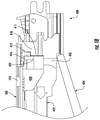
- FIG. 7 is a partial side, cross-sectional view of a surgical stapling instrument of FIG. 3 with the jaws of the end effector in the closed position with a spent cartridge in place in the lower jaw assembly, thereby activating the lockout mechanism;
- FIG. 8 depicts a side view of a drive assembly in accordance with another embodiment of the present disclosure.
- FIG. 9 is a partial side, cross-sectional view of a surgical stapling instrument including the drive assembly of FIG. 8 , with the jaws of the end effector in the open position and a fresh reload positioned in the staple jaw assembly;
- FIG. 10 is a partial side, cross-sectional view of the surgical stapling instrument of FIG. 9 with the jaw assemblies of the end effector in the closed position and the drive assembly in the home position;
- FIG. 11 is a partial side, cross-sectional view of the surgical stapling instrument of FIG. 9 with the jaw assemblies of the end effector in the closed position and the drive assembly partially advanced distally;
- FIGS. 12-14 are a partial side, cross-sectional views of a surgical stapling instrument of FIG. 9 with the jaws of the end effector in the closed position showing sequential stages of proximal movement of the drive assembly after completion of a firing stroke and ejection of staples from the staple cartridge;
- FIG. 15 is a partial side, cross-sectional view of a surgical stapling instrument of FIG. 9 with the jaws of the end effector in the closed position with a spent cartridge in place in the lower jaw assembly, thereby activating the lockout mechanism;
- FIG. 16 depicts a side view of a drive assembly in accordance with another embodiment of the present disclosure.
- FIG. 17 is a partial side, cross-sectional view of a surgical stapling instrument including the drive assembly of FIG. 16 with the jaw assemblies of the end effector in the closed position and the drive assembly in the home position;
- FIG. 18 is a partial side, cross-sectional view of a surgical stapling instrument including another illustrative embodiment of a drive assembly, with the jaws of the end effector in the open position and a fresh reload positioned in the staple jaw assembly; and
- FIG. 19 is a partial side, cross-sectional view of the surgical stapling instrument of FIG. 18 with the jaw assemblies of the end effector in the closed position and the drive assembly in the home position.
- the present disclosure relates to drive assemblies including a drive member, a locking member mounted to the drive member, and a spring.
- the drive member is configured to releasably engage at least one of a knife or a shuttle of a surgical stapling instrument and to translate the knife and/or shuttle in a distal direction through a staple firing stroke.
- Contact between the drive member and the knife and/or shuttle is releasable in that once the knife and/or shuttle are translated by the drive member in the distal direction through a staple firing stroke, the knife and/or shuttle disengages from the drive member, remains at a distal portion of the stapling instrument, and is not translated in a proximal direction by the drive member.
- the locking member is movable from a first position permitting distal translation of the drive member through the staple-firing stroke, and a second position inhibiting distal translation of the drive member through the staple firing stroke.
- the spring is configured to bias the locking member toward the second position.
- the surgical clamping and cutting instrument may be a minimally invasive (e.g., laparoscopic) instrument or an instrument used for open surgery.
- present drive assemblies may be readily adapted for use in surgical instruments that are activated using any technique within the purview of those skilled in the art, such as, for example, manually activated surgical instruments, powered surgical instruments (e.g., electro-mechanically powered instruments), robotic surgical instruments, and the like.
- FIG. 1A is a perspective view of an illustrative surgical stapling instrument 10 capable of utilizing a drive assembly and locking mechanism in accordance with the present disclosure.
- Surgical stapling instrument 10 includes a handle assembly 12 , and an end effector 100 including an anvil jaw assembly 102 and a staple jaw assembly 104 mounted on an elongated shaft 160 of the surgical stapling instrument 10 .
- FIG. 1B shows anvil jaw assembly 102 , including an anvil 106 having staple forming pockets 103 (see FIG. 3A ) supported thereon, and staple jaw assembly 104 .
- Staple jaw assembly 104 and anvil jaw assembly 102 are configured to move from an open position to a closed position. In the open position, a fresh stapling cartridge can be loaded into jaw assembly 104 , a spent staple cartridge removed from jaw assembly 104 , and tissue may be positioned between the jaw assemblies 102 , 104 . In the closed position, jaw assemblies 102 , 104 cooperate to close upon and clamp tissue such that cartridge 122 and anvil 106 are in close cooperative alignment. In the embodiment shown in FIGS.
- staple jaw assembly 104 is stationary and anvil jaw assembly 102 pivots to the open position.
- the jaw assembly containing the anvil is stationary and the jaw assembly containing the staple cartridge pivots to the open position.
- both the anvil jaw assembly and the staple jaw assembly may pivot.
- staple jaw assembly 104 includes a staple cartridge 122 supported in a channel 134 on jaw 123 .
- Cartridge 122 includes a plurality of staples 124 that are supported on corresponding staple drivers 126 provided within respective staple apertures 128 formed in cartridge 122 .
- Cartridge 122 also includes a shuttle 130 having an inclined distal portion 131 that, upon distal movement, sequentially acts on staple drivers 126 , camming them upwardly thereby moving staples 124 into deforming contact with anvil 106 .
- Cartridge 122 also includes a knife 150 configured to translate distally through a channel 127 in cartridge 122 and sever clamped, stapled tissue.
- FIG. 1B further shows a drive assembly 101 that is movably supported on the surgical stapling instrument such that it may pass distally through cartridge 122 and staple jaw assembly 104 when the surgical stapling instrument is fired (e.g., actuated).
- end effector shown in FIGS. 1A and 1B is merely illustrative, and that other end effectors may be employed, including but not limited to the end effectors shown in WO2014/106275, the entire contents of which are incorporated herein by this reference.
- FIG. 2 shows an illustrative drive assembly 101 for a surgical stapling instrument, including drive member 110 , spring 114 , and lockout member 116 .
- Drive member 110 may be any structure capable of pushing at least one of a shuttle or a knife of a surgical stapling instrument with the necessary force to effectively sever or staple human tissue.
- Drive member 110 may be an I-beam, an E-beam, or any other type of drive member capable of performing similar functions.
- drive member 110 is an I-beam and includes a first flange 113 a that travels in a channel 108 (see FIG. 3A ) in the anvil jaw assembly 102 , and a second flange 113 b that travels in a channel 115 (see FIG. 5 ) in the staple jaw assembly 104 .
- Spring 114 is mounted to the drive member 110 by any technique within the purview of those skilled in the art.
- spring 114 is welded to drive member 110 on upper face 112 of drive member 110 .
- Spring 114 is configured to bias engagement portion 118 of locking member 116 in the direction of Arrow “B”, urging engagement portion 118 to extend beyond upper face 112 of drive member 110 to enable the locking mechanism.
- Distal movement of drive assembly 101 advances shuttle 130 by contact with a lower distal end portion 111 of drive member 110 and advances knife 150 by contact with upper distal portion 113 of drive member 110 .
- FIG. 3 shows the proximal end of a fresh reload 122 including shuttle 130 and knife 150 loaded into jaw 123 while jaw assemblies 102 , 104 are in the open position.
- drive member 110 is in the proximal home position of the surgical stapling instrument.
- Locking member 116 is generally L-shaped. Slot 170 is located on jaw assembly 102 in a position proximal of staple forming pockets 107 of anvil 106 (see FIG. 3A ).
- FIG. 4 the fresh reload is shown in place.
- the proximal end 132 of shuttle 130 is engaging lower distal end portion 111 of drive member 110 so that drive member 110 drives shuttle 130 distally upon firing.
- a proximal portion 152 of knife 150 engages an upper distal portion 113 of drive member 110 so that knife 150 may be driven distally.
- drive member 110 continues to drive shuttle 130 and knife 150 distally. Because knife 150 engages footer 119 of locking member 116 , locking member 116 is maintained in a first position and unable rotate upwardly to interact with slot 170 , permitting continued distal translation of drive member 110 through a complete firing stroke.
- drive member 110 can be retracted, leaving shuttle 130 and knife 150 parked at a position in a distal portion of cartridge 122 .
- shuttle 130 may be unable to move proximally towards the home position due to friction with cartridge 122 .
- knife 150 may be parked in a predetermined position in a distally located garage 165 (not shown), the garage 165 including lateral surfaces that face the cutting tip of knife 150 .
- FIG. 8 shows an alternative embodiment of a driver assembly 201 for a surgical stapling instrument, including drive member 210 , spring 214 , and lockout member 216 .
- Drive member 210 may be any structure capable of pushing at least one of a shuttle or a knife of a surgical stapling instrument with the necessary force to effectively sever and/or staple human tissue.
- drive member 210 is an I-beam and includes a first flange 213 a that travels in a channel 208 (see FIG. 9 ) in the anvil jaw assembly 202 , and a second flange 213 b that travels in a channel 215 (see FIG. 9 ) in the staple jaw assembly 204 .
- Spring 214 is welded to upper face 212 a drive member 210 .
- Spring 214 is configured to bias engagement portion 218 of locking member 216 in the direction of Arrow “B”, urging engagement portion 218 to rotate below lower face 212 b of drive member 210 to enable the locking mechanism.
- locking member 116 is substantially linear.
- drive assembly 201 In operation, distal movement of drive assembly 201 advances shuttle 230 by contact with lower distal end portion 211 of drive member 210 and advances knife 250 by contact with upper distal portion 213 of drive member 210 .
- FIG. 9 shows the proximal end of a fresh reload 222 including shuttle 230 and knife 250 loaded into jaw 223 while the jaw assemblies 202 , 204 are in the open position.
- drive member 210 is in the proximal home position of the surgical stapling instrument.
- knife 250 engages locking member 216 overcoming the bias of spring 214 , keeping engagement portion 218 aligned with lower face 212 b of drive member 210 , permitting locking member 216 to bypass a pocket 270 formed in a lower surface of channel 208 of jaw assembly 202 as the drive member moves distally, as best seen in FIG. 10 .
- the fresh reload is in place.
- the proximal end 232 of shuttle 230 engages a lower-distal portion 211 of drive member 210 so that drive member 210 drives shuttle 230 distally upon firing.
- a proximal portion 252 of knife 250 engages an upper distal portion 213 of drive member 210 so that knife 250 may be driven distally.
- drive member 210 continues distally, because knife 250 engages locking member 216 , locking member 216 is maintained in a first position and unable rotate downwardly to interact with pocket 270 (see FIG. 11 ), and the locking mechanism is disengaged, permitting continued distal translation of drive member 210 through a complete firing stroke.
- drive member 210 can be retracted, leaving shuttle 230 and knife 250 at a parked position in a distal portion of cartridge 222 .
- engagement portion 218 of locking member 216 is unable to rotate downward as it rides along the lower surface of channel 208 of jaw assembly 202 as shown in FIG. 12 .
- locking member Once locking member reaches slot 270 , it may rotate downwardly as shown in FIG. 13 , but such rotation will not interfere with proximal motion of drive member 210 .
- FIGS. 16 and 17 depict an alternative embodiment of a drive assembly 301 for use with a surgical stapling instrument.
- shuttle 330 maintains locking member 316 out of engagement with slot 370 in staple jaw assembly 304 (rather than a slot in the anvil jaw assembly), thereby allowing knife 350 to be mounted to, or a sharpened surface of, drive member 310 .
- drive assembly 301 includes drive member 310 , spring 314 , and lockout member 316 .
- spring 314 is configured to bias engagement portion 318 of locking member 316 in the direction of Arrow “B”, urging engagement portion 318 to rotate below lower face 312 of drive member 310 to enable the locking mechanism.
- proximal end 332 of shuttle 330 engages a lower-distal portion 311 of drive member 310 so that drive member 310 drives shuttle 330 distally upon firing. Because shuttle 330 also engages portion 319 of locking member 216 , locking member 316 is maintained in a first position and unable rotate downwardly to interact with slot 370 , permitting distal translation of drive member 310 through a complete firing stroke. Unlike previously presented illustrative embodiments where the knife disables the locking mechanism, in this embodiment shuttle 330 is responsible for disabling the locking mechanism. Using shuttle 330 to restrain rotation of locking member 316 allows for knife 350 to be mounted to or formed directly on drive member 310 , reducing cartridge cost.
- drive member 310 can be retracted, leaving shuttle 330 at a parked position at a distal portion of the cartridge. Further retraction of drive member 310 positions locking member 316 proximal of pocket 370 . Because the staple cartridge is spent and there is no shuttle to restrain downward movement of locking member 316 , any attempt to re-fire the surgical stapling instrument will be prevented by activation of the locking mechanism when locking member 316 rotates under the bias of spring 314 , downwardly below surface 312 of drive member 310 and into contact with pocket 370 in essentially the same manner as described above.
- FIGS. 18 and 19 show an alternative embodiment of a surgical stapling instrument 400 in accordance with the present disclosure.
- Surgical stapling instrument 400 includes a movable anvil jaw assembly 404 and a stationary staple jaw assembly 402 which are configured to move between an open position to a closed position.
- a fresh staple cartridge 422 can be loaded into stationary staple jaw assembly 402
- a spent staple cartridge removed from stationary staple jaw assembly 402 and tissue may be positioned between the jaw assemblies 402 , 404 .
- jaw assemblies 402 , 404 cooperate to close upon and clamp tissue such that cartridge 422 and anvil 406 are in close cooperative alignment.
- the jaw containing cartridge 422 is stationary and the jaw assembly containing the anvil pivots to the open position.
- FIG. 18 shows the proximal end of a fresh reload 422 including shuttle 430 loaded into stationary jaw assembly 402 while the jaw assemblies 402 , 404 are in the open position.
- Knife 450 may be mounted to drive member 410 , or it may be a sharpened surface of drive member 410 , or a component of cartridge 422 , either independent of, or mounted to shuttle 430 .
- proximal end 432 of shuttle 430 engages upper portion 411 of drive member 410 , disabling the locking mechanism so that drive member 410 drives shuttle 430 distally upon firing. Because shuttle 430 also engages locking member 416 , locking member 416 is maintained in a first position and unable rotate upwardly to interact with a slot 470 in stationary jaw assembly 402 , permitting distal translation of drive member 410 through a complete firing stroke.
- drive member 410 can be retracted, leaving shuttle 430 at a parked position at a distal portion of the cartridge. Further retraction of drive member 410 positions locking member 416 proximal of pocket 470 . Because the staple cartridge is spent and there is no shuttle to restrain movement of locking member 416 , any attempt to re-fire the surgical stapling instrument will be prevented by activation of the locking mechanism when locking member 416 rotates under the bias of spring 414 , upwardly above surface 412 of drive member 410 and into contact with pocket 470 in essentially the same manner as described above.
Abstract
Description
Claims (12)
Priority Applications (3)
| Application Number | Priority Date | Filing Date | Title |
|---|---|---|---|
| US16/205,128 US10863988B2 (en) | 2017-11-29 | 2018-11-29 | Surgical instrument with lockout mechanism |
| US17/104,223 US11504124B2 (en) | 2017-11-29 | 2020-11-25 | Surgical instrument with lockout mechanism |
| US17/973,806 US20230047784A1 (en) | 2017-11-29 | 2022-10-26 | Surgical instrument with lockout mechanism |
Applications Claiming Priority (2)
| Application Number | Priority Date | Filing Date | Title |
|---|---|---|---|
| US201762592330P | 2017-11-29 | 2017-11-29 | |
| US16/205,128 US10863988B2 (en) | 2017-11-29 | 2018-11-29 | Surgical instrument with lockout mechanism |
Related Child Applications (1)
| Application Number | Title | Priority Date | Filing Date |
|---|---|---|---|
| US17/104,223 Continuation US11504124B2 (en) | 2017-11-29 | 2020-11-25 | Surgical instrument with lockout mechanism |
Publications (2)
| Publication Number | Publication Date |
|---|---|
| US20190167266A1 US20190167266A1 (en) | 2019-06-06 |
| US10863988B2 true US10863988B2 (en) | 2020-12-15 |
Family
ID=66658338
Family Applications (3)
| Application Number | Title | Priority Date | Filing Date |
|---|---|---|---|
| US16/205,128 Active 2039-03-19 US10863988B2 (en) | 2017-11-29 | 2018-11-29 | Surgical instrument with lockout mechanism |
| US17/104,223 Active 2039-05-30 US11504124B2 (en) | 2017-11-29 | 2020-11-25 | Surgical instrument with lockout mechanism |
| US17/973,806 Pending US20230047784A1 (en) | 2017-11-29 | 2022-10-26 | Surgical instrument with lockout mechanism |
Family Applications After (2)
| Application Number | Title | Priority Date | Filing Date |
|---|---|---|---|
| US17/104,223 Active 2039-05-30 US11504124B2 (en) | 2017-11-29 | 2020-11-25 | Surgical instrument with lockout mechanism |
| US17/973,806 Pending US20230047784A1 (en) | 2017-11-29 | 2022-10-26 | Surgical instrument with lockout mechanism |
Country Status (1)
| Country | Link |
|---|---|
| US (3) | US10863988B2 (en) |
Cited By (22)
| Publication number | Priority date | Publication date | Assignee | Title |
|---|---|---|---|---|
| US11439390B2 (en) | 2018-02-26 | 2022-09-13 | Intuitive Surgical Operations, Inc. | Surgical instrument with lockout mechanism |
| US11504124B2 (en) | 2017-11-29 | 2022-11-22 | Intuitive Surgical Operations, Inc. | Surgical instrument with lockout mechanism |
| US11517312B2 (en) | 2018-02-12 | 2022-12-06 | Intuitive Surgical Operations, Inc. | Surgical instrument with lockout mechanism |
| WO2023021399A2 (en) | 2021-08-16 | 2023-02-23 | Cilag Gmbh International | Firing bailout system for powered surgical stapler |
| WO2023021396A1 (en) | 2021-08-16 | 2023-02-23 | Cilag Gmbh International | Proximally located firing lockout mechanism for surgical stapler |
| WO2023021395A1 (en) | 2021-08-16 | 2023-02-23 | Cilag Gmbh International | Firing system features for surgical stapler |
| WO2023021394A1 (en) | 2021-08-16 | 2023-02-23 | Cilag Gmbh International | Powered surgical stapler having independently operable closure and firing systems |
| WO2023021398A1 (en) | 2021-08-16 | 2023-02-23 | Cilag Gmbh International | Multi-threshold motor control algorithm for powered surgical stapler |
| WO2023021397A1 (en) | 2021-08-16 | 2023-02-23 | Cilag Gmbh International | Cartridge-based firing lockout mechanism for surgical stapler |
| WO2023021400A1 (en) | 2021-08-16 | 2023-02-23 | Cilag Gmbh International | Variable response motor control algorithm for powered surgical stapler |
| WO2023021402A1 (en) | 2021-08-16 | 2023-02-23 | Cilag Gmbh International | Deflectable firing member for surgical stapler |
| WO2023021401A1 (en) | 2021-08-16 | 2023-02-23 | Cilag Gmbh International | Adjustable power transmission mechanism for powered surgical stapler |
| WO2023021393A1 (en) | 2021-08-16 | 2023-02-23 | Cilag Gmbh International | Firing member tracking feature for surgical stapler |
| WO2023021404A1 (en) | 2021-08-16 | 2023-02-23 | Cilag Gmbh International | Multi-position restraining member for sled movement |
| WO2023021403A1 (en) | 2021-08-16 | 2023-02-23 | Cilag Gmbh International | Multiple-sensor firing lockout mechanism for powered surgical stapler |
| US11642129B2 (en) | 2020-01-15 | 2023-05-09 | Intuitive Surgical Operations, Inc. | Staple cartridge and drive member for surgical instrument |
| US11723661B2 (en) | 2018-12-21 | 2023-08-15 | Intuitive Surgical Operations, Inc. | Surgical instruments with switches for deactivating and/or identifying stapler cartridges |
| US11786325B2 (en) | 2019-07-02 | 2023-10-17 | Intuitive Surgical Operations, Inc. | Remotely controlling a system using video |
| US11857188B2 (en) | 2018-12-21 | 2024-01-02 | Intuitive Surgical Operations, Inc. | Articulation assemblies for surgical instruments |
| US11896224B2 (en) | 2019-05-31 | 2024-02-13 | Intuitive Surgical Operations, Inc. | Staple cartridge for a surgical instrument |
| US11944301B2 (en) | 2018-12-21 | 2024-04-02 | Intuitive Surgical Operations, Inc. | Surgical instruments having a reinforced staple cartridge |
| US11944302B2 (en) | 2019-04-15 | 2024-04-02 | Intuitive Surgical Operations, Inc. | Staple cartridge for a surgical instrument |
Families Citing this family (8)
| Publication number | Priority date | Publication date | Assignee | Title |
|---|---|---|---|---|
| USD914878S1 (en) * | 2018-08-20 | 2021-03-30 | Ethicon Llc | Surgical instrument anvil |
| CN110313952A (en) * | 2019-07-30 | 2019-10-11 | 康奇舒宁(苏州)医疗科技有限公司 | It is a kind of to prevent secondary percussion safety device for disposable hysteroscope Endo-GIA |
| US11452524B2 (en) * | 2020-01-31 | 2022-09-27 | Covidien Lp | Surgical stapling device with lockout |
| US11744582B2 (en) | 2021-01-05 | 2023-09-05 | Covidien Lp | Surgical stapling device with firing lockout mechanism |
| US11759206B2 (en) * | 2021-01-05 | 2023-09-19 | Covidien Lp | Surgical stapling device with firing lockout mechanism |
| CN116806134A (en) * | 2021-01-08 | 2023-09-26 | 直观外科手术操作公司 | Surgical instrument employing linear staples and purse-string suture staples |
| US11653922B2 (en) * | 2021-09-29 | 2023-05-23 | Covidien Lp | Surgical stapling device with firing lockout mechanism |
| WO2024011470A1 (en) * | 2022-07-13 | 2024-01-18 | 武汉迈瑞医疗技术研究院有限公司 | Surgical instrument, anastomotic device and staple bin assembly |
Citations (30)
| Publication number | Priority date | Publication date | Assignee | Title |
|---|---|---|---|---|
| US4892244A (en) | 1988-11-07 | 1990-01-09 | Ethicon, Inc. | Surgical stapler cartridge lockout device |
| US5275323A (en) | 1990-11-30 | 1994-01-04 | Ethicon, Inc. | Surgical stapler |
| US5307976A (en) | 1991-10-18 | 1994-05-03 | Ethicon, Inc. | Linear stapling mechanism with cutting means |
| US5487500A (en) | 1994-02-03 | 1996-01-30 | Ethicon Endo-Surgery, Inc. | Surgical stapler instrument |
| US5562239A (en) | 1994-04-28 | 1996-10-08 | Ethicon Endo-Surgery, Inc. | Identification device for surgical instrument |
| US5762255A (en) | 1996-02-20 | 1998-06-09 | Richard-Allan Medical Industries, Inc. | Surgical instrument with improvement safety lockout mechanisms |
| US5779130A (en) | 1994-08-05 | 1998-07-14 | United States Surgical Corporation | Self-contained powered surgical apparatus |
| US5826776A (en) | 1994-12-19 | 1998-10-27 | Ethicon Endo-Surgery, Inc. | Surgical instrument |
| US5871135A (en) | 1993-05-05 | 1999-02-16 | Ethicon Endo-Surgery | Surgical stapler and staple cartridge |
| US5959892A (en) | 1997-08-26 | 1999-09-28 | Macronix International Co., Ltd. | Apparatus and method for programming virtual ground EPROM array cell without disturbing adjacent cells |
| US6032849A (en) | 1995-08-28 | 2000-03-07 | United States Surgical | Surgical stapler |
| US6202914B1 (en) | 1995-10-27 | 2001-03-20 | United States Surgical Corporation | Surgical stapler |
| US6669073B2 (en) | 1997-09-23 | 2003-12-30 | United States Surgical Corporation | Surgical stapling apparatus |
| US6978921B2 (en) | 2003-05-20 | 2005-12-27 | Ethicon Endo-Surgery, Inc. | Surgical stapling instrument incorporating an E-beam firing mechanism |
| US6988649B2 (en) | 2003-05-20 | 2006-01-24 | Ethicon Endo-Surgery, Inc. | Surgical stapling instrument having a spent cartridge lockout |
| US7044352B2 (en) | 2003-05-20 | 2006-05-16 | Ethicon Endo-Surgery, Inc. | Surgical stapling instrument having a single lockout mechanism for prevention of firing |
| US7140527B2 (en) | 2000-10-13 | 2006-11-28 | Tyco Healthcare Group Lp | Surgical fastener applying apparatus |
| US7140528B2 (en) | 2003-05-20 | 2006-11-28 | Ethicon Endo-Surgery, Inc. | Surgical stapling instrument having an electroactive polymer actuated single lockout mechanism for prevention of firing |
| US7328828B2 (en) | 2005-11-04 | 2008-02-12 | Ethicon Endo-Surgery, Inc, | Lockout mechanisms and surgical instruments including same |
| US7380696B2 (en) | 2003-05-20 | 2008-06-03 | Ethicon Endo-Surgery, Inc. | Articulating surgical stapling instrument incorporating a two-piece E-beam firing mechanism |
| US7380695B2 (en) | 2003-05-20 | 2008-06-03 | Ethicon Endo-Surgery, Inc. | Surgical stapling instrument having a single lockout mechanism for prevention of firing |
| US7942303B2 (en) | 2008-06-06 | 2011-05-17 | Tyco Healthcare Group Lp | Knife lockout mechanisms for surgical instrument |
| WO2012142872A1 (en) | 2011-04-20 | 2012-10-26 | 苏州天臣国际医疗科技有限公司 | Straight cutting and stitching device |
| WO2014106275A1 (en) | 2012-12-31 | 2014-07-03 | Intuitive Surgical Operations, Inc. | Surgical staple cartridge with enhanced knife clearance |
| US8800841B2 (en) | 2011-03-15 | 2014-08-12 | Ethicon Endo-Surgery, Inc. | Surgical staple cartridges |
| US20140263567A1 (en) * | 2013-03-13 | 2014-09-18 | Covidien Lp | Surgical stapling apparatus |
| US20150297227A1 (en) | 2014-04-16 | 2015-10-22 | Ethicon Endo-Surgery, Inc. | Surgical fastener cartridges with driver stabilizing arrangements |
| US9717497B2 (en) | 2013-02-28 | 2017-08-01 | Ethicon Llc | Lockout feature for movable cutting member of surgical instrument |
| US20170296172A1 (en) | 2016-04-18 | 2017-10-19 | Ethicon Endo-Surgery, Llc | Surgical instrument comprising a lockout |
| US20180168622A1 (en) | 2016-12-21 | 2018-06-21 | Ethicon Endo-Surgery, Llc | Surgical instrument with multiple failure response modes |
Family Cites Families (225)
| Publication number | Priority date | Publication date | Assignee | Title |
|---|---|---|---|---|
| SU405234A1 (en) | 1970-09-02 | 1975-09-05 | Всесоюзный Научно-Исследовательский Институт Хирургической Аппаратуры И Инструментов | Matrix for suturing surgical apparatus |
| SU886900A1 (en) | 1979-03-26 | 1981-12-07 | Всесоюзный научно-исследовательский и испытательный институт медицинской техники | Surgical apparatus for applying line sutures |
| US4429695A (en) | 1980-02-05 | 1984-02-07 | United States Surgical Corporation | Surgical instruments |
| US4319576A (en) | 1980-02-26 | 1982-03-16 | Senco Products, Inc. | Intralumenal anastomosis surgical stapling instrument |
| US4809695A (en) | 1981-10-21 | 1989-03-07 | Owen M. Gwathmey | Suturing assembly and method |
| US4509518A (en) | 1982-02-17 | 1985-04-09 | United States Surgical Corporation | Apparatus for applying surgical clips |
| US4610383A (en) | 1983-10-14 | 1986-09-09 | Senmed, Inc. | Disposable linear surgical stapler |
| US4767044A (en) | 1984-10-19 | 1988-08-30 | United States Surgical Corporation | Surgical fastener applying apparatus |
| US4605001A (en) | 1984-10-19 | 1986-08-12 | Senmed, Inc. | Surgical stapling instrument with dual staple height mechanism |
| US4608981A (en) | 1984-10-19 | 1986-09-02 | Senmed, Inc. | Surgical stapling instrument with staple height adjusting mechanism |
| US4750488A (en) | 1986-05-19 | 1988-06-14 | Sonomed Technology, Inc. | Vibration apparatus preferably for endoscopic ultrasonic aspirator |
| SU1333319A2 (en) | 1985-12-10 | 1987-08-30 | Петрозаводский государственный университет им.О.В.Куусинена | Suture appliance for hollow organs |
| JPS63503390A (en) | 1986-05-21 | 1988-12-08 | ノボ インダストリ アクテイ−ゼルスカブ | coated detergent enzyme products |
| SU1459659A1 (en) | 1986-09-29 | 1989-02-23 | Всесоюзный научно-исследовательский и испытательный институт медицинской техники | Surgical suturing apparatus for applying line sutures |
| SU1442191A1 (en) | 1987-01-19 | 1988-12-07 | Петрозаводский государственный университет им.О.В.Куусинена | Surgical suturing apparatus |
| ZA88681B (en) | 1987-02-02 | 1988-08-01 | Cassella Aktiengesellschaft | Mixtures of monoazo dyestuffs |
| US4848637A (en) | 1987-06-11 | 1989-07-18 | Pruitt J Crayton | Staple device for use on the mesenteries of the abdomen |
| US5027834A (en) | 1987-06-11 | 1991-07-02 | United States Surgical Corporation | Stapling process for use on the mesenteries of the abdomen |
| US4930503A (en) | 1987-06-11 | 1990-06-05 | Pruitt J Crayton | Stapling process and device for use on the mesenteries of the abdomen |
| AU4633589A (en) | 1988-11-18 | 1990-06-12 | Immuno Sweden Ab | Instrument for anastomosis |
| US5040715B1 (en) | 1989-05-26 | 1994-04-05 | United States Surgical Corp | Apparatus and method for placing staples in laparoscopic or endoscopic procedures |
| US4978049A (en) | 1989-05-26 | 1990-12-18 | United States Surgical Corporation | Three staple drive member |
| US5133735A (en) | 1990-05-10 | 1992-07-28 | Symbiosis Corporation | Thumb-activated actuating member for imparting reciprocal motion to push rod of a disposable laparoscopic surgical instrument |
| US5133736A (en) | 1990-05-10 | 1992-07-28 | Symbiosis Corporation | Investment cast end effectors for disposable laparoscopic surgical instrument |
| US5571285A (en) | 1991-02-19 | 1996-11-05 | Ethicon, Inc. | Surgical staple for insertion into tissue |
| US5688269A (en) | 1991-07-10 | 1997-11-18 | Electroscope, Inc. | Electrosurgical apparatus for laparoscopic and like procedures |
| CA2075227C (en) | 1991-10-18 | 2004-02-10 | Robert J. Geiste | Surgical fastening apparatus with shipping interlock |
| US5312023A (en) | 1991-10-18 | 1994-05-17 | United States Surgical Corporation | Self contained gas powered surgical apparatus |
| US6250532B1 (en) | 1991-10-18 | 2001-06-26 | United States Surgical Corporation | Surgical stapling apparatus |
| US5443198A (en) | 1991-10-18 | 1995-08-22 | United States Surgical Corporation | Surgical fastener applying apparatus |
| US5289963A (en) | 1991-10-18 | 1994-03-01 | United States Surgical Corporation | Apparatus and method for applying surgical staples to attach an object to body tissue |
| US5180092A (en) | 1992-02-05 | 1993-01-19 | Lawrence Crainich | Linear surgical stapling instrument |
| US5484095A (en) | 1992-03-31 | 1996-01-16 | United States Surgical Corporation | Apparatus for endoscopically applying staples individually to body tissue |
| US5484451A (en) | 1992-05-08 | 1996-01-16 | Ethicon, Inc. | Endoscopic surgical instrument and staples for applying purse string sutures |
| JPH0675830B2 (en) | 1992-08-24 | 1994-09-28 | 丸善株式会社 | Stepper |
| US5342396A (en) | 1993-03-02 | 1994-08-30 | Cook Melvin S | Staples |
| US5540375A (en) | 1993-04-20 | 1996-07-30 | United States Surgical Corporation | Endoscopic stapler |
| US5709680A (en) | 1993-07-22 | 1998-01-20 | Ethicon Endo-Surgery, Inc. | Electrosurgical hemostatic device |
| CA2132503C (en) | 1993-10-07 | 2005-05-10 | Donald F. Wilson | Curved knife for linear staplers |
| US5439155A (en) | 1993-10-07 | 1995-08-08 | United States Surgical Corporation | Cartridge for surgical fastener applying apparatus |
| US5452837A (en) | 1994-01-21 | 1995-09-26 | Ethicon Endo-Surgery, Inc. | Surgical stapler with tissue gripping ridge |
| US5452836A (en) | 1994-02-07 | 1995-09-26 | Ethicon Endo-Surgery, Inc. | Surgical stapling instrument with improved jaw closure and staple firing actuator mechanism |
| CA2144818C (en) | 1994-04-07 | 2006-07-11 | Henry Bolanos | Graduated anvil for surgical stapling instruments |
| US5628446A (en) | 1994-05-05 | 1997-05-13 | United States Surgical Corporation | Self-contained powered surgical apparatus |
| US5833695A (en) | 1994-07-13 | 1998-11-10 | Yoon; Inbae | Surgical stapling system and method of applying staples from multiple staple cartridges |
| US5533521A (en) | 1994-07-15 | 1996-07-09 | United States Surgical Corporation | Interchangeable tissue measuring device |
| EP0699418A1 (en) | 1994-08-05 | 1996-03-06 | United States Surgical Corporation | Self-contained powered surgical apparatus |
| US5480089A (en) | 1994-08-19 | 1996-01-02 | United States Surgical Corporation | Surgical stapler apparatus with improved staple pockets |
| US5571116A (en) | 1994-10-02 | 1996-11-05 | United States Surgical Corporation | Non-invasive treatment of gastroesophageal reflux disease |
| US5652849A (en) | 1995-03-16 | 1997-07-29 | Regents Of The University Of Michigan | Apparatus and method for remote control using a visual information stream |
| US5624452A (en) | 1995-04-07 | 1997-04-29 | Ethicon Endo-Surgery, Inc. | Hemostatic surgical cutting or stapling instrument |
| US5752644A (en) | 1995-07-11 | 1998-05-19 | United States Surgical Corporation | Disposable loading unit for surgical stapler |
| US5782396A (en) | 1995-08-28 | 1998-07-21 | United States Surgical Corporation | Surgical stapler |
| US5762256A (en) | 1995-08-28 | 1998-06-09 | United States Surgical Corporation | Surgical stapler |
| US5697542A (en) | 1995-10-19 | 1997-12-16 | Ethicon Endo-Surgery, Inc. | Endoscopic surgical stapler with compact profile |
| US5667626A (en) | 1996-01-29 | 1997-09-16 | Minnesota Mining And Manufacturing Company | Masking device hub providing two position tape support |
| US5820009A (en) | 1996-02-20 | 1998-10-13 | Richard-Allan Medical Industries, Inc. | Articulated surgical instrument with improved jaw closure mechanism |
| IL117607A0 (en) | 1996-03-21 | 1996-07-23 | Dev Of Advanced Medical Produc | Surgical stapler and method of surgical fastening |
| US5792135A (en) | 1996-05-20 | 1998-08-11 | Intuitive Surgical, Inc. | Articulated surgical instrument for performing minimally invasive surgery with enhanced dexterity and sensitivity |
| US7118570B2 (en) | 2001-04-06 | 2006-10-10 | Sherwood Services Ag | Vessel sealing forceps with disposable electrodes |
| US6585735B1 (en) | 1998-10-23 | 2003-07-01 | Sherwood Services Ag | Endoscopic bipolar electrosurgical forceps |
| US6330956B1 (en) | 1998-12-09 | 2001-12-18 | J.W. Pet Company | Molded plastic pet bowl |
| US6174309B1 (en) | 1999-02-11 | 2001-01-16 | Medical Scientific, Inc. | Seal & cut electrosurgical instrument |
| US6264087B1 (en) | 1999-07-12 | 2001-07-24 | Powermed, Inc. | Expanding parallel jaw device for use with an electromechanical driver device |
| US8025199B2 (en) | 2004-02-23 | 2011-09-27 | Tyco Healthcare Group Lp | Surgical cutting and stapling device |
| US6488196B1 (en) | 1999-06-30 | 2002-12-03 | Axya Medical, Inc. | Surgical stapler and method of applying plastic staples to body tissue |
| CA2322061A1 (en) | 1999-10-05 | 2001-04-05 | Anil K. Nalagatla | Stapling instrument having two staple forming surfaces |
| US20040267310A1 (en) | 2000-10-20 | 2004-12-30 | Racenet David C | Directionally biased staple and anvil assembly for forming the staple |
| US6503259B2 (en) | 2000-12-27 | 2003-01-07 | Ethicon, Inc. | Expandable anastomotic device |
| US7699835B2 (en) | 2001-02-15 | 2010-04-20 | Hansen Medical, Inc. | Robotically controlled surgical instruments |
| US6592597B2 (en) | 2001-05-07 | 2003-07-15 | Ethicon Endo-Surgery, Inc. | Adhesive for attaching buttress material to a surgical fastening device |
| US6817974B2 (en) | 2001-06-29 | 2004-11-16 | Intuitive Surgical, Inc. | Surgical tool having positively positionable tendon-actuated multi-disk wrist joint |
| US6895219B2 (en) | 2001-08-27 | 2005-05-17 | Symbol Technologies Inc. | Dual use of FFT circuity in imagers and transceivers |
| US10285694B2 (en) | 2001-10-20 | 2019-05-14 | Covidien Lp | Surgical stapler with timer and feedback display |
| DE10158246C1 (en) | 2001-11-28 | 2003-08-21 | Ethicon Endo Surgery Europe | Surgical stapling instrument |
| US8233501B2 (en) | 2002-02-13 | 2012-07-31 | Interdigital Technology Corporation | Transport block set segmentation |
| US7070083B2 (en) | 2002-04-11 | 2006-07-04 | Tyco Healthcare Group Lp | Surgical stapling apparatus including an anvil and cartridge each having cooperating mating surfaces |
| JP4316491B2 (en) | 2002-05-10 | 2009-08-19 | タイコ ヘルスケア グループ エルピー | Wound closure material applicator and stapler |
| ES2540098T3 (en) | 2002-05-10 | 2015-07-08 | Covidien Lp | Surgical stapling device that has a material applicator set for wound closure |
| WO2003094747A1 (en) | 2002-05-13 | 2003-11-20 | Tyco Healthcare Group, Lp | Surgical stapler and disposable loading unit having different size staples |
| ES2337248T3 (en) | 2002-10-04 | 2010-04-22 | Tyco Healthcare Group Lp | TOOL ASSEMBLY FOR A SURGICAL STAPLING DEVICE. |
| US7931649B2 (en) | 2002-10-04 | 2011-04-26 | Tyco Healthcare Group Lp | Vessel sealing instrument with electrical cutting mechanism |
| JP4006385B2 (en) | 2002-11-20 | 2007-11-14 | 株式会社日立ハイテクノロジーズ | Sugar chain synthesizer |
| US9060770B2 (en) | 2003-05-20 | 2015-06-23 | Ethicon Endo-Surgery, Inc. | Robotically-driven surgical instrument with E-beam driver |
| US7143923B2 (en) | 2003-05-20 | 2006-12-05 | Ethicon Endo-Surgery, Inc. | Surgical stapling instrument having a firing lockout for an unclosed anvil |
| US20070010838A1 (en) | 2003-05-20 | 2007-01-11 | Shelton Frederick E Iv | Surgical stapling instrument having a firing lockout for an unclosed anvil |
| EP1635713B1 (en) | 2003-06-17 | 2012-04-11 | Tyco Healthcare Group LP | Surgical stapling device |
| US7494039B2 (en) | 2003-06-17 | 2009-02-24 | Tyco Healthcare Group Lp | Surgical stapling device |
| US6981628B2 (en) | 2003-07-09 | 2006-01-03 | Ethicon Endo-Surgery, Inc. | Surgical instrument with a lateral-moving articulation control |
| US6786382B1 (en) | 2003-07-09 | 2004-09-07 | Ethicon Endo-Surgery, Inc. | Surgical stapling instrument incorporating an articulation joint for a firing bar track |
| US7055731B2 (en) | 2003-07-09 | 2006-06-06 | Ethicon Endo-Surgery Inc. | Surgical stapling instrument incorporating a tapered firing bar for increased flexibility around the articulation joint |
| US7111769B2 (en) | 2003-07-09 | 2006-09-26 | Ethicon Endo-Surgery, Inc. | Surgical instrument incorporating an articulation mechanism having rotation about the longitudinal axis |
| US6964363B2 (en) | 2003-07-09 | 2005-11-15 | Ethicon Endo-Surgery, Inc. | Surgical stapling instrument having articulation joint support plates for supporting a firing bar |
| US7303108B2 (en) | 2003-09-29 | 2007-12-04 | Ethicon Endo-Surgery, Inc. | Surgical stapling instrument incorporating a multi-stroke firing mechanism with a flexible rack |
| US6905057B2 (en) | 2003-09-29 | 2005-06-14 | Ethicon Endo-Surgery, Inc. | Surgical stapling instrument incorporating a firing mechanism having a linked rack transmission |
| US7083075B2 (en) | 2003-09-29 | 2006-08-01 | Ethicon Endo-Surgery, Inc. | Multi-stroke mechanism with automatic end of stroke retraction |
| US7434715B2 (en) | 2003-09-29 | 2008-10-14 | Ethicon Endo-Surgery, Inc. | Surgical stapling instrument having multistroke firing with opening lockout |
| US6959852B2 (en) | 2003-09-29 | 2005-11-01 | Ethicon Endo-Surgery, Inc. | Surgical stapling instrument with multistroke firing incorporating an anti-backup mechanism |
| US7364061B2 (en) | 2003-09-29 | 2008-04-29 | Ethicon Endo-Surgery, Inc. | Surgical stapling instrument incorporating a multistroke firing position indicator and retraction mechanism |
| US7000819B2 (en) | 2003-09-29 | 2006-02-21 | Ethicon Endo-Surgery, Inc. | Surgical stapling instrument having multistroke firing incorporating a traction-biased ratcheting mechanism |
| EP1677684B1 (en) | 2003-10-17 | 2012-12-05 | Tyco Healthcare Group LP | Surgical stapling device with independent tip rotation |
| US7059508B2 (en) | 2004-06-30 | 2006-06-13 | Ethicon Endo-Surgery, Inc. | Surgical stapling instrument incorporating an uneven multistroke firing mechanism having a rotary transmission |
| US7367485B2 (en) | 2004-06-30 | 2008-05-06 | Ethicon Endo-Surgery, Inc. | Surgical stapling instrument incorporating a multistroke firing mechanism having a rotary transmission |
| US7143925B2 (en) | 2004-07-28 | 2006-12-05 | Ethicon Endo-Surgery, Inc. | Surgical instrument incorporating EAP blocking lockout mechanism |
| US7487899B2 (en) | 2004-07-28 | 2009-02-10 | Ethicon Endo-Surgery, Inc. | Surgical instrument incorporating EAP complete firing system lockout mechanism |
| US8905977B2 (en) | 2004-07-28 | 2014-12-09 | Ethicon Endo-Surgery, Inc. | Surgical stapling instrument having an electroactive polymer actuated medical substance dispenser |
| US7506790B2 (en) | 2004-07-28 | 2009-03-24 | Ethicon Endo-Surgery, Inc. | Surgical instrument incorporating an electrically actuated articulation mechanism |
| US20060025812A1 (en) | 2004-07-28 | 2006-02-02 | Ethicon Endo-Surgery, Inc. | Surgical instrument incorporating an electrically actuated pivoting articulation mechanism |
| US7857183B2 (en) | 2004-07-28 | 2010-12-28 | Ethicon Endo-Surgery, Inc. | Surgical instrument incorporating an electrically actuated articulation mechanism |
| US7147138B2 (en) | 2004-07-28 | 2006-12-12 | Ethicon Endo-Surgery, Inc. | Surgical stapling instrument having an electroactive polymer actuated buttress deployment mechanism |
| US8057508B2 (en) | 2004-07-28 | 2011-11-15 | Ethicon Endo-Surgery, Inc. | Surgical instrument incorporating an electrically actuated articulation locking mechanism |
| US7128254B2 (en) | 2004-09-07 | 2006-10-31 | Ethicon Endo-Surgery, Inc. | Surgical stapling instrument incorporating a multistroke firing mechanism having a rotary slip-clutch transmission |
| WO2006078661A1 (en) | 2005-01-19 | 2006-07-27 | Applied Medical Resources Corporation | Disposable laparoscopic instrument |
| US7559450B2 (en) | 2005-02-18 | 2009-07-14 | Ethicon Endo-Surgery, Inc. | Surgical instrument incorporating a fluid transfer controlled articulation mechanism |
| US7654431B2 (en) | 2005-02-18 | 2010-02-02 | Ethicon Endo-Surgery, Inc. | Surgical instrument with guided laterally moving articulation member |
| US20060291981A1 (en) | 2005-06-02 | 2006-12-28 | Viola Frank J | Expandable backspan staple |
| US8579178B2 (en) | 2005-08-15 | 2013-11-12 | Covidien Lp | Surgical stapling instruments including a cartridge having multiple staples sizes |
| US7398908B2 (en) | 2005-08-15 | 2008-07-15 | Tyco Healthcare Group Lp | Surgical stapling instruments including a cartridge having multiple staple sizes |
| US7401721B2 (en) | 2005-08-15 | 2008-07-22 | Tyco Healthcare Group Lp | Surgical stapling instruments including a cartridge having multiple staple sizes |
| US7407075B2 (en) | 2005-08-15 | 2008-08-05 | Tyco Healthcare Group Lp | Staple cartridge having multiple staple sizes for a surgical stapling instrument |
| US7669746B2 (en) | 2005-08-31 | 2010-03-02 | Ethicon Endo-Surgery, Inc. | Staple cartridges for forming staples having differing formed staple heights |
| US7934630B2 (en) | 2005-08-31 | 2011-05-03 | Ethicon Endo-Surgery, Inc. | Staple cartridges for forming staples having differing formed staple heights |
| US10159482B2 (en) | 2005-08-31 | 2018-12-25 | Ethicon Llc | Fastener cartridge assembly comprising a fixed anvil and different staple heights |
| US7500979B2 (en) | 2005-08-31 | 2009-03-10 | Ethicon Endo-Surgery, Inc. | Surgical stapling device with multiple stacked actuator wedge cams for driving staple drivers |
| US7641091B2 (en) | 2005-10-04 | 2010-01-05 | Tyco Healthcare Group Lp | Staple drive assembly |
| US7635074B2 (en) | 2005-10-04 | 2009-12-22 | Tyco Healthcare Group Lp | Staple drive assembly |
| US7673783B2 (en) | 2005-11-04 | 2010-03-09 | Ethicon Endo-Surgery, Inc. | Surgical stapling instruments structured for delivery of medical agents |
| ATE450208T1 (en) | 2006-07-07 | 2009-12-15 | Ethicon Endo Surgery Inc | SURGICAL CLAP SETTING DEVICE |
| US7665647B2 (en) | 2006-09-29 | 2010-02-23 | Ethicon Endo-Surgery, Inc. | Surgical cutting and stapling device with closure apparatus for limiting maximum tissue compression force |
| US7721930B2 (en) | 2006-11-10 | 2010-05-25 | Thicon Endo-Surgery, Inc. | Disposable cartridge with adhesive for use with a stapling device |
| US8684253B2 (en) | 2007-01-10 | 2014-04-01 | Ethicon Endo-Surgery, Inc. | Surgical instrument with wireless communication between a control unit of a robotic system and remote sensor |
| US8540128B2 (en) | 2007-01-11 | 2013-09-24 | Ethicon Endo-Surgery, Inc. | Surgical stapling device with a curved end effector |
| AU2008223389B2 (en) | 2007-03-06 | 2013-07-11 | Covidien Lp | Surgical stapling apparatus |
| US7735703B2 (en) | 2007-03-15 | 2010-06-15 | Ethicon Endo-Surgery, Inc. | Re-loadable surgical stapling instrument |
| US7832611B2 (en) | 2007-05-16 | 2010-11-16 | The Invention Science Fund I, Llc | Steerable surgical stapler |
| US8931682B2 (en) | 2007-06-04 | 2015-01-13 | Ethicon Endo-Surgery, Inc. | Robotically-controlled shaft based rotary drive systems for surgical instruments |
| US7950561B2 (en) | 2007-06-18 | 2011-05-31 | Tyco Healthcare Group Lp | Structure for attachment of buttress material to anvils and cartridges of surgical staplers |
| US9050098B2 (en) | 2007-11-28 | 2015-06-09 | Covidien Ag | Cordless medical cauterization and cutting device |
| US8573465B2 (en) | 2008-02-14 | 2013-11-05 | Ethicon Endo-Surgery, Inc. | Robotically-controlled surgical end effector system with rotary actuated closure systems |
| US9869339B2 (en) | 2008-04-11 | 2018-01-16 | Flexdex, Inc. | End-effector jaw closure transmission systems for remote access tools |
| US8091756B2 (en) | 2008-05-09 | 2012-01-10 | Tyco Healthcare Group Lp | Varying tissue compression using take-up component |
| US8197479B2 (en) | 2008-12-10 | 2012-06-12 | Tyco Healthcare Group Lp | Vessel sealer and divider |
| US8632539B2 (en) | 2009-01-14 | 2014-01-21 | Covidien Lp | Vessel sealer and divider |
| US8858547B2 (en) | 2009-03-05 | 2014-10-14 | Intuitive Surgical Operations, Inc. | Cut and seal instrument |
| US8365972B2 (en) | 2009-03-31 | 2013-02-05 | Covidien Lp | Surgical stapling apparatus |
| US20110022078A1 (en) | 2009-07-23 | 2011-01-27 | Cameron Dale Hinman | Articulating mechanism |
| WO2014145381A1 (en) | 2013-03-15 | 2014-09-18 | Ceterix Orthopaedics, Inc. | Suture passer devices and methods |
| US8996173B2 (en) | 2010-09-21 | 2015-03-31 | Intuitive Surgical Operations, Inc. | Method and apparatus for hand gesture control in a minimally invasive surgical system |
| US8348127B2 (en) | 2010-04-07 | 2013-01-08 | Covidien Lp | Surgical fastener applying apparatus |
| US8834518B2 (en) | 2010-04-12 | 2014-09-16 | Ethicon Endo-Surgery, Inc. | Electrosurgical cutting and sealing instruments with cam-actuated jaws |
| US8496682B2 (en) | 2010-04-12 | 2013-07-30 | Ethicon Endo-Surgery, Inc. | Electrosurgical cutting and sealing instruments with cam-actuated jaws |
| US8672939B2 (en) | 2010-06-01 | 2014-03-18 | Covidien Lp | Surgical device for performing an electrosurgical procedure |
| US8663270B2 (en) | 2010-07-23 | 2014-03-04 | Conmed Corporation | Jaw movement mechanism and method for a surgical tool |
| US20120080498A1 (en) | 2010-09-30 | 2012-04-05 | Ethicon Endo-Surgery, Inc. | Curved end effector for a stapling instrument |
| KR102184421B1 (en) | 2011-02-18 | 2020-12-01 | 인튜어티브 서지컬 오퍼레이션즈 인코포레이티드 | Fusing and cutting surgical instrument and related methods |
| US9161807B2 (en) | 2011-05-23 | 2015-10-20 | Covidien Lp | Apparatus for performing an electrosurgical procedure |
| US8960521B2 (en) | 2011-07-15 | 2015-02-24 | Covidien Lp | Loose staples removal system |
| US8789739B2 (en) | 2011-09-06 | 2014-07-29 | Ethicon Endo-Surgery, Inc. | Continuous stapling instrument |
| US9254180B2 (en) | 2011-09-15 | 2016-02-09 | Ethicon Endo-Surgery, Inc. | Surgical instrument with staple reinforcement clip |
| US9089326B2 (en) | 2011-10-07 | 2015-07-28 | Ethicon Endo-Surgery, Inc. | Dual staple cartridge for surgical stapler |
| US9016539B2 (en) | 2011-10-25 | 2015-04-28 | Covidien Lp | Multi-use loading unit |
| US9078653B2 (en) | 2012-03-26 | 2015-07-14 | Ethicon Endo-Surgery, Inc. | Surgical stapling device with lockout system for preventing actuation in the absence of an installed staple cartridge |
| US9820765B2 (en) | 2012-05-01 | 2017-11-21 | Covidien Lp | Surgical instrument with stamped double-flange jaws |
| US9668807B2 (en) | 2012-05-01 | 2017-06-06 | Covidien Lp | Simplified spring load mechanism for delivering shaft force of a surgical instrument |
| US20140001234A1 (en) | 2012-06-28 | 2014-01-02 | Ethicon Endo-Surgery, Inc. | Coupling arrangements for attaching surgical end effectors to drive systems therefor |
| US9226767B2 (en) | 2012-06-29 | 2016-01-05 | Ethicon Endo-Surgery, Inc. | Closed feedback control for electrosurgical device |
| US9439665B2 (en) | 2012-12-20 | 2016-09-13 | Covidien Lp | Pediatric combination surgical device |
| MX360430B (en) | 2013-02-08 | 2018-10-31 | Ethicon Endo Surgery Inc | Staple cartridge comprising a releasable cover. |
| RU2669463C2 (en) | 2013-03-01 | 2018-10-11 | Этикон Эндо-Серджери, Инк. | Surgical instrument with soft stop |
| US9629628B2 (en) | 2013-03-13 | 2017-04-25 | Covidien Lp | Surgical stapling apparatus |
| EP3135225B1 (en) | 2013-03-13 | 2019-08-14 | Covidien LP | Surgical stapling apparatus |
| US9888921B2 (en) | 2013-03-13 | 2018-02-13 | Covidien Lp | Surgical stapling apparatus |
| US9717498B2 (en) | 2013-03-13 | 2017-08-01 | Covidien Lp | Surgical stapling apparatus |
| US9572577B2 (en) | 2013-03-27 | 2017-02-21 | Ethicon Endo-Surgery, Llc | Fastener cartridge comprising a tissue thickness compensator including openings therein |
| US9775610B2 (en) | 2013-04-09 | 2017-10-03 | Covidien Lp | Apparatus for endoscopic procedures |
| BR112015026109B1 (en) | 2013-04-16 | 2022-02-22 | Ethicon Endo-Surgery, Inc | surgical instrument |
| US9844368B2 (en) | 2013-04-16 | 2017-12-19 | Ethicon Llc | Surgical system comprising first and second drive systems |
| US9936949B2 (en) | 2013-09-23 | 2018-04-10 | Ethicon Llc | Surgical stapling instrument with drive assembly having toggle features |
| DE102013110847B3 (en) | 2013-10-01 | 2015-01-22 | gomtec GmbH | Control device and method for controlling a robot system by means of gesture control |
| US9549735B2 (en) | 2013-12-23 | 2017-01-24 | Ethicon Endo-Surgery, Llc | Fastener cartridge comprising a firing member including fastener transfer surfaces |
| US9629627B2 (en) | 2014-01-28 | 2017-04-25 | Coviden Lp | Surgical apparatus |
| US9700312B2 (en) | 2014-01-28 | 2017-07-11 | Covidien Lp | Surgical apparatus |
| US9197697B2 (en) | 2014-03-10 | 2015-11-24 | Gazoo, Inc. | Cloud computing system and method |
| US9757126B2 (en) | 2014-03-31 | 2017-09-12 | Covidien Lp | Surgical stapling apparatus with firing lockout mechanism |
| EP3148465B1 (en) | 2014-05-30 | 2018-05-16 | Applied Medical Resources Corporation | Electrosurgical system with an instrument comprising a jaw with a central insulative pad |
| AU2015318095B2 (en) | 2014-09-15 | 2020-02-20 | Applied Medical Resources Corporation | Surgical stapler with self-adjusting staple height |
| US10517594B2 (en) | 2014-10-29 | 2019-12-31 | Ethicon Llc | Cartridge assemblies for surgical staplers |
| US10420603B2 (en) | 2014-12-23 | 2019-09-24 | Applied Medical Resources Corporation | Bipolar electrosurgical sealer and divider |
| US10433844B2 (en) | 2015-03-31 | 2019-10-08 | Ethicon Llc | Surgical instrument with selectively disengageable threaded drive systems |
| KR102454704B1 (en) | 2015-05-15 | 2022-10-14 | 인튜어티브 서지컬 오퍼레이션즈 인코포레이티드 | System and method for reducing blade exposures |
| US9918781B2 (en) | 2015-05-22 | 2018-03-20 | Covidien Lp | Surgical instruments and methods for performing tonsillectomy, adenoidectomy, and other surgical procedures |
| JP2017021186A (en) | 2015-07-10 | 2017-01-26 | キヤノン株式会社 | Frame fastening method, frame, sheet conveyance device, and image forming apparatus |
| US10390829B2 (en) | 2015-08-26 | 2019-08-27 | Ethicon Llc | Staples comprising a cover |
| US10285693B2 (en) | 2015-12-31 | 2019-05-14 | Ethicon Llc | Surgical stapler with locking translatable pin |
| WO2017156070A1 (en) | 2016-03-09 | 2017-09-14 | Intuitive Surgical Operations, Inc. | Force transmission mechanism for surgical instrument, and related devices, systems, and methods |
| EP3463162A4 (en) | 2016-06-03 | 2020-06-24 | Covidien LP | Systems, methods, and computer-readable program products for controlling a robotically delivered manipulator |
| KR102414405B1 (en) | 2016-06-09 | 2022-06-30 | 인튜어티브 서지컬 오퍼레이션즈 인코포레이티드 | Computer-assisted teleoperated surgical systems and methods |
| JP7022709B2 (en) | 2016-07-01 | 2022-02-18 | インテュイティブ サージカル オペレーションズ, インコーポレイテッド | Computer-aided medical system and method |
| CN109843189B (en) | 2016-10-11 | 2022-01-14 | 直观外科手术操作公司 | Stapler cartridge with integral knife |
| US11272947B2 (en) | 2016-11-17 | 2022-03-15 | Covidien Lp | Surgical instruments for performing tonsillectomy, adenoidectomy, and other surgical procedures |
| US10588630B2 (en) | 2016-12-21 | 2020-03-17 | Ethicon Llc | Surgical tool assemblies with closure stroke reduction features |
| US10835245B2 (en) | 2016-12-21 | 2020-11-17 | Ethicon Llc | Method for attaching a shaft assembly to a surgical instrument and, alternatively, to a surgical robot |
| US10588632B2 (en) | 2016-12-21 | 2020-03-17 | Ethicon Llc | Surgical end effectors and firing members thereof |
| JP7010957B2 (en) | 2016-12-21 | 2022-01-26 | エシコン エルエルシー | Shaft assembly with lockout |
| US10524789B2 (en) | 2016-12-21 | 2020-01-07 | Ethicon Llc | Laterally actuatable articulation lock arrangements for locking an end effector of a surgical instrument in an articulated configuration |
| US20190015124A1 (en) | 2017-07-11 | 2019-01-17 | Conmed Corporation | Jaw assembly for a vessel sealer |
| US11291465B2 (en) | 2017-10-30 | 2022-04-05 | Cilag Gmbh International | Surgical instruments comprising a lockable end effector socket |
| CN111902096B (en) | 2017-11-13 | 2024-01-26 | 维卡瑞斯外科手术股份有限公司 | Virtual reality wrist assembly |
| US20220079585A1 (en) | 2017-11-14 | 2022-03-17 | Egan Design LLC | Electrically weldable suture material, and apparatus and method for forming welded suture loops and other welded structures |
| US10863988B2 (en) * | 2017-11-29 | 2020-12-15 | Intuitive Surgical Operations, Inc. | Surgical instrument with lockout mechanism |
| US10743871B2 (en) | 2018-02-01 | 2020-08-18 | Ethicon, Llc | Surgical clip applier with distal clip feeder |
| US11517312B2 (en) | 2018-02-12 | 2022-12-06 | Intuitive Surgical Operations, Inc. | Surgical instrument with lockout mechanism |
| US11439390B2 (en) | 2018-02-26 | 2022-09-13 | Intuitive Surgical Operations, Inc. | Surgical instrument with lockout mechanism |
| US20190365458A1 (en) | 2018-05-31 | 2019-12-05 | Intuitive Surgical Operations, Inc. | Surgical instruments having a jaw locking mechanism |
| US20210386427A1 (en) | 2018-10-19 | 2021-12-16 | Intuitive Surgical Operations, Inc. | Endoscopic purse string suture surgical device |
| US11944301B2 (en) | 2018-12-21 | 2024-04-02 | Intuitive Surgical Operations, Inc. | Surgical instruments having a reinforced staple cartridge |
| US11857188B2 (en) | 2018-12-21 | 2024-01-02 | Intuitive Surgical Operations, Inc. | Articulation assemblies for surgical instruments |
| US11806015B2 (en) | 2018-12-21 | 2023-11-07 | Intuitive Surgical Operations, Inc. | Surgical instruments having mechanisms for identifying and/or deactivating stapler cartridges |
| CN113194847A (en) | 2018-12-21 | 2021-07-30 | 直观外科手术操作公司 | Actuation mechanism for a surgical instrument |
| EP3955831A4 (en) | 2019-04-15 | 2022-12-28 | Intuitive Surgical Operations, Inc. | Staple cartridge for a surgical instrument |
| WO2020214397A1 (en) | 2019-04-17 | 2020-10-22 | Intuitive Surgical Operations, Inc. | Surgical stapling instrument |
| US11786325B2 (en) | 2019-07-02 | 2023-10-17 | Intuitive Surgical Operations, Inc. | Remotely controlling a system using video |
| US20210177500A1 (en) | 2019-12-12 | 2021-06-17 | Intuitive Surgical Operations, Inc. | Surgical instruments having non-linear cam slots |
| US11642129B2 (en) | 2020-01-15 | 2023-05-09 | Intuitive Surgical Operations, Inc. | Staple cartridge and drive member for surgical instrument |
| US11857247B2 (en) | 2020-07-17 | 2024-01-02 | Cilag Gmbh International | Jaw for surgical instrument end effector |
-
2018
- 2018-11-29 US US16/205,128 patent/US10863988B2/en active Active
-
2020
- 2020-11-25 US US17/104,223 patent/US11504124B2/en active Active
-
2022
- 2022-10-26 US US17/973,806 patent/US20230047784A1/en active Pending
Patent Citations (33)
| Publication number | Priority date | Publication date | Assignee | Title |
|---|---|---|---|---|
| US4892244A (en) | 1988-11-07 | 1990-01-09 | Ethicon, Inc. | Surgical stapler cartridge lockout device |
| US4892244B1 (en) | 1988-11-07 | 1991-08-27 | Ethicon Inc | |
| US5275323A (en) | 1990-11-30 | 1994-01-04 | Ethicon, Inc. | Surgical stapler |
| US5307976A (en) | 1991-10-18 | 1994-05-03 | Ethicon, Inc. | Linear stapling mechanism with cutting means |
| US5871135A (en) | 1993-05-05 | 1999-02-16 | Ethicon Endo-Surgery | Surgical stapler and staple cartridge |
| US5487500A (en) | 1994-02-03 | 1996-01-30 | Ethicon Endo-Surgery, Inc. | Surgical stapler instrument |
| US5562239A (en) | 1994-04-28 | 1996-10-08 | Ethicon Endo-Surgery, Inc. | Identification device for surgical instrument |
| US5693042A (en) | 1994-04-28 | 1997-12-02 | Ethicon Endo-Surgery, Inc. | Identification device for surgical instrument |
| US5779130A (en) | 1994-08-05 | 1998-07-14 | United States Surgical Corporation | Self-contained powered surgical apparatus |
| US5826776A (en) | 1994-12-19 | 1998-10-27 | Ethicon Endo-Surgery, Inc. | Surgical instrument |
| US6032849A (en) | 1995-08-28 | 2000-03-07 | United States Surgical | Surgical stapler |
| US6202914B1 (en) | 1995-10-27 | 2001-03-20 | United States Surgical Corporation | Surgical stapler |
| US5762255A (en) | 1996-02-20 | 1998-06-09 | Richard-Allan Medical Industries, Inc. | Surgical instrument with improvement safety lockout mechanisms |
| US5959892A (en) | 1997-08-26 | 1999-09-28 | Macronix International Co., Ltd. | Apparatus and method for programming virtual ground EPROM array cell without disturbing adjacent cells |
| US6669073B2 (en) | 1997-09-23 | 2003-12-30 | United States Surgical Corporation | Surgical stapling apparatus |
| US7140527B2 (en) | 2000-10-13 | 2006-11-28 | Tyco Healthcare Group Lp | Surgical fastener applying apparatus |
| US6988649B2 (en) | 2003-05-20 | 2006-01-24 | Ethicon Endo-Surgery, Inc. | Surgical stapling instrument having a spent cartridge lockout |
| US7044352B2 (en) | 2003-05-20 | 2006-05-16 | Ethicon Endo-Surgery, Inc. | Surgical stapling instrument having a single lockout mechanism for prevention of firing |
| US6978921B2 (en) | 2003-05-20 | 2005-12-27 | Ethicon Endo-Surgery, Inc. | Surgical stapling instrument incorporating an E-beam firing mechanism |
| US7140528B2 (en) | 2003-05-20 | 2006-11-28 | Ethicon Endo-Surgery, Inc. | Surgical stapling instrument having an electroactive polymer actuated single lockout mechanism for prevention of firing |
| US7380696B2 (en) | 2003-05-20 | 2008-06-03 | Ethicon Endo-Surgery, Inc. | Articulating surgical stapling instrument incorporating a two-piece E-beam firing mechanism |
| US7380695B2 (en) | 2003-05-20 | 2008-06-03 | Ethicon Endo-Surgery, Inc. | Surgical stapling instrument having a single lockout mechanism for prevention of firing |
| US7000818B2 (en) | 2003-05-20 | 2006-02-21 | Ethicon, Endo-Surger, Inc. | Surgical stapling instrument having separate distinct closing and firing systems |
| US7328828B2 (en) | 2005-11-04 | 2008-02-12 | Ethicon Endo-Surgery, Inc, | Lockout mechanisms and surgical instruments including same |
| US7942303B2 (en) | 2008-06-06 | 2011-05-17 | Tyco Healthcare Group Lp | Knife lockout mechanisms for surgical instrument |
| US8800841B2 (en) | 2011-03-15 | 2014-08-12 | Ethicon Endo-Surgery, Inc. | Surgical staple cartridges |
| WO2012142872A1 (en) | 2011-04-20 | 2012-10-26 | 苏州天臣国际医疗科技有限公司 | Straight cutting and stitching device |
| WO2014106275A1 (en) | 2012-12-31 | 2014-07-03 | Intuitive Surgical Operations, Inc. | Surgical staple cartridge with enhanced knife clearance |
| US9717497B2 (en) | 2013-02-28 | 2017-08-01 | Ethicon Llc | Lockout feature for movable cutting member of surgical instrument |
| US20140263567A1 (en) * | 2013-03-13 | 2014-09-18 | Covidien Lp | Surgical stapling apparatus |
| US20150297227A1 (en) | 2014-04-16 | 2015-10-22 | Ethicon Endo-Surgery, Inc. | Surgical fastener cartridges with driver stabilizing arrangements |
| US20170296172A1 (en) | 2016-04-18 | 2017-10-19 | Ethicon Endo-Surgery, Llc | Surgical instrument comprising a lockout |
| US20180168622A1 (en) | 2016-12-21 | 2018-06-21 | Ethicon Endo-Surgery, Llc | Surgical instrument with multiple failure response modes |
Non-Patent Citations (1)
| Title |
|---|
| Vertut, Jean and Phillipe Coiffet, Robot Technology: Teleoperation and Robotics Evolution and Development, English translation, Prentice-Hall, Inc., Inglewood Cliffs, NJ, USA 1986, vol. 3A, 332 pages. |
Cited By (29)
| Publication number | Priority date | Publication date | Assignee | Title |
|---|---|---|---|---|
| US11504124B2 (en) | 2017-11-29 | 2022-11-22 | Intuitive Surgical Operations, Inc. | Surgical instrument with lockout mechanism |
| US20230047784A1 (en) * | 2017-11-29 | 2023-02-16 | Intuitive Surgical Operations, Inc. | Surgical instrument with lockout mechanism |
| US11864762B2 (en) | 2018-02-12 | 2024-01-09 | Intuitive Surgical Operations, Inc. | Surgical instrument with lockout mechanism |
| US11517312B2 (en) | 2018-02-12 | 2022-12-06 | Intuitive Surgical Operations, Inc. | Surgical instrument with lockout mechanism |
| US11439390B2 (en) | 2018-02-26 | 2022-09-13 | Intuitive Surgical Operations, Inc. | Surgical instrument with lockout mechanism |
| US11806015B2 (en) | 2018-12-21 | 2023-11-07 | Intuitive Surgical Operations, Inc. | Surgical instruments having mechanisms for identifying and/or deactivating stapler cartridges |
| US11944301B2 (en) | 2018-12-21 | 2024-04-02 | Intuitive Surgical Operations, Inc. | Surgical instruments having a reinforced staple cartridge |
| US11857188B2 (en) | 2018-12-21 | 2024-01-02 | Intuitive Surgical Operations, Inc. | Articulation assemblies for surgical instruments |
| US11723661B2 (en) | 2018-12-21 | 2023-08-15 | Intuitive Surgical Operations, Inc. | Surgical instruments with switches for deactivating and/or identifying stapler cartridges |
| US11944302B2 (en) | 2019-04-15 | 2024-04-02 | Intuitive Surgical Operations, Inc. | Staple cartridge for a surgical instrument |
| US11896224B2 (en) | 2019-05-31 | 2024-02-13 | Intuitive Surgical Operations, Inc. | Staple cartridge for a surgical instrument |
| US11786325B2 (en) | 2019-07-02 | 2023-10-17 | Intuitive Surgical Operations, Inc. | Remotely controlling a system using video |
| US11642129B2 (en) | 2020-01-15 | 2023-05-09 | Intuitive Surgical Operations, Inc. | Staple cartridge and drive member for surgical instrument |
| WO2023021404A1 (en) | 2021-08-16 | 2023-02-23 | Cilag Gmbh International | Multi-position restraining member for sled movement |
| WO2023021397A1 (en) | 2021-08-16 | 2023-02-23 | Cilag Gmbh International | Cartridge-based firing lockout mechanism for surgical stapler |
| WO2023021403A1 (en) | 2021-08-16 | 2023-02-23 | Cilag Gmbh International | Multiple-sensor firing lockout mechanism for powered surgical stapler |
| WO2023021401A1 (en) | 2021-08-16 | 2023-02-23 | Cilag Gmbh International | Adjustable power transmission mechanism for powered surgical stapler |
| WO2023021402A1 (en) | 2021-08-16 | 2023-02-23 | Cilag Gmbh International | Deflectable firing member for surgical stapler |
| US11779332B2 (en) | 2021-08-16 | 2023-10-10 | Cilag Gmbh International | Powered surgical stapler having independently operable closure and firing systems |
| WO2023021400A1 (en) | 2021-08-16 | 2023-02-23 | Cilag Gmbh International | Variable response motor control algorithm for powered surgical stapler |
| WO2023021393A1 (en) | 2021-08-16 | 2023-02-23 | Cilag Gmbh International | Firing member tracking feature for surgical stapler |
| EP4282345A2 (en) | 2021-08-16 | 2023-11-29 | Cilag GmbH International | Cartridge-based firing lockout mechanism for surgical stapler |
| WO2023021398A1 (en) | 2021-08-16 | 2023-02-23 | Cilag Gmbh International | Multi-threshold motor control algorithm for powered surgical stapler |
| WO2023021394A1 (en) | 2021-08-16 | 2023-02-23 | Cilag Gmbh International | Powered surgical stapler having independently operable closure and firing systems |
| WO2023021395A1 (en) | 2021-08-16 | 2023-02-23 | Cilag Gmbh International | Firing system features for surgical stapler |
| WO2023021396A1 (en) | 2021-08-16 | 2023-02-23 | Cilag Gmbh International | Proximally located firing lockout mechanism for surgical stapler |
| WO2023021399A2 (en) | 2021-08-16 | 2023-02-23 | Cilag Gmbh International | Firing bailout system for powered surgical stapler |
| US11944297B2 (en) | 2021-08-16 | 2024-04-02 | Cilag Gmbh International | Variable response motor control algorithm for powered surgical stapler |
| US11957336B2 (en) | 2021-08-16 | 2024-04-16 | Cilag Gmbh International | Proximally located firing lockout mechanism for surgical stapler |
Also Published As
| Publication number | Publication date |
|---|---|
| US20230047784A1 (en) | 2023-02-16 |
| US20210077101A1 (en) | 2021-03-18 |
| US20190167266A1 (en) | 2019-06-06 |
| US11504124B2 (en) | 2022-11-22 |
Similar Documents
| Publication | Publication Date | Title |
|---|---|---|
| US10863988B2 (en) | Surgical instrument with lockout mechanism | |
| JP6932798B2 (en) | Surgical instrument assembly | |
| US20220395270A1 (en) | Surgical instrument with lockout mechanism | |
| US11864762B2 (en) | Surgical instrument with lockout mechanism | |
| US11737755B2 (en) | Surgical instrument comprising separate tissue securing and tissue cutting systems | |
| US11918212B2 (en) | Surgical instrument with selectively disengageable drive systems | |
| US11134944B2 (en) | Surgical stapler knife motion controls | |
| US10524795B2 (en) | Surgical instrument comprising systems for permitting the optional transection of tissue | |
| US8973805B2 (en) | Surgical fastener applying apparatus including a knife guard | |
| CN111295142A (en) | Positive axis rotation lock activated by jaw closure | |
| JP5586856B2 (en) | Disposable motor-driven loading unit for use with surgical cutting and stapling devices | |
| US20220061949A1 (en) | Safety device for surgical instrument |
Legal Events
| Date | Code | Title | Description |
|---|---|---|---|
| FEPP | Fee payment procedure |
Free format text: ENTITY STATUS SET TO UNDISCOUNTED (ORIGINAL EVENT CODE: BIG.); ENTITY STATUS OF PATENT OWNER: LARGE ENTITY |
|
| STPP | Information on status: patent application and granting procedure in general |
Free format text: DOCKETED NEW CASE - READY FOR EXAMINATION |
|
| AS | Assignment |
Owner name: INTUITIVE SURGICAL OPERATIONS, INC., CALIFORNIA Free format text: ASSIGNMENT OF ASSIGNORS INTEREST;ASSIGNORS:PATEL, ATAL C.;GODIN, CHARLES N.;WIXEY, MATTHEW;SIGNING DATES FROM 20181129 TO 20181130;REEL/FRAME:048938/0661 |
|
| STPP | Information on status: patent application and granting procedure in general |
Free format text: NON FINAL ACTION MAILED |
|
| STPP | Information on status: patent application and granting procedure in general |
Free format text: NOTICE OF ALLOWANCE MAILED -- APPLICATION RECEIVED IN OFFICE OF PUBLICATIONS |
|
| STPP | Information on status: patent application and granting procedure in general |
Free format text: PUBLICATIONS -- ISSUE FEE PAYMENT VERIFIED |
|
| STCF | Information on status: patent grant |
Free format text: PATENTED CASE |