US8419758B2 - Cordless hand-held ultrasonic cautery cutting device - Google Patents
Cordless hand-held ultrasonic cautery cutting device Download PDFInfo
- Publication number
- US8419758B2 US8419758B2 US12/266,146 US26614608A US8419758B2 US 8419758 B2 US8419758 B2 US 8419758B2 US 26614608 A US26614608 A US 26614608A US 8419758 B2 US8419758 B2 US 8419758B2
- Authority
- US
- United States
- Prior art keywords
- waveguide
- transducer
- ultrasonic
- handle
- assembly
- Prior art date
- Legal status (The legal status is an assumption and is not a legal conclusion. Google has not performed a legal analysis and makes no representation as to the accuracy of the status listed.)
- Active, expires
Links
Images


Classifications
-
- A—HUMAN NECESSITIES
- A61—MEDICAL OR VETERINARY SCIENCE; HYGIENE
- A61N—ELECTROTHERAPY; MAGNETOTHERAPY; RADIATION THERAPY; ULTRASOUND THERAPY
- A61N7/00—Ultrasound therapy
- A61N7/02—Localised ultrasound hyperthermia
-
- A—HUMAN NECESSITIES
- A61—MEDICAL OR VETERINARY SCIENCE; HYGIENE
- A61B—DIAGNOSIS; SURGERY; IDENTIFICATION
- A61B17/00—Surgical instruments, devices or methods, e.g. tourniquets
- A61B17/12—Surgical instruments, devices or methods, e.g. tourniquets for ligaturing or otherwise compressing tubular parts of the body, e.g. blood vessels, umbilical cord
- A61B17/128—Surgical instruments, devices or methods, e.g. tourniquets for ligaturing or otherwise compressing tubular parts of the body, e.g. blood vessels, umbilical cord for applying or removing clamps or clips
- A61B17/1285—Surgical instruments, devices or methods, e.g. tourniquets for ligaturing or otherwise compressing tubular parts of the body, e.g. blood vessels, umbilical cord for applying or removing clamps or clips for minimally invasive surgery
-
- A—HUMAN NECESSITIES
- A61—MEDICAL OR VETERINARY SCIENCE; HYGIENE
- A61B—DIAGNOSIS; SURGERY; IDENTIFICATION
- A61B17/00—Surgical instruments, devices or methods, e.g. tourniquets
- A61B17/32—Surgical cutting instruments
- A61B17/320068—Surgical cutting instruments using mechanical vibrations, e.g. ultrasonic
- A61B17/320092—Surgical cutting instruments using mechanical vibrations, e.g. ultrasonic with additional movable means for clamping or cutting tissue, e.g. with a pivoting jaw
-
- A—HUMAN NECESSITIES
- A61—MEDICAL OR VETERINARY SCIENCE; HYGIENE
- A61B—DIAGNOSIS; SURGERY; IDENTIFICATION
- A61B17/00—Surgical instruments, devices or methods, e.g. tourniquets
- A61B2017/00017—Electrical control of surgical instruments
-
- A—HUMAN NECESSITIES
- A61—MEDICAL OR VETERINARY SCIENCE; HYGIENE
- A61B—DIAGNOSIS; SURGERY; IDENTIFICATION
- A61B17/00—Surgical instruments, devices or methods, e.g. tourniquets
- A61B2017/0023—Surgical instruments, devices or methods, e.g. tourniquets disposable
-
- A—HUMAN NECESSITIES
- A61—MEDICAL OR VETERINARY SCIENCE; HYGIENE
- A61B—DIAGNOSIS; SURGERY; IDENTIFICATION
- A61B17/00—Surgical instruments, devices or methods, e.g. tourniquets
- A61B2017/0046—Surgical instruments, devices or methods, e.g. tourniquets with a releasable handle; with handle and operating part separable
-
- A—HUMAN NECESSITIES
- A61—MEDICAL OR VETERINARY SCIENCE; HYGIENE
- A61B—DIAGNOSIS; SURGERY; IDENTIFICATION
- A61B17/00—Surgical instruments, devices or methods, e.g. tourniquets
- A61B2017/00477—Coupling
-
- A—HUMAN NECESSITIES
- A61—MEDICAL OR VETERINARY SCIENCE; HYGIENE
- A61B—DIAGNOSIS; SURGERY; IDENTIFICATION
- A61B17/00—Surgical instruments, devices or methods, e.g. tourniquets
- A61B2017/00681—Aspects not otherwise provided for
- A61B2017/00734—Aspects not otherwise provided for battery operated
-
- A—HUMAN NECESSITIES
- A61—MEDICAL OR VETERINARY SCIENCE; HYGIENE
- A61B—DIAGNOSIS; SURGERY; IDENTIFICATION
- A61B17/00—Surgical instruments, devices or methods, e.g. tourniquets
- A61B17/32—Surgical cutting instruments
- A61B17/320068—Surgical cutting instruments using mechanical vibrations, e.g. ultrasonic
- A61B17/320092—Surgical cutting instruments using mechanical vibrations, e.g. ultrasonic with additional movable means for clamping or cutting tissue, e.g. with a pivoting jaw
- A61B2017/320093—Surgical cutting instruments using mechanical vibrations, e.g. ultrasonic with additional movable means for clamping or cutting tissue, e.g. with a pivoting jaw additional movable means performing cutting operation
-
- A—HUMAN NECESSITIES
- A61—MEDICAL OR VETERINARY SCIENCE; HYGIENE
- A61B—DIAGNOSIS; SURGERY; IDENTIFICATION
- A61B17/00—Surgical instruments, devices or methods, e.g. tourniquets
- A61B17/32—Surgical cutting instruments
- A61B17/320068—Surgical cutting instruments using mechanical vibrations, e.g. ultrasonic
- A61B17/320092—Surgical cutting instruments using mechanical vibrations, e.g. ultrasonic with additional movable means for clamping or cutting tissue, e.g. with a pivoting jaw
- A61B2017/320094—Surgical cutting instruments using mechanical vibrations, e.g. ultrasonic with additional movable means for clamping or cutting tissue, e.g. with a pivoting jaw additional movable means performing clamping operation
-
- A—HUMAN NECESSITIES
- A61—MEDICAL OR VETERINARY SCIENCE; HYGIENE
- A61B—DIAGNOSIS; SURGERY; IDENTIFICATION
- A61B17/00—Surgical instruments, devices or methods, e.g. tourniquets
- A61B17/32—Surgical cutting instruments
- A61B17/320068—Surgical cutting instruments using mechanical vibrations, e.g. ultrasonic
- A61B17/320092—Surgical cutting instruments using mechanical vibrations, e.g. ultrasonic with additional movable means for clamping or cutting tissue, e.g. with a pivoting jaw
- A61B2017/320095—Surgical cutting instruments using mechanical vibrations, e.g. ultrasonic with additional movable means for clamping or cutting tissue, e.g. with a pivoting jaw with sealing or cauterizing means
-
- A—HUMAN NECESSITIES
- A61—MEDICAL OR VETERINARY SCIENCE; HYGIENE
- A61B—DIAGNOSIS; SURGERY; IDENTIFICATION
- A61B17/00—Surgical instruments, devices or methods, e.g. tourniquets
- A61B17/32—Surgical cutting instruments
- A61B17/320068—Surgical cutting instruments using mechanical vibrations, e.g. ultrasonic
- A61B17/320092—Surgical cutting instruments using mechanical vibrations, e.g. ultrasonic with additional movable means for clamping or cutting tissue, e.g. with a pivoting jaw
- A61B2017/320097—Surgical cutting instruments using mechanical vibrations, e.g. ultrasonic with additional movable means for clamping or cutting tissue, e.g. with a pivoting jaw with stapling means
-
- A—HUMAN NECESSITIES
- A61—MEDICAL OR VETERINARY SCIENCE; HYGIENE
- A61B—DIAGNOSIS; SURGERY; IDENTIFICATION
- A61B17/00—Surgical instruments, devices or methods, e.g. tourniquets
- A61B17/32—Surgical cutting instruments
- A61B17/320068—Surgical cutting instruments using mechanical vibrations, e.g. ultrasonic
- A61B2017/320098—Surgical cutting instruments using mechanical vibrations, e.g. ultrasonic with transverse or torsional motion
-
- A—HUMAN NECESSITIES
- A61—MEDICAL OR VETERINARY SCIENCE; HYGIENE
- A61B—DIAGNOSIS; SURGERY; IDENTIFICATION
- A61B18/00—Surgical instruments, devices or methods for transferring non-mechanical forms of energy to or from the body
- A61B2018/00571—Surgical instruments, devices or methods for transferring non-mechanical forms of energy to or from the body for achieving a particular surgical effect
- A61B2018/00595—Cauterization
-
- Y—GENERAL TAGGING OF NEW TECHNOLOGICAL DEVELOPMENTS; GENERAL TAGGING OF CROSS-SECTIONAL TECHNOLOGIES SPANNING OVER SEVERAL SECTIONS OF THE IPC; TECHNICAL SUBJECTS COVERED BY FORMER USPC CROSS-REFERENCE ART COLLECTIONS [XRACs] AND DIGESTS
- Y10—TECHNICAL SUBJECTS COVERED BY FORMER USPC
- Y10T—TECHNICAL SUBJECTS COVERED BY FORMER US CLASSIFICATION
- Y10T29/00—Metal working
- Y10T29/49—Method of mechanical manufacture
- Y10T29/49826—Assembling or joining
Definitions
- the present invention relates generally to an ultrasonic cutting device and, more particularly, relates to a cordless, hand-held, fully electrically powered and controlled, surgical ultrasonic cutting device.
- Ultrasonic instruments are effectively used in the treatment of many medical conditions, such as removal of tissue and cauterization of vessels.
- Cutting instruments that utilize ultrasonic waves generate vibrations with an ultrasonic transducer along a longitudinal axis of a cutting blade. By placing a resonant wave along the length of the blade, high-speed longitudinal mechanical movement is produced at the end of the blade.
- These instruments are advantageous because the mechanical vibrations transmitted to the end of the blade are very effective at cutting organic tissue and, simultaneously, coagulate the tissue using the heat energy produced by the ultrasonic frequencies.
- Such instruments are particularly well suited for use in minimally invasive procedures, such as endoscopic or laparoscopic procedures, where the blade is passed through a trocar to reach the surgical site.
- each kind of cutting blade e.g., length, material, size
- producing an effective cutting-blade driving signal is not a trivial task. For instance, the frequency, current, and voltage applied to the cutting tool must all be controlled dynamically, as these parameters change with the varying load placed on the blade and with temperature differentials that result from use of the tool.
- FIG. 1 shows a block schematic diagram of a prior-art circuit used for applying ultrasonic mechanical movements to an end effector.
- the circuit includes a power source 102 , a control circuit 104 , a drive circuit 106 , a matching circuit 108 , a transducer 110 , and also includes a handpiece 112 , and a waveguide 114 secured to the handpiece 112 (diagrammatically illustrated by a dashed line) and supported by a cannula 120 .
- the waveguide 114 terminates to a blade 116 at a distal end.
- a clamping mechanism referred to as an “end effector” 118 , exposes and enables the blade portion 116 of the waveguide 114 to make contact with tissue and other substances.
- the end effector 118 is a pivoting arm that acts to grasp or clamp onto tissue between the arm and the blade 116 . However, in some devices, the end effector 118 is not present.
- the drive circuit 104 produces a high-voltage self-oscillating signal.
- the high-voltage output of the drive circuit 104 is fed to the matching circuit 108 , which contains signal-smoothing components that, in turn, produce a driving signal (wave) that is fed to the transducer 110 .
- the oscillating input to the transducer 110 causes the mechanical portion of the transducer 110 to move back and forth at a magnitude and frequency that sets up a resonance along the waveguide 114 .
- the driving signal applied to the transducer 110 should be as smooth a sine wave as can practically be achieved.
- the matching circuit 108 , the transducer 110 , and the waveguide 114 are selected to work in conjunction with one another and are all frequency sensitive with and to each other.
- the power source that is available and is used in all prior-art ultrasonic cutting devices is an electric mains (e.g., a wall outlet) of, typically, up to 15 A, 120 VAC. Therefore, all known ultrasonic cutting devices resemble that shown in FIGS. 1 and 2 and utilize a countertop box 202 with an electrical cord 204 to be plugged into the electrical mains 206 for supply of power. Resonance is maintained by a phase locked loop (PLL), which creates a closed loop between the output of the matching circuit 108 and the drive circuit 106 . For this reason, in prior art devices, the countertop box 202 always has contained all of the drive and control electronics 104 , 106 and the matching circuit(s) 108 . A typical retail price for such boxes is in the tens of thousands of dollars.
- PLL phase locked loop
- a supply cord 208 delivers a sinusoidal waveform from the box 202 to the transducer 110 within the handpiece 112 and, thereby, to the waveguide 114 .
- the prior art devices present a great disadvantage because the cord 208 has a length, size, and weight that restricts the mobility of the operator.
- the cord 208 creates a tether for the operator and presents an obstacle for the operator and those around him/her during any surgical procedure using the handpiece 112 .
- the cord must be shielded and durable and is very expensive.
- the matching circuit 108 is required always to be located in the box 202 , near the drive circuit 108 , and separated from the transducer 110 by the length of the supply cord 208 .
- This architecture introduces transmission losses and electrical parasitics, which are common products of ultrasonic-frequency transmissions.
- prior-art devices attempt to maintain resonance at varying waveguide 114 load conditions by monitoring and maintaining a constant current applied to the transducer.
- the only predictable relationship between current applied to the transducer 110 and amplitude is at resonance. Therefore, with constant current, the amplitude of the wave along the waveguide 114 is not constant across all frequencies.
- operation of the waveguide 114 is not guaranteed to be at resonance and, because only the current is being monitored and held constant, the amount of movement on the waveguide 114 can vary greatly. For this reason, maintaining constant current is not an effective way of maintaining a constant movement of the waveguide 114 .
- handpieces 112 and transducers 110 are replaced after a finite number of uses, but the box 202 , which is vastly more expensive than the handpiece 112 , is not replaced.
- introduction of new, replacement handpieces 112 and transducers 110 frequently causes a mismatch between the frequency-sensitive components ( 108 , 110 , and 112 ), thereby disadvantageously altering the frequency introduced to the waveguide 114 .
- the only way to avoid such mismatches is for the prior-art circuits to restrict themselves to precise frequencies. This precision brings with it a significant increase in cost.
- Some devices claim to be able to contain all necessary components for ultrasonic procedures within a single handle. These devices, however, do not currently appear in the marketplace and the written descriptions of each disclose virtually no details of bow their circuitry is enabled. At least one such device is described as being completely sealed and all of the device's electronic components, such as the power supply and the transducer, are non-replaceable. This design is self-evident, because the tool, used in surgery, must be sterilizable. However, in some surgeries, a cutting tool reaches its maximum lifespan within very few surgeries or, in some cases, even before the surgery is finished. With a sealed device design, the entire device must be disposed, including its expensive internal components.
- this device is described as using inductive charging. It was not designed or envisioned to use modern, long-lasting, high-power batteries, such as lithium-ion (Li) batteries.
- Li lithium-ion
- Lithium batteries cannot be charged in a series configuration of multiple cells. This is because, as the voltage increases in a particular cell, it begins to accept charging energy faster than the other lower-voltage cells. Therefore, each cell must be monitored so that a charge to that cell can be controlled individually.
- a Lithium battery is formed from a group of cells, a multitude of wires extending from the exterior of the device to the battery is needed.
- Sakurai cannot provide this necessary feature because, by design, the sealed autoclavable Sakurai device does not and cannot have a plurality of external exposed contacts to be coupled to a charging device. In fact, the inductive charging feature for the sealed device is entirely at odds with exposed contacts.
- a cordless handheld apparatus that is capable of performing continuous ultrasonic cutting and cauterizing.
- the invention includes a power supply, a control circuit, a drive circuit, and a matching circuit—all located within a handpiece of the ultrasonic cutting device and all operating and generating waveforms at battery voltages.
- the invention allows components to be replaced or moved between different devices.
- the present invention allows components of the device to be removed, replaced, serviced, and/or interchanged.
- Some components are “disposable,” which, as used herein, means that the component is used for only one procedure and is then discarded.
- Still other components are “reusable,” which, as used herein, means that the component can be aseptically cleaned and then used for at least a second time.
- other components are provided with intelligence that allows them to recognize the device to which they are attached and to alter their function or performance depending on several factors.
- the invention provides a cordless hand-held ultrasonic cautery cutting device that overcomes the hereinafore-mentioned disadvantages of the heretofore-known devices and methods of this general type and that require disposal of and prevent advantageous reuse of costly components.
- an ultrasonic surgical waveguide driving assembly to be attached to a surgical ultrasonic instrument handle having a cordless power source therein and a waveguide.
- the assembly includes a reusable cordless ultrasonic transducer with an ultrasonic waveguide couple at which the transducer is operable to excite a waveguide attached thereto and an ultrasonic handle couple operable to substantially simultaneously connect the transducer to the instrument handle and a power input to the power source.
- the ultrasonic handle couple is operable to also substantially simultaneously connect the waveguide couple to the waveguide.
- a distal end at which is disposed the waveguide couple, the handle couple, and the power input.
- the transducer includes a cord-free proximal end.
- the power input is pair of ring-shaped contacts the circumscribe the waveguide couple.
- the power source is a battery, in particular, a rechargeable battery.
- the substantially simultaneous connection places the transducer in communicative contact with the power source either before or upon finalizing mechanical connection of the transducer and the waveguide.
- an ultrasonic surgical waveguide driving assembly to be attached to a surgical ultrasonic instrument handle having a waveguide and a cordless power source therein.
- the assembly includes a reusable cordless ultrasonic transducer.
- the transducer has a cord-free transducer body having a power input cordlessly connectable to the power source, an ultrasonic waveguide couple at the transducer body and at which the transducer is operable to excite the waveguide attached thereto, and an ultrasonic instrument handle couple at the transducer body and operable to substantially simultaneously connect the transducer to the instrument handle; and the power input to the power source.
- a method for assembling an ultrasonic surgical instrument which includes, in a single step, simultaneously mechanically coupling a reusable cordless ultrasonic transducer to a waveguide supported by a surgical ultrasonic instrument handle and connecting the transducer to a cordless power supply located within the handle.
- FIG. 1 is a diagrammatic illustration of components of a prior-art ultrasonic cutting device with separate power, control, drive and matching components in block diagram form.
- FIG. 2 is a diagram illustrating the prior-art ultrasonic cutting device of FIG. 1 .
- FIG. 3 is a block circuit diagram of an ultrasonic cutting device in accordance with an exemplary embodiment of the present invention.
- FIG. 4 is graph illustrating a square waveform input to the matching circuit in accordance with an exemplary embodiment of the present invention.
- FIG. 5 is graph illustrating a sinusoidal waveform output from the matching circuit in accordance with an exemplary embodiment of the present invention.
- FIG. 6 is a diagrammatic illustration of the effect that a resonant sine wave input to a transducer has on a waveguide of the ultrasonic cutting device in accordance with an exemplary embodiment of the present invention with the sinusoidal pattern shown representing the amplitude of axial motion along the length of the waveguide.
- FIG. 7 is a fragmentary, schematic circuit diagram of an elemental series circuit model for a transducer in accordance with an exemplary embodiment of the present invention.
- FIG. 8 is a fragmentary, schematic circuit diagram of an inventive circuit with the circuit of FIG. 7 and is useful for monitoring a motional current of a transducer in accordance with an exemplary embodiment of the present invention.
- FIG. 9 is a fragmentary, schematic circuit diagram of an elemental parallel circuit model of a transducer in accordance with an exemplary embodiment of the present invention.
- FIG. 10 is fragmentary, schematic circuit diagram of an inventive circuit with the circuit of FIG. 9 and is useful for monitoring the motional current of a transducer in accordance with an exemplary embodiment of the present invention.
- FIG. 11 is a fragmentary, schematic circuit diagram of an inventive circuit with the circuit of FIG. 7 and is useful for monitoring the motional current of a transducer in accordance with an exemplary embodiment of the present invention.
- FIG. 12 is a fragmentary, schematic circuit diagram of an inventive circuit with the circuit of FIG. 9 and is useful for monitoring the motional current of a transducer in accordance with an exemplary embodiment of the present invention.
- FIG. 13 is a side elevational view of a left side of an ultrasonic cutting device handle with fully integrated control, drive and matching components and removable transducer and power supply in accordance with an exemplary embodiment of the present invention.
- FIG. 14 is a side elevational view of the exemplary handle of FIG. 13 with the left-side shell removed and with the upper slide cover removed to show the integrated control, drive and matching components and removable power supply therein in accordance with an exemplary embodiment of the present invention.
- FIG. 15 is a perspective view of a transducer assembly removed from the exemplary handle of FIG. 14 in accordance with an exemplary embodiment of the present invention.
- FIG. 16 is a perspective and partially hidden view of the transducer assembly of FIG. 15 in accordance with an exemplary embodiment of the present invention.
- FIG. 17 is a perspective and partially hidden view of the pack shown in the handle of FIG. 14 in accordance with an exemplary embodiment of the present invention.
- FIG. 18 is a side elevational view of a left side of an ultrasonic cutting device capable of holding in a top area a reusable pack that includes the battery, circuitry, and the transducer in accordance with an exemplary embodiment of the present invention.
- FIG. 19 is a side elevational view of a left side of the ultrasonic cutting device of FIG. 18 showing the access door in accordance with an exemplary embodiment of the present invention.
- FIG. 20 is the removable, reusable pack used in the device shown in FIG. 18 and includes a battery, control circuit, drive circuit, matching circuit, and transducer.
- FIG. 21 is a side elevational view of a left side of an ultrasonic cutting device handle with fully integrated control, drive and matching components and removable power supply in accordance with an exemplary embodiment of the present invention.
- FIG. 22 is a side elevational view of the exemplary handle of FIG. 21 with the left-side shell removed and with the upper slide cover removed to show the integrated control, drive and matching components and removable power supply therein.
- FIG. 23 is a side elevational view of a left side of an ultrasonic cutting device handle with fully integrated control, drive and matching components, and transducer in a removable module and also a removable battery pack in accordance with an exemplary embodiment of the present invention.
- FIG. 24 is a side elevational view of the exemplary handle of FIG. 23 with the left-side shell removed and with the upper slide cover removed to show the integrated control, drive and matching components and removable power supply therein.
- FIG. 25 is a side elevational view of an exemplary handle with the left-side shell removed to show a TAG, a removable power supply, and a blade and waveguide attached to the spindle in accordance with an exemplary embodiment of the present invention.
- FIG. 26 is a side elevational view of an exemplary handle with the left-side shell removed to show electronic coupling between the generator and transducer assembly of the TAG in accordance with an exemplary embodiment of the present invention.
- FIG. 27 is an enlarged side elevational view of the exemplary handle of FIG. 23 from the left side thereof with the left-side shell, the slide cover, and the battery pack removed, and with the trigger in an intermediate actuated position.
- FIG. 28 is an enlarged side elevational view of the exemplary handle of FIG. 23 from the right side thereof with the right-side shell, the slide cover, and the battery pack removed, and with the trigger in a fully actuated position.
- FIG. 29 is an enlarged side elevational view of the exemplary handle of FIG. 23 from the left side thereof with the shell and left-side slide cover removed.
- FIG. 30 is an enlarged side elevational view of the exemplary handle of FIG. 29 from the right side thereof also with internal trigger components removed.
- FIG. 31 is a perspective view from the front left side of a hand-held ultrasonic cutting pen device with fully integrated control, drive and matching components and removable power supply in accordance with an exemplary embodiment of the present invention.
- FIG. 32 is a side elevational view of the hand-held ultrasonic cutting pen device of FIG. 21 from the left side.
- FIG. 33 is a side elevational view of the hand-held ultrasonic cutting pen device of FIG. 32 with the left-side shell removed.
- FIG. 34 is a diagrammatic illustration of a hand-held ultrasonic cutting pen device to be connected to a man-portable, control and power supply assembly in accordance with an exemplary embodiment of the present invention.
- FIG. 35 is a perspective view of a hand-held ultrasonic cutting pen device to be connected to a man-portable, control and power supply assembly in accordance with an exemplary embodiment of the present invention.
- FIG. 36 is a perspective view of the hand-held ultrasonic cutting pen device of FIG. 35 with a left-half shell removed.
- FIG. 37 is a perspective view of a man-portable, control and power supply assembly to be connected to a hand-held ultrasonic cutting pen device in accordance with an exemplary embodiment of the present invention.
- FIG. 38 is a different perspective view of the man-portable, control and power supply assembly of FIG. 37 .
- FIG. 39 is a side elevational view of an exemplary handle with the left-side and upper shell removed to show a waveguide-movement-generation assembly and a smart battery in accordance with an exemplary embodiment of the present invention.
- FIG. 40 is a perspective view of a left side of an ultrasonic cutting device handle with fully integrated control, drive and matching components, and transducer in a removable module, a removable battery pack, control buttons, and a display screen in accordance with an exemplary embodiment of the present invention.
- FIG. 41 is a perspective rear view of view of the exemplary handle of FIG. 13 with the transducer removed in accordance with an exemplary embodiment of the present invention.
- FIG. 42 is a perspective view of the exemplary handle of FIG. 23 with the waveguide-movement-generation assembly removed in accordance with an exemplary embodiment of the present invention.
- FIG. 43 is a perspective cutaway view of the exemplary removed waveguide-movement-generation assembly of FIG. 43 in accordance with an exemplary embodiment of the present invention.
- FIG. 44 is a side elevational cutaway view of the exemplary handle of FIG. 25 with the left-side shell removed to show connection details between the waveguide and waveguide-movement-generation assembly in accordance with an exemplary embodiment of the present invention.
- FIG. 45 is a rear perspective view of the SCUD of FIG. 22 with a display included on the waveguide-movement-generation assembly and a see-through window on the waveguide-movement-generation assembly access door allowing viewing of the display and in accordance with an exemplary embodiment of the present invention.
- FIG. 46 is a side elevational view of an exemplary handle with the right-side shell removed to show an ultrasonic waveguide driving assembly having integrated power source, power source control circuit, and ultrasonic waveform-generating circuit in accordance with an exemplary embodiment of the present invention.
- the terms “a” or “an”, as used herein, are defined as one or more than one.
- the term “plurality,” as used herein, is defined as two or more than two.
- the term “another,” as used herein, is defined as at least a second or more.
- the terms “including” and/or “having,” as used herein, are defined as comprising (i.e., open language).
- the term “coupled,” as used herein, is defined as connected, although not necessarily directly, and not necessarily mechanically.
- Relational terms such as first and second, top and bottom, and the like may be used solely to distinguish one entity or action from another entity or action without necessarily requiring or implying any actual such relationship or order between such entities or actions.
- the terms “comprises,” “comprising,” or any other variation thereof are intended to cover a non-exclusive inclusion, such that a process, method, article, or apparatus that comprises a list of elements does not include only those elements but may include other elements not expressly listed or inherent to such process, method, article, or apparatus.
- An element proceeded by “comprises . . . a” does not, without more constraints, preclude the existence of additional identical elements in the process, method, article, or apparatus that comprises the element.
- the term “about” or “approximately” applies to all numeric values, whether or not explicitly indicated. These terms generally refer to a range of numbers that one of skill in the art would consider equivalent to the recited values (i.e., having the same function or result). In many instances these terms may include numbers that are rounded to the nearest significant figure.
- the term “longitudinal” should be understood to mean in a direction corresponding to an elongated direction of the object being described.
- embodiments of the invention described herein may be comprised of one or more conventional processors and unique stored program instructions that control the one or more processors to implement, in conjunction with certain non-processor circuits and other elements, some, most, or all of the functions of ultrasonic cutting devices described herein.
- the non-processor circuits may include, but are not limited to, signal drivers, clock circuits, power source circuits, and user input and output elements.
- some or all functions could be implemented by a state machine that has no stored program instructions, or in one or more application specific integrated circuits (ASICs), in which each function or some combinations of certain of the functions are implemented as custom logic.
- ASICs application specific integrated circuits
- a combination of the two approaches could also be used. Thus, methods and means for these functions have been described herein.
- program is defined as a sequence of instructions designed for execution on a computer system.
- a “program,” “computer program,” or “software application” may include a subroutine, a function, a procedure, an object method, an object implementation, an executable application, an applet, a servlet, a source code, an object code, a shared library/dynamic load library and/or other sequence of instructions designed for execution on a computer system.
- the present invention overcomes problems with the prior art by providing a lightweight, hand-holdable, ultrasonic cutting device that is powered by and controlled with components that fit entirely within a handle of the device.
- the hand-held device allows a surgeon to perform ultrasonic cutting and/or cauterizing in any surgical procedure without the need for external power and, particularly, without the presence of cords tethering the surgeon to a stationary object and constricting the ability of the surgeon while performing the surgical procedure.
- a block circuit diagram shows the invention 300 , which includes a microprocessor 302 , a clock 330 , a memory 326 , a power supply 304 (e.g., a battery), a switch 306 (e.g., a MOSFET power switch), a drive circuit 308 (PLL), a transformer 310 , a signal smoothing circuit 312 (also referred to as a matching circuit and can be, e.g., a tank circuit), a sensing circuit 314 , a transducer 316 , and a waveguide, which terminates into an ultrasonic cutting blade 318 , referred to herein simply as the waveguide 318 .
- a signal smoothing circuit 312 also referred to as a matching circuit and can be, e.g., a tank circuit
- a sensing circuit 314 e.g., a transducer 316
- a waveguide which terminates into an ultrasonic cutting blade 318 , referred to herein simply
- the invention also includes a cannula 320 for covering and supporting the waveguide 318 .
- the “waveguide-movement-generation assembly” is a sub-assembly including at least the transducer 316 , but can also include other components, such as the drive circuit 308 (PLL), transformer 310 , signal smoothing circuit 312 , and/or the sensing circuit 314 .
- Ultrasonic cutting blades and waveguides are known in the art.
- the present invention's ability to provide all of the necessary components of an ultrasonic cutting tool in a hand-held package provides a great advantage over prior-art devices, which house a majority of the device components within a very expensive and heavy desktop box 202 , as shown in FIG. 2 , and create an expensive and bulky tether 208 between the device's handpiece 112 and the box 202 .
- One feature of the present invention that severs the dependency on high voltage (120 VAC) input power is the utilization of low-voltage switching throughout the wave-forming process and amplification of the driving signal only directly before the transformer stage.
- power is derived from only a battery, or a group of batteries, small enough to fit either within the handpiece 112 or within a small box that attaches to the user, for example, at a waistband.
- State-of-the-art battery technology provides powerful batteries of a few centimeters in height and width and a few millimeters in depth.
- the output of the battery 304 is fed to and powers the processor 302 .
- the processor 302 receives and outputs signals and, as will be described below, functions according to custom logic or in accordance with computer programs that are executed by the processor 302 .
- the device 300 can also include a main memory 326 , preferably, random access memory (RAM), that stores computer-readable instructions and data.
- main memory 326 preferably, random access memory (RAM)
- the output of the battery 304 also goes to a switch 306 that has a duty cycle controlled by the processor 302 .
- the processor 302 is able to dictate the total amount of power that is ultimately delivered to the transducer 316 .
- the switch 306 is an electrically controlled metal-oxide-semiconductor field-effect transistor (MOSFET), although other switches and switching configurations are adaptable as well.
- MOSFET metal-oxide-semiconductor field-effect transistor
- the output of the switch 306 is fed to a drive circuit 308 that contains, for example, a phase detecting PLL and/or a low-pass filter and/or a voltage-controlled oscillator.
- the output of the switch 306 is sampled by the processor 302 to determine the voltage and current of the output signal (referred to in FIG. 3 respectively as AD 2 V In and AD 3 I In). These values are used in a feedback architecture to adjust the pulse width modulation of the switch 306 .
- the duty cycle of the switch 306 can vary from about 20% to about 80%, depending on the desired and actual output from the switch 306 .
- the drive circuit 308 which receives the signal from the switch 306 , includes an oscillatory circuit that turns the output of the switch 306 into an electrical signal having a single ultrasonic frequency, e.g., 55 kHz (referred to as VCO in FIG. 3 ).
- VCO single ultrasonic frequency
- a smoothed-out version of this ultrasonic waveform is ultimately fed to the transducer 316 to produce a resonant sine wave along the waveguide 318 . Resonance is achieved when current and voltage are substantially in phase at the input of the transducer 316 .
- the drive circuit 308 uses a PLL to sense the current and voltage input to the transducer 316 and to synchronize the current and voltage with one another.
- the present invention utilizes the inventive concept of matching the current phase with a phase of the “motional” voltage and/or matches the input voltage phase with a phase of the “motional” current.
- the concept and technique of measuring motional voltage will be explained in detail below and in conjunction with the figures.
- a transformer 310 able to step up the low voltage signal(s) to a higher voltage. It is noted that all upstream switching, prior to the transformer 310 , has been performed at low (i.e., battery driven) voltages, something that, to date, has not been possible for ultrasonic cutting and cautery devices. This is at least partially due to the fact that the drive circuit 308 advantageously uses low on-resistance MOSFET switching devices. Low on-resistance MOSFET switches are advantageous, as they produce less heat than traditional MOSFET device and allow higher current to pass through. Therefore, the switching stage (pre transformer) can be characterized as low voltage/high current.
- the transformer 310 steps up the battery voltage to 120V RMS.
- Transformers are known in the art and are, therefore, not explained here in detail.
- the output of the transformer 310 resembles a square wave 400 , an example of which is shown in FIG. 4 , which waveform is undesirable because it is injurious to certain components, in particular, to the transducer 316 .
- the square wave also generates interference between components.
- the matching circuit 312 of the present invention substantially reduces or eliminates these problems.
- the wave shaping or matching circuit 312 smoothes the square wave 400 output from the transformer 310 and turns it into a driving wave 500 (e.g., a sine wave) an approximation of which is shown in FIG. 5 .
- the matching circuit 312 in one embodiment of the present invention, is a series L-C circuit and is controlled by the well-known principles of Kirchhoff's circuit laws. However, any matching circuit can be used here.
- the smooth sine wave 500 output from the matching circuit 312 is, then, fed to the transducer 316 .
- other driving signals can be output from the matching circuit 312 that are not smooth sine waves.
- a transducer 316 is an electro-mechanical device that converts electrical signals to physical movement. In a broader sense, a transducer is sometimes defined as any device that converts a signal from one form to another.
- An analogous transducer device is an audio speaker, which converts electrical voltage variations representing music or speech to mechanical cone vibration. The speaker cone, in turn, vibrates air molecules to create acoustical energy.
- the driving wave 500 is input to the transducer 316 , which then imparts physical movements to the waveguide 318 . As will be shown, this movement sets up a resonating wave on the waveguide 318 , resulting in motion at the end of the waveguide 318 .
- FIG. 6 provides a diagrammatic illustration of the effect that a resonant sine wave input to a transducer has on a waveguide of the ultrasonic cutting device in accordance with an exemplary embodiment of the present invention with the sinusoidal pattern shown representing the amplitude of axial motion along the length of the waveguide.
- the transducer 316 is coupled to the waveguide 318 .
- the transducer 316 moves a portion 604 of the transducer 316 , which is physically attached to a portion 606 of the attached waveguide 318 , in a first direction 608 .
- the transducer 316 responds to a negative portion 504 of the driving wave 500 and moves the portion 604 of the transducer 316 in a second direction 612 .
- a smooth sine wave 500 in contrast to the square wave 400 , allows the transducer 316 and waveguide 318 to slow before changing directions. The smoother movement is less injurious to the device's components.
- One exemplary embodiment of the portion 604 is a stack of piezoelectric crystals.
- the alternating movement 608 , 612 of the transducer portion 604 places a sinusoidal wave 614 along the length of the waveguide 318 .
- the wave 614 alternatively pulls the end 620 of the waveguide 318 toward the transducer 316 and pushes it away from the transducer 316 , thereby longitudinally moving the tip 620 of the waveguide 318 along distance 618 .
- the tip is considered an “anti-node,” as it is a moving point of the sine wave 614 .
- the resulting movement of the waveguide 318 produces a “sawing” movement along distance 618 at the end of the waveguide 318 . (The wave 614 and linear movement along distance 618 are greatly exaggerated in FIG.
- This high-speed movement along distance 618 provides a cutting waveguide that is able to slice easily through many materials, such as tissue and bone.
- the waveguide 318 also generates a great deal of frictional heat when so stimulated, which heat is conducted within the tissue that the waveguide 318 is cutting. This heat is sufficient to cauterize instantly blood vessels within the tissue being cut.
- the tip 620 of the waveguide 318 may move transverse to the longitudinal axis of the waveguide 318 , creating an incorrect mode, e.g. the tip 620 not moving, a slapping motion with the tip 620 , or several others. This incorrect mode is not ideal and is not reliable for providing adequate cutting and surgical cautery.
- the invention utilizes the PLL in the drive circuit 308 to ensure that the movement 608 , 612 of the waveguide 318 remains resonant along the waveguide 318 by monitoring the phase between the motional current and motional voltage waveforms fed to the transducer 316 and sending a correction signal back to the drive circuit 308 .
- the present invention can be provided with piezo-electric crystal stacks 604 that are cut in a different plane, thereby creating a torsional, or twisting motion of the blade rather than only a sawing motion.
- the present invention can easily be adapted to a full set of uses using requiring a drilling-type motion instead of or with the sawing motion just described.
- FIG. 7 is a schematic circuit diagram of a model transducer 700 , such as transducer 316 , which contains piezo-electric material.
- Piezo-electric transducers are well known in the art. The mass and stiffness of the piezo-electric material creates a mechanically resonant structure within the transducer. Due to the piezo-electric affect, these mechanical properties manifest themselves as electrically equivalent properties. In other words, the electrical resonant frequency seen at the electrical terminals is equal to the mechanical resonant frequency. As shown in FIG.
- the mechanical mass, stiffness, and damping of the transducer 316 may be represented by a series configuration of an inductor/coil L, a capacitor C 2 , and a resistor R, all in parallel with another capacitor C 1 .
- the electrical equivalent transducer model 700 is quite similar to the well-known model for a crystal.
- transducer current i T Flowing into an input 710 of the electrical equivalent transducer model 700 is a transducer current i T .
- a portion i C of i T flows across the parallel capacitor C 1 , which is of a selected type and value that, for the majority of the expected frequency range, retains a substantially static capacitive value.
- the remainder of i T which is defined as i M , is simply i T ⁇ i C and is the actual working current.
- This remainder current i M is referred to herein as the “motional” current. That is, the motional current is that current actually performing the work to move the waveguide 318 .
- Known prior-art designs regulate and synchronize with the total current i T , which includes i C and is not an indicator of the actual amount of current actually causing the motion of the waveguide 318 of the transducer 316 .
- the resistance R increases greatly. This increase in resistance R causes less current i M to flow through the series configuration R-L-C 2 , and more current i C to flow across capacitive element C 1 . In such a case, the waveguide 318 slows down, degrading its performance.
- regulating the overall current is not an effective way to maintain a constant waveguide speed.
- one novel embodiment of the present invention advantageously monitors and regulates the motional current i M flowing through the transducer 316 . By regulating the motional current i M , the movement distance of the waveguide 318 can be regulated easily.
- FIG. 8 is a schematic circuit diagram of an inventive circuit 800 useful for understanding how to obtain the motional current i M of a transducer 700 .
- the circuit 800 has all of the circuit elements of the transducer 700 plus an additional bridging capacitive element C B in parallel with the transducer 700 of FIG. 7 .
- the value of C B is selected so that C 1 /C B is equal to a given ratio r.
- the chosen value for C B should be relatively low. This limits the current that is diverted from i M .
- the driver circuit 308 acts as a current controller and regulates the motional current i M by varying an output of the transformer 310 based on the product of the current flowing through the bridge capacitance C B multiplied by the ratio r subtracted from a total current i T flowing into the transducer 700 .
- This regulation maintains a substantially constant rate of movement of the cutting blade portion of the waveguide 318 across a variety of cutting loads—something that has not been possible to date.
- the sensing circuits 314 measure the motional voltage and/or motional current. Current and voltage measuring devices and circuit configurations for creating voltage meters and current meters are well known in the art. Values of current and voltage can be determined by the present invention in any way now known or later developed, without limitation.
- FIG. 9 shows another embodiment of the present invention, where the transducer 316 is schematically represented as a parallel configuration of a resistive element R, an inductive element L, and a capacitive element C 4 .
- An additional capacitive element C 3 is in a series configuration between an input 802 and the parallel configuration of the resistive element R, the inductive element L, and the capacitive element C 4 .
- This parallel representation models the action of the transducer in the “antiresonant” mode of operation, which occurs at a slightly different frequency.
- a transducer voltage V T is applied between the input terminals 802 , 804 of the transducer 316 .
- the transducer voltage V T is split between a voltage V C across capacitive element C 3 and a motional voltage V M across the parallel configuration of the resistive element R, the inductive element L, and the capacitive element C 4 . It is the motional voltage V M that performs the work and causes the waveguide 318 to move. Therefore, in this exemplary embodiment, it is the motional voltage that should be carefully regulated.
- FIG. 10 shows an exemplary embodiment of an inventive circuit configuration 1000 , according to the present invention.
- the circuit configuration 1000 includes the transducer 900 of FIG. 9 and adds to it three additional capacitive elements C 5 , C 6 , and C 7 .
- Capacitive element C 5 is in series with the transducer circuit 900 of FIG. 9 while the capacitive elements C 6 and C 7 are in series with one another and, together, are in parallel with the series combination of the capacitive element C 5 and the transducer circuit 900 .
- This circuit is analogous to a Wheatstone bridge measuring instrument.
- Wheatstone bridge circuits are used to measure an unknown electrical resistance by balancing two legs of a bridge circuit, one leg of which includes the unknown component.
- a motional voltage V M which equals V T ⁇ V C , is the unknown.
- the capacitive element C 7 is selected so that its value is a ratio A of capacitive element C 3 , with A being less than one.
- the capacitive element C 6 is selected so that its value is the same ratio A of the capacitive element C 5 .
- the ratio of C 5 /C 3 is also the ratio A.
- V m can be represented as simply A ⁇ V fb .
- an input voltage V in equals V T Plus the voltage V B across the capacitive element C 5 .
- the feedback voltage V FB is measured from a first point located between capacitive elements C 6 and C 7 and a second point located between the transducer and the capacitive element C 5 .
- the upstream components of the circuit 300 act as a voltage controller and vary the power V in to maintain a constant feedback voltage V fb , resulting in a substantially constant motional voltage and maintaining a substantially constant rate of movement of the cutting blade portion of the waveguide 318 across a variety of cutting loads.
- the present invention is not simply regulating the input voltage V in , it is varying the input voltage V in for the purpose of regulating the motional voltage V M —which is novel in the art.
- FIG. 11 shows another embodiment of the present invention where the transducer 700 is of the circuit configuration shown in FIG. 7 .
- the configuration of FIG. 11 works similarly to that shown in FIG. 8 and as described above in connection with FIG. 8 .
- a pair of transformers 1104 and 1108 is used to determine and monitor the motional voltage V M .
- a primary winding 1102 of the first transformer 1104 is in a series configuration with a bridge capacitor C B .
- a primary winding 1106 of the second transformer 1108 is in a series configuration with the transducer 700 .
- the leads 1110 and 1112 of the secondary winding 1114 of the first transformer 1104 are coupled through a resistor R 2 .
- the leads 1116 and 1118 of the secondary winding 1120 of the second transformer 1108 are coupled through a resistor R 1 .
- the first lead 1110 of the secondary winding 1114 of the first transformer 1104 is directly connected to the first lead 1116 of the secondary winding 1120 of the second transformer 1108 .
- the secondary windings 1114 and 1120 are in opposite directions from one another, with reference to the primary windings 1102 , 1106 , respectively, and induce a voltage V fb across resistors R 1 and R 2 .
- the feedback voltage V fb will always be proportional to the motional current i M .
- FIG. 12 shows another embodiment of the present invention where the transducer 900 is modeled by the circuit configuration shown in FIG. 9 .
- the configuration of FIG. 12 works similarly to that shown in FIG. 10 and as described above in connection with FIG. 10 .
- a transformer 1210 is used to determine and monitor the motional voltage V M of the transducer 900 .
- a primary winding 1206 of the transformer 1210 is in a series circuit configuration with an inductive element L 2 and a capacitive element C 1 .
- a voltage V in is applied across input leads 1202 and 1204 of the circuit formed by the primary winding 1206 of the transformer 1210 , the inductive element L 2 , and the capacitive element C 1 .
- a current through the primary winding 1206 induces a corresponding current in the secondary winding 1208 of the transformer 1210 .
- the secondary winding 1208 of the transformer 1210 is in a parallel configuration with a combination of the transducer 900 and a bridge capacitor C B .
- the two components forming the combination are in a series configuration.
- the secondary winding 1208 is tapped at a point 1212 .
- a selectable percentage of the induced voltage on the secondary winding 1208 appears from point 1212 to ground 1214 .
- this circuit is analogous to a Wheatstone bridge measuring instrument.
- One leg is the first secondary winding m
- the second leg is the second secondary winding n
- the third leg is the transducer 900
- the fourth leg is the capacitor C B .
- the voltage V M is the unknown.
- the value of a feedback voltage V fb will reflect the motional voltage V M .
- the invention can determine whether the motional voltage V M is changing by monitoring the feedback voltage V fb for changes.
- the transducer may be driven in the parallel resonant mode of operation, where motion is proportional to voltage.
- the advantage of this mode of operation is that the required constant-voltage-mode power supply is simpler to design and safer to operate than a constant-current-mode power supply.
- the transducer has a higher impedance when unloaded (rather than a lower impedance when unloaded in the series-resonant mode of operation), it naturally tends to draw less power when unloaded.
- the parallel-resonant mode of operation is more difficult to maintain because the resonant bandwidth is narrower than that of the series-resonant mode and it has a slightly different natural resonant frequency; hence, the mechanical components of the device must be specifically configured to operate at either the series resonant or parallel-resonant mode of operation.
- the upstream components of the circuit 300 act as a voltage controller and vary the power V in to maintain a constant feedback voltage V fb , resulting in a substantially constant motional voltage V M and maintaining a substantially constant rate of movement of the cutting blade portion of the waveguide 318 across a variety of cutting loads.
- the present invention is not simply regulating the input voltage V in , it is varying the input voltage V in for the purpose of regulating the motional voltage V M —which is novel in the art.
- circuit component degradation can impact negatively the entire circuit's performance.
- One factor that directly affects component performance is heat.
- Known circuits generally monitor switching temperatures (e.g., MOSFET temperatures)
- MOSFET temperatures are no longer a valid indicator of circuit loads and heat.
- the present invention senses with the sensing circuit 314 the temperature of the transformer 310 according to an exemplary embodiment. This temperature sensing is very advantageous as transformer 310 is run at or very close to its maximum temperature during use of the device. Additional temperature will cause the core material, e.g., the ferrite, to break down and permanent damage can occur.
- the present invention can respond to a maximum temperature of the transformer 310 by, for example, reducing the driving power in the transformer 310 , signaling the user, turning the power off completely, pulsing the power, or other appropriate responses.
- the processor 302 is communicatively coupled to the clamping mechanism 118 , which is used to place material in physical contact with the blade portion of the waveguide 318 .
- the clamping mechanism 118 has a range of clamping force values and the processor 302 varies the motional voltage V M based upon the received clamping force value. Because high force values combined with a set motional rate can result in high blade temperatures, a temperature sensor 322 can be communicatively coupled to the processor 302 , where the processor 302 is operable to receive and interpret a signal indicating a current temperature of the blade from the temperature sensor 322 and determine a target frequency of blade movement based upon the received temperature.
- the PLL 308 which is coupled to the processor 302 , is able to determine a frequency of waveguide ( 318 ) movement and communicate the frequency to the processor 302 .
- the processor 302 stores this frequency value in the memory 326 when the device is turned off.
- the processor 302 is able to determine an elapsed time after the device is shut off and retrieve the last frequency of waveguide movement if the elapsed time is less than a predetermined value. The device can then start up at the last frequency, which, presumably, is the optimum frequency for the current load.
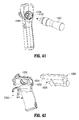
- FIGS. 13 to 30 show various exemplary embodiments of a “gun” type device 1300 , 1800 , 2300 suitable to hold and/or contain the entire inventive device illustrated in the diagram of FIG. 3 .
- the ultrasonic surgical device 1300 includes a disposable ultrasonic cutting tool handle 1408 that has a water-tight sealable battery-holding compartment 1422 , a driving-wave generation circuit 1420 in electrical contact with the battery-holding compartment 1422 , a transducer attachment dock 1404 accessible from an exterior of the handle and operable to releasably physically couple the transducer 1302 to a waveguide 1310 (represented as a dotted line in FIG. 13 ) coupled to the handle 1408 through a waveguide attachment dock 1406 that is disposed to accept and physically couple the ultrasonic waveguide 1310 to the transducer 1302 .
- a waveguide 1310 represented as a dotted line in FIG. 13
- the ultrasonic surgical device 1300 includes a disposable handle body 1308 defining a battery-holding compartment 1422 shaped to receive a battery 1700 therein and operable to couple a proximal end of the ultrasonic waveguide 1310 to the ultrasonic transducer 1302 therethrough.
- the handle body 1308 has a transducer dock 4102 (shown best in FIG. 41 ) exposed to the environment and shaped to interchangeably house at least a portion of the transducer 1302 thereat.
- the handle body 1308 further includes a waveguide attachment dock 1428 shaped to align and attach the proximal end of the waveguide 1310 to the transducer 1302 and thereby hold the waveguide 1310 and the transducer 1302 at least partially within the body when the transducer 1302 is docked in the transducer dock 4102 and the waveguide 1310 is docked in the waveguide attachment dock 1428 .
- An upper portion of the handle body 1308 houses a disposable driving-wave generation circuit 1420 that is in electrical contact with the battery 1700 and the transducer 1302 when the battery 1700 and transducer are disposed, respectively, in the battery-holding compartment 1422 and the transducer dock 4102 .
- the generation circuit 1420 is operable to generate an output waveform sufficient to generate ultrasonic movement along the waveguide by exciting the transducer when the transducer is coupled to the waveguide 1310 .
- the transducer 1302 is generally secured by screwing the transducer 1302 onto a waveguide 1310 , both being at least partially within the transducer port 1404 .
- the physical couple between the handle 1408 and the transducer 1302 once attached, can be water-tight and, in some embodiments, can be aseptic.
- the transducer 1302 imparts the physical forces to the waveguide 318 at the proper frequency and force and receives power from the battery 1700 through conductive power leads 1426 .
- the transducer assembly 1302 is shown in greater detail in FIGS. 15 and 16 .
- the reusable cordless transducer assembly 1402 is shown separate from the device 1300 .
- the inventive transducer assembly 1402 includes a shaft 1504 with an ultrasonic waveguide couple 1508 that is able to attach to a waveguide and, upon activation of the transducer shaft 1504 , excite the attached waveguide, i.e., impart ultrasonic waves along the length of the waveguide.
- the transducer assembly 1402 also has a housing 1506 that protects and seals the internal working components (shown in FIG. 16 ) from the environment. It is advantageous for the transducer assembly 1402 to be selectively removable from the device 1300 .
- the transducer assembly 1402 can be medically disinfected or sterilized, e.g., put in an autoclave, and used for multiple surgeries, while the less-expensive gun itself may be disposable.
- the transducer assembly 1402 can be used in multiple guns or in the same gun up to a desired maximum number of times before it is required to be disposed.
- FIG. 16 shows one exemplary embodiment of the transducer assembly 1302 .
- the movable shaft 1504 Within the housing 1506 is the movable shaft 1504 .
- the shaft 1504 moves laterally within and relative to the housing 1506 .
- the waveguide couple 1508 is male and includes threads 1610 , which are used to secure the transducer assembly 1302 to the non-illustrated waveguide 318 by screwing the waveguide 318 onto the threads 1610 with an appropriate amount of torque.
- the waveguide couple 1508 was female allowing the waveguide to be screwed into the waveguide couple 1508 .
- FIG. 15 shows an exemplary embodiment of electrical connector rings 1510 of the transducer 1402 .
- the connector rings 1510 are brought into contact with, for example, a set of power contacts 4104 , shown in FIG. 41 .
- the power contacts 4104 places the piezoelectric crystal stack 1604 in contact with the power source 1700 of the handle 1408 . This substantially simultaneous coupling can be configured to occur in all embodiments of the present invention.
- the transducer assembly 1302 and the transducer assembly housing 1404 can be sealed so that, in the rare event of surgical fluids contacting the transducer assembly 1302 , they will not introduce themselves into the interior of the housing 1506 .
- the gun 1300 has, within its handle 1408 , a power assembly 1700 (including power source 1702 and a generator 1704 ), referred to herein as a battery-and-generator assembly or “BAG” 1700 , shown in detail in FIG. 17 .
- the battery 1702 within the BAG 1700 can be a single battery or a plurality of battery cells operating as a unit. Both battery configurations (single or multiple cells) will be referred to herein as the “battery” 1702 herein.
- the battery 1702 powers the generator 1704 , which can include some or all of the components shown in FIG. 3 and described in detail above.
- the generator 1704 powers the transducer and includes the processor 302 , the switch 306 (e.g., a MOSFET power switch), the drive circuit 308 (PLL), the transformer 310 , the signal smoothing/matching circuit 312 , and the sensing circuit 314 .
- the present invention's ability to provide all of the necessary reusable generator components of the ultrasonic cutting tool within the disposable handle 1408 of the gun-type device 1300 provides a great advantage over prior-art devices, which house a majority of the device components within the very expensive and heavy desktop box 202 shown in FIG.
- inventive circuit techniques of the present invention sever the dependency on high voltage (120 VAC) input power, a characteristic of all prior-art ultrasonic cutting devices, and utilizes only low-voltage switching throughout the wave-forming process.
- the instant invention provides unique advantages for maintaining a sterile environment in an operating or other environment.
- the handle includes an aseptic seal.
- An “aseptic” seal means a seal that sufficiently isolates a compartment (e.g., inside the handle) and components disposed therein from a sterile field of an operating environment into which the handle has been introduced so that no contaminants from one side of the seal are able to transfer to the other side of the seal.
- the handle 1408 is also provided with a closable door 1412 , for instance, at its bottom 1401 .
- a closable door 1412 for instance, at its bottom 1401 .
- the gun body 1414 which includes the transducer coupling port 1404 and the triggering mechanisms 1418 , is disposable and never used more than for a single surgery.
- This sub-assembly is generally the least expensive of all of the components of the device; in some cases, it is 1/100 th of the total cost of the device.
- the transducer 1302 which is much more expensive and is autoclavable, can be reused multiple times.
- FIGS. 13 and 14 An exemplary procedure for use of the device with the BAG 1700 is explained with regard to FIGS. 13 and 14 .
- a person in the sterile field opens a sealed package containing the new sterile gun body 1408 and removes it for use during the operation.
- the gun body 1408 can either already include the cannula 320 and waveguide 1310 (indicated with a dashed line) or can be coupled to a cannula 320 and waveguide 1310 after the package is opened.
- the sterile (autoclaved) transducer assembly 1302 is inserted into the gun body 1408 and appropriately attached to the waveguide 1310 .
- the surgeon then presents the underside of the gun body 1408 (with the door 1412 open) to the circulating nurse, who drops the BAG 1700 into the grip portion 1424 of the gun handle 1408 without contacting the exterior of the gun body 1408 .
- someone in the operating field e.g., the surgeon
- closes the door 1412 thereby securing the non-sterile BAG 1700 within the gun 1300 through a sterile seal 1401 and preventing it from contaminating the sterile field. Because the removable BAG 1700 is sealed within the handle 1408 , it is “outside” the sterile field during surgery.
- SCUD Self-Contained Ultrasonic Device
- FIGS. 18 and 19 show yet another embodiment of the present invention in which the gun-shaped exterior body 1800 has a different shape than exterior body 1300 of FIGS. 13 and 14 .
- the exterior body 1800 is shaped with a larger upper portion 1802 .
- the generator, battery, and transducer are able to be inserted, either together as an assembly (referred to herein as an “ultrasonic-movement-generation assembly”) or as separate components into a water-tight sealable cordless ultrasonic-movement-generation-assembly-holding compartment 1904 within the upper portion 1802 of the exterior body 1800 .
- the interior of the compartment 1904 remains outside the sterile field during surgery with the aid of a sterile seal 1801 .
- This insertion is performed through use of, as shown in FIG. 19 , a door 1806 , 1906 that can be opened and closed. When closed, the door 1806 , 1906 seals the interior of the gun 1800 from the exterior environment of the gun 1800 and vice versa.
- FIG. 20 shows an embodiment of the ultrasonic-movement-generation assembly 2000 that includes a battery 2002 (in this embodiment, similar to the embodiment of FIG. 17 , the battery is a pack of batteries), a driving-wave generation circuit 2004 (i.e., generator), and a transducer 2006 .
- the entire device 1900 shown in FIGS. 19 , 21 , and 22 , is referred to herein as a Self-Contained Ultrasonic Device or “SCUD.”
- SCUD Self-Contained Ultrasonic Device
- the ultrasonic-movement-generation assembly 2000 can be easily inserted within the compartment 1904 of the disposable handle body 1800 and then sealed from the environment by the door 1806 , 1906 .
- the ultrasonic-movement-generation assembly 2000 can be sterilized, but does not necessarily need to be sterile because it is shielded from the operating environment.
- This provides a tremendous advantage over prior art devices because the ultrasonic-movement-generation assembly 2000 and BAG 1700 do not have to be watertight or autoclavable.
- the electrical connectivity of the components can be easily and inexpensively obtained. For instance, when electrically connected components must be hermetically, or simply waterproof-sealed, the contacts need to be securely protected from moisture and from separation during the high temperature solutions to which they are exposed.
- leads would need to be soldered together or otherwise securely affixed to one another and wrapped with a protective coating to prevent rust/tarnishing and/or separation.
- This protective requirement is not present or at least not as stringent if the components can simply be slipped inside of an outer protective chamber, such as the handle of the ultrasonic gun 1300 , 1800 of the present invention.
- the ultrasonic-movement-generation assembly 2000 (e.g., shown in FIG. 20 ) is made to be inserted into a sealed chamber, it can be configured to open easily and allow any component therein to be removed and exchanged as desired. Including all of the expensive components of the system in the reusable ultrasonic-movement-generation assembly 2000 allows for a simple and inexpensive design for the disposable ultrasonic gun portion of the system.
- FIGS. 21 and 22 show the disposable handle body 1800 with the ultrasonic-movement-generation assembly 2000 inserted in the upper chamber 1904 .
- the disposable handle body 1800 has a waveguide attachment dock 2104 disposed on an exterior of the body 1800 , which is exposed to the environment and has a first couple 2108 operable to releasably physically couple a waveguide to the handle body 1800 .
- the upper chamber 1904 is a water-tight, aseptically sealable, waveguide-movement-generation-assembly-holding compartment and has within its interior a waveguide-movement-generation assembly attachment dock 2106 that is operable to releasably physically couple the ultrasonic-movement-generation assembly 2000 to the handle 2101 and place the ultrasonic-movement-generation assembly 2000 in direct physical contact with an ultrasonic waveguide.
- the ultrasonic-movement-generation assembly 2000 is held in place by a door 1906 having an open position (shown in FIG. 22 ) that allows entry of the ultrasonic-movement-generation assembly 2000 into the chamber 1904 and removal of ultrasonic-movement-generation assembly 2000 from the chamber 1904 .
- the door 1906 also has a closed position (shown in FIG. 21 ) that aseptically seals the interior from the exterior of the handle.
- the chamber 1904 has a motion-generator-assembly ejector 2110 extending at least partially within the holding compartment 1904 and operable to activate (e.g., by movement of the door 1906 from the closed position to the open position) and at least partially eject the assembly 2000 from the holding compartment 1904 .
- the gun 1800 is fully functional and ready to use with a waveguide (see, e.g., FIG. 25 ).
- the exemplary embodiment shown in FIGS. 18-22 allows the costliest portions of the gun to be reused as many times as desired and, advantageously, the portion of the device that is subject to fluids and other contaminates, i.e., the gun 1800 , to be of low cost and disposed after the surgery.
- lithium-ion (Li) batteries should not be charged in a parallel configuration of multiple cells. This is because, as the voltage increases in a particular cell, it begins to accept more charge faster than the other lower-voltage cells. Therefore, each cell must be monitored so that a charge to that cell can be controlled individually.
- a lithium battery is formed from a group of cells, a multitude of wires extending from the exterior of the device to the battery 1702 is needed, at least one additional wire for each battery cell beyond the first.
- each battery cell can have its own exposed set of contacts and, when not present inside the device, each set of contacts can coupled to a corresponding set of contacts in an external, non-sterile battery-charging device.
- TAG Transducer-and-Generator Assembly
- FIGS. 23-30 and 42 - 45 show yet another exemplary embodiment 2300 of the present invention, which includes a disposable ultrasonic cutting tool handle 2301 , a waveguide 2504 , 2508 , a waveguide-movement-generation assembly 2303 , which includes the transducer and driving-wave generation circuit (generator shown in FIG. 24 ), and a battery 304 .
- This embodiment for ease of reference, is referred to herein as a Transducer-and-Generator assembly, or “TAG” 2300 , which acronym refers to the contents of the removable waveguide-movement-generation assembly 2303 .
- TAG Transducer-and-Generator assembly
- the handle 2301 of the TAG 2300 includes a first handle body portion 2302 defining therein an aseptically sealable battery-holding compartment 2410 shaped to receive a removable battery 304 therein.
- the handle 2301 further includes a second handle body portion 2310 that is connected to, or integral with, the first handle body portion 2302 .
- the second handle body portion 2310 has a waveguide attachment dock 2416 exposed to the environment and having a first couple 2418 operable to connect an ultrasonic waveguide 2504 , 2508 thereto, as shown in FIG. 25 .
- the handle 2301 also includes an ultrasonic-motion-generator assembly dock 4202 (shown in FIG.
- An electrical couple (such as couple 4106 , shown in FIG. 41 ), connects the battery 304 within the battery-holding compartment 2410 to the ultrasonic-movement-generator assembly 2303 when the ultrasonic-movement-generator assembly 2303 is docked at the ultrasonic-motion-generator assembly dock 4202 .
- the battery 304 can include part or all of the driving-wave generation circuit.
- the removable ultrasonic-movement-generator assembly 2303 is a cordless (i.e., battery powered) assembly and has a selectively removable securing connector 4204 and an output couple 4206 operable to impart ultrasonic movement to the ultrasonic waveguide 2508 when the waveguide 2508 is connected thereto.
- the assembly 2303 includes a shell 2304 , shown in FIG. 23 , housing an ultrasonic generator 2404 and an ultrasonic transducer 2406 , both shown in FIG. 24 .
- the shell 2304 has a securing connection 4204 shaped to selectively removably connect to a first connector part 4208 of the ultrasonic surgical handle 2300 , shown in FIG. 42 .
- connection 4204 can be a “dove-tail,” as shown in the exemplary embodiment of the figures or any other coupling method that allows the ultrasonic-movement-generator assembly 2303 to be removably attached to the handle 2301 .
- the transducer 2406 has an output couple 4206 operable to impart ultrasonic movement to an ultrasonic waveguide 2508 when the waveguide 2508 is connected thereto.
- the output couple 4206 is a threaded connection that can be screwed onto or into a waveguide 2508 .
- the ultrasonic-movement-generator assembly 2303 can be a sealed watertight and/or autoclavable assembly that can be used in a surgical procedure, sterilized, and then simply be coupled to a brand new handle 2300 to perform a second surgical procedure.
- the TAG 2303 can take several different embodiments.
- FIG. 24 is a cutaway view showing the interior of the TAG 2300 with the near-side (left side) cover of the handle 2301 and the shell 2304 of the ultrasonic-movement-generator assembly 2303 removed.
- the power supply 304 e.g., a battery
- the cylindrical device 2406 shown in FIG. 24 is the transducer assembly, such as the transducer assembly 316 of FIG. 3 .
- the generator 2404 Located above the transducer assembly 2406 .
- the two ultrasonic-movement-generator assembly components 2404 , 2406 when placed inside the covering shell 2304 , advantageously can be easily detached from the handle 2301 and sterilized or replaced as a complete unit.
- the ultrasonic-movement-generator assembly components 2404 , 2406 are hermetically sealed inside the cover 2304 , rendering the ultrasonic-movement-generator assembly 2303 autoclavable so that it can be attached to and used with several different devices.
- the ultrasonic-movement-generator assembly 2303 is coupled to the second portion 2310 of the handle 2302 through a port 2408 .
- the port 2408 when the ultrasonic-movement-generator assembly 2303 is removed, is visible and accessible from an exterior of the handle 2301 .
- the handle 2301 and ultrasonic-movement-generator assembly 2303 could be shaped to create a water-tight seal with one another and prevent moisture on the exterior of either one of the handle 2302 and ultrasonic-movement-generator assembly 2303 from entering the junction between the handle 2301 and ultrasonic-movement-generator assembly 2303 .
- FIG. 24 also shows a battery door 2412 that, when opened, allows a battery 304 to be inserted into the battery-holding compartment 2410 and, when closed, as shown in FIG. 24 , creates a water-tight seal (e.g., aseptic seal) between the interior of the handle 2302 , shown in the cutaway view of FIG. 24 , and the exterior of the handle 2302 , shown in the elevational view of FIG. 23 .
- a water-tight seal e.g., aseptic seal
- the driving-wave generation circuit, or “generator” 2404 is placed in electrical contact with the battery-holding compartment 2410 so that a battery 304 , when inserted, can supply power to the ultrasonic-movement-generator assembly 2303 .
- the transducer 2516 is caused to be releasably physically coupled to a waveguide 2504 , 2508 through the transducer attachment port 2518 and waveguide attachment port 2520 .
- the transducer assembly 2516 can be temporarily locked into a fixed rotational position so that the waveguide 2504 can be attached to the threads 1610 (see, e.g., FIG. 16 ) with sufficient force.
- This physical coupling between the waveguide 2504 and the transducer assembly 2516 allows the transducer assembly 2516 to impart movement to the waveguide 2504 when power is applied to the transducer assembly 2516 .
- the gun 2500 has a spindle 2506 that attaches to the waveguide 2508 .
- the spindle 2506 has indentions that allow a surgeon to easily rotate the spindle 2506 and, therefore, the attached waveguide 2508 and transducer assembly 2516 that is attached to the waveguide 2508 .
- Such a configuration is useful for obtaining the proper cutting-blade angle during surgery.
- the transducer assembly 2516 is able to rotate freely within the transducer housing 2510 .
- the ultrasonic-movement-generator assembly 2502 when the transducer assembly 2516 is located inside the housing 2510 —where it cannot be readily secured by the operator, for example, by holding it steady by hand when the waveguide 2508 is being secured—the ultrasonic-movement-generator assembly 2502 is provided with a button (not shown) that slides into a recess in the housing 2510 or, alternatively, by fixing the rotation of the transducer assembly 2516 at a maximum rotational angle so that, once the maximum rotation is reached, for example, 360 degrees of rotation, no additional rotation is possible and the waveguide 2504 can be screwed thereon. Of course, a maximum rotation in the opposite direction will allow the waveguide 2504 to be removed as well.
- FIG. 26 shows one example of how the generator assembly 2512 and transducer assembly 2516 are electrically coupled so that a physical rotation of the transducer assembly 2516 with respect to the generator assembly 2512 is possible.
- the generator assembly 2516 has a pair of contacts 2602 protruding from its underside, adjacent the transducer assembly 2516 . Proximity of the transducer assembly 2516 to the generator assembly 2512 places one of the pair of contacts 2602 (circled) in physical communication with a pair of contact rings 2604 at the transducer body 2610 so that a driving signal can be steadily applied to the transducer assembly 2516 when needed.
- the pair of contacts 2602 maintains electrical contact regardless of an angle of rotation of the transducer assembly 2516 .
- the transducer assembly 2516 can rotate without any limitations as to the maximum angle or number of rotations.
- the waveguide-movement-generation assembly 2303 can include a battery 304 . This embodiment is advantageous, as it allows the handle portion 2302 to be made smaller or cheaper, as battery contacts are not necessary in the handle portion 2302 .
- the cover 2304 is not present and the transducer assembly 2516 and generator assembly 2512 assemblies are individually covered, i.e., sealed and autoclavable, with each cover being exposed and accessible to a user's fingers.
- an operator attaching the transducer assembly 2516 to the waveguide 2508 has direct access to the transducer assembly 2516 and is able to hold both the transducer assembly 2516 and the waveguide 2508 and turn either one relative to the other during coupling.
- FIGS. 27-30 show more detailed views of exemplary embodiments of the device and the trigger mechanisms. It is noted that there is a difference between the activation trigger of the device shown in FIGS. 19-22 and the trigger shown in FIGS. 23-30 .
- the upper handle portion 1802 is hollow. Because it is hollow, the trigger 2102 can be a thick object that, when squeezed, is able to retract at least partially into the interior of the handle 2101 .
- the thick trigger 2102 has the advantage of preventing a user's fingers from getting pinched when the trigger 2102 is squeezed.
- the embodiment of FIG. 24 includes a battery 304 within the interior of the hand grip 2302 .
- the trigger 2308 cannot retreat inside the hand grip 2302 when actuated, as does the trigger 2102 of FIG. 21 .
- the trigger 2308 is thinner than the trigger 2102 of FIG. 21 in the trigger actuation direction and simply moves toward the hand grip 2302 during actuation (it does not enter the interior of the hand grip 2302 , or enters it only minimally).
- the trigger includes a protrusion 1306 , 2306 extending from the hand grip 1308 , 2302 and preventing the user's finger from moving up and under the trigger 1318 , 2308 .
- the protrusion 1306 , 2306 prevent the user's finger from getting pinched and causing possible discomfort
- the protrusion 1306 , 2306 also prevents the user's finger from interfering with functioning of the trigger 1318 , 2308 .
- FIGS. 31 to 34 illustrate an entirely hand-held and fully self-contained cautery and cutting device 3300 .
- This cutting device 3300 reduces the size of the power supply 3302 considerably.
- the waveguide 3304 is reduced in length. All of the power modification components (the control, drive, and matching circuits 304 , 306 , 308 ) and the power supply 3302 reside at the handpiece 3310 .
- 31 to 34 could have, in accordance with one embodiment, a sealed body 3302 , where the body 3302 housing the power modification components (the control, drive, and matching circuits 304 , 306 , 308 ) and the power supply 3302 is autoclavable and the waveguide 3304 is simply replaced for each procedure.
- the body 3102 could open up and receive the power modification components (the control, drive, and matching circuits 304 , 306 , 308 ) and the power supply 3302 in an aseptic transfer, similar to the device shown in FIG. 21 and described above.
- the power supply can be separated from the handpiece and can, for example, be worn on a physician's belt.
- FIGS. 34 to 38 An example of such embodiments can be seen in FIGS. 34 to 38 .
- the base 3700 shown in FIG. 37 , has a body 3706 that houses a self-contained power source (i.e., a battery) and a generator circuit operable to generate an output waveform and is sized to be handheld.
- the base 3700 is connected through a communications and power tether cord 3702 , illustrated diagrammatically in the figures with a dashed line, to the pen-shaped ultrasonic waveguide handle 3600 , shown in FIGS. 34-36 .
- the transducer 3602 within the handle 3600 is driven by a plurality of driving waves output from the waveform generator within the body 3706 .
- the base 3700 has a user interface 3704 that can be used to communicate data and carry out functions of the device, such as testing and operation. Through the user interface 3704 , the device can be tested in the sealed package without even opening the package. For instance, in one embodiment, a user can press one or more non-illustrated buttons (physical or electronic) in a given sequence (e.g., 5 times in a row) and, thereby, cause the user interface 3704 to display a status of the battery and/or a status of the logic circuitry, all without having to remove it from the sealed package. This is helpful in case of a defect, such as a bad battery, as the purchaser would be able to return the device to the manufacturer before use and, thereby, prove non-use of the device to receive credit.
- all of the power modification components reside in the base 3700 .
- the base 3700 is also provided with a non-illustrated clothing attachment mechanism that can be a simple belt clip, or any other way of attaching a device to a wearer.
- the clothing attachment mechanism allows a surgeon or nurse to wear the base 3700 during a surgery so that the cord 3702 will always be of sufficient length, i.e., as long as his arm can reach, no matter where the surgeon is standing.
- the cautery/cutting device 3400 is shaped to fit into a surgeon's hand.
- the shape illustrated in FIG. 34 is, therefore, only exemplary.
- Another exemplary shape for the pen device 3600 is shown in FIGS. 35 and 36 and is similar to a writing pen so that the surgery can be carried out with the device 3600 to approximate writing—a process that is comfortable to most physicians.
- the pen 3400 , 3600 includes all of the transducer components—the transducer 3402 , 3602 , the protective cannula 3404 , 3604 , and the waveguide 3406 , 3606 .
- one or more of the components, together or separate, can be removed from or exchanged between the handpiece 2300 , 3300 , 3400 , 3600 and the base 3700 for service, replacement, storage, inspection, or other purposes as desired.
- the component(s) of the devices described herein can implement a confirmation process for ensuring that the various component(s) can or should be used in or with the device.
- the components can perform a check (possibly with encryption) to see whether they match the particular handpiece 2300 , 3300 , 3400 , 3600 or base 3700 , i.e., to see if they have the correct manufacturer/model number to work with the part in which or to which it is connected.
- the system can have a safety mechanism where the surgeon using the device is grounded to the circuit 300 .
- the device senses this grounding and immediately ceases movement of the waveguide 318 , 3306 , 3406 , 3606 , thereby instantly preventing the surgeon from cutting him/herself.
- the hand-held instrument 2300 , 3300 , 3400 , 3600 , 3700 is not connected to earth ground, it will be possible to provide a safety circuit that can sense contact with the surgeon and interrupt ultrasonic power delivery.
- a capacitive contact patch located on the hand grip 2302 , 3310 , 3400 , 3600 , 3700 is connected to a capacitive-touch sensing circuit (such as is used for capacitive switching and known to those in the art) and disposed to detect contact of the working tip with the surgeon. When such contact is detected, the drive circuit of the instrument will be shut down to avoid applying cutting energy to the surgeon.
- a sensing circuit would be impractical in systems of the prior art, where the handpiece is connected to a large piece of earth-grounded electrical equipment.
- FIG. 39 shows another exemplary embodiment of the present invention, which includes a “smart” or “intelligent” battery 3902 .
- the smart battery 3902 is used to power a surgical or other device, such as the gun 3900 .
- the smart battery 3902 is not limited to the gun 3900 and, as will be explained, can be used in a variety of devices, which may or may not have power (i.e., current and voltage) requirements that vary from each other.
- the smart battery 3902 is advantageously able to identify the particular device to which it is electrically coupled. It does this through encrypted or unencrypted identification methods.
- the battery 3902 can have a connection portion, such as portion 3904 shown in FIG. 39 .
- the gun's handle 3901 can also be provided with a device identifier 3906 communicatively coupled to the battery-holding compartment 3908 and operable to communicate at least one piece of information about the handle 3901 .
- This information can pertain to the number of times the handle 3901 has been used, the number of times a TAG unit 3910 has been used, the number of times a waveguide (not shown) has been used, the type of waveguide connected to the handle 3901 , the type or identity of TAG 3910 connected to the handle 3901 , or many other characteristics.
- the connection portion 3904 makes communicating contact with the device identifier 3906 .
- the handle 3910 through hardware, software, or a combination thereof, is able to transmit information to the smart battery assembly 3902 . This communicated identifier is received by the connection portion 3904 of the smart battery assembly 3902 .
- the communication portion 3904 is operable to control the output of the battery assembly 3902 to comply with the device's specific power requirements.
- a microcontroller 3916 in the communication portion 3904 of the battery assembly 3902 , it is no longer required that a programmable device be placed in the disposable handle portion 3901 .
- the handle may be sterilized by gamma radiation, which is more economical than other sterilization measures.
- the battery-holding compartment 3908 has a battery ejector device 3912 that extends at least partially within the battery-holding compartment 3908 and is able to cause at least a portion of the battery 3902 to be ejected from the battery-holding compartment 3908 . This prevents an operator from having to reach his or her potentially soiled or otherwise non-sterile fingers inside the device in order to remove the battery assembly 3902 .
- the battery-holding compartment 3908 is activated by a movement of the door from the closed position to the open position. In other words, once the door is opened, the batter 3902 partially ejects out of the compartment 3908 .
- the transducer assembly 1302 contains additional circuit components, such as the tank circuit 312 shown in FIG. 3 .
- the tank circuit 312 is tuned to match the transducer to which it feeds. Therefore, transducers and tank circuits are best matched if they remain as a pair and are not placed in combination with other device.
- the smart battery 3902 could feed different frequencies to the different transducer assemblies 1302 , the frequencies being respectively matched to a particular blade and waveguide assembly. Two popular frequencies for ultrasonic surgery devices are 55 kHz and 40 kHz.
- the communication portion 3904 includes a processor, such as processor 302 , and a memory, such as memory 326 , which may be separate or a single component.
- the processor 302 in combination with the memory 326 , is able to provide intelligent power management for the gun device 3900 .
- This embodiment is particularly advantageous because an ultrasonic device, such as device 300 , has a power requirement (frequency, current, and voltage) that may be unique to the device 300 .
- device 300 may have a particular power requirement or limitation for one dimension or type of waveguide 318 and a second different power requirement for a second type of waveguide having a different dimension, shape, and/or configuration.
- each of the waveguides would have a respective maximum allowable power limit. Exceeding the power limit overstresses the waveguide and eventually causes it to fracture.
- One waveguide from the set of waveguides will naturally have the smallest maximum power tolerance.
- the output of prior-art batteries must be limited by a value of the smallest maximum allowable power input for the smallest/thinnest/most frail waveguide in the set that is envisioned to be used with the device/battery. This would be true even though larger, thicker waveguides could later be attached to that handle and, by definition, allow a greater force to be applied.
- exemplary embodiments of the present invention utilizing the smart battery 3902 are able to intelligently circumvent any previous limitation of ultrasonic devices.
- the smart battery 3902 can produce one output for one device or a particular device configuration and the same battery 3902 can later produce a different output for a second device or device configuration.
- This universal smart battery surgical system lends itself well to the modern operating room where space and time are at a premium. By having a single battery pack that operates many different devices, the nurses can easily manage the storage and retrieval of the packs.
- the smart battery system requires only one type of charging station, thus increasing ease and efficiency of use and decreasing cost.
- a single smart battery 3902 can be used with any one of an entire series of devices and is able to tailor its own power output to the particular device in which it is installed. In one embodiment, this power tailoring is performed by controlling the duty cycle of a switched mode power supply, such as buck, buck-boost, boost, or other configuration, integral with or otherwise coupled to and controlled by the smart battery 3902 .
- a switched mode power supply such as buck, buck-boost, boost, or other configuration
- the smart battery 3902 can dynamically change its power output during device operation. For instance, in vessel sealing devices, power management is very important. In these devices, large constant current values are needed. The total power output needs to be adjusted dynamically because, as the tissue is sealed, its impedance changes.
- Embodiments of the present invention provide the smart battery 3902 with a variable maximum current limit. The current limit can vary from one application (or device) to another, based on the requirements of the application or device.
- an ultrasonic surgical device 4400 has an ultrasonic waveguide 4402 with one of a set of different waveguide types.
- An ultrasonic transducer 4404 is physically coupled to the waveguide 4402 and is operable to impart ultrasonic movement to the ultrasonic waveguide 4402 .
- a cordless ultrasonic-movement-generation assembly 4406 is connected to either the waveguide or the transducer and is operable to generate and deliver a driving-wave frequency and a driving-wave power to the transducer 4402 .
- the device 4400 is able to accept and drive waveguides 4402 of varying dimensions
- the device 4400 is provided with a waveguide detector 4408 coupled to the ultrasonic-movement-generation assembly 4406 and operable to detect the type (e.g., the dimensions) of the waveguide 4402 attached to the transducer 4404 and to cause the ultrasonic-movement-generation 4406 assembly to vary the driving-wave frequency and/or the driving-wave power based upon the detected waveguide type.
- the waveguide detector 4408 can be any device, set of components, software, electrical connections, or other that is/are able to identify at least one property of a waveguide 4402 connected to the device 4400 .
- the smart battery 3902 stores in its memory 326 a record of each time a particular device is used. This record can be useful for assessing the end of a device's useful or permitted life. For instance, once a device is used 20 times, all such batteries 3902 connected to the device will refuse to supply power thereto—because the device is defined as a “no longer reliable” surgical instrument. Reliability is determined based on a number of factors. One factor can be wear; after a certain number of uses, the parts of the device can become worn and tolerances between parts exceeded. This wear can lead to an unacceptable failure during a procedure. In some exemplary embodiments, the smart battery 3902 can recognize which parts are combined and even how many uses each part has experienced. For instance, looking at FIG.
- the battery 1700 can identify both the gun 1300 , as well as the particular transducer assembly 1302 .
- a memory within the smart battery 3902 can record each time the transducer assembly 1302 is operated. If each transducer assembly 1302 has an individual identifier, the smart battery 3902 can keep track of each transducer assembly's use and refuse to supply power to that transducer assembly 1302 once the gun 1300 or the transducer assembly 1302 exceeds its maximum number of uses.
- the TAG, stapler, vessel sealer, etc. circuitry can include a memory chip which records this information also. This way, any number of smart batteries can be used with any number of TAGs, staplers, vessel sealers, etc. and still be able to determine the total number of uses, or the total time of use (through use of clock 330 ), or the total number of actuations etc. of each TAG, stapler, vessel sealer etc.
- buttons 4002 a - n are provided with a plurality of buttons 4002 a - n , although not all can be seen in the left-side view of FIG. 40 .
- These buttons can have various functions that pertain to operation of the device 4000 .
- previous devices were tethered by a cord 208 to a desktop box 202 . If a prior-art device wished to add an additional function, associated with a button, then an additional communication wire would need to be added to the non-changeable strand of wires in the tether 208 .
- the addition of wires renders the tether even less desirous, as the surgeon must work with and support the ever-increasing bundle of wires.
- the present invention is impervious to this disadvantage because all communication is contained within the handle itself and no external wires are needed.
- the device 4000 will generally operate the same and weigh the same, no matter how many buttons are added.
- the present invention is provided with a display screen 4004 that conveys visual information to an operator.
- the visual information can be, for instance, the number of uses a particular waveguide has been subjected to, the battery voltage, the status of the device, such as indicating a non-engaged condition of the device components, button states, warnings, and many others.
- the present invention has a window 4502 on the compartment door 4504 that allows a user to view a display screen 4506 on a movement-generation assembly within the compartment. 4508 .
- the ultrasonic surgical device 4600 includes a cordless unitary housing 4602 sized to fit within a surgical instrument handle 4604 .
- the housing 4602 houses a self-contained power source 4606 and a power source control circuit 4608 that is electrically coupled to the power source 4606 and is operable to control distribution of power from the power source 4606 .
- the housing 4602 also holds an ultrasonic waveform-generating circuit 4610 electrically coupled to the control circuit 4708 and operable to output a waveform sufficient to drive an ultrasonic transducer of the ultrasonic surgical instrument 4600 .
- the ultrasonic waveguide driving assembly 4601 can be inserted into the inexpensive handle 4604 , used for a single surgery, the handle 4604 disposed of, and the assembly can then be inserted and used in multiple other handles to perform additional surgeries.
- all of the expensive components are reused and do not need to be aseptically sealed since they are contained within a battery-holding compartment 4612 of the handle 4604 and are never exposed to the operating environment.
- the present invention provides a small and efficient hand-held ultrasonic cutting device that is self-powered and, therefore, cordless.
- the invention has a separate body-worn pack that houses any combination of the control electronics and the self-contained power supply.
- the expensive set-top box is eliminated entirely.
- the invention provides low-voltage or battery-voltage switching or wave-forming stages prior to the transducer.
- the device allows a user to operate completely free of cords or other tethering devices.
- the present invention by “marrying” all of the frequency sensitive components within one place (e.g., the handle), also eliminates any inductive losses that occur between prior art set-top boxes and handpieces—a disadvantage suffered by all prior-art ultrasonic cautery/cutting devices. Because of the close coupling between the drive circuit 308 and the matching network 312 , the overall power modification circuit is tolerant of higher Q factors and larger frequency ranges.
- the present invention provides additional advantages in the way the device is kept sterile. Because the inventive device is a fraction of a size of the prior art devices, the driving circuit can be placed within the handle.
- the handle, transducer, waveguide, and blade are sterilized and the handle has a door that opens, allowing the battery and driving circuits, which are outside the sterile field, to be dropped inside the handle. When the door is closed, the non-sterile portions are sealed within the handle.
Abstract
Description
Therefore, iC=r·iB and, substituting for iC in the equation iM=iT−iC, leads to: iM=iT−r·iB.
Claims (10)
Priority Applications (47)
| Application Number | Priority Date | Filing Date | Title |
|---|---|---|---|
| US12/266,146 US8419758B2 (en) | 2007-12-03 | 2008-11-06 | Cordless hand-held ultrasonic cautery cutting device |
| EP17184251.1A EP3263055B1 (en) | 2007-12-03 | 2008-12-01 | Cordless hand-held ultrasonic cautery cutting device |
| JP2010537005A JP5813954B2 (en) | 2007-12-03 | 2008-12-01 | Cordless, hand-held ultrasonic cautery cutting device |
| EP11010007.0A EP2433577B1 (en) | 2007-12-03 | 2008-12-01 | Cordless hand-held ultrasonic cautery cutting device |
| CA2968143A CA2968143C (en) | 2007-12-03 | 2008-12-01 | Cordless hand-held ultrasonic cautery cutting device |
| EP11010043.5A EP2433578B1 (en) | 2007-12-03 | 2008-12-01 | Cordless hand-held ultrasonic cautery cutting device |
| EP08858351.3A EP2229104B1 (en) | 2007-12-03 | 2008-12-01 | Cordless hand-held ultrasonic cautery cutting device |
| CA2921116A CA2921116A1 (en) | 2007-12-03 | 2008-12-01 | Cordless hand-held ultrasonic cautery cutting device |
| CA2707837A CA2707837C (en) | 2007-12-03 | 2008-12-01 | Cordless hand-held ultrasonic cautery cutting device |
| AU2008334050A AU2008334050B2 (en) | 2007-12-03 | 2008-12-01 | Cordless hand-held ultrasonic cautery cutting device |
| PCT/US2008/085141 WO2009073608A1 (en) | 2007-12-03 | 2008-12-01 | Cordless hand-held ultrasonic cautery cutting device |
| US12/547,975 US8435257B2 (en) | 2007-12-03 | 2009-08-26 | Cordless hand-held ultrasonic cautery cutting device and method |
| US12/547,999 US8425545B2 (en) | 2007-12-03 | 2009-08-26 | Cordless hand-held ultrasonic cautery cutting device and method |
| US12/547,898 US8061014B2 (en) | 2007-12-03 | 2009-08-26 | Method of assembling a cordless hand-held ultrasonic cautery cutting device |
| US12/868,545 US8334468B2 (en) | 2008-11-06 | 2010-08-25 | Method of switching a cordless hand-held ultrasonic cautery cutting device |
| US13/022,707 US8663262B2 (en) | 2007-12-03 | 2011-02-08 | Battery assembly for battery-powered surgical instruments |
| US13/022,743 US8439939B2 (en) | 2007-12-03 | 2011-02-08 | Method of powering a surgical instrument |
| US13/072,309 US8372101B2 (en) | 2007-12-03 | 2011-03-25 | Cordless hand-held ultrasonic cautery cutting device |
| US13/072,373 US8418349B2 (en) | 2007-12-03 | 2011-03-25 | Method of assembling a cordless hand-held ultrasonic cautery cutting device |
| US13/072,221 US8236020B2 (en) | 2007-12-03 | 2011-03-25 | Cordless hand-held ultrasonic cautery cutting device |
| US13/072,247 US8333778B2 (en) | 2007-12-03 | 2011-03-25 | Cordless hand-held ultrasonic cautery cutting device |
| US13/072,345 US8377085B2 (en) | 2007-12-03 | 2011-03-25 | Cordless hand-held ultrasonic cautery cutting device |
| US13/072,187 US8197502B2 (en) | 2007-12-03 | 2011-03-25 | Method of maintaining constant movement of a cutting blade on an ultrasonic waveguide |
| US13/072,273 US8333779B2 (en) | 2007-12-03 | 2011-03-25 | Method of maintaining constant movement of a cutting blade of an ultrasonic waveguide |
| US13/215,971 US9017355B2 (en) | 2007-12-03 | 2011-08-23 | Battery-powered hand-held ultrasonic surgical cautery cutting device |
| US13/307,750 US9107690B2 (en) | 2007-12-03 | 2011-11-30 | Battery-powered hand-held ultrasonic surgical cautery cutting device |
| JP2011274313A JP5900917B2 (en) | 2007-12-03 | 2011-12-15 | Cordless, hand-held ultrasonic cautery cutting device |
| JP2011274312A JP5818354B2 (en) | 2007-12-03 | 2011-12-15 | Cordless, hand-held ultrasonic cautery cutting device |
| US13/465,820 US9782180B2 (en) | 2007-12-03 | 2012-05-07 | Method of maintaining constant movement of a cutting blade of an ultrasonic waveguide |
| US13/539,694 US9861382B2 (en) | 2007-12-03 | 2012-07-02 | Cordless hand-held ultrasonic cautery cutting device |
| US13/655,522 US8497436B2 (en) | 2008-11-06 | 2012-10-19 | Two-stage switch for surgical device |
| US13/655,571 US8487199B2 (en) | 2008-11-06 | 2012-10-19 | Method of switching a surgical device |
| US13/655,557 US8497437B2 (en) | 2008-11-06 | 2012-10-19 | Method of switching a surgical device |
| US13/655,532 US8502091B2 (en) | 2008-11-06 | 2012-10-19 | Two-Stage Switch for Surgical Device |
| US13/874,010 US9084625B2 (en) | 2007-12-03 | 2013-04-30 | Battery assembly for battery-powered surgical instruments |
| US13/873,958 US8992555B2 (en) | 2007-12-03 | 2013-04-30 | Method of assembling a cordless hand-held ultrasonic cautery cutting device |
| US13/901,994 US8742269B2 (en) | 2008-11-06 | 2013-05-24 | Two-stage switch for surgical device |
| US14/231,042 US20140236202A1 (en) | 2008-11-06 | 2014-03-31 | Method for Operating a Two-Stage Switch for Surgical Device |
| JP2014077366A JP5896426B2 (en) | 2007-12-03 | 2014-04-03 | Cordless, hand-held ultrasonic cautery cutting device |
| JP2014077367A JP5896427B2 (en) | 2007-12-03 | 2014-04-03 | Cordless, hand-held ultrasonic cautery cutting device |
| JP2014077368A JP5896428B2 (en) | 2007-12-03 | 2014-04-03 | Cordless, hand-held ultrasonic cautery cutting device |
| US14/607,358 US20150141988A1 (en) | 2007-12-03 | 2015-01-28 | Two-Stage Switch for Surgical Device |
| US14/625,320 US9314261B2 (en) | 2007-12-03 | 2015-02-18 | Battery-powered hand-held ultrasonic surgical cautery cutting device |
| US14/694,751 US9872696B2 (en) | 2007-12-03 | 2015-04-23 | Battery-powered hand-held ultrasonic surgical cautery cutting device |
| JP2016000364A JP6173496B2 (en) | 2007-12-03 | 2016-01-05 | Cordless, hand-held ultrasonic cautery cutting device |
| US15/131,908 US10799913B2 (en) | 2007-12-03 | 2016-04-18 | Battery-powered hand-held ultrasonic surgical cautery cutting device |
| US15/684,357 US10456158B2 (en) | 2007-12-03 | 2017-08-23 | Cordless hand-held ultrasonic surgical device |
Applications Claiming Priority (8)
| Application Number | Priority Date | Filing Date | Title |
|---|---|---|---|
| US99182907P | 2007-12-03 | 2007-12-03 | |
| US99249807P | 2007-12-05 | 2007-12-05 | |
| US1988808P | 2008-01-09 | 2008-01-09 | |
| US4547508P | 2008-04-16 | 2008-04-16 | |
| US4880908P | 2008-04-29 | 2008-04-29 | |
| US8186508P | 2008-07-18 | 2008-07-18 | |
| US8188508P | 2008-07-18 | 2008-07-18 | |
| US12/266,146 US8419758B2 (en) | 2007-12-03 | 2008-11-06 | Cordless hand-held ultrasonic cautery cutting device |
Related Parent Applications (5)
| Application Number | Title | Priority Date | Filing Date |
|---|---|---|---|
| US12/266,101 Continuation-In-Part US8419757B2 (en) | 2007-12-03 | 2008-11-06 | Cordless hand-held ultrasonic cautery cutting device |
| US12/266,101 Division US8419757B2 (en) | 2007-12-03 | 2008-11-06 | Cordless hand-held ultrasonic cautery cutting device |
| US12/266,191 Continuation-In-Part US8185539B1 (en) | 2007-12-03 | 2008-11-06 | Web site or directory search using speech recognition of letters |
| US12/266,226 Continuation-In-Part US20090143799A1 (en) | 2007-12-03 | 2008-11-06 | Cordless Hand-Held Ultrasonic Cautery Cutting Device |
| US12/269,629 Continuation-In-Part US8403949B2 (en) | 2007-12-03 | 2008-11-12 | Cordless hand-held ultrasonic cautery cutting device |
Related Child Applications (19)
| Application Number | Title | Priority Date | Filing Date |
|---|---|---|---|
| US12/266,226 Continuation-In-Part US20090143799A1 (en) | 2007-12-03 | 2008-11-06 | Cordless Hand-Held Ultrasonic Cautery Cutting Device |
| US12/266,101 Continuation-In-Part US8419757B2 (en) | 2007-12-03 | 2008-11-06 | Cordless hand-held ultrasonic cautery cutting device |
| US12/266,252 Continuation-In-Part US20090143800A1 (en) | 2007-12-03 | 2008-11-06 | Cordless Hand-Held Ultrasonic Cautery Cutting Device |
| US12/547,975 Continuation-In-Part US8435257B2 (en) | 2007-12-03 | 2009-08-26 | Cordless hand-held ultrasonic cautery cutting device and method |
| US12/547,898 Continuation-In-Part US8061014B2 (en) | 2007-12-03 | 2009-08-26 | Method of assembling a cordless hand-held ultrasonic cautery cutting device |
| US12/547,999 Continuation-In-Part US8425545B2 (en) | 2007-12-03 | 2009-08-26 | Cordless hand-held ultrasonic cautery cutting device and method |
| US13/022,707 Continuation-In-Part US8663262B2 (en) | 2007-12-03 | 2011-02-08 | Battery assembly for battery-powered surgical instruments |
| US13/022,743 Continuation-In-Part US8439939B2 (en) | 2007-12-03 | 2011-02-08 | Method of powering a surgical instrument |
| US13/022,707 Division US8663262B2 (en) | 2007-12-03 | 2011-02-08 | Battery assembly for battery-powered surgical instruments |
| US13/022,743 Division US8439939B2 (en) | 2007-12-03 | 2011-02-08 | Method of powering a surgical instrument |
| US13/072,273 Continuation-In-Part US8333779B2 (en) | 2007-12-03 | 2011-03-25 | Method of maintaining constant movement of a cutting blade of an ultrasonic waveguide |
| US13/072,187 Continuation-In-Part US8197502B2 (en) | 2007-12-03 | 2011-03-25 | Method of maintaining constant movement of a cutting blade on an ultrasonic waveguide |
| US13/072,247 Continuation-In-Part US8333778B2 (en) | 2007-12-03 | 2011-03-25 | Cordless hand-held ultrasonic cautery cutting device |
| US13/072,373 Continuation-In-Part US8418349B2 (en) | 2007-12-03 | 2011-03-25 | Method of assembling a cordless hand-held ultrasonic cautery cutting device |
| US13/072,221 Continuation-In-Part US8236020B2 (en) | 2007-12-03 | 2011-03-25 | Cordless hand-held ultrasonic cautery cutting device |
| US13/072,309 Continuation-In-Part US8372101B2 (en) | 2007-12-03 | 2011-03-25 | Cordless hand-held ultrasonic cautery cutting device |
| US13/465,820 Continuation-In-Part US9782180B2 (en) | 2007-12-03 | 2012-05-07 | Method of maintaining constant movement of a cutting blade of an ultrasonic waveguide |
| US13/539,694 Continuation-In-Part US9861382B2 (en) | 2007-12-03 | 2012-07-02 | Cordless hand-held ultrasonic cautery cutting device |
| US14/625,320 Continuation-In-Part US9314261B2 (en) | 2007-12-03 | 2015-02-18 | Battery-powered hand-held ultrasonic surgical cautery cutting device |
Publications (2)
| Publication Number | Publication Date |
|---|---|
| US20090143798A1 US20090143798A1 (en) | 2009-06-04 |
| US8419758B2 true US8419758B2 (en) | 2013-04-16 |
Family
ID=67184142
Family Applications (11)
| Application Number | Title | Priority Date | Filing Date |
|---|---|---|---|
| US12/266,252 Abandoned US20090143800A1 (en) | 2007-12-03 | 2008-11-06 | Cordless Hand-Held Ultrasonic Cautery Cutting Device |
| US12/266,101 Active 2029-12-23 US8419757B2 (en) | 2007-12-03 | 2008-11-06 | Cordless hand-held ultrasonic cautery cutting device |
| US12/266,146 Active 2030-06-10 US8419758B2 (en) | 2007-12-03 | 2008-11-06 | Cordless hand-held ultrasonic cautery cutting device |
| US12/266,226 Abandoned US20090143799A1 (en) | 2007-12-03 | 2008-11-06 | Cordless Hand-Held Ultrasonic Cautery Cutting Device |
| US12/266,320 Active 2029-11-06 US8403948B2 (en) | 2007-12-03 | 2008-11-06 | Cordless hand-held ultrasonic cautery cutting device |
| US12/266,664 Active 2030-06-30 US8372099B2 (en) | 2007-12-03 | 2008-11-07 | Cordless hand-held ultrasonic cautery cutting device |
| US12/269,544 Active 2030-06-28 US8444662B2 (en) | 2007-12-03 | 2008-11-12 | Cordless hand-held ultrasonic cautery cutting device |
| US12/269,629 Active 2030-09-04 US8403949B2 (en) | 2007-12-03 | 2008-11-12 | Cordless hand-held ultrasonic cautery cutting device |
| US12/270,146 Active 2029-09-12 US8403950B2 (en) | 2007-12-03 | 2008-11-13 | Cordless hand-held ultrasonic cautery cutting device |
| US13/022,743 Active 2029-06-08 US8439939B2 (en) | 2007-12-03 | 2011-02-08 | Method of powering a surgical instrument |
| US15/402,531 Active 2029-07-26 US10426508B2 (en) | 2007-12-03 | 2017-01-10 | Cordless hand-held ultrasonic cautery device |
Family Applications Before (2)
| Application Number | Title | Priority Date | Filing Date |
|---|---|---|---|
| US12/266,252 Abandoned US20090143800A1 (en) | 2007-12-03 | 2008-11-06 | Cordless Hand-Held Ultrasonic Cautery Cutting Device |
| US12/266,101 Active 2029-12-23 US8419757B2 (en) | 2007-12-03 | 2008-11-06 | Cordless hand-held ultrasonic cautery cutting device |
Family Applications After (8)
| Application Number | Title | Priority Date | Filing Date |
|---|---|---|---|
| US12/266,226 Abandoned US20090143799A1 (en) | 2007-12-03 | 2008-11-06 | Cordless Hand-Held Ultrasonic Cautery Cutting Device |
| US12/266,320 Active 2029-11-06 US8403948B2 (en) | 2007-12-03 | 2008-11-06 | Cordless hand-held ultrasonic cautery cutting device |
| US12/266,664 Active 2030-06-30 US8372099B2 (en) | 2007-12-03 | 2008-11-07 | Cordless hand-held ultrasonic cautery cutting device |
| US12/269,544 Active 2030-06-28 US8444662B2 (en) | 2007-12-03 | 2008-11-12 | Cordless hand-held ultrasonic cautery cutting device |
| US12/269,629 Active 2030-09-04 US8403949B2 (en) | 2007-12-03 | 2008-11-12 | Cordless hand-held ultrasonic cautery cutting device |
| US12/270,146 Active 2029-09-12 US8403950B2 (en) | 2007-12-03 | 2008-11-13 | Cordless hand-held ultrasonic cautery cutting device |
| US13/022,743 Active 2029-06-08 US8439939B2 (en) | 2007-12-03 | 2011-02-08 | Method of powering a surgical instrument |
| US15/402,531 Active 2029-07-26 US10426508B2 (en) | 2007-12-03 | 2017-01-10 | Cordless hand-held ultrasonic cautery device |
Country Status (6)
| Country | Link |
|---|---|
| US (11) | US20090143800A1 (en) |
| EP (4) | EP3263055B1 (en) |
| JP (7) | JP5813954B2 (en) |
| AU (1) | AU2008334050B2 (en) |
| CA (3) | CA2968143C (en) |
| WO (1) | WO2009073608A1 (en) |
Cited By (174)
| Publication number | Priority date | Publication date | Assignee | Title |
|---|---|---|---|---|
| US20110046620A1 (en) * | 2009-08-19 | 2011-02-24 | Triangle Biomedical Sciences, Inc. | Cordless heated forceps |
| US20130090577A1 (en) * | 2011-10-10 | 2013-04-11 | Chad P. Boudreaux | Ultrasonic surgical instrument with modular end effector |
| US9060775B2 (en) | 2009-10-09 | 2015-06-23 | Ethicon Endo-Surgery, Inc. | Surgical generator for ultrasonic and electrosurgical devices |
| US9066747B2 (en) | 2007-11-30 | 2015-06-30 | Ethicon Endo-Surgery, Inc. | Ultrasonic surgical instrument blades |
| US9095367B2 (en) | 2012-10-22 | 2015-08-04 | Ethicon Endo-Surgery, Inc. | Flexible harmonic waveguides/blades for surgical instruments |
| US9198714B2 (en) | 2012-06-29 | 2015-12-01 | Ethicon Endo-Surgery, Inc. | Haptic feedback devices for surgical robot |
| US9220527B2 (en) | 2007-07-27 | 2015-12-29 | Ethicon Endo-Surgery, Llc | Surgical instruments |
| US9226767B2 (en) | 2012-06-29 | 2016-01-05 | Ethicon Endo-Surgery, Inc. | Closed feedback control for electrosurgical device |
| US9226766B2 (en) | 2012-04-09 | 2016-01-05 | Ethicon Endo-Surgery, Inc. | Serial communication protocol for medical device |
| US9232979B2 (en) | 2012-02-10 | 2016-01-12 | Ethicon Endo-Surgery, Inc. | Robotically controlled surgical instrument |
| US9237921B2 (en) | 2012-04-09 | 2016-01-19 | Ethicon Endo-Surgery, Inc. | Devices and techniques for cutting and coagulating tissue |
| US9241728B2 (en) | 2013-03-15 | 2016-01-26 | Ethicon Endo-Surgery, Inc. | Surgical instrument with multiple clamping mechanisms |
| US9241731B2 (en) | 2012-04-09 | 2016-01-26 | Ethicon Endo-Surgery, Inc. | Rotatable electrical connection for ultrasonic surgical instruments |
| US9283045B2 (en) | 2012-06-29 | 2016-03-15 | Ethicon Endo-Surgery, Llc | Surgical instruments with fluid management system |
| US9308009B2 (en) | 2010-11-05 | 2016-04-12 | Ethicon Endo-Surgery, Llc | Surgical instrument with modular shaft and transducer |
| US9326788B2 (en) | 2012-06-29 | 2016-05-03 | Ethicon Endo-Surgery, Llc | Lockout mechanism for use with robotic electrosurgical device |
| US9351754B2 (en) | 2012-06-29 | 2016-05-31 | Ethicon Endo-Surgery, Llc | Ultrasonic surgical instruments with distally positioned jaw assemblies |
| US9375255B2 (en) | 2010-11-05 | 2016-06-28 | Ethicon Endo-Surgery, Llc | Surgical instrument handpiece with resiliently biased coupling to modular shaft and end effector |
| US9381058B2 (en) | 2010-11-05 | 2016-07-05 | Ethicon Endo-Surgery, Llc | Recharge system for medical devices |
| US9393037B2 (en) | 2012-06-29 | 2016-07-19 | Ethicon Endo-Surgery, Llc | Surgical instruments with articulating shafts |
| US9408622B2 (en) | 2012-06-29 | 2016-08-09 | Ethicon Endo-Surgery, Llc | Surgical instruments with articulating shafts |
| US20160228145A1 (en) * | 2015-02-10 | 2016-08-11 | Covidien Lp | Surgical stapling instrument having ultrasonic energy delivery |
| US9414853B2 (en) | 2007-07-27 | 2016-08-16 | Ethicon Endo-Surgery, Llc | Ultrasonic end effectors with increased active length |
| US9421062B2 (en) | 2010-11-05 | 2016-08-23 | Ethicon Endo-Surgery, Llc | Surgical instrument shaft with resiliently biased coupling to handpiece |
| US9427249B2 (en) | 2010-02-11 | 2016-08-30 | Ethicon Endo-Surgery, Llc | Rotatable cutting implements with friction reducing material for ultrasonic surgical instruments |
| US9439669B2 (en) | 2007-07-31 | 2016-09-13 | Ethicon Endo-Surgery, Llc | Ultrasonic surgical instruments |
| US9439668B2 (en) | 2012-04-09 | 2016-09-13 | Ethicon Endo-Surgery, Llc | Switch arrangements for ultrasonic surgical instruments |
| US9445832B2 (en) | 2007-07-31 | 2016-09-20 | Ethicon Endo-Surgery, Llc | Surgical instruments |
| US9498245B2 (en) | 2009-06-24 | 2016-11-22 | Ethicon Endo-Surgery, Llc | Ultrasonic surgical instruments |
| US9504855B2 (en) | 2008-08-06 | 2016-11-29 | Ethicon Surgery, LLC | Devices and techniques for cutting and coagulating tissue |
| US9510850B2 (en) | 2010-02-11 | 2016-12-06 | Ethicon Endo-Surgery, Llc | Ultrasonic surgical instruments |
| US9554846B2 (en) | 2010-10-01 | 2017-01-31 | Ethicon Endo-Surgery, Llc | Surgical instrument with jaw member |
| US9554854B2 (en) | 2014-03-18 | 2017-01-31 | Ethicon Endo-Surgery, Llc | Detecting short circuits in electrosurgical medical devices |
| US9597143B2 (en) | 2010-11-05 | 2017-03-21 | Ethicon Endo-Surgery, Llc | Sterile medical instrument charging device |
| US9623237B2 (en) | 2009-10-09 | 2017-04-18 | Ethicon Endo-Surgery, Llc | Surgical generator for ultrasonic and electrosurgical devices |
| US9636135B2 (en) | 2007-07-27 | 2017-05-02 | Ethicon Endo-Surgery, Llc | Ultrasonic surgical instruments |
| US9649126B2 (en) | 2010-02-11 | 2017-05-16 | Ethicon Endo-Surgery, Llc | Seal arrangements for ultrasonically powered surgical instruments |
| US9700333B2 (en) | 2014-06-30 | 2017-07-11 | Ethicon Llc | Surgical instrument with variable tissue compression |
| US9707027B2 (en) | 2010-05-21 | 2017-07-18 | Ethicon Endo-Surgery, Llc | Medical device |
| US9724118B2 (en) | 2012-04-09 | 2017-08-08 | Ethicon Endo-Surgery, Llc | Techniques for cutting and coagulating tissue for ultrasonic surgical instruments |
| US9737355B2 (en) | 2014-03-31 | 2017-08-22 | Ethicon Llc | Controlling impedance rise in electrosurgical medical devices |
| US9757186B2 (en) | 2014-04-17 | 2017-09-12 | Ethicon Llc | Device status feedback for bipolar tissue spacer |
| US9764164B2 (en) | 2009-07-15 | 2017-09-19 | Ethicon Llc | Ultrasonic surgical instruments |
| US9782215B2 (en) | 2010-11-05 | 2017-10-10 | Ethicon Endo-Surgery, Llc | Surgical instrument with ultrasonic transducer having integral switches |
| US9782214B2 (en) | 2010-11-05 | 2017-10-10 | Ethicon Llc | Surgical instrument with sensor and powered control |
| US9801648B2 (en) | 2007-03-22 | 2017-10-31 | Ethicon Llc | Surgical instruments |
| US9808308B2 (en) | 2010-04-12 | 2017-11-07 | Ethicon Llc | Electrosurgical cutting and sealing instruments with cam-actuated jaws |
| US9820768B2 (en) | 2012-06-29 | 2017-11-21 | Ethicon Llc | Ultrasonic surgical instruments with control mechanisms |
| US9848902B2 (en) | 2007-10-05 | 2017-12-26 | Ethicon Llc | Ergonomic surgical instruments |
| US9848901B2 (en) | 2010-02-11 | 2017-12-26 | Ethicon Llc | Dual purpose surgical instrument for cutting and coagulating tissue |
| US9848937B2 (en) | 2014-12-22 | 2017-12-26 | Ethicon Llc | End effector with detectable configurations |
| US9872725B2 (en) | 2015-04-29 | 2018-01-23 | Ethicon Llc | RF tissue sealer with mode selection |
| US9877776B2 (en) | 2014-08-25 | 2018-01-30 | Ethicon Llc | Simultaneous I-beam and spring driven cam jaw closure mechanism |
| US9883884B2 (en) | 2007-03-22 | 2018-02-06 | Ethicon Llc | Ultrasonic surgical instruments |
| US9913680B2 (en) | 2014-04-15 | 2018-03-13 | Ethicon Llc | Software algorithms for electrosurgical instruments |
| US9949788B2 (en) | 2013-11-08 | 2018-04-24 | Ethicon Endo-Surgery, Llc | Electrosurgical devices |
| US9962182B2 (en) | 2010-02-11 | 2018-05-08 | Ethicon Llc | Ultrasonic surgical instruments with moving cutting implement |
| US10034684B2 (en) | 2015-06-15 | 2018-07-31 | Ethicon Llc | Apparatus and method for dissecting and coagulating tissue |
| US10034704B2 (en) | 2015-06-30 | 2018-07-31 | Ethicon Llc | Surgical instrument with user adaptable algorithms |
| US10045794B2 (en) | 2007-11-30 | 2018-08-14 | Ethicon Llc | Ultrasonic surgical blades |
| US10085792B2 (en) | 2010-11-05 | 2018-10-02 | Ethicon Llc | Surgical instrument with motorized attachment feature |
| US10092310B2 (en) | 2014-03-27 | 2018-10-09 | Ethicon Llc | Electrosurgical devices |
| US10092348B2 (en) | 2014-12-22 | 2018-10-09 | Ethicon Llc | RF tissue sealer, shear grip, trigger lock mechanism and energy activation |
| US10111699B2 (en) | 2014-12-22 | 2018-10-30 | Ethicon Llc | RF tissue sealer, shear grip, trigger lock mechanism and energy activation |
| US10117702B2 (en) | 2015-04-10 | 2018-11-06 | Ethicon Llc | Surgical generator systems and related methods |
| US10130410B2 (en) | 2015-04-17 | 2018-11-20 | Ethicon Llc | Electrosurgical instrument including a cutting member decouplable from a cutting member trigger |
| US10136938B2 (en) | 2014-10-29 | 2018-11-27 | Ethicon Llc | Electrosurgical instrument with sensor |
| US10143513B2 (en) | 2010-11-05 | 2018-12-04 | Ethicon Llc | Gear driven coupling between ultrasonic transducer and waveguide in surgical instrument |
| US10154852B2 (en) | 2015-07-01 | 2018-12-18 | Ethicon Llc | Ultrasonic surgical blade with improved cutting and coagulation features |
| US10159524B2 (en) | 2014-12-22 | 2018-12-25 | Ethicon Llc | High power battery powered RF amplifier topology |
| US10166060B2 (en) | 2011-08-30 | 2019-01-01 | Ethicon Llc | Surgical instruments comprising a trigger assembly |
| US10172669B2 (en) | 2009-10-09 | 2019-01-08 | Ethicon Llc | Surgical instrument comprising an energy trigger lockout |
| US10179022B2 (en) | 2015-12-30 | 2019-01-15 | Ethicon Llc | Jaw position impedance limiter for electrosurgical instrument |
| US10194973B2 (en) | 2015-09-30 | 2019-02-05 | Ethicon Llc | Generator for digitally generating electrical signal waveforms for electrosurgical and ultrasonic surgical instruments |
| US10194976B2 (en) | 2014-08-25 | 2019-02-05 | Ethicon Llc | Lockout disabling mechanism |
| US10194972B2 (en) | 2014-08-26 | 2019-02-05 | Ethicon Llc | Managing tissue treatment |
| US10201365B2 (en) | 2012-10-22 | 2019-02-12 | Ethicon Llc | Surgeon feedback sensing and display methods |
| US10226273B2 (en) | 2013-03-14 | 2019-03-12 | Ethicon Llc | Mechanical fasteners for use with surgical energy devices |
| US10245064B2 (en) | 2016-07-12 | 2019-04-02 | Ethicon Llc | Ultrasonic surgical instrument with piezoelectric central lumen transducer |
| US10251664B2 (en) | 2016-01-15 | 2019-04-09 | Ethicon Llc | Modular battery powered handheld surgical instrument with multi-function motor via shifting gear assembly |
| USD847990S1 (en) | 2016-08-16 | 2019-05-07 | Ethicon Llc | Surgical instrument |
| US10278721B2 (en) | 2010-07-22 | 2019-05-07 | Ethicon Llc | Electrosurgical instrument with separate closure and cutting members |
| US10285723B2 (en) | 2016-08-09 | 2019-05-14 | Ethicon Llc | Ultrasonic surgical blade with improved heel portion |
| US10285724B2 (en) | 2014-07-31 | 2019-05-14 | Ethicon Llc | Actuation mechanisms and load adjustment assemblies for surgical instruments |
| US10314638B2 (en) | 2015-04-07 | 2019-06-11 | Ethicon Llc | Articulating radio frequency (RF) tissue seal with articulating state sensing |
| US10321950B2 (en) | 2015-03-17 | 2019-06-18 | Ethicon Llc | Managing tissue treatment |
| US10342602B2 (en) | 2015-03-17 | 2019-07-09 | Ethicon Llc | Managing tissue treatment |
| US10349967B2 (en) | 2014-02-28 | 2019-07-16 | Ethicon Llc | Ultrasonic surgical instrument with removable handle assembly |
| US10357303B2 (en) | 2015-06-30 | 2019-07-23 | Ethicon Llc | Translatable outer tube for sealing using shielded lap chole dissector |
| US10376305B2 (en) | 2016-08-05 | 2019-08-13 | Ethicon Llc | Methods and systems for advanced harmonic energy |
| US10420580B2 (en) | 2016-08-25 | 2019-09-24 | Ethicon Llc | Ultrasonic transducer for surgical instrument |
| US10433900B2 (en) | 2011-07-22 | 2019-10-08 | Ethicon Llc | Surgical instruments for tensioning tissue |
| US10456193B2 (en) | 2016-05-03 | 2019-10-29 | Ethicon Llc | Medical device with a bilateral jaw configuration for nerve stimulation |
| US10463421B2 (en) | 2014-03-27 | 2019-11-05 | Ethicon Llc | Two stage trigger, clamp and cut bipolar vessel sealer |
| US10485607B2 (en) | 2016-04-29 | 2019-11-26 | Ethicon Llc | Jaw structure with distal closure for electrosurgical instruments |
| US10524852B1 (en) | 2014-03-28 | 2020-01-07 | Ethicon Llc | Distal sealing end effector with spacers |
| US10524854B2 (en) | 2010-07-23 | 2020-01-07 | Ethicon Llc | Surgical instrument |
| US10537352B2 (en) | 2004-10-08 | 2020-01-21 | Ethicon Llc | Tissue pads for use with surgical instruments |
| US10537380B2 (en) | 2010-11-05 | 2020-01-21 | Ethicon Llc | Surgical instrument with charging station and wireless communication |
| US10555769B2 (en) | 2016-02-22 | 2020-02-11 | Ethicon Llc | Flexible circuits for electrosurgical instrument |
| US10575892B2 (en) | 2015-12-31 | 2020-03-03 | Ethicon Llc | Adapter for electrical surgical instruments |
| US10595929B2 (en) | 2015-03-24 | 2020-03-24 | Ethicon Llc | Surgical instruments with firing system overload protection mechanisms |
| US10595930B2 (en) | 2015-10-16 | 2020-03-24 | Ethicon Llc | Electrode wiping surgical device |
| US10603064B2 (en) | 2016-11-28 | 2020-03-31 | Ethicon Llc | Ultrasonic transducer |
| US10603117B2 (en) | 2017-06-28 | 2020-03-31 | Ethicon Llc | Articulation state detection mechanisms |
| US10639092B2 (en) | 2014-12-08 | 2020-05-05 | Ethicon Llc | Electrode configurations for surgical instruments |
| US10646269B2 (en) | 2016-04-29 | 2020-05-12 | Ethicon Llc | Non-linear jaw gap for electrosurgical instruments |
| USRE47996E1 (en) | 2009-10-09 | 2020-05-19 | Ethicon Llc | Surgical generator for ultrasonic and electrosurgical devices |
| US10660695B2 (en) | 2010-11-05 | 2020-05-26 | Ethicon Llc | Sterile medical instrument charging device |
| US10702329B2 (en) | 2016-04-29 | 2020-07-07 | Ethicon Llc | Jaw structure with distal post for electrosurgical instruments |
| US10709906B2 (en) | 2009-05-20 | 2020-07-14 | Ethicon Llc | Coupling arrangements and methods for attaching tools to ultrasonic surgical instruments |
| US10716615B2 (en) | 2016-01-15 | 2020-07-21 | Ethicon Llc | Modular battery powered handheld surgical instrument with curved end effectors having asymmetric engagement between jaw and blade |
| US10751117B2 (en) | 2016-09-23 | 2020-08-25 | Ethicon Llc | Electrosurgical instrument with fluid diverter |
| US10765470B2 (en) | 2015-06-30 | 2020-09-08 | Ethicon Llc | Surgical system with user adaptable techniques employing simultaneous energy modalities based on tissue parameters |
| US10779876B2 (en) | 2011-10-24 | 2020-09-22 | Ethicon Llc | Battery powered surgical instrument |
| US10779848B2 (en) | 2006-01-20 | 2020-09-22 | Ethicon Llc | Ultrasound medical instrument having a medical ultrasonic blade |
| US10779845B2 (en) | 2012-06-29 | 2020-09-22 | Ethicon Llc | Ultrasonic surgical instruments with distally positioned transducers |
| US10799284B2 (en) | 2017-03-15 | 2020-10-13 | Ethicon Llc | Electrosurgical instrument with textured jaws |
| US10820920B2 (en) | 2017-07-05 | 2020-11-03 | Ethicon Llc | Reusable ultrasonic medical devices and methods of their use |
| US10835307B2 (en) | 2001-06-12 | 2020-11-17 | Ethicon Llc | Modular battery powered handheld surgical instrument containing elongated multi-layered shaft |
| US10842522B2 (en) | 2016-07-15 | 2020-11-24 | Ethicon Llc | Ultrasonic surgical instruments having offset blades |
| US10856896B2 (en) | 2005-10-14 | 2020-12-08 | Ethicon Llc | Ultrasonic device for cutting and coagulating |
| US10856929B2 (en) | 2014-01-07 | 2020-12-08 | Ethicon Llc | Harvesting energy from a surgical generator |
| US10856934B2 (en) | 2016-04-29 | 2020-12-08 | Ethicon Llc | Electrosurgical instrument with electrically conductive gap setting and tissue engaging members |
| US10874418B2 (en) | 2004-02-27 | 2020-12-29 | Ethicon Llc | Ultrasonic surgical shears and method for sealing a blood vessel using same |
| US10881448B2 (en) | 2010-11-05 | 2021-01-05 | Ethicon Llc | Cam driven coupling between ultrasonic transducer and waveguide in surgical instrument |
| US10881449B2 (en) | 2012-09-28 | 2021-01-05 | Ethicon Llc | Multi-function bi-polar forceps |
| US10893883B2 (en) | 2016-07-13 | 2021-01-19 | Ethicon Llc | Ultrasonic assembly for use with ultrasonic surgical instruments |
| US10898256B2 (en) | 2015-06-30 | 2021-01-26 | Ethicon Llc | Surgical system with user adaptable techniques based on tissue impedance |
| US10912580B2 (en) | 2013-12-16 | 2021-02-09 | Ethicon Llc | Medical device |
| US10925659B2 (en) | 2013-09-13 | 2021-02-23 | Ethicon Llc | Electrosurgical (RF) medical instruments for cutting and coagulating tissue |
| US10952759B2 (en) | 2016-08-25 | 2021-03-23 | Ethicon Llc | Tissue loading of a surgical instrument |
| US10959771B2 (en) | 2015-10-16 | 2021-03-30 | Ethicon Llc | Suction and irrigation sealing grasper |
| US10959769B2 (en) | 2010-11-05 | 2021-03-30 | Ethicon Llc | Surgical instrument with slip ring assembly to power ultrasonic transducer |
| US10959806B2 (en) | 2015-12-30 | 2021-03-30 | Ethicon Llc | Energized medical device with reusable handle |
| US10987123B2 (en) | 2012-06-28 | 2021-04-27 | Ethicon Llc | Surgical instruments with articulating shafts |
| US10987156B2 (en) | 2016-04-29 | 2021-04-27 | Ethicon Llc | Electrosurgical instrument with electrically conductive gap setting member and electrically insulative tissue engaging members |
| US11020140B2 (en) | 2015-06-17 | 2021-06-01 | Cilag Gmbh International | Ultrasonic surgical blade for use with ultrasonic surgical instruments |
| US11026627B2 (en) | 2013-03-15 | 2021-06-08 | Cadwell Laboratories, Inc. | Surgical instruments for determining a location of a nerve during a procedure |
| US11033292B2 (en) | 2013-12-16 | 2021-06-15 | Cilag Gmbh International | Medical device |
| US11033325B2 (en) | 2017-02-16 | 2021-06-15 | Cilag Gmbh International | Electrosurgical instrument with telescoping suction port and debris cleaner |
| US11033323B2 (en) | 2017-09-29 | 2021-06-15 | Cilag Gmbh International | Systems and methods for managing fluid and suction in electrosurgical systems |
| US11051873B2 (en) | 2015-06-30 | 2021-07-06 | Cilag Gmbh International | Surgical system with user adaptable techniques employing multiple energy modalities based on tissue parameters |
| US11058447B2 (en) | 2007-07-31 | 2021-07-13 | Cilag Gmbh International | Temperature controlled ultrasonic surgical instruments |
| US11090104B2 (en) | 2009-10-09 | 2021-08-17 | Cilag Gmbh International | Surgical generator for ultrasonic and electrosurgical devices |
| US11129670B2 (en) | 2016-01-15 | 2021-09-28 | Cilag Gmbh International | Modular battery powered handheld surgical instrument with selective application of energy based on button displacement, intensity, or local tissue characterization |
| US11129669B2 (en) | 2015-06-30 | 2021-09-28 | Cilag Gmbh International | Surgical system with user adaptable techniques based on tissue type |
| US11177610B2 (en) | 2017-01-23 | 2021-11-16 | Cadwell Laboratories, ino. | Neuromonitoring connection system |
| US11229471B2 (en) | 2016-01-15 | 2022-01-25 | Cilag Gmbh International | Modular battery powered handheld surgical instrument with selective application of energy based on tissue characterization |
| US11253182B2 (en) | 2018-05-04 | 2022-02-22 | Cadwell Laboratories, Inc. | Apparatus and method for polyphasic multi-output constant-current and constant-voltage neurophysiological stimulation |
| US11266430B2 (en) | 2016-11-29 | 2022-03-08 | Cilag Gmbh International | End effector control and calibration |
| US11311326B2 (en) | 2015-02-06 | 2022-04-26 | Cilag Gmbh International | Electrosurgical instrument with rotation and articulation mechanisms |
| US11324527B2 (en) | 2012-11-15 | 2022-05-10 | Cilag Gmbh International | Ultrasonic and electrosurgical devices |
| US11443649B2 (en) | 2018-06-29 | 2022-09-13 | Cadwell Laboratories, Inc. | Neurophysiological monitoring training simulator |
| US11452525B2 (en) | 2019-12-30 | 2022-09-27 | Cilag Gmbh International | Surgical instrument comprising an adjustment system |
| US11484358B2 (en) | 2017-09-29 | 2022-11-01 | Cilag Gmbh International | Flexible electrosurgical instrument |
| US11490951B2 (en) | 2017-09-29 | 2022-11-08 | Cilag Gmbh International | Saline contact with electrodes |
| US11497546B2 (en) | 2017-03-31 | 2022-11-15 | Cilag Gmbh International | Area ratios of patterned coatings on RF electrodes to reduce sticking |
| US11589916B2 (en) | 2019-12-30 | 2023-02-28 | Cilag Gmbh International | Electrosurgical instruments with electrodes having variable energy densities |
| US11660089B2 (en) | 2019-12-30 | 2023-05-30 | Cilag Gmbh International | Surgical instrument comprising a sensing system |
| US11684412B2 (en) | 2019-12-30 | 2023-06-27 | Cilag Gmbh International | Surgical instrument with rotatable and articulatable surgical end effector |
| US11696776B2 (en) | 2019-12-30 | 2023-07-11 | Cilag Gmbh International | Articulatable surgical instrument |
| US11723716B2 (en) | 2019-12-30 | 2023-08-15 | Cilag Gmbh International | Electrosurgical instrument with variable control mechanisms |
| US11759251B2 (en) | 2019-12-30 | 2023-09-19 | Cilag Gmbh International | Control program adaptation based on device status and user input |
| US11779387B2 (en) | 2019-12-30 | 2023-10-10 | Cilag Gmbh International | Clamp arm jaw to minimize tissue sticking and improve tissue control |
| US11779329B2 (en) | 2019-12-30 | 2023-10-10 | Cilag Gmbh International | Surgical instrument comprising a flex circuit including a sensor system |
| US11786291B2 (en) | 2019-12-30 | 2023-10-17 | Cilag Gmbh International | Deflectable support of RF energy electrode with respect to opposing ultrasonic blade |
| US11812957B2 (en) | 2019-12-30 | 2023-11-14 | Cilag Gmbh International | Surgical instrument comprising a signal interference resolution system |
| US11911063B2 (en) | 2019-12-30 | 2024-02-27 | Cilag Gmbh International | Techniques for detecting ultrasonic blade to electrode contact and reducing power to ultrasonic blade |
| US11937863B2 (en) | 2019-12-30 | 2024-03-26 | Cilag Gmbh International | Deflectable electrode with variable compression bias along the length of the deflectable electrode |
| US11937866B2 (en) | 2019-12-30 | 2024-03-26 | Cilag Gmbh International | Method for an electrosurgical procedure |
| US11944366B2 (en) | 2019-12-30 | 2024-04-02 | Cilag Gmbh International | Asymmetric segmented ultrasonic support pad for cooperative engagement with a movable RF electrode |
| US11950797B2 (en) | 2019-12-30 | 2024-04-09 | Cilag Gmbh International | Deflectable electrode with higher distal bias relative to proximal bias |
| US11957342B2 (en) | 2021-11-01 | 2024-04-16 | Cilag Gmbh International | Devices, systems, and methods for detecting tissue and foreign objects during a surgical operation |
Families Citing this family (614)
| Publication number | Priority date | Publication date | Assignee | Title |
|---|---|---|---|---|
| US20070084897A1 (en) | 2003-05-20 | 2007-04-19 | Shelton Frederick E Iv | Articulating surgical stapling instrument incorporating a two-piece e-beam firing mechanism |
| US9060770B2 (en) | 2003-05-20 | 2015-06-23 | Ethicon Endo-Surgery, Inc. | Robotically-driven surgical instrument with E-beam driver |
| US11890012B2 (en) | 2004-07-28 | 2024-02-06 | Cilag Gmbh International | Staple cartridge comprising cartridge body and attached support |
| US8215531B2 (en) | 2004-07-28 | 2012-07-10 | Ethicon Endo-Surgery, Inc. | Surgical stapling instrument having a medical substance dispenser |
| US7669746B2 (en) | 2005-08-31 | 2010-03-02 | Ethicon Endo-Surgery, Inc. | Staple cartridges for forming staples having differing formed staple heights |
| US11484312B2 (en) | 2005-08-31 | 2022-11-01 | Cilag Gmbh International | Staple cartridge comprising a staple driver arrangement |
| US20070194079A1 (en) | 2005-08-31 | 2007-08-23 | Hueil Joseph C | Surgical stapling device with staple drivers of different height |
| US7934630B2 (en) | 2005-08-31 | 2011-05-03 | Ethicon Endo-Surgery, Inc. | Staple cartridges for forming staples having differing formed staple heights |
| US10159482B2 (en) | 2005-08-31 | 2018-12-25 | Ethicon Llc | Fastener cartridge assembly comprising a fixed anvil and different staple heights |
| US8800838B2 (en) | 2005-08-31 | 2014-08-12 | Ethicon Endo-Surgery, Inc. | Robotically-controlled cable-based surgical end effectors |
| US11246590B2 (en) | 2005-08-31 | 2022-02-15 | Cilag Gmbh International | Staple cartridge including staple drivers having different unfired heights |
| US9237891B2 (en) | 2005-08-31 | 2016-01-19 | Ethicon Endo-Surgery, Inc. | Robotically-controlled surgical stapling devices that produce formed staples having different lengths |
| US20070106317A1 (en) | 2005-11-09 | 2007-05-10 | Shelton Frederick E Iv | Hydraulically and electrically actuated articulation joints for surgical instruments |
| US7753904B2 (en) | 2006-01-31 | 2010-07-13 | Ethicon Endo-Surgery, Inc. | Endoscopic surgical instrument with a handle that can articulate with respect to the shaft |
| US8186555B2 (en) | 2006-01-31 | 2012-05-29 | Ethicon Endo-Surgery, Inc. | Motor-driven surgical cutting and fastening instrument with mechanical closure system |
| US8161977B2 (en) | 2006-01-31 | 2012-04-24 | Ethicon Endo-Surgery, Inc. | Accessing data stored in a memory of a surgical instrument |
| US11793518B2 (en) | 2006-01-31 | 2023-10-24 | Cilag Gmbh International | Powered surgical instruments with firing system lockout arrangements |
| US7845537B2 (en) | 2006-01-31 | 2010-12-07 | Ethicon Endo-Surgery, Inc. | Surgical instrument having recording capabilities |
| US9861359B2 (en) | 2006-01-31 | 2018-01-09 | Ethicon Llc | Powered surgical instruments with firing system lockout arrangements |
| US11278279B2 (en) | 2006-01-31 | 2022-03-22 | Cilag Gmbh International | Surgical instrument assembly |
| US20110024477A1 (en) | 2009-02-06 | 2011-02-03 | Hall Steven G | Driven Surgical Stapler Improvements |
| US11224427B2 (en) | 2006-01-31 | 2022-01-18 | Cilag Gmbh International | Surgical stapling system including a console and retraction assembly |
| US20110290856A1 (en) | 2006-01-31 | 2011-12-01 | Ethicon Endo-Surgery, Inc. | Robotically-controlled surgical instrument with force-feedback capabilities |
| US8708213B2 (en) | 2006-01-31 | 2014-04-29 | Ethicon Endo-Surgery, Inc. | Surgical instrument having a feedback system |
| US8763879B2 (en) | 2006-01-31 | 2014-07-01 | Ethicon Endo-Surgery, Inc. | Accessing data stored in a memory of surgical instrument |
| US8820603B2 (en) | 2006-01-31 | 2014-09-02 | Ethicon Endo-Surgery, Inc. | Accessing data stored in a memory of a surgical instrument |
| US20120292367A1 (en) | 2006-01-31 | 2012-11-22 | Ethicon Endo-Surgery, Inc. | Robotically-controlled end effector |
| US8992422B2 (en) | 2006-03-23 | 2015-03-31 | Ethicon Endo-Surgery, Inc. | Robotically-controlled endoscopic accessory channel |
| US20070225562A1 (en) | 2006-03-23 | 2007-09-27 | Ethicon Endo-Surgery, Inc. | Articulating endoscopic accessory channel |
| DE102006021559A1 (en) * | 2006-05-08 | 2008-11-13 | Universität Paderborn | Food arrangement for an ultrasonic device |
| US8322455B2 (en) | 2006-06-27 | 2012-12-04 | Ethicon Endo-Surgery, Inc. | Manually driven surgical cutting and fastening instrument |
| US20080078802A1 (en) | 2006-09-29 | 2008-04-03 | Hess Christopher J | Surgical staples and stapling instruments |
| US10130359B2 (en) | 2006-09-29 | 2018-11-20 | Ethicon Llc | Method for forming a staple |
| US10568652B2 (en) | 2006-09-29 | 2020-02-25 | Ethicon Llc | Surgical staples having attached drivers of different heights and stapling instruments for deploying the same |
| US11291441B2 (en) | 2007-01-10 | 2022-04-05 | Cilag Gmbh International | Surgical instrument with wireless communication between control unit and remote sensor |
| US8459520B2 (en) | 2007-01-10 | 2013-06-11 | Ethicon Endo-Surgery, Inc. | Surgical instrument with wireless communication between control unit and remote sensor |
| US8684253B2 (en) | 2007-01-10 | 2014-04-01 | Ethicon Endo-Surgery, Inc. | Surgical instrument with wireless communication between a control unit of a robotic system and remote sensor |
| US8652120B2 (en) | 2007-01-10 | 2014-02-18 | Ethicon Endo-Surgery, Inc. | Surgical instrument with wireless communication between control unit and sensor transponders |
| US11039836B2 (en) | 2007-01-11 | 2021-06-22 | Cilag Gmbh International | Staple cartridge for use with a surgical stapling instrument |
| US20080169332A1 (en) | 2007-01-11 | 2008-07-17 | Shelton Frederick E | Surgical stapling device with a curved cutting member |
| US20090001121A1 (en) | 2007-03-15 | 2009-01-01 | Hess Christopher J | Surgical staple having an expandable portion |
| US20080234709A1 (en) | 2007-03-22 | 2008-09-25 | Houser Kevin L | Ultrasonic surgical instrument and cartilage and bone shaping blades therefor |
| US8226675B2 (en) | 2007-03-22 | 2012-07-24 | Ethicon Endo-Surgery, Inc. | Surgical instruments |
| US8893946B2 (en) | 2007-03-28 | 2014-11-25 | Ethicon Endo-Surgery, Inc. | Laparoscopic tissue thickness and clamp load measuring devices |
| US8534528B2 (en) | 2007-06-04 | 2013-09-17 | Ethicon Endo-Surgery, Inc. | Surgical instrument having a multiple rate directional switching mechanism |
| US11672531B2 (en) | 2007-06-04 | 2023-06-13 | Cilag Gmbh International | Rotary drive systems for surgical instruments |
| US7832408B2 (en) | 2007-06-04 | 2010-11-16 | Ethicon Endo-Surgery, Inc. | Surgical instrument having a directional switching mechanism |
| US8931682B2 (en) | 2007-06-04 | 2015-01-13 | Ethicon Endo-Surgery, Inc. | Robotically-controlled shaft based rotary drive systems for surgical instruments |
| US8408439B2 (en) | 2007-06-22 | 2013-04-02 | Ethicon Endo-Surgery, Inc. | Surgical stapling instrument with an articulatable end effector |
| US7753245B2 (en) | 2007-06-22 | 2010-07-13 | Ethicon Endo-Surgery, Inc. | Surgical stapling instruments |
| US11849941B2 (en) | 2007-06-29 | 2023-12-26 | Cilag Gmbh International | Staple cartridge having staple cavities extending at a transverse angle relative to a longitudinal cartridge axis |
| US8348967B2 (en) | 2007-07-27 | 2013-01-08 | Ethicon Endo-Surgery, Inc. | Ultrasonic surgical instruments |
| US8252012B2 (en) | 2007-07-31 | 2012-08-28 | Ethicon Endo-Surgery, Inc. | Ultrasonic surgical instrument with modulator |
| US20110022032A1 (en) * | 2007-10-05 | 2011-01-27 | Tyco Healthcare Group Lp | Battery ejection design for a surgical device |
| US7901423B2 (en) | 2007-11-30 | 2011-03-08 | Ethicon Endo-Surgery, Inc. | Folded ultrasonic end effectors with increased active length |
| US9314261B2 (en) | 2007-12-03 | 2016-04-19 | Covidien Ag | Battery-powered hand-held ultrasonic surgical cautery cutting device |
| US20090143800A1 (en) | 2007-12-03 | 2009-06-04 | Derek Dee Deville | Cordless Hand-Held Ultrasonic Cautery Cutting Device |
| US8663262B2 (en) | 2007-12-03 | 2014-03-04 | Covidien Ag | Battery assembly for battery-powered surgical instruments |
| US8338726B2 (en) * | 2009-08-26 | 2012-12-25 | Covidien Ag | Two-stage switch for cordless hand-held ultrasonic cautery cutting device |
| US8061014B2 (en) | 2007-12-03 | 2011-11-22 | Covidien Ag | Method of assembling a cordless hand-held ultrasonic cautery cutting device |
| US8425545B2 (en) * | 2007-12-03 | 2013-04-23 | Covidien Ag | Cordless hand-held ultrasonic cautery cutting device and method |
| US9107690B2 (en) | 2007-12-03 | 2015-08-18 | Covidien Ag | Battery-powered hand-held ultrasonic surgical cautery cutting device |
| US9017355B2 (en) * | 2007-12-03 | 2015-04-28 | Covidien Ag | Battery-powered hand-held ultrasonic surgical cautery cutting device |
| US8561870B2 (en) | 2008-02-13 | 2013-10-22 | Ethicon Endo-Surgery, Inc. | Surgical stapling instrument |
| US7905381B2 (en) | 2008-09-19 | 2011-03-15 | Ethicon Endo-Surgery, Inc. | Surgical stapling instrument with cutting member arrangement |
| US8758391B2 (en) | 2008-02-14 | 2014-06-24 | Ethicon Endo-Surgery, Inc. | Interchangeable tools for surgical instruments |
| US8752749B2 (en) | 2008-02-14 | 2014-06-17 | Ethicon Endo-Surgery, Inc. | Robotically-controlled disposable motor-driven loading unit |
| US7793812B2 (en) | 2008-02-14 | 2010-09-14 | Ethicon Endo-Surgery, Inc. | Disposable motor-driven loading unit for use with a surgical cutting and stapling apparatus |
| US8636736B2 (en) | 2008-02-14 | 2014-01-28 | Ethicon Endo-Surgery, Inc. | Motorized surgical cutting and fastening instrument |
| US8573465B2 (en) | 2008-02-14 | 2013-11-05 | Ethicon Endo-Surgery, Inc. | Robotically-controlled surgical end effector system with rotary actuated closure systems |
| US7819298B2 (en) | 2008-02-14 | 2010-10-26 | Ethicon Endo-Surgery, Inc. | Surgical stapling apparatus with control features operable with one hand |
| US9179912B2 (en) | 2008-02-14 | 2015-11-10 | Ethicon Endo-Surgery, Inc. | Robotically-controlled motorized surgical cutting and fastening instrument |
| US8459525B2 (en) | 2008-02-14 | 2013-06-11 | Ethicon Endo-Sugery, Inc. | Motorized surgical cutting and fastening instrument having a magnetic drive train torque limiting device |
| US8584919B2 (en) | 2008-02-14 | 2013-11-19 | Ethicon Endo-Sugery, Inc. | Surgical stapling apparatus with load-sensitive firing mechanism |
| US8622274B2 (en) | 2008-02-14 | 2014-01-07 | Ethicon Endo-Surgery, Inc. | Motorized cutting and fastening instrument having control circuit for optimizing battery usage |
| US8657174B2 (en) | 2008-02-14 | 2014-02-25 | Ethicon Endo-Surgery, Inc. | Motorized surgical cutting and fastening instrument having handle based power source |
| US7866527B2 (en) | 2008-02-14 | 2011-01-11 | Ethicon Endo-Surgery, Inc. | Surgical stapling apparatus with interlockable firing system |
| BRPI0901282A2 (en) | 2008-02-14 | 2009-11-17 | Ethicon Endo Surgery Inc | surgical cutting and fixation instrument with rf electrodes |
| US11272927B2 (en) | 2008-02-15 | 2022-03-15 | Cilag Gmbh International | Layer arrangements for surgical staple cartridges |
| US10390823B2 (en) | 2008-02-15 | 2019-08-27 | Ethicon Llc | End effector comprising an adjunct |
| US8058771B2 (en) | 2008-08-06 | 2011-11-15 | Ethicon Endo-Surgery, Inc. | Ultrasonic device for cutting and coagulating with stepped output |
| IT1392906B1 (en) * | 2008-09-11 | 2012-04-02 | Whirlpool Co | INDUCTION ELECTRIC OVEN |
| WO2010030850A2 (en) * | 2008-09-12 | 2010-03-18 | Ethicon Endo-Surgery, Inc. | Ultrasonic device for fingertip control |
| US9107688B2 (en) | 2008-09-12 | 2015-08-18 | Ethicon Endo-Surgery, Inc. | Activation feature for surgical instrument with pencil grip |
| PL3476312T3 (en) | 2008-09-19 | 2024-03-11 | Ethicon Llc | Surgical stapler with apparatus for adjusting staple height |
| US8210411B2 (en) | 2008-09-23 | 2012-07-03 | Ethicon Endo-Surgery, Inc. | Motor-driven surgical cutting instrument |
| US9386983B2 (en) | 2008-09-23 | 2016-07-12 | Ethicon Endo-Surgery, Llc | Robotically-controlled motorized surgical instrument |
| US9005230B2 (en) | 2008-09-23 | 2015-04-14 | Ethicon Endo-Surgery, Inc. | Motorized surgical instrument |
| US11648005B2 (en) | 2008-09-23 | 2023-05-16 | Cilag Gmbh International | Robotically-controlled motorized surgical instrument with an end effector |
| US9050083B2 (en) | 2008-09-23 | 2015-06-09 | Ethicon Endo-Surgery, Inc. | Motorized surgical instrument |
| US8608045B2 (en) | 2008-10-10 | 2013-12-17 | Ethicon Endo-Sugery, Inc. | Powered surgical cutting and stapling apparatus with manually retractable firing system |
| US8397971B2 (en) | 2009-02-05 | 2013-03-19 | Ethicon Endo-Surgery, Inc. | Sterilizable surgical instrument |
| US8414577B2 (en) | 2009-02-05 | 2013-04-09 | Ethicon Endo-Surgery, Inc. | Surgical instruments and components for use in sterile environments |
| US8517239B2 (en) | 2009-02-05 | 2013-08-27 | Ethicon Endo-Surgery, Inc. | Surgical stapling instrument comprising a magnetic element driver |
| BRPI1008667A2 (en) | 2009-02-06 | 2016-03-08 | Ethicom Endo Surgery Inc | improvement of the operated surgical stapler |
| US8453907B2 (en) | 2009-02-06 | 2013-06-04 | Ethicon Endo-Surgery, Inc. | Motor driven surgical fastener device with cutting member reversing mechanism |
| US8444036B2 (en) | 2009-02-06 | 2013-05-21 | Ethicon Endo-Surgery, Inc. | Motor driven surgical fastener device with mechanisms for adjusting a tissue gap within the end effector |
| US9017326B2 (en) | 2009-07-15 | 2015-04-28 | Ethicon Endo-Surgery, Inc. | Impedance monitoring apparatus, system, and method for ultrasonic surgical instruments |
| US8461744B2 (en) | 2009-07-15 | 2013-06-11 | Ethicon Endo-Surgery, Inc. | Rotating transducer mount for ultrasonic surgical instruments |
| US10383629B2 (en) * | 2009-08-10 | 2019-08-20 | Covidien Lp | System and method for preventing reprocessing of a powered surgical instrument |
| US8207651B2 (en) | 2009-09-16 | 2012-06-26 | Tyco Healthcare Group Lp | Low energy or minimum disturbance method for measuring frequency response functions of ultrasonic surgical devices in determining optimum operating point |
| US10441345B2 (en) | 2009-10-09 | 2019-10-15 | Ethicon Llc | Surgical generator for ultrasonic and electrosurgical devices |
| KR101301156B1 (en) * | 2009-12-21 | 2013-09-03 | 주식회사 알로텍 | Comfirmation device for recycling disposable medical handpiece |
| US8220688B2 (en) | 2009-12-24 | 2012-07-17 | Ethicon Endo-Surgery, Inc. | Motor-driven surgical cutting instrument with electric actuator directional control assembly |
| US8851354B2 (en) | 2009-12-24 | 2014-10-07 | Ethicon Endo-Surgery, Inc. | Surgical cutting instrument that analyzes tissue thickness |
| US8419759B2 (en) | 2010-02-11 | 2013-04-16 | Ethicon Endo-Surgery, Inc. | Ultrasonic surgical instrument with comb-like tissue trimming device |
| US8323302B2 (en) | 2010-02-11 | 2012-12-04 | Ethicon Endo-Surgery, Inc. | Methods of using ultrasonically powered surgical instruments with rotatable cutting implements |
| US9259234B2 (en) | 2010-02-11 | 2016-02-16 | Ethicon Endo-Surgery, Llc | Ultrasonic surgical instruments with rotatable blade and hollow sheath arrangements |
| US8382782B2 (en) | 2010-02-11 | 2013-02-26 | Ethicon Endo-Surgery, Inc. | Ultrasonic surgical instruments with partially rotating blade and fixed pad arrangement |
| US8531064B2 (en) | 2010-02-11 | 2013-09-10 | Ethicon Endo-Surgery, Inc. | Ultrasonically powered surgical instruments with rotating cutting implement |
| KR101271827B1 (en) | 2010-07-22 | 2013-06-07 | 포항공과대학교 산학협력단 | Method of preparing carbon thin film |
| US8783543B2 (en) | 2010-07-30 | 2014-07-22 | Ethicon Endo-Surgery, Inc. | Tissue acquisition arrangements and methods for surgical stapling devices |
| US20120035596A1 (en) * | 2010-08-04 | 2012-02-09 | Tegg Troy T | Disposable Drive Interface for Longitudinal Movement of an Elongate Medical Device |
| CA2945596C (en) * | 2010-08-25 | 2018-12-04 | Covidien Ag | Battery-powered hand-held ultrasonic surgical cautery cutting device |
| US20120078244A1 (en) | 2010-09-24 | 2012-03-29 | Worrell Barry C | Control features for articulating surgical device |
| US9364233B2 (en) | 2010-09-30 | 2016-06-14 | Ethicon Endo-Surgery, Llc | Tissue thickness compensators for circular surgical staplers |
| US9307989B2 (en) | 2012-03-28 | 2016-04-12 | Ethicon Endo-Surgery, Llc | Tissue stapler having a thickness compensator incorportating a hydrophobic agent |
| US10123798B2 (en) | 2010-09-30 | 2018-11-13 | Ethicon Llc | Tissue thickness compensator comprising controlled release and expansion |
| US9414838B2 (en) | 2012-03-28 | 2016-08-16 | Ethicon Endo-Surgery, Llc | Tissue thickness compensator comprised of a plurality of materials |
| US9220501B2 (en) | 2010-09-30 | 2015-12-29 | Ethicon Endo-Surgery, Inc. | Tissue thickness compensators |
| US20120080498A1 (en) | 2010-09-30 | 2012-04-05 | Ethicon Endo-Surgery, Inc. | Curved end effector for a stapling instrument |
| US9332974B2 (en) | 2010-09-30 | 2016-05-10 | Ethicon Endo-Surgery, Llc | Layered tissue thickness compensator |
| US8893949B2 (en) | 2010-09-30 | 2014-11-25 | Ethicon Endo-Surgery, Inc. | Surgical stapler with floating anvil |
| US11812965B2 (en) | 2010-09-30 | 2023-11-14 | Cilag Gmbh International | Layer of material for a surgical end effector |
| US11298125B2 (en) | 2010-09-30 | 2022-04-12 | Cilag Gmbh International | Tissue stapler having a thickness compensator |
| US9386988B2 (en) | 2010-09-30 | 2016-07-12 | Ethicon End-Surgery, LLC | Retainer assembly including a tissue thickness compensator |
| US9629814B2 (en) | 2010-09-30 | 2017-04-25 | Ethicon Endo-Surgery, Llc | Tissue thickness compensator configured to redistribute compressive forces |
| US9232941B2 (en) | 2010-09-30 | 2016-01-12 | Ethicon Endo-Surgery, Inc. | Tissue thickness compensator comprising a reservoir |
| US9314246B2 (en) | 2010-09-30 | 2016-04-19 | Ethicon Endo-Surgery, Llc | Tissue stapler having a thickness compensator incorporating an anti-inflammatory agent |
| CN103140178B (en) | 2010-09-30 | 2015-09-23 | 伊西康内外科公司 | Comprise the closure system keeping matrix and alignment matrix |
| US9861361B2 (en) | 2010-09-30 | 2018-01-09 | Ethicon Llc | Releasable tissue thickness compensator and fastener cartridge having the same |
| US11849952B2 (en) | 2010-09-30 | 2023-12-26 | Cilag Gmbh International | Staple cartridge comprising staples positioned within a compressible portion thereof |
| US10945731B2 (en) | 2010-09-30 | 2021-03-16 | Ethicon Llc | Tissue thickness compensator comprising controlled release and expansion |
| US9839420B2 (en) | 2010-09-30 | 2017-12-12 | Ethicon Llc | Tissue thickness compensator comprising at least one medicament |
| US8864009B2 (en) | 2010-09-30 | 2014-10-21 | Ethicon Endo-Surgery, Inc. | Tissue thickness compensator for a surgical stapler comprising an adjustable anvil |
| US9204880B2 (en) | 2012-03-28 | 2015-12-08 | Ethicon Endo-Surgery, Inc. | Tissue thickness compensator comprising capsules defining a low pressure environment |
| US8695866B2 (en) | 2010-10-01 | 2014-04-15 | Ethicon Endo-Surgery, Inc. | Surgical instrument having a power control circuit |
| US9161803B2 (en) | 2010-11-05 | 2015-10-20 | Ethicon Endo-Surgery, Inc. | Motor driven electrosurgical device with mechanical and electrical feedback |
| US9011471B2 (en) | 2010-11-05 | 2015-04-21 | Ethicon Endo-Surgery, Inc. | Surgical instrument with pivoting coupling to modular shaft and end effector |
| US9089338B2 (en) | 2010-11-05 | 2015-07-28 | Ethicon Endo-Surgery, Inc. | Medical device packaging with window for insertion of reusable component |
| US9526921B2 (en) | 2010-11-05 | 2016-12-27 | Ethicon Endo-Surgery, Llc | User feedback through end effector of surgical instrument |
| US9000720B2 (en) | 2010-11-05 | 2015-04-07 | Ethicon Endo-Surgery, Inc. | Medical device packaging with charging interface |
| US9017849B2 (en) | 2010-11-05 | 2015-04-28 | Ethicon Endo-Surgery, Inc. | Power source management for medical device |
| US9649150B2 (en) | 2010-11-05 | 2017-05-16 | Ethicon Endo-Surgery, Llc | Selective activation of electronic components in medical device |
| US9039720B2 (en) | 2010-11-05 | 2015-05-26 | Ethicon Endo-Surgery, Inc. | Surgical instrument with ratcheting rotatable shaft |
| AU2011323176B2 (en) | 2010-11-05 | 2015-10-29 | Ethicon Endo- Surgery, Inc. | Surgical instrument with modular end effector and detection feature |
| CN103442658B (en) | 2010-11-05 | 2016-03-23 | 伊西康内外科公司 | There is the surgical instruments of modular clamp pad |
| WO2012061722A2 (en) | 2010-11-05 | 2012-05-10 | Ethicon Endo-Surgery, Inc. | User feedback through handpiece of surgical instrument |
| EP2635220B1 (en) | 2010-11-05 | 2018-03-14 | Ethicon LLC | Surgical instrument with modular end effector |
| US20120116261A1 (en) | 2010-11-05 | 2012-05-10 | Mumaw Daniel J | Surgical instrument with slip ring assembly to power ultrasonic transducer |
| CA2816986A1 (en) * | 2010-11-05 | 2012-05-10 | Ethicon Endo-Surgery, Inc. | Medical device usage data processing |
| US9017851B2 (en) | 2010-11-05 | 2015-04-28 | Ethicon Endo-Surgery, Inc. | Sterile housing for non-sterile medical device component |
| US20120116265A1 (en) | 2010-11-05 | 2012-05-10 | Houser Kevin L | Surgical instrument with charging devices |
| US9247986B2 (en) | 2010-11-05 | 2016-02-02 | Ethicon Endo-Surgery, Llc | Surgical instrument with ultrasonic transducer having integral switches |
| US20120179159A1 (en) * | 2011-01-07 | 2012-07-12 | Tyco Healthcare Group Lp | Battery Interlock System and Related Method |
| US8585595B2 (en) * | 2011-01-27 | 2013-11-19 | Biomet Manufacturing, Llc | Method and apparatus for aligning bone screw holes |
| US9700288B2 (en) | 2011-03-29 | 2017-07-11 | Covidien Lp | System and method for performing surgical procedures with a modular surgical system having a rail mechanism |
| US10307038B2 (en) | 2011-03-29 | 2019-06-04 | Covidien Lp | System and method for performing surgical procedures with a modular surgical system |
| US20120253328A1 (en) * | 2011-03-30 | 2012-10-04 | Tyco Healthcare Group Lp | Combined presentation unit for reposable battery operated surgical system |
| CA2774751C (en) * | 2011-04-15 | 2018-11-06 | Covidien Ag | Battery powered hand-held ultrasonic surgical cautery cutting device |
| JP6026509B2 (en) | 2011-04-29 | 2016-11-16 | エシコン・エンド−サージェリィ・インコーポレイテッドEthicon Endo−Surgery,Inc. | Staple cartridge including staples disposed within a compressible portion of the staple cartridge itself |
| US8444664B2 (en) | 2011-05-16 | 2013-05-21 | Covidien Lp | Medical ultrasound instrument with articulated jaws |
| US9072535B2 (en) | 2011-05-27 | 2015-07-07 | Ethicon Endo-Surgery, Inc. | Surgical stapling instruments with rotatable staple deployment arrangements |
| US11207064B2 (en) | 2011-05-27 | 2021-12-28 | Cilag Gmbh International | Automated end effector component reloading system for use with a robotic system |
| US9636167B2 (en) * | 2011-05-31 | 2017-05-02 | Covidien Lp | Surgical device with DC power connection |
| US9364288B2 (en) | 2011-07-06 | 2016-06-14 | Ethicon Endo-Surgery, Llc | Sterile battery containment |
| USD700967S1 (en) * | 2011-08-23 | 2014-03-11 | Covidien Ag | Handle for portable surgical device |
| US9050084B2 (en) | 2011-09-23 | 2015-06-09 | Ethicon Endo-Surgery, Inc. | Staple cartridge including collapsible deck arrangement |
| US20130085419A1 (en) | 2011-09-29 | 2013-04-04 | Tyco Healthcare Group Lp | Transducer/Waveguide Engagement Mechanisms for Ultrasonic Surgical Instruments |
| US8958861B2 (en) * | 2011-09-30 | 2015-02-17 | Biosense Webster, Inc. | Electrophysiology catheter handle having accessible interior |
| US20130090576A1 (en) | 2011-10-10 | 2013-04-11 | Foster B. Stulen | Surgical instrument with ultrasonic waveguide defining a fluid lumen |
| US9629652B2 (en) | 2011-10-10 | 2017-04-25 | Ethicon Endo-Surgery, Llc | Surgical instrument with clutching slip ring assembly to power ultrasonic transducer |
| US9763690B2 (en) | 2011-10-10 | 2017-09-19 | Ethicon Llc | Surgical instrument with transducer carrier assembly |
| US8734476B2 (en) | 2011-10-13 | 2014-05-27 | Ethicon Endo-Surgery, Inc. | Coupling for slip ring assembly and ultrasonic transducer in surgical instrument |
| US8662745B2 (en) | 2011-11-11 | 2014-03-04 | Covidien Lp | Methods of measuring conditions of an ultrasonic instrument |
| WO2013090579A1 (en) | 2011-12-16 | 2013-06-20 | Stryker Corporation | System for retrieving tissue samples from a fluid stream generated during a medical/surgical procedure |
| US9326812B2 (en) * | 2012-01-25 | 2016-05-03 | Covidien Lp | Portable surgical instrument |
| US9351753B2 (en) | 2012-01-30 | 2016-05-31 | Covidien Lp | Ultrasonic medical instrument with a curved waveguide |
| US9044230B2 (en) | 2012-02-13 | 2015-06-02 | Ethicon Endo-Surgery, Inc. | Surgical cutting and fastening instrument with apparatus for determining cartridge and firing motion status |
| US10245042B2 (en) * | 2012-03-13 | 2019-04-02 | Medtronic Xomed, Inc. | Check valve vented sterilizable powered surgical handpiece |
| US9364249B2 (en) | 2012-03-22 | 2016-06-14 | Ethicon Endo-Surgery, Llc | Method and apparatus for programming modular surgical instrument |
| US20130253480A1 (en) | 2012-03-22 | 2013-09-26 | Cory G. Kimball | Surgical instrument usage data management |
| AU2013200917A1 (en) | 2012-03-22 | 2013-10-10 | Ethicon Endo-Surgery, Inc. | Activation feature for surgical instrument with pencil grip |
| JP6305979B2 (en) | 2012-03-28 | 2018-04-04 | エシコン・エンド−サージェリィ・インコーポレイテッドEthicon Endo−Surgery,Inc. | Tissue thickness compensator with multiple layers |
| MX353040B (en) | 2012-03-28 | 2017-12-18 | Ethicon Endo Surgery Inc | Retainer assembly including a tissue thickness compensator. |
| US9198662B2 (en) | 2012-03-28 | 2015-12-01 | Ethicon Endo-Surgery, Inc. | Tissue thickness compensator having improved visibility |
| BR112014024098B1 (en) | 2012-03-28 | 2021-05-25 | Ethicon Endo-Surgery, Inc. | staple cartridge |
| US20130267874A1 (en) | 2012-04-09 | 2013-10-10 | Amy L. Marcotte | Surgical instrument with nerve detection feature |
| US9788851B2 (en) | 2012-04-18 | 2017-10-17 | Ethicon Llc | Surgical instrument with tissue density sensing |
| BR112014028926A2 (en) * | 2012-05-23 | 2017-11-28 | Stryker Corp | Battery and control module, tool unit, and electrical surgical tool. |
| US9572592B2 (en) | 2012-05-31 | 2017-02-21 | Ethicon Endo-Surgery, Llc | Surgical instrument with orientation sensing |
| US9301772B2 (en) | 2012-05-31 | 2016-04-05 | Ethicon Endo-Surgery, Llc | Loading cartridge for surgical instrument end effector |
| US9681884B2 (en) | 2012-05-31 | 2017-06-20 | Ethicon Endo-Surgery, Llc | Surgical instrument with stress sensor |
| US11076880B2 (en) * | 2012-06-11 | 2021-08-03 | Covidien Lp | Temperature estimation and tissue detection of an ultrasonic dissector from frequency response monitoring |
| US10677764B2 (en) * | 2012-06-11 | 2020-06-09 | Covidien Lp | Temperature estimation and tissue detection of an ultrasonic dissector from frequency response monitoring |
| US20130331875A1 (en) * | 2012-06-11 | 2013-12-12 | Covidien Lp | Temperature estimation and tissue detection of an ultrasonic dissector from frequency response monitoring |
| US9101358B2 (en) | 2012-06-15 | 2015-08-11 | Ethicon Endo-Surgery, Inc. | Articulatable surgical instrument comprising a firing drive |
| US9119657B2 (en) | 2012-06-28 | 2015-09-01 | Ethicon Endo-Surgery, Inc. | Rotary actuatable closure arrangement for surgical end effector |
| US9028494B2 (en) | 2012-06-28 | 2015-05-12 | Ethicon Endo-Surgery, Inc. | Interchangeable end effector coupling arrangement |
| US20140001231A1 (en) | 2012-06-28 | 2014-01-02 | Ethicon Endo-Surgery, Inc. | Firing system lockout arrangements for surgical instruments |
| US9289256B2 (en) | 2012-06-28 | 2016-03-22 | Ethicon Endo-Surgery, Llc | Surgical end effectors having angled tissue-contacting surfaces |
| US8747238B2 (en) | 2012-06-28 | 2014-06-10 | Ethicon Endo-Surgery, Inc. | Rotary drive shaft assemblies for surgical instruments with articulatable end effectors |
| US9072536B2 (en) | 2012-06-28 | 2015-07-07 | Ethicon Endo-Surgery, Inc. | Differential locking arrangements for rotary powered surgical instruments |
| US11202631B2 (en) | 2012-06-28 | 2021-12-21 | Cilag Gmbh International | Stapling assembly comprising a firing lockout |
| BR112014032776B1 (en) | 2012-06-28 | 2021-09-08 | Ethicon Endo-Surgery, Inc | SURGICAL INSTRUMENT SYSTEM AND SURGICAL KIT FOR USE WITH A SURGICAL INSTRUMENT SYSTEM |
| US9561038B2 (en) | 2012-06-28 | 2017-02-07 | Ethicon Endo-Surgery, Llc | Interchangeable clip applier |
| US9125662B2 (en) | 2012-06-28 | 2015-09-08 | Ethicon Endo-Surgery, Inc. | Multi-axis articulating and rotating surgical tools |
| US9101385B2 (en) | 2012-06-28 | 2015-08-11 | Ethicon Endo-Surgery, Inc. | Electrode connections for rotary driven surgical tools |
| US9649111B2 (en) | 2012-06-28 | 2017-05-16 | Ethicon Endo-Surgery, Llc | Replaceable clip cartridge for a clip applier |
| US9204879B2 (en) | 2012-06-28 | 2015-12-08 | Ethicon Endo-Surgery, Inc. | Flexible drive member |
| EP2866686A1 (en) | 2012-06-28 | 2015-05-06 | Ethicon Endo-Surgery, Inc. | Empty clip cartridge lockout |
| US20140001234A1 (en) | 2012-06-28 | 2014-01-02 | Ethicon Endo-Surgery, Inc. | Coupling arrangements for attaching surgical end effectors to drive systems therefor |
| EP2904981B1 (en) | 2012-10-05 | 2017-05-10 | Olympus Corporation | Treatment device |
| US9241732B2 (en) | 2012-10-16 | 2016-01-26 | Covdien LP | Surgical instrument |
| US9276300B2 (en) * | 2012-11-27 | 2016-03-01 | Covidien Lp | Surgical instruments |
| US10265090B2 (en) | 2013-01-16 | 2019-04-23 | Covidien Lp | Hand held electromechanical surgical system including battery compartment diagnostic display |
| US20140207124A1 (en) * | 2013-01-23 | 2014-07-24 | Ethicon Endo-Surgery, Inc. | Surgical instrument with selectable integral or external power source |
| US9386984B2 (en) | 2013-02-08 | 2016-07-12 | Ethicon Endo-Surgery, Llc | Staple cartridge comprising a releasable cover |
| US10092292B2 (en) | 2013-02-28 | 2018-10-09 | Ethicon Llc | Staple forming features for surgical stapling instrument |
| BR112015021098B1 (en) | 2013-03-01 | 2022-02-15 | Ethicon Endo-Surgery, Inc | COVERAGE FOR A JOINT JOINT AND SURGICAL INSTRUMENT |
| JP6345707B2 (en) | 2013-03-01 | 2018-06-20 | エシコン・エンド−サージェリィ・インコーポレイテッドEthicon Endo−Surgery,Inc. | Surgical instrument with soft stop |
| US20140249557A1 (en) | 2013-03-01 | 2014-09-04 | Ethicon Endo-Surgery, Inc. | Thumbwheel switch arrangements for surgical instruments |
| US20140263552A1 (en) | 2013-03-13 | 2014-09-18 | Ethicon Endo-Surgery, Inc. | Staple cartridge tissue thickness sensor system |
| US9808244B2 (en) | 2013-03-14 | 2017-11-07 | Ethicon Llc | Sensor arrangements for absolute positioning system for surgical instruments |
| US9629629B2 (en) | 2013-03-14 | 2017-04-25 | Ethicon Endo-Surgey, LLC | Control systems for surgical instruments |
| US9332984B2 (en) | 2013-03-27 | 2016-05-10 | Ethicon Endo-Surgery, Llc | Fastener cartridge assemblies |
| US9795384B2 (en) | 2013-03-27 | 2017-10-24 | Ethicon Llc | Fastener cartridge comprising a tissue thickness compensator and a gap setting element |
| US9572577B2 (en) | 2013-03-27 | 2017-02-21 | Ethicon Endo-Surgery, Llc | Fastener cartridge comprising a tissue thickness compensator including openings therein |
| US9867612B2 (en) | 2013-04-16 | 2018-01-16 | Ethicon Llc | Powered surgical stapler |
| BR112015026109B1 (en) | 2013-04-16 | 2022-02-22 | Ethicon Endo-Surgery, Inc | surgical instrument |
| US9574644B2 (en) | 2013-05-30 | 2017-02-21 | Ethicon Endo-Surgery, Llc | Power module for use with a surgical instrument |
| US9421023B2 (en) | 2013-06-12 | 2016-08-23 | Cybersonics, Inc. | Ultrasonic transducer with shock pulsing masses |
| US9993843B2 (en) | 2013-07-15 | 2018-06-12 | Dukane Ias, Llc | Adapter for ultrasonic transducer assembly |
| JP6416260B2 (en) | 2013-08-23 | 2018-10-31 | エシコン エルエルシー | Firing member retractor for a powered surgical instrument |
| US9775609B2 (en) | 2013-08-23 | 2017-10-03 | Ethicon Llc | Tamper proof circuit for surgical instrument battery pack |
| US9504471B2 (en) * | 2013-09-25 | 2016-11-29 | Cybersonics, Inc. | Ultrasonic generator systems and methods |
| US10368892B2 (en) | 2013-11-22 | 2019-08-06 | Ethicon Llc | Features for coupling surgical instrument shaft assembly with instrument body |
| CN105917671A (en) * | 2013-12-04 | 2016-08-31 | 索诺瓦公司 | Method for operating hearing device and hearing device optimised for being powered by mercury-free battery |
| US9724092B2 (en) | 2013-12-23 | 2017-08-08 | Ethicon Llc | Modular surgical instruments |
| US9839428B2 (en) | 2013-12-23 | 2017-12-12 | Ethicon Llc | Surgical cutting and stapling instruments with independent jaw control features |
| US20150173756A1 (en) | 2013-12-23 | 2015-06-25 | Ethicon Endo-Surgery, Inc. | Surgical cutting and stapling methods |
| US9687232B2 (en) | 2013-12-23 | 2017-06-27 | Ethicon Llc | Surgical staples |
| US9962161B2 (en) | 2014-02-12 | 2018-05-08 | Ethicon Llc | Deliverable surgical instrument |
| US9839422B2 (en) | 2014-02-24 | 2017-12-12 | Ethicon Llc | Implantable layers and methods for altering implantable layers for use with surgical fastening instruments |
| CN106232029B (en) | 2014-02-24 | 2019-04-12 | 伊西康内外科有限责任公司 | Fastening system including firing member locking piece |
| US10010340B2 (en) * | 2014-02-28 | 2018-07-03 | Ethicon Llc | Ultrasonic surgical instrument with removable handle assembly |
| US9750499B2 (en) | 2014-03-26 | 2017-09-05 | Ethicon Llc | Surgical stapling instrument system |
| BR112016021943B1 (en) | 2014-03-26 | 2022-06-14 | Ethicon Endo-Surgery, Llc | SURGICAL INSTRUMENT FOR USE BY AN OPERATOR IN A SURGICAL PROCEDURE |
| US9826977B2 (en) | 2014-03-26 | 2017-11-28 | Ethicon Llc | Sterilization verification circuit |
| US9820738B2 (en) | 2014-03-26 | 2017-11-21 | Ethicon Llc | Surgical instrument comprising interactive systems |
| US9913642B2 (en) | 2014-03-26 | 2018-03-13 | Ethicon Llc | Surgical instrument comprising a sensor system |
| CN106456158B (en) | 2014-04-16 | 2019-02-05 | 伊西康内外科有限责任公司 | Fastener cartridge including non-uniform fastener |
| US20150297223A1 (en) | 2014-04-16 | 2015-10-22 | Ethicon Endo-Surgery, Inc. | Fastener cartridges including extensions having different configurations |
| JP6636452B2 (en) | 2014-04-16 | 2020-01-29 | エシコン エルエルシーEthicon LLC | Fastener cartridge including extension having different configurations |
| US9801628B2 (en) | 2014-09-26 | 2017-10-31 | Ethicon Llc | Surgical staple and driver arrangements for staple cartridges |
| BR112016023807B1 (en) | 2014-04-16 | 2022-07-12 | Ethicon Endo-Surgery, Llc | CARTRIDGE SET OF FASTENERS FOR USE WITH A SURGICAL INSTRUMENT |
| US10299792B2 (en) | 2014-04-16 | 2019-05-28 | Ethicon Llc | Fastener cartridge comprising non-uniform fasteners |
| US10045781B2 (en) | 2014-06-13 | 2018-08-14 | Ethicon Llc | Closure lockout systems for surgical instruments |
| US9987099B2 (en) | 2014-06-18 | 2018-06-05 | Covidien Lp | Disposable housings for encasing handle assemblies |
| JP5932192B1 (en) | 2014-08-19 | 2016-06-08 | オリンパス株式会社 | Ultrasonic treatment device |
| BR112017004361B1 (en) | 2014-09-05 | 2023-04-11 | Ethicon Llc | ELECTRONIC SYSTEM FOR A SURGICAL INSTRUMENT |
| US10016199B2 (en) | 2014-09-05 | 2018-07-10 | Ethicon Llc | Polarity of hall magnet to identify cartridge type |
| US11311294B2 (en) | 2014-09-05 | 2022-04-26 | Cilag Gmbh International | Powered medical device including measurement of closure state of jaws |
| US10105142B2 (en) | 2014-09-18 | 2018-10-23 | Ethicon Llc | Surgical stapler with plurality of cutting elements |
| US11523821B2 (en) | 2014-09-26 | 2022-12-13 | Cilag Gmbh International | Method for creating a flexible staple line |
| BR112017005981B1 (en) | 2014-09-26 | 2022-09-06 | Ethicon, Llc | ANCHOR MATERIAL FOR USE WITH A SURGICAL STAPLE CARTRIDGE AND SURGICAL STAPLE CARTRIDGE FOR USE WITH A SURGICAL INSTRUMENT |
| US10076325B2 (en) | 2014-10-13 | 2018-09-18 | Ethicon Llc | Surgical stapling apparatus comprising a tissue stop |
| US9924944B2 (en) | 2014-10-16 | 2018-03-27 | Ethicon Llc | Staple cartridge comprising an adjunct material |
| US10517594B2 (en) | 2014-10-29 | 2019-12-31 | Ethicon Llc | Cartridge assemblies for surgical staplers |
| US11141153B2 (en) | 2014-10-29 | 2021-10-12 | Cilag Gmbh International | Staple cartridges comprising driver arrangements |
| ES2877609T3 (en) | 2014-10-30 | 2021-11-17 | Stryker Far East Inc | Surgical tool with an aseptic power module that enters a specific operating state based on the type of handpiece the power module is attached to |
| CN106413613B (en) | 2014-10-31 | 2019-03-01 | 奥林巴斯株式会社 | Energy disposal plant |
| US9844376B2 (en) | 2014-11-06 | 2017-12-19 | Ethicon Llc | Staple cartridge comprising a releasable adjunct material |
| US10736636B2 (en) | 2014-12-10 | 2020-08-11 | Ethicon Llc | Articulatable surgical instrument system |
| CN104382647A (en) * | 2014-12-17 | 2015-03-04 | 常熟市华星精密铸件有限公司 | Novel electric knife |
| US9844374B2 (en) | 2014-12-18 | 2017-12-19 | Ethicon Llc | Surgical instrument systems comprising an articulatable end effector and means for adjusting the firing stroke of a firing member |
| US10188385B2 (en) | 2014-12-18 | 2019-01-29 | Ethicon Llc | Surgical instrument system comprising lockable systems |
| US9987000B2 (en) | 2014-12-18 | 2018-06-05 | Ethicon Llc | Surgical instrument assembly comprising a flexible articulation system |
| US10117649B2 (en) | 2014-12-18 | 2018-11-06 | Ethicon Llc | Surgical instrument assembly comprising a lockable articulation system |
| US9943309B2 (en) | 2014-12-18 | 2018-04-17 | Ethicon Llc | Surgical instruments with articulatable end effectors and movable firing beam support arrangements |
| US9844375B2 (en) | 2014-12-18 | 2017-12-19 | Ethicon Llc | Drive arrangements for articulatable surgical instruments |
| BR112017012996B1 (en) | 2014-12-18 | 2022-11-08 | Ethicon Llc | SURGICAL INSTRUMENT WITH AN ANvil WHICH IS SELECTIVELY MOVABLE ABOUT AN IMMOVABLE GEOMETRIC AXIS DIFFERENT FROM A STAPLE CARTRIDGE |
| US10085748B2 (en) | 2014-12-18 | 2018-10-02 | Ethicon Llc | Locking arrangements for detachable shaft assemblies with articulatable surgical end effectors |
| US11154301B2 (en) | 2015-02-27 | 2021-10-26 | Cilag Gmbh International | Modular stapling assembly |
| US10180463B2 (en) | 2015-02-27 | 2019-01-15 | Ethicon Llc | Surgical apparatus configured to assess whether a performance parameter of the surgical apparatus is within an acceptable performance band |
| US10226250B2 (en) | 2015-02-27 | 2019-03-12 | Ethicon Llc | Modular stapling assembly |
| US9931118B2 (en) | 2015-02-27 | 2018-04-03 | Ethicon Endo-Surgery, Llc | Reinforced battery for a surgical instrument |
| US10687806B2 (en) | 2015-03-06 | 2020-06-23 | Ethicon Llc | Adaptive tissue compression techniques to adjust closure rates for multiple tissue types |
| US10617412B2 (en) | 2015-03-06 | 2020-04-14 | Ethicon Llc | System for detecting the mis-insertion of a staple cartridge into a surgical stapler |
| US9924961B2 (en) | 2015-03-06 | 2018-03-27 | Ethicon Endo-Surgery, Llc | Interactive feedback system for powered surgical instruments |
| JP2020121162A (en) | 2015-03-06 | 2020-08-13 | エシコン エルエルシーEthicon LLC | Time dependent evaluation of sensor data to determine stability element, creep element and viscoelastic element of measurement |
| US10245033B2 (en) | 2015-03-06 | 2019-04-02 | Ethicon Llc | Surgical instrument comprising a lockable battery housing |
| US9808246B2 (en) | 2015-03-06 | 2017-11-07 | Ethicon Endo-Surgery, Llc | Method of operating a powered surgical instrument |
| US10052044B2 (en) | 2015-03-06 | 2018-08-21 | Ethicon Llc | Time dependent evaluation of sensor data to determine stability, creep, and viscoelastic elements of measures |
| US9901342B2 (en) | 2015-03-06 | 2018-02-27 | Ethicon Endo-Surgery, Llc | Signal and power communication system positioned on a rotatable shaft |
| US10045776B2 (en) | 2015-03-06 | 2018-08-14 | Ethicon Llc | Control techniques and sub-processor contained within modular shaft with select control processing from handle |
| US9993248B2 (en) | 2015-03-06 | 2018-06-12 | Ethicon Endo-Surgery, Llc | Smart sensors with local signal processing |
| US10441279B2 (en) | 2015-03-06 | 2019-10-15 | Ethicon Llc | Multiple level thresholds to modify operation of powered surgical instruments |
| US9895148B2 (en) | 2015-03-06 | 2018-02-20 | Ethicon Endo-Surgery, Llc | Monitoring speed control and precision incrementing of motor for powered surgical instruments |
| US10213201B2 (en) | 2015-03-31 | 2019-02-26 | Ethicon Llc | Stapling end effector configured to compensate for an uneven gap between a first jaw and a second jaw |
| US10039915B2 (en) * | 2015-04-03 | 2018-08-07 | Medtronic Xomed, Inc. | System and method for omni-directional bipolar stimulation of nerve tissue of a patient via a surgical tool |
| US11432902B2 (en) | 2015-04-10 | 2022-09-06 | Covidien Lp | Surgical devices with moisture control |
| US10426468B2 (en) | 2015-04-22 | 2019-10-01 | Covidien Lp | Handheld electromechanical surgical system |
| US11278286B2 (en) | 2015-04-22 | 2022-03-22 | Covidien Lp | Handheld electromechanical surgical system |
| US10368861B2 (en) | 2015-06-18 | 2019-08-06 | Ethicon Llc | Dual articulation drive system arrangements for articulatable surgical instruments |
| US10342568B2 (en) * | 2015-06-23 | 2019-07-09 | Covidien Lp | Ultrasonic surgical device and method for detection of attachment of ultrasonic probe |
| US11446078B2 (en) | 2015-07-20 | 2022-09-20 | Megadyne Medical Products, Inc. | Electrosurgical wave generator |
| US11058425B2 (en) | 2015-08-17 | 2021-07-13 | Ethicon Llc | Implantable layers for a surgical instrument |
| US10166026B2 (en) | 2015-08-26 | 2019-01-01 | Ethicon Llc | Staple cartridge assembly including features for controlling the rotation of staples when being ejected therefrom |
| MX2022009705A (en) | 2015-08-26 | 2022-11-07 | Ethicon Llc | Surgical staples comprising hardness variations for improved fastening of tissue. |
| JP6828018B2 (en) | 2015-08-26 | 2021-02-10 | エシコン エルエルシーEthicon LLC | Surgical staple strips that allow you to change the characteristics of staples and facilitate filling into cartridges |
| MX2022006192A (en) | 2015-09-02 | 2022-06-16 | Ethicon Llc | Surgical staple configurations with camming surfaces located between portions supporting surgical staples. |
| US10357252B2 (en) | 2015-09-02 | 2019-07-23 | Ethicon Llc | Surgical staple configurations with camming surfaces located between portions supporting surgical staples |
| US10238386B2 (en) | 2015-09-23 | 2019-03-26 | Ethicon Llc | Surgical stapler having motor control based on an electrical parameter related to a motor current |
| US10085751B2 (en) | 2015-09-23 | 2018-10-02 | Ethicon Llc | Surgical stapler having temperature-based motor control |
| US10105139B2 (en) | 2015-09-23 | 2018-10-23 | Ethicon Llc | Surgical stapler having downstream current-based motor control |
| US10363036B2 (en) | 2015-09-23 | 2019-07-30 | Ethicon Llc | Surgical stapler having force-based motor control |
| US10076326B2 (en) | 2015-09-23 | 2018-09-18 | Ethicon Llc | Surgical stapler having current mirror-based motor control |
| US10327769B2 (en) | 2015-09-23 | 2019-06-25 | Ethicon Llc | Surgical stapler having motor control based on a drive system component |
| WO2017053363A1 (en) | 2015-09-25 | 2017-03-30 | Covidien Lp | Robotic surgical assemblies and instrument drive connectors thereof |
| US10299878B2 (en) | 2015-09-25 | 2019-05-28 | Ethicon Llc | Implantable adjunct systems for determining adjunct skew |
| US11890015B2 (en) | 2015-09-30 | 2024-02-06 | Cilag Gmbh International | Compressible adjunct with crossing spacer fibers |
| US10736633B2 (en) | 2015-09-30 | 2020-08-11 | Ethicon Llc | Compressible adjunct with looping members |
| US10980539B2 (en) | 2015-09-30 | 2021-04-20 | Ethicon Llc | Implantable adjunct comprising bonded layers |
| US10478188B2 (en) | 2015-09-30 | 2019-11-19 | Ethicon Llc | Implantable layer comprising a constricted configuration |
| US10952726B2 (en) * | 2015-12-10 | 2021-03-23 | Covidien Lp | Handheld electromechanical surgical instruments |
| US10368865B2 (en) | 2015-12-30 | 2019-08-06 | Ethicon Llc | Mechanisms for compensating for drivetrain failure in powered surgical instruments |
| US10292704B2 (en) | 2015-12-30 | 2019-05-21 | Ethicon Llc | Mechanisms for compensating for battery pack failure in powered surgical instruments |
| US10265068B2 (en) | 2015-12-30 | 2019-04-23 | Ethicon Llc | Surgical instruments with separable motors and motor control circuits |
| US10245029B2 (en) | 2016-02-09 | 2019-04-02 | Ethicon Llc | Surgical instrument with articulating and axially translatable end effector |
| US11213293B2 (en) | 2016-02-09 | 2022-01-04 | Cilag Gmbh International | Articulatable surgical instruments with single articulation link arrangements |
| BR112018016098B1 (en) | 2016-02-09 | 2023-02-23 | Ethicon Llc | SURGICAL INSTRUMENT |
| US10448948B2 (en) | 2016-02-12 | 2019-10-22 | Ethicon Llc | Mechanisms for compensating for drivetrain failure in powered surgical instruments |
| US10258331B2 (en) | 2016-02-12 | 2019-04-16 | Ethicon Llc | Mechanisms for compensating for drivetrain failure in powered surgical instruments |
| US11224426B2 (en) | 2016-02-12 | 2022-01-18 | Cilag Gmbh International | Mechanisms for compensating for drivetrain failure in powered surgical instruments |
| US10617413B2 (en) | 2016-04-01 | 2020-04-14 | Ethicon Llc | Closure system arrangements for surgical cutting and stapling devices with separate and distinct firing shafts |
| US10485542B2 (en) | 2016-04-01 | 2019-11-26 | Ethicon Llc | Surgical stapling instrument comprising multiple lockouts |
| US11179150B2 (en) | 2016-04-15 | 2021-11-23 | Cilag Gmbh International | Systems and methods for controlling a surgical stapling and cutting instrument |
| US11607239B2 (en) | 2016-04-15 | 2023-03-21 | Cilag Gmbh International | Systems and methods for controlling a surgical stapling and cutting instrument |
| US10492783B2 (en) | 2016-04-15 | 2019-12-03 | Ethicon, Llc | Surgical instrument with improved stop/start control during a firing motion |
| US10828028B2 (en) | 2016-04-15 | 2020-11-10 | Ethicon Llc | Surgical instrument with multiple program responses during a firing motion |
| US10456137B2 (en) | 2016-04-15 | 2019-10-29 | Ethicon Llc | Staple formation detection mechanisms |
| US10335145B2 (en) | 2016-04-15 | 2019-07-02 | Ethicon Llc | Modular surgical instrument with configurable operating mode |
| US10357247B2 (en) | 2016-04-15 | 2019-07-23 | Ethicon Llc | Surgical instrument with multiple program responses during a firing motion |
| US10405859B2 (en) | 2016-04-15 | 2019-09-10 | Ethicon Llc | Surgical instrument with adjustable stop/start control during a firing motion |
| US10426467B2 (en) | 2016-04-15 | 2019-10-01 | Ethicon Llc | Surgical instrument with detection sensors |
| US20170296173A1 (en) | 2016-04-18 | 2017-10-19 | Ethicon Endo-Surgery, Llc | Method for operating a surgical instrument |
| US10426469B2 (en) | 2016-04-18 | 2019-10-01 | Ethicon Llc | Surgical instrument comprising a primary firing lockout and a secondary firing lockout |
| US11317917B2 (en) | 2016-04-18 | 2022-05-03 | Cilag Gmbh International | Surgical stapling system comprising a lockable firing assembly |
| US10368898B2 (en) | 2016-05-05 | 2019-08-06 | Covidien Lp | Ultrasonic surgical instrument |
| USD847989S1 (en) | 2016-06-24 | 2019-05-07 | Ethicon Llc | Surgical fastener cartridge |
| US10702270B2 (en) | 2016-06-24 | 2020-07-07 | Ethicon Llc | Stapling system for use with wire staples and stamped staples |
| USD850617S1 (en) | 2016-06-24 | 2019-06-04 | Ethicon Llc | Surgical fastener cartridge |
| CN109310431B (en) | 2016-06-24 | 2022-03-04 | 伊西康有限责任公司 | Staple cartridge comprising wire staples and punch staples |
| USD826405S1 (en) | 2016-06-24 | 2018-08-21 | Ethicon Llc | Surgical fastener |
| US10792064B2 (en) | 2016-08-12 | 2020-10-06 | Covidien Lp | Energy-based surgical instrument for treating tissue |
| US11116594B2 (en) | 2016-11-08 | 2021-09-14 | Covidien Lp | Surgical systems including adapter assemblies for interconnecting electromechanical surgical devices and end effectors |
| US10987124B2 (en) | 2016-11-22 | 2021-04-27 | Covidien Lp | Surgical instruments and jaw members thereof |
| US10945727B2 (en) | 2016-12-21 | 2021-03-16 | Ethicon Llc | Staple cartridge with deformable driver retention features |
| US10537324B2 (en) | 2016-12-21 | 2020-01-21 | Ethicon Llc | Stepped staple cartridge with asymmetrical staples |
| US10856868B2 (en) | 2016-12-21 | 2020-12-08 | Ethicon Llc | Firing member pin configurations |
| US10675026B2 (en) | 2016-12-21 | 2020-06-09 | Ethicon Llc | Methods of stapling tissue |
| US10893864B2 (en) | 2016-12-21 | 2021-01-19 | Ethicon | Staple cartridges and arrangements of staples and staple cavities therein |
| US20180168619A1 (en) | 2016-12-21 | 2018-06-21 | Ethicon Endo-Surgery, Llc | Surgical stapling systems |
| US10758230B2 (en) | 2016-12-21 | 2020-09-01 | Ethicon Llc | Surgical instrument with primary and safety processors |
| CN110087565A (en) | 2016-12-21 | 2019-08-02 | 爱惜康有限责任公司 | Surgical stapling system |
| US10568624B2 (en) | 2016-12-21 | 2020-02-25 | Ethicon Llc | Surgical instruments with jaws that are pivotable about a fixed axis and include separate and distinct closure and firing systems |
| US10687810B2 (en) | 2016-12-21 | 2020-06-23 | Ethicon Llc | Stepped staple cartridge with tissue retention and gap setting features |
| US10993715B2 (en) | 2016-12-21 | 2021-05-04 | Ethicon Llc | Staple cartridge comprising staples with different clamping breadths |
| US11419606B2 (en) | 2016-12-21 | 2022-08-23 | Cilag Gmbh International | Shaft assembly comprising a clutch configured to adapt the output of a rotary firing member to two different systems |
| US20180168615A1 (en) | 2016-12-21 | 2018-06-21 | Ethicon Endo-Surgery, Llc | Method of deforming staples from two different types of staple cartridges with the same surgical stapling instrument |
| US10898186B2 (en) | 2016-12-21 | 2021-01-26 | Ethicon Llc | Staple forming pocket arrangements comprising primary sidewalls and pocket sidewalls |
| JP7010956B2 (en) | 2016-12-21 | 2022-01-26 | エシコン エルエルシー | How to staple tissue |
| US11160551B2 (en) | 2016-12-21 | 2021-11-02 | Cilag Gmbh International | Articulatable surgical stapling instruments |
| US10426471B2 (en) | 2016-12-21 | 2019-10-01 | Ethicon Llc | Surgical instrument with multiple failure response modes |
| US10758229B2 (en) | 2016-12-21 | 2020-09-01 | Ethicon Llc | Surgical instrument comprising improved jaw control |
| US10568626B2 (en) | 2016-12-21 | 2020-02-25 | Ethicon Llc | Surgical instruments with jaw opening features for increasing a jaw opening distance |
| US10835245B2 (en) | 2016-12-21 | 2020-11-17 | Ethicon Llc | Method for attaching a shaft assembly to a surgical instrument and, alternatively, to a surgical robot |
| US10667809B2 (en) | 2016-12-21 | 2020-06-02 | Ethicon Llc | Staple cartridge and staple cartridge channel comprising windows defined therein |
| US11684367B2 (en) | 2016-12-21 | 2023-06-27 | Cilag Gmbh International | Stepped assembly having and end-of-life indicator |
| CN110099619B (en) | 2016-12-21 | 2022-07-15 | 爱惜康有限责任公司 | Lockout device for surgical end effector and replaceable tool assembly |
| US11134942B2 (en) | 2016-12-21 | 2021-10-05 | Cilag Gmbh International | Surgical stapling instruments and staple-forming anvils |
| US10571435B2 (en) | 2017-06-08 | 2020-02-25 | Covidien Lp | Systems and methods for digital control of ultrasonic devices |
| US11071554B2 (en) | 2017-06-20 | 2021-07-27 | Cilag Gmbh International | Closed loop feedback control of motor velocity of a surgical stapling and cutting instrument based on magnitude of velocity error measurements |
| US10779820B2 (en) | 2017-06-20 | 2020-09-22 | Ethicon Llc | Systems and methods for controlling motor speed according to user input for a surgical instrument |
| US11090046B2 (en) | 2017-06-20 | 2021-08-17 | Cilag Gmbh International | Systems and methods for controlling displacement member motion of a surgical stapling and cutting instrument |
| USD879808S1 (en) | 2017-06-20 | 2020-03-31 | Ethicon Llc | Display panel with graphical user interface |
| US10980537B2 (en) | 2017-06-20 | 2021-04-20 | Ethicon Llc | Closed loop feedback control of motor velocity of a surgical stapling and cutting instrument based on measured time over a specified number of shaft rotations |
| US10368864B2 (en) | 2017-06-20 | 2019-08-06 | Ethicon Llc | Systems and methods for controlling displaying motor velocity for a surgical instrument |
| US11653914B2 (en) | 2017-06-20 | 2023-05-23 | Cilag Gmbh International | Systems and methods for controlling motor velocity of a surgical stapling and cutting instrument according to articulation angle of end effector |
| US10390841B2 (en) | 2017-06-20 | 2019-08-27 | Ethicon Llc | Control of motor velocity of a surgical stapling and cutting instrument based on angle of articulation |
| US11382638B2 (en) | 2017-06-20 | 2022-07-12 | Cilag Gmbh International | Closed loop feedback control of motor velocity of a surgical stapling and cutting instrument based on measured time over a specified displacement distance |
| US10813639B2 (en) | 2017-06-20 | 2020-10-27 | Ethicon Llc | Closed loop feedback control of motor velocity of a surgical stapling and cutting instrument based on system conditions |
| USD879809S1 (en) | 2017-06-20 | 2020-03-31 | Ethicon Llc | Display panel with changeable graphical user interface |
| US10881399B2 (en) | 2017-06-20 | 2021-01-05 | Ethicon Llc | Techniques for adaptive control of motor velocity of a surgical stapling and cutting instrument |
| US10327767B2 (en) | 2017-06-20 | 2019-06-25 | Ethicon Llc | Control of motor velocity of a surgical stapling and cutting instrument based on angle of articulation |
| US10646220B2 (en) | 2017-06-20 | 2020-05-12 | Ethicon Llc | Systems and methods for controlling displacement member velocity for a surgical instrument |
| US10307170B2 (en) | 2017-06-20 | 2019-06-04 | Ethicon Llc | Method for closed loop control of motor velocity of a surgical stapling and cutting instrument |
| US11517325B2 (en) | 2017-06-20 | 2022-12-06 | Cilag Gmbh International | Closed loop feedback control of motor velocity of a surgical stapling and cutting instrument based on measured displacement distance traveled over a specified time interval |
| USD890784S1 (en) | 2017-06-20 | 2020-07-21 | Ethicon Llc | Display panel with changeable graphical user interface |
| US10881396B2 (en) | 2017-06-20 | 2021-01-05 | Ethicon Llc | Surgical instrument with variable duration trigger arrangement |
| US10624633B2 (en) | 2017-06-20 | 2020-04-21 | Ethicon Llc | Systems and methods for controlling motor velocity of a surgical stapling and cutting instrument |
| US10888321B2 (en) | 2017-06-20 | 2021-01-12 | Ethicon Llc | Systems and methods for controlling velocity of a displacement member of a surgical stapling and cutting instrument |
| US10856869B2 (en) | 2017-06-27 | 2020-12-08 | Ethicon Llc | Surgical anvil arrangements |
| US10772629B2 (en) | 2017-06-27 | 2020-09-15 | Ethicon Llc | Surgical anvil arrangements |
| US11324503B2 (en) | 2017-06-27 | 2022-05-10 | Cilag Gmbh International | Surgical firing member arrangements |
| US10993716B2 (en) | 2017-06-27 | 2021-05-04 | Ethicon Llc | Surgical anvil arrangements |
| US11266405B2 (en) | 2017-06-27 | 2022-03-08 | Cilag Gmbh International | Surgical anvil manufacturing methods |
| US11141154B2 (en) | 2017-06-27 | 2021-10-12 | Cilag Gmbh International | Surgical end effectors and anvils |
| US10903685B2 (en) | 2017-06-28 | 2021-01-26 | Ethicon Llc | Surgical shaft assemblies with slip ring assemblies forming capacitive channels |
| USD869655S1 (en) | 2017-06-28 | 2019-12-10 | Ethicon Llc | Surgical fastener cartridge |
| US11564686B2 (en) | 2017-06-28 | 2023-01-31 | Cilag Gmbh International | Surgical shaft assemblies with flexible interfaces |
| US10588633B2 (en) | 2017-06-28 | 2020-03-17 | Ethicon Llc | Surgical instruments with open and closable jaws and axially movable firing member that is initially parked in close proximity to the jaws prior to firing |
| EP4070740A1 (en) | 2017-06-28 | 2022-10-12 | Cilag GmbH International | Surgical instrument comprising selectively actuatable rotatable couplers |
| US10211586B2 (en) | 2017-06-28 | 2019-02-19 | Ethicon Llc | Surgical shaft assemblies with watertight housings |
| US10716614B2 (en) | 2017-06-28 | 2020-07-21 | Ethicon Llc | Surgical shaft assemblies with slip ring assemblies with increased contact pressure |
| US10765427B2 (en) | 2017-06-28 | 2020-09-08 | Ethicon Llc | Method for articulating a surgical instrument |
| US11058424B2 (en) | 2017-06-28 | 2021-07-13 | Cilag Gmbh International | Surgical instrument comprising an offset articulation joint |
| US11246592B2 (en) | 2017-06-28 | 2022-02-15 | Cilag Gmbh International | Surgical instrument comprising an articulation system lockable to a frame |
| USD854151S1 (en) | 2017-06-28 | 2019-07-16 | Ethicon Llc | Surgical instrument shaft |
| US11259805B2 (en) | 2017-06-28 | 2022-03-01 | Cilag Gmbh International | Surgical instrument comprising firing member supports |
| USD851762S1 (en) | 2017-06-28 | 2019-06-18 | Ethicon Llc | Anvil |
| USD906355S1 (en) | 2017-06-28 | 2020-12-29 | Ethicon Llc | Display screen or portion thereof with a graphical user interface for a surgical instrument |
| US11007022B2 (en) | 2017-06-29 | 2021-05-18 | Ethicon Llc | Closed loop velocity control techniques based on sensed tissue parameters for robotic surgical instrument |
| US10932772B2 (en) | 2017-06-29 | 2021-03-02 | Ethicon Llc | Methods for closed loop velocity control for robotic surgical instrument |
| US10258418B2 (en) | 2017-06-29 | 2019-04-16 | Ethicon Llc | System for controlling articulation forces |
| US10398434B2 (en) | 2017-06-29 | 2019-09-03 | Ethicon Llc | Closed loop velocity control of closure member for robotic surgical instrument |
| US10898183B2 (en) | 2017-06-29 | 2021-01-26 | Ethicon Llc | Robotic surgical instrument with closed loop feedback techniques for advancement of closure member during firing |
| US11944300B2 (en) | 2017-08-03 | 2024-04-02 | Cilag Gmbh International | Method for operating a surgical system bailout |
| US11304695B2 (en) | 2017-08-03 | 2022-04-19 | Cilag Gmbh International | Surgical system shaft interconnection |
| US11471155B2 (en) | 2017-08-03 | 2022-10-18 | Cilag Gmbh International | Surgical system bailout |
| US10729501B2 (en) | 2017-09-29 | 2020-08-04 | Ethicon Llc | Systems and methods for language selection of a surgical instrument |
| US11399829B2 (en) | 2017-09-29 | 2022-08-02 | Cilag Gmbh International | Systems and methods of initiating a power shutdown mode for a surgical instrument |
| US10796471B2 (en) | 2017-09-29 | 2020-10-06 | Ethicon Llc | Systems and methods of displaying a knife position for a surgical instrument |
| USD907647S1 (en) | 2017-09-29 | 2021-01-12 | Ethicon Llc | Display screen or portion thereof with animated graphical user interface |
| US10743872B2 (en) | 2017-09-29 | 2020-08-18 | Ethicon Llc | System and methods for controlling a display of a surgical instrument |
| USD907648S1 (en) | 2017-09-29 | 2021-01-12 | Ethicon Llc | Display screen or portion thereof with animated graphical user interface |
| US10765429B2 (en) | 2017-09-29 | 2020-09-08 | Ethicon Llc | Systems and methods for providing alerts according to the operational state of a surgical instrument |
| USD917500S1 (en) | 2017-09-29 | 2021-04-27 | Ethicon Llc | Display screen or portion thereof with graphical user interface |
| US11090075B2 (en) | 2017-10-30 | 2021-08-17 | Cilag Gmbh International | Articulation features for surgical end effector |
| US11134944B2 (en) | 2017-10-30 | 2021-10-05 | Cilag Gmbh International | Surgical stapler knife motion controls |
| US10779903B2 (en) | 2017-10-31 | 2020-09-22 | Ethicon Llc | Positive shaft rotation lock activated by jaw closure |
| US10842490B2 (en) | 2017-10-31 | 2020-11-24 | Ethicon Llc | Cartridge body design with force reduction based on firing completion |
| US10743874B2 (en) | 2017-12-15 | 2020-08-18 | Ethicon Llc | Sealed adapters for use with electromechanical surgical instruments |
| US11071543B2 (en) | 2017-12-15 | 2021-07-27 | Cilag Gmbh International | Surgical end effectors with clamping assemblies configured to increase jaw aperture ranges |
| US10743875B2 (en) | 2017-12-15 | 2020-08-18 | Ethicon Llc | Surgical end effectors with jaw stiffener arrangements configured to permit monitoring of firing member |
| US10779826B2 (en) | 2017-12-15 | 2020-09-22 | Ethicon Llc | Methods of operating surgical end effectors |
| US10687813B2 (en) | 2017-12-15 | 2020-06-23 | Ethicon Llc | Adapters with firing stroke sensing arrangements for use in connection with electromechanical surgical instruments |
| US10828033B2 (en) | 2017-12-15 | 2020-11-10 | Ethicon Llc | Handheld electromechanical surgical instruments with improved motor control arrangements for positioning components of an adapter coupled thereto |
| US10966718B2 (en) | 2017-12-15 | 2021-04-06 | Ethicon Llc | Dynamic clamping assemblies with improved wear characteristics for use in connection with electromechanical surgical instruments |
| US11033267B2 (en) | 2017-12-15 | 2021-06-15 | Ethicon Llc | Systems and methods of controlling a clamping member firing rate of a surgical instrument |
| US11006955B2 (en) | 2017-12-15 | 2021-05-18 | Ethicon Llc | End effectors with positive jaw opening features for use with adapters for electromechanical surgical instruments |
| US10869666B2 (en) | 2017-12-15 | 2020-12-22 | Ethicon Llc | Adapters with control systems for controlling multiple motors of an electromechanical surgical instrument |
| US11197670B2 (en) | 2017-12-15 | 2021-12-14 | Cilag Gmbh International | Surgical end effectors with pivotal jaws configured to touch at their respective distal ends when fully closed |
| US10779825B2 (en) | 2017-12-15 | 2020-09-22 | Ethicon Llc | Adapters with end effector position sensing and control arrangements for use in connection with electromechanical surgical instruments |
| US10716565B2 (en) | 2017-12-19 | 2020-07-21 | Ethicon Llc | Surgical instruments with dual articulation drivers |
| US10835330B2 (en) | 2017-12-19 | 2020-11-17 | Ethicon Llc | Method for determining the position of a rotatable jaw of a surgical instrument attachment assembly |
| USD910847S1 (en) | 2017-12-19 | 2021-02-16 | Ethicon Llc | Surgical instrument assembly |
| US11045270B2 (en) | 2017-12-19 | 2021-06-29 | Cilag Gmbh International | Robotic attachment comprising exterior drive actuator |
| US10729509B2 (en) | 2017-12-19 | 2020-08-04 | Ethicon Llc | Surgical instrument comprising closure and firing locking mechanism |
| US11020112B2 (en) | 2017-12-19 | 2021-06-01 | Ethicon Llc | Surgical tools configured for interchangeable use with different controller interfaces |
| US11076853B2 (en) | 2017-12-21 | 2021-08-03 | Cilag Gmbh International | Systems and methods of displaying a knife position during transection for a surgical instrument |
| US11311290B2 (en) | 2017-12-21 | 2022-04-26 | Cilag Gmbh International | Surgical instrument comprising an end effector dampener |
| US11129680B2 (en) | 2017-12-21 | 2021-09-28 | Cilag Gmbh International | Surgical instrument comprising a projector |
| US11583274B2 (en) | 2017-12-21 | 2023-02-21 | Cilag Gmbh International | Self-guiding stapling instrument |
| US11076910B2 (en) | 2018-01-22 | 2021-08-03 | Covidien Lp | Jaw members for surgical instruments and surgical instruments incorporating the same |
| US11246621B2 (en) | 2018-01-29 | 2022-02-15 | Covidien Lp | Ultrasonic transducers and ultrasonic surgical instruments including the same |
| US11246617B2 (en) | 2018-01-29 | 2022-02-15 | Covidien Lp | Compact ultrasonic transducer and ultrasonic surgical instrument including the same |
| US11259832B2 (en) | 2018-01-29 | 2022-03-01 | Covidien Lp | Ultrasonic horn for an ultrasonic surgical instrument, ultrasonic surgical instrument including the same, and method of manufacturing an ultrasonic horn |
| US11229449B2 (en) | 2018-02-05 | 2022-01-25 | Covidien Lp | Ultrasonic horn, ultrasonic transducer assembly, and ultrasonic surgical instrument including the same |
| US10582944B2 (en) | 2018-02-23 | 2020-03-10 | Covidien Lp | Ultrasonic surgical instrument with torque assist feature |
| US11399839B2 (en) | 2018-05-07 | 2022-08-02 | Covidien Lp | Surgical devices including trocar lock and trocar connection indicator |
| US11896230B2 (en) | 2018-05-07 | 2024-02-13 | Covidien Lp | Handheld electromechanical surgical device including load sensor having spherical ball pivots |
| US11534172B2 (en) | 2018-05-07 | 2022-12-27 | Covidien Lp | Electromechanical surgical stapler including trocar assembly release mechanism |
| US11241233B2 (en) | 2018-07-10 | 2022-02-08 | Covidien Lp | Apparatus for ensuring strain gauge accuracy in medical reusable device |
| US11596496B2 (en) | 2018-08-13 | 2023-03-07 | Covidien Lp | Surgical devices with moisture control |
| US10856870B2 (en) | 2018-08-20 | 2020-12-08 | Ethicon Llc | Switching arrangements for motor powered articulatable surgical instruments |
| US10779821B2 (en) | 2018-08-20 | 2020-09-22 | Ethicon Llc | Surgical stapler anvils with tissue stop features configured to avoid tissue pinch |
| US11207065B2 (en) | 2018-08-20 | 2021-12-28 | Cilag Gmbh International | Method for fabricating surgical stapler anvils |
| US11324501B2 (en) | 2018-08-20 | 2022-05-10 | Cilag Gmbh International | Surgical stapling devices with improved closure members |
| US11291440B2 (en) | 2018-08-20 | 2022-04-05 | Cilag Gmbh International | Method for operating a powered articulatable surgical instrument |
| US11083458B2 (en) | 2018-08-20 | 2021-08-10 | Cilag Gmbh International | Powered surgical instruments with clutching arrangements to convert linear drive motions to rotary drive motions |
| US11039834B2 (en) | 2018-08-20 | 2021-06-22 | Cilag Gmbh International | Surgical stapler anvils with staple directing protrusions and tissue stability features |
| US11253256B2 (en) | 2018-08-20 | 2022-02-22 | Cilag Gmbh International | Articulatable motor powered surgical instruments with dedicated articulation motor arrangements |
| US11045192B2 (en) | 2018-08-20 | 2021-06-29 | Cilag Gmbh International | Fabricating techniques for surgical stapler anvils |
| USD914878S1 (en) | 2018-08-20 | 2021-03-30 | Ethicon Llc | Surgical instrument anvil |
| US10912559B2 (en) | 2018-08-20 | 2021-02-09 | Ethicon Llc | Reinforced deformable anvil tip for surgical stapler anvil |
| US10842492B2 (en) | 2018-08-20 | 2020-11-24 | Ethicon Llc | Powered articulatable surgical instruments with clutching and locking arrangements for linking an articulation drive system to a firing drive system |
| US11331115B2 (en) | 2018-10-03 | 2022-05-17 | Covidien Lp | Reusable ultrasonic transducer and generator assemblies, surgical instruments including the same, and methods of manufacturing the same |
| US11717276B2 (en) | 2018-10-30 | 2023-08-08 | Covidien Lp | Surgical devices including adapters and seals |
| US11147551B2 (en) | 2019-03-25 | 2021-10-19 | Cilag Gmbh International | Firing drive arrangements for surgical systems |
| US11147553B2 (en) | 2019-03-25 | 2021-10-19 | Cilag Gmbh International | Firing drive arrangements for surgical systems |
| US11696761B2 (en) | 2019-03-25 | 2023-07-11 | Cilag Gmbh International | Firing drive arrangements for surgical systems |
| US11172929B2 (en) | 2019-03-25 | 2021-11-16 | Cilag Gmbh International | Articulation drive arrangements for surgical systems |
| US11426251B2 (en) | 2019-04-30 | 2022-08-30 | Cilag Gmbh International | Articulation directional lights on a surgical instrument |
| US11471157B2 (en) | 2019-04-30 | 2022-10-18 | Cilag Gmbh International | Articulation control mapping for a surgical instrument |
| US11432816B2 (en) | 2019-04-30 | 2022-09-06 | Cilag Gmbh International | Articulation pin for a surgical instrument |
| US11452528B2 (en) | 2019-04-30 | 2022-09-27 | Cilag Gmbh International | Articulation actuators for a surgical instrument |
| US11648009B2 (en) | 2019-04-30 | 2023-05-16 | Cilag Gmbh International | Rotatable jaw tip for a surgical instrument |
| US11253254B2 (en) | 2019-04-30 | 2022-02-22 | Cilag Gmbh International | Shaft rotation actuator on a surgical instrument |
| US11903581B2 (en) | 2019-04-30 | 2024-02-20 | Cilag Gmbh International | Methods for stapling tissue using a surgical instrument |
| US11553971B2 (en) | 2019-06-28 | 2023-01-17 | Cilag Gmbh International | Surgical RFID assemblies for display and communication |
| US11224497B2 (en) | 2019-06-28 | 2022-01-18 | Cilag Gmbh International | Surgical systems with multiple RFID tags |
| US11684434B2 (en) | 2019-06-28 | 2023-06-27 | Cilag Gmbh International | Surgical RFID assemblies for instrument operational setting control |
| US11497492B2 (en) | 2019-06-28 | 2022-11-15 | Cilag Gmbh International | Surgical instrument including an articulation lock |
| US11464601B2 (en) | 2019-06-28 | 2022-10-11 | Cilag Gmbh International | Surgical instrument comprising an RFID system for tracking a movable component |
| US11291451B2 (en) | 2019-06-28 | 2022-04-05 | Cilag Gmbh International | Surgical instrument with battery compatibility verification functionality |
| US11298127B2 (en) | 2019-06-28 | 2022-04-12 | Cilag GmbH Interational | Surgical stapling system having a lockout mechanism for an incompatible cartridge |
| US11478241B2 (en) | 2019-06-28 | 2022-10-25 | Cilag Gmbh International | Staple cartridge including projections |
| US11399837B2 (en) | 2019-06-28 | 2022-08-02 | Cilag Gmbh International | Mechanisms for motor control adjustments of a motorized surgical instrument |
| US11771419B2 (en) | 2019-06-28 | 2023-10-03 | Cilag Gmbh International | Packaging for a replaceable component of a surgical stapling system |
| US11298132B2 (en) | 2019-06-28 | 2022-04-12 | Cilag GmbH Inlernational | Staple cartridge including a honeycomb extension |
| US11246678B2 (en) | 2019-06-28 | 2022-02-15 | Cilag Gmbh International | Surgical stapling system having a frangible RFID tag |
| US11638587B2 (en) | 2019-06-28 | 2023-05-02 | Cilag Gmbh International | RFID identification systems for surgical instruments |
| US11627959B2 (en) | 2019-06-28 | 2023-04-18 | Cilag Gmbh International | Surgical instruments including manual and powered system lockouts |
| US11051807B2 (en) | 2019-06-28 | 2021-07-06 | Cilag Gmbh International | Packaging assembly including a particulate trap |
| US11376098B2 (en) | 2019-06-28 | 2022-07-05 | Cilag Gmbh International | Surgical instrument system comprising an RFID system |
| US11219455B2 (en) | 2019-06-28 | 2022-01-11 | Cilag Gmbh International | Surgical instrument including a lockout key |
| US11241235B2 (en) | 2019-06-28 | 2022-02-08 | Cilag Gmbh International | Method of using multiple RFID chips with a surgical assembly |
| US11660163B2 (en) | 2019-06-28 | 2023-05-30 | Cilag Gmbh International | Surgical system with RFID tags for updating motor assembly parameters |
| US11426167B2 (en) | 2019-06-28 | 2022-08-30 | Cilag Gmbh International | Mechanisms for proper anvil attachment surgical stapling head assembly |
| US11523822B2 (en) | 2019-06-28 | 2022-12-13 | Cilag Gmbh International | Battery pack including a circuit interrupter |
| US11259803B2 (en) | 2019-06-28 | 2022-03-01 | Cilag Gmbh International | Surgical stapling system having an information encryption protocol |
| US11478268B2 (en) | 2019-08-16 | 2022-10-25 | Covidien Lp | Jaw members for surgical instruments and surgical instruments incorporating the same |
| US11666357B2 (en) | 2019-09-16 | 2023-06-06 | Covidien Lp | Enclosure for electronics of a surgical instrument |
| US11684387B2 (en) | 2019-11-25 | 2023-06-27 | Covidien Lp | Methods and ultrasonic devices and systems for vessel sealing |
| US11559304B2 (en) | 2019-12-19 | 2023-01-24 | Cilag Gmbh International | Surgical instrument comprising a rapid closure mechanism |
| US11701111B2 (en) | 2019-12-19 | 2023-07-18 | Cilag Gmbh International | Method for operating a surgical stapling instrument |
| US11844520B2 (en) | 2019-12-19 | 2023-12-19 | Cilag Gmbh International | Staple cartridge comprising driver retention members |
| US11607219B2 (en) | 2019-12-19 | 2023-03-21 | Cilag Gmbh International | Staple cartridge comprising a detachable tissue cutting knife |
| US11504122B2 (en) | 2019-12-19 | 2022-11-22 | Cilag Gmbh International | Surgical instrument comprising a nested firing member |
| US11446029B2 (en) | 2019-12-19 | 2022-09-20 | Cilag Gmbh International | Staple cartridge comprising projections extending from a curved deck surface |
| US11464512B2 (en) | 2019-12-19 | 2022-10-11 | Cilag Gmbh International | Staple cartridge comprising a curved deck surface |
| US11576672B2 (en) | 2019-12-19 | 2023-02-14 | Cilag Gmbh International | Surgical instrument comprising a closure system including a closure member and an opening member driven by a drive screw |
| US11529139B2 (en) | 2019-12-19 | 2022-12-20 | Cilag Gmbh International | Motor driven surgical instrument |
| US11529137B2 (en) | 2019-12-19 | 2022-12-20 | Cilag Gmbh International | Staple cartridge comprising driver retention members |
| US11234698B2 (en) | 2019-12-19 | 2022-02-01 | Cilag Gmbh International | Stapling system comprising a clamp lockout and a firing lockout |
| US11291447B2 (en) | 2019-12-19 | 2022-04-05 | Cilag Gmbh International | Stapling instrument comprising independent jaw closing and staple firing systems |
| US11911032B2 (en) | 2019-12-19 | 2024-02-27 | Cilag Gmbh International | Staple cartridge comprising a seating cam |
| US11304696B2 (en) | 2019-12-19 | 2022-04-19 | Cilag Gmbh International | Surgical instrument comprising a powered articulation system |
| US11931033B2 (en) | 2019-12-19 | 2024-03-19 | Cilag Gmbh International | Staple cartridge comprising a latch lockout |
| US11583275B2 (en) | 2019-12-27 | 2023-02-21 | Covidien Lp | Surgical instruments including sensor assembly |
| US11717980B2 (en) | 2020-01-08 | 2023-08-08 | Lockheed Martin Corporation | Ground detection system for ultrasonic cutting |
| USD974560S1 (en) | 2020-06-02 | 2023-01-03 | Cilag Gmbh International | Staple cartridge |
| USD966512S1 (en) | 2020-06-02 | 2022-10-11 | Cilag Gmbh International | Staple cartridge |
| USD967421S1 (en) | 2020-06-02 | 2022-10-18 | Cilag Gmbh International | Staple cartridge |
| USD975850S1 (en) | 2020-06-02 | 2023-01-17 | Cilag Gmbh International | Staple cartridge |
| USD975278S1 (en) | 2020-06-02 | 2023-01-10 | Cilag Gmbh International | Staple cartridge |
| USD976401S1 (en) | 2020-06-02 | 2023-01-24 | Cilag Gmbh International | Staple cartridge |
| USD975851S1 (en) | 2020-06-02 | 2023-01-17 | Cilag Gmbh International | Staple cartridge |
| US20220031320A1 (en) | 2020-07-28 | 2022-02-03 | Cilag Gmbh International | Surgical instruments with flexible firing member actuator constraint arrangements |
| US11660091B2 (en) | 2020-09-08 | 2023-05-30 | Covidien Lp | Surgical device with seal assembly |
| EP4018938B1 (en) * | 2020-09-16 | 2023-12-27 | Reach Surgical Inc. | Surgical instrument with battery pack |
| US11571192B2 (en) | 2020-09-25 | 2023-02-07 | Covidien Lp | Adapter assembly for surgical devices |
| US20220117623A1 (en) | 2020-10-15 | 2022-04-21 | Covidien Lp | Ultrasonic surgical instrument |
| USD980425S1 (en) | 2020-10-29 | 2023-03-07 | Cilag Gmbh International | Surgical instrument assembly |
| US11844518B2 (en) | 2020-10-29 | 2023-12-19 | Cilag Gmbh International | Method for operating a surgical instrument |
| US11931025B2 (en) | 2020-10-29 | 2024-03-19 | Cilag Gmbh International | Surgical instrument comprising a releasable closure drive lock |
| US11452526B2 (en) | 2020-10-29 | 2022-09-27 | Cilag Gmbh International | Surgical instrument comprising a staged voltage regulation start-up system |
| US11517390B2 (en) | 2020-10-29 | 2022-12-06 | Cilag Gmbh International | Surgical instrument comprising a limited travel switch |
| US11896217B2 (en) | 2020-10-29 | 2024-02-13 | Cilag Gmbh International | Surgical instrument comprising an articulation lock |
| US11617577B2 (en) | 2020-10-29 | 2023-04-04 | Cilag Gmbh International | Surgical instrument comprising a sensor configured to sense whether an articulation drive of the surgical instrument is actuatable |
| US11717289B2 (en) | 2020-10-29 | 2023-08-08 | Cilag Gmbh International | Surgical instrument comprising an indicator which indicates that an articulation drive is actuatable |
| US11779330B2 (en) | 2020-10-29 | 2023-10-10 | Cilag Gmbh International | Surgical instrument comprising a jaw alignment system |
| US11534259B2 (en) | 2020-10-29 | 2022-12-27 | Cilag Gmbh International | Surgical instrument comprising an articulation indicator |
| USD1013170S1 (en) | 2020-10-29 | 2024-01-30 | Cilag Gmbh International | Surgical instrument assembly |
| US11653920B2 (en) | 2020-12-02 | 2023-05-23 | Cilag Gmbh International | Powered surgical instruments with communication interfaces through sterile barrier |
| US11678882B2 (en) | 2020-12-02 | 2023-06-20 | Cilag Gmbh International | Surgical instruments with interactive features to remedy incidental sled movements |
| US11849943B2 (en) | 2020-12-02 | 2023-12-26 | Cilag Gmbh International | Surgical instrument with cartridge release mechanisms |
| US11744581B2 (en) | 2020-12-02 | 2023-09-05 | Cilag Gmbh International | Powered surgical instruments with multi-phase tissue treatment |
| US11737751B2 (en) | 2020-12-02 | 2023-08-29 | Cilag Gmbh International | Devices and methods of managing energy dissipated within sterile barriers of surgical instrument housings |
| US11627960B2 (en) | 2020-12-02 | 2023-04-18 | Cilag Gmbh International | Powered surgical instruments with smart reload with separately attachable exteriorly mounted wiring connections |
| US11653915B2 (en) | 2020-12-02 | 2023-05-23 | Cilag Gmbh International | Surgical instruments with sled location detection and adjustment features |
| US11890010B2 (en) | 2020-12-02 | 2024-02-06 | Cllag GmbH International | Dual-sided reinforced reload for surgical instruments |
| US11944296B2 (en) | 2020-12-02 | 2024-04-02 | Cilag Gmbh International | Powered surgical instruments with external connectors |
| CN112974871B (en) * | 2021-02-07 | 2022-05-27 | 杭州电子科技大学 | Ultrasonic amplitude transformer numerical control correction structure considering local structure and correction method thereof |
| US11701113B2 (en) | 2021-02-26 | 2023-07-18 | Cilag Gmbh International | Stapling instrument comprising a separate power antenna and a data transfer antenna |
| US11950777B2 (en) | 2021-02-26 | 2024-04-09 | Cilag Gmbh International | Staple cartridge comprising an information access control system |
| US11925349B2 (en) | 2021-02-26 | 2024-03-12 | Cilag Gmbh International | Adjustment to transfer parameters to improve available power |
| US11744583B2 (en) | 2021-02-26 | 2023-09-05 | Cilag Gmbh International | Distal communication array to tune frequency of RF systems |
| US11749877B2 (en) | 2021-02-26 | 2023-09-05 | Cilag Gmbh International | Stapling instrument comprising a signal antenna |
| US11812964B2 (en) | 2021-02-26 | 2023-11-14 | Cilag Gmbh International | Staple cartridge comprising a power management circuit |
| US11730473B2 (en) | 2021-02-26 | 2023-08-22 | Cilag Gmbh International | Monitoring of manufacturing life-cycle |
| US11793514B2 (en) | 2021-02-26 | 2023-10-24 | Cilag Gmbh International | Staple cartridge comprising sensor array which may be embedded in cartridge body |
| US11696757B2 (en) | 2021-02-26 | 2023-07-11 | Cilag Gmbh International | Monitoring of internal systems to detect and track cartridge motion status |
| US11751869B2 (en) | 2021-02-26 | 2023-09-12 | Cilag Gmbh International | Monitoring of multiple sensors over time to detect moving characteristics of tissue |
| US11950779B2 (en) | 2021-02-26 | 2024-04-09 | Cilag Gmbh International | Method of powering and communicating with a staple cartridge |
| US11723657B2 (en) | 2021-02-26 | 2023-08-15 | Cilag Gmbh International | Adjustable communication based on available bandwidth and power capacity |
| US11737749B2 (en) | 2021-03-22 | 2023-08-29 | Cilag Gmbh International | Surgical stapling instrument comprising a retraction system |
| US11723658B2 (en) | 2021-03-22 | 2023-08-15 | Cilag Gmbh International | Staple cartridge comprising a firing lockout |
| US11717291B2 (en) | 2021-03-22 | 2023-08-08 | Cilag Gmbh International | Staple cartridge comprising staples configured to apply different tissue compression |
| US11759202B2 (en) | 2021-03-22 | 2023-09-19 | Cilag Gmbh International | Staple cartridge comprising an implantable layer |
| US11826012B2 (en) | 2021-03-22 | 2023-11-28 | Cilag Gmbh International | Stapling instrument comprising a pulsed motor-driven firing rack |
| US11806011B2 (en) | 2021-03-22 | 2023-11-07 | Cilag Gmbh International | Stapling instrument comprising tissue compression systems |
| US11826042B2 (en) | 2021-03-22 | 2023-11-28 | Cilag Gmbh International | Surgical instrument comprising a firing drive including a selectable leverage mechanism |
| US11896219B2 (en) | 2021-03-24 | 2024-02-13 | Cilag Gmbh International | Mating features between drivers and underside of a cartridge deck |
| US11744603B2 (en) | 2021-03-24 | 2023-09-05 | Cilag Gmbh International | Multi-axis pivot joints for surgical instruments and methods for manufacturing same |
| US11786239B2 (en) | 2021-03-24 | 2023-10-17 | Cilag Gmbh International | Surgical instrument articulation joint arrangements comprising multiple moving linkage features |
| US11857183B2 (en) | 2021-03-24 | 2024-01-02 | Cilag Gmbh International | Stapling assembly components having metal substrates and plastic bodies |
| US11849945B2 (en) | 2021-03-24 | 2023-12-26 | Cilag Gmbh International | Rotary-driven surgical stapling assembly comprising eccentrically driven firing member |
| US11896218B2 (en) | 2021-03-24 | 2024-02-13 | Cilag Gmbh International | Method of using a powered stapling device |
| US11793516B2 (en) | 2021-03-24 | 2023-10-24 | Cilag Gmbh International | Surgical staple cartridge comprising longitudinal support beam |
| US11832816B2 (en) | 2021-03-24 | 2023-12-05 | Cilag Gmbh International | Surgical stapling assembly comprising nonplanar staples and planar staples |
| US11903582B2 (en) | 2021-03-24 | 2024-02-20 | Cilag Gmbh International | Leveraging surfaces for cartridge installation |
| US11786243B2 (en) | 2021-03-24 | 2023-10-17 | Cilag Gmbh International | Firing members having flexible portions for adapting to a load during a surgical firing stroke |
| US11849944B2 (en) | 2021-03-24 | 2023-12-26 | Cilag Gmbh International | Drivers for fastener cartridge assemblies having rotary drive screws |
| US11944336B2 (en) | 2021-03-24 | 2024-04-02 | Cilag Gmbh International | Joint arrangements for multi-planar alignment and support of operational drive shafts in articulatable surgical instruments |
| US11826047B2 (en) | 2021-05-28 | 2023-11-28 | Cilag Gmbh International | Stapling instrument comprising jaw mounts |
| US11786248B2 (en) | 2021-07-09 | 2023-10-17 | Covidien Lp | Surgical stapling device including a buttress retention assembly |
| US11717312B2 (en) | 2021-10-01 | 2023-08-08 | Covidien Lp | Surgical system including blade visualization markings |
| US11957337B2 (en) | 2021-10-18 | 2024-04-16 | Cilag Gmbh International | Surgical stapling assembly with offset ramped drive surfaces |
| US11877745B2 (en) | 2021-10-18 | 2024-01-23 | Cilag Gmbh International | Surgical stapling assembly having longitudinally-repeating staple leg clusters |
| US11937816B2 (en) | 2021-10-28 | 2024-03-26 | Cilag Gmbh International | Electrical lead arrangements for surgical instruments |
| US20240000474A1 (en) * | 2022-06-30 | 2024-01-04 | Cilag Gmbh International | Surgical instrument with predetermined separation feature for waste stream utilization and related methods |
Citations (134)
| Publication number | Priority date | Publication date | Assignee | Title |
|---|---|---|---|---|
| US1813902A (en) | 1928-01-18 | 1931-07-14 | Liebel Flarsheim Co | Electrosurgical apparatus |
| US2874470A (en) | 1954-05-28 | 1959-02-24 | James R Richards | High frequency dental tool |
| US2990616A (en) | 1955-03-08 | 1961-07-04 | Cavitron Corp | Ultrasonic cutting tool |
| US3432691A (en) | 1966-09-15 | 1969-03-11 | Branson Instr | Oscillatory circuit for electro-acoustic converter |
| US3489930A (en) | 1968-07-29 | 1970-01-13 | Branson Instr | Apparatus for controlling the power supplied to an ultrasonic transducer |
| US3629726A (en) | 1969-08-29 | 1971-12-21 | Surgical Design Corp | Oscillator and oscillator control circuit |
| US3668486A (en) | 1971-01-08 | 1972-06-06 | Crest Ultrasonics Corp | Load-sensitive generator for driving piezo-electric transducers |
| US3809977A (en) | 1971-02-26 | 1974-05-07 | Ultrasonic Systems | Ultrasonic kits and motor systems |
| US3875945A (en) | 1973-11-02 | 1975-04-08 | Demetron Corp | Electrosurgery instrument |
| US3924335A (en) | 1971-02-26 | 1975-12-09 | Ultrasonic Systems | Ultrasonic dental and other instrument means and methods |
| US4012647A (en) | 1974-01-31 | 1977-03-15 | Ultrasonic Systems, Inc. | Ultrasonic motors and converters |
| US4193818A (en) | 1978-05-05 | 1980-03-18 | American Sterilizer Company | Combined ultrasonic cleaning and biocidal treatment in a single pressure vessel |
| US4300083A (en) | 1977-07-05 | 1981-11-10 | Automation Devices, Inc. | Constant amplitude controller and method |
| US4302728A (en) | 1978-12-28 | 1981-11-24 | Ohtake Works Company, Ltd. | Ultrasonic wave oscillator circuit with output meter |
| US4641053A (en) | 1984-08-14 | 1987-02-03 | Matsushita Seiko Co., Ltd. | Ultrasonic liquid atomizer with an improved soft start circuit |
| US5224680A (en) | 1991-08-22 | 1993-07-06 | Automated Medical Products Corp. | Surgical instrument holder |
| US5264925A (en) | 1992-06-26 | 1993-11-23 | Life Surgery, Inc. | Single sensor video imaging system and method using sequential color object illumination |
| US5275166A (en) | 1992-11-16 | 1994-01-04 | Ethicon, Inc. | Method and apparatus for performing ultrasonic assisted surgical procedures |
| US5374813A (en) | 1992-10-15 | 1994-12-20 | Life Surgery, Inc. | Surgical instrument recycling and tracking system |
| US5394187A (en) | 1992-06-26 | 1995-02-28 | Apollo Camera, L.L.C. | Video imaging systems and method using a single interline progressive scanning sensor and sequential color object illumination |
| US5408268A (en) | 1992-06-26 | 1995-04-18 | Apollo Camera, L.L.C. | Video imaging system and method using a single full frame sensor and sequential color object illumination |
| US5451220A (en) | 1994-08-15 | 1995-09-19 | Microsonic Engineering Devices Company, Inc. | Battery operated multifunction ultrasonic wire for angioplasty |
| US5490860A (en) | 1993-12-08 | 1996-02-13 | Sofamor Danek Properties, Inc. | Portable power cutting tool |
| US5593414A (en) | 1993-08-25 | 1997-01-14 | Apollo Camera, L.L.C. | Method of applying a surgical ligation clip |
| US5685311A (en) | 1994-10-20 | 1997-11-11 | Olympus Optical Company, Ltd. | Image display system |
| US5717306A (en) | 1994-11-18 | 1998-02-10 | Shipp; John I. | Battery identification and power interrupt system |
| US5728130A (en) | 1996-03-22 | 1998-03-17 | Olympus Optical Co., Ltd. | Ultrasonic trocar system |
| US5792138A (en) | 1996-02-22 | 1998-08-11 | Apollo Camera, Llc | Cordless bipolar electrocautery unit with automatic power control |
| US5810859A (en) | 1997-02-28 | 1998-09-22 | Ethicon Endo-Surgery, Inc. | Apparatus for applying torque to an ultrasonic transmission component |
| US5858018A (en) | 1993-08-25 | 1999-01-12 | Apollo Camera, Llc | Low profile tool for applying spring action ligation clips |
| US5873873A (en) | 1997-10-10 | 1999-02-23 | Ethicon Endo-Surgery, Inc. | Ultrasonic clamp coagulator apparatus having improved clamp mechanism |
| US5897569A (en) * | 1997-04-16 | 1999-04-27 | Ethicon Endo-Surgery, Inc. | Ultrasonic generator with supervisory control circuitry |
| US5938633A (en) | 1997-07-09 | 1999-08-17 | Ethicon Endo-Surgery, Inc. | Ultrasonic surgical devices |
| US5944737A (en) | 1997-10-10 | 1999-08-31 | Ethicon Endo-Surgery, Inc. | Ultrasonic clamp coagulator apparatus having improved waveguide support member |
| US5947984A (en) | 1997-10-10 | 1999-09-07 | Ethicon Endo-Surger, Inc. | Ultrasonic clamp coagulator apparatus having force limiting clamping mechanism |
| US5954736A (en) | 1997-10-10 | 1999-09-21 | Ethicon Endo-Surgery, Inc. | Coagulator apparatus having indexed rotational positioning |
| US5994855A (en) | 1998-05-07 | 1999-11-30 | Optiva Corporation | Automatic power adjustment system for introductory use of a vibrating device on a human body |
| US6031526A (en) | 1996-08-08 | 2000-02-29 | Apollo Camera, Llc | Voice controlled medical text and image reporting system |
| US6036667A (en) | 1996-10-04 | 2000-03-14 | United States Surgical Corporation | Ultrasonic dissection and coagulation system |
| US6068647A (en) | 1997-10-10 | 2000-05-30 | Ethicon Endo-Surgery, Inc. | Ultrasonic clamp coagulator apparatus having improved clamp arm tissue pad |
| US6095981A (en) | 1998-07-01 | 2000-08-01 | The Regents Of The University Of California | Apparatus for attachment of needle or catheter to endoluminal ultrasound probe |
| US6162194A (en) | 1998-05-20 | 2000-12-19 | Apollo Camera, Llc | Surgical irrigation apparatus and methods for use |
| US6183426B1 (en) | 1997-05-15 | 2001-02-06 | Matsushita Electric Works, Ltd. | Ultrasonic wave applying apparatus |
| US6254623B1 (en) | 1999-06-30 | 2001-07-03 | Ethicon Endo-Surgery, Inc. | Ultrasonic clamp coagulator surgical instrument with improved blade geometry |
| US6257241B1 (en) | 1999-03-31 | 2001-07-10 | Ethicon Endo-Surgery, Inc. | Method for repairing tissue defects using ultrasonic radio frequency energy |
| US6278218B1 (en) | 1999-04-15 | 2001-08-21 | Ethicon Endo-Surgery, Inc. | Apparatus and method for tuning ultrasonic transducers |
| US6283981B1 (en) | 1998-06-29 | 2001-09-04 | Ethicon Endo-Surgery | Method of balancing asymmetric ultrasonic surgical blades |
| US6287344B1 (en) | 1999-03-31 | 2001-09-11 | Ethicon Endo-Surgery, Inc. | Method for repairing tissue defects using an ultrasonic device |
| US6290575B1 (en) | 1999-03-01 | 2001-09-18 | John I. Shipp | Surgical ligation clip with increased ligating force |
| US6306157B1 (en) | 1996-10-30 | 2001-10-23 | Ethicon, Inc. | Surgical tipping apparatus |
| US6309400B2 (en) | 1998-06-29 | 2001-10-30 | Ethicon Endo-Surgery, Inc. | Curved ultrasonic blade having a trapezoidal cross section |
| US6325811B1 (en) | 1999-10-05 | 2001-12-04 | Ethicon Endo-Surgery, Inc. | Blades with functional balance asymmetries for use with ultrasonic surgical instruments |
| US6328751B1 (en) | 1998-06-29 | 2001-12-11 | Ethicon Endo-Surgery, Inc. | Balanced ultrasonic blade including a plurality of balance asymmetries |
| US6350269B1 (en) | 1999-03-01 | 2002-02-26 | Apollo Camera, L.L.C. | Ligation clip and clip applier |
| US6352532B1 (en) | 1999-12-14 | 2002-03-05 | Ethicon Endo-Surgery, Inc. | Active load control of ultrasonic surgical instruments |
| US6416486B1 (en) | 1999-03-31 | 2002-07-09 | Ethicon Endo-Surgery, Inc. | Ultrasonic surgical device having an embedding surface and a coagulating surface |
| US20020091339A1 (en) | 2000-08-24 | 2002-07-11 | Timi 3 Systems, Inc. | Systems and methods for applying ultrasound energy to stimulating circulatory activity in a targeted body region of an individual |
| US6423082B1 (en) | 2000-03-31 | 2002-07-23 | Ethicon Endo-Surgery, Inc. | Ultrasonic surgical blade with improved cutting and coagulation features |
| US6432118B1 (en) | 1999-10-05 | 2002-08-13 | Ethicon Endo-Surgery, Inc. | Multifunctional curved blade for use with an ultrasonic surgical instrument |
| US6443968B1 (en) | 1997-10-09 | 2002-09-03 | Ethicon Endo-Surgery, Inc. | Dual cam trigger for a surgical instrument |
| US6449006B1 (en) | 1992-06-26 | 2002-09-10 | Apollo Camera, Llc | LED illumination system for endoscopic cameras |
| US6454781B1 (en) | 1999-05-26 | 2002-09-24 | Ethicon Endo-Surgery, Inc. | Feedback control in an ultrasonic surgical instrument for improved tissue effects |
| US6454782B1 (en) | 1998-04-13 | 2002-09-24 | Ethicon Endo-Surgery, Inc. | Actuation mechanism for surgical instruments |
| US20020138090A1 (en) * | 2001-03-26 | 2002-09-26 | Jewett Warren R. | Ultrasonic scalpel |
| US6458142B1 (en) | 1999-10-05 | 2002-10-01 | Ethicon Endo-Surgery, Inc. | Force limiting mechanism for an ultrasonic surgical instrument |
| US6480796B2 (en) | 2000-10-20 | 2002-11-12 | Ethicon Endo-Surgery, Inc. | Method for improving the start up of an ultrasonic system under zero load conditions |
| US6482220B1 (en) | 1996-12-26 | 2002-11-19 | Eclipse Surgical Technologies Inc. | Method and apparatus for creation of drug delivery and/or stimulation pockets in myocardium |
| US6491708B2 (en) | 1999-04-15 | 2002-12-10 | Ethicon Endo-Surgery, Inc. | Ultrasonic transducer with improved compressive loading |
| US6500188B2 (en) | 2001-01-29 | 2002-12-31 | Ethicon Endo-Surgery, Inc. | Ultrasonic surgical instrument with finger actuator |
| US6537291B2 (en) | 2000-10-20 | 2003-03-25 | Ethicon Endo-Surgery, Inc. | Method for detecting a loose blade in a hand piece connected to an ultrasonic surgical system |
| US6561983B2 (en) | 2001-01-31 | 2003-05-13 | Ethicon Endo-Surgery, Inc. | Attachments of components of ultrasonic blades or waveguides |
| US6565520B1 (en) | 1996-08-23 | 2003-05-20 | Orthosonics Ltd. | Apparatus for ultrasonic therapeutic treatment |
| US6588277B2 (en) | 2001-05-21 | 2003-07-08 | Ethicon Endo-Surgery | Method for detecting transverse mode vibrations in an ultrasonic hand piece/blade |
| US6589200B1 (en) | 1999-02-22 | 2003-07-08 | Ethicon Endo-Surgery, Inc. | Articulating ultrasonic surgical shears |
| US20030144680A1 (en) | 2002-01-22 | 2003-07-31 | Sontra Medical, Inc. | Portable ultrasonic scalpel/cautery device |
| US20030149424A1 (en) | 2002-02-07 | 2003-08-07 | Barlev B. Alex | Sterile transfer battery container |
| US6623500B1 (en) | 2000-10-20 | 2003-09-23 | Ethicon Endo-Surgery, Inc. | Ring contact for rotatable connection of switch assembly for use in a surgical system |
| US6626926B2 (en) | 2000-10-20 | 2003-09-30 | Ethicon Endo-Surgery, Inc. | Method for driving an ultrasonic system to improve acquisition of blade resonance frequency at startup |
| US6633234B2 (en) | 2000-10-20 | 2003-10-14 | Ethicon Endo-Surgery, Inc. | Method for detecting blade breakage using rate and/or impedance information |
| US20030199794A1 (en) | 2002-04-17 | 2003-10-23 | Olympus Optical Co., Ltd. | Ultrasonic operating apparatus |
| US20030212363A1 (en) | 2001-04-16 | 2003-11-13 | Surgicon, Inc. | Surgical irrigation apparatus and methods for use |
| US6660017B2 (en) | 1998-06-29 | 2003-12-09 | Ethicon Endo-Surgery, Inc. | Balanced ultrasonic blade including a singular balance asymmetry |
| US6662127B2 (en) | 2000-10-20 | 2003-12-09 | Ethicon Endo-Surgery, Inc. | Method for detecting presence of a blade in an ultrasonic system |
| US6666875B1 (en) | 1999-03-05 | 2003-12-23 | Olympus Optical Co., Ltd. | Surgical apparatus permitting recharge of battery-driven surgical instrument in noncontact state |
| US6678621B2 (en) | 2000-10-20 | 2004-01-13 | Ethicon Endo-Surgery, Inc. | Output displacement control using phase margin in an ultrasonic surgical hand piece |
| US6679899B2 (en) | 2000-10-20 | 2004-01-20 | Ethicon Endo-Surgery, Inc. | Method for detecting transverse vibrations in an ultrasonic hand piece |
| US6719776B2 (en) | 2001-03-01 | 2004-04-13 | Ethicon Endo-Surgery, Inc. | Thumb pad actuator for an ultrasonic surgical instrument |
| EP0705570B1 (en) | 1994-10-07 | 2004-04-28 | United States Surgical Corporation | Self-contained powered surgical apparatus |
| US6752815B2 (en) | 2001-01-31 | 2004-06-22 | Ethicon Endo-Surgery, Inc. | Method and waveguides for changing the direction of longitudinal vibrations |
| US20040256487A1 (en) | 2003-05-20 | 2004-12-23 | Collins James F. | Ophthalmic drug delivery system |
| US6869439B2 (en) | 1996-09-19 | 2005-03-22 | United States Surgical Corporation | Ultrasonic dissector |
| US20050091770A1 (en) | 2003-11-04 | 2005-05-05 | Mourad Pierre D. | Toothbrush employing an acoustic waveguide |
| US20050107658A1 (en) | 2003-11-19 | 2005-05-19 | Transoma Medical, Inc. | Feedback control of ventricular assist devices |
| US20050113815A1 (en) | 2003-11-26 | 2005-05-26 | Ritchie Paul G. | Medical treatment system with energy delivery device for limiting reuse |
| US20050119677A1 (en) | 2003-06-09 | 2005-06-02 | Shipp John I. | Ligation clip applier |
| US6908472B2 (en) | 2000-10-20 | 2005-06-21 | Ethicon Endo-Surgery, Inc. | Apparatus and method for altering generator functions in an ultrasonic surgical system |
| US20050149063A1 (en) | 2003-10-21 | 2005-07-07 | Young Wayne P. | Clip applier tool having a discharge configuration and method for use thereof |
| US6915623B2 (en) | 2003-08-14 | 2005-07-12 | Ethicon, Inc. | Method for assembling a package for sutures |
| US20050203329A1 (en) | 2004-02-06 | 2005-09-15 | Akio Muto | Dispensing and injection system for radiopharmaceuticals |
| US6945981B2 (en) | 2000-10-20 | 2005-09-20 | Ethicon-Endo Surgery, Inc. | Finger operated switch for controlling a surgical handpiece |
| US20050234484A1 (en) | 2004-02-27 | 2005-10-20 | Houser Kevin L | Ultrasonic surgical blade having transverse and longitudinal vibration |
| US20050234338A1 (en) | 2004-03-30 | 2005-10-20 | Shinya Masuda | Treatment apparatus and treatment device for surgical treatments using ultrasonic vibration |
| EP1594209A1 (en) | 2004-05-04 | 2005-11-09 | O2 Micro, Inc. | Reducing the number of power switches in a cordless power tool |
| US20060058825A1 (en) | 2004-09-10 | 2006-03-16 | Aloka Co., Ltd. | Ultrasonic surgical apparatus |
| US20060079878A1 (en) * | 2004-10-08 | 2006-04-13 | Houser Kevin L | Combination tissue pad for use with an ultrasonic surgical instrument |
| US20060087286A1 (en) | 2004-10-18 | 2006-04-27 | Phillips Steven J | Cordless power system |
| US7037306B2 (en) | 2003-06-30 | 2006-05-02 | Ethicon, Inc. | System for creating linear lesions for the treatment of atrial fibrillation |
| US20060129168A1 (en) | 2002-11-12 | 2006-06-15 | Surgicon, Inc. | Surgical ligation clip |
| US7066895B2 (en) | 2003-06-30 | 2006-06-27 | Ethicon, Inc. | Ultrasonic radial focused transducer for pulmonary vein ablation |
| US7074218B2 (en) | 2003-06-30 | 2006-07-11 | Ethicon, Inc. | Multi-modality ablation device |
| US20060178579A1 (en) | 2004-11-30 | 2006-08-10 | Haynes John T | Determining respiratory or circulatory health condition in animals for improved management |
| US20060178667A1 (en) | 2003-11-20 | 2006-08-10 | Sartor Joe D | Electrosurgical pencil with advanced es controls |
| WO2006087885A1 (en) | 2005-02-17 | 2006-08-24 | Olympus Medical Systems Corp. | Portable electronic device and capsule type endoscope diagnosing system |
| US20060194567A1 (en) | 2001-10-10 | 2006-08-31 | Kelly Dylan J | Symmetrically and asymmetrically stacked transistor grouping RF switch |
| US20060206100A1 (en) | 2005-03-09 | 2006-09-14 | Brasseler Usa Medical Llc | Surgical apparatus and power module for same, and a method of preparing a surgical apparatus |
| US20060217729A1 (en) | 2005-03-09 | 2006-09-28 | Brasseler Usa Medical Llc | Surgical apparatus and tools for same |
| US7128720B2 (en) | 2003-06-30 | 2006-10-31 | Ethicon, Inc. | Ultrasonic finger probe |
| US7163548B2 (en) | 2003-11-05 | 2007-01-16 | Ethicon Endo-Surgery, Inc | Ultrasonic surgical blade and instrument having a gain step |
| US20070011836A1 (en) | 2005-05-03 | 2007-01-18 | Second Act Partners, Inc. | Oral hygiene devices employing an acoustic waveguide |
| US7179254B2 (en) | 2004-03-09 | 2007-02-20 | Ethicon, Inc. | High intensity ablation device |
| WO2007047380A2 (en) | 2005-10-14 | 2007-04-26 | Ethicon Endo-Surgery, Inc. | Ultrasonic device for cutting and coagulating |
| US7217128B2 (en) | 2002-12-12 | 2007-05-15 | Discus Dental Impressions, Inc. | Ultrasonic dental insert having interchangeable plastic and metal tips |
| US20070149881A1 (en) | 2005-12-22 | 2007-06-28 | Rabin Barry H | Ultrasonically Powered Medical Devices and Systems, and Methods and Uses Thereof |
| US20070166663A1 (en) | 2006-01-18 | 2007-07-19 | Telles Heidi A | Cordless ultrasonic dental scaler |
| US20070175960A1 (en) | 2006-01-31 | 2007-08-02 | Shelton Frederick E Iv | Surgical instrument having a removable battery |
| US7273483B2 (en) | 2000-10-20 | 2007-09-25 | Ethicon Endo-Surgery, Inc. | Apparatus and method for alerting generator functions in an ultrasonic surgical system |
| US20070239028A1 (en) | 2006-03-29 | 2007-10-11 | Ethicon Endo-Surgery, Inc. | Ultrasonic surgical system and method |
| US20070239101A1 (en) | 2006-02-21 | 2007-10-11 | David Kellogg | Method for applying serum to a person's skin |
| US7335997B2 (en) | 2005-03-31 | 2008-02-26 | Ethicon Endo-Surgery, Inc. | System for controlling ultrasonic clamping and cutting instruments |
| US7337010B2 (en) | 2004-10-29 | 2008-02-26 | Medtronic, Inc. | Medical device having lithium-ion battery |
| US20080051693A1 (en) | 2006-08-25 | 2008-02-28 | Bacoustics Llc | Portable Ultrasound Device for the Treatment of Wounds |
| US20080245841A1 (en) | 2006-05-19 | 2008-10-09 | Smith Kevin W | Method for Operating an Electrical Surgical Instrument with Optimal Tissue Compression |
| US20090143805A1 (en) | 2007-12-03 | 2009-06-04 | Palmer Matthew A | Cordless Hand-Held Ultrasonic Cautery Cutting Device |
| EP2200145A1 (en) | 2007-09-13 | 2010-06-23 | Kazuyuki Sakakibara | Battery pack |
Family Cites Families (73)
| Publication number | Priority date | Publication date | Assignee | Title |
|---|---|---|---|---|
| US3293456A (en) | 1963-03-18 | 1966-12-20 | Branson Instr | Ultrasonic cleaning apparatus |
| US3968783A (en) * | 1974-07-11 | 1976-07-13 | Pfotenhauer James M | Crossbow type gun |
| US4091880A (en) | 1975-10-17 | 1978-05-30 | Concept Inc. | Surgical wire inserter apparatus |
| US4227110A (en) | 1976-11-10 | 1980-10-07 | Westinghouse Electric Corp. | Transducer control system |
| US4309067A (en) | 1979-10-17 | 1982-01-05 | Black & Decker Inc. | Mechanical and electrical connection interface for a battery containing pack |
| US4370302A (en) | 1980-01-04 | 1983-01-25 | Teijin Limited | Machine for solid phase polymerization |
| JPH0216563U (en) | 1988-07-19 | 1990-02-02 | ||
| US4903696A (en) | 1988-10-06 | 1990-02-27 | Everest Medical Corporation | Electrosurgical generator |
| US5113116A (en) | 1989-10-05 | 1992-05-12 | Firma J. Eberspacher | Circuit arrangement for accurately and effectively driving an ultrasonic transducer |
| US5582617A (en) | 1993-07-21 | 1996-12-10 | Charles H. Klieman | Surgical instrument for endoscopic and general surgery |
| DE4401314C2 (en) | 1994-01-19 | 1998-01-22 | Nbb Nachrichtentech Gmbh | Multi-step switch |
| US5553478A (en) | 1994-04-08 | 1996-09-10 | Burndy Corporation | Hand-held compression tool |
| DE4419431C1 (en) | 1994-06-03 | 1995-04-27 | Goldschmidt Ag Th | Polyolefins, polyolefin blends and elastomer-modified polyolefins having increased surface polarity, process for their preparation, and their use |
| US5553675A (en) | 1994-06-10 | 1996-09-10 | Minnesota Mining And Manufacturing Company | Orthopedic surgical device |
| US6284185B1 (en) | 1995-04-28 | 2001-09-04 | Nippon Kayaku Kabushiki Kaisha | Ultraviolet-curable adhesive composition for bonding opaque substrates |
| JPH09224948A (en) * | 1996-02-26 | 1997-09-02 | Olympus Optical Co Ltd | Treatment tool |
| EP0947007B1 (en) | 1996-08-05 | 2001-12-05 | Linvatec Corporation | Sterilizable battery enclosure |
| DE69727183T2 (en) | 1996-09-24 | 2004-11-04 | Xomed Surgical Products, Inc., North Jacksonville | Driven handpiece |
| PT1011494E (en) * | 1997-03-05 | 2007-04-30 | Univ Columbia | Electrothermal device for sealing and joining or cutting tissue |
| JP2002514958A (en) * | 1997-05-19 | 2002-05-21 | アンジオソニックス インコーポレイテッド | Feedback control system for ultrasonic probe |
| GB2337118A (en) * | 1998-05-06 | 1999-11-10 | Csi Technology Inc | Interchangeable sensor monitoring device |
| US6083228A (en) * | 1998-06-09 | 2000-07-04 | Michelson; Gary K. | Device and method for preparing a space between adjacent vertebrae to receive an insert |
| US6126670A (en) | 1998-12-16 | 2000-10-03 | Medtronic, Inc. | Cordless surgical handpiece with disposable battery; and method |
| JP3746628B2 (en) * | 1999-03-05 | 2006-02-15 | オリンパス株式会社 | Surgical device |
| JP2000271143A (en) * | 1999-03-25 | 2000-10-03 | Olympus Optical Co Ltd | Battery type surgery device |
| JP2000287986A (en) * | 1999-04-01 | 2000-10-17 | Olympus Optical Co Ltd | Tool for surgical implement |
| US6214023B1 (en) * | 1999-06-21 | 2001-04-10 | Ethicon Endo-Surgery, Inc. | Ultrasonic surgical instrument with removable clamp arm |
| US6257351B1 (en) | 1999-06-29 | 2001-07-10 | Microaire Surgical Instruments, Inc. | Powered surgical instrument having locking systems and a clutch mechanism |
| JP4282180B2 (en) * | 1999-10-15 | 2009-06-17 | オリンパス株式会社 | Water suction device and medical operation system |
| JP3756726B2 (en) * | 2000-06-05 | 2006-03-15 | オリンパス株式会社 | Ultrasonic transducer drive |
| US6558376B2 (en) | 2000-06-30 | 2003-05-06 | Gregory D. Bishop | Method of use of an ultrasonic clamp and coagulation apparatus with tissue support surface |
| US20020049551A1 (en) * | 2000-10-20 | 2002-04-25 | Ethicon Endo-Surgery, Inc. | Method for differentiating between burdened and cracked ultrasonically tuned blades |
| JP2002263579A (en) * | 2001-03-07 | 2002-09-17 | Olympus Optical Co Ltd | Ultrasonic transducer drive unit |
| US6719446B2 (en) * | 2001-08-24 | 2004-04-13 | Densen Cao | Semiconductor light source for providing visible light to illuminate a physical space |
| JP2003078850A (en) | 2001-09-04 | 2003-03-14 | Minolta Co Ltd | Image data storage system, imaging device, server system and communication card |
| US20040199194A1 (en) * | 2001-12-18 | 2004-10-07 | Witt David A. | Curved clamp arm tissue pad attachment for use with ultrasonic surgical instruments |
| JP4088665B2 (en) * | 2002-01-23 | 2008-05-21 | 株式会社Ijr | Ultrasonic wave generation method and apparatus |
| JP2004129871A (en) | 2002-10-10 | 2004-04-30 | Olympus Corp | Ultrasonic operating device |
| EP2366345B1 (en) * | 2003-06-17 | 2021-04-21 | Ethicon LLC | Hand activated ultrasonic instrument |
| US20040011695A1 (en) * | 2003-06-24 | 2004-01-22 | Wright James H. | Anti-Splash, Anti-Spill Apparatus and Method for Holding Antiseptic Solution During a Surgical Procedure |
| JP2005035041A (en) * | 2003-07-16 | 2005-02-10 | Ryobi Ltd | Method for supplying ink to printing machine |
| JP2005046565A (en) | 2003-07-28 | 2005-02-24 | Daiwa Seisakusho:Kk | Laryngoscope |
| JP4472395B2 (en) * | 2003-08-07 | 2010-06-02 | オリンパス株式会社 | Ultrasonic surgery system |
| US7396336B2 (en) * | 2003-10-30 | 2008-07-08 | Sherwood Services Ag | Switched resonant ultrasonic power amplifier system |
| JP4602681B2 (en) * | 2004-03-30 | 2010-12-22 | オリンパス株式会社 | Ultrasonic coagulation / cutting device and method for assembling and disassembling this device |
| JP2005296411A (en) | 2004-04-13 | 2005-10-27 | Olympus Corp | Ultrasonic treatment apparatus |
| JP4390646B2 (en) * | 2004-07-09 | 2009-12-24 | Necエレクトロニクス株式会社 | Spread spectrum clock generator and modulation method thereof |
| US7156085B2 (en) * | 2004-09-24 | 2007-01-02 | Buzz Bee Toys (H.K.) Co., Limited | Toy gun |
| EP1827240A1 (en) * | 2004-11-30 | 2007-09-05 | Omnisonics Medical Technologies, Inc. | Ultrasonic medical device with variable frequency drive |
| EP1871242B1 (en) | 2005-04-16 | 2017-09-27 | Aesculap AG | Surgical machine and method for controlling and/or regulating the same |
| JP5044551B2 (en) | 2005-06-28 | 2012-10-10 | ストライカー・コーポレイション | Electric surgical instrument with a control module including a sensor for remotely monitoring the instrument power generation unit |
| TWI269467B (en) * | 2005-07-01 | 2006-12-21 | Epitech Technology Corp | Light-emitting diode |
| JP4513688B2 (en) | 2005-08-17 | 2010-07-28 | パナソニック株式会社 | Push-on switch |
| US7230199B2 (en) | 2005-08-19 | 2007-06-12 | Zippy Technology Corp. | Multi-stage button switch |
| JP4572789B2 (en) * | 2005-09-27 | 2010-11-04 | パナソニック電工株式会社 | Ultrasonic generator and ultrasonic beauty device |
| US7771350B2 (en) | 2005-10-21 | 2010-08-10 | General Electric Company | Laryngoscope and laryngoscope handle apparatus including an LED and which may include an ergonomic handle |
| JP4370302B2 (en) | 2006-01-13 | 2009-11-25 | オリンパスメディカルシステムズ株式会社 | Press operation type two-stage switch device and endoscope to which the same is applied |
| JP4757035B2 (en) | 2006-01-13 | 2011-08-24 | オリンパスメディカルシステムズ株式会社 | Ultrasound endoscope |
| US7897888B2 (en) | 2006-03-30 | 2011-03-01 | Strattec Security Corporation | Key fob device and method |
| US7217893B1 (en) | 2006-10-13 | 2007-05-15 | Altek Corporation | Two-stage button structure |
| US7422136B1 (en) | 2007-03-15 | 2008-09-09 | Tyco Healthcare Group Lp | Powered surgical stapling device |
| US7950560B2 (en) | 2007-04-13 | 2011-05-31 | Tyco Healthcare Group Lp | Powered surgical instrument |
| US8512365B2 (en) * | 2007-07-31 | 2013-08-20 | Ethicon Endo-Surgery, Inc. | Surgical instruments |
| US20110022032A1 (en) | 2007-10-05 | 2011-01-27 | Tyco Healthcare Group Lp | Battery ejection design for a surgical device |
| US8758342B2 (en) | 2007-11-28 | 2014-06-24 | Covidien Ag | Cordless power-assisted medical cauterization and cutting device |
| US8425545B2 (en) | 2007-12-03 | 2013-04-23 | Covidien Ag | Cordless hand-held ultrasonic cautery cutting device and method |
| US8338726B2 (en) | 2009-08-26 | 2012-12-25 | Covidien Ag | Two-stage switch for cordless hand-held ultrasonic cautery cutting device |
| US9017355B2 (en) | 2007-12-03 | 2015-04-28 | Covidien Ag | Battery-powered hand-held ultrasonic surgical cautery cutting device |
| US7977587B2 (en) | 2008-10-08 | 2011-07-12 | Research In Motion Limited | Two-stage switch assembly |
| JP4834716B2 (en) | 2008-11-11 | 2011-12-14 | 株式会社アクティブメディカル | Ground fault detector |
| JP2010170942A (en) | 2009-01-26 | 2010-08-05 | Toyota Motor Corp | Battery pack, method for manufacturing the same, battery pack, battery pack module, vehicle mounting the same, and battery mounting equipment |
| US8038693B2 (en) | 2009-10-21 | 2011-10-18 | Tyco Healthcare Group Ip | Methods for ultrasonic tissue sensing and feedback |
| CA2945596C (en) | 2010-08-25 | 2018-12-04 | Covidien Ag | Battery-powered hand-held ultrasonic surgical cautery cutting device |
-
2008
- 2008-11-06 US US12/266,252 patent/US20090143800A1/en not_active Abandoned
- 2008-11-06 US US12/266,101 patent/US8419757B2/en active Active
- 2008-11-06 US US12/266,146 patent/US8419758B2/en active Active
- 2008-11-06 US US12/266,226 patent/US20090143799A1/en not_active Abandoned
- 2008-11-06 US US12/266,320 patent/US8403948B2/en active Active
- 2008-11-07 US US12/266,664 patent/US8372099B2/en active Active
- 2008-11-12 US US12/269,544 patent/US8444662B2/en active Active
- 2008-11-12 US US12/269,629 patent/US8403949B2/en active Active
- 2008-11-13 US US12/270,146 patent/US8403950B2/en active Active
- 2008-12-01 CA CA2968143A patent/CA2968143C/en active Active
- 2008-12-01 CA CA2921116A patent/CA2921116A1/en not_active Abandoned
- 2008-12-01 EP EP17184251.1A patent/EP3263055B1/en active Active
- 2008-12-01 EP EP11010043.5A patent/EP2433578B1/en active Active
- 2008-12-01 AU AU2008334050A patent/AU2008334050B2/en active Active
- 2008-12-01 EP EP11010007.0A patent/EP2433577B1/en active Active
- 2008-12-01 WO PCT/US2008/085141 patent/WO2009073608A1/en active Application Filing
- 2008-12-01 JP JP2010537005A patent/JP5813954B2/en active Active
- 2008-12-01 EP EP08858351.3A patent/EP2229104B1/en active Active
- 2008-12-01 CA CA2707837A patent/CA2707837C/en active Active
-
2011
- 2011-02-08 US US13/022,743 patent/US8439939B2/en active Active
- 2011-12-15 JP JP2011274312A patent/JP5818354B2/en not_active Expired - Fee Related
- 2011-12-15 JP JP2011274313A patent/JP5900917B2/en active Active
-
2014
- 2014-04-03 JP JP2014077366A patent/JP5896426B2/en active Active
- 2014-04-03 JP JP2014077367A patent/JP5896427B2/en not_active Expired - Fee Related
- 2014-04-03 JP JP2014077368A patent/JP5896428B2/en not_active Expired - Fee Related
-
2016
- 2016-01-05 JP JP2016000364A patent/JP6173496B2/en active Active
-
2017
- 2017-01-10 US US15/402,531 patent/US10426508B2/en active Active
Patent Citations (156)
| Publication number | Priority date | Publication date | Assignee | Title |
|---|---|---|---|---|
| US1813902A (en) | 1928-01-18 | 1931-07-14 | Liebel Flarsheim Co | Electrosurgical apparatus |
| US2874470A (en) | 1954-05-28 | 1959-02-24 | James R Richards | High frequency dental tool |
| US2990616A (en) | 1955-03-08 | 1961-07-04 | Cavitron Corp | Ultrasonic cutting tool |
| US3432691A (en) | 1966-09-15 | 1969-03-11 | Branson Instr | Oscillatory circuit for electro-acoustic converter |
| US3489930A (en) | 1968-07-29 | 1970-01-13 | Branson Instr | Apparatus for controlling the power supplied to an ultrasonic transducer |
| US3629726A (en) | 1969-08-29 | 1971-12-21 | Surgical Design Corp | Oscillator and oscillator control circuit |
| US3668486A (en) | 1971-01-08 | 1972-06-06 | Crest Ultrasonics Corp | Load-sensitive generator for driving piezo-electric transducers |
| US3924335A (en) | 1971-02-26 | 1975-12-09 | Ultrasonic Systems | Ultrasonic dental and other instrument means and methods |
| US3809977A (en) | 1971-02-26 | 1974-05-07 | Ultrasonic Systems | Ultrasonic kits and motor systems |
| US3875945A (en) | 1973-11-02 | 1975-04-08 | Demetron Corp | Electrosurgery instrument |
| US4012647A (en) | 1974-01-31 | 1977-03-15 | Ultrasonic Systems, Inc. | Ultrasonic motors and converters |
| US4300083A (en) | 1977-07-05 | 1981-11-10 | Automation Devices, Inc. | Constant amplitude controller and method |
| US4193818A (en) | 1978-05-05 | 1980-03-18 | American Sterilizer Company | Combined ultrasonic cleaning and biocidal treatment in a single pressure vessel |
| US4302728A (en) | 1978-12-28 | 1981-11-24 | Ohtake Works Company, Ltd. | Ultrasonic wave oscillator circuit with output meter |
| US4641053A (en) | 1984-08-14 | 1987-02-03 | Matsushita Seiko Co., Ltd. | Ultrasonic liquid atomizer with an improved soft start circuit |
| US5224680A (en) | 1991-08-22 | 1993-07-06 | Automated Medical Products Corp. | Surgical instrument holder |
| US5264925A (en) | 1992-06-26 | 1993-11-23 | Life Surgery, Inc. | Single sensor video imaging system and method using sequential color object illumination |
| US6449006B1 (en) | 1992-06-26 | 2002-09-10 | Apollo Camera, Llc | LED illumination system for endoscopic cameras |
| US5408268A (en) | 1992-06-26 | 1995-04-18 | Apollo Camera, L.L.C. | Video imaging system and method using a single full frame sensor and sequential color object illumination |
| US5394187A (en) | 1992-06-26 | 1995-02-28 | Apollo Camera, L.L.C. | Video imaging systems and method using a single interline progressive scanning sensor and sequential color object illumination |
| US5374813A (en) | 1992-10-15 | 1994-12-20 | Life Surgery, Inc. | Surgical instrument recycling and tracking system |
| US5275166A (en) | 1992-11-16 | 1994-01-04 | Ethicon, Inc. | Method and apparatus for performing ultrasonic assisted surgical procedures |
| US5593414A (en) | 1993-08-25 | 1997-01-14 | Apollo Camera, L.L.C. | Method of applying a surgical ligation clip |
| US5993465A (en) | 1993-08-25 | 1999-11-30 | Apollo Camera, Llc | Method of ligating a vessel or duct |
| US6607540B1 (en) | 1993-08-25 | 2003-08-19 | Surgicon, Inc. | Pre-clamping method |
| US5858018A (en) | 1993-08-25 | 1999-01-12 | Apollo Camera, Llc | Low profile tool for applying spring action ligation clips |
| US20040097972A1 (en) | 1993-08-25 | 2004-05-20 | Surgicon, Inc. | Surgical ligation clip and method for use thereof |
| US5490860A (en) | 1993-12-08 | 1996-02-13 | Sofamor Danek Properties, Inc. | Portable power cutting tool |
| US5451220A (en) | 1994-08-15 | 1995-09-19 | Microsonic Engineering Devices Company, Inc. | Battery operated multifunction ultrasonic wire for angioplasty |
| EP0705570B1 (en) | 1994-10-07 | 2004-04-28 | United States Surgical Corporation | Self-contained powered surgical apparatus |
| US5685311A (en) | 1994-10-20 | 1997-11-11 | Olympus Optical Company, Ltd. | Image display system |
| US5717306A (en) | 1994-11-18 | 1998-02-10 | Shipp; John I. | Battery identification and power interrupt system |
| US5792138A (en) | 1996-02-22 | 1998-08-11 | Apollo Camera, Llc | Cordless bipolar electrocautery unit with automatic power control |
| US5728130A (en) | 1996-03-22 | 1998-03-17 | Olympus Optical Co., Ltd. | Ultrasonic trocar system |
| US6031526A (en) | 1996-08-08 | 2000-02-29 | Apollo Camera, Llc | Voice controlled medical text and image reporting system |
| US6565520B1 (en) | 1996-08-23 | 2003-05-20 | Orthosonics Ltd. | Apparatus for ultrasonic therapeutic treatment |
| US6869439B2 (en) | 1996-09-19 | 2005-03-22 | United States Surgical Corporation | Ultrasonic dissector |
| US6036667A (en) | 1996-10-04 | 2000-03-14 | United States Surgical Corporation | Ultrasonic dissection and coagulation system |
| US6306157B1 (en) | 1996-10-30 | 2001-10-23 | Ethicon, Inc. | Surgical tipping apparatus |
| US6482220B1 (en) | 1996-12-26 | 2002-11-19 | Eclipse Surgical Technologies Inc. | Method and apparatus for creation of drug delivery and/or stimulation pockets in myocardium |
| US5810859A (en) | 1997-02-28 | 1998-09-22 | Ethicon Endo-Surgery, Inc. | Apparatus for applying torque to an ultrasonic transmission component |
| US5897569A (en) * | 1997-04-16 | 1999-04-27 | Ethicon Endo-Surgery, Inc. | Ultrasonic generator with supervisory control circuitry |
| US6183426B1 (en) | 1997-05-15 | 2001-02-06 | Matsushita Electric Works, Ltd. | Ultrasonic wave applying apparatus |
| US5938633A (en) | 1997-07-09 | 1999-08-17 | Ethicon Endo-Surgery, Inc. | Ultrasonic surgical devices |
| US6280407B1 (en) | 1997-08-14 | 2001-08-28 | United States Surgical Corporation | Ultrasonic dissection and coagulation system |
| US6443968B1 (en) | 1997-10-09 | 2002-09-03 | Ethicon Endo-Surgery, Inc. | Dual cam trigger for a surgical instrument |
| US6068647A (en) | 1997-10-10 | 2000-05-30 | Ethicon Endo-Surgery, Inc. | Ultrasonic clamp coagulator apparatus having improved clamp arm tissue pad |
| US5873873A (en) | 1997-10-10 | 1999-02-23 | Ethicon Endo-Surgery, Inc. | Ultrasonic clamp coagulator apparatus having improved clamp mechanism |
| US5944737A (en) | 1997-10-10 | 1999-08-31 | Ethicon Endo-Surgery, Inc. | Ultrasonic clamp coagulator apparatus having improved waveguide support member |
| US5954736A (en) | 1997-10-10 | 1999-09-21 | Ethicon Endo-Surgery, Inc. | Coagulator apparatus having indexed rotational positioning |
| US5947984A (en) | 1997-10-10 | 1999-09-07 | Ethicon Endo-Surger, Inc. | Ultrasonic clamp coagulator apparatus having force limiting clamping mechanism |
| EP0908148B1 (en) | 1997-10-10 | 2002-01-02 | Ethicon Endo-Surgery, Inc. | Ultrasonic clamp coagulator apparatus having indexed rotational positioning |
| US7135030B2 (en) | 1998-04-13 | 2006-11-14 | Ethicon Endo-Surgery, Inc. | Articulating ultrasonic surgical shears |
| US6454782B1 (en) | 1998-04-13 | 2002-09-24 | Ethicon Endo-Surgery, Inc. | Actuation mechanism for surgical instruments |
| US5994855A (en) | 1998-05-07 | 1999-11-30 | Optiva Corporation | Automatic power adjustment system for introductory use of a vibrating device on a human body |
| US6162194A (en) | 1998-05-20 | 2000-12-19 | Apollo Camera, Llc | Surgical irrigation apparatus and methods for use |
| US6328751B1 (en) | 1998-06-29 | 2001-12-11 | Ethicon Endo-Surgery, Inc. | Balanced ultrasonic blade including a plurality of balance asymmetries |
| US7300446B2 (en) | 1998-06-29 | 2007-11-27 | Ethicon Endo-Surgery, Inc. | Curved ultrasonic end effector |
| US6309400B2 (en) | 1998-06-29 | 2001-10-30 | Ethicon Endo-Surgery, Inc. | Curved ultrasonic blade having a trapezoidal cross section |
| US6660017B2 (en) | 1998-06-29 | 2003-12-09 | Ethicon Endo-Surgery, Inc. | Balanced ultrasonic blade including a singular balance asymmetry |
| US6283981B1 (en) | 1998-06-29 | 2001-09-04 | Ethicon Endo-Surgery | Method of balancing asymmetric ultrasonic surgical blades |
| US6095981A (en) | 1998-07-01 | 2000-08-01 | The Regents Of The University Of California | Apparatus for attachment of needle or catheter to endoluminal ultrasound probe |
| US6589200B1 (en) | 1999-02-22 | 2003-07-08 | Ethicon Endo-Surgery, Inc. | Articulating ultrasonic surgical shears |
| US6290575B1 (en) | 1999-03-01 | 2001-09-18 | John I. Shipp | Surgical ligation clip with increased ligating force |
| US6652545B2 (en) | 1999-03-01 | 2003-11-25 | Surgicon, Inc. | Ligation clip and clip applier |
| US6350269B1 (en) | 1999-03-01 | 2002-02-26 | Apollo Camera, L.L.C. | Ligation clip and clip applier |
| US7207997B2 (en) | 1999-03-01 | 2007-04-24 | Shipp John I | Ligation clip and clip applier |
| US6652539B2 (en) | 1999-03-01 | 2003-11-25 | Surgicon, Inc. | Method for applying a ligation clip |
| US20040116952A1 (en) | 1999-03-05 | 2004-06-17 | Olympus Optical Co., Ltd. | Surgical apparatus permitting recharge of battery-driven surgical instrument in noncontact state |
| US6666875B1 (en) | 1999-03-05 | 2003-12-23 | Olympus Optical Co., Ltd. | Surgical apparatus permitting recharge of battery-driven surgical instrument in noncontact state |
| US6287344B1 (en) | 1999-03-31 | 2001-09-11 | Ethicon Endo-Surgery, Inc. | Method for repairing tissue defects using an ultrasonic device |
| US6416486B1 (en) | 1999-03-31 | 2002-07-09 | Ethicon Endo-Surgery, Inc. | Ultrasonic surgical device having an embedding surface and a coagulating surface |
| US6257241B1 (en) | 1999-03-31 | 2001-07-10 | Ethicon Endo-Surgery, Inc. | Method for repairing tissue defects using ultrasonic radio frequency energy |
| US6278218B1 (en) | 1999-04-15 | 2001-08-21 | Ethicon Endo-Surgery, Inc. | Apparatus and method for tuning ultrasonic transducers |
| US6491708B2 (en) | 1999-04-15 | 2002-12-10 | Ethicon Endo-Surgery, Inc. | Ultrasonic transducer with improved compressive loading |
| US6454781B1 (en) | 1999-05-26 | 2002-09-24 | Ethicon Endo-Surgery, Inc. | Feedback control in an ultrasonic surgical instrument for improved tissue effects |
| US7108695B2 (en) | 1999-05-26 | 2006-09-19 | Ethicon Endo-Surgery, Inc. | Feedback control in an ultrasonic surgical instrument for improved tissue effects |
| US6254623B1 (en) | 1999-06-30 | 2001-07-03 | Ethicon Endo-Surgery, Inc. | Ultrasonic clamp coagulator surgical instrument with improved blade geometry |
| US6325811B1 (en) | 1999-10-05 | 2001-12-04 | Ethicon Endo-Surgery, Inc. | Blades with functional balance asymmetries for use with ultrasonic surgical instruments |
| US6976969B2 (en) | 1999-10-05 | 2005-12-20 | Ethicon Endo-Surgery, Inc. | Blades with functional balance asymmetries for use with ultrasonic surgical instruments |
| US6432118B1 (en) | 1999-10-05 | 2002-08-13 | Ethicon Endo-Surgery, Inc. | Multifunctional curved blade for use with an ultrasonic surgical instrument |
| US6458142B1 (en) | 1999-10-05 | 2002-10-01 | Ethicon Endo-Surgery, Inc. | Force limiting mechanism for an ultrasonic surgical instrument |
| US6773444B2 (en) | 1999-10-05 | 2004-08-10 | Ethicon Endo-Surgery, Inc. | Blades with functional balance asymmetries for use with ultrasonic surgical instruments |
| US6352532B1 (en) | 1999-12-14 | 2002-03-05 | Ethicon Endo-Surgery, Inc. | Active load control of ultrasonic surgical instruments |
| US6423082B1 (en) | 2000-03-31 | 2002-07-23 | Ethicon Endo-Surgery, Inc. | Ultrasonic surgical blade with improved cutting and coagulation features |
| US20020091339A1 (en) | 2000-08-24 | 2002-07-11 | Timi 3 Systems, Inc. | Systems and methods for applying ultrasound energy to stimulating circulatory activity in a targeted body region of an individual |
| US6623500B1 (en) | 2000-10-20 | 2003-09-23 | Ethicon Endo-Surgery, Inc. | Ring contact for rotatable connection of switch assembly for use in a surgical system |
| US7179271B2 (en) | 2000-10-20 | 2007-02-20 | Ethicon Endo-Surgery, Inc | Method for driving an ultrasonic system to improve acquisition of blade resonance frequency at startup |
| US7273483B2 (en) | 2000-10-20 | 2007-09-25 | Ethicon Endo-Surgery, Inc. | Apparatus and method for alerting generator functions in an ultrasonic surgical system |
| US6662127B2 (en) | 2000-10-20 | 2003-12-09 | Ethicon Endo-Surgery, Inc. | Method for detecting presence of a blade in an ultrasonic system |
| US6633234B2 (en) | 2000-10-20 | 2003-10-14 | Ethicon Endo-Surgery, Inc. | Method for detecting blade breakage using rate and/or impedance information |
| US6678621B2 (en) | 2000-10-20 | 2004-01-13 | Ethicon Endo-Surgery, Inc. | Output displacement control using phase margin in an ultrasonic surgical hand piece |
| US6679899B2 (en) | 2000-10-20 | 2004-01-20 | Ethicon Endo-Surgery, Inc. | Method for detecting transverse vibrations in an ultrasonic hand piece |
| US6945981B2 (en) | 2000-10-20 | 2005-09-20 | Ethicon-Endo Surgery, Inc. | Finger operated switch for controlling a surgical handpiece |
| US6626926B2 (en) | 2000-10-20 | 2003-09-30 | Ethicon Endo-Surgery, Inc. | Method for driving an ultrasonic system to improve acquisition of blade resonance frequency at startup |
| US6908472B2 (en) | 2000-10-20 | 2005-06-21 | Ethicon Endo-Surgery, Inc. | Apparatus and method for altering generator functions in an ultrasonic surgical system |
| US6480796B2 (en) | 2000-10-20 | 2002-11-12 | Ethicon Endo-Surgery, Inc. | Method for improving the start up of an ultrasonic system under zero load conditions |
| US7244262B2 (en) | 2000-10-20 | 2007-07-17 | Ethicon Endo-Surgery, Inc. | Method for detecting transverse vibrations in an ultrasonic hand piece |
| US6537291B2 (en) | 2000-10-20 | 2003-03-25 | Ethicon Endo-Surgery, Inc. | Method for detecting a loose blade in a hand piece connected to an ultrasonic surgical system |
| US6500188B2 (en) | 2001-01-29 | 2002-12-31 | Ethicon Endo-Surgery, Inc. | Ultrasonic surgical instrument with finger actuator |
| US6752815B2 (en) | 2001-01-31 | 2004-06-22 | Ethicon Endo-Surgery, Inc. | Method and waveguides for changing the direction of longitudinal vibrations |
| US6561983B2 (en) | 2001-01-31 | 2003-05-13 | Ethicon Endo-Surgery, Inc. | Attachments of components of ultrasonic blades or waveguides |
| US6719776B2 (en) | 2001-03-01 | 2004-04-13 | Ethicon Endo-Surgery, Inc. | Thumb pad actuator for an ultrasonic surgical instrument |
| US6514267B2 (en) | 2001-03-26 | 2003-02-04 | Iep Pharmaceutical Devices Inc. | Ultrasonic scalpel |
| US20020138090A1 (en) * | 2001-03-26 | 2002-09-26 | Jewett Warren R. | Ultrasonic scalpel |
| US20030212363A1 (en) | 2001-04-16 | 2003-11-13 | Surgicon, Inc. | Surgical irrigation apparatus and methods for use |
| US6588277B2 (en) | 2001-05-21 | 2003-07-08 | Ethicon Endo-Surgery | Method for detecting transverse mode vibrations in an ultrasonic hand piece/blade |
| US20060194567A1 (en) | 2001-10-10 | 2006-08-31 | Kelly Dylan J | Symmetrically and asymmetrically stacked transistor grouping RF switch |
| US20030144680A1 (en) | 2002-01-22 | 2003-07-31 | Sontra Medical, Inc. | Portable ultrasonic scalpel/cautery device |
| US20030149424A1 (en) | 2002-02-07 | 2003-08-07 | Barlev B. Alex | Sterile transfer battery container |
| US20030199794A1 (en) | 2002-04-17 | 2003-10-23 | Olympus Optical Co., Ltd. | Ultrasonic operating apparatus |
| US20060129168A1 (en) | 2002-11-12 | 2006-06-15 | Surgicon, Inc. | Surgical ligation clip |
| US7217128B2 (en) | 2002-12-12 | 2007-05-15 | Discus Dental Impressions, Inc. | Ultrasonic dental insert having interchangeable plastic and metal tips |
| US20040256487A1 (en) | 2003-05-20 | 2004-12-23 | Collins James F. | Ophthalmic drug delivery system |
| US20050119677A1 (en) | 2003-06-09 | 2005-06-02 | Shipp John I. | Ligation clip applier |
| US7066895B2 (en) | 2003-06-30 | 2006-06-27 | Ethicon, Inc. | Ultrasonic radial focused transducer for pulmonary vein ablation |
| US7128720B2 (en) | 2003-06-30 | 2006-10-31 | Ethicon, Inc. | Ultrasonic finger probe |
| US7074218B2 (en) | 2003-06-30 | 2006-07-11 | Ethicon, Inc. | Multi-modality ablation device |
| US7037306B2 (en) | 2003-06-30 | 2006-05-02 | Ethicon, Inc. | System for creating linear lesions for the treatment of atrial fibrillation |
| US6915623B2 (en) | 2003-08-14 | 2005-07-12 | Ethicon, Inc. | Method for assembling a package for sutures |
| US20050149063A1 (en) | 2003-10-21 | 2005-07-07 | Young Wayne P. | Clip applier tool having a discharge configuration and method for use thereof |
| US20050091770A1 (en) | 2003-11-04 | 2005-05-05 | Mourad Pierre D. | Toothbrush employing an acoustic waveguide |
| US7163548B2 (en) | 2003-11-05 | 2007-01-16 | Ethicon Endo-Surgery, Inc | Ultrasonic surgical blade and instrument having a gain step |
| US20050107658A1 (en) | 2003-11-19 | 2005-05-19 | Transoma Medical, Inc. | Feedback control of ventricular assist devices |
| US20060178667A1 (en) | 2003-11-20 | 2006-08-10 | Sartor Joe D | Electrosurgical pencil with advanced es controls |
| US20050113815A1 (en) | 2003-11-26 | 2005-05-26 | Ritchie Paul G. | Medical treatment system with energy delivery device for limiting reuse |
| US20050203329A1 (en) | 2004-02-06 | 2005-09-15 | Akio Muto | Dispensing and injection system for radiopharmaceuticals |
| US20050234484A1 (en) | 2004-02-27 | 2005-10-20 | Houser Kevin L | Ultrasonic surgical blade having transverse and longitudinal vibration |
| US7179254B2 (en) | 2004-03-09 | 2007-02-20 | Ethicon, Inc. | High intensity ablation device |
| US20050234338A1 (en) | 2004-03-30 | 2005-10-20 | Shinya Masuda | Treatment apparatus and treatment device for surgical treatments using ultrasonic vibration |
| EP1594209A1 (en) | 2004-05-04 | 2005-11-09 | O2 Micro, Inc. | Reducing the number of power switches in a cordless power tool |
| US20060058825A1 (en) | 2004-09-10 | 2006-03-16 | Aloka Co., Ltd. | Ultrasonic surgical apparatus |
| US20090223033A1 (en) | 2004-10-08 | 2009-09-10 | Houser Kevin L | Combination tissue pad for use with an ultrasonic surgical instrument |
| US20060079878A1 (en) * | 2004-10-08 | 2006-04-13 | Houser Kevin L | Combination tissue pad for use with an ultrasonic surgical instrument |
| US20060087286A1 (en) | 2004-10-18 | 2006-04-27 | Phillips Steven J | Cordless power system |
| US7337010B2 (en) | 2004-10-29 | 2008-02-26 | Medtronic, Inc. | Medical device having lithium-ion battery |
| US20060178579A1 (en) | 2004-11-30 | 2006-08-10 | Haynes John T | Determining respiratory or circulatory health condition in animals for improved management |
| WO2006087885A1 (en) | 2005-02-17 | 2006-08-24 | Olympus Medical Systems Corp. | Portable electronic device and capsule type endoscope diagnosing system |
| US20080033248A1 (en) | 2005-02-17 | 2008-02-07 | Toshimasa Akagi | Portable Electronic Device And Capsule Endoscope Diagnosis System |
| US20060217729A1 (en) | 2005-03-09 | 2006-09-28 | Brasseler Usa Medical Llc | Surgical apparatus and tools for same |
| US20060206100A1 (en) | 2005-03-09 | 2006-09-14 | Brasseler Usa Medical Llc | Surgical apparatus and power module for same, and a method of preparing a surgical apparatus |
| EP1707131B1 (en) | 2005-03-31 | 2008-12-10 | Ethicon Endo-Surgery, Inc. | System for controlling ultrasonic clamping and cutting instruments |
| US7335997B2 (en) | 2005-03-31 | 2008-02-26 | Ethicon Endo-Surgery, Inc. | System for controlling ultrasonic clamping and cutting instruments |
| US20070011836A1 (en) | 2005-05-03 | 2007-01-18 | Second Act Partners, Inc. | Oral hygiene devices employing an acoustic waveguide |
| WO2006119376A3 (en) | 2005-05-03 | 2007-09-20 | Ultreo Inc | Oral hygiene devices employing an acoustic waveguide |
| US7269873B2 (en) | 2005-05-03 | 2007-09-18 | Ultreo, Inc. | Ultrasonic toothbrushes employing an acoustic waveguide |
| WO2007047380A2 (en) | 2005-10-14 | 2007-04-26 | Ethicon Endo-Surgery, Inc. | Ultrasonic device for cutting and coagulating |
| US20070149881A1 (en) | 2005-12-22 | 2007-06-28 | Rabin Barry H | Ultrasonically Powered Medical Devices and Systems, and Methods and Uses Thereof |
| US20070166663A1 (en) | 2006-01-18 | 2007-07-19 | Telles Heidi A | Cordless ultrasonic dental scaler |
| US20070175960A1 (en) | 2006-01-31 | 2007-08-02 | Shelton Frederick E Iv | Surgical instrument having a removable battery |
| US20070239101A1 (en) | 2006-02-21 | 2007-10-11 | David Kellogg | Method for applying serum to a person's skin |
| US20070239028A1 (en) | 2006-03-29 | 2007-10-11 | Ethicon Endo-Surgery, Inc. | Ultrasonic surgical system and method |
| US20080245841A1 (en) | 2006-05-19 | 2008-10-09 | Smith Kevin W | Method for Operating an Electrical Surgical Instrument with Optimal Tissue Compression |
| US20080051693A1 (en) | 2006-08-25 | 2008-02-28 | Bacoustics Llc | Portable Ultrasound Device for the Treatment of Wounds |
| EP2200145A1 (en) | 2007-09-13 | 2010-06-23 | Kazuyuki Sakakibara | Battery pack |
| US20090143805A1 (en) | 2007-12-03 | 2009-06-04 | Palmer Matthew A | Cordless Hand-Held Ultrasonic Cautery Cutting Device |
Non-Patent Citations (5)
| Title |
|---|
| European Search Report of European App. No. 08858351.3. |
| European Search Report of European App. No. 11010007.0. |
| European Search Report of European App. No. 11010043.5. |
| European Search Report of European Patent App. No. 12164202.9. |
| Surgicon, Inc., "SpringLock and SpringLock Remover Launch Presentation Materials", Revised Jan. 23, 2002. |
Cited By (315)
| Publication number | Priority date | Publication date | Assignee | Title |
|---|---|---|---|---|
| US11229472B2 (en) | 2001-06-12 | 2022-01-25 | Cilag Gmbh International | Modular battery powered handheld surgical instrument with multiple magnetic position sensors |
| US10835307B2 (en) | 2001-06-12 | 2020-11-17 | Ethicon Llc | Modular battery powered handheld surgical instrument containing elongated multi-layered shaft |
| US11730507B2 (en) | 2004-02-27 | 2023-08-22 | Cilag Gmbh International | Ultrasonic surgical shears and method for sealing a blood vessel using same |
| US10874418B2 (en) | 2004-02-27 | 2020-12-29 | Ethicon Llc | Ultrasonic surgical shears and method for sealing a blood vessel using same |
| US10537352B2 (en) | 2004-10-08 | 2020-01-21 | Ethicon Llc | Tissue pads for use with surgical instruments |
| US11006971B2 (en) | 2004-10-08 | 2021-05-18 | Ethicon Llc | Actuation mechanism for use with an ultrasonic surgical instrument |
| US10856896B2 (en) | 2005-10-14 | 2020-12-08 | Ethicon Llc | Ultrasonic device for cutting and coagulating |
| US10779848B2 (en) | 2006-01-20 | 2020-09-22 | Ethicon Llc | Ultrasound medical instrument having a medical ultrasonic blade |
| US10722261B2 (en) | 2007-03-22 | 2020-07-28 | Ethicon Llc | Surgical instruments |
| US9883884B2 (en) | 2007-03-22 | 2018-02-06 | Ethicon Llc | Ultrasonic surgical instruments |
| US9801648B2 (en) | 2007-03-22 | 2017-10-31 | Ethicon Llc | Surgical instruments |
| US9987033B2 (en) | 2007-03-22 | 2018-06-05 | Ethicon Llc | Ultrasonic surgical instruments |
| US10828057B2 (en) | 2007-03-22 | 2020-11-10 | Ethicon Llc | Ultrasonic surgical instruments |
| US9636135B2 (en) | 2007-07-27 | 2017-05-02 | Ethicon Endo-Surgery, Llc | Ultrasonic surgical instruments |
| US9913656B2 (en) | 2007-07-27 | 2018-03-13 | Ethicon Llc | Ultrasonic surgical instruments |
| US9220527B2 (en) | 2007-07-27 | 2015-12-29 | Ethicon Endo-Surgery, Llc | Surgical instruments |
| US9642644B2 (en) | 2007-07-27 | 2017-05-09 | Ethicon Endo-Surgery, Llc | Surgical instruments |
| US11607268B2 (en) | 2007-07-27 | 2023-03-21 | Cilag Gmbh International | Surgical instruments |
| US11690641B2 (en) | 2007-07-27 | 2023-07-04 | Cilag Gmbh International | Ultrasonic end effectors with increased active length |
| US9707004B2 (en) | 2007-07-27 | 2017-07-18 | Ethicon Llc | Surgical instruments |
| US9414853B2 (en) | 2007-07-27 | 2016-08-16 | Ethicon Endo-Surgery, Llc | Ultrasonic end effectors with increased active length |
| US10531910B2 (en) | 2007-07-27 | 2020-01-14 | Ethicon Llc | Surgical instruments |
| US10398466B2 (en) | 2007-07-27 | 2019-09-03 | Ethicon Llc | Ultrasonic end effectors with increased active length |
| US10420579B2 (en) | 2007-07-31 | 2019-09-24 | Ethicon Llc | Surgical instruments |
| US9445832B2 (en) | 2007-07-31 | 2016-09-20 | Ethicon Endo-Surgery, Llc | Surgical instruments |
| US11058447B2 (en) | 2007-07-31 | 2021-07-13 | Cilag Gmbh International | Temperature controlled ultrasonic surgical instruments |
| US11877734B2 (en) | 2007-07-31 | 2024-01-23 | Cilag Gmbh International | Ultrasonic surgical instruments |
| US11666784B2 (en) | 2007-07-31 | 2023-06-06 | Cilag Gmbh International | Surgical instruments |
| US9439669B2 (en) | 2007-07-31 | 2016-09-13 | Ethicon Endo-Surgery, Llc | Ultrasonic surgical instruments |
| US10426507B2 (en) | 2007-07-31 | 2019-10-01 | Ethicon Llc | Ultrasonic surgical instruments |
| US10828059B2 (en) | 2007-10-05 | 2020-11-10 | Ethicon Llc | Ergonomic surgical instruments |
| US9848902B2 (en) | 2007-10-05 | 2017-12-26 | Ethicon Llc | Ergonomic surgical instruments |
| US10433866B2 (en) | 2007-11-30 | 2019-10-08 | Ethicon Llc | Ultrasonic surgical blades |
| US11439426B2 (en) | 2007-11-30 | 2022-09-13 | Cilag Gmbh International | Ultrasonic surgical blades |
| US11253288B2 (en) | 2007-11-30 | 2022-02-22 | Cilag Gmbh International | Ultrasonic surgical instrument blades |
| US9339289B2 (en) | 2007-11-30 | 2016-05-17 | Ehticon Endo-Surgery, LLC | Ultrasonic surgical instrument blades |
| US9066747B2 (en) | 2007-11-30 | 2015-06-30 | Ethicon Endo-Surgery, Inc. | Ultrasonic surgical instrument blades |
| US10045794B2 (en) | 2007-11-30 | 2018-08-14 | Ethicon Llc | Ultrasonic surgical blades |
| US11690643B2 (en) | 2007-11-30 | 2023-07-04 | Cilag Gmbh International | Ultrasonic surgical blades |
| US10245065B2 (en) | 2007-11-30 | 2019-04-02 | Ethicon Llc | Ultrasonic surgical blades |
| US10888347B2 (en) | 2007-11-30 | 2021-01-12 | Ethicon Llc | Ultrasonic surgical blades |
| US10265094B2 (en) | 2007-11-30 | 2019-04-23 | Ethicon Llc | Ultrasonic surgical blades |
| US11766276B2 (en) | 2007-11-30 | 2023-09-26 | Cilag Gmbh International | Ultrasonic surgical blades |
| US10433865B2 (en) | 2007-11-30 | 2019-10-08 | Ethicon Llc | Ultrasonic surgical blades |
| US10441308B2 (en) | 2007-11-30 | 2019-10-15 | Ethicon Llc | Ultrasonic surgical instrument blades |
| US11266433B2 (en) | 2007-11-30 | 2022-03-08 | Cilag Gmbh International | Ultrasonic surgical instrument blades |
| US10463887B2 (en) | 2007-11-30 | 2019-11-05 | Ethicon Llc | Ultrasonic surgical blades |
| US10335614B2 (en) | 2008-08-06 | 2019-07-02 | Ethicon Llc | Devices and techniques for cutting and coagulating tissue |
| US10022567B2 (en) | 2008-08-06 | 2018-07-17 | Ethicon Llc | Devices and techniques for cutting and coagulating tissue |
| US10022568B2 (en) | 2008-08-06 | 2018-07-17 | Ethicon Llc | Devices and techniques for cutting and coagulating tissue |
| US9504855B2 (en) | 2008-08-06 | 2016-11-29 | Ethicon Surgery, LLC | Devices and techniques for cutting and coagulating tissue |
| US11890491B2 (en) | 2008-08-06 | 2024-02-06 | Cilag Gmbh International | Devices and techniques for cutting and coagulating tissue |
| US9795808B2 (en) | 2008-08-06 | 2017-10-24 | Ethicon Llc | Devices and techniques for cutting and coagulating tissue |
| US10709906B2 (en) | 2009-05-20 | 2020-07-14 | Ethicon Llc | Coupling arrangements and methods for attaching tools to ultrasonic surgical instruments |
| US9498245B2 (en) | 2009-06-24 | 2016-11-22 | Ethicon Endo-Surgery, Llc | Ultrasonic surgical instruments |
| US11717706B2 (en) | 2009-07-15 | 2023-08-08 | Cilag Gmbh International | Ultrasonic surgical instruments |
| US10688321B2 (en) | 2009-07-15 | 2020-06-23 | Ethicon Llc | Ultrasonic surgical instruments |
| US9764164B2 (en) | 2009-07-15 | 2017-09-19 | Ethicon Llc | Ultrasonic surgical instruments |
| US20110046620A1 (en) * | 2009-08-19 | 2011-02-24 | Triangle Biomedical Sciences, Inc. | Cordless heated forceps |
| US10172669B2 (en) | 2009-10-09 | 2019-01-08 | Ethicon Llc | Surgical instrument comprising an energy trigger lockout |
| US11871982B2 (en) | 2009-10-09 | 2024-01-16 | Cilag Gmbh International | Surgical generator for ultrasonic and electrosurgical devices |
| US9060775B2 (en) | 2009-10-09 | 2015-06-23 | Ethicon Endo-Surgery, Inc. | Surgical generator for ultrasonic and electrosurgical devices |
| US10201382B2 (en) | 2009-10-09 | 2019-02-12 | Ethicon Llc | Surgical generator for ultrasonic and electrosurgical devices |
| US9060776B2 (en) | 2009-10-09 | 2015-06-23 | Ethicon Endo-Surgery, Inc. | Surgical generator for ultrasonic and electrosurgical devices |
| US9623237B2 (en) | 2009-10-09 | 2017-04-18 | Ethicon Endo-Surgery, Llc | Surgical generator for ultrasonic and electrosurgical devices |
| USRE47996E1 (en) | 2009-10-09 | 2020-05-19 | Ethicon Llc | Surgical generator for ultrasonic and electrosurgical devices |
| US10263171B2 (en) | 2009-10-09 | 2019-04-16 | Ethicon Llc | Surgical generator for ultrasonic and electrosurgical devices |
| US11090104B2 (en) | 2009-10-09 | 2021-08-17 | Cilag Gmbh International | Surgical generator for ultrasonic and electrosurgical devices |
| US10265117B2 (en) | 2009-10-09 | 2019-04-23 | Ethicon Llc | Surgical generator method for controlling and ultrasonic transducer waveform for ultrasonic and electrosurgical devices |
| US9649126B2 (en) | 2010-02-11 | 2017-05-16 | Ethicon Endo-Surgery, Llc | Seal arrangements for ultrasonically powered surgical instruments |
| US10117667B2 (en) | 2010-02-11 | 2018-11-06 | Ethicon Llc | Control systems for ultrasonically powered surgical instruments |
| US9510850B2 (en) | 2010-02-11 | 2016-12-06 | Ethicon Endo-Surgery, Llc | Ultrasonic surgical instruments |
| US9427249B2 (en) | 2010-02-11 | 2016-08-30 | Ethicon Endo-Surgery, Llc | Rotatable cutting implements with friction reducing material for ultrasonic surgical instruments |
| US10299810B2 (en) | 2010-02-11 | 2019-05-28 | Ethicon Llc | Rotatable cutting implements with friction reducing material for ultrasonic surgical instruments |
| US9962182B2 (en) | 2010-02-11 | 2018-05-08 | Ethicon Llc | Ultrasonic surgical instruments with moving cutting implement |
| US10835768B2 (en) | 2010-02-11 | 2020-11-17 | Ethicon Llc | Dual purpose surgical instrument for cutting and coagulating tissue |
| US11382642B2 (en) | 2010-02-11 | 2022-07-12 | Cilag Gmbh International | Rotatable cutting implements with friction reducing material for ultrasonic surgical instruments |
| US9848901B2 (en) | 2010-02-11 | 2017-12-26 | Ethicon Llc | Dual purpose surgical instrument for cutting and coagulating tissue |
| US11369402B2 (en) | 2010-02-11 | 2022-06-28 | Cilag Gmbh International | Control systems for ultrasonically powered surgical instruments |
| US9808308B2 (en) | 2010-04-12 | 2017-11-07 | Ethicon Llc | Electrosurgical cutting and sealing instruments with cam-actuated jaws |
| US11090103B2 (en) | 2010-05-21 | 2021-08-17 | Cilag Gmbh International | Medical device |
| US9707027B2 (en) | 2010-05-21 | 2017-07-18 | Ethicon Endo-Surgery, Llc | Medical device |
| US10278721B2 (en) | 2010-07-22 | 2019-05-07 | Ethicon Llc | Electrosurgical instrument with separate closure and cutting members |
| US10524854B2 (en) | 2010-07-23 | 2020-01-07 | Ethicon Llc | Surgical instrument |
| US9707030B2 (en) | 2010-10-01 | 2017-07-18 | Ethicon Endo-Surgery, Llc | Surgical instrument with jaw member |
| US9554846B2 (en) | 2010-10-01 | 2017-01-31 | Ethicon Endo-Surgery, Llc | Surgical instrument with jaw member |
| US11925335B2 (en) | 2010-11-05 | 2024-03-12 | Cilag Gmbh International | Surgical instrument with slip ring assembly to power ultrasonic transducer |
| US10143513B2 (en) | 2010-11-05 | 2018-12-04 | Ethicon Llc | Gear driven coupling between ultrasonic transducer and waveguide in surgical instrument |
| US10945783B2 (en) | 2010-11-05 | 2021-03-16 | Ethicon Llc | Surgical instrument with modular shaft and end effector |
| US9381058B2 (en) | 2010-11-05 | 2016-07-05 | Ethicon Endo-Surgery, Llc | Recharge system for medical devices |
| US10537380B2 (en) | 2010-11-05 | 2020-01-21 | Ethicon Llc | Surgical instrument with charging station and wireless communication |
| US10660695B2 (en) | 2010-11-05 | 2020-05-26 | Ethicon Llc | Sterile medical instrument charging device |
| US9421062B2 (en) | 2010-11-05 | 2016-08-23 | Ethicon Endo-Surgery, Llc | Surgical instrument shaft with resiliently biased coupling to handpiece |
| US9782214B2 (en) | 2010-11-05 | 2017-10-10 | Ethicon Llc | Surgical instrument with sensor and powered control |
| US10881448B2 (en) | 2010-11-05 | 2021-01-05 | Ethicon Llc | Cam driven coupling between ultrasonic transducer and waveguide in surgical instrument |
| US11744635B2 (en) | 2010-11-05 | 2023-09-05 | Cilag Gmbh International | Sterile medical instrument charging device |
| US10085792B2 (en) | 2010-11-05 | 2018-10-02 | Ethicon Llc | Surgical instrument with motorized attachment feature |
| US9510895B2 (en) | 2010-11-05 | 2016-12-06 | Ethicon Endo-Surgery, Llc | Surgical instrument with modular shaft and end effector |
| US11389228B2 (en) | 2010-11-05 | 2022-07-19 | Cilag Gmbh International | Surgical instrument with sensor and powered control |
| US9597143B2 (en) | 2010-11-05 | 2017-03-21 | Ethicon Endo-Surgery, Llc | Sterile medical instrument charging device |
| US11690605B2 (en) | 2010-11-05 | 2023-07-04 | Cilag Gmbh International | Surgical instrument with charging station and wireless communication |
| US9375255B2 (en) | 2010-11-05 | 2016-06-28 | Ethicon Endo-Surgery, Llc | Surgical instrument handpiece with resiliently biased coupling to modular shaft and end effector |
| US10959769B2 (en) | 2010-11-05 | 2021-03-30 | Ethicon Llc | Surgical instrument with slip ring assembly to power ultrasonic transducer |
| US9308009B2 (en) | 2010-11-05 | 2016-04-12 | Ethicon Endo-Surgery, Llc | Surgical instrument with modular shaft and transducer |
| US10376304B2 (en) | 2010-11-05 | 2019-08-13 | Ethicon Llc | Surgical instrument with modular shaft and end effector |
| US9782215B2 (en) | 2010-11-05 | 2017-10-10 | Ethicon Endo-Surgery, Llc | Surgical instrument with ultrasonic transducer having integral switches |
| US10433900B2 (en) | 2011-07-22 | 2019-10-08 | Ethicon Llc | Surgical instruments for tensioning tissue |
| US10166060B2 (en) | 2011-08-30 | 2019-01-01 | Ethicon Llc | Surgical instruments comprising a trigger assembly |
| US9050125B2 (en) * | 2011-10-10 | 2015-06-09 | Ethicon Endo-Surgery, Inc. | Ultrasonic surgical instrument with modular end effector |
| US10653897B2 (en) | 2011-10-10 | 2020-05-19 | Ethicon Llc | Ultrasonic surgical instrument with modular end effector |
| US9872699B2 (en) * | 2011-10-10 | 2018-01-23 | Ethicon Llc | Ultrasonic surgical instrument with modular end effector |
| US20150265309A1 (en) * | 2011-10-10 | 2015-09-24 | Ethicon Endo-Surgery, Inc. | Ultrasonic surgical instrument with modular end effector |
| US20130090577A1 (en) * | 2011-10-10 | 2013-04-11 | Chad P. Boudreaux | Ultrasonic surgical instrument with modular end effector |
| US10779876B2 (en) | 2011-10-24 | 2020-09-22 | Ethicon Llc | Battery powered surgical instrument |
| US9925003B2 (en) | 2012-02-10 | 2018-03-27 | Ethicon Endo-Surgery, Llc | Robotically controlled surgical instrument |
| US10729494B2 (en) | 2012-02-10 | 2020-08-04 | Ethicon Llc | Robotically controlled surgical instrument |
| US9232979B2 (en) | 2012-02-10 | 2016-01-12 | Ethicon Endo-Surgery, Inc. | Robotically controlled surgical instrument |
| US9700343B2 (en) | 2012-04-09 | 2017-07-11 | Ethicon Endo-Surgery, Llc | Devices and techniques for cutting and coagulating tissue |
| US9226766B2 (en) | 2012-04-09 | 2016-01-05 | Ethicon Endo-Surgery, Inc. | Serial communication protocol for medical device |
| US9237921B2 (en) | 2012-04-09 | 2016-01-19 | Ethicon Endo-Surgery, Inc. | Devices and techniques for cutting and coagulating tissue |
| US10517627B2 (en) | 2012-04-09 | 2019-12-31 | Ethicon Llc | Switch arrangements for ultrasonic surgical instruments |
| US9724118B2 (en) | 2012-04-09 | 2017-08-08 | Ethicon Endo-Surgery, Llc | Techniques for cutting and coagulating tissue for ultrasonic surgical instruments |
| US11419626B2 (en) | 2012-04-09 | 2022-08-23 | Cilag Gmbh International | Switch arrangements for ultrasonic surgical instruments |
| US9241731B2 (en) | 2012-04-09 | 2016-01-26 | Ethicon Endo-Surgery, Inc. | Rotatable electrical connection for ultrasonic surgical instruments |
| US9439668B2 (en) | 2012-04-09 | 2016-09-13 | Ethicon Endo-Surgery, Llc | Switch arrangements for ultrasonic surgical instruments |
| US10987123B2 (en) | 2012-06-28 | 2021-04-27 | Ethicon Llc | Surgical instruments with articulating shafts |
| US11871955B2 (en) | 2012-06-29 | 2024-01-16 | Cilag Gmbh International | Surgical instruments with articulating shafts |
| US9226767B2 (en) | 2012-06-29 | 2016-01-05 | Ethicon Endo-Surgery, Inc. | Closed feedback control for electrosurgical device |
| US11096752B2 (en) | 2012-06-29 | 2021-08-24 | Cilag Gmbh International | Closed feedback control for electrosurgical device |
| US9351754B2 (en) | 2012-06-29 | 2016-05-31 | Ethicon Endo-Surgery, Llc | Ultrasonic surgical instruments with distally positioned jaw assemblies |
| US9408622B2 (en) | 2012-06-29 | 2016-08-09 | Ethicon Endo-Surgery, Llc | Surgical instruments with articulating shafts |
| US10993763B2 (en) | 2012-06-29 | 2021-05-04 | Ethicon Llc | Lockout mechanism for use with robotic electrosurgical device |
| US10335182B2 (en) | 2012-06-29 | 2019-07-02 | Ethicon Llc | Surgical instruments with articulating shafts |
| US10441310B2 (en) | 2012-06-29 | 2019-10-15 | Ethicon Llc | Surgical instruments with curved section |
| US10335183B2 (en) | 2012-06-29 | 2019-07-02 | Ethicon Llc | Feedback devices for surgical control systems |
| US9713507B2 (en) | 2012-06-29 | 2017-07-25 | Ethicon Endo-Surgery, Llc | Closed feedback control for electrosurgical device |
| US10966747B2 (en) | 2012-06-29 | 2021-04-06 | Ethicon Llc | Haptic feedback devices for surgical robot |
| US9198714B2 (en) | 2012-06-29 | 2015-12-01 | Ethicon Endo-Surgery, Inc. | Haptic feedback devices for surgical robot |
| US10842580B2 (en) | 2012-06-29 | 2020-11-24 | Ethicon Llc | Ultrasonic surgical instruments with control mechanisms |
| US11717311B2 (en) | 2012-06-29 | 2023-08-08 | Cilag Gmbh International | Surgical instruments with articulating shafts |
| US9737326B2 (en) | 2012-06-29 | 2017-08-22 | Ethicon Endo-Surgery, Llc | Haptic feedback devices for surgical robot |
| US10524872B2 (en) | 2012-06-29 | 2020-01-07 | Ethicon Llc | Closed feedback control for electrosurgical device |
| US9393037B2 (en) | 2012-06-29 | 2016-07-19 | Ethicon Endo-Surgery, Llc | Surgical instruments with articulating shafts |
| US9283045B2 (en) | 2012-06-29 | 2016-03-15 | Ethicon Endo-Surgery, Llc | Surgical instruments with fluid management system |
| US11583306B2 (en) | 2012-06-29 | 2023-02-21 | Cilag Gmbh International | Surgical instruments with articulating shafts |
| US11426191B2 (en) | 2012-06-29 | 2022-08-30 | Cilag Gmbh International | Ultrasonic surgical instruments with distally positioned jaw assemblies |
| US11602371B2 (en) | 2012-06-29 | 2023-03-14 | Cilag Gmbh International | Ultrasonic surgical instruments with control mechanisms |
| US10779845B2 (en) | 2012-06-29 | 2020-09-22 | Ethicon Llc | Ultrasonic surgical instruments with distally positioned transducers |
| US10543008B2 (en) | 2012-06-29 | 2020-01-28 | Ethicon Llc | Ultrasonic surgical instruments with distally positioned jaw assemblies |
| US9326788B2 (en) | 2012-06-29 | 2016-05-03 | Ethicon Endo-Surgery, Llc | Lockout mechanism for use with robotic electrosurgical device |
| US9820768B2 (en) | 2012-06-29 | 2017-11-21 | Ethicon Llc | Ultrasonic surgical instruments with control mechanisms |
| US10398497B2 (en) | 2012-06-29 | 2019-09-03 | Ethicon Llc | Lockout mechanism for use with robotic electrosurgical device |
| US10881449B2 (en) | 2012-09-28 | 2021-01-05 | Ethicon Llc | Multi-function bi-polar forceps |
| US11179173B2 (en) | 2012-10-22 | 2021-11-23 | Cilag Gmbh International | Surgical instrument |
| US9795405B2 (en) | 2012-10-22 | 2017-10-24 | Ethicon Llc | Surgical instrument |
| US10201365B2 (en) | 2012-10-22 | 2019-02-12 | Ethicon Llc | Surgeon feedback sensing and display methods |
| US9095367B2 (en) | 2012-10-22 | 2015-08-04 | Ethicon Endo-Surgery, Inc. | Flexible harmonic waveguides/blades for surgical instruments |
| US11324527B2 (en) | 2012-11-15 | 2022-05-10 | Cilag Gmbh International | Ultrasonic and electrosurgical devices |
| US10226273B2 (en) | 2013-03-14 | 2019-03-12 | Ethicon Llc | Mechanical fasteners for use with surgical energy devices |
| US11272952B2 (en) | 2013-03-14 | 2022-03-15 | Cilag Gmbh International | Mechanical fasteners for use with surgical energy devices |
| US9743947B2 (en) | 2013-03-15 | 2017-08-29 | Ethicon Endo-Surgery, Llc | End effector with a clamp arm assembly and blade |
| US11026627B2 (en) | 2013-03-15 | 2021-06-08 | Cadwell Laboratories, Inc. | Surgical instruments for determining a location of a nerve during a procedure |
| US9241728B2 (en) | 2013-03-15 | 2016-01-26 | Ethicon Endo-Surgery, Inc. | Surgical instrument with multiple clamping mechanisms |
| US10925659B2 (en) | 2013-09-13 | 2021-02-23 | Ethicon Llc | Electrosurgical (RF) medical instruments for cutting and coagulating tissue |
| US10912603B2 (en) | 2013-11-08 | 2021-02-09 | Ethicon Llc | Electrosurgical devices |
| US9949788B2 (en) | 2013-11-08 | 2018-04-24 | Ethicon Endo-Surgery, Llc | Electrosurgical devices |
| US11033292B2 (en) | 2013-12-16 | 2021-06-15 | Cilag Gmbh International | Medical device |
| US10912580B2 (en) | 2013-12-16 | 2021-02-09 | Ethicon Llc | Medical device |
| US10856929B2 (en) | 2014-01-07 | 2020-12-08 | Ethicon Llc | Harvesting energy from a surgical generator |
| US11369404B2 (en) | 2014-02-28 | 2022-06-28 | Cilag Gmbh International | Ultrasonic surgical instrument with removable handle assembly |
| US10349967B2 (en) | 2014-02-28 | 2019-07-16 | Ethicon Llc | Ultrasonic surgical instrument with removable handle assembly |
| US10779879B2 (en) | 2014-03-18 | 2020-09-22 | Ethicon Llc | Detecting short circuits in electrosurgical medical devices |
| US9554854B2 (en) | 2014-03-18 | 2017-01-31 | Ethicon Endo-Surgery, Llc | Detecting short circuits in electrosurgical medical devices |
| US10932847B2 (en) | 2014-03-18 | 2021-03-02 | Ethicon Llc | Detecting short circuits in electrosurgical medical devices |
| US10092310B2 (en) | 2014-03-27 | 2018-10-09 | Ethicon Llc | Electrosurgical devices |
| US11399855B2 (en) | 2014-03-27 | 2022-08-02 | Cilag Gmbh International | Electrosurgical devices |
| US10463421B2 (en) | 2014-03-27 | 2019-11-05 | Ethicon Llc | Two stage trigger, clamp and cut bipolar vessel sealer |
| US10524852B1 (en) | 2014-03-28 | 2020-01-07 | Ethicon Llc | Distal sealing end effector with spacers |
| US10349999B2 (en) | 2014-03-31 | 2019-07-16 | Ethicon Llc | Controlling impedance rise in electrosurgical medical devices |
| US11471209B2 (en) | 2014-03-31 | 2022-10-18 | Cilag Gmbh International | Controlling impedance rise in electrosurgical medical devices |
| US9737355B2 (en) | 2014-03-31 | 2017-08-22 | Ethicon Llc | Controlling impedance rise in electrosurgical medical devices |
| US9913680B2 (en) | 2014-04-15 | 2018-03-13 | Ethicon Llc | Software algorithms for electrosurgical instruments |
| US11337747B2 (en) | 2014-04-15 | 2022-05-24 | Cilag Gmbh International | Software algorithms for electrosurgical instruments |
| US9757186B2 (en) | 2014-04-17 | 2017-09-12 | Ethicon Llc | Device status feedback for bipolar tissue spacer |
| US9700333B2 (en) | 2014-06-30 | 2017-07-11 | Ethicon Llc | Surgical instrument with variable tissue compression |
| US11413060B2 (en) | 2014-07-31 | 2022-08-16 | Cilag Gmbh International | Actuation mechanisms and load adjustment assemblies for surgical instruments |
| US10285724B2 (en) | 2014-07-31 | 2019-05-14 | Ethicon Llc | Actuation mechanisms and load adjustment assemblies for surgical instruments |
| US10194976B2 (en) | 2014-08-25 | 2019-02-05 | Ethicon Llc | Lockout disabling mechanism |
| US9877776B2 (en) | 2014-08-25 | 2018-01-30 | Ethicon Llc | Simultaneous I-beam and spring driven cam jaw closure mechanism |
| US10194972B2 (en) | 2014-08-26 | 2019-02-05 | Ethicon Llc | Managing tissue treatment |
| US10136938B2 (en) | 2014-10-29 | 2018-11-27 | Ethicon Llc | Electrosurgical instrument with sensor |
| US10639092B2 (en) | 2014-12-08 | 2020-05-05 | Ethicon Llc | Electrode configurations for surgical instruments |
| US10092348B2 (en) | 2014-12-22 | 2018-10-09 | Ethicon Llc | RF tissue sealer, shear grip, trigger lock mechanism and energy activation |
| US10159524B2 (en) | 2014-12-22 | 2018-12-25 | Ethicon Llc | High power battery powered RF amplifier topology |
| US9848937B2 (en) | 2014-12-22 | 2017-12-26 | Ethicon Llc | End effector with detectable configurations |
| US10751109B2 (en) | 2014-12-22 | 2020-08-25 | Ethicon Llc | High power battery powered RF amplifier topology |
| US10111699B2 (en) | 2014-12-22 | 2018-10-30 | Ethicon Llc | RF tissue sealer, shear grip, trigger lock mechanism and energy activation |
| US11311326B2 (en) | 2015-02-06 | 2022-04-26 | Cilag Gmbh International | Electrosurgical instrument with rotation and articulation mechanisms |
| EP3225191A1 (en) | 2015-02-10 | 2017-10-04 | Covidien LP | Surgical stapling instrument having ultrasonic energy delivery |
| US20160228145A1 (en) * | 2015-02-10 | 2016-08-11 | Covidien Lp | Surgical stapling instrument having ultrasonic energy delivery |
| EP3056156A2 (en) | 2015-02-10 | 2016-08-17 | Covidien LP | Surgical stapling instrument having ultrasonic energy delivery |
| US10470767B2 (en) * | 2015-02-10 | 2019-11-12 | Covidien Lp | Surgical stapling instrument having ultrasonic energy delivery |
| US10342602B2 (en) | 2015-03-17 | 2019-07-09 | Ethicon Llc | Managing tissue treatment |
| US10321950B2 (en) | 2015-03-17 | 2019-06-18 | Ethicon Llc | Managing tissue treatment |
| US10595929B2 (en) | 2015-03-24 | 2020-03-24 | Ethicon Llc | Surgical instruments with firing system overload protection mechanisms |
| US10314638B2 (en) | 2015-04-07 | 2019-06-11 | Ethicon Llc | Articulating radio frequency (RF) tissue seal with articulating state sensing |
| US10117702B2 (en) | 2015-04-10 | 2018-11-06 | Ethicon Llc | Surgical generator systems and related methods |
| US10130410B2 (en) | 2015-04-17 | 2018-11-20 | Ethicon Llc | Electrosurgical instrument including a cutting member decouplable from a cutting member trigger |
| US9872725B2 (en) | 2015-04-29 | 2018-01-23 | Ethicon Llc | RF tissue sealer with mode selection |
| US10034684B2 (en) | 2015-06-15 | 2018-07-31 | Ethicon Llc | Apparatus and method for dissecting and coagulating tissue |
| US11020140B2 (en) | 2015-06-17 | 2021-06-01 | Cilag Gmbh International | Ultrasonic surgical blade for use with ultrasonic surgical instruments |
| US11141213B2 (en) | 2015-06-30 | 2021-10-12 | Cilag Gmbh International | Surgical instrument with user adaptable techniques |
| US10034704B2 (en) | 2015-06-30 | 2018-07-31 | Ethicon Llc | Surgical instrument with user adaptable algorithms |
| US11129669B2 (en) | 2015-06-30 | 2021-09-28 | Cilag Gmbh International | Surgical system with user adaptable techniques based on tissue type |
| US11553954B2 (en) | 2015-06-30 | 2023-01-17 | Cilag Gmbh International | Translatable outer tube for sealing using shielded lap chole dissector |
| US10952788B2 (en) | 2015-06-30 | 2021-03-23 | Ethicon Llc | Surgical instrument with user adaptable algorithms |
| US10765470B2 (en) | 2015-06-30 | 2020-09-08 | Ethicon Llc | Surgical system with user adaptable techniques employing simultaneous energy modalities based on tissue parameters |
| US11903634B2 (en) | 2015-06-30 | 2024-02-20 | Cilag Gmbh International | Surgical instrument with user adaptable techniques |
| US11051873B2 (en) | 2015-06-30 | 2021-07-06 | Cilag Gmbh International | Surgical system with user adaptable techniques employing multiple energy modalities based on tissue parameters |
| US10898256B2 (en) | 2015-06-30 | 2021-01-26 | Ethicon Llc | Surgical system with user adaptable techniques based on tissue impedance |
| US10357303B2 (en) | 2015-06-30 | 2019-07-23 | Ethicon Llc | Translatable outer tube for sealing using shielded lap chole dissector |
| US10154852B2 (en) | 2015-07-01 | 2018-12-18 | Ethicon Llc | Ultrasonic surgical blade with improved cutting and coagulation features |
| US10610286B2 (en) | 2015-09-30 | 2020-04-07 | Ethicon Llc | Techniques for circuit topologies for combined generator |
| US10687884B2 (en) | 2015-09-30 | 2020-06-23 | Ethicon Llc | Circuits for supplying isolated direct current (DC) voltage to surgical instruments |
| US11766287B2 (en) | 2015-09-30 | 2023-09-26 | Cilag Gmbh International | Methods for operating generator for digitally generating electrical signal waveforms and surgical instruments |
| US11058475B2 (en) | 2015-09-30 | 2021-07-13 | Cilag Gmbh International | Method and apparatus for selecting operations of a surgical instrument based on user intention |
| US10751108B2 (en) | 2015-09-30 | 2020-08-25 | Ethicon Llc | Protection techniques for generator for digitally generating electrosurgical and ultrasonic electrical signal waveforms |
| US10736685B2 (en) | 2015-09-30 | 2020-08-11 | Ethicon Llc | Generator for digitally generating combined electrical signal waveforms for ultrasonic surgical instruments |
| US10194973B2 (en) | 2015-09-30 | 2019-02-05 | Ethicon Llc | Generator for digitally generating electrical signal waveforms for electrosurgical and ultrasonic surgical instruments |
| US11033322B2 (en) | 2015-09-30 | 2021-06-15 | Ethicon Llc | Circuit topologies for combined generator |
| US10624691B2 (en) | 2015-09-30 | 2020-04-21 | Ethicon Llc | Techniques for operating generator for digitally generating electrical signal waveforms and surgical instruments |
| US11559347B2 (en) | 2015-09-30 | 2023-01-24 | Cilag Gmbh International | Techniques for circuit topologies for combined generator |
| US10595930B2 (en) | 2015-10-16 | 2020-03-24 | Ethicon Llc | Electrode wiping surgical device |
| US11666375B2 (en) | 2015-10-16 | 2023-06-06 | Cilag Gmbh International | Electrode wiping surgical device |
| US10959771B2 (en) | 2015-10-16 | 2021-03-30 | Ethicon Llc | Suction and irrigation sealing grasper |
| US10179022B2 (en) | 2015-12-30 | 2019-01-15 | Ethicon Llc | Jaw position impedance limiter for electrosurgical instrument |
| US10959806B2 (en) | 2015-12-30 | 2021-03-30 | Ethicon Llc | Energized medical device with reusable handle |
| US10575892B2 (en) | 2015-12-31 | 2020-03-03 | Ethicon Llc | Adapter for electrical surgical instruments |
| US11229450B2 (en) | 2016-01-15 | 2022-01-25 | Cilag Gmbh International | Modular battery powered handheld surgical instrument with motor drive |
| US10716615B2 (en) | 2016-01-15 | 2020-07-21 | Ethicon Llc | Modular battery powered handheld surgical instrument with curved end effectors having asymmetric engagement between jaw and blade |
| US10299821B2 (en) | 2016-01-15 | 2019-05-28 | Ethicon Llc | Modular battery powered handheld surgical instrument with motor control limit profile |
| US11229471B2 (en) | 2016-01-15 | 2022-01-25 | Cilag Gmbh International | Modular battery powered handheld surgical instrument with selective application of energy based on tissue characterization |
| US11051840B2 (en) | 2016-01-15 | 2021-07-06 | Ethicon Llc | Modular battery powered handheld surgical instrument with reusable asymmetric handle housing |
| US11751929B2 (en) | 2016-01-15 | 2023-09-12 | Cilag Gmbh International | Modular battery powered handheld surgical instrument with selective application of energy based on tissue characterization |
| US11129670B2 (en) | 2016-01-15 | 2021-09-28 | Cilag Gmbh International | Modular battery powered handheld surgical instrument with selective application of energy based on button displacement, intensity, or local tissue characterization |
| US11896280B2 (en) | 2016-01-15 | 2024-02-13 | Cilag Gmbh International | Clamp arm comprising a circuit |
| US10842523B2 (en) | 2016-01-15 | 2020-11-24 | Ethicon Llc | Modular battery powered handheld surgical instrument and methods therefor |
| US10828058B2 (en) | 2016-01-15 | 2020-11-10 | Ethicon Llc | Modular battery powered handheld surgical instrument with motor control limits based on tissue characterization |
| US11134978B2 (en) | 2016-01-15 | 2021-10-05 | Cilag Gmbh International | Modular battery powered handheld surgical instrument with self-diagnosing control switches for reusable handle assembly |
| US10537351B2 (en) | 2016-01-15 | 2020-01-21 | Ethicon Llc | Modular battery powered handheld surgical instrument with variable motor control limits |
| US10709469B2 (en) | 2016-01-15 | 2020-07-14 | Ethicon Llc | Modular battery powered handheld surgical instrument with energy conservation techniques |
| US11684402B2 (en) | 2016-01-15 | 2023-06-27 | Cilag Gmbh International | Modular battery powered handheld surgical instrument with selective application of energy based on tissue characterization |
| US10779849B2 (en) | 2016-01-15 | 2020-09-22 | Ethicon Llc | Modular battery powered handheld surgical instrument with voltage sag resistant battery pack |
| US11058448B2 (en) | 2016-01-15 | 2021-07-13 | Cilag Gmbh International | Modular battery powered handheld surgical instrument with multistage generator circuits |
| US10251664B2 (en) | 2016-01-15 | 2019-04-09 | Ethicon Llc | Modular battery powered handheld surgical instrument with multi-function motor via shifting gear assembly |
| US11202670B2 (en) | 2016-02-22 | 2021-12-21 | Cilag Gmbh International | Method of manufacturing a flexible circuit electrode for electrosurgical instrument |
| US10555769B2 (en) | 2016-02-22 | 2020-02-11 | Ethicon Llc | Flexible circuits for electrosurgical instrument |
| US10987156B2 (en) | 2016-04-29 | 2021-04-27 | Ethicon Llc | Electrosurgical instrument with electrically conductive gap setting member and electrically insulative tissue engaging members |
| US10646269B2 (en) | 2016-04-29 | 2020-05-12 | Ethicon Llc | Non-linear jaw gap for electrosurgical instruments |
| US10702329B2 (en) | 2016-04-29 | 2020-07-07 | Ethicon Llc | Jaw structure with distal post for electrosurgical instruments |
| US10485607B2 (en) | 2016-04-29 | 2019-11-26 | Ethicon Llc | Jaw structure with distal closure for electrosurgical instruments |
| US10856934B2 (en) | 2016-04-29 | 2020-12-08 | Ethicon Llc | Electrosurgical instrument with electrically conductive gap setting and tissue engaging members |
| US11864820B2 (en) | 2016-05-03 | 2024-01-09 | Cilag Gmbh International | Medical device with a bilateral jaw configuration for nerve stimulation |
| US10456193B2 (en) | 2016-05-03 | 2019-10-29 | Ethicon Llc | Medical device with a bilateral jaw configuration for nerve stimulation |
| US10245064B2 (en) | 2016-07-12 | 2019-04-02 | Ethicon Llc | Ultrasonic surgical instrument with piezoelectric central lumen transducer |
| US11883055B2 (en) | 2016-07-12 | 2024-01-30 | Cilag Gmbh International | Ultrasonic surgical instrument with piezoelectric central lumen transducer |
| US10966744B2 (en) | 2016-07-12 | 2021-04-06 | Ethicon Llc | Ultrasonic surgical instrument with piezoelectric central lumen transducer |
| US10893883B2 (en) | 2016-07-13 | 2021-01-19 | Ethicon Llc | Ultrasonic assembly for use with ultrasonic surgical instruments |
| US10842522B2 (en) | 2016-07-15 | 2020-11-24 | Ethicon Llc | Ultrasonic surgical instruments having offset blades |
| US10376305B2 (en) | 2016-08-05 | 2019-08-13 | Ethicon Llc | Methods and systems for advanced harmonic energy |
| US11344362B2 (en) | 2016-08-05 | 2022-05-31 | Cilag Gmbh International | Methods and systems for advanced harmonic energy |
| US10285723B2 (en) | 2016-08-09 | 2019-05-14 | Ethicon Llc | Ultrasonic surgical blade with improved heel portion |
| USD924400S1 (en) | 2016-08-16 | 2021-07-06 | Cilag Gmbh International | Surgical instrument |
| USD847990S1 (en) | 2016-08-16 | 2019-05-07 | Ethicon Llc | Surgical instrument |
| US11925378B2 (en) | 2016-08-25 | 2024-03-12 | Cilag Gmbh International | Ultrasonic transducer for surgical instrument |
| US10420580B2 (en) | 2016-08-25 | 2019-09-24 | Ethicon Llc | Ultrasonic transducer for surgical instrument |
| US10779847B2 (en) | 2016-08-25 | 2020-09-22 | Ethicon Llc | Ultrasonic transducer to waveguide joining |
| US10952759B2 (en) | 2016-08-25 | 2021-03-23 | Ethicon Llc | Tissue loading of a surgical instrument |
| US11350959B2 (en) | 2016-08-25 | 2022-06-07 | Cilag Gmbh International | Ultrasonic transducer techniques for ultrasonic surgical instrument |
| US11839422B2 (en) | 2016-09-23 | 2023-12-12 | Cilag Gmbh International | Electrosurgical instrument with fluid diverter |
| US10751117B2 (en) | 2016-09-23 | 2020-08-25 | Ethicon Llc | Electrosurgical instrument with fluid diverter |
| US10603064B2 (en) | 2016-11-28 | 2020-03-31 | Ethicon Llc | Ultrasonic transducer |
| US11266430B2 (en) | 2016-11-29 | 2022-03-08 | Cilag Gmbh International | End effector control and calibration |
| US11949188B2 (en) | 2017-01-23 | 2024-04-02 | Cadwell Laboratories, Inc. | Methods for concurrently forming multiple electrical connections in a neuro-monitoring system |
| US11177610B2 (en) | 2017-01-23 | 2021-11-16 | Cadwell Laboratories, ino. | Neuromonitoring connection system |
| US11033325B2 (en) | 2017-02-16 | 2021-06-15 | Cilag Gmbh International | Electrosurgical instrument with telescoping suction port and debris cleaner |
| US10799284B2 (en) | 2017-03-15 | 2020-10-13 | Ethicon Llc | Electrosurgical instrument with textured jaws |
| US11497546B2 (en) | 2017-03-31 | 2022-11-15 | Cilag Gmbh International | Area ratios of patterned coatings on RF electrodes to reduce sticking |
| US10603117B2 (en) | 2017-06-28 | 2020-03-31 | Ethicon Llc | Articulation state detection mechanisms |
| US10820920B2 (en) | 2017-07-05 | 2020-11-03 | Ethicon Llc | Reusable ultrasonic medical devices and methods of their use |
| US11490951B2 (en) | 2017-09-29 | 2022-11-08 | Cilag Gmbh International | Saline contact with electrodes |
| US11033323B2 (en) | 2017-09-29 | 2021-06-15 | Cilag Gmbh International | Systems and methods for managing fluid and suction in electrosurgical systems |
| US11484358B2 (en) | 2017-09-29 | 2022-11-01 | Cilag Gmbh International | Flexible electrosurgical instrument |
| US11253182B2 (en) | 2018-05-04 | 2022-02-22 | Cadwell Laboratories, Inc. | Apparatus and method for polyphasic multi-output constant-current and constant-voltage neurophysiological stimulation |
| US11443649B2 (en) | 2018-06-29 | 2022-09-13 | Cadwell Laboratories, Inc. | Neurophysiological monitoring training simulator |
| US11786291B2 (en) | 2019-12-30 | 2023-10-17 | Cilag Gmbh International | Deflectable support of RF energy electrode with respect to opposing ultrasonic blade |
| US11452525B2 (en) | 2019-12-30 | 2022-09-27 | Cilag Gmbh International | Surgical instrument comprising an adjustment system |
| US11707318B2 (en) | 2019-12-30 | 2023-07-25 | Cilag Gmbh International | Surgical instrument with jaw alignment features |
| US11696776B2 (en) | 2019-12-30 | 2023-07-11 | Cilag Gmbh International | Articulatable surgical instrument |
| US11684412B2 (en) | 2019-12-30 | 2023-06-27 | Cilag Gmbh International | Surgical instrument with rotatable and articulatable surgical end effector |
| US11660089B2 (en) | 2019-12-30 | 2023-05-30 | Cilag Gmbh International | Surgical instrument comprising a sensing system |
| US11589916B2 (en) | 2019-12-30 | 2023-02-28 | Cilag Gmbh International | Electrosurgical instruments with electrodes having variable energy densities |
| US11759251B2 (en) | 2019-12-30 | 2023-09-19 | Cilag Gmbh International | Control program adaptation based on device status and user input |
| US11786294B2 (en) | 2019-12-30 | 2023-10-17 | Cilag Gmbh International | Control program for modular combination energy device |
| US11812957B2 (en) | 2019-12-30 | 2023-11-14 | Cilag Gmbh International | Surgical instrument comprising a signal interference resolution system |
| US11779329B2 (en) | 2019-12-30 | 2023-10-10 | Cilag Gmbh International | Surgical instrument comprising a flex circuit including a sensor system |
| US11911063B2 (en) | 2019-12-30 | 2024-02-27 | Cilag Gmbh International | Techniques for detecting ultrasonic blade to electrode contact and reducing power to ultrasonic blade |
| US11779387B2 (en) | 2019-12-30 | 2023-10-10 | Cilag Gmbh International | Clamp arm jaw to minimize tissue sticking and improve tissue control |
| US11723716B2 (en) | 2019-12-30 | 2023-08-15 | Cilag Gmbh International | Electrosurgical instrument with variable control mechanisms |
| US11937863B2 (en) | 2019-12-30 | 2024-03-26 | Cilag Gmbh International | Deflectable electrode with variable compression bias along the length of the deflectable electrode |
| US11937866B2 (en) | 2019-12-30 | 2024-03-26 | Cilag Gmbh International | Method for an electrosurgical procedure |
| US11944366B2 (en) | 2019-12-30 | 2024-04-02 | Cilag Gmbh International | Asymmetric segmented ultrasonic support pad for cooperative engagement with a movable RF electrode |
| US11744636B2 (en) | 2019-12-30 | 2023-09-05 | Cilag Gmbh International | Electrosurgical systems with integrated and external power sources |
| US11950797B2 (en) | 2019-12-30 | 2024-04-09 | Cilag Gmbh International | Deflectable electrode with higher distal bias relative to proximal bias |
| US11957342B2 (en) | 2021-11-01 | 2024-04-16 | Cilag Gmbh International | Devices, systems, and methods for detecting tissue and foreign objects during a surgical operation |
Also Published As
Similar Documents
| Publication | Publication Date | Title |
|---|---|---|
| US10426508B2 (en) | Cordless hand-held ultrasonic cautery device | |
| US9084625B2 (en) | Battery assembly for battery-powered surgical instruments | |
| US20180036031A1 (en) | Cordless hand-held ultrasonic surgical device | |
| US8435257B2 (en) | Cordless hand-held ultrasonic cautery cutting device and method |
Legal Events
| Date | Code | Title | Description |
|---|---|---|---|
| AS | Assignment |
Owner name: SYNTHEON, LLC, FLORIDA Free format text: ASSIGNMENT OF ASSIGNORS INTEREST;ASSIGNORS:SMITH, KEVIN W.;BALES, THOMAS O.;PALMER, MATTHEW A.;AND OTHERS;REEL/FRAME:022021/0836;SIGNING DATES FROM 20081215 TO 20081217 Owner name: SYNTHEON, LLC, FLORIDA Free format text: ASSIGNMENT OF ASSIGNORS INTEREST;ASSIGNORS:SMITH, KEVIN W.;BALES, THOMAS O.;PALMER, MATTHEW A.;AND OTHERS;SIGNING DATES FROM 20081215 TO 20081217;REEL/FRAME:022021/0836 |
|
| AS | Assignment |
Owner name: COVIDIEN AG, SWITZERLAND Free format text: ASSIGNMENT OF ASSIGNORS INTEREST;ASSIGNOR:SYNTHEON, LLC;REEL/FRAME:026196/0102 Effective date: 20090923 |
|
| STCF | Information on status: patent grant |
Free format text: PATENTED CASE |
|
| FPAY | Fee payment |
Year of fee payment: 4 |
|
| MAFP | Maintenance fee payment |
Free format text: PAYMENT OF MAINTENANCE FEE, 8TH YEAR, LARGE ENTITY (ORIGINAL EVENT CODE: M1552); ENTITY STATUS OF PATENT OWNER: LARGE ENTITY Year of fee payment: 8 |