JP2005296411A - Ultrasonic treatment apparatus - Google Patents
Ultrasonic treatment apparatus Download PDFInfo
- Publication number
- JP2005296411A JP2005296411A JP2004118181A JP2004118181A JP2005296411A JP 2005296411 A JP2005296411 A JP 2005296411A JP 2004118181 A JP2004118181 A JP 2004118181A JP 2004118181 A JP2004118181 A JP 2004118181A JP 2005296411 A JP2005296411 A JP 2005296411A
- Authority
- JP
- Japan
- Prior art keywords
- probe
- ultrasonic
- treatment apparatus
- clamp
- arm
- Prior art date
- Legal status (The legal status is an assumption and is not a legal conclusion. Google has not performed a legal analysis and makes no representation as to the accuracy of the status listed.)
- Withdrawn
Links
- 238000009210 therapy by ultrasound Methods 0.000 title claims abstract description 33
- 239000000523 sample Substances 0.000 claims abstract description 76
- 230000005489 elastic deformation Effects 0.000 abstract description 5
- 238000007711 solidification Methods 0.000 abstract 1
- 230000008023 solidification Effects 0.000 abstract 1
- 230000015271 coagulation Effects 0.000 description 13
- 238000005345 coagulation Methods 0.000 description 13
- 230000000694 effects Effects 0.000 description 6
- 238000003780 insertion Methods 0.000 description 4
- 230000037431 insertion Effects 0.000 description 4
- 230000005540 biological transmission Effects 0.000 description 3
- 239000000470 constituent Substances 0.000 description 3
- 230000001112 coagulating effect Effects 0.000 description 2
- 238000000034 method Methods 0.000 description 2
- 239000011347 resin Substances 0.000 description 2
- 229920005989 resin Polymers 0.000 description 2
- 210000001015 abdomen Anatomy 0.000 description 1
- 238000005452 bending Methods 0.000 description 1
- 239000000463 material Substances 0.000 description 1
- 239000007769 metal material Substances 0.000 description 1
- 238000012986 modification Methods 0.000 description 1
- 230000004048 modification Effects 0.000 description 1
- 239000004810 polytetrafluoroethylene Substances 0.000 description 1
- 229920001343 polytetrafluoroethylene Polymers 0.000 description 1
- 238000001356 surgical procedure Methods 0.000 description 1
Images


Landscapes
- Surgical Instruments (AREA)
Abstract
Description
この発明は、例えば外科手術等の手術において生体組織を凝固・切開するのに用いられる超音波処置装置に関する。 The present invention relates to an ultrasonic treatment apparatus used for coagulation / incision of a living tissue in an operation such as a surgical operation.
一般に、開腹して外科手術を施す場合には、生体組織の凝固・切開を行う手段として超音波処置装置が用いられる。このような超音波処置装置は、超音波振動子で発振された超音波振動が増幅されて伝達されるプローブ部に対してクランプ部を接離操作自在に対向配置して、このプローブ部とクランプ部との間で生体組織を把持することで、その凝固・切開処置が行われる(例えば、特許文献1又は2参照)。
しかしながら、上記超音波処置装置では、生体組織の所望の処置部位を、プローブ部とクランプ部で挟持した際に、その処置部位を、プローブ部よりも基端側である近位側において挟持してしまう虞があり、仮に、近位側で挟持してしまうと、その部位には、超音波振動による摩擦が発生しないため凝固・切開ができないことで、手術の進行を妨げる虞を有するため、使い勝手の点で満足の行くものでない。 However, in the above ultrasonic treatment apparatus, when a desired treatment site of biological tissue is clamped between the probe unit and the clamp unit, the treatment site is clamped on the proximal side, which is the proximal side of the probe unit. If it is pinched on the proximal side, friction due to ultrasonic vibration does not occur at the site, so coagulation / incision cannot be performed, which may hinder the progress of surgery. Is not satisfactory.
この発明は上記の事情に鑑みてなされたもので、生体組織の凝固・切開の高精度な処置を容易に実現し得るようにして、使い勝手の向上を図った超音波処置装置を提供することを目的とする。 The present invention has been made in view of the above circumstances, and is to provide an ultrasonic treatment apparatus that is capable of easily realizing a highly accurate treatment of coagulation / incision of a living tissue and is improved in usability. Objective.
この発明は、超音波振動を発生する超音波振動子と、前記超音波振動子が内装される把持部と、前記超音波振動子が発生した超音波振動を生体組織に伝達するブローブ部と、前記プローブ部の一部を覆うプローブカバー部と、前記プローブ部とで前記生体組織を挟持するもので、前記プローブカバー部に前記プローブに対向して回動自在に軸支されるクランプ部と、前記クランプ部を前記プローブ部に対向して回動操作する操作部とを備えて超音波処置装置を構成した。 The present invention includes an ultrasonic transducer that generates ultrasonic vibrations, a gripping unit in which the ultrasonic transducers are installed, a probe unit that transmits ultrasonic vibrations generated by the ultrasonic transducers to a living tissue, A probe cover part covering a part of the probe part, and the probe part sandwiching the living tissue, a clamp part pivotally supported by the probe cover part so as to face the probe; and The ultrasonic treatment apparatus is configured to include an operation unit that rotates the clamp unit to face the probe unit.
上記構成によれば、クランプ部は、操作部の操作に連動してプローブカバーに対して回動され、プローブカバーから露出されるプローブ部との間で生体組織を挟持することにより、生体組織の挟持範囲がプローブ部の近位側への食い込みが規制される。従って、クランプ部とプローブ部とによる挟持範囲が確実に定められるため、簡便にして容易に確実な凝固・切開処置を行うことが可能となる。 According to the above configuration, the clamp unit is rotated with respect to the probe cover in conjunction with the operation of the operation unit, and the biological tissue is clamped between the probe unit and the probe unit exposed from the probe cover. The clamping range restricts the biting of the probe portion toward the proximal side. Accordingly, since the clamping range between the clamp part and the probe part is reliably determined, it is possible to easily and easily perform a reliable coagulation / incision treatment.
この発明によれば、生体組織の挟持操作により確実な凝固・切開を実現し得るようにして、使い勝手の向上を図った超音波処置装置を提供することができる。 According to the present invention, it is possible to provide an ultrasonic treatment apparatus that can achieve reliable coagulation and incision by a clamping operation of a living tissue and is improved in usability.
以下、この発明の実施の形態について、図面を参照して詳細に説明する。 Hereinafter, embodiments of the present invention will be described in detail with reference to the drawings.
(第1の実施の形態)
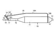
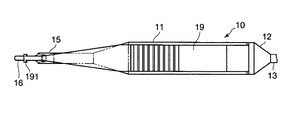
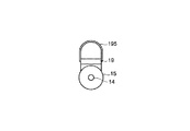
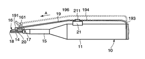
図1及び図2は、この発明の第1の実施の形態に係る超音波処置装置を示すもので、図1は、所期状態を示し、図2は、把持状態を示す。
(First embodiment)
1 and 2 show an ultrasonic treatment apparatus according to the first embodiment of the present invention. FIG. 1 shows an intended state, and FIG. 2 shows a gripping state.
即ち、振動子ユニット10は、把持部を構成する例えば円筒状のカバー11が被着され、このカバー11内には、図示しない超音波振動子及びホーンが内装される。そして、このカバー11の基端には、後カバー12が被着され、この後カバー12より上記超音波振動子(図示せず)に接続されるハンドピースコード13が延出される。
That is, the
このハンドピースコード13には、図示しない電源装置が電気的に接続され、この電源装置(図示せず)を介して上記超音波振動子(図示せず)に電力が供給されて該超音波振動子(図示せず)が発振駆動される。この超音波振動子(図示せず)には、上記ホーン(図示せず)が接続される。このホーン(図示せず)は、上記超音波振動子(図示せず)で発振された超音波振動を増幅させて拡大し、拡大された振動を上記振動子ユニット10のプローブ部を構成するプローブ14に伝達する。
A power supply device (not shown) is electrically connected to the
ホーン(図示せず)には、例えば上記プローブ14が一体的に設けられ、拡大した振動を該プローブ14に伝達する。このプローブ14は、例えば基端側(近位側)から中間部までが、プローブカバー部であるプローブカバー15により覆われて配される。例えば上記超音波振動子(図示せず)基端からプローブ14先端までが、1波長分の長さに設定される。
For example, the
また、上記プローブカバー15は、基端部が上記カバー11に取付けられ、その先端部には、クランプ部16が支点ピン17を介して回動自在に設けられる。このクランプ部16には、把持部材18が上記プローブ14に対向して設けられ、この把持部材18とプローブ14との間で上記生体組織を挟持する。このうち把持部材18は、一般的にはプローブ14が磨耗するのを防ぐために、PTFE等の低摩擦係数の樹脂部材で形成される。
The
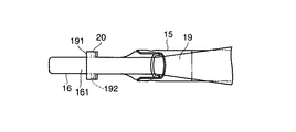
上記クランプ部16の中間部には、支持部161が設けられ、この支持部161には、操作部を構成する回動操作用のアーム19の一端が回動ピン20を介して回動自在に連結される。このアーム19は、例えばばね性を有する金属材料で図3及び図4に示すように一端方向に幅狭に形成されて端部に凹状の取付部191が形成され、この取付部191には、その両端部に挿通孔192が設けられる(図5参照)。そして、アーム19は、その取付部191がクランプ部16の支持部161を挟持するように対向配置された状態で、回動ピン20が取付部191の挿通孔192を通して支持部161に設けられる挿通孔(図の都合上、図示せず)に挿入されて相互間が回動自在に取付けられる。
A
また、アーム19の他端には、折曲部193が形成され、この折曲部193が、上記カバー11と後カバー12との間に挟装されて弾性変形自在に架設される。そして、このアーム19の中間部には、例えば複数の凹部を所定の間隔に配した弾性変形調整用の操作部194が設けられる。これにより、アーム19は、操作部194が矢印A方向に押圧操作されると、そのばね力に抗して弾性変形してクランプ部16を反時計方向に回動させてプローブ14方向に移動させ、把持部材18をプローブ14に接触させる。そして、アーム19は、操作部194の押圧操作が解除されると、そのばね力によりクランプ部16を反転させて、把持部材18をプローブ14から離間させ、初期位置に復帰させる。
Further, a
上記構成において、凝固・切開処置を施す場合には、術者が振動子ユニット10のカバー11を把持してアーム19の操作部194に指を添えた図1に示すようにクランプ部16がプローブ14に対して大きく開いた状態で、これらプローブ13を生体組織の所望の部位に位置を定める。
In the above configuration, when coagulation / incision treatment is performed, the operator grips the
この状態で、アーム19の操作部194に添えた指を矢印A方向に押し込むと、アームが弾性変形して同方向に移動されることで、クランプ部16が支点ピン17を中心として反時計方向に回動されて、プローブ14に接近されて生体組織に接触され、該プローブ14との間で生体組織を挟持する。ここで、上述したように超音波振動子(図示せず)を駆動してプローブ14に超音波振動を伝達することで、クランプ部16の把持部材18と協働して生体組織の凝固・切開処置が行われる。この際、生体組織は、クランプ部16がプローブカバー15に回動自在に支持された部位より、カバー11方向に近位側に挟み込まれることが無いことにより、所望の組織のみの凝固・切開処置が施される。
In this state, when a finger attached to the
次に、クランプ部がプローブに接触された状態からその操作部に添えた指の力を抜くと、アーム19は、そのばね力により初期位置に復帰される(図1参照)。これにより、クランプ部は16、図1に示すようにプローブ14に対して大きく開いた状態となる。
Next, when the force of the finger attached to the operation unit is removed from the state in which the clamp unit is in contact with the probe, the
このように、上記超音波処置装置は、プローブ14の一部を覆うプローブカバー15の先端部に該プローブ14に対向してクランプ部16の基端を回動自在に軸支し、このクランプ部16の中間部を、弾性変形調整用の操作部194を設けたアーム19を介してカバー11に連結するように構成した。
As described above, the ultrasonic treatment apparatus pivotally supports the proximal end of the
これによれば、クランプ部16は、アーム19の操作部194の操作に連動してプローブカバー15に対して回動され、プローブカバー15から露出されるプローブ14との間で生体組織を挟持することにより、生体組織の挟持範囲がプローブ14の近位側への食い込みが規制される。この結果、クランプ部16とプローブ14とによる挟持範囲が確実に定められるため、簡便にして容易に確実な凝固・切開処置を行うことが可能となり、使い勝手の向上が図れて手術進行の迅速化を図ることが可能となる。
According to this, the
(第2の実施の形態)
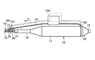
図6及び図7は、この発明の第2の実施の形態に係る超音波処置装置を示すもので、上記第1の実施の形態と略同様の効果が期待される。但し、この図6及び図7においては、上記第1の実施の形態と同一の部分について同一符号を付して、その詳細な説明を省略する。
(Second Embodiment)
6 and 7 show an ultrasonic treatment apparatus according to the second embodiment of the present invention, and an effect substantially the same as that of the first embodiment is expected. However, in FIG. 6 and FIG. 7, the same parts as those in the first embodiment are denoted by the same reference numerals, and detailed description thereof is omitted.
即ち、第2の実施の形態では、アーム19の中間部に操作部を構成する指を挿入するリング部195を設け、このリング部195に術者の指を挿入してアーム19を弾性変形操作するように構成したものである。このリング部195は、ゴムや樹脂材料等の弾性部材を、アーム19の中間部に取付けることで形成される。
That is, in the second embodiment, a
第2の実施の形態によれば、リング部195に指を挿入してアーム19の弾性変形調整を行うことが可能となることにより、例えばクランプ部16をプローブ14に対して開く方向へも高精度な回動操作が容易にして高精度に行うことができるため、所謂、剥離操作においても簡便にして容易に高精度な操作を行うことが可能となる。
According to the second embodiment, it is possible to adjust the elastic deformation of the
(第3の実施の形態)
図8は、この発明の第3の実施の形態に係る超音波処置装置を示すもので、上記第1の実施の形態と略同様の効果を期待することができる。但し、この図8においては、上記第1の実施の形態と同一部分について同一符号を付して、その詳細な説明を省略する。
(Third embodiment)
FIG. 8 shows an ultrasonic treatment apparatus according to the third embodiment of the present invention, and it is possible to expect substantially the same effect as in the first embodiment. However, in FIG. 8, the same parts as those in the first embodiment are denoted by the same reference numerals, and detailed description thereof is omitted.
この第3の実施の形態においては、上記カバー11上に電源オン・オフ切換え用スイッチ21を搭載し、アーム19の背面側に操作用突起196をスイッチ21の切換え操作部211に対向して設けるように構成したものである。
In the third embodiment, a power on / off switching
上記構成により、アーム19の操作部194を矢印A方向に押し込んでクランプ部16を反時計方向に回動させ、その把持部材18とプローブ14との間で生体組織を挟持した状態で、アーム19の突起196がスイッチ21の切換え操作部211を押圧してオンさせる。すると、このスイッチ21のオン信号に応動して上記超音波振動子(図示せず)が駆動されてプローブ14に超音波振動を伝達され、クランプ部16の把持部材18と協働して生体組織の凝固・切開処置が行われる。これによれば、凝固・切開処置の簡便化が促進されて、使い勝手の向上が図れる。
With the above configuration, the
(第4の実施の形態)
図9及び図10は、この発明の第4の実施の形態に係る超音波処置装置を示すもので、上記第1の実施の形態と略同様の効果を期待することができる。但し、この図9及び図10においては、上記第1及び第3の実施の形態と同一部分について同一符号を付して、その詳細な説明を省略する。
(Fourth embodiment)
9 and 10 show an ultrasonic treatment apparatus according to the fourth embodiment of the present invention, and it is possible to expect substantially the same effect as that of the first embodiment. However, in FIG. 9 and FIG. 10, the same reference numerals are given to the same portions as those in the first and third embodiments, and the detailed description thereof is omitted.
この第4の実施の形態においては、上記カバー11上に電源オン・オフ切換え用スイッチ21を搭載し、アーム19には、スイッチ挿通用の開口197(図10参照)を上記スイッチ21の切換え操作部211に対向して設けるように構成したものである。
In the fourth embodiment, a power on / off switching
上記構成により、アーム19の操作部194を矢印A方向に押し込んでクランプ部16を反時計方向に回動させ、その把持部材18とプローブ14との間で生体組織を挟持した状態で、アーム19の開口197より突出されたスイッチ21の切換え操作部211を切換え操作する。すると、このスイッチ21のオン信号に応動して上記超音波振動子(図示せず)が駆動されてプローブ14に超音波振動を伝達され、クランプ部16の把持部材18と協働して生体組織の凝固・切開処置が行われる。これによれば、凝固・切開処置の簡便化が促進されて、さらに使い勝手の向上が図れる。
With the above configuration, the
また、第4の実施の形態では、例えば術者が指を、アーム19の操作部194における開口197を覆うようにしておいて、アーム19を矢印A方向に弾性変形させてクランプ部16の把持部材18を生体組織に接触させ、プローブ14との間で挟持した状態で、直ちにスイッチ21の切換え操作部211の操作を行うことも可能となり、さらに使い勝手の向上を図ることが可能となる。そして、第4の実施の形態においては、アーム19の弾性変形とスイッチ21の切換え操作を独立に行うことが可能となるため、例えば処置具としての使用と共に、把持鉗子としての使用を容易に使い分けることが可能となり、使用形態の多様化が図れる。
Further, in the fourth embodiment, for example, an operator holds a finger by covering the
なお、上記第3及び第4の実施の形態におけるスイッチ21としては、例えば二段階スイッチ構造のものを用いて、その押し込み量に応じて、例えば低い出力あるいは最大出力に可変するように構成したり、無段階スイッチ構造のものを用いて、その押し込み量に応じて設定出力を無段階で切換え設定するように構成するこ
とが可能である。
In addition, as the
また、上記第3及び第4のの実施の形態では、上述した第1の実施の形態と同様の操作部194を設けたアーム構造に適用した場合で説明したが、これに限ることなく、その他、上記第2の実施の形態と同様に中間部にリング部195を設けるようにしたアーム構造においても適用可能で同様の効果が期待される。
In the third and fourth embodiments, the description has been given of the case where the present invention is applied to the arm structure provided with the
よって、この発明は、上記実施の形態に限ることなく、その他、実施段階ではその要旨を逸脱しない範囲で種々の変形を実施し得ることが可能である。さらに、上記実施の形態には、種々の段階の発明が含まれており、開示される複数の構成要件における適宜な組合せにより種々の発明が抽出され得る。 Therefore, the present invention is not limited to the above-described embodiment, and various modifications can be made without departing from the scope of the invention at the stage of implementation. Further, the above embodiments include inventions at various stages, and various inventions can be extracted by appropriately combining a plurality of disclosed constituent elements.
例えば実施の形態に示される全構成要件から幾つかの構成要件が削除されても、発明が解決しようとする課題の欄で述べた課題が解決でき、発明の効果で述べられている効果が得られる場合には、この構成要件が削除された構成が発明として抽出され得る。 For example, even if some constituent requirements are deleted from all the constituent requirements shown in the embodiment, the problem described in the column of the problem to be solved by the invention can be solved, and the effect described in the effect of the invention can be obtained. In such a case, a configuration in which this configuration requirement is deleted can be extracted as an invention.
また、この発明は、上記各実施の形態によれば、その他、次のような構成を得ることもできる。 In addition, according to each of the above embodiments, the present invention can also obtain the following configuration.
(付記1)
超音波振動を発生させる振動子と、この振動子を覆うと共に、把持するためのケーシングと、前記振動子の先端部に設けられ、該振動子からの超音波振動を拡大・伝達する伝達部と、この伝達部の先端部に設けられ、生体組識に接触して前記伝達部からの振動を前記生体組識に伝達するプローブ部と、前記ケーシングから遠位方向に延び、前記プローブ部を覆うシースと、前記ケーシングの基端に回動可能に連結されるアームと、前記プローブ部に対向して配設され、前記プローブ部との間に生体組識を挟み込むクランプ部を有し、前記クランプ部を回動させるためにアームに力を加える力点は、前記ケーシングとの回動部よりも先端である超音波処置装置において、
前記クランプ部は、シース部と回動自在に連結されていることを特徴とする超音波処置装置。
(Appendix 1)
A vibrator that generates ultrasonic vibration, a casing that covers and grips the vibrator, a transmission unit that is provided at the tip of the vibrator and that expands and transmits the ultrasonic vibration from the vibrator, A probe portion provided at a distal end portion of the transmission portion and contacting the biological tissue to transmit vibration from the transmission portion to the biological tissue; and extending in a distal direction from the casing to cover the probe portion A sheath, an arm rotatably connected to a base end of the casing, and a clamp portion disposed opposite to the probe portion and sandwiching a biological tissue between the probe portion and the clamp In the ultrasonic treatment apparatus, the force point that applies force to the arm to rotate the part is at the tip than the rotating part with the casing.
The ultrasonic treatment apparatus, wherein the clamp part is rotatably connected to a sheath part.
(付記2)
前記クランプ部は、アーム部とも回動自在に連結されていることを特徴とする付記1記載の超音波処置装置。
(Appendix 2)
2. The ultrasonic treatment apparatus according to appendix 1, wherein the clamp part is also rotatably connected to an arm part.
(付記3)
前記力点には、指を挿入できるリング部が設けられることを特徴とする付記1又は2記載の超音波処置装置。
(Appendix 3)
The ultrasonic treatment apparatus according to appendix 1 or 2, wherein the force point is provided with a ring part into which a finger can be inserted.
(付記4)
前記ケーシングには、超音波出力用のスイッチが設けられ、前記アームのケーシング側の面には、前記スイッチに対向して突起が設けられ、前記クランプ部を閉じるために前記アームに力を加えると前記アームの突起が前記スイッチを押圧操作することを特徴とする付記1乃至3のいずれか記載の超音波処置装置。
(Appendix 4)
The casing is provided with an ultrasonic output switch, and a projection is provided on the casing side surface of the arm so as to face the switch. When a force is applied to the arm to close the clamp portion, 4. The ultrasonic treatment apparatus according to any one of appendices 1 to 3, wherein the projection of the arm presses the switch.
(付記5)
前記ケーシングには、超音波出力用のスイッチが設けられ、前記アームには、前記スイッチに対向して開口が設けられることを特徴とする付記1乃至3のいずれか記載の超音波処置装置。
(Appendix 5)
The ultrasonic treatment apparatus according to any one of appendices 1 to 3, wherein an ultrasonic output switch is provided in the casing, and an opening is provided in the arm so as to face the switch.
(付記6)
前記スイッチは、2段スイッチであり、押し込みの強弱で設定出力と最大出力に切換えが行われることを特徴とする付記4又は5記載の超音波処置装置。
(Appendix 6)
6. The ultrasonic treatment apparatus according to appendix 4 or 5, wherein the switch is a two-stage switch, and is switched between a set output and a maximum output by pressing in and out.
(付記7)
前記スイッチは、無段階スイッチであり、押し込み量に応じて出力値が可変設定されることを特徴とする付記4又は5記載の超音波処置装置。
(Appendix 7)
6. The ultrasonic treatment apparatus according to appendix 4 or 5, wherein the switch is a stepless switch, and an output value is variably set according to a pressing amount.
(付記8)
前記開口部は、前記力点付近に設けられていることを特徴とする付記5記載の超音波処置装置。
(Appendix 8)
The ultrasonic treatment apparatus according to appendix 5, wherein the opening is provided near the power point.
(付記9)
前記開口部以外に力を加えたとき、前記開口部からスイッチが突出し、超音波出力の入切が可能になることを特徴とする付記5乃至8のいずれか記載の超音波処置装置。
(Appendix 9)
The ultrasonic treatment apparatus according to any one of appendices 5 to 8, wherein when a force is applied to a portion other than the opening, a switch protrudes from the opening, and an ultrasonic output can be turned on and off.
(付記10)
超音波振動を発生させる超音波振動子と、
前記超音波振動子を覆う把持部と、
生体装置に超音波振動を伝達する、前記超音波振動子と接続されたプローブ部と、
前記プローブ部の一部を覆うプローブカバー部と、
前記プローブ部に対向して配設され、前記プローブ部との間に生体組識を挟み込むクランプ部と、
前記クランプ部を操作する操作部と、
前記クランプ部と前記プローブカバー部とを回動自在に軸支する軸支部と、
を有することを特徴とする超音波処置装置。
(Appendix 10)
An ultrasonic transducer that generates ultrasonic vibrations;
A gripping part that covers the ultrasonic transducer;
A probe unit connected to the ultrasonic transducer for transmitting ultrasonic vibrations to a biological device;
A probe cover part covering a part of the probe part;
A clamp portion that is disposed to face the probe portion and sandwiches the biological tissue between the probe portion, and
An operation unit for operating the clamp unit;
A shaft support portion that rotatably supports the clamp portion and the probe cover portion;
An ultrasonic treatment apparatus comprising:
(付記11)
前記操作部は、前記把持部の基端側に回動自在に設けられていることを特徴とする付記10記載の超音波処置装置。
(Appendix 11)
The ultrasonic treatment apparatus according to
10…振動子ユニット、11…カバー、12…後カバー、13…ハンドピースコード、14…プローブ、15…プローブカバー、16…クランプ部、161…支持部、17…支点ピン、18…把持部材、19…アーム、191…取付部、192…挿通孔、193…折曲部、194…操作部、195…リング部、196…突起、197…開口、20…回動ピン、21…スイッチ、211…切換え操作部。
DESCRIPTION OF
Claims (4)
前記超音波振動子が内装される把持部と、
前記超音波振動子が発生した超音波振動を生体組織に伝達するブローブ部と、
前記プローブ部の一部を覆うプローブカバー部と、
前記プローブ部とで前記生体組織を挟持するもので、前記プローブカバー部に前記プローブに対向して回動自在に軸支されるクランプ部と、
前記クランプ部を前記プローブ部に対向して回動操作する操作部と、
を具備することを特徴とする超音波処置装置。 An ultrasonic transducer that generates ultrasonic vibrations;
A gripping portion in which the ultrasonic transducer is installed;
A probe that transmits ultrasonic vibration generated by the ultrasonic transducer to a living tissue;
A probe cover part covering a part of the probe part;
A clamp part that pivotally supports the probe cover part so as to be rotatable in opposition to the probe, with the probe part sandwiching the living tissue.
An operation unit for rotating the clamp unit to face the probe unit;
An ultrasonic treatment apparatus comprising:
Priority Applications (1)
| Application Number | Priority Date | Filing Date | Title |
|---|---|---|---|
| JP2004118181A JP2005296411A (en) | 2004-04-13 | 2004-04-13 | Ultrasonic treatment apparatus |
Applications Claiming Priority (1)
| Application Number | Priority Date | Filing Date | Title |
|---|---|---|---|
| JP2004118181A JP2005296411A (en) | 2004-04-13 | 2004-04-13 | Ultrasonic treatment apparatus |
Publications (1)
| Publication Number | Publication Date |
|---|---|
| JP2005296411A true JP2005296411A (en) | 2005-10-27 |
Family
ID=35328671
Family Applications (1)
| Application Number | Title | Priority Date | Filing Date |
|---|---|---|---|
| JP2004118181A Withdrawn JP2005296411A (en) | 2004-04-13 | 2004-04-13 | Ultrasonic treatment apparatus |
Country Status (1)
| Country | Link |
|---|---|
| JP (1) | JP2005296411A (en) |
Cited By (15)
| Publication number | Priority date | Publication date | Assignee | Title |
|---|---|---|---|---|
| CN102813550A (en) * | 2012-08-27 | 2012-12-12 | 杭州电子科技大学 | Electronic control bending device of tool bit of ultrasonic scalpel |
| JP2013502998A (en) * | 2009-08-26 | 2013-01-31 | シンセオン, エルエルシー | Two-stage switch for cordless, hand-held ultrasonic cautery cutting device |
| US8992555B2 (en) | 2007-12-03 | 2015-03-31 | Covidien Ag | Method of assembling a cordless hand-held ultrasonic cautery cutting device |
| US9017355B2 (en) | 2007-12-03 | 2015-04-28 | Covidien Ag | Battery-powered hand-held ultrasonic surgical cautery cutting device |
| US9084625B2 (en) | 2007-12-03 | 2015-07-21 | Covidien Ag | Battery assembly for battery-powered surgical instruments |
| US9107690B2 (en) | 2007-12-03 | 2015-08-18 | Covidien Ag | Battery-powered hand-held ultrasonic surgical cautery cutting device |
| US9314261B2 (en) | 2007-12-03 | 2016-04-19 | Covidien Ag | Battery-powered hand-held ultrasonic surgical cautery cutting device |
| US10368898B2 (en) | 2016-05-05 | 2019-08-06 | Covidien Lp | Ultrasonic surgical instrument |
| US10426508B2 (en) | 2007-12-03 | 2019-10-01 | Covidien Ag | Cordless hand-held ultrasonic cautery device |
| US10582944B2 (en) | 2018-02-23 | 2020-03-10 | Covidien Lp | Ultrasonic surgical instrument with torque assist feature |
| CN112690873A (en) * | 2020-12-25 | 2021-04-23 | 中南大学湘雅医院 | Bendable ultrasonic knife |
| US11229449B2 (en) | 2018-02-05 | 2022-01-25 | Covidien Lp | Ultrasonic horn, ultrasonic transducer assembly, and ultrasonic surgical instrument including the same |
| US11246621B2 (en) | 2018-01-29 | 2022-02-15 | Covidien Lp | Ultrasonic transducers and ultrasonic surgical instruments including the same |
| US11246617B2 (en) | 2018-01-29 | 2022-02-15 | Covidien Lp | Compact ultrasonic transducer and ultrasonic surgical instrument including the same |
| US11259832B2 (en) | 2018-01-29 | 2022-03-01 | Covidien Lp | Ultrasonic horn for an ultrasonic surgical instrument, ultrasonic surgical instrument including the same, and method of manufacturing an ultrasonic horn |
-
2004
- 2004-04-13 JP JP2004118181A patent/JP2005296411A/en not_active Withdrawn
Cited By (23)
| Publication number | Priority date | Publication date | Assignee | Title |
|---|---|---|---|---|
| US10426508B2 (en) | 2007-12-03 | 2019-10-01 | Covidien Ag | Cordless hand-held ultrasonic cautery device |
| US9872696B2 (en) | 2007-12-03 | 2018-01-23 | Covidien Ag | Battery-powered hand-held ultrasonic surgical cautery cutting device |
| US8992555B2 (en) | 2007-12-03 | 2015-03-31 | Covidien Ag | Method of assembling a cordless hand-held ultrasonic cautery cutting device |
| US9017355B2 (en) | 2007-12-03 | 2015-04-28 | Covidien Ag | Battery-powered hand-held ultrasonic surgical cautery cutting device |
| US9084625B2 (en) | 2007-12-03 | 2015-07-21 | Covidien Ag | Battery assembly for battery-powered surgical instruments |
| US9107690B2 (en) | 2007-12-03 | 2015-08-18 | Covidien Ag | Battery-powered hand-held ultrasonic surgical cautery cutting device |
| US9314261B2 (en) | 2007-12-03 | 2016-04-19 | Covidien Ag | Battery-powered hand-held ultrasonic surgical cautery cutting device |
| US11478820B2 (en) | 2007-12-03 | 2022-10-25 | Covidien Ag | Battery-powered hand-held ultrasonic surgical cautery cutting device |
| US10456158B2 (en) | 2007-12-03 | 2019-10-29 | Covidien Ag | Cordless hand-held ultrasonic surgical device |
| US10799913B2 (en) | 2007-12-03 | 2020-10-13 | Covidien Lp | Battery-powered hand-held ultrasonic surgical cautery cutting device |
| US9861382B2 (en) | 2007-12-03 | 2018-01-09 | Covidien Ag | Cordless hand-held ultrasonic cautery cutting device |
| JP2013502998A (en) * | 2009-08-26 | 2013-01-31 | シンセオン, エルエルシー | Two-stage switch for cordless, hand-held ultrasonic cautery cutting device |
| CN102813550A (en) * | 2012-08-27 | 2012-12-12 | 杭州电子科技大学 | Electronic control bending device of tool bit of ultrasonic scalpel |
| US10368898B2 (en) | 2016-05-05 | 2019-08-06 | Covidien Lp | Ultrasonic surgical instrument |
| US11266432B2 (en) | 2016-05-05 | 2022-03-08 | Covidien Lp | Ultrasonic surgical instrument |
| US11246621B2 (en) | 2018-01-29 | 2022-02-15 | Covidien Lp | Ultrasonic transducers and ultrasonic surgical instruments including the same |
| US11246617B2 (en) | 2018-01-29 | 2022-02-15 | Covidien Lp | Compact ultrasonic transducer and ultrasonic surgical instrument including the same |
| US11259832B2 (en) | 2018-01-29 | 2022-03-01 | Covidien Lp | Ultrasonic horn for an ultrasonic surgical instrument, ultrasonic surgical instrument including the same, and method of manufacturing an ultrasonic horn |
| US12150665B2 (en) | 2018-01-29 | 2024-11-26 | Covidien Lp | Compact ultrasonic transducer and ultrasonic surgical instrument including the same |
| US11229449B2 (en) | 2018-02-05 | 2022-01-25 | Covidien Lp | Ultrasonic horn, ultrasonic transducer assembly, and ultrasonic surgical instrument including the same |
| US11304721B2 (en) | 2018-02-23 | 2022-04-19 | Covidien Lp | Ultrasonic surgical instrument with torque assist feature |
| US10582944B2 (en) | 2018-02-23 | 2020-03-10 | Covidien Lp | Ultrasonic surgical instrument with torque assist feature |
| CN112690873A (en) * | 2020-12-25 | 2021-04-23 | 中南大学湘雅医院 | Bendable ultrasonic knife |
Similar Documents
| Publication | Publication Date | Title |
|---|---|---|
| JP4073410B2 (en) | Ultrasonic treatment device | |
| JP4700715B2 (en) | Energy treatment tool | |
| JP5322720B2 (en) | Surgical equipment | |
| CN100522084C (en) | Hand activated ultrasonic instrument | |
| JP2005296411A (en) | Ultrasonic treatment apparatus | |
| CN110584748B (en) | Ultrasonic surgical instrument in the form of a hemostat having clamping force limiting features | |
| JP2003527155A (en) | Multifunctional curved blade for use with ultrasonic surgical instruments | |
| JP3628771B2 (en) | Ultrasonic therapy device | |
| JP3582816B2 (en) | Ultrasound surgery device | |
| AU2017239617B2 (en) | Hand activated ultrasonic instrument | |
| JP4276873B2 (en) | Ultrasonic treatment device | |
| JP3768827B2 (en) | Ultrasonic surgical device | |
| JP2005288024A (en) | Ultrasonic medical treatment device | |
| AU2014202982A1 (en) | Hand activated ultrasonic instrument |
Legal Events
| Date | Code | Title | Description |
|---|---|---|---|
| A300 | Withdrawal of application because of no request for examination |
Free format text: JAPANESE INTERMEDIATE CODE: A300 Effective date: 20070703 |