EP4032699A1 - Ensemble verre de couverture - Google Patents
Ensemble verre de couverture Download PDFInfo
- Publication number
- EP4032699A1 EP4032699A1 EP21204755.9A EP21204755A EP4032699A1 EP 4032699 A1 EP4032699 A1 EP 4032699A1 EP 21204755 A EP21204755 A EP 21204755A EP 4032699 A1 EP4032699 A1 EP 4032699A1
- Authority
- EP
- European Patent Office
- Prior art keywords
- glass substrate
- major surface
- mol
- curved
- curvature
- Prior art date
- Legal status (The legal status is an assumption and is not a legal conclusion. Google has not performed a legal analysis and makes no representation as to the accuracy of the status listed.)
- Pending
Links
- 239000006059 cover glass Substances 0.000 title claims abstract description 40
- 239000000758 substrate Substances 0.000 claims abstract description 679
- 239000012790 adhesive layer Substances 0.000 claims abstract description 45
- 239000011521 glass Substances 0.000 claims description 750
- 239000000853 adhesive Substances 0.000 claims description 107
- 230000001070 adhesive effect Effects 0.000 claims description 107
- 239000000203 mixture Substances 0.000 claims description 61
- 230000003667 anti-reflective effect Effects 0.000 claims description 19
- 238000004381 surface treatment Methods 0.000 claims description 14
- 239000003513 alkali Substances 0.000 claims description 9
- 239000005354 aluminosilicate glass Substances 0.000 claims description 9
- 230000003670 easy-to-clean Effects 0.000 claims description 7
- 239000005388 borosilicate glass Substances 0.000 claims description 6
- 239000005361 soda-lime glass Substances 0.000 claims description 3
- 238000000034 method Methods 0.000 description 144
- 238000005452 bending Methods 0.000 description 76
- 230000008569 process Effects 0.000 description 47
- 229910044991 metal oxide Inorganic materials 0.000 description 29
- 150000004706 metal oxides Chemical class 0.000 description 29
- 230000009975 flexible effect Effects 0.000 description 28
- 239000002585 base Substances 0.000 description 24
- 239000000463 material Substances 0.000 description 24
- 238000003475 lamination Methods 0.000 description 23
- 150000002500 ions Chemical class 0.000 description 22
- 238000010030 laminating Methods 0.000 description 22
- 239000006058 strengthened glass Substances 0.000 description 21
- 238000000576 coating method Methods 0.000 description 15
- NOTVAPJNGZMVSD-UHFFFAOYSA-N potassium monoxide Inorganic materials [K]O[K] NOTVAPJNGZMVSD-UHFFFAOYSA-N 0.000 description 14
- KKCBUQHMOMHUOY-UHFFFAOYSA-N Na2O Inorganic materials [O-2].[Na+].[Na+] KKCBUQHMOMHUOY-UHFFFAOYSA-N 0.000 description 13
- 239000011248 coating agent Substances 0.000 description 13
- 230000003287 optical effect Effects 0.000 description 11
- 238000005342 ion exchange Methods 0.000 description 10
- 239000004973 liquid crystal related substance Substances 0.000 description 10
- FGIUAXJPYTZDNR-UHFFFAOYSA-N potassium nitrate Chemical compound [K+].[O-][N+]([O-])=O FGIUAXJPYTZDNR-UHFFFAOYSA-N 0.000 description 10
- VWDWKYIASSYTQR-UHFFFAOYSA-N sodium nitrate Chemical compound [Na+].[O-][N+]([O-])=O VWDWKYIASSYTQR-UHFFFAOYSA-N 0.000 description 10
- 238000005259 measurement Methods 0.000 description 9
- 150000003839 salts Chemical class 0.000 description 9
- 238000010438 heat treatment Methods 0.000 description 8
- 238000007654 immersion Methods 0.000 description 8
- 239000010410 layer Substances 0.000 description 8
- FUJCRWPEOMXPAD-UHFFFAOYSA-N Li2O Inorganic materials [Li+].[Li+].[O-2] FUJCRWPEOMXPAD-UHFFFAOYSA-N 0.000 description 7
- 238000013461 design Methods 0.000 description 7
- XUCJHNOBJLKZNU-UHFFFAOYSA-M dilithium;hydroxide Chemical compound [Li+].[Li+].[OH-] XUCJHNOBJLKZNU-UHFFFAOYSA-M 0.000 description 7
- VYPSYNLAJGMNEJ-UHFFFAOYSA-N Silicium dioxide Chemical compound O=[Si]=O VYPSYNLAJGMNEJ-UHFFFAOYSA-N 0.000 description 6
- GWEVSGVZZGPLCZ-UHFFFAOYSA-N Titan oxide Chemical compound O=[Ti]=O GWEVSGVZZGPLCZ-UHFFFAOYSA-N 0.000 description 6
- -1 alkali metal cations Chemical class 0.000 description 6
- 229910000272 alkali metal oxide Inorganic materials 0.000 description 6
- PNEYBMLMFCGWSK-UHFFFAOYSA-N aluminium oxide Inorganic materials [O-2].[O-2].[O-2].[Al+3].[Al+3] PNEYBMLMFCGWSK-UHFFFAOYSA-N 0.000 description 6
- 229910052593 corundum Inorganic materials 0.000 description 6
- 239000004744 fabric Substances 0.000 description 6
- 230000007246 mechanism Effects 0.000 description 6
- 239000004033 plastic Substances 0.000 description 6
- 229920003023 plastic Polymers 0.000 description 6
- 229910001414 potassium ion Inorganic materials 0.000 description 6
- 229910001415 sodium ion Inorganic materials 0.000 description 6
- XOLBLPGZBRYERU-UHFFFAOYSA-N tin dioxide Chemical compound O=[Sn]=O XOLBLPGZBRYERU-UHFFFAOYSA-N 0.000 description 6
- 229910001845 yogo sapphire Inorganic materials 0.000 description 6
- 239000004593 Epoxy Substances 0.000 description 5
- 230000008901 benefit Effects 0.000 description 5
- 238000005728 strengthening Methods 0.000 description 5
- KOPBYBDAPCDYFK-UHFFFAOYSA-N Cs2O Inorganic materials [O-2].[Cs+].[Cs+] KOPBYBDAPCDYFK-UHFFFAOYSA-N 0.000 description 4
- MCMNRKCIXSYSNV-UHFFFAOYSA-N Zirconium dioxide Chemical compound O=[Zr]=O MCMNRKCIXSYSNV-UHFFFAOYSA-N 0.000 description 4
- 230000008859 change Effects 0.000 description 4
- 230000007423 decrease Effects 0.000 description 4
- 238000010586 diagram Methods 0.000 description 4
- AKUNKIJLSDQFLS-UHFFFAOYSA-M dicesium;hydroxide Chemical compound [OH-].[Cs+].[Cs+] AKUNKIJLSDQFLS-UHFFFAOYSA-M 0.000 description 4
- 238000013003 hot bending Methods 0.000 description 4
- 239000007788 liquid Substances 0.000 description 4
- 229910021645 metal ion Inorganic materials 0.000 description 4
- 229910001953 rubidium(I) oxide Inorganic materials 0.000 description 4
- DGAQECJNVWCQMB-PUAWFVPOSA-M Ilexoside XXIX Chemical compound C[C@@H]1CC[C@@]2(CC[C@@]3(C(=CC[C@H]4[C@]3(CC[C@@H]5[C@@]4(CC[C@@H](C5(C)C)OS(=O)(=O)[O-])C)C)[C@@H]2[C@]1(C)O)C)C(=O)O[C@H]6[C@@H]([C@H]([C@@H]([C@H](O6)CO)O)O)O.[Na+] DGAQECJNVWCQMB-PUAWFVPOSA-M 0.000 description 3
- ZLMJMSJWJFRBEC-UHFFFAOYSA-N Potassium Chemical compound [K] ZLMJMSJWJFRBEC-UHFFFAOYSA-N 0.000 description 3
- 239000004820 Pressure-sensitive adhesive Substances 0.000 description 3
- 229910001413 alkali metal ion Inorganic materials 0.000 description 3
- 238000013459 approach Methods 0.000 description 3
- 230000005540 biological transmission Effects 0.000 description 3
- 230000015572 biosynthetic process Effects 0.000 description 3
- 150000001768 cations Chemical class 0.000 description 3
- 229910052681 coesite Inorganic materials 0.000 description 3
- 229910052906 cristobalite Inorganic materials 0.000 description 3
- 230000001747 exhibiting effect Effects 0.000 description 3
- JEIPFZHSYJVQDO-UHFFFAOYSA-N iron(III) oxide Inorganic materials O=[Fe]O[Fe]=O JEIPFZHSYJVQDO-UHFFFAOYSA-N 0.000 description 3
- 229910052751 metal Inorganic materials 0.000 description 3
- 239000002184 metal Substances 0.000 description 3
- 229920002635 polyurethane Polymers 0.000 description 3
- 239000004814 polyurethane Substances 0.000 description 3
- 239000011591 potassium Substances 0.000 description 3
- 238000012545 processing Methods 0.000 description 3
- 239000000377 silicon dioxide Substances 0.000 description 3
- 229910052708 sodium Inorganic materials 0.000 description 3
- 239000011734 sodium Substances 0.000 description 3
- 229910052682 stishovite Inorganic materials 0.000 description 3
- 229910052905 tridymite Inorganic materials 0.000 description 3
- 239000004831 Hot glue Substances 0.000 description 2
- 239000004743 Polypropylene Substances 0.000 description 2
- NIXOWILDQLNWCW-UHFFFAOYSA-N acrylic acid group Chemical group C(C=C)(=O)O NIXOWILDQLNWCW-UHFFFAOYSA-N 0.000 description 2
- 229920006397 acrylic thermoplastic Polymers 0.000 description 2
- 238000004026 adhesive bonding Methods 0.000 description 2
- 229910052783 alkali metal Inorganic materials 0.000 description 2
- 150000001447 alkali salts Chemical class 0.000 description 2
- 239000006117 anti-reflective coating Substances 0.000 description 2
- 229910001423 beryllium ion Inorganic materials 0.000 description 2
- 239000002131 composite material Substances 0.000 description 2
- 239000005357 flat glass Substances 0.000 description 2
- 229920005570 flexible polymer Polymers 0.000 description 2
- 238000001746 injection moulding Methods 0.000 description 2
- IIPYXGDZVMZOAP-UHFFFAOYSA-N lithium nitrate Chemical compound [Li+].[O-][N+]([O-])=O IIPYXGDZVMZOAP-UHFFFAOYSA-N 0.000 description 2
- 238000002156 mixing Methods 0.000 description 2
- 150000002823 nitrates Chemical class 0.000 description 2
- 229920003229 poly(methyl methacrylate) Polymers 0.000 description 2
- 229920000642 polymer Polymers 0.000 description 2
- 229920001155 polypropylene Polymers 0.000 description 2
- 229920001296 polysiloxane Polymers 0.000 description 2
- 229910052700 potassium Inorganic materials 0.000 description 2
- 210000001747 pupil Anatomy 0.000 description 2
- 239000011347 resin Substances 0.000 description 2
- 229920005989 resin Polymers 0.000 description 2
- 229910052701 rubidium Inorganic materials 0.000 description 2
- IGLNJRXAVVLDKE-UHFFFAOYSA-N rubidium atom Chemical compound [Rb] IGLNJRXAVVLDKE-UHFFFAOYSA-N 0.000 description 2
- 238000007493 shaping process Methods 0.000 description 2
- 238000007655 standard test method Methods 0.000 description 2
- 239000002344 surface layer Substances 0.000 description 2
- ISXSCDLOGDJUNJ-UHFFFAOYSA-N tert-butyl prop-2-enoate Chemical compound CC(C)(C)OC(=O)C=C ISXSCDLOGDJUNJ-UHFFFAOYSA-N 0.000 description 2
- 229910000838 Al alloy Inorganic materials 0.000 description 1
- JOYRKODLDBILNP-UHFFFAOYSA-N Ethyl urethane Chemical compound CCOC(N)=O JOYRKODLDBILNP-UHFFFAOYSA-N 0.000 description 1
- 229910000640 Fe alloy Inorganic materials 0.000 description 1
- 229920002430 Fibre-reinforced plastic Polymers 0.000 description 1
- WHXSMMKQMYFTQS-UHFFFAOYSA-N Lithium Chemical compound [Li] WHXSMMKQMYFTQS-UHFFFAOYSA-N 0.000 description 1
- 229910000861 Mg alloy Inorganic materials 0.000 description 1
- 239000004988 Nematic liquid crystal Substances 0.000 description 1
- 229920007019 PC/ABS Polymers 0.000 description 1
- 239000004676 acrylonitrile butadiene styrene Substances 0.000 description 1
- 239000002313 adhesive film Substances 0.000 description 1
- 239000005358 alkali aluminosilicate glass Substances 0.000 description 1
- 229910000287 alkaline earth metal oxide Inorganic materials 0.000 description 1
- 238000000137 annealing Methods 0.000 description 1
- 230000003666 anti-fingerprint Effects 0.000 description 1
- 229910052785 arsenic Inorganic materials 0.000 description 1
- 229910052792 caesium Inorganic materials 0.000 description 1
- TVFDJXOCXUVLDH-UHFFFAOYSA-N caesium atom Chemical compound [Cs] TVFDJXOCXUVLDH-UHFFFAOYSA-N 0.000 description 1
- 238000005266 casting Methods 0.000 description 1
- 238000003426 chemical strengthening reaction Methods 0.000 description 1
- 150000003841 chloride salts Chemical class 0.000 description 1
- 229910052804 chromium Inorganic materials 0.000 description 1
- 239000003086 colorant Substances 0.000 description 1
- 230000000295 complement effect Effects 0.000 description 1
- 150000001875 compounds Chemical class 0.000 description 1
- 230000006835 compression Effects 0.000 description 1
- 238000007906 compression Methods 0.000 description 1
- 229910052802 copper Inorganic materials 0.000 description 1
- 230000008878 coupling Effects 0.000 description 1
- 238000010168 coupling process Methods 0.000 description 1
- 238000005859 coupling reaction Methods 0.000 description 1
- 239000006092 crystalline glass-ceramic Substances 0.000 description 1
- 239000002178 crystalline material Substances 0.000 description 1
- 230000003247 decreasing effect Effects 0.000 description 1
- 230000007812 deficiency Effects 0.000 description 1
- 230000032798 delamination Effects 0.000 description 1
- 238000000151 deposition Methods 0.000 description 1
- 238000005137 deposition process Methods 0.000 description 1
- 238000002845 discoloration Methods 0.000 description 1
- 230000000694 effects Effects 0.000 description 1
- 229920006332 epoxy adhesive Polymers 0.000 description 1
- 238000005530 etching Methods 0.000 description 1
- 238000001125 extrusion Methods 0.000 description 1
- 239000000835 fiber Substances 0.000 description 1
- 239000003733 fiber-reinforced composite Substances 0.000 description 1
- 239000011151 fibre-reinforced plastic Substances 0.000 description 1
- 239000006260 foam Substances 0.000 description 1
- 230000009477 glass transition Effects 0.000 description 1
- 239000002241 glass-ceramic Substances 0.000 description 1
- 239000003292 glue Substances 0.000 description 1
- 238000005286 illumination Methods 0.000 description 1
- 239000012535 impurity Substances 0.000 description 1
- 238000009434 installation Methods 0.000 description 1
- 238000011900 installation process Methods 0.000 description 1
- 229910052742 iron Inorganic materials 0.000 description 1
- 238000005304 joining Methods 0.000 description 1
- 229910052744 lithium Inorganic materials 0.000 description 1
- 238000003754 machining Methods 0.000 description 1
- 229910052748 manganese Inorganic materials 0.000 description 1
- 238000004519 manufacturing process Methods 0.000 description 1
- 150000002739 metals Chemical class 0.000 description 1
- 238000012986 modification Methods 0.000 description 1
- 230000004048 modification Effects 0.000 description 1
- 229910052750 molybdenum Inorganic materials 0.000 description 1
- 229910052759 nickel Inorganic materials 0.000 description 1
- 230000003647 oxidation Effects 0.000 description 1
- 238000007254 oxidation reaction Methods 0.000 description 1
- 239000003973 paint Substances 0.000 description 1
- 239000000049 pigment Substances 0.000 description 1
- 239000004417 polycarbonate Substances 0.000 description 1
- 229920000515 polycarbonate Polymers 0.000 description 1
- 238000010791 quenching Methods 0.000 description 1
- 230000000171 quenching effect Effects 0.000 description 1
- 230000005855 radiation Effects 0.000 description 1
- 238000010955 robust manufacturing process Methods 0.000 description 1
- NCCSSGKUIKYAJD-UHFFFAOYSA-N rubidium(1+) Chemical compound [Rb+] NCCSSGKUIKYAJD-UHFFFAOYSA-N 0.000 description 1
- 239000005368 silicate glass Substances 0.000 description 1
- HUAUNKAZQWMVFY-UHFFFAOYSA-M sodium;oxocalcium;hydroxide Chemical compound [OH-].[Na+].[Ca]=O HUAUNKAZQWMVFY-UHFFFAOYSA-M 0.000 description 1
- 238000004544 sputter deposition Methods 0.000 description 1
- 150000003467 sulfuric acid derivatives Chemical class 0.000 description 1
- 229910052719 titanium Inorganic materials 0.000 description 1
- 238000001721 transfer moulding Methods 0.000 description 1
- 238000011282 treatment Methods 0.000 description 1
- 150000003673 urethanes Chemical class 0.000 description 1
- 229910052720 vanadium Inorganic materials 0.000 description 1
- 238000005406 washing Methods 0.000 description 1
Images


Classifications
-
- B—PERFORMING OPERATIONS; TRANSPORTING
- B32—LAYERED PRODUCTS
- B32B—LAYERED PRODUCTS, i.e. PRODUCTS BUILT-UP OF STRATA OF FLAT OR NON-FLAT, e.g. CELLULAR OR HONEYCOMB, FORM
- B32B17/00—Layered products essentially comprising sheet glass, or glass, slag, or like fibres
- B32B17/06—Layered products essentially comprising sheet glass, or glass, slag, or like fibres comprising glass as the main or only constituent of a layer, next to another layer of a specific material
- B32B17/10—Layered products essentially comprising sheet glass, or glass, slag, or like fibres comprising glass as the main or only constituent of a layer, next to another layer of a specific material of synthetic resin
- B32B17/10005—Layered products essentially comprising sheet glass, or glass, slag, or like fibres comprising glass as the main or only constituent of a layer, next to another layer of a specific material of synthetic resin laminated safety glass or glazing
- B32B17/10009—Layered products essentially comprising sheet glass, or glass, slag, or like fibres comprising glass as the main or only constituent of a layer, next to another layer of a specific material of synthetic resin laminated safety glass or glazing characterized by the number, the constitution or treatment of glass sheets
- B32B17/10036—Layered products essentially comprising sheet glass, or glass, slag, or like fibres comprising glass as the main or only constituent of a layer, next to another layer of a specific material of synthetic resin laminated safety glass or glazing characterized by the number, the constitution or treatment of glass sheets comprising two outer glass sheets
-
- B—PERFORMING OPERATIONS; TRANSPORTING
- B32—LAYERED PRODUCTS
- B32B—LAYERED PRODUCTS, i.e. PRODUCTS BUILT-UP OF STRATA OF FLAT OR NON-FLAT, e.g. CELLULAR OR HONEYCOMB, FORM
- B32B1/00—Layered products having a non-planar shape
-
- B—PERFORMING OPERATIONS; TRANSPORTING
- B32—LAYERED PRODUCTS
- B32B—LAYERED PRODUCTS, i.e. PRODUCTS BUILT-UP OF STRATA OF FLAT OR NON-FLAT, e.g. CELLULAR OR HONEYCOMB, FORM
- B32B17/00—Layered products essentially comprising sheet glass, or glass, slag, or like fibres
- B32B17/06—Layered products essentially comprising sheet glass, or glass, slag, or like fibres comprising glass as the main or only constituent of a layer, next to another layer of a specific material
- B32B17/10—Layered products essentially comprising sheet glass, or glass, slag, or like fibres comprising glass as the main or only constituent of a layer, next to another layer of a specific material of synthetic resin
- B32B17/10005—Layered products essentially comprising sheet glass, or glass, slag, or like fibres comprising glass as the main or only constituent of a layer, next to another layer of a specific material of synthetic resin laminated safety glass or glazing
- B32B17/10807—Making laminated safety glass or glazing; Apparatus therefor
- B32B17/10816—Making laminated safety glass or glazing; Apparatus therefor by pressing
- B32B17/10825—Isostatic pressing, i.e. using non rigid pressure-exerting members against rigid parts
- B32B17/10834—Isostatic pressing, i.e. using non rigid pressure-exerting members against rigid parts using a fluid
- B32B17/10844—Isostatic pressing, i.e. using non rigid pressure-exerting members against rigid parts using a fluid using a membrane between the layered product and the fluid
- B32B17/10853—Isostatic pressing, i.e. using non rigid pressure-exerting members against rigid parts using a fluid using a membrane between the layered product and the fluid the membrane being bag-shaped
-
- B—PERFORMING OPERATIONS; TRANSPORTING
- B32—LAYERED PRODUCTS
- B32B—LAYERED PRODUCTS, i.e. PRODUCTS BUILT-UP OF STRATA OF FLAT OR NON-FLAT, e.g. CELLULAR OR HONEYCOMB, FORM
- B32B17/00—Layered products essentially comprising sheet glass, or glass, slag, or like fibres
- B32B17/06—Layered products essentially comprising sheet glass, or glass, slag, or like fibres comprising glass as the main or only constituent of a layer, next to another layer of a specific material
- B32B17/10—Layered products essentially comprising sheet glass, or glass, slag, or like fibres comprising glass as the main or only constituent of a layer, next to another layer of a specific material of synthetic resin
- B32B17/10005—Layered products essentially comprising sheet glass, or glass, slag, or like fibres comprising glass as the main or only constituent of a layer, next to another layer of a specific material of synthetic resin laminated safety glass or glazing
- B32B17/10807—Making laminated safety glass or glazing; Apparatus therefor
- B32B17/10889—Making laminated safety glass or glazing; Apparatus therefor shaping the sheets, e.g. by using a mould
-
- B—PERFORMING OPERATIONS; TRANSPORTING
- B32—LAYERED PRODUCTS
- B32B—LAYERED PRODUCTS, i.e. PRODUCTS BUILT-UP OF STRATA OF FLAT OR NON-FLAT, e.g. CELLULAR OR HONEYCOMB, FORM
- B32B38/00—Ancillary operations in connection with laminating processes
- B32B38/0012—Mechanical treatment, e.g. roughening, deforming, stretching
-
- B—PERFORMING OPERATIONS; TRANSPORTING
- B32—LAYERED PRODUCTS
- B32B—LAYERED PRODUCTS, i.e. PRODUCTS BUILT-UP OF STRATA OF FLAT OR NON-FLAT, e.g. CELLULAR OR HONEYCOMB, FORM
- B32B7/00—Layered products characterised by the relation between layers; Layered products characterised by the relative orientation of features between layers, or by the relative values of a measurable parameter between layers, i.e. products comprising layers having different physical, chemical or physicochemical properties; Layered products characterised by the interconnection of layers
- B32B7/04—Interconnection of layers
- B32B7/12—Interconnection of layers using interposed adhesives or interposed materials with bonding properties
-
- B—PERFORMING OPERATIONS; TRANSPORTING
- B60—VEHICLES IN GENERAL
- B60K—ARRANGEMENT OR MOUNTING OF PROPULSION UNITS OR OF TRANSMISSIONS IN VEHICLES; ARRANGEMENT OR MOUNTING OF PLURAL DIVERSE PRIME-MOVERS IN VEHICLES; AUXILIARY DRIVES FOR VEHICLES; INSTRUMENTATION OR DASHBOARDS FOR VEHICLES; ARRANGEMENTS IN CONNECTION WITH COOLING, AIR INTAKE, GAS EXHAUST OR FUEL SUPPLY OF PROPULSION UNITS IN VEHICLES
- B60K35/00—Instruments specially adapted for vehicles; Arrangement of instruments in or on vehicles
- B60K35/10—Input arrangements, i.e. from user to vehicle, associated with vehicle functions or specially adapted therefor
-
- B—PERFORMING OPERATIONS; TRANSPORTING
- B60—VEHICLES IN GENERAL
- B60R—VEHICLES, VEHICLE FITTINGS, OR VEHICLE PARTS, NOT OTHERWISE PROVIDED FOR
- B60R1/00—Optical viewing arrangements; Real-time viewing arrangements for drivers or passengers using optical image capturing systems, e.g. cameras or video systems specially adapted for use in or on vehicles
-
- B—PERFORMING OPERATIONS; TRANSPORTING
- B60—VEHICLES IN GENERAL
- B60R—VEHICLES, VEHICLE FITTINGS, OR VEHICLE PARTS, NOT OTHERWISE PROVIDED FOR
- B60R11/00—Arrangements for holding or mounting articles, not otherwise provided for
- B60R11/02—Arrangements for holding or mounting articles, not otherwise provided for for radio sets, television sets, telephones, or the like; Arrangement of controls thereof
- B60R11/0229—Arrangements for holding or mounting articles, not otherwise provided for for radio sets, television sets, telephones, or the like; Arrangement of controls thereof for displays, e.g. cathodic tubes
- B60R11/0235—Arrangements for holding or mounting articles, not otherwise provided for for radio sets, television sets, telephones, or the like; Arrangement of controls thereof for displays, e.g. cathodic tubes of flat type, e.g. LCD
-
- C—CHEMISTRY; METALLURGY
- C03—GLASS; MINERAL OR SLAG WOOL
- C03B—MANUFACTURE, SHAPING, OR SUPPLEMENTARY PROCESSES
- C03B23/00—Re-forming shaped glass
- C03B23/02—Re-forming glass sheets
-
- C—CHEMISTRY; METALLURGY
- C03—GLASS; MINERAL OR SLAG WOOL
- C03B—MANUFACTURE, SHAPING, OR SUPPLEMENTARY PROCESSES
- C03B23/00—Re-forming shaped glass
- C03B23/02—Re-forming glass sheets
- C03B23/023—Re-forming glass sheets by bending
- C03B23/035—Re-forming glass sheets by bending using a gas cushion or by changing gas pressure, e.g. by applying vacuum or blowing for supporting the glass while bending
- C03B23/0352—Re-forming glass sheets by bending using a gas cushion or by changing gas pressure, e.g. by applying vacuum or blowing for supporting the glass while bending by suction or blowing out for providing the deformation force to bend the glass sheet
- C03B23/0357—Re-forming glass sheets by bending using a gas cushion or by changing gas pressure, e.g. by applying vacuum or blowing for supporting the glass while bending by suction or blowing out for providing the deformation force to bend the glass sheet by suction without blowing, e.g. with vacuum or by venturi effect
-
- G—PHYSICS
- G02—OPTICS
- G02F—OPTICAL DEVICES OR ARRANGEMENTS FOR THE CONTROL OF LIGHT BY MODIFICATION OF THE OPTICAL PROPERTIES OF THE MEDIA OF THE ELEMENTS INVOLVED THEREIN; NON-LINEAR OPTICS; FREQUENCY-CHANGING OF LIGHT; OPTICAL LOGIC ELEMENTS; OPTICAL ANALOGUE/DIGITAL CONVERTERS
- G02F1/00—Devices or arrangements for the control of the intensity, colour, phase, polarisation or direction of light arriving from an independent light source, e.g. switching, gating or modulating; Non-linear optics
- G02F1/01—Devices or arrangements for the control of the intensity, colour, phase, polarisation or direction of light arriving from an independent light source, e.g. switching, gating or modulating; Non-linear optics for the control of the intensity, phase, polarisation or colour
- G02F1/13—Devices or arrangements for the control of the intensity, colour, phase, polarisation or direction of light arriving from an independent light source, e.g. switching, gating or modulating; Non-linear optics for the control of the intensity, phase, polarisation or colour based on liquid crystals, e.g. single liquid crystal display cells
- G02F1/133—Constructional arrangements; Operation of liquid crystal cells; Circuit arrangements
- G02F1/1333—Constructional arrangements; Manufacturing methods
- G02F1/13338—Input devices, e.g. touch panels
-
- G—PHYSICS
- G06—COMPUTING; CALCULATING OR COUNTING
- G06F—ELECTRIC DIGITAL DATA PROCESSING
- G06F3/00—Input arrangements for transferring data to be processed into a form capable of being handled by the computer; Output arrangements for transferring data from processing unit to output unit, e.g. interface arrangements
- G06F3/01—Input arrangements or combined input and output arrangements for interaction between user and computer
- G06F3/03—Arrangements for converting the position or the displacement of a member into a coded form
- G06F3/041—Digitisers, e.g. for touch screens or touch pads, characterised by the transducing means
- G06F3/0412—Digitisers structurally integrated in a display
-
- B—PERFORMING OPERATIONS; TRANSPORTING
- B32—LAYERED PRODUCTS
- B32B—LAYERED PRODUCTS, i.e. PRODUCTS BUILT-UP OF STRATA OF FLAT OR NON-FLAT, e.g. CELLULAR OR HONEYCOMB, FORM
- B32B2457/00—Electrical equipment
- B32B2457/20—Displays, e.g. liquid crystal displays, plasma displays
-
- B—PERFORMING OPERATIONS; TRANSPORTING
- B32—LAYERED PRODUCTS
- B32B—LAYERED PRODUCTS, i.e. PRODUCTS BUILT-UP OF STRATA OF FLAT OR NON-FLAT, e.g. CELLULAR OR HONEYCOMB, FORM
- B32B2605/00—Vehicles
- B32B2605/003—Interior finishings
-
- B—PERFORMING OPERATIONS; TRANSPORTING
- B32—LAYERED PRODUCTS
- B32B—LAYERED PRODUCTS, i.e. PRODUCTS BUILT-UP OF STRATA OF FLAT OR NON-FLAT, e.g. CELLULAR OR HONEYCOMB, FORM
- B32B2605/00—Vehicles
- B32B2605/08—Cars
-
- B—PERFORMING OPERATIONS; TRANSPORTING
- B60—VEHICLES IN GENERAL
- B60K—ARRANGEMENT OR MOUNTING OF PROPULSION UNITS OR OF TRANSMISSIONS IN VEHICLES; ARRANGEMENT OR MOUNTING OF PLURAL DIVERSE PRIME-MOVERS IN VEHICLES; AUXILIARY DRIVES FOR VEHICLES; INSTRUMENTATION OR DASHBOARDS FOR VEHICLES; ARRANGEMENTS IN CONNECTION WITH COOLING, AIR INTAKE, GAS EXHAUST OR FUEL SUPPLY OF PROPULSION UNITS IN VEHICLES
- B60K2360/00—Indexing scheme associated with groups B60K35/00 or B60K37/00 relating to details of instruments or dashboards
- B60K2360/143—Touch sensitive instrument input devices
- B60K2360/1438—Touch screens
-
- B—PERFORMING OPERATIONS; TRANSPORTING
- B60—VEHICLES IN GENERAL
- B60K—ARRANGEMENT OR MOUNTING OF PROPULSION UNITS OR OF TRANSMISSIONS IN VEHICLES; ARRANGEMENT OR MOUNTING OF PLURAL DIVERSE PRIME-MOVERS IN VEHICLES; AUXILIARY DRIVES FOR VEHICLES; INSTRUMENTATION OR DASHBOARDS FOR VEHICLES; ARRANGEMENTS IN CONNECTION WITH COOLING, AIR INTAKE, GAS EXHAUST OR FUEL SUPPLY OF PROPULSION UNITS IN VEHICLES
- B60K2360/00—Indexing scheme associated with groups B60K35/00 or B60K37/00 relating to details of instruments or dashboards
- B60K2360/60—Structural details of dashboards or instruments
- B60K2360/68—Features of instruments
- B60K2360/693—Cover plate features
-
- B—PERFORMING OPERATIONS; TRANSPORTING
- B60—VEHICLES IN GENERAL
- B60K—ARRANGEMENT OR MOUNTING OF PROPULSION UNITS OR OF TRANSMISSIONS IN VEHICLES; ARRANGEMENT OR MOUNTING OF PLURAL DIVERSE PRIME-MOVERS IN VEHICLES; AUXILIARY DRIVES FOR VEHICLES; INSTRUMENTATION OR DASHBOARDS FOR VEHICLES; ARRANGEMENTS IN CONNECTION WITH COOLING, AIR INTAKE, GAS EXHAUST OR FUEL SUPPLY OF PROPULSION UNITS IN VEHICLES
- B60K2360/00—Indexing scheme associated with groups B60K35/00 or B60K37/00 relating to details of instruments or dashboards
- B60K2360/92—Manufacturing of instruments
-
- B—PERFORMING OPERATIONS; TRANSPORTING
- B60—VEHICLES IN GENERAL
- B60K—ARRANGEMENT OR MOUNTING OF PROPULSION UNITS OR OF TRANSMISSIONS IN VEHICLES; ARRANGEMENT OR MOUNTING OF PLURAL DIVERSE PRIME-MOVERS IN VEHICLES; AUXILIARY DRIVES FOR VEHICLES; INSTRUMENTATION OR DASHBOARDS FOR VEHICLES; ARRANGEMENTS IN CONNECTION WITH COOLING, AIR INTAKE, GAS EXHAUST OR FUEL SUPPLY OF PROPULSION UNITS IN VEHICLES
- B60K35/00—Instruments specially adapted for vehicles; Arrangement of instruments in or on vehicles
- B60K35/20—Output arrangements, i.e. from vehicle to user, associated with vehicle functions or specially adapted therefor
- B60K35/21—Output arrangements, i.e. from vehicle to user, associated with vehicle functions or specially adapted therefor using visual output, e.g. blinking lights or matrix displays
- B60K35/22—Display screens
-
- B—PERFORMING OPERATIONS; TRANSPORTING
- B60—VEHICLES IN GENERAL
- B60R—VEHICLES, VEHICLE FITTINGS, OR VEHICLE PARTS, NOT OTHERWISE PROVIDED FOR
- B60R13/00—Elements for body-finishing, identifying, or decorating; Arrangements or adaptations for advertising purposes
- B60R13/02—Internal Trim mouldings ; Internal Ledges; Wall liners for passenger compartments; Roof liners
Definitions
- the disclosure relates to vehicle interior systems including cover glass and methods for forming the same, and more particularly to vehicle interior systems including a display and/or touch panel with a curved cover glass and methods for forming the same.
- Vehicle interiors include curved surfaces and can incorporate displays and/or touch panel.
- the materials used to form such curved surfaces are typically limited to polymers, which do not exhibit the durability and optical performance of glass.
- curved glass substrates are desirable, especially when used as covers for displays and/or touch panels.
- Existing methods of forming curved glass substrates, such as thermal forming have drawbacks including high cost, and optical distortion and/or surface marking occurring during curving. Accordingly, there is a need for vehicle interior systems that can incorporate a curved glass substrate in a cost-effective manner and without the problems typically associated with glass thermal forming processes.
- a first aspect of this disclosure pertains to a vehicle interior system.
- the vehicle interior system includes a base having a curved surface, and a display disposed on the curved surface.
- a touch panel may be substituted or used in addition to the display or display module.
- the display of one or more embodiments includes a cold-bent glass substrate having a first major surface, a second major surface opposing the first major surface and a minor surface connecting the first major surface and the second major surface, a thickness defined as a distance between the first major surface and the second major surface, a width defined as a first dimension of one of the first or second major surfaces orthogonal to the thickness, and a length defined as a second dimension of one of the first or second major surfaces orthogonal to both the thickness and the width, and wherein the thickness is 1.5 mm or less, and wherein the second major surface comprises a first radius of curvature of 20 mm or greater, 60 mm or greater, or 250 mm or greater.
- the curvature described herein may be convex, concave, or may have a combination of convex and concave portions having the same or different radii from one another.
- the display may include a display module attached to the second major surface of the curved glass substrate.
- the display module is flat, curved or flexible.
- the display (or a portion thereof such as a second glass substrate) comprises a second radius of curvature that is within 10% of the first radius of curvature.
- the first radius of curvature may be within 10% of the second radius of curvature or the radius of curvature of the curved substrate of the base on which the vehicle interior system is assembled.
- the display may further include an adhesive between the glass substrate and the display module.
- the display module of one or more embodiments includes a second glass substrate and an optional backlight unit, wherein the second glass substrate is disposed adjacent the first major surface and between the optional backlight unit and the first major surface, and wherein either one or both the second glass substrate and the optional backlight unit is curved to exhibit the second radius of curvature.
- the second glass substrate is curved to the second radius of curvature and the remaining portions of the display module are flat.
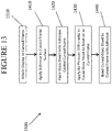
- a second aspect of this disclosure pertains to a method of forming a display.
- the method includes cold-bending a glass substrate having a first major surface and a second major surface opposite the first major surface to a first radius of curvature as measured on the second major surface, and laminating a display module to the first major surface while maintaining the first radius of curvature in the glass substrate to form the display.
- the display module (or a portion thereof such as a second glass substrate) has a second radius of curvature that is within 10% of the first radius of curvature.
- cold-bending the glass substrate may include applying a vacuum to the second major surface to generate the first radius of curvature.
- the method may include laminating an adhesive to the glass substrate before laminating the display module such that the adhesive is disposed between the glass substrate and the display module.
- laminating the display module may include laminating a second glass substrate to the glass substrate; and attaching a backlight unit to the second glass substrate.
- the method includes curving either one of or both the second glass substrate and the backlight unit to the second radius of curvature. In one or more embodiments, only the second glass substrate is curved to the second radius of curvature and the remaining portions of the display module are flat (such as the backlight unit).
- the method includes supporting a glass substrate on a frame.
- the glass substrate has a first major surface and a second major surface opposite the first major surface, and the frame has a curved support surface.
- the first major surface of the glass substrate may face the curved support surface of the frame.
- the method includes applying an air pressure differential to the glass substrate while supported by the frame causing the glass substrate to bend such that the glass substrate conforms to the curved shape of the curved support surface of the frame, forming a curved glass substrate.
- the first major surface of the curved glass substrate includes a curved section and the second major surface of the curved glass substrate includes a curved section.
- a maximum temperature of the glass substrate is less than a glass softening point of the glass substrate.
- a vehicle interior system may include a variety of different curved surfaces that are designed to be transparent, such as display surfaces, and the present disclosure provides articles and methods for forming these curved surfaces from a glass material.
- Forming curved vehicle surfaces from a glass material provides a number of advantages compared to the typical curved plastic panels that are conventionally found in vehicle interiors.
- glass is typically considered to provide enhanced functionality and user experience for many curved cover material applications, such as display applications and touch screen applications, compared to plastic cover materials.
- Curved glass articles are typically formed using hot forming processes. As discussed herein a variety of curved glass articles and processes for making the same are provided that avoid the deficiencies of the typical glass hot-forming process. For example, hot-forming processes are energy intensive and increase the cost of forming a curved glass component, relative to the cold-bending process discussed herein. In addition, hot-forming processes typically make application of coatings, such as anti-reflective coatings, significantly more difficult because many coating materials cannot be applied to a flat piece of glass material prior to the hot-forming process as the coating material typically will not survive the high temperatures of the hot-forming process. Further, application of a coating material to surfaces of a curved glass substrate after hot-bending that also meets performance requirements is substantially more difficult than application to a flat glass substrate. In addition, by avoiding the additional high temperature heating steps needed for thermal forming, the glass articles produced via the cold-bending processes and systems discussed herein may have improved optical properties and/or improved surface properties than similarly shaped glass articles made via thermal-shaping processes.
- the systems and processes disclosed herein specifically provide for cold-bending of thin glass substrates in an economical and efficient process.
- air pressure e.g., a vacuum or overpressure
- the systems and processes described herein provide for such bending and additional curing of bonding adhesive within common equipment and/or common processing steps.
- the processes and systems discussed herein may also allow for attachment of the display components to the glass cover substrate during bending utilizing common equipment and/or common processing steps.
- a first aspect of the instant application pertains to a vehicle interior system.
- vehicle interior system may be incorporated into vehicles such as trains, automobiles (e.g., cars, trucks, buses and the like), seacraft (boats, ships, submarines, and the like), and aircraft (e.g., drones, airplanes, jets, helicopters and the like).
- Figure 1 illustrates an exemplary vehicle interior 10 that includes three different embodiments of a vehicle interior system 100, 200, 300.
- Vehicle interior system 100 includes a center console base 110 with a curved surface 120 including a display 130.
- Vehicle interior system 200 includes a dashboard base 210 with a curved surface 220 including a display 230.
- the dashboard base 210 typically includes an instrument panel 215 which may also include a display.
- Vehicle interior system 300 includes a dashboard steering wheel base 310 with a curved surface 320 and a display 330.
- the vehicle interior system may include a base that is an arm rest, a pillar, a seat back, a floor board, a headrest, a door panel, or any portion of the interior of a vehicle that includes a curved surface.
- the curved glass substrates discussed herein may be used as curved cover glasses for any of the display embodiments discussed herein, including for use in vehicle interior systems 100, 200 and/or 300.
- the term "glass substrate” is used in its broadest sense to include any object made wholly or partly of glass. Glass substrates include laminates of glass and non-glass materials, laminates of glass and crystalline materials, and glass-ceramics (including an amorphous phase and a crystalline phase).
- the glass substrate may be transparent or opaque.
- the glass substrate may include a colorant that provides a specific color.
- the display 130 includes cold-bent curved glass substrate 140 having a first radius of curvature and a display module 150 attached to the glass substrate, wherein at least a portion of the display module 150 has a second radius of curvature that approximates or matches the first radius of curvature, to provide a display with a curved glass substrate as a cover glass that can be integrated into the curved surface of a vehicle interior system.
- the glass substrate 140 includes a first major surface 142 and a second major surface 144 opposite the first major surface.
- the cold-bent glass substrate exhibits the first radius of curvature as measured on the second major surface 144.
- cold-bent refers to curving the glass substrate at a cold-bend temperature which is less than the softening point of the glass (as described herein).
- cold-bendable refers to the capability of a glass substrate to be cold-bent.
- a feature of a cold-bent glass substrate is asymmetric surface compressive stress between the first major surface 142 and the second major surface 144.
- a minor surface 146 connects the first major surface 142 and the second major surface 144.
- the respective compressive stresses in the first major surface 142 and the second major surface 144 of the glass substrate are substantially equal.
- the first major surface 142 and the second major surface 144 exhibit no appreciable compressive stress, prior to cold-bending.
- the first major surface 142 and the second major surface 144 exhibit substantially equal compressive stress with respect to one another, prior to cold-bending.
- after cold-bending shown, for example, in Figure 2 and 7 , the compressive stress on the surface having a concave shape after bending (e.g., second major surface 144 in Figures 2 and 7 ) increases.
- the compressive stress on the concave surface is greater after cold-bending than before cold-bending.
- the cold-bending process increases the compressive stress of the glass substrate being shaped to compensate for tensile stresses imparted during bending and/or forming operations.
- the cold-bending process causes the concave surface (second major surface 144) to experience compressive stresses, while the surface forming a convex shape (i.e., the first major surface 142 in Figures 2 and 7 ) after cold-bending experiences tensile stresses.
- the tensile stress experienced by the convex (i.e., the first major surface 142) following cold-bending results in a net decrease in surface compressive stress, such that the compressive stress in convex surface (i.e., the first major surface 142) of a strengthened glass substrate following cold-bending is less than the compressive stress on the same surface (i.e., first major surface 142) when the glass substrate is flat.
- the first major surface and the second major surface comprise a compressive stress that is substantially equal to one another prior to cold-bending, and thus the first major surface can experience greater tensile stress during cold-bending without risking fracture. This allows for the strengthened glass substrate to conform to more tightly curved surfaces or shapes.
- the thickness of the glass substrate is tailored to allow the glass substrate to be more flexible to achieve the desired radius of curvature. Moreover, a thinner glass substrate 140 may deform more readily, which could potentially compensate for shape mismatches and gaps that may be created by the shape of the display module 150 (when curved). In one or more embodiments, a thin and strengthened glass substrate 140 exhibits greater flexibility especially during cold-bending. The greater flexibility of the glass substrates discussed herein may both allow for sufficient degrees of bending to be created via the air pressure-based bending processes as discussed herein and also for consistent bend formation without heating. In one or more embodiments, the glass substrate 140 and at least a portion of the display module 150 have substantially similar radii of curvature to provide a substantially uniform distance between the first major surface 142 and the display module 150 (which may be filled with an adhesive).
- the cold-bent glass substrate (and optionally the curved display module) may have a compound curve including a major radius and a cross curvature.
- a complexly curved cold-bent glass substrate (and optionally the curved display module) according to one or more embodiments may have a distinct radius of curvature in two independent directions.
- the complexly curved cold-bent glass substrate may thus be characterized as having "cross curvature," where the cold-bent glass substrate (and optionally the curved display module) are curved along an axis (i.e., a first axis) that is parallel to a given dimension and also curved along an axis (i.e., a second axis) that is perpendicular to the same dimension.
- the curvature of the cold-bent glass substrate (and optionally the curved display module) can be even more complex when a significant minimum radius is combined with a significant cross curvature, and/or depth of bend.
- the glass substrate has a thickness (t) that is substantially constant and is defined as a distance between the first major surface 142 and the second major surface 144.
- the thickness (t) as used herein refers to the maximum thickness of the glass substrate.
- the glass substrate includes a width (W) defined as a first maximum dimension of one of the first or second major surfaces orthogonal to the thickness (t), and a length (L) defined as a second maximum dimension of one of the first or second surfaces orthogonal to both the thickness and the width.
- W width
- L length
- the dimensions discussed herein may be average dimensions.
- the glass substrate has a thickness (t) that is about 1.5 mm or less.
- the thickness may be in a range from about 0.01 mm to about 1.5 mm, 0.02 mm to about 1.5 mm, 0.03 mm to about 1.5 mm, 0.04 mm to about 1.5 mm, 0.05mm to about 1.5 mm, 0.06 mm to about 1.5 mm, 0.07 mm to about 1.5 mm, 0.08 mm to about 1.5 mm, 0.09 mm to about 1.5 mm, 0.1 mm to about 1.5 mm, from about 0.15 mm to about 1.5 mm, from about 0.2 mm to about 1.5 mm, from about 0.25 mm to about 1.5 mm, from about 0.3 mm to about 1.5 mm, from about 0.35 mm to about 1.5 mm, from about 0.4 mm to about 1.5 mm, from about 0.45 mm to about 1.5 mm, from about 0.5 mm to about 1.5 mm, from about 0.55 mm to about 1.5 mm, from about 0.6 mm to about 1.5
- the glass substrate has a width (W) in a range from about 5 cm to about 250 cm, from about 10 cm to about 250 cm, from about 15 cm to about 250 cm, from about 20 cm to about 250 cm, from about 25 cm to about 250 cm, from about 30 cm to about 250 cm, from about 35 cm to about 250 cm, from about 40 cm to about 250 cm, from about 45 cm to about 250 cm, from about 50 cm to about 250 cm, from about 55 cm to about 250 cm, from about 60 cm to about 250 cm, from about 65 cm to about 250 cm, from about 70 cm to about 250 cm, from about 75 cm to about 250 cm, from about 80 cm to about 250 cm, from about 85 cm to about 250 cm, from about 90 cm to about 250 cm, from about 95 cm to about 250 cm, from about 100 cm to about 250 cm, from about 110 cm to about 250 cm, from about 120 cm to about 250 cm, from about 130 cm to about 250 cm, from about 140 cm to about 250 cm, from about 150 cm to about 250 cm, from about 5 cm to about 240 cm
- the glass substrate has a length (L) in a range from about 5 cm to about 250 cm, from about 10 cm to about 250 cm, from about 15 cm to about 250 cm, from about 20 cm to about 250 cm, from about 25 cm to about 250 cm, from about 30 cm to about 250 cm, from about 35 cm to about 250 cm, from about 40 cm to about 250 cm, from about 45 cm to about 250 cm, from about 50 cm to about 250 cm, from about 55 cm to about 250 cm, from about 60 cm to about 250 cm, from about 65 cm to about 250 cm, from about 70 cm to about 250 cm, from about 75 cm to about 250 cm, from about 80 cm to about 250 cm, from about 85 cm to about 250 cm, from about 90 cm to about 250 cm, from about 95 cm to about 250 cm, from about 100 cm to about 250 cm, from about 110 cm to about 250 cm, from about 120 cm to about 250 cm, from about 130 cm to about 250 cm, from about 140 cm to about 250 cm, from about 150 cm to about 250 cm, from about 5 cm to about 240 cm
- the glass substrate may be strengthened.
- the glass substrate may be strengthened to include compressive stress that extends from a surface to a depth of compression (DOC).
- DOC depth of compression
- the compressive stress regions are balanced by a central portion exhibiting a tensile stress.
- the stress crosses from a compressive stress to a tensile stress.
- the compressive stress and the tensile stress are provided herein as absolute values.
- the glass substrate may be strengthened mechanically by utilizing a mismatch of the coefficient of thermal expansion between portions of the article to create a compressive stress region and a central region exhibiting a tensile stress.
- the glass substrate may be strengthened thermally by heating the glass to a temperature above the glass transition point and then rapidly quenching.
- the glass substrate may be chemically strengthening by ion exchange.
- ions at or near the surface of the glass substrate are replaced by - or exchanged with - larger ions having the same valence or oxidation state.
- ions in the surface layer of the article and the larger ions are monovalent alkali metal cations, such as Li + , Na + , K + , Rb + , and Cs + .
- monovalent cations in the surface layer may be replaced with monovalent cations other than alkali metal cations, such as Ag + or the like.
- the monovalent ions (or cations) exchanged into the glass substrate generate a stress.
- Ion exchange processes are typically carried out by immersing a glass substrate in a molten salt bath (or two or more molten salt baths) containing the larger ions to be exchanged with the smaller ions in the glass substrate.
- a molten salt bath or two or more molten salt baths
- aqueous salt baths may also be utilized.
- the composition of the bath(s) may include more than one type of larger ion (e.g., Na+ and K+) or a single larger ion.
- parameters for the ion exchange process including, but not limited to, bath composition and temperature, immersion time, the number of immersions of the glass substrate in a salt bath (or baths), use of multiple salt baths, additional steps such as annealing, washing, and the like, are generally determined by the composition of the glass substrate (including the structure of the article and any crystalline phases present) and the desired DOC and CS of the glass substrate that results from strengthening.
- Exemplary molten bath composition may include nitrates, sulfates, and chlorides of the larger alkali metal ion. Typical nitrates include KNO 3 , NaNO 3 , LiNO3, NaSO 4 and combinations thereof.
- the temperature of the molten salt bath typically is in a range from about 380°C up to about 450°C, while immersion times range from about 15 minutes up to about 100 hours depending on glass substrate thickness, bath temperature and glass (or monovalent ion) diffusivity. However, temperatures and immersion times different from those described above may also be used.
- the glass substrates may be immersed in a molten salt bath of 100% NaNO 3 , 100% KNO 3 , or a combination of NaNO 3 and KNO 3 having a temperature from about 370 °C to about 480 °C.
- the glass substrate may be immersed in a molten mixed salt bath including from about 1% to about 99% KNO 3 and from about 1% to about 99% NaNO 3 .
- the glass substrate may be immersed in a second bath, after immersion in a first bath.
- the first and second baths may have different compositions and/or temperatures from one another. The immersion times in the first and second baths may vary. For example, immersion in the first bath may be longer than the immersion in the second bath.
- the glass substrate may be immersed in a molten, mixed salt bath including NaNO 3 and KNO 3 (e.g., 49%/51%, 50%/50%, 51%/49%) having a temperature less than about 420 °C (e.g., about 400 °C or about 380 °C). for less than about 5 hours, or even about 4 hours or less.
- a molten, mixed salt bath including NaNO 3 and KNO 3 (e.g., 49%/51%, 50%/50%, 51%/49%) having a temperature less than about 420 °C (e.g., about 400 °C or about 380 °C). for less than about 5 hours, or even about 4 hours or less.
- Ion exchange conditions can be tailored to provide a "spike” or to increase the slope of the stress profile at or near the surface of the resulting glass substrate.
- the spike may result in a greater surface CS value.
- This spike can be achieved by single bath or multiple baths, with the bath(s) having a single composition or mixed composition, due to the unique properties of the glass compositions used in the glass substrates described herein.
- the different monovalent ions may exchange to different depths within the glass substrate (and generate different magnitudes stresses within the glass substrate at different depths).
- the resulting relative depths of the stress-generating ions can be determined and cause different characteristics of the stress profile.
- CS is measured using those means known in the art, such as by surface stress meter (FSM) using commercially available instruments such as the FSM-6000, manufactured by Orihara Industrial Co., Ltd. (Japan).
- FSM surface stress meter
- FSM-6000 manufactured by Orihara Industrial Co., Ltd. (Japan).
- SOC stress optical coefficient
- SOC fiber and four point bend methods, both of which are described in ASTM standard C770-98 (2013), entitled “Standard Test Method for Measurement of Glass Stress-Optical Coefficient,” the contents of which are incorporated herein by reference in their entirety, and a bulk cylinder method.
- CS may be the "maximum compressive stress" which is the highest compressive stress value measured within the compressive stress layer.
- the maximum compressive stress is located at the surface of the glass substrate. In other embodiments, the maximum compressive stress may occur at a depth below the surface, giving the compressive profile the appearance of a "buried peak.”
- DOC may be measured by FSM or by a scattered light polariscope (SCALP) (such as the SCALP-04 scattered light polariscope available from Glasstress Ltd., located in Tallinn Estonia), depending on the strengthening method and conditions.
- SCALP scattered light polariscope
- FSM or SCALP may be used depending on which ion is exchanged into the glass substrate.
- FSM is used to measure DOC.
- SCALP is used to measure DOC.
- the DOC is measured by SCALP, since it is believed the exchange depth of sodium indicates the DOC and the exchange depth of potassium ions indicates a change in the magnitude of the compressive stress (but not the change in stress from compressive to tensile); the exchange depth of potassium ions in such glass substrates is measured by FSM.
- Central tension or CT is the maximum tensile stress and is measured by SCALP.
- the glass substrate maybe strengthened to exhibit a DOC that is described a fraction of the thickness t of the glass substrate (as described herein).
- the DOC may be equal to or greater than about 0.05t, equal to or greater than about 0.1t, equal to or greater than about 0.11t, equal to or greater than about 0.12t, equal to or greater than about 0.13t, equal to or greater than about 0.14t, equal to or greater than about 0.15t, equal to or greater than about 0.16t, equal to or greater than about 0.17t, equal to or greater than about 0.18t, equal to or greater than about 0.19t, equal to or greater than about 0.2t, equal to or greater than about 0.21t.
- the DOC may be in a range from about 0.08t to about 0.25t, from about 0.09t to about 0.25t, from about 0.18t to about 0.25t, from about 0.11t to about 0.25t, from about 0.12t to about 0.25t, from about 0.13t to about 0.25t, from about 0.14t to about 0.25t, from about 0.15t to about 0.25t, from about 0.08t to about 0.24t, from about 0.08t to about 0.23t, from about 0.08t to about 0.22t, from about 0.08t to about 0.21t, from about 0.08t to about 0.2t, from about 0.08t to about 0.19t, from about 0.08t to about 0.18t, from about 0.08t to about 0.17t, from about 0.08t to about 0.16t, or from about 0.08t to about 0.15t.
- the DOC may be about 20 ⁇ m or less. In one or more embodiments, the DOC may be about 40 ⁇ m or greater (e.g., from about 40 ⁇ m to about 300 ⁇ m, from about 50 ⁇ m to about 300 ⁇ m, from about 60 ⁇ m to about 300 ⁇ m, from about 70 ⁇ m to about 300 ⁇ m, from about 80 ⁇ m to about 300 ⁇ m, from about 90 ⁇ m to about 300 ⁇ m, from about 100 ⁇ m to about 300 ⁇ m, from about 110 ⁇ m to about 300 ⁇ m, from about 120 ⁇ m to about 300 ⁇ m, from about 140 ⁇ m to about 300 ⁇ m, from about 150 ⁇ m to about 300 ⁇ m, from about 40 ⁇ m to about 290 ⁇ m, from about 40 ⁇ m to about 280 ⁇ m, from about 40 ⁇ m to about 260 ⁇ m, from about 40 ⁇ m to about 250 ⁇ m, from about 40 ⁇ m to about 240 ⁇ m, from
- the strengthened glass substrate may have a CS (which may be found at the surface or a depth within the glass substrate) of about 200 MPa or greater, 300 MPa or greater, 400 MPa or greater, about 500 MPa or greater, about 600 MPa or greater, about 700 MPa or greater, about 800 MPa or greater, about 900 MPa or greater, about 930 MPa or greater, about 1000 MPa or greater, or about 1050 MPa or greater.
- CS which may be found at the surface or a depth within the glass substrate
- the strengthened glass substrate may have a CS (which may be found at the surface or a depth within the glass substrate) from about 200 MPa to about 1050 MPa, from about 250 MPa to about 1050 MPa, from about 300 MPa to about 1050 MPa, from about 350 MPa to about 1050 MPa, from about 400 MPa to about 1050 MPa, from about 450 MPa to about 1050 MPa, from about 500 MPa to about 1050 MPa, from about 550 MPa to about 1050 MPa, from about 600 MPa to about 1050 MPa, from about 200 MPa to about 1000 MPa, from about 200 MPa to about 950 MPa, from about 200 MPa to about 900 MPa, from about 200 MPa to about 850 MPa, from about 200 MPa to about 800 MPa, from about 200 MPa to about 750 MPa, from about 200 MPa to about 700 MPa, from about 200 MPa to about 650 MPa, from about 200 MPa to about 600 MPa, from about 200 MPa to about 750 MPa, from
- the strengthened glass substrate may have a maximum tensile stress or central tension (CT) of about 20 MPa or greater, about 30 MPa or greater, about 40 MPa or greater, about 45 MPa or greater, about 50 MPa or greater, about 60 MPa or greater, about 70 MPa or greater, about 75 MPa or greater, about 80 MPa or greater, or about 85 MPa or greater.
- CT maximum tensile stress or central tension
- the maximum tensile stress or central tension may be in a range from about 40 MPa to about 100 MPa, from about 50 MPa to about 100 MPa, from about 60 MPa to about 100 MPa, from about 70 MPa to about 100 MPa, from about 80 MPa to about 100 MPa, from about 40 MPa to about 90 MPa, from about 40 MPa to about 80 MPa, from about 40 MPa to about 70 MPa, or from about 40 MPa to about 60 MPa.
- the strengthened glass substrate exhibits a stress profile along the depth or thickness thereof that exhibits a parabolic-like shape, as described in U.S. Patent No. 9,593,042 , entitled “Glasses and glass ceramics including metal oxide concentration gradient", which is hereby incorporated by reference in its entirety.
- Stress profile refers to the changes in stress from the first major surface to the second major surface. The stress profile may be described in terms of MPa at a given micrometer of thickness or depth from the first major surface or the second major surface.
- the stress profile is substantially free of a flat stress (i.e., compressive or tensile) portion or a portion that exhibits a substantially constant stress (i.e., compressive or tensile).
- the region of the glass substrate exhibiting a tensile stress has a stress profile that is substantially free of a flat stress or free of a substantially constant stress.
- all points of the stress profile between a thickness range from about 0t up to about 0.2• t and greater than 0.8• t (or from about 0 •t to about 0.3• t and greater than 0.7• t ) comprise a tangent that is less than about -0.1 MPa/micrometers or greater than about 0.1 MPa/micrometers.
- the tangent may be less than about -0.2 MPa/micrometers or greater than about 0.2 MPa/micrometers.
- the tangent may be less than about -0.3 MPa/micrometers or greater than about 0.3 MPa/micrometers.
- the tangent may be less than about -0.5 MPa/micrometers or greater than about 0.5 MPa/micrometers.
- the stress profile of one or more embodiments along these thickness ranges i.e., 0 •t up to about 2• t and greater than 0.8t, or from about 0 t to about 0.3• t and 0.7• t or greater) exclude points having a tangent, as described herein.
- stress profiles that exhibit error function or quasi-linear shapes have points along these thickness ranges (i.e., 0 •t up to about 2• t and greater than 0.8• t , or from about 0 •t to about 0.3• t and 0.7• t or greater) that have a tangent that is from about -0.1 MPa/micrometers to about 0.1 MPa/micrometers, from about -0.2 MPa/micrometers to about 0.2 MPa/micrometers, from about -0.3 MPa/micrometers to about 0.3 MPa/micrometers, or from about -0.5 MPa/micrometers to about 0.5 MPa/micrometers (indicating a flat or zero slope stress profile along such thickness ranges, as shown in Figure 2 , 220).
- the stress profiles of one or more embodiments of this disclosure do not exhibit such a stress profile having a flat or zero slope stress profile along these thickness ranges.
- the strengthened glass substrate exhibits a stress profile a thickness range from about 0.1• t to 0.3• t and from about 0.7• t to 0.9• t that comprises a maximum tangent and a minimum tangent.
- the difference between the maximum tangent and the minimum tangent is about 3.5 MPa/micrometers or less, about 3 MPa/micrometers or less, about 2.5 MPa/micrometers or less, or about 2 MPa/micrometers or less.
- the stress profile of the strengthened glass substrate may be substantially free of any linear segments that extend in a depth direction or along at least a portion of the thickness t of the glass substrate. In other words, the stress profile is substantially continuously increasing or decreasing along the thickness t. In some embodiments, the stress profile is substantially free of any linear segments in a depth or thickness direction having a length of about 10 micrometers or more, about 50 micrometers or more, or about 100 micrometers or more, or about 200 micrometers or more. As used herein, the term "linear" refers to a slope having a magnitude of less than about 5 MPa/micrometer, or less than about 2 MPa/micrometer along the linear segment.
- one or more portions of the stress profile that are substantially free of any linear segments in a depth direction are present at depths within the strengthened glass substrate of about 5 micrometers or greater (e.g., 10 micrometers or greater, or 15 micrometers or greater) from either one or both the first major surface or the second major surface.
- the stress profile may include linear segments, but from a depth of about 5 micrometers or greater from the first surface, the stress profile may be substantially free of linear segments.
- the stress profile may include linear segments at depths from about 0t up to about 0.1 t and may be substantially free of linear segments at depths of about 0 . 1 t to about 0.4t.
- the stress profile from a thickness in the range from about 0t to about 0 . 1 t may have a slope in the range from about 20 MPa/microns to about 200 MPa/microns.
- such embodiments may be formed using a single ion-exchange process by which the bath includes two or more alkali salts or is a mixed alkali salt bath or multiple (e.g., 2 or more) ion exchange processes.
- the strengthened glass substrate may be described in terms of the shape of the stress profile along the CT region or the region in the glass substrate that exhibits tensile stress.
- the stress profile along the CT region (where stress is in tension) may be approximated by equation.
- the stress (x) is the stress value at position x.
- the stress is positive (tension).
- MaxCT is the maximum central tension as a positive value in MPa.
- the parabolic-like stress profile is generated due to a non-zero concentration of a metal oxide(s) that varies along a portion of the thickness.
- the variation in concentration may be referred to herein as a gradient.
- the concentration of a metal oxide is non-zero and varies, both along a thickness range from about 0 •t to about 0.3 •t.
- the concentration of the metal oxide is non-zero and varies along a thickness range from about 0• t to about 0.35• t , from about 0• t to about 0.4• t , from about 0• t to about 0.45• t or from about 0 •t to about 0.48• t .
- the metal oxide may be described as generating a stress in the strengthened glass substrate.
- the variation in concentration may be continuous along the above-referenced thickness ranges.
- Variation in concentration may include a change in metal oxide concentration of about 0.2 mol% along a thickness segment of about 100 micrometers. This change may be measured by known methods in the art including microprobe.
- the metal oxide that is non-zero in concentration and varies along a portion of the thickness may be described as generating a stress in the strengthened glass substrate.
- the variation in concentration may be continuous along the above-referenced thickness ranges. In some embodiments, the variation in concentration may be continuous along thickness segments in the range from about 10 micrometers to about 30 micrometers. In some embodiments, the concentration of the metal oxide decreases from the first surface to a point between the first surface and the second surface and increases from the point to the second surface.
- the concentration of metal oxide may include more than one metal oxide (e.g., a combination of Na 2 O and K 2 O).
- the concentration of ions having a larger radius is greater than the concentration of ions having a smaller radius at shallow depths, while the at deeper depths, the concentration of ions having a smaller radius is greater than the concentration of ions having larger radius.
- the concentration of K+ ions in the strengthened glass substrate is greater than the concentration of Na+ ions at shallower depths, while the concentration of Na+ is greater than the concentration of K+ ions at deeper depths.
- the area at or near the surface comprises a greater CS due to the greater amount of larger ions at or near the surface.
- This greater CS may be exhibited by a stress profile having a steeper slope at or near the surface (i.e., a spike in the stress profile at the surface).
- the concentration gradient or variation of one or more metal oxides is created by chemically strengthening the glass substrate, for example, by the ion exchange processes previously described herein, in which a plurality of first metal ions in the glass substrate is exchanged with a plurality of second metal ions.
- the first ions may be ions of lithium, sodium, potassium, and rubidium.
- the second metal ions may be ions of one of sodium, potassium, rubidium, and cesium, with the proviso that the second alkali metal ion has an ionic radius greater than the ionic radius than the first alkali metal ion.
- the second metal ion is present in the glass substrate as an oxide thereof (e.g., Na 2 O, K 2 O, Rb 2 O, Cs 2 O or a combination thereof).
- the metal oxide concentration gradient extends through a substantial portion of the thickness t or the entire thickness t of the strengthened glass substrate, including the CT region. In one or more embodiments, the concentration of the metal oxide is about 0.5 mol% or greater in the CT region. In some embodiments, the concentration of the metal oxide may be about 0.5 mol% or greater (e.g., about 1 mol% or greater) along the entire thickness of the strengthened glass substrate, and is greatest at the first major surface and/or the second major surface and decreases substantially constantly to a point between the first major surface and the second major surface. At that point, the concentration of the metal oxide is the least along the entire thickness t; however the concentration is also non-zero at that point.
- the non-zero concentration of that particular metal oxide extends along a substantial portion of the thickness t (as described herein) or the entire thickness t.
- the lowest concentration in the particular metal oxide is in the CT region.
- the total concentration of the particular metal oxide in the strengthened glass substrate may be in the range from about 1 mol% to about 20 mol%.
- the strengthened glass substrate includes a first metal oxide concentration and a second metal oxide concentration, such that the first metal oxide concentration is in the range from about 0 mol% to about 15 mol% along a first thickness range from about 0t to about 0.5t, and the second metal oxide concentration is in the range from about 0 mol% to about 10 mol% from a second thickness range from about 0 micrometers to about 25 micrometers (or from about 0 micrometers to about 12 micrometers).
- the strengthened glass substrate may include an optional third metal oxide concentration.
- the first metal oxide may include Na 2 O while the second metal oxide may include K2O.
- the concentration of the metal oxide may be determined from a baseline amount of the metal oxide in the glass substrate prior to being modified to include the concentration gradient of such metal oxide.
- Suitable glass compositions for use in the glass substrate include soda lime glass, aluminosilicate glass, borosilicate glass, boroaluminosilicate glass, alkali-containing aluminosilicate glass, alkali-containing borosilicate glass, and alkali-containing boroaluminosilicate glass.
- the glass compositions disclosed herein are described in mole percent (mol%) as analyzed on an oxide basis.
- the glass composition may include SiO 2 in an amount in a range from about 66 mol% to about 80 mol%, from about 67 mol% to about 80 mol%, from about 68 mol% to about 80 mol%, from about 69 mol% to about 80 mol%, from about 70 mol% to about 80 mol%, from about 72 mol% to about 80 mol%, from about 65 mol% to about 78 mol%, from about 65 mol% to about 76 mol%, from about 65 mol% to about 75 mol%, from about 65 mol% to about 74 mol%, from about 65 mol% to about 72 mol%, or from about 65 mol% to about 70 mol%, and all ranges and sub-ranges therebetween.
- the glass composition includes Al 2 O 3 in an amount greater than about 4 mol%, or greater than about 5 mol%. In one or more embodiments, the glass composition includes Al 2 O 3 in a range from greater than about 7 mol% to about 15 mol%, from greater than about 7 mol% to about 14 mol%, from about 7 mol% to about 13 mol%, from about 4 mol% to about 12 mol%, from about 7 mol% to about 11 mol%, from about 8 mol% to about 15 mol%, from 9 mol% to about 15 mol%, from about 9 mol% to about 15 mol%, from about 10 mol% to about 15 mol%, from about 11 mol% to about 15 mol%, or from about 12 mol% to about 15 mol%, and all ranges and sub-ranges therebetween. In one or more embodiments, the upper limit of Al 2 O 3 may be about 14 mol%, 14.2 mol%, 14.4 mol%, 14.6 mol%, or
- the glass article is described as an aluminosilicate glass article or including an aluminosilicate glass composition.
- the glass composition or article formed therefrom includes SiO 2 and Al 2 O 3 and is not a soda lime silicate glass.
- the glass composition or article formed therefrom includes Al 2 O 3 in an amount of about 2 mol% or greater, 2.25 mol% or greater, 2.5 mol% or greater, about 2.75 mol% or greater, about 3 mol% or greater.
- the glass composition comprises B 2 O 3 (e.g., about 0.01 mol% or greater). In one or more embodiments, the glass composition comprises B 2 O 3 in an amount in a range from about 0 mol% to about 5 mol%, from about 0 mol% to about 4 mol%, from about 0 mol% to about 3 mol%, from about 0 mol% to about 2 mol%, from about 0 mol% to about 1 mol%, from about 0 mol% to about 0.5 mol%, from about 0.1 mol% to about 5 mol%, from about 0.1 mol% to about 4 mol%, from about 0.1 mol% to about 3 mol%, from about 0.1 mol% to about 2 mol%, from about 0.1 mol% to about 1 mol%, from about 0.1 mol% to about 0.5 mol%, and all ranges and sub-ranges therebetween. In one or more embodiments, the glass composition is substantially free of B 2 O 3 .
- the phrase "substantially free” with respect to the components of the composition means that the component is not actively or intentionally added to the composition during initial batching, but may be present as an impurity in an amount less than about 0.001 mol%.
- the glass composition optionally comprises P 2 O 5 (e.g., about 0.01 mol% or greater). In one or more embodiments, the glass composition comprises a non-zero amount of P 2 O 5 up to and including 2 mol%, 1.5 mol%, 1 mol%, or 0.5 mol%. In one or more embodiments, the glass composition is substantially free of P 2 O 5 .
- the glass composition may include a total amount of R 2 O (which is the total amount of alkali metal oxide such as Li 2 O, Na 2 O, K 2 O, Rb 2 O, and Cs 2 O) that is greater than or equal to about 8 mol%, greater than or equal to about 10 mol%, or greater than or equal to about 12 mol%.
- R 2 O which is the total amount of alkali metal oxide such as Li 2 O, Na 2 O, K 2 O, Rb 2 O, and Cs 2 O
- the glass composition includes a total amount of R 2 O in a range from about 8 mol% to about 20 mol%, from about 8 mol% to about 18 mol%, from about 8 mol% to about 16 mol%, from about 8 mol% to about 14 mol%, from about 8 mol% to about 12 mol%, from about 9 mol% to about 20 mol%, from about 10 mol% to about 20 mol%, from about 11 mol% to about 20 mol%, from about 12 mol% to about 20 mol%, from about 13 mol% to about 20 mol%, from about 10 mol% to about 14 mol%, or from 11 mol% to about 13 mol%, and all ranges and sub-ranges therebetween.
- the glass composition may be substantially free of Rb 2 O, Cs 2 O or both Rb 2 O and Cs 2 O.
- the R 2 O may include the total amount of Li 2 O, Na 2 O and K 2 O only.
- the glass composition may comprise at least one alkali metal oxide selected from Li 2 O, Na 2 O and K 2 O, wherein the alkali metal oxide is present in an amount greater than about 8 mol% or greater.
- the glass composition comprises Na 2 O in an amount greater than or equal to about 8 mol%, greater than or equal to about 10 mol%, or greater than or equal to about 12 mol%.
- the composition includes Na 2 O in a range from about from about 8 mol% to about 20 mol%, from about 8 mol% to about 18 mol%, from about 8 mol% to about 16 mol%, from about 8 mol% to about 14 mol%, from about 8 mol% to about 12 mol%, from about 9 mol% to about 20 mol%, from about 10 mol% to about 20 mol%, from about 11 mol% to about 20 mol%, from about 12 mol% to about 20 mol%, from about 13 mol% to about 20 mol%, from about 10 mol% to about 14 mol%, or from 11 mol% to about 16 mol%, and all ranges and sub-ranges therebetween.
- the glass composition includes less than about 4 mol% K 2 O, less than about 3 mol% K 2 O, or less than about 1 mol% K 2 O.
- the glass composition may include K 2 O in an amount in a range from about 0 mol% to about 4 mol%, from about 0 mol% to about 3.5 mol%, from about 0 mol% to about 3 mol%, from about 0 mol% to about 2.5 mol%, from about 0 mol% to about 2 mol%, from about 0 mol% to about 1.5 mol%, from about 0 mol% to about 1 mol%, from about 0 mol% to about 0.5 mol%, from about 0 mol% to about 0.2 mol%, from about 0 mol% to about 0.1 mol%, from about 0.5 mol% to about 4 mol%, from about 0.5 mol% to about 3.5 mol%, from about 0.5 mol% to about 3 mol%, from about 0.5
- the glass composition is substantially free of Li 2 O.
- the amount of Na 2 O in the composition may be greater than the amount of Li 2 O. In some instances, the amount of Na 2 O may be greater than the combined amount of Li 2 O and K 2 O. In one or more alternative embodiments, the amount of Li 2 O in the composition may be greater than the amount of Na 2 O or the combined amount of Na 2 O and K 2 O.
- the glass composition may include a total amount of RO (which is the total amount of alkaline earth metal oxide such as CaO, MgO, BaO, ZnO and SrO) in a range from about 0 mol% to about 2 mol%. In some embodiments, the glass composition includes a non-zero amount of RO up to about 2 mol%.
- the glass composition comprises RO in an amount from about 0 mol% to about 1.8 mol%, from about 0 mol% to about 1.6 mol%, from about 0 mol% to about 1.5 mol%, from about 0 mol% to about 1.4 mol%, from about 0 mol% to about 1.2 mol%, from about 0 mol% to about 1 mol%, from about 0 mol% to about 0.8 mol%, from about 0 mol% to about 0.5 mol%, and all ranges and sub-ranges therebetween.
- the glass composition includes CaO in an amount less than about 1 mol%, less than about 0.8 mol%, or less than about 0.5 mol%. In one or more embodiments, the glass composition is substantially free of CaO.
- the glass composition comprises MgO in an amount from about 0 mol% to about 7 mol%, from about 0 mol% to about 6 mol%, from about 0 mol% to about 5 mol%, from about 0 mol% to about 4 mol%, from about 0.1 mol% to about 7 mol%, from about 0.1 mol% to about 6 mol%, from about 0.1 mol% to about 5 mol%, from about 0.1 mol% to about 4 mol%, from about 1 mol% to about 7 mol%, from about 2 mol% to about 6 mol%, or from about 3 mol% to about 6 mol%, and all ranges and sub-ranges therebetween.
- the glass composition comprises ZrO 2 in an amount equal to or less than about 0.2 mol%, less than about 0.18 mol%, less than about 0.16 mol%, less than about 0.15 mol%, less than about 0.14 mol%, less than about 0.12 mol%.
- the glass composition comprises ZrO 2 in a range from about 0.01 mol% to about 0.2 mol%, from about 0.01 mol% to about 0.18 mol%, from about 0.01 mol% to about 0.16 mol%, from about 0.01 mol% to about 0.15 mol%, from about 0.01 mol% to about 0.14 mol%, from about 0.01 mol% to about 0.12 mol%, or from about 0.01 mol% to about 0.10 mol%, and all ranges and sub-ranges therebetween.
- the glass composition comprises SnO 2 in an amount equal to or less than about 0.2 mol%, less than about 0.18 mol%, less than about 0.16 mol%, less than about 0.15 mol%, less than about 0.14 mol%, less than about 0.12 mol%.
- the glass composition comprises SnO 2 in a range from about 0.01 mol% to about 0.2 mol%, from about 0.01 mol% to about 0.18 mol%, from about 0.01 mol% to about 0.16 mol%, from about 0.01 mol% to about 0.15 mol%, from about 0.01 mol% to about 0.14 mol%, from about 0.01 mol% to about 0.12 mol%, or from about 0.01 mol% to about 0.10 mol%, and all ranges and sub-ranges therebetween.
- the glass composition may include an oxide that imparts a color or tint to the glass articles.
- the glass composition includes an oxide that prevents discoloration of the glass article when the glass article is exposed to ultraviolet radiation.
- oxides include, without limitation oxides of: Ti, V, Cr, Mn, Fe, Co, Ni, Cu, Ce, W, and Mo.
- the glass composition includes Fe expressed as Fe 2 O 3 , wherein Fe is present in an amount up to (and including) about 1 mol%. In some embodiments, the glass composition is substantially free of Fe. In one or more embodiments, the glass composition comprises Fe 2 O 3 in an amount equal to or less than about 0.2 mol%, less than about 0.18 mol%, less than about 0.16 mol%, less than about 0.15 mol%, less than about 0.14 mol%, less than about 0.12 mol%.
- the glass composition comprises Fe 2 O 3 in a range from about 0.01 mol% to about 0.2 mol%, from about 0.01 mol% to about 0.18 mol%, from about 0.01 mol% to about 0.16 mol%, from about 0.01 mol% to about 0.15 mol%, from about 0.01 mol% to about 0.14 mol%, from about 0.01 mol% to about 0.12 mol%, or from about 0.01 mol% to about 0.10 mol%, and all ranges and sub-ranges therebetween.
- TiO 2 may be present in an amount of about 5 mol% or less, about 2.5 mol% or less, about 2 mol% or less or about 1 mol% or less. In one or more embodiments, the glass composition may be substantially free of TiO 2 .
- An exemplary glass composition includes SiO 2 in an amount in a range from about 65 mol% to about 75 mol%, Al 2 O 3 in an amount in a range from about 8 mol% to about 14 mol%, Na 2 O in an amount in a range from about 12 mol% to about 17 mol%, K 2 O in an amount in a range of about 0 mol% to about 0.2 mol%, and MgO in an amount in a range from about 1. 5 mol% to about 6 mol%.
- SnO 2 may be included in the amounts otherwise disclosed herein.
- the cold-bent glass substrate 140 has a curvature (first radius of curvature) that matches the curvature (second radius of curvature) of at least a portion of the display module 150 (or matches the radius of curvature of the curved surface of the base of the vehicle interior system). In one or more embodiments, at least a portion of the display module 150 is curved to approach or match the curvature of the cold-bent glass substrate 140. In one or more embodiments, the display module 150 includes a second glass substrate, a backlight unit and other components, any of which may be flexible or may permanently exhibit a curvature. In some embodiments, the entire display module is curved to a second radius of curvature.
- the glass substrate 140 is cold-bent to a curvature that approaches or matches the curvature of at least a portion of the display module 150. In one or more embodiments, at least a portion of the display module 150 is cold-bent to a curvature that approaches or matches the curvature of the cold-bent glass substrate 140.
- the first radius of curvature of the glass substrate when the first radius of curvature of the glass substrate varies across its area, the first radius of curvature referred to herein is the minimum radius of curvature of the glass substrate.
- the second radius of curvature of the display module when the second radius of curvature of the display module varies across its area, the second radius of curvature referred to herein is the minimum radius of curvature of the display module.
- the first radius of curvature may be the minimum radius of curvature adjacent to the display module (as described herein) or the touch panel.
- the location of the first radius of curvature is the same or near the location of the second radius of curvature.
- the first radius of curvature of the curved glass substrate is measured at the same or near the same location at which the second radius of curvature is measured on the second glass substrate or the curved surface of the base in terms of width and length.
- the term "near" when used with reference to the first and second radius of curvature means the first radius of curvature and the second radius of curvature are measured at locations within a distance of 10 cm, 5 cm, or 2 cm from one another.
- the glass substrate 140 has a first radius of curvature of about 20 mm or greater, 40 mm or greater, 50 mm or greater, 60 mm or greater, 100 mm or greater, 250 mm or greater or 500 mm or greater.
- the first radius of curvature may be in a range from about 20 mm to about 1500 mm, from about 30 mm to about 1500 mm, from about 40 mm to about 1500 mm, from about 50 mm to about 1500 mm, 60 mm to about 1500 mm, from about 70 mm to about 1500 mm, from about 80 mm to about 1500 mm, from about 90 mm to about 1500 mm, from about 100 mm to about 1500 mm, from about 120 mm to about 1500 mm, from about 140 mm to about 1500 mm, from about 150 mm to about 1500 mm, from about 160 mm to about 1500 mm, from about 180 mm to about 1500 mm, from about 200 mm to about 1500 mm, from about 220 mm to about 1500 mm, from about 240 mm to about 1500 mm, from about 250 mm to about 1500 mm, from about 260 mm to about 1500 mm, from about 270 mm to about 1500 mm, from about 280 mm to about 1500 mm, from about 290 mm to
- the display module 150 (or the curved surface of the base of the vehicle interior system) has a second radius of curvature of about 20 mm or greater, 40 mm or greater, 50 mm or greater, 60 mm or greater, 100 mm or greater, 250 mm or greater or 500 mm or greater.
- the second radius of curvature may be in a range from about 20 mm to about 1500 mm, from about 30 mm to about 1500 mm, from about 40 mm to about 1500 mm, from about 50 mm to about 1500 mm, 60 mm to about 1500 mm, from about 70 mm to about 1500 mm, from about 80 mm to about 1500 mm, from about 90 mm to about 1500 mm, from about 100 mm to about 1500 mm, from about 120 mm to about 1500 mm, from about 140 mm to about 1500 mm, from about 150 mm to about 1500 mm, from about 160 mm to about 1500 mm, from about 180 mm to about 1500 mm, from about 200 mm to about 1500 mm, from about 220 mm to about 1500 mm, from about 240 mm to about 1500 mm, from about 250 mm to about 1500 mm, from about 260 mm to about 1500 mm, from about 270 mm to about 1500 mm, from about 280 mm to about 1500 mm, from about 290 mm to
- the glass substrate is cold-bent to exhibit a first radius curvature that is within 10% (e.g., about 10 % or less, about 9 % or less, about 8% or less, about 7% or less, about 6% or less, or about 5% or less) of the second radius of curvature of the display module 150 (or the curved surface of the base of the vehicle interior system).
- a first radius curvature that is within 10% (e.g., about 10 % or less, about 9 % or less, about 8% or less, about 7% or less, about 6% or less, or about 5% or less) of the second radius of curvature of the display module 150 (or the curved surface of the base of the vehicle interior system).
- the glass substrate is cold-bent to have a radius of curvature in a range from about 900 mm to about 1100 mm.
- the display module 150 as shown in Figure 5 and includes a second glass substrate 152 and a backlight unit 154.
- the second glass substrate is disposed adjacent the first major surface 142 of the glass substrate. Accordingly, the second glass substrate 152 is disposed between the backlight unit 154 and the first major surface 142.
- the backlight unit 154 is optionally curved to exhibit the second radius of curvature of the display module 150. In one or more embodiments, the backlight unit 154 may be flexible to curve to the second radius of curvature. In one or more embodiments, the second glass substrate 152 may be curved to the second radius of curvature.
- the second glass substrate may be cold-bent to exhibit the second radius of curvature.
- the second radius of curvature is measured on the surface of the second glass substrate 152 adjacent the glass substrate 140.
- the display module 150 (including any one or more of the backlight unit, the second glass substrate, and the frame) are permanently curved to the second radius of curvature of the display module 150.
- the second glass substrate may be cold-bent before or during lamination.
- the backlight unit may be attached to the curved glass substrate, the second glass substrate and/or the frame (as described herein) via an adhesive (as described herein) or by mechanical means (e.g., screws, clamps, clips and the like) known in the art.
- the second glass substrate may have a thickness greater than the thickness of the glass substrate. In one or more embodiments, the thickness is greater than 1 mm, or about 1.5 mm or greater. In one or more embodiments, the thickness of the second glass substrate may have a thickness that is substantially the same as the glass substrate.
- the second glass substrate has a thickness in a range from about 0.1 mm to about 1.5 mm, from about 0.15 mm to about 1.5 mm, from about 0.2 mm to about 1.5 mm, from about 0.25 mm to about 1.5 mm, from about 0.3 mm to about 1.5 mm, from about 0.35 mm to about 1.5 mm, from about 0.4 mm to about 1.5 mm, from about 0.45 mm to about 1.5 mm, from about 0.5 mm to about 1.5 mm, from about 0.55 mm to about 1.5 mm, from about 0.6 mm to about 1.5 mm, from about 0.65 mm to about 1.5 mm, from about 0.7 mm to about 1.5 mm, from about 0.1 mm to about 1.4 mm, from about 0.1 mm to about 1.3 mm, from about 0.1 mm to about 1.2 mm, from about 0.1 mm to about 1.1 mm, from about 0.1 mm to about 1.05 mm, from about 0.1 mm to about 1 mm, from about
- the second glass substrate may have the same glass composition as the glass substrate 140 or may differ from the glass composition used for the glass substrate 140.
- the second glass substrate may have an alkali-free glass composition. Suitable glass compositions for use in the second glass substrate may include soda lime glass, alkali-free aluminosilicate glass, alkali-free borosilicate glass, alkali-free boroaluminosilicate glass, alkali-containing aluminosilicate glass, alkali-containing borosilicate glass, and alkali-containing boroaluminosilicate glass.
- the second glass substrate may be strengthened (as disclosed herein with respect to the glass substrate 140). In some embodiments, the second glass substrate is unstrengthened or strengthened only by mechanical and/or thermal strengthening (i.e., not strengthened by chemical strengthening). In some embodiments, the second glass substrate may be annealed.
- the display comprises an organic light-emitting diode (OLED) display.
- OLED organic light-emitting diode
- the first radius of curvature of the glass substrate is within 10% of the second radius of curvature of the OLED display or the curved surface on which it is assembled (such as the base).
- the display module 150 includes a frame 158.
- the frame 158 is positioned between the backlight unit 154 and the second glass substrate 152.
- the frame may include flanges 159 extending outward from the display module 150 forming an "L" shape with respect to the frame.
- the frame 158 at least partially surrounds the backlight unit 154.
- the frame at least partially surrounds the second glass substrate 152.
- the display module comprises an OLED display
- the OLED structure is between the frame and the glass substrate.
- the frame 158 is associated or assembled with the glass substrate 140, the second glass substrate 152 or another component of the display module in the case of OLED displays.
- the frame can either at least partially surrounds the minor surface 146 of the glass substrate 140 or the minor surface of the glass substrate may not be surrounded by the frame.
- the frame may include secondary flanges 157 that extend to partially surround the second glass substrate 152, the minor surface of the glass substrate 140, and/or another component of the display module in the case of OLED displays.
- the frame 158 includes one or more snap-in features or other features that enable easy and quick installation of the display module 150 in the vehicle interiors.
- the snap-in features or other similar features can be used to assemble the display module with a center console base 110 with a curved surface 120, a dashboard base 210 with a curved surface 220 or a steering wheel base 310 with a curved surface 320.
- the snap-in features could be added separately on the frame or may be integral to the frame.
- the snap-in features could include various snap-in joints such as cantilever, torsion, annular, and the like that engage with a corresponding component after assembly.
- Such snap-in joints can include a first component including a protruding part (such as hook, stud, etc.) that is deflected briefly during the joining process with the vehicle interior and mates with a second component including an opening or depression disposed on the vehicle interior system. After the installation process, the protruding part returns to a stress-free state.
- a protruding part such as hook, stud, etc.
- FIG. 20A An exemplary frame 158 is shown in Figure 20A .
- the frame 158 includes a first component 156 in the form of a protruding part (specifically a cantilever snap-fit joint) and a center console base 110 with a curved surface 120 that includes a second portion 122, in the form of an opening 123, that mates with the first component.
- the display module 150 includes the frame 158 with the first component 156 and the center console base 110 with the curved surface 120 and second portion 122 before assembly.
- Figure 20D shows the display module 150 and center console base 110 after assembly.
- Such embodiments of the frame that permit ease of assembly without the use of additional parts and reduce the time for assembly and related process cost.
- the frame may be fabricated using an injection molding process in which the first component (and the snap-in features) is incorporated in the die. In one or more embodiments, the frame may be used to enable an after-market display module that can be assembled to various vehicle interiors.
- the display includes an adhesive or adhesive layer 160 between the glass substrate 140 and the display module 150.
- the adhesive may be optically clear.
- the adhesive is disposed on a portion of the glass substrate 140 and/or the display module 150.
- the glass substrate may include a periphery 147 adjacent the minor surface 146 defining an interior portion 148 and the adhesive may be disposed on at least a portion of the periphery.
- the thickness of the adhesive may be tailored to ensure lamination between the display module 150 (and more particularly the second glass substrate) and the glass substrate 140.
- the adhesive may have a thickness of about 1 mm or less.
- the adhesive has a thickness in a range from about 200 ⁇ m to about 500 ⁇ m, from about 225 ⁇ m to about 500 ⁇ m, from about 250 ⁇ m to about 500 ⁇ m, from about 275 ⁇ m to about 500 ⁇ m, from about 300 ⁇ m to about 500 ⁇ m, from about 325 ⁇ m to about 500 ⁇ m, from about 350 ⁇ m to about 500 ⁇ m, from about 375 ⁇ m to about 500 ⁇ m, from about 400 ⁇ m to about 500 ⁇ m, from about 200 ⁇ m to about 475 ⁇ m, from about 200 ⁇ m to about 450 ⁇ m, from about 200 ⁇ m to about 425 ⁇ m, from about 200 ⁇ m to about 400 ⁇ m, from about 200 ⁇ m to about 375 ⁇ m, from about 200 ⁇ m to about 350 ⁇ m, from about 200 ⁇ m to about 325 ⁇ m, from about 200 ⁇ m to about 300 ⁇ m, or from about 225 ⁇ m to about
- Exemplary surface treatments include an easy-to-clean surface, an anti-glare surface, an anti-reflective surface, a haptic surface, and a decorative surface.
- the at least a portion of the first major surface and 142 /or the second major surface 144 may include any one, any two or all three of an anti-glare surface, an anti-reflective surface, a haptic surface, and a decorative surface.
- first major surface 142 may include an anti-glare surface and the second major surface 144 may include an anti-reflective surface.
- the first major surface 142 includes an anti-reflective surface and the second major surface 144 includes an anti-glare surface.
- the first major surface 142 comprises either one of or both the anti-glare surface and the anti-reflective surface
- the second major surface 144 includes the decorative surface.
- the anti-reflective surface may be formed using an etching process and may exhibit a transmission haze 20% or less (e.g., about 15% or less, or about 10% or less), and a distinctiveness of image (DOI) of about 80 or less.
- transmission haze and “haze” refer to the percentage of transmitted light scattered outside an angular cone of about ⁇ 2.5° in accordance with ASTM procedure D1003. For an optically smooth surface, transmission haze is generally near zero.
- the term "distinctness of image” is defined by method A of ASTM procedure D5767 (ASTM 5767), entitled “Standard Test Methods for Instrumental Measurements of Distinctness-of-Image Gloss of Coating Surfaces,” the contents of which are incorporated herein by reference in their entirety.
- ASTM 5767 substrate reflectance factor measurements are made on the anti-glare surface at the specular viewing angle and at an angle slightly off the specular viewing angle. The values obtained from these measurements are combined to provide a DOI value.
- DOI 1 ⁇ Ros Rs ⁇ 100 , where Ros is the relative reflection intensity average between 0.2° and 0.4 away from the specular reflection direction, and Rs is the relative reflection intensity average in the specular direction (between +0.05° and -0.05°, centered around the specular reflection direction).
- the input light source angle is +20° from the sample surface normal (as it is throughout this disclosure), and the surface normal to the sample is taken as 0°, then the measurement of specular reflected light Rs is taken as an average in the range of about -19.95° to -20.05°, and Ros is taken as the average reflected intensity in the range of about -20.2° to -20.4° (or from - 19.6° to -19.8°, or an average of both of these two ranges).
- DOI values should be directly interpreted as specifying a target ratio of Ros/Rs as defined herein.
- the anti-glare surface has a reflected scattering profile such that > 95% of the reflected optical power is contained within a cone of +/- 10°, where the cone is centered around the specular reflection direction for any input angle.
- the resulting the anti-glare surface may include a textured surface with plurality of concave features having an opening facing outwardly from the surface.
- the opening may have an average cross-sectional dimension of about 30 micrometers or less.
- the anti-glare surface exhibits low sparkle (in terms of low pixel power deviation reference or PPDr) such as PPDr of about 6% or less, As used herein, the terms "pixel power deviation referenced” and “PPDr” refer to the quantitative measurement for display sparkle.
- PPDr is measured using a display arrangement that includes an edge-lit liquid crystal display screen (twisted nematic liquid crystal display) having a native sub-pixel pitch of 60 ⁇ m ⁇ 180 ⁇ m and a sub-pixel opening window size of about 44 ⁇ m ⁇ about 142 ⁇ m.
- the front surface of the liquid crystal display screen had a glossy, anti-reflection type linear polarizer film.
- a screen is placed in the focal region of an "eye-simulator" camera, which approximates the parameters of the eye of a human observer.
- the camera system includes an aperture (or "pupil aperture") that is inserted into the optical path to adjust the collection angle of light, and thus approximate the aperture of the pupil of the human eye.
- the iris diaphragm subtends an angle of 18 milliradians.
- the anti-reflective surface may be formed by a multi-layer coating stack formed from alternating layers of a high refractive index material and a low refractive index material. Such coatings stacks may include 6 layers or more.
- the anti-reflective surface may exhibit a single-side average light reflectance of about 2% or less (e.g., about 1.5% or less, about 1% or less, about 0.75% or less, about 0.5% or less, or about 0.25% or less) over the optical wavelength regime in the range from about 400 nm to about 800 nm.
- the average reflectance is measured at an incident illumination angle greater than about 0 degrees to less than about 10 degrees.
- the decorative surface may include any aesthetic design formed from a pigment (e.g., ink, paint and the like) and can include a wood-grain design, a brushed metal design, a graphic design, a portrait, or a logo.
- the decorative surface exhibits a deadfront effect in which the decorative surface disguises or masks the underlying display from a viewer when the display is turned off but permits the display to be viewed when the display is turned on.
- the decorative surface may be printed onto the glass substrate.
- the anti-glare surface includes an etched surface.
- the anti-reflective surface includes a multi-layer coating.
- the easy-to-clean surface includes an oleophobic coating that imparts anti-fingerprint properties.
- the haptic surface includes a raised or recessed surface formed from depositing a polymer or glass material on the surface to provide a user with tactile feedback when touched.
- the surface treatment i.e., the easy-to-clean surface, the anti-glare surface, the anti-reflective surface, the haptic surface and/or the decorative surface
- the surface treatment is disposed on at least a portion of the periphery 147 and the interior portion 148 is substantially free of the surface treatment.
- the display module includes touch functionality and such functionality is accessible through the glass substrate 140.
- displayed images or content shown by the display module is visible through the glass substrate 140.
- a second aspect of this disclosure pertains to various methods and systems for cold-bending a glass substrate, such as substrate 140, and/or forming a display.
- the methods and systems discussed herein utilize air pressure differentials to cause bending of the glass substrate.
- these systems and methods bend the glass substrate without use of the high temperatures (e.g., temperatures greater than the glass softening point) that are typical with hot-bending/hot-forming processes.
- the method includes a step 1100 of cold-bending a glass substrate, such as substrate 140, to a first radius of curvature (as described herein), and laminating a display module 150 to the first one of the major surfaces 142 or 144 (see Figures 2 and 3 ) while maintaining the first radius of curvature in the glass substrate to form the display.
- the display module has a second radius of curvature (as described herein) that is within 10% of the first radius of curvature.
- cold-bending the glass substrate 140 includes applying a vacuum to the second major surface 144 of the glass substrate to generate the first radius of curvature 1120.
- applying the vacuum includes placing the glass substrate on a vacuum fixture 1110 before applying the vacuum to the second major surface.
- the glass substrate and subsequent assembly with the display module (steps 1150, 1200) is performed while the vacuum is applied to the glass substrate to cold-bend the glass substrate to the first radius of curvature.
- the glass substrate 140 is temporarily cold-bent by applying the vacuum, and subsequent lamination with the display module 150 permanently cold-bends the glass substrate and forms the display.
- the display module provides the rigidity needed to permanently cold-bend the glass substrate.
- Other mechanisms to temporarily cold-bend the glass substrate may be used.
- the glass substrate may be temporarily affixed to a mold having the desired curvature to cold-bend the glass substrate.
- the glass substrate may be temporarily affixed by a pressure sensitive adhesive or other mechanism.
- the method of one or more embodiments includes laminating an adhesive to the first major surface 142 of the glass substrate 140 before laminating the display module to the first major surface such that the adhesive is disposed between the first major surface and the display module.
- laminating the adhesive may include applying a layer of the adhesive and then applying a normal force using roller or other mechanism.
- Exemplary examples include any suitable optically clear adhesive for bonding the glass substrate to the second glass substrate of the display module 150.
- the adhesive may include an optically clear adhesive available from 3M Corporation under the trade name 8215.
- the thickness of the adhesive may be in a range as otherwise described herein (e.g., from about 200 ⁇ m to about 500 ⁇ m).
- step 1200 of laminating a display module includes laminating the second glass substrate 152 to the glass substrate 140 (step 1210 in Figure 9 ) and then attaching the backlight unit 154 to the second glass substrate (step 1220, in Figure 9 ).
- the method includes cold-bending the second glass substrate during lamination to the glass substrate.
- the second glass substrate is curved prior to lamination.
- the second glass substrate may be temporarily curved or cold-bent before lamination to exhibit the second radius of curvature.
- the second glass substrate may be permanently curved (by, for example, hot forming) to exhibit the second radius of curvature).
- the backlight unit is curved to exhibit the second radius of curvature.
- the backlight unit is flexible and is curved during lamination to the second radius of curvature.
- the backlight unit may be curved prior to lamination.
- the backlight unit may be temporarily curved before lamination to exhibit the second radius of curvature.
- the backlight unit may be permanently curved to exhibit the second radius of curvature).
- step 1220 includes attaching a frame to one of the backlight unit and the second glass substrate.
- the method includes step 1230 of removing the vacuum from the second major surface of glass substrate 140. For example, removing the vacuum from the second major surface may include removing the display from the vacuum fixture.
- the method includes disposing or assembling the display in a vehicle interior system 100, 200, 300.
- the frame may be used to assemble the display to a vehicle interior system as otherwise described herein.
- curved glass substrate is utilized as a cover glass in vehicle interior system 100, 200, 300. It should be understood that any of the glass substrate, frame, and display module embodiments described herein may be formed or utilized in the processes and systems discussed in relation to Figures 10-15 .
- a method 1300 for cold-bending a glass substrate is shown.
- a glass substrate such as glass substrate 140
- the frame may be a frame of a display, such as frame 158 (as described herein) that defines a perimeter and curved shape for a vehicle display.
- the curved frame includes a curved support surface and one of the major surfaces 142 or 144 of glass substrate 140 is placed into contact with the curved support surface of the frame.
- an air pressure differential is applied to the glass substrate while it is supported by the frame causing the glass substrate to bend into conformity with the curved shape of the curved support surface of the frame.
- a curved glass substrate is formed from a generally flat glass substrate (see Figure 3 and 4 ).
- curving the flat piece of glass material forms a curved shape on the major surface facing the frame, while also causing a corresponding (but complimentary) curve to form in the major surface of the glass substrate opposite of the frame.
- Applicant has found that by bending the glass substrate directly on the curved frame, the need for a separate curved die or mold (typically needed in other glass bending processes) is eliminated. Further, Applicant has found that by shaping the glass substrate directly to the curved frame, a wide range of glass radii may be achieved in a low complexity manufacturing process.
- the air pressure differential may be generated by a vacuum fixture, such as fixture 1110.
- the air pressure differential is formed by applying a vacuum to an airtight enclosure surrounding the frame and the glass substrate.
- the airtight enclosure is a flexible polymer shell, such as a plastic bag or pouch.
- the air pressure differential is formed by generating increased air pressure around the glass substrate and the frame with an overpressure device, such as an autoclave. Applicant has further found that air pressure provides a consistent and highly uniform bending force (as compared to a contact-based bending method) which further leads to a robust manufacturing process.
- the temperature of the glass substrate is maintained below the glass softening point of the material of the glass substrate during bending.
- method 1300 is a cold-bending.
- the temperature of the glass substrate is maintained below 500 °C, 400 °C, 300 °C, 200 °C or 100 °C.
- the glass substrate is maintained at or below room temperature during bending.
- the glass substrate is not actively heated via a heating element, furnace, oven, etc. during bending, as is the case when hot-forming glass to a curved shape.
- the cold-bending processes discussed herein are believed to generate curved glass substrates with a variety of properties that are superior to hot-formed glass substrates, particularly for display cover glass applications.
- Applicant believes that, for at least some glass materials, heating during hot-forming processes decreases optical properties of curved glass substrates, and thus, the curved glass substrates formed utilizing the cold-bending processes/systems discussed herein provide for both curved glass shape along with improved optical qualities not believed achievable with hot-bending processes.
- glass coating materials e.g., anti-reflective coatings
- deposition processes such as sputtering processes that are typically ill-suited for coating curved glass articles.
- coating materials also are not able to survive the high temperatures associated with hot-bending processes.
- one or more coating material is applied to major surface 142 and/or to major surface 144 of glass substrate 140 prior to cold-bending (when the glass substrate is flat), and the coated glass substrate is bent to a curved shape as discussed herein.
- Applicant believes that the processes and systems discussed herein allow for bending of glass after one or more coating material has been applied to the glass, in contrast to typical hot-forming processes.
- a process 1400 for forming a display is shown.
- an adhesive material is applied between a curved support surface of the frame and first major surface 142 of glass substrate 140.
- the adhesive is placed first onto the frame support surface, and then at step 1420, glass substrate 140 is placed onto the adhesive coated frame.
- the adhesive may be placed onto first major surface 142 which is then placed into contact with the support surface of the frame.
- the adhesive material may be applied in a variety ways.
- the adhesive is applied using an applicator gun and mixing nozzle or premixed syringes, and spread uniformly using any of the following, for example, a roller, a brush, a doctor blade or a draw down bar.
- the adhesives discussed herein are structural adhesives.
- the structural adhesives may include, but not limited to, an adhesive selected from one of more of the categories: (a) Toughened Epoxy (for example, Masterbond EP21TDCHT-LO, 3M Scotch Weld Epoxy DP460 Off-white); (b) Flexible Epoxy (for example, Masterbond EP21TDC-2LO, 3M Scotch Weld Epoxy 2216 ); (c) Acrylics and/or Toughened Acrylics (for example, LORD Adhesive 403, 406 or 410 Acrylic adhesives with LORD Accelerator 19 or 19GB w/ LORD AP 134 primer, LORD Adhesive 850 or 852/LORD Accelerator 25GB, Loctite HF8000, Loctite AA4800); (d) Urethanes (for example, 3M Scotch Weld Urethane DP640 Brown, Sikaflex 552 and Polyurethane (PUR) Hot Melt adhesives such as, Technomelt PUR 9622-02 UVNA, Loct
- structural adhesives available as sheets or films may be utilized.
- pressure sensitive structural adhesives such as 3M VHB tapes may be utilized. In such embodiments, utilizing a pressure sensitive adhesive allows for the curved glass substrate to be bonded to the frame without the need for a curing step.
- step 1420 a variety of different techniques or mechanisms can be utilized to align the glass substrate with the frame. For example, tabs, markings and clamps can be utilized to align the glass substrate with the frame support surface.
- an air pressure differential is applied to cause glass substrate 140 to bend into conformance with the shape of curved support surface of the curved frame, as discussed above regarding step 1320.
- the now curved glass substrate is bonded to the curved frame support surface via the adhesive. Because the air pressure does not permanently deform the glass substrate, the bonding step occurs during application of the air pressure differential.
- the air pressure differential is between 0.5 and 1.5 atmospheres of pressure (atm), specifically between 0.7 and 1.1 atm, and more specifically is 0.8 to 1 atm.
- Performance of step 1440 is based upon the type of adhesive used to create the bond between the glass substrate and the frame. For example, in embodiments where increasing the temperature will accelerate the cure of the adhesive, heat is applied to cure the adhesive.
- the heat-curable adhesive is cured by raising the temperature to the cure temperature of the adhesive but lower than the glass softening point of the glass substrate, while the glass substrate is held bent in conformance with the shape of curved support surface of the curved frame via the pressure differential.
- the heat may be applied using an oven or a furnace.
- both heat and pressure may be applied via an overpressure device, such as an autoclave.
- the adhesive is a UV-curable adhesive
- UV light is applied to cure the adhesive.
- the adhesive is a pressure sensitive adhesive
- pressure is applied to bond the adhesive between the glass substrate and the frame.
- the adhesive may be an optically clear adhesive, such as a liquid optically clear adhesive.
- a display module such as display module 150
- the glass substrate-frame assembly may be removed from the device applying the pressure differential, prior to attachment of the display module to the frame.
- the display module is attached to the frame via an adhesive such as an optically clear adhesive.
- the display module may be attached to the frame by a variety of mechanical coupling devices, such as screws, snap-in or snap-fit components, etc.
- LOCA liquid optically clear adhesive available from E3 Display at thickness of 125 um is applied to bond the display module to the frame and then the adhesive is UV cured to obtain the assembled part.
- Figure 12 shows a graphical representation of process 1400 including additional steps according to an exemplary embodiment.
- the glass substrate supported on the frame is positioned within an airtight enclosure, shown as plastic vacuum bag 1426.
- a breather cloth is placed on the frame 158/glass substrate 140 to provide connectivity of the part surface to the vacuum port. Additionally, the breather cloth helps in absorbing excess glue that may ooze out of the part during the process.
- a vacuum is drawn within vacuum bag 1426.
- the vacuum bag 1426 with the glass substrate and frame are positioned within an autoclave 1442 which generates heat to cure the adhesive bonding the glass substrate to the frame.
- vacuum bag 1426 is placed in the autoclave at 66 degrees C / 90 psi for 1 hour duration to cure the adhesive.
- an assembled display assembly 1470 including the glass substrate (e.g., cover glass), display frame, and display module is completed with all parts attached together and is ready for mounting in a vehicle interior.
- Process 1500 is substantially the same as process 1400, except as discussed herein. Rather than attach the display module to the frame following bending and following attachment of the glass substrate to the frame, process 1500 attaches the display module to the frame beforehand, at step 1510. In some such embodiments, the display module is bonded to frame via an adhesive that is cured during the same cure step that bonds the glass substrate to the frame. In such embodiments, the display module is bonded to the frame during application of the air pressure differential that causes the bending of glass substrate to the frame.
- display assembly 1470 is shown according to an exemplary embodiment.
- the display assembly includes frame 158 supporting both a display module 150 and a cover glass substrate such as glass substrate 140.
- both display module 150 and glass substrate 140 are coupled to frame 158, and display module 150 is positioned to allow a user to view display module 150 through glass substrate 140.
- frame 158 may be formed from a variety of materials that include, but not limited to plastics such as polycarbonate (PC), polypropylene (PP), Acrylonitrile-Butadiene-Styrene (ABS), PC/ABS blends, etc.), metals (Al-alloys, Mg-alloys, Fe-alloys, etc.), glass-filled resins, fiber reinforced plastics and fiber reinforced composites.
- plastics such as polycarbonate (PC), polypropylene (PP), Acrylonitrile-Butadiene-Styrene (ABS), PC/ABS blends, etc.
- metals Al-alloys, Mg-alloys, Fe-alloys, etc.
- glass-filled resins fiber reinforced plastics and fiber reinforced composites.
- Various processes such as casting, machining, stamping, injection molding, extrusion, pultrusion, resin transfer molding etc. may be utilized to form the curved shape of frame 158.
- toughened epoxy adhesive (supplied by 3M under the tradename 3M Scotch Weld Epoxy DP460 Off-white) was applied to a major surface of a glass substrate or on a curved frame using an applicator gun and mixing nozzle. A roller or brush was used to spread the adhesive uniformly. The glass substrate and frame were stacked or assembled such that the adhesive layer is between the glass substrate and the frame. A high temperature resistant tape was then applied to temporarily maintain the stack alignment. The stack was then placed in a vacuum bag.
- a release cloth (optional) was placed over the stack to prevent sticking to the vacuum bag, and then a breather cloth was placed over to provide connectivity of the part surface to the vacuum port, and finally, the stack, release cloth and breather cloth assembly was placed in a vacuum bag.
- the vacuum bag was then sealed to withstand 760 mm of Hg.
- the vacuum bag was then deaired by drawing a vacuum during which the glass substrate was bent to conform to the curved shape of frame support surface.
- the vacuum bag with the curved glass substrate and supporting frame were placed in an autoclave at 66 °C / 90 pounds per square inch (psi) for 1 hour duration to cure the adhesive.
- the glass substrate is bonded to the curved frame support surface via the cured adhesive.
- a display module may be assembled to the stack to provide a display assembly It should be understood that the adhesive may be applied and the cold-bent stack can be assembled with the curing of the adhesive either at room temperature or at elevated temperature or using UV depending on the cure schedule of the particular adhesive. In some embodiments, pressure may be applied, along with heat. In some instances, heat alone is applied to the stack.
- heat may be applied such that the temperature of the stack is in a range from greater than room temperature (i.e., 23 °C) up to 300 °C, from about 25 °C to about 300 °C, from about 50 °C to about 300 °C, from about 75 °C to about 300 °C, from about 100 °C to about 300 °C, from about 110 °C to about 300 °C, from about 115 °C to about 300 °C, from about 120 °C to about 300 °C, from about 150 °C to about 300 °C, from about 175 °C to about 300 °C, from about 200 °C to about 300 °C, from about 25 °C to about 250 °C, from about 25 °C to about 200 °C, from about 25 °C to about 150 °C, from about 25 °C to about 125 °C, from about 25 °C to about 115 °C, from about 25 °C to about 110 °C, from about 25
- the stack may be heated to such temperatures for a duration from about 2 seconds to about 24 hours, 10 seconds to about 24 hours, from about 30 seconds to about 24 hours, from about 1 minute to about 24 hours, from about 10 minutes to about 24 hours, from about 15 minutes to about 24 hours, from about 20 minutes to about 24 hours, from about 30 minutes to about 24 hours, from about 1 hour to about 24 hours, from about 1.5 hours to about 24 hours, from about 2 hours to about 24 hours, from about 3 hours to about 24 hours, from about 2 seconds to about 4.5 hours, from about 2 seconds to about 4 hours, from about 2 seconds to about 3 hours, from about 2 seconds to about 2 hours, from about 2 seconds to about 1.5 hours, from about 2 seconds to about 1 hour, from about 2 seconds to about 45 minutes, from about 2 seconds to about 30 minutes, from about 2 seconds to about 15 minutes, from about 2 seconds to about 10 minutes, from about 10 minutes to about 45 minutes, or from about 15 minutes to about 45 minutes.
- frame 158 has a support surface 155 that has a curved shape to which glass substrate 140 is shaped to match.
- support surface 155 includes a convex section 161 and a concave section 163, and glass substrate 140 is shaped to conform to the curved shapes of sections 161 and 163.
- first major surface 1471 of glass substrate 140 is the surface in contact with frame support surface 155, and during bending adopts the complementary shape of the frame support surface 155, while an outer, second major surface 1472 of glass substrate 140 adopts a curved shape that generally matches the curved shape of the frame support surface 155.
- second major surface 1472 has a convex section at the position of convex section 161 of frame support surface 155 and has a concave section at the position of concave section 163 of the frame support surface 155.
- first major surface 1471 has a concave section at the position of convex section 161 of the frame support surface 155 and has a convex section at the position of concave section 163 of the frame support surface 155.
- the radius of curvature of convex curve 161 is 250 mm, and the radius of concave curve 163 is 60 mm.
- a non-curved central section is located between the two curved sections.
- glass substrate 14 is chemically strengthened aluminosilicate glass with a thickness of 0.4 mm.
- Figures 14 and 15 provide a specific example of a glass substrate formed with more than one curved section, but in various embodiments, the processes and systems discussed herein can be used to form a wide variety of curved substrates having more or less curved sections than shown in Figures 14 and 15 . Further, it should be understood that while the exemplary embodiments discussed herein are described primarily in relation to bending display cover glass, glass substrate 140 may be formed for any non-display curved glass application, such as cover glass for an instrument panel in a vehicle.
- kits and methods for assembling such kits to provide a display relates to kits and methods for assembling such kits to provide a display.
- Figures 16A-16I show a cold-bent glass 2010 disposed between a viewer and the display, where the glass substrate has a concave curvature from the viewer's point of view.
- the curvature may be convex, or may have a combination of convex and concave portions having the same or different radii from one another.
- a kit 2000 according to one or more embodiments includes a cold-bent glass substrate 2010 (as described herein according to one or more embodiments) and a frame 2020.
- the cold-bent glass substrate includes a first major surface 2012, a second major surface 2014 opposing the first major surface and a minor surface 2016 connecting the first major surface and the second major surface, a thickness defined as a distance between the first major surface and the second major surface, a width defined as a first dimension of one of the first or second major surfaces orthogonal to the thickness, and a length defined as a second dimension of one of the first or second major surfaces orthogonal to both the thickness and the width wherein the second major surface 2014 comprises a first radius of curvature.
- the second major surface forms a concave surface that exhibits a greater compressive stress than the same surface exhibits prior to cold-bending.
- the second major surface exhibits a greater compressive stress than the first major surface.
- the frame 2020 has a curved surface 2022 that is coupled to the second major surface of the cold-bent glass substrate.
- the frame may be coupled to the glass substrate via an adhesive or mechanical means.
- the curved surface 2022 may have substantially the same radius of curvature as the first radius of curvature. In one or more embodiments, the curved surface 2022 has the same radius of curvature as the first radius of curvature.
- the thickness of the cold-bent glass substrate is about 1.5 mm or less.
- the width of the cold-bent glass substrate is in a range from about 5 cm to about 250 cm, and the length of the cold-bent glass substrate is from about 5 cm to about 250 cm. In one or more embodiments, the first radius of curvature is 500 nm or greater.
- the glass substrate may be strengthened as described herein.
- the kit includes a display module.
- the display module includes a display including a second glass substrate 2030, and an optional backlight unit 2040.
- the display module includes only a display (with no backlight unit 2040), as shown in Figure 16E .
- the backlight unit may be provided separately, and attached to the display, as shown in Figure 16F .
- the display may be liquid crystal display or an OLED display.
- the kit may include a touch panel instead of the display module or in addition to the display module (with the touch panel positioned to be disposed between the cold-bent glass substrate and the display module).
- the display or touch panel comprises a second glass substrate 2030 that is curved.
- the second glass substrate comprises a display surface or curved touch panel surface having a second radius of curvature that is within 10% of the first radius of curvature.
- the OLED display or the curved surface of the base has a second radius of curvature that is within 10% of the first radius of curvature.
- the kit includes an adhesive layer 2050 for attachment of the second glass substrate 2030 to the cold-bent glass substrate or the frame.
- the adhesive layer may be disposed on the cold-bent glass substrate on the surface thereof to be attached to the second glass substrate. In the embodiment shown in Figures 16A-16I , the adhesive layer is disposed on the first major surface). In one or more embodiments, the adhesive layer may be disposed on the second glass substrate or both the cold-bent glass substrate and the second glass substrate.
- the adhesive 2050 may be an optically clear adhesive, such as the optically clear adhesives described herein. In one or more embodiments, after the cold-bent substrate 2010 and the curved second glass substrate 2030 are laminated, it is believed that such lamination exerts lower stress on any adhesive layer disposed therein.
- the second radius of curvature may be within 5%, within 4%, within 3% or within 2% of the first radius of curvature.
- the cold-bent glass substrate (and corresponding frame) and the second glass substrate are substantially aligned such that less than 2% of the width, less than 2% of the length or less than 2% of both the width and the length of the cold-bent glass is unaligned with the curved second glass substrate (i.e., unaligned portions are exposed), after lamination.
- less than 5% of the surface area of the first major surface 2012 is unaligned with the second glass substrate or exposed after lamination.
- the thickness of the adhesive may be increased to enhance alignment between the cold-bent glass substrate and the second glass substrate.
- the kit may include a second glass substrate that is attached to the first major surface 2012.
- the second glass substrate is attached to the frame 2020 (not shown).
- the frame 2020 may have the features of the frame 158 described herein.
- the second glass substrate 2030 is substantially flat and is cold-bendable to a second radius of curvature that is within 10% of the first radius of curvature.
- the second glass substrate may be cold-bent to the second radius of curvature and attached to the cold-bent glass substrate or, optionally, the frame (not shown).
- the second glass substrate 2030 or the cold-bent glass substrate 2010 may comprises an adhesive layer to attach the second glass substrate to the cold-bent glass substrate or the frame, as applicable.
- the first major surface 2012 includes an adhesive disposed thereon.
- the adhesive may be an optically clear adhesive that is a composite or exhibits different Young's modulus values on the surface in contact with or adjacent the first major surface, than the opposite surface that contacts or will contact the second glass substrate. It is believed that the second glass substrate may exert lower stress on the adhesive layer and thus a lower bending force may be required to cold-bend the second glass substrate to the cold-bent glass substrate.
- the cold-bent glass substrate and the second glass substrate are substantially aligned such that less than 2% of the width, less than 2% of the length or less than 2% of both the width and the length of the cold-bent glass is unaligned with the second glass substrate (i.e., unaligned portions are exposed), after lamination. In one or more embodiments, less than 5% of the surface area of the first major surface 2012 is unaligned with the second glass substrate or exposed after lamination.
- the backlight unit may be curved.
- the backlight unit exhibits a third radius of curvature that is within 10% of the first radius of curvature, within 10% of the second radius of curvature, or within 10% of the first radius of curvature and the second radius of curvature.
- the display comprises a second glass substrate that is substantially flat and is attached to the first major surface.
- the second glass substrate or the cold-bent glass substrate comprises an adhesive layer 2050 that attaches the second glass substrate to the cold-bent glass substrate (i.e., either directly to the first major surface or a portion of the frame).
- the adhesive attaches a cold-bent glass substrate to a flat second glass substrate.
- the adhesive layer comprises a first surface that is substantially flat and an opposing second surface having a second radius of curvature that is within the 10% of the first radius of curvature.
- the adhesive may be a liquid optically clear adhesive.
- the first radius of curvature is in a range from about 500 nm to about 1000 nm.
- an air gap may be present between the second glass substrate and the cold-bent glass substrate (i.e., the first major surface).
- the adhesive layer may be present on only a portion of the cold-bent glass substrate and/or the second glass substrate such that there is no attachment between a portion of the cold-bent glass substrate and the second glass substrate (as there is no adhesive present to form such attachment).
- Figures 17A-17I illustrate various embodiments of a kit 3000 that includes a frame 3020 that is removable or is temporarily attached to a cold-bent glass substrate 3010.
- Figures 17A-17I show a convex curvature with the cold-bent glass 3010 disposed between a viewer and the display.
- the curvature may be concave, or may have a combination of convex and concave portions having the same or different radii from one another.
- the kit includes a cold-bent glass substrate 3010 comprises a first major surface 3012, a second major surface 3014 opposing the first major surface having a first radius of curvature, and a minor surface connecting the first major surface and the second major surface, a thickness defined as a distance between the first major surface and the second major surface, a width defined as a first dimension of one of the first or second major surfaces orthogonal to the thickness, and a length defined as a second dimension of one of the first or second major surfaces orthogonal to both the thickness and the width, wherein the second major surface comprises a first radius of curvature, and a removable frame 3020 removably coupled to the second major surface.
- the frame 3020 may have the features of the frame 158 described herein.
- the frame has a curved surface that is coupled to the second major surface.
- the curved surface of the frame may have the same radius of curvature as the first radius of curvature.
- the second major surface forms a concave surface that exhibits a greater compressive stress than the same surface exhibits prior to cold-bending. In some embodiments, the second major surface exhibits a greater compressive stress than the first major surface.
- the thickness of the cold-bent glass substrate is about 1.5 mm or less. In one or more embodiments, the width of the cold-bent glass substrate is in a range from about 5 cm to about 250 cm, and the length of the cold-bent glass substrate is from about 5 cm to about 250 cm. In one or more embodiments, the first radius of curvature is 500 nm or greater.
- the glass substrate may be strengthened as described herein.
- the kit includes a display module.
- the display module includes a display including a second glass substrate 3030, and an optional backlight unit 3040.
- the display module includes only a display (with no backlight unit 3040), as shown in Figure 17E .
- the backlight unit or other mechanism or structure may be provided separately, and attached as shown in Figure 17F to maintain the curved shape of the cold-bent glass substrate and the second glass substrate after the removable frame is removed.
- the display may be liquid crystal display or an OLED display.
- the kit may include a touch panel instead of the display module or in addition to the display module (with the touch panel positioned to be disposed between the cold-bent glass substrate and the display module).
- the display or touch panel comprises a second glass substrate 3030 that is curved.
- the second glass substrate comprises a curved display surface or curved touch panel surface having a second radius of curvature that is within 10% of the first radius of curvature.
- the second glass substrate may curved and have sufficient rigidity or structure to maintain the cold-bent shape of the cold-bent glass after the removable frame is removed.
- the OLED display or the curved surface of the base has a second radius of curvature that is within 10% of the first radius of curvature.
- the kit comprises an adhesive layer 3050 for attachment of the second glass substrate to the cold-bent glass substrate (and specifically, the first major surface 3012).
- the adhesive layer may be provided on the cold-bent glass substrate (i.e., the first major surface), on the second glass substrate or both the cold-bent glass substrate and the second glass substrate.
- the adhesive 3050 may be an optically clear adhesive, such as the optically clear adhesives described herein.
- the second radius of curvature may be within 5%, within 4%, within 3% or within 2% of the first radius of curvature.
- the cold-bent glass substrate and the second glass substrate are substantially aligned such that less than 2% of the width, less than 2% of the length or less than 2% of both the width and the length of the cold-bent glass is unaligned with the second glass substrate (i.e., unaligned portions are exposed), after lamination. In one or more embodiments, less than 5% of the surface area of the first major surface 2012 is unaligned with the second glass substrate or exposed after lamination. In some embodiments, the thickness of the adhesive may be increased to enhance alignment between the cold-bent glass substrate and the second glass substrate.
- the kit may include a second glass substrate that is attached to the first major surface 3012.
- the second glass substrate 3030 may be substantially flat and is cold-bendable to a second radius of curvature that is within 10% of the first radius of curvature.
- the second glass substrate may be cold-bent to the second radius of curvature and may be attached to the cold-bent glass substrate (i.e., the first major surface 3012).
- the second glass substrate 3030 or the cold-bent glass substrate 3010 may comprises an adhesive layer to attach the second glass substrate to the cold-bent glass substrate, as applicable.
- the adhesive layer may be disposed on the first major surface.
- the adhesive may be an optically clear adhesive that is a composite or exhibits different Young's modulus values on the surface in contact with or adjacent the first major surface, than the opposite surface that contacts or will contact the second glass substrate. It is believed that the second glass substrate may exert lower stress on the adhesive layer and thus a lower bending force is required to cold-bend the second glass substrate to the cold-bent glass substrate.
- the cold-bent glass substrate and the second glass substrate are substantially aligned such that less than 2% of the width, less than 2% of the length or less than 2% of both the width and the length of the cold-bent glass is unaligned with the second glass substrate (i.e., unaligned portions are exposed), after lamination. In one or more embodiments, less than 5% of the surface area of the first major surface 2012 is unaligned with the second glass substrate or exposed after lamination.
- a curved backlight unit 3040 may be attached to the second glass substrate 3030.
- the backlight unit 3040 exhibits a third radius of curvature that is within 10% of the first radius of curvature, within 10% of the second radius of curvature, or within 10% of the first radius of curvature and the second radius of curvature.
- the backlight unit 3040 provides the structure to maintain the curved shape of the cold-bent glass substrate and the second glass substrate, after the removable frame is removed, as shown in Figures 17C and 17F .
- a corresponding structure is attached to the second substrate opposite the surface that is attached or will attach to the cold-bent glass substrate.
- the display comprises a second glass substrate 3030 that is substantially flat and is attached to the first major surface.
- the frame 3020 maintains the curved shape of the cold-bent glass substrate
- the second glass substrate 3030 or the cold-bent glass substrate 3010 comprises an adhesive layer 3050 that attaches the second glass substrate to the first major surface.
- the adhesive attaches a cold-bent glass substrate to a flat second glass substrate.
- the adhesive layer comprises a first surface that is substantially flat and an opposing second surface having a second radius of curvature that is within the 10% of the first radius of curvature.
- the adhesive may be a liquid optically clear adhesive.
- the first radius of curvature is in a range from about 500 nm to about 1000 nm.
- the adhesive layer is a structural adhesive that provides the structure to maintain the curved shape of the cold-bent glass substrate after the frame is removed, as shown in Figure 17I .
- an air gap may be present between the second glass substrate and the cold-bent glass substrate (i.e., the first major surface).
- the adhesive layer may be present on only a portion of the cold-bent glass substrate and/or the second glass substrate such that there is no attachment between a portion of the cold-bent glass substrate and the second glass substrate (as there is no adhesive present to form such attachment).
- Figures 18A-18B illustrate a kit that includes a flexible glass substrate 4010 that comprises a first major surface, a second major surface opposing the first major surface and a minor surface connecting the first major surface and the second major surface, a thickness defined as a distance between the first major surface and the second major surface, a width defined as a first dimension of one of the first or second major surfaces orthogonal to the thickness, and a length defined as a second dimension of one of the first or second major surfaces orthogonal to both the thickness and the width, and a curved display module 4020 or a curved touch panel having a first radius of curvature, as shown in Figure 18A.
- Figures 18A-18B show a convex curvature with the flexible glass substrate 4010 disposed between a viewer and the display.
- the curvature may be concave, or may have a combination of convex and concave portions having the same or different radii from one another.
- the thickness of the flexible glass substrate 4010 is about 1.5 mm or less. In one or more embodiments, the width of the flexible glass substrate is in a range from about 5 cm to about 250 cm, and the length of the flexible glass substrate is from about 5 cm to about 250 cm. In one or more embodiments, the first radius of curvature is 500 nm or greater. In one or more embodiments, the flexible glass substrate may be strengthened as described herein.
- the display module includes a display including a second glass substrate 4030, and a backlight unit 4040 or other structure for maintaining the curved shape of the curved display module 4020.
- the display module includes only a display (with no backlight unit 4040), as shown in Figure 16E and Figure 18F.
- the backlight unit or other structure may be provided separately, and attached to the display, as shown in Figure 18G.
- the display may be liquid crystal display or an OLED display.
- the display comprises a second glass substrate 4030 that is curved and exhibits the first radius of curvature.
- the kit includes a curved touch panel instead of the curved display module or in addition to the curved display module (with the touch panel positioned to be disposed between the cold-bent glass substrate and the curved display module).
- the curved touch panel includes a second glass substrate that is curved, and which may optionally provide the structural rigidity to maintain its curved shape (even after attachment to the flexible glass substrate as shown in Figure 18B ).
- the kit includes an adhesive layer 4050 for attachment of the second glass substrate 4030 to the flexible glass substrate 4010 (i.e., the first major surface 4012).
- the adhesive layer may be provided on the flexible glass substrate (i.e., the first major surface), on the second glass substrate or both the flexible glass substrate and the second glass substrate.
- the adhesive 4050 may be an optically clear adhesive, such as the optically clear adhesives described herein.
- the second major surface 4014 exhibits a second radius of curvature that is within 10%, within 5%, within 4%, within 3% or within 2% of the first radius of curvature.
- the OLED display or the curved surface of the base has a second radius of curvature that is within 10% of the first radius of curvature.
- the second major surface forms a concave surface that exhibits a greater compressive stress than the same surface exhibits prior to cold-bending. In some embodiments, the second major surface exhibits a greater compressive stress than the first major surface.
- the resulting cold-bent glass substrate (and corresponding frame) and the second glass substrate are substantially aligned such that less than 2% of the width, less than 2% of the length or less than 2% of both the width and the length of the cold-bent glass is unaligned with the second glass substrate (i.e., unaligned portions are exposed), after lamination. In one or more embodiments, less than 5% of the surface area of the first major surface 2012 is unaligned with the second glass substrate or exposed after lamination. In some embodiments, the thickness of the adhesive may be increased to enhance alignment between the cold-bent glass substrate and the second glass substrate.
- the kit includes a bezel formed on the flexible glass substrate to reduce stress on the flexible glass substrate when cold-bending.
- the second glass substrate is attached to the first major surface 4012.
- the flexible glass substrate 4010 is substantially flat and is cold-bendable to a second radius of curvature that is within 10% of the first radius of curvature.
- the flexible glass substrate is cold-bent to the second radius of curvature and attached to the second glass substrate.
- the backlight unit is curved and provides the structure to maintain the cold-bent shape of the second glass substrate and the flexible glass substrate (after it is cold-bent to the second glass substrate).
- the backlight unit exhibits a third radius of curvature that is within 10% of the first radius of curvature, within 10% of the second radius of curvature, or within 10% of the first radius of curvature and the second radius of curvature.
- the second glass substrate is curved and can maintain the curved shape of the cold-bent glass substrate with the backlight unit or other structure.
- an air gap may be present between the second glass substrate and the cold-bent glass substrate (i.e., the first major surface).
- the adhesive layer may be present on only a portion of the cold-bent glass substrate and/or the second glass substrate such that there is no attachment between a portion of the cold-bent glass substrate and the second glass substrate (as there is no adhesive present to form such attachment).
- Figures 19A-19E illustrate embodiments of a method of forming a display.
- Figures 19A-19E show a convex curvature; however, the curvature may be concave, or may have a combination of convex and concave portions having the same or different radii from one another.
- the method 5000 includes cold-bending a stack 5001 to a first radius of curvature as measured on a first surface 5005 of the stack.
- the stack may be a display stack, a touch panel stack or a stack that includes a touch panel and display.
- the display may be liquid crystal display or an OLED display.
- the stack is shown in Figure 19A and includes a first glass substrate 5010 having a first major surface 5012 forming the first surface of the display stack and a second major surface 5014 opposite the first major surface, a display and/or touch panel module disposed on the second major surface 5014.
- the display and/or the touch panel include the second glass substrate 5030.
- the stack is placed on a frame 5020 prior to and during cold-bending to maintain the cold-bent shape of the stack.
- the frame 5020 may have the features of the frame 158 described herein.
- the method includes laminating the display and/or touch panel module to the second major surface such that second glass substrate (or other portion of the display and/or touch panel) comprises a second radius of curvature that is within 10% of the first radius of curvature.
- the first radius of curvature is in a range from about 20 mm to about 1500 mm.
- the second major surface forms a concave surface that exhibits a greater compressive stress than the same surface exhibits prior to cold-bending. In some embodiments, the second major surface exhibits a greater compressive stress than the first major surface.
- the method includes cold-bending the stack by applying a vacuum to the first surface to generate the first radius of curvature. In one or more embodiments, applying the vacuum comprises placing the stack on a vacuum fixture before applying the vacuum to the first surface. In the embodiment shown in Figure 19A , the method includes applying an adhesive layer 5050 between the second glass substrate and the first glass substrate before cold-bending the stack.
- the adhesive layer is disposed on a portion of the second glass substrate or the first glass substrate.
- the display module may include a cold-bendable backlight unit 5040 disposed on the second glass substrate opposite the first glass substrate.
- the module includes only a display or touch panel (with no backlight unit 5040).
- the backlight unit or other mechanism or structure may be provided separately, and attached to the display or touch panel, as shown in Figure 19E to maintain the curved shape of the display stack.
- the frame 5020 may be removed if the backlight unit, second glass substrate, or other component provides adequate structure to maintain the curved shape of the cold-bent glass substrate.
- cold-bending and/or laminating a display stack comprises attaching a backlight unit to the second glass substrate opposite the first glass substrate, wherein the backlight unit is optionally curved to exhibit the second radius of curvature.
- the method includes attaching a frame to the first glass substrate to maintain the first radius of curvature, and simultaneously cold-bending and laminating the display stack.
- the first glass substrate is strengthened. In one or more embodiments, the second glass substrate is unstrengthened. In one or more embodiments, the second glass substrate has a thickness that is greater than a thickness of the glass substrate. In one or more embodiments, the method includes disposing the display in a vehicle interior system.
- Example 1 included a display formed from a 0.55 mm thick glass substrate that is chemically strengthened and exhibits a first radius of curvature of about 1000 mm.
- the glass substrate was provided flat and one major surface (the second major surface) was placed on a vacuum chuck having a radius of curvature of 1000 mm.
- the vacuum was applied to the major surface of the glass substrate to temporarily cold-from the glass substrate to exhibit a first radius of curvature of about 1000 mm, matching the radius of curvature of the vacuum chuck. If the vacuum was removed, the glass substrate would return to being flat and would no longer be cold-bent.
- a layer of adhesive supplied by 3M corporation under the tradename 8215 having a thickness of 250 ⁇ m is applied to the first major surface of the glass substrate (i.e., the surface that is exposed and not in contact with the vacuum chuck). Normal force was applied to a roller to laminate the adhesive to the first major surface of the cold-bent glass substrate.
- the adhesive layer included a carrier film, which was removed after the adhesive layer was laminated to the cold-bent glass substrate.
- a second glass substrate (which was a liquid crystal display glass substrate) was disposed on the adhesive layer.
- the second glass substrate was cold-bent and laminated to adhesive layer using a roller and applying normal force. During lamination of the second glass substrate, the glass substrate continued to be temporarily cold-bent using the vacuum.
- a backlight and frame was applied to the second glass substrate.
- a double sided tape was applied between the frame and the glass substrate.
- the double sided tape was a double-sided acrylic foam tapes supplied by 3M Corporation under the trademark VHB TM Tapes.
- the frame had an L-shaped bezel.
- the assembly of the frame and backlight unit completed formation of the display.
- the vacuum was then removed from the glass substrate and the display was removed.
- the cold-bent glass substrate was permanently cold-bent and had a first radius of curvature.
- the display module (and particularly the second glass substrate) exhibited a second radius of curvature that approached or matched the first radius of curvature.
Landscapes
- Engineering & Computer Science (AREA)
- Chemical & Material Sciences (AREA)
- Physics & Mathematics (AREA)
- Mechanical Engineering (AREA)
- General Engineering & Computer Science (AREA)
- Theoretical Computer Science (AREA)
- General Physics & Mathematics (AREA)
- Combustion & Propulsion (AREA)
- Transportation (AREA)
- Nonlinear Science (AREA)
- Materials Engineering (AREA)
- Organic Chemistry (AREA)
- Human Computer Interaction (AREA)
- Mathematical Physics (AREA)
- Crystallography & Structural Chemistry (AREA)
- Optics & Photonics (AREA)
- Multimedia (AREA)
- Surface Treatment Of Glass (AREA)
- Devices For Indicating Variable Information By Combining Individual Elements (AREA)
- Laminated Bodies (AREA)
- Instrument Panels (AREA)
- Re-Forming, After-Treatment, Cutting And Transporting Of Glass Products (AREA)
- Joining Of Glass To Other Materials (AREA)
Applications Claiming Priority (7)
| Application Number | Priority Date | Filing Date | Title |
|---|---|---|---|
| US201762441651P | 2017-01-03 | 2017-01-03 | |
| US201762529782P | 2017-07-07 | 2017-07-07 | |
| US201762530579P | 2017-07-10 | 2017-07-10 | |
| US201762548026P | 2017-08-21 | 2017-08-21 | |
| US201762599928P | 2017-12-18 | 2017-12-18 | |
| EP18704324.5A EP3507092A2 (fr) | 2017-01-03 | 2018-01-03 | Systèmes d'intérieur de véhicule présentant un verre de couverture incurvé et écran ou panneau tactile et leurs procédés de formation |
| PCT/US2018/012215 WO2018129065A2 (fr) | 2017-01-03 | 2018-01-03 | Systèmes d'intérieur de véhicule présentant un verre de couverture incurvé et écran ou panneau tactile et leurs procédés de formation |
Related Parent Applications (1)
| Application Number | Title | Priority Date | Filing Date |
|---|---|---|---|
| EP18704324.5A Division EP3507092A2 (fr) | 2017-01-03 | 2018-01-03 | Systèmes d'intérieur de véhicule présentant un verre de couverture incurvé et écran ou panneau tactile et leurs procédés de formation |
Publications (1)
| Publication Number | Publication Date |
|---|---|
| EP4032699A1 true EP4032699A1 (fr) | 2022-07-27 |
Family
ID=61189508
Family Applications (6)
| Application Number | Title | Priority Date | Filing Date |
|---|---|---|---|
| EP20156137.0A Active EP3686004B1 (fr) | 2017-01-03 | 2018-01-03 | Systèmes intérieurs de véhicule dotés d'un verre de protection incurvé et d'un dispositif d'affichage |
| EP21204755.9A Pending EP4032699A1 (fr) | 2017-01-03 | 2018-01-03 | Ensemble verre de couverture |
| EP21204264.2A Pending EP3981590A1 (fr) | 2017-01-03 | 2018-01-03 | Kit comprenant un substrat de verre incurvé |
| EP18704324.5A Pending EP3507092A2 (fr) | 2017-01-03 | 2018-01-03 | Systèmes d'intérieur de véhicule présentant un verre de couverture incurvé et écran ou panneau tactile et leurs procédés de formation |
| EP21203426.8A Pending EP3978237A1 (fr) | 2017-01-03 | 2018-01-03 | Kit comprenant un substrat de verre incurvé |
| EP21202900.3A Pending EP3978236A1 (fr) | 2017-01-03 | 2018-01-03 | Système d'intérieur de véhicule |
Family Applications Before (1)
| Application Number | Title | Priority Date | Filing Date |
|---|---|---|---|
| EP20156137.0A Active EP3686004B1 (fr) | 2017-01-03 | 2018-01-03 | Systèmes intérieurs de véhicule dotés d'un verre de protection incurvé et d'un dispositif d'affichage |
Family Applications After (4)
| Application Number | Title | Priority Date | Filing Date |
|---|---|---|---|
| EP21204264.2A Pending EP3981590A1 (fr) | 2017-01-03 | 2018-01-03 | Kit comprenant un substrat de verre incurvé |
| EP18704324.5A Pending EP3507092A2 (fr) | 2017-01-03 | 2018-01-03 | Systèmes d'intérieur de véhicule présentant un verre de couverture incurvé et écran ou panneau tactile et leurs procédés de formation |
| EP21203426.8A Pending EP3978237A1 (fr) | 2017-01-03 | 2018-01-03 | Kit comprenant un substrat de verre incurvé |
| EP21202900.3A Pending EP3978236A1 (fr) | 2017-01-03 | 2018-01-03 | Système d'intérieur de véhicule |
Country Status (8)
| Country | Link |
|---|---|
| US (8) | US11768549B2 (fr) |
| EP (6) | EP3686004B1 (fr) |
| JP (1) | JP2020518495A (fr) |
| KR (6) | KR20210034683A (fr) |
| CN (4) | CN113157126A (fr) |
| MX (1) | MX2019004737A (fr) |
| TW (1) | TWI771357B (fr) |
| WO (1) | WO2018129065A2 (fr) |
Families Citing this family (75)
| Publication number | Priority date | Publication date | Assignee | Title |
|---|---|---|---|---|
| WO2017155932A1 (fr) | 2016-03-09 | 2017-09-14 | Corning Incorporated | Formage à froid d'articles en verre à courbure complexe |
| EP3475237A1 (fr) | 2016-06-28 | 2019-05-01 | Corning Incorporated | Stratification de verre mince renforcé sur une surface en plastique moulée incurvée pour une application de protection d'écran et de décoration |
| CN109416480B (zh) | 2016-07-05 | 2022-08-12 | 康宁公司 | 冷成形玻璃制品和其组装工艺 |
| US10969681B2 (en) * | 2016-08-29 | 2021-04-06 | Canon Kabushiki Kaisha | Method for forming color filter array and method for manufacturing electronic device |
| US10953644B2 (en) | 2016-10-20 | 2021-03-23 | Corning Incorporated | Cold formed 3D cover glass articles and forming process to make the same |
| KR102429148B1 (ko) | 2016-10-25 | 2022-08-04 | 코닝 인코포레이티드 | 디스플레이에 냉간-성형 유리 적층 |
| KR20190104170A (ko) | 2016-12-30 | 2019-09-06 | 코닝 인코포레이티드 | 유리로 덮인 비히클 인테리어 시스템 및 이를 형성하는 방법 |
| US11016590B2 (en) | 2017-01-03 | 2021-05-25 | Corning Incorporated | Vehicle interior systems having a curved cover glass and display or touch panel and methods for forming the same |
| JP2020518495A (ja) | 2017-01-03 | 2020-06-25 | コーニング インコーポレイテッド | 湾曲したカバーガラスとディスプレイまたはタッチパネルを有する乗り物内装システムおよびその形成方法 |
| US10712850B2 (en) | 2017-01-03 | 2020-07-14 | Corning Incorporated | Vehicle interior systems having a curved cover glass and a display or touch panel and methods for forming the same |
| WO2018135495A1 (fr) * | 2017-01-17 | 2018-07-26 | 積水化学工業株式会社 | Matériau de remplissage-liaison, matériau de remplissage-liaison muni d'une feuille de protection, corps stratifié, dispositif optique et panneau de protection pour dispositif optique |
| KR102558993B1 (ko) | 2017-05-15 | 2023-07-24 | 코닝 인코포레이티드 | 윤곽 유리 제품 및 그 제조 방법 |
| FR3067275B1 (fr) | 2017-06-07 | 2022-08-12 | Timothee Boitouzet | Procede de delignification partielle par voie supercritique ou subcritique et de remplissage d'un materiau ligno-cellulosique |
| KR20200030094A (ko) | 2017-07-18 | 2020-03-19 | 코닝 인코포레이티드 | 복잡한 곡선 모양 유리 물품의 냉간 성형 |
| CN115602068A (zh) | 2017-09-12 | 2023-01-13 | 康宁公司(Us) | 用于装饰玻璃上的包括触摸面板的显示器的死前端及相关方法 |
| TWI806897B (zh) | 2017-09-13 | 2023-07-01 | 美商康寧公司 | 用於顯示器的基於光導器的無電面板、相關的方法及載具內部系統 |
| US11065960B2 (en) | 2017-09-13 | 2021-07-20 | Corning Incorporated | Curved vehicle displays |
| TW201918462A (zh) | 2017-10-10 | 2019-05-16 | 美商康寧公司 | 具有改善可靠性的彎曲的覆蓋玻璃的車輛內部系統及其形成方法 |
| KR102015035B1 (ko) * | 2017-11-08 | 2019-08-27 | 엘지전자 주식회사 | 차량용 인스트루먼트 패널 |
| KR102553983B1 (ko) * | 2017-11-20 | 2023-07-11 | 현대자동차주식회사 | 곡면 디스플레이장치 및 그 제조방법 |
| US11768369B2 (en) | 2017-11-21 | 2023-09-26 | Corning Incorporated | Aspheric mirror for head-up display system and methods for forming the same |
| WO2019108015A2 (fr) | 2017-11-30 | 2019-06-06 | Corning Precision Materials Co., Ltd. | Appareil de moulage sous vide, systèmes et procédés de formation de miroirs incurvés |
| CN111656254B (zh) | 2017-11-30 | 2023-06-02 | 康宁公司 | 用于真空成形非球面镜的系统与方法 |
| FR3077895B1 (fr) | 2018-02-09 | 2020-02-28 | Sas Woodoo | Dispositif de detection tactile avec interface tactile en materiau composite |
| CN111989302B (zh) | 2018-03-13 | 2023-03-28 | 康宁公司 | 具有抗破裂的弯曲覆盖玻璃的载具内部系统及用于形成这些载具内部系统的方法 |
| EP3823825A1 (fr) | 2018-07-16 | 2021-05-26 | Corning Incorporated | Systèmes d'intérieur de véhicule pourvus d'un substrat en verre courbé à froid et leurs procédés de formation |
| CN112740312A (zh) * | 2018-07-16 | 2021-04-30 | 康宁公司 | 具有局部亮度调整的显示器和相关方法 |
| EP3826974A1 (fr) | 2018-07-23 | 2021-06-02 | Corning Incorporated | Articles en verre de couvercle et d'intérieur d'automobile ayant une performance d'impact de forme de tête et une visibilité de post-rupture améliorées |
| JP2020015223A (ja) * | 2018-07-25 | 2020-01-30 | 株式会社デンソー | 反射防止フィルム、車両用表示装置 |
| EP3840975A1 (fr) * | 2018-08-20 | 2021-06-30 | Corning Incorporated | Verre protecteur avec renfort pour afficheur ou panneaux tactiles |
| EP3857338A1 (fr) * | 2018-09-25 | 2021-08-04 | AGC Glass Europe | Dispositif de commande de véhicule et procédé de fabrication associé |
| US20220001650A1 (en) * | 2018-10-18 | 2022-01-06 | Corning Incorporated | Method of adhesive selection for cold forming product and process |
| KR20240053012A (ko) * | 2018-10-18 | 2024-04-23 | 코닝 인코포레이티드 | 개선된 머리 모형 충격 성능을 나타내는 강화된 유리 물품 및 이를 혼입한 자동차 내부 시스템 |
| JP2022511626A (ja) * | 2018-10-18 | 2022-02-01 | コーニング インコーポレイテッド | 自動車内装表示パネル用フレーム |
| WO2020101874A2 (fr) * | 2018-11-16 | 2020-05-22 | Corning Incorporated | Dispositifs et procédés de vitrocéramiques avec transmisttance infrarouge réglable |
| US20220009201A1 (en) * | 2018-11-20 | 2022-01-13 | Corning Incorporated | Cold-formed glass article having dual adhesive system and process for cold-forming glass articles |
| EP3883897A1 (fr) | 2018-11-21 | 2021-09-29 | Corning Incorporated | Verre à faible énergie de traction interne fragmentable en dés, et fragmentation par fissuration préférentielle |
| KR20210099596A (ko) * | 2018-11-29 | 2021-08-12 | 코닝 인코포레이티드 | 프레임에 유리 커버 시트를 부착하는 방법 |
| US11423816B2 (en) | 2018-11-29 | 2022-08-23 | Corning Incorporated | Dynamically adjustable display system and methods of dynamically adjusting a display |
| WO2020112435A1 (fr) * | 2018-11-30 | 2020-06-04 | Corning Incorporated | Article en verre formé à froid avec système adapté thermiquement et procédé de formation associé |
| US11116098B2 (en) | 2018-12-10 | 2021-09-07 | Corning Incorporated | Dynamically bendable automotive interior display systems |
| USD922303S1 (en) * | 2018-12-19 | 2021-06-15 | Lg Electronics Inc. | Center console for automobile |
| EP3906153A1 (fr) * | 2019-01-04 | 2021-11-10 | Corning Incorporated | Composites incurvés formés à froid en trois dimensions |
| KR102639878B1 (ko) * | 2019-01-04 | 2024-02-26 | 삼성디스플레이 주식회사 | 진공열 성형장치 및 이를 이용한 표시장치의 제조방법 |
| US20220065026A1 (en) * | 2019-01-14 | 2022-03-03 | Vkr Holding A/S | Vig frame solution with flexible portion |
| WO2020210071A1 (fr) * | 2019-04-11 | 2020-10-15 | Corning Incorporated | Résistance de bord améliorée à l'aide d'un défaut d'appariement de cte |
| WO2020227043A1 (fr) * | 2019-05-03 | 2020-11-12 | Corning Incorporated | Procédés de formage à froid et de formage à chaud combinés pour une flexibilité de conception accrue |
| FR3095875B1 (fr) * | 2019-05-07 | 2021-06-04 | Commissariat Energie Atomique | Interface tactile offrant un retour vibrotactile a localisation amelioree |
| CN113853322A (zh) * | 2019-05-28 | 2021-12-28 | 贝尔-赫拉恒温控制有限公司 | 用于车辆的显示装置 |
| JP2022535425A (ja) * | 2019-06-07 | 2022-08-08 | コーニング インコーポレイテッド | 自動車内装カバーガラス用途のためのキャリア上のフレーム |
| CN114097016B (zh) * | 2019-07-10 | 2023-10-20 | Agc株式会社 | 玻璃基体、盖板玻璃、组装体以及组装体的制造方法 |
| WO2021011536A1 (fr) * | 2019-07-15 | 2021-01-21 | Shanghai Yanfeng Jinqiao Automotive Trim Systems Co. Ltd. | Composant intérieur de véhicule |
| EP3771695A1 (fr) * | 2019-07-31 | 2021-02-03 | Corning Incorporated | Procédé et système pour verre formé à froid |
| JPWO2021044877A1 (fr) | 2019-09-03 | 2021-03-11 | ||
| CN110481045A (zh) * | 2019-09-16 | 2019-11-22 | 江苏铁锚玻璃股份有限公司 | 减重的透明显示触控屏的贴合结构及其制作方法 |
| US11866359B2 (en) | 2019-10-29 | 2024-01-09 | Corning Incorporated | Methods for forming curved glass articles |
| FR3107477B1 (fr) * | 2020-02-26 | 2024-03-01 | Valeo Comfort & Driving Assistance | Procédé d’obtention d’un panneau d’interface courbe, panneau d’interface courbe et dispositif d’interface courbe associé |
| US11952304B2 (en) | 2020-03-12 | 2024-04-09 | Corning Incorporated | Apparatuses, systems and methods for cold forming glass |
| CN111462627A (zh) * | 2020-03-24 | 2020-07-28 | 精电(河源)显示技术有限公司 | 曲面显示屏制作方法及曲面显示屏 |
| US11772361B2 (en) * | 2020-04-02 | 2023-10-03 | Corning Incorporated | Curved glass constructions and methods for forming same |
| US11491735B2 (en) | 2020-04-02 | 2022-11-08 | Corning Incorporated | Apparatus and methods for cold-shaping glass sheets |
| CN111430377B (zh) * | 2020-04-10 | 2022-12-06 | 武汉华星光电半导体显示技术有限公司 | 一种显示面板及其显示方法、显示设备 |
| US20230182459A1 (en) * | 2020-04-23 | 2023-06-15 | Corning Incorporated | Glass article having frame configured for minimal shape deviation and having small bezel width |
| CN113562962B (zh) * | 2020-04-28 | 2023-09-22 | 广州汽车集团股份有限公司 | 一种显示屏面板粘合方法、装置和玻璃显示屏面板 |
| CN111415592B (zh) * | 2020-04-29 | 2022-04-15 | 京东方科技集团股份有限公司 | 将柔性显示面板与盖板玻璃进行贴合的方法及显示装置 |
| JP2023526071A (ja) * | 2020-05-15 | 2023-06-20 | コーニング インコーポレイテッド | 車両内装システム用のoledディスプレイデバイス |
| EP4185465A1 (fr) * | 2020-07-23 | 2023-05-31 | Corning Incorporated | Article en verre comprenant un cadre central flexible pour relier une vitre incurvée à un cadre rigide |
| US20220024798A1 (en) * | 2020-07-24 | 2022-01-27 | Corning Incorporated | Method, system, and chuck for forming tight bend radius glass shapes |
| WO2022051078A1 (fr) * | 2020-09-01 | 2022-03-10 | Corning Incorporated | Article en verre pour intérieur d'automobile ayant des performances de test d'impact de forme de tête améliorées |
| EP4259585A1 (fr) * | 2020-12-08 | 2023-10-18 | Corning Incorporated | Forme optimisée pour performance et fiabilité améliorées pour articles en verre fabriqués avec un procédé de formage à froid |
| FR3117953B1 (fr) * | 2020-12-17 | 2022-11-04 | Valeo Comfort & Driving Assistance | Dispositif d’affichage courbé |
| EP4313657A1 (fr) * | 2021-03-26 | 2024-02-07 | Corning Incorporated | Procédés et systèmes pour gérer des connexions électriques pendant l'assemblage d'articles en verre ayant des dispositifs d'affichage |
| KR102645292B1 (ko) | 2021-12-08 | 2024-03-12 | (주)코텍 | 디스플레이 장치용 패널, 이의 제조 방법, 및 디스플레이 장치용 패널을 구비한 패널 조립체 |
| WO2023191547A1 (fr) * | 2022-03-30 | 2023-10-05 | 주식회사 엘지화학 | Dispositif optique |
| WO2023200591A1 (fr) * | 2022-04-12 | 2023-10-19 | Corning Incorporated | Articles en verre formés à froid avec supports surmoulés et leurs procédés de fabrication |
Citations (8)
| Publication number | Priority date | Publication date | Assignee | Title |
|---|---|---|---|---|
| US4899507A (en) * | 1987-02-27 | 1990-02-13 | Glaceries De Saint - Roch S.A. | Curved glazed panels |
| WO1998001649A1 (fr) * | 1996-07-08 | 1998-01-15 | Holland Railconsult B.V. | Procede de production de vitrage courbe |
| US20070223121A1 (en) * | 2006-03-23 | 2007-09-27 | Centre Luxembourgeois De Recherches Pour Le Verre Et La Ceramique S.A. (C.R.V.C.) | Method of making reflector for solar collector or the like and corresponding product |
| WO2007108861A1 (fr) * | 2006-03-23 | 2007-09-27 | Guardian Industries Corp. | Miroir paraboloïde ou cylindro-parabolique utilisé dans un appareil de concentration d'énergie solaire et procédé de fabrication correspondant |
| WO2015031594A2 (fr) * | 2013-08-29 | 2015-03-05 | Corning Incorporated | Structures de stratifié en verre mince |
| WO2016196531A1 (fr) * | 2015-06-02 | 2016-12-08 | Corning Incorporated | Stratifiés de verre mince sensibles à la lumière |
| WO2016196546A1 (fr) * | 2015-06-02 | 2016-12-08 | Corning Incorporated | Verre feuilleté comprenant une vitre ayant une structure feuilletée verre-verre |
| US9593042B2 (en) | 2014-10-08 | 2017-03-14 | Corning Incorporated | Glasses and glass ceramics including a metal oxide concentration gradient |
Family Cites Families (441)
| Publication number | Priority date | Publication date | Assignee | Title |
|---|---|---|---|---|
| US2068030A (en) | 1934-10-02 | 1937-01-19 | Leo F Lieser | Spark plug |
| BE538214A (fr) | 1947-10-09 | 1955-06-15 | Libbey Owens Ford Glass Co | Moule pour le cintrage de plaques de verre |
| GB805770A (en) | 1955-06-13 | 1958-12-10 | Du Pont | Reinforced glass-containing articles based on polypyromellitimides |
| BE618736A (fr) | 1961-06-12 | |||
| GB991867A (en) | 1962-06-21 | 1965-05-12 | Pirna Guss & Farbenglaswerke | Method of and apparatus for the continuous production of a bar of glass of predetermined profile |
| US3197903A (en) | 1963-05-28 | 1965-08-03 | Gerald A Walley | Dead front display |
| US3338696A (en) | 1964-05-06 | 1967-08-29 | Corning Glass Works | Sheet forming apparatus |
| US3582456A (en) | 1969-05-23 | 1971-06-01 | Monsanto Co | Cold-formable composites |
| BE757057A (fr) | 1969-10-06 | 1971-04-05 | Corning Glass Works | Procede et appareil de controle d'epaisseur d'une feuille de verre nouvellement etiree |
| BE758410A (fr) | 1969-11-06 | 1971-05-03 | Kalle Ag | Complexe, compose de verre et de matiere plastique |
| GB1309333A (en) | 1970-01-19 | 1973-03-07 | Glaverbel | Process for bending glass |
| GB1359165A (en) | 1971-05-21 | 1974-07-10 | Glaverbel | Panels incorporating a glass sheet and the manufacture thereof |
| US3881043A (en) | 1971-06-21 | 1975-04-29 | Ppg Industries Inc | Laminated safety windshields |
| US3778335A (en) | 1971-09-02 | 1973-12-11 | Corning Glass Works | Sodium aluminosilicate glass article strengthened by a surface compressive stress layer |
| US4147527A (en) | 1975-03-28 | 1979-04-03 | Bystrov Nikolai M | Glass sheet molding assembly |
| DE2758581C2 (de) | 1977-12-29 | 1980-01-03 | Bfg Glassgroup, Paris | Windschutzscheibe, insbesondere für Kraftfahrzeuge, mit Innenscheibe aus chemisch vorgespanntem Silikatglas |
| US4238265A (en) | 1978-10-27 | 1980-12-09 | The Boeing Company | Method of manufacturing a glass parabolic-cylindrical solar collector |
| JPS55154329A (en) | 1979-05-18 | 1980-12-01 | Nec Kagoshima Ltd | Manufacture of cover glass for display tube |
| DE3012007A1 (de) | 1980-03-28 | 1981-10-08 | Gebr. Happich Gmbh, 5600 Wuppertal | Schaumstoffkoerper, insbesondere armaturentafel fuer kraftfahrzeuge |
| JPS5748082A (en) | 1980-08-30 | 1982-03-19 | Yoshida Kanamono Kk | Criminal unlocking preventer |
| DE3140366C2 (de) | 1981-10-10 | 1985-02-14 | Metzeler Kautschuk GmbH, 8000 München | Verfahren und Vorrichtung zur Herstellung eines Einbauteils, bestehend aus einer Scheibe und einem Dichtungs- und Halterahmen |
| US4445953A (en) | 1982-02-25 | 1984-05-01 | Ppg Industries, Inc. | Method of forming shaped laminates |
| JPS58194751A (ja) | 1982-05-04 | 1983-11-12 | Asahi Glass Co Ltd | ガラス板の曲げ加工装置 |
| JPS5976561A (ja) | 1982-10-25 | 1984-05-01 | Toshiba Corp | 核燃料再処理用遠心分離機 |
| GB2171990B (en) | 1985-03-08 | 1988-12-07 | Central Glass Co Ltd | Method of strengthening glass article formed of float glass by ion exchange and strengthened glass article |
| FR2596751B1 (fr) | 1986-04-08 | 1988-06-03 | Saint Gobain Vitrage | Dispositif de formage du verre |
| US4802903A (en) | 1986-09-25 | 1989-02-07 | Saint-Gobain Vitrage | Method and apparatus for curving a glass sheet |
| JPS6389317A (ja) | 1986-10-03 | 1988-04-20 | Nissan Motor Co Ltd | 自動車用ウインドウエザ−ストリツプの成形方法 |
| JPH0755841B2 (ja) | 1987-02-03 | 1995-06-14 | 旭硝子株式会社 | 合せガラス用ガラス板の曲げ加工方法 |
| FR2623126B1 (fr) | 1987-11-12 | 1990-02-16 | Saint Gobain Vitrage | Dispositif pour l'assemblage des vitrages feuilletes |
| LU87241A1 (fr) | 1988-06-15 | 1990-02-28 | Glaverbel | Procede d'augmentation de la resistance a la penetration au travers d'une baie vitree et vitrage a resistance a l'effraction renforcee |
| EP0347049A3 (fr) | 1988-06-15 | 1990-06-13 | Dow Corning Corporation | Compositions primaires |
| US4969966A (en) | 1989-06-26 | 1990-11-13 | Water Bonnet Manufacturing, Inc. | Method of producing curved laminated glass panels |
| US4979977A (en) | 1989-09-18 | 1990-12-25 | Ppg Industries, Inc. | Bending iron having member to effect reverse bend and method of using same |
| JPH0359337U (fr) | 1989-10-12 | 1991-06-11 | ||
| JPH03131539A (ja) | 1989-10-17 | 1991-06-05 | Asahi Glass Co Ltd | 曲げ成型用プレス型とガラス板の曲げ成型方法及びその装置 |
| FR2657046B1 (fr) | 1990-01-16 | 1992-04-30 | Saint Gobain Vitrage Int | Dispositif pour l'assemblage par pressage des vitrages feuilletes. |
| JPH03228840A (ja) | 1990-02-02 | 1991-10-09 | Nippon Sheet Glass Co Ltd | ガラス容器の成形方法 |
| FR2658808B1 (fr) | 1990-02-21 | 1993-05-14 | Saint Gobain Vitrage Int | Four de bombage de feuilles de verre par effondrement sur un cadre de bombage et son application a la realisation de vitrages de forme complexe. |
| JPH04119931A (ja) | 1990-09-06 | 1992-04-21 | Asahi Glass Co Ltd | ガラス板の曲げ成形方法 |
| US5250146A (en) | 1990-11-05 | 1993-10-05 | Horvath Steven J | Apparatus for applying anti-lacerative film to glass |
| US5245468A (en) | 1990-12-14 | 1993-09-14 | Ford Motor Company | Anti-reflective transparent coating |
| JP2930147B2 (ja) | 1991-06-24 | 1999-08-03 | 日本板硝子株式会社 | プレスロール装置 |
| US5264058A (en) | 1992-08-24 | 1993-11-23 | Monsanto | Forming a shaped prelaminate and bilayer glazing of glass and plastic |
| EP0620134B1 (fr) | 1993-01-16 | 1997-11-05 | Saint-Gobain Vitrage | Vitrage automobile prééquipé pour le collage dans une baie et procédé de fabrication |
| WO1994025272A1 (fr) | 1993-05-03 | 1994-11-10 | The Geon Company | Articles en pvc thermoplastique renforce de dimensions stables |
| JPH06340029A (ja) | 1993-06-03 | 1994-12-13 | Asahi Chem Ind Co Ltd | ガラスフィルムと樹脂とよりなる積層板 |
| FR2707283B1 (fr) | 1993-07-09 | 1995-09-22 | Saint Gobain Vitrage Int | Procédé et dispositif de formage de plaques de verre et application de ce procédé à l'obtention de vitrages de formes complexes. |
| DE4426344C2 (de) | 1993-09-07 | 1998-02-26 | Ford Motor Co | Anzeigeinstrument |
| IT1267986B1 (it) | 1994-01-19 | 1997-02-20 | Fiat Auto Spa | Procedimento per la formatura di un elemento di materiale composito ed elemento di materiale composito utilizzabile in tale procedimento. |
| DE4415878C2 (de) | 1994-05-05 | 1996-08-14 | Bayerische Motoren Werke Ag | Verbundglasscheibe, insbesondere für Fahrzeuge |
| DE4415787A1 (de) | 1994-05-05 | 1995-11-09 | Tadeusz Tumalski | Schnuller-Thermometer |
| US7489303B1 (en) | 2001-02-22 | 2009-02-10 | Pryor Timothy R | Reconfigurable instrument panels |
| DE19503314C1 (de) | 1995-02-02 | 1996-06-20 | Sekurit Saint Gobain Deutsch | Für die Klebemontage vorgerüstete Glasscheibe, insbesondere Autoglasscheibe |
| JP3364081B2 (ja) | 1995-02-16 | 2003-01-08 | 株式会社半導体エネルギー研究所 | 半導体装置の作製方法 |
| WO1997039074A1 (fr) | 1996-04-15 | 1997-10-23 | Lord Corporation | Compositions polymerisables a radicaux libres comprenant des derives d'aniline para-halogenes |
| EP0816064A1 (fr) | 1996-06-25 | 1998-01-07 | Saint-Gobain Vitrage | Vitrage composite en verre et matière plastique et procédé de détermination des paramètres géométriques optimaux de ce vitrage |
| FR2750075B1 (fr) | 1996-06-25 | 1998-08-21 | Saint Gobain Vitrage | Vitrage feuillete et son procede de fabrication, moule pour le fabriquer et ensemble incorporant un tel vitrage |
| JP3753526B2 (ja) | 1996-12-18 | 2006-03-08 | サクラ精機株式会社 | 顕微鏡標本のカバーガラス貼着方法と装置 |
| JPH10218630A (ja) | 1997-02-04 | 1998-08-18 | A F C Ceramic:Kk | 鏡面成形型 |
| SE508831C2 (sv) | 1997-04-29 | 1998-11-09 | Ovako Steel Ab | Nitrerstål |
| JP4010467B2 (ja) | 1997-05-12 | 2007-11-21 | マツダ株式会社 | コンバーチブル・トップ組立体、並びにその製造方法、及び装置 |
| DE29713779U1 (de) | 1997-08-02 | 1997-10-09 | Sommer Allibert Lignotock Gmbh | Mehrschichtiges Formteil |
| JPH1160293A (ja) | 1997-08-06 | 1999-03-02 | Nippon Sheet Glass Co Ltd | 合わせガラスおよび自動車窓構造 |
| JPH11126029A (ja) | 1997-10-22 | 1999-05-11 | Yazaki Corp | 表示器 |
| US6287674B1 (en) | 1997-10-24 | 2001-09-11 | Agfa-Gevaert | Laminate comprising a thin borosilicate glass substrate as a constituting layer |
| CA2228057C (fr) | 1998-01-28 | 2001-07-31 | Craft Originators Inc. | Materiaux composites pour panneaux servant a l'affichage de graphiques et de couleurs eclaires par l'arriere |
| JP2000068295A (ja) | 1998-08-25 | 2000-03-03 | Tomoegawa Paper Co Ltd | 電子部品用接着フィルム |
| JP3059337U (ja) | 1998-11-25 | 1999-07-09 | 太陽科学株式会社 | 簡易ポケットチーフ |
| FR2787440B1 (fr) | 1998-12-21 | 2001-12-07 | Saint Gobain Vitrage | Substrat transparent comportant un revetement antireflet |
| EP1031409B1 (fr) | 1999-01-27 | 2005-01-12 | Ford Global Technologies, LLC | Procédé de fabrication d'une structure légère en verre utilisant des composites multi-couches en matière verre/plastique |
| DE19906989A1 (de) | 1999-02-19 | 2000-09-14 | Roehm Gmbh | Lärmschutzwandsegment |
| JP2000260330A (ja) | 1999-03-08 | 2000-09-22 | Fujitsu Ltd | プラズマディスプレイパネル及びその蛍光体層形成方法 |
| DE19917426A1 (de) | 1999-04-19 | 2000-10-26 | Weidemann Unternehmensgruppe G | Verfahren zur Herstellung von gebogenem Verbundglas |
| US6263566B1 (en) | 1999-05-03 | 2001-07-24 | Micron Technology, Inc. | Flexible semiconductor interconnect fabricated by backslide thinning |
| US6582799B1 (en) | 1999-06-02 | 2003-06-24 | Ppg Industries Ohio, Inc. | Laminated transparency |
| WO2001073831A1 (fr) | 2000-03-29 | 2001-10-04 | Shin-Etsu Handotai Co., Ltd. | Procede d'obtention de tranches de silicium ou de soi et tranches ainsi obtenues |
| US6420800B1 (en) | 2000-05-25 | 2002-07-16 | Gentex Corporation | Rearview mirror with buttons incorporating display |
| JP3733852B2 (ja) | 2000-09-29 | 2006-01-11 | 日産自動車株式会社 | 表示装置 |
| JP2002255574A (ja) | 2001-02-23 | 2002-09-11 | Canon Inc | ガラス光学素子のプレス成形方法 |
| US6816225B2 (en) | 2001-06-26 | 2004-11-09 | International Business Machines Corporation | LCD cell construction by mechanical thinning of a color filter substrate |
| DE10146687C1 (de) | 2001-09-21 | 2003-06-26 | Flabeg Solarglas Gmbh & Co Kg | Glas mit einer porösen Antireflex-Oberflächenbeschichtung sowie Verfahren zur Herstellung des Glases und Verwendung eines derartigen Glases |
| US6953735B2 (en) | 2001-12-28 | 2005-10-11 | Semiconductor Energy Laboratory Co., Ltd. | Method for fabricating a semiconductor device by transferring a layer to a support with curvature |
| US6903871B2 (en) | 2002-01-09 | 2005-06-07 | Derrick John Page | Reconfigurable surface |
| JP2003276571A (ja) | 2002-03-25 | 2003-10-02 | Jidosha Denki Kogyo Co Ltd | ワイパ装置 |
| JP4132949B2 (ja) | 2002-05-02 | 2008-08-13 | ハイテックエンジニアリング株式会社 | 曲げ合わせガラスの製造方法及び製造装置 |
| US20040026021A1 (en) | 2002-05-31 | 2004-02-12 | Groh A. Anthony | Method of manufacturing a metal-reinforced plastic panel |
| US6904771B2 (en) | 2002-07-25 | 2005-06-14 | Visteon Global Technologies, Inc. | Method of forming and transporting curved glass |
| DE10238607B4 (de) | 2002-08-16 | 2006-04-27 | Schott Ag | Verfahren zur Formung von Glas oder Glaskeramik und dessen Verwendung |
| JP4259829B2 (ja) | 2002-09-06 | 2009-04-30 | スリーエム イノベイティブ プロパティズ カンパニー | イメージ表示体 |
| US20040069770A1 (en) | 2002-10-11 | 2004-04-15 | Schott Corporation | Glass/metal laminate for appliances |
| JP2004284839A (ja) | 2003-03-19 | 2004-10-14 | Nippon Sheet Glass Co Ltd | 合わせガラス |
| FR2852951B1 (fr) | 2003-03-26 | 2007-02-16 | Saint Gobain | Procede de bombage de feuilles de verre par pressage et aspiration |
| DE102004022008A1 (de) | 2003-05-01 | 2004-12-16 | Europtec Gmbh | Glas für Anzeigen und Displays |
| FR2858816B1 (fr) | 2003-08-13 | 2006-11-17 | Saint Gobain | Substrat transparent comportant un revetement antireflet |
| US7237408B2 (en) | 2003-08-29 | 2007-07-03 | Ppg Industries, Ohio, Inc. | Flexible surface mold and method of use |
| US7297040B2 (en) | 2003-10-30 | 2007-11-20 | Industrial Technology Research Institute | Method for manufacturing a flexible panel for a flat panel display |
| DE102004002208B4 (de) | 2004-01-15 | 2011-03-17 | Rudolf Gmbh & Co. Kg Chemische Fabrik | Zubereitungen auf Basis von Organopolysiloxan-Polyammonium-Blockcopolymeren und deren Anwendung auf textilen Substraten |
| GB0407951D0 (en) | 2004-04-08 | 2004-05-12 | Pilkington Plc | Vehicle glazing |
| CN1305793C (zh) | 2004-07-01 | 2007-03-21 | 赵雁 | 双曲面钢化玻璃冷却成型装置 |
| ATE398224T1 (de) | 2004-10-13 | 2008-07-15 | Alfons Oberhofer | Halter für ein plattenförmiges element |
| JP4590258B2 (ja) | 2004-12-28 | 2010-12-01 | 共和成型 株式会社 | ガラス棚の枠体成形方法 |
| US20060191625A1 (en) | 2005-02-28 | 2006-08-31 | Ferro Corporation | Method of decorating laminated glass |
| BE1016540A3 (fr) | 2005-03-10 | 2007-01-09 | Glaverbel | Vitrage automobile a diffusion selective. |
| JP4891554B2 (ja) | 2005-03-11 | 2012-03-07 | セイコーエプソン株式会社 | 表示パネル、これを用いた移動体の表示モジュール、および電子機器 |
| US20060227125A1 (en) | 2005-03-29 | 2006-10-12 | Intel Corporation | Dynamic backlight control |
| WO2008051910A2 (fr) | 2006-10-24 | 2008-05-02 | Donnelly Corporation | Dispositif d'affichage pour un rétroviseur |
| US8521955B2 (en) | 2005-09-13 | 2013-08-27 | Lsi Corporation | Aligned data storage for network attached media streaming systems |
| US7478930B2 (en) * | 2006-01-12 | 2009-01-20 | Samsung Corning Precision Glass Co., Ltd. | Backlight unit with an oxide compound-laminated optical layer |
| JP2007197288A (ja) | 2006-01-30 | 2007-08-09 | Nippon Sheet Glass Co Ltd | 合わせガラス及びこれを用いたガラス窓構造 |
| EP1873126A1 (fr) | 2006-02-22 | 2008-01-02 | Central Glass Co., Ltd. | Substrat vitreux antireflet |
| US20070221313A1 (en) | 2006-03-23 | 2007-09-27 | Centre Luxembourgeois De Recherches Pour Le Verre Et La Ceramique S.A. (C.R.V.C.) | Method of making reflector for solar collector or the like and corresponding product |
| US20070291384A1 (en) | 2006-06-14 | 2007-12-20 | Guardian Industries Corp. | Method of making reflector for solar collector or the like, and corresponding product, including reflective coating designed for improved adherence to laminating layer |
| US8814372B2 (en) | 2006-03-23 | 2014-08-26 | Guardian Industries Corp. | Stiffening members for reflectors used in concentrating solar power apparatus, and method of making same |
| US20070236798A1 (en) | 2006-04-05 | 2007-10-11 | Shelestak Larry J | Antireflective coating and substrates coated therewith |
| WO2008013013A1 (fr) | 2006-07-27 | 2008-01-31 | Sharp Kabushiki Kaisha | Dispositif d'affichage |
| JPWO2008013014A1 (ja) * | 2006-07-27 | 2009-12-17 | シャープ株式会社 | 表示装置 |
| US20080031991A1 (en) | 2006-08-02 | 2008-02-07 | Moya International Co., Ltd. | Injection mold for glass encapsulation |
| KR20080023888A (ko) | 2006-09-12 | 2008-03-17 | 코리아 오토글라스 주식회사 | 반사방지 기능성 코팅유리 |
| CN101516798A (zh) | 2006-09-14 | 2009-08-26 | 日本电气硝子株式会社 | 板状玻璃层叠结构体及多层板状玻璃层叠结构体 |
| US20080085415A1 (en) | 2006-10-04 | 2008-04-10 | Chengtao Li | Decorated plastic glazing assembly via a film insert molding process |
| US20080093753A1 (en) | 2006-10-19 | 2008-04-24 | Schuetz Mark | Process for thermo-molding convex mirrors |
| JP2010517907A (ja) * | 2007-02-06 | 2010-05-27 | サン−ゴバン グラス フランス | 湾曲したペインを含む絶縁グレージングユニット |
| US7750821B1 (en) | 2007-03-30 | 2010-07-06 | Yazaki North America, Inc. | System and method for instrument panel with color graphical display |
| JP2008304535A (ja) | 2007-06-05 | 2008-12-18 | Hitachi Displays Ltd | 表示装置 |
| SE531427C2 (sv) | 2007-06-15 | 2009-03-31 | Scania Cv Ab | Förfarande för fastsättning av en fönsterruta |
| FR2918411B1 (fr) | 2007-07-06 | 2013-10-18 | Faurecia Sys Echappement | Nappe de maintien thermoexpansible. |
| JP5179113B2 (ja) | 2007-08-09 | 2013-04-10 | 株式会社ジャパンディスプレイイースト | 液晶表示装置 |
| US20090096937A1 (en) | 2007-08-16 | 2009-04-16 | Bauer Frederick T | Vehicle Rearview Assembly Including a Display for Displaying Video Captured by a Camera and User Instructions |
| US8169587B2 (en) | 2007-08-16 | 2012-05-01 | Apple Inc. | Methods and systems for strengthening LCD modules |
| JP5213407B2 (ja) | 2007-10-10 | 2013-06-19 | 株式会社ジャパンディスプレイイースト | 液晶表示装置および有機el表示装置 |
| US20090117332A1 (en) | 2007-11-03 | 2009-05-07 | Solfocus, Inc. | Monolithic glass array |
| EP3392220A1 (fr) | 2007-11-29 | 2018-10-24 | Corning Incorporated | Verres ayant des propriétés améliorées de ténacité et de résistance aux rayures |
| EP2233444B1 (fr) | 2007-12-04 | 2013-02-20 | Asahi Glass Company, Limited | Procédé et appareil de formage d'une feuille de verre |
| JP5343862B2 (ja) | 2008-01-25 | 2013-11-13 | 旭硝子株式会社 | ガラス樹脂複合体の製造方法 |
| FR2930917B1 (fr) | 2008-05-06 | 2010-09-10 | Faurecia Interieur Ind | Panneau de garnissage de vehicule automobile comprenant un pictogramme retroeclaire de facon nette |
| DE102008025613A1 (de) | 2008-05-28 | 2009-12-03 | Bayer Materialscience Ag | Hydrophile Polyurethanbeschichtungen |
| US9010153B2 (en) | 2008-07-02 | 2015-04-21 | Corning Incorporated | Method of making shaped glass articles |
| US7542302B1 (en) | 2008-07-14 | 2009-06-02 | International Business Machines Corporation | Minimizing thickness of deadfronted display assemblies |
| TWI384434B (zh) | 2008-08-28 | 2013-02-01 | Au Optronics Corp | 可撓式顯示面板及其製造方法、光電裝置及其製造方法 |
| US20100065342A1 (en) * | 2008-09-15 | 2010-03-18 | Thin Film Devices, Inc. | Touch screen having reduced reflection |
| CN101684032A (zh) | 2008-09-27 | 2010-03-31 | 深圳市三鑫特种玻璃技术股份有限公司石岩生产中心 | 玻璃冷弯方法 |
| TW201017499A (en) | 2008-10-27 | 2010-05-01 | Tpk Touch Solutions Inc | Manufacturing method and structure of curved-surface capacitive touch panel |
| CN102566841B (zh) | 2008-10-31 | 2015-04-15 | 宸美(厦门)光电有限公司 | 曲面状电容式触控板的结构 |
| JP2010145731A (ja) * | 2008-12-18 | 2010-07-01 | Sharp Corp | 表示装置 |
| US8341976B2 (en) | 2009-02-19 | 2013-01-01 | Corning Incorporated | Method of separating strengthened glass |
| FR2942793B1 (fr) | 2009-03-05 | 2012-03-23 | Saint Gobain | Formage d'un vitrage comprenant une ouverture |
| KR20100108044A (ko) | 2009-03-27 | 2010-10-06 | 삼성전자주식회사 | 전자 기기의 키패드 및 그 제조방법 |
| JP2010257562A (ja) | 2009-03-30 | 2010-11-11 | Hoya Corp | 磁気ディスク用基板及びその製造方法 |
| US9803257B2 (en) | 2009-05-07 | 2017-10-31 | Nisshin Steel Co., Ltd. | High-strength stainless steel pipe |
| DE102009021938A1 (de) | 2009-05-19 | 2010-11-25 | Nyssen, Siegfried, Dr. | Verbundglasscheibe und Verfahren zu ihrer Herstellung |
| WO2011029852A1 (fr) | 2009-09-08 | 2011-03-17 | Siemens Concentrated Solar Power Ltd. | Procede de fabrication d'une plaque de verre courbe, systeme de fabrication permettant la mise en oeuvre de ce procede, ensemble miroir courbe pourvu de ce miroir courbe et utilisation dudit miroir ou dudit ensemble |
| US20120263945A1 (en) | 2009-10-09 | 2012-10-18 | Micro Technology Co., Ltd. | Method for manufacturing flexible glass substrate and flexible glass substrate |
| CN102574371B (zh) | 2009-10-20 | 2015-10-07 | 旭硝子株式会社 | 玻璃层叠体、带支承体的显示装置用面板、显示装置用面板、显示装置及它们的制造方法 |
| KR101320501B1 (ko) | 2009-11-23 | 2013-10-23 | 엘지디스플레이 주식회사 | 플렉서블 표시장치 및 그 제조 방법 |
| US20110148267A1 (en) | 2009-12-18 | 2011-06-23 | Mcdaniel Aaron Matthew | Slumped glass spill proof shelf for an appliance and method of manufacturing a shelf |
| MX2012008288A (es) | 2010-01-19 | 2012-08-31 | Guardian Industries | Panel reflector secundario mejorado (srp) con recubrimiento tratable con calor para aplicaciones de energia solar concentrada y/o metodos para hacer el mismo. |
| DE102010007204A1 (de) | 2010-02-05 | 2011-08-11 | Daimler AG, 70327 | Tankdeckel mit optischer Anzeige des zu befüllenden Teibstoffes |
| US8673186B2 (en) | 2010-03-02 | 2014-03-18 | Microsoft Corporation | Fabrication of an optical wedge |
| KR101113289B1 (ko) | 2010-03-04 | 2012-02-24 | 주식회사 토비스 | 곡면 디스플레이 패널 제조 방법, 이를 이용한 곡면 디스플레이 패널, 및 이를 이용한 다중 영상 표시 장치 |
| JP5370944B2 (ja) | 2010-03-17 | 2013-12-18 | 株式会社ジャパンディスプレイ | タッチパネルおよびその製造方法 |
| EP2551136A1 (fr) | 2010-03-25 | 2013-01-30 | Asahi Glass Company, Limited | Procédé de fabrication d'un élément de vitre de véhicule |
| US9595960B2 (en) | 2010-05-04 | 2017-03-14 | Whirlpool Corporation | Dead-front user interface |
| DE102010021161A1 (de) | 2010-05-21 | 2011-11-24 | Faurecia Innenraum Systeme Gmbh | Verfahren zum Umbiegen eines Randabschnitts eines Vorformlings |
| WO2011152380A1 (fr) | 2010-06-02 | 2011-12-08 | 日本電気硝子株式会社 | Stratifié de film de verre |
| WO2011155403A1 (fr) | 2010-06-10 | 2011-12-15 | 日本電気硝子株式会社 | Procédé pour la fabrication d'un stratifié de verre/résine incurvé |
| JP2013189320A (ja) | 2010-07-06 | 2013-09-26 | Asahi Glass Co Ltd | ガラス基板の強度を高める方法 |
| US8923693B2 (en) | 2010-07-30 | 2014-12-30 | Apple Inc. | Electronic device having selectively strengthened cover glass |
| CN201989544U (zh) | 2010-08-02 | 2011-09-28 | 吕孟龙 | 复合玻璃装饰板 |
| US8638549B2 (en) | 2010-08-24 | 2014-01-28 | Apple Inc. | Electronic device display module |
| TWI531811B (zh) | 2010-10-28 | 2016-05-01 | 康寧公司 | 影像螢幕保護玻璃照明 |
| US20120111056A1 (en) | 2010-11-04 | 2012-05-10 | Christopher Prest | Enhanced strengthening of glass |
| CN102464456B (zh) | 2010-11-16 | 2015-12-09 | 信义汽车玻璃(东莞)有限公司 | 一种防反射汽车玻璃及其制备方法 |
| JP2012111661A (ja) | 2010-11-24 | 2012-06-14 | Nippon Electric Glass Co Ltd | ガラス基板およびその製造方法 |
| US8778496B2 (en) | 2010-11-30 | 2014-07-15 | Corning Incorporated | Anti-glare glass sheet having compressive stress equipoise and methods thereof |
| US9346703B2 (en) | 2010-11-30 | 2016-05-24 | Corning Incorporated | Ion exchangable glass with deep compressive layer and high damage threshold |
| DE102010053578A1 (de) * | 2010-12-06 | 2012-06-06 | Daimler Ag | Interieurkomponente und Verfahren zu deren Herstellung |
| CN102557402B (zh) | 2010-12-11 | 2014-07-09 | 富泰华工业(深圳)有限公司 | 曲面玻璃板的成型方法与其采用的模具 |
| EP2463247A1 (fr) | 2010-12-13 | 2012-06-13 | Saint-Gobain Glass France | Procédé et dispositif destinés au pliage de plaques |
| TW201226347A (en) | 2010-12-21 | 2012-07-01 | Chunghwa Picture Tubes Ltd | Method of thinning glass substrate |
| US20120196110A1 (en) | 2011-01-19 | 2012-08-02 | Takashi Murata | Tempered glass and tempered glass sheet |
| EP2681163A1 (fr) | 2011-02-28 | 2014-01-08 | Corning Incorporated | Verre à surface anti-reflet et faible scintillement d'affichage |
| JP5929903B2 (ja) | 2011-04-01 | 2016-06-08 | 旭硝子株式会社 | 合わせガラス、およびその製造方法 |
| KR101636765B1 (ko) | 2011-05-03 | 2016-07-20 | 삼성전자주식회사 | 휴대용 단말기의 화면 밝기를 조정하기 위한 장치 및 방법 |
| US20120280368A1 (en) | 2011-05-06 | 2012-11-08 | Sean Matthew Garner | Laminated structure for semiconductor devices |
| US9140543B1 (en) | 2011-05-25 | 2015-09-22 | Corning Incorporated | Systems and methods for measuring the stress profile of ion-exchanged glass |
| TWI547369B (zh) | 2011-05-27 | 2016-09-01 | 康寧公司 | 玻璃塑膠積層之裝置、處理線、及方法 |
| DE102011050870A1 (de) | 2011-06-06 | 2012-12-06 | Schott Ag | Anzeigevorrichtung |
| TWI591039B (zh) | 2011-07-01 | 2017-07-11 | 康寧公司 | 具高壓縮應力的離子可交換玻璃 |
| BE1020051A3 (fr) | 2011-07-04 | 2013-04-02 | Agc Glass Europe | Vitrage automobile. |
| KR20130005776A (ko) | 2011-07-07 | 2013-01-16 | 블루리버 주식회사 | 씨아이디 콘텐츠의 재생이 가능한 수신 단말기, 씨아이디 콘텐츠 서비스 제공 서버 및 방법 |
| US9169988B2 (en) | 2011-08-02 | 2015-10-27 | Lg Innotek Co., Ltd. | Light emitting module and head lamp including the same |
| US9278655B2 (en) | 2011-08-08 | 2016-03-08 | Faurecia Interior Systems, Inc. | Foldable substrates for motor vehicles and methods for making the same |
| JPWO2013031547A1 (ja) | 2011-08-29 | 2015-03-23 | 旭硝子株式会社 | ガラス板、およびガラス板の製造方法 |
| CN103030262A (zh) | 2011-09-30 | 2013-04-10 | 富泰华工业(深圳)有限公司 | 曲面玻璃板的成型方法与其采用的成型设备 |
| TWI467427B (zh) * | 2011-10-07 | 2015-01-01 | Young Optics Inc | 觸控顯示裝置 |
| CN103930382B (zh) | 2011-10-10 | 2017-12-12 | 康宁股份有限公司 | 用于急弯玻璃板的设备和方法 |
| US8833106B2 (en) | 2012-09-18 | 2014-09-16 | Corning Incorporated | Thermo-mechanical reforming method and system and mechanical reforming tool |
| US8912447B2 (en) | 2011-10-18 | 2014-12-16 | Fischer Technology Pte. Ltd. | Method of moulding |
| CN110002745B (zh) | 2011-11-16 | 2022-10-11 | 康宁股份有限公司 | 具有高裂纹引发阈值的可离子交换玻璃 |
| US20130120850A1 (en) | 2011-11-16 | 2013-05-16 | Delphi Technologies, Inc. | Heads-up display system |
| FR2982855B1 (fr) | 2011-11-17 | 2013-11-08 | Saint Gobain | Bombage a froid d'un vitrage feuillete |
| KR101879615B1 (ko) | 2011-11-23 | 2018-07-19 | 삼성전자주식회사 | 디스플레이 장치 및 그의 제어 방법 |
| US8549885B2 (en) | 2011-11-23 | 2013-10-08 | Corning Incorporated | Process and system for precision glass sheet bending |
| US8776550B2 (en) | 2011-11-23 | 2014-07-15 | Corning Incorporated | Method and system for making glass articles |
| CN104010983A (zh) | 2011-12-26 | 2014-08-27 | 旭硝子株式会社 | 减小由化学强化处理引起的玻璃基板的翘曲的方法及化学强化玻璃基板的制造方法 |
| EP2617690B1 (fr) | 2012-01-19 | 2017-11-22 | Corning Incorporated | Procédé de décoration de verre chimiquement renforcé |
| US20130209824A1 (en) | 2012-02-15 | 2013-08-15 | Rti International Metals, Inc. | Titanium alloys |
| JPWO2013146439A1 (ja) | 2012-03-26 | 2015-12-10 | 旭硝子株式会社 | 化学強化時の反りを低減できるガラス板 |
| KR20140138792A (ko) | 2012-03-26 | 2014-12-04 | 아사히 가라스 가부시키가이샤 | 화학 강화시의 휨을 저감할 수 있는 유리판 |
| JP2015121567A (ja) | 2012-04-11 | 2015-07-02 | シャープ株式会社 | 表示制御装置及び表示装置 |
| US9223162B2 (en) | 2012-04-11 | 2015-12-29 | Apple Inc. | Display having a flexured element |
| FR2990651B1 (fr) | 2012-05-21 | 2014-05-16 | Peugeot Citroen Automobiles Sa | Pare-brise comportant un fenestron pourvu d'une semelle d'accouplement integree de forme conjuguee a celle du montant de carrosserie. |
| US8967834B2 (en) | 2012-05-23 | 2015-03-03 | Iluminage Beauty, Ltd. | Curved dead front display |
| US20130314642A1 (en) | 2012-05-23 | 2013-11-28 | Conopco, Inc., D/B/A Unilever | Non-black dead front display |
| US8962084B2 (en) | 2012-05-31 | 2015-02-24 | Corning Incorporated | Methods of applying a layer of material to a non-planar glass sheet |
| US9517967B2 (en) | 2012-05-31 | 2016-12-13 | Corning Incorporated | Ion exchangeable glass with high damage resistance |
| US9611165B2 (en) | 2012-06-08 | 2017-04-04 | Corning Incorporated | Method and apparatus for bending a glass sheet and an electronic device casing |
| US9120187B2 (en) | 2012-06-08 | 2015-09-01 | Nokia Technologies Oy | Multilayer 3D glass window with embedded functions |
| EP2679551A1 (fr) | 2012-06-28 | 2014-01-01 | Corning Incorporated | Procédé et système pour le réglage de pliage de feuille de verre de précision |
| RU2641303C2 (ru) | 2012-06-29 | 2018-01-17 | Сони Корпорейшн | Устройство отображения |
| US20140014260A1 (en) | 2012-07-12 | 2014-01-16 | Dipakbin Qasem Chowdhury | Laminated structures and methods of manufacturing laminated structures |
| RU2015108648A (ru) | 2012-08-13 | 2016-10-10 | Байер Матириальсайенс Аг | Осветительное устройство для жидкокристаллического отображающего устройства |
| US9028296B2 (en) | 2012-08-30 | 2015-05-12 | Corning Incorporated | Glass sheets and methods of shaping glass sheets |
| WO2014055583A1 (fr) | 2012-10-05 | 2014-04-10 | Corning Incorporated | Structures stratifiées en verre et en métal et procédés permettant de fabriquer des structures stratifiées |
| JP5796561B2 (ja) | 2012-10-23 | 2015-10-21 | 株式会社デンソー | 車載用電子制御装置 |
| WO2014085663A1 (fr) | 2012-11-29 | 2014-06-05 | Corning Incorporated | Procédés de fabrication d'articles de verre par endommagement et attaque par laser |
| US20140168546A1 (en) | 2012-12-13 | 2014-06-19 | 3M Innovative Properties Company | Curved Automatic-Darkening Filter |
| US20140168153A1 (en) | 2012-12-17 | 2014-06-19 | Corning Incorporated | Touch screen systems and methods based on touch location and touch force |
| DE102012224352A1 (de) * | 2012-12-21 | 2014-06-26 | Continental Automotive Gmbh | Elektrooptische Anzeige mit einer transparenten Abdeckung |
| JP2014126564A (ja) | 2012-12-25 | 2014-07-07 | Nippon Electric Glass Co Ltd | 表示装置用カバーガラス、表示装置及び表示装置用カバーガラスの製造方法 |
| KR102136376B1 (ko) | 2013-01-07 | 2020-07-22 | 코닝 인코포레이티드 | 강화 적층 유리 구조 |
| EP2754524B1 (fr) | 2013-01-15 | 2015-11-25 | Corning Laser Technologies GmbH | Procédé et dispositif destinés au traitement basé sur laser de substrats plats, galette ou élément en verre, utilisant un faisceau laser en ligne |
| US9701564B2 (en) | 2013-01-15 | 2017-07-11 | Corning Incorporated | Systems and methods of glass cutting by inducing pulsed laser perforations into glass articles |
| JP5976561B2 (ja) | 2013-02-04 | 2016-08-23 | 株式会社東海理化電機製作所 | 操作装置 |
| CN105793203B (zh) | 2013-02-20 | 2022-03-01 | 康宁股份有限公司 | 用于形成具有形状的玻璃制品的方法和设备 |
| US9187365B2 (en) | 2013-02-25 | 2015-11-17 | Corning Incorporated | Methods for measuring the asymmetry of a glass-sheet manufacturing process |
| WO2014133923A1 (fr) | 2013-02-26 | 2014-09-04 | Corning Incorporated | Procédés de formation de stratifiés de polymère-verre flexibles à mémoire de forme |
| KR20140111403A (ko) | 2013-03-11 | 2014-09-19 | 엘지전자 주식회사 | 성형유리 제조 장치 및 제조 방법 |
| JP6281825B2 (ja) | 2013-03-29 | 2018-02-21 | 株式会社クリエイティブテクノロジー | チャック装置 |
| TWI631019B (zh) | 2013-04-19 | 2018-08-01 | 美商康寧公司 | 形成積層玻璃結構之方法 |
| JP5997655B2 (ja) | 2013-04-26 | 2016-09-28 | 矢崎総業株式会社 | 車両用表示装置 |
| TWI503721B (zh) | 2013-05-09 | 2015-10-11 | Henghao Technology Co Ltd | 觸控電極裝置 |
| US9470919B2 (en) * | 2013-05-14 | 2016-10-18 | Microsoft Technology Licensing, Llc | Methods for producing a glass-based non planar digital display |
| WO2014189118A1 (fr) | 2013-05-24 | 2014-11-27 | 日本電気硝子株式会社 | Procédé de production de plaque en verre renforcée |
| US20160083292A1 (en) | 2013-05-24 | 2016-03-24 | Nippon Electric Glass Co., Ltd. | Method for manufacturing tempered glass sheet |
| US9109881B2 (en) | 2013-06-17 | 2015-08-18 | Corning Incorporated | Prism coupling methods with improved mode spectrum contrast for double ion-exchanged glass |
| DE102013011690B4 (de) * | 2013-07-12 | 2022-04-21 | e.solutions GmbH | Glasoberflächenverbund zur Anordnung vor einer optischen Anzeige, einem Bedienfeld und/ oder zur Verwendung als dekoratives Element, insbesondere in einem Kraftfahrzeug |
| DE102013214108B4 (de) | 2013-07-18 | 2023-05-17 | Bayerische Motoren Werke Aktiengesellschaft | Räumlich gekrümmter Glasformkörper und Verfahren zu dessen Herstellung |
| US9821509B2 (en) | 2013-07-29 | 2017-11-21 | Faurecia Innenraum Systeme Gmbh | Method and device for producing an interior covering part |
| US9573843B2 (en) | 2013-08-05 | 2017-02-21 | Corning Incorporated | Polymer edge-covered glass articles and methods for making and using same |
| US10005246B2 (en) | 2013-08-22 | 2018-06-26 | Faurecia Interior Systems, Inc. | Methods for making interior panels for motor vehicles |
| DE102013109443B4 (de) | 2013-08-30 | 2017-06-22 | Schott Ag | Verfahren zum Ziehen von Glasbändern |
| KR102079556B1 (ko) | 2013-09-25 | 2020-02-20 | 엘지디스플레이 주식회사 | 곡면형 표시장치 및 이의 곡면형성 방법 |
| KR102235722B1 (ko) | 2013-10-14 | 2021-04-05 | 코닝 인코포레이티드 | 이온 교환 공정 및 이로부터 결과하는 화학적으로 강화된 유리 기판 |
| US9649792B2 (en) | 2013-10-15 | 2017-05-16 | Velcro BVBA | Forming longitudinally pleated products |
| FR3012073A1 (fr) | 2013-10-23 | 2015-04-24 | Saint Gobain | Vitrage feuillete asymetrique |
| US9446723B2 (en) | 2013-10-29 | 2016-09-20 | Faurecia Interior Systems, Inc. | Interior panels for motor vehicles and methods for making the interior panels |
| KR101499431B1 (ko) | 2013-11-04 | 2015-03-06 | 코닝정밀소재 주식회사 | 유리기판 성형장치 |
| KR101550292B1 (ko) | 2013-11-04 | 2015-09-04 | 코닝정밀소재 주식회사 | 유리기판 성형장치 |
| CN103587161A (zh) | 2013-11-06 | 2014-02-19 | 徐林波 | 玻璃-金属复合板材及其制造方法和应用 |
| WO2015085283A1 (fr) | 2013-12-06 | 2015-06-11 | General Plasma Inc. | Substrats durables comprenant un revêtement antireflet destinés à être utilisés dans des unités d'affichage de dispositifs électroniques et d'autres technologies associées |
| EP3466676B1 (fr) | 2013-12-06 | 2020-08-05 | Corning Incorporated | Procédés de formation de motifs dans des structures de stratifié en verre mince |
| US9815730B2 (en) | 2013-12-17 | 2017-11-14 | Corning Incorporated | Processing 3D shaped transparent brittle substrate |
| CN108594342B (zh) | 2013-12-19 | 2020-09-25 | 康宁股份有限公司 | 用于显示器应用的织构化表面 |
| US9321677B2 (en) | 2014-01-29 | 2016-04-26 | Corning Incorporated | Bendable glass stack assemblies, articles and methods of making the same |
| FR3017073B1 (fr) | 2014-02-03 | 2016-03-04 | Holdham | Fiche d'informations, destinee a etre introduite entre deux pages d'un produit de papeterie, tel qu'un cahier |
| US9724727B2 (en) | 2014-02-13 | 2017-08-08 | Corning Incorporated | Methods for printing on glass |
| KR101550833B1 (ko) | 2014-03-10 | 2015-09-07 | 이지스코 주식회사 | 고무 점착식 척킹기구 및 이를 구비한 기판 합착장치와 그 제조방법 |
| US9240437B2 (en) | 2014-03-17 | 2016-01-19 | Cbrite Inc. | Flexible TFT backpanel by glass substrate removal |
| KR102187473B1 (ko) | 2014-03-17 | 2020-12-08 | 엘지이노텍 주식회사 | 터치 디바이스 |
| US20150274585A1 (en) | 2014-03-26 | 2015-10-01 | Apple Inc. | Asymmetric chemical strengthening |
| US20170088454A1 (en) | 2014-03-27 | 2017-03-30 | Nippon Sheet Glass Company, Limited | Method for reducing warpage occurring in glass sheet due to chemical strengthening treatment, method for producing glass sheet for chemical strengthening, and method for producing chemically strengthened glass sheet |
| CN203825589U (zh) | 2014-04-10 | 2014-09-10 | 上海博泰悦臻电子设备制造有限公司 | 一种曲面触摸显示屏 |
| KR102353766B1 (ko) | 2014-04-15 | 2022-01-20 | 삼성전자 주식회사 | 디스플레이를 제어하는 장치 및 방법 |
| US9278500B2 (en) | 2014-05-06 | 2016-03-08 | Faurecia Interior Systems, Inc. | Vehicle interior panels with sealed stitching |
| TWI649277B (zh) | 2014-05-07 | 2019-02-01 | 美商康寧公司 | 成形玻璃物件及其形成方法 |
| US11267973B2 (en) | 2014-05-12 | 2022-03-08 | Corning Incorporated | Durable anti-reflective articles |
| CN107814476A (zh) * | 2014-05-15 | 2018-03-20 | 旭硝子株式会社 | 玻璃物品以及玻璃物品的制造方法 |
| KR102276108B1 (ko) | 2014-05-26 | 2021-07-12 | 삼성전자 주식회사 | 폴더형 표시부를 가지는 전자 장치 및 이의 운영 방법 |
| KR102203104B1 (ko) | 2014-06-05 | 2021-01-15 | 삼성디스플레이 주식회사 | 플렉서블 디스플레이 장치 |
| WO2016007815A1 (fr) | 2014-07-10 | 2016-01-14 | Corning Incorporated | Appliqué en verre formé à froid |
| RU2017104427A (ru) | 2014-07-11 | 2018-08-13 | Корнинг Инкорпорейтед | Системы и методы резки стекла путем создания перфорации в стеклянных изделиях с применением импульсного оптического квантового генератора |
| CN208586209U (zh) | 2014-07-14 | 2019-03-08 | 康宁股份有限公司 | 一种用于在工件中形成限定轮廓的多个缺陷的系统 |
| US20160009066A1 (en) | 2014-07-14 | 2016-01-14 | Corning Incorporated | System and method for cutting laminated structures |
| US9617180B2 (en) | 2014-07-14 | 2017-04-11 | Corning Incorporated | Methods and apparatuses for fabricating glass articles |
| JP6213737B2 (ja) | 2014-07-30 | 2017-10-18 | 豊田合成株式会社 | タッチパネル装置およびタッチパネル装置の製造方法 |
| JP2017524642A (ja) * | 2014-07-30 | 2017-08-31 | コーニング インコーポレイテッド | 極薄ガラスシートを改作する方法および装置 |
| KR102454959B1 (ko) | 2014-07-31 | 2022-10-14 | 코닝 인코포레이티드 | 열 템퍼링된 유리 및 유리를 열 템퍼링하는 방법 및 장치 |
| US10434847B2 (en) | 2014-08-07 | 2019-10-08 | Semiconductor Energy Laboratory Co., Ltd. | Display device and driving support system |
| JP6086954B2 (ja) | 2014-08-08 | 2017-03-01 | Japan 3D Devices株式会社 | 光学用曲げガラス板及びその製造方法 |
| CN204111583U (zh) | 2014-08-15 | 2015-01-21 | 福耀集团(上海)汽车玻璃有限公司 | 一种改进型的汽车夹层玻璃炉外压制成型模具 |
| KR102390422B1 (ko) | 2014-08-19 | 2022-04-25 | 코닝 인코포레이티드 | 구부림 가능한 유리 스택 조립체 및 그 제조 방법 |
| JP2017526558A (ja) | 2014-08-20 | 2017-09-14 | コーニング インコーポレイテッド | 大型で薄いガラス/金属積層板 |
| TWI553598B (zh) | 2014-08-27 | 2016-10-11 | 群創光電股份有限公司 | 曲面電子裝置 |
| KR20160031363A (ko) | 2014-09-12 | 2016-03-22 | 삼성전자주식회사 | 유연성 디스플레이 소자를 포함하는 전자 장치 |
| WO2016044360A1 (fr) | 2014-09-17 | 2016-03-24 | Corning Incorporated | Panneau d'affichage incurvé à cristaux liquides et procédé de fabrication |
| US20160091645A1 (en) | 2014-09-30 | 2016-03-31 | Continental Automotive Systems, Inc. | Dead-front lens for interior vehicle display |
| US9606625B2 (en) | 2014-10-13 | 2017-03-28 | Immersion Corporation | Haptically-enabled deformable device with rigid component |
| KR102247283B1 (ko) | 2014-10-20 | 2021-05-03 | 삼성전자주식회사 | 전자 장치 및 그의 외관 부재 제작 방법 |
| WO2016062728A1 (fr) | 2014-10-23 | 2016-04-28 | Sika Technology Ag | Système adhésif à moyen de prétraitement hautement réactif |
| US10690818B2 (en) | 2014-10-31 | 2020-06-23 | Corning Incorporated | Anti-glare substrates with a uniform textured surface and low sparkle and methods of making the same |
| DE102014016323B4 (de) | 2014-11-03 | 2021-11-25 | Audi Ag | Anzeigevorrichtung für einen Kraftwagen, Verfahren zum Betreiben einer Anzeigevorrichtung und Kraftwagen mit einer Anzeigevorrichtung |
| DE102014016328B3 (de) | 2014-11-03 | 2016-03-17 | Audi Ag | Verfahren zum Betreiben einer Anzeigevorrichtung, Anzeigevorrichtung für einen Kraftwagen und Kraftwagen mit einer Anzeigenvorrichtung |
| US20180009197A1 (en) | 2014-11-04 | 2018-01-11 | Corning Incorporated | Bendable glass articles with alkali-free glass elements |
| CN107108343B (zh) | 2014-11-05 | 2020-10-02 | 康宁股份有限公司 | 具有非平面特征和不含碱金属的玻璃元件的玻璃制品 |
| KR20160056763A (ko) | 2014-11-10 | 2016-05-20 | 주식회사 다이아벨 | 밴딩 힌지 장치 및 이를 구비하는 전자기기 |
| DE102014116798A1 (de) | 2014-11-17 | 2016-05-19 | Schott Ag | Chemisch vorspannbares oder vorgespanntes Glas und Verfahren zu dessen Herstellung |
| KR102288437B1 (ko) | 2014-11-21 | 2021-08-10 | 삼성전자주식회사 | 접을 수 있는 전자 장치 |
| WO2016093535A1 (fr) | 2014-12-10 | 2016-06-16 | 엘지전자 주식회사 | Dispositif d'affichage de véhicule et véhicule équipé de celui-ci |
| TWI683425B (zh) | 2015-01-14 | 2020-01-21 | 美商康寧公司 | 玻璃基板以及包含彼之顯示裝置 |
| JP2016130810A (ja) | 2015-01-15 | 2016-07-21 | 株式会社Nsc | 液晶表示パネル用基板 |
| CN204439971U (zh) | 2015-01-15 | 2015-07-01 | 合肥惠科金扬科技有限公司 | 曲面液晶显示设备的超薄边框模组 |
| CN104656999B (zh) | 2015-01-19 | 2017-10-24 | 欧浦登(顺昌)光学有限公司 | 一种弯曲触控显示屏及其制造工艺 |
| CN104503629A (zh) | 2015-01-19 | 2015-04-08 | 欧浦登(顺昌)光学有限公司 | 一种全贴合曲面触控显示屏及其制造工艺 |
| CN204463066U (zh) | 2015-01-19 | 2015-07-08 | 欧浦登(顺昌)光学有限公司 | 一种全贴合曲面触控显示屏 |
| TW201627964A (zh) | 2015-01-26 | 2016-08-01 | 廣達電腦股份有限公司 | 可出現光紋圖案之電子裝置 |
| JP6447193B2 (ja) | 2015-01-30 | 2019-01-09 | ヤマハ株式会社 | スピーカユニット |
| CN107207314B (zh) | 2015-02-05 | 2020-03-10 | Agc株式会社 | 曲面保护玻璃及其制造方法、以及车载用显示构件 |
| JP2015092422A (ja) | 2015-02-20 | 2015-05-14 | 株式会社ミクロ技術研究所 | 湾曲型タッチパネル |
| CN112047624B (zh) | 2015-02-25 | 2022-09-23 | Agc株式会社 | 显示装置及其用的曲面玻璃、曲面罩盖玻璃及其制造方法、以及玻璃构件 |
| DE202015008937U1 (de) | 2015-02-26 | 2016-03-16 | Schott Ag | Beschichteter Glas- oder Glaskeramikartikel |
| JP6698674B2 (ja) | 2015-02-26 | 2020-05-27 | コーニング インコーポレイテッド | 音響性能が増強された薄型積層構造 |
| KR102309091B1 (ko) | 2015-03-02 | 2021-10-07 | 삼성디스플레이 주식회사 | 오토모티브 표시 장치 |
| JP2016169143A (ja) | 2015-03-10 | 2016-09-23 | 旭硝子株式会社 | 化学強化ガラス |
| JP2016173794A (ja) | 2015-03-18 | 2016-09-29 | 小島プレス工業株式会社 | 車両搭載用タッチセンサおよびその製造方法 |
| CN104843976B (zh) | 2015-04-01 | 2018-02-27 | 桂林电子科技大学 | 一种3d曲面超薄玻璃弯曲成型装置和制造方法 |
| KR101738413B1 (ko) | 2015-04-03 | 2017-05-23 | (주)대호테크 | 진공 성형시 흡착성형자국이 발생하지 않도록 한 유리성형용 금형장치 |
| JP2016207200A (ja) | 2015-04-20 | 2016-12-08 | ホシデン株式会社 | タッチパネル及びその製造方法 |
| KR20160124665A (ko) | 2015-04-20 | 2016-10-28 | 호시덴 가부시기가이샤 | 터치 패널 및 그 제조방법 |
| DE102015005365A1 (de) | 2015-04-25 | 2016-10-27 | Audi Ag | Anzeigevorrichtung für einen Kraftwagen, Verfahren zum Betreiben einer Anzeigevorrichtung und Kraftwagen mit einer Anzeigevorrichtung |
| KR102300081B1 (ko) | 2015-04-27 | 2021-09-08 | 삼성디스플레이 주식회사 | 합착 장치 및 이를 이용한 곡면 표시 장치의 제조 방법 |
| KR102414855B1 (ko) | 2015-04-30 | 2022-07-01 | 삼성전자주식회사 | 플렉시블 전자 장치 |
| WO2016183059A1 (fr) | 2015-05-11 | 2016-11-17 | Corning Incorporated | Unités d'affichage de surface à écran opaque |
| JP6491532B2 (ja) | 2015-05-11 | 2019-03-27 | 日本精機株式会社 | 車両用表示装置 |
| CN107683425B (zh) | 2015-06-02 | 2020-04-10 | 康宁股份有限公司 | 用于表面显示单元的多功能材料系统 |
| CN108139623A (zh) | 2015-06-02 | 2018-06-08 | 康宁股份有限公司 | 美学表面以及具有这种表面的显示设备 |
| TW201710113A (zh) | 2015-06-02 | 2017-03-16 | 康寧公司 | 車輛投影系統 |
| US10286631B2 (en) | 2015-06-03 | 2019-05-14 | Precision Glass Bending Corporation | Bent, veneer-encapsulated heat-treated safety glass panels and methods of manufacture |
| KR102098208B1 (ko) | 2015-06-03 | 2020-04-07 | 삼성전자주식회사 | 시인성이 개선된 디스플레이 시스템 및 그 방법 |
| US9895975B2 (en) * | 2015-06-05 | 2018-02-20 | Lg Display Co., Ltd. | Bar type display apparatus and vehicle comprising the same |
| KR102411046B1 (ko) | 2015-06-05 | 2022-06-20 | 엘지디스플레이 주식회사 | 바형 디스플레이 장치 및 이를 포함하는 차량 |
| WO2016205556A1 (fr) | 2015-06-16 | 2016-12-22 | Amx Llc | Dispositif d'affichage rétractable |
| JP6863906B2 (ja) | 2015-06-18 | 2021-04-21 | エージーシー グラス ユーロップAgc Glass Europe | 色消しのエッジを有する高視感透過率ガラス板 |
| JP5927637B1 (ja) | 2015-06-19 | 2016-06-01 | Hoya株式会社 | プレス成形用ガラス素材、プレス成形用ガラス素材の製造方法、及び光学素子の製造方法 |
| KR20170000208A (ko) | 2015-06-23 | 2017-01-02 | 코닝정밀소재 주식회사 | 기판 진공성형 금형 및 방법 |
| FR3037890B1 (fr) | 2015-06-29 | 2019-03-15 | Faurecia Sieges D'automobile | Realisation d'un element d'habillage pour siege de vehicule automobile ou habitacle de vehicule automobile |
| US10017033B2 (en) | 2015-07-10 | 2018-07-10 | Corning Incorporated | Cold formed laminates |
| EP3118174A1 (fr) | 2015-07-17 | 2017-01-18 | AGC Glass Europe | Console centrale pour véhicule |
| EP3118175A1 (fr) | 2015-07-17 | 2017-01-18 | AGC Glass Europe | Élément d'habillage intérieur de véhicule |
| EP3326054A4 (fr) | 2015-07-21 | 2019-03-27 | The Arizona Board of Regents On Behalf of the University of Arizona | Systèmes et procédés d'analyse de données de soins de santé |
| EP3328803A1 (fr) | 2015-07-30 | 2018-06-06 | Corning Incorporated | Verre automobile thermiquement renforcé |
| KR20180034586A (ko) | 2015-07-31 | 2018-04-04 | 코닝 인코포레이티드 | 강화된 비대칭 유리 적층물 |
| JP6729208B2 (ja) | 2015-09-07 | 2020-07-22 | Agc株式会社 | 合わせガラス |
| CN107735697B (zh) | 2015-09-14 | 2020-10-30 | 康宁股份有限公司 | 减反射制品以及包含其的显示器装置 |
| US10343944B2 (en) | 2015-09-21 | 2019-07-09 | Apple Inc. | Glass structure having 3D shape and uniform thickness |
| US9947882B2 (en) | 2015-09-25 | 2018-04-17 | Apple Inc. | Electronic devices with robust flexible displays |
| US20170094039A1 (en) | 2015-09-26 | 2017-03-30 | Liwei Lu | Touch screen protector |
| CN105118391B (zh) | 2015-10-12 | 2017-10-17 | 武汉华星光电技术有限公司 | 用于显示面板与盖板的装配方法及装置 |
| EP3156286A1 (fr) | 2015-10-16 | 2017-04-19 | AGC Glass Europe | Procédé de fixation d'un élément de garniture intérieure de verre dans un véhicule automobile |
| KR102423447B1 (ko) | 2015-10-22 | 2022-07-21 | 삼성전자 주식회사 | 벤디드 디스플레이를 구비한 전자 장치 및 그 제어 방법 |
| US20180345644A1 (en) | 2015-10-27 | 2018-12-06 | Corning Incorporated | Method of laminating ultra-thin glass to non-glass substrates |
| TWI758263B (zh) | 2015-11-19 | 2022-03-21 | 美商康寧公司 | 顯示螢幕保護器 |
| KR20170064360A (ko) | 2015-12-01 | 2017-06-09 | 삼성전자주식회사 | 휘어진 디스플레이를 포함하는 전자 장치 |
| EP3390047A1 (fr) | 2015-12-16 | 2018-10-24 | Corning Incorporated | Stratifiés de verre asymétriques |
| JP6834983B2 (ja) | 2015-12-21 | 2021-02-24 | Agc株式会社 | 積層板 |
| CN205239166U (zh) | 2015-12-24 | 2016-05-18 | 深圳市柔宇科技有限公司 | 汽车中控台及控制面板 |
| KR102459831B1 (ko) | 2015-12-28 | 2022-10-28 | 삼성전자주식회사 | 플렉서블 디스플레이를 포함하는 전자 장치 및 그 동작 방법 |
| WO2017116892A1 (fr) | 2015-12-28 | 2017-07-06 | 3M Innovative Properties Company | Dispositif électronique souple à cavité de fluide |
| KR102489592B1 (ko) | 2015-12-31 | 2023-01-18 | 엘지디스플레이 주식회사 | 플렉서블 표시장치 |
| JP6787066B2 (ja) | 2016-01-05 | 2020-11-18 | Agc株式会社 | 積層板 |
| WO2017123573A2 (fr) | 2016-01-12 | 2017-07-20 | Corning Incorporated | Articles à base de verre fin renforcé chimiquement et thermiquement |
| CN105511127B (zh) | 2016-01-26 | 2020-11-06 | 深圳市华星光电技术有限公司 | 曲面显示屏贴合设备 |
| US10328865B2 (en) | 2016-01-27 | 2019-06-25 | Panasonic Automotive Systems Company Of America, Division Of Panasonic Corporation Of North America | Flexible display framework for cars |
| US20170213872A1 (en) | 2016-01-27 | 2017-07-27 | Semiconductor Energy Laboratory Co., Ltd. | Display device |
| US20190039352A1 (en) | 2016-01-29 | 2019-02-07 | Sabic Global Technologies B.V. | Cover assembly for an electronic device, method of manufacture, and device comprising the cover assembly |
| WO2017155932A1 (fr) | 2016-03-09 | 2017-09-14 | Corning Incorporated | Formage à froid d'articles en verre à courbure complexe |
| KR102509088B1 (ko) | 2016-03-14 | 2023-03-10 | 삼성디스플레이 주식회사 | 표시 장치 |
| US11364860B2 (en) | 2016-03-17 | 2022-06-21 | Agc Glass Europe | Exterior glass trim element for vehicle |
| KR102454824B1 (ko) | 2016-03-25 | 2022-10-18 | 삼성디스플레이 주식회사 | 플렉서블 표시장치 |
| JP6340029B2 (ja) | 2016-04-06 | 2018-06-06 | 太平洋精工株式会社 | ヒューズユニット、及びヒューズユニットの製造方法 |
| US11453612B2 (en) | 2016-04-20 | 2022-09-27 | Corning Incorporated | Glass-based articles including a metal oxide concentration gradient |
| KR102625286B1 (ko) | 2016-04-22 | 2024-01-17 | 삼성디스플레이 주식회사 | 플렉서블 표시장치 |
| US10303315B2 (en) | 2016-04-22 | 2019-05-28 | Samsung Display Co., Ltd. | Flexible display device |
| CN107329301B (zh) | 2016-04-29 | 2020-10-16 | 群创光电股份有限公司 | 显示装置 |
| US10209563B2 (en) | 2016-05-12 | 2019-02-19 | Google Llc | Non-black dead front display assembly |
| TWI655160B (zh) | 2016-05-19 | 2019-04-01 | 美商蘋果公司 | 非對稱化學強化 |
| EP3475237A1 (fr) | 2016-06-28 | 2019-05-01 | Corning Incorporated | Stratification de verre mince renforcé sur une surface en plastique moulée incurvée pour une application de protection d'écran et de décoration |
| CN109416480B (zh) | 2016-07-05 | 2022-08-12 | 康宁公司 | 冷成形玻璃制品和其组装工艺 |
| CN205905907U (zh) | 2016-07-12 | 2017-01-25 | 同济大学 | 一种可自动或手动伸缩翻转的显示屏机构 |
| EP3272719A1 (fr) | 2016-07-20 | 2018-01-24 | AGC Glass Europe | Neutralité d'approche feuille de verre, quelle que soit son épaisseur |
| KR102499448B1 (ko) | 2016-07-21 | 2023-02-15 | 삼성전자주식회사 | 힌지 구조를 포함하는 전자 장치 |
| WO2018022413A1 (fr) | 2016-07-29 | 2018-02-01 | Corning Incorporated | Fibre optique monomode à noyau dopée au chlore et à faible perte de courbure |
| DE102016215546A1 (de) | 2016-08-18 | 2018-02-22 | Faurecia Innenraum Systeme Gmbh | Verfahren zur Herstellung eines Fahrzeuginnenverkleidungsteils und Fahrzeuginnenverkleidungsteil |
| KR102614333B1 (ko) | 2016-09-08 | 2023-12-19 | 삼성디스플레이 주식회사 | 표시장치 |
| KR102636648B1 (ko) | 2016-09-13 | 2024-02-15 | 삼성전자주식회사 | 플렉서블 디스플레이 전자 장치 |
| US20180072022A1 (en) | 2016-09-14 | 2018-03-15 | Innolux Corporation | Curved stack structures, manufacturing methods thereof and curved electronic devices |
| CN206114956U (zh) | 2016-09-27 | 2017-04-19 | 东莞市银特丰光学玻璃科技有限公司 | 一种改良型曲面显示器导光板 |
| CN206114596U (zh) | 2016-09-28 | 2017-04-19 | 济南图科电子有限公司 | 一种小盲区超声波探头 |
| DE102016218916A1 (de) | 2016-09-29 | 2018-03-29 | Faurecia Innenraum Systeme Gmbh | Verkleidungsteil für einen Fahrzeuginnenraum |
| KR102578589B1 (ko) | 2016-09-30 | 2023-09-14 | 엘지디스플레이 주식회사 | 플렉서블 표시장치 |
| KR20180039342A (ko) | 2016-10-10 | 2018-04-18 | 삼성전자주식회사 | 플렉서블 디스플레이를 가지는 전자 장치 |
| US10953644B2 (en) | 2016-10-20 | 2021-03-23 | Corning Incorporated | Cold formed 3D cover glass articles and forming process to make the same |
| KR102429148B1 (ko) | 2016-10-25 | 2022-08-04 | 코닝 인코포레이티드 | 디스플레이에 냉간-성형 유리 적층 |
| KR102329159B1 (ko) | 2016-10-31 | 2021-11-23 | 엘지디스플레이 주식회사 | 이중층 산화물 반도체 물질을 구비한 박막 트랜지스터 기판 |
| KR102649729B1 (ko) | 2016-11-02 | 2024-03-22 | 삼성디스플레이 주식회사 | 표시장치 |
| US10858280B2 (en) | 2016-11-22 | 2020-12-08 | Corning Incorporated | Automotive and architectural glass articles and laminates |
| KR20190086019A (ko) | 2016-11-29 | 2019-07-19 | 코닝 인코포레이티드 | 강화 유리-기반 제품 및 강화 유리-기반 제품에서 휘어짐을 감소시키는 방법 |
| KR102653367B1 (ko) | 2016-12-08 | 2024-04-02 | 삼성전자 주식회사 | 벤디드 디스플레이를 구비한 전자 장치 및 그 제어 방법 |
| KR102516353B1 (ko) | 2016-12-28 | 2023-04-03 | 엘지디스플레이 주식회사 | 플렉서블 표시장치 및 그 제조 방법 |
| US10211416B2 (en) | 2016-12-28 | 2019-02-19 | Shanghai Tianma AM-OLED Co., Ltd. | Flexible display panel, fabrication method, and flexible display apparatus |
| KR102597750B1 (ko) | 2016-12-28 | 2023-11-07 | 엘지디스플레이 주식회사 | 플렉서블 표시장치 |
| KR20190104170A (ko) | 2016-12-30 | 2019-09-06 | 코닝 인코포레이티드 | 유리로 덮인 비히클 인테리어 시스템 및 이를 형성하는 방법 |
| JP2020518495A (ja) * | 2017-01-03 | 2020-06-25 | コーニング インコーポレイテッド | 湾曲したカバーガラスとディスプレイまたはタッチパネルを有する乗り物内装システムおよびその形成方法 |
| TWI755486B (zh) | 2017-02-16 | 2022-02-21 | 美商康寧公司 | 具有一維調光的背光單元 |
| US10760110B2 (en) | 2017-02-24 | 2020-09-01 | KeMyth Biotech Co., Ltd. | Antibiotic testing and screening system |
| US10752542B2 (en) | 2017-03-02 | 2020-08-25 | Corning Incorporated | Asymmetric stress profiles for low warp and high damage resistance glass articles |
| KR102309412B1 (ko) | 2017-04-19 | 2021-10-06 | 엘지전자 주식회사 | 차량에 구비된 차량 제어 장치 및 차량의 제어방법 |
| WO2018200454A1 (fr) | 2017-04-25 | 2018-11-01 | Corning Incorporated | Processus d'affaissement thermique à perforation laser 3d |
| TW201843115A (zh) | 2017-04-26 | 2018-12-16 | 美商康寧公司 | 三維玻璃物件及製造方法 |
| KR102426694B1 (ko) | 2017-05-02 | 2022-07-29 | 삼성전자주식회사 | 플렉서블 디스플레이를 포함하는 전자 장치 |
| KR102558993B1 (ko) | 2017-05-15 | 2023-07-24 | 코닝 인코포레이티드 | 윤곽 유리 제품 및 그 제조 방법 |
| KR102324508B1 (ko) | 2017-06-28 | 2021-11-09 | 엘지디스플레이 주식회사 | 접이식 디스플레이 장치 |
| US10649267B2 (en) | 2017-07-19 | 2020-05-12 | Innolux Corporation | Display device and manufacturing method thereof |
| US10943529B2 (en) | 2017-08-28 | 2021-03-09 | Apple Inc. | Electronic devices with flexible displays |
| KR101882939B1 (ko) | 2017-09-08 | 2018-07-27 | 코닝정밀소재 주식회사 | 기판 진공성형 금형 및 방법 |
| CN115602068A (zh) | 2017-09-12 | 2023-01-13 | 康宁公司(Us) | 用于装饰玻璃上的包括触摸面板的显示器的死前端及相关方法 |
| US11065960B2 (en) | 2017-09-13 | 2021-07-20 | Corning Incorporated | Curved vehicle displays |
| WO2019074800A1 (fr) | 2017-10-09 | 2019-04-18 | Corning Incorporated | Procédés de fixation et d'impression de substrats incurvés |
| TW201918462A (zh) | 2017-10-10 | 2019-05-16 | 美商康寧公司 | 具有改善可靠性的彎曲的覆蓋玻璃的車輛內部系統及其形成方法 |
| KR102553983B1 (ko) | 2017-11-20 | 2023-07-11 | 현대자동차주식회사 | 곡면 디스플레이장치 및 그 제조방법 |
| KR102489830B1 (ko) | 2017-12-29 | 2023-01-18 | 엘지디스플레이 주식회사 | 표시장치 |
| KR102487389B1 (ko) | 2018-01-30 | 2023-01-11 | 삼성전자주식회사 | 제스쳐를 이용하여 화면을 제어하기 위한 폴더블 전자 장치 및 방법 |
| CN108519831B (zh) | 2018-03-05 | 2022-01-14 | 努比亚技术有限公司 | 一种弯折伸缩机构 |
| CN108399863B (zh) | 2018-03-22 | 2020-08-21 | 京东方科技集团股份有限公司 | 一种柔性显示装置及其驱动方法 |
| CN108550587B (zh) | 2018-06-05 | 2020-08-11 | 京东方科技集团股份有限公司 | 柔性显示基板及其制作方法、柔性显示装置 |
| CN109135605A (zh) | 2018-08-09 | 2019-01-04 | 安徽天念材料科技有限公司 | 一种汽车装饰用防破水热熔胶膜及其制备方法 |
| CN111352262A (zh) | 2018-12-21 | 2020-06-30 | 群创光电股份有限公司 | 电子装置 |
| CN109743421B (zh) | 2018-12-29 | 2021-04-23 | Oppo广东移动通信有限公司 | 电子设备 |
| CN111722426A (zh) | 2019-03-20 | 2020-09-29 | 群创光电股份有限公司 | 可挠式液晶显示设备 |
| CN117631355A (zh) | 2019-08-21 | 2024-03-01 | 群创光电股份有限公司 | 显示设备 |
-
2018
- 2018-01-03 JP JP2019518105A patent/JP2020518495A/ja active Pending
- 2018-01-03 EP EP20156137.0A patent/EP3686004B1/fr active Active
- 2018-01-03 EP EP21204755.9A patent/EP4032699A1/fr active Pending
- 2018-01-03 CN CN202110101438.9A patent/CN113157126A/zh active Pending
- 2018-01-03 EP EP21204264.2A patent/EP3981590A1/fr active Pending
- 2018-01-03 WO PCT/US2018/012215 patent/WO2018129065A2/fr unknown
- 2018-01-03 KR KR1020217008331A patent/KR20210034683A/ko not_active IP Right Cessation
- 2018-01-03 CN CN202110101286.2A patent/CN113157125A/zh active Pending
- 2018-01-03 US US15/860,850 patent/US11768549B2/en active Active
- 2018-01-03 KR KR1020237040126A patent/KR20230165359A/ko active Application Filing
- 2018-01-03 TW TW107100170A patent/TWI771357B/zh active
- 2018-01-03 EP EP18704324.5A patent/EP3507092A2/fr active Pending
- 2018-01-03 KR KR1020197013896A patent/KR102077696B1/ko active IP Right Grant
- 2018-01-03 KR KR1020217038244A patent/KR102445875B1/ko active Application Filing
- 2018-01-03 EP EP21203426.8A patent/EP3978237A1/fr active Pending
- 2018-01-03 KR KR1020227032006A patent/KR102606798B1/ko active IP Right Grant
- 2018-01-03 CN CN201880004298.XA patent/CN110520293B/zh active Active
- 2018-01-03 CN CN202110101137.6A patent/CN112987966A/zh active Pending
- 2018-01-03 MX MX2019004737A patent/MX2019004737A/es active IP Right Grant
- 2018-01-03 KR KR1020207003714A patent/KR20200017001A/ko not_active IP Right Cessation
- 2018-01-03 EP EP21202900.3A patent/EP3978236A1/fr active Pending
- 2018-01-23 US US15/877,724 patent/US10175802B2/en active Active
- 2018-10-03 US US16/150,701 patent/US10866665B2/en active Active
- 2018-10-03 US US16/150,619 patent/US11586306B2/en active Active
-
2019
- 2019-05-21 US US16/418,551 patent/US11009983B2/en active Active
- 2019-07-08 US US16/504,966 patent/US10606395B2/en active Active
-
2023
- 2023-02-01 US US18/104,521 patent/US20230185394A1/en active Pending
- 2023-09-05 US US18/242,257 patent/US20230409136A1/en active Pending
Patent Citations (8)
| Publication number | Priority date | Publication date | Assignee | Title |
|---|---|---|---|---|
| US4899507A (en) * | 1987-02-27 | 1990-02-13 | Glaceries De Saint - Roch S.A. | Curved glazed panels |
| WO1998001649A1 (fr) * | 1996-07-08 | 1998-01-15 | Holland Railconsult B.V. | Procede de production de vitrage courbe |
| US20070223121A1 (en) * | 2006-03-23 | 2007-09-27 | Centre Luxembourgeois De Recherches Pour Le Verre Et La Ceramique S.A. (C.R.V.C.) | Method of making reflector for solar collector or the like and corresponding product |
| WO2007108861A1 (fr) * | 2006-03-23 | 2007-09-27 | Guardian Industries Corp. | Miroir paraboloïde ou cylindro-parabolique utilisé dans un appareil de concentration d'énergie solaire et procédé de fabrication correspondant |
| WO2015031594A2 (fr) * | 2013-08-29 | 2015-03-05 | Corning Incorporated | Structures de stratifié en verre mince |
| US9593042B2 (en) | 2014-10-08 | 2017-03-14 | Corning Incorporated | Glasses and glass ceramics including a metal oxide concentration gradient |
| WO2016196531A1 (fr) * | 2015-06-02 | 2016-12-08 | Corning Incorporated | Stratifiés de verre mince sensibles à la lumière |
| WO2016196546A1 (fr) * | 2015-06-02 | 2016-12-08 | Corning Incorporated | Verre feuilleté comprenant une vitre ayant une structure feuilletée verre-verre |
Also Published As
Similar Documents
| Publication | Publication Date | Title |
|---|---|---|
| US11009983B2 (en) | Vehicle interior systems having a curved cover glass and a display or touch panel and methods for forming the same | |
| US10732753B2 (en) | Vehicle interior systems having a curved cover glass and a display or touch panel and methods for forming the same | |
| US11899865B2 (en) | Vehicle interior systems having a curved cover glass and a display or touch panel and methods for forming the same | |
| US20210362601A1 (en) | Vehicle interior systems having a curved cover glass with improved reliability and methods for forming the same | |
| EP3595895A1 (fr) | Systèmes intérieurs de véhicule ayant un verre de revêtement incurvé et un écran ou un panneau tactile et procédés de formation de ceux-ci | |
| US20240134473A1 (en) | Vehicle interior systems having a curved cover glass and a display or touch panel and methods for forming the same |
Legal Events
| Date | Code | Title | Description |
|---|---|---|---|
| PUAI | Public reference made under article 153(3) epc to a published international application that has entered the european phase |
Free format text: ORIGINAL CODE: 0009012 |
|
| STAA | Information on the status of an ep patent application or granted ep patent |
Free format text: STATUS: THE APPLICATION HAS BEEN PUBLISHED |
|
| AC | Divisional application: reference to earlier application |
Ref document number: 3507092 Country of ref document: EP Kind code of ref document: P |
|
| AK | Designated contracting states |
Kind code of ref document: A1 Designated state(s): AL AT BE BG CH CY CZ DE DK EE ES FI FR GB GR HR HU IE IS IT LI LT LU LV MC MK MT NL NO PL PT RO RS SE SI SK SM TR |
|
| STAA | Information on the status of an ep patent application or granted ep patent |
Free format text: STATUS: REQUEST FOR EXAMINATION WAS MADE |
|
| 17P | Request for examination filed |
Effective date: 20230124 |
|
| RBV | Designated contracting states (corrected) |
Designated state(s): AL AT BE BG CH CY CZ DE DK EE ES FI FR GB GR HR HU IE IS IT LI LT LU LV MC MK MT NL NO PL PT RO RS SE SI SK SM TR |
|
| P01 | Opt-out of the competence of the unified patent court (upc) registered |
Effective date: 20230527 |
|
| STAA | Information on the status of an ep patent application or granted ep patent |
Free format text: STATUS: EXAMINATION IS IN PROGRESS |
|
| 17Q | First examination report despatched |
Effective date: 20230922 |