EP3795048A1 - Station d'évacuation - Google Patents
Station d'évacuation Download PDFInfo
- Publication number
- EP3795048A1 EP3795048A1 EP20199035.5A EP20199035A EP3795048A1 EP 3795048 A1 EP3795048 A1 EP 3795048A1 EP 20199035 A EP20199035 A EP 20199035A EP 3795048 A1 EP3795048 A1 EP 3795048A1
- Authority
- EP
- European Patent Office
- Prior art keywords
- debris
- air
- canister
- evacuation station
- separator
- Prior art date
- Legal status (The legal status is an assumption and is not a legal conclusion. Google has not performed a legal analysis and makes no representation as to the accuracy of the status listed.)
- Pending
Links
Images


Classifications
-
- A—HUMAN NECESSITIES
- A47—FURNITURE; DOMESTIC ARTICLES OR APPLIANCES; COFFEE MILLS; SPICE MILLS; SUCTION CLEANERS IN GENERAL
- A47L—DOMESTIC WASHING OR CLEANING; SUCTION CLEANERS IN GENERAL
- A47L7/00—Suction cleaners adapted for additional purposes; Tables with suction openings for cleaning purposes; Containers for cleaning articles by suction; Suction cleaners adapted to cleaning of brushes; Suction cleaners adapted to taking-up liquids
- A47L7/0085—Suction cleaners adapted for additional purposes; Tables with suction openings for cleaning purposes; Containers for cleaning articles by suction; Suction cleaners adapted to cleaning of brushes; Suction cleaners adapted to taking-up liquids adapted for special purposes not related to cleaning
-
- A—HUMAN NECESSITIES
- A47—FURNITURE; DOMESTIC ARTICLES OR APPLIANCES; COFFEE MILLS; SPICE MILLS; SUCTION CLEANERS IN GENERAL
- A47L—DOMESTIC WASHING OR CLEANING; SUCTION CLEANERS IN GENERAL
- A47L9/00—Details or accessories of suction cleaners, e.g. mechanical means for controlling the suction or for effecting pulsating action; Storing devices specially adapted to suction cleaners or parts thereof; Carrying-vehicles specially adapted for suction cleaners
- A47L9/009—Carrying-vehicles; Arrangements of trollies or wheels; Means for avoiding mechanical obstacles
-
- A—HUMAN NECESSITIES
- A47—FURNITURE; DOMESTIC ARTICLES OR APPLIANCES; COFFEE MILLS; SPICE MILLS; SUCTION CLEANERS IN GENERAL
- A47L—DOMESTIC WASHING OR CLEANING; SUCTION CLEANERS IN GENERAL
- A47L9/00—Details or accessories of suction cleaners, e.g. mechanical means for controlling the suction or for effecting pulsating action; Storing devices specially adapted to suction cleaners or parts thereof; Carrying-vehicles specially adapted for suction cleaners
- A47L9/10—Filters; Dust separators; Dust removal; Automatic exchange of filters
- A47L9/106—Dust removal
-
- A—HUMAN NECESSITIES
- A47—FURNITURE; DOMESTIC ARTICLES OR APPLIANCES; COFFEE MILLS; SPICE MILLS; SUCTION CLEANERS IN GENERAL
- A47L—DOMESTIC WASHING OR CLEANING; SUCTION CLEANERS IN GENERAL
- A47L9/00—Details or accessories of suction cleaners, e.g. mechanical means for controlling the suction or for effecting pulsating action; Storing devices specially adapted to suction cleaners or parts thereof; Carrying-vehicles specially adapted for suction cleaners
- A47L9/10—Filters; Dust separators; Dust removal; Automatic exchange of filters
- A47L9/12—Dry filters
- A47L9/122—Dry filters flat
-
- A—HUMAN NECESSITIES
- A47—FURNITURE; DOMESTIC ARTICLES OR APPLIANCES; COFFEE MILLS; SPICE MILLS; SUCTION CLEANERS IN GENERAL
- A47L—DOMESTIC WASHING OR CLEANING; SUCTION CLEANERS IN GENERAL
- A47L9/00—Details or accessories of suction cleaners, e.g. mechanical means for controlling the suction or for effecting pulsating action; Storing devices specially adapted to suction cleaners or parts thereof; Carrying-vehicles specially adapted for suction cleaners
- A47L9/10—Filters; Dust separators; Dust removal; Automatic exchange of filters
- A47L9/12—Dry filters
- A47L9/127—Dry filters tube- or sleeve-shaped
-
- A—HUMAN NECESSITIES
- A47—FURNITURE; DOMESTIC ARTICLES OR APPLIANCES; COFFEE MILLS; SPICE MILLS; SUCTION CLEANERS IN GENERAL
- A47L—DOMESTIC WASHING OR CLEANING; SUCTION CLEANERS IN GENERAL
- A47L9/00—Details or accessories of suction cleaners, e.g. mechanical means for controlling the suction or for effecting pulsating action; Storing devices specially adapted to suction cleaners or parts thereof; Carrying-vehicles specially adapted for suction cleaners
- A47L9/10—Filters; Dust separators; Dust removal; Automatic exchange of filters
- A47L9/14—Bags or the like; Rigid filtering receptacles; Attachment of, or closures for, bags or receptacles
- A47L9/1427—Means for mounting or attaching bags or filtering receptacles in suction cleaners; Adapters
- A47L9/1436—Connecting plates, e.g. collars, end closures
-
- A—HUMAN NECESSITIES
- A47—FURNITURE; DOMESTIC ARTICLES OR APPLIANCES; COFFEE MILLS; SPICE MILLS; SUCTION CLEANERS IN GENERAL
- A47L—DOMESTIC WASHING OR CLEANING; SUCTION CLEANERS IN GENERAL
- A47L9/00—Details or accessories of suction cleaners, e.g. mechanical means for controlling the suction or for effecting pulsating action; Storing devices specially adapted to suction cleaners or parts thereof; Carrying-vehicles specially adapted for suction cleaners
- A47L9/10—Filters; Dust separators; Dust removal; Automatic exchange of filters
- A47L9/14—Bags or the like; Rigid filtering receptacles; Attachment of, or closures for, bags or receptacles
- A47L9/1427—Means for mounting or attaching bags or filtering receptacles in suction cleaners; Adapters
- A47L9/1472—Means for mounting or attaching bags or filtering receptacles in suction cleaners; Adapters combined with security means, e.g. for preventing use, e.g. in case of absence of the bag
-
- A—HUMAN NECESSITIES
- A47—FURNITURE; DOMESTIC ARTICLES OR APPLIANCES; COFFEE MILLS; SPICE MILLS; SUCTION CLEANERS IN GENERAL
- A47L—DOMESTIC WASHING OR CLEANING; SUCTION CLEANERS IN GENERAL
- A47L9/00—Details or accessories of suction cleaners, e.g. mechanical means for controlling the suction or for effecting pulsating action; Storing devices specially adapted to suction cleaners or parts thereof; Carrying-vehicles specially adapted for suction cleaners
- A47L9/10—Filters; Dust separators; Dust removal; Automatic exchange of filters
- A47L9/16—Arrangement or disposition of cyclones or other devices with centrifugal action
- A47L9/1608—Cyclonic chamber constructions
-
- A—HUMAN NECESSITIES
- A47—FURNITURE; DOMESTIC ARTICLES OR APPLIANCES; COFFEE MILLS; SPICE MILLS; SUCTION CLEANERS IN GENERAL
- A47L—DOMESTIC WASHING OR CLEANING; SUCTION CLEANERS IN GENERAL
- A47L9/00—Details or accessories of suction cleaners, e.g. mechanical means for controlling the suction or for effecting pulsating action; Storing devices specially adapted to suction cleaners or parts thereof; Carrying-vehicles specially adapted for suction cleaners
- A47L9/10—Filters; Dust separators; Dust removal; Automatic exchange of filters
- A47L9/16—Arrangement or disposition of cyclones or other devices with centrifugal action
- A47L9/1616—Multiple arrangement thereof
- A47L9/1625—Multiple arrangement thereof for series flow
-
- A—HUMAN NECESSITIES
- A47—FURNITURE; DOMESTIC ARTICLES OR APPLIANCES; COFFEE MILLS; SPICE MILLS; SUCTION CLEANERS IN GENERAL
- A47L—DOMESTIC WASHING OR CLEANING; SUCTION CLEANERS IN GENERAL
- A47L9/00—Details or accessories of suction cleaners, e.g. mechanical means for controlling the suction or for effecting pulsating action; Storing devices specially adapted to suction cleaners or parts thereof; Carrying-vehicles specially adapted for suction cleaners
- A47L9/10—Filters; Dust separators; Dust removal; Automatic exchange of filters
- A47L9/16—Arrangement or disposition of cyclones or other devices with centrifugal action
- A47L9/1616—Multiple arrangement thereof
- A47L9/1641—Multiple arrangement thereof for parallel flow
-
- A—HUMAN NECESSITIES
- A47—FURNITURE; DOMESTIC ARTICLES OR APPLIANCES; COFFEE MILLS; SPICE MILLS; SUCTION CLEANERS IN GENERAL
- A47L—DOMESTIC WASHING OR CLEANING; SUCTION CLEANERS IN GENERAL
- A47L9/00—Details or accessories of suction cleaners, e.g. mechanical means for controlling the suction or for effecting pulsating action; Storing devices specially adapted to suction cleaners or parts thereof; Carrying-vehicles specially adapted for suction cleaners
- A47L9/10—Filters; Dust separators; Dust removal; Automatic exchange of filters
- A47L9/16—Arrangement or disposition of cyclones or other devices with centrifugal action
- A47L9/1658—Construction of outlets
- A47L9/1666—Construction of outlets with filtering means
-
- A—HUMAN NECESSITIES
- A47—FURNITURE; DOMESTIC ARTICLES OR APPLIANCES; COFFEE MILLS; SPICE MILLS; SUCTION CLEANERS IN GENERAL
- A47L—DOMESTIC WASHING OR CLEANING; SUCTION CLEANERS IN GENERAL
- A47L9/00—Details or accessories of suction cleaners, e.g. mechanical means for controlling the suction or for effecting pulsating action; Storing devices specially adapted to suction cleaners or parts thereof; Carrying-vehicles specially adapted for suction cleaners
- A47L9/10—Filters; Dust separators; Dust removal; Automatic exchange of filters
- A47L9/16—Arrangement or disposition of cyclones or other devices with centrifugal action
- A47L9/1683—Dust collecting chambers; Dust collecting receptacles
-
- A—HUMAN NECESSITIES
- A47—FURNITURE; DOMESTIC ARTICLES OR APPLIANCES; COFFEE MILLS; SPICE MILLS; SUCTION CLEANERS IN GENERAL
- A47L—DOMESTIC WASHING OR CLEANING; SUCTION CLEANERS IN GENERAL
- A47L9/00—Details or accessories of suction cleaners, e.g. mechanical means for controlling the suction or for effecting pulsating action; Storing devices specially adapted to suction cleaners or parts thereof; Carrying-vehicles specially adapted for suction cleaners
- A47L9/10—Filters; Dust separators; Dust removal; Automatic exchange of filters
- A47L9/19—Means for monitoring filtering operation
-
- A—HUMAN NECESSITIES
- A47—FURNITURE; DOMESTIC ARTICLES OR APPLIANCES; COFFEE MILLS; SPICE MILLS; SUCTION CLEANERS IN GENERAL
- A47L—DOMESTIC WASHING OR CLEANING; SUCTION CLEANERS IN GENERAL
- A47L9/00—Details or accessories of suction cleaners, e.g. mechanical means for controlling the suction or for effecting pulsating action; Storing devices specially adapted to suction cleaners or parts thereof; Carrying-vehicles specially adapted for suction cleaners
- A47L9/28—Installation of the electric equipment, e.g. adaptation or attachment to the suction cleaner; Controlling suction cleaners by electric means
- A47L9/2805—Parameters or conditions being sensed
- A47L9/281—Parameters or conditions being sensed the amount or condition of incoming dirt or dust
- A47L9/2815—Parameters or conditions being sensed the amount or condition of incoming dirt or dust using optical detectors
-
- A—HUMAN NECESSITIES
- A47—FURNITURE; DOMESTIC ARTICLES OR APPLIANCES; COFFEE MILLS; SPICE MILLS; SUCTION CLEANERS IN GENERAL
- A47L—DOMESTIC WASHING OR CLEANING; SUCTION CLEANERS IN GENERAL
- A47L9/00—Details or accessories of suction cleaners, e.g. mechanical means for controlling the suction or for effecting pulsating action; Storing devices specially adapted to suction cleaners or parts thereof; Carrying-vehicles specially adapted for suction cleaners
- A47L9/28—Installation of the electric equipment, e.g. adaptation or attachment to the suction cleaner; Controlling suction cleaners by electric means
- A47L9/2805—Parameters or conditions being sensed
- A47L9/2821—Pressure, vacuum level or airflow
-
- A—HUMAN NECESSITIES
- A47—FURNITURE; DOMESTIC ARTICLES OR APPLIANCES; COFFEE MILLS; SPICE MILLS; SUCTION CLEANERS IN GENERAL
- A47L—DOMESTIC WASHING OR CLEANING; SUCTION CLEANERS IN GENERAL
- A47L9/00—Details or accessories of suction cleaners, e.g. mechanical means for controlling the suction or for effecting pulsating action; Storing devices specially adapted to suction cleaners or parts thereof; Carrying-vehicles specially adapted for suction cleaners
- A47L9/28—Installation of the electric equipment, e.g. adaptation or attachment to the suction cleaner; Controlling suction cleaners by electric means
- A47L9/2836—Installation of the electric equipment, e.g. adaptation or attachment to the suction cleaner; Controlling suction cleaners by electric means characterised by the parts which are controlled
- A47L9/2842—Suction motors or blowers
-
- A—HUMAN NECESSITIES
- A47—FURNITURE; DOMESTIC ARTICLES OR APPLIANCES; COFFEE MILLS; SPICE MILLS; SUCTION CLEANERS IN GENERAL
- A47L—DOMESTIC WASHING OR CLEANING; SUCTION CLEANERS IN GENERAL
- A47L9/00—Details or accessories of suction cleaners, e.g. mechanical means for controlling the suction or for effecting pulsating action; Storing devices specially adapted to suction cleaners or parts thereof; Carrying-vehicles specially adapted for suction cleaners
- A47L9/28—Installation of the electric equipment, e.g. adaptation or attachment to the suction cleaner; Controlling suction cleaners by electric means
- A47L9/2857—User input or output elements for control, e.g. buttons, switches or displays
-
- A—HUMAN NECESSITIES
- A47—FURNITURE; DOMESTIC ARTICLES OR APPLIANCES; COFFEE MILLS; SPICE MILLS; SUCTION CLEANERS IN GENERAL
- A47L—DOMESTIC WASHING OR CLEANING; SUCTION CLEANERS IN GENERAL
- A47L9/00—Details or accessories of suction cleaners, e.g. mechanical means for controlling the suction or for effecting pulsating action; Storing devices specially adapted to suction cleaners or parts thereof; Carrying-vehicles specially adapted for suction cleaners
- A47L9/28—Installation of the electric equipment, e.g. adaptation or attachment to the suction cleaner; Controlling suction cleaners by electric means
- A47L9/2868—Arrangements for power supply of vacuum cleaners or the accessories thereof
- A47L9/2873—Docking units or charging stations
-
- A—HUMAN NECESSITIES
- A47—FURNITURE; DOMESTIC ARTICLES OR APPLIANCES; COFFEE MILLS; SPICE MILLS; SUCTION CLEANERS IN GENERAL
- A47L—DOMESTIC WASHING OR CLEANING; SUCTION CLEANERS IN GENERAL
- A47L9/00—Details or accessories of suction cleaners, e.g. mechanical means for controlling the suction or for effecting pulsating action; Storing devices specially adapted to suction cleaners or parts thereof; Carrying-vehicles specially adapted for suction cleaners
- A47L9/28—Installation of the electric equipment, e.g. adaptation or attachment to the suction cleaner; Controlling suction cleaners by electric means
- A47L9/2868—Arrangements for power supply of vacuum cleaners or the accessories thereof
- A47L9/2884—Details of arrangements of batteries or their installation
-
- A—HUMAN NECESSITIES
- A47—FURNITURE; DOMESTIC ARTICLES OR APPLIANCES; COFFEE MILLS; SPICE MILLS; SUCTION CLEANERS IN GENERAL
- A47L—DOMESTIC WASHING OR CLEANING; SUCTION CLEANERS IN GENERAL
- A47L2201/00—Robotic cleaning machines, i.e. with automatic control of the travelling movement or the cleaning operation
- A47L2201/02—Docking stations; Docking operations
- A47L2201/022—Recharging of batteries
-
- A—HUMAN NECESSITIES
- A47—FURNITURE; DOMESTIC ARTICLES OR APPLIANCES; COFFEE MILLS; SPICE MILLS; SUCTION CLEANERS IN GENERAL
- A47L—DOMESTIC WASHING OR CLEANING; SUCTION CLEANERS IN GENERAL
- A47L2201/00—Robotic cleaning machines, i.e. with automatic control of the travelling movement or the cleaning operation
- A47L2201/02—Docking stations; Docking operations
- A47L2201/024—Emptying dust or waste liquid containers
-
- A—HUMAN NECESSITIES
- A47—FURNITURE; DOMESTIC ARTICLES OR APPLIANCES; COFFEE MILLS; SPICE MILLS; SUCTION CLEANERS IN GENERAL
- A47L—DOMESTIC WASHING OR CLEANING; SUCTION CLEANERS IN GENERAL
- A47L2201/00—Robotic cleaning machines, i.e. with automatic control of the travelling movement or the cleaning operation
- A47L2201/04—Automatic control of the travelling movement; Automatic obstacle detection
-
- A—HUMAN NECESSITIES
- A47—FURNITURE; DOMESTIC ARTICLES OR APPLIANCES; COFFEE MILLS; SPICE MILLS; SUCTION CLEANERS IN GENERAL
- A47L—DOMESTIC WASHING OR CLEANING; SUCTION CLEANERS IN GENERAL
- A47L2201/00—Robotic cleaning machines, i.e. with automatic control of the travelling movement or the cleaning operation
- A47L2201/06—Control of the cleaning action for autonomous devices; Automatic detection of the surface condition before, during or after cleaning
Definitions
- This disclosure relates to evacuating debris collected by robotic cleaners.
- Autonomous robots are robots which can perform desired tasks in unstructured environments without continuous human guidance. Many kinds of robots are autonomous to some degree. Different robots can be autonomous in different ways. An autonomous robotic cleaner traverses a work surface without continuous human guidance to perform one or more tasks. In the field of home, office, and/or consumer-oriented robotics, mobile robots that perform household functions, such as vacuum cleaning, floor washing, lawn cutting and other such tasks, have become commercially available.
- a robotic cleaner may autonomously move across a floor surface of an environment to collect debris, such as dirt, dust, and hair, and store the collected debris in a debris bin of the robotic cleaner.
- the robotic cleaner may dock with an evacuation station to evacuate the collected debris from the debris bin and/or to charge a battery of the robotic cleaner.
- the evacuation station may include a base that receives the robotic cleaner in a docked position. While in the docked position, the evacuation station interfaces with the debris bin of the robotic cleaner so that the evacuation station can remove debris accumulated within the debris bin.
- the evacuation station may operate in one of two modes, an evacuation mode and an air filtration mode. During the evacuation mode, the evacuation station removes debris from the debris bin of a docked robotic cleaner.
- the evacuation station filters air about the evacuation station, regardless of whether the robotic cleaner is docked at the evacuation station.
- the evacuation station may pass an air flow through a particle filter to remove small particles (e.g., ⁇ 0.1 to ⁇ 0.5 micrometers) before exhausting to the environment.
- the evacuation station may operate in the air filtration mode when the evacuation is not evacuating debris from the debris bin.
- the air filtration mode may operate when a canister for collecting debris is not connected to the base, when the robotic cleaner is not docked with the evacuation station, or whenever debris is not being evacuated from the robotic cleaner.
- the base includes a ramp, a first conduit portion of a pneumatic debris intake conduit, an air mover, and a particle filter.
- the ramp has a receiving surface for receiving and supporting a robotic cleaner having a debris bin.
- the ramp defines an evacuation intake opening arranged to pneumatically interface with the debris bin of the robotic cleaner when the robotic cleaner is received on the receiving surface in a docked position.
- the first conduit portion of the pneumatic debris conduit is pneumatically connected to the evacuation intake opening.
- the air mover has an inlet and an exhaust, with the air mover moving air received from the inlet out the exhaust.
- the particle filter is pneumatically connected to the exhaust of the air mover.
- the canister is removably attached to the base and includes a second conduit portion of the pneumatic debris intake conduit, a separator, an exhaust conduit and a collection bin.
- the second conduit portion is arranged to pneumatically connect to or interface with the first conduit portion to form the pneumatic debris intake conduit (e.g., as a single conduit) when the canister is attached to the base.
- the separator is in pneumatic communication with the second conduit portion of the debris intake conduit, with the separator separating debris out of a received flow of air.
- the exhaust conduit is in pneumatic communication with the separator and arranged to pneumatically connect to the inlet of the air mover when the canister is attached to the base.
- the collection bin is in pneumatic communication with the separator.
- the separator defines at least one collision wall and channels arranged to direct the flow of air from the second conduit portion of the pneumatic debris intake conduit toward the at least one collision wall to separate debris out of the flow of air.
- At least one collision wall may define a separator bin having a substantially cylindrical shape.
- the separator includes an annular filter wall defining an open center region.
- the annular filter wall is arranged to receive the flow of air from the second conduit portion of the pneumatic debris intake conduit to remove debris out of the flow of air.
- the separator may include another particle filter filtering larger particles than the other particle filter.
- the separator may further include a filter bag arranged to receive the flow of air from the second conduit portion of the pneumatic debris intake conduit to remove debris out of the flow of air.
- the collection bin includes a debris ejection door movable between a closed position for collecting debris in the collection bin and an open position for ejecting collected debris from the collection bin.
- the canister and the base may have a trapezoidal shaped cross section.
- the canister and the base may define a height of the evacuation station, the canister defining greater than half of the height of the evacuation station. Additionally or alternatively, the canister defines at least two-thirds of the height of the evacuation station.
- the ramp further includes a seal pneumatically sealing the evacuation intake opening and a collection opening of the robotic cleaner when the robotic cleaner is in the docked position.
- the ramp may further include one or more charging contacts disposed on the receiving surface and arranged to interface with one or more corresponding electrical contacts of the robotic cleaner when received in the docked position.
- the ramp may further include one or more alignment features disposed on the receiving surface and arranged to orient the received robotic cleaner so that the evacuation intake opening pneumatically interfaces with the debris bin of the robotic cleaner and the one or more charging contacts electrically connect to the electrical contacts of the robotic cleaner when received in the docked position.
- one or more alignment features may include wheel ramps accepting wheels of the robotic cleaner while the robotic cleaner is moving to the docked position and wheel cradles supporting the wheels of the robotic cleaner when the robotic cleaner is in the docked position.
- the evacuation station may further include a controller in communication with the air mover and the one or more charging contacts.
- the controller may activate the air mover to move air when the controller receives an indication of electrical connection between the one or more charging contacts and the one or more corresponding electrical contacts.
- the base includes a ramp, a first conduit portion of a pneumatic debris intake conduit, a flow control device, an air mover, and a particle filter.
- the ramp has a receiving surface for receiving and supporting a robotic cleaner having a debris bin.
- the ramp defines an evacuation intake opening arranged to pneumatically interface with the debris bin of the robotic cleaner when the robotic cleaner is received on the receiving surface in a docked position.
- the first conduit portion of the pneumatic debris intake conduit is pneumatically connected to the evacuation intake opening and the flow control device is pneumatically connected to the first conduit portion of the pneumatic debris intake conduit.
- the air mover has an inlet and an exhaust. The inlet is pneumatically connected to the flow control device.
- the air mover moves air received from the inlet or the flow control device out the exhaust.
- the particle filter is pneumatically connected to the exhaust.
- the canister is removable attached to the base and includes a second conduit portion of the pneumatic debris intake conduit, a separator, an exhaust conduit and a collection bin.
- the second conduit portion is arranged to pneumatically connect to or interface with the first conduit portion to form the pneumatic debris intake conduit when the canister is attached to the base.
- the separator is in pneumatic communication with the second conduit portion of the pneumatic debris intake conduit. The separator separates debris out of a received flow of air.
- the exhaust conduit is in pneumatic communication with the separator and arranged to pneumatically connect to the inlet of the air mover when the canister is attached to the base.
- the collection bin is in pneumatic communication with the separator.
- the flow control device moves between a first position that pneumatically connects the exhaust to the inlet of the air mover when the canister is attached to the base and a second position that pneumatically connects an environmental air inlet of the air mover to the exhaust of the air mover. Additionally or alternatively, the flow control device moves to the second position, pneumatically connecting the exhaust to the inlet of the air mover, when the canister is removed from the base.
- the flow control device may be spring biased toward the first position or the second position.
- the evacuation station further includes a controller in communication with the flow control device and the air mover.
- the controller executes operation modes including a first operation mode and a second operation mode.
- the controller activates the air mover and actuates the flow control device to move to the first position, pneumatically connecting the exhaust to the inlet of the air mover.
- the controller activates the air mover and actuates the flow control device to the second position, pneumatically connecting the environmental air inlet of the air mover to the exhaust of the air mover.
- the evacuation station may further include a connection sensor in communication with the controller and sensing connection of the canister to the base.
- the controller executes the first operation mode when the controller receives a first indication from the connection sensor indicating that the canister is connected to the base.
- the controller executes the second operation mode when the controller receives a second indication from the connection sensor indicating that the canister is disconnected from the base.
- the evacuation station may further include one or more charging contacts in communication with the controller, disposed on the receiving surface of the ramp, and arranged to interface with one or more corresponding electrical contacts of the robotic cleaner when received in the docked position.
- the controller receives an indication of electrical connection between the one or more charging contacts and the one or more corresponding electrical contacts it executes the first operation mode. Additionally or alternatively, when the controller receives an indication of electrical disconnection between the one or more charging contacts and the one or more corresponding electrical contacts, it executes the second operation mode.
- the ramp further includes one or more alignment features disposed on the receiving surface and is arranged to orient the received robotic cleaner so that the evacuation intake opening pneumatically interfaces with the debris bin of the robotic cleaner and the one or more charging contacts electrically connected to the electrical contacts of the robotic cleaner when received in the docket position.
- the one or more alignment features may include wheel ramps accepting wheels of the robotic cleaner while the robotic cleaner is moving to the docked position and wheel cradles supporting the wheels of the robotic cleaner when the robotic cleaner is in the docked position.
- the separator defines at least one collision wall and channels arranged to direct the flow of air from the second conduit portion of the pneumatic debris intake conduit toward the at least one collision wall to separate debris out of the flow of air.
- At least one collision wall may define a separator bin having a substantially cylindrical shape.
- the separator includes an annular filter wall defining an open center region.
- the annular filter wall is arranged to receive the flow of air from the second conduit portion of the pneumatic debris intake conduit to remove the debris out of the flow of air.
- the separator may include another particle filter filtering larger particles than the other particle filter.
- the separator may further include a filter bag arranged to receive the flow of air from the second conduit portion of the pneumatic debris intake conduit to remove debris out of the flow of air.
- the collection bin includes a debris ejection door movable between a closed position for collecting debris in the collection bin and an open position for ejecting collected debris from the collection bin.
- the canister and the base may have a trapezoidal shaped cross section.
- the canister and the base may define a height of the evacuation station, the canister defining greater than half of the height of the evacuation station. Additionally or alternatively, the canister defines at least two-thirds of the height of the evacuation station.
- the ramp further includes a seal pneumatically sealing the evacuation intake opening and a collection opening of the robotic cleaner when the robotic cleaner is in the docked position.
- Yet another aspect of the disclosure provides a method that includes receiving, at a computing device, a first indication of whether a robotic cleaner is received on a receiving surface of an evacuation station in a docked position. The method further includes receiving, at the computing device, a second indication of whether a canister of the evacuation station is connected to a base of the evacuation station.
- the method includes actuating a flow control valve, using the computing device, to move to a first position that pneumatically connects exhaust conduit of the canister or base to an inlet of an air mover of the canister or base and activating, using the computing device, the air mover to draw air into an evacuation intake opening defined by the evacuation station pneumatically interfacing with a debris bin of the robotic cleaner to draw debris from the debris bin of the docked robotic cleaner into the canister.
- the method includes actuating the flow control valve, using the computing device, to move to a second position that pneumatically connects an environmental air inlet of the air mover to a particle filter and activating, using the computing device, the air mover to draw air into the environmental air inlet and move the drawn air through the particle filter.
- the method includes receiving the first indication including receiving an electrical signal from one or more changing contacts disposed on the receiving surface and arranged to interface with one or more corresponding electrical contacts of the robotic cleaner when the robotic cleaner is received in the docked position.
- Receiving the second indication includes receiving a signal from a connection sensor sensing connection of the canister to the base.
- the connection sensor includes an optical-interrupt sensor, a contact sensor, and/or a switch.
- the base includes a first conduit portion of a pneumatic debris intake conduit pneumatically connected to the evacuation intake opening.
- the air mover has an inlet and an exhaust, the inlet is pneumatically connected to the flow control valve and the air mover moves air received from the inlet or the flow control valve out the exhaust.
- the particle filter is pneumatically connected to the exhaust.
- the canister includes a second conduit portion of the pneumatic debris intake conduit arranged to pneumatically connect to the first conduit portion to form the pneumatic debris intake conduit when the canister is attached to the base.
- the separator is in pneumatic communication with the second conduit portion, the separator separating debris out of a received flow of air.
- the exhaust is in pneumatic communication with the separator and arranged to pneumatically connect to the inlet of the air mover when the canister is attached to the base and when the flow control valve is in the first position.
- the collection bin is in pneumatic communication with the separator.
- Yet another aspect of the disclosure provides a method that includes receiving a robotic cleaner on a receiving surface.
- the receiving surface defines an evacuation intake opening arranged to pneumatically interface with a debris bin of the robotic cleaner when the robotic cleaner is received in a docked position.
- the method includes drawing a flow of air from the debris bin through a pneumatic debris intake conduit using an air mover.
- the method further includes directing the flow of air to a separator in communication with the pneumatic debris intake conduit.
- the separator is defined by at least one collision wall and channels arranged to direct the flow of air from the pneumatic debris intake conduit toward the at least one collision wall to separate debris out of the flow of air.
- the method further includes collecting the debris separated by the separator in a collection bin in communication with the separator.
- the method further includes receiving a first indication of whether the robotic cleaner is received on the receiving surface in the docked position and receiving a second indication of whether the canister is connected to the base.
- the method further includes drawing the flow of air from the debris bin and directing the flow of air to the separator.
- an evacuation station 100 for evacuating debris collected by a robotic cleaner 10 includes a base 120 and a canister 110 removably attached to the base 120.
- the base 120 includes a ramp 130 having a receiving surface 132 ( FIG. 3 ) for receiving and supporting a robotic cleaner 10 having a debris bin 50.
- the ramp 130 defines an evacuation intake opening 200 arranged to pneumatically interface with the debris bin 50 of the robotic cleaner 10 when robotic cleaner 10 is received on the receiving surface 132 in a docked position.
- the docked position refers to the receiving surface 132 in contact with and supporting wheels 22a, 22b of the robotic cleaner 10.
- the ramp 130 is included at an angle, ⁇ .
- the evacuation station 100 may remove debris from the debris bin 50 of the robotic cleaner 10.
- the evacuation station 100 charges one or more energy storage devices (e.g., a battery 24) of the robotic cleaner 10 while in the docked position.
- the evacuation station 100 simultaneously removes debris from the bin 50 while charging the battery 24 of the robot 10.
- a lower portion 128 of the base 120 proximate to the ramp 130 may include a profile having a radius configured to permit the robot 10 to be received and supported upon the ramp 130.
- External surfaces of the canister 110 and the base 120 may be defined by front and back walls 112, 114 and first and second side walls 116, 118.
- the walls 112, 114, 116, 118 define a trapezoidal shaped cross section of the canister 110 and the base 120 to enable the back wall 114 of the canister 110 and the base 120 to unobtrusively abut and rest flush against a wall in the environment.
- the back wall 114 may include a width (i.e., distance between the side walls 116 and 118) greater than a width of the front wall 112.
- the cross section of the canister 110 and the base 120 may be polygonal, rectangular, circular, elliptical or some other shape.
- the base 120 and the ramp 130 of the evacuation station 100 are integral, while the canister 110 is removably attached to the base 120 (e.g., via one or more latches 124, as shown in FIG. 4 ) to collect debris drawn from the debris bin 50 when the robot 10 is in the docked position at the evacuation station 100.
- the one or more latches 124 releasably engage with corresponding spring-loaded detents 125 ( FIG. 6 ) located on the canister 110.
- the canister 110 and the base 120 together define a height H of the evacuation station 100.
- the canister 110 includes greater than half of the defined height H. In other examples, the canister 110 includes at least two-thirds of the defined height H.
- the canister 110 may attach to the base 120 when a user applies sufficient force, causing features located on the canister 110 to engage with the latches 124 disposed on the base 120.
- a connection sensor 420 ( FIG. 4 ) may communicate with a controller 1300 (e.g., computing device) and sense connection of the canister 110 to the base 120.
- the connection sensor 420 includes a contact sensor (e.g., a switch or a capacitive sensor) sensing whether or not a mechanical connection exists between the one or more latches 124 and corresponding spring-loaded detents 125 located on the canister 110.
- connection sensor 420 includes an optical sensor (e.g., photointerrupter / phototransistor or infrared proximity sensor) sensing whether or not the canister 110 is connected to the base 120.
- the canister 110 may be removed or detached from the base 120 when a user pulls the canister 110 away from the base 120 releasing the latches 124.
- the canister 110 may include a handle 102 for a user to grip to transport the canister 110.
- the canister 110 detaches from the base 120 when a user pulls upward on the handle 102.
- the canister 110 includes an actuator button 102c for releasing the latches 124 of the base 120 from the corresponding spring-loaded detents 125 located on the canister 110 when the user depresses the actuator button 102c.
- the canister 110 includes a debris ejection door button 102a for opening a debris ejection door 662 ( FIG. 6 ) when a user presses the button 102a to empty debris into a trash receptacle when the canister 110 is full.
- the canister 110 includes a filter access door button 102b for opening a filter access door 104 of the canister 110 when the button 102b depresses to access a filter 650 ( FIG. 6 ) or filter bag 1050 ( FIG. 10 ) for inspection, servicing, and/or replacement.
- the buttons 102a, 102b, 102c may be located on or proximate to the handle 102.
- the evacuation station 100 may be powered by an external power source 192 via a power cord 190.
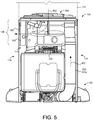
- the external power source 192 may include a wall outlet, delivering an alternating current (AC) via the power cord 190 for powering an air mover 126 ( FIG. 5 ) that causes debris to be pulled from the debris bin 50 of the robotic cleaner10.
- the evacuation station 100 may include a DC converter 1790 (FIG. 17) for powering the controller 1300 of the evacuation station 100.
- the controller 1300 receives signals and executes algorithms to determine whether or not the robotic cleaner 10 is in the docked position at the evacuation station 100. For example, the controller 1300 may detect the location of the robot 10 in relation to the evacuation station 100 (via one or more sensors, such as proximity and/or contact sensors) to determine whether the robotic cleaner 10 is in the docked position. The controller 1300 may operate the evacuation station 100 in an evacuation mode (e.g., first operation mode) to suck and collect debris from the debris bin 50 of the robotic cleaner 10.
- an evacuation mode e.g., first operation mode
- the controller 1300 may operate the evacuation station 100 in an air filtration mode (e.g., second operation mode).
- an air filtration mode environmental air is drawn by the air mover 126 into the base 120 of the evacuation station 100 and filtered before being released to the environment.
- environmental air may be drawn by the air mover 126 through an inlet 298 ( FIG. 5 ) of the base 120 and filtered by a particle filter 302 ( FIG. 5 ) within the base 120 and out an exhaust 300.
- the base 120 may further include a user interface 150 in communication with the controller 1300 for allowing the user to input signals for execution by the evacuation station and for displaying operation and functionality of the evacuation station 100.
- the user interface 150 may display a current capacity of the canister 110, a remaining time for the debris bin 50 to be evacuated, a remaining time for the robot 10 to be charged, a confirmation of the robot 10 being docked, or any other pertinent parameter.
- the user interface 150 and/or controller 1300 are located on the front wall 112 of the canister 110 for improved accessibility and visibility.
- FIGS. 2A and 2B illustrate an exemplary autonomous robotic cleaner 10 (also referred to as a robot) for docking with the evacuation station; however, other types of robotic cleaners are possible as well, with different components and/or different arrangements of components.
- the autonomous robotic cleaner 10 includes a chassis 30 which carries an outer shell 6.
- FIG. 2A shows the outer shell 6 of the robot 10 connected to a front bumper 5.
- the robot 10 may move in forward and reverse drive directions; consequentially, the chassis 30 has corresponding forward and back ends 30a, 30b, respectively.
- the forward end 30a is fore in the direction of primary mobility and the direction of the bumper 5.
- the robot 10 typically moves in the reverse direction primarily during escape, bounces, and obstacle avoidance.
- a collection opening 40 is located toward the middle of the robot 10 and installed within the chassis 30.
- the collection opening 40 includes a first debris extractor 42 and a parallel second debris extractor 44.
- the first debris extractor 42 and/or the parallel second debris extractor 44 is/are removable.
- the collection opening 40 includes a fixed first debris extractor 42 and/or a parallel second debris extractor 44, where fixed refers to an extractor installed on and coupled to the chassis 30, yet removable for routine maintenance.
- the debris extractors 42 and 44 are composed of rubber and include flaps or vanes for collecting debris from the cleaning surface.
- the debris extractors 42 and/or 44 are brushes that may be a pliable multi-vane beater or have pliable beater flaps between rows of brush bristles.
- the battery 24 may be housed within the chassis 30 proximate the collection opening 40. Electrical contacts 25 are electrically connected to the battery 24 for providing charging current and/or voltage to the battery 24 when the robot 10 is in the docked position and is undergoing a charging event. For example, the electrical contacts 25 may contact associated charging contacts 252 ( FIG. 3 ) located on the ramp 130 of the evacuation station 100.
- the forward end 30a of the chassis 30 includes a caster wheel 20 which provides additional support for the robot 10 as a third point of contact with the floor (cleaning surface) and does not hinder robot mobility.
- the removable debris bin 50 is located toward the back end 30b of the robot 10 and installed within or forms part of the outer shell 6.
- the robot 10 includes a display 8 and control panel 12 located upon the outer shell 6.
- the display 8 may display an operational mode of the robot 10, debris capacity of the debris bin 50, state of charge of the battery 24, remaining life of the battery 24, or any other parameters.
- the control panel 12 may receive inputs from a user to turn on/off the robot 10, schedule charging events for the battery 24, select evacuation parameters for evacuating the debris bin 50 at the evacuation station 100, or select a mode of operation for the robot 10.
- the control panel 12 may be in communication with a microprocessor 14 that executes one or more algorithms (e.g., cleaning routines) based upon the user inputs to the control panel 12.
- the bin 50 may include a bin-full detection system 250 for sensing an amount of debris present in the bin 50.
- the bin-full detection system 250 includes an emitter 252 and a detector 254 housed in the bin 50.
- the emitter 252 transmits light and the detector 254 receives reflected light.
- the bin 50 includes a microprocessor 54, which may be connected to the emitter 252 and the detector 254, respectively, to execute an algorithm to determine whether the bin 50 is full.
- the microprocessor 54 may communicate with the battery 24 and the microprocessor 14 of the robot 10.
- the microprocessor 54 may communicate with the robotic cleaner 10 from a bin serial port 56 to a robot serial port 16.
- the robot serial port 16 may be in communication with the microprocessor 14.
- the serial ports 16, 56 may be, for example, mechanical terminals or optical devices.
- the microprocessor 54 may report bin full events to the microprocessor 14 of the robotic cleaner 10.
- the microprocessors 14, 54 may communicate with the controller 1300 to report signals when the robotic cleaner 10 has docked at the ramp 130 of the evacuation station 100.
- the ramp 130 of the evacuation station 100 may include a receiving surface 132 (having an inclination angle ⁇ with respect to the supporting ground surface) selected for facilitating access to and removal of debris residing in the debris bin 50.
- the inclination angle ⁇ may also cause debris residing in the debris bin 50 to gather at the back of the bin 50 (due to gravity) when the robot 10 is received in the docked position.
- the robot 10 docks with the forward end 30a facing the evacuation station 100; however other docking orientations or poses are possible as well.
- the ramp 130 includes one or more charging contacts 252 disposed on the receiving surface 132 and arranged to interface with one or more corresponding electrical contacts 25 of the robotic cleaner 10 when received in the docked position.
- the controller 1300 determines the robot 10 is in the docked position when the controller receives a signal indicating the charging contacts 252 are connected to the electrical contacts 25 of the robot 10.
- the charging contacts 252 may include pins, strips, plates, or other elements sufficient for conducting electrical charge.
- the charging contacts 252 may guide the robotic cleaner 10 (e.g., indicate when the robotic cleaner 10 is docked).
- the ramp 130 includes one or more guide alignment features 240a-d disposed on the receiving surface 132 and arranged to orient the received robotic cleaner so that the evacuation intake opening 200 pneumatically interfaces with the debris bin 50 of the robotic cleaner 10.
- the guide alignment features 240a-d may additionally be arranged to orient the received robotic cleaner so the one or more charging contacts 252 electrically connect to the electrical contacts 25 of the robotic cleaner 10.
- the ramp 130 includes wheel ramps 220a, 220b accepting wheels 22a, 22b of the robotic cleaner 10 while the robotic cleaner 10 is moving to the docked position.
- a left wheel ramp 220a accepts the left wheel 22a of the robot 10 and a right wheel ramp 220b accepts the right wheel 22b of the robot 10.
- Each wheel ramp 220a, 220b may include an inclined surface and a pair of corresponding side walls defining a width of each wheel ramp 220a, 220b for retaining and aligning the wheels 22a, 22b of the robotic cleaner 10 upon the wheel ramps 220a, 220b .
- the wheel ramps 220a, 220b may include a width slightly greater than a width of the wheels 22a, 22b and may include one or more traction features for reducing slippage between the wheels 22a, 22b of the robotic cleaner 10 and the wheel ramps 220a, 220b when the robotic cleaner 10 is moving to the docked position.
- the wheel ramps 220a, 220b further function as guide alignment features for aligning the robot 10 when docking on the ramp 130.
- the one or more guide alignment features include wheel cradles 230a, 230b supporting the wheels 22a, 22b of the robotic cleaner 10 when the robotic cleaner 10 is in the docked position.
- the wheel cradles 230a, 230b serve to support and stabilize the wheels 22a, 22b when the robotic cleaner 10 is in the docked position.
- the wheel cradles 230a, 230b include U-shaped depressions upon the ramp 130 having radii large enough to accept and retain the wheels 22a, 22b after the wheels 22a, 22b traverse the wheel ramps 220a, 220b.
- the wheel cradles 230a, 230b are rectangular shaped, V-shaped or other shaped depressions.
- Surfaces of the wheel cradles 230a, 230b may include a texture permitting slippage of the wheels 22a, 22b such that the wheels 22a, 22b can be rotationally aligned when at least one of the wheel cradles 230a, 230b accepts a corresponding wheel 22a, 22b.
- the cradles 230a, 230b may include sensors (or features) 232a, 232b, respectively, indicating when the robotic cleaner 10 is in the docked position.
- the cradle sensors 232a, 232b may communicate with the controller 1300, 14 and/or 56 to determine when evacuation and/or charging events can occur.
- the cradle sensors 232a, 232b include weight sensors that measure a weight of the robotic cleaner 10 when received in the docked position.
- the features 232a, 232b may include biasing features that depress when the wheels 22a, 22b of the robot 10 are received by the cradles 230a, 230b, causing a signal to be transmitted to the controller 1300, 14 and/or 54 that indicates the robot 10 is in the docked position.
- the evacuation intake opening 200 is arranged to interface with the collection opening 40 of the robotic cleaner 10.
- the evacuation intake opening 200 is arranged to pneumatically interface with the debris bin 50 via the collection opening 40 so that an air flow caused by the air mover 126 draws the debris out of the debris bin 50 and through the collection and evacuation intake openings 40, 200, respectively, to a first conduit portion 202a of a pneumatic debris intake conduit 202 ( FIG. 5 ) of the evacuation station 100.
- the ramp 130 also includes a seal 204 pneumatically sealing the evacuation intake opening 200 and the collection opening 40 of the robotic cleaner 10 when the robotic cleaner 10 is in the docked position.
- the drawn flow of air may or may not cause the primary and parallel secondary debris extractors 42, 44, respectively, to rotate as the debris are drawn through the collection opening 40 of the robotic cleaner 10 and into the evacuation intake opening 200 of the ramp 130.
- the base 120 includes the air mover 126 having the inlet 298 and the exhaust 300.
- the air mover moves air received from the inlet out the exhaust 300.
- the air mover 126 may include a motor and fan or impeller assembly 326 for powering the air mover 126.
- the base 120 houses a particle filter 302 pneumatically connected to the exhaust 300 of the air mover 126.
- the particle filter 302 removes small particles (e.g., between about 0.1 and about 0.5 micrometers) from air received at the inlet 298 and out the exhaust 300 of the air mover 126.
- the particle filter 302 may also remove small particles (e.g., between 0.1 and about 0.5 micrometers) from environmental air received at an environmental air inlet 1230 of the air mover 126 and out the exhaust 300 of the air mover 126.
- the particle filter 302 is a high-efficiency particulate air (HEPA) filter.
- HEPA high-efficiency particulate air
- the particle filter 302 may also be referred to as the HEPA filter and/or an air filter.
- the particle filter 302 is disposable in some examples, and in other examples, the particle filter is washable to remove any small particles collected thereon.
- the base 120 encloses the air mover 126 to draw a flow of air (e.g., air-debris flow 402) from the debris bin 50 when the robotic cleaner 10 is in the docked position and the canister 110 is attached to the base 120.
- the first conduit portion 202a of the pneumatic debris intake conduit 202 transmits the air-debris flow 402 containing debris from the debris bin 50 to a second conduit portion 202b of the pneumatic debris intake conduit 202 enclosed within the canister 110.
- the second conduit portion 202b is arranged to pneumatically interface with the first conduit portion 202a to form the pneumatic debris intake conduit 202 when the canister 110 is attached to the base 120.
- the pneumatic debris intake conduit 202 corresponds to a single, pneumatic conduit for transporting the air-debris flow 402 that includes an air flow containing the debris drawn from the debris bin 50 of the robotic cleaner 10 through the collection and evacuation intake openings 40, 200, respectively.
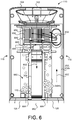
- the canister 110 includes the second conduit portion 202b arranged to pneumatically interface with the first conduit portion 202a to form the pneumatic debris intake conduit 202 when the canister 110 is attached to the base 120.
- the canister 110 includes an annular filter wall 650 in pneumatic communication with the second conduit portion 202b.
- the filter wall 650 may be corrugated to offer relatively greater surface area than a smooth circular wall.
- the annular filter wall 650 is enclosed by a pre-filter cage 640 within the canister 110.
- the annular filter wall 650 defines an open center region 655 enclosed by an outer wall region 652. Accordingly, the annular filter wall 650 includes an annular ring-shaped cross section.
- the annular filter wall 650 corresponds to a separator that separates and/or filters debris out of the air-debris flow 402 received from the pneumatic debris intake conduit 202.
- the air mover 126 draws the air-debris flow 402 through the pneumatic debris intake conduit 202 and the annular filter wall 650 is arranged within the canister 110 to receive the air-debris flow 402 exiting the pneumatic debris intake conduit 202 at the second conduit portion 202b.
- the annular filter wall 650 collects debris from the air-debris flow 402 received from the pneumatic debris intake conduit 202, permitting the debris-free air flow 602 to travel through the open center region 655 to the exhaust conduit 304 arranged to pneumatically connect to the inlet 298 of the air mover 126 when the canister 110 attaches to the base 120.
- the HEPA filter 302 removes any small particles (e.g., ⁇ 0.1 to ⁇ 0.5 micrometers) prior to the air exiting out to the environment at the exhaust 300.
- a portion of the debris collected by the annular filter wall 650 may be embedded upon the filter wall 650 while another portion of the debris may fall into a debris collection bin 660 within the canister 110.
- the air-debris flow 402 may be at least partially restricted from freely passing through the outer wall region 652 of the annular filter wall 650 to the open center region 655 when debris embedded upon the filter wall 650 increases. Maintenance may be performed periodically to dislodge debris from the filter wall 650 or to replace the filter wall 650 after extended use.
- the annular filter wall 650 may be accessed by opening the filter access door 104 to inspect and/or replace the annular filter wall 650 as needed. For instance, the filter access door 104 may open by depressing the filter access door button 102b located proximate the handle 102.
- the debris collection bin 660 defines a volumetric space for storing accumulated debris that falls by gravity after the annular filter wall 650 separates the debris from the air-debris flow 304. As the debris collection bin 660 becomes full of debris indicating a canister full condition, the flow of air (e.g., the air-debris flow 402 and/or the debris-free air flow 602) within the canister 110 may be restricted from flowing freely. In some implementations, one or more capacity sensors 170 located within the collection bin 660 or the exhaust conduit 304 are utilized to detect the canister full condition, indicating that debris should be emptied from the canister 110.
- the capacity sensors 170 include light emitters/detectors arranged to detect when the debris has accumulated to a threshold level within the debris collection bin 660 indicative of the canister full condition. As the debris accumulates within the debris collection bin 660 and reaches the canister full condition, the debris at least partially blocks the air flow causing a pressure drop within the canister 110 and velocity of the flow of air to decrease.
- the capacity sensors 170 include pressure sensors to monitor pressure within the canister 110 and detect the canister full condition when a threshold pressure drop occurs.
- the capacity sensors 170 include velocity sensors to monitor air flow velocity within the canister 110 and detect the canister full condition when the air flow velocity falls below a threshold velocity.
- the capacity sensors 170 are ultrasonic sensors whose signal changes according to the increase in density of debris within the canister so that a bin full signal only issues when the debris is compacted in the bin. This prevents light, fluffy debris stretching from top to bottom from triggering a bin full condition when much more volume is available for debris collection within the canister 110.
- the ultrasonic capacity sensors 170 are located between the vertical middle and top of the canister 110 rather than along the lower half of the canister so the signal received is not affected by debris compacting in the bottom of the canister 110.
- the canister 110 When the debris collection bin 660 is full (e.g., the canister full condition is detected), the canister 110 may be removed from the base 120 and the debris ejection door 662 may be opened to empty the debris into a trash receptacle.
- the debris ejection door 662 opens when the debris ejection door button 102a proximate the handle 102 is depressed, causing the debris ejection door 662 to swing about hinges 664 to permit the debris to empty.
- This one button press debris ejection technique allows a user to empty the canister 110 into a trash receptacle without having to touch the debris or any dirty surface of the canister 110 to open or close the debris ejection door 662.
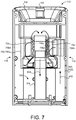
- the canister 110 encloses an air particle separator device 750 (also referred to as a separator) defining at least one collision wall 756a-h and channels arranged to direct the air-debris flow 402 received from the pneumatic debris intake conduit 202 toward the at least one collision wall 756a-d to separate debris out of the air-debris flow 402.
- FIG. 7 illustrates an example air particle separator device 750a including collision walls 756a-b defining a first-stage channel 752 and collision walls 756c-d defining a second-stage channel 754.
- the first-stage channel 752 receives the air-debris flow 402 from the second conduit portion 202b of the pneumatic debris intake conduit 202 and directs the flow 402 by centrifugal force toward collision walls 756a-b of the channel 752, causing coarse debris to separate and collect within a collection bin 760.
- the flow of air from the first-stage channel 752 is received by the second-stage channel 754.
- the second-stage channel 754 directs the flow 402 upward toward collision walls 756c-d defining the channel 754, causing fine debris to separate and collect within the collection bin 760.
- the air mover 126 draws the debris-free air flow 602 through the exhaust conduit 304 and to the inlet 298 and out the exhaust 300.
- small particles e.g., ⁇ 0.1 to ⁇ 0.5 micrometers
- within the debris-free air flow 602 are removed by the HEPA filter 302 prior to exiting out the exhaust 300 to the environment.
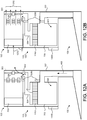
- the canister 110 encloses an annular filter wall 860 in pneumatic communication with an air-particle separator device 750b for filtering and separating debris from the air-debris flow 402 received from the pneumatic debris intake conduit 202 during two stages of particle separation.
- FIG. 8A illustrates a top view of the canister 110
- FIG. 8B illustrates a front view of the canister 110.
- the canister 110 includes a trapezoidal cross section allowing the canister 110 to rest flush against a wall in the environment to aesthetically enhance the appearance of the evacuation station 100; however, the canister 110 may be cylindrical with a circular cross section without limitation in other examples.
- Internal walls of the canister 110 and/or air-particle separator device 750b may include ribs 858 for directing air flow.
- ribs may be disposed upon interior walls of the canister 110 in an orientation that directs debris separated by the filter 860 and/or air-particle separator device 750b to fall away from the exhaust conduit 304 to prevent debris from being received by the inlet 298 of the air mover 126 and clogging the HEPA filter 302.
- the air flow through the exhaust 300 may be restricted if the HEPA filter 302 becomes clogged with debris.
- the filter 860 may include the annular filter wall 650 defining the open center region 655, as described above with reference to FIG. 6 .
- the air-particle separator device 750b may include collision walls 756e-f defining a separator bin 852 in pneumatic communication with the open center region of the filter 860 and one or more conical separators 854.
- the combination of the annular filter wall 860 and the air-particle separator device 750b provides debris to be removed from the air-debris flow 402 during two-stages of air particle separation.
- the filter 860 is arranged to receive the air-debris flow 402 from the pneumatic debris intake conduit 202.
- the filter 860 separates and collects coarse debris from the received air-debris flow 402.
- the coarse debris removed by the filter 860 may accumulate within a coarse debris collection bin 862 and/or embed upon the filter 860.
- the second stage of debris removal commences when the air passes through the filter 860 wall and into the separator bin 852 defined by collision wall 756e.
- the air entering the separator bin 852 may be referred to as a second-stage air flow 802.
- three conical separators 854 are enclosed within the separator bin 852; however, the air-particle separator device 750b may include any number of conical separators 854.
- Each conical separator 854 includes an inlet 856 for receiving the second-stage air flow 802 within the separator bin 852.
- the conical separators 854 include collision walls 756f that angle toward each other to create a funnel (e.g., channel) that causes centrifugal force acting upon the second-stage air flow 802 to increase.
- the increasing centrifugal force causes the second-stage air flow 802 to spin the debris toward collision walls 756f of the conical separators 854, causing fine debris (e.g., dust) to separate and collect within a fine debris collection bin 864.
- fine debris e.g., dust
- the canister 110 may be removed from the base 120 and the debris ejection door 662 may be opened to empty the debris into a trash receptacle.
- a user may open the debris ejection door 662 by depressing the debris ejection door button 102a proximate the handle 102, causing the debris ejection door 662 to swing about hinges 664 to permit the debris to empty from the collection bins 862 and 864.
- This one button press debris ejection technique allows a user to empty the canister 110 into a trash receptacle without having to touch the debris or any dirty surface of the canister 110 to open or close the debris ejection door 662.
- the air mover 126 draws the debris-free air flow 602 from the canister 110 via the exhaust conduit 304 to the inlet 298 and out the exhaust 300.
- small particles e.g., 0.1 to 0.5 micrometers
- FIGS. 9A and 9B the air-particle separator device 750c is arranged in the canister 110 to receive the air-debris flow 402 from the pneumatic debris intake conduit 202.
- FIG. 9A illustrates a top view of the canister 110
- FIG. 9B illustrates a front view of the canister 110.
- the canister 110 includes a trapezoidal cross section allowing the canister 110 to rest flush against a wall in the environment to aesthetically enhance the appearance of the evacuation station 100; however, the canister 110 may include a rectangular, polygonal, circular, or other cross section without limitation in other examples. Ribs 958 may be included upon interior walls of the canister 110 and/or air-particle separator device 750c to facilitate air flow.
- ribs 958 may be disposed upon interior walls of the canister 110 and/or air-particle separator device 750c in an orientation that directs debris separated by the air-particle separator device 750c to fall away from the exhaust conduit 304 to prevent debris from being received by the inlet 298 of the air mover 126 and clogging the HEPA filter 302.
- the air flow through the exhaust 300 may be restricted if the HEPA filter 302 becomes clogged with debris.
- the air-particle separator device 750c includes one or more collision walls 756g-h defining a first-stage separator bin 952 and one or more conical separators 954.
- the separator bin 952 includes a substantially cylindrical shape having a circular cross section. In other examples, the separator bin 952 includes a rectangular, polygonal, or other cross section.
- the first-stage separator bin 952 receives the air-debris flow 402 from the pneumatic debris intake conduit 202, wherein the separator bin 952 is arranged to channel the air-debris flow 402 toward the collision wall 756g, causing coarse debris to separate and collect within a coarse collection bin 962.
- the conical separators 95 in pneumatic communication with the separator bin 952, receive a second-stage air flow 902 referring to an air flow with coarse debris being removed at associated inlets 956.
- three conical separators 954 are enclosed within the first-stage separator bin 952; however, the air-particle separator device 750c may include any number of conical separators 954.
- the conical separators 954 include collision walls 756h that angle toward each other to create a funnel that causes centrifugal force acting upon the second-stage air flow 902 to increase.
- the increasing centrifugal force directs the second-stage air flow 902 toward the one or more collision walls 756h, causing fine debris (e.g., dust) to separate and accumulate within a fine debris collection bin 964.
- fine debris e.g., dust
- the canister 110 may be removed from the base 120 and the debris ejection door 662 may be opened to empty the debris into a trash receptacle.
- a user may open the debris ejection door 662 by depressing the debris ejection door button 102a proximate the handle 102, causing the debris ejection door 662 to swing about hinges 664 to permit the debris to empty from the collection bins 962 and 964.
- the air mover 126 draws the debris-free air flow 602 from the canister 110 via the exhaust conduit 304 to the inlet 298 and out the exhaust 300.
- small particles e.g., 0.1 to 0.5 micrometers
- the HEPA filter 302 prior to exiting out the exhaust 300 to the environment.
- the canister 110 includes a filter bag 1050 arranged to receive the air-debris flow 402 from the pneumatic debris intake conduit 202.
- the filter bag 1050 corresponds to a separator that separates and filters debris out of the air-debris flow 402 received from the pneumatic debris intake conduit 202.
- the filter bag 1050 can be disposable and formed of paper or fabric that allows air to pass through but traps dirt and debris.
- FIG. 10A shows a top view of the canister 110
- FIG. 10B shows a side view of the canister 110.
- the filter bag 1050 while collecting debris via filtration, is porous to permit a debris-free air flow 602 to exit the filter bag 1050 via the exhaust conduit 304.
- the debris-free air flow 602 is received by the inlet 298 of the air mover 126 and out the exhaust 300.
- small particles (-0.1 to ⁇ 0.5 micrometers) within the debris-free air flow 602 are removed by the HEPA filter 302 ( FIG. 5 ) disposed in the base 120 prior to exiting out the exhaust 300 ( FIG. 5 ).
- the filter bag 1050 may include an inlet opening 1052 for receiving the air-debris flow 402 from the pneumatic debris intake conduit 202 exiting from the second conduit portion 202b.
- a fitting 1054 may be used to attach the inlet opening 1052 of the filter bag 1050 to an outlet of the second conduit portion 202b of the pneumatic air-debris intake conduit 202.
- the fitting 1054 includes features that poka-yoke mating the filter bag 1050 so that the bag only mates to the fitting 1054 in a proper orientation for use and expansion within the canister 110.
- the filter bag 1050 includes a matching interface with features accommodating those on the fitting 1054.
- the filter bag 1050 is disposable, requiring replacement when the filter bag 1050 becomes full. In other examples, the filter bag 1050 may be removed from the canister 110 and collected debris may be emptied from the filter bag 1050.
- the filter bag 1050 may be accessed for inspection, maintenance and/or replacement by opening the filter access door 104.
- the filter access door 104 swings about hinges 1004.
- the filter access door 104 is opened by depressing the filter access door button 102b located proximate the handle 102.
- the filter bag 1050 may provide varying degrees of filtration (e.g., ⁇ 0.1 microns to ⁇ 1 microns).
- the filter bag 1050 includes HEPA filtration in addition to, or instead of, the HEPA filter 302 located proximate the exhaust 300 within the base 120 of the evacuation station 100.
- the canister 110 includes a filter bag detection device 1070 configured to detect whether or not the filter bag 1050 is present.
- the filter bag detection device 1070 may include light emitters and detectors configured to detect the presence of the filter bag 1050.
- the filter bag detection device 1070 may relay signals to the controller 1300.
- the filter detection device 1070 detects the filter bag 1050 is not within the canister 110, the filter detection device 1070 prevents the filter access door 104 from closing.
- the controller 1300 may activate mechanical features or latches proximate the canister 110 and/or filter access door 104 to prevent the filter access door 104 from closing.
- the filter bag detection device 1070 is mechanical and movable between a first position for preventing the filter access door 104 from closing and a second position for allowing the filter access door 104 to close.
- a fitting 1054 swings or moves upward when the filter bag 1050 is removed and prevents the filter door 104 from closing. The fitting 1054 is depressed upon insertion of the filter bag 1050 allowing the filter door 104 to close.
- detecting when the filter bag 1050 is not present in the canister 110 prevents the evacuation station 100 from operating in the evacuation mode, even if the robotic cleaner 10 is received at the ramp 130 in the docked position.
- the canister 110 includes a trapezoidal cross section allowing the canister 110 to rest flush against a wall in the environment to aesthetically enhance the appearance of the evacuation station 100.
- the canister 110 may however, include a rectangular, polygonal, circular, or other cross section without limitation in other examples.
- the filter bag 1050 expands as the collected debris accumulates therein. Expansion of the filter bag 1050 into contact with interior walls 1010 of the canister 110 may result in debris only accumulating at a bottom portion of the filter bag 1050, thereby chocking the air flow through the filter bag 1050.
- the filter bag 1050 and/or interior walls 1010 of the canister 110 include protrusions 1080, such as ribs, edges or ridges, disposed upon and extending away from the exterior surface of the filter bag 1050 and/or extending into the canister 110 from the interior walls 1010.
- protrusions 1080 such as ribs, edges or ridges
- the protrusions 1080 on the bag 1050 abut against the interior walls 1010 of the canister 110 to prevent the filter bag 1050 from fully expanding into the interior walls 1010.
- the protrusions 1080 restrict the bag 1050 from fully expanding into flush contact with the interior walls 1010.
- the protrusions 1080 ensure that an air gap is maintained between the filter bag 1050 and the interior walls 1010, such that the filter bag 1050 cannot fully expand into contact the interior walls 1010.
- the protrusions 1080 are elongated ribs uniformly spaced in parallel around the exterior surface of the filter bag 1050 and/or the surface of the interior walls 1010. The spacing between adjacent protrusions 1080 is small enough to prevent the filter bag 1050 from bowing out and into contact with the interior walls.
- the canister 110 is cylindrical and the protrusions 1080 are elongated ribs that run vertically down the length of the canister 110 and around the entire circumference of the canister 110 such that airflow continues to be uniform through the entire surface of the unfilled portion of bag even as debris compacts in the bottom of the bag.
- FIG. 11 shows a schematic view of an example evacuation station 100 including an air particle separator device 750 and an air filtration device 1150.
- the evacuation station 100 includes a base 120, a collection bin 1120 and a ramp 130 for docking with the autonomic robotic cleaner 10.
- the example robotic cleaner 10 docking with the ramp 130 is described above with reference to FIGS. 1-5 ; however, other types of robots 10 are possible as well.
- the base 120 houses a first air mover 126a (e.g. a motor driven vacuum impeller) and the air particle separator device 750.
- the first air mover 126a draws an air-debris flow 402 through a pneumatic debris intake conduit 202 to pull debris from within the debris bin 50 of the robotic 10.
- the pneumatic debris intake conduit 202 provides the air-debris flow 402 from the debris bin 50 to a single stage particle separator 1152 of the air particle separator device 750.
- the centrifugal force created by the geometry of the single stage particle separator 1152 causes the air-debris flow 402 to direct toward one or more collision walls 756 of the separator 1152, causing particles to fall from the drawn air 402 and collect in the collection bin 1120 disposed beneath the single stage particle separator 1152.
- a filter 1154 may be disposed above the single stage particle separator 1152 to prevent debris from being drawn up and through the first air mover 126a and damaging the first air mover 126a.
- a second air mover 126b of the air filtration device 1150 provides suction and draws the debris-free air flow 602 from the air mover 126a through and into the air filtration device 1150.
- the second air mover 126b of the air filtration device 1150 includes a fan/fin/impeller that spins.
- a particle filter 302 may remove small particles (e.g., ⁇ 0.1 to ⁇ 0.5 microns) from the debris-free air flow 602.
- the particle filter 302 is a HEPA filter 302 as described above with reference to FIGS. 4 and 5 . Upon passing through the air particle filter 302, the debris-free air flow 602 may exhaust into the environment external to the evacuation station 100.
- the air filtration device 1150 may further operate as an air filter for filtering environmental air external to the evacuation station 100.
- the second air mover 126b may draw the environmental air 1102 to pass through the HEPA filter 302.
- the air filtration device 1150 filters the environmental air via the HEPA filter 302 when the robot 10 is not received in the docked position, and/or the debris bin 50 of the robot 10 is not being evacuated.
- the air filtration device 1150 simultaneously draws environmental air 1102 and debris-free flow 602 exiting the air particle separator device 750 through the HEPA filter 302.
- the collection bin 1120 is removably attached to the base 120.
- the collection bin 1120 includes a handle 1122 for carrying the collection bin 1120 when removed from the base 120.
- the collection bin 1120 may be detached from the base 120 when the handle 1122 is pulled by the user.
- the user may transport the collection bin 1120 via the handle 1122 to empty the collected debris when the collection bin 1120 is full.
- the collection bin 1120 may include a button-press actuated debris ejection door, similar to the debris ejection door 662 described above with reference to FIG. 6 . This one button press debris ejection technique allows a user to empty the collection bin 1120 into a trash receptacle without having to touch the debris or any dirty surface of the collection bin 1120 to open or close the debris ejection door 662.
- an example evacuation station 100 includes a flow control device 1250 in communication with a controller 1300 that selectively actuates the flow control device 1250 between a first position ( FIG. 12A ) when the evacuation station 100 operates in an evacuation mode and a second position ( FIG. 12B ) when the evacuation station 100 operates in an air filtration mode.
- the flow control device 1250 is a flow control valve spring biased toward the first position or the second position. The flow control device 1250 may be actuated between the first and second positions to selectively block one air flow passage or another.
- the evacuation station 100 may operate in the evacuation mode to evacuate debris from the debris bin 50 of the robotic cleaner 10.
- the controller 1300 activates an air mover 126 (motor and impeller) and actuates the flow control device 1250 to the first position, pneumatically connecting the pneumatic debris intake conduit 202 to the inlet 298 of the air mover 126.
- An air-debris flow 402 may be drawn by the air mover 126 through the pneumatic debris intake conduit 202.
- the canister 110 may enclose a filter 1260 in pneumatic communication with the pneumatic debris intake conduit 202 for filtering/separating debris out of the air-debris flow 402.
- the canister 110 may enclose an air particle separator device 750 for separating the debris out of the air-debris flow 402, as discussed in the examples above.
- a debris collection bin 660 may store accumulated debris that fall by gravity after being separated from the air-debris flow 304 by the filter 1260.
- the flow control device 1250 in the first position pneumatically connects the exhaust conduit 304 to the inlet of 298 of the air mover 126. Accordingly, upon separating/filtering debris out of the air-debris flow 402, a debris-free air flow 602 may travel through the exhaust conduit 304 and into the air mover 126 and out the exhaust 300 when the flow control device 1250 is in the first position associated with the evacuation mode.
- the flow control device 1250 while in the first position, also blocks environmental air 1202 ( FIG. 12B ) from being drawn by the air mover 126 through an environmental air inlet 1230 of the air mover 126 and out the exhaust 300.
- the evacuation station 100 may operate in the air filtration mode.
- the controller 1300 activates the air mover 126 and actuates the flow control device 1250 to the second position, pneumatically connecting the environmental air inlet 1230 to the exhaust 300 of the air mover 126 while pneumatically disconnecting the inlet 298 of the air mover 126 from the exhaust conduit 304.
- the air mover 126 may draw the environmental air 1202 via the environmental air inlet 1230 to pass through an air particle filter 302 such as a HEPA filter described above.
- the environmental air 1202 may travel out the exhaust 300 and back into the environment. Since the flow control device 1250 in the second position pneumatically disconnects the inlet 298 from the exhaust conduit 304, no air flow is drawn by the air mover 126 through the pneumatic debris intake conduit 202 or the exhaust conduit 304.
- the air particle filter 302 e.g., HEPA filter
- air flow generated within the debris bin 50 of the robot 10 during the evacuation mode allows debris in the bin 50 to be sucked out and transported to the evacuation station 100.
- the air flow within the debris bin 50 must be sufficient to permit the debris to be removed while avoiding damage to the bin 50 and a robot motor (not shown) housed within the bin 50.
- the robot motor may generate an air flow to draw debris from the collection opening 40 into the bin 50 to collect the debris within the bin 50, while permitting the air flow to exit the bin 50 through an exhaust vent (not shown) proximate the robot motor.
- the evacuation station can be used, for example, with a bin such as that disclosed in US Patent Application 14/566,243, filed December 10, 2014 and entitled, "DEBRIS EVACUATION FOR CLEANING ROBOTS", which is hereby incorporated by reference in its entirety.
- FIG. 13 shows an example controller 1300 enclosed within the evacuation station 100.
- the external power supply 192 e.g., wall outlet
- the DC converter 1390 may convert AC current from the power supply 192 into DC current for powering the controller 1300.
- the controller 1300 includes a motor module 1702 in communication with the air mover 126 using AC current from the external power supply 192.
- the motor module 1302 may further monitor operational parameters of the air mover 126 such as, but not limited to, rotational speed, output power, and electrical current.
- the motor module 1302 may activate the air mover 126.
- the motor module 1302 actuates the flow control valve 1250 between the first and second positions.
- the controller 1300 includes a canister module 1304 receiving a signal indicating a canister full condition when the canister 110 has reached its capacity for collecting debris.
- the canister module 1304 may receive signals from the one or more capacity sensors 170 located within the canister (e.g., collection chambers or exhaust conduit 304) and determine when the canister full condition is received.
- an interface module 1306 communicates the canister full condition to the user interface 150 by displaying a message indicating the canister full condition.
- the canister module 1304 may receive a signal from the connection sensor 420 indicating if the canister 110 is attached to the base 120 or if the canister 110 is removed from the base 120.
- a charging module 1308 receives an indication of electrical connection between the one or more charging contacts 252 and the one or more a corresponding electrical contacts 25.
- the indication of electrical connection may indicate the robotic cleaner 10 is received in the docked position.
- the controller 1300 may execute the first operation mode (e.g., evacuation mode) when the electrical connection indication is received at the charging module 1308.
- the charging module 1308, in some examples, receives an indication of electrical disconnection between the one or more charging contacts 252 and the one or more a corresponding electrical contacts 25.
- the indication of electrical disconnection may indicate the robotic cleaner 10 is not received in the docked position.
- the controller 1300 may execute the second operation mode (e.g., air filtration mode) when the electrical disconnection indication is received at the charging module 1308.
- the controller 1300 may detect when the charging contacts 252 located upon the ramp 130 are in contact with the electrical contacts 25 of the robotic cleaner 10. For example, the charging module 1308 may determine the robotic cleaner 10 has docked with the evacuation station 100 when the electrical contacts 25 are in contact with the charging contacts 252. The charging module 1308 may communicate the docking determination to the motor module 1302 so that the air mover 126 may be powered to commence evacuating the debris bin 50 of the robotic cleaner 10. The charging module 1308 may further monitor the charge of the battery 24 of the robotic cleaner 10 based on signals communicated between the charging and electrical contacts 25, 252, respectively. When the battery 24 needs charging, the charging module 1308 may provide a charging current for powering the battery.
- the charging module 1308 may block the supply of charging through the electrical contacts 25 of the battery 24.
- the charging module 1308 provides a state of charge or estimated charge time for the battery 24 to the interface module 1306 for display upon the user interface 150.
- the controller 1300 includes a guiding module 1310 that receives signals from the guiding device 122 (emitter 122a and/or detector 122b) located on the base 120. Based upon the signals received from the guiding device 122, the guiding module may determine when the robot 10 is received in the docked position, determine a location of the robot 10, and/or assist in guiding the robot 10 to toward the docked position.
- the guiding module 1310 may additionally or alternatively receive signals from sensors 232a, 232b (e.g., weight sensors) for detecting when the robot 10 is in the docked position.
- the guiding module 1310 may communicate to the motor module 1302 when the robot 10 is received in the docked position so that the air mover 126 can activated for drawing out debris from the debris bin 50 of the robot.
- a bin module 1312 of the controller 1300 may indicate a capacity of the debris bin 50 of the robotic cleaner 10.
- the bin module 1312 may receive signals from the microprocessor 14 and/or 54 of the robot 10 and the capacity sensor 170 that indicate the capacity of the bin 50, e.g., the bin full condition.
- the robot 10 may dock when the battery 24 is in need of charging but the bin 50 is not full of debris.
- the bin module 1312 may communicate to the motor module 1302 that evacuation is no longer needed.
- the bin module 1312 may receive a signal indicating that the bin 50 no longer requires evacuation and the motor module 1302 may be notified to deactivate the air mover 126.
- the bin module 1312 may receive a collection bin identification signal from the microprocessor 14 and/or 54 of the robot 10 that indicates a model type of the debris bin 50 used by the robotic cleaner 10.
- the interface module 1306 receives operational commands input by a user to the user interface 150, e.g., an evacuation schedule and/or charging schedule for evacuating and/or charging the robot 10. For instance, it may be desirable to charge and/or evacuate the robot 10 at specific times even though the bin 50 is not full and/or the battery 24 is not entirely depleted.
- the interface module 1306 may notify the guiding module 1310 to transmit honing signals through the guiding device 122 to call the robot 10 to dock during the time of a set charging and/or evacuation event specified by the user.
- FIG. 14 provides an example arrangement of operations for a method 1400, executable by the controller 1300 of FIG. 13 , for operating the evacuation station 100 between an evacuation mode (e.g., a first operation mode) and an air filtration mode (e.g., a second operation mode).
- the flowchart starts at operation 1402 where the controller 1300 receives a first indication of whether the robotic cleaner 10 is received on the receiving surface 132 in the docked position, and at operation 1404, receives a second indication of whether the canister 110 is connected to the base 120.
- the controller 1300 may receive the first and second indications of operations 1802, 1804, respectively, in any order or in parallel.
- the first indication includes the controller 1300 receiving an electrical signal from the one or more charging contacts 252 disposed on the receiving surface 132 that interface with electrical contacts 25 when the robotic cleaner 10 is in the docked position.
- the second indication includes the controller 1300 receiving a signal from the connection sensor 420 sensing connection of the canister 110 to the base 120.
- the controller 1300 executes the evacuation mode (first operation mode) at operation 1408 by actuating the flow control device 1250 to move to the first position ( FIG. 12A ) that pneumatically connects the evacuation intake opening 200 to the canister 110 and activates the air mover 126 to draw air into the evacuation intake opening 200 to draw debris from the debris bin 50 of the docked robotic cleaner 10 into the canister 110.
- the evacuation mode first operation mode
- the controller 1300 executes the air filtration mode (second operation mode) by actuating the flow control valve 1250 to move to the second position ( FIG. 12B ) that pneumatically connects the environmental air inlet 1230 ( FIGS. 12A and 12B ) to the exhaust 300 of the air mover 126 while pneumatically disconnecting the inlet 298 of the air mover 126 from the exhaust conduit 304.
- the air filtration mode second operation mode
- the air mover 126 may draw environmental air 1202 through the environmental air inlet 1230 and the particle filter 302 and out the exhaust 300.
- operation 1408 additionally detects whether or not the evacuation mode is executing or has recently stopped executing.
- the controller 1300 executes the air filtration mode even though the canister 110 is attached to the base 120 and the robotic cleaner 10 is received in the docked position.
Landscapes
- Engineering & Computer Science (AREA)
- Mechanical Engineering (AREA)
- Robotics (AREA)
- Electric Vacuum Cleaner (AREA)
- Electric Suction Cleaners (AREA)
- Filters For Electric Vacuum Cleaners (AREA)
Applications Claiming Priority (3)
| Application Number | Priority Date | Filing Date | Title |
|---|---|---|---|
| US201462096771P | 2014-12-24 | 2014-12-24 | |
| PCT/US2015/061341 WO2016105702A1 (fr) | 2014-12-24 | 2015-11-18 | Station d'évacuation |
| EP15873923.5A EP3236827B1 (fr) | 2014-12-24 | 2015-11-18 | Station d'évacuation |
Related Parent Applications (1)
| Application Number | Title | Priority Date | Filing Date |
|---|---|---|---|
| EP15873923.5A Division EP3236827B1 (fr) | 2014-12-24 | 2015-11-18 | Station d'évacuation |
Publications (1)
| Publication Number | Publication Date |
|---|---|
| EP3795048A1 true EP3795048A1 (fr) | 2021-03-24 |
Family
ID=56151315
Family Applications (2)
| Application Number | Title | Priority Date | Filing Date |
|---|---|---|---|
| EP15873923.5A Active EP3236827B1 (fr) | 2014-12-24 | 2015-11-18 | Station d'évacuation |
| EP20199035.5A Pending EP3795048A1 (fr) | 2014-12-24 | 2015-11-18 | Station d'évacuation |
Family Applications Before (1)
| Application Number | Title | Priority Date | Filing Date |
|---|---|---|---|
| EP15873923.5A Active EP3236827B1 (fr) | 2014-12-24 | 2015-11-18 | Station d'évacuation |
Country Status (8)
| Country | Link |
|---|---|
| US (4) | US9931007B2 (fr) |
| EP (2) | EP3236827B1 (fr) |
| JP (3) | JP7098113B2 (fr) |
| CN (3) | CN112057008A (fr) |
| AU (2) | AU2015370307B2 (fr) |
| CA (1) | CA2972252C (fr) |
| ES (1) | ES2829919T3 (fr) |
| WO (1) | WO2016105702A1 (fr) |
Families Citing this family (147)
| Publication number | Priority date | Publication date | Assignee | Title |
|---|---|---|---|---|
| ES2829919T3 (es) | 2014-12-24 | 2021-06-02 | Irobot Corp | Estación de evacuación |
| USD771332S1 (en) * | 2015-02-12 | 2016-11-08 | Irobot Corporation | Cleaning robot |
| USD796757S1 (en) * | 2015-02-12 | 2017-09-05 | Irobot Corporation | Robot |
| USD784640S1 (en) * | 2015-02-12 | 2017-04-18 | Irobot Corporation | Robot |
| USD771333S1 (en) * | 2015-02-12 | 2016-11-08 | Irobot Corporation | Cleaning robot |
| USD790141S1 (en) * | 2015-02-12 | 2017-06-20 | Irobot Corporation | Robot |
| USD781512S1 (en) * | 2015-02-12 | 2017-03-14 | Irobot Corporation | Robot |
| US9462920B1 (en) | 2015-06-25 | 2016-10-11 | Irobot Corporation | Evacuation station |
| US11163311B2 (en) | 2015-12-24 | 2021-11-02 | Partnering 3.0 | Robotic equipment including a mobile robot, method for recharging a battery of such mobile robot, and mobile robot docking station |
| FR3046245B1 (fr) * | 2015-12-24 | 2018-02-16 | Partnering 3.0 | Systeme de surveillance de qualite d'air et station d'accueil pour robot mobile equipe de capteurs de qualite d'air |
| JP6660738B2 (ja) * | 2016-01-12 | 2020-03-11 | 東芝ライフスタイル株式会社 | 電気掃除装置 |
| DE102016114338A1 (de) * | 2016-08-03 | 2018-02-08 | Miele & Cie. Kg | Ladevorrichtung für ein Haushaltgerät und Verfahren zum Aufladen eines Haushaltgeräts |
| US10456002B2 (en) | 2016-12-22 | 2019-10-29 | Irobot Corporation | Cleaning bin for cleaning robot |
| US11794141B2 (en) * | 2021-01-25 | 2023-10-24 | Omachron Intellectual Property Inc. | Multiuse home station |
| US10675982B2 (en) * | 2017-03-27 | 2020-06-09 | General Electric Company | System and method for inductive charging with improved efficiency |
| US20180344116A1 (en) * | 2017-06-02 | 2018-12-06 | Irobot Corporation | Scheduling and control system for autonomous robots |
| USD835869S1 (en) * | 2017-06-14 | 2018-12-11 | Guangdong Bona Robot Co., Ltd | Cleaning robot |
| US10941555B2 (en) | 2017-06-16 | 2021-03-09 | Altan Robotech Inc. | Robotic cleaning apparatus and related methods |
| US10941553B2 (en) | 2017-06-16 | 2021-03-09 | Altan Robotech Inc. | Robotic cleaning apparatus and related methods |
| USD843671S1 (en) * | 2017-07-25 | 2019-03-19 | Sharkninja Operating Llc | Robotic vacuum cleaner |
| USD838069S1 (en) * | 2017-08-17 | 2019-01-08 | Altan Robotech Inc. | Cleaning robot |
| USD840617S1 (en) * | 2017-08-31 | 2019-02-12 | Beijing Xiaomi Mobile Software Co., Ltd. | Robotic vacuum |
| US10383499B2 (en) * | 2017-08-31 | 2019-08-20 | Irobot Corporation | Wet robot docking station |
| USD895915S1 (en) * | 2017-09-07 | 2020-09-08 | Sharkninja Operating Llc | Side brush for robotic vacuum cleaner |
| USD877432S1 (en) | 2017-09-07 | 2020-03-03 | Sharkninja Operating Llc | Bumper for robotic vacuum cleaner |
| USD867987S1 (en) * | 2017-09-15 | 2019-11-26 | Beijing Rockrobo Technology Co., Ltd. | Base station |
| CN107608360A (zh) * | 2017-10-26 | 2018-01-19 | 深圳市银星智能科技股份有限公司 | 移动机器人 |
| CN107669216A (zh) * | 2017-11-24 | 2018-02-09 | 珠海市微半导体有限公司 | 智能清洁系统及智能清洁方法 |
| DE102018204172A1 (de) * | 2017-12-27 | 2019-06-27 | Robert Bosch Gmbh | Akku-Sauggerät |
| US10737395B2 (en) * | 2017-12-29 | 2020-08-11 | Irobot Corporation | Mobile robot docking systems and methods |
| US10967749B2 (en) * | 2017-12-29 | 2021-04-06 | Irobot Corporation | Electrostatic discharge systems for autonomous mobile robots |
| DE102018100371A1 (de) * | 2018-01-09 | 2019-07-11 | Vorwerk & Co. Interholding Gmbh | Saugreinigungsgerät mit einem Filterbeutel sowie Filterbeutel für ein Saugreinigungsgerät |
| CN113197526A (zh) * | 2018-05-01 | 2021-08-03 | 尚科宁家运营有限公司 | 自动清洁系统及用于机器人清洁器的对接站 |
| USD893562S1 (en) | 2018-05-04 | 2020-08-18 | Irobot Corporation | Debris container |
| USD893561S1 (en) | 2018-05-04 | 2020-08-18 | Irobot Corporation | Debris container |
| USD890231S1 (en) | 2018-05-04 | 2020-07-14 | Irobot Corporation | Debris container |
| US10842334B2 (en) * | 2018-05-04 | 2020-11-24 | Irobot Corporation | Filtering devices for evacuation stations |
| USD908993S1 (en) | 2018-05-04 | 2021-01-26 | Irobot Corporation | Evacuation station |
| USD930053S1 (en) | 2018-05-04 | 2021-09-07 | Irobot Corporation | Debris container |
| USD924522S1 (en) | 2018-05-04 | 2021-07-06 | Irobot Corporation | Evacuation station |
| USD908992S1 (en) | 2018-05-04 | 2021-01-26 | Irobot Corporation | Evacuation station |
| KR102071959B1 (ko) * | 2018-05-16 | 2020-04-01 | 엘지전자 주식회사 | 로봇 청소기의 충전 데크 |
| GB2574198B (en) * | 2018-05-25 | 2020-11-04 | Sony Interactive Entertainment Inc | Apparatus, system and method of wireless robot charging |
| PT3875013T (pt) * | 2018-06-22 | 2022-04-04 | Bissell Inc | Aparelho de limpeza de superfícies e bandeja |
| TWI668591B (zh) * | 2018-06-28 | 2019-08-11 | 廣達電腦股份有限公司 | 機器人系統 |
| CN115089055B (zh) * | 2018-07-20 | 2024-02-13 | 尚科宁家运营有限公司 | 用于机器人清洁器的对接站和清洁系统 |
| USD906236S1 (en) * | 2018-08-03 | 2020-12-29 | Techtronic Cordless Gp | Docking station for mowers |
| WO2020047303A1 (fr) | 2018-08-30 | 2020-03-05 | Irobot Corporation | Commande de stations d'évacuation |
| US11039725B2 (en) * | 2018-09-05 | 2021-06-22 | Irobot Corporation | Interface for robot cleaner evacuation |
| US11318482B2 (en) | 2018-10-22 | 2022-05-03 | Omachron Intellectual Property Inc. | Air treatment apparatus |
| US11609573B2 (en) * | 2018-10-30 | 2023-03-21 | Florida Power & Light Company | Method for the automated docking of robotic platforms |
| KR20200073966A (ko) | 2018-12-14 | 2020-06-24 | 삼성전자주식회사 | 진공 청소기와 도킹 스테이션을 포함하는 청소 장치 |
| CN109480713B (zh) * | 2018-12-20 | 2023-09-19 | 北京享捷科技有限公司 | 一种扫地机器人吸尘装置以及吸尘方法 |
| CN109480714B (zh) * | 2018-12-25 | 2023-10-03 | 北京享捷科技有限公司 | 一种扫地机器人吸尘充电装置以及吸尘充电方法 |
| CN109662657A (zh) * | 2019-01-07 | 2019-04-23 | 云鲸智能科技(东莞)有限公司 | 一种基站和停靠方法 |
| USD948143S1 (en) | 2019-02-19 | 2022-04-05 | Sharkninja Operating Llc | Robotic vacuum cleaner |
| TWD203966S (zh) * | 2019-03-18 | 2020-04-11 | 大陸商北京小米移動軟件有限公司 | 掃地機充電座 |
| CN111743459A (zh) * | 2019-03-29 | 2020-10-09 | 北京石头世纪科技股份有限公司 | 智能清洁系统、自主机器人和基站 |
| USD906607S1 (en) * | 2019-04-18 | 2020-12-29 | Zhuhai Kaihao Electronics Co., Ltd. | Robotic vacuum cleaner |
| CN110027827A (zh) | 2019-04-30 | 2019-07-19 | 深圳市银星智能科技股份有限公司 | 处理站及清洁系统 |
| CN110051283B (zh) * | 2019-05-17 | 2023-06-09 | 珠海市一微机器人技术有限公司 | 一种面向扫地机器人的智能垃圾收集机器人 |
| CN112043204B (zh) * | 2019-06-05 | 2021-11-26 | 美智纵横科技有限责任公司 | 空气处理组件及具有其的清洁设备 |
| USD947473S1 (en) | 2019-06-14 | 2022-03-29 | Sharkninja Operating Llc | Robot vacuum |
| DE102019004417A1 (de) * | 2019-06-25 | 2020-12-31 | Vorwerk & Co. Interholding Gmbh | Verfahren, Basisstation und Reinigungssystem zum Aussaugen eines Reinigungsgeräts |
| ES2953125T3 (es) | 2019-07-11 | 2023-11-08 | Vorwerk Co Interholding | Estación base para conectar un dispositivo de limpieza y procedimiento para operación de un sistema de limpieza |
| KR20210016704A (ko) * | 2019-08-05 | 2021-02-17 | 삼성전자주식회사 | 로봇 청소기의 스테이션 |
| USD951859S1 (en) * | 2019-08-15 | 2022-05-17 | Beijing Xiaomi Mobile Software Co., Ltd. | Charging base for robot vacuum cleaner |
| CN110623605B (zh) * | 2019-08-21 | 2021-11-30 | 深圳市无限动力发展有限公司 | 工作站及清洁系统 |
| CN110466918B (zh) * | 2019-08-21 | 2022-08-05 | 深圳市无限动力发展有限公司 | 垃圾回收站及清洁系统 |
| KR102208334B1 (ko) * | 2019-09-05 | 2021-01-28 | 삼성전자주식회사 | 진공 청소기와 도킹 스테이션을 포함하는 청소 장치 및 그 제어 방법 |
| CN110601291A (zh) * | 2019-09-17 | 2019-12-20 | 南通明诺电动科技股份有限公司 | 一种磁性式智能电动扫地机充电底座 |
| CN110840334B (zh) * | 2019-11-05 | 2021-05-28 | 深圳市银星智能科技股份有限公司 | 一种机器清洁系统及其维护方法 |
| CN110811437A (zh) * | 2019-11-07 | 2020-02-21 | 珠海格力电器股份有限公司 | 一种集尘方法、装置、清理系统及可读存储介质 |
| CN110859550A (zh) * | 2019-11-07 | 2020-03-06 | 珠海格力电器股份有限公司 | 一种集尘方法、装置、集尘系统及可读存储介质 |
| DE102019131582A1 (de) * | 2019-11-22 | 2021-05-27 | Vorwerk & Co. Interholding Gmbh | Saugreinigungsgerät, System mit einem Saugreinigungsgerät und einer Basisstation sowie Verfahren zum Betrieb eines solchen Systems |
| DE102019131662A1 (de) * | 2019-11-22 | 2021-05-27 | Vorwerk & Co. Interholding Gmbh | Basisstation für ein Bodenbearbeitungsgerät, Antriebsrad für ein Bodenbearbeitungsgerät sowie System aus einer Basisstation und einem Bodenbearbeitungsgerät |
| CN110974090B (zh) * | 2019-12-24 | 2021-11-16 | 深圳市银星智能科技股份有限公司 | 一种排空站及具有此排空站的清洁机器人系统 |
| CN113040650A (zh) * | 2019-12-28 | 2021-06-29 | 尚科宁家(中国)科技有限公司 | 用于扫地机器人的集尘站 |
| CN111110123A (zh) * | 2019-12-28 | 2020-05-08 | 尚科宁家(中国)科技有限公司 | 用于扫地机器人的排空站 |
| CN111035326A (zh) * | 2019-12-28 | 2020-04-21 | 尚科宁家(中国)科技有限公司 | 一种扫地机器人排空站及扫地机器人系统 |
| CN113040649B (zh) * | 2019-12-28 | 2022-12-06 | 尚科宁家(中国)科技有限公司 | 用于扫地机器人的集尘站 |
| AU2020418666A1 (en) * | 2019-12-30 | 2022-07-21 | Lg Electronics Inc. | Charging station for robot cleaner |
| CN111227720A (zh) * | 2020-02-26 | 2020-06-05 | 深圳市银星智能科技股份有限公司 | 一种智能清洁系统 |
| KR20210019940A (ko) | 2020-06-22 | 2021-02-23 | 엘지전자 주식회사 | 청소기 스테이션 및 청소기 스테이션의 제어방법 |
| US20230337878A1 (en) | 2020-03-03 | 2023-10-26 | Lg Electronics Inc. | Vacuum cleaner station, vacuum cleaner system, and method for controlling vacuum cleaner station |
| USD903961S1 (en) * | 2020-03-10 | 2020-12-01 | Shenzhen Modern Business Trading Co., Ltd. | Robotic vacuum cleaner |
| USD906608S1 (en) * | 2020-03-25 | 2020-12-29 | Shenzhen WoMei Tech Co., Ltd. | Robotic vacuum cleaner |
| US11617488B2 (en) | 2020-04-22 | 2023-04-04 | Omachron Intellectual Property Inc. | Robotic vacuum cleaner and docking station for a robotic vacuum cleaner |
| CN111266954B (zh) * | 2020-05-08 | 2020-09-22 | 苏州高之仙自动化科技有限公司 | 工作站和具有其的除尘系统 |
| JP2021186004A (ja) * | 2020-05-26 | 2021-12-13 | 東芝ライフスタイル株式会社 | 電気掃除機 |
| JP1673977S (fr) * | 2020-05-28 | 2020-12-07 | ||
| CN111557614B (zh) * | 2020-05-29 | 2022-02-18 | 深圳市银星智能科技股份有限公司 | 清洁基站以及清洁机器人系统 |
| KR20220000297A (ko) * | 2020-06-25 | 2022-01-03 | 삼성전자주식회사 | 도킹 스테이션, 이동 로봇 및 도킹 스테이션과 이동 로봇을 제어하는 이동 로봇 관리 시스템 |
| KR20220006850A (ko) | 2020-07-09 | 2022-01-18 | 엘지전자 주식회사 | 청소기 스테이션 |
| WO2022016255A1 (fr) * | 2020-07-20 | 2022-01-27 | Omachron Intellectual Property Inc. | Station d'évacuation pour un robot mobile de nettoyage de sol |
| US11529034B2 (en) | 2020-07-20 | 2022-12-20 | Omachron lntellectual Property Inca | Evacuation station for a mobile floor cleaning robot |
| US11717124B2 (en) * | 2020-07-20 | 2023-08-08 | Omachron Intellectual Property Inc. | Evacuation station for a mobile floor cleaning robot |
| DE102020119421A1 (de) * | 2020-07-23 | 2022-01-27 | Miele & Cie. Kg | Station für Reinigungsroboter |
| CN111887777B (zh) * | 2020-07-29 | 2023-03-07 | 深圳市普森斯科技有限公司 | 清扫控制方法、装置、电子设备及存储介质 |
| CN111873835A (zh) * | 2020-07-30 | 2020-11-03 | 孝感峰创智能科技有限公司 | 一种防潮式潮汐式车道机器人用充电桩 |
| JP1716815S (ja) * | 2020-08-07 | 2022-06-07 | 埃除去及び充電機能付き掃除機用スタンド | |
| WO2022032640A1 (fr) * | 2020-08-14 | 2022-02-17 | Irobot Corporation | Socle d'accueil d'évacuation avec une gestion de fluide |
| USD969429S1 (en) | 2020-08-14 | 2022-11-08 | Irobot Corporation | Docking station |
| USD1002136S1 (en) * | 2020-09-08 | 2023-10-17 | Sharkninja Operating Llc | Robot vacuum docking station |
| USD1002976S1 (en) * | 2020-09-08 | 2023-10-24 | Sharkninja Operating Llc | Robot vacuum docking station |
| US11910974B2 (en) * | 2020-10-03 | 2024-02-27 | Viabot Inc. | Conveyor stations for emptying debris collecting robots |
| WO2022075718A1 (fr) * | 2020-10-08 | 2022-04-14 | 엘지전자 주식회사 | Station de dispositif de nettoyage |
| USD965517S1 (en) * | 2020-10-19 | 2022-10-04 | Amazon Technologies, Inc. | Docking station |
| CN112515555B (zh) * | 2020-10-20 | 2022-05-03 | 深圳市银星智能科技股份有限公司 | 一种集尘基站、清洁机器人及清洁系统 |
| KR102466280B1 (ko) * | 2020-12-02 | 2022-11-14 | 삼성전자주식회사 | 로봇청소기 스테이션 |
| US11737625B2 (en) * | 2020-12-04 | 2023-08-29 | Omachron Intellectual Property Inc. | Evacuation station for a mobile floor cleaning robot |
| KR20220081702A (ko) * | 2020-12-09 | 2022-06-16 | 엘지전자 주식회사 | 청소기 시스템 |
| USD974292S1 (en) * | 2020-12-11 | 2023-01-03 | Samsung Electronics Co., Ltd. | Charging holder for vacuum cleaner |
| EP4265168A1 (fr) | 2020-12-16 | 2023-10-25 | LG Electronics Inc. | Système de nettoyage |
| WO2022140222A1 (fr) * | 2020-12-22 | 2022-06-30 | Jones Terry G | Poubelle d'amarrage pour système et procédé de vide robotisé automatisé |
| USD1002977S1 (en) * | 2021-01-04 | 2023-10-24 | Beijing Roborock Technology Co., Ltd. | Charging station with dust collector for sweeping machines |
| CN114869185A (zh) * | 2021-02-05 | 2022-08-09 | 深圳银星智能集团股份有限公司 | 维护基站和清洁机器人系统 |
| TWD216655S (zh) * | 2021-02-07 | 2022-01-11 | 大陸商北京小米移動軟件有限公司 | 清潔機器人基站 |
| KR20220119980A (ko) | 2021-02-22 | 2022-08-30 | 엘지전자 주식회사 | 청소기 스테이션 |
| CN112971648B (zh) * | 2021-03-02 | 2022-08-16 | 广州科语机器人有限公司 | 一种清洁系统、清洁基站及其作业对接方法 |
| CN112842156A (zh) * | 2021-03-18 | 2021-05-28 | 广东乐生智能科技有限公司 | 一种智能扫地集尘装置 |
| CN112998583A (zh) * | 2021-03-23 | 2021-06-22 | 深圳市银星智能科技股份有限公司 | 基站及清洁机器人系统 |
| US11793379B2 (en) | 2021-03-26 | 2023-10-24 | Irobot Corporation | Floor and air cleaning systems and related methods |
| CN113080791B (zh) * | 2021-03-29 | 2023-08-11 | 深圳万拓科技创新有限公司 | 集尘基站 |
| CN112890678A (zh) * | 2021-03-30 | 2021-06-04 | 深圳市银星智能科技股份有限公司 | 集尘装置及清洁机器人系统 |
| CN113080764A (zh) * | 2021-04-07 | 2021-07-09 | 无锡睿米信息技术有限公司 | 一种清洁设备及自清洁方法 |
| EP4070704A1 (fr) * | 2021-04-08 | 2022-10-12 | Vorwerk & Co. Interholding GmbH | Station de base pour un appareil de traitement du sol, ainsi que système composé d'une station de base et d'un appareil de traitement du sol |
| CN113133716B (zh) * | 2021-04-09 | 2022-10-21 | 美智纵横科技有限责任公司 | 清洁装置的基站及具有其的清洁系统 |
| USD981061S1 (en) * | 2021-04-12 | 2023-03-14 | Zhichang Technology (Suzhou) Co., Ltd. | Cleaning robot workstation |
| CN113243858B (zh) * | 2021-04-26 | 2022-12-20 | 北京顺造科技有限公司 | 基站设备及表面清洁系统 |
| BE1029361B1 (de) * | 2021-05-03 | 2022-12-05 | Miele & Cie | Wagen und Verfahren zum Ein- und Ausbringen von Reinigungsrobotern in und aus einem Wagen |
| CN113208515A (zh) * | 2021-06-03 | 2021-08-06 | 深圳市威睿晶科电子有限公司 | 一种扫拖一体的家用智能扫地机器人 |
| US20230010550A1 (en) * | 2021-07-07 | 2023-01-12 | Irobot Corporation | Filtering devices for evacuation stations |
| EP4368085A1 (fr) | 2021-07-09 | 2024-05-15 | LG Electronics Inc. | Station d'aspirateur |
| AU2022306644A1 (en) | 2021-07-09 | 2024-02-01 | Lg Electronics Inc. | Cleaner station |
| KR20230013340A (ko) * | 2021-07-19 | 2023-01-26 | 엘지전자 주식회사 | 청소기 스테이션 |
| KR20230013341A (ko) | 2021-07-19 | 2023-01-26 | 엘지전자 주식회사 | 청소기 스테이션 |
| CN215959650U (zh) * | 2021-08-02 | 2022-03-08 | 美智纵横科技有限责任公司 | 基站以及清洁系统 |
| KR20230040552A (ko) * | 2021-09-16 | 2023-03-23 | 엘지전자 주식회사 | 청소기, 청소기 시스템 및 청소기 시스템의 제어 방법 |
| CA212102S (en) * | 2021-12-07 | 2023-02-07 | Beijing Roborock Tech Co Ltd | Docking station for cleaning robot |
| CN114343503B (zh) * | 2022-01-21 | 2023-08-01 | 深圳市杉川机器人有限公司 | 扫地机器人及其移动方法与装置、存储介质 |
| USD979869S1 (en) * | 2022-01-21 | 2023-02-28 | Sharkninja Operating Llc | Robot vacuum docking station |
| USD980162S1 (en) * | 2022-03-24 | 2023-03-07 | Guangyu Hua | Charger for robotic vacuum cleaner |
| USD976826S1 (en) * | 2022-03-24 | 2023-01-31 | Guangyu Hua | Charger for robotic vacuum cleaner |
| BE1030624B1 (de) | 2022-06-14 | 2024-01-23 | Miele & Cie | Reinigungsstation und Reinigungssystem |
| US20240041284A1 (en) * | 2022-08-03 | 2024-02-08 | Omachron Intellectual Property Inc. | Docking unit for a surface cleaning apparatus |
| DE102022125143A1 (de) * | 2022-09-29 | 2024-04-04 | Miele & Cie. Kg | Verfahren und Steuervorrichtung zum Betreiben einer Reinigungseinrichtung und Reinigungseinrichtung |
Citations (3)
| Publication number | Priority date | Publication date | Assignee | Title |
|---|---|---|---|---|
| US20070079585A1 (en) * | 2005-10-11 | 2007-04-12 | Samsung Gwangju Electronics Co., Ltd. | Multi cyclone dust collector for a vacuum cleaner |
| DE102010000607A1 (de) * | 2010-03-02 | 2011-09-08 | Vorwerk & Co. Interholding Gmbh | Als Basisstation für ein selbsttätig verfahrbares Saug- und/oder Kehrgerät einsetzbarer Haushaltsstaubsauger |
| US20120084937A1 (en) * | 2006-05-19 | 2012-04-12 | Irobot Corporation | Removing Debris From Cleaning Robots |
Family Cites Families (106)
| Publication number | Priority date | Publication date | Assignee | Title |
|---|---|---|---|---|
| US2770825A (en) | 1951-09-10 | 1956-11-20 | Bissell Carpet Sweeper Co | Carpet sweeper and brush cleaning combs therefor |
| JPS5891356A (ja) | 1981-11-26 | 1983-05-31 | 株式会社日本自動車部品総合研究所 | デイ−ゼルエンジンのegr量制御方法 |
| JPS5891356U (ja) * | 1981-12-14 | 1983-06-21 | 三菱電機株式会社 | 電気掃除機 |
| US4733431A (en) * | 1986-12-09 | 1988-03-29 | Whirlpool Corporation | Vacuum cleaner with performance monitoring system |
| CA1307956C (fr) | 1988-05-10 | 1992-09-29 | Raymond G. Spain | Procede de fabrication d'arcticles en materiau composite constitue d'un liant metal-verre et d'une armature en fibres orientees suivant les trois axes |
| JPH0218363U (fr) * | 1988-07-20 | 1990-02-07 | ||
| US5345649A (en) | 1993-04-21 | 1994-09-13 | Whitlow William T | Fan brake for textile cleaning machine |
| JPH0723880A (ja) * | 1993-07-09 | 1995-01-27 | Sharp Corp | アップライト型電気掃除機 |
| BE1008470A3 (fr) * | 1994-07-04 | 1996-05-07 | Colens Andre | Dispositif et systeme automatique de depoussierage de sol et engin y adapte. |
| JPH08335112A (ja) | 1995-06-08 | 1996-12-17 | Minolta Co Ltd | 移動作業ロボットシステム |
| DE19605780A1 (de) * | 1996-02-16 | 1997-08-21 | Branofilter Gmbh | Detektionseinrichtung für Filterbeutel in Staubsaugern |
| JP3274058B2 (ja) | 1996-03-22 | 2002-04-15 | 富士通株式会社 | 光ディバイス |
| US6076226A (en) * | 1997-01-27 | 2000-06-20 | Robert J. Schaap | Controlled self operated vacuum cleaning system |
| DE19708955A1 (de) | 1997-03-05 | 1998-09-10 | Bosch Siemens Hausgeraete | Multifunktionales Saugreinigungsgerät |
| US5995884A (en) * | 1997-03-07 | 1999-11-30 | Allen; Timothy P. | Computer peripheral floor cleaning system and navigation method |
| DE19734193A1 (de) | 1997-08-07 | 1999-02-11 | Branofilter Gmbh | Detektionseinrichtung für Filtereinrichtungen in Staubsaugern |
| US5920043A (en) * | 1997-08-19 | 1999-07-06 | Kinergy Industrial Co., Ltd. | Circuit breaker control device for a vacuum cleaners dust hopper |
| WO1999028800A1 (fr) | 1997-11-27 | 1999-06-10 | Solar & Robotics | Ameliorations a des robots mobiles et a leur systeme de commande |
| US6532404B2 (en) | 1997-11-27 | 2003-03-11 | Colens Andre | Mobile robots and their control system |
| US6263989B1 (en) | 1998-03-27 | 2001-07-24 | Irobot Corporation | Robotic platform |
| US6552729B1 (en) | 1999-01-08 | 2003-04-22 | California Institute Of Technology | Automatic generation of animation of synthetic characters |
| EP1191982B1 (fr) | 1999-06-17 | 2004-06-02 | Solar & Robotics S.A. | Dispositif automatique de ramassage d'objets |
| US6341404B1 (en) * | 2000-01-13 | 2002-01-29 | Royal Appliance Mfg. Co. | Upright vacuum cleaner with cyclonic airflow pathway |
| US7155308B2 (en) | 2000-01-24 | 2006-12-26 | Irobot Corporation | Robot obstacle detection system |
| US6594844B2 (en) | 2000-01-24 | 2003-07-22 | Irobot Corporation | Robot obstacle detection system |
| CN1116524C (zh) | 2000-08-22 | 2003-07-30 | 卢咏林 | 水下驱动自动防堵式水泵取水头 |
| JP2002125899A (ja) | 2000-10-20 | 2002-05-08 | Sanyo Electric Co Ltd | コードレス電気掃除機および充電兼用集塵装置 |
| US6690134B1 (en) | 2001-01-24 | 2004-02-10 | Irobot Corporation | Method and system for robot localization and confinement |
| US6883201B2 (en) | 2002-01-03 | 2005-04-26 | Irobot Corporation | Autonomous floor-cleaning robot |
| US7571511B2 (en) | 2002-01-03 | 2009-08-11 | Irobot Corporation | Autonomous floor-cleaning robot |
| DE10113789B4 (de) * | 2001-03-21 | 2006-09-14 | BSH Bosch und Siemens Hausgeräte GmbH | Anordnung zur Entsorgung von Schmutz mit einem beweglichen Schmutzsauger |
| US20040187457A1 (en) | 2001-05-28 | 2004-09-30 | Andre Colens | Robotic lawnmower |
| US7663333B2 (en) | 2001-06-12 | 2010-02-16 | Irobot Corporation | Method and system for multi-mode coverage for an autonomous robot |
| EP2386924B1 (fr) | 2001-06-12 | 2019-05-29 | iRobot Corporation | Robot mobile |
| JP3986310B2 (ja) | 2001-12-19 | 2007-10-03 | シャープ株式会社 | 親子型電気掃除機 |
| US20050150519A1 (en) * | 2002-07-08 | 2005-07-14 | Alfred Kaercher Gmbh & Co. Kg | Method for operating a floor cleaning system, and floor cleaning system for use of the method |
| KR100468107B1 (ko) * | 2002-10-31 | 2005-01-26 | 삼성광주전자 주식회사 | 외부충전장치를 갖는 로봇청소기 시스템 및 로봇청소기의외부충전장치 접속방법 |
| JP2004267236A (ja) | 2003-03-05 | 2004-09-30 | Hitachi Ltd | 自走式掃除機およびそれに用いる充電装置 |
| US7805220B2 (en) | 2003-03-14 | 2010-09-28 | Sharper Image Acquisition Llc | Robot vacuum with internal mapping system |
| US7801645B2 (en) | 2003-03-14 | 2010-09-21 | Sharper Image Acquisition Llc | Robotic vacuum cleaner with edge and object detection system |
| JP2004313756A (ja) | 2003-03-31 | 2004-11-11 | Sanyo Electric Co Ltd | 電気掃除機及びその集塵装置 |
| DE20308543U1 (de) * | 2003-05-31 | 2003-08-28 | Aichner Filter Gmbh | Halteplatte eines Staubfilterbeutels sowie deren Anordnung in einem Staubsauger |
| DE10333395A1 (de) | 2003-07-16 | 2005-02-17 | Alfred Kärcher Gmbh & Co. Kg | Bodenreinigungssystem |
| AU2004202836B2 (en) | 2003-07-24 | 2006-03-09 | Samsung Gwangju Electronics Co., Ltd. | Dust Receptacle of Robot Cleaner |
| KR100554237B1 (ko) | 2003-09-08 | 2006-02-22 | 삼성광주전자 주식회사 | 사이클론 분리장치 및 이를 구비한 진공청소기 |
| JP4152291B2 (ja) * | 2003-09-30 | 2008-09-17 | 三洋電機株式会社 | 電気掃除機 |
| DE10357637A1 (de) | 2003-12-10 | 2005-07-07 | Vorwerk & Co. Interholding Gmbh | Selbstfahrendes oder zu verfahrendes Kehrgerät sowie Kombination eines Kehrgeräts mit einer Basisstation |
| US7201786B2 (en) | 2003-12-19 | 2007-04-10 | The Hoover Company | Dust bin and filter for robotic vacuum cleaner |
| JP2005211493A (ja) | 2004-01-30 | 2005-08-11 | Funai Electric Co Ltd | 自走式掃除機 |
| KR100592098B1 (ko) * | 2004-02-11 | 2006-06-22 | 삼성광주전자 주식회사 | 진공청소기의 사이클론 집진장치 |
| US7779507B2 (en) * | 2004-03-11 | 2010-08-24 | Lg Electronics Inc. | Vacuum cleaner |
| JP2007530978A (ja) | 2004-03-29 | 2007-11-01 | エヴォリューション ロボティクス インコーポレイテッド | 反射光源を使用する位置推定方法および装置 |
| JP4241493B2 (ja) | 2004-04-28 | 2009-03-18 | 三洋電機株式会社 | 掃除機用集塵装置 |
| US7706917B1 (en) | 2004-07-07 | 2010-04-27 | Irobot Corporation | Celestial navigation system for an autonomous robot |
| DE102004041021B3 (de) | 2004-08-17 | 2005-08-25 | Alfred Kärcher Gmbh & Co. Kg | Bodenreinigungssystem |
| KR100622549B1 (ko) * | 2004-11-25 | 2006-09-19 | 삼성광주전자 주식회사 | 멀티 사이클론 집진장치 |
| US7389156B2 (en) | 2005-02-18 | 2008-06-17 | Irobot Corporation | Autonomous surface cleaning robot for wet and dry cleaning |
| DE602006014364D1 (de) * | 2005-02-18 | 2010-07-01 | Irobot Corp | Autonomer oberflächenreinigungsroboter für nass- und trockenreinigung |
| ES2238196B1 (es) | 2005-03-07 | 2006-11-16 | Electrodomesticos Taurus, S.L. | Estacion base con robot aspirador. |
| KR100704484B1 (ko) * | 2005-05-04 | 2007-04-09 | 엘지전자 주식회사 | 로봇 청소기의 먼지통 감지장치 |
| JP2007023880A (ja) * | 2005-07-15 | 2007-02-01 | Mitsubishi Electric Corp | スクロール圧縮機 |
| KR101199358B1 (ko) * | 2005-07-18 | 2012-11-09 | 엘지전자 주식회사 | 로봇청소기의 먼지비움장치 |
| ES2378138T3 (es) | 2005-12-02 | 2012-04-09 | Irobot Corporation | Movilidad de robot de cubrimiento |
| KR101074937B1 (ko) | 2005-12-02 | 2011-10-19 | 아이로보트 코퍼레이션 | 모듈형 로봇 |
| KR20070074147A (ko) | 2006-01-06 | 2007-07-12 | 삼성전자주식회사 | 청소기 시스템 |
| KR20070074146A (ko) | 2006-01-06 | 2007-07-12 | 삼성전자주식회사 | 청소기 시스템 |
| JP2007236520A (ja) | 2006-03-07 | 2007-09-20 | Toshiba Corp | 電気掃除機 |
| EP1842474A3 (fr) | 2006-04-04 | 2007-11-28 | Samsung Electronics Co., Ltd. | Système robot nettoyeur doté d'un robot nettoyeur et d'une station d'accueil |
| KR20070101002A (ko) | 2006-04-10 | 2007-10-16 | 이바도 | 위성 방식의 청소로봇 시스템 |
| KR20070104989A (ko) | 2006-04-24 | 2007-10-30 | 삼성전자주식회사 | 로봇청소기 시스템 및 그 먼지제거 방법 |
| GB2440108A (en) | 2006-07-18 | 2008-01-23 | Dyson Technology Ltd | Suction cleaner with filter detection mechanism |
| KR100864708B1 (ko) * | 2006-12-28 | 2008-10-23 | 삼성광주전자 주식회사 | 진공청소기의 멀티 사이클론 집진장치 |
| KR101204440B1 (ko) * | 2007-02-26 | 2012-11-26 | 삼성전자주식회사 | 로봇청소기와 도킹스테이션을 구비한 로봇청소기 시스템 |
| EP1980188B1 (fr) | 2007-03-27 | 2012-11-14 | Samsung Electronics Co., Ltd. | Robot nettoyeur doté d'un collecteur de poussière amélioré |
| EP2574265B1 (fr) | 2007-05-09 | 2015-10-14 | iRobot Corporation | Robot autonome de couverture compact |
| KR101330734B1 (ko) * | 2007-08-24 | 2013-11-20 | 삼성전자주식회사 | 로봇청소기와 도킹 스테이션을 구비하는 로봇청소기 시스템 |
| GB2454227B (en) * | 2007-11-01 | 2012-02-29 | Dyson Technology Ltd | Cyclonic separating apparatus |
| US7879120B2 (en) | 2007-11-05 | 2011-02-01 | Samsung Gwangju Electronics Co., Ltd. | Vacuum cleaner |
| CN102083352B (zh) | 2008-04-24 | 2014-10-15 | 艾罗伯特公司 | 用于机器人使能的移动产品的定位、位置控制和导航系统的应用 |
| JP2010273819A (ja) | 2009-05-28 | 2010-12-09 | Panasonic Corp | 電気掃除機 |
| US8973210B2 (en) | 2009-06-30 | 2015-03-10 | Lg Electronics Inc. | Robot cleaner |
| CN201572039U (zh) * | 2009-08-28 | 2010-09-08 | 泰怡凯电器(苏州)有限公司 | 地面处理系统 |
| GB2481608B (en) | 2010-06-30 | 2015-03-04 | Dyson Technology Ltd | A surface treating appliance |
| KR101483541B1 (ko) * | 2010-07-15 | 2015-01-19 | 삼성전자주식회사 | 로봇청소기, 메인터넌스 스테이션 그리고 이들을 가지는 청소시스템 |
| KR101496913B1 (ko) * | 2010-11-03 | 2015-03-02 | 삼성전자 주식회사 | 로봇청소기와 자동배출 스테이션 및 이를 가지는 로봇청소기 시스템 |
| WO2012094617A2 (fr) * | 2011-01-07 | 2012-07-12 | Irobot Corporation | Système de station d'évacuation |
| WO2012149572A2 (fr) | 2011-04-29 | 2012-11-01 | Irobot Corporation | Aspirateur robotique |
| EP2570067A1 (fr) | 2011-09-01 | 2013-03-20 | Samsung Electronics Co., Ltd. | Appareil de nettoyage autonome et son procédé de commande |
| KR101970584B1 (ko) * | 2011-09-01 | 2019-08-27 | 삼성전자주식회사 | 청소 시스템과 그 메인터넌스 스테이션 |
| EP2581015B1 (fr) * | 2011-10-12 | 2015-01-21 | Black & Decker Inc. | Aspirateur |
| EP2581022B1 (fr) | 2011-10-12 | 2014-05-21 | Black & Decker Inc. | Moteur, ventilateur et agencement d'appareil de séparation cyclonique |
| JP3172934U (ja) | 2011-10-28 | 2012-01-12 | 聚隆生活電器(蘇州)有限公司 | サイクロン式集塵装置およびそれを用いた電気掃除機 |
| US20130305481A1 (en) * | 2012-05-15 | 2013-11-21 | Samsung Electronics Co., Ltd. | Maintenance system and cleaning system having the same |
| GB2502131B (en) * | 2012-05-17 | 2014-11-05 | Dyson Technology Ltd | Autonomous vacuum cleaner |
| CN103565349B (zh) * | 2012-07-27 | 2016-03-09 | 科沃斯机器人有限公司 | 智能清洁机器人的工作系统 |
| JP5362889B1 (ja) | 2012-08-08 | 2013-12-11 | 株式会社東芝 | 集塵装置および電気掃除機 |
| DE102012109938A1 (de) | 2012-10-18 | 2014-04-24 | Vorwerk & Co. Interholding Gmbh | Selbsttätig verfahrbares Bodenstaub-Aufsammelgerät, sowie Verfahren zum Betreiben eines solchen Gerätes |
| CN103844996B (zh) * | 2012-12-05 | 2017-02-15 | 科沃斯机器人股份有限公司 | 清洁系统和吸灰装置 |
| CN203841626U (zh) * | 2014-04-02 | 2014-09-24 | 江苏美的春花电器股份有限公司 | 智能清扫设备 |
| CN203763006U (zh) * | 2014-04-04 | 2014-08-13 | 向桂南 | 一种擦地机 |
| CN203861137U (zh) * | 2014-04-18 | 2014-10-08 | 江苏春花杰佳电器有限公司 | 一种设有尘袋漏装保护装置的吸尘器 |
| JP6335050B2 (ja) | 2014-07-04 | 2018-05-30 | 東芝ライフスタイル株式会社 | 電気掃除機 |
| JP6522905B2 (ja) * | 2014-08-20 | 2019-05-29 | 東芝ライフスタイル株式会社 | 電気掃除機 |
| US9788698B2 (en) * | 2014-12-10 | 2017-10-17 | Irobot Corporation | Debris evacuation for cleaning robots |
| ES2829919T3 (es) | 2014-12-24 | 2021-06-02 | Irobot Corp | Estación de evacuación |
| KR101854681B1 (ko) * | 2016-08-25 | 2018-06-08 | 엘지전자 주식회사 | 집진장치 및 이를 구비하는 진공 청소기 |
-
2015
- 2015-11-18 ES ES15873923T patent/ES2829919T3/es active Active
- 2015-11-18 CN CN202010920091.6A patent/CN112057008A/zh active Pending
- 2015-11-18 EP EP15873923.5A patent/EP3236827B1/fr active Active
- 2015-11-18 US US14/944,788 patent/US9931007B2/en active Active
- 2015-11-18 CN CN201710963078.7A patent/CN107811578B/zh active Active
- 2015-11-18 CA CA2972252A patent/CA2972252C/fr active Active
- 2015-11-18 CN CN201580075381.2A patent/CN107405031B/zh active Active
- 2015-11-18 EP EP20199035.5A patent/EP3795048A1/fr active Pending
- 2015-11-18 JP JP2017534319A patent/JP7098113B2/ja active Active
- 2015-11-18 WO PCT/US2015/061341 patent/WO2016105702A1/fr active Application Filing
- 2015-11-18 AU AU2015370307A patent/AU2015370307B2/en active Active
-
2018
- 2018-02-22 US US15/901,952 patent/US10463215B2/en active Active
-
2019
- 2019-10-03 US US16/592,403 patent/US10595692B2/en active Active
-
2020
- 2020-03-23 US US16/827,389 patent/US11969139B2/en active Active
- 2020-07-09 AU AU2020204599A patent/AU2020204599B2/en active Active
- 2020-10-15 JP JP2020173936A patent/JP7254055B2/ja active Active
-
2021
- 2021-11-25 JP JP2021191201A patent/JP7262718B2/ja active Active
Patent Citations (3)
| Publication number | Priority date | Publication date | Assignee | Title |
|---|---|---|---|---|
| US20070079585A1 (en) * | 2005-10-11 | 2007-04-12 | Samsung Gwangju Electronics Co., Ltd. | Multi cyclone dust collector for a vacuum cleaner |
| US20120084937A1 (en) * | 2006-05-19 | 2012-04-12 | Irobot Corporation | Removing Debris From Cleaning Robots |
| DE102010000607A1 (de) * | 2010-03-02 | 2011-09-08 | Vorwerk & Co. Interholding Gmbh | Als Basisstation für ein selbsttätig verfahrbares Saug- und/oder Kehrgerät einsetzbarer Haushaltsstaubsauger |
Also Published As
| Publication number | Publication date |
|---|---|
| JP7262718B2 (ja) | 2023-04-24 |
| AU2015370307A1 (en) | 2017-06-15 |
| EP3236827A1 (fr) | 2017-11-01 |
| US10463215B2 (en) | 2019-11-05 |
| CA2972252C (fr) | 2023-02-28 |
| US20160183752A1 (en) | 2016-06-30 |
| AU2020204599B2 (en) | 2021-09-23 |
| EP3236827A4 (fr) | 2019-04-24 |
| CN107811578A (zh) | 2018-03-20 |
| US11969139B2 (en) | 2024-04-30 |
| WO2016105702A1 (fr) | 2016-06-30 |
| JP7254055B2 (ja) | 2023-04-07 |
| US20200281430A1 (en) | 2020-09-10 |
| JP7098113B2 (ja) | 2022-07-11 |
| US20200029765A1 (en) | 2020-01-30 |
| JP2021035500A (ja) | 2021-03-04 |
| US20180177369A1 (en) | 2018-06-28 |
| CN112057008A (zh) | 2020-12-11 |
| CN107405031A (zh) | 2017-11-28 |
| CN107811578B (zh) | 2020-12-04 |
| JP2018500998A (ja) | 2018-01-18 |
| AU2020204599A1 (en) | 2020-07-30 |
| US9931007B2 (en) | 2018-04-03 |
| ES2829919T3 (es) | 2021-06-02 |
| EP3236827B1 (fr) | 2020-09-30 |
| CN107405031B (zh) | 2020-10-02 |
| US10595692B2 (en) | 2020-03-24 |
| AU2015370307B2 (en) | 2020-04-09 |
| CA2972252A1 (fr) | 2016-06-30 |
| JP2022019815A (ja) | 2022-01-27 |
Similar Documents
| Publication | Publication Date | Title |
|---|---|---|
| AU2020204599B2 (en) | Evacuation station | |
| CN112168071B (zh) | 机器人清洁器工作站 | |
| EP3563745B1 (fr) | Dispositifs de filtration pour stations d'évacuation | |
| EP3860417B1 (fr) | Robot nettoyeur, station et système de nettoyage | |
| WO2017047291A1 (fr) | Dispositif de nettoyage électrique | |
| JP2017055834A (ja) | 電気掃除装置 | |
| JP2017104334A (ja) | 電気掃除装置 | |
| JP2017109017A (ja) | 電気掃除装置 | |
| JP2017104335A (ja) | 電気掃除装置 | |
| CN217792912U (zh) | 清洁机器人及清洁系统 | |
| EP4374761A2 (fr) | Station de dispositif de nettoyage | |
| EP4374762A1 (fr) | Station de nettoyage | |
| WO2022201586A1 (fr) | Système d'aspiration | |
| JP2017055835A (ja) | 電気掃除装置 |
Legal Events
| Date | Code | Title | Description |
|---|---|---|---|
| PUAI | Public reference made under article 153(3) epc to a published international application that has entered the european phase |
Free format text: ORIGINAL CODE: 0009012 |
|
| STAA | Information on the status of an ep patent application or granted ep patent |
Free format text: STATUS: REQUEST FOR EXAMINATION WAS MADE |
|
| STAA | Information on the status of an ep patent application or granted ep patent |
Free format text: STATUS: EXAMINATION IS IN PROGRESS |
|
| 17P | Request for examination filed |
Effective date: 20200929 |
|
| AC | Divisional application: reference to earlier application |
Ref document number: 3236827 Country of ref document: EP Kind code of ref document: P |
|
| AK | Designated contracting states |
Kind code of ref document: A1 Designated state(s): AL AT BE BG CH CY CZ DE DK EE ES FI FR GB GR HR HU IE IS IT LI LT LU LV MC MK MT NL NO PL PT RO RS SE SI SK SM TR |
|
| 17Q | First examination report despatched |
Effective date: 20210305 |