EP2701600B1 - Delivering and/or receiving fluids - Google Patents
Delivering and/or receiving fluids Download PDFInfo
- Publication number
- EP2701600B1 EP2701600B1 EP12721066.4A EP12721066A EP2701600B1 EP 2701600 B1 EP2701600 B1 EP 2701600B1 EP 12721066 A EP12721066 A EP 12721066A EP 2701600 B1 EP2701600 B1 EP 2701600B1
- Authority
- EP
- European Patent Office
- Prior art keywords
- actuator
- deployment
- retraction
- fluid
- opening
- Prior art date
- Legal status (The legal status is an assumption and is not a legal conclusion. Google has not performed a legal analysis and makes no representation as to the accuracy of the status listed.)
- Active
Links
Images


Classifications
-
- A—HUMAN NECESSITIES
- A61—MEDICAL OR VETERINARY SCIENCE; HYGIENE
- A61B—DIAGNOSIS; SURGERY; IDENTIFICATION
- A61B5/00—Measuring for diagnostic purposes; Identification of persons
- A61B5/15—Devices for taking samples of blood
- A61B5/150007—Details
- A61B5/150374—Details of piercing elements or protective means for preventing accidental injuries by such piercing elements
-
- A—HUMAN NECESSITIES
- A61—MEDICAL OR VETERINARY SCIENCE; HYGIENE
- A61B—DIAGNOSIS; SURGERY; IDENTIFICATION
- A61B10/00—Instruments for taking body samples for diagnostic purposes; Other methods or instruments for diagnosis, e.g. for vaccination diagnosis, sex determination or ovulation-period determination; Throat striking implements
- A61B10/0045—Devices for taking samples of body liquids
-
- A—HUMAN NECESSITIES
- A61—MEDICAL OR VETERINARY SCIENCE; HYGIENE
- A61B—DIAGNOSIS; SURGERY; IDENTIFICATION
- A61B5/00—Measuring for diagnostic purposes; Identification of persons
- A61B5/14—Devices for taking samples of blood ; Measuring characteristics of blood in vivo, e.g. gas concentration within the blood, pH-value of blood
- A61B5/1405—Devices for taking blood samples
- A61B5/1411—Devices for taking blood samples by percutaneous method, e.g. by lancet
-
- A—HUMAN NECESSITIES
- A61—MEDICAL OR VETERINARY SCIENCE; HYGIENE
- A61B—DIAGNOSIS; SURGERY; IDENTIFICATION
- A61B5/00—Measuring for diagnostic purposes; Identification of persons
- A61B5/145—Measuring characteristics of blood in vivo, e.g. gas concentration or pH-value ; Measuring characteristics of body fluids or tissues, e.g. interstitial fluid or cerebral tissue
- A61B5/14546—Measuring characteristics of blood in vivo, e.g. gas concentration or pH-value ; Measuring characteristics of body fluids or tissues, e.g. interstitial fluid or cerebral tissue for measuring analytes not otherwise provided for, e.g. ions, cytochromes
-
- A—HUMAN NECESSITIES
- A61—MEDICAL OR VETERINARY SCIENCE; HYGIENE
- A61B—DIAGNOSIS; SURGERY; IDENTIFICATION
- A61B5/00—Measuring for diagnostic purposes; Identification of persons
- A61B5/15—Devices for taking samples of blood
- A61B5/150007—Details
- A61B5/150015—Source of blood
- A61B5/150022—Source of blood for capillary blood or interstitial fluid
-
- A—HUMAN NECESSITIES
- A61—MEDICAL OR VETERINARY SCIENCE; HYGIENE
- A61B—DIAGNOSIS; SURGERY; IDENTIFICATION
- A61B5/00—Measuring for diagnostic purposes; Identification of persons
- A61B5/15—Devices for taking samples of blood
- A61B5/150007—Details
- A61B5/150053—Details for enhanced collection of blood or interstitial fluid at the sample site, e.g. by applying compression, heat, vibration, ultrasound, suction or vacuum to tissue; for reduction of pain or discomfort; Skin piercing elements, e.g. blades, needles, lancets or canulas, with adjustable piercing speed
- A61B5/150061—Means for enhancing collection
- A61B5/150099—Means for enhancing collection by negative pressure, other than vacuum extraction into a syringe by pulling on the piston rod or into pre-evacuated tubes
-
- A—HUMAN NECESSITIES
- A61—MEDICAL OR VETERINARY SCIENCE; HYGIENE
- A61B—DIAGNOSIS; SURGERY; IDENTIFICATION
- A61B5/00—Measuring for diagnostic purposes; Identification of persons
- A61B5/15—Devices for taking samples of blood
- A61B5/150007—Details
- A61B5/150374—Details of piercing elements or protective means for preventing accidental injuries by such piercing elements
- A61B5/150381—Design of piercing elements
- A61B5/150412—Pointed piercing elements, e.g. needles, lancets for piercing the skin
-
- A—HUMAN NECESSITIES
- A61—MEDICAL OR VETERINARY SCIENCE; HYGIENE
- A61B—DIAGNOSIS; SURGERY; IDENTIFICATION
- A61B5/00—Measuring for diagnostic purposes; Identification of persons
- A61B5/15—Devices for taking samples of blood
- A61B5/150007—Details
- A61B5/150374—Details of piercing elements or protective means for preventing accidental injuries by such piercing elements
- A61B5/150381—Design of piercing elements
- A61B5/150503—Single-ended needles
-
- A—HUMAN NECESSITIES
- A61—MEDICAL OR VETERINARY SCIENCE; HYGIENE
- A61B—DIAGNOSIS; SURGERY; IDENTIFICATION
- A61B5/00—Measuring for diagnostic purposes; Identification of persons
- A61B5/15—Devices for taking samples of blood
- A61B5/150969—Low-profile devices which resemble patches or plasters, e.g. also allowing collection of blood samples for testing
-
- A—HUMAN NECESSITIES
- A61—MEDICAL OR VETERINARY SCIENCE; HYGIENE
- A61B—DIAGNOSIS; SURGERY; IDENTIFICATION
- A61B5/00—Measuring for diagnostic purposes; Identification of persons
- A61B5/15—Devices for taking samples of blood
- A61B5/150977—Arrays of piercing elements for simultaneous piercing
-
- A—HUMAN NECESSITIES
- A61—MEDICAL OR VETERINARY SCIENCE; HYGIENE
- A61B—DIAGNOSIS; SURGERY; IDENTIFICATION
- A61B5/00—Measuring for diagnostic purposes; Identification of persons
- A61B5/15—Devices for taking samples of blood
- A61B5/150977—Arrays of piercing elements for simultaneous piercing
- A61B5/150984—Microneedles or microblades
-
- A—HUMAN NECESSITIES
- A61—MEDICAL OR VETERINARY SCIENCE; HYGIENE
- A61B—DIAGNOSIS; SURGERY; IDENTIFICATION
- A61B5/00—Measuring for diagnostic purposes; Identification of persons
- A61B5/15—Devices for taking samples of blood
- A61B5/151—Devices specially adapted for taking samples of capillary blood, e.g. by lancets, needles or blades
- A61B5/15101—Details
- A61B5/15103—Piercing procedure
- A61B5/15107—Piercing being assisted by a triggering mechanism
- A61B5/15113—Manually triggered, i.e. the triggering requires a deliberate action by the user such as pressing a drive button
-
- A—HUMAN NECESSITIES
- A61—MEDICAL OR VETERINARY SCIENCE; HYGIENE
- A61B—DIAGNOSIS; SURGERY; IDENTIFICATION
- A61B5/00—Measuring for diagnostic purposes; Identification of persons
- A61B5/15—Devices for taking samples of blood
- A61B5/151—Devices specially adapted for taking samples of capillary blood, e.g. by lancets, needles or blades
- A61B5/15101—Details
- A61B5/15115—Driving means for propelling the piercing element to pierce the skin, e.g. comprising mechanisms based on shape memory alloys, magnetism, solenoids, piezoelectric effect, biased elements, resilient elements, vacuum or compressed fluids
- A61B5/15117—Driving means for propelling the piercing element to pierce the skin, e.g. comprising mechanisms based on shape memory alloys, magnetism, solenoids, piezoelectric effect, biased elements, resilient elements, vacuum or compressed fluids comprising biased elements, resilient elements or a spring, e.g. a helical spring, leaf spring, or elastic strap
-
- A—HUMAN NECESSITIES
- A61—MEDICAL OR VETERINARY SCIENCE; HYGIENE
- A61B—DIAGNOSIS; SURGERY; IDENTIFICATION
- A61B5/00—Measuring for diagnostic purposes; Identification of persons
- A61B5/15—Devices for taking samples of blood
- A61B5/151—Devices specially adapted for taking samples of capillary blood, e.g. by lancets, needles or blades
- A61B5/15142—Devices intended for single use, i.e. disposable
- A61B5/15144—Devices intended for single use, i.e. disposable comprising driving means, e.g. a spring, for retracting the piercing unit into the housing
-
- A—HUMAN NECESSITIES
- A61—MEDICAL OR VETERINARY SCIENCE; HYGIENE
- A61B—DIAGNOSIS; SURGERY; IDENTIFICATION
- A61B5/00—Measuring for diagnostic purposes; Identification of persons
- A61B5/15—Devices for taking samples of blood
- A61B5/151—Devices specially adapted for taking samples of capillary blood, e.g. by lancets, needles or blades
- A61B5/15186—Devices loaded with a single lancet, i.e. a single lancet with or without a casing is loaded into a reusable drive device and then discarded after use; drive devices reloadable for multiple use
- A61B5/15188—Constructional features of reusable driving devices
-
- A—HUMAN NECESSITIES
- A61—MEDICAL OR VETERINARY SCIENCE; HYGIENE
- A61B—DIAGNOSIS; SURGERY; IDENTIFICATION
- A61B5/00—Measuring for diagnostic purposes; Identification of persons
- A61B5/15—Devices for taking samples of blood
- A61B5/153—Devices specially adapted for taking samples of venous or arterial blood, e.g. with syringes
- A61B5/154—Devices using pre-evacuated means
-
- A—HUMAN NECESSITIES
- A61—MEDICAL OR VETERINARY SCIENCE; HYGIENE
- A61B—DIAGNOSIS; SURGERY; IDENTIFICATION
- A61B5/00—Measuring for diagnostic purposes; Identification of persons
- A61B5/41—Detecting, measuring or recording for evaluating the immune or lymphatic systems
- A61B5/411—Detecting or monitoring allergy or intolerance reactions to an allergenic agent or substance
-
- A—HUMAN NECESSITIES
- A61—MEDICAL OR VETERINARY SCIENCE; HYGIENE
- A61B—DIAGNOSIS; SURGERY; IDENTIFICATION
- A61B5/00—Measuring for diagnostic purposes; Identification of persons
- A61B5/68—Arrangements of detecting, measuring or recording means, e.g. sensors, in relation to patient
- A61B5/6846—Arrangements of detecting, measuring or recording means, e.g. sensors, in relation to patient specially adapted to be brought in contact with an internal body part, i.e. invasive
- A61B5/6847—Arrangements of detecting, measuring or recording means, e.g. sensors, in relation to patient specially adapted to be brought in contact with an internal body part, i.e. invasive mounted on an invasive device
- A61B5/685—Microneedles
-
- A—HUMAN NECESSITIES
- A61—MEDICAL OR VETERINARY SCIENCE; HYGIENE
- A61M—DEVICES FOR INTRODUCING MEDIA INTO, OR ONTO, THE BODY; DEVICES FOR TRANSDUCING BODY MEDIA OR FOR TAKING MEDIA FROM THE BODY; DEVICES FOR PRODUCING OR ENDING SLEEP OR STUPOR
- A61M1/00—Suction or pumping devices for medical purposes; Devices for carrying-off, for treatment of, or for carrying-over, body-liquids; Drainage systems
- A61M1/36—Other treatment of blood in a by-pass of the natural circulatory system, e.g. temperature adaptation, irradiation ; Extra-corporeal blood circuits
- A61M1/38—Removing constituents from donor blood and storing or returning remainder to body, e.g. for transfusion
-
- A—HUMAN NECESSITIES
- A61—MEDICAL OR VETERINARY SCIENCE; HYGIENE
- A61M—DEVICES FOR INTRODUCING MEDIA INTO, OR ONTO, THE BODY; DEVICES FOR TRANSDUCING BODY MEDIA OR FOR TAKING MEDIA FROM THE BODY; DEVICES FOR PRODUCING OR ENDING SLEEP OR STUPOR
- A61M37/00—Other apparatus for introducing media into the body; Percutany, i.e. introducing medicines into the body by diffusion through the skin
- A61M37/0015—Other apparatus for introducing media into the body; Percutany, i.e. introducing medicines into the body by diffusion through the skin by using microneedles
-
- A—HUMAN NECESSITIES
- A61—MEDICAL OR VETERINARY SCIENCE; HYGIENE
- A61M—DEVICES FOR INTRODUCING MEDIA INTO, OR ONTO, THE BODY; DEVICES FOR TRANSDUCING BODY MEDIA OR FOR TAKING MEDIA FROM THE BODY; DEVICES FOR PRODUCING OR ENDING SLEEP OR STUPOR
- A61M5/00—Devices for bringing media into the body in a subcutaneous, intra-vascular or intramuscular way; Accessories therefor, e.g. filling or cleaning devices, arm-rests
-
- G—PHYSICS
- G16—INFORMATION AND COMMUNICATION TECHNOLOGY [ICT] SPECIALLY ADAPTED FOR SPECIFIC APPLICATION FIELDS
- G16H—HEALTHCARE INFORMATICS, i.e. INFORMATION AND COMMUNICATION TECHNOLOGY [ICT] SPECIALLY ADAPTED FOR THE HANDLING OR PROCESSING OF MEDICAL OR HEALTHCARE DATA
- G16H10/00—ICT specially adapted for the handling or processing of patient-related medical or healthcare data
- G16H10/40—ICT specially adapted for the handling or processing of patient-related medical or healthcare data for data related to laboratory analysis, e.g. patient specimen analysis
-
- G—PHYSICS
- G16—INFORMATION AND COMMUNICATION TECHNOLOGY [ICT] SPECIALLY ADAPTED FOR SPECIFIC APPLICATION FIELDS
- G16Z—INFORMATION AND COMMUNICATION TECHNOLOGY [ICT] SPECIALLY ADAPTED FOR SPECIFIC APPLICATION FIELDS, NOT OTHERWISE PROVIDED FOR
- G16Z99/00—Subject matter not provided for in other main groups of this subclass
-
- A—HUMAN NECESSITIES
- A61—MEDICAL OR VETERINARY SCIENCE; HYGIENE
- A61B—DIAGNOSIS; SURGERY; IDENTIFICATION
- A61B10/00—Instruments for taking body samples for diagnostic purposes; Other methods or instruments for diagnosis, e.g. for vaccination diagnosis, sex determination or ovulation-period determination; Throat striking implements
- A61B10/0045—Devices for taking samples of body liquids
- A61B10/0051—Devices for taking samples of body liquids for taking saliva or sputum samples
-
- A—HUMAN NECESSITIES
- A61—MEDICAL OR VETERINARY SCIENCE; HYGIENE
- A61B—DIAGNOSIS; SURGERY; IDENTIFICATION
- A61B10/00—Instruments for taking body samples for diagnostic purposes; Other methods or instruments for diagnosis, e.g. for vaccination diagnosis, sex determination or ovulation-period determination; Throat striking implements
- A61B10/0045—Devices for taking samples of body liquids
- A61B10/007—Devices for taking samples of body liquids for taking urine samples
-
- A—HUMAN NECESSITIES
- A61—MEDICAL OR VETERINARY SCIENCE; HYGIENE
- A61B—DIAGNOSIS; SURGERY; IDENTIFICATION
- A61B10/00—Instruments for taking body samples for diagnostic purposes; Other methods or instruments for diagnosis, e.g. for vaccination diagnosis, sex determination or ovulation-period determination; Throat striking implements
- A61B10/0045—Devices for taking samples of body liquids
- A61B2010/008—Interstitial fluid
-
- A—HUMAN NECESSITIES
- A61—MEDICAL OR VETERINARY SCIENCE; HYGIENE
- A61B—DIAGNOSIS; SURGERY; IDENTIFICATION
- A61B5/00—Measuring for diagnostic purposes; Identification of persons
- A61B5/145—Measuring characteristics of blood in vivo, e.g. gas concentration or pH-value ; Measuring characteristics of body fluids or tissues, e.g. interstitial fluid or cerebral tissue
- A61B5/14532—Measuring characteristics of blood in vivo, e.g. gas concentration or pH-value ; Measuring characteristics of body fluids or tissues, e.g. interstitial fluid or cerebral tissue for measuring glucose, e.g. by tissue impedance measurement
-
- A—HUMAN NECESSITIES
- A61—MEDICAL OR VETERINARY SCIENCE; HYGIENE
- A61B—DIAGNOSIS; SURGERY; IDENTIFICATION
- A61B5/00—Measuring for diagnostic purposes; Identification of persons
- A61B5/145—Measuring characteristics of blood in vivo, e.g. gas concentration or pH-value ; Measuring characteristics of body fluids or tissues, e.g. interstitial fluid or cerebral tissue
- A61B5/14539—Measuring characteristics of blood in vivo, e.g. gas concentration or pH-value ; Measuring characteristics of body fluids or tissues, e.g. interstitial fluid or cerebral tissue for measuring pH
-
- A—HUMAN NECESSITIES
- A61—MEDICAL OR VETERINARY SCIENCE; HYGIENE
- A61B—DIAGNOSIS; SURGERY; IDENTIFICATION
- A61B5/00—Measuring for diagnostic purposes; Identification of persons
- A61B5/145—Measuring characteristics of blood in vivo, e.g. gas concentration or pH-value ; Measuring characteristics of body fluids or tissues, e.g. interstitial fluid or cerebral tissue
- A61B5/1455—Measuring characteristics of blood in vivo, e.g. gas concentration or pH-value ; Measuring characteristics of body fluids or tissues, e.g. interstitial fluid or cerebral tissue using optical sensors, e.g. spectral photometrical oximeters
- A61B5/1459—Measuring characteristics of blood in vivo, e.g. gas concentration or pH-value ; Measuring characteristics of body fluids or tissues, e.g. interstitial fluid or cerebral tissue using optical sensors, e.g. spectral photometrical oximeters invasive, e.g. introduced into the body by a catheter
-
- A—HUMAN NECESSITIES
- A61—MEDICAL OR VETERINARY SCIENCE; HYGIENE
- A61B—DIAGNOSIS; SURGERY; IDENTIFICATION
- A61B5/00—Measuring for diagnostic purposes; Identification of persons
- A61B5/145—Measuring characteristics of blood in vivo, e.g. gas concentration or pH-value ; Measuring characteristics of body fluids or tissues, e.g. interstitial fluid or cerebral tissue
- A61B5/1468—Measuring characteristics of blood in vivo, e.g. gas concentration or pH-value ; Measuring characteristics of body fluids or tissues, e.g. interstitial fluid or cerebral tissue using chemical or electrochemical methods, e.g. by polarographic means
- A61B5/1486—Measuring characteristics of blood in vivo, e.g. gas concentration or pH-value ; Measuring characteristics of body fluids or tissues, e.g. interstitial fluid or cerebral tissue using chemical or electrochemical methods, e.g. by polarographic means using enzyme electrodes, e.g. with immobilised oxidase
- A61B5/14865—Measuring characteristics of blood in vivo, e.g. gas concentration or pH-value ; Measuring characteristics of body fluids or tissues, e.g. interstitial fluid or cerebral tissue using chemical or electrochemical methods, e.g. by polarographic means using enzyme electrodes, e.g. with immobilised oxidase invasive, e.g. introduced into the body by a catheter or needle or using implanted sensors
-
- A—HUMAN NECESSITIES
- A61—MEDICAL OR VETERINARY SCIENCE; HYGIENE
- A61B—DIAGNOSIS; SURGERY; IDENTIFICATION
- A61B5/00—Measuring for diagnostic purposes; Identification of persons
- A61B5/15—Devices for taking samples of blood
- A61B5/150007—Details
- A61B5/150206—Construction or design features not otherwise provided for; manufacturing or production; packages; sterilisation of piercing element, piercing device or sampling device
- A61B5/150221—Valves
-
- A—HUMAN NECESSITIES
- A61—MEDICAL OR VETERINARY SCIENCE; HYGIENE
- A61B—DIAGNOSIS; SURGERY; IDENTIFICATION
- A61B5/00—Measuring for diagnostic purposes; Identification of persons
- A61B5/15—Devices for taking samples of blood
- A61B5/150007—Details
- A61B5/150358—Strips for collecting blood, e.g. absorbent
-
- A—HUMAN NECESSITIES
- A61—MEDICAL OR VETERINARY SCIENCE; HYGIENE
- A61B—DIAGNOSIS; SURGERY; IDENTIFICATION
- A61B5/00—Measuring for diagnostic purposes; Identification of persons
- A61B5/15—Devices for taking samples of blood
- A61B5/150007—Details
- A61B5/150755—Blood sample preparation for further analysis, e.g. by separating blood components or by mixing
-
- A—HUMAN NECESSITIES
- A61—MEDICAL OR VETERINARY SCIENCE; HYGIENE
- A61M—DEVICES FOR INTRODUCING MEDIA INTO, OR ONTO, THE BODY; DEVICES FOR TRANSDUCING BODY MEDIA OR FOR TAKING MEDIA FROM THE BODY; DEVICES FOR PRODUCING OR ENDING SLEEP OR STUPOR
- A61M37/00—Other apparatus for introducing media into the body; Percutany, i.e. introducing medicines into the body by diffusion through the skin
- A61M37/0015—Other apparatus for introducing media into the body; Percutany, i.e. introducing medicines into the body by diffusion through the skin by using microneedles
- A61M2037/0023—Drug applicators using microneedles
Definitions
- the present disclosure generally relates to systems and methods for delivering to and/or receiving fluids or other materials, such as blood or interstitial fluid, from subjects, e.g., to or from the skin and/or beneath the skin.
- fluids or other materials such as blood or interstitial fluid
- Phlebotomy or venipuncture is the process of obtaining intravenous access for the purpose of intravenous therapy or obtaining a sample of venous blood. This process is typically practiced by medical practitioners, including paramedics, phlebotomists, doctors, nurses, and the like. Substantial equipment is needed to obtain blood from a subject, including the use of evacuated (vacuum) tubes, e.g., such as the VacutainerTM (Becton, Dickinson and company) and VacuetteTM (Greiner Bio-One GmBH) systems. Other equipment includes hypodermic needles, syringes, and the like. However, such procedures are complicated and require sophisticated training of practitioners, and often cannot be done in non-medical settings. Accordingly, improvements in methods of obtaining blood or other fluids from or through the skin are still needed.
- evacuated (vacuum) tubes e.g., such as the VacutainerTM (Becton, Dickinson and company) and Vacuette
- US 5 636 640 A describes an apparatus for sampling blood which includes a deformable housing defining a chamber that retains liquid;
- WO 02/100253 A2 describes a blood sampling device with diaphragm actuated lancet;
- EP 1 522 260 A1 describes a device for blood sampling and simultaneous quantitative determination of blood analytes.
- the present invention relates to the subject matter as defined in claim 1 and encompasses the embodiments as defined in claims 2-15.
- the present disclosure generally relates to devices and methods for receiving fluids from a subject, such as the reception and separation of blood to form plasma or serum.
- the subject matter of the present disclosure involves, in some cases, interrelated products, alternative solutions to a particular problem, and/or a plurality of different uses of one or more systems and/or articles.
- the device includes a flow activator arranged to cause fluid to be released from a subject.
- the flow activator may be moved in a deployment direction by a deployment actuator.
- the flow activator may also be moved in a retraction direction by a retraction actuator.
- the flow activator may be at a distance from the opening before deployment that is different from its distance from the opening after retraction.
- an effector that includes only mechanical components moves the flow activator for deployment and retraction. Deployment movement may occur substantially faster than retraction movement.
- the device may include a fluid transporter including an opening and a flow activator, the flow activator being arranged to cause fluid to be released from the subject, as well as a vacuum source that provides a pressure less than ambient pressure.
- the device may also include a channel that is fluidly coupled between the opening and the vacuum source.
- the flow activator is actuated after enablement of fluid communication between the opening and the vacuum source along the channel.
- fluid communication between the opening and the vacuum source along the channel is enabled before the flow activator is moved in a retraction direction.
- a device actuator that actuates the flow activator also enables fluid communication between the opening and the vacuum source along the channel.
- the effector may have an initial stored potential energy prior to any deployment movement of the flow activator.
- the effector may be arranged to release the stored potential energy to retract the flow activator.
- flow activator, retraction actuator, and deployment actuator may be concentrically aligned with one another.
- the device may include a spacer element that is also concentrically aligned with the flow activator, retraction actuator, and deployment actuator.
- the present disclosure encompasses methods of making one or more of the examples described herein, for example, a device for receiving fluid. In still another example, the present disclosure encompasses methods of using one or more of the examples described herein, for example, a device for receiving fluid.
- Examples of the disclosure are not limited in application to the details of construction and the arrangement of components set forth in the following description or illustrated in the drawings. For example, illustrative examples relating to piercing skin and receiving blood released from the pierced skin are discussed below, but examples of the disclosure are not limited to use with devices that pierce skin and/or receive blood. Other examples may be employed, such as devices that receive other bodily fluids without piercing, and examples of the disclosures may be practiced or be carried out in various ways. Also, the phraseology and terminology used herein is for the purpose of description and should not be regarded as limiting.
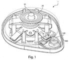
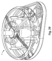
- Fig. 1 shows a fluid receiving device 1 that incorporates various examples of the disclosure.
- Fig. 1 incorporates many of the examples of the disclosure, any suitable number of examples of the disclosure may be incorporated into a fluid receiving device.
- examples of the disclosure may be used alone or in any suitable combination with each other.
- This illustrative example includes a cover 20 and a base 100 that are joined together and may cooperate to enclose various parts of the device 1 and support one or more external features, such as a device actuator 10 that is used to cause the device 1 to receive fluid from a subject.
- the base 100 and the cover 20 may be formed from or otherwise include Polyester (PCTA or PETG) or other polymers with low gas permeability.
- the device actuator 10 in this example is arranged to be actuated by a user (e.g., by the press of a finger), the device actuator 10 may be arranged in other ways, e.g., for actuation by a machine, an electrical signal, or other suitable arrangement to cause the fluid receiving device 1 to receive fluid from a subject. Actuation of the device actuator 10 may occur automatically, e.g., in response to an elapsed timer or other stimulus or condition, or manually.
- the device actuator 10 may include a push-button as shown, a sliding button discussed more below, a touch-screen interface, a switch, or other user-actuatable arrangement, etc.
- the device actuator 10 may allow for actuation of the device 1 only once, e.g., the device actuator 10 may become locked in a position that prevents further actuation, or may allow the device 1 to be actuated multiple times.
- the device 1 may include a fluid transporter that receives fluid from a subject.
- the fluid transporter may include an applicator region where bodily fluids from the body may accumulate.
- the applicator region may be a recess or an indentation within the base of the device, which can receive a fluid from the surface of the skin.
- the applicator region may have any suitable shape.
- the applicator region can be generally hemispherical, semi-oval, rectangular, irregular, etc. More details regarding the applicator region can be found in U.S. and international patent applications each entitled “Systems and Methods for Collecting a Fluid from a Subject", filed on even date herewith.. Also referenced is U.S. Provisional Patent Application Serial No. 61/480,960 , entitled “Systems and Methods for Collecting a Fluid from a Subject," by Haghgooie, et. al., filed on April 29, 2011.
- the fluid transporter may include an opening of any size and/or geometry that is constructed to receive fluid into the device.
- the opening may lie in a two-dimensional plane or the opening may include a three-dimensional cavity, hole, groove, slit, etc.
- the fluid transporter may also include a flow activator, such as one or more microneedles, arranged to cause fluid to be released from the subject, e.g., by piercing the skin of a subject.
- a flow activator such as one or more microneedles
- a flow activator need not be included with all examples as the device may not necessarily employ a mechanism for causing fluid release from the subject.
- the device may receive fluid that has already been released due to another cause, such as a cut or an abrasion, fluid release due to a separate and independent device, such as a separate lancet, an open fluid access such as during a surgical operation, and so on.
- fluid may be introduced into the device via urination, spitting, pouring fluid into the device, etc.
- a flow activator may physically penetrate, pierce, and/or or abrade, chemically peel, corrode and/or irritate, release and/or produce electromagnetic, acoustic or other waves, other otherwise operate to cause fluid release from a subject.
- the flow activator may include a moveable mechanism, e.g., to move a needle, or may not require movement to function.
- the flow activator may include a jet injector or a "hypospray" that delivers fluid under pressure to a subject, a pneumatic system that delivers and/or receives fluid, a hygroscopic agent that adsorbs or absorbs fluid, a reverse iontophoresis system, a transducer that emits ultrasonic waves, or thermal, radiofrequency and/or laser energy, and so on, any of which need not necessarily require movement of a flow activator to cause fluid release from a subject.
- a jet injector or a "hypospray” that delivers fluid under pressure to a subject
- a pneumatic system that delivers and/or receives fluid
- a hygroscopic agent that adsorbs or absorbs fluid
- a reverse iontophoresis system a transducer that emits ultrasonic waves, or thermal, radiofrequency and/or laser energy, and so on, any of which need not necessarily require movement of a flow activator to cause fluid release from a subject.
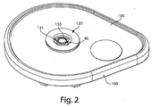
- Fig. 2 shows an underside of the fluid receiving device 1 of Fig. 1 with a fluid transporter 120 that includes an opening 130, an applicator region 131, and a flow activator 90.
- the flow activator 90 includes one or more needles.
- the needles may be extended from the opening 130 to pierce a subject's skin, and then retracted back into the opening to allow blood or other fluid to enter the opening 130. That is, to use the device 1 to receive blood from a subject, the base 100 may be placed on the skin so that the opening 130 is adjacent the skin. Thereafter, the device actuator 10 may be depressed to cause the needles to be deployed, piercing the skin and causing blood to be released.
- Blood may enter the opening and be collected in the storage chamber 140.
- blood may flow into the storage chamber 140 as a result of a relatively low pressure (vacuum) in the device 1 that draws blood from the opening 130 and into the storage chamber 140 (see Fig. 4 ).
- the needles may be of any suitable width, length and/or other size, and the needles may each be solid or hollow.
- the needles may have any suitable cross-section (e.g., perpendicular to the direction of penetration), such as circular, square, oval, elliptical, rectangular, rounded rectangle, triangular, polygonal, hexagonal, irregular, etc.
- the needles may have a length of about 5mm or less. Additional information regarding alternative needle arrangements is provided below.
- activation of the device actuator 10 causes the flow activator 90 to release blood or other fluid from a subject, which is then received at the opening 130.
- the blood or other fluid may then be collected in one or more chambers 140. Collection of the blood or other fluid may be done in any suitable way, such as by absorption, capillary action, suction, or other means.
- activation of the device actuator 10 causes a seal 76 to open so that blood or other fluid may flow from the opening 130, through a channel (see Fig. 4 , element 110) to a chamber 140.
- the device 1 may include a vacuum source that draws the blood or other fluid from the opening 130 and into the chamber 140 upon opening of the seal 76. That is, opening of the seal 76 may introduce a relatively low pressure to the chamber 140, which causes blood or other fluid to be drawn from the opening 130 and into the chamber 140.
- the flow activator may be actuated by a deployment actuator and a retraction actuator.
- the flow activator may be moveable and movement of the flow activator may be caused by a deployment actuator and a retraction actuator.
- the deployment actuator may cause the flow activator to move in a deployment direction towards the skin and/or other surface of a subject
- the retraction actuator may cause the flow activator to move in a retraction direction away from the skin and/or body of a subject.
- providing separate actuators for deployment and retraction movement may provide advantages in some cases, such as enabling the flow activator to be moved at different speeds for deployment and retraction, allowing the actuators to perform other additional functions such as opening a fluid flow path for blood or other fluid, enabling the flow activator to start and finish at different positions in the device before deployment and after retraction, and others.
- the deployment actuator and the retraction actuator may each include any number of suitable components, such as a button, a switch, a lever, a slider, a dial, a compression spring, a Belleville spring, a servo, rotary or linear electric motor, and/or a pneumatic apparatus, or other suitable device.
- the deployment actuator and the retraction actuator may be of the same type, or may be different types of devices.
- Each actuator may operate manually, mechanically, electrically, pneumatically, electromagnetically, or other suitable mode of operation, and may or may not require user input for activation.
- an effector may be arranged to cause deployment and/or retraction movement of a flow activator.
- an effector may include both a deployment actuator and a retraction actuator.
- the effector may be formed from or otherwise include polyester (PETG or PCTA), or acetal resin, acrylonitrile butadiene styrene (ABS), etc.
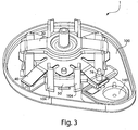
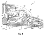
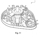
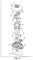
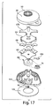
- Figs. 3 , 4 , and 5 illustrate a perspective view of device 1 of Fig. 1 with the cover 20 removed from the base 100, a partial cross sectional view of the device 1, and an exploded view of the device 1, respectively.
- the device 1 includes an effector 50 that includes a retraction actuator 40 and a deployment actuator 60 and that is movable in up and down directions relative to the base 100 along effector guides 104.
- the deployment actuator 60 is attached to the flow activator 90 via a membrane 72 (see Fig. 4 ) so that downward movement of the deployment actuator 60 may cause the flow activator 90 to at least partially extend from the opening 130.
- the membrane 72 may separate a vacuum source 156 in the device 1 from the opening 130 so that a relatively low pressure is maintained in the vacuum source 156 until controllably opened to cause flow into the storage chamber 140.
- the vacuum source 156 may be in the form of a sealed vacuum chamber.
- the deployment actuator 60 has a generally domed shape (e.g., as in a Belleville spring) with a central hole that receives a part of the membrane 72 which attaches the deployment actuator 60 to the flow activator 90.
- the flow activator 90 may be directly connected to the deployment actuator 60, e.g., via a vertical post or other structure that extends from the flow activator 90 to the deployment actuator 60.
- the deployment actuator 60 may initially be arranged in a concave-down configuration shown in Fig.
- the deployment actuator 60 may be made of a suitable material and configuration to rapidly move from the concave-down to concave-up configurations so as to rapidly extend the flow activator 90 from the opening 130 and pierce a subject's skin or other surface. While the deployment actuator 60 in this example is arranged as a flexible spring with a dome shape, the deployment actuator 60 may be of any suitable shape and/or size. For example, the deployment actuator 60 may be circular (having no "legs" unlike the four legs shown in Fig.
- the deployment actuator 60 may have, in some examples, a central hole as shown or another feature, such as a dimple, or button in the center or other location.
- the deployment actuator 60 may be formed from or otherwise include any suitable material, for example, a metal such as stainless steel (e.g., 301, 301LN, 304, 304L, 304LN, 304H, 305, 312, 321, 321H, 316, 316L, 316LN, 316Ti, 317L, 409, 410, 430, 440A, 440B, 440C, 440F, 904L), carbon steel, spring steel, spring brass, phosphor bronze, beryllium copper, titanium, titanium alloy steels, chrome vanadium, nickel alloy steels (e.g., Monel 400, Monel K 500, Inconel 600, Inconel 718, Inconel x 750, etc.), a polymer (e.g., polyvinylchloride, polypropylene, polycarbonate, etc.), a composite or a laminate (e.g., comprising fiberglass, carbon fiber, bamboo, Kevlar, etc.), or the like
- all portions of the deployment actuator may move less than a certain distance when the deployment actuator moves in a deployment direction towards opening 130. In some examples, all portions of the deployment actuator may move less than about 10 mm, less than about 5 mm, less than about 3 mm, less than about 2mm, or less than about 1 mm.
- the retraction actuator 40 in this example includes a reversibly deformable structure in the form of a leaf spring, but, like the deployment actuator 60, other arrangements are possible such as a coil spring, foam, an elastic bladder, or the like.
- the retraction actuator may be formed from or otherwise include any suitable material, for example, 1095 spring steel or 301 stainless steel or other spring material such as 1074/1075, 5160, 9255 spring steel etc.
- the retraction actuator 40 is attached to the deployment actuator 60 via the effector body 50 so that when the retraction actuator 40 is released upon actuation of the device actuator 10, the retraction actuator 40 (and other portions of the effector 50) can move away from the opening 130 along the effector guides 104.
- This retraction motion draws the flow activator 90 and the deployment actuator 60 away from the opening as well.
- the retraction actuator 40 is in a compressed state, storing potential energy. That is, the center of the retraction actuator 40 is pressed downwardly during assembly so that four arms of the retraction actuator 40 are elastically deformed.
- the retraction actuator 40 is held in this depressed condition by ear portions 103 (see Figs. 8 and 9 ) of the retraction actuator 40 engaging with the base 100 until the device 1 is actuated. However, when the device actuator 10 is pushed down during device actuation, arms 31 of the release element 30 engage with the tabs 41 to release the ear portions 103 from the base 100, allowing the center portion of the retraction actuator 40 to move in a retraction direction away from the opening 130. Since the deployment actuator 60 and flow activator 90 are attached to the retraction actuator 40, movement of the retraction actuator 40 upward away from the opening 130 retracts the flow activator 90 from the opening 130.
- movement of the retraction actuator 40 upward away from the opening 130 may also move the deployment actuator 60 in a retraction direction away from the opening 130 as well.
- all portions of the deployment actuator 60 may move less than a certain distance when the deployment actuator 60 moves in a retraction direction away from the opening 130. In some examples, all portions of the deployment actuator may move less than about 10 mm, less than about 5 mm, less than about 3 mm, less than about 2mm, or less than about 1 mm.
- a spacer element 32 is located between the deployment actuator 60 and the retraction actuator 40.
- the spacer element 32 may help to eliminate a gap between the deployment actuator 60 and the release element 30.
- Actuation of device actuator 10 may cause the release element 30 to push down on the spacer element 32, which may in turn push on the deployment actuator 60 and cause the deployment actuator 60 to move the flow activator 90 in a deployment direction.
- the flow activator 90, deployment actuator 60, retraction actuator 40, and spacer element 32 are substantially concentrically aligned.
- the flow activator 90 may be controlled to have any suitable movement for both deployment and retraction.
- the flow activator 90 may be caused to move more rapidly in the deployment direction than in the retraction direction, which has been found to potentially reduce pain when piercing skin to release blood. That is, the deployment actuator 60 may be arranged to relatively rapidly move from the concave-down to concave-up configuration, quickly inserting the flow activator 90 into skin or another surface.
- the flow activator 90 may be more slowly withdrawn from the skin by the retraction actuator 40, e.g., as controlled by a relatively lower force exerted by the retraction actuator 40 on the flow activator 90 than the deployment actuator 60, by damped motion of the retraction actuator 40, or other suitable arrangements.
- having separate deployment and retraction actuators may allow for a shorter range of motion in one direction, such as in the deployment direction, than in another direction, such as the retraction direction.
- the deployment actuator 60 may be made relatively compact, yet generate suitably high force to insert the flow activator 90 into skin.
- a relatively longer distance traveled by the flow activator 90 during retraction may withdraw the activator 90 suitably to allow a pool or other collection of blood to enter a cavity or other space for reception by the device 1. Additionally, a short deployment distance may minimize alignment errors inherent in long travel distances.
- the flow activator may be located at an initial pre-deployment distance from skin or another surface that is different from a final post-retraction distance between the flow activator and the skin or other surface.
- this example can be provided in many different ways, such as by a motor, servo, or automated device as part of an effector
- the effector 50 of the Figs. 1-5 example may provide an arrangement in which flow activator 90 is relatively close to the opening 130 prior to deployment, and is located relatively further away from the opening 130 after retraction.
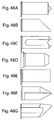
- Figs. 6A-6C show a series of schematic representations of three states of the device 1 of Figs.
- a pre-deployment distance 181 between the opening 130 and the flow activator 90 is relatively small, such as 1mm or less.
- the retraction actuator 40 is compressed, and the deployment actuator 60 is in a concave-down arrangement.
- the deployment actuator 60 is inverted to a concave-up configuration so that the flow activator 90 is deployed.
- the retraction actuator 40 may also be further compressed, e.g., by the user pressing down on the release element 30, but in other examples, the retraction actuator 40 need not be further compressed or otherwise deformed.
- a post-retraction distance 183 between the opening 130 and the flow activator 90 may be larger, in some cases significantly larger, than the pre-deployment distance 181.
- the post-retraction distance 183 in which the flow activator 90 is fully retracted from the opening 130 may be 2-3 mm or more. Retraction of the flow activator 90 from the opening 130 may provide a space into which blood or other fluid released from the subject may collect and/or otherwise be received by the device 1.
- the post-retraction distance is less than, or the same as, the pre-deployment distance, and all examples of the disclosure are not necessarily limited in this regard.
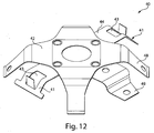
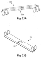
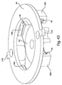
- Figs. 7A and 7B show top perspective and bottom perspective views of the effector 50 of the Figs. 1-5 example, and help to better illustrate how the motion of the effector 50 is controlled.
- the retraction actuator 40 has eight legs radiating from a central body having a central hole. Two of the shorter legs attach the retraction actuator 40 to the effector body 50 via two posts 52 that extend through holes 46 of the retraction actuator 40. The diameter of the post heads 52 may be made larger than the holes 46 and thus fix the retraction actuator 40 to the effector body 50.
- the retraction actuator 40 may alternately be attached to the effector body by 50 by adhesive (e.g. tape, liquid), mechanical fastening (e.g.
- Other legs 48 of the retraction actuator 40 may remain free to flex relative to the effector body 50, e.g., to provide the retraction movement of the effector 50.
- Two of the legs 48 include ear portions 103 which serve to engage with the base 100 and hold the retraction actuator 40 in a compressed, initial position before deployment of the flow activator 90.
- a space or gap 43 is provided between the ear portions 103 and the effector body 50 to allow the ear portions 103 to move toward the body for engagement with the base 100.
- the deployment actuator 60 includes a central hole 66 and lobes 62 that are held within the grooves 56 of the effector body 50. Although the deployment actuator 60 is attached to the effector body 50, a central portion 64 of the deployment actuator 60 remains displaceable relative to the effector body 50 so that the deployment actuator 60 may move to deploy the flow activator 90.
- the effector 50 may be mounted to the base 100 and guided in motion via effector guides 104 that protrude from the base 100.
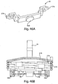
- Fig. 8 shows a close up view of the retraction actuator 40 illustrating how the retraction actuator 40 engages with the base 100 in a compressed, initial state
- Fig. 9 shows a close up view of the ear portions 103 on two of the legs 48 of the retraction actuator 40 that engage with the base 100 to hold the retraction actuator 40 in the compressed, initial state.
- the effector 50 held suitably by the effector guides 104, the effector 50 is pressed downwardly so that ear portions 103 of the tabs 41 can be positioned under corresponding protrusions 101 on the base 100.
- the effector 50 may be released so that the spring force of the legs 48 biases the effector 50 to move upwardly in the retraction direction.
- the effector 50 is held in a compressed condition.
- the flow activator 90 may be at the initial pre-deployment distance 181 (see Fig. 6 ) from the opening 130.
- this pre-deployment distance 181 may be arranged such that actuation of the deployment actuator 60 will cause the flow activator 90 to reach the skin of a subject and allow the flow activator 90 to penetrate and/or pierce the skin to cause fluid flow.
- having the retraction actuator 40 pre-loaded in an initial semi-compressed state may hold the flow activator 90 at a pre-deployment distance 181 that enables the flow activator 90 to be ready for deployment upon actuation of the device actuator 10.
- Fig. 8 also illustrates how the retraction actuator 40 may be released to retract the flow activator 90.
- Arms 31 of the release element 30 may engage with the tabs 41 so that sloped portions of the arms 31 push the tabs 41 outwardly and away from the effector body 50 when the device actuator 10 and the release element 30 are moved downwardly. This releases the ear portions 103 from the protrusions 101, allowing the effector 50 to move upwardly under the bias of the deformed legs of the retraction actuator 40.
- the release element 30 may be formed from or otherwise include polyester (PETG or PCTA), or acetal resin, acrylonitrile butadiene styrene (ABS), etc.
- retraction actuator 40 is shown to engage with the base 100 via a releasable latch arrangement that includes the ear portions 103 and the protrusions 101, other arrangements are possible, such as a releasable lever, a sliding release, a detent, magnets that are separable using a wedge or by flipping polarity, etc., as the disclosure is not limited in this regard.
- the effector may have an initial stored potential energy prior to any deployment movement of the flow activator. That is, the effector may have stored spring energy or other mechanical energy stored, for example, in an elastically deformed element, stored chemical energy, stored electrical energy, etc., that is used to deploy and/or retract a flow activator or cause other motion of other parts of the fluid receiving device.
- the retraction actuator 40 may be held in a compressed state by engagement of the ear portions 103 of the legs 48 with protrusion elements 101 on the base 100. Compression of the retraction actuator 40 stores potential energy in the retraction actuator 40 that can be used for different actions, such as retracting the flow activator 90.
- having the retraction actuator 40 at an initial compressed state permits the retraction actuator 40 to store potential energy and be ready for actuation without requiring energy to be input to the system at the time of actuation of the device.
- the flow activator may move faster in a deployment direction than in a retraction direction.
- the deployment actuator 60 may be arranged to move from an initial, pre-deployment position to a deployment position in rapid fashion, e.g., in a bi-stable manner.
- the retraction actuator 40 may be arranged, e.g., to have a relatively lower spring constant or other characteristic, to move the flow activator 90 at a slower rate during at least a part of the retraction motion.
- the flow activator 90 can be deployed at a speed of at least about 0.1 cm/s, at least about 0.3 cm/s, about 1 cm/s, at least about 3 cm/s, at least about 10 cm/s, at least about 30 cm/s, at least about 1 m/s, at least about 2 m/s, at least about 3 m/s, at least about 4 m/s, at least about 5 m/s, at least about 6 m/s, at least about 7 m/s, at least about 8 m/s, at least about 9 m/s, at least about 10 m/s, at least about 12 m/s, etc., at the point where the flow activator 90 initially contacts the skin.
- the retraction actuator 40 includes only mechanical elements that are not electronically controlled, e.g., as in the case of a spring, an elastic member, collapsible foam, etc.
- the spring or other element may be designed or otherwise arranged to provide a desired retraction speed.
- other mechanical elements such as one or more dampers may be provided to control a withdrawal speed.
- Other, electronically controlled systems such as some servos, pneumatic systems, or the like, may incorporate open or closed loop control to provide a desired retraction rate.
- the user may be able to control the speed of retraction.
- a retraction actuator in the form of a spring may retract more slowly if force is gradually eased off the device actuator. However, if the force is abruptly removed, (e.g. a user suddenly releases the device actuator), the retraction may occur more quickly, although the fastest possible retraction speed may still be slower than the deployment speed.
- the fluid receiving device may contain one or more chambers or vessels 140 for holding fluid received from a subject. In some cases, the chambers may be in fluidic communication with one or more fluid transporters and/or one or more microfluidic channels.
- the fluid receiving device may include a chamber for collecting fluid withdrawn from a subject (e.g., for storage and/or later analysis), a chamber for containing a fluid for delivery to the subject (e.g., blood, saline, optionally containing drugs, hormones, vitamins, pharmaceutical agents, or the like), etc.
- a chamber for collecting fluid withdrawn from a subject e.g., for storage and/or later analysis
- a chamber for containing a fluid for delivery to the subject e.g., blood, saline, optionally containing drugs, hormones, vitamins, pharmaceutical agents, or the like
- the device may include a vacuum source.
- Vacuum a pressure below ambient
- the vacuum source may be one that is self-contained within the device, i.e., the device need not be connected to an external vacuum source (e.g., a house vacuum) during use of the device to withdraw blood or interstitial fluid from the skin and/or from beneath the skin.
- an external vacuum source e.g., a house vacuum
- the vacuum source may include a vacuum source 156 having a pressure less than ambient pressure before blood (or other fluid) is withdrawn into the device, i.e., the vacuum source 156 may be at a "negative pressure” (that is, negative relative to ambient pressure) or at a "vacuum pressure” (or just having a “vacuum”).
- the vacuum in the vacuum source may be at least about 50 mmHg, at least about 100 mmHg, at least about 150 mmHg, at least about 200 mmHg, at least about 250 mmHg, at least about 300 mmHg, at least about 350 mmHg, at least about 400 mmHg, at least about 450 mmHg, at least about 500 mmHg, at least 550 mmHg, at least 600 mmHg, at least 650 mmHg, at least about 700 mmHg, or at least about 750 mmHg, i.e., below the ambient atmospheric pressure.
- an external vacuum or a mechanical device may be used as the vacuum source.
- the device may comprise an internal vacuum source, and/or be connectable to a vacuum source that is external to the device, such as a vacuum pump or an external (line) vacuum source.
- vacuum may be created manually, e.g., by manipulating a syringe pump, a plunger, or the like, or the low pressure may be created mechanically or automatically, e.g., using a piston pump, a syringe, a bulb, a Venturi tube, manual (mouth) suction, etc., or the like.
- the device may be "pre-packaged" with a suitable vacuum source (e.g., a pre-evacuated vacuum source 156); for instance, in one example, the device may be applied to the skin and activated in some fashion to create and/or access the vacuum source.
- the self-contained vacuum source may be actuated in some fashion to create a vacuum within the device.
- the self-contained vacuum source may include a piston, a syringe, a mechanical device such as a vacuum pump able to create a vacuum within the device, and/or chemicals or other reactants that can react to increase or decrease pressure which, with the assistance of mechanical or other means driven by the reaction, can form a pressure differential associated with a pressure regulator. Chemical reaction can also drive mechanical actuation with or without a change in pressure based on the chemical reaction itself.
- a self-contained vacuum source can also include an expandable foam, a shape memory material, or the like.
- the device includes an interface 105 (see Figs. 2 , 4 and 5 ) that is able to help the device apply a vacuum to the skin and/or at the opening 130.
- the interface 105 may be, for example, a suction cup, a layer of a hydrogel material, such as Katecho 10G or other suitable hydrogel, or a circular bowl that is placed on the surface of the skin, and vacuum may be applied to the portion of skin exposed to the device 1 by the interface 105.
- the interface is part of a support structure, e.g., the base 100.
- the interface 105 may be formed from any suitable material, e.g., glass, rubber, polymers such as silicone, polyurethane, nitrile rubber, EPDM rubber, neoprene, or the like.
- the seal between the interface 105 and the skin may be enhanced (e.g., reducing leakage), for instance, using vacuum grease, petroleum jelly, a gel, an adhesive or the like.
- the interface 105 may be relatively small, for example, having a diameter of less than about 5 cm, less than about 4 cm, less than about 3 cm, less than about 2 cm, less than about 1 cm, less than about 5 mm, less than about 4 mm, less than about 3 mm, less than about 2 mm, or less than about 1 mm.
- the interface 105 may be circular, although other shapes are also possible, for example, square, star-shaped (having 5, 6, 7, 8, 9, 10, 11, etc. points), tear-drop, oval, rectangular, or the like.
- vacuum from a vacuum source may facilitate the movement of blood or other fluids from an opening of a fluid transporter to a storage vessel.
- vacuum may be stored in a vacuum source 156, e.g., a majority of space enclosed between device cover 20, base 100, and membrane 72.
- Vacuum in the vacuum source 156 may be selectively coupled to the storage chamber 140 so as to cause fluid at the opening 130 to be drawn into a channel 110 and to the chamber 140.
- one or more channels 110 may be formed into the base 100 or otherwise provided between the opening 130 and the storage chamber 140.
- the channel 110 may be covered at an upper side by a lower surface of a channel plate 80.
- the channel plate 80, membrane 72 and seal 76 could form a single part.
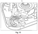
- the channel plate 80 may not only help to define the channel 110, but also define at least a portion of the cavity at the fluid transporter 120, part of the storage chamber 140, a vacuum inlet 154 and flow path 150 used for control of flow between the vacuum source 156 and the storage chamber 140, and a flow path between the channel 110 and the storage chamber 140. That is, as shown in Figs. 4 and 10 , the channel plate 80 helps to define a flow path between the opening 130 and the vacuum source 156 such that flow from the opening 130 may pass through the channel 110 and to an opening 144 in the channel plate 80 that connects the channel 110 and the storage chamber 140.
- the opening 144 may include a filter, a hydrophobic element (e.g., to help prevent aqueous fluid in the storage chamber 140 from later exiting the chamber 140), a one-way valve, or may be completely unobstructed.
- flow may also occur from the storage chamber 140 through a passage 150 in the channel plate 80 to the vacuum inlet 154.
- the vacuum inlet 154 is normally closed by a seal 76, which may be part of the membrane 72, which also helps to isolate the vacuum source 156 from the opening 130 and other potential outlets for the low pressure in the vacuum source 156.
- a seal 76 which may be part of the membrane 72, which also helps to isolate the vacuum source 156 from the opening 130 and other potential outlets for the low pressure in the vacuum source 156.
- the seal 76 is engaged with one of the legs 48 of the retraction actuator 40 (a seal leg 49) so that when the retraction actuator 40 is in a compressed, initial state, the seal leg 49 presses the seal 76 into contact with the vacuum inlet 154 so as to close the passage 150 and prevent communication between the vacuum source 156 and the storage chamber 140.
- the seal leg 49 may move upwardly and/or the force of the seal leg 49 on the seal 76 may be reduced to a point at which the vacuum inlet 154 is open for flow from the storage chamber 140 to the vacuum source 156.
- the vacuum source 156 may draw fluid (e.g., air and/or liquid) from the storage chamber 140 so that fluid in the channel 110 is drawn into the storage chamber 140.
- fluid e.g., air and/or liquid
- a hydrophobic membrane or other suitable element may be provided at the vacuum inlet 154 or other suitable location (such as in the passage 150) to prevent liquid from flowing from the storage chamber 140 into the vacuum source 156.
- fluid communication between the fluid transporter opening and the vacuum source may be enabled in response to actuation of the flow activator or prior to actuation of the flow activator.
- depression of the device actuator 10 may permit communication between the vacuum source 156 and the storage chamber 140/opening 130.
- the seal 76 may be coupled to the seal leg 49 of the retraction actuator 40 so that once the flow activator 90 is actuated, e.g., deployment and retraction are initiated, the seal 76 may be released from the vacuum inlet 154 to permit fluid communication between the vacuum source 156 and the storage chamber 140.
- the seal leg 49 of the retraction actuator 40 moves away from the vacuum inlet 154 (or at least reduces a pressure on the seal 76) as the flow activator 90 is retracted
- flow between the vacuum source 156 and the storage chamber 140 may be enabled by piercing a membrane or foil, e.g., with deployment of the flow activator 90 or upon full retraction of the flow activator 90.
- a membrane seal could be located at the opening 130, and the flow activator 90 itself could serve to puncture the membrane, allowing flow from the opening 130 to the vacuum source 156. Thus, this puncture could serve to expose fluid at the opening 130 to vacuum to draw the fluid into a storage chamber 140.
- a membrane seal may be positioned at locations other than the opening 130, such as at the vacuum inlet 154, and a separate piercing element, such as a spike on the release element 30, could be used to puncture the membrane.
- Other arrangements are possible as well, such as actuating a vacuum source (such as a chemical vacuum source or vacuum pump) in response to flow activator actuation.
- the retraction actuator 40 may be coupled to a syringe piston so that as the retraction actuator 40 moves in the retraction direction, the piston is moved to generate suction at the storage chamber 140.
- the flow activator may be moved in a deployment direction to deploy the flow activator, and moved in a retraction direction to both retract the flow activator and enable fluid communication between the vacuum source and a fluid transporter opening.
- the seal 76 may be released from the vacuum inlet 154 as the flow activator 90 is retracted. Opening of the flow path at the seal 76 may occur at the start of retraction, during retraction, and/or after retraction is complete.
- the seal 76 and flow activator 90 may be both moved in the same retraction direction by the retraction actuator.
- the flow activator 90 may be retracted and the seal 76 lifted to enable fluid communication between the vacuum source 156 and the device opening 130 through a channel 110.
- the seal 76 may be formed from or otherwise include latex or other flexible material such as a thermoplastic elastomer (TPE) or polyurethane. In other examples, a force on the seal 76 may be sufficiently released to allow the relatively low pressure in the vacuum source 156 to cause flow from the storage chamber 140 to the vacuum source 156 to occur.
- the seal 76 need not necessarily be lifted from the vacuum inlet 154, but instead may act as a kind of check valve with a desired crack pressure that permits flow from the storage chamber 140 to the vacuum source 156 while a suitable pressure differential is present across the seal 76, but otherwise inhibits flow through the inlet 154.
- Other arrangements for opening fluid communication during retraction of the flow activator are possible, such as a spike on the retraction actuator 40 that pierces a membrane to open the fluid communication.
- an electrical switch may be opened or closed by the retraction actuator, causing a vacuum source (such as a pump) to be activated.
- movement of the retraction actuator may release a latch or other device, which allows a spring-loaded syringe piston or other device to move, creating a desired vacuum.
- retraction movement of the retraction actuator 40 itself may move a syringe piston or other device to provide a desired vacuum.
- an effector that deploys and/or retracts the flow activator may also enable fluid communication between the fluid transporter opening and the vacuum source.
- Providing a single component or assembly to both deploy and/or retract a flow activator as well as open fluid communication between a fluid transporter and vacuum source may, in some examples, provide for a fluid receiving device that is simpler in operation or construction.
- a single device such as a retraction actuator 40 in the Figs. 1-10 example, may serve to both retract and open a flow path. This may reduce parts needed for construction of the fluid receiving device, reducing cost and/or assembly complexity.
- the effector need not necessarily perform both deployment and retraction functions, but instead may provide only deployment or retraction together with enabling fluid communication.
- the effector may serve to only deploy a flow activator and enable fluid communication between the fluid transporter opening and vacuum source, e.g., in an example where a flow activator is not retracted after deployment, but instead is permitted to remain embedded in skin to withdraw fluid as vacuum is applied to the flow activator.
- enabling of fluid communication between the fluid transporter opening and vacuum source may be provided in different ways, such as by opening a valve or similar structure (such as the seal 76), piercing a membrane, actuating a vacuum source (such as moving a syringe plunger or similar element), activating a chemically-operated vacuum source, and so on.
- the flow activator and the vacuum seal may be attached together, e.g., as part of a single unitary structure or component.
- the flow activator 90 may be attached to the membrane 72, e.g., by co-molding the flow activator 90 with the membrane, adhering the flow activator 90 to the membrane, etc., while the seal 76 is formed from part of the membrane 72 itself.
- Such an arrangement may ease assembly and reduce the number of components in the fluid receiving device 1.
- flow enabled by movement of the seal 76 may cause flow along the channel 110 to the storage chamber 140.
- the channel 110 may be formed, at least in part, by a single component, e.g.
- the channel can have any cross-sectional shape, for example, circular, oval, triangular, irregular, square or rectangular (having any aspect ratio), or the like, and can be covered or uncovered (i.e., open to the external environment surrounding the channel).
- the channel 110 may be of any length.
- the channel 110 can be a simple two-dimensional opening that creates a fluidic coupling between the opening 130 and another vessel such as a vacuum source or a storage vessel. In these cases, the channel may not have any length at all (e.g., as in a two-dimensional opening).
- at least one portion of the channel can have a cross-section that is completely enclosed, and/or the entire channel may be completely enclosed along its entire length with the exception of its inlet and outlet.
- a channel may have any aspect ratio (length to average cross-sectional dimension), e.g., an aspect ratio of at least about 2:1, more typically at least about 3:1, at least about 5:1, at least about 10:1, etc.
- a "cross-sectional dimension" in reference to a fluidic or microfluidic channel is measured in a direction generally perpendicular to fluid flow within the channel.
- a channel generally will include characteristics that facilitate control over fluid transport, e.g., structural characteristics and/or physical or chemical characteristics (hydrophobicity vs. hydrophilicity) and/or other characteristics that can exert a force (e.g., a containing force) on a fluid.
- the fluid within the channel may partially or completely fill the channel.
- the fluid may be held or confined within the channel or a portion of the channel in some fashion, for example, using surface tension (e.g., such that the fluid is held within the channel within a meniscus, such as a concave or convex meniscus).
- surface tension e.g., such that the fluid is held within the channel within a meniscus, such as a concave or convex meniscus.
- some (or all) of the channels may be of a particular size or less, for example, having a largest dimension perpendicular to fluid flow of less than about 5 mm, less than about 2 mm, less than about 1 mm, less than about 500 microns, less than about 200 microns, less than about 100 microns, less than about 60 microns, less than about 50 microns, less than about 40 microns, less than about 30 microns, less than about 25 microns, less than about 10 microns, less than about 3 microns, less than about 1 micron, less than about 300 nm, less than about 100 nm, less than about 30 nm, or less than about 10 nm or less in some cases.
- the channel is a capillary.
- the device may include a microfluidic channel.
- microfluidic “microfluidic,” “microscopic,” “microscale,” the “micro-” prefix (for example, as in “microchannel”), and the like generally refers to elements or articles having widths or diameters of less than about 1 mm, and less than about 100 microns (micrometers) in some cases.
- larger channels may be used instead of, or in conjunction with, microfluidic channels for any of the examples discussed herein.
- channels having widths or diameters of less than about 10 mm, less than about 9 mm, less than about 8 mm, less than about 7 mm, less than about 6 mm, less than about 5 mm, less than about 4 mm, less than about 3 mm, or less than about 2 mm may be used in certain instances.
- the element or article includes a channel through which a fluid can flow.
- specified widths can be a smallest width (i.e. a width as specified where, at that location, the article can have a larger width in a different dimension), or a largest width (i.e. where, at that location, the article has a width that is no wider than as specified, but can have a length that is greater).
- the microfluidic channel may have an average cross-sectional dimension (e.g., perpendicular to the direction of flow of fluid in the microfluidic channel) of less than about 1 mm, less than about 500 microns, less than about 300 microns, or less than about 100 microns.
- the microfluidic channel may have an average diameter of less than about 60 microns, less than about 50 microns, less than about 40 microns, less than about 30 microns, less than about 25 microns, less than about 10 microns, less than about 5 microns, less than about 3 microns, or less than about 1 micron.
- Fluids received from the skin and/or from beneath the skin of the subject will often contain various analytes within the body that are important for diagnostic purposes, for example, markers for various disease states, such as glucose (e.g., for diabetics); other example analytes include ions such as sodium, potassium, chloride, calcium, magnesium, and/or bicarbonate (e.g., to determine dehydration); gases such as carbon dioxide or oxygen; H + (i.e., pH); metabolites such as urea, blood urea nitrogen or creatinine; hormones such as estradiol, estrone, progesterone, progestin, testosterone, androstenedione, etc. (e.g., to determine pregnancy, illicit drug use, or the like); or cholesterol.
- markers for various disease states such as glucose (e.g., for diabetics)
- gases such as carbon dioxide or oxygen
- H + i.e., pH
- metabolites such as urea, blood urea nitrogen or creatinine
- hormones
- Still other examples include insulin, or hormone levels.
- Still other analytes include, but not limited to, high-density lipoprotein ("HDL”), low-density lipoprotein (“LDL”), albumin, alanine transaminase (“ALT”), aspartate transaminase (“AST”), alkaline phosphatase (“ALP”), bilirubin, lactate dehydrogenase, etc.
- HDL high-density lipoprotein
- LDL low-density lipoprotein
- ALT alanine transaminase
- AST aspartate transaminase
- ALP alkaline phosphatase
- bilirubin lactate dehydrogenase, etc.
- hCG beta-human chorionic gonadotrophin
- prothrombin e.g., for coagulation tests
- troponin, BNT or B-type natriuretic peptide, etc. e.g., as cardiac markers
- the fluid receiving device 1 may include one or more sensors for detecting one more characteristics of a fluid received from a subject.
- the sensor(s) may be located in any suitable way or location with respect to the device, such as at the storage chamber 140, at the channel 110, on the cover 20, etc.
- the device 1 may include a pH sensor, an optical sensor, an oxygen sensor, a sensor able to detect the concentration of a substance, or the like.
- useful sensors include dye-based detection systems, affinity-based detection systems, microfabricated gravimetric analyzers, CCD cameras, optical detectors, optical microscopy systems, electrical systems, thermocouples and thermistors, pressure sensors, etc. Those of ordinary skill in the art will be able to identify other suitable sensors.
- the sensor can include a colorimetric detection system in some cases, which may be external to the device, or microfabricated into the device in certain cases.
- a colorimetric detection system if a dye or a fluorescent entity is used (e.g. in a particle), the colorimetric detection system may be able to detect a change or shift in the frequency and/or intensity of the dye or fluorescent entity.
- the senor may be a test strip, for example, test strips that can be obtained commercially.
- test strips include, but are not limited to, glucose test strips, urine test strips, pregnancy test strips, or the like.
- a test strip will typically include a band, piece, or strip of paper or other material and contain one or more regions able to determine an analyte, e.g., via binding of the analyte to a diagnostic agent or a reaction entity able to interact with and/or associate with the analyte.
- the test strip may include various enzymes or antibodies, glucose oxidase and/or ferricyanide, or the like.
- the test strip may be able to determine, for example, glucose, cholesterol, creatinine, ketones, blood, protein, nitrite, pH, urobilinogen, bilirubin, leucocytes, luteinizing hormone, etc., depending on the type of test strip.
- the test strip may be used in any number of different ways.
- a test strip may be obtained commercially and inserted into the device, e.g., before or after receiving blood, interstitial fluid, or other fluids from a subject. At least a portion of the blood or other fluid may be exposed to the test strip to determine an analyte, e.g., in examples where the device uses the test strip as a sensor so that the device itself determines the analyte.
- the device may be sold with a test strip pre-loaded, or a user may need to insert a test strip in a device (and optionally, withdraw and replace the test strip between uses).
- the test strip may form an integral part of the device that is not removable by a user.
- the test strip may be removed from the device and determined externally, e.g., using other apparatuses able to determine the test strip, for example, commercially-available test strip readers.
- the device may include a separation membrane that is impermeable to blood cells and other substances. Fluid received from the subject may flow through a separation membrane, and the received fluid may include components of various sizes.
- the device may receive blood that includes blood cells, clotting factors, proteins, and blood plasma, among other components. Larger components such as blood cells and other larger substances may not be able to pass through the separation membrane while blood plasma is free to pass. In some examples, this blood plasma is collected into a storage chamber. If anticoagulant is not introduced to the blood plasma, the blood plasma, which contains clotting factors such as fibrinogen, may clot, thereby resulting in a solid clot component and a liquid component.
- This liquid component is known as serum, which is blood plasma without fibrinogen or other clotting factors.
- This serum can be collected via aspiration or other suitable method out of the storage chamber, leaving the blood clots in the storage chamber. If anticoagulant is introduced to the blood plasma, the blood plasma will not clot and blood plasma can be collected out of the storage chamber instead.
- the examples described throughout the specification may be used to produce plasma or serum. More details regarding plasma and serum production can be found in U.S. and international patent applications each entitled “Plasma or Serum Production and Removal of Fluids Under Reduced Pressure,” filed on even date herewith. Also referenced is U.S. provisional Patent Application Serial No. 61/480,941 , entitled “Plasma or Serum Production and Removal of Fluids Under Reduced Pressure,” by Haghgooie, et. al., filed on April 29, 2011.
- the device may be connected to an external apparatus for determining at least a portion of the device, a fluid removed from the device, an analyte suspected of being present within the fluid, or the like.
- the device may be connected to an external analytical apparatus, and fluid removed from the device for later analysis, or the fluid may be analyzed within the device in situ, e.g., by adding one or more reaction entities to the device, for instance, to a storage chamber, or to analytical chamber within the device.
- assay disks 200 or membranes may be included in storage chamber 140, as shown in Fig. 4 .
- the external apparatus may have a port or other suitable surface for mating with a port or other suitable surface on the device, and blood, interstitial fluid, or other fluid can be removed from the device using any suitable technique, e.g., using vacuum or pressure, etc.
- the blood or other fluid may be removed by the external apparatus, and optionally, stored and/or analyzed in some fashion.
- the device may include an exit port for removing a fluid from the device (e.g., blood).
- fluid contained within a storage chamber in the device may be removed from the device, and stored for later use or analyzed outside of the device.
- the exit port may be separate from the fluid transporter.
- an exit port can be in fluidic communication with a vacuum source, which can also serve as a fluid reservoir in some cases.
- Other methods for removing blood, interstitial fluid, or other fluids from the device include, but are not limited to, removal using a vacuum line, a pipette, extraction through a septum instead of an exit port, or the like.
- the device may also be positioned in a centrifuge and subjected to various g forces (e.g., to a centripetal force of at least 50 g), e.g., to cause at separation of cells or other substances within a fluid within the device to occur.
- the device may include an anticoagulant or a stabilizing agent for stabilizing the fluid withdrawn from the skin and/or beneath the skin.
- an anticoagulant may be used for blood withdrawn from the skin.
- anticoagulants include, but are not limited to, heparin, citrate, thrombin, oxalate, ethylenediaminetetraacetic acid (EDTA), sodium polyanethol sulfonate, acid citrate dextrose.
- Other agents may be used in conjunction with or instead of anticoagulants, for example, stabilizing agents such as solvents, diluents, buffers, chelating agents, enzyme inhibitors (ie.
- Protease or Nuclease inhibitor examples include, for example, benzalkonium chloride, chlorobutanol, parabens, or thimerosal.
- preservatives include, for example, benzalkonium chloride, chlorobutanol, parabens, or thimerosal.
- antioxidants include ascorbic acid, glutathione, lipoic acid, uric acid, carotenes, alpha-tocopherol, ubiquinol, or enzymes such as catalase, superoxide dismutase, or peroxidases.
- microbials examples include, but are not limited to, ethanol or isopropyl alcohol, azides, or the like.
- chelating agents include, but are not limited to, ethylene glycol tetraacetic acid or ethylenediaminetetraacetic acid.
- buffers include phosphate buffers such as those known to ordinary skill in the art.
- At least a portion of the device may be colored to indicate the anticoagulant(s) contained within the device.
- the colors used may be identical or equivalent to that commercially used for VacutainersTM, VacuettesTM, or other commercially-available phlebotomy equipment.
- lavender and/or purple may indicate ethylenediaminetetraacetic acid
- light blue may indicate citrate
- dark blue may indicate ethylenediaminetetraacetic acid
- green may indicate heparin
- gray may indicate a fluoride and/or an oxalate
- orange may indicate a thrombin
- yellow may indicate sodium polyanethol sulfonate and/or acid citrate dextrose
- black may indicate citrate
- brown may indicate heparin, etc.
- other coloring systems may be used.
- the device carries a color indicative of a recommended bodily use site for the device, e.g., a first color indicative of a device suitable for placement on the back, a second color indicative of a device suitable for placement on a leg, a third color indicative of a device suitable for placement on the arm, etc.
- a device as discussed herein may be shipped to another location for analysis.
- the device may include an anticoagulant or a stabilizing agent contained within the device, e.g., within a storage chamber for the fluid.
- fluid such as blood or interstitial fluid withdrawn from the skin and/or beneath the skin may be delivered to a chamber (e.g., a storage chamber) within the device, then the device, or a portion of the device (e.g., a module) may be shipped to another location for analysis. Any form of shipping may be used, e.g., via mail.
- the retraction actuator 40 of a device 1 may include two separate elements.
- Figs. 11-14 show an example in which the retraction actuator 40 includes a retractor portion 42 and a seal actuator portion 44.
- the retractor portion 42 and the seal actuator portion 44 are stacked and coupled to the effector body 50 via five posts 52. Any number of posts may be used.
- the post 52 may be formed from or otherwise include Polyester (PCTA or PETG) or other polymer such as ABS, acetal resin, polystyrene, etc.
- the retractor portion 42 and the seal actuator portion 44 may be coupled to the effector body 50 via a single post, glue, tape, other adhesive, etc.
- Fig. 12 shows that the retractor portion 42 includes legs 48 that are free to flex relative to the effector 50.
- the seal actuator portion 44 includes tabs 41 and the seal leg 49 that is coupled to the seal 76.
- Both the retractor portion 42 and a seal actuator portion 44 otherwise have essentially the same features as the retraction actuator 40 described above. By separating the retraction actuator 40 into two portions, each may be designed and constructed to have desired features.
- the legs 48 may be desirable to have the legs 48 made of a highly elastic material, whereas the tabs 41 and seal leg 49 may be made of a less elastic material, e.g., to help release the seal 76 as the retraction actuator 40 moves upwardly.
- the membrane 72 may be made independent from the seal 76, e.g., the seal 76 may be formed as part of the seal leg 49 of the actuator 40.
- the flow activator 90 may be mechanically coupled to the deployment actuator 60 via a transmission structure 94 such as a post, a rod, or other. As shown in Fig.
- a post 94 is coupled to the membrane 72, the flow activator 90 and the deployment actuator 60, and may be made relatively stiff or non-compliant, e.g., to help transmit movement from the deployment actuator 60 to the flow activator 90 with little loss.
- Figs. 15-18 show yet another example that is very similar to that of Figs. 1-10 , but in which the latch arrangement used to hold the retraction actuator 40 in an initial, compressed state is modified.
- the device 1 contains a rotatable release element 170 that rotates relative to the base 100 during operation of the device. (The rotatable release element 170 and corresponding portions of the base 100 replace the release element 30 and the tabs 41 of the retraction actuator 40 of the Figs.
- a spinner ramp 174 of the release element 170 initially engages with a lock-out ramp 161 of an effector guide 104 and holds the rotatable release element 170 in place prior to actuation of the device 1.
- Fig. 16 shows a close-up of the initial engagement prior to actuation of the device 1.
- the release element 170 rotates slightly so that the spinner ramp 174 slides and clears the lock-out ramp 161 as the release element 170 moves towards the base 100.
- a fluid receiving device 1 includes a horizontally sliding trigger 304 that can be actuated by a user or other by finger depression. Similar to the examples described above and as shown in Figs. 19 and 20 , the device 1 includes a cover 20 and a base 100, and fluid received at an opening 130 of a fluid transporter 120 may be conducted by a channel 110 to a storage chamber 140 (not shown).
- Figs. 21 and 22 show internal components of the device 1.
- An O-ring seal 340 may be located on a trigger shaft 306 of the trigger 304. In another example, a deformable membrane could form the seal.
- a trigger bridge 336 connected to the carriage 330 moves rearwardly relative to the effector body 50.
- the underside of the trigger bridge 336 includes a trigger tab 338, as can be seen in Figs. 23A and 23B .
- the trigger tab 338 engages with a protrusion 339 (see Fig. 24 ) on the top of the effector body 50 so that as the trigger bridge 336 moves rearwardly, the trigger tab 338 moves the effector body 50 downwardly a sufficient amount to actuate a deployment actuator 60, which has a configuration like that in the examples described above.
- This causes the deployment actuator 60 to deploy the flow activator 90, e.g., to extend needles from the opening 130.
- a retraction actuator of the trigger in the form of wedges 350
- the effector 50 is lifted upwardly away from base 100, thereby retracting the flow activator 90, which is attached to the effector body 50 via the deployment actuator 60, and membrane 72 in a way similar to the examples above.
- the trigger tab 338 may be received in an opening 380 in the effector body 50, allowing a central portion of the effector body 50 to flex upwardly and allowing further retraction of the flow activator 90.
- connection of a flow actuator to a deployment actuator may be done in a variety of different ways, as suggested above.
- Fig. 26A shows a schematic arrangement in which a post 94 used to connect a flow activator (not shown) to a membrane 72 and/or a deployment actuator 60 may be made by an adhesive 400.
- the post 94 may be received into a cavity (or hole) in the membrane 72 as well as a hole in the deployment actuator 60. Engagement of the post 94 with the respective holes or cavities may be made in any suitable way, such as by interference or friction fit, adhesive, riveting, and so on.
- the post 94 is engaged with a cavity of the membrane 72 by an adhesive 400 and has a rivet-type head that engages with the hole in the deployment actuator 60.
- the rivet head of the post 94 may be formed by plastically deforming part of the post 94, or the post 94 may include a flexible material arranged so that an upper portion of the rivet head may be resiliently deformed and forced through the hole of the actuator 60.
- Fig. 26C shows yet another example in which a membrane 72 is joined to a deployment actuator by extending a portion of the membrane 72 through an opening in the actuator 60 and crimping or otherwise deforming the portion of the membrane 72 that extends through the opening.
- a clip, band or other element may be clamped onto the membrane portion to maintain engagement of the membrane and actuator 60.
- the post 94 may be attached to both the membrane and actuator as part of the same process, e.g., part of the post may function as a clip or band.
- Fig. 26D shows an example with a two part post 94 where the membrane 72 is trapped between the two parts of the post.
- the top part of the post extends through a hole in the deployment actuator 60 or is heat staked to create an interference fit between the post and the deployment actuator 60.
- a portion of the post 94 may be forced through an opening at the connection point, and thereby be engaged with the deployment actuator 60.
- the order of operations with regards to deployment and retraction of the flow activator, vacuum release, and the receiving of fluid may be arranged in various sequences.
- vacuum release prior to deployment of the flow activator may help to decrease a pressure differential across the deployment actuator and thereby increase insertion depth of the flow activator.
- the order of operations may be arranged as follows: vacuum release occurs first, then deployment of the flow activator, and finally, retraction of the flow activator.
- fluid receipt may occur before or after retraction, as this example is not limited in this regard.
- fluid receipt may begin before retraction but may not complete until during or after retraction. In some cases, fluid receipt may not begin until during or after retraction.
- Vacuum release may be accomplished in a variety of different ways, as described in previous examples.
- a spike 510 is attached to the end of an arm 33 of release element 30.
- Vacuum may be stored in a vacuum source 156, e.g., a majority of space enclosed by the cover 20, base 100, and membrane 72.
- a seal 512 may prevent communication between the vacuum source 156 and the opening 130.
- spike 510 Upon downward movement of device actuator 10, spike 510 also moves in a downward direction, pierces seal 512, and enters dead volume 514.
- Spike 510 may be partially hollow and may include a vacuum inlet channel 511 which may help ensure flow between the vacuum source 156 and the dead volume 514.
- puncturing seal 512 with spike 510 effectively opens communication between vacuum source 156 and opening 130.
- This initial application of vacuum or other relatively low pressure at the area near opening 130 may cause skin to be drawn into or nearer to the opening.
- further downward movement of device actuator 10 causes actuation ring 540 to contact and actuate deployment actuator 60.
- actuation of deployment actuator 60 may cause the flow activator 90 to at least partially extend from the opening 130 or otherwise move to pierce a subject's skin and cause fluid to be released. Fluid may enter the opening 130, and the vacuum released from vacuum source 156 may draw fluid toward and/or into storage chamber 140.
- a hydrophobic stop membrane 516 that permits passage of air but prevents passage of liquid may be positioned between storage chamber 140 and dead volume 514. As a result, hydrophobic stop membrane 516 may prevent liquid in storage chamber 140 from entering dead volume 514 and vacuum source 156. When storage chamber 140 has been filled with liquid, hydrophobic stop membrane 516 may effectively cooperate with the filled storage chamber 140 to seal off communication between vacuum source 156 and opening 130.
- effector 50 and retraction actuator here, composed of locking portion 45 and retractor 42 - see Fig. 28 ) may cooperate to retract flow activator 90 as described in previous examples. Similar to the example in Fig.
- the retraction actuator may comprise two separated components, locking portion 45 and retractor 42.
- locking portion 45 differs from the seal actuator portion 44 in Fig. 12 because locking portion 45 does not have an additional seal leg 49 that is used to close communication between vacuum source 156 and opening 130.
- a time delay may exist between vacuum release and deployment of the flow activator.
- a release element may be arranged to exhibit an increased resistance against downward vertical movement, thereby creating a time delay between vacuum release and deployment of the flow activator.
- release element 30 may include resistance arms 33 in addition to release arms 31.
- Resistance arms 33 may include legs 34. As shown in Fig. 30 , as release element 30 moves in the downward deployment direction, legs 34 may contact base 100 and may cause latch release 30 to flex radially outward, thereby creating lateral movement of spike 510 to facilitate tearing of seal 512 for vacuum release. After vacuum release, contact between legs 34 and base 100 may also provide an increased resistance against downward vertical movement, which may delay deployment of flow activator 90 by delaying contact between actuation ring 540 with deployment actuator 60.
- holding the device effector rigidly to the base of the device may help to reduce energy loss when the deployment actuator is actuated.
- stress on the effector or poor fit between components may cause the effector to be positioned incorrectly instead of being held down flush against the base.
- incorrect positioning of the effector may reduce the translation of energy to the deployment actuator and flow activator during actuation of the device.
- an interference fit between the release element and the effector may serve to hold the effector down flush against the base of the device and thereby ensure proper positioning of the effector.
- the device actuator 10 may be directly attached or otherwise coupled to the release element 30.
- An actuation ring 540 may be present at the base of the release element 30.
- the base of the release element 30 may engage the effector 50 by means of an interference fit between the actuation ring 540 and the effector 50.
- actuation ring 540 may include legs 542 that are tapered for increased lateral flexibility.
- Fig. 32A depicts initial contact between release element 30 and effector 50 prior to flow activator deployment, where the actuation ring 540 has not yet contacted deployment actuator 60.
- release element 30 moves further downward, release element 30 becomes engaged in an interference fit with effector 50, as shown in Fig. 32B.
- Fig. 32B depicts release element 30 and effector 50 just prior to flow activator deployment, where the actuation ring 540 has achieved initial contact with deployment actuator 60.
- the interference fit permits direct application of pressure to the effector 50 prior to actuation of the deployment actuator 60 in order to ensure that the effector is held flush against the base.
- Such an arrangement may help ensure correct positioning of the effector and allow energy to translate directly from the device actuator 10 and release element 30 to the deployment actuator 60.
- the effector may be held flush against the device base by a wave spring or coil spring located beneath the release element, or by a leaf spring, coil spring, foam, an elastic bladder, or other suitable feature molded on the underside of the release element.
- the device may enable an indication when the receiving of fluid is complete. Such indication may notify a user that the device can be removed from the skin.
- a visual indication may be provided by an indicator 520.
- Indicator 520 may change color when the receiving of fluid is complete.
- indicator 520 may change from clear to the color of the received fluid.
- indicator 520 may include a flat disc of space that can receive and hold fluid.
- Indicator 520 may be in open communication with storage chamber 140. During the receiving of fluid, when fluid reaches the top of storage chamber 140, fluid may enter a passage 522 that connects storage chamber 140 to indicator 520.
- indicator 520 may include a solid or liquid substance that changes color upon contact with the received fluid. In this way, a user may receive an indication that the receiving of fluid is complete without actual sight of the received fluid. For example, indicator 520 may turn a color that is different than the actual collected fluid.
- the device may include an indicator cover 521 that may be transparent or translucent to allow a user to view indicator 520. In some examples, indicator cover 521 may be tinted a color to change the appearance of the color of the fluid. In some cases, indicator cover 521 may be removable.
- the indication may be visual, audible, or tactile, as this example is not limited in this regard.
- filling of storage chamber 140 may trigger the device to emit an audible sound indicating that the receiving of fluid is complete.
- the audible sound may be a mechanical click due to interaction between the device actuator, release element, effector, retraction actuator, deployment actuator, and/or flow activator.
- the audible sound may be an alarm that is triggered due to fluid reaching the top of storage chamber 140.
- the user may receive tactile feedback indicating that the receiving of fluid is complete.
- the device actuator, release element, effector, retraction actuator, deployment actuator, and/or flow activator may be arranged to interact such that the user actuating device actuator experiences a sudden increase or decrease in physical resistance from the device actuator.
- the components of the device may include a detent-type interaction that provides tactile feedback to the user.
- the indications, feedback, and/or alarms may occur at any point in the device actuation process, as indications are not limited to the completion of the receiving of fluid.
- the device may enable an indication when vacuum has been released, when the flow activator has been deployed and/or retracted, when the receiving of fluid has begun, etc.
- the device may also enable an indication or alarm when an insufficient volume fluid has been received, or if the type of fluid received is inappropriate.
- the device may allow a user to access fluid that is received in the storage chamber of the device.
- an access port connected to the storage chamber may allow the user to directly access fluid in the storage chamber.
- an access port 530 may be located at the base of the device.
- a user may remove the fluid using a variety of tools such as a pipette, capillary tube, or other suitable tool.
- a user may access the fluid in the storage chamber without removal of the fluid from the chamber.
- access port 530 may be shaped to permit insertion of objects of different shapes, such as strips as well as pipettes or capillary tubes.
- access port 530 may include a hole 532 to receive cylindrical objects such as pipettes and capillary tubes, and may include a slot 534 to receive rectangular or wide objects such as strips.
- the access port may be positioned to increase ease of fluid removal from the storage chamber.
- access port 530 may be positioned near the side wall 531 of storage chamber 140. Positioning access port 530 away from the center of storage chamber 140 may help to decrease forces such as capillary action that may cause the fluid to resist removal from the storage chamber.
- the bottom of storage chamber may be arranged at a slant such that fluid is slanted downward toward the access port.
- Storage chamber 140 may further include a circular groove that runs around the bottom periphery 535 of the storage chamber where the bottom of the storage chamber meets side wall 531. Such a groove may urge fluid toward access port 530 via wicking, capillary action, or other suitable force.
- a seal may prevent fluid from flowing through the access port.
- the seal may be located inside the storage chamber, in which case a user punctures the seal with a pipette or other suitable tool.
- the seal 536 may be located outside the storage chamber on the base 100, in which case a user may peel off or puncture the seal to access the fluid in the storage chamber.
- other methods of sealing the access port are possible, as this example is not limited in this regard.
- a rotatable release element may be arranged to permit vacuum release prior to flow activator deployment.
- Figs. 39-43 show one example of a device with a rotatable release element. In these figures, the device is depicted its post-deployment, retracted state. The device includes rotatable release element 170 that is free to rotate relative to device actuator 10 (see Figs. 40A-B ). Device actuator 10 is attached to spike 510 such that downward movement of device actuator 10 causes downward movement of spike 510, which then pierces seal 512 for vacuum release. As discussed previously, piercing seal 512 opens communication between the vacuum source and the device opening, allowing vacuum to be applied at the device opening.
- Device actuator 10 also includes tabs 566 that interact with a slide groove 554 formed on the device cover 20 (see Figs. 41 and 42 ) to constrain movement of device actuator 10 to the vertical direction.
- the rotatable release element 170 includes a spinner ramp 562 that interacts with a pre-deployment lockout 556 and a cover ramp 552 (see Figs. 41 and 42 ) formed on the cover 20.
- the retraction actuator 40 and effector 50 are hidden from view to show that rotatable release element 170 also includes an actuation ring 540 that actuates deployment actuator 60 upon contact with the top surface of the deployment actuator 60. (In Fig.
- deployment actuator 60 is shown in its post-deployment state and is therefore arranged concave downward away from actuation ring 540.
- spinner ramp 562 Prior to deployment, spinner ramp 562 is held within pre-deployment lockout 556 such that actuation ring 540 on the release element 170 is held at a distance close to the top surface of the deployment actuator 60. Engagement between spinner ramp 562 and pre-deployment lockout 556 also locks retraction actuator 40 in a compressed, high-energy state.
- Depression of device actuator 10 in the downward direction may first cause spike 510 to pierce seal 512 for vacuum release, then cause actuation ring 540 on the release element 170 to contact and actuate deployment actuator 60, thereby deploying the flow activator, as discussed in previous examples.
- depression of actuator 10 in the downward direction also causes spinner ramp 562 to clear pre-deployment lockout 556, releasing retraction actuator 40 from its compressed, high energy-state.
- Retraction actuator 40 releases its stored potential energy as it decompresses by moving in the upward retraction direction, causing spinner ramp 562 to slide against cover ramp 552 in the upward direction.
- the entire rotatable element 170 rotates clockwise as it also moves upward in the retraction direction.
- actuation of the flow activator may occur in direct response to vacuum release without requiring additional external actuation.
- a pressure differential across the deployment actuator may cause the deployment actuator to deploy the flow activator.
- vacuum may be stored in a vacuum source 156, e.g., a majority of space enclosed between the device cover 20, base 100, and membrane seal 72.
- atmospheric or ambient pressure is stored in the space enclosed by the cover, base, and membrane seal rather than a vacuum source.
- the vacuum source is stored in another location either within the device or external to the device rather than above the deployment actuator.
- the pressure at the top surface of the deployment actuator is at atmospheric or ambient pressure instead of at vacuum pressure. Opening communication between the vacuum source and the device opening may expose the bottom surface of the deployment actuator to vacuum pressure, thereby creating a pressure differential across the deployment actuator: atmospheric or ambient pressure above the deployment actuator and vacuum pressure below. The pressure differential across the deployment actuator may actuate the deployment actuator and subsequently cause deployment of the flow activator. Such an arrangement may allow vacuum to reach the device opening prior to deployment of the flow activator.
- the sequence of events starting from the initial actuation of the device to the end of receipt of fluid may be user-independent, meaning that, after an initial trigger, the entire sequence of events occurs automatically regardless of the subsequent magnitude of pressure, torque, speed, impact, or other force applied to the device actuator after the trigger.
- the device may include a torsion spring that permits a user-independent sequence of actuation events.
- device 1 includes a torsion spring 570 that may serve as a retraction actuator.
- device 1 is depicted in its pre-deployed, high-energy state, with a coiled torsion spring 570 attached to cam 571.
- Potential energy may be stored in coiled torsion spring 570, and the spring may be attached to cam 571 such that the spring is biased to rotate cam 571 in the counterclockwise direction. Engagement between the ends of the actuator arm 574 and lockout protrusions 572 attached to cam 571 prevent rotation of cam 571 and thereby prevent the uncoiling of torsion spring 570.
- Device actuator 10 may be actuated by a downward force, causing the ends of actuator arm 574 to slide vertically downward relative to lock-out protrusions 572. Once the ends of actuator arm 574 slide below and clear the lower surface of lock-out protrusions 572, cam 571 is free to rotate, allowing torsion spring 570 to uncoil and release its stored potential energy.
- torsion spring 570 may serve as the trigger from which all subsequent user-independent events follow. Uncoiling of torsion spring 570 causes cam 571 to rotate in the counterclockwise direction. Cam 571 may be attached to a spike 510 that tears through a seal (not shown) covering dead volume 514, opening communication between a vacuum source and the opening of the device. As shown in Fig. 45 , effector 50 may be attached to deployment actuator 60 via holders 580 and grooves 56. In addition, the effector 50 may include effector tabs 578. As shown in Figs. 46A-B , release element 30 may include an actuation ring 540 and release element tabs 576. As shown in Fig. 44 , effector tab 578 may cooperate with a lower track 588.
- tab 578 interacts with the profile of lower track 588. As the lower track 588 slants upward at the end of its profile, tab 578 is pushed upward by lower track 588. As a result, effector 50 is raised in the vertically upward retraction direction. Similarly, the release element tab 576 of release element 30 cooperates with an upper track 586. During counterclockwise rotation of cam 571, tab 576 interacts with the profile of upper track 586. As the profile of upper track 586 dips downward, tab 576 is pushed downward by upper track 586.
- release element 30 is lowered vertically downward in the deployment direction, causing the actuation ring 540 of release element 30 to contact and actuate deployment actuator 60 (see Figs 46A-B ), thereby actuating a flow activator (not shown) in a manner described in previous examples.
- release element 30 is raised in the vertically upward retraction direction.
- both the release element 30 and the effector 50 are lifted in the retraction direction due to the upward slanting of both upper track 586 and lower track 588, thereby causing retraction of the flow activator (not shown), which is connected to the deployment actuator 60 and effector 50.
- suitable arrangements for achieving a user-independent sequence of events are possible, as this example is not limited in this regard.
- the device may include a protective feature or mechanism used to avoid inadvertent or pre-mature actuation.
- the protective feature may include a physical barrier or covering that prevents actuation of the device actuator.
- the device may include a cap 600 with a spacer ring 602 that prevents compression of device actuator 10. Cap 600 may be removed by a user when the device is ready to be actuated.
- the protective feature may be incorporated into the device actuator or other components of the device.
- the device actuator may include a lost-motion type arrangement in which the device actuator must travel a predefined distance before deployment of the deployment actuator is triggered.
- the device actuator may require application of a minimum pressure or torque before actuation occurs.
- device actuator may include a safety-lock type arrangement in which the user must first twist the device actuator before pushing it down.
- safety-lock type arrangement in which the user must first twist the device actuator before pushing it down.
- a spike used to pierce a seal in order to open communication between a vacuum source and the device opening.
- a wide variety of spike geometries are possible.
- Figs. 48A-G depict various possible spike geometries, such as a cylinder with a pointer at the end ( Fig. 48A ), a cylinder with a slanted end ( Fig. 48B ), a bifurcated arrangement ( Fig. 48C ), a hollow cylinder with beveled tip ( Fig. 48D ), a simple cylinder that may be solid or hollow ( Fig. 48E ), a pointed spike with an indented portion ( Fig. 48F ), and a V-shaped spike with a longitudinal groove ( Fig. 48G ).
- any geometry suitable for seal piercing or tearing may be used for the spike geometry, as this example is not limited in this regard.
- needles included with a flow activator may be arranged in a variety of different ways, depending on the intended application.
- the needle(s) may have a length of less than about 5 mm, less than about 4 mm, less than about 3 mm, less than about 2 mm, less than about 1 mm, less than about 800 micrometers, less than 600 micrometers, less than 500 micrometers, less than 400 micrometers, less than about 300 micrometers, less than about 200 micrometers, less than about 175 micrometers, less than about 150 micrometers, less than about 125 micrometers, less than about 100 micrometers, less than about 75 micrometers, less than about 50 micrometers, less than about 10 micrometers, etc.
- the needle(s) may also have a largest cross-sectional dimension of less than about 5 mm, less than about 4 mm, less than about 3 mm, less than about 2 mm, less than about 1 mm, less than about 800 micrometers, less than 600 micrometers, less than 500 micrometers, less than 400 micrometers, less than about 300 micrometers, less than about 200 micrometers, less than about 175 micrometers, less than about 150 micrometers, less than about 125 micrometers, less than about 100 micrometers, less than about 75 micrometers, less than about 50 micrometers, less than about 10 micrometers, etc.
- the needle(s) may have a rectangular cross section having dimensions of 175 micrometers by 50 micrometers.
- the needle(s) may have an aspect ratio of length to largest cross-sectional dimension of at least about 2:1, at least about 3:1, at least about 4:1, at least 5:1, at least about 7:1, at least about 10:1, at least about 15:1, at least about 20:1, at least about 25:1, at least about 30:1, etc.
- the needle(s) is(are) a microneedle(s).
- a microneedle will have an average cross-sectional dimension (e.g., diameter) of less than about a millimeter.
- microneedles may be hollow or solid, and may be formed from any suitable material, e.g., metals, ceramics, semiconductors, organics, polymers, and/or composites.
- Examples include, but are not limited to, medical grade stainless steel, titanium, nickel, iron, gold, tin, chromium, copper, alloys of these or other metals, silicon, silicon dioxide, and polymers, including polymers of hydroxy acids such as lactic acid and glycolic acid polylactide, polyglycolide, polylactide-co-glycolide, and copolymers with polyethylene glycol, polyanhydrides, polyorthoesters, polyurethanes, polybutyric acid, polyvaleric acid, polylactide-co-caprolactone, polycarbonate, polymethacrylic acid, polyethylenevinyl acetate, polytetrafluorethylene, polymethyl methacrylate, polyacrylic acid, or polyesters.
- polymers of hydroxy acids such as lactic acid and glycolic acid polylactide, polyglycolide, polylactide-co-glycolide, and copolymers with polyethylene glycol, polyanhydrides, polyorthoesters, polyurethane
- more than one needle or microneedle may be used.
- arrays of needles or microneedles may be used, and the needles or microneedles may be arranged in the array in any suitable configuration, e.g., periodic, random, etc.
- the array may have 3 or more, 4 or more, 5 or more, 6 or more, 10 or more, 15 or more, 20 or more, 35 or more, 50 or more, 100 or more, or any other suitable number of needles or microneedles.
- a microneedle will have an average cross-sectional dimension (e.g., diameter) of less than about a micron.
- needles relative to the skin or other surface for these purposes including, in one example, introducing needles into the skin at an angle, relative to the skin's surface, other than 90°, i.e., to introduce a needle or needles into the skin in a slanting fashion so as to limit the depth of penetration. In another example, however, the needles may enter the skin or other surface at approximately 90°.
- the needles may be present in an array selected such that the density of needles within the array is between about 0.5 needles/mm 2 and about 10 needles/mm 2 , and in some cases, the density may be between about 0.6 needles/mm 2 and about 5 needles/mm 2 , between about 0.8 needles/mm 2 and about 3 needles/mm 2 , between about 1 needles/mm 2 and about 2.5 needles/mm 2 , or the like.
- the needles may be positioned within the array such that no two needles are closer than about 1 mm, about 0.9 mm, about 0.8 mm, about 0.7 mm, about 0.6 mm, about 0.5 mm, about 0.4 mm, about 0.3 mm, about 0.2 mm, about 0.1 mm, about 0.05 mm, about 0.03 mm, about 0.01 mm, etc.
- the needles may be chosen such that the area of the needles (determined by determining the area of penetration or perforation on the surface of the skin of the subject by the needles) allows for adequate flow of fluid to or from the skin and/or beneath the skin of the subject.
- the needles may be chosen to have smaller or larger areas (or smaller or large diameters), so long as the area of contact for the needles to the skin is sufficient to allow adequate blood flow from the skin of the subject to the device.
- the needles may be selected to have a combined skin-penetration area of at least about 500 nm 2 , at least about 1,000 nm 2 , at least about 3,000 nm 2 , at least about 10,000 nm 2 , at least about 30,000 nm 2 , at least about 100,000 nm 2 , at least about 300,000 nm 2 , at least about 1 microns 2 , at least about 3 microns 2 , at least about 10 microns 2 , at least about 30 microns 2 , at least about 100 microns 2 , at least about 300 microns 2 , at least about 500 microns 2 , at least about 1,000 microns 2 , at least about 2,000 microns 2 , at least about 2,500 microns 2 , at least about 3,000 microns 2 , at least about 5,000 microns 2 , at least about 8,000 microns 2 , at least about 10,000 microns 2 , at least about 35,000 microns 2 , at least about 100,000
- the needles or microneedles may have any suitable length, and the length may be, in some cases, dependent on the application. For example, needles designed to only penetrate the epidermis may be shorter than needles designed to also penetrate the dermis, or to extend beneath the dermis or the skin.
- the needles or microneedles may have a maximum penetration into the skin of no more than about 3 mm, no more than about 2 mm, no more than about 1.75 mm, no more than about 1.5 mm, no more than about 1.25 mm, no more than about 1 mm, no more than about 900 microns, no more than about 800 microns, no more than about 750 microns, no more than about 600 microns, no more than about 500 microns, no more than about 400 microns, no more than about 300 microns, no more than about 200 microns, no more than about 175 micrometers, no more than about 150 micrometers, no more than about 125 micrometers, no more than about 100 micrometers, no more than about 75 micrometers, no more than about 50 micrometers, etc.
- the needles or microneedles may be selected so as to have a maximum penetration into the skin of at least about 50 micrometers, at least about 100 micrometers, at least about 300 micrometers, at least about 500 micrometers, at least about 1 mm, at least about 2 mm, at least about 3 mm, etc.
- the needles (or microneedles) may be coated.
- the needles may be coated with a substance that is delivered when the needles are inserted into the skin.
- the coating may comprise heparin, an anticoagulant, an anti-inflammatory compound, an analgesic, an anti-histamine compound, etc.
- the coating may comprise a drug or other therapeutic agent such as those described herein.
- the drug or other therapeutic agent may be one used for localized delivery (e.g., of or proximate the region to which the coated needles or microneedles are applied), and/or the drug or other therapeutic agent may be one intended for systemic delivery within the subject.
Landscapes
- Health & Medical Sciences (AREA)
- Life Sciences & Earth Sciences (AREA)
- Engineering & Computer Science (AREA)
- Public Health (AREA)
- General Health & Medical Sciences (AREA)
- Heart & Thoracic Surgery (AREA)
- Medical Informatics (AREA)
- Animal Behavior & Ethology (AREA)
- Veterinary Medicine (AREA)
- Biomedical Technology (AREA)
- Physics & Mathematics (AREA)
- Surgery (AREA)
- Molecular Biology (AREA)
- Pathology (AREA)
- Biophysics (AREA)
- Hematology (AREA)
- Dermatology (AREA)
- Optics & Photonics (AREA)
- Vascular Medicine (AREA)
- Anesthesiology (AREA)
- Pain & Pain Management (AREA)
- Immunology (AREA)
- Primary Health Care (AREA)
- Epidemiology (AREA)
- Manufacturing & Machinery (AREA)
- Emergency Medicine (AREA)
- Chemical & Material Sciences (AREA)
- Chemical Kinetics & Catalysis (AREA)
- General Chemical & Material Sciences (AREA)
- Cardiology (AREA)
- Measurement Of The Respiration, Hearing Ability, Form, And Blood Characteristics Of Living Organisms (AREA)
- Infusion, Injection, And Reservoir Apparatuses (AREA)
- Prostheses (AREA)
- Surgical Instruments (AREA)
Priority Applications (1)
| Application Number | Priority Date | Filing Date | Title |
|---|---|---|---|
| EP16162360.8A EP3087919B2 (en) | 2011-04-29 | 2012-04-26 | Receiving fluids |
Applications Claiming Priority (2)
| Application Number | Priority Date | Filing Date | Title |
|---|---|---|---|
| US201161480977P | 2011-04-29 | 2011-04-29 | |
| PCT/US2012/035191 WO2012149143A1 (en) | 2011-04-29 | 2012-04-26 | Delivering and/or receiving fluids |
Related Child Applications (2)
| Application Number | Title | Priority Date | Filing Date |
|---|---|---|---|
| EP16162360.8A Division EP3087919B2 (en) | 2011-04-29 | 2012-04-26 | Receiving fluids |
| EP16162360.8A Division-Into EP3087919B2 (en) | 2011-04-29 | 2012-04-26 | Receiving fluids |
Publications (2)
| Publication Number | Publication Date |
|---|---|
| EP2701600A1 EP2701600A1 (en) | 2014-03-05 |
| EP2701600B1 true EP2701600B1 (en) | 2016-06-08 |
Family
ID=46085182
Family Applications (2)
| Application Number | Title | Priority Date | Filing Date |
|---|---|---|---|
| EP12721066.4A Active EP2701600B1 (en) | 2011-04-29 | 2012-04-26 | Delivering and/or receiving fluids |
| EP16162360.8A Active EP3087919B2 (en) | 2011-04-29 | 2012-04-26 | Receiving fluids |
Family Applications After (1)
| Application Number | Title | Priority Date | Filing Date |
|---|---|---|---|
| EP16162360.8A Active EP3087919B2 (en) | 2011-04-29 | 2012-04-26 | Receiving fluids |
Country Status (10)
| Country | Link |
|---|---|
| US (5) | US8827971B2 (enExample) |
| EP (2) | EP2701600B1 (enExample) |
| JP (6) | JP6121400B2 (enExample) |
| KR (2) | KR102237667B1 (enExample) |
| CN (1) | CN103874460B (enExample) |
| AU (6) | AU2012249692A1 (enExample) |
| BR (1) | BR112013027351B1 (enExample) |
| CA (1) | CA2833275C (enExample) |
| ES (1) | ES2597081T3 (enExample) |
| WO (1) | WO2012149143A1 (enExample) |
Cited By (5)
| Publication number | Priority date | Publication date | Assignee | Title |
|---|---|---|---|---|
| EP3439555A1 (en) * | 2016-04-08 | 2019-02-13 | Medtronic MiniMed, Inc. | Sensor and transmitter product |
| US10413183B2 (en) | 2016-04-08 | 2019-09-17 | Medtronic Minimed, Inc. | Insertion device |
| US10765369B2 (en) | 2016-04-08 | 2020-09-08 | Medtronic Minimed, Inc. | Analyte sensor |
| US11298060B2 (en) | 2017-01-10 | 2022-04-12 | Drawbridge Health, Inc. | Devices for collecting biological samples |
| US12419547B2 (en) | 2016-04-08 | 2025-09-23 | Medtronic Minimed, Inc. | Sensor and transmitter product |
Families Citing this family (99)
| Publication number | Priority date | Publication date | Assignee | Title |
|---|---|---|---|---|
| GB0402131D0 (en) | 2004-01-30 | 2004-03-03 | Isis Innovation | Delivery method |
| CN102105108B (zh) | 2008-05-21 | 2013-12-04 | 谢拉杰克特股份有限公司 | 制作固体溶液穿孔器贴剂的方法及其使用 |
| US20110105952A1 (en) * | 2009-10-30 | 2011-05-05 | Seventh Sense Biosystems, Inc. | Relatively small devices applied to the skin, modular systems, and methods of use thereof |
| EP2408372B1 (en) | 2009-03-02 | 2019-01-09 | Seventh Sense Biosystems, Inc. | Devices associated with blood sampling |
| US9033898B2 (en) | 2010-06-23 | 2015-05-19 | Seventh Sense Biosystems, Inc. | Sampling devices and methods involving relatively little pain |
| US9295417B2 (en) | 2011-04-29 | 2016-03-29 | Seventh Sense Biosystems, Inc. | Systems and methods for collecting fluid from a subject |
| US9041541B2 (en) | 2010-01-28 | 2015-05-26 | Seventh Sense Biosystems, Inc. | Monitoring or feedback systems and methods |
| WO2011053796A2 (en) * | 2009-10-30 | 2011-05-05 | Seventh Sense Biosystems, Inc. | Systems and methods for treating, sanitizing, and/or shielding the skin or devices applied to the skin |
| ES2561824T3 (es) | 2010-07-16 | 2016-03-01 | Seventh Sense Biosystems, Inc. | Ambiente a baja presión para dispositivos de transferencia de fluidos |
| US20130158482A1 (en) | 2010-07-26 | 2013-06-20 | Seventh Sense Biosystems, Inc. | Rapid delivery and/or receiving of fluids |
| US20120039809A1 (en) | 2010-08-13 | 2012-02-16 | Seventh Sense Biosystems, Inc. | Systems and techniques for monitoring subjects |
| ES2565805T3 (es) | 2010-11-09 | 2016-04-07 | Seventh Sense Biosystems, Inc. | Sistemas e interfaces para el muestreo de sangre |
| AU2012249683A1 (en) | 2011-04-29 | 2013-11-14 | Seventh Sense Biosystems, Inc. | Devices and methods for collection and/or manipulation of blood spots or other bodily fluids |
| US20130158468A1 (en) | 2011-12-19 | 2013-06-20 | Seventh Sense Biosystems, Inc. | Delivering and/or receiving material with respect to a subject surface |
| KR102237667B1 (ko) | 2011-04-29 | 2021-04-12 | 세븐쓰 센스 바이오시스템즈, 인크. | 유체들의 전달 및/또는 수용 |
| EP2765927B1 (en) | 2011-10-12 | 2021-02-24 | Vaxxas Pty Limited | Delivery device |
| US20130211289A1 (en) | 2012-01-25 | 2013-08-15 | Tasso, Inc. | Handheld Device for Drawing, Collecting, and Analyzing Bodily Fluid |
| US11360076B2 (en) | 2012-03-30 | 2022-06-14 | Weavr Health Corp. | Methods and systems to collect a biological sample |
| US9861978B2 (en) | 2012-12-05 | 2018-01-09 | Boston Microfluidics, Inc. | Mechanically actuated vacuum controlled fluid collection |
| US10531981B2 (en) * | 2013-01-25 | 2020-01-14 | Youmedical B.V. | Device for non-surgical cold treatment of disorders |
| US10542922B2 (en) | 2013-03-26 | 2020-01-28 | The Trustees Of Columbia University In The City Of New York | Fluid extraction and drug delivery system and methods using microneedles |
| ES2748062T3 (es) | 2013-04-15 | 2020-03-12 | Becton Dickinson Co | Dispositivo de transferencia de muestreo de fluido biológico y sistema de separación y ensayo de fluido biológico |
| ES2726188T3 (es) | 2013-04-15 | 2019-10-02 | Becton Dickinson Co | Dispositivo de toma de muestra de fluido biológico |
| JP6267319B2 (ja) * | 2013-04-15 | 2018-01-24 | ベクトン・ディキンソン・アンド・カンパニーBecton, Dickinson And Company | 生物学的流体移送デバイスおよび生物学的流体サンプリングシステム |
| ES2958415T3 (es) | 2013-04-15 | 2024-02-08 | Becton Dickinson Co | Dispositivo de separación de fluidos biológicos y sistema de separación y análisis de fluidos biológicos |
| BR112015026248B1 (pt) | 2013-04-15 | 2022-10-18 | Becton, Dickinson And Company | Dispositivo de coleta de fluido biológico e sistema de teste e separação de amostra de fluido biológico |
| JP6247380B2 (ja) | 2013-04-15 | 2017-12-13 | ベクトン・ディキンソン・アンド・カンパニーBecton, Dickinson And Company | 血液採取搬送装置 |
| EP2986216B1 (en) | 2013-04-15 | 2017-11-22 | Becton, Dickinson and Company | Medical device for collection of a biological sample |
| CA3005826C (en) | 2013-04-15 | 2021-11-23 | Becton, Dickinson And Company | Biological fluid collection device and biological fluid separation and testing system |
| EP2986382B1 (en) | 2013-04-15 | 2024-12-04 | Becton, Dickinson and Company | Blood sampling transfer and blood separation device |
| US9517026B2 (en) | 2013-04-15 | 2016-12-13 | Becton, Dickinson And Company | Biological fluid collection device and biological fluid separation and testing system |
| BR112015026252B1 (pt) | 2013-04-15 | 2022-03-22 | Becton, Dickinson And Company | Dispositivo de coleta de fluido biológico e sistema de coleta e teste de fluido biológico |
| JP6174785B2 (ja) * | 2013-04-15 | 2017-08-02 | ベクトン・ディキンソン・アンド・カンパニーBecton, Dickinson And Company | 生物学的流体分離デバイスならびに生物学的流体分離および検査システム |
| MX368793B (es) * | 2013-04-15 | 2019-10-16 | Becton Dickinson Co | Dispositivo de recogida de fluidos biologicos y sistema de separacion y analisis de fluidos biologicos. |
| BR112015026199B1 (pt) * | 2013-04-15 | 2022-03-22 | Becton, Dickinson And Company | Dispositivo de coleta de fluido biológico e sistema de separação de fluido biológico |
| ES2662110T3 (es) | 2013-04-15 | 2018-04-05 | Becton, Dickinson And Company | Dispositivo de transferencia de muestras de fluidos biológicos y sistema de separación y de análisis de fluidos biológicos |
| WO2015009970A1 (en) | 2013-07-18 | 2015-01-22 | Erythron Llc | Spectroscopic measurements with parallel array detector |
| US11358138B2 (en) | 2013-07-19 | 2022-06-14 | Boston Microfluidics Inc. | Fluid sample collection device |
| US10219748B2 (en) * | 2014-01-22 | 2019-03-05 | Nutech Ventures | Gastrointestinal sensor implantation system |
| GB201401133D0 (en) * | 2014-01-23 | 2014-03-12 | Renephra Ltd | Fluid extraction device, applicator device and associated methods |
| WO2015116854A1 (en) * | 2014-01-30 | 2015-08-06 | Podoly Erez | System for saliva collection |
| WO2015131151A2 (en) | 2014-02-28 | 2015-09-03 | Erythron, Llc | Method and apparatus for determining markers of health by analysis of blood |
| WO2016019388A1 (en) | 2014-08-01 | 2016-02-04 | Tasso, Inc. | Devices, systems and methods for gravity-enhanced microfluidic collection, handling and transferring of fluids |
| EP4218892A1 (en) * | 2015-02-02 | 2023-08-02 | Vaxxas Pty Limited | Microprojection array applicator |
| WO2016168090A1 (en) | 2015-04-14 | 2016-10-20 | Nueon, Inc. | Method and apparatus for determining markers of health by analysis of blood |
| EP4252798A3 (en) | 2015-06-04 | 2023-10-25 | Medimop Medical Projects Ltd. | Cartridge insertion for drug delivery device |
| US10371606B2 (en) | 2015-07-21 | 2019-08-06 | Theraos IP Company, LLC | Bodily fluid sample collection and transport |
| EP3689238B1 (en) | 2015-08-06 | 2021-09-29 | Becton, Dickinson and Company | Biological fluid collection device |
| ES2848384T3 (es) * | 2015-08-12 | 2021-08-09 | The Univ Of Tasmania | Dispositivo de recogida de líquido |
| ES2912965T3 (es) | 2015-09-09 | 2022-05-30 | Drawbridge Health Inc | Dispositivos para la recopilación, estabilización y conservación de muestras |
| US11103259B2 (en) | 2015-09-18 | 2021-08-31 | Vaxxas Pty Limited | Microprojection arrays with microprojections having large surface area profiles |
| AU2016333148B2 (en) | 2015-09-28 | 2021-10-14 | Vaxxas Pty Limited | Microprojection arrays with enhanced skin penetrating properties and methods thereof |
| EP3393342B1 (en) * | 2015-12-21 | 2020-07-08 | Tasso, Inc. | Devices for actuation and retraction in fluid collection |
| WO2017165403A1 (en) | 2016-03-21 | 2017-09-28 | Nueon Inc. | Porous mesh spectrometry methods and apparatus |
| US20170290535A1 (en) * | 2016-04-08 | 2017-10-12 | Medtronic Minimed, Inc. | Analyte sensor with indicators |
| EP3451928B1 (en) | 2016-05-04 | 2020-04-15 | midge medical GmbH | Body fluid extraction device |
| EP4029445A1 (en) * | 2016-07-29 | 2022-07-20 | YourBio Health, Inc. | Device for receiving bodily fluid from a subject |
| US10456787B2 (en) | 2016-08-11 | 2019-10-29 | Instrumentation Laboratory Company | Reagent component dispensing caps for reagent containers used in automated clinical analyzers |
| US10585021B2 (en) | 2016-08-11 | 2020-03-10 | Instrumentation Laboratory Company | Dual chamber reagent mixing container |
| JP6815404B2 (ja) | 2016-08-26 | 2021-01-20 | テルモ株式会社 | 医療器具 |
| WO2018085699A1 (en) | 2016-11-04 | 2018-05-11 | Nueon Inc. | Combination blood lancet and analyzer |
| US20180256086A1 (en) * | 2017-03-08 | 2018-09-13 | National Technology & Engineering Solutions Of Sandia, Llc | Microneedle Device for Interstitial Fluid Extraction |
| CN115923337A (zh) | 2017-03-31 | 2023-04-07 | 瓦克萨斯私人有限公司 | 用于涂覆表面的设备和方法 |
| WO2018227246A1 (en) | 2017-06-13 | 2018-12-20 | Vaxxas Pty Limited | Quality control of substrate coatings |
| US11464957B2 (en) * | 2017-08-04 | 2022-10-11 | Vaxxas Pty Limited | Compact high mechanical energy storage and low trigger force actuator for the delivery of microprojection array patches (MAP) |
| WO2019058177A1 (en) * | 2017-09-21 | 2019-03-28 | West Pharma Services Il, Ltd. | INJECTOR NEEDLE INSERTION MECHANISM FOR INJECTOR |
| JP7621580B2 (ja) | 2017-10-27 | 2025-01-27 | ナイチンゲール ヘルス オーイーユィ | 液体試料採取装置 |
| CN107934896B (zh) * | 2017-11-01 | 2020-09-04 | 九牧厨卫股份有限公司 | 一种尿液输送装置 |
| TWI653968B (zh) * | 2017-11-20 | 2019-03-21 | 研能科技股份有限公司 | 血糖偵測裝置 |
| WO2019126421A1 (en) | 2017-12-22 | 2019-06-27 | West Pharma. Services Il., Ltd. | Injector usable with different dimension cartridges |
| CN109998564B (zh) * | 2017-12-30 | 2021-10-08 | 青岛市妇女儿童医院 | 高效节能血液采集存储试管及其使用方法 |
| IT201800004247A1 (it) * | 2018-04-05 | 2019-10-05 | Dispositivo sensore ottico per sostanze fluide | |
| CN118986346A (zh) * | 2018-05-01 | 2024-11-22 | 贝克顿·迪金森公司 | 收集生物流体样品的方法和生物流体收集装置 |
| US11484877B2 (en) | 2018-05-29 | 2022-11-01 | Weavr Health Corp. | Blood metering device with desiccant and support for storage media and inlay with flange |
| JP7460607B2 (ja) | 2018-09-14 | 2024-04-02 | タッソ インコーポレイテッド | 体液収集装置および関連方法 |
| US11772097B2 (en) | 2018-10-19 | 2023-10-03 | Renegadexbio, Pbc | Simultaneous spot test and storage of blood samples |
| GB2595060B (en) | 2018-10-23 | 2022-11-02 | Weavr Health Corp | Funnel with extension tube to augment blood collection device |
| JP2020161569A (ja) * | 2019-03-25 | 2020-10-01 | 株式会社東芝 | 筐体、電子機器、筐体の製造方法、及び電子機器の製造方法 |
| CN114173655B (zh) * | 2019-05-02 | 2024-08-27 | 优生物健康公司 | 用于接收流体的装置和方法 |
| ES2940212T3 (es) | 2019-11-13 | 2023-05-04 | Loop Medical Sa | Dispositivo de recogida de muestras para extraer y recoger una muestra de un fluido de un usuario |
| WO2021222805A1 (en) | 2020-05-01 | 2021-11-04 | Seventh Sense Biosystems, Inc. | Vacuum generation devices and methods |
| RU201119U1 (ru) * | 2020-06-19 | 2020-11-27 | Никита Сергеевич Комов | Устройство забора крови |
| RU2737998C1 (ru) * | 2020-06-19 | 2020-12-07 | Никита Сергеевич Комов | Устройство забора крови |
| JPWO2022114031A1 (enExample) * | 2020-11-25 | 2022-06-02 | ||
| WO2022152699A1 (de) * | 2021-01-12 | 2022-07-21 | Anvajo GmbH | Probenaufnahmevorrichtung |
| CN117157010A (zh) | 2021-02-26 | 2023-12-01 | 塔索公司 | 体液收集装置和相关方法 |
| US12053284B2 (en) | 2021-11-08 | 2024-08-06 | Satio, Inc. | Dermal patch for collecting a physiological sample |
| US11877848B2 (en) | 2021-11-08 | 2024-01-23 | Satio, Inc. | Dermal patch for collecting a physiological sample |
| US12178979B2 (en) | 2021-10-13 | 2024-12-31 | Satio, Inc. | Dermal patch for delivering a pharmaceutical |
| US12023156B2 (en) | 2021-10-13 | 2024-07-02 | Satio, Inc. | Dermal patch for collecting a physiological sample |
| US11964121B2 (en) | 2021-10-13 | 2024-04-23 | Satio, Inc. | Mono dose dermal patch for pharmaceutical delivery |
| US12048543B2 (en) | 2021-11-08 | 2024-07-30 | Satio, Inc. | Dermal patch for collecting a physiological sample with removable vial |
| US11452474B1 (en) | 2021-04-14 | 2022-09-27 | Satio, Inc. | Dual lever dermal patch system |
| US12214346B2 (en) | 2021-10-13 | 2025-02-04 | Satio, Inc. | Dermal patch with a diagnostic test strip |
| EP4340723A2 (en) * | 2021-05-19 | 2024-03-27 | Satio, Inc. | Self-contained dermal patch for blood analysis |
| US11478175B1 (en) | 2021-10-20 | 2022-10-25 | Paulus Holdings Limited | Devices for collecting capillary blood and methods for same |
| US11957465B2 (en) | 2022-08-23 | 2024-04-16 | Reddrop Dx, Inc. | Accelerated ergonomic collection of capillary blood |
| CN117653102A (zh) * | 2022-08-31 | 2024-03-08 | 深圳华大智造科技股份有限公司 | 一种样本采集装置及方法 |
| CN116509458B (zh) * | 2023-03-13 | 2024-07-12 | 深圳大学 | 一种基于微针阵列的负压式快速提取储存组织液的装置 |
Family Cites Families (619)
| Publication number | Priority date | Publication date | Assignee | Title |
|---|---|---|---|---|
| US2735671A (en) | 1956-02-21 | Time delay mechanism | ||
| NL239226A (enExample) | 1958-05-16 | |||
| US2976735A (en) | 1958-09-12 | 1961-03-28 | Gen Motors Corp | Mechanical time delay mechanism |
| US3072122A (en) | 1959-01-15 | 1963-01-08 | Rosenthal Sol Roy | Package for transcutaneous injection |
| US2961233A (en) | 1959-07-29 | 1960-11-22 | Honeywell Regulator Co | Time delay mechanism |
| US3339546A (en) | 1963-12-13 | 1967-09-05 | Squibb & Sons Inc | Bandage for adhering to moist surfaces |
| US3740421A (en) | 1966-09-19 | 1973-06-19 | Basf Wyandotte Corp | Polyoxyethylene-polyoxypropylene aqueous gels |
| US3519171A (en) | 1968-04-26 | 1970-07-07 | Continental Can Co | Dispensing container with metering and time delay valve mechanism |
| US3551554A (en) | 1968-08-16 | 1970-12-29 | Crown Zellerbach Corp | Enhancing tissue penetration of physiologically active agents with dmso |
| NL6816121A (enExample) | 1968-11-12 | 1970-05-14 | ||
| US3711606A (en) | 1970-09-02 | 1973-01-16 | Crown Zellerbach Corp | Enhancing tissue penetration of physiologically active steroidal agents with dmso |
| US3711602A (en) | 1970-10-30 | 1973-01-16 | Crown Zellerbach Corp | Compositions for topical application for enhancing tissue penetration of physiologically active agents with dmso |
| US3964482A (en) | 1971-05-17 | 1976-06-22 | Alza Corporation | Drug delivery device |
| US3908657A (en) | 1973-01-15 | 1975-09-30 | Univ Johns Hopkins | System for continuous withdrawal of blood |
| US4150744A (en) | 1976-02-27 | 1979-04-24 | Smith & Nephew Pharmaceuticals Ltd. | Packaging |
| US4103684A (en) | 1976-12-30 | 1978-08-01 | Aaron Ismach | Hydraulically powered hypodermic injector with adapters for reducing and increasing fluid injection force |
| DE2750454C3 (de) | 1977-11-11 | 1981-01-08 | Walter Sorstedt Kunststoff-Spritzgusswerk, 5223 Nuembrecht | Vorrichtung zur Blutentnahme |
| US4253460A (en) | 1979-07-27 | 1981-03-03 | E. R. Squibb & Sons, Inc. | Ostomy adhesive |
| US4329999A (en) | 1980-03-03 | 1982-05-18 | Michael Phillips | Patient attached patch and method of making |
| US4340067A (en) * | 1980-03-31 | 1982-07-20 | Rattenborg Christen C | Blood collection syringe |
| CA1165240A (en) | 1980-07-09 | 1984-04-10 | The Procter & Gamble Company | Penetrating topical pharmaceutical compositions |
| US4572210A (en) * | 1981-07-01 | 1986-02-25 | Marquest Medical Products, Inc. | Syringe with means for allowing passage of air while preventing the passage of blood to obtain a gas-free blood sample |
| US4517978A (en) | 1983-01-13 | 1985-05-21 | Levin Paul D | Blood sampling instrument |
| DE3313074C2 (de) | 1983-04-12 | 1985-10-31 | Stephan, Eberhart, Prof. Dr., 3000 Hannover | Tragbares Entnahmegerät für Blut und andere Körperflüssigkeiten |
| US4537776A (en) | 1983-06-21 | 1985-08-27 | The Procter & Gamble Company | Penetrating topical pharmaceutical compositions containing N-(2-hydroxyethyl) pyrrolidone |
| US4557943A (en) | 1983-10-31 | 1985-12-10 | Advanced Semiconductor Materials America, Inc. | Metal-silicide deposition using plasma-enhanced chemical vapor deposition |
| ATE151286T1 (de) | 1983-11-14 | 1997-04-15 | Columbia Lab Inc | Bioadhäsive mittel |
| US4605670A (en) | 1984-02-01 | 1986-08-12 | Nitto Electric Industrial Co., Ltd. | Method for percutaneously administering metoclopramide |
| GB8403304D0 (en) | 1984-02-08 | 1984-03-14 | Willett Int Ltd | Fluid application |
| US4553552A (en) | 1984-02-21 | 1985-11-19 | Valdespino Joseph M | Hemodialysis meter |
| DE3580384D1 (de) | 1984-04-09 | 1990-12-13 | Toyo Boseki | Praeparat mit verzoegerter freigabe zum aufbringen auf die schleimhaeute der mundhoehle. |
| US4856533A (en) | 1985-01-29 | 1989-08-15 | Sekisui Kagaku Kogyo Kabushiki Kaisha | Vacuum blood-collection tube |
| JPS61198061A (ja) | 1985-02-28 | 1986-09-02 | Sekisui Chem Co Ltd | ガスバリヤ−性包装体 |
| US4706676A (en) | 1985-02-11 | 1987-11-17 | The United States Of America As Represented By The Secretary Of The Army | Dermal substance collection device |
| US5279294A (en) | 1985-04-08 | 1994-01-18 | Cascade Medical, Inc. | Medical diagnostic system |
| US4627445A (en) | 1985-04-08 | 1986-12-09 | Garid, Inc. | Glucose medical monitoring system |
| EP0200508B1 (en) | 1985-04-27 | 1991-10-02 | Nitto Denko Corporation | Adhesive oral bandages and oral pharmaceutical preparations |
| DE3524824A1 (de) | 1985-07-11 | 1987-01-15 | Fresenius Ag | Vorrichtung zur probennahme und infusion |
| CA1264275A (en) | 1985-09-04 | 1990-01-09 | Wadley Technologies, Inc. | Stabilization of specimens for microbial analysis |
| US4756314A (en) | 1985-10-28 | 1988-07-12 | Alza Corporation | Sweat collection patch |
| US4764378A (en) | 1986-02-10 | 1988-08-16 | Zetachron, Inc. | Buccal drug dosage form |
| JPS6323670A (ja) | 1986-04-25 | 1988-01-30 | バイオ−ポリマ−ズ インコ−ポレ−テツド | 接着・被覆組成物とその使用方法 |
| EP0250693B1 (en) | 1986-06-20 | 1992-04-22 | A. Menarini S.a.S. | Portable device for the instantaneous drawing of blood |
| US4863970A (en) | 1986-11-14 | 1989-09-05 | Theratech, Inc. | Penetration enhancement with binary system of oleic acid, oleins, and oleyl alcohol with lower alcohols |
| JPS63132889A (ja) | 1986-11-21 | 1988-06-04 | Tanabe Seiyaku Co Ltd | キナゾリノン誘導体 |
| US5006342A (en) | 1986-12-22 | 1991-04-09 | Cygnus Corporation | Resilient transdermal drug delivery device |
| US4821733A (en) | 1987-08-18 | 1989-04-18 | Dermal Systems International | Transdermal detection system |
| US4820720A (en) | 1987-08-24 | 1989-04-11 | Alza Corporation | Transdermal drug composition with dual permeation enhancers |
| NL8702370A (nl) | 1987-10-05 | 1989-05-01 | Groningen Science Park | Werkwijze en stelsel voor glucosebepaling en daarvoor bruikbaar meetcelsamenstel. |
| US5014718A (en) | 1988-01-22 | 1991-05-14 | Safety Diagnostics, Inc. | Blood collection and testing method |
| US4908404A (en) | 1988-08-22 | 1990-03-13 | Biopolymers, Inc. | Synthetic amino acid-and/or peptide-containing graft copolymers |
| US5441048A (en) | 1988-09-08 | 1995-08-15 | Sudor Partners | Method and apparatus for determination of chemical species in perspiration |
| US5465713A (en) | 1988-09-08 | 1995-11-14 | Sudor Partners | Energy-assisted transdermal collection patch for accelerated analyte collection and method of use |
| US4957108A (en) | 1988-09-08 | 1990-09-18 | Sudor Partners | Method and apparatus for determination of chemical species in body fluid |
| US5438984A (en) | 1988-09-08 | 1995-08-08 | Sudor Partners | Apparatus and method for the collection of analytes on a dermal patch |
| US5076273A (en) | 1988-09-08 | 1991-12-31 | Sudor Partners | Method and apparatus for determination of chemical species in body fluid |
| US5817012A (en) | 1988-09-08 | 1998-10-06 | Sudormed, Inc. | Method of determining an analyte |
| US5972386A (en) | 1995-12-19 | 1999-10-26 | Flinders Technologies Pty, Ltd. | Dry solid medium for storage and analysis of genetic material |
| US4995402A (en) | 1988-10-12 | 1991-02-26 | Thorne, Smith, Astill Technologies, Inc. | Medical droplet whole blood and like monitoring |
| US4973468A (en) | 1989-03-22 | 1990-11-27 | Cygnus Research Corporation | Skin permeation enhancer compositions |
| US5054499A (en) | 1989-03-27 | 1991-10-08 | Swierczek Remi D | Disposable skin perforator and blood testing device |
| US5145565A (en) | 1989-05-01 | 1992-09-08 | Spacelabs, Inc. | Contamination-free method and apparatus for measuring body fluid chemical parameters |
| US4971068A (en) | 1989-07-07 | 1990-11-20 | Bio-Plexus, Inc. | Blood vessel locating needle assembly with thermochromic indicator |
| US5574134A (en) | 1989-07-11 | 1996-11-12 | University Of Delaware | Polypeptide monomers, linearly extended and/or crosslinked forms thereof, and applications thereof |
| JPH0360645A (ja) * | 1989-07-28 | 1991-03-15 | Safety Diagnostics Inc | 人間又は動物から安全かつ侵入程度が最小限の無痛状態にて血液成分を採取する方法及び装置 |
| US5036861A (en) | 1990-01-11 | 1991-08-06 | Sembrowich Walter L | Method and apparatus for non-invasively monitoring plasma glucose levels |
| CN2065878U (zh) | 1990-01-15 | 1990-11-21 | 韩建礼 | 玻璃负压试管 |
| US5858188A (en) | 1990-02-28 | 1999-01-12 | Aclara Biosciences, Inc. | Acrylic microchannels and their use in electrophoretic applications |
| US5213568A (en) | 1990-03-30 | 1993-05-25 | Medtronic Inc. | Activity controlled electrotransport drug delivery device |
| US5161532A (en) | 1990-04-19 | 1992-11-10 | Teknekron Sensor Development Corporation | Integral interstitial fluid sensor |
| JP2567500B2 (ja) | 1990-06-21 | 1996-12-25 | 株式会社ニッショー | 真空採血管 |
| US5110557A (en) | 1990-07-09 | 1992-05-05 | Brown Bradley V | Blood sample collection apparatus |
| SE467442B (sv) | 1990-09-17 | 1992-07-20 | Anders Trell C O Apoteket | Engaangshylsa foer venoes provtagning enligt vakuumroersmetodiken |
| SE9101022D0 (sv) | 1991-01-09 | 1991-04-08 | Paal Svedman | Medicinsk suganordning |
| DK120991D0 (da) | 1991-06-21 | 1991-06-21 | Novo Nordisk As | Blodproevetager |
| JPH053536A (ja) | 1991-06-25 | 1993-01-08 | Murata Mach Ltd | フアクシミリ装置 |
| US5402798A (en) | 1991-07-18 | 1995-04-04 | Swierczek; Remi | Disposable skin perforator and blood testing device |
| JPH0563506A (ja) | 1991-08-30 | 1993-03-12 | Sony Corp | 不平衡/平衡変換回路 |
| WO1993009723A1 (en) | 1991-11-12 | 1993-05-27 | Ramel Urs A | Lancet device |
| US5231993A (en) | 1991-11-20 | 1993-08-03 | Habley Medical Technology Corporation | Blood sampler and component tester with guide member |
| US6436078B1 (en) | 1994-12-06 | 2002-08-20 | Pal Svedman | Transdermal perfusion of fluids |
| US6048337A (en) | 1992-01-07 | 2000-04-11 | Principal Ab | Transdermal perfusion of fluids |
| JP2572823Y2 (ja) | 1992-02-13 | 1998-05-25 | 株式会社アドバンス | 簡易採血器 |
| US6235313B1 (en) | 1992-04-24 | 2001-05-22 | Brown University Research Foundation | Bioadhesive microspheres and their use as drug delivery and imaging systems |
| US5345070A (en) | 1992-09-25 | 1994-09-06 | Cobe Laboratories, Inc. | Radio frequency tubing sealer |
| CA2151144A1 (en) | 1992-12-07 | 1994-06-23 | Masaru Saita | Diagnostic patch and method for diagnosis using the same |
| US5415177A (en) | 1992-12-31 | 1995-05-16 | Zadini; Filiberto P. | Automatic guide wire placement device for intravascular catheters |
| JP3494183B2 (ja) | 1993-08-10 | 2004-02-03 | 株式会社アドバンス | 簡易採血装置 |
| US5520727A (en) | 1993-08-16 | 1996-05-28 | The Regents Of University Of California | Aqueous algal-based phenolic type adhesives and glues |
| AU7563294A (en) | 1993-08-24 | 1995-03-21 | Metrika Laboratories, Inc. | Novel disposable electronic assay device |
| JP3313209B2 (ja) * | 1993-09-30 | 2002-08-12 | アークレイ株式会社 | 採血器 |
| US5582184A (en) | 1993-10-13 | 1996-12-10 | Integ Incorporated | Interstitial fluid collection and constituent measurement |
| US5445611A (en) | 1993-12-08 | 1995-08-29 | Non-Invasive Monitoring Company (Nimco) | Enhancement of transdermal delivery with ultrasound and chemical enhancers |
| US20020169394A1 (en) | 1993-11-15 | 2002-11-14 | Eppstein Jonathan A. | Integrated tissue poration, fluid harvesting and analysis device, and method therefor |
| US5885211A (en) | 1993-11-15 | 1999-03-23 | Spectrix, Inc. | Microporation of human skin for monitoring the concentration of an analyte |
| US5458140A (en) | 1993-11-15 | 1995-10-17 | Non-Invasive Monitoring Company (Nimco) | Enhancement of transdermal monitoring applications with ultrasound and chemical enhancers |
| ES2120931T3 (es) | 1993-12-07 | 2002-10-01 | Svedman Paul | Dispositivo destinado a los procedimientos de perfusion transdermica. |
| AT400802B (de) | 1993-12-16 | 1996-03-25 | Greiner & Soehne C A | Haltevorrichtung für ein blutprobenentnahmeröhrchen einer blutabnahmevorrichtung |
| US5443080A (en) | 1993-12-22 | 1995-08-22 | Americate Transtech, Inc. | Integrated system for biological fluid constituent analysis |
| JP3593553B2 (ja) | 1994-03-22 | 2004-11-24 | 株式会社アドバンス | 簡易採血装置 |
| GB9406255D0 (en) | 1994-03-29 | 1994-05-18 | Electrosols Ltd | Dispensing device |
| DE4415896A1 (de) | 1994-05-05 | 1995-11-09 | Boehringer Mannheim Gmbh | Analysesystem zur Überwachung der Konzentration eines Analyten im Blut eines Patienten |
| US5529581A (en) | 1994-05-17 | 1996-06-25 | International Technidyne Corporation | Lancet device for creating a skin incision |
| US5516487A (en) | 1994-06-22 | 1996-05-14 | Isolab, Inc. | Absorbent paper for liquid sampling and impregnated paper calibrators and controls |
| JP2723048B2 (ja) * | 1994-06-24 | 1998-03-09 | 株式会社ニッショー | 血液吸出器具 |
| US6007845A (en) | 1994-07-22 | 1999-12-28 | Massachusetts Institute Of Technology | Nanoparticles and microparticles of non-linear hydrophilic-hydrophobic multiblock copolymers |
| US5552118A (en) | 1994-07-22 | 1996-09-03 | Critical Device Corporation | Needleless vacuum container port system |
| JPH0880291A (ja) | 1994-09-13 | 1996-03-26 | Koki Eng:Kk | 採血管の等圧パック構造 |
| US5560543A (en) | 1994-09-19 | 1996-10-01 | Board Of Regents, The University Of Texas System | Heat-resistant broad-bandwidth liquid droplet generators |
| US5504011A (en) | 1994-10-21 | 1996-04-02 | International Technidyne Corporation | Portable test apparatus and associated method of performing a blood coagulation test |
| IE72524B1 (en) | 1994-11-04 | 1997-04-23 | Elan Med Tech | Analyte-controlled liquid delivery device and analyte monitor |
| US5636640A (en) * | 1995-02-06 | 1997-06-10 | Volunteers For Medical Engineering | Liquid sampling and test apparatus |
| AU706447B2 (en) † | 1995-04-13 | 1999-06-17 | Advanced Cytometrix, Inc. | Aspiration needle apparatus incorporating its own vacuum and method and adapter for use therewith |
| JPH08317917A (ja) | 1995-05-25 | 1996-12-03 | Advance Co Ltd | 採血装置 |
| US6107102A (en) | 1995-06-07 | 2000-08-22 | Regents Of The University Of California | Therapeutic microdevices and methods of making and using same |
| US5811108A (en) | 1995-06-26 | 1998-09-22 | Goeringer; Leslie A. | Sun blocking tattoo sticker |
| EP0851768B1 (en) | 1995-09-01 | 2002-04-24 | University of Washington | Interactive molecular conjugates |
| WO1997010745A1 (en) | 1995-09-08 | 1997-03-27 | Integ, Inc. | Body fluid sampler |
| US5682233A (en) | 1995-09-08 | 1997-10-28 | Integ, Inc. | Interstitial fluid sampler |
| US5879367A (en) | 1995-09-08 | 1999-03-09 | Integ, Inc. | Enhanced interstitial fluid collection |
| US6614522B1 (en) | 1995-09-08 | 2003-09-02 | Integ, Inc. | Body fluid sampler |
| US6624882B2 (en) | 1995-09-08 | 2003-09-23 | Integ, Inc. | Methods of sampling body fluid |
| US6044303A (en) | 1995-09-13 | 2000-03-28 | Empi Corp. | TENS device with electronic pain intensity scale |
| US5653739A (en) | 1995-09-13 | 1997-08-05 | Empi, Inc. | Electronic pain feedback system and method |
| US20020068357A1 (en) | 1995-09-28 | 2002-06-06 | Mathies Richard A. | Miniaturized integrated nucleic acid processing and analysis device and method |
| US6133318A (en) | 1995-11-15 | 2000-10-17 | Hart; Francis J. | Oxalic acid or oxalate compositions and methods for bacterial, viral, and other diseases or conditions |
| US5662127A (en) † | 1996-01-17 | 1997-09-02 | Bio-Plas, Inc. | Self-contained blood withdrawal apparatus and method |
| US5985312A (en) | 1996-01-26 | 1999-11-16 | Brown University Research Foundation | Methods and compositions for enhancing the bioadhesive properties of polymers |
| GB9605867D0 (en) | 1996-03-20 | 1996-05-22 | Svedman Paul | Transdermal device |
| US6461644B1 (en) | 1996-03-25 | 2002-10-08 | Richard R. Jackson | Anesthetizing plastics, drug delivery plastics, and related medical products, systems and methods |
| WO1997036681A1 (en) | 1996-04-03 | 1997-10-09 | The Perkin-Elmer Corporation | Device and method for multiple analyte detection |
| US6001307A (en) | 1996-04-26 | 1999-12-14 | Kyoto Daiichi Kagaku Co., Ltd. | Device for analyzing a sample |
| JP2000512267A (ja) | 1996-05-09 | 2000-09-19 | ノボ ノルディスク アクティーゼルスカブ | 抗微生物ペルオキシダーゼ組成物 |
| US5879311A (en) | 1996-05-17 | 1999-03-09 | Mercury Diagnostics, Inc. | Body fluid sampling device and methods of use |
| US5951492A (en) | 1996-05-17 | 1999-09-14 | Mercury Diagnostics, Inc. | Methods and apparatus for sampling and analyzing body fluid |
| US5857983A (en) | 1996-05-17 | 1999-01-12 | Mercury Diagnostics, Inc. | Methods and apparatus for sampling body fluid |
| ES2121564B1 (es) | 1996-05-17 | 2001-02-01 | Mercury Diagnostics Inc | Metodos y aparatos para extraer fluido corporal desde una incision. |
| US7235056B2 (en) | 1996-05-17 | 2007-06-26 | Amira Medical | Body fluid sampling device and methods of use |
| EP1579814A3 (en) | 1996-05-17 | 2006-06-14 | Roche Diagnostics Operations, Inc. | Methods and apparatus for sampling and analyzing body fluid |
| US6340354B1 (en) | 1996-05-17 | 2002-01-22 | Christopher L Rambin | Automated compulsory blood extraction system |
| US6015392A (en) | 1996-05-17 | 2000-01-18 | Mercury Diagnostics, Inc. | Apparatus for sampling body fluid |
| US6332871B1 (en) | 1996-05-17 | 2001-12-25 | Amira Medical | Blood and interstitial fluid sampling device |
| US5951493A (en) | 1997-05-16 | 1999-09-14 | Mercury Diagnostics, Inc. | Methods and apparatus for expressing body fluid from an incision |
| FR2749169B1 (fr) | 1996-06-04 | 1998-08-21 | Delab | Procede pour constituer une preparation injectable et dispositif pour la mise en oeuvre de ce procede |
| DE69719761T2 (de) | 1996-06-18 | 2003-12-18 | Alza Corp., Palo Alto | Vorrichtung zur verbesserung der transdermalen verabreichung von medikamenten oder der abnahme von körperflüssigkeiten |
| US5955096A (en) | 1996-06-25 | 1999-09-21 | Brown University Research Foundation | Methods and compositions for enhancing the bioadhesive properties of polymers using organic excipients |
| EP0925088A2 (en) | 1996-06-28 | 1999-06-30 | Sontra Medical, L.P. | Ultrasound enhancement of transdermal transport |
| US6252129B1 (en) | 1996-07-23 | 2001-06-26 | Electrosols, Ltd. | Dispensing device and method for forming material |
| US6361944B1 (en) | 1996-07-29 | 2002-03-26 | Nanosphere, Inc. | Nanoparticles having oligonucleotides attached thereto and uses therefor |
| US5741138A (en) | 1996-08-12 | 1998-04-21 | The Procter & Gamble Company | Oral compositions |
| US5714390A (en) | 1996-10-15 | 1998-02-03 | Bio-Tech Imaging, Inc. | Cartridge test system for the collection and testing of blood in a single step |
| US6071249A (en) | 1996-12-06 | 2000-06-06 | Abbott Laboratories | Method and apparatus for obtaining blood for diagnostic tests |
| US6063039A (en) | 1996-12-06 | 2000-05-16 | Abbott Laboratories | Method and apparatus for obtaining blood for diagnostic tests |
| US7590549B2 (en) | 1996-12-23 | 2009-09-15 | Health Hero Network, Inc. | Network media access control system for encouraging patient compliance with a treatment plan |
| US6527716B1 (en) | 1997-12-30 | 2003-03-04 | Altea Technologies, Inc. | Microporation of tissue for delivery of bioactive agents |
| US6540962B1 (en) | 1997-03-03 | 2003-04-01 | Kyoto Daiichi Kagaku Co., Ltd. | Testing instrument for analyzing liquid sample |
| US6741877B1 (en) | 1997-03-04 | 2004-05-25 | Dexcom, Inc. | Device and method for determining analyte levels |
| US7041941B2 (en) | 1997-04-07 | 2006-05-09 | Patented Medical Solutions, Llc | Medical item thermal treatment systems and method of monitoring medical items for compliance with prescribed requirements |
| US6225123B1 (en) | 1997-04-30 | 2001-05-01 | Becton Dickinson And Company | Additive preparation and method of use thereof |
| AU734827B2 (en) | 1997-05-21 | 2001-06-21 | Board Of Trustees Of The Leland Stanford Junior University | Composition and method for enhancing transport across biological membranes |
| DE19833868A1 (de) | 1997-05-23 | 2000-05-04 | Wagner Wolfgang | Blutgewinnungseinrichtung |
| RU2223210C2 (ru) | 1997-07-07 | 2004-02-10 | Локтайт (Р Энд Д) Лимитед | Контейнер для анаэробных продуктов |
| US5876675A (en) | 1997-08-05 | 1999-03-02 | Caliper Technologies Corp. | Microfluidic devices and systems |
| US20020013538A1 (en) | 1997-09-30 | 2002-01-31 | David Teller | Method and apparatus for health signs monitoring |
| US5964718A (en) | 1997-11-21 | 1999-10-12 | Mercury Diagnostics, Inc. | Body fluid sampling device |
| US6706000B2 (en) | 1997-11-21 | 2004-03-16 | Amira Medical | Methods and apparatus for expressing body fluid from an incision |
| DE19824036A1 (de) | 1997-11-28 | 1999-06-02 | Roche Diagnostics Gmbh | Analytisches Meßgerät mit Stechhilfe |
| US6155992A (en) | 1997-12-02 | 2000-12-05 | Abbott Laboratories | Method and apparatus for obtaining interstitial fluid for diagnostic tests |
| US6918901B1 (en) | 1997-12-10 | 2005-07-19 | Felix Theeuwes | Device and method for enhancing transdermal agent flux |
| DE69806963T2 (de) | 1997-12-11 | 2002-11-21 | Alza Corp., Mountain View | Vorrichtung zur erhöhung des transdermalen wirkstoffeflusses |
| WO1999029365A1 (en) | 1997-12-11 | 1999-06-17 | Alza Corporation | Device for enhancing transdermal agent flux |
| AU2005399A (en) | 1997-12-19 | 1999-07-12 | Amira Medical | Embossed test strip system |
| US8071384B2 (en) | 1997-12-22 | 2011-12-06 | Roche Diagnostics Operations, Inc. | Control and calibration solutions and methods for their use |
| CN1222334A (zh) | 1998-01-04 | 1999-07-14 | 山东龙冠医疗用品有限公司 | 一种可控自动采血器 |
| US7066884B2 (en) | 1998-01-08 | 2006-06-27 | Sontra Medical, Inc. | System, method, and device for non-invasive body fluid sampling and analysis |
| EP1045714A1 (en) | 1998-01-08 | 2000-10-25 | Sontra Medical, L.P. | Sonophoretic enhanced transdermal transport |
| JP2000014662A (ja) | 1998-01-22 | 2000-01-18 | Terumo Corp | 体液検査装置 |
| US6309887B1 (en) | 1998-01-27 | 2001-10-30 | Flexsite Diagnostics, Inc. | Filter paper treatment for improved diagnostic assays |
| EP1056396B1 (en) | 1998-02-17 | 2005-11-09 | Abbott Laboratories | Interstitial fluid collection and monitoring device |
| US6059736A (en) | 1998-02-24 | 2000-05-09 | Tapper; Robert | Sensor controlled analysis and therapeutic delivery system |
| US6132702A (en) | 1998-02-27 | 2000-10-17 | The Procter & Gamble Company | Oral care compositions comprising chlorite and methods |
| CN2331315Y (zh) | 1998-03-03 | 1999-08-04 | 黄鹏 | 一次性抽血器 |
| US6040135A (en) | 1998-03-06 | 2000-03-21 | Biosafe Laboratories, Inc. | Method for correcting for blood volume in a serum analyte determination |
| US6192890B1 (en) | 1998-03-31 | 2001-02-27 | David H Levy | Changeable tattoos |
| US6091975A (en) | 1998-04-01 | 2000-07-18 | Alza Corporation | Minimally invasive detecting device |
| JP3382853B2 (ja) | 1998-04-09 | 2003-03-04 | 松下電器産業株式会社 | 体液検査装置 |
| US6086545A (en) | 1998-04-28 | 2000-07-11 | Amira Medical | Methods and apparatus for suctioning and pumping body fluid from an incision |
| US8465425B2 (en) | 1998-04-30 | 2013-06-18 | Abbott Diabetes Care Inc. | Analyte monitoring device and methods of use |
| WO1999058051A1 (en) | 1998-05-13 | 1999-11-18 | Cygnus, Inc. | Monitoring of physiological analytes |
| US6302855B1 (en) | 1998-05-20 | 2001-10-16 | Novo Nordisk A/S | Medical apparatus for use by a patient for medical self treatment of diabetes |
| US6503231B1 (en) | 1998-06-10 | 2003-01-07 | Georgia Tech Research Corporation | Microneedle device for transport of molecules across tissue |
| WO1999064580A1 (en) | 1998-06-10 | 1999-12-16 | Georgia Tech Research Corporation | Microneedle devices and methods of manufacture and use thereof |
| US7344499B1 (en) | 1998-06-10 | 2008-03-18 | Georgia Tech Research Corporation | Microneedle device for extraction and sensing of bodily fluids |
| US5963136A (en) | 1998-07-15 | 1999-10-05 | O'brien; Charles Terrence | Interactive prescription compliance and life safety system |
| US7037277B1 (en) | 1998-07-21 | 2006-05-02 | Spectrx, Inc. | System and method for fluid management in a continuous fluid collection and sensor device |
| US6267724B1 (en) | 1998-07-30 | 2001-07-31 | Microfab Technologies, Inc. | Implantable diagnostic sensor |
| US6485703B1 (en) | 1998-07-31 | 2002-11-26 | The Texas A&M University System | Compositions and methods for analyte detection |
| CA2341446C (en) | 1998-08-31 | 2008-10-07 | Johnson & Johnson Consumer Companies, Inc. | Electrotransport device comprising blades |
| US6063365A (en) | 1998-09-10 | 2000-05-16 | International Flavors & Fragrances Inc. | Application of film forming technology to fragrance control release systems; and resultant fragrance control release systems |
| JP2000116629A (ja) | 1998-10-15 | 2000-04-25 | Kdk Corp | 装着体 |
| US6468229B1 (en) | 1998-10-20 | 2002-10-22 | Abbott Laboratories | Apparatus and method for the collection of interstitial fluids |
| AUPP676898A0 (en) | 1998-10-26 | 1998-11-19 | Noble House Group Pty Ltd | Sampling first in blood collection |
| AU775879C (en) | 1998-11-20 | 2005-03-10 | Freedom-2, Inc. | Permanent, removable tissue markings |
| AU2189400A (en) | 1998-12-18 | 2000-07-03 | Minimed, Inc. | Insertion sets with micro-piercing members for use with medical devices and methods of using the same |
| US6620123B1 (en) | 1999-12-17 | 2003-09-16 | Sontra Medical, Inc. | Method and apparatus for producing homogenous cavitation to enhance transdermal transport |
| US20040171980A1 (en) | 1998-12-18 | 2004-09-02 | Sontra Medical, Inc. | Method and apparatus for enhancement of transdermal transport |
| CA2355184A1 (en) | 1998-12-18 | 2000-06-22 | Sontra Medical, Inc. | Methods and apparatus for enhancement of transdermal transport |
| SE9900378D0 (sv) | 1999-02-05 | 1999-02-05 | Forskarpatent I Syd Ab | Gels with shape memory |
| ITMS990002A1 (it) | 1999-02-12 | 2000-08-12 | Dino Cagetti | Valvola,per aghi sterili a doppia punta contrapposta,per il prelievodi sangue da inviare ai laboratori di analisi biochimiche,che permette |
| US6132449A (en) | 1999-03-08 | 2000-10-17 | Agilent Technologies, Inc. | Extraction and transportation of blood for analysis |
| US6368563B1 (en) | 1999-03-12 | 2002-04-09 | Integ, Inc. | Collection well for body fluid tester |
| JP4043135B2 (ja) | 1999-03-29 | 2008-02-06 | 株式会社東芝 | 機能素子および多成分多相系高分子成形体 |
| DE60018726T2 (de) | 1999-04-16 | 2006-04-13 | Johnson & Johnson Consumer Companies, Inc. | Vorrichtung zur iontophoretischen verabreichung von medikamenten mit internen sensoren |
| US6743211B1 (en) | 1999-11-23 | 2004-06-01 | Georgia Tech Research Corporation | Devices and methods for enhanced microneedle penetration of biological barriers |
| US6611707B1 (en) | 1999-06-04 | 2003-08-26 | Georgia Tech Research Corporation | Microneedle drug delivery device |
| AU5461300A (en) | 1999-06-04 | 2000-12-28 | Georgia Tech Research Corporation | Devices and methods for enhanced microneedle penetration of biological barriers |
| US6379324B1 (en) | 1999-06-09 | 2002-04-30 | The Procter & Gamble Company | Intracutaneous microneedle array apparatus |
| US6256533B1 (en) | 1999-06-09 | 2001-07-03 | The Procter & Gamble Company | Apparatus and method for using an intracutaneous microneedle array |
| US6925317B1 (en) | 1999-06-11 | 2005-08-02 | Spectrx, Inc. | Integrated alignment devices, system, and methods for efficient fluid extraction, substance delivery and other applications |
| US6152942A (en) | 1999-06-14 | 2000-11-28 | Bayer Corporation | Vacuum assisted lancing device |
| AU5625200A (en) | 1999-06-18 | 2001-01-09 | University Of Virginia Patent Foundation | An apparatus for fluid transport and related method thereof |
| WO2001006260A1 (en) | 1999-07-19 | 2001-01-25 | California Institute Of Technology | Detection of biomolecules by sensitizer-linked substrates |
| JP4191330B2 (ja) | 1999-08-03 | 2008-12-03 | 浜松ホトニクス株式会社 | 微量液滴形成方法及び微量液滴形成装置 |
| US7133717B2 (en) | 1999-08-25 | 2006-11-07 | Johnson & Johnson Consumer Companies, Inc. | Tissue electroperforation for enhanced drug delivery and diagnostic sampling |
| US6228100B1 (en) | 1999-10-25 | 2001-05-08 | Steven Schraga | Multi-use lancet device |
| CA2287757A1 (en) * | 1999-10-29 | 2001-04-29 | Medical Plastic Devices M.P.D. Inc. | Disposable lancet |
| US6629057B2 (en) | 1999-11-05 | 2003-09-30 | Beckman Coulter, Inc. | Comprehensive verification systems and methods for analyzer-read clinical assays |
| ES2239053T3 (es) | 1999-12-16 | 2005-09-16 | Alza Corporation | Dispositivo para incrementar el flujo transdermico de sustancias de muestreo. |
| US6406919B1 (en) | 1999-12-16 | 2002-06-18 | Biosafe Laboratories, Inc. | Whole blood collection device and method |
| JP2001249996A (ja) | 1999-12-28 | 2001-09-14 | Sony Corp | ホームドクターシステム、血液収納用カプセルおよび注射装置 |
| DE10003507B4 (de) | 2000-01-27 | 2004-06-03 | Knoll, Meinhard, Prof. Dr. | Vorrichtung und Verfahren zur Entnahme von Flüssigkeiten aus körpereigenem Gewebe und Bestimmung von Stoffkonzentrationen in dieser Flüssigkeit |
| US6706159B2 (en) | 2000-03-02 | 2004-03-16 | Diabetes Diagnostics | Combined lancet and electrochemical analyte-testing apparatus |
| US6558361B1 (en) | 2000-03-09 | 2003-05-06 | Nanopass Ltd. | Systems and methods for the transport of fluids through a biological barrier and production techniques for such systems |
| US6465002B1 (en) | 2000-03-13 | 2002-10-15 | Brown University Research Foundation | Liquid crystalline polymers |
| US6612111B1 (en) | 2000-03-27 | 2003-09-02 | Lifescan, Inc. | Method and device for sampling and analyzing interstitial fluid and whole blood samples |
| US6798920B1 (en) | 2000-03-29 | 2004-09-28 | Xerox Corporation | Method for half tone phase matching at run boundaries |
| US7585412B2 (en) | 2000-04-13 | 2009-09-08 | Transvivo, Inc. | Specialized hollow fiber membranes for plasmapheresis and ultrafiltration |
| JP2001314394A (ja) * | 2000-05-10 | 2001-11-13 | Terumo Corp | チップ |
| US6548264B1 (en) | 2000-05-17 | 2003-04-15 | University Of Florida | Coated nanoparticles |
| DE10026172A1 (de) | 2000-05-26 | 2001-11-29 | Roche Diagnostics Gmbh | System zur Entnahme von Körperflüssigkeit |
| US6506168B1 (en) | 2000-05-26 | 2003-01-14 | Abbott Laboratories | Apparatus and method for obtaining blood for diagnostic tests |
| JP2001344352A (ja) | 2000-05-31 | 2001-12-14 | Toshiba Corp | 生活支援装置および生活支援方法および広告情報提供方法 |
| CA2688795C (en) | 2000-06-01 | 2014-07-08 | Science Application International Corporation | Systems and methods for monitoring health and delivering drugs transdermally |
| US6607513B1 (en) | 2000-06-08 | 2003-08-19 | Becton, Dickinson And Company | Device for withdrawing or administering a substance and method of manufacturing a device |
| US6409679B2 (en) | 2000-06-13 | 2002-06-25 | Pacific Paragon Investment Fund Ltd. | Apparatus and method for collecting bodily fluid |
| US20020076443A1 (en) | 2000-06-19 | 2002-06-20 | Stanley Stein | Multiple phase cross-linked compositions and uses thereof |
| US6540675B2 (en) | 2000-06-27 | 2003-04-01 | Rosedale Medical, Inc. | Analyte monitor |
| US6757558B2 (en) | 2000-07-06 | 2004-06-29 | Algodyne, Ltd. | Objective pain measurement system and method |
| US6603987B2 (en) | 2000-07-11 | 2003-08-05 | Bayer Corporation | Hollow microneedle patch |
| US6440096B1 (en) | 2000-07-14 | 2002-08-27 | Becton, Dickinson And Co. | Microdevice and method of manufacturing a microdevice |
| US6656147B1 (en) * | 2000-07-17 | 2003-12-02 | Becton, Dickinson And Company | Method and delivery device for the transdermal administration of a substance |
| WO2002013786A2 (en) | 2000-08-15 | 2002-02-21 | Board Of Trustees Of The University Of Illinois | Method of forming microparticles |
| WO2002015778A1 (en) | 2000-08-18 | 2002-02-28 | Cygnus, Inc. | Analyte monitoring device alarm augmentation system |
| US6749575B2 (en) | 2001-08-20 | 2004-06-15 | Alza Corporation | Method for transdermal nucleic acid sampling |
| US8048386B2 (en) | 2002-02-25 | 2011-11-01 | Cepheid | Fluid processing and control |
| JP4536890B2 (ja) | 2000-09-12 | 2010-09-01 | テルモ株式会社 | 成分測定装置用チップおよび成分測定システム |
| US6537243B1 (en) | 2000-10-12 | 2003-03-25 | Abbott Laboratories | Device and method for obtaining interstitial fluid from a patient for diagnostic tests |
| AU2002210881A1 (en) | 2000-10-12 | 2002-04-22 | Ink Jet Technology Ltd. | Transdermal method |
| RU2275871C2 (ru) * | 2000-10-13 | 2006-05-10 | Алза Корпорейшн | Устройство и способ для прокалывания кожи микровыступами |
| US7131987B2 (en) | 2000-10-16 | 2006-11-07 | Corium International, Inc. | Microstructures and method for treating and conditioning skin which cause less irritation during exfoliation |
| US7198603B2 (en) | 2003-04-14 | 2007-04-03 | Remon Medical Technologies, Inc. | Apparatus and methods using acoustic telemetry for intrabody communications |
| US6685921B2 (en) | 2000-10-25 | 2004-02-03 | The Procter & Gamble Company | Dental care compositions |
| US6589562B1 (en) | 2000-10-25 | 2003-07-08 | Salvona L.L.C. | Multicomponent biodegradable bioadhesive controlled release system for oral care products |
| CA2426600A1 (en) | 2000-10-31 | 2002-05-23 | Smith & Nephew, Inc. | Packaging and delivery system for bone graft particles |
| US20050282774A1 (en) | 2000-10-31 | 2005-12-22 | Eek Bjorn C | Method and pharmaceutical to treat spinal discs |
| WO2002045771A2 (en) | 2000-11-09 | 2002-06-13 | Biovalve Technologies, Inc. | Microneedle adapter |
| WO2002064193A2 (en) | 2000-12-14 | 2002-08-22 | Georgia Tech Research Corporation | Microneedle devices and production thereof |
| GB0030929D0 (en) | 2000-12-19 | 2001-01-31 | Inverness Medical Ltd | Analyte measurement |
| CN2462854Y (zh) | 2001-01-19 | 2001-12-05 | 陈晖紘 | 人体工程学安全真空抽血针筒 |
| US20020099356A1 (en) | 2001-01-19 | 2002-07-25 | Unger Evan C. | Transmembrane transport apparatus and method |
| US6491902B2 (en) | 2001-01-29 | 2002-12-10 | Salvona Llc | Controlled delivery system for hair care products |
| US6890338B1 (en) | 2001-02-27 | 2005-05-10 | Origin Medsystems, Inc. | Method and apparatus for performing anastomosis using ring having tines with weak sections |
| US6854599B2 (en) | 2001-03-06 | 2005-02-15 | Musculoskeletal Transplant Foundation | Packaging system for frozen allograft tissue forms |
| EP1328192B1 (en) | 2001-03-29 | 2011-01-05 | Lifescan Scotland Ltd | Integrated sample testing meter |
| US6861954B2 (en) | 2001-03-30 | 2005-03-01 | Bruce H. Levin | Tracking medical products with integrated circuits |
| US7867756B2 (en) | 2001-04-12 | 2011-01-11 | Arkray, Inc. | Specimen analyzing implement |
| US6783502B2 (en) | 2001-04-26 | 2004-08-31 | Phoenix Bioscience | Integrated lancing and analytic device |
| US7725149B2 (en) | 2004-07-01 | 2010-05-25 | Peyser Thomas A | Devices, methods, and kits for non-invasive glucose measurement |
| US6712792B2 (en) | 2001-05-02 | 2004-03-30 | Becton, Dickinson And Company | Flashback blood collection needle |
| US6591124B2 (en) | 2001-05-11 | 2003-07-08 | The Procter & Gamble Company | Portable interstitial fluid monitoring system |
| US6503209B2 (en) | 2001-05-18 | 2003-01-07 | Said I. Hakky | Non-invasive focused energy blood withdrawal and analysis system |
| US20020188223A1 (en) | 2001-06-08 | 2002-12-12 | Edward Perez | Devices and methods for the expression of bodily fluids from an incision |
| US6501976B1 (en) | 2001-06-12 | 2002-12-31 | Lifescan, Inc. | Percutaneous biological fluid sampling and analyte measurement devices and methods |
| US6793632B2 (en) | 2001-06-12 | 2004-09-21 | Lifescan, Inc. | Percutaneous biological fluid constituent sampling and measurement devices and methods |
| US6721586B2 (en) | 2001-06-12 | 2004-04-13 | Lifescan, Inc. | Percutaneous biological fluid sampling and analyte measurement devices and methods |
| US7001344B2 (en) | 2001-06-12 | 2006-02-21 | Pelikan Technologies, Inc. | Blood sampling device with diaphragm actuated lancet |
| CA2448790C (en) | 2001-06-12 | 2010-09-07 | Pelikan Technologies, Inc. | Electric lancet actuator |
| WO2003088851A1 (en) | 2001-06-12 | 2003-10-30 | Pelikan Technologies, Inc. | Tissue penetration device |
| AU2002348683A1 (en) | 2001-06-12 | 2002-12-23 | Pelikan Technologies, Inc. | Method and apparatus for lancet launching device integrated onto a blood-sampling cartridge |
| US6875613B2 (en) | 2001-06-12 | 2005-04-05 | Lifescan, Inc. | Biological fluid constituent sampling and measurement devices and methods |
| US7537571B2 (en) | 2001-06-12 | 2009-05-26 | Pelikan Technologies, Inc. | Integrated blood sampling analysis system with multi-use sampling module |
| US7344507B2 (en) | 2002-04-19 | 2008-03-18 | Pelikan Technologies, Inc. | Method and apparatus for lancet actuation |
| US7041068B2 (en) | 2001-06-12 | 2006-05-09 | Pelikan Technologies, Inc. | Sampling module device and method |
| AU2002312526A1 (en) | 2001-06-14 | 2003-01-02 | Killer App, Inc. | Viewer interactive event system |
| US6814707B2 (en) | 2001-06-20 | 2004-11-09 | Margie M. Collins | Blood collection safety device |
| US6749792B2 (en) | 2001-07-09 | 2004-06-15 | Lifescan, Inc. | Micro-needles and methods of manufacture and use thereof |
| US6766817B2 (en) | 2001-07-25 | 2004-07-27 | Tubarc Technologies, Llc | Fluid conduction utilizing a reversible unsaturated siphon with tubarc porosity action |
| GB2378753A (en) | 2001-08-17 | 2003-02-19 | Acaris Healthcare Solutions Pl | Collection and analysis of entrained components |
| US6908448B2 (en) | 2001-08-24 | 2005-06-21 | Dermisonics, Inc. | Substance delivery device |
| CA2458208A1 (en) | 2001-08-29 | 2003-03-13 | F. Hoffmann-La Roche Ag | Wicking methods and structures for use in sampling bodily fluids |
| US6881203B2 (en) | 2001-09-05 | 2005-04-19 | 3M Innovative Properties Company | Microneedle arrays and methods of manufacturing the same |
| JP4383168B2 (ja) | 2001-09-12 | 2009-12-16 | ベクトン・ディキンソン・アンド・カンパニー | マイクロ針投与デバイスおよび薬物投与デバイス |
| US8361037B2 (en) | 2001-09-19 | 2013-01-29 | Valeritas, Inc. | Microneedles, microneedle arrays, and systems and methods relating to same |
| DE60144582D1 (de) * | 2001-09-19 | 2011-06-16 | Terumo Corp | Gerät zur messung von komponenten und chips |
| EP1471953B1 (en) | 2001-09-21 | 2011-02-16 | Valeritas, Inc. | Gas pressure actuated microneedle arrays, and systems and methods relating to same |
| CN1558755A (zh) | 2001-09-26 | 2004-12-29 | ���ع��ʹ�˾ | 通过分散和除去溶剂或液相制备亚微米大小的纳米颗粒 |
| CA2500453A1 (en) | 2001-09-28 | 2003-04-03 | Biovalve Technologies, Inc. | Microneedle with membrane |
| US6689100B2 (en) | 2001-10-05 | 2004-02-10 | Becton, Dickinson And Company | Microdevice and method of delivering or withdrawing a substance through the skin of an animal |
| US6939310B2 (en) | 2001-10-10 | 2005-09-06 | Lifescan, Inc. | Devices for physiological fluid sampling and methods of using the same |
| US7429258B2 (en) | 2001-10-26 | 2008-09-30 | Massachusetts Institute Of Technology | Microneedle transport device |
| CN1607968A (zh) | 2001-11-02 | 2005-04-20 | 梅里迪安医学技术公司 | 药物容器、用于施用药物的药物配送套件及其包装方法 |
| US7645253B2 (en) | 2001-11-16 | 2010-01-12 | National Quality Care, Inc. | Wearable ultrafiltration device |
| IL146776A (en) | 2001-11-27 | 2010-11-30 | Yoram Alroy | Device for blood sampling under vacuum conditions |
| AU2002360522A1 (en) | 2001-12-06 | 2003-06-23 | University Of Virginia Patent Foundation | An apparatus for fluid transport and related method thereof |
| CA2470820A1 (en) | 2001-12-17 | 2003-06-26 | Powderject Research Limited | Diagnostic sensing apparatus |
| TWI288758B (en) | 2001-12-19 | 2007-10-21 | Ind Tech Res Inst | Thermal responsive, water-soluble polymers |
| US6952604B2 (en) | 2001-12-21 | 2005-10-04 | Becton, Dickinson And Company | Minimally-invasive system and method for monitoring analyte levels |
| US20030143746A1 (en) | 2002-01-31 | 2003-07-31 | Sage Burton H. | Self-calibrating body anayte monitoring system |
| US7004928B2 (en) | 2002-02-08 | 2006-02-28 | Rosedale Medical, Inc. | Autonomous, ambulatory analyte monitor or drug delivery device |
| DE10208575C1 (de) | 2002-02-21 | 2003-08-14 | Hartmann Paul Ag | Blutanalysegerät zur Bestimmung eines Analyten |
| US6660527B2 (en) | 2002-03-28 | 2003-12-09 | David Karl Stroup | Fluid-transfer collection assembly and method of using the same |
| US7047070B2 (en) | 2002-04-02 | 2006-05-16 | Becton, Dickinson And Company | Valved intradermal delivery device and method of intradermally delivering a substance to a patient |
| US6780171B2 (en) | 2002-04-02 | 2004-08-24 | Becton, Dickinson And Company | Intradermal delivery device |
| GB2388898B (en) | 2002-04-02 | 2005-10-05 | Inverness Medical Ltd | Integrated sample testing meter |
| US7115108B2 (en) | 2002-04-02 | 2006-10-03 | Becton, Dickinson And Company | Method and device for intradermally delivering a substance |
| GB0207944D0 (en) | 2002-04-05 | 2002-05-15 | Univ Cambridge Tech | Method of detection |
| US20040058458A1 (en) | 2002-04-18 | 2004-03-25 | The Regents Of The University Of Michigan | Modulated chemical sensors |
| US8267870B2 (en) † | 2002-04-19 | 2012-09-18 | Sanofi-Aventis Deutschland Gmbh | Method and apparatus for body fluid sampling with hybrid actuation |
| US9795334B2 (en) | 2002-04-19 | 2017-10-24 | Sanofi-Aventis Deutschland Gmbh | Method and apparatus for penetrating tissue |
| US7892183B2 (en) | 2002-04-19 | 2011-02-22 | Pelikan Technologies, Inc. | Method and apparatus for body fluid sampling and analyte sensing |
| US7892185B2 (en) | 2002-04-19 | 2011-02-22 | Pelikan Technologies, Inc. | Method and apparatus for body fluid sampling and analyte sensing |
| US6825161B2 (en) | 2002-04-26 | 2004-11-30 | Salvona Llc | Multi component controlled delivery system for soap bars |
| US20030212344A1 (en) | 2002-05-09 | 2003-11-13 | Vadim Yuzhakov | Physiological sample collection devices and methods of using the same |
| US7343188B2 (en) | 2002-05-09 | 2008-03-11 | Lifescan, Inc. | Devices and methods for accessing and analyzing physiological fluid |
| US20030143113A2 (en) | 2002-05-09 | 2003-07-31 | Lifescan, Inc. | Physiological sample collection devices and methods of using the same |
| US7303726B2 (en) | 2002-05-09 | 2007-12-04 | Lifescan, Inc. | Minimal procedure analyte test system |
| US20030212423A1 (en) | 2002-05-09 | 2003-11-13 | Pugh Jerry T. | Analyte test element with molded lancing blade |
| AU2003231824A1 (en) | 2002-05-22 | 2003-12-12 | Spectrx, Inc. | System and method for the extraction and monitoring of a biological fluid |
| JP2004008413A (ja) | 2002-06-05 | 2004-01-15 | Advance Co Ltd | 簡易採血器及び血液を採取する方法 |
| GB0213437D0 (en) | 2002-06-12 | 2002-07-24 | Univ Cranfield | Temporary tattoos: A novel vehicle for skin testing |
| US7185764B2 (en) | 2002-06-24 | 2007-03-06 | Macronix International Co., Ltd. | Wafer shipping device and storage method for preventing fluoridation in bonding pads |
| US6945952B2 (en) | 2002-06-25 | 2005-09-20 | Theraject, Inc. | Solid solution perforator for drug delivery and other applications |
| CA2393720C (en) | 2002-07-12 | 2010-09-14 | Eli Lilly And Company | Crystalline 2,5-dione-3-(1-methyl-1h-indol-3-yl)-4-[1-(pyridin-2-ylmethyl)piperidin-4-yl]-1h-indol-3-yl]-1h-pyrrole mono-hydrochloride |
| US20040010207A1 (en) | 2002-07-15 | 2004-01-15 | Flaherty J. Christopher | Self-contained, automatic transcutaneous physiologic sensing system |
| JP4257943B2 (ja) | 2002-07-29 | 2009-04-30 | アークレイ株式会社 | 穿刺用ユニット、および穿刺用部材の取り外し具 |
| US20070100666A1 (en) | 2002-08-22 | 2007-05-03 | Stivoric John M | Devices and systems for contextual and physiological-based detection, monitoring, reporting, entertainment, and control of other devices |
| CA2497128C (en) | 2002-08-29 | 2011-10-18 | Becton, Dickinson And Company | Microprotrusion arrays and methods for using same to deliver substances into tissue |
| US7163515B2 (en) | 2002-09-03 | 2007-01-16 | Mcnenny James H | Projectile blood collection device |
| US7148211B2 (en) | 2002-09-18 | 2006-12-12 | Genzyme Corporation | Formulation for lipophilic agents |
| AU2003269844A1 (en) | 2002-10-07 | 2004-04-23 | Novo Nordisk A/S | Needle device comprising a plurality of needles |
| EP1590034B1 (en) | 2002-10-07 | 2014-05-14 | Biovalve Technologies, Inc. | Microneedle array patch |
| WO2004034024A2 (en) | 2002-10-09 | 2004-04-22 | Csp Technologies, Inc. | Lancet system including test strips and cassettes |
| US7964390B2 (en) | 2002-10-11 | 2011-06-21 | Case Western Reserve University | Sensor system |
| US7572237B2 (en) | 2002-11-06 | 2009-08-11 | Abbott Diabetes Care Inc. | Automatic biological analyte testing meter with integrated lancing device and methods of use |
| US6896666B2 (en) | 2002-11-08 | 2005-05-24 | Kochamba Family Trust | Cutaneous injection delivery under suction |
| US20040102717A1 (en) | 2002-11-26 | 2004-05-27 | Yan Qi | Disposable automatic safety assembly means for test and/or delivery |
| EP1570783A4 (en) † | 2002-12-13 | 2009-09-09 | Arkray Inc | NADELEINFÜHRVORRICHTUNG |
| JP2004191336A (ja) | 2002-12-13 | 2004-07-08 | Advance Co Ltd | 検査用チップ |
| CN101014364B (zh) | 2002-12-24 | 2012-01-18 | 里纳特神经系统学公司 | 抗ngf抗体及其使用方法 |
| US7231258B2 (en) | 2002-12-26 | 2007-06-12 | Medtronic Physio-Control Corp. | Communicating medical event information |
| US7481777B2 (en) | 2006-01-05 | 2009-01-27 | Roche Diagnostics Operations, Inc. | Lancet integrated test element tape dispenser |
| US7419638B2 (en) | 2003-01-14 | 2008-09-02 | Micronics, Inc. | Microfluidic devices for fluid manipulation and analysis |
| CN2600055Y (zh) | 2003-02-14 | 2004-01-21 | 高炳源 | 橡塑复合膜封装式负压采血管 |
| CA2877504C (en) | 2003-02-25 | 2017-07-25 | Bennie Thompson | Biopsy device with variable speed cutter advance |
| US20050070819A1 (en) | 2003-03-31 | 2005-03-31 | Rosedale Medical, Inc. | Body fluid sampling constructions and techniques |
| EP1470781A3 (en) | 2003-04-23 | 2005-01-05 | Matsushita Electric Industrial Co., Ltd. | Lancet device and case therefor |
| US20050038669A1 (en) | 2003-05-02 | 2005-02-17 | Orametrix, Inc. | Interactive unified workstation for benchmarking and care planning |
| US7374949B2 (en) | 2003-05-29 | 2008-05-20 | Bayer Healthcare Llc | Diagnostic test strip for collecting and detecting an analyte in a fluid sample |
| US20040253281A1 (en) | 2003-06-12 | 2004-12-16 | Atrium Medical Corp. | Therapeutic markings applied to tissue |
| US8058077B2 (en) | 2003-06-20 | 2011-11-15 | Roche Diagnostics Operations, Inc. | Method for coding information on a biosensor test strip |
| EP1522260A1 (de) * | 2003-06-27 | 2005-04-13 | Ehrfeld Mikrotechnik AG | Vorrichtung zur Blutabnahme und gleichzeitigen quantitativen Bestimmung von Analyten im Blut |
| EP1621132B1 (de) * | 2003-06-27 | 2007-03-07 | Ehrfeld Mikrotechnik AG in Insolvenz | Vorrichtung und Verfahren zur Probenahme und Analyse vor Körperflüssigkeiten |
| DE10345663A1 (de) | 2003-06-27 | 2005-01-20 | Senslab-Gesellschaft Zur Entwicklung Und Herstellung Bioelektrochemischer Sensoren Mbh | Diagnostisches oder analytisches Einmalgebrauchsmittel mit integrierter Lanzette |
| US7393345B2 (en) | 2003-07-18 | 2008-07-01 | Chang-Ming Yang | Sterilized safety syringe |
| WO2005017571A2 (en) | 2003-07-31 | 2005-02-24 | Skymoon Research & Development | Optical in vivo analyte probe using embedded intradermal particles |
| US7172071B2 (en) | 2003-08-05 | 2007-02-06 | Biomet Manufacturing Corp. | Method and apparatus for use of a vacuum package for allograft material |
| WO2005046576A2 (en) | 2003-08-06 | 2005-05-26 | The General Hospital Corporation | Magnetic ink tissue markings |
| WO2005018443A1 (en) | 2003-08-15 | 2005-03-03 | Animas Technologies Llc | Microprocessors, devices, and methods for use in monitoring of physiological analytes |
| AU2004317007A1 (en) | 2003-09-03 | 2005-09-15 | Life Patch International, Inc. | Personal diagnostic devices and related methods |
| US20050054907A1 (en) | 2003-09-08 | 2005-03-10 | Joseph Page | Highly portable and wearable blood analyte measurement system |
| EP1662987B1 (en) | 2003-09-11 | 2011-11-09 | Theranos, Inc. | Medical device for analyte monitoring and drug delivery |
| US7617932B2 (en) | 2003-09-19 | 2009-11-17 | Diabetes Diagnostics, Inc. | Medical device package, kit and associated methods |
| WO2005044333A2 (en) | 2003-10-31 | 2005-05-19 | Alza Corporation | Self-actuating applicator for microprojection array |
| US7413868B2 (en) | 2003-11-05 | 2008-08-19 | Trellis Bioscience, Inc. | Use of particulate labels in bioanalyte detection methods |
| WO2005044364A1 (en) | 2003-11-10 | 2005-05-19 | Agency For Science, Technology And Research | Microneedles and microneedle fabrication |
| US20050172852A1 (en) | 2003-11-12 | 2005-08-11 | The General Hospital Corporation | Variable appearance tissue markings |
| US8615282B2 (en) | 2004-07-13 | 2013-12-24 | Dexcom, Inc. | Analyte sensor |
| US20050228313A1 (en) | 2003-12-04 | 2005-10-13 | University Technologies International Inc. | Fluid sampling, analysis and delivery system |
| US8364230B2 (en) | 2006-10-04 | 2013-01-29 | Dexcom, Inc. | Analyte sensor |
| EP2301428B1 (en) | 2003-12-09 | 2016-11-30 | Dexcom, Inc. | Signal processing for continuous analyte sensor |
| AU2004296404A1 (en) | 2003-12-09 | 2005-06-23 | Spherics, Inc. | Bioadhesive polymers with catechol functionality |
| GB0329288D0 (en) | 2003-12-18 | 2004-01-21 | Inverness Medical Switzerland | Monitoring method and apparatus |
| US7361182B2 (en) | 2003-12-19 | 2008-04-22 | Lightnix, Inc. | Medical lancet |
| US8394328B2 (en) | 2003-12-31 | 2013-03-12 | Nipro Diagnostics, Inc. | Test strip container with integrated meter having strip coding capability |
| SG150506A1 (en) | 2004-02-13 | 2009-03-30 | Univ North Carolina State | Functional materials and novel methods for the fabrication of microfluidic devices |
| US20080020409A1 (en) | 2004-03-03 | 2008-01-24 | Michael Pawlak | Analytical Platform and Method for Generating Protein Expression Profiles of Cell Populations |
| JP2005245705A (ja) | 2004-03-03 | 2005-09-15 | Sekisui Chem Co Ltd | 分注器 |
| DE602004011688D1 (de) | 2004-03-05 | 2008-03-20 | Egomedical Swiss Ag | Analyttestsystem zur bestimmung der konzentration eines analyten in einer physiologischen flüssigkeit |
| US20050215923A1 (en) | 2004-03-26 | 2005-09-29 | Wiegel Christopher D | Fingertip conforming fluid expression cap |
| EP3372614B1 (en) | 2004-04-07 | 2022-06-08 | Rinat Neuroscience Corp. | Methods for treating bone cancer pain by administering a nerve growth factor antagonist |
| ATE497837T1 (de) | 2004-04-09 | 2011-02-15 | Vivebio Llc | Vorrichtungen und verfahren für abnahme, lagerung und transport von biologischen proben |
| US9101302B2 (en) | 2004-05-03 | 2015-08-11 | Abbott Diabetes Care Inc. | Analyte test device |
| US8449479B2 (en) | 2004-05-05 | 2013-05-28 | Becton, Dickinson And Company | Squeeze activated medical puncturing device |
| US20050261639A1 (en) | 2004-05-05 | 2005-11-24 | Atrium Medical Corp. | Medicated ink marker |
| US20050251152A1 (en) | 2004-05-05 | 2005-11-10 | Atrium Medical Corp. | Illuminated medicated ink marker |
| US7591806B2 (en) | 2004-05-18 | 2009-09-22 | Bai Xu | High-aspect-ratio microdevices and methods for transdermal delivery and sampling of active substances |
| US20050267422A1 (en) | 2004-05-26 | 2005-12-01 | Kriesel Marshall S | Fluid delivery apparatus |
| US20090318846A1 (en) | 2004-05-28 | 2009-12-24 | Georgia Tech Research Corporation | Methods and apparatus for surface ablation |
| WO2005123173A1 (en) | 2004-06-10 | 2005-12-29 | 3M Innovative Properties Company | Patch application device and kit |
| US7299081B2 (en) | 2004-06-15 | 2007-11-20 | Abbott Laboratories | Analyte test device |
| DE102004030318B4 (de) | 2004-06-23 | 2009-04-02 | Henkel Ag & Co. Kgaa | Mehrkammer-Pouch |
| EP1765195B1 (en) | 2004-06-25 | 2014-07-30 | Facet Technologies, LLC | Low cost safety lancet |
| US20060001551A1 (en) | 2004-06-30 | 2006-01-05 | Ulrich Kraft | Analyte monitoring system with wireless alarm |
| US20060036187A1 (en) | 2004-06-30 | 2006-02-16 | Hester Vos | Devices, systems and methods for extracting bodily fluid and monitoring an analyte therein |
| JP2006014789A (ja) | 2004-06-30 | 2006-01-19 | Terumo Corp | 体液採取具および体液採取方法 |
| US8343074B2 (en) | 2004-06-30 | 2013-01-01 | Lifescan Scotland Limited | Fluid handling devices |
| DE602005019449D1 (de) | 2004-07-02 | 2010-04-01 | Univ Edinburgh | Fluid-bikontinuierliche teilchenstabilisierte gele |
| JP3982522B2 (ja) | 2004-07-07 | 2007-09-26 | 三菱電機株式会社 | 商取引方法 |
| US8565848B2 (en) | 2004-07-13 | 2013-10-22 | Dexcom, Inc. | Transcutaneous analyte sensor |
| EP1786331A2 (en) | 2004-07-15 | 2007-05-23 | Freedom-2, LLC | Modified tissue marking pigment and method for modifying tissue marking pigment |
| WO2006015299A2 (en) | 2004-07-30 | 2006-02-09 | Microchips, Inc. | Multi-reservoir device for transdermal drug delivery and sensing |
| US20060030790A1 (en) | 2004-08-06 | 2006-02-09 | Braig James R | Sample element with barrier material and vacuum |
| US8696619B2 (en) | 2004-08-10 | 2014-04-15 | Robert P. Schnall | Drug delivery devices |
| GB0427762D0 (en) | 2004-12-17 | 2005-01-19 | Functional Microstructures Ltd | Device and method for transport across barrier |
| US20060058602A1 (en) | 2004-08-17 | 2006-03-16 | Kwiatkowski Krzysztof C | Interstitial fluid analyzer |
| JP2008512162A (ja) | 2004-09-08 | 2008-04-24 | アラーティス メディカル エイエス | センサ |
| GB0420256D0 (en) | 2004-09-13 | 2004-10-13 | Cassells John M | Method and apparatus for sampling and analysis of fluids |
| JP2006109894A (ja) | 2004-10-12 | 2006-04-27 | Casio Comput Co Ltd | 血液成分測定装置 |
| US7775990B2 (en) | 2004-10-27 | 2010-08-17 | Abbott Laboratories | Blood expression device |
| WO2006050031A2 (en) | 2004-10-28 | 2006-05-11 | Sontra Medical Corporation | System and method for analyte sampling and analysis with error correction |
| JP5502279B2 (ja) | 2004-10-28 | 2014-05-28 | エコー セラピューティクス, インコーポレイテッド | ヒドロゲルを使用した検体のサンプリングおよび分析のためのシステムおよび方法 |
| US8043480B2 (en) | 2004-11-10 | 2011-10-25 | The Regents Of The University Of Michigan | Methods for forming biodegradable nanocomponents with controlled shapes and sizes via electrified jetting |
| US7947772B2 (en) | 2004-11-10 | 2011-05-24 | The Regents Of The University Of Michigan | Multiphasic nano-components comprising colorants |
| US8241651B2 (en) | 2004-11-10 | 2012-08-14 | The Regents Of The University Of Michigan | Multiphasic biofunctional nano-components and methods for use thereof |
| EP1809719B1 (en) | 2004-11-10 | 2013-01-16 | The Regents of The University of Michigan | Multi-phasic nanoparticles |
| US8187708B2 (en) | 2004-11-10 | 2012-05-29 | The Regents Of The University Of Michigan | Microphasic micro-components and methods for controlling morphology via electrified jetting |
| US8934955B2 (en) | 2005-01-18 | 2015-01-13 | Stat Medical Devices, Inc. | Cartridge with lancets and test strips and testing device using the cartridge |
| DE102005003789A1 (de) | 2005-01-19 | 2006-07-27 | Roche Diagnostics Gmbh | Testeinheit für Einmaluntersuchungen einer Körperflüssigkeit |
| US20070054119A1 (en) | 2005-03-04 | 2007-03-08 | Piotr Garstecki | Systems and methods of forming particles |
| JP5086235B2 (ja) | 2005-03-09 | 2012-11-28 | クティセンセ アクティーゼルスカブ | マイクロ電子システムを内部に埋め込んだ三次元接着デバイス |
| JP2006280912A (ja) | 2005-03-10 | 2006-10-19 | Fuji Photo Film Co Ltd | 採血用穿刺針 |
| JP5008555B2 (ja) | 2005-04-07 | 2012-08-22 | テルモ株式会社 | 薬剤溶出ステントシステムおよび薬剤溶出ステントシステムの製造方法 |
| EP1709906A1 (de) | 2005-04-07 | 2006-10-11 | F. Hoffmann-La Roche Ag | Verfahren und Vorrichtung zur Entnahme von Körperflüssigkeit |
| US8206650B2 (en) | 2005-04-12 | 2012-06-26 | Chromedx Inc. | Joint-diagnostic spectroscopic and biosensor meter |
| GB0507838D0 (en) | 2005-04-18 | 2005-05-25 | Epsom & St Helier University H | A method of measuring the glomerular filtration rate of an human or animal patient, a self-use kit for providing blood samples for use in measuring glomerular |
| DE102005019306B4 (de) | 2005-04-26 | 2011-09-01 | Disetronic Licensing Ag | Energieoptimierte Datenübertragung eines medizinischen Geräts |
| US8841076B2 (en) | 2005-05-09 | 2014-09-23 | Theranos, Inc. | Systems and methods for conducting animal studies |
| US20060257883A1 (en) | 2005-05-10 | 2006-11-16 | Bjoraker David G | Detection and measurement of hematological parameters characterizing cellular blood components |
| US20080269666A1 (en) | 2005-05-25 | 2008-10-30 | Georgia Tech Research Corporation | Microneedles and Methods for Microinfusion |
| WO2006130760A2 (en) | 2005-05-31 | 2006-12-07 | Smart Medical Technologies, Llc | Systems for tracking and testing of medical specimens and data |
| KR100716015B1 (ko) * | 2005-06-08 | 2007-05-08 | 유재천 | 란셋 장치 및 이를 이용한 혈액의 채취 및 주입 방법 |
| US20070129618A1 (en) | 2005-06-20 | 2007-06-07 | Daniel Goldberger | Blood parameter testing system |
| WO2007002579A2 (en) | 2005-06-23 | 2007-01-04 | Bioveris Corporation | Assay cartridges and methods for point of care instruments |
| ATE477833T1 (de) | 2005-06-27 | 2010-09-15 | 3M Innovative Properties Co | Mikronadelkartuschenanordnung |
| CA2613111C (en) | 2005-06-27 | 2015-05-26 | 3M Innovative Properties Company | Microneedle array applicator device and method of array application |
| US20070004989A1 (en) | 2005-06-29 | 2007-01-04 | Parvinder Dhillon | Device for transdermal sampling |
| WO2007008824A2 (en) | 2005-07-11 | 2007-01-18 | Infotonics Technology Center, Inc. | Minimally invasive allergy testing system |
| US20070031293A1 (en) | 2005-08-04 | 2007-02-08 | Beatty Christopher C | Method and apparatus for collecting and diluting a liquid sample |
| US20070078414A1 (en) | 2005-08-05 | 2007-04-05 | Mcallister Devin V | Methods and devices for delivering agents across biological barriers |
| CA2618973C (en) | 2005-08-12 | 2013-05-28 | Bayer Healthcare Llc | Integrated test system for monitoring bodily fluids |
| JP2007050100A (ja) | 2005-08-18 | 2007-03-01 | Rohm Co Ltd | 被検体採取チップ |
| US7609155B2 (en) | 2005-08-25 | 2009-10-27 | Hinkamp Thomas J | System providing medical personnel with immediate critical data for emergency treatments |
| CN101242869B (zh) † | 2005-09-02 | 2010-05-26 | Iomai公司 | 经皮递送疫苗和透皮递送药物的装置及其应用 |
| GB0518843D0 (en) | 2005-09-15 | 2005-10-26 | Plastic Logic Ltd | A method of forming interconnects using a process of lower ablation |
| US20070185432A1 (en) | 2005-09-19 | 2007-08-09 | Transport Pharmaceuticals, Inc. | Electrokinetic system and method for delivering methotrexate |
| US20070066934A1 (en) | 2005-09-19 | 2007-03-22 | Transport Pharmaceuticals, Inc. | Electrokinetic delivery system and methods therefor |
| CN101415368A (zh) | 2005-09-26 | 2009-04-22 | 皇家飞利浦电子股份有限公司 | 经由皮肤进行物质采样和/或物质输送 |
| US7704704B2 (en) | 2005-09-28 | 2010-04-27 | The Texas A&M University System | Implantable system for glucose monitoring using fluorescence quenching |
| EP1928316B1 (en) | 2005-09-30 | 2014-02-26 | Intuity Medical, Inc. | Multi-site body fluid sampling and analysis cartridge |
| GB2430880A (en) | 2005-10-04 | 2007-04-11 | Cambridge Biostability Ltd | Pharmaceutical compositions stabilized in glassy particles |
| EP1776925A1 (de) | 2005-10-20 | 2007-04-25 | Roche Diagnostics GmbH | Analytisches Hilfsmittel mit einer Lanzette und einer Testkammer |
| US7499739B2 (en) | 2005-10-27 | 2009-03-03 | Smiths Medical Pm, Inc. | Single use pulse oximeter |
| EP1948139A4 (en) | 2005-11-18 | 2012-04-04 | 3M Innovative Properties Co | COATING COMPOSITIONS, COATINGS DERIVED THEREFROM, AND MICRO-NETWORKS COMPRISING SUCH COATINGS |
| US20080200838A1 (en) | 2005-11-28 | 2008-08-21 | Daniel Goldberger | Wearable, programmable automated blood testing system |
| US20070123801A1 (en) | 2005-11-28 | 2007-05-31 | Daniel Goldberger | Wearable, programmable automated blood testing system |
| US20080014627A1 (en) | 2005-12-02 | 2008-01-17 | Cabochon Aesthetics, Inc. | Devices and methods for selectively lysing cells |
| EP1797822A1 (de) | 2005-12-15 | 2007-06-20 | Roche Diagnostics GmbH | Stechsystem zur Entnahme einer Körperflüssigkeit |
| ES2326343T3 (es) | 2005-12-23 | 2009-10-07 | Unomedical A/S | Dispositivo de administracion. |
| US7658728B2 (en) | 2006-01-10 | 2010-02-09 | Yuzhakov Vadim V | Microneedle array, patch, and applicator for transdermal drug delivery |
| CA2636508A1 (en) | 2006-01-12 | 2007-07-19 | Micah James Atkin | New instrumentation systems and methods |
| US20090215159A1 (en) | 2006-01-23 | 2009-08-27 | Quidel Corporation | Device for handling and analysis of a biological sample |
| US20070231355A1 (en) | 2006-01-23 | 2007-10-04 | L'oreal | Cosmetic composition comprising multiphasic particles |
| US20070169411A1 (en) | 2006-01-25 | 2007-07-26 | Thiessen Randall J | Rotating bed gasifier |
| CA2640970A1 (en) * | 2006-01-31 | 2007-08-09 | Matsushita Electric Industrial Co., Ltd. | Blood test method and blood test apparatus |
| ES2477874T3 (es) | 2006-02-08 | 2014-07-18 | Becton, Dickinson And Company | Sistema y método para dispositivos de recogida de muestras de sangre |
| JP2007209549A (ja) | 2006-02-09 | 2007-08-23 | Advance Co Ltd | 採血装置 |
| US8556828B2 (en) | 2006-02-09 | 2013-10-15 | Panasonic Corporation | Blood test device |
| US8133191B2 (en) | 2006-02-16 | 2012-03-13 | Syneron Medical Ltd. | Method and apparatus for treatment of adipose tissue |
| DK4282332T3 (da) | 2006-02-22 | 2024-06-24 | Dexcom Inc | Analytsensor |
| US9119577B2 (en) | 2006-03-01 | 2015-09-01 | Home Access Health Corporation | Specimen collection device |
| JP2007236686A (ja) | 2006-03-09 | 2007-09-20 | Terumo Corp | 包装体 |
| GB0605003D0 (en) | 2006-03-13 | 2006-04-19 | Microsample Ltd | Method and apparatus for piercing the skin and delivery or collection of liquids |
| JP4963849B2 (ja) | 2006-03-13 | 2012-06-27 | シスメックス株式会社 | 微細孔形成システム |
| US20070299399A1 (en) | 2006-03-16 | 2007-12-27 | Seattle Medical Technologies | Infusion device with dosage dial control |
| WO2007108519A1 (ja) | 2006-03-22 | 2007-09-27 | Matsushita Electric Industrial Co., Ltd. | 血液検査装置 |
| WO2007108513A1 (ja) | 2006-03-22 | 2007-09-27 | Matsushita Electric Industrial Co., Ltd. | バイオセンサーおよび成分濃度測定装置 |
| WO2007112034A2 (en) | 2006-03-23 | 2007-10-04 | Becton, Dickinson And Company | System and methods for improved diabetes data management and use |
| US20080154107A1 (en) | 2006-12-20 | 2008-06-26 | Jina Arvind N | Device, systems, methods and tools for continuous glucose monitoring |
| WO2007115291A2 (en) | 2006-04-04 | 2007-10-11 | Freedom-2, Inc. | Tissue markings with discrete absorption particles |
| EP2007272B1 (en) | 2006-04-07 | 2014-07-09 | Radiometer Medical ApS | Mounting device for an electrochemical sensor unit |
| EP1844710B1 (de) | 2006-04-13 | 2008-10-15 | Haemedic AB | Lanzettenvorrichtung zum Punktieren der Haut |
| WO2007124411A1 (en) | 2006-04-20 | 2007-11-01 | 3M Innovative Properties Company | Device for applying a microneedle array |
| US7558622B2 (en) | 2006-05-24 | 2009-07-07 | Bao Tran | Mesh network stroke monitoring appliance |
| TW200744534A (en) | 2006-06-09 | 2007-12-16 | Univ Nat Chiao Tung | Microprobe array structure and manufacturing method thereof |
| US8167847B2 (en) | 2006-06-22 | 2012-05-01 | Excelsior Medical Corporation | Antiseptic cap and antiseptic cap equipped plunger and syringe barrel assembly |
| KR101440795B1 (ko) | 2006-06-30 | 2014-09-22 | 애브비 바이오테크놀로지 리미티드 | 자동 주사 장치 |
| JP2008022988A (ja) | 2006-07-19 | 2008-02-07 | Ritsumeikan | 採血装置 |
| KR100793615B1 (ko) | 2006-07-21 | 2008-01-10 | 연세대학교 산학협력단 | 생분해성 솔리드 마이크로니들 및 이의 제조방법 |
| US20090182306A1 (en) | 2006-07-21 | 2009-07-16 | Georgia Tech Research Corporation | Microneedle Devices and Methods of Drug Delivery or Fluid Withdrawal |
| EP2049900A2 (en) | 2006-07-31 | 2009-04-22 | The Charles Stark Draper Laboratory, Inc. | Quantum dot based fluorescent ion-sensor |
| US7846110B2 (en) | 2006-08-03 | 2010-12-07 | Advanced Medical Products Gmbh | Self-contained test unit for testing body fluids |
| JP2008054884A (ja) | 2006-08-30 | 2008-03-13 | Setsunan Univ | 採液測定装置及び採液測定方法 |
| US20080112886A1 (en) | 2006-09-08 | 2008-05-15 | The Regents Of The University Of California | Engineering shape of polymeric micro- and nanoparticles |
| ES2623137T3 (es) | 2006-09-08 | 2017-07-10 | Becton, Dickinson And Company | Recipiente de muestras con indicador de llenado físico |
| DE602007010480D1 (de) | 2006-09-19 | 2010-12-23 | Panasonic Corp | Blutsensor und diesen enthaltendes blutuntersuchungsinstrument |
| US20080086051A1 (en) | 2006-09-20 | 2008-04-10 | Ethicon Endo-Surgery, Inc. | System, storage medium for a computer program, and method for displaying medical images |
| US20080077430A1 (en) | 2006-09-25 | 2008-03-27 | Singer Michael S | Systems and methods for improving medication adherence |
| JP4871083B2 (ja) | 2006-09-27 | 2012-02-08 | テルモ株式会社 | 体液採取ユニット |
| US8968272B2 (en) | 2006-10-06 | 2015-03-03 | Lipocosm Llc | Closed system and method for atraumatic, low pressure, continuous harvesting, processing, and grafting of lipoaspirate |
| CA2666207A1 (en) | 2006-10-13 | 2008-04-17 | Noble House Group Pty. Ltd. | Means for sampling animal blood |
| JP2008099992A (ja) | 2006-10-20 | 2008-05-01 | Olympus Corp | 採血装置 |
| JP2008099988A (ja) | 2006-10-20 | 2008-05-01 | Olympus Corp | 採血装置 |
| WO2008051939A2 (en) | 2006-10-24 | 2008-05-02 | Medapps, Inc. | Systems and methods for medical data transmission |
| DE102006050909A1 (de) | 2006-10-28 | 2008-04-30 | Sulzer Chemtech Ag | Mehrkomponentenkartusche |
| US7785301B2 (en) | 2006-11-28 | 2010-08-31 | Vadim V Yuzhakov | Tissue conforming microneedle array and patch for transdermal drug delivery or biological fluid collection |
| WO2008067467A2 (en) | 2006-11-29 | 2008-06-05 | West Pharmaceutical Services, Inc. | Syringe cartridge system |
| IL185737A0 (en) | 2007-09-05 | 2008-01-06 | Sindolor Medical Ltd | A device and method for piercing a patient's skin with an injector whilst reducing pain caused by the piercing |
| PL216241B1 (pl) | 2007-01-10 | 2014-03-31 | Htl Strefa Społka Akcyjna | Urządzenie do nakłuwania skóry pacjenta |
| AU2008209537B2 (en) | 2007-01-22 | 2013-01-31 | Corium Pharma Solutions, Inc. | Applicators for microneedle arrays |
| JP2010516457A (ja) | 2007-01-24 | 2010-05-20 | ワットマン インコーポレイテッド | 修飾多孔質膜、膜の細孔の修飾方法、及びその使用法 |
| JPWO2008096552A1 (ja) | 2007-02-09 | 2010-05-20 | パナソニック株式会社 | 血液検査装置 |
| ES2939270T3 (es) | 2007-03-07 | 2023-04-20 | Becton Dickinson Co | Conjunto de seguridad de recogida de sangre con indicador |
| US7713196B2 (en) | 2007-03-09 | 2010-05-11 | Nellcor Puritan Bennett Llc | Method for evaluating skin hydration and fluid compartmentalization |
| US9068977B2 (en) | 2007-03-09 | 2015-06-30 | The Regents Of The University Of Michigan | Non-linear rotation rates of remotely driven particles and uses thereof |
| GB2448493B (en) | 2007-04-16 | 2009-10-14 | Dewan Fazlul Hoque Chowdhury | Microneedle transdermal delivery device |
| WO2008136845A2 (en) | 2007-04-30 | 2008-11-13 | Medtronic Minimed, Inc. | Reservoir filling, bubble management, and infusion medium delivery systems and methods with same |
| US8150505B2 (en) | 2007-05-03 | 2012-04-03 | Path Scientific, Llc | Method and apparatus for the formation of multiple microconduits |
| US8814822B2 (en) | 2007-05-07 | 2014-08-26 | Roche Diagnostics Operations, Inc. | Reciprocating delivery of fluids to the body with analyte concentration monitoring |
| US20080300508A1 (en) | 2007-05-30 | 2008-12-04 | Inverness Medical Switzerland Gmbh | Diagnostic patch |
| EP2171471B1 (en) | 2007-06-08 | 2015-11-18 | The Charles Stark Draper Laboratory, Inc. | Sensors for the detection of diols and carbohydrates using boronic acid chelators for glucose |
| US7591791B2 (en) | 2007-06-21 | 2009-09-22 | Inverness Medical Switzerland Gmbh | Diagnostic thimble |
| DK2173407T3 (da) | 2007-07-02 | 2020-04-27 | Hoffmann La Roche | Anordning til indgivelse af lægemiddel |
| WO2009008267A1 (ja) | 2007-07-11 | 2009-01-15 | Konica Minolta Opto, Inc. | 体液収集装置および体液収集方法 |
| EP2168481B1 (en) | 2007-07-18 | 2013-06-26 | Panasonic Corporation | Blood test device |
| JPWO2009011138A1 (ja) | 2007-07-18 | 2010-09-16 | パナソニック株式会社 | 穿刺装置、血液検査装置及び穿刺方法 |
| EP2182849B1 (en) | 2007-07-21 | 2013-06-05 | Stanley Kim | Lancet system |
| GB0716427D0 (en) | 2007-08-23 | 2007-10-03 | Smartsensor Telemed Ltd | Glucose tolerance test device |
| JP4891276B2 (ja) | 2007-08-23 | 2012-03-07 | テルモ株式会社 | 穿刺装置 |
| CN101795624B (zh) | 2007-08-29 | 2012-09-12 | 百瑞特公司 | 包括采样装置、确定装置和注射装置的便携式医疗设备 |
| US20090099427A1 (en) | 2007-10-12 | 2009-04-16 | Arkal Medical, Inc. | Microneedle array with diverse needle configurations |
| EP2052678A1 (de) | 2007-10-24 | 2009-04-29 | F. Hoffmann-Roche AG | Medizinisches System mit Verbrauchsmittel-Überwachung |
| WO2009055693A2 (en) | 2007-10-24 | 2009-04-30 | The Regents Of The University Of Michigan | Methods for forming biodegradable nanocomponents with controlled shapes and sizes via electrified jetting |
| FR2923151B1 (fr) | 2007-11-02 | 2010-09-03 | Commissariat Energie Atomique | Dispositif de prelevement sanguin comportant au moins un filtre . |
| US7592740B2 (en) | 2007-11-08 | 2009-09-22 | Roche Diagnostics Operations, Inc. | Miniature drug delivery pump with a piezoelectric drive system |
| CN101970030B (zh) | 2007-12-17 | 2014-04-16 | 新世界药品有限公司 | 整合的真皮内递送、诊断和通讯系统 |
| EP2072523A1 (en) | 2007-12-20 | 2009-06-24 | Cognis IP Management GmbH | Alkylene oxide adducts of oligosaccharides |
| WO2009081405A2 (en) | 2007-12-25 | 2009-07-02 | Rapidx Ltd. | Devices and methods for reduced-pain blood sampling |
| US7631760B2 (en) | 2008-02-07 | 2009-12-15 | Amcor Flexibles Healthcare, Inc. | Dual compartment pouch |
| EP2087840A1 (de) * | 2008-02-11 | 2009-08-12 | F.Hoffmann-La Roche Ag | Vorrichtung und Verfahren zur Körperflüssigkeitsentnahme |
| WO2009105564A2 (en) | 2008-02-19 | 2009-08-27 | Xvasive, Inc. | Acupuncture and acupressure therapies |
| US20090216629A1 (en) | 2008-02-21 | 2009-08-27 | James Terry L | System and Method for Incentivizing a Healthcare Individual Through Music Distribution |
| JP5162602B2 (ja) | 2008-02-21 | 2013-03-13 | テルモ株式会社 | 針穿刺痛低減機構付き穿刺具および針穿刺痛低減器具 |
| WO2009107135A2 (en) | 2008-02-27 | 2009-09-03 | Mon4D Ltd. | Device, system and method for modular analyte monitoring |
| CN101248998B (zh) | 2008-03-31 | 2010-12-08 | 天津超然生物技术有限公司 | 一种真空采血管 |
| FR2929135A1 (fr) | 2008-03-31 | 2009-10-02 | Commissariat Energie Atomique | Dispositif d'aliquotage et de dispense d'un liquide |
| US20090259176A1 (en) | 2008-04-09 | 2009-10-15 | Los Gatos Research, Inc. | Transdermal patch system |
| US20090264720A1 (en) | 2008-04-17 | 2009-10-22 | The Cooper Health System | Wearable Automated Blood Sampling and Monitoring System |
| EP2293719B1 (en) | 2008-05-30 | 2015-09-09 | Intuity Medical, Inc. | Body fluid sampling device -- sampling site interface |
| JP2011522616A (ja) | 2008-06-04 | 2011-08-04 | セブンス センス バイオシステムズ,インコーポレーテッド | シングルステップ診断のための組成物および方法 |
| WO2009148133A1 (ja) | 2008-06-05 | 2009-12-10 | 株式会社ライトニックス | 穿刺針カートリッジ及び穿刺装置 |
| CA3095014A1 (en) | 2008-06-06 | 2009-12-10 | Intuity Medical, Inc. | Detection meter and mode of operation |
| US8202240B2 (en) | 2008-08-12 | 2012-06-19 | Caridianbct, Inc. | System and method for collecting plasma protein fractions from separated blood components |
| DE202008010918U1 (de) | 2008-08-15 | 2008-12-24 | Dienst, Michael | Einweg-Spritzensystem auf Blister-Basis zur Entnahme einer Körperblutprobe |
| CN101347384A (zh) | 2008-08-29 | 2009-01-21 | 苏建强 | 内粘垫式膜封真空采血管 |
| EP2408372B1 (en) | 2009-03-02 | 2019-01-09 | Seventh Sense Biosystems, Inc. | Devices associated with blood sampling |
| US9033898B2 (en) | 2010-06-23 | 2015-05-19 | Seventh Sense Biosystems, Inc. | Sampling devices and methods involving relatively little pain |
| US20110105952A1 (en) | 2009-10-30 | 2011-05-05 | Seventh Sense Biosystems, Inc. | Relatively small devices applied to the skin, modular systems, and methods of use thereof |
| WO2010101625A2 (en) | 2009-03-02 | 2010-09-10 | Seventh Sense Biosystems, Inc. | Oxygen sensor |
| US20110105872A1 (en) | 2009-10-30 | 2011-05-05 | Seventh Sense Biosystems, Inc. | Systems and methods for application to skin and control of actuation, delivery, and/or perception thereof |
| US20110172510A1 (en) | 2010-01-13 | 2011-07-14 | Seventh Sense Biosystems, Inc. | Rapid delivery and/or withdrawal of fluids |
| US9041541B2 (en) | 2010-01-28 | 2015-05-26 | Seventh Sense Biosystems, Inc. | Monitoring or feedback systems and methods |
| US9295417B2 (en) | 2011-04-29 | 2016-03-29 | Seventh Sense Biosystems, Inc. | Systems and methods for collecting fluid from a subject |
| EP2411055A2 (en) | 2009-03-26 | 2012-02-01 | Seventh Sense Biosystems, Inc. | Determination of tracers within subjects |
| EP2411067A1 (en) | 2009-03-26 | 2012-02-01 | Seventh Sense Biosystems, Inc. | Monitoring of implants and other devices |
| JP2010233803A (ja) | 2009-03-31 | 2010-10-21 | Sysmex Corp | 微細孔形成用穿刺装置 |
| JP2012523888A (ja) | 2009-04-15 | 2012-10-11 | シー・アール・バード・インコーポレーテッド | 統合された流体管理システムを有する生検機器 |
| JP2012524065A (ja) | 2009-04-17 | 2012-10-11 | ゼノポート,インコーポレーテッド | GABAB受容体リガンドとしてのγ−アミノ酪酸誘導体 |
| US8383044B2 (en) | 2009-07-09 | 2013-02-26 | Becton, Dickinson And Company | Blood sampling device |
| US8317812B2 (en) * | 2009-07-29 | 2012-11-27 | Wah Leong Lum | Lancet device with lance retraction |
| WO2011016019A1 (en) | 2009-08-04 | 2011-02-10 | Pollogen Ltd. | Cosmetic skin rejuvination |
| US20110040208A1 (en) | 2009-08-11 | 2011-02-17 | Abbott Diabetes Care Inc. | Integrated lancet and test strip and methods of making and using same |
| KR20110017063A (ko) | 2009-08-13 | 2011-02-21 | (주)마이티시스템 | 란셋블록 및 란셋작동기 |
| US20130018279A1 (en) | 2009-09-01 | 2013-01-17 | Pathway Genomics | "blood sample collection apparatus and kits" |
| WO2011053796A2 (en) | 2009-10-30 | 2011-05-05 | Seventh Sense Biosystems, Inc. | Systems and methods for treating, sanitizing, and/or shielding the skin or devices applied to the skin |
| US20110105828A1 (en) | 2009-10-30 | 2011-05-05 | Magnetic Acupuncture, LLC | Methods of treating a body part |
| WO2011065972A2 (en) * | 2009-11-24 | 2011-06-03 | Seventh Sense Biosystems, Inc. | Patient-enacted sampling technique |
| WO2011088211A2 (en) | 2010-01-13 | 2011-07-21 | Seventh Sense Biosystems, Inc. | Sampling device interfaces |
| EP3243435A1 (en) | 2010-01-13 | 2017-11-15 | Seventh Sense Biosystems, Inc. | Sampling device interfaces |
| US20110306853A1 (en) * | 2010-03-19 | 2011-12-15 | Michael Darryl Black | Body fluid sampling/fluid delivery device |
| CA2795045C (en) | 2010-03-30 | 2022-07-05 | Julia Cole Finkel | Apparatus and method for human algometry |
| AU2011248166B2 (en) * | 2010-05-04 | 2015-12-17 | Corium Pharma Solutions, Inc. | Applicators for microneedles |
| ES2561824T3 (es) | 2010-07-16 | 2016-03-01 | Seventh Sense Biosystems, Inc. | Ambiente a baja presión para dispositivos de transferencia de fluidos |
| US20130158482A1 (en) | 2010-07-26 | 2013-06-20 | Seventh Sense Biosystems, Inc. | Rapid delivery and/or receiving of fluids |
| EP2954916A3 (en) | 2010-08-13 | 2016-04-20 | Seventh Sense Biosystems, Inc. | Clinical and/or consumer techniques and devices |
| US20120039809A1 (en) | 2010-08-13 | 2012-02-16 | Seventh Sense Biosystems, Inc. | Systems and techniques for monitoring subjects |
| EP3744249B1 (en) | 2010-10-27 | 2025-07-02 | Dexcom, Inc. | Continuous analyte monitor data recording device operable in a blinded mode |
| ES2565805T3 (es) | 2010-11-09 | 2016-04-07 | Seventh Sense Biosystems, Inc. | Sistemas e interfaces para el muestreo de sangre |
| WO2012154362A1 (en) | 2011-04-11 | 2012-11-15 | Seventh Sense Biosysems, Inc. | Devices and methods for delivery and/or withdrawal of fluids and preservation of withdrawn fluids |
| KR102237667B1 (ko) | 2011-04-29 | 2021-04-12 | 세븐쓰 센스 바이오시스템즈, 인크. | 유체들의 전달 및/또는 수용 |
| US20130158468A1 (en) | 2011-12-19 | 2013-06-20 | Seventh Sense Biosystems, Inc. | Delivering and/or receiving material with respect to a subject surface |
| AU2012249683A1 (en) | 2011-04-29 | 2013-11-14 | Seventh Sense Biosystems, Inc. | Devices and methods for collection and/or manipulation of blood spots or other bodily fluids |
| EP3335673B1 (en) | 2011-11-21 | 2025-07-30 | Hyalex Orthopaedics, Inc. | Systems for anchoring orthopaedic implants to bone |
| US9033989B2 (en) * | 2012-06-04 | 2015-05-19 | Depuy (Ireland) | Surgical cutting guide |
| US20140364711A1 (en) | 2013-03-27 | 2014-12-11 | AkibaH Health Corporation | All-in-one analyte sensor in a detachable external mobile device case |
| US9737251B2 (en) | 2014-05-28 | 2017-08-22 | Verily Life Sciences Llc | Needle-free blood draw |
| US20180008183A1 (en) | 2015-01-28 | 2018-01-11 | Seventh Sense Biosystems, Inc. | Devices and methods for delivering and/or receiving fluid |
| ES2912965T3 (es) | 2015-09-09 | 2022-05-30 | Drawbridge Health Inc | Dispositivos para la recopilación, estabilización y conservación de muestras |
| EP3393342B1 (en) | 2015-12-21 | 2020-07-08 | Tasso, Inc. | Devices for actuation and retraction in fluid collection |
| EP4029445A1 (en) | 2016-07-29 | 2022-07-20 | YourBio Health, Inc. | Device for receiving bodily fluid from a subject |
-
2012
- 2012-04-26 KR KR1020197023871A patent/KR102237667B1/ko active Active
- 2012-04-26 EP EP12721066.4A patent/EP2701600B1/en active Active
- 2012-04-26 CA CA2833275A patent/CA2833275C/en active Active
- 2012-04-26 JP JP2014508548A patent/JP6121400B2/ja active Active
- 2012-04-26 BR BR112013027351-8A patent/BR112013027351B1/pt active IP Right Grant
- 2012-04-26 ES ES12721066.4T patent/ES2597081T3/es active Active
- 2012-04-26 US US13/456,570 patent/US8827971B2/en active Active
- 2012-04-26 WO PCT/US2012/035191 patent/WO2012149143A1/en not_active Ceased
- 2012-04-26 EP EP16162360.8A patent/EP3087919B2/en active Active
- 2012-04-26 CN CN201280021297.9A patent/CN103874460B/zh active Active
- 2012-04-26 AU AU2012249692A patent/AU2012249692A1/en not_active Abandoned
- 2012-04-26 KR KR1020137031309A patent/KR102013466B1/ko active Active
- 2012-11-19 US US13/680,351 patent/US8821412B2/en active Active
-
2014
- 2014-07-11 US US14/328,892 patent/US9730624B2/en active Active
-
2016
- 2016-12-03 AU AU2016266112A patent/AU2016266112A1/en not_active Abandoned
-
2017
- 2017-03-29 JP JP2017065121A patent/JP2017131697A/ja not_active Withdrawn
- 2017-06-27 US US15/634,354 patent/US10799166B2/en active Active
-
2018
- 2018-08-31 AU AU2018223046A patent/AU2018223046B2/en not_active Ceased
-
2019
- 2019-06-19 JP JP2019113623A patent/JP6931373B2/ja not_active Expired - Fee Related
-
2020
- 2020-04-29 AU AU2020202814A patent/AU2020202814B2/en active Active
-
2021
- 2021-08-13 JP JP2021131886A patent/JP7273906B2/ja active Active
- 2021-09-17 AU AU2021232809A patent/AU2021232809B2/en active Active
-
2023
- 2023-04-28 JP JP2023074632A patent/JP7660157B2/ja active Active
- 2023-06-13 US US18/333,656 patent/US20230338639A1/en active Pending
- 2023-11-29 AU AU2023274147A patent/AU2023274147B2/en active Active
-
2025
- 2025-03-31 JP JP2025058245A patent/JP2025106344A/ja active Pending
Cited By (12)
| Publication number | Priority date | Publication date | Assignee | Title |
|---|---|---|---|---|
| EP3439555A1 (en) * | 2016-04-08 | 2019-02-13 | Medtronic MiniMed, Inc. | Sensor and transmitter product |
| US10413183B2 (en) | 2016-04-08 | 2019-09-17 | Medtronic Minimed, Inc. | Insertion device |
| US10420508B2 (en) | 2016-04-08 | 2019-09-24 | Medtronic Minimed, Inc. | Sensor connections |
| US10631787B2 (en) | 2016-04-08 | 2020-04-28 | Medtronic Minimed, Inc. | Sensor and transmitter product |
| US10765369B2 (en) | 2016-04-08 | 2020-09-08 | Medtronic Minimed, Inc. | Analyte sensor |
| US10765348B2 (en) | 2016-04-08 | 2020-09-08 | Medtronic Minimed, Inc. | Sensor and transmitter product |
| US11547357B2 (en) | 2016-04-08 | 2023-01-10 | Medtronic Minimed, Inc. | Insertion device |
| US12115002B2 (en) | 2016-04-08 | 2024-10-15 | Medtronic Minimed, Inc. | Analyte sensor |
| EP3439555B1 (en) * | 2016-04-08 | 2025-09-17 | Medtronic MiniMed, Inc. | Sensor and transmitter product |
| US12419547B2 (en) | 2016-04-08 | 2025-09-23 | Medtronic Minimed, Inc. | Sensor and transmitter product |
| US12440162B2 (en) | 2016-04-08 | 2025-10-14 | Medtronic Minimed, Inc. | Sensor connections |
| US11298060B2 (en) | 2017-01-10 | 2022-04-12 | Drawbridge Health, Inc. | Devices for collecting biological samples |
Also Published As
Similar Documents
| Publication | Publication Date | Title |
|---|---|---|
| AU2023274147B2 (en) | Delivering and/or receiving fluids | |
| US20220071534A9 (en) | Delivering and/or receiving fluids | |
| US10543310B2 (en) | Delivering and/or receiving material with respect to a subject surface |
Legal Events
| Date | Code | Title | Description |
|---|---|---|---|
| PUAI | Public reference made under article 153(3) epc to a published international application that has entered the european phase |
Free format text: ORIGINAL CODE: 0009012 |
|
| 17P | Request for examination filed |
Effective date: 20131113 |
|
| AK | Designated contracting states |
Kind code of ref document: A1 Designated state(s): AL AT BE BG CH CY CZ DE DK EE ES FI FR GB GR HR HU IE IS IT LI LT LU LV MC MK MT NL NO PL PT RO RS SE SI SK SM TR |
|
| DAX | Request for extension of the european patent (deleted) | ||
| 17Q | First examination report despatched |
Effective date: 20150630 |
|
| GRAP | Despatch of communication of intention to grant a patent |
Free format text: ORIGINAL CODE: EPIDOSNIGR1 |
|
| INTG | Intention to grant announced |
Effective date: 20151130 |
|
| RAP1 | Party data changed (applicant data changed or rights of an application transferred) |
Owner name: SEVENTH SENSE BIOSYSTEMS, INC. |
|
| RIN1 | Information on inventor provided before grant (corrected) |
Inventor name: CHICKERING, DONALD, E., III Inventor name: HAGHGOOIE, RAMIN Inventor name: GONZALEZ-ZUGASTI, JAVIER Inventor name: MORSE, CHRISTOPHER, J. Inventor name: BOCCUTI, A., DAVID Inventor name: MILLER, RICHARD, L. Inventor name: DAVIS, SHAWN Inventor name: MICHELMAN, MARK Inventor name: FISHER, GREG Inventor name: JAMES, SCOTT Inventor name: DADGAR, MAISAM |
|
| GRAS | Grant fee paid |
Free format text: ORIGINAL CODE: EPIDOSNIGR3 |
|
| GRAA | (expected) grant |
Free format text: ORIGINAL CODE: 0009210 |
|
| AK | Designated contracting states |
Kind code of ref document: B1 Designated state(s): AL AT BE BG CH CY CZ DE DK EE ES FI FR GB GR HR HU IE IS IT LI LT LU LV MC MK MT NL NO PL PT RO RS SE SI SK SM TR |
|
| REG | Reference to a national code |
Ref country code: GB Ref legal event code: FG4D |
|
| REG | Reference to a national code |
Ref country code: CH Ref legal event code: EP |
|
| REG | Reference to a national code |
Ref country code: IE Ref legal event code: FG4D |
|
| REG | Reference to a national code |
Ref country code: AT Ref legal event code: REF Ref document number: 804643 Country of ref document: AT Kind code of ref document: T Effective date: 20160715 |
|
| REG | Reference to a national code |
Ref country code: DE Ref legal event code: R096 Ref document number: 602012019377 Country of ref document: DE |
|
| REG | Reference to a national code |
Ref country code: NL Ref legal event code: MP Effective date: 20160608 |
|
| REG | Reference to a national code |
Ref country code: LT Ref legal event code: MG4D |
|
| PG25 | Lapsed in a contracting state [announced via postgrant information from national office to epo] |
Ref country code: FI Free format text: LAPSE BECAUSE OF FAILURE TO SUBMIT A TRANSLATION OF THE DESCRIPTION OR TO PAY THE FEE WITHIN THE PRESCRIBED TIME-LIMIT Effective date: 20160608 Ref country code: NL Free format text: LAPSE BECAUSE OF FAILURE TO SUBMIT A TRANSLATION OF THE DESCRIPTION OR TO PAY THE FEE WITHIN THE PRESCRIBED TIME-LIMIT Effective date: 20160608 Ref country code: LT Free format text: LAPSE BECAUSE OF FAILURE TO SUBMIT A TRANSLATION OF THE DESCRIPTION OR TO PAY THE FEE WITHIN THE PRESCRIBED TIME-LIMIT Effective date: 20160608 Ref country code: NO Free format text: LAPSE BECAUSE OF FAILURE TO SUBMIT A TRANSLATION OF THE DESCRIPTION OR TO PAY THE FEE WITHIN THE PRESCRIBED TIME-LIMIT Effective date: 20160908 |
|
| REG | Reference to a national code |
Ref country code: AT Ref legal event code: MK05 Ref document number: 804643 Country of ref document: AT Kind code of ref document: T Effective date: 20160608 |
|
| PG25 | Lapsed in a contracting state [announced via postgrant information from national office to epo] |
Ref country code: SE Free format text: LAPSE BECAUSE OF FAILURE TO SUBMIT A TRANSLATION OF THE DESCRIPTION OR TO PAY THE FEE WITHIN THE PRESCRIBED TIME-LIMIT Effective date: 20160608 Ref country code: HR Free format text: LAPSE BECAUSE OF FAILURE TO SUBMIT A TRANSLATION OF THE DESCRIPTION OR TO PAY THE FEE WITHIN THE PRESCRIBED TIME-LIMIT Effective date: 20160608 Ref country code: LV Free format text: LAPSE BECAUSE OF FAILURE TO SUBMIT A TRANSLATION OF THE DESCRIPTION OR TO PAY THE FEE WITHIN THE PRESCRIBED TIME-LIMIT Effective date: 20160608 Ref country code: RS Free format text: LAPSE BECAUSE OF FAILURE TO SUBMIT A TRANSLATION OF THE DESCRIPTION OR TO PAY THE FEE WITHIN THE PRESCRIBED TIME-LIMIT Effective date: 20160608 Ref country code: GR Free format text: LAPSE BECAUSE OF FAILURE TO SUBMIT A TRANSLATION OF THE DESCRIPTION OR TO PAY THE FEE WITHIN THE PRESCRIBED TIME-LIMIT Effective date: 20160909 |
|
| REG | Reference to a national code |
Ref country code: ES Ref legal event code: FG2A Ref document number: 2597081 Country of ref document: ES Kind code of ref document: T3 Effective date: 20170113 |
|
| PG25 | Lapsed in a contracting state [announced via postgrant information from national office to epo] |
Ref country code: EE Free format text: LAPSE BECAUSE OF FAILURE TO SUBMIT A TRANSLATION OF THE DESCRIPTION OR TO PAY THE FEE WITHIN THE PRESCRIBED TIME-LIMIT Effective date: 20160608 Ref country code: SK Free format text: LAPSE BECAUSE OF FAILURE TO SUBMIT A TRANSLATION OF THE DESCRIPTION OR TO PAY THE FEE WITHIN THE PRESCRIBED TIME-LIMIT Effective date: 20160608 Ref country code: CZ Free format text: LAPSE BECAUSE OF FAILURE TO SUBMIT A TRANSLATION OF THE DESCRIPTION OR TO PAY THE FEE WITHIN THE PRESCRIBED TIME-LIMIT Effective date: 20160608 Ref country code: RO Free format text: LAPSE BECAUSE OF FAILURE TO SUBMIT A TRANSLATION OF THE DESCRIPTION OR TO PAY THE FEE WITHIN THE PRESCRIBED TIME-LIMIT Effective date: 20160608 Ref country code: IS Free format text: LAPSE BECAUSE OF FAILURE TO SUBMIT A TRANSLATION OF THE DESCRIPTION OR TO PAY THE FEE WITHIN THE PRESCRIBED TIME-LIMIT Effective date: 20161008 |
|
| PG25 | Lapsed in a contracting state [announced via postgrant information from national office to epo] |
Ref country code: PL Free format text: LAPSE BECAUSE OF FAILURE TO SUBMIT A TRANSLATION OF THE DESCRIPTION OR TO PAY THE FEE WITHIN THE PRESCRIBED TIME-LIMIT Effective date: 20160608 Ref country code: SM Free format text: LAPSE BECAUSE OF FAILURE TO SUBMIT A TRANSLATION OF THE DESCRIPTION OR TO PAY THE FEE WITHIN THE PRESCRIBED TIME-LIMIT Effective date: 20160608 Ref country code: BE Free format text: LAPSE BECAUSE OF FAILURE TO SUBMIT A TRANSLATION OF THE DESCRIPTION OR TO PAY THE FEE WITHIN THE PRESCRIBED TIME-LIMIT Effective date: 20160608 Ref country code: AT Free format text: LAPSE BECAUSE OF FAILURE TO SUBMIT A TRANSLATION OF THE DESCRIPTION OR TO PAY THE FEE WITHIN THE PRESCRIBED TIME-LIMIT Effective date: 20160608 Ref country code: PT Free format text: LAPSE BECAUSE OF FAILURE TO SUBMIT A TRANSLATION OF THE DESCRIPTION OR TO PAY THE FEE WITHIN THE PRESCRIBED TIME-LIMIT Effective date: 20161010 |
|
| REG | Reference to a national code |
Ref country code: DE Ref legal event code: R097 Ref document number: 602012019377 Country of ref document: DE |
|
| PLBE | No opposition filed within time limit |
Free format text: ORIGINAL CODE: 0009261 |
|
| STAA | Information on the status of an ep patent application or granted ep patent |
Free format text: STATUS: NO OPPOSITION FILED WITHIN TIME LIMIT |
|
| REG | Reference to a national code |
Ref country code: FR Ref legal event code: PLFP Year of fee payment: 6 |
|
| 26N | No opposition filed |
Effective date: 20170309 |
|
| PG25 | Lapsed in a contracting state [announced via postgrant information from national office to epo] |
Ref country code: DK Free format text: LAPSE BECAUSE OF FAILURE TO SUBMIT A TRANSLATION OF THE DESCRIPTION OR TO PAY THE FEE WITHIN THE PRESCRIBED TIME-LIMIT Effective date: 20160608 Ref country code: SI Free format text: LAPSE BECAUSE OF FAILURE TO SUBMIT A TRANSLATION OF THE DESCRIPTION OR TO PAY THE FEE WITHIN THE PRESCRIBED TIME-LIMIT Effective date: 20160608 |
|
| REG | Reference to a national code |
Ref country code: IE Ref legal event code: MM4A |
|
| PG25 | Lapsed in a contracting state [announced via postgrant information from national office to epo] |
Ref country code: MC Free format text: LAPSE BECAUSE OF FAILURE TO SUBMIT A TRANSLATION OF THE DESCRIPTION OR TO PAY THE FEE WITHIN THE PRESCRIBED TIME-LIMIT Effective date: 20160608 |
|
| PG25 | Lapsed in a contracting state [announced via postgrant information from national office to epo] |
Ref country code: LU Free format text: LAPSE BECAUSE OF NON-PAYMENT OF DUE FEES Effective date: 20170426 |
|
| REG | Reference to a national code |
Ref country code: FR Ref legal event code: PLFP Year of fee payment: 7 |
|
| PG25 | Lapsed in a contracting state [announced via postgrant information from national office to epo] |
Ref country code: IE Free format text: LAPSE BECAUSE OF NON-PAYMENT OF DUE FEES Effective date: 20170426 |
|
| PG25 | Lapsed in a contracting state [announced via postgrant information from national office to epo] |
Ref country code: MT Free format text: LAPSE BECAUSE OF NON-PAYMENT OF DUE FEES Effective date: 20170426 |
|
| PG25 | Lapsed in a contracting state [announced via postgrant information from national office to epo] |
Ref country code: AL Free format text: LAPSE BECAUSE OF FAILURE TO SUBMIT A TRANSLATION OF THE DESCRIPTION OR TO PAY THE FEE WITHIN THE PRESCRIBED TIME-LIMIT Effective date: 20160608 |
|
| PG25 | Lapsed in a contracting state [announced via postgrant information from national office to epo] |
Ref country code: HU Free format text: LAPSE BECAUSE OF FAILURE TO SUBMIT A TRANSLATION OF THE DESCRIPTION OR TO PAY THE FEE WITHIN THE PRESCRIBED TIME-LIMIT; INVALID AB INITIO Effective date: 20120426 |
|
| PG25 | Lapsed in a contracting state [announced via postgrant information from national office to epo] |
Ref country code: BG Free format text: LAPSE BECAUSE OF FAILURE TO SUBMIT A TRANSLATION OF THE DESCRIPTION OR TO PAY THE FEE WITHIN THE PRESCRIBED TIME-LIMIT Effective date: 20160608 |
|
| PG25 | Lapsed in a contracting state [announced via postgrant information from national office to epo] |
Ref country code: CY Free format text: LAPSE BECAUSE OF NON-PAYMENT OF DUE FEES Effective date: 20160608 |
|
| PG25 | Lapsed in a contracting state [announced via postgrant information from national office to epo] |
Ref country code: MK Free format text: LAPSE BECAUSE OF FAILURE TO SUBMIT A TRANSLATION OF THE DESCRIPTION OR TO PAY THE FEE WITHIN THE PRESCRIBED TIME-LIMIT Effective date: 20160608 |
|
| PG25 | Lapsed in a contracting state [announced via postgrant information from national office to epo] |
Ref country code: TR Free format text: LAPSE BECAUSE OF FAILURE TO SUBMIT A TRANSLATION OF THE DESCRIPTION OR TO PAY THE FEE WITHIN THE PRESCRIBED TIME-LIMIT Effective date: 20160608 |
|
| REG | Reference to a national code |
Ref country code: DE Ref legal event code: R081 Ref document number: 602012019377 Country of ref document: DE Owner name: YOURBIO HEALTH, INC., MEDFORD, US Free format text: FORMER OWNER: SEVENTH SENSE BIOSYSTEMS, INC., MEDFORD, MASS., US |
|
| REG | Reference to a national code |
Ref country code: ES Ref legal event code: PC2A Owner name: YOURBIO HEALTH, INC. Effective date: 20220623 |
|
| P01 | Opt-out of the competence of the unified patent court (upc) registered |
Effective date: 20230509 |
|
| PGFP | Annual fee paid to national office [announced via postgrant information from national office to epo] |
Ref country code: CH Payment date: 20240501 Year of fee payment: 13 |
|
| PGFP | Annual fee paid to national office [announced via postgrant information from national office to epo] |
Ref country code: ES Payment date: 20240503 Year of fee payment: 13 |
|
| PGFP | Annual fee paid to national office [announced via postgrant information from national office to epo] |
Ref country code: IT Payment date: 20240422 Year of fee payment: 13 |
|
| PGFP | Annual fee paid to national office [announced via postgrant information from national office to epo] |
Ref country code: DE Payment date: 20250429 Year of fee payment: 14 |
|
| PGFP | Annual fee paid to national office [announced via postgrant information from national office to epo] |
Ref country code: GB Payment date: 20250428 Year of fee payment: 14 |
|
| PGFP | Annual fee paid to national office [announced via postgrant information from national office to epo] |
Ref country code: FR Payment date: 20250425 Year of fee payment: 14 |
|
| REG | Reference to a national code |
Ref country code: CH Ref legal event code: H13 Free format text: ST27 STATUS EVENT CODE: U-0-0-H10-H13 (AS PROVIDED BY THE NATIONAL OFFICE) Effective date: 20251125 |