WO2019117317A1 - カートリッジ及び画像形成装置 - Google Patents
カートリッジ及び画像形成装置 Download PDFInfo
- Publication number
- WO2019117317A1 WO2019117317A1 PCT/JP2018/046670 JP2018046670W WO2019117317A1 WO 2019117317 A1 WO2019117317 A1 WO 2019117317A1 JP 2018046670 W JP2018046670 W JP 2018046670W WO 2019117317 A1 WO2019117317 A1 WO 2019117317A1
- Authority
- WO
- WIPO (PCT)
- Prior art keywords
- photosensitive drum
- cartridge
- cartridge according
- coupling member
- coupling
- Prior art date
Links
- 230000005540 biological transmission Effects 0.000 claims abstract description 894
- 238000010168 coupling process Methods 0.000 claims abstract description 808
- 230000008878 coupling Effects 0.000 claims abstract description 807
- 238000005859 coupling reaction Methods 0.000 claims abstract description 807
- 238000003825 pressing Methods 0.000 claims description 208
- 230000002093 peripheral effect Effects 0.000 claims description 39
- 230000007246 mechanism Effects 0.000 claims description 28
- 230000009471 action Effects 0.000 claims description 27
- 238000013459 approach Methods 0.000 claims description 24
- 238000012546 transfer Methods 0.000 claims description 19
- 238000011144 upstream manufacturing Methods 0.000 claims description 5
- 238000004891 communication Methods 0.000 claims description 2
- 230000002572 peristaltic effect Effects 0.000 claims 2
- 206010034972 Photosensitivity reaction Diseases 0.000 claims 1
- 230000036211 photosensitivity Effects 0.000 claims 1
- 238000000034 method Methods 0.000 description 157
- 230000008569 process Effects 0.000 description 140
- 238000004140 cleaning Methods 0.000 description 77
- 238000012986 modification Methods 0.000 description 47
- 230000004048 modification Effects 0.000 description 47
- 230000001105 regulatory effect Effects 0.000 description 30
- 230000008859 change Effects 0.000 description 25
- 230000006835 compression Effects 0.000 description 18
- 238000007906 compression Methods 0.000 description 18
- 238000006243 chemical reaction Methods 0.000 description 14
- 239000000463 material Substances 0.000 description 13
- 230000015572 biosynthetic process Effects 0.000 description 12
- 230000005484 gravity Effects 0.000 description 10
- 238000011161 development Methods 0.000 description 8
- 230000000694 effects Effects 0.000 description 7
- 230000033228 biological regulation Effects 0.000 description 5
- 230000007423 decrease Effects 0.000 description 5
- 230000006870 function Effects 0.000 description 5
- 230000001276 controlling effect Effects 0.000 description 4
- 239000002184 metal Substances 0.000 description 4
- 239000000725 suspension Substances 0.000 description 4
- 239000002699 waste material Substances 0.000 description 4
- 238000003466 welding Methods 0.000 description 4
- 239000000853 adhesive Substances 0.000 description 3
- 230000001070 adhesive effect Effects 0.000 description 3
- 230000006399 behavior Effects 0.000 description 3
- 238000002788 crimping Methods 0.000 description 3
- 238000010438 heat treatment Methods 0.000 description 3
- 238000003780 insertion Methods 0.000 description 3
- 238000012423 maintenance Methods 0.000 description 3
- 239000004020 conductor Substances 0.000 description 2
- 238000005520 cutting process Methods 0.000 description 2
- 238000013461 design Methods 0.000 description 2
- 230000005489 elastic deformation Effects 0.000 description 2
- 101000892301 Phomopsis amygdali Geranylgeranyl diphosphate synthase Proteins 0.000 description 1
- 238000010521 absorption reaction Methods 0.000 description 1
- 230000008901 benefit Effects 0.000 description 1
- 230000000903 blocking effect Effects 0.000 description 1
- 210000001072 colon Anatomy 0.000 description 1
- 238000006073 displacement reaction Methods 0.000 description 1
- 239000013013 elastic material Substances 0.000 description 1
- 238000005516 engineering process Methods 0.000 description 1
- 238000002347 injection Methods 0.000 description 1
- 239000007924 injection Substances 0.000 description 1
- 230000037431 insertion Effects 0.000 description 1
- 230000013011 mating Effects 0.000 description 1
- 239000002985 plastic film Substances 0.000 description 1
- 238000007639 printing Methods 0.000 description 1
- 230000001737 promoting effect Effects 0.000 description 1
- 239000011347 resin Substances 0.000 description 1
- 229920005989 resin Polymers 0.000 description 1
- 238000000926 separation method Methods 0.000 description 1
- 238000003756 stirring Methods 0.000 description 1
- 238000003860 storage Methods 0.000 description 1
- 238000013519 translation Methods 0.000 description 1
Images


Classifications
-
- G—PHYSICS
- G03—PHOTOGRAPHY; CINEMATOGRAPHY; ANALOGOUS TECHNIQUES USING WAVES OTHER THAN OPTICAL WAVES; ELECTROGRAPHY; HOLOGRAPHY
- G03G—ELECTROGRAPHY; ELECTROPHOTOGRAPHY; MAGNETOGRAPHY
- G03G21/00—Arrangements not provided for by groups G03G13/00 - G03G19/00, e.g. cleaning, elimination of residual charge
- G03G21/16—Mechanical means for facilitating the maintenance of the apparatus, e.g. modular arrangements
- G03G21/18—Mechanical means for facilitating the maintenance of the apparatus, e.g. modular arrangements using a processing cartridge, whereby the process cartridge comprises at least two image processing means in a single unit
- G03G21/1803—Arrangements or disposition of the complete process cartridge or parts thereof
- G03G21/1817—Arrangements or disposition of the complete process cartridge or parts thereof having a submodular arrangement
- G03G21/1825—Pivotable subunit connection
-
- G—PHYSICS
- G03—PHOTOGRAPHY; CINEMATOGRAPHY; ANALOGOUS TECHNIQUES USING WAVES OTHER THAN OPTICAL WAVES; ELECTROGRAPHY; HOLOGRAPHY
- G03G—ELECTROGRAPHY; ELECTROPHOTOGRAPHY; MAGNETOGRAPHY
- G03G21/00—Arrangements not provided for by groups G03G13/00 - G03G19/00, e.g. cleaning, elimination of residual charge
- G03G21/16—Mechanical means for facilitating the maintenance of the apparatus, e.g. modular arrangements
- G03G21/18—Mechanical means for facilitating the maintenance of the apparatus, e.g. modular arrangements using a processing cartridge, whereby the process cartridge comprises at least two image processing means in a single unit
-
- G—PHYSICS
- G03—PHOTOGRAPHY; CINEMATOGRAPHY; ANALOGOUS TECHNIQUES USING WAVES OTHER THAN OPTICAL WAVES; ELECTROGRAPHY; HOLOGRAPHY
- G03G—ELECTROGRAPHY; ELECTROPHOTOGRAPHY; MAGNETOGRAPHY
- G03G15/00—Apparatus for electrographic processes using a charge pattern
- G03G15/06—Apparatus for electrographic processes using a charge pattern for developing
- G03G15/08—Apparatus for electrographic processes using a charge pattern for developing using a solid developer, e.g. powder developer
- G03G15/0806—Apparatus for electrographic processes using a charge pattern for developing using a solid developer, e.g. powder developer on a donor element, e.g. belt, roller
- G03G15/0808—Apparatus for electrographic processes using a charge pattern for developing using a solid developer, e.g. powder developer on a donor element, e.g. belt, roller characterised by the developer supplying means, e.g. structure of developer supply roller
-
- G—PHYSICS
- G03—PHOTOGRAPHY; CINEMATOGRAPHY; ANALOGOUS TECHNIQUES USING WAVES OTHER THAN OPTICAL WAVES; ELECTROGRAPHY; HOLOGRAPHY
- G03G—ELECTROGRAPHY; ELECTROPHOTOGRAPHY; MAGNETOGRAPHY
- G03G15/00—Apparatus for electrographic processes using a charge pattern
- G03G15/75—Details relating to xerographic drum, band or plate, e.g. replacing, testing
- G03G15/757—Drive mechanisms for photosensitive medium, e.g. gears
-
- G—PHYSICS
- G03—PHOTOGRAPHY; CINEMATOGRAPHY; ANALOGOUS TECHNIQUES USING WAVES OTHER THAN OPTICAL WAVES; ELECTROGRAPHY; HOLOGRAPHY
- G03G—ELECTROGRAPHY; ELECTROPHOTOGRAPHY; MAGNETOGRAPHY
- G03G21/00—Arrangements not provided for by groups G03G13/00 - G03G19/00, e.g. cleaning, elimination of residual charge
- G03G21/16—Mechanical means for facilitating the maintenance of the apparatus, e.g. modular arrangements
- G03G21/1604—Arrangement or disposition of the entire apparatus
- G03G21/1619—Frame structures
-
- G—PHYSICS
- G03—PHOTOGRAPHY; CINEMATOGRAPHY; ANALOGOUS TECHNIQUES USING WAVES OTHER THAN OPTICAL WAVES; ELECTROGRAPHY; HOLOGRAPHY
- G03G—ELECTROGRAPHY; ELECTROPHOTOGRAPHY; MAGNETOGRAPHY
- G03G21/00—Arrangements not provided for by groups G03G13/00 - G03G19/00, e.g. cleaning, elimination of residual charge
- G03G21/16—Mechanical means for facilitating the maintenance of the apparatus, e.g. modular arrangements
- G03G21/1642—Mechanical means for facilitating the maintenance of the apparatus, e.g. modular arrangements for connecting the different parts of the apparatus
- G03G21/1647—Mechanical connection means
-
- G—PHYSICS
- G03—PHOTOGRAPHY; CINEMATOGRAPHY; ANALOGOUS TECHNIQUES USING WAVES OTHER THAN OPTICAL WAVES; ELECTROGRAPHY; HOLOGRAPHY
- G03G—ELECTROGRAPHY; ELECTROPHOTOGRAPHY; MAGNETOGRAPHY
- G03G21/00—Arrangements not provided for by groups G03G13/00 - G03G19/00, e.g. cleaning, elimination of residual charge
- G03G21/16—Mechanical means for facilitating the maintenance of the apparatus, e.g. modular arrangements
- G03G21/1642—Mechanical means for facilitating the maintenance of the apparatus, e.g. modular arrangements for connecting the different parts of the apparatus
- G03G21/1652—Electrical connection means
-
- G—PHYSICS
- G03—PHOTOGRAPHY; CINEMATOGRAPHY; ANALOGOUS TECHNIQUES USING WAVES OTHER THAN OPTICAL WAVES; ELECTROGRAPHY; HOLOGRAPHY
- G03G—ELECTROGRAPHY; ELECTROPHOTOGRAPHY; MAGNETOGRAPHY
- G03G21/00—Arrangements not provided for by groups G03G13/00 - G03G19/00, e.g. cleaning, elimination of residual charge
- G03G21/16—Mechanical means for facilitating the maintenance of the apparatus, e.g. modular arrangements
- G03G21/1661—Mechanical means for facilitating the maintenance of the apparatus, e.g. modular arrangements means for handling parts of the apparatus in the apparatus
- G03G21/1671—Mechanical means for facilitating the maintenance of the apparatus, e.g. modular arrangements means for handling parts of the apparatus in the apparatus for the photosensitive element
-
- G—PHYSICS
- G03—PHOTOGRAPHY; CINEMATOGRAPHY; ANALOGOUS TECHNIQUES USING WAVES OTHER THAN OPTICAL WAVES; ELECTROGRAPHY; HOLOGRAPHY
- G03G—ELECTROGRAPHY; ELECTROPHOTOGRAPHY; MAGNETOGRAPHY
- G03G21/00—Arrangements not provided for by groups G03G13/00 - G03G19/00, e.g. cleaning, elimination of residual charge
- G03G21/16—Mechanical means for facilitating the maintenance of the apparatus, e.g. modular arrangements
- G03G21/1661—Mechanical means for facilitating the maintenance of the apparatus, e.g. modular arrangements means for handling parts of the apparatus in the apparatus
- G03G21/1676—Mechanical means for facilitating the maintenance of the apparatus, e.g. modular arrangements means for handling parts of the apparatus in the apparatus for the developer unit
-
- G—PHYSICS
- G03—PHOTOGRAPHY; CINEMATOGRAPHY; ANALOGOUS TECHNIQUES USING WAVES OTHER THAN OPTICAL WAVES; ELECTROGRAPHY; HOLOGRAPHY
- G03G—ELECTROGRAPHY; ELECTROPHOTOGRAPHY; MAGNETOGRAPHY
- G03G21/00—Arrangements not provided for by groups G03G13/00 - G03G19/00, e.g. cleaning, elimination of residual charge
- G03G21/16—Mechanical means for facilitating the maintenance of the apparatus, e.g. modular arrangements
- G03G21/18—Mechanical means for facilitating the maintenance of the apparatus, e.g. modular arrangements using a processing cartridge, whereby the process cartridge comprises at least two image processing means in a single unit
- G03G21/1839—Means for handling the process cartridge in the apparatus body
- G03G21/1857—Means for handling the process cartridge in the apparatus body for transmitting mechanical drive power to the process cartridge, drive mechanisms, gears, couplings, braking mechanisms
- G03G21/186—Axial couplings
-
- G—PHYSICS
- G03—PHOTOGRAPHY; CINEMATOGRAPHY; ANALOGOUS TECHNIQUES USING WAVES OTHER THAN OPTICAL WAVES; ELECTROGRAPHY; HOLOGRAPHY
- G03G—ELECTROGRAPHY; ELECTROPHOTOGRAPHY; MAGNETOGRAPHY
- G03G21/00—Arrangements not provided for by groups G03G13/00 - G03G19/00, e.g. cleaning, elimination of residual charge
- G03G21/16—Mechanical means for facilitating the maintenance of the apparatus, e.g. modular arrangements
- G03G21/18—Mechanical means for facilitating the maintenance of the apparatus, e.g. modular arrangements using a processing cartridge, whereby the process cartridge comprises at least two image processing means in a single unit
- G03G21/1839—Means for handling the process cartridge in the apparatus body
- G03G21/1857—Means for handling the process cartridge in the apparatus body for transmitting mechanical drive power to the process cartridge, drive mechanisms, gears, couplings, braking mechanisms
- G03G21/1864—Means for handling the process cartridge in the apparatus body for transmitting mechanical drive power to the process cartridge, drive mechanisms, gears, couplings, braking mechanisms associated with a positioning function
-
- G—PHYSICS
- G06—COMPUTING; CALCULATING OR COUNTING
- G06F—ELECTRIC DIGITAL DATA PROCESSING
- G06F3/00—Input arrangements for transferring data to be processed into a form capable of being handled by the computer; Output arrangements for transferring data from processing unit to output unit, e.g. interface arrangements
- G06F3/12—Digital output to print unit, e.g. line printer, chain printer
-
- G—PHYSICS
- G03—PHOTOGRAPHY; CINEMATOGRAPHY; ANALOGOUS TECHNIQUES USING WAVES OTHER THAN OPTICAL WAVES; ELECTROGRAPHY; HOLOGRAPHY
- G03G—ELECTROGRAPHY; ELECTROPHOTOGRAPHY; MAGNETOGRAPHY
- G03G2221/00—Processes not provided for by group G03G2215/00, e.g. cleaning or residual charge elimination
- G03G2221/16—Mechanical means for facilitating the maintenance of the apparatus, e.g. modular arrangements and complete machine concepts
- G03G2221/1651—Mechanical means for facilitating the maintenance of the apparatus, e.g. modular arrangements and complete machine concepts for connecting the different parts
- G03G2221/1657—Mechanical means for facilitating the maintenance of the apparatus, e.g. modular arrangements and complete machine concepts for connecting the different parts transmitting mechanical drive power
Definitions
- the present invention relates to a cartridge and an image forming apparatus.
- the cartridge is detachably mountable to an apparatus main body (image forming apparatus main body) of the image forming apparatus (electrophotographic image forming apparatus).
- the image forming apparatus is an apparatus for forming an image on a recording medium using an electrophotographic image forming process.
- an electrophotographic copying machine an electrophotographic printer (LED printer, laser beam printer, etc.), a facsimile machine, a word processor, etc. are included.
- an electrophotographic photosensitive member that is generally of a drum type as an image carrier, that is, a photosensitive drum (electrophotographic photosensitive drum) is used. To be charged. Next, an electrostatic latent image (electrostatic image) is formed on the photosensitive drum by selectively exposing the charged photosensitive drum. Next, the electrostatic latent image formed on the photosensitive drum is developed as a toner image with a toner as a developer.
- the toner image formed on the photosensitive drum is transferred to a recording material such as a recording sheet or a plastic sheet, and the toner image transferred to the recording material is further subjected to heat or pressure to be applied to the toner image as a recording material
- the image is recorded by fixing on the
- Such an image forming apparatus generally requires toner replenishment and maintenance of various process means.
- the photosensitive drum, the charging means, the developing means, the cleaning means, etc. are grouped in a frame and made into a cartridge, and a cartridge which can be detached from the image forming apparatus main body is put to practical use. ing.
- this cartridge system part of the maintenance of the apparatus can be performed by the user himself without relying on a service person in charge of after-sales service. Therefore, the operability of the apparatus can be remarkably improved, and an image forming apparatus excellent in usability can be provided. Therefore, this cartridge system is widely used in image forming apparatuses.
- a process cartridge is an example of the cartridge.
- the electrophotographic photosensitive drum and the process means acting on the electrophotographic photosensitive drum are integrally formed into a cartridge, and the cartridge is removably mounted on the main body of the image forming apparatus. .
- the coupling member is configured to be movable back and forth in the longitudinal direction, and a trigger for advancing and retreating the coupling member is provided by operating a push bar arranged on the process cartridge.
- a configuration has been proposed in which the tensile cord fixed to the coupling member penetrates the inside of the drum and is exposed to the outside from the non-driving side, and the advancing and retracting movement of the coupling member is realized by inserting and removing the tensile cord.
- the present invention aims to further develop the above-mentioned prior art.
- a representative configuration according to the present application is A cartridge detachably mountable to an image forming apparatus main body, comprising: a tiltable drive transmitting member for transmitting a driving force to the cartridge; Photosensitive drum, A movable member movable with respect to the photosensitive drum to control an inclination angle of the drive transmitting member, wherein: (a) a first movable member for reducing the inclination angle of the drive transmitting member with respect to the photosensitive drum A movable member movable to a position of (b) a second position retracted from the first position; Have.
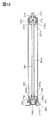
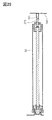
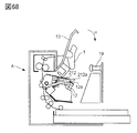
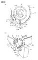
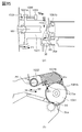
- FIG. 1 is a side view of the process cartridge B. As shown in FIG. 1 ,
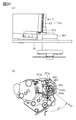
- FIG. 2 is a cross-sectional view of an apparatus main body of the image forming apparatus and a process cartridge.
- FIG. 3 is a cross-sectional view of the process cartridge.
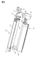
- FIG. 4 is a perspective view of an apparatus main body with an open / close door opened and a process cartridge.
- FIG. 5 is a perspective view of the process cartridge.
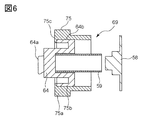
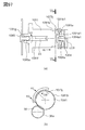
- FIG. 6 is a view for explaining the configuration of the drive side flange unit.
- FIG. 7 is a partial perspective view of a cleaning unit having an operating unit.
- FIG. 8 is a longitudinal partial cross-sectional view of the drum unit drive side end
- FIG. 9 is a partial perspective view of a cleaning unit having an operating unit.
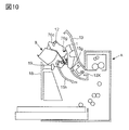
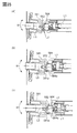
- FIG. 10 is a cross-sectional view of the image forming apparatus in the state before the process cartridge B is mounted on the apparatus main body A by opening the opening / closing door 13 of the apparatus main body.
- FIG. 11 is a cross-sectional view of the image forming apparatus in a state in which the mounting of the process cartridge B on the apparatus main body A is completed and the open / close door 13 is closed.
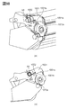
- FIG. 12 is a cross-sectional view of the image forming apparatus for explaining the process in which the cartridge pressing member abuts on the lever member according to the present embodiment.
- FIG. 13 is a perspective view of an outer cylindrical cam member, an inner cylindrical cam member, and a lever member.
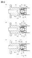
- FIG. 14 is a longitudinal sectional view of the drive transmission member 81 and the coupling member 64 of the apparatus main body A. As shown in FIG.
- FIG. 15 is a longitudinal sectional view of the inclined drive transmission member 81 and the coupling member 64 of the main assembly A of the apparatus.
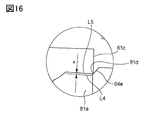
- FIG. 16 is a partially enlarged view of the chamfered portion of the coupling member.
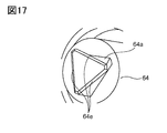
- FIG. 17 is a perspective view for explaining a chamfered portion 64e provided on the end face of the driven transmission portion 64a of the coupling member 64. As shown in FIG.
- FIG. 18 is a longitudinal sectional view of the drum unit of the second embodiment.
- FIG. 19 is a view for explaining a method of assembling the drum unit of the second embodiment.
- FIG. 20 is a partial perspective view for explaining the structure of the cleaning unit having the operation unit.
- FIG. 21 is a perspective view of the process cartridge of the second embodiment.
- FIG. 22 is a cross-sectional view of the image forming apparatus for explaining the process in which the cartridge pressing member abuts on the lever member according to the second embodiment.
- FIG. 23 is a perspective view of the lever member 212, the outer cylindrical cam member 270, and the inner cylindrical cam member 274 according to the second embodiment.
- FIG. 24 is a longitudinal sectional view of the drive transmission member 81 and the coupling member 64 of the apparatus main body A according to the second embodiment.
- FIG. 25 is a perspective view of the main body drive transmission member.
- FIG. 26 is an explanatory view showing a coupling structure of the coupling member and the driving side flange member.
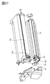
- FIG. 27 is an exploded perspective view of the cartridge.
- FIG. 28 is an explanatory view showing the side surface of the cartridge and the contact member of the apparatus main body.
- FIG. 29 is an explanatory view for explaining grounding (grounding) of the photosensitive drum.
- FIG. 30 is a longitudinal sectional view of the drum unit of the third embodiment.
- FIG. 31 is a perspective view before assembly and a perspective view after assembly.
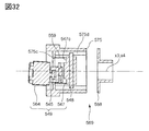
- FIG. 32 is a longitudinal sectional view of the drive side flange unit.
- FIG. 33 is a perspective view for explaining the method of assembling the drum unit and a partial detailed view for explaining the locking portions of the coupling support member 552 and the drum bearing 573.
- FIG. 34 is a side view of the process cartridge.
- FIG. 35 is a longitudinal sectional view of the device body.
- FIG. 36 is a partial detail view of the device body.
- FIG. 37 is a perspective view of a process cartridge.
- FIG. 38 is an exploded view of the coupling unit.
- FIG. 39 is an exploded view of the coupling shaft and the coupling member.
- FIG. 40 is an exploded view of the outer cylindrical cam and the inner cylindrical cam.
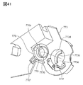
- FIG. 41 is an exploded view of the outer cylindrical cam and the drum bearing.
- FIG. 42 is an exploded view of the inner cylindrical cam and the drum bearing.
- FIG. 43 is a cross-sectional view of a coupling unit.
- FIG. 44 is a cross-sectional view of a coupling unit.
- FIG. 45 is an explanatory view of the coupling unit as viewed from the axial direction.
- FIG. 46 is an explanatory view of the coupling portion as viewed from the axial direction.
- FIG. 47 is a perspective view of a process cartridge.
- FIG. 48 is a perspective view of the coupling.
- FIG. 49 is a perspective view of the coupling.
- FIG. 50 is a cross-sectional view of the coupling.
- FIG. 51 is a cross-sectional view of the coupling.
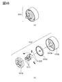
- FIG. 52 is a perspective view of a drive transmission unit.
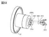
- FIG. 53 is a perspective view of a drive transmission unit.
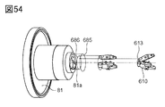
- FIG. 54 is a perspective view of a drive transmission unit.
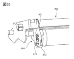
- FIG. 55 is a perspective view of the coupling.
- FIG. 56 is a perspective view of the coupling.
- FIG. 57 is a cross-sectional view of the coupling.
- FIG. 58 is a cross-sectional view of a drive transmission unit.
- FIG. 59 is a cross-sectional view of a drive transmission unit.
- FIG. 60 is a perspective view of the alignment member.
- FIG. 61 is a perspective view of a pin receiving member.
- FIG. 62 is a perspective view of a drive input unit.
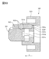
- FIG. 63 is a partial longitudinal sectional view of a drive input unit.
- FIG. 64 is a longitudinal sectional view of the drum unit and a partially enlarged view thereof
- FIG. 65 is an explanatory view of the assembling method of the drum unit.
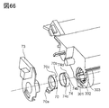
- FIG. 66 is a partial perspective view of the actuation unit and the drive input unit.
- FIG. 67 is a partial perspective view of the actuating unit.
- FIG. 68 is a cross-sectional view of the image forming apparatus as seen from the cartridge non-driving side
- FIG. 69 is a longitudinal sectional view of the apparatus main body and the cartridge.
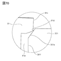
- FIG. 70 is a partially enlarged view of the alignment member and the drive transmission member.
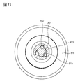
- FIG. 71 is a cross-sectional view of the drive transmission member and the drive input unit.
- FIG. 72 is a perspective view of a drive input unit.
- FIG. 73 is a partial longitudinal sectional view of the drum unit and the drum bearing.
- FIG. 74 is a longitudinal sectional view of the apparatus main body and the cartridge.
- FIG. 75 is a partially enlarged view of the outer periphery receiving alignment core member and the drive transmission member 81.
- FIG. 76 is a perspective view of the cartridge.
- FIG. 77 is a perspective view of the developing unit.
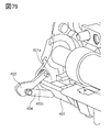
- FIG. 78 is a cross-sectional view of the drive transmission member and the process cartridge.
- FIG. 79 is a perspective view of the developing unit.
- FIG. 80 is a cross-sectional view of the drive transmission member and the process cartridge.
- FIG. 81 is a cross-sectional view of the drive transmission member and the process cartridge.
- FIG. 82 is a cross-sectional view of the drive transmission member and the process cartridge.
- FIG. 83 is a perspective view of the cartridge.
- FIG. 84 is a cross-sectional view of the drive transmission member and the process cartridge.
- FIG. 85 is a perspective view of the developing unit.
- FIG. 86 is a cross-sectional view of a drive transmission member and a process cartridge.
- FIG. 87 is a cross-sectional view of a drive transmission member and a process cartridge.
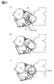
- FIG. 88 (a) is a perspective view of the cartridge. (B) is an exploded perspective view of a cartridge.
- FIG. 89 (a) is a side view of the cartridge. (B) is a cross-sectional view of the cartridge.
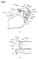
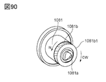
- FIG. 90 is an explanatory view of a drive transmission member.
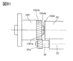
- FIG. 91 is an explanatory view of a cartridge and a drive transmission member.
- FIG. 92 is an explanatory view of a drive transmission member.
- FIG. 93 (a) is an explanatory view of a drive transmission member. (B) is an explanatory view of a cartridge and a drive transmission member.
- FIG. 94 (a) is an explanatory view of a drive transmission member. (B) is an explanatory view of a cartridge and a drive transmission member.
- FIG. 95 (a) is an explanatory view of a drive transmission member.
- (B) is an explanatory view of a cartridge and a drive transmission member.
- FIG. 96 (a) is an explanatory view of a drive transmission member. (B) is an explanatory view of a cartridge and a drive transmission member.
- FIG. 97 (a) is an explanatory view of a drive transmission member. (B) is an explanatory view of a cartridge and a drive transmission member.
- FIG. 98 (a) is a perspective view of the cartridge. (B) is a side view of a cartridge.
- FIG. 99 (a) is a perspective view of the cartridge.
- (B) is a perspective view of a cartridge.
- FIG. 100 (a) is an exploded perspective view of the cartridge. (B) is an exploded perspective view of a cartridge.
- FIG. 101 (a) and (b) show the control member.
- FIG. 102 (a) and (b) are side views of the cartridge.
- FIG. 103 (a) is a cross-sectional view of the cartridge for explaining the arrangement of the control member. (B) is a figure which shows a control member
- FIG. 104 (a) is a side view of the cartridge. (B) is a figure which fills a cartridge and a drive transmission member from the front.
- FIG. 105 is a side view of the cartridge.
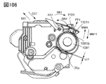
- FIG. 106 is a side view of the cartridge.
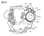
- FIG. 107 is a side view of the cartridge.
- FIG. 108 is a side view of the cartridge.
- FIG. 109 is a side view of the cartridge.
- FIG. 110 (a) and (b) are side views of the cartridge.
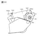
- FIG. 111 is a side view of the cartridge.
- FIG. 112 (a) is an exploded perspective view of the cartridge. (B) is a perspective view of a cartridge.
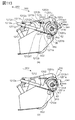
- FIG. 113 (a) and (b) are side views of the cartridge.
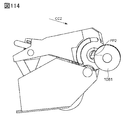
- FIG. 114 is a side view of the cartridge.
- FIG. 115 is a side view of the cartridge.
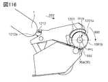
- FIG. 116 is a side view of the cartridge.
- FIG. 117 is a side view of the cartridge.
- FIG. 118 (a) and (b) are side views of the cartridge.
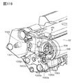
- FIG. 119 is a perspective view of the cartridge.
- FIG. 120 is a side view of the cartridge.
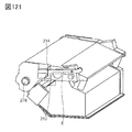
- FIG. 121 is a side view of the cartridge.
- FIG. 122 is a perspective view of the cartridge.
- FIG. 123 is an exploded perspective view of the coupling member.
- FIG. 124 is an exploded perspective view of the coupling member.
- Example 1 will be described in detail based on the drawings.
- the direction of the rotational axis of the electrophotographic photosensitive drum is simply referred to as the longitudinal direction.
- the rotational axis direction (axial direction) is a direction parallel to the axis (rotational axis) of the photosensitive drum.
- the axis of the photosensitive drum is a virtual straight line extending along the rotational center of the photosensitive drum. The photosensitive drum rotates about its rotation axis.
- the side to which the electrophotographic photosensitive drum receives the driving force from the image forming apparatus main body is set as the driving side, and the opposite side is set as the non-driving side.
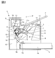
- FIG. 2 is a cross-sectional view of an apparatus body (electrophotographic image forming apparatus main body, image forming apparatus main body) A of the electrophotographic image forming apparatus and a process cartridge (hereinafter referred to as a cartridge B).
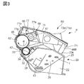
- FIG. 3 is a cross-sectional view of the cartridge B.
- the apparatus main body A is a portion of the electrophotographic image forming apparatus from which the cartridge B is removed.
- the cartridge B is removable from the apparatus main body A.
- the electrophotographic image forming apparatus (image forming apparatus) shown in FIG. 2 is a laser beam printer using an electrophotographic technology in which the cartridge B is detachably mounted on the apparatus main body A.
- the exposure device 3 laser scanner unit
- the sheet tray 4 storing a recording medium (hereinafter, referred to as a sheet material PA) to be an image forming object is disposed below the cartridge B.
- the electrophotographic photosensitive drum 62 is a photosensitive member (electrophotographic photosensitive member) used for electrophotographic image formation.
- the fixing device 9 includes a heating roller 9a and a pressure roller 9b.
- the electrophotographic photosensitive drum (hereinafter, referred to as the photosensitive drum 62 or simply the drum 62) is rotationally driven in the direction of arrow R at a predetermined circumferential speed (process speed).
- the charging roller (charging member) 66 to which the bias voltage is applied contacts the outer peripheral surface of the drum 62 and charges the outer peripheral surface of the drum 62 uniformly.
- the charging roller 66 is a rotating body (roller) that can rotate and move in contact with the drum 62.
- the charging member is not limited to such a rotatable contact roller configuration, and a charging member (charging device) fixed with a space between it and the drum 62 may be used like a colon charging device. Is also possible.
- the exposure device 3 outputs a laser beam L according to the image information.
- the laser beam L passes through a laser opening 71 h provided in the cleaning frame 71 of the cartridge B, and scans and exposes the outer peripheral surface of the drum 62. Thereby, an electrostatic latent image corresponding to the image information is formed on the outer peripheral surface of the drum 62.
- the toner T in the toner chamber 29 is stirred and conveyed by the rotation of the conveying member (stirring member) 43 and delivered to the toner supply chamber 28.
- the toner T is carried on the surface of the developing roller 32 by the magnetic force of the magnet roller 34 (fixed magnet).
- the developing roller 32 is a developer carrier that carries a developer (toner T) on the surface thereof in order to develop the latent image (electrostatic latent image) formed on the drum 62.
- a noncontact development method is used in which the latent image is developed with a minute gap between the developing roller 32 and the drum 62. It is also possible to adopt a contact development method in which the latent image is developed in a state where the development roller 32 is in contact with the drum 62.
- the layer thickness of the toner T on the circumferential surface of the developing roller 32 as a developer carrier is regulated.
- the toner T is supplied to the drum 62 according to the electrostatic latent image to develop the latent image. Thereby, the latent image is visualized as a toner image.
- the drum 62 is an image bearing member carrying a latent image and an image (toner image, developer image) formed of toner (developer) on the surface thereof.
- the drum 62 and the developing roller 32 are rotatable members (rotating members) that can rotate in a state where the developer (toner) is carried on the surface thereof.
- the sheet material PA stored in the lower part of the apparatus main body A is taken from the sheet tray 4 by the pickup roller 5a, the pair of feed rollers 5b, and the pair of transport rollers 5c. Be sent out. Then, the sheet material PA is conveyed to the transfer position between the drum 62 and the transfer roller 7 via the transfer guide 6. At this transfer position, the toner image is sequentially transferred from the drum 62 to the sheet material PA.
- the sheet material PA to which the toner image has been transferred is separated from the drum 62 and conveyed to the fixing device 9 along the conveyance guide 8. Then, the sheet material PA passes through the nip portion of the heating roller 9 a and the pressure roller 9 b which constitute the fixing device 9. The pressure and heat fixing process is performed at the nip portion, and the toner image is fixed to the sheet material PA.
- the sheet material PA subjected to the fixing process of the toner image is conveyed to the discharge roller pair 10 and discharged to the discharge tray 11.
- the drum 62 after transfer has the residual toner on the outer peripheral surface removed by the cleaning blade 77, and is used again in the image forming process.
- the toner is stored in the waste toner chamber 71 b of the toner cleaning unit 60 removed from the drum 62.
- the cleaning unit 60 is a unit having a photosensitive drum 62.
- the charging roller 66, the developing roller 32, the transfer roller 7, and the cleaning blade 77 are process means (process members, acting members) that act on the drum 62. ⁇ Configuration of Entire Cartridge>
- FIG. 3 is a cross-sectional view of the cartridge B
- FIGS. 4 and 5 are perspective views illustrating the configuration of the cartridge B.
- the cartridge B includes a cleaning unit (photosensitive member holding unit, drum holding unit, image carrier holding unit, first unit) 60 and a developing unit (developer carrier holding unit, second unit) 20.
- the cartridge B in this embodiment is a process cartridge.
- the process cartridge is a cartridge integrally formed with the electrophotographic photosensitive member and at least one of the process means acting thereon, and is detachably mountable to the main body (apparatus main body) of the electrophotographic image forming apparatus.
- process means include charging means, developing means and cleaning means.
- the cleaning unit 60 has a drum 62, a charging roller 66, a cleaning member 77, and a cleaning frame 71 for supporting them.
- the drive-side drum flange 63 provided on the drive side of the drum 62 is rotatably supported by the hole 73 a of the drum bearing 73 on the drive side.
- the drum bearing 73, the side member 76, and the cleaning frame 71 can also be collectively referred to as a cleaning frame.
- the drum bearing 73, the side member 76, and the cleaning frame 71 are all part of a frame that constitutes a cartridge.
- the drum bearing 73, the side member 76, and the cleaning frame 71 are sometimes referred to as a drum frame because they are frames for supporting the photosensitive drum 62.
- the hole (not shown) of the non-driving side drum flange is rotatably supported by the drum shaft 78 press-fitted into the hole 71c provided in the cleaning frame 71.
- the charging roller 66 and the cleaning member 77 are disposed in contact with the outer peripheral surface of the drum 62, respectively.
- the cleaning member 77 has a rubber blade 77a, which is a blade-like elastic member formed of rubber as an elastic material, and a support member 77b for supporting the rubber blade.
- the rubber blade 77 a is in contact with the drum 62 in the counter direction with respect to the rotational direction of the drum 62. That is, the rubber blade 77 a is in contact with the drum 62 such that the tip end faces the upstream side in the rotational direction of the drum 62.
- the waste toner removed from the surface of the drum 62 by the cleaning member 77 is collected in a waste toner chamber 71 b formed by the cleaning frame 71 and the cleaning member 77.
- a squeeze sheet 65 for preventing the waste toner from leaking from the cleaning frame 71 is provided at the edge of the cleaning frame 71 so as to abut on the drum 62.
- the charging roller 66 is rotatably attached to the cleaning unit 60 via charging roller bearings (not shown) at both ends in the longitudinal direction of the cleaning frame 71.
- the longitudinal direction of the cleaning frame 71 (the longitudinal direction of the cartridge B) is substantially parallel to the direction in which the rotation axis of the drum 62 extends (axial direction).
- the axial direction (the direction parallel to the axis of the drum) of the drum 62 is intended in the case of the longitudinal direction or simply the axial direction without particular notice.
- the charging roller 66 is in pressure contact with the drum 62 by the charging roller bearing 67 being pressed toward the drum 62 by the biasing member 68.
- the charging roller 66 is driven to rotate by the rotation of the drum 62.
- the developing unit 20 has a developing roller 32, a developing container 23 supporting the developing roller 32, a developing blade 42 and the like.
- the developing roller 32 is rotatably attached to the developing container 23 by bearings 27 (FIG. 5) and bearings 37 (FIG. 4) provided at both ends.
- the developer container 23, the bearing member 27, and the bearing member 37 are all part of the frame of the cartridge.
- the developing container 23, the bearing members 27, and the bearing members 37 are frames constituting the developing unit 20 (frames for supporting the developing roller 32), and therefore, they may be generically called a developing frame.
- a magnet roller 34 is provided in the developing roller 32.
- a developing blade 42 for regulating the toner layer on the developing roller 32 is disposed.
- the spacing roller 38 is attached to both ends of the developing roller 32 on the developing roller 32, and the spacing roller 38 and the drum 62 are in contact with each other. It is held with 62 and a slight gap.
- a blowout preventing sheet 33 for preventing the toner from leaking from the developing unit 20 is provided at the edge of the bottom member 22 so as to abut on the developing roller 32.
- a conveying member 43 is provided in the toner chamber 29 formed by the developing container 23 and the bottom member 22. The conveying member 43 agitates the toner contained in the toner chamber 29 and conveys the toner to the toner supply chamber 28.
- the cartridge B is configured by combining a cleaning unit (first unit) 60 and a developing unit (second unit) 20.
- the developing unit 20 is movably connected to the cleaning unit 60. More specifically, the developing unit 20 is rotatably (rotatably) connected to the cleaning unit 60. Thereafter, the side member 76 is assembled to the cleaning unit 60 to configure the cartridge B.
- the non-driving side biasing member 46L (FIG. 4) and the non-driving side biasing member 46R (FIG. 4) are formed by compression springs.
- the developing unit 20 is urged against the cleaning unit 60 by the urging force of these springs, and the developing roller 32 is reliably pressed in the direction of the drum 62.
- the developing roller 32 is held at a predetermined distance from the drum 62 by the spacing members 38 attached to both ends of the developing roller 32.
- the coupling member 64 and the advancing and retracting mechanism for advancing and retracting the coupling member will be described.
- the coupling member 64 is a member (driving input member, input coupling) for receiving a driving force (rotational force) for rotating the drum 62 and the developing roller 32 from the outside of the cartridge (that is, the image forming apparatus main body). is there.
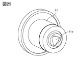
- FIG. 25 shows a perspective view of the drive transmission member (drive output member) 81.
- the drive transmission member 81 is provided with a recess (drive transmission portion 81a) having a substantially triangular shape.
- the driven transmission portion 64a of the coupling member 64 is engaged with the recess (drive transmission portion 81a), and the coupling member 64 receives a driving force.
- the drive side flange unit 69 will be described with reference to FIG.
- the coupling member 64 is provided at the end of the photosensitive drum 62. That is, the coupling member 64 is movably supported by the flange member 75 fixed to the end of the photosensitive drum 62.
- the driving side flange unit 69 is composed of a coupling member 64, a driving side flange member 75, a lid member 58, and a first pressing member 59.
- the coupling member 64 has a driven transmission portion (driving force receiving portion) 64a and a driving transmission portion 64b.
- the driving force is transmitted from the drive transmission member (drive output member) 81 (see FIGS. 14 and 25) of the apparatus main body A to the drive transmission unit 64a.
- the drive transmission portion 64 b is supported by the drive side flange member 75 and simultaneously transmits the drive to the drive side flange member 75.
- the driving side flange member 75 includes a gear portion 75a for transmitting a drive to a gear member 36 (see FIG. 27) provided at an end of the developing roller, a coupling support portion 75b (see FIG. 26), and the like.
- the coupling member 64 is inserted into the inner periphery (coupling support portion 75b) of the driving side flange member 75, the first pressing member 59 for urging the coupling member 64 toward the driving side is inserted.
- the lid member 58 is fixed to the end 75c of the drive side flange member 75 by welding or the like, whereby the drive side flange unit 69 is configured.
- FIG. 26 shows a perspective view of the drive side flange member 75 and the coupling member 64.
- the inner peripheral surface of the drive side flange member 75 is a coupling support portion 75b.
- the outer peripheral surface of the coupling member 64 is supported by the inner peripheral surface (the coupling support portion 75 b), whereby the coupling member 64 is supported by the drive side flange member 75.
- two surfaces symmetrically arranged with respect to the rotation axis are flat portions. This flat portion is the drive transmission portion 64 b of the coupling member 64.
- two flat portions 75b1 are provided to correspond to the drive transmission portion 64b.
- the flat portion of the flange member 75 becomes the driven transmission portion 75 b 1 of the flange member 75. That is, when the drive transmitting portion 64 b of the coupling member 64 contacts the transmitted portion 75 b 1 of the flange member 75, the driving force is transmitted from the coupling member 64 to the flange member 75.
- the drive-side flange 75 of the drive-side flange unit 69 is fixed to the end of the photosensitive drum 62 by means such as press fitting or crimping (see FIG. 8).
- the driving force (rotational force) received by the coupling member 64 from the drive transmission member 81 is transmitted to the photosensitive drum 62 via the driving side flange 75. That is, since the coupling member 64 is connected to the end of the photosensitive drum via the driving side flange member 75, the coupling member 64 can transmit the driving toward the photosensitive drum 62.
- FIG. 27 shows an exploded perspective view of the cartridge.
- the driving force (rotational force) is transmitted from the driving side flange 75 to the developing roller 32 via the gear 75a. That is, the gear 75 a meshes with the developing roller gear 36 and transmits the rotation of the drive side flange 75 to the developing roller gear 36.
- the developing roller gear 36 is a gear provided to the developing roller 32, and in detail, is engaged with the shaft portion of the developing roller flange 35 fixed to the end of the developing roller 32. Therefore, the rotation of the developing roller gear 36 is transmitted to the developing roller 32 through the developing roller flange 35. Further, the developing roller gear 36 also transmits the driving force to the conveying member gear 41 via the idler gear 39.
- the conveying member gear 41 is a gear provided on the conveying member 43 (see FIG. 3), and when the conveying member gear 41 rotates, the conveying member 43 also rotates.
- the drive side flange 75 is a drive transmission member (cartridge side drive transmission member) for transmitting the drive from the coupling member 64 to the drum 62, the developing roller 32, the conveyance member 43 and the like.
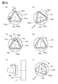
- the driven transmission portion 64a of the coupling member 64 adopts a convex shape (convex portion) having a substantially triangular cross section. Specifically, a substantially triangular cross-section was adopted in a counterclockwise direction with respect to the axis of the photosensitive drum from the driving side to the non-driving side.
- the driven transmission portion 64a is not limited to such a shape, and may be any one that can be engaged with the drive transmission member 81 (see FIG. 25) to receive a driving force.
- the drive transmission member 81 of the apparatus main body A is provided with a substantially triangular recess (drive transmission portion 81a: see FIG. 25) which can be engaged with the driven transmission portion 64a. Therefore, the driven transmission portion 64a has a convex shape that engages with the concave portion.
- the convex shape may be not one but a plurality, and the shape is not limited to a triangle. In addition, the convex shape is shaped like twisting a triangle, but it may not necessarily be twisting.
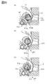
- the coupling member 64 is configured to be able to move back and forth along the longitudinal direction (axial direction) as shown in FIG. FIG. 14 (a) shows a state in which the coupling member is retracted and disengaged from the drive transmission member 81, and in FIG. 14 (c), the coupling member 64 is advanced and engaged with the drive transmission member 81. It shows a state of agreement. Moreover, in FIG.14 (b), the state (process of advancing and retreating movement) between FIG.14 (a) and FIG.14 (c) is shown.
- FIG. 7 an operating unit (operating mechanism, advancing and retracting unit, advancing and retracting mechanism) which enables such longitudinal movement of the coupling member 64 will be described with reference to FIGS. 7, 8 and 9.
- FIG. 7 an operating unit (operating mechanism, advancing and retracting unit, advancing and retracting mechanism) which enables such longitudinal movement of the coupling member 64 will be described with reference to FIGS. 7, 8 and 9.
- FIG. 7 is a partial perspective view for explaining the configuration of the operation unit provided in the cleaning unit 60 according to the present embodiment.
- FIG. 8 is a partial longitudinal sectional view of the drum unit drive side end portion according to the present embodiment.
- FIG. 9 is a partial perspective view for explaining the actuation unit according to the present embodiment as in FIG.
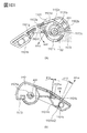
- the actuating unit comprises an outer cylindrical cam member 70, an inner cylindrical cam member 74, a lever member 12, a second pressing member (elastic member, biasing member) 14 and the like.
- the operating unit is a control mechanism (control unit) that is connected to the coupling member 64 and controls the movement (advancing / removing movement) of the coupling member 64.
- the outer cylindrical cam member 70 is composed of a cylindrical cam portion 70 b and a lever member engaging portion 70 a that engages the lever member 12. Similar to the outer cylindrical cam member 70, the inner cylindrical cam member 74 contacts the cylindrical cam portion 70b and the coupling member 64 to restrict the longitudinal position of the coupling member 64 from the longitudinal position restricting surface 74d or the like. Configured
- the outer cylindrical cam member 70 and the inner cylindrical cam member 74 are configured to be supported by the outer peripheral portion 73 a of the drum bearing member 73. Further, the lever member engaging portion 70a of the outer cylindrical cam member 70 is configured to be exposed to the outside of the drum bearing member 73 (see FIG. 9).
- the lever member 12 After the developing unit 20 is supported by the cleaning unit 60, the lever member 12 has the engaged portion 12b provided at one end of the lever member 12 engaged with the lever member engaging portion 70a of the outer cylindrical cam member 70. Further, the lever member 12 is disposed such that the slid portion 12 c at the other end is positioned between the slide ribs 71 g provided on the cleaning frame 71. That is, the projection-like engaging portion 70a enters into the hole-shaped engaged portion 12b and both are engaged, and the lever member 12 is connected to the outer cylindrical cam member 70.
- the second pressing member 14 for pressing and urging the lever member 12 is disposed between the cleaning frame 71 and the lever member 12.
- a torsion coil spring is used as the second pressing member (biasing member) 14 in the present embodiment, the present invention is not limited thereto.
- an elastic member (spring) having a different structure such as a compression coil spring may be suitably used. It is possible.
- a process cartridge having the operation unit according to the present embodiment is configured.
- the operation unit is connected to the coupling member 64 at the inner cylindrical cam 74, and the operation of the lever member 12 can advance and retract (move) the coupling member 64.
- the lever member 12 since the lever member 12 is connected to the outer cylindrical cam member 70, the outer cylindrical cam 70 is rotated by substantially linear movement of the lever member 12.
- the outer cylindrical cam 70 is in contact with the inner cylindrical cam 74, and the rotational movement of the outer cylindrical cam 70 advances and retracts the inner cylindrical cam 74 in the longitudinal direction.
- the inner cylindrical cam 74 is in contact with the coupling member 62, and the advancing and retreating of the inner cylindrical cam 74 and the advancing and retreating of the coupling member 62 are interlocked.
- lever member 12 is functionally (indirectly and operatively) connected to the coupling member 64 via the outer cylindrical cam member 70 and the inner cylindrical cam member 74, and the lever member 12 and the coupling member 64 are connected.
- the lever member 12 is functionally (indirectly and operatively) connected to the coupling member 64 via the outer cylindrical cam member 70 and the inner cylindrical cam member 74, and the lever member 12 and the coupling member 64 are connected.
- the lever member 12 is configured to move by contact and separation with a cartridge pressing member (pressing force applying member) provided in the apparatus main body A.
- FIG. 1 is a side view of a process cartridge B according to the present embodiment.
- FIG. 10 is a cross-sectional view of the image forming apparatus in a state before the process cartridge B is mounted on the apparatus main body A by opening the opening / closing door 13 of the apparatus main body.
- FIG. 11 is a cross-sectional view of the image forming apparatus in a state in which the mounting of the process cartridge B on the apparatus main body A is completed and the open / close door 13 is closed.
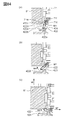
- FIG. 12A is a sectional view of the image forming apparatus in a state where the cartridge pressing member 1 starts to abut against the pressed portion 12a of the lever member 12 in the process of closing the opening / closing door 13 of the apparatus main body A in the H direction in FIG. FIG.
- FIG. 12B is a cross-sectional view of the image forming apparatus with the open / close door 13 of the apparatus main body A completely closed.
- FIG. 13 is a perspective view of the lever member 12, the outer cylindrical cam member 70, and the inner cylindrical cam member 74 according to the present embodiment.
- FIG. 13 (a) is a perspective view of a state (FIGS. 10, 11, 12 (a)) before the cartridge pressing member 1 abuts on the pressed portion 12a of the lever member 12.
- FIG. 13C is a perspective view of the state where the open / close door 13 is completely closed and a predetermined pressure of the cartridge pressing spring 19 is applied to the contact portion 12a of the lever member 12 (FIG. 12B).
- FIG. 13 (b) is a perspective view in a state between FIG. 13 (a) and FIG. 13 (c) (FIGS. 12 (a) to 12 (b)).
- FIG. 14 is a longitudinal sectional view of the drive transmission member 81 and the coupling member 64 of the apparatus main body A according to the present embodiment as described above.
- FIG. 14 (a) is a longitudinal sectional view of a state (FIGS. 10, 11, 12 (a)) before the cartridge pressing member abuts on the pressed portion 12a of the lever member 12. is there.
- FIG. 14 (c) is a longitudinal sectional view of a state where the open / close door 13 is completely closed and a predetermined pressure of the cartridge pressing spring 19 is applied to the contact portion 12a of the lever member 12 ((FIG. 12 (b))
- Fig. 14 (b) is a longitudinal sectional view in a state between Fig. 14 (a) and Fig.
- the process cartridge B is attached to the apparatus main body A after the open / close door 13 of the apparatus main body A is opened by rotating it around the rotation center 13 X.
- the open / close door 13 is provided inside the apparatus main body A. It is an opening and closing member for opening and closing the cartridge mounting portion (a space for mounting the cartridge)
- the guide rail (guide member) 15h for guiding the guided portions 76c and 76g of the process cartridge B in the mounting portion.
- the cartridge B is inserted into the mounting portion of the apparatus main body A along the guide rails 15h and 15g (only the drive side is shown) Mounting of the process cartridge B is provided to the drum bearing member 73 as shown in FIG. The process is completed when the portions to be positioned 73d, 73f abut the device main body positioning portions 15a, 15b or are inserted to the vicinity thereof.
- Two cartridge pressing members 1 are attached to both axial ends of the open / close door 13 (FIG. 11).
- the two cartridge pressing members 1 are movable with respect to the open / close door 13 within a predetermined range.
- the two cartridge pressing springs 19 are attached to both longitudinal end portions of the front plate 18 provided in the apparatus main body A.
- cartridge pressed portions 71e as biasing receiving portions of the cartridge pressing spring 19 are provided at both longitudinal end portions.
- a predetermined pressure F2 is applied from the cartridge pressing spring 19 to the cartridge pressed portion 71e and the lever pressed portion 12a.
- the outer cylindrical cam member 70 engaged with the lever member 12 and rotatably supported about the drum axis is biased in the G direction in FIG. 13 (a).
- the most non-driving side surface 70c of the outer cylindrical cam member 70 and the innermost surface 74c of the inner cylindrical cam member 74 abut.
- the coupling member 64 is urged toward the driving side by the first pressing member 59, and the coupling abutment portion 64c is on the coupling member longitudinal position restricting surface 74d of the inner cylindrical cam member 74. It is pressed. That is, according to the longitudinal position (position in the longitudinal direction) of the inner cylindrical cam member 74, the longitudinal position of the coupling member 64 is also determined.
- the first pressing member 59 is used to operate the coupling member 64 to the drive side, the first pressing member 59 can also be regarded as a part of the above-described operation unit.
- a compression coil spring is used as the first pressing member 59, but it is also possible to bias the coupling member 64 using an elastic member of another shape or the like.
- the inner cylindrical cam member 74 is arranged to retract the coupling member 64 into the drum against the elastic force of the first pressing member 59. That is, as shown in FIGS. 10 and 11, in the state in which the main body door 13 is released or in the state before the cartridge pressing member 1 abuts on the lever member 12, the coupling member 64 is positioned most on the non-drive side. It is configured as follows. The position where the coupling member 64 is retracted to the non-driving side (that is, the inside of the cartridge B) is referred to as a first position (retraction position, inside position, non-engagement position, disengagement position). As shown in FIG.
- the driven transmission portion 64a of the coupling member 64 and the drive transmission portion 81a of the drive transmission member 81 overlap in the longitudinal direction. It is configured not to. That is, the attachment and detachment of the apparatus main body A of the process cartridge B can be performed smoothly without interference between the coupling member 64 and the drive transmission member 81 of the apparatus main body.
- An inner cylindrical cam member 74 is adjacent to the outer cylindrical cam member 70.
- the inner cylindrical cam member 74 is not rotatably configured, and has a structure that can move only in the axial direction.
- the cylindrical cam portion 70b of the outer cylindrical cam member 70 and the cylindrical cam portion 74b of the inner cylindrical cam member 74 contact each other on the slopes.
- the inner cylindrical cam member 74 starts to move in the longitudinal direction to the drive side (N direction) by the pressing force of the first pressing spring member 59.
- the coupling member 64 pressed by the first pressing spring member 59 is also allowed to move in the longitudinal direction.
- the movement of the coupling member 64 advances the coupling member 64 toward the drive side (i.e., the outer side of the cartridge B).
- the driven transmission portion 64a of the coupling member 64 is engaged with the drive transmission portion 81a of the drive transmission member of the apparatus main body in the longitudinal direction (FIG. 14B).
- the phases of the cylindrical cam portions of the outer cylindrical cam member 74 and the inner cylindrical cam member 70 coincide with each other as shown in FIG.
- the inner cylindrical cam member 74 and the coupling member 64 are configured to be positioned closest to the drive side by the biasing force of the first pressing member 59.
- the position at which the coupling member 64 advances to the drive side in this manner is called a second transfer (advanced position, outer position, engaged position, drive transmission position) in this embodiment.
- the coupling member 64 located at the second position (advanced position) can be regarded as advancing toward the outside of the photosensitive drum 62 (outside of the cartridge).
- the coupling member 64 located at the first position (retracted position) described above can be regarded as being retracted toward the inside of the photosensitive drum 62 (the inside of the cartridge).
- the coupling member 64 moves along the axis of the photosensitive drum 62 substantially in parallel with the axis.
- the present invention is not necessarily limited to such a configuration.
- the first position (retracted position) and the second position (advanced position) are obtained by moving the coupling member 64 in a direction inclined with respect to the axis. You may move to the position) and.
- the drive transmission portion 64a of the coupling member 64 and the drive transmission portion 81a of the drive transmission member 81 perform stable drive transmission. It is configured to be able to secure a necessary amount of longitudinal engagement.
- the position of the lever member 12 when holding the coupling member 64 in the second position may also be referred to as a second position (second position of the lever member).
- the second position by the lever member 12 is a position (operating position, operating position) which moves by applying a force to the lever member 12 from the outside of the cartridge B, and is an operating position for acting on the coupling member 64.
- the engagement holding position is an engagement holding position for holding the advancing state of the coupling member 64 and holding the engaged state of the coupling member 64 and the drive transmission member 81.
- the driven transmission portion of the coupling member 64 has a twisted triangular shape. Therefore, when the lever member 12 is operated to the second position, the triangular phases of the drive transmitting portion 81a of the drive transmitting member 81 of the apparatus main body and the driven transmitting portion 64a of the coupling member 64 are aligned. It may not be. At this time, in the process of moving the coupling member 64 to the second position on the drive side, the drive transmission portion 64 a comes into contact with the end face 81 c of the drive transmission member 81 and stops.
- the drive transmission portion 64a can not engage with the drive transmission portion 81a, the drive transmission member 81 and the coupling member 64 interfere with each other, and the coupling member 64 can not move to the second position. In this state, the first pressing member 59 is partially compressed.
- the drive transmission portion 81a can be engaged with the driven transmission portion 64a.
- the elastic deformation of the first pressing member 59 that has been compressed is partially eliminated, and the coupling member 64 can be moved to the second position.
- the first pressing member 59 is compressed when the drive transmission member 81 and the coupling member 64 interfere with each other, so that the influence of the interference extends to the drive transmission member 81 and the coupling member 64. I'm holding back.
- the first pressing member 59 is also a cushion member (buffer member, damper) for suppressing the influence of interference.
- the main body pressing member 1 When the process cartridge is pulled out to the outside of the main body door 13, the main body pressing member 1 is separated from the lever member 12 in the process of opening the open / close door 13. Thereafter, the lever member 12 starts to move in the E direction from the state of FIG. 13C by the biasing force of the second pressing member 14 (FIG. 9). Thereby, the outer cylindrical cam member 70 is rotated in the G direction, and the inner cylindrical cam member 74 and the coupling member 64 are configured to take the first position by the shapes 70b and 74b of the outer and inner cylindrical cam portions. .
- the position of the lever member 12 when positioning the coupling member 64 in the first position may also be referred to as the first position.
- the first position of the lever member 12 is a position (normal position, inoperative position) where no external force is applied to the lever member 12 from the outside of the cartridge.
- the first position of the lever member 12 is a retreat holding position and a retreat allowing position which holds and allows the state where the coupling member 12 is retreated, and the cartridge B is mounted and dismounted from the apparatus main body A It is a mounting allowance position and a removal allowance position which allow to be done.
- FIGS. 13 (a) and 14 (a) show a state in which the lever member 12 and the coupling member 64 are in the first position, respectively.
- FIGS. 13 (c) and 14 (c) show the lever member 12 and the coupling member 64 in the second position, respectively.
- 13 (b) and 14 (b) show the position (intermediate position) in the process of moving the lever member 12 and the coupling member 64 from the first position to the second position, respectively.
- the process cartridge B By moving the coupling member 64 to the first position (retracted position), the process cartridge B can be removed from the apparatus main body A.
- the lever member 12 is an operation member (moving member) operated and moved by the force from the outside of the cartridge (that is, the apparatus main body A). Then, the movement of the lever member 12 is transmitted to the coupling member 64 via the two cam members 70 and 74, and the coupling member 64 is between the first position (retracted position) and the second position (advanced position) It will move. That is, the lever member 12 is operated to move the coupling member 64.
- the two cam members (the outer cylindrical cam member 70 and the inner cylindrical cam member 74) provided in the actuating unit are cam mechanisms for interlocking the lever member 12 with the coupling member 64.
- the lever member 12 is configured to move in a cross direction crossing the longitudinal direction (a direction substantially perpendicular to the longitudinal direction).
- the cam mechanism converts this cross movement into movement of the coupling member 64 along the longitudinal direction.
- the first pressing member 59 is a biasing member that biases the coupling member 64 toward a specific position (a second position and an advancing position).
- the second pressing member 14 is a biasing member that biases the lever member 12 to a specific position (first position, normal position).
- the downstream side (the side indicated by the arrow K in the drawing) of the moving direction in which the lever member 12 moves from the first position (normal position) to the second position (operating position).
- the contact surface 82a of the charging roller contact member 82 is oriented. That is, the contact surface 82a faces in the direction of the arrow J1 in FIG.
- the charging roller contact member 82 is electrically connected to the charging roller 66 and contacts the contact member for charging bias application (main body side electrical contact) provided in the device main body A, whereby voltage is applied from the device main body A Electrical contacts.
- FIG. 28 is an explanatory view showing the electrical contacts (contact members) of the cartridge B and the apparatus main body A.
- the cartridge B has a developing roller contact member 83 electrically connected to the developing roller 32.
- the developing roller contact member 83 contacts a contact member (electrical contact: see FIG. 28) 102 for applying a developing bias voltage provided on the apparatus main body A, whereby a voltage is applied from the apparatus main body A. That is, when the contact surface (exposed surface, exposed portion) 83a of the developing roller contact member 83 comes into contact with the contact member 102 on the apparatus main body side, the developing bias voltage from the apparatus main body A passes through the developing roller 32 to the developing roller contact member 83. Is applied via the
- the contact surface 83a of the developing roller contact member is also directed to the downstream side of the movement direction of the lever member 12 (direction K in the drawing). That is, the contact surface 83a faces in the direction of arrow I1 in FIG.
- the pressing force is held toward the downstream side (the side indicated by the arrow K) in the moving direction of the lever member 12.
- the charging roller contact member 82 (contact surface 82a) and the developing roller contact member 83 (contact surface 83a) also face the downstream side. Therefore, using the pressing force (force acting in the direction of arrow K) by the cartridge pressing member 1, the main body contact of the apparatus main body corresponding to the charging roller contact member 82 (contact surface 82a) and the developing roller contact member 83 (contact surface 83a) It can be biased towards the member. Thereby, it is possible to stabilize the contact state of each contact member (82, 83) on the cartridge side and the main body contact member.
- the positioning portions 73d and 73f of the cartridge B can be reliably pressed to the positioning portions 15a and 15b (FIG. 12) of the apparatus main body by using the pressing force that the lever member 12 receives. That is, normally, when each of the charging roller contact member 82 and the developing roller contact member 83 contacts the corresponding main body contact member on the main body side, the main body is directed in the direction perpendicular to the charging contact surface 82a and the developing contact surface 83a. Contact pressure (contact pressure) is received from the contact member. In FIG. 28, the charging contact surface 82a receives a force in the arrow J2 direction, and the developing contact surface 83a receives a force in the arrow I2 direction.
- the positioning portions 73d and 73f of the cartridge B can be more surely pressed against the positioning portions 15a and 15b of the apparatus main body by the force of the cartridge pressing member 1, and the cartridge can be mounted and positioned on the apparatus main body A in a stable posture. As described above, since the positioning accuracy of the cartridge into the apparatus main body is improved, the stable engagement of the coupling member 64 and the drive transmission member 81 of the apparatus main body becomes possible.
- an electrical contact such as the charging roller contact member 82 or the developing roller contact member 83 faces the downstream side in the moving direction of the lever member 12 (the side indicated by the arrow K)
- the electrical contact It is not required that the direction in which the is facing be made parallel to the arrow K. If the direction in which the electrical contact faces is smaller than 90 degrees with respect to the arrow K (that is, if the above angle is greater than 0 degrees and less than 90 degrees), the electrical contacts are in the moving direction of the lever member 12. It can be considered as facing the downstream side.
- the angle between arrow K and arrow J1 is less than 90 degrees, and the angle between arrow K and arrow I1 is less than 90 degrees.
- the lever member 12 is disposed on the same side of the cartridge as the respective electrical contacts (the charging roller contact member 82 and the developing roller contact member 83) in the longitudinal direction (axial direction). That is, both the lever member 12 and the respective electrical contacts 82 and 83 are disposed on one end side (one side) of the cartridge in the longitudinal direction.
- the contact pressure received by each of the electrical contacts 82, 83 and the pressing force applied by the cartridge pressing member 1 to the lever member 12 both act on the same end of the cartridge. Therefore, the cartridge pressing member 1 can easily bias and position the cartridge B by the cartridge pressing member 1 against the contact pressure by the pressing force by which the lever member 12 is pressed.
- the respective electrical contacts may be separately disposed at both ends of the cartridge. If the number of electrical contacts is an odd number, it is conceivable to dispose the lever member 12 on the side where more electrical contacts are disposed.
- one end of the cartridge on which the lever member 12 and the electrical contacts 82 and 83 are disposed is the side on which the coupling member 64 is disposed (drive side). Even if vibration or the like is transmitted to the drive side of the cartridge B provided with the coupling member 64 when the coupling member 64 receives the rotational force, the lever member 12 is biased on the drive side of the cartridge B. The influence of the vibration etc. can be suppressed by
- both of the two electric contacts 82 and 83 provided on the cartridge B are provided on the main body side contact member 102 provided on the apparatus main body A by using the pressing force with which the lever member 12 is pressed, It turned toward 103.
- not all of the plurality of electrical contacts need to be biased using the pressing force with which the lever member 12 is pressed. If at least one of the plurality of electrical contacts of the cartridge B faces the downstream side in the moving direction of the lever, the pressing force that the lever member 12 receives on those electrical contacts is applied to the main body A It can be biased to the provided electrical contacts on the body side.
- two cartridge pressing members 1 are provided on the apparatus main body A.
- One pressing member 1 presses the lever member 12 on the drive side of the cartridge B
- the other pressing member 1 presses the frame of the cartridge B on the other end side (the other side, non-drive side) of the cartridge B .
- the cartridge B receives the force at one point. May be That is, it is sufficient that at least the lever member 12 receives a force by the pressing member 1.
- the lever member 12 is disposed between the charging contact surface 82a and the developing contact surface 83a in a plane perpendicular to the axis of the drum. That is, when the lever member 12 is in the first position as shown in FIG. 28, a line segment L1 connecting both ends of the lever member 12 and a line segment connecting the charging contact surface 82a and the developing contact surface 83a in the plane When drawing L2, these two line segments L1 and L2 cross each other.
- the pressing force that the lever member 12 receives from the pressing member 1 can be distributed to the two electrical contacts 82 and 83 in a well-balanced manner. That is, in the process of mounting the cartridge, although the force received by the electric contacts 82 and 83 and the force received by the lever member 12 are applied to the cartridge B, the moment generated in the cartridge B is stabilized by these. Even if the lever member 12 receives a pressing force, the attitude of the cartridge B is unlikely to change.
- the positioned portions 73d and 73f of the cartridge B can be reliably fixed to the positioning portions 15a and 15b (FIG. 12) of the apparatus main body. Can be pressed. That is, stable engagement of the coupling member 64 and the drive transmission member 81 of the apparatus main body is possible.
- a line segment L2 intersects a line connecting the contact portion 212a of the lever member 12 and the engaged portion 212b.
- the lever member 12 has a shape extending along the movement direction (K direction) of the lever member. Therefore, in the process of the lever member 12 being pressed by the pressing member 1 of the apparatus main body A and moving in the K direction, the force of the pressing member 1 is smoothly transmitted to the cartridge B via the lever member 12. Therefore, by using the force of the pressing member 1, the contact members 82 and 83 on the cartridge side can be more reliably brought into contact with the corresponding contact members on the main body side.
- the integral lever member 12 was used as an operation member, the operation member may be comprised by connection of several members.
- the plurality of contact members may be referred to as a first contact member (first electrical contact), a second contact member (second electrical contact), and the like.
- the charging roller contact member 82 and the developing roller contact member 83 are connected to the charging roller 67 and the developing roller 30. That is, the respective electrical contacts 82, 83 are connected to the process members 6730 acting on the photosensitive members, and are used to apply a voltage from the apparatus main body A to these process members 6730, respectively.
- the electrical contacts (contact members) are not limited to those for applying a voltage to such process members.
- an electrical contact electrically connected to the memory is provided in the cartridge B.
- This electrical contact is used for the device main body A to read information in the memory or write new information in the memory by contacting the electrical contact in the device main body A.
- the present embodiment can be suitably applied to such an electrical contact for information communication.
- the cleaning frame 73 is provided with the pressed portion 71e pressed by the cartridge pressing member 1 in the apparatus main body. That is, after the pressing member 1 presses the lever member 12 to move it from the first position to the second position, the pressing member 1 also contacts the pressed portion 71 e of the cleaning frame 73. Then, the pressing member 1 applies a pressing force to the cartridge B via the lever member 12 and the pressed portion 71e.
- the pressing member 1 does not necessarily need to contact the cleaning frame 73, and the pressing member 1 contacts only the abutted portion 12a of the lever member, so that the pressing force is applied to the cartridge B through only the lever member 12. You may configure it. ⁇ Modification>
- FIG. 15A is a longitudinal cross-sectional view of a state in which the process cartridge is inserted into the apparatus main body A and the open / close door 13 is closed.
- FIG. 15B the drive force is input to the apparatus main body A, and the drive transmission member 81 starts to rotate, and the phase of the drive transmission portion 81a and the phase of the driven transmission portion 64a of the coupling member 64 fall within a predetermined range.
- FIG. 15C is a longitudinal cross-sectional view of a state in which the engagement of the drive transmission portion 81 a of the drive transmission member 81 and the driven transmission portion 64 a of the coupling member 64 is completed.
- FIGS. 15 (a), (b) and (c) the drive transmission member is reduced while the inclination angle of the drive transmission member 81 is reduced as the coupling member 64 moves to the second position (advanced position). The process of engaging 81 is shown.
- FIG. 16 is an enlarged partial view showing a portion surrounded by a circle J in FIG. 15A.
- FIG. 17 illustrates a chamfered portion 64e provided on the end face of the driven transmission portion 64a of the coupling member 64. It is a perspective view.
- the diameter ⁇ D1 of the supported portion 81b of the drive transmission member 81 and the diameter ⁇ D2 of the support portion 85a of the drive transmission member support member 85 are configured to satisfy ⁇ D1> ⁇ D2. Yes.
- the drive transmission member 81 can move relative to the support member 85.
- the drive transmission member 81 and the coupling member 64 are engaged, the drive transmission member 81 can be moved to align its axis with the axis of the coupling member 64. That is, the rotation axis L3 of the drive transmission member 81 is configured to be precisely aligned with the rotation axis L1 of the coupling member 64.
- the drive transmission member 81 is supported by the driven transmission portion 64 a of the coupling member 64.
- a gap is provided between the supported portion 81 b of the drive transmission member 81 and the support portion 85 a of the drive transmission member support member 85 according to the relationship of ⁇ D1> ⁇ D2.
- the drive transmission member 81 is movable within the range of this gap.
- the drive transmission member 81 before engaging with the coupling member 64 is inclined by its own weight in the V direction in the figure as shown in FIG. 15 (a) from the relationship of ⁇ D1> ⁇ D2.
- the coupling member 64 is originally movable from the first position to the second position.
- driven transmission portion 64a of coupling member 64 is immediately engaged with drive transmission portion 81a of drive transmission member 81. I can not fit.
- the inclination angle of the drive transmission member 81 with respect to the horizontal surface is reduced until the drive transmission portion 81a of the drive transmission member 81 can be engaged with the driven transmission portion 64a of the coupling member 64 of the coupling member 64.
- the coupling member 64 applies a force to the drive transmission member 81 to move the drive transmission member 81 so as to reduce the inclination angle.
- the chamfered portion (inclined portion, tapered portion) inclined with respect to the axis line of the coupling member 64 is provided on the triangular ridge line of the drive side end portion of the coupling member 64.
- 64e is provided.
- the chamfered portion 64 e is an action portion for acting on the drive transmission member 81, and can move the drive transmission member 81 by contacting the drive transmission member 81 under a specific condition.
- the size of the chamfered portion 64e is such that, as shown in FIG.
- the drive transmission portion 81 a of the transmission member 81 is configured to be positioned.
- the position of the ridge line inside the chamfered portion 64e is indicated by L4
- the position of the edge (edge) of the recess which is the drive transmission portion 81a is indicated by L5.
- the inclined portion of the chamfered portion 64e is the drive transmission portion 81a (recess).
- the edge (L5) of the drive transmission portion 81a is located radially outward of the ridge line (L4) inside the chamfered portion 64e by a distance x.
- the inclined chamfered portion 64e applies a force to the drive transmission member 81 in a direction perpendicular to the surface. Therefore, when the chamfered portion 64 e comes in contact with the edge of the drive transmission portion 81 a, it applies a left upward force to the drive transmission member 81 in the figure. Therefore, as shown in FIG. 15 (b), a moment is applied to the drive transmission member 81 in the arrow W direction with the fixed end as a fulcrum. Thus, the drive transmission member 81 swings (tilts) in the arrow W direction.
- the drive transmission portion 81a When the drive transmission member 81 swings in the direction of arrow W, the drive transmission portion 81a can be engaged with the driven transmission portion 64a, so that the coupling member 64 moves toward the second position on the drive side to drive the drive member. The engagement between the transmission portion 81a and the driven transmission portion 64a is completed.
- the rotation axis L3 of the drive transmission member 81 coincides with the rotation axis L1 of the coupling member 64 with high accuracy.
- the tip (free end side) of the drive transmission member 81 is interlocked with the advancing movement of the coupling member 64. It can be lifted upwards. As a result, it is possible to make the drive transmission member 81 and the coupling member 64 engage with each other by reducing the difference in angle between the drive transmission member 81 and the coupling member 64 (the angle formed by the rotational axes of each other).
- the chamfered portion (inclined portion) 64 e is a biasing portion that biases the drive transmission drive transmission member 81, and is also an operation portion that acts on the drive transmission member 81.
- the chamfered portion (inclined portion) 64 e is inclined in order to apply, to the drive transmission member 81, a force acting in a direction to reduce the inclination angle of the drive transmission member 81.
- the chamfered portion 64 e is an inclined surface (surface portion) located in the vicinity of the tip of the coupling member 64.
- the chamfered portion 64 e is inclined so as to be closer to the axis of the coupling member 64 as it approaches the tip of the coupling member 64.
- the chamfered portion 64e is inclined so as to be closer to the axis of the photosensitive drum as it approaches the tip of the coupling member 64.
- the chamfered portion 64 e shown in FIG. 16 is inclined downward as it goes to the left.
- the left end of the chamfered portion 64 e is the tip of the coupling member 64.
- the axis of the coupling member 64 and the axis of the photosensitive drum are located below the chamfered portion 64e. That is, the chamfered portion 64e approaches the axis of the coupling member 64 positioned below as it goes to the tip of the coupling member positioned on the left.
- the coupling member 64 is a movable member movably provided to the cartridge B, and biases the drive transmission member 81 to reduce the inclination of the drive transmission member 81 with respect to the coupling member 64.
- the drive transmission member 81 is aligned with the coupling member 64.
- the coupling member 64 moves to the second position, it may be considered that the phases of the drive transmission portion 81a and the driven transmission portion 64a are largely different. In that case, since the drive transmission portion 81a and the driven transmission portion 64a can not be engaged, the coupling member 64 comes into contact with the drive transmission member 81 and stops at one end while the coupling member 64 moves to the second position. Even in this case, when the drive is input to the apparatus main body next time, when the drive transmission member 81 rotates, the phase of the driven transmission portion 64a of the coupling member 64 with respect to the phase of the drive transmission portion 81a changes. .
- the phase difference between the drive transmission portion 81a and the driven transmission portion 64a decreases, and the triangular attitude of the drive transmission portion 81a and the triangular attitude of the driven transmission portion 64a of the coupling member 64 become closer.
- the coupling member 64 can be engaged with the drive transmission member 81 (see FIG. 15B).
- the coupling member 64 presses the drive transmission member 81 by the chamfered portion 64e to swing the drive transmission member 81 inclined in the V direction in the direction (W direction in the drawing) to reduce the inclination angle. That is, by bringing the chamfered portion 64 e into contact with the drive transmission member 81, the center position of the tip of the drive transmission member 81 can be brought close to the center position of the tip of the coupling member 64. In this state, the coupling member 64 itself moves to the drive side to complete the engagement with the drive transmission member 81 (FIG. 15 (c)).
- the inclination direction (V direction) of the drive transmission member 81 is the gravity direction, but this inclination direction may be any direction.
- the coupling member 64 of this modification can be engaged with the drive transmission member 81. That is, when the chamfered portion 64a contacts the drive transmission member 81, the center position of the tip of the drive transmission member 81 is moved closer to the center position of the tip of the coupling member 64 as in the above description. That is, as in the case where the drive transmission member 81 is inclined, the drive transmission member 81 and the coupling member 64 can be engaged even if the axis of the drive transmission member 81 is shifted in any direction.
- the position (retraction position) of the coupling member 64 retracted toward the inside of the photosensitive drum 62 is referred to as a first position, and the coupling member 64 advanced toward the outside of the photosensitive drum
- the position (advanced position) was called the second position.
- the retracted position may be referred to as a second position
- the advanced position may be referred to as a first position.
- the normal position of the lever member 12 is referred to as a first position
- the operating position of the lever member 12 is referred to as a second position.
- the normal position may be referred to as the second position of the lever member 12 and the operative position may be referred to as the first position of the lever member.
- the operating member (lever member 12) is disposed on the drive side of the cartridge B (the side on which the coupling member is disposed). It is disposed on the side opposite to the drive side in the longitudinal direction).
- FIG. 18 is a longitudinal sectional view of the drum unit of the second embodiment.
- FIG. 19 is a view for explaining a method of assembling the drum unit of the second embodiment.
- the driving side flange unit 269 is composed of a coupling member 264, a driving side flange member 275, a lid member 258, a first pressing member 259 and the like.
- the drum unit is constituted by the drive side flange unit 269, the connection member 261, the cushion member (buffer member, damper) 255, the non-drive side flange member 254, and the inner cylindrical cam member 274.
- the coupling member 264 includes a drive transmission portion 264 a and a drive transmission portion 264 b for transmitting a drive to the drive side flange member 275.
- the drive side flange member 275 also has a gear portion 275 a and the like for transmitting the drive to the developing roller gear provided at the end of the developing roller.
- the connection member 261 includes a cushion member support portion 261a, a connection portion 261b connecting the coupling member 264 and the inner cylindrical cam member 274, and a supported portion 261c supported by the inner cylindrical cam member.
- the inner cylindrical cam member 274 is inserted into the cylindrical cam portion 274a (FIG. 23), the connecting member support portion 274b, the supported portion 274c supported by the drum shaft 278, and the inner peripheral portion 254b of the non-driving side flange member 254. And an outer diameter portion 274d.
- the first pressing member 259 formed of a compression spring or the like is between the first member abutting surface 264 d (see FIG. 24) of the coupling member 264 and the first member abutting surface 275 d (see FIG. 24) of the driving side flange member 275. It is provided.
- the coupling member 264 is provided at the end of the photosensitive drum 62. That is, as in the first embodiment, the drive side flange unit 269 having the coupling member 264 is fixed to the drive side end of the photosensitive drum 62 by means such as press fitting and crimping. Further, as shown in FIG. 19, the connecting member 261 supporting the cushion member 255 is inserted into the drum from the non-driving side end 62b. The non-driving side flange member 254 is fixed to the non-driving side drum end 62b by means such as caulking in the same manner as in the first embodiment with the inner cylindrical cam member 274 fitted in the inner peripheral portion 254b (FIG. 18). Thus, the drum unit of the second embodiment is configured. The coupling member 264 is movably connected to the drive side flange member 275.
- the driven transmission portion 264a of the coupling member 264 adopts a convex shape having a substantially triangular cross section. Specifically, a substantially triangular cross section is adopted, which is twisted counterclockwise from the drive side to the non-drive side with respect to the axis of the photosensitive drum.
- FIG. 20 is a partial perspective view for explaining the configuration of the cleaning unit 260 having the operation unit according to this embodiment.
- FIG. 21 is a perspective view of the process cartridge of this embodiment.
- FIG. 22A is a sectional view of the image forming apparatus in a state where the cartridge pressing member 1 starts to abut against the pressed portion 212a of the lever member 212 in the process of closing the opening / closing door 13 of the apparatus main body A in the H direction in FIG. FIG.
- FIG. 22B is a cross-sectional view of the image forming apparatus with the open / close door 13 of the apparatus main body A completely closed.
- FIG. 23 is a perspective view of the lever member 212, the outer cylindrical cam member 270, and the inner cylindrical cam member 274 according to the present embodiment.
- FIG. 23A is a perspective view of a state before the cartridge pressing member 1 abuts on the pressed portion 212 a of the lever member 212.
- FIG. 23C is a perspective view of the state where the open / close door 13 is completely closed and a predetermined pressure of the cartridge pressing spring 19 is applied to the contact portion 212a of the lever member 212 (FIG. 22B).
- FIG. 23 (b) is a perspective view in a state between FIG. 23 (a) and FIG. 23 (c) (FIGS. 22 (a) to 22 (b)).
- the actuating unit comprises an outer cylindrical cam member 270, an inner cylindrical cam member 274, a lever member (operation member) 212, a second pressing member 214 (FIG. 21) and the like.
- the outer cylindrical cam member 270 includes a cylindrical cam portion 270 a and a lever member engaging portion 270 b that engages the lever member 212.
- the lever member 212 is composed of an abutting portion 212a with which the cartridge pressing member 1 (FIG. 21) of the apparatus main body A abuts, an engaged portion 212b engaged with the outer cam member 270, and the like.
- the outer cylindrical cam member 270 with the lever member 212 engaged is attached to the cleaning frame 271 from the top to the bottom in the drawing. Specifically, it is supported so as to be rotatable with respect to the cleaning frame 271 by the drum shaft 278 together with the drum unit via the supported portion 270c.
- the second pressing member 214 and the developing unit 20 are attached to the cleaning unit 260, and the process cartridge of this embodiment is configured.
- the cartridge pressing member 1 provided in the apparatus main body A contacts and separates from the lever member 212, whereby the lever member 212 moves and the coupling member 264 moves back and forth.
- the longitudinal positioning structure of the coupling member 264 of this embodiment will be described with reference to FIG.
- the longitudinal position of the coupling member 264 is determined by the outer cylindrical cam member 270, the inner cylindrical cam member 274, and the connecting member 261.
- the coupling member 264 pressed to the non-driving side by the first pressing member 259 urges the connecting member 261 in the s direction shown in FIG. 23A, and the end face 261d is the inner cylindrical cam member 274. Abuts against the longitudinal restricting surface 274d. This determines the longitudinal position of the coupling member. As described later, the longitudinal position of the inner cylindrical cam member 274 is determined by the phase of the cylindrical cam portions of the outer cylindrical cam member 270 and the inner cylindrical cam member 274, as shown in FIG.
- FIG. 24 is a longitudinal sectional view of the drive transmission member 81 and the coupling member 264 of the apparatus main body A according to the present embodiment.
- FIG. 24 (a) is a longitudinal cross-sectional view of a state before the cartridge pressing member abuts on the pressed portion 212a of the lever member 212.
- FIG. FIG. 24 (c) is a longitudinal sectional view of a state where the open / close door 13 is completely closed and a predetermined pressure of the cartridge pressing spring 19 is applied to the contact portion 12a of the lever member 212 ((FIG. 22 (b))
- Fig. 24 (b) is a longitudinal sectional view in a state between Fig. 24 (a) and Fig. 24 (c) (Figs. 22 (a) to 22 (b)).
- the lever member 212 is moved by the second pressing member 214 (see FIG. 21) in FIGS. It is biased in the arrow E direction.
- the cylindrical cams of the outer cylindrical cam member 270 and the inner cylindrical cam member 274 are configured to be in the phase shown in FIG. Direction). Therefore, the coupling member 264 whose longitudinal position is determined via the coupling member 261 and the cushion member 255 is configured to be located closest to the non-driving side. That is, the actuating unit including the coupling member 261 and the like allows the coupling member 264 to retract to the non-driving side by the biasing force of the first pressing member 259 (see FIG.
- the position where the coupling member 264 is retracted to the non-driving side in this manner is called the first position also in the present embodiment, as in the first embodiment.
- the first pressing member (biasing member, elastic member) 259 which biases the coupling member 264 toward the non-driving side can also be regarded as part of the operation unit.
- the coupling member 264 when the coupling member 264 is in the first position, the driven transmission portion 264a of the coupling member 264 and the drive transmission portion 81a of the drive transmission member 81 overlap in the longitudinal direction. It is configured not to. That is, the mounting and demounting of the apparatus main body A of the process cartridge B can be performed smoothly without interference between the coupling member 264 and the drive transmission member 81 of the apparatus main body.
- the movement of the inner cylindrical cam member 274 in the longitudinal direction (N direction) causes the connecting member 261 connected to the inner cylindrical cam member 274 to start moving against the biasing force of the first pressing portion 259 (FIG. 19).
- the movement of the coupling member 261 further starts the movement of the coupling member 264a in the N direction, and the driven transmission portion 264a of the coupling member 264 and the drive transmission portion 81a of the drive transmission member 81 of the apparatus main body are engaged in the longitudinal direction
- the relationship can be established (FIG. 24 (b)).
- the connecting member 261 is not directly connected to the coupling member 264, but as described above, the connecting member 261 is connected to the coupling member 264 via the cushion member 255 (see FIG. 19). .
- the cushion member 255 is an elastic member that can expand and contract.
- the connection member 261 moves in the N direction, the cushion member 255 is compressed, and the coupling member 264 is moved in the N direction using an elastic force generated by the compression. . That is, when the elastic force (biasing force) of the cushion member 255 exceeds the elastic force (biasing force) of the first pressing member 259 (see FIG. 19), the coupling member 264 biases the first pressing member 259 and thus the cartridge Move forward to the outside.
- This cushion member 255 can also be regarded as part of the actuation unit.
- the drive transmission portion 264a of the coupling member 264 and the drive transmission portion 81a of the drive transmission member 81 perform stable drive transmission. It is configured to be able to secure a necessary amount of longitudinal engagement.
- the positions of the lever member 212 corresponding to the first position and the second position of the coupling member 264 are referred to as the first position and the second position, respectively.
- Do. 23 (a) and 24 (a) show the first position of the lever member 212 and the coupling member 264, respectively
- FIGS. 23 (c) and 24 (c) respectively show the lever member 212 and The second position of the coupling member 264 is shown.
- FIGS. 23 (b) and 24 (b) show intermediate positions in the process of moving the lever member 212 and the coupling member 264 from the first position to the second position, respectively.
- the driven transmission portion 264a of the coupling member 264 has a twisted triangular shape. Therefore, when the drive transmission portion 81a of the drive transmission member 81 (FIG. 25 and the drive transmission portion 64 of the coupling member 264 do not match in phase, the drive transmission portion 81a and the driven transmission portion 64a do not completely engage with each other). The coupling member 264 interferes with the drive transmission member 81. At this time, the coupling member 264 can not be sufficiently moved to the second position (projected position).
- the coupling member 264 is at the second position (FIG. Can not move to 24 (c)).
- the cushion member 255 is largely compressed to absorb the positional deviation between the lever member 212 and the coupling member 264. That is, the cushion member 255 is a buffer member disposed between the lever member 212 and the coupling member 264, and is used to allow interference between the coupling member 264 and the drive transmission member 81.
- the coupling member 264 is configured to be stopped at the end face 81c of the drive transmission member 81 without being stretched in the longitudinal direction.
- the drive transmission member 81 When a drive is input to the apparatus main body A in this state, the drive transmission member 81 is rotated, whereby the phase difference between the coupling member 264 and the drive transmission member 81 falls within a predetermined range as in the first embodiment. Then, the coupling member 264 can move to the second position. That is, when the phase difference between the coupling member 264 and the drive transmission member 81 falls within a predetermined range, the elastic deformation of the cushion member 255 is partially eliminated, and the coupling member 264 is Move to the second position. Thereby, the coupling member 264 and the drive transmission member 81 are engaged.
- a compression coil spring is used for the cushion member 255, but other elastic members such as rubber can also be suitably used.
- the cushion member 255 may be disposed somewhere between the lever member 212 and the coupling member 264, and it is not always necessary to dispose the cushion member 255 between the coupling member 261 and the coupling member 264. .
- it may act as a cushion member by elastically deforming a part of resin which constitutes lever member 212. Also in this case, it can be considered that a cushion member is present between the lever member 212 and the coupling member 264.
- the cushion member 255 is attached to the projection of the coupling member 264 with a gap. Therefore, the cushion member 255 is rotatable with respect to the coupling member 264. In other words, when receiving the rotational force, the coupling member 264 slides and rotates relative to the cushion member 255. When the coupling member 264 rotates, the cushion member 255 does not rotate, and the connecting member 261 to which the cushion member 255 is connected also does not rotate. Further, in the present embodiment, the drum shaft 278 and the inner cylindrical cam member 274 are configured so as not to be rotatable relative to each other.
- the cross section of the drum shaft 278 and the recess (support portion 274c) of the inner cylindrical cam member 274 have a non-circular cross section, and the drum shaft 278 engages (fits) with the support portion 274c.
- the inner cylindrical cam member 274 does not rotate with respect to the drum shaft 278. That is, the inner cylindrical cam 274 does not rotationally move, but can only move back and forth in the axial direction (longitudinal direction) along the drum axis 278.
- the non-driving side flange member 254 is fixed to the photosensitive drum 62, and is configured to be rotatable with respect to the outer diameter portion 274d (FIG. 19) of the inner cylindrical cam member 274.
- the photosensitive drum 62 and the non-driving side flange member 254 rotate. Then, the non-driving side flange member 254 disposed to surround the inner cylindrical cam member 274 rotates while sliding relative to the inner cylindrical cam member 274. The non-driving side flange member 254 is supported by the drum shaft 278 via the inner cylindrical cam member 274.
- the operation member (lever member 212) and the cam mechanism (inner cylindrical cam member 274 and outer cylindrical cam member 270) are provided on the non-drive side. Therefore, the cartridge B is provided with a connecting member 261 for connecting the operating member and the cam mechanism on the non-driving side and the coupling member 264 on the driving side.
- the connection member 261 can also be regarded as part of the actuating unit for moving the coupling member 264.
- the connecting member 261 is an extending member extending in the longitudinal direction of the cartridge B. In the present embodiment, by arranging the connecting member 261 inside the drum 62, the dead space in the drum 62 is effectively utilized.
- first pressing member 259 as a biasing member for biasing the coupling member 264 to the first position (retracted position).
- first position normally position
- force of the first pressing member 259 allows the coupling member 264 to be in the retracted position.
- the cam mechanism (the inner cylindrical cam member 274, the outer cylindrical cam member 270) and the connecting member 261 interlock.
- the cam mechanism moves the coupling member 264 against the biasing force of the first pressing member 259 to the second position (advanced position).
- the connecting member 261 is not directly connected to the coupling member 264, and as described above, the connecting member 261 and the coupling member 264 are connected via the cushion member 255 in between.
- the drum shaft 278, the inner cylindrical cam member 274, and the non-driving side flange member 254 are made of a conductive material. Thus, the drum 62 and the drum shaft 278 are electrically connected.
- the drum shaft 278 is a contact member (electrical contact) electrically connected to the drum 62 and used to ground the drum 62.
- the drum shaft 278 is configured to be electrically connected to the sheet metal member of the apparatus main body A via the contact member 103 provided on the apparatus main body A as shown in FIG.
- FIG. 29 is an explanatory view for explaining grounding of the photosensitive drum 62.
- the contact member 103 is an electric contact on the side of the apparatus main body A electrically connected to a sheet metal member (plate-like metal frame constituting the apparatus main body A) 104.
- a part of the operating unit is electrically connected to the drum 62 and the drum shaft 278 so that the drum 62 and the sheet metal member of the apparatus main body A are electrically connected via the drum shaft 278 and the operating unit. It is configured.
- the drum shaft 278, the inner cylindrical cam member 274, and the non-driving side flange member 254 of a conductive material, the drum can be stably connected (grounded).
- the coupling member 264 of the present embodiment can engage with the drive transmission member 81.
- the lever member 212 (operation member) is disposed on the opposite non-driving side of the coupling member 264. Since the non-drive side of the cartridge B can not arrange (or reduce the number of arranged drive transmission members such as gears) as compared with the drive side, it is easy to secure a space for arranging the lever member 212 . That is, by disposing the lever member 212 on the non-driving side of the cartridge B, the degree of freedom in design can be increased with respect to the structure, shape, and arrangement of the lever member 212.
- actuating unit since a part of the actuating unit is disposed on the non-driving side, a part of this actuating unit can be effectively used as a path for grounding the drum 62. Further, even if the lever member 212 is disposed on the non-driving side opposite to the side on which the respective electrical contacts 82 and 83 are disposed, the respective electrical contacts 82 and 83 are not as large as those of the first embodiment. Can be pressed onto the body side electrical contacts 102, 103.
- the operation member 12 and the coupling member 64 are disposed on the same side of the cartridge in the axial direction of the photosensitive drum (see FIGS. 1, 4, 5, 9). That is, in the first embodiment, like the coupling member 64, the operation member 12 is disposed in the vicinity of the end on the drive side of the frame of the cartridge. That is, both the operation member 12 and the coupling member 64 are disposed in the vicinity of the drum bearing 73 disposed on the drive side.
- the operation member 212 and the cartridge member 264 are disposed on the opposite side of the cartridge (FIG. 21). That is, the operation member 212 is disposed in the vicinity of the non-driving side end of the cleaning frame 71.
- a third embodiment will now be described.
- a drive transmission member 581 is shown in which the axis is inclined with respect to the axis of the photosensitive drum.
- a structure in which the coupling member (drive input member) is engaged with the inclined drive transmission member 581 by determining the position and posture of the coupling member (drive input member) so as to follow the axis of the inclined drive transmission member 581 Will be described later (in FIG. 35).
- FIG. 30 is a longitudinal sectional view of the drum unit.
- FIG. 31 is a perspective view for explaining the Oldham coupling 549 used in this embodiment
- FIG. 31 (a) is a perspective view before assembly
- FIG. 31 (b) is a perspective view after assembly
- FIG. 32 is a longitudinal sectional view of the drive side flange unit 569.
- the drive side flange unit 569 includes the drive input member 564, the intermediate body 545, the drive force transmission pin 548, the output member 547, the lid member 558, the first pressing. It comprises members 559 and the like.
- the drum unit of the present embodiment comprises the drive side flange unit 569, the connecting member 261, the cushion member 255, the non-drive side flange member 254, and the inner cylindrical cam member 274.
- the connecting member 261, the cushion member 255, the non-driving side flange member 254, and the inner cylindrical cam member 274, which are actuating member units for advancing and retracting the drive input member 564 in the longitudinal direction, use the same configuration as in the second embodiment. , I omit detailed explanation.
- the drive input member 564 of the present embodiment has a driven transmission portion (drive force receiving portion) 564a as in the above-described embodiment.
- the drive input member 564 is a part of the coupling member (Oldham coupling 549), and the drive force is input to the drive input member 564 via the driven transmission portion 564a.
- the shape of the driven transmission portion 564a is triangular as in the above-described embodiment. Further, the drive input member 564 is provided with a guided rib 564b to be engaged with an Oldham coupling 549 described later.
- the Oldham coupling 549 is, as shown in FIG. 31, a drive input member (input disk, input member, input unit) 564, an intermediate (intermediate member, intermediate disk, intermediate portion) 545, a drive output member (output member, output) Disc, output unit 547 is included.
- the intermediate body 545 has a guide groove 545a and a guided rib 545b.
- the output member 547 is provided with a guided groove 547a and a hole 547b into which a drive transmission pin described later is inserted.
- the drive input member 564 is engaged with the intermediate body 545 by engaging the guided ribs 564b provided on the drive input member with the guide grooves 545a of the intermediate body 545. .
- the drive input member 564 can move in the x1 direction in FIG. 31A with respect to the intermediate body. That is, the input member 564 is engaged with the intermediate 545 so as to be slidable relative to the intermediate 545 in the x1 direction.
- the intermediate body 545 is locked to the output member 547 by engaging the guided groove 545b provided on the intermediate body with the guided groove 547a of the output member 547.
- the intermediate body 545 can move in the x2 direction in FIG. 31A with respect to the output member 547. That is, the intermediate body 545 is engaged with the output member 547 so as to be slidable in the x2 direction with respect to the output member 547.
- the drive input member 564 is configured to be able to move relative to the output member 547 in any direction of the x1 direction and the x2 direction. Further, as shown in FIG. 2A, in this embodiment, the guided width d5 of the guided rib 564b of the drive input member, the width d6 of the guide groove of the intermediate, and the guided width d7 of the intermediate and the output member The width d8 of the slide groove is configured to satisfy d5 ⁇ d6 and d7 ⁇ d8.
- the axis of the drive input member 564 is configured to be tiltable with respect to the axis of the photosensitive drum.
- a drive transmission pin 548 for transmitting the driving force received by the drive input member 564 to the driving side flange member 575 via the receiving surface 575d is inserted into the hole 547b of the output member 547. Thereby, the Oldham coupling 549 including the drive input member 564 is completed (FIG. 31 (b)).
- the input member 564 is a disk to which a driving force is input from the outside.
- the output member 547 is a disk for outputting a driving force from the Oldham coupling 549 toward the photosensitive drum. That is, the output member 547 has a drive transmission pin (drive transmission portion) 548 for outputting a driving force to the drive side flange member 575.
- the driving force output from the output member 547 through the driving transmission pin 548 is transmitted to the photosensitive drum through the driving drum flange.
- an intermediate body (intermediate member) 545 is provided between the input member 564 and the output member 547 so as to transmit the driving force from the input member 564 to the output member 547, and for the input member 564 and the output member 547. It is an engaged disc.
- FIG. 32 is a cross-sectional view of the drive side drum flange unit 569 and is a view before assembling the lid member 558. As shown in FIG.
- the Oldham coupling 549 including the drive input member 564 is inserted into the drive side flange member 575 together with the first pressing member 559 as in the second embodiment.
- the first pressing member 559 is disposed between the contact surface 547 c of the output member 547 and the contact surface 575 c of the driving side flange member 575.
- the Oldham coupling 549 including the drive input member 564 is configured to be biased to the first position in the longitudinal direction, which is the retracted position.
- the axis x3 of the output member 547 and the axis x4 of the driving side flange member 575 are configured to be coaxial.
- the lid member 558 is fixed to the drive side flange member 575.
- the driving side flange member 564 to which the lid member 558 is fixed is fixed to the photosensitive drum 62.
- the connecting member 261, the cushion member 255, the non-driving side flange member 254, and the inner cylindrical cam member 274 described in the second embodiment are also attached to the drum unit (FIG. 30).
- the drive input member 564 is configured to take an arbitrary position in the x1 direction and the x2 direction in FIG. 31A with respect to the output member 547. Further, since the output members 547 and the axes x3 and x4 of the drive side flange member are coaxial with the axis L1 of the photosensitive drum 62, the drive input member 564 in this embodiment is in the x1 direction with respect to the axial line of the photosensitive drum 62, It can take any position in the x2 direction.
- FIG. 33A is a perspective view for explaining the method of assembling the drum unit.
- FIG. 33 (b) is a partial detail view for explaining a locking portion of the coupling support member 552 and the drum bearing 573.
- FIG. 34 is a side view of the process cartridge according to the present embodiment.
- the drum unit of the present embodiment is rotatably supported by the cleaning frame 571 via a drum bearing 573 as shown in FIG.
- a coupling support member 552 and a coupling urging member 553 are attached to the drum bearing 573 in the present embodiment.
- the coupling support member 552 is configured such that the locked portion 552b is locked to the notch 573a provided in the drum bearing 573.
- the relationship between the width d3 of the engaged portion 552b of the coupling support member 552 and the notch width d4 of the notch portion 573a of the drum bearing 573 is set such that d4> d3.
- the axis of the coupling support member 552 is configured to be inclinable with respect to the axis of the photosensitive drum.
- a torsion coil spring is used as the coupling urging member 553 of this embodiment, and the torsion coil spring is held by the bosses 573 c and 573 d of the drum bearing 573.
- One end of the torsion coil spring is in contact with the abutted portion 552d of the coupling support member 552, and the coupling support member 552 is configured to be biased in the X5 direction in FIG. 34 (b).
- the coupling support member 552 is configured to rotatably support the drive input member outer peripheral portion 564c at the inner peripheral portion 552a.
- the drive input member 564 supported by the coupling support member 552 is biased in the x5 direction by the biasing force of the coupling biasing member 553.
- the direction x5 is a direction for the drive input member 564 to engage with the drive transmission member 81 having an axis inclined with respect to the axis of the photosensitive drum.
- the drive transmission member 581 is configured to be inclinable also in the present embodiment. That is, as in the above-described embodiment, there is a gap (backlash) between the bearing for supporting the drive transmission member 581 and the drive transmission member 581.
- the drive transmission member 581 can be inclined within the range of this gap.
- the direction in which the drive transmission member 581 is inclined is different from that of the above-described embodiments. That is, in the embodiment described above, the drive transmission member is inclined downward by gravity in a state where it is not connected to the cartridge B (see FIG. 15 and the like). However, in the present embodiment, the drive transmission member 581 is inclined in a direction different from the direction of gravity (the direction immediately below). Specifically, as shown in FIG. 34A, the drive transmission member 581 is inclined so that the tip of the drive transmission member 581 is directed to the downstream side in the mounting direction KH of the cartridge B. This is due to the following reasons.
- the cartridge is mounted on the apparatus main body in a state where the cartridge is slightly inclined to the apparatus main body. At this time, a part of the cartridge B lightly contacts the tip end portion of the drive transmission member 581 and pushes it, and the drive transmission member 581 may be inclined to the downstream side in the mounting direction KH. If the attitude and the force at the time of mounting the cartridge B are different, the manner of contact between the cartridge B and the drive transmission member 581 is also different, and there is a possibility that the tilting direction or tilting distance of the drive transmission member 581 changes. Under such an environment, the posture (inclination direction) of the drive transmission member 581 changes each time the cartridge B is mounted, which may make it difficult to stably engage the drive transmission member 581 with the cartridge B.
- the drive transmission member 581 is inclined to the downstream side in the mounting direction KH in advance. That is, regardless of how the cartridge B is mounted, the drive transmission member 581 is always inclined in the substantially same direction to take a substantially posture. As a result, the connection between the drive transmission member 581 and the cartridge B is stabilized each time.
- the tip of the drive transmission member 581 is inclined with respect to the cartridge B in the direction of the arrow x5 shown in FIG.
- the arrow X5 direction is a direction in which a line (half straight line) X6 extending from the center of the photosensitive drum toward the center of the developing roller is rotated counterclockwise by 41 degrees.
- the counterclockwise direction is the direction in which the photosensitive drum rotates when the latent image and the toner image are formed on the surface of the photosensitive drum.
- the drive input member 564 is also moved in the X5 direction with respect to the photosensitive drum with respect to the drive transmission member 581 inclined in the X5 direction as described above. Thereby, the drive transmission member 581 and the drive input member 564 are engaged (connected). This will be described in detail with reference to FIGS. 35 and 36.
- FIG. 35 (a) is a longitudinal cross-sectional view of a state in which the process cartridge is inserted into the apparatus main body A and the open / close door 13 is closed.
- the driving force is input to the apparatus main body A
- the drive transmission member 581 starts to rotate
- the phase of the drive transmission portion 581a and the phase of the driven transmission portion 564a of the drive input member 564 fall within a predetermined range.
- FIG. 35C is a longitudinal cross-sectional view of a state in which the engagement of the drive transmission portion 581a of the drive transmission member 581 and the driven transmission portion 564a of the drive input member 564 is completed.
- FIG. 36 is a detail view of a portion y in FIG.
- the coupling member (Oldham coupling 549) of a present Example is the structure which can advance / retract like the coupling member of the above-mentioned Example 1,2.
- the configuration for moving the Oldham coupling 549 (the drive input member 564, the intermediate body 545, the output member 547) along the longitudinal direction is the same as that of the second embodiment. That is, the output member 547 moves along the axial direction of the photosensitive drum 62 as in the case of the coupling member 264 shown in FIG. By the movement of the output member 547, the entire coupling member (Oldham coupling 549) moves between the advanced position (see FIG. 35C) and the retracted position (see FIG. 35A).
- the drive input member 564 is biased in the x5 direction of FIG. 34B so that the drive input member 564 can be engaged with the drive transmission member 581 having the axis L6.
- a part of the chamfered portion 564e is located in the drive transmission portion 581a of the drive transmission member 581 in the radial direction.
- the drive input member 564 is biased in the x5 direction.
- the axes of the drive input member (input member, input unit) 564 and the coupling support member (coupling bearing) 552 are configured to be inclinable with respect to the axis of the photosensitive drum. Therefore, when the engagement of the drive input member 564 and the drive transmission member 581 is completed, the axes of the drive input member 564 and the coupling support member 552 are coaxial with the axis of the drive transmission member 581.
- the drive transmission member of the apparatus main body is driven through the drive input member 564, the intermediate (intermediate member, intermediate portion) 545, the output member (output portion) 547, the drive transmission pin 548, and the drive side flange member 575. It is transmitted to the body drum.
- the drive input member 564 is biased in the x5 direction (FIG. 34), thereby having the axis L6 inclined with respect to the axis L1 of the photosensitive drum.
- the drive input member 564 can be engaged with the drive transmission member 81.
- the Oldham coupling 549 (the drive input member 564, the intermediate body 545, the output member 547) is an off-axis for allowing a state (an off-axis state) in which the axis of the drive transmission member 581 does not coincide with the axis of the photosensitive drum. It is an allowance mechanism (axial offset absorption mechanism).
- the coupling member (Oldham coupling 549) has an input member 564 for receiving a driving force from the apparatus main body and an output member 547 for outputting the driving force to the photosensitive drum.
- the axis of the output member 547 is substantially coincident with the axis L1 of the photosensitive drum, while the input member 564 is movable relative to the output member 547 in a direction intersecting (perpendicular to) the axis of the output member is there. That is, the axis (rotation center) of the input member 564 can be shifted (offset, or separated) with respect to the axis (L 1) of the output member 547.
- the input member 564 can absorb the displacement generated between the axis of the drive transmission member 581 and the axis of the photosensitive drum. That is, since the input member 654 is displaced in the direction intersecting the axis L1, the tip of the drive transmission member 581 and the input member 654 are close to each other when the cartridge B is mounted to the apparatus main body. In this state, the input member 654 further approaches the drive transmission member 581 along the axis L1 and engages with the drive transmission member 581.
- the direction in which the center of the input member 654 is displaced with respect to the output member 547 and the photosensitive drum is the direction of the arrow X5 shown in FIG. 34 (b).
- the X5 direction is a direction in which the tip end side of the drive transmission member 581 is inclined as described above.
- the X5 direction is a direction in which a line X6 extending from the center of the photosensitive drum toward the center of the developing roller is rotated counterclockwise (that is, downstream in the rotational direction of the photosensitive drum) by an angle X5.
- the angle in the direction X5 in which the tip of the drive transmission member 581 is inclined is 41 degrees. Accordingly, the angle X7 in the direction of displacing the input member 654 is also 41 degrees.
- the angle of the direction in which the drive transmission member 581 is displaced does not have to be strictly 41 degrees so that it is in the range of 11 ° to 71 ° (a range of ⁇ 30 degrees with respect to the angle of the drive transmission member 581). May be That is, the direction in which the input member 654 is displaced with respect to the photosensitive drum is in a range larger than 11 degrees and smaller than 71 degrees with respect to X6.
- the input member 654 is held in a state of being moved in the X5 direction by urging the input member 654 with the coupling urging member 553 (see FIG. 33A).
- An elastic member (spring) was adopted as the coupling biasing member 553.
- the coupling biasing member 553 of the present embodiment is a torsion coil spring, but is not limited to this and may be another configuration.
- the axis of the input member 654 can also be inclined with respect to the axis (L1) of the output member 547 or the photosensitive drum 62.
- the input member 654 is also inclined along the inclined drive transmission member 581 to stabilize the engagement between the drive transmission member 581 and the input member 654.
- the axis of the input member 654 is inclined so as to approach the axis of the drum as it goes to the tip (ie, the left side) of the Oldham coupling.
- the axis of the input member 654 is inclined toward the upper left.
- the drive transmission member 581 is inclined in the KH direction (X5 direction) (see FIGS. 34A and 34B).
- the drive transmission members of the first embodiment and the second embodiment may be inclined in the direction as in this embodiment. Also in the embodiment to be described later, the drive transmission member may be inclined in the direction as in this embodiment.
- the slope of the tip of the coupling member 64 is brought into contact with the drive transmission member 81.
- the coupling member 64 causes the drive transmission member 81 to tilt, and the coupling member 64 is engaged with the drive transmission member 81.
- the drive transmission member 81 is engaged with the coupling member by controlling the phase of the coupling member to be in a specific state in accordance with the inclination of the drive transmission member 81. That is, the coupling member is held at a phase that allows easy engagement with the inclined drive transmission member 81.
- the differences in configuration and operation that occur as a result of such changes in the coupling method of the coupling will be particularly described in detail. (Description of mounting and demounting of process cartridge)
- FIG. 37 is a perspective view of a cartridge B showing one embodiment according to the present application.
- FIG. 37A is an overall view of the cartridge B.
- FIG. FIG. 37B is an exploded view of the cartridge B for describing a mechanism for operating the input member (drive input member, moving member) 764.
- a coupling unit U3 including an input member 764 is provided on the side surface of the cleaning frame 771.
- the side surface also includes a drum bearing 773 rotatably supporting the drum unit U1, and a regulating member 790 fixed to the drum bearing 773 to regulate movement of the coupling unit U3 in the longitudinal outer direction LO.
- FIG. 37 (b) is an exploded perspective view when the regulating member 790 and the drum bearing 773 are removed.
- the regulating member 790 is fixed to the drum bearing 773 with a screw 791.
- the end surface 790a of the restricting member 790 can be in contact with an end surface 770a of the outer cylindrical cam 770 described later in FIG. 43, and restricts the movement of the outer cylindrical cam 770 in the longitudinal outer direction LO.
- FIGS. 38 (a) and 38 (b) are exploded perspective views of the coupling unit U3. Longitudinal outside is LO, longitudinal inside is LI.
- the coupling unit U3 includes a coupling shaft 793, a third pressing member 787, an input member 764, an outer cylindrical cam 770, an inner cylindrical cam 774, a first pressing spring 759, a driving flange 775, a screw spring 789, and a fixing screw 788. Be done.
- the coupling shaft 793 is provided on the drive side flange 775.
- the coupling shaft 793 is fixed to the drive side flange 775 using a fixing screw 788.
- the coupling shaft 793 is provided coaxially with the rotational axis L1 of the drum 62. More specifically, the fixing screw 788 passes through the hole 775a of the drive side flange 775, is inserted into the hole 793a1 of the coupling shaft 793, and is fixed by a screw.
- the coupling shaft 793 has a distal end portion 793b as a restricting portion in the longitudinal outer direction LO (longitudinal outer end portion) and a shaft 793a in the longitudinal inner direction LI.
- an engagement portion 793b1 as a drive transmission portion formed of a plurality of concavities and convexities is provided in the longitudinal inner direction LI of the tip end portion 793b.
- An end face 793b2 is provided radially inward of the engagement portion 793b1 (an enlarged view is shown in FIG. 43).
- the input member 764 has a driven transmission portion 764a which is a substantially triangular twisted prism at one end, and a substantially triangular prism 764e at the other end.
- the input member 764 has an engaging portion 764f as a driving force transmitting portion including a through hole 764c and a plurality of concavo-convex portions at the center of the rotation axis L1. (The enlarged view is shown in FIG. 39 (a).)
- the engaging portion 764f is radially inward of the driven transmission portion 764a and adjacent to the longitudinal outer direction LO of the through hole 764c.
- the coupling shaft 793 is inserted into the through hole 764c of the input member 764.
- the third pressing member 787 is attached around the shaft 793a of the coupling shaft 793, and is disposed between the end surface 793b2 of the tip portion 793b as the regulating portion of the coupling shaft 793 and the input member 764.
- An engaging portion 793b1 as a driving force receiving portion of the coupling shaft 793 and an engaging portion 764f as a driving force transmitting portion of the input member 764 are configured to be engageable and disengageable. Thus, the driving force is transmitted or blocked between the input member 764 and the coupling shaft 793.
- the coupling member of this embodiment includes an input member 764 and a coupling shaft 793.
- the input member 764 is a drive input member provided on the coupling member for receiving an input of driving force from the outside.
- the input member 764 is a movable member (movable coupling member) movable along the axis of the coupling member.
- the coupling shaft 793 is an output member (drive output member +) for outputting a driving force from the coupling member toward the photosensitive drum.
- the coupling shaft 793 is a connecting member connected so as to be able to transmit the driving force to the driving side flange 775, and is a fixing member fixed to the driving side flange 775 and the photosensitive drum.
- the engaging portion 793b1 functions as a regulating portion
- the engaging portion 764f functions as a regulated portion.
- the coupling shaft 793 can restrict the movement of the input member 764 by the contact between the restricting portion (engaging portion 793 b 1) and the controlled portion (engaging portion 764 f). That is, the movement of the input member 764 in a direction away from the drive side flange 775 (or the drum 62) can be restricted.
- the outer cylindrical cam 770 is provided to surround the input member 764.
- the longitudinal outer direction LO of the outer cylindrical cam 770 has an end face 770a.
- the longitudinal inward direction LI of the outer cylindrical cam 770 has an end face 770b provided with a cam 770e and a cylindrical portion 770c provided with a through hole 770d at the center.
- the inner cylindrical cam 774 has a cylinder 774a, a hole 774j, an outer end face 774b, a hole 774c, a cam 774d, a hole 774e, a shaft 774f, an inner end face 774g, a wall 774h and a hole 774i.
- the hole 774 j is provided at the center of the cylindrical portion 774 a.
- the cam 774d protrudes from the outer end surface 774b in the longitudinally outward direction LO.
- a hole 774c is disposed around the cylindrical portion 774a.
- Holes 774 e are provided at least on the outer end surface 774 b. The holes 774 e may penetrate.
- the shaft 774f and the wall 774h are arranged to project from the inner end surface 774g in the longitudinal inward direction LI.
- the longitudinal inward direction LI of the inner cylindrical cam 774 is provided with a hole 774i.
- the hole 774i receives the shaft 793a of the coupling shaft 793.
- the shaft 764d of the input member 764 is accommodated in the hole 774j.
- the cylindrical portion 770c of the outer cylindrical cam 770 is accommodated in the hole 774c.
- the cam 774d of the inner cylindrical cam 774 and the end face 770b including the inclined surface 770e of the outer cylindrical cam 770 are configured to abut on each other.
- the screw spring 789 has a hole 789a, an arm 789b, and an arm 789c. As the hole 789a of the torsion spring 789 is inserted into the shaft 774f, the torsion spring 789 is held by the shaft 774f.
- the arm 789 c abuts on the radially inner surface of a wall 774 h provided on the inner cylindrical cam 774.
- the arm 789 b abuts on a substantially triangular prism 786 e provided on the input member 764.
- two cams 774 d and two holes 774 e are provided, and three shafts 774 f and three walls 774 h are provided.
- the drive flange 775 has a hole 775a in the longitudinal inward direction LI.
- the drive side flange 775 has a gear 775b, a hole 775c and an end face 775d in the longitudinal outer direction LO.
- the first pressing spring 759 as a biasing member is accommodated in the hole 775 c of the drive side flange 775.
- the first pressing spring 759 abuts on the end face 775d of the drive side flange 775 in the longitudinal inward direction LI and abuts on the end face 774g of the inner cylindrical cam 774 in the longitudinal outward direction LO.
- FIG. 39 is an enlarged perspective view of the coupling shaft 793, the third pressing member 787 as a biasing member, and the input member 764. As shown in FIG. It is for demonstrating the front-end
- An engaging portion 793 b 1 as a driving force receiving portion formed of a plurality of concavities and convexities is provided at a tip end portion 793 b as a regulated portion of the coupling shaft 793.
- An arbitrary convex portion of the tip end portion 793b has a surface 793b3 on one side in the circumferential direction and a surface 793b4 on the opposite side in the circumferential direction.
- the surface 793b3 is a drive transmission surface (shaft side driving force receiving portion or flange side driving force receiving portion).
- a third pressing member 787 is provided around the shaft 793a.
- the end surface 787a of the third pressing member 787 abuts on the end surface 793b2 of the tip end portion 793b in the assembled state.
- An arbitrary convex portion of the engaging portion 764f has a surface 764j on one side in the circumferential direction and a surface 764k on the other side in the circumferential direction.
- the surface 764 j is a drive transmission surface (drive power transmission unit).
- the coupling shaft 793 and the input member 764 are in a drive transmission state, the surface 793 b 3 as a driving force receiving portion of the coupling shaft 793 abuts on the surface 764 j as a driving force transmission portion of the input member 764.
- the member 764 transmits the driving force to the coupling shaft 793.
- the input member 764 comprises an end surface 764l.
- the end surface 764l abuts on the end surface 787b (FIG. 43) of the third pressing member 787 in the assembled state.
- the input member 764 has a through hole 764c centered on the axis L1.
- FIG. 40 is a view for explaining the contact portion between the outer cylindrical cam 770 and the inner cylindrical cam 774.
- the cylindrical portion 770 c of the outer cylindrical cam 770 is accommodated in and supported by the hole 774 c of the inner cylindrical cam 774.
- the end surface 770b of the outer cylindrical cam 770 includes an inclined surface 770e, an end surface 770g, and an end surface 770h.
- the cam 774d of the inner cylindrical cam 774 includes a bevel 774k and an end face 774l.
- FIG. 41 is a view for explaining the configuration of the drum bearing 773 accommodating the outer cylindrical cam 770. As shown in FIG. 41
- the outer cylindrical cam 770 includes a cylindrical portion 770c, an outer cylindrical portion 770i, an engaging portion 770f, and an end surface 770b.
- the drum bearing 773 includes a fan-shaped hole 773c for accommodating the cylindrical portion 770c, a hole 773d for accommodating the outer cylindrical portion 770i, an end face 773e in contact with the end face 770b, and a slit 773f for accommodating the engaging portion 770f.
- the outer cylindrical cam 770 is rotatably attached to the drum bearing 773.
- FIG. 42 is a view for explaining the configuration of the inner cylindrical cam 774 and the drum bearing 773.
- the inner cylindrical cam 774 includes a cam 774d, a hole 774e and an outer end face 774b.
- the drum bearing 773 is provided with a rib 773f, a hole 773g, and an end face 773h.
- the rib 773 f of the drum bearing 773 is accommodated in the hole 774 e of the inner cylindrical cam 774.
- the inner cylindrical cam 774 is configured to be slidable along the rotational axis L1 of the drum 62 while being restricted from relative rotation with respect to the drum bearing 773.
- the cam 774 d of the inner cylindrical cam 774 is accommodated in the hole 773 g of the drum bearing 773.
- An outer end surface 774 b of the inner cylindrical cam 774 is configured to be able to abut on an end surface 773 h of the drum bearing 773.
- FIG. 43 is a cross-sectional view of the coupling unit U3 and the drum bearing 773 taken along the cross-sectional line of FIG.
- FIG. 43 (b) shows a state in which the input member 764 is retracted toward the longitudinally inward direction LI (a state where it is located at the retracted position).
- the coupling shaft 793 is held by the fixing screw 788 with respect to the drive side flange 775.
- the input member 764 is rotatable about the axis L1 with respect to the coupling shaft 793, and is supported movably in the direction of the axis L1.
- the engaging portion 793 b 1 of the coupling shaft 793 and the engaging portion 764 f of the input member 764 are not engaged with each other.
- a third pressing member 787 as a biasing member is provided between the coupling shaft 793 and the input member 764.
- the third pressing member 787 acts to move the input member 764 relative to the coupling shaft 793 in the longitudinal inward direction LI.
- An end face 787 a of the third pressing member 787 abuts on an end face 793 b 2 of the coupling shaft 793.
- the end face 787 b of the third pressing member 787 abuts on the end face 764 l of the input member 764.
- the inner cylindrical cam 774 is disposed between the input member 764 and the drive flange 775.
- a first pressing spring 759 for pressing the inner cylindrical cam is disposed between the inner cylindrical cam 774 and the drive side flange 775.
- the first pressing spring 759 acts to move the inner cylindrical cam 774 relative to the drive side flange 775 in the longitudinally outward direction LO.
- the first pressing spring 759 is provided inside the drive side flange 775.
- the outer cylindrical cam 770 regulates the movement of the inner cylindrical cam 774 in the longitudinally outward direction LO.
- the regulating member 790 regulates the movement of the outer cylindrical cam 770 in the longitudinal outer direction LO.
- the regulating member 790 is fixed to the drum bearing 773.
- the drum bearing 773 rotatably supports the drive side flange 775 and the outer cylindrical cam 770.
- FIG. 43 (b) shows a state in which the input member 764 is retracted toward the longitudinally inward direction LI (a state where it is located at the retracted position).
- the biasing force of the first pressing spring 759 causes the inner cylindrical cam 774 to exert a force in the direction of the longitudinal outer direction LO.
- the cam 774l of the inner cylindrical cam 774 abuts on the end face 770g of the outer cylindrical cam 770.
- the outer cylindrical cam 770 is forced by the inner cylindrical cam 774 in the direction of the longitudinal outer direction LO.
- the end surface 770a of the outer cylindrical cam 770 is restricted in movement in the longitudinal outer direction LO by the end surface 790a of the restriction member 790.
- the third pressing member 787 biases the input member 764 in the longitudinal inner direction LI such that the end surface 764 n (in the longitudinal inward direction LI) of the input member 764 abuts on the end surface 774 m of the inner cylindrical cam 774.
- the connection between the engaging portion 793b1 as the driving force receiving portion of the coupling shaft 793 and the engaging portion 764f as the driving force transmitting portion of the input member 764 is released (disengaged state) Yes). Therefore, at this time, the rotational driving force of the input member 764 can not be transmitted to the coupling shaft 793.
- the input member 764 at this time is located at the (driving force) non-transmission position. That is, the input member 764 and the coupling shaft 793 function as a clutch.
- FIG. 43 (a) shows a state in which the input member 764 protrudes in the longitudinally outward direction LO (a state where the input member 764 is in the protruding position or the advanced position).
- the lever member 712 causes the outer cylindrical cam 770 to rotate to a predetermined phase (see FIGS. 45A and 45B). Then, the end surface 774l of the inner cylindrical cam 774 moves from being in contact with the end surface 770h of the outer cylindrical cam 770 to being in contact with the end surface 770n (see also FIG. 14). Thereby, the inner cylindrical cam 774 is moved in the longitudinal outer direction LO by the biasing force of the translation cam first pressing spring 759. The end surface 774m of the inner cylindrical cam 774 pushes the end surface 764n (in the longitudinal inward direction LI) of the input member 764.
- the input member 764 moves in the longitudinal outer direction LO.
- an engaging portion 793 b 1 as a driving force receiving portion of the coupling shaft 793 is engaged (connected) with an engaging portion 764 f as a driving force transmitting portion of the input member 764.
- the rotational driving force of the input member 764 can be transmitted to the coupling shaft 793.
- the input member 764 and the coupling shaft 793 constitute a coupling member of the present embodiment.
- the tip end portion 793 b of the coupling shaft 793 restricts the movement of the input member 764 in the longitudinally outward direction LO.
- the phase control mechanism is a mechanism that sets the input member 764 to a phase that can be easily engaged with the drive transmission member 81 of the apparatus main body.
- FIGS. 44 (a) and 44 (b) are cross-sectional views of the coupling unit U3.
- the torsion spring 789 is supported by inserting the shaft 774f of the inner cylindrical cam 774 into the hole 789a of the screw spring 789.
- One of the two torsion springs 789 (arm 789 c) abuts the wall 774 h of the inner cylindrical cam 774.
- FIG. 44A shows a state in which the input member 764 is stopped at a certain phase after the end of image formation.
- An arm 789 b of the torsion spring 789 is in contact with a substantially triangular prism 764 e of the input member 764. More specifically, the arm 789b abuts near the apex 764h of the prism 764e.
- the torsion spring 789 is set such that the biasing force acts in the direction in which the arms 789 b and 789 c spread. Therefore, the biasing force of the torsion spring 789 that the input member 764 receives via the arm 789b acts in the direction of rotating the input member 764 clockwise in FIG. 44 (a).
- the input member 764 when the input member 764 is coupled (engaged) with the drive transmission member 81, the input member 764 does not rotate. However, when the user opens the open / close door 13 of the apparatus main body A (FIG. 12A), the input member 764 retracts in the longitudinal inner direction LI. That is, by moving the input member 764 from the advanced position (drive transmitting position, projecting position: FIG. 43 (a)) to the retracted position (non-drive transmitting position: FIG. 43 (b)), the input member 764 becomes the drive transmitting member 81. Disengage with the Further, at this time, the input member 764 also disengages from the coupling shaft 793.
- the engaging portion 793b1 as the driving force receiving portion of the coupling shaft 793 and the engaging portion 764f as the driving force transmitting portion of the input member 764 are disengaged. Then, the input member 764 can freely rotate with respect to the coupling shaft 793.
- the input member 764 is rotated by the biasing force of the torsion spring 789, and becomes a phase shown in FIG. 44 (b) from the phase shown in FIG. 44 (a).
- the phase of the input member 764 shown in FIG. 44B is a phase in which the arm 789 b abuts on the arc portion 764 p of the input member 764.
- the rotational moment received by the input member 764 from the torsion spring 789 is balanced, and the rotation of the input member 764 is stopped. That is, the input member 764 is held by the torsion spring 789 at a predetermined phase shown in FIG.
- the torsion spring 789 is a phasing member for setting the input member 764 to a predetermined phase.
- the prism 764 e of the input member 764 has a substantially triangular shape, which is substantially 120 degrees in rotational symmetry (symmetrical shape). Therefore, while the input member 764 rotates one rotation (360 degrees), the rotation is stopped by the torsion spring every 120 degrees. That is, assuming that the phase of the input member 764 shown in FIG. 44B is 0 degrees, the rotational moment received by the input member 764 is balanced even when the input member 764 is 120 degrees and 240 degrees, and the input member 764 is balanced. Rotation is stopped. In other words, the input member 764 is held (turned off) by the torsion spring 789 in any of three different phases (0 degrees, 120 degrees, and 240 degrees in this embodiment).
- the phase control means is not limited to the above configuration, and may be another configuration.
- the number of torsion springs 789 is not necessarily limited to this number, and the phase of the input member 764 is not limited to one even if the torsion springs 789 are one or two. It can be set to any of the three phases.
- the prism of the input member 764 is rotationally symmetric at 120 degrees, strict symmetry is not required. That is, although the input members 764 are held in any of three phases, it is not required that their phases be exactly 0 degrees, 120 degrees, and 240 degrees.
- FIG. FIG. 45 is a view of the drive transmission unit as viewed from the axial direction LO.
- the three apexes 764h (FIGS. 38 and 44) of the substantially triangular prism 764e of the input member 764a are arranged in the same manner as the three apexes 764u of the substantially triangular driven transmission portion 764a. It is substantially the same as the arranged phase. In that case, the direction in which each vertex 764 u points is substantially the same as the direction in which each vertex 764 h points.
- the drive transmission member 81 of the apparatus main body A and the coupling member (input member 764) of the cartridge B are smoothly connected as described below. I am doing it.
- the drive transmission member 81 is held inclined to the downstream side in the cartridge mounting direction also in this embodiment (see FIG. 34). Specifically, in a state where the open / close door 13 is open (FIG. 12A), the drive transmission member 81 is inclined in the direction of arrow AZ shown in FIG. 45A.
- the direction of the arrow AZ is a direction indicated by inclining the line downstream of the drum 62 by 41 °.
- the rotational direction of the drum 62 is the direction in which the drum 62 rotates during image formation (during toner image formation).
- the surface of the drum 62 is the charging roller 66 (see FIG. 3), the developing roller It is a direction (arrow AX direction) which contacts or approaches in order of 32.
- any one of three triangular apexes 764 u which is the driven transmission portion 764 a of the input member 764 is positioned substantially in the AZ direction in which the drive transmission member 81 is inclined (FIG. 45 (a)) ).
- the portion (apex 764u) that protrudes most in the radial direction from the center of the drum 62 is located in the AZ direction in which the drive transmission member 81 is inclined.
- the substantially triangular phase of the drive transmission portion 81a of the drive transmission member 81 is substantially triangular of the driven transmission portion 764a of the input member 764. Align with the phase of the shape (see FIG. 45 (b)). Then, the driven transmission portion 764a of the input member 764 enters the drive transmission portion 81a of the drive transmission member 81, and the engagement is achieved.
- FIGS. 46 (a) to 46 (f) are cross-sectional views of the drive transmission part as viewed from the axial direction LO.
- FIG. 46C is a cross-sectional view as seen from the direction perpendicular to the axis of the drive transmission portion.
- the apparatus main body includes the drive transmission member 81
- the cartridge includes the power input member 764, which are couplings coupled to each other.
- these couplings serve as the respective engaging portions
- the concave portion 81a see FIG. 25, FIG. 46 (a) etc.
- the convex portion 764a are substantially triangular.
- FIG. 38 (a) and FIG. 46 (a)) is included. Since the tips (corners and apexes) of these triangular shapes (81a, 764a) are portions transmitting the driving force, they are rounded into an arc shape in order to maintain necessary strength. Then, as shown in FIG.
- the gap LA between the sides is longer than the gap LB between the tips of the other (the gap LA has more room than the gap LB).
- the vertex 764y of the triangular shape (convex part 764a) on the cartridge side is the direction in which the drive transmission member 81 inclines (lower left AZ direction in the figure). It is preferable to aim at This corresponds to turning the side 764x of the convex portion 764a to the side opposite to the AZ direction in which the drive transmission member 81 is inclined. Accordingly, the convex portion 764a of the input member 764 can be smoothly engaged with the concave portion 81a of the inclined drive transmission member 81.
- the side of the concave portion 81a and the side of the convex portion 764a are located in the area where the gap is narrowed (that is, the side opposite to the direction in which the drive transmission member 81 is inclined).
- the clearance between the side of the concave portion 81a and the side of the convex portion 764a originally secures a relatively long distance LA as shown in (Expression A) and FIG. 46 (a). Therefore, even if the gap is shortened due to the inclination of the drive transmission member 81, the positional relationship necessary to achieve the engagement between the drive transmission member and the input member can be maintained.
- the convex portion 764a can enter inside the concave portion 81a by the force of the first pressing spring 759 (see FIGS. 38A and 38B). Further, the drive transmission member 81 continues to rotate, and the concave portion 81a and the convex portion 764a are engaged as shown in FIG. 46 (d), and the convex portion 764a receives the driving force from the concave portion 81a.
- the input is such that the gap between the drive transmission member 81 and the input member 764 is secured more than a certain amount.
- the phase of the member 764 is set. In this embodiment, this corresponds to orienting the side of the triangular shape (convex portion 764a) of the input member 764 to the opposite side (that is, the upper right in FIG. 46D) to the direction AZ in which the drive transmission member 81 is inclined. Do.
- one of the three apexes 764 y of the triangular shape (convex portion 764 a) of the input member 764 corresponds to the inclination direction AZ (lower left) of the drive transmission member 81.
- the three apexes (three arcs 764 y) of the convex portion 764 a correspond to a driving force receiving portion for receiving the driving force from the driving force transmission member 81.
- the gaps LA and LB between the triangular shapes are set in consideration of dimensional tolerances of the concave portion 81a and the concave portion 764a.
- the gap LA between the sides is set larger in consideration of not only the dimensional tolerance but also facilitating engagement of the input member 764 with the rotating drive transmission member 81.
- a force may act in a direction to move the coupling member 764 away from the drive transmission member 81 at a stage where the engagement between the concave portion 81a and the convex portion 764a is insufficient. That is, as shown in FIG. 46C, the input member 764 may come in contact with the chamfer 81p of the recess 81a or the like, and the input member 764 may receive a force from the drive transmission member 81 in the direction to prevent the engagement.
- the gap LA is set large so that such a force does not occur.
- the inclination direction (direction of arrow AZ) of the drive transmission member 91 is a direction in which the line drawn from the center of the drum 62 to the center of the developing roller 32 is inclined 41 degrees downstream of the rotation direction of the drum 62.
- the apex of the projection (projection) 764 rotates 11 degrees to 71 degrees downstream of the rotational direction of the drum 62 with respect to a line extending from the center of the drum 62 toward the center of the developing roller 32. You should aim at the range you
- the engagement portions (recessed portion 81a and convex portion 764a) of the drive transmission member 81 and the input member 764 are similar to each other and are substantially equilateral triangles. That is, each of the concave portion 81a and the convex portion 764a was rotationally symmetrical at 120 degrees.
- the shape of the convex portion 764a may be a triangular shape that is partially missing, may not be triangular, and may not be rotationally symmetrical at 120 degrees.
- the protrusion 764a contacts the recess 81a at three points to receive a driving force. Is desirable. More desirably, these three points should be arranged evenly. That is, even when the shape of the convex portion 764a is different from that of the present embodiment, it is desirable that the convex 764a have driving force receiving portions at positions corresponding to the three apexes (arc portions 764y) of the present embodiment. That is, it is preferable that the distance between adjacent driving force receiving portions is approximately 120 degrees with reference to the axis of the convex portion 764a (driving force receiving portion).
- Example 5
- the coupling member 664 shown in this embodiment includes an input member (a drive receiving member, a drive input member, an input portion) 610 for receiving a driving force from the outside of the cartridge, and an urging member (biasing) for restricting the attitude of the input member 610.
- Section 620, and an advancing and retracting member 630 which can be advanced and retracted in the rotational axis direction of the photosensitive drum.
- the input member 610 and the biasing member 620 are supported by a support member (support portion) 640, and are arranged three by three along the circumferential direction (rotational direction) of the photosensitive drum.
- the configuration for advancing and retracting the coupling member 664 by the operation member (lever member 12) and the operation thereof are the same as in the first embodiment (FIG. 7, FIG. 9, FIG. 10, FIG. 11, FIG. 12, FIG. 13). These descriptions are omitted.
- the cylindrical shape 611 of the input member 610 engages with the concave shape 641 of the support member 640 a and is rotatably (suspably) supported.
- the input member 610 can change the tilt angle with the cylindrical shape 611 as an axis.
- the cylindrical shape 612 of the input member 610 is engaged with and supported by one end 621 of the biasing member 620.
- the other end 622 of the biasing member 620 is engaged with and supported by the cylindrical shape 642 of the support member 640a.
- the support members 640a and 640b are in a mutually connected relationship, and the arrangement position of the input member 610 and the urging member 620 is set by including and supporting the input member 610 and the urging member 620 between the support members 640a and 640b. Regulate.
- the biasing member 620 is a pulling spring, and the force of the pulling spring restricts the input member 610 in the rotational direction about the cylindrical shape 611.
- the advancing and retracting member 630 includes an advancing and retracting member 630 a having an advancing and retracting abutment point 631 capable of abutting on the advancing and retracting input member 610 at the time of advancing and retracting, and an advancing and retracting member 630 b receiving the advancing and retracting drive by the lever member 12. These two are joined by welding or the like and are in a connection relationship with each other. As the advancing and retracting member 630 advances and retracts, the entire coupling member 664 also advances and retracts.
- the input member 610 has a tip (drive receiving portion) 613 for engaging with the drive transmission member 81 of the apparatus main body A.
- the input member 610 receives rotational driving via the tip end portion 613 to transmit the rotational driving to the support member 640 a that supports the input member 610.
- the surface 640 c of the support member 640 a and the surface 640 d of the support member 640 b are joined by welding or the like and are in a coupling relationship, and the support member 640 a and the support member 640 b integrally rotate as the support member 640.
- the support member 640b has a first rotation receiving portion 643 and can be engaged with a second rotation receiving portion 632 of the advancing and retracting member 630b to transmit rotational driving. That is, the advancing and retracting member 630 and the supporting member 640 can slide relative to each other in the drum axial direction L1, and on the other hand, can be integrally rotated.
- the advancing and retracting member 630b has a third rotation receiving portion 633, and in the present embodiment, by providing a fourth rotation receiving portion (not shown) corresponding to the third rotation receiving portion 633 in the drive side flange 75 Together, it can transmit rotational drive.
- FIG. 50 is a longitudinal cross-sectional view of the drive transmission member 81 and the coupling member 664 of the apparatus main body A according to the present embodiment, and as in FIG. It is the figure (a)-(f) shown stepwise.
- FIG. 50 (a) shows the state of the retracted position where the coupling member 664 is moved to the inside of the cartridge most in conjunction with the movement of the lever member 12.
- FIG. 50 (d) shows the state of the advanced position where the coupling member 664 is most moved to the outside of the cartridge in conjunction with the movement of the lever member 12.
- FIGS. 50 (b) and 50 (c) show the state of moving from the retracted position to the advanced position and the state of moving from the advanced position to the retracted position.
- FIG. 50 (e) and FIG. 50 (f) show the state of moving from the advanced position to the retracted position.
- the order of state change in one forward and backward movement of the coupling member 664 is (a) ⁇ (b) ⁇ (c) ⁇ (d) ⁇ (e) ⁇ (f) ⁇ (a) or (a) ) ⁇ (b) ⁇ (c) ⁇ (d) ⁇ (c) ⁇ (b) ⁇ (a).
- the advancing and retracting member 630 can slide on the drum axis L1 by rotating the cylindrical cam 74 by operating the lever 12 (see FIG. 12). Then, the position of the support member 640 in the direction of the drum axis L1 and the amount of opening (the amount of movement in the radial direction) of the tip 613 of the input member 610 change according to the slide of the advancing and retracting member 630.
- the cylindrical shape 611 presses the concave shape 641 of the support member 640 a that supports the cylindrical shape 611 in the H direction in the drawing, and the entire coupling member 664 advances in the H direction in the drawing. That is, the support member 640, the input member 610, and the advancing and retracting member 630 are integrated in a state where the tip end 613 of the input member 610 is not opened until just before the stopper shape 698 provided on the drum bearing member 73 and the support member 640a abut. And move in the illustrated H direction.
- the distal end 613 of the input member 610 enters the second advanced position where the tip end 613 of the input member 610 can be engaged with the triangular recess (drive transmitting portion) 81a (see FIG. 25) of the drive transmitting member 81.
- the input member 610 is rotated when the force to rotate in the direction of R shown in the figure around the cylindrical shape 611 is larger than the force of the pulling spring of the biasing member 620, and the inclination angle in the direction of R shown in the figure. Changes.
- the tip 613 of the input member 610 starts to open radially outward.
- the radial direction is the radial direction (rotational radius direction) of the coupling member 664. That is, the tip of the input member 610 starts to move away from the axis of the coupling member 664.
- the advancing and retracting member 630 retracts, and the entire coupling member 664 tries to retract, but the support member 640b and the stopper shape 699 provided on the drum bearing member 73 abut, and the support member 640b is further G direction Do not move to Thereafter, the advancing / retracting member 630 retracts to change the contact state of the input member 610 with the advancing / retracting member 630, and the input member 610 is rotated about the cylindrical shape 611 by the force of the pulling spring of the biasing member 620. The tilt angle changes in the direction. As a result, the tip 613 of the input member 610 closes radially inward. That is, the tip end 613 of the drive transmission member 610 approaches the axis of the coupling member 664.
- the input member 610 is rotated about the cylindrical shape 611 by the force of the pulling spring of the biasing member 620, and the inclination angle changes in the L direction in the drawing.
- the engagement between the tip 613 of the input member 610 and the triangular recess (drive transmitting portion) 81a (see FIG. 25) of the drive transmitting member 81 is released.
- the inclination angle of the input member 610 changes in the L direction in the drawing by retracting the advancing and retracting member 630 as described above.
- the amount of change in the inclination angle of the input member 610 may be set large. Then, when the tip end of the input member 610 moves radially outward, the amount of projection (X in FIG. 51B) in which the input member 610 projects outward becomes large.
- the engagement width between the recess (drive transmission portion) 81 a of the drive transmission member 81 and the input member 610 in the axial direction can be further increased. Then, even if the entire coupling member 664 does not slide along the axial direction, it can be engaged with the drive transmission member 81 only by tilting the input member 610.
- the coupling member 664 advances and retreats by moving (tilting) only a part of it (ie, only the input member 610). That is, only by the tilting operation (tilting) of the input member 610, the coupling member 664 releases the engagement between the advanced position (FIG. 51B) for engaging with the drive transmission member 81 and the drive transmission member 81. It is possible to take an evacuation position (FIG. 51 (a)) to
- a circle 686 is drawn around the rotation axis passing through the point closest to the rotation axis of the coupling member 664.
- the circle 686 is an inscribed circle of the drive transmission unit 81a.
- both the circle 688 and the circle 686 are figures perpendicular to the rotation axis.
- the circle 688 formed by the tip portion 613 may be smaller than the circle 686 formed by the drive transmission unit 81a. That is, in this case, the input member 610 enters the inside of the drive transmission portion 81 a regardless of the combination of the phase of the recess (drive transmission portion) 81 a of the drive transmission member 81 and the input member 610 of the coupling member 664. Thereafter, the inclination angle of the input member 610 is changed to allow the drive transmission member 81 and the input member 610 to be reliably engaged.
- FIG. 52 the state in which the rotational axes of the drive transmission member 81 and the coupling member 664 coincide with each other has been described as an example.
- the drive transmission member 81 shown in FIGS. 50 (a) and 50 (b) is inclined with respect to the axis of the coupling member 664 in the same manner as the drive transmission member shown in the modification of the first embodiment. There is. Even in such a case, the input member 610 can be engaged with the drive transmission member 81 if the following conditions are satisfied.
- FIG. 53 shows the drive transmission member 81 inclined more than the actual configuration.
- a circle 687 passing a point closest to the rotation axis of the coupling member 664 in the recess (drive transmission portion) 81a of the drive transmission member 81 is drawn around the rotation axis of the coupling member 664.
- the circle 687 is a figure perpendicular to the rotation axis. Since drive transmission member 81 is inclined, circle 687 is smaller than circle 686 (FIG. 52) described above.
- the circle 687 formed by the recess (drive transmission portion) 81 a of the drive transmission member 81 may be larger than the circle 688 formed by the tip portion 613 of the input member 610. That is, in this case, regardless of the combination of the phase of the recess (drive transmission portion) 81a of the drive transmission member 81 and the input member 610 of the coupling member 664, the input member 610 of the coupling member 664 is the drive transmission portion 81a. Can enter. That is, when the inclination angle of the input member 610 changes after the coupling member 664 advances, the input member 610 engages with the drive transmission member 81. Further, as the inclination angle of the input member 610 changes, the drive transmission member 81 becomes substantially coaxial with the coupling member 664 by reducing the inclination angle. The drive transmission member 81 is aligned with the coupling member 664.
- the change in the inclination angle of the input member 610 may stop halfway. That is, as shown in FIG. 54, when the inclination angle of the input member 610 changes until the minimum inner diameter portion (circle 686) of the drive transmission portion 81a comes in contact with the input member 610, the input member 610 is stopped at one end.
- the first pressing member 59 serves as a damper, and the advancing and retracting member 630 does not further advance.
- the first pressing member 59 holds the compression reaction force in the direction in which the advancing and retracting member 630 advances. Therefore, when the drive transmission member 81 is rotated by the drive of the device main body and the phase of the recess (drive transmission portion) 81 a of the drive transmission member 81 and the input member 610 of the coupling member 664 match, the advancing and retreating member 630 is Then, the inclination angle of the input member 610 also changes.
- the inclination angle of the input member 610 changes until the tip of the input member 610 is disposed at the position corresponding to the circle 685 of the maximum inner diameter of the recess (drive transmission portion) 81 a of the drive transmission member 81.
- the drive transmission member 81 is biased by the input member 610, and the drive transmission member 81 rotates (retracts) so as to reduce its inclination angle.
- the drive transmission member 81 is aligned with the input member 610, and reliable engagement between the drive transmission member 81 and the input member 610 is possible.
- the input member (drive input member) 610 of this embodiment is different in moving direction from the input member (coupling member 64) shown in the modification of the first embodiment, and is also moved in the radial direction. Even with such a configuration, the input member 610 moves toward the inner surface of the recess of the drive transmission member 81 to bias the drive transmission member 81, thereby reducing the inclination angle of the drive transmission member 81. Can. Thus, the input member 610 can be engaged with the inclined drive transmission member 81 in the same manner as the coupling member 64 shown in the modification of the first embodiment.
- the present invention is not limited to this configuration.
- the shape of the advancing and retracting member 630 is not limited to the shape of the present embodiment.
- the driven transmission portion 64a of the coupling member 64 adopts a convex shape (convex portion) having a substantially triangular cross section (see FIG. 17).
- the driven transmission portion is constituted by a plurality of members (see FIG. 55).
- FIG. 55 is a perspective view showing the appearance of the coupling member 864 of the sixth embodiment.
- FIG. 56 is a partial perspective view for explaining the configuration of the actuation unit of the sixth embodiment.
- FIG. 57 is a partial longitudinal cross-sectional view of a drum unit drive side end portion according to a sixth embodiment.
- FIG. 58 is a side view showing the operation of the coupling of the sixth embodiment.
- FIG. 59 is a cross-sectional view showing the operation of the coupling of the sixth embodiment.
- the drum bearing member 873 is supported by the cleaning unit 860.
- the coupling member 864 includes a plurality of protrusions 801, a protrusion support member (support member) 802, a protrusion pressing member 803, a lid member 858, and the like.
- the projection 801 is an input member (drive input member) to which a driving force is input from the outside of the coupling member 864 (that is, from the drive transmission member of the apparatus main body).
- the outer cylindrical cam member 870 and the inner cylindrical cam member 874 are configured to be supported by the outer peripheral portion 873b of the drum bearing member 873 as in the first embodiment. did.
- the inner cylindrical surface 802 c of the support member 802 is configured to be supported by the hole 873 a of the drum bearing member 873.
- a plurality of protrusions 801 are provided on the inner peripheral portion of the support member 802.
- the support member 802 is a holding member (support member) for holding and supporting the plurality of protrusions 801.
- the plurality of protrusions 801 are provided with a drive receiving portion 801a for receiving a drive transmission force from the drive portion side, a longitudinal position control surface 801b, and a pressing cylindrical shaft 801c.
- a protrusion pressing member 803 is installed on each of the pressing cylindrical shafts 801 c of the plurality of protrusions 801.
- the opposite side of the protrusion 801 of the protrusion pressing member 803 is supported by a plurality of cylindrical shafts 858 a installed on the lid member 858.
- the lid member 858 is fixed to the end 875 c of the driving side flange member 875 by means such as welding.
- the protrusion 801 is engaged with and supported by the drive receiving portion 801 a in the engagement hole 802 a so as to be movable in the axial direction.
- the outer cylindrical surface 802 b of the support member 802 is supported by the inner circumferential surface 875 b of the drive flange 875 so as to be movable in the arrow N direction.
- the plurality of projecting portions 801 that have received the pressing force of the plurality of projecting pressing members 803 press the supporting member 802 in the arrow N direction.
- the support member 802 receives the pressing force in the direction of the arrow N, and the longitudinal regulating surface 802 e abuts against the longitudinal regulating surface 874 d of the inner cylindrical cam member 874.
- the inner cylindrical cam member 874 which has received the pressing force in the arrow N direction abuts on the outer cylindrical cam member 870 and presses the outer cylindrical cam member 870 in the arrow N direction.
- the outer cylindrical cam member 870 collides with the drum bearing member 873 fixed to the cleaning unit 860 in the direction of the axis N, and its longitudinal position is regulated.
- the coupling member 864 of the present embodiment can be advanced and retracted between the advanced position and the retracted position. Specifically, when the support member 802 of the coupling member 864 moves back and forth in the same manner as in the first embodiment, the coupling member 864 moves between the advanced position and the retracted position (figure of the first embodiment) 13).
- the support member 802 is urged toward the drive side (arrow N side) by the projection pressing member 803, and the longitudinal regulating surface 802e is urged against the longitudinal regulating surface 874d of the inner cylindrical cam member 874. It is done.
- the inner cylindrical cam member 874 is disposed to retract the support member 802 into the drum against the elastic force of the projection pressing member 803. This is a state in which the support member 802 of the coupling member 864 is in the first position (retracted position).
- the cartridge pressing member 1 provided on the open / close door 13 abuts on the lever member 12 (see FIGS. 12A and 12B).
- the support member 802 of the coupling member 864 moves from the first position (retracted position) to the second position (advanced position) on the drive side.
- the longitudinal position of the support member 802 is also determined.
- the projection pressing member 803 operates the support member 802 to the drive side, the projection pressing member 803 can also be regarded as a part of the above-described operation unit.
- a compression coil spring is used as the projection pressing member 803, but it is also possible to bias the supporting member 802 using an elastic member of another shape or the like.
- the drive transmission member 881 of this embodiment is inclined similarly to the drive transmission member 81 shown in the modification of the first embodiment.
- the drive transmission member 881 and the coupling member 864 are not arranged coaxially.
- the rotational axis L3 of the drive transmission member 881 and the rotational axis L1 of the coupling member 864 are not coaxial before engagement, how is the coupling member 864 engaged with the drive transmission member 881? Will be explained.
- FIG. 58 is a longitudinal sectional view of the drive transmission member 881 and the coupling member 864 of the apparatus main body A according to the present embodiment.
- FIG. 58 (a) is a longitudinal cross-sectional view of a state in which the process cartridge is inserted into the apparatus main body A.
- FIG. 58 (a) is a longitudinal cross-sectional view of a state in which the process cartridge is inserted into the apparatus main body A.
- FIG. 58B is a longitudinal cross-sectional view of a state in which the open / close door 13 (not shown) is closed after the process cartridge is inserted into the apparatus main body A.
- the drive force is input to the apparatus main body A, the drive transmission member 881 starts to rotate, and a part of the projection 801 of the coupling member 864 engages with a part of the drive input coupling 881. It is in the beginning state.
- FIG. 58 (d) is a view immediately after the phase of the drive transmission portion 881a and the phase of the protrusion 801 of the coupling member 864 fall within a predetermined range.
- FIG. 58E is a cross-sectional view in which engagement of the drive transmission portion 881a of the drive transmission member 881 and the projection 801 of the coupling member 864 is completed.
- the inclination angle of the drive transmission member 881 is reduced as the plurality of projections 801 of the coupling member 864 advance the engagement with the drive transmission member 881 sequentially. While the process of completing the engagement is shown.
- 59 (a) to 59 (e) are cross-sectional views in the direction perpendicular to the axis of the drive transmission member 881 and the coupling member 864 corresponding to the timings of FIGS. 58 (a) to 58 (e).
- the drive transmission member 881 is supported by the drive transmission member support member 85. At this time, a gap is provided between the supported portion 881 b of the drive transmission member 881 and the support portion 85 a of the drive transmission member support member 85 according to the relationship of ⁇ D1> ⁇ D2.
- the drive transmission member 881 is movable within the range of this gap.
- the drive transmission member 881 is inclined by its own weight in the V direction in the figure, as shown in FIG. 58A, from the relationship of ⁇ D1> ⁇ D2.
- the support member 802 of the coupling member 864 is moved from the first position to the second via the lever member 12, the outer cylindrical cam member 870 and the inner cylindrical cam member 874. Move to the position. At this time, the plurality of protrusions 801 whose longitudinal positions are restricted by the support member 802 also project in the arrow N direction as the support member 802 moves.
- the plurality of (six) protrusions 801 are defined as 801A to 801F, respectively (see FIG. 59 (b)). Each of these protrusions 801 can move forward and backward independently.
- the other surfaces 881g and 881i of the drive transmission member 881 abut against part of the protrusions 801C and 801D, and the movement in the aligning direction is restricted. Therefore, the drive transmission member 881 continues rotating while moving in the direction of the arrow HB which is the alignment direction.
- the drive transmission member 881 is engaged while being aligned in the direction of the arrow HB.
- the plurality of projections 801 simultaneously abut the surfaces 881d, 881e, 881f of the drive transmission member 881. Place in position. Thereby, the aligning operation can be obtained.
- the projections 881 are aligned by the projections 801 and have a drive transmission relationship.
- each of the plurality of protrusions 801 is biased by the corresponding spring (the protrusion pressing member 803), the protrusions 801 can move independently of each other.
- Each of the protrusions 801 moves back and forth according to the rotation of the drive transmission member 881 and sequentially engages with the drive transmission member 881. That is, the number of protrusions 801 engaged with the drive transmission member 881 increases sequentially.
- the inclination angle of the drive transmission member 881 gradually decreases, and finally the engagement (coupling, coupling) of the drive transmission member 881 and the coupling member 864 is completed.
- the inclination angle of the drive transmission member 881 with respect to the photosensitive drum can be set to a value close to 0 degree. That is, the drive transmission member 881 can be aligned with the photosensitive drum.
- the support member 802 is moved in the direction of the arrow S shown in FIG. 58A by the operation of the lever 12 described above. Then, the projection 801 retracts to the positions shown in FIGS. 58A and 59A, and the engagement with the drive transmission member 881 is released.
- the inclination direction (V direction) of the drive transmission member 881 is the gravity direction, but this inclination direction may be any direction.
- the drive transmission member 881 may be inclined in the direction shown in the third embodiment and the like.
- the following relationship may be satisfied. That is, when the drive transmission member 881 and the coupling member 864 are coaxially arranged, at least three of the plurality of protrusions 801 are installed at positions where they can be engaged with the drive transmission member 881 simultaneously. Good.
- the plurality of projections 801 are arranged with projections other than the projections engaged on the rotation locus of the surfaces 881 d, 881 e, 881 f of the drive transmission member 881, the projections other than the projections engaged with the drive transmission member 881 In some cases, it is difficult to obtain the effect of alignment.
- a plurality of (six) projections 801 of the coupling member 864 are arranged to form a substantially triangular shape (see FIG. 59E). This is because the concave portions 81a (see FIG. 59A) of the drive transmission member 881 are substantially triangular, and accordingly, the six projections 801 are arranged accordingly.
- the plurality of protrusions 801 By arranging the plurality of protrusions 801 to correspond to the shape of the concave portion of the drive transmission member 881, the number of the protrusions 801 engaged with the concave portion 81a sequentially increases according to the rotation of the drive transmission member 881. (See FIGS. 59 (a)-(e)). As a result, as shown in FIGS. 58 (a) to 58 (e), the amount of inclination of the drive transmission member 881 is reduced, and the connection between the drive transmission member 881 and the coupling member 864 can be achieved.
- a seventh embodiment will now be described.
- the description of the same points as the above-mentioned embodiment may be omitted.
- those corresponding to the members described in the first embodiment and the second embodiment are to be given the same names as the members in the first embodiment and the second embodiment. Only points different from one may be described.
- the drive transmission unit 81 is configured to be tiltable (tiltable)
- the angled difference between the drive transmission member 81 and the coupling member 64 is reduced by inclining the chamfered portion 64 e with respect to the advancing and retracting direction of the coupling member 64 to reduce the drive transmission member 81 and the cup.
- the engagement with the ring member 64 is possible.
- the drive input unit 300 including the alignment member 301 and the drive transmission member 81 can be engaged.
- the drive input unit 300 corresponds to the coupling member in the present embodiment.
- the operation member (lever member 12) as in Embodiment 1 is disposed on the drive side of the cartridge B, and the operation member (lever member 212) as in Embodiment 2 is disposed on the non-drive side of the cartridge B.
- the lever member 12 advances and retracts the pin receiving member 303
- the lever member 212 advances and retracts the centering member 301.
- the pin receiving member 303 and the alignment member 301 can move forward and backward independently of each other.
- a drive input unit 300 configured of the alignment member 301, the pins (protrusions, drive input members, input portions) 302, and the pin receiving members (support portions, output portions) 303 is shown in FIGS. This will be described with reference to FIGS. 62 and 63.
- FIG. 60 is a perspective view of the alignment member 301 according to the present embodiment.
- FIG. 61 is a perspective view of a pin receiving member 303 according to the present embodiment.
- FIG. 62 is a perspective view of the drive input unit 300 according to this embodiment.
- FIG. 63 is a partial longitudinal sectional view of the drive input unit 300 according to the present embodiment.
- the aligning member 301 is provided with a slope 301a, a cylindrical portion 301b, a notch 301c, a longitudinal restricting surface 301d, a connecting member receiving portion 301e, and an end face 301f.
- three notch portions 301c are provided at equal intervals along the cylindrical portion 301b.
- the pin receiving member 303 is provided with a pin receiving portion 303a, a drive transmitting portion 303b, a cylindrical receiving portion 303c, a hole portion 303d, a groove portion 303e, a spring seat surface 303f and a longitudinal restricting surface 303h. ing. At this time, three pin receiving portions 303a are provided at equal intervals along the cylindrical receiving portion 303c.
- the drive input unit 300 in the present embodiment is composed of an alignment member 301, a pin 302, and a pin receiving member 303.
- the cylindrical portion 301 b of the alignment member 301 is inserted into and engaged with the cylindrical receiving portion 303 c of the pin receiving member 303.
- the pin 302 is engaged with the pin receiving portion 303 a of the pin receiving member 303.
- the pin 302 is inserted to a position in contact with the longitudinal restricting surface 303h, and can be fixed firmly by applying an adhesive or the like to the groove 303e from the side of the spring seat 303f.
- the pin 302 is provided with a flange portion 302a, and the pin 302 is engaged with the notch portion 301c of the aligning member 301 at the flange portion 302a.
- the aligning member 301 is urged in the direction V by the drive input unit connecting member 304 described later, the longitudinal regulating surface 301 d of the aligning member 301 abuts on the flange portion 302 a of the pin 302, and the longitudinal direction of the aligning member 301 is It is regulated.
- one pin is provided in each of the three notches of the aligning member 301.
- the drive transmitting portion 303 b is provided in the pin receiving member 303.
- the drive transmission portion 64b of the coupling member 64 of the first embodiment is supported by the drive side flange member 75 and transmits the drive to the drive side flange member 75
- the drive transmission portion 303b is connected to the drive side flange member 75. Transmit the drive.
- the configuration in which the drive transmission portion 303 b is supported by the drive-side flange member 75 and the configuration in which the drive-side flange member 75 is supported by the photosensitive drum 62 are the same as in the first embodiment.
- the drive-side flange unit 269 and the drum unit according to the present embodiment, and the operation unit capable of advancing and retracting the aligning member 301 in the longitudinal direction will be described using FIGS. 21, 23, 64 and 65. Do.
- FIG. 64 is a longitudinal sectional view of a drum unit according to a seventh embodiment and a partially enlarged view thereof.
- FIG. 65 is a view for explaining the assembling method of the drum unit of the seventh embodiment.
- the drive side flange unit 269 includes the drive input unit 300 including the centering member 301, the pin 302 and the pin receiving member 303, the drive side flange member 275, and the lid member. 258, and the first pressing member 259 and the like.
- the drive input unit 300 is provided instead of the coupling member 64 of the first embodiment and the coupling member 264 of the second embodiment.
- the drum unit is constituted by the drive side flange unit 269, the drive input unit connecting member 304, the cushion member 255, the non-drive side flange member 254, and the inner cylindrical cam member 274.
- the configuration of the driving side flange member 275 is the same as that of the first embodiment, and the configurations of the inner cylindrical cam member 274, the non-driving side flange member 254, and the lid member 258 are the same as that of the second embodiment.
- the drive input unit connection member 304 includes a centering member support 304a, a cushion member support 304b, a connection 304c for connecting the drive input unit 300 and the inner cylindrical cam member 274, and a supported part supported by the inner cylindrical cam member 274. 304 d and so on.
- a first pressing member 259 composed of a compression spring or the like is provided between the spring seat surface 303 f of the pin receiving member 303 and the lid member 258.
- the drive side flange unit 269 is fixed to the drive side end portion of the photosensitive drum 62 by means such as press fitting or crimping. Further, as shown in FIG. 65, the drive input unit connecting member 304 having the cushion member 255 supported by the cushion member support portion 304b is inserted into the drum from the non-drive side end 62b. At this time, the cushion member 255 supported by the drive input unit connecting member 304 abuts against the spring seat surface 303f of the pin receiving member 303, and the aligning member supporting portion 304a engages with the connecting member receiving portion 301e of the aligning member 301. Do.
- the alignment member support portion 304 a of the drive input unit connection member 304 and the connection member receiving portion 301 e of the alignment member 301 are firmly fixed by press fitting, screwing, an adhesive or the like.
- the non-driving side flange member 254 is fixed to the non-driving side drum end 62b by means such as caulking in the same manner as the first embodiment in a state where the inner cylindrical cam member 274 is fitted to the inner peripheral portion 254b.
- the drive input unit connection member 304 is rotatably supported by the supported portion 304 d by the connection member support portion 274 b of the inner cylindrical cam member 274.
- the drum unit of the seventh embodiment is configured.
- the operation unit on the cartridge non-driving side is constituted by the outer cylindrical cam member 270, the inner cylindrical cam member 274, the lever member (operation member) 212, the second pressing member 214 and the like (FIG. 21). , Figure 23).
- the operation unit on the non-drive side of the cartridge will be called a non-operation side operation unit.
- the configuration and operation of this non-driving side operation unit are the same as those of the operation unit of the second embodiment.
- the difference from the second embodiment is that the cushion member 255 supported by the connecting member 261 abuts on the pin receiving member 303 instead of the coupling member 264 as described above.
- the centering member support portion 304 a of the drive input unit connecting member 304 is firmly fixed to the centering member 301.
- the longitudinal position of the coupling member 264 is determined by the outer cylindrical cam member 270, the inner cylindrical cam member 274, and the connecting member 261.
- the longitudinal position of the alignment member 301 is determined by the outer cylindrical cam member 270, the inner cylindrical cam member 274 and the drive input unit connecting member 304.
- the alignment member 301 is configured to be positioned most on the non-drive side before the cartridge pressing member abuts on the lever member 212 of the non-drive side operation unit.
- the position where the aligning member 301 is retracted to the non-driving side is referred to as the aligning member retracted position (the retracted position of the aligning member, the non-operating position).
- the cartridge pressing member 1 abuts on the lever member 212 of the non-driving side operation unit. Then, the inner cylindrical cam member 74, the drive input unit 300, and the centering member 301 are configured to be positioned closest to the drive side by the biasing force of the cushion member 255.
- the position where the alignment member 301 advances to the drive side in this manner is called the alignment member advancement position (the advance position of the alignment member, the acting position) in this embodiment.
- FIG. 64, 66, and 67 an operation unit which enables the longitudinal movement of the pin receiving member 303 will be described with reference to FIGS. 64, 66, and 67.
- FIG. 64, 66, and 67 an operation unit which enables the longitudinal movement of the pin receiving member 303 will be described with reference to FIGS. 64, 66, and 67.
- FIG. 66 is a partial perspective view for describing configurations of an operation unit and a drive input unit 300 provided in the cleaning unit 60 according to the present embodiment.
- FIG. 67 is a partial perspective view for explaining an actuation unit according to the present embodiment.
- a control mechanism that controls the movement (advancing movement) of the pin receiving member 303 connected to the pin receiving member 303 as in the first embodiment.
- this operation unit is provided on the drive side of the cartridge as in the first embodiment.
- the operation unit on the drive side of the cartridge will be referred to as a drive side operation unit.
- the drive side operation unit is constituted by the outer cylindrical cam member 70, the inner cylindrical cam member 74, the lever member 12, the second pressing member (elastic member, biasing member) 14 and the like.
- the inner cylindrical cam member 74 regulates the longitudinal position of the coupling member 64 by the coupling member longitudinal position regulating surface 74 d by contacting the cylindrical cam portion 70 b and the drive input unit 300. In the present embodiment, instead, the inner cylindrical cam member 74 regulates the longitudinal position of the drive input unit 300 by the coupling member longitudinal position regulating surface 74d.
- the drive side operation unit is connected to the drive input unit 300 at the inner cylindrical cam 74, and the pin receiving member 303 can be advanced / retracted (moved) by the operation of the lever member 12. Along with the movement of the pin receiving member 303, the pin 302 fixed firmly to the pin receiving member 303 also moves. The manner of this operation is similar to that of the coupling unit 64 of the actuating unit in the first embodiment.
- the inner cylindrical cam member 74 retracts the pin receiving member 303 into the drum against the elastic force of the first pressing member 259. It is arranged to make it That is, in the state in which the main body door 13 is released, or in the state before the cartridge pressing member 1 abuts on the lever member 12, the pin receiving member 303 is configured to be located most on the non-driving side. The position where the pin receiving member 303 is retracted to the non-driving side is referred to as a pin receiving member retracted position. As shown in FIG.
- the pin 302 and the drive transmitting portion 81a of the drive transmitting member 81 of the main device A are configured not to overlap in the longitudinal direction. . That is, when the alignment member 301 is also at the alignment member retracted position, the device main body A of the process cartridge B can be smoothly removed without interference between the pin 302 and the drive transmission member 81 of the device main body. it can. Further, although details will be described later, when the open / close door 13 is completely closed, the cartridge pressing member 1 abuts on the lever member 12 of the drive side operation unit.
- the inner cylindrical cam member 74, the pin receiving member 303, and the pin 302 are configured to be positioned closest to the driving side by the biasing force of the first pressing member 259.
- the position where the pin receiving member 303 is advanced to the driving side in this manner is referred to as a pin receiving member advanced position in this embodiment.
- the pin receiving member 303 moves along the axis of the photosensitive drum 62 between the retracted position and the advanced position.
- FIG. 68 shows the cartridge non-driving side of the image forming apparatus in a state where the cartridge pressing member 1 approaches the lever member 12 and the lever member 212 in the process of closing the opening / closing door 13 of the apparatus main body A in the H direction in the figure. It is the sectional view seen from. In the drawing, the lever member 12 located on the drive side is indicated by a broken line.
- the two cartridge pressing members 1 are disposed at positions where they can come into contact with the lever member 12 and the lever member 212, respectively. That is, one cartridge pressing member 1 is configured to press the drive side on the cartridge side, and the other cartridge pressing member 1 is configured to press the driven side of the cartridge.
- the two cartridge pressing members 1 respectively disposed on the driving side and the non-driving side as described above are arranged so as to overlap each other when viewed along the axis of the photosensitive drum.
- the pressed portion 212a of the lever member 212 contacts the cartridge pressing member 1 earlier than the pressed portion 12a of the lever member 12 in the process of closing the open / close door 13 in the H direction in the figure. It is arranged to touch. Therefore, in the process of closing the open / close door 13, the non-drive side operation unit operates earlier than the drive side operation unit. Therefore, as described later, the advancing and retreating of the centering member 301 by the non-driving side operation unit operates earlier than the advancing and retreating of the pin receiving member 303 by the driving side operation unit.
- FIG. 69 (a) is a longitudinal sectional view of the apparatus main body A and the cartridge in a state in which the cartridge is inserted into the apparatus main body A and the open / close door 13 is completely opened.
- 69 (b) is a longitudinal sectional view when the lever member 212 of the non-driving side operation unit starts to be pushed by the cartridge pressing member 1 in the process of closing the opening / closing door 13 after the cartridge is inserted into the apparatus main body A.
- FIG. 69 (c) is a longitudinal sectional view when the opening / closing door 13 is further closed and the lever member 212 is pushed by the cartridge pressing member 1 and the aligning member 301 reaches the aligning member advancing position.
- 69 (d) is a longitudinal sectional view showing a state in which the engagement of the drive transmission portion 81a of the drive transmission member 81 and the pin 302 of the drive input unit 300 is completed.
- 69 (d) shows that the open / close door 13 is completely closed, the lever member 12 of the drive side operation unit is pushed by the cartridge pressing member 1, and the drive force is further input to the apparatus main body A. In the state after the drive transmission member 81 is rotated. Thus, the drive transmission portion 81a and the pin 302 are engaged.
- FIG. 70 is a partially enlarged view of a portion where the inclined surface 301a of the alignment member 301 abuts on the end surface 81c of the drive transmission member 81, just before the alignment member 301 and the drive transmission member 81 abut.
- FIG. 71 is a cross-sectional view of the drive transmission member 81 and the drive input unit 300 in the engaged state, taken along section Z in FIG. 69 (d) perpendicular to the longitudinal direction of the cartridge.
- the drive transmission member 81 before engaging with the pin 302 is inclined by its own weight in the V direction in the figure, as shown in FIG. 69A, as in the case of the first embodiment.
- the alignment member 301 and the pin 302 are in the retracted position, and neither of them is in contact with the drive transmission member 81.
- the cartridge pressing member 1 and the pressed portion 212a of the lever member 212 abut.
- the outer cylindrical cam member 270 rides on the inner cylindrical cam member 274, the inner cylindrical cam member 274, the drive input unit connecting member 304, and the aligning member 301 begin to move to the drive side of the cartridge.
- the slope 301 a of the alignment member 301 abuts on the ridge line 81 d of the drive transmission portion 81 a of the drive transmission member 81. Thereafter, the alignment member 301 moves to the drive side while pushing the drive transmission member 81.
- the aligning member 301 can be moved to the driving side against the torque acting in the direction in which the drive transmission member 81 tilts by its own weight.
- the alignment member 301 is rotated in the direction W in the drawing of the drive transmission member 81, that is, moved to the drive side while reducing the inclination angle of the drive transmission member 81.
- the pin 302 engages with the drive transmission unit 81a at this time.
- the pin 302 and the pin receiving member 303 remain moved to the drive side until the pin 302 abuts on the end face 81 c of the drive transmission member 81.
- the phase difference of the pin 302 of the drive input unit 300 with respect to the phase of the drive transmission unit 81a is reduced by the rotation of the drive transmission member 81.
- the pin 302 engages with the drive transmission portion 81 a by the biasing force of the first pressing member 59.
- the pin 302 can receive the driving force from the drive transmitting unit 81a.
- the pin 302 is an input member (drive input member) to which a driving force is input.
- the pin 302 and the pin receiving member 303 are rotated by the driving force from the drive transmitting portion 81.
- the aligning member 301 is rotated by receiving the driving force from the flange portion 302a of the pin 302 to the notch portion 301c.
- the drive input unit connecting member 304 also rotates while sliding relative to the connecting member support portion 274 b of the inner cylindrical cam member 274 integrally with the aligning member 301.
- the slope 301a and the cylindrical portion 301b of the alignment member 301 are engaged with the drive transmission portion 81a.
- the respective rotational axes can be made to coincide with each other with high accuracy.
- three pins (input member, input portion) 302 and pin receiving members (output member, output portion, support portion) 303 correspond to coupling members.
- the driving force input to the pin 302 is transmitted to the pin receiving member 303 and is output from the pin receiving member 303 to the photosensitive drum 62.
- the coupling member of the present embodiment is also disposed at the end of the photosensitive drum by being supported movably by the flange member 75.
- the drive input unit 300 excluding the alignment member 301 is called a coupling member, but in a broad sense, the entire drive input unit 300 may be called a coupling member.
- the coupling member 64 engages with the drive transmission member 81 by reducing the inclination of the drive transmission member 81 itself.
- the movable member (alignment member) 301 disposed in the vicinity of the input member (pin 302) of the coupling member faces the drive transmission member 81 from the retracted position (non-acting position). Move to the advanced position (working position). This corresponds to the process shown in FIGS. 69 (a), (b) and (c). As the alignment member 301 moves in this manner, the alignment member 301 biases the drive transmission member 81, thereby reducing the inclination angle of the drive transmission member 81. As a result, the drive input member (302) and the drive transmission member 81 can be engaged with each other. This is the state shown in FIG. 69 (c).
- the coupling members (pins 302 and pin receiving members 303) move from the retracted position to the advanced position (See FIG. 69 (d)).
- the coupling member engages with the drive transmission member 81.
- the alignment member 301 and the coupling member are configured to be able to advance and retract at different timings.
- the drive transmission is increased by the amount provided with the chamfered portion 64e.
- the engagement width between the member 81 and the coupling member is reduced.
- the component which directly receives the driving force of the drive transmission member 81 is the pin 302, and it is the aligning member 301 that aligns the rotation axis of the drive transmission member 81 with the rotation axis of the drum. There is no need to chamfer the pin 302 itself. Therefore, a sufficient engagement width can be provided, and more reliable drive transmission can be performed.
- the outer periphery receiving alignment member 305 is provided instead of the alignment member 301 of the seventh embodiment, and the outer periphery receiving alignment member 305 and the drive transmission portion outer periphery 81 e are engaged with each other to rotate the rotation shaft L3 of the drive transmission member 81.
- a modified example in which the rotational axis L1 of the drive input unit 300 is adjusted will be described.
- FIG. 72 is a perspective view of a drive input unit 300 according to the present modification.
- FIG. 73 is a partial longitudinal sectional view of the drum unit and the drum bearing 73 according to the present modification.
- the outer periphery receiving and aligning member 305 is provided with an inclined surface 305a, a cylindrical portion 305b, a base portion 304c, and a hole portion 305d.
- a hole 305 d is provided at the center of the base portion 304 c on the disc.
- three cylinders 305b are provided at equal intervals in the circumferential direction on the outer side in the radial direction of the hole portion 305d.
- An inclined surface 305a is provided at the end of the cylindrical portion 304b.
- the slope 305a is a slope that approaches the base portion 304c as it goes inward in the radial direction of the base portion 304c.
- the drive input unit 300 is provided with an outer peripheral support alignment member 305 instead of the alignment member 301.
- the part excluding the alignment member 305 from the drive input unit 300 corresponds to the coupling member of the present embodiment, but in a broad sense, the entire drive input member 300 may also be called a coupling member. is there.
- the drive input unit connecting member 304 is provided with a base support 304e.
- the hole 305 d of the outer periphery receiving and aligning member 305 is inserted into the base support portion 304, and is firmly fixed by a screw or an adhesive.
- the outer peripheral support alignment member 305 is inserted into the drum while being assembled to the drive input unit connecting member 304.
- the pin receiving member 303 is provided with an outer cylindrical receiving portion 303i. This is provided at a position corresponding to the cylindrical portion 305b of the outer periphery receiving alignment member 305, and can be engaged by aligning the phase when the drive input unit connecting member 304 is inserted.
- the lid member 258 also has a cylindrical receiving portion 258 a at a position corresponding to the cylindrical portion 305 b of the outer periphery receiving and aligning member 305.
- the cylindrical portion 305b of the outer periphery receiving alignment member 305 is configured to project from the inside of the drum to the outside of the drum through the cylinder receiving portion 258a of the lid member 258 and the outer periphery cylindrical receiving portion 303i of the pin receiving member 303.
- the drum bearing 73 supports not the pin receiving member 303 but the drive side flange 275.
- the first pressing member 259, the outer cylindrical cam 70, and the inner cylindrical cam 74 avoid the outer periphery receiving alignment member 305 by increasing the inner diameter, but the basic configuration is the same as that described above.
- the configurations of the pin 302, the cushion member 255, and the non-driving side flange 254 are also the same as described above.
- the outer circumferential alignment member 305 is movable in the longitudinal direction of the cartridge together with the drive input unit connecting member 304 along with the operation of the non-driving side operation unit, as in the case of the above-described alignment member 301. At this time, the position at which the outer periphery receiving alignment member 305 is advanced most to the drive side is referred to as the alignment member advanced position also in this modification.
- FIG. 74 (a) is a longitudinal sectional view of the apparatus main body A and the cartridge in a state in which the cartridge is inserted into the apparatus main body A and the open / close door 13 is completely opened.
- FIG. 74 (b) is a longitudinal sectional view when the lever member 212 of the non-driving side operation unit starts to be pushed by the cartridge pressing member 1 in the process of closing the opening / closing door 13 after inserting the cartridge into the apparatus main body A. It is.
- FIG. 74 (c) is a longitudinal sectional view when the open / close door 13 is further closed and the lever member 212 is pushed by the cartridge pressing member 1 and the outer periphery receiving alignment member 305 reaches the alignment member advanced position.
- FIG. 74 (b) is a longitudinal sectional view when the lever member 212 of the non-driving side operation unit starts to be pushed by the cartridge pressing member 1 in the process of closing the opening / closing door 13 after inserting the cartridge into the apparatus main body A.
- 74 (d) is a longitudinal cross-sectional view of a state in which the engagement of the drive transmission portion 81a of the drive transmission member 81 and the pin 302 of the drive input unit 300 is completed.
- 74 (d) shows that the opening / closing door 13 is completely closed, the lever member 12 of the drive side operation unit is pushed by the cartridge pressing member 1, and the driving force is further input to the apparatus main body A. This is a state after the drive transmission member 81 is rotated.
- FIGS. 74 (a), (b), (c) and (d), the inclination angle of the drive transmission member 81 along with the movement of the outer periphery receiving alignment member 305 of the drive input unit 300 to the centering member advancing position.
- the process of engaging with the drive transmission member 81 is shown while reducing.
- FIG. 75 is a partially enlarged view of the outer peripheral alignment / adjustment member 305 and the drive transmission member 81 just before the drive transmission member 81 abuts, where the inclined surface 305a of the outer peripheral alignment / alignment member 305 contacts the end face 81c of the drive transmission member 81.
- the drive transmission member 81 before engaging with the pin 302 is inclined by its own weight in the V direction in the figure as shown in FIG. 74 (a) as in the case of the first embodiment.
- the outer periphery receiving alignment member 305 and the pin 302 are in the retracted position, and neither of them is in contact with the drive transmission member 81.
- the cartridge pressing member 1 and the pressed portion 212a of the lever member 212 abut.
- the drive input unit connecting member 304, and the outer peripheral alignment member 305 start to move the cylindrical cam to the drive side of the cartridge.
- the inclined surface 305a of the outer periphery alignment member 305 abuts on the outer peripheral ridge 81f of the drive transmission portion 81a of the drive transmission member 81.
- the centering member 301 is moved to the drive side while pushing the drive transmission member 81.
- the aligning member 301 can be moved to the driving side against the torque acting in the direction in which the drive transmission member 81 tilts by its own weight.
- the drive transmission member 81 rotates in the direction W in the drawing of the drive transmission member 81, that is, moves toward the drive side while reducing the inclination angle of the drive transmission member 81.
- the operation after the outer peripheral receiving alignment member 305 is moved to the alignment position is the same as that described above.
- the pin 302 and the pull-out member 303 move integrally from the pin receiving member withdrawal position to the drive side by the action of the drive side operation unit. Further, when a drive is input to the main device A, the drive transmitting portion 81 and the pin 302 are engaged.
- the pin 302 and the pin receiving member 303 are rotated by the driving force from the drive transmitting portion 81.
- the outer peripheral receiving aligning member 305 is a cylindrical portion from the outer cylindrical receiving portion 303i of the pin receiving member 303. It receives a driving force at 305 b and rotates.
- the drive input unit connecting member 304 also rotates while sliding relative to the connecting member support portion 274b of the inner cylindrical cam member 274 integrally with the outer periphery receiving alignment member 305.
- the slope 301a and the cylindrical portion 301b of the alignment member 301 are engaged with the drive transmission portion 81a. Thereby, even when the rotation axes of the drive transmission member 81 and the drive input unit 300 are offset, the respective rotation axes can be made to coincide with each other with high accuracy.
- a shape is provided at a location different from the drive transmission portion 81a for transmitting the drive force of the drive transmission member 81, that is, an outer peripheral ridge 81f, in which the rotation axis of the drive transmission member 81 matches the rotation axis of the drum. . Therefore, in the pin 302 which directly receives the driving force from the drive transmission member 81, the restriction on the shape is reduced, and the diameter of the pin 302 can be increased or a shape conforming to the drive transmission portion 81a can be provided. Therefore, according to this modification, depending on the shape of the pin 302, more reliable drive transmission can be performed, and the strength of the pin 302 can also be increased.
- outer periphery reception alignment member 305 aligns with three cylindrical parts, even if it is a circular pipe shape, for example, if it can align, the shape will not be limited. Even in this case, the same effect can be obtained.
- the drive transmission member of this embodiment is configured to be tiltable (tiltable) in the same manner as the drive transmission unit 81 shown in the modification of the first embodiment.
- 76 and 77 are perspective views of the process cartridge of the eighth embodiment.
- a coupling member (drive input member) 264 for receiving a driving force from the apparatus main body is provided on the cartridge.
- a lever 212 for advancing and retracting the coupling member 264 is provided on the non-drive side of the cartridge. Therefore, the coupling member 64 can be advanced and retracted similarly to the coupling member 264 described in the second embodiment (see FIGS. 24 (a) to (c)).
- the drive side bearing member 401 is provided with a control member 402.
- the drive side bearing member 401 is a part of the frame of the cartridge, and is a member for rotatably supporting the photosensitive drum on the drive side of the cartridge.
- the bearing member 401 is also a portion that constitutes the side surface of the cartridge frame.
- the drive side bearing member 401 is a portion that constitutes the end of the frame in the axial direction of the photosensitive drum.
- the control member 402 is disposed on the same side (drive side) of the coupling member 64 and the cartridge in the axial direction of the photosensitive drum.
- the control member 402 is disposed in the vicinity of the end (bearing member 401) of the frame of the cartridge in the axial direction of the photosensitive drum.
- the control member 402 is provided with a restricting portion 402a, a contact portion 402b and an initial contact portion 402c.
- the control member 402 is provided on the drive side bearing member 401 so as to be rotatable about the axis MX, and is stationary with the initial contact portion 402c and the control member contact portion 401a in contact with each other.
- the position of the control member 402 at this time is called a non-operating position (retracted position).
- the control member 402 is located on the outer side (arrow LO) side of the tip of the coupling member 64 in the axial direction of the photosensitive drum.
- FIG. 78 is a cross-sectional view of the drive transmission member and the process cartridge when the process cartridge is attached to the apparatus main body.
- the control member 402 is provided downstream of the line M1 connecting the rotational axis of the drum 62 and the developing roller 32 in the direction of gravity. Further, a moment in the direction of the arrow MA acts on the control member 402 by its own weight with the axis MX as a rotation center, and the initial contact portion 402 c is in contact with the control member contact portion 401 a of the drive side bearing member 401.
- the contact portion (cartridge side guide portion) 402b of the control member 402 contacts the main body guide portion 403 provided on the apparatus main body A.
- the contact portion 402b moves along the main body guide portion 403, and the control member 402 rotates in the direction of the arrow MB about the axis MX.
- the restricting portion 402a contacts the side surface 81f of the drive transmission member 81 as shown in FIG. 78 (c). Then, the restricting portion (biasing portion, action portion) 402a presses and urges the side surface 81f of the drive transmission member in the arrow MC direction.
- the moment in the direction of arrow W shown in FIG. 15 is generated in the drive transmission member 81, whereby the inclination angle of the drive transmission member 81 can be reduced.
- the distance L2 between the drum rotation axis and the regulation portion 402a is shorter than the distance L1 between the drum rotation axis and the regulation portion 402a in FIG. 78 (a).
- the position of the control member 402 at this time is called an action position (contact position).
- the restricting portion 402 a of the control member 402 When the control member 402 is in the acting position, the restricting portion 402 a of the control member 402 is located in the vicinity of the peripheral surface (outer peripheral surface) of the photosensitive drum 62 on a plane perpendicular to the axis of the photosensitive drum 62. In other words, when the cartridge is viewed along the axis of the photosensitive drum 62, the restricting portion 402 a of the control member 402 is located near the circumferential surface of the photosensitive drum 62.
- the restricting portion 402 a is a portion where the distance to the axis of the photosensitive drum is variable, and is a portion constituting the surface of the restricting member 402.
- the control member 402 When the control member 402 is in the operating position, when viewed along the axis of the photosensitive drum 62, the regulating portion 402a faces the side on which the photosensitive drum is located.
- FIG. 79 is a perspective view of a configuration in which an initialization spring 404 is provided on the control member 402 and the drive side bearing member 401 in the eighth embodiment.
- the initial contact portion 402c of the control member 402 can be more reliably brought into contact with the control member contact portion 401a of the drive side bearing member 401. Therefore, the inclination angle of the drive transmission member 81 can be reduced more stably.
- the difference in angle between the axis of the drive transmission member 81 and the axis of the coupling member 64 is reduced. That is, since the center (see FIG. 25) of the output coupling portion 81a provided at the tip of the drive transmission member 81 approaches the center of the coupling member 264, the output coupling portion 81a can be engaged with the coupling member 264. It will be in the state.
- the coupling member 264 can be advanced and retracted in the same manner as the coupling member 264 shown in the second embodiment. Therefore, in the present embodiment, the coupling member 264 can be engaged with the drive transmission member 81 by approaching the drive transmission member 81 as in the case of the coupling member 264 shown in FIGS. (C)).
- the control member 402 assists (or assists) the alignment of the drive transmission member 81 with respect to the coupling member 264 by changing the inclination angle of the drive transmission member 81 (assist member, alignment member, movable member) ).
- the restricting portion 402 a is an operating portion (contact portion) that contacts the drive transmission member 81 and acts on the drive transmission member 81.
- the restricting portion 402 a is a biasing portion that applies a force by biasing the drive transmission member 81 to reduce the inclination angle of the drive transmission member 81.
- Control member 402 is movable between two positions.
- the position of the control member 402 shown by a solid line in FIG. 78 (d) is the position acting on the drive transmission member 81 (the above-described action position: see FIG. 78 (c)).
- the restricting portion 402 a of the control member 402 is located in the vicinity of the circumferential surface of the photosensitive drum 62 in a plane perpendicular to the axis of the photosensitive drum.
- the action position of the control member 402 is a position where the inclination of the drive transmission member 81 is reduced by acting on the drive transmission member 81, more specifically, by biasing the drive transmission member 81.
- the non-operating position is a position retracted from the operating position.
- the control member 402 is located on the outer side in the axial direction (arrow LO direction side in FIG. 76) than the tip of the coupling member 264 located at the retracted position.
- the tension spring 404 (see FIG. 79) is shown as an initialization spring (elastic member) for holding the control member 402 in the initial position (non-acting position, retracted position). Any configuration that can perform initialization can be used. For example, a method of providing a compression spring, a torsion coil spring or the like as a spring (elastic member) other than the tension spring can be considered.
- a weight may be attached to the tip of the control member, and the weight may hold the control member in the initial position when the cartridge is mounted. The method is not limited.
- control member 402 is disposed so as not to cover the surface of the photosensitive drum 62 or to contact the surface so as not to disturb the image forming process performed on the surface of the photosensitive drum 62. At least when the control member 402 is located at the operating position (FIG. 78C), the surface of the photosensitive drum 62 is not covered or in contact with the surface. ⁇ Modification 1 of Example 8>
- FIG. 80 is a cross-sectional view of a process cartridge of the present modification.
- control member 412 is provided between the cleaning frame 71 and the drum bearing 73 slidably in the directions of arrows MD and ME.
- the control member 412 is provided downstream of the line M1 connecting the rotation shaft of the drum 62 and the developing roller 32 in the gravity direction.
- the control member 412 is provided with a restricting portion (action portion, urging portion) 412a, an abutting portion 412b, and an initial contact portion 412c.
- the control member 412 is biased in the direction of the arrow ME by its own weight, and is stationary with the initial contact portion 412 c in contact with the contact portion 73 g of the drum bearing 73. This is a state in which the control member 412 is in the non-operating position (retracted position).
- FIG. 81 is a cross-sectional view of the drive transmission member and the process cartridge when the process cartridge is attached to the apparatus main body. As shown in FIG. 81A, the initial contact portion 412c of the control member 412 is in contact with the contact portion 73g of the drum bearing 73 by its own weight.
- the control member 412 is provided downstream of the line M1 connecting the rotation shaft of the drum 62 and the developing roller 32 in the gravity direction.
- the contact portion 412b contacts the main assembly guide portion 413 as shown in FIG. 81 (b).
- the control member 412 receives the reaction force from the main assembly guide portion 413 and moves in the arrow MD direction. Along with this, the restricting portion 412 a comes into contact with the coupling portion side surface 81 g of the drive transmission member 81. When the process cartridge is further inserted, the restricting portion 412a presses the coupling portion side surface 81g in the arrow MD direction. As a result, as in the first embodiment, the moment in the direction of arrow W shown in FIG. 15 is generated in the drive transmission member 81, whereby the inclination angle of the drive transmission member 81 can be reduced. This is a state where the control member 412 is located at the operating position.
- FIG. 82 is a cross-sectional view of a configuration in which an initialization spring 414 is provided between the control member 412 and the cleaning frame 71. As shown in FIG. By providing the initialization spring 414, the initialization spring 414 biases the control member 412 in the ME direction. As a result, the initial contact portion 412c of the control member 412 can be more reliably brought into contact with the contact portion 73g of the drum bearing 73.
- the centering member 301 is disposed at the end of the photosensitive drum 62. That is, the aligning member 301 is disposed in the vicinity of the pin (drive input member) 301 of the coupling member (see FIG. 62).
- the control member 412 of the present embodiment is not disposed in the vicinity of the coupling member 264 but disposed in the frame of the cartridge. Thus, even the control member (alignment assisting member, movable member, alignment member) 412 disposed apart from the coupling member 264 moves toward the drive transmission member 81 and attaches the drive transmission member 81. By biasing, the inclination angle of the drive transmission member 81 can be reduced. Thus, the control member 412 can engage and couple the drive transmission member 81 with the coupling member 264.
- FIG. 83 is a perspective view of a process cartridge of the present modification.
- FIG. 84 is a cross-sectional view taken along the line A-A in FIG. 83 when the process cartridge is mounted on the apparatus main body.
- FIG. 87 is a longitudinal sectional view of FIG.
- control member 422 is provided downstream of the line M1 connecting the rotational axes of the drum 62 and the developing roller 32 in the direction of gravity.
- the cleaning frame 71 is provided with an initial restricting portion 711, an after-insertion restricting portion 771m, and a frame-side biasing force receiving portion 71n.
- a control member 422 is supported by the cleaning frame 71 so as to be rotatable about an axis MY.
- the control member 422 is provided with a restricting portion (action portion, urging portion) 422a, an abutting portion 422b, an initial contact portion 422c, a post-insertion contact portion 422d, and a control member side urging force receiving portion 422e.
- a tension spring 424 as a biasing member is provided in the control member side biasing force receiving portion 422e and the frame side biasing force receiving portion 71n.
- a force in the arrow MF direction from the tension spring 424 acts on the control member 422 before being inserted into the apparatus main body.
- a moment in the MG direction acts on the control member 422, so that the control member 422 rotates around the axis MY and stands still in a state where the initial contact portion 422c and the initial regulating portion 71l of the cleaning frame 71 abut. ing. This is a state in which the control member 422 is in the non-operating position (retracted position).
- the contact portion (cartridge side guide portion) 422b of the control member 422 abuts on the main body frame (main body side guide portion) 423 as shown in FIG. 84 (b).
- the control member 422 rotates in the direction of the arrow MH around the rotation axis MY by the reaction force that the contact portion 422 b receives from the main body guide portion 423.
- FIG. 84C when the process cartridge is further inserted, the control member 422 rotates in the MH direction by the force in the arrow MF direction received from the tension spring 424 and contacts the side surface 81f of the drive transmission member 81.
- the drive transmission member 81 is pressed in the arrow MI direction.
- the moment in the direction of arrow W shown in FIG. 15 is generated in the drive transmission member 81, whereby the inclination angle of the drive transmission member 81 can be reduced.
- the control member 422 (control unit) is located at the acting position.
- the distance L6 between the drum rotation axis in FIG. 87 (c) and the restricting portion 422a is shorter than the distance L5 between the drum rotation axis in FIG. 87 (a) and the restricting portion 422a.
- the restricting portion 422a is located in the vicinity of the circumferential surface of the drum in a plane perpendicular to the axis of the photosensitive drum.
- control member 402 and the control member 412 (see FIG. 80A) described in the eighth embodiment and the first modification of the eighth embodiment extend in the direction perpendicular to the axis of the photosensitive drum. It moved and did not displace in the axial direction of the photosensitive drum. That is, the control member 402 rotates around an axis portion MX (see FIG. 77) parallel to the axis of the photosensitive drum, and the control member 412 slides linearly in the direction orthogonal to the axis of the photosensitive drum (See FIG. 80 (a)).
- the drive transmission portion 81 is configured to be tiltable (tiltable) in the same manner as the above-described configuration.
- control member 432 is provided with a compression spring 435 as a pressing portion.
- FIG. 86 is a cross-sectional view of the process cartridge mounted on the apparatus body.
- the drum bearing 73 is provided with an abutting portion 73g.
- the compression spring 435 abuts on the main body guide portion 433 as shown in FIG. 86B, and the compression spring 435 biases the control member 432 in the arrow MJ direction.
- the contact portion 432 b of the control member 432 abuts on the side surface 81 f of the drive transmission member 81, and presses the drive transmission member 81 in the arrow MJ direction.
- the drive transmission member 81 generates a moment in the direction of arrow W shown in FIG. 15 as in the first embodiment, and the drive transmission member 81 abuts against the restricting portion 73g provided on the drum bearing 73.
- the inclination angle of can be reduced.
- Example 9 the mechanism of Example 1 or the mechanism disclosed in Example 2 was used as a mechanism for advancing and retracting the coupling, but the method for advancing and retracting is not limited to this method, and other methods I don't care.
- Example 9 the mechanism of Example 1 or the mechanism disclosed in Example 2 was used as a mechanism for advancing and retracting the coupling, but the method for advancing and retracting is not limited to this method, and other methods I don't care.
- the drive transmission portion 1081 is configured to be tiltable (tiltable) as in the eighth embodiment (FIG. 92), and control members (alignment assisting member, movable member, biasing member, alignment)
- control members alignment assisting member, movable member, biasing member, alignment
- the driving force is transmitted to the developing roller 32 by meshing the developing roller gear 36 with the gear portion 75a provided on the driving side flange member 75 (see FIG. 27). That is, the driving force input from the apparatus main body to the coupling member (drive input member) of the cartridge is transmitted not only to the photosensitive drum but also to the developing roller 32 by being branched inside the cartridge.
- the cartridge and the image forming apparatus main body do not necessarily have such a structure. That is, a structure in which the developing roller 32 receives the driving force directly from the image forming apparatus main body separately from the photosensitive drum 62 is also conceivable.
- the developing roller gear 36 is directly exposed to the drive transmission member 1081 of the apparatus main body A by exposing the developing roller gear 36 to the outside of the cartridge, and the drive force is directly received from the drive transmission member 1081.
- the coupling member 64 is configured to be able to move back and forth in the longitudinal direction with respect to the drum 62 (see FIG. 6 and FIG. 8).
- the coupling member may be fixed to the end of the photosensitive drum. Therefore, in the present embodiment, a coupling member fixed to the photosensitive drum is introduced.
- the drive transmission member 81 is inclined by its own weight in the direction of arrow V shown in FIG. 15 in the eighth embodiment, this is not always necessary. As described in the third embodiment and the like, it is conceivable that the drive transmission member is inclined by a force other than gravity, and that the drive transmission member is inclined in a direction different from the gravity direction. Therefore, in the present embodiment, as shown in FIG. 92, the drive transmission member 1081 is inclined in the arrow VV direction by the elastic force F22. This makes it possible to reduce the resistance when attaching and detaching the process cartridge B to and from the apparatus main body A (details will be described later). (Configuration of coupling member and control member)
- FIG. 88 (a) is a perspective view of the cartridge B according to the present embodiment.
- FIG. 88 (b) is an exploded perspective view of the cartridge B according to the present embodiment.
- FIG. 89 (a) is a side view of the cartridge B according to the present embodiment.
- FIG. 89 (b) is a cross-sectional view taken along line XX-XX of FIG. 89 (a), showing the cartridge B drive side end.
- a control member 1001 which is a member for controlling the attitude of the drive transmission member 1081 (FIG. 92) is disposed in the vicinity of the end of the frame of the cartridge.
- the control member 1001 is a movable member movable with respect to the photosensitive drum 62.
- the control member 1001 is provided with a hole 1001 c.
- the hole 1001 c is supported by a support boss 1071 a provided on the cleaning frame 1071.
- the drum bearing 1073 is integrally fixed to the cleaning frame 1071.
- the drum bearing 1073 and the cleaning frame 1071 constitute a part of the frame of the cartridge.
- the drum bearing 1071 and the cleaning frame 1071 are frames constituting the cleaning unit 60 (see FIG. 4).
- the control member 1001 is rotatably attached to the drum bearing 1073 about an axis AA of the support boss 1071a.
- an urging spring 1002 which is a torsion coil spring is attached to the support boss 1071 a, and one end 1002 a of the urging spring 1002 is in contact with the pressed portion 1001 d of the control member 1001.
- the other end 1002 b of the biasing spring 1002 is in contact with the abutted portion 1073 c of the drum bearing 1073. Therefore, the control member 1001 is biased in the arrow BB direction by the biasing force FF1 of the biasing spring 1002.
- the drum bearing 1073 is provided with a control member contact portion (stop portion) 1073 a that defines the rotation range of the control member 1001. Since the control member 1001 is biased in the direction of the arrow BB by the biasing spring 1002, the abutted portion 1001b of the control member 1001 is in a posture in which it abuts on the control member abutting portion 1073a. That is, the movement of the control member 1001 is stopped by the control member contact portion 1073 a coming into contact with the control member 1001.
- the restricting portion (biasing portion, action portion) 1001a of the control member 1001 is a drum as seen from the direction of arrow HH parallel to the axis of the drum 62 (see FIG. 88 (a)). In the vicinity of the surface 62a of 62, it is arranged at the position of the distance DA. The position of the control member 1001 in this state is called the action position of the control member.
- the restricting portion 1001 a of the control member 1001 is disposed longitudinally outside the driven transmission portion 1064 a of the coupling member 1064 at a distance DB.
- control member 1001 when an external force is applied to the restricting portion 1001a of the control member 1001, the control member 1001 may rotate in the BB2 direction about the axis AA. It is possible. At that time, the control member 1001 is rotated in the BB2 direction against the biasing force of the biasing spring 1002. In that state, the abutted portion 1001b of the control member 1001 does not abut on the control member abutting portion 1073a. The control member 1001 can rotate in the direction of the arrow BB2 by a predetermined angle.
- the coupling member 64 is attached to the drum 62 via the drive side flange member 75 so as to be movable back and forth in the longitudinal direction (see FIGS. 6 and 8).
- the coupling member 1064 is integrally fixed to the drum 62. Therefore, the coupling member 1064 has no mechanism for advancing and retracting in the longitudinal direction with respect to the drum 62.
- the coupling member 64 transmits the drive to the developing roller gear 36 through the gear portion 75a of the drive side flange member 75 (see FIG. 27).
- the coupling member 1064 has no gear portion and does not transmit the drive to the developing roller gear 36.
- the tooth surface 36a of the developing roller gear 36 is located longitudinally outside with respect to the coupling member 1064, and the tooth surface 36a is exposed on the outer surface of the cartridge B as shown in FIG.
- the drive transmission member 1081 of the apparatus main body A has a drive transmission portion (output coupling portion) 1081a and a gear portion (output gear portion) 1081b.
- FIG. 91 shows a state in which the coupling member 1064 according to the present embodiment is engaged with the drive transmission member 1081.
- the drive transmission member 1081 is disposed coaxially with the drum 62.
- the drive transmission portion 1081a meshes with the driven transmission portion 1064a of the coupling member 1064, and at the same time, the gear portion 1081b meshes with the tooth surface (drive input portion) 36a of the developing roller gear 36.
- the drive transmission member 1081 can simultaneously transmit the driving force to the coupling member 1064 and the developing roller gear 36.
- the developing roller gear 36 is a drive input member (gear member) to which a driving force is input from the outside of the cartridge B (that is, the drive transmission member 1081 of the apparatus main body).
- the developing roller gear 36 may be referred to as a drive input gear member. (Configuration of drive transmission member)
- the cartridge B is inserted into the mounting portion of the apparatus main assembly A along the guide rails 15h and 15g (see FIGS. 10 and 11).
- the direction CC in which the cartridge B is finally attached to the apparatus main body A is a cutting line XX connecting the center PP of the drum 62 and the center QQ of the developing roller 32. It is almost orthogonal to the other.
- FIG. 92 is a cross-sectional view showing a support configuration of the drive transmission member 1081 according to the present embodiment.
- FIG. 92 shows a state in which the cartridge B is not attached to the apparatus main body A, and the open / close door 13 is open.
- the supported portion 1081f of the drive transmission member 1081 having a cylindrical shape is supported by the support portion 1085a of the drive transmission member support member 1085 having a spherical shape. Therefore, the drive transmission member 1081 can be inclined at the center RR of the support portion 1085a, and at the same time, the drive transmission member 1081 can move along the cylindrical axis EE of the supported portion 1081f.
- an advancing / retracting member 1003 movable in the direction of the arrow KK and in the direction of the arrow TT (FIG. 96A) according to the opening / closing operation of the open / close door 13 is attached to the drive transmitting member 1081 by means not shown.
- the advancing and retracting member 1003 is provided with an inclined spring 1006 which is a compression spring, and urges the drive transmission member 1081 with a biasing force FF2 in the pressed portion 1081c.
- the abutted portion 1081d of the drive transmission member 1081 abuts on the projection 1004 provided on the apparatus main body A by the biasing force FF2 of the inclined spring 1006, and at the same time, the abutted portion 1081e abuts on the projection 1005.
- the drive transmission member 1081 is inclined in the arrow VV direction.
- the inclination direction of the drive transmission member 1081 viewed from the direction of arrow HH, which is a direction parallel to the axis of the drum 62, is a direction having an arrow GG direction component parallel to the cutting line XX in FIG.
- the projections 1004 and the projections 1005 are preferably provided at positions where the inclination direction of the drive transmission member 1081 is in the range of ⁇ 45 ° with respect to the arrow GG (see FIGS. 93 (b) and 94 (b)).
- FIGS. 93 to 96 the control member 1001 is shaded.
- 93 (a) and 93 (b) show the state immediately before the control portion 1001a of the control member 1001 contacts the gear portion 1081b of the drive transmission member 1081 in the process of opening the opening / closing door 13 and mounting the cartridge B on the apparatus main body A. Is shown.
- FIGS. 94 (a) and 94 (b) show a state in which the cartridge B is inserted from the state shown in FIGS. 93 (a) and 93 (b) to the mounting portion of the apparatus main body A.
- FIGS. 96 (a) and (b) show the state after driving from the state of FIGS. 95 (a) and (b).
- the drive transmission member is the same as in the state where the cartridge B is not attached to the apparatus main body A.
- Reference numeral 1081 is inclined in the arrow VV direction.
- the control member 1001 is biased in the direction of arrow BB by the biasing force FF1 of the biasing spring 1002, and the abutted portion 1001b of the control member 1001 controls the drum bearing 1073. It is in contact with the member contact part (stop part) 1073a. That is, the movement of the control member 1001 is stopped by the control member contact portion 1073a in a state where the control member 1001 is located at the acting position.
- the control portion 1001a of the control member 1001 abuts on the gear portion 1081b of the drive transmission member 1081.
- the drive transmission member 1081 receives the biasing force FF3 from the control unit 1001a.
- the moment MM3 (not shown) is MM2> MM3. Therefore, the drive transmission member 1081 is maintained in the inclined state in the arrow VV direction.
- the gear portion 1081 b of the drive transmission member 1081 is separated from the tooth surface 36 a of the developing roller gear 36 with a gap LL. Therefore, the gear portion 1081 b of the drive transmission member 1081 does not contact the tooth surface 36 a of the developing roller gear 36 during the process of mounting the cartridge B in the mounting portion of the apparatus main body A.
- the control unit 1001a receives the reaction force FF4 of FF3 from the gear portion 1081b.
- the moment MM1 around AA by the biasing force FF1 and the moment MM4 around AA by the reaction force FF4 are MM1.
- the control member 1001 rotates in the direction of the arrow NN against the biasing force FF1 of the biasing spring 1002, and the abutted portion 1001b separates from the control member abutting portion 1073a.
- the control member 1001 is located at the non-acting position (retracted position).
- the restricting portion 1001a of the control member 1001 is retracted away from the axis of the photosensitive drum to allow the drive transmission member 1081 to incline.
- the control member 1001 shown in FIGS. 95 (a) and 95 (b) is located at the acting position, and the restriction portion 1001a of the control member 1001 applies a force F33 to the drive transmission member 1081 to transmit the drive to the photosensitive drum.
- the inclination angle of the member 1081 is reduced.
- the drive transmission member 1081 moves to the left side of the drawing, and the engagement between the output coupling portion 1081a (see FIG. 90) of the drive transmission member 1081 and the coupling member 1064 is released.
- the moment MM2 in the arrow VV direction by the biasing force FF2 and the moment MM3 of the arrow WW by the biasing force FF3 are MM2> MM3. Therefore, the drive transmission member 1081 is inclined in the arrow VV direction.
- the gear portion 1081b of the drive transmission member 1081 is separated from the tooth surface 36a of the developing roller gear 36 with a gap LL.
- the gear portion 1081 b of the drive transmission member 1081 meshes with the tooth surface 36 a of the developing roller gear 36.
- the drive transmission member 1081 is rotated in the direction of the arrow CW shown in FIG.
- the gear portion 1081 b of the drive transmission member 1081 and the tooth surface 36 a of the developing roller gear 36 are helical gears.
- the drive transmission member 1081 receives the reaction force of the meshing force caused by the rotational load of the developing roller 32 from the developing roller gear 36.
- this reaction force has a component in the direction of the arrow KK (component along the axial direction of the photosensitive drum).
- the drive transmission member 1081 moves in the direction of the arrow KK from the position shown in FIG. 95 (a).
- FIG. 97 (a) is a cross-sectional view through the rotation axis of the coupling member 1064.
- FIG. FIG. 97 (b) schematically shows a YY-YY cross section in FIG. 97 (a).
- the drive transmission member 1081 moves in the arrow KK direction.
- the supported portion 1081f of the drive transmission member 1081 is supported by a substantially spherical support portion 1085a that the drive transmission member support member 1085 has. Therefore, the rotation axis EE of the drive transmission member 1081 can be inclined in the arrow VV direction with the fixed end 1081 g side of the drive transmission member 1081 as the rotation center.
- the end 1081a1 (free end, tip) of the drive transmission member 1081 on the drive transmission portion 1081a side is the direction of the arrow FD which is the meshing force direction of the gear portion 1081b of the drive transmission member 1081 and the tooth surface 36a of the developing roller gear 36.
- FIG. 95 (a) the drive transmission member 1081 further rotates in the direction of the arrow KK with the inclination maintained, by further rotating the drive transmission member 1081 about the rotation axis EE. Since the inclination of the drive transmission member 1081 is maintained within a certain range, the driven transmission portion 1064a of the coupling member 1064 is a part of the drive transmission portion 1081a of the drive transmission member 1081 as shown in FIG. It is possible to get inside the hole.
- the drive transmission portion 1081a of the drive transmission member 1081 is a concave portion having a substantially triangular concave shape as shown in FIG. 88 (a).
- the driven transmission portion 1064a of the coupling member 1064 is a convex portion having a substantially triangular convex shape as shown in FIG. Therefore, when the phase of the drive transmission portion 1081a of the drive transmission member 1081 does not match the phase of the driven transmission portion 1064a of the coupling member 1064, the driven transmission portion 1064a may enter the inside of the drive transmission portion 1081a. Can not.
- the driven transmission portion 1064a of the coupling member 1064 drives the drive transmission member 1081. It enters into the inside of the transmission unit 1081a.
- the recess 1081a of the drive transmission member 1081 and the driven transmission portion 1064a of the coupling member 1064 are engaged.
- the drive transmission member 1081 can transmit the driving force to the coupling member 1064.
- the rotation axis EE of the drive transmission member 1081 substantially coincides with the rotation axis LC9 of the coupling member 1064 while the recess 1081a of the drive transmission member 1081 and the driven transmission portion 1064a of the coupling member 1064 are engaged with each other.
- the drive transmission member 1081 reaches the state at the time of image formation shown in FIGS. 96 (a) and 96 (b).
- control member 1001 not only assists the alignment of the drive transmission member 1081 with respect to the coupling member 1064 by urging the drive transmission member 1081 but also directs the drive transmission member 1081 to the developing roller gear 36. Energize.
- the control member 1001 moves from the non-operating position (retracted position: FIGS. 94 (a) and (b)) to the operating position (FIGS. 95 (a) and (b)). .
- the control member 1001 biases the drive transmission member 1081 to reduce the inclination angle of the drive transmission member 1081 with respect to the photosensitive drum 62.
- the control member 1001 engages the gear portion (output gear portion) 1081b (see FIG. 90) of the drive transmission member 1081 with the tooth surface (input gear portion) 36a of the developing roller gear 36 (FIG. 95 (a ), (B)).
- the drive transmission member 1081 retracts from the coupling member 1064 and the engagement with the coupling member 1064 is released.
- the control member 1001 moves from the acting position (FIGS. 95A and 95B) to the non-acting position (retracted position: FIGS. 94A and 94B).
- the control member 1001 allows the drive transmission member 1081 to tilt. Since the inclination angle of the drive transmission member 1081 with respect to the photosensitive drum 62 is increased, the meshing between the gear portion of the drive transmission member 1081 and the developing roller gear can be eliminated. In this state, the cartridge can be easily removed.
- the control member 1001 is arranged so as not to disturb the image forming process performed on the surface of the photosensitive drum 62. That is, a part of the surface of the photosensitive drum 62 is exposed from the frame of the cartridge, and at this exposed portion, the toner image formed on the surface of the photosensitive drum 62 is transferred to the image forming apparatus main body. Therefore, at least when the control member 1001 is located at the operating position (see FIG. 88A), the control member 1001 should not cover the exposed portion of the photosensitive drum 62 or contact the exposed portion. Are arranged. In particular, the control member 1001 is disposed so as not to cover or contact the image forming area (area where the toner image can be formed) of the photosensitive drum.
- the coupling member 1064 is not configured to move between the advanced position and the retracted position.
- the drive transmission member 1081 starts driving as described above, the drive transmission member 1081 moves so as to approach the coupling member 1064 so that the drive transmission member 1081 and the coupling member 1064 can be coupled.
- the gear portion (output gear portion) 1081a of the drive transmission member 1081 and the gear member (developing roller gear) 36 on the cartridge side are helical gears. That is, when the drive transmission member 1081 is driven, the meshing of the gears causes a force to draw the drive transmission member 1081 toward the cartridge side.
- the gear 36 of the developing roller engages with the gear portion of the flange member (75) attached to the end of the photosensitive drum to receive the driving force (see FIG. 27).
- the drive transmission member of the image forming apparatus main body is formed by partially changing the configuration as described above and partially exposing the gear (gear member, helical gear) 36 of the developing roller to the outside of the cartridge as in this embodiment. It may be directly engaged with the gear portion of the gear.
- the drive transmission member acts as a coupling member on the cartridge side due to the force generated by the meshing of the gears when the drive transmission member is driven. It moves to approach (see FIG. 96). The connection between the drive transmission member and the coupling member can be assisted.
- the gear on the cartridge side engaged with the drive transmission member 1081 is the developing roller gear 36 attached to the shaft of the developing roller 32.
- the gear 36 on the cartridge side shown in FIG. 88 (a) may not be the gear attached to the developing roller 32, and may not be the gear for transmitting the driving force to the developing roller 32. . That is, as long as the cartridge has a gear capable of meshing with the gear portion 1081a of the drive transmission member 1081, it may not be the developing roller gear.
- the driving force from the gear 36 to only the conveying member 34 via the idler gear 39 and the conveying member gear 41 (see FIG. 3)
- the driving force received by the coupling member 1064 is limited to only the photosensitive drum as in the first to eighth embodiments. It may be transmitted to the developing roller 32 as well.
- the drive force is transmitted from the gear 36 to the development roller 32 through another drive transmission means (for example, an idler gear) while the development roller 32 or the gear 36 is not directly attached to the shaft thereof.
- another drive transmission means for example, an idler gear
- FIG. 99 is a perspective view showing the appearance of the cartridge according to the present embodiment.
- FIGS. 100 (a) and 100 (b) are exploded perspective views of the cartridge according to the present embodiment.
- FIG. 101 is a side view illustrating the support configuration of the control member 1101 and the biasing spring 1102 in the cartridge according to the present embodiment.
- FIG. 102 is a side view of the cartridge according to the present embodiment.
- FIG. 103 (a) is a cross-sectional view taken along the line XX1 of FIG. 102 (a) of the cartridge according to this embodiment.
- the drum bearing 1173 is integrally fixed to the cleaning frame 1171 by a screw 1107.
- the drum bearing 1173 and the cleaning frame 1171 constitute a part of the cartridge frame.
- the drum bearing 1173 and the cleaning frame 1171 are frames constituting the cleaning unit 60 (see FIG. 4).
- the control member 1101 which is a member for controlling the attitude of the drive transmission member 1081 (see FIG. 92), is rotatably attached to the drum bearing 1173 around the axis AA1 according to the configuration described below. It is energized.
- FIG. 99 (b) shows a state in which the control member 1101 is rotated from the state of FIG. 99 (a) in the direction of the arrow NN1, which is the opposite direction to the arrow BB1.
- a control member (movable member) 1101 is provided on the drive side of the cartridge (the side on which the coupling member is disposed). It is arranged.
- the control member 1101 is provided with a shaft 1101 a and a shaft 1101 b.
- the shaft portion 1101a and the shaft portion 1101b are coaxially arranged.
- a hole 1173a and a hole 1173b are provided coaxially in the drum bearing 1173.
- the hole 1173a rotatably supports the shaft 1101a and the hole 1173b rotatably supports the shaft 1101b along the axis AA1. There is.
- an urging spring 1102 which is a torsion coil spring is attached to an inner portion 1101 c of the control member 1101.
- the coil portion 1102c of the biasing member 1102 is inserted into the shaft portion 1101b of the control member 1101, and one end 1102a of the biasing spring 1102 contacts the pressed portion 1101d of the control member 1101. I am in touch.
- the other end 1102 b of the biasing spring is in contact with the abutted portion 1173 c of the drum bearing 1173. Therefore, the control member 1101 receives the biasing force FF11 from the biasing spring 1102 at the pressed portion 1101d, and is biased in the arrow BB1 direction with respect to the drum bearing 1173.
- control member 1101 has a guided portion rib 1101e (protruding portion).
- the guided portion rib 1101 e is a protruding portion that protrudes outward in the axial direction of the photosensitive drum, and is a portion that constitutes a guide portion (control member side guide portion).
- the drum bearing 1173 is provided with a control member abutting portion 1173 d for defining the rotation range of the control member 1101. Since the control member 1101 is biased in the direction of arrow BB1 by the biasing spring 1102, the abutted portion 1101g (see FIG. 100 (b)) of the control member 1101 contacts the control member abutting portion (stopping portion) 1173d. It will be in the posture where it touches. The attitude of the control member 1101 at this time is defined as a normal attitude with respect to the drum bearing 1173.
- FIG. 102 (a) shows the cartridge as viewed from the arrow HH1 parallel to the axis PP1 of the drum 62 (see FIG. 99 (a)).
- the restricting portion action of the control member 1101
- the portion (biasing portion) 1101 h is disposed in the vicinity of the surface 62 a of the drum 62. This is a state where the control member 1101 is located at the operating position.
- the restricting portion 1101 h is set to be at the position of the distance DC 1 with respect to the axis PP 1 of the drum 62.
- the distance DC1 is set to satisfy the relationship “DC1 ⁇ DA1 ⁇ 1.2” with respect to the radius DA1 of the drum. DC1 is less than 1.2 times the radius of the drum.
- the action position of the control member 1101 is a position for the control member 1101 to act on the drive transmission member (details will be described later).
- the movement of the control member 1101 is stopped by the stop portion 1173 d in a state where the control member 1101 is located at the action position shown in FIG. 102A and the restricting portion 1101 h is located near the peripheral surface of the drum 62. It has been stopped.
- it is not necessarily limited to such a configuration. That is, a configuration is also conceivable in which the control member 1101 does not stop at the operating position, and the restricting portion 1101h can move closer to the axis of the drum 62 than in the state shown in FIG. 102 (a).
- the movement range of the control member 1101 may include an action position and a non-action position (retraction position) described later, and the control member 1101 may not stop at the action position.
- the restricting portion 1101h of the control member 1101 is disposed at the position outside the longitudinal direction (left side in the figure) of the driven transmission portion 1064a of the coupling member 1064 at a distance DB1.
- the entire control member 1101 is located longitudinally outside the tip of the coupling member 1064.
- control member 1101 when the control member 1101 is positioned at the acting position, the control member 1101 is disposed so as not to disturb the image forming process performed on the surface of the photosensitive drum 62.
- the control member 1101 does not cover the image forming area of the photosensitive drum 62 or touch the image forming area.
- the control member 1101 has a retracting portion (concave portion) 1101f at a position of the distance DE1 with respect to the axis PP1.
- the distance DE1 and the distance DC1 are DE1> DC1
- the relationship is
- the retracting portion 1101 f is a recessed portion (small width portion) recessed so as to reduce the width of the control member 1101, and is recessed away from the axis PP1 of the photosensitive drum when the control member 1101 is positioned at the acting position. It is a recess.
- the control member 1101 resists the biasing force FF11 of the biasing spring 1102 and the direction of the arrow NN1 centered on the axis AA1. It is possible to rotate. In this state, the abutted portion 1101 g of the control member 1101 is in a state of being separated from the control member abutting portion 1173 d. That is, the control member 1101 can rotate in the direction of the arrow NN1 by a predetermined angle. At this time, the distance DC2 between the restricting portion 1101h of the control member 1101 and the rotation axis PP1 of the drum 62 is DC1 ⁇ DC2.
- the position where the control member 1101 has moved so that the restricting portion 1101h is separated from the axis PP1 of the drum 62 as in the eighth embodiment is called a non-operating position (retracting position) as in the eighth and ninth embodiments.
- the surface portion near the tip of the control member 1101, that is, the restricting portion 1101h is configured to move away from the axis PP1 of the drum 62.
- the control member 1101 receives an external force at an arbitrary point (area indicated by a dotted line in the figure) of the first guided portion 1101k and the second guided portion 1101m shown in FIG. 101 (b), the control member 1101 smoothly around the axis AA1.
- the first guided portion 1101k is a part of the guided rib 1101e, and the second guided portion 1101m is a portion including the restricting portion 1101h.
- the pressure angle is one of the design parameters of the cam.
- the pressure angle ⁇ 12 of the control member 1101 will be described as an example. It is assumed that the cam (control member 1101) operates by receiving the external force FF 14 at a point 1101 m2. At this time, the tangent of the locus SS1 (in the present embodiment, a rotation locus centered on the axis AA1) along which the point 1101 m2 moves, and the direction of the external force FF 14 (that is, the normal direction of the surface on which the point exists) It is defined as a corner. In general, the smaller the pressure angle, the smoother the cam can operate. In this embodiment, the pressure angle is set to 60 degrees or less at an arbitrary position of the first guided portion 1101k and the second guided portion 1101m including the restricting portion 1101h.
- the control member 1101 has a fixed end (first end) 1101U having a shaft 1101a and a shaft 1101b, and a tip having a restricting portion 1101h (free end, second (End portion) 1101 S, and an intermediate portion T connecting the tip end portion and the fixed end portion.
- the guided rib 1101 e is disposed at an intermediate portion of the control member 1101.
- the middle portion 1101U has the above-described retraction portion 1101f, and the width of the middle portion 1101U is narrower in the retraction portion 1101f. That is, the retracting portion 1101 f is a small-width portion smaller in width than the periphery.
- the width of the retracting portion 1101f is LA1, and the width of the control member 1101 becomes larger than the width LA1 away from the retracting portion 1101f.
- the maximum width of the fixed end 1101U and the maximum width of the tip 1101S are larger than the minimum width LA1 of the middle 1101U.
- the coupling member 1064 is integrally fixed to the drum 62 also in the present embodiment. Further, as shown in FIG. 99, the tooth surface 36a of the developing roller gear 36 is located longitudinally outside with respect to the coupling member 1064 and the tooth surface 36a is exposed on the outer surface of the cartridge B.
- the configuration of the drive transmission member 1081 in the present embodiment is the same as that of the ninth embodiment (see FIGS. 90 to 92), and thus the description thereof is omitted in the present embodiment. (Operation at CRG insertion)
- FIGS. 104 to 107 show the process of opening the opening / closing door 13 and mounting the cartridge B on the apparatus main body A.
- FIGS. 104 to 107 show the process of opening the opening / closing door 13 and mounting the cartridge B on the apparatus main body A.
- FIG. 104 (a) is a side view at a predetermined timing before the cartridge B is mounted in the final mounting position in the process of mounting the cartridge B in the apparatus main assembly A.
- FIG. FIG. 104 (b) is a view of the drive transmission member and the cartridge as viewed in the direction of arrow HH1 shown in FIG. 104 (a).
- FIGS. 104 (a) and 104 (b) when the cartridge B is mounted in the direction of arrow CC1 with respect to the apparatus main body A, the first guided portion 1101k of the control member 1101 It is in contact with the provided first guide portion 1182 at point 1101k1.
- control member 1101 rotates from the normal posture with respect to the drum bearing 1173 in the direction of the arrow NN1 about the axis AA1.
- first guide portion 1182 contacts only the contact point 1101k of the first guided portion 1101k in FIG. 104, this is not limited to one particular point.
- the contact point 1101k1 moves within the range of the first guided portion 1101k indicated by a dotted line illustrated in FIG. 101 (b).
- the cartridge B is inserted in the direction of the arrow CC1, and the cartridge B is mounted at the final mounting position which is the position at the time of printing.
- the restricting portion 1101 h of the control member 1101 is in contact with the gear portion 1081 b of the drive transmission member 1081.
- the drive transmission member 1081 maintains a state of being inclined in the arrow VV direction.
- Control member 1101 receives reaction force FF4 from gear portion 1081b of drive transmission member 1081 and moment MM4 around arrow NN1 due to reaction force FF4.
- the moment MM11 around the arrow BB1 by the biasing force FF11 see FIG.
- control member 1101 receives from the biasing spring 1102 and the moment MM4 by the reaction force FF4 are MM11 ⁇ MM4. Therefore, the control member 1101 is in a posture in which it is rotated from the normal posture against the biasing force FF11 of the biasing spring 1102 in the direction of the arrow NN1 about the axis AA1. As a result, the gear portion 1081a of the drive transmission member 1081 is separated from the tooth surface 36a of the developing roller gear 36 with a gap LL1.
- the reaction force FF 4 is reduced by the configuration described using FIG. 95 in the previous embodiment.
- a moment MM11 around the arrow BB1 by the biasing force FF11 received by the control member 1101 and a moment MM4 by the reaction force FF4 become MM11> MM4.
- the control member 1101 rotates about the axis AA1 in the direction of the arrow BB1.
- the abutted portion 1101 g of the control member 1101 abuts on the control member abutting portion 1173 d of the drum bearing 1173, and the control member 1101 takes a regular posture with respect to the drum bearing 1173.
- the control member 1101 is in the state of being located at the acting position.
- the drive transmission member 1081 is rotated in the direction of arrow WW shown in FIG. 95 by the contact force FF3 received from the restricting portion 1101h of the control member 1101, so the inclination angle of the drive transmission member 1081 decreases.
- the gear portion (output gear portion) 1081a of the drive transmission member 1081 and the tooth surface 36a of the developing roller gear (gear member) 36 mesh in the region SS1. Alternatively, they can be engaged.
- the action position of the control member 1101 is a position for reducing the inclination angle of the drive transmission member 1081 by the control member 1101 so that the drive transmission member 1081 can be connected to the cartridge.
- the drive transmission member 1081 When the drive transmission member 1081 is driven in a state in which the gear portion 1081a of the drive transmission member 1081 and the developing roller gear 36 can be engaged, the drive transmission member 1081 is in the direction of the arrow KK (see FIG. 96A) as in the previous embodiment. Power. This is a force generated by the engagement of the helical gears (the gear portion 81a and the gear 36). By this force, the drive transmission member 1081 moves in the direction of the arrow KK, and the drive transmission member 1081a and the driven transmission portion (driving force receiving portion) 1064a of the coupling member 1064 are engaged.
- the control member 1101 takes a normal posture with respect to the drum bearing 1173.
- the restricting portion 1101h of the control member 1101 does not contact the gear portion 1081b of the drive transmission member 1081, and has a gap UU1. This is preferable in that the restricting portion 1101 h does not affect the drive (rotation) of the drive transmission member 1081.
- Such a configuration can be taken, as described above, when the control member 1101 is located at the acting position (when taking the normal posture), the abutted portion 1101g of the control member 1101 (see FIG. 100 (b)) Is in contact with the stop portion 1173 d (FIG. 100 (a)). That is, the stop portion 1173 d stops the movement of the control member 1101 by coming into contact with the abutted portion 1101 g so that the restricting portion 1101 h does not contact the drive transmission member 1081.
- the control member 1101 may be configured such that the movement is not stopped at the action position. That is, the regulating portion 1101 h can also be closer to the axis of the photosensitive drum than the position shown in FIG. 108.
- the drive transmission member 1081 performs driving in a state where the restricting portion 1101 h contacts the drive transmission member 1081. That is, in the present embodiment, when the regulating portion 1101 h of the control member 1101 is closest to the axis of the photosensitive drum, it approaches the circumferential surface 62 a of the photosensitive drum 62 (see FIG. 102A).
- the control member 1101 can move until at least the restricting portion 1101h approaches the circumferential surface of the photosensitive drum 62, the control member 1101 can bias the drive transmission member 1081 inclined by the restricting portion 1101h (see FIG. 107). ).
- the gear portion 1081a of the drive transmission member 1081 can be engaged with the gear 36 on the cartridge side.
- the distance DC1 from the restricting portion 1101h to the axis of the photosensitive drum is set to “DC1 ⁇ DA1 ⁇ 1” with respect to the radius DA1 of the drum 62. .25 ”is satisfied.
- “DC1 ⁇ DA1 ⁇ 1.2” is satisfied.
- the distance from the regulating portion 1101 h to the axis of the photosensitive drum 62 is the shortest distance between the two. That is, it is the distance measured from the regulating portion 1101 h to the axis of the photosensitive drum 62 along the direction orthogonal to the axis of the photosensitive drum. As viewed along the axis of the photosensitive drum when the control member 1101 is at the acting position, the restricting portion 1101 h is the portion closest to the outer peripheral surface of the drum 62 in the control member 1101.
- the restriction portion 1101 h is an action portion that acts on the drive transmission member 1081. More specifically, the restricting portion 1101 h is a biasing portion that biases the drive transmission member 1081. When the control member 1101 is located at the acting position, the restricting portion 1101 h faces the side where the axis of the photosensitive drum 62 is located (see FIG. 103).
- the drive transmission member 108 may be inclined downstream of the arrow CC1 in the mounting direction as shown in FIG. 109 immediately after the open / close door 13 is closed. There is. In that case, it is presumed that the drive transmission member 1081 does not mesh with the developing roller gear 36, and is in a state of being sandwiched between the regulation portion 1101h of the control member 1101 and the contact portion 1126a provided on the side cover 1126.
- the contact portion 1126a is an opposing portion (a mating surface) that faces the restricting portion 1101h when the control member 1101 is located at the acting position.
- an angle ⁇ 13 between tangents of the contact portion 1126a and the regulation portion 1101h is set to be “ ⁇ 13> 25 °”. That is, ⁇ 13 is larger than 25 degrees.
- the drive transmission member 1081 receives the contact force FF12 from the control member 1101. At the same time, the contact force FF13 is received from the contact portion 1126a of the side cover 1126. The drive transmission member 1081 is pulled in the direction of the arrow DD1 by these two contact forces, and the gear portion 1081b meshes with the tooth surface 36a of the developing roller gear 36, as shown in FIG.
- the contact portion 1126 a is a pinching portion for pinching the drive transmission member 1081 between itself and the control member 1101.
- the control member 1101 is retracted from the operating position toward the non-operating position so as to allow the drive transmission member 1081 to incline. That is, the control member 1101 is moved so as to move the restricting portion 1101 h of the control member 1101 away from the axis of the photosensitive drum 62.
- the distance DC2 (see FIG. 102B) from the restricting portion 1101h to the axis of the drum 62 when the control member 1101 moves to the non-acting position satisfies “DC2> 1.25 ⁇ DA1”. ing.
- DC2 becomes larger than 1.25 times the radius of the drum 62. This is to allow inclination of the drive transmission member 1081.
- the control member 1101 of the present embodiment adopts a configuration in which the movable range of the restricting portion 1011 h is larger than this condition. That is, when the control member 1101 is positioned at the non-acting position (retracted position), it is possible to further move the restricting portion 1011 h away from the axis of the photosensitive drum. This is because, as shown in FIGS. 104 (a) and 105 (b), the control member 1101 is guided by the main body side guide (the first guide portion 1182, the second guide portion 1183) when mounting or removing the cartridge. This is because the configuration is adopted in which the control member 1101 is moved largely by guiding. The control member 1101 is allowed to pass above the drive transmission member 1081 when mounting and removing the cartridge by widely moving the surface portion (regulating portion 1101 h) in the vicinity of the tip of the control member 1101 from the axis of the photosensitive drum. There is.
- the control member 1101 can be moved so that the distance DC2 from the restricting portion 1101 h of the control member 1101 to the axis of the drum 62 satisfies “DC2> 1.5 ⁇ DA1” with respect to the radius DA1 of the drum 62.
- the control member 1101 can move to a non-operating position (retracting position) in which DC2 is larger than 1.5 times the radius of the drum 62.
- DC2> 2 ⁇ DA1 is satisfied.
- the drive transmission member 1081 moves in the direction of the arrow KK shown in FIG. 94 by meshing with the developing roller gear 36 provided on the developing roller 32.
- the cartridge side gear member for meshing with the drive transmission member 1081 is not necessarily provided to the developing roller 32 (see FIG. 91).
- FIG. 112 (a) is an exploded perspective view of the cartridge according to the present embodiment.
- FIG. 112 (b) is a perspective view of the cartridge according to this embodiment.
- the control member 1201 has a C shape (arc shape), and the coupling member and the control member 1201 are on the same side (drive side) of the cartridge in the axial direction of the photosensitive member. It is arranged.
- the control member 1201 is an extending portion arranged to be extended from the side of the cartridge.
- the control member 1201 is provided with a first boss 1201 a and a second boss 1201 b.
- the drum bearing 1273 is provided with an arc-shaped slit 1273a centered on the axis PP2 of the drum 62.
- the first boss 1201 b and the second boss 1201 c of the control member 1201 are inserted into the slit 1273 a. Therefore, as shown in FIG. 112 (b), the control member 1201 is rotatably supported by the drum bearing 1273 around the axis PP2.
- the cleaning frame 1271 is provided with a guide rib 1271a and a pair of slide ribs 1271g.
- the lever member 1212 having the cam surface 1212 d has the guided portion 1212 b supported by the guide rib 1271 a, and the end 1212 c is disposed between the slide rib pair 1271 g. Therefore, the lever member 1212 can slide relative to the cleaning frame 1271 in the directions of the arrows DD2 and EE2.
- FIG. 113 is a side view in which the drum bearing 1273 is hidden for the purpose of illustration.
- Fig. 113 (a) shows a state where the control member (movable member) 1201 is located at the non-operating position (retracted position), and
- Fig. 113 (b) shows a state where the control member 1201 is located at the operating position.
- the second boss 1201c of the control member 1201 has one end 1202a of the biasing spring 1202 as a tension spring attached, and the control member 1201 receives the biasing force FF21 from the biasing spring 1202. There is. Therefore, the control member 1201 receives the moment MM21 in the direction of the arrow NN2 about the axis PP2 by the biasing force FF21. As a result, the first boss 1201 b abuts on the contact point 1212 d 1 of the cam surface 1212 d of the lever member 1212.
- the lever member 1212 Since the lever member 1212 receives the contact force FF22 from the first boss 1201b at the contact point 1212d1, the lever member 1212 slides in the arrow EE2 direction opposite to the arrow DD2, and the butting portion 1212e is the subject of the cleaning frame 1271 The position abuts on the abutment portion 1271c.
- the other end 1202 b of the biasing spring 1202 is attached to the spring hooking portion 1271 b of the cleaning frame 1271.
- the surface of the control member 1201 facing the axial line side of the photosensitive drum is a restricting portion (action portion, urging portion) 1201a in the present embodiment.
- the restricting portion 1201a in the present embodiment is also a portion that restricts the inclination angle of the drive transmission member 1081 as in the restricting portion 1101h (see FIG. 106) of the tenth embodiment.
- the end 1201a1 of the restricting portion 1201a of the control member 1201 is positioned at an angle ⁇ 21 in the direction of the arrow NN2 about the axis PP2 with respect to a straight line GG2 connecting the axis PP2 of the drum 62 and the axis RR2 of the developing roller gear.
- the arrow NN is the same as the rotational direction of the photosensitive drum (see the arrow R in FIG. 3) at the time of image formation.
- the angle ⁇ 21 is set to satisfy “ ⁇ 21> 20 °”. In other words, when the angle from the straight line GG2 to the end 1201a1 of the restricting portion 1201a is measured about the axis PP2 of the drum 62, the angle becomes smaller than 160 degrees.
- the end 1201a of the control member 1201 is located in a range smaller than 160 degrees from the straight line GG2 toward the upstream side (the opposite direction of the arrow NN2) of the rotational direction of the drum 62.
- the axis RR2 of the developing roller gear is also the axis of the developing roller 32 (see FIG. 91).
- the lever member 1212 slides in the arrow DD2 direction.
- the control member 1201 pivots in the direction of the arrow BB3 about the axis PP2.
- the end 1201a1 of the restriction surface 1201a is located at an angle ⁇ 22 in the direction of the arrow BB3 with respect to the straight line GG2.
- the arrow BB3 direction is the direction opposite to the rotational direction R (see FIG. 3) of the photosensitive drum at the time of image formation. It is desirable that the angle ⁇ 22 be ⁇ 22> 10 °.
- the end 1201a of the control member 1201 moves from the straight line GG2 toward the upstream side in the rotational direction of the drum 62 to a position exceeding 190 degrees.
- the restricting portion 1201a of the control member 1201 draws an arc-like locus centered on the axis PP2, the distance DC4 between the restricting portion 1201a and the axis PP2 does not change even if the lever member 1212 is operated. Or even if the distance changes, the change is small.
- the inner surface of the control member 1201 is located near the circumferential surface of the photosensitive drum 1 when viewed along the axis of the photosensitive drum. That is, when viewed along the axis of the photosensitive drum, the control member 1201 moves in the vicinity of the outer peripheral surface of the photosensitive drum 1 along the outer peripheral surface of the photosensitive drum 1.
- the control member 1201 moves from the non-operating position (FIG. 113A) to the operating position (FIG. 113B)
- the control member 1201 is configured to cross the straight line GG2.
- FIG. 114 is a side view at a predetermined timing during mounting of the cartridge B on the apparatus main body A in a state where the open / close door 13 is open.
- the cartridge pressing member 1 provided on the open / close door 13 presses the pressed portion 1212a of the lever member 1212 in the direction of the arrow DD2, as in the configuration shown in FIGS.
- the control member 1201 pivots in the direction of the arrow BB3 about the axis PP2. That is, the control member 1201 moves from the non-operating position to the operating position.
- the distance DC4 between the restricting portion 1201a and the center of the axis PP2 does not change.
- the drive transmission member 1081 exists on the locus 1201a1 of the restriction portion 1201a, as shown in FIG.
- the gear portion 1081b of the drive transmission member 1081 receives the contact force FF23 from the restriction portion 1201a of the control member 1201.
- the drive transmission member 1081 is inclined in the direction of the arrow WW in FIG. 94 by the contact force FF23. Then, the gear portion 1081b of the drive transmission member 1081 and the tooth surface 36a of the developing roller gear 36 mesh in the region SS2.
- the following conditions are satisfied so that the control member 1201 can surely bias the drive transmission member.
- the distance DC4 from the surface (the restricting portion 1201a) of the control member 1201 to the axis of the drum 62 is “DC4 ⁇ 1.3 ⁇ DA1”.
- DC4 ⁇ 1.2 ⁇ DA1” is set.
- DA1 is the radius of the photosensitive drum 62 (see FIG. 113A). That is, DC4 is less than 1.3 times the radius of the drum, and more preferably less than 1.2 times.
- the drive transmission member 1081 moves in the direction of the arrow KK (see FIG. 96A) as in the previous embodiment, and the driven transmission of the drive transmission member 1081a and the coupling member 1064 is performed.
- the portion 1064a is engaged.
- the restricting portion 1201a of the control member 1201 does not contact the gear portion 1081b of the drive transmission member 1081, and has a gap UU2. This can prevent the control member 1201 from blocking the rotation of the drive transmission member 1081.
- the control member 1201 when the control member 1201 is located at the non-acting position (see FIG. 106), the following conditions are satisfied so that the control member 1201 does not prevent the rotation of the drive transmission member.
- the distance DC4 from the surface (the regulating portion 1201a) of the control member 1201 to the axis of the drum 62 satisfies “DC4> 1.06 ⁇ DA1”.
- DA1 is the radius of the photosensitive drum 62 (see FIG. 113A). That is, DC4 is greater than 1.06 times the radius of the drum.
- DA4> 1.09 ⁇ DA1 is satisfied. That is, DA4 is greater than 1.09 times the radius of the drum.
- the pivoting operation of the control member 1101 is performed by the first guide portion 1182 and the second guide portion 1183 provided in the apparatus main body A, but this is not always necessary.
- the control member 1101 in the tenth embodiment is connected to the lever member 1212 with the same configuration as that of the present embodiment.
- the control member 1101 pivots in the direction of the arrow BB1 about the axis AA1 in conjunction with the lever member 1212 sliding in the directions of the arrows DD2 and DD2.
- Example 12 (Modification of Example 3)
- FIG. 119 is a perspective view of the process cartridge of this embodiment.
- the process cartridge includes an Oldham coupling 549 having the same configuration as that of the third embodiment.
- the Oldham coupling 549 has a drive input member 564.
- the process cartridge has a coupling support member 1300 and a coupling biasing member 1301.
- the drive input member 564 is rotatably supported by the coupling support member 1300.
- the twelfth embodiment differs from the third embodiment in the direction in which the coupling support member 1300 is biased by the coupling biasing member 1301.
- the coupling support member 552 is biased by the coupling biasing member 553 in the direction of the arrow x5.
- the coupling support member 1300 of Embodiment 12 is biased by the coupling biasing member 1301 in the direction of the arrow x5b shown in FIG.
- the coupling biasing member 1301 is supported by the drum bearing 1302.
- a boss 1302 c of the drum bearing 1302 holds the coupling biasing member 1301.
- One end of the arm of the coupling biasing member 1301 abuts on a boss 1302 d of the drum bearing 1302.
- the other end of the arm of the coupling biasing member 1301 abuts on the abutted portion 1300 d of the coupling support member 1300.
- the coupling biasing member 1301 biases the coupling support member 1300 in the direction of the arrow x5b.
- the drum bearing 1302 has a notch 1302a.
- the clearance relationship between the notch 1302 a and the engaged portion 1300 b of the coupling support member 1300 is the same as that of the third embodiment.
- the drive input member 564 and the coupling support member 1300 can be inclined with respect to the drum bearing 1302. Even when the drive input member 564 is inclined with respect to the drum 62, the drive input member 564 can transmit the drive to the drum 62 by the Oldham coupling mechanism (see FIGS. 31 and 35) similar to that of the third embodiment. Is configured.
- FIG. 120 is a side view of the process cartridge of this embodiment.
- the direction from the rotation axis center c1 of the drum 62 (dotted line) to the rotation center c2 of the developing roller 32 (dotted line) is x6 (FIG. 34 (b) as in the third embodiment).
- x6 FIG. 34 (b)
- the drive input member 564 is biased by the coupling biasing member 1301
- the direction from the rotation center c1 of the drum 62 toward the center c3 of the tip of the drive input member 564 is x5b.
- an angle x7b formed by x6 and x5b is set to 180 degrees.
- the x 7 b may not be exactly 180 degrees, and may be in the range of 150 to 210 degrees (range of ⁇ 30 degrees). That is, the direction X5b in which the center of the drive input member 564 is displaced with respect to the center of the drum 62 is in a range larger than 150 degrees toward the upstream side of the rotational direction of the drum 62 and smaller than 210 degrees with respect to X6. There is. In any case, the input member 564 of the coupling member is displaced away from the developing roller 32.
- the process cartridge in the present embodiment is provided with a lever member 212 for advancing and retracting the drive input member 564 (FIG. 120) in the drum axial direction.
- the lever member 212 is provided on the non-drive side of the process cartridge.
- the configuration for moving the drive input member 564 by the lever member 212 is the same as that of the second embodiment (see FIG. 21).
- a modification of the twelfth embodiment will be described as a thirteenth embodiment.
- the present modification mainly describes differences from the twelfth embodiment.
- the description of the same points as the twelfth embodiment will be omitted.
- the same names are described for those corresponding to the members described in the twelfth embodiment.
- FIG. 122 is a view seen from the drive side.
- FIG. 123 is a view as seen from the non-driving side.
- the structure for transmitting the drive from the drive input member 1312 to the photosensitive drum 62 is different from that of the twelfth embodiment. This will be described with reference to FIG.
- the coupling member of this embodiment also has an input member (input portion) 1312, an intermediate (intermediate portion) 1310, and an output member (output portion) 1311.
- the driving force input to the input member 1312 is output from the output member 1311 toward the photosensitive drum.
- the coupling support member 552 rotatably supports the drive input member (input member, input unit) 1312.
- the drum bearing 1302 supports the drive side flange member 575 and the coupling biasing member 553.
- the input member 1312 has a driven transmission portion 1312a at one end, and has a connection with the intermediate 1310 at the other end.
- the intermediate body (intermediate member, intermediate portion) 1310 has a ball 1310a, a ball 1310e, a pin 1310b, and a pin 1310d.
- the output member 1311 has a recess 1311 c and a recess 1311 d.
- the sphere 1310 e of the intermediate body 1310 is accommodated in the recess 1311 c of the output member 1311.
- the pin 1310d of the intermediate body 1310 is accommodated in the recess 1311d of the output member (output portion) 1311 and is connected to be able to transmit a drive.
- the drive side flange member 575 Inside the drive side flange member 575, the intermediate body 1310, the first pressing member 559, the output member 1311 and the cushion member 255 are accommodated.
- the drive side flange member 575 and the lid member 558 are coupled.
- the driving side flange member 575 and the output member 1311 are connected so as to be able to transmit a drive.
- the first pressing member 559 is provided between the driving side flange member 575 and the output member 1311.
- the cushion member 255 is provided between the output member 1311 and the connecting member 261.
- the connecting member 261 is housed in the drum 62.
- the driving side flange member 575 is connected to the drum 62 so as to be capable of driving transmission.
- the ball 1310 a of the intermediate body 1310 is accommodated in the recess 1312 b of the input member 1312.
- the pin 1310 b of the intermediate body 1310 is accommodated in the recess 1312 c of the drive input member 1312 and is connected to be able to transmit a drive.
- the cylindrical portion 1311a of the output member 1311 is accommodated in the recess 575a of the driving side flange member 575.
- the pin 1311 b of the output member 1311 is accommodated in the recess 575 b of the driving side flange member 575 and is connected to be able to transmit the drive.
- FIG. 124 is a cross-sectional view of the drive side flange unit 1313. As shown in FIG. The rotational axis of the drum is L1, the rotational axis of the input member 1312 is Lc, and the rotational axis of the intermediate 1310 is Ld.
- the input member 1312 is tiltably engaged with the intermediate body 1310. Further, the intermediate body 1310 is tiltably engaged with the output member 1311. With such a configuration, when the photosensitive drum 62 is rotationally driven from the image forming apparatus main body, the axes L1, Lc, and Ld are all inclined to each other.
- the output member 1311 of the coupling member is disposed substantially coaxially with the photosensitive drum.
- the axis Ld of the intermediate body is inclined away from the axis L1 of the photosensitive drum and the output member as it goes to the tip end side (right side in the drawing) of the coupling member. That is, the axis Ld is inclined toward the upper right.
- the axis Lc of the input member 1312 is offset with respect to the rotation axis L1 of the photosensitive drum 62 and the output member 1311. Further, the axis Lc of the input member 1312 is inclined so as to approach the axis L1 of the photosensitive drum as it goes to the tip side (right side in the drawing) of the coupling member. That is, the axis Lc is inclined toward the lower right of the drawing.
- One end, which is the non-driving side of the intermediate body 1310, is rotatably and tiltably supported by the output member 1311. The other end on the drive side of the intermediate 1310 is rotatably and tiltably coupled to the end of the input member 1312.
- the connecting member 261 can move back and forth along the direction of the axis L1.
- the cushion member (buffer member, damper) 255 is a compression coil spring as an example, and is provided between the connecting member 261 and the output member 1311 in a compressed state.
- the first pressing member 559 is a compression coil spring as an example, and is provided in a compressed state between the output member 1311 and the driving side flange member 575.
- the output member 1311 When the connecting member 261 moves along the axis L1 of the photosensitive drum, the output member 1311 also moves along the axis L1. As a result, the coupling member (the output member 1311, the intermediate 1310, and the input member 1312) moves between the retracted position and the advanced position as in the third embodiment (see FIGS. 35 (a), (b) and (c)). It is possible to move back and forth.
- the input member 1312 is configured to rotate by receiving a driving force from a drive transmission unit 1081 (see also FIG. 92) of the main body.
- the rotation axis Lc of the input member 1312 can be inclined so as to be approximately parallel to the rotation axis EE of the drive transmission unit 1081. Therefore, when the drive is transmitted from the main body to the drum 62, the input member 1312 and the drive transmitting portion 1081 are in close contact with each other by the rotational load of the drum 62, and the rotation axis Lc of the input member 1312 and the rotation axis EE of the drive transmitting portion 1081 Are almost parallel.
- the coupling support member 552 is movable relative to the drum bearing 1302.
- the driven transmission portion 1312a of the input member 1312 is inserted into the drive transmission portion 1081a (see also FIG. 90) of the drive transmission member 1081, the input member 1312 moves in accordance with the position of the drive transmission member 1081. Since it can be done, each other can be engaged smoothly.
- the coupling support member 552 it is also possible to fix the coupling support member 552 to the drum bearing 1302 in an immovable state. At that time, the coupling biasing member 553 is unnecessary.
- the drive transmission member 1081 of the image forming apparatus main body moves in accordance with the position of the input member 1312. Thereby, the amount of inclination of the input member 1312 and the drive transmission member 1081 is fixed, and the uneven rotation of the drum 62 is reduced.
- the coupling support member 552 can be fixed to the drum bearing 573. Whether the coupling support member 552 can be moved or fixed relative to the drum bearing 1302 can be appropriately selected as needed.
- Embodiments 1 to 13 and their modifications have been described.
- the configurations in each of these embodiments and their variations can be used in combination.
- the cartridge introduced in each of the above-described embodiments and each variation has a unique configuration aiming to connect the coupling member (drive input member) of the cartridge to the inclined drive transmission member (see FIG. 15 etc.) Each had (features).
- the cartridge may have a plurality of these configurations (features) introduced in different embodiments.
- an image forming apparatus and a cartridge capable of smoothly performing drive connection are provided.
- Exposure device (laser scanner unit) Reference Signs List 4 sheet tray 5a pickup roller 5b feeding roller pair 5c conveying roller pair 6 transfer guide 7 transfer roller 8 conveying guide 9 fixing device 9a heating roller 9b pressure roller 10 discharge roller 13 opening / closing door 20 developing device unit 23 toner storage frame 30 Development roller gear 32 Development roller (developer carrier) 34 Magnet roller 37 Bearing member 38 Spacing member 43 Conveying member 60 Cleaning unit 62 Drum (electrophotographic photosensitive drum) 64 Coupling member 67 Charging roller 71 Cleaning frame 73 Drum bearing 77 Cleaning blade 77a Rubber blade 77b Support member 78 Drum axis A Image forming apparatus main body (apparatus main body) B Process cartridge (cartridge) C Shortwise direction D Conveying direction F, G Direction of the figure L Laser light T Toner (developer) P sheet material (recording medium) R rotation direction S paper path
Landscapes
- Physics & Mathematics (AREA)
- General Physics & Mathematics (AREA)
- Engineering & Computer Science (AREA)
- Computer Vision & Pattern Recognition (AREA)
- Theoretical Computer Science (AREA)
- Human Computer Interaction (AREA)
- General Engineering & Computer Science (AREA)
- Electrophotography Configuration And Component (AREA)
- Discharging, Photosensitive Material Shape In Electrophotography (AREA)
- Dry Development In Electrophotography (AREA)
- Cameras In General (AREA)
Priority Applications (43)
| Application Number | Priority Date | Filing Date | Title |
|---|---|---|---|
| BR112020011659-9A BR112020011659A2 (pt) | 2017-12-13 | 2018-12-12 | cartucho e aparelho de formação de imagem |
| CN202211499206.4A CN116300352A (zh) | 2017-12-13 | 2018-12-12 | 盒与图像形成装置 |
| CA3085418A CA3085418A1 (en) | 2017-12-13 | 2018-12-12 | Cartridge and image forming apparatus |
| CN202211498471.0A CN116184779A (zh) | 2017-12-13 | 2018-12-12 | 盒与图像形成装置 |
| CN202211498452.8A CN116184778A (zh) | 2017-12-13 | 2018-12-12 | 盒与图像形成装置 |
| CN202211498809.2A CN116224736A (zh) | 2017-12-13 | 2018-12-12 | 盒与图像形成装置 |
| CN202211498454.7A CN116224735A (zh) | 2017-12-13 | 2018-12-12 | 盒与图像形成装置 |
| CN202211499894.4A CN116184785A (zh) | 2017-12-13 | 2018-12-12 | 盒与图像形成装置 |
| KR1020227001733A KR102402358B1 (ko) | 2017-12-13 | 2018-12-12 | 카트리지 및 화상 형성 장치 |
| EP18888533.9A EP3726298B1 (en) | 2017-12-13 | 2018-12-12 | Cartridge and image forming device {} |
| CN202211499245.4A CN116184784A (zh) | 2017-12-13 | 2018-12-12 | 盒与图像形成装置 |
| KR1020247005693A KR20240026254A (ko) | 2017-12-13 | 2018-12-12 | 카트리지 |
| KR1020227033952A KR102499050B1 (ko) | 2017-12-13 | 2018-12-12 | 카트리지 |
| CN202211498453.2A CN116224734A (zh) | 2017-12-13 | 2018-12-12 | 盒与图像形成装置 |
| CN202211498771.9A CN116184794A (zh) | 2017-12-13 | 2018-12-12 | 盒与图像形成装置 |
| CN202211498775.7A CN116184782A (zh) | 2017-12-13 | 2018-12-12 | 盒与图像形成装置 |
| KR1020227017225A KR102450783B1 (ko) | 2017-12-13 | 2018-12-12 | 카트리지 |
| RU2020122702A RU2745019C1 (ru) | 2017-12-13 | 2018-12-12 | Картридж и устройство формирования изображений |
| KR1020207019303A KR102354074B1 (ko) | 2017-12-13 | 2018-12-12 | 카트리지 및 화상 형성 장치 |
| ES18888533T ES2932091T3 (es) | 2017-12-13 | 2018-12-12 | Cartucho y dispositivo de formación de imágenes |
| KR1020237004525A KR102592503B1 (ko) | 2017-12-13 | 2018-12-12 | 카트리지 |
| CN202211498731.4A CN116184780A (zh) | 2017-12-13 | 2018-12-12 | 盒与图像形成装置 |
| CN202211498850.XA CN116414014A (zh) | 2017-12-13 | 2018-12-12 | 盒与图像形成装置 |
| CN202211498765.3A CN116184781A (zh) | 2017-12-13 | 2018-12-12 | 盒与图像形成装置 |
| MX2020006252A MX2020006252A (es) | 2017-12-13 | 2018-12-12 | Cartucho y aparato de formacion de imagen. |
| CN202211498848.2A CN116184783A (zh) | 2017-12-13 | 2018-12-12 | 盒与图像形成装置 |
| CN202211499271.7A CN116430694A (zh) | 2017-12-13 | 2018-12-12 | 盒与图像形成装置 |
| CN202211498733.3A CN116165857A (zh) | 2017-12-13 | 2018-12-12 | 盒与图像形成装置 |
| CN201880079414.4A CN111433684B (zh) | 2017-12-13 | 2018-12-12 | 盒与图像形成装置 |
| KR1020237035607A KR102640007B1 (ko) | 2017-12-13 | 2018-12-12 | 프로세스 카트리지 |
| AU2018384358A AU2018384358B2 (en) | 2017-12-13 | 2018-12-12 | Cartridge and Image Forming Apparatus |
| CN202211499207.9A CN116203811A (zh) | 2017-12-13 | 2018-12-12 | 盒与图像形成装置 |
| CN202211135161.2A CN115469518A (zh) | 2017-12-13 | 2018-12-12 | 盒与图像形成装置 |
| EP22155128.6A EP4050422A1 (en) | 2017-12-13 | 2018-12-12 | Cartridge and image forming apparatus |
| SG11202005446QA SG11202005446QA (en) | 2017-12-13 | 2018-12-12 | Cartridge and image forming apparatus |
| CN202211512454.8A CN116184786A (zh) | 2017-12-13 | 2018-12-12 | 盒与图像形成装置 |
| US16/896,339 US20200301352A1 (en) | 2017-12-13 | 2020-06-09 | Cartridge and image forming apparatus |
| CONC2020/0007888A CO2020007888A2 (es) | 2017-12-13 | 2020-06-26 | Cartucho y aparato de formación de imagen |
| AU2021269369A AU2021269369C1 (en) | 2017-12-13 | 2021-11-17 | Cartridge and image forming apparatus |
| US17/978,636 US11703794B2 (en) | 2017-12-13 | 2022-11-01 | Cartridge and image forming apparatus |
| US18/124,107 US11927910B2 (en) | 2017-12-13 | 2023-03-21 | Cartridge and image forming apparatus |
| US18/237,469 US20230400809A1 (en) | 2017-12-13 | 2023-08-24 | Cartridge and image forming apparatus |
| AU2023263551A AU2023263551A1 (en) | 2017-12-13 | 2023-11-10 | Cartridge and image forming apparatus |
Applications Claiming Priority (6)
| Application Number | Priority Date | Filing Date | Title |
|---|---|---|---|
| JP2017238454 | 2017-12-13 | ||
| JP2017-238454 | 2017-12-13 | ||
| JP2018068246 | 2018-03-30 | ||
| JP2018-068246 | 2018-03-30 | ||
| JP2018080112 | 2018-04-18 | ||
| JP2018-080112 | 2018-04-18 |
Related Child Applications (1)
| Application Number | Title | Priority Date | Filing Date |
|---|---|---|---|
| US16/896,339 Continuation US20200301352A1 (en) | 2017-12-13 | 2020-06-09 | Cartridge and image forming apparatus |
Publications (1)
| Publication Number | Publication Date |
|---|---|
| WO2019117317A1 true WO2019117317A1 (ja) | 2019-06-20 |
Family
ID=66819305
Family Applications (1)
| Application Number | Title | Priority Date | Filing Date |
|---|---|---|---|
| PCT/JP2018/046670 WO2019117317A1 (ja) | 2017-12-13 | 2018-12-12 | カートリッジ及び画像形成装置 |
Country Status (17)
| Country | Link |
|---|---|
| US (4) | US20200301352A1 (zh) |
| EP (2) | EP3726298B1 (zh) |
| JP (3) | JP6971959B2 (zh) |
| KR (7) | KR102592503B1 (zh) |
| CN (20) | CN116184780A (zh) |
| AU (3) | AU2018384358B2 (zh) |
| BR (1) | BR112020011659A2 (zh) |
| CA (1) | CA3085418A1 (zh) |
| CL (1) | CL2020001574A1 (zh) |
| CO (1) | CO2020007888A2 (zh) |
| ES (1) | ES2932091T3 (zh) |
| MA (1) | MA51156A (zh) |
| MX (1) | MX2020006252A (zh) |
| RU (2) | RU2765093C2 (zh) |
| SG (1) | SG11202005446QA (zh) |
| TW (3) | TWI723308B (zh) |
| WO (1) | WO2019117317A1 (zh) |
Cited By (1)
| Publication number | Priority date | Publication date | Assignee | Title |
|---|---|---|---|---|
| WO2021066186A1 (ja) * | 2019-09-30 | 2021-04-08 | キヤノン株式会社 | 画像形成装置、およびプロセスカートリッジ |
Families Citing this family (11)
| Publication number | Priority date | Publication date | Assignee | Title |
|---|---|---|---|---|
| JP6376749B2 (ja) * | 2013-12-06 | 2018-08-22 | キヤノン株式会社 | プロセスカートリッジおよび電子写真画像形成装置 |
| JP6971959B2 (ja) * | 2017-12-13 | 2021-11-24 | キヤノン株式会社 | カートリッジ及び画像形成装置 |
| JP7218178B2 (ja) | 2018-12-28 | 2023-02-06 | キヤノン株式会社 | プロセスカートリッジ |
| JP7305417B2 (ja) | 2019-04-25 | 2023-07-10 | キヤノン株式会社 | プロセスカートリッジ及び画像形成装置 |
| MA56211A (fr) * | 2019-06-12 | 2022-04-20 | Canon Kk | Cartouche, accessoire et kit de montage |
| MX2022015746A (es) * | 2020-09-17 | 2023-01-19 | Canon Kk | Cartucho, unidad de tambor y aparato que forma imagen. |
| WO2022124422A1 (ja) | 2020-12-07 | 2022-06-16 | キヤノン株式会社 | トナー容器、画像形成システム |
| EP4338013A1 (en) * | 2021-07-09 | 2024-03-20 | Hewlett-Packard Development Company, L.P. | Clutch actuation between positions |
| WO2023282909A1 (en) * | 2021-07-09 | 2023-01-12 | Hewlett-Packard Development Company, L.P. | Toner transfer modulators |
| EP4338011A1 (en) * | 2021-07-09 | 2024-03-20 | Hewlett-Packard Development Company, L.P. | Disruptions of toner transfers from developers to photoreceptors |
| JP2023057884A (ja) | 2021-10-12 | 2023-04-24 | キヤノン株式会社 | プロセスカートリッジ |
Citations (7)
| Publication number | Priority date | Publication date | Assignee | Title |
|---|---|---|---|---|
| JP2007240007A (ja) * | 2007-06-11 | 2007-09-20 | Canon Inc | 画像形成装置 |
| US20100303503A1 (en) * | 2009-05-29 | 2010-12-02 | Samsung Electronics Co., Ltd. | Image forming apparatus and developing cartridge thereof |
| JP2012137794A (ja) * | 2006-12-11 | 2012-07-19 | Canon Inc | 画像形成装置 |
| JP2016040625A (ja) | 2010-01-28 | 2016-03-24 | 珠海艾派克科技股▲ふん▼有限公司 | 画像形成装置の処理ボックス |
| WO2017057781A1 (ja) * | 2015-09-30 | 2017-04-06 | キヤノン株式会社 | ドラムユニット、プロセスカートリッジおよび画像形成装置 |
| JP2018068246A (ja) | 2016-11-02 | 2018-05-10 | デンカ株式会社 | 防草材及びそれの使用方法 |
| JP2018080112A (ja) | 2015-02-20 | 2018-05-24 | 日本農薬株式会社 | 除草剤組成物および使用方法 |
Family Cites Families (140)
| Publication number | Priority date | Publication date | Assignee | Title |
|---|---|---|---|---|
| DE69330145T2 (de) * | 1992-06-30 | 2001-08-30 | Canon Kk | Prozesskassette und Bildaufzeichnungssystem |
| DE69435168D1 (de) | 1993-01-19 | 2009-01-02 | Canon Kk | Längliche Beleuchtungsvorrichtung und Informationsauslesevorrichtung, die eine solche Beleuchtungsvorrichtung aufweist |
| US6426807B1 (en) | 1993-01-19 | 2002-07-30 | Canon Kabushiki Kaisha | Light guide, illuminating device having the light guide, and image reading device and information processing apparatus having the illuminating device |
| JP2875203B2 (ja) | 1995-03-27 | 1999-03-31 | キヤノン株式会社 | 電子写真画像形成装置、プロセスカートリッジ、駆動力伝達部品、及び、電子写真感光体ドラム |
| JPH09171339A (ja) | 1995-12-20 | 1997-06-30 | Tec Corp | 画像形成装置 |
| US6240266B1 (en) | 1996-03-21 | 2001-05-29 | Canon Kabushiki Kaisha | Process cartridge and drum mount for photosensitive drum |
| US6226478B1 (en) | 1996-03-21 | 2001-05-01 | Canon Kabushiki Kaisha | Process cartridge having drive mount for photosensitive drum |
| JP3809250B2 (ja) | 1996-07-04 | 2006-08-16 | キヤノン株式会社 | 支持部品、現像剤収納容器、プロセスカートリッジ、及び、電子写真画像形成装置 |
| JPH1069199A (ja) | 1996-08-29 | 1998-03-10 | Canon Inc | クリーニング装置及びプロセスカートリッジ及び電子写真画像形成装置及びクリーニングフレーム |
| JP3745049B2 (ja) | 1996-09-26 | 2006-02-15 | キヤノン株式会社 | プロセスカートリッジ及び電子写真画像形成装置 |
| CN1117296C (zh) | 1996-09-26 | 2003-08-06 | 佳能株式会社 | 处理盒,电子照相成象装置驱动力传动部件以及电子照相感光鼓 |
| JP3745047B2 (ja) | 1996-09-26 | 2006-02-15 | キヤノン株式会社 | 電子写真画像形成装置及びプロセスカートリッジ |
| JP2000075765A (ja) | 1998-08-28 | 2000-03-14 | Matsushita Electric Ind Co Ltd | カラー画像形成装置 |
| JP3658202B2 (ja) | 1998-08-31 | 2005-06-08 | キヤノン株式会社 | 現像カートリッジの組み立て方法 |
| JP3768706B2 (ja) | 1998-12-28 | 2006-04-19 | キヤノン株式会社 | 電子写真画像形成装置 |
| JP2001034055A (ja) | 1999-02-18 | 2001-02-09 | Canon Inc | 現像剤収納容器及びカートリッジ |
| US6463225B1 (en) | 1999-09-09 | 2002-10-08 | Canon Kabushiki Kaisha | Developing apparatus, process cartridge, feeding member and an elastic sheet |
| JP2001092335A (ja) | 1999-09-17 | 2001-04-06 | Canon Inc | プロセスカートリッジ、電子写真画像形成装置及び現像剤量検出部材 |
| JP3338024B2 (ja) | 1999-09-27 | 2002-10-28 | キヤノン株式会社 | 取っ手、プロセスカートリッジ、取っ手取り付け方法、及び、電子写真画像形成装置 |
| JP3338023B2 (ja) | 1999-09-27 | 2002-10-28 | キヤノン株式会社 | プロセスカートリッジ、取っ手取り付け方法、及び電子写真画像形成装置 |
| JP3679665B2 (ja) | 1999-11-19 | 2005-08-03 | キヤノン株式会社 | 間隙保証部材および現像装置および帯電装置およびプロセスカートリッジ |
| JP4365969B2 (ja) | 2000-01-20 | 2009-11-18 | キヤノン株式会社 | 現像装置、プロセスカートリッジ及び電子写真画像形成装置 |
| JP2001281996A (ja) | 2000-04-03 | 2001-10-10 | Canon Inc | 現像カートリッジ及びプロセスカートリッジ及び電子写真画像形成装置 |
| JP2001290360A (ja) | 2000-04-07 | 2001-10-19 | Canon Inc | 現像剤容器、プロセスカートリッジ、現像装置及び画像形成装置 |
| JP2001290359A (ja) | 2000-04-07 | 2001-10-19 | Canon Inc | 現像剤容器、現像剤量検知システム、プロセスカートリッジ、現像装置及び画像形成装置 |
| AU2007200914A1 (en) | 2000-06-09 | 2007-03-22 | Seaquist Closures Foreign, Inc. | Dispensing closure for spreadable product |
| JP2002006609A (ja) | 2000-06-26 | 2002-01-11 | Canon Inc | トナーシール部材及び現像カートリッジ及びプロセスカートリッジ及び電子写真画像形成装置 |
| JP2002023476A (ja) | 2000-07-07 | 2002-01-23 | Canon Inc | 現像カートリッジ及びプロセスカートリッジ及び電子写真画像形成装置 |
| JP4046933B2 (ja) * | 2000-08-02 | 2008-02-13 | キヤノン株式会社 | 駆動伝達装置及びこれを備える画像形成装置 |
| JP3715879B2 (ja) | 2000-10-12 | 2005-11-16 | キヤノン株式会社 | プロセスカートリッジ、及び、電子写真画像形成装置 |
| JP3442047B2 (ja) | 2000-11-17 | 2003-09-02 | キヤノン株式会社 | プロセスカートリッジ及び電子写真画像形成装置 |
| JP3652246B2 (ja) | 2000-12-21 | 2005-05-25 | キヤノン株式会社 | プロセスカートリッジ及び画像形成装置 |
| JP3566697B2 (ja) | 2001-02-09 | 2004-09-15 | キヤノン株式会社 | プロセスカートリッジ、電子写真画像形成装置、及び、離隔機構 |
| JP3840063B2 (ja) | 2001-04-27 | 2006-11-01 | キヤノン株式会社 | プロセスカートリッジ |
| JP3814524B2 (ja) * | 2001-11-27 | 2006-08-30 | キヤノン株式会社 | 粉体収納容器及びこれを備えた現像装置並びに電子写真画像形成装置 |
| JP2003255804A (ja) | 2001-12-07 | 2003-09-10 | Canon Inc | プロセスカートリッジの再生産方法および現像装置の再生産方法 |
| JP4125007B2 (ja) | 2002-01-11 | 2008-07-23 | キヤノン株式会社 | プロセスカートリッジおよび電子写真画像形成装置 |
| JP3595798B2 (ja) | 2002-01-31 | 2004-12-02 | キヤノン株式会社 | プロセスカートリッジおよび電子写真画像形成装置 |
| JP2003241606A (ja) | 2002-02-20 | 2003-08-29 | Canon Inc | プロセスカートリッジ及びクリーニング装置 |
| JP3634807B2 (ja) | 2002-02-20 | 2005-03-30 | キヤノン株式会社 | プロセスカートリッジおよび画像形成装置 |
| JP3658372B2 (ja) | 2002-02-22 | 2005-06-08 | キヤノン株式会社 | プロセスカートリッジおよびプロセスカートリッジ用の離間保持部材 |
| JP2003307931A (ja) | 2002-04-17 | 2003-10-31 | Canon Inc | プロセスカートリッジ及び電子写真画像形成装置 |
| JP3809402B2 (ja) | 2002-05-17 | 2006-08-16 | キヤノン株式会社 | プロセスカートリッジ、及び、電子写真画像形成装置 |
| JP4174380B2 (ja) | 2002-07-04 | 2008-10-29 | キヤノン株式会社 | 電子写真感光体ドラム及びプロセスカートリッジ |
| US20040028429A1 (en) | 2002-08-09 | 2004-02-12 | Canon Kabushiki Kaisha | Development apparatus and process cartridge using the same |
| JP3548564B2 (ja) | 2002-11-08 | 2004-07-28 | キヤノン株式会社 | 現像ローラー組立方法 |
| JP3970161B2 (ja) | 2002-11-08 | 2007-09-05 | キヤノン株式会社 | プロセスカートリッジの再生産方法 |
| JP2004205950A (ja) | 2002-12-26 | 2004-07-22 | Canon Inc | クリーニング装置、プロセスカートリッジおよび画像形成装置 |
| DE10308355A1 (de) | 2003-02-27 | 2004-12-23 | Aventis Pharma Deutschland Gmbh | Aryl-cycloalkyl substituierte Alkansäurederivate, Verfahren zu ihrer Herstellung und ihre Anwendung als Arzneimittel |
| JP2004317995A (ja) | 2003-04-21 | 2004-11-11 | Canon Inc | トナーシール部材及びプロセスカートリッジ |
| JP3625470B1 (ja) | 2003-09-30 | 2005-03-02 | キヤノン株式会社 | プロセスカートリッジ、及び、電子写真画像形成装置 |
| JP2005242255A (ja) | 2004-02-27 | 2005-09-08 | Canon Inc | プロセスカートリッジ、現像カートリッジ、及び把持部材部品 |
| JP4717455B2 (ja) | 2004-02-27 | 2011-07-06 | キヤノン株式会社 | 画像形成装置 |
| JP4250555B2 (ja) | 2004-03-09 | 2009-04-08 | キヤノン株式会社 | 電子写真画像形成装置及び離間部材 |
| JP4455124B2 (ja) | 2004-03-31 | 2010-04-21 | キヤノン株式会社 | 電子写真画像形成装置 |
| JP4630688B2 (ja) | 2004-08-30 | 2011-02-09 | キヤノン株式会社 | 現像装置 |
| JP4817682B2 (ja) | 2004-12-13 | 2011-11-16 | キヤノン株式会社 | クリーニングユニット、プロセスカートリッジ、及び画像形成装置 |
| JP4865341B2 (ja) | 2005-02-04 | 2012-02-01 | キヤノン株式会社 | プロセスカートリッジ及び電子写真画像形成装置 |
| JP4850427B2 (ja) | 2005-03-28 | 2012-01-11 | キヤノン株式会社 | プロセスカートリッジ及び電子写真画像形成装置 |
| JP4280770B2 (ja) * | 2006-01-11 | 2009-06-17 | キヤノン株式会社 | プロセスカートリッジ及び電子写真画像形成装置 |
| JP4378374B2 (ja) * | 2006-03-10 | 2009-12-02 | キヤノン株式会社 | プロセスカートリッジ、現像剤補給カートリッジ、及び電子写真画像形成装置 |
| JP4378361B2 (ja) * | 2006-06-02 | 2009-12-02 | キヤノン株式会社 | プロセスカートリッジおよびこれを備えた画像形成装置 |
| JP5393001B2 (ja) | 2006-06-26 | 2014-01-22 | キヤノン株式会社 | プロセスカートリッジ、プロセスカートリッジの組み立て方法、及び分解方法 |
| JP5147371B2 (ja) | 2006-12-11 | 2013-02-20 | キヤノン株式会社 | プロセスカートリッジ及び画像形成装置 |
| JP4464435B2 (ja) * | 2006-12-11 | 2010-05-19 | キヤノン株式会社 | プロセスカートリッジ及び電子写真画像形成装置 |
| JP4444997B2 (ja) | 2006-12-11 | 2010-03-31 | キヤノン株式会社 | プロセスカートリッジ及び電子写真画像形成装置 |
| US20080138113A1 (en) * | 2006-12-11 | 2008-06-12 | Niko Jay Murrell | Disturbance Feature to Promote Image Process Member Drive Train Engagement |
| JP4444999B2 (ja) | 2006-12-11 | 2010-03-31 | キヤノン株式会社 | 現像装置、プロセスカートリッジ及び電子写真画像形成装置 |
| JP4498407B2 (ja) | 2006-12-22 | 2010-07-07 | キヤノン株式会社 | プロセスカートリッジ、電子写真画像形成装置、及び、電子写真感光体ドラムユニット |
| RU2467369C2 (ru) | 2006-12-22 | 2012-11-20 | Кэнон Кабусики Кайся | Деталь, передающая вращательное усилие |
| JP4280772B2 (ja) | 2006-12-28 | 2009-06-17 | キヤノン株式会社 | プロセスカートリッジ及び電子写真画像形成装置 |
| JP5311854B2 (ja) | 2007-03-23 | 2013-10-09 | キヤノン株式会社 | 電子写真画像形成装置、現像装置、及び、カップリング部材 |
| JP5053743B2 (ja) * | 2007-07-23 | 2012-10-17 | 株式会社リコー | 画像形成装置 |
| JP4440295B2 (ja) | 2007-10-31 | 2010-03-24 | キヤノン株式会社 | プロセスカートリッジの再生産方法 |
| JP4968957B2 (ja) | 2008-03-31 | 2012-07-04 | キヤノン株式会社 | 枠体ユニット、現像装置及びプロセスカートリッジ、並びに、枠体ユニット、現像装置及びプロセスカートリッジの製造方法 |
| JP2009270594A (ja) * | 2008-04-30 | 2009-11-19 | Canon Inc | 軸受装置及びそれを備える画像形成装置 |
| JP5127565B2 (ja) | 2008-05-23 | 2013-01-23 | キヤノン株式会社 | カートリッジ及び画像形成装置 |
| JP5004870B2 (ja) | 2008-05-23 | 2012-08-22 | キヤノン株式会社 | プロセスカートリッジ、及び電子写真画像形成装置 |
| JP5328230B2 (ja) | 2008-06-10 | 2013-10-30 | キヤノン株式会社 | カートリッジ、及び、前記カートリッジを用いた電子写真画像形成装置 |
| JP5127584B2 (ja) * | 2008-06-20 | 2013-01-23 | キヤノン株式会社 | ドラムユニット、及び、電子写真画像形成装置 |
| JP5288900B2 (ja) | 2008-06-20 | 2013-09-11 | キヤノン株式会社 | プロセスカートリッジ及び電子写真画像形成装置 |
| US9518577B2 (en) | 2008-06-27 | 2016-12-13 | Lynntech, Inc. | Apparatus for pumping a fluid |
| JP4440318B2 (ja) | 2008-07-31 | 2010-03-24 | キヤノン株式会社 | プロセスカートリッジ及び電子写真画像形成装置 |
| JP4941523B2 (ja) * | 2008-08-28 | 2012-05-30 | ブラザー工業株式会社 | 画像形成装置およびプロセスカートリッジ |
| JP4674628B2 (ja) * | 2008-10-10 | 2011-04-20 | 富士ゼロックス株式会社 | 画像形成装置 |
| US9488958B2 (en) * | 2010-01-28 | 2016-11-08 | Zhuhai Seine Technology Co., Ltd. | Process cartridge having a driving force receiver |
| JP5041014B2 (ja) * | 2010-01-28 | 2012-10-03 | ブラザー工業株式会社 | 駆動力伝達機構および画像形成装置 |
| JP5762054B2 (ja) | 2010-03-16 | 2015-08-12 | キヤノン株式会社 | プロセスカートリッジ及び画像形成装置 |
| JP5222877B2 (ja) * | 2010-03-24 | 2013-06-26 | 京セラドキュメントソリューションズ株式会社 | 軸部材保持機構、感光体ドラムユニット及び画像形成装置 |
| JP2012003243A (ja) | 2010-05-19 | 2012-01-05 | Canon Inc | プロセスカートリッジ及び電子写真画像形成装置 |
| JP5507350B2 (ja) | 2010-06-11 | 2014-05-28 | 任天堂株式会社 | 携帯型情報端末、携帯型情報端末制御プログラム、携帯型情報システム、および、携帯型情報端末制御方法 |
| JP5839826B2 (ja) | 2011-04-22 | 2016-01-06 | キヤノン株式会社 | 現像装置の再生産方法、プロセスカートリッジの再生産方法、現像装置、及び、プロセスカートリッジ |
| JP5868079B2 (ja) | 2011-09-05 | 2016-02-24 | キヤノン株式会社 | カートリッジおよび画像形成装置 |
| JP5847507B2 (ja) | 2011-09-14 | 2016-01-20 | キヤノン株式会社 | カートリッジ及び画像形成装置 |
| KR101848393B1 (ko) * | 2011-11-18 | 2018-04-13 | 에스프린팅솔루션 주식회사 | 화상형성장치 및 화상형성장치의 동력전달구조 |
| JP5460824B2 (ja) | 2011-12-09 | 2014-04-02 | キヤノン株式会社 | カートリッジ |
| JP5967957B2 (ja) | 2012-01-31 | 2016-08-10 | キヤノン株式会社 | 画像形成装置 |
| US9297929B2 (en) | 2012-05-25 | 2016-03-29 | Johnson & Johnson Vision Care, Inc. | Contact lenses comprising water soluble N-(2 hydroxyalkyl) (meth)acrylamide polymers or copolymers |
| JP6066841B2 (ja) | 2012-09-10 | 2017-01-25 | キヤノン株式会社 | 現像カートリッジ、プロセスカートリッジ及び画像形成装置 |
| JP6029393B2 (ja) | 2012-09-11 | 2016-11-24 | キヤノン株式会社 | プロセスカートリッジ |
| JP6140962B2 (ja) | 2012-09-27 | 2017-06-07 | キヤノン株式会社 | カートリッジ及びプロセスカートリッジ及び画像形成装置 |
| JP6053428B2 (ja) | 2012-09-27 | 2016-12-27 | キヤノン株式会社 | 現像剤収容容器、現像カートリッジ、プロセスカートリッジ及び画像形成装置 |
| JP5975823B2 (ja) | 2012-09-28 | 2016-08-23 | キヤノン株式会社 | カートリッジ及び画像形成装置 |
| JP6245932B2 (ja) | 2012-11-06 | 2017-12-13 | キヤノン株式会社 | カートリッジ、現像カートリッジ、プロセスカートリッジ及び画像形成装置 |
| JP5991163B2 (ja) * | 2012-11-20 | 2016-09-14 | ブラザー工業株式会社 | カートリッジおよび画像形成装置 |
| JP6033103B2 (ja) | 2013-01-25 | 2016-11-30 | キヤノン株式会社 | カートリッジ、現像カートリッジ、プロセスカートリッジ及び画像形成装置 |
| JP6370039B2 (ja) | 2013-01-31 | 2018-08-08 | キヤノン株式会社 | 収納容器、現像装置、プロセスカートリッジ及び画像形成装置 |
| US9182733B2 (en) | 2013-02-07 | 2015-11-10 | Canon Kabushiki Kaisha | Developer supply cartridge, process cartridge and image forming apparatus |
| JP6289172B2 (ja) | 2013-05-23 | 2018-03-07 | キヤノン株式会社 | 現像剤容器、現像カートリッジ、プロセスカートリッジ及び画像形成装置 |
| JP6112974B2 (ja) | 2013-05-31 | 2017-04-12 | キヤノン株式会社 | 現像剤容器、現像カートリッジ、プロセスカートリッジ及び画像形成装置 |
| JP6173069B2 (ja) | 2013-06-27 | 2017-08-02 | キヤノン株式会社 | 現像剤容器、現像カートリッジ、プロセスカートリッジ及び画像形成装置 |
| JP6324022B2 (ja) * | 2013-10-30 | 2018-05-16 | キヤノン株式会社 | 駆動伝達装置、定着装置、及び画像形成装置 |
| JP6376749B2 (ja) * | 2013-12-06 | 2018-08-22 | キヤノン株式会社 | プロセスカートリッジおよび電子写真画像形成装置 |
| JP6373065B2 (ja) | 2014-05-29 | 2018-08-15 | キヤノン株式会社 | 画像形成装置 |
| EP3002236B1 (en) * | 2014-06-20 | 2017-08-02 | Kyocera Document Solutions Inc. | Sheet cassette, feeding device, and image forming device |
| CN112255902B (zh) | 2014-11-28 | 2023-10-27 | 佳能株式会社 | 盒和电子照相成像装置 |
| DE112015005353B4 (de) | 2014-11-28 | 2022-02-03 | Canon Kabushiki Kaisha | Kartusche |
| SG10202011933XA (en) * | 2014-11-28 | 2021-01-28 | Canon Kk | Cartridge, member constituting cartridge, and image forming apparatus |
| EP3032142A1 (en) * | 2014-12-11 | 2016-06-15 | Canon Kabushiki Kaisha | Drive transmission device for transmitting rotary drive |
| GB2552915B (en) | 2015-02-27 | 2021-03-31 | Canon Kk | Drum unit, cartridge and coupling member |
| CA3071070A1 (en) | 2015-02-27 | 2016-09-01 | Canon Kabushiki Kaisha | Cartridge |
| JP6771899B2 (ja) | 2015-03-10 | 2020-10-21 | キヤノン株式会社 | カートリッジ、及び駆動伝達ユニットの組み立て方法 |
| EP3093716B1 (en) | 2015-05-15 | 2020-09-30 | Canon Kabushiki Kaisha | Feeding device, process cartridge and image forming apparatus |
| US10156825B2 (en) * | 2016-02-29 | 2018-12-18 | Canon Kabushiki Kaisha | Developing apparatus with independently rotatable members supporting a developing frame body, process cartridge, and image forming apparatus |
| CN107132738A (zh) | 2016-02-29 | 2017-09-05 | 佳能株式会社 | 显影盒和图像形成装置 |
| JP6658094B2 (ja) | 2016-02-29 | 2020-03-04 | ブラザー工業株式会社 | 画像形成装置 |
| JP6746330B2 (ja) | 2016-03-11 | 2020-08-26 | キヤノン株式会社 | 現像カートリッジおよび画像形成装置 |
| JP6653082B2 (ja) * | 2016-05-23 | 2020-02-26 | 株式会社リコー | 駆動伝達装置および画像形成装置 |
| CN114442462B (zh) | 2016-06-14 | 2024-03-22 | 佳能株式会社 | 处理盒和电子照相式成像装置 |
| WO2018037574A1 (ja) | 2016-08-26 | 2018-03-01 | キヤノン株式会社 | カートリッジおよび画像形成装置 |
| AU2016420865B2 (en) | 2016-08-26 | 2020-07-02 | Canon Kabushiki Kaisha | Drum unit, cartridge, electrophotographic image forming apparatus and coupling member |
| JP6957205B2 (ja) | 2017-05-31 | 2021-11-02 | キヤノン株式会社 | カートリッジおよび画像形成装置 |
| JP6971959B2 (ja) | 2017-12-13 | 2021-11-24 | キヤノン株式会社 | カートリッジ及び画像形成装置 |
| JP7058992B2 (ja) | 2017-12-13 | 2022-04-25 | キヤノン株式会社 | 画像形成装置およびカートリッジ |
| US10627780B2 (en) | 2018-01-23 | 2020-04-21 | Canon Kabushiki Kaisha | Cartridge and image forming apparatus |
| JP2018136580A (ja) | 2018-05-31 | 2018-08-30 | キヤノン株式会社 | カートリッジ、及び画像形成装置 |
| JP7262983B2 (ja) | 2018-11-30 | 2023-04-24 | キヤノン株式会社 | プロセスカートリッジ及び画像形成装置 |
| JP7187305B2 (ja) | 2018-12-28 | 2022-12-12 | キヤノン株式会社 | プロセスカートリッジ及び現像カートリッジ |
| US10983475B2 (en) | 2019-02-25 | 2021-04-20 | Canon Kabushiki Kaisha | Image forming apparatus and image forming unit |
| JP7305417B2 (ja) | 2019-04-25 | 2023-07-10 | キヤノン株式会社 | プロセスカートリッジ及び画像形成装置 |
-
2018
- 2018-12-12 JP JP2018232911A patent/JP6971959B2/ja active Active
- 2018-12-12 BR BR112020011659-9A patent/BR112020011659A2/pt unknown
- 2018-12-12 CN CN202211498731.4A patent/CN116184780A/zh active Pending
- 2018-12-12 KR KR1020237004525A patent/KR102592503B1/ko active IP Right Grant
- 2018-12-12 KR KR1020227033952A patent/KR102499050B1/ko active IP Right Grant
- 2018-12-12 CN CN202211499245.4A patent/CN116184784A/zh active Pending
- 2018-12-12 RU RU2021106224A patent/RU2765093C2/ru active
- 2018-12-12 CN CN202211498848.2A patent/CN116184783A/zh active Pending
- 2018-12-12 AU AU2018384358A patent/AU2018384358B2/en active Active
- 2018-12-12 CN CN202211499271.7A patent/CN116430694A/zh active Pending
- 2018-12-12 CN CN202211499894.4A patent/CN116184785A/zh active Pending
- 2018-12-12 KR KR1020247005693A patent/KR20240026254A/ko not_active Application Discontinuation
- 2018-12-12 MX MX2020006252A patent/MX2020006252A/es unknown
- 2018-12-12 CN CN202211498850.XA patent/CN116414014A/zh active Pending
- 2018-12-12 RU RU2020122702A patent/RU2745019C1/ru active
- 2018-12-12 MA MA051156A patent/MA51156A/fr unknown
- 2018-12-12 KR KR1020227017225A patent/KR102450783B1/ko active IP Right Grant
- 2018-12-12 CN CN202211499207.9A patent/CN116203811A/zh active Pending
- 2018-12-12 KR KR1020207019303A patent/KR102354074B1/ko active IP Right Grant
- 2018-12-12 CN CN202211498771.9A patent/CN116184794A/zh active Pending
- 2018-12-12 KR KR1020227001733A patent/KR102402358B1/ko active IP Right Grant
- 2018-12-12 EP EP18888533.9A patent/EP3726298B1/en active Active
- 2018-12-12 CN CN202211498453.2A patent/CN116224734A/zh active Pending
- 2018-12-12 WO PCT/JP2018/046670 patent/WO2019117317A1/ja active Application Filing
- 2018-12-12 CN CN202211498452.8A patent/CN116184778A/zh active Pending
- 2018-12-12 CN CN202211498471.0A patent/CN116184779A/zh active Pending
- 2018-12-12 SG SG11202005446QA patent/SG11202005446QA/en unknown
- 2018-12-12 CN CN202211498765.3A patent/CN116184781A/zh active Pending
- 2018-12-12 CN CN202211498733.3A patent/CN116165857A/zh active Pending
- 2018-12-12 CN CN202211498775.7A patent/CN116184782A/zh active Pending
- 2018-12-12 ES ES18888533T patent/ES2932091T3/es active Active
- 2018-12-12 CN CN202211498809.2A patent/CN116224736A/zh active Pending
- 2018-12-12 EP EP22155128.6A patent/EP4050422A1/en active Pending
- 2018-12-12 CN CN202211512454.8A patent/CN116184786A/zh active Pending
- 2018-12-12 CN CN202211499206.4A patent/CN116300352A/zh active Pending
- 2018-12-12 CN CN202211135161.2A patent/CN115469518A/zh active Pending
- 2018-12-12 CN CN202211498454.7A patent/CN116224735A/zh active Pending
- 2018-12-12 CA CA3085418A patent/CA3085418A1/en active Pending
- 2018-12-12 CN CN201880079414.4A patent/CN111433684B/zh active Active
- 2018-12-12 KR KR1020237035607A patent/KR102640007B1/ko active IP Right Grant
- 2018-12-13 TW TW107144982A patent/TWI723308B/zh active
- 2018-12-13 TW TW110106916A patent/TWI775330B/zh active
- 2018-12-13 TW TW111127720A patent/TWI822199B/zh active
-
2020
- 2020-06-09 US US16/896,339 patent/US20200301352A1/en active Pending
- 2020-06-11 CL CL2020001574A patent/CL2020001574A1/es unknown
- 2020-06-26 CO CONC2020/0007888A patent/CO2020007888A2/es unknown
-
2021
- 2021-10-25 JP JP2021174145A patent/JP7263483B2/ja active Active
- 2021-11-17 AU AU2021269369A patent/AU2021269369C1/en active Active
-
2022
- 2022-11-01 US US17/978,636 patent/US11703794B2/en active Active
-
2023
- 2023-03-21 US US18/124,107 patent/US11927910B2/en active Active
- 2023-04-04 JP JP2023060597A patent/JP2023076580A/ja active Pending
- 2023-08-24 US US18/237,469 patent/US20230400809A1/en active Pending
- 2023-11-10 AU AU2023263551A patent/AU2023263551A1/en active Pending
Patent Citations (7)
| Publication number | Priority date | Publication date | Assignee | Title |
|---|---|---|---|---|
| JP2012137794A (ja) * | 2006-12-11 | 2012-07-19 | Canon Inc | 画像形成装置 |
| JP2007240007A (ja) * | 2007-06-11 | 2007-09-20 | Canon Inc | 画像形成装置 |
| US20100303503A1 (en) * | 2009-05-29 | 2010-12-02 | Samsung Electronics Co., Ltd. | Image forming apparatus and developing cartridge thereof |
| JP2016040625A (ja) | 2010-01-28 | 2016-03-24 | 珠海艾派克科技股▲ふん▼有限公司 | 画像形成装置の処理ボックス |
| JP2018080112A (ja) | 2015-02-20 | 2018-05-24 | 日本農薬株式会社 | 除草剤組成物および使用方法 |
| WO2017057781A1 (ja) * | 2015-09-30 | 2017-04-06 | キヤノン株式会社 | ドラムユニット、プロセスカートリッジおよび画像形成装置 |
| JP2018068246A (ja) | 2016-11-02 | 2018-05-10 | デンカ株式会社 | 防草材及びそれの使用方法 |
Cited By (5)
| Publication number | Priority date | Publication date | Assignee | Title |
|---|---|---|---|---|
| WO2021066186A1 (ja) * | 2019-09-30 | 2021-04-08 | キヤノン株式会社 | 画像形成装置、およびプロセスカートリッジ |
| US11693356B2 (en) | 2019-09-30 | 2023-07-04 | Canon Kabushiki Kaisha | Image forming apparatus and process cartridge |
| TWI821599B (zh) * | 2019-09-30 | 2023-11-11 | 日商佳能股份有限公司 | 圖像形成裝置及處理卡盒 |
| JP7418109B2 (ja) | 2019-09-30 | 2024-01-19 | キヤノン株式会社 | 画像形成装置 |
| US11966193B2 (en) | 2019-09-30 | 2024-04-23 | Canon Kabushiki Kaisha | Image forming apparatus and process cartridge |
Also Published As
Similar Documents
| Publication | Publication Date | Title |
|---|---|---|
| WO2019117317A1 (ja) | カートリッジ及び画像形成装置 | |
| TW202409754A (zh) | 匣盒及影像形成裝置 |
Legal Events
| Date | Code | Title | Description |
|---|---|---|---|
| 121 | Ep: the epo has been informed by wipo that ep was designated in this application |
Ref document number: 18888533 Country of ref document: EP Kind code of ref document: A1 |
|
| ENP | Entry into the national phase |
Ref document number: 3085418 Country of ref document: CA |
|
| WWE | Wipo information: entry into national phase |
Ref document number: 122021024936 Country of ref document: BR |
|
| NENP | Non-entry into the national phase |
Ref country code: DE |
|
| ENP | Entry into the national phase |
Ref document number: 2018384358 Country of ref document: AU Date of ref document: 20181212 Kind code of ref document: A |
|
| ENP | Entry into the national phase |
Ref document number: 20207019303 Country of ref document: KR Kind code of ref document: A |
|
| ENP | Entry into the national phase |
Ref document number: 2018888533 Country of ref document: EP Effective date: 20200713 |
|
| REG | Reference to national code |
Ref country code: BR Ref legal event code: B01A Ref document number: 112020011659 Country of ref document: BR |
|
| ENP | Entry into the national phase |
Ref document number: 112020011659 Country of ref document: BR Kind code of ref document: A2 Effective date: 20200610 |