WO2018094565A1 - 脉冲噪声下的波束成形方法及装置 - Google Patents
脉冲噪声下的波束成形方法及装置 Download PDFInfo
- Publication number
- WO2018094565A1 WO2018094565A1 PCT/CN2016/106779 CN2016106779W WO2018094565A1 WO 2018094565 A1 WO2018094565 A1 WO 2018094565A1 CN 2016106779 W CN2016106779 W CN 2016106779W WO 2018094565 A1 WO2018094565 A1 WO 2018094565A1
- Authority
- WO
- WIPO (PCT)
- Prior art keywords
- weight vector
- array
- optimization problem
- optimal weight
- target optimization
- Prior art date
- Legal status (The legal status is an assumption and is not a legal conclusion. Google has not performed a legal analysis and makes no representation as to the accuracy of the status listed.)
- Ceased
Links
Images


Classifications
-
- G—PHYSICS
- G01—MEASURING; TESTING
- G01S—RADIO DIRECTION-FINDING; RADIO NAVIGATION; DETERMINING DISTANCE OR VELOCITY BY USE OF RADIO WAVES; LOCATING OR PRESENCE-DETECTING BY USE OF THE REFLECTION OR RERADIATION OF RADIO WAVES; ANALOGOUS ARRANGEMENTS USING OTHER WAVES
- G01S7/00—Details of systems according to groups G01S13/00, G01S15/00, G01S17/00
- G01S7/02—Details of systems according to groups G01S13/00, G01S15/00, G01S17/00 of systems according to group G01S13/00
- G01S7/28—Details of pulse systems
Definitions
- the present invention relates to the field of array signal processing technologies, and in particular, to a beamforming method and apparatus under impulse noise.
- BF Beam Forming
- Capon beamforming which minimizes array output power by making the array gain of the signal direction of interest to one.
- the technique has a high sidelobe level, especially in the case of unexpected interference, or when the noise power increases sharply, the beamforming performance is severely deteriorated. Then this inevitably leads to a drop in the output SINR.
- the sparse constraint is added to the Capon beamforming technology, and the sidelobe level is greatly improved.
- the current beamforming techniques assume that the signal obeys a Gaussian distribution.
- impulse noise is a more common type of signal than Gaussian signals.
- the ⁇ -stability distribution can be used to model this type of impulse noise. index). Since there is no second-order statistic for the ⁇ -stable distribution, the impulse noise is modeled by Gaussian distribution, and the performance of the traditional beamforming algorithm is seriously degraded.
- the main object of the present invention is to provide a beamforming method and apparatus under impulse noise, which aims to solve the problem of reducing the sidelobe noise and interference by using the sparseness of the beam pattern on the basis of the statistical characteristics of the unknown impulse noise, and enhancing the target signal. , to improve the technical problem of output SINR.
- a first aspect of the present invention provides a beamforming method under impulse noise, including:
- the joint array output geometric power and the l 1 norm are minimized, and the target optimization problem is obtained;
- Beamforming is performed according to the optimal weight vector.
- a second aspect of the present invention provides a beamforming apparatus under impulse noise, comprising:
- the optimization module is used to utilize the sparseness of the beam pattern, the joint array output geometric power and the l 1 norm are minimized, and the target optimization problem is obtained;
- a solution module for solving the target optimization problem by using a stochastic gradient algorithm or a recursive least squares method to obtain an optimal weight vector
- a beamforming module configured to perform beamforming according to the optimal weight vector.
- the invention provides a beamforming method under impulse noise.
- the sparseness of the beamforming pattern, the combined array output geometric power and the l 1 norm are minimized, and the target optimization problem is obtained, and the random gradient algorithm is utilized.
- the recursive least squares method is used to solve the target optimization problem, and the optimal weight vector is obtained, and beamforming is performed according to the optimal weight vector.
- the target optimization problem is obtained by using the sparse joint output array output geometric power of the beam pattern and the l 1 norm minimization
- the optimal weight vector is obtained by using a random gradient algorithm or a recursive least squares method. Avoid statistical parameters of estimated impulse noise, apply to almost all noise pulses, while effectively reducing sidelobe interference and noise, and improving the output SINR.
- FIG. 1 is a schematic flow chart of a beamforming method under impulse noise in a first embodiment of the present invention
- FIG. 2 is a schematic diagram of functional modules of a beamforming apparatus under impulse noise in a second embodiment of the present invention
- 3a is a schematic diagram of a beam pattern effect in an embodiment of the present invention.
- FIG. 3b is a schematic diagram of a beam pattern effect according to an embodiment of the present invention.
- FIG. 4 is a schematic diagram of an SINR effect according to an embodiment of the present invention.
- the present invention proposes a method in beamforming impulse noise, by using norm sparsity joint geometry array output power and the beam pattern l is minimized to obtain objective optimization problem using stochastic gradient algorithm or Similar to the recursive least squares method to obtain the optimal weight vector, the statistical parameters of the estimated impulse noise can be avoided, which is suitable for almost all noise pulses, and effectively reduces sidelobe interference and noise, and improves the output SINR.
- FIG. 1 is a schematic flowchart of a beamforming method under impulse noise according to a first embodiment of the present invention, where the method includes:
- Step 101 Using the sparsity of the beam pattern, the joint array output geometric power and the l 1 norm are minimized, and the target optimization problem is obtained;
- Step 102 Solving the target optimization problem by using a random gradient algorithm or a similar recursive least squares method to obtain an optimal weight vector;
- Step 103 Perform beamforming according to the optimal weight vector.
- the beamforming method under impulse noise is implemented by a beamforming device under impulse noise, assuming a uniform linear array comprising M antenna elements, a narrowband signal of interest and a plurality of irrelevant signals.
- the interference signal is incident on the antenna element from the far field, the beamforming device will receive the M ⁇ 1 dimensional signal, and the beamforming device will utilize the sparseness of the beam pattern, the combined array output power and the l 1 norm to be minimized, Get the goal optimization problem.
- the target optimization problem is as follows:
- E represents the statistical mean
- w is the M ⁇ 1 dimensional weight vector
- M represents M antenna elements
- H represents conjugate transpose
- x(n) represents the M ⁇ 1 dimensional signal received by the antenna array at time n
- ⁇ represents Weigh the sparseness and the regularization parameter of the output power of the array.
- A is the M ⁇ L-dimensional steering vector matrix formed by the spatial sampling in the sidelobe angle region.
- L is the number of samples in the angular region, and ⁇ 0 is the direction of the signal of interest.
- St represents a constraint;
- A [a( ⁇ 1 ), . . . , a( ⁇ L )], and
- d is the array element spacing, ⁇ represents the wavelength, and i has a value of 1 to L.
- the beamforming device also solves the target optimization problem by using a stochastic gradient algorithm or a similar recursive least squares method to obtain an optimal weight vector.
- the cost function of the target optimization problem is established by using the target optimization problem, and the cost function is solved by using a stochastic gradient algorithm or a recursive least squares method to obtain an optimal weight vector.
- J(w) denotes that J is a cost function with w as a parameter
- N denotes the number of snapshots
- w is an M ⁇ 1 dimension vector
- M denotes M antenna elements
- H denotes conjugate transpose
- x(n ) is expressed as an M ⁇ 1 dimensional signal received by the antenna array at time n
- ⁇ represents a regularization parameter for weighing the sparsity and the geometric power of the array output
- A is an M ⁇ L dimensional steering vector matrix formed by spatial sampling in the side lobe angle region
- L is the number of samples in the angular region
- ⁇ 0 is the direction of the signal of interest
- ⁇ is the Lagrangian multiplier
- A [a( ⁇ 1 ), . . . , a( ⁇ L )], and
- d is the array element spacing, ⁇ represents the wavelength, and i has a value of 1 to L.
- the beamforming device performs beamforming according to the optimal weight vector. It can be understood that the method for beamforming according to the weight vector is prior art, and Make a statement.
- the target optimization problem is obtained by using the sparsity joint array output geometric power of the beam pattern and the l 1 norm minimization, and the optimal weight vector is obtained by using a stochastic gradient algorithm or a similar recursive least squares method.
- Statistical parameters for estimating impulse noise can be avoided, which is suitable for almost all noise pulses, while effectively reducing sidelobe interference and noise, and improving the output SINR.
- the optimal weight vector obtained by using the random gradient algorithm is:
- I is the unit matrix of M rows and M columns
- diag ⁇ represents a diagonal matrix in which the elements are diagonal elements
- * represents a conjugate
- H represents a conjugate transpose
- w is M ⁇ 1 dimensional weight vector
- M represents M antenna array elements
- ⁇ represents the iteration step size, which is one
- x(n) is the M ⁇ 1 dimensional signal received by the antenna array at time n
- ⁇ 0 is the direction of the signal of interest
- A is the M ⁇ L dimensional steering vector matrix formed by spatial sampling in the sidelobe angle region
- L For the number of samples in the angular region
- ⁇ represents the regularization parameter that weighs the sparsity and the geometric power of the array output;
- A [a( ⁇ 1 ), . . . , a( ⁇ L )], and
- d is the array element spacing, ⁇ represents the wavelength, and i has a value of 1 to L.
- n 1,...,N, loop through the following steps:
- A [a( ⁇ 1 ), . . . , a( ⁇ L )], and
- d is the spacing of the elements, ⁇ represents the wavelength, and the value of i is 1 to L.
- I is the unit matrix of M rows and M columns
- diag ⁇ represents a diagonal matrix in which the elements are diagonal elements
- * represents a conjugate
- H represents a conjugate transpose
- w(n+1) represents The weight vector calculated at time n+1
- w is the M ⁇ 1 dimension vector
- M represents M antenna elements
- ⁇ represents the iteration step, which is a constant
- x(n) is expressed as the antenna array receives at time n.
- M ⁇ 1 dimensional signal ⁇ 0 is the direction of the signal of interest
- A is the M ⁇ L dimensional steering vector matrix formed by spatial sampling in the side lobe angle region
- L is the number of samples in the angular region
- ⁇ is the weighted sparsity and The regularization parameter of the array output geometric power.
- the optimal weight vector obtained by using a recursive least squares method is:
- w is the weight vector
- ⁇ is the regularization parameter for weighing the sparsity and the geometric power of the array output
- A is the M formed by the spatial sampling in the side lobe angle region.
- ⁇ L-dimensional steering vector matrix L is the number of samples in the angular region
- n belongs to 1 to N
- N is the number of snapshots
- x(n) is the M ⁇ 1-dimensional signal received by the antenna array at time n
- ⁇ 0 is the direction of the signal of interest
- A [a( ⁇ 1 ), . . . , a( ⁇ L )], and
- d is the array element spacing, ⁇ represents the wavelength, and i has a value of 1 to L.
- w is the weight vector
- ⁇ is the regularization parameter for weighing the sparsity and the geometric power of the array output
- A is the M formed by the spatial sampling in the side lobe angle region.
- ⁇ L-dimensional steering vector matrix L is the number of samples in the angular region
- n belongs to 1 to N
- N is the number of snapshots
- x(n) is the M ⁇ 1-dimensional signal received by the antenna array at time n
- ⁇ 0 is the direction of the signal of interest
- A [a( ⁇ 1 ), . . . , a( ⁇ L )], and
- d is the array element spacing, ⁇ represents the wavelength, and i has a value of 1 to L.
- FIG. 2 is a schematic diagram of functional modules of a beamforming apparatus under impulse noise according to a second embodiment of the present invention, including:
- the optimization module 201 is configured to utilize the sparseness of the beam pattern, minimize the output geometric power of the joint array, and minimize the l 1 norm to obtain a target optimization problem;
- the solving module 202 is configured to solve the target optimization problem by using a random gradient algorithm or a similar recursive least squares method to obtain an optimal weight vector;
- the beamforming module 203 is configured to perform beamforming according to the optimal weight vector.
- a uniform linear array comprising M antenna elements, a narrowband signal of interest and a plurality of non-coherent interference signals are incident on the antenna element from the far field, and the beamforming device receives The M ⁇ 1 dimensional signal, and the optimization module 201 will use the sparseness of the beam pattern, the joint array output power, and the l 1 norm to minimize the target optimization problem.
- the target optimization problem is as follows:
- E represents the statistical mean
- w is the M ⁇ 1 dimensional weight vector
- M represents M antenna elements
- H represents conjugate transpose
- x(n) represents the M ⁇ 1 dimensional signal received by the antenna array at time n
- ⁇ represents Weigh the sparseness and the regularization parameter of the output power of the array.
- A is the M ⁇ L-dimensional steering vector matrix formed by the spatial sampling in the sidelobe angle region.
- L is the number of samples in the angular region, and ⁇ 0 is the direction of the signal of interest.
- St represents a constraint;
- A [a( ⁇ 1 ), . . . , a( ⁇ L )], and
- d is the array element spacing, ⁇ represents the wavelength, and i has a value of 1 to L.
- the solution module 202 solves the target optimization problem by using a stochastic gradient algorithm or a recursive least squares method to obtain an optimal weight vector.
- the cost function of the target optimization problem is established by using the target optimization problem, and the cost function of the target optimization problem is solved by using a stochastic gradient algorithm or a recursive least squares method to obtain an optimal weight vector.
- J(w) denotes that J is a cost function with w as a parameter
- N denotes the number of snapshots
- w is an M ⁇ 1 dimension vector
- M denotes M antenna elements
- H denotes conjugate transpose
- x(n ) is expressed as an M ⁇ 1 dimensional signal received by the antenna array at time n
- ⁇ represents a regularization parameter for weighing the sparsity and the geometric power of the array output
- A is an M ⁇ L dimensional steering vector matrix formed by spatial sampling in the side lobe angle region
- L is the number of samples in the angular region
- ⁇ 0 is the direction of the signal of interest
- ⁇ is the Lagrangian multiplier
- A [a( ⁇ 1 ), . . . , a( ⁇ L )], and
- d is the array element spacing, ⁇ represents the wavelength, and i has a value of 1 to L.
- the beamforming module 203 performs beamforming according to the optimal weight vector. It can be understood that the method of beamforming according to the weight vector is prior art, where Do not repeat them.
- the target optimization problem is obtained by using the sparsity joint array output geometric power of the beam pattern and the l 1 norm minimization, and the optimal weight vector is obtained by using a stochastic gradient algorithm or a similar recursive least squares method.
- Statistical parameters for estimating impulse noise can be avoided, which is suitable for almost all noise pulses, while effectively reducing sidelobe interference and noise, and improving the output SINR.
- the optimal weight vector obtained by the solution module 202 by using the random gradient algorithm is:
- I is the unit matrix of M rows and M columns
- diag ⁇ represents a diagonal matrix in which the elements are diagonal elements
- * represents a conjugate
- H represents a conjugate transpose
- w(n+1) represents The weight vector calculated at time n+1
- w is the M ⁇ 1 dimension vector
- M represents M antenna elements
- ⁇ represents the iteration step.
- a constant, x(n) is the M ⁇ 1 dimensional signal received by the antenna array at time n, ⁇ 0 is the direction of the signal of interest
- A is the M ⁇ L dimensional steering vector matrix formed by spatial sampling in the sidelobe angle region.
- L is the number of samples in the angular region, and ⁇ represents the regularization parameter for weighing the sparsity and the geometric power of the array output;
- A [a( ⁇ 1 ), . . . , a( ⁇ L )], and
- d is the array element spacing, ⁇ represents the wavelength, and i has a value of 1 to L.
- n 1,...,N, loop through the following steps:
- A [a( ⁇ 1 ), . . . , a( ⁇ L )], and
- d is the array element spacing, ⁇ represents the wavelength, and i has a value of 1 to L.
- I is the unit matrix of M rows and M columns
- diag ⁇ represents a diagonal matrix in which the elements are diagonal elements
- * represents a conjugate
- H represents a conjugate transpose
- w(n+1) represents The weight vector at time n+1
- w is the M ⁇ 1 dimension vector
- M represents M antenna elements
- ⁇ represents the iteration step, which is a constant
- x(n) represents the M ⁇ received by the antenna array at time n.
- 1D signal ⁇ 0 is the direction of the signal of interest
- A is the M ⁇ L dimensional steering vector matrix formed by spatial sampling in the sidelobe angle region
- L is the number of samples in the angular region
- ⁇ is the weighted sparsity and array output geometry. Regularization parameters of power.
- the optimal weight vector obtained by the solving module 202 by using the similar recursive least squares method is:
- w is the weight vector
- ⁇ is the regularization parameter for weighing the sparsity and the geometric power of the array output
- A is the M formed by the spatial sampling in the side lobe angle region.
- ⁇ L-dimensional steering vector matrix L is the number of samples in the angular region
- n belongs to 1 to N
- N is the number of snapshots
- x(n) is expressed as the antenna array at time n
- d is the spacing of the elements, ⁇ is the wavelength, and the value of i is 1 to L.
- n 1,...,N, loop through the following steps:
- w is the weight vector
- ⁇ is the regularization parameter for weighing the sparsity and the geometric power of the array output
- A is the M formed by the spatial sampling in the side lobe angle region.
- ⁇ L-dimensional steering vector matrix L is the number of samples in the angular region
- n belongs to 1 to N
- N is the number of snapshots
- x(n) is the M ⁇ 1-dimensional signal received by the antenna array at time n
- ⁇ 0 is the direction of the signal of interest
- A [a( ⁇ 1 ), . . . , a( ⁇ L )], and
- d is the array element spacing, ⁇ represents the wavelength, and i has a value of 1 to L.
- the target optimization problem is obtained by using the sparsity joint array output geometric power of the beam pattern and the l 1 norm minimization, and the solution is obtained by using a random gradient algorithm or a similar recursive least squares method.
- the optimal vector, the proposed method and device can avoid the statistical parameters of the estimated impulse noise, and is suitable for almost all noise pulses, and effectively reduces sidelobe interference and noise, and improves the output SINR.
- A is a steering vector matrix formed by spatial sampling in the range of [-90°, 0°) and (0°, 90°), the sampling interval is 1°, and the signal of interest and two interfering signals are built.
- the mode is a symmetric ⁇ -stable distribution with a positional parameter of 0 and its characteristic function is ( ⁇ is a scale parameter).
- SNR is defined as ( ⁇ s and ⁇ n represent the scale parameters of the signal and noise, respectively).
- the definition of the interference ratio is the same as the signal to noise ratio.
- the arrival direction of the signal of interest is 0°
- the arrival directions of the two interference signals are -30° and 30°
- the signal-to-noise ratio is 20dB
- the dry-to-noise ratio is 30dB
- the additive impulse noise is modeled as a complex symmetric ⁇ -stable distribution.
- the snapshot number N is 100.
- the ordinate indicates the normalized pattern gain
- the abscissa indicates the spatial range of the beam scan [-90°, 90°].
- the characteristic index ⁇ [0.2,2] please refer to the figure, which is a schematic diagram of the effect of SINR in the embodiment of the present invention, wherein the abscissa represents the feature index and the ordinate represents the SINR, as can be seen from FIG. 4: in the steady state, The present invention is 3 dB higher than the output SINR of the existing beamforming algorithm, and the beamforming performance is much better. In addition, the present invention has a high SINR for the impulse noise output of any characteristic index ⁇ , and has good robustness to impulse noise.
- the disclosed apparatus and method may be implemented in other manners.
- the device embodiments described above are merely illustrative.
- the division of the modules is only a logical function division.
- there may be another division manner for example, multiple modules or components may be combined or Can be integrated into another system, or some features can be ignored or not executed.
- the mutual coupling or direct coupling or communication connection shown or discussed may be an indirect coupling or communication connection through some interface, device or module. It can be electrical, mechanical or other form.
- the modules described as separate components may or may not be physically separated.
- the components displayed as modules may or may not be physical modules, that is, may be located in one place, or may be distributed to multiple network modules. Some or all of the modules may be selected according to actual needs to achieve the purpose of the solution of the embodiment.
- each functional module in each embodiment of the present invention may be integrated into one processing module, or each module may exist physically separately, or two or more modules may be integrated into one module.
- the above integrated modules can be implemented in the form of hardware or in the form of software functional modules.
- the integrated modules if implemented in the form of software functional modules and sold or used as separate products, may be stored in a computer readable storage medium.
- the technical solution of the present invention which is essential or contributes to the prior art, or all or part of the technical solution, may be embodied in the form of a software product stored in a storage medium.
- a number of instructions are included to cause a computer device (which may be a personal computer, server, or network device, etc.) to perform all or part of the steps of the methods described in various embodiments of the present invention.
- the foregoing storage medium includes: a U disk, a mobile hard disk, a read-only memory (ROM), a random access memory (RAM), a magnetic disk, or an optical disk, and the like. .
Landscapes
- Engineering & Computer Science (AREA)
- Computer Networks & Wireless Communication (AREA)
- Physics & Mathematics (AREA)
- General Physics & Mathematics (AREA)
- Radar, Positioning & Navigation (AREA)
- Remote Sensing (AREA)
- Variable-Direction Aerials And Aerial Arrays (AREA)
Abstract
本发明公开了一种脉冲噪声下的波束成形方法及装置,该方法包括:利用波束成形方向图的稀疏性,联合阵列输出几何功率及l
1范数最小化,得到目标优化问题,并利用随机梯度算法或者类似递归最小二乘法对目标优化问题进行求解,得到最优权矢量,根据该最优权矢量进行波束成形。相对于现有技术,通过利用波束方向图的稀疏性联合阵列输出几何功率及l
1范数最小化得到目标优化问题,并利用随机梯度算法或者类似递归最小二乘法求解得到最优权矢量,可以避免估计脉冲噪声的统计参数,适用于几乎所有的噪声脉冲,同时有效降低了旁瓣干扰与噪声,提高了输出SINR。
Description
本发明涉及阵列信号处理技术领域,尤其涉及一种脉冲噪声下的波束成形方法及装置。
无论在雷达还是通信技术领域,阵列信号处理一直都是多天线系统的一项重要任务,而束波形成(Beam Forming,BF)技术又是阵列信号处理中一项最重要的技术,该技术的基本思想是通过增强感兴趣信号,抑制来自其它方向的干扰信号,以最大化输出信号与干扰加噪声比((Signal to Interference plus Noise Ratio,SINR)。
传统的波束成形方法都是基于阵列输出的二阶统计量来最小化阵列输出功率,如Capon波束成形技术,该技术通过使感兴趣信号方向的阵列增益为1来最小化阵列输出功率。然而,该技术旁瓣电平较高,特别是出现未预料的干扰,或噪声功率急剧增加时,波束成形性能会严重变差。那么这就必然导致了输出SINR的下降。为解决该问题,在Capon波束形成技术中加入了稀疏约束,旁瓣电平得到了较大改善。
然而,目前的波束形成技术都是假设信号服从高斯分布,而实际场景中,脉冲噪声是一种比高斯信号更常见的信号类型,可用α稳定分布来建模该类型脉冲噪声(α为其特征指数)。由于α稳定分布不存在二阶统计量,所以把脉冲噪声用高斯分布来建模,传统的波束形成算法性能严重下降。
为了解决此脉冲噪声下传统波束形成算法性能下降的问题,学者们提出一些相关方法,如基于分数低阶矩(Fractional Lower-order Statistics,FLOS)的lp-Capon方法、l1正则化最小绝对无畸变响应(l1-regularized Minimum Absolute Distortionless Response,l1-MADR)BF方法、基于零阶统计量(Zero-order Statistics,ZOS)BF方法等等。基于分数低阶矩的lp-Capon方法利用脉冲噪声存在p(0<p<α<2)阶矩来改善波束形成的性能,但其性能的好坏依赖于阶
数p先验知识的准确性,而且先验知识的高效性仍需要更多的研究;而l1正则化最小绝对无畸变响应BF方法仅仅适用于1<α<2脉冲噪声环境;同样基于零阶统计量BF方法利用脉冲噪声的对数矩作为统计量,因此这就避免估计脉冲噪声特征指数及其分数阶数p。但是该方法旁瓣电平较高。
因此,在未知脉冲噪声统计特性的基础上,如何利用波束方向图的稀疏性降低旁瓣噪声,增强目标信号,提高输出SINR是目前亟待解决的问题。
发明内容
本发明的主要目的在于提供一种脉冲噪声下的波束成形方法及装置,旨在解决在未知脉冲噪声统计特性的基础上,如何利用波束方向图的稀疏性降低旁瓣噪声及干扰,增强目标信号,提高输出SINR的技术问题。
为实现上述目的,本发明第一方面提供一种脉冲噪声下的波束成形方法,包括:
利用波束方向图的稀疏性,联合阵列输出几何功率及l1范数最小化,得到目标优化问题;
利用随机梯度算法或者类似递归最小二乘法对所述目标优化问题进行求解,得到最优权矢量;
根据所述最优权矢量进行波束成形。
为实现上述目的,本发明第二方面提供一种脉冲噪声下的波束成形装置,包括:
优化模块,用于利用波束方向图的稀疏性,联合阵列输出几何功率及l1范数最小化,得到目标优化问题;
求解模块,用于利用随机梯度算法或者类似递归最小二乘法对所述目标优化问题进行求解,得到最优权矢量;
波束成形模块,用于根据所述最优权矢量进行波束成形。
本发明提供一种脉冲噪声下的波束成形方法,在该方法中,利用波束成形方向图的稀疏性,联合阵列输出几何功率及l1范数最小化,得到目标优化问题,并利用随机梯度算法或者类似递归最小二乘法对目标优化问题进行求解,得到最优权矢量,根据该最优权矢量进行
波束成形。相对于现有技术,通过利用波束方向图的稀疏性联合阵列输出几何功率及l1范数最小化得到目标优化问题,并利用随机梯度算法或者类似递归最小二乘法求解得到最优权矢量,可以避免估计脉冲噪声的统计参数,适用于几乎所有的噪声脉冲,同时有效降低了旁瓣干扰与噪声,提高了输出SINR。
为了更清楚地说明本发明实施例或现有技术中的技术方案,下面将对实施例或现有技术描述中所需要使用的附图作简单地介绍,显而易见地,下面描述中的附图仅仅是本发明的一些实施例,对于本领域技术人员来讲,在不付出创造性劳动性的前提下,还可以根据这些附图获得其他的附图。
图1为本发明第一实施例中脉冲噪声下的波束成形方法的流程示意图;
图2为本发明第二实施例中脉冲噪声下的波束成形装置的功能模块的示意图;
图3a为本发明实施例中波束方向图效果的示意图;
图3b为本发明实施例中波束方向图效果的示意图;
图4为本发明实施例中SINR效果示意图。
为使得本发明的发明目的、特征、优点能够更加的明显和易懂,下面将结合本发明实施例中的附图,对本发明实施例中的技术方案进行清楚、完整地描述,显然,所描述的实施例仅仅是本发明一部分实施例,而非全部实施例。基于本发明中的实施例,本领域技术人员在没有做出创造性劳动前提下所获得的所有其他实施例,都属于本发明保护的范围。
由于现有技术中在未知脉冲噪声统计特性的基础上,存在如何利用波束方向图的稀疏性降低旁瓣噪声和干扰,增强目标信号,提高输出SINR的技术问题。
为了解决上述技术问题,本发明提出一种脉冲噪声下的波束成形方法,通过利用波束方向图的稀疏性联合阵列输出几何功率及l1范数最小化得到目标优化问题,并利用随机梯度
算法或者类似递归最小二乘法求解得到最优权矢量,可以避免估计脉冲噪声的统计参数,适用于几乎所有的噪声脉冲,同时有效降低了旁瓣干扰与噪声,提高了输出SINR。
请参阅图1,为本发明第一实施例中脉冲噪声下的波束成形方法的流程示意图,该方法包括:
步骤101、利用波束方向图的稀疏性,联合阵列输出几何功率及l1范数最小化,得到目标优化问题;
步骤102、利用随机梯度算法或者类似递归最小二乘法对所述目标优化问题进行求解,得到最优权矢量;
步骤103、根据所述最优权矢量进行波束成形。
在本发明实施例中,脉冲噪声下的波束成形方法是由脉冲噪声下的波束成形装置实现的,假设一均匀线阵,包含M个天线阵元,一个窄带的感兴趣信号和多个不相干干扰信号从远场入射到该天线阵元上,波束成形装置将接收到M×1维信号,且波束成形装置将利用波束方向图的稀疏性,联合阵列输出功率及l1范数最小化,得到目标优化问题。
其中,该目标优化问题如下:

s.t.wHa(θ0)=1
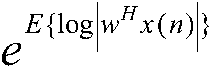
其中, 为阵列输出几何功率,λ||wHA||1为稀疏约束项;


E表示求统计均值,w为M×1维权矢量,M表示M个天线阵元,H表示共轭转置,x(n)表示为天线阵列在n时刻接收的M×1维信号,λ表示权衡稀疏度与阵列输出几何功率的正则化参数,A为旁瓣角度区域内空域采样形成的M×L维导向矢量矩阵,L为角度区域内采样个数,θ0为感兴趣信号的方向,s.t.表示约束条件;
其中,A=[a(θ1),......,a(θL)],且 其中,d为阵元间距,ξ表示波长,i的值为1至L。
在本发明实施例中,波束成形装置还将利用随机梯度算法或者类似递归最小二乘法对目标优化问题进行求解,得到最优权矢量。且具体包括:利用目标优化问题建立该目标优化问题的代价函数,利用随机梯度算法或者类似递归最小二乘法对该代价函数进行求解,得到最优权矢量。
其中,上述目标优化问题的代价函数为:

其中,J(w)表示J是以w为参数的代价函数,N表示快拍个数,w为M×1维权矢量,M表示M个天线阵元,H表示共轭转置,x(n)表示为天线阵列在n时刻接收的M×1维信号,λ表示权衡稀疏度与阵列输出几何功率的正则化参数,A为旁瓣角度区域内空域采样形成的M×L维导向矢量矩阵,L为角度区域内采样个数,θ0为感兴趣信号的方向,γ为拉格朗日乘子;
其中,A=[a(θ1),......,a(θL)],且 其中,d为阵元间距,ξ表示波长,i的值为1至L。
在本发明实施例中,在得到最优权矢量之后,波束成形装置将根据该最优权矢量进行波束成形,可以理解的是,根据权矢量进行波束成形的方法是现有技术,此处不做赘述。
在本发明实施例中,通过利用波束方向图的稀疏性联合阵列输出几何功率及l1范数最小化得到目标优化问题,并利用随机梯度算法或者类似递归最小二乘法求解得到最优权矢量,可以避免估计脉冲噪声的统计参数,适用于几乎所有的噪声脉冲,同时有效降低了旁瓣干扰与噪声,提高了输出SINR。
进一步的,在本发明实施例中,利用所述随机梯度算法得到的最优权矢量为:

其中,

C=I-μ·λA∏(w(n))AH,
∏(w(n))=diag{|(AHw(n))1|-1,...,|(AHw(n))L|-1},
y(n)=w(n)Hx(n)

其中,I为M行M列的单位矩阵,diag{·}表示以其中元素为对角元素构成的对角矩阵,*表示取共轭,H表示共轭转置,w(n+1)表示在时刻n+1时计算得到的权矢量,且n=N时的权矢量为最优权矢量,w为M×1维权矢量,M表示M个天线阵元,μ表示迭代步长,为一个常数,x(n)表示为天线阵列在n时刻接收的M×1维信号,θ0为感兴趣信号的方向,A为旁瓣角度区域内空域采样形成的M×L维导向矢量矩阵,L为角度区域内采样个数,λ表示权衡稀疏度与阵列输出几何功率的正则化参数;
其中,A=[a(θ1),......,a(θL)],且 其中,d为阵元间距,ξ表示波长,i的值为1至L。
为了更好的理解本发明实施例中的技术方案,下面将详细介绍利用随机梯度算法得到最优权矢量的步骤,如下:
n=1,......,N,循环执行以下步骤:
1、∏(w(n))=diag{|(AHw(n))1|-1,......,|(AHw(n))L|-1}
2、y(n)=w(n)Hx(n)
3、C(n)=I-μλA∏(w(n))AH
4、
其中,n的初始值为1,且在执行步骤4之后,将令w(n+1)=w(n),返回执行步骤1进行迭代,直至n=N,且将w(N+1)的值作为最优权矢量。
其中,
其中,A=[a(θ1),......,a(θL)],且 其中,
d为阵元间距,ξ表示波长,i的值为1至L。
其中,
d为阵元间距,ξ表示波长,i的值为1至L。
其中,I为M行M列的单位矩阵,diag{·}表示以其中元素为对角元素构成的对角矩阵,*表示取共轭,H表示共轭转置,w(n+1)表示在时刻n+1时计算得到的权矢量,w为M×1维权矢量,M表示M个天线阵元,μ表示迭代步长,为一个常数,x(n)表示为天线阵列在n时刻接收的M×1维信号,θ0为感兴趣信号的方向,A为旁瓣角度区域内空域采样形成的M×L维导向矢量矩阵,L为角度区域内采样个数,λ表示权衡稀疏度与阵列输出几何功率的正则化参数。
进一步的,在本发明实施例中,利用类似递归最小二乘法得到的最优权矢量为:

其中,
Q=P(n)-P(n)λA[AHP(n)λA+∏(w(n))-1]-1AHP(n)

其中,w为权矢量,且在n=N时得到的权矢量为最优权矢量,λ表示权衡稀疏度与阵列输出几何功率的正则化参数,A为旁瓣角度区域内空域采样形成的M×L维导向矢量矩阵,L为角度区域内采样个数,n属于1至N,且N为快拍个数,x(n)表示为天线阵列在n时刻接收的M×1维信号,θ0为感兴趣信号的方向;
其中,A=[a(θ1),......,a(θL)],且 其中,d为阵元间距,ξ表示波长,i的值为1至L。
为了更好的理解本发明实施例中的技术方案,下面将详细描述利用类似递归最小二乘法得到的最优权矢量的步骤,如下:
n=1,.......,N,循环执行以下步骤:
1、∏(w(n))=diag{|(AHw(n))1|-1,......,|(AHw(n))L|-1}
2、y(n)=w(n)Hx(n)
3、
4、Q=P(n)-P(n)λA[AHP(n)λA+∏(w(n))-1]-1AHP(n)
5、
其中,w为权矢量,且在n=N时得到的权矢量为最优权矢量,λ表示权衡稀疏度与阵列输出几何功率的正则化参数,A为旁瓣角度区域内空域采样形成的M×L维导向矢量矩阵,L为角度区域内采样个数,n属于1至N,且N为快拍个数,x(n)表示为天线阵列在n时刻接收的M×1维信号,θ0为感兴趣信号的方向;
其中,A=[a(θ1),......,a(θL)],且 其中,d为阵元间距,ξ表示波长,i的值为1至L。
请参阅图2,为本发明第二实施例中脉冲噪声下的波束成形装置的功能模块的示意图,包括:
优化模块201,用于利用波束方向图的稀疏性,联合阵列输出几何功率及l1范数最小化,得到目标优化问题;
求解模块202,用于利用随机梯度算法或者类似递归最小二乘法对所述目标优化问题进行求解,得到最优权矢量;
波束成形模块203,用于根据所述最优权矢量进行波束成形。
在本发明实施例中,假设一均匀线阵,包含M个天线阵元,一个窄带的感兴趣信号和多个不相干干扰信号从远场入射到该天线阵元上,波束成形装置将接收到M×1维信号,且优化模块201将利用波束方向图的稀疏性,联合阵列输出功率及l1范数最小化,得到目标优化问题。
其中,该目标优化问题如下:

s.t.wHa(θ0)=1
其中, 为阵列输出几何功率,λ||wHA||1为稀疏约束项;


E表示求统计均值,w为M×1维权矢量,M表示M个天线阵元,H表示共轭转置,x(n)表示为天线阵列在n时刻接收的M×1维信号,λ表示权衡稀疏度与阵列输出几何功率的正则化参数,A为旁瓣角度区域内空域采样形成的M×L维导向矢量矩阵,L为角度区域内采样个数,θ0为感兴趣信号的方向,s.t.表示约束条件;
其中,A=[a(θ1),......,a(θL)],且 其中,d为阵元间距,ξ表示波长,i的值为1至L。
在本发明实施例中,求解模块202利用随机梯度算法或者类似递归最小二乘法对目标优化问题进行求解,得到最优权矢量。且具体包括:利用目标优化问题建立该目标优化问题的代价函数,利用随机梯度算法或者类似递归最小二乘法对该目标优化问题的代价函数进行求解,得到最优权矢量。
其中,上述目标优化问题的代价函数为:

其中,J(w)表示J是以w为参数的代价函数,N表示快拍个数,w为M×1维权矢量,M表示M个天线阵元,H表示共轭转置,x(n)表示为天线阵列在n时刻接收的M×1维信号,λ表示权衡稀疏度与阵列输出几何功率的正则化参数,A为旁瓣角度区域内空域采样形成的M×L维导向矢量矩阵,L为角度区域内采样个数,θ0为感兴趣信号的方向,γ为拉格朗日乘子;
其中,A=[a(θ1),......,a(θL)],且 其中,d为阵元间距,ξ表示波长,i的值为1至L。
在本发明实施例中,在得到最优权矢量之后,波束成形模块203将根据该最优权矢量进行波束成形,可以理解的是,根据权矢量进行波束成形的方法是现有技术,此处不做赘述。
在本发明实施例中,通过利用波束方向图的稀疏性联合阵列输出几何功率及l1范数最小化得到目标优化问题,并利用随机梯度算法或者类似递归最小二乘法求解得到最优权矢量,
可以避免估计脉冲噪声的统计参数,适用于几乎所有的噪声脉冲,同时有效降低了旁瓣干扰与噪声,提高了输出SINR。
进一步的,在本发明实施例中,求解模块202利用所述随机梯度算法得到的最优权矢量为:

其中,

C=I-μ·λA∏(w(n))AH,
∏(w(n))=diag{|(AHw(n))1|-1,...,|(AHw(n))L|-1},
y(n)=w(n)Hx(n)

其中,I为M行M列的单位矩阵,diag{·}表示以其中元素为对角元素构成的对角矩阵,*表示取共轭,H表示共轭转置,w(n+1)表示在时刻n+1时计算得到的权矢量,且在n=N时的权矢量为最优权矢量,w为M×1维权矢量,M表示M个天线阵元,μ表示迭代步长,为一个常数,x(n)表示为天线阵列在n时刻接收的M×1维信号,θ0为感兴趣信号的方向,A为旁瓣角度区域内空域采样形成的M×L维导向矢量矩阵,L为角度区域内采样个数,λ表示权衡稀疏度与阵列输出几何功率的正则化参数;
其中,A=[a(θ1),......,a(θL)],且 其中,d为阵元间距,ξ表示波长,i的值为1至L。
为了更好的理解本发明实施例中的技术方案,下面将详细介绍利用随机梯度算法得到最优权矢量的步骤,如下:
n=1,......,N,循环执行以下步骤:
1、∏(w(n))=diag{|(AHw(n))1|-1,......,|(AHw(n))L|-1}
2、y(n)=w(n)Hx(n)
3、C(n)=I-μλA∏(w(n))AH
4、
其中,n的初始值为1,且在执行步骤4之后,将令w(n+1)=w(n),返回执行步骤1进行迭代,直至n=N,且将w(N+1)的值作为最优权矢量。
其中,
其中,A=[a(θ1),......,a(θL)],且 其中,d为阵元间距,ξ表示波长,i的值为1至L。
其中,I为M行M列的单位矩阵,diag{·}表示以其中元素为对角元素构成的对角矩阵,*表示取共轭,H表示共轭转置,w(n+1)表示在n+1时刻的权矢量,w为M×1维权矢量,M表示M个天线阵元,μ表示迭代步长,为一个常数,x(n)表示为天线阵列在n时刻接收的M×1维信号,θ0为感兴趣信号的方向,A为旁瓣角度区域内空域采样形成的M×L维导向矢量矩阵,L为角度区域内采样个数,λ表示权衡稀疏度与阵列输出几何功率的正则化参数。
进一步的,在本发明实施例中,求解模块202利用所述类似递归最小二乘法得到的最优权矢量为:

其中,
Q=P(n)-P(n)λA[AHP(n)λA+∏(w(n))-1]-1AHP(n)

其中,w为权矢量,且在n=N时得到的权矢量为最优权矢量,λ表示权衡稀疏度与阵列输出几何功率的正则化参数,A为旁瓣角度区域内空域采样形成的M×L维导向矢量矩阵,L为角度区域内采样个数,n属于1至N,且N为快拍个数,x(n)表示为天线阵列在n时刻

d为阵元间距,ξ表示波长,i的值为1至L。
为了更好的理解本发明实施例中的技术方案,下面将详细描述利用类似递归最小二乘法得到的最优权矢量的步骤,如下:
n=1,......,N,循环执行以下步骤:
1、∏(w(n))=diag{|(AHw(n))1|-1,......,|(AHw(n))L|-1}
2、y(n)=w(n)Hx(n)
3、
4、Q=P(n)-P(n)λA[AHP(n)λA+∏(w(n))-1]-1AHP(n)
5、
其中,w为权矢量,且在n=N时得到的权矢量为最优权矢量,λ表示权衡稀疏度与阵列输出几何功率的正则化参数,A为旁瓣角度区域内空域采样形成的M×L维导向矢量矩阵,L为角度区域内采样个数,n属于1至N,且N为快拍个数,x(n)表示为天线阵列在n时刻接收的M×1维信号,θ0为感兴趣信号的方向;
其中,A=[a(θ1),......,a(θL)],且 其中,d为阵元间距,ξ表示波长,i的值为1至L。
基于上述描述,在本发明实施例中,通过利用波束方向图的稀疏性联合阵列输出几何功率及l1范数最小化得到目标优化问题,并利用随机梯度算法或者类似递归最小二乘法求解得到最优权矢量,所提方法及装置可以避免估计脉冲噪声的统计参数,适用于几乎所有的噪声脉冲,同时有效降低了旁瓣干扰与噪声,提高了输出SINR。
可以理解的是,本发明实施例中技术方案可以应用于雷达或通信中的阵列信号处理领域,以提高雷达或通信系统抗低空干扰、脉冲噪声的能力。
为了更好理解本发明实施例中的技术方案,下面将通过仿真数据来说明本发明实施例中脉冲噪声下的波束成形方法在波束方向图与SINR两方面的有益效果。
1、波束方向图
令阵元数为M=8,阵元间距为d=0.5ζ(ζ为波长),请参阅图3a及图3b,为波束方向图效果的示意图,对于随机梯度算法,λ=0.02,μ=10-4;对于类似递归最小二乘算法,λ=0.8,最大迭代次数为20次;对于分数低阶矩BF算法,阶数p=1,对于l1-MADR算法,λ=0.01,最大迭代次数为20。且对所有算法,A为[-90°,0°)和(0°,90°]角度范围内空域采样形成的导向矢量矩阵,采样间距为1°,感兴趣信号和两个干扰信号都建模为对称α稳定分布,位置参数为0,其特征函数为 (η为尺度参数)。
其中,信噪比定义为 (ηs和ηn分别表示信号和噪声的尺度参数)。
可以理解的是,干扰比的定义与信噪比相同。感兴趣信号的到达方向为0°,两个干扰信号的到达方向分别为-30°和30°,信噪比为20dB,干噪比为30dB,加性脉冲噪声建模为复对称α稳定分布,快拍数N为100,图中纵坐标表示的是归一化方向图增益,横坐标表示波束扫描的空域范围[-90°,90°]。
其中,图3a中,a=1.5,图3b中a=0.6,该a表示特征指数,从图3a及图3b中可以看出在特征指数逐渐变小时,利用本发明实施例中的随机梯度算法及类似递归最小二乘法得到的波束方向图效果更优。
2、SINR
令特征指数α∈[0.2,2],请参阅图,为本发明实施例中SINR的效果示意图,其中,横坐标表示特征指数,纵坐标表示SINR,从图4可以看出:稳定状态下,本发明比现有波束形成算法的输出SINR高3dB,波束成形性能要好很多。此外,本发明在任意特征指数α的脉冲噪声输出SINR都要高,对脉冲噪声有较好的稳健性。
在本申请所提供的几个实施例中,应该理解到,所揭露的装置和方法,可以通过其它的方式实现。例如,以上所描述的装置实施例仅仅是示意性的,例如,所述模块的划分,仅仅为一种逻辑功能划分,实际实现时可以有另外的划分方式,例如多个模块或组件可以结合或者可以集成到另一个系统,或一些特征可以忽略,或不执行。另一点,所显示或讨论的相互之间的耦合或直接耦合或通信连接可以是通过一些接口,装置或模块的间接耦合或通信连
接,可以是电性,机械或其它的形式。
所述作为分离部件说明的模块可以是或者也可以不是物理上分开的,作为模块显示的部件可以是或者也可以不是物理模块,即可以位于一个地方,或者也可以分布到多个网络模块上。可以根据实际的需要选择其中的部分或者全部模块来实现本实施例方案的目的。
另外,在本发明各个实施例中的各功能模块可以集成在一个处理模块中,也可以是各个模块单独物理存在,也可以两个或两个以上模块集成在一个模块中。上述集成的模块既可以采用硬件的形式实现,也可以采用软件功能模块的形式实现。
所述集成的模块如果以软件功能模块的形式实现并作为独立的产品销售或使用时,可以存储在一个计算机可读取存储介质中。基于这样的理解,本发明的技术方案本质上或者说对现有技术做出贡献的部分或者该技术方案的全部或部分可以以软件产品的形式体现出来,该计算机软件产品存储在一个存储介质中,包括若干指令用以使得一台计算机设备(可以是个人计算机,服务器,或者网络设备等)执行本发明各个实施例所述方法的全部或部分步骤。而前述的存储介质包括:U盘、移动硬盘、只读存储器(ROM,Read-Only Memory)、随机存取存储器(RAM,Random Access Memory)、磁碟或者光盘等各种可以存储程序代码的介质。
需要说明的是,对于前述的各方法实施例,为了简便描述,故将其都表述为一系列的动作组合,但是本领域技术人员应该知悉,本发明并不受所描述的动作顺序的限制,因为依据本发明,某些步骤可以采用其它顺序或者同时进行。其次,本领域技术人员也应该知悉,说明书中所描述的实施例均属于优选实施例,所涉及的动作和模块并不一定都是本发明所必须的。
在上述实施例中,对各个实施例的描述都各有侧重,某个实施例中没有详述的部分,可以参见其它实施例的相关描述。
以上为对本发明所提供的一种脉冲噪声下的波束成形方法及装置的描述,对于本领域的技术人员,依据本发明实施例的思想,在具体实施方式及应用范围上均会有改变之处,综上,本说明书内容不应理解为对本发明的限制。
Claims (10)
- 一种脉冲噪声下的波束成形方法,其特征在于,包括:利用波束方向图的稀疏性,联合阵列输出几何功率及l1范数最小化,得到目标优化问题;利用随机梯度算法或者类似递归最小二乘法对所述目标优化问题进行求解,得到最优权矢量;根据所述最优权矢量进行波束成形。
- 根据权利要求1所述的方法,其特征在于,所述目标优化问题如下:
 s.t.wHa(θ0)=1其中,为阵列输出几何功率,λ||wHA||1为稀疏约束项;
 表示对表达式
 取最小值时对应的参数w;
 E表示求统计均值,w为M×1维权矢量,M表示M个天线阵元,H表示共轭转置,x(n)表示为天线阵列在n时刻接收的M×1维信号,λ表示权衡稀疏度与阵列输出几何功率的正则化参数,A为旁瓣角度区域内空域采样形成的M×L维导向矢量矩阵,L为角度区域内采样个数,θ0为感兴趣信号的方向,s.t.表示约束条件;其中,A=[a(θ1),......,a(θL)],且其中,d为阵元间距,ξ表示波长,i的值为1至L。
- 根据权利要求1所述的方法,其特征在于,所述利用随机梯度算法或者类似递归最小二乘法对所述目标优化问题进行求解,得到最优权矢量的步骤包括:利用所述目标优化问题建立所述目标优化问题的代价函数;利用所述随机梯度算法或者所述类似递归最小二乘法对所述代价函数进行求解,得到最优权矢量;其中,所述目标优化问题的代价函数为:
 其中,J(w)表示J是以w为参数的代价函数,N表示快拍个数,w为M×1维权矢量,M表示M个天线阵元,H表示共轭转置,x(n)表示为天线阵列在n时刻接收的M×1维信号,λ表示权衡稀疏度与阵列输出几何功率的正则化参数,A为旁瓣角度区域内空域采样形成的M×L维导向矢量矩阵,L为角度区域内采样个数,θ0为感兴趣信号的方向,γ为拉格朗日乘子;其中,A=[a(θ1),......,a(θL)],且其中,d为阵元间距,ξ表示波长,i的值为1至L。
- 根据权利要求3所述的方法,其特征在于,利用所述随机梯度算法得到的最优权矢量为:
 其中,
其中, C=I-μ·λA∏(w(n))AH,
 y(n)=w(n)Hx(n)
 其中,I为M行M列的单位矩阵,diag{·}表示以其中元素为对角元素构成的对角矩阵,*表示取共轭,H表示共轭转置,w(n+1)表示在时刻n+1时计算得到的权矢量,且在n=N时的权矢量为最优权矢量,w为M×1维权矢量,M表示M个天线阵元,μ表示迭代步长,为一个常数,x(n)表示为天线阵列在n时刻接收的M×1维信号,θ0为感兴趣信号的方向,A为旁瓣角度区域内空域采样形成的M×L维导向矢量矩阵,L为角度区域内采样个数,λ表示权衡稀疏度与阵列输出几何功率的正则化参数;其中,A=[a(θ1),......,a(θL)],且其中,d为阵元间距,ξ表示波长,i的值为1至L。
- 根据权利要求3所述的方法,其特征在于,所述利用所述类似递归最小二乘法得到的最优权矢量为:
 其中,Q=P(n)-P(n)λA[AHP(n)λA+∏(w(n))-1]-1AHP(n)
 其中,w为权矢量,且在n=N时得到的权矢量为最优权矢量,λ表示权衡稀疏度与阵列输出几何功率的正则化参数,A为旁瓣角度区域内空域采样形成的M×L维导向矢量矩阵,L为角度区域内采样个数,n属于1至N,且N为快拍个数,x(n)表示为天线阵列在n时刻接收的M×1维信号,θ0为感兴趣信号的方向,其中,A=[a(θ1),......,a(θL)],且其中,d为阵元间距,ξ表示波长,i的值为1至L。
- 一种脉冲噪声下的波束成形装置,其特征在于,包括:优化模块,用于利用波束方向图的稀疏性,联合阵列输出几何功率及l1范数最小化,得到目标优化问题;求解模块,用于利用随机梯度算法或者类似递归最小二乘法对所述目标优化问题进行求解,得到最优权矢量;波束成形模块,用于根据所述最优权矢量进行波束成形。
- 根据权利要求6所述的装置,其特征在于,所述目标优化问题如下:
 s.t.wHa(θ0)=1其中,为阵列输出几何功率,λ||wHA||1为稀疏约束项;
 表示对表达式
 取最小值时对应的参数w;
 E表示求统计均值,w为M×1维权矢量,M表示M个天线阵元,H表示共轭转置,x(n) 表示为天线阵列在n时刻接收的M×1维信号,λ表示权衡稀疏度与阵列输出几何功率的正则化参数,A为旁瓣角度区域内空域采样形成的M×L维导向矢量矩阵,L为角度区域内采样个数,θ0为感兴趣信号的方向,s.t.表示约束条件;其中,A=[a(θ1),......,a(θL)],且其中,d为阵元间距,ξ表示波长,i的值为1至L。
- 根据权利要求6所述的装置,其特征在于,所述求解模块具体用于:利用所述目标优化问题建立所述目标优化问题的代价函数;利用所述随机梯度算法或者所述类似递归最小二乘法对所述代价函数进行求解,得到最优权矢量;其中,所述目标优化问题的代价函数为:
 其中,J(w)表示J是以w为参数的代价函数,N表示快拍个数,w为M×1维权矢量,M表示M个天线阵元,H表示共轭转置,x(n)表示为天线阵列在n时刻接收的M×1维信号,λ表示权衡稀疏度与阵列输出几何功率的正则化参数,A为旁瓣角度区域内空域采样形成的M×L维导向矢量矩阵,L为角度区域内采样个数,θ0为感兴趣信号的方向,γ为拉格朗日乘子;其中,A=[a(θ1),......,a(θL)],且其中,d为阵元间距,ξ表示波长,i的值为1至L。
- 根据权利要求8所述的装置,其特征在于,所述求解模块利用所述随机梯度算法得到的最优权矢量为:
 其中,
其中, C=I-μ·λA∏(w(n))AH,
 y(n)=w(n)Hx(n)
 其中,I为M行M列的单位矩阵,diag{·}表示以其中元素为对角元素构成的对角矩阵,*表示取共轭,H表示共轭转置,w(n+1)表示在时刻n+1时计算得到的权矢量,且在n=N时的权矢量为最优权矢量,w为M×1维权矢量,M表示M个天线阵元,μ表示迭代步长,为一个常数,x(n)表示为天线阵列在n时刻接收的M×1维信号,θ0为感兴趣信号的方向,A为旁瓣角度区域内空域采样形成的M×L维导向矢量矩阵,L为角度区域内采样个数,λ表示权衡稀疏度与阵列输出几何功率的正则化参数;其中,A=[a(θ1),......,a(θL)],且其中,d为阵元间距,ξ表示波长,i的值为1至L。
- 根据权利要求8所述的装置,其特征在于,所述求解模块利用所述类似递归最小二乘法得到的最优权矢量为:
 其中,Q=P(n)-P(n)λA[AHP(n)λA+∏(w(n))-1]-1AHP(n)
 其中,w为权矢量,且在n=N时得到的权矢量为最优权矢量,λ表示权衡稀疏度与阵列输出几何功率的正则化参数,A为旁瓣角度区域内空域采样形成的M×L维导向矢量矩阵,L为角度区域内采样个数,n属于1至N,且N为快拍个数,x(n)表示为天线阵列在n时刻接收的M×1维信号,θ0为感兴趣信号的方向,其中,A=[a(θ1),......,a(θL)],且其中, d为阵元间距,ξ表示波长,i的值为1至L。
Priority Applications (1)
| Application Number | Priority Date | Filing Date | Title |
|---|---|---|---|
| PCT/CN2016/106779 WO2018094565A1 (zh) | 2016-11-22 | 2016-11-22 | 脉冲噪声下的波束成形方法及装置 |
Applications Claiming Priority (1)
| Application Number | Priority Date | Filing Date | Title |
|---|---|---|---|
| PCT/CN2016/106779 WO2018094565A1 (zh) | 2016-11-22 | 2016-11-22 | 脉冲噪声下的波束成形方法及装置 |
Publications (1)
| Publication Number | Publication Date |
|---|---|
| WO2018094565A1 true WO2018094565A1 (zh) | 2018-05-31 |
Family
ID=62194607
Family Applications (1)
| Application Number | Title | Priority Date | Filing Date |
|---|---|---|---|
| PCT/CN2016/106779 Ceased WO2018094565A1 (zh) | 2016-11-22 | 2016-11-22 | 脉冲噪声下的波束成形方法及装置 |
Country Status (1)
| Country | Link |
|---|---|
| WO (1) | WO2018094565A1 (zh) |
Cited By (78)
| Publication number | Priority date | Publication date | Assignee | Title |
|---|---|---|---|---|
| CN109946672A (zh) * | 2019-04-15 | 2019-06-28 | 西安电子科技大学 | 基于被动孔径合成稀疏阵列的doa估计方法 |
| CN109946665A (zh) * | 2019-03-07 | 2019-06-28 | 西安电子科技大学 | 基于阵列雷达的获取真实目标的方法 |
| CN110083923A (zh) * | 2019-04-23 | 2019-08-02 | 成都电科星天科技有限公司 | 一种基于高阶泰勒展开的低副瓣阵列天线的优化布局方法 |
| CN110146847A (zh) * | 2019-05-05 | 2019-08-20 | 西安电子科技大学 | 一种基于伪框架理论的强干扰信号抑制方法 |
| CN110174658A (zh) * | 2019-06-14 | 2019-08-27 | 西安电子科技大学 | 基于秩一降维模型和矩阵补全的波达方向估计方法 |
| CN110196421A (zh) * | 2019-06-10 | 2019-09-03 | 西北工业大学 | 一种密布式mimo声纳自适应波束形成探测方法 |
| CN110398711A (zh) * | 2019-08-01 | 2019-11-01 | 天津工业大学 | 一种声呐共形阵基于阵列流形测量的方向图综合方法 |
| CN110611528A (zh) * | 2019-09-26 | 2019-12-24 | 南京邮电大学 | 基于能效最大化的卫星安全通信鲁棒波束成形方法及系统 |
| CN110705175A (zh) * | 2019-08-19 | 2020-01-17 | 中国人民解放军国防科技大学 | 一种错位子阵阵面设计方法 |
| CN110988812A (zh) * | 2019-12-26 | 2020-04-10 | 南京长峰航天电子科技有限公司 | 一种实现超宽带信号接收数字波束形成方法 |
| CN111007466A (zh) * | 2019-12-03 | 2020-04-14 | 西安电子科技大学 | 一种基于引入距离门自由度的dcar干扰抑制方法及系统 |
| CN111046330A (zh) * | 2018-10-12 | 2020-04-21 | 中国电子科技集团公司第三十八研究所 | 一种基于可变取值空间的有效点生成方法 |
| CN111241470A (zh) * | 2020-01-19 | 2020-06-05 | 河北科技大学 | 基于自适应零陷展宽算法的波束合成方法及装置 |
| CN111812612A (zh) * | 2020-06-18 | 2020-10-23 | 西安电子科技大学 | 基于子阵正交lfm信号的mimo雷达部分相关波形设计方法 |
| CN111830495A (zh) * | 2020-07-08 | 2020-10-27 | 中国人民解放军空军工程大学 | 一种基于凸优化学习的机载雷达自适应波束形成算法 |
| CN112346030A (zh) * | 2020-10-30 | 2021-02-09 | 西安电子科技大学 | 无人机群的超分辨波达方向估计方法 |
| CN112596033A (zh) * | 2020-10-21 | 2021-04-02 | 西安电子科技大学 | 阵元-脉冲编码mimo雷达欺骗式干扰抑制方法 |
| CN112699526A (zh) * | 2020-12-02 | 2021-04-23 | 广东工业大学 | 非凸二次矩阵不等式的鲁棒自适应波束形成方法及系统 |
| CN112710983A (zh) * | 2020-12-16 | 2021-04-27 | 浙江大学 | 基于乘性张量波束扫描的电磁矢量互质面阵多维参数估计方法 |
| CN112711000A (zh) * | 2020-12-16 | 2021-04-27 | 浙江大学 | 基于最小化准则的电磁矢量互质面阵张量功率谱估计方法 |
| CN112748407A (zh) * | 2020-12-15 | 2021-05-04 | 杭州电子科技大学 | 一种基于极化敏感面阵的空域-极化域联合谱估计方法 |
| CN112799007A (zh) * | 2020-12-07 | 2021-05-14 | 西安电子科技大学 | 一种未知非均匀噪声背景下的doa估计方法 |
| CN112834981A (zh) * | 2021-03-15 | 2021-05-25 | 哈尔滨工程大学 | 一种脉冲噪声背景下的零陷阵波达方位估计方法 |
| CN112904269A (zh) * | 2021-01-13 | 2021-06-04 | 西安电子科技大学 | 基于极大似然的多天线无线电台与无人机通信的测向方法 |
| CN113156381A (zh) * | 2021-04-01 | 2021-07-23 | 湖南城市学院 | 一种机载外辐射源雷达多径杂波抑制方法 |
| CN113176558A (zh) * | 2021-04-20 | 2021-07-27 | 哈尔滨工程大学 | 一种矢量舷侧阵稳健波束形成方法 |
| CN113219412A (zh) * | 2021-03-18 | 2021-08-06 | 西安电子科技大学 | 一种最大增益的多点阵列响应控制方向图综合 |
| CN113242070A (zh) * | 2021-04-29 | 2021-08-10 | 广东工业大学 | 一种鲁棒自适应波束形成的优化方法及系统 |
| CN113311395A (zh) * | 2021-06-21 | 2021-08-27 | 南京工业职业技术大学 | 一种基于遗传算法的子阵划分和子阵权值联合优化的方法 |
| CN113376584A (zh) * | 2021-05-13 | 2021-09-10 | 西安电子科技大学 | 基于改进对角加载的稳健自适应波束形成方法 |
| CN113419209A (zh) * | 2021-07-05 | 2021-09-21 | 中国人民解放军空军工程大学 | 一种锥面共形阵列盲极化波达方向估计方法 |
| CN113504505A (zh) * | 2021-06-02 | 2021-10-15 | 华南理工大学 | 一种适用于低信噪比环境下的一维doa估计方法 |
| CN113656747A (zh) * | 2021-08-13 | 2021-11-16 | 南京理工大学 | 基于分支定界的多期望信号下的阵列自适应波束形成方法 |
| CN113673317A (zh) * | 2021-07-12 | 2021-11-19 | 电子科技大学 | 基于原子范数最小化可降维的二维离格doa估计方法 |
| CN113671485A (zh) * | 2021-07-02 | 2021-11-19 | 西安电子科技大学 | 基于admm的米波面阵雷达二维doa估计方法 |
| CN113901684A (zh) * | 2021-09-28 | 2022-01-07 | 中国科学院国家空间科学中心 | 一种基于无栅格压缩感知的稀布同心圆环阵天线设计方法 |
| CN114169243A (zh) * | 2021-12-10 | 2022-03-11 | 浙江辰时科技集团有限公司 | Mimo干扰信道下空中计算多任务联邦学习方法 |
| CN114329328A (zh) * | 2021-12-27 | 2022-04-12 | 中国科学技术大学 | 一种基于非高斯非圆信号特性的稳健自适应波束形成方法 |
| CN114552237A (zh) * | 2022-04-25 | 2022-05-27 | 杭州洛微科技有限公司 | 二维相控阵天线设计方法、装置和二维相控阵天线 |
| CN114563764A (zh) * | 2021-12-03 | 2022-05-31 | 北京无线电测量研究所 | 一种自适应波束生成方法及系统 |
| CN114740435A (zh) * | 2022-03-31 | 2022-07-12 | 中国人民解放军空军工程大学 | 一种雷达阵列信号波束形成方法及系统 |
| CN114759959A (zh) * | 2022-04-12 | 2022-07-15 | 东南大学 | 一种抑制波束间干扰的相控阵波束成形方法 |
| CN114779197A (zh) * | 2022-04-22 | 2022-07-22 | 南京理工大学紫金学院 | 一种基于期望导向矢量估计和矩阵重构的波束形成方法 |
| CN114818793A (zh) * | 2022-04-12 | 2022-07-29 | 西北工业大学 | 一种基于辅助阵元的稳健波束形成方法 |
| CN114847952A (zh) * | 2022-04-27 | 2022-08-05 | 北京航空航天大学杭州创新研究院 | 去除多通道心磁信号冲击噪声的方法、设备和介质 |
| CN114859299A (zh) * | 2022-07-06 | 2022-08-05 | 长沙莫之比智能科技有限公司 | 基于无人机避障毫米波雷达的加权约束复合滤波方法 |
| CN114895258A (zh) * | 2022-04-14 | 2022-08-12 | 南京理工大学 | 基于降维编码的稀疏通道数字接收阵列系统及其工作方法 |
| CN114996653A (zh) * | 2022-06-29 | 2022-09-02 | 东南大学 | 一种基于原子范数最小化的二维鲁棒自适应波束形成方法 |
| CN115036710A (zh) * | 2022-06-07 | 2022-09-09 | 中国电子科技集团公司第三十八研究所 | 一种多级分形子阵平面阵列及其排布方法 |
| CN115048808A (zh) * | 2022-07-08 | 2022-09-13 | 中国电子科技集团公司第五十四研究所 | 一种基于线性分式半正定松弛的恒模赋形方向图综合方法 |
| CN115061155A (zh) * | 2022-03-29 | 2022-09-16 | 西北工业大学 | 一种抗干扰极化敏感阵列重构方法 |
| CN115097390A (zh) * | 2022-06-24 | 2022-09-23 | 中国科学院空天信息创新研究院 | 一种雷达通信一体化波形生成方法和设备 |
| CN115130331A (zh) * | 2022-08-30 | 2022-09-30 | 湖北工业大学 | 基于稀疏阵列的鲁棒频率不变波束形成方法 |
| CN115276745A (zh) * | 2022-07-12 | 2022-11-01 | 湖北工业大学 | 一种基于交替方向惩罚的鲁棒波束形成方法及系统 |
| CN115276748A (zh) * | 2022-07-20 | 2022-11-01 | 哈尔滨工业大学 | 一种具有重构配置功能的时间调制阵列波束控制方法 |
| CN115329540A (zh) * | 2022-07-18 | 2022-11-11 | 中国科学院国家空间科学中心 | 一种单脉冲雷达天线和差波束形成的子阵划分方法 |
| CN115361052A (zh) * | 2022-07-29 | 2022-11-18 | 南京邮电大学 | 一种兼顾能效和谱效的卫星波束成形方法及装置 |
| CN115421128A (zh) * | 2022-07-08 | 2022-12-02 | 西北工业大学 | 适用于圆环类阵列的任意阶稳健超指向性波束优化方法 |
| CN115642944A (zh) * | 2022-10-19 | 2023-01-24 | 广东工业大学 | 一种基于序列凸近似法的鲁棒自适应波束形成方法和系统 |
| CN115712089A (zh) * | 2022-11-18 | 2023-02-24 | 西安电子科技大学 | 基于子阵方向图的栅瓣干扰抑制方法 |
| CN116148770A (zh) * | 2023-04-21 | 2023-05-23 | 湖南工商大学 | 基于阵列信号处理的声源定位方法、装置及系统 |
| CN116184316A (zh) * | 2023-01-06 | 2023-05-30 | 山东大学 | 一种利用无人机群进行多辐射源定位的方法 |
| CN116299209A (zh) * | 2022-09-23 | 2023-06-23 | 航天恒星科技有限公司 | 一种机载gnss-s雷达的大型域舰船信号干扰抑制方法 |
| CN116430303A (zh) * | 2023-03-13 | 2023-07-14 | 中国电子科技集团公司第二十九研究所 | 宽带平面阵列多波束形成方法及比幅测角方法 |
| CN116719022A (zh) * | 2023-06-07 | 2023-09-08 | 电子科技大学 | 基于累加调参迭代的共形极化阵发射波束赋形算法 |
| CN117579451A (zh) * | 2024-01-15 | 2024-02-20 | 成都中科合迅科技有限公司 | 控制噪声分布的数字相控阵天线多方向的噪声调制方法 |
| CN117856850A (zh) * | 2024-01-26 | 2024-04-09 | 中国科学院声学研究所 | 一种白噪声增益约束的稳健自适应波束形成方法及系统 |
| CN118209934A (zh) * | 2024-05-20 | 2024-06-18 | 中国电子科技集团公司信息科学研究院 | 空基分布式阵列波束合成方法及装置、电子设备、介质 |
| CN118409285A (zh) * | 2024-07-02 | 2024-07-30 | 中国人民解放军国防科技大学 | 间歇采样转发干扰采样矢量估计方法及装置 |
| CN118886169A (zh) * | 2024-07-05 | 2024-11-01 | 中山大学 | 一种基于图论的小尺度矢量水听器阵列波束形成方法 |
| CN119652374A (zh) * | 2024-11-18 | 2025-03-18 | 国网山东省电力公司电力科学研究院 | 一种自适应信号波束形成方法、装置、设备及存储介质 |
| CN119936824A (zh) * | 2025-01-23 | 2025-05-06 | 西安电子科技大学 | 多个非确知区域优化方向矢量的mimo雷达波束形成方法 |
| CN119943085A (zh) * | 2024-12-30 | 2025-05-06 | 中电信人工智能科技(北京)有限公司 | 基于指向性卷积波束形成的语音增强与分离方法、装置 |
| CN119959886A (zh) * | 2025-01-21 | 2025-05-09 | 西安电子科技大学 | 一种低计算复杂度的双极化阵列自适应波束形成方法 |
| CN120280693A (zh) * | 2025-06-09 | 2025-07-08 | 中国电子科技集团公司第五十四研究所 | 一种微服务化的智能空域抗干扰方法 |
| CN120871017A (zh) * | 2025-08-27 | 2025-10-31 | 深圳云里物里科技股份有限公司 | 阵列信号方向估计方法、电子设备及定位系统 |
| WO2026102556A1 (en) * | 2024-11-12 | 2026-05-21 | Hangzhou Innovation Institute Of Beihang University | Shaped-beam sparse linear arrays design method |
| CN120871017B (zh) * | 2025-08-27 | 2026-08-14 | 深圳云里物里科技股份有限公司 | 阵列信号方向估计方法、电子设备及定位系统 |
Citations (3)
| Publication number | Priority date | Publication date | Assignee | Title |
|---|---|---|---|---|
| US20140153742A1 (en) * | 2012-11-30 | 2014-06-05 | Mitsubishi Electric Research Laboratories, Inc | Method and System for Reducing Interference and Noise in Speech Signals |
| CN104935367A (zh) * | 2015-04-27 | 2015-09-23 | 电子科技大学 | 一种基于信道空间稀疏特性的快速迭代波束成形方法 |
| CN106680779A (zh) * | 2016-11-22 | 2017-05-17 | 深圳大学 | 脉冲噪声下的波束成形方法及装置 |
-
2016
- 2016-11-22 WO PCT/CN2016/106779 patent/WO2018094565A1/zh not_active Ceased
Patent Citations (3)
| Publication number | Priority date | Publication date | Assignee | Title |
|---|---|---|---|---|
| US20140153742A1 (en) * | 2012-11-30 | 2014-06-05 | Mitsubishi Electric Research Laboratories, Inc | Method and System for Reducing Interference and Noise in Speech Signals |
| CN104935367A (zh) * | 2015-04-27 | 2015-09-23 | 电子科技大学 | 一种基于信道空间稀疏特性的快速迭代波束成形方法 |
| CN106680779A (zh) * | 2016-11-22 | 2017-05-17 | 深圳大学 | 脉冲噪声下的波束成形方法及装置 |
Non-Patent Citations (1)
| Title |
|---|
| LIU ZHEN ET AL.: "RobustCapon beamforming method based on sparse constraint", ACTA PHYSICA SINICA, vol. 65, no. 10, 13 April 2016 (2016-04-13), pages 104303-3 - 104303-4 * |
Cited By (115)
| Publication number | Priority date | Publication date | Assignee | Title |
|---|---|---|---|---|
| CN111046330A (zh) * | 2018-10-12 | 2020-04-21 | 中国电子科技集团公司第三十八研究所 | 一种基于可变取值空间的有效点生成方法 |
| CN111046330B (zh) * | 2018-10-12 | 2022-08-16 | 中国电子科技集团公司第三十八研究所 | 一种基于可变取值空间的有效点生成方法 |
| CN109946665A (zh) * | 2019-03-07 | 2019-06-28 | 西安电子科技大学 | 基于阵列雷达的获取真实目标的方法 |
| CN109946665B (zh) * | 2019-03-07 | 2023-04-21 | 西安电子科技大学 | 基于阵列雷达的获取真实目标的方法 |
| CN109946672A (zh) * | 2019-04-15 | 2019-06-28 | 西安电子科技大学 | 基于被动孔径合成稀疏阵列的doa估计方法 |
| CN109946672B (zh) * | 2019-04-15 | 2022-12-02 | 西安电子科技大学 | 基于被动孔径合成稀疏阵列的doa估计方法 |
| CN110083923A (zh) * | 2019-04-23 | 2019-08-02 | 成都电科星天科技有限公司 | 一种基于高阶泰勒展开的低副瓣阵列天线的优化布局方法 |
| CN110083923B (zh) * | 2019-04-23 | 2022-12-06 | 成都电科星天科技有限公司 | 一种基于高阶泰勒展开的低副瓣阵列天线的优化布局方法 |
| CN110146847A (zh) * | 2019-05-05 | 2019-08-20 | 西安电子科技大学 | 一种基于伪框架理论的强干扰信号抑制方法 |
| CN110146847B (zh) * | 2019-05-05 | 2022-12-23 | 西安电子科技大学 | 一种基于伪框架理论的强干扰信号抑制方法 |
| CN110196421A (zh) * | 2019-06-10 | 2019-09-03 | 西北工业大学 | 一种密布式mimo声纳自适应波束形成探测方法 |
| CN110174658A (zh) * | 2019-06-14 | 2019-08-27 | 西安电子科技大学 | 基于秩一降维模型和矩阵补全的波达方向估计方法 |
| CN110174658B (zh) * | 2019-06-14 | 2023-03-28 | 西安电子科技大学 | 基于秩一降维模型和矩阵补全的波达方向估计方法 |
| CN110398711A (zh) * | 2019-08-01 | 2019-11-01 | 天津工业大学 | 一种声呐共形阵基于阵列流形测量的方向图综合方法 |
| CN110705175A (zh) * | 2019-08-19 | 2020-01-17 | 中国人民解放军国防科技大学 | 一种错位子阵阵面设计方法 |
| CN110611528A (zh) * | 2019-09-26 | 2019-12-24 | 南京邮电大学 | 基于能效最大化的卫星安全通信鲁棒波束成形方法及系统 |
| CN111007466A (zh) * | 2019-12-03 | 2020-04-14 | 西安电子科技大学 | 一种基于引入距离门自由度的dcar干扰抑制方法及系统 |
| CN111007466B (zh) * | 2019-12-03 | 2023-05-26 | 西安电子科技大学 | 一种基于引入距离门自由度的dcar干扰抑制方法及系统 |
| CN110988812A (zh) * | 2019-12-26 | 2020-04-10 | 南京长峰航天电子科技有限公司 | 一种实现超宽带信号接收数字波束形成方法 |
| CN111241470B (zh) * | 2020-01-19 | 2023-08-18 | 河北科技大学 | 基于自适应零陷展宽算法的波束合成方法及装置 |
| CN111241470A (zh) * | 2020-01-19 | 2020-06-05 | 河北科技大学 | 基于自适应零陷展宽算法的波束合成方法及装置 |
| CN111812612A (zh) * | 2020-06-18 | 2020-10-23 | 西安电子科技大学 | 基于子阵正交lfm信号的mimo雷达部分相关波形设计方法 |
| CN111830495B (zh) * | 2020-07-08 | 2023-07-21 | 中国人民解放军空军工程大学 | 一种基于凸优化学习的机载雷达自适应波束形成算法 |
| CN111830495A (zh) * | 2020-07-08 | 2020-10-27 | 中国人民解放军空军工程大学 | 一种基于凸优化学习的机载雷达自适应波束形成算法 |
| CN112596033A (zh) * | 2020-10-21 | 2021-04-02 | 西安电子科技大学 | 阵元-脉冲编码mimo雷达欺骗式干扰抑制方法 |
| CN112596033B (zh) * | 2020-10-21 | 2023-06-30 | 西安电子科技大学 | 阵元-脉冲编码mimo雷达欺骗式干扰抑制方法 |
| CN112346030A (zh) * | 2020-10-30 | 2021-02-09 | 西安电子科技大学 | 无人机群的超分辨波达方向估计方法 |
| CN112346030B (zh) * | 2020-10-30 | 2023-06-30 | 西安电子科技大学 | 无人机群的超分辨波达方向估计方法 |
| CN112699526A (zh) * | 2020-12-02 | 2021-04-23 | 广东工业大学 | 非凸二次矩阵不等式的鲁棒自适应波束形成方法及系统 |
| CN112699526B (zh) * | 2020-12-02 | 2023-08-22 | 广东工业大学 | 非凸二次矩阵不等式的鲁棒自适应波束形成方法及系统 |
| CN112799007A (zh) * | 2020-12-07 | 2021-05-14 | 西安电子科技大学 | 一种未知非均匀噪声背景下的doa估计方法 |
| CN112748407A (zh) * | 2020-12-15 | 2021-05-04 | 杭州电子科技大学 | 一种基于极化敏感面阵的空域-极化域联合谱估计方法 |
| CN112711000A (zh) * | 2020-12-16 | 2021-04-27 | 浙江大学 | 基于最小化准则的电磁矢量互质面阵张量功率谱估计方法 |
| CN112710983B (zh) * | 2020-12-16 | 2023-09-26 | 浙江大学 | 基于乘性张量波束扫描的电磁矢量互质面阵多维参数估计方法 |
| CN112710983A (zh) * | 2020-12-16 | 2021-04-27 | 浙江大学 | 基于乘性张量波束扫描的电磁矢量互质面阵多维参数估计方法 |
| CN112711000B (zh) * | 2020-12-16 | 2023-08-11 | 浙江大学 | 基于最小化准则的电磁矢量互质面阵张量功率谱估计方法 |
| CN112904269A (zh) * | 2021-01-13 | 2021-06-04 | 西安电子科技大学 | 基于极大似然的多天线无线电台与无人机通信的测向方法 |
| CN112904269B (zh) * | 2021-01-13 | 2023-06-30 | 西安电子科技大学 | 基于极大似然的多天线无线电台与无人机通信的测向方法 |
| CN112834981B (zh) * | 2021-03-15 | 2022-07-15 | 哈尔滨工程大学 | 一种脉冲噪声背景下的零陷阵波达方位估计方法 |
| CN112834981A (zh) * | 2021-03-15 | 2021-05-25 | 哈尔滨工程大学 | 一种脉冲噪声背景下的零陷阵波达方位估计方法 |
| CN113219412A (zh) * | 2021-03-18 | 2021-08-06 | 西安电子科技大学 | 一种最大增益的多点阵列响应控制方向图综合 |
| CN113219412B (zh) * | 2021-03-18 | 2023-12-26 | 西安电子科技大学 | 一种最大增益的多点阵列响应控制方向图综合 |
| CN113156381A (zh) * | 2021-04-01 | 2021-07-23 | 湖南城市学院 | 一种机载外辐射源雷达多径杂波抑制方法 |
| CN113176558B (zh) * | 2021-04-20 | 2023-09-29 | 哈尔滨工程大学 | 一种矢量舷侧阵稳健波束形成方法 |
| CN113176558A (zh) * | 2021-04-20 | 2021-07-27 | 哈尔滨工程大学 | 一种矢量舷侧阵稳健波束形成方法 |
| CN113242070B (zh) * | 2021-04-29 | 2022-05-06 | 广东工业大学 | 一种鲁棒自适应波束形成的优化方法及系统 |
| CN113242070A (zh) * | 2021-04-29 | 2021-08-10 | 广东工业大学 | 一种鲁棒自适应波束形成的优化方法及系统 |
| CN113376584A (zh) * | 2021-05-13 | 2021-09-10 | 西安电子科技大学 | 基于改进对角加载的稳健自适应波束形成方法 |
| CN113376584B (zh) * | 2021-05-13 | 2023-03-14 | 西安电子科技大学 | 基于改进对角加载的稳健自适应波束形成方法 |
| CN113504505B (zh) * | 2021-06-02 | 2023-11-03 | 华南理工大学 | 一种适用于低信噪比环境下的一维doa估计方法 |
| CN113504505A (zh) * | 2021-06-02 | 2021-10-15 | 华南理工大学 | 一种适用于低信噪比环境下的一维doa估计方法 |
| CN113311395B (zh) * | 2021-06-21 | 2023-07-25 | 南京工业职业技术大学 | 一种基于遗传算法的子阵划分和子阵权值联合优化的方法 |
| CN113311395A (zh) * | 2021-06-21 | 2021-08-27 | 南京工业职业技术大学 | 一种基于遗传算法的子阵划分和子阵权值联合优化的方法 |
| CN113671485B (zh) * | 2021-07-02 | 2024-01-30 | 西安电子科技大学 | 基于admm的米波面阵雷达二维doa估计方法 |
| CN113671485A (zh) * | 2021-07-02 | 2021-11-19 | 西安电子科技大学 | 基于admm的米波面阵雷达二维doa估计方法 |
| CN113419209A (zh) * | 2021-07-05 | 2021-09-21 | 中国人民解放军空军工程大学 | 一种锥面共形阵列盲极化波达方向估计方法 |
| CN113419209B (zh) * | 2021-07-05 | 2023-06-20 | 中国人民解放军空军工程大学 | 一种锥面共形阵列盲极化波达方向估计方法 |
| CN113673317B (zh) * | 2021-07-12 | 2023-04-07 | 电子科技大学 | 基于原子范数最小化可降维的二维离格doa估计方法 |
| CN113673317A (zh) * | 2021-07-12 | 2021-11-19 | 电子科技大学 | 基于原子范数最小化可降维的二维离格doa估计方法 |
| CN113656747A (zh) * | 2021-08-13 | 2021-11-16 | 南京理工大学 | 基于分支定界的多期望信号下的阵列自适应波束形成方法 |
| CN113901684A (zh) * | 2021-09-28 | 2022-01-07 | 中国科学院国家空间科学中心 | 一种基于无栅格压缩感知的稀布同心圆环阵天线设计方法 |
| CN114563764A (zh) * | 2021-12-03 | 2022-05-31 | 北京无线电测量研究所 | 一种自适应波束生成方法及系统 |
| CN114169243A (zh) * | 2021-12-10 | 2022-03-11 | 浙江辰时科技集团有限公司 | Mimo干扰信道下空中计算多任务联邦学习方法 |
| CN114329328A (zh) * | 2021-12-27 | 2022-04-12 | 中国科学技术大学 | 一种基于非高斯非圆信号特性的稳健自适应波束形成方法 |
| CN114329328B (zh) * | 2021-12-27 | 2024-05-28 | 中国科学技术大学 | 一种基于非高斯非圆信号特性的稳健自适应波束形成方法 |
| CN115061155B (zh) * | 2022-03-29 | 2024-04-26 | 西北工业大学 | 一种抗干扰极化敏感阵列重构方法 |
| CN115061155A (zh) * | 2022-03-29 | 2022-09-16 | 西北工业大学 | 一种抗干扰极化敏感阵列重构方法 |
| CN114740435A (zh) * | 2022-03-31 | 2022-07-12 | 中国人民解放军空军工程大学 | 一种雷达阵列信号波束形成方法及系统 |
| CN114759959A (zh) * | 2022-04-12 | 2022-07-15 | 东南大学 | 一种抑制波束间干扰的相控阵波束成形方法 |
| CN114759959B (zh) * | 2022-04-12 | 2024-01-30 | 东南大学 | 一种抑制波束间干扰的相控阵波束成形方法 |
| CN114818793A (zh) * | 2022-04-12 | 2022-07-29 | 西北工业大学 | 一种基于辅助阵元的稳健波束形成方法 |
| CN114895258A (zh) * | 2022-04-14 | 2022-08-12 | 南京理工大学 | 基于降维编码的稀疏通道数字接收阵列系统及其工作方法 |
| CN114779197A (zh) * | 2022-04-22 | 2022-07-22 | 南京理工大学紫金学院 | 一种基于期望导向矢量估计和矩阵重构的波束形成方法 |
| CN114552237B (zh) * | 2022-04-25 | 2023-04-07 | 杭州洛微科技有限公司 | 二维相控阵天线设计方法、装置和二维相控阵天线 |
| CN114552237A (zh) * | 2022-04-25 | 2022-05-27 | 杭州洛微科技有限公司 | 二维相控阵天线设计方法、装置和二维相控阵天线 |
| CN114847952A (zh) * | 2022-04-27 | 2022-08-05 | 北京航空航天大学杭州创新研究院 | 去除多通道心磁信号冲击噪声的方法、设备和介质 |
| CN115036710A (zh) * | 2022-06-07 | 2022-09-09 | 中国电子科技集团公司第三十八研究所 | 一种多级分形子阵平面阵列及其排布方法 |
| CN115036710B (zh) * | 2022-06-07 | 2024-05-28 | 中国电子科技集团公司第三十八研究所 | 一种多级分形子阵平面阵列及其排布方法 |
| CN115097390A (zh) * | 2022-06-24 | 2022-09-23 | 中国科学院空天信息创新研究院 | 一种雷达通信一体化波形生成方法和设备 |
| CN114996653A (zh) * | 2022-06-29 | 2022-09-02 | 东南大学 | 一种基于原子范数最小化的二维鲁棒自适应波束形成方法 |
| CN114859299A (zh) * | 2022-07-06 | 2022-08-05 | 长沙莫之比智能科技有限公司 | 基于无人机避障毫米波雷达的加权约束复合滤波方法 |
| CN115421128A (zh) * | 2022-07-08 | 2022-12-02 | 西北工业大学 | 适用于圆环类阵列的任意阶稳健超指向性波束优化方法 |
| CN115048808A (zh) * | 2022-07-08 | 2022-09-13 | 中国电子科技集团公司第五十四研究所 | 一种基于线性分式半正定松弛的恒模赋形方向图综合方法 |
| CN115276745B (zh) * | 2022-07-12 | 2024-05-10 | 湖北工业大学 | 一种基于交替方向惩罚的鲁棒波束形成方法及系统 |
| CN115276745A (zh) * | 2022-07-12 | 2022-11-01 | 湖北工业大学 | 一种基于交替方向惩罚的鲁棒波束形成方法及系统 |
| CN115329540A (zh) * | 2022-07-18 | 2022-11-11 | 中国科学院国家空间科学中心 | 一种单脉冲雷达天线和差波束形成的子阵划分方法 |
| CN115329540B (zh) * | 2022-07-18 | 2025-08-22 | 中国科学院国家空间科学中心 | 一种单脉冲雷达天线和差波束形成的子阵划分方法 |
| CN115276748A (zh) * | 2022-07-20 | 2022-11-01 | 哈尔滨工业大学 | 一种具有重构配置功能的时间调制阵列波束控制方法 |
| CN115361052B (zh) * | 2022-07-29 | 2023-07-25 | 南京邮电大学 | 一种兼顾能效和谱效的卫星波束成形方法及装置 |
| CN115361052A (zh) * | 2022-07-29 | 2022-11-18 | 南京邮电大学 | 一种兼顾能效和谱效的卫星波束成形方法及装置 |
| CN115130331A (zh) * | 2022-08-30 | 2022-09-30 | 湖北工业大学 | 基于稀疏阵列的鲁棒频率不变波束形成方法 |
| CN116299209A (zh) * | 2022-09-23 | 2023-06-23 | 航天恒星科技有限公司 | 一种机载gnss-s雷达的大型域舰船信号干扰抑制方法 |
| CN115642944A (zh) * | 2022-10-19 | 2023-01-24 | 广东工业大学 | 一种基于序列凸近似法的鲁棒自适应波束形成方法和系统 |
| CN115712089A (zh) * | 2022-11-18 | 2023-02-24 | 西安电子科技大学 | 基于子阵方向图的栅瓣干扰抑制方法 |
| CN116184316A (zh) * | 2023-01-06 | 2023-05-30 | 山东大学 | 一种利用无人机群进行多辐射源定位的方法 |
| CN116430303A (zh) * | 2023-03-13 | 2023-07-14 | 中国电子科技集团公司第二十九研究所 | 宽带平面阵列多波束形成方法及比幅测角方法 |
| CN116148770A (zh) * | 2023-04-21 | 2023-05-23 | 湖南工商大学 | 基于阵列信号处理的声源定位方法、装置及系统 |
| CN116148770B (zh) * | 2023-04-21 | 2023-07-07 | 湖南工商大学 | 基于阵列信号处理的声源定位方法、装置及系统 |
| CN116719022A (zh) * | 2023-06-07 | 2023-09-08 | 电子科技大学 | 基于累加调参迭代的共形极化阵发射波束赋形算法 |
| CN117579451B (zh) * | 2024-01-15 | 2024-04-05 | 成都中科合迅科技有限公司 | 控制噪声分布的数字相控阵天线多方向的噪声调制方法 |
| CN117579451A (zh) * | 2024-01-15 | 2024-02-20 | 成都中科合迅科技有限公司 | 控制噪声分布的数字相控阵天线多方向的噪声调制方法 |
| CN117856850A (zh) * | 2024-01-26 | 2024-04-09 | 中国科学院声学研究所 | 一种白噪声增益约束的稳健自适应波束形成方法及系统 |
| CN118209934A (zh) * | 2024-05-20 | 2024-06-18 | 中国电子科技集团公司信息科学研究院 | 空基分布式阵列波束合成方法及装置、电子设备、介质 |
| CN118409285A (zh) * | 2024-07-02 | 2024-07-30 | 中国人民解放军国防科技大学 | 间歇采样转发干扰采样矢量估计方法及装置 |
| CN118409285B (zh) * | 2024-07-02 | 2024-09-06 | 中国人民解放军国防科技大学 | 间歇采样转发干扰采样矢量估计方法及装置 |
| CN118886169A (zh) * | 2024-07-05 | 2024-11-01 | 中山大学 | 一种基于图论的小尺度矢量水听器阵列波束形成方法 |
| WO2026102556A1 (en) * | 2024-11-12 | 2026-05-21 | Hangzhou Innovation Institute Of Beihang University | Shaped-beam sparse linear arrays design method |
| CN119652374A (zh) * | 2024-11-18 | 2025-03-18 | 国网山东省电力公司电力科学研究院 | 一种自适应信号波束形成方法、装置、设备及存储介质 |
| CN119943085A (zh) * | 2024-12-30 | 2025-05-06 | 中电信人工智能科技(北京)有限公司 | 基于指向性卷积波束形成的语音增强与分离方法、装置 |
| CN119959886A (zh) * | 2025-01-21 | 2025-05-09 | 西安电子科技大学 | 一种低计算复杂度的双极化阵列自适应波束形成方法 |
| CN119936824A (zh) * | 2025-01-23 | 2025-05-06 | 西安电子科技大学 | 多个非确知区域优化方向矢量的mimo雷达波束形成方法 |
| CN119936824B (zh) * | 2025-01-23 | 2025-11-25 | 西安电子科技大学 | 多个非确知区域优化方向矢量的mimo雷达波束形成方法 |
| CN120280693A (zh) * | 2025-06-09 | 2025-07-08 | 中国电子科技集团公司第五十四研究所 | 一种微服务化的智能空域抗干扰方法 |
| CN120871017A (zh) * | 2025-08-27 | 2025-10-31 | 深圳云里物里科技股份有限公司 | 阵列信号方向估计方法、电子设备及定位系统 |
| CN120871017B (zh) * | 2025-08-27 | 2026-08-14 | 深圳云里物里科技股份有限公司 | 阵列信号方向估计方法、电子设备及定位系统 |
Similar Documents
| Publication | Publication Date | Title |
|---|---|---|
| CN109490819B (zh) | 一种基于稀疏贝叶斯学习的离格波达方向估计方法 | |
| CN111337893B (zh) | 一种基于实值稀疏贝叶斯学习的离格doa估计方法 | |
| CN107576931B (zh) | 一种基于协方差低维度迭代稀疏重构的相关/相干信号波达方向估计方法 | |
| CN109633538B (zh) | 非均匀采样系统的最大似然时差估计方法 | |
| CN108957387B (zh) | 一种卫星信号二维到达角估计方法及系统 | |
| CN106680779B (zh) | 脉冲噪声下的波束成形方法及装置 | |
| CN104199029B (zh) | 一种提高压缩感知雷达目标成像性能的测量矩阵设计方法 | |
| WO2018165971A1 (zh) | 脉冲噪声下的加权稀疏约束稳健波束形成方法及装置 | |
| CN107064926B (zh) | 空域色噪声背景下的双基地mimo雷达角度估算方法 | |
| CN111474527B (zh) | 机载stap雷达快速去互耦的杂波协方差矩阵估计方法 | |
| CN117289262B (zh) | 穿墙雷达目标检测方法及系统 | |
| CN104155629B (zh) | 一种冲击噪声背景下小快拍数信号波达方向估计方法 | |
| CN107561484A (zh) | 基于内插互质阵列协方差矩阵重建的波达方向估计方法 | |
| CN111142062A (zh) | 一种利用Toeplitz特性的无栅格目标波达方向估计方法 | |
| CN112698263A (zh) | 一种基于正交传播算子的单基地互质mimo阵列doa估计算法 | |
| CN119846547B (zh) | 脉冲噪声下非圆ebnc-pflom联合优化doa估计方法 | |
| CN114019449A (zh) | 信号源的波达方向估计方法、装置、电子设备及存储介质 | |
| CN113075621B (zh) | 针对分布式网络化雷达的信号级定位算法精度界计算方法 | |
| CN107342836B (zh) | 脉冲噪声下的加权稀疏约束稳健波束形成方法及装置 | |
| Chai | Compressed sensing based DOA estimation algorithm | |
| CN116359834A (zh) | 一种基于嵌套阵列改进的samp的波达方向估计方法 | |
| CN115453450A (zh) | 一种嵌套阵下对抗互藕的稳健doa估计方法 | |
| CN119758244A (zh) | 一种基于稀疏重构的远近场混合源定位方法 | |
| CN109298384B (zh) | 一种基于变分贝叶斯推断的非均匀直线阵波达方向角估计方法 | |
| CN114184999B (zh) | 一种互耦小孔径阵列的生成式模型处理方法 |
Legal Events
| Date | Code | Title | Description |
|---|---|---|---|
| 121 | Ep: the epo has been informed by wipo that ep was designated in this application |
Ref document number: 16922275 Country of ref document: EP Kind code of ref document: A1 |
|
| NENP | Non-entry into the national phase |
Ref country code: DE |
|
| 32PN | Ep: public notification in the ep bulletin as address of the adressee cannot be established |
Free format text: NOTING OF LOSS OF RIGHTS PURSUANT TO RULE 112(1) EPC (EPO FORM 1205A DATED 28.08.2019) |
|
| 122 | Ep: pct application non-entry in european phase |
Ref document number: 16922275 Country of ref document: EP Kind code of ref document: A1 |