WO2014088016A1 - 大容量袋供給装置および大容量袋供給装置用補充具 - Google Patents
大容量袋供給装置および大容量袋供給装置用補充具 Download PDFInfo
- Publication number
- WO2014088016A1 WO2014088016A1 PCT/JP2013/082527 JP2013082527W WO2014088016A1 WO 2014088016 A1 WO2014088016 A1 WO 2014088016A1 JP 2013082527 W JP2013082527 W JP 2013082527W WO 2014088016 A1 WO2014088016 A1 WO 2014088016A1
- Authority
- WO
- WIPO (PCT)
- Prior art keywords
- bag
- plate
- stock
- capacity
- supply device
- Prior art date
Links
Images


Classifications
-
- B—PERFORMING OPERATIONS; TRANSPORTING
- B65—CONVEYING; PACKING; STORING; HANDLING THIN OR FILAMENTARY MATERIAL
- B65B—MACHINES, APPARATUS OR DEVICES FOR, OR METHODS OF, PACKAGING ARTICLES OR MATERIALS; UNPACKING
- B65B43/00—Forming, feeding, opening or setting-up containers or receptacles in association with packaging
- B65B43/12—Feeding flexible bags or carton blanks in flat or collapsed state; Feeding flat bags connected to form a series or chain
- B65B43/14—Feeding individual bags or carton blanks from piles or magazines
- B65B43/16—Feeding individual bags or carton blanks from piles or magazines by grippers
- B65B43/18—Feeding individual bags or carton blanks from piles or magazines by grippers by suction-operated grippers
-
- B—PERFORMING OPERATIONS; TRANSPORTING
- B65—CONVEYING; PACKING; STORING; HANDLING THIN OR FILAMENTARY MATERIAL
- B65B—MACHINES, APPARATUS OR DEVICES FOR, OR METHODS OF, PACKAGING ARTICLES OR MATERIALS; UNPACKING
- B65B43/00—Forming, feeding, opening or setting-up containers or receptacles in association with packaging
- B65B43/12—Feeding flexible bags or carton blanks in flat or collapsed state; Feeding flat bags connected to form a series or chain
- B65B43/14—Feeding individual bags or carton blanks from piles or magazines
-
- B—PERFORMING OPERATIONS; TRANSPORTING
- B65—CONVEYING; PACKING; STORING; HANDLING THIN OR FILAMENTARY MATERIAL
- B65B—MACHINES, APPARATUS OR DEVICES FOR, OR METHODS OF, PACKAGING ARTICLES OR MATERIALS; UNPACKING
- B65B43/00—Forming, feeding, opening or setting-up containers or receptacles in association with packaging
- B65B43/26—Opening or distending bags; Opening, erecting, or setting-up boxes, cartons, or carton blanks
- B65B43/30—Opening or distending bags; Opening, erecting, or setting-up boxes, cartons, or carton blanks by grippers engaging opposed walls, e.g. suction-operated
-
- B—PERFORMING OPERATIONS; TRANSPORTING
- B65—CONVEYING; PACKING; STORING; HANDLING THIN OR FILAMENTARY MATERIAL
- B65B—MACHINES, APPARATUS OR DEVICES FOR, OR METHODS OF, PACKAGING ARTICLES OR MATERIALS; UNPACKING
- B65B57/00—Automatic control, checking, warning, or safety devices
- B65B57/10—Automatic control, checking, warning, or safety devices responsive to absence, presence, abnormal feed, or misplacement of articles or materials to be packaged
- B65B57/12—Automatic control, checking, warning, or safety devices responsive to absence, presence, abnormal feed, or misplacement of articles or materials to be packaged and operating to control, or stop, the feed of wrapping materials, containers, or packages
-
- B—PERFORMING OPERATIONS; TRANSPORTING
- B65—CONVEYING; PACKING; STORING; HANDLING THIN OR FILAMENTARY MATERIAL
- B65H—HANDLING THIN OR FILAMENTARY MATERIAL, e.g. SHEETS, WEBS, CABLES
- B65H1/00—Supports or magazines for piles from which articles are to be separated
- B65H1/02—Supports or magazines for piles from which articles are to be separated adapted to support articles on edge
- B65H1/025—Supports or magazines for piles from which articles are to be separated adapted to support articles on edge with controlled positively-acting mechanical devices for advancing the pile to present the articles to the separating device
-
- B—PERFORMING OPERATIONS; TRANSPORTING
- B65—CONVEYING; PACKING; STORING; HANDLING THIN OR FILAMENTARY MATERIAL
- B65H—HANDLING THIN OR FILAMENTARY MATERIAL, e.g. SHEETS, WEBS, CABLES
- B65H3/00—Separating articles from piles
- B65H3/08—Separating articles from piles using pneumatic force
- B65H3/0808—Suction grippers
- B65H3/0883—Construction of suction grippers or their holding devices
-
- B—PERFORMING OPERATIONS; TRANSPORTING
- B65—CONVEYING; PACKING; STORING; HANDLING THIN OR FILAMENTARY MATERIAL
- B65H—HANDLING THIN OR FILAMENTARY MATERIAL, e.g. SHEETS, WEBS, CABLES
- B65H3/00—Separating articles from piles
- B65H3/36—Separating articles from piles by separators moved in special paths, e.g. enclosing an area
- B65H3/38—Separating articles from piles by separators moved in special paths, e.g. enclosing an area the paths not enclosing an area
-
- B—PERFORMING OPERATIONS; TRANSPORTING
- B65—CONVEYING; PACKING; STORING; HANDLING THIN OR FILAMENTARY MATERIAL
- B65H—HANDLING THIN OR FILAMENTARY MATERIAL, e.g. SHEETS, WEBS, CABLES
- B65H3/00—Separating articles from piles
- B65H3/46—Supplementary devices or measures to assist separation or prevent double feed
- B65H3/48—Air blast acting on edges of, or under, articles
-
- B—PERFORMING OPERATIONS; TRANSPORTING
- B65—CONVEYING; PACKING; STORING; HANDLING THIN OR FILAMENTARY MATERIAL
- B65H—HANDLING THIN OR FILAMENTARY MATERIAL, e.g. SHEETS, WEBS, CABLES
- B65H5/00—Feeding articles separated from piles; Feeding articles to machines
- B65H5/08—Feeding articles separated from piles; Feeding articles to machines by grippers, e.g. suction grippers
- B65H5/10—Reciprocating or oscillating grippers, e.g. suction or gripper tables
-
- B—PERFORMING OPERATIONS; TRANSPORTING
- B65—CONVEYING; PACKING; STORING; HANDLING THIN OR FILAMENTARY MATERIAL
- B65H—HANDLING THIN OR FILAMENTARY MATERIAL, e.g. SHEETS, WEBS, CABLES
- B65H5/00—Feeding articles separated from piles; Feeding articles to machines
- B65H5/08—Feeding articles separated from piles; Feeding articles to machines by grippers, e.g. suction grippers
- B65H5/14—Details of grippers; Actuating-mechanisms therefor
-
- B—PERFORMING OPERATIONS; TRANSPORTING
- B65—CONVEYING; PACKING; STORING; HANDLING THIN OR FILAMENTARY MATERIAL
- B65H—HANDLING THIN OR FILAMENTARY MATERIAL, e.g. SHEETS, WEBS, CABLES
- B65H7/00—Controlling article feeding, separating, pile-advancing, or associated apparatus, to take account of incorrect feeding, absence of articles, or presence of faulty articles
- B65H7/02—Controlling article feeding, separating, pile-advancing, or associated apparatus, to take account of incorrect feeding, absence of articles, or presence of faulty articles by feelers or detectors
-
- B—PERFORMING OPERATIONS; TRANSPORTING
- B65—CONVEYING; PACKING; STORING; HANDLING THIN OR FILAMENTARY MATERIAL
- B65B—MACHINES, APPARATUS OR DEVICES FOR, OR METHODS OF, PACKAGING ARTICLES OR MATERIALS; UNPACKING
- B65B2210/00—Specific aspects of the packaging machine
- B65B2210/04—Customised on demand packaging by determining a specific characteristic, e.g. shape or height, of articles or material to be packaged and selecting, creating or adapting a packaging accordingly, e.g. making a carton starting from web material
-
- B—PERFORMING OPERATIONS; TRANSPORTING
- B65—CONVEYING; PACKING; STORING; HANDLING THIN OR FILAMENTARY MATERIAL
- B65B—MACHINES, APPARATUS OR DEVICES FOR, OR METHODS OF, PACKAGING ARTICLES OR MATERIALS; UNPACKING
- B65B59/00—Arrangements to enable machines to handle articles of different sizes, to produce packages of different sizes, to vary the contents of packages, to handle different types of packaging material, or to give access for cleaning or maintenance purposes
- B65B59/003—Arrangements to enable adjustments related to the packaging material
-
- B—PERFORMING OPERATIONS; TRANSPORTING
- B65—CONVEYING; PACKING; STORING; HANDLING THIN OR FILAMENTARY MATERIAL
- B65G—TRANSPORT OR STORAGE DEVICES, e.g. CONVEYORS FOR LOADING OR TIPPING, SHOP CONVEYOR SYSTEMS OR PNEUMATIC TUBE CONVEYORS
- B65G47/00—Article or material-handling devices associated with conveyors; Methods employing such devices
- B65G47/74—Feeding, transfer, or discharging devices of particular kinds or types
- B65G47/90—Devices for picking-up and depositing articles or materials
- B65G47/91—Devices for picking-up and depositing articles or materials incorporating pneumatic, e.g. suction, grippers
- B65G47/915—Devices for picking-up and depositing articles or materials incorporating pneumatic, e.g. suction, grippers provided with drive systems with rotary movements only
-
- B—PERFORMING OPERATIONS; TRANSPORTING
- B65—CONVEYING; PACKING; STORING; HANDLING THIN OR FILAMENTARY MATERIAL
- B65H—HANDLING THIN OR FILAMENTARY MATERIAL, e.g. SHEETS, WEBS, CABLES
- B65H2301/00—Handling processes for sheets or webs
- B65H2301/30—Orientation, displacement, position of the handled material
- B65H2301/33—Modifying, selecting, changing orientation
- B65H2301/332—Turning, overturning
- B65H2301/3321—Turning, overturning kinetic therefor
- B65H2301/33216—Turning, overturning kinetic therefor about an axis perpendicular to the direction of displacement and to the surface of material
-
- B—PERFORMING OPERATIONS; TRANSPORTING
- B65—CONVEYING; PACKING; STORING; HANDLING THIN OR FILAMENTARY MATERIAL
- B65H—HANDLING THIN OR FILAMENTARY MATERIAL, e.g. SHEETS, WEBS, CABLES
- B65H2301/00—Handling processes for sheets or webs
- B65H2301/40—Type of handling process
- B65H2301/44—Moving, forwarding, guiding material
- B65H2301/447—Moving, forwarding, guiding material transferring material between transport devices
- B65H2301/4471—Grippers, e.g. moved in paths enclosing an area
- B65H2301/44716—Grippers, e.g. moved in paths enclosing an area oscillated in arcuate paths
-
- B—PERFORMING OPERATIONS; TRANSPORTING
- B65—CONVEYING; PACKING; STORING; HANDLING THIN OR FILAMENTARY MATERIAL
- B65H—HANDLING THIN OR FILAMENTARY MATERIAL, e.g. SHEETS, WEBS, CABLES
- B65H2301/00—Handling processes for sheets or webs
- B65H2301/40—Type of handling process
- B65H2301/44—Moving, forwarding, guiding material
- B65H2301/447—Moving, forwarding, guiding material transferring material between transport devices
- B65H2301/4472—Suction grippers, e.g. moved in paths enclosing an area
- B65H2301/44722—Suction grippers, e.g. moved in paths enclosing an area oscillated in arcuate paths
-
- B—PERFORMING OPERATIONS; TRANSPORTING
- B65—CONVEYING; PACKING; STORING; HANDLING THIN OR FILAMENTARY MATERIAL
- B65H—HANDLING THIN OR FILAMENTARY MATERIAL, e.g. SHEETS, WEBS, CABLES
- B65H2301/00—Handling processes for sheets or webs
- B65H2301/40—Type of handling process
- B65H2301/44—Moving, forwarding, guiding material
- B65H2301/447—Moving, forwarding, guiding material transferring material between transport devices
- B65H2301/4473—Belts, endless moving elements on which the material is in surface contact
-
- B—PERFORMING OPERATIONS; TRANSPORTING
- B65—CONVEYING; PACKING; STORING; HANDLING THIN OR FILAMENTARY MATERIAL
- B65H—HANDLING THIN OR FILAMENTARY MATERIAL, e.g. SHEETS, WEBS, CABLES
- B65H2404/00—Parts for transporting or guiding the handled material
- B65H2404/20—Belts
- B65H2404/23—Belts with auxiliary handling means
- B65H2404/232—Blade, plate, finger
-
- B—PERFORMING OPERATIONS; TRANSPORTING
- B65—CONVEYING; PACKING; STORING; HANDLING THIN OR FILAMENTARY MATERIAL
- B65H—HANDLING THIN OR FILAMENTARY MATERIAL, e.g. SHEETS, WEBS, CABLES
- B65H2405/00—Parts for holding the handled material
- B65H2405/20—Cassettes, holders, bins, decks, trays, supports or magazines for sheets stacked on edge
- B65H2405/21—Parts and details thereof
- B65H2405/211—Parts and details thereof bottom
-
- B—PERFORMING OPERATIONS; TRANSPORTING
- B65—CONVEYING; PACKING; STORING; HANDLING THIN OR FILAMENTARY MATERIAL
- B65H—HANDLING THIN OR FILAMENTARY MATERIAL, e.g. SHEETS, WEBS, CABLES
- B65H2511/00—Dimensions; Position; Numbers; Identification; Occurrences
- B65H2511/10—Size; Dimensions
- B65H2511/13—Thickness
-
- B—PERFORMING OPERATIONS; TRANSPORTING
- B65—CONVEYING; PACKING; STORING; HANDLING THIN OR FILAMENTARY MATERIAL
- B65H—HANDLING THIN OR FILAMENTARY MATERIAL, e.g. SHEETS, WEBS, CABLES
- B65H2511/00—Dimensions; Position; Numbers; Identification; Occurrences
- B65H2511/20—Location in space
- B65H2511/21—Angle
- B65H2511/216—Orientation, e.g. with respect to direction of movement
-
- B—PERFORMING OPERATIONS; TRANSPORTING
- B65—CONVEYING; PACKING; STORING; HANDLING THIN OR FILAMENTARY MATERIAL
- B65H—HANDLING THIN OR FILAMENTARY MATERIAL, e.g. SHEETS, WEBS, CABLES
- B65H2701/00—Handled material; Storage means
- B65H2701/10—Handled articles or webs
- B65H2701/11—Dimensional aspect of article or web
- B65H2701/112—Section geometry
- B65H2701/1125—Section geometry variable thickness
- B65H2701/11252—Section geometry variable thickness thicker edges, e.g. reinforced
-
- B—PERFORMING OPERATIONS; TRANSPORTING
- B65—CONVEYING; PACKING; STORING; HANDLING THIN OR FILAMENTARY MATERIAL
- B65H—HANDLING THIN OR FILAMENTARY MATERIAL, e.g. SHEETS, WEBS, CABLES
- B65H2701/00—Handled material; Storage means
- B65H2701/10—Handled articles or webs
- B65H2701/19—Specific article or web
- B65H2701/191—Bags, sachets and pouches or the like
Definitions
- the present invention relates to a large-capacity bag supply device that stocks large-capacity bags such as stand packs and gusset bags, which are stocked in an upright state, and supplies them to a packaging machine.
- a general rotary packaging machine is equipped with a clamp on the outer peripheral edge of a rotating filling table, and a bag adsorbed by a suction means from a bag supply device is delivered to the clamp by a delivery device, and a package is filled while being rotated and transferred. After that, the bag mouth is sealed and packaged.
- the number of bags that can be stocked at one time is about 200. If the packaging machine has a packaging capacity of 50 bags / minute, the continuous operation time will be about 4 minutes, and bags will be supplied continuously. A full-time worker is needed to replenish the equipment.
- Patent Document 1 employs a vertical bag stock mechanism that accommodates a large number of bags in a standing posture.
- This bag stock mechanism enables a large number of bags to be stocked in a space-saving and stable state at a time, and reduces the number of times the bag is refilled by an operator.
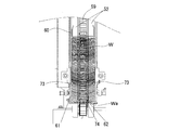
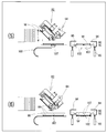
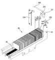
- FIG. 21 is a schematic view of a conventional bag supplying apparatus disclosed in Patent Document 1.
- This bag feeding device includes a bag stock mechanism 1 that stores a number of bags W in a stacked manner and transports them forward, and transports the bags W forward one bag at a time before being supplied to a packaging machine (not shown).
- a bag positioning mechanism 2 that positions the bag W
- a bag delivery mechanism 3 that is disposed between the bag stock mechanism 1 and the bag positioning mechanism 2
- the bag supply mechanism 4 supplies the bag W positioned at the predetermined position of the positioning mechanism 2 to the packaging machine.
- the bag stock mechanism 1 accommodates a large number of bags W stacked in a standing posture with the bag mouth facing upward, conveys them forward, and positions the leading bag W at a predetermined position on the front side in the conveyance direction. 5, a frame guide 6 installed on the frame 6, a pair of left and right cassette guide members 7 installed on the frame 6, and first conveyors 8 and 8 installed on the frame 6.
- the frame 6 includes a cradle 9 and a pair of left and right side plates 11 that are gently inclined toward the front.
- the front and rear ends of the side plate 11 protrude forward and backward from the cradle 9, and the front and rear pulleys 13 and 14 of the first conveyor 8 are formed on the side plate.
- the support shafts 15 and 16 to which are fixed are rotatably supported horizontally.
- a conveyor belt 17 is stretched around the pulleys 13 and 14 in the front-rear direction, and the upper side of the conveyor belt 17 is supported on the cradle 9.
- the support shafts 15 and 16 are intermittently rotated counterclockwise in FIG. 21 by a motor (not shown), whereby the conveyor belt 17 is intermittently rotated while sliding on the cradle 9 toward the front side (left side in FIG. 21). To do.
- the cassette guide member 7 has a plate-like portion 18 arranged in a vertical plane along the conveyance direction of the first conveyor 8 (which is also the conveyance direction of the bag W), and is formed at the front end thereof perpendicular to the conveyance direction. And a first stopper 19.
- the pair of left and right cassette guide members 7 and 7 are disposed on the cradle 9 and the distance between them can be adjusted.
- the first stoppers 19, 19 are formed so as to face each other, function as stoppers, and the top bag Wa of the bags W accommodated in the bag stock mechanism 1 is positioned by contacting the first stopper 19. . Note that only the vicinity of both side edges of the leading bag Wa contacts the first stopper 19 with a predetermined width.
- the bag stock mechanism 1 further includes a bag supply cassette 21.
- This bag supply cassette 21 has a substantially box shape without a lid, and is arranged in a vertical plane along the conveying direction of the first conveyor 8 and accommodates a number of bags W in a standing posture with the bag mouth facing upward. can do.
- the vicinity of both edges of the bottom portion of the bag W is supported by the bottom wall, both side edges of the bag W are regulated by the both side walls, and the bag W is conveyed forward by the first conveyor 8.
- the bag stock mechanism 1 further includes a bag pressing member 29.
- the bag pressing member 29 is placed on the first conveyor 8 and moves forward together with the bags W while pressing the rear ends of the large number of bags W stored in the bag supply cassette 21 to maintain the standing posture of the bags W. To do.
- the operation of the bag supplying apparatus described above is performed as follows, for example.
- the bag holding member 29 is placed behind the bag supply cassette 21.
- (2) The shutter which fixed the bag W from the bag supply cassette 21 is extracted, and the first conveyor 8 is driven once.
- the top bag Wa in the cassette contacts the first stopper 19 and is positioned at the take-out position.
- the bag pressing member 29 presses the tail of the bag group in the cassette.
- the first conveyor 8 is driven intermittently, and the remaining bag group in the bag supply cassette 21 is conveyed forward by one bag.
- the leading bag Wa contacts the first stopper 19 and is positioned at the take-out position.
- the operator removes the bag supply cassette 21 and newly sets the bag supply cassette 21 containing a large number of bags W (replacement of the cassette). Replenish.
- the bag pressing member 29 presses the tail of the bag group in the bag supply cassette 21, and maintains the standing posture of the bag W to push the bag group forward in parallel.
- the thickness is different between the top and bottom (bag mouth side and bag bottom side), such as a stand pack, gusset bag, etc., and the number of bags increases. Since the difference in thickness between the upper and lower sides becomes large, the bag group is bent to one side, and the bag stock mechanism does not stand up in the correct posture, and there is a possibility that a suction error due to the suction holding member 32 may occur. For this reason, in the conventional bag stock mechanism 1, there is a limit to the number of bags that can be set at one time even if the bags W are arranged upright.
- the present invention has an object to provide a large-capacity bag supply device that can stock large-capacity bags and enables continuous operation of the packaging machine for a long time compared to the conventional one. To do.
- the large-capacity bag supply device of the present invention is a large-capacity bag supply device in which a large amount of bags are stocked, one bag is taken out from the stocked bag group and supplied to the packaging machine side.
- a bag stock means having a mechanism for guiding the stocked bag group to the tip side, and a bag transport means for transporting the bag of the bag stock means to the packaging machine side.
- the bag removing means for taking out the bag from the bag stock means
- the bag direction detecting means for detecting the direction of the bag, between the bag stock means and the bag conveying means.
- a bag turning means for turning the bag in a predetermined direction to be carried by the bag carrying means.
- the refilling tool for a large-capacity bag supply device of the present invention is a refilling tool for refilling a bag stock passage of a bag stock means, and a partition plate formed in a shape that can be fitted into the bag stock passage opens a predetermined interval. And connected by a connecting plate.
- the large-capacity bag supply device can store a large amount of bags in the above-described configuration in order to stock the bag stock means by arranging the bag mouths of the bags in the left and right directions and averaging the bag thicknesses.
- the refilling tool for a large-capacity bag supply device of the present invention can easily refill the bag stock means with the above-described configuration.
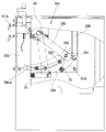
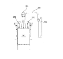
- FIG. 1 is a perspective view of the large-capacity bag supply device of the present invention
- FIG. 2 is a front view
- FIG. 3 is a plan view.
- the large-capacity bag supply device of this embodiment stocks upright bags W with a large capacity, and also includes a bag stock means having a mechanism for guiding the stocked bag group to the tip side, and a bag W of the bag stock means.
- a bag conveying means for conveying to the packaging machine side, a bag removing means for taking out the bag W from the bag stock means between the bag stock means and the bag conveying means, and a direction of the bag W taken out by the bag removing means And a bag turning means for turning the bag W in a predetermined direction to be conveyed by the bag conveying means based on the direction of the bag W detected by the bag direction detecting means. . In the following, each of these means will be described.
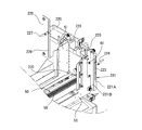
- a bag stock mechanism 50 which is a bag stock means, is shown in the front portion of the large-capacity bag supply device in FIG.
- the bag stock mechanism 50 includes a bag stock passage 52 in the central longitudinal direction of a base 51 in which plate materials are combined in a rectangular shape.
- a large capacity bag is placed with the bag mouth facing sideways in an upright state.
- the bag group is a bag with a zipper such as a stand pack or a gusset bag, but may be a flat bag or the like.
- the difference in thickness between the bag mouth side and the bag bottom side increases as the bags W are stacked in the same direction.
- the bag W does not stand up in the correct posture in the bag stock mechanism 50, and there is a possibility that a take-out error may occur in the bag removing means. For this reason, the bag mouth side and the bag bottom side of the bags W, such as 10 sheets or 20 sheets, are gathered to some extent and stocked, and the difference in thickness between the bag mouth side and the bag bottom side is averaged. Are aligned in a completely undistorted state and stocked in the bag stock passage 52.
- the bag stock passage 52 is provided with side feed conveyors 53 on both sides.
- a string belt 72 is bridged between a driving pulley 55 provided on a rod-shaped rotating shaft 54 standing in front and a rear driven pulley (not shown).
- the strap belt 72 rotates to slowly feed the bag group forward.
- the side-feed conveyor 53 is mounted on a frame 56 disposed in the longitudinal direction of the base 51, and this frame 56 is supported by a plurality of installation rods 57 that are installed in the width direction of the base 51. .
- the frame 56 is slidable in the width direction of the base 51.
- a bag pushing belt 59 is laid at the center of the bottom of the bag stock passage 52 in the longitudinal direction, and a bag pushing member 60 is set on the bag pushing belt 59 so as to be detachable vertically.
- the bag pushing belt 59 is rotationally driven, the bag pushing member 60 slowly moves forward, pushes the bag group stocked in the bag stock passage 52 forward from the rear, and delivers it to the bag removing means.
- the bag stock passage 52 has a gate-like plate plate 61 at the front end of a frame 56 equipped with a side-feed conveyor 53, and a locking plate 62 is installed between the upper ends of the plate plates 61 (see FIG. 1, see FIG.
- the side feed conveyor 53 and the bag pressing member 60 are locked so that the bag Wa at the front end of the bag group pushed forward of the bag stock passage 52 does not jump out, and the front end of the bag group is transferred to a bag removing means to be described later.
- the bag Wa is held.
- an alignment rod 73 is erected on the inner side of the gate-like plate plate 61.
- This alignment rod 73 uses a hollow pipe connected to an air source, an injection hole (not shown) is opened forward, and air is injected.
- the alignment rod 73 curves the bag group stocked in the bag stock passage 52 in a convex shape so as to be detected by a bag detection piece 74 provided at the tip of the bag stock passage 52.
- the bag W since the bag W may be bent and bent, as shown in FIG. 4, as shown in the rear portion of the bag group (upper portion in FIG. 4), the bag W is simply put into the bag stock passage 52 as it is. When stocked, it becomes a wavy state.
- the bag W When the bag W is pushed by the bag pressing member 60 while keeping the state of the rear portion of the bag group, the bag W at the tip contacts the bag detecting piece 74 when the bag W is curved in a convex shape on the rear side. The bag W is not detected.
- the bag pushing belt 59 is driven to rotate, and the bag W is further sent forward even though the bag W is already present. To do. Since the bag W is different in thickness in the upper and lower sides and the both sides of the bag group of the bag stock passage 52 are in a dense state, the bag W cannot be fed forward even if the bag pushing belt 59 is driven to rotate.
- the alignment rod 73 is erected on the inner side of the gate-like plate plate 61 to restrict the movement of both sides of the bag W and to push out the central portion of the bag W. W is sent out in a state of being bent forward in a convex shape. By curving the bag W in this manner, the bag Wa at the tip can be reliably brought into contact with the bag detection piece 74.
- the bag detection piece 74 jumps slightly upward (upward in the plane of FIG. 4) from the bottom of the bag stock passage 52 and turns OFF. (Downward direction) and turned ON. The presence / absence of the bag W is detected by the withdrawal / extraction of the bag detection piece 74. Since the alignment rod 73 may not be necessary depending on the type of bag W, the alignment rod may be removable.
- an injection hole for blowing out air is formed at the front end side of the alignment rod 73, and air is sent to both ends of the bag W by the air from the injection hole, and between the bags. Air enters and it becomes easy to remove the bag Wa at the tip with a suction cup 76 of the bag removing means described later. The air also functions to return the end of the bag W that has been curved too much.
- this injection hole is not essential, and the alignment rod 73 does not need to be hollow.
- the alignment rod 73 may have a structure that restricts movement of both ends of the bag W and pushes out the central portion of the bag W.
- the bag removing means is a mechanism for taking out the bag W located at the tip of the bag stock mechanism 50 and delivering it to the bag direction detecting means.
- the bag removing means receives a bag removing mechanism 63 for taking out the bag W from the bag stock mechanism 50, and a bag delivery for receiving the bag W taken out from the bag removing mechanism 63 and delivering it to the bag direction detecting means described later.
- the mechanism 64 is comprised.
- a parallel rod 66 is cantilevered in the horizontal direction on the side portion of the first drive box 65.
- the parallel rod 66 includes a main rod 67 and a sub rod 68, and both ends of these rods 67 and 68 are connected by a connecting plate 69.
- the main rod 67 is connected to a drive mechanism (not shown).
- a screw rod 70 is rotatably supported in the middle of the main rod 67 and the sub rod 68.
- a handle 71 is provided at the end of the screw rod 70, and by rotating the handle 71, the lateral spacing of the suction cup 76 described later can be adjusted.
- An inverted L-shaped slide plate 75 is slidably provided at both ends of the parallel rod 66 and inside the connecting plate 69 in a front view of FIG.
- a female screw is formed on the slide plate 75, and the screw rod 70 is engaged with the female screw.
- the slide plates 75 at both ends are moved closer to and away from each other, and the lateral distance of the suction cup 76 can be adjusted.
- air cylinders 77 are attached to the lower ends of the slide plates 75, respectively.
- a mounting plate 78 is vertically mounted on the operating rod 77 A of these air cylinders 77, and a slide rod 79 is mounted in parallel to the mounting plate 78 on support pieces extending from both ends of the mounting plate 78.
- Two suction cups 76 are fixed to one slide rod 79 by screws 80 so as to be slidable in the vertical direction. Accordingly, a total of four suction cups 76 are fixed to the two slide rods 79.
- the width of the suction cup 76 can be adjusted by rotating the handle 71, and the vertical position of the suction cup 76 can be adjusted by loosening the screw 80 and sliding the suction cup 76 along the slide rod 79.
- FIG. 5B is a front view of the bag passing mechanism 64.
- the bag passing mechanism 64 is adjacent to the bag removing mechanism 63 and is supported in a cantilevered manner in the horizontal direction from the first drive box 65. Of course, there is no problem even if the bag passing mechanism 64 is supported by both ends.
- the rotating cylinder 81 of the bag passing mechanism 64 stores an outer shaft 82 and an intermediate shaft 83, and a plate-like sliding guide 84 is attached to the outer shaft 82 so as to protrude outward.
- the sliding guide 84 rotates in the forward and reverse directions along with the movement.
- a sliding portion 85 is slidably covered on the sliding guide 84, and a main body plate 86 is fixed to the sliding portion 85.
- An air cylinder 87 is attached in the longitudinal direction of the main body plate 86, and a holding portion 88 is pivotally supported at the tip of the main body plate 86.
- the holding portion 88 is opened and closed by the air cylinder 87 and the bag W is gripped.
- One end of an L-shaped link 89 is connected to the middle shaft 83 of the rotating cylinder 81, and the other end is connected to the outer portion of the main body plate 86.
- the rotation of the intermediate shaft 83 is transmitted to the link 89, and the sliding portion 85 reciprocates according to the sliding guide 84 via the main body plate 86 by the bending motion of the link 89.
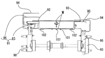
- the bag direction detecting means is a mechanism for detecting by the detection unit 91 in which direction the bag W spanned on the bag erection base 90 from the bag passing mechanism 64 is spanned.
- This bag direction detecting means detects a thickness of one of the bag erection side 90 and the bag bottom side of the bag W on the bag erection base 90 over which the bag W taken out from the bag stock mechanism 50 is bridged.
- a detector 91 for determining the direction of the bag W.
- FIG. 6 is a side view of the bag mounting base 90
- FIG. 7 is a perspective view.
- the bag erection base 90 has a parallel counter section 92 made of two long steel materials.
- the counter unit 92 is a steel material having a cross section formed in an inverted L shape.
- the upper horizontal part is the counter part 92 and the lower horizontal part is the side plate 102.
- the side plate 102 partially extends in a bowl shape slightly horizontally.
- the interval between the counter portion 92 and the counter portion 92 is set to be shorter than the longitudinal dimension of the bag W and longer than the width dimension, and the width is adjusted according to the bag W by the handle 93 and the screw screw. Can do.
- U-shaped holding plates 94 for holding the bag mouth side and the bag bottom side of the bag W stretched in the longitudinal direction are arranged on both outer side portions of the respective counter portions 92 of the bag mounting base 90. .
- the upper part of the holding plate 94 abuts on the counter part 92, sandwiches the bag mouth side and the bag bottom side of the bag W spanned on the counter part 92, and a bag turning sucker 107 of a bag turning means described later
- the bag W is prevented from being detached from the bag erection base 90 even if the bag W is lifted from and contacted.
- the lower end of the holding plate 94 is connected to the air cylinder 95, and the holding plate 94 can be moved up and down by the expansion and contraction of the air cylinder 95 to hold or open the bag W on the counter portion 92. It is.
- a detection unit 91 for measuring the thickness of the bag W is disposed adjacent to the holding plate 94.
- the detection unit 91 includes a detection plate 96 made of a U-shaped plate similar to the holding plate 94, and a measurement sensor that measures the thickness of the bag W by measuring the position of the detection plate 96. 97.
- An air cylinder 98 is also connected to the lower end of the detected plate 96, and the detected plate 96 moves up and down by the expansion and contraction of the air cylinder 98 to press the bag W on the counter unit 92. As shown in FIG.
- the distance of the detected plate 96 is measured by the measurement sensor 97, and the detected plate 96 is a bag mouth with a zipper. It is possible to determine whether the side is clamped or whether the bag bottom side without a zipper is clamped. That is, since there is a zipper on the bag mouth side, the detected plate 96 is located slightly above, and the distance is longer than that on the bag bottom side.
- the holding plate 94 and the detection plate 96 are integrally formed, and the integrated plate is detected by the measurement sensor 97, or the detection plate 96 is used as the detection plate 96.
- the holding plate 94 also serving as 96 may be detected by the measurement sensor 97.
- the bag conveying means is a bag conveying mechanism 100 arranged from the lower part of the bag erection base 90 to the packaging machine side, and the string belt for conveying the bag W from the lower part of the bag erection base 90 to a bag mouth lift mechanism 106 described later.
- a conveyor 101 is provided.
- the bag transport mechanism 100 is disposed below the bag erection base 90, and side plates 102 are disposed in parallel on both sides of the cord belt conveyor 101, and the string belt conveyor 101 is disposed between the side plates 102. ing. As shown in FIG.
- the distance between the side plates 102 is smaller than the lateral width of the bag W, and the bag W swung in the surface direction by the bag swivel mechanism 105 described below is between the counter unit 92 and the counter unit 92 of the bag erection base 90. It passes through and descends and is placed on the side plates 102 and the string belt conveyor 101 on both sides. Since both side portions of the bag W ride on the side plate 102 and the central portion rides and is supported on the string belt conveyor 101, the bag W is moved to the bag mouth lift mechanism 106 side by driving the string belt conveyor 101. Be transported.
- three optical sensors 103 are provided at the front end of the bag transport mechanism 100, and one rear optical sensor 103 detects that the bag W has approached the front end.
- the two sensors at the front end accurately stop the both sides of the front end of the bag W without tilting to a predetermined position at the front end of the bag transport mechanism 100. It is provided to detect whether or not
- FIG. 8 is a perspective view of a bag turning mechanism 105 which is a kind of bag turning means.
- the bag turning mechanism 105 is a mechanism that rotates the bag W spanned on the bag erection base 90 by the bag passing mechanism 64 in the forward and reverse directions.
- the role of the bag turning mechanism 105 is to turn the bag W in a predetermined direction and deliver it to the bag transport mechanism 100. That is, since the bag W is stocked in the bag stock mechanism 50 with the bag mouth and the bag bottom turned right and left, when the bag W is transported by the bag transport mechanism 100 as it is and delivered to the packaging machine, A bag W is inconvenient because it is delivered to the packaging machine in the reverse state with the bag bottom side up.
- the bag W transported by the bag transport mechanism 100 detects the direction of the bag W on the bag erection base 90 by the bag direction detection means so that the bag mouth lift mechanism 106 can always attract the bag mouth side.
- the bag turning mechanism 105 rotates so that the bag mouth faces the downstream side.
- the bag swiveling mechanism 105 is provided with a bag swivel sucker 107 for adsorbing the center portion of the bag W held by the holding plate 94 from below on the bag erection base 90 at the upper end of the suction pipe 108.
- a suction hose (not shown) is joined to the elbow at the lower end of the pipe 108.
- the suction pipe 108 is joined to the turning shaft 111 of the turning actuator 110 via the bracket 109 and is turned in the forward and reverse directions by the air-driven turning actuator 110.
- the turning actuator 110 is slidably set on a rectangular substrate 112, and one end of a screw screw 113 as a position adjusting mechanism is connected thereto. By rotating the handle 114 attached to the other end of the screw screw 113, the swing actuator 110 can slide on the substrate 112 to adjust the position of the bag swing sucker 107.
- the bag swivel sucker 107 is set so as to come to the center position of the bag W spanned on the bag erection base 90 as described above, but the size of the bag W is not constant depending on the type of the bag W. Therefore, the center position shifts due to the replacement of the bag W. In that case, the handle 114 is rotated and the turning actuator 110 is slid to set the bag turning suction cup 107 so as to come to the center position of the bag W.
- the bag turning mechanism 105 is moved up and down by an elevating unit 115 that supports the substrate 112 from below (see FIG. 2).
- the bag swivel sucker 107 sucks the bag W spanned on the bag erection base 90 from below by the elevating part 115 and rotates the bag W 90 degrees in either forward or reverse direction. It descends to the lower end position and is placed on both side plates 102 and the cord belt conveyor 101.
- the elevating part 115 is moved up and down by a crank mechanism in the box 116.
- the bag mouth lift mechanism 106 shown in FIG. 2 sucks and lifts the bag mouth of the bag W transported to the tip of the bag transport mechanism 100 so that the next bag delivery mechanism (not shown) receives the bag W. It is a mechanism to make.
- the bag delivery mechanism delivers the bag W received from the bag mouth lift mechanism 106 to the rotary packaging machine.
- the bag mouth lift mechanism 106 is attached to a second drive box 117 adjacent to the first drive box 65. As shown in FIGS. 2 and 3, one end of the link 118 is pivotally supported on the side of the second drive box 117, and a parallel bar 121 for installing the block 120 of the suction cup 119 is provided near the other end. A triangular plate 122 for mounting is pivotally supported. As described above, one end of the parallel bar 121 is fixed to the triangular plate 122 in a cantilever manner, and the block 120 having two suction cups 119 attached to the parallel bar 121 is held.
- one end of the link 118 is rotated clockwise by the drive mechanism in the second drive box 117, and when the other end of the link 118 is at the lower end position, the suction cup 119 is lowered and the bag transport mechanism 100 The bag W that stops is adsorbed to the tip of the bag.
- the sucker 119 is lifted above the link 118 by the action of the two rods 123 connected to the triangular plate 122 and the parallel bar 121, and the bag W of the sucker 119 is moved to the bag delivery mechanism in the next step. Pick up and hand it over to the rotary packaging machine.
- the bag mouth lift mechanism 106 and the bag delivery mechanism are basically the same as a mechanism that is set in a conventional bag box or string conveyor type bag feeder.
- the large-capacity bag supply device as described above can set, for example, about 3000 bags at a time, and can operate continuously for 60 minutes if the capacity is 50 bags / minute. Therefore, it can be expected that the operator who replenishes the bag will be concurrently served.
- the bag W can be set up sideways and the bag mouth is automatically determined, even if the bag W is bent to one side when a bag with a zipper is set in a large capacity, the bag W By arranging the set directions alternately 180 degrees, the overall length of the apparatus can be kept relatively short.
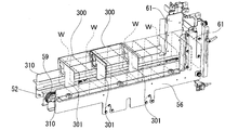
- FIGS. 9 to 11 show the use state of the large-capacity bag supply device of the present invention.
- the bag stock mechanism 50 on the left side of FIG. The difference in thickness between both sides of the bag group is averaged with the mouth and the bag bottom reversed left and right, and the bag group is aligned in a parallel posture as a whole and stocked in a large amount in the bag stock passage 52.
- the parallel rod 66 of the bag removing mechanism 63 rotates clockwise around the main rod 67 so that the suction surface of the suction cup 76 is parallel to the surface of the bag Wa at the tip of the bag stock mechanism 50.
- the operating rod 77A of the air cylinder 77 is extended, and the suction cup 76 attached to the slide rod 79 goes to pick up the bag Wa at the tip of the bag stock mechanism 50.
- the suction cup 76 adsorbs the leading end bag Wa
- the operating rod 77A of the air cylinder 77 contracts.
- the bag passing mechanism 64 is still on standby.
- the bag removing mechanism 63 sucks the bag Wa at the tip of the bag stock mechanism 50 and rotates the parallel rod 66 45 degrees counterclockwise around the main rod 67.
- the bag passing mechanism 64 slides the sliding portion 85 downward as much as possible by the link 89 and opens the holding shaft 88 with the outer shaft 82 opened. Rotate 45 degrees to the right.
- the clamping unit 88 comes to a position for clamping the bag W held by the suction cup 76 of the bag removing mechanism 63, the air cylinder 87 is activated and the clamping unit 88 clamps the bag W (FIG. 5B). See).
- FIG. 10 (3) is a front view and a side view of the bag stock mechanism 50 and the bag transport mechanism 100.
- the bag passing mechanism 64 that has received the bag W from the bag removing mechanism 63 rotates downward and places the bag W on the bag erection base 90. Since the bag W is in a state of being bridged between the counter unit 92 and the counter unit 92 of the bag erection base 90, the bag W is on the bag erection base 90 as shown in the right diagram of FIG. At this stage, the bag mouth side and the bag bottom side of the bag W have not yet been pressed onto the bag erection base 90 by the holding plate 94.
- the bag removing mechanism 63 rotates 45 degrees to the left and takes the next bag W to the bag stock mechanism 50, but the bag passing mechanism 64 places the bag W on the bag erection base 90.
- the air cylinder 95 is operated, and the bag mouth side and the bag bottom side of the bag W are held on the bag erection base 90 by the holding plate 94.
- the air cylinder 98 of the detection unit 91 is activated, and the detected plate 96 presses the bag W.
- the bag W is stocked in the bag stock mechanism 50 with the bag mouth and the bag bottom turned left and right, in FIG. 6, whether the bag mouth is left or right differs depending on the stocking state. .
- the detected plate 96 presses one side of the bag W, and the measurement sensor 97 measures the distance in the vertical direction of the detected plate 96. Since the bag mouth is provided with a zipper, the detected plate 96 is raised upward by the amount of the zipper as compared with the bag bottom side, and therefore the value of the measurement sensor 97 reveals whether it is the bag mouth or the bag bottom.
- the bag turning mechanism 105 is further lifted by the lifting / lowering part 115 of the bag turning mechanism 105, and at the same time, the bag turning sucker 107 is raised and the bag held by the holding plate 94 of the bag erection base 90. Adsorb the center of the back surface of W.
- the bag passing mechanism 64 is about to receive the next bag W from the bag removing mechanism 63. Then, from the result of measurement by the measurement sensor 97, after determining the rotation direction of the bag swivel sucker 107 depending on whether the detection unit 91 side is the bag mouth side or the bag bottom side, the air cylinder 95 is actuated and the holding plate 94 and The to-be-detected plate 96 rises to open the bag W, actuate the turning actuator 110 in FIG. 8, and rotate the suction pipe 108 through the bracket 109 by 90 degrees.
- the direction of rotation of the bag W is such that when the bag W is transported by the bag transport mechanism 100 in a later step, the bag mouth side faces the downstream side (the front end side of the bag transport mechanism 100).
- the suction cup 119 adsorbs the bag mouth.
- the bag turning mechanism 105 rotates the bag W to the left or right side so that the bag mouth lifting mechanism 106 can suck the bag mouth.
- the bag turning mechanism 105 is lowered by the elevating part 115 in a state where the bag W rotated 90 degrees in the proper direction in the above process is sucked by the bag turning sucker 107, as shown in FIG.
- the bag W is placed on the side plate 102 and the string belt conveyor 101 of the bag transport mechanism 100.
- the upper layer bag W shown in FIG. 6 rotates so as to face the width direction of the bag W, so that the bag W stretched over the bag erection base 90 is It is possible to pass between the counter unit 92 and the counter unit 92 and place it on the side plate 102 and the string belt conveyor 101.
- the bag W placed on the side plate 102 and the string belt conveyor 101 is transported downstream by the bag transport mechanism 100 and stops at a position determined by the optical sensor 103 at the tip of the bag transport mechanism 100. After that, the link 118 of the bag mouth lift mechanism 106 pivots downward and sucks the bag W stopped by the suction cup 119, and then receives the bag W of the bag mouth lift mechanism 106 by the bag delivery mechanism (not shown). Deliver to rotary packaging machine. In the rotary type packaging machine, the packing material is filled and the bag mouth of the bag W is sealed.
- the bag stock passage 52 of the bag stock mechanism 50 is fixed in a horizontal state, and the bags are stocked in a vertically standing state.
- the bag stock passage 52 is the conventional bag of FIG. You may incline like a supply apparatus.
- the bag removing means is composed of two mechanisms, the bag removing mechanism 63 and the bag passing mechanism 64, but is not limited to such two structures.
- the bag removing mechanism 63 in FIG. 5A is configured, and the bag W adsorbed by the suction cup 76 of the bag removing mechanism 63 is placed on the bag erection base 90 and held by the holding plate 94 to be detected.
- the direction of the bag W may be detected at 91. Since there is no bag passing mechanism 64, the structure is simplified.
- the bag direction detecting means includes a bag erection base 90 and a detection unit 91, and sandwiches the bag W on the bag erection base 90 with a holding plate 94 to detect the thickness of the bag W to detect the direction of the bag.
- the non-contact detection unit may be used as the bag direction detection means.
- the direction of the bag W may be determined by imaging with a CCD camera, or the direction of the bag W may be determined by detecting surface irregularities and thicknesses by laser light.
- the bag removing mechanism 63 shown in FIG. 5A is provided with a turning means (drive device such as a motor) for turning the slide rod 79, and a suction cup. If the bag W adsorbed at 76 is turned, the bag erection base 90 and the holding plate 94 are not necessary. That is, while the bag is taken out from the bag stock mechanism 50 by the bag removing mechanism 63 and the bag W is placed on the bag transport mechanism 100, the direction of the bag W is detected by the non-contact detecting unit, and the bag turning means is used. What is necessary is just to correct
- the bag removing mechanism 63 of the embodiment has a parallel rod 66 supported in a cantilevered manner on the side of the first drive box 65, and on both ends of the parallel rod 66, As shown in FIG. 5A, inverted L-shaped slide plates 75 are slidably provided, and air cylinders 77 are attached to the lower ends of the slide plates 75, respectively.
- FIG. 12 shows a first modification of the bag removing mechanism 63, which is characterized in that the configuration is simple and the number of parts is small as compared with the bag removing mechanism 63 of the embodiment.
- the bag removing mechanism 163 of the first modification will be described with reference to the drawings.
- reference numeral 167 denotes a main rod that rotates in connection with a drive mechanism (not shown).
- One end of the main rod 167 is supported by the first drive box 65, and the other end is supported from above by a support member 67A.
- the upper ends of two plate-like parallel turning arms 200 are fixed to both ends of the main rod 167.
- a support rod 201 is rotatably mounted between the lower ends of the two rotating arms 200, and two blocks 76A to which suction cups 76 are attached are fixed near both ends of the support rod 201.
- crank rod 202 One end of the crank rod 202 is connected to one end of the support rod 201, and a rotating wheel 203 is provided at the other end of the crank rod 202, and the rotating wheel 203 is fitted in the guide groove 204 ⁇ / b> A of the guide plate 204.
- the guide plate 204 is thin at one end, thicker while drawing an arc on the other end, and the other end is rectangular, the bottom is horizontal, and the whole is a thick plate with a substantially trapezoidal shape. It is done.
- One end of the guide plate 204 is supported from above by a column 205 near the bag stock mechanism 50, and the other end is also supported from above by a column 206 near the bag passing mechanism 64.
- the guide groove 204A formed in the guide plate 204 is curved upward from one end on the left side to the other end side on the right side, but the suction surface of the suction cup 76 is on the bag Wa at the tip of the bag stock mechanism 50 on one end side. It is formed so that it may contact
- the rotation arm 200 In the bag removing mechanism 163, when the main rod 167 rotates in the left-right direction, the rotation arm 200 also rotates at an angle of about 45 degrees according to the rotation of the main rod 167. With the rotating arm 200 rotated and the suction cup 76 stopped rotating to the left most, the rotating wheel 203 is positioned on one end side of the guide groove 204A, and the block 76A is interposed via the crank rod 202 and the support rod 201. Kept horizontal. For this reason, the suction surface of the suction cup 76 attached to the block 76A comes into contact with the bag Wa at the tip of the bag stock mechanism 50 in parallel, and the suction cup 76 can reliably suck and take out the bag W.
- the rotating arm 200 rotates 45 degrees counterclockwise and stops with the suction cup 76 adsorbing the bag W.
- the rotating wheel 203 of the crank rod 202 is guided in the guide groove 204A, rolls in the right direction, and rises as it moves in the right direction. For this reason, the crank rod 202 also rotates while following the movement of the rotating wheel 203.
- the suction cup 76 of the block 76A fixed to the support rod 201 also rotates downward, and the clamping portion 88 of the bag passing mechanism 64 is attached to the suction cup 76. The sucked bag W is clamped.
- the gate plate plate 61 is provided at the front end of the frame 56 equipped with the side-feed conveyor 53, and the locking plate 62 is installed between the top ends of the gate plate plate 61.
- the side-feed conveyor 53 and the bag pressing member 60 By the side-feed conveyor 53 and the bag pressing member 60, the bag Wa at the tip of the bag group pushed forward of the bag stock passage 52 is locked and held so as not to jump out.
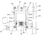
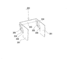
- the modified example 2 shown in FIGS. 13 and 14 has a structure in which the upper and lower sides and the left and right sides of the bag Wa are pressed so that the bag Wa at the tip of the bag group stocked in the bag stock mechanism 50 does not jump out. It has become.
- a plate extending across the upper front end side of the pair of gate-like plate plates 61 is the locking plate 220 of the second modification.
- the locking plate 220 has an action of holding the upper side of the bag W so as not to bend, and is made of an elongated rectangular plate, and the height can be adjusted.
- the locking plate 220 is installed on a functional plate 221 that is attached in the vertical direction of the front end of the gate plate 61 and has an L shape in plan view.
- This function plate 221 has two functions. One serves as the erection part 221A for laying the locking plate 220, and the other one regulates the bag Wa from the side so that the bag Wa at the tip does not jump out, as will be described later. This is the role of the holding unit 221B. However, it is good also as two separate members with each function of the erection part 221A and the holding part 221B instead of the integral thing provided with two functions.
- One functional plate 221 is a plate body having an L-shape in plan view as described above, but on the front side thereof, as shown in FIG. One end is fixed by a fixed handle 224 through the slit 223. When the fixed handle 224 is loosened, the locking plate 220 can slide in the vertical direction along the slit 223 to adjust the height.
- the surface of the functional plate 221 in which the slit 223 is formed is cut with a scale serving as a guideline for fixing the locking plate 220, and the locking plate 220 according to the size of the bag W. The height of can be set easily.
- the other functional plate 221 is also formed with a long slit in the vertical direction. As shown in FIG. 14, the lateral dimension of the locking plate 220 is longer than the distance between the one functional plate 221 and the other functional plate 221, and the locking plate 220 protrudes through the slit of the other functional plate 221. However, the end is not fixed. With such a configuration, even if the handle 58 is rotated according to the size of the bag W and the distance between the frames 56 is adjusted by screw screws, the locking plate 220 passes through the slit of the other functional plate 221 and the frame 56 It does not interfere with the adjustment of the interval. Further, the locking plate 220 can be slid in the vertical direction along the slits of one and the other functional plate 221 simply by loosening the fixed handle 224, and the height can be adjusted.
- the rear side of the functional plate 221 is a holding portion 221 ⁇ / b> B, and restricts from the side so that the bag W at the tip does not jump out from the tip of the bag stock passage 52.
- the holding portion 221 ⁇ / b> B is formed with irregularities at a predetermined interval, and it can be expected that the side edges of the bag W are locked by the convex portions 221 b to prevent the two pieces of the bag W from being removed.
- a plurality of types of functional plates 221 provided with holding portions 221B having different numbers of irregularities and different intervals according to the size of the bag W may be prepared.
- a lower presser plate 230 is provided at the lower end of the front end of the bag stock mechanism 50. As shown in FIG. 14, the lower presser plate 230 is provided at the upper part on the downstream side of the bag pushing belt 59 and regulates the lower part of the bag W.
- the upper edge of the bag W is locked by the locking plate 220, both sides are locked by the holding portion 221 ⁇ / b> B, and the lower portion is pressed by the lower pressing plate 230. Even if the bag W stocked in the stock mechanism 50 is pushed up and pushed forward, the bag Wa at the tip can be held in a posture that can be stably adsorbed by the suction cup 76.
- a center pressing plate 225 that presses the center upper portion of the bag W is provided.
- the central pressing plate 225 is located at the upper center of the bag W, and when the suction bag 76 is sucked and taken out by the suction cup 76, the second bag W behind is not peeled off together with the front bag Wa. In addition, the second bag W is pushed back.
- This center pressing plate 225 eliminates mistakes in taking two sheets and increases the stability of bag removal.
- the central pressing plate 225 is a rectangular plate made of stainless steel (SUS304) as a spring material, and protrudes in a curved manner toward the bag W side.
- the upper end of the center pressing plate 225 is supported by a supporting plate 226 extending in the lateral direction.
- the rear end of the support plate 226 is fixed to a rectangular fixed plate 228 by a fixed handle 227.
- a slit 229 is also formed in the fixed plate 228.
- the bag W at the tip is detected by providing only one bag detection piece 74 at the tip of the bag stock passage 52.
- the bag detecting pieces 240 are provided at two locations inside the gate-shaped plate 61.
- the bag pressing belt 59 is actuated to activate the bag group. Is pushed forward by the bag pushing belt 59 until the two bag detecting pieces 240 simultaneously detect the bag W.
- the bag detection piece 240 does not only detect whether the bag W is positioned at the tip of the bag stock mechanism 50, but stands upright even in a bag group in which the left and right are twisted.
- the suction state can be corrected to prevent the suction mistake caused by the suction cup 76.
- the bag detection piece 240 shown in FIG. 15 is pivotally supported on the inner side of the gate-shaped plate 61, and a protrusion 240B protrudes from the upper center of the L-shaped swing piece 240A.
- a protrusion 240B protrudes from the upper center of the L-shaped swing piece 240A.
- Modification 4 In the above embodiment, as shown in FIG. 4, an injection hole for blowing air is formed on the tip side of the alignment rod 73, and air is sent to both ends of the bag group by the air from the injection hole. In this example, air enters between the bags, and the suction bag 76 of the bag removing means, which will be described later, facilitates the removal of the leading bag Wa.
- FIG. 16 and 17 show a fourth modification of the above embodiment.
- three air nozzles are arranged at the upper end of the bag stock mechanism 50.
- the large first air nozzle 251 arranged at the upper end of the tip is fixed to the fixing plate 228 via the pipe 250 so that the slit-shaped injection port is parallel to the bag W.
- the second and third air nozzles 252 and 253 provided on the upper inner side of the gate-shaped plate 61 are arranged close to the bag group so that the slit-shaped injection ports intersect with the bag W.
- the first and second sheets are in close contact with each other and are in a vacuum state, and the second bag W is also peeled off at the same time. May occur.
- the air is jetted between the first and second bags W by injecting air from the first, second, and third air nozzles 251, 252, and 253, the vacuum state is eased.
- the frequency of occurrence of mistakes in taking two sheets is reduced.
- the bag pressing member 60 is set to the bag pressing belt 59 so as to be vertically detachable, and when the bag pressing belt 59 is rotationally driven, the bag pressing member 60 moves slowly forward to the bag stock passage 52.
- the bag group stocked in (1) is pushed forward from the rear and transferred to the bag removing means.
- the bag stock passage 52 is provided with side feed conveyors 53 on both sides, and the cord belt 72 rotates to slowly feed the bag group forward from the side.
- FIG. 18 is a perspective view of Modification 5 of the above embodiment.
- the large-capacity bag supply device replenishment tool 300 functions in place of the bag pressing member 60.
- the side feeding conveyor 53 is not provided, and a long locking plate 310 having an L-shaped cross section for locking the replenishing tool 300 is attached to the upper part of the frame 56 along the frame 56. It has been.
- FIG. 19 is a perspective view of the replenishing tool 300.
- the replenishing tool 300 can also be used for the bag stock mechanism 50 as in the above embodiment.
- two plate-like partition plates 301 are arranged at a predetermined interval, and the corner portions of both partition plates 301 are connected by a rectangular connection plate 303.
- the partition plate 301 is notched in a step shape so as to be fitted into the bag stock passage 52 to form a stepped portion 304.
- the width is narrower and higher than the bag stock passage 52, and the bag W is stabilized.
- the bag stock passage 52 is formed so that it can be placed upright. It should be noted that the interval between the partition plates 301 is too narrow when the bag W is replenished so that the number of sheets to be replenished is not too small. Set such an interval.
- FIG. 20 is a perspective view when the bag W is refilled. As shown in this perspective view, the replenishment tool 300 is fixed to the bag stock passage 52 when the engagement slit 310 is engaged with the engagement plate 310 and the bag W is replenished.
- the replenishment tool 300 disposed in the bag stock passage 52 is provided with a bag mouth side and a bag bottom side of a bag W of 10 or 20 or a certain number of bags, similar to the embodiment.
- the stock is reversed left and right, the thickness difference between the bag mouth side and the bag bottom side is averaged, and aligned and stocked without distortion.
- the replenishment tool 300 is changed from the locked state to the lying state.
- the front replenishing tool 300 is removed. Since the replenishing tool 300 is on the bag pushing belt 59, the replenishing tool 300 is sent to the front gate plate 61 side by the bag pushing belt 59 when the large-capacity bag supply device is continuously operated.
- the replenishing tool 300 supports the rear portion so that the bundle of bags does not collapse, and the entire bag group is gradually sent to the bag removing mechanism 63 side by the movement of the bag pushing belt 59.
- the bag pressing member 60 is set vertically on the bag pressing belt 59, so that the bag W is not disturbed after the bag W is replenished with the replenishing tool 300. You can remove it.
- the shape of the partition plate 301 is not limited to the shape shown in FIG. 19, and is a shape that fits into the bag stock passage 52, and the two partition plates 301 are predetermined by the connecting plate 303. What is necessary is just to connect at intervals.
- the present invention is useful in a large-capacity bag supply device for bags having different bag thicknesses such as a stand pack and a gusset bag.
- Bag stock mechanism (bag stock means) 52 Bag stock passage 53 Side feed conveyor 59 Bag pressing belt 60 Bag pressing member 63 Bag removing mechanism (bag removing means) 64 Bag delivery mechanism (bag removal means) 66 Parallel rod 67 Main rod 68 Sub rod 70 Screw rod 73 Alignment rod 74 Bag detection piece 75 Slide plate 76 Suction cup 76A Block 77 Air cylinder 90 Bag installation stand (bag direction detection means) 91 Detection part (bag direction detection means) 92 Counter unit 94 Holding plate 96 Detected plate 97 Measurement sensor 100 Bag transport mechanism (bag transport means) 105 Bag turning mechanism (bag turning means) 107 Bag swivel sucker (bag swivel means) 113 Screw screw (position adjustment mechanism) 167 Main rod 200 Rotating arm 201 Support rod 202 Crank rod 204 Guide plate 204A Guide groove 220 Locking plate 221B Holding portion 225 Center pressing plate 230 Lower pressing plate 240 Bag detection piece 251 First air nozzle 252 Second air nozzle 253 Third air nozzle 300 Refill tool
Abstract
Description
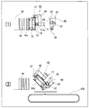
(1)はじめに、袋口を上に向けた起立姿勢で多数の袋Wを重ねて収容した袋供給カセット21を、カセットガイド部材7,7の間に挿入して受け台9上に載置し、袋供給カセット21の背後に袋押さえ部材29を置く。
(2)袋供給カセット21から袋Wを固定していたシャッターを抜き出し、第1コンベア8を1回分駆動する。これによりカセット内の先頭の袋Waが第1ストッパ19に当接して取出し位置に位置決めされる。カセット内の袋群の後尾を袋押さえ部材29が押さえる。
(3)ロータ31の複数の袋受渡し機構3が回転しながら、前記取出し位置に位置決めされた先頭の袋Waを吸着して取り出す。取り出される毎に、第1コンベア8が断続駆動され、袋供給カセット21内の残りの袋群を前方に1袋分搬送する。そのたびに先頭の袋Waが第1ストッパ19に当接して前記取出し位置に位置決めされる。
(4)袋供給カセット21内の袋Wがなくなると、作業者が当該袋供給カセット21を外して、多数の袋Wを収容した袋供給カセット21を新たにセットし(カセットの交換)、袋の補充を行う。
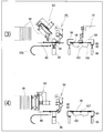
図1の大容量袋供給装置の手前の部分には、袋ストック手段である袋ストック機構50が示されている。この袋ストック機構50は、板材を長方形に組み合わせた基台51の中央長手方向に、袋ストック通路52を備えている。この袋ストック通路52に、起立した状態で袋口が横向きとなった袋を大容量載置する。この袋群は、スタンドパック、ガセット袋等のジッパー付き袋等であるが、平袋等であってもよい。これらの袋群の袋口側と袋底側で厚みが相違する袋Wの場合に、袋Wを同じ方向に多く重ねるに従って、袋口側と袋底側の厚みの差が大きくなるために袋群が捻じれた状態となって、袋ストック機構50内で袋Wが正しい姿勢で起立せず、袋取り手段で取り出しミスが発生するおそれがある。このため、10枚とか20枚とか、ある程度まとまった枚数の袋Wの袋口側と袋底側を左右逆にしてストックし、袋口側と袋底側の厚みの差を平均化し、袋群を全体的に歪みの無い状態で整列して袋ストック通路52にストックする。
袋取り手段は、袋ストック機構50の先端に位置する袋Wを取り出して袋方向検知手段に受け渡す機構である。本実施の形態では、袋取り手段は、袋ストック機構50から袋Wを取り出す袋取り機構63と、この袋取り機構63から取り出した袋Wを受け取り、後述の袋方向検知手段に受け渡す袋渡し機構64とから構成されている。
袋方向検知手段は、前記袋渡し機構64から袋架設台90上に架け渡された袋Wがどちらの方向に架け渡されているのか検知部91により検知する機構である。この袋方向検知手段は、袋ストック機構50から取り出した袋Wを架け渡す袋架設台90と、この袋架設台90上で袋Wの袋口側か袋底側の一方の厚みを検知して袋Wの方向を判断する検知部91とを備えている。
袋搬送手段は、袋架設台90の下部から包装機側にかけて配置された袋搬送機構100であって、前記袋架設台90の下部から後述する袋口リフト機構106まで袋Wを搬送する紐ベルトコンベア101を備える。この袋搬送機構100は前記袋架設台90より下層に配置されており、紐ベルトコンベア101の両側部には側板102が平行に位置し、この側板102の間に、紐ベルトコンベア101が配置されている。図6に示すように、側板102間の間隔は袋Wの横幅より小さく、後述する袋旋回機構105により面方向に旋回した袋Wが前記袋架設台90のカウンター部92とカウンター部92との間を通り抜け、下降し、両側の側板102上と紐ベルトコンベア101上に乗せられる。袋Wの両側部が側板102上に乗り、中央部が紐ベルトコンベア101上に乗って支持されることとなるため、紐ベルトコンベア101が駆動することにより袋Wは袋口リフト機構106側に搬送される。
図8は袋旋回手段の一種である袋旋回機構105の斜視図である。この袋旋回機構105は、袋渡し機構64により袋架設台90上に架け渡された袋Wを正逆方向に回転する機構である。この袋旋回機構105の役割は、所定方向に袋Wを旋回して袋搬送機構100に受け渡すためのものである。即ち、前記袋ストック機構50に、袋Wが袋口と袋底を左右逆にしてストックされているため、そのままの状態で袋Wを袋搬送機構100で搬送して包装機に受け渡すと、ある袋Wは袋底側を上にして逆の状態で包装機に受け渡されることになり不都合である。そこで、袋搬送機構100で搬送された袋Wは、袋口リフト機構106が袋口側を常に吸着できるように、前記袋方向検知手段で袋架設台90上の袋Wの方向を検知してこの袋旋回機構105により袋口が下流側に向くように回転する。
図2に示す袋口リフト機構106は、袋搬送機構100の先端部に搬送されてきた袋Wの袋口を吸着して持ち上げて、図示していない次の袋受渡し機構が袋Wを受け取るようにする機構である。なお、袋受渡し機構は、袋口リフト機構106から受け取った袋Wをロータリー式包装機に受け渡す。
以上のような大容量袋供給装置は、例えば、袋3000枚程度を一度にセット可能であって、能力50袋/分であれば、60分の連続運転が可能となる。よって、袋を補充する作業者の兼任が期待できる。さらに、袋Wを横向き起立してセットでき、袋口を自動判定する方式を採用したことで、ジッパー付き袋等を大容量でセットすると一方に湾曲してしまう袋Wであっても、袋Wのセット方向を180度交互に並べることで装置の全長を比較的短く抑えられる。
図9~図11は本発明の大容量袋供給装置の使用状態を示すもので、図9(1)の左側の袋ストック機構50には、まとまった枚数の袋Wが起立した状態で、袋口と袋底を左右逆にして袋群の両側部の厚みの差を平均化し、袋群が全体的に並列な姿勢に整列して袋ストック通路52に大容量ストックされている。
上記実施の形態では、袋を袋ストック機構50に大容量ストックするために、袋Wの袋口を左右逆方向に並べると説明したが、袋Wが少量の場合は袋口側と袋底側の厚みは問題にならないので、従来のものと同様に袋口を揃えた状態で袋ストック機構50にストックして操作してもよい。従って、袋ストック機構50は袋の袋口を左右逆方向に並べなければならない構造ではない。さらに、前記実施例ではジッパー付き袋を大容量ストックして、包装機に供給する大容量袋供給装置を説明したが、平袋の場合は多数枚の袋群の上下の厚みの差がないために袋群が湾曲することがないので、その場合は袋Wを回転しないように制御装置を切り替えできるようにしてもよい。
前記袋取り手段は、袋取り機構63と袋渡し機構64の2つの機構から構成したが、かかる2つの構成に限定されない。例えば、図5(A)の袋取り機構63だけの構成とし、この袋取り機構63の吸盤76で吸着した袋Wを袋架設台90上に載置し、保持板94で保持して検知部91で袋Wの方向を検知するようにしてもよい。袋渡し機構64が無い分、構造が簡単になる。
前記袋方向検知手段は、袋架設台90と検知部91とにより構成し、袋架設台90上の袋Wを保持板94で挟み付けて袋Wの厚みを検知して袋の方向を検知した。しかし、袋方向検知手段は非接触の検知部を用いてもよい。例えば、CCDカメラの撮像により袋Wの方向を判断したり、レーザ光による表面の凹凸や厚みの検知により、袋Wの方向を判断したりするようなものであってもよい。
前記実施の形態の袋取り機構63は、図1に示すように、第1駆動ボックス65の側部に、平行ロッド66が水平方向に片持ちで支持され、この平行ロッド66の両端部に、図5(A)に示すように、逆L字形のスライド板75がスライド可能に設けられ、これらのスライド板75の下端部にエアーシリンダ77が各々取り付けられている。
前記実施の形態では、側面送りコンベア53が装備されたフレーム56の先端に、ゲート状プレート板61を有し、このゲート状プレート板61先端上部の間に、係止板62が架設され、前記側面送りコンベア53と袋押部材60により、袋ストック通路52の前方に押し出された袋群の先端の袋Waが飛び出ないように係止して保持している。
前記実施の形態では、図4に示すように、袋ストック通路52の先端部に袋検知片74を一か所だけ設けて先端の袋Wを検知しているが、変形例3では、図15に示すように、ゲート状プレート板61の内側の二か所に袋検知片240を設けている。袋検知片240をゲート状プレート板61の内側2か所に設けることにより、先端の袋Wがこの2か所の袋検知片240で同時に検知されない場合、袋押しベルト59を作動させて袋群を前方に押し出して、2か所の袋検知片240が同時に袋Wを検知するまで袋押しベルト59で押し続ける。このようにすることにより、袋検知片240は袋Wが袋ストック機構50の先端に位置するか否かだけを検知するのではなく、左右がねじれた状態の袋群であっても真っ直ぐに起立した状態に修正することができ、吸盤76による吸着ミスを防ぐことができる。
前記の実施の形態では、図4に示すように、整列ロッド73の先端側にはエアーを吹き出すための噴射孔が形成されて、この噴射孔からのエアーにより袋群の両端にエアーが送り込まれ、袋同士の間にエアーが入り、後述する袋取り手段の吸盤76で先端の袋Waを取りやすくする例を示した。
前記実施の形態では、袋押しベルト59に袋押部材60が垂直に着脱可能にセットされ、袋押しベルト59が回転駆動すると、袋押部材60が前方にゆっくりと移動して、袋ストック通路52にストックされた袋群を後方から前方に押し出して袋取り手段に受け渡している。また、前記袋ストック通路52は、両側に側面送りコンベア53が配置されており、紐ベルト72が回転して袋群を側面から前方にゆっくりと送り出している。
52 袋ストック通路
53 側面送りコンベア
59 袋押しベルト
60 袋押部材
63 袋取り機構(袋取り手段)
64 袋渡し機構(袋取り手段)
66 平行ロッド
67 メインロッド
68 サブロッド
70 スクリューロッド
73 整列ロッド
74 袋検知片
75 スライド板
76 吸盤
76A ブロック
77 エアーシリンダ
90 袋架設台(袋方向検知手段)
91 検知部(袋方向検知手段)
92 カウンター部
94 保持板
96 被検知板
97 計測センサー
100 袋搬送機構(袋搬送手段)
105 袋旋回機構(袋旋回手段)
107 袋旋回吸盤(袋旋回手段)
113 スクリューネジ(位置調整機構)
167 メインロッド
200 回動アーム
201 支持杆
202 クランクロッド
204 案内板
204A 案内溝
220 係止板
221B 抱持部
225 中央押さえ板
230 下部押さえ板
240 袋検知片
251 第1エアーノズル
252 第2エアーノズル
253 第3エアーノズル
300 補充用具
301 仕切板
303 連結板
W 袋
Claims (16)
- 袋が大容量ストックされ、このストックされた袋群から1袋ずつ取り出して、包装機側へ供給する大容量袋供給装置であって、
大容量袋供給装置は、袋を大容量ストックすると共に、ストックした袋群を先端側へ案内する機構を備えた袋ストック手段と、この袋ストック手段の袋を包装機側に搬送する袋搬送手段と、を備え、
前記袋ストック手段と袋搬送手段の間に、袋ストック手段から袋を取り出す袋取り手段と、袋の方向を検知する袋方向検知手段と、前記袋方向検知手段により検知した袋の方向に基づいて、袋搬送手段で搬送する定められた方向に袋を旋回する袋旋回手段と、を備えたことを特徴とする大容量袋供給装置。 - 袋取り手段は、袋ストック手段から袋を取り出す袋取り機構と、この袋取り機構から取り出した袋を受け取り、袋方向検知手段に受け渡す袋渡し機構と、から構成されたことを特徴とする請求項1に記載の大容量袋供給装置。
- 袋方向検知手段は、袋取り手段から取り出した袋を架け渡す袋架設台を備え、この袋架設台上で袋の上下端部の少なくとも一方の厚みを検知して袋の方向を判断する検知部を備えたことを特徴とする請求項1に記載の大容量袋供給装置。
- 袋架設台は、袋を架設する平行に配置されたカウンター部と、カウンター部に架け渡された袋を両側から押さえて保持する保持板とから構成され、検知部は、カウンター上の袋を押さえ付ける被検知板と、この被検知板の位置を計測して袋の厚みを計る計測センサーとからなることを特徴とする請求項3に記載の大容量袋供給装置。
- 保持板と被検知板とを一体に形成してこの一体の板を計測センサーで検知するか、又は保持板が被検知板を兼ね、被検知板を兼ねた保持板を計測センサーで検知することを特徴とする請求項4に記載の大容量袋供給装置。
- 袋旋回手段は、袋方向検知手段により検知した袋を吸着する袋旋回吸盤を備え、この袋を吸着した袋旋回吸盤を、袋搬送手段で搬送する方向に旋回する袋旋回機構を備えたことを特徴とする請求項1に記載の大容量袋供給装置。
- 袋架設台のカウンター部は、袋が長手方向に架け渡し可能で、幅方向には架設不可能な間隔に設定され、カウンター部の下部から包装機にかけて袋搬送手段を配置し、前記袋旋回手段は、カウンター部に架け渡された長手方向の袋を幅方向に旋回して、袋架設台から下降させて袋搬送手段に乗り移らせるように配置することを特徴とする請求項4に記載の大容量袋供給装置。
- 袋旋回手段は、袋の寸法に応じて袋旋回吸盤の位置を調整する位置調整機構を備えたことを特徴とする請求項1又は請求項6又は請求項7に記載の大容量袋供給装置。
- 前記袋ストック手段は、袋を大容量ストックする袋ストック通路を備え、この袋ストック通路の途中に、袋の両端の移動を規制し、袋の中央部を押し出して袋群を前方に湾曲させる整列ロッドを立設し、袋ストック通路の先端中頃に、先頭の袋を検知する袋検知片を備えたことを特徴とする請求項1に記載の大容量袋供給装置。
- 袋取り機構は、駆動機構と連結するメインロッドとサブロッドからなる平行ロッドを備え、前記平行ロッドの両端部に、スライド板がスライド可能に設けられ、スライド板には、吸盤を備えたエアーシリンダが取り付けられ、前記メインロッドとサブロッドの間に、スクリューロッドが回動可能に支持され、スクリューロッドの回動により、両端部のスライド板が近接、離間して、吸盤の間隔を調整することができることを特徴とする請求項1に記載の大容量袋供給装置。
- 袋取り機構は、駆動機構と連結するメインロッドの両端部に、回動アームが固定され、これら回動アームに支持杆が回動可能に架設され、この支持杆の両端近傍に、吸盤を取り付けたブロックが固定され、支持杆の一端には、クランクロッドの一端が連結し、このクランクロッドの他端が案内板の案内溝に沿って案内されて支持杆を回動することを特徴とする請求項1に記載の大容量袋供給装置。
- 袋ストック手段は、ストックされた袋群の先端の袋が袋ストック手段の前端から飛び出ないように、袋の上縁部を係止板で係止し、両サイドを抱持部で係止し、下部を下部押さえ板で押さえることを特徴とする請求項1に記載の大容量袋供給装置。
- 袋ストック手段に、ストックされた袋の2枚取りを防止する中央押さえ板が、先端の袋の中央上部に設けられていることを特徴とする請求項1又は請求項12に記載の大容量袋供給装置。
- 袋ストック手段の袋ストック通路の先端部両側二か所に、先端の袋を検知する袋検知片を設けたことを特徴とする請求項1に記載の大容量袋供給装置。
- 前記袋ストック手段は、袋を大容量ストックする袋ストック通路を備え、この袋ストック通路の先端上部に、袋同士の間にエアーを入れるエアーノズルを配置したことを特徴とする請求項1に記載の大容量袋供給装置。
- 袋ストック手段の袋ストック通路に袋を補充する補充用具であって、袋ストック通路に嵌め込める形状に形成された仕切板が、所定間隔を開けて連結板で連結されていることを特徴とする大容量袋供給装置用補充用具。
Priority Applications (7)
| Application Number | Priority Date | Filing Date | Title |
|---|---|---|---|
| BR112015012362-7A BR112015012362B1 (pt) | 2012-12-06 | 2013-12-04 | aparelho para suprir uma grande quantidade de sacos |
| CN201380059376.3A CN104781149B (zh) | 2012-12-06 | 2013-12-04 | 大容量供袋设备 |
| CH00759/15A CH709201B1 (fr) | 2012-12-06 | 2013-12-04 | Appareil pour alimenter une machine d'emballage en une grande quantité de sacs. |
| KR1020157006472A KR101771494B1 (ko) | 2012-12-06 | 2013-12-04 | 대용량백 공급 장치 및 대용량백 공급 장치용 보충 기구 |
| US14/646,929 US9714105B2 (en) | 2012-12-06 | 2013-12-04 | Apparatus for supplying a large amount of bag |
| MX2015006840A MX2015006840A (es) | 2012-12-06 | 2013-12-04 | Aparato de suministro de bolsas de alto volumen. |
| DE112013005850.2T DE112013005850B4 (de) | 2012-12-06 | 2013-12-04 | Vorrichtung zum Zuführen einer großen Menge an Säcken |
Applications Claiming Priority (4)
| Application Number | Priority Date | Filing Date | Title |
|---|---|---|---|
| JP2012266949 | 2012-12-06 | ||
| JP2012-266949 | 2012-12-06 | ||
| JP2013-199693 | 2013-09-26 | ||
| JP2013199693A JP6355121B2 (ja) | 2012-12-06 | 2013-09-26 | 大容量袋供給装置 |
Publications (1)
| Publication Number | Publication Date |
|---|---|
| WO2014088016A1 true WO2014088016A1 (ja) | 2014-06-12 |
Family
ID=50883434
Family Applications (1)
| Application Number | Title | Priority Date | Filing Date |
|---|---|---|---|
| PCT/JP2013/082527 WO2014088016A1 (ja) | 2012-12-06 | 2013-12-04 | 大容量袋供給装置および大容量袋供給装置用補充具 |
Country Status (10)
| Country | Link |
|---|---|
| US (1) | US9714105B2 (ja) |
| JP (1) | JP6355121B2 (ja) |
| KR (1) | KR101771494B1 (ja) |
| CN (1) | CN104781149B (ja) |
| BR (1) | BR112015012362B1 (ja) |
| CH (1) | CH709201B1 (ja) |
| DE (1) | DE112013005850B4 (ja) |
| MX (1) | MX2015006840A (ja) |
| TW (1) | TWI622526B (ja) |
| WO (1) | WO2014088016A1 (ja) |
Cited By (5)
| Publication number | Priority date | Publication date | Assignee | Title |
|---|---|---|---|---|
| CN108778934A (zh) * | 2015-08-07 | 2018-11-09 | 英达格工业设备股份有限公司 | 用于对灌装机供给膜袋的设备和方法 |
| CN108995915A (zh) * | 2018-07-27 | 2018-12-14 | 天津市世平科技有限公司 | 一种连续不干胶气泡袋连续开袋装袋封合装置 |
| CN109835708A (zh) * | 2018-12-27 | 2019-06-04 | 惠州市慧丰电子材料有限公司 | Pcb自动翻板机及其板居中工艺 |
| CN111776261A (zh) * | 2020-08-03 | 2020-10-16 | 红安正邦养殖有限公司 | 一种猪饲料生产用灌装设备及其灌装方法 |
| CN116395219A (zh) * | 2023-06-08 | 2023-07-07 | 雄县旭日纸塑包装有限公司 | 一种可调节的智能型塑料包装机 |
Families Citing this family (19)
| Publication number | Priority date | Publication date | Assignee | Title |
|---|---|---|---|---|
| JP6364603B2 (ja) * | 2014-09-10 | 2018-08-01 | ゼネラルパッカー株式会社 | 給袋装置およびそれを備えた包装機 |
| CN105314163A (zh) * | 2015-10-09 | 2016-02-10 | 宁波天睦自动化设备有限公司 | 一种自动供袋机 |
| TWI608964B (zh) * | 2016-11-09 | 2017-12-21 | bo xian Wu | Open bag unit and packaging machine |
| CN107244456A (zh) * | 2017-07-05 | 2017-10-13 | 前海拉斯曼智能系统(深圳)有限公司 | 取书形胶袋机构 |
| CN107264879B (zh) * | 2017-07-26 | 2022-07-08 | 烟台圣元自动化设备有限公司 | 一种吨袋自动供袋装置及吨袋自动包装系统 |
| CN108100386B (zh) * | 2017-12-13 | 2019-10-25 | 泉州市歆妍工业设计有限公司 | 一种自助式塑料袋自取机 |
| CN108534644B (zh) * | 2018-04-17 | 2023-08-25 | 安徽工业大学 | 一种芯棒对心和塞入装置 |
| CN109367899A (zh) * | 2018-11-29 | 2019-02-22 | 江苏弘琪工业自动化有限公司 | 自动搬运撑袋装料装置 |
| CN109823599A (zh) * | 2019-04-09 | 2019-05-31 | 蔡井辉 | 一种自动化的食品包装生产线及其生产方法 |
| KR102280766B1 (ko) * | 2019-10-15 | 2021-07-23 | 주식회사 한독자동기 | 로터리 파우치 포장기용 파우치 공급장치 |
| JP2021113062A (ja) * | 2020-01-17 | 2021-08-05 | 株式会社古川製作所 | 袋供給装置 |
| CN112193510A (zh) * | 2020-09-11 | 2021-01-08 | 芜湖顺威智能科技有限公司 | 一种多功能取件装置 |
| DE102020124945A1 (de) | 2020-09-24 | 2022-03-24 | Iwk Verpackungstechnik Gmbh | Füllvorrichtung für einen Faltschachtel-Speicher einer Verpackungsmaschine und Verfahren zum Füllen eines Faltschachtel-Speichers |
| CN112758419B (zh) * | 2020-12-22 | 2022-03-08 | 丽水学院 | 一种自动装袋计算总价的称量设备及其使用方法 |
| CN112849545B (zh) * | 2020-12-31 | 2023-01-24 | 义利北冰洋(北京)食品有限公司 | 一种便捷式自助饮料机及其使用方法 |
| CN113619131B (zh) * | 2021-07-12 | 2023-05-05 | 伟弘智造(上海)包装科技股份有限公司 | 一种吸纸覆膜生产线设备 |
| CN113928610B (zh) * | 2021-10-25 | 2022-10-28 | 杭州鸿光浪花豆业食品有限公司 | 一种大盒包装内酯豆腐生产工艺 |
| CN114013741A (zh) * | 2021-12-06 | 2022-02-08 | 芜湖辉东自动化科技有限公司 | 一种自动上袋机构 |
| CN114368188A (zh) * | 2022-01-12 | 2022-04-19 | 梁堪顺 | 一种医用口罩包装复合袋生产装置及生产工艺 |
Citations (4)
| Publication number | Priority date | Publication date | Assignee | Title |
|---|---|---|---|---|
| JPH05124751A (ja) * | 1991-10-25 | 1993-05-21 | Toyo Jidoki Co Ltd | 給袋装置 |
| JPH0640427A (ja) * | 1991-02-08 | 1994-02-15 | Nagasaki Kiki Mfg Co Ltd | 自動袋詰機の自動給袋装置 |
| JP2007039113A (ja) * | 2005-08-05 | 2007-02-15 | Kyoto Seisakusho Co Ltd | 空袋供給装置 |
| JP2007290768A (ja) | 2006-04-27 | 2007-11-08 | Toyo Jidoki Co Ltd | 包装機の給袋装置 |
Family Cites Families (21)
| Publication number | Priority date | Publication date | Assignee | Title |
|---|---|---|---|---|
| JPS50102787U (ja) * | 1974-01-24 | 1975-08-25 | ||
| JPS50126659U (ja) * | 1974-03-28 | 1975-10-17 | ||
| US4078784A (en) * | 1976-10-07 | 1978-03-14 | Harris Corporation | Signature opening apparatus |
| US4228886A (en) * | 1978-12-26 | 1980-10-21 | Ppg Industries, Inc. | Position sensor |
| US4462585A (en) * | 1982-04-06 | 1984-07-31 | Metromail Corporation | Thickness adjustable material detector for gripper mechanism |
| JPS59133545U (ja) * | 1983-02-25 | 1984-09-06 | ゼネラルパツカ−株式会社 | 包装袋の分離準備装置 |
| JPS6159507U (ja) * | 1984-09-18 | 1986-04-22 | ||
| US4971515A (en) * | 1985-06-03 | 1990-11-20 | Roberts Corporation | Apparatus for moving individual sheets from a stack of sheets |
| JP2841105B2 (ja) * | 1990-06-29 | 1998-12-24 | 凸版印刷株式会社 | シート状物品の積層体の送り装置 |
| JP2577877Y2 (ja) * | 1992-05-26 | 1998-08-06 | 大和製罐株式会社 | 袋供給装置 |
| JP2950994B2 (ja) | 1993-10-04 | 1999-09-20 | ビューラー・アクチェンゲゼルシャフト | 輸送袋を自動的に封止する方法とその装置 |
| JPH0986706A (ja) * | 1995-09-22 | 1997-03-31 | Kao Corp | 袋の分離取出し方法及び装置 |
| JPH09289241A (ja) * | 1996-04-22 | 1997-11-04 | Shinkawa Ltd | ウェーハ搬送装置 |
| JPH1016919A (ja) | 1996-06-28 | 1998-01-20 | Tokyo Autom Mach Works Ltd | シート材の供給装置 |
| JPH10167222A (ja) * | 1996-12-12 | 1998-06-23 | Furukawa Seisakusho:Kk | 給袋装置 |
| US6024533A (en) * | 1998-09-30 | 2000-02-15 | Gelco International L.L.C. | Battery plate feeding and handling apparatus |
| JP2001163314A (ja) * | 1999-12-07 | 2001-06-19 | Fuji Photo Film Co Ltd | 印刷装置を備えた商品包装装置 |
| JP3703411B2 (ja) * | 2001-07-19 | 2005-10-05 | ファナック株式会社 | ワーク取り出し装置 |
| US20050191164A1 (en) * | 2002-10-23 | 2005-09-01 | Siemens Schweiz Ag | Device for effecting the positionally accurate conveyance of flat articles to be sorted to an input device for a sorting conveyor |
| US7293591B2 (en) * | 2003-02-28 | 2007-11-13 | Ishida Co., Ltd. | System for mounting products to a tape |
| JP5324238B2 (ja) * | 2009-01-20 | 2013-10-23 | 東洋自動機株式会社 | 袋詰め包装における開袋方法及び装置 |
-
2013
- 2013-09-26 JP JP2013199693A patent/JP6355121B2/ja active Active
- 2013-12-04 BR BR112015012362-7A patent/BR112015012362B1/pt active IP Right Grant
- 2013-12-04 CN CN201380059376.3A patent/CN104781149B/zh active Active
- 2013-12-04 US US14/646,929 patent/US9714105B2/en active Active
- 2013-12-04 CH CH00759/15A patent/CH709201B1/fr unknown
- 2013-12-04 WO PCT/JP2013/082527 patent/WO2014088016A1/ja active Application Filing
- 2013-12-04 MX MX2015006840A patent/MX2015006840A/es unknown
- 2013-12-04 DE DE112013005850.2T patent/DE112013005850B4/de active Active
- 2013-12-04 KR KR1020157006472A patent/KR101771494B1/ko active IP Right Grant
- 2013-12-06 TW TW102144995A patent/TWI622526B/zh active
Patent Citations (4)
| Publication number | Priority date | Publication date | Assignee | Title |
|---|---|---|---|---|
| JPH0640427A (ja) * | 1991-02-08 | 1994-02-15 | Nagasaki Kiki Mfg Co Ltd | 自動袋詰機の自動給袋装置 |
| JPH05124751A (ja) * | 1991-10-25 | 1993-05-21 | Toyo Jidoki Co Ltd | 給袋装置 |
| JP2007039113A (ja) * | 2005-08-05 | 2007-02-15 | Kyoto Seisakusho Co Ltd | 空袋供給装置 |
| JP2007290768A (ja) | 2006-04-27 | 2007-11-08 | Toyo Jidoki Co Ltd | 包装機の給袋装置 |
Cited By (8)
| Publication number | Priority date | Publication date | Assignee | Title |
|---|---|---|---|---|
| CN108778934A (zh) * | 2015-08-07 | 2018-11-09 | 英达格工业设备股份有限公司 | 用于对灌装机供给膜袋的设备和方法 |
| CN108778934B (zh) * | 2015-08-07 | 2020-10-16 | 英达格工业设备股份有限公司 | 用于对灌装机供给膜袋的设备和方法 |
| CN108995915A (zh) * | 2018-07-27 | 2018-12-14 | 天津市世平科技有限公司 | 一种连续不干胶气泡袋连续开袋装袋封合装置 |
| CN109835708A (zh) * | 2018-12-27 | 2019-06-04 | 惠州市慧丰电子材料有限公司 | Pcb自动翻板机及其板居中工艺 |
| CN109835708B (zh) * | 2018-12-27 | 2023-10-24 | 惠州市慧丰电子材料有限公司 | Pcb自动翻板机及其板居中工艺 |
| CN111776261A (zh) * | 2020-08-03 | 2020-10-16 | 红安正邦养殖有限公司 | 一种猪饲料生产用灌装设备及其灌装方法 |
| CN116395219A (zh) * | 2023-06-08 | 2023-07-07 | 雄县旭日纸塑包装有限公司 | 一种可调节的智能型塑料包装机 |
| CN116395219B (zh) * | 2023-06-08 | 2023-08-04 | 雄县旭日纸塑包装有限公司 | 一种可调节的智能型塑料包装机 |
Also Published As
| Publication number | Publication date |
|---|---|
| CH709201B1 (fr) | 2018-06-15 |
| JP2014131926A (ja) | 2014-07-17 |
| DE112013005850T5 (de) | 2015-08-20 |
| KR20150051218A (ko) | 2015-05-11 |
| US20150307219A1 (en) | 2015-10-29 |
| US9714105B2 (en) | 2017-07-25 |
| BR112015012362A2 (pt) | 2017-07-11 |
| DE112013005850B4 (de) | 2021-08-05 |
| MX2015006840A (es) | 2016-01-25 |
| CN104781149A (zh) | 2015-07-15 |
| TWI622526B (zh) | 2018-05-01 |
| BR112015012362B1 (pt) | 2021-01-12 |
| CN104781149B (zh) | 2016-10-26 |
| JP6355121B2 (ja) | 2018-07-11 |
| KR101771494B1 (ko) | 2017-08-25 |
| TW201433504A (zh) | 2014-09-01 |
Similar Documents
| Publication | Publication Date | Title |
|---|---|---|
| JP6355121B2 (ja) | 大容量袋供給装置 | |
| JP4753780B2 (ja) | 包装機の給袋装置 | |
| US8122692B2 (en) | Empty bag supply method and empty bag supply apparatus | |
| JP6871668B2 (ja) | 袋体供給システム及び袋体供給方法 | |
| JP6110085B2 (ja) | 給袋装置 | |
| JP2004359310A (ja) | 包装袋の供給装置 | |
| JP4285847B2 (ja) | 空袋供給装置 | |
| CN109808950B (zh) | 袋体贮藏柜和袋体供给方法 | |
| JP2019202805A (ja) | 包装袋供給システム及び当該包装袋供給システムの制御方法 | |
| JPH09207919A (ja) | 折畳みカートンの取出し開口方法および装置 | |
| JP3973096B2 (ja) | 包装材供給装置 | |
| TW202229112A (zh) | 用以將大量儲存之袋子供給至其他裝置之裝置、及其控制方法 | |
| JP2022161414A (ja) | 袋供給装置における袋搬送機構 | |
| JP2002104325A (ja) | パウチ袋の供給装置 | |
| JP2009292505A (ja) | 添付書類供給装置 | |
| JP3853337B2 (ja) | 袋とラベルの供給装置 | |
| JPH0596662A (ja) | 製函用段ボールシートの整列供給装置 | |
| JP2024000246A (ja) | 被包装物を袋底側に移動させる機構を備えた大容量袋供給装置及び被包装物を袋底まで移動させる移動方法 | |
| JP2017226525A (ja) | 容器搬送装置 | |
| JP5529668B2 (ja) | 連続式袋箱 | |
| JP5299709B2 (ja) | 投入ガイド取外し装置及び取外し方法 | |
| JP2001335009A (ja) | 袋体供給装置 | |
| JP2018111586A (ja) | 送出装置 | |
| JPH08192914A (ja) | 物品の分離移送装置 | |
| JP2009062167A (ja) | ブランク供給装置 |
Legal Events
| Date | Code | Title | Description |
|---|---|---|---|
| 121 | Ep: the epo has been informed by wipo that ep was designated in this application |
Ref document number: 13860084 Country of ref document: EP Kind code of ref document: A1 |
|
| ENP | Entry into the national phase |
Ref document number: 20157006472 Country of ref document: KR Kind code of ref document: A |
|
| WWE | Wipo information: entry into national phase |
Ref document number: 14646929 Country of ref document: US |
|
| WWE | Wipo information: entry into national phase |
Ref document number: 10201500000759 Country of ref document: CH |
|
| WWE | Wipo information: entry into national phase |
Ref document number: MX/A/2015/006840 Country of ref document: MX |
|
| WWE | Wipo information: entry into national phase |
Ref document number: IDP00201503329 Country of ref document: ID |
|
| WWE | Wipo information: entry into national phase |
Ref document number: 112013005850 Country of ref document: DE Ref document number: 1120130058502 Country of ref document: DE |
|
| REG | Reference to national code |
Ref country code: BR Ref legal event code: B01A Ref document number: 112015012362 Country of ref document: BR |
|
| 122 | Ep: pct application non-entry in european phase |
Ref document number: 13860084 Country of ref document: EP Kind code of ref document: A1 |
|
| ENP | Entry into the national phase |
Ref document number: 112015012362 Country of ref document: BR Kind code of ref document: A2 Effective date: 20150528 |