WO2011132784A1 - Machine rotative - Google Patents
Machine rotative Download PDFInfo
- Publication number
- WO2011132784A1 WO2011132784A1 PCT/JP2011/059976 JP2011059976W WO2011132784A1 WO 2011132784 A1 WO2011132784 A1 WO 2011132784A1 JP 2011059976 W JP2011059976 W JP 2011059976W WO 2011132784 A1 WO2011132784 A1 WO 2011132784A1
- Authority
- WO
- WIPO (PCT)
- Prior art keywords
- rotor
- oil
- flow path
- stator
- housing
- Prior art date
Links
Images


Classifications
-
- H—ELECTRICITY
- H02—GENERATION; CONVERSION OR DISTRIBUTION OF ELECTRIC POWER
- H02K—DYNAMO-ELECTRIC MACHINES
- H02K9/00—Arrangements for cooling or ventilating
- H02K9/19—Arrangements for cooling or ventilating for machines with closed casing and closed-circuit cooling using a liquid cooling medium, e.g. oil
- H02K9/197—Arrangements for cooling or ventilating for machines with closed casing and closed-circuit cooling using a liquid cooling medium, e.g. oil in which the rotor or stator space is fluid-tight, e.g. to provide for different cooling media for rotor and stator
-
- H—ELECTRICITY
- H02—GENERATION; CONVERSION OR DISTRIBUTION OF ELECTRIC POWER
- H02K—DYNAMO-ELECTRIC MACHINES
- H02K1/00—Details of the magnetic circuit
- H02K1/06—Details of the magnetic circuit characterised by the shape, form or construction
- H02K1/22—Rotating parts of the magnetic circuit
- H02K1/32—Rotating parts of the magnetic circuit with channels or ducts for flow of cooling medium
-
- H—ELECTRICITY
- H02—GENERATION; CONVERSION OR DISTRIBUTION OF ELECTRIC POWER
- H02K—DYNAMO-ELECTRIC MACHINES
- H02K5/00—Casings; Enclosures; Supports
- H02K5/04—Casings or enclosures characterised by the shape, form or construction thereof
- H02K5/16—Means for supporting bearings, e.g. insulating supports or means for fitting bearings in the bearing-shields
- H02K5/173—Means for supporting bearings, e.g. insulating supports or means for fitting bearings in the bearing-shields using bearings with rolling contact, e.g. ball bearings
- H02K5/1737—Means for supporting bearings, e.g. insulating supports or means for fitting bearings in the bearing-shields using bearings with rolling contact, e.g. ball bearings radially supporting the rotor around a fixed spindle; radially supporting the rotor directly
-
- H—ELECTRICITY
- H02—GENERATION; CONVERSION OR DISTRIBUTION OF ELECTRIC POWER
- H02K—DYNAMO-ELECTRIC MACHINES
- H02K7/00—Arrangements for handling mechanical energy structurally associated with dynamo-electric machines, e.g. structural association with mechanical driving motors or auxiliary dynamo-electric machines
- H02K7/08—Structural association with bearings
- H02K7/086—Structural association with bearings radially supporting the rotor around a fixed spindle; radially supporting the rotor directly
- H02K7/088—Structural association with bearings radially supporting the rotor around a fixed spindle; radially supporting the rotor directly radially supporting the rotor directly
-
- H—ELECTRICITY
- H02—GENERATION; CONVERSION OR DISTRIBUTION OF ELECTRIC POWER
- H02K—DYNAMO-ELECTRIC MACHINES
- H02K9/00—Arrangements for cooling or ventilating
- H02K9/19—Arrangements for cooling or ventilating for machines with closed casing and closed-circuit cooling using a liquid cooling medium, e.g. oil
-
- H—ELECTRICITY
- H02—GENERATION; CONVERSION OR DISTRIBUTION OF ELECTRIC POWER
- H02K—DYNAMO-ELECTRIC MACHINES
- H02K1/00—Details of the magnetic circuit
- H02K1/06—Details of the magnetic circuit characterised by the shape, form or construction
- H02K1/22—Rotating parts of the magnetic circuit
- H02K1/27—Rotor cores with permanent magnets
- H02K1/2706—Inner rotors
- H02K1/272—Inner rotors the magnetisation axis of the magnets being perpendicular to the rotor axis
- H02K1/274—Inner rotors the magnetisation axis of the magnets being perpendicular to the rotor axis the rotor consisting of two or more circumferentially positioned magnets
- H02K1/2753—Inner rotors the magnetisation axis of the magnets being perpendicular to the rotor axis the rotor consisting of two or more circumferentially positioned magnets the rotor consisting of magnets or groups of magnets arranged with alternating polarity
- H02K1/276—Magnets embedded in the magnetic core, e.g. interior permanent magnets [IPM]
-
- H—ELECTRICITY
- H02—GENERATION; CONVERSION OR DISTRIBUTION OF ELECTRIC POWER
- H02K—DYNAMO-ELECTRIC MACHINES
- H02K5/00—Casings; Enclosures; Supports
- H02K5/04—Casings or enclosures characterised by the shape, form or construction thereof
- H02K5/12—Casings or enclosures characterised by the shape, form or construction thereof specially adapted for operating in liquid or gas
- H02K5/128—Casings or enclosures characterised by the shape, form or construction thereof specially adapted for operating in liquid or gas using air-gap sleeves or air-gap discs
-
- H—ELECTRICITY
- H02—GENERATION; CONVERSION OR DISTRIBUTION OF ELECTRIC POWER
- H02K—DYNAMO-ELECTRIC MACHINES
- H02K7/00—Arrangements for handling mechanical energy structurally associated with dynamo-electric machines, e.g. structural association with mechanical driving motors or auxiliary dynamo-electric machines
- H02K7/10—Structural association with clutches, brakes, gears, pulleys or mechanical starters
- H02K7/116—Structural association with clutches, brakes, gears, pulleys or mechanical starters with gears
-
- H—ELECTRICITY
- H02—GENERATION; CONVERSION OR DISTRIBUTION OF ELECTRIC POWER
- H02K—DYNAMO-ELECTRIC MACHINES
- H02K9/00—Arrangements for cooling or ventilating
- H02K9/22—Arrangements for cooling or ventilating by solid heat conducting material embedded in, or arranged in contact with, the stator or rotor, e.g. heat bridges
- H02K9/227—Heat sinks
Definitions
- the present invention relates to a rotating machine that cools a motor using a cooling medium.
- Cooling a rotating machine used in an electric vehicle with a cooling medium is useful for efficiently generating a propulsive force (rotational force) from electric power while maintaining the rotor and stator at an appropriate temperature.
- a related technique is disclosed in Japanese Patent Office Published Patent Publication No. 2005-278319.
- the present inventors examined a specific structure of the rotating machine in order to further improve the cooling efficiency.
- the sealing performance against the cooling medium in the rotor and stator affects the conversion efficiency from electric power to propulsive force (rotational force) in the rotating machine.
- This invention is made
- aspects of the present invention include A housing with a stator fixed inside; An outer housing attached to the outside of the housing; A rotor shaft penetrating the housing in the horizontal direction and having both ends fixed to the outer housing; A rotor disposed inside the housing and rotatably supported by the rotor shaft and rotated by the stator; An inlet that is exposed to the outside of the outer housing and into which a refrigerant fluid flows from the outside of the rotor shaft, and a refrigerant fluid that flows into the annular space between the rotor shaft and the rotor flows into the annular space.
- the refrigerant fluid that has flowed through the rotor shaft-side refrigerant flow path and is taken in from the intake port passes through the discharge port located outside the housing with the stator fixed inside, and the housing and the outside thereof. Since it is discharged into the gap with the outer housing, the stator fixed inside the housing can be reliably sealed from the coolant fluid for cooling the rotor.
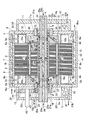
- FIG. 2 is a cross-sectional view taken along the line AA in FIG. It is sectional drawing which shows the motor concerning the 2nd Embodiment of this invention. It is sectional drawing which shows the motor concerning the 3rd Embodiment of this invention. It is sectional drawing which shows the motor concerning the 4th Embodiment of this invention.
- FIG. 6 is a BB cross-sectional view of the rotor and stator of FIG. 5. FIG. 6 is a cross-sectional view taken along the line CC of FIG. It is explanatory drawing which shows the sealing method by the stator seal
- an electric vehicle motor as an example of a rotating machine has a stator 2 fixed to an inner peripheral surface of an inner housing 1 as a housing.
- the rotor 3 is rotatably arranged on the inner peripheral side.
- the rotor 3 is rotatable with respect to a center shaft 4 (rotor shaft) serving as a fixed shaft.
- the center shaft 4 is fixed at both ends to outer housings 5 and 6 provided on both sides of the inner housing 1 in the axial direction. is there.
- axial direction is the axial direction of the central axis 4 (left and right direction in FIG. 1), and in the following description, when “axial direction” is used, the central axis 4 unless otherwise specified.
- the stator 2 includes a laminated stator core 7 constituted by laminating a plurality of electromagnetic steel plates as plate members made of a magnetic material, and a coil 8 inserted in a slot (not shown) formed in the stator core 7.
- the inner housing 1 includes a cylindrical portion 9 that is open at both ends in the axial direction, and left and right side wall portions 10 and 11 that are provided so as to close the openings at both ends of the cylindrical portion 9 in the axial direction. ing.
- stator core 7 is fixed to the inner peripheral surface of the cylindrical portion 9.
- a stator oil introduction flow path 9a into which oil as a cooling medium flows is formed along the axial direction at the upper part in the vertical direction of the cylindrical part 9, while the oil is placed outside the inner housing 1 at the lower part.
- a stator oil discharge channel 9b for discharging is formed along the axial direction.
- the above-described vertical direction corresponds to the vertical direction in FIG. 1 perpendicular to the axial direction of the cylindrical portion 9 arranged horizontally along the axial direction.
- the stator oil introduction passage 9a includes an oil introduction port 9ai on one side in the left axial direction in FIG. 1, and an oil discharge hole 9c (on the inner wall portion of the cylindrical portion 9 corresponding to the stator oil introduction passage 9a).
- a refrigerant supply port is formed, and oil introduced from the oil introduction port 9ai is discharged to the stator 2 side.
- the oil discharge hole 9c is formed at a position corresponding to the coil end portion 8a protruding from the stator core 7 of the coil 8 on both sides in the axial direction.
- stator oil discharge passage 9b is provided with an oil discharge port 9bo on the other side in the right axial direction in FIG. 1, and an oil discharge hole is formed in the inner wall portion of the cylindrical portion 9 corresponding to the stator oil discharge passage 9b.
- 9d is formed so that the oil on the stator 2 side is discharged to the stator oil discharge passage 9b.
- the oil discharge hole 9d is formed at a position corresponding to the coil end portion 8a in the same manner as the oil discharge hole 9c.
- the oil discharge hole 9d has a larger diameter than the oil discharge hole 9c. Further, a stator seal 12 (partition wall member) as a cylindrical sealing material made of resin or the like is provided on the inner peripheral side (rotor 3 side) of the coil end portion 8a.
- the rotor 3 positioned inside the stator 2 includes a laminated rotor core 14 formed by laminating a plurality of electromagnetic steel plates as magnetic plates, and an axial direction (electromagnetic) of the rotor core 14. Steel plate stacking direction) End rings 15 as end members provided at both ends.
- an annular air gap 16 is formed between the outer peripheral surface of the rotor core 14 and the inner peripheral surface of the stator core 7.
- a rectangular parallelepiped permanent magnet 17 that is long in the axial direction is embedded in the vicinity of the stator 2 side of the rotor core 14.
- a plurality of the permanent magnets 17 are provided at equal intervals along the circumferential direction of the circular rotor core 7, and are accommodated and fixed in through holes 18 serving as accommodation holes that penetrate the rotor core 14 in the axial direction. is doing.
- Cylindrical rotation support members 19 and 20 are fixed to both sides of the rotor core 14 in the axial direction of the end ring 15 described above.
- the rotation support members 19 and 20 protrude outward in the axial direction in a state in which the rotation support members 19 and 20 are inserted through openings 10a and 11a formed at the centers of the side wall portions 10 and 11 of the inner housing 1 through appropriate gaps.
- a central shaft 4 is rotatably supported via 21.
- the rotation support members 19 and 20 described above constitute a part of the rotor 3.
- the mounting hole 23a formed at the center of the outer side wall 23 one end of the central shaft 4 is fixed in a state of projecting to the outside.
- the outer housing 6 on the right side in FIG. 1 in which the other end portion of the central shaft 4 is fixedly supported is an outer cylindrical portion whose inner end portion in the axial direction is fixed to the side wall portion 11 of the inner housing 1. 24 and an outer side wall portion 25 that closes the outer cylindrical portion 24 on the side opposite to the inner housing 1.
- the other end portion of the central shaft 4 is fixed to the mounting hole 25a formed at the center of the outer side wall portion 25 in a state of projecting to the outside.
- a rotor oil introduction flow path 26 is formed that penetrates along the axial direction over the entire length thereof and into which oil as a cooling medium is introduced. Oil is introduced into the rotor oil introduction passage 26 from end openings 26a and 26b (inflow ports) at both axial ends by an oil supply means such as an oil pump (not shown).
- a cylindrical sleeve 27 is fixed to the inner wall of the through hole at the center of the rotor 3 into which the central shaft 4 is inserted, extending from the rotor core 14 to a part of the end rings 15 on both axial sides thereof.
- An annular gap 28 (annular space) is formed between the central axis 4 and the outer peripheral surface of the central shaft 4.
- a discharge port that communicates the gap 28 and the rotor oil introduction passage 26 (rotor shaft side refrigerant passage) in the central shaft 4 with the central shaft 4 at a position corresponding to the axial center of the rotor 3.
- a plurality of communication channels 29 are provided at equal intervals in the circumferential direction (for example, four locations).
- An annular gap 30 is also formed between the left and right end rings 15 positioned axially outside the sleeve 27 and the central shaft 4, and the inner peripheral surface of each end ring 15 corresponding to the gap 30.
- an internal screw 31 (spiral groove) is formed as a spiral-shaped portion.
- Each of the inner screws 31 is a screw seal that suppresses oil from flowing outward in the axial direction by transferring the oil existing around the inner screw 31 to the axial center side by the rotation of the rotor 3 including the end ring 15. Is configured.
- Each of the left and right gaps 30 communicates with an annular gap 32 between the rotation support members 19 and 20 and the central shaft 4 through an internal space 21a of the bearing 21.
- a rotor oil discharge port 32a is provided as a cooling medium discharge port, which is disposed outside the housing 1 and opens in gaps 5a and 6a between the outer housings 5 and 6 and the inner housing 1 (gap between the housing and the outer housing). ing. Further, rotor oil discharge holes 23b and 25b are formed at the lower ends of the outer side wall portions 23 and 25 of the outer housings 5 and 6, respectively.
- the oil passage 33 as a cooling medium passage is formed and communicated.
- a plurality of the oil flow paths 33 described above are formed along the circumferential direction corresponding to the through holes 18 (accommodating holes) accommodating the permanent magnets 17 described above.
- the oil flow path 33 includes a gap flow path 35 (FIG. 2) formed around the permanent magnet 17 in the through hole 18 and an inlet flow path 37 formed in the end ring 15 upstream of the gap flow path 35. (Intake) and an outlet channel 39 formed in the end ring 15 on the downstream side of the gap channel 35.
- the gap channel 35 is opposed to the semicircular channel 35 a that is formed to face part of both circumferential end surfaces of the permanent magnet 17 and the inner side surface of the permanent magnet 17. And a flat channel 35b to be formed.
- the semicircular channel 35a is inevitably formed when the permanent magnet 17 is accommodated and fixed, and the flat channel 35b may not be provided.
- the inlet channel 37 extends between the inner screw 31 and the rotor core 14 in the axial direction from the sleeve 27 to the end ring 15 in the radial direction of the central shaft 4, and the downstream end thereof is a through hole.
- One end opening 18a of 18 is communicated with.
- the outlet channel 39 is formed obliquely on the end ring 15 from the communicating portion toward the bearing 21 by communicating the upstream end with the other end opening 18b of the through-hole 18, and downstream thereof.
- the end on the side is opened around the inner side in the axial direction of the bearing 21. Therefore, the internal space 21 a of the bearing 21 communicates with the outlet passage 39.
- the oil passage 33 including the outlet passage 39, the internal space 21a of the bearing 21, and the rotor oil discharge port 32a are constituent elements of the rotor-side refrigerant passage.
- a plurality of oil flow paths 33 formed along the circumferential direction of the rotor 3 form an inlet flow path 37 on the right end ring 15 in FIG. 1 and an outlet flow path 39 on the left side in FIG. 1 is formed on the end ring 15 on the left side in FIG. 1 and an outlet channel 39 is formed in the end ring 15 in FIG.
- Those formed on the right end ring 15 are alternately set along the circumferential direction.
- the oil flowing through the plurality of oil flow paths 33 has two systems, one that flows from the front side to the back side in FIG. 2 and the one that flows from the back side to the front side in FIG. It exists in the circumferential direction alternately.
- the right rotation support member 20 has a simple cylindrical shape, but the left rotation support member 19 in FIG. 1 includes a side plate portion 41 fixed to the end ring 15.
- the outlet passage 39 and the inner periphery in the axial direction of the bearing 21 are communicated with each other through an oil hole 41 a formed in the side plate portion 41.
- An outer gear 43 is formed on the outer periphery of the end of the rotation support member 19 on the rotor oil discharge port 32a side.
- the output gear 44 is engaged with the outer gear 43, and the output gear 44 is further output.
- the shaft 45 is connected.
- the output shaft 45 protrudes outside from an opening 23c formed in the outer side wall portion 23 of the outer housing 5, and is connected to, for example, a differential mechanism of an electric vehicle.
- the rotor 3 rotates relative to the stator 2 by energization of the coil 8 of the stator 2, and at that time, the coil 8 of the stator 2 and the permanent magnet 17 of the rotor 3 generate heat.
- oil is introduced into the rotor oil introduction passage 26 of the central shaft 4 from an oil supply means such as an oil pump (not shown), and at the same time, the stator formed in the cylindrical portion 9 of the inner housing 1. Oil is introduced into the oil introduction channel 9a.
- the pressure of the oil in the gap 28 is maintained by this seal, and the oil that has flowed into the inlet flow path 37 by the pressure passes through the gap flow path 35 formed around the permanent magnet 17 of the through hole 18.
- the permanent magnet 17 that generates heat is cooled.
- the cooled oil flows out to the periphery of the bearing 21 through the outlet channel 39 and flows into the internal space 21a to lubricate the bearing 21.
- the bearing 21 is supplied with oil in a state in which the temperature is increased by taking heat from the permanent magnet 17 of the rotor 3 and the viscosity is lowered, so that the frictional resistance of the bearing 21 is reduced and mechanical loss is reduced. Reduction of the motor efficiency is achieved.
- the oil supplied to the bearing 21 flows into the outer housings 5 and 6 from the rotor oil discharge ports 32a of the rotation support members 19 and 20, and becomes an outer housing oil reservoir 47 at the lower portion to form the rotor oil discharge port 23b. 25b are discharged to the outside.
- the oil introduced into the stator oil introduction passage 9a of the inner housing 1 from the oil introduction port 9ai drops from the oil discharge hole 9c to the coil end portion 8a to cool the coil 8, particularly the coil 8, and then to the lower part.
- the inner housing oil pool 48 is retained.
- the oil in the inner housing oil reservoir 48 flows out from the oil discharge hole 9d to the stator oil discharge passage 9b, and is then discharged to the outside through the oil discharge port 9bo.
- the oil discharged to the outside after cooling the rotor 3 and the stator 2 is returned to an oil storage (not shown) and circulated in a radiated state in the electric vehicle according to the present embodiment, for example.
- the oil introduced into the central shaft 4 passes through the clearance 28 on the outer peripheral side of the central shaft 4 from the communication flow path 29 of the central shaft 4 to the rotor. 3, the temperature increase of the rotor 3, which is a heat generating part, can be efficiently suppressed, and the temperature increase of the permanent magnet 17 can be suppressed to suppress the demagnetization thereof.
- the oil after passing through the oil flow path 33 is discharged into the outer housings 5 and 6 outside the inner housing 1 provided with the stator 2 on the inner peripheral side. Intrusion of oil into the air gap 16 can be suppressed without setting a particularly complicated seal structure, and motor loss can be reduced.
- the oil as the refrigerant fluid for cooling the rotor 3 flows through the rotor side refrigerant flow path including the oil flow path 33, the internal space 21a of the bearing 21, and the rotor oil discharge port 32a.
- the rotor oil discharge port 32a is located outside the inner housing 1 with the stator 2 fixed inside. Therefore, the oil flowing through the rotor-side refrigerant flow path is discharged from the rotor oil discharge port 32a to the gaps 5a and 6a between the inner housing 1 and the outer housings 5 and 6 outside thereof.
- the oil flowing through the rotor-side refrigerant flow path can be reliably sealed to the stator 2 in the inner housing 1 without using a seal structure.
- the air gap 16 between the stator 2 and the rotor 3 can be reliably ensured.
- the oil cooling flow path uses the existing central shaft 4, end ring 15, rotor core 14, bearing 21, and rotation support members 19 and 20. It can be formed without adding new parts.
- the oil introduced into the stator oil introduction flow path 9a of the inner housing 1 drops and cools directly on the coil end portion 8a of the coil 8 that generates heat, in particular, the stator 2. Can be reduced. At that time, the oil that has cooled the stator 2 including the coil 8 can be prevented from entering the air gap 16 by the stator seal 12 to reduce motor loss.
- the sealing structure by the stator seal 12 is particularly complicated because the cylindrical stator seal 12 is simply arranged on the inner peripheral side of the coil end portion 8a and the coil 8 of the stator 2 and the rotor 3 are cut off. No seal structure is required.
- the oil flow path 33 inside the rotor 3 is formed across the rotor core 14 provided with the permanent magnets 17 and the end rings 15 provided at both end portions in the axial direction of the rotor core 14. Therefore, it is not necessary to separately provide a dedicated member for forming the flow path, and an existing motor constituent member can be used, so that an increase in material cost can be suppressed.
- the rotor core 14 is configured by a laminated body in which a plurality of electromagnetic steel plates are laminated, and the oil flow path 33 provided in the rotor core 14 is linearly formed in a direction parallel to the lamination direction of the plurality of electromagnetic steel plates. Since it forms, the shape of a some electromagnetic steel plate can be unified, and manufacturing cost can be reduced.
- the rotor core 14 is provided with a through hole 18 for accommodating the permanent magnet 17, and the oil flow path 33 is a gap between the inner wall of the through hole 18 and the permanent magnet 17. There is no need to separately form a flow path, and the manufacturing cost can be reduced accordingly.
- the clearance channel 35 that is a component of the rotor-side refrigerant channel can be easily configured using the through hole 18 for accommodating the permanent magnet 17 of the rotor 3. Further, since the oil flowing through the gap passage 35 between the through hole 18 and the permanent magnet 17 contacts the permanent magnet 17 which is the largest heat release source on the rotor 3 side, the rotor 3 can be efficiently cooled. Can do.
- a plurality of oil flow paths 33 inside the rotor 3 are provided along the rotation direction of the rotor 3, and the oil flow direction between the plurality of oil flow paths 33 is not uniform. Since the flow directions of the oil flowing through the oil flow path 33 are set to be opposite to each other along the circumferential direction of FIG. 2, the rotor 3 can be cooled more efficiently. Furthermore, by changing the shape of the end ring 15, the path flowing through the permanent magnet 17 can be freely changed.
- the bearing 21 that supports the rotor 3 so as to be rotatable with respect to the central shaft 4 is disposed in the vicinity of the outlet of the outlet channel 39 formed in the end ring 15. At this time, the oil flowing out from the outlet channel 39 takes heat from the rotor 3, particularly the permanent magnet 17, and the temperature rises and the viscosity is lowered. Therefore, the frictional resistance of the bearing 21 is reduced and the mechanical loss is reduced. It can reduce and contribute to the high efficiency of a motor.
- the oil that has flowed through the gap flow path 35 that is a component of the rotor-side refrigerant flow path and is heated by the heat radiation of the rotor 3 to decrease the viscosity passes through the internal space 21a of the bearing 21 as lubricating oil. For this reason, the increase in the stirring resistance of the bearing 21 can be suppressed simultaneously with the cooling of the rotor 3.
- the oil on the bearing 21 side is moved to the communication channel 29 side of the central shaft 4 by the rotation of the rotor 3 on the inner surface of the end ring 15 between the bearing 21 and the communication channel 29 of the central shaft 4.
- An internal screw 31 to be transferred is provided.
- the oil is applied with pressure toward the inner side in the axial direction, and is prevented from moving toward the bearing 21 and can be sealed.
- the pressure in the gap 28 is maintained by this seal, and the oil can be efficiently fed into the inlet channel 37 of the oil channel 33 on the rotor 3 side by the pressure.
- the seal structure using the inner screw 31 can be used corresponding to the rotational speed of a wide range.
- stator seal 12 that seals the oil supplied to the stator 2 with respect to the rotor 3 is provided, the oil loss to the air gap 16 can be suppressed and the motor loss can be reduced.
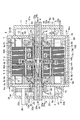
- the rotor core 14 is divided into two parts in the axial direction with the central part in the axial direction as a boundary. , 17B, an intermediate ring 49 is interposed.
- the intermediate ring 49 is formed with a radial channel 49a as an inlet channel extending in the radial direction and an axial channel 49b extending in the axial direction communicating with the radially outer end of the radial channel 49a. is doing.
- the radial flow path 49 a communicates with an opening hole 27 a formed in the sleeve 27 with a radially inner end opening.
- both axial openings of the axial flow passage 49b are provided around the through holes 18A and 18B corresponding to the through holes 18 shown in FIG. 2 in which the permanent magnets 17A and 17B in the rotor cores 14A and 14B are embedded. It communicates with the gap channel (corresponding to the gap channel 35 in FIG. 2).
- the gap flow path around the through holes 18A and 18B here constitutes an axial flow path for flowing the oil flowing into the radial flow path 49a, which is an inlet flow path, outward in the axial direction.
- the left and right end rings 15 each have an outlet channel 39 similar to the outlet channel 39 formed in the left end ring 15 in FIG.
- the upstream end opening communicates with the clearance channel around the through holes 18A and 18B.
- an inner screw similar to the inner screw 31 formed on the inner surface of the end ring 15 described above extends from the axially outer end portion to a position near the opening hole 27a. 50 is formed, and also in this portion, a screw seal is formed.
- the oil introduced from the end openings 26a and 26b into the rotor oil introduction passage 26 of the central shaft 4 is transmitted from the communication passage 29 to the central shaft 4. And flow into the radial flow path 49a and the axial flow path 49b in the intermediate ring 49 through the outer peripheral gap 28 and the opening hole 27a of the sleeve 27. Thereafter, the oil in the intermediate ring 49 passes through the clearance passages formed around the permanent magnets 17A and 17B of the through holes 18A and 18B, thereby generating heat in the same manner as in the first embodiment. Cool 17A and 17B.
- the oil whose temperature has risen after cooling flows out from the outlet passage 39 toward the bearing 21 to lubricate the bearing 21 and then, from the rotor oil discharge port 32a, the outer housings 5 and 6 as in the first embodiment. Flows out.
- the oil introduced into the rotor oil introduction passage 26 of the central shaft 4 is supplied to the central portion where the temperature of the rotor 3 is likely to be higher, and flows from the central portion toward the outside in the axial direction.
- the rotor 3 can be cooled more efficiently.
- the inner thread 50 is also formed on the inner surface of the sleeve 27 to constitute the screw seal. Therefore, the axial length of the screw seal is longer than that of the first embodiment. It has become. For this reason, the sealing performance is improved accordingly, and the pressure applied to the inner side in the axial direction (on the intermediate ring 49 side) by the sealing mechanism is further increased, and even if the initial supply pressure into the central shaft 4 is low, The oil supply pressure to the intermediate ring 49 side can be kept high, and the oil circulation efficiency can be increased to further increase the cooling efficiency.
- the central shaft 4 is supported with respect to the outer side wall portions 23, 25 of the left and right outer housings 5, 6 with respect to the first embodiment shown in FIG. 1.
- Rotating shafts 51 and 52 are rotatable.
- the output gear 44 is fixed to a counter shaft 53 that is rotatably attached to the side wall portion 10 of the inner housing 1 and the outer side wall portion 23 of the outer housing 5 at both ends. Is fixed.
- a central shaft gear 55 is fixed to the rotatable central shaft 4, and the central shaft gear 55 and the counter shaft gear 54 are engaged with each other.
- the output gear 44, the counter shaft 53, and the counter shaft gear 54 are rotated in the opposite direction to the rotor 3 by the rotation of the rotor 3, and at the same time, the center shaft gear 55 that is meshed with the counter shaft gear 54 is The central shaft 4 rotates in the same direction as the rotor 3.
- the rotation of the rotor 3 can be reduced or increased according to the gear ratio to the central shaft 4 to transmit power, and the central shaft 4 can be used as an output shaft to transmit power to the outside.
- the stator core 7 includes an annular yoke 71 a and a plurality of teeth 71 b arranged in a state of protruding toward the central axis of the yoke 71 a along the circumferential direction of the yoke 71 a.
- the stator core 7 provided with eight teeth 71 b and eight slots 71 c is shown to avoid complication, but the number of these can be arbitrarily set.
- the teeth 71b provided in the stator core 7 function as magnetic poles when a three-phase alternating current is supplied to the coil 8 inserted in the slot 71c.
- the stator core 7 is arranged around the rotor 3 so that the protruding direction of each tooth 71b is directed to the rotation axis of the central shaft 4, and in this arrangement, the gap between the stator core 14 and the rotor core 14 is the air gap 16 described above.
- the protrusion amount of the teeth 71b is set.
- the coil 8 is inserted in a slot 71c formed in the stator core 7, and forms a magnetic pole corresponding to a current supplied from the outside.
- the coil 8 includes a first coil supplied with a U-phase current, a second coil supplied with a V-phase current, and a third coil supplied with a W-phase current.
- the first to third coils are sequentially arranged in the circumferential direction of the stator core 7. For this reason, when a three-phase alternating current is supplied to the coil 8, a rotating magnetic field is formed along the inner peripheral surface of the stator core 7.
- the coil 8 is attached to the stator core 7 such that the coil end portion 8 a protrudes from both end portions of the stator core 7. That is, as shown in FIG. 1, the coil end 8 a protrudes leftward from the left end E ⁇ b> 1 of the stator core 7, and the coil end 8 a protrudes from the right end E ⁇ b> 2 of the stator core 7. Since all the coils 8 are attached to the stator core 7 in such a state, the coil end portions 8a are arranged in a circle along the end portions E1 and E2 of the stator core 7.
- ring-shaped mold members 60a and 60b along the end portions E1 and E2 are formed on the end portions E1 and E2 of the stator core 7 so as to cover the root portion of the coil end portion 8a.
- the mold members 60a and 60b are covered with the mold members 60a and 60b because the oil is used for the rotor while cooling with cooling oil is possible. This is to prevent the air gap 16 that is the gap between the stator 3 and the stator 2 from entering.
- stator 2 (coil 8) is efficiently cooled.
- the end portions of the stator seals 12 and 12 forming part of the side wall 10 and the side wall 11 constituting the inner housing 1 are sealed with mold members 60a and 60b, and the rotor 3 is disposed.
- the oil is prevented from entering the air gap 16 by separating the space S1 (first space) and the space S2 (second space) in which the coil end 8a is disposed.
- the thickness of the mold members 60a and 60b is set in consideration of the degree of sealing and the cooling efficiency. In other words, if the tips of the stator seals 12 and 12 cannot be sealed, the oil will enter the air gap 16, so that the thickness of the mold members 60 a and 60 b is at least sealed at the tips of the stator seals 12 and 12. It must be of a thickness that can be done. Further, as the thickness of the mold members 60a and 60b increases, the exposed portion of the coil end portion 8a decreases, and the cooling efficiency using oil decreases. For this reason, the thickness of the mold members 60a and 60b needs to be equal to or less than a thickness that can ensure the required cooling efficiency.
- the specific thickness of the mold members 60a and 60b is set to, for example, about 50% of the protruding amount of the coil end portion 8a, and preferably about 20 to 30% of the protruding amount of the coil end portion 8a.
- a mold member 60 c similar to the mold members 60 a and 60 b is formed inside the stator core 7 so as to fill a gap inside the slot 71 c formed in the stator core 7.
- the mold member 60c is provided to fix the coil 8 inserted in the slot 71c to prevent vibration of the coil 8 in the slot 71c and to increase the cooling efficiency of the coil 8.
- the mold members 60a and 60b covering the root portion of the coil end portion 8a and the mold member 60c for fixing the coil 8 in the slot 71c have high thermal conductivity. It is desirable. For example, it is desirable to form the mold members 60a, 60b, and 60c using a heat conductive resin mixed with a heat conductive filler having insulating properties such as silicon oxide (SiO 2 ) and aluminum oxide (Al 2 O 3 ). .
- the mold members 60a and 60b and the mold member 60c may be formed using materials having the same thermal conductivity, or may be formed of materials having different thermal conductivities.
- the coil 8 attached to the stator core 7 has a high density of wire material (wire material forming the coil 8) at the portion inserted into the slot 71c and the tip portion of the coil end portion 8a, and the wire material at the root portion of the coil end portion 8a.
- the density is low.
- the thermal resistance is higher in the portion where the wire density is lower (the root portion of the coil end portion 8a) than in the portion where the wire density is higher (inside the slot 71c and the tip end portion of the coil end portion 8a). Therefore, it is desirable to form the mold members 60a and 60b using a material having a higher thermal conductivity than the material of the mold member 60c.
- the mold resins 60a and 60b formed at the end portions E1 and E2 of the stator core 7 for example, when the viscosity at the time of formation is given priority over the heat conductivity after the formation, it is lower than the material of the mold member 60c.
- the mold resins 60a and 60b may be formed using a material having thermal conductivity and viscosity. Such a material is necessary when, for example, the material of the mold member 60c cannot sufficiently fill the gap at the root portion of the coil end portion 8a (the gap between the wire and the wire forming the coil 8).
- the mold members 60a and 60b and the mold member 60c may be formed of different materials.
- the mold members 60a and 60b are also used to seal the front ends of the stator seals 12 and 12, the mold members 60a and 60b are formed using a material that is elastic even after curing.
- the mold member 60c is formed by using a material having a high hardness after curing.
- An oil discharge hole 9c (refrigerant supply port) formed in the inner wall portion of the cylindrical portion 9 of the inner housing 1 is covered with exposed portions (mold members 60a and 60b) of the coil end portion 8a protruding from the end portions E1 and E2 of the stator core 7.
- exposed portions (mold members 60a and 60b) of the coil end portion 8a protruding from the end portions E1 and E2 of the stator core 7.
- each of the upper part of the (not-shown part) it is provided at a plurality of locations along the rotation direction of the rotor 3.
- FIG. 7 is a sectional view taken along the line CC in FIG.
- the oil discharge holes 9c are provided at three locations along the rotation direction of the central shaft 4 above the exposed portion of the coil end portion 32a. These oil discharge holes 9c are arranged in the rotation direction of the rotor 3 with an interval of 20 to 70 °, for example.
- the oil supplied from each of the oil discharge holes 9c is dropped on different portions of the coil end portion 8a, and moves downward through the exposed portion of the coil end portion 8a.
- the bottom portion of the cylindrical portion 9 is an inner housing oil sump 48 in which oil that has moved downward through the exposed portion of the coil end 8a is temporarily stored.
- oil discharge holes 9c are formed at three locations along the rotation direction of the rotor 3 .
- the oil discharge holes 9 c are formed according to the size of the motor, etc. It may be formed at two or four or more locations along the rotation direction of the rotor 3.
- the oil discharge holes 9c are not necessarily arranged in a straight line in the rotation direction of the rotor 3, and may be arranged so that the positions in the axial direction are different.
- the stator seal 12 described above is integrally protruded from the inner side surface of each side wall portion 10, 11 of the inner housing 1.
- Each stator seal 12 has an outer diameter that is approximately the same as the inner diameter of the stator core 7 (mold member 60a), and is attached in a state where its tip is in contact with the mold member 60a, and a space S1 in which the rotor 3 is disposed. Is separated from the space S2 in which the coil end portion 8a is disposed. That is, the space S1 and S2 are separated by sealing the tip of the stator seal 12 with the mold member 60a.
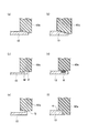
- FIG. 8 is a view showing a sealing method by the stator seal 12 in the fourth embodiment of the present invention.
- the stator seals 12 and 12 provided on the side wall portion 10 and the side wall portion 11 are sealed by contacting the tip portions of the stator seals 12 and 12 with the mold members 60a and 60b.
- various methods are conceivable as the method of bringing the part into contact with the mold members 60a and 60b (sealing method).
- a method of sealing the stator seal 12 with the mold member 60a will be described.
- the outer peripheral surface at the front end portion of the stator seal 12 and the inner peripheral surface of the mold member 60a are both tapered, and the front end portion of the stator seal 12 is formed over the entire periphery.
- the contact area between the stator seal 12 and the mold member 60a is increased by engaging with the inner peripheral surface of 60a.
- the outer peripheral surface at the front end of the stator seal 12 is formed in a taper shape, and the inner peripheral surface of the mold member 60a is formed in a step shape, so that the front end of the stator seal 12 is entirely formed. This is a method of increasing the contact location between the stator seal 12 and the mold member 60a by engaging with the inner peripheral surface of the mold member 60a over the circumference.
- the flange F is formed at the front end portion of the stator seal 12, and the groove M is formed at the inner peripheral surface of the mold member 60a.
- a groove is formed at the tip of the stator seal 12 to provide an O-ring R, and the O-ring R provided at the tip of the stator seal 12 is molded over the entire circumference. This is a method of increasing the degree of sealing between the stator seal 12 and the mold member 60a by contacting the inner peripheral surface of 60a.
- a protrusion Q is formed over the entire outer periphery of the tip of the stator seal 12, and the inner periphery of the mold member 60a is formed over the entire periphery of the protrusion Q.
- the degree of sealing between the stator seal 12 and the mold member 60a is increased.
- a notch K is formed on the inner peripheral surface side of the mold member 60a, and the leading end of the stator seal 12 is formed in the notch K formed in the mold member 60a over the entire circumference. This is a method of increasing the degree of sealing between the stator seal 12 and the mold member 60a by engaging them.
- cooling oil is supplied to the oil discharge holes 9c by a pump or the like (not shown), and is dropped at a plurality of locations in the exposed portion of the coil end portion 8a disposed in the space S2.
- the oil dropped on the coil end portion 8a moves downward through the exposed portion of the coil end portion 8a.
- oil can be spread over the entire coil end portion 8a arranged along the end portion of the stator core 7 by dropping oil at a plurality of locations on the coil end portion 8a, The part 8a can be efficiently cooled.
- stator seals 12 and 12 on the side wall portions 10 and 11 are sealed by the mold members 60a and 60b, so that the space S1 in which the rotor 3 is disposed and the coil end portion 8a are disposed on both the left and right sides of the stator core 7. Is separated from the space S2. For this reason, even if oil is supplied into the space S2 from the oil discharge hole 9c, the oil can be prevented from entering the air gap 16.
- the mold members 60a and 60b are formed at both end portions of the stator core 7 so as to cover the root portion of the coil end portion 8a, and the space S1 in which the rotor 3 is disposed and the coil end portion 8a.
- Stator seals 12 and 12 are separated from the space S2 in which the mold members 60 are disposed in contact with the mold members 60a and 60b, respectively.
- FIG. 9 is sectional drawing which shows the structure of the motor as a rotary machine by the 5th Embodiment of this invention.
- the motor of this embodiment shown in FIG. 9 is provided with a mold member 61 instead of the mold member 60a on the side wall 10 side in the motor of the fourth embodiment, and the stator seal 12a is integrated with the side wall 10 instead of the stator seal 12. This is different from the motor according to the fifth embodiment shown in FIG.
- the mold member 61 is formed so that the shape of the central axis 4 in the axial direction is asymmetric with respect to the mold member 60b formed on the right side of the stator core 7.
- the mold member 61 includes an annular portion 61a formed in an annular shape along the end portion (end portion E1) of the stator core 7 so as to cover the root portion of the coil end portion 8a, and the annular portion 61a. It has a shape having a cylindrical protruding portion 61b protruding to the left.
- the annular portion 61a has the same shape as the mold member 60a shown in FIG.
- the stator seal 12 a of the side wall portion 10 is formed to have a shorter axial length than the stator seal 12 of the side wall portion 11. This is because the above-described mold member 61 has a cylindrical protruding portion 61b that protrudes to the left from the annular portion 61a, so that the stator seal 12a has a length to the annular portion 61a of the mold member 61. This is because the stator seal 12a can be brought into contact with the mold member 61 even if not.
- the mold member 61 and the mold member 60b are formed at both ends of the stator core 7 so as to cover the root portion of the coil end portion 8a, and the space S1 in which the rotor 3 is disposed and the coil end portion 8a are formed.
- the partition walls 52b and 53c that separate the arranged space S2 are attached in contact with the mold members 61 and 60b, respectively.
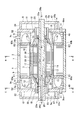
- FIG. 10 is sectional drawing which shows the structure of the motor as a rotary machine by the 6th Embodiment of this invention.
- the motor of the sixth embodiment shown in FIG. 10 the case where the adhesive force between the laminated electrical steel sheets constituting the rotor core 14 in the first to fifth embodiments described above decreases as the temperature of the rotor 3 increases. Assuming that oil leakage to the air gap 16 is further prevented.
- illustration of an output system of rotation of the motor is omitted. The detailed configuration of the motor according to the sixth embodiment will be described below.
- the cylindrical sleeve 27 (ring-shaped sleeve member) has an outer diameter and an inner diameter larger than those of the first to fifth embodiments described above, and accordingly, the rotor core 14 and the end.
- the dimension in the diameter direction of the ring 15 is shortened.
- the sleeve 27 is attached to the outer peripheral surface of a cylindrical rotating body 70 (second rotating body portion) forming a part of the rotor 3, and the rotor core 14 and the end ring 15 are attached to the outer peripheral surface of the sleeve 27.
- the oil flow path 33 of the rotor 3 is formed not in the rotor core 14 and the end ring 15 but in the rotating body 70 as described later. Further, in the present embodiment, the inner screw 31 is formed not on the inner peripheral surface of the left and right end rings 15 but on the inner peripheral surface of the rotating body 70 near the bearing 21.
- Rotating support members 19 and 20 are attached to both end faces of the rotating body 70 so that the positions of the central axes coincide with each other.
- the rotation support members 19 and 20 form an annular gap 32 (first flow path) for guiding oil in the axial direction of the central shaft 4 between the central shaft 4.
- the rotating body 70 is formed with a larger diameter than the rotation support members 19 and 20.
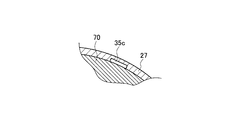
- a groove 35 c (concave portion) that forms a clearance channel 35 (refrigerant channel) of the oil channel 33 with the inner peripheral surface of the sleeve 27 is formed.
- eight grooves 35 c having a rectangular cross-sectional shape are formed at equal intervals along the circumferential direction of the rotating body 70.
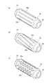
- FIG. 12 is a perspective view of the rotating body 70 provided in the rotor 3 according to the embodiment of the present invention.
- the groove 35c is formed in the rotating body 70 so as to extend linearly in the axial direction.
- the groove 35c is not formed so as to reach both end portions in the axial direction of the rotating body 70, but extends from the vicinity of one end portion in the axial direction of the rotating body 70 to the vicinity of the other end portion. Is formed. This is to prevent the oil supplied to the groove 35 c forming the gap channel 35 from leaking between the rotating body 70 and the sleeve 27 as much as possible.
- the groove 35c formed on the outer peripheral surface of the rotating body 70 may be formed in a spiral shape along the axial direction as shown in FIG. 12 (b). As shown, it may be formed in a meandering shape along the axial direction.
- the temperature distribution in the circumferential direction of the rotor 3 is made uniform compared to the case where the groove 35c is formed in a straight shape as shown in FIG. 12 (a). can do.
- the groove 35c is formed in a meandering shape as shown in FIG. 12C, the cooling efficiency of the rotor 3 can be improved as compared with the case where the groove 35c is formed in a linear shape as shown in FIG. it can.
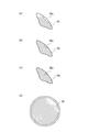
- FIG. 13 is a diagram showing a cross-sectional shape of a groove formed in a rotating shaft provided in a motor as a rotating machine according to an embodiment of the present invention.
- a groove 35 c having a rectangular cross section is formed on the outer peripheral surface of the rotating body 70 of the central shaft 4.
- the cross-sectional shape of the groove 35c may be an arc shape shown in FIG. 13B (an arc shape convex toward the rotation axis), or a triangular shape shown in FIG. 13C (one vertex is rotated). It may be a triangle shape toward the axis).
- annular gap 28 formed between the inner peripheral surface of the rotator 70 and the outer peripheral surface of the central shaft 4, and a groove 35 c formed on the outer peripheral surface of the rotator 70.
- An inlet channel 37 and an outlet channel 39 (second channel) communicating with each other are formed. As shown in FIG. 11, these inlet channel 37 and outlet channel 39 extend in the radial direction (specifically, four different directions) of the rotating body 70 from the gap 28 toward the groove 35c. Is formed.
- the oil flow path 33 configured by the gap flow path 35, the inlet flow path 37, and the outlet flow path 39 described above corresponds to the circumferential direction corresponding to the through hole 18 (accommodating hole) that accommodates the permanent magnet 17 described above.
- a plurality are formed along. That is, as shown in FIG. 10, the oil flow path 33 is close to the permanent magnet 17 of the through hole 18, and the gap flow path 35 is formed by a groove 35 c formed on the outer peripheral surface of the rotating body 70.
- An inlet channel 37 (intake) formed in the upstream rotating body 70 and an outlet channel 39 formed in the rotating body 70 downstream of the gap channel 35 are provided.
- the inlet channel 37 extends toward the radial direction of the central shaft 4 at a position closer to the center in the axial direction than the inner screw 31 on the inner peripheral surface of the rotating body 70, and the downstream end thereof is a groove 35 c. It is made to communicate with one end.
- the outlet channel 39 has an upstream end communicated with the other end of the groove 35c and is formed obliquely on the rotating body 70 from the communicating portion toward the bearing 21, and the downstream end thereof is formed.
- An opening is formed around the inner side of the bearing 21 in the axial direction. Therefore, the internal space 21 a of the bearing 21 communicates with the outlet passage 39.
- the oil passage 33 including the outlet passage 39, the internal space 21a of the bearing 21, and the rotor oil discharge port 32a are constituent elements of the rotor-side refrigerant passage.
- the plurality of oil flow paths 33 formed along the circumferential direction of the rotating body 70 alternately replace the positions of the inlet flow path 37 and the outlet flow path 39 in the axial direction of the rotating body 70. Therefore, the oil flowing through the gap passages 35 of the plurality of oil passages 33 flows from the front side to the back side in FIG. 11 and flows from the back side to the front side in FIG. Two systems exist alternately in the circumferential direction.
- the rotating body 70 is positioned in the rotational direction with respect to the rotor core 14 such that each of the grooves 35 c formed on the outer peripheral surface of the rotating body 70 is closest to each of the permanent magnets 17 of the rotor core 14.
- This is to increase the cooling efficiency of the rotor 3 by bringing the groove 35c constituting the gap flow path 35 through which oil is guided as close as possible to the permanent magnet 17 that is a heat generation source.
- the rotor 3 includes a rotor core 14, a permanent magnet 17, and an end ring 15, is attached to a rotating body 70 together with a sleeve 27, and is configured to be rotatable around the central axis 4 together with the rotating body 70.
- the rotor core 14 is configured by laminating a plurality of electromagnetic steel plates as a plate material made of a magnetic material with an adhesive, and the above-described rotating body 70 is inserted into the central portion together with the sleeve 27. It is.
- the end ring 15 is an annular member that is provided on both sides of the rotor core 14 in the axial direction (lamination direction of the electromagnetic steel plates) and sandwiches the rotor core 14 in the axial direction.
- the length of the rotor core 14 in the axial direction is set so that the length including the thickness of the end rings 15 provided on both sides in the axial direction of the rotor core 14 is equal to the length of the rotating body 70 in the axial direction. Yes.
- the sleeve 27 is an annular member provided between the rotating body 70 and the rotor 3, and is formed of the same material as the central shaft 4 and the rotating body 70, for example.
- the sleeve 27 is set so that its axial length is equal to the axial length of the rotating body 70, and is fitted to the outer peripheral surface of the rotating body 70 by shrink fitting, for example.
- a gap channel 35 is formed between the rotating body 70 and the sleeve 27 by the groove 35 c.
- the oil guided to the groove 35 c as the gap flow path 35 flows between the rotating body 70 and the sleeve 27. For this reason, even if the rotor 3 rotates at a high speed in a situation where the adhesive strength of the adhesive that adheres the magnetic steel sheets constituting the rotor core 14 is reduced due to the temperature rise of the motor, the groove 35c as the gap channel 35 is formed. It is possible to prevent leakage of guided oil.
- the rotor core 14 described above is fitted to the outer peripheral surface of the sleeve 27 by shrink fitting, for example.
- the sleeve 27 is fitted to the outer peripheral surface of the rotating body 70 by shrink fitting or the like, there is almost no leakage of the oil guided to the groove 35c, but the pressure of the oil guided to the groove 35c. If the value is high, there is a possibility of leakage. For this reason, it is desirable that the sleeve 27 is brazed to the rotating body 70 at both ends in the axial direction, welded, or sealed by providing a sealing material such as an O-ring between the sleeve 27 and the rotating body 70.
- the pressure of the oil in the gap 28 is held by this seal, and the oil flows into the inlet channel 37 from the gap 28 by the pressure.
- the oil that has flowed into the inlet channel 37 is guided to a groove 35 c formed on the outer peripheral surface of the rotating body 70.
- the gap channel 35 is formed by the groove 35c between the rotating body 70 and the sleeve 27, the permanent magnet 17 is cooled when the oil is guided to the groove 35c.
- the gap channel 35 is disposed so as to be closest to the permanent magnet 17 provided in the rotor core 14, the rotor core 14 and the permanent magnet 17 can be efficiently cooled.
- the oil that has passed through the gap channel 35 by the groove 35c flows out to the periphery of the bearing 21 through the outlet channel 39, flows into the internal space 21a, and lubricates the bearing 21.
- the groove 35c that forms the clearance channel 35 that guides oil is formed on the outer peripheral surface of the rotor 70 of the rotor 3, and the rotor 70 and the rotor core 14 between which the groove 35c is formed are formed.
- An annular sleeve 27 is provided in the oil pipe so that the oil guided to the groove 35 c flows between the rotating body 70 and the sleeve 27.
- a groove 35 c is formed on the outer peripheral surface of the rotating body 70 having a larger diameter than the rotation support members 19 and 20, and the rotor 70 and the rotor core 14 between which the groove 35 c is formed are formed.
- a coolant channel is formed at a position close to the permanent magnet 17. For this reason, the rotor 3 including the permanent magnet 17 can be cooled easily and efficiently.
- the number, length, and shape (including the cross-sectional shape) of the grooves 35c formed on the outer peripheral surface of the rotating body 70 are not limited to the above-described shapes. Further, the arrangement and the positional relationship in the rotation direction (circumferential direction) of the groove 35c formed on the outer peripheral surface of the rotating body 70 and the permanent magnet 17 provided in the rotor core 14 are not limited to the above-described positional relationship, and are arbitrary. Arrangement and positional relationship.
- the rotation support members 19 and 20 and the rotating body 70 are integrally formed as an example.
- the rotation support members 19 and 20 and the rotating body 70 may be composed of different members.
- the groove 35 c as the concave portion forming the gap flow path 35 is formed on the outer peripheral surface of the rotating body 70
- the groove 35c may be formed on the inner peripheral surface of the sleeve 27 as shown in FIG. 14, and the groove 35c is formed between the outer peripheral surface of the rotating body 70 and the inner peripheral surface of the sleeve 27 as shown in FIG. It may be formed on both sides.
- the present invention can be widely applied to rotating machines that convert electric power into rotational force, or rotating machines that convert electric power into rotational power, such as a generator.
- Inner housing (housing) 2 Stator 3 Rotor 4 Center axis (rotor axis) 5,6 Outer housing 5a, 6a Gap between inner housing and outer housing (gap between housing and outer housing) 7 Stator core 8 Coil 8a Coil end 9c Oil discharge hole (refrigerant supply port) 12, 12a Stator seal (seal material, partition member) 14, 14A, 14B Rotor core 15 End ring (end member) 17, 17A, 17B Permanent magnet 18 Through hole of rotor core (accommodating hole for accommodating permanent magnet) 19, 20 Rotating support member (first rotating body) 21 Bearing that rotatably supports the rotor with respect to the central axis 21a Internal space of the bearing (rotor side refrigerant flow path) 26 Rotor oil introduction flow path (rotor shaft side refrigerant flow path) 26a, 26b End opening (inlet) 27 Sleeve 28 Clearance between rotor and central axis (annular space) 29 Communication channel (outlet) 31 Internal thread on the inner peripheral surface of the
Abstract
Priority Applications (5)
| Application Number | Priority Date | Filing Date | Title |
|---|---|---|---|
| JP2012511726A JP5445675B2 (ja) | 2010-04-23 | 2011-04-22 | 回転機 |
| EP11772115.9A EP2562914A4 (fr) | 2010-04-23 | 2011-04-22 | Machine rotative |
| KR1020127030056A KR101340403B1 (ko) | 2010-04-23 | 2011-04-22 | 회전기 |
| US13/642,328 US8928195B2 (en) | 2010-04-23 | 2011-04-22 | Rotary machine |
| CN201180019748.0A CN102906969B (zh) | 2010-04-23 | 2011-04-22 | 旋转机械 |
Applications Claiming Priority (6)
| Application Number | Priority Date | Filing Date | Title |
|---|---|---|---|
| JP2010-099805 | 2010-04-23 | ||
| JP2010099805 | 2010-04-23 | ||
| JP2010286586 | 2010-12-22 | ||
| JP2010-286586 | 2010-12-22 | ||
| JP2011-068204 | 2011-03-25 | ||
| JP2011068204 | 2011-03-25 |
Publications (1)
| Publication Number | Publication Date |
|---|---|
| WO2011132784A1 true WO2011132784A1 (fr) | 2011-10-27 |
Family
ID=44834298
Family Applications (1)
| Application Number | Title | Priority Date | Filing Date |
|---|---|---|---|
| PCT/JP2011/059976 WO2011132784A1 (fr) | 2010-04-23 | 2011-04-22 | Machine rotative |
Country Status (6)
| Country | Link |
|---|---|
| US (1) | US8928195B2 (fr) |
| EP (1) | EP2562914A4 (fr) |
| JP (1) | JP5445675B2 (fr) |
| KR (1) | KR101340403B1 (fr) |
| CN (1) | CN102906969B (fr) |
| WO (1) | WO2011132784A1 (fr) |
Cited By (17)
| Publication number | Priority date | Publication date | Assignee | Title |
|---|---|---|---|---|
| CN103633761A (zh) * | 2012-08-27 | 2014-03-12 | 丰田自动车株式会社 | 旋转电机 |
| CN104704723A (zh) * | 2012-08-08 | 2015-06-10 | Ac推进有限公司 | 液冷式电动机 |
| CN104838567A (zh) * | 2012-10-09 | 2015-08-12 | 整体动力系统有限公司 | 旋转设备、马达以及冷却马达的方法 |
| US20150288252A1 (en) * | 2012-11-12 | 2015-10-08 | Siemens Aktiengesellschaft | Cooling system for electric generators |
| JP2016063734A (ja) * | 2015-02-20 | 2016-04-25 | 日本電産株式会社 | モータ |
| US20160372983A1 (en) * | 2015-06-16 | 2016-12-22 | Toyota Jidosha Kabushiki Kaisha | Rotor of rotary electric machine |
| US20170012503A1 (en) * | 2015-07-06 | 2017-01-12 | Toyota Jidosha Kabushiki Kaisha | Rotor of rotary electric machine |
| JP2018170943A (ja) * | 2017-03-30 | 2018-11-01 | 株式会社小松製作所 | ロータ、電動機及び油圧ショベル |
| JP2019134567A (ja) * | 2018-01-30 | 2019-08-08 | 本田技研工業株式会社 | 回転電機のステータ |
| JP2019170150A (ja) * | 2018-03-22 | 2019-10-03 | 本田技研工業株式会社 | 回転電気のロータ |
| JP2020058194A (ja) * | 2018-10-04 | 2020-04-09 | トヨタ自動車株式会社 | 回転電機 |
| WO2020105467A1 (fr) * | 2018-11-20 | 2020-05-28 | ジヤトコ株式会社 | Structure de refroidissement d'huile moteur |
| WO2021117884A1 (fr) * | 2019-12-12 | 2021-06-17 | 株式会社Ihi | Dispositif de rotation |
| JP2022041828A (ja) * | 2020-08-31 | 2022-03-11 | ジン-ジン エレクトリック テクノロジーズ カンパニー リミテッド | モータ軸 |
| US11309766B2 (en) * | 2020-01-07 | 2022-04-19 | GM Global Technology Operations LLC | Cooling jacket with coolant mass balancing for electric motors |
| WO2022180875A1 (fr) * | 2021-02-24 | 2022-09-01 | 日本電産株式会社 | Machine électrique tournante et dispositif d'entraînement |
| WO2023234183A1 (fr) * | 2022-05-31 | 2023-12-07 | ヤマハ発動機株式会社 | Moteur et unité moteur |
Families Citing this family (102)
| Publication number | Priority date | Publication date | Assignee | Title |
|---|---|---|---|---|
| ES2453218T3 (es) * | 2010-10-29 | 2014-04-04 | Günther Hirn | Accionamiento eléctrico para una bicicleta |
| WO2012086228A1 (fr) | 2010-12-22 | 2012-06-28 | 株式会社Ihi | Machine tournante |
| JP5695013B2 (ja) * | 2012-11-02 | 2015-04-01 | 本田技研工業株式会社 | 回転電機の磁石温度推定装置及び磁石温度推定方法 |
| CN103973005A (zh) * | 2013-01-24 | 2014-08-06 | 艾默生环境优化技术(苏州)有限公司 | 一种转子以及包含该转子的电动机和压缩机 |
| KR101464621B1 (ko) * | 2013-05-08 | 2014-11-26 | 자동차부품연구원 | 구동장치 |
| CN103296824B (zh) * | 2013-05-20 | 2015-12-23 | 精进电动科技(北京)有限公司 | 汽车电机的油冷却系统和一种汽车电机 |
| CN104253509A (zh) * | 2013-06-28 | 2014-12-31 | 殷天明 | 电机绕组线圈直接冷却方法及系统 |
| JP6174150B2 (ja) * | 2013-08-05 | 2017-08-02 | 三菱電機株式会社 | 永久磁石埋込型回転電機 |
| CN203589922U (zh) * | 2013-10-09 | 2014-05-07 | 富鼎电子科技(嘉善)有限公司 | 马达 |
| JP6022077B2 (ja) * | 2013-10-22 | 2016-11-09 | 三菱電機株式会社 | 回転電機用ロータ |
| KR102063727B1 (ko) | 2013-11-05 | 2020-01-08 | 현대모비스 주식회사 | 오일 냉각 방식 모터용 냉각 구조 |
| CN105814779B (zh) | 2013-12-13 | 2018-05-08 | 三菱电机株式会社 | 永磁体埋入型旋转电机 |
| JP6181609B2 (ja) * | 2014-06-30 | 2017-08-16 | ファナック株式会社 | エアパージ構造を備えた電動機 |
| US9712022B2 (en) * | 2014-07-29 | 2017-07-18 | GM Global Technology Operations LLC | Use of an involute shaped housing surrounding shaft(s) to promote shaft annulus fluid flow |
| US10554091B2 (en) * | 2014-08-22 | 2020-02-04 | Regal Beloit America, Inc. | Electric machine with rotor, stator and housing cooling passages |
| JP2016063599A (ja) * | 2014-09-17 | 2016-04-25 | ナブテスコ株式会社 | 減速機付モータ |
| DE112014007108T5 (de) * | 2014-10-28 | 2017-07-27 | Mitsubishi Electric Corporation | Elektrische Rotationsmaschine |
| CN105715559A (zh) * | 2014-12-05 | 2016-06-29 | 杭州三花研究院有限公司 | 电子泵 |
| US9954260B2 (en) | 2015-03-16 | 2018-04-24 | Thunder Power New Energy Vehicle Development Company Limited | Battery system with heat exchange device |
| US9533551B2 (en) | 2015-03-16 | 2017-01-03 | Thunder Power Hong Kong Ltd. | Electric vehicle thermal management system with series and parallel structure |
| US9550406B2 (en) | 2015-03-16 | 2017-01-24 | Thunder Power Hong Kong Ltd. | Thermal dissipation system of an electric vehicle |
| US10173687B2 (en) | 2015-03-16 | 2019-01-08 | Wellen Sham | Method for recognizing vehicle driver and determining whether driver can start vehicle |
| US10703211B2 (en) | 2015-03-16 | 2020-07-07 | Thunder Power New Energy Vehicle Development Company Limited | Battery pack, battery charging station, and charging method |
| JP6389793B2 (ja) * | 2015-04-09 | 2018-09-12 | 株式会社三井ハイテック | 積層鉄心の検査方法及びその検査装置 |
| JP5959687B1 (ja) * | 2015-04-28 | 2016-08-02 | 三菱電機株式会社 | 回転電機 |
| US10038355B2 (en) * | 2015-07-08 | 2018-07-31 | Caterpillar Inc. | Electric machine having rotor and stator cooling assembly |
| US10715013B2 (en) * | 2016-01-14 | 2020-07-14 | Honeywell International Inc. | Compact high speed generator having respective oil and air cooling passages |
| DE102016204980A1 (de) * | 2016-03-24 | 2017-09-28 | Zf Friedrichshafen Ag | Elektrische Maschine mit einer Kühleinrichtung |
| JP2017212867A (ja) | 2016-05-19 | 2017-11-30 | 三星電子株式会社Samsung Electronics Co.,Ltd. | 埋込磁石型モータ及びこれを用いた圧縮機 |
| DE102016209752A1 (de) * | 2016-06-03 | 2017-12-07 | Continental Automotive Gmbh | Kühlung einer elektrischen Maschine |
| CN106100205A (zh) * | 2016-08-08 | 2016-11-09 | 武汉理工大学 | 一种电机润滑冷却装置 |
| WO2018030348A1 (fr) * | 2016-08-09 | 2018-02-15 | 日本電産株式会社 | Unité de moteur |
| JP6302984B1 (ja) * | 2016-10-21 | 2018-03-28 | 本田技研工業株式会社 | 回転電機及び駆動装置 |
| KR101846921B1 (ko) | 2016-10-24 | 2018-04-09 | 현대자동차 주식회사 | 구동모터의 냉각유닛 |
| DE102016222846A1 (de) * | 2016-11-21 | 2018-05-24 | Audi Ag | Elektrische Maschine |
| JP6412089B2 (ja) * | 2016-12-01 | 2018-10-24 | ファナック株式会社 | モータ |
| KR20180070112A (ko) | 2016-12-16 | 2018-06-26 | 현대자동차주식회사 | 냉각수 열교환 냉각방식 구동모터 및 환경차량 |
| DE102017201117A1 (de) * | 2017-01-24 | 2018-07-26 | Bayerische Motoren Werke Aktiengesellschaft | Verfahren zum Kühlen einer elektrischen Maschine sowie elektrische Maschine |
| GB2560375A (en) * | 2017-03-10 | 2018-09-12 | Edwards Ltd | Rotating machine and rotors for use therein |
| CN106972666B (zh) * | 2017-04-27 | 2019-06-14 | 哈尔滨工业大学 | 一种油冷、低耗外转子永磁电机 |
| GB2562760B (en) * | 2017-05-24 | 2020-04-01 | Equipmake Ltd | A rotor for an electric motor |
| DE102017112348A1 (de) * | 2017-06-06 | 2018-12-06 | Dr. Ing. H.C. F. Porsche Aktiengesellschaft | Elektrische Maschine |
| DE102017114211A1 (de) * | 2017-06-27 | 2018-12-27 | Schaeffler Technologies AG & Co. KG | Elektromotor mit Lagerung sowie Antriebsstrang |
| DE112018003438T5 (de) * | 2017-07-05 | 2020-04-16 | Mitsubishi Electric Corporation | Rotierende elektrische Maschine |
| GB201712113D0 (en) * | 2017-07-27 | 2017-09-13 | Rolls Royce Plc | Electrical machine apparatus |
| JPWO2019021696A1 (ja) * | 2017-07-28 | 2020-05-28 | 日本電産株式会社 | モータ |
| CN107300448B (zh) * | 2017-08-08 | 2023-12-29 | 包头磁馨电子有限公司 | 一种直线电机定子密封测试装置及方法 |
| US11128201B2 (en) * | 2017-09-06 | 2021-09-21 | Ge Aviation Systems Llc | Method and assembly of a stator sleeve |
| JP6919989B2 (ja) * | 2017-09-08 | 2021-08-18 | トヨタ自動車株式会社 | 車両用回転電機の冷却装置 |
| DE102017129212A1 (de) * | 2017-12-08 | 2019-06-13 | Dr. Ing. H.C. F. Porsche Aktiengesellschaft | Rotor mit Kühlung |
| DE102017223490B3 (de) * | 2017-12-21 | 2019-06-27 | Audi Ag | Kühlmittelverteiler für eine Maschinenanordnung sowie entsprechende Maschinenanordnung |
| US10630134B2 (en) * | 2018-02-20 | 2020-04-21 | Ford Global Technologies, Llc | Electric machine cooling passage with internal fin structure |
| JP2019149884A (ja) * | 2018-02-27 | 2019-09-05 | 本田技研工業株式会社 | 回転電機のロータ、及び、回転電機 |
| JP7071845B2 (ja) * | 2018-03-02 | 2022-05-19 | 本田技研工業株式会社 | 回転電機 |
| EP4213347A1 (fr) * | 2018-03-12 | 2023-07-19 | Mitsubishi Electric Corporation | Moteur électrique, compresseur, ventilateur et appareil de réfrigération et de climatisation |
| CN110299777B (zh) * | 2018-03-22 | 2021-05-25 | 本田技研工业株式会社 | 旋转电机的转子 |
| US10323644B1 (en) * | 2018-05-04 | 2019-06-18 | Lex Submersible Pumps FZC | High-speed modular electric submersible pump assemblies |
| US10385856B1 (en) * | 2018-05-04 | 2019-08-20 | Lex Submersible Pumps FZC | Modular electric submersible pump assemblies with cooling systems |
| DE102018118275A1 (de) * | 2018-07-27 | 2020-01-30 | Valeo Siemens Eautomotive Germany Gmbh | Rotoranordnung für eine elektrische Maschine, elektrische Maschine für ein Fahrzeug und Fahrzeug |
| CN110829730B (zh) * | 2018-08-08 | 2021-09-21 | 爱信艾达株式会社 | 旋转电机用转子和具备该转子的车辆用驱动装置 |
| FR3086130B1 (fr) * | 2018-09-19 | 2020-10-16 | Ge Energy Power Conversion Technology Ltd | Rotor pour machine electrique asynchrone a arbre non traversant et machine electrique associee |
| CN111082600B (zh) * | 2018-10-18 | 2024-01-23 | 广东德昌电机有限公司 | 电机 |
| KR102621527B1 (ko) * | 2018-11-13 | 2024-01-04 | 현대자동차주식회사 | 구동모터의 회전자 슬리브 및 이를 포함하는 구동 모터 |
| EP3672035B1 (fr) * | 2018-12-19 | 2022-02-23 | LG Magna e-Powertrain Co., Ltd. | Moteur |
| DE102018222469A1 (de) * | 2018-12-20 | 2020-06-25 | Audi Ag | Rotor für einen Elektromotor |
| KR102172262B1 (ko) * | 2019-01-25 | 2020-10-30 | 엘지전자 주식회사 | 전동기 |
| US11139719B2 (en) * | 2019-02-13 | 2021-10-05 | Hamilton Sundstrand Corporation | Dual fluid rotating shaft |
| KR102198959B1 (ko) | 2019-02-21 | 2021-01-07 | 엘지전자 주식회사 | 모터 |
| EP3709484A1 (fr) * | 2019-03-14 | 2020-09-16 | Siemens Aktiengesellschaft | Machine électrique blindée à circuit de refroidissement de liquide extérieur |
| JP2020162275A (ja) * | 2019-03-26 | 2020-10-01 | 株式会社荏原製作所 | キャンドモータとそれにより駆動するポンプ、及びそれを用いたロケットエンジンシステムと液体燃料ロケット |
| US11108302B2 (en) * | 2019-03-26 | 2021-08-31 | Pratt & Whitney Canada Corp. | Electric generator having a liquid coolant system |
| CN113424416A (zh) * | 2019-03-29 | 2021-09-21 | 日本电产株式会社 | 马达 |
| KR102649706B1 (ko) | 2019-04-12 | 2024-03-19 | 엘지마그나 이파워트레인 주식회사 | 모터 |
| JP7099987B2 (ja) * | 2019-05-06 | 2022-07-12 | トヨタ自動車株式会社 | 車両用電動機の冷却機構 |
| DE102019208301A1 (de) * | 2019-06-06 | 2020-12-10 | Zf Friedrichshafen Ag | Kühlkörper für eine elektrische Maschine |
| CN110380545B (zh) * | 2019-06-27 | 2021-01-29 | 华为技术有限公司 | 一种转子、一种电机及一种电动车 |
| DE102019117637A1 (de) * | 2019-07-01 | 2021-01-07 | Dr. Ing. H.C. F. Porsche Aktiengesellschaft | Anordnung zum Kühlen einer Elektromaschine bei einem Kraftfahrzeug sowie Verfahren zum Betreiben der Anordnung |
| DE102019117893B4 (de) * | 2019-07-03 | 2021-10-07 | Dr. Ing. H.C. F. Porsche Aktiengesellschaft | Antriebsstrang für ein Kraftfahrzeug mit einer direktgekühlten elektrischen Maschine und einem Getriebe, Kraftfahrzeug |
| US11476733B2 (en) * | 2019-11-01 | 2022-10-18 | GM Global Technology Operations LLC | Electric machine with forced convection-based rotor cooling of rotor magnets |
| JP7346287B2 (ja) * | 2019-12-25 | 2023-09-19 | 株式会社クボタ | 液冷モータ及び液冷モータを用いた冷却装置 |
| DE102019135895A1 (de) | 2019-12-30 | 2021-08-19 | Seg Automotive Germany Gmbh | Elektrische Maschine |
| US11469634B2 (en) * | 2020-01-08 | 2022-10-11 | GM Global Technology Operations LLC | Rotor cooling system with increased coolant residence time for electric motor |
| CN111162633A (zh) * | 2020-01-15 | 2020-05-15 | 华为技术有限公司 | 电机转子及汽车 |
| JP6958655B2 (ja) * | 2020-03-19 | 2021-11-02 | 株式会社明電舎 | 回転機 |
| EP4131742A4 (fr) * | 2020-03-25 | 2024-04-10 | Ihi Corp | Rotor de machine électrique tournante |
| DE102020111217A1 (de) * | 2020-04-24 | 2021-10-28 | Gea Mechanical Equipment Gmbh | Separator mit Direktantrieb |
| EP3907862A1 (fr) * | 2020-05-05 | 2021-11-10 | Volvo Car Corporation | Commande électrique |
| US11909262B2 (en) | 2020-05-08 | 2024-02-20 | Hamilton Sundstrand Corporation | Thermal management for generator/ motor stators |
| US11824427B2 (en) * | 2020-05-11 | 2023-11-21 | Zi Yi Electrical Engineering Co., Ltd | Canned motor device |
| KR20220045315A (ko) * | 2020-10-05 | 2022-04-12 | 현대자동차주식회사 | 모터 커버 구조 |
| JP2022103966A (ja) * | 2020-12-28 | 2022-07-08 | 日本電産株式会社 | 駆動装置 |
| JP2022107336A (ja) * | 2021-01-08 | 2022-07-21 | トヨタ自動車株式会社 | モータの磁石油冷構造及びモータ |
| US11722038B2 (en) | 2021-01-13 | 2023-08-08 | Dana Belgium N.V. | Systems and methods for cooling electric motor |
| DE102021111321A1 (de) * | 2021-05-03 | 2022-11-03 | Bayerische Motoren Werke Aktiengesellschaft | Rotoreinrichtung für eine elektrische Maschine |
| EP4327438A1 (fr) * | 2021-05-13 | 2024-02-28 | DRS Naval Power Systems, Inc. | Procédé et système pour dispositif de retenue de pôle avec refroidissement intégré |
| DE102021128081A1 (de) | 2021-10-28 | 2023-05-04 | Audi Aktiengesellschaft | Kühlmittelversorgung für einen elektrischen Fahrzeugachsantrieb |
| DE102022100804A1 (de) | 2022-01-14 | 2023-07-20 | Audi Aktiengesellschaft | Kühlmittelversorgungssystem für einen elektrischen Fahrzeugachsantrieb |
| WO2023146002A1 (fr) * | 2022-01-28 | 2023-08-03 | 엘지마그나 이파워트레인 주식회사 | Ensemble moteur |
| CN114759706B (zh) * | 2022-03-17 | 2023-02-10 | 华为电动技术有限公司 | 一种转子、电机和电动车 |
| DE102022205950A1 (de) | 2022-06-13 | 2023-12-14 | Zf Friedrichshafen Ag | Elektrische Achse mit integrierten Schmiermittelreservoir sowie Fahrzeug mit der elektrischen Achse |
| JP2024025370A (ja) * | 2022-08-12 | 2024-02-26 | 本田技研工業株式会社 | 回転電機システムと、それを備える複合動力システム |
| JP2024025375A (ja) * | 2022-08-12 | 2024-02-26 | 本田技研工業株式会社 | 回転電機システムと、それを備える複合動力システム |
Citations (8)
| Publication number | Priority date | Publication date | Assignee | Title |
|---|---|---|---|---|
| JPS6192166U (fr) * | 1984-11-21 | 1986-06-14 | ||
| JPH0214287U (fr) * | 1988-07-08 | 1990-01-29 | ||
| JP2002325394A (ja) * | 2001-04-26 | 2002-11-08 | Nissan Motor Co Ltd | 電機子 |
| JP2003289650A (ja) * | 2002-03-28 | 2003-10-10 | Nissan Motor Co Ltd | 回転電機 |
| JP2004208463A (ja) * | 2002-12-26 | 2004-07-22 | Nissan Motor Co Ltd | 回転電機の冷却構造 |
| JP2005278319A (ja) | 2004-03-25 | 2005-10-06 | Honda Motor Co Ltd | モータ式動力装置 |
| JP2008178243A (ja) * | 2007-01-19 | 2008-07-31 | Toyota Motor Corp | 磁石温度推定装置、磁石保護装置および磁石温度推定方法、磁石保護方法 |
| JP2009027837A (ja) * | 2007-07-19 | 2009-02-05 | Toyota Motor Corp | 回転電機 |
Family Cites Families (25)
| Publication number | Priority date | Publication date | Assignee | Title |
|---|---|---|---|---|
| JPS52108511U (fr) | 1976-02-16 | 1977-08-18 | ||
| US4311932A (en) * | 1980-01-28 | 1982-01-19 | Sundstrand Corporation | Liquid cooling for induction motors |
| JPS6192166A (ja) | 1984-09-27 | 1986-05-10 | Nippon Telegr & Teleph Corp <Ntt> | 多出力dc−dcコンバ−タ |
| US5019733A (en) * | 1987-09-25 | 1991-05-28 | Honda Giken Kogyo Kabushiki Kaisha | AC generator |
| JPH0214287A (ja) | 1988-07-01 | 1990-01-18 | Taiyo Kagaku Co Ltd | 液体用イオン化ユニット |
| US5189325A (en) * | 1990-06-15 | 1993-02-23 | General Electric Company | Liquid cooling the rotor of an electrical machine |
| JPH04100170A (ja) | 1990-08-17 | 1992-04-02 | Nippon Steel Corp | プロセスコンピュータのアクセラレータ |
| US6879069B1 (en) * | 2000-06-21 | 2005-04-12 | Bae Systems Controls Inc. | Rotating machine with cooled hollow rotor bars |
| JP3806303B2 (ja) * | 2000-12-11 | 2006-08-09 | 三菱重工業株式会社 | 発電機における冷却構造 |
| JP4715028B2 (ja) | 2001-05-14 | 2011-07-06 | 日産自動車株式会社 | 回転電機 |
| US6727609B2 (en) * | 2001-08-08 | 2004-04-27 | Hamilton Sundstrand Corporation | Cooling of a rotor for a rotary electric machine |
| US20030132673A1 (en) * | 2002-01-17 | 2003-07-17 | Shijian Zhou | Centrifugal liquid cooling system for an electric motor |
| JP2003224945A (ja) | 2002-01-30 | 2003-08-08 | Nissan Motor Co Ltd | 回転電機におけるステータの冷却構造 |
| JP4167886B2 (ja) | 2002-11-25 | 2008-10-22 | 株式会社日本自動車部品総合研究所 | 回転電機 |
| JP3979389B2 (ja) * | 2004-01-09 | 2007-09-19 | 日産自動車株式会社 | 電動機のロータ冷却構造 |
| JP4403888B2 (ja) | 2004-04-15 | 2010-01-27 | 株式会社日立製作所 | 回転電機及びその製造方法 |
| JP4519533B2 (ja) | 2004-06-11 | 2010-08-04 | 本田技研工業株式会社 | モータの製造方法 |
| US7462963B2 (en) * | 2004-11-30 | 2008-12-09 | Nissan Motor Co., Ltd. | Motor cooling device and cooling method |
| JP4586542B2 (ja) * | 2005-01-17 | 2010-11-24 | トヨタ自動車株式会社 | 回転電機 |
| JP4645200B2 (ja) | 2005-01-17 | 2011-03-09 | トヨタ自動車株式会社 | 回転電機のステータおよび回転電機 |
| JP2008283730A (ja) * | 2007-05-08 | 2008-11-20 | Sumitomo Electric Ind Ltd | 電動機用分割固定子、この分割固定子を備える電動機用固定子、この電動機用固定子を備える電動機及び電動機用分割固定子の製造方法 |
| JP5388636B2 (ja) | 2009-03-09 | 2014-01-15 | 本田技研工業株式会社 | 回転電機 |
| JP2010220340A (ja) | 2009-03-16 | 2010-09-30 | Toyota Motor Corp | 回転電機 |
| JP2010226903A (ja) | 2009-03-25 | 2010-10-07 | Toyota Motor Corp | 回転電機用コイル及びステータ |
| JP5417960B2 (ja) | 2009-04-16 | 2014-02-19 | トヨタ自動車株式会社 | 回転電機 |
-
2011
- 2011-04-22 EP EP11772115.9A patent/EP2562914A4/fr not_active Withdrawn
- 2011-04-22 KR KR1020127030056A patent/KR101340403B1/ko active IP Right Grant
- 2011-04-22 WO PCT/JP2011/059976 patent/WO2011132784A1/fr active Application Filing
- 2011-04-22 CN CN201180019748.0A patent/CN102906969B/zh active Active
- 2011-04-22 US US13/642,328 patent/US8928195B2/en active Active
- 2011-04-22 JP JP2012511726A patent/JP5445675B2/ja active Active
Patent Citations (8)
| Publication number | Priority date | Publication date | Assignee | Title |
|---|---|---|---|---|
| JPS6192166U (fr) * | 1984-11-21 | 1986-06-14 | ||
| JPH0214287U (fr) * | 1988-07-08 | 1990-01-29 | ||
| JP2002325394A (ja) * | 2001-04-26 | 2002-11-08 | Nissan Motor Co Ltd | 電機子 |
| JP2003289650A (ja) * | 2002-03-28 | 2003-10-10 | Nissan Motor Co Ltd | 回転電機 |
| JP2004208463A (ja) * | 2002-12-26 | 2004-07-22 | Nissan Motor Co Ltd | 回転電機の冷却構造 |
| JP2005278319A (ja) | 2004-03-25 | 2005-10-06 | Honda Motor Co Ltd | モータ式動力装置 |
| JP2008178243A (ja) * | 2007-01-19 | 2008-07-31 | Toyota Motor Corp | 磁石温度推定装置、磁石保護装置および磁石温度推定方法、磁石保護方法 |
| JP2009027837A (ja) * | 2007-07-19 | 2009-02-05 | Toyota Motor Corp | 回転電機 |
Non-Patent Citations (1)
| Title |
|---|
| See also references of EP2562914A4 |
Cited By (27)
| Publication number | Priority date | Publication date | Assignee | Title |
|---|---|---|---|---|
| CN104704723A (zh) * | 2012-08-08 | 2015-06-10 | Ac推进有限公司 | 液冷式电动机 |
| CN103633761A (zh) * | 2012-08-27 | 2014-03-12 | 丰田自动车株式会社 | 旋转电机 |
| CN104838567A (zh) * | 2012-10-09 | 2015-08-12 | 整体动力系统有限公司 | 旋转设备、马达以及冷却马达的方法 |
| US20150288255A1 (en) * | 2012-10-09 | 2015-10-08 | Integral Powertrain Ltd. | Rotary device, a motor and a method of cooling a motor |
| JP2015534803A (ja) * | 2012-10-09 | 2015-12-03 | インテグラル パワートレイン リミテッドIntegral Powertrain Limited | 回転装置、モーター、および、モーターの冷却方法 |
| US9882455B2 (en) * | 2012-11-12 | 2018-01-30 | Siemens Aktiengesellschaft | Cooling system for electric generators |
| US20150288252A1 (en) * | 2012-11-12 | 2015-10-08 | Siemens Aktiengesellschaft | Cooling system for electric generators |
| JP2016063734A (ja) * | 2015-02-20 | 2016-04-25 | 日本電産株式会社 | モータ |
| US10199893B2 (en) * | 2015-06-16 | 2019-02-05 | Toyota Jidosha Kabushiki Kaisha | Rotor of rotary electric machine |
| US20160372983A1 (en) * | 2015-06-16 | 2016-12-22 | Toyota Jidosha Kabushiki Kaisha | Rotor of rotary electric machine |
| US20170012503A1 (en) * | 2015-07-06 | 2017-01-12 | Toyota Jidosha Kabushiki Kaisha | Rotor of rotary electric machine |
| US10128704B2 (en) * | 2015-07-06 | 2018-11-13 | Toyota Jidosha Kabushiki Kaisha | Rotor of rotary electric machine |
| JP2018170943A (ja) * | 2017-03-30 | 2018-11-01 | 株式会社小松製作所 | ロータ、電動機及び油圧ショベル |
| JP2019134567A (ja) * | 2018-01-30 | 2019-08-08 | 本田技研工業株式会社 | 回転電機のステータ |
| JP2019170150A (ja) * | 2018-03-22 | 2019-10-03 | 本田技研工業株式会社 | 回転電気のロータ |
| JP2020058194A (ja) * | 2018-10-04 | 2020-04-09 | トヨタ自動車株式会社 | 回転電機 |
| JP7053886B2 (ja) | 2018-11-20 | 2022-04-12 | ジヤトコ株式会社 | モータ油冷構造 |
| JPWO2020105467A1 (ja) * | 2018-11-20 | 2021-09-27 | ジヤトコ株式会社 | モータ油冷構造 |
| WO2020105467A1 (fr) * | 2018-11-20 | 2020-05-28 | ジヤトコ株式会社 | Structure de refroidissement d'huile moteur |
| WO2021117884A1 (fr) * | 2019-12-12 | 2021-06-17 | 株式会社Ihi | Dispositif de rotation |
| JPWO2021117884A1 (fr) * | 2019-12-12 | 2021-06-17 | ||
| US11309766B2 (en) * | 2020-01-07 | 2022-04-19 | GM Global Technology Operations LLC | Cooling jacket with coolant mass balancing for electric motors |
| JP2022041828A (ja) * | 2020-08-31 | 2022-03-11 | ジン-ジン エレクトリック テクノロジーズ カンパニー リミテッド | モータ軸 |
| JP7112541B2 (ja) | 2020-08-31 | 2022-08-03 | ジン-ジン エレクトリック テクノロジーズ カンパニー リミテッド | モータ軸 |
| US11828327B2 (en) | 2020-08-31 | 2023-11-28 | Jing-Jin Electric Technologies Co., Ltd. | Electric-machine shaft |
| WO2022180875A1 (fr) * | 2021-02-24 | 2022-09-01 | 日本電産株式会社 | Machine électrique tournante et dispositif d'entraînement |
| WO2023234183A1 (fr) * | 2022-05-31 | 2023-12-07 | ヤマハ発動機株式会社 | Moteur et unité moteur |
Also Published As
| Publication number | Publication date |
|---|---|
| US8928195B2 (en) | 2015-01-06 |
| JPWO2011132784A1 (ja) | 2013-07-18 |
| EP2562914A4 (fr) | 2016-06-22 |
| CN102906969A (zh) | 2013-01-30 |
| CN102906969B (zh) | 2015-05-13 |
| JP5445675B2 (ja) | 2014-03-19 |
| EP2562914A1 (fr) | 2013-02-27 |
| KR20130027512A (ko) | 2013-03-15 |
| KR101340403B1 (ko) | 2013-12-11 |
| US20130038151A1 (en) | 2013-02-14 |
Similar Documents
| Publication | Publication Date | Title |
|---|---|---|
| JP5445675B2 (ja) | 回転機 | |
| JP5772832B2 (ja) | 回転機 | |
| CN107093933B (zh) | 用于机动车的电机,用于电机的线圈架和机动车 | |
| JP5703698B2 (ja) | 回転機及び車両 | |
| WO2010050340A1 (fr) | Machine dynamoélectrique | |
| US20120025642A1 (en) | Rotating electric machine | |
| CN111614207B (zh) | 离心式流体冷却轴向磁通电机 | |
| JP2012165620A (ja) | 回転機 | |
| CN110601446B (zh) | 转子的制造方法 | |
| JP2012090434A (ja) | 回転電機 | |
| JP5392012B2 (ja) | 電動機 | |
| JPWO2018159477A1 (ja) | ポンプ装置 | |
| JP5892091B2 (ja) | マルチギャップ型回転電機 | |
| JP2010226841A (ja) | 回転電機 | |
| JP2012210120A (ja) | 回転電機 | |
| JP2013051805A (ja) | 回転電機の冷却構造 | |
| JP5330860B2 (ja) | 回転電機 | |
| JP5943056B2 (ja) | 回転機 | |
| JP2012016240A (ja) | 回転電機及び回転電機冷却システム | |
| JP7483928B2 (ja) | 回転子、回転電機 | |
| CN110556948B (zh) | 旋转电机的转子及其制造方法和旋转电机 | |
| JP2019154191A (ja) | 回転電機のステータ及びステータの製造方法 | |
| JP2012090415A (ja) | 回転電機の冷却構造 |
Legal Events
| Date | Code | Title | Description |
|---|---|---|---|
| WWE | Wipo information: entry into national phase |
Ref document number: 201180019748.0 Country of ref document: CN |
|
| 121 | Ep: the epo has been informed by wipo that ep was designated in this application |
Ref document number: 11772115 Country of ref document: EP Kind code of ref document: A1 |
|
| WWE | Wipo information: entry into national phase |
Ref document number: 2012511726 Country of ref document: JP |
|
| WWE | Wipo information: entry into national phase |
Ref document number: 13642328 Country of ref document: US |
|
| NENP | Non-entry into the national phase |
Ref country code: DE |
|
| WWE | Wipo information: entry into national phase |
Ref document number: 2011772115 Country of ref document: EP |
|
| ENP | Entry into the national phase |
Ref document number: 20127030056 Country of ref document: KR Kind code of ref document: A |