EP3907862A1 - Commande électrique - Google Patents
Commande électrique Download PDFInfo
- Publication number
- EP3907862A1 EP3907862A1 EP20172926.6A EP20172926A EP3907862A1 EP 3907862 A1 EP3907862 A1 EP 3907862A1 EP 20172926 A EP20172926 A EP 20172926A EP 3907862 A1 EP3907862 A1 EP 3907862A1
- Authority
- EP
- European Patent Office
- Prior art keywords
- section
- hollow shaft
- electric drive
- cooling section
- coolant
- Prior art date
- Legal status (The legal status is an assumption and is not a legal conclusion. Google has not performed a legal analysis and makes no representation as to the accuracy of the status listed.)
- Pending
Links
Images


Classifications
-
- H—ELECTRICITY
- H02—GENERATION; CONVERSION OR DISTRIBUTION OF ELECTRIC POWER
- H02K—DYNAMO-ELECTRIC MACHINES
- H02K1/00—Details of the magnetic circuit
- H02K1/06—Details of the magnetic circuit characterised by the shape, form or construction
- H02K1/22—Rotating parts of the magnetic circuit
- H02K1/32—Rotating parts of the magnetic circuit with channels or ducts for flow of cooling medium
-
- B—PERFORMING OPERATIONS; TRANSPORTING
- B60—VEHICLES IN GENERAL
- B60K—ARRANGEMENT OR MOUNTING OF PROPULSION UNITS OR OF TRANSMISSIONS IN VEHICLES; ARRANGEMENT OR MOUNTING OF PLURAL DIVERSE PRIME-MOVERS IN VEHICLES; AUXILIARY DRIVES FOR VEHICLES; INSTRUMENTATION OR DASHBOARDS FOR VEHICLES; ARRANGEMENTS IN CONNECTION WITH COOLING, AIR INTAKE, GAS EXHAUST OR FUEL SUPPLY OF PROPULSION UNITS IN VEHICLES
- B60K11/00—Arrangement in connection with cooling of propulsion units
- B60K11/02—Arrangement in connection with cooling of propulsion units with liquid cooling
-
- B—PERFORMING OPERATIONS; TRANSPORTING
- B60—VEHICLES IN GENERAL
- B60K—ARRANGEMENT OR MOUNTING OF PROPULSION UNITS OR OF TRANSMISSIONS IN VEHICLES; ARRANGEMENT OR MOUNTING OF PLURAL DIVERSE PRIME-MOVERS IN VEHICLES; AUXILIARY DRIVES FOR VEHICLES; INSTRUMENTATION OR DASHBOARDS FOR VEHICLES; ARRANGEMENTS IN CONNECTION WITH COOLING, AIR INTAKE, GAS EXHAUST OR FUEL SUPPLY OF PROPULSION UNITS IN VEHICLES
- B60K1/00—Arrangement or mounting of electrical propulsion units
-
- H—ELECTRICITY
- H02—GENERATION; CONVERSION OR DISTRIBUTION OF ELECTRIC POWER
- H02K—DYNAMO-ELECTRIC MACHINES
- H02K5/00—Casings; Enclosures; Supports
- H02K5/04—Casings or enclosures characterised by the shape, form or construction thereof
- H02K5/20—Casings or enclosures characterised by the shape, form or construction thereof with channels or ducts for flow of cooling medium
- H02K5/203—Casings or enclosures characterised by the shape, form or construction thereof with channels or ducts for flow of cooling medium specially adapted for liquids, e.g. cooling jackets
-
- H—ELECTRICITY
- H02—GENERATION; CONVERSION OR DISTRIBUTION OF ELECTRIC POWER
- H02K—DYNAMO-ELECTRIC MACHINES
- H02K7/00—Arrangements for handling mechanical energy structurally associated with dynamo-electric machines, e.g. structural association with mechanical driving motors or auxiliary dynamo-electric machines
- H02K7/003—Couplings; Details of shafts
-
- H—ELECTRICITY
- H02—GENERATION; CONVERSION OR DISTRIBUTION OF ELECTRIC POWER
- H02K—DYNAMO-ELECTRIC MACHINES
- H02K9/00—Arrangements for cooling or ventilating
- H02K9/19—Arrangements for cooling or ventilating for machines with closed casing and closed-circuit cooling using a liquid cooling medium, e.g. oil
-
- B—PERFORMING OPERATIONS; TRANSPORTING
- B60—VEHICLES IN GENERAL
- B60K—ARRANGEMENT OR MOUNTING OF PROPULSION UNITS OR OF TRANSMISSIONS IN VEHICLES; ARRANGEMENT OR MOUNTING OF PLURAL DIVERSE PRIME-MOVERS IN VEHICLES; AUXILIARY DRIVES FOR VEHICLES; INSTRUMENTATION OR DASHBOARDS FOR VEHICLES; ARRANGEMENTS IN CONNECTION WITH COOLING, AIR INTAKE, GAS EXHAUST OR FUEL SUPPLY OF PROPULSION UNITS IN VEHICLES
- B60K1/00—Arrangement or mounting of electrical propulsion units
- B60K2001/003—Arrangement or mounting of electrical propulsion units with means for cooling the electrical propulsion units
- B60K2001/006—Arrangement or mounting of electrical propulsion units with means for cooling the electrical propulsion units the electric motors
Definitions
- the present disclosure relates to an electric drive for a vehicle, a use of such an electric drive in a vehicle and a vehicle comprising such an electric drive.
- electric drives/electric machines are known in a variety of different designs.
- synchronous motors comprising a rotor unit in which permanent magnets are arranged. These permanent magnets can be driven by magnetic interaction provided by a stator unit arranged around the rotor unit. Thereby, the rotor unit may be set in rotation.
- an electric drive for a vehicle comprising: at least one hollow shaft mounted for rotation about an axis of rotation; at least one rotor unit being arranged rotationally fixed with the hollow shaft; at least one coolant circuit provided at least partially between the hollow shaft and the rotor unit; wherein the coolant circuit comprises at least one cooling section which is provided adjacent to the rotor unit; and wherein the cooling section has an increasing radius or diameter at least partially along its extension parallel to the axis of rotation.
- the present disclosure proposes to provide a coolant circuit comprising at least a cooling section, which is provided adjacent to the rotor unit, in particular immediately adjacent to the magnets of the rotor unit.
- This cooling section extends along a direction parallel to the axis of rotation of the rotor unit.
- the radius of the cooling section increases along the axis of rotation, i.e. that the distance of the cooling section from the axis of rotation is not constant, but increases parallel to the axis of rotation.
- the distance to the rotation axis increases with a constant value, i.e. the cooling section is arranged quasi inclined to the rotation axis.
- the radius of the cooling section increases in the direction in which the coolant is to be transported or moved.
- the present disclosure makes it possible to guide a coolant, e.g. oil, along the magnets of the rotor unit without the need for a pump or similar conveying device. Moreover, it is possible to transport the coolant to the cooling section with its increasing diameter back towards the center of the hollow shaft and then to a gearbox without the need of a separate pump. Thereby, the rotor unit may be cooled and the performance of the electric drive can be increased without having a coolant, e.g. oil, in the electric machine. As a result, the present disclosure may provide an electric drive more agile due to a higher performance, at low costs, weight and complexity.
- a coolant e.g. oil
- electric drive is to be understood in a broad sense and is not limited to a specific design of a drive unit.
- rotor unit is to understand broadly and is not limited to a certain design of a rotor unit.
- the cooling section may comprise bores arranged spirally around the hollow shaft.
- the cooling section may comprise straight-line bores.
- the cooling section may be designed as a circulating chamber.
- the present disclosure is not limited to a specific geometry of the cooling section and comprises all geometries which, at least in a section, have an expanding radius or diameter in order to move a coolant by rotation in a direction along the axis of rotation.
- the coolant circuit may comprise an inflow section, which is in fluid communication with the cooling section and is adapted to conduct coolant to the cooling section.
- the function of the inflow section is to conduct the coolant to the cooling section, whereby the geometry of the inflow section is designed so that the coolant is conveyed by the rotation of the rotor unit.
- the present disclosure is not limited to a certain geometry of the inflow section.
- the inflow section may be provided by bores provided from the hollow shaft to the cooling section.
- several bores can be provided around the hollow shaft, which are arranged on a common conical surface and which extend from the hollow shaft to the cooling section. This makes it possible to introduce the coolant into the hollow shaft and lead it to the cooling section via the bores, wherein the coolant in the inflow section is also moved by the rotation of the rotor unit.
- the coolant circuit may comprise a discharge section adapted to direct coolant from the cooling section towards the axis of rotation.
- the function of the discharge section is to lead the coolant away from the cooling section so that it can be led back into a coolant chamber or a gearbox and from there to the inflow section again, thus providing a closed coolant circuit.
- the present disclosure is not limited to a certain geometry of the discharge section as long as the coolant can be led away from the cooling section.
- the discharge section may be provided by bores provided from the cooling section to the hollow shaft, wherein the hollow shaft having a larger inner diameter at the discharge section than at the inflow section.
- several bores can be provided around the hollow shaft, which are arranged on a common conical surface and which extend from the cooling section to the hollow shaft.
- the diameter of the hollow shaft at the inflow section is smaller than the diameter at the discharge section. This provides a pressure difference between the inflow section and the discharge section, which allows coolant to be forced out of the discharge section to the hollow shaft from where it may be led to a gearbox or coolant reservoir.
- the discharge section may be provided by at least one spatula element, which is arranged rotatably with respect to the hollow shaft by a bearing arrangement provided on the hollow shaft.
- the spatula element is arranged at a front end of the cooling section.
- the discharge section may not comprise bores, but only one or more spatula elements.
- the spatula element may not rotate, so that the coolant may be guided along the spatula element in the direction of the hollow shaft without the coolant being forced outwards by the rotation of the rotor unit.
- the discharge section may be provided by a discharge chamber which is provided non-rotating, axially adjacent to the cooling section and which is arranged in axial extension on the hollow shaft.
- the inflow section may be provided in the hollow shaft.
- the coolant circuit may comprise an inflow section within the hollow shaft, a cooling section provided by a chamber with an increasing radius/diameter leading the coolant to a discharge chamber, which is arranged axially adjacent to the cooling section.
- the inflow section and the cooling section may be connection by means of radially provided bores or holes leading from the inflow section to the cooling section.
- the cooling section and the discharge chamber may also be connected by means of radially provided bores or holes leading from the cooling section to the discharge chamber. From the discharge chamber, the coolant may be led to a gearbox or coolant chamber, e.g. oil separator.
- no pump unit e.g. an oil pump
- the present disclosure allows to provide a coolant circuit for the rotor unit, which may provide a coolant flow/movement without a separate pump unit, only driven by the rotation of the rotor unit. Thereby, the rotor unit may be cooled and the performance of the electric drive can be increased without the need of providing a pump unit, thereby also reducing the weight of a disclosed drive unit.
- a further aspect relates to a use of an electric drive described above in a vehicle.
- a further aspect relates to a vehicle comprising at least one electric drive explained above.
- the vehicle is an electric vehicle or a hybrid vehicle with an electric drive.
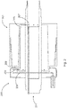
- FIG. 1 is a schematic view of a drive unit 100 according to an embodiment of the present disclosure.
- the drive unit 100 comprises hollow shaft 101 mounted for rotation about an axis of rotation, a rotor unit 102, which is arranged rotationally fixed with the hollow shaft 101, i.e. when the rotor unit 102 is driven by a stator unit (not shown), the rotor unit 101 and thus the hollow shaft 101 are rotated.
- the drive unit 100 or the rotor unit 102 may be rotatably connected with the stator unit by means of corresponding bearing assemblies 103.
- the drive unit 100 further comprises a coolant circuit comprising at least an inflow section 104, a cooling section 105 and a discharge section 106.
- a coolant circuit comprising at least an inflow section 104, a cooling section 105 and a discharge section 106.
- the path of the coolant through the inflow section 104, the cooling section 105 and the discharge section 106 is indicated by arrows.
- the function of the inflow section 104 is to conduct the coolant, e.g. oil, to the cooling section 105, whereby the geometry of the inflow section 104 is designed so that the coolant is conveyed by the rotation of the rotor unit 102.
- the inflow section 104 may be provided by channels or bores 104 leading from the hollow shaft 101 to the cooling section 105.
- Several channels or bores 104 can be provided around the hollow shaft 101, which can be arranged on a common conical surface and which extend from the hollow shaft 101 to the cooling section 105. This makes it possible to introduce the coolant into the hollow shaft 101 and lead it to the cooling section 105 via the bores 104 of the inflow section 104, wherein the coolant in the inflow section 104 is moved by the rotation of the rotor unit 102.
- the cooling section 105 in the shown embodiment comprises bores 105 arranged around the hollow shaft 101 adjacent to the rotor unit 102, in particular immediately adjacent to the magnets of the rotor unit 102.
- the bores 105 may be provided in any desired geometry, e.g. spirally arranged around the hollow shaft 101 or as straight-line bores arranged around the hollow shaft 101.
- a chamber or several chambers surrounding the hollow shaft 101 may be provided in the cooling section 105.
- the bores 105 in the cooling section 105 have an expanding radius or diameter in order to move a coolant by rotation in a direction along the axis of rotation, i.e. the distance of the cooling section from the axis of rotation is not constant, but increases parallel to the axis of rotation.
- the distance of the bores 105 to the rotation axis increases with a constant value, i.e. the cooling section 105 is arranged quasi inclined to the rotation axis.
- the radius of the cooling section 105 increases in the direction in which the coolant is to be transported or moved, e.g. in the shown embodiment, the radius/diameter of the bores increases towards the right side.
- the coolant is moved along the cooling section 105 to the right side due to the rotation of the rotor unit forcing the coolant in the direction of the increasing radius. This movement of the coolant can be provided without the need for a pump or similar conveying device.
- the discharge section 106 is adapted to direct coolant from the cooling section 105 towards the axis of rotation, i.e. towards the hollow shaft 101.
- the function of the discharge section 106 is to lead the coolant away from the cooling section 105 so that it can be led back into a coolant chamber or a gearbox and from there again to the hollow shaft 101 and the inflow section 104 providing a closed coolant circuit.
- the discharge section 106 is provided by bores 106 connecting the cooling section 105 with the hollow shaft 101.
- the hollow shaft 101 having a larger inner diameter at the discharge section 106 than at the inflow section 104 (indicated by the arrow 107 in figure 1 ). This provides a pressure difference between the inflow section 104 and the discharge section 106, which allows coolant to be forced out of the discharge section 106 to the hollow shaft 101 from where it may be led to a gearbox or coolant reservoir (not shown).
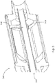
- Figure 2 is a schematic view of a drive unit 200 according to a further embodiment of the present disclosure.
- the coolant circuit may comprise an inflow section within the hollow shaft 201, a cooling section 205 provided by a cooling chamber 205 with an increasing radius/diameter leading the coolant to a discharge chamber 206, which is arranged axially adjacent to the cooling section 205.
- a cooling section 205 provided by a cooling chamber 205 with an increasing radius/diameter leading the coolant to a discharge chamber 206, which is arranged axially adjacent to the cooling section 205.
- the path of the coolant through the hollow shaft 201, the cooling section 205 and the discharge chamber 206 is indicated by arrows.
- the inflow section/the hollow shaft 201 and the cooling section 205 may be connection by means of radially provided bores 207 or holes leading from the hollow shaft 201 to the cooling section 205.
- the cooling section 205 and the discharge chamber 206 may also be connected by means of radially provided bores 208 or holes leading from the cooling section 205 to the discharge chamber 206.
- the coolant may be led to a gearbox or coolant chamber, e.g. oil separator.
- the discharge chamber 206 is supported by means of at least one bearing assembly 209 which is provided near the rotor unit 202 and/or at a wall section of the cooling chamber 205 such that the discharge chamber 206 does not rotate with the rotor unit 202.
- Figure 3 is a schematic view of a drive unit 300 according to a further embodiment of the present disclosure.
- the path of the coolant is indicated by arrows.
- this embodiment comprises a spatula element 306 as a discharge section 306, which is provided on the front side of the cooling section 305.
- the spatula element 306 is arranged on the hollow shaft 301 by means of a bearing assembly 310 so that the spatula element 306 does not rotate with the rotor unit (not shown) and the hollow shaft 301.
- the coolant can therefore be guided in the direction of the hollow shaft 301 on the spatula element 306 without the coolant being forced outwards by rotation.
- the coolant may be lead into the hollow shaft by means of respective bores or similar means.
- the coolant may be passed through an inflow section and a cooling section as shown in the design example in figure 1 .
- FIG 4 is a schematic view of a drive unit 400 according to a further embodiment of the present disclosure. This embodiment corresponds to the embodiment shown in figure 3 comprising an alternative design of a spatula element 406.
- the path of the coolant through is indicated by arrows.
- the spatula element 406 is supported on a bearing assembly 410, which is arranged on a supporting wall 411 of the housing of the drive unit 400.
Priority Applications (2)
| Application Number | Priority Date | Filing Date | Title |
|---|---|---|---|
| EP20172926.6A EP3907862A1 (fr) | 2020-05-05 | 2020-05-05 | Commande électrique |
| US17/307,403 US11760189B2 (en) | 2020-05-05 | 2021-05-04 | Electric drive |
Applications Claiming Priority (1)
| Application Number | Priority Date | Filing Date | Title |
|---|---|---|---|
| EP20172926.6A EP3907862A1 (fr) | 2020-05-05 | 2020-05-05 | Commande électrique |
Publications (1)
| Publication Number | Publication Date |
|---|---|
| EP3907862A1 true EP3907862A1 (fr) | 2021-11-10 |
Family
ID=70553862
Family Applications (1)
| Application Number | Title | Priority Date | Filing Date |
|---|---|---|---|
| EP20172926.6A Pending EP3907862A1 (fr) | 2020-05-05 | 2020-05-05 | Commande électrique |
Country Status (2)
| Country | Link |
|---|---|
| US (1) | US11760189B2 (fr) |
| EP (1) | EP3907862A1 (fr) |
Citations (6)
| Publication number | Priority date | Publication date | Assignee | Title |
|---|---|---|---|---|
| US20030132673A1 (en) * | 2002-01-17 | 2003-07-17 | Shijian Zhou | Centrifugal liquid cooling system for an electric motor |
| EP1522749A1 (fr) * | 2002-07-12 | 2005-04-13 | Mitsubishi Denki Kabushiki Kaisha | Broche pour palier magnetique |
| EP2562914A1 (fr) * | 2010-04-23 | 2013-02-27 | IHI Corporation | Machine rotative |
| DE102017214507A1 (de) * | 2017-08-21 | 2019-02-21 | Continental Automotive Gmbh | Mehrteilige Rotorwelle für eine elektrische Maschine |
| JP2019216555A (ja) * | 2018-06-13 | 2019-12-19 | 本田技研工業株式会社 | ロータ及び回転電機 |
| US20200036248A1 (en) * | 2018-07-27 | 2020-01-30 | Valeo Siemens Eautomotive Germany Gmbh | End plate for a rotor assembly of an electrical machine, rotor assembly for an electrical machine, and vehicle |
-
2020
- 2020-05-05 EP EP20172926.6A patent/EP3907862A1/fr active Pending
-
2021
- 2021-05-04 US US17/307,403 patent/US11760189B2/en active Active
Patent Citations (6)
| Publication number | Priority date | Publication date | Assignee | Title |
|---|---|---|---|---|
| US20030132673A1 (en) * | 2002-01-17 | 2003-07-17 | Shijian Zhou | Centrifugal liquid cooling system for an electric motor |
| EP1522749A1 (fr) * | 2002-07-12 | 2005-04-13 | Mitsubishi Denki Kabushiki Kaisha | Broche pour palier magnetique |
| EP2562914A1 (fr) * | 2010-04-23 | 2013-02-27 | IHI Corporation | Machine rotative |
| DE102017214507A1 (de) * | 2017-08-21 | 2019-02-21 | Continental Automotive Gmbh | Mehrteilige Rotorwelle für eine elektrische Maschine |
| JP2019216555A (ja) * | 2018-06-13 | 2019-12-19 | 本田技研工業株式会社 | ロータ及び回転電機 |
| US20200036248A1 (en) * | 2018-07-27 | 2020-01-30 | Valeo Siemens Eautomotive Germany Gmbh | End plate for a rotor assembly of an electrical machine, rotor assembly for an electrical machine, and vehicle |
Also Published As
| Publication number | Publication date |
|---|---|
| US20210347247A1 (en) | 2021-11-11 |
| US11760189B2 (en) | 2023-09-19 |
Similar Documents
| Publication | Publication Date | Title |
|---|---|---|
| US9300189B2 (en) | Fluid-cooled electric machine | |
| US10323644B1 (en) | High-speed modular electric submersible pump assemblies | |
| US10811939B2 (en) | Rotating electric machine | |
| US10615665B2 (en) | Electric machine | |
| US8159094B2 (en) | Electric motor having fluid circulation system and methods for cooling an electric motor | |
| US3790309A (en) | Unitary pump-motor assembly | |
| US20080272661A1 (en) | Liquid cooled rotor assembly | |
| EP3401549B1 (fr) | Turbocompresseur | |
| US20130129488A1 (en) | Foil bearing supported motor-driven blower | |
| CN111095746B (zh) | 用于电机的多部件转子轴 | |
| US6457951B2 (en) | Magnetically coupled canned rotary pump | |
| US20190145428A1 (en) | Compact, modular, integral pump or turbine with coaxial fluid flow | |
| US10385856B1 (en) | Modular electric submersible pump assemblies with cooling systems | |
| CN103326512A (zh) | 一种超高速永磁电机驱动的离心式空气压缩机冷却结构 | |
| EP4055683A1 (fr) | Moteur à flux axial avec noyaux de stator ayant des plaques de face agrandies | |
| CN111436205A (zh) | 具有整体冷却的电机及独立控制的转子速度的模块化多级整体密封电动泵 | |
| EP3907862A1 (fr) | Commande électrique | |
| WO2016033667A1 (fr) | Pompe à moteur à palier flottant refroidie par fluide circulant | |
| CN105637741A (zh) | 电动机 | |
| EP4052358B1 (fr) | Pompe ou turbine compacte, modulaire, à moteur ou générateur modulaire intégré et écoulement de fluide coaxial | |
| CN108779777B (zh) | 在多级泵中平衡轴向力的中心衬套 | |
| CN114389391A (zh) | 电机,包括电机的齿轮电动机和包括电机的车辆 | |
| US20200173496A1 (en) | Bearing housing for a turbomachine, and turbomachine having a bearing housing | |
| CN104295504A (zh) | 离心泵 | |
| WO2017029852A1 (fr) | Dispositif de palier vertical |
Legal Events
| Date | Code | Title | Description |
|---|---|---|---|
| PUAI | Public reference made under article 153(3) epc to a published international application that has entered the european phase |
Free format text: ORIGINAL CODE: 0009012 |
|
| STAA | Information on the status of an ep patent application or granted ep patent |
Free format text: STATUS: EXAMINATION IS IN PROGRESS |
|
| 17P | Request for examination filed |
Effective date: 20210107 |
|
| AK | Designated contracting states |
Kind code of ref document: A1 Designated state(s): AL AT BE BG CH CY CZ DE DK EE ES FI FR GB GR HR HU IE IS IT LI LT LU LV MC MK MT NL NO PL PT RO RS SE SI SK SM TR |
|
| B565 | Issuance of search results under rule 164(2) epc |
Effective date: 20201019 |