US6414894B2 - Semiconductor device with reduced current consumption in standby state - Google Patents
Semiconductor device with reduced current consumption in standby state Download PDFInfo
- Publication number
- US6414894B2 US6414894B2 US09/778,062 US77806201A US6414894B2 US 6414894 B2 US6414894 B2 US 6414894B2 US 77806201 A US77806201 A US 77806201A US 6414894 B2 US6414894 B2 US 6414894B2
- Authority
- US
- United States
- Prior art keywords
- address
- circuit
- signal
- refresh
- receiving
- Prior art date
- Legal status (The legal status is an assumption and is not a legal conclusion. Google has not performed a legal analysis and makes no representation as to the accuracy of the status listed.)
- Expired - Fee Related
Links
Images


Classifications
-
- G—PHYSICS
- G11—INFORMATION STORAGE
- G11C—STATIC STORES
- G11C7/00—Arrangements for writing information into, or reading information out from, a digital store
- G11C7/10—Input/output [I/O] data interface arrangements, e.g. I/O data control circuits, I/O data buffers
- G11C7/1006—Data managing, e.g. manipulating data before writing or reading out, data bus switches or control circuits therefor
-
- G—PHYSICS
- G11—INFORMATION STORAGE
- G11C—STATIC STORES
- G11C11/00—Digital stores characterised by the use of particular electric or magnetic storage elements; Storage elements therefor
- G11C11/21—Digital stores characterised by the use of particular electric or magnetic storage elements; Storage elements therefor using electric elements
- G11C11/34—Digital stores characterised by the use of particular electric or magnetic storage elements; Storage elements therefor using electric elements using semiconductor devices
- G11C11/40—Digital stores characterised by the use of particular electric or magnetic storage elements; Storage elements therefor using electric elements using semiconductor devices using transistors
- G11C11/401—Digital stores characterised by the use of particular electric or magnetic storage elements; Storage elements therefor using electric elements using semiconductor devices using transistors forming cells needing refreshing or charge regeneration, i.e. dynamic cells
- G11C11/406—Management or control of the refreshing or charge-regeneration cycles
- G11C11/40615—Internal triggering or timing of refresh, e.g. hidden refresh, self refresh, pseudo-SRAMs
-
- G—PHYSICS
- G11—INFORMATION STORAGE
- G11C—STATIC STORES
- G11C11/00—Digital stores characterised by the use of particular electric or magnetic storage elements; Storage elements therefor
- G11C11/21—Digital stores characterised by the use of particular electric or magnetic storage elements; Storage elements therefor using electric elements
- G11C11/34—Digital stores characterised by the use of particular electric or magnetic storage elements; Storage elements therefor using electric elements using semiconductor devices
- G11C11/40—Digital stores characterised by the use of particular electric or magnetic storage elements; Storage elements therefor using electric elements using semiconductor devices using transistors
- G11C11/401—Digital stores characterised by the use of particular electric or magnetic storage elements; Storage elements therefor using electric elements using semiconductor devices using transistors forming cells needing refreshing or charge regeneration, i.e. dynamic cells
- G11C11/406—Management or control of the refreshing or charge-regeneration cycles
- G11C11/40622—Partial refresh of memory arrays
-
- G—PHYSICS
- G11—INFORMATION STORAGE
- G11C—STATIC STORES
- G11C11/00—Digital stores characterised by the use of particular electric or magnetic storage elements; Storage elements therefor
- G11C11/21—Digital stores characterised by the use of particular electric or magnetic storage elements; Storage elements therefor using electric elements
- G11C11/34—Digital stores characterised by the use of particular electric or magnetic storage elements; Storage elements therefor using electric elements using semiconductor devices
- G11C11/40—Digital stores characterised by the use of particular electric or magnetic storage elements; Storage elements therefor using electric elements using semiconductor devices using transistors
- G11C11/401—Digital stores characterised by the use of particular electric or magnetic storage elements; Storage elements therefor using electric elements using semiconductor devices using transistors forming cells needing refreshing or charge regeneration, i.e. dynamic cells
- G11C11/4063—Auxiliary circuits, e.g. for addressing, decoding, driving, writing, sensing or timing
- G11C11/407—Auxiliary circuits, e.g. for addressing, decoding, driving, writing, sensing or timing for memory cells of the field-effect type
- G11C11/4074—Power supply or voltage generation circuits, e.g. bias voltage generators, substrate voltage generators, back-up power, power control circuits
-
- G—PHYSICS
- G11—INFORMATION STORAGE
- G11C—STATIC STORES
- G11C2207/00—Indexing scheme relating to arrangements for writing information into, or reading information out from, a digital store
- G11C2207/22—Control and timing of internal memory operations
- G11C2207/2227—Standby or low power modes
-
- G—PHYSICS
- G11—INFORMATION STORAGE
- G11C—STATIC STORES
- G11C2211/00—Indexing scheme relating to digital stores characterized by the use of particular electric or magnetic storage elements; Storage elements therefor
- G11C2211/401—Indexing scheme relating to cells needing refreshing or charge regeneration, i.e. dynamic cells
- G11C2211/406—Refreshing of dynamic cells
- G11C2211/4067—Refresh in standby or low power modes
Definitions
- the present invention generally relates to semiconductor devices, and particularly to reduction of current consumption in standby state of a semiconductor device having therein a dynamic semiconductor memory device requiring refresh.
- a semiconductor memory device is required to have smaller size and lower power consumption.
- the semiconductor memory device is often employed being integrated on one chip with a microcomputer and a large-sized logic circuit.
- An integrated circuit on which various circuits of such large size are mounted to implement system-on-chip is herein referred to as system LSI.
- a conventional structure of a semiconductor memory device is first described before discussion on reduction in supply current consumption of the system LSI.
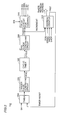
- FIG. 35 is a schematic block diagram showing a structure of a conventional semiconductor memory device 1000 .
- semiconductor memory device 1000 includes an external clock signal input terminal 1116 receiving externally supplied complementary clock signals ext.CLK and ext./CLK, clock input buffers 1084 and 1085 buffering the clock signals supplied to external clock signal input terminal 1116 , an internal control clock signal generating circuit 1118 receiving respective outputs of clock input buffers 1084 and 1085 to generate internal clock signal int.CLK, and a mode decoder 1120 receiving an external control signal supplied to an external control signal input terminal 1110 via input buffers 1012 - 1020 which operate according to internal clock signal int.CLK.
- External control signal input terminal 1110 receives clock enable signal CKE, chip select signal /CS, row address strobe signal /RAS, column address strobe signal /CAS and write control signal /WE.
- Clock enable signal CKE is used to allow a control signal to be input to the chip. If this signal is not activated, input of the control signal is not permitted and semiconductor memory device 1000 does not accept signal input from the outside.
- Chip select signal /CS is used for determining whether a command signal is input or not. When this signal is activated (at L level), a command is identified according to a combination of levels of other control signals at the rising edge of the clock signal.
- Mode decoder 1120 outputs an internal control signal for controlling an operation of an internal circuit of semiconductor memory device 1000 according to these external control signals.
- Mode decoder 1120 outputs, as internal control signals, signal ROWA, signal COLA, signal ACT, signal PC, signal READ, signal WRITE, signal APC and signal SR.
- Signal ROWA indicates that row-related access is made
- signal COLA indicates that column-related access is made
- signal ACT is used to instruct that a word line is activated.
- Signal PC specifies precharge operation to end a row-related circuit operation.
- Signal READ instructs a column-related circuit to perform reading operation
- signal WRITE instructs the column-related circuit to perform writing operation.
- Signal APC specifies auto precharge operation.
- precharge operation is automatically started simultaneously with the end of a burst cycle.
- Signal SR designates self refresh operation.
- a self refresh timer operates. After a certain time passes, a word line is activated and the refresh operation starts.
- Semiconductor memory device 1000 further includes a self refresh timer 1054 which starts its operation when self refresh mode is designated by signal SR and then designates activation of a word line, i.e., start of the refresh operation when a certain time passes, and a refresh address counter 1056 for generating a refresh address according to an instruction from self refresh timer 1054 .
- a self refresh timer 1054 which starts its operation when self refresh mode is designated by signal SR and then designates activation of a word line, i.e., start of the refresh operation when a certain time passes
- a refresh address counter 1056 for generating a refresh address according to an instruction from self refresh timer 1054 .
- Semiconductor memory device 1000 further includes a reference potential input terminal 1022 receiving signal VREF which is to be used as a reference for determining whether an input signal is H or L level, a mode register 1046 holding an address signal supplied via an address signal input terminal 1112 as well as information regarding a predetermined operation mode, for example, information regarding burst length according to a combination of external control signals described above, a row address latch 1250 receiving address signals via address input buffers 1032 - 1038 operating according to internal clock signal int.CLK 2 to hold, when a row address is input, the input row address, a column address latch 1550 receiving address signals A 0 -A 12 to hold, when a column address is input, this column address, a multiplexer 1058 receiving respective outputs from refresh address counter 1056 and row address latch 1250 to select the output from row address latch 1250 in the normal operation and select the output from refresh address counter 1056 in self refresh operation and accordingly output the selected one, and a row predecoder 1136 receiving an output from multiplexer 1058 to
- Semiconductor memory device 1000 further includes a burst address counter 1060 generating an internal column address according to burst length data from mode register 1046 based on the column address held in column address latch 1550 , a column predecoder 1134 receiving an output of burst address counter 1060 to predecode a corresponding column address, a bank address latch 1052 receiving bank addresses BA 0 -BA 2 supplied to an address input terminal via input buffers 1040 - 1044 which operate according to internal clock signal int.CLK, and a bank decoder 1122 receiving an output of bank address latch 1052 to decode a bank address.
- a burst address counter 1060 generating an internal column address according to burst length data from mode register 1046 based on the column address held in column address latch 1550
- a column predecoder 1134 receiving an output of burst address counter 1060 to predecode a corresponding column address
- a bank address latch 1052 receiving bank addresses BA 0 -BA 2 supplied to an address input terminal via
- the address signal supplied to address signal input terminal 1112 is also used for writing data in the mode register by a combination of any bits when operation mode information is written into the mode register. For example, burst length BL, value of CAS latency CL and the like are designated by a combination of a predetermined number of bits of an address signal.
- Bank address signals BA 0 -BA 2 designate an access bank in each of the row-related access and the column-related access. Specifically, in the row-related access and the column-related access each, bank address signals BA 0 -BA 2 supplied to address signal input buffers 1040 - 1044 are taken by bank address latch 1052 and then decoded by bank decoder 1122 to be transmitted to each memory array block (bank).
- semiconductor memory device 1000 includes memory array blocks 100 a - 100 g respectively serving as banks 0 - 7 each for independent reading/writing operation, a row decoder 1244 for selecting a row (word line) in a corresponding bank according to respective outputs from bank decoder 1122 and row predecoder 1136 , a column decoder 1242 for selecting a column (bit line pair) in a corresponding bank according to an output from column predecoder 1134 , an I/O port 1266 supplying data read from a selected memory cell in a selected bank to a global I/O bus G-I/O in reading operation and supplying write data transmitted by bus G-I/O to a corresponding bank in writing operation, a data input/output circuit 1086 holding externally supplied write data and supplying it to bus G-I/O in writing operation and holding read data transmitted by bus G-I/O in reading operation, and bidirectional input/output buffers 1072 - 1082 for transmitting input/output data DQ 0 -
- Bidirectional input/output buffers 1072 - 1082 operate in synchronization with the internal clock signal according to operation mode data held in mode register 1046 .
- FIG. 36 illustrates power supply potential applied from the outside to a conventional system LSI.
- the system LSI includes a chip CH on which a logic portion LG and a DRAM portion MEM are mounted.
- the DRAM portion includes a power supply generating circuit VGEN 1 generating boosted potential VPP and a power supply generating circuit VGEN 2 generating substrate potential VBB.
- the logic portion LG receives supply potential LVDDH of 3.3V applied from the outside via a terminal T 50 and potential LVDDL of 1.5V applied via a terminal T 51 .
- the DRAM portion MEM receives supply potential DVDDH of 3.3V applied from the outside via a terminal T 52 and supply potential DVDDL of 1.5V applied via a terminal T 53 .
- supply potentials LVDDH and LVDDL applied to the logic portion LG are set at 0V to stop power supply current from being applied. In this way, current consumption in the logic portion LG in the standby state is reduced.
- Preferably personal digital assistants and the like can be operated by a battery as long as possible. In order to achieve this, power consumption of the system LSI should be reduced as much as possible.
- the DRAM portion included in the system LSI requires refresh operation even in the standby state in order to preserve data stored in a memory cell.
- the refresh operation is carried out in every one cycle at regular intervals, or all of memory cells are successively refreshed and this successive refresh is carried out at regular intervals.
- any circuit operation is carried out in the DRAM portion, which accompanies leakage current upon activation of a transistor.
- the leakage current in operation and in standby state increases as threshold voltage of an employed MOS transistor is decreased in order to accelerate the speed of operation and to lower the power supply potential. As a result, current consumption of the entire device increases.
- FIG. 37 illustrates power supply potential applied to peripheral circuitry of the DRAM portion MEM shown in FIG. 36 .
- power supply potential DVDDL applied to the DRAM portion MEM is provided to a clock control unit 1402 , a row-related command control unit 1404 , a column-related command control unit 1406 , a row-related address control unit 1408 , a bank address control unit 1410 , a column-related address control unit 1412 , an input/output data-related control unit 1414 and a self refresh-related control unit 1416 .
- Supply potential DVDDL is also applied from the outside to the peripheral circuitry except for the memory array portion shown in FIG. 36 in the conventional device. For this reason, a considerable leakage current is generated in the standby state in any circuit which is unnecessary in the refresh operation, for example, input/output data-related control unit 1414 and the like.
- One object of the present invention is to provide a semiconductor device having a power down mode which enables power supply current to be consumed less while information stored in a DRAM portion is preserved in standby state.
- the present invention in brief, is a semiconductor device transmitting/receiving data in a normal mode and performing refresh of stored data with reduced current consumption in the power down mode.
- the semiconductor device includes a memory array, a first peripheral circuit and a second peripheral circuit.
- the memory array includes a plurality of memory cells arranged in a matrix of rows and columns.
- the first peripheral circuit inputs/outputs data to be stored in a memory cell in the normal mode.
- the first peripheral circuit stops its operation for reducing current consumption in the power down mode.
- the second peripheral circuit controls refreshing of data held in a memory cell in the power down mode.
- a major advantage of the present invention is that reduction of current consumption is possible by stopping the first peripheral circuit from operating in the power down mode.
- FIG. 1 is a schematic block diagram showing a structure of a semiconductor device 1 according to a first embodiment of the invention.
- FIG. 2 is a block diagram showing a structure of a refresh control unit 132 in FIG. 1 .
- FIG. 3 is a circuit diagram illustrating a hierarchical power supply structure.
- FIG. 4 is a waveform chart illustrating an operation of a circuit having the hierarchical power supply structure shown in FIG. 3 .
- FIG. 5 is a block diagram showing a first example of an address counter 312 in FIG. 2 .
- FIG. 6 is an operation waveform chart illustrating an operation of address counter 312 shown in FIG. 5 .
- FIG. 7 is a block diagram showing a structure of an address counter 312 a which is a modification of address counter 312 .
- FIG. 8 is an operation waveform chart illustrating an operation of address counter 312 a in FIG. 7 .
- FIG. 9 illustrates that power supply is externally provided to a semiconductor device according to a second embodiment.
- FIG. 10 shows a structure in which power supply potential is applied to an internal circuit of a DRAM portion shown in FIG. 9 .
- FIG. 11 illustrates a first example of grouping peripheral circuits PCKT 1 and PCKT 2 shown in FIG. 10 .
- FIG. 12 illustrates a second example of grouping peripheral circuits.
- FIG. 13 illustrates a third example of grouping peripheral circuits.
- FIG. 14 is a schematic showing a structure of a memory array.
- FIG. 15 illustrates a structure of a boundary portion inactivating an I/O line used for writing operation by stopping power supply.
- FIG. 16 is a circuit diagram showing a structure of a flip-flop 1172 a in FIG. 15 .
- FIG. 17 illustrates that power supply is applied preceding and following a read amplifier 1154 in FIG. 14 .
- FIG. 18 is a circuit diagram showing a structure of read amplifier 1154 and an equalize circuit 528 in FIG. 17 .
- FIG. 19 is a block diagram illustrating that a transistor having a high threshold is used for a part of a block for the purpose of reducing power consumption of a refresh control-related portion.
- FIG. 20 is a circuit diagram showing a circuit structure for multiplexing an address in a normal operation and an address in a self refresh.
- FIG. 21 is a circuit diagram showing a second structure for multiplexing addresses.
- FIG. 22 is a circuit diagram showing a structure of a level converting circuit.
- FIG. 23 is a circuit diagram showing a structure of a selection circuit 620 in FIG. 21 .
- FIG. 24 is a circuit diagram showing a structure of a first level converting circuit 660 for level converting from 1.5V to 3.3V.
- FIG. 25 is a circuit diagram showing a structure of a level converting circuit 680 as a second example of level conversion.
- FIG. 26 is a circuit diagram showing a structure of a level converting circuit 710 as a third example of level conversion.
- FIG. 27 is a circuit diagram showing a structure of a column selection line fixing circuit 730 .
- FIG. 28 is a circuit diagram showing a structure of a column selection line fixing circuit 740 as a second example for fixing a column selection line.
- FIG. 29 is a circuit diagram showing a structure of a column selection line fixing circuit 757 as a third example for fixing a column selection line.
- FIG. 30 is a block diagram showing a structure of a semiconductor device 800 according to a third embodiment.
- FIG. 31 is a circuit diagram showing a structure of a DRAM power supply circuit 810 in FIG. 30 .
- FIG. 32 is a circuit diagram showing a structure of a clock/reset control circuit 806 in FIG. 30 .
- FIG. 33 is an operation waveform chart illustrating a power down mode of the DRAM portion of the semiconductor device in FIG. 30 .
- FIG. 34 is a waveform chart illustrating an operation of returning from the power down mode in FIG. 33 to an operation mode.
- FIG. 35 is a schematic block diagram showing a structure of a conventional semiconductor memory device 1000 .
- FIG. 36 illustrates supply potential applied from the outside to the conventional system LSI.
- FIG. 37 illustrates power supply potential applied to a peripheral circuit of the DRAM portion MEM in FIG. 36 .
- FIG. 1 is a schematic block diagram showing a structure of a semiconductor device 1 according to the first embodiment of the invention.
- semiconductor device 1 includes a large-sized logic portion 2 coupled to a group of external pin terminals PG to carry out designated processing, and a DRAM portion 4 coupled to logic portion 2 via internal interconnection to store data required by logic portion 2 .
- Logic portion 2 outputs to DRAM portion 4 , clock signals CLK and /CLK, control signals CKE, /CS, /RAS, /CAS, and /WE, reference potential Vref for taking data in, row address signals RA 0 -RA 12 , column address signals CA 0 -CA 10 , and bank address signals BA 0 -BA 2 .
- Logic portion 2 and DRAM portion 4 transmit and receive data signals DQ 0 -DQ 31 .
- logic portion 2 and DRAM portion 4 are integrated on one chip, it is easier to increase the number of signal lines for data transmission compared with a logic portion and a DRAM portion mounted on separate chips. Therefore, the structure in FIG. 1 does not have so-called address pin multiplexing and has separate lines for column address and row address transmitted from the logic portion to the DRAM portion.
- DRAM portion 4 includes clock input buffers 50 and 52 buffering complementary clock signals CLK and /CLK supplied from logic portion 2 , an internal control clock signal generating circuit 118 receiving respective outputs of clock input buffers 50 and 52 to output internal clock signal int.CLK, input buffers 12 - 20 receiving control signals CKE, /CS, /RAS, /CAS and /WE according to internal clock signal int.CLK, and a mode decoder 120 receiving control signals via input buffers 12 - 20 to output an internal control signal for controlling an operation of an internal circuit.
- Clock enable signal CKE is used for permitting input of a control signal to the chip. If the clock enable signal is not activated, input of the control signal is not allowed and DRAM portion 4 does not transmit and receive data to and from the logic portion.
- Chip select signal /CS is used for determining if a command signal is supplied or not. During the period in which this signal is activated (L level), a command is identified according to a combination of levels of other control signals at the rising edge of the clock signal.
- Mode decoder 120 outputs as internal control signals, for example, signal ROWA, signal COLA, signal ACT, signal PC, signal READ, signal WRITE, signal APC and signal SR.
- Signal ROWA indicates that row-related access is made
- signal COLA indicates that column-related access is made
- signal ACT is a signal for designating activation of a word line.
- Signal PC specifies precharge operation to instruct that row-related circuit operation is completed.
- Signal READ instructs a column-related circuit to perform reading operation
- signal WRITE instructs a column-related circuit to perform writing operation
- Signal APC designates auto precharge operation.
- precharge operation is automatically started simultaneously with the end of a burst cycle.
- Signal SR specifies self refresh operation. For example, when a combination of control signals designating a self refresh mode is supplied from the logic portion in a standby mode, the self refresh signal SR is generated. Accordingly, the self refresh operation is started, a self refresh timer operates, and a word line is activated after a certain time passes and accordingly the refresh operation is started.
- DRAM portion 4 further receives reference potential VREF used as a reference for determining whether an input signal is H level or L level.
- DRAM portion 4 further includes a mode register 122 holding information regarding a predetermined operation mode according to a combination of an address signal and a control signal supplied from the logic portion, for example, information regarding burst length, a row address latch 124 receiving and holding row address signals RA 0 -RA 12 from the logic portion, a column address latch 126 receiving and holding column address signals CA 0 -CA 10 supplied from the logic portion, a row predecoder 140 receiving an output from row address latch 124 to predecode a row address, a burst address counter 134 generating an internal column address according to data on the burst length from mode register 122 using as a reference the column address held in column address latch 126 , a column predecoder 142 receiving an output from burst address counter 134 to predecode a corresponding column address, a bank address latch 128 receiving bank addresses BA 0 -BA 2 supplied from the logic portion via input buffers 40 - 44 operating according to internal clock signal int.CLK to hold a designated bank address
- Address signals supplied from the logic portion are used for writing data into the mode register according to a combination of several bits. For example, values of burst length BL, CAS latency CL and the like are designated according to a combination of a predetermined number of bits of an address signal.
- Bank address signals BA 0 -BA 2 designate respective access banks in row-related access and column-related access. Specifically, in each of the row-related access and the column-related access, bank address signals BA 0 -BA 2 supplied from the logic portion 2 are taken by bank address latch 128 , decoded by bank decoder 136 and thereafter transmitted to each memory array block (bank).
- DRAM portion 4 further includes a refresh control unit 132 receiving an address signal from the logic portion and signal SR designating the self refresh mode to control the refresh, and a multiplexer 144 for switching between a row-related control signal and a bank designation signal output from refresh control unit 132 and respective outputs of row predecoder 140 and bank decoder 136 according to signal SR.
- a refresh control unit 132 receiving an address signal from the logic portion and signal SR designating the self refresh mode to control the refresh
- a multiplexer 144 for switching between a row-related control signal and a bank designation signal output from refresh control unit 132 and respective outputs of row predecoder 140 and bank decoder 136 according to signal SR.
- DRAM portion 4 further includes memory array blocks 100 a - 100 g serving as respective banks 0 - 7 where reading/writing operation can be performed separately, a row decoder 244 for selecting a row (word line) in a corresponding bank according to an output of multiplexer 144 , a column predecoder 242 for selecting a column (bit line pair) in a corresponding bank according to an output of column predecoder 142 , an I/O port 266 supplying data read from a selected memory cell in a selected bank to a global I/O bus G-I/O in reading operation and supplying write data transmitted by bus GI/O to a corresponding bank in writing operation, a data input/output circuit 130 holding write data supplied from the outside to supply it to bus G-I/O in writing operation and holding read data transmitted by bus G-I/O in reading operation, and data input/output buffers 72 - 78 for transmitting and receiving input/output data DQ 0 -DQ 31 between data input/output circuit
- DRAM portion 4 further includes a VDC circuit 138 receiving supply potential VDDH of 3.3V from the outside to output supply potential VDD 2 of 2.0V for example.
- FIG. 2 is a block diagram showing a structure of refresh control unit 132 shown in FIG. 1 .
- refresh control unit 132 includes a timer 302 receiving self refresh signal SR from mode decoder 120 in FIG. 1 to measure a standby period of refresh when the mode is changed to self refresh mode, a trigger pulse generating circuit 304 outputting trigger pulse TRIG according to an output of timer 302 , a cyclic timer 306 outputting cycle signal CYCLE determining a cycle of word line activation in refresh according to trigger pulse TRIG, an RAS clock generating circuit 308 outputting row-related operation reference clock signal RASCK according to cycle signal CYCLE, and a delay circuit 310 for control outputting signals EQ, MWL, SO and PC at predetermined timing using clock signal RASCK as a reference. Control delay circuit 310 outputs signals EQ, MWL, SO and PC when internal enable signal IEN is activated.
- Signal EQ indicates an equalize period of a bit line
- signal MWL indicates an activation period of a main word line
- signal SO indicates an activation period of a sense amplifier
- signal PC indicates a precharge period
- Refresh control unit 132 further includes an address counter 312 which is reset according to reset signal PON and self refresh reset signal SRRST when the power is made on, receives start address SADR and end address EADR from the logic portion, and increments an address according to clock signal RASCK.
- Address counter 312 outputs refresh address ReADR to the memory array and outputs timer reset signal TRST to timer 302 when one cycle of address count is completed.
- Timer 302 in refresh control unit 132 is not required to operate speedily. Therefore, timer 302 is constituted of a transistor having a high threshold and has small leakage current even in operation.
- trigger pulse TRIG is generated and address counter 312 starts its operation according to trigger signal TRIG.
- Address counter 312 is constituted of a transistor operating with a low threshold.
- standby state is started by a reset signal.
- Address counter 312 employs hierarchical power supply structure described below and can reduce the leakage current in the standby state.
- FIG. 3 is a circuit diagram illustrating the hierarchical power supply structure.
- Inverters IV 1 -IV 5 five stages of inverters IV 1 -IV 5 connected in series are shown as internal circuits.
- Input signal IN supplied to the first stage inverter IV 1 is at L level in standby cycle.
- Inverters IV 1 -IV 5 have the same structure and each include a P channel MOS transistor PT and an N channel MOS transistor NT. These MOS transistors PT and NT are low-threshold voltage (L-Vth) MOS transistors having a small absolute value of threshold voltage.
- L-Vth low-threshold voltage
- a main supply line 321 receiving supply potential Vcc a sub supply line 323 coupled to main supply line 321 via a P channel MOS transistor PQ for leakage cut, a main ground line 322 transmitting ground potential Vss, and a sub ground line 324 connected to main ground line 322 via an N channel MOS transistor NQ for leakage cut.
- Leakage cut MOS transistors PQ and NQ are constituted of respective MOS transistors each having an absolute value of the threshold voltage (M-Vth) greater than the absolute value of the threshold voltage of MOS transistors PT and NT.
- MOS transistor PQ has its gate receiving control signal / ⁇
- MOS transistor NQ has its gate receiving control signal ⁇ .
- Control signal ⁇ is at H level in an active cycle in which an internal circuit operates.
- Control signal ⁇ is at L level in a standby cycle in which the internal circuit is on standby.
- control signal / ⁇ is at L level in the active cycle and at H level in the standby cycle.
- inverters IV 1 , IV 3 , IV 5 . . . in the stages of odd numbers in the internal circuits the source of P channel MOS transistor PT is connected to main supply line 321 and the source of N channel MOS transistor NT is connected to sub ground line 324 .
- inverters IV 2 , IV 4 . . . of the even number stages the source of P channel MOS transistor PT is connected to sub supply line 323 and the source of N channel MOS transistor NT is connected to main ground line 322 .
- FIG. 4 is a waveform chart illustrating an operation of a circuit having the hierarchical power supply structure shown in FIG. 3 .
- control signal ⁇ is at L level and control signal / ⁇ is at H level.
- Input signal IN is at L level.
- leakage cut MOS transistors PQ and NQ are in off state.
- Inverters IV 1 , IV 3 and IV 5 of the odd number stages each have input signal IN at L level. Therefore, P channel MOS transistor PT is in on state while N channel MOS transistor NT is in off state. P channel MOS transistor PT has its source connected to main supply line 321 and N channel MOS transistor NT has its source connected to sub ground line 324 .
- N channel MOS transistor NT receives a signal of L level at its gate and accordingly is turned off. In this state, when there is a potential difference of at least a certain value between the source coupled to the sub ground line and the drain, off-leakage current is generated.
- Sub ground line 324 is connected to main ground line 322 via leakage cut MOS transistor NQ having a relatively high threshold voltage M-Vth. Therefore, even if the off-leakage current flows from inverters IV 1 , IV 3 and IV 5 . . . to sub ground line 324 , leakage cut MOS transistor NQ cannot discharge all of this off-leakage current. Consequently, voltage level SVss on sub ground line 324 becomes higher than ground potential Vss.
- Potential SVss on sub ground line 324 is finally determined by a relation between the amount of leakage current discharged by leakage cut MOS transistor NQ and off-leakage current from inverter stage included in the internal circuit.
- potential SVss on sub ground line 324 becomes higher than ground potential Vss, the portion between the gate and source of N channel MOS transistor NT in each of inverters IV 1 , IV 3 , IV 5 . . . of odd number stages is set into an inverse-bias state. In this case, the off-leakage current is further reduced.
- inverters IV 2 , IV 4 . . . of even number stages input signal has H level.
- the source of P channel MOS transistor PT is connected to sub power supply line 323 and the source of N channel MOS transistor NT is connected to main ground line 322 .
- the N channel MOS transistor has the same source and drain corresponding to ground potential Vss level. In the P channel MOS transistor PT, off-leakage current is generated even in the non-conducting state.
- leakage cut MOS transistor PQ having a relatively large absolute value (M-Vth) of threshold voltage is provided.
- the amount of leakage current from main supply line 321 to sub supply line 323 is determined by leakage cut MOS transistor PQ and voltage SVcc on sub supply line 323 drops lower than the level of supply potential Vcc level.
- the voltage level of SVcc on sub supply line 323 is finally determined by a relation between leakage current supplied from leakage cut MOS transistor PQ and the total of off-leakage current in inverters IV 2 , IV 4 . . . of even number stages.
- voltage SVcc becomes lower than supply potential Vcc
- in inverters IV 2 , IV 4 . . . of even number stages the portion between the gate and source of P channel MOS transistor PT is set into reverse-bias state and the off-leakage current is further reduced.
- control signal ⁇ has H level and control signal / ⁇ has L level, leakage cut MOS transistors PQ and NQ are turned on, main supply line 321 is connected to sub supply line 323 , and main ground line 322 is connected to sub ground line 324 .
- MOS transistors of inverters IV 1 -IV 5 . . . constituting internal circuits are each a MOS transistor having low threshold voltage and operate at a high speed.
- Current supply capability of leakage cut MOS transistors PQ and NQ is set at a large value for ensuring the operation of this internal circuit.
- the hierarchical structure described above is thus realized by providing a main supply line and a sub supply line as supply lines and a main ground line and a sub ground line as ground lines.
- the impedance of supply line/ground line is increased to reduce the leakage current in the standby cycle, and the impedance of the supply line/ground line is reduced in the active cycle in order to achieve a high speed operation by MOS transistors having low threshold voltage in the internal circuits.
- Address counter 312 in FIG. 2 can have such a hierarchical power supply structure so as to implement a semiconductor device having reduced current consumption in the standby period in which no refresh is performed in the power down mode and operates at a high speed in the refresh.
- MOS transistors PQ and NQ are turned off, substrate potential is made lower than the source potential of the transistor to further reduce the leakage current so that further reduction of the leakage current is realized.
- the leakage current can further be reduced by decreasing current supplied to a common source line of a sense amplifier in the memory array.
- FIG. 5 is a block diagram showing a first example of address counter 312 in FIG. 2 .
- address counter 312 includes a latch circuit 332 receiving and holding start address SADR from the logic portion, a latch circuit 334 receiving and holding end address EADR supplied from the logic portion, and a counter 336 performing count-up operation according to clock signal RASCK from RAS clock generating circuit 308 in FIG. 2, outputs refresh address ReADRO, and outputs timer reset signal TRST at the end of one cycle of refresh addresses.
- Address counter 312 further includes a comparison circuit 338 comparing refresh address ReADRO output from counter 336 with start address SADR held by latch circuit 332 to activate an output when refresh address ReADRO is equal to or greater than start address SADR, a comparison circuit 340 comparing refresh address ReADRO with end address EADR held by latch circuit 334 to activate an output when refresh address ReADRO is equal to or smaller than end address EADR, an AND circuit 342 receiving respective outputs of comparison circuits 338 and 340 to output internal enable signal IEN, and a buffer circuit 344 receiving refresh address ReADRO to output refresh address ReADR to the row decoder of the memory array when enable signal IEN is activated.
- a comparison circuit 338 comparing refresh address ReADRO output from counter 336 with start address SADR held by latch circuit 332 to activate an output when refresh address ReADRO is equal to or greater than start address SADR
- a comparison circuit 340 comparing refresh address ReADRO with end address EADR held by latch circuit 334 to activate an output when refresh address Re
- FIG. 6 is an operation waveform chart illustrating an operation of address counter 312 shown in FIG. 5 .
- the DRAM portion preceding input of a command at time t 1 , the DRAM portion is instructed by the logic portion to perform refresh before transition to power down mode.
- internal clock signal CLK is fixed at L level according to decreasing of supply voltage of the logic portion and clock signal supplied to the DRAM portion is inactivated.
- a command determined by a combination of control signals /CS, /RAS, /CAS and /WE specifies a power down mode.
- a start address and an end address for designating a region to be refreshed are supplied from the logic circuit. In refresh, designation of a column address is unnecessary.
- the logic circuit thus supplies a refresh start address as row address signals RADD 0 -RADDn and supplies a refresh end address as column address signals CADD 0 -CADDn. Refresh is performed between the start address and the end address and no refresh operation is carried out for other addresses and they are skipped. These addresses may be specified by a bank address for example.
- the refresh start address SADR and refresh end address EADR are supplied from the logic portion to the DRAM portion when the logic portion uses the DRAM portion, prior to the power down mode, by recognizing a memory region where information should be held in transition to the power down mode.
- the refresh start address and the refresh end address are held in latch circuits 332 and 334 in address counter 312 of the DRAM portion, supply of the power supply voltage to the logic portion is stopped to reduce power consumption.
- timer 302 supplies a predetermined output because that it is a predetermined time and accordingly trigger pulse generating circuit 302 outputs trigger pulse TRIG.
- Cyclic timer 306 then outputs cycle signal CYCLE in a period corresponding to the refresh cycle and accordingly clock signal RASCK is input to address counter 312 .
- Clock signal RASCK is input to counter 336 of address counter 312 and counter 336 successively outputs refresh address signal ReADRO.
- refresh operation is unnecessary for a memory region which holds no necessary information.
- comparison circuit 338 and comparison circuit 340 determine whether refresh address signal ReADRO generated currently by counter 336 is present between a start address and an end address and accordingly internal enable signal IEN is output.
- the refresh address signal is smaller than the start address. Therefore, an output of buffer circuit 344 is inactivated and internal enable signal IEN is also inactivated.
- No refresh address is transmitted to the memory array and no control signal is transmitted from control delay circuit 310 .
- These signals have their levels fixed and current consumption is accordingly reduced by the amount of current for driving a signal line by these signals.
- trigger pulse TRIG is accordingly activated, and address counter 312 changes to the active mode to start counting of a refresh address.
- refresh address matches start address, refresh is carried out for a memory cell which stores information to be preserved.
- clock enable signal CKE is activated to H level, power is applied to the logic circuit and clock signal CLK is input to the DRAM portion. Then, all memory areas are first refreshed by inserting a dummy cycle considering the case in which refresh is completed in the way in the power down mode. After this, data is transmitted and received again between the logic circuit portion and the DRAM portion.
- FIG. 7 is a block diagram showing a structure of an address counter 312 a as a modification of address counter 312 .
- address counter 312 a is different in the structure from address counter 312 in that an address detecting circuit 352 and a comparison circuit 354 are included instead of comparison circuits 338 and 340 , AND circuit 342 and buffer circuit 344 .
- Other components are similar to those of address counter 312 and description thereof is not repeated here.
- address detecting circuit 352 When address detecting circuit 352 receives start address SADR and end address EADR from latch circuits 332 and 334 , it detects the ratio of an address region to be refreshed to the entire address region and outputs to cyclic timer 306 in FIG. 2 cycle selection signal SELC for selecting a refresh cycle.
- cyclic timer 306 the number of stages of counter circuits included is changed according to cycle selection signal SELC so as to change the refresh cycle.
- clock signal RASCK is input to counter 336 and the cycle for counting up refresh address ReADR is changed.
- the period of clock signal RASCK can be made four times provided that the start address and end address are selected in the range of one-fourth of addresses of 4012 word lines. Refresh can be carried out at dispersed times and accordingly, the peak current can be reduced which is advantageous for reducing power consumption in the standby state.
- comparison circuit 354 When refresh address ReADR output from counter 336 matches end address EADR held by latch circuit 334 , comparison circuit 354 outputs timer reset signal TRST to timer 302 in FIG. 3 .
- FIG. 8 is an operation waveform chart illustrating an operation of address counter 312 a in FIG. 7 .
- timer 302 measures a standby period until time t 2 as described in conjunction with FIG. 6 .
- trigger pulse TRIG is activated according to change of an output of timer 302 .
- cyclic timer 306 generates cyclic pulse CYCLE according to refresh cycle selected by address detecting circuit 352 .
- Counter 336 starts count up of refresh address ReADR from start address SADR received from latch circuit 332 . Different from the operation shown in FIG. 6, the period is extended by the ratio of the memory region skipped in the FIG. 6 and refresh is continued to the end address.
- timer reset signal TRST is output from comparison circuit 354 , and timer 302 starts measuring the standby period again. In this period, the address counter is set in the standby mode.
- This structure is advantageous in that refresh period is extended to reduce the peak value of current consumption as long as the refresh interval of a memory cell is allowed, and accordingly power consumption can be reduced.
- the first embodiment has been described according to which power consumption is reduced by decreasing the refresh region. It is also possible to cut the power consumption by employing a structure in which power is made off for a certain portion of the internal circuit of the DRAM portion in the power down mode, for example.
- FIG. 9 illustrates that power is externally supplied to a semiconductor device according to the second embodiment.
- a semiconductor device CH has a logic portion LG and a DRAM portion MEM.
- a voltage generating circuit VGENl for generating boosted potential VPP and a voltage generating circuit VGEN 2 for generating substrate potential VBB are provided.
- Logic portion LG receives supply potential LVDDH of 3.3V via a terminal T 1 and receives supply potential VDD of 1.5V via a terminal T 2 .
- Supply potential VDD is also applied to DRAM portion MEM.
- Supply potential DVDDH of 3.3V is applied to DRAM portion MEM via a terminal T 3 .
- supply potentials LVDDH and VDD provided to logic portion LG are set in off state in the power down mode.
- DRAM portion MEM operates to refresh information held by a memory cell only by supply potential DVDDH in the power down mode.
- FIG. 10 shows a structure for providing supply potential to an internal circuit of the DRAM portion in FIG. 9 .
- peripheral circuits PCKT 1 and PCKT 2 are provided for controlling their operations.
- the memory cell arrays operate with a high voltage and the peripheral circuit portions operate with 1.5V in the normal operation. Especially the peripheral circuit portions are often supplied with the same power source. Further, in order to operate them with a low voltage external power source, the threshold voltage or the like of a transistor constituting the peripheral circuit is reduced. In this case, a problem occurs that leakage current increases due to reduction of the threshold voltage. The leakage current also leads to power loss when power is being applied in non-operating state of the peripheral circuits.
- peripheral circuit PCKT 1 operates by receiving from the outside supply potential VDD of 1.5V via supply lines L 1 and L 4 .
- the power supply is made off in the power down mode and accordingly the leakage current is reduced.
- supply potential VDD 3 is continuously supplied in order to perform refresh operation or the like for memory arrays ARY 1 and ARY 2 even in the power down mode. Only the supply potential DVDDH of 3.3V is applied to the DRAM portion in the power down mode as shown in FIG. 9 . Therefore, the DRAM portion generates supply potential VDD 3 for operating peripheral circuit PCKT 2 from supply potential DVDDH in the power down mode.
- a voltage down converter circuit VDC receiving supply potential DVDDH of 3.3V to decrease it to approximately 2.0V
- power supply selection circuits SE 1 and SE 2 selectively applying supply potential VDD and an output of voltage down converter circuit VDC to respective supply lines L 1 and L 4 .
- Power supply selection circuit SE 1 includes an N channel MOS transistor Tr 2 activated by self refresh signal SR to transmit an output of voltage down converter circuit VDC to supply line L 2 , and an N channel MOS transistor Tr 1 turned on according to signal /SR which is an inverted version of the self refresh signal to supply power supply potential VDD to supply line L 2 in the normal operation.
- Power supply selection circuit SE 2 is activated according to self refresh signal SR to reduce an output of voltage down converter circuit VDC by the threshold voltage to supply it to supply line L 3 , and an N channel MOS transistor Tr 4 turned on according to signal /SR to supply externally provided power supply potential VDD to supply line L 3 in the normal operation.
- a switch SW 1 for connecting supply lines L 1 and L 2 and a switch SW 2 for connecting supply lines L 3 and L 4 are provided for any user requiring no power down mode.
- switches SW 1 and SW 2 may be implemented by an aluminum mask option (using an optional photomask for aluminum line to change interconnections) employed in a manufacturing process of a semiconductor device.
- FIG. 11 illustrates a first example of grouping in peripheral circuits PCKT 1 and PCKT 2 in FIG. 10 .
- the DRAM portion generally includes as the peripheral circuit a clock control unit 402 , a row-related command control unit 404 , a column-related command control unit 406 , a row-related address control unit 408 , a bank address control unit 410 , a column-related address control unit 412 , an input/output data-related control unit 414 and a self refresh-related control unit 416 .
- Clock control unit 402 includes for example clock input buffers 50 and 52 and internal control clock signal generating circuit 118 illustrated in FIG. 1 .
- Row-related command control unit 404 includes for example input buffers 12 - 20 and a portion of mode decoder 120 that generates a row-related command.
- Column-related command control unit 406 includes input buffers 12 - 20 and a portion of mode decoder 120 that generates a column-related command.
- Row-related address control unit 408 includes for example row address latch 124 and row predecoder 140 .
- Bank address control unit 410 includes for example input buffers 40 - 44 , bank address latch 128 and bank decoder 136 .
- Column-related address control unit 412 includes for example column address latch 126 , burst address counter 134 and column predecoder 142 .
- Input/output data-related control unit 414 includes data input/output buffers 72 - 78 and data input/output circuit 130 .
- Self refresh-related control unit 416 includes refresh control unit 132 and multiplexer 144 .
- input/output data-related control unit 414 operates with supply potential VDD applied from the outside and other components operate with supply potential VDD 3 generated in the power down mode based on supply potential DVDDH described above in conjunction with FIG. 10 .
- input/output data-related control unit 414 is included in peripheral circuit PCKT 1
- peripheral circuit PCKT 2 includes clock control unit 402 , row-related command control unit 404 , column-related command control unit 406 , row-related address control unit 408 , bank address control unit 410 , column-related address control unit 412 and self refresh-related control unit 416 .
- FIG. 12 illustrates a second example of grouping in the peripheral circuit.
- external supply potential VDD is supplied to input/output data-related control unit 414 , column-related address control unit 412 , column-related command control unit 406 and clock control unit 402 via a supply line 424 .
- Supply potential VDD 3 is supplied to self refresh-related control unit 416 , row-related command control unit 404 , row-related address control unit 408 , and bank address control unit 410 via a supply line 422 .
- peripheral circuit PCKT 1 in FIG. 10 includes clock control unit 402 , column-related command control unit 406 , column-related address control unit 412 and input/output data-related control unit 414 .
- Peripheral circuit PCKT 2 includes row-related command control unit 404 , row-related address control unit 408 and bank address control unit 410 .
- FIG. 13 illustrates a third example of grouping in the peripheral circuit.
- external supply potential VDD is supplied via a supply line 428 to clock control unit 402 , column-related command control unit 406 , row-related address control unit 408 , bank address control unit 410 , column-related address control unit 412 and input/output data-related control unit 414 .
- Supply potential VDD 3 is applied to self refresh-related control unit 416 and row-related control unit 404 via a supply line 426 .
- peripheral circuit PCKT 1 in FIG. 10 includes clock control unit 402 , column-related command control unit 406 , row-related address control unit 408 , bank address control unit 410 , column-related address control unit 412 and input/output data-related control unit 414 .
- Peripheral circuit PCKT 2 includes row-related command control unit 404 and self refresh-related control unit 416 .
- FIG. 14 is a schematic diagram showing a structure of a memory array.
- the memory array has memory mats arranged in a matrix of four rows and four columns.
- a group of main word drivers 1142 is provided correspondingly to each row and an I/O selector 1152 is provided correspondingly to each column.
- Each memory mat has a corresponding sense amplifier 1148 and a corresponding sub word driver 1150 .
- a driver 1160 activates main column line selection signal MYS and an SDYS driver 1146 activates segment decode YS selection signal SDYS. These signals cause activation of sub YS signal SYS and accordingly, a corresponding I/O gate 1162 activates an I/O line 1164 .
- a main word driver 1156 first activates a main word line MWL.
- An SD driver 1144 activates a segment decode line SD.
- Main word line MWL and segment decode line SD activate a corresponding sub word driver 1168 and then a sub word line 1170 is activated and an access transistor connected to a memory cell is turned on.
- a bit line pair 1158 outputs data and the data amplified by a sense amplifier 1166 is read via I/O line 1164 .
- a read amplifier 1154 and a write amplifier 1153 are connected to I/O line 1164 and read amplifier 1154 and write amplifier 1153 are connected to an input/output latch 1172 .
- Input/output latch 1172 is connected to an input buffer 1174 and an output buffer 1176 for transmitting and receiving data to and from the logic portion.
- input/output data-related control unit 414 is supplied with operation supply potential from supply potential VDD which is made off in the power down mode. Therefore, in self refresh in the power down mode, power supply of input/output latch 1172 , input buffer 1174 and output buffer 1176 is made off. In this case, if I/O line 1164 has an unstable potential, any negative influence may be exerted on the refresh operation.
- FIG. 15 shows a structure of a boundary portion inactivating an I/O line used for writing operation, by stopping power supply.
- Latch circuit 1172 includes flip-flops 1172 a and 1172 b receiving write data signals WDATa and WDATb respectively transmitted via the input/output control unit from the logic portion.
- Gate circuit 504 includes an AND circuit 505 a receiving signal /SR which is set at L level when self refresh is carried out and an output of flip-flop 1172 a, and an AND circuit 505 b receiving signal /SR and an output of flip-flop 1172 b.
- An output of AND circuit 505 a is supplied to an input of inverter 1153 a for driving a write I/O line WIOa and an output of AND circuit 505 b is supplied to an input of inverter 1153 b for driving a write I/O line WIOb.
- Such a gate circuit 504 is provided in addition to conventional components in order to set signal /SR at L level in the power down mode, and accordingly, respective outputs of AND circuits 505 a and 505 b are fixed at H level and then the write I/O line is fixed at H level.
- FIG. 16 is a circuit diagram showing a structure of flip-flop 1172 a in FIG. 15 .
- flip-flop 1172 a includes a clocked inverter 506 activated according to clock signal /CK which is inverted when input signal D is supplied, an inverter 508 receiving and inverting an output of inverter 506 , a clocked inverter 510 receiving and inverting an output of inverter 508 and activated according to clock signal CK supplied to an input portion of inverter 508 , a transmission gate 512 which becomes conductive according to clock signal CK to transmit an output of inverter 508 to the next stage, an inverter 514 receiving and inverting data transmitted by transmission gate 512 , a clocked inverter 516 receiving and inverting an output of inverter 514 and activated according to clock signal /CK supplied to an input portion of inverter 514 , and an inverter 518 receiving and inverting an output of inverter 514 to provide output signal Q.
- Flip-flop 1172 b has the same structure as that of flip-flop 1172 a and
- supply potential VDD applied to latch circuit 1172 is set in off state in power down refresh mode. Even if respective outputs of flip-flops 1172 a and 1172 b become unstable, the write I/O line is fixed by providing gate circuit 504 and using signal ISR. Therefore, when supply potential VDD is made on again to make transition to the normal operation, the write I/O line never becomes unstable. In this way, the operation can be stabilized.
- FIG. 17 illustrates that power supply is applied preceding and following read amplifier 1154 shown in FIG. 14 .
- an equalize circuit 528 is connected to read I/O lines RIO and /RIO and the read I/ 0 lines are precharged to H level before reading operation.
- This equalize circuit 528 is supplied with operation potential from supply potential VDD 3 .
- Data read onto read I/O lines RIO and /RIO is supplied to read amplifier 1154 .
- Read amplifier 1154 amplifies the read data and supplies it to a latch 1172 c.
- Latch 1172 c supplies the read data RDAT to the logic portion via the input/output control unit.
- Read amplifier 1154 and latch 1172 c are supplied with operation supply potential from supply potential VDD which is made off in power down refresh mode.
- FIG. 18 is a circuit diagram showing a structure of read amplifier 1154 and equalize circuit 528 shown in FIG. 17 .
- equalize circuit 528 includes P channel MOS transistors 538 and 540 for coupling respective read I/O lines RIO and /RIO to supply potential VDD 3 .
- the gates of P channel MOS transistors 538 and 540 receive precharge signal /PC.
- Read amplifier 1154 includes an N channel MOS transistor 534 connected between a ground node and an output node NOUT 1 and having its gate connected to read I/O line /RIO, an N channel MOS transistor 536 connected between an output node NOUT 2 and the ground node and having its gate connected to read I/O line RIO, a P channel MOS transistor 532 connected between a node receiving supply potential VDD and node NOUT 2 and having its gate connected to node NOUT 1 , and a P channel MOS transistor 530 connected between the node receiving supply potential VDD and node NOUT 1 and having its gate connected to node NOUT 2 .
- Supply potential is thus applied to the read amplifier and the equalize circuit so as to prevent any influence on data in the array even if supply potential VDD is made off in the power down refresh mode.
- FIG. 19 is a block diagram illustrating that a transistor having a high threshold is employed in some blocks for the purpose of reducing power consumption in the refresh control-related portion.
- a buffer 626 activates self refresh signal SR. Accordingly, an address control circuit 614 , an SR timer 616 and an SR control circuit 618 start respective operations.
- address signal Add is supplied to a buffer 606 and an output of buffer 606 and a refresh address Ref/Add output from address control circuit 614 are supplied to a multiplexer 608 .
- Multiplexer 608 outputs a refresh address signal when self refresh signal SR is activated.
- An output of multiplexer 608 is supplied to an address comparison circuit 604 and a replace instruction circuit and predecoder 610 .
- Address comparison circuit 604 compares a replace address signal set by a fuse 602 with an input address signal and issues a replace instruction to replace instruction circuit and predecoder 610 when these addresses match each other.
- Replace instruction circuit and predecoder 610 outputs result of decoding to a buffer 612 and buffer 612 outputs array select information to the memory array.
- a selection circuit 620 receives command signal CMD from the mode decoder via a buffer 622 in the normal operation. Selection circuit 620 receives a command signal from SR control circuit 618 at the other input in the self refresh. Selection circuit 620 outputs any of the command signals to a buffer 624 according to self refresh signal SR, and buffer 624 transmits the command signal to the array. A buffer 628 is further provided for transmitting a reset signal from the logic portion.
- the circuit portion which should operate at a high speed needs a transistor having a low threshold voltage.
- another circuit constituted of a transistor having a high threshold voltage different from the normal circuit is activated.
- the reason is that no high speed reading operation like that in the normal operation is required in the self refresh.
- Signals required for refresh may be only those for inactivation of an equalize signal, activation of a word line and activation of a sense amplifier.
- address control circuit 614 , SR timer 616 and SR control circuit 618 are constituted by using transistors having a high threshold voltage.
- fuse 602 and address comparison circuit 604 are constituted by transistors having a high threshold voltage operating with supply voltage of 3.3 V and having a thick gate oxide film.
- multiplexers 608 and 620 and buffers 626 and 628 are constituted of transistors having a thick gate oxide film and operate with supply voltage of 1.5 V.
- FIG. 20 is a circuit diagram showing a first example of a circuit structure for multiplexing an address in the normal operation and an address in the self refresh.
- multiplexer 608 includes multiplexers 608 a - 608 c for multiplexing bits of address signal Add and refresh address signal Ref-Add. These multiplexers select an address signal according to self refresh signal SR and output the selected address signal to a decode unit 550 .
- Decode unit 550 includes N channel MOS transistors 552 - 556 connected in series between a node N 1 and a ground node. Respective outputs of multiplexers 608 a - 608 c are supplied to respective gates of N channel MOS transistors 552 - 556 .
- Node N 1 is coupled to supply potential VDD 3 by a P channel MOS transistor 566 according to precharge signal /PC.
- the potential on node N 1 is inverted by an inverter 558 to be output as output signal OUT.
- Signal OUT is supplied to the gate of a P channel MOS transistor 564 connected between node N 1 and a node to which supply potential VDD 3 is applied.
- Inverter 558 includes a P channel MOS transistor 560 and an N channel MOS transistor 562 connected in series between the node to which supply potential VDD 3 is supplied and the ground node.
- the gates of P channel MOS transistor 560 and N channel MOS transistor 562 are both connected to node N 1 and output signal OUT is supplied from a connection node between P channel MOS transistor 560 and N channel MOS transistor 562 .
- FIG. 21 is a circuit diagram showing a second example of a structure for address multiplexing.
- a circuit 609 in the second example includes decode units 568 and 570 instead of multiplexer 608 and decode unit 550 in structure 549 of the first example.
- Decode unit 568 includes N channel MOS transistors 572 - 576 having respective gates receiving address signal Add in the normal operation and connected in series between node N 1 and the ground node.
- Decode unit 570 includes N channel MOS transistors 578 - 582 having respective gates receiving refresh address Ref-Add in the refresh and connected in series between node N 1 and the ground node. In the normal operation, each bit of refresh address Ref-Add is set at L level. In the self refresh mode, each bit of normal address signal Add is fixed at L level. In this structure, an N channel MOS transistor having a high threshold voltage Vth is employed in decode unit 570 so as to reduce leakage current in the power down mode.
- decode unit 568 For operational switching from decode unit 568 to decode unit 570 , decode unit 568 should be set in a non-operating state. In this case, it is not necessarily required to set all address bits of address signals Add at L level. Any address which always fixed at L level in the self refresh may be supplied to one of transistors 572 - 576 . Similarly, in order not to operate decode unit 570 in the normal operation, any address which is always fixed at L level in the normal operation may be supplied to any of transistors 578 - 582 .
- a circuit structure employed for transmitting a command signal to a memory array when a plurality of supply potentials are present as shown in FIG. 19 is described.
- FIG. 22 is a circuit diagram showing a structure of a level conversion circuit.
- the level conversion circuit includes an N channel MOS transistor 638 connected between a node N 3 and a ground node and having its gate receiving command signal CMD, an N channel MOS transistor 636 connected between a node N 2 and the gate of N channel MOS transistor 638 and having its gate receiving supply potential VDD, a P channel MOS transistor 632 connected between node N 2 and a node receiving supply potential VDD and having its gate connected to node N 3 , and a P channel MOS transistor 634 connected between the node receiving supply potential VDD and node N 3 and having its gate connected to node N 2 . From node N 3 , output signal OUT is supplied.
- an output amplitude of command signal CMD is converted to an amplitude between ground potential and supply potential VDD.
- FIG. 23 is a circuit diagram showing a structure of selection circuit 620 in FIG. 21 .
- selection circuit 620 includes an N channel MOS transistor 648 connected between a node N 6 and the ground node and having its gate receiving command signal CMD, an N channel MOS transistor 646 connected between a node N 4 and the gate of N channel MOS transister 648 and having its gate receiving inversion signal /SR of a self refresh signal, a P channel MOS transistor 642 connected between node N 4 and a node receiving supply potential VDD 3 and having its gate connected to node N 6 , and a P channel MOS transistor 644 connected between the node receiving supply potential VDD 3 and node N 6 and having its gate connected to node N 4 .
- Output signal OUT is supplied from node N 6 and output signal /OUT is supplied from node N 4 .
- Selection circuit 620 further includes an N channel MOS transistor 652 connected between the ground node and node N 6 and having its gate receiving command signal Ref-CMD in the refresh, and an N channel MOS transistor 650 connected between node N 4 and the gate of N channel MOS transistor 652 and having its gate receiving self refresh signal SR. Since N channel MOS transistors 650 and 652 operate only in the self refresh mode, higher speed than that in the normal operation is unnecessary. Therefore, an N channel MOS transistor having a high threshold voltage and low leakage current is employed. By such a structure, leakage current in the self refresh can be reduced and power consumption of the chip can further be decreased.
- FIG. 24 is a circuit diagram showing a structure of a first level conversion circuit 660 for converting the level from 1.5V to 3.3V.
- level conversion circuit 660 includes an inverter 666 receiving and inverting a mode signal, a transmission gate 662 which becomes conductive according to an output of inverter 666 to transmit signal Sig supplied in the normal operation to a node N 10 , a clocked inverter 668 activated by mode signal Mode, receiving signal Ref in the refresh and inverting it, an inverter 670 having its input connected to node N 10 , a P channel MOS transistor 672 and an N channel MOS transistor 676 connected in series between a node receiving supply potential of 3.3V and the ground node, and a P channel MOS transistor 674 and an N channel MOS transistor 678 connected in series between the node receiving supply potential of 3.3V and the ground node.
- the gate of N channel MOS transister 676 is connected to node N 10 .
- the gate of N channel MOS transistor 678 receives an output of inverter 670 .
- An output of P channel MOS transistor 672 is connected to a connection node between P channel MOS transistor 674 and N channel MOS transistor 678 .
- the gate of P channel MOS transistor 674 is connected to a connection node between P channel MOS transistor 672 and N channel MOS transistor 676 .
- An output signal Sout is supplied from the connection node between P channel MOS transistor 674 and N channel MOS transistor 678 .
- Level conversion circuit 660 employs as transistors 672 - 678 MOS transistors having a high threshold voltage. Therefore, leakage current in the refresh mode is set small in this portion. MOS transistors having a low threshold voltage are employed as other transistors and inverters. Such a structure uses the minimum number of transistors to carry out the conversion.
- FIG. 25 is a circuit diagram showing a structure of a level conversion circuit 680 as a second example.
- level conversion circuit 680 includes an inverter 686 receiving and inverting signal Sig, an inverter 692 receiving and inverting mode signal Mode, and clocked inverters 694 and 696 connected in series, activated according to mode signal Mode and receiving signal Ref.
- An output of clocked inverter 694 is connected to a node N 12 and an output of clocked inverter 696 is connected to a node N 13 .
- Level conversion circuit 680 further includes a transmission gate 682 which becomes conductive when mode signal Mode is at L level to transmit signal Sig to node N 12 , and a transmission gate 688 which becomes conductive when mode signal Mode is at L level to transmit an output of inverter 686 to node N 13 .
- Level conversion circuit 680 further includes an N channel MOS transistor 702 connected between a node N 14 and the ground node and having its gate connected to node N 12 , an N channel MOS transistor 704 connected between a node N 15 and the ground node and having its gate connected to node N 13 , a P channel MOS transistor 698 connected between a supply node receiving 3.3V and node N 14 and having its gate connected to node N 15 , and a P channel MOS transistor 700 connected between the node receiving supply potential of 3.3V and node N 15 and having its gate connected to node N 14 .
- level conversion circuit 680 input-related circuits associated with the transmission gate and signal Ref are constituted by transistors having a high threshold voltage controlled by 3.3V. Compared with level conversion circuit 660 shown in FIG. 24, the number of transistors increases and the speed becomes a little lower. However, the gate potential of transmission gates 682 and 688 is controlled by 3.3V. Therefore, it is not necessary to supply a signal having an amplitude of 1.5V and power source of any circuitry operating with supply potential of 1.5V may be made off.
- FIG. 26 is a circuit diagram showing a structure of a level conversion circuit 710 as a third example of the level conversion circuit.
- level conversion circuit 710 includes an inverter 722 receiving and inverting signal Sig, an N channel MOS transistor 720 connected between a node N 23 and the ground node and having its gate receiving mode signal Mode, an N channel MOS transistor 716 connected between a node N 20 and node N 23 and having its gate receiving signal Sig, an N channel MOS transistor 718 connected between nodes N 21 and N 23 and having its gate receiving an output of inverter 722 , a P channel MOS transistor 712 connected between node N 20 and a supply node receiving 3.3V and having its gate connected to node N 21 , and a P channel MOS transistor 714 connected between the supply node receiving 3.3V and node N 21 and having its gate connected to node N 20 .
- Level conversion circuit 710 further includes an inverter 728 receiving and inverting mode signal Mode, a clocked inverter 730 activated according to mode signal Mode and receiving and inverting signal Ref, and a transmission gate 724 for coupling nodes N 21 and N 24 according to the mode signal and an output of inverter 728 .
- Level conversion circuit 710 is constituted of transistors having a high threshold voltage except for inverter 722 .
- Level conversion circuit 710 is different from level conversion circuit 680 in FIG. 25 in that signal Sig applied with the amplitude of 1.5V is level-converted and thereafter the resultant signal is multiplexed with signal Ref supplied in the refresh.
- Level conversion circuit 710 can be constituted with a reduced number of transistors compared with level conversion circuit 680 .
- the column selection line becomes a floating state when 1.5V-related power supply is made off. Therefore, the potential should be fixed.
- FIG. 27 is a circuit diagram showing a structure of a column selection line fixing circuit 730 .
- column selection line fixing circuit 730 includes a NAND circuit 732 receiving write enable signal WE and address signal Yadd, an inverter 736 receiving and inverting signal Self set at H level in the self refresh mode, a NAND circuit 734 receiving respective outputs of NAND circuit 732 and inverter 736 , an inverter 738 receiving and inverting an output of NAND circuit 734 and having its output connected to a write column selection line CSLWL, and an inverter 740 receiving an output of NAND circuit 734 and having its output connected to a write column selection line CSLWR.
- Column selection line fixing circuit 730 is constituted of transistors all having a low threshold voltage and operating with 1.5V. In the self refresh, signal Self is at H level. Therefore, an output of NAND circuit 734 is fixed at H level and accordingly both of write column selection lines CSLWL and CSLWR are fixed at L level.
- FIG. 28 is a circuit diagram showing a structure of a column selection line fixing circuit 740 as the second example of a structure for fixing a column selection line.
- column selection line fixing circuit 740 includes a NAND circuit 742 receiving write enable signal WE and address signal Yadd, a level shifter 744 converting an output of NAND circuit 742 from the amplitude of 1.5V to the amplitude of 2.5V or 3.3V, an inverter 746 receiving and inverting signal Self, a transmission gate 748 which becomes conductive according to inverter 746 and signal Self to transmit an output of level shifter 744 to a node N 30 , a P channel MOS transistor 752 receiving an output of inverter 746 at its gate for coupling node N 30 to supply potential of 2.5V or 3.3V, an inverter 754 having its input connected to node N 30 and its output connected to write column selection line CSLWL, and an inverter 756 having its input connected to node N 30 and its output connected to column selection line CSLWR.
- Column selection line fixing circuit 740 is employed when the column selection line operates with 2.5V or 3.3V.
- a transmission gate a transistor having a high threshold voltage is employed. Precharge operation of 2.5V/3.3V is carried out by P channel MOS transistor 752 having a high threshold voltage.
- signal Self is activated to H level and accordingly P channel MOS transistor 752 is turned on and transmission gate 748 becomes nonconductive.
- Node N 30 is then fixed at H level and accordingly both of column selection lines CSLWL and CSLWR are fixed at H level.
- NAND circuit 742 with its power source set in the off state and the level shifter 744 are separated by node N 30 and transmission gate 748 . Then noise of the column selection line can be reduced.
- FIG. 29 is a circuit diagram showing a structure of a column selection line fixing circuit 757 as a third example of the structure for fixing the column selection line.
- column selection line fixing circuit 757 includes a NAND circuit 758 receiving write enable signal WE and address signal Yadd, an inverter 760 receiving and inverting an output of NAND circuit 758 , an inverter 762 receiving and inverting an output of inverter 760 , an inverter 768 receiving and inverting an output of inverter 760 , an inverter 770 receiving and inverting signal Self which is at H level in the self refresh, a transmission gate 764 which becomes conductive according to inverter 770 and signal Self to transmit an output of inverter 762 to write column selection line CSLWL, a transmission gate 772 which becomes conductive according to an output of inverter 770 and signal Self to transmit an output of inverter 768 to write column selection line CSLWR, and N channel MOS transistors 766 and 778 having the gate receiving signal SELF for fixing respective write column selection lines CSLWL and CSLWR at ground potential in the self refresh mode.
- column selection line fixing circuit 757 enables further reduction of a slight amount of through current or leakage current of driver circuits or inverters 754 and 756 for driving the column selection line.
- the power supply of inverters 762 and 768 as the driver circuits can be made off and transmission gates 764 and 772 separate respective outputs of inverters 762 and 768 from column selection lines CSLWL and CSLWR. In this way, leakage current of the driver circuit can be eliminated when the column selection line is fixed at L level.
- FIG. 30 is a block diagram showing a structure of a semiconductor device 800 according to the third embodiment.
- semiconductor device 800 includes a logic portion 802 transmitting and receiving data to and from the outside and performing various arithmetic operations and the like, and a DRAM portion 804 receiving from logic portion 802 a command signal and an address signal and transmitting and receiving data to and from logic portion 802 .
- DRAM portion 804 includes a clock/reset control circuit 806 receiving signal NPDSR from the logic portion and outputting power down mode signal PDSR and making various reset controls, a peripheral circuit 812 receiving a command signal and an address signal from logic portion 802 , a peripheral circuit 814 receiving an internal command signal and an internal address signal and the like from peripheral circuit 812 to perform row-related processing, a self refresh control circuit 808 outputting clock signal CLKS to peripheral circuit 314 in the self refresh mode, a DRAM power supply circuit 810 receiving externally provided supply potential of 3.3V and supply potential VDD of 1.5V to output 1.5V supply potential VDD 3 and 2.0V supply potential VDD 2 to a memory array, and memory array 860 in which reading of data is controlled by peripheral circuits 814 and 812 .
- a clock/reset control circuit 806 receiving signal NPDSR from the logic portion and outputting power down mode signal PDSR and making various reset controls
- a peripheral circuit 812 receiving a command signal and an address signal from logic portion 802
- Peripheral circuit 812 includes a command decoder 822 receiving command signal CMD from the logic portion with the amplitude of 1.5V, an address buffer 824 receiving row address signal RAD [ 14 : 0 ] from logic portion 802 with an amplitude of 1.5V, an address buffer 826 receiving column address signal CAD [ 7 : 0 ] from logic portion 802 with an amplitude of 1.5V, a column predecoder 828 predecoding an output of address buffer 826 , and a clock buffer 834 receiving 1.5V amplitude clock signal CLK from logic portion 802 to supply it to any circuit of DRAM portion 804 .
- a command decoder 822 receiving command signal CMD from the logic portion with the amplitude of 1.5V
- an address buffer 824 receiving row address signal RAD [ 14 : 0 ] from logic portion 802 with an amplitude of 1.5V
- an address buffer 826 receiving column address signal CAD [ 7 : 0 ] from logic portion 802 with an amplitude of 1.5V
- Peripheral circuit 812 further includes a preamplifier/write driver 858 reading data from memory array 860 or writing data into memory array 860 , and an I/O selector 830 transmitting and receiving data to and from preamplifier/write driver 858 and selectively connecting it with a data input/output buffer according to an output of column decoder 828 .
- Data input/output buffer 832 transmits and receives data input signal DI and data output signal DO to and from logic portion 802 with an amplitude of 1.5V.
- Peripheral circuit 814 includes a selection circuit 833 receiving self refresh command REFS from command decoder 822 and receiving power down self refresh signal PDSR from clock/reset control circuit 806 and activate signal REFSD according to any of them, an ACT generating circuit 838 receiving signal REFSD and refresh command REFA and row active command ACT from command decoder 822 and outputting row-related activation signal NACT, a flip-flop 840 receiving signal NACT synchronously with clock signal CLKR after reset according to reset signal NRSTR to latch the received signal, and a timing generating circuit 844 outputting a timing signal for activating a word line and a sense amplifier according to an output of flip-flop 840 .
- Peripheral circuit 814 further includes an address counter 835 outputting a refresh address according to refresh command REFA, signal REFSD, and row-related activation signal NANCT, a selection circuit 836 transmitting an output of address counter 835 to the inside as an address signal in the refresh and transmitting an output of address buffer 824 to the inside in the normal operation, a row-related fuse 848 where a redundancy replace address is set, a redundancy determination circuit 846 comparing the redundancy replace address with an address supplied from selection circuit 836 to make judgement of redundancy replace, a row predecoder 850 predecoding an output of redundancy determination circuit 846 , and a flip-flop 852 taking an output of row predecoder 850 synchronously with clock signal CLKR to supply it to row decoder 846 after reset by reset signal NRSTR.
- an address counter 835 outputting a refresh address according to refresh command REFA, signal REFSD, and row-related activation signal NANCT
- a selection circuit 836
- Peripheral circuit 814 further includes a row decoder 854 for performing row-related decode processing for selecting a memory cell of memory array 860 , and a column decoder 856 receiving an output of column predecoder 828 to make column-related selection.
- column decoder 856 is structured to fix potentials of read and write selection lines CSLR/W by signal PDSR.
- Refresh control circuit 808 includes a level shift circuit 818 receiving signal REFSD and performing level shift, a self timer 816 activated according to an output of level shift circuit 818 , generating a clock signal by a ring oscillator included inside, and outputting a reference clock for self refresh using the generated clock signal as a reference, and a down converter 820 receiving an output of self timer 816 to convert it to the one having a low level amplitude.
- An output of down converter 820 is supplied as clock signal CLKS to ACT generating circuit 838 which outputs row-related activation pulse.
- VDDH is supply potential of 3.3V supplied from the outside.
- Supply potential VDD is an externally applied supply potential of 1.5V.
- the logic portion receives supply potentials VDDH and VDD to carry out internal operation.
- a clock reset control circuit and peripheral circuit 814 receive as operation supply potential, 1.5V supply potential VDD 3 from DRAM power supply circuit 810 .
- Peripheral circuit 812 receives supply potential VDD as its operational supply potential.
- FIG. 31 is a circuit diagram showing a structure of DRAM power supply circuit 810 in FIG. 30 .
- DRAM power supply circuit 810 includes a level shifter 862 converting the level of the power down self refresh signal to 3.3V, a buffer circuit 864 driven by power supply of 3.3V and buffering an output of level shifter 862 , a down converter 866 converting the voltage of an output of level shifter 862 to 2V, a voltage down converter circuit 868 receiving 3.3V supply potential VDDH and outputting 2.0V supply potential VDD 2 , an N channel MOS transistor 872 turned on in the normal operation mode to transmit externally provided 1.5V supply potential VDD to an output node NVO, and an N channel MOS transistor 870 turned on in the power down mode to transmit an output of voltage down converter circuit 868 to output node NVO. From output node NVO, supply potential VDD 3 is output as an output of DRAM supply circuit 810 .
- Supply potential VDD 2 is an output of voltage down converter circuit 868 and applied to a memory array.
- N channel MOS transistor 870 The gate potential of N channel MOS transistor 870 is set at 2V in the power down mode. Voltage drop corresponding to almost threshold voltage is generated by N channel MOS transistor 870 and supply potential VDD 3 is set at approximately 1.5V in the power down mode.
- a switch 874 is provided for allowing coupling between the node receiving external supply potential VDD and output node NVO when the power down mode is unnecessary.
- Switch 874 may be set selectively in the conductive state by changing a metal mask in a manufacturing process of a semiconductor device.
- FIG. 32 is a circuit diagram showing a structure of clock/reset control circuit 806 in FIG. 30 .
- clock/reset control circuit 806 includes a buffer circuit 898 receiving reset signal NRESET from the logic portion to supply reset signal NRST to the inside, a buffer circuit 900 receiving signal NPDSR from the logic portion, and an OR circuit 902 receiving signal NRESET and an output of buffer circuit 900 and outputting signal NRSTR.
- Clock reset control circuit 806 further includes a pulse generating circuit 882 receiving signal NPDSR from the logic portion and generating a low-active pulse signal on the fall of the received signal, a counter 886 receiving refresh command signal REFA from a command decoder after reset by reset signal NRESET to carry out counting up and change an output when eight inputs are received, an OR circuit 904 receiving an output of counter 886 and an output of buffer 900 and outputting signal NRSTS, a pulse generating circuit 888 generating a low-active pulse according to an output of counter 886 , and a latch circuit 896 set by an output of pulse generating circuit 888 and reset by reset signal NRESET.
- a pulse generating circuit 882 receiving signal NPDSR from the logic portion and generating a low-active pulse signal on the fall of the received signal
- a counter 886 receiving refresh command signal REFA from a command decoder after reset by reset signal NRESET to carry out counting up and change an output when eight inputs are received
- an OR circuit 904 receiving an
- Clock/reset control circuit 806 further includes a pulse generating circuit 883 receiving signal LAT which is a /Q output signal of latch circuit 890 and generating a low-active pulse signal on the falling of the received signal, and a latch circuit 884 set by an output of pulse generating circuit 882 and reset by an output of pulse generating circuit 883 .
- Power down self refresh signal PDSR is supplied from the Q output of latch circuit 884 .
- Clock/reset control circuit 860 further includes a selector 896 receiving clock signal CLK having 1.5V amplitude supplied from the logic portion and clock signal CLKS generated by self timer 816 in FIG. 30, and selecting any of clock signals according to signal REFSD to output it as clock signal CLKR.
- FIG. 33 is an operation waveform chart illustrating power down mode of the DRAM portion of the semiconductor device shown in FIG. 30 .
- an auto refresh command is supplied from the logic portion to the DRAM portion at time t 3 to refresh the entire memory space. Then at the time t 4 , the logic portion sets signal NPDSR at L level to cause the DRAM portion to start a self refresh operation. From time t 4 , the DRAM portion is in the power down mode.
- supply potential LVDDH and 1.5V supply potential VCC 1 . 5 applied to the logic portion are set in the off state and accordingly the power down mode is started.
- supply potential applied for self refresh is 3.3V supply potential DVDDH only.
- 1.5V supply potential VCC 1 . 5 is applied and successively a stable clock signal is applied.
- reset signal NRESET is fixed at L level for 200 ⁇ minutes, and thereafter reset signal NRESET is set at H level to cancel reset and refresh command REFA is input eight times to initialize the internal circuit.
- self refresh exit command SREX for terminating the self refresh is input and signal NPDSR is raised from L level to H level.
- the logic portion supplies an auto refresh command to the DRAM portion and the DRAM portion refreshes the entire memory space. After the last refresh command REFA is issued, all banks are inactivated and command can be input after the minimum read cycle time tRC+1 clock passes.
- FIG. 34 is a waveform chart illustrating an operation when the mode returns from the power down mode to the operation mode in FIG. 33 .
- signal NPDSR falls to L level and accordingly pulse generating circuit 882 generates low-active pulse signal FS. Accordingly latch circuit 884 is set and signal PDSR is set at H level.
- reset signal NRESET after cancellation of power down is input and then latch circuit 890 is reset.
- Refresh command REFA is input eight times and then at time t 8 , an output of counter 886 generates a pulse signal to set latch circuit 890 .
- Signal LAT as the /Q output of latch circuit 890 then falls from H level to L level and latch circuit 884 is reset according to an output of pulse generating circuit 883 .
- Signal PDSR is then at L level and thereafter the normal operation can be carried out.
- the return sequence from the power down mode is the same as the normal power supply sequence.
- refresh command REFA is input eight times to reset all special modes set in a mode register and the like.
- signal NPDSR rises to H level.
- Signal NPDSR is used for transition to the power down mode and having no influence on an operation when it rises to H level any time after the mode returns to the normal mode.
Landscapes
- Engineering & Computer Science (AREA)
- Microelectronics & Electronic Packaging (AREA)
- Computer Hardware Design (AREA)
- Dram (AREA)
- Logic Circuits (AREA)
Priority Applications (2)
| Application Number | Priority Date | Filing Date | Title |
|---|---|---|---|
| US10/167,437 US6597617B2 (en) | 2000-05-24 | 2002-06-13 | Semiconductor device with reduced current consumption in standby state |
| US10/607,259 US6868029B2 (en) | 2000-05-24 | 2003-06-27 | Semiconductor device with reduced current consumption in standby state |
Applications Claiming Priority (2)
| Application Number | Priority Date | Filing Date | Title |
|---|---|---|---|
| JP2000-152651 | 2000-05-24 | ||
| JP2000152651A JP2001338489A (ja) | 2000-05-24 | 2000-05-24 | 半導体装置 |
Related Child Applications (1)
| Application Number | Title | Priority Date | Filing Date |
|---|---|---|---|
| US10/167,437 Continuation US6597617B2 (en) | 2000-05-24 | 2002-06-13 | Semiconductor device with reduced current consumption in standby state |
Publications (2)
| Publication Number | Publication Date |
|---|---|
| US20010045579A1 US20010045579A1 (en) | 2001-11-29 |
| US6414894B2 true US6414894B2 (en) | 2002-07-02 |
Family
ID=18658046
Family Applications (3)
| Application Number | Title | Priority Date | Filing Date |
|---|---|---|---|
| US09/778,062 Expired - Fee Related US6414894B2 (en) | 2000-05-24 | 2001-02-07 | Semiconductor device with reduced current consumption in standby state |
| US10/167,437 Expired - Lifetime US6597617B2 (en) | 2000-05-24 | 2002-06-13 | Semiconductor device with reduced current consumption in standby state |
| US10/607,259 Expired - Lifetime US6868029B2 (en) | 2000-05-24 | 2003-06-27 | Semiconductor device with reduced current consumption in standby state |
Family Applications After (2)
| Application Number | Title | Priority Date | Filing Date |
|---|---|---|---|
| US10/167,437 Expired - Lifetime US6597617B2 (en) | 2000-05-24 | 2002-06-13 | Semiconductor device with reduced current consumption in standby state |
| US10/607,259 Expired - Lifetime US6868029B2 (en) | 2000-05-24 | 2003-06-27 | Semiconductor device with reduced current consumption in standby state |
Country Status (4)
| Country | Link |
|---|---|
| US (3) | US6414894B2 (enExample) |
| JP (1) | JP2001338489A (enExample) |
| KR (1) | KR100408615B1 (enExample) |
| DE (1) | DE10110157B4 (enExample) |
Cited By (20)
| Publication number | Priority date | Publication date | Assignee | Title |
|---|---|---|---|---|
| US20020126559A1 (en) * | 2001-03-08 | 2002-09-12 | Cowles Timothy B. | Refresh controller and address remapping circuit and method for dual mode full/reduced density drams |
| US20030061536A1 (en) * | 2001-08-27 | 2003-03-27 | Kiyoshi Nakai | Power controlling method for semiconductor storage device and semiconductor storage device employing same |
| US6560154B1 (en) * | 1999-05-14 | 2003-05-06 | Hitachi, Ltd. | Semiconductor integrated circuit device |
| US20030191888A1 (en) * | 2002-04-09 | 2003-10-09 | Klein Dean A. | Method and system for dynamically operating memory in a power-saving error correction mode |
| US20030193829A1 (en) * | 2002-04-11 | 2003-10-16 | Morgan Donald M. | Method and system for low power refresh of dynamic random access memories |
| US20030214871A1 (en) * | 2001-11-14 | 2003-11-20 | Hiroyuki Mizuno | Semiconductor memory device requiring refresh |
| US6751159B2 (en) * | 2001-10-26 | 2004-06-15 | Micron Technology, Inc. | Memory device operable in either a high-power, full-page size mode or a low-power, reduced-page size mode |
| US20040143769A1 (en) * | 2003-01-22 | 2004-07-22 | Xiaowei Deng | Low leakage sram scheme |
| US6771553B2 (en) | 2001-10-18 | 2004-08-03 | Micron Technology, Inc. | Low power auto-refresh circuit and method for dynamic random access memories |
| US20040170051A1 (en) * | 2003-02-28 | 2004-09-02 | Samsung Electronics Co., Ltd. | Interfacing circuit for reducing current consumption |
| US20040184324A1 (en) * | 2002-06-07 | 2004-09-23 | Pax George E | Reduced power registered memory module and method |
| KR100506057B1 (ko) * | 2002-07-15 | 2005-08-03 | 주식회사 하이닉스반도체 | 부분 어레이 셀프 리프레시를 수행하는 반도체 메모리 장치 |
| US20060090056A1 (en) * | 2002-07-10 | 2006-04-27 | Johnson Christopher S | Dynamically setting burst length and type |
| US20070189096A1 (en) * | 2006-02-10 | 2007-08-16 | Hynix Semiconductor Inc. | Active cycle control circuit and method for semiconductor memory apparatus |
| US20080291750A1 (en) * | 2007-05-25 | 2008-11-27 | Nec Electronics Corporation | Semiconductor device that uses a plurality of source voltages |
| US20090196115A1 (en) * | 2008-02-05 | 2009-08-06 | Renesas Technology Corp. | Semiconductor device for preventing erroneous write to memory cell in switching operational mode between normal mode and standby mode |
| US20090231929A1 (en) * | 2006-06-16 | 2009-09-17 | Patrenella Capital Ltd., Llc | Memory and control unit |
| US9036440B2 (en) * | 2012-06-28 | 2015-05-19 | SK Hynix Inc. | Semiconductor memory device |
| US20190027210A1 (en) * | 2011-02-23 | 2019-01-24 | Rambus Inc. | Protocol for memory power-mode control |
| US10800176B2 (en) | 2015-12-11 | 2020-10-13 | Hewlett-Packard Development Company, L.P. | Collapsible container and sensor |
Families Citing this family (84)
| Publication number | Priority date | Publication date | Assignee | Title |
|---|---|---|---|---|
| JP3534681B2 (ja) * | 2000-06-01 | 2004-06-07 | 松下電器産業株式会社 | 半導体記憶装置 |
| US7733069B2 (en) | 2000-09-29 | 2010-06-08 | Canon Kabushiki Kaisha | Power converting apparatus and power generating apparatus |
| KR100421904B1 (ko) * | 2001-03-21 | 2004-03-10 | 주식회사 하이닉스반도체 | 반도체 소자의 리프래쉬 회로 |
| US6590822B2 (en) * | 2001-05-07 | 2003-07-08 | Samsung Electronics Co., Ltd. | System and method for performing partial array self-refresh operation in a semiconductor memory device |
| JP2002373489A (ja) * | 2001-06-15 | 2002-12-26 | Mitsubishi Electric Corp | 半導体記憶装置 |
| KR100452319B1 (ko) * | 2002-05-10 | 2004-10-12 | 삼성전자주식회사 | 반도체 메모리 장치의 내부전원전압 발생회로 및내부전원전압 제어방법 |
| JP4041358B2 (ja) * | 2002-07-04 | 2008-01-30 | 富士通株式会社 | 半導体メモリ |
| KR100881815B1 (ko) * | 2002-07-12 | 2009-02-03 | 주식회사 하이닉스반도체 | 반도체 메모리 장치 |
| US7002867B2 (en) * | 2002-09-25 | 2006-02-21 | Infineon Technologies Aktiengesellschaft | Refresh control circuit for ICs with a memory array |
| JP4747155B2 (ja) * | 2002-10-29 | 2011-08-17 | ルネサスエレクトロニクス株式会社 | メモリ制御システム |
| KR100557590B1 (ko) * | 2002-12-26 | 2006-03-03 | 주식회사 하이닉스반도체 | 반도체 메모리 장치의 오토 리프레시 제어회로 |
| JP4184104B2 (ja) | 2003-01-30 | 2008-11-19 | 株式会社ルネサステクノロジ | 半導体装置 |
| JP2004259343A (ja) | 2003-02-25 | 2004-09-16 | Renesas Technology Corp | 半導体記憶装置 |
| US6765433B1 (en) * | 2003-03-20 | 2004-07-20 | Atmel Corporation | Low power implementation for input signals of integrated circuits |
| KR100591759B1 (ko) * | 2003-12-03 | 2006-06-22 | 삼성전자주식회사 | 반도체 메모리의 전원 공급장치 |
| KR100596434B1 (ko) * | 2003-12-29 | 2006-07-05 | 주식회사 하이닉스반도체 | 레이아웃 면적을 줄일 수 있는 반도체 메모리 장치 |
| US7342841B2 (en) * | 2004-12-21 | 2008-03-11 | Intel Corporation | Method, apparatus, and system for active refresh management |
| US7472220B2 (en) | 2006-07-31 | 2008-12-30 | Metaram, Inc. | Interface circuit system and method for performing power management operations utilizing power management signals |
| US8327104B2 (en) | 2006-07-31 | 2012-12-04 | Google Inc. | Adjusting the timing of signals associated with a memory system |
| US9507739B2 (en) | 2005-06-24 | 2016-11-29 | Google Inc. | Configurable memory circuit system and method |
| US20080082763A1 (en) * | 2006-10-02 | 2008-04-03 | Metaram, Inc. | Apparatus and method for power management of memory circuits by a system or component thereof |
| US8438328B2 (en) | 2008-02-21 | 2013-05-07 | Google Inc. | Emulation of abstracted DIMMs using abstracted DRAMs |
| US8060774B2 (en) | 2005-06-24 | 2011-11-15 | Google Inc. | Memory systems and memory modules |
| US20070014168A1 (en) * | 2005-06-24 | 2007-01-18 | Rajan Suresh N | Method and circuit for configuring memory core integrated circuit dies with memory interface integrated circuit dies |
| US9542352B2 (en) | 2006-02-09 | 2017-01-10 | Google Inc. | System and method for reducing command scheduling constraints of memory circuits |
| US8089795B2 (en) | 2006-02-09 | 2012-01-03 | Google Inc. | Memory module with memory stack and interface with enhanced capabilities |
| US8081474B1 (en) | 2007-12-18 | 2011-12-20 | Google Inc. | Embossed heat spreader |
| US8111566B1 (en) | 2007-11-16 | 2012-02-07 | Google, Inc. | Optimal channel design for memory devices for providing a high-speed memory interface |
| US8041881B2 (en) | 2006-07-31 | 2011-10-18 | Google Inc. | Memory device with emulated characteristics |
| US8335894B1 (en) | 2008-07-25 | 2012-12-18 | Google Inc. | Configurable memory system with interface circuit |
| US10013371B2 (en) | 2005-06-24 | 2018-07-03 | Google Llc | Configurable memory circuit system and method |
| US8055833B2 (en) | 2006-10-05 | 2011-11-08 | Google Inc. | System and method for increasing capacity, performance, and flexibility of flash storage |
| US8244971B2 (en) | 2006-07-31 | 2012-08-14 | Google Inc. | Memory circuit system and method |
| US8796830B1 (en) | 2006-09-01 | 2014-08-05 | Google Inc. | Stackable low-profile lead frame package |
| US7580312B2 (en) | 2006-07-31 | 2009-08-25 | Metaram, Inc. | Power saving system and method for use with a plurality of memory circuits |
| US8397013B1 (en) | 2006-10-05 | 2013-03-12 | Google Inc. | Hybrid memory module |
| US8386722B1 (en) | 2008-06-23 | 2013-02-26 | Google Inc. | Stacked DIMM memory interface |
| US8130560B1 (en) | 2006-11-13 | 2012-03-06 | Google Inc. | Multi-rank partial width memory modules |
| US20080028136A1 (en) * | 2006-07-31 | 2008-01-31 | Schakel Keith R | Method and apparatus for refresh management of memory modules |
| US7386656B2 (en) | 2006-07-31 | 2008-06-10 | Metaram, Inc. | Interface circuit system and method for performing power management operations in conjunction with only a portion of a memory circuit |
| US7392338B2 (en) | 2006-07-31 | 2008-06-24 | Metaram, Inc. | Interface circuit system and method for autonomously performing power management operations in conjunction with a plurality of memory circuits |
| US7590796B2 (en) | 2006-07-31 | 2009-09-15 | Metaram, Inc. | System and method for power management in memory systems |
| US9171585B2 (en) | 2005-06-24 | 2015-10-27 | Google Inc. | Configurable memory circuit system and method |
| US7609567B2 (en) | 2005-06-24 | 2009-10-27 | Metaram, Inc. | System and method for simulating an aspect of a memory circuit |
| US8090897B2 (en) | 2006-07-31 | 2012-01-03 | Google Inc. | System and method for simulating an aspect of a memory circuit |
| US8359187B2 (en) | 2005-06-24 | 2013-01-22 | Google Inc. | Simulating a different number of memory circuit devices |
| US8077535B2 (en) | 2006-07-31 | 2011-12-13 | Google Inc. | Memory refresh apparatus and method |
| KR100725362B1 (ko) | 2005-07-11 | 2007-06-07 | 삼성전자주식회사 | 동적 메모리 장치 및 이를 포함하는 통신 단말기 |
| JP2007066463A (ja) * | 2005-09-01 | 2007-03-15 | Renesas Technology Corp | 半導体装置 |
| WO2007028109A2 (en) | 2005-09-02 | 2007-03-08 | Metaram, Inc. | Methods and apparatus of stacking drams |
| US7385858B2 (en) * | 2005-11-30 | 2008-06-10 | Mosaid Technologies Incorporated | Semiconductor integrated circuit having low power consumption with self-refresh |
| US7362640B2 (en) * | 2005-12-29 | 2008-04-22 | Mosaid Technologies Incorporated | Apparatus and method for self-refreshing dynamic random access memory cells |
| US9632929B2 (en) | 2006-02-09 | 2017-04-25 | Google Inc. | Translating an address associated with a command communicated between a system and memory circuits |
| KR100810060B1 (ko) | 2006-04-14 | 2008-03-05 | 주식회사 하이닉스반도체 | 반도체 메모리 소자 및 그의 구동방법 |
| KR100776747B1 (ko) * | 2006-05-09 | 2007-11-19 | 주식회사 하이닉스반도체 | 반도체 메모리 장치의 로우 어드레스 제어 회로 및 방법 |
| KR100780624B1 (ko) * | 2006-06-29 | 2007-11-29 | 주식회사 하이닉스반도체 | 반도체 메모리 장치 및 그 구동방법 |
| US20080028135A1 (en) * | 2006-07-31 | 2008-01-31 | Metaram, Inc. | Multiple-component memory interface system and method |
| US20080025136A1 (en) * | 2006-07-31 | 2008-01-31 | Metaram, Inc. | System and method for storing at least a portion of information received in association with a first operation for use in performing a second operation |
| US7724589B2 (en) | 2006-07-31 | 2010-05-25 | Google Inc. | System and method for delaying a signal communicated from a system to at least one of a plurality of memory circuits |
| DE102006043456B4 (de) | 2006-09-15 | 2010-04-08 | Qimonda Ag | Verfahren zum Auffrischen des Inhalts einer Speicherzelle einer Speicheranordnung sowie entsprechende Speicheranordnung |
| JP4832232B2 (ja) * | 2006-09-20 | 2011-12-07 | パナソニック株式会社 | 半導体集積回路装置及び電子装置 |
| US7733731B2 (en) * | 2007-03-05 | 2010-06-08 | Micron Technology, Inc. | Control of inputs to a memory device |
| JP2009009680A (ja) * | 2007-05-25 | 2009-01-15 | Nec Electronics Corp | 半導体装置 |
| US8209479B2 (en) | 2007-07-18 | 2012-06-26 | Google Inc. | Memory circuit system and method |
| KR100880316B1 (ko) * | 2007-07-25 | 2009-01-28 | 주식회사 하이닉스반도체 | 메모리 소자 및 그 독출 방법 |
| US8080874B1 (en) | 2007-09-14 | 2011-12-20 | Google Inc. | Providing additional space between an integrated circuit and a circuit board for positioning a component therebetween |
| US8355292B2 (en) * | 2008-10-01 | 2013-01-15 | Altera Corporation | Volatile memory elements with soft error upset immunity |
| KR100974225B1 (ko) * | 2008-12-23 | 2010-08-06 | 주식회사 하이닉스반도체 | 임피던스 조정 주기 설정회로 및 반도체 집적회로 |
| JP5599977B2 (ja) * | 2009-01-22 | 2014-10-01 | ピーエスフォー ルクスコ エスエイアールエル | 半導体記憶装置 |
| WO2010144624A1 (en) | 2009-06-09 | 2010-12-16 | Google Inc. | Programming of dimm termination resistance values |
| KR101926604B1 (ko) | 2012-02-27 | 2018-12-07 | 삼성전자 주식회사 | 스탠바이 모드 바디 바이어스 제어 방법 및 이를 이용한 반도체 장치 |
| JP5867464B2 (ja) * | 2013-08-06 | 2016-02-24 | コニカミノルタ株式会社 | 情報処理装置及びリフレッシュ制御プログラム並びにリフレッシュ制御方法 |
| KR20170045795A (ko) * | 2015-10-20 | 2017-04-28 | 삼성전자주식회사 | 메모리 장치 및 이를 포함하는 메모리 시스템 |
| US10332582B2 (en) | 2017-08-02 | 2019-06-25 | Qualcomm Incorporated | Partial refresh technique to save memory refresh power |
| JP2019053444A (ja) * | 2017-09-13 | 2019-04-04 | 東芝メモリ株式会社 | 半導体集積回路及び半導体装置 |
| US11100962B2 (en) | 2017-12-26 | 2021-08-24 | SK Hynix Inc. | Semiconductor device with a power-down mode and a power gating circuit and semiconductor system including the same |
| US11838020B1 (en) | 2017-12-26 | 2023-12-05 | SK Hynix Inc. | Semiconductor memory device including write driver with power gating structures and operating method thereof |
| US10943626B1 (en) | 2017-12-26 | 2021-03-09 | SK Hynix Inc. | Semiconductor memory device with power gating circuit for data input-output control block and data input/output block and semiconductor system including the same |
| KR20200033690A (ko) * | 2018-09-20 | 2020-03-30 | 에스케이하이닉스 주식회사 | 파워다운모드를 제공하는 반도체장치 및 이를 사용하여 파워다운모드를 제어하는 방법 |
| US11295803B2 (en) * | 2019-08-30 | 2022-04-05 | Qualcomm Incorporated | Memory with dynamic voltage scaling |
| KR102791225B1 (ko) | 2020-05-07 | 2025-04-07 | 에스케이하이닉스 주식회사 | 클럭 생성을 제어하는 전자장치 |
| US11495276B2 (en) | 2020-05-07 | 2022-11-08 | SK Hynix Inc. | Electronic devices for controlling clock generation |
| KR102749604B1 (ko) * | 2020-09-24 | 2025-01-02 | 에스케이하이닉스 주식회사 | 파워게이팅동작을 수행하는 장치 |
| KR20240117196A (ko) | 2023-01-25 | 2024-08-01 | 삼성전자주식회사 | 클럭 드라이버, 이의 동작 방법, 클럭 드라이버를 포함하는 메모리 장치, 및 메모리 시스템 |
Citations (11)
| Publication number | Priority date | Publication date | Assignee | Title |
|---|---|---|---|---|
| US4616346A (en) * | 1983-03-04 | 1986-10-07 | Nec Corporation | Random access memory capable of varying a frequency in active and standby modes |
| US4688196A (en) * | 1983-09-06 | 1987-08-18 | Nec Corporation | Semiconductor dynamic memory device with less power consumption in internal refresh mode |
| US5075886A (en) * | 1988-07-06 | 1991-12-24 | Kabushiki Kaisha Toshiba | Refresh control circuit of pseudo static random access memory and pseudo static random access memory apparatus |
| JPH06502510A (ja) | 1990-10-12 | 1994-03-17 | インテル・コーポレーション | 電源が限られているコンピュータにおける低速メモリ・リフレッシュ |
| JPH06103758A (ja) * | 1992-09-21 | 1994-04-15 | Fujitsu Ltd | ダイナミック型半導体記憶装置 |
| JPH06168588A (ja) * | 1992-11-30 | 1994-06-14 | Hitachi Ltd | 半導体記憶装置 |
| JPH06282984A (ja) | 1992-03-24 | 1994-10-07 | Texas Instr Inc <Ti> | セルフリフレッシュによるdramの電力管理装置および方法 |
| EP0632463A2 (en) * | 1993-06-28 | 1995-01-04 | Casio Computer Company Limited | Electronic device having pseudo-SRAM |
| US5740118A (en) * | 1995-11-22 | 1998-04-14 | Fujitsu Limited | Semiconductor memory device |
| JPH11306752A (ja) | 1998-04-27 | 1999-11-05 | Nec Corp | Dram混載電子回路装置 |
| US6172928B1 (en) * | 1998-12-04 | 2001-01-09 | Mitsubishi Denki Kabushiki Kaisha | Semiconductor memory device with normal mode and power down mode |
Family Cites Families (15)
| Publication number | Priority date | Publication date | Assignee | Title |
|---|---|---|---|---|
| JPS61105795A (ja) * | 1984-10-29 | 1986-05-23 | Nec Corp | メモリ回路 |
| US5113373A (en) * | 1990-08-06 | 1992-05-12 | Advanced Micro Devices, Inc. | Power control circuit |
| JP3034362B2 (ja) * | 1990-11-22 | 2000-04-17 | 株式会社日立製作所 | 周辺制御装置およびscsiバス制御装置 |
| US5262998A (en) * | 1991-08-14 | 1993-11-16 | Micron Technology, Inc. | Dynamic random access memory with operational sleep mode |
| US5345424A (en) * | 1993-06-30 | 1994-09-06 | Intel Corporation | Power-up reset override architecture and circuit for flash memory |
| JP2838967B2 (ja) * | 1993-12-17 | 1998-12-16 | 日本電気株式会社 | 同期型半導体装置用パワーカット回路 |
| US5615162A (en) * | 1995-01-04 | 1997-03-25 | Texas Instruments Incorporated | Selective power to memory |
| JP3607407B2 (ja) * | 1995-04-26 | 2005-01-05 | 株式会社日立製作所 | 半導体記憶装置 |
| KR0164395B1 (ko) * | 1995-09-11 | 1999-02-18 | 김광호 | 반도체 메모리 장치와 그 리이드 및 라이트 방법 |
| IL121044A (en) * | 1996-07-15 | 2000-09-28 | Motorola Inc | Dynamic memory device |
| JP3319960B2 (ja) * | 1996-10-17 | 2002-09-03 | 富士通株式会社 | 半導体装置 |
| US5835401A (en) * | 1996-12-05 | 1998-11-10 | Cypress Semiconductor Corporation | Dram with hidden refresh |
| JPH1186537A (ja) * | 1997-09-03 | 1999-03-30 | Nec Corp | Dram装置 |
| KR100269313B1 (ko) * | 1997-11-07 | 2000-12-01 | 윤종용 | 대기시전류소모가적은반도체메모리장치 |
| JP3420120B2 (ja) * | 1999-06-29 | 2003-06-23 | 日本電気株式会社 | 同期型半導体メモリシステム |
-
2000
- 2000-05-24 JP JP2000152651A patent/JP2001338489A/ja active Pending
-
2001
- 2001-02-07 US US09/778,062 patent/US6414894B2/en not_active Expired - Fee Related
- 2001-03-02 DE DE10110157A patent/DE10110157B4/de not_active Expired - Fee Related
- 2001-04-13 KR KR10-2001-0019955A patent/KR100408615B1/ko not_active Expired - Fee Related
-
2002
- 2002-06-13 US US10/167,437 patent/US6597617B2/en not_active Expired - Lifetime
-
2003
- 2003-06-27 US US10/607,259 patent/US6868029B2/en not_active Expired - Lifetime
Patent Citations (13)
| Publication number | Priority date | Publication date | Assignee | Title |
|---|---|---|---|---|
| US4616346A (en) * | 1983-03-04 | 1986-10-07 | Nec Corporation | Random access memory capable of varying a frequency in active and standby modes |
| US4688196A (en) * | 1983-09-06 | 1987-08-18 | Nec Corporation | Semiconductor dynamic memory device with less power consumption in internal refresh mode |
| US5075886A (en) * | 1988-07-06 | 1991-12-24 | Kabushiki Kaisha Toshiba | Refresh control circuit of pseudo static random access memory and pseudo static random access memory apparatus |
| US5465367A (en) | 1990-10-12 | 1995-11-07 | Intel Corporation | Slow memory refresh in a computer with a limited supply of power |
| JPH06502510A (ja) | 1990-10-12 | 1994-03-17 | インテル・コーポレーション | 電源が限られているコンピュータにおける低速メモリ・リフレッシュ |
| JPH06282984A (ja) | 1992-03-24 | 1994-10-07 | Texas Instr Inc <Ti> | セルフリフレッシュによるdramの電力管理装置および方法 |
| US5365487A (en) | 1992-03-24 | 1994-11-15 | Texas Instruments Incorporated | DRAM power management with self-refresh |
| JPH06103758A (ja) * | 1992-09-21 | 1994-04-15 | Fujitsu Ltd | ダイナミック型半導体記憶装置 |
| JPH06168588A (ja) * | 1992-11-30 | 1994-06-14 | Hitachi Ltd | 半導体記憶装置 |
| EP0632463A2 (en) * | 1993-06-28 | 1995-01-04 | Casio Computer Company Limited | Electronic device having pseudo-SRAM |
| US5740118A (en) * | 1995-11-22 | 1998-04-14 | Fujitsu Limited | Semiconductor memory device |
| JPH11306752A (ja) | 1998-04-27 | 1999-11-05 | Nec Corp | Dram混載電子回路装置 |
| US6172928B1 (en) * | 1998-12-04 | 2001-01-09 | Mitsubishi Denki Kabushiki Kaisha | Semiconductor memory device with normal mode and power down mode |
Cited By (66)
| Publication number | Priority date | Publication date | Assignee | Title |
|---|---|---|---|---|
| US6560154B1 (en) * | 1999-05-14 | 2003-05-06 | Hitachi, Ltd. | Semiconductor integrated circuit device |
| US20040032781A1 (en) * | 2001-03-08 | 2004-02-19 | Cowles Timothy B. | Refresh controller and address remapping circuit and method for dual mode full/reduced density DRAMs |
| US20020126559A1 (en) * | 2001-03-08 | 2002-09-12 | Cowles Timothy B. | Refresh controller and address remapping circuit and method for dual mode full/reduced density drams |
| US6925021B2 (en) | 2001-03-08 | 2005-08-02 | Micron Technology, Inc. | Refresh controller and address remapping circuit and method for dual mode full/reduced density DRAMs |
| US6850457B2 (en) | 2001-03-08 | 2005-02-01 | Micron Technology, Inc. | Refresh controller and address remapping circuit and method for dual mode full/reduced density DRAMS |
| US6839300B2 (en) | 2001-03-08 | 2005-01-04 | Micron Technology, Inc. | Refresh controller and address remapping circuit and method for dual mode full/reduced density DRAMs |
| US20030061536A1 (en) * | 2001-08-27 | 2003-03-27 | Kiyoshi Nakai | Power controlling method for semiconductor storage device and semiconductor storage device employing same |
| US6795362B2 (en) * | 2001-08-27 | 2004-09-21 | Elpida Memory, Inc. | Power controlling method for semiconductor storage device and semiconductor storage device employing same |
| US7079439B2 (en) | 2001-10-18 | 2006-07-18 | Micron Technology, Inc. | Low power auto-refresh circuit and method for dynamic random access memories |
| US6771553B2 (en) | 2001-10-18 | 2004-08-03 | Micron Technology, Inc. | Low power auto-refresh circuit and method for dynamic random access memories |
| US20040268018A1 (en) * | 2001-10-18 | 2004-12-30 | Cowles Timothy B | Low power auto-refresh circuit and method for dynamic random access memories |
| US6965540B2 (en) | 2001-10-26 | 2005-11-15 | Micron Technology, Inc. | Memory device operable in either a high-power, full-page size mode or a low-power, reduced-page size mode |
| US6751159B2 (en) * | 2001-10-26 | 2004-06-15 | Micron Technology, Inc. | Memory device operable in either a high-power, full-page size mode or a low-power, reduced-page size mode |
| US20040213036A1 (en) * | 2001-10-26 | 2004-10-28 | Farrell Todd D. | Memory device operable in either a high-power, full-page size mode or a low-power, reduced-page size mode |
| US6807122B2 (en) * | 2001-11-14 | 2004-10-19 | Hitachi, Ltd. | Semiconductor memory device requiring refresh |
| US20030214871A1 (en) * | 2001-11-14 | 2003-11-20 | Hiroyuki Mizuno | Semiconductor memory device requiring refresh |
| US6838331B2 (en) | 2002-04-09 | 2005-01-04 | Micron Technology, Inc. | Method and system for dynamically operating memory in a power-saving error correction mode |
| US7275130B2 (en) | 2002-04-09 | 2007-09-25 | Micron Technology, Inc. | Method and system for dynamically operating memory in a power-saving error correcting mode |
| US20040243886A1 (en) * | 2002-04-09 | 2004-12-02 | Klein Dean A. | Method and system for dynamically operating memory in a power-saving error correcting mode |
| US20030191888A1 (en) * | 2002-04-09 | 2003-10-09 | Klein Dean A. | Method and system for dynamically operating memory in a power-saving error correction mode |
| US7362641B2 (en) | 2002-04-11 | 2008-04-22 | Micron Technology, Inc. | Method and system for low power refresh of dynamic random access memories |
| US7480199B2 (en) | 2002-04-11 | 2009-01-20 | Micron Technology, Inc. | Method for low power refresh of a dynamic random access memory using a slower refresh rate than a normal refresh rate |
| US6751143B2 (en) | 2002-04-11 | 2004-06-15 | Micron Technology, Inc. | Method and system for low power refresh of dynamic random access memories |
| US20070171753A1 (en) * | 2002-04-11 | 2007-07-26 | Micron Technology, Inc. | Method and system for low power refresh of dynamic random access memories |
| US20030193829A1 (en) * | 2002-04-11 | 2003-10-16 | Morgan Donald M. | Method and system for low power refresh of dynamic random access memories |
| US20070171752A1 (en) * | 2002-04-11 | 2007-07-26 | Micron Technology, Inc. | Method and system for low power refresh of dynamic random access memories |
| US20060181947A1 (en) * | 2002-04-11 | 2006-08-17 | Morgan Donald M | Method and system for low power refresh of dynamic random access memories |
| US7072237B2 (en) | 2002-04-11 | 2006-07-04 | Micron Technology, Inc. | Method and system for low power refresh of dynamic random access memories |
| US7180797B2 (en) | 2002-06-07 | 2007-02-20 | Micron Technology, Inc. | Reduced power registered memory module and method |
| US20060028904A1 (en) * | 2002-06-07 | 2006-02-09 | Micron Technology, Inc. | Reduced power registered memory module and method |
| US20040184324A1 (en) * | 2002-06-07 | 2004-09-23 | Pax George E | Reduced power registered memory module and method |
| US7072231B2 (en) | 2002-06-07 | 2006-07-04 | Micron Technology, Inc. | Reduced power registered memory module and method |
| US8281052B2 (en) | 2002-07-10 | 2012-10-02 | Round Rock Research, Llc | Dynamically setting burst length of double data rate memory device by applying signal to at least one external pin during a read or write transaction |
| US8019913B2 (en) | 2002-07-10 | 2011-09-13 | Round Rock Research, Llc | Dynamically setting burst length of double data rate memory device by applying signal to at least one external pin during a read or write transaction |
| US8156262B2 (en) | 2002-07-10 | 2012-04-10 | Round Rock Research, Llc | Dynamically setting burst length of double data rate memory device by applying signal to at least one external pin during a read or write transaction |
| US20060090056A1 (en) * | 2002-07-10 | 2006-04-27 | Johnson Christopher S | Dynamically setting burst length and type |
| US7984207B2 (en) | 2002-07-10 | 2011-07-19 | Round Rock Research, Llc | Dynamically setting burst length of double data rate memory device by applying signal to at least one external pin during a read or write transaction |
| US20090307446A1 (en) * | 2002-07-10 | 2009-12-10 | Johnson Christopher S | Dynamically setting burst length of a double data rate memory device |
| US7603493B2 (en) * | 2002-07-10 | 2009-10-13 | Micron Technology, Inc. | Dynamically setting burst length of memory device by applying signal to at least one external pin during a read or write transaction |
| KR100506057B1 (ko) * | 2002-07-15 | 2005-08-03 | 주식회사 하이닉스반도체 | 부분 어레이 셀프 리프레시를 수행하는 반도체 메모리 장치 |
| US20040143769A1 (en) * | 2003-01-22 | 2004-07-22 | Xiaowei Deng | Low leakage sram scheme |
| US7039818B2 (en) * | 2003-01-22 | 2006-05-02 | Texas Instruments Incorporated | Low leakage SRAM scheme |
| US20040170051A1 (en) * | 2003-02-28 | 2004-09-02 | Samsung Electronics Co., Ltd. | Interfacing circuit for reducing current consumption |
| US7167990B2 (en) * | 2003-02-28 | 2007-01-23 | Samsung Electronics, Co., Ltd. | Interfacing circuit for reducing current consumption |
| US7515495B2 (en) * | 2006-02-10 | 2009-04-07 | Hynix Semiconductor Inc. | Active cycle control circuit and method for semiconductor memory apparatus |
| US20090185440A1 (en) * | 2006-02-10 | 2009-07-23 | Hynix Semiconductor Inc. | Active cycyle control circuit for semiconductor memory apparatus |
| US20070189096A1 (en) * | 2006-02-10 | 2007-08-16 | Hynix Semiconductor Inc. | Active cycle control circuit and method for semiconductor memory apparatus |
| US8149641B2 (en) | 2006-02-10 | 2012-04-03 | Hynix Semiconductor Inc. | Active cycle control circuit for semiconductor memory apparatus |
| US20090231929A1 (en) * | 2006-06-16 | 2009-09-17 | Patrenella Capital Ltd., Llc | Memory and control unit |
| US7821868B2 (en) * | 2006-06-16 | 2010-10-26 | Hideaki Miyamoto | Memory and control unit |
| US20080291750A1 (en) * | 2007-05-25 | 2008-11-27 | Nec Electronics Corporation | Semiconductor device that uses a plurality of source voltages |
| US7692978B2 (en) | 2007-05-25 | 2010-04-06 | Nec Electronics Corporation | Semiconductor device that uses a plurality of source voltages |
| US20110116321A1 (en) * | 2008-02-05 | 2011-05-19 | Renesas Electronics Corporation | Semiconductor device for preventing erroneous write to memory cell in switching operational mode between normal mode and standby mode |
| US7894292B2 (en) * | 2008-02-05 | 2011-02-22 | Renesas Electronics Corporation | Semiconductor device for preventing erroneous write to memory cell in switching operational mode between normal mode and standby mode |
| US20090196115A1 (en) * | 2008-02-05 | 2009-08-06 | Renesas Technology Corp. | Semiconductor device for preventing erroneous write to memory cell in switching operational mode between normal mode and standby mode |
| US8593859B2 (en) | 2008-02-05 | 2013-11-26 | Renesas Electronics Corporation | Semiconductor device for preventing erroneous write to memory cell in switching operational mode between normal mode and standby mode |
| US20190027210A1 (en) * | 2011-02-23 | 2019-01-24 | Rambus Inc. | Protocol for memory power-mode control |
| US10614869B2 (en) | 2011-02-23 | 2020-04-07 | Rambus Inc. | Protocol for memory power-mode control |
| US10622053B2 (en) | 2011-02-23 | 2020-04-14 | Rambus Inc. | Protocol for memory power-mode control |
| US10672450B2 (en) * | 2011-02-23 | 2020-06-02 | Rambus Inc. | Protocol for memory power-mode control |
| US10878878B2 (en) | 2011-02-23 | 2020-12-29 | Rambus Inc. | Protocol for memory power-mode control |
| US11250901B2 (en) | 2011-02-23 | 2022-02-15 | Rambus Inc. | Protocol for memory power-mode control |
| US11621030B2 (en) | 2011-02-23 | 2023-04-04 | Rambus Inc. | Protocol for memory power-mode control |
| US11948619B2 (en) | 2011-02-23 | 2024-04-02 | Rambus Inc. | Protocol for memory power-mode control |
| US9036440B2 (en) * | 2012-06-28 | 2015-05-19 | SK Hynix Inc. | Semiconductor memory device |
| US10800176B2 (en) | 2015-12-11 | 2020-10-13 | Hewlett-Packard Development Company, L.P. | Collapsible container and sensor |
Also Published As
| Publication number | Publication date |
|---|---|
| KR20010107547A (ko) | 2001-12-07 |
| DE10110157B4 (de) | 2005-04-14 |
| DE10110157A1 (de) | 2001-11-29 |
| US20020163845A1 (en) | 2002-11-07 |
| US6597617B2 (en) | 2003-07-22 |
| KR100408615B1 (ko) | 2003-12-06 |
| US6868029B2 (en) | 2005-03-15 |
| US20010045579A1 (en) | 2001-11-29 |
| JP2001338489A (ja) | 2001-12-07 |
| US20040027902A1 (en) | 2004-02-12 |
Similar Documents
| Publication | Publication Date | Title |
|---|---|---|
| US6414894B2 (en) | Semiconductor device with reduced current consumption in standby state | |
| US6992946B2 (en) | Semiconductor device with reduced current consumption in standby state | |
| US6434075B2 (en) | Semiconductor circuit device with reduced power consumption in slow operation mode | |
| KR100383503B1 (ko) | 데이터 유지 모드시의 소비 전류가 저감된 반도체 기억 장치 | |
| US7057960B1 (en) | Method and architecture for reducing the power consumption for memory devices in refresh operations | |
| KR100443909B1 (ko) | 반도체 메모리 장치의 부분 어레이 셀프 리플레쉬 동작을수행하기 위한 장치 및 방법 | |
| US5867438A (en) | DRAM with reduced electric power consumption | |
| EP0498107B1 (en) | A semiconductor memory device with an internal voltage generating circuit | |
| US6442095B1 (en) | Semiconductor memory device with normal mode and power down mode | |
| US6081468A (en) | Semiconductor device | |
| KR100315608B1 (ko) | 다이내믹형 반도체 기억 장치 | |
| US6219292B1 (en) | Semiconductor memory device having reduced power requirements during refresh operation by performing refresh operation in a burst method | |
| US6055206A (en) | Synchronous semiconductor memory device capable of reducing power dissipation by suppressing leakage current during stand-by and in active operation | |
| KR20010002766A (ko) | 리프레시 주기 선택 회로 및 입/출력 비트 폭 선택 회로를 구비한 다이내믹 랜덤 액세스 메모리 장치 | |
| KR100431303B1 (ko) | 페이지 기록 모드를 수행할 수 있는 슈도 스태틱램 | |
| US6291869B1 (en) | Semiconductor circuit device having hierarchical power supply structure | |
| KR950009074B1 (ko) | 다이너믹형 반도체 기억장치 | |
| CN111863067B (zh) | 用于控制半导体装置中的驱动信号的设备和方法 | |
| KR100274732B1 (ko) | 반도체 기억 장치 | |
| KR100287889B1 (ko) | 셀프 리프레쉬 회로 | |
| JP2000030455A (ja) | 半導体記憶装置 | |
| JPH11288589A (ja) | 半導体記憶装置 | |
| JP2002117677A (ja) | 半導体集積回路 |
Legal Events
| Date | Code | Title | Description |
|---|---|---|---|
| AS | Assignment |
Owner name: MITSUBISHI DENKI KABUSHIKI KAISHA, JAPAN Free format text: ASSIGNMENT OF ASSIGNORS INTEREST;ASSIGNORS:OOISHI, TSUKASA;TSUJI, TAKAHARU;ISHIKAWA, MASATOSHI;AND OTHERS;REEL/FRAME:011538/0789 Effective date: 20010125 |
|
| FEPP | Fee payment procedure |
Free format text: PAYOR NUMBER ASSIGNED (ORIGINAL EVENT CODE: ASPN); ENTITY STATUS OF PATENT OWNER: LARGE ENTITY |
|
| FPAY | Fee payment |
Year of fee payment: 4 |
|
| FPAY | Fee payment |
Year of fee payment: 8 |
|
| AS | Assignment |
Owner name: RENESAS ELECTRONICS CORPORATION, JAPAN Free format text: ASSIGNMENT OF ASSIGNORS INTEREST;ASSIGNOR:MITSUBISHI DENKI KABUSHIKI KAISHA;REEL/FRAME:025980/0219 Effective date: 20110307 |
|
| REMI | Maintenance fee reminder mailed | ||
| LAPS | Lapse for failure to pay maintenance fees | ||
| STCH | Information on status: patent discontinuation |
Free format text: PATENT EXPIRED DUE TO NONPAYMENT OF MAINTENANCE FEES UNDER 37 CFR 1.362 |
|
| FP | Lapsed due to failure to pay maintenance fee |
Effective date: 20140702 |