EP3558169B1 - Heart valve sealing devices and delivery devices therefor - Google Patents
Heart valve sealing devices and delivery devices therefor Download PDFInfo
- Publication number
- EP3558169B1 EP3558169B1 EP18788284.0A EP18788284A EP3558169B1 EP 3558169 B1 EP3558169 B1 EP 3558169B1 EP 18788284 A EP18788284 A EP 18788284A EP 3558169 B1 EP3558169 B1 EP 3558169B1
- Authority
- EP
- European Patent Office
- Prior art keywords
- coaption element
- paddles
- paddle
- leaflets
- valve
- Prior art date
- Legal status (The legal status is an assumption and is not a legal conclusion. Google has not performed a legal analysis and makes no representation as to the accuracy of the status listed.)
- Active
Links
- 210000003709 heart valve Anatomy 0.000 title description 17
- 238000007789 sealing Methods 0.000 title description 12
- 239000000463 material Substances 0.000 claims description 65
- 230000008439 repair process Effects 0.000 claims description 62
- 239000004744 fabric Substances 0.000 claims description 41
- 229910052751 metal Inorganic materials 0.000 claims description 17
- 239000002184 metal Substances 0.000 claims description 16
- 125000006850 spacer group Chemical group 0.000 description 123
- 210000004115 mitral valve Anatomy 0.000 description 122
- 210000001519 tissue Anatomy 0.000 description 113
- 230000007246 mechanism Effects 0.000 description 82
- 230000033001 locomotion Effects 0.000 description 67
- 238000002513 implantation Methods 0.000 description 37
- 210000005246 left atrium Anatomy 0.000 description 37
- 239000008280 blood Substances 0.000 description 34
- 210000004369 blood Anatomy 0.000 description 34
- 210000005240 left ventricle Anatomy 0.000 description 34
- 238000000034 method Methods 0.000 description 32
- 206010067171 Regurgitation Diseases 0.000 description 21
- 238000011010 flushing procedure Methods 0.000 description 15
- 229910001000 nickel titanium Inorganic materials 0.000 description 15
- 210000000591 tricuspid valve Anatomy 0.000 description 15
- 230000008901 benefit Effects 0.000 description 14
- 230000017531 blood circulation Effects 0.000 description 14
- 210000003698 chordae tendineae Anatomy 0.000 description 14
- HLXZNVUGXRDIFK-UHFFFAOYSA-N nickel titanium Chemical compound [Ti].[Ti].[Ti].[Ti].[Ti].[Ti].[Ti].[Ti].[Ti].[Ti].[Ti].[Ni].[Ni].[Ni].[Ni].[Ni].[Ni].[Ni].[Ni].[Ni].[Ni].[Ni].[Ni].[Ni].[Ni] HLXZNVUGXRDIFK-UHFFFAOYSA-N 0.000 description 14
- 230000002861 ventricular Effects 0.000 description 14
- MWCLLHOVUTZFKS-UHFFFAOYSA-N Methyl cyanoacrylate Chemical compound COC(=O)C(=C)C#N MWCLLHOVUTZFKS-UHFFFAOYSA-N 0.000 description 13
- 210000001765 aortic valve Anatomy 0.000 description 13
- 229910001285 shape-memory alloy Inorganic materials 0.000 description 13
- 230000001746 atrial effect Effects 0.000 description 12
- 230000009467 reduction Effects 0.000 description 11
- 206010027727 Mitral valve incompetence Diseases 0.000 description 10
- 230000008878 coupling Effects 0.000 description 10
- 238000010168 coupling process Methods 0.000 description 10
- 238000005859 coupling reaction Methods 0.000 description 10
- 230000007257 malfunction Effects 0.000 description 10
- 239000000853 adhesive Substances 0.000 description 9
- 230000001070 adhesive effect Effects 0.000 description 9
- 210000005245 right atrium Anatomy 0.000 description 9
- 210000005241 right ventricle Anatomy 0.000 description 9
- 239000003381 stabilizer Substances 0.000 description 9
- 238000013459 approach Methods 0.000 description 8
- 239000011295 pitch Substances 0.000 description 8
- 230000008569 process Effects 0.000 description 8
- 208000031481 Pathologic Constriction Diseases 0.000 description 7
- 239000011248 coating agent Substances 0.000 description 7
- 238000000576 coating method Methods 0.000 description 7
- 230000007423 decrease Effects 0.000 description 7
- 230000006870 function Effects 0.000 description 7
- 150000002739 metals Chemical class 0.000 description 7
- 210000003540 papillary muscle Anatomy 0.000 description 7
- 230000036316 preload Effects 0.000 description 7
- 210000003102 pulmonary valve Anatomy 0.000 description 7
- 230000000717 retained effect Effects 0.000 description 7
- 229910001220 stainless steel Inorganic materials 0.000 description 7
- 239000010935 stainless steel Substances 0.000 description 7
- 230000036262 stenosis Effects 0.000 description 7
- 208000037804 stenosis Diseases 0.000 description 7
- 238000003466 welding Methods 0.000 description 7
- 210000003484 anatomy Anatomy 0.000 description 6
- 238000005452 bending Methods 0.000 description 6
- 210000002414 leg Anatomy 0.000 description 6
- 230000014759 maintenance of location Effects 0.000 description 6
- 229920000642 polymer Polymers 0.000 description 6
- 229920002614 Polyether block amide Polymers 0.000 description 5
- 201000010099 disease Diseases 0.000 description 5
- 208000037265 diseases, disorders, signs and symptoms Diseases 0.000 description 5
- 239000007943 implant Substances 0.000 description 5
- 238000001356 surgical procedure Methods 0.000 description 5
- 230000007704 transition Effects 0.000 description 5
- 230000008859 change Effects 0.000 description 4
- 230000006378 damage Effects 0.000 description 4
- 230000003205 diastolic effect Effects 0.000 description 4
- 239000012530 fluid Substances 0.000 description 4
- 210000003205 muscle Anatomy 0.000 description 4
- 239000004033 plastic Substances 0.000 description 4
- 229920003023 plastic Polymers 0.000 description 4
- 230000002829 reductive effect Effects 0.000 description 4
- 239000010959 steel Substances 0.000 description 4
- 210000005166 vasculature Anatomy 0.000 description 4
- 208000012287 Prolapse Diseases 0.000 description 3
- 229910000831 Steel Inorganic materials 0.000 description 3
- 230000002950 deficient Effects 0.000 description 3
- 230000001419 dependent effect Effects 0.000 description 3
- 230000010339 dilation Effects 0.000 description 3
- 206010014665 endocarditis Diseases 0.000 description 3
- 210000003191 femoral vein Anatomy 0.000 description 3
- 210000002837 heart atrium Anatomy 0.000 description 3
- 230000002439 hemostatic effect Effects 0.000 description 3
- 230000007935 neutral effect Effects 0.000 description 3
- 230000007480 spreading Effects 0.000 description 3
- 238000003892 spreading Methods 0.000 description 3
- 230000002966 stenotic effect Effects 0.000 description 3
- 229910000851 Alloy steel Inorganic materials 0.000 description 2
- 239000004698 Polyethylene Substances 0.000 description 2
- FAPWRFPIFSIZLT-UHFFFAOYSA-M Sodium chloride Chemical compound [Na+].[Cl-] FAPWRFPIFSIZLT-UHFFFAOYSA-M 0.000 description 2
- 210000000709 aorta Anatomy 0.000 description 2
- 238000002716 delivery method Methods 0.000 description 2
- 230000004064 dysfunction Effects 0.000 description 2
- 239000000945 filler Substances 0.000 description 2
- 208000015181 infectious disease Diseases 0.000 description 2
- 230000002458 infectious effect Effects 0.000 description 2
- 210000003127 knee Anatomy 0.000 description 2
- 230000000670 limiting effect Effects 0.000 description 2
- 239000007769 metal material Substances 0.000 description 2
- 208000010125 myocardial infarction Diseases 0.000 description 2
- RVTZCBVAJQQJTK-UHFFFAOYSA-N oxygen(2-);zirconium(4+) Chemical compound [O-2].[O-2].[Zr+4] RVTZCBVAJQQJTK-UHFFFAOYSA-N 0.000 description 2
- 230000036961 partial effect Effects 0.000 description 2
- -1 polyethylene Polymers 0.000 description 2
- 229920000573 polyethylene Polymers 0.000 description 2
- 239000004810 polytetrafluoroethylene Substances 0.000 description 2
- 229920001343 polytetrafluoroethylene Polymers 0.000 description 2
- 210000003492 pulmonary vein Anatomy 0.000 description 2
- 230000003134 recirculating effect Effects 0.000 description 2
- 230000000284 resting effect Effects 0.000 description 2
- 239000012781 shape memory material Substances 0.000 description 2
- 239000007787 solid Substances 0.000 description 2
- 238000011282 treatment Methods 0.000 description 2
- 210000001631 vena cava inferior Anatomy 0.000 description 2
- 206010007559 Cardiac failure congestive Diseases 0.000 description 1
- 206010010356 Congenital anomaly Diseases 0.000 description 1
- 208000010496 Heart Arrest Diseases 0.000 description 1
- 206010019280 Heart failures Diseases 0.000 description 1
- 206010020772 Hypertension Diseases 0.000 description 1
- 208000025747 Rheumatic disease Diseases 0.000 description 1
- 230000001154 acute effect Effects 0.000 description 1
- 239000003570 air Substances 0.000 description 1
- 238000004873 anchoring Methods 0.000 description 1
- 238000002399 angioplasty Methods 0.000 description 1
- 210000004763 bicuspid Anatomy 0.000 description 1
- 230000003683 cardiac damage Effects 0.000 description 1
- 210000000748 cardiovascular system Anatomy 0.000 description 1
- 238000004891 communication Methods 0.000 description 1
- 239000002131 composite material Substances 0.000 description 1
- 230000006835 compression Effects 0.000 description 1
- 238000007906 compression Methods 0.000 description 1
- 238000010276 construction Methods 0.000 description 1
- 208000029078 coronary artery disease Diseases 0.000 description 1
- 238000012937 correction Methods 0.000 description 1
- 238000002788 crimping Methods 0.000 description 1
- 230000003247 decreasing effect Effects 0.000 description 1
- 230000007812 deficiency Effects 0.000 description 1
- 238000011257 definitive treatment Methods 0.000 description 1
- 230000003412 degenerative effect Effects 0.000 description 1
- 238000013461 design Methods 0.000 description 1
- 230000003745 detangling effect Effects 0.000 description 1
- 229910003460 diamond Inorganic materials 0.000 description 1
- 239000010432 diamond Substances 0.000 description 1
- 238000006073 displacement reaction Methods 0.000 description 1
- 238000009826 distribution Methods 0.000 description 1
- 230000002526 effect on cardiovascular system Effects 0.000 description 1
- 239000013013 elastic material Substances 0.000 description 1
- 229920001971 elastomer Polymers 0.000 description 1
- 239000006260 foam Substances 0.000 description 1
- 239000006261 foam material Substances 0.000 description 1
- 238000005187 foaming Methods 0.000 description 1
- 239000000499 gel Substances 0.000 description 1
- 230000010247 heart contraction Effects 0.000 description 1
- 208000019622 heart disease Diseases 0.000 description 1
- 208000018578 heart valve disease Diseases 0.000 description 1
- 230000006872 improvement Effects 0.000 description 1
- 230000004054 inflammatory process Effects 0.000 description 1
- 210000004971 interatrial septum Anatomy 0.000 description 1
- 230000002427 irreversible effect Effects 0.000 description 1
- 238000003698 laser cutting Methods 0.000 description 1
- 210000004072 lung Anatomy 0.000 description 1
- 230000036244 malformation Effects 0.000 description 1
- 238000004519 manufacturing process Methods 0.000 description 1
- 208000005907 mitral valve insufficiency Diseases 0.000 description 1
- 239000000203 mixture Substances 0.000 description 1
- 208000015122 neurodegenerative disease Diseases 0.000 description 1
- 230000000149 penetrating effect Effects 0.000 description 1
- 230000035515 penetration Effects 0.000 description 1
- 239000004417 polycarbonate Substances 0.000 description 1
- 229920000515 polycarbonate Polymers 0.000 description 1
- 239000002861 polymer material Substances 0.000 description 1
- 229920001296 polysiloxane Polymers 0.000 description 1
- 238000004321 preservation Methods 0.000 description 1
- 210000001147 pulmonary artery Anatomy 0.000 description 1
- 230000002685 pulmonary effect Effects 0.000 description 1
- 230000004044 response Effects 0.000 description 1
- 208000004124 rheumatic heart disease Diseases 0.000 description 1
- 229920000431 shape-memory polymer Polymers 0.000 description 1
- 230000002459 sustained effect Effects 0.000 description 1
- 239000003356 suture material Substances 0.000 description 1
- 230000035488 systolic blood pressure Effects 0.000 description 1
- 210000002435 tendon Anatomy 0.000 description 1
- XLYOFNOQVPJJNP-UHFFFAOYSA-N water Substances O XLYOFNOQVPJJNP-UHFFFAOYSA-N 0.000 description 1
Images


Classifications
-
- A—HUMAN NECESSITIES
- A61—MEDICAL OR VETERINARY SCIENCE; HYGIENE
- A61F—FILTERS IMPLANTABLE INTO BLOOD VESSELS; PROSTHESES; DEVICES PROVIDING PATENCY TO, OR PREVENTING COLLAPSING OF, TUBULAR STRUCTURES OF THE BODY, e.g. STENTS; ORTHOPAEDIC, NURSING OR CONTRACEPTIVE DEVICES; FOMENTATION; TREATMENT OR PROTECTION OF EYES OR EARS; BANDAGES, DRESSINGS OR ABSORBENT PADS; FIRST-AID KITS
- A61F2/00—Filters implantable into blood vessels; Prostheses, i.e. artificial substitutes or replacements for parts of the body; Appliances for connecting them with the body; Devices providing patency to, or preventing collapsing of, tubular structures of the body, e.g. stents
- A61F2/02—Prostheses implantable into the body
- A61F2/24—Heart valves ; Vascular valves, e.g. venous valves; Heart implants, e.g. passive devices for improving the function of the native valve or the heart muscle; Transmyocardial revascularisation [TMR] devices; Valves implantable in the body
- A61F2/2442—Annuloplasty rings or inserts for correcting the valve shape; Implants for improving the function of a native heart valve
- A61F2/246—Devices for obstructing a leak through a native valve in a closed condition
-
- A—HUMAN NECESSITIES
- A61—MEDICAL OR VETERINARY SCIENCE; HYGIENE
- A61B—DIAGNOSIS; SURGERY; IDENTIFICATION
- A61B17/00—Surgical instruments, devices or methods, e.g. tourniquets
-
- A—HUMAN NECESSITIES
- A61—MEDICAL OR VETERINARY SCIENCE; HYGIENE
- A61B—DIAGNOSIS; SURGERY; IDENTIFICATION
- A61B17/00—Surgical instruments, devices or methods, e.g. tourniquets
- A61B17/00234—Surgical instruments, devices or methods, e.g. tourniquets for minimally invasive surgery
-
- A—HUMAN NECESSITIES
- A61—MEDICAL OR VETERINARY SCIENCE; HYGIENE
- A61B—DIAGNOSIS; SURGERY; IDENTIFICATION
- A61B17/00—Surgical instruments, devices or methods, e.g. tourniquets
- A61B17/04—Surgical instruments, devices or methods, e.g. tourniquets for suturing wounds; Holders or packages for needles or suture materials
- A61B17/0469—Suturing instruments for use in minimally invasive surgery, e.g. endoscopic surgery
-
- A—HUMAN NECESSITIES
- A61—MEDICAL OR VETERINARY SCIENCE; HYGIENE
- A61B—DIAGNOSIS; SURGERY; IDENTIFICATION
- A61B17/00—Surgical instruments, devices or methods, e.g. tourniquets
- A61B17/34—Trocars; Puncturing needles
- A61B17/3468—Trocars; Puncturing needles for implanting or removing devices, e.g. prostheses, implants, seeds, wires
-
- A—HUMAN NECESSITIES
- A61—MEDICAL OR VETERINARY SCIENCE; HYGIENE
- A61F—FILTERS IMPLANTABLE INTO BLOOD VESSELS; PROSTHESES; DEVICES PROVIDING PATENCY TO, OR PREVENTING COLLAPSING OF, TUBULAR STRUCTURES OF THE BODY, e.g. STENTS; ORTHOPAEDIC, NURSING OR CONTRACEPTIVE DEVICES; FOMENTATION; TREATMENT OR PROTECTION OF EYES OR EARS; BANDAGES, DRESSINGS OR ABSORBENT PADS; FIRST-AID KITS
- A61F2/00—Filters implantable into blood vessels; Prostheses, i.e. artificial substitutes or replacements for parts of the body; Appliances for connecting them with the body; Devices providing patency to, or preventing collapsing of, tubular structures of the body, e.g. stents
- A61F2/02—Prostheses implantable into the body
- A61F2/24—Heart valves ; Vascular valves, e.g. venous valves; Heart implants, e.g. passive devices for improving the function of the native valve or the heart muscle; Transmyocardial revascularisation [TMR] devices; Valves implantable in the body
- A61F2/2409—Support rings therefor, e.g. for connecting valves to tissue
-
- A—HUMAN NECESSITIES
- A61—MEDICAL OR VETERINARY SCIENCE; HYGIENE
- A61F—FILTERS IMPLANTABLE INTO BLOOD VESSELS; PROSTHESES; DEVICES PROVIDING PATENCY TO, OR PREVENTING COLLAPSING OF, TUBULAR STRUCTURES OF THE BODY, e.g. STENTS; ORTHOPAEDIC, NURSING OR CONTRACEPTIVE DEVICES; FOMENTATION; TREATMENT OR PROTECTION OF EYES OR EARS; BANDAGES, DRESSINGS OR ABSORBENT PADS; FIRST-AID KITS
- A61F2/00—Filters implantable into blood vessels; Prostheses, i.e. artificial substitutes or replacements for parts of the body; Appliances for connecting them with the body; Devices providing patency to, or preventing collapsing of, tubular structures of the body, e.g. stents
- A61F2/02—Prostheses implantable into the body
- A61F2/24—Heart valves ; Vascular valves, e.g. venous valves; Heart implants, e.g. passive devices for improving the function of the native valve or the heart muscle; Transmyocardial revascularisation [TMR] devices; Valves implantable in the body
- A61F2/2412—Heart valves ; Vascular valves, e.g. venous valves; Heart implants, e.g. passive devices for improving the function of the native valve or the heart muscle; Transmyocardial revascularisation [TMR] devices; Valves implantable in the body with soft flexible valve members, e.g. tissue valves shaped like natural valves
- A61F2/2418—Scaffolds therefor, e.g. support stents
-
- A—HUMAN NECESSITIES
- A61—MEDICAL OR VETERINARY SCIENCE; HYGIENE
- A61F—FILTERS IMPLANTABLE INTO BLOOD VESSELS; PROSTHESES; DEVICES PROVIDING PATENCY TO, OR PREVENTING COLLAPSING OF, TUBULAR STRUCTURES OF THE BODY, e.g. STENTS; ORTHOPAEDIC, NURSING OR CONTRACEPTIVE DEVICES; FOMENTATION; TREATMENT OR PROTECTION OF EYES OR EARS; BANDAGES, DRESSINGS OR ABSORBENT PADS; FIRST-AID KITS
- A61F2/00—Filters implantable into blood vessels; Prostheses, i.e. artificial substitutes or replacements for parts of the body; Appliances for connecting them with the body; Devices providing patency to, or preventing collapsing of, tubular structures of the body, e.g. stents
- A61F2/02—Prostheses implantable into the body
- A61F2/24—Heart valves ; Vascular valves, e.g. venous valves; Heart implants, e.g. passive devices for improving the function of the native valve or the heart muscle; Transmyocardial revascularisation [TMR] devices; Valves implantable in the body
- A61F2/2427—Devices for manipulating or deploying heart valves during implantation
- A61F2/243—Deployment by mechanical expansion
-
- A—HUMAN NECESSITIES
- A61—MEDICAL OR VETERINARY SCIENCE; HYGIENE
- A61F—FILTERS IMPLANTABLE INTO BLOOD VESSELS; PROSTHESES; DEVICES PROVIDING PATENCY TO, OR PREVENTING COLLAPSING OF, TUBULAR STRUCTURES OF THE BODY, e.g. STENTS; ORTHOPAEDIC, NURSING OR CONTRACEPTIVE DEVICES; FOMENTATION; TREATMENT OR PROTECTION OF EYES OR EARS; BANDAGES, DRESSINGS OR ABSORBENT PADS; FIRST-AID KITS
- A61F2/00—Filters implantable into blood vessels; Prostheses, i.e. artificial substitutes or replacements for parts of the body; Appliances for connecting them with the body; Devices providing patency to, or preventing collapsing of, tubular structures of the body, e.g. stents
- A61F2/02—Prostheses implantable into the body
- A61F2/24—Heart valves ; Vascular valves, e.g. venous valves; Heart implants, e.g. passive devices for improving the function of the native valve or the heart muscle; Transmyocardial revascularisation [TMR] devices; Valves implantable in the body
- A61F2/2442—Annuloplasty rings or inserts for correcting the valve shape; Implants for improving the function of a native heart valve
- A61F2/2445—Annuloplasty rings in direct contact with the valve annulus
-
- A—HUMAN NECESSITIES
- A61—MEDICAL OR VETERINARY SCIENCE; HYGIENE
- A61F—FILTERS IMPLANTABLE INTO BLOOD VESSELS; PROSTHESES; DEVICES PROVIDING PATENCY TO, OR PREVENTING COLLAPSING OF, TUBULAR STRUCTURES OF THE BODY, e.g. STENTS; ORTHOPAEDIC, NURSING OR CONTRACEPTIVE DEVICES; FOMENTATION; TREATMENT OR PROTECTION OF EYES OR EARS; BANDAGES, DRESSINGS OR ABSORBENT PADS; FIRST-AID KITS
- A61F2/00—Filters implantable into blood vessels; Prostheses, i.e. artificial substitutes or replacements for parts of the body; Appliances for connecting them with the body; Devices providing patency to, or preventing collapsing of, tubular structures of the body, e.g. stents
- A61F2/02—Prostheses implantable into the body
- A61F2/24—Heart valves ; Vascular valves, e.g. venous valves; Heart implants, e.g. passive devices for improving the function of the native valve or the heart muscle; Transmyocardial revascularisation [TMR] devices; Valves implantable in the body
- A61F2/2442—Annuloplasty rings or inserts for correcting the valve shape; Implants for improving the function of a native heart valve
- A61F2/2454—Means for preventing inversion of the valve leaflets, e.g. chordae tendineae prostheses
- A61F2/2457—Chordae tendineae prostheses
-
- A—HUMAN NECESSITIES
- A61—MEDICAL OR VETERINARY SCIENCE; HYGIENE
- A61L—METHODS OR APPARATUS FOR STERILISING MATERIALS OR OBJECTS IN GENERAL; DISINFECTION, STERILISATION OR DEODORISATION OF AIR; CHEMICAL ASPECTS OF BANDAGES, DRESSINGS, ABSORBENT PADS OR SURGICAL ARTICLES; MATERIALS FOR BANDAGES, DRESSINGS, ABSORBENT PADS OR SURGICAL ARTICLES
- A61L27/00—Materials for grafts or prostheses or for coating grafts or prostheses
- A61L27/02—Inorganic materials
- A61L27/04—Metals or alloys
-
- A—HUMAN NECESSITIES
- A61—MEDICAL OR VETERINARY SCIENCE; HYGIENE
- A61L—METHODS OR APPARATUS FOR STERILISING MATERIALS OR OBJECTS IN GENERAL; DISINFECTION, STERILISATION OR DEODORISATION OF AIR; CHEMICAL ASPECTS OF BANDAGES, DRESSINGS, ABSORBENT PADS OR SURGICAL ARTICLES; MATERIALS FOR BANDAGES, DRESSINGS, ABSORBENT PADS OR SURGICAL ARTICLES
- A61L27/00—Materials for grafts or prostheses or for coating grafts or prostheses
- A61L27/50—Materials characterised by their function or physical properties, e.g. injectable or lubricating compositions, shape-memory materials, surface modified materials
- A61L27/56—Porous materials, e.g. foams or sponges
-
- A—HUMAN NECESSITIES
- A61—MEDICAL OR VETERINARY SCIENCE; HYGIENE
- A61B—DIAGNOSIS; SURGERY; IDENTIFICATION
- A61B17/00—Surgical instruments, devices or methods, e.g. tourniquets
- A61B17/0057—Implements for plugging an opening in the wall of a hollow or tubular organ, e.g. for sealing a vessel puncture or closing a cardiac septal defect
-
- A—HUMAN NECESSITIES
- A61—MEDICAL OR VETERINARY SCIENCE; HYGIENE
- A61B—DIAGNOSIS; SURGERY; IDENTIFICATION
- A61B17/00—Surgical instruments, devices or methods, e.g. tourniquets
- A61B17/04—Surgical instruments, devices or methods, e.g. tourniquets for suturing wounds; Holders or packages for needles or suture materials
- A61B17/0401—Suture anchors, buttons or pledgets, i.e. means for attaching sutures to bone, cartilage or soft tissue; Instruments for applying or removing suture anchors
-
- A—HUMAN NECESSITIES
- A61—MEDICAL OR VETERINARY SCIENCE; HYGIENE
- A61B—DIAGNOSIS; SURGERY; IDENTIFICATION
- A61B17/00—Surgical instruments, devices or methods, e.g. tourniquets
- A61B17/00234—Surgical instruments, devices or methods, e.g. tourniquets for minimally invasive surgery
- A61B2017/00238—Type of minimally invasive operation
- A61B2017/00243—Type of minimally invasive operation cardiac
-
- A—HUMAN NECESSITIES
- A61—MEDICAL OR VETERINARY SCIENCE; HYGIENE
- A61B—DIAGNOSIS; SURGERY; IDENTIFICATION
- A61B17/00—Surgical instruments, devices or methods, e.g. tourniquets
- A61B2017/00535—Surgical instruments, devices or methods, e.g. tourniquets pneumatically or hydraulically operated
- A61B2017/00557—Surgical instruments, devices or methods, e.g. tourniquets pneumatically or hydraulically operated inflatable
-
- A—HUMAN NECESSITIES
- A61—MEDICAL OR VETERINARY SCIENCE; HYGIENE
- A61B—DIAGNOSIS; SURGERY; IDENTIFICATION
- A61B17/00—Surgical instruments, devices or methods, e.g. tourniquets
- A61B2017/00743—Type of operation; Specification of treatment sites
- A61B2017/00778—Operations on blood vessels
- A61B2017/00783—Valvuloplasty
-
- A—HUMAN NECESSITIES
- A61—MEDICAL OR VETERINARY SCIENCE; HYGIENE
- A61B—DIAGNOSIS; SURGERY; IDENTIFICATION
- A61B17/00—Surgical instruments, devices or methods, e.g. tourniquets
- A61B2017/00831—Material properties
- A61B2017/00867—Material properties shape memory effect
-
- A—HUMAN NECESSITIES
- A61—MEDICAL OR VETERINARY SCIENCE; HYGIENE
- A61B—DIAGNOSIS; SURGERY; IDENTIFICATION
- A61B17/00—Surgical instruments, devices or methods, e.g. tourniquets
- A61B17/04—Surgical instruments, devices or methods, e.g. tourniquets for suturing wounds; Holders or packages for needles or suture materials
- A61B17/0401—Suture anchors, buttons or pledgets, i.e. means for attaching sutures to bone, cartilage or soft tissue; Instruments for applying or removing suture anchors
- A61B2017/0464—Suture anchors, buttons or pledgets, i.e. means for attaching sutures to bone, cartilage or soft tissue; Instruments for applying or removing suture anchors for soft tissue
-
- A—HUMAN NECESSITIES
- A61—MEDICAL OR VETERINARY SCIENCE; HYGIENE
- A61F—FILTERS IMPLANTABLE INTO BLOOD VESSELS; PROSTHESES; DEVICES PROVIDING PATENCY TO, OR PREVENTING COLLAPSING OF, TUBULAR STRUCTURES OF THE BODY, e.g. STENTS; ORTHOPAEDIC, NURSING OR CONTRACEPTIVE DEVICES; FOMENTATION; TREATMENT OR PROTECTION OF EYES OR EARS; BANDAGES, DRESSINGS OR ABSORBENT PADS; FIRST-AID KITS
- A61F2/00—Filters implantable into blood vessels; Prostheses, i.e. artificial substitutes or replacements for parts of the body; Appliances for connecting them with the body; Devices providing patency to, or preventing collapsing of, tubular structures of the body, e.g. stents
- A61F2/02—Prostheses implantable into the body
- A61F2/24—Heart valves ; Vascular valves, e.g. venous valves; Heart implants, e.g. passive devices for improving the function of the native valve or the heart muscle; Transmyocardial revascularisation [TMR] devices; Valves implantable in the body
- A61F2/2427—Devices for manipulating or deploying heart valves during implantation
-
- A—HUMAN NECESSITIES
- A61—MEDICAL OR VETERINARY SCIENCE; HYGIENE
- A61F—FILTERS IMPLANTABLE INTO BLOOD VESSELS; PROSTHESES; DEVICES PROVIDING PATENCY TO, OR PREVENTING COLLAPSING OF, TUBULAR STRUCTURES OF THE BODY, e.g. STENTS; ORTHOPAEDIC, NURSING OR CONTRACEPTIVE DEVICES; FOMENTATION; TREATMENT OR PROTECTION OF EYES OR EARS; BANDAGES, DRESSINGS OR ABSORBENT PADS; FIRST-AID KITS
- A61F2/00—Filters implantable into blood vessels; Prostheses, i.e. artificial substitutes or replacements for parts of the body; Appliances for connecting them with the body; Devices providing patency to, or preventing collapsing of, tubular structures of the body, e.g. stents
- A61F2/02—Prostheses implantable into the body
- A61F2/24—Heart valves ; Vascular valves, e.g. venous valves; Heart implants, e.g. passive devices for improving the function of the native valve or the heart muscle; Transmyocardial revascularisation [TMR] devices; Valves implantable in the body
- A61F2/2442—Annuloplasty rings or inserts for correcting the valve shape; Implants for improving the function of a native heart valve
- A61F2/2454—Means for preventing inversion of the valve leaflets, e.g. chordae tendineae prostheses
-
- A—HUMAN NECESSITIES
- A61—MEDICAL OR VETERINARY SCIENCE; HYGIENE
- A61F—FILTERS IMPLANTABLE INTO BLOOD VESSELS; PROSTHESES; DEVICES PROVIDING PATENCY TO, OR PREVENTING COLLAPSING OF, TUBULAR STRUCTURES OF THE BODY, e.g. STENTS; ORTHOPAEDIC, NURSING OR CONTRACEPTIVE DEVICES; FOMENTATION; TREATMENT OR PROTECTION OF EYES OR EARS; BANDAGES, DRESSINGS OR ABSORBENT PADS; FIRST-AID KITS
- A61F2/00—Filters implantable into blood vessels; Prostheses, i.e. artificial substitutes or replacements for parts of the body; Appliances for connecting them with the body; Devices providing patency to, or preventing collapsing of, tubular structures of the body, e.g. stents
- A61F2/02—Prostheses implantable into the body
- A61F2/24—Heart valves ; Vascular valves, e.g. venous valves; Heart implants, e.g. passive devices for improving the function of the native valve or the heart muscle; Transmyocardial revascularisation [TMR] devices; Valves implantable in the body
- A61F2/2442—Annuloplasty rings or inserts for correcting the valve shape; Implants for improving the function of a native heart valve
- A61F2/2463—Implants forming part of the valve leaflets
-
- A—HUMAN NECESSITIES
- A61—MEDICAL OR VETERINARY SCIENCE; HYGIENE
- A61F—FILTERS IMPLANTABLE INTO BLOOD VESSELS; PROSTHESES; DEVICES PROVIDING PATENCY TO, OR PREVENTING COLLAPSING OF, TUBULAR STRUCTURES OF THE BODY, e.g. STENTS; ORTHOPAEDIC, NURSING OR CONTRACEPTIVE DEVICES; FOMENTATION; TREATMENT OR PROTECTION OF EYES OR EARS; BANDAGES, DRESSINGS OR ABSORBENT PADS; FIRST-AID KITS
- A61F2/00—Filters implantable into blood vessels; Prostheses, i.e. artificial substitutes or replacements for parts of the body; Appliances for connecting them with the body; Devices providing patency to, or preventing collapsing of, tubular structures of the body, e.g. stents
- A61F2/02—Prostheses implantable into the body
- A61F2/24—Heart valves ; Vascular valves, e.g. venous valves; Heart implants, e.g. passive devices for improving the function of the native valve or the heart muscle; Transmyocardial revascularisation [TMR] devices; Valves implantable in the body
- A61F2/2442—Annuloplasty rings or inserts for correcting the valve shape; Implants for improving the function of a native heart valve
- A61F2/2466—Delivery devices therefor
-
- A—HUMAN NECESSITIES
- A61—MEDICAL OR VETERINARY SCIENCE; HYGIENE
- A61F—FILTERS IMPLANTABLE INTO BLOOD VESSELS; PROSTHESES; DEVICES PROVIDING PATENCY TO, OR PREVENTING COLLAPSING OF, TUBULAR STRUCTURES OF THE BODY, e.g. STENTS; ORTHOPAEDIC, NURSING OR CONTRACEPTIVE DEVICES; FOMENTATION; TREATMENT OR PROTECTION OF EYES OR EARS; BANDAGES, DRESSINGS OR ABSORBENT PADS; FIRST-AID KITS
- A61F2210/00—Particular material properties of prostheses classified in groups A61F2/00 - A61F2/26 or A61F2/82 or A61F9/00 or A61F11/00 or subgroups thereof
- A61F2210/0014—Particular material properties of prostheses classified in groups A61F2/00 - A61F2/26 or A61F2/82 or A61F9/00 or A61F11/00 or subgroups thereof using shape memory or superelastic materials, e.g. nitinol
-
- A—HUMAN NECESSITIES
- A61—MEDICAL OR VETERINARY SCIENCE; HYGIENE
- A61F—FILTERS IMPLANTABLE INTO BLOOD VESSELS; PROSTHESES; DEVICES PROVIDING PATENCY TO, OR PREVENTING COLLAPSING OF, TUBULAR STRUCTURES OF THE BODY, e.g. STENTS; ORTHOPAEDIC, NURSING OR CONTRACEPTIVE DEVICES; FOMENTATION; TREATMENT OR PROTECTION OF EYES OR EARS; BANDAGES, DRESSINGS OR ABSORBENT PADS; FIRST-AID KITS
- A61F2210/00—Particular material properties of prostheses classified in groups A61F2/00 - A61F2/26 or A61F2/82 or A61F9/00 or A61F11/00 or subgroups thereof
- A61F2210/009—Particular material properties of prostheses classified in groups A61F2/00 - A61F2/26 or A61F2/82 or A61F9/00 or A61F11/00 or subgroups thereof magnetic
-
- A—HUMAN NECESSITIES
- A61—MEDICAL OR VETERINARY SCIENCE; HYGIENE
- A61F—FILTERS IMPLANTABLE INTO BLOOD VESSELS; PROSTHESES; DEVICES PROVIDING PATENCY TO, OR PREVENTING COLLAPSING OF, TUBULAR STRUCTURES OF THE BODY, e.g. STENTS; ORTHOPAEDIC, NURSING OR CONTRACEPTIVE DEVICES; FOMENTATION; TREATMENT OR PROTECTION OF EYES OR EARS; BANDAGES, DRESSINGS OR ABSORBENT PADS; FIRST-AID KITS
- A61F2220/00—Fixations or connections for prostheses classified in groups A61F2/00 - A61F2/26 or A61F2/82 or A61F9/00 or A61F11/00 or subgroups thereof
- A61F2220/0008—Fixation appliances for connecting prostheses to the body
- A61F2220/0016—Fixation appliances for connecting prostheses to the body with sharp anchoring protrusions, e.g. barbs, pins, spikes
-
- A—HUMAN NECESSITIES
- A61—MEDICAL OR VETERINARY SCIENCE; HYGIENE
- A61F—FILTERS IMPLANTABLE INTO BLOOD VESSELS; PROSTHESES; DEVICES PROVIDING PATENCY TO, OR PREVENTING COLLAPSING OF, TUBULAR STRUCTURES OF THE BODY, e.g. STENTS; ORTHOPAEDIC, NURSING OR CONTRACEPTIVE DEVICES; FOMENTATION; TREATMENT OR PROTECTION OF EYES OR EARS; BANDAGES, DRESSINGS OR ABSORBENT PADS; FIRST-AID KITS
- A61F2220/00—Fixations or connections for prostheses classified in groups A61F2/00 - A61F2/26 or A61F2/82 or A61F9/00 or A61F11/00 or subgroups thereof
- A61F2220/0025—Connections or couplings between prosthetic parts, e.g. between modular parts; Connecting elements
- A61F2220/0041—Connections or couplings between prosthetic parts, e.g. between modular parts; Connecting elements using additional screws, bolts, dowels or rivets, e.g. connecting screws
-
- A—HUMAN NECESSITIES
- A61—MEDICAL OR VETERINARY SCIENCE; HYGIENE
- A61F—FILTERS IMPLANTABLE INTO BLOOD VESSELS; PROSTHESES; DEVICES PROVIDING PATENCY TO, OR PREVENTING COLLAPSING OF, TUBULAR STRUCTURES OF THE BODY, e.g. STENTS; ORTHOPAEDIC, NURSING OR CONTRACEPTIVE DEVICES; FOMENTATION; TREATMENT OR PROTECTION OF EYES OR EARS; BANDAGES, DRESSINGS OR ABSORBENT PADS; FIRST-AID KITS
- A61F2220/00—Fixations or connections for prostheses classified in groups A61F2/00 - A61F2/26 or A61F2/82 or A61F9/00 or A61F11/00 or subgroups thereof
- A61F2220/0025—Connections or couplings between prosthetic parts, e.g. between modular parts; Connecting elements
- A61F2220/0075—Connections or couplings between prosthetic parts, e.g. between modular parts; Connecting elements sutured, ligatured or stitched, retained or tied with a rope, string, thread, wire or cable
-
- A—HUMAN NECESSITIES
- A61—MEDICAL OR VETERINARY SCIENCE; HYGIENE
- A61F—FILTERS IMPLANTABLE INTO BLOOD VESSELS; PROSTHESES; DEVICES PROVIDING PATENCY TO, OR PREVENTING COLLAPSING OF, TUBULAR STRUCTURES OF THE BODY, e.g. STENTS; ORTHOPAEDIC, NURSING OR CONTRACEPTIVE DEVICES; FOMENTATION; TREATMENT OR PROTECTION OF EYES OR EARS; BANDAGES, DRESSINGS OR ABSORBENT PADS; FIRST-AID KITS
- A61F2220/00—Fixations or connections for prostheses classified in groups A61F2/00 - A61F2/26 or A61F2/82 or A61F9/00 or A61F11/00 or subgroups thereof
- A61F2220/0025—Connections or couplings between prosthetic parts, e.g. between modular parts; Connecting elements
- A61F2220/0091—Connections or couplings between prosthetic parts, e.g. between modular parts; Connecting elements connected by a hinged linkage mechanism, e.g. of the single-bar or multi-bar linkage type
-
- A—HUMAN NECESSITIES
- A61—MEDICAL OR VETERINARY SCIENCE; HYGIENE
- A61F—FILTERS IMPLANTABLE INTO BLOOD VESSELS; PROSTHESES; DEVICES PROVIDING PATENCY TO, OR PREVENTING COLLAPSING OF, TUBULAR STRUCTURES OF THE BODY, e.g. STENTS; ORTHOPAEDIC, NURSING OR CONTRACEPTIVE DEVICES; FOMENTATION; TREATMENT OR PROTECTION OF EYES OR EARS; BANDAGES, DRESSINGS OR ABSORBENT PADS; FIRST-AID KITS
- A61F2230/00—Geometry of prostheses classified in groups A61F2/00 - A61F2/26 or A61F2/82 or A61F9/00 or A61F11/00 or subgroups thereof
- A61F2230/0002—Two-dimensional shapes, e.g. cross-sections
- A61F2230/0004—Rounded shapes, e.g. with rounded corners
- A61F2230/0008—Rounded shapes, e.g. with rounded corners elliptical or oval
-
- A—HUMAN NECESSITIES
- A61—MEDICAL OR VETERINARY SCIENCE; HYGIENE
- A61F—FILTERS IMPLANTABLE INTO BLOOD VESSELS; PROSTHESES; DEVICES PROVIDING PATENCY TO, OR PREVENTING COLLAPSING OF, TUBULAR STRUCTURES OF THE BODY, e.g. STENTS; ORTHOPAEDIC, NURSING OR CONTRACEPTIVE DEVICES; FOMENTATION; TREATMENT OR PROTECTION OF EYES OR EARS; BANDAGES, DRESSINGS OR ABSORBENT PADS; FIRST-AID KITS
- A61F2230/00—Geometry of prostheses classified in groups A61F2/00 - A61F2/26 or A61F2/82 or A61F9/00 or A61F11/00 or subgroups thereof
- A61F2230/0002—Two-dimensional shapes, e.g. cross-sections
- A61F2230/0004—Rounded shapes, e.g. with rounded corners
- A61F2230/0013—Horseshoe-shaped, e.g. crescent-shaped, C-shaped, U-shaped
-
- A—HUMAN NECESSITIES
- A61—MEDICAL OR VETERINARY SCIENCE; HYGIENE
- A61F—FILTERS IMPLANTABLE INTO BLOOD VESSELS; PROSTHESES; DEVICES PROVIDING PATENCY TO, OR PREVENTING COLLAPSING OF, TUBULAR STRUCTURES OF THE BODY, e.g. STENTS; ORTHOPAEDIC, NURSING OR CONTRACEPTIVE DEVICES; FOMENTATION; TREATMENT OR PROTECTION OF EYES OR EARS; BANDAGES, DRESSINGS OR ABSORBENT PADS; FIRST-AID KITS
- A61F2230/00—Geometry of prostheses classified in groups A61F2/00 - A61F2/26 or A61F2/82 or A61F9/00 or A61F11/00 or subgroups thereof
- A61F2230/0002—Two-dimensional shapes, e.g. cross-sections
- A61F2230/0028—Shapes in the form of latin or greek characters
- A61F2230/0045—Omega-shaped
-
- A—HUMAN NECESSITIES
- A61—MEDICAL OR VETERINARY SCIENCE; HYGIENE
- A61F—FILTERS IMPLANTABLE INTO BLOOD VESSELS; PROSTHESES; DEVICES PROVIDING PATENCY TO, OR PREVENTING COLLAPSING OF, TUBULAR STRUCTURES OF THE BODY, e.g. STENTS; ORTHOPAEDIC, NURSING OR CONTRACEPTIVE DEVICES; FOMENTATION; TREATMENT OR PROTECTION OF EYES OR EARS; BANDAGES, DRESSINGS OR ABSORBENT PADS; FIRST-AID KITS
- A61F2230/00—Geometry of prostheses classified in groups A61F2/00 - A61F2/26 or A61F2/82 or A61F9/00 or A61F11/00 or subgroups thereof
- A61F2230/0063—Three-dimensional shapes
- A61F2230/0069—Three-dimensional shapes cylindrical
-
- A—HUMAN NECESSITIES
- A61—MEDICAL OR VETERINARY SCIENCE; HYGIENE
- A61F—FILTERS IMPLANTABLE INTO BLOOD VESSELS; PROSTHESES; DEVICES PROVIDING PATENCY TO, OR PREVENTING COLLAPSING OF, TUBULAR STRUCTURES OF THE BODY, e.g. STENTS; ORTHOPAEDIC, NURSING OR CONTRACEPTIVE DEVICES; FOMENTATION; TREATMENT OR PROTECTION OF EYES OR EARS; BANDAGES, DRESSINGS OR ABSORBENT PADS; FIRST-AID KITS
- A61F2230/00—Geometry of prostheses classified in groups A61F2/00 - A61F2/26 or A61F2/82 or A61F9/00 or A61F11/00 or subgroups thereof
- A61F2230/0063—Three-dimensional shapes
- A61F2230/0093—Umbrella-shaped, e.g. mushroom-shaped
-
- A—HUMAN NECESSITIES
- A61—MEDICAL OR VETERINARY SCIENCE; HYGIENE
- A61F—FILTERS IMPLANTABLE INTO BLOOD VESSELS; PROSTHESES; DEVICES PROVIDING PATENCY TO, OR PREVENTING COLLAPSING OF, TUBULAR STRUCTURES OF THE BODY, e.g. STENTS; ORTHOPAEDIC, NURSING OR CONTRACEPTIVE DEVICES; FOMENTATION; TREATMENT OR PROTECTION OF EYES OR EARS; BANDAGES, DRESSINGS OR ABSORBENT PADS; FIRST-AID KITS
- A61F2240/00—Manufacturing or designing of prostheses classified in groups A61F2/00 - A61F2/26 or A61F2/82 or A61F9/00 or A61F11/00 or subgroups thereof
-
- A—HUMAN NECESSITIES
- A61—MEDICAL OR VETERINARY SCIENCE; HYGIENE
- A61F—FILTERS IMPLANTABLE INTO BLOOD VESSELS; PROSTHESES; DEVICES PROVIDING PATENCY TO, OR PREVENTING COLLAPSING OF, TUBULAR STRUCTURES OF THE BODY, e.g. STENTS; ORTHOPAEDIC, NURSING OR CONTRACEPTIVE DEVICES; FOMENTATION; TREATMENT OR PROTECTION OF EYES OR EARS; BANDAGES, DRESSINGS OR ABSORBENT PADS; FIRST-AID KITS
- A61F2250/00—Special features of prostheses classified in groups A61F2/00 - A61F2/26 or A61F2/82 or A61F9/00 or A61F11/00 or subgroups thereof
- A61F2250/0014—Special features of prostheses classified in groups A61F2/00 - A61F2/26 or A61F2/82 or A61F9/00 or A61F11/00 or subgroups thereof having different values of a given property or geometrical feature, e.g. mechanical property or material property, at different locations within the same prosthesis
- A61F2250/0036—Special features of prostheses classified in groups A61F2/00 - A61F2/26 or A61F2/82 or A61F9/00 or A61F11/00 or subgroups thereof having different values of a given property or geometrical feature, e.g. mechanical property or material property, at different locations within the same prosthesis differing in thickness
-
- A—HUMAN NECESSITIES
- A61—MEDICAL OR VETERINARY SCIENCE; HYGIENE
- A61F—FILTERS IMPLANTABLE INTO BLOOD VESSELS; PROSTHESES; DEVICES PROVIDING PATENCY TO, OR PREVENTING COLLAPSING OF, TUBULAR STRUCTURES OF THE BODY, e.g. STENTS; ORTHOPAEDIC, NURSING OR CONTRACEPTIVE DEVICES; FOMENTATION; TREATMENT OR PROTECTION OF EYES OR EARS; BANDAGES, DRESSINGS OR ABSORBENT PADS; FIRST-AID KITS
- A61F2250/00—Special features of prostheses classified in groups A61F2/00 - A61F2/26 or A61F2/82 or A61F9/00 or A61F11/00 or subgroups thereof
- A61F2250/0058—Additional features; Implant or prostheses properties not otherwise provided for
- A61F2250/006—Additional features; Implant or prostheses properties not otherwise provided for modular
-
- A—HUMAN NECESSITIES
- A61—MEDICAL OR VETERINARY SCIENCE; HYGIENE
- A61F—FILTERS IMPLANTABLE INTO BLOOD VESSELS; PROSTHESES; DEVICES PROVIDING PATENCY TO, OR PREVENTING COLLAPSING OF, TUBULAR STRUCTURES OF THE BODY, e.g. STENTS; ORTHOPAEDIC, NURSING OR CONTRACEPTIVE DEVICES; FOMENTATION; TREATMENT OR PROTECTION OF EYES OR EARS; BANDAGES, DRESSINGS OR ABSORBENT PADS; FIRST-AID KITS
- A61F2250/00—Special features of prostheses classified in groups A61F2/00 - A61F2/26 or A61F2/82 or A61F9/00 or A61F11/00 or subgroups thereof
- A61F2250/0058—Additional features; Implant or prostheses properties not otherwise provided for
- A61F2250/0069—Sealing means
-
- A—HUMAN NECESSITIES
- A61—MEDICAL OR VETERINARY SCIENCE; HYGIENE
- A61L—METHODS OR APPARATUS FOR STERILISING MATERIALS OR OBJECTS IN GENERAL; DISINFECTION, STERILISATION OR DEODORISATION OF AIR; CHEMICAL ASPECTS OF BANDAGES, DRESSINGS, ABSORBENT PADS OR SURGICAL ARTICLES; MATERIALS FOR BANDAGES, DRESSINGS, ABSORBENT PADS OR SURGICAL ARTICLES
- A61L2430/00—Materials or treatment for tissue regeneration
- A61L2430/20—Materials or treatment for tissue regeneration for reconstruction of the heart, e.g. heart valves
Definitions
- the present application relates generally to prosthetic devices and related methods for helping to seal native heart valves and prevent or reduce regurgitation therethrough, as well as devices and related methods for implanting such prosthetic devices.
- trans-septal technique comprises inserting a catheter into the right femoral vein, up the inferior vena cava and into the right atrium. The septum is then punctured and the catheter passed into the left atrium.
- a healthy heart has a generally conical shape that tapers to a lower apex.
- the heart is four-chambered and comprises the left atrium, right atrium, left ventricle, and right ventricle.
- the left and right sides of the heart are separated by a wall generally referred to as the septum.
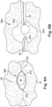
- the native mitral valve of the human heart connects the left atrium to the left ventricle.
- the mitral valve has a very different anatomy than other native heart valves.
- the mitral valve includes an annulus portion, which is an annular portion of the native valve tissue surrounding the mitral valve orifice, and a pair of cusps, or leaflets, extending downward from the annulus into the left ventricle.
- the mitral valve annulus can form a "D"-shaped, oval, or otherwise out-of-round cross-sectional shape having major and minor axes.
- the anterior leaflet can be larger than the posterior leaflet, forming a generally "C"-shaped boundary between the abutting sides of the leaflets when they are closed together.
- the anterior leaflet and the posterior leaflet function together as a one-way valve to allow blood to flow only from the left atrium to the left ventricle.
- the left atrium receives oxygenated blood from the pulmonary veins.
- the muscles of the left atrium contract and the left ventricle dilates (also referred to as “ventricular diastole” or “diastole"), the oxygenated blood that is collected in the left atrium flows into the left ventricle.
- the present invention relates to a valve repair device for repairing a native valve of a patient.
- the valve repair device comprises a paddle frame, an inner paddle and an outer paddle connected to the inner paddle.
- the connection is such that the inner and outer paddles are connected to the paddle frame at a connection between the inner paddle and the outer paddle.
- Each of these valves has flexible leaflets (e.g., leaflets 20, 22 shown in Figures 4 and 5 ) extending inward across the respective orifices that come together or "coapt" in the flowstream to form the one-way, fluid-occluding surfaces.
- the native valve repair systems of the present application are described primarily with respect to the mitral valve MV. Therefore, anatomical structures of the left atrium LA and left ventricle LV will be explained in greater detail. It should be understood that the devices described herein may also be used in repairing other native valves, e.g., the devices can be used in repairing the tricuspid valve TV, the aortic valve AV, and the pulmonary valve PV.
- the left atrium LA receives oxygenated blood from the lungs.
- the blood that was previously collected in the left atrium LA moves through the mitral valve MV and into the left ventricle LV by expansion of the left ventricle LV.
- the left ventricle LV contracts to force the blood through the aortic valve AV and ascending aorta AA into the body.
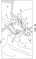
- the mitral valve MV includes two leaflets, the anterior leaflet 20 and the posterior leaflet 22.
- the mitral valve MV also includes an annulus 24, which is a variably dense fibrous ring of tissues that encircles the leaflets 20, 22.
- the mitral valve MV is anchored to the wall of the left ventricle LV by chordae tendineae 10.
- the chordae tendineae 10 are cord-like tendons that connect the papillary muscles 12 (i.e., the muscles located at the base of the chordae tendineae and within the walls of the left ventricle) to the leaflets 20, 22 of the mitral valve MV.
- Various disease processes can impair proper function of one or more of the native valves of the heart H.
- These disease processes include degenerative processes (e.g., Barlow's Disease, fibroelastic deficiency), inflamatory processes (e.g., Rheumatic Heart Disease), and infectious processes (e.g., endocarditis).
- degenerative processes e.g., Barlow's Disease, fibroelastic deficiency
- inflamatory processes e.g., Rheumatic Heart Disease
- infectious processes e.g., endocarditis
- damage to the left ventricle LV or the right ventricle RV from prior heart attacks i.e., myocardial infarction secondary to coronary artery disease
- other heart diseases e.g., cardiomyopaty
- a healthy mitral valve MV when a healthy mitral valve MV is in a closed position, the anterior leaflet 20 and the posterior leaflet 22 coapt, which prevents blood from leaking from the left ventricle LV to the left atrium LA.
- regurgitation occurs when the anterior leaflet 20 and/or the posterior leaflet 22 of the mitral valve MV is displaced into the left atrium LA during systole.
- This failure to coapt causes a gap 26 between the anterior leaflet 20 and the posterior leaflet 22, which allows blood to flow back into the left atrium LA from the left ventricle LV during systole.
- a leaflet e.g. leaflets 20, 22 of mitral valve MV
- may malfunction which can thereby lead to regurgitation.
- the mitral valve MV of a patient can have a wide gap 26 between the anterior leaflet 20 and the posterior leaflet 22 when the mitral valve is in a closed position (i.e., during the systolic phase).
- the gap 26 can have a width W between about 2.5 mm and about 17.5 mm, such as between about 5 mm and about 15 mm, such as between about 7.5 mm and about 12.5 mm, such as about 10 mm.
- the gap 3002 can have a width W greater than 15 mm.
- a valve repair device is desired that is capable of engaging the anterior leaflet 20 and the posterior leaflet 22 to close the gap 26 and prevent regurgitation of blood through the mitral valve MV.
- the mitral valve MV and the tricuspid valve TV are more prone to deformation of leaflets, which, as described above, prevents the mitral valve or tricuspid valve from closing properly and allows for regurgitation or back flow of blood from the ventricle into the atrium (e.g., a deformed mitral valve MV may allow for regurgitation or back flow from the left ventricle LV to the left atrium LA).
- the regurgitation or back flow of blood from the ventricle to the atrium results in valvular insufficiency.
- Deformations in the structure or shape of the mitral valve MV or the tricuspid valve TV are often repairable.
- An exemplary implantable prosthetic device has a coaption element and at least one anchor.
- the coaption element is configured to be positioned within the native heart valve orifice to help fill the space and form a more effective seal, thereby reducing or preventing regurgitation described above.
- the coaption element can have a structure that is impervious to blood and that allows the native leaflets to close around the coaption element during ventricular systole to block blood from flowing from the left or right ventricle back into the left or right atrium, respectively.
- the prosthetic device can be configured to seal against two or three native valve leaflets; that is, the device may be used in the native mitral (bicuspid) and tricuspid valves.
- the coaption element is sometimes referred to herein as a spacer because the coaption element can fill a space between improperly functioning native mitral or tricuspid leaflets that do not close completely.
- the atrial or upper portion is positioned in or adjacent to the right atrium, and the ventricular or lower portion is positioned in or adjacent to the right ventricle, and the side surface that extends between the native tricuspid leaflets.
- the anchor and the coaption element can be positioned independently with respect to each other by separately moving each of the anchor and the coaption element along the longitudinal axis of the shaft or actuation wire. In some embodiments, the anchor and the coaption element can be positioned simultaneously by moving the anchor and the coaption element together along the longitudinal axis of the shaft or actuation wire.
- the anchor can be configured to be positioned behind a native leaflet when implanted such that the leaflet is grasped by the anchor.
- the disclosed prosthetic devices can be configured such that the anchor is connected to a leaflet, taking advantage of the tension from native chordae tendineae to resist high systolic pressure urging the device toward the left atrium. During diastole, the devices can rely on the compressive and retention forces exerted on the leaflet that is grasped by the anchor.
- the device 100 can include any other features for an implantable prosthetic device discussed in the present application, and the device 100 can be positioned to engage valve tissue 20, 22 as part of any suitable valve repair system (e.g., any valve repair system disclosed in the present application).
- any suitable valve repair system e.g., any valve repair system disclosed in the present application.
- the device 100 is deployed from a delivery sheath 102 and includes a coaption portion 104 and an anchor portion 106.
- the coaption portion 104 of the device 100 includes a coaption element 110 that is adapted to be implanted between the leaflets of the native mitral valve and is slidably attached to an actuation wire or shaft 112.
- the anchor portion 106 is actuatable between open and closed conditions and can take a wide variety of forms, such as, for example, paddles, gripping elements, or the like. Actuation of the actuation wire 112 opens and closes the anchor portion 106 of the device 100 to grasp the mitral valve leaflets during implantation.
- the actuation wire or shaft 112 may take a wide variety of different forms.
- the actuation wire or shaft may be threaded such that rotation of the actuation wire or shaft moves the anchor portion 106 relative to the coaption portion 104.
- the actuation wire or shaft may be unthreaded, such that pushing or pulling the actuation wire or shaft 112 moves the anchor portion 106 relative to the coaption portion 104.
- the anchor portion 106 of the device 100 includes outer paddles 120 and inner paddles 122 that are connected between a cap 114 and the coaption element 110 by portions 124, 126, 128.
- the portions 124, 126, 128 may be jointed and/or flexible to move between all of the positions described below.
- the interconnection of the outer paddles 120, the inner paddles 122, the coaption element 110, and the cap 114 by the portions 124, 126, and 128 can constrain the device to the positions and movements illustrated herein.
- the actuation wire 112 extends through the delivery sheath and the coaption element 110 to the cap 114 at the distal connection of the anchor portion 106. Extending and retracting the actuation wire 112 increases and decreases the spacing between the coaption element 110 and the cap 114, respectively.
- a collar removably attaches the coaption element 110 to the delivery sheath 102 so that the actuation wire 112 slides through the collar and coaption element 110 during actuation to open and close the paddles 120, 122 of the anchor portion 106.
- the anchor portion 106 includes attachment portions or gripping members.
- the illustrated gripping members are barbed clasps 130 that include a base or fixed arm 132, a moveable arm 134, barbs 136, and a joint portion 138.
- the fixed arms 132 are attached to the inner paddles 122, with the joint portion 138 disposed proximate the coaption element 110.
- the barbed clasps have flat surfaces and do not fit in a recess of the paddle. Rather, the flat portions of the barbed clasps are disposed against the surface of the inner paddle 122.
- the joint portion 138 provides a spring force between the fixed and moveable arms 132, 134 of the barbed clasp 130.
- the joint portion 138 can be any suitable joint, such as a flexible joint, a spring joint, a pivot joint, or the like.
- the joint portion 138 is a flexible piece of material integrally formed with the fixed and moveable arms 132, 134.
- the fixed arms 132 are attached to the inner paddles 122 and remain stationary relative to the inner paddles 122 when the moveable arms 134 are opened to open the barbed clasps 130 and expose the barbs 136.
- the barbed clasps 130 are opened by applying tension to actuation lines 116 attached to the moveable arms 134, thereby causing the moveable arms 134 to pivot on the joint portions 138.
- the paddles 120, 122 are opened and closed to grasp the native mitral valve leaflets between the paddles 120, 122 and the coaption element 110.
- the barbed clasps 130 further secure the native leaflets by engaging the leaflets with barbs 136 and pinching the leaflets between the moveable and fixed arms 134, 132.
- the barbs 136 of the barbed clasps 130 increase friction with the leaflets or may partially or completely puncture the leaflets.
- the actuation lines 116 can be actuated separately so that each barbed clasp 130 can be opened and closed separately.
- the barbed clasps 130 can be opened and closed relative to the position of the inner paddle 122 (as long as the inner paddle is in an open position), thereby allowing leaflets to be grasped in a variety of positions as the particular situation requires.
- the barbed clasps 130 can be opened separately by pulling on an attached actuation line 116 that extends through the delivery sheath 102 to the barbed clasp 130.
- the actuation line 116 can take a wide variety of forms, such as, for example, a line, a suture, a wire, a rod, a catheter, or the like.
- the barbed clasps 130 can be spring loaded so that in the closed position the barbed clasps 130 continue to provide a pinching force on the grasped native leaflet. This pinching force remains constant regardless of the position of the inner paddles 122. Barbs 136 of the barbed clasps 130 can pierce the native leaflets to further secure the native leaflets.
- the device 100 is shown in an elongated or fully open condition for deployment from the delivery sheath.
- the device 100 is loaded in the delivery sheath in the fully open position, because the fully open position takes up the least space and allows the smallest catheter to be used (or the largest device 100 to be used for a given catheter size).
- the cap 114 is spaced apart from the coaption element 110 such that the paddles 120, 122 of the anchor portion 106 are fully extended.
- an angle formed between the interior of the outer and inner paddles 120, 122 is approximately 180 degrees.
- the barbed clasps 130 are kept in a closed condition during deployment through the delivery sheath 102 so that the barbs 136 ( Fig. 11 ) do not catch or damage the sheath or tissue in the patient's heart.
- the device 100 is shown in an elongated detangling condition, similar to Figure 8 , but with the barbed clasps 130 in a fully open position, ranging from about 140 degrees to about 200 degrees, to about 170 degrees to about 190 degrees, or about 180 degrees between fixed and moveable portions of the barbed clasps 130.
- Fully opening the paddles 120, 122 and the clasps 130 has been found to improve ease of detanglement from anatomy of the patient during implantation of the device 100.
- the actuation wire 112B is extended to push the cap 114 away from the coaption element 110, thereby pulling on the outer paddle 120, which in turn pulls on the inner paddle 122, causing the second anchor portion 106 to partially unfold.
- the independent paddle control illustrated by Figure 11A can be implemented on any of the devices disclosed by the present application.
- the sleeve can be machined to have an interior shape that matches or is slightly smaller than the exterior shape of the ends of the spacer member 202 and the anchor 204, so that the sleeve can be friction fit on the connection portions.
- One or more barbs or projections 208 can be mounted on the frame of the spacer member 202.
- the free ends of the barbs or projections 208 can comprise various shapes including rounded, pointed, barbed, or the like.
- the projections 208 can exert a retaining force against native leaflets by virtue of the anchors 204, which are shaped to force the native leaflets inwardly into the spacer member 202.
- the paddle portions are aligned or straight in the direction of the longitudinal axis of the device and the joint portions 423 of the anchors 408 are adjacent the longitudinal axis of the coaption member 410 (e.g., similar to the configuration shown in Figure 59 ).
- the anchors 408 can be moved to a fully folded configuration (e.g., Figure 23 ) by moving the toward the coaption member 410.
- the clasps 430 can comprise attachment or fixed portions 432 and arm or moveable portions 434.
- the attachment or fixed portions 432 can be coupled to the inner paddles 422 of the anchors 408 in various ways such as with sutures, adhesive, fasteners, welding, stitching, swaging, friction fit and/or other means for coupling.
- the moveable portions 434 can comprise one or more side beams 431. When two side beams are included as illustrated, the side beams can be spaced apart to form slots 431A.
- the slots 431A can be configured to receive the fixed portions 432.
- the moveable portions 434 can also include spring portions 434A that are coupled to the fixed portions 432 and barb support portions 434B disposed opposite the spring portions 434A.
- the paddle frames 524 can also be configured to extend laterally (i.e., perpendicular to a longitudinal axis of the coaption member 510) beyond an outer diameter of the coaption member 510.
- the inner paddle portions 522 and the outer paddle portions 520 are formed from a continuous strip of fabric that are connected to the paddle frames 524.
- the inner paddle portions and the outer paddle portions can be connected to the connection portion of the paddle frame at the flexible connection between the inner paddle portion and the outer paddle portion.
- the implantable device 500 is shown being delivered and implanted within the native mitral valve MV of the heart H.
- the device 500 has a covering 540 (see Figure 30 ) over the coaption element 510, clasps 530, inner paddles 522 and/or the outer paddles 520.
- the device 500 is deployed from a delivery sheath 502 and includes a coaption portion 504 and an anchor portion 506 including a plurality of anchors 508 (i.e., two in the illustrated embodiment).
- the device 500 is loaded in the delivery sheath in the fully open position, because the fully open position takes up the least space and allows the smallest catheter to be used (or the largest device 500 to be used for a given catheter size).
- the delivery sheath is inserted into the left atrium LA through the septum and the device 500 is deployed from the delivery sheath 502 in the fully open condition.
- the actuation wire 512 is then retracted to move the device 500 into the fully closed condition shown in Figures 36-37 and then maneuvered towards the mitral valve MV as shown in Figure 38 .
- the distance the leaflets 20, 22 need to be approximated is still minimized if the coaption element 510 is placed precisely at a regurgitant gap and the regurgitant gap is less than the width (medial - lateral) of the coaption element 510.
- the anatomy of the leaflets 20, 22 is such that the inner sides of the leaflets coapt at the free end portions and the leaflets 20, 22 start receding or spreading apart from each other.
- the leaflets 20, 22 spread apart in the atrial direction, until each leaflet meets with the mitral annulus.
- the dimensions of the coaption element are selected to minimize the number of implants that a single patient will require (preferably one), while at the same time maintaining low transvalvular gradients.
- the anterior-posterior distance X 47B at the top of the spacer is about 5mm
- the medial-lateral distance X 67D of the spacer at its widest is about 10mm.
- the overall geometry of the device 510 can be based on these two dimensions and the overall shape strategy described above. It should be readily apparent that the use of other anterior-posterior distance anterior-posterior distance X 47B and medial-lateral distance X 67D as starting points for the device will result in a device having different dimensions. Further, using other dimensions and the shape strategy described above will also result in a device having different dimensions.
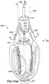
- the device 500 is shown in a three-quarters extended position.
- the device 500 is moved into the three-quarters extended position by continuing to extend the actuation wire 512 described above, thereby increasing the distance D between the attachment portion 505 and distal portion 507.
- Continuing to extend the actuation wire 512 pulls down on the outer paddles 520 and paddle frames 524, thereby causing the inner paddles 522 to spread apart further from the coaption element 510.
- the inner paddles 522 are open beyond 90 degrees to an approximately 135-degree angle with the coaption element 510.
- the paddle frames 524 are less spread than in the laterally extended or open position and begin to move inward toward the actuation wire 512 as the actuation wire 512 extends further.
- the outer paddles 520 also flex back toward the actuation wire 512.
- the increased gap 520A formed in the laterally extended or open position allows clasps 530 to open even further ( Figure 57 ), thereby increasing the size of the gap 530A.
- the outer paddles 520 and the paddle frames 522 never move or flex to or past a ninety degree angle with respect to the coaption element 510.
- the inner and outer paddles 522, 520 can have a somewhat curved shape.
- valve repair device 700 After valve tissue is received in the openings 706 between the paddles 702 and the gripping members 704, the valve repair device is moved back to the closed position (as shown in Figure 63A ) to secure the valve repair device 700 to the valve tissue.
- the implantable device 700 can include any other features for an implantable device discussed in the present application, and the implantable device 700 can be positioned to engage valve tissue 20, 22 as part of any suitable valve repair system (e.g., any valve repair system disclosed in the present application).
- the device 500 has a shape that is substantially symmetrical around a vertical front-to-back plane 550 and is generally narrower at the distal portion 507 than the proximal portion 505.
- the shape of the coaption element 510 and paddle frames 524 is generally rounded to prevent the device 500 from catching or snagging on structures of the heart, such as the chordae tendineae, during implantation. For this reason, the proximal collar 511 ( Figure 68 ) and cap 514 ( Figure 68 ) also have round edges.
- the paddle frames 524 When viewed from the front or back, the paddle frames 524 can be seen to have a generally rounded shape, extending upwards and outwards from the distal portion 507 to approximately coincide with the shape of the coaption element 510 when viewed from the front or back.
- the coaption element 510 and paddle frames 524 generally define the shape of the device 500 when viewed from the front or back.
- the rounded shape of the paddle frames 524 and the corresponding rounded shape of the coaption element can distribute leaflet stress across a wider surface.
- the paddle frames 524 and/or the coaption element 510 can have other shapes.
- the closed paddles 520, 522 form gaps 542 between the inner paddles 522 and the coaption element 510 that are configured to receive native tissue.
- the narrowing of the coaption element 510 gives the gaps 542 a somewhat teardrop shape that increases in width as the gaps 542 approach the distal portion 507 of the device. The widening of the gaps 542 toward the distal portion 507 allows the paddles 520, 522 to contact tissue grasped in the gaps 542 nearer to the proximal portion 505.
- the paddle frames 524 extend vertically from the distal portion 507 toward the proximal portion 505 until approximately a middle third of the device 500 before bending or flaring outward so that the connection portion of the frames 524 passes through gaps 544 formed by the inner paddles 522 folded inside of the outer paddles 520.
- the connection of the frames are positioned inside the inner paddles 522 or outside the outer paddles 520.
- the outer paddles 520 have a rounded shape that is similar to that of the coaption element 510 when viewed from the front or back ( Figures 67-68 ).
- the device 500 has a substantially round shape.
- the round shape of the device 500 is particularly visible when the device 500 is viewed from the top ( Figures 70-71 ) or bottom ( Figures 72-73 ).
- the paddle frames 224 each have an arcuate shape with a smaller radius than the coaption element 510 so that the gaps 542 formed between the inner paddles 522 and paddle frames 524 and the coaption element 510 taper as they approach left 551 and right 553 sides of the device 500.
- native tissue such as the leaflets 20, 22 tend to be pinched between the paddle frames 524 and the coaption element 510 towards the left and right sides 551, 553 of the device 500.
- the paddle frames 524 extend outward from the distal portion 507 of the device 500 to the left and right sides 551, 553 at a narrow or slight angle from the side-to-side plane 552.
- the paddle frames 524 extend further away from the side-to-side plane 552 as the paddle frames 524 extend toward the proximal portion of the device 500 ( Figure 69 ) to ultimately form the arcuate shape seen in Figures 70-71 .
- the device 500 is shown sliced by cross-section plane 81 positioned about one-quarter of the way between the distal portion 507 and the proximal portion 505 of the coaption element 510.
- a cross-sectional view of the device 500 is shown as viewed from cross-section plane 81 in Figure 80 .
- the coaption element 510 has a generally oval shape oriented along the side-to-side plane 552 that is narrower than the oval shape seen in Figure 77 .
- the paddle frames 524 can be seen near the left and right sides 551, 553 very close to or in contact with the coaption element 510.
- the gaps 542 are generally crescent shaped and are wider than the gaps 542 viewed along the plane 79 ( Figure 79 .)
- the device 500 is shown sliced by cross-section plane 83 positioned near the distal portion 507 of the coaption element 510.
- a cross-sectional view of the device 500 is shown as viewed from cross-section plane 83 in Figure 82 .
- the coaption element 510 has a generally oval shape oriented along the side-to-side plane 552 that is narrower than the oval shape seen in Figure 79 as the coaption element 510 tapers toward the distal portion 507 of the device 500.
- the paddle frames 524 can be seen near the left and right sides 551, 553 very close to or in contact with the coaption element 510. While the inner paddles 522 are not visible in Figure 81 , the gaps 542 are generally crescent shaped and are wider than the gaps 542 viewed along the plane 81 ( Figure 81 .)
- exemplary implantable devices 100, 500 are shown without clasps or articulable gripping members. Rather, the exemplary devices 100, 500 shown in Figures 84-88 have barbs or gripping members 800 and/or 802 integrated into portions of the coaption element or paddles of the anchor portion of the devices to facilitate grasping of the tissue of the native heart valve.
- an exemplary implantable device 100 that does not include articulable clasps or gripping elements.
- the device 100 is deployed from a delivery sheath 102 and includes a coaption portion 104 and an anchor portion 106.
- the coaption portion 104 of the device 100 includes a coaption element 110 that is adapted to be implanted between the leaflets 20, 22 of the native mitral valve MV and is slidably attached to an actuation wire or shaft 112 that extends through the coaption element 110 to a distal cap 114.
- the anchor portion 106 of the device 100 includes outer paddles 120 and inner paddles 122 that are connected between the distal cap 114 and the coaption element 110.
- the anchor portion 106 is actuatable between open and closed conditions and can take a wide variety of forms, such as, for example, paddles, gripping elements, or the like. Actuation of the actuation wire 112 opens and closes the anchor portion 106 of the device 100 to grasp the mitral valve leaflets 20, 22 during implantation.
- the device 100 shown in Figure 85 includes barbed portions 800 arranged on the inner paddles 122, with each inner paddle 122 having at least one barbed portion 800.
- each inner paddle 122 has at least one barbed portion 800.
- the barbed portions 800 are sharp so that they engage—and in some examples, pierce—the native tissue and prohibit the tissue from retracting from the device 100.
- the barbed portions 800 are angled downward to increase engagement with the native tissue.
- the exemplary implantable device 500 is shown that does not include articulable clasps or gripping elements.
- the device 500 includes a coaption portion 502 and an anchor portion 504.
- the coaption portion 502 of the device 500 includes a coaption element 510 that is adapted to be implanted between the leaflets 20, 22 of the native mitral valve MV and is slidably attached to an actuation wire or shaft 512 that extends through the coaption element 510 to a distal cap 514.
- the device 500 includes barbed portions 800 arranged on the inner paddles 522, with each inner paddle 522 optionally having more than one barbed portion 800.
- each inner paddle 522 optionally having more than one barbed portion 800.
- the barbed portions 800 are sharp so that they engage—and in some examples, pierce—the native tissue and prohibit the tissue from retracting from the device 500.
- the barbed portions 800 are angled downward to increase engagement with the native tissue.
- the exemplary implantable device 500 is shown that does not include separate articulable clasps or gripping elements.
- the device 500 includes a coaption portion 502 and an anchor portion 504.
- the coaption portion 502 of the device 500 includes a coaption element 510 that is adapted to be implanted between the leaflets 20, 22 of the native mitral valve MV and is slidably attached to an actuation wire or shaft 512 that extends through the coaption element 510 to a distal cap 514.
- the anchor portion 506 of the device 500 includes outer paddles 520 and inner paddles 522 that are connected between the distal cap 514 and the coaption element 510.
- the anchor portion 506 is actuatable between open and closed conditions and can take a wide variety of forms, such as, for example, paddles, gripping elements, or the like. Actuation of the actuation wire 512 opens and closes the anchor portion 506 of the device 500 to grasp the mitral valve leaflets 20, 22 during implantation.
- the device 500 includes barbed portions 800 arranged on the coaption element 510, with each side of the coaption element 510 having more than one barbed portion 800.
- the anchor portion 506 of the device 500 is closed, tissue grasped between the inner paddles 522 and the coaption element 510 is pressed against the barbed portions 800.
- the barbed portions 800 are sharp so that they engage—and in some examples, pierce—the native tissue and prohibit the tissue from retracting from the device 500.
- the barbed portions 800 are angled downward to increase engagement with the native tissue.
- the exemplary implantable device 500 is shown that does not include separate articulable clasps or gripping elements.
- the device 500 includes a coaption portion 502 and an anchor portion 504.
- the coaption portion 502 of the device 500 includes a coaption element 510 that is adapted to be implanted between the leaflets 20, 22 of the native mitral valve MV and is slidably attached to an actuation wire or shaft 512 that extends through the coaption element 510 to a distal cap 514.
- the anchor portion 506 of the device 500 includes outer paddles 520 and inner paddles 522 that are connected between the distal cap 514 and the coaption element 510.
- the anchor portion 506 is actuatable between open and closed conditions and can take a wide variety of forms, such as, for example, paddles, gripping elements, or the like. Actuation of the actuation wire 512 opens and closes the anchor portion 506 of the device 500 to grasp the mitral valve leaflets 20, 22 during implantation.
- the device 500 includes barbed portions 800 arranged on the coaption element 510, with each side of the coaption element 510 including at least one barbed portion 800. Similar to device 1500 described above, the device 500 also includes barbed portions 802 arranged on the inner paddles 522, with each inner paddle 522 having at least one barbed portion 802.
- tissue grasped between the inner paddles 522 and the coaption element 510 is pressed against the barbed portions 800, 802.
- the barbed portions 800, 802 are sharp so that they engage—and in some examples, pierce—the native tissue and prohibit the tissue from retracting from the device 500.
- the barbed portions 800, 802 are angled downward to increase engagement with the native tissue.
- the combination of barbed portions 800 on the coaption element 510 and barbed portions 802 on the inner paddles 522 forms the grasped tissue into an S-shaped tortuous path as it passes over the barbed portions 800, 802.
- the coaption element 510 and paddles 520, 522 of the exemplary device 500 are shown.
- the coaption element 510 and the paddles can be made from a wide variety of different materials.
- the coaption element 510 and paddles 520, 522 may be formed from a material that may be a metal fabric, such as a mesh, woven, braided, electrospun or formed in any other suitable way or a laser cut or otherwise cut flexible material.
- the material may be cloth, shape-memory alloy wire—such as Nitinol—to provide shape setting capability, or any other flexible material suitable for implantation in the human body.
- the coaption element is made from a braided mesh of metal wires, such as a braided mesh of nitinol wires.
- the coaption element 510 is made of a braided mesh of between 25 and 100 wires, such as between 40 and 85 wires, such as between 45 and 60 wires, such as about 48 Nitinol wires or 48 Nitinol wires.
- the coaption element can be covered in a cloth, such as a polyethylene cloth.
- the coaption element 510 can be surrounded in its entirely with a cloth cover, such as a polyethylene cloth of a fine mesh.
- the cloth cover can provide a blood seal on the surface of the spacer, and/or promote rapid tissue ingrowth.
- a shape memory material such as braided Nitinol wire mesh
- the use of a shape memory material, such as braided Nitinol wire mesh, for the construction of the coaption element 510 results in a coaption element that can self-expandable, flexible in all directions, and/or results in low strains when the coaption element is crimped and/or bent.
- the material can be a single piece, two halves joined together, or a plurality of sections or pieces that are fastened or joined together in any suitable manner, such as, by welding, with adhesives, or the like.
- the device 500 extends from a proximal portion 505 to a distal portion 507 and includes a coaption element 510, inner paddles 522, and outer paddles 520.
- the coaption element 510 includes a proximal opening 519A and a distal opening 515 ( Figures 92 and 94 ).
- the proximal opening 519A of the coaption element 510 is formed in a proximal portion 519 of the coaption element 510.
- the coaption element 510 is jointably connected to the inner paddles 522 by joint portions 525.
- the inner paddles 522 are jointably connected to the outer paddles 520 by joint portions 523.
- the outer paddles 520 are jointably attached to distal portions 527 by joint portions 521.
- Coaption gaps 542 are formed between the inner paddles 522 and the coaption element 510.
- Paddle gaps 544 are formed between the inner and outer paddles 520, 522 when the paddles 520, 522 are folded, for example, as shown in Figure 90 .
- the coaption element 510 includes the proximal portion 519, a middle portion 518, and a distal portion 517.
- the proximal portion 519 includes the proximal opening 519A.
- the distal portion 517 includes the distal opening 515 and is connected to the joint portions 525.
- the shape of the coaption element 510 is generally rounded to prevent the device 500 from catching or snagging on structures of the heart, such as the chordae tendineae, during implantation.
- the distal portion 507 of the device 500 is generally narrower than the proximal portion 505 of the device 500 when the device 500 is viewed from the side.
- the coaption element 510 flares outwards in the proximal portion 519 from the proximal opening 519A to the middle portion 518.
- the coaption element 510 then tapers or narrows in the middle portion 518 from the proximal portion 519 to the distal portion 517.
- the distal portion 517 remains narrow and then splits into the two joint portions 525.
- the generally rounded features of the device 500 are further demonstrated by the round shape of the joint portions 523 that jointably connect the inner and outer paddles 520, 522 and the outwardly bowed shape of the outer paddles 520.
- the coaption gaps 542 formed between the inner paddles 522 and the coaption element 510 are configured to receive native tissue.
- the narrowing of the coaption element 510 gives the gaps 542 a somewhat teardrop shape that increases in width as the gaps 542 approach the distal portion 507 of the device 500.
- the widening of the gaps 542 toward the distal portion 507 allows the inner paddles 522 to contact tissue grasped in the gaps 542 nearer to the proximal portion 505 where pinching forces are greater as a result of the mechanical advantage provided by the length of the paddles 520, 522 and other securing or anchoring elements, such as those described in the present application.
- a top view of the device 500 is shown.
- the proximal opening 519A in the coaption element 510 is visible at the proximal portion 505 of the device 500 and the coaption element 510 can be seen to be hollow inside.
- the coaption element 510 has a generally oval-shape when viewed from the top. While the paddles 520, 522 appear as protruding rectangular shapes, the paddles 520, 522 can extend laterally and have an arcuate or crescent-like shape.
- FIG. 95 perspective and cross-sectional views of the device 500 are shown.
- the device 500 is shown sliced by cross-section plane 96 near the proximal portion of the coaption element 510.
- Figure 96 a cross-sectional view of the device 500 is shown as viewed from cross-section plane 96 in Figure 95 .
- the coaption element 510 has a generally oval shape with thicker portions along the sides of the coaption element 510.
- the distal opening 515 is visible from the proximal portion and the coaption element 510 has a hollow interior.
- the device 500 is shown sliced by cross-section plane 98 positioned about half of the way between the distal portion 507 and the proximal portion 505 of the coaption element 510.
- a cross-sectional view of the device 500 is shown as viewed from cross-section plane 98 in Figure 97 .
- the coaption element 510 has a generally oval shape that is larger than the oval shape of Figure 96 .
- the device 500 is shown sliced by cross-section plane 102 positioned near the distal portion 507 of the coaption element 510.
- a cross-sectional view of the device 500 is shown as viewed from cross-section plane 102 in Figure 101 .
- the coaption element 510 has a generally oval shape that is smaller than the oval shape seen in Figure 100 and that is split as the coaption element 510 joins the joint portions 525.
- the exemplary implantable prosthetic device 100 is shown having covered and uncovered portions.
- the device 100 is shown implanted in the native mitral valve MV and secured to the native leaflets 20, 22.
- the device 100 includes a coaption element 110, paddles 120, clasps 130, and a cap 114.
- the paddles 120 and clasps 130 are in a closed position to secure the device 100 to the grasped native leaflets 20, 22 of the mitral valve MV.
- a proximal portion 105 of the device 100 is exposed to the left atrium LA and a distal portion 107 of the device 100 is exposed to the left ventricle LV.
- the device 100 is shown with a covering 900 that covers the entirety of the coaption element 110 and the cap 114.
- the covering 900 can be a cloth or fabric such as PET, velour, electrospun or other suitable fabric.
- the cover in lieu of or in addition to a fabric, can include a coating (e.g., polymeric) that is applied to the prosthetic spacer device and/or mechanical sealing mechanisms, such as silicone and interlocking joints can be used.
- the covering 900 can be formed from a metal fabric, such as a mesh, woven, braided, or formed in any other suitable way or a laser cut or otherwise cut flexible material..
- the covering 900 may be cloth, shape-memory alloy wire—such as Nitinol—to provide shape setting capability, or any other flexible material suitable for implantation in the human body.
- the covering 900 prohibits blood flow through coaption element 110 at the proximal portion 105, and also provides a seal between the device 100 and the leaflets 20, 22.
- the covering 900 aids in the prohibition of blood flow through the mitral valve MV at the location of the device 100.
- the covering 900 also prohibits recirculating blood flow from entering the device 100 from the distal portion 107.
- the device 100 is shown with a covering 1000 that partially covers the coaption element 110 from the proximal portion 105 of the device 100 to the portion of the coaption element 110 that engages the native leaflets 20, 22.
- the cover can be a cloth or fabric such as PET, velour, or other suitable fabric.
- the cover in lieu of or in addition to a fabric, can include a coating (e.g., polymeric) that is applied to the prosthetic spacer device.
- the covering 1000 can be formed from a metal fabric, such as a mesh, woven, braided, or formed in any other suitable way or a laser cut or otherwise cut flexible material.
- the covering 1000 may be cloth, shape-memory alloy wire—such as Nitinol—to provide shape setting capability, or any other flexible material suitable for implantation in the human body. Thus, the covering 1000 prohibits blood flow through the coaption element 110 at the proximal portion 105.
- shape-memory alloy wire such as Nitinol
- the device 100 is shown with a covering 1100 that partially covers the coaption element 110 extending from the portion of the coaption element 110 that engages the native leaflets 20, 22 toward the distal portion 107.
- the covering 1100 also covers the cap 114.
- the cover can be a cloth or fabric such as PET, velour, or other suitable fabric.
- the cover in lieu of or in addition to a fabric, can include a coating (e.g., polymeric) that is applied to the prosthetic spacer device.
- the covering 1100 can be formed from a mesh, woven, braided, or formed in any other suitable way.
- the covering 1100 may be cloth, electrospun material, and/or shape-memory alloy wire—such as Nitinol—to provide shape setting capability, or any other flexible material suitable for implantation in the human body.
- blood flow can enter the coaption element 110 but is prohibited from passing through the device by the covering 1100 arranged toward the distal portion 107.
- the covering 1100 also prohibits recirculating blood flow from entering the device 100 from the distal portion 107.
- an exemplary coaption element 1200 for an implantable prosthetic device is shown.
- the coaption element 1200 can be used with any of the implantable prosthetic devices described in the present application.
- the coaption element 1200 has a generally cylindrical shape extending between two caps 1201.
- the coaption element 1200 can have any shape, such as any of the shapes disclosed herein.
- the direction of expansion of the coaption element 1200 can be controlled.
- the width/size of the coaption element in the Anterior to Posterior direction (when implanted), Medial to Lateral direction (when implanted), or both can be expanded (or contracted) in a controlled manner.
- the coaption element can be made from a mesh 1200 of material. Referring now to Figure 107 , the mesh wall of the generally cylindrical coaption element 1200 extends outward from the caps 1201 by a distance 1204. Referring now to Figure 108 , axial forces 1208 are applied to the caps 1201 of the coaption element 1200 causing the coaption element 1200 to compress in an axial direction. Compressing the coaption element 1200 axially causes the coaption element 1200 to expand or bulge in an outward direction 1210, such that the distance 1204 increases.
- the coaption element 1200 can be compressed in a wide variety of different ways.
- a threaded connection can be used to draw the two ends of the coaption element together or push the two ends of the coaption element apart.
- a collar can be provided on each end of the coaption element. One of the collars can threadedly engage a threaded shaft, while the other collar is rotatably connected to the shaft. Rotating the shaft in one direction draws the collars together. Rotating the shaft in the opposite direction moves the collars apart.
- coaption element 1200 similar to the example illustrated by Figures 106-109 , for an implantable prosthetic device is shown.
- the coaption element 1200 can be used with any of the implantable prosthetic devices described in the present application.
- the coaption element 1200 has a generally cylindrical shape extending between two caps 1201.
- the coaption element 1200 can have any shape, such as any of the shapes disclosed herein.
- the coaption element 1200 comprises a tube 1203 with slots 1205.
- the tube 1203 can be made from a shape memory alloy, such as nitinol, and the slots can be cut, such as laser cut, into the tube.
- the slots can be cut into the material that forms the tube, before the material is formed into a tube.
- the direction of expansion of the coaption element 1200 can be controlled.
- the configuration of the slots 1205 and/or a shape-set of the tube can be selected to control the shape of the expanded coaption element 1200.
- the configuration of the slots 1205 and/or a shape-set can determine the way the width/size of the coaption element in the Anterior to Posterior direction, and/or Medial to Lateral direction expanded (and/or contract).
- the tube wall of the generally cylindrical coaption element 1200 can extend outward from caps 1201 by a distance 1204.
- axial forces 1208 and/or rotational forces 1209 can be applied to the caps 1201 of the coaption element 1200 causing the coaption element 1200 to expand from the configuration illustrated by Figure 106A to the configuration illustrated by Figure 108A .
- the coaption element 1200 can be compressed in a wide variety of different ways.
- a threaded connection 1221 can be used to draw the two ends of the coaption element together and twist the coaption element in a first direction or push the two ends of the coaption element apart and twist the coaption element in a second direction.
- a collar can be provided on each end of the coaption element. One of the collars can threadedly engage a threaded shaft, while the other collar is fixedly connected to the shaft. Rotating the shaft in one direction draws the collars together and rotates the collars relative to one another in a first direction.
- the pitch of the threaded connection can be selected to set a ratio between the distance the coaption element 1200 is compressed and the angle that the coaption element is twisted.
- FIGs 106C and 108C illustrate another exemplary controllably expandable coaption element 1200 for an implantable prosthetic device.
- the coaption element 1200 can be used on its own, with a covering, or inside any of the coaption elements described herein (to expand the coaption element).
- the coaption element 1200 can be used with any of the implantable prosthetic devices described in the present application.
- the coaption element 1200 has pairs of pivotally connected arms 1231.
- the pairs of pivotally connected arms 1231 each extending between and pivotally connected to two caps 1201. In the illustrated example, there are two pairs of pivotally connected arms 1231. However, there can be one, three, four, or any number of pairs of pivotally connected arms.
- the direction of expansion of the coaption element 1200 can be controlled.
- two pairs (as illustrated) of pivotally connected arms can be included to change the width/size of the coaption element in only one of the Anterior to Posterior direction, and/or Medial to Lateral direction.
- Four pairs of pivotally connected arms 1231 can be included to change the width/size of the coaption element in both the Anterior to Posterior direction and Medial to Lateral direction.
- the arms may have different lengths and/or pivot point locations to make the coaption element 1200 expand (or contract) differently in different dictions.
- the lengths of the arms can be selected to expand more in the Medial to Lateral direction than the Anterior to Posterior direction.
- axial forces 1208 can be applied to the caps 1201 of the coaption element 1200 causing the coaption element 1200 to expand from the configuration illustrated by Figure 106C to the configuration illustrated by Figure 108C .
- compressing the pivotally connected arms 1231 axially causes the pivotal connections 1233 or knees to spread apart in an outward direction 1210, such that the distance 1204 increases.
- the coaption element 1200 can be compressed in a wide variety of different ways.
- a threaded connection 1221 can be used to draw the two ends of the coaption element together or push the two ends of the coaption element apart.
- a collar can be provided on each end of the coaption element. One of the collars can threadedly engage a threaded shaft, while the other collar is rotatably connected to the shaft. Rotating the shaft in one direction draws the collars together. Rotating the shaft in the opposite direction moves the collars apart.
- Figures 106D and 108D illustrate another exemplary expandable coaption element 1200 for an implantable prosthetic device.
- the coaption element 1200 can be used on its own, with a covering (See Figures 106E and 108E ), or inside any of the coaption elements described herein (to expand the coaption element).
- the coaption element 1200 can be used with any of the implantable prosthetic devices described in the present application.
- the coaption element 1200 has, a central support member 1243, one or more pivotally connected arms 1241, and connection lines 1245. Each arm 1241 extends from a pivotal connection to the central support member 1243.
- connection line 1245 is connected to the central support member 1243 and a pivotally connected arm 1241.
- the length of the connection line 1245 sets the degree to which the connection arms pivot away from the central support member 1243. In the illustrated example, there are two pivotally connected arms 1241. However, there can be one, three, four, or any number of pivotally connected arms.
- the direction of expansion of the coaption element 1200 can be controlled.
- two pivotally connected arms can be included to change the width/size of the coaption element in only one of the Anterior to Posterior direction, and/or Medial to Lateral direction.
- Four pivotally connected arms 1241 can be included to change the width/size of the coaption element in both the Anterior to Posterior direction and Medial to Lateral direction.
- the arms and/or the connection lines 1245 may have different lengths and/or pivot point locations to make the coaption element 1200 expand (or contract) differently in different dictions.
- the lengths of the arms and/or the connection lines can be selected to expand more in the Medial to Lateral direction than the Anterior to Posterior direction.
- the arms 1241 can be moved from the contracted position ( Figure 106D ) to the expanded position ( Figure 108D ).
- the arms 1241 can be biased toward the expanded position 1241 by a spring or other biasing means.
- restraints 1247 such as sutures hold the arms 1241 in the contracted position.
- the restraints 1247 can be removed or broken to cause the coaption element 1200 to expand from the configuration illustrated by Figure 106D to the configuration illustrated by Figure 108D .
- Figures 106E and 108E illustrate an example that is similar to the example illustrated by Figures 106D and 108D , except that the coaption element includes a covering material 1253.
- the covering material 1253 can extend from the central support member 1243 to each arm 1241.
- the covering material 1253 can be used with the connection lines 1245 or the covering material can eliminate the need for the connection lines 1245.
- the coaption element 1200 can be used with any of the implantable prosthetic devices described in the present application.
- the coaption element 1200 is defined by a coil 1263 extending between two caps 1201.
- the coaption element 1200 can have any shape, such as any of the shapes disclosed herein.
- the coil 1263 can be made from a shape memory alloy, such as nitinol.
- the direction of expansion of the coaption element 1200 can be controlled.
- the shape-set of the coil 1263 can be selected to control the shape of the expanded coaption element 1200.
- the configuration of the shape-set can determine the way the width/size of the coaption element in the Anterior to Posterior direction, and/or Medial to Lateral direction expand (and/or contract).
- Referring to Axial forces 1208 and/or rotational forces 1209 can be applied to caps 1201 of the coaption element 1200 causing the coaption element 1200 to expand or retract from the configuration illustrated by Figure 106F .
- extending the coil 1263 axially and twisting the coil 1263 contracts the coil in an inward direction 1211 and compressing the coil 1263 axially and twisting the coil in the opposite direction expands or bulge the coil in an outward direction.
- the coaption element 1200 can be compressed in a wide variety of different ways.
- a threaded connection 1221 can be used to draw the two ends of the coaption element together and twist the coaption element in a first direction or push the two ends of the coaption element apart and twist the coaption element in a second direction.
- a collar can be fixedly connected to each end of the coil 1263. One of the collars can threadedly engage a threaded shaft, while the other collar is fixedly connected to the shaft. Rotating the shaft in one direction draws the collars together and rotates the collars relative to one another in a first direction.
- the pitch of the threaded connection can be selected to set a ratio between the distance the coaption element 1200 is compressed and the angle that the coaption element is twisted.
- Figures 106G-106I illustrate exemplary expandable coaption elements 1200.
- the coaption elements are inflated by a fluid medium to expand the coaption element.
- the fluid medium can take a wide variety of different forms. Examples of fluids that can be used to inflate the coaption element 1200 include, but are not limited to, air, gel, water, blood, foaming materials, etc.
- the coaption element 1200 can be used with any of the implantable prosthetic devices described in the present application.
- the coaption element 1200 can have an outer layer 1271 (For example, any of the coaption elements 110, 510 disclosed herein) and an inner layer 1273 or balloon.
- the coaption element 1200 can have any shape, such as any of the shapes disclosed herein.
- the inner layer 1273 is disposed in the outer layer 1271 and can have generally the same shape as the inner surface of the outer layer.
- the inner layer can be made from an expandable material, such as a rubber or other material traditionally used for making balloons and angioplasty devices.
- the outer layer 1271 can be made from a shape memory alloy, such as nitinol.
- the direction of expansion of the coaption element 1200 can be controlled.
- the inner layer 1273 comprises two balloons that are optionally connected together.
- the inner layer can comprise 3, 4, or any number of balloons.
- the balloons can be individually inflated to control the shape of expansion of the coaption element 1200.
- the connection can also affect the shape of expansion.
- the balloons are connected together along a plane 1275 or area. Expansion of the inner layer 1273 in the direction 1277 will be less than the expansion in the direction 1279 due to the connection 1275.
- the expansion due to inflation can be limited to or substantially limited to expansion in the Medial to Lateral direction.
- the use of multiple balloons and the configuration of any connections between the balloons can determine the way the width/size of the coaption element in the Anterior to Posterior direction, and/or Medial to Lateral direction expand (and/or contract).
- the inner layer 1273 comprises one or more supports 1281 or struts.
- One support 1281 is illustrated, but any number can be used.
- the inner layer can comprise 2, 3, 4, or any number of supports.
- the supports 1281 can divide the inner layer into multiple independently inflatable chambers or the supports may not seal off independent chambers and inflation fluid applied to any chamber will fill all of the chambers.
- the chambers can be individually inflated to control the shape of expansion of the coaption element 1200.
- the supports also affect the shape of expansion.
- the support 1281 will reduce or eliminate expansion of the inner layer 1273 in the direction 1277.
- the expansion due to inflation can be limited to or substantially limited to expansion in the Medial to Lateral direction.
- the use of multiple independently inflatable chambers and/or the configuration of the support members 1281 can determine the way the width/size of the coaption element in the Anterior to Posterior direction, and/or Medial to Lateral direction expand (and/or contract).
- an exemplary implantable prosthetic device 1300 is shown.
- the device 1300 is similar to the device 100, described above, and includes a coaption element 1310, paddles 1320, and clasps or gripping members 1330.
- a top view of the coaption element 1310 is shown.
- the coaption element 1310 has a generally oval-shaped cross-section.
- the coaption element 1310 does not include a central opening and can be formed from a solid piece of material, such as foam.
- the device 1300 can include any other features for an implantable prosthetic device discussed in the present application, and the device 1300 can be positioned to engage valve tissue 20, 22 as part of any suitable valve repair system (e.g., any valve repair system disclosed in the present application).
- the prosthetic device 1300 can be opened and closed in a wide variety of different ways. For example, a sleeve can be slidably disposed over the coaption element to engage and open the paddles. Or, the paddles can be opened by pulling a line or suture that opens the clasps and the movement of the clasps can open the paddles. However, any mechanism for opening and closing the device 1300 can be used.
- the paddle frame 1400 can be used with any of the implantable prosthetic devices described in the present application.
- the paddle frame 1400 is formed from a piece of material 1402, such as nitinol, or any other suitable material.
- the paddle frame 1400 extends from a cap attachment portion 1410 to a paddle connection portion 1420 and has a proximal portion 1422, a middle portion 1424, and a distal portion 1426.
- the paddle frame 1400 includes attachment portions 1440 for securing a cover (see Figure 30 ), the inner paddle 520, and/or the outer paddle 522 to the paddle frame 1400.
- the paddle frame 1400 is thinner in the location of the fifth curve 1438 to facilitate bending of both sides of the paddle frame 1400 toward the center plane 1404 during, for example, crimping of the device.
- the paddle frame 1400 extends between a first attachment portion 1412 in a generally rounded, three-dimensional shape through the proximal, middle, and distal portions 1422, 1424, 1426 and returns to a second attachment portion 1414.
- the paddle frame 1400 is bent or curved in multiple locations as the paddle frame 1400 extends between the first and second attachment portions 1412, 1414.
- the attachment portions 1412, 1414 include notches 1416, 1418 respectively for attachment to the cap.
- the paddle frame 1400 flexes at the area 1419.
- the area 1419 can include a wider portion 1417 to distribute the stress that results from flexing the paddle frame 1400 over a greater area.
- notches 1416, 1418 can include radiused notches 1415 at each end of the notches. The radiused notches 1415 serve as strain reliefs for the bending area 1419 and the area where the paddle frame 1400 connects to the cap.
- a flat blank 1403 of paddle frame 1400 can be cut, for example laser cut, from a flat sheet of material. Referring to Figure 192 , the cut blank 1403 can then be bent to form the three-dimensional shaped paddle frame 1400.
- the paddle frames 1400 can be shape set to provide increased clamping force against or toward the coaption element 510 when the paddles 520, 522 are in the closed configuration. This is because the paddle frames are shape-set relative to the closed position (e.g. Figure 194 ) to a first position (e.g., Figure 193 ) which is beyond the position where the inner paddle 520 would engage the coaption element, such as beyond the central plane 552 of the device 500, such as beyond the opposite side of the coaption element, such as beyond the outer paddle on the opposite side of the coaption element.
- the paddle frame 194 is flexed and attached to the inner and outer paddles 522, 520, for example by stitching. This results in the paddle frames having a preload (i.e., the clamping force against or toward the coaption element is greater than zero) when the paddle frames 1400 are in the closed configuration.
- shape-setting the paddle frames 1400 in the Figure 193 configuration can increase the clamping force of the paddle frames 1400 compared to paddle frames that are shape-set in the closed configuration ( Figure 194 ).
- the magnitude of the preload of the paddle frames 1400 can be altered by adjusting the degree to which the paddle frames 1400 are shape-set relative to the coaption element 510. The farther the paddle frames 1400 are shape set past the closed position, the greater the preload.
- the curves of the paddle frame 1400 may be independent from one another, that is, one curve is complete before another curve starts, or may be combined, that is, the paddle frame 1400 curves in multiple directions simultaneously.
- the paddle frame 1400 curves away from a median or central plane 1404 ( Figure 115 ) at a first curve 1430 to widen the shape of the paddle frame 1400. As can be seen in Figure 117 , the paddle frame 1400 also curves away from a frontal plane 1406 in the location of the first curve 1430. The paddle frame 1400 curves away from the outward direction of the first curve 1430 at a second curve 1432 to form sides of the frame 1400. The paddle frame continues to slope away from the frontal plane 1406 in the location of the second curve 1432. In some embodiments, the second curve 1432 has a larger radius than the first curve 1430.
- the paddle frame 1400 curves away from the frontal plane 1406 at a third curve 1434 as the paddle frame 1400 continues to curve in the arc of the second curve 1432 when viewed from the frontal plane 1406.
- This curvature at the third curve 1434 results in a gradual departure of the frame 1400, and thus the native valve leaflet from the centerline 1406. This departure from the centerline results in spreading of the leaflet tissue toward the valve annulus, which can result in less stress on the leaflet tissue.
- the paddle frame 1400 curves toward the lateral plane 1404 at a fourth curve 1436 as the frame 1400 continues to curve away from the frontal plane 1406.
- the rounded three-dimensional shape of the paddle frame 1400 is closed with a fifth curve 1438 that joins both sides of the paddle frame 1400.
- the paddle frame 1400 has a generally arcuate shape as the frame 1400 extends away from the attachment portion 1420 and to the closed portion 1424.
- the middle portion 1422 of the frame is closer to the frontal plane 1406 than the closed portion 1424, giving the sides of the middle portion 1422 a rounded, wing-like shape that engages the curved surface of coaption element (not shown) during grasping of native tissue between a paddle (not shown) and coaption element of an implantable device of the present invention.
- the paddle frame 1400 is shown in an expanded condition ( Figure 119 ) and a compressed condition ( Figure 120 ).
- the paddle frame 1400 is in a compressed condition when the paddles are disposed in a delivery device 1450.
- the paddle frame 1400 is moved from the expanded condition to the compressed condition by compressing the paddle in the direction X and extending a length of the paddle in the direction Y.
- the paddles have a width H.
- the width H can be, for example between about 4 mm and about 7 mm, such as, between about 5 mm and about 6 mm. In alternative embodiments, the width H can be less than 4 mm or more than 7 mm.
- the width H of the compressed paddles 1400 is substantially equal to a width D of the delivery opening 1452 of the delivery device 1450.
- the ratio between the width W of the paddles in the expanded condition and the width H of the paddles in the compressed condition can be, for example, about 4 to 1 or less, such as about 3 to 1 or less, such as about 2 to 1 or less, such as about 1.5 to 1, such as about 1.25 to 1, such as about 1 to 1. In alternative embodiments, the ratio between the width W and the width H can be more than 4 to 1.
- Figure 120 illustrates the connection portions 1410 compressed from the positions illustrated by Figure 119 . However, in some exemplary embodiments, the connection portions 1410 will not be compressed. For example, the connection portions 1410 will not be compressed when the connection portions 1410 are connected to a cap 514.
- the exemplary implantable device 500 is shown in open and closed conditions with paddle frames that are compressed or stretched as the anchor portion 506 of the device is opened and closed.
- the paddle frames 1524 are like the paddle frame 1400 described above.
- the anchor portion 506 is shown in a closed condition.
- the paddle frames 1524 have a first width W1 and a first length L1.
- the anchor portion 506 is shown in an open condition and the paddle frames 1524 are in an extended condition ( Figure 124 ). Opening the anchor portion 506 of the device 500 causes the paddle frames 1524 to pivot outward from the coaption portion 510 and transition to the extended condition.
- the paddle frames 1524 In the extended condition, the paddle frames 1524 have a second or extended length L2 and a second or extended width W2. In the extended condition, the paddle frame 1524 lengthens and narrows such that the second length L2 is greater than the first length L1 and the second width W2 is narrower than the first width W1.
- the paddle frames become narrower and can have less chordal engagement during grasping of the leaflets. However, the paddle frames become wide when the implant is closed to enhance support of the leaflet.
- Another advantage of this embodiment is that the paddle frames also become narrower and longer in the bailout position. The narrower paddle size in the elongated or bailout position can allow for less chordal entanglement and increased ease of bailout.
- the exemplary implantable device 500 is shown in open and closed conditions with paddle frames that are compressed or stretched as the anchor portion 506 of the device is opened and closed.
- the paddle frames 1624 are similar to the paddle frame 1400 described above.
- the anchor portion 506 is shown in a closed condition.
- the paddle frames 1624 have a first width W1 and a first length L1.
- the anchor portion 506 is shown in an open condition and the paddle frames 1624 are in a compressed condition ( Figure 128 ). Opening the anchor portion 506 of the device 500 causes the paddle frames 1624 to pivot outward from the coaption portion 510 and transition to the compressed condition.
- the paddle frames 1624 In the compressed condition, the paddle frames 1624 have a second or compressed length L2 and a second or compressed width W2. In the compressed condition, the paddle frame 1624 shortens and widens such that the second length L2 is less than the first length L1 and the second width W2 is wider than the first width W1.
- exemplary implantable prosthetic devices are shown that can be locked or fastened closed.
- the exemplary implantable prosthetic device 500 is shown that can be locked or retained in a closed condition with magnets.
- the device 500 includes a coaption element 510 and paddles 520.
- the paddles 520 open and close to grasp leaflets 20, 22 of the native heart valve, as described in more detail above.
- the coaption element 510 includes one or more magnets 1700 and the paddles 520 include one or more magnets 1702.
- the magnets 1700, 1702 have opposite poles facing each other such that the magnets 1702 in the paddles 520 are attracted to the magnets 1700 in the coaption element 510 and the magnetic attractive forces between the magnets 1700, 1702 retain the paddles 520 in a closed condition.
- the magnets 1700, 1702 are programmed or polymagnets with patterns of polarity such that the implantable device 500 can be locked and unlocked by moving—such as rotating—the magnet 1700 within the coaption element.
- the magnet 1700 can be configured such that the magnet 1700 attracts the magnets 1702 in the paddles 520 in a first orientation and repels the magnets 1702 in the paddles 520 when the magnet 1700 is rotated 90 degrees into a second orientation.
- the exemplary implantable prosthetic device 500 is shown that can be locked or retained in a closed condition with an elastic band 1800.
- the elastic band 1800 can be made from any flexible material and have any configuration.
- the elastic band can comprise coiled nitinol, can have a stent like structure, etc.
- the device 500 includes a coaption element 510, paddles 520, and barbed clasps 530.
- the paddles 520 and barbed clasps 530 open and close to grasp leaflets 20, 22 of the native heart valve, as described in more detail above.
- the paddles 520 move between an open condition ( Figure 130 ) to a closed condition ( Figure 131 ) by actuation of an actuation wire or shaft 512, as described above.
- the elastic band 1800 can be arranged to lock or retain the device 500 in a closed condition. When the device 500 is in the open condition ( Figure 130 ) the band 1800 is arranged around the paddles 520 in a relaxed or disengaged condition.
- the band 1800 may be arranged around a narrower portion of the open device 500, such as a tapered portion of the paddles 520 near a distal portion 507 of the device.
- the band 1800 is arranged around the paddles 520 in an engaged condition.
- the band 1800 when the band 1800 is in the engaged condition it is arranged around the widest portion of the device 500 or can be arranged around the center of the device 500.
- the band 1800 is moved from the disengaged condition in a closing or engaging direction 1802 to the engaged condition with sutures (not shown) or other suitable means of moving the band 1800. Movement of the band 1800 can cause the paddles 520 to move in a closing direction 1804, thereby closing and securing the device 500 in a single movement of the band 1800. Alternatively, device 500 may be closed and the band 1800 moved into the engaged location to secure the device 500 in the closed condition.
- the exemplary implantable prosthetic device 500 is shown that can be locked or retained in a closed condition with a biasing member 1900.
- the device 500 includes a coaption element 510, paddles 520, and barbed clasps 530.
- the paddles 520 are moved between open and closed positions with an actuation wire 512 extending through the coaption element 510 to a cap 514.
- the paddles 520 and barbed clasps 530 are opened and closed to grasp leaflets 20, 22 of the native heart valve, as described in more detail above.
- the paddles 520 and the clasps 530 engage the tissue of valve leaflets 20, 22 and each other to secure the device 500 to the valve tissue.
- the biasing member 1900 (e.g., a spring) is configured to bias the cap 514 toward the coaption element 510, thereby biasing the device 500 toward the closed condition.
- a delivery device not shown
- the delivery device is removed from the patient's body and the biasing member 1900 maintains the device 500 in a closed condition to prevent detachment of the device 500 from the valve tissue.
- an exemplary implantable prosthetic device 2000 is shown that can be locked or retained in a closed condition with latches.
- the device 2000 can include any other features for an implantable prosthetic device discussed in the present application, and the device 2000 can be positioned to engage valve tissue 20, 22 as part of any suitable valve repair system (e.g., any valve repair system disclosed in the present application).
- the device 2000 is similar to other implantable devices described above and includes paddles 2002 and gripping members or clasps 2004.
- the paddles 2002 are opened and closed to grasp the native leaflets 20, 22 in a gap 2006 between the paddles 2002 and gripping members 2004.
- the device 2000 also includes a latch member 2008 attached to the paddles 2002, in which the latch member 2008 is configured to attach the paddles 2002 to the gripping members 2004 when the device 2000 is in the closed position.
- the latch member 2008 serves as a secondary latching mechanism and is configured to keep the device 2000 in the closed position when other mechanisms fail.
- the device 2000 is in an open position with valve tissue 20, 22 disposed in the gap or opening 2006 between the paddles 2002 and the gripping members 2004.
- the device 2000 is moved to the closed position such that the valve tissue 20, 22 is secured between the paddles 2002 and the gripping members 2004.
- the device 2000 can be moved to the closed position by any suitable manner, such as, for example, any manner described in the present application.
- the latch member 2008 punctures the valve tissue 20, 22 and is inserted into or through the gripping member 2004 to secure the paddle 2002 to the gripping member 2004.
- the latch member 2008 can take any suitable form that can secure the paddles 2002 to the gripping members 2004, such as, for example, metals, plastics, etc.
- the exemplary implantable prosthetic device 2000 is shown that can be locked or retained in a closed condition with latches.
- the device 2000 includes a coaption element 2010.
- the device 2000 is in an open position with valve tissue 20, 22 disposed in the gap or opening 2006 between the paddles 2002 and the gripping members 2004.
- the device 2000 is moved to the closed position such that the valve tissue 20, 22 is secured between the paddles 2002 and the gripping members 2004.
- the device 2000 can be moved to the closed position by any suitable manner, such as, for example, any manner described in the present application.
- the latch member 2008 punctures the valve tissue 20, 22 and is inserted into or through the gripping member 2004 to secure the paddle 2002 to the gripping member 2004.
- the latch member 2008 protrudes beyond the gripping members 2004 and into the coaption element 2010.
- the latch member 2008 may be secured in the coaption element 2010 by latching onto a portion of the coaption element 2010 or by penetrating the coaption element 2010 material.
- the latch member 2008 can take any suitable form that can secure the paddles 2002 to the gripping members 2004, such as, for example, metals, plastics, etc.
- implantable prosthetic devices and exemplary methods of using the same are shown that facilitate release of native tissue grasped by the implantable prosthetic devices.
- the devices can include any other features for an implantable prosthetic device discussed in the present application, and the devices can be positioned to engage valve tissue 20, 22 as part of any suitable valve repair system (e.g., any valve repair system disclosed in the present application).
- the device 2100 is delivered from a delivery sheath 2102 and has a coaption element 2110, paddles 2120, and clasps or gripping members 2130.
- the gripping members 2130 include barbs 2132 and stretchable portions 2134.
- the stretchable portions 2134 allow the clasps 2130 to be stretched in a stretching direction 2136.
- Actuation sutures 2104 extend from the delivery sheath 2102 to the clasps 2130. Retracting the sutures 2104 in a retraction direction 2106 opens and stretches the clasps 2130 to a fully extended position. In certain examples, the clasps 2130 primarily stretch once the clasps 2130 are in the fully open position.
- the stretchable portion 2134 is configured to be moved such that the barbs 2132 exit the valve tissue in a direction substantially opposite the direction in which the barbs entered the native tissue.
- the clasps 2130 can be otherwise extendable to allow for disengagement from the native tissue without tearing the native tissue.
- joint portions 2131 can be configured to allow the barbs 2132 of the clasps 2130 to be pulled in the direction 2136.
- the device 500 includes a coaption element 510, inner paddles 522, outer paddles 520, and barbed clasps 530.
- the device 500 is deployed from a delivery sheath 502.
- An actuation wire 512 extends through the coaption element 510 to a cap 514. Actuation of the actuation wire 512 opens and closes the paddles 520, 522 to open and close the device.
- the barbed clasps 530 include barbs 536, moveable arms 534, and stationary arms 532.
- the stationary arms 532 are attached to the inner paddles 522 so that the clasps 530 move with the movement of the inner paddles 522.
- Actuation sutures 537 extend from the delivery sheath 502 to the moveable arms 534 of the clasps 530.
- Figures 138-141 illustrate an exemplary method of releasing grasped valve tissue.
- the device is shown in a substantially open position to more clearly illustrate the movements of the parts of the device 500 that are involved with tissue release.
- the tissue release method is more likely to be practiced with the device 500 in the more closed positions illustrated by Figures 142 and 143 . That is, it is not likely that the paddles and clasps will be substantially opened before moving the clasps to release the valve tissue as illustrated by Figures 138-141 . It is more likely that the paddles and clasps will only be opened slightly before releasing the valve tissue as illustrated by Figures 142 and 143 .
- the same parts that move in the example illustrated by Figures 138-141 move in the example illustrated by Figures 142-143 .
- the device 500 is shown in a substantially open position with the clasps 530 in a closed position.
- Retraction of the actuation sutures 537 pivots the moveable arms 534 of the clasps 530 to a partially open position ( Figure 139 ) and then to a fully open position ( Figure 140 ).
- Figure 141 once the clasps 530 are in the fully open position ( Figure 140 ), further retraction of the actuation sutures 537 in the retraction direction 560 pulls upward on the moveable arms 534, barbs 536, and inner paddles 522 in a tissue release direction.
- the portion 523 of the inner paddles 522 closest to the coaption element flex upward in direction 562 to allow this movement in the retraction direction 560.
- the inner paddles can flex at the small gap (if there is a small gap) or at the connection 523 between the coaption element 510 and the inner paddles if there is not a gap.
- This flexing movement 562 of the inner paddles 522 can optionally also cause the outer paddles to pivot downward. Movement of the barbs 536 in the tissue release direction 560 allows for clean disengagement from the native tissue.
- the barbs can be at an angle ⁇ (see Figure 138 ) to the moveable arms 534 that facilitates release from the tissue.
- the angle ⁇ can be between 10 and 60 degrees, such as 20 and 50 degrees, such as 25 and 45 degrees, such as about 30 degrees, or 30 degrees.
- the device 500 is shown in a slightly opened position or a closed position.
- the same parts of the device 500 move in the example illustrated by Figures 142 and 143 as in the example illustrated by Figures 138-141 .
- further retraction of the actuation sutures 537 in the retraction direction 560 pulls upward on the moveable arms 534, barbs 536, and inner paddles 522.
- the portion of the inner paddles 522 closest to the coaption element flexes or is lifted-up in the direction 562 to allow the movement 560.
- the inner paddles can flex 562 at the small gap (if there is a small gap) or at the connection between the coaption element 510 and the inner paddles if there is not a gap.
- the movement of the barbs 536 in the direction 560 releases the valve tissue from the barbs.
- the lifting on the inner paddles 522 can optionally also force the outer paddles 520 to move outward in an opening direction 564.
- the optional outward movement 564 of the outer paddles 520 relieves the pinching force applied to grasped tissue by the paddles and the coaption element. Relieving the pinching force on the tissue can also assist in the release of the tissue from the barbs.
- the device 500 is moved from the position illustrated by Figure 143 to the position illustrated by Figure 140 or 141 to fully disengage the device from the native valve.
- Figures 144-152 show an exemplary delivery assembly 2200 and its components.
- the delivery assembly 2200 can comprise the implantable prosthetic spacer device 500 (or any other implantable device described in the present application) and a delivery apparatus 2202.
- the delivery apparatus 2202 can comprise a plurality of catheters and catheter stabilizers.
- the delivery apparatus 2202 includes a first catheter 2204, a second catheter 2206, a third catheter 2208, and catheter stabilizers 2210.
- the second catheter 2206 extends coaxially through the first catheter 2204
- the third catheter 2208 extends coaxially through the first and second catheters 2204, 2206.
- the prosthetic spacer device 500 can be releasably coupled to a distal end portion of the third catheter 2208 of the delivery apparatus 2202, as further described below.
- the delivery assembly 2200 is configured, for example, for implanting the prosthetic spacer device 500 in a native mitral valve via a transseptal delivery approach.
- the delivery assembly 2200 can be configured for implanting the prosthetic spacer device 500 in aortic, tricuspid, or pulmonary valve regions of a human heart.
- the delivery assembly 2200 can be configured for various delivery methods, including transseptal, transaortic, transventricular, etc.
- the first collar or cap 514 of the prosthetic spacer device 500 can include a bore 516A.
- the bore 516A can comprise internal threads configured to releasably engage corresponding external threads on a distal end 512B of the actuation shaft 512 of the delivery apparatus 2202, as shown in Figure 145 .
- the second or proximal collar 511 of the prosthetic spacer device 500 can include a central opening 511C that is axially aligned with the bore 516A of the cap 514.
- the central opening 511C of the proximal collar 511 can be configured to slidably receive the actuation shaft 512 of the delivery apparatus 2202, as shown in Figure 145 .
- the proximal collar 511 and/or the coaption element 510 can have a sealing member (not shown, but see, e.g., the sealing member 413 shown in Figure 23 ) configured to seal the central opening 511C when the actuation shaft 512 is withdrawn from the central opening 511C.
- the proximal collar 511 can also include a plurality of bosses or projections 511A and a plurality of guide openings 511B.
- the projections 511A can extending radially outwardly and can be circumferentially offset (e.g., by about 90 degrees) relative to the guide openings 511B.
- the guide openings 511B can be disposed radially outwardly from the central opening 511C.
- the projections 511A and the guide openings 511B of the proximal collar 511 can be configured to releasably engage a coupler 2214 of the delivery apparatus 2202, as shown in Figure 145 .
- the delivery apparatus 2202 can include the first and second catheters 2204, 2206.
- the first and second catheters 2204, 2206 can be used, for example, to access an implantation location (e.g., a native mitral valve region of a heart) and/or to position the third catheter 2208 at the implantation location.
- the first and second catheters 2204, 2206 can comprise first and second sheaths 2216, 2218, respectively.
- the catheters 2204, 2206 can be configured such that the sheaths 2216, 2218 are steerable. Additional details regarding the first catheter 2204 can be found, for example, in U.S. Published Patent Application No. 2016/0155987 . Additional details regarding the second catheter 2206 can be found, for example, in U.S. Provisional Patent Application No. 62/418,528 .
- delivery apparatus 2202 can also include the third catheter 2208, as mentioned above.
- the third catheter 2208 can be used, for example, to deliver, manipulate, position, and/or deploy the prosthetic spacer device 500 at the implantation location.
- the actuation shaft 512 can be moveable (e.g., axially and/or rotationally) relative to the outer shaft 2220 and the handle 2222.
- the clasp control members 537 can extend through and be axially movable relative to the handle 2222 and the outer shaft 2220.
- the clasp control members 537 can also be axially movable relative to the actuation shaft 512.
- the coupler 2214 of the third catheter 2208 can be releasably coupled to the proximal collar 511 of the prosthetic spacer device 500.
- the coupler 2214 can comprise a plurality of flexible arms 2228 and a plurality of stabilizer members 2230.
- the flexible arms 2228 can comprise apertures 2232, ports 2233 ( Figure 146 ), and eyelets 2234 ( Figure 147 ).
- the flexible arms 2228 can be configured to pivot between a first or release configuration ( Figure 146 ) and a second or coupled configuration ( Figures 145 and 147 ). In the first configuration, the flexible arms 2228 extend radially outwardly relative to the stabilizer members 2230.
- the outer shaft 2220 can include one or more coil portions 2242 disposed radially outwardly from the lumens 2238, 2240.
- the outer shaft 2220 can comprise a first coil 2242a, a second coil 2242b, and a third coil 2242c.
- the first coil 2242a can be the radially outermost coil
- the third coil 2242c can be the radially innermost coil
- the second coil 2242b can be radially disposed between the first coil 2242a and the third coil 2242c.
- the coil portions 2242 can comprise various materials and/or configurations.
- the coil portions 2242 can be formed from stainless steel.
- the first and third coils 2242a, 2242c comprise stainless steel coils wound in a left hand configuration
- the second coil 2242b comprises a stainless steel coil wound in a right hand configuration.
- the actuation shaft 512 can extend distally from the knob 2226, through the actuation tube 2268, through the actuation lumens 2262, 2280 of the housing 2246, through the actuation lumen 2238 of the outer shaft 2220, and through the coupler 2214.
- the paddles 520, 522 can be folded by retracting the actuation shaft 512 of the third catheter 2208 relative to the outer shaft 2220 of the third catheter 2208 and/or by advancing the outer shaft 2220 relative to the actuation shaft 512, causing the paddles 520, 522 to bend from the configuration shown in Figure 153 , to the configuration shown in Figure 154 , and then to the configuration shown in Figure 155 .
- This can be accomplished, for example, by placing the actuation lock mechanism 2248 in the release configuration (e.g., by rotating the knob 2288 counterclockwise relative to the handle 2222) and then moving the knob 2226 proximally relative to the housing 2246.
- the prosthetic spacer device 500 can then be positioned coaxial relative to the native mitral valve MV by manipulating (e.g., steering and/or bending) the second sheath 2218 of the second catheter 2206, as shown in Figure 155 .
- the prosthetic spacer device 500 can also be rotated (e.g., by rotating the housing 2246) relative to the native mitral valve MV such that the paddles 520, 522 align with native leaflets 20, 22 of the mitral valve MV.
- the paddles 520, 522 of the prosthetic spacer device 500 can then be partially opened (i.e., moved radially outwardly relative to the coaption element 510) to the configuration shown in Figure 156 by moving the knob 2226 distally relative to the housing 2246.
- the prosthetic spacer device 500 can then be advanced through the annulus of the native mitral valve MV and at least partially into the left ventricle LV.
- the prosthetic spacer device 500 is then partially retracted such that the paddles 520, 522 are positioned behind the ventricular portions of the leaflets 20, 22 (e.g., at the A2/P2 positions) and the coaption element 510 is disposed on the atrial side of the leaflets 20, 22.
- first or second side portions 2294, 2296 proximally relative to the knob 2226 and the housing 2246 opens the clasps 530 (e.g., as shown by the right clasp 530 as illustrated in Figure 157 ). Once a clasp 530 is closed, a physician can re-open the clasp 530 to adjust the positioning of the clasp 530.
- the physician can release the prosthetic spacer device 500 from the delivery apparatus 2202.
- the clasps 530 can be released from the delivery apparatus 2202 by releasing the clasp control members 537 from the locking members 2292 and unthreading the clasp control members 537 from the openings 535 of the clasps 530.
- the cap 514 of the prosthetic spacer device 500 can be released from the delivery apparatus 2202 by rotating the knob 2226 in the second direction relative to the housing 2246 such that the actuation shaft 512 withdraws from the bore 516A.
- the actuation shaft 512 can then be retracted proximally through the prosthetic spacer device 500 by pulling the knob 2226 proximally relative to the housing 2224.
- the shafts 512, 2220 of the third catheter 2208 can then be retracted proximally into the second sheath 2218 of the second catheter 2206, and the second sheath 2218 of the second catheter 2206 can be retracted proximally into the first sheath 2216 of the first catheter 2204.
- the catheters 2204, 2206, 2208 can then be retracted proximally and removed from the patient's vasculature.
- the native mitral valve MV comprises a double orifice during ventricular diastole, as shown in Figure 160 .
- the side surfaces of the native leaflets 20, 22 can coapt all the way around the prosthetic spacer device 500 to prevent or reduce mitral regurgitation.
- the handle 2300 can be configured similar to the handle 2222, except that the handle 2300 is configured such that rotational movement of the first knob 2318 of the actuation control mechanism 2304 relative to the housing 2302 causes axial movement of the actuation tube 2268 and the actuation shaft 512; whereas, the handle 2222 is configured such that axial movement of the knob 2226 relative to the housing 2246 causes axial movement of the actuation tube 2268 and the actuation shaft 512.
- the housing 2302 can include a main body 2306 and the nose portion 2256.
- the main body 2306 of the housing 2302 can comprise an actuation lumen 2308, control member lumens 2310, and a flange portion 2312.
- the flange portion 2312 can extend axially from a proximal end portion of the main body 2306 and annularly around the actuation lumen 2308.
- the inside diameter of the distal end portion 2328 can be configured such that the distal end portion 2328 of the first knob 2318 can extend over the flange portion 2312 of the main body 2306.
- the openings 2332 ( Figure 162 ) can be configured to axially align with the grooves 2314 when the first knob 2318 is disposed over the flange 2312.
- the attachment pins 2320 can be configured so as to extend through the openings 2332 of the first knob 2318 and into grooves 2314 of the flange 2312. In this manner, the attachment pins 2320 allow relative rotational movement and prevent relative axial movement between the first knob 2318 and the flange 2312.
- the second knob 2326 can comprise a first, distal portion 2342 and a second, proximal portion 2344.
- the first portion 2342 can include internal threads (not shown) corresponding to the external threads 2334 of the drive screw 2322.
- the second portion 2344 can comprise a conical inside surface configured to engage a proximal end portion 2346 of the collet 2324.
- the actuation tube 2268 and the drive screw 2322 move axially together when the first knob 2318 is rotated relative to the housing 2306.
- Rotating the second knob 2326 in a second direction (e.g., counterclockwise) relative to the drive screw 2322 causes the second portion 2344 of the second knob 2326 to move away from the proximal end portion 2346 of the collet 2324 and thus allows the collet 2324 to move radially outwardly relative to the actuation tube 2268.
- the actuation tube 2268 and the drive screw 2322 can move relative to each other.
- the physician can use the actuation control mechanism 2304 of the handle 2300 to manipulate the paddles 520, 522 of the prosthetic spacer device 500 relative to the spacer member 202 of the prosthetic spacer device 500.
- the actuation control mechanism 2304 can be activated by rotating the second knob 2326 in the first direction relative to the drive screw 2322 to secure the actuation tube 2268 and thus the actuation shaft 512 to the drive screw 2322.
- the prosthetic spacer device 500 can be released from the delivery apparatus 2202 by rotating the second knob 2326 in the second direction relative to the drive screw 2322. This allows the actuation tube 2268 and thus the actuation shaft 512 to move relative to the drive screw 2322. The shafts 512, 2220 of the delivery apparatus 2202 can then be removed from the respective collars 3508, 3510 of the prosthetic spacer device 500, as described above.
- Configuring a delivery apparatus with the actuation control mechanism 2304 can provide several advantages.
- the rotational forces required to actuate the first knob 2318 of the handle 2300 can be less than the axial forces required to actuate the knob 2226 of the handle 2300.
- Figures 163-164 show an exemplary coupler 2400 and an exemplary proximal collar 2402.
- the coupler 2400 can be coupled to the distal end portion of the outer shaft 2220 ( Figure 149 ) in a manner similar to the coupler 2214.
- the proximal collar 2402 can be coupled to a proximal end portion of the coaption element 510 in a manner similar to the proximal collar 511 ( Figure 146 ).
- the coupler 2400 and the proximal collar 2402 can be used, for example, in lieu of the coupler 2214 and the proximal collar 514 of the delivery assembly 2200, respectively, to releasably couple the prosthetic spacer device 500 to the outer shaft 2220 ( Figure 149 ).
- Figures 165-166 show examples of a cap 2500, an actuation shaft 2502, and a release member (e.g., wire) 2504, which can be used, for example, with the delivery assembly 2200.
- the cap 2500 can be coupled to the distal portion of the prosthetic spacer device 500.
- a proximal portion (not shown) of the actuation shaft 2502 can be coupled to the actuation tube 2268 and the knob 2226. From the proximal end portion, the actuation shaft 2502 can extend distally through the handle 2222 ( Figure 150 ), through the outer shaft 2220 ( Figure 150 ), and into the prosthetic spacer device 500 ( Figure 145 ).
- the cap 2500 can be released from the actuation shaft 2500 by retracting the release member 2504 proximally such that the distal end portion 2514 of the release member 2504 withdraws from the opening 2512 of the tongue 2508. This allows the tongue to move radially outwardly from the second state back to the first state, thereby releasing the cap 2500 from the actuation shaft 2502.
- the cap 2500 and the actuation shaft 2502 can be formed without threads. Removing the threads can make manufacturing the cap 2500 and the actuation shaft 2502 easier and/or less expensive. Removing the threads from the actuation shaft 2502 can also reduce the likelihood the actuation shaft 2502 could catch or snag on another component of the delivery assembly 2200.
- the actuation shaft 2606 can extend distally through the handle 2222 ( Figure 150 ), through the outer shaft 2220 ( Figure 150 ), and into the prosthetic spacer device 200 ( Figure 145 ).
- a distal end portion of the actuation shaft 2606 can be releasably coupled to the cap 2604 of the prosthetic spacer device 500.
- the coupler 2600, the proximal collar 2602, the cap 2604, and the actuation shaft 2606 can be used, for example, in lieu of the coupler 2214, the proximal collar 511, the cap 514, and the actuation shaft 512 of the delivery assembly 2200, respectively.
- connection portion 2608 can have an axially-extending lumen 2614 configured to slidably receive the actuation shaft 2606.
- connection portion 2608 can also have a recessed outwardly facing surface 2615 configured to be inserted into the distal end portion of the outer shaft 2220, as shown in Figure 167 .
- the pins 2610 can be spaced circumferentially relative to each other and relative to the securing members 2612.
- the securing members 2612 can be spaced circumferentially relative to each other.
- the pins 2610 and the securing members 2612 can be configured in an alternating type pattern (e.g., pin-securing member-pin and so on) on the connection portion 2608.
- the pins 2610 can be configured to extend into openings 2616 of the proximal collar 2602.
- the securing members 2612 can be suture loops.
- the securing members 2612 can be configured to extend through the openings 2616 of the proximal collar 2602 and around the actuation shaft 2606. For clarity, only one securing member 2612 is shown extending around the actuation shaft 2606 in Figure 167 .
- the proximal collar 2602 can comprise a central lumen 2618 disposed radially inward from the openings 2616.
- the central lumen 2618 can extend axially and can be configured to slidably receive the actuation shaft 2606, as shown in Figure 167 .
- the cap 2604 can be configured in a sleeve-like manner such that the actuation shaft 2606 can slidably extend through the cap 2604, as shown in Figure 167 .
- the actuation shaft 2606 can comprise a radially-expandable portion 2620 disposed at or near the distal end portion 2622 of the actuation shaft 2606.
- the radially-expandable portion 2620 can be configured to be selectively expandable from a compressed configuration to an expanded configuration.
- the radially-expandable portion 2620 can be configured such that an outside diameter of the radially-expandable portion 2620 is less than the inside diameter of the cap 2604, the central lumen 2618 of the proximal collar 2602, and the lumen 2614 of the coupler 2600 when the radially-expandable portion 2620 is in the compressed configuration.
- the radially expandable portion 2620 When the radially expandable portion 2620 is in the expanded configuration, the outside diameter of the radially-expandable portion 2620 is greater than the inside diameter of the cap 2604. Thus, in the expanded configuration, the radially-expandable portion 2620 can prevent the distal end portion 2622 from moving proximally relative to the cap 2604.
- the prosthetic spacer device 500 can be releasably coupled to the outer shaft 2220 and the actuation shaft 2606 by inserting the pins 2610 and the securing members 2612 through respective openings 2616 in the proximal collar 2602.
- the actuation shaft 2606 With the radially-expandable portion 2620 in the compressed configuration, the actuation shaft 2606 can be advanced distally through the lumen 2614 of the coupler 2600, through the lumen 2618 and the securing members 2612 of the proximal collar 2602, and through the cap 2604 such that the radially-expandable portion 2620 is disposed distal relative to the cap 2604.
- the radially-expandable portion 2620 of the actuation shaft 2606 can then be expanded from the compressed configuration to the expanded configuration, thus releasably coupling the prosthetic spacer device 500 to the outer shaft 2220 and the actuation shaft 2606.
- FIGs 169-170 show an exemplary clasp control members 2700, which can be used, for example, in lieu of the clasp control members 537 of the delivery assembly 2200.
- the clasp control members 2700 can comprise sleeves 2702, connecting members 2704, and release members 2706.
- the connecting members 2704 and the release members 2706 can extend axially through and can be movable relative to the sleeves 2702.
- Proximal end portions (not shown) of the sleeves 2702 can be coupled to the control member tubes 2270, and distal end portions of the sleeves 2708 can be releasable coupled to the clasps 530 of the prosthetic spacer device 500 by the connecting members 2704 and the release members 2706, as further described below.
- the connecting members 2704 can, for example, be suture loops that extend distally from the clasp control mechanism 2250 of the delivery apparatus 2202, through the control member tubes 2270, through the sleeves 2702, and through the openings 535 of the clasps 530.
- the connecting members 2704 can be releasably coupled to the clasps 530 the prosthetic spacer device 500 by the release members 2706.
- the release members 2706 can, for example, be wires that extend distally from the clasp control mechanism 2250 of the delivery apparatus 2202, through the control member tubes 2270, through the sleeves 2702, and through the loops of the connecting members 2704. In this manner, the release members 2706 releasably couple the connecting members 2704 and thus the sleeves 2702 to the clasps 530 by preventing the connection members 2704 from withdrawing through the openings 535 of the clasps 530.
- the connection members 2704 can be released from the clasps 530 by withdrawing the release members 2706 from the loops of the connecting members 2704 and withdrawing the connecting members 2704 from the openings 535 of the clasps 530.
- the clasps 530 can be actuated (either together or separately) by moving the sleeves 2702 axially relative to the outer shaft 2220 and the actuation shaft 512. This can be accomplished, for example, by moving the actuator member 2290, which are coupled to the sleeves 2702 via the control tubes 2268, relative to the housing 2246 and actuation tube 2268. Moving the actuation member 2290 proximally relative to the housing 2246 and actuation tube 2268 can open the clasps 530 and moving the actuation member 2290 distally relative to the housing 2246 and actuation tube 2268 can close the clasps 530.
- the sleeves 2702 are relatively rigid (e.g., compared to the clasp control members 537), the sleeves 2702 can be used to push the clasps 530 closed (either in lieu of or in addition to the bias of the clasps 530 to the closed position). This pushability can help to ensure the native leaflets are grasped within the clasps 530 and thus secured to the paddles 520, 522.
- Coupling a clasp control member 2700 to the guide rail 2800 rather than directly to the clasps 530 allows the clasp control member 2700 to slide longitudinally along the guide rail 2800 as the clasp 530 moves between the open and the closed configurations. This can, for example, allow the clasp control member 2700 to maintain a relatively constant angle relative to the paddles 520, 522 as the clasps 530 are actuated.
- the clasp control member 2700 can slide outwardly toward a first side portion 2802 of the guide rail 2800 when the clasp 206 is pulled open, and the clasp control member 2700 can slide inwardly toward a second side portion 2804 of the guide rail 2800 when the clasp 530 is pushed closed. This can therefore reduce the force required to actuate the clasp control member 2700.
- Figure 172 shows an example of a shaft 2900.
- the shaft 2900 can be used, for example, with the delivery apparatus 500 in lieu of the outer shaft 2220 of the third catheter 508.
- the shaft 2900 can comprise a plurality of axially extending lumens, including an actuation shaft lumen 2902 and a plurality of control member lumens 2904 (e.g., four in the illustrated example) disposed radially outwardly from the actuation shaft lumen 2902.
- the control member lumens 2904 can be spaced relative to each other and can be evenly distributed circumferentially around the actuation shaft lumen 2902. For example, each of the control member lumens 2904 can be located approximately 90 degrees from an adjacent control member lumen 2904.
- the actuation shaft lumen 2902 can be configured to receive the actuation shaft 512, and the control member lumens 2904 can be configured to receive the clasp control members 537.
- the lumens 2902, 2904 can also be configured such that the actuation shaft 512 and clasp control members 537 can be movable (e.g., axially and/or rotationally) relative to the lumens 2902, 2904, respectively.
- the lumens 2902, 2904 can comprise a liner or coating (e.g., PTFE) configured to reduce friction between the lumens 2902, 2904 and the actuation shaft 512 and clasp control members 537, respectively.
- Configuring the shaft 2900 in this manner can, for example, further improve control of the distal end portion of the shaft 2900.
- this configuration can prevent or reduce "whipping" (e.g., sudden or abrupt movement) at the distal end portion of the shaft 2900 when the shaft 2900 is rotated at the proximal end portion (e.g., by rotating the housing 2246 of the handle 2222).
- a physician can more precisely control the distal end portion of the shaft 2900 and thus more precisely control the prosthetic spacer device (e.g., the spacer device 500) during the implantation procedure such as when the physician rotates the prosthetic spacer device to align the anchors of the prosthetic spacer device with the native leaflets.
- the housing 2246 of the handle 2222 can comprise four control member lumens 2264, 2282 (i.e., four of each) that are coupled to the control member lumens 2904.
- each portion of the clasp control members 537 can extend distally in a separate lumen from the clasp control mechanism 2250 of the handle 2222 to the prosthetic spacer device 500.
- the actuation wire 512 can be hollow so that a tethering line or suture 3000 can be extended through the actuation wire 512 to the device 500.
- the actuation wire 512 extends through the device 500 and is attached to the cap 514. Retracting the tethering line 3000 in the retraction direction X relative to the coupler 2200 reduces the length of the tethering line 3000, thereby moving the coupler 2200 toward the device 500 in a recapture direction Y.
- the device 500 is shown in a closed position having been delivered and implanted in the native mitral valve.
- the coupler 2200 is opened and moved away from the device in a retraction direction X so that the performance of the device 500 can be monitored to see if any adjustments may be desirable. If further adjustments to the device 500 are desired, the tethering line 3000 is retracted in the retraction direction X so that the coupler 2200 moves in the recapture direction Y toward the device 500.
- the coupler 2200 has been moved into a suitable position to recapture the device 500.
- the actuation lines 3002 for each moveable arm 2228 are retracted in an actuation direction A to cause the moveable arms 2228 to move in a closing direction B close around the proximal collar 511 of the device 500.
- the tethering line 3000 is adjusted simultaneously with the actuation lines 3002 to aid in recapturing the device 500 which may be moving around as the native mitral valve MV opens and closes.
- the moveable arms 2228 are closed around the proximal collar 511.
- the actuation wire 512 is then moved in a distal direction C, through the securing portions 2234 of the moveable arms 2228 and into the device 500 along the tethering line 3000.
- a threaded end 512B of the actuation wire 512 is threaded into a threaded receptacle 516A of the cap 514 as shown in Figure 176 .
- Figures 174A and 175A illustrate another example of a mechanism that can be used to recouple the coupler 2200 to the collar 511 of the device 500.
- the actuation wire 512 can be hollow so that a tethering line or suture 3000 can be extended through the actuation wire 512 to the device 500.
- retracting the tethering line 3000 in the retraction direction X moves the coupler 2200 toward the device 500 in a recapture direction Y.
- the moveable arms 2228 are closed around the proximal collar 511.
- the actuation wire 512 is then moved in a distal direction and into the device 500 along the tethering line 3000.
- a threaded end 512B of the actuation wire 512 is threaded into a threaded receptacle 516A of the cap 514 as shown in Figure 176 .
- the device 3100 includes an implantable prosthetic device 3110 and a coupler 3120.
- An actuation shaft or wire 3130 can extend through the coupler 3120 to the device 3110 to open and close the device 3110.
- the device 3110 is similar to exemplary implantable prosthetic devices described in the present application and includes a proximal collar 3112 having an opening 3114 and radially disposed apertures 3116.
- the coupler 3120 has moveable arms or fingers 3122 that can be moved between open and closed positions.
- the moveable arms 3122 include protrusions 3124 configured to engage the apertures 3116 of the proximal collar 3112 of the device 3110.
- the moveable arms 3122 are biased inward so that moving the actuation shaft 3130 in a distal direction Y through the coupler 3120 and between the moveable arms 3122 spreads the moveable arms 3122 outwards so that the protrusions 3124 engage the apertures 3116.
- the protrusions 3124 and apertures 3116 are tapered to ease engagement of the protrusions 3124 with the apertures 3116.
- Moving the actuation shaft 3130 in a retraction direction X allows the moveable arms 3122 to move inward so that the protrusions 3124 disengage the apertures 3116. In this way the device 3110 can be released and recaptured by the coupler 3120.
- the device 3200 includes an implantable prosthetic device 3210 and a coupler 3220.
- An actuation shaft or wire 3230 can extend through the coupler 3220 to the device 3210 to open and close the device 3210.
- the device 3210 is similar to exemplary implantable prosthetic devices described in the present application and includes a proximal collar 3212 having an opening 3214 and radially disposed apertures 3216.
- the coupler 3220 has moveable arms or fingers 3222 that can be moved between open and closed positions.
- the moveable arms 3222 include protrusions 3224 configured to engage the apertures 3216 of the proximal collar 3212 of the device 3210.
- the moveable arms 3222 are biased inward so that moving the actuation shaft 3230 in a distal direction Y through the coupler 3220 and between the moveable arms 3222 spreads the moveable arms 3222 outwards so that the protrusions 3224 engage the apertures 3216.
- Moving the actuation shaft 3230 in a retraction direction X allows the moveable arms 3222 to move inward so that the protrusions 3224 disengage the apertures 3216. In this way the device 3210 can be released and recaptured by the coupler 3220.
- the actuation wire 3230 can be hollow so that a tethering line or suture 3232 can be extended through the actuation wire 3230 to the device 3210.
- the actuation wire 3230 extends through the opening 3214 of the device 3210 and is attached to securing portions 3218. Retracting the tethering line 3232 in the retraction direction X ( Figure 180 ) reduces the length of the tethering line 3232, thereby moving the coupler 3220 toward the device 3210 such that the moveable arms 3222 are inserted into the opening 3214 of the device 3210 as shown in Figure 180 .
- the actuation wire 3230 is moved in the distal direction Y to recouple the coupler 3220 to the device 3210.
- the actuation wire 3230 engages the moveable arms 3222, thereby causing the protrusions 3224 to move in an outward direction A to engage the apertures 3216 of the device 3210.
- the protrusions 3224 and apertures 3216 are tapered to ease engagement of the protrusions 3224 with the apertures 3216.
- the tethering line 3232 is adjusted simultaneously as the actuation shaft 3230 is extended to take up slack in the actuation line and maintain engagement between the coupler 3220 and device 3210.
- the device 3300 includes an implantable prosthetic device 3310 and a coupler 3320.
- An actuation shaft or wire 3330 can extend through the coupler 3320 to the device 3310 to open and close the device 3310.
- the device 3310 is similar to exemplary implantable prosthetic devices described in the present application and includes a proximal collar 3312 having an opening 3314 and radially disposed apertures 3316.
- the coupler 3320 has moveable arms or fingers 3322 that can be moved between open and closed positions.
- the moveable arms 3322 include distal protrusions 3324 configured to engage the apertures 3316 of the proximal collar 3312 of the device 3310.
- the moveable arms 3324 also include internal protrusions 3326 having apertures 3328 configured to receive the actuation shaft 3330. In the closed position, the internal apertures 3328 are offset from the actuation shaft 3330.
- the actuation shaft 3330 has a tapered end 3332 to engage the offset apertures 3328. As successive apertures 3328 are engaged by the tapered end 3332 of the actuation shaft 3330, the moveable arms 3322 are moved outward to engage the opening 3314.
- the moveable arms 3322 are biased inward so that moving the actuation shaft 3330 in a distal direction Y through the coupler 3320 and between the moveable arms 3322 spreads the moveable arms 3322 outwards so that the protrusions 3324 engage the apertures 3316.
- Moving the actuation shaft 3330 in a retraction direction X allows the moveable arms 3322 to move inward so that the protrusions 3324 disengage the apertures 3316. In this way the device 3310 can be released and recaptured by the coupler 3320.
- the prosthetic device 3300 is similar to the device 3200 and includes a tethering line (not shown) that allows the device 3300 to be recaptured.
- the device 3400 includes an implantable prosthetic device 3410 and a coupler 3420.
- An actuation shaft or wire 3430 can extend through the coupler 3420 to the device 3410 to open and close the device 3410.
- the device 3410 is similar to exemplary implantable prosthetic devices described in the present application and includes a proximal collar 3412 having an opening 3414 and radially disposed apertures 3416.
- the coupler 3420 has moveable arms or fingers 3422 that can be moved between open and closed positions.
- the moveable arms 3422 include distal protrusions 3424 configured to engage the apertures 3416 of the proximal collar 3412 of the device 3410.
- the moveable arms 3424 also include internal protrusions 3426 having apertures 3428 configured to receive the actuation shaft 3430. In the closed position, the internal apertures 3428 are offset from the actuation shaft 3430.
- the actuation shaft 3430 has a tapered end 3432 to engage the offset apertures 3428. As successive apertures 3428 are engaged by the tapered end 3432 of the actuation shaft 3430, the moveable arms 3422 are moved inward to engage the opening 3414.
- the moveable arms 3422 are biased outward so that moving the actuation shaft 3430 in a distal direction Y through the coupler 3420 and between the moveable arms 3422 retracts the moveable arms 3422 inwards so that the protrusions 3424 engage the apertures 3416.
- Moving the actuation shaft 3430 in a retraction direction X allows the moveable arms 4622 to spread outward so that the protrusions 3424 disengage the apertures 3416. In this way the device 3410 can be released and recaptured by the coupler 3420.
- the prosthetic device 3400 is similar to the device 3200 and includes a tethering line (not shown) that allows the device 3400 to be recaptured.
- the actuation shaft 3500 for placing and actuating an implantable prosthetic device is shown.
- the actuation shaft 3500 includes a hollow placement shaft 3510 and a hollow device shaft 3520 that fit over a retaining shaft 3530 that holds the placement and device shafts 3510, 3520 together at a connection 3502.
- the placement shaft 3510 extends from a delivery device 3504 and when coupled to the device shaft 3520 allows an implantable device 3506 to be placed in a suitable location for implantation.
- the location of the connection 3502 between the placement shaft 3510 and the device shaft 3520 can be at a wide variety of different positions in an implantable device.
- the connection 3502 may at a proximal portion of a device or may be at a distal portion of a device.
- the positioning shaft 3510 can include a protruding portion 3512 and a recessed receiving portion 3514.
- the device shaft 3520 can also include a protruding portion 3522 and a recessed receiving portion 3524. When the shafts 3510, 3520 are coupled, the protruding portion 3512 of the placement shaft 3510 is received by the receiving portion 3524 of the device shaft 3520, and the protruding portion 3522 of the device shaft 3520 is received by the receiving portion 3514 of the placement shaft 3510.
- the shafts 3510, 3520 can be connected in a wide variety of different ways.
- the shaft 3510 can include a bore or channel 3516 that is aligned with a bore or channel 3526 of the shaft 3520 when the protruding portions 3512, 3522 are disposed in the receiving portions 3514, 3524, respectively.
- the shafts 3510, 3520 are retained together.
- the retaining shaft 3530 is removed from the openings 3516, 3526 in the direction Z, protruding portions 3512, 3522 can be removed from the receiving portions 3514, 3524, such that the device 3506 is detached from the placement shaft 3510.
- the control mechanism 3600 can be used to open and close first and second clasps or gripping members 3610, 3620 to grasp native leaflets for implantation of an implantable prosthetic device.
- the control mechanism 3600 includes a first gripper control member 3612 and a second gripper control member 3622.
- the first gripper control member 3612 is configured to move the first gripping member 3610 bi-directionally in the direction X
- the second gripper control member 3622 is configured to move the first gripping member 3620 bi-directionally in the direction Z.
- Movement of the first gripping member 3610 in the direction X adjusts the width W of a first opening 3616 between the first gripping member 3610 and a first paddle 3614, and movement of the second gripping member 3620 in the direction Z will adjust the width H of a second opening 3626 between the second gripping member 3620 and a second paddle 3624.
- the gripper control members 3610, 3620 include a push/pull link 3611, 3621, such as, for example, a catheter, a flexible rod, or a stiff wire and a coupler 3613, 3623.
- Each push/pull link 3611, 3621 extends from a delivery device 3602 and is removably attached to the corresponding gripping member 3612, 3622 by the couplers 3613, 3623.
- the link 3611 is configured to be pushed and pulled in the direction Y. Movement of the link 3611 in the direction Y causes the gripping member 3610 to move in the direction X.
- the link 3621 is configured to be pushed and pulled in the direction M, and movement of the link 3621 in the direction M causes the gripping member 3620 to move in the direction H.
- the actuation mechanism 3700 allows for pushing and pulling of portions of an implantable device, such as the clasps or gripping members described above.
- the mechanism 3700 includes first and second control members 3710, 3720 that extend from a delivery device 3702.
- the delivery device 3702 may be any suitable device, such as a sheath or catheter.
- the first and second control members 3710, 3720 include first and second sutures 3712, 3722 and first and second flexible wires 3714, 3724.
- the first and second flexible wires 3714, 3724 extend from the delivery device 3702 and each include a loop 3716, 3726 for receiving the first and second sutures 3712, 3722 and for engaging a clasp or gripping member.
- Each of the first and second sutures 3712, 3722 extends from the delivery device 3702, through a one of the first and second loops 3716, 3726, respectively, and back into the delivery device 3702.
- each suture 3712, 3722 extends through one of the loops 3716, 3726 once.
- each suture 3712, 3722 extends through one of the loops 3716, 3726 twice.
- the first and second control members 3712, 3722 extend through separate delivery devices 3702.
- the sutures 3712, 3722 are removably attached to moveable arms of exemplary barbed clasps described above.
- the first and second loops 3716, 3726 of the respective wires 3714, 3724 are able to move along the corresponding sutures 3712, 3722 such that the loops 3716, 3726 can engage the corresponding barbed clasps to engage the moveable arms. That is, the sutures 3712, 3722 are used to pull the moveable arms in an opening direction and the wires 3714, 3724 are used to push the moveable arms in a closing direction.
- the wires 3714, 3724 can be made of, for example, steel alloy, nickel-titanium alloy, or any other metal or plastic material.
- the wires 3714, 3724 can have a diameter between about 0.10 mm and about 0.35 mm, between about 0.15 mm and about 0.30 mm, and between about 0.20 mm and about 0.25 mm. While the wires 3714, 3724 are shown as coming out of separate lumens than the sutures 3712, 3722, in another example, the wires 3714, 3724 can share a lumen with a suture.
- the wires 3714, 3724 can be replaced with a rigid or semi-rigid tube or pushable coil.
- the tube or pushable coil can share a lumen with a suture loop, the suture loop can be disposed inside the tube or pushable coil.
- the tube or pushable coil can be advanced over one side or both sides of each suture loop to push.
- the tube, pushable coil, or wire can be retracted as necessary into the catheter when not needed.
- an actuation or control mechanism 3800 includes a first catheter 3811, a second catheter 3821, and single line 3830, such as a wire or suture.
- the first catheter 3811 and line 3830 are configured to move a first gripping member 3810 in the direction X
- the second catheter 3821 and line 3830 configured to move a second gripping member 3820 in the direction Z. Movement of the gripping member 3810 in the direction X will adjust the width W of a first opening 3816 between the first gripping member 3810 and a first paddle 3814
- movement of the second gripping member 3820 in the direction Z will adjust the width H of a second opening 3826 between the second gripping member 3820 and a second paddle 3824.
- the second catheter 3821 is configured to be pushed in the direction M while the line 3830 is payed out of the first catheter 3811 or tension in the line 3830 is reduced.
- the second catheter 3821 is configured to be pulled in the direction M while the line 3830 is pulled into the second catheter 3821 or tension in the line 3830 is increased. Movement of the second catheter 3821 in the direction M causes the second catheter 3821 to move the second gripping member 3820 in the direction H.
- control mechanism 3800 described above with reference to Figure 189 can include a first flexible wire with a loop (e.g., the flexible wire 3714 with the loop 3716 shown in Figure 188 ) and a second flexible wire with a loop (e.g., the flexible wire 3724 with the loop 3726 shown in Figure 188 ), and the single line 3830 extends through the loop 3716, 3726 of each of the wires 3830.
- a first flexible wire with a loop e.g., the flexible wire 3714 with the loop 3716 shown in Figure 188
- second flexible wire with a loop e.g., the flexible wire 3724 with the loop 3726 shown in Figure 188
- an actuation or control mechanism 3900 includes a single line 3930, such as a suture or wire, that is removably attached to first and second clasps or gripping members 3910, 3920 and removably fixed between a placement shaft 3904 and a device shaft 3906 of an implantable device.
- the shafts 3904, 3906 are similar to the shafts 3510, 3520, described in more detail above.
- the single line 3930 is connected at a connection 3908 between the shafts 3904, 3906, such that the single line 3930 can separately control the gripping members 3910, 3920.
- first portion 3832 of the line 3830 in a direction Y will adjust a width W between the first gripping member 3910 and a first paddle 3914, but will not adjust a width H between the second gripping member 3920 and a second paddle 3924.
- movement of a second portion 3934 of the line 3930 in a direction M will adjust a width H between the second gripping member 3920 and a second paddle 3924, but will not adjust the width W between the first gripping member 3910 and the first paddle 3914.
- the line 3930 can then be retracted into the catheter 3902 to release the gripping members 3910, 3920 by pulling one end of the line 3930 into the catheter 3902. Pulling one end of the line 3930 into the catheter 3902 pulls the other end of the line 3930 through the gripping members 3910, 3920 and then into the catheter 3902. Any of the lines described herein can be retracted in this manner.
Landscapes
- Health & Medical Sciences (AREA)
- Cardiology (AREA)
- Life Sciences & Earth Sciences (AREA)
- Engineering & Computer Science (AREA)
- Biomedical Technology (AREA)
- General Health & Medical Sciences (AREA)
- Veterinary Medicine (AREA)
- Public Health (AREA)
- Animal Behavior & Ethology (AREA)
- Heart & Thoracic Surgery (AREA)
- Transplantation (AREA)
- Oral & Maxillofacial Surgery (AREA)
- Surgery (AREA)
- Vascular Medicine (AREA)
- Molecular Biology (AREA)
- Nuclear Medicine, Radiotherapy & Molecular Imaging (AREA)
- Medical Informatics (AREA)
- Chemical & Material Sciences (AREA)
- Dermatology (AREA)
- Medicinal Chemistry (AREA)
- Epidemiology (AREA)
- Pathology (AREA)
- Inorganic Chemistry (AREA)
- Mechanical Engineering (AREA)
- Dispersion Chemistry (AREA)
- Rheumatology (AREA)
- Prostheses (AREA)
- Infusion, Injection, And Reservoir Apparatuses (AREA)
- Orthopedics, Nursing, And Contraception (AREA)
Priority Applications (9)
| Application Number | Priority Date | Filing Date | Title |
|---|---|---|---|
| EP21218181.2A EP4011331A1 (en) | 2017-04-18 | 2018-04-18 | Heart valve sealing devices and delivery devices therefor |
| EP20161486.4A EP3682854B1 (en) | 2017-04-18 | 2018-04-18 | Heart valve sealing devices and delivery devices therefor |
| PL20161486T PL3682854T3 (pl) | 2017-04-18 | 2018-04-18 | Urządzenia do uszczelniania zastawki serca i urządzenia do ich doprowadzania |
| EP23155390.0A EP4193966B1 (en) | 2017-04-18 | 2018-04-18 | Heart valve sealing devices and delivery devices therefor |
| EP21218155.6A EP4011330A1 (en) | 2017-04-18 | 2018-04-18 | Heart valve sealing devices and delivery devices therefor |
| DK20161486.4T DK3682854T3 (da) | 2017-04-18 | 2018-04-18 | Hjerteklaptætningsindretninger og tilførselsindretninger dertil |
| SI201830577T SI3558169T1 (sl) | 2017-04-18 | 2018-04-18 | Tesnilne naprave za srčno zaklopko in dovajalne naprave zanje |
| PL18788284T PL3558169T3 (pl) | 2017-04-18 | 2018-04-18 | Urządzenia do uszczelniania zastawki serca i urządzenia do ich doprowadzania |
| HRP20220104TT HRP20220104T1 (hr) | 2017-04-18 | 2018-04-18 | Uređaji za brtvljenje srčanih zalistaka i uređaji za njihovu isporuku |
Applications Claiming Priority (5)
| Application Number | Priority Date | Filing Date | Title |
|---|---|---|---|
| US201762486835P | 2017-04-18 | 2017-04-18 | |
| US201762504389P | 2017-05-10 | 2017-05-10 | |
| US201762555240P | 2017-09-07 | 2017-09-07 | |
| US201762571552P | 2017-10-12 | 2017-10-12 | |
| PCT/US2018/028189 WO2018195215A2 (en) | 2017-04-18 | 2018-04-18 | Heart valve sealing devices and delivery devices therefor |
Related Child Applications (5)
| Application Number | Title | Priority Date | Filing Date |
|---|---|---|---|
| EP20161486.4A Division EP3682854B1 (en) | 2017-04-18 | 2018-04-18 | Heart valve sealing devices and delivery devices therefor |
| EP20161486.4A Division-Into EP3682854B1 (en) | 2017-04-18 | 2018-04-18 | Heart valve sealing devices and delivery devices therefor |
| EP21218181.2A Division EP4011331A1 (en) | 2017-04-18 | 2018-04-18 | Heart valve sealing devices and delivery devices therefor |
| EP23155390.0A Division EP4193966B1 (en) | 2017-04-18 | 2018-04-18 | Heart valve sealing devices and delivery devices therefor |
| EP21218155.6A Division EP4011330A1 (en) | 2017-04-18 | 2018-04-18 | Heart valve sealing devices and delivery devices therefor |
Publications (3)
| Publication Number | Publication Date |
|---|---|
| EP3558169A2 EP3558169A2 (en) | 2019-10-30 |
| EP3558169A4 EP3558169A4 (en) | 2020-03-18 |
| EP3558169B1 true EP3558169B1 (en) | 2022-01-19 |
Family
ID=63856933
Family Applications (5)
| Application Number | Title | Priority Date | Filing Date |
|---|---|---|---|
| EP20161486.4A Active EP3682854B1 (en) | 2017-04-18 | 2018-04-18 | Heart valve sealing devices and delivery devices therefor |
| EP21218181.2A Pending EP4011331A1 (en) | 2017-04-18 | 2018-04-18 | Heart valve sealing devices and delivery devices therefor |
| EP18788284.0A Active EP3558169B1 (en) | 2017-04-18 | 2018-04-18 | Heart valve sealing devices and delivery devices therefor |
| EP23155390.0A Active EP4193966B1 (en) | 2017-04-18 | 2018-04-18 | Heart valve sealing devices and delivery devices therefor |
| EP21218155.6A Pending EP4011330A1 (en) | 2017-04-18 | 2018-04-18 | Heart valve sealing devices and delivery devices therefor |
Family Applications Before (2)
| Application Number | Title | Priority Date | Filing Date |
|---|---|---|---|
| EP20161486.4A Active EP3682854B1 (en) | 2017-04-18 | 2018-04-18 | Heart valve sealing devices and delivery devices therefor |
| EP21218181.2A Pending EP4011331A1 (en) | 2017-04-18 | 2018-04-18 | Heart valve sealing devices and delivery devices therefor |
Family Applications After (2)
| Application Number | Title | Priority Date | Filing Date |
|---|---|---|---|
| EP23155390.0A Active EP4193966B1 (en) | 2017-04-18 | 2018-04-18 | Heart valve sealing devices and delivery devices therefor |
| EP21218155.6A Pending EP4011330A1 (en) | 2017-04-18 | 2018-04-18 | Heart valve sealing devices and delivery devices therefor |
Country Status (24)
| Country | Link |
|---|---|
| US (25) | US10952853B2 (he) |
| EP (5) | EP3682854B1 (he) |
| JP (1) | JP7204665B2 (he) |
| KR (5) | KR102693748B1 (he) |
| CN (2) | CN115990075A (he) |
| AU (2) | AU2018256385B2 (he) |
| BR (1) | BR112019021267A2 (he) |
| CA (1) | CA3052493A1 (he) |
| CO (1) | CO2019012710A2 (he) |
| CR (1) | CR20190348A (he) |
| CY (1) | CY1125264T1 (he) |
| DK (2) | DK3682854T3 (he) |
| ES (2) | ES2906137T3 (he) |
| HR (2) | HRP20220104T1 (he) |
| HU (2) | HUE058123T2 (he) |
| IL (2) | IL302989A (he) |
| LT (2) | LT3682854T (he) |
| MX (5) | MX2019010326A (he) |
| PL (2) | PL3682854T3 (he) |
| PT (2) | PT3558169T (he) |
| RU (1) | RU2759657C2 (he) |
| SG (1) | SG11201907076YA (he) |
| SI (2) | SI3682854T1 (he) |
| WO (1) | WO2018195215A2 (he) |
Cited By (1)
| Publication number | Priority date | Publication date | Assignee | Title |
|---|---|---|---|---|
| US12036117B2 (en) | 2019-04-10 | 2024-07-16 | Neovasc Tiara Inc. | Prosthetic valve with natural blood flow |
Families Citing this family (169)
| Publication number | Priority date | Publication date | Assignee | Title |
|---|---|---|---|---|
| US8652202B2 (en) | 2008-08-22 | 2014-02-18 | Edwards Lifesciences Corporation | Prosthetic heart valve and delivery apparatus |
| US8449599B2 (en) | 2009-12-04 | 2013-05-28 | Edwards Lifesciences Corporation | Prosthetic valve for replacing mitral valve |
| US8870950B2 (en) | 2009-12-08 | 2014-10-28 | Mitral Tech Ltd. | Rotation-based anchoring of an implant |
| US20110224785A1 (en) | 2010-03-10 | 2011-09-15 | Hacohen Gil | Prosthetic mitral valve with tissue anchors |
| US8579964B2 (en) | 2010-05-05 | 2013-11-12 | Neovasc Inc. | Transcatheter mitral valve prosthesis |
| US9763657B2 (en) | 2010-07-21 | 2017-09-19 | Mitraltech Ltd. | Techniques for percutaneous mitral valve replacement and sealing |
| US11653910B2 (en) | 2010-07-21 | 2023-05-23 | Cardiovalve Ltd. | Helical anchor implantation |
| US9554897B2 (en) | 2011-04-28 | 2017-01-31 | Neovasc Tiara Inc. | Methods and apparatus for engaging a valve prosthesis with tissue |
| US9308087B2 (en) | 2011-04-28 | 2016-04-12 | Neovasc Tiara Inc. | Sequentially deployed transcatheter mitral valve prosthesis |
| WO2013021375A2 (en) | 2011-08-05 | 2013-02-14 | Mitraltech Ltd. | Percutaneous mitral valve replacement and sealing |
| US8852272B2 (en) | 2011-08-05 | 2014-10-07 | Mitraltech Ltd. | Techniques for percutaneous mitral valve replacement and sealing |
| WO2013021374A2 (en) * | 2011-08-05 | 2013-02-14 | Mitraltech Ltd. | Techniques for percutaneous mitral valve replacement and sealing |
| US9345573B2 (en) | 2012-05-30 | 2016-05-24 | Neovasc Tiara Inc. | Methods and apparatus for loading a prosthesis onto a delivery system |
| EP4166111A1 (en) | 2013-01-24 | 2023-04-19 | Cardiovalve Ltd. | Ventricularly-anchored prosthetic valves |
| US9439763B2 (en) | 2013-02-04 | 2016-09-13 | Edwards Lifesciences Corporation | Prosthetic valve for replacing mitral valve |
| US9572665B2 (en) | 2013-04-04 | 2017-02-21 | Neovasc Tiara Inc. | Methods and apparatus for delivering a prosthetic valve to a beating heart |
| EP4066786A1 (en) | 2014-07-30 | 2022-10-05 | Cardiovalve Ltd. | Articulatable prosthetic valve |
| WO2016090308A1 (en) | 2014-12-04 | 2016-06-09 | Edwards Lifesciences Corporation | Percutaneous clip for repairing a heart valve |
| US9974651B2 (en) | 2015-02-05 | 2018-05-22 | Mitral Tech Ltd. | Prosthetic valve with axially-sliding frames |
| CA2973940C (en) | 2015-02-05 | 2022-08-23 | Mitraltech Ltd. | Prosthetic valve with axially-sliding frames |
| CN110433010A (zh) | 2015-05-14 | 2019-11-12 | 爱德华兹生命科学公司 | 心脏瓣膜密封装置及其递送装置 |
| DE112017000541T5 (de) | 2016-01-29 | 2018-10-18 | Neovasc Tiara Inc. | Klappenprothese zum verhindern einer abflussobstruktion |
| US10531866B2 (en) | 2016-02-16 | 2020-01-14 | Cardiovalve Ltd. | Techniques for providing a replacement valve and transseptal communication |
| US10835714B2 (en) | 2016-03-21 | 2020-11-17 | Edwards Lifesciences Corporation | Multi-direction steerable handles for steering catheters |
| US10799676B2 (en) | 2016-03-21 | 2020-10-13 | Edwards Lifesciences Corporation | Multi-direction steerable handles for steering catheters |
| US10799675B2 (en) | 2016-03-21 | 2020-10-13 | Edwards Lifesciences Corporation | Cam controlled multi-direction steerable handles |
| US10799677B2 (en) | 2016-03-21 | 2020-10-13 | Edwards Lifesciences Corporation | Multi-direction steerable handles for steering catheters |
| US11219746B2 (en) | 2016-03-21 | 2022-01-11 | Edwards Lifesciences Corporation | Multi-direction steerable handles for steering catheters |
| US10973638B2 (en) | 2016-07-07 | 2021-04-13 | Edwards Lifesciences Corporation | Device and method for treating vascular insufficiency |
| US20190231525A1 (en) | 2016-08-01 | 2019-08-01 | Mitraltech Ltd. | Minimally-invasive delivery systems |
| EP3496664B1 (en) | 2016-08-10 | 2021-09-29 | Cardiovalve Ltd | Prosthetic valve with concentric frames |
| JP7199344B2 (ja) * | 2016-08-15 | 2023-01-05 | ザ クリーヴランド クリニック ファウンデーション | 逆流のある心臓弁の弁尖を少なくとも部分的に支持するための装置及び方法 |
| US12011352B2 (en) * | 2016-08-15 | 2024-06-18 | The Cleveland Clinic Foundation | Apparatuses and methods for at least partially supporting a valve leaflet of a regurgitant heart valve |
| US10653862B2 (en) | 2016-11-07 | 2020-05-19 | Edwards Lifesciences Corporation | Apparatus for the introduction and manipulation of multiple telescoping catheters |
| CN113893064A (zh) | 2016-11-21 | 2022-01-07 | 内奥瓦斯克迪亚拉公司 | 用于快速收回经导管心脏瓣膜递送系统的方法和系统 |
| CN110290764B (zh) | 2016-12-21 | 2022-04-29 | 特里弗洛心血管公司 | 心脏瓣膜支撑装置及用于制造和使用该装置的方法 |
| US10905554B2 (en) | 2017-01-05 | 2021-02-02 | Edwards Lifesciences Corporation | Heart valve coaptation device |
| US11224511B2 (en) | 2017-04-18 | 2022-01-18 | Edwards Lifesciences Corporation | Heart valve sealing devices and delivery devices therefor |
| MX2019010326A (es) * | 2017-04-18 | 2019-10-21 | Edwards Lifesciences Corp | Dispositivos de sellado de valvula cardiaca y dispositivos de suministro para los mismos. |
| US10799312B2 (en) | 2017-04-28 | 2020-10-13 | Edwards Lifesciences Corporation | Medical device stabilizing apparatus and method of use |
| US10959846B2 (en) | 2017-05-10 | 2021-03-30 | Edwards Lifesciences Corporation | Mitral valve spacer device |
| EP3417831B2 (en) | 2017-06-19 | 2023-05-24 | HVR Cardio Oy | Delivery device for an annuloplasty implant |
| WO2019010370A1 (en) * | 2017-07-06 | 2019-01-10 | Raghuveer Basude | FABRIC PREVENTION DEVICES AND ASSOCIATED METHODS |
| JP7308183B2 (ja) | 2017-07-24 | 2023-07-13 | エモリー ユニバーシティー | 心臓弁尖強化装置及びシステム |
| US10888421B2 (en) | 2017-09-19 | 2021-01-12 | Cardiovalve Ltd. | Prosthetic heart valve with pouch |
| US11793633B2 (en) | 2017-08-03 | 2023-10-24 | Cardiovalve Ltd. | Prosthetic heart valve |
| US11819405B2 (en) | 2017-09-19 | 2023-11-21 | Cardiovalve Ltd. | Prosthetic valve with inflatable cuff configured for radial extension |
| US12064347B2 (en) | 2017-08-03 | 2024-08-20 | Cardiovalve Ltd. | Prosthetic heart valve |
| US11246704B2 (en) | 2017-08-03 | 2022-02-15 | Cardiovalve Ltd. | Prosthetic heart valve |
| US10856984B2 (en) | 2017-08-25 | 2020-12-08 | Neovasc Tiara Inc. | Sequentially deployed transcatheter mitral valve prosthesis |
| US11051940B2 (en) | 2017-09-07 | 2021-07-06 | Edwards Lifesciences Corporation | Prosthetic spacer device for heart valve |
| US11065117B2 (en) | 2017-09-08 | 2021-07-20 | Edwards Lifesciences Corporation | Axisymmetric adjustable device for treating mitral regurgitation |
| US11110251B2 (en) | 2017-09-19 | 2021-09-07 | Edwards Lifesciences Corporation | Multi-direction steerable handles for steering catheters |
| US9895226B1 (en) | 2017-10-19 | 2018-02-20 | Mitral Tech Ltd. | Techniques for use with prosthetic valve leaflets |
| EP3697318B1 (en) * | 2017-10-20 | 2024-08-14 | Edwards Lifesciences Corporation | Localized fusion of native leaflets using activated adhesive |
| GB201720803D0 (en) | 2017-12-13 | 2018-01-24 | Mitraltech Ltd | Prosthetic Valve and delivery tool therefor |
| US10111751B1 (en) | 2018-01-09 | 2018-10-30 | Edwards Lifesciences Corporation | Native valve repair devices and procedures |
| US10231837B1 (en) | 2018-01-09 | 2019-03-19 | Edwards Lifesciences Corporation | Native valve repair devices and procedures |
| US10136993B1 (en) | 2018-01-09 | 2018-11-27 | Edwards Lifesciences Corporation | Native valve repair devices and procedures |
| US10507109B2 (en) | 2018-01-09 | 2019-12-17 | Edwards Lifesciences Corporation | Native valve repair devices and procedures |
| US10123873B1 (en) | 2018-01-09 | 2018-11-13 | Edwards Lifesciences Corporation | Native valve repair devices and procedures |
| US10238493B1 (en) | 2018-01-09 | 2019-03-26 | Edwards Lifesciences Corporation | Native valve repair devices and procedures |
| JP7343393B2 (ja) | 2018-01-09 | 2023-09-12 | エドワーズ ライフサイエンシーズ コーポレイション | 天然心臓弁修復装置および処置 |
| US10973639B2 (en) | 2018-01-09 | 2021-04-13 | Edwards Lifesciences Corporation | Native valve repair devices and procedures |
| US10159570B1 (en) | 2018-01-09 | 2018-12-25 | Edwards Lifesciences Corporation | Native valve repair devices and procedures |
| US10105222B1 (en) | 2018-01-09 | 2018-10-23 | Edwards Lifesciences Corporation | Native valve repair devices and procedures |
| US10076415B1 (en) | 2018-01-09 | 2018-09-18 | Edwards Lifesciences Corporation | Native valve repair devices and procedures |
| US10245144B1 (en) | 2018-01-09 | 2019-04-02 | Edwards Lifesciences Corporation | Native valve repair devices and procedures |
| GB201800399D0 (en) | 2018-01-10 | 2018-02-21 | Mitraltech Ltd | Temperature-control during crimping of an implant |
| WO2019195860A2 (en) | 2018-04-04 | 2019-10-10 | Vdyne, Llc | Devices and methods for anchoring transcatheter heart valve |
| US11389297B2 (en) * | 2018-04-12 | 2022-07-19 | Edwards Lifesciences Corporation | Mitral valve spacer device |
| US11207181B2 (en) | 2018-04-18 | 2021-12-28 | Edwards Lifesciences Corporation | Heart valve sealing devices and delivery devices therefor |
| US10779946B2 (en) | 2018-09-17 | 2020-09-22 | Cardiovalve Ltd. | Leaflet-testing apparatus |
| US11344413B2 (en) | 2018-09-20 | 2022-05-31 | Vdyne, Inc. | Transcatheter deliverable prosthetic heart valves and methods of delivery |
| US11278437B2 (en) | 2018-12-08 | 2022-03-22 | Vdyne, Inc. | Compression capable annular frames for side delivery of transcatheter heart valve replacement |
| US10595994B1 (en) | 2018-09-20 | 2020-03-24 | Vdyne, Llc | Side-delivered transcatheter heart valve replacement |
| US11071627B2 (en) | 2018-10-18 | 2021-07-27 | Vdyne, Inc. | Orthogonally delivered transcatheter heart valve frame for valve in valve prosthesis |
| US10321995B1 (en) | 2018-09-20 | 2019-06-18 | Vdyne, Llc | Orthogonally delivered transcatheter heart valve replacement |
| US11184888B2 (en) * | 2018-09-25 | 2021-11-23 | Qualcomm Incorporated | Rate matching for a downlink transmission with multiple transmission configurations |
| US10945844B2 (en) | 2018-10-10 | 2021-03-16 | Edwards Lifesciences Corporation | Heart valve sealing devices and delivery devices therefor |
| US11109969B2 (en) | 2018-10-22 | 2021-09-07 | Vdyne, Inc. | Guidewire delivery of transcatheter heart valve |
| WO2020093172A1 (en) | 2018-11-08 | 2020-05-14 | Neovasc Tiara Inc. | Ventricular deployment of a transcatheter mitral valve prosthesis |
| AU2019384540A1 (en) * | 2018-11-21 | 2021-06-03 | Edwards Lifesciences Corporation | Heart valve sealing devices, delivery devices therefor, and retrieval devices |
| US11253359B2 (en) | 2018-12-20 | 2022-02-22 | Vdyne, Inc. | Proximal tab for side-delivered transcatheter heart valves and methods of delivery |
| US10653522B1 (en) | 2018-12-20 | 2020-05-19 | Vdyne, Inc. | Proximal tab for side-delivered transcatheter heart valve prosthesis |
| WO2020148629A1 (en) * | 2019-01-14 | 2020-07-23 | Valfix Medical Ltd. | Anchors and locks for percutaneous valve implants |
| US11273032B2 (en) | 2019-01-26 | 2022-03-15 | Vdyne, Inc. | Collapsible inner flow control component for side-deliverable transcatheter heart valve prosthesis |
| US11185409B2 (en) | 2019-01-26 | 2021-11-30 | Vdyne, Inc. | Collapsible inner flow control component for side-delivered transcatheter heart valve prosthesis |
| WO2020167677A1 (en) * | 2019-02-11 | 2020-08-20 | Edwards Lifesciences Corporation | Heart valve sealing devices and delivery devices therefor |
| DK3923867T3 (da) | 2019-02-14 | 2023-12-04 | Edwards Lifesciences Corp | Hjerteklapforseglingsindretninger og leveringsindretninger dertil |
| CN113660916A (zh) * | 2019-02-25 | 2021-11-16 | 爱德华兹生命科学公司 | 心脏瓣膜密封装置 |
| EP3934583B1 (en) | 2019-03-05 | 2023-12-13 | Vdyne, Inc. | Tricuspid regurgitation control devices for orthogonal transcatheter heart valve prosthesis |
| CA3132873A1 (en) | 2019-03-08 | 2020-09-17 | Neovasc Tiara Inc. | Retrievable prosthesis delivery system |
| US10631983B1 (en) | 2019-03-14 | 2020-04-28 | Vdyne, Inc. | Distal subannular anchoring tab for side-delivered transcatheter valve prosthesis |
| US11173027B2 (en) | 2019-03-14 | 2021-11-16 | Vdyne, Inc. | Side-deliverable transcatheter prosthetic valves and methods for delivering and anchoring the same |
| US10758346B1 (en) | 2019-03-14 | 2020-09-01 | Vdyne, Inc. | A2 clip for side-delivered transcatheter mitral valve prosthesis |
| US11076956B2 (en) | 2019-03-14 | 2021-08-03 | Vdyne, Inc. | Proximal, distal, and anterior anchoring tabs for side-delivered transcatheter mitral valve prosthesis |
| CA3135753C (en) | 2019-04-01 | 2023-10-24 | Neovasc Tiara Inc. | Controllably deployable prosthetic valve |
| WO2020219286A1 (en) * | 2019-04-22 | 2020-10-29 | Edwards Lifesciences Corporation | Heart valve repair |
| EP3965701A4 (en) | 2019-05-04 | 2023-02-15 | Vdyne, Inc. | CINCH DEVICE AND METHOD FOR DEPLOYING A SIDE-PLACED PROSTHETIC HEART VALVE IN A NATIVE RING |
| CN109998610B (zh) * | 2019-05-09 | 2021-01-22 | 青岛市妇女儿童医院(青岛市妇幼保健院、青岛市残疾儿童医疗康复中心、青岛市新生儿疾病筛查中心) | 一种先天性心脏病外科介入治疗用输送装置 |
| WO2020236735A1 (en) * | 2019-05-20 | 2020-11-26 | Edwards Lifesciences Corporation | Heart valve sealing devices, delivery devices therefor, and retrieval devices |
| WO2020236931A1 (en) | 2019-05-20 | 2020-11-26 | Neovasc Tiara Inc. | Introducer with hemostasis mechanism |
| CN113873971A (zh) | 2019-05-22 | 2021-12-31 | 特里弗洛心血管公司 | 心脏瓣膜支撑设备 |
| WO2020250014A1 (en) * | 2019-06-14 | 2020-12-17 | DICANDIA, Andrea | Heart valve repair apparatus |
| CA3143344A1 (en) | 2019-06-20 | 2020-12-24 | Neovasc Tiara Inc. | Low profile prosthetic mitral valve |
| US11648117B2 (en) | 2019-07-12 | 2023-05-16 | Boston Scientific Scimed, Inc. | Devices, systems, and methods for clamping a leaflet of a heart valve |
| WO2021027589A1 (zh) * | 2019-08-12 | 2021-02-18 | 杭州德晋医疗科技有限公司 | 可回收的瓣膜夹合器及瓣膜夹合器回收系统 |
| CN114599316A (zh) | 2019-08-20 | 2022-06-07 | 维迪内股份有限公司 | 用于可侧面递送经导管人工瓣膜的递送和取回装置和方法 |
| EP4021445A4 (en) | 2019-08-26 | 2023-09-20 | Vdyne, Inc. | LATERAL DELIVERY TRANSCATHETER PROSTHETIC VALVES AND METHODS FOR THEIR DELIVERY AND ANCHORING |
| AU2020362058A1 (en) * | 2019-10-09 | 2021-12-23 | Edwards Lifesciences Corporation | Heart valve sealing devices and delivery devices therefor |
| CA3143014A1 (en) * | 2019-10-15 | 2021-04-22 | Edwards Lifesciences Corporation | Heart valve sealing devices and delivery devices therefor |
| WO2021098371A1 (zh) * | 2019-11-19 | 2021-05-27 | 杭州德晋医疗科技有限公司 | 可独立控制的瓣膜夹合系统 |
| WO2021135406A1 (zh) * | 2019-12-31 | 2021-07-08 | 杭州德晋医疗科技有限公司 | 支撑件及瓣环成形装置 |
| US11234813B2 (en) | 2020-01-17 | 2022-02-01 | Vdyne, Inc. | Ventricular stability elements for side-deliverable prosthetic heart valves and methods of delivery |
| JP7363558B2 (ja) * | 2020-02-18 | 2023-10-18 | 三菱電機ビルソリューションズ株式会社 | 天井ボード裏の検査治具及びそれを用いた天井ボード裏の検査方法 |
| CN111134901B (zh) * | 2020-02-27 | 2021-12-07 | 宁波珈禾整形专科医院有限公司 | 一种鼻骨假体无痕植入装置及其使用方法 |
| CN111904660B (zh) * | 2020-03-18 | 2023-03-31 | 杭州德晋医疗科技有限公司 | 瓣膜夹合装置及瓣膜夹合系统 |
| US20230157819A1 (en) * | 2020-03-18 | 2023-05-25 | Hangzhou Valgen Medtech Co., Ltd | Valve clamping device and valve clamping system |
| WO2021195447A1 (en) * | 2020-03-25 | 2021-09-30 | Raghuveer Basude | Tissue grasping devices and related methods |
| CN115515533A (zh) | 2020-03-31 | 2022-12-23 | 爱德华兹生命科学公司 | 具有低压缩的高柔性植入物导管 |
| EP4110231A4 (en) * | 2020-03-31 | 2023-08-09 | Shanghai Newmed Medical Co., Ltd. | FABRIC TIGHTENING DEVICES |
| CN111281607A (zh) * | 2020-03-31 | 2020-06-16 | 上海纽脉医疗科技有限公司 | 一种倒刺夹片及组织夹持装置 |
| CN111281606A (zh) * | 2020-03-31 | 2020-06-16 | 上海纽脉医疗科技有限公司 | 一种组织夹持装置 |
| CN111265341A (zh) * | 2020-03-31 | 2020-06-12 | 上海纽脉医疗科技有限公司 | 一种具有锁止机构的组织夹持装置 |
| CN111265340A (zh) * | 2020-03-31 | 2020-06-12 | 上海纽脉医疗科技有限公司 | 一种组织夹持装置及其夹子主体 |
| CN111449805A (zh) * | 2020-04-02 | 2020-07-28 | 科凯(南通)生命科学有限公司 | 一种瓣膜修复夹具 |
| KR20230003165A (ko) * | 2020-05-11 | 2023-01-05 | 상하이 뉴메드 메디컬 씨오., 엘티디. | 승모판 보수 기구 및 그의 제어 핸들 |
| IT202000012562A1 (it) | 2020-05-27 | 2021-11-27 | Milano Politecnico | Dispositivo e assieme per riparare una valvola cardiaca |
| EP4138940A1 (en) | 2020-07-22 | 2023-03-01 | Edwards Lifesciences Corporation | Anti-fouling implantable material and method of making |
| JP2023538879A (ja) | 2020-08-14 | 2023-09-12 | エドワーズ ライフサイエンシーズ コーポレイション | 弁尖張力指示を有する弁修復インプラント |
| EP4196053A1 (en) * | 2020-08-17 | 2023-06-21 | Hangzhou Valgen Medtech Co., Ltd. | Valve clamping device with adjustable bearing force and valve clamping system |
| EP4018968A4 (en) * | 2020-09-29 | 2023-11-22 | Shanghai HanYu Medical Technology Co., Ltd | CLAMPING DEVICE |
| US20220117737A1 (en) * | 2020-10-15 | 2022-04-21 | Evalve, Inc. | Biased distal assemblies with locking mechanism |
| WO2022083027A1 (zh) * | 2020-10-21 | 2022-04-28 | 江苏臻亿医疗科技有限公司 | 一种可调节可移除的瓣膜夹持装置 |
| IT202000025879A1 (it) * | 2020-10-30 | 2022-04-30 | Star Tric S R L | Protesi articolata per una valvola tricuspide o mitrale |
| CN114515214A (zh) * | 2020-11-20 | 2022-05-20 | 深圳市健心医疗科技有限公司 | 人工瓣膜和人工瓣膜系统 |
| US11957583B2 (en) * | 2020-12-14 | 2024-04-16 | Versa Vascular Inc. | System and method for cardiac valve repair |
| KR20230124011A (ko) | 2020-12-23 | 2023-08-24 | 에드워즈 라이프사이언시스 코포레이션 | 심장 판막 보수 장치 및 이를 위한 전달 장치 |
| CN114681144B (zh) * | 2020-12-30 | 2024-06-07 | 沛嘉医疗科技(苏州)有限公司 | 一种用于夹合组织的系统 |
| CN114681142B (zh) * | 2020-12-30 | 2023-05-09 | 沛嘉医疗科技(苏州)有限公司 | 一种用于夹合组织的固定装置 |
| CA3208330A1 (en) | 2021-01-15 | 2022-07-21 | Edwards Lifesciences Corporation | Heart valve sealing devices and delivery devices therefor |
| CN115068167A (zh) * | 2021-03-12 | 2022-09-20 | 瀚芯医疗科技(深圳)有限公司 | 一种可回收的瓣膜夹合装置及系统 |
| JP2024516237A (ja) | 2021-04-28 | 2024-04-12 | エドワーズ ライフサイエンシーズ コーポレイション | 心臓弁処置デバイスのための送達デバイス |
| CN113331996A (zh) * | 2021-05-25 | 2021-09-03 | 北京领健医疗科技有限公司 | 一种锚定夹及使用其的瓣膜闭合器械 |
| CN113288516A (zh) * | 2021-05-25 | 2021-08-24 | 北京领健医疗科技有限公司 | 一种锚定夹及使用其的瓣膜闭合器械 |
| CN113230001B (zh) * | 2021-06-28 | 2024-03-01 | 广东脉搏医疗科技有限公司 | 一种瓣膜夹合装置 |
| EP4362854A2 (en) | 2021-07-01 | 2024-05-08 | Edwards Lifesciences Corporation | Heart valve repair devices and delivery devices therefor |
| CN117915865A (zh) * | 2021-07-14 | 2024-04-19 | 波士顿科学国际有限公司 | 二尖瓣瓣叶夹 |
| CA3224720A1 (en) | 2021-07-20 | 2023-01-26 | Edwards Lifesciences Corporation | Sensing heart valve repair devices |
| AU2022314654A1 (en) | 2021-07-23 | 2024-01-18 | Edwards Lifesciences Corporation | Heart valve repair devices |
| CN113679512A (zh) * | 2021-08-11 | 2021-11-23 | 上海傲流医疗科技有限公司 | 一种治疗三尖瓣返流的修复装置 |
| EP4429595A1 (en) * | 2021-11-10 | 2024-09-18 | Star Tric S.R.L. | Articulated prosthesis for a tricuspid or mitral valve and related catching device |
| EP4429596A1 (en) | 2021-11-12 | 2024-09-18 | Edwards Lifesciences Corporation | Heart valve sealing devices and delivery devices therefor |
| WO2023091520A1 (en) | 2021-11-19 | 2023-05-25 | Edwards Lifesciences Corporation | Heart valve repair devices |
| MX2024005056A (es) | 2021-12-09 | 2024-07-19 | Edwards Lifesciences Corp | Dispositivos de sellado de válvulas cardíacas y dispositivos de implementación para los mismos. |
| WO2023146859A1 (en) | 2022-01-26 | 2023-08-03 | Edwards Lifesciences Corporation | Delivery devices for heart valve repair and replacement devices |
| WO2023158593A1 (en) | 2022-02-15 | 2023-08-24 | Edwards Lifesciences Corporation | Heart valve repair devices and delivery devices therefor |
| WO2023158592A1 (en) | 2022-02-15 | 2023-08-24 | Edwards Lifesciences Corporation | Heart valve repair devices |
| WO2023167825A1 (en) | 2022-03-02 | 2023-09-07 | Edwards Lifesciences Corporation | Heart valve repair devices and delivery devices therefor |
| WO2023183216A1 (en) | 2022-03-21 | 2023-09-28 | Edwards Lifesciences Corporation | Heart valve repair devices and delivery devices therefor |
| WO2023196183A1 (en) | 2022-04-04 | 2023-10-12 | Edwards Lifesciences Corporation | Heart valve repair devices and delivery devices therefor |
| WO2023200706A1 (en) | 2022-04-15 | 2023-10-19 | Edwards Lifesciences Corporation | Methods and apparatus for removal of valve repair devices |
| WO2023249858A1 (en) | 2022-06-22 | 2023-12-28 | Edwards Lifesciences Corporation | Heart valve repair devices and delivery devices therefor |
| TW202409558A (zh) | 2022-07-22 | 2024-03-01 | 美商愛德華生命科學公司 | 用於醫療程序的基於生物阻抗之回饋 |
| WO2024049852A1 (en) | 2022-09-02 | 2024-03-07 | Edwards Lifesciences Corporation | Heart valve repair devices and delivery devices therefor |
| US11992199B2 (en) * | 2022-09-30 | 2024-05-28 | Shanghai ConFlow MedTech Co., Ltd. | Valve leaflet obstruction repair clip and repair system thereof |
| US11654024B1 (en) | 2022-10-31 | 2023-05-23 | Capstan Medical Inc. | Heart valve clip |
| WO2024151584A2 (en) | 2023-01-11 | 2024-07-18 | Edwards Lifesciences Corporation | Methods and systems for repairing a native valve |
Family Cites Families (623)
| Publication number | Priority date | Publication date | Assignee | Title |
|---|---|---|---|---|
| US519297A (en) | 1894-05-01 | Bauer | ||
| US3029518A (en) | 1957-01-25 | 1962-04-17 | Electronique & Automatisme Sa | Relative motion electrical measuring apparatus |
| US3779234A (en) * | 1971-06-30 | 1973-12-18 | Intersc Res Inst | Ultrasonic catheter with rotating transducers |
| DE2232914A1 (de) | 1971-07-12 | 1973-02-08 | Jeanette Lois Rubricius | Chirurgische klemme |
| US3874388A (en) | 1973-02-12 | 1975-04-01 | Ochsner Med Found Alton | Shunt defect closure system |
| US4340091A (en) | 1975-05-07 | 1982-07-20 | Albany International Corp. | Elastomeric sheet materials for heart valve and other prosthetic implants |
| US4035849A (en) | 1975-11-17 | 1977-07-19 | William W. Angell | Heart valve stent and process for preparing a stented heart valve prosthesis |
| JPS5936A (ja) | 1982-06-24 | 1984-01-05 | オリンパス光学工業株式会社 | 内視鏡の可撓管 |
| US4506669A (en) | 1982-09-22 | 1985-03-26 | Blake Joseph W Iii | Skin approximator |
| US4693248A (en) | 1983-06-20 | 1987-09-15 | Ethicon, Inc. | Two-piece tissue fastener with deformable retaining receiver |
| US4592340A (en) | 1984-05-02 | 1986-06-03 | Boyles Paul W | Artificial catheter means |
| US4590937A (en) | 1985-01-07 | 1986-05-27 | American Cyanamid Company | Nonmetallic surgical clip |
| US5125895A (en) | 1986-07-22 | 1992-06-30 | Medtronic Versaflex, Inc. | Steerable catheter |
| JPS63158064A (ja) | 1986-12-23 | 1988-07-01 | テルモ株式会社 | 血管拡張カテ−テル |
| US4803983A (en) | 1987-03-23 | 1989-02-14 | Siegel Irwin M | Muscle biopsy clamp |
| US5478353A (en) | 1987-05-14 | 1995-12-26 | Yoon; Inbae | Suture tie device system and method for suturing anatomical tissue proximate an opening |
| US5266073A (en) | 1987-12-08 | 1993-11-30 | Wall W Henry | Angioplasty stent |
| CA1330285C (en) | 1987-12-22 | 1994-06-21 | Geoffrey S. Martin | Triple lumen catheter |
| US4994077A (en) | 1989-04-21 | 1991-02-19 | Dobben Richard L | Artificial heart valve for implantation in a blood vessel |
| US5318529A (en) | 1989-09-06 | 1994-06-07 | Boston Scientific Corporation | Angioplasty balloon catheter and adaptor |
| US5059177A (en) | 1990-04-19 | 1991-10-22 | Cordis Corporation | Triple lumen balloon catheter |
| US5411552A (en) | 1990-05-18 | 1995-05-02 | Andersen; Henning R. | Valve prothesis for implantation in the body and a catheter for implanting such valve prothesis |
| DK124690D0 (da) | 1990-05-18 | 1990-05-18 | Henning Rud Andersen | Klapprotes til implantering i kroppen for erstatning af naturlig klap samt kateter til brug ved implantering af en saadan klapprotese |
| CA2049123C (en) | 1990-09-13 | 2002-01-15 | David T. Green | Apparatus and method for subcuticular stapling of body tissue |
| US5611794A (en) | 1990-10-11 | 1997-03-18 | Lasersurge, Inc. | Clamp for approximating tissue sections |
| US5176698A (en) | 1991-01-09 | 1993-01-05 | Scimed Life Systems, Inc. | Vented dilatation cathether and method for venting |
| US5171252A (en) | 1991-02-05 | 1992-12-15 | Friedland Thomas W | Surgical fastening clip formed of a shape memory alloy, a method of making such a clip and a method of using such a clip |
| US5370685A (en) | 1991-07-16 | 1994-12-06 | Stanford Surgical Technologies, Inc. | Endovascular aortic valve replacement |
| IL103445A (en) | 1991-10-18 | 1997-04-15 | Ethicon Inc | Endoscopic tissue manipulator |
| US5363861A (en) | 1991-11-08 | 1994-11-15 | Ep Technologies, Inc. | Electrode tip assembly with variable resistance to bending |
| US5192297A (en) | 1991-12-31 | 1993-03-09 | Medtronic, Inc. | Apparatus and method for placement and implantation of a stent |
| US5327905A (en) | 1992-02-14 | 1994-07-12 | Boaz Avitall | Biplanar deflectable catheter for arrhythmogenic tissue ablation |
| US5325845A (en) | 1992-06-08 | 1994-07-05 | Adair Edwin Lloyd | Steerable sheath for use with selected removable optical catheter |
| US6010531A (en) | 1993-02-22 | 2000-01-04 | Heartport, Inc. | Less-invasive devices and methods for cardiac valve surgery |
| US5797960A (en) | 1993-02-22 | 1998-08-25 | Stevens; John H. | Method and apparatus for thoracoscopic intracardiac procedures |
| EP0684789A1 (en) | 1993-02-22 | 1995-12-06 | Valleylab, Inc. | A laparoscopic dissection tension retractor device and method |
| US5389077A (en) | 1993-03-03 | 1995-02-14 | Uresil Corporation | Minimally invasive body cavity penetrating instruments |
| NL9300572A (nl) | 1993-03-31 | 1994-10-17 | Cordis Europ | Werkwijze voor het vervaardigen van een extrusieprofiel met over de lengte varierende eigenschappen en daarmee vervaardigde catheter. |
| US5450860A (en) | 1993-08-31 | 1995-09-19 | W. L. Gore & Associates, Inc. | Device for tissue repair and method for employing same |
| US5607462A (en) | 1993-09-24 | 1997-03-04 | Cardiac Pathways Corporation | Catheter assembly, catheter and multi-catheter introducer for use therewith |
| US5824044A (en) | 1994-05-12 | 1998-10-20 | Endovascular Technologies, Inc. | Bifurcated multicapsule intraluminal grafting system |
| US5728068A (en) | 1994-06-14 | 1998-03-17 | Cordis Corporation | Multi-purpose balloon catheter |
| JP3970341B2 (ja) | 1994-06-20 | 2007-09-05 | テルモ株式会社 | 血管カテーテル |
| US5554185A (en) | 1994-07-18 | 1996-09-10 | Block; Peter C. | Inflatable prosthetic cardiovascular valve for percutaneous transluminal implantation of same |
| US5733299A (en) | 1994-10-20 | 1998-03-31 | Cordis Corporation | Two balloon catheter |
| US5599305A (en) | 1994-10-24 | 1997-02-04 | Cardiovascular Concepts, Inc. | Large-diameter introducer sheath having hemostasis valve and removable steering mechanism |
| US5779688A (en) | 1994-10-28 | 1998-07-14 | Intella Interventional Systems, Inc. | Low profile balloon-on-a-wire catheter with shapeable and/or deflectable tip and method |
| US5487746A (en) | 1994-11-23 | 1996-01-30 | Yu; George W. | Surgical clip having a longitudinal opening through which clamped tissue protrudes |
| US5609598A (en) | 1994-12-30 | 1997-03-11 | Vnus Medical Technologies, Inc. | Method and apparatus for minimally invasive treatment of chronic venous insufficiency |
| US5695504A (en) | 1995-02-24 | 1997-12-09 | Heartport, Inc. | Devices and methods for performing a vascular anastomosis |
| US5626607A (en) | 1995-04-03 | 1997-05-06 | Heartport, Inc. | Clamp assembly and method of use |
| US5888247A (en) | 1995-04-10 | 1999-03-30 | Cardiothoracic Systems, Inc | Method for coronary artery bypass |
| US5891112A (en) | 1995-04-28 | 1999-04-06 | Target Therapeutics, Inc. | High performance superelastic alloy braid reinforced catheter |
| US5565004A (en) | 1995-05-30 | 1996-10-15 | Christoudias; George C. | Christoudias twin forceps approximator |
| US5639274A (en) | 1995-06-02 | 1997-06-17 | Fischell; Robert E. | Integrated catheter system for balloon angioplasty and stent delivery |
| US5716417A (en) | 1995-06-07 | 1998-02-10 | St. Jude Medical, Inc. | Integral supporting structure for bioprosthetic heart valve |
| US5843076A (en) | 1995-06-12 | 1998-12-01 | Cordis Webster, Inc. | Catheter with an electromagnetic guidance sensor |
| US5836311A (en) | 1995-09-20 | 1998-11-17 | Medtronic, Inc. | Method and apparatus for temporarily immobilizing a local area of tissue |
| US5591195A (en) | 1995-10-30 | 1997-01-07 | Taheri; Syde | Apparatus and method for engrafting a blood vessel |
| US6579305B1 (en) | 1995-12-07 | 2003-06-17 | Medtronic Ave, Inc. | Method and apparatus for delivery deployment and retrieval of a stent comprising shape-memory material |
| CN1142351A (zh) | 1996-01-09 | 1997-02-12 | 郑宏 | 房间隔缺损闭合器 |
| US5782746A (en) | 1996-02-15 | 1998-07-21 | Wright; John T. M. | Local cardiac immobilization surgical device |
| US6182664B1 (en) | 1996-02-19 | 2001-02-06 | Edwards Lifesciences Corporation | Minimally invasive cardiac valve surgery procedure |
| US5894843A (en) | 1996-02-20 | 1999-04-20 | Cardiothoracic Systems, Inc. | Surgical method for stabilizing the beating heart during coronary artery bypass graft surgery |
| US5727569A (en) | 1996-02-20 | 1998-03-17 | Cardiothoracic Systems, Inc. | Surgical devices for imposing a negative pressure to fix the position of cardiac tissue during surgery |
| US6132370A (en) | 1996-04-26 | 2000-10-17 | Genzyme Corporation | Retractor-mounted coronary stabilizer |
| US20050245894A1 (en) | 1996-05-20 | 2005-11-03 | Medtronic Vascular, Inc. | Methods and apparatuses for drug delivery to an intravascular occlusion |
| DE19627992A1 (de) | 1996-07-11 | 1998-01-22 | Storz Karl Gmbh & Co | Instrument mit zwei voneinander unabhängigen Zangenmäulern |
| US6217585B1 (en) | 1996-08-16 | 2001-04-17 | Converge Medical, Inc. | Mechanical stent and graft delivery system |
| US5968069A (en) | 1996-08-23 | 1999-10-19 | Scimed Life Systems, Inc. | Stent delivery system having stent securement apparatus |
| US5741297A (en) | 1996-08-28 | 1998-04-21 | Simon; Morris | Daisy occluder and method for septal defect repair |
| US5968068A (en) | 1996-09-12 | 1999-10-19 | Baxter International Inc. | Endovascular delivery system |
| US5749890A (en) | 1996-12-03 | 1998-05-12 | Shaknovich; Alexander | Method and system for stent placement in ostial lesions |
| US5921979A (en) | 1996-12-18 | 1999-07-13 | Guidant Corporation | Apparatus and method for tissue and organ stabilization |
| US5776142A (en) | 1996-12-19 | 1998-07-07 | Medtronic, Inc. | Controllable stent delivery system and method |
| EP0850607A1 (en) | 1996-12-31 | 1998-07-01 | Cordis Corporation | Valve prosthesis for implantation in body channels |
| US5938616A (en) | 1997-01-31 | 1999-08-17 | Acuson Corporation | Steering mechanism and steering line for a catheter-mounted ultrasonic transducer |
| US5891017A (en) | 1997-01-31 | 1999-04-06 | Baxter Research Medical, Inc. | Surgical stabilizer and method for isolating and immobilizing cardiac tissue |
| US5972020A (en) | 1997-02-14 | 1999-10-26 | Cardiothoracic Systems, Inc. | Surgical instrument for cardiac valve repair on the beating heart |
| US6508825B1 (en) | 1997-02-28 | 2003-01-21 | Lumend, Inc. | Apparatus for treating vascular occlusions |
| US5885271A (en) | 1997-03-14 | 1999-03-23 | Millennium Cardiac Strategies, Inc. | Device for regional immobilization of a compliant body |
| US6143016A (en) | 1997-04-21 | 2000-11-07 | Advanced Cardiovascular Systems, Inc. | Sheath and method of use for a stent delivery system |
| US6019777A (en) | 1997-04-21 | 2000-02-01 | Advanced Cardiovascular Systems, Inc. | Catheter and method for a stent delivery system |
| US6017358A (en) | 1997-05-01 | 2000-01-25 | Inbae Yoon | Surgical instrument with multiple rotatably mounted offset end effectors |
| US5957835A (en) | 1997-05-16 | 1999-09-28 | Guidant Corporation | Apparatus and method for cardiac stabilization and arterial occlusion |
| US6004329A (en) | 1997-05-29 | 1999-12-21 | Baxter International Inc. | Shape-adjustable surgical implement handle |
| US6033361A (en) | 1997-06-02 | 2000-03-07 | General Surgical Innovations, Inc. | Vascular retractor |
| US5861024A (en) | 1997-06-20 | 1999-01-19 | Cardiac Assist Devices, Inc | Electrophysiology catheter and remote actuator therefor |
| DE69841237D1 (de) | 1997-06-27 | 2009-11-26 | Univ Columbia | Vorrichtung zum Reparieren von Kreislaufklappen |
| US6162208A (en) | 1997-09-11 | 2000-12-19 | Genzyme Corporation | Articulating endoscopic implant rotator surgical apparatus and method for using same |
| FR2768324B1 (fr) | 1997-09-12 | 1999-12-10 | Jacques Seguin | Instrument chirurgical permettant, par voie percutanee, de fixer l'une a l'autre deux zones de tissu mou, normalement mutuellement distantes |
| US5916147A (en) | 1997-09-22 | 1999-06-29 | Boury; Harb N. | Selectively manipulable catheter |
| US6120496A (en) | 1998-05-05 | 2000-09-19 | Scimed Life Systems, Inc. | Surgical method and apparatus for positioning a diagnostic or therapeutic element within the body and coupling device for use with same |
| US5961536A (en) | 1997-10-14 | 1999-10-05 | Scimed Life Systems, Inc. | Catheter having a variable length balloon and method of using the same |
| US6086600A (en) | 1997-11-03 | 2000-07-11 | Symbiosis Corporation | Flexible endoscopic surgical instrument for invagination and fundoplication |
| US6027510A (en) | 1997-12-08 | 2000-02-22 | Inflow Dynamics Inc. | Stent delivery system |
| US6200315B1 (en) | 1997-12-18 | 2001-03-13 | Medtronic, Inc. | Left atrium ablation catheter |
| US6530952B2 (en) | 1997-12-29 | 2003-03-11 | The Cleveland Clinic Foundation | Bioprosthetic cardiovascular valve system |
| US6251092B1 (en) | 1997-12-30 | 2001-06-26 | Medtronic, Inc. | Deflectable guiding catheter |
| US6193734B1 (en) | 1998-01-23 | 2001-02-27 | Heartport, Inc. | System for performing vascular anastomoses |
| US5944738A (en) * | 1998-02-06 | 1999-08-31 | Aga Medical Corporation | Percutaneous catheter directed constricting occlusion device |
| US7169141B2 (en) | 1998-02-24 | 2007-01-30 | Hansen Medical, Inc. | Surgical instrument |
| US6174327B1 (en) | 1998-02-27 | 2001-01-16 | Scimed Life Systems, Inc. | Stent deployment apparatus and method |
| US6527979B2 (en) | 1999-08-27 | 2003-03-04 | Corazon Technologies, Inc. | Catheter systems and methods for their use in the treatment of calcified vascular occlusions |
| US7569062B1 (en) | 1998-07-15 | 2009-08-04 | St. Jude Medical, Inc. | Mitral and tricuspid valve repair |
| US6165183A (en) | 1998-07-15 | 2000-12-26 | St. Jude Medical, Inc. | Mitral and tricuspid valve repair |
| US6468285B1 (en) | 1998-09-03 | 2002-10-22 | The Cleveland Clinic Foundation | Surgical instruments and procedures |
| US6544215B1 (en) | 1998-10-02 | 2003-04-08 | Scimed Life Systems, Inc. | Steerable device for introducing diagnostic and therapeutic apparatus into the body |
| US5980534A (en) | 1998-10-07 | 1999-11-09 | Gimpelson; Richard J. | Cervical clamp |
| WO2000040159A1 (en) | 1998-12-31 | 2000-07-13 | Yeung Teresa T | Tissue fastening devices and delivery means |
| US6193732B1 (en) | 1999-01-08 | 2001-02-27 | Cardiothoracic System | Surgical clips and apparatus and method for clip placement |
| US6500147B2 (en) | 1999-02-22 | 2002-12-31 | Medtronic Percusurge, Inc. | Flexible catheter |
| US6514228B1 (en) | 1999-03-05 | 2003-02-04 | Scimed Life Systems, Inc. | Balloon catheter having high flow tip |
| US6752813B2 (en) | 1999-04-09 | 2004-06-22 | Evalve, Inc. | Methods and devices for capturing and fixing leaflets in valve repair |
| DE60045096D1 (de) | 1999-04-09 | 2010-11-25 | Evalve Inc | Verfahren und vorrichtung zur herzklappenreperation |
| US7226467B2 (en) | 1999-04-09 | 2007-06-05 | Evalve, Inc. | Fixation device delivery catheter, systems and methods of use |
| US8216256B2 (en) * | 1999-04-09 | 2012-07-10 | Evalve, Inc. | Detachment mechanism for implantable fixation devices |
| US20040044350A1 (en) | 1999-04-09 | 2004-03-04 | Evalve, Inc. | Steerable access sheath and methods of use |
| US10327743B2 (en) | 1999-04-09 | 2019-06-25 | Evalve, Inc. | Device and methods for endoscopic annuloplasty |
| WO2006116558A2 (en) | 1999-04-09 | 2006-11-02 | Evalve, Inc. | Device and methods for endoscopic annuloplasty |
| US7811296B2 (en) | 1999-04-09 | 2010-10-12 | Evalve, Inc. | Fixation devices for variation in engagement of tissue |
| CA2373636A1 (en) | 1999-05-11 | 2000-11-16 | Craig Berky | Surgical clamp devices and methods especially useful in cardiac surgery |
| US6241743B1 (en) | 1999-05-13 | 2001-06-05 | Intellicardia, Inc. | Anastomosis device and method |
| US6858034B1 (en) | 1999-05-20 | 2005-02-22 | Scimed Life Systems, Inc. | Stent delivery system for prevention of kinking, and method of loading and using same |
| US6544279B1 (en) | 2000-08-09 | 2003-04-08 | Incept, Llc | Vascular device for emboli, thrombus and foreign body removal and methods of use |
| US6383171B1 (en) | 1999-10-12 | 2002-05-07 | Allan Will | Methods and devices for protecting a passageway in a body when advancing devices through the passageway |
| US6312447B1 (en) | 1999-10-13 | 2001-11-06 | The General Hospital Corporation | Devices and methods for percutaneous mitral valve repair |
| US6626930B1 (en) | 1999-10-21 | 2003-09-30 | Edwards Lifesciences Corporation | Minimally invasive mitral valve repair method and apparatus |
| US6471672B1 (en) | 1999-11-10 | 2002-10-29 | Scimed Life Systems | Selective high pressure dilation balloon |
| FR2800984B1 (fr) | 1999-11-17 | 2001-12-14 | Jacques Seguin | Dispositif de remplacement d'une valve cardiaque par voie percutanee |
| US7018406B2 (en) | 1999-11-17 | 2006-03-28 | Corevalve Sa | Prosthetic valve for transluminal delivery |
| US6458153B1 (en) | 1999-12-31 | 2002-10-01 | Abps Venture One, Ltd. | Endoluminal cardiac and venous valve prostheses and methods of manufacture and delivery thereof |
| US7736687B2 (en) * | 2006-01-31 | 2010-06-15 | Advance Bio Prosthetic Surfaces, Ltd. | Methods of making medical devices |
| PL211860B1 (pl) | 2000-01-31 | 2012-07-31 | Cook Biotech Inc | Zespół zastawki stentu |
| US6454799B1 (en) | 2000-04-06 | 2002-09-24 | Edwards Lifesciences Corporation | Minimally-invasive heart valves and methods of use |
| US7083628B2 (en) | 2002-09-03 | 2006-08-01 | Edwards Lifesciences Corporation | Single catheter mitral valve repair device and method for use |
| ES2228912T3 (es) | 2000-07-14 | 2005-04-16 | Cook Incorporated | Dispositivo para uso medico con trenzado y bobina. |
| SE0002878D0 (sv) | 2000-08-11 | 2000-08-11 | Kimblad Ola | Device and method for treatment of atrioventricular regurgitation |
| US7510572B2 (en) | 2000-09-12 | 2009-03-31 | Shlomo Gabbay | Implantation system for delivery of a heart valve prosthesis |
| WO2004030568A2 (en) | 2002-10-01 | 2004-04-15 | Ample Medical, Inc. | Device and method for repairing a native heart valve leaflet |
| WO2004030570A2 (en) | 2002-10-01 | 2004-04-15 | Ample Medical, Inc. | Devices for retaining native heart valve leaflet |
| US6461382B1 (en) | 2000-09-22 | 2002-10-08 | Edwards Lifesciences Corporation | Flexible heart valve having moveable commissures |
| US6269829B1 (en) | 2000-09-29 | 2001-08-07 | Industrial Technology Research Institute | Integrated gas meter |
| US6723038B1 (en) | 2000-10-06 | 2004-04-20 | Myocor, Inc. | Methods and devices for improving mitral valve function |
| US6936058B2 (en) * | 2000-10-18 | 2005-08-30 | Nmt Medical, Inc. | Over-the-wire interlock attachment/detachment mechanism |
| US6508806B1 (en) | 2000-12-13 | 2003-01-21 | Advanced Cardiovascular Systems, Inc. | Catheter with multi-layer wire reinforced wall construction |
| US6764504B2 (en) | 2001-01-04 | 2004-07-20 | Scimed Life Systems, Inc. | Combined shaped balloon and stent protector |
| US20020107531A1 (en) | 2001-02-06 | 2002-08-08 | Schreck Stefan G. | Method and system for tissue repair using dual catheters |
| JP4588977B2 (ja) | 2001-02-28 | 2010-12-01 | レックス メディカル リミテッド パートナーシップ | 新生物を治療するアブレーション液を供給するための装置 |
| US7011094B2 (en) | 2001-03-02 | 2006-03-14 | Emphasys Medical, Inc. | Bronchial flow control devices and methods of use |
| US6537290B2 (en) | 2001-03-05 | 2003-03-25 | Edwards Lifesciences Corporation | Sealing access cannula system |
| US7374571B2 (en) | 2001-03-23 | 2008-05-20 | Edwards Lifesciences Corporation | Rolled minimally-invasive heart valves and methods of manufacture |
| US6733525B2 (en) | 2001-03-23 | 2004-05-11 | Edwards Lifesciences Corporation | Rolled minimally-invasive heart valves and methods of use |
| US7556646B2 (en) | 2001-09-13 | 2009-07-07 | Edwards Lifesciences Corporation | Methods and apparatuses for deploying minimally-invasive heart valves |
| US6837867B2 (en) | 2001-04-30 | 2005-01-04 | Biosense Webster, Inc. | Steerable catheter with reinforced tip |
| US6585718B2 (en) | 2001-05-02 | 2003-07-01 | Cardiac Pacemakers, Inc. | Steerable catheter with shaft support system for resisting axial compressive loads |
| US20020173811A1 (en) | 2001-05-21 | 2002-11-21 | Hosheng Tu | Apparatus and methods for valve removal |
| US7338514B2 (en) | 2001-06-01 | 2008-03-04 | St. Jude Medical, Cardiology Division, Inc. | Closure devices, related delivery methods and tools, and related methods of use |
| FR2828263B1 (fr) | 2001-08-03 | 2007-05-11 | Philipp Bonhoeffer | Dispositif d'implantation d'un implant et procede d'implantation du dispositif |
| US6776765B2 (en) | 2001-08-21 | 2004-08-17 | Synovis Life Technologies, Inc. | Steerable stylet |
| DE60225303T2 (de) | 2001-08-31 | 2009-02-26 | Mitral Interventions, Redwood City | Vorrichtung für eine herzklappenreperatur |
| US20070112358A1 (en) | 2001-09-06 | 2007-05-17 | Ryan Abbott | Systems and Methods for Treating Septal Defects |
| US6893460B2 (en) | 2001-10-11 | 2005-05-17 | Percutaneous Valve Technologies Inc. | Implantable prosthetic valve |
| US6866669B2 (en) | 2001-10-12 | 2005-03-15 | Cordis Corporation | Locking handle deployment mechanism for medical device and method |
| US6962597B2 (en) | 2001-10-24 | 2005-11-08 | Scimed Life Systems, Inc. | Inner member support block |
| US7594926B2 (en) | 2001-11-09 | 2009-09-29 | Boston Scientific Scimed, Inc. | Methods, systems and devices for delivering stents |
| US6789467B2 (en) | 2001-11-16 | 2004-09-14 | Merial Limited | Automatic poultry injection delivery apparatus |
| US20070073389A1 (en) | 2001-11-28 | 2007-03-29 | Aptus Endosystems, Inc. | Endovascular aneurysm devices, systems, and methods |
| US7147657B2 (en) | 2003-10-23 | 2006-12-12 | Aptus Endosystems, Inc. | Prosthesis delivery systems and methods |
| US7137993B2 (en) | 2001-12-03 | 2006-11-21 | Xtent, Inc. | Apparatus and methods for delivery of multiple distributed stents |
| US20070198038A1 (en) | 2001-12-03 | 2007-08-23 | Cohen Adam L | Microdevices for Tissue Approximation and Retention, Methods for Using, and Methods for Making |
| JP4116567B2 (ja) | 2001-12-13 | 2008-07-09 | 住友ベークライト株式会社 | 内視鏡用クリップ装置およびそれに用いられる内視鏡用クリップ |
| US20030144573A1 (en) | 2001-12-19 | 2003-07-31 | Heilman Marlin S. | Back-flow limiting valve member |
| US20030120341A1 (en) | 2001-12-21 | 2003-06-26 | Hani Shennib | Devices and methods of repairing cardiac valves |
| US7189258B2 (en) | 2002-01-02 | 2007-03-13 | Medtronic, Inc. | Heart valve system |
| US6764510B2 (en) | 2002-01-09 | 2004-07-20 | Myocor, Inc. | Devices and methods for heart valve treatment |
| US7048754B2 (en) | 2002-03-01 | 2006-05-23 | Evalve, Inc. | Suture fasteners and methods of use |
| US6855137B2 (en) | 2002-03-07 | 2005-02-15 | Visionary Biomedical, Inc. | Catheter shaft with coextruded stiffener |
| US20070185376A1 (en) | 2002-03-11 | 2007-08-09 | Wilson Roger F | System and method for positioning a laparoscopic device |
| US7392080B2 (en) | 2002-03-11 | 2008-06-24 | Altea Therapeutics Corporation | Transdermal drug delivery patch system, method of making same and method of using same |
| US7094244B2 (en) | 2002-03-26 | 2006-08-22 | Edwards Lifesciences Corporation | Sequential heart valve leaflet repair device and method of use |
| US7052511B2 (en) | 2002-04-04 | 2006-05-30 | Scimed Life Systems, Inc. | Delivery system and method for deployment of foreshortening endoluminal devices |
| US7105016B2 (en) | 2002-04-23 | 2006-09-12 | Medtronic Vascular, Inc. | Integrated mechanical handle with quick slide mechanism |
| EP1521550A4 (en) | 2002-06-12 | 2011-02-23 | Mitral Interventions Inc | PROCESS FOR JOINING FABRICS |
| US8348963B2 (en) | 2002-07-03 | 2013-01-08 | Hlt, Inc. | Leaflet reinforcement for regurgitant valves |
| US8172856B2 (en) | 2002-08-02 | 2012-05-08 | Cedars-Sinai Medical Center | Methods and apparatus for atrioventricular valve repair |
| FR2843297B1 (fr) * | 2002-08-09 | 2004-12-31 | Braun Medical | Ensemble medical et procede pour la sortie controlee d'une prothese expansible dans un conduit corporel |
| WO2004014282A2 (en) | 2002-08-13 | 2004-02-19 | The General Hospital Corporation | Cardiac devices and methods for percutaneous repair of atrioventricular valves |
| US20040034365A1 (en) | 2002-08-16 | 2004-02-19 | Lentz David J. | Catheter having articulation system |
| US7727247B2 (en) | 2002-08-21 | 2010-06-01 | Olympus Corporation | Living tissue ligation device |
| WO2004023976A2 (en) | 2002-09-13 | 2004-03-25 | Damage Control Surgical Technologies, Inc. | Method and apparatus for vascular and visceral clipping |
| US8454628B2 (en) | 2002-09-20 | 2013-06-04 | Syntheon, Llc | Surgical fastener aligning instrument particularly for transoral treatment of gastroesophageal reflux disease |
| US7137184B2 (en) | 2002-09-20 | 2006-11-21 | Edwards Lifesciences Corporation | Continuous heart valve support frame and method of manufacture |
| ATE418938T1 (de) | 2002-10-01 | 2009-01-15 | Ample Medical Inc | Vorrichtungen und systeme zur umformung eines herzklappen-annulus |
| WO2004045378A2 (en) | 2002-11-15 | 2004-06-03 | The Government Of The United States Of America As Represented By The Secretary Of Health And Human Services | Method and device for catheter-based repair of cardiac valves |
| EP1572009A2 (en) | 2002-12-17 | 2005-09-14 | Applied Medical Resources Corporation | Surgical staple-clip and applier |
| US6945956B2 (en) | 2002-12-23 | 2005-09-20 | Medtronic, Inc. | Steerable catheter |
| US20070156197A1 (en) | 2005-12-15 | 2007-07-05 | Cardiac Pacemakers, Inc. | Method and apparatus for improved medical device profile |
| JP4145149B2 (ja) | 2003-01-17 | 2008-09-03 | オリンパス株式会社 | 生体組織のクリップ装置 |
| US6987995B2 (en) | 2003-03-12 | 2006-01-17 | Biosense Webster, Inc. | Multifunctional catheter handle |
| US7250041B2 (en) | 2003-03-12 | 2007-07-31 | Abbott Cardiovascular Systems Inc. | Retrograde pressure regulated infusion |
| US7381210B2 (en) | 2003-03-14 | 2008-06-03 | Edwards Lifesciences Corporation | Mitral valve repair system and method for use |
| US7399315B2 (en) | 2003-03-18 | 2008-07-15 | Edwards Lifescience Corporation | Minimally-invasive heart valve with cusp positioners |
| US7175656B2 (en) | 2003-04-18 | 2007-02-13 | Alexander Khairkhahan | Percutaneous transcatheter heart valve replacement |
| EP2926772A1 (en) | 2003-04-24 | 2015-10-07 | Cook Medical Technologies LLC | Artificial valve prosthesis with improved flow dynamics |
| US20040220593A1 (en) | 2003-05-01 | 2004-11-04 | Secant Medical, Llc | Restraining clip for mitral valve repair |
| US6913614B2 (en) | 2003-05-08 | 2005-07-05 | Cardia, Inc. | Delivery system with safety tether |
| US10631871B2 (en) | 2003-05-19 | 2020-04-28 | Evalve, Inc. | Fixation devices, systems and methods for engaging tissue |
| US7972347B2 (en) | 2003-06-27 | 2011-07-05 | Surgical Security, Llc | Device for surgical repair, closure, and reconstruction |
| EP1653888B1 (en) | 2003-07-21 | 2009-09-09 | The Trustees of The University of Pennsylvania | Percutaneous heart valve |
| US8500792B2 (en) | 2003-09-03 | 2013-08-06 | Bolton Medical, Inc. | Dual capture device for stent graft delivery system and method for capturing a stent graft |
| US7758625B2 (en) | 2003-09-12 | 2010-07-20 | Abbott Vascular Solutions Inc. | Delivery system for medical devices |
| WO2005030833A1 (ja) | 2003-09-25 | 2005-04-07 | Kanebo, Limited | ポリエステル樹脂組成物ならびに光学材料 |
| US7452363B2 (en) | 2003-09-30 | 2008-11-18 | Ethicon Endo-Surgery, Inc. | Applier for fastener for single lumen access anastomosis |
| US7967829B2 (en) | 2003-10-09 | 2011-06-28 | Boston Scientific Scimed, Inc. | Medical device delivery system |
| US7553324B2 (en) | 2003-10-14 | 2009-06-30 | Xtent, Inc. | Fixed stent delivery devices and methods |
| US7959666B2 (en) | 2003-12-23 | 2011-06-14 | Sadra Medical, Inc. | Methods and apparatus for endovascularly replacing a heart valve |
| US8603160B2 (en) | 2003-12-23 | 2013-12-10 | Sadra Medical, Inc. | Method of using a retrievable heart valve anchor with a sheath |
| US7748389B2 (en) | 2003-12-23 | 2010-07-06 | Sadra Medical, Inc. | Leaflet engagement elements and methods for use thereof |
| US7381219B2 (en) * | 2003-12-23 | 2008-06-03 | Sadra Medical, Inc. | Low profile heart valve and delivery system |
| US7824443B2 (en) | 2003-12-23 | 2010-11-02 | Sadra Medical, Inc. | Medical implant delivery and deployment tool |
| US7780725B2 (en) | 2004-06-16 | 2010-08-24 | Sadra Medical, Inc. | Everting heart valve |
| US8828078B2 (en) | 2003-12-23 | 2014-09-09 | Sadra Medical, Inc. | Methods and apparatus for endovascular heart valve replacement comprising tissue grasping elements |
| US7887574B2 (en) | 2003-12-23 | 2011-02-15 | Scimed Life Systems, Inc. | Stent delivery catheter |
| US8840663B2 (en) * | 2003-12-23 | 2014-09-23 | Sadra Medical, Inc. | Repositionable heart valve method |
| US8328868B2 (en) | 2004-11-05 | 2012-12-11 | Sadra Medical, Inc. | Medical devices and delivery systems for delivering medical devices |
| US20050165429A1 (en) | 2004-01-23 | 2005-07-28 | Peter Douglas | Surgical clamp possessing a combined parallel and scissor style clamp head |
| US8337545B2 (en) | 2004-02-09 | 2012-12-25 | Cook Medical Technologies Llc | Woven implantable device |
| US8430925B2 (en) | 2004-02-27 | 2013-04-30 | Cardiacmd, Inc. | Prosthetic heart valves, scaffolding structures, and systems and methods for implantation of same |
| US7753932B2 (en) | 2004-03-25 | 2010-07-13 | Boston Scientific Scimed, Inc. | Medical device and related methods of packaging |
| NL1025830C2 (nl) | 2004-03-26 | 2005-02-22 | Eric Berreklouw | Samenstel omvattende een ring voor bevestiging in een door lichaamsweefsel omgeven doorgang alsmede een applicator voor het in de doorgang plaatsen van de ring. |
| US20060025857A1 (en) | 2004-04-23 | 2006-02-02 | Bjarne Bergheim | Implantable prosthetic valve |
| US8012201B2 (en) | 2004-05-05 | 2011-09-06 | Direct Flow Medical, Inc. | Translumenally implantable heart valve with multiple chamber formed in place support |
| US7704268B2 (en) | 2004-05-07 | 2010-04-27 | Nmt Medical, Inc. | Closure device with hinges |
| EP3398522B1 (en) | 2004-05-14 | 2019-12-25 | Evalve, Inc. | Locking mechanisms for fixation devices |
| US9061120B2 (en) | 2004-08-05 | 2015-06-23 | Oscor Inc. | Catheter control mechanism and steerable catheter |
| WO2006032051A2 (en) | 2004-09-14 | 2006-03-23 | Edwards Lifesciences Ag | Device and method for treatment of heart valve regurgitation |
| WO2006036837A2 (en) | 2004-09-24 | 2006-04-06 | Nmt Medical, Inc. | Occluder device double securement system for delivery/recovery of such occluder device |
| AU2005289474B2 (en) | 2004-09-27 | 2010-12-09 | Evalve, Inc. | Methods and devices for tissue grasping and assessment |
| US8052592B2 (en) * | 2005-09-27 | 2011-11-08 | Evalve, Inc. | Methods and devices for tissue grasping and assessment |
| WO2009053952A2 (en) | 2007-10-26 | 2009-04-30 | Mednua Limited | A medical device for use in treatment of a valve |
| US20060178700A1 (en) | 2004-12-15 | 2006-08-10 | Martin Quinn | Medical device suitable for use in treatment of a valve |
| US9775963B2 (en) | 2010-11-03 | 2017-10-03 | Biocardia, Inc. | Steerable endoluminal devices and methods |
| JP4758173B2 (ja) | 2004-12-24 | 2011-08-24 | オリンパス株式会社 | 結紮装置 |
| US7691095B2 (en) | 2004-12-28 | 2010-04-06 | St. Jude Medical, Atrial Fibrillation Division, Inc. | Bi-directional steerable catheter control handle |
| US7869865B2 (en) | 2005-01-07 | 2011-01-11 | Biosense Webster, Inc. | Current-based position sensing |
| US7578838B2 (en) | 2005-01-12 | 2009-08-25 | Cook Incorporated | Delivery system with helical shaft |
| US8470028B2 (en) | 2005-02-07 | 2013-06-25 | Evalve, Inc. | Methods, systems and devices for cardiac valve repair |
| US20100298929A1 (en) | 2005-02-07 | 2010-11-25 | Thornton Troy L | Methods, systems and devices for cardiac valve repair |
| WO2006086434A1 (en) | 2005-02-07 | 2006-08-17 | Evalve, Inc. | Methods, systems and devices for cardiac valve repair |
| US7585308B2 (en) | 2005-03-30 | 2009-09-08 | Ethicon Endo-Surgery, Inc. | Handle system and method for use in anastomotic procedures |
| WO2006127509A2 (en) | 2005-05-20 | 2006-11-30 | Mayo Foundation For Medical Education And Research | Devices and methods for reducing cardiac valve regurgitation |
| US8500798B2 (en) | 2005-05-24 | 2013-08-06 | Edwards Lifesciences Corporation | Rapid deployment prosthetic heart valve |
| US20060282149A1 (en) | 2005-06-08 | 2006-12-14 | Xtent, Inc., A Delaware Corporation | Apparatus and methods for deployment of multiple custom-length prostheses (II) |
| US7938851B2 (en) | 2005-06-08 | 2011-05-10 | Xtent, Inc. | Devices and methods for operating and controlling interventional apparatus |
| US7780723B2 (en) | 2005-06-13 | 2010-08-24 | Edwards Lifesciences Corporation | Heart valve delivery system |
| US7618413B2 (en) | 2005-06-22 | 2009-11-17 | Boston Scientific Scimed, Inc. | Medical device control system |
| US8147506B2 (en) | 2005-08-05 | 2012-04-03 | Ethicon Endo-Surgery, Inc. | Method and clamp for gastric reduction surgery |
| US7972359B2 (en) * | 2005-09-16 | 2011-07-05 | Atritech, Inc. | Intracardiac cage and method of delivering same |
| US7556414B2 (en) | 2005-10-07 | 2009-07-07 | Karl Storz Endovision, Inc. | Endoscopic light source safety and control system with optical sensor |
| US8167932B2 (en) | 2005-10-18 | 2012-05-01 | Edwards Lifesciences Corporation | Heart valve delivery system with valve catheter |
| CA2626540A1 (en) | 2005-10-26 | 2007-05-03 | Brigham And Women's Hospital, Inc. | Devices and methods for treating mitral valve regurgitation |
| US8778017B2 (en) | 2005-10-26 | 2014-07-15 | Cardiosolutions, Inc. | Safety for mitral valve implant |
| US8092525B2 (en) | 2005-10-26 | 2012-01-10 | Cardiosolutions, Inc. | Heart valve implant |
| US8449606B2 (en) | 2005-10-26 | 2013-05-28 | Cardiosolutions, Inc. | Balloon mitral spacer |
| US7785366B2 (en) | 2005-10-26 | 2010-08-31 | Maurer Christopher W | Mitral spacer |
| US9259317B2 (en) | 2008-06-13 | 2016-02-16 | Cardiosolutions, Inc. | System and method for implanting a heart implant |
| US8764820B2 (en) | 2005-11-16 | 2014-07-01 | Edwards Lifesciences Corporation | Transapical heart valve delivery system and method |
| US20070186933A1 (en) * | 2006-01-17 | 2007-08-16 | Pulmonx | Systems and methods for delivering flow restrictive element to airway in lungs |
| US9681948B2 (en) | 2006-01-23 | 2017-06-20 | V-Wave Ltd. | Heart anchor device |
| US20070191154A1 (en) | 2006-02-10 | 2007-08-16 | Genereux Dana A | Racquet sport apparatus & method |
| WO2007097983A2 (en) | 2006-02-14 | 2007-08-30 | Sadra Medical, Inc. | Systems and methods for delivering a medical implant |
| EP2583640B1 (en) | 2006-02-16 | 2022-06-22 | Venus MedTech (HangZhou), Inc. | Minimally invasive replacement heart valve |
| US8147541B2 (en) | 2006-02-27 | 2012-04-03 | Aortx, Inc. | Methods and devices for delivery of prosthetic heart valves and other prosthetics |
| JP2009530060A (ja) | 2006-03-20 | 2009-08-27 | エックステント・インコーポレーテッド | 連結されたプロテーゼセグメントの展開装置及び方法 |
| US20140066736A1 (en) | 2006-03-31 | 2014-03-06 | Abbott Diabetes Care Inc. | Analyte Sensor Calibration Management |
| US20070239254A1 (en) | 2006-04-07 | 2007-10-11 | Chris Chia | System for percutaneous delivery and removal of a prosthetic valve |
| US20070244546A1 (en) | 2006-04-18 | 2007-10-18 | Medtronic Vascular, Inc. | Stent Foundation for Placement of a Stented Valve |
| US8518024B2 (en) | 2006-04-24 | 2013-08-27 | Transenterix, Inc. | System and method for multi-instrument surgical access using a single access port |
| WO2007127352A1 (en) | 2006-04-27 | 2007-11-08 | William A. Cook Australia Pty. Ltd. | Handle for a deployment device |
| US20080091169A1 (en) | 2006-05-16 | 2008-04-17 | Wayne Heideman | Steerable catheter using flat pull wires and having torque transfer layer made of braided flat wires |
| US20080234660A2 (en) | 2006-05-16 | 2008-09-25 | Sarah Cumming | Steerable Catheter Using Flat Pull Wires and Method of Making Same |
| US8052731B2 (en) | 2006-06-02 | 2011-11-08 | Cardiac Pacemakers, Inc. | Medical electrical lead with expandable fixation features |
| IE20070428A1 (en) | 2006-06-15 | 2007-12-21 | Mednua Ltd | A medical device suitable for use in treatment of a valve |
| US8167894B2 (en) | 2006-08-09 | 2012-05-01 | Coherex Medical, Inc. | Methods, systems and devices for reducing the size of an internal tissue opening |
| US8529597B2 (en) | 2006-08-09 | 2013-09-10 | Coherex Medical, Inc. | Devices for reducing the size of an internal tissue opening |
| US8979941B2 (en) | 2006-08-09 | 2015-03-17 | Coherex Medical, Inc. | Devices for reducing the size of an internal tissue opening |
| ATE470410T1 (de) | 2006-09-08 | 2010-06-15 | Edwards Lifesciences Corp | Integriertes system zum einsatz eines herzventils |
| US8894682B2 (en) | 2006-09-11 | 2014-11-25 | Boston Scientific Scimed, Inc. | PFO clip |
| US7713284B2 (en) | 2006-09-13 | 2010-05-11 | Crofford Theodore W | Self-opening skin staple |
| US8834564B2 (en) | 2006-09-19 | 2014-09-16 | Medtronic, Inc. | Sinus-engaging valve fixation member |
| US8876895B2 (en) | 2006-09-19 | 2014-11-04 | Medtronic Ventor Technologies Ltd. | Valve fixation member having engagement arms |
| US8029556B2 (en) | 2006-10-04 | 2011-10-04 | Edwards Lifesciences Corporation | Method and apparatus for reshaping a ventricle |
| US7749235B2 (en) | 2006-10-20 | 2010-07-06 | Ethicon Endo-Surgery, Inc. | Stomach invagination method and apparatus |
| US20110257723A1 (en) | 2006-11-07 | 2011-10-20 | Dc Devices, Inc. | Devices and methods for coronary sinus pressure relief |
| EP3329860A1 (en) | 2006-11-07 | 2018-06-06 | David Stephen Celermajer | Devices for the treatment of heart failure |
| US8585716B2 (en) | 2006-12-13 | 2013-11-19 | Boston Scientific Scimed, Inc. | Apparatus for applying hemostatic clips |
| US8070799B2 (en) | 2006-12-19 | 2011-12-06 | Sorin Biomedica Cardio S.R.L. | Instrument and method for in situ deployment of cardiac valve prostheses |
| US20080177389A1 (en) | 2006-12-21 | 2008-07-24 | Rob Gene Parrish | Intervertebral disc spacer |
| US7731706B2 (en) | 2006-12-29 | 2010-06-08 | St. Jude Medical, Atrial Fibrillation Division, Inc. | True angular catheter shaft deflection apparatus |
| US20100121433A1 (en) * | 2007-01-08 | 2010-05-13 | Millipede Llc, A Corporation Of Michigan | Reconfiguring heart features |
| US9192471B2 (en) | 2007-01-08 | 2015-11-24 | Millipede, Inc. | Device for translumenal reshaping of a mitral valve annulus |
| US7766208B2 (en) | 2007-01-24 | 2010-08-03 | Medtronic Vascular, Inc. | Low-profile vascular closure systems and methods of using same |
| WO2008090978A1 (ja) | 2007-01-26 | 2008-07-31 | Olympus Medical Systems Corp. | 把持装置および把持具 |
| US8070802B2 (en) | 2007-02-23 | 2011-12-06 | The Trustees Of The University Of Pennsylvania | Mitral valve system |
| US7753949B2 (en) | 2007-02-23 | 2010-07-13 | The Trustees Of The University Of Pennsylvania | Valve prosthesis systems and methods |
| US8979872B2 (en) | 2007-03-13 | 2015-03-17 | Longevity Surgical, Inc. | Devices for engaging, approximating and fastening tissue |
| JP5267456B2 (ja) | 2007-04-05 | 2013-08-21 | 株式会社カネカ | ステントデリバリーシステム |
| US20100121350A1 (en) * | 2007-04-12 | 2010-05-13 | Greg Mirigian | Instantaneous mechanical detachment mechanism for vaso-occlusive devices |
| EP2143404B1 (en) | 2007-04-27 | 2012-02-15 | Terumo Kabushiki Kaisha | Stent delivery system |
| US8480730B2 (en) | 2007-05-14 | 2013-07-09 | Cardiosolutions, Inc. | Solid construct mitral spacer |
| EP3150171A1 (en) | 2007-05-15 | 2017-04-05 | JenaValve Technology, Inc. | Handle for manipulating a catheter tip, catheter system and medical insertion system for inserting a self-expandalbe heart valve stent |
| US9533122B2 (en) | 2007-05-18 | 2017-01-03 | Boston Scientific Scimed, Inc. | Catheter drive system with control handle rotatable about two axes separated from housing by shaft |
| US20080294230A1 (en) | 2007-05-24 | 2008-11-27 | Cook Incorporated | Apparatus and methods for deploying self-expanding stents |
| US20080294248A1 (en) | 2007-05-25 | 2008-11-27 | Medical Entrepreneurs Ii, Inc. | Prosthetic Heart Valve |
| WO2008150529A1 (en) | 2007-06-04 | 2008-12-11 | St. Jude Medical, Inc. | Prosthetic heart valves |
| US20090012541A1 (en) | 2007-06-11 | 2009-01-08 | Valentx, Inc. | Expandable fastener system with flower petal-shaped retention elements |
| US7771416B2 (en) | 2007-06-14 | 2010-08-10 | Ethicon Endo-Surgery, Inc. | Control mechanism for flexible endoscopic device and method of use |
| EP2124855A4 (en) | 2007-06-22 | 2010-06-09 | Icon Medical Corp | HEATABLE DELIVERY DEVICE |
| US7914515B2 (en) | 2007-07-18 | 2011-03-29 | St. Jude Medical, Atrial Fibrillation Division, Inc. | Catheter and introducer catheter having torque transfer layer and method of manufacture |
| US8326878B2 (en) | 2007-07-19 | 2012-12-04 | Carnegie Research, Inc. | System for and method of processing business personnel information |
| US8500773B2 (en) * | 2007-08-01 | 2013-08-06 | Boston Scientific Scimed, Inc. | Spring detach joint for delivering a detachable implantable device |
| ES2632485T3 (es) | 2007-08-21 | 2017-09-13 | Symetis Sa | Una válvula de reemplazo |
| JP5329542B2 (ja) | 2007-08-23 | 2013-10-30 | ダイレクト フロウ メディカル、 インク. | インプレース形成支持部を有する経腔的に移植可能な心臓弁 |
| JP2009061112A (ja) | 2007-09-06 | 2009-03-26 | Ge Medical Systems Global Technology Co Llc | 超音波探触子および超音波撮像装置 |
| US8114154B2 (en) | 2007-09-07 | 2012-02-14 | Sorin Biomedica Cardio S.R.L. | Fluid-filled delivery system for in situ deployment of cardiac valve prostheses |
| US20090138079A1 (en) | 2007-10-10 | 2009-05-28 | Vector Technologies Ltd. | Prosthetic heart valve for transfemoral delivery |
| US8597347B2 (en) | 2007-11-15 | 2013-12-03 | Cardiosolutions, Inc. | Heart regurgitation method and apparatus |
| ES2782379T3 (es) | 2007-12-14 | 2020-09-14 | Edwards Lifesciences Corp | Válvula protésica |
| US8366603B2 (en) | 2007-12-21 | 2013-02-05 | Boston Scientific Scimed, Inc. | Endoscope including a multifunction conductor |
| US8431057B2 (en) | 2007-12-30 | 2013-04-30 | St. Jude Medical, Atrial Fibrillation Division, Inc. | Catheter shaft and method of its manufacture |
| EP2254514B1 (en) * | 2008-01-24 | 2018-10-03 | Medtronic, Inc | Stents for prosthetic heart valves |
| US8157853B2 (en) | 2008-01-24 | 2012-04-17 | Medtronic, Inc. | Delivery systems and methods of implantation for prosthetic heart valves |
| US8968393B2 (en) | 2008-02-28 | 2015-03-03 | Medtronic, Inc. | System and method for percutaneous mitral valve repair |
| EP3912597A1 (en) | 2008-02-29 | 2021-11-24 | Edwards Lifesciences Corporation | Expandable member for deploying a prosthetic device |
| US8048024B2 (en) | 2008-03-17 | 2011-11-01 | Boston Scientific Scimed, Inc. | Steering mechanism |
| US8313525B2 (en) | 2008-03-18 | 2012-11-20 | Medtronic Ventor Technologies, Ltd. | Valve suturing and implantation procedures |
| US20090276040A1 (en) | 2008-05-01 | 2009-11-05 | Edwards Lifesciences Corporation | Device and method for replacing mitral valve |
| US8128642B2 (en) | 2008-05-02 | 2012-03-06 | Tyco Healthcare Group Lp | Fluid delivery system for surgical instruments |
| US8096985B2 (en) | 2008-05-07 | 2012-01-17 | Guided Delivery Systems Inc. | Deflectable guide |
| US9061119B2 (en) | 2008-05-09 | 2015-06-23 | Edwards Lifesciences Corporation | Low profile delivery system for transcatheter heart valve |
| US20090287304A1 (en) | 2008-05-13 | 2009-11-19 | Kardium Inc. | Medical Device for Constricting Tissue or a Bodily Orifice, for example a mitral valve |
| US8323335B2 (en) | 2008-06-20 | 2012-12-04 | Edwards Lifesciences Corporation | Retaining mechanisms for prosthetic valves and methods for using |
| US7976574B2 (en) | 2008-08-08 | 2011-07-12 | Advanced Cardiovascular Systems, Inc. | Delivery system with variable delivery rate for deploying a medical device |
| US8652202B2 (en) | 2008-08-22 | 2014-02-18 | Edwards Lifesciences Corporation | Prosthetic heart valve and delivery apparatus |
| US8137308B2 (en) | 2008-09-16 | 2012-03-20 | Biosense Webster, Inc. | Catheter with adjustable deflection sensitivity |
| US8333757B2 (en) | 2008-09-22 | 2012-12-18 | Boston Scientific Scimed, Inc. | Biasing a catheter balloon |
| WO2010040009A1 (en) | 2008-10-01 | 2010-04-08 | Cardiaq Valve Technologies, Inc. | Delivery system for vascular implant |
| US9149376B2 (en) | 2008-10-06 | 2015-10-06 | Cordis Corporation | Reconstrainable stent delivery system |
| JP2010125200A (ja) | 2008-11-28 | 2010-06-10 | Mizutec:Kk | 医療用把持装置 |
| US8308798B2 (en) | 2008-12-19 | 2012-11-13 | Edwards Lifesciences Corporation | Quick-connect prosthetic heart valve and methods |
| US8808368B2 (en) | 2008-12-22 | 2014-08-19 | Valtech Cardio, Ltd. | Implantation of repair chords in the heart |
| US8147542B2 (en) | 2008-12-22 | 2012-04-03 | Valtech Cardio, Ltd. | Adjustable repair chords and spool mechanism therefor |
| US8715342B2 (en) * | 2009-05-07 | 2014-05-06 | Valtech Cardio, Ltd. | Annuloplasty ring with intra-ring anchoring |
| US20110245655A1 (en) | 2008-12-26 | 2011-10-06 | Takayuki Abe | Magnetic resonance imaging apparatus and pulse sequence adjusting method |
| US20100174363A1 (en) | 2009-01-07 | 2010-07-08 | Endovalve, Inc. | One Piece Prosthetic Valve Support Structure and Related Assemblies |
| US8366767B2 (en) | 2009-03-30 | 2013-02-05 | Causper Medical Inc. | Methods and devices for transapical delivery of a sutureless valve prosthesis |
| US20100249497A1 (en) | 2009-03-30 | 2010-09-30 | Peine William J | Surgical instrument |
| US9486208B2 (en) | 2009-05-01 | 2016-11-08 | Cayenne Medical, Inc. | Meniscal repair systems and methods |
| US8439970B2 (en) | 2009-07-14 | 2013-05-14 | Edwards Lifesciences Corporation | Transapical delivery system for heart valves |
| US8623028B2 (en) * | 2009-09-23 | 2014-01-07 | Intuitive Surgical Operations, Inc. | Surgical port feature |
| EP2810604B1 (en) | 2009-09-25 | 2016-07-06 | Boston Scientific Scimed, Inc. | Devices for approximating tissue |
| US9730790B2 (en) * | 2009-09-29 | 2017-08-15 | Edwards Lifesciences Cardiaq Llc | Replacement valve and method |
| US20110082538A1 (en) | 2009-10-01 | 2011-04-07 | Jonathan Dahlgren | Medical device, kit and method for constricting tissue or a bodily orifice, for example, a mitral valve |
| US8449599B2 (en) * | 2009-12-04 | 2013-05-28 | Edwards Lifesciences Corporation | Prosthetic valve for replacing mitral valve |
| US20130190861A1 (en) | 2012-01-23 | 2013-07-25 | Tendyne Holdings, Inc. | Prosthetic Valve for Replacing Mitral Valve |
| US20110137331A1 (en) | 2009-12-07 | 2011-06-09 | Michael Walsh | Perfusion device |
| US8870950B2 (en) | 2009-12-08 | 2014-10-28 | Mitral Tech Ltd. | Rotation-based anchoring of an implant |
| US8475523B2 (en) | 2010-02-17 | 2013-07-02 | Medtronic, Inc. | Distal tip assembly for a heart valve delivery catheter |
| US8795354B2 (en) * | 2010-03-05 | 2014-08-05 | Edwards Lifesciences Corporation | Low-profile heart valve and delivery system |
| JP5588711B2 (ja) | 2010-03-30 | 2014-09-10 | 富士フイルム株式会社 | 結紮装置 |
| US8579964B2 (en) * | 2010-05-05 | 2013-11-12 | Neovasc Inc. | Transcatheter mitral valve prosthesis |
| US9763657B2 (en) * | 2010-07-21 | 2017-09-19 | Mitraltech Ltd. | Techniques for percutaneous mitral valve replacement and sealing |
| US8992604B2 (en) * | 2010-07-21 | 2015-03-31 | Mitraltech Ltd. | Techniques for percutaneous mitral valve replacement and sealing |
| EP4098227A1 (en) | 2010-07-23 | 2022-12-07 | Edwards Lifesciences Corporation | Retaining mechanisms for prosthetic valves |
| US10076327B2 (en) | 2010-09-14 | 2018-09-18 | Evalve, Inc. | Flexible actuator mandrel for tissue apposition systems |
| US8104149B1 (en) | 2010-09-22 | 2012-01-31 | Geraghty, Llc | Money clip |
| RS61904B2 (sr) | 2010-10-05 | 2024-08-30 | Edwards Lifesciences Corp | Protetski srčani zalistak |
| EP2438954B1 (en) | 2010-10-08 | 2016-12-28 | Greatbatch Ltd. | Bi-directional catheter steering handle |
| DK2627264T3 (en) | 2010-10-11 | 2015-09-07 | Cook Medical Technologies Llc | MEDICAL DEVICES WITH DETACHABLE, pivotal jaws |
| EP2637577B1 (en) | 2010-11-09 | 2017-10-18 | Cook Medical Technologies LLC | Clip system having tether segments for closure |
| US9072517B2 (en) | 2010-11-15 | 2015-07-07 | Wake Forest University Health Sciences | Natural orifice transluminal endoscopic devices for closure of luminal perforations and associated methods |
| WO2012078067A1 (en) | 2010-12-07 | 2012-06-14 | Globetek 2000 Pty Ltd | Method of a hemostasis creation with restoration possibility of blood- flow in tubular elastic structures of an organism and device for its realization |
| WO2012092437A1 (en) * | 2010-12-29 | 2012-07-05 | Chidren's Hospital- Boston | Curved fiber arrangement for prosthetic heart valves |
| US10398445B2 (en) | 2011-01-11 | 2019-09-03 | Amsel Medical Corporation | Method and apparatus for clamping tissue layers and occluding tubular body structures |
| EP2478868A1 (en) | 2011-01-25 | 2012-07-25 | The Provost, Fellows, Foundation Scholars, and the other Members of Board, of the College of the Holy and Undivided Trinity of Queen Elizabeth | Implant device |
| US9155619B2 (en) | 2011-02-25 | 2015-10-13 | Edwards Lifesciences Corporation | Prosthetic heart valve delivery apparatus |
| US9308087B2 (en) * | 2011-04-28 | 2016-04-12 | Neovasc Tiara Inc. | Sequentially deployed transcatheter mitral valve prosthesis |
| US9554897B2 (en) | 2011-04-28 | 2017-01-31 | Neovasc Tiara Inc. | Methods and apparatus for engaging a valve prosthesis with tissue |
| US8685319B2 (en) | 2011-04-29 | 2014-04-01 | Medtronic, Inc. | Combination oxygenator and arterial filter device with a fiber bundle of continuously wound hollow fibers for treating blood in an extracorporeal blood circuit |
| CA2825043A1 (en) | 2011-05-23 | 2012-11-29 | California Institute Of Technology | Accommodating intraocular lens |
| CN107496054B (zh) * | 2011-06-21 | 2020-03-03 | 托尔福公司 | 人工心脏瓣膜装置及相关系统和方法 |
| US9119716B2 (en) | 2011-07-27 | 2015-09-01 | Edwards Lifesciences Corporation | Delivery systems for prosthetic heart valve |
| WO2013016618A2 (en) | 2011-07-27 | 2013-01-31 | The Cleveland Clinic Foundation | Apparatus, system, and method for treating a regurgitant heart valve |
| WO2013021374A2 (en) | 2011-08-05 | 2013-02-14 | Mitraltech Ltd. | Techniques for percutaneous mitral valve replacement and sealing |
| US8852272B2 (en) | 2011-08-05 | 2014-10-07 | Mitraltech Ltd. | Techniques for percutaneous mitral valve replacement and sealing |
| US20140324164A1 (en) | 2011-08-05 | 2014-10-30 | Mitraltech Ltd. | Techniques for percutaneous mitral valve replacement and sealing |
| WO2013021375A2 (en) | 2011-08-05 | 2013-02-14 | Mitraltech Ltd. | Percutaneous mitral valve replacement and sealing |
| WO2013022727A1 (en) | 2011-08-11 | 2013-02-14 | Cook Medical Technologies Llc | Steerable catheters |
| US9510948B2 (en) | 2011-09-09 | 2016-12-06 | Emory University | Systems, devices and methods for repair of heart valve lesions |
| US9387075B2 (en) | 2011-09-12 | 2016-07-12 | Highlife Sas | Transcatheter valve prosthesis |
| US8945177B2 (en) | 2011-09-13 | 2015-02-03 | Abbott Cardiovascular Systems Inc. | Gripper pusher mechanism for tissue apposition systems |
| US9011468B2 (en) | 2011-09-13 | 2015-04-21 | Abbott Cardiovascular Systems Inc. | Independent gripper |
| JP5343113B2 (ja) | 2011-09-15 | 2013-11-13 | 富士フイルム株式会社 | クリップユニット及びこれを用いる結紮装置 |
| JP6133309B2 (ja) | 2011-10-19 | 2017-05-24 | トゥエルヴ, インコーポレイテッド | 人工心臓弁デバイス |
| US9039757B2 (en) | 2011-10-19 | 2015-05-26 | Twelve, Inc. | Prosthetic heart valve devices, prosthetic mitral valves and associated systems and methods |
| US9827093B2 (en) | 2011-10-21 | 2017-11-28 | Edwards Lifesciences Cardiaq Llc | Actively controllable stent, stent graft, heart valve and method of controlling same |
| JP6210236B2 (ja) | 2011-12-05 | 2017-10-11 | ピーアイ‐アール‐スクエアード リミティッド | 心臓弁における石灰化部位の破砕 |
| JP5884496B2 (ja) | 2012-01-16 | 2016-03-15 | オムロンヘルスケア株式会社 | 血圧測定装置、および、血圧測定装置の制御方法 |
| US20130304197A1 (en) | 2012-02-28 | 2013-11-14 | Mvalve Technologies Ltd. | Cardiac valve modification device |
| US20150094802A1 (en) | 2012-02-28 | 2015-04-02 | Mvalve Technologies Ltd. | Single-ring cardiac valve support |
| WO2013173618A2 (en) | 2012-05-16 | 2013-11-21 | Edwards Lifesciences Corporation | Systems and methods for placing a coapting member between valvular leaflets |
| US9474605B2 (en) * | 2012-05-16 | 2016-10-25 | Edwards Lifesciences Corporation | Devices and methods for reducing cardiac valve regurgitation |
| DE102012010798A1 (de) * | 2012-06-01 | 2013-12-05 | Universität Duisburg-Essen | Implantierbare Vorrichtung zur Verbesserung oder Behebung einer Herzklappeninsuffizienz |
| WO2014006471A2 (en) | 2012-07-04 | 2014-01-09 | Vectorious Medical Technologies Ltd | Organ wall retention mechanism for implants |
| EP2695586B1 (en) | 2012-08-10 | 2019-05-08 | Sorin Group Italia S.r.l. | A valve prosthesis and kit |
| US9468525B2 (en) | 2012-08-13 | 2016-10-18 | Medtronic, Inc. | Heart valve prosthesis |
| WO2014034254A1 (ja) | 2012-08-30 | 2014-03-06 | オリンパスメディカルシステムズ株式会社 | 閉孔器 |
| US20140067048A1 (en) * | 2012-09-06 | 2014-03-06 | Edwards Lifesciences Corporation | Heart Valve Sealing Devices |
| US9220507B1 (en) | 2012-10-14 | 2015-12-29 | Manoj B. Patel | Tissue spreading vascular clips with locking mechanism and non-slip clamping surfaces |
| US9282972B1 (en) | 2012-10-14 | 2016-03-15 | Innovative Urololy, Llc | Surgical clips with penetrating locking mechanism and non-slip clamping surfaces |
| EP2911594B1 (en) | 2012-10-23 | 2018-12-05 | Valtech Cardio, Ltd. | Controlled steering functionality for implant-delivery tool |
| US10029073B2 (en) | 2012-11-13 | 2018-07-24 | Abbott Cardiovascular Systems, Inc. | Steerable assembly for surgical catheter |
| FR2999069B1 (fr) | 2012-12-06 | 2016-03-11 | In2Bones | Agrafe de compression a jambes convergentes |
| US8986371B2 (en) | 2013-01-08 | 2015-03-24 | Medtronic CV Luxembourg S.a.r.l. | Method of treating paravalvular leakage after prosthetic valve implantation |
| US20140200662A1 (en) | 2013-01-16 | 2014-07-17 | Mvalve Technologies Ltd. | Anchoring elements for intracardiac devices |
| EP4166111A1 (en) | 2013-01-24 | 2023-04-19 | Cardiovalve Ltd. | Ventricularly-anchored prosthetic valves |
| US9439763B2 (en) | 2013-02-04 | 2016-09-13 | Edwards Lifesciences Corporation | Prosthetic valve for replacing mitral valve |
| US9926719B2 (en) | 2013-02-13 | 2018-03-27 | Nabors Drilling Technologies Usa, Inc. | Slingshot side saddle substructure |
| US10105221B2 (en) | 2013-03-07 | 2018-10-23 | Cedars-Sinai Medical Center | Method and apparatus for percutaneous delivery and deployment of a cardiovascular prosthesis |
| US9657817B2 (en) | 2013-03-11 | 2017-05-23 | Boston Scientific Scimed, Inc. | Deflection mechanism |
| US20140277427A1 (en) * | 2013-03-14 | 2014-09-18 | Cardiaq Valve Technologies, Inc. | Prosthesis for atraumatically grasping intralumenal tissue and methods of delivery |
| US9232998B2 (en) | 2013-03-15 | 2016-01-12 | Cardiosolutions Inc. | Trans-apical implant systems, implants and methods |
| US9289297B2 (en) * | 2013-03-15 | 2016-03-22 | Cardiosolutions, Inc. | Mitral valve spacer and system and method for implanting the same |
| JP6221300B2 (ja) | 2013-03-28 | 2017-11-01 | 住友ベークライト株式会社 | カテーテルおよびカテーテル操作部 |
| JP6561044B2 (ja) | 2013-05-03 | 2019-08-14 | メドトロニック,インコーポレイテッド | 弁搬送ツール |
| US9763781B2 (en) | 2013-05-07 | 2017-09-19 | George Kramer | Inflatable transcatheter intracardiac devices and methods for treating incompetent atrioventricular valves |
| EP2994072B1 (en) * | 2013-05-09 | 2022-01-19 | Mitrassist Medical Ltd. | Heart valve assistive prosthesis |
| EP2999435B1 (en) * | 2013-05-20 | 2022-12-21 | Twelve, Inc. | Implantable heart valve devices, mitral valve repair devices and associated systems |
| ES2699785T3 (es) * | 2013-05-20 | 2019-02-12 | Edwards Lifesciences Corp | Dispositivo para la administración de válvula protésica cardiaca |
| EP3003220A1 (en) | 2013-05-29 | 2016-04-13 | Mvalve Technologies Ltd. | Cardiac valve support device fitted with valve leaflets |
| WO2014197750A1 (en) | 2013-06-07 | 2014-12-11 | Schlumberger Canada Limited | Piezoelectric coatings for downhole sensing and monitoring |
| WO2014201452A1 (en) | 2013-06-14 | 2014-12-18 | Cardiosolutions, Inc. | Mitral valve spacer and system and method for implanting the same |
| TWI583938B (zh) | 2013-06-19 | 2017-05-21 | Lg化學股份有限公司 | 評估封裝膜之可靠性使用期限之方法及用於評估該膜之可靠性之裝置 |
| CR20160094A (es) * | 2013-08-14 | 2018-03-05 | Mitral Valve Tech Sarl | Equipo y métodos para implantar una válvula cardiaca de reemplazo |
| US9393111B2 (en) | 2014-01-15 | 2016-07-19 | Sino Medical Sciences Technology Inc. | Device and method for mitral valve regurgitation treatment |
| US20150100116A1 (en) | 2013-10-07 | 2015-04-09 | Medizinische Universitat Wien | Implant and method for improving coaptation of an atrioventricular valve |
| AU2014342935B2 (en) | 2013-10-28 | 2019-05-16 | Tendyne Holdings, Inc. | Prosthetic heart valve and systems and methods for delivering the same |
| US9622863B2 (en) | 2013-11-22 | 2017-04-18 | Edwards Lifesciences Corporation | Aortic insufficiency repair device and method |
| WO2015079443A1 (en) | 2013-11-28 | 2015-06-04 | Mvalve Technologies Ltd. | Intracardiac devices comprising stabilizing elements having improved fatigue resistance |
| EP3079633B1 (en) * | 2013-12-11 | 2023-01-18 | Cedars-Sinai Medical Center | Devices for transcatheter mitral valve replacement in a double-orifice mitral valve |
| WO2015112645A1 (en) * | 2014-01-21 | 2015-07-30 | Levita Magnetics International Corp. | Laparoscopic graspers and systems therefor |
| EP3730095A1 (en) | 2014-02-14 | 2020-10-28 | Edwards Lifesciences Corporation | Percutaneous leaflet augmentation |
| WO2015127283A1 (en) * | 2014-02-21 | 2015-08-27 | Cardiaq Valve Technologies, Inc. | Delivery device for controlled deployement of a replacement valve |
| CN106068108B (zh) | 2014-02-21 | 2019-03-01 | 米特拉尔维尔福科技有限责任公司 | 用于递送人工二尖瓣和锚固装置的装置、系统和方法 |
| US20150257683A1 (en) | 2014-03-13 | 2015-09-17 | Audiology-Online Ltd | Apparatus for testing hearing |
| WO2015138890A1 (en) | 2014-03-14 | 2015-09-17 | Boston Scientific Scimed, Inc. | Methods and apparatus for clipping tissue |
| US9572666B2 (en) * | 2014-03-17 | 2017-02-21 | Evalve, Inc. | Mitral valve fixation device removal devices and methods |
| US10390943B2 (en) | 2014-03-17 | 2019-08-27 | Evalve, Inc. | Double orifice device for transcatheter mitral valve replacement |
| US9532870B2 (en) * | 2014-06-06 | 2017-01-03 | Edwards Lifesciences Corporation | Prosthetic valve for replacing a mitral valve |
| US9662203B2 (en) * | 2014-06-11 | 2017-05-30 | Medtronic Vascular, Inc. | Prosthetic valve with vortice-inducing baffle |
| US10111749B2 (en) | 2014-06-11 | 2018-10-30 | Medtronic Vascular, Inc. | Prosthetic valve with flow director |
| ES2908178T3 (es) | 2014-06-18 | 2022-04-28 | Polares Medical Inc | Implantes de válvula mitral para el tratamiento de la regurgitación valvular |
| CA2955389C (en) | 2014-07-23 | 2023-04-04 | Corvia Medical, Inc. | Devices and methods for treating heart failure |
| US10799359B2 (en) * | 2014-09-10 | 2020-10-13 | Cedars-Sinai Medical Center | Method and apparatus for percutaneous delivery and deployment of a cardiac valve prosthesis |
| US10016272B2 (en) | 2014-09-12 | 2018-07-10 | Mitral Valve Technologies Sarl | Mitral repair and replacement devices and methods |
| US10105225B2 (en) | 2014-10-22 | 2018-10-23 | Medtronic, Inc. | Devices, systems and methods for tissue approximation, including approximating mitral valve leaflets |
| US9750605B2 (en) | 2014-10-23 | 2017-09-05 | Caisson Interventional, LLC | Systems and methods for heart valve therapy |
| US9700445B2 (en) | 2014-11-04 | 2017-07-11 | Abbott Cardiovascular Systems, Inc. | One-way actuator knob |
| CN106102599B (zh) | 2014-12-12 | 2020-04-17 | 阿特瑞克尔公司 | 封堵夹 |
| US10188392B2 (en) * | 2014-12-19 | 2019-01-29 | Abbott Cardiovascular Systems, Inc. | Grasping for tissue repair |
| WO2016110760A1 (en) | 2015-01-05 | 2016-07-14 | Strait Access Technologies Holdings (Pty) Ltd | Heart valve leaflet capture device |
| CN107427305B (zh) | 2015-01-05 | 2020-03-17 | 海峡接入控股(私人)有限公司 | 心脏瓣膜小叶捕获装置 |
| KR101653481B1 (ko) | 2015-01-16 | 2016-09-01 | 엘지전자 주식회사 | 진공 청소기 및 집진장치 |
| US10188833B2 (en) | 2015-01-21 | 2019-01-29 | Medtronic Vascular, Inc. | Guide catheter with steering mechanisms |
| CN110840374B (zh) * | 2015-02-23 | 2022-07-15 | 阿特里柯雷股份有限公司 | 医疗设备 |
| US10524912B2 (en) | 2015-04-02 | 2020-01-07 | Abbott Cardiovascular Systems, Inc. | Tissue fixation devices and methods |
| CN110433010A (zh) * | 2015-05-14 | 2019-11-12 | 爱德华兹生命科学公司 | 心脏瓣膜密封装置及其递送装置 |
| JPWO2016195015A1 (ja) | 2015-06-02 | 2018-05-24 | 旭硝子株式会社 | 光拡散板 |
| US10376673B2 (en) | 2015-06-19 | 2019-08-13 | Evalve, Inc. | Catheter guiding system and methods |
| US10238494B2 (en) | 2015-06-29 | 2019-03-26 | Evalve, Inc. | Self-aligning radiopaque ring |
| US10667815B2 (en) | 2015-07-21 | 2020-06-02 | Evalve, Inc. | Tissue grasping devices and related methods |
| WO2017015632A1 (en) | 2015-07-23 | 2017-01-26 | Cedars-Sinai Medical Center | Device for securing heart valve leaflets |
| US10413408B2 (en) | 2015-08-06 | 2019-09-17 | Evalve, Inc. | Delivery catheter systems, methods, and devices |
| EP3334382B1 (en) | 2015-08-14 | 2020-12-16 | Caisson Interventional, LLC | Systems and methods for heart valve therapy |
| US10588744B2 (en) | 2015-09-04 | 2020-03-17 | Edwards Lifesciences Corporation | Delivery system for prosthetic heart valve |
| CN106491245B (zh) | 2015-09-06 | 2018-08-07 | 先健科技(深圳)有限公司 | 瓣膜夹持装置 |
| US10226309B2 (en) | 2015-10-09 | 2019-03-12 | Evalve, Inc. | Devices, systems, and methods to support, stabilize, and position a medical device |
| USD809139S1 (en) | 2015-10-09 | 2018-01-30 | Evalve, Inc. | Handle for a medical device |
| US10238495B2 (en) | 2015-10-09 | 2019-03-26 | Evalve, Inc. | Delivery catheter handle and methods of use |
| US10456243B2 (en) | 2015-10-09 | 2019-10-29 | Medtronic Vascular, Inc. | Heart valves prostheses and methods for percutaneous heart valve replacement |
| FR3043907A1 (fr) | 2015-11-23 | 2017-05-26 | Alain Dibie | Assemblage pour le remplacement de la valve atrio-ventriculaire tricuspide |
| ES2875921T3 (es) | 2015-12-22 | 2021-11-11 | Medira Ag | Dispositivo protésico de mejora de coaptación de válvula mitral |
| US10099050B2 (en) | 2016-01-21 | 2018-10-16 | Medtronic, Inc. | Interventional medical devices, device systems, and fixation components thereof |
| US10675442B2 (en) | 2016-02-08 | 2020-06-09 | Nextern, Inc. | Robotically augmented catheter manipulation handle |
| US10299924B2 (en) | 2016-02-10 | 2019-05-28 | Abbott Cardiovascular Systems Inc. | System and method for implant delivery |
| CN109069220B (zh) * | 2016-03-11 | 2021-05-25 | Cerus血管内设备有限公司 | 封堵装置 |
| US10799675B2 (en) | 2016-03-21 | 2020-10-13 | Edwards Lifesciences Corporation | Cam controlled multi-direction steerable handles |
| US10307243B2 (en) | 2016-03-29 | 2019-06-04 | Spiration, Inc. | Dual membrane airway valve |
| CN105726072B (zh) | 2016-04-14 | 2018-02-27 | 江苏大学 | 一种经心尖植入的二尖瓣气囊闭合板阻塞体及植入方法 |
| WO2017200920A1 (en) * | 2016-05-19 | 2017-11-23 | Boston Scientific Scimed, Inc. | Prosthetic valves, valve leaflets and related methods |
| US10327810B2 (en) | 2016-07-05 | 2019-06-25 | Mainstay Medical Limited | Systems and methods for enhanced implantation of electrode leads between tissue layers |
| US11185413B2 (en) | 2016-07-13 | 2021-11-30 | Medfree, Inc. | Tissue grasping devices and related methods |
| WO2018013856A1 (en) | 2016-07-13 | 2018-01-18 | Medfree, Inc. | Tissue grasping devices and related methods |
| US10478304B2 (en) * | 2016-07-20 | 2019-11-19 | Abbott Cardiovascular Systems Inc. | Independent system for tricuspid valve repair |
| US10350062B2 (en) | 2016-07-21 | 2019-07-16 | Edwards Lifesciences Corporation | Replacement heart valve prosthesis |
| CN106175986B (zh) | 2016-07-26 | 2017-12-01 | 复旦大学附属中山医院 | 一种瓣膜夹合器 |
| EP3490444B1 (en) | 2016-07-28 | 2023-06-07 | Evalve, Inc. | Systems and methods for intra-procedural cardiac pressure monitoring |
| CN106175845B (zh) | 2016-08-01 | 2019-01-15 | 上海纽脉医疗科技有限公司 | 一种二尖瓣瓣叶修复用闭合装置 |
| CN107789017B (zh) | 2016-08-31 | 2020-12-01 | 上海锦葵医疗器械股份有限公司 | 二尖瓣夹 |
| WO2018050203A1 (en) | 2016-09-16 | 2018-03-22 | Coramaze Technologies Gmbh | Heart implant |
| WO2018050200A1 (en) | 2016-09-16 | 2018-03-22 | Coramaze Technologies Gmbh | Heart implant |
| US10420574B2 (en) | 2016-09-19 | 2019-09-24 | Richard Devere Thrasher, III | Double forceps |
| US11071564B2 (en) | 2016-10-05 | 2021-07-27 | Evalve, Inc. | Cardiac valve cutting device |
| US10653862B2 (en) | 2016-11-07 | 2020-05-19 | Edwards Lifesciences Corporation | Apparatus for the introduction and manipulation of multiple telescoping catheters |
| US10398552B2 (en) | 2016-11-15 | 2019-09-03 | Abbott Cardiovascular Systems Inc. | Fixation devices, systems and methods for heart valve leaf repair |
| US10548614B2 (en) | 2016-11-29 | 2020-02-04 | Evalve, Inc. | Tricuspid valve repair system |
| US10575841B1 (en) | 2016-11-29 | 2020-03-03 | The Lonnie and Shannon Paulos Trust | Soft locking suture anchor assembly and methods of use |
| US10420565B2 (en) | 2016-11-29 | 2019-09-24 | Abbott Cardiovascular Systems Inc. | Cinch and post for tricuspid valve repair |
| WO2018106710A1 (en) | 2016-12-06 | 2018-06-14 | Boston Scientific Scimed, Inc. | Compressive coupler for reloadable hemostasis clipping device |
| US10603165B2 (en) | 2016-12-06 | 2020-03-31 | Edwards Lifesciences Corporation | Mechanically expanding heart valve and delivery apparatus therefor |
| US10779837B2 (en) | 2016-12-08 | 2020-09-22 | Evalve, Inc. | Adjustable arm device for grasping tissues |
| CN110290764B (zh) | 2016-12-21 | 2022-04-29 | 特里弗洛心血管公司 | 心脏瓣膜支撑装置及用于制造和使用该装置的方法 |
| US10905554B2 (en) | 2017-01-05 | 2021-02-02 | Edwards Lifesciences Corporation | Heart valve coaptation device |
| US11013600B2 (en) | 2017-01-23 | 2021-05-25 | Edwards Lifesciences Corporation | Covered prosthetic heart valve |
| EP3576670A4 (en) | 2017-02-06 | 2020-12-30 | Caisson Interventional LLC | SYSTEMS AND METHODS FOR HEART VALVE THERAPY |
| US10675439B2 (en) | 2017-02-21 | 2020-06-09 | Abbott Cardiovascular Systems Inc. | High torsion delivery catheter element |
| US10952852B2 (en) | 2017-02-24 | 2021-03-23 | Abbott Cardiovascular Systems Inc. | Double basket assembly for valve repair |
| US11224511B2 (en) | 2017-04-18 | 2022-01-18 | Edwards Lifesciences Corporation | Heart valve sealing devices and delivery devices therefor |
| MX2019010326A (es) * | 2017-04-18 | 2019-10-21 | Edwards Lifesciences Corp | Dispositivos de sellado de valvula cardiaca y dispositivos de suministro para los mismos. |
| US10959846B2 (en) | 2017-05-10 | 2021-03-30 | Edwards Lifesciences Corporation | Mitral valve spacer device |
| EP3621529A1 (en) | 2017-05-12 | 2020-03-18 | Evalve, Inc. | Long arm valve repair clip |
| US10869759B2 (en) | 2017-06-05 | 2020-12-22 | Edwards Lifesciences Corporation | Mechanically expandable heart valve |
| US10779829B2 (en) | 2017-06-07 | 2020-09-22 | Evalve, Inc. | Tissue compression device for cardiac valve repair |
| EP3417831B2 (en) | 2017-06-19 | 2023-05-24 | HVR Cardio Oy | Delivery device for an annuloplasty implant |
| WO2019010370A1 (en) | 2017-07-06 | 2019-01-10 | Raghuveer Basude | FABRIC PREVENTION DEVICES AND ASSOCIATED METHODS |
| US20190030285A1 (en) | 2017-07-27 | 2019-01-31 | Evalve, Inc. | Intravascular delivery system with centralized steering |
| JP6951145B2 (ja) | 2017-07-28 | 2021-10-20 | キヤノンメディカルシステムズ株式会社 | 医用情報処理システム |
| PL422397A1 (pl) | 2017-07-29 | 2019-02-11 | Endoscope Spółka Z Ograniczoną Odpowiedzialnością | Układ do sterowania końcówką sondy medycznej, zwłaszcza sondy endoskopu oraz uchwyt endoskopu |
| US11173032B2 (en) | 2017-08-28 | 2021-11-16 | Edwards Lifesciences Corporation | Transcatheter device for treating mitral regurgitation |
| US11051940B2 (en) | 2017-09-07 | 2021-07-06 | Edwards Lifesciences Corporation | Prosthetic spacer device for heart valve |
| DK3498224T3 (da) | 2017-10-19 | 2022-03-07 | Shanghai Hanyu Medical Tech Co Ltd | Ventilclipsanordning |
| EP3881788B1 (en) | 2017-10-24 | 2022-11-16 | St. Jude Medical, Cardiology Division, Inc. | System for determining contact status of a medical device with tissue |
| US20190159782A1 (en) | 2017-11-28 | 2019-05-30 | Covidien Lp | Surgical ligation clip with tissue stop member |
| CN109953779B (zh) | 2017-12-26 | 2021-08-31 | 先健科技(深圳)有限公司 | 夹合装置及固定组织的系统 |
| US10136993B1 (en) | 2018-01-09 | 2018-11-27 | Edwards Lifesciences Corporation | Native valve repair devices and procedures |
| US10973639B2 (en) | 2018-01-09 | 2021-04-13 | Edwards Lifesciences Corporation | Native valve repair devices and procedures |
| US10105222B1 (en) | 2018-01-09 | 2018-10-23 | Edwards Lifesciences Corporation | Native valve repair devices and procedures |
| US10123873B1 (en) * | 2018-01-09 | 2018-11-13 | Edwards Lifesciences Corporation | Native valve repair devices and procedures |
| US10130475B1 (en) | 2018-01-09 | 2018-11-20 | Edwards Lifesciences Corporation | Native valve repair devices and procedures |
| US10231837B1 (en) | 2018-01-09 | 2019-03-19 | Edwards Lifesciences Corporation | Native valve repair devices and procedures |
| US10076415B1 (en) | 2018-01-09 | 2018-09-18 | Edwards Lifesciences Corporation | Native valve repair devices and procedures |
| US10245144B1 (en) * | 2018-01-09 | 2019-04-02 | Edwards Lifesciences Corporation | Native valve repair devices and procedures |
| US10507109B2 (en) * | 2018-01-09 | 2019-12-17 | Edwards Lifesciences Corporation | Native valve repair devices and procedures |
| JP7343393B2 (ja) | 2018-01-09 | 2023-09-12 | エドワーズ ライフサイエンシーズ コーポレイション | 天然心臓弁修復装置および処置 |
| US10238493B1 (en) | 2018-01-09 | 2019-03-26 | Edwards Lifesciences Corporation | Native valve repair devices and procedures |
| US10159570B1 (en) | 2018-01-09 | 2018-12-25 | Edwards Lifesciences Corporation | Native valve repair devices and procedures |
| US10111751B1 (en) | 2018-01-09 | 2018-10-30 | Edwards Lifesciences Corporation | Native valve repair devices and procedures |
| EP3749255A4 (en) | 2018-02-08 | 2022-02-23 | Invalve Therapeutics, Inc. | METHODS, DEVICE AND DEVICES FOR THE TREATMENT OF HEART VALVES |
| US11389297B2 (en) * | 2018-04-12 | 2022-07-19 | Edwards Lifesciences Corporation | Mitral valve spacer device |
| US11207181B2 (en) * | 2018-04-18 | 2021-12-28 | Edwards Lifesciences Corporation | Heart valve sealing devices and delivery devices therefor |
| CN112312863A (zh) | 2018-04-24 | 2021-02-02 | 拉古维尔·巴苏德 | 可取回的组织抓取装置、间隔物、人造瓣膜及相关方法 |
| CN110495972A (zh) | 2018-05-17 | 2019-11-26 | 杭州德晋医疗科技有限公司 | 瓣膜夹合器及瓣膜夹合系统 |
| CN112654332A (zh) | 2018-07-29 | 2021-04-13 | 库斯帕有限公司 | 用于瓣膜关闭不全的经导管人工瓣尖 |
| US10945844B2 (en) | 2018-10-10 | 2021-03-16 | Edwards Lifesciences Corporation | Heart valve sealing devices and delivery devices therefor |
| US11364117B2 (en) | 2018-10-15 | 2022-06-21 | St. Jude Medical, Cardiology Division, Inc. | Braid connections for prosthetic heart valves |
| CN209996540U (zh) | 2018-11-04 | 2020-01-31 | 上海汇挚医疗科技有限公司 | 夹具、瓣膜瓣环夹具组件及瓣膜瓣环修复系统 |
| CA3118722A1 (en) | 2018-11-20 | 2020-05-28 | Edwards Lifesciences Corporation | Deployment tools and methods for delivering a device to a native heart valve |
| AU2019384540A1 (en) | 2018-11-21 | 2021-06-03 | Edwards Lifesciences Corporation | Heart valve sealing devices, delivery devices therefor, and retrieval devices |
| AU2019388851A1 (en) | 2018-11-29 | 2021-06-03 | Edwards Lifesciences Corporation | Catheterization method and apparatus |
| WO2020167677A1 (en) | 2019-02-11 | 2020-08-20 | Edwards Lifesciences Corporation | Heart valve sealing devices and delivery devices therefor |
| DK3923867T3 (da) | 2019-02-14 | 2023-12-04 | Edwards Lifesciences Corp | Hjerteklapforseglingsindretninger og leveringsindretninger dertil |
| CA3130335A1 (en) | 2019-02-20 | 2020-08-27 | Edwards Lifesciences Corporation | Counterflexing steerable catheter for transcatheter heart valve therapy |
| CN113660916A (zh) | 2019-02-25 | 2021-11-16 | 爱德华兹生命科学公司 | 心脏瓣膜密封装置 |
| WO2020219286A1 (en) | 2019-04-22 | 2020-10-29 | Edwards Lifesciences Corporation | Heart valve repair |
| CN113825453A (zh) | 2019-05-17 | 2021-12-21 | 波士顿科学国际有限公司 | 医用成像装置和系统 |
| WO2020236735A1 (en) | 2019-05-20 | 2020-11-26 | Edwards Lifesciences Corporation | Heart valve sealing devices, delivery devices therefor, and retrieval devices |
| CN113873971A (zh) | 2019-05-22 | 2021-12-31 | 特里弗洛心血管公司 | 心脏瓣膜支撑设备 |
| EP4005532A4 (en) | 2019-07-31 | 2022-09-28 | Hangzhou Valgen Medtech Co., Ltd. | VALVE CLAMP WITH DIAPHRAGM AND VALVE CLAMPING DEVICE |
| CN110338857B (zh) | 2019-08-02 | 2024-03-29 | 上海纽脉医疗科技有限公司 | 一种瓣叶修复用夹持器 |
| CN211723546U (zh) | 2019-08-06 | 2020-10-23 | 上海捍宇医疗科技有限公司 | 一种瓣膜夹合器及其夹合系统 |
| CN211243911U (zh) | 2019-08-12 | 2020-08-14 | 杭州德晋医疗科技有限公司 | 可回收的瓣膜夹合器及瓣膜夹合器回收系统 |
| EP4014894A4 (en) | 2019-08-13 | 2022-08-31 | Hangzhou Valgen Medtech Co., Ltd. | ADJUSTABLE VALVE PRESSURE DEVICE AND VALVE PRESSURE SYSTEM |
| US11497506B2 (en) | 2019-08-28 | 2022-11-15 | Shanghai Huihe Healthcare Technology Co., Ltd. | Clamping instrument and clamping assembly |
| CN110537946B (zh) | 2019-09-26 | 2024-07-26 | 上海纽脉医疗科技有限公司 | 一种组织夹持装置及其使用方法 |
| BR112021024585A2 (pt) | 2019-09-30 | 2022-04-12 | Edwards Lifesciences Corp | Dispositivos de vedação de válvula cardíaca e dispositivos de entrega para os mesmos |
| AU2020362058A1 (en) | 2019-10-09 | 2021-12-23 | Edwards Lifesciences Corporation | Heart valve sealing devices and delivery devices therefor |
| CA3143014A1 (en) | 2019-10-15 | 2021-04-22 | Edwards Lifesciences Corporation | Heart valve sealing devices and delivery devices therefor |
| CN110664515A (zh) | 2019-10-15 | 2020-01-10 | 北京航天卡迪技术开发研究所 | 横竖夹合的二尖瓣夹及输送系统 |
| CN212346813U (zh) | 2019-10-31 | 2021-01-15 | 杭州德晋医疗科技有限公司 | 可探测瓣膜夹持状态的瓣膜夹合器及瓣膜夹合系统 |
| WO2021098371A1 (zh) | 2019-11-19 | 2021-05-27 | 杭州德晋医疗科技有限公司 | 可独立控制的瓣膜夹合系统 |
| WO2021127051A1 (en) | 2019-12-18 | 2021-06-24 | Evalve, Inc. | Wide clip with deformable width |
| AU2020412672A1 (en) | 2019-12-23 | 2022-01-06 | Edwards Lifesciences Corporation | Heart valve sealing devices and delivery devices therefor |
| CN111904660B (zh) | 2020-03-18 | 2023-03-31 | 杭州德晋医疗科技有限公司 | 瓣膜夹合装置及瓣膜夹合系统 |
| EP4110231A4 (en) | 2020-03-31 | 2023-08-09 | Shanghai Newmed Medical Co., Ltd. | FABRIC TIGHTENING DEVICES |
| CN115515533A (zh) | 2020-03-31 | 2022-12-23 | 爱德华兹生命科学公司 | 具有低压缩的高柔性植入物导管 |
| CN212415988U (zh) | 2020-04-02 | 2021-01-29 | 科凯(南通)生命科学有限公司 | 一种瓣膜修复夹具 |
| KR20230003165A (ko) | 2020-05-11 | 2023-01-05 | 상하이 뉴메드 메디컬 씨오., 엘티디. | 승모판 보수 기구 및 그의 제어 핸들 |
| US20210401434A1 (en) | 2020-06-24 | 2021-12-30 | Medtronic Vascular, Inc. | Apparatus and methods for removal of heart valve ligation clip |
| EP4171443A2 (en) | 2020-06-30 | 2023-05-03 | Edwards Lifesciences Corporation | Systems and methods for heart valve leaflet repair |
| JP2023538879A (ja) | 2020-08-14 | 2023-09-12 | エドワーズ ライフサイエンシーズ コーポレイション | 弁尖張力指示を有する弁修復インプラント |
| CN212490263U (zh) | 2020-08-17 | 2021-02-09 | 杭州德晋医疗科技有限公司 | 承托力可调的瓣膜夹合装置和瓣膜夹合系统 |
| CN217310719U (zh) | 2020-09-01 | 2022-08-30 | 爱德华兹生命科学公司 | 用于保持医疗装置的稳定系统 |
| CN111870398A (zh) | 2020-09-07 | 2020-11-03 | 上海捍宇医疗科技有限公司 | 一种瓣膜夹合器 |
| CN111870399A (zh) | 2020-09-07 | 2020-11-03 | 上海捍宇医疗科技有限公司 | 一种带有封堵功能的瓣膜夹合器 |
| CN111920549A (zh) | 2020-09-10 | 2020-11-13 | 上海纽脉医疗科技有限公司 | 二尖瓣夹持装置的夹子主体、二尖瓣夹持装置和修复设备 |
| CN112120831A (zh) | 2020-09-25 | 2020-12-25 | 上海捍宇医疗科技有限公司 | 一种带可扩张臂的夹合器 |
| EP4018968A4 (en) | 2020-09-29 | 2023-11-22 | Shanghai HanYu Medical Technology Co., Ltd | CLAMPING DEVICE |
| CN112168427A (zh) | 2020-11-02 | 2021-01-05 | 上海竑宇医疗科技有限公司 | 一种心尖植入尖瓣夹合装置及心尖植入尖瓣夹合方法 |
| CA3201954A1 (en) | 2020-11-13 | 2022-05-19 | Edwards Lifesciences Innovation (Israel) Ltd. | Valve leaflet treatment systems and methods |
| KR20230124011A (ko) | 2020-12-23 | 2023-08-24 | 에드워즈 라이프사이언시스 코포레이션 | 심장 판막 보수 장치 및 이를 위한 전달 장치 |
| CA3208330A1 (en) | 2021-01-15 | 2022-07-21 | Edwards Lifesciences Corporation | Heart valve sealing devices and delivery devices therefor |
| CN116916856A (zh) | 2021-01-15 | 2023-10-20 | 爱德华兹生命科学创新(以色列)有限公司 | 连合间小叶支撑件 |
| EP4281009A1 (en) | 2021-01-21 | 2023-11-29 | Edwards Lifesciences Innovation (Israel) Ltd. | Fasteners for percutaneous devices |
| CN116867451A (zh) | 2021-02-18 | 2023-10-10 | 圣犹达医疗用品心脏病学部门有限公司 | 一种接触质量系统和方法 |
| EP4312866A1 (en) | 2021-03-30 | 2024-02-07 | Edwards Lifesciences Corporation | Medical device support and method of use |
| CN215019733U (zh) | 2021-04-02 | 2021-12-07 | 上海汇禾医疗科技有限公司 | 夹合器械 |
| EP4362854A2 (en) | 2021-07-01 | 2024-05-08 | Edwards Lifesciences Corporation | Heart valve repair devices and delivery devices therefor |
| CN117642137A (zh) | 2021-07-16 | 2024-03-01 | 爱德华兹生命科学公司 | 用于解决瓣膜小叶问题的装置和方法 |
| CA3224720A1 (en) | 2021-07-20 | 2023-01-26 | Edwards Lifesciences Corporation | Sensing heart valve repair devices |
| AU2022314654A1 (en) | 2021-07-23 | 2024-01-18 | Edwards Lifesciences Corporation | Heart valve repair devices |
| CN113476182B (zh) | 2021-09-06 | 2021-11-19 | 上海汇禾医疗器械有限公司 | 一种人体心脏植入器械输送接口及使用方法 |
| CN113855328A (zh) | 2021-09-30 | 2021-12-31 | 宁波健世科技股份有限公司 | 一种经导管心脏瓣膜置换系统 |
-
2018
- 2018-04-18 MX MX2019010326A patent/MX2019010326A/es unknown
- 2018-04-18 HR HRP20220104TT patent/HRP20220104T1/hr unknown
- 2018-04-18 CA CA3052493A patent/CA3052493A1/en active Pending
- 2018-04-18 BR BR112019021267A patent/BR112019021267A2/pt unknown
- 2018-04-18 CN CN202211719442.2A patent/CN115990075A/zh active Pending
- 2018-04-18 SG SG11201907076YA patent/SG11201907076YA/en unknown
- 2018-04-18 KR KR1020237027062A patent/KR102693748B1/ko active IP Right Grant
- 2018-04-18 CR CR20190348A patent/CR20190348A/es unknown
- 2018-04-18 EP EP20161486.4A patent/EP3682854B1/en active Active
- 2018-04-18 WO PCT/US2018/028189 patent/WO2018195215A2/en active Application Filing
- 2018-04-18 CN CN201880018124.9A patent/CN110536656B/zh active Active
- 2018-04-18 LT LTEP20161486.4T patent/LT3682854T/lt unknown
- 2018-04-18 EP EP21218181.2A patent/EP4011331A1/en active Pending
- 2018-04-18 KR KR1020197025652A patent/KR102566728B1/ko active IP Right Grant
- 2018-04-18 HU HUE20161486A patent/HUE058123T2/hu unknown
- 2018-04-18 KR KR1020237027070A patent/KR102693745B1/ko active IP Right Grant
- 2018-04-18 IL IL302989A patent/IL302989A/he unknown
- 2018-04-18 RU RU2019136696A patent/RU2759657C2/ru active
- 2018-04-18 DK DK20161486.4T patent/DK3682854T3/da active
- 2018-04-18 EP EP18788284.0A patent/EP3558169B1/en active Active
- 2018-04-18 HU HUE18788284A patent/HUE058331T2/hu unknown
- 2018-04-18 ES ES18788284T patent/ES2906137T3/es active Active
- 2018-04-18 PT PT187882840T patent/PT3558169T/pt unknown
- 2018-04-18 AU AU2018256385A patent/AU2018256385B2/en active Active
- 2018-04-18 EP EP23155390.0A patent/EP4193966B1/en active Active
- 2018-04-18 PT PT201614864T patent/PT3682854T/pt unknown
- 2018-04-18 IL IL269799A patent/IL269799B2/he unknown
- 2018-04-18 SI SI201830609T patent/SI3682854T1/sl unknown
- 2018-04-18 HR HRP20220260TT patent/HRP20220260T1/hr unknown
- 2018-04-18 PL PL20161486T patent/PL3682854T3/pl unknown
- 2018-04-18 PL PL18788284T patent/PL3558169T3/pl unknown
- 2018-04-18 LT LTEPPCT/US2018/028189T patent/LT3558169T/lt unknown
- 2018-04-18 KR KR1020237027063A patent/KR102693746B1/ko active IP Right Grant
- 2018-04-18 KR KR1020247026379A patent/KR20240125986A/ko active Application Filing
- 2018-04-18 JP JP2019555174A patent/JP7204665B2/ja active Active
- 2018-04-18 ES ES20161486T patent/ES2906555T3/es active Active
- 2018-04-18 SI SI201830577T patent/SI3558169T1/sl unknown
- 2018-04-18 DK DK18788284.0T patent/DK3558169T3/da active
- 2018-04-18 EP EP21218155.6A patent/EP4011330A1/en active Pending
- 2018-09-07 US US16/125,598 patent/US10952853B2/en active Active
- 2018-09-12 US US16/128,932 patent/US10888425B2/en active Active
- 2018-09-13 US US16/130,853 patent/US10849754B2/en active Active
- 2018-09-18 US US16/134,047 patent/US10842627B2/en active Active
- 2018-09-18 US US16/134,553 patent/US10925732B2/en active Active
- 2018-09-18 US US16/133,960 patent/US11000373B2/en active Active
- 2018-09-19 US US16/135,920 patent/US10869763B2/en active Active
- 2018-09-21 US US16/138,728 patent/US10925733B2/en active Active
- 2018-09-27 US US16/143,983 patent/US10925734B2/en active Active
- 2018-10-02 US US16/149,300 patent/US11013601B2/en active Active
- 2018-10-03 US US16/150,437 patent/US10945843B2/en active Active
- 2018-10-24 US US16/169,911 patent/US11179240B2/en active Active
- 2018-10-25 US US16/171,194 patent/US10905553B2/en active Active
- 2018-10-25 US US16/171,262 patent/US11020229B2/en active Active
- 2018-10-25 US US16/171,202 patent/US11602431B2/en active Active
- 2018-10-29 US US16/173,158 patent/US10918482B2/en active Active
- 2018-11-01 US US16/178,459 patent/US10959848B2/en active Active
- 2018-11-02 US US16/179,591 patent/US20190069993A1/en not_active Abandoned
-
2019
- 2019-01-14 US US16/247,149 patent/US10524913B2/en active Active
- 2019-01-14 US US16/247,114 patent/US10507108B2/en active Active
- 2019-08-29 MX MX2023006116A patent/MX2023006116A/es unknown
- 2019-08-29 MX MX2023007701A patent/MX2023007701A/es unknown
- 2019-08-29 MX MX2023006117A patent/MX2023006117A/es unknown
- 2019-08-29 MX MX2023006115A patent/MX2023006115A/es unknown
- 2019-10-04 US US16/593,292 patent/US11160657B2/en active Active
- 2019-11-14 CO CONC2019/0012710A patent/CO2019012710A2/es unknown
-
2021
- 2021-02-17 US US17/178,162 patent/US11850153B2/en active Active
- 2021-03-08 US US17/195,513 patent/US20210186686A1/en active Pending
- 2021-10-29 US US17/514,757 patent/US20220117728A1/en active Pending
-
2022
- 2022-03-16 CY CY20221100214T patent/CY1125264T1/el unknown
-
2023
- 2023-11-09 AU AU2023263506A patent/AU2023263506A1/en active Pending
- 2023-11-13 US US18/507,986 patent/US20240081999A1/en active Pending
Cited By (1)
| Publication number | Priority date | Publication date | Assignee | Title |
|---|---|---|---|---|
| US12036117B2 (en) | 2019-04-10 | 2024-07-16 | Neovasc Tiara Inc. | Prosthetic valve with natural blood flow |
Also Published As
Similar Documents
| Publication | Publication Date | Title |
|---|---|---|
| US11160657B2 (en) | Heart valve sealing devices and delivery devices therefor |
Legal Events
| Date | Code | Title | Description |
|---|---|---|---|
| REG | Reference to a national code |
Ref country code: HR Ref legal event code: TUEP Ref document number: P20220104 Country of ref document: HR |
|
| STAA | Information on the status of an ep patent application or granted ep patent |
Free format text: STATUS: THE INTERNATIONAL PUBLICATION HAS BEEN MADE |
|
| PUAI | Public reference made under article 153(3) epc to a published international application that has entered the european phase |
Free format text: ORIGINAL CODE: 0009012 |
|
| STAA | Information on the status of an ep patent application or granted ep patent |
Free format text: STATUS: REQUEST FOR EXAMINATION WAS MADE |
|
| 17P | Request for examination filed |
Effective date: 20190625 |
|
| AK | Designated contracting states |
Kind code of ref document: A2 Designated state(s): AL AT BE BG CH CY CZ DE DK EE ES FI FR GB GR HR HU IE IS IT LI LT LU LV MC MK MT NL NO PL PT RO RS SE SI SK SM TR |
|
| AX | Request for extension of the european patent |
Extension state: BA ME |
|
| RIN1 | Information on inventor provided before grant (corrected) |
Inventor name: WINSTON, MATTHEW Inventor name: DELGADO, SERGIO Inventor name: TAYLOR, DAVID M. Inventor name: DIXON, ERIC ROBERT Inventor name: FRESCHAUF, LAUREN R. Inventor name: METCHIK, ASHER L. Inventor name: TYLER, II, GREGORY SCOTT Inventor name: SOK, SAM Inventor name: SIEGEL, ALEXANDER J. |
|
| A4 | Supplementary search report drawn up and despatched |
Effective date: 20200218 |
|
| RIC1 | Information provided on ipc code assigned before grant |
Ipc: A61F 2/24 20060101AFI20200212BHEP Ipc: A61B 17/064 20060101ALN20200212BHEP Ipc: A61B 17/00 20060101ALN20200212BHEP Ipc: A61B 17/12 20060101ALI20200212BHEP |
|
| DAV | Request for validation of the european patent (deleted) | ||
| DAX | Request for extension of the european patent (deleted) | ||
| RIC1 | Information provided on ipc code assigned before grant |
Ipc: A61F 2/24 20060101AFI20200526BHEP Ipc: A61B 17/00 20060101ALN20200526BHEP Ipc: A61B 17/12 20060101ALI20200526BHEP Ipc: A61B 17/064 20060101ALN20200526BHEP |
|
| STAA | Information on the status of an ep patent application or granted ep patent |
Free format text: STATUS: EXAMINATION IS IN PROGRESS |
|
| STAA | Information on the status of an ep patent application or granted ep patent |
Free format text: STATUS: EXAMINATION IS IN PROGRESS |
|
| 17Q | First examination report despatched |
Effective date: 20200924 |
|
| RIC1 | Information provided on ipc code assigned before grant |
Ipc: A61B 17/064 20060101ALN20210310BHEP Ipc: A61B 17/00 20060101ALN20210310BHEP Ipc: A61B 17/12 20060101ALI20210310BHEP Ipc: A61F 2/24 20060101AFI20210310BHEP |
|
| GRAP | Despatch of communication of intention to grant a patent |
Free format text: ORIGINAL CODE: EPIDOSNIGR1 |
|
| STAA | Information on the status of an ep patent application or granted ep patent |
Free format text: STATUS: GRANT OF PATENT IS INTENDED |
|
| INTG | Intention to grant announced |
Effective date: 20210416 |
|
| GRAJ | Information related to disapproval of communication of intention to grant by the applicant or resumption of examination proceedings by the epo deleted |
Free format text: ORIGINAL CODE: EPIDOSDIGR1 |
|
| STAA | Information on the status of an ep patent application or granted ep patent |
Free format text: STATUS: EXAMINATION IS IN PROGRESS |
|
| GRAP | Despatch of communication of intention to grant a patent |
Free format text: ORIGINAL CODE: EPIDOSNIGR1 |
|
| STAA | Information on the status of an ep patent application or granted ep patent |
Free format text: STATUS: GRANT OF PATENT IS INTENDED |
|
| INTC | Intention to grant announced (deleted) | ||
| INTG | Intention to grant announced |
Effective date: 20210909 |
|
| RIC1 | Information provided on ipc code assigned before grant |
Ipc: A61B 17/064 20060101ALN20210827BHEP Ipc: A61B 17/00 20060101ALN20210827BHEP Ipc: A61B 17/12 20060101ALI20210827BHEP Ipc: A61F 2/24 20060101AFI20210827BHEP |
|
| GRAS | Grant fee paid |
Free format text: ORIGINAL CODE: EPIDOSNIGR3 |
|
| GRAA | (expected) grant |
Free format text: ORIGINAL CODE: 0009210 |
|
| STAA | Information on the status of an ep patent application or granted ep patent |
Free format text: STATUS: THE PATENT HAS BEEN GRANTED |
|
| AK | Designated contracting states |
Kind code of ref document: B1 Designated state(s): AL AT BE BG CH CY CZ DE DK EE ES FI FR GB GR HR HU IE IS IT LI LT LU LV MC MK MT NL NO PL PT RO RS SE SI SK SM TR |
|
| REG | Reference to a national code |
Ref country code: GB Ref legal event code: FG4D |
|
| REG | Reference to a national code |
Ref country code: PT Ref legal event code: SC4A Ref document number: 3558169 Country of ref document: PT Date of ref document: 20220126 Kind code of ref document: T Free format text: AVAILABILITY OF NATIONAL TRANSLATION Effective date: 20220120 |
|
| REG | Reference to a national code |
Ref country code: DK Ref legal event code: T3 Effective date: 20220124 Ref country code: CH Ref legal event code: EP |
|
| REG | Reference to a national code |
Ref country code: DE Ref legal event code: R096 Ref document number: 602018029825 Country of ref document: DE |
|
| REG | Reference to a national code |
Ref country code: AT Ref legal event code: REF Ref document number: 1463351 Country of ref document: AT Kind code of ref document: T Effective date: 20220215 |
|
| REG | Reference to a national code |
Ref country code: FI Ref legal event code: FGE Ref country code: IE Ref legal event code: FG4D |
|
| REG | Reference to a national code |
Ref country code: SE Ref legal event code: TRGR |
|
| REG | Reference to a national code |
Ref country code: NO Ref legal event code: T2 Effective date: 20220119 |
|
| REG | Reference to a national code |
Ref country code: ES Ref legal event code: FG2A Ref document number: 2906137 Country of ref document: ES Kind code of ref document: T3 Effective date: 20220413 |
|
| REG | Reference to a national code |
Ref country code: HR Ref legal event code: T1PR Ref document number: P20220104 Country of ref document: HR |
|
| REG | Reference to a national code |
Ref country code: NL Ref legal event code: FP |
|
| REG | Reference to a national code |
Ref country code: GR Ref legal event code: EP Ref document number: 20220400655 Country of ref document: GR Effective date: 20220418 |
|
| REG | Reference to a national code |
Ref country code: EE Ref legal event code: FG4A Ref document number: E022081 Country of ref document: EE Effective date: 20220316 |
|
| REG | Reference to a national code |
Ref country code: HR Ref legal event code: ODRP Ref document number: P20220104 Country of ref document: HR Payment date: 20220414 Year of fee payment: 5 |
|
| REG | Reference to a national code |
Ref country code: HU Ref legal event code: AG4A Ref document number: E058331 Country of ref document: HU |
|
| PG25 | Lapsed in a contracting state [announced via postgrant information from national office to epo] |
Ref country code: RS Free format text: LAPSE BECAUSE OF FAILURE TO SUBMIT A TRANSLATION OF THE DESCRIPTION OR TO PAY THE FEE WITHIN THE PRESCRIBED TIME-LIMIT Effective date: 20220119 Ref country code: BG Free format text: LAPSE BECAUSE OF FAILURE TO SUBMIT A TRANSLATION OF THE DESCRIPTION OR TO PAY THE FEE WITHIN THE PRESCRIBED TIME-LIMIT Effective date: 20220419 |
|
| REG | Reference to a national code |
Ref country code: DE Ref legal event code: R097 Ref document number: 602018029825 Country of ref document: DE |
|
| PG25 | Lapsed in a contracting state [announced via postgrant information from national office to epo] |
Ref country code: SM Free format text: LAPSE BECAUSE OF FAILURE TO SUBMIT A TRANSLATION OF THE DESCRIPTION OR TO PAY THE FEE WITHIN THE PRESCRIBED TIME-LIMIT Effective date: 20220119 Ref country code: SK Free format text: LAPSE BECAUSE OF FAILURE TO SUBMIT A TRANSLATION OF THE DESCRIPTION OR TO PAY THE FEE WITHIN THE PRESCRIBED TIME-LIMIT Effective date: 20220119 |
|
| PLBE | No opposition filed within time limit |
Free format text: ORIGINAL CODE: 0009261 |
|
| STAA | Information on the status of an ep patent application or granted ep patent |
Free format text: STATUS: NO OPPOSITION FILED WITHIN TIME LIMIT |
|
| PG25 | Lapsed in a contracting state [announced via postgrant information from national office to epo] |
Ref country code: AL Free format text: LAPSE BECAUSE OF FAILURE TO SUBMIT A TRANSLATION OF THE DESCRIPTION OR TO PAY THE FEE WITHIN THE PRESCRIBED TIME-LIMIT Effective date: 20220119 |
|
| 26N | No opposition filed |
Effective date: 20221020 |
|
| PG25 | Lapsed in a contracting state [announced via postgrant information from national office to epo] |
Ref country code: MC Free format text: LAPSE BECAUSE OF FAILURE TO SUBMIT A TRANSLATION OF THE DESCRIPTION OR TO PAY THE FEE WITHIN THE PRESCRIBED TIME-LIMIT Effective date: 20220119 Ref country code: LU Free format text: LAPSE BECAUSE OF NON-PAYMENT OF DUE FEES Effective date: 20220418 |
|
| REG | Reference to a national code |
Ref country code: AT Ref legal event code: UEP Ref document number: 1463351 Country of ref document: AT Kind code of ref document: T Effective date: 20220119 |
|
| REG | Reference to a national code |
Ref country code: HR Ref legal event code: ODRP Ref document number: P20220104 Country of ref document: HR Payment date: 20230302 Year of fee payment: 6 |
|
| P01 | Opt-out of the competence of the unified patent court (upc) registered |
Effective date: 20230524 |
|
| PGFP | Annual fee paid to national office [announced via postgrant information from national office to epo] |
Ref country code: GR Payment date: 20240312 Year of fee payment: 7 |
|
| PGFP | Annual fee paid to national office [announced via postgrant information from national office to epo] |
Ref country code: IS Payment date: 20240307 Year of fee payment: 7 |
|
| PGFP | Annual fee paid to national office [announced via postgrant information from national office to epo] |
Ref country code: NL Payment date: 20240226 Year of fee payment: 7 Ref country code: IE Payment date: 20240223 Year of fee payment: 7 |
|
| REG | Reference to a national code |
Ref country code: HR Ref legal event code: ODRP Ref document number: P20220104 Country of ref document: HR Payment date: 20240301 Year of fee payment: 7 |
|
| PG25 | Lapsed in a contracting state [announced via postgrant information from national office to epo] |
Ref country code: MK Free format text: LAPSE BECAUSE OF FAILURE TO SUBMIT A TRANSLATION OF THE DESCRIPTION OR TO PAY THE FEE WITHIN THE PRESCRIBED TIME-LIMIT Effective date: 20220119 |
|
| PGFP | Annual fee paid to national office [announced via postgrant information from national office to epo] |
Ref country code: RO Payment date: 20240313 Year of fee payment: 7 Ref country code: EE Payment date: 20240305 Year of fee payment: 7 Ref country code: GB Payment date: 20240229 Year of fee payment: 7 |
|
| PGFP | Annual fee paid to national office [announced via postgrant information from national office to epo] |
Ref country code: NO Payment date: 20240222 Year of fee payment: 7 Ref country code: LV Payment date: 20240220 Year of fee payment: 7 Ref country code: IT Payment date: 20240313 Year of fee payment: 7 Ref country code: HR Payment date: 20240301 Year of fee payment: 7 Ref country code: FR Payment date: 20240223 Year of fee payment: 7 Ref country code: BE Payment date: 20240319 Year of fee payment: 7 Ref country code: TR Payment date: 20240320 Year of fee payment: 7 Ref country code: SE Payment date: 20240226 Year of fee payment: 7 Ref country code: PL Payment date: 20240226 Year of fee payment: 7 |
|
| PGFP | Annual fee paid to national office [announced via postgrant information from national office to epo] |
Ref country code: LT Payment date: 20240403 Year of fee payment: 7 |
|
| PGFP | Annual fee paid to national office [announced via postgrant information from national office to epo] |
Ref country code: DE Payment date: 20240220 Year of fee payment: 7 |
|
| PGFP | Annual fee paid to national office [announced via postgrant information from national office to epo] |
Ref country code: DK Payment date: 20240411 Year of fee payment: 7 |
|
| PGFP | Annual fee paid to national office [announced via postgrant information from national office to epo] |
Ref country code: CH Payment date: 20240501 Year of fee payment: 7 |
|
| PGFP | Annual fee paid to national office [announced via postgrant information from national office to epo] |
Ref country code: ES Payment date: 20240508 Year of fee payment: 7 |
|
| PGFP | Annual fee paid to national office [announced via postgrant information from national office to epo] |
Ref country code: AT Payment date: 20240326 Year of fee payment: 7 Ref country code: CZ Payment date: 20240402 Year of fee payment: 7 |
|
| PGFP | Annual fee paid to national office [announced via postgrant information from national office to epo] |
Ref country code: FI Payment date: 20240412 Year of fee payment: 7 Ref country code: CY Payment date: 20240312 Year of fee payment: 7 Ref country code: SI Payment date: 20240226 Year of fee payment: 7 |
|
| PGFP | Annual fee paid to national office [announced via postgrant information from national office to epo] |
Ref country code: PT Payment date: 20240412 Year of fee payment: 7 |
|
| PGFP | Annual fee paid to national office [announced via postgrant information from national office to epo] |
Ref country code: HU Payment date: 20240314 Year of fee payment: 7 |