EP3417831B2 - Delivery device for an annuloplasty implant - Google Patents
Delivery device for an annuloplasty implant Download PDFInfo
- Publication number
- EP3417831B2 EP3417831B2 EP17176749.4A EP17176749A EP3417831B2 EP 3417831 B2 EP3417831 B2 EP 3417831B2 EP 17176749 A EP17176749 A EP 17176749A EP 3417831 B2 EP3417831 B2 EP 3417831B2
- Authority
- EP
- European Patent Office
- Prior art keywords
- implant
- holder
- delivery
- sheath
- configuration
- Prior art date
- Legal status (The legal status is an assumption and is not a legal conclusion. Google has not performed a legal analysis and makes no representation as to the accuracy of the status listed.)
- Active
Links
Images


Classifications
-
- A—HUMAN NECESSITIES
- A61—MEDICAL OR VETERINARY SCIENCE; HYGIENE
- A61F—FILTERS IMPLANTABLE INTO BLOOD VESSELS; PROSTHESES; DEVICES PROVIDING PATENCY TO, OR PREVENTING COLLAPSING OF, TUBULAR STRUCTURES OF THE BODY, e.g. STENTS; ORTHOPAEDIC, NURSING OR CONTRACEPTIVE DEVICES; FOMENTATION; TREATMENT OR PROTECTION OF EYES OR EARS; BANDAGES, DRESSINGS OR ABSORBENT PADS; FIRST-AID KITS
- A61F2/00—Filters implantable into blood vessels; Prostheses, i.e. artificial substitutes or replacements for parts of the body; Appliances for connecting them with the body; Devices providing patency to, or preventing collapsing of, tubular structures of the body, e.g. stents
- A61F2/02—Prostheses implantable into the body
- A61F2/24—Heart valves ; Vascular valves, e.g. venous valves; Heart implants, e.g. passive devices for improving the function of the native valve or the heart muscle; Transmyocardial revascularisation [TMR] devices; Valves implantable in the body
- A61F2/2442—Annuloplasty rings or inserts for correcting the valve shape; Implants for improving the function of a native heart valve
- A61F2/2466—Delivery devices therefor
-
- A—HUMAN NECESSITIES
- A61—MEDICAL OR VETERINARY SCIENCE; HYGIENE
- A61F—FILTERS IMPLANTABLE INTO BLOOD VESSELS; PROSTHESES; DEVICES PROVIDING PATENCY TO, OR PREVENTING COLLAPSING OF, TUBULAR STRUCTURES OF THE BODY, e.g. STENTS; ORTHOPAEDIC, NURSING OR CONTRACEPTIVE DEVICES; FOMENTATION; TREATMENT OR PROTECTION OF EYES OR EARS; BANDAGES, DRESSINGS OR ABSORBENT PADS; FIRST-AID KITS
- A61F2/00—Filters implantable into blood vessels; Prostheses, i.e. artificial substitutes or replacements for parts of the body; Appliances for connecting them with the body; Devices providing patency to, or preventing collapsing of, tubular structures of the body, e.g. stents
- A61F2/02—Prostheses implantable into the body
- A61F2/24—Heart valves ; Vascular valves, e.g. venous valves; Heart implants, e.g. passive devices for improving the function of the native valve or the heart muscle; Transmyocardial revascularisation [TMR] devices; Valves implantable in the body
- A61F2/2442—Annuloplasty rings or inserts for correcting the valve shape; Implants for improving the function of a native heart valve
- A61F2/2445—Annuloplasty rings in direct contact with the valve annulus
- A61F2/2448—D-shaped rings
-
- A—HUMAN NECESSITIES
- A61—MEDICAL OR VETERINARY SCIENCE; HYGIENE
- A61F—FILTERS IMPLANTABLE INTO BLOOD VESSELS; PROSTHESES; DEVICES PROVIDING PATENCY TO, OR PREVENTING COLLAPSING OF, TUBULAR STRUCTURES OF THE BODY, e.g. STENTS; ORTHOPAEDIC, NURSING OR CONTRACEPTIVE DEVICES; FOMENTATION; TREATMENT OR PROTECTION OF EYES OR EARS; BANDAGES, DRESSINGS OR ABSORBENT PADS; FIRST-AID KITS
- A61F2230/00—Geometry of prostheses classified in groups A61F2/00 - A61F2/26 or A61F2/82 or A61F9/00 or A61F11/00 or subgroups thereof
- A61F2230/0063—Three-dimensional shapes
- A61F2230/0091—Three-dimensional shapes helically-coiled or spirally-coiled, i.e. having a 2-D spiral cross-section
Definitions
- This invention pertains in general to the field of cardiac valve replacement and repair. More particularly the invention relates to a system comprising a delivery device for an annuloplasty implant and an annuloplasty implant.
- Mitral and tricuspid valve replacement and repair are frequently performed with aid of an annuloplasty ring, used to reduce the diameter of the annulus, or modify the geometry of the annulus in any other way, or aid as a generally supporting structure during the valve replacement or repair procedure.
- annuloplasty rings or other annuloplasty implants are put into position by various delivery devices.
- Prior art WO 2014/190329 A1 discloses a delivery device for an annuloplasty implant.
- a problem with prior art delivery devices is lack of steerability or maneuverability of the implant, thereby increasing the amount of manipulation of the implant both during the positioning phase and during repositioning to get the implant in the correct position, which may lead to a more complicated and time consuming procedure.
- a premium is placed on reducing the amount of time used to replace and repair valves as the heart is frequently arrested and without perfusion.
- a further problem with prior art devices is less-than-optimal engagement mechanisms between the implant and the delivery wire that does not provide sufficient reliability, and/or requires exact, i.e. time consuming, navigation and manipulation before final securement is achieved.
- an improved medical device for delivering an annuloplasty implant would be advantageous and in particular allowing for avoiding more of the above mentioned problems and compromises, and in particular allowing for increased maneuverability, reducing the time of lengthy surgery procedures, cost effectiveness, and increased patient safety. Also, a system comprising such device and an annuloplasty implant, would be advantageous.
- examples of the present invention preferably seeks to mitigate, alleviate or eliminate one or more deficiencies, disadvantages or issues in the art, such as the above-identified, singly or in any combination by providing a device according to the appended patent claims.
- a delivery device for an annuloplasty implant comprises an outer sheath, and a delivery wire being movable within said sheath in a longitudinal direction thereof, a holder being releasably connectable to said implant, said holder being pivotably connected to a distal portion of said delivery wire, wherein said holder is folded inside said outer sheath in a delivery configuration, and wherein said holder is foldable from said delivery configuration to an expanded deployed configuration outside said outer sheath.
- a system comprising a delivery device according to the first aspect and an annuloplasty implant
- said annuloplasty implant is formed from a shape memory material and having a relaxed general ring shape when implanted, and a stretched elongated shape for delivery in said sheath, wherein said implant is pivotable outside said sheath by moving said holder from said delivery configuration to said expanded deployed configuration.
- Some examples of the disclosure provide for facilitated delivery of an annuloplasty implant to a target site.
- Some examples of the disclosure provide for increased steerability or maneuverability of an annuloplasty implant.
- Some examples of the disclosure provide for less time consuming positioning of an annuloplasty implant at a target site in the heart.
- Some examples of the disclosure provide for less cumbersome attachment and detachment of an annuloplasty implant to a medical delivery device.
- Some examples of the disclosure provide for increased accuracy in positioning an annuloplasty implant at the annulus and thereby reducing the risk of complications.
- Some examples of the disclosure provide for a reduced risk of damaging the cardiac valve implant during a repair or replacement procedure.
- Some examples of the disclosure provide for better ability to reposition an annuloplasty implant.
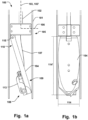
- Fig. 1a illustrates an example of a delivery device 100 for an annuloplasty implant 200 (not shown).
- the delivery device 100 comprises an outer sheath 101, and a delivery wire 102 being movable within the sheath 101 in a longitudinal direction 103 of the outer sheath 101.
- the delivery device 100 comprises a holder 104 being releasably connectable to the implant 200.
- the holder 104 is pivotably connected, i.e. having a rotating connection, to a distal portion 105 of the delivery wire 102. Thereby, the holder 104 is able to be folded inside the outer sheath 102 in a delivery configuration, which is illustrated in Figs. 1a-b , and Figs. 3a-b .
- the holder 104 is in the delivery configuration when the delivery device 100 is being navigated to the target site at which the implant 200 is to be positioned.
- the holder 104 is foldable from the delivery configuration to an expanded deployed configuration outside the outer sheath 101, which is illustrated in Fig. 3c .
- the pivoting connection allows for facilitated transfer from the collapsed delivery configuration inside the outer sheath 101 to the expanded deployed configuration, requiring a minimum amount of force.
- Figs. 3a-c schematically illustrate the implant 200 being delivered from the delivery device 100.
- the holder 104 is folded inside the outer sheath 101, and releasably holds the implant 200 at a distal end thereof.
- the implant 200 is in this case formed from a shape memory material and is flexible enough to be stretched in the longitudinal direction 103 of the outer sheath 101.
- the delivery wire 102 has pushed the holder 104 further towards the distal end of the delivery device 100.
- the holder 104 is in this case about to be pushed out and removed from the radial constraint of the outer sheath 101, and the implant 200 has already been expelled from the sheath 101, and is thereby allowed to assume the pre-defined relaxed shape of the shape memory material from which it is formed.
- the implant 200 is an annuloplasty ring, intended to be positioned around the annulus of a heart valve.
- Fig. 3c illustrates the case where the delivery wire 102 has pushed the holder 104 to a position outside the sheath 101, and the holder 104 has been folded from the delivery configuration to the expanded deployed configuration by a rotating motion of the holder 104 relative the delivery wire 102.
- the implant 200 Since the implant 200 is releasably held by the holder 104, the implant 200 is also rotated relative the delivery wire 102.
- the degree of rotation of the implant 200 thereby substantially corresponds to the degree of rotation of the holder 104, as the implant 200 is substantially rigidly fixated at the holder 104.
- this allows for a high degree of maneuverability of the implant 200.
- torque may be effectively transferred to the implant 200, since the holder 104 is now in the expanded configuration. Rotation of the implant 200 for example around the longitudinal axis 103 of the sheath 102 can thereby be facilitated.
- the implant 200 may also be controllably rotated a desired amount around the axis of the pivoting connection of the holder 104, which is exemplified by pivoting connection 115 in Fig. 3c .
- rotation of the implant 200 around such multiple axes provides for an optimized steerability and facilitating positioning of the implant 200 at the target site.
- the space around the valve annulus in the heart is a tightly confined space requiring such increased maneuverability provided by the delivery device 100, in order to position the implant 200 at the correct angle relative the plane of the valve and the associated annulus.
- Fig. 3c again, illustrating an example of holding an annuloplasty ring 200, such ring 200 can now be manipulated to be positioned in the correct plane, e.g.
- Such helix shaped implants 200 can thus be effectively delivered in the correct position at the annulus by the delivery device 100 as well as being delivered to the target site through the narrow space available due to the compact delivery shape of the holder 104, and the compact mechanism for transferring the holder 104 to the expanded deployed configuration outside the sheath 101, by the pivotable connection.
- Figs. 4a-c show examples where the holder 104 is rotated in varying angles relative the delivery wire 102. In these examples, the outer sheath 101 has been removed for clarity of presentation.
- the implant 200 being an annuloplasty ring 200, is shown in the expanded pre-defined relaxed configuration.
- Figs. 4a and 4c show the least and most amount of rotation, respectively, with Fig. 4b in between.
- Fig. 4d is a view from beneath the distal end of the delivery device 100 when in the maximum expanded configuration.
- Figs. 5a-b show the delivery device 100 in similar configurations to those of Figs. 3b-c , respectively, but in further enlarged views.
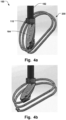
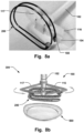
- Figs. 6a-b show other examples of the delivery device 100.
- the device 100 has a delivery wire 102, and a holder 104 which can releasably connect to an implant 200, which is shown in Fig. 8a .
- the holder 104 is pivotably connected to a distal portion 105 of the delivery wire 102, at pivoting connection 115.
- the holder 104 can be moved from a folded configuration, like the configuration illustrated in Fig. 6a , to an expanded deployed configuration, like the configuration illustrated in Fig. 6b , by rotating around the pivoting connection 115.
- the implant 200 will also be rotated when held by the holder 104 in the delivery device 100 of Figs. 6a-b , with the similar advantages as already described above.
- the outer sheath 102 has been omitted in Figs. 6a-b for clarity of presentation.
- the holder 100 may be elongated and extending in the longitudinal direction 103 of the sheath 101 in the delivery configuration, as seen for example in Figs. 1a-b .
- the holder 104 assumes a compact cross-sectional dimension perpendicular to the longitudinal direction 103, while providing significant reach and torque abilities when extending in a radial direction 106, perpendicular to the longitudinal direction 103, in the expanded deployed configuration.
- the implant 200 may be releasably connected at the distal end 109 of the holder 104, which facilitates the rotation of the implant 200 when the holder 104 is in the expanded deployed configuration.
- the delivery device 100 may comprise a control member 107, such as a control wire 107, connected to the holder 104, as schematically illustrated in Fig. 1a .
- Actuation of the control member 107 moves the holder 104 from the delivery configuration to the expanded deployed configuration by a pivoting motion.
- Actuation of the control member 107 can be a pulling action of the control member 107 towards the proximal end of the delivery device 100, so that the control member 107 lifts the holder 104 to the expanded deployed configuration as seen in Fig. 3c .
- control member 107 may be pushed towards the distal end 109, in order to move the holder 104 from the expanded deployed configuration to the delivery configuration in which the holder is folded to extend in the longitudinal direction 103, to be withdrawn into the sheath 101, as illustrated in Figs. 3a-b . It is also conceivable that the control member 107 can be actuated in other ways, such as for example by a rotating motion, that affects the movement of the holder 104 by a screw-like or winding motion, so that the holder 104 is lifted to the expanded deployed configuration, or in the opposite direction for folding inside the sheath 101. Fig.
- control member 107 also illustrates the control member 107, extending from the delivery wire 101 or the outer sheath 102, to the holder 104.
- the control member 107 may be attached to a position of the holder 104 that provides for a facilitated actuation thereof. Having the attachment point positioned closer to the radial periphery of the holder, when in the expanded configuration, can provide for reducing the force required to deploy the holder 104 in the expanded deployed configuration.
- the control member 107 may be actuated by a predetermined amount in order to precisely control the amount of rotation of the holder 104, and thereby the amount of rotation of the implant 200, to position the implant 200 in the correct position at the target site.
- Figs. 6a-b shows an example where the control member 107 is centrally connected to a distal portion of the holder 104, for either pushing the central distal portion of the holder distally, towards a distal end of the delivery device 100, relative the delivery wire 102, so that the holder 104 assumes the elongated shape in the longitudinal direction 103 as exemplified in Fig. 6a , or pulled relative the delivery wire 102, so that the holder 104 is folded to the expanded configuration, as exemplified in Fig. 6b .
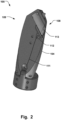
- the holder 104 may comprise a connecting unit 108, which is illustrated in e.g. Figs. 1a , 2 , 6a , and 8a , that is adapted to releasably connect to the implant 200. Releasably connected should be construed as the implant 200 can be readily released from the connecting unit.
- the connecting unit 108 may be arranged at a distal end 109 of the holder, as seen in e.g. Fig. 2 . This allows for utilizing the full length of the holder 104 for improving the maneuverability of the implant 200, i.e. facilitating the positioning of the implant 200, while attaining a compact profile of the delivery device, particularly in the expanded deployed configuration.
- the delivery wire 102 may be rotatable relative the sheath 101, i.e. around a central axis 103' of the sheath 101.
- the connecting unit 108 may be adapted to apply a force at a peripheral portion 118 of the implant 200, at a distance 119 from the central axis 103' of the sheath 101 when the implant 200, in use, is held by the holder 104 in the expanded deployed configuration, such that the force can bring the implant into rotation about the central axis 103'.
- torque can be transferred from the rotation of the delivery wire 102, relative the sheath 101, to the implant 200 via the connecting unit 108. Rotation of the implant 200 into the correct position is thus facilitated.
- the connecting unit 108 can be adapted to connect to the implant 200, such as an annuloplasty ring, at the peripheral portion 118 of the ring.
- the length 114' of the elongated holder 104 may correspond substantially to a radius (r) of the implant 200, when the implant 200, in use, is held by the holder in the expanded deployed configuration and the implant has a general ring shape with the radius (r), i.e. when being an annuloplasty ring. As illustrated in Fig. 4d , this may provide for an optimal length 114' of the holder 104, which will provide for a compact profile while allowing the distal end 109 of the holder to be fixated at the periphery 118 of the implant 200, improving the steerability.
- the distance 119 from the center of the sheath 101 to the connecting unit 108 may thus substantially correspond to the radius (r) of the annuloplasty ring 200.
- the connecting unit 108 may be adapted to connect to an end portion 113 of the implant 200, as illustrated in Fig. 4d .
- the connecting unit 108 may be aligned at a distal end 109 of the holder 104 so that a proximal end 110 of the holder 104 is position substantially at the center 125 of the implant 200, when the implant 200, in use, is held by the holder 104 in the expanded deployed configuration and the implant has a general ring shape with the center 125, i.e. being an annuloplasty ring.
- a concentric rotation of the ring 200 around the central axis 103' of the sheath 101 can thereby be provided.
- the connecting unit 108 may thus be angled relative the holder 104, see further Fig. 2 , to allow such positioning of the proximal end 110 at the center 125 of the ring 200, corresponding substantially to the location of the central axis 103'.
- the connecting unit 108 may be connected to a release unit 111, such as a release wire 111, illustrated in Fig. 2 . Actuation of the release unit 111 may release the implant 200 from the holder 104 by disengaging an implant lock 112. This provides for a reliable and robust delivery of the implant 200.
- the implant look 112 may be adapted to interlock with an end portion 113 of the implant 200, also illustrated in Fig. 2 . Here only the end portion 113 is illustrated for clarity of presentation, but the end portion 113 is fixated to the implant 200.
- the implant look 112 may for example engage with an aperture, recess, protrusion or a flat surface in the end portion 113, from which it can be removed to release the implant 200.
- the implant lock 112 may be engageable with an end portion 113 of the implant 200, when the implant 200, in use, is held by the holder 104.
- the width 114 of the holder 104 i.e. its dimension in the radial direction perpendicular to the longitudinal direction 103, may correspond substantially to the diameter of the outer sheath 101, as illustrated in Fig. 1b . This may provide improve stability of the holder 104 when operated.
- the holder 104 may be pivotably connected at a pivot joint 115 arranged at the distal portion 105 of the delivery wire 102.
- the pivot joint 115 may be arranged at a periphery of the distal portion in a radial direction 106, perpendicular to the longitudinal direction 103, which is illustrated in Fig. 1a . It is thus possible to achieve a greater momentum when actuating the control member 107, for example by pulling the control member 107 towards the proximal end of the delivery device 100, i.e. towards the operator end, in order to lift the holder 104 to the expanded deployed configuration as seen in Fig. 3c .
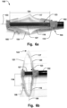
- the holder 104 may have a first 116 and a second 117 pivotable portion, each being expandable in radially opposite directions in the expanded deployed configuration along the radial direction 106, as illustrated in Figs. 6b and 8a-b .
- This provides for a robust and stable delivery device 100, and both of the pivotable portions 116, 117, may act as supporting members for the implant 200, when in the expanded deployed configuration, as schematically illustrated in Fig. 8b . Undesired tilting of the implant 200 may thus be prevented when navigating the implant 200 to the correct position over the heart valve 500.
- Each of the first and second pivotable portions 116, 117 may comprise foldable proximal 120 and distal 121 sections forming V-shaped first and second pivotable portions 116, 117, each having an apex 122 at a radially outward position, along the radial direction 106, and a base 123 at a radially inward position. This is illustrated in Fig. 6b , where each of the pivotable portions 116, 117, have such foldable proximal 120 and distal 121 sections forming a V-shaped portion.
- the length 124 of the base 123 is adjustable by moving the control member 107 relative the delivery wire 102, as illustrated in Fgi.
- a system 300 comprising a delivery device 100 as described according to the examples above and an annuloplasty implant 200.
- the annuloplasty implant 200 may be formed from a shape memory material and having a relaxed general ring shape when implanted, and a stretched elongated shape for delivery in the sheath, wherein the implant is pivotable outside the sheath 101 by moving the holder 104 from the delivery configuration to the expanded deployed configuration, as explained above and with the above mentioned advantages.
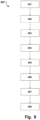
- a method 400 is provided for delivering an annuloplasty implant 200 with a delivery device 100.
- the method 400 is schematically illustrated in Fig. 9 .
- the order in which the steps are described should not be construed as limiting, and it is conceivable that the order of the steps may be varied depending on the particular procedure.
- the delivery device 100 has a holder 104 as described in the examples above, being pivotably connected to the distal portion 105 of the delivery wire 102 inside the sheath 101.
- the holder 104 is releasably connectable to the implant 200.
- the method 400 comprises holding 401 the implant 200 inside the sheath 101 whereby the holder 104 is folded inside the sheath 101 in a delivery configuration; moving 402 the holder 104 distally out of the sheath 101 whereby the implant 200, being formed from a shape memory material assumes a pre-defined shape; and folding 403 the holder 104 from a the delivery configuration to an expanded deployed configuration outside the sheath 101 whereby the implant 200 is pivoted 404 by the holder 104 into position at a heart valve 500.
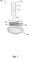
- Fig. 7 illustrates an example where the implant 200 has been pivoted into the correct position adjacent the heart valve 500.
- the implant 200 is a helix-shaped implant.
- the implant 200 may then be rotated into the correct position through the valve 500, so that the ringshaped supports of the helix implant are positioned on either side of the heart valve leaflets.
- the annuloplasty implant 200 may be a helix ring and the method may comprise holding 405 the helix ring 200 at a periphery 118 thereof at a distance 119 from a central axis 103' of the sheath 101 in the expanded deployed configuration; turning 406 the helix ring 200 into the valve 500 by a rotating motion such that a first 501 and second 502 support members are positioned on each side of the heart valve leaflets; disconnecting 407 the implant 200 from the holder 104; and folding 408 the holder 104 inside the outer sheath 101 in the delivery configuration.
- the delivery device 100 can then subsequently be withdrawn from the target site.
- FIG. 8b illustrates another example of positioning the delivery device 100, as described with reference to Figs 6a-b and 8a , at the heart valve 500.
Description
- This invention pertains in general to the field of cardiac valve replacement and repair. More particularly the invention relates to a system comprising a delivery device for an annuloplasty implant and an annuloplasty implant.
- Diseased mitral and tricuspid valves frequently need replacement or repair. The mitral and tricuspid valve leaflets or supporting chordae may degenerate and weaken or the annulus may dilate leading to valve leak. Mitral and tricuspid valve replacement and repair are frequently performed with aid of an annuloplasty ring, used to reduce the diameter of the annulus, or modify the geometry of the annulus in any other way, or aid as a generally supporting structure during the valve replacement or repair procedure. Such annuloplasty rings or other annuloplasty implants are put into position by various delivery devices. Prior art
WO 2014/190329 A1 discloses a delivery device for an annuloplasty implant. - A problem with prior art delivery devices is lack of steerability or maneuverability of the implant, thereby increasing the amount of manipulation of the implant both during the positioning phase and during repositioning to get the implant in the correct position, which may lead to a more complicated and time consuming procedure. During heart surgery, a premium is placed on reducing the amount of time used to replace and repair valves as the heart is frequently arrested and without perfusion.
- A further problem with prior art devices is less-than-optimal engagement mechanisms between the implant and the delivery wire that does not provide sufficient reliability, and/or requires exact, i.e. time consuming, navigation and manipulation before final securement is achieved.
- The above problems may have dire consequences for the patient and the health care system. Patient risk is increased.
- Hence, an improved medical device for delivering an annuloplasty implant would be advantageous and in particular allowing for avoiding more of the above mentioned problems and compromises, and in particular allowing for increased maneuverability, reducing the time of lengthy surgery procedures, cost effectiveness, and increased patient safety. Also, a system comprising such device and an annuloplasty implant, would be advantageous.
- Accordingly, examples of the present invention preferably seeks to mitigate, alleviate or eliminate one or more deficiencies, disadvantages or issues in the art, such as the above-identified, singly or in any combination by providing a device according to the appended patent claims.
- According to a first aspect a delivery device for an annuloplasty implant is provided. The delivery device comprises an outer sheath, and a delivery wire being movable within said sheath in a longitudinal direction thereof, a holder being releasably connectable to said implant, said holder being pivotably connected to a distal portion of said delivery wire, wherein said holder is folded inside said outer sheath in a delivery configuration, and wherein said holder is foldable from said delivery configuration to an expanded deployed configuration outside said outer sheath.
- According to a second aspect a system comprising a delivery device according to the first aspect and an annuloplasty implant is provided, wherein said annuloplasty implant is formed from a shape memory material and having a relaxed general ring shape when implanted, and a stretched elongated shape for delivery in said sheath, wherein said implant is pivotable outside said sheath by moving said holder from said delivery configuration to said expanded deployed configuration.
- Further examples of the invention are defined in the dependent claims, wherein features for the second and subsequent aspects of the disclosure are as for the first aspect mutatis mutandis.
- Some examples of the disclosure provide for facilitated delivery of an annuloplasty implant to a target site.
- Some examples of the disclosure provide for increased steerability or maneuverability of an annuloplasty implant.
- Some examples of the disclosure provide for less time consuming positioning of an annuloplasty implant at a target site in the heart.
- Some examples of the disclosure provide for less cumbersome attachment and detachment of an annuloplasty implant to a medical delivery device.
- Some examples of the disclosure provide for increased accuracy in positioning an annuloplasty implant at the annulus and thereby reducing the risk of complications.
- Some examples of the disclosure provide for a reduced risk of damaging the cardiac valve implant during a repair or replacement procedure.
- Some examples of the disclosure provide for better ability to reposition an annuloplasty implant.
- It should be emphasized that the term "comprises/comprising" when used in this specification is taken to specify the presence of stated features, integers, steps or components but does not preclude the presence or addition of one or more other features, integers, steps, components or groups thereof.
- These and other aspects, features and advantages of which examples of the invention are capable of will be apparent and elucidated from the following description of embodiments of the present invention, reference being made to the accompanying drawings, in which
-
Fig. 1a is a schematic illustration, in a side view, of a delivery device according to one example; -
Fig. 1b is a schematic illustration, in a side view rotated 90 degrees relativeFig. 1a , of a delivery device according to one example; -
Fig. 2 is a schematic illustration, in a perspective view, of a delivery device according to one example; -
Figs. 3a-c are schematic illustrations, in side views, of a delivery device holding an annuloplasty implant according to one example; -
Figs. 4a-d are schematic illustrations, in perspective views, of a delivery device holding an annuloplasty implant according to one example; -
Figs. 5a-b are schematic illustrations, in perspective views, of a delivery device holding an annuloplasty implant according to one example; -
Figs. 6a-b are schematic illustrations, in perspective views, of a delivery device according to one example; -
Fig 7 is a schematic illustration, in a perspective view, of a delivery device holding an annuloplasty implant at a heart valve according to one example; -
Fig 8a is a schematic illustration, in a perspective view, of a delivery device inFigs. 6a-b holding an annuloplasty implant; -
Fig 8b is a schematic illustration, in a perspective view, of a delivery device inFigs 6a-b holding an annuloplasty implant at a heart valve according to one example; -
Fig. 9 is a flow-chart of a method of delivering an annuloplasty implant at a target site in the heart according to one example. - Specific examples of the invention will now be described with reference to the accompanying drawings. This invention may, however, be embodied in many different forms and should not be construed as limited to the examples set forth herein; rather, these examples are provided so that this disclosure will be thorough and complete, and will fully convey the scope of the invention to those skilled in the art. The terminology used in the detailed description of the embodiments illustrated in the accompanying drawings is not intended to be limiting of the invention. In the drawings, like numbers refer to like elements.
- The following description focuses on examples applicable to cardiac valve implants such as annuloplasty rings. However, it will be appreciated that the invention is not limited to this application but may be applied to many other annuloplasty implants and cardiac valve implants including for example replacement valves, and other medical implantable devices.
-
Fig. 1a illustrates an example of adelivery device 100 for an annuloplasty implant 200 (not shown). Thedelivery device 100 comprises anouter sheath 101, and adelivery wire 102 being movable within thesheath 101 in alongitudinal direction 103 of theouter sheath 101. Thedelivery device 100 comprises aholder 104 being releasably connectable to theimplant 200. Theholder 104 is pivotably connected, i.e. having a rotating connection, to adistal portion 105 of thedelivery wire 102. Thereby, theholder 104 is able to be folded inside theouter sheath 102 in a delivery configuration, which is illustrated inFigs. 1a-b , andFigs. 3a-b . Theholder 104 is in the delivery configuration when thedelivery device 100 is being navigated to the target site at which theimplant 200 is to be positioned. Theholder 104 is foldable from the delivery configuration to an expanded deployed configuration outside theouter sheath 101, which is illustrated inFig. 3c . By having aholder 104 being pivotably connected at adistal portion 105 of thedelivery wire 102, and thereby foldable between a delivery configuration and an expanded deployed configuration, it is possible to attain a compact shape during the delivery procedure, whereas a robust and highly torquable configuration is achieved in the expanded state, when theimplant 200 is to be deployed. It is thus easy to transfer force at the operator end to the distal portion of thedelivery device 100 where theimplant 200 is attached, allowing for a high steerability and maneuverability at the target site. This can reduce the time of the implantation procedure and therefore generally allow for a more safe intervention. The pivoting connection allows for facilitated transfer from the collapsed delivery configuration inside theouter sheath 101 to the expanded deployed configuration, requiring a minimum amount of force. -
Figs. 3a-c schematically illustrate theimplant 200 being delivered from thedelivery device 100. InFig. 3a theholder 104 is folded inside theouter sheath 101, and releasably holds theimplant 200 at a distal end thereof. Theimplant 200 is in this case formed from a shape memory material and is flexible enough to be stretched in thelongitudinal direction 103 of theouter sheath 101. InFig. 3b , thedelivery wire 102 has pushed theholder 104 further towards the distal end of thedelivery device 100. Theholder 104 is in this case about to be pushed out and removed from the radial constraint of theouter sheath 101, and theimplant 200 has already been expelled from thesheath 101, and is thereby allowed to assume the pre-defined relaxed shape of the shape memory material from which it is formed. In this case, theimplant 200 is an annuloplasty ring, intended to be positioned around the annulus of a heart valve.Fig. 3c illustrates the case where thedelivery wire 102 has pushed theholder 104 to a position outside thesheath 101, and theholder 104 has been folded from the delivery configuration to the expanded deployed configuration by a rotating motion of theholder 104 relative thedelivery wire 102. Since theimplant 200 is releasably held by theholder 104, theimplant 200 is also rotated relative thedelivery wire 102. The degree of rotation of theimplant 200 thereby substantially corresponds to the degree of rotation of theholder 104, as theimplant 200 is substantially rigidly fixated at theholder 104. As mentioned above, this allows for a high degree of maneuverability of theimplant 200. For example, torque may be effectively transferred to theimplant 200, since theholder 104 is now in the expanded configuration. Rotation of theimplant 200 for example around thelongitudinal axis 103 of thesheath 102 can thereby be facilitated. Theimplant 200 may also be controllably rotated a desired amount around the axis of the pivoting connection of theholder 104, which is exemplified by pivotingconnection 115 inFig. 3c . Thus, rotation of theimplant 200 around such multiple axes provides for an optimized steerability and facilitating positioning of theimplant 200 at the target site. In particular, for annuloplasty implants, the space around the valve annulus in the heart is a tightly confined space requiring such increased maneuverability provided by thedelivery device 100, in order to position theimplant 200 at the correct angle relative the plane of the valve and the associated annulus. Turning toFig. 3c again, illustrating an example of holding anannuloplasty ring 200,such ring 200 can now be manipulated to be positioned in the correct plane, e.g. by rotation around the pivotable connection to the delivery wire, and subsequently rotated around thelongitudinal axis 103 of thesheath 101 in order to be rotated in place around the tissue of the annulus. The latter is particularly advantageous for helix- or coiled shaped annuloplasty rings, as illustrated inFig. 3c , since these rings can then be rotated through the commissures as the valve so that the lower ring is positioned beneath the valve leaflets, and the top ring is positioned above the valve leaflets. Such helix shapedimplants 200 can thus be effectively delivered in the correct position at the annulus by thedelivery device 100 as well as being delivered to the target site through the narrow space available due to the compact delivery shape of theholder 104, and the compact mechanism for transferring theholder 104 to the expanded deployed configuration outside thesheath 101, by the pivotable connection. -
Figs. 4a-c , show examples where theholder 104 is rotated in varying angles relative thedelivery wire 102. In these examples, theouter sheath 101 has been removed for clarity of presentation. Theimplant 200, being anannuloplasty ring 200, is shown in the expanded pre-defined relaxed configuration.Figs. 4a and4c show the least and most amount of rotation, respectively, withFig. 4b in between.Fig. 4d is a view from beneath the distal end of thedelivery device 100 when in the maximum expanded configuration. -
Figs. 5a-b show thedelivery device 100 in similar configurations to those ofFigs. 3b-c , respectively, but in further enlarged views. -
Figs. 6a-b show other examples of thedelivery device 100. As described above, thedevice 100 has adelivery wire 102, and aholder 104 which can releasably connect to animplant 200, which is shown inFig. 8a . Theholder 104 is pivotably connected to adistal portion 105 of thedelivery wire 102, at pivotingconnection 115. Theholder 104 can be moved from a folded configuration, like the configuration illustrated inFig. 6a , to an expanded deployed configuration, like the configuration illustrated inFig. 6b , by rotating around thepivoting connection 115. As with thedelivery device 100 illustrated inFigs. 1-5 , theimplant 200 will also be rotated when held by theholder 104 in thedelivery device 100 ofFigs. 6a-b , with the similar advantages as already described above. Theouter sheath 102 has been omitted inFigs. 6a-b for clarity of presentation. - The
holder 100 may be elongated and extending in thelongitudinal direction 103 of thesheath 101 in the delivery configuration, as seen for example inFigs. 1a-b . By having anelongated holder 104, theholder 104 assumes a compact cross-sectional dimension perpendicular to thelongitudinal direction 103, while providing significant reach and torque abilities when extending in aradial direction 106, perpendicular to thelongitudinal direction 103, in the expanded deployed configuration. Theimplant 200 may be releasably connected at thedistal end 109 of theholder 104, which facilitates the rotation of theimplant 200 when theholder 104 is in the expanded deployed configuration. - The
delivery device 100 may comprise acontrol member 107, such as acontrol wire 107, connected to theholder 104, as schematically illustrated inFig. 1a . Actuation of thecontrol member 107 moves theholder 104 from the delivery configuration to the expanded deployed configuration by a pivoting motion. Actuation of thecontrol member 107 can be a pulling action of thecontrol member 107 towards the proximal end of thedelivery device 100, so that thecontrol member 107 lifts theholder 104 to the expanded deployed configuration as seen inFig. 3c . Similarly, thecontrol member 107 may be pushed towards thedistal end 109, in order to move theholder 104 from the expanded deployed configuration to the delivery configuration in which the holder is folded to extend in thelongitudinal direction 103, to be withdrawn into thesheath 101, as illustrated inFigs. 3a-b . It is also conceivable that thecontrol member 107 can be actuated in other ways, such as for example by a rotating motion, that affects the movement of theholder 104 by a screw-like or winding motion, so that theholder 104 is lifted to the expanded deployed configuration, or in the opposite direction for folding inside thesheath 101.Fig. 5b also illustrates thecontrol member 107, extending from thedelivery wire 101 or theouter sheath 102, to theholder 104. Thecontrol member 107 may be attached to a position of theholder 104 that provides for a facilitated actuation thereof. Having the attachment point positioned closer to the radial periphery of the holder, when in the expanded configuration, can provide for reducing the force required to deploy theholder 104 in the expanded deployed configuration. Thecontrol member 107 may be actuated by a predetermined amount in order to precisely control the amount of rotation of theholder 104, and thereby the amount of rotation of theimplant 200, to position theimplant 200 in the correct position at the target site. -
Figs. 6a-b shows an example where thecontrol member 107 is centrally connected to a distal portion of theholder 104, for either pushing the central distal portion of the holder distally, towards a distal end of thedelivery device 100, relative thedelivery wire 102, so that theholder 104 assumes the elongated shape in thelongitudinal direction 103 as exemplified inFig. 6a , or pulled relative thedelivery wire 102, so that theholder 104 is folded to the expanded configuration, as exemplified inFig. 6b . - The
holder 104 may comprise a connectingunit 108, which is illustrated in e.g.Figs. 1a ,2 ,6a , and8a , that is adapted to releasably connect to theimplant 200. Releasably connected should be construed as theimplant 200 can be readily released from the connecting unit. The connectingunit 108 may be arranged at adistal end 109 of the holder, as seen in e.g.Fig. 2 . This allows for utilizing the full length of theholder 104 for improving the maneuverability of theimplant 200, i.e. facilitating the positioning of theimplant 200, while attaining a compact profile of the delivery device, particularly in the expanded deployed configuration. - The
delivery wire 102 may be rotatable relative thesheath 101, i.e. around a central axis 103' of thesheath 101. The connectingunit 108 may be adapted to apply a force at aperipheral portion 118 of theimplant 200, at adistance 119 from the central axis 103' of thesheath 101 when theimplant 200, in use, is held by theholder 104 in the expanded deployed configuration, such that the force can bring the implant into rotation about the central axis 103'. Thus, torque can be transferred from the rotation of thedelivery wire 102, relative thesheath 101, to theimplant 200 via the connectingunit 108. Rotation of theimplant 200 into the correct position is thus facilitated. The connectingunit 108 can be adapted to connect to theimplant 200, such as an annuloplasty ring, at theperipheral portion 118 of the ring. - The length 114' of the
elongated holder 104, as illustrated inFig. 1b , may correspond substantially to a radius (r) of theimplant 200, when theimplant 200, in use, is held by the holder in the expanded deployed configuration and the implant has a general ring shape with the radius (r), i.e. when being an annuloplasty ring. As illustrated inFig. 4d , this may provide for an optimal length 114' of theholder 104, which will provide for a compact profile while allowing thedistal end 109 of the holder to be fixated at theperiphery 118 of theimplant 200, improving the steerability. Thedistance 119 from the center of thesheath 101 to the connectingunit 108 may thus substantially correspond to the radius (r) of theannuloplasty ring 200. - The connecting
unit 108 may be adapted to connect to anend portion 113 of theimplant 200, as illustrated inFig. 4d . The connectingunit 108 may be aligned at adistal end 109 of theholder 104 so that aproximal end 110 of theholder 104 is position substantially at thecenter 125 of theimplant 200, when theimplant 200, in use, is held by theholder 104 in the expanded deployed configuration and the implant has a general ring shape with thecenter 125, i.e. being an annuloplasty ring. A concentric rotation of thering 200 around the central axis 103' of thesheath 101 can thereby be provided. This improves the control of the rotating motion of theimplant 200, since it can be predictably moved by a rotating motion only, i.e. minimizing any translatory motion, when rotating thedelivery wire 102 to position theimplant 200 at the target site. In particular, when rotating thering 200 through the commissures of the valve, it can be preferable to avoid movement of the ring in other directions at the valve. This can also minimize the risk of damaging the surrounding anatomy. The connectingunit 108 may thus be angled relative theholder 104, see furtherFig. 2 , to allow such positioning of theproximal end 110 at thecenter 125 of thering 200, corresponding substantially to the location of the central axis 103'. - The connecting
unit 108 may be connected to arelease unit 111, such as arelease wire 111, illustrated inFig. 2 . Actuation of therelease unit 111 may release theimplant 200 from theholder 104 by disengaging animplant lock 112. This provides for a reliable and robust delivery of theimplant 200. The implant look 112 may be adapted to interlock with anend portion 113 of theimplant 200, also illustrated inFig. 2 . Here only theend portion 113 is illustrated for clarity of presentation, but theend portion 113 is fixated to theimplant 200. The implant look 112 may for example engage with an aperture, recess, protrusion or a flat surface in theend portion 113, from which it can be removed to release theimplant 200. - Thus, the
implant lock 112 may be engageable with anend portion 113 of theimplant 200, when theimplant 200, in use, is held by theholder 104. - The
width 114 of theholder 104, i.e. its dimension in the radial direction perpendicular to thelongitudinal direction 103, may correspond substantially to the diameter of theouter sheath 101, as illustrated inFig. 1b . This may provide improve stability of theholder 104 when operated. - The
holder 104 may be pivotably connected at a pivot joint 115 arranged at thedistal portion 105 of thedelivery wire 102. The pivot joint 115 may be arranged at a periphery of the distal portion in aradial direction 106, perpendicular to thelongitudinal direction 103, which is illustrated inFig. 1a . It is thus possible to achieve a greater momentum when actuating thecontrol member 107, for example by pulling thecontrol member 107 towards the proximal end of thedelivery device 100, i.e. towards the operator end, in order to lift theholder 104 to the expanded deployed configuration as seen inFig. 3c . It will thus be easier to pivot theholder 104 into this configuration due to the increased distance between the central axis 103' of thesheath 101 and the pivot joint 115, since the latter is positioned adjacent the periphery of thedistal portion 105 of thedelivery wire 102. The increased distance from the pivot joint 115 to thecentral axis 103 contributes to an overall increase in distance between the pivot joint 115 and the fixation point of thecontrol member 107 at theholder 104, which advantageously is positioned in the opposite radial direction, with respect to the pivot joint. I.e. the pivot joint 115 and the mentioned fixation point will be positioned at radially opposite sides with the central axis 103' of thesheath 101 inbetween. - Turning again to
Figs. 6a-b , theholder 104 may have a first 116 and a second 117 pivotable portion, each being expandable in radially opposite directions in the expanded deployed configuration along theradial direction 106, as illustrated inFigs. 6b and8a-b . This provides for a robust andstable delivery device 100, and both of thepivotable portions implant 200, when in the expanded deployed configuration, as schematically illustrated inFig. 8b . Undesired tilting of theimplant 200 may thus be prevented when navigating theimplant 200 to the correct position over theheart valve 500. - Each of the first and second
pivotable portions pivotable portions radial direction 106, and a base 123 at a radially inward position. This is illustrated inFig. 6b , where each of thepivotable portions length 124 of thebase 123 is adjustable by moving thecontrol member 107 relative thedelivery wire 102, as illustrated in Fgi. 6a, where the control member 197 has been pushed further towards the distal end of thedelivery device 100, relative thedelivery wire 102, so that thebase 123 has alonger length 124 compared to the configuration inFig. 6b . The proximal anddistal sections length 124 of thebase 123. Thus further provides for a simple and reliable mechanism for transferring the delivery device between the two mentioned configurations. - A
system 300 is provided comprising adelivery device 100 as described according to the examples above and anannuloplasty implant 200. Theannuloplasty implant 200 may be formed from a shape memory material and having a relaxed general ring shape when implanted, and a stretched elongated shape for delivery in the sheath, wherein the implant is pivotable outside thesheath 101 by moving theholder 104 from the delivery configuration to the expanded deployed configuration, as explained above and with the above mentioned advantages. - A
method 400 is provided for delivering anannuloplasty implant 200 with adelivery device 100. Themethod 400 is schematically illustrated inFig. 9 . The order in which the steps are described should not be construed as limiting, and it is conceivable that the order of the steps may be varied depending on the particular procedure. Thedelivery device 100 has aholder 104 as described in the examples above, being pivotably connected to thedistal portion 105 of thedelivery wire 102 inside thesheath 101. Theholder 104 is releasably connectable to theimplant 200. Themethod 400 comprises holding 401 theimplant 200 inside thesheath 101 whereby theholder 104 is folded inside thesheath 101 in a delivery configuration; moving 402 theholder 104 distally out of thesheath 101 whereby theimplant 200, being formed from a shape memory material assumes a pre-defined shape; and folding 403 theholder 104 from a the delivery configuration to an expanded deployed configuration outside thesheath 101 whereby theimplant 200 is pivoted 404 by theholder 104 into position at aheart valve 500.Fig. 7 illustrates an example where theimplant 200 has been pivoted into the correct position adjacent theheart valve 500. In this example, theimplant 200 is a helix-shaped implant. Theimplant 200 may then be rotated into the correct position through thevalve 500, so that the ringshaped supports of the helix implant are positioned on either side of the heart valve leaflets. - Thus, the
annuloplasty implant 200 may be a helix ring and the method may comprise holding 405 thehelix ring 200 at aperiphery 118 thereof at adistance 119 from a central axis 103' of thesheath 101 in the expanded deployed configuration; turning 406 thehelix ring 200 into thevalve 500 by a rotating motion such that a first 501 and second 502 support members are positioned on each side of the heart valve leaflets; disconnecting 407 theimplant 200 from theholder 104; and folding 408 theholder 104 inside theouter sheath 101 in the delivery configuration. Thedelivery device 100 can then subsequently be withdrawn from the target site. This provides for the above mentioned advantages ultimately allowing for increased maneuverability, facilitating the positioning of thehelix implant 200 at the valve and further reducing the time the procedure and increasing patient safety.Fig. 8b illustrates another example of positioning thedelivery device 100, as described with reference toFigs 6a-b and8a , at theheart valve 500. - The present invention has been described above with reference to specific embodiments. However, other embodiments than the above described are equally possible within the scope of the invention. The different features of the invention may be combined in other combinations than those described. The scope of the invention is only limited by the appended patent claims. More generally, those skilled in the art will readily appreciate that all parameters, dimensions, materials, and configurations described herein are meant to be exemplary and that the actual parameters, dimensions, materials, and/or configurations will depend upon the specific application or applications for which the teachings of the present invention is/are used.
Claims (13)
- System (300) comprisinga delivery device (100) for an annuloplasty implant (200) comprising:an outer sheath (101),a delivery wire (102) being movable within said sheath in a longitudinal direction (103) thereof,a holder being releasably connectable to said implant, said holder being pivotably connected to a distal portion (105) of said delivery wire, wherein said holder is folded inside said outer sheath in a delivery configuration, wherein said holder is foldable from said delivery configuration to an expanded deployed configuration outside said outer sheath,and an annuloplasty implant (200), wherein said annuloplasty implant is formed from a shape memory material and having a relaxed general ring shape when implanted, and a stretched elongated shape for delivery in said sheath, wherein said implant is pivotable outside said sheath by moving said holder from said delivery configuration to said expanded deployed configuration.
- System according to claim 1, wherein said holder is elongated and is extending in said longitudinal direction in said delivery configuration, and extending in a radial direction (106), perpendicular to said longitudinal direction, in said expanded deployed configuration.
- System according to claim 1 or 2, wherein the delivery device comprises a control member (107), such as a control wire (107), connected to said holder, whereby actuation of said control member moves said holder from said delivery configuration to said expanded deployed configuration by a pivoting motion.
- System according to any of claims 1 - 3, wherein said holder comprises a connecting unit (108) that is adapted to releasably connect to said implant, wherein said connecting unit is arranged at a distal end (109) of said holder.
- System according to claim 4, wherein said delivery wire is rotatable relative said sheath, wherein said connecting unit is adapted to apply a force at a peripheral portion (118) of said implant, at a distance (119) from a central axis (103') of said sheath when said implant, in use, is held by said holder in said expanded deployed configuration, such that said force can bring said implant into rotation about said central axis.
- System according to any of claims 2-5, wherein the length (114') of said elongated holder corresponds substantially to a radius (r) of said implant, when said implant, in use, is held by said holder in said expanded deployed configuration and said implant has a general ring shape with said radius (r).
- System according to claims 6, wherein said connecting unit is adapted to connect to an end portion (113) of said implant, and said connecting unit is aligned at a distal end (109) of said holder so that a proximal end (110) of said holder is position substantially at the center (125) of said implant, when said implant, in use, is held by said holder in said expanded deployed configuration and said implant has a general ring shape with said center (125).
- System according to any of claims 1-7, wherein said connecting unit is connected to a release unit (111), such as a release wire (111), whereby actuation of said release unit releases said implant from said holder by disengaging an implant lock (112).
- System according to claim 8, wherein said implant lock is engageable with an end portion (113) of said implant, when said implant, in use, is held by said holder.
- System according to any of claims 1-9, wherein the width (114) of said holder corresponds substantially to the diameter of said outer sheath.
- System according to any of claims 1-10, wherein said holder is pivotably connected at a pivot joint (115) arranged at said distal portion of said delivery wire, wherein said pivot joint is arranged at a periphery of said distal portion in a radial direction (106), perpendicular to said longitudinal direction.
- System according to any of claims 2-6, wherein said holder has a first (116) and a second (117) pivotable portion, each being expandable in radially opposite directions in said expanded deployed configuration along said radial direction.
- System according to claim 3 and 12, wherein each of said first and second pivotable portions comprises foldable proximal (120) and distal (121) sections forming V-shaped first and second pivotable portions having an apex (122) at a radially outward position and a base (123) at a radially inward position, and wherein the length (124) of said base is adjustable by moving said control member relative said delivery wire, whereby said proximal and distal sections are foldable between said delivery configuration and said expanded deployed configuration by adjusting the length of said base.
Priority Applications (3)
| Application Number | Priority Date | Filing Date | Title |
|---|---|---|---|
| EP17176749.4A EP3417831B2 (en) | 2017-06-19 | 2017-06-19 | Delivery device for an annuloplasty implant |
| PCT/EP2018/066157 WO2018234256A1 (en) | 2017-06-19 | 2018-06-18 | Delivery device for an annuloplasty implant |
| US16/624,079 US11654025B2 (en) | 2017-06-19 | 2018-06-18 | Delivery device for an annuloplasty implant |
Applications Claiming Priority (1)
| Application Number | Priority Date | Filing Date | Title |
|---|---|---|---|
| EP17176749.4A EP3417831B2 (en) | 2017-06-19 | 2017-06-19 | Delivery device for an annuloplasty implant |
Publications (3)
| Publication Number | Publication Date |
|---|---|
| EP3417831A1 EP3417831A1 (en) | 2018-12-26 |
| EP3417831B1 EP3417831B1 (en) | 2020-05-27 |
| EP3417831B2 true EP3417831B2 (en) | 2023-05-24 |
Family
ID=59091407
Family Applications (1)
| Application Number | Title | Priority Date | Filing Date |
|---|---|---|---|
| EP17176749.4A Active EP3417831B2 (en) | 2017-06-19 | 2017-06-19 | Delivery device for an annuloplasty implant |
Country Status (3)
| Country | Link |
|---|---|
| US (1) | US11654025B2 (en) |
| EP (1) | EP3417831B2 (en) |
| WO (1) | WO2018234256A1 (en) |
Families Citing this family (33)
| Publication number | Priority date | Publication date | Assignee | Title |
|---|---|---|---|---|
| US8449599B2 (en) | 2009-12-04 | 2013-05-28 | Edwards Lifesciences Corporation | Prosthetic valve for replacing mitral valve |
| US8579964B2 (en) | 2010-05-05 | 2013-11-12 | Neovasc Inc. | Transcatheter mitral valve prosthesis |
| US9554897B2 (en) | 2011-04-28 | 2017-01-31 | Neovasc Tiara Inc. | Methods and apparatus for engaging a valve prosthesis with tissue |
| US9308087B2 (en) | 2011-04-28 | 2016-04-12 | Neovasc Tiara Inc. | Sequentially deployed transcatheter mitral valve prosthesis |
| WO2013114214A2 (en) | 2012-01-31 | 2013-08-08 | Orford Holdings Sa | Mitral valve docking devices, systems and methods |
| US9345573B2 (en) | 2012-05-30 | 2016-05-24 | Neovasc Tiara Inc. | Methods and apparatus for loading a prosthesis onto a delivery system |
| US9572665B2 (en) | 2013-04-04 | 2017-02-21 | Neovasc Tiara Inc. | Methods and apparatus for delivering a prosthetic valve to a beating heart |
| US10016272B2 (en) | 2014-09-12 | 2018-07-10 | Mitral Valve Technologies Sarl | Mitral repair and replacement devices and methods |
| US10524792B2 (en) | 2014-12-04 | 2020-01-07 | Edwards Lifesciences Corporation | Percutaneous clip for repairing a heart valve |
| EP3738551A1 (en) | 2015-05-14 | 2020-11-18 | Edwards Lifesciences Corporation | Heart valve sealing devices and delivery devices therefor |
| US11833034B2 (en) | 2016-01-13 | 2023-12-05 | Shifamed Holdings, Llc | Prosthetic cardiac valve devices, systems, and methods |
| WO2017127939A1 (en) | 2016-01-29 | 2017-08-03 | Neovasc Tiara Inc. | Prosthetic valve for avoiding obstruction of outflow |
| US10799675B2 (en) | 2016-03-21 | 2020-10-13 | Edwards Lifesciences Corporation | Cam controlled multi-direction steerable handles |
| US10653862B2 (en) | 2016-11-07 | 2020-05-19 | Edwards Lifesciences Corporation | Apparatus for the introduction and manipulation of multiple telescoping catheters |
| CN113893064A (en) | 2016-11-21 | 2022-01-07 | 内奥瓦斯克迪亚拉公司 | Methods and systems for rapid retrieval of transcatheter heart valve delivery systems |
| KR20230121168A (en) | 2017-04-18 | 2023-08-17 | 에드워즈 라이프사이언시스 코포레이션 | Heart valve sealing devices and delivery devices therefor |
| US11224511B2 (en) | 2017-04-18 | 2022-01-18 | Edwards Lifesciences Corporation | Heart valve sealing devices and delivery devices therefor |
| EP3672530A4 (en) | 2017-08-25 | 2021-04-14 | Neovasc Tiara Inc. | Sequentially deployed transcatheter mitral valve prosthesis |
| US11051940B2 (en) | 2017-09-07 | 2021-07-06 | Edwards Lifesciences Corporation | Prosthetic spacer device for heart valve |
| US11040174B2 (en) | 2017-09-19 | 2021-06-22 | Edwards Lifesciences Corporation | Multi-direction steerable handles for steering catheters |
| SG11202006509SA (en) | 2018-01-09 | 2020-08-28 | Edwards Lifesciences Corp | Native valve repair devices and procedures |
| US10231837B1 (en) | 2018-01-09 | 2019-03-19 | Edwards Lifesciences Corporation | Native valve repair devices and procedures |
| US10111751B1 (en) | 2018-01-09 | 2018-10-30 | Edwards Lifesciences Corporation | Native valve repair devices and procedures |
| US11234818B2 (en) * | 2018-05-21 | 2022-02-01 | Medtentia International Ltd Oy | Annuloplasty device |
| CA3115270A1 (en) | 2018-10-05 | 2020-04-09 | Shifamed Holdings, Llc | Prosthetic cardiac valve devices, systems, and methods |
| US10945844B2 (en) | 2018-10-10 | 2021-03-16 | Edwards Lifesciences Corporation | Heart valve sealing devices and delivery devices therefor |
| US11737872B2 (en) | 2018-11-08 | 2023-08-29 | Neovasc Tiara Inc. | Ventricular deployment of a transcatheter mitral valve prosthesis |
| MX2021009464A (en) | 2019-02-14 | 2021-09-10 | Edwards Lifesciences Corp | Heart valve sealing devices and delivery devices therefor. |
| US11471282B2 (en) | 2019-03-19 | 2022-10-18 | Shifamed Holdings, Llc | Prosthetic cardiac valve devices, systems, and methods |
| JP7438236B2 (en) | 2019-04-01 | 2024-02-26 | ニオバスク ティアラ インコーポレイテッド | Controllably deployable prosthetic valve |
| EP3952792A4 (en) | 2019-04-10 | 2023-01-04 | Neovasc Tiara Inc. | Prosthetic valve with natural blood flow |
| US11779742B2 (en) | 2019-05-20 | 2023-10-10 | Neovasc Tiara Inc. | Introducer with hemostasis mechanism |
| AU2020295566B2 (en) | 2019-06-20 | 2023-07-20 | Neovasc Tiara Inc. | Low profile prosthetic mitral valve |
Citations (9)
| Publication number | Priority date | Publication date | Assignee | Title |
|---|---|---|---|---|
| US20030050693A1 (en) † | 2001-09-10 | 2003-03-13 | Quijano Rodolfo C. | Minimally invasive delivery system for annuloplasty rings |
| WO2003047467A1 (en) † | 2001-12-04 | 2003-06-12 | Edwards Lifesciences Corporation | Minimally-invasive annuloplasty repair segment delivery template system |
| US6936058B2 (en) † | 2000-10-18 | 2005-08-30 | Nmt Medical, Inc. | Over-the-wire interlock attachment/detachment mechanism |
| US7959661B2 (en) † | 1999-05-20 | 2011-06-14 | Boston Scientific Scimed, Inc. | Delivery system for endoluminal implant |
| WO2013059776A1 (en) † | 2011-10-21 | 2013-04-25 | Syntheon Cardiology, Llc | Actively controllable stent, stent graft, heart valve and method of controlling same |
| US8652202B2 (en) † | 2008-08-22 | 2014-02-18 | Edwards Lifesciences Corporation | Prosthetic heart valve and delivery apparatus |
| US9155619B2 (en) † | 2011-02-25 | 2015-10-13 | Edwards Lifesciences Corporation | Prosthetic heart valve delivery apparatus |
| EP3120811A2 (en) † | 2009-09-17 | 2017-01-25 | Abbott Vascular | Methods, systems and devices for cardiac valve repair |
| US20170156859A1 (en) † | 2015-12-02 | 2017-06-08 | Edwards Lifesciences Corporation | Suture deployment of prosthetic heart valve |
Family Cites Families (13)
| Publication number | Priority date | Publication date | Assignee | Title |
|---|---|---|---|---|
| ATE484241T1 (en) | 1999-04-09 | 2010-10-15 | Evalve Inc | METHOD AND DEVICE FOR HEART VALVE REPAIR |
| WO2006116558A2 (en) | 1999-04-09 | 2006-11-02 | Evalve, Inc. | Device and methods for endoscopic annuloplasty |
| US6752813B2 (en) | 1999-04-09 | 2004-06-22 | Evalve, Inc. | Methods and devices for capturing and fixing leaflets in valve repair |
| US20100121433A1 (en) | 2007-01-08 | 2010-05-13 | Millipede Llc, A Corporation Of Michigan | Reconfiguring heart features |
| EP2072027B1 (en) | 2007-12-21 | 2020-06-17 | Medtentia International Ltd Oy | pre-annuloplasty device and method |
| WO2013114214A2 (en) | 2012-01-31 | 2013-08-08 | Orford Holdings Sa | Mitral valve docking devices, systems and methods |
| WO2014190329A1 (en) * | 2013-05-24 | 2014-11-27 | Valcare, Inc. | Heart and peripheral vascular valve replacement in conjunction with a support ring |
| US10226330B2 (en) | 2013-08-14 | 2019-03-12 | Mitral Valve Technologies Sarl | Replacement heart valve apparatus and methods |
| US20160030176A1 (en) * | 2014-08-04 | 2016-02-04 | Medizinische Universität Wien | Implant and method for improving coaptation of an atrioventricular valve |
| US9700412B2 (en) * | 2014-06-26 | 2017-07-11 | Mitralix Ltd. | Heart valve repair devices for placement in ventricle and delivery systems for implanting heart valve repair devices |
| EP3182932B1 (en) * | 2014-08-18 | 2019-05-15 | St. Jude Medical, Cardiology Division, Inc. | Annuloplasty ring with sensor |
| FR3060292B1 (en) * | 2016-12-15 | 2019-01-25 | Cmi'nov | DEVICE FOR REALIZING OR PREPARING MITRAL ANNULOPLASTY BY TRANSFEMORAL PATHWAY |
| KR20230121168A (en) | 2017-04-18 | 2023-08-17 | 에드워즈 라이프사이언시스 코포레이션 | Heart valve sealing devices and delivery devices therefor |
-
2017
- 2017-06-19 EP EP17176749.4A patent/EP3417831B2/en active Active
-
2018
- 2018-06-18 US US16/624,079 patent/US11654025B2/en active Active
- 2018-06-18 WO PCT/EP2018/066157 patent/WO2018234256A1/en active Application Filing
Patent Citations (9)
| Publication number | Priority date | Publication date | Assignee | Title |
|---|---|---|---|---|
| US7959661B2 (en) † | 1999-05-20 | 2011-06-14 | Boston Scientific Scimed, Inc. | Delivery system for endoluminal implant |
| US6936058B2 (en) † | 2000-10-18 | 2005-08-30 | Nmt Medical, Inc. | Over-the-wire interlock attachment/detachment mechanism |
| US20030050693A1 (en) † | 2001-09-10 | 2003-03-13 | Quijano Rodolfo C. | Minimally invasive delivery system for annuloplasty rings |
| WO2003047467A1 (en) † | 2001-12-04 | 2003-06-12 | Edwards Lifesciences Corporation | Minimally-invasive annuloplasty repair segment delivery template system |
| US8652202B2 (en) † | 2008-08-22 | 2014-02-18 | Edwards Lifesciences Corporation | Prosthetic heart valve and delivery apparatus |
| EP3120811A2 (en) † | 2009-09-17 | 2017-01-25 | Abbott Vascular | Methods, systems and devices for cardiac valve repair |
| US9155619B2 (en) † | 2011-02-25 | 2015-10-13 | Edwards Lifesciences Corporation | Prosthetic heart valve delivery apparatus |
| WO2013059776A1 (en) † | 2011-10-21 | 2013-04-25 | Syntheon Cardiology, Llc | Actively controllable stent, stent graft, heart valve and method of controlling same |
| US20170156859A1 (en) † | 2015-12-02 | 2017-06-08 | Edwards Lifesciences Corporation | Suture deployment of prosthetic heart valve |
Also Published As
| Publication number | Publication date |
|---|---|
| EP3417831B1 (en) | 2020-05-27 |
| EP3417831A1 (en) | 2018-12-26 |
| US20200205979A1 (en) | 2020-07-02 |
| WO2018234256A1 (en) | 2018-12-27 |
| US11654025B2 (en) | 2023-05-23 |
Similar Documents
| Publication | Publication Date | Title |
|---|---|---|
| EP3417831B2 (en) | Delivery device for an annuloplasty implant | |
| EP3405139B1 (en) | Annuloplasty implant | |
| EP2822473B1 (en) | Treatment catheter member with encircling function | |
| CN110573113B (en) | Annuloplasty implant | |
| EP2704669B1 (en) | Medical device for a cardiac valve implant | |
| EP3700467A1 (en) | Annuloplasty implant | |
| EP3019123A1 (en) | Delivery system with projections | |
| EP3060169B1 (en) | Adjustable annuloplasty ring and system | |
| WO2011031733A2 (en) | Apparatus and method for delivering an implantable medical device to a diseased cardiac valve | |
| US20230310154A1 (en) | Method of repairing a defective heart valve | |
| JP2023539269A (en) | Improved latch wire and driver shaft | |
| EP4065045B1 (en) | Annuloplasty device | |
| CN116583231A (en) | Anchoring devices, systems, and methods for implantable devices |
Legal Events
| Date | Code | Title | Description |
|---|---|---|---|
| PUAI | Public reference made under article 153(3) epc to a published international application that has entered the european phase |
Free format text: ORIGINAL CODE: 0009012 |
|
| STAA | Information on the status of an ep patent application or granted ep patent |
Free format text: STATUS: THE APPLICATION HAS BEEN PUBLISHED |
|
| AK | Designated contracting states |
Kind code of ref document: A1 Designated state(s): AL AT BE BG CH CY CZ DE DK EE ES FI FR GB GR HR HU IE IS IT LI LT LU LV MC MK MT NL NO PL PT RO RS SE SI SK SM TR |
|
| AX | Request for extension of the european patent |
Extension state: BA ME |
|
| STAA | Information on the status of an ep patent application or granted ep patent |
Free format text: STATUS: REQUEST FOR EXAMINATION WAS MADE |
|
| 17P | Request for examination filed |
Effective date: 20190626 |
|
| RBV | Designated contracting states (corrected) |
Designated state(s): AL AT BE BG CH CY CZ DE DK EE ES FI FR GB GR HR HU IE IS IT LI LT LU LV MC MK MT NL NO PL PT RO RS SE SI SK SM TR |
|
| GRAP | Despatch of communication of intention to grant a patent |
Free format text: ORIGINAL CODE: EPIDOSNIGR1 |
|
| STAA | Information on the status of an ep patent application or granted ep patent |
Free format text: STATUS: GRANT OF PATENT IS INTENDED |
|
| INTG | Intention to grant announced |
Effective date: 20191212 |
|
| GRAS | Grant fee paid |
Free format text: ORIGINAL CODE: EPIDOSNIGR3 |
|
| GRAA | (expected) grant |
Free format text: ORIGINAL CODE: 0009210 |
|
| STAA | Information on the status of an ep patent application or granted ep patent |
Free format text: STATUS: THE PATENT HAS BEEN GRANTED |
|
| AK | Designated contracting states |
Kind code of ref document: B1 Designated state(s): AL AT BE BG CH CY CZ DE DK EE ES FI FR GB GR HR HU IE IS IT LI LT LU LV MC MK MT NL NO PL PT RO RS SE SI SK SM TR |
|
| REG | Reference to a national code |
Ref country code: GB Ref legal event code: FG4D |
|
| REG | Reference to a national code |
Ref country code: CH Ref legal event code: EP |
|
| REG | Reference to a national code |
Ref country code: AT Ref legal event code: REF Ref document number: 1273745 Country of ref document: AT Kind code of ref document: T Effective date: 20200615 |
|
| REG | Reference to a national code |
Ref country code: DE Ref legal event code: R096 Ref document number: 602017017181 Country of ref document: DE |
|
| REG | Reference to a national code |
Ref country code: LT Ref legal event code: MG4D |
|
| PG25 | Lapsed in a contracting state [announced via postgrant information from national office to epo] |
Ref country code: IS Free format text: LAPSE BECAUSE OF FAILURE TO SUBMIT A TRANSLATION OF THE DESCRIPTION OR TO PAY THE FEE WITHIN THE PRESCRIBED TIME-LIMIT Effective date: 20200927 Ref country code: SE Free format text: LAPSE BECAUSE OF FAILURE TO SUBMIT A TRANSLATION OF THE DESCRIPTION OR TO PAY THE FEE WITHIN THE PRESCRIBED TIME-LIMIT Effective date: 20200527 Ref country code: GR Free format text: LAPSE BECAUSE OF FAILURE TO SUBMIT A TRANSLATION OF THE DESCRIPTION OR TO PAY THE FEE WITHIN THE PRESCRIBED TIME-LIMIT Effective date: 20200828 Ref country code: NO Free format text: LAPSE BECAUSE OF FAILURE TO SUBMIT A TRANSLATION OF THE DESCRIPTION OR TO PAY THE FEE WITHIN THE PRESCRIBED TIME-LIMIT Effective date: 20200827 Ref country code: LT Free format text: LAPSE BECAUSE OF FAILURE TO SUBMIT A TRANSLATION OF THE DESCRIPTION OR TO PAY THE FEE WITHIN THE PRESCRIBED TIME-LIMIT Effective date: 20200527 Ref country code: FI Free format text: LAPSE BECAUSE OF FAILURE TO SUBMIT A TRANSLATION OF THE DESCRIPTION OR TO PAY THE FEE WITHIN THE PRESCRIBED TIME-LIMIT Effective date: 20200527 Ref country code: PT Free format text: LAPSE BECAUSE OF FAILURE TO SUBMIT A TRANSLATION OF THE DESCRIPTION OR TO PAY THE FEE WITHIN THE PRESCRIBED TIME-LIMIT Effective date: 20200928 |
|
| REG | Reference to a national code |
Ref country code: NL Ref legal event code: MP Effective date: 20200527 |
|
| PG25 | Lapsed in a contracting state [announced via postgrant information from national office to epo] |
Ref country code: LV Free format text: LAPSE BECAUSE OF FAILURE TO SUBMIT A TRANSLATION OF THE DESCRIPTION OR TO PAY THE FEE WITHIN THE PRESCRIBED TIME-LIMIT Effective date: 20200527 Ref country code: HR Free format text: LAPSE BECAUSE OF FAILURE TO SUBMIT A TRANSLATION OF THE DESCRIPTION OR TO PAY THE FEE WITHIN THE PRESCRIBED TIME-LIMIT Effective date: 20200527 Ref country code: RS Free format text: LAPSE BECAUSE OF FAILURE TO SUBMIT A TRANSLATION OF THE DESCRIPTION OR TO PAY THE FEE WITHIN THE PRESCRIBED TIME-LIMIT Effective date: 20200527 Ref country code: BG Free format text: LAPSE BECAUSE OF FAILURE TO SUBMIT A TRANSLATION OF THE DESCRIPTION OR TO PAY THE FEE WITHIN THE PRESCRIBED TIME-LIMIT Effective date: 20200827 |
|
| REG | Reference to a national code |
Ref country code: AT Ref legal event code: MK05 Ref document number: 1273745 Country of ref document: AT Kind code of ref document: T Effective date: 20200527 |
|
| PG25 | Lapsed in a contracting state [announced via postgrant information from national office to epo] |
Ref country code: NL Free format text: LAPSE BECAUSE OF FAILURE TO SUBMIT A TRANSLATION OF THE DESCRIPTION OR TO PAY THE FEE WITHIN THE PRESCRIBED TIME-LIMIT Effective date: 20200527 Ref country code: AL Free format text: LAPSE BECAUSE OF FAILURE TO SUBMIT A TRANSLATION OF THE DESCRIPTION OR TO PAY THE FEE WITHIN THE PRESCRIBED TIME-LIMIT Effective date: 20200527 |
|
| PG25 | Lapsed in a contracting state [announced via postgrant information from national office to epo] |
Ref country code: SM Free format text: LAPSE BECAUSE OF FAILURE TO SUBMIT A TRANSLATION OF THE DESCRIPTION OR TO PAY THE FEE WITHIN THE PRESCRIBED TIME-LIMIT Effective date: 20200527 Ref country code: ES Free format text: LAPSE BECAUSE OF FAILURE TO SUBMIT A TRANSLATION OF THE DESCRIPTION OR TO PAY THE FEE WITHIN THE PRESCRIBED TIME-LIMIT Effective date: 20200527 Ref country code: AT Free format text: LAPSE BECAUSE OF FAILURE TO SUBMIT A TRANSLATION OF THE DESCRIPTION OR TO PAY THE FEE WITHIN THE PRESCRIBED TIME-LIMIT Effective date: 20200527 Ref country code: DK Free format text: LAPSE BECAUSE OF FAILURE TO SUBMIT A TRANSLATION OF THE DESCRIPTION OR TO PAY THE FEE WITHIN THE PRESCRIBED TIME-LIMIT Effective date: 20200527 Ref country code: CZ Free format text: LAPSE BECAUSE OF FAILURE TO SUBMIT A TRANSLATION OF THE DESCRIPTION OR TO PAY THE FEE WITHIN THE PRESCRIBED TIME-LIMIT Effective date: 20200527 Ref country code: RO Free format text: LAPSE BECAUSE OF FAILURE TO SUBMIT A TRANSLATION OF THE DESCRIPTION OR TO PAY THE FEE WITHIN THE PRESCRIBED TIME-LIMIT Effective date: 20200527 Ref country code: IT Free format text: LAPSE BECAUSE OF FAILURE TO SUBMIT A TRANSLATION OF THE DESCRIPTION OR TO PAY THE FEE WITHIN THE PRESCRIBED TIME-LIMIT Effective date: 20200527 Ref country code: EE Free format text: LAPSE BECAUSE OF FAILURE TO SUBMIT A TRANSLATION OF THE DESCRIPTION OR TO PAY THE FEE WITHIN THE PRESCRIBED TIME-LIMIT Effective date: 20200527 |
|
| REG | Reference to a national code |
Ref country code: CH Ref legal event code: PL |
|
| PG25 | Lapsed in a contracting state [announced via postgrant information from national office to epo] |
Ref country code: PL Free format text: LAPSE BECAUSE OF FAILURE TO SUBMIT A TRANSLATION OF THE DESCRIPTION OR TO PAY THE FEE WITHIN THE PRESCRIBED TIME-LIMIT Effective date: 20200527 Ref country code: SK Free format text: LAPSE BECAUSE OF FAILURE TO SUBMIT A TRANSLATION OF THE DESCRIPTION OR TO PAY THE FEE WITHIN THE PRESCRIBED TIME-LIMIT Effective date: 20200527 Ref country code: MC Free format text: LAPSE BECAUSE OF FAILURE TO SUBMIT A TRANSLATION OF THE DESCRIPTION OR TO PAY THE FEE WITHIN THE PRESCRIBED TIME-LIMIT Effective date: 20200527 |
|
| REG | Reference to a national code |
Ref country code: DE Ref legal event code: R026 Ref document number: 602017017181 Country of ref document: DE |
|
| PLBI | Opposition filed |
Free format text: ORIGINAL CODE: 0009260 |
|
| PLAX | Notice of opposition and request to file observation + time limit sent |
Free format text: ORIGINAL CODE: EPIDOSNOBS2 |
|
| PG25 | Lapsed in a contracting state [announced via postgrant information from national office to epo] |
Ref country code: LU Free format text: LAPSE BECAUSE OF NON-PAYMENT OF DUE FEES Effective date: 20200619 |
|
| 26 | Opposition filed |
Opponent name: EDWARDS LIFESCIENCES CORPORATION Effective date: 20210226 |
|
| REG | Reference to a national code |
Ref country code: BE Ref legal event code: MM Effective date: 20200630 |
|
| PG25 | Lapsed in a contracting state [announced via postgrant information from national office to epo] |
Ref country code: FR Free format text: LAPSE BECAUSE OF NON-PAYMENT OF DUE FEES Effective date: 20200727 Ref country code: IE Free format text: LAPSE BECAUSE OF NON-PAYMENT OF DUE FEES Effective date: 20200619 Ref country code: CH Free format text: LAPSE BECAUSE OF NON-PAYMENT OF DUE FEES Effective date: 20200630 Ref country code: LI Free format text: LAPSE BECAUSE OF NON-PAYMENT OF DUE FEES Effective date: 20200630 |
|
| PG25 | Lapsed in a contracting state [announced via postgrant information from national office to epo] |
Ref country code: BE Free format text: LAPSE BECAUSE OF NON-PAYMENT OF DUE FEES Effective date: 20200630 Ref country code: SI Free format text: LAPSE BECAUSE OF FAILURE TO SUBMIT A TRANSLATION OF THE DESCRIPTION OR TO PAY THE FEE WITHIN THE PRESCRIBED TIME-LIMIT Effective date: 20200527 |
|
| PLBB | Reply of patent proprietor to notice(s) of opposition received |
Free format text: ORIGINAL CODE: EPIDOSNOBS3 |
|
| GBPC | Gb: european patent ceased through non-payment of renewal fee |
Effective date: 20210619 |
|
| PG25 | Lapsed in a contracting state [announced via postgrant information from national office to epo] |
Ref country code: GB Free format text: LAPSE BECAUSE OF NON-PAYMENT OF DUE FEES Effective date: 20210619 |
|
| PG25 | Lapsed in a contracting state [announced via postgrant information from national office to epo] |
Ref country code: TR Free format text: LAPSE BECAUSE OF FAILURE TO SUBMIT A TRANSLATION OF THE DESCRIPTION OR TO PAY THE FEE WITHIN THE PRESCRIBED TIME-LIMIT Effective date: 20200527 Ref country code: MT Free format text: LAPSE BECAUSE OF FAILURE TO SUBMIT A TRANSLATION OF THE DESCRIPTION OR TO PAY THE FEE WITHIN THE PRESCRIBED TIME-LIMIT Effective date: 20200527 Ref country code: CY Free format text: LAPSE BECAUSE OF FAILURE TO SUBMIT A TRANSLATION OF THE DESCRIPTION OR TO PAY THE FEE WITHIN THE PRESCRIBED TIME-LIMIT Effective date: 20200527 |
|
| PG25 | Lapsed in a contracting state [announced via postgrant information from national office to epo] |
Ref country code: MK Free format text: LAPSE BECAUSE OF FAILURE TO SUBMIT A TRANSLATION OF THE DESCRIPTION OR TO PAY THE FEE WITHIN THE PRESCRIBED TIME-LIMIT Effective date: 20200527 |
|
| APBM | Appeal reference recorded |
Free format text: ORIGINAL CODE: EPIDOSNREFNO |
|
| APBP | Date of receipt of notice of appeal recorded |
Free format text: ORIGINAL CODE: EPIDOSNNOA2O |
|
| APAH | Appeal reference modified |
Free format text: ORIGINAL CODE: EPIDOSCREFNO |
|
| APBU | Appeal procedure closed |
Free format text: ORIGINAL CODE: EPIDOSNNOA9O |
|
| RAP4 | Party data changed (patent owner data changed or rights of a patent transferred) |
Owner name: HVR CARDIO OY |
|
| REG | Reference to a national code |
Ref country code: DE Ref legal event code: R081 Ref document number: 602017017181 Country of ref document: DE Owner name: HVR CARDIO OY, FI Free format text: FORMER OWNER: MEDTENTIA INTERNATIONAL LTD OY, ESPOO, FI |
|
| PUAH | Patent maintained in amended form |
Free format text: ORIGINAL CODE: 0009272 |
|
| STAA | Information on the status of an ep patent application or granted ep patent |
Free format text: STATUS: PATENT MAINTAINED AS AMENDED |
|
| 27A | Patent maintained in amended form |
Effective date: 20230524 |
|
| AK | Designated contracting states |
Kind code of ref document: B2 Designated state(s): AL AT BE BG CH CY CZ DE DK EE ES FI FR GB GR HR HU IE IS IT LI LT LU LV MC MK MT NL NO PL PT RO RS SE SI SK SM TR |
|
| REG | Reference to a national code |
Ref country code: DE Ref legal event code: R102 Ref document number: 602017017181 Country of ref document: DE |
|
| P01 | Opt-out of the competence of the unified patent court (upc) registered |
Effective date: 20230428 |
|
| PGFP | Annual fee paid to national office [announced via postgrant information from national office to epo] |
Ref country code: DE Payment date: 20230629 Year of fee payment: 7 |