EP3552690B1 - Systeme und verfahren zur automatisierten vorbereitung, verarbeitung und analyse von proben - Google Patents
Systeme und verfahren zur automatisierten vorbereitung, verarbeitung und analyse von proben Download PDFInfo
- Publication number
- EP3552690B1 EP3552690B1 EP18248249.7A EP18248249A EP3552690B1 EP 3552690 B1 EP3552690 B1 EP 3552690B1 EP 18248249 A EP18248249 A EP 18248249A EP 3552690 B1 EP3552690 B1 EP 3552690B1
- Authority
- EP
- European Patent Office
- Prior art keywords
- electrophoresis
- cartridge
- sample
- communication
- sub
- Prior art date
- Legal status (The legal status is an assumption and is not a legal conclusion. Google has not performed a legal analysis and makes no representation as to the accuracy of the status listed.)
- Active
Links
Images


Classifications
-
- G—PHYSICS
- G01—MEASURING; TESTING
- G01N—INVESTIGATING OR ANALYSING MATERIALS BY DETERMINING THEIR CHEMICAL OR PHYSICAL PROPERTIES
- G01N27/00—Investigating or analysing materials by the use of electric, electrochemical, or magnetic means
- G01N27/26—Investigating or analysing materials by the use of electric, electrochemical, or magnetic means by investigating electrochemical variables; by using electrolysis or electrophoresis
- G01N27/416—Systems
- G01N27/447—Systems using electrophoresis
- G01N27/44756—Apparatus specially adapted therefor
- G01N27/44791—Microapparatus
-
- B—PERFORMING OPERATIONS; TRANSPORTING
- B01—PHYSICAL OR CHEMICAL PROCESSES OR APPARATUS IN GENERAL
- B01L—CHEMICAL OR PHYSICAL LABORATORY APPARATUS FOR GENERAL USE
- B01L3/00—Containers or dishes for laboratory use, e.g. laboratory glassware; Droppers
- B01L3/50—Containers for the purpose of retaining a material to be analysed, e.g. test tubes
- B01L3/502—Containers for the purpose of retaining a material to be analysed, e.g. test tubes with fluid transport, e.g. in multi-compartment structures
- B01L3/5027—Containers for the purpose of retaining a material to be analysed, e.g. test tubes with fluid transport, e.g. in multi-compartment structures by integrated microfluidic structures, i.e. dimensions of channels and chambers are such that surface tension forces are important, e.g. lab-on-a-chip
- B01L3/502715—Containers for the purpose of retaining a material to be analysed, e.g. test tubes with fluid transport, e.g. in multi-compartment structures by integrated microfluidic structures, i.e. dimensions of channels and chambers are such that surface tension forces are important, e.g. lab-on-a-chip characterised by interfacing components, e.g. fluidic, electrical, optical or mechanical interfaces
-
- G—PHYSICS
- G01—MEASURING; TESTING
- G01N—INVESTIGATING OR ANALYSING MATERIALS BY DETERMINING THEIR CHEMICAL OR PHYSICAL PROPERTIES
- G01N27/00—Investigating or analysing materials by the use of electric, electrochemical, or magnetic means
- G01N27/26—Investigating or analysing materials by the use of electric, electrochemical, or magnetic means by investigating electrochemical variables; by using electrolysis or electrophoresis
- G01N27/416—Systems
- G01N27/447—Systems using electrophoresis
- G01N27/44704—Details; Accessories
-
- G—PHYSICS
- G01—MEASURING; TESTING
- G01N—INVESTIGATING OR ANALYSING MATERIALS BY DETERMINING THEIR CHEMICAL OR PHYSICAL PROPERTIES
- G01N27/00—Investigating or analysing materials by the use of electric, electrochemical, or magnetic means
- G01N27/26—Investigating or analysing materials by the use of electric, electrochemical, or magnetic means by investigating electrochemical variables; by using electrolysis or electrophoresis
- G01N27/416—Systems
- G01N27/447—Systems using electrophoresis
- G01N27/44756—Apparatus specially adapted therefor
- G01N27/44786—Apparatus specially adapted therefor of the magneto-electrophoresis type
-
- G—PHYSICS
- G01—MEASURING; TESTING
- G01N—INVESTIGATING OR ANALYSING MATERIALS BY DETERMINING THEIR CHEMICAL OR PHYSICAL PROPERTIES
- G01N27/00—Investigating or analysing materials by the use of electric, electrochemical, or magnetic means
- G01N27/26—Investigating or analysing materials by the use of electric, electrochemical, or magnetic means by investigating electrochemical variables; by using electrolysis or electrophoresis
- G01N27/416—Systems
- G01N27/447—Systems using electrophoresis
- G01N27/453—Cells therefor
-
- B—PERFORMING OPERATIONS; TRANSPORTING
- B01—PHYSICAL OR CHEMICAL PROCESSES OR APPARATUS IN GENERAL
- B01L—CHEMICAL OR PHYSICAL LABORATORY APPARATUS FOR GENERAL USE
- B01L2200/00—Solutions for specific problems relating to chemical or physical laboratory apparatus
- B01L2200/04—Exchange or ejection of cartridges, containers or reservoirs
-
- B—PERFORMING OPERATIONS; TRANSPORTING
- B01—PHYSICAL OR CHEMICAL PROCESSES OR APPARATUS IN GENERAL
- B01L—CHEMICAL OR PHYSICAL LABORATORY APPARATUS FOR GENERAL USE
- B01L2200/00—Solutions for specific problems relating to chemical or physical laboratory apparatus
- B01L2200/10—Integrating sample preparation and analysis in single entity, e.g. lab-on-a-chip concept
-
- B—PERFORMING OPERATIONS; TRANSPORTING
- B01—PHYSICAL OR CHEMICAL PROCESSES OR APPARATUS IN GENERAL
- B01L—CHEMICAL OR PHYSICAL LABORATORY APPARATUS FOR GENERAL USE
- B01L2200/00—Solutions for specific problems relating to chemical or physical laboratory apparatus
- B01L2200/16—Reagents, handling or storing thereof
-
- B—PERFORMING OPERATIONS; TRANSPORTING
- B01—PHYSICAL OR CHEMICAL PROCESSES OR APPARATUS IN GENERAL
- B01L—CHEMICAL OR PHYSICAL LABORATORY APPARATUS FOR GENERAL USE
- B01L2300/00—Additional constructional details
- B01L2300/06—Auxiliary integrated devices, integrated components
- B01L2300/0681—Filter
-
- B—PERFORMING OPERATIONS; TRANSPORTING
- B01—PHYSICAL OR CHEMICAL PROCESSES OR APPARATUS IN GENERAL
- B01L—CHEMICAL OR PHYSICAL LABORATORY APPARATUS FOR GENERAL USE
- B01L2300/00—Additional constructional details
- B01L2300/08—Geometry, shape and general structure
- B01L2300/0861—Configuration of multiple channels and/or chambers in a single devices
- B01L2300/0867—Multiple inlets and one sample wells, e.g. mixing, dilution
-
- B—PERFORMING OPERATIONS; TRANSPORTING
- B01—PHYSICAL OR CHEMICAL PROCESSES OR APPARATUS IN GENERAL
- B01L—CHEMICAL OR PHYSICAL LABORATORY APPARATUS FOR GENERAL USE
- B01L2300/00—Additional constructional details
- B01L2300/18—Means for temperature control
- B01L2300/1805—Conductive heating, heat from thermostatted solids is conducted to receptacles, e.g. heating plates, blocks
- B01L2300/1822—Conductive heating, heat from thermostatted solids is conducted to receptacles, e.g. heating plates, blocks using Peltier elements
-
- B—PERFORMING OPERATIONS; TRANSPORTING
- B01—PHYSICAL OR CHEMICAL PROCESSES OR APPARATUS IN GENERAL
- B01L—CHEMICAL OR PHYSICAL LABORATORY APPARATUS FOR GENERAL USE
- B01L2300/00—Additional constructional details
- B01L2300/18—Means for temperature control
- B01L2300/1805—Conductive heating, heat from thermostatted solids is conducted to receptacles, e.g. heating plates, blocks
- B01L2300/1827—Conductive heating, heat from thermostatted solids is conducted to receptacles, e.g. heating plates, blocks using resistive heater
-
- B—PERFORMING OPERATIONS; TRANSPORTING
- B01—PHYSICAL OR CHEMICAL PROCESSES OR APPARATUS IN GENERAL
- B01L—CHEMICAL OR PHYSICAL LABORATORY APPARATUS FOR GENERAL USE
- B01L2400/00—Moving or stopping fluids
- B01L2400/04—Moving fluids with specific forces or mechanical means
- B01L2400/0403—Moving fluids with specific forces or mechanical means specific forces
- B01L2400/0415—Moving fluids with specific forces or mechanical means specific forces electrical forces, e.g. electrokinetic
- B01L2400/0421—Moving fluids with specific forces or mechanical means specific forces electrical forces, e.g. electrokinetic electrophoretic flow
-
- B—PERFORMING OPERATIONS; TRANSPORTING
- B01—PHYSICAL OR CHEMICAL PROCESSES OR APPARATUS IN GENERAL
- B01L—CHEMICAL OR PHYSICAL LABORATORY APPARATUS FOR GENERAL USE
- B01L7/00—Heating or cooling apparatus; Heat insulating devices
- B01L7/52—Heating or cooling apparatus; Heat insulating devices with provision for submitting samples to a predetermined sequence of different temperatures, e.g. for treating nucleic acid samples
-
- G—PHYSICS
- G01—MEASURING; TESTING
- G01N—INVESTIGATING OR ANALYSING MATERIALS BY DETERMINING THEIR CHEMICAL OR PHYSICAL PROPERTIES
- G01N27/00—Investigating or analysing materials by the use of electric, electrochemical, or magnetic means
- G01N27/26—Investigating or analysing materials by the use of electric, electrochemical, or magnetic means by investigating electrochemical variables; by using electrolysis or electrophoresis
- G01N27/416—Systems
- G01N27/447—Systems using electrophoresis
- G01N27/44704—Details; Accessories
- G01N27/44743—Introducing samples
Definitions
- Electrophoresis is the motion of dispersed particles relative to a fluid under the influence of a spatially uniform electric field. It may be caused by the presence of a charged interface between the particle surface and the surrounding fluid. Electrophoresis is the basis for a number of analytical techniques used in biochemistry for separating molecules by size, charge, or binding affinity.
- WO 2013/059750 refers to sample preparation, processing and analysis systems.
- US 5,053,115 refers to an automated neutral marker for capillary electrophoresis.
- EP 0,448,313 refers to a retractable member for fluid, optical and electrical communication in capillary zone electrophoresis.
- WO 2012/027567 A1 discloses an apparatus for processing biological sample, which delimits alignment feature for engaging corresponding alignment feature on cartridge and ensuring that elements are positioned adjacent to associated section.
- US 2014/186841 A1 discloses a method, system, and apparatus for analysis of a biological sample.
- U.S. patent publication 2003/0197139 refers to a valve for use in micro fluidic structures.
- U.S. patent publication 2009/0314970 refers to a mechanically-actuated microfluidic pinch valve.
- U.S. patent publication 2013/0240140 refers to a process for producing a micro fluidic apparatus and related laminating devices.
- U.S. patent 6,883,774 refers to a microvalve and method of forming a microvalve.
- U.S. patent 7,318,912 refers to microfluidic systems and methods for combining discreet fluid volumes.
- U.S. patent 8,313,941 refers to integrated microfluidic control employing programmable tacile actutors.
- U.S. patent 8,501,305 refers to a laminate.
- U.S. patent 5,085,757 refers to an integrated temperature control/alignment system for use with a high performance capillary electrophoretic apparatus comprising a complementary pair of capillary column mounting plates formed from an electrically insulative, high thermal conductivity material for mounting a capillary column.
- U.S. patent 6,660,148 refers to an electrophoretic method and an electrophoretic instrument therefor.
- U.S. patent 7,081,191 refers to a capillary electrophoresis device.
- U.S. patent 7,419,578 refers to a capillary electrophoresis apparatus.
- U.S. patent 7,531,076 refers to a capillary cassette and method for manufacturing same.
- U.S. patent 7,749,365 refers to optimized sample injection structures in microfluidic separations.
- U.S. patent 8,398,642 refers to a system comprising an electrophoresis assembly.
- U.S. patent 8,512,538 refers to a capillary electrophoresis device in which capillaries are thermally regulated on a thermally responsive electrical path attached to an electrically insulating circuit board.
- U.S. patent 8,748,165 refers to a system comprising an electrophoresis assembly.
- U.S. patent publication 2004/0146452 refers to an electrophoresis method and apparatus capable of maintaining high reliability upon a repeated use of the same gel.
- U.S. patent publication 2004/0217004 refers to an electrode plate of a sample plate set on the body of an electrophoretic apparatus, while a plug is inserted into a migration high voltage line connection hole and connected to a high-tension distribution cable.
- U.S. patent publication 2009/0183990 refers to a capillary electrophoresis apparatus a capillary array unit having a capillary array including capillaries having a capillary head and a detection unit, a frame for supporting the capillary array, and a load header for holding cathode ends of the capillaries.
- U.S. patent publication 2013/0115607 refers to an integrated and automated sample-to-answer system that, starting from a sample comprising biological material, generates a genetic profile in less than two hours.
- U.S. patent publication 2014/0065628 refers to methods and devices for separating and detecting nucleic acid fragments labeled with a plurality of spectrally resolvable dyes using a single light source or multiple light sources.
- the present disclosure provides systems that may be used in various applications, such as sample preparation, processing and/or analysis. Also provided herein are integrated electrophoresis cartridges that can releasably engage with such systems.
- the invention is defined by the independent claim. Embodiments of the invention are set out in the dependent claims.
- an electrophoresis cartridge adapted to releasably engage with a cartridge interface of a system.
- the electrophoresis cartridge comprises: an electrophoresis assembly including: (1) an anode sub-assembly comprising an anode, (2) a cathode sub-assembly comprising a cathode; and (3) at least one electrophoresis capillary having a first end and a second end, wherein the cathode and the anode are configured to provide a voltage gradient across the first end and the second end of the at least one electrophoresis capillary, wherein the electrophoresis cartridge is engageable with the cartridge interface to permit automatically establishing at least one of: (i) an optical communication between the system and a portion of the at least one electrophoresis capillary; (ii) an electrical communication between the system and the anode and the cathode; (iii) a fluidic communication between the system and the
- the electromagnetic communication is wireless communication (e.g., radio frequency identification, WiFi communication or Bluetooth communication) between the system and the electrophoresis cartridge, which may be used, for example, to identify the cartridge or transmit information and/or instructions from the system to the cartridge, or vice versa.
- wireless communication e.g., radio frequency identification, WiFi communication or Bluetooth communication
- the electrophoresis cartridge further comprises an electrophoresis separation medium container for holding an electrophoresis separation medium, wherein the electrophoresis separation medium container is in fluidic communication with the anode.
- the electrophoresis separation medium container is contained in a cartridge that is removably insertable into the electrophoresis cartridge.
- the electrophoresis cartridge is engageable with the cartridge interface to place at least one sample inlet port of the electrophoresis cartridge in fluid communication with a sample outlet port of the system.
- the electrophoresis cartridge further comprises a fluid handling device configured to move the electrophoresis separation medium into the at least one electrophoresis capillary.
- the fluid handling device comprises a pump.
- the electrophoresis cartridge further comprises a source of capillary regeneration fluid in communication with the anode sub-assembly.
- the regeneration fluid is an inorganic fluid.
- the regeneration fluid is an organic fluid.
- the regeneration fluid is an alkaline fluid.
- the regeneration fluid comprises alkali hydroxide.
- the electrophoresis cartridge further comprises a source of electrophoresis medium in communication with the cathode sub-assembly. In some embodiments, the electrophoresis cartridge further comprises a detection window that exposes at least a portion of the at least one electrophoresis capillary, wherein the electrophoresis cartridge is engageable with the cartridge interface to place an optical source of the system in optical communication with the detection window.
- the electrophoresis cartridge further comprises an electrical interface communicating with the anode and the cathode, wherein the engagement of the electrophoresis cartridge places the electrical interface in electrical communication with a power source for applying a voltage gradient between the anode and the cathode.
- the electrophoresis cartridge further comprises a first waste container in fluidic communication with the cathode sub-assembly. In some embodiments, the electrophoresis cartridge further comprises a second waste container in fluidic communication with the anode sub-assembly. In some embodiments, the electrophoresis cartridge further comprises a lysis buffer container in fluidic communication with a first reagent port in the cathode sub-assembly that engages ports in the system. In some embodiments, the electrophoresis cartridge further comprises a water container in fluidic communication with a second reagent port in the cathode sub-assembly that engages ports in the system.
- the engagement of the electrophoresis cartridge with the cartridge interface automatically establishes a plurality of the communications. In some embodiments, the engagement of the electrophoresis cartridge with the cartridge interface automatically establishes (i). In some embodiments, the engagement of the electrophoresis cartridge with the cartridge interface automatically establishes (ii). In some embodiments, the engagement of the electrophoresis cartridge with the cartridge interface automatically establishes (iii). In some embodiments, the engagement of the electrophoresis cartridge with the cartridge interface automatically establishes (iv). In some embodiments, the engagement of the electrophoresis cartridge with the cartridge interface automatically establishes (v). In some embodiments, the engagement of the electrophoresis cartridge with the cartridge interface automatically establishes (vi). In some embodiments, the engagement of the electrophoresis cartridge with the cartridge interface automatically establishes any two, three, four, five or all of (i)-(vi).
- an electrophoresis cartridge comprises: an integrated electrophoresis assembly including: (1) an anode sub-assembly comprising an anode, (2) a cathode sub-assembly comprising a cathode; and (3) at least one electrophoresis capillary having a first end and a second end, wherein the cathode and the anode provide a voltage gradient between the first end and the second end of the at least one capillary.
- the electrophoresis cartridge further comprises: (a) an electrophoresis separation medium container for holding an electrophoresis separation medium and communicating through a fluid line with the anode; and (b) a fluid handling device that moves the electrophoresis separation medium to the at least one electrophoresis capillary.
- the fluid handling device comprises a pump.
- the electrophoresis separation medium container is contained in a cartridge that is removably insertable into the electrophoresis cartridge.
- the electrophoresis cartridge further comprises a source of capillary regeneration fluid in fluidic communication with the anode assembly.
- the capillary regeneration fluid is an inorganic fluid.
- the capillary regeneration fluid is an organic fluid.
- the capillary regeneration fluid is an alkaline fluid.
- the capillary regeneration fluid comprises alkali hydroxide.
- the electrophoresis cartridge further comprises a source of electrophoresis medium in fluidic communication with the cathode. In some embodiments, the electrophoresis cartridge further comprises a first waste container in fluidic communication with the cathode sub-assembly. In some embodiments, the electrophoresis cartridge further comprises a second waste container in fluidic communication with the anode sub-assembly.
- the cartridge has a footprint of at most about 12 inches x 12 inches and a weight between about 1 kg and about 7 kg.
- the electrophoresis cartridge further comprises at least one mating member that enables the cartridge to releasably mate with a cartridge interface of an electrophoresis system. In some embodiments, the at least one mating member enables the cartridge to snap into a resting position in the cartridge interface.
- the electrophoresis cartridge further comprises a gel cartridge interface that releasably engages with a gel cartridge for providing an electrophoresis gel to the at least one electrophoresis capillary.
- the integrated electrophoresis assembly is single piece.
- a method comprises: (a) providing a system comprising an electrophoresis cartridge interface that releasably engages with an electrophoresis cartridge comprising (1) an anode sub-assembly comprising an anode; (2) a cathode sub-assembly comprising a cathode; and (3) at least one electrophoresis capillary that is in fluid communication with the anode and the cathode; (b) receiving the electrophoresis cartridge at the electrophoresis cartridge interface; and (c) automatically establishing at least one of (i) an optical communication between an optical detection assembly of the system and a portion of the at least one electrophoresis capillary, (ii) an electrical communication between the system and the anode and the cathode, (iii) a fluidic communication between the system and the at least one electrophoresis capillary, (iv) a thermal communication between the system and the electrophoresis cartridge
- the method further comprises providing a voltage gradient between a first end of the at least one electrophoresis capillary having the anode and a second end of the at least one electrophoresis capillary having the cathode.
- the system further comprises a voltage control assembly, an optics module, at least one thermal control assembly, at least one sample outlet, and at least one fluid control assembly.
- the automatically establishing comprises automatically establishing at least one of (i) an electrical communication between the voltage control assembly and the anode and the cathode, (ii) a sensing communication between the optics module and the at least the portion of the at least one electrophoresis capillary, (iii) a thermal communication between the at least one thermal control assembly and the at least one electrophoresis capillary, and (iv) a fluidic communication between the at least one fluid control assembly and the at least one electrophoresis capillary.
- the method further comprises, with the aid of the at least one fluid control assembly, directing flow of a sample from the at least one sample outlet through the at least one electrophoresis capillary.
- the optics module comprises a light source and an optical detection assembly.
- the light source is laser.
- the method further comprises detecting with the optical detection assembly a signal from the at least the portion of the at least one electrophoresis capillary upon the flow of the sample through the at least one electrophoresis capillary.
- the method further comprises providing an electrophoresis separation medium container for holding an electrophoresis separation medium and communicating through a fluid line with the anode.
- the electrophoresis separation medium container is contained in a cartridge that is removably insertable into the electrophoresis cartridge.
- the method further comprises providing a control module that tests a robustness of the at least one communication established in (c). In some embodiments, the method further comprises removing the electrophoresis cartridge from the electrophoresis cartridge interface.
- the automatically establishing comprises automatically establishing at least two of (i)-(vi). In some embodiments, the automatically establishing comprises automatically establishing at least three of (i)-(vi). In some embodiments, the automatically establishing comprises automatically establishing at least four of (i)-(vi). In some embodiments, the automatically establishing comprises automatically establishing at least five of (i)-(vi). In some embodiments, the automatically establishing comprises automatically establishing all of (i)-(vi). In some embodiments, the automatically establishing is in response to user instructions provided to a control module of the system.
- the method further comprises, with the aid of the at least one fluid control assembly, directing flow of at least one reagent through a fluid line from the electrophoresis cartridge to the system.
- the at least one reagent comprises a lysis buffer.
- the at least one reagent comprises water.
- the method further comprises performing sample separation in the system followed by sample analysis.
- a system comprises: (a) a sample cartridge interface that engages with a sample cartridge; (b) a sample preparation module that (1) performs sample analysis on a sample from the sample cartridge to produce an analyte and (2) directs the analyte to a sample outlet port, which analysis is performed when the sample cartridge is engaged with the sample cartridge interface; and (c) an electrophoresis cartridge interface that is releasably engageable with an electrophoresis cartridge including an integrated electrophoresis assembly having (1) an anode sub-assembly comprising an anode, (2) a cathode sub-assembly comprising a cathode, and (3) at least one electrophoresis capillary having a first end and a second end, wherein the cathode and the anode provide a voltage gradient between the first end and the second end of the at least one capillary, wherein the electrophoresis cartridge interface is engageable with the electrophoresis cartridge to
- system further comprise a fluid handling system that moves the analyte from the sample outlet port to the at least one electrophoresis capillary when the electrophoresis cartridge is engaged with the electrophoresis cartridge interface.
- system further comprises a control module that is programmed to test a robustness of the at least one of the automatic communications.
- the automatically establishing is in response to user instructions provided to a control module of the system.
- the electrophoresis cartridge interface is engageable with the electrophoresis cartridge to automatically establish at least two of (i)-(vi). In some embodiments, the electrophoresis cartridge interface is engageable with the electrophoresis cartridge to automatically establish at least three of (i)-(vi). In some embodiments, the electrophoresis cartridge interface is engageable with the electrophoresis cartridge to automatically establish at least four of (i)-(vi). In some embodiments, the electrophoresis cartridge interface is engageable with the electrophoresis cartridge to automatically establish at least five of (i)-(vi). In some embodiments, the electrophoresis cartridge interface is engageable with the electrophoresis cartridge to automatically establish all of (i)-(vi).
- the electrophoresis cartridge interface is engageable with the electrophoresis cartridge to automatically establish a fluidic communication between at least one sample outlet of the system and the at least one electrophoresis capillary.
- system further comprises a signaling mechanism that signals a user to replace the electrophoresis cartridge.
- system further comprises an electronic display with a user interface, wherein the user interface provides the signaling mechanism.
- a cartridge comprising: (a) a body comprising a malleable material; and (b) a layer comprising a deformable material bonded to a surface of the body and sealing one or more fluidic channels that communicate with one or more valve bodies formed in a surface of the body; wherein: (i) the one or more valve bodies comprise: (A) a segment of the channel comprising a wall having a pair of ridges and a floor depressed into the surface; and (B) reliefs depressed into the surface and defining depressions that flank the ridges on two sides of the segment of the channel; and (iii) the layer is bonded to the surface of the body and to the ridges such that the one or more channels, channel segments and reliefs are sealed; and wherein a valve body sealed with the layer forms a valve closable by forcing the layer against the floor of the segment of the channel.
- the cartridge of comprises elements of a fluidic circuit including a fluid inlet, a fluid outlet and at least one compartment, which elements are fluidically connected through fluidic channels, wherein at least one fluidic channel comprises a valve body.
- the cartridge comprises at least one compartment selected from a reagent compartment, a sample compartment, a mixing compartment, a reaction compartment and a waste compartment.
- a fluid inlet or a fluid outlet comprises a via through the body.
- the cartridge comprises at least one sample compartment configured to accept a cotton tipped swab.
- the cartridge comprises at least one mixing chamber configured for bubbling of air through the mixing chamber.
- the cartridge comprises a reaction chamber comprising a solid substrate, e.g., solid phase extraction material, for retaining analyte from a sample.
- the cartridge comprises a pump configured as a depression in the surface.
- the solid substrate comprises a material that binds nucleic acid.
- the solid substrate comprises Whatman paper, a carboxylated particle, a sponge-like material, a polymer membrane, magnetically attractable particles, or glass particles.
- the solid substrate binds a predetermined amount of material.
- the cartridge comprises a reaction chamber comprising one or more thermally conductive wallsand configured for thermal cycling.
- the cartridge comprises at least one waste compartment.
- the cartridge comprises a waste chamber, wherein the waste chamber comprises a material that degrades nucleic acid. In another embodiment the material that degrades nucleic acid comprises a hypochlorite salt. In another embodiment the cartridge further comprises guide vias through the body. In another embodiment the body further comprises a barrel comprising a plunger and in fluid communication with at least one of the fluidic channels. In another embodiment the body further comprises at least one reagent compartment comprising a reagent, wherein the compartment comprises an openable seal that, when opened, puts the compartment in fluidic communication through a via with a fluidic channel on the surface.
- the body further comprises one or more reagent compartments comprising reagents including nucleic acid primers, nucleotides and DNA polymerases sufficient to perform PCR.
- the reagents are sufficient for performing multiplex PCR on STR loci.
- the body further comprises a pump configured as a depression in the surface.
- the deformable material has a durometer value of between 10 Shore D to 80 Shore D.
- the deformable material comprises a heat seal material.
- the deformable material comprises a material selected from polypropylene, polyethylene, polystyrene, cycloolefin co-polymer (COC), mylar, polyacetate) and a metal.
- a portion of the layer of deformable material covering a valve seat does not comprise an elastomeric material, e.g., is not PDMS.
- the layer of deformable material has a higher yield strength than the malleable material.
- the deformable material is attached to the body through an adhesive.
- the deformable material is welded to the body.
- the cartridge comprises (i) a surface, (ii) one or more channels formed in the surface and elements of a fluidic circuit including a fluid inlet, a fluid outlet and at least three chambers, which elements are fluidically connected through fluidic channels, wherein each fluidic channel connecting two of the chambers comprises a valve body.
- one of the chambers is configured as a lysis chamber configured to accept a biological sample
- one of the chambers is configured as a mixing chamber configured to bubble air when liquid is contained in the mixing chamber
- one of the chambers is configured as a reaction chamber comprising one or more thermally conductive walls and configured for thermal cycling.
- the cartridge further comprises, at least one reagent compartment comprising reagents for performing PCR (e.g., PCR primers, nucleotides and a DNA polymerase), wherein the at least one reagent chamber comprises an openable seal that, when opened, puts the reagent chamber in fluidic communication with the reaction chamber.
- At least one reagent chamber comprises PCR primers selected to amplify a plurality of STR loci.
- one of the chambers is configured as a lysis chamber configured to accept a biological sample
- one of the chambers is configured as an isolation chamber configured to receive magnetically responsive capture particles and to immobilize said particles when a magnetic force is applied to the isolation chamber
- one of the chambers is configured as a reaction chamber comprising one or more thermally conductive wallsand configured for thermal cycling.
- the cartridge further comprises, at least two sets of reagent compartments, wherein a first set of reagent compartments comprises reagents for performing PCR, and wherein a second set of reagent compartments comprises reagents for performing cycle sequencing, wherein each reagent compartment comprises openable seal that, when opened, puts the reagent compartment in fluidic communication with the reaction chamber.
- the cartridge further comprises a reagent compartment comprising reagents to degrade PCR primers and nucleotide triphosphates.
- the cartridge further comprises at least two sets of reagent compartments, wherein both the first set of reagent compartments and the second set of reagent compartments comprise reagents for performing PCR, and wherein each reagent compartment comprises openable seal that, when opened, puts the reagent compartment in fluidic communication with the reaction chamber.
- the PCR reagents in one of the sets of reagent compartments comprises reagents for performing adapted for performing quantification of human DNA.
- the cartridge comprises a branched fluidic circuit comprising chambers connected by fluidic channels and comprising a common portion and a plurality of branches, wherein the common portion comprises a fluid inlet and a lysis chamber, and wherein each branch comprises at least one reaction chamber comprising one or more thermally conductive wallsand configured for thermal cycling, at least one isolation chamber and a fluid outlet, wherein at least the fluidic channels connecting a reaction chamber with an isolation chamber comprises a valve body.
- the common portion comprises a common isolation chamber.
- each branch further comprises at least one reagent chamber reagent compartment comprising an openable seal that, when opened, puts the reagent compartment in fluidic communication with the reaction chamber in the branch.
- the cartridge comprises two branches, wherein a first branch comprises reagents to perform a forward cycle sequencing reaction on a target polynucleotide and a second branch comprises reagents to perform a reverse cycle sequencing reaction on a target polynucleotide.
- a body comprising a malleable material and comprising: (i) a surface, (ii) one or more channels formed in the surface and fluidically communicating with one or more valve bodies, (iii) one or more valve bodies formed in the surface comprising: (A) a segment of the channel comprising a wall having a pair of ridges raised above the surface and a floor depressed into the surface; and (B) reliefs depressed into the surface and defining depressions that flank the ridges on two sides of the segment of the channel.
- the malleable material comprises a plastic, a wax or a soft metal.
- the malleable material comprises a thermoplastic, a thermoset, a single component resin or a multi-component resin.
- the malleable material comprises polypropylene, polystyrene, polyethylene, polyethylene terephthalate, polyester, polyamide, vinyl, poly(vinylchloride) (PVC), polycarbonate, polyurethane, polyvinyldiene chloride, cyclic olefin copolymer (COC), or any combination thereof.
- the body is injection molded or 3D printed.
- the surface is substantially defined in a plane.
- one or more of the channels has at least one aspect no greater than any of 1 mm, 2 mm, 3 mm, 4 mm or 5 mm.
- one or more of the channels comprises a wall having a pair of ridges raised above the surface and a floor depressed into the surface.
- the ridges have a height above the surface between about 50 ⁇ and about 300 ⁇ .
- the floor of the channel segment has a depth below the surface between about 50 ⁇ and about 300 ⁇ .
- the valve body has a substantially oblong shape.
- the channel segment comprises a force concentration zone.
- the channel segment comprises a textured floor (e.g., corrugated or dimpled).
- the reliefs have a depth below the surface of between 100 ⁇ and 300 ⁇ .
- the valve body has an area of no more than any of 100 mm 2 , 50 mm 2 , 25 mm 2 , 20 mm 2 , 15 mm 2 or 10 mm 2 .
- Another not claimed aspect of the present disclosure provides a method of making an article comprising: (a) providing a body comprising a malleable material and comprising: (i) a surface, (ii) one or more channels formed in the surface and fluidically communicating with one or more valve bodies, (iii) one or more valve bodies formed in the surface comprising: (A) a segment of the channel comprising a wall having a pair of ridges raised above the surface and a floor depressed into the surface; and (B) reliefs depressed into the surface and defining depressions that flank the ridges on two sides of the segment of the channel; (b) providing a layer comprising a deformable material; and (c) bonding the layer to the surface and the ridges, wherein bonding seals the one or more channels, channel segments and reliefs.
- the body comprises a thermoplastic.
- the layer of deformable material comprises a heat seal.
- bonding comprises applying heat and pressure to the heat seal against the body surface sufficient to weld a heat seal against the ridges and areas of the surface flanking the one or more channels and the reliefs.
- the pressure is applied with a heated die.
- Another not claimed aspect of the present disclosure provides a method of making an article comprising: (a) providing a body comprising a malleable material and comprising: (i) a surface, (ii) one or more channels formed in the surface and fluidically communicating with one or more valve bodies, (iii) one or more valve bodies formed in the surface comprising: (A) a segment of the channel comprising a wall having a pair of ridges and a floor depressed into the surface; and (B) reliefs depressed into the surface and defining depressions that flank the ridges on two sides of the segment of the channel; (b) providing a layer comprising a deformable material; and (c) bonding the layer to the surface and the ridges, wherein bonding seals the one or more channels, channel segments and reliefs.
- bonding comprises thermal bonding (e.g., heat sealing, welding, laser welding), chemical bonding (e.g., chemical bonding of oxide to PDMS, vapor bonding) or application of selectively placed adhesives
- an instrument comprising a cartridge interface and a cartridge engaged with the cartridge interface, wherein: (I) the cartridge is a cartridge of this disclosure; (II) a cartridge interface comprising a plurality of rams, each ram positioned to actuate a valve and comprising a head having a widest dimension that is wider than a channel segment and less wide than the relief width, so that, when actuated toward the valve, the ram head presses the deformable material against the ridges and the floor, thereby closing the valve, but clearing the reliefs.
- the cartridge interface has a substantially planar face configured to mate with a substantially planar surface of the fluidic cartridge.
- the rams are retractable toward the interface and are spring biased toward the cartridge.
- the ram head has a length:width ratio of at least any of 2:1, 3:1, 4:1, 5:1, 6:1, 7:1, 8:1, 9:1 or 10:1.
- the ram head has an edge in its longest aspect that is substantially straight and either substantially flat or curved no more than a depth of a valve relief.
- at least one ram is comprised in a cam mechanism, wherein rotation of the cam actuates the ram toward or away from the valve.
- the cartridge interface further comprises a cover plate configured to receive the cartridge and comprising at least one plunger positioned to actuate at least one valve in cartridge.
- the cartridge interface further comprises a cover plate comprising a fluid inlet line that engages an inlet port on the cartridge and/or a fluid outlet line that engages an exit port on the cartridge.
- the sample cartridge is configured to receive one or more samples and to perform nucleic acid extraction and isolation, and DNA amplification when the cartridge is engaged with a cartridge interface.
- the instrument further comprises a sample analysis module in fluidic communication with a port in the cartridge interface that communicates with a reaction chamber of the engaged cartridge.
- the sample analysis module comprises an electrophoresis assembly comprising a capillary comprising a medium adapted for capillary electrophoresis and a cathode and anode configured to place a voltage across the capillary.
- the sample analysis module further comprises a detection assembly for detecting molecules in the capillary.
- the detection assembly comprises a laser and a detector for detecting laser light.
- the sample analysis module comprises a chromatograph, a DNA sequencer, an electrometer, an electrophoresis instrument, an ellipsometer, an interferometer, a mass spectrometer, an NMR spectrometer, a spectrometer a thermometer, a voltmeter.
- the instrument further comprises a source of magnetic force configured to exert a magnetic force against a chamber in the cartridge
- the instrument comprises an actuator, e.g., a plunger, configured to move one or more reagents from sealed compartments on the cartridge into fluidic channels of the cartridge.
- Another not claimed aspect of the present disclosure provides a method of controlling fluid flow in a fluid channel of fluidic cartridge comprising: (A) providing an instrument of this disclosure wherein at least one of the fluidic channels comprises a liquid; (B) closing a valve by actuating a ram head against the valve to force the deformable layer against the channel segment floor; (C) releasing the valve by retracting the ram head from the layer; and (D) moving the liquid through the valve by applying pressure to liquid in a fluidic channel, wherein fluid under pressure opens the valve.
- the method further comprises, after step (D): (E) re-closing the valve by actuating a ram head against the valve to force the deformable layer against the channel segment floor.
- the pressure is sourced through a pump internal to the cartridge or a pump external to the cartridge (e.g., a syringe) and delivered, optionally, through an inlet in the cartridge connected to a fluidic channel in the cartridge.
- a nearly incompressible fluid is moved through any fluidic channel in one direction only.
- no valve is closed and then opened before a liquid passes through the valve.
- Another not claimed aspect of the present disclosure provides a method of moving fluid in a fluid channel of fluidic cartridge comprising: (I) providing a fluidic cartridge comprising: (a) a body comprising a malleable material; and (b) a pump comprising a pump body defining a pump chamber and formed at least in part from a portion of the malleable material, wherein the pump chamber contains a liquid or a gas; (c) a fluidic channel internal to the cartridge and fluidically connected to the pump chamber, wherein the fluidic channel contains a liquid; and (II) deforming the pump body, e.g., with a piston, so that liquid or gas in the pump chamber exerts pressure on the fluid in the fluidic channel, whereby fluid in the fluidic channel moves through the fluidic channel.
- a fluidic cartridge comprising: (a) a body comprising a malleable material; and (b) a pump comprising a pump body defining a pump chamber and formed at least in part from a portion of the malleable material
- Another not claimed aspect of the present disclosure provides a method performed using a cartridge of this disclosure comprising: a) moving an extraction medium through at least one open valve in the cartridge to an extraction chamber in the cartridge comprising a biological sample and lysing cells in the biological sample to create an extract; b) moving the extract through at least one open valve in the cartridge to a reaction chamber in the cartridge; c) moving reagents for performing a biochemical reaction into the reaction chamber to create a mixture; d) performing a biochemical reaction on the mixture to create a reaction product; and e) performing analysis on the reaction product.
- the extraction medium comprises lysis buffer and the extract comprises a lysate.
- the analysis is capillary electrophoresis.
- performing capillary electrophoresis comprises moving the reaction product out of the cartridge and injecting it into an electrophoresis capillary.
- the one or more target sequences are STR sequences.
- the reagents comprise reagents for performing cycle sequencing, the biochemical reaction is cycle sequencing of a target sequence and the reaction product is a set of dideoxy-terminated polynucleotides.
- biochemical analysis comprises sequencing the set by performing capillary electrophoresis.
- the reagents comprise reagents for performing PCR and the biochemical reaction is PCR amplification of one or more target sequences.
- the method further comprises, before cycle sequencing, moving reagents for performing PCR into the reaction chamber and performing PCR on a target sequence and, optionally, purifying PCR product before performing cycle sequencing.
- the method comprises, moving a liquid from a first chamber in the cartridge through a fluidic channel comprising at least one open valve to a second chamber in the cartridge and, after the liquid has moved past the open valve, closing the valve.
- the method comprises, moving liquid from an inlet in the cartridge through a fluidic circuit in cartridge and out an outlet in the cartridge, wherein the fluidic circuit comprises a plurality of valves and wherein a biochemical reaction is performed on the liquid in the cartridge; and wherein no valve is closed and then opened before the liquid passes through the valve.
- Another not claimed aspect of the present disclosure provides a method performed using a system described above and elsewhere herein, comprising: a) moving an extraction medium to an extraction chamber in a cartridge comprising a biological sample and lysing cells in the biological sample to create an extract; b)moving the extract to a reaction chamber in the cartridge; c) moving reagents for performing a biochemical reaction into the reaction chamber to create a mixture; d) performing a biochemical reaction on the mixture to create a reaction product; and e) performing a biochemical analysis on the reaction product.
- the biochemical analysis is capillary electrophoresis.
- performing capillary electrophoresis comprises moving the reaction product out of the cartridge and injecting it into an electrophoresis capillary.
- the reagents comprise reagents for performing PCR and the biochemical reaction is PCR amplification of one or more target sequences.
- the one or more target sequences are STR sequences.
- the reagents comprise reagents for performing cycle sequencing, the biochemical reaction is cycle sequencing of a target sequence and the reaction product is a set of dideoxy-terminated polynucleotides.
- the biochemical analysis comprises sequencing the set by performing capillary electrophoresis.
- the method further comprises, before the cycle sequencing, moving reagents for performing PCR into the reaction chamber and performing PCR on a target sequence and, optionally, purifying PCR product before performing cycle sequencing.
- the method further comprises moving a liquid from a first chamber in the cartridge through a fluidic channel comprising at least one open valve to a second chamber in the cartridge and, after the liquid has moved past the open valve, closing the valve.
- the method further comprises moving liquid from an inlet in the cartridge through a fluidic circuit in cartridge and out an outlet in the cartridge, wherein the fluidic circuit comprises a plurality of valves and wherein the biochemical reaction is performed on the liquid in the cartridge; and wherein no valve is closed and then opened before the liquid passes through the valve.
- the method further comprises: before step (b): dividing the extract into a plurality of aliquots, each aliquot moved into a different reaction chamber; after step (d): removing unused reagents from each reaction product; moving each reaction product into a second reaction chamber ; and performing a second biochemical reaction on the reaction products.
- the biochemical reaction of step (d) comprises nucleic acid amplification and the second biochemical reaction comprises cycle sequencing to produce a set of dideoxy-terminated polynucleotides.
- the biochemical analysis comprises sequencing the set by capillary electrophoresis.
- sample refers to a sample containing biological material.
- a sample may be, e.g., a fluid sample (e.g., a blood sample) or a tissue sample (e.g., a cheek swab).
- a sample may be a portion of a larger sample.
- a sample can be a biological sample having a nucleic acid, such as deoxyribonucleic acid (DNA) or ribonucleic acid (RNA), or a protein.
- a sample can be a forensic sample or an environmental sample.
- a sample can be pre-processed before it is introduced to the system; the preprocessing can include extraction from a material that would not fit into the system, quantification of the amount of cells, DNA or other biopolymers or molecules, concentration of a sample, separation of cell types such as sperm from epithelial cells, concentration of DNA using an Aurora system (Boreal Genomics) or bead processing or other concentration methods or other manipulations of the sample.
- the preprocessing can include extraction from a material that would not fit into the system, quantification of the amount of cells, DNA or other biopolymers or molecules, concentration of a sample, separation of cell types such as sperm from epithelial cells, concentration of DNA using an Aurora system (Boreal Genomics) or bead processing or other concentration methods or other manipulations of the sample.
- a sample can be carried in a carrier, such as a swab, a wipe, a sponge, a scraper, a piece punched out a material, a material on which a target analyte is splattered, a food sample, a liquid in which an analyte is dissolved, such as water, soda.
- a sample can be a direct biological sample such as a liquid such as blood, semen, saliva; or a solid such a solid tissue sample, flesh or bone.
- the system provided in the present disclosure can also be applied to process and analyze a sample that has been previously preprocessed, for example, by extraction of DNA from large object such as a bed sheet or chair and other processing which may include quantification of DNA concentration, cell concentration, or other manipulations before input of the pre-processed sample into the sample cartridge of the system.
- Systems provided herein may be capable of preparing, processing and analyzing a single sample or a plurality of samples.
- Several operations can be performed by the system provided herein, for example, (a) receiving one or more samples; (b) isolating and extracting target material from the received sample; (c) purifying and amplifying the whole target material or selective portion of the target material to produce an analyte ready to be examined; and (d) separating, detecting and analyzing the prepared analyte.
- a system may comprise a user interface, a sample cartridge interface, and an electrophoresis interface.
- the sample cartridge interface and the electrophoresis interface are configured to releasably engage with a sample cartridge for sample processing, and an electrophoresis cartridge for sample analysis respectively.
- Systems provided herein can be fully automated, enabling a user to receive, process and analyze a sample without substantial labor and input. Sample preparation, processing and analysis can be accomplished in provided systems without the necessity of manually removing and transferring the sample, reagents and analytes among different parts in the system.
- systems provided herein can be dimensioned to minimize footprint, enabling the portability and usefulness in a wide context of applications.
- the systems may be used in on-the-go situations, such as remote locations, or they may be used in situations in which transportation is not readily available or user mobility is desired, such as battlefields scenarios and crime scenes.
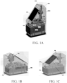
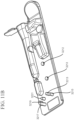
- FIG. 1A shows a system for sample processing and analysis.
- System 1900 can include several functional elements.
- System 1900 can include a sample preparation sub-system, a sample analysis sub-system and a control sub-system.
- a sample preparation sub-system of the system 1900 can include a sample cartridge interface 103 configured to engage a sample cartridge 102 , sources of reagents for performing a biochemical protocol, a fluidics assembly configured to move reagents within the sample preparation sub-system.
- a fluidics assembly can include a pump, such as a syringe pump. The pump is fluidically connectable through valves to the outlets for reagents such as water and lysis buffer and to a source of air. The pump can be configured to deliver lysis buffer and water through fluidic lines 1910 and 1911 , respectively, to inlet port 1912 in the sample cartridge. Air or liquid pressure applied by the pump to inlet port 1912 can pump analyte out outlet port 1913 and through line 1912 into the analyte inlet in the electrophoresis cartridge.
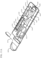
- Cartridge body 1801 includes the following valve bodies: 1841 Cycler Out (A0), 1842 Lysis (A1), 1843 Waste Shut Off (A3), 1844 Waste In (A4), 1845 Cycler In (B0), 1846 Lysis Transfer (B1), 1847 Product Bottom (B2), 1848 Product Top (B3) and 1850 Vent (B4)
- valve bodies can include various types of valves, such as valves actuated with the aid of rams described in U.S. Provisional Patent Application Serial No. 62/001,533, filed March 21, 2014 , and U.S. Provisional Patent Application Serial No. 62/067,120, filed October 22, 2014 .
- the valve bodies can include Micro-Robotic on-Chip Valve and Pump valves (MOVe), as described, for example, in U.S. Patent Nos. 8,394,642 and 8,672,532 .
- MOVe Micro-Robotic on-Chip Valve and Pump valves
- cartridge body 1801 includes lysis chamber 1820 .
- Cartridge 1801 can include reagent chambers filled with, e.g., nucleic acid size standards (molecules of known sizes), PCR master mix and PCR primers, respectively, and sealed with, e.g., balls acting as closures for ball valves. When opened, the reagent chambers come into fluidic communication with fluidic channels in sample cartridge 1801 , for example, through ports 1852 (internal lane standard), 1853 and 1854 (PCR Master Mix and PCR Primer Mix). Pistons can actuate the ball valves, pushing fluids through the ports and into the channels to which they are connected.
- Sample cartridge 1801 also can include inlet port 1812 and output port 1813 .
- inlet port 1812 and outlet port 1813 each engage a fluid line.
- the fluid line connected to inlet port 1812 can be attached to a pressure source, e.g., a syringe, to exert positive or negative pressure to fluidic channels via the inlet port, transporting liquids, such as lysis buffer, water or air, into or out of the cartridge.
- the fluid line connected to output port 1813 can conduct analyte from the cartridge to a sub-system for analyte analysis.
- cartridge body 1801 includes lysis chamber 1820 and, optionally, closable cap 1864 to close lysis chamber 1820 .
- Cartridge 1801 includes pump 1884 .
- Pump 1884 e.g., an air pump
- Pump 1884 is configured as a chamber defined by walls of the cartridge body. Pump 1884 is fluidically connected to at least one fluidic channel in the cartridge body. Walls of the pump comprise, at least in part, the malleable material of the cartridge body. Accordingly, the walls can be deformed, for example by mechanical force, increasing pressure in the chamber to pump liquid or air in fluidic channels in fluidic communication with the pump.
- Pump 1884 can be actuated with a plunger or piston that depresses walls of pump 1884 and forces, for example, air from the pump body through the fluidic channel to which it is connected. Pump 1884 can be used to clear fluid from a fluidic channel. For example, in this embodiment, reagent introduced from port 1852 into reaction chamber 1822 may leave dead volume in channel 1831 . Pump 1884 can be used to pump this dead volume of reagent into reaction chamber 1822 .
- a sample analysis sub-system can include an electrophoresis assembly including an anode, a cathode and an electrophoresis capillary in electric and fluidic communication with the anode and cathode, and a sample inlet communicating between a sample outlet in the sample cartridge and an inlet to the capillary. These can be contained, e.g., within an electrophoresis cartridge 104 .
- the sample analysis sub-system can further include an optical assembly including a source of coherent light, such as laser 1988 , an optical train, including, e.g., lenses 1955 , and a detector, configured to be aligned with the electrophoresis capillary and to detect an optical signal, e.g., fluorescence, therein.
- the electrophoresis cartridge also includes a source of electrophoresis separation medium and, in some cases sources of liquid reagents, such as water and lysis buffer, delivered through outlets in the electrophoresis cartridge to the system.
- Separation channels for electrophoresis can take two main forms. One form is a "capillary”, which refers to a long and typically cylindrical structure. Another is “microchannel”, which refers to a microfluidic channel in a microfluidic device, such as a microfluidic chip or plate.
- a control sub-system can include a computer 1973 programmed to operate the system.
- the control sub-system can include user interface 101 that receives instructions from a user which are transmitted to the computer and displays information from the computer to the user.
- the user interface 101 may be as described in U.S. Provisional Patent Application Serial No. 62/067,429, filed October 22, 2014 .
- the control sub-system includes a communication system configured to send information to a remote server and to receive information from a remote server.
- FIGS. 1B and 1C present the system of FIG. 1A in further detail.
- a sample cartridge interface 103 and an electrophoresis interface 105 are comprised in the system, for engaging the sample cartridge and the electrophoresis cartridge. Both the sample cartridge and the electrophoresis cartridge provided herein can be releasably or removably engaged with the system.
- the system of FIGS. 1A-1C can be used in forensic analysis to decode the genetic information of a single sample. In some cases, the system may be used to determine the genetic profile of a sample in less than about 6 hours, 5 hours, 4 hours, 3 hours, 2.5 hours, 2 hours, 1.5 hours, 1 hour, 30 minutes, 20 minutes, 10 minutes, 5 minutes 1 minute or less. Such time may depend upon, for example, the number of steps included in sample processing operations.
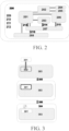
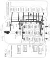
- a schematic of the system of FIGS. 1A-1C is illustrated in FIG. 2 .
- a chassis 200 is included for structural support, which may be formed of a metallic material, such as aluminum or steel, a polymeric material, or a combination thereof. In some cases, the chassis may be structured to minimize the weight of the system.
- a user interface which comprises system electronic controls 201 , embedded computer 202 , and a user interface screen capable of identifying and reading fingerprint 204 and sample patch barcode 205 , is included in the system.
- the user interface receives and processes requests or instructions from and delivers information to a user. It can include software programmed to execute routines for performing the operations mentioned, above, and transmit and receive information, such as computer files, from remote locations, e.g., over the internet.
- a sample cartridge interface 206 is provided for receiving a sample cartridge for sample processing.
- the sample cartridge described herein can be configured to receive one or more samples and to perform at least one of sample isolation, extraction, purification, amplification or dilution, when the sample cartridge is engaged with the sample cartridge interface of the system.
- Sample amplification can include polymerase chain reaction (PCR).
- PCR polymerase chain reaction
- One or more reagents that are needed for performing one or more steps of sample processing may be pre-loaded or comprised in the sample cartridge, for example, washing buffer, lysis buffer, diluent, or amplification reagents.
- the electrophoresis system comprises all essential parts for performing an electrophoretic analysis, such as an electrophoresis capillary, electrodes (e.g., anode and cathode), electrophoresis separation medium, or electrophoresis buffer.
- an electrophoretic analysis such as an electrophoresis capillary, electrodes (e.g., anode and cathode), electrophoresis separation medium, or electrophoresis buffer.
- it may comprise reagent that can be used to perform STR analysis. It may further comprise one or more reagent container for holding reagents that are used for sample processing, e.g., a lysis buffer container.
- the lysis buffer may be placed in fluidic communication with the sample cartridge and used for isolating the target material out of the sample during sample processing, after both the sample cartridge and the electrophoresis cartridge are engaged with the system.
- at least one automatic communication between the electrophoresis cartridge and the system may be established, for example, an electrical communication 213 between the electrophoresis cartridge and the system electronic controls 201 , an optical communication 214 between a portion of the electrophoresis capillary in the electrophoresis cartridge and an optics module 203 of the system, a fluidic communication 215 between a sample inlet port of the electrophoresis cartridge and a sample outlet port of the sample cartridge, a mechanical and thermal 216 communication between the electrophoresis cartridge and a motorized drives and cooling module 208 of the system.
- the integrated electrophoresis cartridge 207 has all or substantially all of the components necessary for electrophoresis in a compact unit that is readily insertable into and removable from the electrophoresis cartridge interface. This may permit a user to readily engage the cartridge 207 with the system without having to open the system.
- all or substantially all of the components necessary for electrophoresis e.g., anode, cathode and at least one electrophoresis capillary are included on a single board or support or multiple boards or supports that are securably integrated with one another.
- the system provided herein may further comprise a power source 212 for supplying the power for the system, AC mains 211 for applying a voltage gradient across the anode and the cathode, one or more fans 210 for dissipate the heat for one or more parts of the system, and one or more USB ports 209 for collecting and transferring data either within the system or outside the system.
- a power source 212 for supplying the power for the system
- AC mains 211 for applying a voltage gradient across the anode and the cathode
- one or more fans 210 for dissipate the heat for one or more parts of the system
- USB ports 209 for collecting and transferring data either within the system or outside the system.
- the electrophoresis cartridge may comprise one or more of sub-containers or sub-cartridges that are removably insertable in the electrophoresis cartridge, such as, sub-containers for holding electrophoresis separation medium, reagents for sample processing, or reagents for sample analysis.
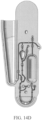
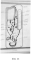
- FIG. 3 shows an example of an electrophoresis cartridge comprising an electrophoresis separation medium sub-container. As shown in FIG. 3 , an electrophoresis cartridge is manufactured to have a space 302 configured to specifically receive and accommodate a secondary or sub-container.
- a sub-container 301 used for holding the electrophoresis separation medium can be stored outside the electrophoresis cartridge 303 before the engagement of the electrophoresis cartridge with the system.
- the sub-container which holds the electrophoresis separation medium may be installed into the electrophoresis cartridge 305 a short time before the engagement of the electrophoresis cartridge with the system, for example, less than 1 hour, 50 minutes, 40 minutes, 30 minutes, 20 minutes, 15 minutes, 10 minutes, 5 minutes before engaging the electrophoresis cartridge with the system.
- the sub-container may be placed in thermal communication with a thermal control module of the system, which may adjust the temperature of the sub-container to a desired value and maintain it for a period of time.
- the present disclosure also provides an integrated electrophoresis cartridge for sample analysis which has a small footprint and configured to removably engage with a system for sample preparation, processing and analysis.
- the electrophoresis cartridge includes a capillary electrophoresis assembly which comprises an anode sub-assembly, a cathode assembly and at least one electrophoresis capillary having a first and a second end, across which a voltage gradient may be applied.
- the anode sub-assembly may comprise a single anode or a number of anodes.
- the cathode sub-assembly may comprise one cathode or a number of cathodes.
- the first and second end of the electrophoresis capillary may be in communication with the anode and cathode sub-assemblies respectively.
- the term "footprint” generally refers to the horizontal surface area or the area of a surface covered when the electrophoresis cartridge is placed on that surface.
- the electrophoresis cartridge can have a footprint of less than or equal to about 1 m 2 , 9000 cm 2 , 8000 cm 2 , 7000 cm 2 , 6000 cm 2 , 5000 cm 2 , 4500 cm 2 , 4000 cm 2 , 3500 cm 2 , 3000 cm 2 , 2500 cm 2 , 2000 cm 2 , 1900 cm 2 , 1800 cm 2 , 1700 cm 2 , 1600 cm 2 , 1500 cm 2 , 1400 cm 2 , 1300 cm 2 , 1200 cm 2 , 1100 cm 2 , 1000 cm 2 , 900 cm 2 , 800 cm 2 , 700 cm 2 , 600 cm 2 , 500 cm 2 , 450 cm 2 , 400 cm 2 , 350 cm 2 , 300 cm 2 , 250 cm 2 , 200 cm 2 , 150 cm 2 , 100 cm 2
- the electrophoresis cartridge may further comprise an electrophoresis separation medium container for holding an electrophoresis separation medium and communication with at least one anode in anode sub-assembly through a fluid line.
- a fluid handling device may be included in the electrophorese cartridge, with the aid of which, the electrophoresis separation medium may be moved into the at least one electrophoresis capillary. Any type of devices that is capable of moving the fluid may be used, such as valves, pumps, electrostatic fluid accelerators, and various other forms of process equipment.
- the electrophoresis cartridge may also comprise a sample inlet port, which is able to receive a sample from a sample outlet port of the system and in fluid communication with at least one cathode in cathode sub-assembly and an opening of electrophoresis capillary.
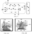
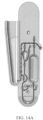
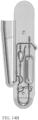
- FIGS. 4A and 4B show clear shell views of an example of an electrophoresis cartridge of the present disclosure.
- the electrophoresis cartridge may comprise a cartridge casing 400 , a sub-container (or sub-cartridge) casing 401 , an optical interface 402 for providing a light source and detecting signals from analytes, one or more hydrodynamic devices (e.g., fluid coupling) 403 , an anode sub-assembly 404 , a cathode sub-assembly 405 , an electrophoresis capillary 406 , an electrical interface 407 , one or more mechanical interfaces (e.g., 408 , 409 , 412 and 413 ) for applying pressure or forces on parts of the electrophoresis cartridge, a thermal interface 410 for control the temperature of the sub-container 401 , and an electrical interface 411 for providing a voltage between at least one anode in the anode sub-assembl
- FIG. 6A An example of the cathode sub-assembly that can be included in an electrophoresis cartridge of the present disclosure is shown in FIG. 6A .
- Three cathode nodes 602 are included in the cathode sub-assembly and places in electrical communication with an electrophoresis capillary port 606 .
- the cathode nodes can be disposed in close proximity to the electrophoresis capillary port, for example, at least one cathode node is positioned opposite the electrophoresis capillary port, as shown in FIG. 6A .
- the cathode nodes may be also placed in fluidic communication with a sample inlet port 603 , a first reagent port 604 , a second reagent port 605 and a waste port 601 , through a passage of the cathode sub-assembly.
- the sample inlet port 603 may further communicate with at least one sample outlet port of the sample cartridge interface and receive the prepared sample from it.
- the received sample may flow though a sample line into the passage of the cathode sub-assembly and with the application of the voltage gradient, be pushed into the electrophoresis capillary.
- One or more reagents e.g., electrophoresis buffer, water etc.
- a waste container is provided and in fluid communication with all other fluid ports (e.g., the sample inlet port, the electrophoresis capillary port, and the first and the second reagents ports), through the waste port and the passage of the cathode sub-assembly. Any excessive fluid or liquid leak from any one of the ports and the cathode sub-assembly may flow into the waste container and be collected.
- FIG. 6B shows an example of the anode sub-assembly comprised in an electrophoresis cartridge of the present disclosure.
- the anode sub-assembly comprises an anode node 612 which is in electrical communication with an electrophoresis capillary port 614 .
- the anode sub-assembly may further comprise an electrophoresis separation medium port 611 , one or more reagent ports ( 607 and 613 ), and a waste port 609 . All these ports are in fluid communication with the anode node 612 and the electrophoresis capillary port 614 , through a passage of the anode sub-assembly.
- anode sub-assembly Further comprised in the anode sub-assembly are two mechanical interfaces that are in mechanical communication with the rest parts of the anode sub-assembly and aid in delivering and transferring fluid flow of the electrophoresis separation medium and the reagents among different parts of the anode sub-assembly.
- the mechanical interface may comprise a high pressure piston 608 that may move vertically and apply a high pressure onto the passage of the anode sub-assembly.
- the mechanical interface may comprise an anode main piston 610 which moves horizontally and is capable of relieving the pressure from the high pressure piston.
- the electrophoresis separation medium port 611 may receive an electrophoresis separation medium from the electrophoresis medium sub-container. The received electrophoresis separation medium may then be moved through a fluid line into the passage of the anode sub-assembly and placed in communication with the electrophoresis capillary port 614 .
- the high pressure piston 608 then moves down to apply a high pressure onto the passage and pushes the electrophoresis separation medium into at least one electrophoresis capillary via the electrophoresis capillary port 614 .
- One or more reagents e.g., water, electrophoresis buffer
- one of the reagent ports may be used to receive a regeneration fluid and in communication with the passage and one or more other parts of the anode sub-assembly.
- the regeneration fluid may be used to flush and rinse the electrophoresis capillary to renew or restore its function or performance, after one or more times of use.
- Time period and frequency for applying the regeneration fluid may vary, depending upon a number of factors.
- factors may include temperature, property of regeneration fluid (e.g., viscosity), type of regeneration fluid, quantity of regeneration fluid, pressure or force used to drive the regeneration fluid, size of opening of the electrophoresis capillary, total surface area of the electrophoresis capillary to be regenerated, substances or material adsorpted on inner wall or surface of the electrophoresis capillary that needs to be removed, or combinations thereof.
- a regeneration fluid can be an organic fluid, an aqueous fluid, a non-aqueous inorganic fluid, or mixtures thereof.
- a regeneration fluid may comprise one or more types of alkali hydroxide, such as LiOH, NaOH, KOH, RbOH, or CsOH.
- a regeneration fluid may comprise one or more salts, such as sodium tetraborate and trisodium phosphate. In some cases, more than one type of regeneration fluid may be used in certain application.
- a second and a third regeneration fluid may be used to further cleanse the electrophoresis capillary.
- a regeneration fluid may have a high pH value, such as 11.
- a regeneration fluid may have a low pH value, such as 2.5.
- pH value of a regeneration fluid may vary depending on different applications.
- a waste container is provided to receive and collect any excess fluid or possible leak from the anode sub-assembly via the waste port 609 included in the anode sub-assembly.
- the electrophoresis cartridge can be configured to releasably engage with a cartridge interface of a sample-profiling system. As further provided, engagement of the electrophoresis cartridge may automatically establish at least one communication between the electrophoresis cartridge and the system.
- Non-limiting examples of communications may include fluidic communication, electrical communication, optical communication, mechanical communication, electromagnetic communication, thermal communication, electrochemical communication, radiofrequency communication, magnetic communication and combinations thereof.
- Electromagnetic communication can include, for example, optical communication and/or wireless communication (e.g., radio-frequency identification (RFID), WiFi, Bluetooth).
- RFID radio-frequency identification
- the automatic communication may be established between at least one part of the electrophoresis cartridge and at least one component of the system.
- an optical communication may be made between a portion of at least one electrophoresis capillary and an optics module of the system.
- an electrical communication may be made between a voltage control assembly of the system and the anode and the cathode of the electrophoresis cartridge.
- a fluidic communication may be established between at least one sample inlet of the electrophoresis cartridge and at least one sample outlet of the system.
- one or more mechanical communication may be established between one or more mechanical interfaces of the system and the anode sub-assembly and the cathode sub-assembly of the electrophoresis cartridge.
- a thermal communication may be made between at least one electrophoresis capillary and a thermal control assembly of the system.
- a fluidic communication may be made between at least one electrophoresis capillary and a fluid control assembly of the system.
- engagement of the electrophoresis cartridge and establishment of at least one automatic communication may occur concurrently.
- engagement of the electrophoresis cartridge and establishment of at least one automatic communication may occur sequentially. For example, at least one communication may be automatically established after the electrophoresis cartridge is engaged with the system. In cases where more than one automatic communication is made, they may be made simultaneously or sequentially, or in some cases these automatic communications may be grouped and different groups of communication may occur simultaneously or sequentially.
- the automatic communication is made in response to user instructions provided to a control module of the system. In some cases, the automatic communication may be triggered by some manual operation, for example, pressing a button by the user. In some cases, automatic communication is established by mechanical engagement of the cartridge with the system. For example, such engagement can place fluid conduits in into communication by sliding or snapping them into place during engagement. Automatic electrical communication can be achieved when engagement physically connects electrical terminals on both the cartridge and the interface. Automatic optical communication can occur when placement of the cartridge in the interface places a detection element, such as a capillary, in the path of an optical train of an optical assembly in the instrument. Alternatively, the system can be configured to establish communication once the system senses that the cartridge is engaged. For example, once the cartridge is engaged, the system can automatically move fluid conduits into engagement with fluid ports n the cartridge. Alternatively, one the cartridge is engaged, the system can be configured to automatically establish radio communication with the cartridge.
- At least one automatic communication may be desirable to check or test the robustness of the communication. For example, in some cases, it may be required to check whether the automatic communication is made properly. In cases where more than one automatic communication is made, it may be useful to check the number of proper and accurate communications that have been made.
- Built-in circuits may be used to transform the checking results into an output signal which may subsequently be displayed on a user interface screen of the system.
- each of the automatic communications may have an individual built-in circuit.
- a signal built-in circuit may be used for all communications.
- a number of communications may share one built-in circuit.
- a variety of signals may be outputted and used herein as an indicator of the checking results, e.g., audio, visual, tactile, or combinations thereof.
- the outputted signal may include lights that may light up to indicate the number of accurate communications.
- a number of lights corresponding to each of automatic communications may be used and the number of lights that are lit off out of the total number of lights may indicate the number of communications that are inaccurately established. For example, if a total of five automatic communications are to be checked and after checking, three lights out of five are lit, then it may indicate only two automatic communications are properly established.
- a numerical value may be displayed that is indicative of number of properly established communications. For example, a number may indicate that two out of five communications are made correctly.
- a color may be displayed that is indicative of the proper communication. For example, a green color may indicate that the communication is accurately established. A yellow light may indicate that the communication is acceptable for further operations but not optimal, and a red light may indicate that the communication is incorrectly made and needs to be repeated.
- a visual indicator such as a bar may be utilized. The quality of the communication may be indicated based on how full the bar is.
- audio signals may be outputted indicating the accuracy of the communication. For example, when communication is improperly made and a fix is required, a beeping or words of warning may be produced. In some cases, the system may vibrate or provide any other type of tactile warning if the communication is not made properly.
- the electrophoresis cartridge 500 may comprise an electrophoresis assembly which includes an anode sub-assembly 507 , a cathode sub-assembly 510 , and at least one electrophoresis capillary 509 to be used in sample separation and analysis for at least one sample.
- at least one capillary is one capillary or one to 10 capillaries.
- a plurality of electrophoresis capillaries may be used for performing electrophoresis analysis on a number of samples.
- the cathode sub-assembly can include at least about 1, 2, 3, 4, 5, 6, 7, 8, 9, or 10 cathode nodes.
- the anode sub-assembly can include at least about 1, 2, 3, 4, 5, 6, 7, 8, 9, or 10 anode nodes.
- three cathode nodes 511 are included in the cathode sub-assembly and in fluidic and electrical communication with a first end of the electrophoresis capillary.
- At least one anode node 529 is comprised in the anode sub-assembly and in fluidic and electrical communication with a second end of the electrophoresis capillary.
- anode sub-assembly and a cathode sub-assembly comprising one anode node and three cathode nodes
- any number of anodes and cathodes may be used, dependent upon, different applications. For example, in some cases, equal to or less than about 20, 15, 10, 9, 8, 7, 6, 5, 4, 3, 2, or 1 anodes or cathodes may be utilized. In some cases, greater than or equal to about 1, 2, 3, 4, 5, 6, 7, 8, 9, 10, 15 or 20 anodes or cathodes may be utilized. In some cases, the number of anodes or cathodes used in a certain application may be between any of the two values described herein, for example, 11.
- the electrophoresis cartridge may also comprise more than one container for holding electrophoresis separation medium and more than one reagent for sample processing and analysis. As shown in FIG. 5 , an electrophoresis separation medium container 501 , a first reagent container 502 , a second reagent container 503 , a third reagent container 504 , and a fourth reagent container 505 are included in the electrophoresis cartridge 500. As provided in the present disclosure, one or more containers may be configured to be removably insertable into the electrophoresis cartridge. After each run of sample analysis is completed, one or more containers may be replaced or reused, depending upon, the applications.
- the container may be stored or transported at room temperature. In some cases, the container may be stored or transported at a high temperature. In some cases, the container may be stored or transported at a low temperature.
- the container may be stored or transported at a temperature less than or equal to about 50°C, 40°C, 30°C, 25°C, 20°C, 15°C, 10°C, 5°C, 0°C, -5°C, -10°C, -20°C, -30°C, -40°C, -50°C, -60°C, -70°C, -80°C, -90°C, or -100°C.
- the container may be stored or transported at a temperature greater than or equal to - 20°C, -10°C, -5°C, 0°C, 5°C, 10°C, 15°C, 20°C, 25°C, 30°C, 35°C, 40°C, 45°C, 50°C, 55°C, 60°C, 70°C, 80°C, 90°C, or 100°C.
- the container may be stored or transported at a temperature between any of the two values described herein, for example, 4°C.
- An electrophoresis separation medium can be solid, semi-solid, liquid (e.g., gel), such as organic material, natural macromolecules, synthetic or semi-synthetic polymers (e.g., linear homopolymer or block copolymer, cross-linked homopolymer or block copolymer), or combinations thereof.
- Non-limiting examples of electrophoresis separation media may include agarose, sucrose, cellulose acetate, starch-gel, polyacrylamide (e.g., the LPA line (including LPA-1) of separation gels (Beckman Coulter), the POP TM line (including POP-4 TM , POP-6 TM and POP-7 TM ) of separation polymers (Life Technologies), and a modified LPA with a self-coating polymer (e.g., LPA V2E (IntegenX Inc.)), hydroxyethylcellulose, and other biopolymers.
- polyacrylamide e.g., the LPA line (including LPA-1) of separation gels (Beckman Coulter)
- the POP TM line including POP-4 TM , POP-6 TM and POP-7 TM
- a modified LPA with a self-coating polymer e.g., LPA V2E (IntegenX Inc.)
- denaturing gel electrophoresis can be performed using a separation polymer or gel that comprises a chemical denaturant (e.g., urea, formamide or N-methyl-pyrrolidone) or at a temperature (e.g., at least about 65° C, 75° C, 85° C or 90° C or higher) that denatures double-stranded nucleic acid fragments.
- a chemical denaturant e.g., urea, formamide or N-methyl-pyrrolidone
- a temperature e.g., at least about 65° C, 75° C, 85° C or 90° C or higher
- the electrophoresis separation medium container 501 Once the electrophoresis separation medium container 501 is properly engaged with the electrophoresis cartridge, with the aid of a first mechanical interface 515 for controlling one or more fluid handling devices (e.g., a pump), the electrophoresis separation medium may be driven and moved into the anode sub-assembly 507 .
- the electrophoresis separation medium may be further pushed into at least one of the electrophoresis capillary with the application of a second and a third mechanical interface 514 and 516 by exerting a force (or pressure) on a high pressure piston 506 and an anode main piston (not shown).
- reagents may be solid, semi-solid or liquid. In cases where liquid reagents are used, they may comprise organic fluid, inorganic fluid, or a mixture thereof.
- reagents may comprise water, electrophoresis buffer, sample processing buffer (e.g., a lysis buffer), loading buffer, regeneration fluid, or combinations thereof.
- sample processing buffer e.g., a lysis buffer
- loading buffer e.g., a lysis buffer
- regeneration fluid e.g., a mixture thereof.
- reagents can be provided (e.g., stored) in an aqueous solution, or can be provided (e.g., stored) in a solid or dry (e.g., lyophilized) form and then placed into solution by addition of a liquid (e.g., an aqueous solution) as appropriate.
- a liquid e.g., an aqueous solution
- reagents can be provided (e.g., stored) in a substantially water-free non-ionic organic solvent (e.g., an alcohol solvent) or in a substantially water-free ionic organic solvent (e.g., a deep eutectic solvent) and can be rehydrated by addition of an aqueous solution as appropriate, as described in PCT Patent Publication No. WO 2014/055936 .
- the term "regeneration fluid" generally refers to a fluid that is able to renew or restore the function or performance of one or more parts of the electrophoresis cartridge, for example, the electrophoresis capillary.
- the regeneration fluid may comprise an aqueous solution.
- the regeneration fluid may comprise an alkaline fluid.
- the regeneration fluid may comprise one or more alkali hydroxides.
- two waste containers 512 and 513 may be included in the electrophoresis cartridge and communicate with the anode-subassembly and the cathode sub-assembly, respectively.
- the collection capacity (e.g., volume) of the waster container may vary, dependent upon, the applications. In some cases, a high collection capacity may be desirable, for example, if a large amount of samples are to be analyzed and a large quantity of reagents is expected to be consumed. In some cases, a low collection capacity may be sufficient.
- the collection capacity may be less than or equal to about 500 milliliter (mL), 400 mL, 300 mL, 200 mL, 100 mL, 90mL, 80mL, 70 mL, 60 mL, 50 mL, 40 mL, 30 mL, or 20mL.
- the collection capacity of the waste container may be greater than or equal to about 5 mL, 10 mL, 20 mL, 30 mL, 40 mL, 45 mL, 50 mL, 55 mL, 60 mL, 65 mL, 70 mL, 75 mL, 80 mL, 85 mL, 90 mL, 95 mL, 100 mL, 150 mL, or 200 mL.
- the collection capacity of the waste container may be between any of the two values described herein, for example, 25mL.
- Any number of water containers (e.g., at least 1, 2, 3, 4, or 5) may be included in the electrophoresis cartridge, as provided in the present disclosure.
- each of the reagent containers and the electrophoresis separation medium container may be provided with its water container.
- the electrophoresis cartridge may further comprise a plurality of fluid handling devices which place various parts or components of the electrophoresis cartridge in fluidic communication.
- any type of devices that is capable of moving or transferring the fluid may be used, such as valves, pumps, electrostatic fluid accelerators, and various other forms of process equipment.
- pumps 520 and 521 are used to drive the reagents stored in the first and the second reagent containers 502 and 503 to the anode sub-assembly 507 , through their respective fluid conduits.
- pumps 522 and 523 are utilized to transfer the reagents kept in the second and the third reagent containers 503 and 504 to the cathode sub-assembly 510 , through two separate fluid conduits.
- the reagent containers communicate with more than one part of the electrophoresis cartridge or the system.
- the second and the third reagent containers 503 and 504 are placed in communication with parts outside of the electrophoresis cartridge, besides their communication with the cathode sub-assembly 510 of the electrophoresis cartridge as described above.
- both of the reagent containers are in fluidic communication with the sample cartridge interface 519 and a fluid handling device 518 through a fluid line.
- a four-port valve 528 and a three-port valve 527 are utilized to direct, control and regulate different types of fluid flow in the fluid line.
- reagent containers installed inside the electrophoresis cartridge while communicate only with parts or components which are outside of the electrophoresis cartridge.
- a fourth reagent container 505 is engaged with the electrophoresis cartridge and placed in fluidic communication with the sample cartridge interface 519 through a fluid line.
- one or more hydrodynamic devices e.g., fluid couplings 524, 525 and 526) may be included in the electrophoresis cartridge which may aid in delivering and transferring the reagents, analytes or samples through the fluid line.
- the electrophoresis cartridge may also comprise a sample delivery assembly comprising at least one sample inlet port and at least one sample line, with each sample line placing a sample inlet port in communication with the first end of the electrophoresis capillary through a passage in the cathode sub-assembly.
- the sample inlet port may be further configured to communicate with a sample outlet port comprised in a sample cartridge interface 519 , via a hydrodynamic device 526 , for example, a fluid coupling or a hydraulic coupling.
- a separation channel e.g., an electrophoresis capillary
- any suitable method for moving the prepared sample into the separation channel may be used in the context of the present disclosure.
- field-amplified stacking FAS
- FAS field-amplified stacking
- a bolus of a material e.g., air
- the material has an electrical conductivity that differs from the electrical conductivity of the electrophoresis buffer or the sample.
- the sample When the sample is positioned across the separation channel, the sample can be electrokinetically injected into the separation channel at an appropriate voltage (e.g., about 3 kV to about 5 kV, or about 4 kV) over an appropriate amount of time (e.g., about 10 sec to about 20 sec, or about 15 sec).
- a pump may be used to drive the sample into the separation channel.
- the capillary can be inserted into the sample line so that sample flows across the opening to the capillary.
- the sample line can be co-axial with the electrophoresis capillary.
- the sample may then be subjected to sample separation and analysis within the separation channel, with the aid of an electric field, as can be generated upon the application of a voltage gradient across the anode 529 and the cathode 511 .
- analytes in the electrophoresis capillary move through the matrix (i.e., electrophoresis separation medium) at different rates, determined by one or more factors, such as mass, charge, or a combination thereof.
- a portion of the electrophoresis capillary can be used as an optical window 508 which is capable of receiving a light from a light source and emitting signals that can be captured and detected by one or more detectors included in a detection assembly.
- an optics module may be provided, which may comprise both the light source and the detection assembly.
- the light source is positioned to deliver a beam to at least one electrophoresis capillary via the optical window.
- One or more optical detectors e.g., charge-coupled device (CCD), complementary metal-oxide-semiconductor (CMOS), photodetector, photo diode, or photomultiplier detector
- CCD charge-coupled device
- CMOS complementary metal-oxide-semiconductor
- photodetector e.g., photodetector
- photo diode photomultiplier detector
- the optical communication between the optical window in the electrophoresis cartridge and both the light source and the optics module may be automatically established at the same time as the occurrence of the engagement of the electrophoresis cartridge.
- the capillary can be movably supported by a compliant member, which can be spring-biased toward the optics assembly.
- the optics module in the system physically engages the compliant member causing rough lateral alignment of the capillary with the optics.
- Features on the engagement assembly of the optics module, when engaging the compliant member can provide fine alignment through movement of the capillary across the compliant member.
- the capillary can be thermally regulated, e.g., heated, to maintain an appropriate running temperature.
- the capillary can be heated by, for example, flowing temperature-controlled air over the capillary, by placing the capillary in thermal contact with a thermoelectric heater (e.g., a Peltier), or by placing the capillary in thermal contact with a resistive heater.
- a thermoelectric heater e.g., a Peltier
- a capillary heater assembly can comprise a flexible heater circuit comprising a resistive heater (e.g., a wire trace) in a polymeric substrate.
- a capillary thermal regulating assembly includes the following elements: A capillary is sandwiched between hook and loop layers of a fabric hook-and-loop fastener (e.g., a Velcro ® strip). A resistive heater, such as a nicrome wire, is placed in thermal contact with the capillary through one of the fabric layers, e.g., placed in physical contact an external surface of the layer. This assembly can be supported by a thermal spreader, such as graphite, e.g., flexible graphite.
- the capillary is sandwiched between two strips of a thermal conductive gel, such as Thermacool TC3008 (Saint Gobain, Courbevoie, France).
- This sandwich is, in turn, sandwiched between heat spreaders, such as a graphite film (e.g., KERATHERM ® Graphite Film, Kerafol, Eschenbach, Germany).
- heat spreaders such as a graphite film (e.g., KERATHERM ® Graphite Film, Kerafol, Eschenbach, Germany).
- strip heaters e.g., Kapton
- electrophoresis cartridges that can be reusable for at least 2 times, 4 times, 6 times, 8 times, 10 times, 12 times, 14 times, 16 times, 18 times, 20 times, 21 times, 22 times, 23 times, 24 times, 25 times, 26 time, 27 time, 28 times, 29 times, 30 times, 35 times, 40 times, 45 times, 50 times, 60 times, 70 times, 80 times, 90 times, or 100 times.
- a regeneration fluid is included in the electrophoresis cartridge and used to flush and rinse the electrophoresis capillary after each time of use.
- the method may comprise: (a) providing a system comprising an electrophoresis cartridge interface that releasably engages with an electrophoresis cartridge comprising (1) an anode sub-assembly comprising an anode, (2) a cathode sub-assembly comprising a cathode, and (3) at least one electrophoresis capillary that is in fluid communication with the anode and the cathode; (b) receiving the electrophoresis cartridge at the electrophoresis cartridge interface; (c) automatically establishing at least one of (i) an optical communication between an optical detection assembly of the electrophoresis system and a portion of the at least one electrophoresis capillary, (ii) an electrical communication between the system and the anode and the cathode, (iii) a fluidic communication between the system and the at least one electrophor
- the system may further comprise a voltage control assembly (e.g., a power source) which is capable of applying a voltage gradient across the anode and the cathode, at least one thermal control assembly, at least one sample outlet, an optics module, and at least one fluid control assembly.
- the optics module may comprise a light source and a detection assembly comprising one or more optical detectors.
- the fluid control assembly may comprise a fluid container for holding one or more of reagents or fluid that are necessary for sample preparation, processing and analysis, and at least one fluid handling device that is capable of moving the fluid within the electrophoresis cartridge or the system.
- the automatically established communication comprises at least one of (i) an electrical communication between the voltage control assembly and the anode and the cathode, (ii) a sensing communication between the optics module and at least a portion of the electrophoresis capillary, (iii) a thermal communication between at least one thermal control assembly and the electrophoresis capillary, (iv) a first fluidic communication between at least one sample outlet and the electrophoresis capillary, and (v) a second fluid communication between at least one fluid control assembly and the electrophoresis capillary.
- engagement of the electrophoresis cartridge and establishment of at least one automatic communication may occur concurrently or sequentially.
- at least one communication may be automatically established after the electrophoresis cartridge is engaged with the system.
- more than one automatic communication is made, they may be made simultaneously or sequentially.
- these automatic communications may be grouped and different groups of communication may occur simultaneously or sequentially.
- the automatic communication is made in response to user instructions provided to a control module of the system.
- the automatic communication may be triggered by some manual operation, for example, pressing a button by the user.
- the sample cartridges of this disclosure can be used in an integrated system for preparing a sample, for example, DNA isolation and amplification.
- a sample contained on for example a swab or a card punch can be introduced into sample chamber 120.
- the cartridge can be engaged with sample cartridge interface 103.
- Cell lysis buffer contained in an off-chip reservoir can be feed through port 112 into the fluidic channel in the cartridge and into the sample chamber 120 by closing valves 141, 142, 143, and 147.
- Port 112 can be connected to a syringe or to another source of positive or negative pressure.
- lysate can be moved through a fluidic channel on the cartridge, for example, with a plunger that applied vacuum through port 112 to draw the fluid into reaction chamber 122 by opening valves 147, 148, 149, and 142; and closing valves 146, 145, 143, 144, and 141.
- the DNA reaction chamber can include material that captures a pre-determined amount of analyte. Excess fluid can be moved into waste chamber 123 while the reaction chamber is filled. Reagents for performing PCR or other reactions can be introduced into the reaction chamber through ports 115 and 116. In one embodiment, as detailed in U.S. Patent Application Publication No. US 2013/0115607 and International Patent Application Publication No.
- an actuator pushes on ball valves (not shown), to push the master mix in port 115 and the primers in port 116 into reaction chamber 122.
- a thermal control mechanism in the system can apply heat to perform thermal cycling in reaction chamber 122 of the cartridge with valves 148 and 149 closed. Following thermal cycling, valves 148, 145, 143 and 141 are opened and valves 149, 146, 147, 144, 142 are closed, and internal lane standard is dispensed from port 114 into reaction chamber 122 and pushed into mix chamber 121.
- valves 141, 142, 145, 146 are closed; valves 143 and 144 are opened and the amplified STR mixture with internal lane standard is pushed to through port 113 to a capillary electrophoresis analysis module for separation, detection, and analysis.
- cartridges of this disclosure can be used to perform DNA amplification and subsequent preparation for cycle sequencing.
- the target for sequencing can be, for example, a diagnostic target, such as a gene for genotyping, a polynucleotide bearing a somatic mutation, e.g., from a tumor, or a polynucleotide from an infectious microorganism such as a bacterium or a virus.
- Cartridge 2100 has input 2110.
- a sample 2105 can be introduced into sample chamber 2120.
- the cartridge can be engaged with an interface of instrument 2180 configured to supply reagents and motive forces.
- Cell lysis buffer contained in an off-chip reservoir 2182 can be fed through port 2112 into a fluidic channel in the cartridge and into the sample chamber 2120 by opening valve 2114.
- Port 2112 can be connected to a syringe 2170 or to another source of positive or negative pressure.
- lysate can be moved through a fluidic channel on the cartridge into isolation chamber 2130 by opening valve 2116; if required vacuum can be applied by syringe 2170 by opening valve 2118.
- Magnetically responsive particles e.g., beads 2184
- the beads can be preloaded into isolation chamber 2130.
- Polynucleotides can be captured on the particles and immobilized by application of a magnetic force to the isolation chamber 2130 by magnetic actuator 2135. The particles can be washed with, e.g., ethanol 2186, and the wash moved to a waste chamber on cartridge (not shown) or off-cartridge 2188.
- the polynucleotides can be moved into a reaction chamber 2140 for PCR by opening valve 2122.
- Reagents for amplifying a specific nucleotide sequence can be introduced into the reaction chamber from sealed compartments through ports 2113 and 2115 or these sealed compartments can contain the reagents in an integrated vial with seals by for example Teflon balls. These include primers, nucleotides, and hot start DNA polymerase. Primers are typically kept separate in a "primer mix” from the other ingredients, mixed as "master mix”.
- a thermal control mechanism in the system e.g., thermal cycler 2160, can apply heat to perform thermal cycling in reaction chamber 2140 of the cartridge.
- primers and nucleotide triphosphates can be degraded by adding, for example, exonuclease I and shrimp alkaline phosphatase from a sealed compartment through port 2117. Following reaction, the exonuclease I and shrimp alkaline phosphatase can be degraded by heating to 80 °C by thermal cycler 2160.
- Reagents for performing cycle sequencing can then be introduced into the reaction chamber, for example, from sealed compartments on the cartridge through ports 2119 and 2121.
- These include a sequencing primer, nucleotides, hot start DNA polymerase, and labeled dideoxynucleotides (e.g.BigDye ® terminators form Life Technologies ® ) for dye terminator sequencing.
- Primers are typically kept separate in a "primer mix” from the other ingredients, mixed as "master mix”. Thermal cycling produces dideoxynucleotide-terminated polynucleotides with base specific fluorescent label.
- This mixture can then be moved back into isolation chamber 2130.
- Magnetically responsive particles can be introduced into isolation chamber 2130 for polynucleotide capture and clean up.
- Cleaned up polynucleotides can then be pushed, e.g., with air 2192 through output port 2123 to a capillary electrophoresis analysis module for separation, detection, and analysis.
- some or all reagents are stored in compartments on the cartridge for movement into the fluidic circuit as needed.
- FIGs. 11A and 11B Another example of a sample cartridge configured to perform this method is depicted in FIGs. 11A and 11B .
- Cartridge 3200 includes inlet 3210, pressure port 3212, lysis chamber 3220, filter chamber 3236, isolation chamber 3230, reaction chamber 3240, magnetically attractable beads 3285 in the reaction chamber, ports 3213 and 3215 for PCR reagents, ports 3219 and 3221 for cycle sequencing reagents, exit port 3213, and valves 3213, 3214, 3241, 3243, 3244, 3245, 3248, 3249 and 3250.
- the cartridge aspect in FIG. 11B shows ports 3212 and 3213, as well as open compartments for ports 3213, 3215, 3217, 3219 and 3221.
- a sample cartridge of this disclosure has a fluidic circuit with a plurality of branches, each branch adapted to perform a separate biochemical reaction.
- each of two branches can be used to perform one of forward and reverse strand cycle sequencing on a sample.
- the forward strand can be prepared for sequencing in a first branch and the reverse strand can be prepared for sequencing in a second branch.
- different branches can be used to amplify different target nucleotide sequences from the same sample.
- FIG. 12 An exemplary cartridge 2200 for such an embodiment is shown in FIG. 12 .
- Cartridge 2200 has input 2210.
- a sample 2205 can be introduced into sample chamber 2220.
- the cartridge can be engaged with an interface of instrument 2280 configured to supply reagents and motive forces.
- Cell lysis buffer contained in an off-chip reservoir 2282 can be fed through port 2212 into a fluidic channel in the cartridge and into the sample chamber 2220 by opening valve 2214.
- the lysis solution can be compatible with particles used to capture polynucleotides.
- Port 2212 can be connected to a syringe or to another source of positive or negative pressure.
- lysate can be moved through a fluidic channel on the cartridge into isolation chamber 2230 by opening valve 2216.
- Magnetically responsive particles e.g., beads 2284
- Polynucleotides can be captured on the particles and immobilized by application of a magnetic force to the isolation chamber 2230 by magnetic actuator 2235.
- the particles can be washed with, e.g., ethanol 2286, and the wash moved to a waste chamber or off-cartridge 2288.
- reaction chambers 2240a-c for PCR by opening valves 2222a-c. This can be done, for example, by opening and closing these valves sequentially, and moving material into each open chamber.
- Reagents for amplifying a specific nucleotide sequence can be introduced into the reaction chamber from sealed compartments or may be present in lyophilized form.
- a thermal control mechanism in the system e.g., thermal cycler 2260, can apply heat to perform thermal cycling in reaction chamber 2240 of the cartridge.
- primers and nucleotide triphosphates are degraded by, for example, exonuclease I and shrimp alkaline phosphatase present in lyophilized form or added from a sealed compartment.
- exonuclease I and shrimp alkaline phosphatase can be degraded by heating to 80 °C by thermal cycler 2260.
- reaction chambers 2250a-c The samples are then moved into reaction chambers 2250a-c by opening valves 2251a-c for preparation for cycle sequencing.
- reagents for performing cycle sequencing can be introduced into the reaction chamber, for example, from sealed compartments on the cartridge or may be present in lyophilized form. Thermal cycling produces dideoxynucleotide-terminated polynucleotides with base specific labels.
- the product of the thermal cycling reactions is then moved into clean-up chambers 2254a-c by opening valves 2253a-c.
- Magnetically responsive particles can be introduced into clean-up chambers 2254a-c for polynucleotide capture and clean up.
- Cleaned up polynucleotides can then be pushed, e.g., with air 2292 through output ports 2223a-c by opening valves 2255a-c to a capillary electrophoresis analysis module for separation, detection, and analysis.
- sample cartridges of this disclosure include a DNA quantification function.
- a DNA quantification function can be useful to meter an amount of DNA for amplification determined appropriate for down-stream applications such as STR amplification.
- FIG. 13 An exemplary cartridge 2300 for such an embodiment is shown in FIG. 13 .
- Cartridge 2300 has input 2310.
- a sample 2305 can be introduced into sample chamber 2320.
- the cartridge can be engaged with an interface of instrument 2380 configured to supply reagents and motive forces.
- Cell lysis buffer contained in an off-chip reservoir 2382 can be fed through port 2312 into a fluidic channel in the cartridge and into the sample chamber 2320 by opening valve 2314.
- Port 2312 can be connected to a syringe 2370 or to another source of positive or negative pressure.
- lysate can be moved through a fluidic channel on the cartridge into isolation chamber 2330 by opening valve 2316.
- Magnetically responsive particles e.g., beads 2384
- Polynucleotides can be captured on the particles and immobilized by application of a magnetic force to the isolation chamber 2330 by magnetic actuator 2335.
- the particles can be washed with, e.g., ethanol 2386, and the wash moved to a waste chamber or off-cartridge 2388.
- a predetermined amount of the particles with captured DNA can be moved into a reaction chamber 2340 by opening valve 2322.
- Magnetic actuator 2335 immobilizes the beads in reaction chamber 2340.
- Human-specific qPCR reagents such as Quantifiler from Thermo Fisher Scientific TM or Plexor HY System from Promega TM , are introduced into the reaction chamber from sealed compartments through ports 2319 and 2321.
- a thermal control mechanism in the system e.g., thermal cycler 2360, can apply heat to perform thermal cycling in reaction chamber 2340 of the cartridge for qPCR.
- a detection device 2370 e.g., using illumination, determines the course of the reaction. This information is used to determine how much DNA is captured per unit bead volume. The amount of beads necessary to carry the predetermined quantity of DNA needed is calculated.
- Material in reaction chamber 2340 can then be pushed, e.g., with air, 2392 through output port 2323.
- reaction chamber 2340 a volume of beads from isolation chamber 2330 determined to carry the desired amount of DNA is moved into reaction chamber 2340.
- Reagents for performing PCR can then be introduced into the reaction chamber, for example, from sealed compartments on the cartridge through ports 2313 and 2315, and the reaction thermal cycled.
- Internal ladder standard 2317 can then be pushed, e.g., with air 2392 through output port 2323 to a capillary electrophoresis analysis module for separation, detection, and analysis.
- the cartridges of this disclosure can be used in an integrated system for analyzing a sample, for example, DNA isolation and amplification with real time or end point detection.
- the samples can be interrogated by an optical detection system while amplifying in reaction chamber 122.
- the readout can be the change in fluorescence or by melting point.
- the probes can be human specific for human identification, forensics, or molecular diagnostic applications, or specific for pathogens for molecular diagnostic applications, or for bioagents for biodefense applications or nonspecific intercalators for determining the amount of DNA present.
- Amplification methods include, for example, thermal or isothermal amplification reactions, for example, PCR, rolling circle amplification, whole genome amplification, nucleic acid sequence-based amplification, and single strand displacement amplification, single primer isothermal linear amplification (SPIA), loop-mediated isothermal amplification, ligation-mediated rolling circle amplification and the like.
- thermal or isothermal amplification reactions for example, PCR, rolling circle amplification, whole genome amplification, nucleic acid sequence-based amplification, and single strand displacement amplification, single primer isothermal linear amplification (SPIA), loop-mediated isothermal amplification, ligation-mediated rolling circle amplification and the like.
- the sample cartridges of this disclosure can be used in an integrated system for analyzing a sample.
- the assay can detect a polypeptide (e.g., immunoassay) or a nucleic acid (e.g., PCR or reverse transcriptase followed by amplification).
- a polypeptide e.g., immunoassay
- a nucleic acid e.g., PCR or reverse transcriptase followed by amplification
- ports 115 and 116 can be used to add primary and secondary antibodies to the sample.
- the detection can be in sample chamber 121 or the sample can be moved through port 113 to a detector.
- the assay can be multiplex or single analyte. They can involve any assay to measure the presence, amount, activity, or other characteristics of the sample. These include assays that involve detection by fluorescence, luminescence, chemiluminescence, absorbance, reflectance, transmittance, birefringence, refractive index, colorimetric, and combinations thereof.
- the enzyme master mix and the substrate might be individually added to the reaction and the progress or endpoint of the assay monitored optically.
- sample cartridges of this disclosure can be used to prepare samples for additional analytical devices.
- Analytical methods can include sequencing, chromatography, (e.g., gas or size exclusion) electrometry, ellipsometry, refractrometry, interferometry (e.g., back scattering interferometry), spectrometry (e.g., mass spectrometry, NMR spectrometry, Raman spectroscopy, Surface-enhanced Raman Spectroscopy), surface plasmon resonance.
- Sequencing methods can include high-throughput sequencing, pyrosequencing, sequencing-by-synthesis, single-molecule sequencing, nanopore sequencing, semiconductor sequencing, sequencing-by-ligation, sequencing-by-hybridization, RNA-Seq (Illumina), Digital Gene Expression (Helicos), Next generation sequencing, Single Molecule Sequencing by Synthesis (SMSS)(Helicos), massively-parallel sequencing, Clonal Single Molecule Array (Solexa), shotgun sequencing, Maxim-Gilbert sequencing, Sanger sequencing, primer walking, sequencing using PacBio, SOLiD, Ion Torrent, or Nanopore platforms.
- SMSS Single Molecule Sequencing by Synthesis
- Solexa Single Molecule Array
- reagents such as molecular weight markers (size standards) can be combined with the PCR product.
- Products of the PCR can be moved off chip for analysis through an output line connected to port 113 (sample out).
- the amount of human DNA may need to be quantified.
- the typical forensic process is to quantify an extracted sample using real time polymerase chain reaction (PCR) in a separate instrument before the sample is STR amplified.
- PCR real time polymerase chain reaction
- a human specific probe is added to the STR mixture which has fluorescence outside the range used by the STR kit.
- the reaction chamber 122 is interrogated by a suitable wavelength of light for the human specific probe while the STR is being PCR amplified.
- the human specific probe can be a quencher such as a Black Hole Quencher ® or a TaqMan ® probe or other chemistries well know to one skilled in the art.
- the fluorescence from the human specific probe is monitored to quantify the amount of human DNA in the reaction.
- the number of amplification cycles can be adjusted based upon the amount of human DNA measured; this can be on a cartridge-by-cartridge monitoring if independent thermal cyclers are in use.
- One advantage is that the human specific probe will allow the concurrent STR amplification to achieve an optimal amplification and produce an amount of STR product that is optimal for the kit.
- a second advantage is the real time monitoring concurrent with the STR amplification allows integration of a sample-to-answer system without having an additional separate quantification process.
- a third advantage is for low copy number samples where there is barely enough sample to produce a good STR profile the integration of the quantification with the STR amplification prevents the aliquot typically used for quantification from causing the remaining sample to not have enough DNA for a good STR amplification.
- FIG. 8 shows a computer system 801 that is programmed or otherwise configured to facilitate sample preparation, processing and/or analysis.
- the computer system 801 can regulate various aspects of sample preparation, processing and/or analysis of the present disclosure, such as, for example, engaging an electrophoresis cartridge with an electrophoresis interface of a system for sample preparation, processing and/or analysis (see, e.g., FIGs. 1A-1C ).
- the computer system 801 can be integrated with such system.
- the computer system 801 includes a central processing unit (CPU, also "processor” and “computer processor” herein) 805 , which can be a single core or multi core processor, or a plurality of processors for parallel processing.
- the computer system 801 also includes memory or memory location 810 (e.g., random-access memory, read-only memory, flash memory), electronic storage unit 815 (e.g., hard disk), communication interface 820 (e.g., network adapter) for communicating with one or more other systems, and peripheral devices 825 , such as cache, other memory, data storage and/or electronic display adapters.
- the memory 810 , storage unit 815 , interface 820 and peripheral devices 825 are in communication with the CPU 805 through a communication bus (solid lines), such as a motherboard.
- the storage unit 815 can be a data storage unit (or data repository) for storing data.
- the computer system 801 can be operatively coupled to a computer network ("network") 830 with the aid of the communication interface 820.
- the network 830 can be the Internet, an internet and/or extranet, or an intranet and/or extranet that is in communication with the Internet.
- the network 830 in some cases is a telecommunication and/or data network.
- the network 830 can include one or more computer servers, which can enable distributed computing, such as cloud computing.
- the network 830 in some cases with the aid of the computer system 801 , can implement a peer-to-peer network, which may enable devices coupled to the computer system 801 to behave as a client or a server.
- the CPU 805 can execute a sequence of machine-readable instructions, which can be embodied in a program or software.
- the instructions may be stored in a memory location, such as the memory 810 .
- the instructions can be directed to the CPU 805 , which can subsequently program or otherwise configure the CPU 805 to implement methods of the present disclosure. Examples of operations performed by the CPU 805 can include fetch, decode, execute, and writeback.
- the CPU 805 can be part of a circuit, such as an integrated circuit.
- a circuit such as an integrated circuit.
- One or more other components of the system 801 can be included in the circuit.
- the circuit is an application specific integrated circuit (ASIC).
- the storage unit 815 can store files, such as drivers, libraries and saved programs.
- the storage unit 815 can store user data, e.g., user preferences and user programs.
- the computer system 801 in some cases can include one or more additional data storage units that are external to the computer system 801 , such as located on a remote server that is in communication with the computer system 801 through an intranet or the Internet.
- the computer system 801 can communicate with one or more remote computer systems through the network 830 .
- the computer system 801 can communicate with a remote computer system of a user (e.g., operator).
- remote computer systems include personal computers (e.g., portable PC), slate or tablet PC's (e.g., Apple ® iPad, Samsung ® Galaxy Tab), telephones, Smart phones (e.g., Apple ® iPhone, Android-enabled device, Blackberry ® ), or personal digital assistants.
- the user can access the computer system 801 via the network 830 .
- Methods as described herein can be implemented by way of machine (e.g., computer processor) executable code stored on an electronic storage location of the computer system 801, such as, for example, on the memory 810 or electronic storage unit 815 .
- the machine executable or machine readable code can be provided in the form of software.
- the code can be executed by the processor 805 .
- the code can be retrieved from the storage unit 815 and stored on the memory 810 for ready access by the processor 805 .
- the electronic storage unit 815 can be precluded, and machine-executable instructions are stored on memory 810 .
- the code can be pre-compiled and configured for use with a machine have a processer adapted to execute the code, or can be compiled during runtime.
- the code can be supplied in a programming language that can be selected to enable the code to execute in a pre-compiled or as-compiled fashion.
- aspects of the systems and methods provided herein can be embodied in programming.
- Various aspects of the technology may be thought of as “products” or “articles of manufacture” typically in the form of machine (or processor) executable code and/or associated data that is carried on or embodied in a type of machine readable medium.
- Machine-executable code can be stored on an electronic storage unit, such memory (e.g., read-only memory, random-access memory, flash memory) or a hard disk.
- “Storage” type media can include any or all of the tangible memory of the computers, processors or the like, or associated modules thereof, such as various semiconductor memories, tape drives, disk drives and the like, which may provide non-transitory storage at any time for the software programming.
- All or portions of the software may at times be communicated through the Internet or various other telecommunication networks. Such communications, for example, may enable loading of the software from one computer or processor into another, for example, from a management server or host computer into the computer platform of an application server.
- another type of media that may bear the software elements includes optical, electrical and electromagnetic waves, such as used across physical interfaces between local devices, through wired and optical landline networks and over various air-links.
- the physical elements that carry such waves, such as wired or wireless links, optical links or the like, also may be considered as media bearing the software.
- terms such as computer or machine "readable medium” refer to any medium that participates in providing instructions to a processor for execution.
- a machine readable medium such as computer-executable code
- a tangible storage medium such as computer-executable code
- Non-volatile storage media include, for example, optical or magnetic disks, such as any of the storage devices in any computer(s) or the like, such as may be used to implement the databases, etc. shown in the drawings.
- Volatile storage media include dynamic memory, such as main memory of such a computer platform.
- Tangible transmission media include coaxial cables; copper wire and fiber optics, including the wires that comprise a bus within a computer system.
- Carrier-wave transmission media may take the form of electric or electromagnetic signals, or acoustic or light waves such as those generated during radio frequency (RF) and infrared (IR) data communications.
- RF radio frequency
- IR infrared
- Common forms of computer-readable media therefore include for example: a floppy disk, a flexible disk, hard disk, magnetic tape, any other magnetic medium, a CD-ROM, DVD or DVD-ROM, any other optical medium, punch cards paper tape, any other physical storage medium with patterns of holes, a RAM, a ROM, a PROM and EPROM, a FLASH-EPROM, any other memory chip or cartridge, a carrier wave transporting data or instructions, cables or links transporting such a carrier wave, or any other medium from which a computer may read programming code and/or data.
- Many of these forms of computer readable media may be involved in carrying one or more sequences of one or more instructions to a processor for execution.
- the computer system 801 can include or be in communication with an electronic display 835 that comprises a user interface (UI) 840 , for example, for enabling the user to instruct the computer system 801 to begin sample preparation, processing and/or analysis.
- UI user interface
- Examples of UI's include, without limitation, a graphical user interface (GUI) and web-based user interface.
- GUI graphical user interface
- the user interface 840 may be as described in U.S. Provisional Patent Application Serial No. 62/067,429, filed October 22, 2014 .
- Methods and systems of the present disclosure can be implemented by way of one or more algorithms.
- An algorithm can be implemented by way of software upon execution by the central processing unit 805 .
- the algorithm can, for example, implement the general operation of a system for sample preparation, processing and/or analysis.
- the algorithm can regulate the sequential opening and closing of valves or the operation of an electrophoresis cartridge.
- the sample cartridge is a polypropylene molding with an integrated syringe barrel and sample chamber with a polyethylene heat seal over the area of the fluidics. There is an absorbent material in the waste chamber and a small dot of capture material in the reaction chamber.
- the barrel is loaded with a quantity of lysis solution (500-1000 ⁇ L) isolated between two rubber plungers. There are three reagent vessels on the chip that seal with top and bottom Teflon balls; two for the two parts of the Global Filer mastermix/primer which are loaded with 7-10 ⁇ L of solution and one containing a water/ILS solution that is used as a diluent before transfer to the cathode.
- Another protocol, performed on cartridge 1801, includes the following steps. Valve configurations are shown in FIG. 15 .
- Another protocol, performed on cartridge of FIG. 16 includes the following steps. All valves begin in open configuration.
- This example shows a method to perform cycle sequencing on a nucleic acid. (Refer to FIG. 10 .)
- This example shows a method to perform amplification of markers, e.g., diagnostic markers, followed by cycle sequencing of the amplification product. (Refer to FIG. 12 .)
- This example shows a method to quantify amount of human DNA before STR amplification for human identification or diagnostic fragment sizing (Refer to FIG. 13 .)
- the electrophoresis cartridge is a polypropylene molding comprising an anode sub-assembly, a cathode sub-assembly, an electrophoresis capillary and a gel sub-cartridge containing cross-linked polyacrylamide.
- the electrophoresis capillary has a first and a second end, each of which is in electrical communication with the anode sub-assembly and the cathode sub-assembly respectively.
- a portion of the electrophoresis capillary is used as an optical window for receiving a light from a light source and providing signals of the analytes for detection and further analysis.
- the cathode sub-assembly comprise there cathodes and a cathode main piston, and in fluid communication with the first end of the electrophoresis capillary, a water container, a buffer container and a first waste container.
- the anode sub-assembly comprises an anode main piston and a high pressure piston, and is in fluid communication with the second end of the electrophoresis capillary, the gel sub-cartridge, the water container, a regeneration fluid container and a second waste container.
- the electrophoresis cartridge further comprises a lysis buffer container, a sample inlet port in fluidic communication with a sample cartridge interface having a sample outlet port.
- the electrophoresis system is highly integrated and configured to removably engage with a system for sample preparation, processing and analysis.
- the system comprises there fully-integrated and automated components, i.e., a user interface, a sample cartridge interface and an electrophoresis cartridge interface.
- the sample cartridge interface and the electrophoresis cartridge interface are configured to releasably engage a sample cartridge for sample processing and an electrophoresis cartridge for sample analysis.
- the user interface further comprises a control module, a user interface screen and an embedded computer system.
- the user interface is configured to read and identify the fingerprint of a user and barcodes of sample packaging.
- a user inputs one or more instructions or requests via the user interface screen and the embedded computer processes the requests and transforms the requests into signals which then initiate the operation of the system.
- a user removes an electrophoresis cartridge from packaging and load into the instrument. Instrument senses the cartridge and engages. Multiple communications between the electrophoresis cartridge and the system including: (i) a fluidic communication between an inlet port of the electrophoresis cartridge and an outlet port of a sample cartridge comprised in the system, (ii) an electrical communication between electrodes (i.e., anode and cathode) of the electrophoresis cartridge and a power source of the system, (iii) an optical communication between an optical window of the electrophoresis cartridge and an optics module of the system, (iv) a first thermal communication between the electrophoresis capillary and a first thermo control assembly of the system, (v) a second thermal communication between a gel sub-cartridge of the electrophoresis cartridge and a second thermal control assembly of the system, (vi) a first mechanical communication between an anode sub-assembly of the electrophoresis cartridge and a first mechanical interface of the system,
- Electrophoresis gel stored in the gel sub-cartridge is pumped and injected into the electrophoresis capillary by a high pressure piston comprised in the anode sub-assembly.
- a washing buffer is pumped into a passage of the cathode sub-assembly for removing excessive gel remained in the cathode sub-assembly.
- a prepared analyte is directed into the electrophoresis capillary from the sample line in the cathode sub-assembly.
- a voltage gradient is then applied across two ends of the electrophoresis capillary to perform electrophoretic analysis and separate different components of the analyte which emit distinguishable optical signals upon the illumination of a laser.
- the signals are detected by a CCD camera comprised in the optics module and subjected to further analysis. Conclusion is drawn based on the results.
Landscapes
- Health & Medical Sciences (AREA)
- Chemical & Material Sciences (AREA)
- Life Sciences & Earth Sciences (AREA)
- Molecular Biology (AREA)
- Analytical Chemistry (AREA)
- Chemical Kinetics & Catalysis (AREA)
- General Health & Medical Sciences (AREA)
- Biochemistry (AREA)
- Physics & Mathematics (AREA)
- Electrochemistry (AREA)
- General Physics & Mathematics (AREA)
- Immunology (AREA)
- Pathology (AREA)
- Dispersion Chemistry (AREA)
- Hematology (AREA)
- Clinical Laboratory Science (AREA)
- Apparatus Associated With Microorganisms And Enzymes (AREA)
Claims (15)
- Elektrophorese-Kartusche (500, 305), umfassend:(a) eine integrierte Elektrophorese-Anordnung einschließlich:(1) einer Anoden-Unteranordnung (507, 404), umfassend eine Anode (529, 612);(2) einer Kathoden-Unteranordnung (510, 405), umfassend eine Kathode (511, 602); und(3) mindestens einer Elektrophorese-Kapillare (509, 406) mit einem ersten Ende in Fluidkommunikation mit der Kathoden-Unteranordnung (405, 510) und einem zweiten Ende in Fluidkommunikation mit der Anoden-Unteranordnung (404, 507), wobei die Kathode und die Anode konfiguriert sind, um einen Spannungsgradienten zwischen dem ersten Ende und dem zweiten Ende der mindestens einen Elektrophorese-Kapillare bereitzustellen(b) einen Reagenzbehälter (502, 503, 504, 505), umfassend Elektrophorese-Puffer;(c) eine Pumpe (520, 521, 522, 523), die konfiguriert ist, um Elektrophorese-Puffer von dem Reagenzbehälter (502, 503, 504, 505) zu der Kathoden-Unteranordnung (405, 510) durch eine Fluidleitung in Fluidkommunikation zwischen dem Reagenzbehälter (502, 503, 504, 505) und der Kathoden-Unteranordnung (405, 510) zu übertragen; und(d) eine Probeneinlassöffnung und mindestens eine Probenleitung, wobei die Probenleitung die Probeneinlassöffnung in Fluidkommunikation mit dem ersten Ende der Elektrophorese-Kapillare (406, 509) durch einen Durchgang in der Kathoden-Unteranordnung (405, 510) bringt.
- Elektrophorese-Kartusche nach Anspruch 1, ferner umfassend eine Quelle von Elektrophorese-Medium in Fluidkommunikation mit der Kathode.
- Elektrophorese-Kartusche nach Anspruch 1, ferner umfassend einen Abfallbehälter (513) in Fluidkommunikation mit der Kathoden-Unteranordnung.
- Elektrophorese-Kartusche nach Anspruch 1, ferner umfassend einen Abfallbehälter (512) in Fluidkommunikation mit der Anoden-Unteranordnung.
- Elektrophorese-Kartusche nach Anspruch 1, ferner umfassend mindestens ein Passelement, das ermöglicht, dass sich die Kartusche mit einer Kartuschenschnittstelle eines Elektrophorese-Systems lösbar verbindet, wobei das mindestens eine Passelement bevorzugt ermöglicht, dass die Kartusche in eine Ruheposition in der Kartuschenschnittstelle einrastet.
- Elektrophorese-Kartusche nach Anspruch 1, ferner umfassend eine Gelkartuschenschnittstelle, die mit einer Gelkartusche lösbar in Eingriff ist, zum Bereitstellen eines Elektrophoresegels für die mindestens eine Elektrophorese-Kapillare.
- Elektrophorese-Kartusche nach Anspruch 1, ferner umfassend einen Elektrophorese-Trennmediumbehälter (501) zum Halten eines Elektrophorese-Trennmediums und Kommunizieren mit der Anode durch eine Fluidleitung, wobei der Elektrophorese-Trennmediumbehälter bevorzugt in einer Kartusche enthalten ist, die in die Elektrophorese-Kartusche lösbar eingeführt werden kann.
- Elektrophorese-Kartusche nach Anspruch 7, ferner umfassend eine Fluidhandhabungsvorrichtung, die konfiguriert ist, um das Elektrophorese-Trennmedium in die mindestens eine Elektrophorese-Kapillare zu bewegen, wobei die Fluidhandhabungsvorrichtung bevorzugt eine Pumpe umfasst.
- Elektrophorese-Kartusche nach Anspruch 1, ferner umfassend:ein Reagenz, das verwendet werden kann, um Short-Tandem-Repeat (STR) -Analyse durchzuführen; und/odereinen oder mehrere Reagenzbehälter zum Halten von Reagenzien, die zur Probenverarbeitung verwendet werden; und/odereinen oder mehrere von Teilbehältern oder Teilkartuschen, die in die Elektrophorese-Kartusche lösbar eingeführt werden können, bevorzugt Teilbehälter zum Halten von Elektrophorese-Trennmedium, Reagenzien zur Probenverarbeitung oder Reagenzien zur Probenanalyse; und/odereinen oder mehrere Reagenzbehälter zum Halten von Reagenzien zur Probenverarbeitung, wobei die Elektrophorese-Kartusche bevorzugt einen Elektrophorese-Trennmediumbehälter (501), einen ersten Reagenzbehälter (502), einen zweiten Reagenzbehälter (503), einen dritten Reagenzbehälter (504) und einen vierten Reagenzbehälter (505) umfasst.
- Elektrophorese-Kartusche nach Anspruch 1, ferner umfassend eine oder mehrere zusätzliche Komponenten, ausgewählt aus der Gruppe bestehend aus einem Kartuschengehäuse (400), einem Teilbehältergehäuse (401), einer optischen Schnittstelle (402) zum Bereitstellen einer Lichtquelle und Erfassen von Signalen von Analyten, einer oder mehreren hydrodynamischen Vorrichtungen (403), einer elektrischen Schnittstelle (407), einer oder mehreren mechanischen Schnittstellen (408, 409, 412, 413) zum Ausüben von Druck oder Kräften auf Teile der Elektrophorese-Kartusche, einer thermischen Schnittstelle (410) zum Steuern der Temperatur des Teilbehälters und einer elektrischen Schnittstelle (411) zum Bereitstellen einer Spannung zwischen mindestens einer Anode in der Anoden-Unteranordnung und mindestens einer Kathode in der Kathoden-Unteranordnung.
- Elektrophorese-Kartusche nach Anspruch 1, wobei ein Abschnitt der Elektrophorese-Kapillare ein optisches Fenster (508) umfasst, das in der Lage ist, Licht von einer Lichtquelle zu empfangen und Signale zu emittieren, die durch einen oder mehrere Detektoren aufgenommen und erfasst werden können.
- Elektrophorese-Kartusche nach Anspruch 1, wobei die Elektrophorese-Kartusche konfiguriert ist, um mit einer Kartuschenschnittstelle eines Probenprofilierungssystems lösbar in Eingriff zu sein, wobei Eingreifen der Elektrophorese-Kartusche bevorzugt automatisch mindestens eine Kommunikation zwischen der Elektrophorese-Kartusche und dem System herstellt, wobei die mindestens eine Kommunikation ausgewählt ist aus der Gruppe bestehend aus einer Fluidkommunikation, einer elektrischen Kommunikation, einer optischen Kommunikation, einer mechanischen Kommunikation, einer elektromagnetischen Kommunikation, einer thermischen Kommunikation, einer elektrochemischen Kommunikation, einer Hochfrequenz-Kommunikation, einer magnetischen Kommunikation und Kombinationen davon.
- Elektrophorese-Kartusche nach Anspruch 1, wobei:die Kathode in elektrischer Kommunikation mit einer Elektrophorese-Kapillaröffnung (606) ist und/oder die Kathode in Fluidkommunikation mit der Probeneinlassöffnung (603), einer ersten Reagenzöffnung (604) einer zweiten Reagenzöffnung (605) und einer ersten Abfallöffnung (601) durch einen Durchgang der Kathoden-Unteranordnung ist; und/oderdie Anode in elektrischer Kommunikation mit einer Elektrophorese-Kapillaröffnung (614) ist und die Anoden-Unteranordnung bevorzugt eine Elektrophorese-Trennmediumöffnung (611), eine oder mehrere Reagenzöffnungen (607, 613) und/oder eine zweite Abfallöffnung (609) umfasst, wobei die Elektrophorese-Trennmediumöffnung, die eine oder mehreren Reagenzöffnungen und/oder die zweite Abfallöffnung in Fluidkommunikation mit der Anode und der Elektrophorese-Kapillaröffnung durch einen Durchgang der Anoden-Unteranordnung ist.
- System, umfassend:eine Probenkartusche; undein Probenanalyse-Untersystem, umfassend:die Elektrophorese-Kartusche nach einem der Ansprüche 1-13, wobei die mindestens eine Elektrophorese-Kapillare in elektrischer und Fluidkommunikation mit der Anode und Kathode ist; undeinen Probeneinlass, der zwischen einer Probenöffnung in der Probenkartusche und einem Einlass zu der Elektrophorese-Kapillare kommuniziert.
- System nach Anspruch 14, ferner umfassend:eine Elektrophorese-Schnittstelle, die konfiguriert ist, um mit der Elektrophorese-Kartusche lösbar in Eingriff zu sein; undeine Probenkartusche-Schnittstelle, die konfiguriert ist, um mit der Probenkartusche lösbar in Eingriff zu sein.
Applications Claiming Priority (6)
| Application Number | Priority Date | Filing Date | Title |
|---|---|---|---|
| US201462067404P | 2014-10-22 | 2014-10-22 | |
| US201462067429P | 2014-10-22 | 2014-10-22 | |
| US201462069752P | 2014-10-28 | 2014-10-28 | |
| US201562161156P | 2015-05-13 | 2015-05-13 | |
| EP15851818.3A EP3209410B1 (de) | 2014-10-22 | 2015-10-21 | Elektrophoretische kassette und entsprechendes verfahren zur automatisierten vorbereitung, verarbeitung und analyse von proben |
| PCT/US2015/056764 WO2016065073A1 (en) | 2014-10-22 | 2015-10-21 | Systems and methods for sample preparation, processing and analysis |
Related Parent Applications (2)
| Application Number | Title | Priority Date | Filing Date |
|---|---|---|---|
| EP15851818.3A Division-Into EP3209410B1 (de) | 2014-10-22 | 2015-10-21 | Elektrophoretische kassette und entsprechendes verfahren zur automatisierten vorbereitung, verarbeitung und analyse von proben |
| EP15851818.3A Division EP3209410B1 (de) | 2014-10-22 | 2015-10-21 | Elektrophoretische kassette und entsprechendes verfahren zur automatisierten vorbereitung, verarbeitung und analyse von proben |
Publications (2)
| Publication Number | Publication Date |
|---|---|
| EP3552690A1 EP3552690A1 (de) | 2019-10-16 |
| EP3552690B1 true EP3552690B1 (de) | 2024-09-25 |
Family
ID=55761510
Family Applications (2)
| Application Number | Title | Priority Date | Filing Date |
|---|---|---|---|
| EP15851818.3A Active EP3209410B1 (de) | 2014-10-22 | 2015-10-21 | Elektrophoretische kassette und entsprechendes verfahren zur automatisierten vorbereitung, verarbeitung und analyse von proben |
| EP18248249.7A Active EP3552690B1 (de) | 2014-10-22 | 2015-10-21 | Systeme und verfahren zur automatisierten vorbereitung, verarbeitung und analyse von proben |
Family Applications Before (1)
| Application Number | Title | Priority Date | Filing Date |
|---|---|---|---|
| EP15851818.3A Active EP3209410B1 (de) | 2014-10-22 | 2015-10-21 | Elektrophoretische kassette und entsprechendes verfahren zur automatisierten vorbereitung, verarbeitung und analyse von proben |
Country Status (4)
| Country | Link |
|---|---|
| US (3) | US10690627B2 (de) |
| EP (2) | EP3209410B1 (de) |
| CN (2) | CN113092563B (de) |
| WO (1) | WO2016065073A1 (de) |
Families Citing this family (28)
| Publication number | Priority date | Publication date | Assignee | Title |
|---|---|---|---|---|
| GB0421529D0 (en) | 2004-09-28 | 2004-10-27 | Landegren Gene Technology Ab | Microfluidic structure |
| CA2641271A1 (en) | 2006-02-03 | 2008-03-13 | Microchip Biotechnologies, Inc. | Microfluidic devices |
| EP2438016B1 (de) | 2009-06-05 | 2021-06-02 | IntegenX Inc. | Universelles probenpräparationssystem und seine verwendung in einem integrierten analysesystem |
| US9121058B2 (en) | 2010-08-20 | 2015-09-01 | Integenx Inc. | Linear valve arrays |
| US10865440B2 (en) | 2011-10-21 | 2020-12-15 | IntegenX, Inc. | Sample preparation, processing and analysis systems |
| US20150136604A1 (en) | 2011-10-21 | 2015-05-21 | Integenx Inc. | Sample preparation, processing and analysis systems |
| CN105873681B (zh) | 2013-11-18 | 2019-10-11 | 尹特根埃克斯有限公司 | 用于样本分析的卡盒和仪器 |
| WO2015179098A1 (en) | 2014-05-21 | 2015-11-26 | Integenx Inc. | Fluidic cartridge with valve mechanism |
| CN113092563B (zh) | 2014-10-22 | 2024-06-07 | 尹特根埃克斯有限公司 | 用于样品制备、处理和分析的系统和方法 |
| US10210410B2 (en) | 2014-10-22 | 2019-02-19 | Integenx Inc. | Systems and methods for biometric data collections |
| US10233491B2 (en) | 2015-06-19 | 2019-03-19 | IntegenX, Inc. | Valved cartridge and system |
| US10349589B2 (en) | 2016-09-08 | 2019-07-16 | Hemex Health, Inc. | Diagnostics systems and methods |
| EP3510396B1 (de) | 2016-09-08 | 2021-12-08 | Hemex Health, Inc. | Diagnosesystem |
| EP3548603A4 (de) | 2016-11-29 | 2020-10-28 | S2 Genomics, Inc. | Verfahren und vorrichtung zur verarbeitung von gewebeproben |
| EP3586118B1 (de) * | 2017-02-24 | 2023-12-27 | Life Technologies Corporation | Kapillarelektrophoresesystem |
| WO2019147525A1 (en) | 2018-01-26 | 2019-08-01 | Advanced Electrofluidic Systems, Llc | Method and apparatus for isolating and detecting biological and other particles |
| EP3803324A4 (de) | 2018-06-01 | 2023-02-22 | S2 Genomics, Inc. | Verfahren und vorrichtung zur verarbeitung von gewebeproben |
| CN108796586B (zh) * | 2018-06-25 | 2019-06-11 | 福州大学 | 一种基于光定向电泳沉积的镂空结构的3d打印方法 |
| WO2020036869A1 (en) | 2018-08-16 | 2020-02-20 | Emd Millipore Corporation | Closed bioprocessing device |
| US11740203B2 (en) | 2019-06-25 | 2023-08-29 | Hemex Health, Inc. | Diagnostics systems and methods |
| CN110346285B (zh) * | 2019-07-22 | 2021-09-14 | 中国石油大学(华东) | 力学特性检测装置以及力检测系统 |
| CN112442435B (zh) * | 2019-08-28 | 2025-02-07 | 宁波海尔施基因科技股份有限公司 | 一种集pcr扩增与毛细管电泳分析于一体的检测方法 |
| US20210205807A1 (en) * | 2020-01-03 | 2021-07-08 | Anubhav Dubey | Acoustofluidic Platform for Fully Automated End-to-End Biological Sample Processing |
| USD1106481S1 (en) * | 2022-01-24 | 2025-12-16 | Sony Group Corporation | Sample sorting device |
| WO2024124419A1 (zh) * | 2022-12-14 | 2024-06-20 | 深圳华大生命科学研究院 | 核酸测序样本预处理装置及方法 |
| JP2024126876A (ja) * | 2023-03-08 | 2024-09-20 | インテジェンエックス インコーポレイテッド | キャピラリカートリッジ |
| WO2025062623A1 (ja) * | 2023-09-22 | 2025-03-27 | 株式会社日立ハイテク | 前処理一体型電気泳動装置 |
| WO2025193544A1 (en) * | 2024-03-11 | 2025-09-18 | Abbott Laboratories | Sample fluid analysis devices, cartridges for use therein, and methods of use thereof |
Citations (2)
| Publication number | Priority date | Publication date | Assignee | Title |
|---|---|---|---|---|
| WO2012027567A1 (en) * | 2010-08-27 | 2012-03-01 | Stan Smith | Improvements in and relating to performance of an analyser for biological samples |
| US20140186841A1 (en) * | 2007-08-09 | 2014-07-03 | Frederic Zenhausern | Sensing and identifying biological samples on microfluidic devices |
Family Cites Families (547)
| Publication number | Priority date | Publication date | Assignee | Title |
|---|---|---|---|---|
| US153314A (en) | 1874-07-21 | Improvement in skirt-protectors | ||
| US3075740A (en) | 1960-06-02 | 1963-01-29 | Dow Chemical Co | Diaphragm valve |
| US3352643A (en) | 1964-09-02 | 1967-11-14 | Hitachi Ltd | Liquid chromatography and chromatographs |
| US3433257A (en) | 1966-02-01 | 1969-03-18 | Ibm | Diaphragm type fluid logic latch |
| US3568692A (en) | 1967-11-27 | 1971-03-09 | Bowles Eng Corp | Optical machining process |
| US3662517A (en) | 1970-04-08 | 1972-05-16 | Sherwood Medical Ind Inc | Syringe filling apparatus |
| US3930311A (en) | 1973-12-20 | 1976-01-06 | Andrews Lawrence F | Reinforced orthodontic bracket |
| US4011357A (en) | 1974-03-07 | 1977-03-08 | Mobil Oil Corporation | Laminate of biaxially oriented polystyrene film and polystyrene foam |
| US4011351A (en) | 1975-01-29 | 1977-03-08 | International Business Machines Corporation | Preparation of resist image with methacrylate polymers |
| US4113665A (en) | 1977-02-03 | 1978-09-12 | Ameron, Inc. | Coatings prepared from trialkoxysilanes |
| EP0024207B1 (de) | 1979-08-17 | 1983-04-13 | Alan Ralston Rice | Pfahlrammenvorrichtung |
| US4963498A (en) | 1985-08-05 | 1990-10-16 | Biotrack | Capillary flow device |
| GB8523166D0 (en) | 1985-09-19 | 1985-10-23 | Yarsley Technical Centre Ltd | Scratch resistant coatings |
| US5085757A (en) | 1987-11-25 | 1992-02-04 | Northeastern University | Integrated temperature control/alignment system for high performance capillary electrophoretic apparatus |
| US5053115A (en) | 1990-01-25 | 1991-10-01 | Spectra-Physics, Inc. | Automated neutral marker for capillary electrophoresis |
| US5523231A (en) | 1990-02-13 | 1996-06-04 | Amersham International Plc | Method to isolate macromolecules using magnetically attractable beads which do not specifically bind the macromolecules |
| US5750015A (en) | 1990-02-28 | 1998-05-12 | Soane Biosciences | Method and device for moving molecules by the application of a plurality of electrical fields |
| US5935401A (en) | 1996-09-18 | 1999-08-10 | Aclara Biosciences | Surface modified electrophoretic chambers |
| US6176962B1 (en) | 1990-02-28 | 2001-01-23 | Aclara Biosciences, Inc. | Methods for fabricating enclosed microchannel structures |
| US5770029A (en) | 1996-07-30 | 1998-06-23 | Soane Biosciences | Integrated electrophoretic microdevices |
| US5019236A (en) * | 1990-03-19 | 1991-05-28 | Hewlett-Packard Company | Retractable member for fluid, optical and electrical communication in capillary zone electrophoresis |
| US5387505A (en) | 1990-05-04 | 1995-02-07 | Eastman Kodak Company | Preparation and isolation of single-stranded biotinylated nucleic acids by heat avidin-biotin cleavage |
| SE470347B (sv) | 1990-05-10 | 1994-01-31 | Pharmacia Lkb Biotech | Mikrostruktur för vätskeflödessystem och förfarande för tillverkning av ett sådant system |
| US5131997A (en) * | 1990-05-11 | 1992-07-21 | Hewlett-Packard Company | Capillary zone electrophoresis cassette |
| DE69104775T2 (de) | 1990-05-29 | 1995-06-01 | Waters Investments Ltd | Verfahren und Vorrichtung zum Durchführen der Kapillarelektroforese. |
| US5364759B2 (en) | 1991-01-31 | 1999-07-20 | Baylor College Medicine | Dna typing with short tandem repeat polymorphisms and identification of polymorphic short tandem repeats |
| JPH07209251A (ja) | 1994-01-14 | 1995-08-11 | Hitachi Ltd | 電気泳動装置 |
| US5302272A (en) | 1992-03-05 | 1994-04-12 | Beckman Instruments, Inc. | Fiber optic flow cell for detection of electrophoresis separation with a capillary column and method of making same |
| US5587128A (en) | 1992-05-01 | 1996-12-24 | The Trustees Of The University Of Pennsylvania | Mesoscale polynucleotide amplification devices |
| US5637469A (en) | 1992-05-01 | 1997-06-10 | Trustees Of The University Of Pennsylvania | Methods and apparatus for the detection of an analyte utilizing mesoscale flow systems |
| US5726026A (en) | 1992-05-01 | 1998-03-10 | Trustees Of The University Of Pennsylvania | Mesoscale sample preparation device and systems for determination and processing of analytes |
| WO1993022058A1 (en) | 1992-05-01 | 1993-11-11 | Trustees Of The University Of Pennsylvania | Polynucleotide amplification analysis using a microfabricated device |
| US5304487A (en) | 1992-05-01 | 1994-04-19 | Trustees Of The University Of Pennsylvania | Fluid handling in mesoscale analytical devices |
| US5275645A (en) | 1992-11-24 | 1994-01-04 | Ameron, Inc. | Polysiloxane coating |
| US5482836A (en) | 1993-01-14 | 1996-01-09 | The Regents Of The University Of California | DNA purification by triplex-affinity capture and affinity capture electrophoresis |
| US5324401A (en) | 1993-02-05 | 1994-06-28 | Iowa State University Research Foundation, Inc. | Multiplexed fluorescence detector system for capillary electrophoresis |
| US5338427A (en) * | 1993-02-26 | 1994-08-16 | Biometric Imaging Inc. | Single use separation cartridge for a capillary electrophoresis instrument |
| EP0620432B1 (de) | 1993-04-15 | 2004-08-25 | Zeptosens AG | Verfahren zur Steuerung der Probeneinführung bei Mikrosäulentrennungstechniken und Probenentnahmevorrichtungen |
| JP3563140B2 (ja) | 1995-01-19 | 2004-09-08 | 株式会社日立製作所 | キャピラリーアレイ電気泳動装置 |
| US5482845A (en) | 1993-09-24 | 1996-01-09 | The Trustees Of Columbia University In The City Of New York | Method for construction of normalized cDNA libraries |
| US5776748A (en) | 1993-10-04 | 1998-07-07 | President And Fellows Of Harvard College | Method of formation of microstamped patterns on plates for adhesion of cells and other biological materials, devices and uses therefor |
| US5453163A (en) | 1993-10-29 | 1995-09-26 | Yan; Chao | Electrokinetic packing of capillary columns |
| US6358385B1 (en) | 1993-12-17 | 2002-03-19 | The Perkin-Elmer Corporation | Polymers for separation of biomolecules by capillary electrophoresis |
| US5578180A (en) | 1994-03-31 | 1996-11-26 | Novel Experimental Technology | System for PH-neutral longlife precast electrophoresis gel |
| US20070269799A9 (en) | 1994-06-22 | 2007-11-22 | Zhang David Y | Nucleic acid amplification methods |
| US5639428A (en) | 1994-07-19 | 1997-06-17 | Becton Dickinson And Company | Method and apparatus for fully automated nucleic acid amplification, nucleic acid assay and immunoassay |
| US6001229A (en) | 1994-08-01 | 1999-12-14 | Lockheed Martin Energy Systems, Inc. | Apparatus and method for performing microfluidic manipulations for chemical analysis |
| US5705628A (en) | 1994-09-20 | 1998-01-06 | Whitehead Institute For Biomedical Research | DNA purification and isolation using magnetic particles |
| WO1998053300A2 (en) | 1997-05-23 | 1998-11-26 | Lynx Therapeutics, Inc. | System and apparaus for sequential processing of analytes |
| US5571410A (en) | 1994-10-19 | 1996-11-05 | Hewlett Packard Company | Fully integrated miniaturized planar liquid sample handling and analysis device |
| US5775371A (en) | 1995-03-08 | 1998-07-07 | Abbott Laboratories | Valve control |
| US5741462A (en) | 1995-04-25 | 1998-04-21 | Irori | Remotely programmable matrices with memories |
| US5675155A (en) | 1995-04-26 | 1997-10-07 | Beckman Instruments, Inc. | Multicapillary fluorescent detection system |
| US5589136A (en) | 1995-06-20 | 1996-12-31 | Regents Of The University Of California | Silicon-based sleeve devices for chemical reactions |
| US6168948B1 (en) | 1995-06-29 | 2001-01-02 | Affymetrix, Inc. | Miniaturized genetic analysis systems and methods |
| US5856174A (en) | 1995-06-29 | 1999-01-05 | Affymetrix, Inc. | Integrated nucleic acid diagnostic device |
| US20020022261A1 (en) | 1995-06-29 | 2002-02-21 | Anderson Rolfe C. | Miniaturized genetic analysis systems and methods |
| CA2181109A1 (en) | 1995-07-18 | 1997-01-19 | Nobuko Imajo | Polypeptide and process for measuring living body components using the same |
| US5872010A (en) | 1995-07-21 | 1999-02-16 | Northeastern University | Microscale fluid handling system |
| US20020068357A1 (en) | 1995-09-28 | 2002-06-06 | Mathies Richard A. | Miniaturized integrated nucleic acid processing and analysis device and method |
| US5705813A (en) | 1995-11-01 | 1998-01-06 | Hewlett-Packard Company | Integrated planar liquid handling system for maldi-TOF MS |
| DE69523610T2 (de) | 1995-12-14 | 2003-04-03 | Agilent Technologies, Inc. (N.D.Ges.D.Staates Delaware) | Säule für kapillarchromatographische Trennverfahren |
| US5863502A (en) | 1996-01-24 | 1999-01-26 | Sarnoff Corporation | Parallel reaction cassette and associated devices |
| US5948684A (en) | 1997-03-31 | 1999-09-07 | University Of Washington | Simultaneous analyte determination and reference balancing in reference T-sensor devices |
| US5942443A (en) | 1996-06-28 | 1999-08-24 | Caliper Technologies Corporation | High throughput screening assay systems in microscale fluidic devices |
| US5885470A (en) | 1997-04-14 | 1999-03-23 | Caliper Technologies Corporation | Controlled fluid transport in microfabricated polymeric substrates |
| US5994064A (en) | 1996-04-24 | 1999-11-30 | Identigene, Inc. | Simple and complex tandem repeats with DNA typing method |
| US6387707B1 (en) | 1996-04-25 | 2002-05-14 | Bioarray Solutions | Array Cytometry |
| US5971158A (en) | 1996-06-14 | 1999-10-26 | University Of Washington | Absorption-enhanced differential extraction device |
| US6429025B1 (en) | 1996-06-28 | 2002-08-06 | Caliper Technologies Corp. | High-throughput screening assay systems in microscale fluidic devices |
| US6074827A (en) | 1996-07-30 | 2000-06-13 | Aclara Biosciences, Inc. | Microfluidic method for nucleic acid purification and processing |
| US6136212A (en) | 1996-08-12 | 2000-10-24 | The Regents Of The University Of Michigan | Polymer-based micromachining for microfluidic devices |
| US6110343A (en) | 1996-10-04 | 2000-08-29 | Lockheed Martin Energy Research Corporation | Material transport method and apparatus |
| EP0946749A1 (de) | 1996-11-20 | 1999-10-06 | The Regents Of The University Of Michigan | Mikrofabrizierte vorrichtungen sowie verfahren zur isothermen amplifikation von nukleinsäuren |
| JPH10206384A (ja) | 1997-01-16 | 1998-08-07 | Kagaku Gijutsu Shinko Jigyodan | マルチキャピラリー電気泳動装置 |
| US5993626A (en) * | 1997-01-24 | 1999-11-30 | Landers; James P. | Capillary electrophoresis of transferrin glycoforms |
| US6306588B1 (en) | 1997-02-07 | 2001-10-23 | Invitrogen Corporation | Polymerases for analyzing or typing polymorphic nucleic acid fragments and uses thereof |
| US6117634A (en) | 1997-03-05 | 2000-09-12 | The Reagents Of The University Of Michigan | Nucleic acid sequencing and mapping |
| US5903348A (en) | 1997-03-12 | 1999-05-11 | Nz Applied Technologies, Inc. | System and method for molecular sample measurements |
| US6445448B1 (en) | 1997-03-12 | 2002-09-03 | Corning Applied Technologies, Corp. | System and method for molecular sample measurement |
| US6235471B1 (en) | 1997-04-04 | 2001-05-22 | Caliper Technologies Corp. | Closed-loop biochemical analyzers |
| US6391622B1 (en) | 1997-04-04 | 2002-05-21 | Caliper Technologies Corp. | Closed-loop biochemical analyzers |
| EP0972183A4 (de) | 1997-04-04 | 2006-12-06 | Biosite Inc | Verfahren zur verwendung magnetischer partikeln zur konzentration von liganden |
| US6872527B2 (en) | 1997-04-16 | 2005-03-29 | Xtrana, Inc. | Nucleic acid archiving |
| US5951262A (en) | 1997-04-18 | 1999-09-14 | Centriflow Llc | Mechanism for providing motive force and for pumping applications |
| EP0981408B1 (de) | 1997-05-16 | 2004-04-21 | Alberta Research Council | Mikrofluidisches system und verfahren zu dessen betrieb |
| US6632619B1 (en) | 1997-05-16 | 2003-10-14 | The Governors Of The University Of Alberta | Microfluidic system and methods of use |
| GB9713597D0 (en) | 1997-06-28 | 1997-09-03 | Sec Dep Of The Home Department | Improvements in and relating to forensic identification |
| US6073482A (en) | 1997-07-21 | 2000-06-13 | Ysi Incorporated | Fluid flow module |
| JP3481828B2 (ja) | 1997-08-26 | 2003-12-22 | 株式会社日立製作所 | 電気泳動分析装置,電気泳動分析方法及びそれに用いる試料容器 |
| US6190616B1 (en) | 1997-09-11 | 2001-02-20 | Molecular Dynamics, Inc. | Capillary valve, connector, and router |
| WO1999014368A2 (en) | 1997-09-15 | 1999-03-25 | Whitehead Institute For Biomedical Research | Methods and apparatus for processing a sample of biomolecular analyte using a microfabricated device |
| US6007775A (en) | 1997-09-26 | 1999-12-28 | University Of Washington | Multiple analyte diffusion based chemical sensor |
| US5842787A (en) | 1997-10-09 | 1998-12-01 | Caliper Technologies Corporation | Microfluidic systems incorporating varied channel dimensions |
| JP2001520377A (ja) | 1997-10-15 | 2001-10-30 | アクレイラ バイオサイエンシズ,インコーポレイティド | 積層状マイクロ構造式装置および積層状マイクロ構造式装置製造方法 |
| US7922073B2 (en) | 1997-10-21 | 2011-04-12 | Carlos De La Huerga | Vial printing method and apparatus |
| DK1179585T3 (da) | 1997-12-24 | 2008-11-10 | Cepheid | Indretning og fremgangsmåde til lysis |
| US6200814B1 (en) | 1998-01-20 | 2001-03-13 | Biacore Ab | Method and device for laminar flow on a sensing surface |
| US6167910B1 (en) | 1998-01-20 | 2001-01-02 | Caliper Technologies Corp. | Multi-layer microfluidic devices |
| US6685809B1 (en) | 1999-02-04 | 2004-02-03 | Ut-Battelle, Llc | Methods for forming small-volume electrical contacts and material manipulations with fluidic microchannels |
| WO1999041599A1 (en) | 1998-02-16 | 1999-08-19 | The Institute Of Physical And Chemical Research | Capillary cassette and method of producing the same |
| US6103083A (en) | 1998-02-20 | 2000-08-15 | Tetragen | Capillary electrophoresis apparatus and method |
| US6251343B1 (en) | 1998-02-24 | 2001-06-26 | Caliper Technologies Corp. | Microfluidic devices and systems incorporating cover layers |
| JPH11248679A (ja) | 1998-02-26 | 1999-09-17 | Jasco Corp | キャピラリーゾーン電気泳動装置 |
| WO1999046591A2 (en) | 1998-03-10 | 1999-09-16 | Strategic Diagnostics, Inc. | Integrated assay device and methods of production and use |
| JP3730778B2 (ja) * | 1998-03-14 | 2006-01-05 | 株式会社堀場製作所 | キャピラリー電気泳動装置 |
| US6979424B2 (en) | 1998-03-17 | 2005-12-27 | Cepheid | Integrated sample analysis device |
| WO1999058664A1 (en) | 1998-05-14 | 1999-11-18 | Whitehead Institute For Biomedical Research | Solid phase technique for selectively isolating nucleic acids |
| US6627446B1 (en) | 1998-07-02 | 2003-09-30 | Amersham Biosciences (Sv) Corp | Robotic microchannel bioanalytical instrument |
| US6787111B2 (en) | 1998-07-02 | 2004-09-07 | Amersham Biosciences (Sv) Corp. | Apparatus and method for filling and cleaning channels and inlet ports in microchips used for biological analysis |
| US6787308B2 (en) | 1998-07-30 | 2004-09-07 | Solexa Ltd. | Arrayed biomolecules and their use in sequencing |
| US20030148024A1 (en) | 2001-10-05 | 2003-08-07 | Kodas Toivo T. | Low viscosity precursor compositons and methods for the depositon of conductive electronic features |
| US6387234B1 (en) | 1998-08-31 | 2002-05-14 | Iowa State University Research Foundation, Inc. | Integrated multiplexed capillary electrophoresis system |
| US6103199A (en) | 1998-09-15 | 2000-08-15 | Aclara Biosciences, Inc. | Capillary electroflow apparatus and method |
| US6572830B1 (en) | 1998-10-09 | 2003-06-03 | Motorola, Inc. | Integrated multilayered microfludic devices and methods for making the same |
| EP0999443A3 (de) | 1998-11-02 | 2002-09-18 | The Institute of Physical and Chemical Research | Kapillarelektroforesesvorrichtung, Probenplatte, und Probeneinspritzverfahren |
| EP1006355A3 (de) | 1998-11-30 | 2000-11-08 | The Institute of Physical and Chemical Research | Kapillarelektrophoresegerät |
| WO2000036151A1 (en) | 1998-12-14 | 2000-06-22 | Li-Cor, Inc. | A heterogeneous assay for pyrophosphate detection |
| US6887693B2 (en) | 1998-12-24 | 2005-05-03 | Cepheid | Device and method for lysing cells, spores, or microorganisms |
| GB9900298D0 (en) | 1999-01-07 | 1999-02-24 | Medical Res Council | Optical sorting method |
| DE60030957T2 (de) | 1999-02-16 | 2007-06-14 | Applera Corp., Foster City | Kugelabgabesystem |
| US6153389A (en) | 1999-02-22 | 2000-11-28 | Haarer; Brian K. | DNA additives as a mechanism for unambiguously marking biological samples |
| ATE556149T1 (de) | 1999-02-23 | 2012-05-15 | Caliper Life Sciences Inc | Manipulation von mikropartikeln in mikrofluidischen systemen |
| EP1411340A3 (de) | 1999-02-26 | 2004-05-19 | EXACT Sciences Corporation | Biochemische Reinigungsvorrichtungen mit immobilisierten Fang-Sonden und ihre Verwendungszwecke |
| ATE265040T1 (de) | 1999-02-26 | 2004-05-15 | Exact Sciences Corp | Biochemische reinigungsgeräte mit immobilisierten fangsonden und ihre anwendungen |
| US6319476B1 (en) | 1999-03-02 | 2001-11-20 | Perseptive Biosystems, Inc. | Microfluidic connector |
| US7150994B2 (en) | 1999-03-03 | 2006-12-19 | Symyx Technologies, Inc. | Parallel flow process optimization reactor |
| US6048100A (en) | 1999-03-10 | 2000-04-11 | Industrial Label Corp. | Resealable closure for a bag |
| US6994986B2 (en) | 1999-03-17 | 2006-02-07 | The Board Of Trustees Of The Leland Stanford University | In vitro synthesis of polypeptides by optimizing amino acid metabolism |
| WO2000060362A1 (en) | 1999-04-08 | 2000-10-12 | Chung Chang Young | Apparatus for fast preparation and analysis of nucleic acids |
| WO2000061198A1 (en) | 1999-04-12 | 2000-10-19 | Hitachi Chemical Co., Ltd. | Method of producing probe arrays for biological materials using fine particles |
| US6322683B1 (en) | 1999-04-14 | 2001-11-27 | Caliper Technologies Corp. | Alignment of multicomponent microfabricated structures |
| US20040053290A1 (en) | 2000-01-11 | 2004-03-18 | Terbrueggen Robert Henry | Devices and methods for biochip multiplexing |
| US7056661B2 (en) | 1999-05-19 | 2006-06-06 | Cornell Research Foundation, Inc. | Method for sequencing nucleic acid molecules |
| CA2374390A1 (en) | 1999-05-20 | 2000-12-14 | Illumina, Inc. | Combinatorial decoding of random nucleic acid arrays |
| JP4022069B2 (ja) | 1999-05-28 | 2007-12-12 | シーフィード | 細胞破壊装置および方法 |
| GB9913561D0 (en) | 1999-06-10 | 1999-08-11 | Cortecs Diagnostics Limited | Apparatus, instrument & device for conducting an assay |
| WO2000079009A2 (en) | 1999-06-22 | 2000-12-28 | Invitrogen Corporation | Improved primers and methods for the detection and discrimination of nucleic acids |
| IL147302A0 (en) | 1999-06-28 | 2002-08-14 | California Inst Of Techn | Microfabricated elastomeric valve and pump systems |
| US6929030B2 (en) | 1999-06-28 | 2005-08-16 | California Institute Of Technology | Microfabricated elastomeric valve and pump systems |
| US6818395B1 (en) | 1999-06-28 | 2004-11-16 | California Institute Of Technology | Methods and apparatus for analyzing polynucleotide sequences |
| US6899137B2 (en) | 1999-06-28 | 2005-05-31 | California Institute Of Technology | Microfabricated elastomeric valve and pump systems |
| US6533914B1 (en) | 1999-07-08 | 2003-03-18 | Shaorong Liu | Microfabricated injector and capillary array assembly for high-resolution and high throughput separation |
| EP1203096B1 (de) | 1999-07-28 | 2008-12-31 | Merck Serono Biodevelopment | Durchfluss-Mikroreaktor in dem lokale Temperaturzyklen auf eine fliessende Probe einwirken |
| US6977145B2 (en) | 1999-07-28 | 2005-12-20 | Serono Genetics Institute S.A. | Method for carrying out a biochemical protocol in continuous flow in a microreactor |
| US6423536B1 (en) | 1999-08-02 | 2002-07-23 | Molecular Dynamics, Inc. | Low volume chemical and biochemical reaction system |
| US6524456B1 (en) | 1999-08-12 | 2003-02-25 | Ut-Battelle, Llc | Microfluidic devices for the controlled manipulation of small volumes |
| US6824663B1 (en) | 1999-08-27 | 2004-11-30 | Aclara Biosciences, Inc. | Efficient compound distribution in microfluidic devices |
| US6846626B1 (en) | 1999-09-01 | 2005-01-25 | Genome Technologies, Llc | Method for amplifying sequences from unknown DNA |
| US20020151089A1 (en) | 1999-09-15 | 2002-10-17 | Chapman William H. | Separating components of biological samples |
| US7244559B2 (en) | 1999-09-16 | 2007-07-17 | 454 Life Sciences Corporation | Method of sequencing a nucleic acid |
| US6623945B1 (en) | 1999-09-16 | 2003-09-23 | Motorola, Inc. | System and method for microwave cell lysing of small samples |
| EP1218543A2 (de) | 1999-09-29 | 2002-07-03 | Solexa Ltd. | Polynukleotidsequenzierung |
| US6623613B1 (en) | 1999-10-01 | 2003-09-23 | The Regents Of The University Of California | Microfabricated liquid sample loading system |
| JP3896739B2 (ja) | 1999-10-29 | 2007-03-22 | 株式会社日立製作所 | キャピラリー電気泳動装置 |
| US6326068B1 (en) | 1999-11-08 | 2001-12-04 | Exxonmobil Oil Corporation | Multi-layer hermetically sealable film |
| US7329388B2 (en) | 1999-11-08 | 2008-02-12 | Princeton Biochemicals, Inc. | Electrophoresis apparatus having staggered passage configuration |
| US6120184A (en) | 1999-11-17 | 2000-09-19 | Stone Container Corporation | Bag apparatus with reclosable pour spout |
| CA2290731A1 (en) | 1999-11-26 | 2001-05-26 | D. Jed Harrison | Apparatus and method for trapping bead based reagents within microfluidic analysis system |
| US6432290B1 (en) | 1999-11-26 | 2002-08-13 | The Governors Of The University Of Alberta | Apparatus and method for trapping bead based reagents within microfluidic analysis systems |
| DE10011304B4 (de) | 2000-03-09 | 2011-05-05 | Siteco Beleuchtungstechnik Gmbh | Leuchte mit inhomogener Lichtabstrahlung |
| EP1257664A4 (de) | 2000-01-28 | 2006-04-05 | Althea Technologies Inc | Verfahren zur analyse der genexpression |
| SE0000300D0 (sv) | 2000-01-30 | 2000-01-30 | Amersham Pharm Biotech Ab | Microfluidic assembly, covering method for the manufacture of the assembly and the use of the assembly |
| US6807490B1 (en) | 2000-02-15 | 2004-10-19 | Mark W. Perlin | Method for DNA mixture analysis |
| US7922984B2 (en) | 2000-02-18 | 2011-04-12 | Selective Micro Technologies, Llc | Apparatus and method for controlled delivery of a gas |
| US6454924B2 (en) | 2000-02-23 | 2002-09-24 | Zyomyx, Inc. | Microfluidic devices and methods |
| MXPA02008385A (es) | 2000-02-28 | 2004-07-30 | Adsil Lc | Composiciones de recubrimiento basadas en silano, productos recubiertos obtenidos de las mismas y metodos para usarlas. |
| JP3389547B2 (ja) | 2000-02-28 | 2003-03-24 | 株式会社日立製作所 | 電気泳動装置 |
| EP1269171B1 (de) | 2000-03-07 | 2006-05-31 | Northeastern University | Paralleles array unabhängiger thermostaten für säulentrennungen |
| EP1265659A4 (de) | 2000-03-22 | 2006-12-13 | Docusys Inc | System zur überwachung und zur abgabe von wirkstoffen |
| AU2001242184A1 (en) | 2000-03-28 | 2001-10-08 | Queen:S University At Kingston | Methods for effecting neuroprotection using a potassium channel modulator |
| JP2001283190A (ja) | 2000-03-30 | 2001-10-12 | Fuji Photo Film Co Ltd | 画像処理装置 |
| US7867763B2 (en) | 2004-01-25 | 2011-01-11 | Fluidigm Corporation | Integrated chip carriers with thermocycler interfaces and methods of using the same |
| SE0001768D0 (sv) | 2000-05-12 | 2000-05-12 | Helen Andersson | Mikrofluidisk flödescell för manipulering av partiklar |
| JP3918403B2 (ja) | 2000-05-15 | 2007-05-23 | 株式会社日立製作所 | キャピラリアレイ |
| US6531282B1 (en) | 2000-05-30 | 2003-03-11 | Oligotrail, Llc | Multiplex amplification and analysis of selected STR loci |
| US7351376B1 (en) | 2000-06-05 | 2008-04-01 | California Institute Of Technology | Integrated active flux microfluidic devices and methods |
| US20020015959A1 (en) | 2000-06-23 | 2002-02-07 | Bardell Ronald L. | Fluid mixing in microfluidic structures |
| AU2001273057A1 (en) | 2000-06-27 | 2002-01-08 | Fluidigm Corporation | A microfluidic design automation method and system |
| US6885982B2 (en) | 2000-06-27 | 2005-04-26 | Fluidigm Corporation | Object oriented microfluidic design method and system |
| US6734401B2 (en) | 2000-06-28 | 2004-05-11 | 3M Innovative Properties Company | Enhanced sample processing devices, systems and methods |
| US6627159B1 (en) | 2000-06-28 | 2003-09-30 | 3M Innovative Properties Company | Centrifugal filling of sample processing devices |
| US6748886B2 (en) | 2000-07-03 | 2004-06-15 | Brother Kogyo Kabushiki Kaisha | Workpiece formed with pattern and method and apparatus for manufacturing the same |
| US6531041B1 (en) | 2000-07-20 | 2003-03-11 | Symyx Technologies, Inc. | Multiplexed capillary electrophoresis system with rotatable photodetector |
| US7004184B2 (en) | 2000-07-24 | 2006-02-28 | The Reagents Of The University Of Michigan | Compositions and methods for liquid metering in microchannels |
| US20020048534A1 (en) | 2000-08-24 | 2002-04-25 | David Storek | Sample preparing arrangement and a method relating to such an arrangement |
| US8048386B2 (en) | 2002-02-25 | 2011-11-01 | Cepheid | Fluid processing and control |
| EP1978110B1 (de) | 2000-09-06 | 2010-05-26 | Transnetyx, Inc. | Computer-basiertes Verfahren und System zum Screenen von genomischer DNS |
| EP1334347A1 (de) | 2000-09-15 | 2003-08-13 | California Institute Of Technology | Miniaturisierte querstromvorrichtungen und -verfahren |
| US7790368B1 (en) | 2000-09-22 | 2010-09-07 | Hitachi, Ltd. | Method for analyzing nucleic acid |
| US7097809B2 (en) | 2000-10-03 | 2006-08-29 | California Institute Of Technology | Combinatorial synthesis system |
| US7258774B2 (en) | 2000-10-03 | 2007-08-21 | California Institute Of Technology | Microfluidic devices and methods of use |
| EP1341596B1 (de) * | 2000-10-06 | 2010-07-07 | Arturus Capital Limited | Multi-port-elektrophorese-trennvorrichtung und entsprechendes verfahren |
| US6782746B1 (en) | 2000-10-24 | 2004-08-31 | Sandia National Laboratories | Mobile monolithic polymer elements for flow control in microfluidic devices |
| DE60001177T2 (de) | 2000-10-25 | 2003-10-23 | Bruker Biospin Gmbh | LC-NMR System, enthaltend eine Vorrichtung zum Einfangen von mindestens einer Komponente eines Chromatographieflusses |
| CN1275035C (zh) * | 2000-10-28 | 2006-09-13 | 厦门大学 | 电泳分离装置及其使用方法 |
| CA2361980A1 (en) | 2000-11-13 | 2002-05-13 | Arkmount Systems Inc. | Heat sealing and cutting mechanism and container forming apparatus incorporating the same |
| AU2002230524A1 (en) | 2000-11-16 | 2002-05-27 | California Institute Of Technology | Apparatus and methods for conducting assays and high throughput screening |
| US6951632B2 (en) | 2000-11-16 | 2005-10-04 | Fluidigm Corporation | Microfluidic devices for introducing and dispensing fluids from microfluidic systems |
| US6521188B1 (en) | 2000-11-22 | 2003-02-18 | Industrial Technology Research Institute | Microfluidic actuator |
| US6527003B1 (en) | 2000-11-22 | 2003-03-04 | Industrial Technology Research | Micro valve actuator |
| SE0004351D0 (sv) | 2000-11-27 | 2000-11-27 | Helen Andersson | System och metod för tidstyrd vätskehantering för reaktioner och processer i ett mikrofluidiskt flödescellsystem |
| CA2430086A1 (en) | 2000-12-01 | 2002-06-06 | Cetek Corporation | High throughput capillary electrophoresis system |
| FR2818378B1 (fr) | 2000-12-14 | 2003-06-13 | Commissariat Energie Atomique | Dispositif de renforcement de fluorescence large bande a faibles pertes et capteur optique biologique ou chimique l'utilisant |
| US20020137039A1 (en) | 2000-12-22 | 2002-09-26 | Baxter Aktiengesellschaft | 5' Nuclease nucleic acid amplification assay having an improved internal control |
| US20020123538A1 (en) | 2000-12-29 | 2002-09-05 | Peiguang Zhou | Hot-melt adhesive based on blend of amorphous and crystalline polymers for multilayer bonding |
| CA2431237A1 (en) | 2001-01-08 | 2002-07-11 | President And Fellows Of Harvard College | Valves and pumps for microfluidic systems and method for making microfluidic systems |
| EP1421190A2 (de) | 2001-01-16 | 2004-05-26 | Genset | Metabolische gen-nukleinsäuren und polypeptide und ihre verwendungen |
| US20020098097A1 (en) | 2001-01-22 | 2002-07-25 | Angad Singh | Magnetically-actuated micropump |
| ATE364174T1 (de) | 2001-01-26 | 2007-06-15 | Biocal Technology Inc | Optische detektion in einem mehrkanaligen bioseparationssystem |
| US8898021B2 (en) | 2001-02-02 | 2014-11-25 | Mark W. Perlin | Method and system for DNA mixture analysis |
| AUPR324101A0 (en) | 2001-02-21 | 2001-03-15 | Commonwealth Scientific And Industrial Research Organisation | Novel gene and uses therefor to modify pasture qualities of crops |
| US6816075B2 (en) | 2001-02-21 | 2004-11-09 | 3M Innovative Properties Company | Evidence and property tracking for law enforcement |
| US7223363B2 (en) | 2001-03-09 | 2007-05-29 | Biomicro Systems, Inc. | Method and system for microfluidic interfacing to arrays |
| US6852287B2 (en) | 2001-09-12 | 2005-02-08 | Handylab, Inc. | Microfluidic devices having a reduced number of input and output connections |
| US6907147B2 (en) | 2001-03-30 | 2005-06-14 | Intel Corporation | Method and apparatus for aligning and orienting polarization maintaining optical fibers |
| JP3897277B2 (ja) | 2001-04-02 | 2007-03-22 | 株式会社日立製作所 | キャピラリアレイ及びキャピラリアレイ光検出装置 |
| WO2002081729A2 (en) | 2001-04-06 | 2002-10-17 | California Institute Of Technology | Nucleic acid amplification utilizing microfluidic devices |
| US6752922B2 (en) | 2001-04-06 | 2004-06-22 | Fluidigm Corporation | Microfluidic chromatography |
| EP2338670A1 (de) | 2001-04-06 | 2011-06-29 | Fluidigm Corporation | Polymeroberflächenmodifizierung |
| US6802342B2 (en) | 2001-04-06 | 2004-10-12 | Fluidigm Corporation | Microfabricated fluidic circuit elements and applications |
| EP1392814B1 (de) | 2001-04-25 | 2007-06-13 | Cornell Research Foundation, Inc. | Anlagen und verfahren für zellkulturen auf pharmacokinetischer basis |
| US6724414B2 (en) | 2001-05-24 | 2004-04-20 | Ricoh Company, Ltd. | Imaging device array, optical writing unit and image forming apparatus |
| US7318912B2 (en) | 2001-06-07 | 2008-01-15 | Nanostream, Inc. | Microfluidic systems and methods for combining discrete fluid volumes |
| US6629820B2 (en) | 2001-06-26 | 2003-10-07 | Micralyne Inc. | Microfluidic flow control device |
| GB0119959D0 (en) | 2001-08-16 | 2001-10-10 | Sec Dep Of The Home Department | Improvements in and relating to analysis |
| US20030095897A1 (en) | 2001-08-31 | 2003-05-22 | Grate Jay W. | Flow-controlled magnetic particle manipulation |
| US20040013536A1 (en) | 2001-08-31 | 2004-01-22 | Hower Robert W | Micro-fluidic pump |
| JP4381670B2 (ja) | 2001-10-30 | 2009-12-09 | 株式会社日立製作所 | 反応装置 |
| US7142987B2 (en) | 2001-11-07 | 2006-11-28 | Genvault Corporation | Apparatus, system, and method of archival and retrieval of samples |
| US20030087425A1 (en) | 2001-11-07 | 2003-05-08 | Eggers Mitchell D | Sample carrier |
| JP2005508196A (ja) | 2001-11-07 | 2005-03-31 | アプレラ コーポレイション | 核酸分析の汎用ヌクレオチド |
| US20030087455A1 (en) | 2001-11-07 | 2003-05-08 | Eggers Mitchell D | Sample carrier system |
| US7584240B2 (en) | 2001-11-07 | 2009-09-01 | Genvault Corporation | Automated biological sample archive for storage, retrieval and analysis of large numbers of samples for remote clients |
| US20030129755A1 (en) | 2001-11-07 | 2003-07-10 | Genvault Corporation | System and method of storing and retrieving storage elements |
| EP2360234B1 (de) | 2001-11-30 | 2015-07-22 | Fluidigm Corporation | Mikrofluide Vorrichtung und Verfahren seiner Verwendung |
| US7691333B2 (en) | 2001-11-30 | 2010-04-06 | Fluidigm Corporation | Microfluidic device and methods of using same |
| GB0129816D0 (en) | 2001-12-13 | 2002-01-30 | The Technology Partnership Plc | Testing device for chemical or biochemical analysis |
| US6864480B2 (en) | 2001-12-19 | 2005-03-08 | Sau Lan Tang Staats | Interface members and holders for microfluidic array devices |
| US8068023B2 (en) | 2001-12-28 | 2011-11-29 | Dulin Jacques M | System for maintaining security of evidence throughout chain of custody |
| US6532997B1 (en) | 2001-12-28 | 2003-03-18 | 3M Innovative Properties Company | Sample processing device with integral electrophoresis channels |
| AU2003202026A1 (en) | 2002-01-16 | 2003-09-02 | Dynal Biotech Asa | Method for isolating nucleic acids and protein from a single sample |
| WO2003062814A1 (fr) | 2002-01-18 | 2003-07-31 | Hitachi High-Technologies Corporation | Dispositif electrophoretique capillaire |
| WO2003065019A1 (en) | 2002-01-25 | 2003-08-07 | Illumina, Inc. | Sensor arrays for detecting analytes in fluids |
| US6581441B1 (en) | 2002-02-01 | 2003-06-24 | Perseptive Biosystems, Inc. | Capillary column chromatography process and system |
| EP1474236B1 (de) | 2002-02-13 | 2006-01-04 | Nanostream, Inc. | Mikrofluidische trennungskollonen und deren herstellungsverfahren |
| JP3922039B2 (ja) | 2002-02-15 | 2007-05-30 | 株式会社日立製作所 | 電磁波吸収材料及びそれを用いた各種製品 |
| US6685442B2 (en) | 2002-02-20 | 2004-02-03 | Sandia National Laboratories | Actuator device utilizing a conductive polymer gel |
| EP1488365A4 (de) | 2002-03-11 | 2007-05-09 | Athenix Corp | Integriertes system für die erfassung genetischer diversität mit hohem durchsatz |
| US7312085B2 (en) | 2002-04-01 | 2007-12-25 | Fluidigm Corporation | Microfluidic particle-analysis systems |
| EP2666849A3 (de) | 2002-04-01 | 2014-05-28 | Fluidigm Corporation | Mikrofluidische Partikelanalysesysteme |
| DE60333995D1 (de) | 2002-05-09 | 2010-10-14 | Univ Chicago | Einrichtugn und verfahren für druckgesteuerten plug-transport und reaktion |
| US20030215369A1 (en) | 2002-05-17 | 2003-11-20 | Eggers Mitchell D. | Sample carrier receiver |
| US20030217923A1 (en) | 2002-05-24 | 2003-11-27 | Harrison D. Jed | Apparatus and method for trapping bead based reagents within microfluidic analysis systems |
| JP3780226B2 (ja) | 2002-05-31 | 2006-05-31 | 株式会社日立ハイテクノロジーズ | 電気泳動装置、及び電気泳動方法 |
| US20040101444A1 (en) | 2002-07-15 | 2004-05-27 | Xeotron Corporation | Apparatus and method for fluid delivery to a hybridization station |
| US6786708B2 (en) | 2002-07-18 | 2004-09-07 | The Regents Of The University Of Michigan | Laminated devices and methods of making same |
| US20040018611A1 (en) | 2002-07-23 | 2004-01-29 | Ward Michael Dennis | Microfluidic devices for high gradient magnetic separation |
| US7198759B2 (en) | 2002-07-26 | 2007-04-03 | Applera Corporation | Microfluidic devices, methods, and systems |
| WO2004011681A1 (en) | 2002-07-26 | 2004-02-05 | Applera Corporation | Microfluidic device including purification column with excess diluent, and method |
| DE60312990T2 (de) | 2002-08-02 | 2007-12-13 | GE Healthcare (SV) Corp., Sunnyvale | Integriertes Mikrochip-Design |
| US7244961B2 (en) | 2002-08-02 | 2007-07-17 | Silicon Valley Scientific | Integrated system with modular microfluidic components |
| US20040038385A1 (en) | 2002-08-26 | 2004-02-26 | Langlois Richard G. | System for autonomous monitoring of bioagents |
| US20040197845A1 (en) | 2002-08-30 | 2004-10-07 | Arjang Hassibi | Methods and apparatus for pathogen detection, identification and/or quantification |
| ATE355128T1 (de) | 2002-09-06 | 2006-03-15 | Epigem Ltd | Modulares mikrofluidsystem |
| US7157228B2 (en) | 2002-09-09 | 2007-01-02 | Bioarray Solutions Ltd. | Genetic analysis and authentication |
| JP4554365B2 (ja) * | 2002-09-11 | 2010-09-29 | テンプル・ユニバーシティ−オブ・ザ・コモンウェルス・システム・オブ・ハイアー・エデュケイション | 高処理能力電気泳動分離のための自動化システム |
| JP3725109B2 (ja) | 2002-09-19 | 2005-12-07 | 財団法人生産技術研究奨励会 | マイクロ流体デバイス |
| TW590982B (en) | 2002-09-27 | 2004-06-11 | Agnitio Science & Technology I | Micro-fluid driving device |
| JP5695287B2 (ja) | 2002-10-02 | 2015-04-01 | カリフォルニア インスティテュート オブ テクノロジー | 微小流体の核酸解析 |
| US6883774B2 (en) | 2002-10-21 | 2005-04-26 | Lockheed Martin Corporation | Microelectromechanical high pressure gas microvalve |
| US7932098B2 (en) | 2002-10-31 | 2011-04-26 | Hewlett-Packard Development Company, L.P. | Microfluidic system utilizing thin-film layers to route fluid |
| US7217542B2 (en) | 2002-10-31 | 2007-05-15 | Hewlett-Packard Development Company, L.P. | Microfluidic system for analyzing nucleic acids |
| US7718442B2 (en) | 2002-11-22 | 2010-05-18 | Genvault Corporation | Sealed sample storage element system and method |
| JP2004180594A (ja) | 2002-12-04 | 2004-07-02 | Shimadzu Corp | 細胞培養装置 |
| AU2003298938A1 (en) | 2002-12-05 | 2004-06-30 | Protasis Corporation | Configurable microfluidic substrate assembly |
| EP1579013A4 (de) | 2002-12-13 | 2007-02-28 | Gene Codes Forensics Inc | Verfahren zum erstellen von proilen und zur identifizierung von personen unter verwendung von probendaten |
| US20050266582A1 (en) | 2002-12-16 | 2005-12-01 | Modlin Douglas N | Microfluidic system with integrated permeable membrane |
| KR101048831B1 (ko) | 2002-12-27 | 2011-07-13 | 신에쯔 한도타이 가부시키가이샤 | 단결정 제조용 흑연 히터 및 단결정 제조장치와 단결정 제조방법 |
| WO2004061085A2 (en) | 2002-12-30 | 2004-07-22 | The Regents Of The University Of California | Methods and apparatus for pathogen detection and analysis |
| US7122153B2 (en) | 2003-01-08 | 2006-10-17 | Ho Winston Z | Self-contained microfluidic biochip and apparatus |
| WO2004066191A2 (en) | 2003-01-16 | 2004-08-05 | Intelitrac, Inc. | A method and or system to perform automated facial recognition and comparison using multiple 2d facial images parsed from a captured 3d facial image |
| US7049558B2 (en) | 2003-01-27 | 2006-05-23 | Arcturas Bioscience, Inc. | Apparatus and method for heating microfluidic volumes and moving fluids |
| US7575865B2 (en) | 2003-01-29 | 2009-08-18 | 454 Life Sciences Corporation | Methods of amplifying and sequencing nucleic acids |
| AU2004209001B2 (en) | 2003-01-29 | 2007-10-11 | 454 Life Sciences Corporation | Bead emulsion nucleic acid amplification |
| US7046357B2 (en) | 2003-01-30 | 2006-05-16 | Ciphergen Biosystems, Inc. | Apparatus for microfluidic processing and reading of biochip arrays |
| US7338637B2 (en) | 2003-01-31 | 2008-03-04 | Hewlett-Packard Development Company, L.P. | Microfluidic device with thin-film electronic devices |
| CA2515075C (en) | 2003-02-05 | 2012-10-02 | Iquum, Inc. | Sample processing |
| KR20050112095A (ko) | 2003-03-10 | 2005-11-29 | 더 리젠츠 오브 더 유니버시티 오브 미시건 | 프로그래머블 액튜에이터를 이용한 일체형 미세유동제어 |
| US7604965B2 (en) | 2003-04-03 | 2009-10-20 | Fluidigm Corporation | Thermal reaction device and method for using the same |
| US7476363B2 (en) | 2003-04-03 | 2009-01-13 | Fluidigm Corporation | Microfluidic devices and methods of using same |
| US7745116B2 (en) | 2003-04-08 | 2010-06-29 | Pacific Biosciences Of California, Inc. | Composition and method for nucleic acid sequencing |
| CN100514053C (zh) | 2003-04-11 | 2009-07-15 | 比奥卡尔技术公司 | 多毛细管电泳盒接合机构 |
| US7419578B2 (en) | 2003-04-11 | 2008-09-02 | Hitachi High-Technologies Corporation | Capillary electrophoresis apparatus |
| WO2004094020A2 (en) | 2003-04-17 | 2004-11-04 | Fluidigm Corporation | Crystal growth devices and systems, and methods for using same |
| US20100075858A1 (en) | 2003-04-29 | 2010-03-25 | Genvault Corporation | Biological bar code |
| US20050026181A1 (en) | 2003-04-29 | 2005-02-03 | Genvault Corporation | Bio bar-code |
| US20040219533A1 (en) | 2003-04-29 | 2004-11-04 | Jim Davis | Biological bar code |
| WO2004098757A2 (en) | 2003-05-06 | 2004-11-18 | New Jersey Institute Of Technology | Microfluidic mixing using flow pulsing |
| US20050181394A1 (en) | 2003-06-20 | 2005-08-18 | Illumina, Inc. | Methods and compositions for whole genome amplification and genotyping |
| DE10330804A1 (de) | 2003-07-08 | 2005-04-28 | Fresenius Medical Care De Gmbh | Einwegkassette |
| US20050042656A1 (en) | 2003-07-09 | 2005-02-24 | Davis James C. | Room temperature elution of nucleic acids |
| US7943393B2 (en) | 2003-07-14 | 2011-05-17 | Phynexus, Inc. | Method and device for extracting an analyte |
| US7785769B2 (en) | 2003-07-25 | 2010-08-31 | The United States of America as reprsented by the Secretary of the Navy | Immobilization of oligonucleotides and proteins in sugar-containing hydrogels |
| US7357898B2 (en) | 2003-07-31 | 2008-04-15 | Agency For Science, Technology And Research | Microfluidics packages and methods of using same |
| US20050047967A1 (en) | 2003-09-03 | 2005-03-03 | Industrial Technology Research Institute | Microfluidic component providing multi-directional fluid movement |
| US7287239B2 (en) | 2003-10-27 | 2007-10-23 | International Business Machines Corporation | Performance in model-based OPC engine utilizing efficient polygon pinning method |
| CA2563310A1 (en) | 2003-11-07 | 2005-05-26 | Princeton Biochemicals, Inc. | Multi-dimensional electrophoresis apparatus |
| KR20060105787A (ko) | 2003-11-21 | 2006-10-11 | 가부시키가이샤 에바라 세이사꾸쇼 | 액체를 이용한 마이크로칩 장치 |
| US7939249B2 (en) | 2003-12-24 | 2011-05-10 | 3M Innovative Properties Company | Methods for nucleic acid isolation and kits using a microfluidic device and concentration step |
| SG152261A1 (en) | 2004-01-25 | 2009-05-29 | Fluidigm Corp | Crystal forming devices and systems and methods for making and using the same |
| ES2439225T3 (es) | 2004-01-26 | 2014-01-22 | President And Fellows Of Harvard College | Sistema y método para el suministro de fluidos |
| ATE462493T1 (de) | 2004-02-02 | 2010-04-15 | Silicon Valley Scient Inc | Integriertes system mit modularen mikrofluidischen komponenten |
| US8043849B2 (en) | 2004-02-24 | 2011-10-25 | Thermal Gradient | Thermal cycling device |
| WO2005091820A2 (en) | 2004-03-05 | 2005-10-06 | Alumina Micro Llc | Selective bonding for forming a microvalve |
| WO2005113147A2 (en) | 2004-04-08 | 2005-12-01 | Biomatrica, Inc. | Integration of sample storage and sample management for life science |
| US7077175B2 (en) | 2004-04-09 | 2006-07-18 | Hongfeng Yin | Particle packing of microdevice |
| EP2345739B8 (de) | 2004-05-03 | 2016-12-07 | Handylab, Inc. | Mikrofluidische Vorrichtung zur Verarbeitung polynukleotidhaltiger Proben |
| JP4683538B2 (ja) | 2004-05-06 | 2011-05-18 | セイコーインスツル株式会社 | 分析用マイクロチップを含む分析システムと分析方法 |
| US7694694B2 (en) | 2004-05-10 | 2010-04-13 | The Aerospace Corporation | Phase-change valve apparatuses |
| JP3952036B2 (ja) | 2004-05-13 | 2007-08-01 | コニカミノルタセンシング株式会社 | マイクロ流体デバイス並びに試液の試験方法および試験システム |
| DK1773978T3 (da) | 2004-05-19 | 2014-05-26 | Univ Pittsburgh | Perfunderede, tredimensionelle celle/vævssygdomsmodeller |
| EP1758937B1 (de) | 2004-05-24 | 2009-09-02 | Genvault Corporation | Stabile lagerung von protein und stabile lagerung von nukleinsäure in wiedergewinnbarer form |
| JP4372616B2 (ja) | 2004-05-28 | 2009-11-25 | アイダエンジニアリング株式会社 | マイクロバルブ、マイクロポンプ及びこれらを内蔵するマイクロチップ |
| US7799553B2 (en) | 2004-06-01 | 2010-09-21 | The Regents Of The University Of California | Microfabricated integrated DNA analysis system |
| US20050272144A1 (en) | 2004-06-08 | 2005-12-08 | Konica Minolta Medical & Graphic, Inc. | Micro-reactor for improving efficiency of liquid mixing and reaction |
| US20060057209A1 (en) | 2004-09-16 | 2006-03-16 | Predicant Biosciences, Inc. | Methods, compositions and devices, including microfluidic devices, comprising coated hydrophobic surfaces |
| WO2006020617A1 (en) | 2004-08-09 | 2006-02-23 | Generation Biotech, Llc | Method for nucleic acid isolation and amplification |
| WO2006032044A2 (en) | 2004-09-15 | 2006-03-23 | Microchip Biotechnologies, Inc. | Microfluidic devices |
| US7170050B2 (en) | 2004-09-17 | 2007-01-30 | Pacific Biosciences Of California, Inc. | Apparatus and methods for optical analysis of molecules |
| GB0421529D0 (en) | 2004-09-28 | 2004-10-27 | Landegren Gene Technology Ab | Microfluidic structure |
| US8056881B2 (en) | 2004-10-13 | 2011-11-15 | University Of Virginia Patent Foundation | Electrostatic actuation for management of flow in micro-total analysis systems (μ-TAS) and related method thereof |
| US7832429B2 (en) | 2004-10-13 | 2010-11-16 | Rheonix, Inc. | Microfluidic pump and valve structures and fabrication methods |
| US7608160B2 (en) | 2004-10-13 | 2009-10-27 | Rheonix, Inc. | Laminated microfluidic structures and method for making |
| WO2006053588A1 (en) | 2004-11-17 | 2006-05-26 | Agilent Technologies, Inc. | Supply arrangement with supply reservoir element and fluidic device |
| US20110038758A1 (en) | 2004-11-22 | 2011-02-17 | Nissui Pharmaceutical Co., Ltd. | Microchip |
| KR100634525B1 (ko) | 2004-11-23 | 2006-10-16 | 삼성전자주식회사 | 복수 개의 전자석이 배치되어 있는 마이크로채널을포함하는 미세유동 장치, 그를 이용하여 시료를 혼합하는방법 및 세포를 용해하는 방법 |
| WO2006071470A2 (en) | 2004-12-03 | 2006-07-06 | California Institute Of Technology | Microfluidic devices with chemical reaction circuits |
| US8883487B2 (en) | 2004-12-23 | 2014-11-11 | Abbott Point Of Care Inc. | Molecular diagnostics system and methods |
| CA2634815A1 (en) | 2004-12-24 | 2006-06-29 | Moore, Ian Marshall | Safety syringe |
| US20060163143A1 (en) | 2005-01-26 | 2006-07-27 | Chirica Gabriela S | Microliter scale solid phase extraction devices |
| IL166716A0 (en) | 2005-02-07 | 2006-01-15 | Gene Bio Applic Ltd | Double chamber tank for electrophoresis |
| CA2496481A1 (en) | 2005-02-08 | 2006-08-09 | Mds Inc., Doing Business Through It's Mds Sciex Division | Method and apparatus for sample deposition |
| WO2006085443A1 (ja) | 2005-02-10 | 2006-08-17 | Matsushita Electric Industrial Co., Ltd. | 流体チップ、それを用いた流体移動制御方法、および化学反応装置 |
| US7407757B2 (en) | 2005-02-10 | 2008-08-05 | Population Genetics Technologies | Genetic analysis by sequence-specific sorting |
| US20060210994A1 (en) | 2005-03-15 | 2006-09-21 | Joyce Timothy H | Microfluidic systems and methods for using microfluidic devices |
| US20060210998A1 (en) | 2005-03-18 | 2006-09-21 | Christiane Kettlitz | Determination of antibiotic resistance in staphylococcus aureus |
| US20070017812A1 (en) | 2005-03-30 | 2007-01-25 | Luc Bousse | Optimized Sample Injection Structures in Microfluidic Separations |
| JP4431518B2 (ja) | 2005-04-05 | 2010-03-17 | 株式会社日立ハイテクノロジーズ | 電気泳動装置、及びキャピラリアレイ |
| US20070015179A1 (en) | 2005-04-26 | 2007-01-18 | Trustees Of Boston University | Plastic microfluidic chip and methods for isolation of nucleic acids from biological samples |
| US20070020654A1 (en) | 2005-05-19 | 2007-01-25 | Affymetrix, Inc. | Methods and kits for preparing nucleic acid samples |
| US20060263789A1 (en) | 2005-05-19 | 2006-11-23 | Robert Kincaid | Unique identifiers for indicating properties associated with entities to which they are attached, and methods for using |
| US8206974B2 (en) | 2005-05-19 | 2012-06-26 | Netbio, Inc. | Ruggedized apparatus for analysis of nucleic acid and proteins |
| US7316766B2 (en) | 2005-05-27 | 2008-01-08 | Taidoc Technology Corporation | Electrochemical biosensor strip |
| US20070031283A1 (en) | 2005-06-23 | 2007-02-08 | Davis Charles Q | Assay cartridges and methods for point of care instruments |
| US7817273B2 (en) | 2005-06-30 | 2010-10-19 | Life Technologies Corporation | Two-dimensional spectral imaging system |
| US20070031865A1 (en) | 2005-07-07 | 2007-02-08 | David Willoughby | Novel Process for Construction of a DNA Library |
| US7428848B2 (en) | 2005-08-09 | 2008-09-30 | Cfd Research Corporation | Electrostatic sampler and method |
| US20070184463A1 (en) | 2005-09-30 | 2007-08-09 | Caliper Life Sciences, Inc. | Microfluidic device for purifying a biological component using magnetic beads |
| WO2007044917A2 (en) | 2005-10-11 | 2007-04-19 | Handylab, Inc. | Polynucleotide sample preparation device |
| US7709544B2 (en) | 2005-10-25 | 2010-05-04 | Massachusetts Institute Of Technology | Microstructure synthesis by flow lithography and polymerization |
| US20080311585A1 (en) | 2005-11-02 | 2008-12-18 | Affymetrix, Inc. | System and method for multiplex liquid handling |
| US20070122819A1 (en) | 2005-11-25 | 2007-05-31 | Industrial Technology Research Institute | Analyte assay structure in microfluidic chip for quantitative analysis and method for using the same |
| US20080179255A1 (en) | 2007-01-29 | 2008-07-31 | Searete Llc, A Limited Liability Corporation Of The State Of Delaware | Fluidic devices |
| US7763453B2 (en) | 2005-11-30 | 2010-07-27 | Micronics, Inc. | Microfluidic mixing and analytic apparatus |
| JP4593451B2 (ja) | 2005-12-05 | 2010-12-08 | セイコーインスツル株式会社 | マイクロリアクターシステム及び送液方法 |
| US7976795B2 (en) | 2006-01-19 | 2011-07-12 | Rheonix, Inc. | Microfluidic systems |
| CN101004423B (zh) | 2006-01-19 | 2011-12-28 | 博奥生物有限公司 | 流体样品分析用卡盒系统 |
| JP2007198765A (ja) | 2006-01-24 | 2007-08-09 | Toray Ind Inc | 分析チップおよび分析方法 |
| US7749365B2 (en) | 2006-02-01 | 2010-07-06 | IntegenX, Inc. | Optimized sample injection structures in microfluidic separations |
| CA2641271A1 (en) | 2006-02-03 | 2008-03-13 | Microchip Biotechnologies, Inc. | Microfluidic devices |
| RU2300099C1 (ru) * | 2006-02-26 | 2007-05-27 | Общество с ограниченной ответственностью "ВИНТЕЛ" | Способ электрофоретического определения состава многокомпонентных растворов и устройство для его осуществления |
| ES2393758T3 (es) | 2006-03-15 | 2012-12-27 | Micronics, Inc. | Ensayos integrados de ácidos nucleicos |
| US7766033B2 (en) | 2006-03-22 | 2010-08-03 | The Regents Of The University Of California | Multiplexed latching valves for microfluidic devices and processors |
| US7998708B2 (en) | 2006-03-24 | 2011-08-16 | Handylab, Inc. | Microfluidic system for amplifying and detecting polynucleotides in parallel |
| WO2007112114A2 (en) | 2006-03-24 | 2007-10-04 | Handylab, Inc. | Integrated system for processing microfluidic samples, and method of using same |
| US9063132B2 (en) | 2006-03-29 | 2015-06-23 | Inverness Medical Switzerland Gmbh | Assay device and method |
| KR100785010B1 (ko) | 2006-04-06 | 2007-12-11 | 삼성전자주식회사 | 수소 결합을 이용하여 고체 지지체의 친수성 표면 상에서핵산 정제 방법 및 장치 |
| EP4190448A3 (de) | 2006-05-11 | 2023-09-20 | Bio-Rad Laboratories, Inc. | Mikrofluidische vorrichtungen |
| WO2007136840A2 (en) | 2006-05-20 | 2007-11-29 | Codon Devices, Inc. | Nucleic acid library design and assembly |
| US8296088B2 (en) | 2006-06-02 | 2012-10-23 | Luminex Corporation | Systems and methods for performing measurements of one or more materials |
| AU2007261114B2 (en) | 2006-06-12 | 2012-07-12 | Pacific Biosciences Of California, Inc. | Substrates for performing analytical reactions |
| US8137912B2 (en) | 2006-06-14 | 2012-03-20 | The General Hospital Corporation | Methods for the diagnosis of fetal abnormalities |
| AU2007265628B2 (en) | 2006-06-23 | 2012-12-06 | Revvity Health Sciences, Inc. | Methods and devices for microfluidic point-of-care immunoassays |
| US8337777B2 (en) | 2006-06-28 | 2012-12-25 | Applied Biosystems, Llc | Sample distribution devices and methods |
| US7629124B2 (en) | 2006-06-30 | 2009-12-08 | Canon U.S. Life Sciences, Inc. | Real-time PCR in micro-channels |
| US20080027756A1 (en) | 2006-06-30 | 2008-01-31 | Richard Gabriel | Systems and methods for identifying and tracking individuals |
| EP1881080A1 (de) | 2006-07-18 | 2008-01-23 | Institut Gustave Roussy | Funktionsstörung des Toll-ähnliches Rezeptors 4 und biologische Anwendungen davon |
| ES2574558T3 (es) | 2006-07-24 | 2016-06-20 | Ardagh Mp Group Netherlands B.V. | Anilla para una tapa y proceso para fabricar dicha anilla |
| WO2008012104A2 (en) | 2006-07-28 | 2008-01-31 | Qiagen Gmbh | Device for processing samples |
| US9582639B2 (en) | 2006-08-11 | 2017-02-28 | University Of Tennessee Research Foundation | Method and apparatus for mobile disaster victim identification |
| WO2008024319A2 (en) | 2006-08-20 | 2008-02-28 | Codon Devices, Inc. | Microfluidic devices for nucleic acid assembly |
| WO2008147382A1 (en) | 2006-09-27 | 2008-12-04 | Micronics, Inc. | Integrated microfluidic assay devices and methods |
| US8244866B2 (en) | 2006-09-27 | 2012-08-14 | International Business Machines Corporation | Matching an autonomic manager with a manageable resource |
| WO2008039875A1 (en) | 2006-09-28 | 2008-04-03 | California Institute Of Technology | System and method for interfacing with a microfluidic chip |
| CN101165472B (zh) * | 2006-10-20 | 2010-05-12 | 中国科学院大连化学物理研究所 | 一种多通道模式毛细管电泳装置 |
| US8841116B2 (en) | 2006-10-25 | 2014-09-23 | The Regents Of The University Of California | Inline-injection microdevice and microfabricated integrated DNA analysis system using same |
| US8846313B2 (en) | 2006-11-06 | 2014-09-30 | Clondiag Gmbh | Assays |
| US20080242560A1 (en) | 2006-11-21 | 2008-10-02 | Gunderson Kevin L | Methods for generating amplified nucleic acid arrays |
| US20080145898A1 (en) | 2006-12-14 | 2008-06-19 | Applera Corporation | Sequencing methods |
| US8262900B2 (en) | 2006-12-14 | 2012-09-11 | Life Technologies Corporation | Methods and apparatus for measuring analytes using large scale FET arrays |
| WO2008076395A2 (en) | 2006-12-14 | 2008-06-26 | The Trustees Of The University Of Pennsylvania | Mechanically actuated diagnostic device |
| EP2639578B1 (de) | 2006-12-14 | 2016-09-14 | Life Technologies Corporation | Vorrichtung zur Messung von Analyten mithilfe großer FET-Arrays |
| US8409877B2 (en) | 2006-12-29 | 2013-04-02 | Intel Corporation | Enzymatic signal generation and detection of binding complexes in stationary fluidic chip |
| GB2445739A (en) | 2007-01-16 | 2008-07-23 | Lab901 Ltd | Polymeric laminates containing heat seals |
| EP2126766A2 (de) | 2007-01-26 | 2009-12-02 | Illumina Inc. | Verfahren und system für effiziente genetische sequenzierung bei bilddaten |
| EP2121983A2 (de) | 2007-02-02 | 2009-11-25 | Illumina Cambridge Limited | Verfahren zur kennzeichnung von proben und sequenzierung mehrerer nukleotidmatrizen |
| KR20100028526A (ko) | 2007-02-05 | 2010-03-12 | 마이크로칩 바이오테크놀로지스, 인크. | 마이크로유체 및 나노유체 장치, 시스템 및 응용 |
| US8877518B2 (en) | 2007-02-06 | 2014-11-04 | The Trustees Of The University Of Pennsylvania | Multiplexed nanoscale electrochemical sensors for multi-analyte detection |
| WO2008098094A1 (en) | 2007-02-06 | 2008-08-14 | Network Biosystems, Inc. | Devices and methods for the performance of miniaturized in vitro assays |
| WO2011084703A2 (en) | 2009-12-21 | 2011-07-14 | Advanced Liquid Logic, Inc. | Enzyme assays on a droplet actuator |
| CA2984820C (en) * | 2007-04-04 | 2021-12-07 | Ande Corporation | Plastic microfluidic separation and detection platforms |
| US8221990B2 (en) | 2007-04-06 | 2012-07-17 | Teijin Pharma Limited | Screening GPR12 receptor for substances having Nesfatin-1-like action, or which regulate Nesfatin-1 action |
| US8702976B2 (en) | 2007-04-18 | 2014-04-22 | Ondavia, Inc. | Hand-held microfluidic testing device |
| US20080262474A1 (en) | 2007-04-20 | 2008-10-23 | Boston Scientific Scimed, Inc. | Medical device |
| WO2008147530A1 (en) | 2007-05-24 | 2008-12-04 | The Regents Of The University Of California | Integrated fluidics devices with magnetic sorting |
| US20100111770A1 (en) | 2007-06-07 | 2010-05-06 | Samsung Electronics Co., Ltd. | Microfluidic Chip and Method of Fabricating The Same |
| EP2167216B1 (de) | 2007-06-29 | 2012-05-02 | The President and Fellows of Harvard College | Materialtrennungsverfahren auf dichtebasis, überwachung feststoffunterstützter reaktionen und messung der dichte kleiner flüssigkeitsvolumina und feststoffe |
| WO2009008236A1 (ja) | 2007-07-10 | 2009-01-15 | Konica Minolta Medical & Graphic, Inc. | マイクロ検査チップの液体混合方法および検査装置 |
| US9618139B2 (en) | 2007-07-13 | 2017-04-11 | Handylab, Inc. | Integrated heater and magnetic separator |
| US8287820B2 (en) | 2007-07-13 | 2012-10-16 | Handylab, Inc. | Automated pipetting apparatus having a combined liquid pump and pipette head system |
| US8454906B2 (en) | 2007-07-24 | 2013-06-04 | The Regents Of The University Of California | Microfabricated droplet generator for single molecule/cell genetic analysis in engineered monodispersed emulsions |
| US7744737B1 (en) | 2007-07-26 | 2010-06-29 | Sandia Corporation | Microfluidic device for the assembly and transport of microparticles |
| DE102007035721B4 (de) | 2007-07-30 | 2019-02-07 | Robert Bosch Gmbh | Mikroventil, Verfahren zum Herstellen eines Mikroventils sowie Mikropumpe |
| WO2009020435A1 (en) | 2007-08-07 | 2009-02-12 | Agency For Science, Technology And Research | Integrated microfluidic device for gene synthesis |
| WO2009026566A1 (en) | 2007-08-23 | 2009-02-26 | Cynvenio Biosystems, Llc | Trapping magnetic sorting system for target species |
| US8268263B2 (en) | 2007-09-06 | 2012-09-18 | Siemens Healthcare Diagnostics Inc. | Reagent cartridge |
| US8398642B2 (en) | 2007-09-20 | 2013-03-19 | Symmetry Medical, Inc. | Dual reamer driver |
| US7960116B2 (en) | 2007-09-28 | 2011-06-14 | Pacific Biosciences Of California, Inc. | Nucleic acid sequencing methods and systems |
| US20110008776A1 (en) | 2007-11-26 | 2011-01-13 | Atonomics A/S | Integrated separation and detection cartridge using magnetic particles with bimodal size distribution |
| WO2009108260A2 (en) | 2008-01-22 | 2009-09-03 | Microchip Biotechnologies, Inc. | Universal sample preparation system and use in an integrated analysis system |
| JP4937934B2 (ja) | 2008-01-22 | 2012-05-23 | 株式会社日立ハイテクノロジーズ | キャピラリアレイユニット及びキャピラリ電気泳動装置 |
| US20110127222A1 (en) | 2008-03-19 | 2011-06-02 | Cynvenio Biosystems, Inc. | Trapping magnetic cell sorting system |
| US20130215116A1 (en) | 2008-03-21 | 2013-08-22 | Dressbot, Inc. | System and Method for Collaborative Shopping, Business and Entertainment |
| US20090275038A1 (en) | 2008-04-07 | 2009-11-05 | Transnetyx, Inc. | Method and apparatus for forensic screening |
| EP2271919A1 (de) | 2008-04-16 | 2011-01-12 | Cynvenio Biosystems, Inc. | Magnetisches trennsystem mit vor- und nachbearbeitungsmodulen |
| US7867713B2 (en) | 2008-04-21 | 2011-01-11 | Lawrence Livermore National Security, Llc | Polymerase chain reaction system using magnetic beads for analyzing a sample that includes nucleic acid |
| US20090269504A1 (en) | 2008-04-24 | 2009-10-29 | Momentive Performance Materials Inc. | Flexible hardcoats and substrates coated therewith |
| KR100960066B1 (ko) | 2008-05-14 | 2010-05-31 | 삼성전자주식회사 | 동결건조시약이 저장된 미세유동장치 및 이를 이용한시료분석방법 |
| US8323568B2 (en) | 2008-06-13 | 2012-12-04 | Honeywell International Inc. | Magnetic bead assisted sample conditioning system |
| EP2300164B1 (de) | 2008-06-19 | 2018-03-14 | Boehringer Ingelheim Microparts GmbH | Fluiddosierbehälter |
| US20100209957A1 (en) | 2008-06-20 | 2010-08-19 | Genvault Corporation | Biosample storage devices and methods of use thereof |
| US8092761B2 (en) | 2008-06-20 | 2012-01-10 | Silverbrook Research Pty Ltd | Mechanically-actuated microfluidic diaphragm valve |
| US7892496B2 (en) | 2008-06-20 | 2011-02-22 | Silverbrook Research Pty Ltd | Mechanically-actuated microfluidic pinch valve |
| US7976789B2 (en) | 2008-07-22 | 2011-07-12 | The Board Of Trustees Of The University Of Illinois | Microfluidic device for preparing mixtures |
| HU230201B1 (hu) | 2008-07-30 | 2015-10-28 | Benedek Horváth | Forgókapa, főleg felszíni talajművelési munkákhoz |
| US8753868B2 (en) * | 2008-08-04 | 2014-06-17 | General Electric Company | Method and system for selective isolation of target biological molecules in a general purpose system |
| US8697007B2 (en) * | 2008-08-06 | 2014-04-15 | The Trustees Of The University Of Pennsylvania | Biodetection cassette with automated actuator |
| WO2010017210A1 (en) | 2008-08-07 | 2010-02-11 | Fluidigm Corporation | Microfluidic mixing and reaction systems for high efficiency screening |
| US20100035252A1 (en) | 2008-08-08 | 2010-02-11 | Ion Torrent Systems Incorporated | Methods for sequencing individual nucleic acids under tension |
| CN102159726A (zh) | 2008-09-05 | 2011-08-17 | 生命科技公司 | 用于核酸测序验证、校准和标准化的方法和系统 |
| US8283165B2 (en) | 2008-09-12 | 2012-10-09 | Genvault Corporation | Matrices and media for storage and stabilization of biomolecules |
| JP5311518B2 (ja) | 2008-10-06 | 2013-10-09 | コーニンクレッカ フィリップス エヌ ヴェ | マイクロ流体装置 |
| US9422409B2 (en) | 2008-10-10 | 2016-08-23 | Massachusetts Institute Of Technology | Method of hydrolytically stable bonding of elastomers to substrates |
| EP2350652A2 (de) | 2008-10-10 | 2011-08-03 | Cnrs-Dae | Zellsortierungsvorrichtung |
| US20100137143A1 (en) | 2008-10-22 | 2010-06-03 | Ion Torrent Systems Incorporated | Methods and apparatus for measuring analytes |
| WO2010054000A1 (en) | 2008-11-04 | 2010-05-14 | Richard Joseph | Methods, flow cells and systems for single cell analysis |
| EP2384429A1 (de) | 2008-12-31 | 2011-11-09 | Integenx Inc. | Instrument mit mikrofluidischem chip |
| NZ594443A (en) | 2009-02-03 | 2014-06-27 | Netbio Inc | Nucleic acid purification |
| EP2393942A2 (de) | 2009-02-09 | 2011-12-14 | Forensic Science Service Ltd | Verbesserungen bei und in verbindung mit mikrofluidikvorrichtungen zur verarbeitung einer probe |
| EP2411810B1 (de) | 2009-03-23 | 2020-10-14 | Siemens Healthcare Nederland B.V. | Manipulation von magnetpartikeln in einer biologischen probe |
| US20100243916A1 (en) | 2009-03-30 | 2010-09-30 | Lockheed Martin Corporation | Modular optical diagnostic platform for chemical and biological target diagnosis and detection |
| WO2010121326A1 (en) | 2009-04-24 | 2010-10-28 | Iceutica Pty Ltd | A novel formulation of naproxen |
| CN102439398A (zh) * | 2009-04-27 | 2012-05-02 | 蛋白质发现公司 | 可编程电泳凹口过滤器系统及方法 |
| US20110003301A1 (en) | 2009-05-08 | 2011-01-06 | Life Technologies Corporation | Methods for detecting genetic variations in dna samples |
| GB2473868A (en) | 2009-09-28 | 2011-03-30 | Invitrogen Dynal As | Apparatus and method of automated processing of biological samples |
| CN102459565A (zh) | 2009-06-02 | 2012-05-16 | 尹特根埃克斯有限公司 | 具有隔膜阀的流控设备 |
| WO2010141131A1 (en) | 2009-06-04 | 2010-12-09 | Lockheed Martin Corporation | Multiple-sample microfluidic chip for dna analysis |
| EP2438016B1 (de) | 2009-06-05 | 2021-06-02 | IntegenX Inc. | Universelles probenpräparationssystem und seine verwendung in einem integrierten analysesystem |
| WO2010147654A2 (en) | 2009-06-15 | 2010-12-23 | Netbio Inc. | Improved methods for forensic dna quantitation |
| WO2011003941A1 (en) | 2009-07-07 | 2011-01-13 | Fraunhofer-Gesellschaft zur Förderung der angewandten Forschung e.V. | Device for detection of biological agents |
| US20120164036A1 (en) | 2009-07-21 | 2012-06-28 | Seth Stern | Microfluidic devices and uses thereof |
| US8551787B2 (en) | 2009-07-23 | 2013-10-08 | Fluidigm Corporation | Microfluidic devices and methods for binary mixing |
| GB2472236A (en) | 2009-07-29 | 2011-02-02 | Iti Scotland Ltd | Apparatus for analysing microfluidic devices |
| EP2287610A1 (de) | 2009-08-20 | 2011-02-23 | Corning Incorporated | Thiolmodifizierte Oberflächenimmobilisierungsartikel und -verfahren |
| US8601573B2 (en) | 2009-09-17 | 2013-12-03 | International Business Machines Corporation | Facial recognition for document and application data access control |
| JP2013505018A (ja) | 2009-09-21 | 2013-02-14 | アコーニ バイオシステムズ | 磁気溶解方法及び装置 |
| TWI421495B (zh) | 2009-10-30 | 2014-01-01 | Univ Nat Cheng Kung | 微流體晶片 |
| AU2010315867A1 (en) | 2009-11-03 | 2012-06-21 | University Of Virginia Patent Foundation | Versatile, visible method for detecting polymeric analytes |
| EP2502104B1 (de) | 2009-11-18 | 2020-09-02 | Boston Scientific Scimed, Inc. | Vorrichtung im zusammenhang mit einem distalen endteil einer seitlich abstrahlenden glasfaser mit mehreren kapillarkomponenten |
| US8584703B2 (en) | 2009-12-01 | 2013-11-19 | Integenx Inc. | Device with diaphragm valve |
| US8280208B2 (en) | 2009-12-14 | 2012-10-02 | Verizon Patent And Licensing Inc. | Optical fiber connector and network device configuration |
| JP5791634B2 (ja) | 2010-01-29 | 2015-10-07 | マイクロニクス, インコーポレイテッド | サンプル−回答型のマイクロ流体カートリッジ |
| WO2011106724A2 (en) | 2010-02-26 | 2011-09-01 | Life Technologies Corporation | Fast pcr for str genotyping |
| US8720036B2 (en) | 2010-03-09 | 2014-05-13 | Netbio, Inc. | Unitary biochip providing sample-in to results-out processing and methods of manufacture |
| US20110240127A1 (en) | 2010-04-02 | 2011-10-06 | Integenx Inc. | Fluidic Article Fabricated In One Piece |
| US20120100522A1 (en) | 2010-04-06 | 2012-04-26 | Genvault Corporation | Stabilized chemical dehydration of biological material |
| EP2561334A1 (de) | 2010-04-12 | 2013-02-27 | Genvault Corporation | Produkte und verfahren zur gewebekonservierung |
| EA022356B1 (ru) * | 2010-04-16 | 2015-12-30 | Опкоу Дайагностикс, Ллк | Способ управления средами в микрофлюидных системах с обратной связью |
| US8512538B2 (en) | 2010-05-28 | 2013-08-20 | Integenx Inc. | Capillary electrophoresis device |
| JP2012036182A (ja) | 2010-07-15 | 2012-02-23 | Kyoyu Agri Kk | 徐放性微粒子及び徐放性微粒子含有製剤 |
| JP5824281B2 (ja) | 2010-08-10 | 2015-11-25 | アークレイ株式会社 | 電気泳動装置、および電気泳動装置の制御方法 |
| EP2418840A2 (de) | 2010-08-11 | 2012-02-15 | FUJIFILM Corporation | Bildaufnahmevorrichtung und Signalverarbeitungsverfahren zur Erzeugung von Bilddaten hoher Qualität |
| EP2606242A4 (de) | 2010-08-20 | 2016-07-20 | Integenx Inc | Mikrofluidikvorrichtungen mit mechanisch abgedichteten membranventilen |
| US9121058B2 (en) | 2010-08-20 | 2015-09-01 | Integenx Inc. | Linear valve arrays |
| JP5930482B2 (ja) | 2010-08-24 | 2016-06-08 | バイオプティック インコーポレイテッドBioptic, Inc. | 使い捨て生体分析カートリッジ、及び生体分析を、同カートリッジを用いて行なう装置 |
| WO2012028595A1 (de) | 2010-09-01 | 2012-03-08 | Boehringer Ingelheim Microparts Gmbh | Verfahren zum herstellen einer mikrofluidischen vorrichtung sowie diesbezügliche laminiereinrichtungen |
| EP2635706B1 (de) | 2010-11-05 | 2015-04-01 | Centre Hospitalier Universitaire Vaudois | Verfahren zum nachweis der anwesenheit eines dna-hauptkontributors in einem dna-gemisch |
| FR2967362B1 (fr) | 2010-11-16 | 2012-12-21 | Genewave | Cartouche microfluidique pour diagnostic moleculaire |
| US20120181460A1 (en) | 2011-01-14 | 2012-07-19 | Integenx Inc. | Valves with Hydraulic Actuation System |
| EP2479466A1 (de) | 2011-01-21 | 2012-07-25 | Biocartis SA | Mikropumpe oder Normal-Aus-Mikroventil |
| JP5320416B2 (ja) * | 2011-01-26 | 2013-10-23 | 株式会社日立ハイテクノロジーズ | 電気泳動装置,キャピラリアレイ、及びキャピラリユニット |
| CN103403589B (zh) | 2011-03-09 | 2017-12-19 | 古河电气工业株式会社 | 光纤束结构的制造方法、光纤连接方法、光纤束终端结构、光纤的连接结构 |
| EP2689028B1 (de) | 2011-03-23 | 2017-08-30 | Pacific Biosciences Of California, Inc. | Isolierung von polymerase-nukleinsäurekomplexen und deren ladung auf substrate |
| WO2012136333A2 (en) | 2011-04-07 | 2012-10-11 | 4Titude Ltd. | Heat weldable film for labelling plastic polymer reaction tubes |
| US8661151B2 (en) | 2011-05-09 | 2014-02-25 | Google Inc. | Dynamic playlist for mobile computing device |
| EP2707509A4 (de) | 2011-05-12 | 2014-11-26 | Netbio Inc | Verfahren und zusammensetzungen zur schnellen multiplex-amplifikation von str-loci |
| US9292916B2 (en) | 2011-08-09 | 2016-03-22 | Hid Global Corporation | Methods and systems for estimating genetic characteristics from biometric measurements |
| WO2013028643A1 (en) | 2011-08-20 | 2013-02-28 | Integenx Inc. | Preparation of polynucleotides on a solid substrate for sequencing |
| US9250229B2 (en) | 2011-09-25 | 2016-02-02 | Theranos, Inc. | Systems and methods for multi-analysis |
| US20130074944A1 (en) | 2011-09-26 | 2013-03-28 | Integenx Inc. | Methods and Apparatuses for Releasably Fastening Pins |
| US8894946B2 (en) | 2011-10-21 | 2014-11-25 | Integenx Inc. | Sample preparation, processing and analysis systems |
| US20150136604A1 (en) | 2011-10-21 | 2015-05-21 | Integenx Inc. | Sample preparation, processing and analysis systems |
| WO2013130910A1 (en) | 2012-02-29 | 2013-09-06 | Integenx Inc. | Sample preparation, processing and analysis systems |
| US10865440B2 (en) | 2011-10-21 | 2020-12-15 | IntegenX, Inc. | Sample preparation, processing and analysis systems |
| US9339812B2 (en) | 2012-02-13 | 2016-05-17 | Neumodx Molecular, Inc. | System and method for processing and detecting nucleic acids |
| US9322054B2 (en) | 2012-02-22 | 2016-04-26 | Lockheed Martin Corporation | Microfluidic cartridge |
| US8900529B2 (en) | 2012-04-27 | 2014-12-02 | General Electric Company | Microfluidic chamber device and fabrication |
| US8842888B2 (en) | 2012-06-15 | 2014-09-23 | Aoptix Technologies, Inc. | User interface for combined biometric mobile device |
| CA2874870C (en) | 2012-07-16 | 2020-07-07 | Sharath Chandra MAHAVADI | Capillary electrophoresis for reservoir fluid analysis at wellsite and laboratory |
| JP6029366B2 (ja) * | 2012-07-23 | 2016-11-24 | 株式会社日立ハイテクノロジーズ | 前処理・電気泳動用一体型カートリッジ、前処理一体型キャピラリ電気泳動装置及び前処理一体型キャピラリ電気泳動方法 |
| WO2014022700A2 (en) * | 2012-08-01 | 2014-02-06 | Prakash Ranjit A | Functionally integrated device for multiplex genetic identification and method for separation and detection of dna fragments |
| US20140065628A1 (en) | 2012-08-28 | 2014-03-06 | Integenx Inc. | Methods and Devices for Multi-Color, Out-of-Phase Detection in Electrophoresis |
| US20140081657A1 (en) | 2012-09-18 | 2014-03-20 | Perkinelmer Health Sciences, Inc. | Apparatus and Methods for Storage and Transfer of Patient Information Using Biological Sample Cards with Short Range Communications |
| WO2014055936A1 (en) | 2012-10-04 | 2014-04-10 | Integenx Inc. | Preservation of biological materials in non-aqueous fluid media |
| US20140161686A1 (en) | 2012-12-10 | 2014-06-12 | Advanced Liquid Logic, Inc. | System and method of dispensing liquids in a microfluidic device |
| US10360634B2 (en) | 2013-07-16 | 2019-07-23 | Esurance Insurance Services, Inc. | Virtual home inspection |
| US9855554B2 (en) | 2013-07-22 | 2018-01-02 | President And Fellows Of Harvard College | Microfluidic cartridge assembly |
| US20150088772A1 (en) | 2013-09-25 | 2015-03-26 | International Business Machines Corporation | Enhancing it service management ontology using crowdsourcing |
| US10194321B2 (en) | 2013-10-24 | 2019-01-29 | The Mitre Corporation | Periodic mobile forensics |
| JP2016536591A (ja) | 2013-11-12 | 2016-11-24 | エックス−レイ オプティカル システムズ インコーポレーテッド | 不均質なサンプルの走査装置およびそのx線分析器のアプリケーション |
| CN105873681B (zh) | 2013-11-18 | 2019-10-11 | 尹特根埃克斯有限公司 | 用于样本分析的卡盒和仪器 |
| EP2878375A1 (de) | 2013-11-29 | 2015-06-03 | Genewave | Mikrofluidische Kartusche für molekulare Diagnose, Andockstation mit solch einer mikrofluidischen Kartusche und Verfahren zur Analyse einer biologischen Probe |
| EP3114470B1 (de) * | 2014-03-07 | 2023-09-27 | Life Technologies Corporation | Kassette mit kapillararray-anordnung für kapillarelektrophorese |
| JP6755188B2 (ja) | 2014-03-07 | 2020-09-16 | ライフ テクノロジーズ コーポレーション | キャピラリー電気泳動のための光学システム |
| CN103868970B (zh) * | 2014-03-21 | 2016-01-06 | 上海通微分析技术有限公司 | 全自动高精度毛细管电泳仪 |
| WO2015179098A1 (en) | 2014-05-21 | 2015-11-26 | Integenx Inc. | Fluidic cartridge with valve mechanism |
| CN106471363A (zh) * | 2014-08-06 | 2017-03-01 | 卡尤迪生物科技(北京)有限公司 | 电泳装置 |
| US10210410B2 (en) | 2014-10-22 | 2019-02-19 | Integenx Inc. | Systems and methods for biometric data collections |
| CN113092563B (zh) | 2014-10-22 | 2024-06-07 | 尹特根埃克斯有限公司 | 用于样品制备、处理和分析的系统和方法 |
| USD772086S1 (en) | 2015-04-27 | 2016-11-22 | IntegenX, Inc. | Housing for biochemical analysis apparatus |
| WO2016176671A2 (en) | 2015-04-30 | 2016-11-03 | IntegenX, Inc. | Crowd-sourced automated review of forensic files |
| US10233491B2 (en) | 2015-06-19 | 2019-03-19 | IntegenX, Inc. | Valved cartridge and system |
| US10725801B2 (en) | 2015-09-23 | 2020-07-28 | IntegenX, Inc. | Systems and methods for live help |
| EP3341927B1 (de) | 2015-09-30 | 2024-06-19 | IntegenX Inc. | Kommandozentrale |
| US10855748B2 (en) | 2015-09-30 | 2020-12-01 | IntegenX, Inc. | Command center |
| GB201708207D0 (en) | 2015-10-21 | 2017-07-05 | Integenx Inc | No details |
-
2015
- 2015-10-21 CN CN202110335315.1A patent/CN113092563B/zh active Active
- 2015-10-21 EP EP15851818.3A patent/EP3209410B1/de active Active
- 2015-10-21 EP EP18248249.7A patent/EP3552690B1/de active Active
- 2015-10-21 US US14/919,620 patent/US10690627B2/en active Active
- 2015-10-21 CN CN201580070426.7A patent/CN107106983B/zh active Active
- 2015-10-21 WO PCT/US2015/056764 patent/WO2016065073A1/en not_active Ceased
-
2020
- 2020-05-11 US US16/871,797 patent/US12099032B2/en active Active
-
2024
- 2024-08-26 US US18/814,847 patent/US20240418675A1/en active Pending
Patent Citations (2)
| Publication number | Priority date | Publication date | Assignee | Title |
|---|---|---|---|---|
| US20140186841A1 (en) * | 2007-08-09 | 2014-07-03 | Frederic Zenhausern | Sensing and identifying biological samples on microfluidic devices |
| WO2012027567A1 (en) * | 2010-08-27 | 2012-03-01 | Stan Smith | Improvements in and relating to performance of an analyser for biological samples |
Also Published As
| Publication number | Publication date |
|---|---|
| WO2016065073A1 (en) | 2016-04-28 |
| EP3209410B1 (de) | 2024-12-25 |
| CN113092563B (zh) | 2024-06-07 |
| US12099032B2 (en) | 2024-09-24 |
| CN107106983B (zh) | 2021-04-16 |
| CN107106983A (zh) | 2017-08-29 |
| US10690627B2 (en) | 2020-06-23 |
| CN113092563A (zh) | 2021-07-09 |
| US20210003530A1 (en) | 2021-01-07 |
| US20240418675A1 (en) | 2024-12-19 |
| EP3552690A1 (de) | 2019-10-16 |
| EP3209410A4 (de) | 2018-05-02 |
| EP3209410A1 (de) | 2017-08-30 |
| US20160116439A1 (en) | 2016-04-28 |
Similar Documents
| Publication | Publication Date | Title |
|---|---|---|
| US20240418675A1 (en) | Systems and methods for sample preparation, processing and analysis | |
| US12152272B2 (en) | Fluidic cartridge with valve mechanism | |
| US10233491B2 (en) | Valved cartridge and system | |
| US9322054B2 (en) | Microfluidic cartridge | |
| US8894946B2 (en) | Sample preparation, processing and analysis systems | |
| US9063121B2 (en) | Plurality of reaction chambers in a test cartridge | |
| Nguyen et al. | Modular micro-PCR system for the onsite rapid diagnosis of COVID-19 | |
| Jayamohan et al. | Advances in microfluidics and lab-on-a-chip technologies | |
| EP4334706A1 (de) | Multiomikanalysevorrichtung und verfahren zur verwendung davon | |
| O’Keefe et al. | Highly efficient real-time droplet analysis platform for high-throughput interrogation of DNA sequences by melt | |
| Shimazaki et al. | Parallel evaluation of melting temperatures of DNAs in the arrayed droplets through the fluorescence from DNA intercalators | |
| Li et al. | A Versatile “Sample‐in‐Answer‐Out” Microfluidic System for Combined Detection of Multi‐Functional Forensic Human Genetic Markers | |
| Bhat et al. | Evaluation of a droplet digital polymerase chain reaction format for DNA copy number quantification | |
| Dalton | Continuous flow digital PCR for absolute quantification of nucleic acids | |
| EP3673083A1 (de) | Kartusche, analysesystem und verfahren zum testen einer probe |
Legal Events
| Date | Code | Title | Description |
|---|---|---|---|
| STAA | Information on the status of an ep patent application or granted ep patent |
Free format text: STATUS: UNKNOWN |
|
| PUAI | Public reference made under article 153(3) epc to a published international application that has entered the european phase |
Free format text: ORIGINAL CODE: 0009012 |
|
| STAA | Information on the status of an ep patent application or granted ep patent |
Free format text: STATUS: THE APPLICATION HAS BEEN PUBLISHED |
|
| AC | Divisional application: reference to earlier application |
Ref document number: 3209410 Country of ref document: EP Kind code of ref document: P |
|
| AK | Designated contracting states |
Kind code of ref document: A1 Designated state(s): AL AT BE BG CH CY CZ DE DK EE ES FI FR GB GR HR HU IE IS IT LI LT LU LV MC MK MT NL NO PL PT RO RS SE SI SK SM TR |
|
| STAA | Information on the status of an ep patent application or granted ep patent |
Free format text: STATUS: REQUEST FOR EXAMINATION WAS MADE |
|
| 17P | Request for examination filed |
Effective date: 20200416 |
|
| RBV | Designated contracting states (corrected) |
Designated state(s): AL AT BE BG CH CY CZ DE DK EE ES FI FR GB GR HR HU IE IS IT LI LT LU LV MC MK MT NL NO PL PT RO RS SE SI SK SM TR |
|
| STAA | Information on the status of an ep patent application or granted ep patent |
Free format text: STATUS: EXAMINATION IS IN PROGRESS |
|
| 17Q | First examination report despatched |
Effective date: 20220527 |
|
| GRAP | Despatch of communication of intention to grant a patent |
Free format text: ORIGINAL CODE: EPIDOSNIGR1 |
|
| STAA | Information on the status of an ep patent application or granted ep patent |
Free format text: STATUS: GRANT OF PATENT IS INTENDED |
|
| RIC1 | Information provided on ipc code assigned before grant |
Ipc: B01L 7/00 20060101ALI20240402BHEP Ipc: B01L 3/00 20060101ALI20240402BHEP Ipc: G01N 27/49 20060101ALI20240402BHEP Ipc: G01N 27/447 20060101ALI20240402BHEP Ipc: C25B 11/02 20060101ALI20240402BHEP Ipc: B01D 59/42 20060101AFI20240402BHEP |
|
| INTG | Intention to grant announced |
Effective date: 20240418 |
|
| GRAS | Grant fee paid |
Free format text: ORIGINAL CODE: EPIDOSNIGR3 |
|
| GRAA | (expected) grant |
Free format text: ORIGINAL CODE: 0009210 |
|
| STAA | Information on the status of an ep patent application or granted ep patent |
Free format text: STATUS: THE PATENT HAS BEEN GRANTED |
|
| AC | Divisional application: reference to earlier application |
Ref document number: 3209410 Country of ref document: EP Kind code of ref document: P |
|
| AK | Designated contracting states |
Kind code of ref document: B1 Designated state(s): AL AT BE BG CH CY CZ DE DK EE ES FI FR GB GR HR HU IE IS IT LI LT LU LV MC MK MT NL NO PL PT RO RS SE SI SK SM TR |
|
| REG | Reference to a national code |
Ref country code: GB Ref legal event code: FG4D |
|
| REG | Reference to a national code |
Ref country code: CH Ref legal event code: EP |
|
| REG | Reference to a national code |
Ref country code: DE Ref legal event code: R096 Ref document number: 602015090007 Country of ref document: DE |
|
| REG | Reference to a national code |
Ref country code: IE Ref legal event code: FG4D |
|
| P01 | Opt-out of the competence of the unified patent court (upc) registered |
Free format text: CASE NUMBER: APP_62996/2024 Effective date: 20241127 |
|
| REG | Reference to a national code |
Ref country code: LT Ref legal event code: MG9D |
|
| PG25 | Lapsed in a contracting state [announced via postgrant information from national office to epo] |
Ref country code: NO Free format text: LAPSE BECAUSE OF FAILURE TO SUBMIT A TRANSLATION OF THE DESCRIPTION OR TO PAY THE FEE WITHIN THE PRESCRIBED TIME-LIMIT Effective date: 20241225 |
|
| PG25 | Lapsed in a contracting state [announced via postgrant information from national office to epo] |
Ref country code: GR Free format text: LAPSE BECAUSE OF FAILURE TO SUBMIT A TRANSLATION OF THE DESCRIPTION OR TO PAY THE FEE WITHIN THE PRESCRIBED TIME-LIMIT Effective date: 20241226 Ref country code: FI Free format text: LAPSE BECAUSE OF FAILURE TO SUBMIT A TRANSLATION OF THE DESCRIPTION OR TO PAY THE FEE WITHIN THE PRESCRIBED TIME-LIMIT Effective date: 20240925 |
|
| PG25 | Lapsed in a contracting state [announced via postgrant information from national office to epo] |
Ref country code: BG Free format text: LAPSE BECAUSE OF FAILURE TO SUBMIT A TRANSLATION OF THE DESCRIPTION OR TO PAY THE FEE WITHIN THE PRESCRIBED TIME-LIMIT Effective date: 20240925 |
|
| PG25 | Lapsed in a contracting state [announced via postgrant information from national office to epo] |
Ref country code: LV Free format text: LAPSE BECAUSE OF FAILURE TO SUBMIT A TRANSLATION OF THE DESCRIPTION OR TO PAY THE FEE WITHIN THE PRESCRIBED TIME-LIMIT Effective date: 20240925 |
|
| PG25 | Lapsed in a contracting state [announced via postgrant information from national office to epo] |
Ref country code: RS Free format text: LAPSE BECAUSE OF FAILURE TO SUBMIT A TRANSLATION OF THE DESCRIPTION OR TO PAY THE FEE WITHIN THE PRESCRIBED TIME-LIMIT Effective date: 20241225 |
|
| REG | Reference to a national code |
Ref country code: NL Ref legal event code: MP Effective date: 20240925 |
|
| PG25 | Lapsed in a contracting state [announced via postgrant information from national office to epo] |
Ref country code: RS Free format text: LAPSE BECAUSE OF FAILURE TO SUBMIT A TRANSLATION OF THE DESCRIPTION OR TO PAY THE FEE WITHIN THE PRESCRIBED TIME-LIMIT Effective date: 20241225 Ref country code: NO Free format text: LAPSE BECAUSE OF FAILURE TO SUBMIT A TRANSLATION OF THE DESCRIPTION OR TO PAY THE FEE WITHIN THE PRESCRIBED TIME-LIMIT Effective date: 20241225 Ref country code: LV Free format text: LAPSE BECAUSE OF FAILURE TO SUBMIT A TRANSLATION OF THE DESCRIPTION OR TO PAY THE FEE WITHIN THE PRESCRIBED TIME-LIMIT Effective date: 20240925 Ref country code: GR Free format text: LAPSE BECAUSE OF FAILURE TO SUBMIT A TRANSLATION OF THE DESCRIPTION OR TO PAY THE FEE WITHIN THE PRESCRIBED TIME-LIMIT Effective date: 20241226 Ref country code: FI Free format text: LAPSE BECAUSE OF FAILURE TO SUBMIT A TRANSLATION OF THE DESCRIPTION OR TO PAY THE FEE WITHIN THE PRESCRIBED TIME-LIMIT Effective date: 20240925 Ref country code: BG Free format text: LAPSE BECAUSE OF FAILURE TO SUBMIT A TRANSLATION OF THE DESCRIPTION OR TO PAY THE FEE WITHIN THE PRESCRIBED TIME-LIMIT Effective date: 20240925 |
|
| REG | Reference to a national code |
Ref country code: AT Ref legal event code: MK05 Ref document number: 1726208 Country of ref document: AT Kind code of ref document: T Effective date: 20240925 |
|
| PG25 | Lapsed in a contracting state [announced via postgrant information from national office to epo] |
Ref country code: NL Free format text: LAPSE BECAUSE OF FAILURE TO SUBMIT A TRANSLATION OF THE DESCRIPTION OR TO PAY THE FEE WITHIN THE PRESCRIBED TIME-LIMIT Effective date: 20240925 |
|
| PG25 | Lapsed in a contracting state [announced via postgrant information from national office to epo] |
Ref country code: PT Free format text: LAPSE BECAUSE OF FAILURE TO SUBMIT A TRANSLATION OF THE DESCRIPTION OR TO PAY THE FEE WITHIN THE PRESCRIBED TIME-LIMIT Effective date: 20250127 Ref country code: IS Free format text: LAPSE BECAUSE OF FAILURE TO SUBMIT A TRANSLATION OF THE DESCRIPTION OR TO PAY THE FEE WITHIN THE PRESCRIBED TIME-LIMIT Effective date: 20250125 |
|
| PG25 | Lapsed in a contracting state [announced via postgrant information from national office to epo] |
Ref country code: RO Free format text: LAPSE BECAUSE OF FAILURE TO SUBMIT A TRANSLATION OF THE DESCRIPTION OR TO PAY THE FEE WITHIN THE PRESCRIBED TIME-LIMIT Effective date: 20240925 Ref country code: SM Free format text: LAPSE BECAUSE OF FAILURE TO SUBMIT A TRANSLATION OF THE DESCRIPTION OR TO PAY THE FEE WITHIN THE PRESCRIBED TIME-LIMIT Effective date: 20240925 |
|
| PG25 | Lapsed in a contracting state [announced via postgrant information from national office to epo] |
Ref country code: ES Free format text: LAPSE BECAUSE OF FAILURE TO SUBMIT A TRANSLATION OF THE DESCRIPTION OR TO PAY THE FEE WITHIN THE PRESCRIBED TIME-LIMIT Effective date: 20240925 |
|
| PG25 | Lapsed in a contracting state [announced via postgrant information from national office to epo] |
Ref country code: AT Free format text: LAPSE BECAUSE OF FAILURE TO SUBMIT A TRANSLATION OF THE DESCRIPTION OR TO PAY THE FEE WITHIN THE PRESCRIBED TIME-LIMIT Effective date: 20240925 Ref country code: EE Free format text: LAPSE BECAUSE OF FAILURE TO SUBMIT A TRANSLATION OF THE DESCRIPTION OR TO PAY THE FEE WITHIN THE PRESCRIBED TIME-LIMIT Effective date: 20240925 |
|
| PG25 | Lapsed in a contracting state [announced via postgrant information from national office to epo] |
Ref country code: PL Free format text: LAPSE BECAUSE OF FAILURE TO SUBMIT A TRANSLATION OF THE DESCRIPTION OR TO PAY THE FEE WITHIN THE PRESCRIBED TIME-LIMIT Effective date: 20240925 Ref country code: CZ Free format text: LAPSE BECAUSE OF FAILURE TO SUBMIT A TRANSLATION OF THE DESCRIPTION OR TO PAY THE FEE WITHIN THE PRESCRIBED TIME-LIMIT Effective date: 20240925 |
|
| PG25 | Lapsed in a contracting state [announced via postgrant information from national office to epo] |
Ref country code: IT Free format text: LAPSE BECAUSE OF FAILURE TO SUBMIT A TRANSLATION OF THE DESCRIPTION OR TO PAY THE FEE WITHIN THE PRESCRIBED TIME-LIMIT Effective date: 20240925 Ref country code: SK Free format text: LAPSE BECAUSE OF FAILURE TO SUBMIT A TRANSLATION OF THE DESCRIPTION OR TO PAY THE FEE WITHIN THE PRESCRIBED TIME-LIMIT Effective date: 20240925 |
|
| REG | Reference to a national code |
Ref country code: DE Ref legal event code: R097 Ref document number: 602015090007 Country of ref document: DE |
|
| PG25 | Lapsed in a contracting state [announced via postgrant information from national office to epo] |
Ref country code: MC Free format text: LAPSE BECAUSE OF FAILURE TO SUBMIT A TRANSLATION OF THE DESCRIPTION OR TO PAY THE FEE WITHIN THE PRESCRIBED TIME-LIMIT Effective date: 20240925 |
|
| PG25 | Lapsed in a contracting state [announced via postgrant information from national office to epo] |
Ref country code: DK Free format text: LAPSE BECAUSE OF FAILURE TO SUBMIT A TRANSLATION OF THE DESCRIPTION OR TO PAY THE FEE WITHIN THE PRESCRIBED TIME-LIMIT Effective date: 20240925 |
|
| PG25 | Lapsed in a contracting state [announced via postgrant information from national office to epo] |
Ref country code: BE Free format text: LAPSE BECAUSE OF NON-PAYMENT OF DUE FEES Effective date: 20241031 Ref country code: LU Free format text: LAPSE BECAUSE OF NON-PAYMENT OF DUE FEES Effective date: 20241021 |
|
| PLBE | No opposition filed within time limit |
Free format text: ORIGINAL CODE: 0009261 |
|
| STAA | Information on the status of an ep patent application or granted ep patent |
Free format text: STATUS: NO OPPOSITION FILED WITHIN TIME LIMIT |
|
| REG | Reference to a national code |
Ref country code: BE Ref legal event code: MM Effective date: 20241031 |
|
| 26N | No opposition filed |
Effective date: 20250626 |
|
| PG25 | Lapsed in a contracting state [announced via postgrant information from national office to epo] |
Ref country code: SE Free format text: LAPSE BECAUSE OF FAILURE TO SUBMIT A TRANSLATION OF THE DESCRIPTION OR TO PAY THE FEE WITHIN THE PRESCRIBED TIME-LIMIT Effective date: 20240925 |
|
| PG25 | Lapsed in a contracting state [announced via postgrant information from national office to epo] |
Ref country code: IE Free format text: LAPSE BECAUSE OF NON-PAYMENT OF DUE FEES Effective date: 20241021 |
|
| REG | Reference to a national code |
Ref country code: CH Ref legal event code: U11 Free format text: ST27 STATUS EVENT CODE: U-0-0-U10-U11 (AS PROVIDED BY THE NATIONAL OFFICE) Effective date: 20251101 |
|
| PGFP | Annual fee paid to national office [announced via postgrant information from national office to epo] |
Ref country code: DE Payment date: 20250919 Year of fee payment: 11 |
|
| PGFP | Annual fee paid to national office [announced via postgrant information from national office to epo] |
Ref country code: GB Payment date: 20251013 Year of fee payment: 11 |
|
| PG25 | Lapsed in a contracting state [announced via postgrant information from national office to epo] |
Ref country code: HR Free format text: LAPSE BECAUSE OF FAILURE TO SUBMIT A TRANSLATION OF THE DESCRIPTION OR TO PAY THE FEE WITHIN THE PRESCRIBED TIME-LIMIT Effective date: 20240925 |
|
| PGFP | Annual fee paid to national office [announced via postgrant information from national office to epo] |
Ref country code: FR Payment date: 20251013 Year of fee payment: 11 |
|
| PGFP | Annual fee paid to national office [announced via postgrant information from national office to epo] |
Ref country code: CH Payment date: 20251101 Year of fee payment: 11 |
|
| PG25 | Lapsed in a contracting state [announced via postgrant information from national office to epo] |
Ref country code: CY Free format text: LAPSE BECAUSE OF FAILURE TO SUBMIT A TRANSLATION OF THE DESCRIPTION OR TO PAY THE FEE WITHIN THE PRESCRIBED TIME-LIMIT; INVALID AB INITIO Effective date: 20151021 |
|
| PG25 | Lapsed in a contracting state [announced via postgrant information from national office to epo] |
Ref country code: HU Free format text: LAPSE BECAUSE OF FAILURE TO SUBMIT A TRANSLATION OF THE DESCRIPTION OR TO PAY THE FEE WITHIN THE PRESCRIBED TIME-LIMIT; INVALID AB INITIO Effective date: 20151021 |