EP3496795B1 - A collapsible conduit, patient interface and headgear connector - Google Patents
A collapsible conduit, patient interface and headgear connector Download PDFInfo
- Publication number
- EP3496795B1 EP3496795B1 EP17838905.2A EP17838905A EP3496795B1 EP 3496795 B1 EP3496795 B1 EP 3496795B1 EP 17838905 A EP17838905 A EP 17838905A EP 3496795 B1 EP3496795 B1 EP 3496795B1
- Authority
- EP
- European Patent Office
- Prior art keywords
- conduit
- cannula
- section
- thickness
- face
- Prior art date
- Legal status (The legal status is an assumption and is not a legal conclusion. Google has not performed a legal analysis and makes no representation as to the accuracy of the status listed.)
- Active
Links
- 239000007789 gas Substances 0.000 claims description 177
- 230000000241 respiratory effect Effects 0.000 claims description 29
- 230000029058 respiratory gaseous exchange Effects 0.000 claims description 28
- 230000002829 reductive effect Effects 0.000 claims description 14
- 239000012858 resilient material Substances 0.000 claims description 6
- 239000013536 elastomeric material Substances 0.000 claims description 5
- 230000001154 acute effect Effects 0.000 description 30
- 239000000463 material Substances 0.000 description 26
- 230000003434 inspiratory effect Effects 0.000 description 22
- 238000004891 communication Methods 0.000 description 20
- CURLTUGMZLYLDI-UHFFFAOYSA-N Carbon dioxide Chemical compound O=C=O CURLTUGMZLYLDI-UHFFFAOYSA-N 0.000 description 19
- 238000002560 therapeutic procedure Methods 0.000 description 19
- 238000002644 respiratory therapy Methods 0.000 description 18
- QVGXLLKOCUKJST-UHFFFAOYSA-N atomic oxygen Chemical compound [O] QVGXLLKOCUKJST-UHFFFAOYSA-N 0.000 description 15
- 238000000034 method Methods 0.000 description 15
- 239000001301 oxygen Substances 0.000 description 15
- 229910052760 oxygen Inorganic materials 0.000 description 15
- 238000007789 sealing Methods 0.000 description 14
- 238000002627 tracheal intubation Methods 0.000 description 14
- 239000001569 carbon dioxide Substances 0.000 description 11
- 229910002092 carbon dioxide Inorganic materials 0.000 description 11
- 210000003128 head Anatomy 0.000 description 10
- 210000001331 nose Anatomy 0.000 description 10
- 210000005069 ears Anatomy 0.000 description 9
- 229920001296 polysiloxane Polymers 0.000 description 8
- 238000011144 upstream manufacturing Methods 0.000 description 8
- 230000005540 biological transmission Effects 0.000 description 7
- 210000000088 lip Anatomy 0.000 description 7
- 230000009977 dual effect Effects 0.000 description 6
- 239000012530 fluid Substances 0.000 description 6
- 238000009423 ventilation Methods 0.000 description 6
- IJGRMHOSHXDMSA-UHFFFAOYSA-N Atomic nitrogen Chemical compound N#N IJGRMHOSHXDMSA-UHFFFAOYSA-N 0.000 description 5
- 230000007935 neutral effect Effects 0.000 description 5
- 238000003825 pressing Methods 0.000 description 5
- 206010002091 Anaesthesia Diseases 0.000 description 4
- GQPLMRYTRLFLPF-UHFFFAOYSA-N Nitrous Oxide Chemical compound [O-][N+]#N GQPLMRYTRLFLPF-UHFFFAOYSA-N 0.000 description 4
- 230000037005 anaesthesia Effects 0.000 description 4
- 239000008280 blood Substances 0.000 description 4
- 210000004369 blood Anatomy 0.000 description 4
- 230000007246 mechanism Effects 0.000 description 4
- 210000002345 respiratory system Anatomy 0.000 description 4
- 230000001720 vestibular Effects 0.000 description 4
- 238000001949 anaesthesia Methods 0.000 description 3
- 230000003444 anaesthetic effect Effects 0.000 description 3
- 230000008901 benefit Effects 0.000 description 3
- 230000008859 change Effects 0.000 description 3
- 230000000295 complement effect Effects 0.000 description 3
- 230000001815 facial effect Effects 0.000 description 3
- 238000011010 flushing procedure Methods 0.000 description 3
- 230000000670 limiting effect Effects 0.000 description 3
- 239000000203 mixture Substances 0.000 description 3
- 238000006213 oxygenation reaction Methods 0.000 description 3
- 230000008569 process Effects 0.000 description 3
- 239000000126 substance Substances 0.000 description 3
- 230000007704 transition Effects 0.000 description 3
- 230000037303 wrinkles Effects 0.000 description 3
- 241001631457 Cannula Species 0.000 description 2
- 206010039897 Sedation Diseases 0.000 description 2
- 238000005452 bending Methods 0.000 description 2
- 238000010276 construction Methods 0.000 description 2
- -1 for example HTPE Substances 0.000 description 2
- 230000006870 function Effects 0.000 description 2
- 230000036541 health Effects 0.000 description 2
- 230000000366 juvenile effect Effects 0.000 description 2
- 229910052757 nitrogen Inorganic materials 0.000 description 2
- 239000001272 nitrous oxide Substances 0.000 description 2
- 230000036961 partial effect Effects 0.000 description 2
- 230000037361 pathway Effects 0.000 description 2
- 210000003800 pharynx Anatomy 0.000 description 2
- 239000004033 plastic Substances 0.000 description 2
- 229920003023 plastic Polymers 0.000 description 2
- 238000011084 recovery Methods 0.000 description 2
- 230000002787 reinforcement Effects 0.000 description 2
- 230000036280 sedation Effects 0.000 description 2
- 238000001356 surgical procedure Methods 0.000 description 2
- 229920002725 thermoplastic elastomer Polymers 0.000 description 2
- 210000000216 zygoma Anatomy 0.000 description 2
- WQZGKKKJIJFFOK-GASJEMHNSA-N Glucose Natural products OC[C@H]1OC(O)[C@H](O)[C@@H](O)[C@@H]1O WQZGKKKJIJFFOK-GASJEMHNSA-N 0.000 description 1
- 208000029154 Narrow face Diseases 0.000 description 1
- 206010028980 Neoplasm Diseases 0.000 description 1
- 239000004743 Polypropylene Substances 0.000 description 1
- 208000029152 Small face Diseases 0.000 description 1
- 208000005392 Spasm Diseases 0.000 description 1
- 239000004433 Thermoplastic polyurethane Substances 0.000 description 1
- 229920000122 acrylonitrile butadiene styrene Polymers 0.000 description 1
- 239000004676 acrylonitrile butadiene styrene Substances 0.000 description 1
- 239000003570 air Substances 0.000 description 1
- 229940124326 anaesthetic agent Drugs 0.000 description 1
- 239000003994 anesthetic gas Substances 0.000 description 1
- 230000004888 barrier function Effects 0.000 description 1
- 239000011324 bead Substances 0.000 description 1
- 230000009286 beneficial effect Effects 0.000 description 1
- 210000000621 bronchi Anatomy 0.000 description 1
- 201000011510 cancer Diseases 0.000 description 1
- 230000003750 conditioning effect Effects 0.000 description 1
- 230000001419 dependent effect Effects 0.000 description 1
- 230000003292 diminished effect Effects 0.000 description 1
- 230000000694 effects Effects 0.000 description 1
- 230000005489 elastic deformation Effects 0.000 description 1
- 238000001839 endoscopy Methods 0.000 description 1
- 210000003811 finger Anatomy 0.000 description 1
- 239000006261 foam material Substances 0.000 description 1
- 239000003193 general anesthetic agent Substances 0.000 description 1
- 239000008103 glucose Substances 0.000 description 1
- 239000001307 helium Substances 0.000 description 1
- 229910052734 helium Inorganic materials 0.000 description 1
- SWQJXJOGLNCZEY-UHFFFAOYSA-N helium atom Chemical compound [He] SWQJXJOGLNCZEY-UHFFFAOYSA-N 0.000 description 1
- GWUAFYNDGVNXRS-UHFFFAOYSA-N helium;molecular oxygen Chemical compound [He].O=O GWUAFYNDGVNXRS-UHFFFAOYSA-N 0.000 description 1
- 230000002452 interceptive effect Effects 0.000 description 1
- 210000000867 larynx Anatomy 0.000 description 1
- 210000004072 lung Anatomy 0.000 description 1
- 230000014759 maintenance of location Effects 0.000 description 1
- 238000005259 measurement Methods 0.000 description 1
- 230000004048 modification Effects 0.000 description 1
- 238000012986 modification Methods 0.000 description 1
- 208000001022 morbid obesity Diseases 0.000 description 1
- 210000003928 nasal cavity Anatomy 0.000 description 1
- 210000001989 nasopharynx Anatomy 0.000 description 1
- 210000004237 neck muscle Anatomy 0.000 description 1
- 235000020824 obesity Nutrition 0.000 description 1
- 230000002093 peripheral effect Effects 0.000 description 1
- 229920000515 polycarbonate Polymers 0.000 description 1
- 239000004417 polycarbonate Substances 0.000 description 1
- 229920001155 polypropylene Polymers 0.000 description 1
- 230000003014 reinforcing effect Effects 0.000 description 1
- 238000009877 rendering Methods 0.000 description 1
- 230000004202 respiratory function Effects 0.000 description 1
- 230000000284 resting effect Effects 0.000 description 1
- 238000005070 sampling Methods 0.000 description 1
- 208000037974 severe injury Diseases 0.000 description 1
- 230000009528 severe injury Effects 0.000 description 1
- 239000007779 soft material Substances 0.000 description 1
- 239000004753 textile Substances 0.000 description 1
- 229920002803 thermoplastic polyurethane Polymers 0.000 description 1
- 210000003813 thumb Anatomy 0.000 description 1
- 210000003437 trachea Anatomy 0.000 description 1
Images


Classifications
-
- A—HUMAN NECESSITIES
- A61—MEDICAL OR VETERINARY SCIENCE; HYGIENE
- A61M—DEVICES FOR INTRODUCING MEDIA INTO, OR ONTO, THE BODY; DEVICES FOR TRANSDUCING BODY MEDIA OR FOR TAKING MEDIA FROM THE BODY; DEVICES FOR PRODUCING OR ENDING SLEEP OR STUPOR
- A61M16/00—Devices for influencing the respiratory system of patients by gas treatment, e.g. mouth-to-mouth respiration; Tracheal tubes
- A61M16/06—Respiratory or anaesthetic masks
- A61M16/0666—Nasal cannulas or tubing
- A61M16/0672—Nasal cannula assemblies for oxygen therapy
-
- A—HUMAN NECESSITIES
- A61—MEDICAL OR VETERINARY SCIENCE; HYGIENE
- A61M—DEVICES FOR INTRODUCING MEDIA INTO, OR ONTO, THE BODY; DEVICES FOR TRANSDUCING BODY MEDIA OR FOR TAKING MEDIA FROM THE BODY; DEVICES FOR PRODUCING OR ENDING SLEEP OR STUPOR
- A61M16/00—Devices for influencing the respiratory system of patients by gas treatment, e.g. mouth-to-mouth respiration; Tracheal tubes
- A61M16/08—Bellows; Connecting tubes ; Water traps; Patient circuits
-
- A—HUMAN NECESSITIES
- A61—MEDICAL OR VETERINARY SCIENCE; HYGIENE
- A61M—DEVICES FOR INTRODUCING MEDIA INTO, OR ONTO, THE BODY; DEVICES FOR TRANSDUCING BODY MEDIA OR FOR TAKING MEDIA FROM THE BODY; DEVICES FOR PRODUCING OR ENDING SLEEP OR STUPOR
- A61M16/00—Devices for influencing the respiratory system of patients by gas treatment, e.g. mouth-to-mouth respiration; Tracheal tubes
- A61M16/01—Devices for influencing the respiratory system of patients by gas treatment, e.g. mouth-to-mouth respiration; Tracheal tubes specially adapted for anaesthetising
-
- A—HUMAN NECESSITIES
- A61—MEDICAL OR VETERINARY SCIENCE; HYGIENE
- A61M—DEVICES FOR INTRODUCING MEDIA INTO, OR ONTO, THE BODY; DEVICES FOR TRANSDUCING BODY MEDIA OR FOR TAKING MEDIA FROM THE BODY; DEVICES FOR PRODUCING OR ENDING SLEEP OR STUPOR
- A61M16/00—Devices for influencing the respiratory system of patients by gas treatment, e.g. mouth-to-mouth respiration; Tracheal tubes
- A61M16/06—Respiratory or anaesthetic masks
- A61M16/0666—Nasal cannulas or tubing
-
- A—HUMAN NECESSITIES
- A61—MEDICAL OR VETERINARY SCIENCE; HYGIENE
- A61M—DEVICES FOR INTRODUCING MEDIA INTO, OR ONTO, THE BODY; DEVICES FOR TRANSDUCING BODY MEDIA OR FOR TAKING MEDIA FROM THE BODY; DEVICES FOR PRODUCING OR ENDING SLEEP OR STUPOR
- A61M16/00—Devices for influencing the respiratory system of patients by gas treatment, e.g. mouth-to-mouth respiration; Tracheal tubes
- A61M16/08—Bellows; Connecting tubes ; Water traps; Patient circuits
- A61M16/0875—Connecting tubes
-
- A—HUMAN NECESSITIES
- A61—MEDICAL OR VETERINARY SCIENCE; HYGIENE
- A61M—DEVICES FOR INTRODUCING MEDIA INTO, OR ONTO, THE BODY; DEVICES FOR TRANSDUCING BODY MEDIA OR FOR TAKING MEDIA FROM THE BODY; DEVICES FOR PRODUCING OR ENDING SLEEP OR STUPOR
- A61M16/00—Devices for influencing the respiratory system of patients by gas treatment, e.g. mouth-to-mouth respiration; Tracheal tubes
- A61M16/10—Preparation of respiratory gases or vapours
- A61M16/104—Preparation of respiratory gases or vapours specially adapted for anaesthetics
-
- A—HUMAN NECESSITIES
- A61—MEDICAL OR VETERINARY SCIENCE; HYGIENE
- A61M—DEVICES FOR INTRODUCING MEDIA INTO, OR ONTO, THE BODY; DEVICES FOR TRANSDUCING BODY MEDIA OR FOR TAKING MEDIA FROM THE BODY; DEVICES FOR PRODUCING OR ENDING SLEEP OR STUPOR
- A61M16/00—Devices for influencing the respiratory system of patients by gas treatment, e.g. mouth-to-mouth respiration; Tracheal tubes
- A61M16/10—Preparation of respiratory gases or vapours
- A61M16/14—Preparation of respiratory gases or vapours by mixing different fluids, one of them being in a liquid phase
- A61M16/16—Devices to humidify the respiration air
-
- A—HUMAN NECESSITIES
- A61—MEDICAL OR VETERINARY SCIENCE; HYGIENE
- A61M—DEVICES FOR INTRODUCING MEDIA INTO, OR ONTO, THE BODY; DEVICES FOR TRANSDUCING BODY MEDIA OR FOR TAKING MEDIA FROM THE BODY; DEVICES FOR PRODUCING OR ENDING SLEEP OR STUPOR
- A61M16/00—Devices for influencing the respiratory system of patients by gas treatment, e.g. mouth-to-mouth respiration; Tracheal tubes
- A61M16/06—Respiratory or anaesthetic masks
- A61M16/0683—Holding devices therefor
-
- A—HUMAN NECESSITIES
- A61—MEDICAL OR VETERINARY SCIENCE; HYGIENE
- A61M—DEVICES FOR INTRODUCING MEDIA INTO, OR ONTO, THE BODY; DEVICES FOR TRANSDUCING BODY MEDIA OR FOR TAKING MEDIA FROM THE BODY; DEVICES FOR PRODUCING OR ENDING SLEEP OR STUPOR
- A61M16/00—Devices for influencing the respiratory system of patients by gas treatment, e.g. mouth-to-mouth respiration; Tracheal tubes
- A61M16/10—Preparation of respiratory gases or vapours
- A61M16/12—Preparation of respiratory gases or vapours by mixing different gases
-
- A—HUMAN NECESSITIES
- A61—MEDICAL OR VETERINARY SCIENCE; HYGIENE
- A61M—DEVICES FOR INTRODUCING MEDIA INTO, OR ONTO, THE BODY; DEVICES FOR TRANSDUCING BODY MEDIA OR FOR TAKING MEDIA FROM THE BODY; DEVICES FOR PRODUCING OR ENDING SLEEP OR STUPOR
- A61M25/00—Catheters; Hollow probes
- A61M25/0021—Catheters; Hollow probes characterised by the form of the tubing
- A61M25/0023—Catheters; Hollow probes characterised by the form of the tubing by the form of the lumen, e.g. cross-section, variable diameter
- A61M2025/0025—Catheters; Hollow probes characterised by the form of the tubing by the form of the lumen, e.g. cross-section, variable diameter having a collapsible lumen
-
- A—HUMAN NECESSITIES
- A61—MEDICAL OR VETERINARY SCIENCE; HYGIENE
- A61M—DEVICES FOR INTRODUCING MEDIA INTO, OR ONTO, THE BODY; DEVICES FOR TRANSDUCING BODY MEDIA OR FOR TAKING MEDIA FROM THE BODY; DEVICES FOR PRODUCING OR ENDING SLEEP OR STUPOR
- A61M2202/00—Special media to be introduced, removed or treated
- A61M2202/02—Gases
- A61M2202/0208—Oxygen
-
- A—HUMAN NECESSITIES
- A61—MEDICAL OR VETERINARY SCIENCE; HYGIENE
- A61M—DEVICES FOR INTRODUCING MEDIA INTO, OR ONTO, THE BODY; DEVICES FOR TRANSDUCING BODY MEDIA OR FOR TAKING MEDIA FROM THE BODY; DEVICES FOR PRODUCING OR ENDING SLEEP OR STUPOR
- A61M2202/00—Special media to be introduced, removed or treated
- A61M2202/02—Gases
- A61M2202/0225—Carbon oxides, e.g. Carbon dioxide
-
- A—HUMAN NECESSITIES
- A61—MEDICAL OR VETERINARY SCIENCE; HYGIENE
- A61M—DEVICES FOR INTRODUCING MEDIA INTO, OR ONTO, THE BODY; DEVICES FOR TRANSDUCING BODY MEDIA OR FOR TAKING MEDIA FROM THE BODY; DEVICES FOR PRODUCING OR ENDING SLEEP OR STUPOR
- A61M2202/00—Special media to be introduced, removed or treated
- A61M2202/02—Gases
- A61M2202/0241—Anaesthetics; Analgesics
-
- A—HUMAN NECESSITIES
- A61—MEDICAL OR VETERINARY SCIENCE; HYGIENE
- A61M—DEVICES FOR INTRODUCING MEDIA INTO, OR ONTO, THE BODY; DEVICES FOR TRANSDUCING BODY MEDIA OR FOR TAKING MEDIA FROM THE BODY; DEVICES FOR PRODUCING OR ENDING SLEEP OR STUPOR
- A61M2202/00—Special media to be introduced, removed or treated
- A61M2202/02—Gases
- A61M2202/0266—Nitrogen (N)
- A61M2202/0275—Nitric oxide [NO]
-
- A—HUMAN NECESSITIES
- A61—MEDICAL OR VETERINARY SCIENCE; HYGIENE
- A61M—DEVICES FOR INTRODUCING MEDIA INTO, OR ONTO, THE BODY; DEVICES FOR TRANSDUCING BODY MEDIA OR FOR TAKING MEDIA FROM THE BODY; DEVICES FOR PRODUCING OR ENDING SLEEP OR STUPOR
- A61M2202/00—Special media to be introduced, removed or treated
- A61M2202/02—Gases
- A61M2202/0266—Nitrogen (N)
- A61M2202/0283—Nitrous oxide (N2O)
-
- A—HUMAN NECESSITIES
- A61—MEDICAL OR VETERINARY SCIENCE; HYGIENE
- A61M—DEVICES FOR INTRODUCING MEDIA INTO, OR ONTO, THE BODY; DEVICES FOR TRANSDUCING BODY MEDIA OR FOR TAKING MEDIA FROM THE BODY; DEVICES FOR PRODUCING OR ENDING SLEEP OR STUPOR
- A61M2202/00—Special media to be introduced, removed or treated
- A61M2202/02—Gases
- A61M2202/0291—Xenon
-
- A—HUMAN NECESSITIES
- A61—MEDICAL OR VETERINARY SCIENCE; HYGIENE
- A61M—DEVICES FOR INTRODUCING MEDIA INTO, OR ONTO, THE BODY; DEVICES FOR TRANSDUCING BODY MEDIA OR FOR TAKING MEDIA FROM THE BODY; DEVICES FOR PRODUCING OR ENDING SLEEP OR STUPOR
- A61M2205/00—General characteristics of the apparatus
- A61M2205/02—General characteristics of the apparatus characterised by a particular materials
- A61M2205/0216—Materials providing elastic properties, e.g. for facilitating deformation and avoid breaking
-
- A—HUMAN NECESSITIES
- A61—MEDICAL OR VETERINARY SCIENCE; HYGIENE
- A61M—DEVICES FOR INTRODUCING MEDIA INTO, OR ONTO, THE BODY; DEVICES FOR TRANSDUCING BODY MEDIA OR FOR TAKING MEDIA FROM THE BODY; DEVICES FOR PRODUCING OR ENDING SLEEP OR STUPOR
- A61M2205/00—General characteristics of the apparatus
- A61M2205/33—Controlling, regulating or measuring
- A61M2205/3303—Using a biosensor
-
- A—HUMAN NECESSITIES
- A61—MEDICAL OR VETERINARY SCIENCE; HYGIENE
- A61M—DEVICES FOR INTRODUCING MEDIA INTO, OR ONTO, THE BODY; DEVICES FOR TRANSDUCING BODY MEDIA OR FOR TAKING MEDIA FROM THE BODY; DEVICES FOR PRODUCING OR ENDING SLEEP OR STUPOR
- A61M2209/00—Ancillary equipment
- A61M2209/08—Supports for equipment
- A61M2209/088—Supports for equipment on the body
-
- A—HUMAN NECESSITIES
- A61—MEDICAL OR VETERINARY SCIENCE; HYGIENE
- A61M—DEVICES FOR INTRODUCING MEDIA INTO, OR ONTO, THE BODY; DEVICES FOR TRANSDUCING BODY MEDIA OR FOR TAKING MEDIA FROM THE BODY; DEVICES FOR PRODUCING OR ENDING SLEEP OR STUPOR
- A61M2210/00—Anatomical parts of the body
- A61M2210/06—Head
- A61M2210/0662—Ears
-
- A—HUMAN NECESSITIES
- A61—MEDICAL OR VETERINARY SCIENCE; HYGIENE
- A61M—DEVICES FOR INTRODUCING MEDIA INTO, OR ONTO, THE BODY; DEVICES FOR TRANSDUCING BODY MEDIA OR FOR TAKING MEDIA FROM THE BODY; DEVICES FOR PRODUCING OR ENDING SLEEP OR STUPOR
- A61M2210/00—Anatomical parts of the body
- A61M2210/06—Head
- A61M2210/0681—Sinus (maxillaris)
-
- A—HUMAN NECESSITIES
- A61—MEDICAL OR VETERINARY SCIENCE; HYGIENE
- A61M—DEVICES FOR INTRODUCING MEDIA INTO, OR ONTO, THE BODY; DEVICES FOR TRANSDUCING BODY MEDIA OR FOR TAKING MEDIA FROM THE BODY; DEVICES FOR PRODUCING OR ENDING SLEEP OR STUPOR
- A61M2230/00—Measuring parameters of the user
- A61M2230/20—Blood composition characteristics
- A61M2230/205—Blood composition characteristics partial oxygen pressure (P-O2)
-
- A—HUMAN NECESSITIES
- A61—MEDICAL OR VETERINARY SCIENCE; HYGIENE
- A61M—DEVICES FOR INTRODUCING MEDIA INTO, OR ONTO, THE BODY; DEVICES FOR TRANSDUCING BODY MEDIA OR FOR TAKING MEDIA FROM THE BODY; DEVICES FOR PRODUCING OR ENDING SLEEP OR STUPOR
- A61M2230/00—Measuring parameters of the user
- A61M2230/40—Respiratory characteristics
- A61M2230/43—Composition of exhalation
- A61M2230/432—Composition of exhalation partial CO2 pressure (P-CO2)
Definitions
- US 2014/0102456 (Ovonsky et al. ) describes an air delivery conduit including first and second conduit portions that cooperate to form the conduit, each conduit portion including an inner layer of a film laminate that forms an interior surface of the conduit and an outer layer of a textile (655) that forms an exterior surface of the conduit.
- the present invention provides a breathing conduit according to the claims.
- the first side is curved outwardly when in the open configuration.
- the cross section of the collapsible portion comprises a tail portion extending from one or both corners of the section comprising acute internal angles, each tail portion providing a ramp from the edge of the section onto a top of the section in the closed configuration.
- the thickness of the sides of the cross section taper to be thicker at at least one corner of the cross section comprising an obtuse angle.
- the thickness of the cross section provides for a tapering collapsed cross section that tapers in thickness from the edges of the cross section to a thicker section between the edges of the collapsed cross section.
- the nasal interface is a nasal cannula.
- the tines each extend from a base of the second part, an end of each tine distal from the base free to deflect laterally relative to the base.
- a connector adapted to connect a headgear to a patient interface comprises: a first connector part (e.g. a male part) and a complementary second connector part (e.g. a female part) comprising a pair of spaced apart resilient tines to receive the first connector part therebetween, the second connector part adapted to be removably coupled to a headgear, the second connector part comprising a base, each tine extending from the base, and an end of each tine distal from the base free to deflect laterally relative to the base so that the tines deflect laterally apart to release the first connector part from the second connector part.
- a first connector part e.g. a male part
- a complementary second connector part e.g. a female part
- the patient interface comprises a plug and a conduit connector, the plug adapted to fit to an end of one or both side members, and the conduit connector adapted to fit to an end of the other one or both side members.
- the angle is 10 to 30degrees, or 15 to 25 degrees, or about 20degrees.
- the vent aperture is in the non-collapsible portion of the conduit.
- the conduit comprises the collapsible portion and a non-collapsible portion and the lever is pivotally attached to the non-collapsible potion of the conduit, and wherein the collapsible portion is located between the interface portion and the non-collapsible portion of the conduit.
- the frame comprises a concave interior to receive a correspondingly shaped convex shape of the body.
- one or both arms is length adjustable
- the patient interface is a nasal cannula.
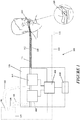
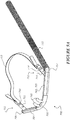
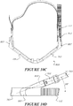
- FIG. 1 shows a respiratory therapy system 100.
- the respiratory therapy system 100 comprises a flow generator 102.
- the flow generator 102 is configured to generate gas flows that are passed through the respiratory therapy system 100.
- the flow generator 102 passes the air to a humidifier 104.
- the humidifier 104 is configured to heat and humidify gas flows generated by the flow generator 102.
- the flow generator 102 comprises a blower adapted to receive gases from the environment outside of the respiratory therapy system 100 and propel them through the respiratory therapy system 100.
- the flow generator 102 may comprise some other gas generation means.
- the flow generator 102 may comprise a source available from a hospital gas outlet (e.g.
- 'High flow' or 'high flow therapy' may refer to the delivery of gases to a patient at a flow rate of between about 5 or 10 L/min and about 100 L/min, or between about 15 L/min and about 95 L/min, or between about 20 L/min and about 90 L/min, or between about 25 L/min and about 85 L/min, or between about 30 L/min and about 80 L/min, or between about 35 L/min and about 75 L/min, or between about 40 L/min and about 70 L/min, or between about 45 L/min and about 65 L/min, or between about 50 L/min and about 60 L/min.
- the gases being supplied or delivered to the user or patient may be delivered to different parts of the user's or a patient's airway.
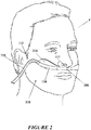
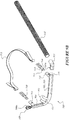
- the flow manifold 206 receives flow from one lateral side of the flow manifold 206 (e.g. with respect to an imaginary vertical plane bisecting the face of the patient P) and channels flow to the manifold and each of the nasal prongs 208.
- a conduit may extend from the left hand side or from the right hand side of the manifold. In some situations providing the conduit on the left hand side of the patient interface may be preferred for access for a clinician, for example for intubation. Alternatively, a conduit extending from the right hand side may be preferred, for example in procedures such as endoscopies where the patient is typically lying on his or her left hand side.
- the patient interface 200 may comprise greater (for example, three or four) or fewer (for example, one) nasal delivery element 208.
- each nasal delivery elements 208 can have different properties. For example, one of a pair of nasal delivery elements 208 can be relatively long and the other nasal delivery element 208 can be relatively short.
- the flow manifold 206 may be configured to receive flow from two lateral sides of the flow manifold 206 (e.g. from a 'left' and 'right' of the flow manifold 206 instead of just the patient's right hand side of the flow manifold 206 as seen in Figure 2 ).
- multiple gas conduits may be used to provide for pneumatic communication between the flow manifold 206 and the respiratory therapy system 100.
- the patient interface may comprise dual conduits, the first gas conduit 203 extending from a first side of the interface (in the illustrated example the right hand side of the patient) and a second gas conduit extending from a second opposite side of the interface.
- the flow manifold 206 may be configured to receive flow from a non-lateral side of the flow manifold 206 (e.g. from a 'bottom' or 'top' of the flow manifold 206).
- a system may find benefit in the selective delivery of separate therapies to a patient using different patient interfaces, and/or in stopping or ceasing the delivery of a therapy from an interface and/or allowing gases provided by an interface to be sampled.
- the system and devices as described find particular application in emergency resuscitation, around intubation of a patient receiving high flow therapy, ear, nose, and throat (ENT) surgery, in assisting with conditioning of a patient in a pre-operative state prior to administration of anaesthetics, and during post-extubation and recovery.
- Anaesthesiologists also use a mask with a bag to oxygenate a patient, and in some instances find it more beneficial to use a bag mask if a patient's vital signs begin to drop for example to deliver more pressure or have greater control over the variation in delivered pressure.
- a medical professional may wish to switch between different respiratory systems or support modes.
- first mode respiratory support may be provided by first respiratory support system (for example via the patient interface 200) and in a second mode respiratory support may be provided by a second respiratory support system (for example via the patient interface 300), with the support from the first system switched off.
- first respiratory support system for example via the patient interface 200
- a second mode respiratory support may be provided by a second respiratory support system (for example via the patient interface 300), with the support from the first system switched off.
- the additional flow from a high flow provided by nasal interface 200 may also modify the expected behaviour of the anaesthetic circuit provided by the face mask 300, and therefore it may be advantageous to be able to turn the additional flow from the first respiratory system off.
- the seal of the face mask acting on the first portion of the gas conduit causes the first portion to form a seal or at least a partial seal between the nasal outlets of the first patient interface 200 and the flow generator 102. Additionally, the seal of the face mask forms a seal or at least a partial seal over the first portion of the gas conduit.
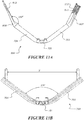
- Figures 6a and 6b illustrate a lateral cross section of a collapsible portion of a conduit 500, which may be integrally formed with and as part of a patient interface, for example a high flow cannula.
- Figure 6a shows the conduit 500 in a first or open configuration
- Figure 6b shows the same conduit 500 cross section in a second or collapsed/closed configuration.
- gases may flow along the conduit and in the closed configuration the collapsible portion is substantially sealed/occluded so that gases flow along the conduit substantially ceases.
- the outward curvature or curvature of the arcuate portions 531, 532 has a radius that is sufficiently large to prevent or reduce the occurrence of creases in the conduit or gaps between the first and second sides when in the collapsed configuration.
- the outward curvature or curvature of the arcuate portions 531, 532 may help to maintain the cross-section in the open configuration when no external force is applied.
- the outward curvature or curvature of the arcuate portions 531, 532 may help to reduce the resistance to flow of the cross-section by increasing the cross-sectional area and reducing the sharpness of internal corners.
- the first side adjacent each fold point is at an angle to the flat portion 510 such that an external angle (alpha) between the first side adjacent the fold point and the flat portion 510 is less than 80 degrees, or less than 75 degrees, or less than 70 degrees, or less than 65 degrees, or less than 60 degrees, or less than 55 degrees, or less than 50 degrees, or less than 45 degrees, or less than 40 degrees, or less than 35 degrees, or less than 30 degrees, or is between 50 and 70 degrees, or is between 60 and 70 degrees, or may be about 65 degrees.
- the angle is illustrated as being 62.6degrees in Figure 6a .
- the cross section is shaped so that the fold points 621, 622 are spaced away from the user's face in an open configuration.
- the first and second sides 611, 612 are curved outwardly when in the open configuration, so that the lateral cross section is substantially oval or elliptical; but in contrast to a true oval or elliptical shape which have rounded ends on a major axis of the oval or ellipse, in the lateral cross sections of Figures 7a to 7c the first and second sides converge to a point at each fold point of the cross section.
- the fold points When in the open configuration the fold points are spaced from the user's face and in the closed configuration the fold points are moved to be against or adjacent to the user's face.
- Figures 8a and 8b illustrate further alternative cross sections for a collapsible conduit portion, not according to the claimed invention.
- the cross section may be substantially a rhombus or parallelogram shape.
- the shape of the illustrated cross sections is substantially parallelogram shaped, however, one skilled in the art will understand features of the parallelogram shaped cross sections described below may be applied in a rhombus shaped cross section, unless the context suggests otherwise.
- the four corners of the parallelogram shaped cross section provide fold points 421 to 424. In an open configuration the four sides of the parallelogram are spaced apart, and in a closed configuration the cross section folds at the corners 421, 422, 423, 424 so that adjacent sides of the parallelogram come together into contact. In the closed configuration the corners 421 and 422 comprising acute internal angles are located at edges of the collapsed cross section.
- the cross section is arranged so that a long side of the parallelogram is located against a user's face in use. Having a long side positioned against a user's face may assist to ensure the conduit is correct situated to be collapsed by the seal of a mask pressing over the conduit. Having the long side resting against face also reduces the profile of the collapsible portion of the conduit on the user's face and provides a cleaner more aesthetically pleasing, less intrusive look.
- the cross section may be configured such that a short side of the parallelogram rests against the user's face. This may be particularly useful for use with infants, as an infant or juvenile provides limited facial area to support the conduit.
- the tail portion tapers from a height of approximately the thickness of the side of the cross section that contacts the user's face to a reduced height, for example 0.5mm or less, or may taper to a point.
- the height of the tail portion (where the tail portion connects to a side of the cross section, for example side 412(ii)) may be about 1mm to 3mm, or about 1mm to 2mm, or 1mm to 1.5mm, or about 1.2mm. In some configurations the height of the tail portion may be similar to the thickness of the side of the cross section that contacts the user's face.
- the thickness of side 412 is greatest at the obtuse angled corner.
- the resulting collapsed profile should taper in thickness from a maximum thickness at or adjacent to the flattened obtuse angled corner 424 towards the folded acute angled corners at the edges of the collapsed section.
- the thickness of the side 412 tapers to be greater at the obtuse corner 424.
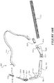
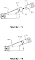
- each of the side members may be a conduit, and a plug or cap 708 may be provided to a distal end of one side member and a conduit connector 707 may be provided to the distal end of the other side member, so that the cannula is configured as a single inlet cannula for use with a single patient conduit 112.
- the cannula may be configured to a dual inlet cannula by replacing the plug 708 with another connector to connect a second patient conduit.
- the cannula may be configured to a single inlet cannula with a patient conduit attached to the distal end of either the left side member or the right side member, and a plug attached to the distal end of the other one of the left and right side members.
- a headgear connector 712 is provided to each side member 703, 704.
- the headgear connector comprises a first part 710 and a second part 711 that releasably mate together.
- the female part 711 of the connector 712 may be formed of a resilient or flexible/compliant material, and the male part 710 may be formed from a relatively rigid material.
- one of the connector parts may be attached to a side member of the cannula, and the other one of the connector parts attached to a headgear strap.
- the tines configuration of the female connector therefore achieves a connector that is secure in an axial direction on which forces in the headgear strap are aligned, yet allows for a relatively easy or reduced disconnection force by relative rotation between the male and female parts 810, 811. Relative rotation of the male and female parts does not occur in normal operation, other than when rotated by a person wishing to disconnect the headgear from the interface, and thus the described arrangement prevents or reduces accidental detachment.
- This configuration therefore allows for easily release of the cannula from the headgear which may assist in reducing the difficulty in removing the cannula from a user's face.
- the female half 811 may be disengaged from the male half by a user singlehandedly, by simply twisting the female part relative to the male part.
- the apertures and projections may be circular, with another feature such as complementary ramps or cam surfaces on the male and female parts arranged so that relative rotation between the parts cases the tines to spread apart to disengage each projection from the corresponding aperture.
- the cannula is arranged so that the headgear strap extends from the side members at an angle to the side members when the cannula is viewed from a side of the cannula.
- the angle may be 10 to 30degrees, or 15 to 25 degrees, or about 20degrees.
- the headgear strap 713 is shown to extend from the side members of the cannula at an angle of about 20 degrees.
- the headgear connector is preferably oriented at the desired angle.
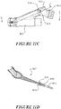
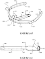
- each arm comprises a first portion 942 slidingly received in a second portion 943, relative movement between the first and second portions achieving a variable length.
- the arms may include a telescoping configuration with a ratchet assembly.
- the ratchet assembly may include a locking mechanism adapted to lock the telescoping arms one or more predetermined positions.
- the locking mechanism may comprise a moveable latch movably secured to one part 942, 943 of an arm to movably engage a series of grooves or apertures in another part 943, 942 of the arm.
- the patient interface is a nasal cannula.
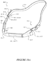
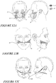
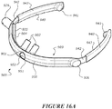
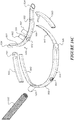
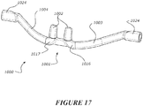
- Figure 17 illustrates a further embodiment of a cannula 1000 with a left hand gases inlet 1024 and a right hand gases inlet 1024.
- the cannula comprises a manifold 1001 and a pair of nasal prongs 1002 or outlets extending from the manifold, and a side member 1003, 1004 extending from each side of the manifold 1001.
- the term 'manifold' as used in this specification and claims is intended to broadly mean, unless the context suggests otherwise, a member comprising at least two separate lumens, or a member comprising a single lumen with at least two inlets or at least two outlets.
- each side member 1003, 1004 is configured to be collapsible, and is independently collapsible of the other. In normal use, if one member 1003, 1004 was to be collapsed or its lumen inadvertently obstructed, the other side member 1003, 1004 would continue to provide a flow of gases to the user via the associated nasal prong or outlet 1002.
- the cannula 1000 is preferably formed in a single integrally formed body of flexible material.
- the cannula may comprise a rigid frame or shield, for example frame 801 as described above with reference to the embodiment of Figure 15 , or frame 950 described with reference to Figures 16A to 16E .
- the manifold includes a gases pathway that allows fluid communication between the lumens of the left and right side members 1003, 1004.
- the gases pathway in the manifold also allows fluid or gases communication between the lumen of the left side member 1003 and the right hand prong 1002 and the lumen of the right side member 1004 and the left hand prong 1002.
- gases can be received by both prongs from either of the left and right inlets 1024 in case one prong is unexpectedly occluded.
- Such an arrangement may be advantageous because the inspiratory demand can be met and a sufficient flow rate be provided to an apnoeic patient to ensure there is enough O2 delivered and flushing of CO2 occurs.
- the cannula 1100 further comprises a mechanism to collapse the collapsible portion of the conduit.
- the mechanism is a rigid component (rigid relative to the collapsible conduit portion) attached to an outside of the cannula to move from a first configuration in which the collapsible portion is in the open configuration to a second configuration in which the component presses against an outside of the collapsible portion to pinch or flatten the collapsible portion into the closed configuration.
Landscapes
- Health & Medical Sciences (AREA)
- Pulmonology (AREA)
- Anesthesiology (AREA)
- Emergency Medicine (AREA)
- Life Sciences & Earth Sciences (AREA)
- Public Health (AREA)
- Heart & Thoracic Surgery (AREA)
- Hematology (AREA)
- Engineering & Computer Science (AREA)
- Animal Behavior & Ethology (AREA)
- General Health & Medical Sciences (AREA)
- Biomedical Technology (AREA)
- Veterinary Medicine (AREA)
- Otolaryngology (AREA)
- Respiratory Apparatuses And Protective Means (AREA)
- Infusion, Injection, And Reservoir Apparatuses (AREA)
- Prostheses (AREA)
- Media Introduction/Drainage Providing Device (AREA)
- External Artificial Organs (AREA)
Description
- This disclosure relates to various patient interfaces and particularly to patient interfaces for use with a high flow system. The patient interfaces include deliberately collapsible features to facilitate the stopping of gas flow through the patient interface and/or allow a face mask to be used over the patient interface while positioned on a user's face. The disclosure also relates to headgear connectors, and to breathing conduits with a collapsible portion.
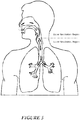
- Patients may lose respiratory function during anaesthesia, or sedation, or more generally during certain medical procedures. Prior to a medical procedure a patient may be pre-oxygenated by a medical professional to provide a reservoir of oxygen saturation, and this pre-oxygenation and CO2 flushing/washout may be carried out with a high flow therapy via a nasal cannula or other patient interface.
- Once under general anaesthesia, patients must be intubated to ventilate the patient. In some cases, intubation is completed in 30 to 60 seconds, but in other cases, particularly if the patient's airway is difficult to traverse (for example, due to cancer, severe injury, obesity or spasm of the neck muscles), intubation will take significantly longer. While pre-oxygenation provides a buffer against declines in oxygen saturation, for long intubation procedures, it is necessary to interrupt the intubation process and increase the patient's oxygen saturation to adequate levels. The interruption of the intubation process may happen several times for difficult intubation processes, which is time consuming and puts the patient at severe health risk. After approximately three attempts at intubation the medical procedure, such as an intubation method will be abandoned.
- In the event that manual ventilation of the apnoeic, non-intubated, patient is urgently required (such as due to unsuccessful intubation of the patient) it is necessary to quickly remove the high flow patient interface and then apply a non-invasive ventilation mask, e.g. a face mask and bag, to the patient. A cannula may be difficult to remove quickly from the patient, for example connectors between headgear and a cannula may be difficult to release quickly or manipulate with one hand. Failure to remove the patient interface may result in the cushion of the face mask overlying the patient interface or patient interface gases supply tube, disrupting the seal between the face mask and the patient's face. Gases may consequently leak from the face mask during ventilation, rendering ventilation ineffective or inefficient.
- In this specification, where reference has been made to external sources of information, including patent specifications and other documents, this is generally for the purpose of providing a context for discussing the features of the present invention. Unless stated otherwise, reference to such sources of information is not to be construed, in any jurisdiction, as an admission that such sources of information are prior art or form part of the common general knowledge in the art.
-
US 2014/0102456 (Ovizinsky et al. ) describes an air delivery conduit including first and second conduit portions that cooperate to form the conduit, each conduit portion including an inner layer of a film laminate that forms an interior surface of the conduit and an outer layer of a textile (655) that forms an exterior surface of the conduit. -
WO 2016/157105 (FISHER & PAYKEL HEALTHCARE LIMITED) describes a respiratory system comprising a first patient interface for delivery of a first flow of gases to a patient, a second patient interface for delivery of a second flow of gases to the patient, and a device and/or sensing arrangement that is configure to facilitate a switching of the system between a first respiratory mode where the device allowing delivery of the first flow of gases to an outlet of the first patient interface when the second patient interface is absent from the patient, and a second respiratory mode where the device reducing or stopping delivery of the first flow of gases to the outlet of the first patient interface when the second patient interface is located together with the first patient interface upon the patient. - It is an object of this disclosure to provide a breathing conduit or a patient interface or a headgear connector which goes at least some way towards overcoming one or more of the above mentioned problems or difficulties, or to provide the industry/public with a useful choice.
- The present invention provides a breathing conduit according to the claims.
- In accordance with at least one of the embodiments disclosed herein, a breathing conduit for providing a flow of respiratory gases, whether formed with a patient interface or as a separate conduit, comprises a collapsible portion, a lateral cross section of the collapsible portion comprising:
- a first side comprising a flat portion for positioning against a user's face,
- a second side opposite the first side and facing away from the user's face,
- the first and second sides joined by first and second fold points, in an open configuration the first and second fold points spaced away from the flat portion of the first side in a direction away from the user's face in use,
- wherein an inner length of the first side between the fold points and an inner length of the second side between the fold points are substantially equal, and
- in a partially closed or closed configuration the second side being moved towards or against the first side with the collapsible portion folding at the first and second fold points.
- In some embodiments, the first side comprises an outwardly curved portion between the flat portion and each of the first and second fold points when in the open configuration.
- In some embodiments, the thickness of the outwardly curved portion tapers from the flat portion towards the respective fold point, from a greater thickness to a reduced thickness.
- In some embodiments, the first side is curved outwardly when in the open configuration.
- In some embodiments, the second side is curved outwardly when in the open configuration.
- In some embodiments, in the closed configuration the first and second fold points are moved to be against or adjacent the face of a user.
- In some embodiments, the thickness of the first side and/or the second side tapers towards each fold point, from a greater thickness to a reduced thickness.
- In some embodiments, a maximum thickness of the first side is at an apex of the first side and/or a maximum thickness of the second side is at an apex of the second side.
- The thickness of the first and second fold points is less than the thickness of the remainder of the lateral cross section of the collapsible portion.
- In some embodiments, the second side is thinner than the first side.
- In some embodiments, in the open configuration the first side adjacent each fold point is at an angle to the flat portion such that an external angle between the first side adjacent the fold point and the flat portion is less than 80 degrees, or less than 75 degrees, or less than 70 degrees, or less than 65 degrees, or less than 60 degrees, or less than 55 degrees, or less than 50 degrees, or less than 45 degrees, or less than 40 degrees, or less than 35 degrees, or less than 30 degrees, or is between 50 and 70 degrees, or is between 60 and 70 degrees, or about 62 to 68 degrees, or is about 64 to 66 degrees, or is about 65 degrees.
- In some embodiments, in the open configuration a line tangential to the portion of the first side adjacent to each folding point is an angle to a line extending between the first and second fold points such that an angle (beta) between the line and the portion adjacent the fold point is less than 70 degrees, or less than 65 degrees, or less than 60 degrees, or less than 55 degrees, or less than 50 degrees, or less than 45 degrees, or less than 40 degrees, or less than 35 degrees, or less than 30 degrees, or is between 30 and 60 degrees, or is between 40 and 50 degrees, or may be about 45 degrees.
- In some embodiments, the flat portion has a thickness of about 0.5mm, and the fold points have a thickness of about 0.2mm.
- In some embodiments, the flat portion has a length of about 5mm to 10mm or about 7mm, and/or
wherein a lateral width of the cross section of the collapsible portion is between 10mm and 15mm or about 13mm. - In some embodiments, the first side tapers from a thickness of 0.5mm to a thinner thickness at the fold point.
- In some embodiments, the ratio of:
- i) the thickness of the (thicker) centre of the first and/or second sides of the lateral cross section and thickness of the (thinner) first and second fold points is in the range of about 1 to 8, or about 1.5 to 3.5, or
- ii) the thickest part of the lateral cross section to the thinnest part of the lateral cross section being the fold points is in the range of about 1 to 8, or about 1.5 to 3.5
- In some embodiments, the ratio of the relative thicknesses between the (thicker) flat portion of the first side and the (thinner) fold points is in the range of about 1 to 8, or about 1.5 to 3.5.
- In some embodiments, the first and second fold points delimit or define the extent of the first and second sides, or the first and second sides each extend fully between the fold points, e.g. from the first fold point to the second fold point.
- In some embodiments, the collapsible portion has reflective symmetry about a centre line of the lateral cross section of the collapsible portion, the centre line extending through a centre of the first and second sides of the lateral cross section of the collapsible portion.
- In some embodiments, a distance between the first and second fold points is greater than a width of the flat portion.
- In some embodiments, a maximum width of the cross section is defined by a distance between the fold points.
- In some embodiments, the first and second sides are curved outwardly, the lateral cross section being substantially oval or elliptical but with the first and second sides converging to a point at each fold point.
- In some embodiments, the first side diverges outwardly either side of the flat portion towards the respective fold point.
- In some embodiments, the conduit is a conduit portion of the patient interface.
- In some embodiments, the patient interface is a nasal interface.
- In some embodiments, the patient interface is a nasal cannula.
- In some embodiments, the collapsible portion is formed from an elastomeric/resilient material, for example silicone.
- In accordance with at least one of the embodiments disclosed herein, a breathing conduit for providing a flow of respiratory gases, whether formed with a patient interface or as a separate conduit, comprises a collapsible portion, a lateral cross section of the collapsible portion comprising:
- a first side for positioning against a user's face,
- a second side opposite the first side to face away from the user's face,
- the first and second sides joined by first and second fold points,
- the conduit adapted to collapse from an open configuration to a closed configuration by folding at the fold points so that the first side and the second side are positioned in contact or adjacent each other to substantially occlude flow through the conduit when in the closed configuration.
- In some embodiments, an inner length of the first side between the fold points and an inner length of the second side between the fold points are substantially equal.
- In some embodiments, the lateral cross section has reflective symmetry about a line extending through the first and second fold points.
- In some embodiments, the lateral cross section has reflective symmetry about a centre line of the cross section, the centre line extending through a centre of the first and second sides of the cross section.
- In some embodiments, the second side is curved outwardly when in the open configuration.
- In some embodiments, the first side is curved outwardly when in the open configuration.
- In some embodiments, in the closed configuration the fold points are moved to be against or adjacent the face of a user.
- In some embodiments, the thickness of the first side and/or the second side tapers towards each fold point, from a greater thickness to a reduced thickness, the maximum thickness being at an apex of each of the first side and second side respectively.
- In some embodiments, the thickness of the fold points is less than the thickness of the remainder of the cross section of the collapsible portion.
- In some embodiments, the second side is thinner than the first side.
- In some embodiments, the ratio of:
- i) the thickness of the (thicker) centre of the first and/or second sides of the lateral cross section and the thickness of the (thinner) fold points is in the range of about 1 to 8, or about 1.5 to 3.5, or
- ii) the thickest part of the lateral cross section to the thinnest part of the lateral cross section being the fold points is in the range of about 1 to 8, or about 1.5 to 3.5.
- In some embodiments, in the open configuration a line tangential to the portion of the first side adjacent to each folding point is an angle to a line extending between the first and second fold points such that an angle (beta) between the line and the portion adjacent the fold point is less than 70 degrees, or less than 65 degrees, or less than 60 degrees, or less than 55 degrees, or less than 50 degrees, or less than 45 degrees, or less than 40 degrees, or less than 35 degrees, or less than 30 degrees, or is about 30 to 60 degrees, or about 40 to 50 degrees, or may be about 45 degrees.
- In some embodiments, the first and second fold points delimit or define the extent of the first and second sides, or the first and second sides each extend fully between the fold points, e.g. from the first fold point to the second fold point.
- In some embodiments, a maximum width of the cross section is defined by a distance between the fold points.
- In some embodiments, the first and second sides are curved outwardly, the lateral cross section being substantially oval or elliptical but with the first and second sides converging to a point at each fold point.
- In some embodiments, the conduit is a conduit portion of a patient interface.
- In some embodiments, the patient interface is a nasal interface.
- In some embodiments, the nasal interface is a nasal cannula.
- In some embodiments, the collapsible portion is formed from an elastomeric/resilient material, for example silicone.
- In accordance with at least one of the embodiments disclosed herein, a breathing conduit for providing a flow of respiratory gases, whether formed with a patient interface or as a separate conduit, comprises a collapsible portion, a lateral cross section of the collapsible portion being substantially rhombus or parallelogram shaped, the four corners of the rhombus or parallelogram shaped cross section providing fold points, in an open configuration the four sides of the rhombus or parallelogram spaced apart, and in a closed configuration the cross section folding at the corners so that adjacent sides of the rhombus or parallelogram come together into contact and with the corners comprising acute internal angles located at edges of the cross section.
- In some embodiments, the lateral cross section of the collapsible portion being substantially parallelogram shaped and adapted such that a long side of the parallelogram is located against a user's face in use.
- In some embodiments, an acute angle of the rhombus or parallelogram is less than 70 degrees, or less than 65 degrees, or less than 60 degrees, or less than 55 degrees, or less than 50 degrees, or less than 45 degrees, or less than 40 degrees, or less than 35 degrees, or less than 30 degrees, or is between 45 and 65 degrees, or is between 55 and 65 degrees, or may be about 60 degrees.
- In some embodiments, the thickness of the sides of the rhombus or parallelogram taper towards each corner (fold point) with an acute angle, from a greater thickness to a reduced thickness.
- In some embodiments, the thickness of the corners (fold points) comprising an acute angle is less than the thickness of the sides or a remainder of the cross section of the collapsible portion.
- In some embodiments, a side of the rhombus or parallelogram shaped cross section for locating against a user's face is thicker than other sides of the rhombus or parallelogram shaped cross section.
- In some embodiments, the ratio of:
- i) the relative thicknesses between the (thicker) sides of the lateral cross section and the (thinner) fold points is in the range of about 1 to 8, or about 1.5 to 3.5, or
- ii) the thickest part of the lateral cross section to the thinnest part of the lateral cross section being the fold points is in the range of about 1 to 8, or about 1.5 to 3.5.
- In some embodiments, the cross section comprises an internal notch at the corners comprising an acute angle so that the thickness at the corners comprising an acute angle is less than the thickness of the sides of the cross section.
- In some embodiments, the sides of the rhombus or parallelogram have a thickness of about 0.5mm, and wherein the corners comprising an acute angle have a thickness of about 0.2mm.
- In some embodiments, the cross section of the collapsible portion comprises a tail portion extending from one or both corners of the section comprising acute internal angles, each tail portion providing a ramp from the edge of the section onto a top of the section in the closed configuration.
- In some embodiments, a side of the rhombus or parallelogram shaped cross section for locating against a user's face is thicker than other sides of the rhombus or parallelogram shaped cross section, and
- the cross section comprises only one tail portion that extends from the corner of the cross section comprising an acute angle at the thicker side of the cross section.
- In some embodiments, the thickness of the sides of the cross section taper to be thicker at at least one corner of the cross section comprising an obtuse angle.
- In some embodiments, the thickness of the cross section provides for a tapering collapsed cross section that tapers in thickness from the edges of the cross section to a thicker section between the edges of the collapsed cross section.
- In some embodiments, the cross section has reflective symmetry on a line extending through the corners comprising an obtuse angle.
- In some embodiments, the conduit is a conduit portion of a patient interface.
- In some embodiments, the patient interface is a nasal interface.
- In some embodiments, the nasal interface is a nasal cannula.
- In some embodiments, the collapsible portion is formed from an elastomeric/resilient material, for example silicone.
- In accordance with at least one of the embodiments disclosed herein, a patient interface comprises a breathing conduit as described in any one or more of the above statements.
- In some embodiments, the interface is a nasal interface comprising a single inlet, at least one nasal outlet, and the breathing conduit extending between the single inlet and the at least one nasal outlet.
- In accordance with at least one of the embodiments disclosed herein, a connector adapted to connect a headgear to a patient interface comprises:
a first connector part (e.g. a male part) and a second connector part (e.g. a female part), the second connector part comprising a pair of spaced apart tines to receive the first part therebetween when the first and second parts are connected together. - In some embodiments, the tines each extend from a base of the second part, an end of each tine distal from the base free to deflect laterally relative to the base.
- In some embodiments, one or both of the tines comprises an aperture or a lateral projection, and the first part comprises a corresponding lateral projection or aperture, such that with the first part received between the tines the lateral projection is received in the aperture to retain the first and second parts together.
- In some embodiments, the aperture is a slot oriented with a major axis lateral to a longitudinal axis of a headgear strap to be attached to the patient interface.
- In some embodiments, each tine comprises a said aperture and the first connector comprises a said lateral projection on each lateral side of the first part.
- In some embodiments, the first and second parts are complementarily adapted to rotate relative to one another from a engaged position to disengage, the first and second parts comprising complementary features such that relative rotation between the first and second parts causes the tines to deflect and spread apart to release the second part from the first part.
- In some embodiments, the aperture and projection are complementarily adapted so that relative rotation between the first and second parts causes the projection to release from the aperture and deflect a said tine over the projection.
- In some embodiments, the lateral projection comprising a bevelled edge to deflect the tines apart when inserting the first part in between the tines of the second part in an axial direction of the connector parts.
- In some embodiments, the second connector part is releasably coupled to a headgear.
- In accordance with at least one of the embodiments disclosed herein, a connector adapted to connect a headgear to a patient interface comprises:
a first connector part (e.g. a male part) and a complementary second connector part (e.g. a female part) comprising a pair of spaced apart resilient tines to receive the first connector part therebetween, the second connector part adapted to be removably coupled to a headgear, the second connector part comprising a base, each tine extending from the base, and an end of each tine distal from the base free to deflect laterally relative to the base so that the tines deflect laterally apart to release the first connector part from the second connector part. - In some embodiments, the first and second connector parts are adapted to be connected together by moving the second connector part axially towards the first connector part, and
the connector parts adapted to be disconnected by relative rotation about a lateral projection on one of the first and second parts received in an aperture on the other one of the first and second parts. - In accordance with at least one of the embodiments disclosed herein, a patient interface comprises:
- a manifold and at least one nasal prong or an outlet extending from the manifold to be received by a user's nare or mouth,
- a side member extending from each side of the manifold, each side member comprising a collapsible portion comprising a lumen, in an open configuration the lumen remaining open and the collapsible portion adapted to be pinched or flattened to a closed configuration (e.g. by an external force) to occlude or substantially occlude the lumen, and wherein at least one of the side members is a conduit for a flow of gases from an inlet of the patient interface to the manifold.
- In some embodiments, the patient interface comprises a plug and a conduit connector, the plug adapted to fit to an end of one or both side members, and the conduit connector adapted to fit to an end of the other one or both side members.
- In some embodiments, each side member is formed as a conduit, and the patient interface comprises a plug and a conduit connector, the plug and conduit connector both adapted to fit to an inlet end of both side members, so that the patient interface is configurable to a dual inlet patient interface or a left or right sided single patient interface.
- In some embodiments, the patient interface comprises a wall near to and on an inlet side of a said nasal prong or outlet, to separate the lumen of one side member from the manifold and the other side member, such that only one of the side members acts as a conduit to provide a flow of gases from an inlet of the patient interface to the manifold.
- In some embodiments, the lumen of the side member that is separate from the manifold comprises a relief hole so that the lumen of the side arm separate from the manifold is in communication with the atmosphere.
- In some embodiments, the wall is curved or shaped to direct a flow from the manifold to the at least one nasal prong or outlet and/or to reduce resistance to flow.
- In some embodiments, the side members, manifold and the at least one nasal prong or outlet are integrally formed as a unitary member.
- In some embodiments, the side members are formed from a relatively soft or compliant material and the plug and/or conduit connector is formed from a relatively rigid or hard material.
- In some embodiments, the patient interface comprises a removable shield to configure the patient interface for use without collapsing.
- In some embodiments, the shield is adapted to fit over and cover a side member, or both side members and the manifold.
- In some embodiments, the shield comprises one or more pair of jaws, each pair of jaws configured to grab around a portion of the patient interface to hold the shield to the patient interface.
- In some embodiments, the patient interface is a nasal cannula comprising the manifold and at least one said nasal prong or a nasal outlet extending from the manifold to be received by a user's nare.
- In some embodiments, a part of a headgear connector is integrally formed with each side member.
- In some embodiments, when dependent on claim 13, wherein a part of a headgear connector is integrally formed with the conduit connector and/or a part of a headgear connector is integrally formed with the plug.
- In some embodiments, the cannula comprises a pair of headgear connector parts (e.g. a pair of male parts or a pair of female parts), each part adapted to connect to a corresponding headgear connector part to attach a headgear to the cannula, and wherein each headgear connector part is arranged at an angle to the side members in a side view of the cannula, so that in use the cannula is positioned horizontally on the user's face and with a headgear extending above the user's ears.
- In some embodiments, the angle is 10 to 30degrees, or 15 to 25 degrees, or about 20degrees.
- In some embodiments, in plan view the cannula comprises an obtuse angle between the side members when in a neutral or unbent configuration.
- In some embodiments, the obtuse angle in the range of 100 to 130 degrees, or about 100 to 120 degrees, or about 100 to 110 degrees, or about 105 degrees (e.g. 106 degrees).
- In some embodiments, the side members are substantially straight in a neutral or unbent configuration, and the manifold is curved to provide the obtuse angle between the side members.
- In some embodiments, the cannula comprises a pair of headgear connector parts (e.g. a pair of male parts or a pair of female parts), each part adapted to connect to a corresponding headgear connector part to attach a headgear to the cannula, and wherein each headgear connector part is arranged at an angle to the side members in a plan view of the cannula, wherein the angle is in the range of 130 degrees to 170 degrees, or 140 degrees to 160 degrees, or 145 degrees to 155 degrees.
- In some embodiments, the cannula comprises a pair of headgear connector parts (e.g. a pair of male parts or a pair of female parts), each part adapted to connect to a corresponding headgear connector part to attach a headgear to the cannula, and wherein a distance between distal ends of the side arms, or between the pair of headgear connector parts is about 100mm to 150mm, or about 110mm to 140mm, or about 110mm to 130mm or about 120mm.
- In accordance with at least one of the embodiments disclosed herein, a nasal cannula comprises:
- a manifold and at least one nasal prong or outlet extending from the manifold to be received by a user's nare, and a side member extending from each side of the manifold, and
- wherein in plan view the cannula comprises an obtuse angle between the side members when in a neutral or unbent configuration.
- In some embodiments, the obtuse angle in the range of 100 to 130 degrees, or about 100 to 120 degrees, or about 100 to 110 degrees, or about 105 degrees (e.g. 106 degrees).
- In some embodiments, the side members are substantially straight in a neutral or unbent configuration, and the manifold is curved to provide the obtuse angle between the side members.
- In some embodiments, the cannula comprises a pair of headgear connector parts (e.g. a pair of male parts or a pair of female parts), each part adapted to connect to a corresponding headgear connector part to attach a headgear to the cannula, and wherein each headgear connector part is arranged at an angle to the side members in a plan view of the cannula, wherein the angle is in the range of 130 degrees to 170 degrees, or 140 degrees to 160 degrees, or 145 degrees to 155 degrees.
- In some embodiments, the cannula comprises a pair of headgear connector parts (e.g. a pair of male parts or a pair of female parts), each part adapted to connect to a corresponding headgear connector part to attach a headgear to the cannula, and wherein each headgear connector part is arranged at an angle to the side members in a side view of the cannula, so that in use the cannula is positioned horizontally on the user's face and with a headgear extending above the user's ears.
- In some embodiments, the angle is 10 to 30degrees, or 15 to 25 degrees, or about 20degrees.
- In some embodiments, the nasal cannula comprises a wall near to and on an inlet side of a said nasal prong or outlet, to separate the lumen of one side member from the manifold and the other side member, such that only one of the side members acts as a conduit to provide a flow of gases from an inlet of the cannula to the manifold.
- In some embodiments, the lumen of the side member that is separate from the manifold comprises a relief hole so that the lumen of the side arm separate from the manifold is in communication with the atmosphere.
- In accordance with at least one of the embodiments disclosed herein, a conduit for a respiratory support system comprises:
- a collapsible portion, in an open configuration the collapsible portion remaining open and in a closed configuration the collapsible portion being pinched or flattened to occlude or substantially occlude the conduit, and
- a relatively rigid component adapted to move from a first configuration in which the collapsible portion is in the open configuration to a second configuration in which the component presses against an outside of the collapsible portion to pinch or flatten the collapsible portion into the closed configuration.
- In some embodiments, the component comprises a shield attached to the outside of the collapsible portion, the shield adapted to distribute an external force applied to the shield to a predetermined collapsible area of the collapsible portion.
- In some embodiments, the component comprises a lever adapted to pivot from the first configuration to the second configuration.
- In some embodiments, the conduit comprises the collapsible portion and a non-collapsible portion and the lever is pivotally attached to the non-collapsible potion of the conduit.
- In some embodiments, the conduit comprises a vent aperture upstream of the collapsible portion and wherein the lever comprises a first arm extending from a first side of a pivot and a second arm extending from an opposite second side of the pivot, and
in the first configuration the lever is pivoted about the pivot so that the first arm does not pinch or flatten the collapsible portion and the second arm substantially occludes the vent aperture, and in the second configuration the lever is pivoted about the pivot so that the first arm pinches or flattens the collapsible portion and the second arm lifts away from the vent aperture to allow gases in the conduit upstream of the collapsible portion to vent to atmosphere. - In some embodiments, the vent aperture is in the non-collapsible portion of the conduit.
- In some embodiments, the lever comprises a projection or rim to press against the collapsible portion in the second configuration.
- In accordance with at least one of the embodiments disclosed herein a patient interface comprises:
- an interface portion for interfacing with a user's nasal or oral airway, and
- a conduit as described in any one or more of the preceding statements, the conduit extending from the interface portion, and
- the relatively rigid component attached to the conduit or interface portion to move from the first configuration to the second configuration.
- In some embodiments, the component comprises a lever pivotally attached to the conduit or interface portion to pivot from the first configuration to the second configuration.
- In some embodiments, the conduit comprises the collapsible portion and a non-collapsible portion and the lever is pivotally attached to the non-collapsible potion of the conduit, and wherein the collapsible portion is located between the interface portion and the non-collapsible portion of the conduit.
- In some embodiments, the patient interface is a nasal cannula and the interface portion comprises a manifold and at least one nasal prong or outlet extending from the manifold.
- In some embodiments, the patient interface is an oral interface to be received in a user's mouth.
- In accordance with at least one of the embodiments disclosed herein a patient interface comprises:
- a body comprising:
- a manifold and at least one nasal prong or an outlet extending from the manifold, and
- a left hand side member extending from a left side of the manifold and a right hand side member extending from a right side of the manifold, each side member comprising an inlet portion and a lumen to provide a conduit for a flow of gases from the inlet portion to the manifold, and
- a frame comprising a tube connector and a blanked hollow projection, the tube connector and the blanked hollow projection adapted to receive a said inlet portion of the body with the frame attached to the body, the frame movably attached to the body to selectively configure the patient interface between a left hand inlet configuration and a right hand inlet configuration,
- in the left hand inlet configuration the inlet portion of the left hand side member received in the tube connector and the inlet portion of the right hand side member received in the blanked hollow projection, and
- in the right hand inlet configuration the inlet portion of the right hand side member received in the tube connector and the inlet portion of the left hand side member received in the blanked hollow projection.
- In some embodiments, the conduit of each side member comprises a collapsible portion, in an open configuration the collapsible portion remaining open and in a closed configuration the collapsible portion being pinched or flattened to occlude or substantially occlude the conduit.
- In some embodiments, the frame is adapted to deform so that a force applied to the front of the frame elastically bends the frame to collapse the conduit of a said member to the closed configuration.
- In some embodiments, the frame is rotationally attached to the body rotate the frame relative to the body to selectively configure the cannula between the left hand inlet configuration and the right hand inlet configuration.
- In some embodiments, the frame comprises a concave interior to receive a correspondingly shaped convex shape of the body.
- In some embodiments, the patient interface is a nasal cannula, said body being a cannula body comprising the manifold and said at least one nasal prong or a nasal outlet extending from the manifold to be received by a user's nare.
- In accordance with at least one of the embodiments disclosed herein a patient interface comprises a headgear, the headgear comprising a pair of arms, each arm comprising an ear plug, each ear plug adapted to fit within a user's ear to retain the patient interface in position on the user's face.
- In some embodiments, one or both arms is length adjustable
- In some embodiments, one or both arms is telescopic, one or both arms comprising a first portion slidingly received in a second portion, relative movement between the first and second arms adjusting the length of the arm.
- In some embodiments, one of the first and second portions of each arm is integrally formed with a frame attached to a body of the patient interface.
- In some embodiments, one of the first and second portions of the arm is more rigid than the other one of the first and second portions of the arm.
- In some embodiments, the patient interface is a nasal cannula.
- The term 'conduit' as used in this specification and claims is intended to broadly mean, unless the context suggests otherwise, any member that forms or provides a lumen for directing a flow of gases. For example a conduit or conduit portion may be part of a patient interface or may be a separate conduit attachable to a patient interface to provide a flow of gases to the patient interface
- The phrase 'lateral cross section' of a conduit means a cross section transverse to the flow path of the conduit, e.g. perpendicular to a flow path or longitudinal axis of the conduit. As a further example, the lateral cross section may be viewed from an end of the conduit.
- Unless the context suggests otherwise, the thickness of a side or a portion of a lateral cross section of a conduit is the lateral wall thickness of the side or portion of the cross section. For example, the thickness at a point (i.e. a fold point) on the cross section is the smallest distance across the wall of the cross section from an outer surface to an inner surface of the wall at that point. For example, in
Figure 6A , the thickness of afold point 522 is the distance from the outside surface to the inside surface at thefold point 522, for example along a line extending through a centre of the cross section, or a line extending across the cross section extending through both fold points 522 of the cross section. - The term "comprising" as used in this specification and claims means "consisting at least in part of". When interpreting each statement in this specification and claims that includes the term "comprising", features other than that or those prefaced by the term may also be present. Related terms such as "comprise" and "comprises" are to be interpreted in the same manner.
- It is intended that reference to a range of numbers disclosed herein (for example, 1 to 10) also incorporates reference to all rational numbers within that range (for example, 1, 1.1, 2, 3, 3.9, 4, 5, 6, 6.5, 7, 8, 9 and 10) and also any range of rational numbers within that range (for example, 2 to 8, 1.5 to 5.5 and 3.1 to 4.7) and, therefore, all sub-ranges of all ranges expressly disclosed herein are hereby expressly disclosed. These are only examples of what is specifically intended and all possible combinations of numerical values between the lowest value and the highest value enumerated are to be considered to be expressly stated in this application in a similar manner.
- As used herein the term "and/or" means "and" or "or", or both.
- As used herein "(s)" following a noun means the plural and/or singular forms of the noun.
- To those skilled in the art to which the invention relates, many changes in construction and widely differing embodiments and applications of the invention will suggest themselves without departing from the scope of the invention as defined in the appended claims. The disclosures and the descriptions herein are purely illustrative and are not intended to be in any sense limiting.
- The disclosure consists in the foregoing and also envisages constructions of which the following gives examples only.
- Preferred embodiments of the disclosure will be described by way of example only and with reference to the following drawings.
-
Figure 1 shows a respiratory therapy system. -
Figure 2 shows a patient wearing a patient interface. -
Figure 3 shows a patient wearing a patient interface (a first patient interface) and a face mask (a second patient interface). -
Figure 4 shows a cross-section of a portion of a patient interface or conduit. -
Figure 5 shows a typical airway of a patient. -
Figures 6A and 6B show a lateral (across the flow path of the conduit) cross section of a collapsible portion of a conduit.Figure 6a shows the conduit in a first or open configuration, andFigure 6b shows the conduit in a second or closed configuration. -
Figures 7A to 7C show alternative lateral cross sections for a collapsible conduit portion. -
Figures 8A and 8B show alternative lateral cross sections for a collapsible conduit portion, not according to the claimed invention. -
Figure 8C illustrates a possible collapsed profile for the cross section ofFigure 8a . -
Figure 8D illustrates a possible collapsed profile for the cross section ofFigure 8b . -
Figures 9A to 9H show a nasal cannula.Figure 9A is a perspective view,Figure 9B is an exploded perspective view,Figure 9C is a top (plan) view,Figure 9D is a front view,Figure 9E is a side view,Figures 9F to 9H are 'transparent top, front and side views respectively. -
Figures 10A to 10D show a nasal cannula.Figure 10A is a perspective view,Figure 10B is an exploded perspective view,Figure 10C is a top (plan) view,Figure 10D is a side view on a connector of the cannula. -
Figures 11A to 11D illustrate parts of a headgear connector engaging and disengaging.Figure 11A shows the connector parts separated,Figure 11B shows the connector parts connected together,Figure 11C shows the parts rotated relative to one another to disengage, andFigure 11D is a cross section on line I-I inFigure 11C . -
Figures 12A and 12B illustrate soft portions of a user's face, andFigure 12C illustrates a cannula positioned across a soft portion of a user's face. -
Figures 13A and 13B illustrate geometries of two embodiments of a cannula. -
Figures 14A to 14B illustrate a cannula with alternative headgear. -
Figure 15 is a perspective view of a cannula and a shield configured to attach to the cannula to support the cannula against collapse. -
Figures 16A to 16E show a nasal cannula.Figure 16A is a perspective view,Figure 16B is a front view,Figure 16C is an exploded view,Figure 16D is a perspective view showing a compliant cannula body rotated relative to a relatively rigid cannula member, andFigure 16E is a cross section on line I-I infigure 16B . -
Figure 17 is a perspective view of a nasal cannula. -
Figures 18A to 18D show a nasal cannula.Figure 18A is a front perspective view,Figure 18B is a rear perspective view,Figure 18C is a cross sectional view showing an actuating lever in an open position to allow a flow of gases to flow from nasal prongs of the cannula, andFigure 18D is a cross sectional view showing an actuating lever in a closed position to block a flow of gases flowing from nasal prongs of the cannula. -
Figure 19 is an exploded view of an oral interface. - Various embodiments are described with reference to the Figures. Throughout the Figures and specification, the same reference numerals may be used to designate the same or similar components, and redundant descriptions thereof may be omitted.
-
Figure 1 shows arespiratory therapy system 100. Therespiratory therapy system 100 comprises a flow generator 102. The flow generator 102 is configured to generate gas flows that are passed through therespiratory therapy system 100. The flow generator 102 passes the air to ahumidifier 104. Thehumidifier 104 is configured to heat and humidify gas flows generated by the flow generator 102. In some configurations, the flow generator 102 comprises a blower adapted to receive gases from the environment outside of therespiratory therapy system 100 and propel them through therespiratory therapy system 100. In some configurations, the flow generator 102 may comprise some other gas generation means. For example, in some configurations, the flow generator 102 may comprise a source available from a hospital gas outlet (e.g. oxygen or air), or one or more containers of compressed air and/or another gas and one or more valve arrangements adapted to control the rate at which gases leave the one or more containers. As another example, in some configurations, the flow generator 102 may comprise an oxygen concentrator. In some configurations, the flow generator 102 may be adapted to deliver a high flow therapy. - According to various configurations and embodiments described herein, a flowrate of gases supplied or provided to an interface or via a system, such as through a flowpath, may comprise, but is not limited to, flows of at least about 5, 10, 20, 30, 40, 50, 60, 70, 80, 90, 100, 110, 120, 130, 140, 150 L/min, or more, and useful ranges may be selected between any of these values (for example, about 40 to about 80, about 50 to about 80, about 60 to about 80, about 70 to about 100 L/min, about 70 to 80 L/min). Flowrates above about 15 L/min in some embodiments may be used in such configurations or embodiments, in particular but not limited to flowrates of about 60-70 L/min. 'High flow' or 'high flow therapy' may refer to the delivery of gases to a patient at a flow rate of between about 5 or 10 L/min and about 100 L/min, or between about 15 L/min and about 95 L/min, or between about 20 L/min and about 90 L/min, or between about 25 L/min and about 85 L/min, or between about 30 L/min and about 80 L/min, or between about 35 L/min and about 75 L/min, or between about 40 L/min and about 70 L/min, or between about 45 L/min and about 65 L/min, or between about 50 L/min and about 60 L/min.
- Gases delivered may comprise a percentage of oxygen. In some configurations, the percentage of oxygen in the gases delivered may be between about 20% and about 100%, or between about 30% and about 100%, or between about 40% and about 100%, or between about 50% and about 100%, or between about 60% and about 100%, or between about 70% and about 100%, or between about 80% and about 100%, or between about 90% and about 100%, or about 100%, or 100%.
- High flow therapy has been found effective in meeting or exceeding the patient's normal peak inspiratory demand, to increase oxygenation of the patient and/or reduce the work of breathing. Additionally, high flow therapy may generate a flushing effect in the nasopharynx such that the anatomical dead space of the upper airways is flushed by the high incoming gas flows. This creates a reservoir of fresh gas available of each and every breath, while minimising re-breathing of carbon dioxide, nitrogen, etc.
- As relatively high gas delivery flow rates may be used with the embodiments or configurations described herein, the gases being supplied or delivered to the user or patient may be delivered to different parts of the user's or a patient's airway.
- Such relatively high flow rates of gases may assist in providing the supplied gases into a user's airway, or to different parts of a user's airway, for example such flow rates may allow for a delivery of such gases to the upper or lower airway regions. Upper airway region typically includes the nasal cavity, pharynx and larynx, while the lower airway region typically includes the trachea, primary bronchi and lungs.
-
Figure 5 shows a typical airway of a person, and includes arrows to indicate how a relatively high flow rate of gases supplied to a user may be utilised to effectively push or drive the supplied gases further or deeper into a user's airway than when the person is under normal or typical self-driven respiratory conditions, or when a patient has a diminished respiratory drive. - The
respiratory therapy system 100 comprises ahousing 106 that at least partially houses both the flow generator 102 and the humidifier 104 (e.g. therespiratory therapy system 100 may comprise an integrated flow generator/humidifier apparatus). In other configurations the flow generator 102 andhumidifier 104 may have separate housings. Ahardware controller 108 is shown to be in electronic communication with the flow generator 102 and thehumidifier 104, although in some configurations thehardware controller 108 might only communicate with the flow generator 102 or thehumidifier 104. Thehardware controller 108 may comprise a microcontroller or some other architecture configured to direct the operation of controllable components of therespiratory therapy system 100, including but not limited to the flow generator 102 and/or thehumidifier 104. An input/output module 110 is shown to be in electronic communication with thecontroller 108. The input/output module 110 may be configured to allow a user to interface with thecontroller 108 to facilitate the control of controllable components of therespiratory therapy system 100, including but not limited to the flow generator 102 and/or thehumidifier 104, and/or view data regarding the operation of therespiratory therapy system 100 and/or its components. The input/output module 110 might comprise, for example, one or more buttons, knobs, dials, switches, levers, touch screens, speakers, displays and/or other input or output peripherals that a user might use to view data and/or input commands to control components of therespiratory therapy system 100. - As further shown in
Figure 1 , asupplementary gas source 124 may be used to add one or more supplementary gases to the gases flowing through therespiratory therapy system 100. The one or more supplementary gases join the gas flow generated by the flow generator 102. Thesupplementary gas source 124 may be configured to deliver one or more supplementary gases including but not limited to air, oxygen (O2), carbon dioxide (CO2), nitrogen (N2), nitrous oxide (NO), and/or heliox (a mixture of helium and oxygen). Thesupplementary gas source 124 may deliver the one or more supplementary gases via a firstsupplementary gas conduit 128 to a location upstream of the flow generator 102, and/or may deliver the one or more supplementary gases via a secondsupplementary gas conduit 132 to a location downstream of the flow generator 102 and/or upstream of thehumidifier 104. One or moresupplementary flow valves supplementary gas source 124 and through the first and/or secondsupplementary gas conduits supplementary flow valves controller 108, which may in turn control the operation and/or state of the one or more of thesupplementary flow valves supplementary gas source 124 may be configured to add one or more supplementary gases downstream of thehumidifier 104. - As shown in
Figure 1 , aconduit 112 extending from thehumidifier 104 links thehumidifier 104 to apatient interface 200. Theconduit 112 may comprise aconduit heater 114 adapted to heat gases passing through theconduit 112. In other configurations theconduit heater 114 may not be present. Thepatient interface 200 is shown to be a nasal cannula, although it should be understood that in some configurations, other patient interfaces may be suitable. For example, in some configurations, thepatient interface 200 may comprise a sealing or non-sealing interface, and may comprise a nasal mask, an oral mask, an oro-nasal mask, a full face mask, a nasal pillows mask, a nasal cannula, an endotracheal tube, tracheostomy tube, a combination of the above or some other gas conveying system. In a preferred embodiment, thepatient interface 200 is a non-sealing interface such as a nasal cannula, which allows gases to be exchanged with the environment. For example, the non-sealing cannula allows carbon dioxide to be removed and/or cleared from the patient's airways while the patient receives flow therapy from thesystem 100. Further, in some preferred embodiments, thepatient interface 200 is in the form of a nasal interface, such that the system does not interfere with other oral airway equipment and/or devices, for example, a tracheal tube in an intubation procedure. Accordingly, the patient may continue to receive flow therapy throughout the intubation procedure. In other embodiments, thepatient interface 200 is an oral interface, for example an oral interface that is received in a user's mouth. An oral interface may be preferred in situations involving medical procedures via the nose, such that the interface does not interfere with nasal airway equipment and/or devices, for example a tracheal tube used in a nasal intubation procedure. In other embodiments the interface may be suitable for both nasal and oral placement or may be adapted between a nasal and an oral configuration. An example oral interface is illustrated inFigure 19 . - As shown, in some configurations the
patient interface 200 may also comprise agas sensing module 120 adapted to measure a characteristic of gases passing through thepatient interface 200. In other configurations thegas sensing module 120 could be positioned and adapted to measure the characteristics of gases at or near other parts of therespiratory therapy system 100. Thegas sensing module 120 may comprise one or more sensors adapted to measure various characteristics of gases, including but not limited to pressure, flow rate, temperature, absolute humidity, relative humidity, enthalpy, gas composition, oxygen concentration, carbon dioxide concentration, and/or nitrogen concentration. Gas properties determined by thegas sensing module 120 may be utilized in a number of ways, including but not limited to closed loop control of parameters of the gases. For example, in some configurations flow rate data taken by agas sensing module 120 may be used to determine the instantaneous flow, which in turn may be used to determine the respiratory cycle of the patient to facilitate the delivery of flow in synchronicity with portions of the respiratory cycle. Thegas sensing module 120 may communicate with thecontroller 108 over afirst transmission line 122. In some configurations, thefirst transmission line 122 may comprise a data communication connection adapted to transmit a data signal. The data communication connection could comprise a wired data communication connection such as but not limited to a data cable, or a wireless data communication connection such as but not limited to Wi-Fi or Bluetooth. In some configurations, both power and data may be communicated over the samefirst transmission line 122. For example, thegas sensing module 120 may comprise a modulator that may allow a data signal to be 'overlaid' on top of a power signal. The data signal may be superimposed over the power signal and the combined signal may be demodulated before use by thecontroller 108. In other configurations thefirst transmission line 122 may comprise a pneumatic communication connection adapted to transmit a gas flow for analysis at a portion of therespiratory therapy system 100. - Additionally as shown a
physiological sensor module 121 may be present. Thephysiological sensor module 121 may be configured to detect various characteristics of the patient or of the health of the patient, including but not limited to heart rate, EEG signal, EKG/ECG signal, inertial sensors attached to the patient (e.g.: chest) to detect movement, blood oxygen concentration (via, for example, a pulse oximeter), blood CO2 concentration, transcutaneous CO2 (TcCO2) and/or blood glucose. Similarly, thephysiological sensor module 121 may communicate with thecontroller 108 over asecond transmission line 123. Thesecond transmission line 123 may comprise wired or wireless data communication connections similarly to thefirst transmission line 122, and power and data may be communicated similarly. Thephysiological sensor module 121 may be used, for example, to determine the blood oxygen saturation of the patient. -
Figure 2 shows a user or patient P wearing apatient interface 200, for example thepatient interface 200 of the respiratory system ofFigure 1 . The patient depicted is an adult, however, the patient may be an infant or juvenile. In the illustrated non-limiting configuration, thepatient interface 200 is a nasal cannula. Thepatient interface 200 comprises afirst gas conduit 202. Thefirst gas conduit 202 is adapted to receive gases from the respiratory therapy system 100 (for example, via theconduit 112 shown inFigure 1 ) and channel the gases to the patient P. Thefirst gas conduit 202 may comprise areinforcement element 203 adapted to strengthen and/or add rigidity to the first gas conduit to prevent deformation or collapse of thefirst gas conduit 202 arising due to the application of forces against thefirst gas conduit 202. Thereinforcement element 203 may include a number of structures, including but not limited to plastic or metallic reinforcing beads that lie in or on the wall of thefirst conduit lumen 202. - The
first gas conduit 202 is in pneumatic communication with aflow manifold 206. Theflow manifold 206 receives gases from thefirst gas conduit 202 and passes them to one or more nasal delivery elements 208 (e.g. nasal prongs). The one or morenasal delivery elements 208 extend outwardly from theflow manifold 206. The one or morenasal delivery elements 208 are adapted to be non-sealingly positioned in one or more nares of the patient P. As shown, thepatient interface 200 comprises twonasal prongs 208 adapted to be positioned one in each of the patient's nares. Eachnasal prong 208 may be shaped or angled such that it extends inwardly towards a septum of the patient's nose. Alternatively the firstpatient interface 200 may be a sealing nasal interface. - In the embodiment shown in
Figure 2 , theflow manifold 206 receives flow from one lateral side of the flow manifold 206 (e.g. with respect to an imaginary vertical plane bisecting the face of the patient P) and channels flow to the manifold and each of thenasal prongs 208. In some embodiments a conduit may extend from the left hand side or from the right hand side of the manifold. In some situations providing the conduit on the left hand side of the patient interface may be preferred for access for a clinician, for example for intubation. Alternatively, a conduit extending from the right hand side may be preferred, for example in procedures such as endoscopies where the patient is typically lying on his or her left hand side. In other configurations, thepatient interface 200 may comprise greater (for example, three or four) or fewer (for example, one)nasal delivery element 208. In other configurations, eachnasal delivery elements 208 can have different properties. For example, one of a pair ofnasal delivery elements 208 can be relatively long and the othernasal delivery element 208 can be relatively short. - In some configurations, the
flow manifold 206 may be configured to receive flow from two lateral sides of the flow manifold 206 (e.g. from a 'left' and 'right' of theflow manifold 206 instead of just the patient's right hand side of theflow manifold 206 as seen inFigure 2 ). In some such configurations, multiple gas conduits may be used to provide for pneumatic communication between theflow manifold 206 and therespiratory therapy system 100. For example, the patient interface may comprise dual conduits, thefirst gas conduit 203 extending from a first side of the interface (in the illustrated example the right hand side of the patient) and a second gas conduit extending from a second opposite side of the interface. In some configurations, theflow manifold 206 may be configured to receive flow from a non-lateral side of the flow manifold 206 (e.g. from a 'bottom' or 'top' of the flow manifold 206). - The patient interface may further comprise mounts and/or supports, e.g., cheek supports 210, for attaching and/or supporting the
gas conduit 202 or conduits on the patient's face. Alternatively or additionally, the patient interface may be held in place via one or more headstraps or headgear. - The
first gas conduit 202 of thepatient interface 200 comprises afirst portion 204 configured to transition from a first configuration in which a first level of gases is able to pass through thefirst portion 204 to a second configuration in which a second level of gases is able to pass through thefirst portion 204. -
Figure 3 shows a non-limiting exemplary embodiment of a patient P wearing thepatient interface 200 as shown inFigure 2 (a first patient interface) underneath aface mask 300 assembly (a second patient interface).Figure 3 schematically shows the face mask as a transparent structure in order to illustrate thepatient interface 200 under it. The firstpatient interface 200 may be used with a first respiratory support subsystem and the secondpatient interface 300 may be used together with a second respiratory support subsystem. - A system may find benefit in the selective delivery of separate therapies to a patient using different patient interfaces, and/or in stopping or ceasing the delivery of a therapy from an interface and/or allowing gases provided by an interface to be sampled. The system and devices as described find particular application in emergency resuscitation, around intubation of a patient receiving high flow therapy, ear, nose, and throat (ENT) surgery, in assisting with conditioning of a patient in a pre-operative state prior to administration of anaesthetics, and during post-extubation and recovery.
-
Face mask assembly 300 may be used as or with a second respiratory support subsystem and/or to deliver one or more substances other than a substance delivered by thecannula 200, for example anesthetic agents or oxygen, to the patient, or the same substance but at different flow and/or pressure levels. Alternatively, theface mask assembly 300 may be used to stop the delivery of therapy from a first respiratory support subsystem. Theface mask assembly 300 may also be adapted to measure respiratory gases, for example exhaled carbon dioxide from the patient, the measurements of which may otherwise be affected by flow from thepatient interface 200 of the first respiratory support subsystem. - Accordingly, the embodiment shown in
Figure 3 allows for the alternation between the two different respiratory support subsystems. Additionally, this configuration may allow thepatient interface 200 to be left on the patient throughout the surgical procedure and/or into recovery (whether or not the patient continues to receive flow therapy through thepatient interface 200 throughout the procedure) without interfering with other clinical practices. - In the embodiment shown,
face mask assembly 300 comprises afull face mask 302 configured to cover both the patient's nose and mouth. In other configurations, theface mask 300 may be a nasal mask which is placed over thepatient interface 200 to cover only the patient's nasal region. - As shown, the
face mask 302 comprises aseal region 304 adapted to seal against the patient's face. Theface mask assembly 300 is connected to a second gas source, for example via afilter element 350, which supplies the one or more other gases to the patient via the face mask. That is, the second gas source is preferably different from the source supplying gas (for example,supplementary gas source 124/flow generator 102) to thepatient interface 200. - In a preferred embodiment, the
face mask assembly 300 is connected to a separate gas source or a separate respiratory support device. For example, the respiratory support can be a ventilator or a CPAP or a high flow therapy device or a manual resuscitator (for example a hand held face mask with bag). Alternatively or additionally theface mask assembly 300 may be connected to a device for measuring a characteristic of respiratory gases. - Alternatively the
mask assembly 300 could be connected to an anesthetic device and anesthetic gas, or air, or oxygen, or a combination of gases, can be delivered via themask 302. - The embodiment shown in
Figure 3 allows for the delivery of gas from multiple sources via at least two different respiratory support modes, and further allows a doctor, clinician or medical professional to quickly and easily change the type of respiratory support mode. - In one particular application, a patient preparing for anaesthesia can be pre-oxygenated by delivering a high flow of oxygen or humidified gases or mixture of both via a nasal cannula. In some circumstances, anaesthesiologists managing the sedation of a patient may want to switch between delivery of gas flow from one patient interface (for example a nasal cannula 200) and delivery of gas flow from another patient interface, such as via a
face mask 300. - Anaesthesiologists also use a mask with a bag to oxygenate a patient, and in some instances find it more beneficial to use a bag mask if a patient's vital signs begin to drop for example to deliver more pressure or have greater control over the variation in delivered pressure. In some situations a medical professional may wish to switch between different respiratory systems or support modes. In first mode respiratory support may be provided by first respiratory support system (for example via the patient interface 200) and in a second mode respiratory support may be provided by a second respiratory support system (for example via the patient interface 300), with the support from the first system switched off. For example, the additional flow from a high flow provided by
nasal interface 200 may also modify the expected behaviour of the anaesthetic circuit provided by theface mask 300, and therefore it may be advantageous to be able to turn the additional flow from the first respiratory system off. - In some configurations, the switching between two respiratory support modes or subsystems may be facilitated by a structure of the
first gas conduit 202, which hasfirst portion 204 configured to transition from a first configuration in which a first level of gases is able to pass through thefirst portion 204 to a second configuration in which a second level of gases is able to pass through thefirst portion 204. - In some configurations, the
first portion 204 is configured to be more collapsible or otherwise better adapted at changing the flow of gas through the first portion 204 (therefore reducing the flow of gas through the conduit and to the patient) than other portions of theconduit 202, and/or allowing a seal of a mask to seal over the top of the conduit. In other configurations the entire conduit may be configured to be collapsible. In some configurations a vent arrangement may be provided upstream of a collapsible portion, to vent gases from the conduit upstream of the collapsible portion to atmosphere. - In some embodiments, the first configuration or first condition is a substantially open configuration and the second configuration or second condition is a substantially closed configuration. That is, the
conduit 202 is configured to be more collapsible, deformable or otherwise adapted to fully close off the flow at thefirst portion 204 than at other portions of theconduit 202. -
Figure 4 shows one example of this configuration, in which the conduit (for example theconduit 202 of thenasal cannula 200 offigure 3 ) at afirst portion 204 is substantially closed by theseal 304 offace mask 302. In such an embodiment, the first portion (i.e. the more collapsible or deformable section) of the first gas conduit should be of a length that is greater than a width of a section of a seal of the face mask that bears over the first portion of the first gas conduit. This ensures the seal of the face mask does not bear over a non-collapsible section of the first gas conduit. For example, the first portion may extend from a distance of 35mm or less from the centre of a user's nose to at least 50mm from the centre of a user's nose, the first portion having a length of at least 15mm. In some embodiments the length of the first portion may be at least 15mm, 20mm, 25mm, 30mm, 35mm, 40mm, 45mm, 50mm or greater. - The
first portion 204 may progress between the first and second configurations based on a relative level of force applied to the wall of thefirst portion 204. For example, as shown inFigure 3 , the force may be applied by theseal 304 offace mask 302. In this example,first portion 204 is configured to be positioned under theseal 304 of theface mask 302. - Alternatively, the force may be applied to
first portion 204 by other means, e.g., clamps (not shown), or alternatively a medical practitioner may compress the conduit by pressing on the conduit wall with a finger or thumb. - In some embodiments, the seal of the face mask acting on the first portion of the gas conduit causes the first portion to form a seal or at least a partial seal between the nasal outlets of the first
patient interface 200 and the flow generator 102. Additionally, the seal of the face mask forms a seal or at least a partial seal over the first portion of the gas conduit. - Switching between respiratory support therapies is therefore achieved simply by applying a mask to the patient's face so that the seal of the mask collapses (partially or completely) the first portion of the gas conduit of the
first interface 200 to 'turn off' or reduce the therapy supplied by thefirst interface 200 and also provides a seal between theface mask 300 and the external surface of thefirst portion 204 of theconduit 202 such that therapy can be provided by themask 300 with the therapy provided by the first interface shut off. The cannula with a collapsible conduit portion allows a user, e.g. an anesthetist or a nurse or a clinician to use a mask and prevent delivery of gases from multiple sources (e.g. the mask and cannula). Thefirst interface 200 is structured and functions in a manner to prevent the delivery of high flow and other respiratory therapy or anesthesia gases through a mask. In some embodiments the removal of the mask from the patient's face allows the therapy supplied by the first interface to recommence, as the conduit returns from the collapsed configuration to the open configuration. -
Figures 6a and 6b illustrate a lateral cross section of a collapsible portion of aconduit 500, which may be integrally formed with and as part of a patient interface, for example a high flow cannula.Figure 6a shows theconduit 500 in a first or open configuration, andFigure 6b shows thesame conduit 500 cross section in a second or collapsed/closed configuration. In the open configuration gases may flow along the conduit and in the closed configuration the collapsible portion is substantially sealed/occluded so that gases flow along the conduit substantially ceases. - In the embodiment of
Figure 6a , the lateral cross section of the collapsible portion of theconduit 500 comprises afirst side 511 with aflat portion 510 for positioning against a user's face. The flat portion is thought to assist with positioning the conduit on a user's face, for example assisting with holding the tube in a correct orientation on the user's face for when a mask is applied over the tube, and/or assist with the conduit moving from the open to the closed configuration. The flat portion may help the conduit to rest on the user's face and provide a stable mounting surface. Asecond side 512 of the conduit is opposite to the first side and faces away from the user's face. The first and second sides are joined by first and second fold points 521 and 522. In the open configuration the fold points are spaced away from the flat portion of the first side and therefore away from the user's face. In an alternative embodiment (not illustrated) the fold points may be coplanar with the flat section. The collapsible cross section may be such that the fold points are adjacent or rest on the face. In the configuration shown inFigure 6A the internal length of the first side and the second side being equal allows for flat folding of the collapsible portion. - In a partially closed or closed configuration the second side is moved towards or against the first side with the collapsible portion folding at the first and second fold points. In the closed configuration the fold points 521, 522 may be moved to be against or adjacent the face of a user. In order to assist with the conduit sealing closed in the closed configuration to substantially prevent a flow of gases along the conduit and/or to assist with providing a substantially flat conduit over which the mask seal may seal against, an inner length of the first side between the fold points and an inner length of the second side between the fold points are substantially equal. This configuration may assist the collapsible portion to achieve a substantially flat configuration, or a configuration in which the inner surfaces of the first and second sides of the conduit come together in contact substantially fully along their lengths (e.g. without bubbles, ripples or wrinkles), when in the closed or collapsed configuration, as shown in
Figure 6b . The first and second fold points delimit or define the extent of the first and second sides. In other words, the first and second sides each extend fully between the fold points, e.g. from the first fold point to the second fold point. For example, the length of thefirst side 511 between the fold points 521, 522 is illustrated inFigure 6A by double endedarrow 511a, and the length of thesecond side 512 between the fold points 521, 522 is illustrated inFigure 6A by double endedarrow 512a - In some embodiments, the first side may comprise an outwardly curved or
arcuate portion flat portion 510 and each of the first and second fold points 521, 522 when in the open configuration. The twocurved portions arcuate portions arcuate portions arcuate portions - In an alternative configuration, the curved or
arcuate portions - In some embodiments the thickness of the
curved portions flat portion 510 towards therespective fold point - In some configurations, the
second side 512 of the conduit is curved outwardly when in the open configuration, as shown inFigure 6a . In some configurations thesecond side 512 is a continuous curved or arcuate portion, e.g. the second side is curved outwardly from the first fold point to the second fold point. In some embodiments the curvature of the second side may be about a single radius of curvature. In some configurations, the thickness of thesecond side 512 tapers towards eachfold point - According to the invention, the thickness of the fold points 521, 522 is less than the thickness of the remainder of the cross section of the collapsible portion. The relatively thin section of the fold points allows the section to be particularly adapted to fold or bend at the fold points to transition between the open and closed configurations. The conduit preferentially bends or folds at the fold points to move between the open and closed configurations. The thickness of the fold points relative to the thickness of other sections of the collapsible portion allows the collapsible portion to collapse flat so that preferably the collapsed portion substantially seals to substantially stop flow through the conduit, and additionally, to also facilitate the mask seal sealing over the top of the conduit and with the user's face at the edges of the collapsed portion. The thin fold points combined with the outwards curve of the second side may encourage a gradual tapering of the collapsed portion from the centre of the cross section towards the user's face in the collapsed configuration, reducing the chance of leaks between the conduit and the seal of the mask and the user's face.
- In some embodiments, in the open configuration the first side adjacent each fold point is at an angle to the
flat portion 510 such that an external angle (alpha) between the first side adjacent the fold point and theflat portion 510 is less than 80 degrees, or less than 75 degrees, or less than 70 degrees, or less than 65 degrees, or less than 60 degrees, or less than 55 degrees, or less than 50 degrees, or less than 45 degrees, or less than 40 degrees, or less than 35 degrees, or less than 30 degrees, or is between 50 and 70 degrees, or is between 60 and 70 degrees, or may be about 65 degrees. For example the angle is illustrated as being 62.6degrees inFigure 6a . - In some configurations, the first side diverges outwardly either side of the
flat portion 510 towards therespective fold point flat portion 510 so that the cross section is without a defined 'corner' at each extent of the flat portion. A sharp corner in the first side at the edge of the flat portion may cause upwards buckling on a lower surface of the cross section, creating a gap between the conduit and the face when in the collapsed configuration. - As described above, in some embodiments the flat portion may be thicker than other portions of the cross section. For example, in some embodiments, the flat portion may have a thickness of about 0.5mm. In some embodiments, the fold points have a thickness of about 0.2mm. In some embodiments, the flat portion may have a thickness of 0.5mm to 1.5mm. In some embodiments the fold point may have a thickness of 0.2 to 0.4mm.
- In some configurations, the ratio of the relative thicknesses between the (thicker) centre of the first and/or second sides of the lateral cross section and the (thinner) fold points is in the range of about 1 to 8, or about 1.5 to 3.5. In some configurations, the ratio of the relative thicknesses between the (thicker) flat portion of the first side and/or the apex of the second side of the lateral cross section and the (thinner) fold points is in the range of about 1 to 8, or about 1.5 to 3.5. In some configurations, the ratio of the thickest part of the lateral cross section to the thinnest part of the lateral cross section being the fold points is in the range of about 1 to 8, or about 1.5 to 3.5. If the ratios stated are greater than the stated range the thickest parts of the cross section may reduce the flexibility of the collapsible portion. If the ratios are less than the stated range the conduit may be too think and may collapse under its own weight and/or may result in creases, folds or wrinkles in areas outer than the fold points, which is undesirable for sealing of the conduit and also sealing with the seal of the mask over the top of the conduit. However, the walls of the collapsible section are sufficiently thin to ensure suppleness when used with the user so that the conduit is comfortable against the user's face. The above stated ratios relate to tested materials being silicone with a Shore hardness of 60 to 70A and thermoplastic polyurethane.
- As an exemplary embodiment, in some configurations, the flat portion has a length of about 5mm to 10mm or about 7mm, and/or a lateral width of the cross section of the collapsible portion is between 10mm and 15mm or about 13mm. A distance between the fold points is greater than a width of the flat portion. In an alternative embodiment, the first side is without a
flat portion 510. For example the first side may be curved between the fold points, the curvature (may include one or more radius of curvatures) extending from one fold point to the other fold point. -
Figures 7a to 7c illustrate alternative cross sections for a collapsible conduit portion. With reference toFigure 7a , the cross section has afirst side 611 for positioning against a user's face, and asecond side 612 opposite the first side to face away from the user's face. Unlike in the earlier described embodiment with aflat portion 510, in the embodiments offigures 7a to 7c , thefirst side 611 is without a flat portion. The first and second sides are joined by first and second fold points 621, 622. The first and second fold points delimit or define the extent of the first and second sides, or in other words the first and second sides each extend fully between the fold points, e.g. from the first fold point to the second fold point. In the illustrated embodiments, a maximum width of the cross section is defined by a distance between the fold points. - In the illustrated embodiment the cross section is shaped so that the fold points 621, 622 are spaced away from the user's face in an open configuration. The first and
second sides Figures 7a to 7c the first and second sides converge to a point at each fold point of the cross section. When in the open configuration the fold points are spaced from the user's face and in the closed configuration the fold points are moved to be against or adjacent to the user's face. - In some embodiments, for example as shown in
Figures 7b and 7c , the fold points are the thinnest points of the lateral cross section, such that the collapsible portion preferentially folds at the fold points when collapsing to a closed configuration. In some configurations, for example as shown inFigures 7b and 7c , the thickness of the first side and/or the second side tapers towards each fold point, from a greater thickness to a reduced thickness. The maximum thickness is preferably at an apex 641, 642 of each of the first side and second side respectively. According to the invention, the thickness of the fold points is less than the thickness of the remainder of the cross section of the collapsible portion. In some configurations, for example as described below in relation to the embodiment ofFigure 8b , the cross section may comprise an internal notch (780 onfigure 8b ) at the fold points so that the thickness at the fold points is reduced compare to other portions of the cross section. In some configurations, as shown inFigure 7c , the second side may be thinner than the first side, to promote collapsing of the second side towards the first side when pressed by the seal of a mask. - In some embodiments, the ratio of the relative thicknesses between the (thicker) centre of the first and/or second sides of the lateral cross section and the (thinner) fold points is in the range of about 1 to 8, or about 1.5 to 3.5. In some configurations, the ratio of the thickest part of the lateral cross section to the thinnest part of the lateral cross section being the fold points is in the range of about 1 to 8, or about 1.5 to 3.5. As described above in relation to earlier embodiments, if the ratios stated are greater than the stated range the thickest parts of the cross section may reduce the flexibility of the collapsible portion. If the ratios are less than the stated range the conduit may be too think and may collapse under its own weight and/or may result in creases, folds or wrinkles in areas outer than the fold points, which is undesirable for sealing of the conduit and also sealing with the seal of the mask over the top of the conduit.
- As described above in relation to the earlier described embodiments, it is desirable that the cross section achieves a flat shape when in the closed configuration, to substantially occlude a lumen of the conduit and present a flat shape over which a seal of a mask can rest and seal against the conduit and the user's face. To assist with achieving a flat shape when in the closed configuration the cross section may comprise a number of other features. For example, in some embodiments, the lateral cross section has reflective symmetry on a
line 650 extending through the first and second fold points. In some embodiments, an inner length 611a of the first side between the fold points and aninner length 612a of the second side between the fold points are substantially equal. In some embodiments, the collapsible section has reflective symmetry about a centre line (e.g. line 660 inFigure 7b ) of the cross section, the centre line extending through a centre of the first and second sides of the cross section. Such features may assist with achieving a flat shape by avoiding creasing or folding other than at the fold points. - With reference to
figure 7a , in some configurations, when in the open configuration a line 670 tangential to the portion of the first side adjacent to each folding point is an angle to aline 650 extending through the first and second fold points such that an angle (beta) between the line and the portion adjacent the fold point is less than 70 degrees, or less than 65 degrees, or less than 60 degrees, or less than 55 degrees, or less than 50 degrees, or less than 45 degrees, or less than 40 degrees, or less than 35 degrees, or less than 30 degrees, or is between 30 and 60 degrees, or is between 40 and 50 degrees, or may be about 45 degrees. Making this angle (beta) acute may assist in the cross section collapsing to a flat state. -
Figures 8a and 8b illustrate further alternative cross sections for a collapsible conduit portion, not according to the claimed invention. In some configurations, the cross section may be substantially a rhombus or parallelogram shape. InFigures 8a and 8b the shape of the illustrated cross sections is substantially parallelogram shaped, however, one skilled in the art will understand features of the parallelogram shaped cross sections described below may be applied in a rhombus shaped cross section, unless the context suggests otherwise. The four corners of the parallelogram shaped cross section providefold points 421 to 424. In an open configuration the four sides of the parallelogram are spaced apart, and in a closed configuration the cross section folds at thecorners corners - In some configurations, the cross section is arranged so that a long side of the parallelogram is located against a user's face in use. Having a long side positioned against a user's face may assist to ensure the conduit is correct situated to be collapsed by the seal of a mask pressing over the conduit. Having the long side resting against face also reduces the profile of the collapsible portion of the conduit on the user's face and provides a cleaner more aesthetically pleasing, less intrusive look. In some configurations however, the cross section may be configured such that a short side of the parallelogram rests against the user's face. This may be particularly useful for use with infants, as an infant or juvenile provides limited facial area to support the conduit.
- To assist with collapsing of the conduit, preferably the acute corner angle of the parallelogram is less than 70 degrees, or less than 65 degrees, or less than 60 degrees, or less than 55 degrees, or less than 50 degrees, or less than 45 degrees, or less than 40 degrees, or less than 35 degrees, or less than 30 degrees, or is between 45 and 65 degrees, or is between 55 and 65 degrees, or may be about 60 degrees.
- As described previously, preferably the fold points have a thinner cross section that other portions of the lateral cross section. In some configurations the thickness of the sides of the parallelogram (or rhombus) taper towards each corner (fold point) 421, 422 with an acute angle, from a greater thickness to a reduced thickness. In some configurations, the thickness of the acute angled corners (fold points) is less than the thickness of the remainder of the cross section of the collapsible portion. As shown in
Figure 8b , the cross section may comprises aninternal notch 480 at thecorners corners sides corners - In some configurations, a
first side 411 of the lateral cross section extends between the twocorners angled corner 423 of the parallelogram. An oppositesecond side 412 of the lateral cross section extends between the twocorners angled corner 424 of the parallelogram. In some configurations, aninner length 411a of the first side between the fold points 421, 422 and an inner length 412a of the second side between the fold points 421, 422 are substantially equal. In some configurations thesecond side 412 is thinner than thefirst side 411. - In some configurations, a ratio of the relative thicknesses between the (thicker) sides of the lateral cross section and the (thinner) fold points is in the range of about 1 to 8, or about 1.5 to 3.5, or the ratio of the thickest part of the lateral cross section to the thinnest part of the lateral cross section being the fold points is in the range of about 1 to 8, or about 1.5 to 3.5.
- In some configurations, a side 411(i) of the parallelogram cross section that rests against a user's face is thicker than other sides. For example, side 411(i) may be thicker than the adjacent side 411(ii) joined to side 411(i) by an obtuse angle of the parallelogram, and/or side 411(i) may be thicker than the adjacent side 412(ii) joined to side 411(i) by an acute angle of the parallelogram, and/or side 411(i) may be thicker than the side 412(i) opposite to side 411(i). In some configurations, the ratio of the thickness of a thinner side of the cross section to the thickness of side 411(i) (i.e. the base of the cross section) is in the range of 0.3 to 0.7. In one preferred configuration, the ratio is 0.5. For example, in one configuration the base 411(i) of the parallelogram is about 1.4mm and the thickness of the other sides is about 0.7mm.
- In some configurations, the ratio of the length of the base (the side 411(i) in contact with the user's face) between an obtuse corner and an acute corner of the cross section and the thickness of the base is in the range of 4 to 6.
- With reference to
figure 8b , in some configurations the cross section of the collapsible portion comprises atail portion 490 extending from one or bothcorners tail portion 490 provides a ramp at the edge of the collapsed section, from the user's face onto a top of the collapsed section in the closed configuration. The ramp ortail portion 490 thus provides a tapering or transitioning thickness at the edge of the collapsed section, allowing the seal of a mask to gradually compress from the user's face onto the collapsed section to provide an improved seal against the user's face and the collapsed portion of the conduit. In some configurations the cross section has reflective symmetry on aline 450 extending through thecorners angled corner - In some configurations, the tail portion tapers from a height of approximately the thickness of the side of the cross section that contacts the user's face to a reduced height, for example 0.5mm or less, or may taper to a point. The height of the tail portion (where the tail portion connects to a side of the cross section, for example side 412(ii)) may be about 1mm to 3mm, or about 1mm to 2mm, or 1mm to 1.5mm, or about 1.2mm. In some configurations the height of the tail portion may be similar to the thickness of the side of the cross section that contacts the user's face. In some configurations, the height of the tail portion may be similar to the thickness of the side of the cross section that contacts the user's face plus the thickness of the opposite side of the cross section (e.g. side 412(i)) that comes into contact with the side that contacts the user's face when the cross section is in a collapsed configuration. In some configurations the height of the tail portion is about the same as the height of the collapsed cross section. A ratio of the height of the tail portion and the thickness of the thinnest section of the cross section may be about 1.2 to 1.9.
- The tail portion may have a length of about 2mm to 6mm, or about 10% to about 50% of the width of the collapsible cross section, or about 30% of the width of the collapsible cross section.
- In some configurations, the collapsible portion may have a lateral cross section configured so that in a collapsed or closed configuration the cross section forms a profile that tapers from a deeper or thicker cross section to thinner section at the edges of the collapsed section, for example as shown in
Figures 8c and 8d . -
Figure 8c represents a possible collapsed profile of the cross section ofFigure 8a or a cross section similar to that offigure 8a .Figure 8d represents a possible collapsed profile of the cross section ofFigure 8b or a cross section similar to that offigure 8b . In some configurations, one or both of the sides of the cross section may taper in thickness from the acute angled corner(s) 421, 422 that form the fold points of the profile towards the corner(s) comprising an obtuse angle. Once collapsed the acute angle corners are located at the edges of the collapsed section. The tapering of the thickness of the side or sides from the acute angled corners to the obtuse angled corners creates a collapsed section that has a greater thickness in a portion in between the edges collapsed section, as shown inFigures 8C and 8D . Infigures 8c and 8d the tapering of the thickness of the sides from the acute to the obtuse angled corners is exaggerated to illustrate the concept of having a tapering thickness to achieve a tapering collapsed section. Infigure 8a , thesecond side 412 of the cross section comprising two adjacent sides 412(i) and 412(ii) and anobtuse angle 424 of the parallelogram tapers in thickness, from the acuteangled corner 422 to the obtuseangled corner 424. The thickness ofside 412 is greatest at the obtuse angled corner. The resulting collapsed profile should taper in thickness from a maximum thickness at or adjacent to the flattened obtuseangled corner 424 towards the folded acute angled corners at the edges of the collapsed section. Similarly, in the cross section ofFigure 8b , the thickness of theside 412 tapers to be greater at theobtuse corner 424. - As described above, in some configurations, a side 411(i) of the parallelogram cross section that rests against a user's face may be thicker than other sides of the parallelogram, for example as shown in
Figure 8b . In a collapsed configuration, the cross section is thinner through the thinner adjacent sides 411(ii) and 412(ii) when collapsed together, and the cross section is thicker through the thicker side 411(i) and adjacent side 412(ii) when collapsed together. The thinner section through the thinner sides may provide a tapering of the cross section from theedge 422 to the thicker section resulting from the thicker side 411(i). To provide a tapering of the thickness from theother edge 421 of the collapsed section, preferably, the cross section has theramp portion 490 at the acute angled corner at the thicker side of the cross section. - The collapsible conduit of any one of the above described embodiments may be formed from any suitable material but in one preferred embodiment may be formed from a elastomeric/resilient material such as for example silicone. The material is substantially soft and is biocompatible. In some embodiments, the collapsible portion is formed so that a natural or undeformed cross section of the collapsible portion is the open configuration. The collapsible portion is elastically deformed to move from the open configuration to the collapsed configuration, by an external force applied to a side of the conduit. When the force is removed, the conduit returns to its undeformed open configuration due to the resiliency of the conduit material. Furthermore, the collapsible portion is biased to move from the collapsed configuration to the open configuration by an internal pressure of a gases flow within the conduit expanding the conduit to the open configuration.
- The above described collapsible cross-sections may form only a portion of a length of a conduit. Remaining portions of the conduit may have relatively thicker wall sections or have a different cross-section (for example round) to prevent unintended collapse of portions of the conduit other than the collapsible portion. The shape and/or wall thickness may gradually change from a cross section in a non-collapsible portion to the cross section in the collapsible portion. In some embodiments the internal cross-sectional area (e.g. the cross sectional area of the lumen of the conduit) along the collapsible portion is similar to the cross-sectional area of the
inspiratory tube 112 to avoid large changes in area that could lead to turbulence and an increased resistance to flow. - As described earlier, in some embodiments, a collapsible conduit or collapsing portion of a conduit may be integrally formed with and as part of a patient interface. An example of a
nasal cannula 700 comprising a collapsible conduit portion is now described with reference toFigures 9A to 9H . - The
nasal cannula 700 comprises amanifold portion 701 from whichnasal prongs 702 extend. A side arm ormember manifold portion 701. Acollapsible conduit portion 704 may be integrally formed in or with a side member of the cannula. In some embodiments, aside member 703 is a conduit 705 for transporting a flow of gases from apatient conduit 112 to the manifold 701, e.g. the cannula comprises a conduit 705 extending from a side of themanifold 701. Substantially a full length of the conduit 705 may be configured to collapse, or a portion of the length of the conduit 705 may be configured to collapse. - In an embodiment where the cannula comprises a left side member 703 (left with respect to a patient) and a
right side member 704, one or both side members may form a conduit for transporting gases to the conduit. Where both side members are conduits, twopatient conduits 112 are provided, one conduit to a distal end of each side member. In some embodiments, as illustrated inFigures 9A to 9H , oneside member 703 may be configured as a conduit 705 and theother side member 704 may be configured to collapse but in use to not provide a flow of gases to the manifold. With both the conduit 705 and theside member 704 configured to collapse, a face mask may be provided over the cannula with the cannula remaining on the face of the user. A seal of the face mask presses against a portion of each of theside member 704 and conduit 705 so that they collapse, allowing the seal of the face mask to form a satisfactory seal with the user's face and the cannula, as described earlier with reference toFigure 3 . - In some embodiments, the left and
right side members side members Figure 6A . If both side members have the same cross section this may allow the members to exhibit the same collapsing behaviour when the user applies an even force onto the patient's face and thus a similar seal of the facemask over both cannula side members may be achieved. In some embodiments, each of the side members may be a conduit, and a plug orcap 708 may be provided to a distal end of one side member and aconduit connector 707 may be provided to the distal end of the other side member, so that the cannula is configured as a single inlet cannula for use with a singlepatient conduit 112. The cannula may be configured to a dual inlet cannula by replacing theplug 708 with another connector to connect a second patient conduit. Alternatively, the cannula may be configured to a single inlet cannula with a patient conduit attached to the distal end of either the left side member or the right side member, and a plug attached to the distal end of the other one of the left and right side members. In other words, the cannula may be configurable between a left hand inlet and a right hand inlet cannula, by connecting a conduit connector and plug to the appropriate side member. In some embodiments, the conduit connector and plug and cannula side members may be configured so that theconnector 707 and plug 708 may each be fitted to both the left and right side members, such that the cannula may be configured between a left or right inlet by swapping the connector and plug from the left and right side members. - As best illustrated in
Figure 9G , in some embodiments, thecannula 700 may comprise a barrier orwall 706 to separate a lumen of one side member from a lumen of the other side member. In the illustrated configuration, the cannula is a single inlet cannula. However, the cross section of the two side members may be the same, but with only one side member used as a conduit to provide a flow of gases from thepatient conduit 112 to themanifold 701. In some embodiments the wall is curved to assist with directing a flow of gases from the conduit 705 into theprongs 702. This may assist with reducing the resistance to flow compared to a sharp corner. Further, this wall may act as a rib to help keep the gas path open near the prongs and prevent kinking of the cannula (for example if the cannula is bent around a patient with a small or narrow face). The wall separates the lumen or interior volume of oneside arm 704 from the other 703. One side arm that is not in fluid communication with thenasal prongs 702 may have a relief hole or holes, so that the interior volume or lumen of the side member is open to the atmosphere, to allow air to escape from the interior of the side member as it is collapsed. Alternatively a relief hole may be provided in theplug 708, or no plug may be provided, e.g. the distal end of the side member may be left open. In some embodiments the interior volume of the side member not in communication with the nasal prongs may be in fluid communication with a user's exhaled breath, e.g. via a CO2 sampling tube, and a hole in the side member may be used to sample exhaled breath. - In some embodiments, the
side members side members manifold 701 andnasal prongs 702 may be a unitary integrally formed member. In some embodiments, the plug and/or conduit connector may be formed from a rigid material, for example HTPE, polypropylene, ABS, polycarbonate, or the like. The term rigid is used relatively with respect to the material that is used to form the side arms, which is substantially less rigid (more resilient or compliant to elastic deformation). A relatively more rigid plug or conduit connector may assist in maintaining the tube cross section in a normally open configuration. In some embodiments the side members may be formed separately to the manifold and attached or connected to the manifold. The manifold may comprise a relatively rigid material, to be more rigid that the soft or compliant side members. - In some embodiments, a
headgear connector 712 is provided to eachside member first part 710 and asecond part 711 that releasably mate together. For example there may be afemale connector part 711 and amale connector part 710 that releasably fit together. Thefemale part 711 of theconnector 712 may be formed of a resilient or flexible/compliant material, and themale part 710 may be formed from a relatively rigid material. In some embodiments, one of the connector parts may be attached to a side member of the cannula, and the other one of the connector parts attached to a headgear strap. In some embodiments, one of the connector parts may be integrally formed with a side member of the cannula, for example as illustrated inFigures 9A to 9H . In the embodiment offigures 9A to 9H , a female part orhalf 711 of the headgear connector is integrally formed with aside member half 710 of the connector is attached to aheadgear strap 713. In such an embodiment theplug 708 andconduit connector 707 may pneumatically block an opening through the female connector half that would otherwise communicate with a lumen of the side members. For example, the plug andconduit connector projection female connector half 711. Theprojection connector - As shown in
Figures 10A to 10D , in some embodiments aheadgear connector half 810 is integrally formed with aconduit connector 807 or plug 808 fitted/attached to a distal end of aside member cannula 800. Having theheadgear connector 812 and theconduit connector 807 integrally formed together in one relatively rigid component may increase stability compared to an arrangement where the headgear connector and conduit connector are separately connected to the relatively soft cannula body. - In
Figure 10C the cannula is illustrated with aconduit connector 807 fitted to both side members which in some embodiments can configure the cannula into a dual inlet cannula. In such an embodiment, a wall (e.g. likewall 706 inFigure 9G ) may be provided in the manifold 701 between theprongs 702, so that the prongs are pneumatically separate. A left hand prong oroutlet 702 is provided a flow of gases via the lumen of the left hand side member703, and a right hand prong oroutlet 702 is provided a flow of gases via the lumen of the righthand side member 704. Alternatively both the left andright hand conduits nasal outlets 702. - In some embodiments, as shown in
Figure 10B , theplug connector rib 813 to be received in a corresponding recess within the side member (not shown) to retain the plug or connector within the side member. In the illustrated embodiment ofFigure 10B , the raisedrib 813 is a continuous cannula rib or rim about the connector and plug, to fit in an annular recess within the side member. The rib or rim and corresponding recess may also act as a seal to prevent or minimise leakage of gases from the lumen of the side member between the side member and the connector/plug. - As shown in
Figures 9A to 9H , and infigures 10A to 10D , in some embodiments thefemale connector half aperture lateral projection male connector half male connector half lateral projection female connector half corresponding apertures lateral projection lateral projection aperture - In the embodiment of
Figures 9A to 9H , the female connector half is formed as a socket for receiving the male connector half. To disengage the two halves of the connector one half is pulled axially from the other, to remove the male connector half from the socket of the female connector half. When pulling the connector halves 710, 711 apart, the female half elastically deflects so that sides of the female connector half ride over the lateral projections of the male connector half to release thelateral projections 714 from theapertures 715 in the female half. - In the embodiment of
Figures 10A to 10D , thefemale connector half 811 comprises two spaced apart tines or prongs 811A, 811B. The tines may form sides of the female part. The tines extend from a base 811C of the female connector half, such that a free end of each tine distal from the base may deflect laterally relative to the base. The way in which the connector halves 810, 811 are connected together and disconnected is illustrated inFigures 11A to 11D . As shown inFigure 11A , to connect the twohalves Figure 11A , so that the male part is received between the tines of the female part. An axial direction is with respect to a direction that a headgear strap is to extend from theconnector 812. When the halves are connected, thelateral projections 814 engage theapertures 815 in the tines, as shown inFigure 11B . Pulling the halves axially apart can take a significant amount of force, to allow the tines to deflect and spread apart to ride over theprojections 814. Under normal use, any axial force applied to the connectors, for example from tightening the headgear, is less than the axial force required to axially separate the connector halves. However, to disengage thefemale part 811 from themale part 810, the female part may be rotated about an axis lateral to theconnector parts connector 812, as represented by the arrow inFigure 11C . Theapertures 815 are shaped so that relative rotation between the male and female parts causes the projection to release from the aperture and deflect a said tine over the projection. For example, where the aperture is a slot and the corresponding projection is elongated to fit the slot, relative rotation between the parts causes the tines to spread as the projection interferes with an area of the tine around the slot. InFigure 11C and 11D , the female part is rotated so that the male and female parts are only partially engaged, with the tines deflected outwards to ride over the lateral projections, to disengage the female part from the male part. A force required to rotate the female part relative to the male part is reduced compared to a force required to separate the parts axially, because theprotrusions 814 andcorresponding apertures 815 are elongated with a major axis aligned perpendicular to the length direction of the head strap. With the major axis of the apertures and projections perpendicular to the strap an area over which an axial force may act is increased, creating a more secure attachment. The tines configuration of the female connector therefore achieves a connector that is secure in an axial direction on which forces in the headgear strap are aligned, yet allows for a relatively easy or reduced disconnection force by relative rotation between the male andfemale parts female half 811 may be disengaged from the male half by a user singlehandedly, by simply twisting the female part relative to the male part. In another embodiment, the apertures and projections may be circular, with another feature such as complementary ramps or cam surfaces on the male and female parts arranged so that relative rotation between the parts cases the tines to spread apart to disengage each projection from the corresponding aperture. - To create an effective seal between a
mask 300 and thecannula -
Figure 12A illustrates relatively soft areas S compared to relatively hard areas H of a user's face.Figure 12B further highlights the soft areas S of the user's face, which may be described as an area bounded by a line extending from the bottom of the users nose to a centre area of the user's ear, and a line running from a user's upper lip (bottom of the philtrum) approximately horizontally with the user in a standing position, e.g. above the user's lower jawbone. As shown inFigure 12C , preferably the cannula is positioned in the softer area of the user's face. - In order to position the cannula side members in a softer area of the user's face, in some embodiments the cannula is arranged so that the headgear strap extends from the side members at an angle to the side members when the cannula is viewed from a side of the cannula. For example, the angle may be 10 to 30degrees, or 15 to 25 degrees, or about 20degrees. In
figures 9E and10D theheadgear strap 713 is shown to extend from the side members of the cannula at an angle of about 20 degrees. To position the headgear strap at the desired angle, the headgear connector is preferably oriented at the desired angle. For example, inFigure 9E , thefemale connector half 711 is integrally formed with the side member at an angle to the side member to orientate the strap correctly to the cannula. InFigure 10D , themale connector half 810 is integrally formed with theconduit connector 807 at an angle to the side member with the conduit connector attached to the side member to orientate the strap correctly to thecannula 800. In the embodiments ofFigure 9A to 9H and10A to 10D , the angle of the strap is positioned to locate the cannula approximately horizontally across the user's face (when the user is in a standing position) and with the headgear strap extending above the user's ears. As the head strap is directed over the patient's ears, the medical practitioner can apply a jaw thrust to the patient without obstruction. As shown inFigure 10D , theconduit connector 807 is arranged so that theconduit 112 extends from the cannula in line with theside member 703. Also, as shown inFigure 10C , in plan view, the angle of theconduit connector 807 and theheadgear connector 812 relative to theside member - The
cannulas Figures 13A and 13B , with some indicated geometries (infigure 13B theconduit connector 707 and plug 708 are omitted). In the Figures, and including inFigures 13A and 13B , the cannula is illustrated in an unbent or un-deflected configuration, (e.g. a neutral or relaxed state). In some embodiments, in plan view, there is an obtuse angle between the side members. In some embodiments the angle between the side members is in the range of 100 to 130 degrees, or about 100 to 120 degrees, or about 100 to 110 degrees, or about 105 degrees. In the illustrated embodiments the angle is 106degrees. Such an angle allows the cannula to contour around the user's face without the manifold or side members kinking. In particular, this angle may be equal to or greater than the angle that is required to conform the cannula to a typical adult's face. In this case the cannula will lie on the face or may be slightly bent or deformed inwards to conform to the user's face as the headstrap is tightened. Bending the cannula inward (i.e. around the user's face) is much less likely to kink the flexible cannula than bending the cannula outward (i.e. away from the user's face, such as when a smaller angle is used). A large angle is also particularly useful to fit patients who receive this therapy who are likely to be high BMI and thus have larger head circumferences. - In some embodiments, in a plan view of the cannula, a distance between distal ends of the side arms, and/or between the pair of
headgear connectors 712, 812 (distance X inFigure 13B ), is about 100mm to 150mm, or about 110mm to 140mm, or about 110mm to 130mm or about 120mm. This distance is a sufficient width for a non-invasive ventilation mask to overlay the cannula with the edges of the seal falling within X (a non-invasive ventilation mask may typically have a width of approximately 100mm). In some embodiments, the relativelyrigid connector 807 is positioned as close as possible to theprongs 702, while still allowing for the collapsible portion to be long enough for a mask to fit over (dimension X). Such an arrangement may improve comfort, as having theconnector 807 as close as possible to the prongs (i.e. to the centre of the user's face) positions the connector away from the side of the patient's head so that with the patient lying on his or her side the connector may not be directly under the patient's face between the patient's head and pillow. - In some embodiments, in plan view there may be an obtuse angle between the headgear connector and the side arm. For example, as shown in
Figure 13A , thecannula 800 comprises an angle of about 150degrees between theheadgear connector 812 and theside member - The above described geometries and arrangements may provide a number of benefits. Having the cannula horizontal across the face under the nose means the collapsible portion of the cannula intersects the facemask seal at a perpendicular angle and so the area over which the seal acts is as small as possible, reducing the required force to cause the collapsible portion to collapse. Further, a horizontal section encourages the cannula to lie in the soft sections of the face as the soft area just next to the nose is relatively small. The described arrangements may reduce the risk of the cannula and/or
conduit 112 angling up towards the user's ears and lying across the user's hard cheekbone. The obtuse angle between the inspiratory tube and the cannula conduit described above removes sharp (sudden) corners in the gases flow path which can lead to turbulence and increase resistance to flow. The arrangement also aligns theconduit connector 807 close to the user's face to reduce leverage from the weight ofconduit 112 which could cause kinking of the cannula. In some embodiments, theconduit connector 807 could be angled inwards towards the user's face for even closer positioning of the conduit to the face. For example, inFigure 10C the conduit connector is arranged approximately parallel to a sagittal plane of the user, whereas in some embodiments theconnector 807 could be angled in inwards by 15 degrees relative to the sagittal plane. As described above, theheadstrap connector 810 and theconduit connector 807 may be substantially in the same plane (vertically above) to reduce leverage from the weight of conduit which could cause kinking of the cannula. In some embodiments, theheadgear connector 810 may be centred over theinspiratory tube connector 807 also to reduce leverage from weight of conduit which could cause kinking. -
Figures 14A to 14C illustrate alternative headgear. InFigure 14A , the headgear comprises astrap 713. InFigure 14B , the headgear comprises a pair ofelastic loops 720, each loop configured to loop around an ear of the user. InFigure 14C , the headgear comprises a pair ofarms 730 similar in function the arms of a pair of spectacles. Thearms 730 preferably extend down past the back of the ears to ensure secure retention of the cannula to the user's face. The described headgear may all have identical connectors and so be interchangeable as the user or patient desires. Aheadgear elastic loops 720 may be pulled through theconnector 812 to tighten). - In some embodiments the
cannula Figure 15 , aremovable shield 801 may be provided to fit over the side members and manifold. Theshield 801 may be formed from a relatively rigid material to support the cannula against collapse, for example against collapsing as a result of an external force applied to the cannula. The shield may comprise one or more (e.g. two) pairs ofjaws 802 that are configured to grab around a portion of the cannula side arm or manifold or the plug or conduit connector to hold the shield to the cannula. In the illustrated embodiment the shield comprises a pair of jaws at each end of the shield, each pair of jaws configured to grip around a portion of a corresponding side member. The cannula may comprise a cannula body formed of a relatively flexible material, the cannula body comprising the manifold and at least one nasal prong or outlet, and a side member extending from each side of the manifold, as described earlier. The shield or frame is formed of a relatively rigid material (compared to the cannula body material). The shield attaches to the cannula body, to support the cannula body against collapse of the side arms. - In the above described cannula, in preferred embodiments, the cannula is 'slim' to reduce the size of the interface on the patient's face. Also, the relatively
rigid headgear connector -
Figures 16A to 16E illustrate afurther cannula embodiment 900 comprising acannula body 935 formed of a relatively flexible material and aframe 950 formed of a relatively rigid material. Thecannula body 935 comprises a manifold 901 and at least one nasal prong oroutlet 902, and a side arm ormember left side member 903 extends from a left side of the manifold and aright side member 904 extends from a right side of the manifold. Each side member comprises a lumen to provide a conduit for a flow of gases from an inlet of the cannula to the manifold. In some embodiments the conduit of each side arm comprises a collapsible portion as described in earlier embodiments. Theframe 950 is attached to thecannula body 935 and may prevent collapse of the cannula body and conduit. In some embodiments, theframe 950 supports thecannula body 935 but allows for thebody 935 to collapse when a force is applied to a front surface of theframe 950, to occlude the lumen. Theframe 950 may be adapted to deform elastically so that a force applied to the front of thecannula frame 950 bends the frame and collapses aside member frame 950 andcannula body 935 return to an un-collapsed configuration. Alternatively, in some embodiments, theframe 950 can act as a strut or support for thecannula body 935 to prevent collapsing of the cannula body. The frame can be used with the body in procedures where collapsing of the cannula is undesirable. The frame may be removably attachable to the body. - The
cannula body 935 may comprise agases inlet portion 924 to a lumen of the cannula body. Thegases inlet portion 924 may be located at or towards an end of aside arm gases inlet portion 924 at eachside arm frame 950 may comprise aninspiratory tube connector 925 to attach aninspiratory tube 112 to the cannula. In some embodiments, theinspiratory tube connector 925 receives thegases inlet portion 924 of the cannula body. When gases are supplied to thecannula 900, a pressure of the gases forces the gases inlet portion 924 (e.g. inflates the inlet portion) against an inside of theinspiratory tube connector 925. An outer surface of thegases inlet portion 924 contacts an inner surface of theinspiratory tube connector 925 to create a seal to substantially prevent gases leaking. - The
cannula body 935 andframe 950 are movably attached together. For example, in some embodiments, theframe 950 may be pivotally (rotationally) attached to thecannula body 935, so that the frame may be rotated relative to the cannula body. In the illustrated embodiment, the cannula body may comprise apost 952 and the frame may comprise anaperture 951 or recess for receiving the post, theframe 950 rotating on the aperture orrecess 951 about thepost 952. The post may be formed of a relatively rigid material compared to the material generally forming the cannula body. The post may be overmoulded into the softer or resilient material of the cannula body. In an alternative configuration thecannula body 935 may comprise an aperture or recess to receive a post of theframe 950. In some embodiments, the cannula body comprises agases inlet portion 924 at eachside arm 903, 904 (e.g. towards or at an end of each side arm). The frame comprises an inspiratory tube connector and a blanked hollow projection or recess 926 (e.g. a blanked tubular projection). Theinspiratory tube connector 925 is adapted to receive a saidgases inlet portion 924 of thecannula body 935. When gases are supplied to thecannula 900, a pressure of the gases within the cannula forces the gases inlet portion 924 (e.g. inflates the inlet portion) against an inside of thetube connector 925. An outer surface of the gases inlet portion contacts an inner surface of the tube connector to create a seal to substantially prevent gases leaking from between thetube connector 925 and thecannula body 935. Similarly, thehollow projection 926 is adapted to receive a saidgases inlet portion 924 of thecannula body 935. When gases are supplied to the cannula, a pressure of the gases within the cannula forces the gases inlet portion 924 (e.g. inflates the inlet portion) against an inside of thehollow projection 926. An outer surface of thegases inlet portion 924 contacts an inner surface of thehollow projection 926 to create a seal to substantially prevent gases leaking. Rotation of thecannula body 935 relative to theframe 950 selectively configures thecannula 900 between a left hand conduit inlet and a right hand conduit inlet.Figure 16D illustrates the frame rotated relative to the cannula body partway between the left and right hand configurations. Alternatively or additionally, theframe 950 may be removably attached to thebody 935 and attachable to the body in two orientations, a first orientation providing a left hand inlet and a second orientation providing a right hand inlet. The cannula is configured as a left hand inlet cannula when theinlet portion 924 at the lefthand side member 903 of the cannula body is received in theinspiratory tube connector 925 of the frame and theinlet portion 924 at the righthand side member 904 of the cannula body is received in thehollow projection 926 of theframe 950. The cannula is configured as a right hand inlet cannula when theinlet portion 924 at the righthand side member 904 of the cannula body is received in theinspiratory tube connector 925 of the frame and theinlet portion 924 at the lefthand side member 903 of the cannula body is received in thehollow projection 926 of the frame 950 (as illustrated inFigure 16A ). - In an alternative embodiment, the cannula body may include a pair of
gases inlet portions 924, each located at or towards a distal end of each side arm, and the frame comprising a pair ofinspiratory tube connectors 925 located at opposing ends or located at opposed sides of the frame to correspond with and receive one of the pair ofgases entries 924 so that the cannula is configured for use as a dual entry cannula. A pair of inspiratory tubes may be attached to the pair oftube connectors 925 to supply gases to the cannula. - As illustrated in
Figure 16E , theframe 950 may comprise a concave rear side 953 (the side that faces towards a user's face in use to receive thecannula body 935. Afront 906 of the cannula body (facing away from the user's face in use may be complementarily convex to fit within the frame. - As illustrated by example in
Figures 16A to 16E , in some embodiments a patient interface comprises a headgear, the headgear comprising a pair of ear plugs 941. Eachear plug 941 is adapted to fit within a user's ear, to retain thepatient interface 900 in position on the user's face. The headgear may comprise a pair ofarms 940, each ear plug provided on a respective said arm. One or both arms may be length adjustable. For example, one or both arms may comprise a telescopic configuration. One or both arms may comprise two or more parts that are arranged in a nested, telescoping configuration. In the illustrated embodiment, each arm comprises afirst portion 942 slidingly received in asecond portion 943, relative movement between the first and second portions achieving a variable length. This allows the interface to be easily sized for different patients. The arms may include a telescoping configuration with a ratchet assembly. The ratchet assembly may include a locking mechanism adapted to lock the telescoping arms one or more predetermined positions. For example the locking mechanism may comprise a moveable latch movably secured to onepart part second portions arm 940 may be integrally formed with a side of the cannula. In the illustrated embodiment, thefirst portion 942 of eacharm 940 is integrally formed with theframe 950 that is attached to thecannula body 935. One of the first andsecond portions arms 940 may be more rigid than the other one of the first and second portions of the arms. For example, thefirst portion 942 received in thesecond portion 943 may be more rigid than thesecond portion 943. Preferably the ear plugs are formed of a soft material for comfort and grip in the ears of the user. For example the ear plugs may be formed of a silicone or other suitable plastics material or a foam material. In an alternative embodiment thearms 940 comprises first andsecond portions - The
cannula body 935 andframe 950 are generally curved to match the shape of a human face. A human face is substantially curved when moving from the nose to along the cheeks. The curved shape of the cannula body and the frame follow the general shape of the human face. The curved shape allows for a lower profile on the face and a better fit on the patients face. The cannula ofFigures 16A to 16E may comprise the geometry features described above with reference toFigures 13A and 13B . The cannula body and frame have a curved shape. The cannula body and frame both have a convexly curved front surface (954 and 906 inFigure 16C ). The convex curvature of the front surface of the cannula body and frame is a curvature from top to bottom of the body and frame (e.g. relative to a person wearing the cannula) as shown in the cross section ofFigure 16E . - The cannula of
Figures 16A to 16E is configured to rest or be positioned horizontal across the patient's face (e.g. with respect to the patient in a standing position). Such an arrangement ensures that when a face mask is applied over the top of the cannula the seal of the face mask is approximately perpendicular to the collapsible portion of the cannula, for a range of mask sizes and including larger masks. Also, the disclosed arrangement is useful in situations where a clinician does not want to lift the patient's head to apply or remove the cannula. The configuration ofFigures 16A to 16E may be particularly easy to apply when the patient is lying down as no attachment is required behind the patient's ears and so the cannula may be applied straight onto the patient's face with the clinician standing directly over the patient. -
Figure 17 illustrates a further embodiment of acannula 1000 with a lefthand gases inlet 1024 and a righthand gases inlet 1024. The cannula comprises a manifold 1001 and a pair ofnasal prongs 1002 or outlets extending from the manifold, and aside member manifold 1001. The term 'manifold', as used in this specification and claims is intended to broadly mean, unless the context suggests otherwise, a member comprising at least two separate lumens, or a member comprising a single lumen with at least two inlets or at least two outlets. In the illustrated embodiment, themanifold 1001 comprises twoseparate manifold lumens outlet 1002, such that the prongs or outlets are pneumatically separate. Theside members inlet 1024 to acorresponding manifold lumen outlet 1002. A flow of gases is provided to the cannula via the twoinlets 1024. In some embodiments theinlets 1024 may be formed from a rigid material which may provide an improved connection with a gases supply tube or conduit. A rigid element may help to achieve a sealed connection with a connector of a gases supply conduit. The rigid connector may be moulded or overmoulded or co-moulded to the cannula body. - Each
side member member other side member outlet 1002. In some embodiments, as illustrated, thecannula 1000 is preferably formed in a single integrally formed body of flexible material. In some embodiments, in addition to the single integrally formed cannula body, the cannula may comprise a rigid frame or shield, forexample frame 801 as described above with reference to the embodiment ofFigure 15 , or frame 950 described with reference toFigures 16A to 16E . An interface that delivers flow from two sides may allow the size of theinspiration conduits 112 to be smaller than a single delivery conduit while still being able to deliver the same flow rate. This would be advantageous in reducing the size of the interface on the face and allowing the clinician greater access to the patient's face and airway. - In an alternative embodiment, the manifold includes a gases pathway that allows fluid communication between the lumens of the left and
right side members left side member 1003 and theright hand prong 1002 and the lumen of theright side member 1004 and theleft hand prong 1002. In such an alternative embodiment, gases can be received by both prongs from either of the left andright inlets 1024 in case one prong is unexpectedly occluded. Such an arrangement may be advantageous because the inspiratory demand can be met and a sufficient flow rate be provided to an apnoeic patient to ensure there is enough O2 delivered and flushing of CO2 occurs. - In some embodiments the
cannula 1000 is formed in a curved configuration to conform to the facial features of a user and may comprise geometry features as described above with reference toFigures 13A and 13B . Thecannula 1000 may include appropriate headgear connectors, for example as described with reference toFigures 11A to 11D . The headgear connectors may be attached to the cannula at a location on the side members or may be connected to theinlet sections 1024. A force from headgear may pull the cannula against the user's face such that flexible body of the cannula deforms to conform to the face of the patient. With the cannula conforming to the patient's face the cannula achieves a low profile on the patient's face. -
Figures 18A to 18D provide a further example of anasal cannula 1100 comprising a collapsible conduit portion. The cannula comprises aside member 1103 that forms or comprises a collapsible conduit portion. Thenasal cannula 1100 comprises amanifold portion 1101 from whichnasal prongs 1102 extend. A side arm ormember 1103 extends from one side of themanifold portion 1101. In some embodiments aside member 1103 extends from each side of the manifold portion as described in earlier embodiments. Acollapsible conduit portion 1103 may be integrally formed in or with a side member of the cannula. In some embodiments, aside member 1103 is a conduit for transporting a flow of gases from a patient conduit (e.g. conduit 112 inFigure 1 ) to themanifold 1101, e.g. the cannula comprises aconduit 1103 extending from at least one side of themanifold 1101. Substantially a full length of theconduit 1103 may be configured to collapse, or a portion of the length of theconduit 1103 may be configured to collapse. In the illustrated embodiment, thecannula 1100 comprises aconduit 1103 with acollapsible portion 1103a and anon-collapsible portion 1103b. Thecollapsible portion 1103a may be formed from a relatively soft flexible material, such as a silicone material. Thenon-collapsible portion 1103b may be formed from a relatively hard or rigid material, compared to the material of the collapsible portion. In some embodiments thecollapsible portion 1103a is located between the manifold 1101 and thenon-collapsible portion 1103b of the conduit. In some embodiments thenon-collapsible portion 1103a comprises aninlet 1124 to receive a flow of gases to thecannula 1100. - In some embodiments the
cannula 1100 further comprises a mechanism to collapse the collapsible portion of the conduit. In some embodiments the mechanism is a rigid component (rigid relative to the collapsible conduit portion) attached to an outside of the cannula to move from a first configuration in which the collapsible portion is in the open configuration to a second configuration in which the component presses against an outside of the collapsible portion to pinch or flatten the collapsible portion into the closed configuration. In the illustrated embodiment the component is alever 1150 that is actuated by an externally applied force, for example a force provided by theseal 304 of a face mask pressing against thelever 1150 as theface mask 304 is applied to a user's face over the top of thecannula 1100. In some embodiments thelever 1150 is pivotally supported by or attached to thenon-collapsible portion 1103b of theconduit 1103. In use a user may press the lever (e.g. by pressing a face mask seal against the lever) to pivot thelever 1150 to press the lever against thecollapsible portion 1103a to collapse thecollapsible portion 1103a and occlude or partially occlude the lumen of thecollapsible portion 1103a. Thelever 1150 is pivotable between a first configuration as shown inFigure 18C in which the collapsible portion is open, and a second configuration as shown inFigure 18D in which the collapsible portion is closed. In the second configuration the lever presses against an outside of thecollapsible portion 1103a of the conduit to pinch or flatten the conduit. In some embodiments, the lever may be pivotally attached to themanifold portion 1150, should the manifold have sufficient rigidity to pivotally support the lever to pivot between the first and second configurations. When a force is removed from thelever 1150, gases flow through the collapsible portion and force the lever to return to the first configuration. The lever may comprise a projection such as arim 1151 that contacts and pinches the conduit in the closed configuration. The projection orrim 1151 is preferably wider than the collapsible portion so that the rim applies across the full width of the conduit. - In some embodiments, the
lever 1150 comprises afirst arm 1152 extending from a first side of apivot 1153 and asecond arm 1154 extending from an opposite second side of thepivot 1153. When in the first configuration (figure 18C ) thelever 1150 is pivoted about thepivot 1153 so that the first arm does not pinch or flatten the conduit and thesecond arm 1154 covers or closes or obscures avent aperture 1120 in theconduit 1103. In the second configuration (figure 18D ) thelever 1150 is pivoted so that thefirst arm 1152 pinches or flattens theconduit 1103 and thesecond arm 1154 lifts away from thevent aperture 1120 to allow gases in the conduit upstream of thecollapsible portion 1103a to vent to atmosphere. In such an embodiment thelever 1150 operates in a seesaw fashion to, in the first configuration, occlude thecollapsible portion 1103a and vent the conduit upstream, and in the second configuration, to allow thecollapsible portion 1103b to open and close thevent aperture 1120. - In some embodiments the
cannula 1100 is formed in a curved configuration to conform to the facial features of a user. Thecannula 1100 is illustrated with asingle side member 1103 however in some embodiments may comprise a left hand side member and a right hand side member as described in earlier embodiments, and may comprise geometry features as described above with reference toFigures 13A and 13B . Further, thecannula 1100 may include appropriate headgear connectors, for example as described with reference toFigures 11A to 11D . The headgear connectors may be attached to the cannula at a location on the side members. A force from headgear may pull the cannula against the user's face such that flexible body of the cannula deforms to conform to the face of the patient. With the cannula conforming to the patient's face the cannula achieves a low profile on the patient's face. - In some embodiments, a conduit, e.g.
inspiratory conduit 112 may comprise a collapsible portion and alever 1150 as described above. - In some embodiments, the patient interface or a conduit may comprise a collapsible portion and a rigid shield or member attached to the outside of the collapsible portion. The member is rigid relative to the conduit portion and therefore is adapted to distribute an external force applied to the member over a predetermined collapsible area of the collapsible portion. The rigid member assists to ensure the collapsible portion is pinched off adequately to substantially occlude the conduit and avoid creasing or folding of the conduit that might otherwise provide a leak path through the collapsed portion of the conduit.
- Aspects of the present invention are described above with reference to nasal cannulas. However, aspects of the present invention may be applied in other interfaces, such as for example an oral interface. An example
oral interface 1200 is illustrated inFigure 19 , general features of which are described inUS patent 9,155,855 interface 1200 comprises avestibular shield 1221, anouter flap 1225, and aconnector 1235 that connects the outer flap to the vestibular shield. In use thevestibular shield 1221 is received in the user's mouth and sits inside the user's lips, and theouter flap 1225 sits outside the user's mouth about the outside of the user's lips. A seal is formed by pressure caused by theouter flap 1225 on the outside of the user's lips and an opposing force of thevestibular shield 1221 on the inside of the user's lips. Theinterface 1200 provides a flow of gases to the user through the connector and viaoutlets outlets outlets 1232, 1233 of theshield 1221. In the illustrated embodiment amanifold 1201 is provided to attach to the connector. A side member or conduit comprising a lumen extends from each side of the manifold, aleft side member 1203 and a right side member 1204 (with respect to a user). An inspiratory conduit (e.g. conduit 112) is connected in use to at least one of theside members connector 1235 via aninlet 1234 of the connector and to the user's airway via theconnector outlets manifold 1201 andoutlet 1202 from the manifold (e.g. to be connected with connector inlet 1234) and theside members outer flap 1225 orconnector 1235 or both. In some embodiments, theouter flap 1225,connector 1235 andshield 1221 may be integrally formed, and may be integrally formed together with the manifold 1201 andside members side members side members outer flap 1225. In some embodiments, the side members or conduits are integrally formed with the outer flap and/or may be positioned between a patient face side of the outer flap that contacts a user's face or lips and an outer (opposite) side of the outer flap. Theoral interface 1200 may further comprise any one or more features of cannula embodiments described above in relation to collapsible conduit portions and/or configurability, e.g. as a dual or single inlet interface. - Where, in the foregoing description reference has been made to integers or components having known equivalents thereof, those integers are herein incorporated as if individually set forth.
- Although the present disclosure has been described in terms of certain embodiments, other embodiments apparent to those of ordinary skill in the art also are within the scope of this disclosure. Thus, various changes and modifications may be made without departing from the scope of the disclosure. For instance, various components may be repositioned as desired. Moreover, not all of the features, aspects and advantages are necessarily required to practice the present disclosure. Accordingly, the scope of the present disclosure is intended to be defined only by the claims that follow.
Claims (18)
- A breathing conduit for providing a flow of respiratory gases, whether formed with a patient interface (200) or as a separate conduit, the conduit (500) comprising a collapsible portion, a lateral cross section of the collapsible portion comprising:a first side (611, 511) for positioning against a user's face,a second side (612, 512) opposite the first side and facing away from the user's face,the first and second sides (611, 612, 511, 512) joined by first and second fold points (621, 622, 521, 522), in an open configuration the first and second fold points (621, 622, 521, 522) are spaced away from the user's face in use,wherein an inner length of the first side (611, 511) between the fold points (621, 622, 521, 522) and an inner length of the second side (612, 512) between the fold points (621, 622, 521, 522) are substantially equal, andin a partially closed or closed configuration the second side (612, 512) being moved towards or against the first side (611, 511) with the collapsible portion folding at the first and second fold points (621, 622, 521, 522),wherein the thickness of the first and second fold points (621, 622, 521, 522) is less than the thickness of the remainder of the lateral cross section of the collapsible portion.
- A breathing conduit as claimed in claim 1, wherein the first side (511) comprises a flat portion (510) for positioning against the user's face.
- A breathing conduit as claimed in claim 1 or 2, wherein the second side (612, 512) is curved outwardly when in the open configuration.
- A breathing conduit as claimed in any one of the preceding claims, wherein the first side (511), comprises an outwardly curved portion (531, 532) between the flat portion (510) and each of the first and second fold points (521, 522) when in the open configuration.
- A breathing conduit as claimed in any one of the preceding claims, wherein in the closed configuration the first and second fold points (621, 622, 521, 522) are moved to be against or adjacent the face of a user.
- A breathing conduit as claimed in any one of the preceding claims, wherein:
the thickness of the outwardly curved portion (531, 532) tapers from the flat portion (510) towards the respective fold point, from a greater thickness to a reduced thickness. - A breathing conduit as claimed in any one of the preceding claims, wherein the thickness of the first side (611, 511) and/or the second side (612, 512) tapers towards each fold point (621, 622, 521, 522), from a greater thickness to a reduced thickness.
- A breathing conduit as claimed in any one of the preceding claims, wherein the ratio of:i) the thickness of the centre of the first and/or second sides (611, 612, 511, 512) of the lateral cross section and the thickness of the first and second fold points (621, 622, 521, 522) is in the range of about 1 to 8, and/orii) the thickness of the flat portion (510) of the first side (511) and the thickness of the first and second fold points (521, 522) is in the range of about 1 to 8, and/oriii) the thickest part of the lateral cross section to the thinnest part of the lateral cross section being the fold points (621, 622, 521, 522) is in the range of about 1 to 8.
- A breathing conduit as claimed in any one of the preceding claims, wherein in the open configuration the first side (511) adjacent each fold point (521, 522) is at an angle to the flat portion (510) such that an external angle between the first side (511) adjacent the fold point (521, 522) and the flat portion (510) is about 60 to 70 degrees, or about 62 to 68 degrees, or is about 64 to 66 degrees, or is about 65 degrees.
- A breathing conduit as claimed in any one of the preceding claims, wherein the flat portion (510) has a length of about 5mm to 10mm or about 7mm, and/or
wherein a lateral width of the cross section of the collapsible portion is between 10mm and 15mm or about 13mm. - A breathing conduit as claimed in any one of the preceding claims, wherein the first and second fold points (621, 622, 521, 522) delimit or define the extent of the first and second sides (611, 612, 511, 512), or the first and second sides (611, 612, 511, 512) each extend fully between the fold points (621, 622, 521, 522), from the first fold point (621, 521) to the second fold point (622, 522).
- A breathing conduit as claimed in any one of the preceding claims, wherein the collapsible portion has reflective symmetry about a centre line of the lateral cross section of the collapsible portion, the centre line extending through a centre of the first and second sides of the lateral cross section of the collapsible portion.
- A breathing conduit as claimed in any one of the preceding claims, wherein a distance between the first and second fold points (521, 522) is greater than a width of the flat portion (510).
- A breathing conduit as claimed in any one of the preceding claims, wherein the first side (511) diverges outwardly either side of the flat portion (510) towards the respective fold point.
- A breathing conduit as claimed in any one of the preceding claims, wherein the collapsible portion is formed from an elastomeric/resilient material.
- A breathing conduit as claimed in any one of the preceding claims, wherein the conduit (500) is a conduit portion of the patient interface (200), optionally wherein the patient interface (200) is a nasal cannula (700, 1100).
- A breathing conduit as claimed in any one of the preceding claims, wherein the conduit (500) is integral with the patient interface (200).
- A patient interface comprising a breathing conduit as claimed in any one of claims 1 to 17, wherein the patient interface (200) is a nasal interface comprising a single inlet, at least one nasal outlet, and the breathing conduit extending between the single inlet and the at least one nasal outlet.
Priority Applications (1)
| Application Number | Priority Date | Filing Date | Title |
|---|---|---|---|
| EP21200092.1A EP3995168A1 (en) | 2016-08-11 | 2017-08-11 | A collapsible conduit, patient interface and headgear connector |
Applications Claiming Priority (4)
| Application Number | Priority Date | Filing Date | Title |
|---|---|---|---|
| US201662373561P | 2016-08-11 | 2016-08-11 | |
| US201662399893P | 2016-09-26 | 2016-09-26 | |
| US201662431608P | 2016-12-08 | 2016-12-08 | |
| PCT/IB2017/054896 WO2018029638A1 (en) | 2016-08-11 | 2017-08-11 | A collapsible conduit, patient interface and headgear connector |
Related Child Applications (1)
| Application Number | Title | Priority Date | Filing Date |
|---|---|---|---|
| EP21200092.1A Division EP3995168A1 (en) | 2016-08-11 | 2017-08-11 | A collapsible conduit, patient interface and headgear connector |
Publications (3)
| Publication Number | Publication Date |
|---|---|
| EP3496795A1 EP3496795A1 (en) | 2019-06-19 |
| EP3496795A4 EP3496795A4 (en) | 2020-04-01 |
| EP3496795B1 true EP3496795B1 (en) | 2021-10-06 |
Family
ID=61161933
Family Applications (2)
| Application Number | Title | Priority Date | Filing Date |
|---|---|---|---|
| EP21200092.1A Pending EP3995168A1 (en) | 2016-08-11 | 2017-08-11 | A collapsible conduit, patient interface and headgear connector |
| EP17838905.2A Active EP3496795B1 (en) | 2016-08-11 | 2017-08-11 | A collapsible conduit, patient interface and headgear connector |
Family Applications Before (1)
| Application Number | Title | Priority Date | Filing Date |
|---|---|---|---|
| EP21200092.1A Pending EP3995168A1 (en) | 2016-08-11 | 2017-08-11 | A collapsible conduit, patient interface and headgear connector |
Country Status (10)
| Country | Link |
|---|---|
| US (2) | US11324908B2 (en) |
| EP (2) | EP3995168A1 (en) |
| JP (3) | JP7083812B2 (en) |
| KR (2) | KR20220165802A (en) |
| CN (4) | CN114569857A (en) |
| AU (2) | AU2017309412B2 (en) |
| CA (1) | CA3033581A1 (en) |
| GB (4) | GB2602779B (en) |
| SG (2) | SG10202101375QA (en) |
| WO (1) | WO2018029638A1 (en) |
Families Citing this family (10)
| Publication number | Priority date | Publication date | Assignee | Title |
|---|---|---|---|---|
| US9826789B2 (en) * | 2014-08-09 | 2017-11-28 | Apple Inc. | Milanese band |
| LT3988153T (en) | 2015-03-31 | 2024-08-26 | Fisher & Paykel Healthcare Limited | A user interface for supplying gases to an airway |
| TWI833731B (en) * | 2018-02-13 | 2024-03-01 | 紐西蘭商費雪&佩凱爾關心健康有限公司 | Patient interface |
| US11717632B2 (en) * | 2018-03-29 | 2023-08-08 | Nihon Kohden Corporation | Airway adaptor and nasal cannula |
| EP3906078B1 (en) | 2019-01-29 | 2023-04-26 | ResMed Pty Ltd | Headgear tubing for a patient interface |
| CN111330130A (en) * | 2020-03-04 | 2020-06-26 | 深圳市量子氢生物技术有限公司 | Cavity-divided type nasal suction tube |
| CN213554576U (en) * | 2020-10-14 | 2021-06-29 | 沈阳迈思医疗科技有限公司 | Oxygen inhalation nasal plug device |
| US20220362501A1 (en) * | 2021-05-11 | 2022-11-17 | Invent Medical Corporation | Air flow system cannula |
| WO2023026203A1 (en) * | 2021-08-25 | 2023-03-02 | Fisher & Paykel Healthcare Limited | Patient interface gas sampling and accessory for patient interface |
| USD1035869S1 (en) * | 2021-11-17 | 2024-07-16 | Fisher & Paykel Healthcare Limited | Respiratory conduit with connector |
Family Cites Families (1195)
| Publication number | Priority date | Publication date | Assignee | Title |
|---|---|---|---|---|
| US260959A (en) | 1882-07-11 | emery | ||
| US596341A (en) | 1897-12-28 | Handle-bar clamp for bicycles | ||
| US509409A (en) | 1893-11-28 | Robert | ||
| US939726A (en) | 1909-11-09 | Magdiel Morris Mfg Company | Composite wall and method of construction same. | |
| US2735432A (en) | 1956-02-21 | hudson | ||
| US543125A (en) | 1895-07-23 | Means for fastening parallel wires together | ||
| US613979A (en) | 1898-11-08 | Checking device | ||
| US1806586A (en) | 1931-05-26 | w christmas | ||
| GB1095321A (en) | ||||
| US207626A (en) | 1878-09-03 | Improvement in belting for wool-washers | ||
| US27846A (en) | 1860-04-10 | Henry underwood | ||
| US396528A (en) | 1889-01-22 | Belt-fastener | ||
| US531766A (en) | 1895-01-01 | David block | ||
| US538895A (en) | 1895-05-07 | Power-transmitting band | ||
| US286561A (en) | 1883-10-09 | vincent | ||
| US495439A (en) | 1893-04-11 | Peter thacher | ||
| US402632A (en) | 1889-05-07 | Oiler | ||
| US540255A (en) | 1895-06-04 | Franz tiieodor iiirsch | ||
| US614676A (en) | 1898-11-22 | Bicycle-brake | ||
| US553000A (en) | 1896-01-14 | Display-cover for barrels | ||
| US584501A (en) | 1897-06-15 | Concentrator-belt | ||
| US639193A (en) | 1898-04-07 | 1899-12-12 | Jesse B Alliger | Barrel. |
| US642549A (en) | 1899-06-22 | 1900-01-30 | Patrick Kennedy | Driving belt. |
| US727385A (en) | 1903-01-05 | 1903-05-05 | Daniel Kops | Corset. |
| US733852A (en) | 1903-03-07 | 1903-07-14 | Charles W Lee | Eccentric. |
| FR353777A (en) | 1904-04-29 | 1905-09-20 | William Legrande Stone | Combination lock |
| GB190419761A (en) | 1904-09-13 | 1905-07-27 | John Hopper | Improvements in and relating to Mechanically Propelled Road Vehicles. |
| US827243A (en) | 1905-04-27 | 1906-07-31 | Gustaf A Larson | Tricycle. |
| US1156385A (en) | 1905-08-03 | 1915-10-12 | Jeffrey Mfg Co | Conveyer. |
| US897955A (en) | 1905-12-01 | 1908-09-08 | Henry N Barrett | Attachment for graders. |
| US829677A (en) | 1906-04-11 | 1906-08-28 | William Sillman | Machine for making millboard. |
| US899670A (en) | 1906-12-22 | 1908-09-29 | Scovill Manufacturing Co | Snap-fastening slide-buckle. |
| US906215A (en) | 1907-05-20 | 1908-12-08 | Goodrich Co B F | Apparatus for vulcanizing rubber. |
| GB190826914A (en) | 1908-12-11 | 1909-07-08 | Ernest Edmund Bentall | New or Improved Belt Shifter. |
| US973242A (en) | 1909-11-13 | 1910-10-18 | James Thomas Wayson Jr | Drive-chain. |
| GB191228764A (en) | 1912-12-13 | 1913-05-22 | John March Booth | Improvements in Driving Belts for Machinery. |
| US1125542A (en) | 1914-03-11 | 1915-01-19 | Aubrey Humphries | Apparatus for use in administering anesthetics. |
| US1146111A (en) | 1914-05-23 | 1915-07-13 | Harry H Styll | Ophthalmic mounting. |
| US1364513A (en) | 1918-01-19 | 1921-01-04 | Ono Koh | Toy |
| US1431052A (en) | 1919-01-07 | 1922-10-03 | Stephen P Shukie | Soft-ball machine |
| GB155079A (en) | 1919-10-21 | 1920-12-16 | Lydia Agnes Clyde Robertson | Improvements in and connected with corsets |
| US1479900A (en) | 1921-02-07 | 1924-01-08 | Goodrich Co B F | Method and machine for making cabled structures |
| US1471360A (en) | 1922-04-18 | 1923-10-23 | American Optical Corp | Strap fastener for eyeglasses |
| US1560889A (en) | 1922-07-06 | 1925-11-10 | Vickers Ltd | Pneumatic piano player |
| US1471726A (en) | 1922-07-24 | 1923-10-23 | Charles L Ginty | Change-speed cone pulley |
| GB216224A (en) | 1923-02-26 | 1924-05-26 | Oscar Georg Robert Becker | Improved construction of machine for finishing wood work by glasspapering |
| US1722599A (en) | 1925-11-10 | 1929-07-30 | Pullman Car And Mfg Corp | Pulley |
| GB268133A (en) | 1926-03-29 | 1927-03-31 | Christian Hamilton Gray | Improvements in or relating to endless conveyors |
| US1705115A (en) | 1926-10-09 | 1929-03-12 | John A Hollestelle | Restraining device and holder |
| US1706314A (en) | 1927-10-22 | 1929-03-19 | Chester C Norris | Lens strap |
| GB311747A (en) | 1928-02-15 | 1929-05-15 | Clovis Daniel Marie Joseph Let | Automatic machine for breaking flax or other textile plants |
| US1805442A (en) | 1928-12-14 | 1931-05-12 | Wallfisch Ludwig | Wedge shaped driving belt |
| US1918998A (en) | 1929-08-08 | 1933-07-18 | American Optical Corp | Lens strap |
| US1894467A (en) | 1929-09-26 | 1933-01-17 | Ig Farbenindustrie Ag | Production of foils and apparatus therefor |
| GB344485A (en) | 1929-11-29 | 1931-03-02 | Ig Farbenindustrie Ag | Improvements in and apparatus for the manufacture and production of films and foils |
| US1824759A (en) | 1930-05-24 | 1931-09-29 | George K Bainbridge | Plastic rolling machine |
| US1945617A (en) | 1931-02-24 | 1934-02-06 | Universal Optical Corp | Ophthalmic mounting |
| GB390005A (en) | 1931-05-12 | 1933-03-30 | Henry Stinson Johns | Improvements in and relating to bag filling machines |
| GB395932A (en) | 1932-06-25 | 1933-07-27 | Bausch & Lomb | Ophthalmic mounting and method of making same |
| US1970137A (en) | 1932-09-09 | 1934-08-14 | Ames Baldwin Wyoming Co | Method of making shovels and like implements |
| US1998560A (en) | 1933-04-17 | 1935-04-23 | Harold E Smith | Machine for twisting doughy substances |
| GB425152A (en) | 1933-07-22 | 1935-03-07 | Alfred Senft | Improvements in gas-masks |
| US2013242A (en) | 1934-05-12 | 1935-09-03 | Bancroft Holdings Ltd | Conveying mechanism |
| GB443649A (en) | 1934-09-12 | 1936-03-04 | Cecil Alexander Elliott | Improvements relating to revolving doors |
| US2073471A (en) | 1935-10-08 | 1937-03-09 | Western Electric Co | Power transmission device |
| GB474843A (en) | 1936-06-06 | 1937-11-09 | Thomas Finney Pearson | Improvements in conveyors |
| US2176735A (en) | 1936-06-12 | 1939-10-17 | Dayton Rubber Mfg Co | Belt connector |
| GB477368A (en) | 1936-06-29 | 1937-12-29 | David Southern | Improvements in or relating to driving gear for domestic wringers |
| US2111053A (en) | 1936-08-29 | 1938-03-15 | Flexible Steel Lacing Co | Belt fastener for side driving or v-belts |
| US2116488A (en) | 1937-01-13 | 1938-05-03 | Katzinger Edward Co | Centering pan set |
| US2116490A (en) | 1937-01-13 | 1938-05-03 | Katzinger Edward Co | Centering pan set |
| US2157061A (en) | 1937-04-30 | 1939-05-02 | Siegling Ernst | Driving belt |
| GB486401A (en) | 1937-04-30 | 1938-06-02 | Ernst Siegling | Improvements relating to driving belts |
| GB500525A (en) | 1937-08-06 | 1939-02-10 | United Carr Fastener Corp | Improvements relating to buckle fasteners |
| US2169968A (en) | 1937-08-06 | 1939-08-15 | United Carr Fastener Corp | Fastening installation |
| GB509048A (en) | 1937-11-27 | 1939-06-27 | Candace Charles Marston | Improvements in or relating to conveyors |
| GB506795A (en) | 1937-12-01 | 1939-06-01 | Dorothea Dakin | A portable foldable container |
| GB505229A (en) | 1937-12-29 | 1939-05-08 | Joaquin Montane Marti | Improvements in or relating to the treatment of endless elastic driving belts |
| GB514910A (en) | 1938-05-18 | 1939-11-21 | Frederick George Downing | Improvements relating to apparatus for assembling gas mask respirators |
| US2284848A (en) | 1938-06-07 | 1942-06-02 | James S Ryan | Method and apparatus for drying glue |
| US2236304A (en) | 1938-09-28 | 1941-03-25 | American Optical Corp | Ophthalmic mounting |
| US2241814A (en) | 1938-12-21 | 1941-05-13 | American Anode Inc | Manufacture of sheet rubber |
| US2220453A (en) | 1939-06-13 | 1940-11-05 | Bert J Lowres | Lens strap for ophthalmic mountings |
| US2267051A (en) | 1939-12-21 | 1941-12-23 | Martin Copeland Company | Ophthalmic mounting |
| US2314814A (en) | 1940-01-05 | 1943-03-23 | Borland Bruce | Seal |
| US2234265A (en) | 1940-04-11 | 1941-03-11 | Bert J Lowres | Ophthalmic mounting |
| US2310622A (en) | 1940-09-25 | 1943-02-09 | Adel Prec Products Corp | Conduit fastener |
| US2400077A (en) | 1941-01-07 | 1946-05-14 | John F Dauster | Head harness |
| US2277981A (en) | 1941-01-28 | 1942-03-31 | William M Horton | Vehicle lamp display device |
| US2348277A (en) | 1941-04-14 | 1944-05-09 | Walter M Boothby | Oxygen mask |
| US2377970A (en) | 1941-09-29 | 1945-06-12 | William G Rives | Means for mounting lenses |
| US2338145A (en) | 1941-09-29 | 1944-01-04 | Adel Prec Products Corp | Line supporting clip |
| US2287409A (en) | 1942-02-05 | 1942-06-23 | Biawitz Samuel | Leather goods edge pressing device |
| GB566171A (en) | 1942-09-15 | 1944-12-18 | George Dearsley | Improvements in or relating to devices for supporting ammunition belts, for example during the feeding movement to an automatic gun |
| GB571283A (en) | 1943-06-24 | 1945-08-17 | William Wycliffe Spooner | Improvements in conveying apparatus |
| GB570861A (en) | 1943-09-10 | 1945-07-25 | John Arthur Whipp | An improved closure for metal vessels |
| GB573704A (en) | 1943-10-25 | 1945-12-03 | Adel Prec Products Corp | Pipe or other line supporting clip |
| US2533271A (en) | 1945-02-28 | 1950-12-12 | Carl R Livermon | Road vehicle |
| US2564326A (en) | 1946-04-05 | 1951-08-14 | Walter R Dray | Power transmitting belt |
| US2529301A (en) | 1946-10-14 | 1950-11-07 | Henry G Lykken | Apparatus for making endless v-belts |
| US2514432A (en) | 1947-05-01 | 1950-07-11 | Thomas G Whitford | Combination flashlight and traffic signal |
| US2661503A (en) | 1948-07-22 | 1953-12-08 | Warner Swasey Co | Rectangular condenser for pin drafters |
| US2576154A (en) | 1948-07-23 | 1951-11-27 | Fred C Trautvetter | Adjustable filling device for feed troughs |
| US2609699A (en) | 1948-11-15 | 1952-09-09 | Abbott M Rohn | Noiseless sheave |
| US2643380A (en) | 1949-09-23 | 1953-06-30 | Blair David | Shoulder strap holder |
| US2567150A (en) | 1949-11-18 | 1951-09-04 | Nat Standard Co | Applicator for tire building or other machines |
| US2620513A (en) | 1950-03-08 | 1952-12-09 | Union Asbestos & Rubber Co | Method of and apparatus for forming pipe insulation |
| US2601083A (en) | 1950-05-02 | 1952-06-17 | Teleflex Inc | Force transmission apparatus |
| US2690591A (en) | 1950-09-08 | 1954-10-05 | Archibald L Wallace | Vulcanizing mold having interlocking segments |
| US2687333A (en) | 1951-02-05 | 1954-08-24 | Joseph C Kostolnik | Journal box packing retainer |
| US2589439A (en) | 1951-03-26 | 1952-03-18 | Willson Products Inc | Goggles |
| US2709371A (en) | 1951-10-01 | 1955-05-31 | Singer Mfg Co | Universal bobbin winder pulleys |
| US2669127A (en) | 1952-06-25 | 1954-02-16 | Jr William Heyl Raser | Toothed belt for power transmission |
| US2738688A (en) | 1952-08-20 | 1956-03-20 | Shaw Louis Eaton | Differential type variable speed device |
| US2786736A (en) | 1953-01-27 | 1957-03-26 | Celanese Corp | Process and apparatus for treating filamentary material |
| US2718255A (en) | 1953-06-29 | 1955-09-20 | Louis Levin & Son Inc | Belt splicing device |
| US2811967A (en) | 1954-01-05 | 1957-11-05 | Draegerwerk Ag | Mask with dust filter |
| GB746711A (en) | 1954-04-20 | 1956-03-21 | Capewell Mfg Company | Improvements in adjustable strap connector |
| US2801547A (en) | 1954-11-15 | 1957-08-06 | Guibert Francis Walter | Adjustable transmission mechanism utilizing a flexible belt provided with projections |
| US2831487A (en) | 1954-12-03 | 1958-04-22 | Maxine A Tafilaw | Catheter device |
| US2868199A (en) | 1955-05-20 | 1959-01-13 | Charles H Hudson | Cannula |
| US2819780A (en) | 1955-11-18 | 1958-01-14 | Hughes Tool Co | Links for fabricating flexible ammunition chutes |
| US2998818A (en) | 1956-05-01 | 1961-09-05 | Chemetron Corp | Face piece |
| GB814268A (en) | 1956-05-24 | 1959-06-03 | Daimler Benz Ag | Improvements relating to chain drives |
| GB840638A (en) | 1957-07-11 | 1960-07-06 | Nat Res Dev | Fluid sealing means |
| BE571704A (en) | 1957-11-12 | |||
| US2986276A (en) | 1957-12-30 | 1961-05-30 | Emerson Radio & Phonograph Cor | Mail culling equipment |
| US2943775A (en) | 1958-01-27 | 1960-07-05 | Richard G Mack | Back pack and harness for carrying compressed gas cylinders |
| US2969081A (en) | 1958-06-23 | 1961-01-24 | Eaton Mfg Co | Drain valves |
| GB843810A (en) | 1958-10-04 | 1960-08-10 | Visi Chick Brooder Company Ltd | Egg cleaning devices |
| US2931277A (en) | 1958-11-25 | 1960-04-05 | Int Paper Box Machine Co | Folder belt apparatus |
| US3002304A (en) | 1959-03-16 | 1961-10-03 | Arthur W Drese | Animated display apparatus |
| GB877473A (en) | 1959-05-12 | 1961-09-13 | Frank Bernard Harley | Improvements relating to buckles |
| GB877472A (en) | 1959-05-12 | 1961-09-13 | Frank Bernard Harley | Improvements relating to buckles |
| US3096279A (en) | 1959-12-23 | 1963-07-02 | Komline Sanderson Eng Corp | Flexible belt filter unit |
| US3004535A (en) | 1960-03-01 | 1961-10-17 | Carl A Nielson | Optical insert for gas masks |
| DE1181504B (en) | 1960-09-17 | 1964-11-12 | Geweka A G | Device for sharpening the ends of single or multi-layer drive belts or conveyor belts to be made endless |
| US3101029A (en) | 1960-11-04 | 1963-08-20 | Joseph L Johnston | Feeding mechanism for drum-type firearm |
| US3197201A (en) | 1960-11-07 | 1965-07-27 | Magnavox Co | Card transport system |
| CH392412A (en) | 1961-01-25 | 1965-05-15 | Kenk Erhard | Device for attaching the short striking cap of underlay looms to the intermediate piece |
| NL131677C (en) | 1961-01-26 | |||
| US3095876A (en) | 1961-03-22 | 1963-07-02 | Firewel Company Inc | Quick donning mask |
| US3234806A (en) | 1961-03-31 | 1966-02-15 | Maurer Albrecht | V-belt pulley variable transmission |
| GB962714A (en) | 1961-10-18 | 1964-07-01 | Vyzk Ustav Zemedelskych Stroju | Improvements in and relating to seed drills |
| US3208505A (en) | 1962-01-03 | 1965-09-28 | Robertshaw Controls Co | Holders for pilot burners, thermocouples and the like |
| US3362403A (en) | 1963-12-11 | 1968-01-09 | Robertshaw Controls Co | Unified helmet and oxygen breathing assembly |
| US3245276A (en) | 1964-03-31 | 1966-04-12 | Wall Abner Daon | Motion and power-transmitting belts |
| US3263292A (en) | 1964-09-30 | 1966-08-02 | Virginia Garment Co Inc | Plastic closure device |
| CH430944A (en) | 1964-12-26 | 1967-08-31 | Ceskoslovenska Akademie Ved | Device for measuring facial deformations |
| US3446880A (en) | 1964-12-31 | 1969-05-27 | James H Enicks | Method of manufacturing a protective athletic pad |
| GB1065362A (en) | 1965-03-17 | 1967-04-12 | Gestetner Ltd | Improvements in or relating to driving belts |
| US3429761A (en) | 1965-04-02 | 1969-02-25 | American Biltrite Rubber Co | Tape reclaiming device and process |
| GB1105267A (en) | 1965-05-07 | 1968-03-06 | Moogk Friedrich | Stepless variable v-belt driving gear with asymmetric v-belt |
| US3365967A (en) | 1965-06-07 | 1968-01-30 | Moogk Friedrich | Stepless variable v-belt driving gear with asymmetric v-belt |
| US3365966A (en) | 1965-07-15 | 1968-01-30 | Heyer Don | Geared pulley and belt drive |
| US3345685A (en) | 1965-08-30 | 1967-10-10 | Tintarella S A | Match making machine |
| US3563166A (en) | 1967-08-07 | 1971-02-16 | Strojosvit Np | Rotary press |
| US3542116A (en) | 1968-01-15 | 1970-11-24 | U S Smelting Refining & Mining | Method and apparatus for the continuous casting of metal tubing |
| NL6801637A (en) | 1968-02-06 | 1969-08-08 | ||
| SE322110B (en) | 1968-03-04 | 1970-03-23 | Frigoscandia Contracting Ab | |
| US3513844A (en) | 1968-04-30 | 1970-05-26 | Metro Hospital Supply Co Inc | Adjustable nonrestrictive nasal cannula |
| ZA697698B (en) | 1968-11-25 | 1971-06-30 | Uniroyal Inc | Positive power transmission system |
| US3616818A (en) | 1968-12-09 | 1971-11-02 | Ilc Ind Inc | Crush resistant conduit |
| GB1265008A (en) | 1968-12-11 | 1972-03-01 | ||
| US3585639A (en) | 1969-02-24 | 1971-06-22 | Johnson & Johnson | Protective athletic pad |
| NO120342B (en) | 1969-03-11 | 1970-10-05 | Danckert Krohn Holm A S | |
| US3603384A (en) | 1969-04-08 | 1971-09-07 | Modine Mfg Co | Expandable tube, and heat exchanger |
| DE1918621C3 (en) | 1969-04-12 | 1972-01-20 | Stromag Maschf | Elastic shaft coupling |
| US3576138A (en) | 1969-05-01 | 1971-04-27 | Cornelius Wildhagen | Reversible drive |
| US3632932A (en) | 1969-08-08 | 1972-01-04 | Gen Electric | Current-limiting circuit breaker having a field strap assembly |
| DE1944548C3 (en) | 1969-09-02 | 1980-04-03 | Laerdal, Asmund S., Stavanger (Norwegen) | Collapsible ventilation mask and transport bag therefor |
| ZA71821B (en) | 1970-03-24 | 1971-10-27 | British Ropes Ltd | Improvements in or relating to a belt-like load bearing member |
| US3623377A (en) | 1970-05-06 | 1971-11-30 | Dayco Corp | Asymmetric variable speed drive |
| GB1356931A (en) | 1970-07-24 | 1974-06-19 | Foody P | Conveyor belt |
| US3677801A (en) | 1970-07-28 | 1972-07-18 | Dart Ind Inc | Method of coating irregular objects |
| GB1364838A (en) | 1970-10-01 | 1974-08-29 | Trebron Holdings Ltd | Transport systems |
| SE346293B (en) | 1970-10-14 | 1972-07-03 | Asea Ab | |
| GB1361599A (en) | 1971-10-18 | 1974-07-30 | British American Tobacco Co | Apparatus for use in the production of tobacco smoke filters |
| GB1369198A (en) | 1970-11-16 | 1974-10-02 | Unilever Ltd | Fruit-like food product |
| US3656359A (en) | 1970-12-21 | 1972-04-18 | Goodyear Tire & Rubber | Asymmetric belt construction |
| US3654640A (en) | 1970-12-24 | 1972-04-11 | Frederick Katzman | Above ground swimming pool construction |
| US3679214A (en) | 1971-01-12 | 1972-07-25 | Jack D Boyte | Golf club swing training aid |
| US3718137A (en) | 1971-01-13 | 1973-02-27 | Medical Specialties Inc | Clavicle brace |
| GB1380573A (en) | 1971-03-08 | 1975-01-15 | Conveyors Yorkshire Ltd | Troughed belt conveyor |
| US3682171A (en) | 1971-03-31 | 1972-08-08 | Baxter Laboratories Inc | Nasal cannula |
| GB1400431A (en) | 1971-05-21 | 1975-07-16 | Farrell B J | Padded sheet materials and articles made therefrom |
| US3754552A (en) | 1971-06-08 | 1973-08-28 | Sandoz Ag | Flexible nasal cannula |
| GB1369199A (en) | 1971-11-15 | 1974-10-02 | Unilever Ltd | Fruit-like food products |
| BE794903A (en) | 1972-02-02 | 1973-08-02 | Uniroyal Sa | ASYMETRIC PNEUMATIC BANDAGE FOR VEHICLES |
| US3783705A (en) | 1972-06-14 | 1974-01-08 | Becker E And A Kg | V-belt for a stepless variable asymmetric v-belt driving gear |
| US3802824A (en) | 1972-06-28 | 1974-04-09 | J Przybylski | Apparatus for forming an annulus of dough used for bagels and the like |
| US3941637A (en) | 1972-11-09 | 1976-03-02 | Mitsubishi Belting Limited | Method of manufacturing a conveyor belt and an apparatus therefor |
| GB1369348A (en) | 1972-11-09 | 1974-10-02 | Legrand Sa | Ring clamps |
| GB1400799A (en) | 1972-11-14 | 1975-07-23 | Goodyear Tire & Rubber | V-belts |
| US3858615A (en) | 1972-12-11 | 1975-01-07 | Puritan Bennett Corp | Flexible hose construction |
| US3839738A (en) | 1973-01-22 | 1974-10-08 | J Coslett | Helmet strap |
| DE2305309A1 (en) | 1973-02-03 | 1974-08-08 | Varta Batterie | ACCUMULATOR PLATE AND METHOD OF MANUFACTURING IT |
| JPS49108351A (en) | 1973-02-12 | 1974-10-15 | ||
| GB1427985A (en) | 1973-04-27 | 1976-03-10 | Nat Res Dev | Compression apparatus |
| US3857295A (en) | 1973-05-11 | 1974-12-31 | Dayco Corp | Trapezium power transmission belt |
| US4120324A (en) | 1973-08-01 | 1978-10-17 | Pahl'sche Gummi- und Asbestgesellschaft Paguag | High pressure hose composed of elastomers and embedded reinforcements |
| US3894900A (en) | 1973-09-07 | 1975-07-15 | Gates Rubber Co | Elastomer-free fabric surface for power transmission belt tooth facing |
| US3964328A (en) | 1973-09-07 | 1976-06-22 | The Gates Rubber Company | Elastomer-free fabric surface for power transmission belt tooth facing |
| US3888240A (en) | 1974-02-08 | 1975-06-10 | Survival Technology | Electrode assembly and methods of using the same in the respiratory and/or cardiac monitoring of an infant |
| US4866816A (en) | 1974-04-19 | 1989-09-19 | Panduit Corp. | One-piece cable tie |
| JPS5444060B2 (en) | 1974-05-24 | 1979-12-24 | ||
| US4049300A (en) | 1974-06-26 | 1977-09-20 | Schneider Daniel J | Fluid driven power producing apparatus |
| GB1483216A (en) | 1974-08-01 | 1977-08-17 | Pahl Sche Gummi U Asbest Ges | High pressure hose having an elastomeric core |
| US3957282A (en) | 1974-12-05 | 1976-05-18 | Finnigan Joseph C | Attachment for a vehicle shoulder harness |
| US4030300A (en) | 1975-02-12 | 1977-06-21 | Thompson William C | Power generating system |
| AT354208B (en) | 1975-05-17 | 1979-12-27 | Arntz Optibelt Kg | BELT DRIVE |
| GB1499105A (en) | 1975-05-22 | 1978-01-25 | Conveyors Ltd | Troughed belt conveyor |
| JPS582919Y2 (en) | 1975-05-28 | 1983-01-19 | 三菱自動車工業株式会社 | toothed belt transmission |
| NL155927B (en) | 1975-10-09 | 1978-02-15 | Doornes Transmissie Bv | METAL DRIVE BELT AND PUSH ELEMENT IN FRONT OF THIS. |
| US4007644A (en) | 1975-10-20 | 1977-02-15 | Scm Corporation | Belt |
| US4033360A (en) | 1975-12-05 | 1977-07-05 | Philip Morris Incorporated | Apparatus providing output indication of tobacco rod firmness |
| US4019399A (en) | 1976-01-21 | 1977-04-26 | Dayco Corporation | Endless power transmission belt |
| GB1558766A (en) | 1976-02-13 | 1980-01-09 | Goodyear Tire & Rubber | Drive belt |
| JPS589013Y2 (en) | 1976-05-29 | 1983-02-18 | 日本電信電話株式会社 | power transmission device |
| US4051741A (en) | 1976-06-21 | 1977-10-04 | Marczewski George A | Drive belt with connector |
| AU505422B2 (en) | 1976-07-19 | 1979-11-22 | Unilever Limited | Fruitlike gel food product |
| US4079633A (en) | 1976-08-30 | 1978-03-21 | Airborne Mfg. Co. | Tractor belt |
| US4147069A (en) | 1976-10-01 | 1979-04-03 | Fmc Corporation | Geared belt for positive drive transmission |
| US4202344A (en) | 1976-10-05 | 1980-05-13 | Harold Mills | Electrocardiograph electrodes and associated assemblies |
| US4106505A (en) | 1977-01-17 | 1978-08-15 | Salter Labs., Inc. | Nasal cannula assembly |
| DE2726319A1 (en) | 1977-06-10 | 1978-12-21 | Wolfgang Geisinger | Medical drip feed bottle suspension fitting - consists of strap attached to hanger by weak portions, acting as hinges to tilt bottle |
| FR2394457A1 (en) | 1977-06-13 | 1979-01-12 | Geisinger Wolfgang | Medical drip feed bottle suspension fitting - consists of strap attached to hanger by weak portions, acting as hinges to tilt bottle |
| IT1117812B (en) | 1977-06-22 | 1986-02-24 | Geisinger Wolfgang | Medical drip feed bottle suspension fitting - consists of strap attached to hanger by weak portions, acting as hinges to tilt bottle |
| DE2836030C2 (en) | 1977-08-24 | 1987-01-29 | Molins Ltd., London | Rod production machine for the tobacco processing industry |
| GB2088297B (en) | 1977-08-25 | 1983-01-19 | Dunlop Ltd | Improvements to tyres |
| US4145938A (en) | 1977-10-11 | 1979-03-27 | Laird Jr Jonathan L | Strap wrench |
| US4337056A (en) | 1977-12-12 | 1982-06-29 | Uniroyal, Inc. | Mechanical power transmission system |
| ZA786820B (en) | 1977-12-14 | 1979-11-28 | Uniroyal Inc | Mechanical power transmission system |
| AU543022B2 (en) | 1977-12-14 | 1985-03-28 | Uniroyal Inc. | Toothed belt and pulley transmission |
| CA1115090A (en) | 1977-12-23 | 1981-12-29 | Uniroyal, Inc. | Pulley for positive drive systems |
| US4289230A (en) | 1978-01-19 | 1981-09-15 | Mcgee Terence | Troughed belt conveyors |
| US4201205A (en) | 1978-01-20 | 1980-05-06 | Hudson Oxygen Therapy Sales Company | Oxygen mask |
| US4168024A (en) | 1978-02-10 | 1979-09-18 | Abbott Laboratories | Polystyrene carrier |
| US4196760A (en) | 1978-03-03 | 1980-04-08 | Baseman James H | Material feeding machine |
| DE2810233C2 (en) | 1978-03-07 | 1979-10-18 | Siemens Ag, 1000 Berlin Und 8000 Muenchen | Latch arrangement for electrical circuit breakers |
| DE2821911A1 (en) | 1978-05-17 | 1979-11-22 | Auergesellschaft Gmbh | STRAP ARRANGEMENT FOR RESPIRATORY DEVICES |
| GB1603557A (en) | 1978-05-24 | 1981-11-25 | Conveyors Yorkshire Ltd | Troughed belt conveyor |
| US4266912A (en) | 1978-10-06 | 1981-05-12 | Stephan Roman | Rotor blade support setup for rotary wing aircraft |
| JPS5578856U (en) | 1978-11-27 | 1980-05-30 | ||
| IT1220960B (en) | 1979-01-02 | 1990-06-21 | Hooker Chemicals Plastics Corp | IMPROVED PULLEY IN PLASTIC MATERIAL |
| JPS55119441U (en) | 1979-02-17 | 1980-08-23 | ||
| DE2912604C2 (en) | 1979-03-29 | 1983-12-01 | Manfred Dipl.-Ing. 3320 Salzgitter Kayß | Bag filling machine |
| US4198167A (en) | 1979-03-30 | 1980-04-15 | Sam Stein Associates Inc. | Automatic tempura batter mixer |
| JPS55152945A (en) | 1979-04-27 | 1980-11-28 | Toyobo Co Ltd | Timing belt and manufacturing method thereof |
| JPS55161948U (en) | 1979-05-09 | 1980-11-20 | ||
| JPS571159Y2 (en) | 1979-06-04 | 1982-01-08 | ||
| JPS564057U (en) | 1979-06-21 | 1981-01-14 | ||
| AU542540B2 (en) | 1979-07-20 | 1985-02-28 | Hendrikson, A | Belt construction |
| US4263908A (en) | 1979-07-25 | 1981-04-28 | Mizerak Vladimir S | Nasal cannula mask |
| JPS5810612B2 (en) | 1979-08-10 | 1983-02-26 | 趙 「トウ」星 | Ball chain positive drive continuously variable transmission |
| US4316070A (en) | 1979-08-21 | 1982-02-16 | Prosise Robert L | Cookware with liquid microwave energy moderator |
| US4262406A (en) | 1979-10-12 | 1981-04-21 | Ceel-Co | Method of assembling strapping |
| JPS5832043Y2 (en) | 1979-12-04 | 1983-07-15 | 三ツ星ベルト株式会社 | toothed belt |
| JPS5683635A (en) | 1979-12-11 | 1981-07-08 | Teruo Honami | Coupling cable with node-shaped body |
| JPS5689057U (en) | 1979-12-12 | 1981-07-16 | ||
| US4359445A (en) | 1980-01-21 | 1982-11-16 | Owens-Corning Fiberglas Corporation | Method for producing a lofted mat |
| US4292365A (en) | 1980-01-21 | 1981-09-29 | Owens-Corning Fiberglas Corporation | Polymeric mats having continuous filaments with an asymmetrical cross-sectional shape |
| US4270888A (en) | 1980-01-21 | 1981-06-02 | Owens-Corning Fiberglas Corporation | Apparatus for producing filaments |
| JPS56109939A (en) | 1980-01-30 | 1981-08-31 | Yunitsuta Kk | Toothed belt |
| US4330287A (en) | 1980-02-28 | 1982-05-18 | The Gates Rubber Company | Ribbed power transmission belt |
| JPS56141245U (en) | 1980-03-26 | 1981-10-24 | ||
| JPS56167955A (en) | 1980-05-27 | 1981-12-23 | Mitsuboshi Belting Ltd | Transmission apparatus with toothed belt |
| US4409995A (en) | 1980-06-23 | 1983-10-18 | Philip Morris, Inc. | Method for applying particulate matter to tobacco |
| JPS5723451U (en) | 1980-07-11 | 1982-02-06 | ||
| JPS5730866A (en) | 1980-08-01 | 1982-02-19 | Ricoh Co Ltd | Separating device for transfer material of copying machine |
| US4452594A (en) | 1980-10-10 | 1984-06-05 | The Gates Rubber Company | Toothed belt and sprocket |
| US4449959A (en) | 1980-10-10 | 1984-05-22 | Mitsuboshi Belting Ltd. | Cross grooved banded drive belt |
| DE3070624D1 (en) | 1980-10-21 | 1985-06-13 | Mitsuboshi Belting Ltd | Cross-grooved banded drive belt |
| CA1158071A (en) | 1980-10-21 | 1983-12-06 | Kaname Matsumura | Cross-grooved banded drive belt |
| US4377162A (en) | 1980-11-26 | 1983-03-22 | Staver Peter J | Facial protective device, and methods of constructing and utilizing same |
| JPS5794153A (en) | 1980-12-01 | 1982-06-11 | Furukawa Electric Co Ltd:The | Pre-fabricated type magnetic belt |
| US4416368A (en) | 1980-12-23 | 1983-11-22 | The Japan Tobacco & Salt Public Corporation | Conveyor mechanism for cylindrical articles |
| CA1178752A (en) | 1981-06-11 | 1984-12-04 | Richard J. L'abbe | Explosive ordnance disposal helmet |
| US4422456A (en) | 1981-09-08 | 1983-12-27 | City Of Hope National Medical Center | Nasal cannula structure |
| JPS58106642U (en) | 1982-01-16 | 1983-07-20 | トヨタ自動車株式会社 | Timing belt |
| JPS58134249A (en) | 1982-02-04 | 1983-08-10 | Bando Chem Ind Ltd | Toothed belt |
| IT1149695B (en) | 1982-02-26 | 1986-12-03 | Pirelli | TOOTHED BELT |
| CA1169305A (en) | 1982-03-03 | 1984-06-19 | Gordon A.D. Reed | Catalytic curing of coatings |
| JPS58184338A (en) | 1982-04-19 | 1983-10-27 | Nichirin Gomme Kogyo Kk | Flexible timing belt |
| JPS58183240A (en) | 1982-04-21 | 1983-10-26 | Yokohama Rubber Co Ltd:The | Manufacture of endless transmission belt |
| US4427226A (en) | 1982-04-22 | 1984-01-24 | Shartzer Ewart E | Plastic lens insertion and removal device |
| JPS58187637A (en) | 1982-04-26 | 1983-11-01 | Isao Kuribayashi | Moniliform timing belt |
| JPS58169244U (en) | 1982-05-07 | 1983-11-11 | 日産自動車株式会社 | Toothed belt and pulley |
| US4475248A (en) | 1982-06-01 | 1984-10-09 | Canadian Patents & Development Limited | Explosive ordinance disposal helmet |
| JPS58220720A (en) | 1982-06-16 | 1983-12-22 | Mitsuboshi Belting Ltd | Manufacture of timing belt and double timing belt |
| JPS5928308U (en) | 1982-08-12 | 1984-02-22 | 日本ノ−シヨン工業株式会社 | Flat ring for belt adjuster |
| JPS5945346U (en) | 1982-09-17 | 1984-03-26 | 湯浅株式会社 | Specially shaped mini-pitch power transmission mechanism |
| US4515577A (en) | 1982-10-20 | 1985-05-07 | Uniroyal, Inc. | Low backlash-high-torque power transmission system and toothed belt used therein |
| JPS5977146A (en) | 1982-10-21 | 1984-05-02 | Mitsuboshi Belting Ltd | Method for jointing cogged belt |
| EP0125424A1 (en) | 1983-03-15 | 1984-11-21 | van den Bergh, Jozef Erasmus | Respiratory gas flow control apparatus |
| FR2555408B2 (en) | 1983-04-14 | 1986-11-21 | Rombi Max | INSECTICIDE NECKLACE AND MANUFACTURING METHOD THEREOF |
| US4498480A (en) | 1983-07-01 | 1985-02-12 | Mortensen John L | Adjustable probe belt assembly |
| JPS6040846U (en) | 1983-08-30 | 1985-03-22 | 三ツ星ベルト株式会社 | Toothed belt drive device |
| DK150430C (en) | 1983-09-23 | 1987-07-13 | Ole Eckert | CABLE PERFORMANCE UNIT |
| JPS6095233A (en) | 1983-10-28 | 1985-05-28 | Fuji Heavy Ind Ltd | Toothed belt |
| GB8330380D0 (en) | 1983-11-15 | 1983-12-21 | Beckly D E | Man overboard retrieval device |
| JPS60113843A (en) | 1983-11-23 | 1985-06-20 | Yamaha Motor Co Ltd | Power transmitting gear belt |
| US4586915A (en) | 1984-01-12 | 1986-05-06 | Uniroyal Power Transmission Company, Inc. | Power transmission system and toothed belt therefor |
| FR2558235B1 (en) | 1984-01-16 | 1986-06-13 | Poutrait Morin | QUICK FITTING CONNECTION TO A TIRE VALVE |
| NL8400213A (en) | 1984-01-24 | 1985-08-16 | Doornes Transmissie Bv | DRIVE BELT FOR APPLICATION TO V-SHAPED PULLEYS. |
| EP0190118A1 (en) | 1984-04-25 | 1986-08-13 | Objective Products, Inc. | Luggage carrier apparatus |
| JPS60234172A (en) | 1984-05-04 | 1985-11-20 | Fuji Xerox Co Ltd | Silencer mechanism in drive unit for copying machine |
| IT1173773B (en) | 1984-05-16 | 1987-06-24 | C I N T E L Sas | MACHINE FOR THE AUTOMATIC APPLICATION OF HOOKS TO ELASTIC CONCHES FOR THE SPRING OF SEATS, BACKRESTS AND SIMILAR |
| JPS6120948U (en) | 1984-07-11 | 1986-02-06 | バンドー化学株式会社 | Toothed belt drive device |
| US4575042A (en) | 1984-08-17 | 1986-03-11 | Associates Of Dallas | Pneumatically amplified conservation valve |
| DE8426813U1 (en) | 1984-09-07 | 1984-12-06 | Hamül Werkzeugfabrik Th. Kirschbaum KG, 8590 Marktredwitz | DRIVE DEVICE FOR PLAY-FREE CONVERTING A ROTATIONAL MOTION INTO A LINEAR MOTION |
| US5237986A (en) | 1984-09-13 | 1993-08-24 | Minnesota Mining And Manufacturing Company | Respirator harness assembly |
| US4569468A (en) | 1984-09-18 | 1986-02-11 | International Business Machines Corporation | Continuous forms feed tractor with multiple cut forms chutes |
| JPS61105532A (en) | 1984-10-29 | 1986-05-23 | Toshiba Corp | Image forming device |
| BR8507057A (en) | 1984-11-15 | 1987-03-10 | Dayco Corp | SYNCHRONOUS DRIVING SYSTEM AND PROCESS TO DO THE SAME |
| JPS61127942A (en) | 1984-11-26 | 1986-06-16 | Honda Motor Co Ltd | Transmission belt |
| US4603442A (en) | 1984-12-28 | 1986-08-05 | Barfield Kenneth E | Single lens goggle |
| BR8600761A (en) | 1985-02-25 | 1986-11-04 | Shiro Kanao | UNDERGROUND PIPE OF SYNTHETIC RESIN WITH THE CAPACITY TO WITHSTAND HIGH PRESSURE |
| DE3517782A1 (en) | 1985-05-17 | 1986-11-20 | Mannesmann AG, 4000 Düsseldorf | CLEANER FOR A DRUM |
| US4832173A (en) | 1985-05-31 | 1989-05-23 | Kirin Beer Kabushiki Kaisha | Device for rotating containers while transporting same |
| JPS6231758A (en) | 1985-08-02 | 1987-02-10 | Mitsuboshi Belting Ltd | Driving device for belt |
| US4643701A (en) | 1985-09-04 | 1987-02-17 | Phillips Home Products | Sprocket and tape combination |
| FI72378C (en) | 1985-09-09 | 1987-05-11 | Urpo Mantovaara | KILREMSKIVA OCH -VAEXEL. |
| JPS6280321A (en) | 1985-10-01 | 1987-04-13 | Tsubakimoto Chain Co | Toothed belt |
| GB2182268B (en) | 1985-11-02 | 1989-10-04 | Metal Box Plc | The coating of articles |
| DE3542990A1 (en) | 1985-12-05 | 1987-06-11 | Continental Gummi Werke Ag | Conveyor belt |
| DE3544770A1 (en) | 1985-12-18 | 1987-06-19 | Stockhausen Chem Fab Gmbh | METHOD AND DEVICE FOR THE CONTINUOUS PRODUCTION OF POLYMERISATES AND COPOLYMERISATES OF ACRYLIC ACID AND / OR METHACRYLIC ACID |
| US4706683A (en) | 1985-12-20 | 1987-11-17 | Bowman Gray School Of Medicine, Wake Forest University | Method and apparatus for bolus delivery of gases and aerosols and insufflations |
| JPS62159857A (en) | 1985-12-30 | 1987-07-15 | Toshio Oura | Transmission device |
| JPS62200051A (en) | 1986-02-25 | 1987-09-03 | Bando Chem Ind Ltd | Toothed belt |
| FR2597847B1 (en) | 1986-04-29 | 1989-04-21 | Chambon Machines | MACHINE FOR RECEIVING AND STACKING CUT BLANKS |
| JPH0640352Y2 (en) | 1986-05-12 | 1994-10-19 | 三ツ星ベルト株式会社 | Toothed belt |
| IT1188682B (en) | 1986-05-21 | 1988-01-20 | Pirelli | FLEXIBLE BELT AND RELATED TRANSMISSION |
| JPS636246A (en) | 1986-06-25 | 1988-01-12 | Chugoku Kogyo Kk | Three-dimensional synchronous transmission belt |
| JPS6334341A (en) | 1986-07-28 | 1988-02-15 | Honda Motor Co Ltd | Belt with teeth |
| GB2194207A (en) | 1986-08-15 | 1988-03-02 | Gough & Company | Belt for elevating conveyor |
| IT1197142B (en) | 1986-09-02 | 1988-11-25 | Snam Progetti | BASIN OVEN FOR METALLURGY OF NON-FERROUS METALS |
| AU8239887A (en) | 1986-10-31 | 1988-05-25 | Filcon Corporation | Mask |
| NL8700156A (en) | 1987-01-23 | 1988-08-16 | Doornes Transmissie Bv | DRIVING BELT, CROSS-ELEMENT FOR A DRIVING BELT AND METHOD AND APPARATUS FOR MANUFACTURE THEREOF. |
| US4753233A (en) | 1987-02-10 | 1988-06-28 | Advantage Medical | Nasal cannula |
| JPH0627528B2 (en) | 1987-02-27 | 1994-04-13 | ニツタ株式会社 | Endless transmission belt made of liquid cast elastomer material and manufacturing method thereof |
| JPS63209909A (en) | 1987-02-27 | 1988-08-31 | Nitta Kk | Manufacture of endless transmission belt |
| JPS63214538A (en) | 1987-02-27 | 1988-09-07 | Nitta Kk | Endless transmission belt |
| US4793342A (en) | 1987-03-03 | 1988-12-27 | Terry McGovern Gaber | Emergency smoke hood and breathing mask |
| AU596339B2 (en) | 1987-03-06 | 1990-04-26 | Tonen Sekiyukagaku K.K. | Plastic pipe and method and apparatus for manufacturing same |
| JPS63222846A (en) | 1987-03-12 | 1988-09-16 | Nitta Kk | Manufacture of endless toothed belt and device therefor and toothed belt thereof |
| US4960121A (en) | 1987-03-18 | 1990-10-02 | Figgie International, Inc. | Half-face mask assembly |
| JPH0248773B2 (en) | 1987-03-31 | 1990-10-26 | Bando Chemical Ind | HATSUKIBERUTODENDOSOCHI |
| JPS63246532A (en) | 1987-03-31 | 1988-10-13 | Bando Chem Ind Ltd | Transmission belt and manufacture thereof |
| US4873100A (en) | 1987-04-15 | 1989-10-10 | The Procter & Gamble Company | Bistable expandable bottle |
| JPS63273090A (en) | 1987-04-30 | 1988-11-10 | Mitsubishi Nuclear Fuel Co Ltd | Support grid |
| EP0312494A3 (en) | 1987-10-16 | 1991-01-16 | Institut Straumann Ag | Alloplastic material for building of a part of an artificial soft tissue or reinforcement of a part of a natural soft tissue |
| DE3874860T2 (en) | 1987-11-12 | 1993-04-29 | Mitsuboshi Belting Ltd | TIMING BELT AND DRIVE. |
| JPH0221046A (en) | 1987-12-29 | 1990-01-24 | Mitsuboshi Belting Ltd | Toothed belt and driving gear using same |
| EP0320698B1 (en) | 1987-12-12 | 1993-02-24 | Jäger, Arnold | Process for making shaped belts, in particular toothed belts, from rubber or the like |
| US5138666A (en) | 1987-12-18 | 1992-08-11 | Actron Manufacturing Company | Voice transmission system |
| JPH071051B2 (en) | 1988-01-13 | 1995-01-11 | 三ツ星ベルト株式会社 | Toothed belt and drive device using the same |
| JPH0621604B2 (en) | 1988-01-27 | 1994-03-23 | バンドー化学株式会社 | Toothed belt and power transmission device using the belt |
| GB2218726A (en) | 1988-02-12 | 1989-11-22 | Applied Microsurgical Res | Clamps |
| US5089189A (en) | 1988-04-08 | 1992-02-18 | Centrite Corp. | Process for reinforced polymeric composites |
| JPH01307544A (en) | 1988-06-06 | 1989-12-12 | Matsushita Electric Ind Co Ltd | Toothed belt |
| JPH0242230A (en) | 1988-08-02 | 1990-02-13 | Bando Chem Ind Ltd | Toothed belt |
| JPH0269225A (en) | 1988-09-05 | 1990-03-08 | Hitachi Cable Ltd | Manufacture of toothed urethane foam belt |
| US4878491A (en) | 1988-09-23 | 1989-11-07 | Mcgilvray Iii Donald A | Exercise snorkel apparatus |
| JPH0299236A (en) | 1988-10-01 | 1990-04-11 | Kobe Steel Ltd | Manufacture of endless hoop having metallic teeth |
| US4944442A (en) | 1988-10-06 | 1990-07-31 | Curwood, Inc. | Web retention and advancement mechanism |
| JPH02122910A (en) | 1988-11-01 | 1990-05-10 | Mitsuboshi Belting Ltd | Injecting mold for toothed belt made of synthetic resin |
| IT1229809B (en) | 1988-11-11 | 1991-09-13 | Pirelli Transmissioni Ind Spa | TIMING BELT AND RELATED TRANSMISSION. |
| US5005571A (en) | 1988-11-25 | 1991-04-09 | Dietz Henry G | Mouth nose mask for use with an inhalation therapy and/or breathing monitoring apparatus |
| IT1227627B (en) | 1988-11-29 | 1991-04-23 | Pirelli Transmissioni Ind Spa | TIMING PULLEY AND RELATED TRANSMISSION. |
| US5018471A (en) | 1989-01-10 | 1991-05-28 | Stevens William E | Marine fender for pilings of marine structures |
| US4989599A (en) | 1989-01-26 | 1991-02-05 | Puritan-Bennett Corporation | Dual lumen cannula |
| JP2566319B2 (en) | 1989-05-22 | 1996-12-25 | キヤノン株式会社 | Timing belt drive mechanism |
| EP0384049B1 (en) | 1989-02-20 | 1994-11-30 | Mitsuboshi Belting Ltd. | Power transmission belt and drive |
| US4960476A (en) | 1989-02-21 | 1990-10-02 | Daycon Products, Inc. | Method of making a belt construction and rotatable pulley combination |
| US4981462A (en) | 1989-02-21 | 1991-01-01 | Dayco Products, Inc. | Belt construction, rotatable pulley and combination thereof and methods making the same |
| JPH02248740A (en) | 1989-03-23 | 1990-10-04 | Toshiba Corp | Toothed belt |
| JPH02253034A (en) | 1989-03-24 | 1990-10-11 | Toshiba Corp | Drive unit and image forming device |
| GB8910247D0 (en) | 1989-05-04 | 1989-06-21 | Envopak Group Ltd | Security seal |
| US5023023A (en) | 1989-06-20 | 1991-06-11 | Allen Elenewski | Method of forming curved transparent cellulose diacetate visor having silk screened electric heating conductor |
| US5171310A (en) | 1989-07-17 | 1992-12-15 | Chisena Ernest C | Method and apparatus for treating fractures of long bones |
| IT1230810B (en) | 1989-08-09 | 1991-10-29 | Vamatex Spa | VARIABLE THICKNESS PLIER BELT FOR CLAMPS WEAVING FRAMES. |
| US5052084A (en) | 1989-10-20 | 1991-10-01 | Minnesota Mining And Manufacturing Company | Elastic strap fastener assembly |
| JPH02199339A (en) | 1989-10-23 | 1990-08-07 | Fuji Electric Co Ltd | Timing belt for conveyer device |
| IT221683Z2 (en) | 1990-03-21 | 1994-09-13 | Continental Ag | TIMING BELT AND TIMING BELT TRANSMISSION |
| DE4101293A1 (en) | 1990-04-30 | 1991-10-31 | Tipp Ex Gmbh & Co Kg | Hand device for transferring film from carrier strip to substrate - involves endless belt with cross grooves or studs connecting winding and storage spool cores |
| DE4016174A1 (en) | 1990-05-19 | 1991-11-21 | Mueller Wilhelm H Gmbh | TIMING BELT DRIVE |
| JPH0449076A (en) | 1990-06-18 | 1992-02-18 | Nec Corp | Spacing power transmission means of serial printer |
| US5088162A (en) | 1990-07-16 | 1992-02-18 | Allan Robert M | Connector apparatus |
| US5640744A (en) | 1990-07-16 | 1997-06-24 | Allan; Robert M. | Nested ridge strap connector apparatus |
| US5154446A (en) | 1990-07-27 | 1992-10-13 | Darlene Blake | Shoulder belt adjustment device for seat belt systems |
| US5291880A (en) | 1990-08-16 | 1994-03-08 | Cairns & Brother Inc. | Protective helmet with protective facepiece connection and adjustment provision |
| EP0482735A3 (en) | 1990-10-25 | 1992-11-19 | Borg-Warner Automotive Transmission And Engine Components Corporation | Torsional vibration damper with retaining ring |
| US5176249A (en) | 1991-02-08 | 1993-01-05 | The Cambridge Wire Cloth Company | Single faceted round back wire, oblique crimp connecting rod woven wire conveyor belt |
| US5404871A (en) | 1991-03-05 | 1995-04-11 | Aradigm | Delivery of aerosol medications for inspiration |
| US5121916A (en) | 1991-03-06 | 1992-06-16 | Pitney Bowes Inc. | Article of manufacture for use in letter processing apparatus |
| EP0506490A1 (en) | 1991-03-29 | 1992-09-30 | Sumitomo Rubber Industries Limited | Pneumatic tyre |
| US5192178A (en) | 1991-05-02 | 1993-03-09 | Silbernagel Frederick J | Extensible discharge chute assembly |
| US5373980A (en) | 1991-05-24 | 1994-12-20 | Pho | Lens case with selective circumferential compression |
| US5201398A (en) | 1991-06-04 | 1993-04-13 | Clugston Charles M | Apparatus for unscrambling sealed containers |
| AU659963B2 (en) | 1991-07-18 | 1995-06-01 | Joseph Allen Carmien | Composite tool handle and method of making same |
| JP2516855B2 (en) | 1991-08-28 | 1996-07-24 | ユニッタ株式会社 | Toothed belt and transmission |
| JP2994502B2 (en) | 1991-09-21 | 1999-12-27 | 新日本製鐵株式会社 | Apparatus and method for continuously producing molded articles |
| CN2116121U (en) | 1991-09-24 | 1992-09-16 | 杜在永 | Circular cross section tooth-shape belt and belt pulley |
| US5214986A (en) | 1991-09-27 | 1993-06-01 | Roberts Peter M | Quick release mechanism for tools such as socket wrenches |
| FR2682043A1 (en) | 1991-10-03 | 1993-04-09 | Intertechnique Sa | RESPIRATORY EQUIPMENT WITH ORO-NASAL MASK. |
| US5269296A (en) | 1991-10-29 | 1993-12-14 | Landis Robert M | Nasal continuous positive airway pressure apparatus and method |
| US5477852A (en) | 1991-10-29 | 1995-12-26 | Airways Ltd., Inc. | Nasal positive airway pressure apparatus and method |
| DE69232480T2 (en) | 1991-12-20 | 2002-11-21 | Resmed Ltd., North Ryde | Ventilator for generating continuous positive airway pressure (CPAP) |
| CN2114727U (en) | 1991-12-28 | 1992-09-02 | 哈尔滨工业大学 | Plane top circle-arc tooth locking hand and wheel |
| US5201498A (en) | 1992-01-21 | 1993-04-13 | Akins Edward A | Flexible fencing system |
| JPH11221286A (en) | 1992-03-19 | 1999-08-17 | Keiji Igaki | Medical tube |
| DE4225494A1 (en) | 1992-04-07 | 1993-10-14 | Focke & Co | Method and device for transporting packages |
| GB2266614A (en) | 1992-04-25 | 1993-11-03 | Venture Projects | Floor mounted folding sign system |
| GB2266671B (en) | 1992-04-28 | 1995-07-26 | D & C Ltd | Filter apparatus |
| US5254049A (en) | 1992-05-01 | 1993-10-19 | The Goodyear Tire & Rubber Company | Synchronous drive belt |
| US5224719A (en) | 1992-05-15 | 1993-07-06 | Goodspeed Byron Lester | Skateboard |
| US5364315A (en) | 1992-05-18 | 1994-11-15 | Mitsuboshi Belting Ltd. | V-ribbed belt |
| JP2534192B2 (en) | 1992-05-18 | 1996-09-11 | 三ツ星ベルト株式会社 | V-ribbed belt and power transmission device |
| US5325892A (en) | 1992-05-29 | 1994-07-05 | Minnesota Mining And Manufacturing Company | Unidirectional fluid valve |
| JPH0650398A (en) | 1992-07-29 | 1994-02-22 | Ricoh Co Ltd | Power transmission mechanism, manufacture thereof and recording device equipped with power transmission mechanism |
| JPH0694081A (en) | 1992-09-08 | 1994-04-05 | Canon Inc | Belt transmission mechanism and recorder therewith |
| JPH0630548U (en) | 1992-09-22 | 1994-04-22 | 大同特殊鋼株式会社 | High strength timing belt |
| JPH0811975B2 (en) | 1992-10-12 | 1996-02-07 | 三ツ星ベルト株式会社 | Manufacturing method of open end toothed belt |
| JPH0640503U (en) | 1992-11-05 | 1994-05-31 | 株式会社東京自働機械製作所 | Transmission |
| JPH0665650U (en) | 1993-02-25 | 1994-09-16 | バンドー化学株式会社 | Toothed belt |
| US5355184A (en) | 1993-04-09 | 1994-10-11 | Nicholas G. Varveris | Frame for eyeglasses having flexible straps lens retainers |
| US5390373A (en) | 1993-04-15 | 1995-02-21 | Flory, Inc. | Swim goggles |
| JPH06328590A (en) | 1993-05-26 | 1994-11-29 | Bando Chem Ind Ltd | Molding of belt by using liquid molding material |
| JPH074469A (en) | 1993-06-16 | 1995-01-10 | Sumitomo Rubber Ind Ltd | Belt with rubber tooth and connecting method |
| EP0634186B1 (en) | 1993-06-18 | 2000-08-23 | Resmed Limited | Facial breathing mask |
| JP2500290B2 (en) | 1993-07-07 | 1996-05-29 | バンドー化学株式会社 | Toothed belt |
| JP2562112B2 (en) | 1993-07-07 | 1996-12-11 | 三ツ星ベルト株式会社 | V-ribbed belt and grinder wheel for V-ribbed belt |
| US5348000A (en) | 1993-07-19 | 1994-09-20 | Teves Leonides Y | Apparatus and method for dispensing oxygen and anesthesia via interchangeable facemask and nasal catheter |
| US5485850A (en) | 1993-08-13 | 1996-01-23 | Dietz; Henry G. | Monitor of low pressure intervals with control capabilities |
| JP2729568B2 (en) | 1993-09-22 | 1998-03-18 | 清隆 瀧本 | Three-dimensional fashion belt |
| FR2710272B1 (en) | 1993-09-23 | 1995-12-01 | Intertechnique Sa | Quick-fitting respiratory protection equipment. |
| US5441046A (en) | 1993-09-29 | 1995-08-15 | Respironics, Inc. | Quick release mechanism for nasal and/or oral gas delivery mask |
| US5444750A (en) | 1993-11-09 | 1995-08-22 | Bass Gambling Supplies Inc. | Tally punch machine |
| US5435321A (en) | 1993-12-10 | 1995-07-25 | E.V.C. | Joint displacement measurement apparatus |
| JPH07167221A (en) | 1993-12-17 | 1995-07-04 | Bando Chem Ind Ltd | Power transmission belt |
| JPH07243483A (en) | 1994-03-07 | 1995-09-19 | Bridgestone Corp | Transmission belt |
| DE19501230A1 (en) | 1994-03-17 | 1996-07-18 | Hoermann Kg Verkaufsges | Positive drive device |
| US5457891A (en) | 1994-03-18 | 1995-10-17 | Generation Ii Orthotics, Inc. | Leg angle measurement gauge |
| US5618266A (en) * | 1994-03-31 | 1997-04-08 | Liprie; Samuel F. | Catheter for maneuvering radioactive source wire to site of treatment |
| CN1073044C (en) | 1994-04-01 | 2001-10-17 | 阿克佐诺贝尔公司 | Clamping straps with safety mechanism for container covers |
| NL9400586A (en) | 1994-04-13 | 1995-11-01 | Doornes Transmissie Bv | Fixed gear ratio gearbox. |
| SE504756C2 (en) | 1994-06-23 | 1997-04-21 | Sicon Roulunds Ab | Reversing device for conveyor belt |
| DE9411933U1 (en) | 1994-07-22 | 1994-10-27 | Gottlieb Weinmann Geräte für Medizin und Arbeitsschutz GmbH + Co, 22525 Hamburg | Gas supply line |
| US5472418A (en) | 1994-07-28 | 1995-12-05 | Palestrant; Aubrey M. | Flattened collapsible vascular catheter |
| US5861116A (en) | 1994-08-31 | 1999-01-19 | Plastic Innovations, Inc. | Process for installing a pipe liner |
| US5509409A (en) | 1994-09-12 | 1996-04-23 | The Living Trust Of Marjorie F. Weatherholt | Nasal cannula assembly |
| FR2726060B1 (en) | 1994-10-20 | 1996-11-29 | Hutchinson | POWER TRANSMISSION BELT |
| JPH08121558A (en) | 1994-10-20 | 1996-05-14 | Sony Corp | Drive mechanism |
| PL182802B1 (en) | 1994-10-31 | 2002-03-29 | Gates Corp | Belts made of ethylene alpha olefins |
| GB9422007D0 (en) | 1994-11-01 | 1994-12-21 | Beacon Jonathan P | An orthopaedic measurement and display system |
| JP2802039B2 (en) | 1994-11-10 | 1998-09-21 | 三ツ星ベルト株式会社 | Mold equipment for manufacturing cast elastomer molded products |
| US5510721A (en) | 1994-12-19 | 1996-04-23 | Ford Motor Company | Method and adjustment for known good die testing using resilient conductive straps |
| EP0721867B1 (en) | 1995-01-11 | 2001-11-28 | Yugengaisha Mutsumichi Kenkyujo | Belt connecting metal fitting and manufacturing method for the same |
| US5533506A (en) | 1995-01-13 | 1996-07-09 | Medlife, Inc. | Nasal tube assembly |
| US5538000A (en) | 1995-02-06 | 1996-07-23 | Hans Rudolph, Inc. | Airflow delivery system |
| JPH08326851A (en) | 1995-05-31 | 1996-12-10 | Toyota Motor Corp | Toothed belt transmission device |
| US5713542A (en) | 1995-07-11 | 1998-02-03 | Avery Dennison Corporation | Locator tie |
| JPH0942381A (en) | 1995-07-27 | 1997-02-10 | Unitta Co Ltd | Colored power transmission belt for two wheeler and manufacture thereof |
| US5934275A (en) | 1995-09-15 | 1999-08-10 | Splash Shield, Lp | Mask with elastic webbing |
| US5697362A (en) | 1995-09-27 | 1997-12-16 | Albrecht; Glenn C. | Swimming device |
| JP3335517B2 (en) | 1995-12-25 | 2002-10-21 | ワイケイケイ株式会社 | Article delivery equipment |
| IT1285252B1 (en) | 1996-02-23 | 1998-06-03 | Technisub Spa | ADJUSTABLE BACK STRAP FOR DIVING AND SWIMMING EQUIPMENT |
| US5724677A (en) | 1996-03-08 | 1998-03-10 | Minnesota Mining And Manufacturing Company | Multi-part headband and respirator mask assembly and process for making same |
| US6070579A (en) | 1996-03-08 | 2000-06-06 | 3M Innovative Properties Company | Elastomeric composite headband |
| JPH09257103A (en) | 1996-03-25 | 1997-09-30 | Toyota Motor Corp | Belt with teeth |
| US5734995A (en) | 1996-03-26 | 1998-04-07 | Chiang; Herman | Swimming goggles |
| US5697363A (en) | 1996-04-12 | 1997-12-16 | Albert Einstein Healthcare Network | Inhalation and monitoring mask with headset |
| US5655643A (en) | 1996-05-08 | 1997-08-12 | United Parcel Service Of America, Inc. | High speed, compound, belted diverter and method of operating same |
| JPH09329205A (en) | 1996-06-10 | 1997-12-22 | Honda Motor Co Ltd | Power transmitting element and power transmission |
| NO316962B1 (en) | 1996-07-12 | 2004-07-12 | Tomra Systems Asa | Device for handling containers |
| CN2305523Y (en) | 1996-07-16 | 1999-01-27 | 薛荣生 | Mosaic combined synchronous tooth belt |
| FR2752165B1 (en) | 1996-08-12 | 1998-10-09 | Intertechnique Sa | RESPIRATORY PROTECTION EQUIPMENT WITH FAST SETUP |
| US5722218A (en) | 1996-08-16 | 1998-03-03 | Automated Packaging Systems, Inc. | Plastic transport system |
| JPH1078086A (en) | 1996-08-30 | 1998-03-24 | Mitsuboshi Belting Ltd | Toothed belt |
| US6035852A (en) | 1996-08-30 | 2000-03-14 | Hoftman; Moshe | Inflated cuff anesthesia/respirator mask with improved nasal/maxilla bone adaptation |
| JPH10153243A (en) | 1996-09-26 | 1998-06-09 | Mitsuboshi Belting Ltd | Toothed belt driving device |
| JPH10132031A (en) | 1996-10-29 | 1998-05-22 | Bando Chem Ind Ltd | Toothed belt |
| JPH10132061A (en) | 1996-10-29 | 1998-05-22 | Bando Chem Ind Ltd | Toothed pulley and belt transmitting device using the same |
| US6019101A (en) | 1996-10-31 | 2000-02-01 | Sleepnet Corporation | Nasal air mask |
| US5881429A (en) | 1996-11-06 | 1999-03-16 | Kalish Canada Inc. | Portable container cleaning station |
| JPH10141446A (en) | 1996-11-14 | 1998-05-29 | Nippon Mektron Ltd | Drive belt |
| JPH10153239A (en) | 1996-11-21 | 1998-06-09 | Mitsuboshi Belting Ltd | Toothed belt |
| DE59703369D1 (en) | 1996-11-22 | 2001-05-17 | Volkswagen Ag | TIMING BELT OR CHAIN GEAR |
| US6050916A (en) | 1996-11-22 | 2000-04-18 | Volkswagen Ag | Toothed belt or chain drive arrangement having a tooth with different flank geometry from other teeth |
| US5827243A (en) | 1996-11-29 | 1998-10-27 | Palestrant; Aubrey M. | Collapsible aspiration catheter |
| AUPO400296A0 (en) | 1996-12-02 | 1997-01-02 | Resmed Limited | A mask and harness apparatus |
| NL1004774C2 (en) | 1996-12-13 | 1998-06-17 | Miedema B V | Device for transporting agricultural products. |
| EP0944786B1 (en) | 1996-12-23 | 2001-11-21 | IGUS SPRITZGUSSTEILE FÜR DIE INDUSTRIE GmbH | Energy-supply chain |
| JPH10205584A (en) | 1997-01-21 | 1998-08-04 | Bando Chem Ind Ltd | Toothed belt and its manufacture |
| US5915542A (en) | 1997-01-24 | 1999-06-29 | Swiet; Theodore L. | Amphibious sport goggle having malleable frame and interchangeable lenses |
| JPH10213183A (en) | 1997-01-28 | 1998-08-11 | Mitsuboshi Belting Ltd | Toothed belt and manufacture thereof |
| JPH10235742A (en) | 1997-02-25 | 1998-09-08 | Mitsuboshi Belting Ltd | Spinning device for manufacturing toothed belt |
| US6478025B1 (en) | 1997-03-20 | 2002-11-12 | Tayco | Firefighting hood and SCBA face mask system |
| KR100505555B1 (en) | 1997-04-07 | 2005-11-08 | 아시모리고교가부시키가시야 | Toothed Belts |
| JPH10311390A (en) | 1997-05-12 | 1998-11-24 | Toyota Motor Corp | Rotation transmission device by toothed belt |
| US6038706A (en) | 1997-05-15 | 2000-03-21 | Seiler; Douglas A. | Convertible protective cover for a mask |
| JPH10318336A (en) | 1997-05-21 | 1998-12-04 | Mitsuboshi Belting Ltd | Helical toothed belt and manufacture thereof |
| CA2214732C (en) | 1997-07-31 | 2002-05-07 | Automated Packaging Systems, Inc. | Sealing machine and method |
| US6270595B1 (en) | 1997-08-25 | 2001-08-07 | Komatsu Ltd. | Bushing for crawler belt and method of manufacture |
| JP3460526B2 (en) | 1997-09-02 | 2003-10-27 | タカタ株式会社 | Air belt device |
| JPH1178775A (en) | 1997-09-02 | 1999-03-23 | Takata Kk | Air belt device |
| ATE219559T1 (en) | 1997-09-08 | 2002-07-15 | Breco Antriebstechnik Breher G | BELT DRIVE |
| JP3544288B2 (en) | 1997-09-30 | 2004-07-21 | Ykk株式会社 | Slider puller connector for slide fastener |
| JPH11132291A (en) | 1997-10-27 | 1999-05-18 | Mitsubishi Motors Corp | Toothed belt transmission device |
| US6010304A (en) | 1997-10-29 | 2000-01-04 | General Electric Company | Blade retention system for a variable rotor blade |
| JPH11166596A (en) | 1997-12-02 | 1999-06-22 | Bando Chem Ind Ltd | Toothed belt |
| DE29721744U1 (en) | 1997-12-09 | 1998-03-05 | Achenbach GmbH Metalltechnik, 57076 Siegen | Covering hood, in particular for conveyor belts |
| US6065756A (en) | 1997-12-10 | 2000-05-23 | General Electric Co. | Flex seal for gas turbine expansion joints |
| DE19757373A1 (en) | 1997-12-22 | 1999-06-24 | Takata Europ Gmbh | Arrangement for rolling up a webbing |
| IL123122A0 (en) | 1998-01-29 | 1998-09-24 | Oridion Medical Ltd | Oral/nasal cannula |
| JPH11246019A (en) | 1998-03-06 | 1999-09-14 | Tsubakimoto Chain Co | Toothed belt for carrying, and cover removing jig for toothed belt |
| US6036290A (en) | 1998-03-13 | 2000-03-14 | Hoffman Enclosures, Inc. | Seismic subframe for electrical enclosure |
| US6364086B1 (en) | 1998-05-29 | 2002-04-02 | Rexroth Star Gmbh | Chain of rolling elements chain arrangement |
| FR2779373B3 (en) | 1998-06-05 | 2000-08-25 | Facom | UNIDIRECTIONAL DRIVE STRAP WRENCH |
| DE69938022T2 (en) | 1998-06-09 | 2008-05-08 | Takata Corp. | Chain compound for cover for inflatable safety belt |
| JP3787458B2 (en) | 1998-08-06 | 2006-06-21 | イチカワ株式会社 | Papermaking belt |
| US6109578A (en) | 1998-08-10 | 2000-08-29 | Guthrie; Karl | Borehole-engaging apparatus |
| CN2334953Y (en) | 1998-08-14 | 1999-08-25 | 牡丹江市特种胶制品厂 | Stepless speed change skid-proof band |
| US6637434B2 (en) | 1998-10-30 | 2003-10-28 | Linda J. Noble | Nasal gas delivery system and method for use thereof |
| US6796308B2 (en) | 1998-12-09 | 2004-09-28 | Resmed Limited | Mask cushion and frame assembly |
| DE19904714C2 (en) | 1999-02-05 | 2002-10-31 | Daimler Chrysler Ag | Passenger or estate cars with the loading area designed as an endless belt |
| US6390915B2 (en) | 1999-02-22 | 2002-05-21 | Amadas Industries | Combine for separating crops |
| US6338342B1 (en) | 1999-02-22 | 2002-01-15 | Cabot Safety Intermediate Corporation | Respirator headpiece and release mechanism |
| US6346800B1 (en) | 1999-02-24 | 2002-02-12 | Canon Kabushiki Kaisha | Power supply device and fixing device operating with the power supply device |
| EP1033631B1 (en) | 1999-03-03 | 2008-12-10 | Seiko Epson Corporation | Fixing device for use with an oil coating mechanism |
| CA2364508A1 (en) | 1999-03-09 | 2000-09-14 | Thomas Skorch | Method and apparatus for improving gate removal from a mold |
| US20070137653A1 (en) | 2000-03-13 | 2007-06-21 | Wood Thomas J | Ventilation interface for sleep apnea therapy |
| US6478026B1 (en) | 1999-03-13 | 2002-11-12 | Thomas J. Wood | Nasal ventilation interface |
| US6595215B2 (en) | 2000-03-13 | 2003-07-22 | Innomed Technologies, Inc. | Ventilation interface for sleep apnea therapy |
| US6776162B2 (en) | 2000-03-13 | 2004-08-17 | Innomed Technologies, Inc. | Ventilation interface for sleep apnea therapy |
| JP2000337444A (en) | 1999-03-25 | 2000-12-05 | Bando Chem Ind Ltd | Toothed belt, toothed belt transmission device, and business equipment |
| FR2791655B1 (en) | 1999-04-02 | 2001-05-04 | Maurice Granger | CONTROL AND SECURITY DEVICE FOR THE OUTPUT OF STRIPS FOR AN APPARATUS FOR DISTRIBUTING AND SIMULTANEOUS CUTTING OF STRIPS OF WOUND MATERIAL |
| US6332465B1 (en) | 1999-06-02 | 2001-12-25 | 3M Innovative Properties Company | Face masks having an elastic and polyolefin thermoplastic band attached thereto by heat and pressure |
| WO2000074612A1 (en) | 1999-06-03 | 2000-12-14 | Dj Orthopedics, Llc | D-rings for braces |
| EP1063448A3 (en) | 1999-06-22 | 2003-11-12 | NORDDEUTSCHE SEEKABELWERKE GMBH & CO. KG | Belt, especially conveyor belt and method for making the same |
| JP3919393B2 (en) | 1999-09-01 | 2007-05-23 | キヤノン株式会社 | Carriage moving device, recording device, and reading device |
| JP2001083822A (en) | 1999-09-13 | 2001-03-30 | Canon Inc | Heating device, image heating device and image forming device |
| CA2310350C (en) | 1999-10-07 | 2004-12-14 | Dew Engineering And Development Limited | Adapter for providing fluid control between a canteen and face mask fluid tube |
| US6284622B1 (en) | 1999-10-25 | 2001-09-04 | Advanced Micro Devices, Inc. | Method for filling trenches |
| US6652691B1 (en) | 1999-10-28 | 2003-11-25 | Xerox Corporation | Seam stress release and protrusion elimination process |
| JP3888009B2 (en) | 1999-10-28 | 2007-02-28 | タカタ株式会社 | Air belt and air belt device |
| BR0015503A (en) | 1999-11-12 | 2003-12-23 | Gates Corp | Power transmission belt with tubular mesh override |
| IT1311308B1 (en) | 1999-12-10 | 2002-03-12 | Dayco Europe Srl | BELT FOR A VARIABLE RATIO TRANSMISSION IN A CONTINUOUS WAY. |
| FR2806000B1 (en) | 2000-03-10 | 2002-05-31 | Intertechnique Sa | QUICK-SETTING HEAD PROTECTION EQUIPMENT |
| IT1314509B1 (en) | 2000-03-15 | 2002-12-18 | Scubapro Europ | UNDERWATER MACHERA WITH COMPENSATION. |
| AU2001249406A1 (en) | 2000-04-04 | 2001-10-15 | Ilife Systems, Inc. | Apparatus and method for detecting an inclination of a body |
| US6484871B2 (en) | 2000-04-28 | 2002-11-26 | Rapistan Systems Advertising Corp. | Segmented belt turn conveyor belt |
| ATE309835T1 (en) | 2000-06-14 | 2005-12-15 | Fisher & Paykel Healthcare Ltd | NOSE MASK |
| AUPQ821500A0 (en) | 2000-06-19 | 2000-07-13 | Australian Centre For Advanced Medical Technology Ltd | Mask |
| US6367732B1 (en) | 2000-06-19 | 2002-04-09 | Illinois Tool Works Inc. | Strapping machine with twisted belt drive |
| US6669712B1 (en) | 2000-06-30 | 2003-12-30 | Norman Cardoso | Nasal oxygen cannula with supply tube management |
| AUPQ880800A0 (en) | 2000-07-17 | 2000-08-10 | Australian Centre For Advanced Medical Technology Ltd | Mask |
| US6877349B2 (en) | 2000-08-17 | 2005-04-12 | Industrial Origami, Llc | Method for precision bending of sheet of materials, slit sheets fabrication process |
| DE10139123A1 (en) | 2000-09-06 | 2002-03-14 | Luk Lamellen & Kupplungsbau | Linked chain incorporating discs with nitrogen enriched surface layers, notably for the adjustable and continuous conical plates of reduction gear mechanisms |
| KR100655193B1 (en) | 2000-09-25 | 2006-12-08 | 반도 카가쿠 가부시키가이샤 | Toothed belt, transmission device for toothed belt, and office instrument |
| JP2002098201A (en) | 2000-09-25 | 2002-04-05 | Bando Chem Ind Ltd | Toothed belt transmission device and business equipment |
| JP2002098202A (en) | 2000-09-25 | 2002-04-05 | Bando Chem Ind Ltd | Toothed belt transmission device and business equipment |
| JP4550985B2 (en) | 2000-09-25 | 2010-09-22 | バンドー化学株式会社 | Toothed belt transmission and office equipment |
| JP2002098196A (en) | 2000-09-25 | 2002-04-05 | Bando Chem Ind Ltd | Toothed belt and toothed belt drive unit and office equipment |
| FR2814326B1 (en) | 2000-09-26 | 2002-11-29 | Wolf Outils | MOWER-MULCHER |
| DE10059456C2 (en) | 2000-11-30 | 2002-10-10 | Arvinmeritor Gmbh | Drive device for motor vehicle sunroofs |
| JP3998955B2 (en) | 2000-12-20 | 2007-10-31 | 株式会社リコー | Fixing device and image forming apparatus using the same |
| US6488026B2 (en) | 2001-01-05 | 2002-12-03 | Mark A. Lauer | Universal oxygen connector |
| US6688843B2 (en) | 2001-01-09 | 2004-02-10 | Calsonic Kansei Corporation | Once-through pump |
| DE10105383C2 (en) | 2001-02-06 | 2003-06-05 | Heptec Gmbh | Anti-snoring device |
| US6634975B2 (en) | 2001-02-16 | 2003-10-21 | The Gates Corporation | Flexible drive ring belt |
| US20020123402A1 (en) | 2001-03-05 | 2002-09-05 | Mott Philip J. | Compression type inverted tooth chain |
| US7462154B2 (en) | 2001-03-08 | 2008-12-09 | Nihon Kohden Corporation | Sensor for measuring carbon dioxide in respiratory gas |
| GB2373777A (en) | 2001-03-28 | 2002-10-02 | Ace Conveyor Equip | Mobius conveyor belt |
| US7229375B2 (en) | 2001-04-23 | 2007-06-12 | Borgwarner Inc. | Back drive silent chain system with low profile sprocket |
| US6527474B2 (en) | 2001-04-30 | 2003-03-04 | Stella Corporation | Pavement drain |
| US6941710B2 (en) | 2001-06-02 | 2005-09-13 | Scott A. Eden | Columnar jack concealing device |
| EP1270777B1 (en) | 2001-06-21 | 2005-09-21 | Maschinenfabrik Rieter Ag | Locked snap-fitting connection between carding flat and driving belt |
| JP3496830B2 (en) | 2001-06-28 | 2004-02-16 | バンドー化学株式会社 | V belt for high load transmission |
| US6609772B2 (en) | 2001-07-09 | 2003-08-26 | International Engineering And Manufacturing, Inc. | Traction stud force distributing backer member |
| US6571797B1 (en) | 2001-07-16 | 2003-06-03 | Moldex-Metric, Inc. | Single strap respirator mask with head harness |
| US6609990B2 (en) | 2001-07-18 | 2003-08-26 | The Gates Corporation | Power transmission belt and method |
| AU2004203100A1 (en) | 2001-07-18 | 2004-07-29 | The Gates Corporation | Power transmission belt and method |
| US9326695B1 (en) | 2004-11-12 | 2016-05-03 | Orbital Research Inc | Electrode harness and method of taking biopotential measurements |
| WO2003026808A1 (en) | 2001-09-21 | 2003-04-03 | Philip Morris Products Inc. | Paper coated with band having thickness gradient |
| CA2460773C (en) | 2001-09-24 | 2012-04-10 | Atsuo F. Fukunaga | Breathing circuits having unconventional respiratory conduits and systems and methods for optimizing utilisation of fresh gases |
| US7261105B2 (en) | 2001-09-24 | 2007-08-28 | F-Concepts Llc | Breathing circuits having unconventional respiratory conduits and systems and methods for optimizing utilization of fresh gases |
| WO2003029070A1 (en) | 2001-10-03 | 2003-04-10 | Galileo Mobility Instruments Ltd. | Adaptable traction system of a vehicle |
| US7073688B2 (en) | 2001-10-09 | 2006-07-11 | Camelbak Products, Llc | Personal hydration system with component connectivity |
| JP3532544B2 (en) | 2001-10-30 | 2004-05-31 | 株式会社テムコジャパン | Transmitter / receiver for mounting a face or cap strap |
| JP3514252B2 (en) | 2001-11-06 | 2004-03-31 | 昌純 高田 | Self-propelled colonoscope |
| AUPR895301A0 (en) | 2001-11-19 | 2002-01-24 | Metal Storm Limited | Gun |
| AU2002362132A1 (en) | 2001-12-12 | 2003-06-23 | Hipco, Incorporated | Biological defense masks |
| US7017577B2 (en) | 2002-01-18 | 2006-03-28 | Matich Ronald D | Face mask with seal and neutralizer |
| AU2003219624B2 (en) | 2002-02-04 | 2006-11-30 | Fisher & Paykel Healthcare Limited | Breathing assistance apparatus |
| US6580894B1 (en) | 2002-02-25 | 2003-06-17 | Kabushiki Kaisha Toshiba | Fixing apparatus |
| JP3995956B2 (en) | 2002-02-26 | 2007-10-24 | 不二精工株式会社 | Pneumatic tire and manufacturing method thereof |
| US7407279B2 (en) | 2002-03-06 | 2008-08-05 | Brother Kogyo Kabushiki Kaisha | Image forming apparatus and cleaning method thereof |
| US6684882B1 (en) | 2002-03-15 | 2004-02-03 | Kenneth R. Morine | Respirator |
| US7743767B2 (en) | 2002-04-23 | 2010-06-29 | Resmed Limited | Ergonomic and adjustable respiratory mask assembly with frame |
| JP2003326966A (en) | 2002-05-15 | 2003-11-19 | Nippon Pop Rivets & Fasteners Ltd | Side visor support device |
| JP3694278B2 (en) | 2002-06-07 | 2005-09-14 | レオン自動機株式会社 | Continuous rod-shaped food forming method and apparatus, and conveyor belt |
| AU2003246441B2 (en) | 2002-06-14 | 2009-01-22 | Resmed R&D Germany Gmbh | Mask cushioning and forehead pad for a respiratory mask, respiratory mask in addition to a mould and method for their production |
| US6938806B2 (en) | 2002-07-11 | 2005-09-06 | Cameron P. James | Golf club rack for motorcycle |
| US7101381B2 (en) | 2002-08-02 | 2006-09-05 | C.R. Bard, Inc. | Implantable prosthesis |
| US6783186B1 (en) | 2002-08-06 | 2004-08-31 | Mcganty Leo Francis | Twist-free seat belt |
| US7814911B2 (en) | 2004-10-15 | 2010-10-19 | Aeiomed, Inc. | Nares seal |
| FR2843699B1 (en) | 2002-08-23 | 2004-10-29 | Intertechnique Sa | INDIVIDUAL DEVICE FOR SUPPLYING RESPIRATORY GAS |
| US7243649B2 (en) | 2002-08-26 | 2007-07-17 | King Systems Corporation | Anesthesia administration mask and eye shield |
| DE20321882U1 (en) | 2002-09-06 | 2011-12-09 | Resmed Ltd. | Forehead pad for breathing mask |
| US7074226B2 (en) | 2002-09-19 | 2006-07-11 | Sdgi Holdings, Inc. | Oval dilator and retractor set and method |
| ITMI20022047A1 (en) | 2002-09-27 | 2004-03-28 | Tigullio S R L | COLLAPSIBLE BREATHING DEVICE, PARTICULARLY FOR AQUATIC ACTIVITIES |
| WO2004030723A2 (en) | 2002-10-03 | 2004-04-15 | Scott Laboratories, Inc. | Bite block apparatus and method for use with a sedation an analgesia system |
| JP3938899B2 (en) | 2002-10-21 | 2007-06-27 | 株式会社タバタ | Snorkel holder |
| US7225811B2 (en) | 2002-10-30 | 2007-06-05 | Ruiz Sherrie E | Headgear apparatus |
| US20040094149A1 (en) | 2002-11-14 | 2004-05-20 | Creative Biomedics, Inc. | Pulmonary function filter, pulmonary sensor combination and components thereof |
| US7013097B2 (en) | 2002-11-29 | 2006-03-14 | Canon Kabushiki Kaisha | Fixing apparatus, and image forming apparatus |
| NL1022072C2 (en) | 2002-12-03 | 2004-06-07 | Doornes Transmissie Bv | Transverse element with a distance surface between a supporting surface and a pulley sheave contact surface. |
| US9155855B2 (en) | 2002-12-06 | 2015-10-13 | Fisher & Paykel Healthcare Limited | Mouthpiece |
| JP4275957B2 (en) | 2003-01-21 | 2009-06-10 | ゲイツ・ユニッタ・アジア株式会社 | Transmission belt and manufacturing method thereof |
| US7331349B2 (en) | 2003-01-23 | 2008-02-19 | Surgical Devices, Ltd., Co. Morningstar Holding Ltd. | Method and device for the prevention of snoring and sleep apnea |
| NZ562413A (en) | 2003-02-21 | 2009-02-28 | Resmed Ltd | Headgear assembly for nasal pillows mask |
| US6923515B2 (en) | 2003-02-24 | 2005-08-02 | Arctic Cat Inc. | Low noise track profile |
| US6792787B1 (en) | 2003-03-27 | 2004-09-21 | Hms Products, Co. | Press transfer having a clutch drive disconnect |
| CA2520480C (en) | 2003-03-28 | 2013-12-24 | Med-Eng Systems Inc. | Head protector |
| EP1608468B1 (en) | 2003-04-03 | 2010-03-03 | Ie-Tec Licensing Limited | Heavy particle separation |
| DE10315636A1 (en) | 2003-04-04 | 2004-10-14 | Dorstewitz, Rainer, Dr.-Ing. | Leather skiving machine has slip belt feed to hoop knife with shallow profiled surface lubricated by water |
| US7503327B2 (en) | 2003-04-10 | 2009-03-17 | Resmed Limited | Mask with integral cushion and forehead piece |
| WO2004094275A1 (en) | 2003-04-17 | 2004-11-04 | Cambridge International, Inc. | Plastic woven spiral conveyor belt |
| WO2004098715A2 (en) | 2003-05-02 | 2004-11-18 | Op-D-Op, Inc. | Lightweight ventilated face shield frame |
| US7493902B2 (en) | 2003-05-30 | 2009-02-24 | Fisher & Paykel Healthcare Limited | Breathing assistance apparatus |
| US20040244799A1 (en) | 2003-06-03 | 2004-12-09 | Hans Rudolph, Inc. | Tube seal adaptor for face masks |
| JP4223329B2 (en) | 2003-06-09 | 2009-02-12 | ユニ・チャーム株式会社 | Humidifier for face wearing |
| US20050000024A1 (en) | 2003-07-03 | 2005-01-06 | Jakubowski Henryk P. | Inflatable and fully adjustable foot and seat support for travelers |
| JP3886130B2 (en) | 2003-07-04 | 2007-02-28 | 株式会社椿本チエイン | Chain sprocket |
| US7296574B2 (en) | 2003-07-18 | 2007-11-20 | Ric Investments, Llc | Forehead pad and forehead support using same |
| CN1826151A (en) | 2003-07-18 | 2006-08-30 | 阿科巴有限责任公司 | Method and system of individually controlling airway pressure of a patient's nares |
| US7391983B2 (en) | 2003-07-30 | 2008-06-24 | Matsushita Electric Industrial Co., Ltd. | Method and apparatus for controlling image forming operation of an image forming apparatus |
| US7472707B2 (en) | 2003-08-06 | 2009-01-06 | Innomed Technologies, Inc. | Nasal interface and system including ventilation insert |
| US7353826B2 (en) | 2003-08-08 | 2008-04-08 | Cardinal Health 205, Inc. | Sealing nasal cannula |
| WO2005018524A2 (en) | 2003-08-18 | 2005-03-03 | Wondka Anthony D | Method and device for non-invasive ventilation with nasal interface |
| GB2405349A (en) | 2003-09-01 | 2005-03-02 | Secr Defence | Resilient mask with improved seal |
| WO2005024730A1 (en) | 2003-09-06 | 2005-03-17 | Valerio Abate | An automated multi-function desk for use in a post office |
| TWI270390B (en) | 2003-09-09 | 2007-01-11 | Lee Yong Chuol | Disposable dust protective mask |
| US7047971B2 (en) | 2003-10-03 | 2006-05-23 | Ric Investments, Llc. | Patient interface with forehead and chin support |
| US7255107B1 (en) | 2003-10-14 | 2007-08-14 | Gomez Roy C | Nasal mask assembly for nasal delivery |
| FR2861445B1 (en) | 2003-10-24 | 2006-03-24 | Hutchinson | RIBBED BELT FOR POWER TRANSMISSION |
| JP3829133B2 (en) | 2003-10-27 | 2006-10-04 | バンドー化学株式会社 | Rubber composition for transmission belt and transmission belt |
| RU2253773C1 (en) | 2003-10-28 | 2005-06-10 | Сапаров Владимир Николаевич | Drive belt |
| WO2005044090A2 (en) | 2003-11-04 | 2005-05-19 | General Hospital Corporation | Respiration motion detection and health state assessment system |
| US8464709B2 (en) | 2003-11-17 | 2013-06-18 | Lowell R. Wedemeyer | Cheek path airway and cheek pouch anchor |
| JP2005155682A (en) | 2003-11-20 | 2005-06-16 | Bando Chem Ind Ltd | Treatment liquid for transmission belt duck, duck for transmission belt, and transmission belt |
| JP4442858B2 (en) | 2003-11-26 | 2010-03-31 | キヤノン株式会社 | Image forming apparatus |
| AT412814B (en) | 2003-12-17 | 2005-07-25 | Joh Fuchs & Sohn Ges M B H Kun | PULLEY AND LOOP BELT FOR RIBBON |
| JP4463051B2 (en) | 2003-12-24 | 2010-05-12 | ヤマウチ株式会社 | Manufacturing method of press belt |
| JP3959692B2 (en) | 2004-01-12 | 2007-08-15 | 喜十郎 川北 | Telescopic strap device |
| FI20040090A (en) | 2004-01-22 | 2005-07-23 | Kone Corp | A walkway, ramp or step |
| US7211206B2 (en) | 2004-01-23 | 2007-05-01 | Century-Board Usa Llc | Continuous forming system utilizing up to six endless belts |
| US7763341B2 (en) | 2004-01-23 | 2010-07-27 | Century-Board Usa, Llc | Filled polymer composite and synthetic building material compositions |
| JP2007519834A (en) | 2004-01-30 | 2007-07-19 | ボイス ペ−パ− パテント ゲ−エムベ−ハ− | State-of-the-art dehydration system |
| CA2702200C (en) | 2004-01-30 | 2012-12-18 | Voith Paper Patent Gmbh | Press section and permeable belt in a paper machine |
| JP4418689B2 (en) | 2004-02-04 | 2010-02-17 | キヤノン株式会社 | Image forming apparatus |
| JP2005221676A (en) | 2004-02-04 | 2005-08-18 | Canon Inc | Image forming apparatus and its controlling method |
| JP2005221677A (en) | 2004-02-04 | 2005-08-18 | Canon Inc | Image forming apparatus |
| JP4386262B2 (en) | 2004-02-04 | 2009-12-16 | キヤノン株式会社 | Image forming apparatus |
| US7178525B2 (en) | 2004-02-06 | 2007-02-20 | Ric Investments, Llc | Patient interface assembly supported under the mandible |
| JP4298542B2 (en) | 2004-02-20 | 2009-07-22 | キヤノン株式会社 | Image heating device |
| WO2005079726A1 (en) | 2004-02-23 | 2005-09-01 | Fisher & Paykel Healthcare Limited | Breathing assistance apparatus |
| EP1574747A3 (en) | 2004-03-11 | 2005-12-14 | RENOLD Plc | A chain |
| US7856982B2 (en) | 2004-03-11 | 2010-12-28 | Ric Investments, Llc | Patient interface device |
| US7413839B2 (en) | 2004-03-18 | 2008-08-19 | Ricoh Company, Ltd. | Toner, developer, toner container, process cartridge, and an image forming apparatus |
| NZ595133A (en) | 2004-04-15 | 2013-06-28 | Resmed Ltd | Headgear for positive air pressure treatment with a bifurcated conduit which compensates for occusion in one side if a patient rolls in their sleep |
| WO2005117001A1 (en) | 2004-05-27 | 2005-12-08 | Konica Minolta Opto, Inc. | Objective optical system, optical pickup, and optical disc drive |
| NZ700217A (en) | 2004-06-16 | 2016-11-25 | Resmed Ltd | Cushion for a respiratory mask assembly |
| NZ739208A (en) | 2004-06-16 | 2019-07-26 | ResMed Pty Ltd | Headgear for a respiratory mask assembly |
| AU2005253641B2 (en) | 2004-06-16 | 2011-12-01 | ResMed Pty Ltd | Cushion for a respiratory mask assembly |
| US7481219B2 (en) | 2004-06-18 | 2009-01-27 | Mergenet Medical, Inc. | Medicine delivery interface system |
| DE102004030261A1 (en) | 2004-06-23 | 2006-01-19 | Deutsche Institute für Textil- und Faserforschung (DITF) | Garment with integrated sensors |
| DE102004030068B3 (en) | 2004-06-23 | 2005-06-23 | Drägerwerk AG | Respiration mask for continuous positive airway pressure respiration device with respiration gases supplied via bandage attaching mask to head of patient |
| CN1972727B (en) | 2004-06-25 | 2010-07-14 | 雷斯梅德有限公司 | Forehead support for a patient interface |
| US7845352B2 (en) | 2004-07-20 | 2010-12-07 | Carefusion 205, Inc. | Flexible CPAP mask |
| US7614638B2 (en) | 2004-08-02 | 2009-11-10 | The Burton Corporation | Convertible toe strap |
| US9415182B2 (en) | 2004-08-27 | 2016-08-16 | The Johns Hopkins University | Disposable sleep and breathing monitor |
| WO2006024253A1 (en) | 2004-09-03 | 2006-03-09 | Weinmann Geräte für Medizin GmbH & Co. KG | Plastics for medical technical devices |
| CN1752479A (en) | 2004-09-21 | 2006-03-29 | 王国斌 | Slide palte deformed tooth stepless engagement adjustable gear |
| CA2582511A1 (en) | 2004-09-29 | 2006-04-06 | Dayco Europe S.R.L. Con Unico Socio | Toothed belt drive for use with oil |
| AU2005292746A1 (en) | 2004-10-04 | 2006-04-13 | Industrial Research Limited | Angle and force measurement instrument |
| US7597190B2 (en) | 2004-10-15 | 2009-10-06 | Rick Lee | Belt including a flexible rare earth magnetic strip and conveyor utilizing a belt including a flexible rare earth magnetic strip |
| JP4357402B2 (en) | 2004-10-18 | 2009-11-04 | 株式会社椿本チエイン | Transport device |
| US6981503B1 (en) | 2004-11-16 | 2006-01-03 | Leon Shapiro | Hands free-anesthesia mask |
| JP4791725B2 (en) | 2004-11-19 | 2011-10-12 | 日本板硝子株式会社 | Reinforcing sheet for reinforcing toothed belt, toothed belt and method for manufacturing the same |
| SG171607A1 (en) | 2004-12-08 | 2011-06-29 | Ventus Medical Inc | Respiratory devices and methods of use |
| US8042539B2 (en) | 2004-12-10 | 2011-10-25 | Respcare, Inc. | Hybrid ventilation mask with nasal interface and method for configuring such a mask |
| US9492627B2 (en) | 2005-01-03 | 2016-11-15 | Resmed Limited | Headgear assembly for patient interface |
| AU2006299938B2 (en) | 2005-02-09 | 2011-05-26 | Ina Acquisition Corp. | Exhaust and/or condensate port for cured in place liners and installation methods and apparatus |
| JPWO2006098275A1 (en) | 2005-03-15 | 2008-08-21 | 松下電器産業株式会社 | Fixing device, heating roller, and image forming apparatus |
| US7753051B2 (en) | 2005-03-18 | 2010-07-13 | King Systems Corporation | Face mask strap system |
| CA2502044A1 (en) | 2005-03-21 | 2006-09-21 | Cobra Fixations Cie Ltee. - Cobra Anchors Co. Ltd. | Anchor assembly for fastener |
| US20090199610A1 (en) | 2005-04-06 | 2009-08-13 | Kikuchi Seisakusho Co., Ltd. | Actuator, parallel link mechanism using the same, and long material bending device |
| US8175674B2 (en) | 2005-04-19 | 2012-05-08 | Koninklijke Philips Electronics N.V. | Belt device |
| DE102005019203A1 (en) | 2005-04-28 | 2006-05-04 | Daimlerchrysler Ag | Radial motor vehicle tire comprises a running belt and/or shoulder sections which incorporate stiffening zones which impede formation and propagation of longitudinal flexural waves |
| DE102005022758B3 (en) | 2005-05-18 | 2006-09-07 | Audi Ag | Sprocket chain for conical disk belt transmission has outer roll surface of at least one pressure weight running out to conical at end faces |
| US20060281187A1 (en) | 2005-06-13 | 2006-12-14 | Rosedale Medical, Inc. | Analyte detection devices and methods with hematocrit/volume correction and feedback control |
| US7455063B2 (en) | 2005-06-17 | 2008-11-25 | Nellcor Puritan Bennett Llc | Adjustable gas delivery mask having a flexible gasket |
| US8171934B1 (en) | 2005-07-15 | 2012-05-08 | Ric Investments, Llc | Forehead pad and forehead support assembly |
| US20070045152A1 (en) * | 2005-08-01 | 2007-03-01 | Resmed Limited | Storage system for an apparatus that delivers breathable gas to a patient |
| JP4670531B2 (en) | 2005-08-02 | 2011-04-13 | タカタ株式会社 | Air belt and air belt device |
| US8316848B2 (en) | 2005-08-15 | 2012-11-27 | Resmed Limited | CPAP systems |
| JP2007075861A (en) | 2005-09-15 | 2007-03-29 | Daido Kogyo Co Ltd | Method for machining hole on chain plate and chain |
| DE602005018556D1 (en) | 2005-09-27 | 2010-02-04 | Dayco Europe Srl | SHOE LEGGED GEARBOX FOR USE IN OIL |
| DE602005016469D1 (en) | 2005-09-27 | 2009-10-15 | Dayco Europe Srl | GEARBOX FOR USE IN OIL AND TIMING BELTS THEREFOR |
| US7850052B2 (en) | 2005-10-07 | 2010-12-14 | Penguin Brands, Inc. | Waistpack having quick access/deposit hydration bottle |
| EP1920917B1 (en) | 2005-10-13 | 2016-07-13 | NOK Corporation | Primer composition and metal-rubber laminate using same |
| JP2007107617A (en) | 2005-10-13 | 2007-04-26 | Tsubakimoto Chain Co | Sprocket for standard chain |
| WO2007041786A1 (en) | 2005-10-14 | 2007-04-19 | Resmed Ltd | Nasal assembly |
| US7422015B2 (en) | 2005-11-22 | 2008-09-09 | The General Electric Company | Arrangement and method for detecting spontaneous respiratory effort of a patient |
| US20070113856A1 (en) | 2005-11-22 | 2007-05-24 | General Electric Company | Respiratory monitoring with cannula receiving respiratory airflows |
| US7305988B2 (en) | 2005-12-22 | 2007-12-11 | The General Electric Company | Integrated ventilator nasal trigger and gas monitoring system |
| WO2007070978A1 (en) | 2005-12-23 | 2007-06-28 | E.I.T. Pty Ltd | Internal bleeding detection apparatus |
| US8478386B2 (en) | 2006-01-10 | 2013-07-02 | Accuvein Inc. | Practitioner-mounted micro vein enhancer |
| CN2903582Y (en) | 2006-01-10 | 2007-05-23 | 黄玉德 | Concave-convex particle block driving belt and pulley |
| US20080142015A1 (en) | 2006-01-27 | 2008-06-19 | David Groll | Apparatus to provide continuous positive airway pressure |
| US7308968B2 (en) | 2006-02-08 | 2007-12-18 | Orville Douglas Denison | Transportable rescue conveyer |
| US7878200B2 (en) | 2006-02-13 | 2011-02-01 | Carefusion 2200, Inc. | Infant headgear for supporting a patient airway interface device |
| US20070213154A1 (en) | 2006-03-13 | 2007-09-13 | Broyan Frederick K | Drive mechanism for non-personnel lifting device |
| US7527709B2 (en) | 2006-03-14 | 2009-05-05 | Voith Paper Patent Gmbh | High tension permeable belt for an ATMOS system and press section of paper machine using the permeable belt |
| US8631793B2 (en) | 2006-03-29 | 2014-01-21 | Teijin Pharma Limited | Nasal respiratory mask system and connection/disconnection means used therein |
| US20070235034A1 (en) | 2006-04-06 | 2007-10-11 | Deirdre Iris Weaver | Headband for holding a nasal cannula on an infant |
| US7524403B2 (en) | 2006-04-28 | 2009-04-28 | Voith Paper Patent Gmbh | Forming fabric and/or tissue molding belt and/or molding belt for use on an ATMOS system |
| US7550061B2 (en) | 2006-04-28 | 2009-06-23 | Voith Paper Patent Gmbh | Dewatering tissue press fabric for an ATMOS system and press section of a paper machine using the dewatering fabric |
| US8887725B2 (en) | 2006-05-10 | 2014-11-18 | Respcare, Inc. | Ventilation interface |
| ITPS20060012A1 (en) | 2006-05-18 | 2007-11-19 | Cl Com Srl | NEW MASK FOR PROTECTION AGAINST BIOLOGICAL AGENTS WITH TWO PORTIONS. |
| AU2007267970B2 (en) | 2006-05-23 | 2011-05-26 | Ventus Medical, Inc. | Nasal respiratory devices |
| US20090197726A1 (en) | 2006-06-02 | 2009-08-06 | Teijin Fibers Limited | Canvas for toothed belt and toothed belt containing same |
| US7726309B2 (en) | 2006-06-05 | 2010-06-01 | Ric Investments, Llc | Flexible connector |
| WO2008040050A1 (en) | 2006-10-02 | 2008-04-10 | Resmed Ltd | Cushion for mask system |
| US20070290248A1 (en) | 2006-06-14 | 2007-12-20 | Rolf Weis | Manufacturing method for an integrated semiconductor structure and corresponding semiconductor structure |
| US7500480B2 (en) | 2006-06-16 | 2009-03-10 | Koninklijke Philips Electronics N.V. | Chin pivot patient interface device |
| AT503828B1 (en) | 2006-06-16 | 2008-03-15 | Klatt Peter Ing | LOADING FLOOR FOR A LOADING AREA OF A VEHICLE |
| GB2439152A (en) | 2006-06-16 | 2007-12-19 | Joseph Cardona | Winding device for a loading strap |
| US20080000472A1 (en) | 2006-07-03 | 2008-01-03 | Nancy Wall | Respiratory therapy apparatus with oxygen flow diverter |
| US7635323B2 (en) | 2006-07-19 | 2009-12-22 | Adam Halbridge | Exercise apparatus |
| AU2014201200B2 (en) | 2006-07-28 | 2015-08-27 | Resmed Limited | Delivery of Respiratory Therapy |
| WO2008011682A1 (en) | 2006-07-28 | 2008-01-31 | Resmed Ltd | Delivery of respiratory therapy |
| EP2051760B1 (en) | 2006-07-28 | 2014-03-12 | ResMed Limited | Patient interface |
| AU2007302631B2 (en) | 2006-09-28 | 2013-10-31 | Australian Centre For Advanced Medical Technology Pty Ltd | Improved respirator mask |
| US20080099022A1 (en) | 2006-10-26 | 2008-05-01 | 3M Innovative Properties Company | Respirator That Uses A Predefined Nose Foam Shape |
| JP4667342B2 (en) | 2006-11-07 | 2011-04-13 | 株式会社豊田中央研究所 | Endless belt for power transmission |
| WO2008060587A2 (en) | 2006-11-15 | 2008-05-22 | Vapotherm, Inc. | Nasal cannula with reduced heat loss to reduce rainout |
| US7726314B1 (en) | 2006-12-06 | 2010-06-01 | Christopher Koo Khim Ming | Nebulizer, filter or inhalant mask encouraging use thereof |
| EP2090327B1 (en) | 2006-12-08 | 2018-12-05 | Teijin Pharma Limited | Headgear and process for producing the same |
| EP2101855B1 (en) | 2006-12-15 | 2013-08-21 | ResMed Limited | Respiratory Mask |
| ES2569880T3 (en) | 2006-12-15 | 2016-05-12 | Resmed Ltd. | Administration of respiratory therapy |
| NZ575405A (en) | 2006-12-15 | 2012-09-28 | Resmed Ltd | Respiratory mask with foam cushion that has wings extending laterally and/or vertically beyond flanks of patient's nose |
| JP5412028B2 (en) | 2006-12-22 | 2014-02-12 | ヤマウチ株式会社 | Shoe press belt |
| US20080194997A1 (en) | 2007-02-08 | 2008-08-14 | Rehabilitation Institute Of Chicago | System and method for diagnosing and treating patellar maltracking and malalignment |
| US7416073B1 (en) | 2007-02-09 | 2008-08-26 | Geo. M. Martin Company | Diverting flat belt support system |
| NO326256B1 (en) | 2007-02-14 | 2008-10-27 | Nat Oilwell Norway As | Device by winch |
| US8667964B2 (en) | 2007-02-16 | 2014-03-11 | Ric Investments, Llc | Nasal interface |
| WO2008102459A1 (en) | 2007-02-23 | 2008-08-28 | Gates Unitta Asia Company | Friction transmission belt |
| EP2120751A2 (en) | 2007-02-28 | 2009-11-25 | Mass Modular Spine System | Tension fixation system |
| NZ600517A (en) | 2007-03-02 | 2014-05-30 | Resmed Ltd | Respiratory mask |
| JP2008228989A (en) | 2007-03-20 | 2008-10-02 | Omron Healthcare Co Ltd | Bioimpedance measurement attachment unit |
| CN201043586Y (en) | 2007-03-22 | 2008-04-02 | 上海五同同步带有限公司 | Elastic poly v-belt |
| BRPI0721425B8 (en) | 2007-03-27 | 2018-07-10 | Dayco Europe Srl | transmission for an internal combustion engine comprising an oil-soaked timing belt and a tensioning shoe |
| KR20070104332A (en) | 2007-04-27 | 2007-10-25 | 데이코 유럽 에스.알.엘. 콘 유니코 소시오 | Toothed belt drive for use with oil |
| WO2008142766A1 (en) | 2007-05-21 | 2008-11-27 | Hirata Corporation | Workpiece holder unit and conveyor system |
| JP5258206B2 (en) | 2007-05-25 | 2013-08-07 | コンビ株式会社 | Seat belt holding structure |
| US8826909B2 (en) | 2007-06-01 | 2014-09-09 | Ramses Nashed | Respiratory face mask and headstrap assembly |
| NZ569153A (en) | 2007-06-22 | 2010-02-26 | Resmed Ltd | Strap forms forehead support cushion for a facial mask |
| WO2009003137A1 (en) | 2007-06-26 | 2008-12-31 | Venetec International, Inc. | Securement system for an endotracheal tube |
| EP2179866B1 (en) | 2007-07-13 | 2012-02-08 | Bridgestone Corporation | Pneumatic tire |
| NZ570059A (en) | 2007-07-30 | 2010-08-27 | Resmed Ltd | Nostril prong elastic support for gas breathing mask |
| JP4832378B2 (en) | 2007-08-08 | 2011-12-07 | 株式会社椿本チエイン | Silent chain |
| US20120131730A1 (en) | 2007-08-10 | 2012-05-31 | Gilad Shoham | Contoured Face Shields and Method of Producing Optically Clear Parts |
| US20090055999A1 (en) | 2007-08-29 | 2009-03-05 | Troxel. Llc | Chin strap retainer ring for headgear |
| US7944343B2 (en) | 2007-10-07 | 2011-05-17 | Audi Ag | System and method for providing information in a vehicle |
| US8573201B2 (en) | 2007-10-22 | 2013-11-05 | Resmed Limited | Patient interface systems |
| US7768473B2 (en) | 2007-10-24 | 2010-08-03 | The Will-Burt Company | Strap driven field mast |
| WO2009062010A2 (en) | 2007-11-07 | 2009-05-14 | Mergenet Solutions, Inc. | Cushion for ventilation interface |
| EP2228488B1 (en) | 2007-11-20 | 2016-03-16 | Ichikawa Co., Ltd. | Shoe press comprising a shoe press belt |
| CA2712481A1 (en) | 2008-01-18 | 2009-07-23 | Breathe Technologies, Inc. | Methods and devices for improving efficacy of non-invasive ventilation |
| JP2011510707A (en) | 2008-01-25 | 2011-04-07 | サルター ラブス | Inhalation therapy system with nasal cannula assembly |
| US8366739B2 (en) | 2008-01-30 | 2013-02-05 | Ohk Medical Devices Ltd. | Motion control devices |
| US7905028B2 (en) | 2008-02-04 | 2011-03-15 | William A. Ward | Systems and methods for collecting body measurements, virtually simulating models of actual and target body shapes, ascertaining garment size fitting, and processing garment orders |
| NZ783425A (en) | 2008-03-04 | 2022-12-23 | ResMed Pty Ltd | Mask system |
| NZ623338A (en) | 2008-03-04 | 2015-12-24 | Resmed Ltd | Unobtrusive interface systems |
| TWI378781B (en) | 2008-03-12 | 2012-12-11 | Jung Tang Huang | A belt integrated with stress sensing and output reaction |
| US8224219B2 (en) | 2008-03-12 | 2012-07-17 | Fuji Xerox Co., Ltd. | Fixing device, image forming apparatus, heat fixing member for fixing device, cylindrical rotating member and medium transporting device |
| DE202008004596U1 (en) | 2008-04-02 | 2009-08-13 | Weidmüller Interface GmbH & Co. KG | marking device |
| JP3143503U (en) | 2008-05-15 | 2008-07-24 | 世慶實業股▲ふん▼有限公司 | shredder |
| JP4989556B2 (en) | 2008-05-26 | 2012-08-01 | 三ツ星ベルト株式会社 | V-ribbed belt |
| US20120029145A1 (en) | 2008-05-27 | 2012-02-02 | Brown Wade H | Extrusion of polyurethane composite materials |
| NZ610184A (en) | 2008-05-29 | 2014-11-28 | Resmed Ltd | Flexible structure for mask, and method and apparatus for evaluating performance of a mask in use |
| US9901699B2 (en) | 2008-06-04 | 2018-02-27 | Resmed Limited | Pad for a mask |
| WO2009151344A1 (en) | 2008-06-12 | 2009-12-17 | Fisher & Paykel Healthcare Limited | Respiratory nasal interface with sealing cap portions |
| US20100012221A1 (en) | 2008-07-17 | 2010-01-21 | Chien-Ping Lien | Water refilling assembly for hydro pack |
| CN101629612A (en) | 2008-07-17 | 2010-01-20 | 宁国聚隆实业有限公司 | Synchronous belt |
| US9999738B2 (en) | 2008-07-24 | 2018-06-19 | Resmed Limited | Gel cushion pad for mask |
| US20110131944A1 (en) | 2008-08-08 | 2011-06-09 | Nitta Corporation | False-twist belt |
| US7588139B1 (en) | 2008-08-12 | 2009-09-15 | Campbell Iii William Arthur | Conveyor assembly |
| US8517022B2 (en) | 2008-08-19 | 2013-08-27 | Jbr Holding, L.C. | Minimally invasive nasal cannula |
| EP2159448B1 (en) | 2008-08-25 | 2013-01-16 | Robert Bosch GmbH | Pulley drive system |
| JP5546175B2 (en) | 2008-08-27 | 2014-07-09 | キヤノン株式会社 | Image heating device |
| JP5277839B2 (en) | 2008-09-26 | 2013-08-28 | アイシン精機株式会社 | Fastening structure of frame molding and belt molding |
| CH701564A2 (en) | 2009-07-30 | 2011-01-31 | Marco Hoerler | Lift for use in home, has pulleys whose diameter is larger than diameter of another pulleys arranged on mutually parallel axles |
| CH701918A2 (en) | 2009-09-21 | 2011-03-31 | Kone Corp | the chuck drive belt. |
| DE112009002575T5 (en) | 2008-10-23 | 2012-08-30 | Bando Chemical Industries, Ltd. | Friktionsantriebsriemen |
| EP2387443A4 (en) | 2008-11-07 | 2015-12-16 | Au Ct Advanced Med Technology | Headgear support for respirator mask |
| US8291905B2 (en) | 2008-11-19 | 2012-10-23 | Moenning Jr John Edward | Combination anesthesia and scavenger surgical mask |
| JP5376911B2 (en) | 2008-11-20 | 2013-12-25 | キヤノン株式会社 | Image heating device |
| CN103736190B (en) | 2008-11-27 | 2016-08-17 | 帝人制药株式会社 | Breathing mask wear part and breathing mask |
| DE102009047246A1 (en) * | 2008-12-01 | 2010-06-10 | Fisher & Paykel Healthcare Ltd., East Tamaki | nasal cannula |
| CN112642039A (en) | 2008-12-10 | 2021-04-13 | 瑞思迈私人有限公司 | Headband for face mask |
| US8728280B2 (en) | 2008-12-12 | 2014-05-20 | Albany International Corp. | Industrial fabric including spirally wound material strips with reinforcement |
| US20100152564A1 (en) | 2008-12-16 | 2010-06-17 | Hoang Van Nguyen | Method and apparatus for external monitoring device |
| JP2010145592A (en) | 2008-12-17 | 2010-07-01 | Canon Inc | Image heating device |
| US8434485B2 (en) | 2008-12-30 | 2013-05-07 | Carefusion 2200, Inc. | Respiratory mask |
| US20110284347A1 (en) | 2009-01-12 | 2011-11-24 | Laitram, L.L.C. | Metal-fused plastic conveyor belt components and methods of making |
| WO2010115168A1 (en) | 2009-04-02 | 2010-10-07 | Breathe Technologies, Inc. | Methods, systems and devices for non-invasive open ventilation with gas delivery nozzles within an outer tube |
| GB2467122A (en) | 2009-01-21 | 2010-07-28 | Betina Korshoj Andersen | Adhesive strap for foetal monitoring transducers and the like |
| WO2010088325A2 (en) | 2009-01-29 | 2010-08-05 | Cornell Research Foundation, Inc. | Electrocardiogram monitor |
| EP2222090A1 (en) | 2009-02-20 | 2010-08-25 | 3M Innovative Properties Company | Arm |
| US20120049533A1 (en) | 2009-02-23 | 2012-03-01 | Kelly Patrick D | Buoyant airbarge and spinnaker sail combinations for generating electric power from wind |
| EP2228091A1 (en) | 2009-03-12 | 2010-09-15 | Joline GmbH & Co. KG | Double lumen tubing with improved kinking resistance |
| US8355769B2 (en) | 2009-03-17 | 2013-01-15 | Advanced Brain Monitoring, Inc. | System for the assessment of sleep quality in adults and children |
| DE102009016150A1 (en) | 2009-04-04 | 2010-10-07 | F. Stephan Gmbh | Atraumatic nasal tube for noninvasive respiratory support (NIV-CPAP) |
| WO2010127161A2 (en) | 2009-04-29 | 2010-11-04 | Koehler Richard H | Surgical face mask, including reusable masks, with filtered inhalation and exhalation valves |
| US8764927B2 (en) | 2009-04-30 | 2014-07-01 | Sca Hygiene Products Ab | Method and apparatus for providing a diaper |
| US8926904B2 (en) | 2009-05-12 | 2015-01-06 | Daniel Wai-Cheong So | Method and apparatus for the analysis and identification of molecules |
| AU2010246985B2 (en) * | 2009-05-12 | 2015-07-16 | Fisher & Paykel Healthcare Limited | Patient interface and aspects thereof |
| EP2437836B1 (en) | 2009-05-18 | 2016-07-06 | Weinmann Geräte für Medizin GmbH & Co. KG | Respiratory device comprising a fastening system |
| CN102458547B (en) | 2009-05-29 | 2016-05-11 | 瑞思迈有限公司 | Nasal mask system |
| WO2010139087A1 (en) | 2009-05-31 | 2010-12-09 | Yang Changming | Garment for making a diagnosis and giving treatment |
| JP5455447B2 (en) | 2009-06-03 | 2014-03-26 | キヤノン株式会社 | Belt member conveying apparatus and image forming apparatus provided with the same |
| RU2508485C2 (en) | 2009-06-23 | 2014-02-27 | Чжэцзян Кинглэнд Трансмишн Индастри Ко., Лтд. | System of composite v-belt drive composed of friction gearing and engagement gearing |
| CN101649882B (en) | 2009-06-23 | 2011-06-29 | 杭州肯莱特传动工业有限公司 | V-shaped transmission belt and belt wheel as well as compound transmission mode thereof |
| JP2011033768A (en) | 2009-07-31 | 2011-02-17 | Canon Inc | Heating rotating body and image heating device using the heating rotating body |
| CN201496473U (en) | 2009-08-10 | 2010-06-02 | 杭州肯莱特传动工业有限公司 | Belt with continuous circular arc teeth for oil pumping unit |
| US8402966B2 (en) | 2009-08-14 | 2013-03-26 | Scott Technologies, Inc. | Air purifying respirator having inhalation and exhalation ducts to reduce rate of pathogen transmission |
| US20110040367A1 (en) | 2009-08-14 | 2011-02-17 | Medtronic Vascular, Inc. | Low Profile Prosthesis |
| TW201106999A (en) | 2009-08-26 | 2011-03-01 | Hsiner Co Ltd | Breathing mask |
| WO2011045984A1 (en) | 2009-10-13 | 2011-04-21 | ゲイツ・ユニッタ・アジア株式会社 | Toothed belt |
| JP4980405B2 (en) | 2009-10-15 | 2012-07-18 | 株式会社椿本チエイン | Toothed belt pulley |
| CN102667244A (en) | 2009-10-19 | 2012-09-12 | 株式会社安川电机 | Transmission mechanism for nonparallel axes, and robot |
| TWI374101B (en) | 2009-10-23 | 2012-10-11 | Tien Hsin Industries Co Ltd | Detachable belt for a belt pulley bicycle |
| GB2475044B (en) | 2009-11-03 | 2012-05-30 | Hsiner Co Ltd | Respiratory mask including an adjustment unit |
| US20110108041A1 (en) | 2009-11-06 | 2011-05-12 | Elliot Sather | Nasal devices having a safe failure mode and remotely activatable |
| US20170281394A1 (en) | 2009-11-12 | 2017-10-05 | James P. Viken | Method and device for nasal dilation by applying force to a target cheek area without mandibular displacement |
| EP3741418B1 (en) | 2009-11-18 | 2024-05-08 | Fisher & Paykel Healthcare Limited | Nasal interface |
| US9138554B2 (en) | 2009-11-23 | 2015-09-22 | Koninklijke Philips N.V. | Patient interface device with single-sided nasal component |
| EP2327441B1 (en) | 2009-11-25 | 2013-01-23 | Dräger Medical GmbH | System for ventilating patients |
| US9944763B2 (en) | 2009-12-01 | 2018-04-17 | Gates Corporation | Polyurea-urethane cord treatment for power transmission belt and belt |
| JP5473569B2 (en) | 2009-12-02 | 2014-04-16 | キヤノン株式会社 | Image heating device |
| JP3158407U (en) * | 2009-12-10 | 2010-04-02 | アトムメディカル株式会社 | Nostril cannula |
| JP5780741B2 (en) | 2009-12-18 | 2015-09-16 | キヤノン株式会社 | Fixing device |
| AU2010335069B2 (en) | 2009-12-23 | 2016-01-21 | Fisher & Paykel Healthcare Limited | An interface |
| EP2519295B1 (en) | 2009-12-28 | 2015-09-02 | Koninklijke Philips N.V. | Subject interface appliance and method for delivering a breathable substance to a subject while obtaining gas samples from the airway of the subject |
| US9399106B2 (en) | 2010-01-13 | 2016-07-26 | Thomas Julius Borody | Mask for use with a patient undergoing a sedated endoscopic procedure |
| CN102725018A (en) | 2010-01-15 | 2012-10-10 | 皇家飞利浦电子股份有限公司 | Replaceable nasal pillow |
| BR112012017097A2 (en) | 2010-01-15 | 2016-04-05 | Koninkl Philips Electronics Nv | kit for fitting a patient interface device to a patient's nostril, kit for closing a patient's gas flow and method of providing a customizable patient interface device |
| RU92605U1 (en) | 2010-01-21 | 2010-03-27 | Илья Маркович Антонов | VASE |
| US20110185541A1 (en) | 2010-02-01 | 2011-08-04 | Robert Henry Guptill | Strap adjustment device |
| US20110197893A1 (en) | 2010-02-12 | 2011-08-18 | Compumedics Medical Innovation Pty Ltd | Quick release headgear strap |
| US8616209B2 (en) | 2010-02-19 | 2013-12-31 | Resmed Limited | Supplemental gas delivery device for mask assembly |
| US20130133646A1 (en) | 2010-03-02 | 2013-05-30 | Koninklijke Philips Electronics N.V. | Helmet-type of patient interface device and method use |
| US8851078B2 (en) | 2010-03-05 | 2014-10-07 | Resmed Limited | Chin strap |
| WO2011110962A1 (en) * | 2010-03-08 | 2011-09-15 | Koninklijke Philips Electronics N.V. | Patient interface device with tubing assembly |
| EP3081251B1 (en) | 2010-03-15 | 2019-10-16 | Muffin Incorporated | Apparatus for cerebral cooling |
| US20130008448A1 (en) | 2010-03-25 | 2013-01-10 | Koninklijke Philips Electronics N.V. | Patient interface device employing a floating adjustable arm |
| US9387300B2 (en) | 2010-03-25 | 2016-07-12 | Respcare, Inc. | Adjustable nasal prong and headgear assembly |
| US8978648B2 (en) * | 2010-04-07 | 2015-03-17 | Resmed Limited | Air delivery conduit |
| US20110272986A1 (en) | 2010-04-13 | 2011-11-10 | Joseph Iacovoni | Chair construction and method therefore |
| US8393324B1 (en) | 2010-04-22 | 2013-03-12 | Steven Saad | Directionally efficient respirator mask |
| US9381106B2 (en) | 2010-04-23 | 2016-07-05 | Invictus Medical, Inc. | Cranial position orientation detection method and apparatus for pediatric patients |
| US20110271955A1 (en) | 2010-05-07 | 2011-11-10 | Allegiance Corporation | Surgical mask |
| WO2012006415A1 (en) | 2010-07-08 | 2012-01-12 | Guyette Robert F | Nasal mask |
| US20120030912A1 (en) | 2010-08-05 | 2012-02-09 | Moldex-Metric, Inc. | Adjustable buckle for a respriator mask |
| CN103068429B (en) | 2010-08-09 | 2016-02-10 | 皇家飞利浦电子股份有限公司 | Portable patient interface system |
| DE102010037089A1 (en) | 2010-08-20 | 2012-02-23 | Contitech Antriebssysteme Gmbh | Flat belts, in particular for an elevator installation |
| WO2012027371A1 (en) | 2010-08-24 | 2012-03-01 | Jon Hinds | Suspension training exercise device |
| WO2012025278A1 (en) | 2010-08-27 | 2012-03-01 | Sgl Carbon Se | Load-pulling system |
| US20120047614A1 (en) | 2010-08-27 | 2012-03-01 | Medu-Scientific, Ltd. | Disposable Face Shield |
| GB201014618D0 (en) | 2010-09-03 | 2010-10-13 | Qinetiq Ltd | Respirtory protection equipment |
| US20120071285A1 (en) | 2010-09-16 | 2012-03-22 | Armin Sebastian Tay | Tooth Designs for Block Transmission Belts |
| US20130230674A1 (en) | 2010-09-17 | 2013-09-05 | Salter Labs | Mask strap head, facial or ear cushion |
| JP6096662B2 (en) | 2010-09-30 | 2017-03-15 | レスメド・リミテッドResMed Limited | Patient interface system |
| AU2011308095B2 (en) | 2010-09-30 | 2014-10-09 | Resmed Limited | Mask system |
| US8776418B1 (en) | 2010-09-30 | 2014-07-15 | Fitbit, Inc. | Interchangeable cases for biometric monitoring devices |
| JP5517876B2 (en) | 2010-10-14 | 2014-06-11 | キヤノン株式会社 | Fixing device |
| WO2012053176A1 (en) | 2010-10-21 | 2012-04-26 | バンドー化学株式会社 | Friction transmission belt |
| CN103328030A (en) | 2010-10-25 | 2013-09-25 | 因斯利普科技有限公司 | Butterfly nasal mask |
| DE102010043063B4 (en) | 2010-10-28 | 2012-11-08 | Böwe Systec Gmbh | Apparatus and method for buffering a plurality of goods or crop groups and paper handling equipment therewith |
| DE102010050783A1 (en) | 2010-11-10 | 2012-05-10 | Thyssenkrupp Presta Ag | Low-noise belt drive |
| US8632455B2 (en) | 2010-11-12 | 2014-01-21 | Ethicon Endo-Surgery, Inc. | Gastric band with asymmetrical member |
| JP5784300B2 (en) | 2010-11-17 | 2015-09-24 | 株式会社東芝 | RF coil apparatus and magnetic resonance imaging apparatus |
| US20120125338A1 (en) | 2010-11-22 | 2012-05-24 | Alireza Yarahmadi | Dual tube mask with nasal cannula |
| JP5846869B2 (en) | 2010-11-26 | 2016-01-20 | 三ツ星ベルト株式会社 | Polyurethane toothed belt and method for producing the same |
| US8771185B2 (en) | 2010-12-22 | 2014-07-08 | Sleepsafe Drivers, Inc. | System and method for reliable sleep diagnostic testing |
| WO2012106373A2 (en) * | 2011-01-31 | 2012-08-09 | Breathe Technologies, Inc. | Methods, systems and devices for ventilation using a nasal ventilation mask with a manifold and internal compliant tube and nasal sealing cushion assembly |
| US9541235B2 (en) | 2011-02-17 | 2017-01-10 | Raytheon Company | Belted toroid pressure vessel and method for making the same |
| DE102011011500A1 (en) | 2011-02-17 | 2011-12-01 | Daimler Ag | Safety belt i.e. three point safety belt, for occupant in vehicle i.e. car, has holding element comprising belt button connected to attachment element, where belt button is connected with attachment element in precise position |
| BR112013021734B1 (en) | 2011-02-24 | 2021-03-09 | The Gates Corporation | timing belts and timing belt manufacturing methods |
| US20130211208A1 (en) | 2011-03-08 | 2013-08-15 | Vijay K. Varadan | Smart materials, dry textile sensors, and electronics integration in clothing, bed sheets, and pillow cases for neurological, cardiac and/or pulmonary monitoring |
| CN202040271U (en) | 2011-03-10 | 2011-11-16 | 锐展(铜陵)科技有限公司 | Transmission belt for engine compressor |
| JP5133439B2 (en) | 2011-03-25 | 2013-01-30 | シャープ株式会社 | Lighting device and lighting device including the same |
| US8640710B2 (en) | 2011-03-29 | 2014-02-04 | Sara Matthews | Orthodontic protraction headgear appliance protective cover assembly |
| JP5681020B2 (en) | 2011-03-31 | 2015-03-04 | ニッタ株式会社 | Toothed belt |
| US9044562B2 (en) | 2011-05-11 | 2015-06-02 | Carefusion 207, Inc. | Quick donning headgear |
| GB201108199D0 (en) | 2011-05-16 | 2011-06-29 | Scott Health & Safety Ltd | Breathing mask with head top |
| EP2713865B1 (en) | 2011-05-23 | 2017-10-18 | SHL Telemedicine International Ltd. | An electrocardiographic monitoring system |
| DE102011102511B4 (en) | 2011-05-26 | 2014-09-25 | Dräger Safety AG & Co. KGaA | Respiratory protection device |
| US9211388B2 (en) | 2011-05-31 | 2015-12-15 | Resmed Limited | Mask assembly supporting arrangements |
| GB201109515D0 (en) | 2011-06-07 | 2011-07-20 | Imp Innovations Ltd | Implant and implant system |
| EP2717954B1 (en) | 2011-06-08 | 2020-09-30 | ResMed Pty Ltd | Air delivery conduit |
| WO2012172778A1 (en) | 2011-06-17 | 2012-12-20 | 横浜ゴム株式会社 | Pneumatic radial tire |
| EP3323458B1 (en) | 2011-06-21 | 2022-08-31 | ResMed Pty Ltd | Pap system |
| EP3566736B1 (en) | 2011-07-01 | 2020-12-09 | Fisher & Paykel Healthcare Limited | Nasal mask interface assembly |
| PL2543938T3 (en) | 2011-07-07 | 2014-03-31 | Tvp Solar Sa | Method for manufacturing a vacuum solar thermal panel and related vacuum solar thermal panel |
| WO2013016381A2 (en) | 2011-07-27 | 2013-01-31 | Alto Designs, Llc | Belt drive pulley with a non-integrally formed centering flange |
| US20140186909A1 (en) | 2011-08-05 | 2014-07-03 | Kevin J. Calzia | Flexible Photobioreactors, Systems and Methods |
| CN202251664U (en) | 2011-08-24 | 2012-05-30 | 宁波凯驰胶带有限公司 | One-step forming synchronous belt |
| US20130052014A1 (en) | 2011-08-25 | 2013-02-28 | Patrick D. Kelly | Spinnaker sails from interwoven straps for generating electric power from wind |
| CA2750638A1 (en) | 2011-08-26 | 2013-02-26 | Patrick D. Kelly | Buoyant airbarge and spinnaker sail combinations for generating electric power from wind |
| WO2013029196A1 (en) | 2011-08-26 | 2013-03-07 | 国立云林科技大学 | Feedback-control wearable upper-limb electrical stimulation device |
| US9617029B2 (en) | 2011-08-31 | 2017-04-11 | Amcor Limited | Lightweight container base |
| BR112014005043B1 (en) | 2011-08-31 | 2020-12-08 | Amcor Rigid Plastics Usa, Llc | thermoset container and mold system |
| KR20130035156A (en) | 2011-09-28 | 2013-04-08 | 종 덕 홍 | Timingbelt making use of the gear and manufacturing method thereof |
| BR112014007909A2 (en) | 2011-10-06 | 2017-04-18 | Koninklijke Philips Nv | method of geometrically forming a part of a mask holder to accommodate a selected part of a intended user's head, method of geometrically forming a handle on a part of a patient's head, and mask holder assembly |
| JP5863385B2 (en) | 2011-10-26 | 2016-02-16 | キヤノン株式会社 | Image heating device |
| EP2772662A4 (en) | 2011-10-26 | 2015-06-17 | Bando Chemical Ind | V-belt for transmitting high load and method for manufacturing same |
| JP6383662B2 (en) | 2011-10-27 | 2018-08-29 | コーニンクレッカ フィリップス エヌ ヴェKoninklijke Philips N.V. | Contractible patient conduit respiratory therapy system |
| WO2013067582A1 (en) * | 2011-11-08 | 2013-05-16 | Resmed Limited | Electrically stimulated respiratory assistance components |
| JP5885240B2 (en) | 2011-11-21 | 2016-03-15 | ゲイツ・ユニッタ・アジア株式会社 | Transmission belt |
| US9107737B2 (en) | 2011-11-21 | 2015-08-18 | Alan Schwartz | Goggles with facial conforming eyepieces |
| WO2013076624A1 (en) | 2011-11-22 | 2013-05-30 | Koninklijke Philips Electronics N.V. | Inflatable headgear for a patient interface assembly |
| GB2500860A (en) | 2011-12-09 | 2013-10-09 | Univ Swansea | Harness for a bird |
| JP5722756B2 (en) | 2011-12-14 | 2015-05-27 | タカタ株式会社 | Seat belt fixing buckle and seat belt device provided with the same |
| DE102012000920A1 (en) | 2012-01-18 | 2013-07-18 | Dräger Safety AG & Co. KGaA | helmet |
| CN104039397A (en) | 2012-01-18 | 2014-09-10 | 霍尼韦尔国际公司 | Ergonomic back plate for self-contained breathing apparatus |
| US9247775B2 (en) | 2012-01-23 | 2016-02-02 | Daio Paper Corporation | Mask |
| US10406387B2 (en) | 2012-02-15 | 2019-09-10 | 3M Innovative Properties Company | Interlock system for a respirator waist belt |
| US9119975B2 (en) | 2012-02-15 | 2015-09-01 | 3M Innovative Properties Company | Respirator waist belt |
| JP5862787B2 (en) | 2012-02-24 | 2016-02-16 | ダイキン工業株式会社 | Fluoro rubber composition |
| AU2012258296B2 (en) | 2012-03-21 | 2013-12-12 | Lewis Australia Pty Ltd | Conveyor Belt Roller Replacement |
| US9364622B2 (en) | 2012-04-20 | 2016-06-14 | Fsc Laboratories, Inc. | Inhalation devices and systems and methods including the same |
| JP5727442B2 (en) | 2012-04-25 | 2015-06-03 | 三ツ星ベルト株式会社 | Transmission belt |
| US9582035B2 (en) | 2014-02-25 | 2017-02-28 | Medibotics Llc | Wearable computing devices and methods for the wrist and/or forearm |
| HUE059691T2 (en) | 2012-07-11 | 2022-12-28 | Covestro Intellectual Property Gmbh & Co Kg | Device and method for producing phosgene |
| JP6588333B2 (en) | 2012-07-27 | 2019-10-09 | レスメド・プロプライエタリー・リミテッド | Patient interface and method for forming the patient interface |
| US10016572B2 (en) | 2012-08-01 | 2018-07-10 | Koninklijke Philips N.V. | Pivoting quick release for a patient interface device |
| WO2014025591A1 (en) * | 2012-08-10 | 2014-02-13 | Breathe Technologies, Inc. | Ventilation mask with integrated piloted exhalation valve |
| WO2014053987A1 (en) | 2012-10-02 | 2014-04-10 | Koninklijke Philips N.V. | Patient interface device with frame and clips |
| AU2013332513B2 (en) | 2012-10-17 | 2018-03-22 | Fisher & Paykel Healthcare Limited | Interface comprising a nasal sealing portion and a rolling hinge |
| US9302064B2 (en) | 2012-10-17 | 2016-04-05 | Shabina M Hussain | Oxygen face mask with capnometer and side port |
| US9192793B2 (en) | 2012-10-25 | 2015-11-24 | Honeywell International Inc. | Abrasive blast respirator |
| JP6059111B2 (en) | 2012-10-31 | 2017-01-11 | 三ツ星ベルト株式会社 | Friction transmission belt |
| CN203033307U (en) | 2012-12-05 | 2013-07-03 | 梁海坤 | Synchronous belt |
| US20140158127A1 (en) | 2012-12-07 | 2014-06-12 | Parion Sciences, Inc. | Nasal cannula for delivery of aerosolized medicaments |
| US9199512B2 (en) | 2012-12-20 | 2015-12-01 | The Goodyear Tire & Rubber Company | Pneumatic tire with geodesic belt |
| EP2945678B1 (en) | 2013-01-16 | 2021-07-07 | ResMed Pty Ltd | Cushion member for a patient interface |
| DE102013000809A1 (en) | 2013-01-17 | 2014-07-17 | Dräger Safety AG & Co. KGaA | Carrying system for a blower filter device, blower filter device and blower filter system |
| US9655783B2 (en) | 2013-03-11 | 2017-05-23 | Smith Optics, Inc. | Strap attachment systems and goggles including same |
| US9320450B2 (en) | 2013-03-14 | 2016-04-26 | The Nielsen Company (Us), Llc | Methods and apparatus to gather and analyze electroencephalographic data |
| US9861778B2 (en) | 2013-03-15 | 2018-01-09 | Resmed Limited | Humidifier reservoir |
| US10004866B2 (en) | 2013-03-15 | 2018-06-26 | Lucy Carol Davis | Facial mask apparatus and method of making |
| CN109806477A (en) | 2013-03-15 | 2019-05-28 | 费雪派克医疗保健有限公司 | Ose bag tube assembly and associated components |
| CN115350377A (en) | 2013-03-15 | 2022-11-18 | 瑞思迈私人有限公司 | Humidifier reservoir |
| JP6055430B2 (en) | 2013-03-29 | 2016-12-27 | 三ツ星ベルト株式会社 | Transmission belt |
| TWI631930B (en) | 2013-04-01 | 2018-08-11 | 美盛醫電股份有限公司 | Physiology signal sensing device |
| WO2014169241A1 (en) | 2013-04-12 | 2014-10-16 | Cognionics, Inc. | Headgear for dry electroencephalogram sensors |
| SG10201913703TA (en) * | 2013-05-07 | 2020-03-30 | Fisher & Paykel Healthcare Ltd | Patient interface and headgear for a respiratory apparatus |
| EP2994041B1 (en) | 2013-05-09 | 2019-10-23 | Garmin Switzerland GmbH | Swimming heart rate monitor |
| SG11201508838TA (en) | 2013-05-15 | 2015-12-30 | Bando Chemical Ind | Toothed belt, production method therefor, and belt transmission device |
| US20140360502A1 (en) | 2013-06-05 | 2014-12-11 | Clete Kushida | Apnea treatment method and device |
| US10549060B2 (en) | 2013-06-25 | 2020-02-04 | ResMed Pty Ltd | Outlet connection assembly and method of making the same |
| JP6144234B2 (en) | 2013-06-27 | 2017-06-07 | 三ツ星ベルト株式会社 | Transmission belt, fiber member thereof, and method of manufacturing fiber member |
| US20160150958A1 (en) | 2013-06-29 | 2016-06-02 | Vladimir Kranz | Live holter |
| WO2015001434A1 (en) | 2013-07-01 | 2015-01-08 | Seraphim Sense Ltd. | Wearable health sensor |
| WO2015005055A1 (en) | 2013-07-11 | 2015-01-15 | コニカミノルタ株式会社 | Imaging device |
| WO2015006826A1 (en) | 2013-07-17 | 2015-01-22 | Resmed Limited | A patient interface system for treatment of respiratory disorders |
| CN104295710A (en) | 2013-07-17 | 2015-01-21 | 赵旭 | A concave skid-resistant structure of a belt pulley |
| US9925348B2 (en) | 2013-07-17 | 2018-03-27 | Upods, Llc | Gas delivery device |
| US20160199613A1 (en) | 2013-08-18 | 2016-07-14 | Innotech Ltd | Compressible respiratory therapy hose and collecting rod for storage |
| US9704412B2 (en) | 2013-08-26 | 2017-07-11 | John Andrew Wells | Biometric data gathering |
| US10335567B2 (en) | 2013-08-27 | 2019-07-02 | 12th Man Technologies, Inc. | Nitric oxide upper airway delivery system and method |
| JP2015045380A (en) | 2013-08-29 | 2015-03-12 | ヤマハ発動機株式会社 | V-belt, belt type speed change gear, and saddle type vehicle |
| JP5931028B2 (en) | 2013-08-30 | 2016-06-08 | 三ツ星ベルト株式会社 | Bicycle toothed belt drive |
| CA2923303A1 (en) | 2013-09-04 | 2015-03-12 | Joel B. Metelits | Flow triggered pulsed oxygen delivery for medical applications |
| JP5850013B2 (en) | 2013-09-12 | 2016-02-03 | コニカミノルタ株式会社 | Fixing apparatus, image forming apparatus, and induction heating apparatus |
| CN203486450U (en) | 2013-09-12 | 2014-03-19 | 艾艾精密工业输送系统(上海)股份有限公司 | Transmission device |
| CN204170256U (en) | 2013-09-30 | 2015-02-25 | 中山谷能医疗器械科技有限公司 | The three-dimensional head bandage of a kind of breathing mask |
| CN203874247U (en) | 2013-09-30 | 2014-10-15 | 中山谷能医疗器械科技有限公司 | High-frequency wave one-step forming edge-sealed planar head tying band for breathing mask |
| US9685265B2 (en) | 2013-10-17 | 2017-06-20 | Magnetactical Llc | Wearable magnet housing |
| JP6233803B2 (en) | 2013-10-25 | 2017-11-22 | セイコーインスツル株式会社 | Biological information detection device |
| CN105637338A (en) | 2013-11-05 | 2016-06-01 | 米其林集团总公司 | Method and apparatus for non-destructive detection of tire anomalies |
| JP6134255B2 (en) | 2013-11-21 | 2017-05-24 | 株式会社沖データ | Belt, transfer belt, transfer belt unit, and image forming apparatus |
| WO2015079396A1 (en) | 2013-11-27 | 2015-06-04 | Fisher & Paykel Healthcare Limited | Headgear assembly for breathing interface |
| CN203614658U (en) | 2013-12-04 | 2014-05-28 | 浙江三特科技有限公司 | Multi-wedge belt |
| US20150151070A1 (en) | 2013-12-04 | 2015-06-04 | Boa Technology Inc. | Closure methods and devices for head restraints and masks |
| CN203614659U (en) | 2013-12-04 | 2014-05-28 | 浙江三特科技有限公司 | Stepless speed change belt of motorcycle |
| US10278592B2 (en) | 2013-12-09 | 2019-05-07 | Samsung Electronics Co., Ltd. | Modular sensor platform |
| FR3015535B1 (en) | 2013-12-24 | 2016-02-05 | Soletanche Freyssinet | ANCHOR DEVICE WITH SPACER FOR CLOSURE FRAMES. |
| BR112016013302B1 (en) | 2013-12-25 | 2021-12-28 | Nippon Sheet Glass Company, Limited | WATER-BASED TREATMENT AGENT TO FORM A RUBBER REINFORCEMENT CORD, RUBBER REINFORCEMENT CORD FORMED WITH THE USE THEREOF AND PRODUCTION METHOD THEREOF, AND RUBBER PRODUCT THAT EMPLOYS A RUBBER REINFORCEMENT CORD |
| EP2889715B1 (en) | 2013-12-27 | 2017-07-26 | Panasonic Intellectual Property Management Co., Ltd. | Wearable electronic device |
| WO2015100499A1 (en) | 2014-01-06 | 2015-07-09 | Interaxon Inc. | Wearable apparatus for brain sensors |
| PT2894115T (en) | 2014-01-10 | 2016-11-15 | Sandvik Intellectual Property | A conveyor belt and conveyor arrangement provided with such a conveyor belt, and a method of producing such a conveyor belt |
| CN103697745A (en) | 2014-01-20 | 2014-04-02 | 丹佛斯微通道换热器(嘉兴)有限公司 | Collecting pipe assembly and heat exchanger with collecting pipe assembly |
| US20150201867A1 (en) | 2014-01-21 | 2015-07-23 | The Charlotte Mecklenburg Hospital Authority D/B/A Carolinas Healthcare System | Electronic free-space motion monitoring and assessments |
| US9119708B2 (en) | 2014-01-31 | 2015-09-01 | Nozewair, Llc | Devices to dilate nasal airways for various applications involving: activities using goggles with a helmet or goggles alone; swimming with goggles, without or with a swim cap; sleep; sleep with a CPAP mask; and for physical activities |
| CN105939841B (en) | 2014-02-12 | 2017-11-14 | 阪东化学株式会社 | The manufacture method and transmission belt of transmission belt |
| CN106102504A (en) | 2014-02-14 | 2016-11-09 | 赛尔米克实验室公司 | For the elastic system of power cable, goods and method and the wearable electronic installation using elastic power cable |
| US20150231355A1 (en) | 2014-02-20 | 2015-08-20 | Shine Ball Enterprise Co., Ltd. | Support Apparatus for Front-Mounted Breathing Tube |
| EP3110487B1 (en) | 2014-02-26 | 2019-11-20 | Koninklijke Philips N.V. | Patient interface with automatic position adjustment |
| JP6349806B2 (en) | 2014-03-14 | 2018-07-04 | セイコーエプソン株式会社 | Liquid ejecting apparatus and driving method of liquid ejecting apparatus |
| JP6324336B2 (en) | 2014-03-31 | 2018-05-16 | 三ツ星ベルト株式会社 | Toothed belt |
| ES2748344T3 (en) | 2014-05-05 | 2020-03-16 | Decathlon Sa | Diving mask with integrated snorkel |
| KR20170009833A (en) | 2014-05-20 | 2017-01-25 | 닛폰고세이가가쿠고교 가부시키가이샤 | Resin sheet, resin sheet with adhesive layer, and use of same |
| KR101654413B1 (en) | 2014-05-21 | 2016-09-05 | 최충식 | Smart mask for healthcare service |
| US9273738B2 (en) | 2014-05-30 | 2016-03-01 | Goodrich Corporation | Belt park brake and methods |
| FI126623B (en) | 2014-05-30 | 2017-03-15 | Pulseon Oy | Biometric monitor strap |
| JP6354342B2 (en) | 2014-05-30 | 2018-07-11 | オムロンヘルスケア株式会社 | Belt and wearable equipment |
| JP2017516593A (en) | 2014-06-04 | 2017-06-22 | レボリューショナリー メディカル デバイシーズ,インコーポレイテッド | Mouth and mouth ventilation mask |
| JP2015232638A (en) | 2014-06-10 | 2015-12-24 | 株式会社リコー | Fixation device and image forming apparatus |
| NZ780711A (en) | 2014-06-19 | 2023-03-31 | ResMed Pty Ltd | Patient interface for respiratory therapy |
| DE102014009661B4 (en) | 2014-06-30 | 2016-01-28 | Dräger Safety AG & Co. KGaA | Protective cover with a visor size-independent attachment to the headband |
| CN106537396B (en) | 2014-07-10 | 2020-06-09 | 皇家飞利浦有限公司 | System and method for providing personalized advice to a patient |
| US9599009B2 (en) | 2014-07-22 | 2017-03-21 | Deere & Company | Reversible mechanical fan |
| US9826789B2 (en) | 2014-08-09 | 2017-11-28 | Apple Inc. | Milanese band |
| GB2529238A (en) | 2014-08-14 | 2016-02-17 | Royal College Of Art | Helmet and helmet system |
| US9776795B2 (en) | 2014-08-15 | 2017-10-03 | Sanki Engineering Co., Ltd. | Curved belt conveyor apparatus |
| CN111939417B (en) | 2014-08-25 | 2023-07-04 | 费雪派克医疗保健有限公司 | Respiratory mask and related parts, components or subassemblies thereof |
| CN113398411B (en) | 2014-09-16 | 2024-04-19 | 费雪派克医疗保健有限公司 | Headgear assembly and interface assembly with headgear |
| EP3193995B1 (en) | 2014-09-19 | 2022-07-27 | Fisher&Paykel Healthcare Limited | Patient interface |
| CN204312619U (en) | 2014-09-19 | 2015-05-06 | 宁波伏龙同步带有限公司 | A kind of band limiting tooth Timing Belt |
| WO2016044881A1 (en) | 2014-09-24 | 2016-03-31 | Fidelis Technologies Pty Ltd | A temperature measuring device and a system for communicating a body temperature |
| US10821253B2 (en) | 2014-09-26 | 2020-11-03 | Fisher & Paykel Healthcare Limited | Adaptable patient interface with creep zones |
| US20160089261A1 (en) | 2014-09-29 | 2016-03-31 | Kenneth Quinn | Respiratory Treatment Devices for Airway Obstruction Therapy and the Like |
| GB2530739A (en) | 2014-09-30 | 2016-04-06 | Montfort Services Sdn Bhd | Improvements in or relating to wearable monitors |
| US10508712B2 (en) | 2014-10-31 | 2019-12-17 | Mitsuboshi Belting Ltd. | Friction transmission belt and manufacturing method thereof |
| JP6517125B2 (en) | 2014-10-31 | 2019-05-22 | 三ツ星ベルト株式会社 | Flat belt, belt mechanism, belt lifting mechanism, mounting method, and flat belt manufacturing method |
| CN104476789B (en) | 2014-11-10 | 2016-06-29 | 宁波凯驰胶带有限公司 | A kind of color burst band preparation method |
| CN104315082B (en) | 2014-11-10 | 2016-06-08 | 宁波凯驰胶带有限公司 | A kind of preparation method of U-shaped transmission band |
| CN104295665B (en) | 2014-11-10 | 2016-05-18 | 宁波凯驰胶带有限公司 | A kind of high moment of torsion Timing Belt preparation method |
| CN104455310A (en) | 2014-11-13 | 2015-03-25 | 完颜学明 | Arc spiral internal tooth ring and rubber arc tooth belt |
| CN204200955U (en) | 2014-11-14 | 2015-03-11 | 大庆丹诺石油科技开发有限公司 | A kind of without slide beam intelligent oil pumping machine belt |
| AU2015347003C1 (en) | 2014-11-14 | 2021-04-01 | Fisher & Paykel Healthcare Limited | Patient interface |
| CA2966156C (en) | 2014-11-17 | 2019-02-12 | Exxonmobil Upstream Research Company | Liquid collection system |
| CN107073237A (en) | 2014-11-19 | 2017-08-18 | 皇家飞利浦有限公司 | Strap member for patient interface |
| CN106999689B (en) | 2014-11-19 | 2020-05-05 | 皇家飞利浦有限公司 | Frame/headstock adjustment assembly |
| KR102017967B1 (en) | 2014-11-19 | 2019-10-14 | 나이키 이노베이트 씨.브이. | Athletic band with removable module |
| CN204327859U (en) | 2014-11-27 | 2015-05-13 | 薛宜 | A kind of special flat rubber belting |
| WO2016082144A1 (en) | 2014-11-27 | 2016-06-02 | Intel Corporation | Wearable personal computer and healthcare devices |
| US10359327B2 (en) | 2014-12-01 | 2019-07-23 | Ebay Inc. | Waist measuring belt |
| US20160157779A1 (en) | 2014-12-08 | 2016-06-09 | Intel Corporation | Wearable sensor apparatus with multiple flexible substrates |
| NL2014004B1 (en) | 2014-12-18 | 2016-10-12 | Widek B V | Composite sprocket wheel and method for forming the same. |
| JP6430241B2 (en) | 2014-12-26 | 2018-11-28 | 三ツ星ベルト株式会社 | Transmission belt manufacturing method |
| CN204344806U (en) | 2014-12-30 | 2015-05-20 | 宁波亿力斯汽车部件有限公司 | Poly Vbelt |
| JP6359692B2 (en) | 2015-01-16 | 2018-07-18 | レオン自動機株式会社 | Method and apparatus for manufacturing stick-shaped food, and method and apparatus for manufacturing encapsulated food |
| JP6399489B2 (en) | 2015-01-23 | 2018-10-03 | 株式会社一山機械 | Food stirring and conveying device and food stirring and conveying system |
| WO2016141210A1 (en) | 2015-03-03 | 2016-09-09 | Valley Children's Healthcare | Cranium cuddler |
| EP3736009B8 (en) | 2015-03-04 | 2023-01-25 | Fisher & Paykel Healthcare Limited | Headgear top strap connector |
| US10898668B2 (en) | 2015-03-04 | 2021-01-26 | ResMed Pty Ltd | Plastic to textile coupling for a patient interface and methods of manufacturing same |
| US10022073B2 (en) | 2015-03-20 | 2018-07-17 | Intel Corproation | Wearable apparatus with a stretch sensor |
| JP6588368B2 (en) | 2015-03-25 | 2019-10-09 | 三ツ星ベルト株式会社 | Toothed belt |
| BR112017020248A2 (en) | 2015-03-26 | 2018-05-22 | Koninklijke Philips Nv | range for positioning a medical monitoring device, respiratory monitor, and respiratory monitoring method |
| JP2016183707A (en) | 2015-03-26 | 2016-10-20 | バンドー化学株式会社 | Belt, and belt with projections |
| US11135387B2 (en) | 2015-03-30 | 2021-10-05 | Fisher & Paykel Healthcare Limited | Patient interface |
| LT3988153T (en) | 2015-03-31 | 2024-08-26 | Fisher & Paykel Healthcare Limited | A user interface for supplying gases to an airway |
| CN104757971B (en) | 2015-04-15 | 2017-01-25 | 重庆博恩富克医疗设备有限公司 | Signal detection device and method |
| US10159779B2 (en) | 2015-05-04 | 2018-12-25 | Antionette Olivarez | Vital sleeve |
| RU2015117275A (en) | 2015-05-07 | 2016-11-27 | федеральное государственное бюджетное образовательное учреждение высшего профессионального образования "Санкт-Петербургский государственный морской технический университет" (СПбГМТУ) | DESIGN OF THE ICE BELT OF THE METAL MARINE ICE-RESISTANT STRUCTURE (OPTIONS) |
| WO2016196454A1 (en) | 2015-05-29 | 2016-12-08 | Cerevast Medical Inc. | Methods and apparatuses for transdermal electrical stimulation |
| CN204805430U (en) | 2015-06-03 | 2015-11-25 | 舟山华意汽车配件制造有限公司 | Driving belt |
| CN204736990U (en) | 2015-06-03 | 2015-11-04 | 传诚技研有限公司 | Belt and belt pulley with location structure |
| CN108471925A (en) | 2015-06-08 | 2018-08-31 | 加利利医疗中心健康公司 | The method and apparatus for being used to support endotracheal tube |
| GB201510384D0 (en) | 2015-06-13 | 2015-07-29 | Young Peter J | Medical gas delivery system |
| US20160375205A1 (en) | 2015-06-24 | 2016-12-29 | Philip Wayne Cressman | Nasal Inhaler Band |
| US10849556B2 (en) | 2015-06-29 | 2020-12-01 | Polar Electro Oy | Solution for form-fitting strap |
| US20170002905A1 (en) | 2015-07-02 | 2017-01-05 | Liftwave, Inc. Dba Rise Robotics | Bi-directionally Acting Differential Drive Apparatuses, Systems, and Methods |
| GB2540153B (en) | 2015-07-07 | 2018-10-10 | Anthony Griffiths Joseph | Respirator with adjustable visor |
| JP6108321B2 (en) | 2015-07-16 | 2017-04-05 | 本田技研工業株式会社 | Belt type continuously variable transmission |
| US10722673B2 (en) | 2015-07-24 | 2020-07-28 | ResMed Pty Ltd | Headgear with covered edge |
| AU2016298653B2 (en) | 2015-07-24 | 2021-04-15 | Fisher & Paykel Healthcare Limited | Headgear assembly |
| US20170028150A1 (en) | 2015-07-31 | 2017-02-02 | Linda McNulty | Conversion mask |
| RU159556U1 (en) | 2015-08-03 | 2016-02-10 | Публичное акционерное общество "Татнефть" им. В.Д. Шашина | QUALITY CONTROL DEVICE FOR POLISHED STOCK RECTIFICATION |
| AU2016307638B2 (en) | 2015-08-14 | 2021-09-09 | Fisher & Paykel Healthcare Limited | Headgear adjustment mechanism |
| CA3034380A1 (en) | 2015-08-19 | 2017-02-23 | Tortle Products Llc | Head positioning aids with attachments for medical devices |
| KR102073783B1 (en) | 2015-08-20 | 2020-02-05 | 쓰리엠 이노베이티브 프로퍼티즈 캄파니 | Head band member for wearing respirator mask and head cradle including same |
| US20180264220A1 (en) | 2015-08-21 | 2018-09-20 | Stc.Unm | Seal Between Bag Valve Mask and Face, with Nasal Cannula |
| ES2843678T3 (en) | 2015-08-21 | 2021-07-20 | Inventio Ag | Belt pulley for an elevator installation |
| CN204985507U (en) | 2015-08-29 | 2016-01-20 | 宁波伏龙同步带有限公司 | Synchronous belt |
| US20170065785A1 (en) | 2015-09-08 | 2017-03-09 | Brett H. Roberts | Headgear apparatus to prevent or reduce injury from prolonged cannula use |
| SG10201913711TA (en) | 2015-09-11 | 2020-03-30 | Fisher & Paykel Healthcare Ltd | Nasal seal, mask and respiratory interface assembly |
| EP3147239B1 (en) | 2015-09-23 | 2018-01-17 | BRECO Antriebstechnik Breher GmbH & Co. KG | Tooth belt with integrated supporting rolling means |
| US11183303B2 (en) | 2015-10-13 | 2021-11-23 | Salu Design Group Inc. | Wearable health monitors and methods of monitoring health |
| JP6349369B2 (en) | 2015-10-29 | 2018-06-27 | 三ツ星ベルト株式会社 | Manufacturing method of core wire for transmission belt, treatment agent, and treatment kit |
| WO2017073647A1 (en) | 2015-10-29 | 2017-05-04 | 三ツ星ベルト株式会社 | Method for manufacturing core wire for transmission belt, treatment agent, and kit for treatment |
| CN105795554B (en) | 2015-12-07 | 2018-07-27 | 小米科技有限责任公司 | Mask |
| CN205226231U (en) | 2015-12-11 | 2016-05-11 | 韩俊伟 | Special tooth belt of vibrations environment |
| US20180361096A1 (en) | 2015-12-16 | 2018-12-20 | Koninklijke Philips N.V. | Respiratory interface device including custom features |
| WO2017110784A1 (en) | 2015-12-21 | 2017-06-29 | 三ツ星ベルト株式会社 | Friction drive belt |
| WO2017110790A1 (en) | 2015-12-22 | 2017-06-29 | 三ツ星ベルト株式会社 | Friction-transmission belt and method for manufacturing same |
| RU2736095C9 (en) | 2016-01-11 | 2021-06-18 | Конинклейке Филипс Н.В. | Strap and buckle assembly |
| CA3011526A1 (en) | 2016-01-17 | 2017-07-20 | Hexyoo Scientific Inc. | Polymer gel products with physiological and biomechanical benefits and/or monitoring |
| US9827392B2 (en) | 2016-01-18 | 2017-11-28 | Baiping Lei | Nasal breathing apparatus and method with multifunction |
| CN109152903B (en) * | 2016-01-21 | 2022-01-14 | 瑞思迈私人有限公司 | Adjustable headgear tube for a patient interface |
| CN205534007U (en) | 2016-02-01 | 2016-08-31 | 江苏港达带业有限公司 | Synchronous belt |
| US10448712B2 (en) | 2016-02-04 | 2019-10-22 | Michael E. Nipke, LLC | Size-adjustable fashion accessory |
| EP3423139B1 (en) | 2016-03-02 | 2021-08-11 | Fisher & Paykel Healthcare Limited | Nasal respiratory interface and adjustable headgear |
| US10576313B2 (en) | 2016-03-09 | 2020-03-03 | Shigematsu Works Co., Ltd. | Detachable connector |
| SG10202009038XA (en) | 2016-03-16 | 2020-10-29 | Fisher & Paykel Healthcare Ltd | Strap assembly, strap connector, headgear, headgear assembly, method of forming headgear, tubular connector, patient interface and method of joining straps |
| US10198930B2 (en) | 2016-03-21 | 2019-02-05 | Bi Incorporated | Systems and methods for improved monitor attachment |
| CN108778108B (en) | 2016-03-23 | 2022-12-27 | 皇家飞利浦有限公司 | Blood pressure monitor |
| CN205555824U (en) | 2016-03-29 | 2016-09-07 | 江南嘉捷电梯股份有限公司 | Tow and hang elevator |
| CN105752809A (en) | 2016-03-29 | 2016-07-13 | 江南嘉捷电梯股份有限公司 | Tractive suspension elevator |
| WO2017168919A1 (en) | 2016-03-30 | 2017-10-05 | バンドー化学株式会社 | Method for producing belt, and two-layer bonding machine |
| DE112017001731B4 (en) | 2016-03-30 | 2022-01-20 | Bando Chemical Industries, Ltd. | Method of manufacturing a belt and two-ply splicing machine |
| KR101992870B1 (en) | 2016-03-30 | 2019-06-25 | 반도 카가쿠 가부시키가이샤 | Belt manufacturing method, cylindrical mold and crosslinking apparatus used therefor |
| JP6935213B2 (en) | 2016-03-30 | 2021-09-15 | 株式会社ブリヂストン | Pneumatic tires |
| JP6132949B1 (en) | 2016-03-30 | 2017-05-24 | バンドー化学株式会社 | Manufacturing method of toothed belt |
| JP6728904B2 (en) | 2016-04-05 | 2020-07-22 | オムロンヘルスケア株式会社 | Pulse wave detection device and biological information measurement device |
| AU2017252762B2 (en) | 2016-04-22 | 2022-04-21 | Fisher & Paykel Healthcare Limited | Patient interface and aspects thereof |
| CN109414557B (en) | 2016-04-28 | 2022-08-30 | 瑞思迈私人有限公司 | Patient interface |
| CN205639467U (en) | 2016-05-23 | 2016-10-12 | 姜影 | Tooth belt that has replacement ability in region |
| JP6740174B2 (en) | 2016-05-23 | 2020-08-12 | 三ツ星ベルト株式会社 | Transmission belt |
| US11326665B2 (en) | 2016-05-23 | 2022-05-10 | Mitsuboshi Belting Ltd. | Transmission belt |
| WO2017204250A1 (en) | 2016-05-25 | 2017-11-30 | 三ツ星ベルト株式会社 | Toothed belt and manufacturing method therefor |
| JP6553674B2 (en) | 2016-05-25 | 2019-07-31 | 三ツ星ベルト株式会社 | Toothed belt and method of manufacturing the same |
| WO2017206104A1 (en) | 2016-06-01 | 2017-12-07 | 王雷 | Nasal dilator |
| US11033206B2 (en) | 2016-06-03 | 2021-06-15 | Circulex, Inc. | System, apparatus, and method for monitoring and promoting patient mobility |
| ES2751305T3 (en) | 2016-06-07 | 2020-03-31 | Kone Corp | Elevator rope, elevator arrangement, and elevator |
| KR101758652B1 (en) | 2016-06-10 | 2017-07-17 | 서강대학교산학협력단 | Mask type Nasal cannula |
| CN106005898A (en) | 2016-06-30 | 2016-10-12 | 青岛华夏橡胶工业有限公司 | Vertical lifting belt type conveying system |
| CN109312819B (en) | 2016-07-08 | 2019-06-04 | 阪东化学株式会社 | Toothed belt and its manufacturing method |
| CN205859041U (en) | 2016-07-13 | 2017-01-04 | 上海五同同步带有限公司 | A kind of modular system Timing Belt |
| WO2018017209A1 (en) | 2016-07-18 | 2018-01-25 | South Cone, Inc. | System for retaining an upper on a sole structure |
| WO2018021454A1 (en) | 2016-07-29 | 2018-02-01 | 三ツ星ベルト株式会社 | Thermosetting polyurethane composition and use thereof |
| JP6633577B2 (en) | 2016-07-29 | 2020-01-22 | 三ツ星ベルト株式会社 | Thermosetting polyurethane composition and use thereof |
| JP6904355B2 (en) | 2016-08-02 | 2021-07-14 | 横浜ゴム株式会社 | Run flat tire |
| US20180036503A1 (en) | 2016-08-08 | 2018-02-08 | Mohamed Aly-Helmy MOHAMED | Cpap cannula device |
| US11000660B2 (en) | 2016-08-10 | 2021-05-11 | Oridion Medical 1987 Ltd. | Oxygen-capnography mask for continuous CO2 monitoring |
| IT201600089365A1 (en) | 2016-09-02 | 2018-03-02 | Paola Papoff | METHOD AND SYSTEM FOR THE DETERMINATION OF THE RESPIRATORY PROFILE OF A PATIENT SUBJECT TO OXYGEN THERAPY AT HIGH FLOWS THROUGH NOSE-NANNULE |
| US20180064968A1 (en) | 2016-09-06 | 2018-03-08 | Aleksandr Taslagyan | Wearable Air Purifier |
| US10728644B2 (en) | 2016-09-11 | 2020-07-28 | Spigen Korea Co., Ltd. | Holding strap for wireless ear-bud style earpieces having a stem |
| KR101966700B1 (en) | 2016-09-13 | 2019-04-08 | 이상용 | Multifunction chain unit |
| AU2016101634A4 (en) | 2016-09-15 | 2016-10-13 | Sandpit Innovation Pty Ltd | An apparatus and a method for lifting a conveyor belt |
| AU2017216448B2 (en) | 2016-09-15 | 2023-08-03 | Sandpit Innovation Pty Ltd | An apparatus and a method for lifting a conveyor belt |
| CN106438881A (en) | 2016-09-26 | 2017-02-22 | 四川大学 | Circular-arc tooth line type synchronous belt transmission system |
| WO2018085951A1 (en) | 2016-11-11 | 2018-05-17 | Swisstom Ag | Sensor belt and positioning aid fol electro-imfedance tomography imaging in neonates |
| CN108217384B (en) | 2016-12-14 | 2021-07-06 | 奥的斯电梯公司 | Elevator system suspension member termination with restraint |
| EP4234224A3 (en) | 2016-12-30 | 2023-10-18 | Fisher & Paykel Healthcare Limited | Thermoformed mask |
| US10959473B2 (en) | 2017-01-10 | 2021-03-30 | Hmount Ltd | Plastic helmet mounting assembly |
| KR101898799B1 (en) | 2017-01-19 | 2018-09-13 | 쓰리엠 이노베이티브 프로퍼티즈 캄파니 | Head cradle including a head band member having excellent flexibility |
| US9999392B1 (en) | 2017-01-20 | 2018-06-19 | Hylonome LLC | Equine performance tracking and monitoring system |
| RU172161U1 (en) | 2017-01-20 | 2017-06-29 | Общество С Ограниченной Ответственностью "Часовой Завод Ника" | CUTTING WATCHES |
| US10912373B2 (en) | 2017-02-02 | 2021-02-09 | Gg Brands, Llc. | Makeup shields and methods of use |
| JP6829388B2 (en) | 2017-02-27 | 2021-02-10 | 株式会社椿本チエイン | Toothed belt transmission device |
| WO2018155722A1 (en) | 2017-02-27 | 2018-08-30 | 三ツ星ベルト株式会社 | Transmission belt |
| AU2018228127B2 (en) | 2017-03-01 | 2020-04-30 | Sekisui Chemical Co., Ltd. | Strip member for spiral pipe and rehabilitation method of existing pipe |
| JP2018146048A (en) | 2017-03-07 | 2018-09-20 | 株式会社ジェイテクト | Synchronous belt, belt transmission device, electric steering device, synchronous belt manufacturing method, and synchronous belt manufacturing device |
| CN206592477U (en) | 2017-03-14 | 2017-10-27 | 南通赛必特机电科技有限公司 | A kind of lift car traction composite band |
| CN106763488A (en) | 2017-03-14 | 2017-05-31 | 南通赛必特机电科技有限公司 | A kind of lift car traction composite band |
| JP6853571B2 (en) | 2017-03-29 | 2021-03-31 | 株式会社ExH | Power supply system |
| CN206770516U (en) | 2017-04-20 | 2017-12-19 | 浙江三星胶带有限公司 | Transmission belt, belt transmission system and the equipment using the belt transmission system |
| CN106969092A (en) | 2017-04-20 | 2017-07-21 | 浙江三星胶带有限公司 | Transmission belt, belt transmission system and the equipment using the belt transmission system |
| JP6748131B2 (en) | 2017-04-27 | 2020-08-26 | 三ツ星ベルト株式会社 | Helical tooth belt transmission |
| KR20220027270A (en) | 2017-04-27 | 2022-03-07 | 미쓰보 시베루토 가부시키 가이샤 | Helically toothed belt power transmitting device |
| FI127459B1 (en) | 2017-05-05 | 2018-06-29 | Pulseon Oy | A strap for a biometric monitor and a biometric monitor connected to the strap |
| AU2018201087B1 (en) | 2017-05-08 | 2018-04-26 | P & M Hebbard Pty Ltd | Improvements for respiratory masks |
| JP6408645B1 (en) | 2017-05-15 | 2018-10-17 | 株式会社ソリック | Automatic door device with driven pulley with friction reduction part |
| US20180355682A1 (en) | 2017-06-13 | 2018-12-13 | Schlumberger Technology Corporation | Oil Field Services Apparatus and Methods |
| WO2018232130A1 (en) | 2017-06-15 | 2018-12-20 | Wells Noel E | Device for securing a nasal cannula |
| CN206988367U (en) | 2017-06-23 | 2018-02-09 | 广州市鑫东浩工业皮带有限公司 | Steel wire timing belt and tape handler |
| JP6824934B2 (en) | 2017-06-30 | 2021-02-03 | 三ツ星ベルト株式会社 | Belt with protrusion |
| CN207406705U (en) | 2017-07-05 | 2018-05-25 | 浙江奥力孚胶带有限公司 | A kind of overlength seamless polyurethane synchronous belt production equipment |
| CN107191539A (en) | 2017-07-05 | 2017-09-22 | 浙江奥力孚胶带有限公司 | A kind of overlength seamless polyurethane synchronous belt and its production equipment and preparation method |
| US10061352B1 (en) | 2017-08-14 | 2018-08-28 | Oculus Vr, Llc | Distributed augmented reality system |
| EP3672440A4 (en) | 2017-08-21 | 2021-05-05 | Maku Inc. | Adjustable fastening system for straps |
| WO2019042486A1 (en) | 2017-08-31 | 2019-03-07 | Vladimir Kranz | Universal ecg monitor |
| US20180160749A1 (en) | 2017-09-12 | 2018-06-14 | Ingee KIM | Anti-fog surgical mask with a middle vapor barrier |
| US20190082968A1 (en) | 2017-09-15 | 2019-03-21 | Prasad Karnik | System and method of continuous health monitoring |
| CN108087494A (en) | 2017-12-01 | 2018-05-29 | 余姚市奥祥轴承有限公司 | A kind of synchronous belt |
| CN108180254B (en) | 2017-12-28 | 2020-04-21 | 北京金风科创风电设备有限公司 | Toothed belt and method for manufacturing same |
| AU2018100107A4 (en) | 2018-01-25 | 2018-03-01 | Zhang, Hui | A circular column formwork system and method of utilisation thereof |
| TWI833731B (en) | 2018-02-13 | 2024-03-01 | 紐西蘭商費雪&佩凱爾關心健康有限公司 | Patient interface |
| CN208237006U (en) | 2018-03-27 | 2018-12-14 | 陈志民 | Tooth band and the linear mould group of a kind of guide block and sealing shirt rim |
| CN208457110U (en) | 2018-06-04 | 2019-02-01 | 青岛科技大学 | A kind of molding synchronous belt of 3D printing |
| CN208519118U (en) | 2018-06-21 | 2019-02-19 | 佛山艾麦工业皮带有限公司 | A kind of enhanced synchronous belt |
| CN208417402U (en) | 2018-07-14 | 2019-01-22 | 台州忠翔科技股份有限公司 | A kind of stable type polyurethane synchronous belt |
| CN208381203U (en) | 2018-07-16 | 2019-01-15 | 福建双延兴业传动科技股份有限公司 | A kind of synchronous belt of high-intensity and high-tenacity |
| CN208381207U (en) | 2018-07-16 | 2019-01-15 | 福建双延兴业传动科技股份有限公司 | A kind of synchronous belt being easily installed |
| JP6672408B2 (en) | 2018-09-20 | 2020-03-25 | 株式会社ソリック | Automatic door device with driven pulley with friction reducing part |
| CN108996374A (en) | 2018-10-06 | 2018-12-14 | 湖州巨创电梯部件有限公司 | Anti-offset traction device |
-
2017
- 2017-08-11 EP EP21200092.1A patent/EP3995168A1/en active Pending
- 2017-08-11 EP EP17838905.2A patent/EP3496795B1/en active Active
- 2017-08-11 GB GB2205983.6A patent/GB2602779B/en active Active
- 2017-08-11 SG SG10202101375QA patent/SG10202101375QA/en unknown
- 2017-08-11 SG SG11201901094YA patent/SG11201901094YA/en unknown
- 2017-08-11 KR KR1020227041699A patent/KR20220165802A/en not_active Application Discontinuation
- 2017-08-11 US US16/324,277 patent/US11324908B2/en active Active
- 2017-08-11 WO PCT/IB2017/054896 patent/WO2018029638A1/en unknown
- 2017-08-11 CN CN202210192238.3A patent/CN114569857A/en active Pending
- 2017-08-11 GB GB1903008.9A patent/GB2567998B/en active Active
- 2017-08-11 CN CN202210192219.0A patent/CN114569856A/en active Pending
- 2017-08-11 KR KR1020197006593A patent/KR102473341B1/en active IP Right Grant
- 2017-08-11 JP JP2019507839A patent/JP7083812B2/en active Active
- 2017-08-11 GB GB2209504.6A patent/GB2605734B/en active Active
- 2017-08-11 CA CA3033581A patent/CA3033581A1/en active Pending
- 2017-08-11 CN CN201780062553.1A patent/CN109803707B/en active Active
- 2017-08-11 GB GB2212787.2A patent/GB2607540B/en active Active
- 2017-08-11 AU AU2017309412A patent/AU2017309412B2/en active Active
- 2017-08-11 CN CN202210192173.2A patent/CN114569855A/en active Pending
-
2022
- 2022-03-29 US US17/707,800 patent/US20220323708A1/en active Pending
- 2022-06-01 JP JP2022089402A patent/JP2022122959A/en active Pending
- 2022-11-17 AU AU2022271438A patent/AU2022271438A1/en active Pending
-
2024
- 2024-02-02 JP JP2024014781A patent/JP2024054186A/en active Pending
Also Published As
Similar Documents
| Publication | Publication Date | Title |
|---|---|---|
| US20220323708A1 (en) | Collapsible conduit, patient interface and headgear connector | |
| CN109906097B (en) | Patient interface, system and method | |
| US20200368479A1 (en) | Collapsible conduit, patient interface and headgear connector | |
| KR20240049827A (en) | Patient Interface Gas Sampling and Accessories for Patient Interface | |
| AU2021221742A1 (en) | Patent interface gas sampling | |
| WO2024038409A1 (en) | Gas collector | |
| CN118613211A (en) | Patient interface gas sampling techniques and fittings for patient interfaces | |
| KR20240010716A (en) | patient interface | |
| JP2024534842A (en) | Patient Interface Gas Sampling and Accessories for Patient Interfaces |
Legal Events
| Date | Code | Title | Description |
|---|---|---|---|
| STAA | Information on the status of an ep patent application or granted ep patent |
Free format text: STATUS: THE INTERNATIONAL PUBLICATION HAS BEEN MADE |
|
| PUAI | Public reference made under article 153(3) epc to a published international application that has entered the european phase |
Free format text: ORIGINAL CODE: 0009012 |
|
| STAA | Information on the status of an ep patent application or granted ep patent |
Free format text: STATUS: REQUEST FOR EXAMINATION WAS MADE |
|
| 17P | Request for examination filed |
Effective date: 20190212 |
|
| AK | Designated contracting states |
Kind code of ref document: A1 Designated state(s): AL AT BE BG CH CY CZ DE DK EE ES FI FR GB GR HR HU IE IS IT LI LT LU LV MC MK MT NL NO PL PT RO RS SE SI SK SM TR |
|
| AX | Request for extension of the european patent |
Extension state: BA ME |
|
| DAV | Request for validation of the european patent (deleted) | ||
| DAX | Request for extension of the european patent (deleted) | ||
| A4 | Supplementary search report drawn up and despatched |
Effective date: 20200302 |
|
| RIC1 | Information provided on ipc code assigned before grant |
Ipc: A61M 16/08 20060101AFI20200225BHEP Ipc: A61M 16/06 20060101ALI20200225BHEP |
|
| GRAP | Despatch of communication of intention to grant a patent |
Free format text: ORIGINAL CODE: EPIDOSNIGR1 |
|
| STAA | Information on the status of an ep patent application or granted ep patent |
Free format text: STATUS: GRANT OF PATENT IS INTENDED |
|
| INTG | Intention to grant announced |
Effective date: 20210316 |
|
| GRAS | Grant fee paid |
Free format text: ORIGINAL CODE: EPIDOSNIGR3 |
|
| GRAA | (expected) grant |
Free format text: ORIGINAL CODE: 0009210 |
|
| STAA | Information on the status of an ep patent application or granted ep patent |
Free format text: STATUS: THE PATENT HAS BEEN GRANTED |
|
| AK | Designated contracting states |
Kind code of ref document: B1 Designated state(s): AL AT BE BG CH CY CZ DE DK EE ES FI FR GB GR HR HU IE IS IT LI LT LU LV MC MK MT NL NO PL PT RO RS SE SI SK SM TR |
|
| REG | Reference to a national code |
Ref country code: GB Ref legal event code: FG4D |
|
| REG | Reference to a national code |
Ref country code: CH Ref legal event code: EP Ref country code: AT Ref legal event code: REF Ref document number: 1435697 Country of ref document: AT Kind code of ref document: T Effective date: 20211015 |
|
| REG | Reference to a national code |
Ref country code: IE Ref legal event code: FG4D |
|
| REG | Reference to a national code |
Ref country code: DE Ref legal event code: R096 Ref document number: 602017047295 Country of ref document: DE |
|
| REG | Reference to a national code |
Ref country code: LT Ref legal event code: MG9D |
|
| REG | Reference to a national code |
Ref country code: NL Ref legal event code: MP Effective date: 20211006 |
|
| REG | Reference to a national code |
Ref country code: AT Ref legal event code: MK05 Ref document number: 1435697 Country of ref document: AT Kind code of ref document: T Effective date: 20211006 |
|
| PG25 | Lapsed in a contracting state [announced via postgrant information from national office to epo] |
Ref country code: RS Free format text: LAPSE BECAUSE OF FAILURE TO SUBMIT A TRANSLATION OF THE DESCRIPTION OR TO PAY THE FEE WITHIN THE PRESCRIBED TIME-LIMIT Effective date: 20211006 Ref country code: LT Free format text: LAPSE BECAUSE OF FAILURE TO SUBMIT A TRANSLATION OF THE DESCRIPTION OR TO PAY THE FEE WITHIN THE PRESCRIBED TIME-LIMIT Effective date: 20211006 Ref country code: FI Free format text: LAPSE BECAUSE OF FAILURE TO SUBMIT A TRANSLATION OF THE DESCRIPTION OR TO PAY THE FEE WITHIN THE PRESCRIBED TIME-LIMIT Effective date: 20211006 Ref country code: BG Free format text: LAPSE BECAUSE OF FAILURE TO SUBMIT A TRANSLATION OF THE DESCRIPTION OR TO PAY THE FEE WITHIN THE PRESCRIBED TIME-LIMIT Effective date: 20220106 Ref country code: AT Free format text: LAPSE BECAUSE OF FAILURE TO SUBMIT A TRANSLATION OF THE DESCRIPTION OR TO PAY THE FEE WITHIN THE PRESCRIBED TIME-LIMIT Effective date: 20211006 |
|
| PG25 | Lapsed in a contracting state [announced via postgrant information from national office to epo] |
Ref country code: IS Free format text: LAPSE BECAUSE OF FAILURE TO SUBMIT A TRANSLATION OF THE DESCRIPTION OR TO PAY THE FEE WITHIN THE PRESCRIBED TIME-LIMIT Effective date: 20220206 Ref country code: SE Free format text: LAPSE BECAUSE OF FAILURE TO SUBMIT A TRANSLATION OF THE DESCRIPTION OR TO PAY THE FEE WITHIN THE PRESCRIBED TIME-LIMIT Effective date: 20211006 Ref country code: PT Free format text: LAPSE BECAUSE OF FAILURE TO SUBMIT A TRANSLATION OF THE DESCRIPTION OR TO PAY THE FEE WITHIN THE PRESCRIBED TIME-LIMIT Effective date: 20220207 Ref country code: PL Free format text: LAPSE BECAUSE OF FAILURE TO SUBMIT A TRANSLATION OF THE DESCRIPTION OR TO PAY THE FEE WITHIN THE PRESCRIBED TIME-LIMIT Effective date: 20211006 Ref country code: NO Free format text: LAPSE BECAUSE OF FAILURE TO SUBMIT A TRANSLATION OF THE DESCRIPTION OR TO PAY THE FEE WITHIN THE PRESCRIBED TIME-LIMIT Effective date: 20220106 Ref country code: NL Free format text: LAPSE BECAUSE OF FAILURE TO SUBMIT A TRANSLATION OF THE DESCRIPTION OR TO PAY THE FEE WITHIN THE PRESCRIBED TIME-LIMIT Effective date: 20211006 Ref country code: LV Free format text: LAPSE BECAUSE OF FAILURE TO SUBMIT A TRANSLATION OF THE DESCRIPTION OR TO PAY THE FEE WITHIN THE PRESCRIBED TIME-LIMIT Effective date: 20211006 Ref country code: HR Free format text: LAPSE BECAUSE OF FAILURE TO SUBMIT A TRANSLATION OF THE DESCRIPTION OR TO PAY THE FEE WITHIN THE PRESCRIBED TIME-LIMIT Effective date: 20211006 Ref country code: GR Free format text: LAPSE BECAUSE OF FAILURE TO SUBMIT A TRANSLATION OF THE DESCRIPTION OR TO PAY THE FEE WITHIN THE PRESCRIBED TIME-LIMIT Effective date: 20220107 Ref country code: ES Free format text: LAPSE BECAUSE OF FAILURE TO SUBMIT A TRANSLATION OF THE DESCRIPTION OR TO PAY THE FEE WITHIN THE PRESCRIBED TIME-LIMIT Effective date: 20211006 |
|
| REG | Reference to a national code |
Ref country code: DE Ref legal event code: R097 Ref document number: 602017047295 Country of ref document: DE |
|
| PG25 | Lapsed in a contracting state [announced via postgrant information from national office to epo] |
Ref country code: SM Free format text: LAPSE BECAUSE OF FAILURE TO SUBMIT A TRANSLATION OF THE DESCRIPTION OR TO PAY THE FEE WITHIN THE PRESCRIBED TIME-LIMIT Effective date: 20211006 Ref country code: SK Free format text: LAPSE BECAUSE OF FAILURE TO SUBMIT A TRANSLATION OF THE DESCRIPTION OR TO PAY THE FEE WITHIN THE PRESCRIBED TIME-LIMIT Effective date: 20211006 Ref country code: RO Free format text: LAPSE BECAUSE OF FAILURE TO SUBMIT A TRANSLATION OF THE DESCRIPTION OR TO PAY THE FEE WITHIN THE PRESCRIBED TIME-LIMIT Effective date: 20211006 Ref country code: EE Free format text: LAPSE BECAUSE OF FAILURE TO SUBMIT A TRANSLATION OF THE DESCRIPTION OR TO PAY THE FEE WITHIN THE PRESCRIBED TIME-LIMIT Effective date: 20211006 Ref country code: DK Free format text: LAPSE BECAUSE OF FAILURE TO SUBMIT A TRANSLATION OF THE DESCRIPTION OR TO PAY THE FEE WITHIN THE PRESCRIBED TIME-LIMIT Effective date: 20211006 Ref country code: CZ Free format text: LAPSE BECAUSE OF FAILURE TO SUBMIT A TRANSLATION OF THE DESCRIPTION OR TO PAY THE FEE WITHIN THE PRESCRIBED TIME-LIMIT Effective date: 20211006 |
|
| PLBE | No opposition filed within time limit |
Free format text: ORIGINAL CODE: 0009261 |
|
| STAA | Information on the status of an ep patent application or granted ep patent |
Free format text: STATUS: NO OPPOSITION FILED WITHIN TIME LIMIT |
|
| 26N | No opposition filed |
Effective date: 20220707 |
|
| PG25 | Lapsed in a contracting state [announced via postgrant information from national office to epo] |
Ref country code: AL Free format text: LAPSE BECAUSE OF FAILURE TO SUBMIT A TRANSLATION OF THE DESCRIPTION OR TO PAY THE FEE WITHIN THE PRESCRIBED TIME-LIMIT Effective date: 20211006 |
|
| PG25 | Lapsed in a contracting state [announced via postgrant information from national office to epo] |
Ref country code: SI Free format text: LAPSE BECAUSE OF FAILURE TO SUBMIT A TRANSLATION OF THE DESCRIPTION OR TO PAY THE FEE WITHIN THE PRESCRIBED TIME-LIMIT Effective date: 20211006 |
|
| PG25 | Lapsed in a contracting state [announced via postgrant information from national office to epo] |
Ref country code: MC Free format text: LAPSE BECAUSE OF FAILURE TO SUBMIT A TRANSLATION OF THE DESCRIPTION OR TO PAY THE FEE WITHIN THE PRESCRIBED TIME-LIMIT Effective date: 20211006 |
|
| REG | Reference to a national code |
Ref country code: CH Ref legal event code: PL |
|
| PG25 | Lapsed in a contracting state [announced via postgrant information from national office to epo] |
Ref country code: LU Free format text: LAPSE BECAUSE OF NON-PAYMENT OF DUE FEES Effective date: 20220811 Ref country code: LI Free format text: LAPSE BECAUSE OF NON-PAYMENT OF DUE FEES Effective date: 20220831 Ref country code: CH Free format text: LAPSE BECAUSE OF NON-PAYMENT OF DUE FEES Effective date: 20220831 |
|
| REG | Reference to a national code |
Ref country code: BE Ref legal event code: MM Effective date: 20220831 |
|
| PG25 | Lapsed in a contracting state [announced via postgrant information from national office to epo] |
Ref country code: IT Free format text: LAPSE BECAUSE OF FAILURE TO SUBMIT A TRANSLATION OF THE DESCRIPTION OR TO PAY THE FEE WITHIN THE PRESCRIBED TIME-LIMIT Effective date: 20211006 |
|
| P01 | Opt-out of the competence of the unified patent court (upc) registered |
Effective date: 20230526 |
|
| PG25 | Lapsed in a contracting state [announced via postgrant information from national office to epo] |
Ref country code: BE Free format text: LAPSE BECAUSE OF NON-PAYMENT OF DUE FEES Effective date: 20220831 |
|
| PGFP | Annual fee paid to national office [announced via postgrant information from national office to epo] |
Ref country code: IE Payment date: 20230724 Year of fee payment: 7 Ref country code: GB Payment date: 20230720 Year of fee payment: 7 |
|
| PGFP | Annual fee paid to national office [announced via postgrant information from national office to epo] |
Ref country code: FR Payment date: 20230720 Year of fee payment: 7 Ref country code: DE Payment date: 20230720 Year of fee payment: 7 |
|
| PG25 | Lapsed in a contracting state [announced via postgrant information from national office to epo] |
Ref country code: HU Free format text: LAPSE BECAUSE OF FAILURE TO SUBMIT A TRANSLATION OF THE DESCRIPTION OR TO PAY THE FEE WITHIN THE PRESCRIBED TIME-LIMIT; INVALID AB INITIO Effective date: 20170811 |
|
| PG25 | Lapsed in a contracting state [announced via postgrant information from national office to epo] |
Ref country code: CY Free format text: LAPSE BECAUSE OF FAILURE TO SUBMIT A TRANSLATION OF THE DESCRIPTION OR TO PAY THE FEE WITHIN THE PRESCRIBED TIME-LIMIT Effective date: 20211006 |
|
| PG25 | Lapsed in a contracting state [announced via postgrant information from national office to epo] |
Ref country code: MK Free format text: LAPSE BECAUSE OF FAILURE TO SUBMIT A TRANSLATION OF THE DESCRIPTION OR TO PAY THE FEE WITHIN THE PRESCRIBED TIME-LIMIT Effective date: 20211006 |
|
| PG25 | Lapsed in a contracting state [announced via postgrant information from national office to epo] |
Ref country code: TR Free format text: LAPSE BECAUSE OF FAILURE TO SUBMIT A TRANSLATION OF THE DESCRIPTION OR TO PAY THE FEE WITHIN THE PRESCRIBED TIME-LIMIT Effective date: 20211006 |