JP6728904B2 - Pulse wave detection device and biological information measurement device - Google Patents
Pulse wave detection device and biological information measurement device Download PDFInfo
- Publication number
- JP6728904B2 JP6728904B2 JP2016075966A JP2016075966A JP6728904B2 JP 6728904 B2 JP6728904 B2 JP 6728904B2 JP 2016075966 A JP2016075966 A JP 2016075966A JP 2016075966 A JP2016075966 A JP 2016075966A JP 6728904 B2 JP6728904 B2 JP 6728904B2
- Authority
- JP
- Japan
- Prior art keywords
- wrist
- region
- band member
- pulse wave
- protrusion
- Prior art date
- Legal status (The legal status is an assumption and is not a legal conclusion. Google has not performed a legal analysis and makes no representation as to the accuracy of the status listed.)
- Active
Links
Images


Classifications
-
- A—HUMAN NECESSITIES
- A61—MEDICAL OR VETERINARY SCIENCE; HYGIENE
- A61B—DIAGNOSIS; SURGERY; IDENTIFICATION
- A61B5/00—Measuring for diagnostic purposes; Identification of persons
- A61B5/68—Arrangements of detecting, measuring or recording means, e.g. sensors, in relation to patient
- A61B5/6801—Arrangements of detecting, measuring or recording means, e.g. sensors, in relation to patient specially adapted to be attached to or worn on the body surface
- A61B5/684—Indicating the position of the sensor on the body
-
- A—HUMAN NECESSITIES
- A61—MEDICAL OR VETERINARY SCIENCE; HYGIENE
- A61B—DIAGNOSIS; SURGERY; IDENTIFICATION
- A61B5/00—Measuring for diagnostic purposes; Identification of persons
- A61B5/02—Detecting, measuring or recording pulse, heart rate, blood pressure or blood flow; Combined pulse/heart-rate/blood pressure determination; Evaluating a cardiovascular condition not otherwise provided for, e.g. using combinations of techniques provided for in this group with electrocardiography or electroauscultation; Heart catheters for measuring blood pressure
- A61B5/024—Detecting, measuring or recording pulse rate or heart rate
- A61B5/02438—Detecting, measuring or recording pulse rate or heart rate with portable devices, e.g. worn by the patient
-
- A—HUMAN NECESSITIES
- A61—MEDICAL OR VETERINARY SCIENCE; HYGIENE
- A61B—DIAGNOSIS; SURGERY; IDENTIFICATION
- A61B5/00—Measuring for diagnostic purposes; Identification of persons
- A61B5/68—Arrangements of detecting, measuring or recording means, e.g. sensors, in relation to patient
- A61B5/6801—Arrangements of detecting, measuring or recording means, e.g. sensors, in relation to patient specially adapted to be attached to or worn on the body surface
- A61B5/6802—Sensor mounted on worn items
- A61B5/681—Wristwatch-type devices
-
- A—HUMAN NECESSITIES
- A61—MEDICAL OR VETERINARY SCIENCE; HYGIENE
- A61B—DIAGNOSIS; SURGERY; IDENTIFICATION
- A61B5/00—Measuring for diagnostic purposes; Identification of persons
- A61B5/68—Arrangements of detecting, measuring or recording means, e.g. sensors, in relation to patient
- A61B5/6801—Arrangements of detecting, measuring or recording means, e.g. sensors, in relation to patient specially adapted to be attached to or worn on the body surface
- A61B5/6813—Specially adapted to be attached to a specific body part
- A61B5/6824—Arm or wrist
-
- A—HUMAN NECESSITIES
- A61—MEDICAL OR VETERINARY SCIENCE; HYGIENE
- A61B—DIAGNOSIS; SURGERY; IDENTIFICATION
- A61B5/00—Measuring for diagnostic purposes; Identification of persons
- A61B5/68—Arrangements of detecting, measuring or recording means, e.g. sensors, in relation to patient
- A61B5/6801—Arrangements of detecting, measuring or recording means, e.g. sensors, in relation to patient specially adapted to be attached to or worn on the body surface
- A61B5/683—Means for maintaining contact with the body
- A61B5/6831—Straps, bands or harnesses
-
- A—HUMAN NECESSITIES
- A61—MEDICAL OR VETERINARY SCIENCE; HYGIENE
- A61B—DIAGNOSIS; SURGERY; IDENTIFICATION
- A61B2562/00—Details of sensors; Constructional details of sensor housings or probes; Accessories for sensors
- A61B2562/16—Details of sensor housings or probes; Details of structural supports for sensors
- A61B2562/164—Details of sensor housings or probes; Details of structural supports for sensors the sensor is mounted in or on a conformable substrate or carrier
Description
本発明は、脈波検出装置及び生体情報測定装置に関する。 The present invention relates to a pulse wave detecting device and a biological information measuring device.
手首の橈骨動脈等の動脈が通る生体部位に圧力センサを直接接触させた状態で、このセンサにより検出される情報を用いて心拍数、脈拍数、又は、血圧等の生体情報を測定することのできる生体情報測定装置が知られている(例えば特許文献1〜3参照)。
When a pressure sensor is in direct contact with a body part through which an artery such as the radial artery of the wrist passes, the heart rate, pulse rate, or blood pressure and other biological information can be measured using the information detected by this sensor. A biological information measuring device that can be used is known (see, for example,
特許文献1には、手首に装着した状態で、手の甲側に巻きつけられる部分に尺骨を避けるための開口を設けることで、装置の手首への装着状態を安定して維持させることのできる生体情報測定装置が記載されている。
In
特許文献2には、手首に巻き付けられてその巻き付け方向へ伸縮可能となるバンドに、バンドの伸縮にともなって伸縮し、その伸縮の度合いによってバンド巻き付け強さを示すためのマーキング部と、マーキング部の伸縮の度合いが最適なバンド巻き付け強さに対応しているか否かを判定するための基準となる基準ボタンとが設けられた生体情報測定装置が記載されている。
In
この生体情報測定装置によれば、マーキング部と基準ボタンを用いて装置の装着を行うことで、使用者の手首の太さに関係なく、最適なバンド巻き付け強さで装置の装着が可能となる。 According to this biological information measuring device, by mounting the device using the marking part and the reference button, the device can be mounted with the optimum band winding strength regardless of the thickness of the wrist of the user. ..
特許文献3には、手首に巻きつけるバンド部の両端部を3つに分割し、分割された各バンド部の一端と他端を個別に固定できるようにした生体情報測定装置が記載されている。
特許文献1及び特許文献2の生体情報測定装置は、圧力センサ部分を収容する筐体を1本のバンドによって手首に締め付けて固定することで、手首への装着を行うものである。手首には、尺骨が突き出た部分があるが、特許文献1及び特許文献2の生体情報測定装置では、バンドを締め付ける際に、この尺骨が邪魔になって装置の装着感や装着の容易性が損なわれたり、装着後に装置の位置ずれが生じたりする可能性がある。
The biological information measuring devices of
バンドに伸縮性の高いものを採用すれば、装置の装着感や装着の容易性を向上させることは可能である。しかし、伸縮性の高いバンドでは、装置を手首に固定した後に、バンド部分の伸縮が原因で圧力センサ部分の位置にずれが生じる可能性があり、精度よく生体情報を測定することが難しい。 If a band having high elasticity is adopted, it is possible to improve the feeling of wearing the device and the ease of wearing the device. However, with a highly elastic band, the position of the pressure sensor portion may be displaced due to the expansion and contraction of the band portion after the device is fixed to the wrist, and it is difficult to accurately measure biological information.
特許文献3の生体情報測定装置は、バンドの各分割部分に圧力センサを固定することで、各圧力センサの押し当て位置を調整可能にするものである。しかし、バンドそのものに圧力センサが設けられているため、手の動きによって圧力センサ位置がずれる可能性が高く、生体情報を高精度に測定することができない。
The biological information measuring device of
ここでは圧力センサによって圧脈波を検出する生体情報測定装置について述べたが、例えば光電センサによって容積脈波を検出する生体情報測定装置についても同様の課題が生じる。 Here, the biological information measuring device that detects the pressure pulse wave by the pressure sensor has been described, but the same problem also occurs in the biological information measuring device that detects the volume pulse wave by the photoelectric sensor, for example.
本発明は、上記事情に鑑みてなされたものであり、手首への装着感と装着の容易性を向上させ、かつ、精度よく脈波を検出することのできる脈波検出装置と、これを備える生体情報測定装置を提供することを目的とする。 The present invention has been made in view of the above circumstances, and is provided with a pulse wave detection device capable of improving a feeling of wearing on a wrist and ease of wearing, and capable of accurately detecting a pulse wave, and the same. An object is to provide a biological information measuring device.
本発明の脈波検出装置は、利用者の手首の動脈から脈波を検出する脈波検出センサを含む本体部と、前記本体部を前記手首に固定するための帯状のバンド部材と、を備え、前記本体部は、前記バンド部材によって前記手首に固定された固定状態において、前記手首の尺骨の突起又は前記手首の橈骨の突起を露出させる位置に配置され、前記バンド部材は、第一の領域と、前記第一の領域よりも伸縮性の高い第二の領域とを含み、前記第二の領域は、前記固定状態において、前記手首の尺骨の突起又は前記手首の橈骨の突起と少なくとも接触し、前記第二の領域の前記バンド部材の長手方向の伸縮性は、前記第二の領域の前記長手方向に直交する方向の伸縮性よりも低いものである。
本発明の脈波検出装置は、利用者の手首の動脈から脈波を検出する脈波検出センサを含む本体部と、前記本体部を前記手首に固定するための帯状のバンド部材と、を備え、前記バンド部材は、基端部において前記本体部に固定され、前記本体部は、前記バンド部材によって前記手首に固定された固定状態において、前記手首の尺骨の突起又は前記手首の橈骨の突起を露出させる位置に配置され、前記バンド部材は、前記基端部から先端部まで延びる第一の領域と、前記第一の領域よりも伸縮性の高い第二の領域とを含み、前記第二の領域は、前記固定状態において、前記手首の尺骨の突起又は前記手首の橈骨の突起と少なくとも接触し、前記バンド部材は、前記バンド部材の一部と他部を着脱自在に結合するための面ファスナーを、前記手首と接触する面の反対面に有し、前記面ファスナーの被結合部と前記被結合部に結合される結合部のうちの少なくとも一方は、前記反対面のうち、前記固定状態において前記手首の尺骨の突起又は前記手首の橈骨の突起と重なる範囲を除く面に設けられているものである。
本発明の脈波検出装置は、利用者の手首の動脈から脈波を検出する脈波検出センサを含む本体部と、前記本体部を前記手首に固定するための帯状のバンド部材と、を備え、前記バンド部材は、基端部において前記本体部に固定され、前記本体部は、前記バンド部材によって前記手首に固定された固定状態において、前記手首の尺骨の突起又は前記手首の橈骨の突起を露出させる位置に配置され、前記バンド部材は、前記基端部から先端部まで延びる第一の領域と、前記第一の領域よりも伸縮性の高い第二の領域とを含み、前記第二の領域は、前記固定状態において、前記手首の尺骨の突起又は前記手首の橈骨の突起と少なくとも接触し、前記バンド部材は、前記固定状態において、前記手首の尺骨の突起又は前記手首の橈骨の突起と接触する第一の部分、及び、前記第一の部分と重なる第二の部分を有し、前記第一の部分と前記第二の部分がそれぞれ前記第二の領域であるものである。
The pulse wave detection device of the present invention includes a main body portion including a pulse wave detection sensor that detects a pulse wave from an artery of a user's wrist, and a band-shaped band member for fixing the main body portion to the wrist. , The main body portion is arranged at a position where the protrusion of the ulna of the wrist or the protrusion of the radius of the wrist is exposed in the fixed state in which the main body is fixed to the wrist by the band member, and the band member is the first region. And a second region having higher elasticity than the first region, wherein the second region is at least in contact with the protrusion of the ulna of the wrist or the protrusion of the radius of the wrist in the fixed state. The elasticity of the band member in the second region in the longitudinal direction is lower than the elasticity of the second region in the direction orthogonal to the longitudinal direction.
The pulse wave detection device of the present invention includes a main body portion including a pulse wave detection sensor that detects a pulse wave from an artery of a user's wrist, and a band-shaped band member for fixing the main body portion to the wrist. , The band member is fixed to the main body portion at the proximal end portion, the main body portion, in a fixed state fixed to the wrist by the band member, the protrusion of the ulna of the wrist or the radial protrusion of the wrist. The band member is arranged at a position to be exposed, the band member includes a first region extending from the base end portion to the tip end portion, and a second region having higher elasticity than the first region, and the second region. In the fixed state, the region is at least in contact with the protrusion of the ulna of the wrist or the protrusion of the radius of the wrist, and the band member is a surface fastener for detachably coupling a part of the band member and another part. Has a surface opposite to the surface that comes into contact with the wrist, and at least one of the coupled portions of the surface fastener and the coupling portion coupled to the coupled portion is, in the fixed state, of the opposite surfaces. It is provided on a surface excluding a range overlapping the protrusion of the ulna of the wrist or the protrusion of the radius of the wrist.
The pulse wave detection device of the present invention includes a main body portion including a pulse wave detection sensor that detects a pulse wave from an artery of a user's wrist, and a band-shaped band member for fixing the main body portion to the wrist. , The band member is fixed to the main body portion at the proximal end portion, the main body portion, in a fixed state fixed to the wrist by the band member, the protrusion of the ulna of the wrist or the radial protrusion of the wrist. The band member is arranged at a position to be exposed, the band member includes a first region extending from the base end portion to the tip end portion, and a second region having higher elasticity than the first region, and the second region. The region is in contact with at least the ulnar projection of the wrist or the radial projection of the wrist in the fixed state, and the band member is in the fixed state with the ulnar projection of the wrist or the radial projection of the wrist. It has the 1st part which contacts, and the 2nd part which overlaps with the said 1st part, and the said 1st part and the said 2nd part are the said 2nd area|regions, respectively.
本発明の生体情報測定装置は、前記脈波検出装置と、前記脈波検出装置によって検出された脈波に基づいて生体情報を算出する生体情報演算部と、を備えるものである。 The biological information measuring device of the present invention includes the pulse wave detecting device and a biological information calculating section that calculates biological information based on the pulse wave detected by the pulse wave detecting device.
本発明によれば、手首への装着感と装着の容易性を向上させ、かつ、精度よく脈波を検出することのできる脈波検出装置と、これを備える生体情報測定装置を提供することができる。 Advantageous Effects of Invention According to the present invention, it is possible to provide a pulse wave detection device capable of improving a feeling of wearing on a wrist and ease of wearing, and capable of accurately detecting a pulse wave, and a biological information measuring device including the pulse wave detection device. it can.
以下、本発明の実施形態について図面を参照して説明する。 Embodiments of the present invention will be described below with reference to the drawings.
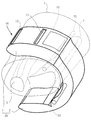
図1は、本発明の一実施形態を説明するための生体情報測定装置100の外観構成を示す模式図である。
FIG. 1 is a schematic diagram showing an external configuration of a biological
生体情報測定装置100は、本体部20と、図1では不図示の後述する帯状のバンド部材3と、を備える。図1は、このバンド部材3によって本体部20が手首Hに固定された固定状態を示している。
The biological
図1には、生体情報測定装置100の利用者の左の手首Hを示しており、図中の手前側が利用者の手が存在する方向である。また、図中の上側が手のひらの向いている方向である。手首H内には、橈骨Tと、尺骨Sと、橈骨動脈TDとを図示している。
FIG. 1 shows the left wrist H of the user of the biological
生体情報測定装置100は、利用者の手首Hの橈骨Tに沿う橈骨動脈TDから脈波(圧脈波又は容積脈波)を検出する脈波検出部10を有し、脈波検出部10によって検出される脈波に基づいて、心拍数、脈拍数、又は、血圧値等の生体情報を測定するものである。
The biological
脈波検出部10は公知の構成を採用することができる。例えば、脈波検出部10は、圧力センサとこれを皮膚に押し当てる機構を有し、圧力センサによって圧脈波を検出する。または、脈波検出部10は、光電センサを有し、光電センサによって検出された信号から容積脈波を検出する。圧力センサ又は光電センサは脈波検出センサを構成する。
The pulse
生体情報測定装置100の本体部20は、脈波検出部10と、脈波検出部10によって検出される脈波に基づいて心拍数、脈拍数、又は、血圧値等の生体情報を算出する図示しない生体情報算出部と、を含む。
The
生体情報算出部は、生体情報測定装置100とは別の機器に設けられるものであってもよい。つまり、生体情報測定装置100の本体部20は、脈波検出部10を少なくとも含むものであればよい。生体情報測定装置100は脈波検出装置として機能する。
The biological information calculation unit may be provided in a device other than the biological
本体部20は、手首Hの周方向に沿って巻き付け可能に構成されており、バンド部材3によって手首Hに固定された固定状態において、手首Hの尺骨Sの突起を露出させる位置に配置される。言い換えると、本体部20は、バンド部材3によって手首Hに固定された固定状態において、手首Hの周方向における両端部間が尺骨Sを覆わない構成になっている。
The
本体部20は、脈波検出部10を収容する筐体1と、筐体1と連結された筐体2とから構成されている。筐体2は、接着又は溶着等の固着によって筐体1に連結されたり、連結ピンによって筐体1に着脱自在に連結されたりしている。
The
筐体1は、固定状態において、脈波検出部10の橈骨動脈TDに対する位置を安定させるため、また、精密素子を含む脈波検出部10を保護するために、剛性の高い第一の剛性の部材を主体に構成されている。第一の剛性の部材としては、例えば、樹脂又は金属等が用いられる。
In the fixed state, the
筐体2は、一部又は全部が第一の剛性よりも低い第二の剛性の部材により構成されている。例えば、筐体2は、外周面(手首Hと対向する面の反対側の面)から所定の厚みまでは第二の剛性の部材により構成され、それ以外の部分は第一の剛性の部材により構成されている。
The
このように、筐体1よりも剛性の低い部材を筐体2の外周面に用いることで、筐体2を手首Hの形状に合わせて変形させることを容易にしている。第二の剛性の部材は、例えば、弾性部材又は形状記憶合金等が用いられる。
In this way, by using a member having lower rigidity than the
なお、脈波検出部10を含む本体部20は、図1では筐体1と筐体2に分けているが、完全な1つの筐体としてもよい。
The
筐体2の内周面(手首Hと対向する面)には、バンド部材3を固定するためのバンド留め具22が設けられている。バンド留め具22は、図1の例では、円柱状の金具により構成されている。
A
筐体1の外周面(手首Hと対向する面の反対面)には、バンド部材3を筐体1に係止するための孔部11,12が、手首Hの周方向に沿って並べて設けられている。
On the outer peripheral surface of the housing 1 (opposite to the surface facing the wrist H), holes 11 and 12 for locking the
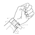
図2及び図3は、生体情報測定装置100のバンド部材3による本体部20の手首への固定方法を説明するための図である。
2 and 3 are views for explaining a method of fixing the
生体情報測定装置100の利用者は、図3のように、本体部20を手首に仮置きした状態から、バンド部材3の先端を手の甲側から手のひら側に回して、該先端を孔部12に挿入し、孔部11からバンド部材3の先端を引き出す。この状態が図2及び図3の状態である。
As shown in FIG. 3, the user of the biological
図2及び図3の状態から、バンド部材3の先端を強く引くことで、本体部20を手首Hに固定した状態を得ることができる。この状態において、バンド部材3は、利用者の手首にある尺骨の突起Saと接触する部分を有する(図3参照)。
By pulling the tip of the
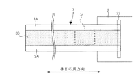
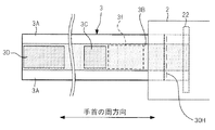
図4は、バンド留め具22に固定されるバンド部材3を手首との接触面側から見た平面図である。図5は、バンド留め具22に固定されるバンド部材3を手首との接触面の反対面側から見た平面図である。図4及び図5は、バンド部材3を一方向(手首への巻き付け方向)に展開した状態をこの一方向とバンド部材3の短手方向の各々に直交する方向から見た平面図である。
FIG. 4 is a plan view of the
バンド部材3は、本体部20の長手方向(手首Hの周方向と同義)に沿って伸びる帯状の部材である。バンド部材3は、例えば布、革、又は、ゴム等の本体部20よりも剛性の低い部材により構成される。
The
図4及び図5に示す例では、バンド部材3は、短手方向に間をあけて並ぶ2つの第一の領域3Aと、この2つの第一の領域3Aの間に設けられた第一の領域3Aよりも伸縮性の高い第二の領域3Bと、を有する。第一の領域3Aと第二の領域3Bは、それぞれ、バンド部材3の長手方向の一端から他端まで伸びる矩形形状となっている。
In the example shown in FIG. 4 and FIG. 5, the
部材の伸縮性とは、部材に力が加えられたときに該力の加わる方向にどれだけ部材が伸びるかを示す特性である。任意の領域に対して所定の力が加えられたときに、この任意の領域が該力の加えている方向に伸びる量が大きいほど、この任意の領域の伸縮性は高い。 The stretchability of a member is a characteristic that indicates how much the member extends in the direction in which the force is applied when a force is applied to the member. When a predetermined force is applied to an arbitrary region, the larger the amount of expansion of the arbitrary region in the direction in which the force is applied, the higher the elasticity of the arbitrary region.
第一の領域3Aと第二の領域3Bとで伸縮性が異なる構成としては、第一の領域3Aと第二の領域3Bが伸縮性の異なる材料で形成されている構成、第一の領域3Aと第二の領域3Bがそれぞれ同じ材料で形成されかつ第一の領域3Aよりも第二の領域3Bの厚みが小さい構成、第一の領域3Aと第二の領域3Bが異なる材料で形成されかつ第一の領域3Aよりも第二の領域3Bの厚みが小さい構成、又は、第一の領域3Aと第二の領域3Bがそれぞれ同じ材質の糸を編むことで形成されかつ糸の編み方が異なる構成、第一の領域3Aと第二の領域3Bが伸縮性の異なる材料で形成され、かつ、第一の領域3Aよりも第二の領域3Bの厚みが小さい構成(後述する図9〜図11参照)等がある。
As the configuration in which the first region 3A and the
バンド部材3の長手方向における基端部(一端部)は筐体2に固定されている。具体的には、バンド部材3は、その長手方向における基端側からバンド留め具22に巻き返された状態で同一面同士が接着又は縫製されて、バンド留め具22に固定されている。図5中の符号30Hは、バンド部材3が基端側から折り返されて縫製又は接着されている箇所を示している。バンド部材3の長手方向における先端部(他端部)は、どこにも支持されていないフリーの状態となっている。
A base end portion (one end portion) of the
なお、バンド部材3の基端部を筐体2に固定する方法は上述したものに限らない。例えば、バンド部材3の基端部を、ビス等を用いて筐体2に固定する構成としてもよい。又は、バンド部材3の基端部を、面ファスナーによってバンド留め具22に固定する構成としてもよい。
The method of fixing the base end portion of the
バンド部材3の第二の領域3Bは、バンド部材3によって本体部20が手首Hに固定された固定状態において、手首Hの尺骨の突起Saと接触する。手首Hの太さ及び尺骨の突起Saの位置には個人差はあるが、多数の人の手の形状のデータを用いることで、固定状態において、尺骨の突起Saに第二の領域3Bが接触するバンド部材3を設計することができる。図4及び図5に示した破線で示す範囲3fは、多数の人の手の形状のデータを用いることで求められるバンド部材3の尺骨の突起Saと接触しうる範囲を示している。
The
図5に示すように、固定状態においてバンド部材3の手首Hと接触する接触面の反対面には、面ファスナーを構成するフック状に起毛されたフック部3Cと、面ファスナーを構成するループ状に密集して起毛されたループ部3Dが形成されている。フック部3Cは被結合部を構成し、ループ部3Dは結合部を構成する。
As shown in FIG. 5, on the surface opposite to the contact surface of the
フック部3Cとループ部3Dにより構成される面ファスナーは、バンド部材3の一部をバンド部材3の他部に着脱可能に結合するための手段を構成する。
The surface fastener constituted by the
ループ部3Dは、バンド部材3の先端部に設けられている。フック部3Cは、バンド部材3の手首Hと接触する接触面の反対面のうち、範囲3fとループ部3Dを除く部分に設けられている。
The
利用者は、図2及び図3に示す状態から、バンド部材3の先端部を引き、バンド部材3を手首Hに巻き付ける。そして、利用者は、バンド部材3に設けられたループ部3Dを、バンド部材3に設けられたフック部3Cに貼り付ける。これにより、バンド部材3による本体部20の手首Hへの固定が完了する。
The user pulls the tip of the
以上のように、生体情報測定装置100は、本体部20を手首Hに固定するためのバンド部材3が、第一の領域3Aと第二の領域3Bを有する構成である。そして、第二の領域3Bは、固定状態において尺骨の突起Saと接触する。第二の領域3Bは、第一の領域3Aよりも高い伸縮性を有しているため、図2及び図3のようにバンド部材3を手首Hに巻き付けた状態において、尺骨の突起Saから第二の領域3Bに加わる力が、第二の領域3Bの伸びによって低減され、この結果、バンド部材3から尺骨の突起Saに加わる圧力が低減される。
As described above, in the biological
このように、生体情報測定装置100によれば、手首に負担を与えずに本体部20の固定が可能となる。このため、利用者はバンド部材3を強く巻き付けて本体部20を手首に固定するようになり、本体部20と手首Hの密着性を向上させることができる。この結果、脈波検出部10が所望の位置からずれるのを防いで、高精度の脈波検出が可能となる。
As described above, according to the biological
また、生体情報測定装置100では、バンド部材3の手首との接触面の反対面において、面ファスナーを構成するフック部3C及びループ部3Dが範囲3fを除く位置に設けられている。このため、範囲3fにおける第二の領域3Bの伸縮性が低下するのを防ぐことができ、バンド部材3から尺骨の突起Saに加わる圧力を効果的に低減させることができる。
Further, in the biological
また、範囲3fと重なる部分に面ファスナーが存在しないことで、フック部3Cとループ部3Dを貼り合せたときに、尺骨の突起Sa上にバンド部材3が2重に密着して配置されるのを防ぐことができる。このため、固定状態において尺骨の突起Saに加わる圧力が増加するのを防いで、生体情報測定装置100の装着性を向上させることができる。
Further, since there is no surface fastener in the portion overlapping the
なお、フック部3Cは範囲3fと重なっていてもよい。この場合は、フック部3Cを含めた状態で第二の領域3Bの伸縮性が第一の領域3Aの伸縮性よりも高くなっていればよい。
The
生体情報測定装置100のバンド部材3は第一の領域3Aを有している。この第一の領域3Aは、第二の領域3Bよりも伸縮性が低い。このため、バンド部材3を手首に巻き付ける際にバンド部材3全体が手首の周方向に伸びすぎるのを防ぐことができ、生体情報測定装置100の装着性を向上させることができる。また、固定状態においては、バンド部材3全体が手首の周方向に伸びるのが抑制されるため、脈波検出部10の位置ずれを防いで、高精度の脈波検出が可能となる。
The
なお、バンド部材3の第二の領域3Bは、バンド部材3の長手方向の伸縮性よりも、バンド部材3の短手方向(長手方向に直交する方向)の伸縮性の方が高いことが好ましい。
The
例えば、バンド部材3の長手方向における第一の領域3Aの伸縮性と、バンド部材3の長手方向における第二の領域3Bの伸縮性は同じ(“同じ”には公差が含まれていてもよい)であり、バンド部材3の短手方向における第二の領域3Bの伸縮性は、バンド部材3の短手方向における第一の領域3Aの伸縮性よりも高い構成とするのがよい。
For example, the elasticity of the first region 3A in the longitudinal direction of the
このような構成により、固定状態においてバンド部材3が長手方向に伸びる力がより抑制されるため、手首の動き等による本体部20の位置ずれを防ぐことができる。また、第二の領域3Bについては、バンド部材3の短手方向に伸びやすくなっていることで、固定状態において尺骨の突起Saに加わる圧力が増加するのを防ぐことができ、生体情報測定装置100の装着性を向上させることができる。
With such a configuration, the force by which the
次に、生体情報測定装置100の変形例を説明する。
Next, a modified example of the biological
(第一の変形例)
図6は、生体情報測定装置100の第一の変形例を示す図であり、図5に対応する図である。図6に示す生体情報測定装置100は、フック部3Cの位置が筐体2の外周面上に変更された点を除いては、図5と同じ構成である。
(First modification)
FIG. 6 is a diagram showing a first modification of the biological
この構成によれば、フック部3Cとループ部3Dを貼り合せたときに、尺骨の突起Sa上にバンド部材3が2重に密着して配置されるのを防ぐことができ、生体情報測定装置100の装着性を向上させることができる。
According to this configuration, when the
なお、図5及び図6では、バンド部材3による本体部20の手首への固定状態を維持するための手段として面ファスナーを採用しているが、この手段は面ファスナーに限らない。
5 and 6, a surface fastener is used as a means for maintaining the state where the
例えば、公知の時計バンドに用いられている中留部材を採用してもよい。バンド部材3の一部をバンド部材3の他部に着脱可能に結合するための手段、又は、バンド部材3の一部を筐体2に着脱可能に結合するための手段として中留部材を採用する場合でも、この中留部材が範囲3fを除く位置に設けられていることで、生体情報測定装置100の装着性を向上させることができる。
For example, a clasp member used in a known watch band may be adopted. The clasp member is used as a means for detachably coupling a part of the
(第二の変形例)
図7は、生体情報測定装置100の第二の変形例を示す図であり、図4に対応する図である。図7に示す生体情報測定装置100は、バンド部材3の第一の領域3A及び第二の領域3Bの形状が異なる点を除いては、図4と同じ構成である。
(Second modification)
FIG. 7 is a diagram showing a second modification of the biological
図7に示すバンド部材3は、上述した範囲3fが第二の領域3Bによって構成され、第二の領域3B以外が第一の領域3Aによって構成されている。
In the
この構成によれば、バンド部材3の大部分が第一の領域3Aによって構成されているため、固定状態においてバンド部材3が長手方向に伸びる力が抑制される。したがって、固定状態において、手首の動き等による本体部20の位置ずれを防ぐことができる。また、第二の領域3Bについては伸縮性が高いことで、尺骨の突起Saに加わる圧力が増加するのを防ぐことができ、生体情報測定装置100の装着性を向上させることができる。
According to this configuration, most of the
(第三の変形例)
図8は、生体情報測定装置100の第三の変形例を示す図であり、図5に対応する図である。図8に示す生体情報測定装置100は、筐体2の手首の周方向の長さが短くなっている点と、フック部3Cの位置が異なる点を除いては、図5と同じ構成である。
(Third modification)
FIG. 8 is a diagram showing a third modification of the biological
図8に示す生体情報測定装置100のバンド部材3のフック部3Cは、範囲3fと筐体2の端部との間に設けられている。
The
図8に示す構成では、フック部3Cとループ部3Dを貼り合せた状態において、尺骨の突起Sa上に第二の領域3Bが2つ重なった状態となる。このように、尺骨の突起Sa上にバンド部材3が二度重なる構成であっても、第二の領域3Bの伸縮性が高いことで、尺骨の突起Saに加わる圧力を低減することができる。
In the configuration shown in FIG. 8, when the
特に、第一の領域3Aよりも第二の領域3Bの厚みが薄いことで、第二の領域3Bの伸縮性が相対的に高くなっている場合には、尺骨の突起Sa上に第二の領域3Bが二重に重なっていても厚みが抑えられるため、装置の装着性への影響は軽微なものとなる。
In particular, when the
(第四の変形例)
図9は、生体情報測定装置100の第四の変形例を示す図であり、図5に対応する図である。図9に示す生体情報測定装置100のバンド部材3は、第二の領域3Bが第一の領域3Aによって囲まれている点と、ループ部3Dが削除され、第一の領域3Aの手首との接触面の反対面にループ部が形成されている点を除いては、図8と同じ構成である。
(Fourth modification)
9: is a figure which shows the 4th modification of the biological
図10は、図9に示すバンド部材3の分解斜視図である。
FIG. 10 is an exploded perspective view of the
図10に示すように、図9に示す生体情報測定装置100のバンド部材3は、第一の部材30Aと、第一の部材30Aの裏面に固定される第二の部材30Bと、第二の部材30Bの裏面に固定されるフック部3Cと、を備える。
As shown in FIG. 10, the
このバンド部材3は、フック部3Cが第一の部材30Aの表面上方に位置するように折り返し線Lにて折り返される。このバンド部材3は、折り返し部分を除く第二の部材30Bの裏面が手首と接触する接触面を構成する。また、折り返されて第一の部材30Aの表面に固定されるフック部3Cが形成されている面と、この面以外の第一の部材30Aの表面とが、上記接触面の反対面を構成する。
The
第一の部材30Aは、手首の周方向に伸びる帯状の部材であり、開口部30aを有する。開口部30aの平面形状は、図9に示した第二の領域3Bと同じになっており、開口部30aは固定状態において上述した範囲30fを覆う。第一の部材30Aの表面には、フック部3Cと共に面ファスナーを構成するループ部が形成されている。
The
第二の部材30Bは、手首の周方向に伸びる帯状の部材であり、第一の部材30Aよりも伸縮性の高い材料で構成されている。
The
フック部3Cは、第二の部材30Bの先端部(折り返し線Lよりも先端側の部分)の裏面に固定されている。
3 C of hook parts are being fixed to the back surface of the front-end|tip part (front end side rather than the folding|returning line L) of the
図10に示すバンド部材3では、第一の部材30Aと第二の部材30Bとの重なり部分が第一の領域3Aを構成する。また、第一の部材30Aの開口部30aと第二の部材30Bとの重なり部分が第二の領域3Bを構成する。図10の構成によれば、バンド部材3が2層構造で構成されているため、バンド部材3の巻き付け強度を十分に確保しながら、尺骨から加わる圧力を逃がして装着性を向上させることができる。
In the
(第五の変形例)
図11は、図9に示した生体情報測定装置100のバンド部材3の変形例を示す分解斜視図である。
(Fifth Modification)
FIG. 11 is an exploded perspective view showing a modified example of the
図11に示すバンド部材3は、第三の部材30Dと、第三の部材30Dの裏面に固定される第四の部材30Eと、第四の部材30Eの裏面に固定される第五の部材30Fと、第五の部材30Fの裏面に固定されるフック部3Cと、を備える。
The
このバンド部材3は、フック部3Cが第三の部材30Dの表面上方に位置するように折り返し線Lにて折り返される。このバンド部材3は、折り返し部分を除く第五の部材30Fの裏面が手首と接触する接触面を構成する。また、折り返されて第三の部材30Dの表面に固定されるフック部3Cが形成されている面と、この面以外の第三の部材30Dの表面とが、上記接触面の反対面を構成する。
The
第三の部材30Dは、手首の周方向に伸びる帯状の部材である。第三の部材30Dの表面には、フック部3Cと共に面ファスナーを構成するループ部が形成されている。
The
第四の部材30Eは、手首の周方向に伸びる帯状の部材であり、開口部30bを有する。開口部30bの平面形状は、図9に示した第二の領域3Bと同じになっており、開口部30bは固定状態において上述した範囲30fを覆う。
The
第五の部材30Fは、手首の周方向に伸びる帯状の部材であり、第三の部材30D及び第四の部材30Eよりも伸縮性の高い材料で構成されている。
The
フック部3Cは、第五の部材30Fの先端部(折り返し線Lよりも先端側の部分)の裏面に固定されている。
3 C of hook parts are being fixed to the back surface of the front-end|tip part (front end side rather than the folding line L) of
図11に示すバンド部材3では、第三の部材30Dと第四の部材30Eと第五の部材30Fの重なり部分が第一の領域3Aを構成する。また、第三の部材30Dと第四の部材30Eの開口部30bと第五の部材30Fとの重なり部分が第二の領域3Bを構成する。図11の構成によれば、バンド部材3が3層構造で構成されているため、バンド部材3の巻き付け強度を十分に確保しながら、尺骨から加わる圧力を逃がして装着性を向上させることができる。
In the
ここまでの説明した生体情報測定装置100は、固定状態において尺骨の突起Saを露出させる位置に本体部20が配置されるものである。本発明は、固定状態において橈骨の突起を露出させる位置に本体部が配置される生体情報測定装置にも適用可能である。
In the biological
例えば、図12に示すように、脈波検出部10Aを含む本体部20Aを手首Hの手の甲側に帯状のバンド部材30によって固定する生体情報測定装置100Aにも本発明を適用できる。
For example, as shown in FIG. 12, the present invention can be applied to the biological
生体情報測定装置100Aは、バンド部材30によって本体部20Aを手首Hに固定した状態において、橈骨の突起Taを露出させる位置に本体部20Aが配置される。そして、バンド部材30によって本体部20Aを手首Hに固定した状態においては、バンド部材30の一部が橈骨の突起Taと接触する。
In the biological
このため、バンド部材30において、橈骨の突起Taと接触しうる範囲を上述した第二の領域3Bとし、第二の領域3B以外の領域を第一の領域3Aとすることで、バンド部材30から橈骨の突起Taに対して加わる圧力を低減して、生体情報測定装置の装着性を向上させることができる。
Therefore, in the
今回開示された実施形態はすべての点で例示であって制限的なものではないと考えられるべきである。本発明の範囲は上記した説明ではなくて特許請求の範囲によって示され、特許請求の範囲と均等の意味及び範囲内でのすべての変更が含まれることが意図される。 The embodiments disclosed this time are to be considered as illustrative in all points and not restrictive. The scope of the present invention is shown not by the above description but by the claims, and is intended to include meanings equivalent to the claims and all modifications within the scope.
以上説明してきたように、本明細書には以下の事項が開示されている。 As described above, the following items are disclosed in this specification.
開示された脈波検出装置は、利用者の手首の動脈から脈波を検出する脈波検出センサを含む本体部と、前記本体部を前記手首に固定するための帯状のバンド部材と、を備え、前記本体部は、前記バンド部材によって前記手首に固定された固定状態において、前記手首の尺骨の突起又は前記手首の橈骨の突起を露出させる位置に配置され、前記バンド部材は、第一の領域と、前記第一の領域よりも伸縮性の高い第二の領域とを含み、前記第二の領域は、前記固定状態において、前記手首の尺骨の突起又は前記手首の橈骨の突起と少なくとも接触するものである。 The disclosed pulse wave detection device includes a main body including a pulse wave detection sensor that detects a pulse wave from an artery of a user's wrist, and a band-shaped band member for fixing the main body to the wrist. , The main body portion is arranged at a position where the protrusion of the ulna of the wrist or the protrusion of the radius of the wrist is exposed in the fixed state in which the main body is fixed to the wrist by the band member, and the band member is the first region. And a second region having higher elasticity than the first region, wherein the second region is at least in contact with the ulnar projection of the wrist or the radial projection of the wrist in the fixed state. It is a thing.
開示された脈波検出装置は、前記第二の領域の前記バンド部材の長手方向の伸縮性は、前記第二の領域の前記長手方向に直交する方向の伸縮性よりも低いものである。 In the disclosed pulse wave detection device, the elasticity of the band member in the second region in the longitudinal direction is lower than the elasticity of the second region in the direction orthogonal to the longitudinal direction.
開示された脈波検出装置は、前記第二の領域の前記バンド部材の長手方向の伸縮性は、前記第一の領域の前記長手方向の伸縮性と同じであるものである。 In the disclosed pulse wave detection device, the elasticity in the longitudinal direction of the band member in the second region is the same as the elasticity in the longitudinal direction of the first region.
開示された脈波検出装置は、前記バンド部材は、前記バンド部材の一部と他部を着脱自在に結合するための面ファスナーを、前記手首と接触する面の反対面に有し、前記面ファスナーの被結合部と前記被結合部に結合される結合部のうちの少なくとも一方は、前記反対面のうち、前記固定状態において前記手首の尺骨の突起又は前記手首の橈骨の突起と重なる範囲を除く面に設けられているものである。 In the disclosed pulse wave detecting device, the band member has a surface fastener for detachably coupling a part and another part of the band member on a surface opposite to a surface in contact with the wrist. At least one of the coupled portion of the fastener and the coupling portion coupled to the coupled portion has, on the opposite surface, a range overlapping the protrusion of the ulna of the wrist or the protrusion of the radius of the wrist in the fixed state. It is provided on the surface to be excluded.
開示された脈波検出装置は、前記バンド部材は、前記固定状態において、前記手首の尺骨の突起又は前記手首の橈骨の突起と接触する第一の部分、及び、前記第一の部分と重なる第二の部分を有し、前記第一の部分と前記第二の部分がそれぞれ前記第二の領域であるものを含む。 In the disclosed pulse wave detection device, the band member, in the fixed state, a first portion that comes into contact with a protrusion of the ulna of the wrist or a protrusion of the radius of the wrist, and a first portion that overlaps with the first portion. It has two parts, and each of the first part and the second part is the second region.
開示された生体情報測定装置は、前記脈波検出装置と、前記脈波検出装置によって検出された脈波に基づいて生体情報を算出する生体情報算出部と、を備えるものである。 The disclosed biological information measurement device includes the pulse wave detection device and a biological information calculation unit that calculates biological information based on the pulse wave detected by the pulse wave detection device.
100,100A 生体情報測定装置
1,2 筐体
10,10A 脈波検出部
11,12 孔部
20,20A 本体部
22 バンド留め具
T 橈骨
Ta 橈骨の突起
S 尺骨
Sa 尺骨の突起
TD 橈骨動脈
H 手首
3,30 バンド部材
3A 第一の領域
3B 第二の領域
3C フック部
3D ループ部
3f 尺骨の突起Saと接触し得る範囲
L 折り返し線
30H 固定箇所
30A 第一の部材
30B 第二の部材
30D 第三の部材
30E 第四の部材
30F 第五の部材
30a,30b 開口部
100,100A Biological
Claims (5)
前記本体部を前記手首に固定するための帯状のバンド部材と、を備え、
前記本体部は、前記バンド部材によって前記手首に固定された固定状態において、前記手首の尺骨の突起又は前記手首の橈骨の突起を露出させる位置に配置され、
前記バンド部材は、第一の領域と、前記第一の領域よりも伸縮性の高い第二の領域とを含み、
前記第二の領域は、前記固定状態において、前記手首の尺骨の突起又は前記手首の橈骨の突起と少なくとも接触し、
前記第二の領域の前記バンド部材の長手方向の伸縮性は、前記第二の領域の前記長手方向に直交する方向の伸縮性よりも低い脈波検出装置。 A main body portion including a pulse wave detection sensor that detects a pulse wave from the artery of the wrist of the user,
A band-shaped band member for fixing the main body to the wrist,
The main body portion is arranged at a position where the protrusion of the ulna of the wrist or the protrusion of the radius of the wrist is exposed in a fixed state where the main body is fixed to the wrist by the band member,
The band member includes a first region and a second region having higher elasticity than the first region,
The second region, in the fixed state, at least contact with the protrusion of the ulna of the wrist or the protrusion of the radius of the wrist,
A pulse wave detecting device in which the elasticity of the band member in the second region in the longitudinal direction is lower than the elasticity of the second region in a direction orthogonal to the longitudinal direction.
前記第二の領域の前記バンド部材の長手方向の伸縮性は、前記第一の領域の前記長手方向の伸縮性と同じである脈波検出装置。 The pulse wave detection device according to claim 1, wherein
The pulse wave detection device, wherein the elasticity of the band member in the second region in the longitudinal direction is the same as the elasticity of the first region in the longitudinal direction.
前記本体部を前記手首に固定するための帯状のバンド部材と、を備え、
前記バンド部材は、基端部において前記本体部に固定され、
前記本体部は、前記バンド部材によって前記手首に固定された固定状態において、前記手首の尺骨の突起又は前記手首の橈骨の突起を露出させる位置に配置され、
前記バンド部材は、前記基端部から先端部まで延びる第一の領域と、前記第一の領域よりも伸縮性の高い第二の領域とを含み、
前記第二の領域は、前記固定状態において、前記手首の尺骨の突起又は前記手首の橈骨の突起と少なくとも接触し、
前記バンド部材は、前記バンド部材の一部と他部を着脱自在に結合するための面ファスナーを、前記手首と接触する面の反対面に有し、
前記面ファスナーの被結合部と前記被結合部に結合される結合部のうちの少なくとも一方は、前記反対面のうち、前記固定状態において前記手首の尺骨の突起又は前記手首の橈骨の突起と重なる範囲を除く面に設けられている脈波検出装置。 A main body portion including a pulse wave detection sensor that detects a pulse wave from the artery of the wrist of the user,
A band-shaped band member for fixing the main body to the wrist,
The band member is fixed to the main body at the base end,
The main body portion is arranged at a position where the protrusion of the ulna of the wrist or the protrusion of the radius of the wrist is exposed in a fixed state where the main body is fixed to the wrist by the band member,
The band member includes a first region extending from the base end portion to the tip end portion, and a second region having a higher elasticity than the first region,
The second region, in the fixed state, at least contact with the protrusion of the ulna of the wrist or the protrusion of the radius of the wrist,
The band member has a surface fastener for detachably coupling a part and the other part of the band member on a surface opposite to a surface in contact with the wrist,
At least one of the coupled portion of the surface fastener and the coupling portion coupled to the coupled portion overlaps the ulnar projection of the wrist or the radial projection of the wrist in the fixed state on the opposite surface. Pulse wave detection device provided on the surface excluding the range.
前記本体部を前記手首に固定するための帯状のバンド部材と、を備え、
前記バンド部材は、基端部において前記本体部に固定され、
前記本体部は、前記バンド部材によって前記手首に固定された固定状態において、前記手首の尺骨の突起又は前記手首の橈骨の突起を露出させる位置に配置され、
前記バンド部材は、前記基端部から先端部まで延びる第一の領域と、前記第一の領域よりも伸縮性の高い第二の領域とを含み、
前記第二の領域は、前記固定状態において、前記手首の尺骨の突起又は前記手首の橈骨の突起と少なくとも接触し、
前記バンド部材は、前記固定状態において、前記手首の尺骨の突起又は前記手首の橈骨の突起と接触する第一の部分、及び、前記第一の部分と重なる第二の部分を有し、前記第一の部分と前記第二の部分がそれぞれ前記第二の領域である脈波検出装置。 A main body portion including a pulse wave detection sensor that detects a pulse wave from the artery of the wrist of the user,
A band-shaped band member for fixing the main body to the wrist,
The band member is fixed to the main body at the base end,
The main body portion is arranged at a position where the protrusion of the ulna of the wrist or the protrusion of the radius of the wrist is exposed in a fixed state where the main body is fixed to the wrist by the band member,
The band member includes a first region extending from the base end portion to the tip end portion, and a second region having a higher elasticity than the first region,
The second region, in the fixed state, at least contact with the protrusion of the ulna of the wrist or the protrusion of the radius of the wrist,
The band member has, in the fixed state, a first portion that comes into contact with a protrusion of the ulna of the wrist or a protrusion of the radius of the wrist, and a second portion that overlaps the first portion. A pulse wave detecting device in which one portion and the second portion are the second regions, respectively.
前記脈波検出装置によって検出された脈波に基づいて生体情報を算出する生体情報算出部と、を備える生体情報測定装置。 A pulse wave detecting device according to any one of claims 1 to 4,
A biological information measuring device, comprising: a biological information calculating unit that calculates biological information based on a pulse wave detected by the pulse wave detecting device.
Priority Applications (5)
| Application Number | Priority Date | Filing Date | Title |
|---|---|---|---|
| JP2016075966A JP6728904B2 (en) | 2016-04-05 | 2016-04-05 | Pulse wave detection device and biological information measurement device |
| EP17778997.1A EP3424416B1 (en) | 2016-04-05 | 2017-03-27 | Pulse wave detection device and biometric information measurement device |
| PCT/JP2017/012453 WO2017175618A1 (en) | 2016-04-05 | 2017-03-27 | Pulse wave detection device and biometric information measurement device |
| CN201780021334.9A CN109069012B (en) | 2016-04-05 | 2017-03-27 | Pulse wave detection device and biological information measurement device |
| US16/144,244 US11147512B2 (en) | 2016-04-05 | 2018-09-27 | Pulse wave detection device and biometric information measurement device |
Applications Claiming Priority (1)
| Application Number | Priority Date | Filing Date | Title |
|---|---|---|---|
| JP2016075966A JP6728904B2 (en) | 2016-04-05 | 2016-04-05 | Pulse wave detection device and biological information measurement device |
Publications (3)
| Publication Number | Publication Date |
|---|---|
| JP2017184998A JP2017184998A (en) | 2017-10-12 |
| JP2017184998A5 JP2017184998A5 (en) | 2019-04-11 |
| JP6728904B2 true JP6728904B2 (en) | 2020-07-22 |
Family
ID=60001040
Family Applications (1)
| Application Number | Title | Priority Date | Filing Date |
|---|---|---|---|
| JP2016075966A Active JP6728904B2 (en) | 2016-04-05 | 2016-04-05 | Pulse wave detection device and biological information measurement device |
Country Status (5)
| Country | Link |
|---|---|
| US (1) | US11147512B2 (en) |
| EP (1) | EP3424416B1 (en) |
| JP (1) | JP6728904B2 (en) |
| CN (1) | CN109069012B (en) |
| WO (1) | WO2017175618A1 (en) |
Families Citing this family (3)
| Publication number | Priority date | Publication date | Assignee | Title |
|---|---|---|---|---|
| EP3988153B1 (en) | 2015-03-31 | 2024-04-24 | Fisher & Paykel Healthcare Limited | A user interface for supplying gases to an airway |
| EP3995168A1 (en) | 2016-08-11 | 2022-05-11 | Fisher & Paykel Healthcare Limited | A collapsible conduit, patient interface and headgear connector |
| JP7107822B2 (en) * | 2018-11-30 | 2022-07-27 | シチズン時計株式会社 | Sphygmomanometer cuff |
Family Cites Families (14)
| Publication number | Priority date | Publication date | Assignee | Title |
|---|---|---|---|---|
| JPS5141285A (en) | 1974-10-04 | 1976-04-07 | Iwatsu Electric Co Ltd | MYAKUHAKEI |
| JPH05329117A (en) | 1992-05-28 | 1993-12-14 | Sanyo Electric Co Ltd | Band type information detection device |
| GB2341233B (en) * | 1998-02-16 | 2003-08-13 | Seiko Epson Corp | Biometric measuring device |
| JP3931459B2 (en) * | 1998-05-22 | 2007-06-13 | カシオ計算機株式会社 | Band and wrist device |
| JP3636071B2 (en) * | 2000-12-25 | 2005-04-06 | 松下電工株式会社 | Sphygmomanometer cuff |
| JP3952957B2 (en) * | 2003-01-22 | 2007-08-01 | オムロンヘルスケア株式会社 | Cuff for wrist blood pressure monitor |
| JP2008168054A (en) * | 2007-01-15 | 2008-07-24 | Citizen Holdings Co Ltd | Band for wrist-mounted type living body measuring apparatus |
| JP5395484B2 (en) * | 2009-03-25 | 2014-01-22 | シチズンホールディングス株式会社 | Mounting device |
| JP5012941B2 (en) * | 2010-03-26 | 2012-08-29 | カシオ計算機株式会社 | Biological information measuring device |
| JP5691040B2 (en) * | 2011-10-27 | 2015-04-01 | ダイナエアー株式会社 | Humidity control system and operation monitoring method thereof |
| US9226663B2 (en) * | 2014-04-07 | 2016-01-05 | Physical Enterprises, Inc. | Systems and methods for optical isolation in measuring physiological parameters |
| US20170113059A1 (en) * | 2014-04-11 | 2017-04-27 | Wristspace, Llc | Wrist worn sensor |
| US9938646B2 (en) * | 2015-03-08 | 2018-04-10 | Apple Inc. | Woven band with different stretch regions |
| JP6172591B2 (en) | 2016-02-12 | 2017-08-02 | 株式会社リコー | Image forming apparatus |
-
2016
- 2016-04-05 JP JP2016075966A patent/JP6728904B2/en active Active
-
2017
- 2017-03-27 EP EP17778997.1A patent/EP3424416B1/en active Active
- 2017-03-27 WO PCT/JP2017/012453 patent/WO2017175618A1/en active Application Filing
- 2017-03-27 CN CN201780021334.9A patent/CN109069012B/en active Active
-
2018
- 2018-09-27 US US16/144,244 patent/US11147512B2/en active Active
Also Published As
| Publication number | Publication date |
|---|---|
| US20190021668A1 (en) | 2019-01-24 |
| US11147512B2 (en) | 2021-10-19 |
| EP3424416B1 (en) | 2022-10-05 |
| JP2017184998A (en) | 2017-10-12 |
| EP3424416A1 (en) | 2019-01-09 |
| CN109069012A (en) | 2018-12-21 |
| CN109069012B (en) | 2021-08-20 |
| EP3424416A4 (en) | 2020-03-04 |
| WO2017175618A1 (en) | 2017-10-12 |
Similar Documents
| Publication | Publication Date | Title |
|---|---|---|
| JP6728904B2 (en) | Pulse wave detection device and biological information measurement device | |
| JP2008168054A (en) | Band for wrist-mounted type living body measuring apparatus | |
| JP4153972B1 (en) | Biological compression device and blood pressure measurement device | |
| JP6662167B2 (en) | Pulse wave detection device, biological information measurement device, mounting aid for pulse wave detection device | |
| JP2009240511A (en) | Biometric device | |
| WO2017043260A1 (en) | Pulse wave detector | |
| JP2017051273A (en) | Pressure pulse wave detection device | |
| CN109069015B (en) | Pulse wave detection device and biological information measurement device | |
| CN109069016B (en) | Pulse wave detection device and biological information measurement device | |
| JP5404446B2 (en) | Armband for sphygmomanometer | |
| WO2017043261A1 (en) | Pulse wave detector | |
| JP6597083B2 (en) | Pulse wave detector | |
| JP4740579B2 (en) | Wrist sphygmomanometer | |
| JP2006087516A (en) | Pulse rate measuring device, band for attaching pulse rate sensor, and holder for pulse rate measuring device | |
| JP2017063984A (en) | Pulse wave detector | |
| JP4248917B2 (en) | Pulse wave detector | |
| JP2006055517A (en) | Band for attaching biological information measuring sensor and holder for biological information measuring device | |
| KR200471749Y1 (en) | Cuff for hemadynamometer | |
| JP2010088506A (en) | Living body pressing device and blood pressure measuring device |
Legal Events
| Date | Code | Title | Description |
|---|---|---|---|
| RD02 | Notification of acceptance of power of attorney |
Free format text: JAPANESE INTERMEDIATE CODE: A7422 Effective date: 20170120 |
|
| A521 | Request for written amendment filed |
Free format text: JAPANESE INTERMEDIATE CODE: A523 Effective date: 20190301 |
|
| A621 | Written request for application examination |
Free format text: JAPANESE INTERMEDIATE CODE: A621 Effective date: 20190301 |
|
| A131 | Notification of reasons for refusal |
Free format text: JAPANESE INTERMEDIATE CODE: A131 Effective date: 20200310 |
|
| A521 | Request for written amendment filed |
Free format text: JAPANESE INTERMEDIATE CODE: A523 Effective date: 20200428 |
|
| TRDD | Decision of grant or rejection written | ||
| A01 | Written decision to grant a patent or to grant a registration (utility model) |
Free format text: JAPANESE INTERMEDIATE CODE: A01 Effective date: 20200602 |
|
| A61 | First payment of annual fees (during grant procedure) |
Free format text: JAPANESE INTERMEDIATE CODE: A61 Effective date: 20200615 |
|
| R150 | Certificate of patent or registration of utility model |
Ref document number: 6728904 Country of ref document: JP Free format text: JAPANESE INTERMEDIATE CODE: R150 |