EP3424416B1 - Pulse wave detection device and biometric information measurement device - Google Patents
Pulse wave detection device and biometric information measurement device Download PDFInfo
- Publication number
- EP3424416B1 EP3424416B1 EP17778997.1A EP17778997A EP3424416B1 EP 3424416 B1 EP3424416 B1 EP 3424416B1 EP 17778997 A EP17778997 A EP 17778997A EP 3424416 B1 EP3424416 B1 EP 3424416B1
- Authority
- EP
- European Patent Office
- Prior art keywords
- wrist
- band member
- region
- pulse wave
- biometric information
- Prior art date
- Legal status (The legal status is an assumption and is not a legal conclusion. Google has not performed a legal analysis and makes no representation as to the accuracy of the status listed.)
- Active
Links
- 238000005259 measurement Methods 0.000 title claims description 65
- 238000001514 detection method Methods 0.000 title claims description 5
- 210000000707 wrist Anatomy 0.000 claims description 99
- 238000000034 method Methods 0.000 claims description 50
- 230000008569 process Effects 0.000 claims description 45
- 210000000623 ulna Anatomy 0.000 claims description 38
- 230000008878 coupling Effects 0.000 claims description 10
- 238000010168 coupling process Methods 0.000 claims description 10
- 238000005859 coupling reaction Methods 0.000 claims description 10
- 210000001367 artery Anatomy 0.000 claims description 4
- 230000004048 modification Effects 0.000 description 16
- 238000012986 modification Methods 0.000 description 16
- 239000000463 material Substances 0.000 description 7
- 230000036772 blood pressure Effects 0.000 description 5
- 238000006073 displacement reaction Methods 0.000 description 5
- 210000002321 radial artery Anatomy 0.000 description 5
- 230000008602 contraction Effects 0.000 description 4
- 238000010586 diagram Methods 0.000 description 3
- 239000004744 fabric Substances 0.000 description 3
- 238000004804 winding Methods 0.000 description 3
- 238000009940 knitting Methods 0.000 description 2
- 239000002184 metal Substances 0.000 description 2
- 230000001419 dependent effect Effects 0.000 description 1
- 230000000694 effects Effects 0.000 description 1
- 239000010985 leather Substances 0.000 description 1
- 230000007246 mechanism Effects 0.000 description 1
- 239000011347 resin Substances 0.000 description 1
- 229920005989 resin Polymers 0.000 description 1
- 239000005060 rubber Substances 0.000 description 1
- 229910001285 shape-memory alloy Inorganic materials 0.000 description 1
- 238000003466 welding Methods 0.000 description 1
Images


Classifications
-
- A—HUMAN NECESSITIES
- A61—MEDICAL OR VETERINARY SCIENCE; HYGIENE
- A61B—DIAGNOSIS; SURGERY; IDENTIFICATION
- A61B5/00—Measuring for diagnostic purposes; Identification of persons
- A61B5/68—Arrangements of detecting, measuring or recording means, e.g. sensors, in relation to patient
- A61B5/6801—Arrangements of detecting, measuring or recording means, e.g. sensors, in relation to patient specially adapted to be attached to or worn on the body surface
- A61B5/684—Indicating the position of the sensor on the body
-
- A—HUMAN NECESSITIES
- A61—MEDICAL OR VETERINARY SCIENCE; HYGIENE
- A61B—DIAGNOSIS; SURGERY; IDENTIFICATION
- A61B5/00—Measuring for diagnostic purposes; Identification of persons
- A61B5/02—Detecting, measuring or recording pulse, heart rate, blood pressure or blood flow; Combined pulse/heart-rate/blood pressure determination; Evaluating a cardiovascular condition not otherwise provided for, e.g. using combinations of techniques provided for in this group with electrocardiography or electroauscultation; Heart catheters for measuring blood pressure
- A61B5/024—Detecting, measuring or recording pulse rate or heart rate
- A61B5/02438—Detecting, measuring or recording pulse rate or heart rate with portable devices, e.g. worn by the patient
-
- A—HUMAN NECESSITIES
- A61—MEDICAL OR VETERINARY SCIENCE; HYGIENE
- A61B—DIAGNOSIS; SURGERY; IDENTIFICATION
- A61B5/00—Measuring for diagnostic purposes; Identification of persons
- A61B5/68—Arrangements of detecting, measuring or recording means, e.g. sensors, in relation to patient
- A61B5/6801—Arrangements of detecting, measuring or recording means, e.g. sensors, in relation to patient specially adapted to be attached to or worn on the body surface
- A61B5/6802—Sensor mounted on worn items
- A61B5/681—Wristwatch-type devices
-
- A—HUMAN NECESSITIES
- A61—MEDICAL OR VETERINARY SCIENCE; HYGIENE
- A61B—DIAGNOSIS; SURGERY; IDENTIFICATION
- A61B5/00—Measuring for diagnostic purposes; Identification of persons
- A61B5/68—Arrangements of detecting, measuring or recording means, e.g. sensors, in relation to patient
- A61B5/6801—Arrangements of detecting, measuring or recording means, e.g. sensors, in relation to patient specially adapted to be attached to or worn on the body surface
- A61B5/6813—Specially adapted to be attached to a specific body part
- A61B5/6824—Arm or wrist
-
- A—HUMAN NECESSITIES
- A61—MEDICAL OR VETERINARY SCIENCE; HYGIENE
- A61B—DIAGNOSIS; SURGERY; IDENTIFICATION
- A61B5/00—Measuring for diagnostic purposes; Identification of persons
- A61B5/68—Arrangements of detecting, measuring or recording means, e.g. sensors, in relation to patient
- A61B5/6801—Arrangements of detecting, measuring or recording means, e.g. sensors, in relation to patient specially adapted to be attached to or worn on the body surface
- A61B5/683—Means for maintaining contact with the body
- A61B5/6831—Straps, bands or harnesses
-
- A—HUMAN NECESSITIES
- A61—MEDICAL OR VETERINARY SCIENCE; HYGIENE
- A61B—DIAGNOSIS; SURGERY; IDENTIFICATION
- A61B2562/00—Details of sensors; Constructional details of sensor housings or probes; Accessories for sensors
- A61B2562/16—Details of sensor housings or probes; Details of structural supports for sensors
- A61B2562/164—Details of sensor housings or probes; Details of structural supports for sensors the sensor is mounted in or on a conformable substrate or carrier
Definitions
- the present invention relates to a pulse wave detector and a biometric information measurement device.
- a biometric information measurement device is known that, in a state where a pressure sensor is directly contacted with a living body portion through which an artery such as the radial artery in the wrist passes, can measure biometric information such as the heart rate, the pulse rate, or the blood pressure by using information detected by the sensor (for example, see Patent Literatures 1 to 3).
- Patent Literature 1 discloses a biometric information measurement device in which an opening for avoiding the ulna is disposed in a portion that is to be wound around the back side of the hand in a state where the device is attached to the wrist, whereby the state where the device is attached to the wrist is enabled to be stably maintained.
- Patent Literature 2 discloses a biometric information measurement device in which a band that is to be wound around the wrist, and that is stretchable and contractible in the winding direction is provided with: a marking portion that stretches or contracts in connection with stretching or contraction of the band, and that indicates the band wound strength depending on the degree of stretching or contraction of the band; and a reference button functioning as a reference for determining whether the degree of stretching or contraction indicated by the marking portion corresponds to the optimum band wound strength or not.
- the device when the attachment of the device is performed by using the marking portion and the reference button, the device can be attached at the optimum band wound strength irrespective of the diameter of the wrist of the user.
- Patent Literature 3 discloses a biometric information measurement device in which both end portions of a band portion that is to be wound around the wrist are divided into three parts, and one and other ends of the divided band parts are enabled to be respectively secured.
- Patent Literature 4 relates to a band for a wrist-mounted type living body measuring apparatus.
- Patent Literature 5 discloses a wrist type blood pressure meter cuff.
- Patent Literature 6 relates to a device for mounting on a wrist.
- Patent Literature 7 discloses a biometric measuring device.
- Each of the biometric information measurement devices disclosed in Patent Literatures 1 and 2 is to be attached to the wrist by fastening and securing a housing which accommodates the pressure sensor portion, to the wrist with the single band.
- the ulna has a protruding portion.
- the biometric information measurement devices of Patent Literatures 1 and 2 there is a possibility that the ulna may interfere the fastening of the band to worsen the feeling and easiness of attachment of the device, or, after attachment, displacement of the position of the device may occur.
- pressure sensors are secured to the divided parts, respectively, thereby enabling the pressing positions of the pressure sensors to be adjustable.
- the pressure sensors are disposed on the band itself, and therefore there is a high possibility that the positions of the pressure sensors may be displaced by a motion of the hand. As a result, the device cannot accurately measure biometric information.
- biometric information measurement devices which detect a pressure pulse wave by using a pressure sensor have been described above, similar problems occur also in a biometric information measurement device in which, for example, a volume pulse wave is detected by using a photoelectric sensor.
- the invention has been conducted in view of the above circumstances. It is an object of the invention to provide a pulse wave detector in which the feeling and easiness of attachment to the wrist are improved, and which can accurately detect a pulse wave, and also a biometric information measurement device including the detector.
- a pulse wave detector comprising: a body portion including a pulse wave detection sensor which detects a pulse wave from an artery in a wrist of a user; and a strip-shaped band member for securing the body portion to the wrist, wherein in a secured state where the body portion is secured to the wrist with the band member, the body portion is placed in a position where a process of an ulna in the wrist or a process of a radius in the wrist is exposed, wherein the band member includes a first region, and a second region which is higher in stretchability than the first region, and wherein in the secured state, the second region is at least in contact with the process of the ulna in the wrist or the process of the radius in the wrist, wherein a stretchability of the second region in a longitudinal direction of the band member is lower than a stretchability of the second region
- a biometric information measurement device including: the pulse wave detector; and a biometric information calculating section which calculates biometric information based on the pulse wave detected by the pulse wave detector.
- a pulse wave detector in which the feeling and easiness of attachment to the wrist are improved, and a pulse wave can be accurately detected, and also a biometric information measurement device including the detector.
- Fig. 1 is a diagram showing the external configuration of a biometric information measurement device 100 for illustrating an embodiment of the invention.
- the biometric information measurement device 100 includes a body portion 20, and a strip-shaped band member 3 which is not shown in Fig. 1 , and which will be described later.
- Fig. 1 shows a secured state where the body portion 20 is secured to the wrist H with the band member 3.
- Fig. 1 shows the left wrist H of the user of the biometric information measurement device 100.
- the near side of the figure coincides with the direction in which the hand of the user exists.
- the upper side of the figure is in the direction along which the palm of the hand is oriented.
- the radius T, the ulna S, and the radial artery TD are shown.
- the biometric information measurement device 100 has a pulse wave detecting section 10 which detects a pulse wave (a pressure pulse wave or a volume pulse wave) from the radial artery TD that extends along the radius T in the wrist H of the user, and measures biometric information such as the hear rate, the pulse rate, or the blood pressure value based on the pulse wave detected by the pulse wave detecting section 10.
- a pulse wave a pressure pulse wave or a volume pulse wave
- the pulse wave detecting section 10 may have a known configuration.
- the pulse wave detecting section 10 has a pressure sensor, and a mechanism which presses it against the skin, and detects a pressure pulse wave by using the pressure sensor.
- the pulse wave detecting section 10 has a photoelectric sensor, and detects a volume pulse wave from a signal detected by the photoelectric sensor.
- the pressure sensor or the photoelectric sensor constitutes the pulse wave detection sensor.
- the body portion 20 of the biometric information measurement device 100 includes the pulse wave detecting section 10, and a biometric information calculating section that is not shown, and that calculates biometric information such as the heart rate, the pulse rate, or the blood pressure value based on the pulse wave detected by the pulse wave detecting section 10.
- the biometric information calculating section may be disposed in an apparatus other than the biometric information measurement device 100. Namely, the body portion 20 of the biometric information measurement device 100 is requested to have at least the pulse wave detecting section 10.
- the biometric information measurement device 100 functions as the pulse wave detector.
- the body portion 20 is configured so as to be woundable in the circumferential direction of the wrist H, and to be placed in a position where the process of the ulna S in the wrist H is exposed in the state where the body portion is secured to the wrist H with the band member 3.
- the body portion 20 is configured so that the portion between the both ends in the circumferential direction of the wrist H does not cover the ulna S in the state where the body portion is secured to the wrist H with the band member 3.
- the body portion 20 is configured by a housing 1 which accommodates the pulse wave detecting section 10, and a housing 2 which is coupled with the housing 1.
- the housing 2 is coupled with the housing 1 by securing such as adhesion or welding, or detachably coupled with the housing 1 by coupling pins.
- the housing 1 is configured mainly by a first rigid member having a high rigidity in order to stabilize the position of the pulse wave detecting section 10 with respect to the radial artery TD in the secured state, and to protect the pulse wave detecting section 10 including precision elements.
- a first rigid member for example, a resin or a metal is used.
- a part or the whole of the housing 2 is configured by a second rigid member having a rigidity which is lower than the first rigidity.
- the housing 2 is configured by the second rigid member in a range extending from the outer circumferential surface (the surface opposite to the surface which is opposed to the wrist H) to a predetermined thickness, and by the first rigid member in the other part.
- the member which is lower in rigidity than the housing 1 is used in the outer circumferential surface of the housing 2 as described above, thereby facilitating the housing 2 to be deformed in accordance with the shape of the wrist H.
- the second rigid member for example, an elastic member, a shape-memory alloy, or the like is used.
- the body portion 20 including the pulse wave detecting section 10 is split into the housing 1 and the housing 2, the body portion may be configured by a completely single member.
- a band fastener 22 for securing the band member 3 is disposed on the inner circumferential surface (the surface which is opposed to the wrist H) of the housing 2.
- the band fastener 22 is configured by a columnar metal fitting.
- hole portions 11, 12 for engaging the band member 3 with the housing 1 are disposed in juxtaposition with each other in the circumferential direction of the wrist H.
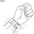
- Figs. 2 and 3 are views illustrating a method of securing the body portion 20 to the wrist with the band member 3 of the biometric information measurement device 100.
- the user of the biometric information measurement device 100 moves the tip end of the band member 3 from the back side of the hand toward the hand palm side, inserts the tip end into the hole portion 12, and then pulls out the tip end of the band member 3 from the hole portion 11.
- the resulting state is the state of Figs. 2 and 3 .
- the tip end of the band member 3 When, in the state of Figs. 2 and 3 , the tip end of the band member 3 is strongly pulled, it is possible to obtain a state where the body portion 20 is secured to the wrist H. In the state, the band member 3 has a part which is in contact with the process Sa of the ulna S that is in the wrist of the user (see Fig. 3 ).
- Fig. 4 is a plan view of the band member 3 which is secured to the band fastener 22, as seen from the side of the contact surface with respect to the wrist.
- Fig. 5 is a plan view of the band member 3 which is secured to the band fastener 22, as seen from the side of the surface opposite to the contact surface with respect to the wrist.
- Figs. 4 and 5 are plan views of a state where the band member 3 is developed in one direction (the direction in which the band member is wound around the wrist), as seen in directions which are perpendicular respectively to the one direction and the short side direction of the band member 3.
- the band member 3 is a strip-shaped member which extends in the longitudinal direction (synonymous with the circumferential direction of the wrist H) of the body portion 20.
- the band member 3 is configured by a member which is lower in rigidity than the body portion 20, such as cloth, leather, or rubber.
- the band member 3 has two first regions 3A which are juxtaposed with a gap in the short side direction, and a second region 3B which is disposed between the two first regions 3A, and which is higher in stretchability than the first regions 3A.
- Each of the first regions 3A and the second region 3B has a rectangular shape which extends from one end in the longitudinal direction of the band member 3 to the other end.
- the stretchability of a member is a characteristic indicating the degree in which, when a force is applied to the member, the member extends in the application direction of the force.
- Examples of the configuration where the stretchability of the first regions 3A and that of the second region 3B are different from each other are: a configuration where the first regions 3A and the second region 3B are formed by materials having different stretchabilities; that where the first regions 3A and the second region 3B are formed by the same material, and the second region 3B is thinner than the first regions 3A; that where the first regions 3A and the second region 3B are formed by different materials, and the second region 3B is thinner than the first regions 3A; that where the first regions 3A and the second region 3B are formed by knitting with threads having the same quality, and their knitting processes are performed in different manners; and that where the first regions 3A and the second region 3B are formed materials having different stretchabilities, and the second region 3B is thinner than the first regions 3A (see Figs. 9 to 11 which will be described later).
- the basal end portion (the one end portion) in the longitudinal of the band member 3 is secured to the housing 2. Specifically, portions of the same surface of the band member 3 are bonded or sewn to each other in a state where the basal end side in the longitudinal direction is wound back from the band fastener 22, whereby the band member 3 is secured to the band fastener 22.
- the reference numeral 30H in Fig. 5 denotes the portion where the basal end side of the band member 3 is wound back and sewn or bonded to another portion.
- a tip end portion (other end portion) in the longitudinal direction of the band member 3 is in a free state where the portion is not supported by any member.
- the method of securing the basal end portion of the band member 3 to the housing 2 is not limited the above-described method.
- a configuration in which the basal end portion of the band member 3 is secured to the housing 2 by using screws or the like may be employed.
- a configuration in which the basal end portion of the band member 3 is secured to the band fastener 22 by using a hook and loop fastener may be employed.
- the second region 3B of the band member 3 is in contact with the process Sa of the ulna in the wrist H in the secured state where the body portion 20 is secured to the wrist H with the band member 3.
- the diameter of the wrist H and the position of the process Sa of the ulna are different among individuals.
- the range 3f which is indicated by the broken line in Figs. 4 and 5 indicates a range which is obtained by using data of hand shapes of many persons, and in which the band member 3 can be contacted with the process Sa of the ulna.
- a hook portion 3C in which fabrics are raised in hook-like shapes to constitute a hook and loop fastener, and a loop portion 3D in which fabrics are densely raised in loop-like shapes to constitute the hook and loop fastener are formed on the surface opposite to the contact surface of the band member 3 which is to be in contact with the wrist H in the secured state.
- the hook portion 3C constitutes the coupled portion
- the loop portion 3D constitutes the coupling portion.
- the hook and loop fastener which is configured by the hook portion 3C and the loop portion 3D constitutes means for detachably coupling a part of the band member 3 with another part of the band member 3.
- the loop portion 3D is disposed in the tip end portion of the band member 3.
- the hook portion 3C is disposed in a portion of the surface opposite to the contact surface of the band member 3 which is to be in contact with the wrist H, excluding the range 3f and the loop portion 3D.
- the biometric information measurement device 100 has the configuration in which the band member 3 for securing the body portion 20 to the wrist H includes the first regions 3A and the second region 3B.
- the second region 3B is in contact with the process Sa of the ulna.
- the second region 3B is higher in stretchability than the first regions 3A.
- the force which is applied from the process Sa of the ulna to the second region 3B is reduced by extension of the second region 3B.
- a pressure which is applied from the band member 3 to the process Sa of the ulna is reduced.
- the biometric information measurement device 100 As described above, securing of the body portion 20 is enabled without imposing a burden on the wrist. Therefore, the user strongly winds the band member 3 to cause the body portion 20 to be secured to the wrist, and the close contactness between the body portion 20 and the wrist H can be improved. As a result, the pulse wave detecting section 10 can be prevented from being displaced from a desired position, and a pulse wave can be accurately detected.
- the hook portion 3C and loop portion 3D which constitute the hook and loop fastener are disposed in portions other than the range 3f in the surface opposite to the contact surface with respect to the wrist in the band member 3. Therefore, it is possible to prevent the stretchability of the second region 3B in the range 3f from being lowered, and the pressure which is exerted from the band member 3 to the process Sa of the ulna can be effectively lowered.
- the hook and loop fastener does not exist in the portion which is to overlap with the range 3f.
- the hook portion 3C and the loop portion 3D are applied together, therefore, it is possible to prevent the band member 3 from being doubly closely placed above the process Sa of the ulna. Consequently, the pressure which is applied to the process Sa of the ulna in the secured state can be prevented from being increased, and the attachability of the biometric information measurement device 100 can be improved.
- the hook portion 3C may overlap with the range 3f. In this case, the stretchability of the second region 3B in a state where it includes the hook portion 3C is requested to be higher than that of the first regions 3A.
- the band member 3 of the biometric information measurement device 100 has the first regions 3A.
- the first regions 3A are lower in stretchability than the second region 3B.
- the band member 3 When the band member 3 is wound around the wrist, therefore, it is possible to prevent the whole band member 3 from excessively extending in the circumferential direction of the wrist, and the attachability of the biometric information measurement device 100 can be improved.
- the whole band member 3 In the secured state, moreover, the whole band member 3 is prevented from extending in the circumferential direction of the wrist. Therefore, the positional displacement of the pulse wave detecting section 10 can be prevented from occurring, and a pulse wave can be accurately detected.
- the stretchability in the short side direction (the direction perpendicular to the longitudinal direction) of the band member 3 is preferably higher than that of the band member 3 in the longitudinal direction of the band member 3.
- a configuration is preferable where the stretchability of the first regions 3A in the longitudinal direction of the band member 3 is identical with that of the second region 3B in the longitudinal direction of the band member 3 (the term "identical” may involve some tolerances), and the stretchability of the second region 3B in the short side direction of the band member 3 is higher than that of the first regions 3A in the short side direction of the band member 3.
- the force which causes the band member 3 in the secured state to extend in the longitudinal direction is suppressed, and therefore the positional displacement of the body portion 20 due to a motion of the wrist or the like can be prevented from occurring.
- the band member 3 In the second region 3B, moreover, the band member 3 easily extends in the short side direction of the band member 3. Therefore, it is possible to prevent the pressure which is applied to the process Sa of the ulna in the secured state, from being increased, and the attachability of the biometric information measurement device 100 can be improved.
- Fig. 6 is a view showing a first modification of the biometric information measurement device 100, and corresponding to Fig. 5 .
- the biometric information measurement device 100 shown in Fig. 6 is configured in the same manner as Fig. 5 except that the position of the hook portion 3C is changed to a position on the outer circumferential surface of the housing 2.
- the hook portion 3C and the loop portion 3D are applied together, it is possible to prevent the band member 3 from being doubly closely placed above the process Sa of the ulna, and the attachability of the biometric information measurement device 100 can be improved.
- a hook and loop fastener is used as means for maintaining the state where the body portion 20 is secured to the wrist with the band member 3, the means is not limited to a hook and loop fastener.
- a clasp member which is used in a known watchband may be employed. Even in the case where a clasp member is employed as means for detachably coupling a part of the band member 3 with another part of the band member 3, or means for detachably coupling a part of the band member 3 with the housing 2, when the clasp member is disposed in a position excluding the range 3f, the attachability of the biometric information measurement device 100 can be improved.
- Fig. 7 is a view showing a second modification of the biometric information measurement device 100, and corresponding to Fig. 4 .
- the biometric information measurement device 100 shown in Fig. 7 is configured in the same manner as Fig. 4 except that the first region 3A and second region 3B of the band member 3 have different shapes.
- the above-described range 3f is configured by the second region 3B, and the region other than the second region 3B is configured by the first region 3A.
- the majority of the band member 3 is configured by the first region 3A, and therefore the force which causes the band member 3 in the secured state to extend in the longitudinal direction is suppressed. Consequently, the positional displacement of the body portion 20 due to a motion of the wrist or the like can be prevented from occurring.
- the second region 3B has high stretchability, it is possible to prevent the pressure which is applied to the process Sa of the ulna, from being increased, and the attachability of the biometric information measurement device 100 can be improved.
- Fig. 8 is a view showing a third modification of the biometric information measurement device 100, and corresponding to Fig. 5 .
- the biometric information measurement device 100 shown in Fig. 8 is configured in the same manner as Fig. 5 except that the length of the housing 2 in the circumferential direction of the wrist is shortened, and the hook portion 3C is disposed in a different position.
- the hook portion 3C of the band member 3 is disposed between the range 3f and an end portion of the housing 2.
- the stretchability of the second region 3B is relatively high because the second region 3B is smaller in thickness than the first regions 3A, even when the second region 3B doubly overlaps with the process Sa of the ulna, particularly, the thickness can be suppressed, and therefore the influence on the attachability of the device is weak.
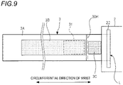
- Fig. 9 is a view showing a fourth modification of the biometric information measurement device 100, and corresponding to Fig. 5 .
- the band member 3 of the biometric information measurement device 100 shown in Fig. 9 is configured in the same manner as Fig. 8 except that the second region 3B is surrounded by the first region 3A, the loop portion 3D is deleted, and a loop portion is formed on the surface opposite to the contact surface with respect to the wrist in the first region 3A.
- Fig. 10 is an exploded perspective view of the band member 3 shown in Fig. 9 .
- the band member 3 of the biometric information measurement device 100 shown in Fig. 9 includes a first member 30A, a second member 30B which is secured to the rear surface of the first member 30A, and the hook portion 3C which is secured to the rear surface of the second member 30B.
- the band member 3 is folded back in a folding line L so that the hook portion 3C is located above the front surface of the first member 30A.
- the rear surface of the second member 30B other than the folded back portion constitutes a contact surface which is to be in contact with the wrist.
- the surface on which the hook portion 3C that is to be folded back and secured to the front surface of the first member 30A is formed, and the front surface of the first member 30A other than the surface constitute the surface opposite to the contact surface.
- the first member 30A is a strip-shaped member which extends along the circumferential direction of the wrist, and has an opening 30a.
- the plan shape of the opening 30a is identical with that of the second region 3B shown in Fig. 9 , and, in the secured state, the opening 30a covers the above-described range 3f.
- a loop portion which cooperates with the hook portion 3C to constitute a hook and loop fastener is formed on the front surface of the first member 30A.
- the second member 30B is a strip-shaped member which extends along the circumferential direction of the wrist, and made of a material which is higher in stretchability than the first member 30A.
- the hook portion 3C is secured to the rear surface of a tip end portion (the portion which is on the tip end side of the folding line L) of the second member 30B.
- the overlapping portions of the first member 30A and the second member 30B constitute the first region 3A. Moreover, the overlapping portion of the opening 30a of the first member 30A, and the second member 30B constitutes the second region 3B. According to the configuration of Fig. 10 , the band member 3 is configured into the two-layer structure, and therefore the pressure which is applied from the ulna is caused to escape, and the attachability can be improved while sufficiently ensuring the winding strength of the band member 3.
- Fig. 11 is an exploded perspective view showing a modification of the band member 3 of the biometric information measurement device 100 shown in Fig. 9 .
- the band member 3 shown in Fig. 11 includes a third member 30D, a fourth member 30E which is secured to the rear surface of the third member 30D, a fifth member 30F which is secured to the rear surface of the fourth member 30E, and the hook portion 3C which is secured to the rear surface of the fifth member 30F.
- the band member 3 is folded back in a folding line L so that the hook portion 3C is located above the front surface of the third member 30D.
- the rear surface of the fifth member 30F other than the folded back portion constitutes a contact surface which is to be in contact with the wrist.
- the surface on which the hook portion 3C that is to be folded back and secured to the front surface of the third member 30D is formed, and the front surface of the third member 30D other than the surface constitute the surface opposite to the contact surface.
- the third member 30D is a strip-shaped member which extends along the circumferential direction of the wrist.
- a loop portion which cooperates with the hook portion 3C to constitute a hook and loop fastener is formed on the front surface of third member 30D.
- the fourth member 30E is a strip-shaped member which extends along the circumferential direction of the wrist, and has an opening 30b.
- the plan shape of the opening 30b is identical with that of the second region 3B shown in Fig. 9 , and, in the secured state, the opening 30b covers the above-described range 3f.
- the fifth member 30F is a strip-shaped member which extends along the circumferential direction of the wrist, and made of a material which is higher in stretchability than the third member 30D and the fourth member 30E.
- the hook portion 3C is secured to the rear surface of a tip end portion (the portion which is on the tip end side of the folding line L) of the fifth member 30F.
- the overlapping portions of the third member 30D, the fourth member 30E, and the fifth member 30F constitute the first region 3A.
- the overlapping portion of the third member 30D, the opening 30b of the fourth member 30E, and the fifth member 30F constitutes the second region 3B.
- the band member 3 is configured into the three-layer structure, and therefore the pressure which is applied from the ulna is caused to escape, and the attachability can be improved while sufficiently ensuring the winding strength of the band member 3.
- the body portion 20 is placed in a position where the process Sa of the ulna is exposed in the secured state.
- the invention can be applied also to a biometric information measurement device in which a body portion is placed in a position where the process of the radius is exposed in the secured state.
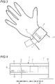
- the invention can be applied also to a biometric information measurement device 100A in which, as shown in Fig. 12 , a body portion 20A including a pulse wave detecting section 10A is secured to the hand back side of the wrist H with a strip-shaped band member 30.
- the body portion 20A is placed in a position where the process Ta of the radius is exposed in a state where the body portion 20A is secured to the wrist H with the band member 30. In the state where the body portion 20A is secured to the wrist H with the band member 30, a part of the band member 30 is in contact with the process Ta of the radius.
- the range where the member can contacted with the process Ta of the radius is set as the above-described second range 3B, and the region other than the second range 3B is set as the above-described first region 3A, therefore, the pressure which is applied from the band member 30 to the process Ta of the radius is lowered, and the attachability of the biometric information measurement device can be improved.
- a pulse wave detector comprising: a body portion including a pulse wave detection sensor which detects a pulse wave from an artery in a wrist of a user; and a strip-shaped band member for securing the body portion to the wrist, wherein in a secured state where the body portion is secured to the wrist with the band member, the body portion is placed in a position where a process of an ulna in the wrist or a process of a radius in the wrist is exposed, wherein the band member includes a first region, and a second region which is higher in stretchability than the first region, and wherein in the secured state, the second region is at least in contact with the process of the ulna in the wrist or the process of the radius in the wrist, wherein a stretchability of the second region in a longitudinal direction of the band member is lower than a stretchability of the second region in a direction perpendicular to the longitudinal direction.
- the stretchability of the second region in the longitudinal direction of the band member is identical with a stretchability of the first region in the longitudinal direction.
- the band member has a hook and loop fastener for detachably coupling together a part of the band member and another part, on a surface opposite to a surface which is in contact with the wrist, and at least one of a coupled portion of the hook and loop fastener, and a coupling portion which is coupled with the coupled portion is disposed on a surface of the opposite surface other than a region where, in the secured state, the portion overlaps with the process of the ulna in the wrist or the process of the radius in the wrist.
- the band member has a first portion which, in the secured state, is in contact with the process of the ulna in the wrist or the process of the radius in the wrist, and a second portion which overlaps with the first portion, and the first portion and the second portion are the second region.
- a biometric information measurement device including: the pulse wave detector; and a biometric information calculating section which calculates biometric information based on the pulse wave detected by the pulse wave detector.
- the invention is very convenient and effective particularly in application to a blood pressure monitor or the like.
Description
- The present invention relates to a pulse wave detector and a biometric information measurement device.
- A biometric information measurement device is known that, in a state where a pressure sensor is directly contacted with a living body portion through which an artery such as the radial artery in the wrist passes, can measure biometric information such as the heart rate, the pulse rate, or the blood pressure by using information detected by the sensor (for example, see
Patent Literatures 1 to 3). -
Patent Literature 1 discloses a biometric information measurement device in which an opening for avoiding the ulna is disposed in a portion that is to be wound around the back side of the hand in a state where the device is attached to the wrist, whereby the state where the device is attached to the wrist is enabled to be stably maintained. -
Patent Literature 2 discloses a biometric information measurement device in which a band that is to be wound around the wrist, and that is stretchable and contractible in the winding direction is provided with: a marking portion that stretches or contracts in connection with stretching or contraction of the band, and that indicates the band wound strength depending on the degree of stretching or contraction of the band; and a reference button functioning as a reference for determining whether the degree of stretching or contraction indicated by the marking portion corresponds to the optimum band wound strength or not. - According to the biometric information measurement device, when the attachment of the device is performed by using the marking portion and the reference button, the device can be attached at the optimum band wound strength irrespective of the diameter of the wrist of the user.
-
Patent Literature 3 discloses a biometric information measurement device in which both end portions of a band portion that is to be wound around the wrist are divided into three parts, and one and other ends of the divided band parts are enabled to be respectively secured. Patent Literature 4 relates to a band for a wrist-mounted type living body measuring apparatus. Patent Literature 5 discloses a wrist type blood pressure meter cuff. Patent Literature 6 relates to a device for mounting on a wrist. Patent Literature 7 discloses a biometric measuring device. -
- Patent Literature 1:
JP-A-2008-168054 - Patent Literature 2:
JP-A-05-329117 - Patent Literature 3:
JP-A-S51-041285 - Patent Literature 4:
JP-A-2008-168054 - Patent Literature 5:
US 2004/193059 A1 - Patent Literature 6:
JP-A-2010-220948 - Patent Literature 7:
US 2002/151775 A1 - Each of the biometric information measurement devices disclosed in
Patent Literatures Patent Literatures - When a highly stretchable material is used in the band, the feeling and easiness of attachment of the device can be improved. In the case of a band having a high stretchability, after the device is secured to the wrist, however, there arises a possibility that displacement of the position of the pressure sensor portion may be caused by stretching or contraction of the band portion, and therefore it is difficult to accurately measure biometric information.
- In the biometric information measurement device of
Patent Literature 3, pressure sensors are secured to the divided parts, respectively, thereby enabling the pressing positions of the pressure sensors to be adjustable. However, the pressure sensors are disposed on the band itself, and therefore there is a high possibility that the positions of the pressure sensors may be displaced by a motion of the hand. As a result, the device cannot accurately measure biometric information. - Although biometric information measurement devices which detect a pressure pulse wave by using a pressure sensor have been described above, similar problems occur also in a biometric information measurement device in which, for example, a volume pulse wave is detected by using a photoelectric sensor.
- The invention has been conducted in view of the above circumstances. It is an object of the invention to provide a pulse wave detector in which the feeling and easiness of attachment to the wrist are improved, and which can accurately detect a pulse wave, and also a biometric information measurement device including the detector.
- The invention provides a pulse wave detector and a biometric information measurement device as recited in the independent claims. Advantageous embodiments are set out in the dependent claims. According to the invention, there is provided a pulse wave detector comprising: a body portion including a pulse wave detection sensor which detects a pulse wave from an artery in a wrist of a user; and a strip-shaped band member for securing the body portion to the wrist, wherein in a secured state where the body portion is secured to the wrist with the band member, the body portion is placed in a position where a process of an ulna in the wrist or a process of a radius in the wrist is exposed, wherein the band member includes a first region, and a second region which is higher in stretchability than the first region, and wherein in the secured state, the second region is at least in contact with the process of the ulna in the wrist or the process of the radius in the wrist, wherein a stretchability of the second region in a longitudinal direction of the band member is lower than a stretchability of the second region in a direction perpendicular to the longitudinal direction.
- According to the invention, there is provided a biometric information measurement device including: the pulse wave detector; and a biometric information calculating section which calculates biometric information based on the pulse wave detected by the pulse wave detector.
- According to the invention, it is possible to provide a pulse wave detector in which the feeling and easiness of attachment to the wrist are improved, and a pulse wave can be accurately detected, and also a biometric information measurement device including the detector.
-
- [
Fig. 1] Fig. 1 is a diagram showing the external configuration of a biometricinformation measurement device 100 for illustrating an embodiment of the invention. - [
Fig. 2] Fig. 2 is a view illustrating a method of securing abody portion 20 to the wrist with aband member 3 of the biometricinformation measurement device 100. - [
Fig. 3] Fig. 3 is a view illustrating the method of securing thebody portion 20 to the wrist with theband member 3 of the biometricinformation measurement device 100. - [
Fig. 4] Fig. 4 is a plan view of theband member 3 which is secured to aband fastener 22, as seen from a side of a contact surface with respect to the wrist. - [
Fig. 5] Fig. 5 is a plan view of theband member 3 which is secured to theband fastener 22, as seen from the side of a surface opposite to the contact surface with respect to the wrist. - [
Fig. 6] Fig. 6 is a view showing a first modification of the biometricinformation measurement device 100. - [
Fig. 7] Fig. 7 is a view showing a second modification of the biometricinformation measurement device 100. - [
Fig. 8] Fig. 8 is a view showing a third modification of the biometricinformation measurement device 100. - [
Fig. 9] Fig. 9 is a view showing a fourth modification of the biometricinformation measurement device 100. - [
Fig. 10] Fig. 10 is an exploded perspective view of theband member 3 shown inFig. 9 . - [
Fig. 11] Fig. 11 is an exploded perspective view showing a modification of theband member 3 of the biometricinformation measurement device 100 shown inFig. 9 . - [
Fig. 12] Fig. 12 is a diagram showing the configuration of a biometricinformation measurement device 100A for illustrating an embodiment of the invention. - Hereinafter, embodiments of the invention will be described with reference to the drawings.
-
Fig. 1 is a diagram showing the external configuration of a biometricinformation measurement device 100 for illustrating an embodiment of the invention. - The biometric
information measurement device 100 includes abody portion 20, and a strip-shaped band member 3 which is not shown inFig. 1 , and which will be described later.Fig. 1 shows a secured state where thebody portion 20 is secured to the wrist H with theband member 3. -
Fig. 1 shows the left wrist H of the user of the biometricinformation measurement device 100. The near side of the figure coincides with the direction in which the hand of the user exists. The upper side of the figure is in the direction along which the palm of the hand is oriented. In the wrist H, the radius T, the ulna S, and the radial artery TD are shown. - The biometric
information measurement device 100 has a pulsewave detecting section 10 which detects a pulse wave (a pressure pulse wave or a volume pulse wave) from the radial artery TD that extends along the radius T in the wrist H of the user, and measures biometric information such as the hear rate, the pulse rate, or the blood pressure value based on the pulse wave detected by the pulsewave detecting section 10. - The pulse
wave detecting section 10 may have a known configuration. For example, the pulsewave detecting section 10 has a pressure sensor, and a mechanism which presses it against the skin, and detects a pressure pulse wave by using the pressure sensor. Alternatively, the pulsewave detecting section 10 has a photoelectric sensor, and detects a volume pulse wave from a signal detected by the photoelectric sensor. The pressure sensor or the photoelectric sensor constitutes the pulse wave detection sensor. - The
body portion 20 of the biometricinformation measurement device 100 includes the pulsewave detecting section 10, and a biometric information calculating section that is not shown, and that calculates biometric information such as the heart rate, the pulse rate, or the blood pressure value based on the pulse wave detected by the pulsewave detecting section 10. - The biometric information calculating section may be disposed in an apparatus other than the biometric
information measurement device 100. Namely, thebody portion 20 of the biometricinformation measurement device 100 is requested to have at least the pulsewave detecting section 10. The biometricinformation measurement device 100 functions as the pulse wave detector. - The
body portion 20 is configured so as to be woundable in the circumferential direction of the wrist H, and to be placed in a position where the process of the ulna S in the wrist H is exposed in the state where the body portion is secured to the wrist H with theband member 3. In other words, thebody portion 20 is configured so that the portion between the both ends in the circumferential direction of the wrist H does not cover the ulna S in the state where the body portion is secured to the wrist H with theband member 3. - The
body portion 20 is configured by ahousing 1 which accommodates the pulsewave detecting section 10, and ahousing 2 which is coupled with thehousing 1. Thehousing 2 is coupled with thehousing 1 by securing such as adhesion or welding, or detachably coupled with thehousing 1 by coupling pins. - The
housing 1 is configured mainly by a first rigid member having a high rigidity in order to stabilize the position of the pulsewave detecting section 10 with respect to the radial artery TD in the secured state, and to protect the pulsewave detecting section 10 including precision elements. As the first rigid member, for example, a resin or a metal is used. - A part or the whole of the
housing 2 is configured by a second rigid member having a rigidity which is lower than the first rigidity. For example, thehousing 2 is configured by the second rigid member in a range extending from the outer circumferential surface (the surface opposite to the surface which is opposed to the wrist H) to a predetermined thickness, and by the first rigid member in the other part. - The member which is lower in rigidity than the
housing 1 is used in the outer circumferential surface of thehousing 2 as described above, thereby facilitating thehousing 2 to be deformed in accordance with the shape of the wrist H. As the second rigid member, for example, an elastic member, a shape-memory alloy, or the like is used. - Although, in
Fig. 1 , thebody portion 20 including the pulsewave detecting section 10 is split into thehousing 1 and thehousing 2, the body portion may be configured by a completely single member. - A
band fastener 22 for securing theband member 3 is disposed on the inner circumferential surface (the surface which is opposed to the wrist H) of thehousing 2. In the example ofFig. 1 , theband fastener 22 is configured by a columnar metal fitting. - In the outer circumferential surface (the surface opposite to the surface opposed to the wrist H) of the
housing 1,hole portions band member 3 with thehousing 1 are disposed in juxtaposition with each other in the circumferential direction of the wrist H. -
Figs. 2 and3 are views illustrating a method of securing thebody portion 20 to the wrist with theband member 3 of the biometricinformation measurement device 100. - In a state where the
body portion 20 is temporarily placed on the wrist, as shown inFig. 3 , the user of the biometricinformation measurement device 100 moves the tip end of theband member 3 from the back side of the hand toward the hand palm side, inserts the tip end into thehole portion 12, and then pulls out the tip end of theband member 3 from thehole portion 11. The resulting state is the state ofFigs. 2 and3 . - When, in the state of
Figs. 2 and3 , the tip end of theband member 3 is strongly pulled, it is possible to obtain a state where thebody portion 20 is secured to the wrist H. In the state, theband member 3 has a part which is in contact with the process Sa of the ulna S that is in the wrist of the user (seeFig. 3 ). -
Fig. 4 is a plan view of theband member 3 which is secured to theband fastener 22, as seen from the side of the contact surface with respect to the wrist.Fig. 5 is a plan view of theband member 3 which is secured to theband fastener 22, as seen from the side of the surface opposite to the contact surface with respect to the wrist.Figs. 4 and5 are plan views of a state where theband member 3 is developed in one direction (the direction in which the band member is wound around the wrist), as seen in directions which are perpendicular respectively to the one direction and the short side direction of theband member 3. - The
band member 3 is a strip-shaped member which extends in the longitudinal direction (synonymous with the circumferential direction of the wrist H) of thebody portion 20. Theband member 3 is configured by a member which is lower in rigidity than thebody portion 20, such as cloth, leather, or rubber. - In the example shown in
Figs. 4 and5 , theband member 3 has twofirst regions 3A which are juxtaposed with a gap in the short side direction, and asecond region 3B which is disposed between the twofirst regions 3A, and which is higher in stretchability than thefirst regions 3A. Each of thefirst regions 3A and thesecond region 3B has a rectangular shape which extends from one end in the longitudinal direction of theband member 3 to the other end. - The stretchability of a member is a characteristic indicating the degree in which, when a force is applied to the member, the member extends in the application direction of the force. When a predetermined force is applied to an arbitrary region, the larger the elongation amount of the arbitrary region in the application direction of the force, the higher the stretchability of the arbitrary region.
- Examples of the configuration where the stretchability of the
first regions 3A and that of thesecond region 3B are different from each other are: a configuration where thefirst regions 3A and thesecond region 3B are formed by materials having different stretchabilities; that where thefirst regions 3A and thesecond region 3B are formed by the same material, and thesecond region 3B is thinner than thefirst regions 3A; that where thefirst regions 3A and thesecond region 3B are formed by different materials, and thesecond region 3B is thinner than thefirst regions 3A; that where thefirst regions 3A and thesecond region 3B are formed by knitting with threads having the same quality, and their knitting processes are performed in different manners; and that where thefirst regions 3A and thesecond region 3B are formed materials having different stretchabilities, and thesecond region 3B is thinner than thefirst regions 3A (seeFigs. 9 to 11 which will be described later). - The basal end portion (the one end portion) in the longitudinal of the
band member 3 is secured to thehousing 2. Specifically, portions of the same surface of theband member 3 are bonded or sewn to each other in a state where the basal end side in the longitudinal direction is wound back from theband fastener 22, whereby theband member 3 is secured to theband fastener 22. Thereference numeral 30H inFig. 5 denotes the portion where the basal end side of theband member 3 is wound back and sewn or bonded to another portion. A tip end portion (other end portion) in the longitudinal direction of theband member 3 is in a free state where the portion is not supported by any member. - The method of securing the basal end portion of the
band member 3 to thehousing 2 is not limited the above-described method. For example, a configuration in which the basal end portion of theband member 3 is secured to thehousing 2 by using screws or the like may be employed. Alternatively, a configuration in which the basal end portion of theband member 3 is secured to theband fastener 22 by using a hook and loop fastener may be employed. - The
second region 3B of theband member 3 is in contact with the process Sa of the ulna in the wrist H in the secured state where thebody portion 20 is secured to the wrist H with theband member 3. The diameter of the wrist H and the position of the process Sa of the ulna are different among individuals. When data of hand shapes of many persons are used, however, it is possible to design theband member 3 in which thesecond region 3B is in contact with the process Sa of the ulna in the secured state. Therange 3f which is indicated by the broken line inFigs. 4 and5 indicates a range which is obtained by using data of hand shapes of many persons, and in which theband member 3 can be contacted with the process Sa of the ulna. - As shown in
Fig. 5 , ahook portion 3C in which fabrics are raised in hook-like shapes to constitute a hook and loop fastener, and aloop portion 3D in which fabrics are densely raised in loop-like shapes to constitute the hook and loop fastener are formed on the surface opposite to the contact surface of theband member 3 which is to be in contact with the wrist H in the secured state. Thehook portion 3C constitutes the coupled portion, and theloop portion 3D constitutes the coupling portion. - The hook and loop fastener which is configured by the
hook portion 3C and theloop portion 3D constitutes means for detachably coupling a part of theband member 3 with another part of theband member 3. - The
loop portion 3D is disposed in the tip end portion of theband member 3. Thehook portion 3C is disposed in a portion of the surface opposite to the contact surface of theband member 3 which is to be in contact with the wrist H, excluding therange 3f and theloop portion 3D. - In the state shown in
Figs. 2 and3 , the user pulls the tip end portion of theband member 3, and winds theband member 3 around the wrist H. Then, the user applies theloop portion 3D disposed on theband member 3, to thehook portion 3C disposed on theband member 3. As a result, the securing of thebody portion 20 to the wrist H with theband member 3 is completed. - As described above, the biometric
information measurement device 100 has the configuration in which theband member 3 for securing thebody portion 20 to the wrist H includes thefirst regions 3A and thesecond region 3B. In the secured state, thesecond region 3B is in contact with the process Sa of the ulna. Thesecond region 3B is higher in stretchability than thefirst regions 3A. In the state where theband member 3 is wound around the wrist H as shown inFigs. 2 and3 , therefore, the force which is applied from the process Sa of the ulna to thesecond region 3B is reduced by extension of thesecond region 3B. As a result, a pressure which is applied from theband member 3 to the process Sa of the ulna is reduced. - According to the biometric
information measurement device 100, as described above, securing of thebody portion 20 is enabled without imposing a burden on the wrist. Therefore, the user strongly winds theband member 3 to cause thebody portion 20 to be secured to the wrist, and the close contactness between thebody portion 20 and the wrist H can be improved. As a result, the pulsewave detecting section 10 can be prevented from being displaced from a desired position, and a pulse wave can be accurately detected. - In the biometric
information measurement device 100, moreover, thehook portion 3C andloop portion 3D which constitute the hook and loop fastener are disposed in portions other than therange 3f in the surface opposite to the contact surface with respect to the wrist in theband member 3. Therefore, it is possible to prevent the stretchability of thesecond region 3B in therange 3f from being lowered, and the pressure which is exerted from theband member 3 to the process Sa of the ulna can be effectively lowered. - Moreover, the hook and loop fastener does not exist in the portion which is to overlap with the
range 3f. When thehook portion 3C and theloop portion 3D are applied together, therefore, it is possible to prevent theband member 3 from being doubly closely placed above the process Sa of the ulna. Consequently, the pressure which is applied to the process Sa of the ulna in the secured state can be prevented from being increased, and the attachability of the biometricinformation measurement device 100 can be improved. - The
hook portion 3C may overlap with therange 3f. In this case, the stretchability of thesecond region 3B in a state where it includes thehook portion 3C is requested to be higher than that of thefirst regions 3A. - The
band member 3 of the biometricinformation measurement device 100 has thefirst regions 3A. Thefirst regions 3A are lower in stretchability than thesecond region 3B. When theband member 3 is wound around the wrist, therefore, it is possible to prevent thewhole band member 3 from excessively extending in the circumferential direction of the wrist, and the attachability of the biometricinformation measurement device 100 can be improved. In the secured state, moreover, thewhole band member 3 is prevented from extending in the circumferential direction of the wrist. Therefore, the positional displacement of the pulsewave detecting section 10 can be prevented from occurring, and a pulse wave can be accurately detected. - In the
second region 3B of theband member 3, the stretchability in the short side direction (the direction perpendicular to the longitudinal direction) of theband member 3 is preferably higher than that of theband member 3 in the longitudinal direction of theband member 3. - For example, a configuration is preferable where the stretchability of the
first regions 3A in the longitudinal direction of theband member 3 is identical with that of thesecond region 3B in the longitudinal direction of the band member 3 (the term "identical" may involve some tolerances), and the stretchability of thesecond region 3B in the short side direction of theband member 3 is higher than that of thefirst regions 3A in the short side direction of theband member 3. - According to the configuration, the force which causes the
band member 3 in the secured state to extend in the longitudinal direction is suppressed, and therefore the positional displacement of thebody portion 20 due to a motion of the wrist or the like can be prevented from occurring. In thesecond region 3B, moreover, theband member 3 easily extends in the short side direction of theband member 3. Therefore, it is possible to prevent the pressure which is applied to the process Sa of the ulna in the secured state, from being increased, and the attachability of the biometricinformation measurement device 100 can be improved. - Next, modifications of the biometric
information measurement device 100 will be described. -
Fig. 6 is a view showing a first modification of the biometricinformation measurement device 100, and corresponding toFig. 5 . The biometricinformation measurement device 100 shown inFig. 6 is configured in the same manner asFig. 5 except that the position of thehook portion 3C is changed to a position on the outer circumferential surface of thehousing 2. - According to the configuration, when the
hook portion 3C and theloop portion 3D are applied together, it is possible to prevent theband member 3 from being doubly closely placed above the process Sa of the ulna, and the attachability of the biometricinformation measurement device 100 can be improved. - Although, in
Figs. 5 and 6 , a hook and loop fastener is used as means for maintaining the state where thebody portion 20 is secured to the wrist with theband member 3, the means is not limited to a hook and loop fastener. - For example, a clasp member which is used in a known watchband may be employed. Even in the case where a clasp member is employed as means for detachably coupling a part of the
band member 3 with another part of theband member 3, or means for detachably coupling a part of theband member 3 with thehousing 2, when the clasp member is disposed in a position excluding therange 3f, the attachability of the biometricinformation measurement device 100 can be improved. -
Fig. 7 is a view showing a second modification of the biometricinformation measurement device 100, and corresponding toFig. 4 . The biometricinformation measurement device 100 shown inFig. 7 is configured in the same manner asFig. 4 except that thefirst region 3A andsecond region 3B of theband member 3 have different shapes. - In the
band member 3 shown inFig. 7 , the above-describedrange 3f is configured by thesecond region 3B, and the region other than thesecond region 3B is configured by thefirst region 3A. - According to the configuration, the majority of the
band member 3 is configured by thefirst region 3A, and therefore the force which causes theband member 3 in the secured state to extend in the longitudinal direction is suppressed. Consequently, the positional displacement of thebody portion 20 due to a motion of the wrist or the like can be prevented from occurring. Since thesecond region 3B has high stretchability, it is possible to prevent the pressure which is applied to the process Sa of the ulna, from being increased, and the attachability of the biometricinformation measurement device 100 can be improved. -
Fig. 8 is a view showing a third modification of the biometricinformation measurement device 100, and corresponding toFig. 5 . The biometricinformation measurement device 100 shown inFig. 8 is configured in the same manner asFig. 5 except that the length of thehousing 2 in the circumferential direction of the wrist is shortened, and thehook portion 3C is disposed in a different position. - In the biometric
information measurement device 100 shown inFig. 8 , thehook portion 3C of theband member 3 is disposed between therange 3f and an end portion of thehousing 2. - In the configuration shown in
Fig. 8 , in the state where thehook portion 3C and theloop portion 3D are applied together, two members or the two portions of thesecond region 3B overlap with each other above the process Sa of the ulna. Even in the configuration where theband member 3 doubly overlaps with the process Sa of the ulna as described above, the stretchability of thesecond region 3B is high, and therefore the pressure which is applied to the process Sa of the ulna can be lowered. - In the case where the stretchability of the
second region 3B is relatively high because thesecond region 3B is smaller in thickness than thefirst regions 3A, even when thesecond region 3B doubly overlaps with the process Sa of the ulna, particularly, the thickness can be suppressed, and therefore the influence on the attachability of the device is weak. -
Fig. 9 is a view showing a fourth modification of the biometricinformation measurement device 100, and corresponding toFig. 5 . Theband member 3 of the biometricinformation measurement device 100 shown inFig. 9 is configured in the same manner asFig. 8 except that thesecond region 3B is surrounded by thefirst region 3A, theloop portion 3D is deleted, and a loop portion is formed on the surface opposite to the contact surface with respect to the wrist in thefirst region 3A. -
Fig. 10 is an exploded perspective view of theband member 3 shown inFig. 9 . - As shown in
Fig. 10 , theband member 3 of the biometricinformation measurement device 100 shown inFig. 9 includes afirst member 30A, asecond member 30B which is secured to the rear surface of thefirst member 30A, and thehook portion 3C which is secured to the rear surface of thesecond member 30B. - The
band member 3 is folded back in a folding line L so that thehook portion 3C is located above the front surface of thefirst member 30A. In theband member 3, the rear surface of thesecond member 30B other than the folded back portion constitutes a contact surface which is to be in contact with the wrist. Moreover, the surface on which thehook portion 3C that is to be folded back and secured to the front surface of thefirst member 30A is formed, and the front surface of thefirst member 30A other than the surface constitute the surface opposite to the contact surface. - The
first member 30A is a strip-shaped member which extends along the circumferential direction of the wrist, and has anopening 30a. The plan shape of theopening 30a is identical with that of thesecond region 3B shown inFig. 9 , and, in the secured state, theopening 30a covers the above-describedrange 3f. A loop portion which cooperates with thehook portion 3C to constitute a hook and loop fastener is formed on the front surface of thefirst member 30A. - The
second member 30B is a strip-shaped member which extends along the circumferential direction of the wrist, and made of a material which is higher in stretchability than thefirst member 30A. - The
hook portion 3C is secured to the rear surface of a tip end portion (the portion which is on the tip end side of the folding line L) of thesecond member 30B. - In the
band member 3 shown inFig. 10 , the overlapping portions of thefirst member 30A and thesecond member 30B constitute thefirst region 3A. Moreover, the overlapping portion of theopening 30a of thefirst member 30A, and thesecond member 30B constitutes thesecond region 3B. According to the configuration ofFig. 10 , theband member 3 is configured into the two-layer structure, and therefore the pressure which is applied from the ulna is caused to escape, and the attachability can be improved while sufficiently ensuring the winding strength of theband member 3. -
Fig. 11 is an exploded perspective view showing a modification of theband member 3 of the biometricinformation measurement device 100 shown inFig. 9 . - The
band member 3 shown inFig. 11 includes athird member 30D, afourth member 30E which is secured to the rear surface of thethird member 30D, afifth member 30F which is secured to the rear surface of thefourth member 30E, and thehook portion 3C which is secured to the rear surface of thefifth member 30F. - The
band member 3 is folded back in a folding line L so that thehook portion 3C is located above the front surface of thethird member 30D. In theband member 3, the rear surface of thefifth member 30F other than the folded back portion constitutes a contact surface which is to be in contact with the wrist. Moreover, the surface on which thehook portion 3C that is to be folded back and secured to the front surface of thethird member 30D is formed, and the front surface of thethird member 30D other than the surface constitute the surface opposite to the contact surface. - The
third member 30D is a strip-shaped member which extends along the circumferential direction of the wrist. A loop portion which cooperates with thehook portion 3C to constitute a hook and loop fastener is formed on the front surface ofthird member 30D. - The
fourth member 30E is a strip-shaped member which extends along the circumferential direction of the wrist, and has anopening 30b. The plan shape of theopening 30b is identical with that of thesecond region 3B shown inFig. 9 , and, in the secured state, theopening 30b covers the above-describedrange 3f. - The
fifth member 30F is a strip-shaped member which extends along the circumferential direction of the wrist, and made of a material which is higher in stretchability than thethird member 30D and thefourth member 30E. - The
hook portion 3C is secured to the rear surface of a tip end portion (the portion which is on the tip end side of the folding line L) of thefifth member 30F. - In the
band member 3 shown inFig. 11 , the overlapping portions of thethird member 30D, thefourth member 30E, and thefifth member 30F constitute thefirst region 3A. Moreover, the overlapping portion of thethird member 30D, theopening 30b of thefourth member 30E, and thefifth member 30F constitutes thesecond region 3B. According to the configuration ofFig. 11 , theband member 3 is configured into the three-layer structure, and therefore the pressure which is applied from the ulna is caused to escape, and the attachability can be improved while sufficiently ensuring the winding strength of theband member 3. - In the biometric
information measurement device 100 which has been described above, thebody portion 20 is placed in a position where the process Sa of the ulna is exposed in the secured state. The invention can be applied also to a biometric information measurement device in which a body portion is placed in a position where the process of the radius is exposed in the secured state. - For example, the invention can be applied also to a biometric
information measurement device 100A in which, as shown inFig. 12 , abody portion 20A including a pulsewave detecting section 10A is secured to the hand back side of the wrist H with a strip-shapedband member 30. - In the biometric
information measurement device 100A, thebody portion 20A is placed in a position where the process Ta of the radius is exposed in a state where thebody portion 20A is secured to the wrist H with theband member 30. In the state where thebody portion 20A is secured to the wrist H with theband member 30, a part of theband member 30 is in contact with the process Ta of the radius. - When, in the
band member 30, the range where the member can contacted with the process Ta of the radius is set as the above-describedsecond range 3B, and the region other than thesecond range 3B is set as the above-describedfirst region 3A, therefore, the pressure which is applied from theband member 30 to the process Ta of the radius is lowered, and the attachability of the biometric information measurement device can be improved. - The presently disclosed embodiment should be considered in all respects to be illustrative and not restrictive. The scope of the invention is indicated by the appended claims rather than the foregoing description, and all changes which come within the meaning and range of equivalents thereof are intended to be embraced therein.
- As described above, the following matters are disclosed in the specification.
- Disclosed is a pulse wave detector according to the invention, comprising: a body portion including a pulse wave detection sensor which detects a pulse wave from an artery in a wrist of a user; and a strip-shaped band member for securing the body portion to the wrist, wherein in a secured state where the body portion is secured to the wrist with the band member, the body portion is placed in a position where a process of an ulna in the wrist or a process of a radius in the wrist is exposed, wherein the band member includes a first region, and a second region which is higher in stretchability than the first region, and wherein in the secured state, the second region is at least in contact with the process of the ulna in the wrist or the process of the radius in the wrist, wherein a stretchability of the second region in a longitudinal direction of the band member is lower than a stretchability of the second region in a direction perpendicular to the longitudinal direction.
- According to the disclosed pulse wave detector, the stretchability of the second region in the longitudinal direction of the band member is identical with a stretchability of the first region in the longitudinal direction.
- According to the disclosed pulse wave detector, the band member has a hook and loop fastener for detachably coupling together a part of the band member and another part, on a surface opposite to a surface which is in contact with the wrist, and at least one of a coupled portion of the hook and loop fastener, and a coupling portion which is coupled with the coupled portion is disposed on a surface of the opposite surface other than a region where, in the secured state, the portion overlaps with the process of the ulna in the wrist or the process of the radius in the wrist.
- According to the disclosed pulse wave detector, the band member has a first portion which, in the secured state, is in contact with the process of the ulna in the wrist or the process of the radius in the wrist, and a second portion which overlaps with the first portion, and the first portion and the second portion are the second region.
- Disclosed is a biometric information measurement device including: the pulse wave detector; and a biometric information calculating section which calculates biometric information based on the pulse wave detected by the pulse wave detector.
- The invention is very convenient and effective particularly in application to a blood pressure monitor or the like.
- Although the invention has been described with reference to the specific embodiments, the invention is not limited to the embodiments, and various changes can be made without departing from the scope of the disclosed invention.
- The application is based on
Japanese Patent Application (No. 2016-075966) filed on April 5, 2016 -
- 100, 100A
- Biometric Information Measurement Device
- 1, 2
- Housing
- 10, 10A
- Pulse Wave Detecting Section
- 11, 12
- Hole Portion
- 20, 20A
- Body Portion
- 22
- Band Fastener
- T
- Radius
- Ta
- Process of Radius
- S
- Ulna
- Sa
- Process of Ulna
- TD
- Radial Artery
- H
- Wrist
- 3, 30
- Band Member
- 3A
- First Region
- 3B
- Second Region
- 3C
- Hook Portion
- 3D
- Loop Portion
- 3f
- Range Where Device Can Be Contacted With Process Sa Of Ulna
- L
- Folding Line
- 30H
- Secured Portion
- 30A
- First Member
- 30B
- Second Member
- 30D
- Third Member
- 30E
- Fourth Member
- 30F
- Fifth Member
- 30a, 30b
- Opening
Claims (5)
- A pulse wave detector comprising:a body portion (20) including a pulse wave detection sensor which detects a pulse wave from an artery in a wrist of a user; anda strip-shaped band member (3) for securing the body portion (20) to the wrist,wherein in a secured state where the body portion (20) is secured to the wrist with the band member (3), the body portion (20) is placed in a position where a process of an ulna in the wrist or a process of a radius in the wrist is exposed,wherein the band member (3) includes a first region (3A), and a second region (3B) which is higher in stretchability than the first region (3A),wherein in the secured state, the second region (3B) is at least in contact with the process of the ulna in the wrist or the process of the radius in the wrist,characterized in thata stretchability of the second region (3B) in a longitudinal direction of the band member (3) is lower than a stretchability of the second region (3B) in a direction perpendicular to the longitudinal direction.
- The pulse wave detector according to claim 1,
wherein the stretchability of the second region (3B) in the longitudinal direction of the band member (3) is identical with a stretchability of the first region (3A) in the longitudinal direction. - The pulse wave detector according to claim 1 or 2,wherein the band member (3) has a hook and loop fastener for detachably coupling together a part of the band member (3) and another part, on a surface opposite to a surface which is in contact with the wrist, andwherein, of a coupled portion (3C) of the hook and loop fastener and a coupling portion (3D) which is coupled with the coupled portion (3C), at least the coupling portion (3D) is disposed in a tip end portion of the band member (3).
- The pulse wave detector according to any one of claims 1 to 3,
wherein the band member (3) has a first portion (30A) which has an opening (30a), and a second portion (30B) which is secured to a rear surface of the first portion, and an overlapping portion of the opening (30a) and the second portion (30B) constitutes the second region (3B). - A biometric information measurement device (100) including:the pulse wave detector according to any one of claims 1 to 4; anda biometric information calculating section which calculates biometric information based on the pulse wave detected by the pulse wave detector.
Applications Claiming Priority (2)
| Application Number | Priority Date | Filing Date | Title |
|---|---|---|---|
| JP2016075966A JP6728904B2 (en) | 2016-04-05 | 2016-04-05 | Pulse wave detection device and biological information measurement device |
| PCT/JP2017/012453 WO2017175618A1 (en) | 2016-04-05 | 2017-03-27 | Pulse wave detection device and biometric information measurement device |
Publications (3)
| Publication Number | Publication Date |
|---|---|
| EP3424416A1 EP3424416A1 (en) | 2019-01-09 |
| EP3424416A4 EP3424416A4 (en) | 2020-03-04 |
| EP3424416B1 true EP3424416B1 (en) | 2022-10-05 |
Family
ID=60001040
Family Applications (1)
| Application Number | Title | Priority Date | Filing Date |
|---|---|---|---|
| EP17778997.1A Active EP3424416B1 (en) | 2016-04-05 | 2017-03-27 | Pulse wave detection device and biometric information measurement device |
Country Status (5)
| Country | Link |
|---|---|
| US (1) | US11147512B2 (en) |
| EP (1) | EP3424416B1 (en) |
| JP (1) | JP6728904B2 (en) |
| CN (1) | CN109069012B (en) |
| WO (1) | WO2017175618A1 (en) |
Families Citing this family (3)
| Publication number | Priority date | Publication date | Assignee | Title |
|---|---|---|---|---|
| EP4151261A1 (en) | 2015-03-31 | 2023-03-22 | Fisher & Paykel Healthcare Limited | A user interface and system for supplying gases to an airway |
| CN114569856A (en) | 2016-08-11 | 2022-06-03 | 费雪派克医疗保健有限公司 | Collapsible catheter, patient interface and headgear connector |
| JP7107822B2 (en) * | 2018-11-30 | 2022-07-27 | シチズン時計株式会社 | Sphygmomanometer cuff |
Family Cites Families (14)
| Publication number | Priority date | Publication date | Assignee | Title |
|---|---|---|---|---|
| JPS5141285A (en) | 1974-10-04 | 1976-04-07 | Iwatsu Electric Co Ltd | MYAKUHAKEI |
| JPH05329117A (en) | 1992-05-28 | 1993-12-14 | Sanyo Electric Co Ltd | Band type information detection device |
| JP3475427B2 (en) * | 1998-02-16 | 2003-12-08 | セイコーエプソン株式会社 | Biological information measurement device |
| JP3931459B2 (en) * | 1998-05-22 | 2007-06-13 | カシオ計算機株式会社 | Band and wrist device |
| JP3636071B2 (en) * | 2000-12-25 | 2005-04-06 | 松下電工株式会社 | Sphygmomanometer cuff |
| JP3952957B2 (en) * | 2003-01-22 | 2007-08-01 | オムロンヘルスケア株式会社 | Cuff for wrist blood pressure monitor |
| JP2008168054A (en) * | 2007-01-15 | 2008-07-24 | Citizen Holdings Co Ltd | Band for wrist-mounted type living body measuring apparatus |
| JP5395484B2 (en) * | 2009-03-25 | 2014-01-22 | シチズンホールディングス株式会社 | Mounting device |
| JP5012941B2 (en) * | 2010-03-26 | 2012-08-29 | カシオ計算機株式会社 | Biological information measuring device |
| JP5691040B2 (en) * | 2011-10-27 | 2015-04-01 | ダイナエアー株式会社 | Humidity control system and operation monitoring method thereof |
| US9226663B2 (en) * | 2014-04-07 | 2016-01-05 | Physical Enterprises, Inc. | Systems and methods for optical isolation in measuring physiological parameters |
| US20170113059A1 (en) * | 2014-04-11 | 2017-04-27 | Wristspace, Llc | Wrist worn sensor |
| US9938646B2 (en) * | 2015-03-08 | 2018-04-10 | Apple Inc. | Woven band with different stretch regions |
| JP6172591B2 (en) | 2016-02-12 | 2017-08-02 | 株式会社リコー | Image forming apparatus |
-
2016
- 2016-04-05 JP JP2016075966A patent/JP6728904B2/en active Active
-
2017
- 2017-03-27 CN CN201780021334.9A patent/CN109069012B/en active Active
- 2017-03-27 WO PCT/JP2017/012453 patent/WO2017175618A1/en active Application Filing
- 2017-03-27 EP EP17778997.1A patent/EP3424416B1/en active Active
-
2018
- 2018-09-27 US US16/144,244 patent/US11147512B2/en active Active
Also Published As
| Publication number | Publication date |
|---|---|
| EP3424416A4 (en) | 2020-03-04 |
| US11147512B2 (en) | 2021-10-19 |
| WO2017175618A1 (en) | 2017-10-12 |
| CN109069012B (en) | 2021-08-20 |
| CN109069012A (en) | 2018-12-21 |
| JP6728904B2 (en) | 2020-07-22 |
| JP2017184998A (en) | 2017-10-12 |
| EP3424416A1 (en) | 2019-01-09 |
| US20190021668A1 (en) | 2019-01-24 |
Similar Documents
| Publication | Publication Date | Title |
|---|---|---|
| US11147512B2 (en) | Pulse wave detection device and biometric information measurement device | |
| EP3443894B1 (en) | Pulse wave detection device and biological information measuring device | |
| US20120253210A1 (en) | Cuff of Sphygmomanometer | |
| US11229371B2 (en) | Butterfly cuff | |
| US20180192890A1 (en) | Pulse wave detecting device | |
| CN211155745U (en) | Fixed-point pressurizing device and pulse diagnosis instrument | |
| US20190038155A1 (en) | Pulse wave detection device and biological information measuring device | |
| JP2017051273A (en) | Pressure pulse wave detection device | |
| CN109069015B (en) | Pulse wave detection device and biological information measurement device | |
| US11553847B2 (en) | Pulse wave detecting device | |
| CN107920756B (en) | Pulse wave detection device | |
| CN107242863A (en) | A kind of worn on the wrist heart rate, blood oxygen measuring device | |
| KR20090044238A (en) | Pulse wave measuring apparatus | |
| JP2017063984A (en) | Pulse wave detector | |
| GB2618434A (en) | Conduit securement device comprising a force sensor |
Legal Events
| Date | Code | Title | Description |
|---|---|---|---|
| STAA | Information on the status of an ep patent application or granted ep patent |
Free format text: STATUS: THE INTERNATIONAL PUBLICATION HAS BEEN MADE |
|
| PUAI | Public reference made under article 153(3) epc to a published international application that has entered the european phase |
Free format text: ORIGINAL CODE: 0009012 |
|
| STAA | Information on the status of an ep patent application or granted ep patent |
Free format text: STATUS: REQUEST FOR EXAMINATION WAS MADE |
|
| 17P | Request for examination filed |
Effective date: 20181005 |
|
| AK | Designated contracting states |
Kind code of ref document: A1 Designated state(s): AL AT BE BG CH CY CZ DE DK EE ES FI FR GB GR HR HU IE IS IT LI LT LU LV MC MK MT NL NO PL PT RO RS SE SI SK SM TR |
|
| AX | Request for extension of the european patent |
Extension state: BA ME |
|
| STAA | Information on the status of an ep patent application or granted ep patent |
Free format text: STATUS: REQUEST FOR EXAMINATION WAS MADE |
|
| DAV | Request for validation of the european patent (deleted) | ||
| DAX | Request for extension of the european patent (deleted) | ||
| RIC1 | Information provided on ipc code assigned before grant |
Ipc: A61B 5/00 20060101ALI20191008BHEP Ipc: A61B 5/02 20060101AFI20191008BHEP |
|
| A4 | Supplementary search report drawn up and despatched |
Effective date: 20200205 |
|
| RIC1 | Information provided on ipc code assigned before grant |
Ipc: A61B 5/00 20060101ALI20200130BHEP Ipc: A61B 5/02 20060101AFI20200130BHEP |
|
| GRAP | Despatch of communication of intention to grant a patent |
Free format text: ORIGINAL CODE: EPIDOSNIGR1 |
|
| STAA | Information on the status of an ep patent application or granted ep patent |
Free format text: STATUS: GRANT OF PATENT IS INTENDED |
|
| INTG | Intention to grant announced |
Effective date: 20220304 |
|
| GRAJ | Information related to disapproval of communication of intention to grant by the applicant or resumption of examination proceedings by the epo deleted |
Free format text: ORIGINAL CODE: EPIDOSDIGR1 |
|
| STAA | Information on the status of an ep patent application or granted ep patent |
Free format text: STATUS: REQUEST FOR EXAMINATION WAS MADE |
|
| GRAP | Despatch of communication of intention to grant a patent |
Free format text: ORIGINAL CODE: EPIDOSNIGR1 |
|
| STAA | Information on the status of an ep patent application or granted ep patent |
Free format text: STATUS: GRANT OF PATENT IS INTENDED |
|
| INTC | Intention to grant announced (deleted) | ||
| INTG | Intention to grant announced |
Effective date: 20220614 |
|
| GRAS | Grant fee paid |
Free format text: ORIGINAL CODE: EPIDOSNIGR3 |
|
| GRAA | (expected) grant |
Free format text: ORIGINAL CODE: 0009210 |
|
| STAA | Information on the status of an ep patent application or granted ep patent |
Free format text: STATUS: THE PATENT HAS BEEN GRANTED |
|
| AK | Designated contracting states |
Kind code of ref document: B1 Designated state(s): AL AT BE BG CH CY CZ DE DK EE ES FI FR GB GR HR HU IE IS IT LI LT LU LV MC MK MT NL NO PL PT RO RS SE SI SK SM TR |
|
| REG | Reference to a national code |
Ref country code: GB Ref legal event code: FG4D |
|
| REG | Reference to a national code |
Ref country code: CH Ref legal event code: EP |
|
| REG | Reference to a national code |
Ref country code: AT Ref legal event code: REF Ref document number: 1522234 Country of ref document: AT Kind code of ref document: T Effective date: 20221015 |
|
| REG | Reference to a national code |
Ref country code: IE Ref legal event code: FG4D |
|
| REG | Reference to a national code |
Ref country code: DE Ref legal event code: R096 Ref document number: 602017062407 Country of ref document: DE |
|
| REG | Reference to a national code |
Ref country code: LT Ref legal event code: MG9D |
|
| REG | Reference to a national code |
Ref country code: NL Ref legal event code: MP Effective date: 20221005 |
|
| REG | Reference to a national code |
Ref country code: AT Ref legal event code: MK05 Ref document number: 1522234 Country of ref document: AT Kind code of ref document: T Effective date: 20221005 |
|
| PG25 | Lapsed in a contracting state [announced via postgrant information from national office to epo] |
Ref country code: NL Free format text: LAPSE BECAUSE OF FAILURE TO SUBMIT A TRANSLATION OF THE DESCRIPTION OR TO PAY THE FEE WITHIN THE PRESCRIBED TIME-LIMIT Effective date: 20221005 |
|
| PG25 | Lapsed in a contracting state [announced via postgrant information from national office to epo] |
Ref country code: SE Free format text: LAPSE BECAUSE OF FAILURE TO SUBMIT A TRANSLATION OF THE DESCRIPTION OR TO PAY THE FEE WITHIN THE PRESCRIBED TIME-LIMIT Effective date: 20221005 Ref country code: PT Free format text: LAPSE BECAUSE OF FAILURE TO SUBMIT A TRANSLATION OF THE DESCRIPTION OR TO PAY THE FEE WITHIN THE PRESCRIBED TIME-LIMIT Effective date: 20230206 Ref country code: NO Free format text: LAPSE BECAUSE OF FAILURE TO SUBMIT A TRANSLATION OF THE DESCRIPTION OR TO PAY THE FEE WITHIN THE PRESCRIBED TIME-LIMIT Effective date: 20230105 Ref country code: LT Free format text: LAPSE BECAUSE OF FAILURE TO SUBMIT A TRANSLATION OF THE DESCRIPTION OR TO PAY THE FEE WITHIN THE PRESCRIBED TIME-LIMIT Effective date: 20221005 Ref country code: FI Free format text: LAPSE BECAUSE OF FAILURE TO SUBMIT A TRANSLATION OF THE DESCRIPTION OR TO PAY THE FEE WITHIN THE PRESCRIBED TIME-LIMIT Effective date: 20221005 Ref country code: ES Free format text: LAPSE BECAUSE OF FAILURE TO SUBMIT A TRANSLATION OF THE DESCRIPTION OR TO PAY THE FEE WITHIN THE PRESCRIBED TIME-LIMIT Effective date: 20221005 Ref country code: AT Free format text: LAPSE BECAUSE OF FAILURE TO SUBMIT A TRANSLATION OF THE DESCRIPTION OR TO PAY THE FEE WITHIN THE PRESCRIBED TIME-LIMIT Effective date: 20221005 |
|
| PG25 | Lapsed in a contracting state [announced via postgrant information from national office to epo] |
Ref country code: RS Free format text: LAPSE BECAUSE OF FAILURE TO SUBMIT A TRANSLATION OF THE DESCRIPTION OR TO PAY THE FEE WITHIN THE PRESCRIBED TIME-LIMIT Effective date: 20221005 Ref country code: PL Free format text: LAPSE BECAUSE OF FAILURE TO SUBMIT A TRANSLATION OF THE DESCRIPTION OR TO PAY THE FEE WITHIN THE PRESCRIBED TIME-LIMIT Effective date: 20221005 Ref country code: LV Free format text: LAPSE BECAUSE OF FAILURE TO SUBMIT A TRANSLATION OF THE DESCRIPTION OR TO PAY THE FEE WITHIN THE PRESCRIBED TIME-LIMIT Effective date: 20221005 Ref country code: IS Free format text: LAPSE BECAUSE OF FAILURE TO SUBMIT A TRANSLATION OF THE DESCRIPTION OR TO PAY THE FEE WITHIN THE PRESCRIBED TIME-LIMIT Effective date: 20230205 Ref country code: HR Free format text: LAPSE BECAUSE OF FAILURE TO SUBMIT A TRANSLATION OF THE DESCRIPTION OR TO PAY THE FEE WITHIN THE PRESCRIBED TIME-LIMIT Effective date: 20221005 Ref country code: GR Free format text: LAPSE BECAUSE OF FAILURE TO SUBMIT A TRANSLATION OF THE DESCRIPTION OR TO PAY THE FEE WITHIN THE PRESCRIBED TIME-LIMIT Effective date: 20230106 |
|
| P01 | Opt-out of the competence of the unified patent court (upc) registered |
Effective date: 20230512 |
|
| REG | Reference to a national code |
Ref country code: DE Ref legal event code: R097 Ref document number: 602017062407 Country of ref document: DE |
|
| PG25 | Lapsed in a contracting state [announced via postgrant information from national office to epo] |
Ref country code: SM Free format text: LAPSE BECAUSE OF FAILURE TO SUBMIT A TRANSLATION OF THE DESCRIPTION OR TO PAY THE FEE WITHIN THE PRESCRIBED TIME-LIMIT Effective date: 20221005 Ref country code: RO Free format text: LAPSE BECAUSE OF FAILURE TO SUBMIT A TRANSLATION OF THE DESCRIPTION OR TO PAY THE FEE WITHIN THE PRESCRIBED TIME-LIMIT Effective date: 20221005 Ref country code: EE Free format text: LAPSE BECAUSE OF FAILURE TO SUBMIT A TRANSLATION OF THE DESCRIPTION OR TO PAY THE FEE WITHIN THE PRESCRIBED TIME-LIMIT Effective date: 20221005 Ref country code: DK Free format text: LAPSE BECAUSE OF FAILURE TO SUBMIT A TRANSLATION OF THE DESCRIPTION OR TO PAY THE FEE WITHIN THE PRESCRIBED TIME-LIMIT Effective date: 20221005 Ref country code: CZ Free format text: LAPSE BECAUSE OF FAILURE TO SUBMIT A TRANSLATION OF THE DESCRIPTION OR TO PAY THE FEE WITHIN THE PRESCRIBED TIME-LIMIT Effective date: 20221005 |
|
| PGFP | Annual fee paid to national office [announced via postgrant information from national office to epo] |
Ref country code: DE Payment date: 20230331 Year of fee payment: 7 |
|
| PLBE | No opposition filed within time limit |
Free format text: ORIGINAL CODE: 0009261 |
|
| STAA | Information on the status of an ep patent application or granted ep patent |
Free format text: STATUS: NO OPPOSITION FILED WITHIN TIME LIMIT |
|
| PG25 | Lapsed in a contracting state [announced via postgrant information from national office to epo] |
Ref country code: SK Free format text: LAPSE BECAUSE OF FAILURE TO SUBMIT A TRANSLATION OF THE DESCRIPTION OR TO PAY THE FEE WITHIN THE PRESCRIBED TIME-LIMIT Effective date: 20221005 Ref country code: AL Free format text: LAPSE BECAUSE OF FAILURE TO SUBMIT A TRANSLATION OF THE DESCRIPTION OR TO PAY THE FEE WITHIN THE PRESCRIBED TIME-LIMIT Effective date: 20221005 |
|
| 26N | No opposition filed |
Effective date: 20230706 |
|
| PG25 | Lapsed in a contracting state [announced via postgrant information from national office to epo] |
Ref country code: MC Free format text: LAPSE BECAUSE OF FAILURE TO SUBMIT A TRANSLATION OF THE DESCRIPTION OR TO PAY THE FEE WITHIN THE PRESCRIBED TIME-LIMIT Effective date: 20221005 |
|
| REG | Reference to a national code |
Ref country code: CH Ref legal event code: PL |
|
| GBPC | Gb: european patent ceased through non-payment of renewal fee |
Effective date: 20230327 |
|
| PG25 | Lapsed in a contracting state [announced via postgrant information from national office to epo] |
Ref country code: SI Free format text: LAPSE BECAUSE OF FAILURE TO SUBMIT A TRANSLATION OF THE DESCRIPTION OR TO PAY THE FEE WITHIN THE PRESCRIBED TIME-LIMIT Effective date: 20221005 |
|
| REG | Reference to a national code |
Ref country code: BE Ref legal event code: MM Effective date: 20230331 |
|
| PG25 | Lapsed in a contracting state [announced via postgrant information from national office to epo] |
Ref country code: LU Free format text: LAPSE BECAUSE OF NON-PAYMENT OF DUE FEES Effective date: 20230327 |
|
| REG | Reference to a national code |
Ref country code: IE Ref legal event code: MM4A |
|
| PG25 | Lapsed in a contracting state [announced via postgrant information from national office to epo] |
Ref country code: GB Free format text: LAPSE BECAUSE OF NON-PAYMENT OF DUE FEES Effective date: 20230327 |
|
| PG25 | Lapsed in a contracting state [announced via postgrant information from national office to epo] |
Ref country code: LI Free format text: LAPSE BECAUSE OF NON-PAYMENT OF DUE FEES Effective date: 20230331 Ref country code: IE Free format text: LAPSE BECAUSE OF NON-PAYMENT OF DUE FEES Effective date: 20230327 Ref country code: GB Free format text: LAPSE BECAUSE OF NON-PAYMENT OF DUE FEES Effective date: 20230327 Ref country code: FR Free format text: LAPSE BECAUSE OF NON-PAYMENT OF DUE FEES Effective date: 20230331 Ref country code: CH Free format text: LAPSE BECAUSE OF NON-PAYMENT OF DUE FEES Effective date: 20230331 |
|
| PG25 | Lapsed in a contracting state [announced via postgrant information from national office to epo] |
Ref country code: BE Free format text: LAPSE BECAUSE OF NON-PAYMENT OF DUE FEES Effective date: 20230331 |
|
| PGFP | Annual fee paid to national office [announced via postgrant information from national office to epo] |
Ref country code: DE Payment date: 20240130 Year of fee payment: 8 |