EP2713865B1 - An electrocardiographic monitoring system - Google Patents
An electrocardiographic monitoring system Download PDFInfo
- Publication number
- EP2713865B1 EP2713865B1 EP12788738.8A EP12788738A EP2713865B1 EP 2713865 B1 EP2713865 B1 EP 2713865B1 EP 12788738 A EP12788738 A EP 12788738A EP 2713865 B1 EP2713865 B1 EP 2713865B1
- Authority
- EP
- European Patent Office
- Prior art keywords
- electrodes
- ecg
- belt
- electrode
- user
- Prior art date
- Legal status (The legal status is an assumption and is not a legal conclusion. Google has not performed a legal analysis and makes no representation as to the accuracy of the status listed.)
- Active
Links
Images


Classifications
-
- A—HUMAN NECESSITIES
- A61—MEDICAL OR VETERINARY SCIENCE; HYGIENE
- A61B—DIAGNOSIS; SURGERY; IDENTIFICATION
- A61B5/00—Measuring for diagnostic purposes; Identification of persons
- A61B5/68—Arrangements of detecting, measuring or recording means, e.g. sensors, in relation to patient
- A61B5/6887—Arrangements of detecting, measuring or recording means, e.g. sensors, in relation to patient mounted on external non-worn devices, e.g. non-medical devices
- A61B5/6898—Portable consumer electronic devices, e.g. music players, telephones, tablet computers
-
- A—HUMAN NECESSITIES
- A61—MEDICAL OR VETERINARY SCIENCE; HYGIENE
- A61B—DIAGNOSIS; SURGERY; IDENTIFICATION
- A61B5/00—Measuring for diagnostic purposes; Identification of persons
- A61B5/24—Detecting, measuring or recording bioelectric or biomagnetic signals of the body or parts thereof
- A61B5/316—Modalities, i.e. specific diagnostic methods
- A61B5/318—Heart-related electrical modalities, e.g. electrocardiography [ECG]
- A61B5/332—Portable devices specially adapted therefor
-
- A—HUMAN NECESSITIES
- A61—MEDICAL OR VETERINARY SCIENCE; HYGIENE
- A61B—DIAGNOSIS; SURGERY; IDENTIFICATION
- A61B5/00—Measuring for diagnostic purposes; Identification of persons
- A61B5/0002—Remote monitoring of patients using telemetry, e.g. transmission of vital signals via a communication network
- A61B5/0004—Remote monitoring of patients using telemetry, e.g. transmission of vital signals via a communication network characterised by the type of physiological signal transmitted
- A61B5/0006—ECG or EEG signals
-
- A—HUMAN NECESSITIES
- A61—MEDICAL OR VETERINARY SCIENCE; HYGIENE
- A61B—DIAGNOSIS; SURGERY; IDENTIFICATION
- A61B5/00—Measuring for diagnostic purposes; Identification of persons
- A61B5/0002—Remote monitoring of patients using telemetry, e.g. transmission of vital signals via a communication network
- A61B5/0015—Remote monitoring of patients using telemetry, e.g. transmission of vital signals via a communication network characterised by features of the telemetry system
- A61B5/0022—Monitoring a patient using a global network, e.g. telephone networks, internet
-
- A—HUMAN NECESSITIES
- A61—MEDICAL OR VETERINARY SCIENCE; HYGIENE
- A61B—DIAGNOSIS; SURGERY; IDENTIFICATION
- A61B5/00—Measuring for diagnostic purposes; Identification of persons
- A61B5/24—Detecting, measuring or recording bioelectric or biomagnetic signals of the body or parts thereof
- A61B5/25—Bioelectric electrodes therefor
- A61B5/279—Bioelectric electrodes therefor specially adapted for particular uses
- A61B5/28—Bioelectric electrodes therefor specially adapted for particular uses for electrocardiography [ECG]
- A61B5/282—Holders for multiple electrodes
-
- A—HUMAN NECESSITIES
- A61—MEDICAL OR VETERINARY SCIENCE; HYGIENE
- A61B—DIAGNOSIS; SURGERY; IDENTIFICATION
- A61B5/00—Measuring for diagnostic purposes; Identification of persons
- A61B5/24—Detecting, measuring or recording bioelectric or biomagnetic signals of the body or parts thereof
- A61B5/316—Modalities, i.e. specific diagnostic methods
- A61B5/318—Heart-related electrical modalities, e.g. electrocardiography [ECG]
- A61B5/339—Displays specially adapted therefor
-
- A—HUMAN NECESSITIES
- A61—MEDICAL OR VETERINARY SCIENCE; HYGIENE
- A61B—DIAGNOSIS; SURGERY; IDENTIFICATION
- A61B5/00—Measuring for diagnostic purposes; Identification of persons
- A61B5/48—Other medical applications
- A61B5/486—Bio-feedback
-
- A—HUMAN NECESSITIES
- A61—MEDICAL OR VETERINARY SCIENCE; HYGIENE
- A61B—DIAGNOSIS; SURGERY; IDENTIFICATION
- A61B5/00—Measuring for diagnostic purposes; Identification of persons
- A61B5/68—Arrangements of detecting, measuring or recording means, e.g. sensors, in relation to patient
- A61B5/6801—Arrangements of detecting, measuring or recording means, e.g. sensors, in relation to patient specially adapted to be attached to or worn on the body surface
- A61B5/6813—Specially adapted to be attached to a specific body part
- A61B5/6823—Trunk, e.g., chest, back, abdomen, hip
-
- A—HUMAN NECESSITIES
- A61—MEDICAL OR VETERINARY SCIENCE; HYGIENE
- A61B—DIAGNOSIS; SURGERY; IDENTIFICATION
- A61B5/00—Measuring for diagnostic purposes; Identification of persons
- A61B5/68—Arrangements of detecting, measuring or recording means, e.g. sensors, in relation to patient
- A61B5/6801—Arrangements of detecting, measuring or recording means, e.g. sensors, in relation to patient specially adapted to be attached to or worn on the body surface
- A61B5/6813—Specially adapted to be attached to a specific body part
- A61B5/6824—Arm or wrist
-
- A—HUMAN NECESSITIES
- A61—MEDICAL OR VETERINARY SCIENCE; HYGIENE
- A61B—DIAGNOSIS; SURGERY; IDENTIFICATION
- A61B5/00—Measuring for diagnostic purposes; Identification of persons
- A61B5/68—Arrangements of detecting, measuring or recording means, e.g. sensors, in relation to patient
- A61B5/6801—Arrangements of detecting, measuring or recording means, e.g. sensors, in relation to patient specially adapted to be attached to or worn on the body surface
- A61B5/6813—Specially adapted to be attached to a specific body part
- A61B5/6828—Leg
-
- A—HUMAN NECESSITIES
- A61—MEDICAL OR VETERINARY SCIENCE; HYGIENE
- A61B—DIAGNOSIS; SURGERY; IDENTIFICATION
- A61B5/00—Measuring for diagnostic purposes; Identification of persons
- A61B5/68—Arrangements of detecting, measuring or recording means, e.g. sensors, in relation to patient
- A61B5/6801—Arrangements of detecting, measuring or recording means, e.g. sensors, in relation to patient specially adapted to be attached to or worn on the body surface
- A61B5/683—Means for maintaining contact with the body
- A61B5/6831—Straps, bands or harnesses
-
- A—HUMAN NECESSITIES
- A61—MEDICAL OR VETERINARY SCIENCE; HYGIENE
- A61B—DIAGNOSIS; SURGERY; IDENTIFICATION
- A61B5/00—Measuring for diagnostic purposes; Identification of persons
- A61B5/72—Signal processing specially adapted for physiological signals or for diagnostic purposes
- A61B5/7221—Determining signal validity, reliability or quality
-
- A—HUMAN NECESSITIES
- A61—MEDICAL OR VETERINARY SCIENCE; HYGIENE
- A61B—DIAGNOSIS; SURGERY; IDENTIFICATION
- A61B5/00—Measuring for diagnostic purposes; Identification of persons
- A61B5/74—Details of notification to user or communication with user or patient ; user input means
- A61B5/7465—Arrangements for interactive communication between patient and care services, e.g. by using a telephone network
-
- A—HUMAN NECESSITIES
- A61—MEDICAL OR VETERINARY SCIENCE; HYGIENE
- A61B—DIAGNOSIS; SURGERY; IDENTIFICATION
- A61B5/00—Measuring for diagnostic purposes; Identification of persons
- A61B5/74—Details of notification to user or communication with user or patient ; user input means
- A61B5/7475—User input or interface means, e.g. keyboard, pointing device, joystick
Definitions
- the present invention relates to the field of telemedicine systems. More particularly, the invention relates to a system for capturing 12 lead ECG and rhythm strip data from a patient remotely using a telecommunication mobile device, such as iPhone.
- ECG devices that can obtain a standard 12 lead ECG, such as clinical ECG machines, personal acoustic devices (e.g., CardioSen'C CardioBeeper 12L or CardioBeeper 12/12 by SHL Telemedicine).
- the latter personal devices adapted to be used by a non medical individual to capture a 12 lead ECG and/or Rhythm strip when the user has symptoms, routinely, as part of drug studies, pre/post surgery, etc.
- these devices do allow a user to gather some information and transfer it to remote medical data center, no ECG information is available for the user itself.
- the prior-art personal devices such as the Cardiosen'C are less comfortable to carry by the user due to their overall dimensions.
- the Cardiosen'C can communicate with a remote data center directly via its internal cellular modem.
- this takes considerable power thus a large battery and charger is required resulting in a device having relatively large dimensions. Therefore, there is also a need for a smaller device than the Cardiosen'C and the other prior-art units. With a smaller battery the device is easier to carry and therefore it is more desirable.
- US Patent application No. 2010/069735 discloses a device, system and method for obtaining a 12 lead electrocardiogram (ECG) from measurements obtained with 3 electrodes in some embodiments (it should be noted that some separate embodiments of the present invention relate to such measurements with 4 electrodes).
- ECG electrocardiogram
- the solution proposed by this application is based on a handheld electrode(s) that is manipulated on the chest by a user hand.
- it does not include a configuration on which the set of at least 9 skin monitoring electrodes are deployed, such that the electrodes are automatically positioned at the standard anatomical electrode locations for acquiring the standard 12-lead ECG (i.e., clinical 12-lead ECG) in accordance with precordial electrode locations that have been established by Wilson in association with Einthoven and Goldberger.
- it does not suggest the simultaneous detection of the quality of all the 6 precordial and 3 limb contacts necessary for the standard 12 lead ECG, and therefore no real-time measurements can be obtained for generating a reliable rhythm strip.
- US Patent application No. 2010/174204 discloses a device for capturing a 12-lead electrocardiogram from signals representative of the cardiac activity of a patient and acquired with the help of at least nine electrodes.
- the electrocardiograph comprises a body having a front face and at least one arm suitable for being folded beside the body and pivotable about an axis that is substantially parallel to the front face.
- Each arm is adapted to form a variable dihedral angle with the front face so that the substantially concave surface formed by the front face and the or each arm and having 6 precordial electrodes distributed thereon, is capable of adapting to the patient's morphology so as to enable the precordial electrodes to be properly positioned on the patient's chest.
- finger electrodes also acquire the muscle induced electromagnetic fields (EMF) signals from the muscles of the arms, hands and fingers.
- EMF muscle induced electromagnetic fields
- This noise can obscure some small amplitude components of the ECG signal such as the "p" waves. Further this interfering noise is further aggravated by certain disease related conditions such as Parkinson's disease and tremors thus increasing this undesired noise.
- the use of finger electrodes occupies the user's hands during the signal acquisition periods so that it is not possible to operate communication and display devices such as Smartphones.
- US Patent application No. 2010/174204 shows the precordial or chest electrodes all in one in a straight line.
- the standard placement of precordial electrodes is specified at certain anatomical locations as setforth by Wilson and they are not in a straight line.
- the V1 and V2 electrodes are at the same elevation and the V4, V5 and V6 are on a second horizontal line, however the V1-V2 line and line V4-V5-V6 are not at the same elevation.
- V2 to V4 which includes the V3 electrode which constitutes a third line, V2-V3-V4.
- this line is not aligned with either the V1-V2 line or the V4-V5-V6 line.
- US Patent application No. US2003/0187363 shows a portable ECG device, comprising a housing supporting a plurality of chest and limb electrodes for affixing to different parts of a patient's body so as to measure the patient's rhythm strip and 12-lead ECG.
- An ECG signalling circuit within the housing is adapted to collect and transmit in real time fractional ECG data on at least two output channels in parallel, thereby allowing complete ECG data to be transmitted in less time than could be done by collecting and transmitting the complete ECG data serially on a single output channel in real time.
- the present invention is particularly aimed at ill people or patients known to suffer from cardiac problems, and patients recovering from a surgical intervention or cardiac episode or a disease.
- the present invention relates to an electrocardiographic monitoring system, which comprises: a) a personal ECG device for providing 12-lead electrocardiogram data that represents the electrical activity of a user's heart, wherein said 12-lead electrocardiogram obtained from a set of at least 9 skin electrodes each of which is electrically connected to said personal ECG device, either directly or via a chest electrode belt; b) a short range wireless communication module embedded within said personal ECG device for data communicating with a smartphone; and c) a dedicated smartphone application for being executed by said smartphone, for visually displaying information related to said provided 12-lead electrocardiogram and for data communicating with a remote data center.
- a system according to the invention is defined in claim 1.
- the electrode belt includes a chest strap with 6 anatomically positioned precordial ECG electrodes, Right/Left Arm electrodes, an elastic portion to extend around the chest and a unique, convenient closure containing electrical connections.
- the electrode belt can be detached from the personal ECG device and replaced by various belts to personalize belt size to chest size and gender.
- the personal ECG device is configured in such a way that it is capable of storing at least one retractable ECG electrode (i.e., the waist electrode that is placed at the waist or belt line positioned halfway from the naval to the left hip) and its conductive wire within its housing to conserve space.
- the electrode is a spool with an outside electrically conductive electrode surface to allow the winding of the wire into the housing of the personal ECG device similar to a child's YOYO.
- the retractable ECG electrode is provided with a retracting means to store the wire, such as a spring or alternative device within the housing of the personal ECG device to retract the wire inside for compact storage.
- the functions described herein may be performed by executable code and instructions stored in computer readable medium and running on one or more processor-based systems as defined in claim 1. However, hardwired electronic circuits can also be utilized. Further, with respect to the example processes described herein, not all the process states need to be reached, nor do the states have to be performed in the illustrated order. Further, certain process states that are illustrated as being serially performed can be performed in parallel.
- PDA personal digital assistant
- user inputs or gestures are described as being provided via phone key presses, data entry via a keyboard, the use of touch screens or by clicking a button, optionally, user inputs can be provided using other techniques, such as by voice or otherwise.
- Fig. 1 schematically illustrates a layout of an ECG monitoring system 10, according to an embodiment of the present invention.
- System 10 enables an individual to immediately gather and transmit 12-lead ECG and a rhythm strip data to a remote unit or to any required destination.
- the system 10 provides data which represents the electrical activity of the heart.
- the 12 Lead ECG defines the graphic representation of the electrical activity of the heart from various anatomical locations of the body.
- the electrical activity of the heart recorded over time is called a rhythm strip.
- the system 10 and its components are described in further details herein below.
- System 10 comprises three main components: a personal ECG device 1, an application installed on a suitable mobile communication device 2 (e.g., an iPhone application) and a remote data center 3 with a dedicated software (e.g., the SHL medical monitoring center of SHL Telemedicine, remote medical center, or any other data center).
- a personal ECG device 1 an application installed on a suitable mobile communication device 2 (e.g., an iPhone application) and a remote data center 3 with a dedicated software (e.g., the SHL medical monitoring center of SHL Telemedicine, remote medical center, or any other data center).
- a suitable mobile communication device 2 e.g., an iPhone application
- a remote data center 3 with a dedicated software e.g., the SHL medical monitoring center of SHL Telemedicine, remote medical center, or any other data center.
- the personal ECG device 1 comprises skin electrodes and electronic components which are used for real-time transmission of the electrical activity of the heart as acquired by the skin electrodes.
- Device 1 transmits the data representing the electrical activity of the heart via a wireless communication link (e.g., via Bluetooth) to the mobile communication device 2.
- a wireless communication link e.g., via Bluetooth
- the electrocardiogram is constructed in the remote data center 3.
- the construction of the ECG and the operation of the remote data center 3 involve the following tasks:
- the system 10 of the present invention allows the user to acquire the ECG, visualize the ECG (as delivered from the remote data center 3) on a smartphone and further, utilizing the smartphone allows the user to forward the electrocardiogram to a medical expert, his own doctor, or to a remote facility for analysis and/or advice.
- ECG related activity can be conveyed to the user via the display unit of the smartphone. These may further include indication regarding the quality of the electrode contact and other relevant information (e.g., guidance and instructions for the user during and/or after the use), to be discussed in greater details below.
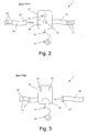
- Figs. 2 and 3 show a personal ECG device 1 that can be used in conjunction with the invention.
- the device 1 illustrated in this figures is particularly convenient because it has a relatively small dimension and wherein its housing 11 is configured in such a way that it contains on its front panel a visual indicator 12 (e.g., in form of a glowing heart), which displays the status of the personal ECG device 1.
- Device 1 further comprises a "start” button 13 which used for turning “on” (or “off”) the personal ECG device 1 (e.g., the "start” button can be located adjacent to the visual indicator 12).
- the visual indicator 12 should be located on the front side of the housing of the personal ECG device 1 or on other location that will be seen easily by the user. This visual indicator 12 displays the status of the personal ECG device 1, whether it is turned on, measuring or has an error.
- Device 1 further comprises a set of skin electrodes, wherein some of them are deployed along an electrode belt 16 (such as the exemplary electrodes indicated by numerals 21, 22 and 23), while other electrodes V1 and V2 are attached to the rear side of the housing 11 (see Fig. 3 ).
- an electrode belt 16 such as the exemplary electrodes indicated by numerals 21, 22 and 23
- other electrodes V1 and V2 are attached to the rear side of the housing 11 (see Fig. 3 ).
- the device 1 also comprises a waist electrode 14 that is electrically connected to device 1 through a novel and unique retractable mechanism (i.e., a yoyo-like mechanism), as will be described in further herein after.
- the housing 11 of device 1 includes a compartment 20 adapted to store the waist electrode 14 while it is not in use.
- the compartment 20 is located at the rear side of the housing 11, as easily seen in Fig. 3 .
- This arrangement provides a compact and comfortable solution to the storage of the waist electrode 14.
- Another advantage of the present invention over the prior-art devices is that the waist electrode 14 can easily and automatically be returned into its storage compartment 20 after the use, due to the retractable mechanism.
- the rear side of the housing 11 has two electrodes (precordial electrodes V1 and V2).
- the housing 11 should be placed against the center of the user's chest.
- the housing's ergonomic design ensures the correct positioning of the electrodes V1 and V2 against the chest, while affording the user maximum comfort with minimal exertion when operating the device.
- the device 1 further comprises a belt closure 18 for closing the belt 16, while it surrounds the body of the user.
- the buckle of belt 16 and the belt closure are also electrically connected.
- electrical wirings can be used to connect each of the skin electrodes 21-23 (that are deployed along belt 16) to the buckle 19 of belt 16, while the electrical connection between the belt's buckle 19 and the belt closure 18 allows to transfer the electrical activity of the heart as acquired by the skin electrodes 21-23 to the electronic components of device 1.
- the personal ECG device 1 is powered by a power source such as one or more batteries.
- the batteries can be 2 lithium "AAA" batteries.
- alkaline batteries can also be used.
- FIG. 4 a schematic layout of the electronic components within the housing 11 of the personal ECG device 1 is shown in accordance with an embodiment of the present invention.
- the electronic components that are located inside the housing 11 of device 1 are divided to two main electronic modules: an analog module 32 and a digital module 33.
- the analog module 32 contains signal conditioning circuitry to acquire the low level electrical signals from the electrodes 31.
- the signals from the electrodes 31 are acquired in such a manner to obtain the data for the standard Einthoven limb leads, the Goldberger augmented leads and the Wilson precordial leads which comprise the standard 12 lead electrocardiogram.
- the signal condition circuitry may include typical electronic components for amplifying the low level electrical signals from the electrodes 31 and to convert them into a digital form, such as input amplifiers, analog to digital converters, filters, and/or other components that can be used to manipulate analog signals.
- the digital module 33 digitizes the electrocardiographic signals. Further this module also provides the two way wireless communication protocol to convey all the digital data to and from the mobile communication device 2 (e.g., a wireless communication between the device 1 and an iPhone, iPad, iTouch, other smartphones or wireless communication devices via a Bluetooth (BT) module 36 or other wireless protocol).
- Device 1 further comprises a User Interface (UI) 34 or other Man Machine Interface, which may include one or more visual indicator (e.g., the glowing heart 12) and/or other display unit (e.g., LCD panel), one or more functional button (e.g., such as the start button 13), etc.
- UI User Interface
- UI User Interface
- the personal ECG device of the present invention needs to transmit data to a paired and relatively adjacent portable communication device, such as a smartphone (using short range data communication protocol, e.g., Bluetooth).
- Short range transmissions reduce power consumption.
- the personal ECG device requires a smaller battery, which leads to its relatively smaller dimensions (e.g., about 8.5cm width, 11cm length and 1.5cm height).
- a smaller battery also results in a lighter unit (e.g., about 100g).
- Lower power consumption also allows the practical use of disposable batteries, eliminating the need for a recharger with cable. All these factors further reduce the size and weight of a user's carrying/storage package.
- the device housing and belt contain electrodes (i.e., set of skin electrodes) for acquiring electrical signals from the conventional anatomic electrode locations for a 12 lead electrocardiogram from the chest and limbs.
- the electrodes can be made from PC ABS + 20% glass fiber with a coating of silver/silver chloride (Ag/AgCl).
- a 12-lead ECG is a recording of the heart's electrical activity from 9 anatomical located electrodes on the body which are combined to produce a conventional clinical 12-lead record.
- a personal ECG device with electrodes belt is shown in accordance with an embodiment of the present invention.
- the electrodes Location deployed as follows: two electrodes are located on the housing (indicated by V1 & V2), four precordial electrodes are located on the left electrode belt (indicated by V3 to V6, two limb electrodes consisting of Left Arm (LA), Right Arm (RA) belt mounted electrodes and a flying lead Left Leg (LL) (waist) retractable limb electrode (i.e., the waist electrode 14 with the yoyo-like mechanism (not shown in rear view fig, 4 )) attached via a conductive wire.
- two electrodes are located on the housing (indicated by V1 & V2)
- four precordial electrodes are located on the left electrode belt (indicated by V3 to V6)
- two limb electrodes consisting of Left Arm (LA), Right Arm (RA) belt mounted electrodes and a flying lead Left Leg (LL) (waist) retractable limb electrode (i.e.
- the belt can be detached from the housing of the personal ECG device.
- the personal ECG device can fit all users.
- different belts with strategically positioned electrodes can be used for each gender.
- the electrode belt comprises a dual purpose belt closure: An interlocking fastener is attached to the belt. This permits the user to mechanically attach the end of the chest belt to the housing. Further, this fastener contains electrical contacts to electrically connect some belt monitoring electrodes to the electronics of the device as will be described in further details herein after in the electrodes belt section.
- the personal ECG device is provided with a dual proposes belt closure (as shown in Figs. 5 and 6 ).
- the electrode belt includes electrical wiring for electrically contacting the electrodes via the belt closure to the electronics of the personal ECG device.
- the electrode belt is an elastic chest strap which comprises 6 precordial ECG electrodes, Right/Left Arm electrodes (indicated by RA and LA in Fig. 5 ) and a unique, convenient belt closure 18 containing electrical connections to electrically connect with buckle 19 (in addition to their mechanical engagement while fastening the belt around the user's chest).
- At least 9 electrodes are required to be positioned on the user's body.
- Six of the electrodes are precordial electrodes that a positioned at certain anatomical electrode locations on the chest (as indicated by electrodes V1-V6 in Fig. 6 ).
- the remaining 3 electrodes are limb electrodes monitor the electrical signals on the left arm (LA electrode), right arm (RA electrode) and the left leg (i.e., the retractable waist electrode).
- LA electrode left arm
- RA electrode right arm
- the left leg i.e., the retractable waist electrode
- RA Right Arm
- LA Left Arm
- the electrodes belt further includes a body reference electrode as indicated by numeral 27 in Fig. 6 .
- the body reference electrode 27 provides a reference for the input amplifiers of the signal conditioning circuitry, which contributes to reduction of mains noise and better performance.
- the electrodes belt can be made from neoprene covered with Nylon fabric which is the same material utilized for wet suits. This is a comfortable and soft material, ideal for repeated flexing applications. Two electrodes belts are connected with stretch belt.
- the left part of the electrode belt is permanently attached to the left side of the housing and contains seven electrodes: five electrodes (4 precordial monitoring electrodes and one amplifier reference electrode) on the inside of the belt and a further two limb electrodes (i.e., a duplication of electrodes to monitor LA (Left Arm)) on the outside.
- the right part of the electrode belt contain two electrodes on the outside, both are for the RA right arm connection.
- the right electrode belt has a double contact buckle that insures good electrical connection between the electrodes and the housing.
- the two parts of the electrode belt are connected with stretch belt between them. To accommodate different chest sizes, there are different size belts.
- the belts have electrodes positioned in the optimal position for each chest size.
- the personal ECG device further comprises an electrode attached with wire to the bottom of the housing (referred to as "flying" electrode).
- This "flying" electrode is labeled 'waist', referring to where it should be placed.
- the flying ('waist') is positioned at the user's belt line against the bare skin, halfway from the navel to the left hip. Together with the electrodes on the front of the electrode belts, these make up the three limb electrodes.
- the limb electrodes and the other electrodes on the belt in combination with those on the housing device permit the acquisition of ECG data for a rhythm strip and 12 lead ECG for remote interpretation by a qualified healthcare professional.
- the flying electrode has wire a spool or retractor that collect the entire waist electrode wire to the electrode compartment. Using this retractor enables the compact packing of the waist electrode. When the device is not in use, there is no electrode wire hanging outside the housing as occur in prior art devices.
- the outer plastic of the flying electrode may have a conductive coating to reduce electrical noise.
- the electrode wire connects with a spring to the plastic with good conductivity.
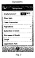
- the application may include the following options or application menus: Symptoms menus - the application can display menus of predefined selectable symptoms so that the user can select any present symptoms. Perform an ECG - This permit selecting symptoms and recording an ECG including a screen to display the electrode status and guide the user in how to position the electrodes.
- Fig. 7 shows a graphical example screen of a symptom menu of the smartphone application.
- Electrodes Contact Quality Display - Fig. 8 shows a graphical example of electrodes contact quality screen of the smartphone application. This screen displays the contact status of the electrodes and will guide the user to correctly position the electrodes in order to improve the contact of the electrodes with the user's body, for example, by displaying visual messages on the displayed image of the human chest (when the personal ECG device is not position correctly), such as "position waist electrode tightly against your skin”, “attach device to chest”, “tighten strap”, etc.
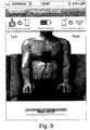
- FIG. 9 shows a graphical example of the ECG perform starting screen of the smartphone application. This screen shows an indication that all the electrodes are in contact (i.e., which is an essential information before the beginning of the recording progress).
- Viewing ECGs - Fig. 10 shows a graphical example of recorded ECGs screen of the smartphone application. This screen permits the viewing of the recorded ECGs.
- Sending ECG - Fig. 11 shows a graphical example of Send ECGs screen of the smartphone application. This screen permits the forwarding of ECGs, e.g., via e-mail or fax.
- Help Function - This includes training information for using the personal ECG device, using the smartphone application and information about the symptoms.
Description
- The present invention relates to the field of telemedicine systems. More particularly, the invention relates to a system for capturing 12 lead ECG and rhythm strip data from a patient remotely using a telecommunication mobile device, such as iPhone.
- It is known that chronically ill, people or patients known to suffer from cardiac problems, and patients recovering from a surgical intervention or cardiac episode or a disease use personal ECG devices whether this on regular basis or while they don't feel well. In the prior art there are several ECG devices that can obtain a standard 12 lead ECG, such as clinical ECG machines, personal acoustic devices (e.g., CardioSen'C CardioBeeper 12L or CardioBeeper 12/12 by SHL Telemedicine). The latter personal devices adapted to be used by a non medical individual to capture a 12 lead ECG and/or Rhythm strip when the user has symptoms, routinely, as part of drug studies, pre/post surgery, etc. Although these devices do allow a user to gather some information and transfer it to remote medical data center, no ECG information is available for the user itself.
- Moreover, some of the prior-art personal devices, such as the Cardiosen'C are less comfortable to carry by the user due to their overall dimensions. For example, the Cardiosen'C can communicate with a remote data center directly via its internal cellular modem. However, this takes considerable power thus a large battery and charger is required resulting in a device having relatively large dimensions. Therefore, there is also a need for a smaller device than the Cardiosen'C and the other prior-art units. With a smaller battery the device is easier to carry and therefore it is more desirable.
-
US Patent application No. 2010/069735 discloses a device, system and method for obtaining a 12 lead electrocardiogram (ECG) from measurements obtained with 3 electrodes in some embodiments (it should be noted that some separate embodiments of the present invention relate to such measurements with 4 electrodes). However, the solution proposed by this application is based on a handheld electrode(s) that is manipulated on the chest by a user hand. Moreover, it does not include a configuration on which the set of at least 9 skin monitoring electrodes are deployed, such that the electrodes are automatically positioned at the standard anatomical electrode locations for acquiring the standard 12-lead ECG (i.e., clinical 12-lead ECG) in accordance with precordial electrode locations that have been established by Wilson in association with Einthoven and Goldberger. Furthermore, it does not suggest the simultaneous detection of the quality of all the 6 precordial and 3 limb contacts necessary for the standard 12 lead ECG, and therefore no real-time measurements can be obtained for generating a reliable rhythm strip. -
US Patent application No. 2010/174204 discloses a device for capturing a 12-lead electrocardiogram from signals representative of the cardiac activity of a patient and acquired with the help of at least nine electrodes. The electrocardiograph comprises a body having a front face and at least one arm suitable for being folded beside the body and pivotable about an axis that is substantially parallel to the front face. Each arm is adapted to form a variable dihedral angle with the front face so that the substantially concave surface formed by the front face and the or each arm and having 6 precordial electrodes distributed thereon, is capable of adapting to the patient's morphology so as to enable the precordial electrodes to be properly positioned on the patient's chest. However, in order to obtain the readings the user needs to place his index fingers on the device, to acquire the limb lead acquisition of the ECG signals. Moreover, it is well known that finger electrodes also acquire the muscle induced electromagnetic fields (EMF) signals from the muscles of the arms, hands and fingers. This noise can obscure some small amplitude components of the ECG signal such as the "p" waves. Further this interfering noise is further aggravated by certain disease related conditions such as Parkinson's disease and tremors thus increasing this undesired noise. The use of finger electrodes occupies the user's hands during the signal acquisition periods so that it is not possible to operate communication and display devices such as Smartphones. - Moreover,
US Patent application No. 2010/174204 shows the precordial or chest electrodes all in one in a straight line. However, the standard placement of precordial electrodes is specified at certain anatomical locations as setforth by Wilson and they are not in a straight line. For proper 12-lead readings, the V1 and V2 electrodes are at the same elevation and the V4, V5 and V6 are on a second horizontal line, however the V1-V2 line and line V4-V5-V6 are not at the same elevation. There is a transition from V2 to V4 which includes the V3 electrode which constitutes a third line, V2-V3-V4. As can be seen, this line is not aligned with either the V1-V2 line or the V4-V5-V6 line. Thus if all the sensing electrodes are in a straight line as depicted by this patent application, there will be some differences to a standard 12 lead electrocardiogram that adheres to the standard precordial electrode placement. - US Patent application No.
US2003/0187363 shows a portable ECG device, comprising a housing supporting a plurality of chest and limb electrodes for affixing to different parts of a patient's body so as to measure the patient's rhythm strip and 12-lead ECG. An ECG signalling circuit within the housing is adapted to collect and transmit in real time fractional ECG data on at least two output channels in parallel, thereby allowing complete ECG data to be transmitted in less time than could be done by collecting and transmitting the complete ECG data serially on a single output channel in real time. Although these prior art ECG devices are capable of transmitting data to remote medical data center, there still exists a need for a device that can be quickly and accurately applied to obtain a clinical 12 lead ECG and rhythm strip. There also still exists a need for such a system which is reliable in use and is user-friendly. There further exists a need for a personal ECG device which can be used in combination with existing portable computer based communication devices (e.g., a mobile cellphone or a smartphone) for enhancing the interaction between the remote medical data center the personal ECG device and the user itself. - It is an object of the present invention to overcome the drawbacks of the prior-art devices and to fulfill the aforementioned needs. The present invention is particularly aimed at ill people or patients known to suffer from cardiac problems, and patients recovering from a surgical intervention or cardiac episode or a disease.
- It is another object of the present invention to provide a system which is capable of remotely communicate with a data center.
- It is yet another object of the present invention to provide a system which is capable of locally displaying ECG related activity information to the user including the quality of the electrode contact and other relevant information (e.g., guidance and instructions for the user during and/or after the use).
- Other objects and advantages of the invention will become apparent as the description proceeds.
- The present invention relates to an electrocardiographic monitoring system, which comprises: a) a personal ECG device for providing 12-lead electrocardiogram data that represents the electrical activity of a user's heart, wherein said 12-lead electrocardiogram obtained from a set of at least 9 skin electrodes each of which is electrically connected to said personal ECG device, either directly or via a chest electrode belt; b) a short range wireless communication module embedded within said personal ECG device for data communicating with a smartphone; and c) a dedicated smartphone application for being executed by said smartphone, for visually displaying information related to said provided 12-lead electrocardiogram and for data communicating with a remote data center. A system according to the invention is defined in
claim 1. According to an embodiment of the present invention, the electrode belt includes a chest strap with 6 anatomically positioned precordial ECG electrodes, Right/Left Arm electrodes, an elastic portion to extend around the chest and a unique, convenient closure containing electrical connections. Optionally, the electrode belt can be detached from the personal ECG device and replaced by various belts to personalize belt size to chest size and gender. - According to an embodiment of the present invention, the personal ECG device is configured in such a way that it is capable of storing at least one retractable ECG electrode (i.e., the waist electrode that is placed at the waist or belt line positioned halfway from the naval to the left hip) and its conductive wire within its housing to conserve space. According to some embodiments, the electrode is a spool with an outside electrically conductive electrode surface to allow the winding of the wire into the housing of the personal ECG device similar to a child's YOYO. Alternatively the retractable ECG electrode is provided with a retracting means to store the wire, such as a spring or alternative device within the housing of the personal ECG device to retract the wire inside for compact storage.
- In the drawings:
-
Fig. 1 schematically illustrates a layout of the personal ECG electrocardiographic monitoring system, according to an embodiment of the present invention; -
Figs. 2 schematically illustrates a front view of a personal ECG device, according to an embodiment of the present invention; -
Figs. 3 schematically illustrates a rear view of the personal ECG device ofFig. 2 ; -
Fig. 4 schematically illustrates an electronic block diagram of the personal ECG device, according to an embodiment of the present invention; -
Fig. 5 schematically illustrates a front view of a personal ECG device provided with an electrodes belt, according to an embodiment of the present invention; -
Fig. 6 schematically illustrates a rear view of the personal ECG device ofFig. 5 ; and -
Figs. 7-11 schematically illustrate example Smartphone screen layouts of a dedicated application to be used with the personal ECG device, according to an embodiment of the present invention. - The following description relates to embodiments of an electrocardiographic (ECG) monitoring system and method of the present invention by way of illustration only. It should be noted that from the following discussion, alternative embodiments of the structures and methods disclosed herein will be readily recognized as viable alternatives that may be employed without departing from the principles of the claimed invention. The invention being defined by the appended claims 1-5. Reference will now be made to several embodiments of the present invention(s), examples of which are illustrated in the accompanying figures. Wherever practicable similar or like reference numbers may be used in the figures and may indicate similar or like functionality. As aforementioned hereinabove, the figures depict embodiments of the present invention for purposes of illustration only.
- Unless otherwise indicated, the functions described herein may be performed by executable code and instructions stored in computer readable medium and running on one or more processor-based systems as defined in
claim 1. However, hardwired electronic circuits can also be utilized. Further, with respect to the example processes described herein, not all the process states need to be reached, nor do the states have to be performed in the illustrated order. Further, certain process states that are illustrated as being serially performed can be performed in parallel. - Similarly, while certain examples may refer to a smartphone, other computer or electronic systems can be used as well, such as, without limitation, a network-enabled personal digital assistant (PDA), computer, communication hub or data device with an operating system and on which a user can install applications and so on.
- In addition, while certain user inputs or gestures are described as being provided via phone key presses, data entry via a keyboard, the use of touch screens or by clicking a button, optionally, user inputs can be provided using other techniques, such as by voice or otherwise.
-
Fig. 1 schematically illustrates a layout of anECG monitoring system 10, according to an embodiment of the present invention.System 10 enables an individual to immediately gather and transmit 12-lead ECG and a rhythm strip data to a remote unit or to any required destination. Thesystem 10 provides data which represents the electrical activity of the heart. The 12 Lead ECG defines the graphic representation of the electrical activity of the heart from various anatomical locations of the body. The electrical activity of the heart recorded over time is called a rhythm strip. Thesystem 10 and its components are described in further details herein below. -
System 10 comprises three main components: apersonal ECG device 1, an application installed on a suitable mobile communication device 2 (e.g., an iPhone application) and aremote data center 3 with a dedicated software (e.g., the SHL medical monitoring center of SHL Telemedicine, remote medical center, or any other data center). - The
personal ECG device 1 comprises skin electrodes and electronic components which are used for real-time transmission of the electrical activity of the heart as acquired by the skin electrodes.Device 1 transmits the data representing the electrical activity of the heart via a wireless communication link (e.g., via Bluetooth) to themobile communication device 2. - According to an embodiment of the present invention, the electrocardiogram is constructed in the
remote data center 3. The construction of the ECG and the operation of theremote data center 3 involve the following tasks: - receiving ECG data packets (from the mobile communication device) and performing error checking (by using any suitable error control technique that enables reliable delivery of digital data over communication channels);
- processing the ECG data and creating a 12 lead ECG and/or Rhythm strip record;
- storing the ECG records; and
- upon request, sending ECG records and/or other related data in a variety of forms to other data devices (e.g., fax, email, printer, mobile phone, smartphone, etc).
- In some uses, it is advantageous for the user to be able to capture and visualize their own ECG and then forward it to their doctor or another medical facility. By utilizing a smartphone, the
system 10 of the present invention allows the user to acquire the ECG, visualize the ECG (as delivered from the remote data center 3) on a smartphone and further, utilizing the smartphone allows the user to forward the electrocardiogram to a medical expert, his own doctor, or to a remote facility for analysis and/or advice. - According to some embodiments of the invention, ECG related activity can be conveyed to the user via the display unit of the smartphone. These may further include indication regarding the quality of the electrode contact and other relevant information (e.g., guidance and instructions for the user during and/or after the use), to be discussed in greater details below.
-
Figs. 2 and 3 show apersonal ECG device 1 that can be used in conjunction with the invention. Thedevice 1 illustrated in this figures is particularly convenient because it has a relatively small dimension and wherein itshousing 11 is configured in such a way that it contains on its front panel a visual indicator 12 (e.g., in form of a glowing heart), which displays the status of thepersonal ECG device 1..Device 1 further comprises a "start"button 13 which used for turning "on" (or "off") the personal ECG device 1 (e.g., the "start" button can be located adjacent to the visual indicator 12). Preferably, thevisual indicator 12 should be located on the front side of the housing of thepersonal ECG device 1 or on other location that will be seen easily by the user. Thisvisual indicator 12 displays the status of thepersonal ECG device 1, whether it is turned on, measuring or has an error. -
Device 1 further comprises a set of skin electrodes, wherein some of them are deployed along an electrode belt 16 (such as the exemplary electrodes indicated bynumerals Fig. 3 ). - According to an embodiment of the invention, the
device 1 also comprises awaist electrode 14 that is electrically connected todevice 1 through a novel and unique retractable mechanism (i.e., a yoyo-like mechanism), as will be described in further herein after. Thehousing 11 ofdevice 1 includes acompartment 20 adapted to store thewaist electrode 14 while it is not in use. In this embodiment, thecompartment 20 is located at the rear side of thehousing 11, as easily seen inFig. 3 . This arrangement provides a compact and comfortable solution to the storage of thewaist electrode 14. Another advantage of the present invention over the prior-art devices is that thewaist electrode 14 can easily and automatically be returned into itsstorage compartment 20 after the use, due to the retractable mechanism. - In this embodiment, the rear side of the
housing 11 has two electrodes (precordial electrodes V1 and V2). Thehousing 11 should be placed against the center of the user's chest. The housing's ergonomic design ensures the correct positioning of the electrodes V1 and V2 against the chest, while affording the user maximum comfort with minimal exertion when operating the device. - The
device 1 further comprises abelt closure 18 for closing thebelt 16, while it surrounds the body of the user. According to an embodiment of the invention, in addition to the mechanical attachment, the buckle ofbelt 16 and the belt closure are also electrically connected. For example, electrical wirings (not shown) can be used to connect each of the skin electrodes 21-23 (that are deployed along belt 16) to thebuckle 19 ofbelt 16, while the electrical connection between the belt'sbuckle 19 and thebelt closure 18 allows to transfer the electrical activity of the heart as acquired by the skin electrodes 21-23 to the electronic components ofdevice 1. - The
personal ECG device 1 is powered by a power source such as one or more batteries. For example, the batteries can be 2 lithium "AAA" batteries. Alternatively, alkaline batteries can also be used. - Referring now to
Fig. 4 , a schematic layout of the electronic components within thehousing 11 of thepersonal ECG device 1 is shown in accordance with an embodiment of the present invention. The electronic components that are located inside thehousing 11 ofdevice 1 are divided to two main electronic modules: ananalog module 32 and adigital module 33. - The
analog module 32 contains signal conditioning circuitry to acquire the low level electrical signals from theelectrodes 31. The signals from theelectrodes 31 are acquired in such a manner to obtain the data for the standard Einthoven limb leads, the Goldberger augmented leads and the Wilson precordial leads which comprise the standard 12 lead electrocardiogram. For example, the signal condition circuitry may include typical electronic components for amplifying the low level electrical signals from theelectrodes 31 and to convert them into a digital form, such as input amplifiers, analog to digital converters, filters, and/or other components that can be used to manipulate analog signals. - The
digital module 33 digitizes the electrocardiographic signals. Further this module also provides the two way wireless communication protocol to convey all the digital data to and from the mobile communication device 2 (e.g., a wireless communication between thedevice 1 and an iPhone, iPad, iTouch, other smartphones or wireless communication devices via a Bluetooth (BT)module 36 or other wireless protocol).Device 1 further comprises a User Interface (UI) 34 or other Man Machine Interface, which may include one or more visual indicator (e.g., the glowing heart 12) and/or other display unit (e.g., LCD panel), one or more functional button (e.g., such as the start button 13), etc.. - One of the advantages of the personal ECG device of the present invention with respect to prior-art devices is that it needs to transmit data to a paired and relatively adjacent portable communication device, such as a smartphone (using short range data communication protocol, e.g., Bluetooth). Short range transmissions reduce power consumption. Accordingly, the personal ECG device requires a smaller battery, which leads to its relatively smaller dimensions (e.g., about 8.5cm width, 11cm length and 1.5cm height). A smaller battery also results in a lighter unit (e.g., about 100g). Lower power consumption also allows the practical use of disposable batteries, eliminating the need for a recharger with cable. All these factors further reduce the size and weight of a user's carrying/storage package.
- The device housing and belt contain electrodes (i.e., set of skin electrodes) for acquiring electrical signals from the conventional anatomic electrode locations for a 12 lead electrocardiogram from the chest and limbs. For example, the electrodes can be made from PC ABS + 20% glass fiber with a coating of silver/silver chloride (Ag/AgCl).
- Usually several electrodes are used and they can be combined into a number of pairs (e.g., left arm and right arm electrodes). The output from each combination is known as a lead. Each lead is said to look at the heart from a different angle. A 12-lead ECG is a recording of the heart's electrical activity from 9 anatomical located electrodes on the body which are combined to produce a conventional clinical 12-lead record.
- Referring now to
Figs. 5 and6 , a personal ECG device with electrodes belt is shown in accordance with an embodiment of the present invention. In this embodiment, the electrodes Location deployed as follows: two electrodes are located on the housing (indicated by V1 & V2), four precordial electrodes are located on the left electrode belt (indicated by V3 to V6, two limb electrodes consisting of Left Arm (LA), Right Arm (RA) belt mounted electrodes and a flying lead Left Leg (LL) (waist) retractable limb electrode (i.e., thewaist electrode 14 with the yoyo-like mechanism (not shown in rear viewfig, 4 )) attached via a conductive wire. - According to an embodiment of the present invention, the belt can be detached from the housing of the personal ECG device. For example, there can be plurality of belts sizes in order to accommodate variety of chest sizes, wherein each one of them is designed for a specific gender and body size. By replacing the belt, the personal ECG device can fit all users. To accommodate different chest sizes, different belts with strategically positioned electrodes can be used for each gender.
- According to an embodiment of the present invention, the electrode belt comprises a dual purpose belt closure: An interlocking fastener is attached to the belt. This permits the user to mechanically attach the end of the chest belt to the housing. Further, this fastener contains electrical contacts to electrically connect some belt monitoring electrodes to the electronics of the device as will be described in further details herein after in the electrodes belt section.
- According to an embodiment of the present invention, the personal ECG device is provided with a dual proposes belt closure (as shown in
Figs. 5 and6 ). The electrode belt includes electrical wiring for electrically contacting the electrodes via the belt closure to the electronics of the personal ECG device. - In this embodiment, the electrode belt is an elastic chest strap which comprises 6 precordial ECG electrodes, Right/Left Arm electrodes (indicated by RA and LA in
Fig. 5 ) and a unique,convenient belt closure 18 containing electrical connections to electrically connect with buckle 19 (in addition to their mechanical engagement while fastening the belt around the user's chest). - In general, in order to obtain a 12 lead electrocardiogram, at least 9 electrodes are required to be positioned on the user's body. Six of the electrodes are precordial electrodes that a positioned at certain anatomical electrode locations on the chest (as indicated by electrodes V1-V6 in
Fig. 6 ). The remaining 3 electrodes are limb electrodes monitor the electrical signals on the left arm (LA electrode), right arm (RA electrode) and the left leg (i.e., the retractable waist electrode). For simplicity of use, as aforementioned herein before the personal ECG device has 2 precordial, chest-facing electrodes on the electronic enclosure case (i.e., on the rear side of the housing) and the remaining 4 precordial electrodes are on the belt itself. In addition, two limb electrodes Right Arm (RA) and Left Arm (LA) outward facing electrodes. To easily apply the elastic belt, the electrode belt is permanently attached to the electronic enclosure and the other end is fitted with a novel closure/snap. In this way, when the mechanical belt fastener is engaged with the case, an electrical connection is also achieved to the RA sensing electrodes. - According to an embodiment of the invention, the electrodes belt further includes a body reference electrode as indicated by numeral 27 in
Fig. 6 . Thebody reference electrode 27 provides a reference for the input amplifiers of the signal conditioning circuitry, which contributes to reduction of mains noise and better performance. - For example, the electrodes belt can be made from neoprene covered with Nylon fabric which is the same material utilized for wet suits. This is a comfortable and soft material, ideal for repeated flexing applications. Two electrodes belts are connected with stretch belt.
- The left part of the electrode belt is permanently attached to the left side of the housing and contains seven electrodes: five electrodes (4 precordial monitoring electrodes and one amplifier reference electrode) on the inside of the belt and a further two limb electrodes (i.e., a duplication of electrodes to monitor LA (Left Arm)) on the outside. The right part of the electrode belt contain two electrodes on the outside, both are for the RA right arm connection. The right electrode belt has a double contact buckle that insures good electrical connection between the electrodes and the housing. The two parts of the electrode belt are connected with stretch belt between them. To accommodate different chest sizes, there are different size belts. The belts have electrodes positioned in the optimal position for each chest size.
- According to an embodiment of the present invention, the personal ECG device further comprises an electrode attached with wire to the bottom of the housing (referred to as "flying" electrode). This "flying" electrode is labeled 'waist', referring to where it should be placed. The flying ('waist') is positioned at the user's belt line against the bare skin, halfway from the navel to the left hip. Together with the electrodes on the front of the electrode belts, these make up the three limb electrodes. The limb electrodes and the other electrodes on the belt in combination with those on the housing device permit the acquisition of ECG data for a rhythm strip and 12 lead ECG for remote interpretation by a qualified healthcare professional.
- The flying electrode has wire a spool or retractor that collect the entire waist electrode wire to the electrode compartment. Using this retractor enables the compact packing of the waist electrode. When the device is not in use, there is no electrode wire hanging outside the housing as occur in prior art devices.
- The outer plastic of the flying electrode may have a conductive coating to reduce electrical noise. The electrode wire connects with a spring to the plastic with good conductivity.
- The example screen layouts, appearance, and terminology of Smartphone application as depicted and described herein with respect to
Figs 7-11 , are intended to be illustrative and exemplary, and in no way limit the scope of the invention as claimed. The invention being entirely defined by the appended claims 1-5. The application may include the following options or application menus: Symptoms menus - the application can display menus of predefined selectable symptoms so that the user can select any present symptoms. Perform an ECG - This permit selecting symptoms and recording an ECG including a screen to display the electrode status and guide the user in how to position the electrodes.Fig. 7 shows a graphical example screen of a symptom menu of the smartphone application. - Electrodes Contact Quality Display -
Fig. 8 shows a graphical example of electrodes contact quality screen of the smartphone application. This screen displays the contact status of the electrodes and will guide the user to correctly position the electrodes in order to improve the contact of the electrodes with the user's body, for example, by displaying visual messages on the displayed image of the human chest (when the personal ECG device is not position correctly), such as "position waist electrode tightly against your skin", "attach device to chest", "tighten strap", etc. - ECG recording progress -
Fig. 9 shows a graphical example of the ECG perform starting screen of the smartphone application. This screen shows an indication that all the electrodes are in contact (i.e., which is an essential information before the beginning of the recording progress). - Viewing ECGs -
Fig. 10 shows a graphical example of recorded ECGs screen of the smartphone application. This screen permits the viewing of the recorded ECGs. - Sending ECG -
Fig. 11 shows a graphical example of Send ECGs screen of the smartphone application. This screen permits the forwarding of ECGs, e.g., via e-mail or fax. - Help Function - This includes training information for using the personal ECG device, using the smartphone application and information about the symptoms.
Claims (5)
- An electrocardiographic monitoring system for obtaining a 12-lead electrocardiogram (ECG) and a rhythm strip, comprising:- a personal ECG device (1) having a housing (11) that includes an analog module (32) adapted for acquiring low level electrical signals from skin monitoring electrodes (31), a digital module (33) for converting the acquired signals into digital data form, and a communication module for wirelessly communication between said personal ECG device (1) and a mobile communication device (2), thereby enabling to convey data between both devices including the transferring of said converted digital data to said mobile communication device (2);- a dedicated application for being executed by said mobile device, for data communicating with a remote data center in order to transmit the data to said remote data center for processing said data and creating a 12-lead ECG and rhythm strip record
characterized in that the system further comprises- 9 skin monitoring electrodes suitable to be positioned on the body of a user in a conventional anatomic electrode locations for a 12-lead ECG from the chest and limbs, in accordance with Einthoven, Goldberger and Wilson, wherein said conventional anatomic electrode locations are obtained by deploying said electrodes along a belt (16) connected with said personal ECG device (1) and on the housing (11) of said personal ECG device (1), wherein at least four of said electrodes (V3-V6) are chest-facing precordial electrodes that are located on the inside of said belt and are for positioning on the chest of said user, two electrodes (LA, RA) are belt mounted outward facing limb electrodes located on the outside of said belt (16) to acquire electrical signals of the left arm electrode (LA) and the right arm electrode (RA), 1 flying electrode (LL) suitable to acquire the electrical signals of the left leg of said user, and two additional chest-facing precordial electrodes (V1, V2) are located on the housing of said personal ECG device. - A system according to claim 1, in which the housing includes a belt closure (18) arrangement for mechanically securing the belt (16) while it surrounds the body of the user, and for electrically connecting at least some of the electrodes of said belt (16) to the analog module (32).
- A system according to claim 1, in which the mobile communication device (2) establishes data communication with the remote data center (3) while in voice contact with a representative of said remote data center.
- A system according to claim 1, in which the wireless communication between the personal ECG device (1) and the mobile communication device (2) enables a user to improve the contact quality of the electrodes by using the mobile communication device to display the contact quality of each skin monitoring electrode, thereby providing feedback to the user to evaluate the quality of the electrode contact and permitting said user to improve the contact and thus the quality of the resulting ECG.
- A system according to claim 1, in which the mobile communication device (2) provides instructions, questions, or other relevant data to a user while operating the personal ECG device (1).
Applications Claiming Priority (2)
| Application Number | Priority Date | Filing Date | Title |
|---|---|---|---|
| US201161488913P | 2011-05-23 | 2011-05-23 | |
| PCT/IL2012/000200 WO2012160550A1 (en) | 2011-05-23 | 2012-05-21 | An electrocardiographic monitoring system and method |
Publications (3)
| Publication Number | Publication Date |
|---|---|
| EP2713865A1 EP2713865A1 (en) | 2014-04-09 |
| EP2713865A4 EP2713865A4 (en) | 2014-10-22 |
| EP2713865B1 true EP2713865B1 (en) | 2017-10-18 |
Family
ID=47216686
Family Applications (1)
| Application Number | Title | Priority Date | Filing Date |
|---|---|---|---|
| EP12788738.8A Active EP2713865B1 (en) | 2011-05-23 | 2012-05-21 | An electrocardiographic monitoring system |
Country Status (5)
| Country | Link |
|---|---|
| US (1) | US9215998B2 (en) |
| EP (1) | EP2713865B1 (en) |
| JP (1) | JP6038897B2 (en) |
| CN (1) | CN103607945B (en) |
| WO (1) | WO2012160550A1 (en) |
Families Citing this family (67)
| Publication number | Priority date | Publication date | Assignee | Title |
|---|---|---|---|---|
| EP3165161B1 (en) | 2010-05-12 | 2020-05-06 | Irhythm Technologies, Inc. | Device features and design elements for long-term adhesion |
| US8509882B2 (en) | 2010-06-08 | 2013-08-13 | Alivecor, Inc. | Heart monitoring system usable with a smartphone or computer |
| US9351654B2 (en) | 2010-06-08 | 2016-05-31 | Alivecor, Inc. | Two electrode apparatus and methods for twelve lead ECG |
| WO2014074913A1 (en) | 2012-11-08 | 2014-05-15 | Alivecor, Inc. | Electrocardiogram signal detection |
| US9220430B2 (en) | 2013-01-07 | 2015-12-29 | Alivecor, Inc. | Methods and systems for electrode placement |
| CA2898626C (en) * | 2013-01-24 | 2020-05-12 | Irhythm Technologies, Inc. | Physiological monitoring device |
| US10022053B2 (en) * | 2013-02-22 | 2018-07-17 | Cloud Dx, Inc. | Simultaneous multi-parameter physiological monitoring device with local and remote analytical capability |
| US20140239743A1 (en) * | 2013-02-27 | 2014-08-28 | James Edward Jennings | Xeno transduction system |
| WO2014145927A1 (en) | 2013-03-15 | 2014-09-18 | Alivecor, Inc. | Systems and methods for processing and analyzing medical data |
| DE102013209593B4 (en) * | 2013-05-23 | 2017-05-18 | Getemed Medizin- Und Informationstechnik Ag | Arrangement for providing a long-term ECG |
| US9247911B2 (en) | 2013-07-10 | 2016-02-02 | Alivecor, Inc. | Devices and methods for real-time denoising of electrocardiograms |
| US11147499B2 (en) | 2013-08-30 | 2021-10-19 | Joseph Wiesel | Method and apparatus for detecting atrial fibrillation |
| EP3079571A4 (en) | 2013-12-12 | 2017-08-02 | Alivecor, Inc. | Methods and systems for arrhythmia tracking and scoring |
| PT3094237T (en) * | 2014-01-14 | 2022-01-11 | Ab Medica S P A | Electrocardiograph |
| US20150282734A1 (en) * | 2014-04-08 | 2015-10-08 | Timothy Schweikert | Medical device placement system and a method for its use |
| CN103927452B (en) * | 2014-04-23 | 2016-03-30 | 努比亚技术有限公司 | A kind of remote health monitoring system, method and apparatus |
| ITNA20140013U1 (en) * | 2014-05-07 | 2015-11-07 | Brera Medical Tech S R L | PORTABLE DEVICE FOR THE TREATMENT OF WRINKLES USING MODULATED SINGLE-DIRECT CURRENT AMPLIFIED THROUGH SMARTPHONE BY WIRELESS CONNECTION |
| WO2015189476A1 (en) * | 2014-06-12 | 2015-12-17 | Mega Elektroniikka Oy | Electrode band for sensing bio-electrical signal |
| US20160066812A1 (en) * | 2014-09-08 | 2016-03-10 | Aliphcom | Strap band for a wearable device |
| US20160066853A1 (en) * | 2014-09-08 | 2016-03-10 | Aliphcom | Strap band for a wearable device |
| US20160066841A1 (en) * | 2014-09-08 | 2016-03-10 | Aliphcom | Strap band for a wearable device |
| CN104305989A (en) * | 2014-10-30 | 2015-01-28 | 无锡中盛医疗设备有限公司 | Remote electrocardiograph monitoring system |
| CN116530951A (en) | 2014-10-31 | 2023-08-04 | 意锐瑟科技公司 | Wireless physiological monitoring device and system |
| JP6843759B2 (en) | 2015-03-31 | 2021-03-17 | フィッシャー アンド ペイケル ヘルスケア リミテッド | User interface and system for supplying gas to the airways |
| WO2016161152A1 (en) * | 2015-03-31 | 2016-10-06 | University Of Pittsburgh - Of The Commonwealth System Of Higher Education | Wearable cardiac elecrophysiology measurement devices, software, systems and methods |
| EP3282933B1 (en) | 2015-05-13 | 2020-07-08 | Alivecor, Inc. | Discordance monitoring |
| JP6758327B2 (en) * | 2015-06-22 | 2020-09-23 | ディ ハート ソチエタ レスポンサビリタ リミタータD−Heart S.R.L. | Electronic system to control the acquisition of electrocardiogram |
| KR20170001490A (en) * | 2015-06-26 | 2017-01-04 | 삼성전자주식회사 | The electronic apparatus and method for controlling function in the electronic apparatus using the bio-metric sensor |
| CN104997504B (en) * | 2015-07-20 | 2017-12-29 | 秦培强 | A kind of dynamic ecg monitoring instrument |
| US20170055870A1 (en) * | 2015-08-25 | 2017-03-02 | Spaulding Medical, LLC | Simplified ECG Acquisition, Transmission And Sharing System |
| KR101739542B1 (en) * | 2015-10-07 | 2017-06-08 | 주식회사 헬스리안 | Wearable and wireless 12 channel electrocardiograph system |
| TWI726853B (en) * | 2015-10-29 | 2021-05-11 | 傅真 | Personal wearable device, system and method for continuously detecting body physiological information track to establish healthy life mode |
| US11357453B2 (en) * | 2015-12-18 | 2022-06-14 | Baxter International Inc. | Neck-worn physiological monitor |
| CN109313931A (en) * | 2016-05-11 | 2019-02-05 | 泰拓卡尔有限公司 | For providing system, the method and computer program product of feedback related with medical inspection |
| JP6785856B2 (en) * | 2016-06-30 | 2020-11-18 | タツタ電線株式会社 | Biological electrodes and methods for forming bioelectrodes |
| WO2018003698A1 (en) | 2016-06-30 | 2018-01-04 | タツタ電線株式会社 | Electrode material |
| US10629325B2 (en) | 2016-06-30 | 2020-04-21 | Tatsuta Electric Wire & Cable Co., Ltd. | Silver chloride paste |
| CN109803707B (en) | 2016-08-11 | 2022-03-22 | 费雪派克医疗保健有限公司 | Collapsible catheter, patient interface and headgear connector |
| US11213238B2 (en) | 2016-12-30 | 2022-01-04 | Imedrix Systems Private Limited | Cardiac health monitoring device and a method thereof |
| KR20180090616A (en) * | 2017-02-03 | 2018-08-13 | 삼성전자주식회사 | Electronic device with body information detection function |
| SE541874C2 (en) * | 2017-04-04 | 2020-01-02 | Coala Life Ab | Capturing ecg measurements in a portable sensor device |
| WO2018212757A1 (en) * | 2017-05-15 | 2018-11-22 | Joseph Wiesel | Method and apparatus for detecting atrial fibrilation |
| US10845955B2 (en) | 2017-05-15 | 2020-11-24 | Apple Inc. | Displaying a scrollable list of affordances associated with physical activities |
| CN107296600A (en) * | 2017-05-17 | 2017-10-27 | 哈尔滨工业大学(威海) | A kind of quick 12 lead electrocardiosignal method for evaluating quality |
| CN111491557B (en) * | 2017-12-15 | 2024-04-05 | 深圳迈瑞生物医疗电子股份有限公司 | Lead electrode identification device, method, storage medium and medical monitoring equipment |
| EP3787491A4 (en) | 2018-03-05 | 2022-04-06 | Rakesh Shah | Mobile electrocardiogram system |
| DK180241B1 (en) | 2018-03-12 | 2020-09-08 | Apple Inc | User interfaces for health monitoring |
| DK201870380A1 (en) | 2018-05-07 | 2020-01-29 | Apple Inc. | Displaying user interfaces associated with physical activities |
| US11317833B2 (en) | 2018-05-07 | 2022-05-03 | Apple Inc. | Displaying user interfaces associated with physical activities |
| JP7102266B2 (en) * | 2018-07-06 | 2022-07-19 | オムロンヘルスケア株式会社 | Belt and electrocardiographic measuring device |
| CN109805921B (en) * | 2018-12-18 | 2022-03-25 | 深圳小辣椒科技有限责任公司 | Electrocardio data cross-platform sampling method and electrocardio monitoring system |
| US11152100B2 (en) | 2019-06-01 | 2021-10-19 | Apple Inc. | Health application user interfaces |
| US11228835B2 (en) | 2019-06-01 | 2022-01-18 | Apple Inc. | User interfaces for managing audio exposure |
| US11234077B2 (en) | 2019-06-01 | 2022-01-25 | Apple Inc. | User interfaces for managing audio exposure |
| US11209957B2 (en) | 2019-06-01 | 2021-12-28 | Apple Inc. | User interfaces for cycle tracking |
| DK201970534A1 (en) | 2019-06-01 | 2021-02-16 | Apple Inc | User interfaces for monitoring noise exposure levels |
| CN110477899A (en) * | 2019-08-06 | 2019-11-22 | 苏州米特希赛尔人工智能有限公司 | 5 Lead ambulatory electrocardiogram monitoring device of back belt type |
| EP4004702A1 (en) | 2019-09-09 | 2022-06-01 | Apple Inc. | Research study user interfaces |
| CN111000552B (en) * | 2019-12-23 | 2021-10-01 | 深圳市凯沃尔电子有限公司 | Intelligent electrocardiograph |
| CA3171482C (en) | 2020-02-12 | 2024-03-26 | Irhythm Technologies, Inc | Non-invasive cardiac monitor and methods of using recorded cardiac data to infer a physiological characteristic of a patient |
| JP7050213B2 (en) * | 2020-03-30 | 2022-04-07 | 日東電工株式会社 | Biosensors, biosensor systems and motion control methods for biosensors |
| DK181037B1 (en) | 2020-06-02 | 2022-10-10 | Apple Inc | User interfaces for health applications |
| US11350864B2 (en) | 2020-08-06 | 2022-06-07 | Irhythm Technologies, Inc. | Adhesive physiological monitoring device |
| JP2023536982A (en) | 2020-08-06 | 2023-08-30 | アイリズム・テクノロジーズ・インコーポレイテッド | Electrical components of physiological monitoring devices |
| US11698710B2 (en) | 2020-08-31 | 2023-07-11 | Apple Inc. | User interfaces for logging user activities |
| CN114271833A (en) * | 2021-12-27 | 2022-04-05 | 嘉兴域途科技有限公司 | Miniature wearable single-lead ECG (electrocardiogram) mobile electrocardiograph and monitoring method thereof |
| CN115633970B (en) * | 2022-12-19 | 2023-06-06 | 浙江强脑科技有限公司 | Portable physiological signal monitoring device and physiological signal monitoring method |
Citations (1)
| Publication number | Priority date | Publication date | Assignee | Title |
|---|---|---|---|---|
| US20030187363A1 (en) * | 2000-03-23 | 2003-10-02 | Yoram Alroy | Portable egg signaling device |
Family Cites Families (17)
| Publication number | Priority date | Publication date | Assignee | Title |
|---|---|---|---|---|
| JPH01265942A (en) * | 1988-04-18 | 1989-10-24 | Yukio Sekine | Twelve induction cardiographic potential recording device |
| CN1124823C (en) * | 1995-07-28 | 2003-10-22 | 北京新兴生物医学工程研究发展中心 | Standard cardioelectric lead meauring method without wilson network |
| IL131538A (en) * | 1999-08-23 | 2011-01-31 | Shl Telemedicine Internat Ltd | Compact electrode assembly for a portable ecg signaling device |
| JP4587008B2 (en) * | 2000-07-24 | 2010-11-24 | 大名 魏 | Standard 12-lead ECG construction method and ECG inspection device |
| US6970737B1 (en) * | 2000-09-13 | 2005-11-29 | Ge Medical Systems Information Technologies, Inc. | Portable ECG device with wireless communication interface to remotely monitor patients and method of use |
| CN101052967B (en) * | 2004-09-24 | 2012-09-05 | 皇家飞利浦电子股份有限公司 | Method of medical monitoring |
| US20070142715A1 (en) * | 2005-12-20 | 2007-06-21 | Triage Wireless, Inc. | Chest strap for measuring vital signs |
| US8903477B2 (en) * | 2006-07-29 | 2014-12-02 | Lior Berkner | Device for mobile electrocardiogram recording |
| SG141283A1 (en) * | 2006-09-29 | 2008-04-28 | Nextwave Biomedical Pte Ltd | Method and apparatus for generating an electrocardiogram |
| CN100488448C (en) * | 2007-01-10 | 2009-05-20 | 赵峰 | Electrocardiograph with three-dimensional image and method for implementing same |
| EP2114245A2 (en) * | 2007-03-01 | 2009-11-11 | Card Guard Scientific Survival Ltd. | Method and system for electrocardiography |
| FR2917962B1 (en) * | 2007-06-26 | 2010-11-26 | Parsys Sante | AMBULATORY ELECTROCARDIOGRAPH EVENEMENTIAL. |
| KR101055594B1 (en) * | 2008-09-25 | 2011-08-09 | 군산대학교산학협력단 | Methods for massive culture of Dinophysis acuminata and isolation of pectenotoxin-2 |
| US8467860B2 (en) * | 2009-01-20 | 2013-06-18 | Alexandria Salazar | Portable system and method for monitoring of a heart and other body functions |
| DE102009012352B4 (en) * | 2009-03-09 | 2013-08-29 | Personal Medsystems Gmbh | Method and device for recording an electrocardiogram |
| US20110028821A1 (en) * | 2009-07-31 | 2011-02-03 | Newcardio, Inc. | Electrocardiographic Monitoring System and Method Using Orthogonal Electrode Pattern |
| US20110105928A1 (en) * | 2009-11-05 | 2011-05-05 | Newcardio, Inc. | ECG Reconstruction For Atrial Activity Monitoring And Detection |
-
2012
- 2012-05-21 CN CN201280024670.6A patent/CN103607945B/en active Active
- 2012-05-21 WO PCT/IL2012/000200 patent/WO2012160550A1/en active Application Filing
- 2012-05-21 JP JP2014512001A patent/JP6038897B2/en not_active Expired - Fee Related
- 2012-05-21 EP EP12788738.8A patent/EP2713865B1/en active Active
-
2013
- 2013-11-20 US US14/085,165 patent/US9215998B2/en active Active
Patent Citations (1)
| Publication number | Priority date | Publication date | Assignee | Title |
|---|---|---|---|---|
| US20030187363A1 (en) * | 2000-03-23 | 2003-10-02 | Yoram Alroy | Portable egg signaling device |
Also Published As
| Publication number | Publication date |
|---|---|
| WO2012160550A1 (en) | 2012-11-29 |
| JP2014517759A (en) | 2014-07-24 |
| CN103607945B (en) | 2016-08-17 |
| EP2713865A1 (en) | 2014-04-09 |
| US9215998B2 (en) | 2015-12-22 |
| EP2713865A4 (en) | 2014-10-22 |
| JP6038897B2 (en) | 2016-12-07 |
| CN103607945A (en) | 2014-02-26 |
| US20140081118A1 (en) | 2014-03-20 |
Similar Documents
| Publication | Publication Date | Title |
|---|---|---|
| EP2713865B1 (en) | An electrocardiographic monitoring system | |
| US11445966B2 (en) | Extended wear electrocardiography and physiological sensor monitor | |
| US11622722B2 (en) | System and method for monitoring conditions of a subject based on wireless sensor data | |
| US10635782B2 (en) | Physical examination method and apparatus | |
| EP3038523B1 (en) | Contactless electrocardiography | |
| US20140073979A1 (en) | eCard ECG Monitor | |
| US20200375493A1 (en) | Universal ECG Monitor | |
| US20140275817A1 (en) | Portable, Pediatric Medical Diagnostic Device | |
| WO2015158220A1 (en) | Neck-worn electrocardiogram detection device | |
| CA3036168A1 (en) | Leadless electrocardiogram monitor | |
| GB2523880A (en) | Sensor | |
| KR20040072553A (en) | Electrocardiogram measuring necklace and portable electrocardiogram measuring system | |
| CN203873753U (en) | S type integrated wireless ECG recorder | |
| US20220369983A1 (en) | System and method for 12-lead ecg recording and wireless remote monitoring | |
| CN211094088U (en) | Wearable electrocardiogram monitoring device | |
| KR102471204B1 (en) | Head set appartus for detecting human signal | |
| Nag et al. | Wireless e-jacket for multiparameter biophysical monitoring and telemedicine applications | |
| CN215874674U (en) | Casing, intelligent system and smart machine | |
| US20240099633A1 (en) | Electrocardiogram measurement apparatus | |
| US20240065606A1 (en) | Electrocardiogram measurement apparatus | |
| TW200831055A (en) | Wireless sleep electrocardiograph (ECG ) measurement system | |
| JP2022105043A (en) | Electrocardiograph | |
| GR1010592B (en) | Mobile phone protective case/cover with bio-medical data transfer system for 12-lead ecg recording | |
| TW201540260A (en) | Neck-mounted electrocardio detection device | |
| CZ201737A3 (en) | A universal monitor with external power supply |
Legal Events
| Date | Code | Title | Description |
|---|---|---|---|
| PUAI | Public reference made under article 153(3) epc to a published international application that has entered the european phase |
Free format text: ORIGINAL CODE: 0009012 |
|
| 17P | Request for examination filed |
Effective date: 20131122 |
|
| AK | Designated contracting states |
Kind code of ref document: A1 Designated state(s): AL AT BE BG CH CY CZ DE DK EE ES FI FR GB GR HR HU IE IS IT LI LT LU LV MC MK MT NL NO PL PT RO RS SE SI SK SM TR |
|
| DAX | Request for extension of the european patent (deleted) | ||
| A4 | Supplementary search report drawn up and despatched |
Effective date: 20140919 |
|
| RIC1 | Information provided on ipc code assigned before grant |
Ipc: A61B 5/00 20060101ALI20140915BHEP Ipc: A61B 5/0404 20060101AFI20140915BHEP Ipc: A61B 5/044 20060101ALI20140915BHEP Ipc: A61B 5/0408 20060101ALI20140915BHEP |
|
| 17Q | First examination report despatched |
Effective date: 20160607 |
|
| GRAP | Despatch of communication of intention to grant a patent |
Free format text: ORIGINAL CODE: EPIDOSNIGR1 |
|
| INTG | Intention to grant announced |
Effective date: 20170526 |
|
| GRAS | Grant fee paid |
Free format text: ORIGINAL CODE: EPIDOSNIGR3 |
|
| GRAA | (expected) grant |
Free format text: ORIGINAL CODE: 0009210 |
|
| AK | Designated contracting states |
Kind code of ref document: B1 Designated state(s): AL AT BE BG CH CY CZ DE DK EE ES FI FR GB GR HR HU IE IS IT LI LT LU LV MC MK MT NL NO PL PT RO RS SE SI SK SM TR |
|
| REG | Reference to a national code |
Ref country code: GB Ref legal event code: FG4D |
|
| REG | Reference to a national code |
Ref country code: CH Ref legal event code: EP |
|
| REG | Reference to a national code |
Ref country code: AT Ref legal event code: REF Ref document number: 937228 Country of ref document: AT Kind code of ref document: T Effective date: 20171115 Ref country code: IE Ref legal event code: FG4D |
|
| REG | Reference to a national code |
Ref country code: DE Ref legal event code: R096 Ref document number: 602012038723 Country of ref document: DE |
|
| REG | Reference to a national code |
Ref country code: NL Ref legal event code: MP Effective date: 20171018 |
|
| REG | Reference to a national code |
Ref country code: LT Ref legal event code: MG4D |
|
| REG | Reference to a national code |
Ref country code: AT Ref legal event code: MK05 Ref document number: 937228 Country of ref document: AT Kind code of ref document: T Effective date: 20171018 |
|
| PG25 | Lapsed in a contracting state [announced via postgrant information from national office to epo] |
Ref country code: NL Free format text: LAPSE BECAUSE OF FAILURE TO SUBMIT A TRANSLATION OF THE DESCRIPTION OR TO PAY THE FEE WITHIN THE PRESCRIBED TIME-LIMIT Effective date: 20171018 |
|
| PG25 | Lapsed in a contracting state [announced via postgrant information from national office to epo] |
Ref country code: NO Free format text: LAPSE BECAUSE OF FAILURE TO SUBMIT A TRANSLATION OF THE DESCRIPTION OR TO PAY THE FEE WITHIN THE PRESCRIBED TIME-LIMIT Effective date: 20180118 Ref country code: LT Free format text: LAPSE BECAUSE OF FAILURE TO SUBMIT A TRANSLATION OF THE DESCRIPTION OR TO PAY THE FEE WITHIN THE PRESCRIBED TIME-LIMIT Effective date: 20171018 Ref country code: ES Free format text: LAPSE BECAUSE OF FAILURE TO SUBMIT A TRANSLATION OF THE DESCRIPTION OR TO PAY THE FEE WITHIN THE PRESCRIBED TIME-LIMIT Effective date: 20171018 Ref country code: SE Free format text: LAPSE BECAUSE OF FAILURE TO SUBMIT A TRANSLATION OF THE DESCRIPTION OR TO PAY THE FEE WITHIN THE PRESCRIBED TIME-LIMIT Effective date: 20171018 Ref country code: FI Free format text: LAPSE BECAUSE OF FAILURE TO SUBMIT A TRANSLATION OF THE DESCRIPTION OR TO PAY THE FEE WITHIN THE PRESCRIBED TIME-LIMIT Effective date: 20171018 |
|
| REG | Reference to a national code |
Ref country code: FR Ref legal event code: PLFP Year of fee payment: 7 |
|
| PG25 | Lapsed in a contracting state [announced via postgrant information from national office to epo] |
Ref country code: BG Free format text: LAPSE BECAUSE OF FAILURE TO SUBMIT A TRANSLATION OF THE DESCRIPTION OR TO PAY THE FEE WITHIN THE PRESCRIBED TIME-LIMIT Effective date: 20180118 Ref country code: IS Free format text: LAPSE BECAUSE OF FAILURE TO SUBMIT A TRANSLATION OF THE DESCRIPTION OR TO PAY THE FEE WITHIN THE PRESCRIBED TIME-LIMIT Effective date: 20180218 Ref country code: HR Free format text: LAPSE BECAUSE OF FAILURE TO SUBMIT A TRANSLATION OF THE DESCRIPTION OR TO PAY THE FEE WITHIN THE PRESCRIBED TIME-LIMIT Effective date: 20171018 Ref country code: RS Free format text: LAPSE BECAUSE OF FAILURE TO SUBMIT A TRANSLATION OF THE DESCRIPTION OR TO PAY THE FEE WITHIN THE PRESCRIBED TIME-LIMIT Effective date: 20171018 Ref country code: AT Free format text: LAPSE BECAUSE OF FAILURE TO SUBMIT A TRANSLATION OF THE DESCRIPTION OR TO PAY THE FEE WITHIN THE PRESCRIBED TIME-LIMIT Effective date: 20171018 Ref country code: LV Free format text: LAPSE BECAUSE OF FAILURE TO SUBMIT A TRANSLATION OF THE DESCRIPTION OR TO PAY THE FEE WITHIN THE PRESCRIBED TIME-LIMIT Effective date: 20171018 Ref country code: GR Free format text: LAPSE BECAUSE OF FAILURE TO SUBMIT A TRANSLATION OF THE DESCRIPTION OR TO PAY THE FEE WITHIN THE PRESCRIBED TIME-LIMIT Effective date: 20180119 |
|
| REG | Reference to a national code |
Ref country code: DE Ref legal event code: R097 Ref document number: 602012038723 Country of ref document: DE |
|
| PG25 | Lapsed in a contracting state [announced via postgrant information from national office to epo] |
Ref country code: DK Free format text: LAPSE BECAUSE OF FAILURE TO SUBMIT A TRANSLATION OF THE DESCRIPTION OR TO PAY THE FEE WITHIN THE PRESCRIBED TIME-LIMIT Effective date: 20171018 Ref country code: SK Free format text: LAPSE BECAUSE OF FAILURE TO SUBMIT A TRANSLATION OF THE DESCRIPTION OR TO PAY THE FEE WITHIN THE PRESCRIBED TIME-LIMIT Effective date: 20171018 Ref country code: EE Free format text: LAPSE BECAUSE OF FAILURE TO SUBMIT A TRANSLATION OF THE DESCRIPTION OR TO PAY THE FEE WITHIN THE PRESCRIBED TIME-LIMIT Effective date: 20171018 Ref country code: CZ Free format text: LAPSE BECAUSE OF FAILURE TO SUBMIT A TRANSLATION OF THE DESCRIPTION OR TO PAY THE FEE WITHIN THE PRESCRIBED TIME-LIMIT Effective date: 20171018 |
|
| PLBE | No opposition filed within time limit |
Free format text: ORIGINAL CODE: 0009261 |
|
| STAA | Information on the status of an ep patent application or granted ep patent |
Free format text: STATUS: NO OPPOSITION FILED WITHIN TIME LIMIT |
|
| PG25 | Lapsed in a contracting state [announced via postgrant information from national office to epo] |
Ref country code: PL Free format text: LAPSE BECAUSE OF FAILURE TO SUBMIT A TRANSLATION OF THE DESCRIPTION OR TO PAY THE FEE WITHIN THE PRESCRIBED TIME-LIMIT Effective date: 20171018 Ref country code: SM Free format text: LAPSE BECAUSE OF FAILURE TO SUBMIT A TRANSLATION OF THE DESCRIPTION OR TO PAY THE FEE WITHIN THE PRESCRIBED TIME-LIMIT Effective date: 20171018 Ref country code: RO Free format text: LAPSE BECAUSE OF FAILURE TO SUBMIT A TRANSLATION OF THE DESCRIPTION OR TO PAY THE FEE WITHIN THE PRESCRIBED TIME-LIMIT Effective date: 20171018 |
|
| 26N | No opposition filed |
Effective date: 20180719 |
|
| PG25 | Lapsed in a contracting state [announced via postgrant information from national office to epo] |
Ref country code: SI Free format text: LAPSE BECAUSE OF FAILURE TO SUBMIT A TRANSLATION OF THE DESCRIPTION OR TO PAY THE FEE WITHIN THE PRESCRIBED TIME-LIMIT Effective date: 20171018 |
|
| REG | Reference to a national code |
Ref country code: CH Ref legal event code: PL |
|
| REG | Reference to a national code |
Ref country code: BE Ref legal event code: MM Effective date: 20180531 |
|
| PG25 | Lapsed in a contracting state [announced via postgrant information from national office to epo] |
Ref country code: MC Free format text: LAPSE BECAUSE OF FAILURE TO SUBMIT A TRANSLATION OF THE DESCRIPTION OR TO PAY THE FEE WITHIN THE PRESCRIBED TIME-LIMIT Effective date: 20171018 |
|
| REG | Reference to a national code |
Ref country code: IE Ref legal event code: MM4A |
|
| PG25 | Lapsed in a contracting state [announced via postgrant information from national office to epo] |
Ref country code: CH Free format text: LAPSE BECAUSE OF NON-PAYMENT OF DUE FEES Effective date: 20180531 Ref country code: LI Free format text: LAPSE BECAUSE OF NON-PAYMENT OF DUE FEES Effective date: 20180531 |
|
| PG25 | Lapsed in a contracting state [announced via postgrant information from national office to epo] |
Ref country code: LU Free format text: LAPSE BECAUSE OF NON-PAYMENT OF DUE FEES Effective date: 20180521 |
|
| PG25 | Lapsed in a contracting state [announced via postgrant information from national office to epo] |
Ref country code: IE Free format text: LAPSE BECAUSE OF NON-PAYMENT OF DUE FEES Effective date: 20180521 |
|
| PG25 | Lapsed in a contracting state [announced via postgrant information from national office to epo] |
Ref country code: BE Free format text: LAPSE BECAUSE OF NON-PAYMENT OF DUE FEES Effective date: 20180531 |
|
| PG25 | Lapsed in a contracting state [announced via postgrant information from national office to epo] |
Ref country code: MT Free format text: LAPSE BECAUSE OF NON-PAYMENT OF DUE FEES Effective date: 20180521 |
|
| PG25 | Lapsed in a contracting state [announced via postgrant information from national office to epo] |
Ref country code: TR Free format text: LAPSE BECAUSE OF FAILURE TO SUBMIT A TRANSLATION OF THE DESCRIPTION OR TO PAY THE FEE WITHIN THE PRESCRIBED TIME-LIMIT Effective date: 20171018 |
|
| PG25 | Lapsed in a contracting state [announced via postgrant information from national office to epo] |
Ref country code: PT Free format text: LAPSE BECAUSE OF FAILURE TO SUBMIT A TRANSLATION OF THE DESCRIPTION OR TO PAY THE FEE WITHIN THE PRESCRIBED TIME-LIMIT Effective date: 20171018 Ref country code: HU Free format text: LAPSE BECAUSE OF FAILURE TO SUBMIT A TRANSLATION OF THE DESCRIPTION OR TO PAY THE FEE WITHIN THE PRESCRIBED TIME-LIMIT; INVALID AB INITIO Effective date: 20120521 |
|
| PG25 | Lapsed in a contracting state [announced via postgrant information from national office to epo] |
Ref country code: MK Free format text: LAPSE BECAUSE OF NON-PAYMENT OF DUE FEES Effective date: 20171018 Ref country code: CY Free format text: LAPSE BECAUSE OF FAILURE TO SUBMIT A TRANSLATION OF THE DESCRIPTION OR TO PAY THE FEE WITHIN THE PRESCRIBED TIME-LIMIT Effective date: 20171018 |
|
| PG25 | Lapsed in a contracting state [announced via postgrant information from national office to epo] |
Ref country code: AL Free format text: LAPSE BECAUSE OF FAILURE TO SUBMIT A TRANSLATION OF THE DESCRIPTION OR TO PAY THE FEE WITHIN THE PRESCRIBED TIME-LIMIT Effective date: 20171018 |
|
| REG | Reference to a national code |
Ref country code: DE Ref legal event code: R079 Ref document number: 602012038723 Country of ref document: DE Free format text: PREVIOUS MAIN CLASS: A61B0005040400 Ipc: A61B0005332000 |
|
| P01 | Opt-out of the competence of the unified patent court (upc) registered |
Effective date: 20230602 |
|
| PGFP | Annual fee paid to national office [announced via postgrant information from national office to epo] |
Ref country code: IT Payment date: 20230525 Year of fee payment: 12 Ref country code: FR Payment date: 20230523 Year of fee payment: 12 Ref country code: DE Payment date: 20230530 Year of fee payment: 12 |
|
| P02 | Opt-out of the competence of the unified patent court (upc) changed |
Effective date: 20230821 |
|
| PGFP | Annual fee paid to national office [announced via postgrant information from national office to epo] |
Ref country code: GB Payment date: 20230523 Year of fee payment: 12 |