EP3490439B1 - Scanner intra-buccal pouvant établir un diagnostic dentaire - Google Patents
Scanner intra-buccal pouvant établir un diagnostic dentaire Download PDFInfo
- Publication number
- EP3490439B1 EP3490439B1 EP17835309.0A EP17835309A EP3490439B1 EP 3490439 B1 EP3490439 B1 EP 3490439B1 EP 17835309 A EP17835309 A EP 17835309A EP 3490439 B1 EP3490439 B1 EP 3490439B1
- Authority
- EP
- European Patent Office
- Prior art keywords
- teeth
- images
- light
- tooth
- data
- Prior art date
- Legal status (The legal status is an assumption and is not a legal conclusion. Google has not performed a legal analysis and makes no representation as to the accuracy of the status listed.)
- Active
Links
- 230000003595 spectral effect Effects 0.000 claims description 71
- 230000010287 polarization Effects 0.000 claims description 25
- 238000001914 filtration Methods 0.000 claims description 5
- 238000000034 method Methods 0.000 description 209
- 230000000149 penetrating effect Effects 0.000 description 160
- 238000003384 imaging method Methods 0.000 description 107
- 238000005286 illumination Methods 0.000 description 92
- 230000035515 penetration Effects 0.000 description 82
- 208000002925 dental caries Diseases 0.000 description 60
- 210000004268 dentin Anatomy 0.000 description 58
- 210000003298 dental enamel Anatomy 0.000 description 47
- 230000003902 lesion Effects 0.000 description 38
- 230000011218 segmentation Effects 0.000 description 34
- 230000000875 corresponding effect Effects 0.000 description 25
- 230000005855 radiation Effects 0.000 description 20
- 238000003708 edge detection Methods 0.000 description 19
- 230000004044 response Effects 0.000 description 17
- 238000003860 storage Methods 0.000 description 16
- 230000033001 locomotion Effects 0.000 description 12
- 230000001351 cycling effect Effects 0.000 description 11
- 238000001514 detection method Methods 0.000 description 11
- 238000012545 processing Methods 0.000 description 11
- 238000013507 mapping Methods 0.000 description 10
- 230000015654 memory Effects 0.000 description 9
- 230000003287 optical effect Effects 0.000 description 8
- 230000008569 process Effects 0.000 description 8
- 238000011282 treatment Methods 0.000 description 8
- 239000013598 vector Substances 0.000 description 8
- 230000009466 transformation Effects 0.000 description 7
- 238000010586 diagram Methods 0.000 description 6
- 239000000463 material Substances 0.000 description 6
- 238000009877 rendering Methods 0.000 description 6
- 230000009286 beneficial effect Effects 0.000 description 5
- 238000001444 catalytic combustion detection Methods 0.000 description 5
- 230000008859 change Effects 0.000 description 5
- 238000004891 communication Methods 0.000 description 5
- 230000001276 controlling effect Effects 0.000 description 5
- 210000004513 dentition Anatomy 0.000 description 5
- 230000006870 function Effects 0.000 description 5
- 230000005865 ionizing radiation Effects 0.000 description 5
- 238000010801 machine learning Methods 0.000 description 5
- 239000000203 mixture Substances 0.000 description 5
- 230000036346 tooth eruption Effects 0.000 description 5
- 230000008878 coupling Effects 0.000 description 4
- 238000010168 coupling process Methods 0.000 description 4
- 238000005859 coupling reaction Methods 0.000 description 4
- 230000003247 decreasing effect Effects 0.000 description 4
- 239000000523 sample Substances 0.000 description 4
- 210000001519 tissue Anatomy 0.000 description 4
- 238000004458 analytical method Methods 0.000 description 3
- 230000008901 benefit Effects 0.000 description 3
- 238000004422 calculation algorithm Methods 0.000 description 3
- 239000003086 colorant Substances 0.000 description 3
- 238000004590 computer program Methods 0.000 description 3
- 210000000214 mouth Anatomy 0.000 description 3
- 230000036961 partial effect Effects 0.000 description 3
- 239000007787 solid Substances 0.000 description 3
- 238000012800 visualization Methods 0.000 description 3
- 238000010521 absorption reaction Methods 0.000 description 2
- 230000004888 barrier function Effects 0.000 description 2
- 230000005540 biological transmission Effects 0.000 description 2
- 230000000903 blocking effect Effects 0.000 description 2
- 238000007408 cone-beam computed tomography Methods 0.000 description 2
- 230000007423 decrease Effects 0.000 description 2
- 238000009826 distribution Methods 0.000 description 2
- 239000000835 fiber Substances 0.000 description 2
- 230000036541 health Effects 0.000 description 2
- 238000002347 injection Methods 0.000 description 2
- 239000007924 injection Substances 0.000 description 2
- 230000000873 masking effect Effects 0.000 description 2
- 238000005259 measurement Methods 0.000 description 2
- 238000012544 monitoring process Methods 0.000 description 2
- 239000002245 particle Substances 0.000 description 2
- 230000002093 peripheral effect Effects 0.000 description 2
- 230000009467 reduction Effects 0.000 description 2
- 238000001228 spectrum Methods 0.000 description 2
- 238000000547 structure data Methods 0.000 description 2
- 238000012876 topography Methods 0.000 description 2
- 230000000007 visual effect Effects 0.000 description 2
- 238000010146 3D printing Methods 0.000 description 1
- 238000000342 Monte Carlo simulation Methods 0.000 description 1
- 208000004188 Tooth Wear Diseases 0.000 description 1
- 239000011358 absorbing material Substances 0.000 description 1
- 230000003466 anti-cipated effect Effects 0.000 description 1
- 210000000988 bone and bone Anatomy 0.000 description 1
- 238000004364 calculation method Methods 0.000 description 1
- 238000004040 coloring Methods 0.000 description 1
- 238000013170 computed tomography imaging Methods 0.000 description 1
- 238000002939 conjugate gradient method Methods 0.000 description 1
- 238000010276 construction Methods 0.000 description 1
- 238000011109 contamination Methods 0.000 description 1
- 238000012937 correction Methods 0.000 description 1
- 230000002596 correlated effect Effects 0.000 description 1
- 238000013016 damping Methods 0.000 description 1
- 230000037123 dental health Effects 0.000 description 1
- 238000013461 design Methods 0.000 description 1
- 238000011161 development Methods 0.000 description 1
- 230000018109 developmental process Effects 0.000 description 1
- 238000003745 diagnosis Methods 0.000 description 1
- 201000005581 enamel erosion Diseases 0.000 description 1
- 238000005538 encapsulation Methods 0.000 description 1
- 238000005516 engineering process Methods 0.000 description 1
- 238000011156 evaluation Methods 0.000 description 1
- 238000000802 evaporation-induced self-assembly Methods 0.000 description 1
- 230000007717 exclusion Effects 0.000 description 1
- 238000000605 extraction Methods 0.000 description 1
- 238000002546 full scan Methods 0.000 description 1
- 238000007429 general method Methods 0.000 description 1
- 210000004195 gingiva Anatomy 0.000 description 1
- 238000009499 grossing Methods 0.000 description 1
- 210000003128 head Anatomy 0.000 description 1
- 239000007943 implant Substances 0.000 description 1
- 238000001746 injection moulding Methods 0.000 description 1
- 238000002372 labelling Methods 0.000 description 1
- 230000000670 limiting effect Effects 0.000 description 1
- 239000004973 liquid crystal related substance Substances 0.000 description 1
- 238000004519 manufacturing process Methods 0.000 description 1
- 230000007246 mechanism Effects 0.000 description 1
- 238000012986 modification Methods 0.000 description 1
- 230000004048 modification Effects 0.000 description 1
- 238000000465 moulding Methods 0.000 description 1
- 238000003333 near-infrared imaging Methods 0.000 description 1
- 238000003909 pattern recognition Methods 0.000 description 1
- 230000002085 persistent effect Effects 0.000 description 1
- 238000004321 preservation Methods 0.000 description 1
- 230000002829 reductive effect Effects 0.000 description 1
- 238000005070 sampling Methods 0.000 description 1
- 229920006395 saturated elastomer Polymers 0.000 description 1
- 238000004088 simulation Methods 0.000 description 1
- 239000000243 solution Substances 0.000 description 1
- 239000003826 tablet Substances 0.000 description 1
- 230000002123 temporal effect Effects 0.000 description 1
- 238000003325 tomography Methods 0.000 description 1
- 230000007704 transition Effects 0.000 description 1
- 238000002834 transmittance Methods 0.000 description 1
- 239000012780 transparent material Substances 0.000 description 1
- 238000002604 ultrasonography Methods 0.000 description 1
- 238000001429 visible spectrum Methods 0.000 description 1
Images


Classifications
-
- G—PHYSICS
- G06—COMPUTING; CALCULATING OR COUNTING
- G06F—ELECTRIC DIGITAL DATA PROCESSING
- G06F16/00—Information retrieval; Database structures therefor; File system structures therefor
- G06F16/90—Details of database functions independent of the retrieved data types
- G06F16/95—Retrieval from the web
- G06F16/953—Querying, e.g. by the use of web search engines
- G06F16/9535—Search customisation based on user profiles and personalisation
-
- A—HUMAN NECESSITIES
- A61—MEDICAL OR VETERINARY SCIENCE; HYGIENE
- A61C—DENTISTRY; APPARATUS OR METHODS FOR ORAL OR DENTAL HYGIENE
- A61C19/00—Dental auxiliary appliances
- A61C19/04—Measuring instruments specially adapted for dentistry
-
- H—ELECTRICITY
- H04—ELECTRIC COMMUNICATION TECHNIQUE
- H04N—PICTORIAL COMMUNICATION, e.g. TELEVISION
- H04N13/00—Stereoscopic video systems; Multi-view video systems; Details thereof
- H04N13/20—Image signal generators
- H04N13/204—Image signal generators using stereoscopic image cameras
- H04N13/207—Image signal generators using stereoscopic image cameras using a single 2D image sensor
- H04N13/221—Image signal generators using stereoscopic image cameras using a single 2D image sensor using the relative movement between cameras and objects
-
- A—HUMAN NECESSITIES
- A61—MEDICAL OR VETERINARY SCIENCE; HYGIENE
- A61B—DIAGNOSIS; SURGERY; IDENTIFICATION
- A61B1/00—Instruments for performing medical examinations of the interior of cavities or tubes of the body by visual or photographical inspection, e.g. endoscopes; Illuminating arrangements therefor
- A61B1/24—Instruments for performing medical examinations of the interior of cavities or tubes of the body by visual or photographical inspection, e.g. endoscopes; Illuminating arrangements therefor for the mouth, i.e. stomatoscopes, e.g. with tongue depressors; Instruments for opening or keeping open the mouth
-
- A—HUMAN NECESSITIES
- A61—MEDICAL OR VETERINARY SCIENCE; HYGIENE
- A61B—DIAGNOSIS; SURGERY; IDENTIFICATION
- A61B5/00—Measuring for diagnostic purposes; Identification of persons
- A61B5/0059—Measuring for diagnostic purposes; Identification of persons using light, e.g. diagnosis by transillumination, diascopy, fluorescence
- A61B5/0062—Arrangements for scanning
-
- A—HUMAN NECESSITIES
- A61—MEDICAL OR VETERINARY SCIENCE; HYGIENE
- A61B—DIAGNOSIS; SURGERY; IDENTIFICATION
- A61B5/00—Measuring for diagnostic purposes; Identification of persons
- A61B5/0059—Measuring for diagnostic purposes; Identification of persons using light, e.g. diagnosis by transillumination, diascopy, fluorescence
- A61B5/0082—Measuring for diagnostic purposes; Identification of persons using light, e.g. diagnosis by transillumination, diascopy, fluorescence adapted for particular medical purposes
- A61B5/0084—Measuring for diagnostic purposes; Identification of persons using light, e.g. diagnosis by transillumination, diascopy, fluorescence adapted for particular medical purposes for introduction into the body, e.g. by catheters
- A61B5/0086—Measuring for diagnostic purposes; Identification of persons using light, e.g. diagnosis by transillumination, diascopy, fluorescence adapted for particular medical purposes for introduction into the body, e.g. by catheters using infrared radiation
-
- A—HUMAN NECESSITIES
- A61—MEDICAL OR VETERINARY SCIENCE; HYGIENE
- A61B—DIAGNOSIS; SURGERY; IDENTIFICATION
- A61B5/00—Measuring for diagnostic purposes; Identification of persons
- A61B5/0059—Measuring for diagnostic purposes; Identification of persons using light, e.g. diagnosis by transillumination, diascopy, fluorescence
- A61B5/0082—Measuring for diagnostic purposes; Identification of persons using light, e.g. diagnosis by transillumination, diascopy, fluorescence adapted for particular medical purposes
- A61B5/0088—Measuring for diagnostic purposes; Identification of persons using light, e.g. diagnosis by transillumination, diascopy, fluorescence adapted for particular medical purposes for oral or dental tissue
-
- A—HUMAN NECESSITIES
- A61—MEDICAL OR VETERINARY SCIENCE; HYGIENE
- A61B—DIAGNOSIS; SURGERY; IDENTIFICATION
- A61B5/00—Measuring for diagnostic purposes; Identification of persons
- A61B5/45—For evaluating or diagnosing the musculoskeletal system or teeth
- A61B5/4538—Evaluating a particular part of the muscoloskeletal system or a particular medical condition
- A61B5/4542—Evaluating the mouth, e.g. the jaw
- A61B5/4547—Evaluating teeth
-
- A—HUMAN NECESSITIES
- A61—MEDICAL OR VETERINARY SCIENCE; HYGIENE
- A61B—DIAGNOSIS; SURGERY; IDENTIFICATION
- A61B5/00—Measuring for diagnostic purposes; Identification of persons
- A61B5/72—Signal processing specially adapted for physiological signals or for diagnostic purposes
- A61B5/7203—Signal processing specially adapted for physiological signals or for diagnostic purposes for noise prevention, reduction or removal
-
- A—HUMAN NECESSITIES
- A61—MEDICAL OR VETERINARY SCIENCE; HYGIENE
- A61B—DIAGNOSIS; SURGERY; IDENTIFICATION
- A61B5/00—Measuring for diagnostic purposes; Identification of persons
- A61B5/74—Details of notification to user or communication with user or patient ; user input means
- A61B5/742—Details of notification to user or communication with user or patient ; user input means using visual displays
- A61B5/7435—Displaying user selection data, e.g. icons in a graphical user interface
-
- A—HUMAN NECESSITIES
- A61—MEDICAL OR VETERINARY SCIENCE; HYGIENE
- A61C—DENTISTRY; APPARATUS OR METHODS FOR ORAL OR DENTAL HYGIENE
- A61C1/00—Dental machines for boring or cutting ; General features of dental machines or apparatus, e.g. hand-piece design
- A61C1/08—Machine parts specially adapted for dentistry
- A61C1/088—Illuminating devices or attachments
-
- A—HUMAN NECESSITIES
- A61—MEDICAL OR VETERINARY SCIENCE; HYGIENE
- A61C—DENTISTRY; APPARATUS OR METHODS FOR ORAL OR DENTAL HYGIENE
- A61C9/00—Impression cups, i.e. impression trays; Impression methods
- A61C9/004—Means or methods for taking digitized impressions
- A61C9/0046—Data acquisition means or methods
- A61C9/0053—Optical means or methods, e.g. scanning the teeth by a laser or light beam
-
- G—PHYSICS
- G06—COMPUTING; CALCULATING OR COUNTING
- G06Q—INFORMATION AND COMMUNICATION TECHNOLOGY [ICT] SPECIALLY ADAPTED FOR ADMINISTRATIVE, COMMERCIAL, FINANCIAL, MANAGERIAL OR SUPERVISORY PURPOSES; SYSTEMS OR METHODS SPECIALLY ADAPTED FOR ADMINISTRATIVE, COMMERCIAL, FINANCIAL, MANAGERIAL OR SUPERVISORY PURPOSES, NOT OTHERWISE PROVIDED FOR
- G06Q50/00—Systems or methods specially adapted for specific business sectors, e.g. utilities or tourism
- G06Q50/01—Social networking
-
- G—PHYSICS
- G06—COMPUTING; CALCULATING OR COUNTING
- G06T—IMAGE DATA PROCESSING OR GENERATION, IN GENERAL
- G06T15/00—3D [Three Dimensional] image rendering
- G06T15/08—Volume rendering
-
- G—PHYSICS
- G06—COMPUTING; CALCULATING OR COUNTING
- G06T—IMAGE DATA PROCESSING OR GENERATION, IN GENERAL
- G06T17/00—Three dimensional [3D] modelling, e.g. data description of 3D objects
-
- G—PHYSICS
- G06—COMPUTING; CALCULATING OR COUNTING
- G06T—IMAGE DATA PROCESSING OR GENERATION, IN GENERAL
- G06T7/00—Image analysis
- G06T7/50—Depth or shape recovery
- G06T7/55—Depth or shape recovery from multiple images
-
- G—PHYSICS
- G06—COMPUTING; CALCULATING OR COUNTING
- G06T—IMAGE DATA PROCESSING OR GENERATION, IN GENERAL
- G06T7/00—Image analysis
- G06T7/70—Determining position or orientation of objects or cameras
- G06T7/73—Determining position or orientation of objects or cameras using feature-based methods
- G06T7/75—Determining position or orientation of objects or cameras using feature-based methods involving models
-
- H—ELECTRICITY
- H04—ELECTRIC COMMUNICATION TECHNIQUE
- H04N—PICTORIAL COMMUNICATION, e.g. TELEVISION
- H04N13/00—Stereoscopic video systems; Multi-view video systems; Details thereof
- H04N13/20—Image signal generators
- H04N13/204—Image signal generators using stereoscopic image cameras
- H04N13/246—Calibration of cameras
-
- H—ELECTRICITY
- H04—ELECTRIC COMMUNICATION TECHNIQUE
- H04N—PICTORIAL COMMUNICATION, e.g. TELEVISION
- H04N13/00—Stereoscopic video systems; Multi-view video systems; Details thereof
- H04N13/20—Image signal generators
- H04N13/204—Image signal generators using stereoscopic image cameras
- H04N13/254—Image signal generators using stereoscopic image cameras in combination with electromagnetic radiation sources for illuminating objects
-
- H—ELECTRICITY
- H04—ELECTRIC COMMUNICATION TECHNIQUE
- H04N—PICTORIAL COMMUNICATION, e.g. TELEVISION
- H04N13/00—Stereoscopic video systems; Multi-view video systems; Details thereof
- H04N13/20—Image signal generators
- H04N13/257—Colour aspects
-
- H—ELECTRICITY
- H04—ELECTRIC COMMUNICATION TECHNIQUE
- H04N—PICTORIAL COMMUNICATION, e.g. TELEVISION
- H04N13/00—Stereoscopic video systems; Multi-view video systems; Details thereof
- H04N13/20—Image signal generators
- H04N13/271—Image signal generators wherein the generated image signals comprise depth maps or disparity maps
-
- A—HUMAN NECESSITIES
- A61—MEDICAL OR VETERINARY SCIENCE; HYGIENE
- A61B—DIAGNOSIS; SURGERY; IDENTIFICATION
- A61B2560/00—Constructional details of operational features of apparatus; Accessories for medical measuring apparatus
- A61B2560/02—Operational features
- A61B2560/0223—Operational features of calibration, e.g. protocols for calibrating sensors
-
- G—PHYSICS
- G06—COMPUTING; CALCULATING OR COUNTING
- G06T—IMAGE DATA PROCESSING OR GENERATION, IN GENERAL
- G06T2207/00—Indexing scheme for image analysis or image enhancement
- G06T2207/30—Subject of image; Context of image processing
- G06T2207/30004—Biomedical image processing
- G06T2207/30036—Dental; Teeth
-
- G—PHYSICS
- G06—COMPUTING; CALCULATING OR COUNTING
- G06T—IMAGE DATA PROCESSING OR GENERATION, IN GENERAL
- G06T2207/00—Indexing scheme for image analysis or image enhancement
- G06T2207/30—Subject of image; Context of image processing
- G06T2207/30244—Camera pose
-
- G—PHYSICS
- G06—COMPUTING; CALCULATING OR COUNTING
- G06T—IMAGE DATA PROCESSING OR GENERATION, IN GENERAL
- G06T2210/00—Indexing scheme for image generation or computer graphics
- G06T2210/41—Medical
Definitions
- the methods and apparatuses described herein may relate to optical scanners, and particularly for generating three-dimensional representations of objects.
- described herein are methods and apparatuses that may be useful in scanning, including 3D scanning, and analyzing the intraoral cavity for diagnosis, treatment, longitudinal tracking, tooth measurement, and detection of dental caries and cracks.
- These methods and apparatuses may generate volumetric models of the internal structure of the teeth, and/or may include color scanning.
- ionizing radiation e.g., X-rays
- X-Ray bitewing radiograms are often used to provide non-quantitative images into the teeth.
- images are typically limited in their ability to show features and may involve a lengthy and expensive procedure to take.
- Other techniques such as cone beam computed tomography (CBCT) may provide tomographic images, but still require ionizing radiation.
- CBCT cone beam computed tomography
- WO2016/084066 (A.B. Imaging Solutions Ltd.) discloses an intraoral 3D scanner including an illumination module for visible light illumination and infrared illumination of a subject's dentition.
- the present invention relates to an intraoral scanning system for generating a three-dimensional volumetric model of a subject's teeth in accordance with claim 1.
- any of these apparatuses may include intraoral scanners for scanning into or around a subject's oral cavity and that are equipped with a light source or light sources that can illuminate in two or more spectral ranges: a surface-feature illuminating spectral range (e.g., visible light) and a penetrative spectral range (e.g.
- the scanning apparatus may also include one or more sensors for detecting the emitted light and one or more processors for controlling operation of the scanning and for analyzing the received light from both the first spectral range and the second spectral range to generate a model of the subject's teeth including the surface of the teeth and features within the teeth, including within the enamel and dentin.
- the generated mode may be a 3D volumetric model or a panoramic image.
- a volumetric model may include a virtual representation of an object in three dimensions in which internal regions (structures, etc.) are arranged within the volume in three physical dimensions in proportion and relative relation to the other internal and surface features of the object which is being modeled.
- a volumetric representation of a tooth may include the outer surface as well as internal structures within the tooth (beneath the tooth surface) proportionately arranged relative to the tooth, so that a section through the volumetric model would substantially correspond to a section through the tooth, showing position and size of internal structures; a volumetric model may be section from any (e.g., arbitrary) direction and correspond to equivalent sections through the object being modeled.
- a volumetric model may be electronic or physical.
- a physical volumetric model may be formed, e.g., by 3D printing, or the like.
- the volumetric models described herein may extend into the volume completely (e.g., through the entire volume, e.g., the volume of the teeth) or partially (e.g., into the volume being modeled for some minimum depth, e.g., 2mm, 3mm, 4mm, 5mm, 6mm, 7mm, 8mm, 9mm, 10mm, 12 mm, etc.).
- Non-ionizing methods of imaging and/or detecting internal structures may be used, such as taking images using a penetrating wavelength to view structures within the teeth by illuminating them using one or more penetrative spectral ranges (wavelengths), including using trans-illumination (e.g., illuminating from one side and capturing light from the opposite side after passing through the object), and/or small-angle penetration imaging (e.g., reflective imaging, capturing light that has been reflected/scattered from internal structures when illuminating with a penetrating wavelength).
- trans-illumination e.g., illuminating from one side and capturing light from the opposite side after passing through the object
- small-angle penetration imaging e.g., reflective imaging, capturing light that has been reflected/scattered from internal structures when illuminating with a penetrating wavelength.
- multiple penetration images may be taken from the same relative position.
- traditional penetration imaging techniques e.g., trans-illumination
- the angle between the light emitter illumination direction and the detector (e.g., camera) view angle is 90 degrees or 180 degrees
- the angle is much smaller (e.g., between 0 degrees and 25 degrees, between 0 degrees and 20 degrees, between 0 degrees and 15 degrees, between 0 degrees and 10 degrees, etc.).
- Smaller angles may be particularly beneficial because the illumination (light source) and sensing (detector(s), e.g., camera(s), etc.) may be closer to each other, and may provide a scanning wand for the intraoral scanner that can be more easily positioned and moved around a subject's teeth.
- These small-angle penetration images and imaging techniques may also be referred to herein as reflective illumination and/or imaging, or as reflective/scattering imaging.
- penetrating imaging may refer to any appropriate type of penetrating imaging unless otherwise specified, including trans-illumination, small-angle penetration imaging, etc.
- small small angles may also result in direct reflection from the surface of the object (e.g., teeth), which may obscure internal structures.
- the methods and apparatuses described here are particularly effective in combining a 3D surface model of the tooth or teeth with the imaged internal features such as lesions (caries, cracks, etc.) that may be detected by the use of penetration imaging by using an intraoral scanner that is adapted for separate but concurrent (or nearly-concurrent) detection of both the surface and internal features.
- Combining surface scanning and the penetration imaging may be performed by alternating or switching between these different modalities in a manner that allows the use of the same coordinate system for the two.
- both surface and penetrative scanning may be simultaneously viewed, for example, by selectively filtering the wavelengths imaged to separate the IR (near-IR) light from the visible light.
- the 3D surface data may therefore provide important reference and angle information for the internal structures, and may allow the interpretation and analysis of the penetrating images that may otherwise be difficult or impossible to interpret.
- a model of a subject's teeth including the steps of: capturing three-dimensional (3D) surface model data of at least a portion of a subject's tooth using an intraoral scanner; taking a plurality of images into the tooth using a penetrative wavelength with the intraoral scanner; and forming a 3D model of the tooth including internal structure using the 3D surface model data and the plurality of images.
- 3D three-dimensional
- a method for generating a model of a subject's teeth may include: capturing three-dimensional (3D) surface model data of at least a portion of a subject's tooth with an intraoral scanner operating in a first imaging modality, wherein the 3D surface model data has a first coordinate system; taking a plurality of images into the tooth with the intraoral scanner operating in a second imaging modality using a penetrative wavelength, wherein the plurality of images reference the first coordinate system; and forming a 3D model of the tooth including internal structures using the 3D surface model data and the plurality of images.
- the capturing the first wavelength does not necessarily capture images, but may directly capture a 3D surface scan.
- the second penetrating modalities may be captured as images processed as described herein.
- capturing the 3D surface model data may include determining a 3D surface topology using any appropriate method.
- determining a 3D surface topology may include using confocal focusing.
- Capturing the 3D surface model data may comprise using on or more of: confocal scanning, stereo vision or structured light triangulation.
- Any of the methods and apparatuses described herein may be used to model, image and/or render a 3D image of a single tooth or region of a tooth, multiple teeth, teeth and gums, or other intraoral structures, particularly from within a subject's mouth.
- the methods and apparatuses for performing them described herein include 3D color intraoral scanning/scanners.
- the methods may include capturing color intraoral 3D data.
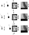
- the method and apparatuses may control the switching between collecting surface data and collecting penetration imaging (penetrative) data.
- any of these methods may include taking images using the penetrative wavelength as the 3D surface model data is being captured, e.g., by switching between the first imaging modality and the second (penetrative) imaging modality.
- taking the plurality of images may comprise using a same sensor on the intraoral scanner to capture 3D surface model data and the plurality of images using the penetrative wavelength.
- a separate sensor or sensors may be used.
- taking the plurality of images may comprise using a different sensor on the intraoral scanner to capture 3D surface model data and the plurality of images using the penetrative wavelength.
- taking images of the tooth using the penetrative wavelength may include taking penetration images at any angle between the illumination source and the sensor (e.g., detector or camera).
- internal feature (e.g., reflective imaging) data may be imaged using a small angle configuration, in which one or preferably more penetration images are taken at different orientations relative to the tooth/teeth.
- taking the plurality of images may comprise illuminating the tooth at an angle of between 0° and 15° relative to a sensor (e.g., detector, camera, etc.) receiving the illumination from the tooth, reflecting off of the internal composition of the tooth/teeth.
- Taking the plurality of images generally includes taking one or more (e.g., a plurality, including two or more, three or more, etc.) penetration images at different angles of the intraoral scanner relative to the tooth over the same region of the tooth.
- penetration images e.g., penetration images such as these small-angle penetration images
- Taking the plurality of images generally includes taking one or more (e.g., a plurality, including two or more, three or more, etc.) penetration images at different angles of the intraoral scanner relative to the tooth over the same region of the tooth.
- the same internal region of the tooth will appear in multiple different scans from different angles.
- any number of sensors may be included on the intraoral scanner, e.g., the wand of the intraoral scanner. Any appropriate sensor for detecting and recording the appropriate spectral range(s) (e.g., of light) may be used. Sensors may be referred to and may include detectors, cameras, and the like. For example, taking a plurality of images may comprise using a plurality of sensors on the intraoral scanner to capture the plurality of images using the penetrative wavelength.
- the illumination used to take a penetration image is generally penetrative, so that it may at least partially penetrate and pass through the enamel and dentin of the teeth.
- Penetrative wavelengths of light may include generally infrared (and particularly near infrared) light. For example, light in the range of 700 to 1090 nm (e.g., 850 nm) may be used. Other wavelengths and ranges of wavelengths may be used, including wavelengths shorter than the visible spectrum.
- taking the plurality of images may comprise illuminating the tooth with infrared light.
- Taking the plurality of images may include illuminating the tooth with one or more of white light (including but not limited to white light trans-illumination), UV/Blue fluorescence and red light fluorescence.
- the illumination used to take a penetration image can be considered semi-penetrative in the sense that internal tooth regions (e.g., points or voxels) may be visible from only a few camera positions and orientations; the point may be obstructed by other structures in some images which include the volume point in their field of view. In that sense, images that include the volume point in their field of view may not image this volume point.
- the methods and apparatuses described herein may take into account the high masking of volume points, unlike other penetrative scanning techniques such as CT, which uses X-ray imaging in which no masking occurs.
- any appropriate technique may be used to form the 3D models of the tooth including the (combined) surface and internal structures from the penetration imaging.
- These 3D models may be referred to as combined 3D surface/volume models, 3D volumetric surface models, or simply "3D models," or the like.
- both the surface data and the penetration imaging data may generally be in the same coordinate system. The two may be combined by using the common coordinate system.
- the surface data may be expressed as a surface model and the internal features added to this model.
- the data may be reconstructed into a three-dimensional model concurrently (after adding together).
- One or both datasets may be separately modified (e.g., filtered, subtracted, etc.).
- forming the 3D model of the tooth including internal structures may comprise combing the 3D surface model data with an internal structure data (including volumetric data).
- Forming the 3D model of the tooth including internal structures may comprise combining the plurality of penetration images, wherein the plurality of penetration images may be taken from different angles using the intraoral scanner.
- the data may be analyzed automatically or manually by the system.
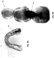
- the method and apparatuses described herein may include examining internal features and/or identifying features of interest, including crack and caries.
- Features may be recognized based on feature-recognition criterion (e.g., dark or light regions in the penetration images), pattern-recognition, machine learning, or the like.
- Features may be marked, including coloring, labeling or the like.
- Feature may be marked directly in the 3D model, on the penetration image, or in a data structure that references (e.g., shares a coordinate system with) the 3D model of the tooth formed by the methods and apparatuses described herein.
- intraoral scanning systems for generating a model of a subject's teeth that include: a hand-held wand having at least one sensor and a plurality of light sources, wherein the light sources are configured to emit light at a first spectral range and a second spectral range, wherein the second spectral range is penetrative; and one or more processors operably connected to the hand-held wand, the one or more processors configured to: generate a three-dimensional (3D) surface model of at least a portion of a subject's tooth using light from a first spectral range; and generate a 3D model of the subject's tooth including internal structures based on the 3D surface model and on a plurality of images taken at the second spectral range showing internal structures.
- 3D three-dimensional
- An intraoral scanning system for generating a model of a subject's teeth may include: a hand-held wand having at least one sensor and a plurality of light sources, wherein the light sources are configured to emit light at a first spectral range and a second spectral range, further wherein the second spectral range is penetrative; and one or more processors operably connected to the hand-held wand, the one or more processors configured to: determine surface information by using light in the first spectral range sensed by the hand-held wand, using a first coordinate system; generate a three-dimensional (3D) surface model of at least a portion of a subject's tooth using the surface information; take a plurality of images in the second spectral range, wherein the images reference the first coordinate system; and generate a 3D model of the subject's tooth including internal structures based on the 3D surface model and the a plurality of images.
- 3D three-dimensional
- additional modalities e.g., laser florescence, etc.
- other internal scanning techniques e.g., laser florescence
- a hand-held intraoral scanner to scan a portion of a subject's tooth using a first modality to capture three-dimensional (3D) surface model data of the tooth
- using the hand-held intraoral scanner to scan the portion of the subject's tooth using a second modality to image into the tooth using a penetrative wavelength to capture internal data of the tooth
- cycling between the first modality and the second modality wherein cycling rapidly switches between the first modality and the second modality so that images using the penetrative wavelength share a coordinate system with the 3D surface model data captured in the first modality.
- any of the methods described herein may include automatically adjusting the duration of time spent scanning in first modality, the duration of time spent in the second modality, or the duration of time spent in the first and the second modality when cycling between the first modality and the second modality.
- any of these methods may include automatically adjusting a duration of time spent scanning in first modality, the duration of time spent in the second modality, or the duration of time spent in the first and the second modality when cycling between the first modality and the second modality based on the captured 3D surface model data, the internal data, or both the 3D surface model data and the internal data.
- a method of generating a model of a subject's teeth may include: using a hand-held intraoral scanner to scan a portion of a subject's tooth using a first modality to capture three-dimensional (3D) surface model data of the tooth; using the hand-held intraoral scanner to scan the portion of the subject's tooth using a second modality to image into the tooth using a penetrative wavelength to capture internal data of the tooth; cycling between the first modality and the second modality using a scanning scheme wherein cycling rapidly switches between the first modality and the second modality so that the internal data uses the same coordinate system as the 3D surface model data captured in the first modality; and adjusting the scanning scheme based on the captured 3D surface model data, the internal data, or both the 3D surface model data and the internal data.
- Any of these methods may include combining the 3D surface model data and the internal data of the tooth to form a 3D model of the tooth.
- capturing the 3D surface model data may include determining a 3D surface topology using confocal focusing/confocal scanning, stereo vision or structured light triangulation.
- cycling may comprise cycling between the first modality, the second modality, and a third modality, wherein cycling rapidly switches between the first modality, the second modality and the third modality so that images using the penetrative wavelength share a coordinate system with the 3D surface model captured in the first modality.
- the third modality may be another penetrative modality or a non-penetrative modality (e.g., color, a visual image the subject's tooth, etc.).
- Using the hand-held intraoral scanner to scan the portion of the subject's tooth using the second modality may include illuminating the tooth at an angle of between 0° and 15° relative to a direction of view of the sensor receiving the illumination (e.g., small angle illumination).
- the step of using the hand-held intraoral scanner to scan the portion of the subject's tooth using the second modality may include taking a plurality of penetration images at a plurality of different angles between an illumination source and a sensor and/or at a plurality of different positions or angles relative to the tooth so that the same internal region of the tooth is imaged from different angles relative to the tooth.
- any appropriate penetrative wavelength may be used, including infrared (e.g., near infrared).
- using the hand-held intraoral scanner to scan the portion of the subject's tooth using the second modality may comprise illuminating with one or more of: white light trans-illumination, UV/Blue fluorescence, and red light fluorescence.
- intraoral scanning systems for generating a model of a subject's teeth that are configured to cycle between scanning modes.
- intraoral scanning systems comprising: a hand-held intraoral wand having at least one sensor and a plurality of light sources, wherein the light sources are configured to emit light at a first spectral range and at a second spectral range, further wherein the second spectral range is penetrative; and one or more processors operably connected to the hand-held intraoral wand, the one or more processors configured to cause the wand to cycle between a first mode and a second mode, wherein in the first mode the wand emits light at the first spectral range for a first duration and the one or more processors receives three dimensional (3D) surface data in response, and wherein in the second mode the wand emits light at the second spectral range for a second duration and the one or more processors receives image data in response.
- 3D three dimensional
- An intraoral scanning system for generating a model of a subject's teeth may include: a hand-held intraoral wand having at least one sensor and a plurality of light sources, wherein the light sources are configured to emit light at a first spectral range and at a second spectral range, further wherein the second spectral range is penetrative; and one or more processors operably connected to the wand, the one or more processors configured to cause the wand to cycle between a first mode and a second mode, wherein in the first mode the wand emits light at the first spectral range for a first duration and the one or more processors receives three dimensional (3D) surface data in response, and wherein in the second mode the wand emits light at the second spectral range for a second duration and the one or more processors receives image data in response; wherein the one or more processors is configured to adjusting the first duration and the second duration based on the received 3D surface data, the received image data, or both the 3D
- one mode may be the surface scanning (3D surface), which may be, for example, at 680 nm.
- Another mode may be a penetrative scan, using, e.g., near-IR light (e.g., 850 nm).
- Another mode may be color imaging, using white light (e.g., approximately 400 to 600 nm).
- a method of imaging through a tooth to detect cracks and caries may include: taking a plurality of penetration images through the tooth at different orientations using a hand-held intraoral scanner in a first position, wherein the intraoral scanner is emitting light at a penetrative wavelength; determining surface location information using the intraoral scanner at the first position; and generating a three-dimensional (3D) model of the tooth using the plurality of penetration images and the surface location information.
- Generating a 3D model of the tooth may comprise repeating the steps of taking the plurality of penetration images and generating the 3D model for a plurality of different locations.
- Taking the plurality of penetration images through the tooth at different orientations may include taking penetration images in which each penetration image is taken using either or both of: a different illumination source or combination of illumination sources on the intraoral scanner emitting the penetrative wavelength or a different image sensor on the intraoral scanner taking the image.
- taking the plurality of penetration images may comprise taking three or more penetration images.
- Taking the plurality of penetration images through the tooth surface at different orientations may comprises taking penetration images using small angle illumination/viewing, for example, wherein, for each penetration image, an angle between emitted light and light received by an image sensor is between 0 and 15 degrees.
- a method of imaging through a tooth to detect cracks and caries may include: scanning a tooth from multiple positions, wherein scanning comprises repeating, for each position: taking a plurality of penetration images through the tooth at different orientations using an intraoral scanner, wherein the intraoral scanner is emitting light at a penetrative wavelength and wherein, for each penetration image, an angle between emitted light and light received by an image sensor is between 0 and 15 degrees, and determining surface location information using the intraoral scanner; and generating a three-dimensional (3D) model of the tooth using the penetration images and the surface location information.
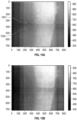
- the method may include illuminating the object with a light source that is emitting (e.g., exclusively or primarily radiating) a penetrating wavelength, taking a plurality of images of the object with a camera sensitive to the penetrating wavelength (e.g., recording in the range of radiation wavelengths), receiving location data representing a location of the camera relative to the object for each of the plurality of images, generating for each point in a volume an upper bound on a scattering coefficient from the plurality of images and the location data, and generating an image of the object from the upper bound of scattering coefficients for each point.
- a light source that is emitting (e.g., exclusively or primarily radiating) a penetrating wavelength
- taking a plurality of images of the object with a camera sensitive to the penetrating wavelength e.g., recording in the range of radiation wavelengths
- receiving location data representing a location of the camera relative to the object for each of the plurality of images
- the penetrating wavelength of light applied to the object may be emitted from substantially the same direction as the camera.
- the image or images generated may illustrate features within the volume of the object, and the image may also include (or be modified to include) the outer boundary of the object, as well as the internal structure(s).
- a tooth may be described as an object including semi-transparent strongly scattering region or regions; in general, teeth may also include strong scattering regions (such as dentine), and lightly scattering, highly transparent regions (such as the enamel) at near-IR wavelengths. Teeth may also include regions having intermedia or mixed scattering properties, such as caries. The methods and apparatuses for performing volumetric scans described herein are well suited for mapping these different regions in the tooth/teeth.
- a method of reconstructing a volumetric structure from an object including semi-transparent strongly scattering regions for a range of radiation wavelengths may include: taking a plurality of images of the object with a camera in the range of radiation wavelengths, wherein lighting for the plurality of images is projected substantially from a direction of the camera, receiving location data representing a location of the camera relative to the object for each of the plurality of images, generating for each point in a volume an upper bound on a scattering coefficient from the plurality of images and the location data, and generating an image of the object from the upper bound of scattering coefficients for each point.
- the range of radiation wavelengths may be infrared or near infrared wavelength(s).
- Any of these methods may also include receiving surface data representing an exterior surface of the object, wherein the generating step is performed for each point in the volume within the exterior surface of the object.
- the object may comprise a tooth, having an exterior enamel surface and an interior dentin surface.
- Teeth are just one type of object including semi-transparent strongly scattering regions; other examples may include other both tissues (including soft and/or hard tissues), e.g., bone, etc.
- These objects including semi-transparent strongly scattering regions may include regions that are typically semi-transparent and strongly scattering for the penetrative wavelengths (e.g., the infrared or near infrared wavelengths), as described herein.
- the location data may generally include position and orientation data of the camera at the time of capturing each of the plurality of images.
- the location data may comprise three numerical coordinates in a three-dimensional space, and pitch, yaw, and roll of the camera.
- Generating for each point in the volume the upper bound on scattering coefficients may comprise projecting each point of a 3D grid of points corresponding to the volume of the object onto each of the plurality images using a first calibration, producing a list of intensity values for each projected point, converting each intensity value on the list of intensity values to a scattering coefficient according to a volume response, and storing a minimum scattering coefficient value for each grid point from the list of scattering coefficient values.
- the first calibration may comprise a fixed pattern noise calibration to calibrate for sensor issues and image ghosts of the camera.
- the first calibration may comprise a camera calibration that determines a transformation for the camera that projects known points in space to points on an image.
- Also described herein are methods of reconstructing a volumetric structure from a tooth, semi-transparent in a range of radiation wavelengths comprising receiving, in a processor, a representation of a surface of the tooth in a first coordinate system, receiving, in the processor, a plurality of images of the tooth in the range of radiation wavelengths, the plurality of images taken with lighting projected substantially from a direction of a camera, receiving, in the processor, location data representing a location of the camera for each of the plurality of images, projecting each point of a grid of points corresponding to a volume within the surface of the tooth onto each of the plurality images using a first calibration, producing a list of intensity values for each projected point, converting each intensity value on the list of intensity values to a scattering coefficient according to a volume response, and storing a minimum scattering coefficient for each point into a list of minimum scattering coefficients.
- Any of these methods may further comprise producing an image from the list of minimum scattering coefficients.
- the location data may comprise position and orientation data of the camera (or cameras) at the time of capturing each of the plurality of images.
- the first calibration may comprise a fixed pattern noise calibration to calibrate for sensor issues and image ghosts of the camera.
- the first calibration may comprise a camera calibration that determines a transformation for the camera that projects known points in space to points on an image.
- the method may further comprise receiving surface data representing an exterior surface of the object, wherein the projecting step is performed for each point inside the volume within the exterior surface of the object.
- the grid of points may comprise a cubic grid.
- any of the methods described herein may be embodied as software, firmware and/or hardware.
- any of these methods may be configured as non-transitory computing device readable medium having instructions stored thereon for performing the method.
- a non-transitory computing device readable medium having instructions stored thereon for reconstructing a volumetric structure from a tooth that is semi-transparent in a range of radiation wavelengths.
- the instructions may be executable by a processor to cause a computing device to receive a representation of a surface of the tooth in a first coordinate system, receive a plurality of images of the tooth in the range of radiation wavelengths, the plurality of images taken with lighting projected substantially from a direction of a camera, receive location data representing a location of the camera for each of the plurality of images, project each point of a grid of points corresponding to a volume of the tooth onto each of the plurality of images using a first calibration, produce a list of intensity values for each projected point, convert each intensity value on the list of intensity values to a scattering coefficient according to a volume response, and store a minimum scattering coefficient for each point into a list of minimum scattering coefficients, and produce an image from the list of minimum scattering coefficients.
- the location data may comprise position and orientation data of the camera at the time of capturing each of the plurality of near-infrared images.
- the location data may comprise three numerical coordinates in a three-dimensional space, and pitch, yaw, and roll of the camera.
- the first calibration may comprise a fixed pattern noise calibration to calibrate for sensor issues and image ghosts of the camera.
- the first calibration may comprise a camera calibration that determines a transformation for the camera that projects known points in space to points on an image.
- the grid of points may be inside the tooth; as mentioned, the grid of points may comprise a cubic grid.
- any appropriate method of forming the internal structures of the patient's teeth using the penetrative wavelength images may use the two-dimensional penetrative images along with position and/or orientation information about the scanner relative to the object being imaged (e.g., the teeth) to segment the 2D penetrative images to form a three-dimensional model of the teeth including an internal structure from within the teeth.
- a penetrative image may refer to an images taken with a near-IR and/or IR wavelength), penetrating into the object.
- the position and/or orientation of the scanner may be a proxy for the position and/or orientation of the camera taking the images which is one the scanner (e.g., on a handheld wand).
- methods of modeling a subject's teeth comprising: capturing, with an intraoral scanner, a plurality of images of an interior of the subject's teeth and a position and orientation of the intraoral scanner specific to each image of the plurality of images; segmenting the plurality of images to form an internal structure corresponding to a structure within the subject's teeth; using the position and orientation of the plurality of images to project the internal structure onto a three-dimensional model of the subject's teeth; and displaying the three-dimensional model of the subject's teeth including the internal structure.
- the 3D surface model may be concurrently captured using a non-penetrative wavelength (e.g., surface scan) while capturing the penetrative images.
- capturing may comprise capturing surface images of the subject's teeth while capturing the plurality of images of the interior of the subject's teeth.
- the method may also include forming the three dimensional model of the subject's teeth from the captured surface images.
- forming the three dimensional model of the subject's teeth may comprise determining a three-dimensional surface topology using confocal focusing.
- Capturing the surface images of the subject's teeth may comprise using confocal scanning, stereo vision or structured light triangulation.
- the same device e.g., scanner
- a separate processor e.g., remote to the scanner
- Any of these methods may also include storing and/or transmitting plurality of penetrative images and the position and orientation of the intraoral scanner while capturing the plurality of two-dimensional images, including transmitting to a remote processor for performing the segmentation and later steps.
- the 3D model including the internal structure(s) may be displayed while the scanner is operating. This may advantageously allow the user to see, in real-time or near real-time the internal structure(s) in the subject's teeth.
- any of these methods may include displaying the three-dimensional model as the images are captured.
- Segmenting the plurality of images may comprise applying edge detection to the plurality of images to identify closed boundaries within the plurality of images. Segmenting the plurality of images may comprise forming a volumetric density map from the plurality of images to identify the internal structure. Segmenting the volumetric density map may include segmenting by identifying one or more iso-surfaces within the volumetric density map to identify the internal features. Any of these methods may include segmenting the volumetric density map to identify the internal feature (e.g., cracks, caries, dental fillings, dentin, etc.).
- the processors may be configured to segment the plurality of images by applying edge detection to the plurality of images to identify closed boundaries within the plurality of images.
- the processor may be configured to segment the plurality of images by forming a pixel density map from the plurality of images to identify the internal structure.
- the processor may be configured to identify closed segments within the pixel density map to identify the internal structure.
- Non-transitory computing device readable medium having instructions stored thereon that are executable by a processor to cause an intraoral scanning apparatus to: capture a plurality of images using a penetrative wavelength of light and a position and orientation of the intraoral scanner specific to each image of the plurality of images; segment the plurality of images to form an internal structure corresponding to a structure within a subject's teeth; use the position and orientation of the intraoral scanner specific to each image to project the internal structure onto a three-dimensional model of the subject's teeth; and display the three-dimensional model of the subject's teeth including the internal structure.
- the non-transitory computing device readable medium having instructions may be further configured to cause the intraoral scanning apparatus to segment the plurality of images by applying edge detection to the plurality of images to identify closed boundaries within the plurality of images.
- the non-transitory computing device readable medium having instructions may be further configured to cause the intraoral scanning apparatus to segment the plurality of images by forming a pixel density map from the plurality of images to form the internal structure.
- the non-transitory computing device readable medium having instructions may be further configured to cause the intraoral scanning apparatus to segment the plurality of images by identifying closed segments within the pixel density map to form the internal structure.
- Non-transitory computing device readable medium having instructions stored thereon that are executable by a processor to cause a computing device to: receive, from a scanner, three-dimensional surface model data of a subject's teeth; receive, from the scanner, a plurality of images of an interior of the subject's teeth and position and orientation of the intraoral scanner specific to each image of the plurality of images; segment the plurality of images to form an internal structure of the subject's teeth; project the internal structure of the subject's teeth onto the three-dimensional surface model; and display the three-dimensional surface model showing the internal structure.
- a three-dimensional (3D) volumetric model of a subject's teeth using an intraoral scanner comprising: capturing 3D surface model data of at least a portion of the subject's teeth using an intraoral scanner as the intraoral scanner is moved over the teeth; taking a plurality of images into the teeth using a near-infrared (near-IR) wavelength with the intraoral scanner as the intraoral scanner is moved over the teeth so that multiple images of a same internal region of the teeth are imaged; determining, for each of the plurality of images into the teeth, a position of the intraoral scanner relative to the subject's teeth using the 3D surface model data; and forming the 3D volumetric model of the subject's teeth including internal features using the plurality of images and the position of the intraoral scanner relative to the subject's teeth.
- near-IR near-infrared
- a method for generating a three-dimensional (3D) volumetric model of a subject's teeth using an intraoral scanner may include: capturing 3D surface model data of at least a portion of the subject's teeth using an intraoral scanner as the intraoral scanner is moved over the teeth; taking a plurality of images into the teeth using a near-infrared (near-IR) wavelength as the intraoral scanner is moved over the teeth by emitting a near-IR light from the intraoral scanner in a first polarization, and detecting, in an image sensor in the intraoral scanner, the near-IR light returning to the intraoral scanner, wherein the near-IR light returning to the intraoral scanner is filtered to remove specular reflection by filtering near-IR light in the first polarization from the near-IR light returning to the intraoral scanner before it reaches the image sensor; determining, for each of the plurality of images into the teeth, a position of the intraoral scanner relative to the subject's teeth when each of the plurality of images is captured, using the 3D surface model data; and
- the near-IR light returning to the intraoral scanner may be filtered to remove specular reflection by filtering all or nearly all of the near-IR light in the first polarization from the near-IR light returning to the intraoral scanner before it reaches the image sensor.
- an intraoral scanning system for generating a three-dimensional (3D) volumetric model of a subject's teeth may include: a hand-held wand having at least one image sensor and a plurality of light sources, wherein the light sources are configured to emit light at a first spectral range and a second spectral range, wherein the second spectral range is within near-infrared (near-IR) range of wavelengths; and one or more processors operably connected to the hand-held wand, the one or more processors configured to: capture 3D surface model data of at least a portion of the subject's teeth as the intraoral scanner is moved over the teeth; take a plurality of images into the teeth using light in the second spectral range as the intraoral scanner is moved over the teeth so that multiple images of a same internal region of the teeth are imaged; determine, for each of the plurality of images into the teeth, a position of the hand-held wand relative to the
- An intraoral scanning system for generating a three-dimensional (3D) volumetric model of a subject's teeth may include: a hand-held wand having at least one image sensor and a plurality of light sources, wherein the light sources are configured to emit light at a first spectral range and a second spectral range, wherein the second spectral range is within near-infrared (near-IR) range of wavelengths; a filter in front of the image sensor configured to filter light in the second spectral range and the first polarization; and one or more processors operably connected to the hand-held wand, the one or more processors configured to: capture 3D surface model data of at least a portion of the subject's teeth as the intraoral scanner is moved over the teeth; take a plurality of images into the teeth using light in the second spectral as the intraoral scanner is moved over the teeth by emitting a near-IR light from the intraoral scanner in a first polarization, and detecting, in an image sensor in the intraoral scanner, the
- methods of imaging into a subject's teeth to detect cracks and caries using an intraoral scanner comprising: scanning the intraoral scanner over the subject's teeth; taking a plurality of near-infrared (near-IR) images into the subject's teeth at different orientations using the intraoral scanner emitting both a near-IR wavelength and a non-penetrative wavelength; determining a position of the intraoral scanner relative to the subject's teeth for each location of an image from the plurality of near-IR images using the non-penetrative wavelength; and generating a three-dimensional (3D) volumetric model of the subject's teeth using the plurality of near-IR images and the position of the intraoral scanner relative to the subject's teeth for each near-IR image of the plurality of near-IR images.
- 3D three-dimensional
- Any of these methods may include analyzing the volumetric model to identify a crack or caries (or other internal regions of the teeth).
- a method of imaging through a subject's teeth to detect cracks and caries may include: scanning the subject's teeth from multiple positions, wherein scanning comprises repeating, for each position: taking a plurality of near-infrared (near-IR) images into the teeth at different orientations using an intraoral scanner, wherein the intraoral scanner is emitting light at a near-IR wavelength in a first polarization and wherein, for each near-IR image, an angle between emitted light and light received by an image sensor is between 0 and 15 degrees, further wherein received near-IR light is filtered to block near-IR light in the first polarization, and determining a position of the intraoral scanner relative to the subject's teeth for each location of an image from the plurality of near-IR images using; and generating a three-dimensional (3D) volumetric model of the tooth using the penetration images and the surface location information.
- 3D three-dimensional
- a method of forming a three-dimensional (3D) volumetric model of a subject's teeth may include: taking a plurality of near-infrared (near-IR) images of the subject's teeth with a camera sensor, wherein the near-IR lighting for the plurality of near-IR images is projected substantially from a direction of the camera sensor; receiving location data representing a location of the camera relative to the subject's teeth for each of the plurality of near-IR images; generating, for each point in a volume, an upper bound on a scattering coefficient from the plurality of near-IR images and the location data; combining the upper bound of scattering coefficients for each point in a volume to form a 3D volumetric model of the subject's teeth; and outputting the 3D volumetric model of the subject's teeth.
- near-IR near-infrared
- any of these methods may include forming an iso-surface from the 3D volumetric model of the subject's teeth.
- the iso-surface may be formed by selecting a threshold or range of values of the scattering coefficients. Sub-ranges may correspond to different internal regions (e.g., structures).
- outputting may comprise forming an iso-surface corresponding to an interior dentin surface from the 3D volumetric model of the subject's teeth.
- a method of reconstructing a volumetric structure from a tooth, wherein the tooth is semi-transparent in a range of radiation wavelengths may include: receiving, in a processor, a representation of a surface of the tooth in a first coordinate system; receiving, in the processor, a plurality of images of the tooth taken by a camera in the range of radiation wavelengths, the plurality of images taken with lighting projected substantially from a direction of the camera; receiving, in the processor, location data representing a location of the camera for each of the plurality of images; projecting each point of a grid of points corresponding to a volume within the surface of the tooth onto each of the plurality images using a first calibration; producing a list of intensity values for each projected point; converting each intensity value on the list of intensity values to a scattering coefficient according to a volume response; and storing a minimum scattering coefficient for each point into a list of minimum scattering coefficients.
- any of these methods may be embodied in an apparatus, including software, hardware and/or firmware for performing the method.
- described herein are non-transitory computing device readable medium having instructions stored thereon for reconstructing a volumetric structure from a tooth that is semi-transparent in a range of radiation wavelengths, wherein the instructions are executable by a processor to cause a computing device to: receive a representation of a surface of the tooth in a first coordinate system; receive a plurality of images of the tooth taken by a camera in the range of radiation wavelengths, the plurality of images taken with lighting projected substantially from a direction of the camera; receive location data representing a location of the camera for each of the plurality of images; project each point of a grid of points corresponding to a volume of the tooth onto each of the plurality of images using a first calibration; produce a list of intensity values for each projected point; convert each intensity value on the list of intensity values to a scattering coefficient according to a volume response; and store a minimum scattering coefficient for each point from the scattering coefficient
- a method of modeling a subject's teeth may include: capturing, with an intraoral scanner, a plurality of images of an interior of the subject's teeth and a position and orientation of the intraoral scanner specific to each image of the plurality of images; segmenting the plurality of images to form an internal structure corresponding to a structure within the subject's teeth; using the position and orientation of the plurality of images to project the internal structure onto a three-dimensional model of the subject's teeth; and displaying the three-dimensional model of the subject's teeth including the internal structure.
- intraoral scanning apparatus configured to generate a model of a subject's teeth
- the apparatus comprising: an intraoral scanner having a plurality of light sources and a position and orientation sensor, wherein the light sources are configured to emit light at a first spectral range and at a second spectral range, further wherein the second spectral range is penetrative; and a processor operably connected to the intraoral scanner, the one or more processors configured to cause the scanner to capture a plurality of images and position and orientation of the intraoral scanner corresponding to each of the plurality of images when the intraoral scanner is emitting light at the second spectral range; wherein the processor is further configured to segment the plurality of images to form an internal structures corresponding to a structure within the subject's teeth, and to display or transmit a three-dimensional model of the subject's teeth including the internal structure.
- Non-transitory computing device readable medium having instructions stored thereon that are executable by a processor to cause an intraoral scanning apparatus to: capture a plurality of images using a penetrative wavelength of light and a position and orientation of the intraoral scanner specific to each image of the plurality of images; segment the plurality of images to form an internal structure corresponding to a structure within a subject's teeth; use the position and orientation of the intraoral scanner specific to each image to project the internal structure onto a three-dimensional model of the subject's teeth; and display the three-dimensional model of the subject's teeth including the internal structure.
- the received data may comprise data from tooth surface penetrating intraoral scan of the subject.
- the received data may further comprise data from a tooth surface intraoral scan of the subject.
- the method may also include determining, from the received data, a surface of the tooth of the subject; mapping the surface of the tooth with the portion of the volume of the first internal feature and the portion of the volume of the second internal feature; and outputting the 3D volume with the surface of the tooth with the portion of the volume of the first internal feature and the portion of the volume of the second internal feature.
- the received data may further comprise data from a tooth surface color intraoral scan of the subject.
- the method may also comprise, determining, from the received data, a color of the surface of the tooth of the subject; mapping the color of the surface of the tooth to the surface of the tooth; and outputting the 3D volume with the surface of the tooth and the color of the surface of the tooth.
- the first internal feature of the tooth may comprise a dentin of the tooth and the second internal feature of the tooth comprises an enamel of the tooth.
- the intraoral scan may comprise a second intraoral scan of the subject; and wherein the method further comprises receiving data associated with a prior intraoral scan of the subject; determining from the received data associated with the prior intraoral scan of the subject, at least a portion of a volume of the enamel or the dentin; and determining a volume change of the enamel or the dentin by comparing the portion of the volume of the enamel or the dentin determined from the received data associated with the second intraoral scan and the portion of the volume of the enamel or the dentin determined from the received data associated with the prior intraoral scan; and outputting the determined volume change.
- the method may also include detecting a dental caries of the tooth by comparing the second internal feature and the first internal feature and outputting a signal to the user associated with the detected dental caries.
- Comparing the second internal feature and the second internal feature may comprise analyzing whether the volume of the second internal feature extends from a surface of the volume of the first internal feature.
- Analyzing may comprise determining whether the volume of the second internal feature extends from the surface of the volume of the first internal feature and to a portion of the second internal feature associated with the dentin.
- the method may also include calculating a volume of the second internal feature that extends from the surface of the volume of the first internal feature and outputting a signal associated with the calculated volume.
- Also described are method comprising: receiving data associated with an intraoral scan of a subject; determining, from the received data, a volume of a dental caries of a tooth of the subject; quantifying the volume of the dental caries of the tooth of the subject; and outputting a signal associated with the quantified volume of the dental caries of the tooth of the subject.
- the method may also include determining, from the received data, a volume of an enamel of the tooth of the subject; mapping the volume of the enamel to the volume of the dental caries; and outputting a 3D volume of the mapped volumes of the enamel and the dental caries to a user. For example, determining, from the received data, a volume of a dentin of the tooth of the subject; mapping the volume of the dentin to the volume of the enamel and the volume of the dental caries; and outputting the 3D volume of the mapped volumes of the enamel and the dental caries with the volume of the dentin.
- the intraoral scan of the subject may comprise a second intraoral scan of the subject and wherein the method further comprises receiving data associated with a prior intraoral scan of the subject; determining, from the received data associated with the prior intraoral scan of the subject, a prior volume of the dental caries of the tooth of the subject; outputting a signal associated with a difference in volume between the volume of the dental caries and the prior volume of the dental caries.
- the method may also comprise outputting a 3D model of the volume of the dental caries of the tooth of the subject.
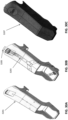
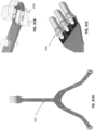
- trans-illumination adapter sleeve device for an intraoral scanner, the device comprising: a sleeve body configured to fit over a wand of an intraoral scanner, the sleeve body comprising a light-passing region at a distal end of the sleeve body configured to allow near-infrared (near-IR) light to pass through the sleeve; a first wing region extending from the distal end of the sleeve body adjacent to the light-passing region; and a near-IR light source configured to emit near-IR light from the first wing region.
- the near-IR light source may be configured to emit near-IR light transverse to the light-passing region.
- the device may also include a second wing region extending from the distal end of the sleeve body adjacent to the light-passing region having a second near-IR light source configured to emit near-IR light from the second wing region.
- the device may also include an electrical contact on a proximal end of the sleeve body configured to apply electrical energy to the near-IR light source.
- the device may also include a flexible circuit coupling the electrical contact to the near-IR light source. Any of these devices may include a camera sensor operably connected to a second wing extending from the distal end of the sleeve body adjacent to the light-passing region.
- FIG. 1A illustrates one example of an intraoral scanner 101 that may be configured or adapted as described herein to generate 3D models having both surface and internal features.
- an exemplary intraoral scanner may include a wand 103 that can be hand-held by an operator (e.g., dentist, dental hygienist, technician, etc.) and moved over a subject's tooth or teeth to scan both surface and internal structures.
- an operator e.g., dentist, dental hygienist, technician, etc.
- the wand may include one or more sensors 105 (e.g., cameras such as CMOS, CCDs, detectors, etc.) and one or more light sources 109, 110, 111.
- sensors 105 e.g., cameras such as CMOS, CCDs, detectors, etc.
- light sources 109, 110, 111 In FIG. 1B , three light sources are shown: a first light source 109 configured to emit light in a first spectral range for detection of surface features (e.g., visible light, monochromatic visible light, etc.; this light does not have to be visible light), a second color light source (e.g., white light between 400-700 nm, e.g., approximately 400-600 nm), and a third light source 111 configured to emit light in a second spectral range for detection of internal features within the tooth (e.g., by trans-illumination, small-angle penetration imaging, laser florescence, etc., which may generically be referred to as penetration
- the light source may be any appropriate light source, including LED, fiber optic, etc.
- the wand 103 may include one or more controls (buttons, switching, dials, touchscreens, etc.) to aid in control (e.g., turning the wand on/of, etc.); alternatively or additionally, one or more controls, not shown, may be present on other parts of the intraoral scanner, such as a foot petal, keyboard, console, touchscreen, etc.
- any appropriate light source may be used, in particular, light sources matched to the mode being detected.
- any of these apparatuses may include a visible light source or other (including non-visible) light source for surface detection (e.g., at or around 680 nm, or other appropriate wavelengths).
- a color light source typically a visible light source (e.g., "white light” source of light) for color imaging may also be included.
- a penetrating light source for penetration imaging e.g., infrared, such as specifically near infrared light source
- penetration imaging e.g., infrared, such as specifically near infrared light source
- the intraoral scanner 101 may also include one or more processors, including linked processors or remote processors, for both controlling the wand 103 operation, including coordinating the scanning and in reviewing and processing the scanning and generation of the 3D model including surface and internal features.
- the one or more processors 113 may include or may be coupled with a memory 115 for storing scanned data (surface data, internal feature data, etc.).
- Communications circuitry 117 including wireless or wired communications circuitry may also be included for communicating with components of the system (including the wand) or external components, including external processors.
- the system may be configured to send and receive scans or 3D models.
- One or more additional outputs 119 may also be included for outputting or presenting information, including display screens, printers, etc.
- inputs 121 buttons, touchscreens, etc.
- the apparatus may allow or request user input for controlling scanning and other operations.
- any of the apparatuses and methods described herein may be used to scan for and/or identify internal structures such as cracks, caries (decay) and lesions in the enamel and/or dentin.
- any of the apparatuses described herein may be configured to perform scans that may be used to detect internal structures using a penetrative wavelength or spectral range of penetrative wavelengths.
- methods for detecting cracks, caries and/or lesions or other internal feature such as dental fillings, etc.
- penetrative scanning techniques may be used or incorporated into the apparatus, including but not limited to trans-illumination and small-angle penetration imaging, both of which detect the passage of penetrative wavelengths of light from or through the tissue (e.g., from or through a tooth or teeth).
- Trans-illumination is one technique that may be used for seeing internal features of teeth.
- FIGS. 2A and 2B illustrate these: a 180° configuration and a 90° configuration. Both configurations may be used for visualizing inside the teeth, and mainly through the enamel.
- a penetrative wavelength (including a spectral range of one or more penetrative wavelengths) is emitted from a light source 203 and passed from one side of the tooth 201, and a sensor 205 (e.g., camera) on the opposite side detects the light that has passed through the tooth without being scattered or absorbed.
- a sensor 205 e.g., camera
- the tooth 201 is illuminated by light from light sources (203, 203') on either side of the tooth 201, and the camera 205, which is oriented 90° relative to both light sources, detect light at the right angle to the light source.
- trans-illumination has been limited to the use of a single projection type, in order to give an image capture inside the tooth (similar to the use of an x-ray).
- a penetrative wavelength such as between 700 to 1300 nm, 700 to 1090 nm, etc., e.g., 850 nm
- one or more 180° projection may be useful as the light travels a shorter distance and is less scattered, however the combination of multiple different projections (orientations) from the same location (e.g., at approximately the same scanning time, within a few milliseconds of each other) may permit the system to build a volumetric model of the enamel-dentin area.
- the intraoral scanner may be adapted to provide trans-illumination imaging in this configuration.
- FIGS. 2C and 2D illustrate one example of a distal end of a wand of an intraoral scanner adapted to collect trans-illumination images at 90 and 180°, in which the wand 213 includes a pair of projections or wings 215 each housing a light source (LED) and camera combination 217.
- both wings and the base of the wand may include light sources and sensors (cameras) so that at least three trans-illumination images may be taken from a single position of the wand relative to the teeth, as shown in FIGS. 3A-3C .
- FIG. 3A-3C In FIG.
- FIG. 3A a first orientation is shown, in which the right LED 303 is on, illuminating through the tooth for detection/capture (180°) by the camera 305 on the left.
- FIG. 3D is similar to FIG. 3A , showing light applied from the right side passing into the tooth (arrows) and either passing through to the camera sensor 305 (also referred to herein as an image sensor, camera, or just “sensor”), or scattered from an internal region. The orientation of the camera sensor and illumination source may be switched.
- the left LED 303' is on, illuminating through the tooth for detection/capture (180°) by the camera 305' on the right.
- FIG. 3C both of the LEDs 303, 303' are on, illuminating from both right and left sides, and a camera 305" located 90° off of the axis of the LEDs captures the trans-illumination image.
- the trans-illumination imaging data such as that described above can be combined with, and collected concurrently with, 3D surface data (e.g., 3D surface model data) of the teeth, allowing an additional layer of data on internal structures such as caries and cracks.
- 3D surface data e.g., 3D surface model data
- the use of multiple projections (taken from multiple orientations) as described may enable reconstruction of volumetric models internal structures of the teeth enamel, showing features that would not otherwise be visible.
- the 90° and 180° configurations of trans-illumination of the teeth may be useful, it may be particularly beneficial to provide penetration imaging configurations in which the angle between the emitted and received rays (vectors) is much smaller, e.g., between 0° and 30°, between 0° and 25 °, between 0° and 20°, between 0° and 15°, between 0° and 10°, etc. In particular, angles between 0° and 15 ° (or between >0° and 15°) may be useful.
- Trans-illumination in the 180° configuration and 90° configuration may constrain the movement of the intraoral scanner wand around the teeth due to their camera to light source angle constraint (as shown in FIGS. 2C and 2D ).
- methods and apparatuses for penetration imaging/visualization e.g., of the enamel-dentin area, using a small angle, including between 0° and 15°.
- a light source (LED) emitting a penetrative spectral range e.g., 850 nm
- this penetration imaging may be combined with concurrent 3D surface modeling of the teeth.
- the relative positions of the light source(s) and cameras(s) are typically known, and one or more penetration images may be taken at each position of the wand.
- the intraoral scanning wand may be configured with just a slight curve, allowing it to fit and be easily maneuvered around the intraoral cavity, unlike wands configured to measure 90° and 180° trans-illumination, which may use a device geometry including side wings to hold the LEDs and sensor(s) so that the wand can wrap around the tooth for the imaging (e.g., see FIG. 2C ).
- the use of small-angle reflectance imaging may enable scanning in buccal and lingual directions, whereas the 90 degree (trans-illumination) scanning as described herein may be limited to scanning in the occlusal direction.
- the use of a small angle for penetration imaging may include imaging into the tooth using the wand in a way that enables unconstraint movement around the tooth, and may enable capturing the internal structure data while also scanning for 3D (surface) model data, without requiring a dedicated structure and/or mode of operation.
- the use of small angles between the emitting light and the detector(s) may also be complicated by direct reflections.
- direct reflection may occur in regions on the surface of the tooth in which the angle between the illumination and the imaging angles are approximately equal (e.g., in the cone of light and imaging NA). These direct reflections may be problematic if they saturate the sensor, or if they show surface information but obscure deeper structure information.
- the apparatus and methods of using them described herein may capture and use multiple illumination orientations taken from the same position.
- taking multiple images from the same position may effectively mean taking multiple images at approximately the same time, so that a significant amount of movement has not occurred.
- the images may be taken within a few milliseconds (less than 500 msec, less than 400 msec, less than 300 msec, less than 200 msec, less than 100 msec, less than 50 msec, etc.) of each other, and/or correcting for small movements.
- the apparatuses and/or methods may reduce or eliminate the problems arising from saturation with direct reflection by using only the non-saturated pixels.
- the surface information may be subtracted from the penetration images as part of the process. For example, visible light images ("viewfinder images”) or surface imaging may be used to remove direct surface reflections.
- the apparatuses may know the position of the wand at all times based on the surface scan, even when taking images at different (even small angle) angles.
- the position of the wand may be known relative to the object(s) being scanned. Based on this information, the apparatus may estimate which part(s) of the multiple images or signals is/are arriving from the surface and what is/are arriving from deeper structures.
- FIG. 4A illustrates an example of a configuration of penetrative light sources 403, 403'(e.g., penetrative spectral range light sources) and camera(s) 405 that may be used as part of an intraoral scanner wand, shown in different positions around the target object (tooth 401).
- penetrative light sources 403, 403' e.g., penetrative spectral range light sources
- camera(s) 405 that may be used as part of an intraoral scanner wand, shown in different positions around the target object (tooth 401).
- three camera positions are shown, and each in each position the camera is flanked by the pair of LEDs (e.g., 403 and 403') for emitting light in the penetrative spectral range (penetrative wavelength).
- a single light source e.g., LED
- Different images using the penetrative modality may be taken at different wand positions relative to the teeth.
- the wand may be configured with multiple imaging sensors (cameras) and multiple light sources, allowing multiple penetration images may be taken at approximately the same time, e.g., by turning on multiple sensors when illuminating from one or more LED orientations (e.g., FIGS. 5G and 5E , etc.).
- FIGS. 5A-5I at least nine different orientations of penetration images may be taken, as shown.
- multiple orientations may be taken sequentially, including within a very short time period (e.g., within ⁇ 500 ms, 400 ms, ⁇ 300 ms, etc.).
- FIGS. 4B-4F illustrate other emitters and detectors for use with of any of the penetrating wavelengths that may be used to take images into the object having semi-transparent strongly scattering regions (e.g., teeth). These images typically collect reflective mode (e.g., light at a penetrative wavelength that has passed into the tooth, and been scattered/reflected from internal structures so that it can be collected by the detector.
- reflective mode e.g., light at a penetrative wavelength that has passed into the tooth, and been scattered/reflected from internal structures so that it can be collected by the detector.
- FIG. 4B a combination of classic (e.g., 90°, 180°) trans-illumination and small-angle illumination angles are included.
- classic e.g. 90°, 180°
- the angle of the ray of light emitted and collected is very small (e.g., around 0°) and can be collected by placing the emitter 403, 403' and detector 405 assembly (e.g., CMOS, CCD, etc.) adjacent to each other, as shown in FIG. 4C , combined with each other, as shown in FIG. 4D , or simply sharing a common or near-common beam path, as shown in FIGS. 4E and 4F , which may use reflection or waveguides to direct emitted and/or received light, including the use of beam splitters (dichroic beam splitters) and/or filters.
- the emitter 403, 403' and detector 405 assembly e.g., CMOS, CCD, etc.
- any appropriate sensor may be used, including CMOS or CCD cameras, or any other sensor that is capable of detecting the appropriate wavelength, such as near-IR wavelength detectors.
- penetration imaging and particularly small angle illumination/imaging, which may also be described as reflective imaging, may provide information about internal regions (such as cracks, caries, lesions, etc.) of the teeth that would not otherwise be available.
- the internal feature (or internal region) information may be incorporated into a 3D model, which may be particularly powerful when combined with surface information (e.g., the 3D surface model or depth information). This may allow the user to capture the diagnostics data seamlessly during the 3D scanning procedure while allowing unconstrained movement around the teeth to capture data from different angles, providing a 3D model of the tooth interior.
- any of the internal feature data including, but not limited to, penetration imaging data.
- internal feature data such as penetration imaging data may be combined with surface data (surface imaging data) collected from the same or approximately the same position of an intraoral scanner so that the same coordinate system may be applied to both types of data.
- a color 3D intraoral scanner such as the one shown in FIG. 1A , may be equipped with illumination devices emitting light at two or more different spectral ranges for capturing a variety of surface and internal features.
- the data e.g., surface data and internal feature data
- the internal feature data may be gathered by any appropriate penetrative imaging technique, including the reflective (e.g., small-angle) illumination and imaging, and trans-illumination imaging techniques described above or by other techniques known in the art, including, but not limited to UV/blue fluorescence and red light fluorescence.
- the internal feature data may be collected (and may include lesion and internal teeth structure images) and combined with the surface data including color 3D surface model data for the teeth.
- the combination of surface and internal data may be expressed as a 3D model or 3D rendering, which may include a full color 3D data (including models and renderings) of the lesions and tooth internal structure as well as the surface of the teeth, gums and any other scanned portion of the intraoral region.
- the internal and surface data may be coextensive, in some variations the surface data may be more extensive than the internal data; for example, the 3D model may include internal data for only a portion of the 3D model, while other regions may not include (or may include only incomplete) internal features.
- a 3D model of a tooth or teeth including both surface and internal elements may be analyzed either automatically or manually, and internal features may be identified and/or marked.
- lesions, caries and/or cracks may be labeled, including color coding, e.g., according to their type and level of risk they represent in one or more images that may be provided and/or as part of a data file that is generate to show these images.
- a written transcript/description of these findings may be provided.
- An intraoral scanner for generating a 3D model including both surface and internal structure as described herein may include one or more image sensors.
- the image sensor may be configured for capturing color 3D (surface) images or data, and may also capture lesion and teeth internal structure images.
- the system may have multiple sensors.
- the surface data may be acquired using an intraoral scanner in any appropriate manner.
- the intraoral scanner is generally configured to scan (via the wand) in both surface and internal imaging modes, including concurrently.
- surface data may be captured using a color intraoral 3D scanner by confocal, stereo vision or structured light triangulation or any other 3D surface scanning technology capable of intraoral scanning.
- the illumination light sources may be located at the front tip of the intraoral scanner wand, e.g., near the scanned objects or inside the scanner head.
- the front tip illumination configuration may be configurable according to the application needs with or without any particular light source suitable for the desired diagnostics feature by changing the front tip.
- the light source(s) and the sensors may be arranged in any appropriate manner, including as shown in FIGS. 10A-10B and 4 .
- the light sources and cameras may be adjacent to each other.
- the system or method uses miniature sensors 1005, 1007, e.g., located at the front tip in a wrap-around manner, to capture stereoscopic 3D internal feature data (e.g., images) and/or for facilitating penetration imaging in a more efficient fashion.
- the lesion/internal tooth structure capture methods may be any combination through-tooth penetration imaging, including one or more of: trans-illumination, red light laser fluorescence and blue/UV laser fluorescence, etc.
- the internal feature data may be used in combination with the surface data, including the coordinate system of the surface data, to reconstruct a 3D representation of the tooth structure.
- a 3D reconstruction of the tooth data may be reconstructed by an algorithm combining several (e.g., multiple) 2D images using the any of the internal feature imaging techniques described herein, typically taken at several different angles or orientations.
- Data captured by the intraoral scanner may be stored by the device and/or transmitted to a physician, medical record, dentist, or the like.
- any of the data captured by the intraoral scanner i.e. a color 3D model combining the topography of the teeth lesions and internal teeth structure, may be maintained in a designated patient database for longitudinal monitoring and preservation of patient's oral health.
- the data may be annotated (including dating and/or markings referencing internal features) or unannotated.
- longitudinal comparison in time may be done using the 3D models described herein at one or more levels, including by comparing across time: surface changes, visual color changes, internal/volumetric changes, or any combination of these. For example, each can be shown as before and after e.g., by manual evaluation, or subtracted and compared automatically.
- two or more 3D models may be superimposed with one another on a display to highlight differences between the 3D models. The superimposed models may help highlight changes in enamel thickness, dentin volume, color, opacity, and/or decreases/increases in caries size, for example.
- a 3D model of a patient's dentition from an earlier date may be morphed into a 3D model of the patient's dentition at a later date to help highlight any changes in the patient's dentition over time.
- a time series of 3D models may be progressively morphed from one to the next to provide a video or animation of the changes in the patient's dentition.
- Automatic comparison may be done by applying or converting to a common coordinate system, which may in particular be done using surface information (e.g., based on the 3D surface model data that is included as part of the generated 3D volumetric model).
- the scans may be adjusted or normalized relative to each other for automatic, semi-automatic or manual comparison.
- a scan of the tooth or teeth e.g., a full jaw scan, partial scan, etc.
- a matching and/or morphing function may be applied to one or both scans to allow more direct comparison.
- a matching and/or morphing function may be used.
- a morphing function may bring the external surfaces to match and align, allowing a voxel-to-voxel comparison. This may also allow comparison of full scans to partial scans.
- captured data may be stored and saved in the same coordinate system.
- surface data including 3D surface model data
- the internal feature data may use or reference the same coordinate system (e.g., so that the internal feature data is I(x, y, z)).
- common features or structures may have the same address (coordinates) between both data sets.
- FIG. 6 is a diagram illustrating an example of a method for generating a 3D model or rendering of a tooth or teeth using surface data and internal feature data.
- a hand-held intraoral scanning wand may first be positioned adjacent to a target intraoral region 601 to being scanning. Once scanning is initiated, the apparatus may collect surface data (e.g., 3D model surface data) including depth information in a first coordinate system 603. The surface data may typically be collected while illuminating the sample using a first illumination spectrum, such as visible light (e.g., monochromatic or broadband light).
- a first illumination spectrum such as visible light (e.g., monochromatic or broadband light).
- Internal feature data may also be collected, e.g., using a second illumination spectrum (which may include just a single wavelength or small range of wavelengths) that is/are penetrative into the tooth/teeth 605.
- This data may use the same coordinate system as the surface data, which may be accomplished as described in greater detail below.
- the data may be analyzed, and/or filtered (including subtracting, smoothing, etc.), and combined to form a 3D model rendering of the intraoral cavity (e.g., tooth, teeth, gums, jaw, etc.) using both the surface data and the internal feature data 607.
- the algorithm may use the reference to the known 3D surface scan to improve the accuracy of the internal feature data.
- the internal feature data collected 605 may be used to reconstruct a volumetric model of the tooth or teeth including the internal features.
- tomographic reconstruction e.g., optical tomography
- a fully volumetric modeling may be used.
- every penetrating light ray can either be refracted, reflected, scattered and/or absorbed (including combinations of these), depending on the material properties and the light used.
- the methods and/or apparatus may divide the volume of the tooth into small voxels and for each voxel, estimate these four parameters (refraction index, reflection, scattering, absorption) based on the imaging data collected, using the coordinate system corresponding to the coordinate system of the surface data.
- More complex models may also be used.
- the method or apparatus may compare how well the captured images, fit this model.
- the apparatus and/or method may seek to minimize the difference between the captured images and the modeled, predicted image.
- An initial guess may be built from the 3D surface capture, including estimates of enamel parameters and width.
- Multi-surface modeling assumes a set of material (and in some cases uniform) in optical properties, such as properties for air, dentin, and enamel (but may include more than these three). This technique may seek to find the boundaries between the materials. There are multiple ways to accomplish this, including using techniques similar to what is described above for the full volumetric modeling, but without the voxels representation.
- a contour line method may be used in which a first (e.g., air-enamel) boundary is given from the 3D surface capture, and then, by finding the edges of regions in the 2D penetrating images, a smooth 3D surface may be approximated that best fits this silhouette.
- recording the surface data and internal feature data in the same coordinate system may be achieved by scanning both the surface and the internal features at the same position and/or time.
- a hand-held user controlled intraoral scanning device e.g., wand
- any of the apparatuses and methods described herein may coordinate scanning at the different modalities or modes (e.g., surface data scanning and/or internal features/penetrative data scanning).
- FIG. 7 illustrates one method in which the intraoral scanner alternates between surface scanning and one or more other scanning modalities (e.g., internal feature scanning, such as penetration imaging scanning).
- the wand may be moved over the target while the apparatus automatically scans 703 the target for both surface data and internal data.
- the system may alternate (switch) between scanning a portion of the tooth using a first modality 705 (e.g., surface scanning, using emitting light in an appropriate wavelength of range of wavelengths) to collect surface data such as 3D surface model data and scanning with a second modality 707 (e.g. a penetrative wavelength).
- a first modality 705 e.g., surface scanning, using emitting light in an appropriate wavelength of range of wavelengths
- a second modality 707 e.g. a penetrative wavelength
- the method and apparatus may briefly switch to a second modality (e.g., a penetrative wavelength or range of wavelengths) to collect internal feature data for a brief time period (second duration) 707 over approximately the same region of the object scanned in the surface mode.
- a second modality e.g., a penetrative wavelength or range of wavelengths
- the coordinate system between the two modalities is approximately the same and the wand is in approximately the same position, as long as the second duration is appropriately short (e.g., less than 500 msec, less than 400 msec, less than 300 msec, etc., less than 200 msec, less than 100 msec, less than 50 msec, etc.).
- the method and apparatus may extrapolate the position of the wand relative to the surface, based on the surface data information collected immediately before and after collecting the internal data.
- the apparatus may interpolate the positions between each scan (e.g., first modality scan, such as a surface scan, a second modality scan, such as a penetrative, e.g., near-IR scan or scan(s) and a third modality scan, such as a color scan, etc.). This interpolation may correct for the small but potentially significant movement of the wand during scanning.
- interpolating when coordinating between the surface and internal structures, in which the scanning is being manually performed, interpolating (and/or extrapolating) to approximate the more accurate 3D position of the teeth (or of the teeth relative to the scanning wand) for each scanned image.
- the portion of the teeth scanned using a penetrative wavelength may therefore be interpolated proportionally between the surface scans done before and after the penetrative scan(s). See, e.g., FIG. 8 , described below, showing an exemplary relative timing of the scans in each mode.
- the position of the teeth and/or wand/scanner during a scan may be extrapolated from the prior surface scan position based on the rate of movement of the scanning wand (e.g., as estimated from the rate of change across the surface from prior surface scans, and/or motion sensor(s) in the wand). Correcting the coordinate system of each scan in this manner (for example, in x, y and z position, and orientations angles) may allow images in different modalities to be tightly registered relative to each other, regardless of how the scanner is manipulated by the user. In penetrative scans, in which multiple scans may be taken from the same relative position and used to reconstruct internal features, the accuracy of the coordinate system may allow higher resolution modeling of the internal features.
- the light emitted and received may have different polarizations.
- the reflective light mode for example when using small-angle penetration imaging, some of the energy is penetrating, but some is also reflected from the surface.
- it may be preferable to block this direct surface reflection which may be done in any appropriate manner, including using polarization.
- the sample e.g., tooth
- this polarization may also be helpful to block direct light from the illumination source in trans-illumination (e.g., where there is a direct line of sight to the illuminator as in 180° trans-illumination).
- the methods and apparatuses described herein include switching between modes to distinguish surface and internal structures, in some variations, they may be truly simultaneously detected, for example, using a dichroic beam splitter and/or filter.
- the surface data may be collected and processed separately from the internal features, and these two data sets may be recombined later; this technique may inherently use the same coordinate system.
- FIG. 2E shows a schematic of intraoral scanner configured to do both surface scanning (e.g., visible light, non-penetrative) and penetrative scanning using a near infra-red (NIR) wavelength (at 850 nm in this example).
- the scanner includes a near-IR illumination light 289 and a first polarizer 281 and a second polarizer 283 in front of the image sensor 285 to block near-IR light reflected off the surface of the tooth 290 (P-polarization light) while still collecting near-IR light scattered from internal tooth structures/regions (S-polarization light).
- NIR near infra-red
- the NIR light illuminates the tooth in P-polarization, and specular light reflected from the surface of the tooth, e.g., the enamel, is reflected with specular reflection hence its P-polarization state is conserved.
- the wavelength selective quarter waveplate 293 does not modify the polarization of the near-IR light (e.g., it leaves the polarization state of the near-IR light being delivered unchanged) but changes the polarization of the returning scan light from P to S such that only surface reflection are captured in the scan wavelength.
- the returning near-IR light having a mixture of S and P polarizations, is first filtered through the polarization beam splitter (PBS) 294 and polarizing filer 283 such that only the S-polarization is transmitted to the image sensor.
- PBS polarization beam splitter
- polarizing filer 283 such that only the S-polarization is transmitted to the image sensor.
- specular light having the original p-polarization, is blocked.
- Other intraoral scanner configurations with or without polarization filters such as those shown in FIG. 2E may be used as part of the probe.
- the surface scan may be performed by illuminating the surface (using the scanner illumination unit 297), illuminating in p-polarization, and the polarization is reversed by the wavelength-selective quarter waveplate 293 (transmitting S-polarization light to the image sensor).
- the scanning scheme including the duration of the scanning modalities such as the second scanning modality to determine internal feature data, may be manually or automatically adjusted 709.
- scanning procedure time sharing and sequence
- the system may automatically optimize the scanning resources so as to get high-quality scans and/or more complete reconstructions.
- the method or apparatus may determine the quality of the scanned data 709, such as the quality of the scanned surface data, and may adjust the scanning duration(s) (e.g., the second duration) accordingly.
- An estimate of quality may be made automatically, for example, based on blurring, over- or under- saturation, etc.
- the duration of a scanning scheme may be dynamically adjusted (e.g., increased or decreased) based on the quality of the scans in this modality; if the prior x scans in this modality are below a first (e.g., minimum) quality threshold (quantifying one or more of: blurring, over-saturation, under-saturation, etc.) the scan duration for that modality, d i , may be increased.
- Scan time may be reduced if the duration of the scan is above a minimum duration and the quality is above a second quality threshold (which may be the same as the first quality threshold or greater than the first quality threshold). Reducing the scan duration may allow the duration of other scanning modalities to increase and/or the rate of switching between scanning modalities to increase.
- the scan duration for a modality may be adjusted based on the completeness of the 3D model being reconstructed. For example, when scanning a region of the 3D model having a more complete surface model (e.g., regions over which the surface model has already been made), the duration of the surface scan may be decreased, and the duration of the penetrative scan (e.g., a reflective scan using a near-IR wavelength, or a trans-illumination scan using a near-IR wavelength) may be increased to increase the resolution and/or extent of the internal structures.
- the frequency of the scanning in each mode may be adjusted dynamically by the apparatus. Any of the methods and apparatuses described herein may also be configured to give feedback to the user to slow down or add scans from a specific angle by showing these missing regions or angles in the 3D graphical display.
- FIG. 8 illustrates an exemplary method of operating an intraoral scanner so that it switches between different scanning modalities, including surface scanning 801, laser florescence 803, color visible light scan (viewfinder) 805, penetration scanning 807, UV scanning, etc.
- the system may initially switch between the scanning modalities with a default scanning scheme; as mentioned, the system may then (in real time) analyze the data coming from each of the scanning modalities and may prioritize the scanning modalities that have less complete data, for example, by expanding the frequency and/or duration (d) that they are scanned.
- the system may compare the gathered data from the one or more of the scanning modalities to predetermined data resolution thresholds in order to determine which scanning modalities to prioritize. For example, a system may increase the frequency or duration of surface penetrative imaging after determining that sufficient surface data had been gathered with a surface imaging modality and that internal feature data resolution is still insufficient. Alternatively or additionally, in some variations scanning may be done for different modalities simultaneously. Once sufficient scanning area has been completed, the combined 3D model of the intraoral region may be assembled using the scanned data 711; alternatively the 3D model may be continuously assembled as the scanning is ongoing. The frequency of the scanning 809 is shown by the frequency of the scan amplitude in FIG.
- the frequency of the depth scanning 809 may be increased or decreased dynamically during scanning. For example, to allow longer scanning duration scans, or to accommodate for a faster-moving wand/scanner by the user.
- the wand may include a motion sensor (e.g., an accelerometer, etc.) to detect movement rates, and the scanning rate(s) and duration(s) may be adjusted based on the detected motion of the scanner.
- the resulting 3D model including surface and internal structures may be used in a variety of ways to benefit subject (e.g., patient) health care.
- the 3D model may be used to identify (automatically or manually) and analyze lesions, caries and/or cracks in the teeth.
- the 3D model may be used, for example, to measure size shape and location of lesion including decay, to assess the type of decay based on translucently, color, shape, and/or to assess the type of surface issues based on surface illumination e.g. cracks, decay, etc. 609.
- This 3D data (or data derived from it) may be monitored over time for a particular patient 611.
- the 3D data may be checked for changes in shape size and type over time either visually or using an algorithm.
- the 3D data may be annotated. For example, after a first scan, a clinician may mark areas of interest which may be manually or automatically assessed in following scans.
- the 3D data may be used to help treat or provide treatment guidance and monitoring 613. For example, if a clinician decides to restore a tooth, the 3D data showing surface and internal regions generated as described herein may be used to provide reduction guidelines for the tooth to ensure the removal of the decayed volume.
- additional (e.g., intermediate) scans may be made to provide the doctor with further direction and immediate feedback on the reduction.
- FIGS. 9A and 9B illustrate one example of a 3D model 900 rendering of an intraoral region of a subject including both surface (total surface is shown in the projection of FIG. 9A ) and internal structures, shown in the enlarged region in FIG. 9B .
- the darker region 903 apparent from the penetration imaging using 850 nm light combined with the 3D surface data shows a region of interest.
- the region of interest may be a carious region or a dental filing, or the like.
- the ability to manipulate images like this to rotate, zoom, section and otherwise view the 3D model or regions of the 3D model may greatly enhance the treatment and understanding of a subject's dental needs.
- FIGS. 11A-11I illustrates one example of volumetric modeling of internal tooth structure using a penetrative wavelength such as near-IR trans-illumination ("TI").
- TI near-IR trans-illumination
- a lesion in the tooth may be detected when light is bellow lesion or at the level of the lesion. When the light is below the lesion, the lesion absorbs the light, thus lesion appears as dark spot in the image.
- FIG. 11D a tooth having a lesion is shown with a scanner sensor 1101 above the tooth (positioned above the occlusive surface of the tooth).
- the scanner includes one or (as illustrated in FIGS. 11D-11F ) two light sources (emitters) 1105, 1105', emitting near-IR light, as shown by the arrows.
- the light penetrates the tooth and the sensor 1101 detects the occlusion of light due to the lesion, as shown in FIG. 11A .
- Moving the scanner with the light source upwards i.e., moving the wand of the scanner higher along the tooth
- the corresponding position of the light sources relative to the tooth is shown in FIG. 11E schematically, and in the illustration of FIG. 11H .
- the dark spot representing the lesion 1113 will start shrinking until completely disappearing, turning into light saturation.
- the dark spot is no longer present (e.g., FIG. 11C ) and only the central occlusive region (the dentin) is shown.
- the outer surface of the tooth and gingiva may be concurrently scanned using a separate light source, providing the 3D outer surface of the tooth, and therefore the distance from the tooth to the scanner.
- This information may be used to map the lesion's depth and/or shape.
- Such depth scanning may be manually or automatically performed, and may be useful for providing a backup and/or alternative to volumetric modeling (e.g., 0-degree volumetric modeling) of the tooth/teeth.
- volumetric modeling e.g., 0-degree volumetric modeling
- this vertical scanning of the teeth (which may be performed in any direction (bottom to top of tooth, top to bottom, etc.) may be used as one type or sub-type of volumetric scanning that may provide information on shape and position of dentin and/or lesions.
- the method of vertically (z-axis) scanning of the teeth/tooth with an intraoral scanner may provide an alternative method of volumetric scanning.
- data may be acquired by scanning up or down (in the z-axis) the tooth/teeth.
- one configuration for the scanning devices described may optically image the inside region of a tooth/teeth using, e.g., trans-illumination (through the sides) at an angle, such as a 90° angle, between light source and camera.
- trans-illumination through the sides
- an angle such as a 90° angle
- an occluded region corresponding to the caries will be present in the x,y image.
- a method for scanning using a penetrative wavelength may begin with illuminating from the sides and imaging from above and placing light as close as possible to gum line. The method may then proceed to move up along the z axis of tooth, moving away from the tooth's occlusive surface. This may allow the light to hit a lesion from different depths (in the z-axis). As illustrated in FIGS.
- a caries will be initially present, and as the scanner is drawn upwards, may shrink in the imaging plane (x,y) until it is no longer blocking the light.
- Any of these methods may also calculate or determine the z-position along the tooth as the scanner is moved upwards, so that the relative depth on the tooth is known, and therefore the depth of the lesion is from the enamel layer. From this information, the dimensions of the lesion may also be determined (e.g., an estimate of how far along the z- position the lesion extends), as well as the breadth and extent (e.g., how far it extends in x,y) may also be determined. Along with the surface 3D model, showing the outer shape of the tooth, this information may be used to provide a model of the tooth and the overall lesion.
- a model of both the external and internal structures of the tooth may be determined.
- Depth scans (even non-contiguous scans) along the z-axis of the tooth may be particularly useful for determining the depths and/or dimensions of internal structures within the tooth/teeth.
- a 3D scan of the tooth may be performed concurrently with the penetrative (including depth) scanning.
- the method may include determining a depth (z) dimension for each scan, showing the relative depth of the light source(s), e.g., the near-IR light source(s) relative to the tooth.
- This information may be provided by the 3D surface scan corresponding/correlating to the penetrative scan.
- Depth information e.g., knowing how much the scanner has been moved in the z-axis
- the depth (z) scanning described herein may be performed manually or automatically.
- this scanning may be performed by manually scanning the wand up and along the teeth.
- both concurrent 3D surface modeling and internal modeling/imaging may be continuously performed during scanning. Any appropriate scanning rate (e.g., 20 scans per second) may be done.
- a user may scan at a reasonable speed, and output may be done in real-time, including displaying a lesion, and/or lesions (and any other internal structures) may be displayed later following analysis by the software.
- concurrent scanning may be performed so that the surface scanning (using a laser) may be done for an approximately 35 ms period, followed by a window of 15 ms for other types of imaging, including color, near IR, etc., and repeated during the scanning period.
- the near-IR scanning may be done for 5 ms within the 15 ms window.
- Shorter sampling may be beneficial (e.g., shorter than 20 ms, shorter than 15 ms, shorter than 12 ms, shorter than 10 ms, shorter than 7 ms, shorter than 5 ms, etc.), as it may reduce smearing of the image.
- shorter scan times may require higher energy, e.g., more power/current to the penetrative light source.
- Imaging data may be collected throughout.
- scanning may be done for longer or shorter periods of time (e.g., surface scanning, near IR scanning, color scanning, etc.), and/or at the same time (e.g., laser surface scanning and near-IR concurrently, using different emitters/detectors, for example).
- concurrent or rapid alternating within 200 ms, within 150 ms, within 100 ms, within 50 ms, etc.
- surface and penetrative scanning may permit coordination between the surface (e.g., 3D) molding and internal structures as described above.
- These methods and apparatuses may therefore generate images, including three-dimensional models, of internal structures without requiring a model of the external surface.
- described herein are methods and apparatuses, including computing device readable media, for reconstructing a volumetric structure from an object including semi-transparent strongly scattering regions, such as a tooth. More specifically, these apparatuses (e.g., systems) and methods may provide techniques for reconstructing an inner structure of an object, such as the dentin in the teeth.
- objects that are semi-transparent and strongly scattering to a specific wavelength can be imaged according to the methods (and using any of the apparatuses) described herein. If the location and orientation of the camera with respect to the object is known, the inner structure of the object can be reconstructed with a low computational complexity proportional to the volume being reconstructed and the number of images.
- FIG. 1A illustrates one example of an intraoral scanner 101 that may be configured or adapted as described herein to generate 3D models having both surface and internal features. As shown schematically in FIG.
- an exemplary intraoral scanner may include a wand 103 that can be hand-held by an operator (e.g., dentist, dental hygienist, technician, etc.) and moved over a subject's tooth or teeth to scan both surface and internal structures.
- the wand may include one or more sensors 105 (e.g., cameras such as CMOS, CCDs, detectors, etc.) and one or more light sources 109, 110, 111.
- first light source 109 configured to emit light in a first spectral range for detection of surface features (e.g., visible light, monochromatic visible light, etc.) and a second light source 111 configured to emit light in a second spectral range for detection of internal features within the tooth (e.g., by trans-illumination, small-angle penetration imaging, laser florescence, etc., which may generically be referred to as penetration imaging).
- first light source 109 configured to emit light in a first spectral range for detection of surface features (e.g., visible light, monochromatic visible light, etc.)
- second light source 111 configured to emit light in a second spectral range for detection of internal features within the tooth (e.g., by trans-illumination, small-angle penetration imaging, laser florescence, etc., which may generically be referred to as penetration imaging).
- penetration imaging e.g., by trans-illumination, small-angle penetration imaging, laser florescence, etc.
- the light source may
- the wand 103 may include one or more controls (buttons, switching, dials, touchscreens, etc.) to aid in control (e.g., turning the wand on/of, etc.); alternatively or additionally, one or more controls, not shown, may be present on other parts of the intraoral scanner, such as a foot petal, keyboard, console, touchscreen, etc.
- the wand 103 may also include one or more position and/or orientation sensors 123, such as an accelerometer, magnetic field sensor, gyroscope sensors, GPS etc.
- the wand may include an optical sensor, magnetic sensor, or other some combination thereof, for detecting the relative position of the wand, and particularly of the camera(s) with respect to the object being imaged (e.g., a tooth or teeth).
- the apparatus may detect the relative position of the wand based on the surface images (e.g., surface scanning) and/or viewfinding scan taken as described above.
- any appropriate light source may be used, in particular, light sources matched to the mode being detected.
- any of these apparatuses may include a visible light source or other light source for surface detection (e.g., at or around 680 nm or other appropriate wavelengths), a visible light source (e.g., white light source of light) for traditional imaging, including color imaging, and/or a penetrating light source for penetration imaging (e.g., infrared and/or near infrared light source).
- the relative positions of the light source(s) and cameras(s) are typically known, and one or more penetration images may be taken at each position of the wand.
- the positions of the light source(s) and camera(s) can include three numerical coordinates (e.g., x, y, z) in a three-dimensional space, and pitch, yaw, and roll of the camera.
- the intraoral scanner 101 may also include one or more processors, including linked processors or remote processors, for both controlling the wand 103 operation, including coordinating the scanning and in reviewing and processing the scanning and generation of the 3D model including surface and internal features.
- the one or more processors 113 may include or may be coupled with a memory 115 for storing scanned data (surface data, internal feature data, etc.).
- Communications circuitry 117 including wireless or wired communications circuitry may also be included for communicating with components of the system (including the wand) or external components, including external processors.
- the system may be configured to send and receive scans or 3D models.
- One or more additional outputs 119 may also be included for outputting or presenting information, including display screens, printers, etc.
- inputs 121 buttons, touchscreens, etc.
- the apparatus may allow or request user input for controlling scanning and other operations.
- any of the apparatuses and methods described herein may be used to scan for and identify internal structures such as cracks, caries (decay) and lesions in the enamel and/or dentin.
- any of the apparatuses described herein may be configured to perform scans to detect internal structures using a penetrative wavelength or spectral range of penetrative wavelengths.
- penetrative scanning techniques penetration imaging
- trans-illumination and small-angle penetration imaging both of which detect the passage of penetrative wavelengths of light through the tissue (e.g., through a tooth or teeth) may be of particular interest.
- the methods and apparatuses for visualization of the enamel-dentin area using a penetrative wavelength (such as, for example, 850nm) described herein may acquire a plurality of projections or orientations from a single position of the scanner relative to the tooth/teeth; in particular three or more orientations or projections may be taken at each position. Taking multiple (e.g., 3 or more) projections may provide better imaging, as it may produce multiple (e.g., 3 or more) images through the tooth from a particular location of the wand relative to the tooth/teeth.
- a penetrative wavelength such as, for example, 850nm
- FIG. 12 illustrates an example of a portion of a scanner configured to include penetration light sources 1202, 1202' (e.g., penetrative spectral range light) and cameras that may be used as part of an intraoral scanner wand.
- a camera 1200 is shown that is flanked by a pair of LEDs 1202, 1202' for emitting light in the penetrative spectral range in substantially the same direction as the camera towards a target T (such as a tooth 1201).
- a single light source 1202 e.g., LED
- the light sources of the wand are projected in substantially the same direction as the camera, but in some embodiments the light sources can vary +/- 15 degrees from the direction of the camera, as described above.
- FIG. 13 shows a flowchart 1300 that describes one method for reconstructing a volumetric structure from an object having semi-transparent strongly scattering regions for a range of radiation wavelengths.
- the object having semi-transparent strongly scattering regions can be, for example, a tooth comprising an exterior enamel surface and an interior dentin surface.
- the method comprises taking a plurality of images of the object with a camera in the range of radiation wavelengths, wherein lighting for the plurality of images is projected substantially from a direction of the camera.
- the range of radiation wavelengths is an infrared or near infrared wavelength.
- the infrared or near infrared wavelength can be used, for example, to penetrate the semi-transparent object.
- the lighting for the plurality of images can vary +/- 15 degrees from the direction of the camera.
- the plurality of images can be stored in computer memory coupled to the camera.
- any of these methods may also include receiving location data representing a location of the camera relative to the object for each of the plurality of images.
- the location data includes the position and orientation of the camera with respect to the object.
- This location data can be determined from the plurality of images, or alternatively or additionally, the position and orientation can be measured with sensors 123 on the wand (e.g., gyroscope sensors, accelerometers, GPS, etc.).
- the position and orientation can be computed by registration of scanned surface data.
- the location data comprises three numerical coordinates in a three-dimensional space (e.g., x, y, and z in a Cartesian coordinate system), and pitch, yaw, and roll of the camera.
- the location data can also be quantified as vector metrics (e.g., rotation metrics and vector position).
- the method further comprises generating for each point in a volume an upper bound on a scattering coefficient from the plurality of images and the location data.
- Each of the plurality of images may be a projection from the real world (a 3D environment) onto a 2D plane (the image), during which process the depth is lost.
- Each 3D point corresponding to a specific image point may be constrained to be on the line of sight of the camera.
- the real world position of each 3D point can be found as the intersection of two or more projection rays through the process of triangulation.
- an upper bound on a scattering coefficient is determined for each point in a volume that represents the object being scanned.
- the upper bound is selected from the plurality of images for each point using the location data from the camera to triangulate the position of each point.
- the plurality of images produces an intensity for each point that is a result of the amount of light reflected by the object. This intensity for each point is used to generate the scattering coefficient for each point.
- the upper bound on the scattering coefficient for each point can be stored in memory coupled to the camera.
- Generating, for each point in the volume an upper bound on the scattering coefficients may include projecting each point of a 3D grid of points corresponding to the volume of the object onto each of the plurality images using a first calibration, producing a list of scattering coefficient values for each projected point, correcting each scattering coefficient value on the list of scattering coefficient values according to a volume response, and storing a minimum scattering coefficient value for each grid point from the list of scattering coefficient values.
- a number of calibrations can be performed to facilitate projecting each point of the 3D grid of points onto each of the plurality of images.
- the first calibration may comprise a fixed pattern noise calibration to calibrate for sensor issues and image ghosts of the camera.
- the first calibration comprises a camera calibration that determines a transformation for the camera that projects known points in space to points on an image.
- all of the calibrations described above can be performed prior to projecting the points onto the images.
- the upper bound on the scattering coefficient(s) may only be determined for points within an exterior surface of the object being imaged.
- the methods described herein can further include receiving surface data representing an exterior surface of the object (e.g., scan data representing an exterior or enamel surface of a tooth). With the exterior surface data, only points within this exterior surface (e.g., internal points) can be used to generate scattering coefficients. This may allow the imaging to focus only on, for example, a dentin surface within an enamel surface of teeth.
- any of these methods may comprise generating an image of the object from the upper bound of scattering coefficients for each point 308.
- Example of generating these images are provided herein, and may include forming a line and/or surface based on threshold values of the scattering coefficients or values based on the scattering coefficients.
- FIG. 14 is a flowchart 400 that illustrates a method for reconstructing a volumetric structure from a tooth.
- the tooth can be semi-transparent in a range of radiation wavelengths.
- the method comprises receiving, in a processor, a representation of a surface of the tooth in a first coordinate system.
- the representation of the surface of the tooth can be, for example, a 3D model of the tooth that is produced either by scanning the teeth or by taking a mold of the teeth.
- the method may also include receiving, in the processor, a plurality of images of the tooth in the range of radiation wavelengths, the plurality of images taken with lighting projected substantially from a direction of a camera 404.
- the wavelength is a penetrative wavelength of the infrared or near infrared region or a range within the IR/near IR.
- the infrared (IR) or near infrared wavelength can be used, for example, to penetrate the tooth.
- the lighting for the plurality of images can vary +/- 15 degrees from the direction of the camera.
- the plurality of images can be stored in computer memory coupled to the camera.
- the method further comprises receiving, in the processor, location data representing a location of the camera for each of the plurality of images.
- location data includes the position and orientation of the camera with respect to the object.
- This location data can be determined from the plurality of images, or alternatively, the position and orientation can be measured with sensors on the camera (e.g., gyroscope sensors, accelerometers, GPS, etc.). Alternatively or additionally, the position and orientation can be computed by registration of scanned surface data.
- the location data comprises three numerical coordinates in a three-dimensional space (e.g., x, y, and z in a Cartesian coordinate system), and pitch, yaw, and roll of the camera.
- the location data can also be quantified as vector metrics (e.g., rotation metrics and vector position).
- the method may also include projecting each point of a grid of points corresponding to a volume within the surface of the tooth onto each of the plurality images using a first calibration 408.
- the grid of points that is produced may be inside of the exterior surface of the tooth.
- the grid can sit on a cubic grid, for example.
- Each grid point can be projected onto each of the plurality of images using a calibration.
- a number of calibrations can be performed to facilitate projecting each point of the grid onto each of the plurality of images.
- the calibration may comprise a fixed pattern noise calibration to calibrate for sensor issues and image ghosts of the camera.
- the calibration may comprise a camera calibration that determines a transformation for the camera that projects known points in space to points on an image. In some embodiments, all of the calibrations described above can be performed prior to projecting the points onto the images.
- the method may further include producing a list of intensity values for each projected point 410.
- the plurality of images produces an intensity for each point that is a result of the amount of light reflected by the object. This intensity value for each point may be stored.
- the method may further comprise converting each intensity value on the list of intensity values to a scattering coefficient according to a volume response. This step may be performed to calibrate the intensity value for each pixel. The process calculates a scattering coefficient that would produce such an intensity value for each point relative to the position of the camera. The output is a scattering coefficient which normalizes the intensity according to a volume response.
- the method may further include storing a minimum scattering coefficient for each point into a list of minimum scattering coefficients 414.
- the method may further comprise producing an image from the list of minimum scattering coefficient for each point.
- FIGS. 15A-E show one example of an image fixed pattern noise calibration, which gives a constant response for a uniform plane target.
- FIG. 15A shows an original image of a plane uniform target, including two particles 1501, 1502 in the middle of the image.
- FIG. 15B shows the median image after moving the target parallel to the plane. This causes the two particles to "disappear" from the image.
- FIG. 15C shows the image after applying a bias coefficient figure for each pixel, which creates strong electronic noise in the image.
- FIG. 15D a slope has been applied to each pixel, resulting in a smooth pattern given by the optics.
- FIG. 15E shows the final image after response equalization.
- a camera calibration which allows the projection of real world (3D) points to 2D image pixels.
- the camera calibration determines a transformation for the camera that projects known points in space to points on an image.
- a volumetric response calibration that gives a scattering coefficient for all points in the world given an intensity in the image within a field of view of the camera may also be applied. This calibration brings a standard scattering coefficient to constant response anywhere in the field of view.
- a scan to world camera calibration may be applied that is a rigid body transformation that converts from the scan coordinate system (of the 3D scan of the object) to the camera calibration coordinate system (of the 2D images of the object).
- Back propagation may include estimating (e.g., tracing) rays going through the tooth volume and entering the camera. The actual intensities reaching the sensor for each ray may be taken from the penetrative images and camera positions and orientations. For each ray the damping of the intensity due to scattering in the volume it passes may be estimated. For example, the transmission of light through a strongly scattering and weakly absorbing material may be modeled using a hybrid calculation scheme of scattering by the Monte Carlo method to obtain the temporal variation of transmittance of the light through the material.
- a set of projection data may be estimated by temporally extrapolating the difference in the optical density between the absorbing object and a non-absorbing reference to the shortest time of flight.
- This technique may therefore give a difference in absorption coefficients. For example, see Yamada et al., "Simulation of fan-beam-type optical computed-tomography imaging of strongly scattering and weakly absorbing media," Appl. Opt. 32, 4808-4814 (1993 ).
- the volumetric scattering may then be estimated by solving for the actual intensities reaching the sensor.
- FIG. 16 is a simplified block diagram of a data processing sub-system 500.
- Data processing system 500 typically includes at least one processor 502 which communicates with a number of peripheral devices over bus subsystem 504. These peripheral devices typically include a storage subsystem 506 (memory subsystem 508 and file storage subsystem 514), a set of user interface input and output devices 518, and an interface to outside networks 516, including the public switched telephone network.
- Data processing system 500 may include a terminal or a low-end personal computer or a high-end personal computer, workstation or mainframe.
- the user interface input devices may include a keyboard and may further include a pointing device and a scanner.
- the pointing device may be an indirect pointing device such as a mouse, trackball, touchpad, or graphics tablet, or a direct pointing device such as a touchscreen incorporated into the display.
- Other types of user interface input devices such as voice recognition systems, may be used.
- User interface output devices may include a printer and a display subsystem, which includes a display controller and a display device coupled to the controller.
- the display device may be a cathode ray tube (CRT), a flat-panel device such as a liquid crystal display (LCD), or a projection device.
- the display subsystem may also provide nonvisual display such as audio output.
- Storage subsystem 506 may maintain the basic programming and data constructs that provide the functionality of the present invention. The methods described herein may be configured as software, firmware and/or hardware, and (of software/firmware) may be stored in storage subsystem 506. Storage subsystem 506 typically comprises memory subsystem 508 and file storage subsystem 514.
- Memory subsystem 508 typically includes a number of memories including a main random access memory (RAM) 510 for storage of instructions and data during program execution and a read only memory (ROM) 512 in which fixed instructions are stored.
- RAM main random access memory
- ROM read only memory
- the ROM would include portions of the operating system; in the case of IBM-compatible personal computers, this would include the BIOS (basic input/output system).
- File storage subsystem 514 may provide persistent (nonvolatile) storage for program and data files, and may include at least one hard disk drive and at least one floppy disk drive (with associated removable media). There may also be other devices such as a CD-ROM drive and optical drives (all with their associated removable media). Additionally, the system may include drives of the type with removable media cartridges. One or more of the drives may be located at a remote location, such as in a server on a local area network or at a site on the Internet's World Wide Web.
- bus subsystem may be used generically so as to include any mechanism for letting the various components and subsystems communicate with each other as intended.
- the other components need not be at the same physical location.
- portions of the file storage system could be connected over various local-area or wide-area network media, including telephone lines.
- the input devices and display need not be at the same location as the processor, although it is anticipated that the present invention will most often be implemented in the context of PCS and workstations.
- Bus subsystem 504 is shown schematically as a single bus, but a typical system has a number of buses such as a local bus and one or more expansion buses (e.g., ADB, SCSI, ISA, EISA, MCA, NuBus, or PCI), as well as serial and parallel ports. Network connections are usually established through a device such as a network adapter on one of these expansion buses or a modem on a serial port.
- the client computer may be a desktop system or a portable system.
- Scanner 520 may correspond to the wand and other components responsible for scanning casts of the patient's teeth obtained either from the patient or from an orthodontist and providing the scanned digital data set information to data processing system 500 for further processing.
- scanner 520 may be located at a remote location and communicate scanned digital data set information to data processing system 500 over network interface 524.
- the techniques described here may be implemented in hardware or software, or a combination of the two.
- the techniques may be implemented in computer programs executing on programmable computers that each includes a processor, a storage medium readable by the processor (including volatile and nonvolatile memory and/or storage elements), and suitable input and output devices.
- Program code is applied to data entered using an input device to perform the functions described and to generate output information.
- the output information is applied to one or more output devices.
- Each program can be implemented in a high level procedural or object-oriented programming language to operate in conjunction with a computer system.
- the programs can be implemented in assembly or machine language, if desired. In any case, the language may be a compiled or interpreted language.
- Each such computer program can be stored on a storage medium or device (e.g., CD-ROM, hard disk or magnetic diskette) that is readable by a general or special purpose programmable computer for configuring and operating the computer when the storage medium or device is read by the computer to perform the procedures described.
- a storage medium or device e.g., CD-ROM, hard disk or magnetic diskette
- the system also may be implemented as a computer-readable storage medium, configured with a computer program, where the storage medium so configured causes a computer to operate in a specific and predefined manner.
- FIGS. 26A-26C and 27A-27G illustrate steps that may form part of a method of forming a 3D volumetric model of a patient's teeth and may be used for one or more treatments using the methods and apparatuses described above.
- an intraoral scanner 2801 capable of measuring both surface (including, in some variations color, e.g., R-G-B color) and internal structures may be used to scan the patient's teeth (e.g., taking images and scans of the jaw, including the teeth).
- the apparatus may scan in different modalities, including surface (non-penetrative or not substantially penetrating, e.g., visible light, white light) and penetrative (e.g., near 1R/IR) wavelengths.
- Scanning typically includes scanning from multiple positions around the oral cavity and assembling the resulting images into a three-dimensional model of the teeth, e.g., by solving the relative position of the scans relative to the jaw ( FIG. 26C ).
- the surface scanning may be used to construct a model (e.g., a 3D digital model, and/or renderings) of the outer surface of the jaw/teeth 2803, as shown in FIG. 26C .
- internal structures within the teeth may be formed or modeled to form a volumetric model of the teeth including the internal structures that are extracted from the penetrative scans (e.g., near-IR and/or IR scans), as illustrated in FIGS. 27A-27G .
- FIGS. 26A-27G describe one method of reconstructing internal structures by using scattering coefficients (other methods may be used alternatively or additionally).
- FIG. 27A a grid is constructed of points representing the inner volume of the jaw/teeth. All of the grid points are projected onto the penetrative (e.g., near-IR) images taken, and all pixel positions may be saved for each of the grid points, as shown in FIG. 27B .
- the apparatus may calculate the scattering coefficient which would result in the gray level of pixel observed, as graphically illustrated in FIG. 27C .
- the eye may represent the viewing angle of the sensor (e.g., camera).
- the apparatus may take the minimal scattering coefficient that is calculated ( FIG. 27D ).
- the grid of points with corresponding minimal scattering coefficients may then provide a volume 2909 that may be sampled at the grid points based on thresholds or correlations (e.g., iso-surfaces) of minimal scattering values, as shown in FIG. 27E.
- FIG. 27G shows an iso-surface 2911 created by identifying a constant value of the density function sampled.
- FIG. 27F is an enlarged view of the same region of the teeth, showing both the iso-surface from FIG. 27G as well as a ghosted image (partially transparent) of the enamel 2915 around the iso-surface.
- This iso-surface may represent dentin and (as described below) dental caries extending from the outer surface of the tooth toward the dentin.
- the iso-surface shows the dentin-enamel transition 2911 visible beneath the enamel 2915.
- the example in FIG. 27F also indicates a dental caries shown in circled region 2913.
- the dental caries (similar to the dentin) appears as an iso-surface within or surrounded by the enamel.
- the dental caries may be distinguished because it extends from the inner, dentin region to an outer surface of the tooth. Since the methods and apparatuses described herein may accurately reconstruct both the outer surface and the inner structures, this characteristic configuration (showing an arm or extension extending from the outer surface through the IR/near-IR transparent enamel) may be used to identify dental caries.
- a likely dental caries region is circled 2913, showing an extension or bridge between two teeth in a region where the surface scan shows that the teeth are actually separate.
- the internal scanning e.g., from the IR/near-IR images
- Any of the apparatuses and methods described herein may be configured to automatically or semi-automatically identify these regions or irregularities corresponding to dental caries and the like. They may be highlighted in the model, image or representation of the teeth, and/or a flag, alert or other notification, along with a putative location, may be presented, transmitted and/or stored.
- the threshold(s) used to determine the iso-surfaces may be chosen to distinguish between the one or more internal features such as the dentin, caries, fillings, cracks, etc.
- the apparatus may automatically (or semi-automatically) determine and distinguish internal structures within the teeth based on the shape of the iso-surfaces and/or their relative position(s) within the teeth.
- caries may have a similar densities (e.g., scattering coefficients) compared to dentin. However, the morphology of the caries may distinguish them from dentin.
- the apparatus may detect 'arms' or appendages of material having a density (e.g., scattering coefficients) similar to that for dentin, but extending from the out surface of the enamel.
- the extent of a caries may be determined by mapping the outer surface of the iso-density map for regions extending from the outer surface toward a larger, defined internal dentin pattern.
- the border between the dentin and the internal extent of the caries may be determined by approximating the continuous surface of the dentin, including the region around the "projecting" region and/or looking at the rate of change of direction of the surface of the dentin.
- Other internal structures, such as fillings, cracks and the like may be distinguished based on their scattering coefficient value ranges, and/or based on their position or morphology.
- the apparatus may display them in different colors, annotations, etc.
- the scanner may see inside the enamel and reconstruct the margin line.
- additional wavelengths e.g., green light
- different radiation modalities e.g., ultrasound
- the resulting volumetric 3D model of the teeth may be used to reconstruct teeth base on the histological teeth.
- the volumetric model may be used to create dental prosthetics (implants, etc.) that have a more realistic appearance and/or a better fit.
- FIG. 28A shows an example of a volumetric reconstruction taken at a first time, showing the dentin 3001 (solid) and enamel 3003 (made slightly transparent).
- FIG. 28B show another example of a volumetric model of teeth showing the dentin 3001 and enamel 3003.
- the volumetric model may include width information may provide estimates of wear over time as well. For example, changes in the enamel width over time and over different regions of the teeth may be easily tracked. By knowing the enamel width we can estimate the tooth wear and provide a snap shot of the severity of wear.
- any appropriate method and/or apparatus for generating images of internal structures from within a tooth (or other semi-transparent, strongly scattering object) may be used.
- any of the apparatuses and methods described herein may use the two-dimensional penetrative images along with position and/or orientation information about the intraoral scanner relative to the object being imaged (e.g., the teeth) to segment the two-dimensional penetrative images and form a three-dimensional model of the teeth including one or more internal structures within the object.
- a penetrative image may refer to images taken with a near-IR and/or IR wavelength, revealing internal structures within the object (e.g., tooth).
- the position and/or orientation of the scanner may be a proxy for the position and/or orientation of the camera taking the images which is on the scanner (e.g., on a handheld wand).
- the apparatuses and methods described herein may construct a three-dimensional (3D) volumetric model of the teeth from segmented two-dimensional (2D) images. These methods and apparatuses may also segment the 3D model of the teeth.
- the methods and apparatuses described herein allow for the direct segmentation of the penetrative images. This may allow for the identification of dentin within the teeth, including the location and morphology of the dentin, as well as the identification and location of cracks, lesions, and/or caries in the teeth, including in the dentin.
- segmentation may allow for reconstruction of a volumetric model based on the penetrative images and the knowledge of the camera position corresponding to the penetrative images.
- a volumetric model of teeth can be segmented and these segments (relating to different internal structures of the tooth) may be projected back to the images and/or combined with a surface model of the teeth (e.g., the outer tooth surface), allowing projections onto the surface images and better segmentation of the inner structures of teeth.
- penetrative images taken through the teeth with a penetrative wavelength may include inner teeth structures and/or 3D data.
- These images may be taken using any of the dental scanners described herein, and the teeth volume may be segmented into different regions according to opacity, color, and other properties of the images and 3D data. These regions can be for example: healthy enamel, dentin, lesion, dental filling(s), etc.
- the segmentation can be done on 2D images or on volumetric models. The segmentation can be used to classify the images and/or the 3D models according to the presence of different segments.
- a user may be able to detect by this segmentation manually or automatically (or semi-automatically) to classify different internal structures, such as: dental caries, enamel erosion, and other dental issues.
- the images or models may be used to measure internal regions of a tooth or multiple teeth segments for better dental treatments, including aligning teeth or other treatment planning.
- a user may be able to locate dental lesion in an accurate fashion to plan accurate filling with minimal enamel extraction.
- segmentation as described herein may permit the capture of inner teeth structure without ionizing radiation, as is currently used with X-rays.
- Dental issues may be presented on 3D volumetric model. Further, as will be described in detail below, segmentation and classification of internal structures may be automatized. Finally, exact measurements of internal structures may be taken for better treatment planning.
- FIG. 17 illustrates an example of a data flow for scanning teeth with an intraoral scanner to identify internal structures.
- the method shown includes three parts.
- the teeth may be scanned with an intraoral scanner 1701 (or any other scanner) configured to provide penetrative scans into the teeth using an optical (e.g., IR, near IR, etc.) wavelength or range of wavelengths. Any of these scanners may also concurrently scan to determine a surface features (e.g., via one or more non-penetrative wavelengths), color, etc., as described above.
- an optical e.g., IR, near IR, etc.
- Any of these scanners may also concurrently scan to determine a surface features (e.g., via one or more non-penetrative wavelengths), color, etc., as described above.
- a plurality of penetrative scans 1703, 1703' are taken, and the position of the camera 1705, 1705' (e.g., x,y,z position and/or pitch, roll, yaw angles) may be determined and/or recorded for each penetrative image.
- the surface of the teeth may also and concurrently be imaged, and a 3D surface model of the teeth 1707 determined, as described above.
- the patient's teeth may be scanned, for example, with an intraoral 3D scanner 1702 that is capable of imaging the inner teeth structure using, for example, near infra-red imaging.
- the location and orientation of the camera may be determined, in part, from the 3D scanning data and/or the 3D teeth surface model 1707.
- the penetrative images may be segmented 1711.
- segmentation may be done in one of two ways.
- the images On the inner teeth structure images, the images may be segmented using contour finding 1713, 1713'. Machine learning methods may be applied to further automate this process.
- near images where their camera position is close
- the method may also include projecting pixels from the inner teeth images back to the teeth and calculating a density map of inner teeth reflection coefficient. Enclosing surfaces of different segments may be found or estimated by using iso-surfaces or thresholds of the density map and/or by machine learning methods.
- segmenting the images and projecting the segments back to a model (such as the 3D surface model, e.g., projecting back to the world), may be used to find a segment by the intersection of the segment projections and the teeth surface.
- the results may be displayed 1717, transmitted and/or stored.
- the results may be displayed by the scanning system during the intraoral scanning procedure.
- the results may be shown by images with enclosing contours for different segments, a 3D density map, etc.
- a density map 1715 representing the dentin beneath the enamel on the outer surface, is shown.
- This image may be color coded to show different segments.
- internal segments (structures) are shown within the 3D surface model (which is shown transparent); not all teeth have been scanned with penetrative images, thus, only some are shown.
- Alternative views, sections, slices, projections or the like may be provided.
- the example image includes artifacts that are present outside of the teeth 1716; these may be removed or trimmed, based on the surface model 1718.
- a segment may mark each pixel on the image.
- Internal structures such as dentin, enamel, cracks, lesions, etc. may be automatically determined by segmentation, and may be identified manually or automatically (e.g., based on machine learning of the 3D structure, etc.). Segments may be displayed separately or together (e.g., in different colors, densities, etc.) with or without the surface model (e.g., the 3D surface model).
- the patient is initially scanned with a 3D scanner capable of both surface scanning and penetrative scanning (e.g., near IR imaging), and the orientation and/or position of the camera is known (based on the position and/or orientation of the wand and/or the surface scans).
- This position and orientation may be relative to the tooth surface.
- the method and apparatus may therefore have an estimate of the camera position (where it is located, e.g., x,y,z position of the camera, and its rotational position).
- FIGS. 18A-18C illustrate a first example of automatic segmentation of a near-IR image.
- FIG. 18A shows a first automatic segmentation of the outer surface of the teeth, determined by, e.g., edge detection.
- FIG. 18A shows a first automatic segmentation of the outer surface of the teeth, determined by, e.g., edge detection.
- FIG. 18A shows a first automatic segmentation of the outer surface of the teeth, determined by, e.g., edge detection.
- the edges 1803 of the outer perimeter are shown.
- only a first level of edge detection was performed, looking for the outer perimeter.
- FIG. 18B and 18C a continuous edge region 1805 is shown, derived from the edge detection, and mapped onto the near-IR image (original image).
- FIGS. 19A-19C show the identification and mapping of other edges from the same image.
- FIG. 19A-19C show the identification and mapping of other edges from the same image.
- FIG. 19A shows just the edges detected using a threshold setting value from the near-IR image (e.g., FIG. 19C ).
- FIG. 19B five (overlapping 1905) segments, 0-4, are traced from the detected edges by forming continuous lines. The different segments are shown color coded, and a color key identifying the segments is shown on the right. From the near-IR images the apparatus can automatically segment the images.
- FIGS. 18A-18C and 19A-19C the different segments are marked and may correspond to different regions (or different internal structures) on image. When multiple images are analyzed, these putative segments may be re-projected back to a 3D model and/or shown in the images.
- FIGS. 20A-20C and 21A-21C illustrate other examples of near-IR images from the same patient shown in FIGS. 18A-19C , illustrating segmentation based on edge detection and identification of presumptive continuous line regions from the detected edges.
- FIG. 21A-21C another region of the teeth from the same patient are shown; eight segments (0-7) have been identified in this image, as shown in FIG. 21B.
- FIG. 21A shows the edge detection of the original image, shown in FIG. 21C .
- FIGS. 22A-22C illustrate segmentation of another region of the patient's teeth.
- FIG. 22A shows the detected edges from the original near-IR image.
- FIGS. 22B and 22C show eight segments (0-7) identified on the near-IR image.
- FIGS. 23A-23C illustrate segmentation of another region of the patient's teeth;
- FIG. 23A shows the detection of edges
- FIG. 23B shows segments identified from these edges
- FIG. 23C shows the original near-IR image.
- the segmented images may be used to form a model of the internal structures of the scanned object (e.g., teeth).
- the surface 3D model may also be used.
- FIGS. 24A-24B show a three-dimensional model of a region of the patient's teeth formed by segmented images, including those shown in FIGS. 18A-23C .
- the 3D reconstruction includes the outer surface of the teeth (shown as partially transparent), and different internal segments may be shown in different colors and/or transparencies.
- the dentin (inner part of teeth) 2404 is shown within the teeth 2405 boundary.
- FIG. 24A the dentin (inner part of teeth) 2404 is shown within the teeth 2405 boundary.
- the segment showing the dentin is a surface (volume in FIG. 24B ), but it may also be shown as a density map, as will be illustrated in FIGS. 25A and 25B , below.
- the resulting 3D volume including the segmented images may be iteratively used to take images through the resulting volume, which may be 'projections' that can be compared directly to the original near-IR images, and this comparison may be used to modify the model. This process may be repeated (iterated) to refine the model, which may provide better segmentation of images.
- segmentation may include edge detection. Any appropriate edge detection method may be used, including machine learning. Segmentation of the plurality of near-IR images may be used in conjunction with the positional information of the camera to reconstruct the volume. Since a plurality of different sections (different conics) are known, and segmented, the resulting segments inside of all of the projections of the conics, from different positions are known and intersections of these segments may therefore be determined. This process may be made easier by using the outer surface boundary of the teeth, which may be provided by the surface imaging and/or the 3D model.
- this process may be iterative; the method may use the 3D data to project simulated penetrative (e.g., near-IR) images that may be compared to the original to improve segmentation and derive a second, evolved, model of the internal structures. Similarly, segments or segment regions outside of the teeth surface 2407 may be removed.
- simulated penetrative e.g., near-IR
- FIG. 24B shows a section through the teeth, showing the internal structures, including the dentin 2404 and the enamel thickness between the outer surface 2405 and the dentin 2404.
- FIGS. 25A and 25B show an reconstruction of the teeth including internal structures (also shown in FIG. 17 , above).
- the internal structures are shown by a density mapping (e.g., segments).
- the dentin 2505 is shown in more detail within a portion of the surface model 2503 in FIG. 25B .
- the outer surface of the teeth may also be identified as a segment (as shown in FIGS. 25A and 25B ), and there is near-perfect agreement between the segmented outer surface and the outer surface as determined from surface imaging in this example.
- any of the devices described herein may also include a sleeve or sleeves that is configured to protect the intraoral scanner wand, but may also be configured to extend the functionality and/or adapt the scanner for use with a penetrative wavelength, including trans-illumination.
- the sleeve illustrated in FIGS. 29A-31B is an example of a sleeve that may be used as a barrier (e.g., sanitary barrier) to prevent contamination of the wand portion of the intraoral scanner, as the scanner may be used with different patients, and also as an adapter for providing trans-illumination by IR/near-IR wavelength imaging.
- the sleeve in these figures is configured as a trans-illumination sleeve with electrical couplings.
- the sleeves described herein may include both penetrative wavelength illumination (e.g., near-IR and/or IR LEDs) and one or more sensors (e.g., CCDs) or may use the same cameras already on the wand.
- FIG. 29A the wand of an intra-oral scanner is shown with a sleeve 3101 disposed around the end of the wand 3105; the sleeve is shown as semi-transparent, so that the internal structures (connectors) are visible.
- FIG. 29B shows just the sleeve 3105 for the intraoral scanner (wand) shown as solid.
- the sleeve 3105 slips over the end of the wand so that the light sources and cameras (sensors) already on the wand are able to visualize through the sleeve, and so that the electrical contacts 3123, which may provide control, power and/or data transmission to the LEDs and/or sensors 3125 integrated into or on the sleeve.
- the sleeve includes a pair of wing regions 3103 on opposite sides, facing each other and extending from the distal end of the wand when the sleeve is placed over the wand.
- the sleeve 3101 may be held on the end of the wand by friction or by an attachment (not shown). Consequently, the sleeve may be readily removed from the wand and a new sleeve can be placed on the wand each time the scanner is used on a different patient.
- the sleeve may be configured to transmit IR (e.g., near IR), and thus may include one or more projections 3103 (e.g., for trans-illumination, etc.) as shown in FIG. 29B .
- the electrical contacts and connector integrated into the sleeve may adapt the scanner for IR/near-IR trans-illumination.
- the sleeve may include circuitry (e.g., flex circuitry) connecting to an LED illumination (IR/near-IR) source and/or one or more sensors, particularly for trans-illumination.
- circuitry e.g., flex circuitry
- FIG. 30A shows an example of the frame 3201 of the sleeve, which may be rigid or semi-rigid.
- the frame may support the flex circuitry 3203 (shown in FIG. 30B ) and/or connectors 3205 and may also provide shielding (e.g., blocking light).
- the frame and circuitry may be covered by a flexible outer sleeve 3207 as shown in FIG. 30C .
- the sleeve may be assembled by injection molding of the component parts, including the overall sleeve, windows for illumination and image capture, connectors for the circuitry and one or more LED holding regions (e.g., injection of an IR and visible-light transparent material forming windows through the sleeve, then injection of the rigid sleeve material).
- the flex circuitry may then be positioned, and LED encapsulation may be placed, using mold locators.
- the flexible outer sleeve may then be injected.
- FIGS. 31A-31C illustrate more detailed views of the flex circuitry 3301, connectors 3303 and LED holders/shields 3305.
- FIGS. 32A-32B illustrate examples of the LED positioner and light blocker portion of the distal end of the sleeve.
- the example shown in FIG. 32A includes a support frame or arm 3404 that extends down and includes a light shroud or blocker region 3406 encapsulating a portion of the LED. Exemplary dimensions are shown.
- references to a structure or feature that is disposed "adjacent" another feature may have portions that overlap or underlie the adjacent feature.
- the device may be otherwise oriented (rotated 90 degrees or at other orientations) and the spatially relative descriptors used herein interpreted accordingly.
- the terms “upwardly”, “downwardly”, “vertical”, “horizontal” and the like are used herein for the purpose of explanation only unless specifically indicated otherwise.
- first and second may be used herein to describe various features/elements (including steps), these features/elements should not be limited by these terms, unless the context indicates otherwise. These terms may be used to distinguish one feature/element from another feature/element. Thus, a first feature/element discussed below could be termed a second feature/element, and similarly, a second feature/element discussed below could be termed a first feature/element without departing from the teachings of the present invention.
- a numeric value may have a value that is +/- 0.1% of the stated value (or range of values), +/- 1 % of the stated value (or range of values), +/- 2% of the stated value (or range of values), +/- 5% of the stated value (or range of values), +/-10% of the stated value (or range of values), etc.
- Any numerical values given herein should also be understood to include about or approximately that value, unless the context indicates otherwise. For example, if the value "10" is disclosed, then “about 10" is also disclosed. Any numerical range recited herein is intended to include all sub-ranges subsumed therein.
Claims (11)
- Système de balayage intra-buccal permettant de générer un modèle volumétrique tridimensionnel (3D) des dents d'un sujet, le système comprenant :un tube portatif (103) comportant au moins un capteur d'images (105) et une pluralité de sources de lumière (109-111), lesdites sources de lumière étant conçues pour émettre de la lumière dans une première plage spectrale et une seconde plage spectrale, ladite seconde plage spectrale se trouvant dans la plage de longueurs d'onde du proche infrarouge (proche IR) ; etun ou plusieurs processeurs (113) reliés de manière fonctionnelle au tube portatif, lesdits un ou plusieurs processeurs étant configurés pour :capturer des données de modèle de surface 3D d'au moins une partie des dents du sujet lorsque le tube portatif (103) du scanner intra-buccal est déplacé au-dessus des dents ;recevoir une pluralité d'images dans les dents en utilisant de la lumière dans la seconde plage spectrale lorsque le tube portatif (103) du scanner intra-buccal est déplacé au-dessus des dents de sorte que de multiples images d'une même zone interne des dents soient imagées ;recevoir, pour chacune de la pluralité d'images dans les dents, une position du capteur d'images (105) du tube portatif (103) par rapport aux dents du sujet ; etformer le modèle volumétrique 3D des dents du sujet comprenant des caractéristiques internes par la projection de chaque point d'une grille de points correspondant à un volume de la dent sur la pluralité d'images à l'aide d'un premier étalonnage, et par l'utilisation de la pluralité d'images et la position du capteur d'images (105) par rapport aux dents du sujet.
- Système selon la revendication 1, lesdits un ou plusieurs processeurs (113) étant configurés pour former le modèle volumétrique 3D des dents du sujet par la détermination, à partir de la pluralité d'images et de la position du tube portatif (103) du scanner intra-buccal, de coefficients de diffusion pour les points dans le modèle de surface 3D et par la génération des caractéristiques internes à l'aide des coefficients de diffusion.
- Système selon la revendication 1, comprenant en outre un filtre devant le capteur d'images (105) conçu pour filtrer la lumière dans la seconde plage spectrale et la première polarisation.
- Système selon la revendication 1, lesdits un ou plusieurs processeurs (113) étant configurés pour prendre la pluralité d'images dans les dents en utilisant de la lumière dans le second spectre lorsque le tube portatif (103) du scanner intra-buccal est déplacé au-dessus des dents par l'émission d'une lumière proche IR à partir du scanner intra-buccal dans une première polarisation, et la détection, dans un capteur d'images (105) dans le scanner intra-buccal, de la lumière proche IR revenant vers le scanner intra-buccal, la lumière proche IR revenant vers le scanner intra-buccal étant filtrée pour éliminer la réflexion spéculaire en filtrant la lumière proche IR dans la première polarisation issue de la lumière proche IR revenant vers le scanner intra-buccal avant qu'elle n'atteigne le capteur d'images (105).
- Système selon la revendication 1, ledit tube portatif (103) comprenant au moins un capteur d'images secondaire supplémentaire en plus des capteurs d'images (105).
- Système selon la revendication 1, lesdits un ou plusieurs processeurs (113) étant configurés pour déterminer des informations de surface à l'aide d'une focalisation confocale.
- Système selon la revendication 1, lesdits un ou plusieurs processeurs (113) étant configurés pour déterminer des informations de surface à l'aide d'un balayage confocal, d'une vision stéréo ou d'une triangulation à lumière structurée.
- Système selon la revendication 1, ledit tube portatif (103) étant conçu pour effectuer un cycle entre l'émission de lumière dans la première plage spectrale pour effectuer un balayage de surface et la seconde plage spectrale pour détecter des structures internes par commutation entre la première plage spectrale et la seconde plage spectrale de sorte que les images prises avec la seconde plage spectrale partagent un système de coordonnées avec le balayage de surface.
- Système selon la revendication 1, ledit capteur d'images (105) étant configuré pour capturer à la fois les données de modèle de surface 3D et les données internes de la dent.
- Système selon la revendication 1, ladite pluralité de sources de lumière (109-111) comprenant une source de lumière à lumière blanche.
- Système selon la revendication 1, en outre ladite pluralité de sources de lumière (109-111) et ledit capteur d'images (105) étant agencés de sorte que la lumière émise dans la seconde plage spectrale soit réfléchie par une dent et reçue par lesdits un ou plusieurs capteurs selon un angle compris entre 0° et 15°.
Priority Applications (4)
| Application Number | Priority Date | Filing Date | Title |
|---|---|---|---|
| PL19185299T PL3578131T3 (pl) | 2016-07-27 | 2017-07-27 | Skaner wewnątrzustny z możliwościami diagnostyki stomatologicznej |
| EP19185299.5A EP3578131B1 (fr) | 2016-07-27 | 2017-07-27 | Scanner intra-oral ayant des capacités de diagnostic dentaire |
| DK19185299.5T DK3578131T3 (da) | 2016-07-27 | 2017-07-27 | Intraoral scanner med dentale diagnosticeringsegenskaber |
| EP23177391.2A EP4252698A3 (fr) | 2016-07-27 | 2017-07-27 | Scanner intra-buccal pouvant établir un diagnostic dentaire |
Applications Claiming Priority (4)
| Application Number | Priority Date | Filing Date | Title |
|---|---|---|---|
| US201662367607P | 2016-07-27 | 2016-07-27 | |
| US201762477387P | 2017-03-27 | 2017-03-27 | |
| US201762517467P | 2017-06-09 | 2017-06-09 | |
| PCT/US2017/044253 WO2018022940A1 (fr) | 2016-07-27 | 2017-07-27 | Scanner intra-buccal pouvant établir un diagnostic dentaire |
Related Child Applications (3)
| Application Number | Title | Priority Date | Filing Date |
|---|---|---|---|
| EP19185299.5A Division EP3578131B1 (fr) | 2016-07-27 | 2017-07-27 | Scanner intra-oral ayant des capacités de diagnostic dentaire |
| EP19185299.5A Division-Into EP3578131B1 (fr) | 2016-07-27 | 2017-07-27 | Scanner intra-oral ayant des capacités de diagnostic dentaire |
| EP23177391.2A Division EP4252698A3 (fr) | 2016-07-27 | 2017-07-27 | Scanner intra-buccal pouvant établir un diagnostic dentaire |
Publications (4)
| Publication Number | Publication Date |
|---|---|
| EP3490439A1 EP3490439A1 (fr) | 2019-06-05 |
| EP3490439A4 EP3490439A4 (fr) | 2020-04-08 |
| EP3490439B1 true EP3490439B1 (fr) | 2023-06-07 |
| EP3490439C0 EP3490439C0 (fr) | 2023-06-07 |
Family
ID=61011419
Family Applications (3)
| Application Number | Title | Priority Date | Filing Date |
|---|---|---|---|
| EP23177391.2A Pending EP4252698A3 (fr) | 2016-07-27 | 2017-07-27 | Scanner intra-buccal pouvant établir un diagnostic dentaire |
| EP17835309.0A Active EP3490439B1 (fr) | 2016-07-27 | 2017-07-27 | Scanner intra-buccal pouvant établir un diagnostic dentaire |
| EP19185299.5A Active EP3578131B1 (fr) | 2016-07-27 | 2017-07-27 | Scanner intra-oral ayant des capacités de diagnostic dentaire |
Family Applications Before (1)
| Application Number | Title | Priority Date | Filing Date |
|---|---|---|---|
| EP23177391.2A Pending EP4252698A3 (fr) | 2016-07-27 | 2017-07-27 | Scanner intra-buccal pouvant établir un diagnostic dentaire |
Family Applications After (1)
| Application Number | Title | Priority Date | Filing Date |
|---|---|---|---|
| EP19185299.5A Active EP3578131B1 (fr) | 2016-07-27 | 2017-07-27 | Scanner intra-oral ayant des capacités de diagnostic dentaire |
Country Status (12)
| Country | Link |
|---|---|
| US (6) | US10123706B2 (fr) |
| EP (3) | EP4252698A3 (fr) |
| JP (3) | JP2019523064A (fr) |
| KR (4) | KR20230154476A (fr) |
| CN (7) | CN210727927U (fr) |
| AU (2) | AU2017302364B2 (fr) |
| CA (1) | CA3030676A1 (fr) |
| DE (1) | DE202017007142U1 (fr) |
| DK (1) | DK3578131T3 (fr) |
| ES (1) | ES2843501T3 (fr) |
| PL (1) | PL3578131T3 (fr) |
| WO (1) | WO2018022940A1 (fr) |
Families Citing this family (196)
| Publication number | Priority date | Publication date | Assignee | Title |
|---|---|---|---|---|
| US11026768B2 (en) | 1998-10-08 | 2021-06-08 | Align Technology, Inc. | Dental appliance reinforcement |
| US9492245B2 (en) | 2004-02-27 | 2016-11-15 | Align Technology, Inc. | Method and system for providing dynamic orthodontic assessment and treatment profiles |
| US7904308B2 (en) | 2006-04-18 | 2011-03-08 | Align Technology, Inc. | Method and system for providing indexing and cataloguing of orthodontic related treatment profiles and options |
| US7878805B2 (en) | 2007-05-25 | 2011-02-01 | Align Technology, Inc. | Tabbed dental appliance |
| US8738394B2 (en) | 2007-11-08 | 2014-05-27 | Eric E. Kuo | Clinical data file |
| US8108189B2 (en) | 2008-03-25 | 2012-01-31 | Align Technologies, Inc. | Reconstruction of non-visible part of tooth |
| US9492243B2 (en) | 2008-05-23 | 2016-11-15 | Align Technology, Inc. | Dental implant positioning |
| US8092215B2 (en) | 2008-05-23 | 2012-01-10 | Align Technology, Inc. | Smile designer |
| US8172569B2 (en) | 2008-06-12 | 2012-05-08 | Align Technology, Inc. | Dental appliance |
| US8152518B2 (en) | 2008-10-08 | 2012-04-10 | Align Technology, Inc. | Dental positioning appliance having metallic portion |
| US8292617B2 (en) | 2009-03-19 | 2012-10-23 | Align Technology, Inc. | Dental wire attachment |
| US8765031B2 (en) | 2009-08-13 | 2014-07-01 | Align Technology, Inc. | Method of forming a dental appliance |
| US9211166B2 (en) | 2010-04-30 | 2015-12-15 | Align Technology, Inc. | Individualized orthodontic treatment index |
| US9241774B2 (en) | 2010-04-30 | 2016-01-26 | Align Technology, Inc. | Patterned dental positioning appliance |
| WO2012168322A2 (fr) | 2011-06-06 | 2012-12-13 | 3Shape A/S | Dispositif de balayage tridimensionnel (3d) à double résolution |
| US9403238B2 (en) | 2011-09-21 | 2016-08-02 | Align Technology, Inc. | Laser cutting |
| US9375300B2 (en) | 2012-02-02 | 2016-06-28 | Align Technology, Inc. | Identifying forces on a tooth |
| US9220580B2 (en) | 2012-03-01 | 2015-12-29 | Align Technology, Inc. | Determining a dental treatment difficulty |
| US9414897B2 (en) | 2012-05-22 | 2016-08-16 | Align Technology, Inc. | Adjustment of tooth position in a virtual dental model |
| US9192305B2 (en) | 2012-09-28 | 2015-11-24 | Align Technology, Inc. | Estimating a surface texture of a tooth |
| US8948482B2 (en) | 2012-11-01 | 2015-02-03 | Align Technology, Inc. | Motion compensation in a three dimensional scan |
| US9668829B2 (en) | 2012-12-19 | 2017-06-06 | Align Technology, Inc. | Methods and systems for dental procedures |
| US9393087B2 (en) | 2013-08-01 | 2016-07-19 | Align Technology, Inc. | Methods and systems for generating color images |
| US10111581B2 (en) | 2014-02-27 | 2018-10-30 | Align Technology, Inc. | Thermal defogging system and method |
| US9439568B2 (en) | 2014-07-03 | 2016-09-13 | Align Technology, Inc. | Apparatus and method for measuring surface topography optically |
| US10772506B2 (en) | 2014-07-07 | 2020-09-15 | Align Technology, Inc. | Apparatus for dental confocal imaging |
| US9675430B2 (en) | 2014-08-15 | 2017-06-13 | Align Technology, Inc. | Confocal imaging apparatus with curved focal surface |
| US9724177B2 (en) | 2014-08-19 | 2017-08-08 | Align Technology, Inc. | Viewfinder with real-time tracking for intraoral scanning |
| US9660418B2 (en) | 2014-08-27 | 2017-05-23 | Align Technology, Inc. | VCSEL based low coherence emitter for confocal 3D scanner |
| US9610141B2 (en) | 2014-09-19 | 2017-04-04 | Align Technology, Inc. | Arch expanding appliance |
| US10449016B2 (en) | 2014-09-19 | 2019-10-22 | Align Technology, Inc. | Arch adjustment appliance |
| WO2016054744A1 (fr) * | 2014-10-09 | 2016-04-14 | Dental Wings Inc. | Procédé et système de traitement de prothèses dentaires |
| US9744001B2 (en) | 2014-11-13 | 2017-08-29 | Align Technology, Inc. | Dental appliance with cavity for an unerupted or erupting tooth |
| JP2017537744A (ja) | 2014-12-17 | 2017-12-21 | ケアストリーム ヘルス インク | 口腔内3d蛍光撮像 |
| US10504386B2 (en) | 2015-01-27 | 2019-12-10 | Align Technology, Inc. | Training method and system for oral-cavity-imaging-and-modeling equipment |
| US9451873B1 (en) | 2015-03-06 | 2016-09-27 | Align Technology, Inc. | Automatic selection and locking of intraoral images |
| US10108269B2 (en) | 2015-03-06 | 2018-10-23 | Align Technology, Inc. | Intraoral scanner with touch sensitive input |
| US9844426B2 (en) | 2015-03-12 | 2017-12-19 | Align Technology, Inc. | Digital dental tray |
| JP6366546B2 (ja) * | 2015-07-13 | 2018-08-01 | 株式会社モリタ製作所 | 口腔内三次元計測装置、口腔内三次元計測方法及び口腔内三次元計測結果の表示方法 |
| US10248883B2 (en) | 2015-08-20 | 2019-04-02 | Align Technology, Inc. | Photograph-based assessment of dental treatments and procedures |
| US10335250B2 (en) | 2015-10-07 | 2019-07-02 | uLab Systems, Inc. | Three-dimensional printed dental appliances using lattices |
| US10631953B2 (en) | 2015-10-07 | 2020-04-28 | uLab Systems, Inc. | Three-dimensional printed dental appliances using support structures |
| US10357336B2 (en) | 2015-10-07 | 2019-07-23 | uLab Systems, Inc. | Systems and methods for fabricating dental appliances or shells |
| US10624717B2 (en) | 2015-10-07 | 2020-04-21 | Ulab Systems Inc. | Tooth modeling system |
| US11583365B2 (en) | 2015-10-07 | 2023-02-21 | uLab Systems, Inc. | System and methods for tooth movement as a flock |
| US11554000B2 (en) | 2015-11-12 | 2023-01-17 | Align Technology, Inc. | Dental attachment formation structure |
| US11931222B2 (en) | 2015-11-12 | 2024-03-19 | Align Technology, Inc. | Dental attachment formation structures |
| US11103330B2 (en) | 2015-12-09 | 2021-08-31 | Align Technology, Inc. | Dental attachment placement structure |
| US11596502B2 (en) | 2015-12-09 | 2023-03-07 | Align Technology, Inc. | Dental attachment placement structure |
| US20190038367A1 (en) | 2016-01-26 | 2019-02-07 | Cyberdontics, Inc. | Automated dental treatment system |
| US10758193B2 (en) * | 2016-04-14 | 2020-09-01 | Hibrand Industries Ag | Medical radiation protector and production thereof |
| EP3471653B1 (fr) | 2016-06-17 | 2021-12-22 | Align Technology, Inc. | Dispositif de surveillance de performances d'un appareil orthodontique |
| EP3471599A4 (fr) | 2016-06-17 | 2020-01-08 | Align Technology, Inc. | Appareils intraoraux avec détection |
| US10136972B2 (en) | 2016-06-30 | 2018-11-27 | Align Technology, Inc. | Historical scan reference for intraoral scans |
| US10507087B2 (en) | 2016-07-27 | 2019-12-17 | Align Technology, Inc. | Methods and apparatuses for forming a three-dimensional volumetric model of a subject's teeth |
| PL3578131T3 (pl) * | 2016-07-27 | 2021-06-28 | Align Technology, Inc. | Skaner wewnątrzustny z możliwościami diagnostyki stomatologicznej |
| US10299741B2 (en) * | 2016-09-14 | 2019-05-28 | Dental Imaging Technologies Corporation | Multiple-dimension imaging sensor and state-based operation of an imaging system including a multiple-dimension imaging sensor |
| US10213180B2 (en) | 2016-09-14 | 2019-02-26 | Dental Imaging Technologies Corporation | Multiple-dimension imaging sensor with operation based on magnetic field detection |
| US10932733B2 (en) | 2016-09-14 | 2021-03-02 | Dental Imaging Technologies Corporation | Multiple-dimension imaging sensor with operation based on movement detection |
| US10357342B2 (en) * | 2016-09-21 | 2019-07-23 | uLab Systems, Inc. | Digital dental examination and documentation |
| US10888395B2 (en) * | 2016-10-28 | 2021-01-12 | Align Technology, Inc. | Mold and aligner with cut line markings |
| CN117257492A (zh) | 2016-11-04 | 2023-12-22 | 阿莱恩技术有限公司 | 用于牙齿图像的方法和装置 |
| US11559378B2 (en) | 2016-11-17 | 2023-01-24 | James R. Glidewell Dental Ceramics, Inc. | Scanning dental impressions |
| WO2018102770A1 (fr) | 2016-12-02 | 2018-06-07 | Align Technology, Inc. | Commande de force, mécanisme d'arrêt, structure de régulation d'appareil de réglage d'arcade amovible |
| WO2018102702A1 (fr) | 2016-12-02 | 2018-06-07 | Align Technology, Inc. | Caractéristiques d'un appareil dentaire permettant l'amélioration de la parole |
| WO2018102811A1 (fr) | 2016-12-02 | 2018-06-07 | Align Technology, Inc. | Procédés et appareils pour personnaliser des dispositifs d'expansion palatine rapides à l'aide de modèles numériques |
| CN114224534A (zh) | 2016-12-02 | 2022-03-25 | 阿莱恩技术有限公司 | 腭扩张器和扩张腭的方法 |
| US10888399B2 (en) | 2016-12-16 | 2021-01-12 | Align Technology, Inc. | Augmented reality enhancements for dental practitioners |
| US10548700B2 (en) | 2016-12-16 | 2020-02-04 | Align Technology, Inc. | Dental appliance etch template |
| US10456043B2 (en) | 2017-01-12 | 2019-10-29 | Align Technology, Inc. | Compact confocal dental scanning apparatus |
| US10779718B2 (en) | 2017-02-13 | 2020-09-22 | Align Technology, Inc. | Cheek retractor and mobile device holder |
| US10613515B2 (en) | 2017-03-31 | 2020-04-07 | Align Technology, Inc. | Orthodontic appliances including at least partially un-erupted teeth and method of forming them |
| US11045283B2 (en) | 2017-06-09 | 2021-06-29 | Align Technology, Inc. | Palatal expander with skeletal anchorage devices |
| US10708574B2 (en) | 2017-06-15 | 2020-07-07 | Align Technology, Inc. | Three dimensional imaging apparatus with color sensor |
| WO2019005808A1 (fr) | 2017-06-26 | 2019-01-03 | Align Technology, Inc. | Indicateur de performance de biocapteur pour appareils intrabuccaux |
| WO2019008585A1 (fr) * | 2017-07-04 | 2019-01-10 | Dentlytec G.P.L. Ltd | Dispositif de mesure dentaire guidé |
| US10885521B2 (en) | 2017-07-17 | 2021-01-05 | Align Technology, Inc. | Method and apparatuses for interactive ordering of dental aligners |
| CN114903623A (zh) | 2017-07-21 | 2022-08-16 | 阿莱恩技术有限公司 | 颚轮廓锚固 |
| WO2019023631A1 (fr) | 2017-07-27 | 2019-01-31 | Align Technology, Inc. | Système et procédés de traitement d'un aligneur orthodontique au moyen d'une tomographie par cohérence optique |
| EP3658070A1 (fr) | 2017-07-27 | 2020-06-03 | Align Technology, Inc. | Teinte, transparence et émaillage dentaire |
| US11116605B2 (en) * | 2017-08-15 | 2021-09-14 | Align Technology, Inc. | Buccal corridor assessment and computation |
| US11123156B2 (en) | 2017-08-17 | 2021-09-21 | Align Technology, Inc. | Dental appliance compliance monitoring |
| US10930377B2 (en) * | 2017-08-29 | 2021-02-23 | International Business Machines Corporation | Dental health tracking via blockchain |
| US10783629B2 (en) | 2017-09-29 | 2020-09-22 | Align Technology, Inc. | Aligner image based quality control system |
| US10813720B2 (en) | 2017-10-05 | 2020-10-27 | Align Technology, Inc. | Interproximal reduction templates |
| DE102017124580B3 (de) * | 2017-10-20 | 2019-01-31 | Sicat Gmbh & Co. Kg | Verfahren zur Ermittlung und Visualisierung von Zahnstellungen unter Einwirkung von Beißkräften |
| US11534268B2 (en) | 2017-10-27 | 2022-12-27 | Align Technology, Inc. | Alternative bite adjustment structures |
| US11576752B2 (en) | 2017-10-31 | 2023-02-14 | Align Technology, Inc. | Dental appliance having selective occlusal loading and controlled intercuspation |
| US11096763B2 (en) | 2017-11-01 | 2021-08-24 | Align Technology, Inc. | Automatic treatment planning |
| US20190147648A1 (en) * | 2017-11-14 | 2019-05-16 | Doug Wolff | Estimated 3D Models Of Interior Structures |
| US11534974B2 (en) | 2017-11-17 | 2022-12-27 | Align Technology, Inc. | Customized fabrication of orthodontic retainers based on patient anatomy |
| US20190200903A1 (en) * | 2017-11-19 | 2019-07-04 | Kare Mobile Inc. | Intraoral vizualization systems and methods for using same |
| CN107966421A (zh) * | 2017-11-23 | 2018-04-27 | 北京古三智能科技有限公司 | 一种利用780 nm近红外二极管激光实现的牙体硬组织成像方法 |
| EP3716885B1 (fr) | 2017-11-30 | 2023-08-30 | Align Technology, Inc. | Appareils buccaux orthodontiques comprenant des capteurs |
| US11432908B2 (en) | 2017-12-15 | 2022-09-06 | Align Technology, Inc. | Closed loop adaptive orthodontic treatment methods and apparatuses |
| US10980613B2 (en) | 2017-12-29 | 2021-04-20 | Align Technology, Inc. | Augmented reality enhancements for dental practitioners |
| US10952816B2 (en) | 2018-01-26 | 2021-03-23 | Align Technology, Inc. | Visual prosthetic and orthodontic treatment planning |
| CN114587237A (zh) | 2018-01-26 | 2022-06-07 | 阿莱恩技术有限公司 | 诊断性口内扫描和追踪 |
| WO2019161284A1 (fr) * | 2018-02-16 | 2019-08-22 | Board Of Supervisors Of Louisiana State University And Agricultural And Mechanical College | Imagerie dentaire sans rayonnement ionisant par fluorescence dans le proche infrarouge, et systèmes associés |
| CN108460762A (zh) * | 2018-03-16 | 2018-08-28 | 鲍志遥 | 一种快速检测龋齿的检测装置及其方法 |
| US11334977B2 (en) * | 2018-03-22 | 2022-05-17 | James R. Glidewell Dental Ceramics, Inc. | System and method for performing quality control of manufactured models |
| US11210788B2 (en) * | 2018-03-22 | 2021-12-28 | James R. Glidewell Dental Ceramics, Inc. | System and method for performing quality control |
| US11120179B2 (en) * | 2018-03-22 | 2021-09-14 | James R. Glidewell Dental Ceramics, Inc. | System and method for performing quality control |
| US11937991B2 (en) | 2018-03-27 | 2024-03-26 | Align Technology, Inc. | Dental attachment placement structure |
| US11449992B2 (en) * | 2018-04-02 | 2022-09-20 | Koninklijke Philips N.V. | Method and system for teledentistry images |
| KR20200141498A (ko) | 2018-04-11 | 2020-12-18 | 얼라인 테크널러지, 인크. | 해제 가능한 구개 확장기 |
| US11310518B2 (en) * | 2018-04-11 | 2022-04-19 | Sony Corporation | Image processing apparatus and method |
| EP3557191A1 (fr) * | 2018-04-20 | 2019-10-23 | CSEM Centre Suisse d'Electronique et de Microtechnique SA - Recherche et Développement | Système et procédé d'amélioration de la précision d'une position d'objet |
| CN108836442A (zh) * | 2018-05-02 | 2018-11-20 | 上海市肺科医院 | 一种肺部结节一体化扫描定位方法及定位设备 |
| US20210247504A1 (en) * | 2018-05-09 | 2021-08-12 | Ams Sensors Asia Pte. Ltd | Three-dimensional imaging and sensing applications using polarization specific vcsels |
| US11517272B2 (en) | 2018-05-10 | 2022-12-06 | 3M Innovative Properties Company | Simulated orthodontic treatment via augmented visualization in real-time |
| EP3794556B1 (fr) * | 2018-05-18 | 2023-02-22 | Carestream Dental LLC | Dispositif de balayage dentaire en 3d avec appariement de nuance à base angulaire |
| US20210264600A1 (en) * | 2018-06-21 | 2021-08-26 | 3Shape A/S | Method, device and system for correlating at least one additional 2d-image to a 3d-representation of at least a part of tooth |
| US11096765B2 (en) * | 2018-06-22 | 2021-08-24 | Align Technology, Inc. | Light field intraoral 3D scanner with structured light illumination |
| CN110623763B (zh) * | 2018-06-22 | 2023-03-14 | 阿莱恩技术有限公司 | 用多个微型摄像头和微型图案投射器的口内3d扫描仪 |
| CN108827151B (zh) * | 2018-06-22 | 2020-05-19 | 北京大学口腔医学院 | 数据配准方法及数据配准系统 |
| US10996813B2 (en) * | 2018-06-29 | 2021-05-04 | Align Technology, Inc. | Digital treatment planning by modeling inter-arch collisions |
| FR3083900B1 (fr) * | 2018-07-13 | 2021-08-27 | Dental Monitoring | Procede d'analyse d'une photo d'une arcade dentaire |
| US11304692B2 (en) | 2018-07-16 | 2022-04-19 | Cilag Gmbh International | Singular EMR source emitter assembly |
| KR20200008749A (ko) * | 2018-07-17 | 2020-01-29 | 주식회사 아이원바이오 | 구강 스캐너 및 이를 이용한 3차원 오버레이 영상 표시방법 |
| CN109218707B (zh) * | 2018-08-15 | 2020-09-04 | 苏州佳世达电通有限公司 | 口扫系统及口扫方法 |
| CN108986209B (zh) * | 2018-08-15 | 2020-04-14 | 雅客智慧(北京)科技有限公司 | 一种种植体种植精度的评价方法及系统 |
| DE102018121862A1 (de) * | 2018-09-07 | 2020-03-12 | Kavo Dental Gmbh | Zahnärztliches Kamerahandstück zum Transilluminieren von Zähnen |
| CN109166625B (zh) * | 2018-10-10 | 2022-06-07 | 欧阳聪星 | 一种牙齿虚拟编辑方法及系统 |
| EP3650821B1 (fr) * | 2018-11-08 | 2021-07-28 | Sirona Dental Systems GmbH | Système et procédé permettant de déterminer la couleur des dents |
| EP3660791A1 (fr) * | 2018-11-27 | 2020-06-03 | a.tron3d GmbH | Procédé mis en oeuvre par ordinateur permettant de détecter des géométries de surface tridimensionnelles |
| KR102056910B1 (ko) * | 2018-12-21 | 2019-12-17 | 주식회사 디오에프연구소 | 3차원 구강 스캐너 및 이를 이용한 구강 스캔 방법 |
| CN109793482B (zh) * | 2019-01-07 | 2022-06-21 | 苏州佳世达光电有限公司 | 口腔扫描装置及其控制方法 |
| US11455721B2 (en) * | 2019-02-01 | 2022-09-27 | Andrew Timothy Jang | Multiwave dental imaging system |
| CN109730646A (zh) * | 2019-02-01 | 2019-05-10 | 温州大学 | 一种口内三维扫描成像方法 |
| US20220051406A1 (en) * | 2019-02-01 | 2022-02-17 | Andrew Timothy Jang | Dental imaging mixed reality system |
| EP3930559A1 (fr) | 2019-02-27 | 2022-01-05 | 3Shape A/S | Dispositif de balayage avec pointes de balayage remplaçables |
| KR102237033B1 (ko) * | 2019-03-06 | 2021-04-07 | 주식회사 디디에스 | 자동 스캔모드 변경이 가능한 구강 스캐너 및 이를 이용한 스캐닝 방법 |
| US11744681B2 (en) | 2019-03-08 | 2023-09-05 | Align Technology, Inc. | Foreign object identification and image augmentation for intraoral scanning |
| KR20210138652A (ko) * | 2019-03-11 | 2021-11-19 | 쓰리세이프 에이/에스 | 디지털 3 차원 치과적 모델들을 생성하기 위한 시스템 및 방법 |
| US11382517B2 (en) * | 2019-03-11 | 2022-07-12 | D4D Technologies, Llc | Intra-oral scanning device with integrated optical coherence tomography (OCT) |
| JP6936826B2 (ja) * | 2019-03-18 | 2021-09-22 | 株式会社モリタ製作所 | 画像処理装置、表示システム、画像処理方法、および画像処理プログラム |
| US11295444B2 (en) * | 2019-04-01 | 2022-04-05 | Align Technology, Inc. | Vision and geometric approaches to detect defects in dental appliances |
| US11478132B2 (en) | 2019-04-05 | 2022-10-25 | Align Technology. Inc. | Intraoral scanner sleeve authentication and identification |
| CN110013340A (zh) * | 2019-04-29 | 2019-07-16 | 安然医疗器械(天津)有限公司 | 一种牙科数字化远程三维扫描装置和方法 |
| US11455727B2 (en) | 2019-05-02 | 2022-09-27 | Align Technology, Inc. | Method and apparatus for excessive materials removal from intraoral scans |
| US10849723B1 (en) * | 2019-05-07 | 2020-12-01 | Sdc U.S. Smilepay Spv | Scanning device |
| RU2715986C1 (ru) * | 2019-05-21 | 2020-03-04 | Общество с ограниченной ответственностью "ФЛЮОРТЕХ" (ООО "ФЛЮОРТЕХ") | Инфракрасный сенсор для аппаратно-программного комплекса инфракрасной диафаноскопии тканей ротовой полости |
| US11602414B2 (en) * | 2019-06-11 | 2023-03-14 | Align Technology, Inc. | Aligner material, cleanliness, and quality detection via aligner case |
| US11563929B2 (en) | 2019-06-24 | 2023-01-24 | Align Technology, Inc. | Intraoral 3D scanner employing multiple miniature cameras and multiple miniature pattern projectors |
| US11534271B2 (en) * | 2019-06-25 | 2022-12-27 | James R. Glidewell Dental Ceramics, Inc. | Processing CT scan of dental impression |
| US11622843B2 (en) | 2019-06-25 | 2023-04-11 | James R. Glidewell Dental Ceramics, Inc. | Processing digital dental impression |
| US11540906B2 (en) | 2019-06-25 | 2023-01-03 | James R. Glidewell Dental Ceramics, Inc. | Processing digital dental impression |
| AU2020319629A1 (en) | 2019-07-29 | 2022-02-10 | Align Technology, Inc. | Full-scanner barrier for an intra-oral device |
| CN110570509B (zh) * | 2019-08-27 | 2021-07-02 | 华中科技大学 | 一种基于网格的模型分区切片方法 |
| CN114364336A (zh) * | 2019-09-10 | 2022-04-15 | 阿莱恩技术有限公司 | 牙科全景视图 |
| CN110584943A (zh) * | 2019-09-29 | 2019-12-20 | 中国人民解放军陆军军医大学第一附属医院 | 具有激光辅助测距定深功能的牙科综合治疗椅 |
| EP3811898A1 (fr) * | 2019-10-24 | 2021-04-28 | Canon Production Printing Holding B.V. | Procédé et appareil d'impression d'une prothèse dentaire dans des applications d'impression dentaire 3d |
| US11937996B2 (en) | 2019-11-05 | 2024-03-26 | Align Technology, Inc. | Face capture and intraoral scanner and methods of use |
| CN110840490A (zh) * | 2019-11-15 | 2020-02-28 | 浙江工业大学 | 基于高频超声的口腔扫描装置及方法 |
| CN110853023A (zh) * | 2019-11-15 | 2020-02-28 | 浙江工业大学 | 一种牙印模高频超声扫描方法及系统 |
| CN110801208B (zh) * | 2019-11-27 | 2022-04-05 | 东北师范大学 | 一种牙齿裂缝检测方法及系统 |
| KR20220133182A (ko) * | 2019-12-04 | 2022-10-04 | 덴탈 이미징 테크놀로지스 코퍼레이션 | 자동 차트작성을 동반한 구강내 3d 스캐닝 |
| US11832996B2 (en) | 2019-12-30 | 2023-12-05 | Cilag Gmbh International | Analyzing surgical trends by a surgical system |
| US11219501B2 (en) | 2019-12-30 | 2022-01-11 | Cilag Gmbh International | Visualization systems using structured light |
| US11896442B2 (en) | 2019-12-30 | 2024-02-13 | Cilag Gmbh International | Surgical systems for proposing and corroborating organ portion removals |
| US11744667B2 (en) | 2019-12-30 | 2023-09-05 | Cilag Gmbh International | Adaptive visualization by a surgical system |
| US11759283B2 (en) | 2019-12-30 | 2023-09-19 | Cilag Gmbh International | Surgical systems for generating three dimensional constructs of anatomical organs and coupling identified anatomical structures thereto |
| US11284963B2 (en) | 2019-12-30 | 2022-03-29 | Cilag Gmbh International | Method of using imaging devices in surgery |
| US11776144B2 (en) | 2019-12-30 | 2023-10-03 | Cilag Gmbh International | System and method for determining, adjusting, and managing resection margin about a subject tissue |
| US11648060B2 (en) | 2019-12-30 | 2023-05-16 | Cilag Gmbh International | Surgical system for overlaying surgical instrument data onto a virtual three dimensional construct of an organ |
| KR102269897B1 (ko) * | 2020-01-08 | 2021-06-28 | 주식회사 메디트 | 이미지 필터링 방법 |
| WO2021155045A1 (fr) * | 2020-01-29 | 2021-08-05 | Cyberdontics (Usa), Inc. | Procédé et appareil pour cartographier des surfaces de dent |
| US11373300B2 (en) * | 2020-01-31 | 2022-06-28 | International Business Machines Corporation | Image stitching using geometry-based image orientation |
| US11931213B2 (en) | 2020-01-31 | 2024-03-19 | James R. Glidewell Dental Ceramics, Inc. | Semi-automatic system and method using boundary loop segments for segmenting teeth |
| CA3169232A1 (fr) | 2020-02-26 | 2021-09-02 | Pamela Sharon Oren-Artzi | Systemes et procedes de surveillance dentaire non invasive |
| CN111383332B (zh) * | 2020-03-26 | 2023-10-13 | 深圳市菲森科技有限公司 | 一种三维扫描和重建系统、计算机设备和可读存储介质 |
| WO2021221406A1 (fr) * | 2020-04-28 | 2021-11-04 | 주식회사 메디트 | Système et procédé de mesure de distance de cavite pulpaire |
| KR102544535B1 (ko) * | 2020-04-28 | 2023-06-16 | 주식회사 메디트 | 치수강 거리 측정 시스템 및 방법 |
| WO2021229592A1 (fr) * | 2020-05-12 | 2021-11-18 | Vyagreswara Sarma Mokkapati | Système et dispositif de criblage intra-buccal de multiples anomalies buccales |
| JP7324735B2 (ja) * | 2020-07-01 | 2023-08-10 | 株式会社モリタ製作所 | 識別装置、スキャナシステム、識別方法、および識別用プログラム |
| WO2022038134A1 (fr) * | 2020-08-17 | 2022-02-24 | 3Shape A/S | Système et procédé de balayage d'un objet dentaire |
| US11544846B2 (en) | 2020-08-27 | 2023-01-03 | James R. Glidewell Dental Ceramics, Inc. | Out-of-view CT scan detection |
| US20220079714A1 (en) * | 2020-09-11 | 2022-03-17 | Align Technology, Inc. | Automatic segmentation quality assessment for secondary treatment plans |
| US11806210B2 (en) | 2020-10-12 | 2023-11-07 | Align Technology, Inc. | Method for sub-gingival intraoral scanning |
| US11741569B2 (en) * | 2020-11-30 | 2023-08-29 | James R. Glidewell Dental Ceramics, Inc. | Compression of CT reconstruction images involving quantizing voxels to provide reduced volume image and compressing image |
| CN112509060A (zh) * | 2020-12-10 | 2021-03-16 | 浙江明峰智能医疗科技有限公司 | 基于图像深度学习的ct二次扫描定位方法、系统及计算机可读存储介质 |
| US20220202295A1 (en) * | 2020-12-30 | 2022-06-30 | Align Technology, Inc. | Dental diagnostics hub |
| KR102516823B1 (ko) * | 2021-01-26 | 2023-04-03 | 주식회사 메디트 | 3차원 스캔 시스템, 및 그 동작 방법 |
| US11721017B2 (en) * | 2021-03-31 | 2023-08-08 | James R. Glidewell Dental Ceramics, Inc. | CT reconstruction quality control |
| KR102503831B1 (ko) * | 2021-04-06 | 2023-02-27 | (주)레비스톤 | 3차원 구강내 열화상 영상 생성 시스템 및 방법 |
| US20220392066A1 (en) * | 2021-06-03 | 2022-12-08 | Medit Corp. | Data processing method |
| WO2023278354A1 (fr) * | 2021-06-28 | 2023-01-05 | Get-Grin Inc. | Procédé et système pour effectuer un balayage dentaire |
| WO2023004147A1 (fr) * | 2021-07-23 | 2023-01-26 | Align Technology, Inc | Scanner intra-buccal avec séquençage d'éclairage et polarisation commandée |
| KR102632851B1 (ko) * | 2021-11-15 | 2024-02-01 | 연세대학교 산학협력단 | 치과용 광영상 촬영시스템 |
| US20230190182A1 (en) * | 2021-12-17 | 2023-06-22 | Digital Diagnostics Inc. | Tooth decay diagnostics using artificial intelligence |
| CN114283548A (zh) * | 2021-12-27 | 2022-04-05 | 北京科技大学天津学院 | 一种无人机火灾持续监测方法及其系统 |
| DE102022102045B4 (de) | 2022-01-28 | 2023-10-26 | epitome GmbH | Vorrichtung und Verfahren zur Erfassung von Biofilm im Mundraum |
| WO2023244812A1 (fr) * | 2022-06-17 | 2023-12-21 | Sdc U.S. Smilepay Spv | Dispositif de balayage |
| WO2024054937A1 (fr) * | 2022-09-08 | 2024-03-14 | Cyberdontics (Usa), Inc. | Système et procédés de balayage de tomographie par cohérence optique |
| WO2024063922A1 (fr) * | 2022-09-21 | 2024-03-28 | Colgate-Palmolive Company | Dispositif de surveillance de la santé buccale |
Citations (11)
| Publication number | Priority date | Publication date | Assignee | Title |
|---|---|---|---|---|
| EP1693021A1 (fr) | 2003-12-08 | 2006-08-23 | J. Morita Manufacturing Corporation | Dispositif de traitement dentaire |
| US20080090208A1 (en) | 2006-10-16 | 2008-04-17 | Natural Dental Implants Gmbh | Customized dental prosthesis for periodontal- or osseointegration, and related systems and methods |
| DE102007060263A1 (de) | 2007-08-16 | 2009-02-26 | Steinbichler Optotechnik Gmbh | Vorrichtung zur Ermittlung der 3D-Koordinaten eines Objekts, insbesondere eines Zahns |
| EP2166303A1 (fr) | 2008-09-18 | 2010-03-24 | Steinbichler Optotechnik GmbH | Dispositif destiné à la détermination de coordonnées 3D d'un objet, en particulier d'une dent |
| EP2363094A2 (fr) | 2010-03-01 | 2011-09-07 | Josef Schweiger | Procédé, dispositif et programme informatique pour la fabrication d'une prothèse dentaire |
| JP2013007645A (ja) | 2011-06-24 | 2013-01-10 | Nikon Corp | 測定装置、形状測定装置、形状測定方法、及び構造物の製造方法 |
| US20130103176A1 (en) | 2003-04-03 | 2013-04-25 | Cadent Ltd. | Method and system for fabricating a dental coping, and a coping fabricated thereby |
| US20130323674A1 (en) | 2012-06-01 | 2013-12-05 | Sony Corporation | Dental apparatus, image acquisition method, and information processing apparatus |
| KR20160041632A (ko) | 2014-10-08 | 2016-04-18 | 주식회사 굿닥터스 | 다목적 의료용 카메라 장치 |
| WO2016084066A1 (fr) | 2014-11-27 | 2016-06-02 | A. B. Imaging Solutions Ltd | Scanner 3d intraoral |
| WO2016113745A1 (fr) | 2015-01-18 | 2016-07-21 | Dentlytec G.P.L. Ltd | Système, dispositif et procédé d'exploration dentaire intra-orale |
Family Cites Families (1134)
| Publication number | Priority date | Publication date | Assignee | Title |
|---|---|---|---|---|
| US2194790A (en) | 1937-04-27 | 1940-03-26 | Gluck Jeno | Artificial tooth and crown of tooth |
| US2171695A (en) | 1939-02-08 | 1939-09-05 | Robert N Harper | Method and apparatus for procuring impressions of the surfaces of the anterior teeth or dental work |
| US2467432A (en) | 1943-07-23 | 1949-04-19 | Harold D Kesling | Method of making orthodontic appliances and of positioning teeth |
| US2531222A (en) | 1946-11-25 | 1950-11-21 | Harold D Kesling | Tooth positioning appliance |
| US2835628A (en) | 1957-04-01 | 1958-05-20 | Jacob A Saffir | Means for treating teeth |
| US3092907A (en) | 1960-02-12 | 1963-06-11 | Harry A Traiger | Intraoral traction apparatus |
| US3089487A (en) | 1960-10-20 | 1963-05-14 | Enicks | Protective mouthpiece |
| US3178820A (en) | 1962-02-19 | 1965-04-20 | Harold D Kesling | Intra-oral tooth positioner |
| US3211143A (en) | 1962-04-30 | 1965-10-12 | Marc E Grossberg | Mouth protector |
| US3379193A (en) | 1965-10-11 | 1968-04-23 | Richard P. Monaghan | Method of forming and using teeth covers |
| US3385291A (en) | 1965-12-20 | 1968-05-28 | Leonard G. Martin | Dental device |
| US3407500A (en) | 1966-05-06 | 1968-10-29 | Peter C. Kesling | Tooth positioner |
| US3478742A (en) | 1967-10-23 | 1969-11-18 | Edward H Bohlmann | Orthodontic multipurpose repositioner and oral habit conditioner |
| US3496936A (en) | 1967-10-31 | 1970-02-24 | Kenneth W Gores | Mouthguard |
| US3556093A (en) | 1968-10-18 | 1971-01-19 | Micro Wave Voice Corp | Speech aid device |
| US3503127A (en) | 1968-12-24 | 1970-03-31 | Simon Kasdin | Denture with a receptacle therein |
| US3533163A (en) | 1969-08-18 | 1970-10-13 | Stanley Kirschenbaum | Orthodontia device |
| US3660900A (en) | 1969-11-10 | 1972-05-09 | Lawrence F Andrews | Method and apparatus for improved orthodontic bracket and arch wire technique |
| US3600808A (en) | 1970-01-22 | 1971-08-24 | James Jackson Reeve | Anterior root-torquing auxiliary wire |
| US3860803A (en) | 1970-08-24 | 1975-01-14 | Diecomp Inc | Automatic method and apparatus for fabricating progressive dies |
| US3683502A (en) | 1970-09-14 | 1972-08-15 | Melvin Wallshein | Orthodontic systems |
| US3724075A (en) | 1971-03-08 | 1973-04-03 | P Kesling | Universal tooth positioning and retaining appliance |
| US3738005A (en) | 1972-03-22 | 1973-06-12 | M Cohen | Method and apparatus for applying orthodontic brackets and the like |
| US3797115A (en) | 1972-06-07 | 1974-03-19 | E Silverman | Orthodontic element |
| US3885310A (en) | 1972-11-01 | 1975-05-27 | Michael E Northcutt | Orthodontic appliance |
| US3916526A (en) | 1973-05-10 | 1975-11-04 | Fred Frank Schudy | Method and apparatus for orthodontic treatment |
| US4450150A (en) | 1973-05-17 | 1984-05-22 | Arthur D. Little, Inc. | Biodegradable, implantable drug delivery depots, and method for preparing and using the same |
| US3813781A (en) | 1973-09-04 | 1974-06-04 | A Forgione | Bruxism monitoring device |
| US4039653A (en) | 1974-01-23 | 1977-08-02 | Defoney, Brenman, Mayes & Baron | Long-acting articles for oral delivery and process |
| US4179811A (en) | 1974-01-29 | 1979-12-25 | Rolf Hinz | Frontal mouth plate for orthodontic prophylaxis and early treatment of dental anomalies |
| US3922786A (en) | 1974-01-30 | 1975-12-02 | Joseph L Lavin | Method and apparatus for forming and fitting orthodontic appliances |
| US3949477A (en) | 1974-11-18 | 1976-04-13 | Morton Cohen | Orthodontic method and apparatus |
| US3983628A (en) | 1975-01-24 | 1976-10-05 | Raul Acevedo | Dental articulator, new bite registration guide, and diagnostic procedure associated with stereodont orthodontic study model |
| US3955282A (en) | 1975-03-03 | 1976-05-11 | Mcnall Earl G | Process of mounting orthodontic bracket to tooth |
| US3950851A (en) | 1975-03-05 | 1976-04-20 | Bergersen Earl Olaf | Orthodontic positioner and method for improving retention of tooth alignment therewith |
| US4014096A (en) | 1975-03-25 | 1977-03-29 | Dellinger Eugene L | Method and apparatus for orthodontic treatment |
| DE2534368A1 (de) | 1975-08-01 | 1977-02-17 | Scheu Dental | Bracket fuer orthodontisch zu behandelnde zaehne und verfahren zur labormaessigen vorbereitung des anbringens derselben |
| CA1125059A (fr) | 1975-10-28 | 1982-06-08 | Earl O. Bergersen | Appareil orthodontique et methode d'utilisation pendant que la dentition est mixte |
| US4055895A (en) | 1976-03-29 | 1977-11-01 | Professional Positioners, Inc. | Intra-oral tooth positioner and process for production thereof |
| US4134208A (en) | 1976-09-22 | 1979-01-16 | Lawrence Pearlman | Adjustable positioning means for orthodontic brackets |
| JPS5358191A (en) | 1976-11-05 | 1978-05-25 | Osamu Yoshii | Method of producing dental correction treating instrument using silicon resin material |
| US4348178A (en) | 1977-01-03 | 1982-09-07 | Kurz Craven H | Vibrational orthodontic appliance |
| US4129946A (en) | 1977-02-17 | 1978-12-19 | Unitek Corporation | Dental crown form |
| US4117596A (en) | 1977-07-06 | 1978-10-03 | Melvin Wallshein | Apparatus and method for mounting orthodontic appliances to teeth |
| US4179812A (en) | 1977-09-06 | 1979-12-25 | White Velton C | Dental bracket bonding agent and method of use |
| US4183141A (en) | 1977-12-05 | 1980-01-15 | Dellinger Eugene L | Method and apparatus for treating malocclusion |
| US4195046A (en) | 1978-05-04 | 1980-03-25 | Kesling Peter C | Method for molding air holes into a tooth positioning and retaining appliance |
| US4204325A (en) | 1978-05-12 | 1980-05-27 | Arroyo Research and Consulting Company | Orthodontic bracket bonding system |
| US4324547A (en) | 1978-09-16 | 1982-04-13 | Vishay Intertechnology, Inc. | Dentistry technique |
| US4253828A (en) | 1979-04-09 | 1981-03-03 | Coles Donna C | Orthodontic appliance |
| US4255138A (en) | 1979-08-31 | 1981-03-10 | Frohn Hermann Josef | Apparatus for use in maxillary orthopaedics |
| DE2936847A1 (de) | 1979-09-12 | 1981-03-19 | Paul Dr. 6054 Rodgau Heitlinger | Verfahren zur herstellung von zahnersatz und vorrichtung zur durchfuehrung des verfahrens |
| IT1126508B (it) | 1979-12-07 | 1986-05-21 | Giovanni Drisaldi | Dispositivo di posizionamento e protezione per un attacco ortodontico |
| US4278087A (en) | 1980-04-28 | 1981-07-14 | Alza Corporation | Device with integrated operations for controlling release of agent |
| US4299568A (en) | 1980-06-13 | 1981-11-10 | Crowley John A | Orthodontic appliance |
| US4575805A (en) | 1980-12-24 | 1986-03-11 | Moermann Werner H | Method and apparatus for the fabrication of custom-shaped implants |
| US4419992A (en) | 1981-02-12 | 1983-12-13 | Chorbajian Peter M | Occlusal splints and the method of manufacturing the same |
| US4368040A (en) | 1981-06-01 | 1983-01-11 | Ipco Corporation | Dental impression tray for forming a dental prosthesis in situ |
| US4439154A (en) | 1981-07-13 | 1984-03-27 | Mayclin Thomas J | Permanent identification method for removable dental prosthesis and structure |
| US4433960A (en) | 1981-07-13 | 1984-02-28 | Garito Jon C | Extracoronal dental splint and splinting method |
| US4433956A (en) | 1981-07-27 | 1984-02-28 | Witzig John W | Orthopedic corrector and method of correction of Class II malocclusion |
| CH648200A5 (it) | 1981-11-09 | 1985-03-15 | Weissenfluh Hawe Neos | Matrice universale per effettuare otturazioni a scopo. |
| DE3203937C2 (de) | 1982-02-05 | 1985-10-03 | Luc Dr. 4150 Krefeld Barrut | Verfahren und Vorrichtung zum maschinellen Sanieren oder Korrigieren mindestens eines Zahnes oder zum maschinellen Vorbereiten mindestens eines Zahnes für eine festsitzende prothetische Restaurierung und zum maschinellen Herstellen der festsitzenden prothetischen Restaurierung |
| FR2525103B1 (fr) | 1982-04-14 | 1985-09-27 | Duret Francois | Dispositif de prise d'empreinte par des moyens optiques, notamment en vue de la realisation automatique de protheses |
| US4663720A (en) | 1984-02-21 | 1987-05-05 | Francois Duret | Method of and apparatus for making a prosthesis, especially a dental prosthesis |
| US4519386A (en) | 1983-07-29 | 1985-05-28 | Sullivan Ashley H | Mouth splint |
| US4500294A (en) | 1983-10-03 | 1985-02-19 | Epic International Corporation | Method and device for detecting dental cavities |
| US4505672A (en) | 1983-11-14 | 1985-03-19 | Kurz Craven H | Two-piece gnathologic orthodontic positioner |
| US4818542A (en) | 1983-11-14 | 1989-04-04 | The University Of Kentucky Research Foundation | Porous microspheres for drug delivery and methods for making same |
| US4526540A (en) | 1983-12-19 | 1985-07-02 | Dellinger Eugene L | Orthodontic apparatus and method for treating malocclusion |
| DE3415006A1 (de) | 1984-04-19 | 1985-11-07 | Helge Dr. 8000 München Fischer-Brandies | Zahntechnisches verfahren und vorrichtung zum biegen und tordieren eines drahtstueckes |
| DE3526198A1 (de) | 1984-07-26 | 1986-02-13 | Renfert GmbH & Co, 7700 Singen | Zahnersatzteil sowie verfahren zu seiner herstellung |
| US4553936A (en) | 1984-07-31 | 1985-11-19 | Dentsply Research & Development Corp. | Dental impression tray and method of use |
| US4798534A (en) | 1984-08-03 | 1989-01-17 | Great Lakes Orthodontic Laboratories Inc. | Method of making a dental appliance |
| US4575330A (en) | 1984-08-08 | 1986-03-11 | Uvp, Inc. | Apparatus for production of three-dimensional objects by stereolithography |
| US4629424A (en) | 1984-08-30 | 1986-12-16 | Integrated Ionics, Inc. | Intraoral ambient sensing device |
| US4609349A (en) | 1984-09-24 | 1986-09-02 | Cain Steve B | Active removable orthodontic appliance and method of straightening teeth |
| US4591341A (en) | 1984-10-03 | 1986-05-27 | Andrews Lawrence F | Orthodontic positioner and method of manufacturing same |
| JPS61123493A (ja) | 1984-11-20 | 1986-06-11 | Mitsubishi Electric Corp | レ−ザ加工装置 |
| US4664626A (en) | 1985-03-19 | 1987-05-12 | Kesling Peter C | System for automatically preventing overtipping and/or overuprighting in the begg technique |
| US4763791A (en) | 1985-06-06 | 1988-08-16 | Excel Dental Studios, Inc. | Dental impression supply kit |
| GB2176402B (en) | 1985-06-20 | 1989-04-19 | Craig Med Prod Ltd | Wound management appliance for use on the human skin |
| US4608021A (en) | 1985-08-19 | 1986-08-26 | Barrett Ronald A | Method and apparatus for dental restoration using light curable restoratives |
| DE3669647D1 (de) | 1985-08-21 | 1990-04-26 | Kontron Holding Ag | Verfahren und geraet zur atmungsueberwachung. |
| US4764111A (en) | 1985-11-21 | 1988-08-16 | Knierim Rupert W | Reminder and enforcer apparatus |
| US4665621A (en) | 1986-03-31 | 1987-05-19 | Jerome B. Ackerman | Measuring probe |
| US4936862A (en) | 1986-05-30 | 1990-06-26 | Walker Peter S | Method of designing and manufacturing a human joint prosthesis |
| CH672722A5 (fr) | 1986-06-24 | 1989-12-29 | Marco Brandestini | |
| US4877398A (en) | 1987-04-16 | 1989-10-31 | Tp Orthodontics, Inc. | Bracket for permitting tipping and limiting uprighting |
| US4741700A (en) | 1986-07-16 | 1988-05-03 | Barabe David J | Dental breath freshening device |
| US4676747A (en) | 1986-08-06 | 1987-06-30 | Tp Orthodontics, Inc. | Torquing auxiliary |
| US4983334A (en) | 1986-08-28 | 1991-01-08 | Loren S. Adell | Method of making an orthodontic appliance |
| US4886451A (en) | 1986-09-25 | 1989-12-12 | Gac International, Inc. | Orthodontic appliances for dental arch expansion |
| US4755139A (en) | 1987-01-29 | 1988-07-05 | Great Lakes Orthodontics, Ltd. | Orthodontic anchor appliance and method for teeth positioning and method of constructing the appliance |
| US4790752A (en) | 1987-01-30 | 1988-12-13 | Poly-Optical Products, Inc. | Illuminated dental impression tray |
| US4850864A (en) | 1987-03-30 | 1989-07-25 | Diamond Michael K | Bracket placing instrument |
| US4850865A (en) | 1987-04-30 | 1989-07-25 | Napolitano John R | Orthodontic method and apparatus |
| US4856991A (en) | 1987-05-05 | 1989-08-15 | Great Lakes Orthodontics, Ltd. | Orthodontic finishing positioner and method of construction |
| US4830612A (en) | 1987-05-26 | 1989-05-16 | Bergersen Earl Olaf | Deciduous dentition treatment appliance and orthodontic method |
| US4836778A (en) | 1987-05-26 | 1989-06-06 | Vexcel Corporation | Mandibular motion monitoring system |
| DE3723555C2 (de) | 1987-07-16 | 1994-08-11 | Steinbichler Hans | Verfahren zur Herstellung von Zahnersatz |
| NL8701879A (nl) | 1987-08-11 | 1989-03-01 | Marinus Bastiaan Guis | Werkwijze voor het aanbrengen van een orthodontische draadbeugel. |
| NL8702391A (nl) | 1987-10-07 | 1989-05-01 | Elephant Edelmetaal Bv | Werkwijze voor het met behulp van een cad-cam systeem vervaardigen van een dentaalkroon voor een gebitspreparatie. |
| US4793803A (en) | 1987-10-08 | 1988-12-27 | Martz Martin G | Removable tooth positioning appliance and method |
| US4880380A (en) | 1987-10-13 | 1989-11-14 | Martz Martin G | Orthodonture appliance which may be manually installed and removed by the patient |
| US5130064A (en) | 1988-04-18 | 1992-07-14 | 3D Systems, Inc. | Method of making a three dimensional object by stereolithography |
| US4941826A (en) | 1988-06-09 | 1990-07-17 | William Loran | Apparatus for indirect dental machining |
| US5194003A (en) | 1988-06-13 | 1993-03-16 | Transpharm Group, Inc. | Removable device for delivering beneficial agents orally |
| US4861268A (en) | 1988-06-13 | 1989-08-29 | Transpharm Group | Tooth-anchored beneficial agent delivery device |
| JPH028359A (ja) | 1988-06-25 | 1990-01-11 | Kubota Ltd | 耐摩耗性・親油疎水性溶射被膜および溶射材料 |
| US5204670A (en) | 1988-08-29 | 1993-04-20 | B. I. Incorporated | Adaptable electric monitoring and identification system |
| US4952928A (en) | 1988-08-29 | 1990-08-28 | B. I. Incorporated | Adaptable electronic monitoring and identification system |
| US5372502A (en) | 1988-09-02 | 1994-12-13 | Kaltenbach & Voight Gmbh & Co. | Optical probe and method for the three-dimensional surveying of teeth |
| US5100316A (en) | 1988-09-26 | 1992-03-31 | Wildman Alexander J | Orthodontic archwire shaping method |
| US5055039A (en) | 1988-10-06 | 1991-10-08 | Great Lakes Orthodontics, Ltd. | Orthodontic positioner and methods of making and using same |
| US4935635A (en) | 1988-12-09 | 1990-06-19 | Harra Dale G O | System for measuring objects in three dimensions |
| IL88842A (en) | 1988-12-30 | 1990-07-26 | Shafir Aaron | Apparatus and method for digitizing the contour of a surface particularly useful for preparing a dental crown |
| US5011405A (en) | 1989-01-24 | 1991-04-30 | Dolphin Imaging Systems | Method for determining orthodontic bracket placement |
| WO1990008505A1 (fr) | 1989-01-24 | 1990-08-09 | Dolphin Imaging Systems Inc. | Procede et appareil de generation d'images cephalometriques |
| US5049077A (en) | 1989-03-20 | 1991-09-17 | Johnson & Johnson Consumer Products, Inc. | Intraoral medication releasing system |
| US4889238A (en) | 1989-04-03 | 1989-12-26 | The Procter & Gamble Company | Medicament package for increasing compliance with complex therapeutic regimens |
| US4975052A (en) | 1989-04-18 | 1990-12-04 | William Spencer | Orthodontic appliance for reducing tooth rotation |
| US5348154A (en) | 1989-05-10 | 1994-09-20 | Minnesota Mining And Manufacturing Company | Packaging curable materials |
| US5027281A (en) | 1989-06-09 | 1991-06-25 | Regents Of The University Of Minnesota | Method and apparatus for scanning and recording of coordinates describing three dimensional objects of complex and unique geometry |
| US5128870A (en) | 1989-06-09 | 1992-07-07 | Regents Of The University Of Minnesota | Automated high-precision fabrication of objects of complex and unique geometry |
| US5121333A (en) | 1989-06-09 | 1992-06-09 | Regents Of The University Of Minnesota | Method and apparatus for manipulating computer-based representations of objects of complex and unique geometry |
| JPH039712U (fr) | 1989-06-20 | 1991-01-30 | ||
| US5356291A (en) | 1989-07-03 | 1994-10-18 | Dunhall Pharmaceuticals, Inc. | Treatment of a tooth |
| US4968251A (en) | 1989-07-03 | 1990-11-06 | Darnell Daniel H | Treatment of a tooth |
| DE3923744C1 (fr) | 1989-07-18 | 1990-08-23 | Frohn, Hermann-Josef, Dr., 5460 Linz, De | |
| US5015183A (en) | 1989-08-07 | 1991-05-14 | Fenick Thomas J | Locating device and method of placing a tooth implant |
| US5018969A (en) | 1989-09-25 | 1991-05-28 | Ormco Corporation | Braided elastic wire, with memory, for braces |
| FR2652256A1 (fr) | 1989-09-26 | 1991-03-29 | Jourda Gerard | Dispositif pour etablir le trace d'une plaque dentaire partielle amovible. |
| US5002485A (en) | 1989-10-02 | 1991-03-26 | Aagesen Larry K | Orthopedic appliance |
| US4971557A (en) | 1989-10-17 | 1990-11-20 | Johnson & Johnson Consumer Products, Inc. | Cheek retractor |
| US5037295A (en) | 1989-11-15 | 1991-08-06 | Bergersen Earl Olaf | Muscular expansion oral shield appliance |
| US5222499A (en) | 1989-11-15 | 1993-06-29 | Allen George S | Method and apparatus for imaging the anatomy |
| EP0434334B1 (fr) | 1989-12-21 | 1994-02-02 | Minnesota Mining And Manufacturing Company | Compositions dentaires, procédé pour la préparation d'articles formés par une "polymérisation photoinifertée" de ces compositions dentaires et articles dentaires formés produits par ce procédé |
| US5139419A (en) | 1990-01-19 | 1992-08-18 | Ormco Corporation | Method of forming an orthodontic brace |
| US5368478A (en) | 1990-01-19 | 1994-11-29 | Ormco Corporation | Method for forming jigs for custom placement of orthodontic appliances on teeth |
| US5395238A (en) | 1990-01-19 | 1995-03-07 | Ormco Corporation | Method of forming orthodontic brace |
| US5454717A (en) | 1990-01-19 | 1995-10-03 | Ormco Corporation | Custom orthodontic brackets and bracket forming method and apparatus |
| US5431562A (en) | 1990-01-19 | 1995-07-11 | Ormco Corporation | Method and apparatus for designing and forming a custom orthodontic appliance and for the straightening of teeth therewith |
| US5533895A (en) | 1990-01-19 | 1996-07-09 | Ormco Corporation | Orthodontic appliance and group standardized brackets therefor and methods of making, assembling and using appliance to straighten teeth |
| US5474448A (en) | 1990-01-19 | 1995-12-12 | Ormco Corporation | Low profile orthodontic appliance |
| US5447432A (en) | 1990-01-19 | 1995-09-05 | Ormco Corporation | Custom orthodontic archwire forming method and apparatus |
| US5103838A (en) | 1990-02-09 | 1992-04-14 | Yousif Edward N | Dental night guard |
| JPH03258479A (ja) | 1990-03-06 | 1991-11-18 | Mitsubishi Electric Corp | レーザ加工装置 |
| US5440326A (en) | 1990-03-21 | 1995-08-08 | Gyration, Inc. | Gyroscopic pointer |
| US5562448A (en) | 1990-04-10 | 1996-10-08 | Mushabac; David R. | Method for facilitating dental diagnosis and treatment |
| US5224049A (en) | 1990-04-10 | 1993-06-29 | Mushabac David R | Method, system and mold assembly for use in preparing a dental prosthesis |
| JPH0428359A (ja) | 1990-05-24 | 1992-01-30 | Mitsubishi Petrochem Co Ltd | 歯列矯正用マウスピースの製造法 |
| US5452219A (en) | 1990-06-11 | 1995-09-19 | Dentsply Research & Development Corp. | Method of making a tooth mold |
| US5314335A (en) | 1990-08-16 | 1994-05-24 | John Fung | Dental crown |
| US5340309A (en) | 1990-09-06 | 1994-08-23 | Robertson James G | Apparatus and method for recording jaw motion |
| US5123425A (en) | 1990-09-06 | 1992-06-23 | Edentec | Obstructive sleep apnea collar |
| SE468198B (sv) | 1990-12-12 | 1992-11-23 | Nobelpharma Ab | Foerfarande och anordning foer framstaellning av individuellt utformade tredimensionella kroppar anvaendbara som tandersaettningar, proteser, etc |
| NL9002792A (nl) | 1990-12-18 | 1992-07-16 | Orthodontie Research Bv | Werkwijze voor het aanbrengen van een tandheelkundig hulpmiddel alsmede een daarbij te gebruiken mal. |
| US5094614A (en) | 1991-03-08 | 1992-03-10 | Wildman Alexander J | Miniature self-locking labial bracket |
| US5083919A (en) | 1991-03-21 | 1992-01-28 | Quach Thanh D | Retainer and method of making |
| US5131844A (en) | 1991-04-08 | 1992-07-21 | Foster-Miller, Inc. | Contact digitizer, particularly for dental applications |
| US5335657A (en) | 1991-05-03 | 1994-08-09 | Cyberonics, Inc. | Therapeutic treatment of sleep disorder by nerve stimulation |
| US5131843A (en) | 1991-05-06 | 1992-07-21 | Ormco Corporation | Orthodontic archwire |
| US5145364A (en) | 1991-05-15 | 1992-09-08 | M-B Orthodontics, Inc. | Removable orthodontic appliance |
| US5176517A (en) | 1991-10-24 | 1993-01-05 | Tru-Tain, Inc. | Dental undercut application device and method of use |
| US5242304A (en) | 1991-10-24 | 1993-09-07 | Tru-Tain, Inc. | Dental appliance including surface-mounted undercuts and method of manufacture |
| SE469158B (sv) | 1991-11-01 | 1993-05-24 | Nobelpharma Ab | Dental avkaenningsanordning avsedd att anvaendas i samband med styrning av en verkstadsutrustning |
| CA2077173C (fr) | 1991-11-22 | 2003-04-22 | Michael Chen | Methode et appareil de manipulation directe d'objets tridimensionnels sur un ecran d'ordinateur |
| DE4200741C2 (de) | 1992-01-14 | 2000-06-15 | Kaltenbach & Voigt | Einrichtung zum Erkennen von Karies an Zähnen |
| DE4207169A1 (de) | 1992-03-06 | 1993-09-09 | Siemens Solar Gmbh | Laserbearbeitungsverfahren fuer ein werkstueck mit nicht ebener oberflaeche |
| US5328362A (en) | 1992-03-11 | 1994-07-12 | Watson Sherman L | Soft resilient interocclusal dental appliance, method of forming same and composition for same |
| US5273429A (en) | 1992-04-03 | 1993-12-28 | Foster-Miller, Inc. | Method and apparatus for modeling a dental prosthesis |
| US5238404A (en) | 1992-04-27 | 1993-08-24 | Ormco Corporation | Orthodontic brace for positioning teeth |
| US5384862A (en) | 1992-05-29 | 1995-01-24 | Cimpiter Corporation | Radiographic image evaluation apparatus and method |
| FR2693096B1 (fr) | 1992-07-06 | 1994-09-23 | Deshayes Marie Josephe | Procédé de modélisation de la morphologie crânienne et faciale à partir d'une radiographie du crâne. |
| US6283761B1 (en) | 1992-09-08 | 2001-09-04 | Raymond Anthony Joao | Apparatus and method for processing and/or for providing healthcare information and/or healthcare-related information |
| US5542842A (en) | 1992-11-09 | 1996-08-06 | Ormco Corporation | Bracket placement jig assembly and method of placing orthodontic brackets on teeth therewith |
| US5456600A (en) | 1992-11-09 | 1995-10-10 | Ormco Corporation | Coordinated orthodontic archwires and method of making same |
| JP3380553B2 (ja) | 1992-11-09 | 2003-02-24 | オルムコ コーポレイション | 注文歯科矯正器具形成方法及び装置 |
| US5904479A (en) | 1992-11-12 | 1999-05-18 | Staples; Jeffrey J. | Orthodontic palate expander apparatus |
| US5324186A (en) | 1993-02-18 | 1994-06-28 | Douglas R. Held | Apparatus for molding a dental prosthesis |
| US5528735A (en) | 1993-03-23 | 1996-06-18 | Silicon Graphics Inc. | Method and apparatus for displaying data within a three-dimensional information landscape |
| SE501333C2 (sv) | 1993-05-27 | 1995-01-16 | Sandvik Ab | Metod för framställning av keramiska tandrestaurationer |
| CN1054737C (zh) | 1993-07-12 | 2000-07-26 | 欧索-泰公司 | 一种可供多种族使用的预成型正牙治疗用具 |
| SE501411C2 (sv) | 1993-07-12 | 1995-02-06 | Nobelpharma Ab | Förfarande och anordning vid tredimensionell kropp användbar i människokroppen |
| SE501410C2 (sv) | 1993-07-12 | 1995-02-06 | Nobelpharma Ab | Förfarande och anordning i samband med framställning av tand, brygga, etc |
| USD354355S (en) | 1993-07-14 | 1995-01-10 | Ormco Corporation | Lingual orthodontic pendulum appliance |
| NL9301308A (nl) | 1993-07-26 | 1995-02-16 | Willem Frederick Van Nifterick | Werkwijze voor het vastzetten van een tandprothese op implantaten in het kaakbeen van een patiënt en middel te gebruiken daarbij. |
| US5382164A (en) | 1993-07-27 | 1995-01-17 | Stern; Sylvan S. | Method for making dental restorations and the dental restoration made thereby |
| US5427117A (en) | 1993-09-29 | 1995-06-27 | Thornton; W. Keith | Apparatus for prevention of snoring and improved breathing during sleep |
| EP0679864A4 (fr) | 1993-09-30 | 1997-12-17 | Komatsu Mfg Co Ltd | Appareil optique a foyer commun. |
| US5435902A (en) | 1993-10-01 | 1995-07-25 | Andre, Sr.; Larry E. | Method of incremental object fabrication |
| US5583977A (en) | 1993-10-21 | 1996-12-10 | Taligent, Inc. | Object-oriented curve manipulation system |
| US6339767B1 (en) | 1997-06-02 | 2002-01-15 | Aurigin Systems, Inc. | Using hyperbolic trees to visualize data generated by patent-centric and group-oriented data processing |
| US5338198A (en) | 1993-11-22 | 1994-08-16 | Dacim Laboratory Inc. | Dental modeling simulator |
| US5626537A (en) | 1993-11-23 | 1997-05-06 | Danyo; J. Joseph | Exercise compliance apparatus and method |
| US5344315A (en) | 1993-12-02 | 1994-09-06 | Hamilton Ortho Inc. | Multi-strand orthodontic arch wires and methods for use thereof |
| US5499633A (en) | 1993-12-17 | 1996-03-19 | Fenton; Douglas F. | Anti-snoring device with adjustable upper and lower relational members |
| US6507832B1 (en) | 1994-02-15 | 2003-01-14 | R.R. Donnelley & Sons Company | Using ink temperature gain to identify causes of web breaks in a printing system |
| SE502427C2 (sv) | 1994-02-18 | 1995-10-16 | Nobelpharma Ab | Metod och anordning utnyttjande artikulator och datorutrustning |
| US5415542A (en) | 1994-03-01 | 1995-05-16 | Tp Orthodontics, Inc. | Orthodontic finishing appliance |
| US5487662A (en) | 1994-03-22 | 1996-01-30 | Minnesota Mining And Manufacturing Company | Dental impression tray for photocurable impression material |
| US5570182A (en) | 1994-05-27 | 1996-10-29 | Regents Of The University Of California | Method for detection of dental caries and periodontal disease using optical imaging |
| US5621648A (en) | 1994-08-02 | 1997-04-15 | Crump; Craig D. | Apparatus and method for creating three-dimensional modeling data from an object |
| US5880961A (en) | 1994-08-02 | 1999-03-09 | Crump; Craig D. | Appararus and method for creating three-dimensional modeling data from an object |
| US5540732A (en) | 1994-09-21 | 1996-07-30 | Medtronic, Inc. | Method and apparatus for impedance detecting and treating obstructive airway disorders |
| SE503498C2 (sv) | 1994-10-04 | 1996-06-24 | Nobelpharma Ab | Metod och anordning vid produkt avsedd att ingå i människokroppen och avscanningsanordning för modell till produkten |
| US5522725A (en) | 1994-10-14 | 1996-06-04 | Minnesota Mining And Manufacturing Company | Method of enhancing the bond strength of an orthodontic appliance to a tooth |
| DE4442611C2 (de) | 1994-11-30 | 1997-05-07 | Manfred Dr Pfeiffer | Gerät zur Bilderfassung im Oralbereich, insbesondere zur zahnmedizinischen Diagnose |
| WO1996023452A1 (fr) | 1995-02-03 | 1996-08-08 | Pavel Danielovich Mailian | Appareil orthodontique pour le traitement d'une occlusion distale |
| US6515593B1 (en) | 1995-02-15 | 2003-02-04 | Izex Technologies, Inc. | Communication system for an instrumented orthopedic restraining device and method therefor |
| US5549476A (en) | 1995-03-27 | 1996-08-27 | Stern; Sylvan S. | Method for making dental restorations and the dental restoration made thereby |
| JP3672966B2 (ja) | 1995-04-14 | 2005-07-20 | 株式会社ユニスン | 歯科用予測模型の作成方法および作成装置 |
| DE29506839U1 (de) | 1995-04-22 | 1995-06-22 | Pfeiffer Manfred Dr | Intraoral eines Patientenmundes plazierbarer Sensor zur Erstellung von Zahn-/Kieferaufnahmen eines Patienten |
| US5645421A (en) | 1995-04-28 | 1997-07-08 | Great Lakes Orthodontics Ltd. | Orthodontic appliance debonder |
| US5651671A (en) | 1995-05-12 | 1997-07-29 | Seay; William J. | Orthodontia analytical system |
| US6070140A (en) | 1995-06-05 | 2000-05-30 | Tran; Bao Q. | Speech recognizer |
| US5543780A (en) | 1995-06-16 | 1996-08-06 | Secure Care Products, Inc. | Monitoring tag with removal detection |
| WO1997001992A1 (fr) | 1995-06-30 | 1997-01-23 | Summer John D | Appareil et procede pour detecter le contact entre des dents |
| JP3522394B2 (ja) | 1995-07-04 | 2004-04-26 | デジタルプロセス株式会社 | 歯牙補綴物設計・製造装置 |
| US5683244A (en) | 1995-07-10 | 1997-11-04 | Truax; Lloyd H. | Dental appliance to correct malocclusion |
| US5655653A (en) | 1995-07-11 | 1997-08-12 | Minnesota Mining And Manufacturing Company | Pouch for orthodontic appliance |
| EP0840574B1 (fr) | 1995-07-21 | 2003-02-19 | Cadent Ltd. | Procede et systeme d'acquisition d'image tridimensionnelle de la denture |
| US5690486A (en) | 1995-07-28 | 1997-11-25 | Dentalase Corporation | Dental tooth color detector apparatus and method |
| US5790242A (en) | 1995-07-31 | 1998-08-04 | Robotic Vision Systems, Inc. | Chromatic optical ranging sensor |
| FR2737403B1 (fr) | 1995-07-31 | 1997-09-26 | David Michel | Dispositif intrabuccal, destine notamment au traitement du ronflement |
| US5742700A (en) | 1995-08-10 | 1998-04-21 | Logicon, Inc. | Quantitative dental caries detection system and method |
| US6034622A (en) | 1995-08-18 | 2000-03-07 | Robert A. Levine | Location monitoring via implanted radio transmitter |
| US5769631A (en) | 1995-09-11 | 1998-06-23 | Williams; Michael O. | Orthodontic device |
| US7633625B1 (en) | 1995-09-20 | 2009-12-15 | J.A. Woollam Co., Inc. | Spectroscopic ellipsometer and polarimeter systems |
| US7616319B1 (en) | 1995-09-20 | 2009-11-10 | James D. Welch | Spectroscopic ellipsometer and polarimeter systems |
| AU707381B2 (en) | 1995-09-27 | 1999-07-08 | University Of Washington | Orthodontics headgear compliance monitor |
| US5737084A (en) | 1995-09-29 | 1998-04-07 | Takaoka Electric Mtg. Co., Ltd. | Three-dimensional shape measuring apparatus |
| US5816800A (en) | 1995-10-26 | 1998-10-06 | Ortho Organizers, Inc. | Palatal arch expander assembly and method of adjusting |
| FI955389A0 (fi) | 1995-11-09 | 1995-11-09 | Antti Sakari Aaltonen | Tandskyddande profylaktisk preparat och administreringsmedlen emot mellanoerpatogener |
| JP2879003B2 (ja) | 1995-11-16 | 1999-04-05 | 株式会社生体光情報研究所 | 画像計測装置 |
| JP3408683B2 (ja) | 1995-12-01 | 2003-05-19 | 株式会社インジェックス | 歯科用器具 |
| US5711665A (en) | 1995-12-19 | 1998-01-27 | Minnesota Mining & Manufacturing | Method and apparatus for bonding orthodontic brackets to teeth |
| US6678669B2 (en) | 1996-02-09 | 2004-01-13 | Adeza Biomedical Corporation | Method for selecting medical and biochemical diagnostic tests using neural network-related applications |
| US6382975B1 (en) | 1997-02-26 | 2002-05-07 | Technique D'usinage Sinlab Inc. | Manufacturing a dental implant drill guide and a dental implant superstructure |
| US5725376A (en) | 1996-02-27 | 1998-03-10 | Poirier; Michel | Methods for manufacturing a dental implant drill guide and a dental implant superstructure |
| EP1042993B1 (fr) | 1996-03-06 | 2003-06-04 | Rainer Dr. Hahn | Dispositif pour l' obtention d'empreintes dentaires |
| ES2123415B1 (es) | 1996-03-15 | 1999-07-01 | Castro Padial Jose Jesus | Aparato para aplicacion de un material de impresion a la superficie oclusal de los dientes. |
| US5692894A (en) | 1996-04-08 | 1997-12-02 | Raintree Essix, Inc. | Thermoformed plastic dental retainer and method of construction |
| US5799100A (en) | 1996-06-03 | 1998-08-25 | University Of South Florida | Computer-assisted method and apparatus for analysis of x-ray images using wavelet transforms |
| US5823778A (en) | 1996-06-14 | 1998-10-20 | The United States Of America As Represented By The Secretary Of The Air Force | Imaging method for fabricating dental devices |
| US5879155A (en) | 1996-08-05 | 1999-03-09 | Big Picture, Inc. | Adjustable customized composite dental appliance with wire band |
| US5725378A (en) | 1996-08-16 | 1998-03-10 | Wang; Hong-Chi | Artificial tooth assembly |
| DE19636354A1 (de) | 1996-09-02 | 1998-03-05 | Ruedger Dipl Ing Rubbert | Verfahren und Vorrichtung zur Durchführung von optischen Aufnahmen |
| JPH1075963A (ja) | 1996-09-06 | 1998-03-24 | Nikon Corp | 歯科補綴物モデルの設計方法およびこの方法を実行するプログラムを記録した媒体 |
| DE19640495C2 (de) | 1996-10-01 | 1999-12-16 | Leica Microsystems | Vorrichtung zur konfokalen Oberflächenvermessung |
| AUPO280996A0 (en) | 1996-10-04 | 1996-10-31 | Dentech Investments Pty Ltd | Creation and utilization of 3D teeth models |
| US5886702A (en) | 1996-10-16 | 1999-03-23 | Real-Time Geometry Corporation | System and method for computer modeling of 3D objects or surfaces by mesh constructions having optimal quality characteristics and dynamic resolution capabilities |
| US5711666A (en) | 1996-10-22 | 1998-01-27 | Hanson; G. Herbert | Self-ligating orthodontic brackets |
| US6571227B1 (en) | 1996-11-04 | 2003-05-27 | 3-Dimensional Pharmaceuticals, Inc. | Method, system and computer program product for non-linear mapping of multi-dimensional data |
| JP2824424B2 (ja) | 1996-11-07 | 1998-11-11 | 株式会社エフ・エーラボ | 三次元加工方法 |
| US5774425A (en) | 1996-11-15 | 1998-06-30 | The University Of British Columbia | Time monitoring appliance |
| US6201880B1 (en) | 1996-12-31 | 2001-03-13 | Electro-Optical Sciences | Method and apparatus for electronically imaging a tooth through transillumination by light |
| US5911576A (en) | 1997-01-15 | 1999-06-15 | Bruxcare, L.L.C. | Measurement device for quantifying the severity of bruxism |
| US6217334B1 (en) | 1997-01-28 | 2001-04-17 | Iris Development Corporation | Dental scanning method and apparatus |
| IL120135A0 (en) | 1997-02-03 | 1997-06-10 | Dentop Systems Ltd | A video system for three dimensional imaging and photogrammetry |
| DE29704185U1 (de) | 1997-03-07 | 1997-04-30 | Kaltenbach & Voigt | Vorrichtung zum Erkennen von Karies, Plaque oder bakteriellem Befall an Zähnen |
| US6540707B1 (en) | 1997-03-24 | 2003-04-01 | Izex Technologies, Inc. | Orthoses |
| US6353040B1 (en) | 1997-04-02 | 2002-03-05 | Dentsply Research & Development Corp. | Dental composite restorative material and method of restoring a tooth |
| US5813854A (en) | 1997-04-07 | 1998-09-29 | Nikodem; Stephen G. | Orthodontic brace installation device |
| US6018713A (en) | 1997-04-09 | 2000-01-25 | Coli; Robert D. | Integrated system and method for ordering and cumulative results reporting of medical tests |
| SE509141C2 (sv) | 1997-04-10 | 1998-12-07 | Nobel Biocare Ab | Arrangemang och system för dental produktframställning och informationsgivning |
| US5957686A (en) | 1997-04-29 | 1999-09-28 | Anthony; Wayne L. | Incisor block |
| US5848115A (en) | 1997-05-02 | 1998-12-08 | General Electric Company | Computed tomography metrology |
| FR2763238B1 (fr) | 1997-05-15 | 1999-08-06 | Francois Bonnet | Preforme permettant l'obtention apres deformation d'appareils orthodontiques personnalises, les appareils obtenus et leur procede d'obtention |
| US5879158A (en) | 1997-05-20 | 1999-03-09 | Doyle; Walter A. | Orthodontic bracketing system and method therefor |
| US5866058A (en) | 1997-05-29 | 1999-02-02 | Stratasys Inc. | Method for rapid prototyping of solid models |
| US6409504B1 (en) | 1997-06-20 | 2002-06-25 | Align Technology, Inc. | Manipulating a digital dentition model to form models of individual dentition components |
| US6705863B2 (en) | 1997-06-20 | 2004-03-16 | Align Technology, Inc. | Attachment devices and methods for a dental appliance |
| US6471511B1 (en) | 1997-06-20 | 2002-10-29 | Align Technology, Inc. | Defining tooth-moving appliances computationally |
| AU744385B2 (en) | 1997-06-20 | 2002-02-21 | Align Technology, Inc. | Method and system for incrementally moving teeth |
| US6450807B1 (en) | 1997-06-20 | 2002-09-17 | Align Technology, Inc. | System and method for positioning teeth |
| US6183248B1 (en) | 1998-11-30 | 2001-02-06 | Muhammad Chishti | System and method for releasing tooth positioning appliances |
| US5975893A (en) | 1997-06-20 | 1999-11-02 | Align Technology, Inc. | Method and system for incrementally moving teeth |
| US6309215B1 (en) | 1997-06-20 | 2001-10-30 | Align Technology Inc. | Attachment devices and method for a dental applicance |
| JP4183779B2 (ja) | 1997-06-20 | 2008-11-19 | 日酸Tanaka株式会社 | レーザ切断方法およびレーザ切断装置 |
| US6587829B1 (en) | 1997-07-31 | 2003-07-01 | Schering Corporation | Method and apparatus for improving patient compliance with prescriptions |
| US5876199A (en) | 1997-08-28 | 1999-03-02 | Ortho-Tain, Inc. | Appliance adapted to fit many mouth and tooth sizes for orthodontic correction and other uses |
| US5975906A (en) | 1997-09-16 | 1999-11-02 | Knutson; Eric J. | Soft polymer dental strip and process therefor |
| US6152731A (en) | 1997-09-22 | 2000-11-28 | 3M Innovative Properties Company | Methods for use in dental articulation |
| US6299438B1 (en) | 1997-09-30 | 2001-10-09 | Implant Sciences Corporation | Orthodontic articles having a low-friction coating |
| US5882192A (en) | 1997-10-30 | 1999-03-16 | Ortho-Tain, Inc. | Computerized orthodontic diagnosis and appliance dispenser |
| US6573998B2 (en) | 1997-11-06 | 2003-06-03 | Cynovad, Inc. | Optoelectronic system using spatiochromatic triangulation |
| DE19749525C1 (de) | 1997-11-08 | 1999-06-10 | Lohmann Therapie Syst Lts | Laserstrahl-Schneideverfahren zum Schneiden von Laminat zur Applikation auf die Haut und Fixiervorrichtung |
| US6807537B1 (en) | 1997-12-04 | 2004-10-19 | Microsoft Corporation | Mixtures of Bayesian networks |
| US6288138B1 (en) | 1997-12-18 | 2001-09-11 | Sun Medical Co., Ltd. | Dental adhesive kit |
| US6230142B1 (en) | 1997-12-24 | 2001-05-08 | Homeopt, Llc | Health care data manipulation and analysis system |
| US6002706A (en) | 1997-12-30 | 1999-12-14 | General Electric Company | Method and apparatus for controlling the size of a laser beam |
| IL122807A0 (en) | 1997-12-30 | 1998-08-16 | Cadent Ltd | Virtual orthodontic treatment |
| US6526168B1 (en) | 1998-03-19 | 2003-02-25 | The Regents Of The University Of California | Visual neural classifier |
| US6560592B1 (en) | 1998-03-19 | 2003-05-06 | Micro Data Base Systems, Inc. | Multi-model computer database storage system with integrated rule engine |
| US6520772B2 (en) | 1998-04-23 | 2003-02-18 | Michael O. Williams | Bimaxillary jaw expanding appliance |
| US6402510B1 (en) | 1998-04-23 | 2002-06-11 | Michael O. Williams | Buccal tipping-resistant mandibular and maxillary arch expander |
| US5934288A (en) | 1998-04-23 | 1999-08-10 | General Electric Company | Method and apparatus for displaying 3D ultrasound data using three modes of operation |
| BE1011899A6 (fr) | 1998-04-30 | 2000-02-01 | Ucb Sa | Compositions pharmaceutiques gelifiables utilisables. |
| US7117188B2 (en) | 1998-05-01 | 2006-10-03 | Health Discovery Corporation | Methods of identifying patterns in biological systems and uses thereof |
| DE19825021A1 (de) | 1998-06-04 | 1999-12-09 | Kaltenbach & Voigt | Verfahren und Vorrichtung zum Erkennen von Karies, Plaque, Konkrementen oder bakteriellem Befall an Zähnen |
| JP2002519093A (ja) | 1998-06-29 | 2002-07-02 | プルス、エンドプロテーティク、アクチエンゲゼルシャフト | 人工膝を挿入するための装置及び方法 |
| DE19829278C1 (de) | 1998-06-30 | 2000-02-03 | Sirona Dental Systems Gmbh | 3-D-Kamera zur Erfassung von Oberflächenstrukturen, insbesondere für zahnmedizinische Zwecke |
| AUPP450598A0 (en) | 1998-07-06 | 1998-07-30 | Palmisano, Richard George | A mandibular advancement device |
| US5971754A (en) | 1998-07-30 | 1999-10-26 | Sondhi; Anoop | Indirect bonding method and adhesive for orthodontic treatment |
| IL125659A (en) | 1998-08-05 | 2002-09-12 | Cadent Ltd | Method and device for three-dimensional simulation of a structure |
| US6567814B1 (en) | 1998-08-26 | 2003-05-20 | Thinkanalytics Ltd | Method and apparatus for knowledge discovery in databases |
| US5964587A (en) | 1998-09-16 | 1999-10-12 | Sato; Mikio | Bite control point and a method to form a projection on tooth surface |
| US6243601B1 (en) | 1998-09-18 | 2001-06-05 | Abund Ottokar Wist | Transillumination imaging instrumentation with scattered light discrimination |
| AU6036199A (en) | 1998-09-18 | 2000-04-10 | Jean-Pierre Durand | Microwave polymerization system for dentistry |
| AR027482A1 (es) | 1998-10-08 | 2003-04-02 | Align Technology Inc | Sistema de visualizacion de dientes. |
| US11026768B2 (en) | 1998-10-08 | 2021-06-08 | Align Technology, Inc. | Dental appliance reinforcement |
| US6514074B1 (en) | 1999-05-14 | 2003-02-04 | Align Technology, Inc. | Digitally modeling the deformation of gingival |
| US6802713B1 (en) | 1998-10-08 | 2004-10-12 | Align Technology, Inc. | Defining tooth-moving appliances computationally |
| EP1119309B1 (fr) | 1998-10-08 | 2016-06-01 | Align Technology, Inc. | Developpement informatique automatise d'un plan de traitement orthodontique et appareil prevu a cet effet |
| US6227850B1 (en) | 1999-05-13 | 2001-05-08 | Align Technology, Inc. | Teeth viewing system |
| IL126838A (en) | 1998-11-01 | 2003-04-10 | Cadent Ltd | Dental image processing method and system |
| US6212435B1 (en) | 1998-11-13 | 2001-04-03 | Respironics, Inc. | Intraoral electromuscular stimulation device and method |
| US6328745B1 (en) | 1998-11-24 | 2001-12-11 | The Trustees Of Columbia University In The City Of New York | Palate expander |
| US6406292B1 (en) | 1999-05-13 | 2002-06-18 | Align Technology, Inc. | System for determining final position of teeth |
| US6572372B1 (en) | 2000-04-25 | 2003-06-03 | Align Technology, Inc. | Embedded features and methods of a dental appliance |
| US20020192617A1 (en) | 2000-04-25 | 2002-12-19 | Align Technology, Inc. | Embedded features and methods of a dental appliance |
| US7121825B2 (en) | 1998-11-30 | 2006-10-17 | Align Technology, Inc. | Tooth positioning appliances and systems |
| US6542894B1 (en) | 1998-12-09 | 2003-04-01 | Unica Technologies, Inc. | Execution of multiple models using data segmentation |
| US6123544A (en) | 1998-12-18 | 2000-09-26 | 3M Innovative Properties Company | Method and apparatus for precise bond placement of orthodontic appliances |
| US20050171594A1 (en) | 1998-12-31 | 2005-08-04 | Angiotech International Ag | Stent grafts with bioactive coatings |
| US6587529B1 (en) | 1999-02-25 | 2003-07-01 | Texas Instruments Incorporated | Phase detector architecture for phase error estimating and zero phase restarting |
| US5989023A (en) | 1998-12-31 | 1999-11-23 | John D. Summer | Intraoral jaw tracking device |
| US6102701A (en) | 1999-01-21 | 2000-08-15 | Engeron; Michael G. | Retractor apparatus |
| US6099303A (en) | 1999-02-01 | 2000-08-08 | University Of Florida | Force recording orthodontic appliance |
| US6744932B1 (en) | 2000-04-28 | 2004-06-01 | Orametrix, Inc. | System and method for mapping a surface |
| US7068825B2 (en) | 1999-03-08 | 2006-06-27 | Orametrix, Inc. | Scanning system and calibration method for capturing precise three-dimensional information of objects |
| JP3062290U (ja) | 1999-03-18 | 1999-09-28 | チカミミルテック株式会社 | リテ―ナ―ワイヤ―および該リテ―ナ―ワイヤ―を用いた歯列保定装置 |
| US6190165B1 (en) | 1999-03-23 | 2001-02-20 | Ormco Corporation | Plastic orthodontic appliance having mechanical bonding base and method of making same |
| US6594539B1 (en) | 1999-03-29 | 2003-07-15 | Genex Technologies, Inc. | Three-dimensional dental imaging method and apparatus having a reflective member |
| US6392192B1 (en) | 1999-09-15 | 2002-05-21 | W. A. Whitney Co. | Real time control of laser beam characteristics in a laser-equipped machine tool |
| NL1012012C2 (nl) | 1999-05-10 | 2000-11-23 | Inspektor Res Systems B V | Werkwijze en inrichting voor het bepalen van cariÙsactiviteit van een carieuze laesie in een tand. |
| US6602070B2 (en) | 1999-05-13 | 2003-08-05 | Align Technology, Inc. | Systems and methods for dental treatment planning |
| US6318994B1 (en) | 1999-05-13 | 2001-11-20 | Align Technology, Inc | Tooth path treatment plan |
| JP2000339468A (ja) | 1999-05-31 | 2000-12-08 | Minolta Co Ltd | 3次元データの位置合わせ方法及び装置 |
| US6542593B1 (en) | 1999-06-02 | 2003-04-01 | Accenture Llp | Rules database server in a hybrid communication system architecture |
| US6556659B1 (en) | 1999-06-02 | 2003-04-29 | Accenture Llp | Service level management in a hybrid network architecture |
| US6616579B1 (en) | 1999-06-14 | 2003-09-09 | Sensorpad Systems, Inc. | Apparatus for isometric exercise |
| US6470338B1 (en) | 1999-07-09 | 2002-10-22 | Lawyershomepagenetwork, Inc. | Computerized system and method for assisting potential clients to identify and appropriate provider for professional services |
| US6535865B1 (en) | 1999-07-14 | 2003-03-18 | Hewlett Packard Company | Automated diagnosis of printer systems using Bayesian networks |
| CA2379515A1 (fr) | 1999-07-23 | 2001-02-01 | Richard D. Hull | Systeme d'indexation moleculaire a influence textuelle et procede correspondant mis en application ou assiste par ordinateur |
| GB2352512B (en) | 1999-07-23 | 2002-03-13 | Toshiba Res Europ Ltd | A radiation probe and detecting tooth decay |
| AU6339100A (en) | 1999-07-29 | 2001-02-19 | Steven P. Afsahi | Bleaching orthodontic retainer |
| US6183249B1 (en) | 1999-07-29 | 2001-02-06 | 3M Innovative Properties Company | Release substrate for adhesive precoated orthodontic appliances |
| US6120287A (en) | 1999-08-06 | 2000-09-19 | Advanced Research And Technology Institute, Inc. | Apparatus and method for measuring orthodontic force applied by an orthodontic appliance |
| US6213767B1 (en) | 1999-08-19 | 2001-04-10 | Ormco Corporation | Individual dose adhesive delivery and orthodontic appliance system |
| EP1182422B1 (fr) | 2000-08-18 | 2007-11-21 | Cameron International Corporation | Actionneur linéaire |
| US6611867B1 (en) | 1999-08-31 | 2003-08-26 | Accenture Llp | System, method and article of manufacture for implementing a hybrid network |
| US6523019B1 (en) | 1999-09-21 | 2003-02-18 | Choicemaker Technologies, Inc. | Probabilistic record linkage model derived from training data |
| US6598043B1 (en) | 1999-10-04 | 2003-07-22 | Jarg Corporation | Classification of information sources using graph structures |
| US6702804B1 (en) | 1999-10-04 | 2004-03-09 | Stereotaxis, Inc. | Method for safely and efficiently navigating magnetic devices in the body |
| US6523009B1 (en) | 1999-11-06 | 2003-02-18 | Bobbi L. Wilkins | Individualized patient electronic medical records system |
| US6529902B1 (en) | 1999-11-08 | 2003-03-04 | International Business Machines Corporation | Method and system for off-line detection of textual topical changes and topic identification via likelihood based methods for improved language modeling |
| US6624752B2 (en) | 1999-11-15 | 2003-09-23 | Bluetags A/S | Object detection system |
| US6671818B1 (en) | 1999-11-22 | 2003-12-30 | Accenture Llp | Problem isolation through translating and filtering events into a standard object format in a network based supply chain |
| US6606744B1 (en) | 1999-11-22 | 2003-08-12 | Accenture, Llp | Providing collaborative installation management in a network-based supply chain environment |
| EP1103435B1 (fr) | 1999-11-24 | 2005-06-08 | Federal-Mogul S.A. | Dispositif d'essuie-glace |
| US7234937B2 (en) | 1999-11-30 | 2007-06-26 | Orametrix, Inc. | Unified workstation for virtual craniofacial diagnosis, treatment planning and therapeutics |
| US6471512B1 (en) | 1999-11-30 | 2002-10-29 | Ora Metrix, Inc. | Method and apparatus for determining and monitoring orthodontic treatment |
| US6350120B1 (en) | 1999-11-30 | 2002-02-26 | Orametrix, Inc. | Method and apparatus for designing an orthodontic apparatus to provide tooth movement |
| US6736638B1 (en) | 2000-04-19 | 2004-05-18 | Orametrix, Inc. | Method and apparatus for orthodontic appliance optimization |
| US6632089B2 (en) | 1999-11-30 | 2003-10-14 | Orametrix, Inc. | Orthodontic treatment planning with user-specified simulation of tooth movement |
| US6540512B1 (en) | 1999-11-30 | 2003-04-01 | Orametrix, Inc. | Method and apparatus for treating an orthodontic patient |
| US7296996B2 (en) | 1999-11-30 | 2007-11-20 | Orametrix, Inc. | Virtual bracket placement and evaluation |
| US6587828B1 (en) | 1999-11-30 | 2003-07-01 | Ora Metrix, Inc. | Method and apparatus for automated generation of a patient treatment plan |
| US7003472B2 (en) | 1999-11-30 | 2006-02-21 | Orametrix, Inc. | Method and apparatus for automated generation of a patient treatment plan |
| US6315553B1 (en) | 1999-11-30 | 2001-11-13 | Orametrix, Inc. | Method and apparatus for site treatment of an orthodontic patient |
| US6648640B2 (en) | 1999-11-30 | 2003-11-18 | Ora Metrix, Inc. | Interactive orthodontic care system based on intra-oral scanning of teeth |
| US20020007284A1 (en) | 1999-12-01 | 2002-01-17 | Schurenberg Kurt B. | System and method for implementing a global master patient index |
| US6532455B1 (en) | 1999-12-22 | 2003-03-11 | Sequoia Software Corporation | Method and system for content-based document security, routing, and action execution |
| US6516288B2 (en) | 1999-12-22 | 2003-02-04 | Curtis A. Bagne | Method and system to construct action coordination profiles |
| US20010032100A1 (en) | 1999-12-23 | 2001-10-18 | Khalid Mahmud | Dynamic remotely accessible medical record |
| AU2607301A (en) | 1999-12-29 | 2001-07-09 | Ormco Corporation | Custom orthodontic appliance forming method and apparatus |
| US6689055B1 (en) | 1999-12-31 | 2004-02-10 | Ge Medical Systems Global Technology Company, Llc | Method and apparatus for acquisition and analysis of non-imaging data collected during ultrasound exam |
| US6611783B2 (en) | 2000-01-07 | 2003-08-26 | Nocwatch, Inc. | Attitude indicator and activity monitoring device |
| CA2297273A1 (fr) | 2000-01-26 | 2001-07-26 | Michael D. Perelgut | Imagerie tridimensionnelle d'une structure dure sans recourir au rayonnement ionisant |
| AUPQ540900A0 (en) | 2000-02-03 | 2000-02-24 | Morrison, Michael | Apparatus for composting |
| US6463344B1 (en) | 2000-02-17 | 2002-10-08 | Align Technology, Inc. | Efficient data representation of teeth model |
| US6633789B1 (en) | 2000-02-17 | 2003-10-14 | Align Technology, Inc. | Effiicient data representation of teeth model |
| US6386869B1 (en) | 2000-02-18 | 2002-05-14 | Peter J. Zegarelli | Oral therapeutic delivery appliance |
| US6650944B2 (en) | 2000-02-23 | 2003-11-18 | Medtronic, Inc. | Follow-up monitoring method and system for implantable medical devices |
| US6564209B1 (en) | 2000-03-08 | 2003-05-13 | Accenture Llp | Knowledge management tool for providing abstracts of information |
| US7379885B1 (en) | 2000-03-10 | 2008-05-27 | David S. Zakim | System and method for obtaining, processing and evaluating patient information for diagnosing disease and selecting treatment |
| EP1949850A3 (fr) | 2000-03-17 | 2010-05-19 | Medtronic, Inc. | Résumé immédiat d'un moniteur d'insuffisance cardiaque pour systèmes de gestion de patient |
| US20020188478A1 (en) | 2000-03-24 | 2002-12-12 | Joe Breeland | Health-care systems and methods |
| US7728848B2 (en) | 2000-03-28 | 2010-06-01 | DG FastChannel, Inc. | Tools for 3D mesh and texture manipulation |
| US6772026B2 (en) | 2000-04-05 | 2004-08-03 | Therics, Inc. | System and method for rapidly customizing design, manufacture and/or selection of biomedical devices |
| US6405729B1 (en) | 2000-04-05 | 2002-06-18 | W. Keith Thornton | Oral appliance for improving breathing and method of constructing same |
| US6971873B2 (en) | 2000-04-19 | 2005-12-06 | Orametrix, Inc. | Virtual bracket library and uses thereof in orthodontic treatment planning |
| US6239705B1 (en) | 2000-04-19 | 2001-05-29 | Jeffrey Glen | Intra oral electronic tracking device |
| AU5160501A (en) | 2000-04-19 | 2001-11-20 | Orametrix Inc | Method and system for placement of orthodontic apparatus |
| US6580948B2 (en) | 2000-04-25 | 2003-06-17 | Medtronic, Inc. | Interface devices for instruments in communication with implantable medical devices |
| US6524101B1 (en) | 2000-04-25 | 2003-02-25 | Align Technology, Inc. | System and methods for varying elastic modulus appliances |
| US6454565B2 (en) | 2000-04-25 | 2002-09-24 | Align Technology, Inc. | Systems and methods for varying elastic modulus appliances |
| US6621491B1 (en) | 2000-04-27 | 2003-09-16 | Align Technology, Inc. | Systems and methods for integrating 3D diagnostic data |
| US7471821B2 (en) | 2000-04-28 | 2008-12-30 | Orametrix, Inc. | Method and apparatus for registering a known digital object to scanned 3-D model |
| US6592368B1 (en) | 2000-05-01 | 2003-07-15 | Arthur K. Weathers, Jr. | Dental cortical plate alignment platform |
| US6436058B1 (en) | 2000-06-15 | 2002-08-20 | Dj Orthopedics, Llc | System and method for implementing rehabilitation protocols for an orthopedic restraining device |
| US6402707B1 (en) | 2000-06-28 | 2002-06-11 | Denupp Corporation Bvi | Method and system for real time intra-orally acquiring and registering three-dimensional measurements and images of intra-oral objects and features |
| US20020004727A1 (en) | 2000-07-03 | 2002-01-10 | Knaus William A. | Broadband computer-based networked systems for control and management of medical records |
| US6496814B1 (en) | 2000-07-19 | 2002-12-17 | International Business Machines Corporation | Method and system for integrating spatial analysis, and scheduling to efficiently schedule and monitor infrastructure maintenance |
| DE60033551T2 (de) * | 2000-07-26 | 2007-11-08 | Japan Science And Technology Agency, Kawaguchi | Sonde zum analysieren von protein-protein-wechselwirkungen und entsprechendes verfahren dafür |
| US6687696B2 (en) | 2000-07-26 | 2004-02-03 | Recommind Inc. | System and method for personalized search, information filtering, and for generating recommendations utilizing statistical latent class models |
| US6542881B1 (en) | 2000-08-03 | 2003-04-01 | Wizsoft Inc. | System and method for revealing necessary and sufficient conditions for database analysis |
| US6613001B1 (en) | 2000-08-14 | 2003-09-02 | Jeffrey B. Dworkin | Intraoral appliance, monitoring device and method of treating patient |
| US7040896B2 (en) | 2000-08-16 | 2006-05-09 | Align Technology, Inc. | Systems and methods for removing gingiva from computer tooth models |
| US6386878B1 (en) | 2000-08-16 | 2002-05-14 | Align Technology, Inc. | Systems and methods for removing gingiva from teeth |
| US6633772B2 (en) | 2000-08-18 | 2003-10-14 | Cygnus, Inc. | Formulation and manipulation of databases of analyte and associated values |
| ES2329762T3 (es) | 2000-08-30 | 2009-12-01 | Nobel Biocare Ab | Cofia de impresion. |
| US20020026105A1 (en) | 2000-08-30 | 2002-02-28 | Healtheheart, Inc. | Patient analysis and risk reduction system and associated methods including the use of patient monitored data |
| GB0021325D0 (en) | 2000-08-31 | 2000-10-18 | Smith & Nephew | Rehabilitation device |
| US6647383B1 (en) | 2000-09-01 | 2003-11-11 | Lucent Technologies Inc. | System and method for providing interactive dialogue and iterative search functions to find information |
| US6626180B1 (en) | 2000-09-08 | 2003-09-30 | Bite Tech, Inc. | Quadruple composite performance enhancing dental appliance |
| JP2002092235A (ja) | 2000-09-20 | 2002-03-29 | Yozan Inc | 医療機関紹介システムと方法 |
| US7878801B2 (en) | 2000-09-21 | 2011-02-01 | Align Technology, Inc. | Systems and methods for dental appliance compliance indication |
| AU2001294674A1 (en) | 2000-09-21 | 2002-04-02 | Align Technology, Inc. | Concurrent tooth repositioning and substance delivery |
| US6607382B1 (en) | 2000-09-21 | 2003-08-19 | Align Technology, Inc. | Methods and systems for concurrent tooth repositioning and substance delivery |
| US7553157B2 (en) | 2004-09-24 | 2009-06-30 | Align Technology, Inc. | Systems and methods for dental appliance compliance indication |
| WO2002024052A2 (fr) | 2000-09-22 | 2002-03-28 | The Board Of Trustee Of The University Of Illinois | Utilisation de forces cycliques pour accelerer le remodelage des os craniofaciaux |
| US6482298B1 (en) | 2000-09-27 | 2002-11-19 | International Business Machines Corporation | Apparatus for electroplating alloy films |
| US6499995B1 (en) | 2000-10-04 | 2002-12-31 | Dann A. Schwartz | Phosphorescent dental appliance and method of construction |
| US6694234B2 (en) | 2000-10-06 | 2004-02-17 | Gmac Insurance Company | Customer service automation systems and methods |
| ATE515977T1 (de) | 2000-10-11 | 2011-07-15 | Imatx Inc | Verfahren und vorrichtung zur analyse von röntgenbildern |
| US6678548B1 (en) | 2000-10-20 | 2004-01-13 | The Trustees Of The University Of Pennsylvania | Unified probabilistic framework for predicting and detecting seizure onsets in the brain and multitherapeutic device |
| US6386867B1 (en) | 2000-11-30 | 2002-05-14 | Duane Milford Durbin | Method and system for imaging and modeling dental structures |
| US6364660B1 (en) | 2000-10-25 | 2002-04-02 | Duane Milford Durbin | Method and system for imaging and modeling dental structures |
| US6910045B2 (en) | 2000-11-01 | 2005-06-21 | Collegenet, Inc. | Automatic data transmission in response to content of electronic forms satisfying criteria |
| US6597934B1 (en) | 2000-11-06 | 2003-07-22 | Inspektor Research Systems B.V. | Diagnostic image capture |
| US6616447B1 (en) | 2000-11-15 | 2003-09-09 | Biolase Technology, Inc. | Device for dental care and whitening |
| WO2002042733A2 (fr) | 2000-11-16 | 2002-05-30 | Ciphergen Biosystems, Inc. | Procede d'analyse de spectres de masse |
| US7072501B2 (en) | 2000-11-22 | 2006-07-04 | R2 Technology, Inc. | Graphical user interface for display of anatomical information |
| US20020064759A1 (en) | 2000-11-30 | 2002-05-30 | Durbin Duane Milford | Method and system for viewing, altering and archiving digital models of dental structures and computer integrated manufacturing of physical models of dental structures |
| US6595342B1 (en) | 2000-12-07 | 2003-07-22 | Sony Corporation | Method and apparatus for a biometrically-secured self-service kiosk system for guaranteed product delivery and return |
| US6783360B2 (en) | 2000-12-13 | 2004-08-31 | Align Technology, Inc. | Systems and methods for positioning teeth |
| DE50002672D1 (de) | 2000-12-19 | 2003-07-31 | Brainlab Ag | Verfahren und Vorrichtung zur navigationsgestüzten Zahnbehandlung |
| JP2002197186A (ja) | 2000-12-27 | 2002-07-12 | Fujitsu Ltd | 個人情報管理装置 |
| AT409216B (de) | 2001-01-23 | 2002-06-25 | Grabner Gerald Dr | Verfahren zur tragekontrolle von regulierungen |
| US6551243B2 (en) | 2001-01-24 | 2003-04-22 | Siemens Medical Solutions Health Services Corporation | System and user interface for use in providing medical information and health care delivery support |
| JP3453366B2 (ja) | 2001-01-25 | 2003-10-06 | 株式会社半導体先端テクノロジーズ | 基板の洗浄装置および洗浄方法 |
| FR2820307B1 (fr) | 2001-02-08 | 2004-08-27 | Eric Dutertre | Dispositif orthodontique pour positionner et maintenir les dents d'un individu dans une position predeterminee |
| US20020108938A1 (en) | 2001-02-09 | 2002-08-15 | Patel Rajesh S. | Method of laser controlled material processing |
| US6643646B2 (en) | 2001-03-01 | 2003-11-04 | Hitachi, Ltd. | Analysis of massive data accumulations using patient rule induction method and on-line analytical processing |
| US6697793B2 (en) | 2001-03-02 | 2004-02-24 | The United States Of America As Represented By The Administrator Of The National Aeronautics And Space Administration | System, method and apparatus for generating phrases from a database |
| US6482002B2 (en) | 2001-03-05 | 2002-11-19 | 3M Innovative Properties Company | Orthodontic appliance providing enhanced adhesive cure |
| US6623698B2 (en) | 2001-03-12 | 2003-09-23 | Youti Kuo | Saliva-monitoring biosensor electrical toothbrush |
| US6737607B2 (en) | 2001-03-16 | 2004-05-18 | Tip Engineering Group, Inc. | Apparatus for laser cutting a workpiece |
| US6691110B2 (en) | 2001-03-22 | 2004-02-10 | International Business Machines Corporation | System and method for discovering patterns with noise |
| US7556646B2 (en) | 2001-09-13 | 2009-07-07 | Edwards Lifesciences Corporation | Methods and apparatuses for deploying minimally-invasive heart valves |
| CA2342709A1 (fr) | 2001-03-23 | 2002-09-23 | Dentalmatic Technologies Inc. | Methodes de restauration dentaire |
| DE60239925D1 (de) | 2001-03-29 | 2011-06-16 | Lasx Ind Inc | Steuerung für einen laser mit prädiktiven modellen des bewegungssystems des laserstrahls |
| US6574561B2 (en) | 2001-03-30 | 2003-06-03 | The University Of North Florida | Emergency management system |
| US7080979B2 (en) | 2001-04-13 | 2006-07-25 | Orametrix, Inc. | Method and workstation for generating virtual tooth models from three-dimensional tooth data |
| US7156655B2 (en) | 2001-04-13 | 2007-01-02 | Orametrix, Inc. | Method and system for comprehensive evaluation of orthodontic treatment using unified workstation |
| US7717708B2 (en) | 2001-04-13 | 2010-05-18 | Orametrix, Inc. | Method and system for integrated orthodontic treatment planning using unified workstation |
| US8021147B2 (en) | 2001-04-13 | 2011-09-20 | Orametrix, Inc. | Method and system for comprehensive evaluation of orthodontic care using unified workstation |
| US6435871B1 (en) | 2001-04-23 | 2002-08-20 | Donal P. Inman | Orthodontic appliance and method |
| US6749414B1 (en) | 2001-04-30 | 2004-06-15 | Stratasys, Inc. | Extrusion apparatus for three-dimensional modeling |
| FR2824903B1 (fr) | 2001-05-21 | 2004-01-16 | Sciences Tech Ind De La Lumier | Amelioration aux procedes et dispositifs de mesure par imagerie confocale a chromatisme etendu |
| US6626569B2 (en) | 2001-05-30 | 2003-09-30 | The Research Foundation Of Suny | Quality assurance system for a medical linear accelerator |
| US20040054355A1 (en) | 2001-05-31 | 2004-03-18 | Intuitive Surgical, Inc. | Tool guide and method for introducing an end effector to a surgical site in minimally invasive surgery |
| US6418933B1 (en) | 2001-06-15 | 2002-07-16 | Patrick J. Strong | Anti-snoring device and method of making same |
| US6843370B2 (en) | 2001-06-20 | 2005-01-18 | American Orthodontics | Package for prepasted orthodontic bracket |
| US6680459B2 (en) | 2001-06-22 | 2004-01-20 | Nippei Toyama Corporation | Laser beam machining apparatus and laser beam machining method |
| US6615158B2 (en) | 2001-06-25 | 2003-09-02 | National Instruments Corporation | System and method for analyzing a surface by mapping sample points onto the surface and sampling the surface at the mapped points |
| WO2003003932A2 (fr) | 2001-07-02 | 2003-01-16 | Deluke Anthony G | Dispositif d'expansion palatine profile |
| US20050003318A1 (en) | 2001-07-02 | 2005-01-06 | Young-Kyu Choi | Orthodontic appliance by using a shape memory polymer |
| US6733289B2 (en) | 2001-07-30 | 2004-05-11 | 3M Innovative Properties Company | Method and apparatus for selecting a prescription for an orthodontic brace |
| US7253832B2 (en) * | 2001-08-13 | 2007-08-07 | Olympus Corporation | Shape extraction system and 3-D (three dimension) information acquisition system using the same |
| US6413086B1 (en) | 2001-08-30 | 2002-07-02 | William R. Womack | Interproximal gauge and method for determining a width of a gap between adjacent teeth |
| US6739870B2 (en) | 2001-09-26 | 2004-05-25 | 3M Innovative Properties Company | Use of finite element analysis for orthodontic mechanics and appliance selection |
| US20040202983A1 (en) | 2001-09-28 | 2004-10-14 | Align Technology, Inc. | Method and kits for forming pontics in polymeric shell aligners |
| US6890285B2 (en) | 2001-10-01 | 2005-05-10 | Tariq Rahman | Brace compliance monitor |
| US8771149B2 (en) | 2001-10-01 | 2014-07-08 | The Nemours Foundation | Compliance monitor and method for a medical device |
| US20030068598A1 (en) | 2001-10-10 | 2003-04-10 | Pekka Vallittu | Dental or medical device |
| US6702765B2 (en) | 2001-10-18 | 2004-03-09 | Wisconsin Alumni Research Foundation | Apparatus for measuring tongue/hard palate contact pressure |
| US6672868B1 (en) * | 2001-11-23 | 2004-01-06 | Electro-Optical Sciences Inc. | Method of transillumination imaging of teeth |
| US20030101079A1 (en) | 2001-11-27 | 2003-05-29 | 3M Innovative Properties Company | Method for the enhancement of orthodontic treatments |
| US6844885B2 (en) | 2001-11-30 | 2005-01-18 | Hewlett-Packard Development Company, L.P. | Image editing via grid elements |
| JP2003178158A (ja) | 2001-12-07 | 2003-06-27 | Canon Inc | 第三者証拠資料保存型の調書プリントサービスシステム |
| US6767208B2 (en) | 2002-01-10 | 2004-07-27 | Align Technology, Inc. | System and method for positioning teeth |
| US6679700B2 (en) | 2002-01-16 | 2004-01-20 | Progressive America, Inc. | Archwire system |
| US7347686B2 (en) | 2002-01-22 | 2008-03-25 | Geodigm Corporation | Method and apparatus using a scanned image for marking bracket locations |
| US7016952B2 (en) | 2002-01-24 | 2006-03-21 | Ge Medical Technology Services, Inc. | System and method for universal remote access and display of diagnostic images for service delivery |
| US20030144886A1 (en) | 2002-01-29 | 2003-07-31 | Taira Rick K. | Method and system for generating textual medical reports |
| US6976841B1 (en) | 2002-02-21 | 2005-12-20 | Nova Ranger, Inc. | Intra oral dental irradiation device for material curing and dental imaging |
| US7155373B2 (en) | 2002-02-22 | 2006-12-26 | 3M Innovative Properties Company | Selection of orthodontic brackets |
| JP2003245289A (ja) | 2002-02-22 | 2003-09-02 | Univ Nihon | 歯科用インプラント施術支援装置 |
| US7036514B2 (en) | 2002-03-05 | 2006-05-02 | Janise E. Heck | Intra-oral cavity surgical device |
| US20040078222A1 (en) | 2002-03-08 | 2004-04-22 | Mansoor Khan | Method and system for providing medical health care services |
| US6978268B2 (en) | 2002-03-16 | 2005-12-20 | Siemens Medical Solutions Health Services Corporation | Healthcare organization central record and record identifier management system |
| US7130835B2 (en) | 2002-03-28 | 2006-10-31 | Bausch & Lomb Incorporated | System and method for predictive ophthalmic correction |
| US6702575B2 (en) | 2002-04-03 | 2004-03-09 | Jack Keith Hilliard | Orthodontic aligner auxiliary system |
| JP3607259B2 (ja) | 2002-04-16 | 2005-01-05 | ヤマザキマザック株式会社 | 3次元線状加工装置 |
| US6830450B2 (en) | 2002-04-18 | 2004-12-14 | Align Technology, Inc. | Systems and methods for improved engagement between aligners and teeth |
| US20030207224A1 (en) | 2002-05-01 | 2003-11-06 | Lotte Brian Walter | Patient specific bite positioner |
| US7074039B2 (en) | 2002-05-02 | 2006-07-11 | Cadent Ltd. | Method and system for assessing the outcome of an orthodontic treatment |
| US7328706B2 (en) | 2002-05-06 | 2008-02-12 | Dynamic Mouth Devices Llc | Therapeutic and protective dental device useful as an intra-oral delivery system |
| CA2385981A1 (fr) | 2002-05-08 | 2003-11-08 | Neks Recherche & Developpement Inc. | Appareil et methode de detection des caries dentaires |
| US20050131738A1 (en) | 2002-05-15 | 2005-06-16 | Morris Tommy J. | System and method for handling medical information |
| US6790036B2 (en) | 2002-05-23 | 2004-09-14 | Neil John Graham | Orthodontic tooth repositioner |
| US10052177B2 (en) | 2002-05-28 | 2018-08-21 | Ormco Corporation | Custom orthodontic bracket placement jig and jig making method and apparatus |
| MXPA04011379A (es) | 2002-05-28 | 2005-02-14 | Ortho Tain Inc | Dispositivo ortodoncico basado en un sistema y metodo de tamanos y formas pronosticados de dientes que no han brotado. |
| YU103904A (sh) | 2002-05-30 | 2006-05-25 | Ortho-Tain Inc. | Dentalni aparat koji ima kopiranu zubnu površinu i/ili predviđenu zubnu površinu i metod za korekciju položaja zuba pacijenta |
| CN1655731A (zh) | 2002-05-30 | 2005-08-17 | 奥尔托-泰恩公司 | 用于治疗咬合不正的具有可附装式上下两半部分的牙齿矫正器和系统以及方法 |
| US7104790B2 (en) | 2002-05-31 | 2006-09-12 | Cronauer Edward A | Orthodontic appliance with embedded wire for moving teeth and method |
| US7963766B2 (en) | 2002-05-31 | 2011-06-21 | Cronauer Edward A | Orthodontic appliance with embedded wire for moving teeth |
| EP1509158B1 (fr) | 2002-05-31 | 2009-04-01 | Ormco Corporation | Traitement orthodontique personnalise au moyen d'elements d'appareil en stock |
| AT6405U1 (de) * | 2002-06-05 | 2003-10-27 | Card Casinos Austria Res & Dev | Chipsortiervorrichtung |
| AU2003247718A1 (en) | 2002-07-03 | 2004-01-23 | University Of Connecticut | Advanced thermoplastics for orthodontics |
| US20040009449A1 (en) | 2002-07-09 | 2004-01-15 | James Mah | Removable expansion appliance |
| US7112065B2 (en) | 2002-07-22 | 2006-09-26 | Cadent Ltd. | Method for defining a finish line of a dental prosthesis |
| US7813787B2 (en) | 2002-07-31 | 2010-10-12 | Inspektor Research Systems Bv | Dental implement and method for tooth surface inspection |
| US7077647B2 (en) | 2002-08-22 | 2006-07-18 | Align Technology, Inc. | Systems and methods for treatment analysis by teeth matching |
| US7156661B2 (en) | 2002-08-22 | 2007-01-02 | Align Technology, Inc. | Systems and methods for treatment analysis by teeth matching |
| US20040080621A1 (en) | 2002-08-26 | 2004-04-29 | Fisher Ken Scott | Electronic camera with onboard image manipulator |
| US20040152036A1 (en) | 2002-09-10 | 2004-08-05 | Amir Abolfathi | Architecture for treating teeth |
| US20040197728A1 (en) | 2002-09-10 | 2004-10-07 | Amir Abolfathi | Architecture for treating teeth |
| US7033327B2 (en) | 2002-09-13 | 2006-04-25 | 3M Innovative Properties Company | Method of determining the long axis of an object |
| US6988893B2 (en) | 2002-09-13 | 2006-01-24 | Medical College Of Georgia Research Institute Inc. | Disposable photographic cheek retraction apparatus and method of using the same |
| US7252509B2 (en) | 2002-09-17 | 2007-08-07 | Orametrix, Inc. | Tooth templates for bracket positioning and other uses |
| US7294141B2 (en) | 2002-09-20 | 2007-11-13 | Ortho-Tain, Inc. | Pacifier, a system and a method for maintaining proper dentitions |
| US7963765B2 (en) | 2002-09-20 | 2011-06-21 | Ortho-Tain, Inc | System of dental appliances having various sizes and types and a method for treating malocclusions of patients of various ages without adjustments or appointments |
| US7458810B2 (en) | 2002-09-20 | 2008-12-02 | Bergersen Earl O | Dental appliance having an altered vertical thickness between an upper shell and a lower shell with an integrated hinging mechanism to attach an upper shell and a lower shell and a system and a method for treating malocclusions |
| MXPA05003194A (es) | 2002-09-26 | 2005-06-08 | Ormco Corp | Sistema y metodo de aparato ortodontico personalizado. |
| DK1549244T3 (da) | 2002-10-03 | 2012-09-03 | Cadent Ltd | Fremgangsmåde til fremstilling af en fysisk tandmodel |
| US7138640B1 (en) | 2002-10-17 | 2006-11-21 | Kla-Tencor Technologies, Corporation | Method and apparatus for protecting surfaces of optical components |
| US20050186526A1 (en) | 2002-11-01 | 2005-08-25 | Bas Medical, Inc. | Methods and systems for enabling and stabilizing tooth movement |
| US6984128B2 (en) | 2002-11-01 | 2006-01-10 | Bas Medical, Inc. | Methods for enabling and stabilizing tooth movement |
| US6814574B2 (en) | 2002-11-06 | 2004-11-09 | Align Technology, Inc. | Dental pliers for forming and removing bumps on appliances |
| US7244230B2 (en) | 2002-11-08 | 2007-07-17 | Siemens Medical Solutions Usa, Inc. | Computer aided diagnostic assistance for medical imaging |
| DE10252298B3 (de) | 2002-11-11 | 2004-08-19 | Mehl, Albert, Prof. Dr. Dr. | Verfahren zur Herstellung von Zahnersatzteilen oder Zahnrestaurationen unter Verwendung elektronischer Zahndarstellungen |
| US7087018B2 (en) | 2002-11-13 | 2006-08-08 | Siemens Medical Solutions Usa, Inc. | System and method for real-time feature sensitivity analysis based on contextual information |
| US6820623B2 (en) | 2002-11-14 | 2004-11-23 | Bite Tech, Inc. | Polyethylene dental appliance and mouthguard with tactifier resin |
| WO2004051516A1 (fr) | 2002-11-27 | 2004-06-17 | Amirsys, Inc. | Systeme electronique de reference clinique et d'education et son mode d'utilisation |
| DK1579171T3 (da) | 2002-12-31 | 2009-07-20 | D4D Technologies Llc | Laserdigitizersystem til dentale anvendelser |
| US8251699B2 (en) | 2002-12-31 | 2012-08-28 | Brian C. Reising | Orthodontic bracket and method of attaching orthodontic brackets to teeth |
| JP4545140B2 (ja) | 2003-01-15 | 2010-09-15 | コーニンクレッカ フィリップス エレクトロニクス エヌ ヴィ | 画像データ処理方法、医療用観察システム、医療用検査装置及びコンピュータプログラム |
| US7597556B1 (en) | 2003-01-28 | 2009-10-06 | Harrison Iii Louie V | Dental composite delivery system and method |
| US7106233B2 (en) | 2003-01-30 | 2006-09-12 | Delphi Technologies, Inc. | Integrated galvanomagnetic sensor array system |
| US7985414B2 (en) | 2003-02-04 | 2011-07-26 | Warsaw Orthopedic, Inc. | Polyurethanes for osteoimplants |
| US20040158194A1 (en) | 2003-02-06 | 2004-08-12 | Wolff Andy And Beiski Ben Z. | Oral devices and methods for controlled drug release |
| US20040166462A1 (en) | 2003-02-26 | 2004-08-26 | Align Technology, Inc. | Systems and methods for fabricating a dental template |
| US7658610B2 (en) | 2003-02-26 | 2010-02-09 | Align Technology, Inc. | Systems and methods for fabricating a dental template with a 3-D object placement |
| US20040166463A1 (en) | 2003-02-26 | 2004-08-26 | Align Technology, Inc. | Systems and methods for combination treatments of dental patients |
| US7458936B2 (en) | 2003-03-12 | 2008-12-02 | Siemens Medical Solutions Usa, Inc. | System and method for performing probabilistic classification and decision support using multidimensional medical image databases |
| EP1606576A4 (fr) | 2003-03-24 | 2006-11-22 | D3D L P | Systeme numeriseur laser pour applications dentaires |
| US20050038669A1 (en) | 2003-05-02 | 2005-02-17 | Orametrix, Inc. | Interactive unified workstation for benchmarking and care planning |
| US7228191B2 (en) | 2003-05-02 | 2007-06-05 | Geodigm Corporation | Method and apparatus for constructing crowns, bridges and implants for dental use |
| US7020963B2 (en) | 2003-05-02 | 2006-04-04 | 3M Innovative Properties Company | Method and apparatus for indirect bonding of orthodontic appliances |
| US20040219479A1 (en) | 2003-05-02 | 2004-11-04 | Malin Leo J. | Tool for installing a dental implant |
| US7361018B2 (en) | 2003-05-02 | 2008-04-22 | Orametrix, Inc. | Method and system for enhanced orthodontic treatment planning |
| US20040259049A1 (en) | 2003-06-17 | 2004-12-23 | Avi Kopelman | Method and system for selecting orthodontic appliances |
| FR2856546B1 (fr) | 2003-06-17 | 2005-11-04 | Centre Nat Rech Scient | Procede et dispositif d'acquisition et de traitement d'images d'un objet tel qu'une dent |
| JP4403489B2 (ja) | 2003-06-20 | 2010-01-27 | 株式会社 アソインターナショナル | 歯列保定装置 |
| US7245753B2 (en) | 2003-06-26 | 2007-07-17 | Carestream Health, Inc. | Method for determining dental alignment using radiographs |
| US7256921B2 (en) | 2003-07-01 | 2007-08-14 | Transitions Optical, Inc. | Polarizing, photochromic devices and methods of making the same |
| FI118789B (fi) | 2003-07-07 | 2008-03-31 | Lm Instr Oy | Oikomiskoje |
| US7428997B2 (en) | 2003-07-29 | 2008-09-30 | Microvision, Inc. | Method and apparatus for illuminating a field-of-view and capturing an image |
| US7426292B2 (en) | 2003-08-07 | 2008-09-16 | Mitsubishi Electric Research Laboratories, Inc. | Method for determining optimal viewpoints for 3D face modeling and face recognition |
| US7192273B2 (en) | 2003-08-07 | 2007-03-20 | Mcsurdy Jr David W | System and method for palatal expansion |
| WO2005013843A2 (fr) * | 2003-08-08 | 2005-02-17 | The Regents Of The Univeristy Of California | Diaphanoscopie dans l'infrarouge proche pour imagerie de carie dentaire recente |
| US20050038181A1 (en) | 2003-08-15 | 2005-02-17 | Colgate-Palmolive Company | Silicone polymer based liquid tooth whitening composition |
| US20050040551A1 (en) | 2003-08-19 | 2005-02-24 | Biegler Robert M. | Hardenable dental article and method of manufacturing the same |
| US20050042577A1 (en) | 2003-08-19 | 2005-02-24 | Kvitrud James R. | Dental crown forms and methods |
| US7077646B2 (en) | 2003-08-29 | 2006-07-18 | Jack Keith Hilliard | Automated method for producing improved orthodontic aligners |
| US20050074717A1 (en) | 2003-10-03 | 2005-04-07 | 3M Innovative Properties Company | Method and apparatus for bonding orthodontic appliances to teeth |
| US7137812B2 (en) | 2003-10-03 | 2006-11-21 | 3M Innovative Properties Company | Apparatus for indirect bonding of orthodontic appliances and method of making the same |
| US7474932B2 (en) | 2003-10-23 | 2009-01-06 | Technest Holdings, Inc. | Dental computer-aided design (CAD) methods and systems |
| US20050108052A1 (en) | 2003-11-03 | 2005-05-19 | Omaboe Nortey J. | Proces for diagnosic system and method applying artificial intelligence techniques to a patient medical record and that combines customer relationship management (CRM) and enterprise resource planning (ERP) software in a revolutionary way to provide a unique-and uniquely powerful and easy-to-use-tool to manage veterinary or human medical clinics and hospitals |
| DE10352394B4 (de) | 2003-11-10 | 2009-07-30 | Ivoclar Vivadent Ag | Intraorale Kameraeinrichtung sowie Verfahren zum Erzeugen eines ausgerichteten Bildes eines intraoralen Gegenstandes, insbesondere eines Patientenzahnes |
| US7463929B2 (en) | 2003-11-21 | 2008-12-09 | Simmons John C | Intelligent assisted control of living bodies |
| US7354270B2 (en) | 2003-12-22 | 2008-04-08 | Align Technology, Inc. | Surgical dental appliance |
| US20050144150A1 (en) | 2003-12-30 | 2005-06-30 | Shankar Ramamurthy | Remote process capture, identification, cataloging and modeling |
| US20050186524A1 (en) | 2004-02-24 | 2005-08-25 | Align Technology, Inc. | Arch expander |
| US7930189B2 (en) | 2004-02-27 | 2011-04-19 | Align Technology, Inc. | Method and system for providing dynamic orthodontic assessment and treatment profiles |
| US7904308B2 (en) | 2006-04-18 | 2011-03-08 | Align Technology, Inc. | Method and system for providing indexing and cataloguing of orthodontic related treatment profiles and options |
| US7880751B2 (en) | 2004-02-27 | 2011-02-01 | Align Technology, Inc. | Method and system for providing dynamic orthodontic assessment and treatment profiles |
| US8126726B2 (en) | 2004-02-27 | 2012-02-28 | Align Technology, Inc. | System and method for facilitating automated dental measurements and diagnostics |
| US7970627B2 (en) | 2004-02-27 | 2011-06-28 | Align Technology, Inc. | Method and system for providing dynamic orthodontic assessment and treatment profiles |
| US7987099B2 (en) | 2004-02-27 | 2011-07-26 | Align Technology, Inc. | Dental data mining |
| US8874452B2 (en) | 2004-02-27 | 2014-10-28 | Align Technology, Inc. | Method and system for providing dynamic orthodontic assessment and treatment profiles |
| US9492245B2 (en) | 2004-02-27 | 2016-11-15 | Align Technology, Inc. | Method and system for providing dynamic orthodontic assessment and treatment profiles |
| US7970628B2 (en) | 2004-02-27 | 2011-06-28 | Align Technology, Inc. | Method and system for providing dynamic orthodontic assessment and treatment profiles |
| US11298209B2 (en) | 2004-02-27 | 2022-04-12 | Align Technology, Inc. | Method and system for providing dynamic orthodontic assessment and treatment profiles |
| US7637740B2 (en) | 2004-02-27 | 2009-12-29 | Align Technology, Inc. | Systems and methods for temporally staging teeth |
| DE102004011769B3 (de) | 2004-03-09 | 2005-08-18 | Kuka Schweissanlagen Gmbh | Verfahren zum Laserbearbeiten und Lasereinrichtung |
| FR2867377A1 (fr) | 2004-03-11 | 2005-09-16 | Vetea Miklus | Support pour attaches d'orthodontie destinees a etre collees, par transfert et simultanement, sur des dents d'un patient |
| US6983752B2 (en) | 2004-03-11 | 2006-01-10 | Sleep Sound Services Zzz | Dental appliance for the treatment of sleep disorders |
| US7241142B2 (en) | 2004-03-19 | 2007-07-10 | Align Technology, Inc. | Root-based tooth moving sequencing |
| US20070183633A1 (en) | 2004-03-24 | 2007-08-09 | Andre Hoffmann | Identification, verification, and recognition method and system |
| AU2005225249A1 (en) | 2004-03-25 | 2005-10-06 | Dror Ortho-Design Ltd. | Orthodontic appliance and method |
| WO2005098730A2 (fr) | 2004-03-26 | 2005-10-20 | Siemens Medical Solutions Health Services Corporation | Systeme de support d'echange de donnees et d'images medicales entre differentes applications executables |
| US7347688B2 (en) | 2004-04-15 | 2008-03-25 | Cadent Ltd. | Dental targetting device and method |
| US20050244791A1 (en) | 2004-04-29 | 2005-11-03 | Align Technology, Inc. | Interproximal reduction treatment planning |
| US20050244781A1 (en) | 2004-04-29 | 2005-11-03 | Norbert Abels | Orthodontic treatment method for concurrent correction of multiple conditions |
| US7324661B2 (en) | 2004-04-30 | 2008-01-29 | Colgate-Palmolive Company | Computer-implemented system and method for automated and highly accurate plaque analysis, reporting, and visualization |
| CA2566246A1 (fr) | 2004-05-17 | 2005-12-08 | Right Force Orthodontics, Inc. | Verrous orthodontiques reagissant a des forces et systemes et procedes les utilisant |
| CN1954340A (zh) | 2004-05-18 | 2007-04-25 | 皇家飞利浦电子股份有限公司 | 使用三维可变形网格模型对物体的三维树状管形表面自动分段的图像处理系统 |
| EP1751549B1 (fr) | 2004-05-21 | 2007-11-21 | Kafa El-Khorassani, Hossein | Indicateur orthodontique |
| US7796243B2 (en) | 2004-06-09 | 2010-09-14 | National Research Council Of Canada | Detection and monitoring of changes in mineralized tissues or calcified deposits by optical coherence tomography and Raman spectroscopy |
| EP1941843B1 (fr) | 2004-06-17 | 2021-11-17 | Align Technology, Inc. | Procédé et appareil d'imagerie couleur d'une structure tridimensionnelle |
| ATE406850T1 (de) | 2004-06-17 | 2008-09-15 | Cadent Ltd | Verfahren und gerät zur farbbildformung einer dreidimensionalen struktur |
| US7292759B2 (en) | 2005-06-07 | 2007-11-06 | Biolase Technology, Inc. | Contra-angle rotating handpiece having tactile-feedback tip ferrule |
| JP2008507315A (ja) | 2004-07-23 | 2008-03-13 | ベイスキー、ベン、シオン | 口腔内に電子的に埋込む装置の製造方法、試験方法および試験器 |
| JP4725878B2 (ja) | 2004-08-04 | 2011-07-13 | 功 松野 | 歯科矯正装置のブラケット取り付け治具およびブラケット付き取り付け治具。 |
| US20060056670A1 (en) | 2004-09-15 | 2006-03-16 | General Electric Company | Systems, methods and apparatus for image quality analysis |
| US9463287B1 (en) | 2004-09-20 | 2016-10-11 | Bing Innovations, Llc | Controlling usage of replaceable tool ends |
| JP2006088163A (ja) | 2004-09-21 | 2006-04-06 | Fanuc Ltd | レーザ装置 |
| US8899976B2 (en) | 2004-09-24 | 2014-12-02 | Align Technology, Inc. | Release agent receptacle |
| KR100571965B1 (ko) | 2004-09-25 | 2006-04-17 | 삼성전자주식회사 | 잉크젯 프린팅 헤드 및 이를 채용한 잉크젯 프린터 |
| US20060110698A1 (en) | 2004-10-08 | 2006-05-25 | Robson Farrand C | Dental orthotic devices and methods for management of impaired oral functions and resultant indications |
| EP1843702A1 (fr) | 2004-10-14 | 2007-10-17 | Malcolm Grenness | Composition optique amelioree pour des empreintes ou repliques de petits objets |
| US20100196837A1 (en) | 2004-10-14 | 2010-08-05 | Christopher John Farrell | Orthodontic appliance |
| US20060084024A1 (en) | 2004-10-14 | 2006-04-20 | Farrell Christopher J | Oral appliance |
| EP1805480B1 (fr) | 2004-10-29 | 2009-01-14 | DeguDent GmbH | Procede et dispositif pour l`acquisition de donnees de contour et/ou des proprietes optiques d'un object tridimensionnel semi-transparent |
| US20060093982A1 (en) | 2004-11-02 | 2006-05-04 | Huafeng Wen | Method and apparatus for manufacturing and constructing a dental aligner |
| US20060099545A1 (en) | 2004-11-08 | 2006-05-11 | 3M Innovative Properties Company | Methods of orthodontic treatment |
| MX2007005635A (es) | 2004-11-10 | 2007-07-05 | Ortho Tain Inc | Un aparato superior y uno inferior, preformados y/o hechos a la medida, y una tecnica para fijar dichos aparatos a una primera area de la denticion y mover las piezas dentales hacia una segunda area de la denticion. |
| US7869983B2 (en) | 2004-11-17 | 2011-01-11 | 3M Innovative Properties Company | Computing final occlusion with respect to torque loss in a three-dimensional virtual orthodontic system |
| US7693564B2 (en) | 2004-11-19 | 2010-04-06 | General Electric Company | System, apparatus and method for forensic facial approximation |
| US7217131B2 (en) | 2004-11-26 | 2007-05-15 | Vuillemot William C | Method for dental restoration and kit |
| US7862336B2 (en) | 2004-11-26 | 2011-01-04 | Cadent Ltd. | Method and system for providing feedback data useful in prosthodontic procedures associated with the intra oral cavity |
| US7329122B1 (en) | 2004-11-30 | 2008-02-12 | Michael Glenn Scott | Accelerated orthodontic apparatus and method |
| US20060115785A1 (en) | 2004-11-30 | 2006-06-01 | Chunhua Li | Systems and methods for intra-oral drug delivery |
| US7947508B2 (en) | 2004-11-30 | 2011-05-24 | Align Technology, Inc. | Systems and methods for intra-oral diagnosis |
| US20060115782A1 (en) | 2004-11-30 | 2006-06-01 | Chunhua Li | Systems and methods for coating a dental appliance |
| DE102004059526B4 (de) | 2004-12-09 | 2012-03-08 | Sirona Dental Systems Gmbh | Vermessungseinrichtung und Verfahren nach dem Grundprinzip der konfokalen Mikroskopie |
| WO2006061783A1 (fr) | 2004-12-10 | 2006-06-15 | Koninklijke Philips Electronics N. V. | Dispositif d'examen comportant de multiples points lumineux |
| US20060127852A1 (en) | 2004-12-14 | 2006-06-15 | Huafeng Wen | Image based orthodontic treatment viewing system |
| US20060137813A1 (en) | 2004-12-29 | 2006-06-29 | Robrecht Michael J | Registered lamination of webs using laser cutting |
| US7494338B2 (en) * | 2005-01-11 | 2009-02-24 | Duane Durbin | 3D dental scanner |
| US7442040B2 (en) | 2005-01-13 | 2008-10-28 | Align Technology, Inc. | Template for veneer application |
| US20060173715A1 (en) | 2005-02-01 | 2006-08-03 | Hao Wang | Health information system and method |
| CA2598171C (fr) | 2005-02-16 | 2014-05-13 | Dentsply International Inc. | Thermoformage de plastique du type ii |
| US20060183082A1 (en) | 2005-02-17 | 2006-08-17 | D4D Technologies, Lp | Method and computer system for creating a dental restoration model |
| US20060188834A1 (en) | 2005-02-18 | 2006-08-24 | Hilliard Jack K | Method for creating features in orthodontic aligners |
| EP1869403B1 (fr) | 2005-03-03 | 2017-06-14 | Align Technology, Inc. | Systeme et procede pour l'exploration d'une cavite intrabuccale |
| EP3536276B1 (fr) | 2005-03-07 | 2022-06-29 | Align Technology, Inc. | Gouttière dentaire à deux couches |
| US7831322B2 (en) | 2005-03-07 | 2010-11-09 | Align Technology, Inc. | Producing wrinkled dental aligner for dental treatment |
| US20060234179A1 (en) | 2005-04-15 | 2006-10-19 | Huafeng Wen | Dental aligner devices having snap-on connectors |
| DE102005011066A1 (de) | 2005-03-08 | 2006-09-14 | Sirona Dental Systems Gmbh | Verfahren zur Herstellung der Lageübereinstimmung von 3D-Datensätzen in einem dentalen CAD/CAM-System |
| WO2006095611A1 (fr) | 2005-03-11 | 2006-09-14 | Toyo Ink Mfg. Co., Ltd. | Encre electriquement conductrice, circuit electriquement conducteur et support de type sans contact |
| MX2007011471A (es) | 2005-03-17 | 2007-12-05 | Nielsen Media Res Inc | Metodos y aparato para utilizar informacion del comportamiento de miembros de la audiencia para determinar el cumplimiento con los requisitos de uso del sistema de medicion de audiencia. |
| DE202005004927U1 (de) | 2005-03-23 | 2005-06-02 | Ria-Btr Produktions-Gmbh | Anschlusselement |
| DE202005004929U1 (de) | 2005-03-23 | 2005-06-02 | Ria-Btr Produktions-Gmbh | Anschlusselement |
| WO2006100700A1 (fr) | 2005-03-24 | 2006-09-28 | Vincenzo De Dominicis | Dispositif permettant de simuler les effets d'un appareil orthodontique sur une dentition de modele virtuel |
| US7357637B2 (en) | 2005-03-25 | 2008-04-15 | Snap On Smile Llc | Dental appliance |
| US7374421B2 (en) | 2005-03-31 | 2008-05-20 | Frederick Solomon | System and method for improved control of tooth movement with elastic repositioning appliances |
| US7972134B2 (en) | 2005-04-01 | 2011-07-05 | 3M Innovative Properties Company | Response surfaces for orthodontic treatment planning |
| ITRM20060175A1 (it) | 2005-04-04 | 2006-10-05 | Mc Technology Gmbh | Elemento di supporto per morsetti di connessione |
| US20060257815A1 (en) | 2005-04-05 | 2006-11-16 | Vincenzo De Dominicis | Device for simulating the effects of an orthodontic appliance |
| US20060275736A1 (en) | 2005-04-22 | 2006-12-07 | Orthoclear Holdings, Inc. | Computer aided orthodontic treatment planning |
| US20060275731A1 (en) | 2005-04-29 | 2006-12-07 | Orthoclear Holdings, Inc. | Treatment of teeth by aligners |
| US7476100B2 (en) | 2005-05-17 | 2009-01-13 | Align Technology, Inc. | Guide apparatus and methods for making tooth positioning appliances |
| DE102005023351A1 (de) | 2005-05-17 | 2006-11-30 | Micro-Epsilon Messtechnik Gmbh & Co Kg | Vorrichtung und Verfahren zum Vermessen von Oberflächen |
| US7641473B2 (en) | 2005-05-20 | 2010-01-05 | Orametrix, Inc. | Method and apparatus for digitally evaluating insertion quality of customized orthodontic arch wire |
| US8029277B2 (en) | 2005-05-20 | 2011-10-04 | Orametrix, Inc. | Method and system for measuring tooth displacements on a virtual three-dimensional model |
| US20070106138A1 (en) | 2005-05-26 | 2007-05-10 | Beiski Ben Z | Intraoral apparatus for non-invasive blood and saliva monitoring & sensing |
| US7609875B2 (en) | 2005-05-27 | 2009-10-27 | Orametrix, Inc. | Scanner system and method for mapping surface of three-dimensional object |
| US8636505B2 (en) | 2005-06-01 | 2014-01-28 | Sirona Dental Systems Gmbh | Carrier for a fastening element to be fabricated and a method for production thereof, particularly as an orthodontic bracket |
| US7613620B2 (en) | 2005-06-07 | 2009-11-03 | Angadbir Singh Salwan | Physician to patient network system for real-time electronic communications and transfer of patient health information |
| WO2006133548A1 (fr) | 2005-06-13 | 2006-12-21 | Braebon Medical Corporation | Système de surveillance et de diagnostic de trouble du sommeil |
| US7286127B2 (en) | 2005-06-22 | 2007-10-23 | Microsoft Corporation | Large mesh deformation using the volumetric graph Laplacian |
| US8414293B2 (en) | 2005-06-28 | 2013-04-09 | Colgate-Palmolive Company | Carrier strip for application to oral surfaces and related methods |
| BRPI0613428A8 (pt) * | 2005-07-18 | 2017-12-05 | Abrams Stephen | Aparelho para radiometria fototermal e luminescência modulada para inspeção dos tecidos dentais de um paciente, método para a detecção de defeitos no tecido dental, e, sistema de formação de imagem modulada e método para formar imagem do tecido dental |
| US20070087300A1 (en) | 2005-07-20 | 2007-04-19 | Willison Brian D | Invisible spring aligner |
| US7806687B2 (en) | 2005-08-19 | 2010-10-05 | National University Corporation Okayama University | Occlusal state correction-supporting apparatus, program, and recording medium |
| US20090306939A1 (en) | 2005-08-19 | 2009-12-10 | 9104-6516 Quebec Inc | Dental analysis method and system |
| TWI422913B (zh) | 2005-08-26 | 2014-01-11 | Konica Minolta Opto Inc | A thin film and a method for manufacturing the same, and a polarizing plate and a liquid crystal display device using the same |
| CA2517252A1 (fr) | 2005-08-29 | 2007-02-28 | Neks Technologies Inc. | Detection de la carie interproximale a l'aide d'une sonde optique examinant la surface occlusale de la dent |
| DE102005042013B4 (de) | 2005-09-02 | 2008-07-03 | Neuschäfer, Gerd | Injektionskorrekturabformlöffel |
| DE102005043627B4 (de) | 2005-09-13 | 2012-06-14 | Fraunhofer-Gesellschaft zur Förderung der angewandten Forschung e.V. | Optischer Sensor und Verfahren zur optischen Abstands- und/oder Farbmessung |
| EP1769769A1 (fr) | 2005-09-28 | 2007-04-04 | DePuy Orthopädie GmbH | Poursuite des dispositifs chirurgicaux |
| US7596253B2 (en) | 2005-10-31 | 2009-09-29 | Carestream Health, Inc. | Method and apparatus for detection of caries |
| US7460230B2 (en) | 2005-11-04 | 2008-12-02 | J.A. Woollam Co., Inc. | Deviation angle self compensating substantially achromatic retarder |
| US7450231B2 (en) | 2005-11-04 | 2008-11-11 | J.A. Woollam Co., Inc. | Deviation angle self compensating substantially achromatic retarder |
| US7907280B2 (en) | 2005-11-04 | 2011-03-15 | J.A. Woollam Co., Inc. | Method of constructing a deviation angle self compensating substantially achromatic retarder to compensate beam traslation |
| US20080057467A1 (en) | 2005-11-17 | 2008-03-06 | Gittelson Glenn L | Dental Implant Surgical Guide |
| US7736006B2 (en) | 2005-11-21 | 2010-06-15 | Microvision, Inc. | Substrate-guided display with improved image quality |
| JP4504911B2 (ja) | 2005-11-30 | 2010-07-14 | イマグノーシス株式会社 | 医療用撮影マーカー |
| BRPI0619485A2 (pt) | 2005-12-08 | 2011-10-04 | Peter S Lovely | imagem dental de infravermelho |
| US20070141525A1 (en) | 2005-12-16 | 2007-06-21 | Cinader Jr David K | Registering banded appliances for digital orthodontics treatment planning |
| US7831443B2 (en) | 2005-12-16 | 2010-11-09 | Group Health Plan, Inc. | Method and computer program product for measuring and utilizing efficiency of medical resource and services providers |
| ITVI20050339A1 (it) | 2005-12-20 | 2007-06-21 | Livio Campana | Macchina utensile per il taglio laser di materiali in lastre e in tubi |
| US7731495B2 (en) | 2005-12-20 | 2010-06-08 | 3M Innovative Properties Company | User interface having cross section control tool for digital orthodontics |
| US8017891B2 (en) | 2005-12-23 | 2011-09-13 | Donald Nevin | Internal heater for thermoform plastic sheet |
| WO2007079433A2 (fr) | 2006-01-03 | 2007-07-12 | Biolase Technology, Inc. | Detection de carie au moyen d'imagerie en temps reel et d'une pluralite de frequences d'excitation |
| US8075210B2 (en) | 2006-01-19 | 2011-12-13 | Seiko Epson Corporation | Device for producing tags for patient wristbands, a system for producing tags for patient wristbands, and a print medium |
| US7912257B2 (en) | 2006-01-20 | 2011-03-22 | 3M Innovative Properties Company | Real time display of acquired 3D dental data |
| DE102006003752A1 (de) | 2006-01-25 | 2007-09-20 | Mc Technology Gmbh | Kupplung |
| US20070192137A1 (en) | 2006-02-01 | 2007-08-16 | Ombrellaro Mark P | Access control in an electronic medical record system |
| DE102006007170B4 (de) | 2006-02-08 | 2009-06-10 | Sirona Dental Systems Gmbh | Verfahren und Anordnung zur schnellen und robusten chromatisch konfokalen 3D-Messtechnik |
| US7752060B2 (en) | 2006-02-08 | 2010-07-06 | Health Grades, Inc. | Internet system for connecting healthcare providers and patients |
| US20070218422A1 (en) | 2006-02-24 | 2007-09-20 | Ehrenfeld Richard J | Adjustable cheek retractor with saliva extracting tongue guard |
| ES2690122T3 (es) | 2006-02-28 | 2018-11-19 | Ormco Corporation | Software y métodos para planificación de tratamiento dental |
| DE102006010279A1 (de) | 2006-03-02 | 2007-09-06 | Mc Technology Gmbh | Stecker für geschirmte Datenkabel |
| WO2007103377A2 (fr) | 2006-03-06 | 2007-09-13 | Klinger Advanced Aesthetics Inc. | Systèmes et procédés reposant sur l'emploi d'une base dynamique pour la mise en oeuvre de techniques d'amélioration esthétique |
| PL1834696T3 (pl) | 2006-03-14 | 2013-08-30 | Hoffmann La Roche | Sposób wytwarzania wielowarstwowego elementu analitycznego |
| JP4506706B2 (ja) | 2006-03-28 | 2010-07-21 | パナソニック電工株式会社 | 歯列矯正装置 |
| EP2036514B1 (fr) | 2006-03-28 | 2010-05-19 | Panasonic Electric Works Co., Ltd. | Appareil orthodontique |
| DE102006016354A1 (de) | 2006-04-05 | 2007-10-18 | Mc Technology Gmbh | Klemmenblock zum Anschließen von elektrischen Leitern |
| US20070239488A1 (en) | 2006-04-05 | 2007-10-11 | Derosso Robert | Computerized dental patient record |
| DE102006016364B4 (de) | 2006-04-05 | 2012-10-31 | Mc Technology Gmbh | Klemmenblock zum Anschließen von elektrischen Leitern |
| JP4988236B2 (ja) | 2006-04-12 | 2012-08-01 | ローム株式会社 | インバータならびにそれを用いた発光装置および画像表示装置、電源装置 |
| US8843381B2 (en) | 2006-04-18 | 2014-09-23 | Align Technology, Inc. | Automated method and system for case matching assessment based on geometrical evaluation of stages in treatment plan |
| US7577284B2 (en) | 2006-04-21 | 2009-08-18 | Carestream Health, Inc. | Optical detection of dental caries |
| US20090286195A1 (en) | 2006-05-02 | 2009-11-19 | Sears Robert S | Force-responsive orthodontic brackets and systems and methods which use the same |
| KR100865079B1 (ko) | 2006-05-04 | 2008-10-24 | 주식회사 오라픽스 | 치열 교정용 브라켓 위치설정 지그 및 그 제조방법 |
| EP2020951A2 (fr) | 2006-05-04 | 2009-02-11 | Bruce Willard Hultgren | Système et procédé de modélisation dentaire |
| WO2007129833A1 (fr) | 2006-05-04 | 2007-11-15 | Orapix Co., Ltd. | Support de correction d'un ensemble de dents, gabarit de positionnement du support, système de correction d'un ensemble de dents à l'aide de celui-ci et procédé de fabrication dudit gabarit |
| DE102006021640B3 (de) | 2006-05-08 | 2007-10-11 | Sirona Dental Systems Gmbh | Verfahren, Rohling, Rohlingssortiment, Zahndatenbank und Rohlingsdatenbank mit vorgefertigter Teilendfläche zur Herstellung von Zahnersatzteilen |
| US7460248B2 (en) | 2006-05-15 | 2008-12-02 | Carestream Health, Inc. | Tissue imaging system |
| US7637262B2 (en) | 2006-06-12 | 2009-12-29 | Bailey Dennis R | Anti-retrusion oral appliance |
| US7841464B2 (en) | 2006-06-21 | 2010-11-30 | 3M Innovative Properties Company | Packaged orthodontic appliance with user-applied adhesive |
| DE102006028814A1 (de) | 2006-06-21 | 2007-12-27 | Mc Technology Gmbh | Kontaktelement zum Anschließen eines elektrischen Leiters |
| DE102006030135B4 (de) | 2006-06-28 | 2008-05-08 | Mc Technology Gmbh | Vorrichtung zur Montage von Stiften auf einer Leiterplatte |
| JP2008035494A (ja) | 2006-06-30 | 2008-02-14 | Ricoh Co Ltd | 画像処理装置及び画像処理方法 |
| US7500851B2 (en) | 2006-07-01 | 2009-03-10 | Williams Michael O | Maxillary arch expander unbanded to teeth |
| US7746339B2 (en) | 2006-07-14 | 2010-06-29 | Align Technology, Inc. | System and method for automatic detection of dental features |
| US7844429B2 (en) | 2006-07-19 | 2010-11-30 | Align Technology, Inc. | System and method for three-dimensional complete tooth modeling |
| US7689398B2 (en) | 2006-08-30 | 2010-03-30 | Align Technology, Inc. | System and method for modeling and application of interproximal reduction of teeth |
| US8038444B2 (en) | 2006-08-30 | 2011-10-18 | Align Technology, Inc. | Automated treatment staging for teeth |
| US7668355B2 (en) | 2006-08-31 | 2010-02-23 | Carestream Health, Inc. | Method for detection of caries |
| US20090192821A9 (en) | 2006-09-01 | 2009-07-30 | Athenahealth, Inc. | Medical image annotation |
| US20080062429A1 (en) * | 2006-09-12 | 2008-03-13 | Rongguang Liang | Low coherence dental oct imaging |
| JP2008067732A (ja) | 2006-09-12 | 2008-03-27 | Kiyoshi Yasumuro | 口腔筋トレーニング器具 |
| WO2008033893A1 (fr) | 2006-09-13 | 2008-03-20 | 3M Innovative Properties Company | Articles dentaires multicouche malléable préformés |
| US8201560B2 (en) | 2006-09-19 | 2012-06-19 | Dembro Jay L | Flexible dental appliance |
| USD603796S1 (en) | 2006-09-28 | 2009-11-10 | Mc Technology Gmbh | Connector |
| USD594413S1 (en) | 2006-10-11 | 2009-06-16 | Mc Technology Gmbh | Mounting frame for connectors of data telecommunication cables |
| US7702139B2 (en) | 2006-10-13 | 2010-04-20 | Carestream Health, Inc. | Apparatus for caries detection |
| US7711447B2 (en) | 2006-10-20 | 2010-05-04 | Align Technology, Inc. | System and method for automated generating of a cutting curve on a surface |
| AU2007317189B2 (en) | 2006-11-07 | 2014-04-24 | Body Balancing Pty Ltd | Mandibular advancement device |
| US7892474B2 (en) | 2006-11-15 | 2011-02-22 | Envisiontec Gmbh | Continuous generative process for producing a three-dimensional object |
| US20080118882A1 (en) | 2006-11-17 | 2008-05-22 | Li-Hung Su | Moisture resistant pressure sensitive adhesives for orthodontic applications |
| US20080115791A1 (en) | 2006-11-21 | 2008-05-22 | Andres Heine | Mandibular Advancement Mouthpiece, An Intraoccusal Removable Improved Device For Eliminating Or Reducing Snoring |
| US20080118886A1 (en) * | 2006-11-21 | 2008-05-22 | Rongguang Liang | Apparatus for dental oct imaging |
| USD565509S1 (en) | 2006-11-28 | 2008-04-01 | Mc Technology Gmbh | Terminal |
| US7950131B2 (en) | 2006-12-19 | 2011-05-31 | Jack Keith Hilliard | Robotic system for forming features in orthodontic aligners |
| US8401826B2 (en) | 2006-12-22 | 2013-03-19 | Align Technology, Inc. | System and method for representation, modeling and application of three-dimensional digital pontics |
| KR20090119839A (ko) | 2006-12-27 | 2009-11-20 | 마크 렘첸 | 뼈 밀도 측정에 따른 치열 교정력을 결정하고 적용하는 방법 및 시스템 |
| CN101573643B (zh) | 2006-12-27 | 2011-03-09 | 帝人株式会社 | 偏振元件和液晶显示装置 |
| US8473030B2 (en) | 2007-01-12 | 2013-06-25 | Medtronic Vascular, Inc. | Vessel position and configuration imaging apparatus and methods |
| DE202007000848U1 (de) | 2007-01-15 | 2007-03-15 | Mc Technology Gmbh | Steckverbinder |
| JP4232826B2 (ja) | 2007-01-22 | 2009-03-04 | セイコーエプソン株式会社 | レーザ光源装置およびそれを用いたモニタ装置ならびに画像表示装置 |
| DE102007004547A1 (de) | 2007-01-24 | 2008-07-31 | Mc Technology Gmbh | Kontaktelement |
| DE102007004545B4 (de) | 2007-01-24 | 2009-01-08 | Mc Technology Gmbh | Elektrische Anschlussklemme |
| DE102007005726B4 (de) | 2007-01-31 | 2010-05-12 | Sirona Dental Systems Gmbh | Vorrichtung und Verfahren zur optischen 3D-Vermessung |
| US20090029310A1 (en) | 2007-02-26 | 2009-01-29 | Clearcorrect, Inc. | Dental models and series of dental models, and methods and apparatus for making and using same |
| US7878804B2 (en) | 2007-02-28 | 2011-02-01 | Align Technology, Inc. | Tracking teeth movement correction |
| US20150173856A1 (en) | 2007-03-14 | 2015-06-25 | Orthoaccel Technologies Inc. | Intra-oral vibrating othodontic devices |
| US8562337B2 (en) | 2007-03-19 | 2013-10-22 | Align Technology, Inc. | Active attachments for interacting with a polymeric shell dental appliance |
| US8439671B2 (en) | 2007-03-22 | 2013-05-14 | 3M Innovative Properties Company | Methods and apparatus for bonding orthodontic appliances using photocurable adhesive material |
| DE102007014755A1 (de) | 2007-03-28 | 2008-10-09 | Mc Technology Gmbh | Vorrichtung zum Halten wenigstens zweier Anschlussleitungen |
| US7626705B2 (en) | 2007-03-30 | 2009-12-01 | Mitutoyo Corporation | Chromatic sensor lens configuration |
| GB0706155D0 (en) | 2007-03-30 | 2007-05-09 | Univ Strathclyde | A non-ionising imager |
| US20080254403A1 (en) | 2007-04-10 | 2008-10-16 | Jack Keith Hilliard | System for cnc-machining fixtures to set orthodontic archwires |
| DE102007018389B4 (de) | 2007-04-17 | 2012-01-12 | Mc Technology Gmbh | Steckverbinder |
| GB0707454D0 (en) | 2007-04-18 | 2007-05-23 | Materialise Dental Nv | Computer-assisted creation of a custom tooth set-up using facial analysis |
| US7878805B2 (en) | 2007-05-25 | 2011-02-01 | Align Technology, Inc. | Tabbed dental appliance |
| US8099268B2 (en) | 2007-05-25 | 2012-01-17 | Align Technology, Inc. | Tooth modeling |
| US8275180B2 (en) | 2007-08-02 | 2012-09-25 | Align Technology, Inc. | Mapping abnormal dental references |
| US20080306724A1 (en) | 2007-06-08 | 2008-12-11 | Align Technology, Inc. | Treatment planning and progress tracking systems and methods |
| US8075306B2 (en) | 2007-06-08 | 2011-12-13 | Align Technology, Inc. | System and method for detecting deviations during the course of an orthodontic treatment to gradually reposition teeth |
| WO2008152756A1 (fr) | 2007-06-15 | 2008-12-18 | Kaneka Corporation | Elément optique, dispositif d'affichage et dispositif optique |
| JP2009000412A (ja) | 2007-06-25 | 2009-01-08 | Nippon Dental Support:Kk | 歯列矯正具 |
| KR100869858B1 (ko) | 2007-06-27 | 2008-11-24 | (주)엠씨테크놀로지 | 액정 표시 장치, 그의 구동 장치, 디지털 아날로그 변환기및 출력 전압 증폭 회로 |
| KR100869859B1 (ko) | 2007-06-29 | 2008-11-24 | (주)엠씨테크놀로지 | 증폭 회로 및 이를 이용하는 표시 장치의 구동 장치 |
| EP3527167A1 (fr) | 2007-06-29 | 2019-08-21 | 3M Innovative Properties Co. | Marquage de marge assisté par vidéo pour modèles dentaires |
| US20090030290A1 (en) | 2007-07-23 | 2009-01-29 | Kozuch Michael J | Method and apparatus for automated differentiated diagnosis of illness |
| US7481121B1 (en) | 2007-07-27 | 2009-01-27 | Align Technology, Inc. | Orthodontic force measurement system |
| US7543511B2 (en) | 2007-07-27 | 2009-06-09 | Align Technology Inc. | Concurrently measuring a force exerted upon each of a plurality of teeth |
| WO2009016645A2 (fr) | 2007-07-31 | 2009-02-05 | Alp Multitech Pvt. Ltd. | Procédé et appareil pour découper un métal de feuille par laser à fibre avec un moteur linéaire |
| DE202007011113U1 (de) | 2007-08-09 | 2007-11-08 | Mc Technology Gmbh | Verdrahtungsleiterplatte |
| DE202007011112U1 (de) | 2007-08-09 | 2007-11-15 | Mc Technology Gmbh | Adapterplatte, Steckfassung und Vorrichtung zur Verbindung einer elektronischen Steuerung mit ihren Anschlussleitungen |
| US20090061381A1 (en) | 2007-09-05 | 2009-03-05 | Duane Milford Durbin | Systems and methods for 3D previewing |
| DE102007043197B4 (de) | 2007-09-11 | 2015-03-26 | Mc Technology Gmbh | Anschlussklemme |
| EP2039288A1 (fr) | 2007-09-18 | 2009-03-25 | Olympus Corporation | Appareil d'observation dentaire |
| AT506257B1 (de) | 2007-09-21 | 2012-04-15 | Weinlaender Michael Dr | Vorrichtung zur herstellung von photografischen aufnahmen im mundbereich |
| DE102007046228A1 (de) | 2007-09-26 | 2009-04-09 | Degudent Gmbh | Verfahren zur Erkennung von Veränderungen an zumindest einem Zahn |
| KR100893392B1 (ko) | 2007-10-18 | 2009-04-17 | (주)엠씨테크놀로지 | 전압 증폭 출력 회로 및 이를 이용하는 액정 표시 장치의구동 장치 |
| US20090105523A1 (en) | 2007-10-18 | 2009-04-23 | Sonitus Medical, Inc. | Systems and methods for compliance monitoring |
| JP4558775B2 (ja) | 2007-10-23 | 2010-10-06 | 富士通株式会社 | 加工装置および加工方法並びに板ばねの製造方法 |
| US8296952B2 (en) | 2007-11-01 | 2012-10-30 | Greenberg Surgical Technologies, Llc | Orthodontic treatment aligners based on CT data |
| US8738394B2 (en) | 2007-11-08 | 2014-05-27 | Eric E. Kuo | Clinical data file |
| US8144954B2 (en) | 2007-11-08 | 2012-03-27 | D4D Technologies, Llc | Lighting compensated dynamic texture mapping of 3-D models |
| DE102007054907A1 (de) | 2007-11-15 | 2009-05-28 | Sirona Dental Systems Gmbh | Verfahren zur optischen Vermessung von Objekten unter Verwendung eines Triangulationsverfahrens |
| US20090130620A1 (en) | 2007-11-19 | 2009-05-21 | Mohamadreza Yazdi | Bone supported palatal expansion appliance |
| US8118592B2 (en) | 2007-11-21 | 2012-02-21 | Joseph Tortorici | Hybrid orthodontic appliance |
| US8113837B2 (en) | 2007-11-26 | 2012-02-14 | Peter John Zegarelli | Oral appliance for delivering a medicament |
| EP2224894A1 (fr) | 2007-11-28 | 2010-09-08 | 3M Innovative Properties Company | Articles dentaires en imprégné usinés numériquement |
| WO2009070480A1 (fr) | 2007-11-29 | 2009-06-04 | 3M Innovative Properties Company | Procédés et appareils pour appliquer un mastic dentaire sur les dents d'un patient d'orthodontie |
| US7865259B2 (en) | 2007-12-06 | 2011-01-04 | Align Technology, Inc. | System and method for improved dental geometry representation |
| KR100962697B1 (ko) | 2007-12-18 | 2010-06-11 | 주식회사 엘티에스 | 레이저를 이용한 양면테이프 커팅방법 |
| US7791810B2 (en) | 2007-12-21 | 2010-09-07 | Microvision, Inc. | Scanned beam display having high uniformity and diminished coherent artifacts |
| CN101969877B (zh) | 2007-12-21 | 2014-01-29 | 3M创新有限公司 | 基于简化图像的正畸治疗监测 |
| GB0724992D0 (en) | 2007-12-21 | 2008-01-30 | Materialise Nv | Tooth improvement |
| WO2009085560A1 (fr) | 2007-12-31 | 2009-07-09 | Marcus Jeffrey R | Dispositif de fixation intermaxillaire et procédé d'utilisation correspondant |
| DE112009000099T5 (de) | 2008-01-04 | 2010-11-11 | 3M Innovative Properties Co., St. Paul | Bildsignaturen zur Verwendung in einer bewegungsbasierten dreidimensionalen Rekonstruktion |
| US7929151B2 (en) | 2008-01-11 | 2011-04-19 | Carestream Health, Inc. | Intra-oral camera for diagnostic and cosmetic imaging |
| DE102008006258B4 (de) | 2008-01-25 | 2011-08-25 | MC Technology GmbH, 78176 | Vorrichtung zum Abziehen einer Anschlussklemme |
| US8899977B2 (en) | 2008-01-29 | 2014-12-02 | Align Technology, Inc. | Orthodontic repositioning appliances having improved geometry, methods and systems |
| US8439672B2 (en) | 2008-01-29 | 2013-05-14 | Align Technology, Inc. | Method and system for optimizing dental aligner geometry |
| USD618619S1 (en) | 2008-01-30 | 2010-06-29 | Mc Technology Gmbh | Connecting terminal |
| JP2009205330A (ja) | 2008-02-27 | 2009-09-10 | Nec Corp | 携帯電話装置、デンタルケアシステム、デンタルケア方法、デンタルケアプログラムおよびプログラム記録媒体 |
| US8023676B2 (en) | 2008-03-03 | 2011-09-20 | Sonitus Medical, Inc. | Systems and methods to provide communication and monitoring of user status |
| US20090226020A1 (en) | 2008-03-04 | 2009-09-10 | Sonitus Medical, Inc. | Dental bone conduction hearing appliance |
| CN102036616B (zh) | 2008-03-21 | 2015-05-13 | 高桥淳 | 三维数字放大镜手术支持系统 |
| US8108189B2 (en) | 2008-03-25 | 2012-01-31 | Align Technologies, Inc. | Reconstruction of non-visible part of tooth |
| DE102008017481B4 (de) | 2008-04-03 | 2013-10-24 | Sirona Dental Systems Gmbh | Vorrichtung und Verfahren zur optischen 3D-Vermessung und zur Farbmessung |
| FR2930334B1 (fr) | 2008-04-22 | 2011-05-13 | Nanotec Solution | Dispositif et procede d'analyse optique, appareil et procede de mesure chromatique associes |
| DE102008020511A1 (de) | 2008-04-23 | 2009-11-05 | Mc Technology Gmbh | Kontaktelement für eine Anschlussklemme, Anschlussklemme und Steckbrücke für ein Kontaktelement |
| GB0807611D0 (en) | 2008-04-25 | 2008-06-04 | Univ Manchester | Dental imaging and apparatus thereof |
| JP5147060B2 (ja) | 2008-05-02 | 2013-02-20 | 栄子 小菅 | 歯科x線画像の照合システム及び歯科x線画像の照合方法 |
| US20090281433A1 (en) | 2008-05-07 | 2009-11-12 | Sonitus Medical, Inc. | Systems and methods for pulmonary monitoring and treatment |
| WO2009140582A2 (fr) | 2008-05-16 | 2009-11-19 | Geodigm Corporation | Procédé et appareil permettant de combiner des images de scanner dentaire 3d avec d'autres ensembles de données 3d |
| JP4184427B1 (ja) | 2008-05-19 | 2008-11-19 | 照子 筒井 | 歯科矯正治療用アライナー |
| US8092215B2 (en) | 2008-05-23 | 2012-01-10 | Align Technology, Inc. | Smile designer |
| US9492243B2 (en) | 2008-05-23 | 2016-11-15 | Align Technology, Inc. | Dental implant positioning |
| DE102008026470A1 (de) | 2008-06-03 | 2010-02-04 | Bticino S.P.A. | Druckstück für eine Anschlussklemme |
| DE102008026471B3 (de) | 2008-06-03 | 2010-02-04 | Bticino S.P.A. | Verbindungselement zur Herstellung einer elektrisch leitenden Verbindung zwischen zwei Anschlussklemmen |
| DE102008026467B4 (de) | 2008-06-03 | 2011-12-29 | Mc Technology Gmbh | Steckverbindersystem |
| DE102008026805B4 (de) | 2008-06-05 | 2011-01-13 | Mc Technology Gmbh | Einzelklemme |
| DE102008027399A1 (de) | 2008-06-09 | 2009-12-10 | Mc Technology Gmbh | Mehrpolige Anschlussklemme |
| US8172569B2 (en) | 2008-06-12 | 2012-05-08 | Align Technology, Inc. | Dental appliance |
| US20100015565A1 (en) | 2008-06-13 | 2010-01-21 | Roberto J. Carrillo Gonzalez | Orthodontic Devices |
| US8235716B2 (en) | 2008-06-24 | 2012-08-07 | Marc Lemchen | Method for using radio frequency identification microchips in orthodontic brackets |
| DK2299926T3 (da) | 2008-06-26 | 2020-03-02 | 3M Innovative Properties Co | Fremgangsmåde til fremstilling af en overførselsbakke til ortodontiske anordninger |
| US8059051B2 (en) * | 2008-07-07 | 2011-11-15 | Sierra Nevada Corporation | Planar dielectric waveguide with metal grid for antenna applications |
| SE533147C2 (sv) | 2008-07-07 | 2010-07-06 | Drsk Dev Ab | Metod och anordning för att öva dentalbehandlingar |
| JP5131696B2 (ja) | 2008-07-08 | 2013-01-30 | 大日本印刷株式会社 | レーザーカット装置 |
| AU2009273823B2 (en) * | 2008-07-24 | 2015-07-09 | Massachusetts Institute Of Technology | Systems and methods for imaging using absorption |
| US20110143673A1 (en) | 2008-08-06 | 2011-06-16 | Direct-Beam Inc. | Automatic positioning of diversity antenna array |
| JP4811612B2 (ja) | 2008-08-11 | 2011-11-09 | 株式会社モリタ東京製作所 | 歯科光診断装置用プローブ |
| EP2163339B1 (fr) | 2008-09-11 | 2016-11-02 | Bystronic Laser AG | Installation de coupe au laser destinée à couper une pièce usinée à l'aide d'un rayon laser à vitesse de coupe variable |
| US8517726B2 (en) | 2008-09-12 | 2013-08-27 | Align Technology, Inc. | Dental appliance with resilient portion |
| US20100152599A1 (en) | 2008-09-15 | 2010-06-17 | Duhamel James Brian | Oral appliance compliance monitoring system |
| US20100068676A1 (en) | 2008-09-16 | 2010-03-18 | David Mason | Dental condition evaluation and treatment |
| DE102008050111B3 (de) | 2008-10-06 | 2010-05-06 | Mc Technology Gmbh | Steckverbinder-Buchsenanordnung für die Daten- und Kommunikationstechnik |
| US8152518B2 (en) | 2008-10-08 | 2012-04-10 | Align Technology, Inc. | Dental positioning appliance having metallic portion |
| DE102008062879B4 (de) | 2008-10-10 | 2010-10-28 | Universität Stuttgart | Verfahren und Anordnung zur skalierbaren Interferometrie |
| US8297286B2 (en) | 2008-10-20 | 2012-10-30 | Rampup, Llc | Physical rehabilitation and training aid: method of using musculoskeletal repositioning device |
| CN102203550B (zh) * | 2008-10-28 | 2013-10-16 | 3形状股份有限公司 | 带有反馈控制的扫描器 |
| DE102008055789B3 (de) | 2008-11-04 | 2010-04-01 | Mc Technology Gmbh | Abdeckung für eine trennbare Verbindung |
| EP2355742B2 (fr) | 2008-11-20 | 2021-11-10 | Align Technology, Inc. | Systèmes et procédés orthodontiques comportant des fixations paramétriques |
| GB0821366D0 (en) | 2008-11-21 | 2008-12-31 | Ortho Pro Teknica Ltd | Orthodontic teeth positioning appliances |
| US8936463B2 (en) | 2008-11-24 | 2015-01-20 | Align Technology, Inc. | Dental appliance with simulated teeth and method for making |
| US8542901B2 (en) | 2008-12-05 | 2013-09-24 | Siemens Aktiengesellschaft | Method for correcting motion artifacts in magnetic resonance images |
| CL2008003661A1 (es) | 2008-12-10 | 2010-12-10 | Aplik S A | Metodo y dispositivo para determinar cuantitativamente las caracteristicas opticas superficiales de un objeto de referencia compuesto por una pluralidad de capas opticamente diferenciables. |
| US9642678B2 (en) | 2008-12-30 | 2017-05-09 | Align Technology, Inc. | Method and system for dental visualization |
| CN102361598B (zh) | 2009-01-15 | 2016-03-02 | 美丹提克股份公司 | 印痕匙以及用于探测结构、布置方式或形状的方法 |
| CN102292018B (zh) | 2009-01-20 | 2014-12-24 | 卡尔斯特里姆保健公司 | 用于龋检测的方法和设备 |
| JP5433381B2 (ja) | 2009-01-28 | 2014-03-05 | 合同会社IP Bridge1号 | 口腔内測定装置及び口腔内測定方法 |
| WO2010091106A1 (fr) | 2009-02-03 | 2010-08-12 | Abbott Cardiovascular Systems Inc. | Système de découpe au laser amélioré |
| EP2216752A1 (fr) | 2009-02-09 | 2010-08-11 | EADS Deutschland GmbH | Procédé de visualisation d'incertitudes géométriques |
| US8419428B2 (en) | 2009-02-12 | 2013-04-16 | Kenneth H. Lawrence | Illuminated dental retractor |
| US8995493B2 (en) | 2009-02-17 | 2015-03-31 | Trilumina Corp. | Microlenses for multibeam arrays of optoelectronic devices for high frequency operation |
| DE102009001086B4 (de) | 2009-02-23 | 2014-03-27 | Sirona Dental Systems Gmbh | Handgehaltene dentale Kamera und Verfahren zur optischen 3D-Vermessung |
| US8936464B2 (en) | 2009-02-24 | 2015-01-20 | Cadent Ltd. | Method, system and model for indirect bonding |
| US8054556B2 (en) | 2009-03-13 | 2011-11-08 | Young Optics Inc. | Lens |
| US8292617B2 (en) | 2009-03-19 | 2012-10-23 | Align Technology, Inc. | Dental wire attachment |
| EP2229914B1 (fr) | 2009-03-20 | 2018-05-30 | Nobel Biocare Services AG | Système et procédé d'alignement des modèles virtuels |
| US8345257B2 (en) | 2009-04-20 | 2013-01-01 | D4D Technologies, Llc | Swept source optical coherence tomography (OCT) method and system |
| DE102009020188B4 (de) | 2009-05-07 | 2014-12-18 | Mc Technology Gmbh | Vorrichtung zum Lösen eines in einem Gehäuse über eine Verbindung fixierten Transceivers aus dem Gehäuse |
| DE102009025815A1 (de) | 2009-05-15 | 2010-11-25 | Degudent Gmbh | Messanordnung sowie Verfahren zum dreidimensionalen Messen eines Objektes |
| US8867800B2 (en) | 2009-05-27 | 2014-10-21 | James R. Glidewell Dental Ceramics, Inc. | Method of designing and fabricating patient-specific restorations from intra-oral scanning of a digital impression |
| US8570530B2 (en) | 2009-06-03 | 2013-10-29 | Carestream Health, Inc. | Apparatus for dental surface shape and shade imaging |
| US20100312484A1 (en) | 2009-06-05 | 2010-12-09 | Duhamel James B | System for monitoring of and managing compliance with treatment for obstructive sleep apnea using oral appliance therapy and method therfor |
| ES2607052T3 (es) | 2009-06-17 | 2017-03-29 | 3Shape A/S | Aparato de escaneo de enfoque |
| US8768016B2 (en) | 2009-06-19 | 2014-07-01 | Carestream Health, Inc. | Method for quantifying caries |
| JP5963671B2 (ja) | 2009-06-26 | 2016-08-03 | インヴェンサス・コーポレーション | ジグザクの構成でスタックされたダイに関する電気的相互接続 |
| US8542231B2 (en) * | 2009-06-29 | 2013-09-24 | Crytek Gmbh | Method, computer graphics image rendering system and computer-readable data storage medium for computing of indirect illumination in a computer graphics image of a scene |
| US8215312B2 (en) | 2009-07-07 | 2012-07-10 | Charles Garabadian | Therapeutic mouthpiece for treating sleep disorders |
| WO2011005276A1 (fr) | 2009-07-10 | 2011-01-13 | Teasdale Russell C | Systèmes et procédés pour dispositifs orthodontiques |
| US20110007920A1 (en) | 2009-07-13 | 2011-01-13 | Sonitus Medical, Inc. | Intra-oral brackets for transmitting vibrations |
| US9059644B2 (en) * | 2009-07-21 | 2015-06-16 | Herbert S Kobayashi | Automatic blade leveler right tilt-left tilt-null control and method |
| CA2770642C (fr) | 2009-08-11 | 2019-04-02 | New York University | Methodes et dispositifs orthodontiques |
| US8765031B2 (en) | 2009-08-13 | 2014-07-01 | Align Technology, Inc. | Method of forming a dental appliance |
| KR101733422B1 (ko) | 2009-08-20 | 2017-05-10 | 코닌클리케 필립스 엔.브이. | 구성 가능한 강도 분포를 갖는 레이저 장치 |
| WO2011021139A2 (fr) | 2009-08-20 | 2011-02-24 | Koninklijke Philips Electronics N.V. | Dispositif laser à cavité verticale qui émet par la surface (vcsel) avec rétroaction sélective angulaire |
| CA2771309C (fr) | 2009-08-21 | 2017-09-05 | Dentsply International Inc. | Fabrication d'aligneur orthodontique par procede de recouvrement |
| US8896592B2 (en) | 2009-08-21 | 2014-11-25 | Align Technology, Inc. | Digital dental modeling |
| US8373090B2 (en) | 2009-09-04 | 2013-02-12 | Abbott Cardiovascular Systems Inc. | Method and apparatus to prevent stent damage caused by laser cutting |
| US20110081625A1 (en) | 2009-10-06 | 2011-04-07 | China Medical University | Denture |
| US8573224B2 (en) | 2009-10-16 | 2013-11-05 | Airway Technologies, Llc | Custom-molded oral appliance and method of forming |
| JP2011087733A (ja) | 2009-10-22 | 2011-05-06 | Panasonic Corp | 口腔内測定装置 |
| US8587582B2 (en) | 2009-11-02 | 2013-11-19 | Align Technology, Inc. | Generating a dynamic three-dimensional occlusogram |
| US9848958B2 (en) | 2009-11-02 | 2017-12-26 | Align Technology, Inc. | Generating a dynamic three-dimensional occlusogram |
| US8708697B2 (en) | 2009-12-08 | 2014-04-29 | Align Technology, Inc. | Tactile objects for orthodontics, systems and methods |
| AR075488A1 (es) | 2009-12-11 | 2011-04-06 | Villalba Raul Horacio | Dispositivo odontologico para la correccion del micrognatismo transversal del maxilar superior en pacientes adultos y procedimiento para la construccion del dispositivo y una guia quirurgica |
| WO2011084528A1 (fr) * | 2009-12-15 | 2011-07-14 | Emory University Office Of Technology Transfer | Système et méthode permettant de fournir un guidage anatomique en temps réel au cours d'un acte diagnostique ou thérapeutique |
| TW201121516A (en) | 2009-12-31 | 2011-07-01 | zheng-he Huang | Structure and positioning method of dental bracket |
| WO2011102118A1 (fr) | 2010-02-16 | 2011-08-25 | 財団法人ヒューマンサイエンス振興財団 | Procédé de fabrication d'un élément de revêtement dentaire et appareil de conception assistée par ordinateur (cad)/fabrication assistée par ordinateur (cam) dentaire |
| DE102010002206B4 (de) | 2010-02-22 | 2015-11-26 | Sirona Dental Systems Gmbh | Bracketsystem und Verfahren zur Planung und Positionierung eines Bracketsystems zur Korrektur von Zahnfehlstellungen |
| US8753114B2 (en) | 2010-02-26 | 2014-06-17 | William C. Vuillemot | Method for dental restoration and related kit |
| US8366445B2 (en) | 2010-02-26 | 2013-02-05 | Vuillemot William C | Method for dental restoration and related kit |
| US9788917B2 (en) | 2010-03-17 | 2017-10-17 | ClearCorrect Holdings, Inc. | Methods and systems for employing artificial intelligence in automated orthodontic diagnosis and treatment planning |
| US8478698B1 (en) | 2010-03-17 | 2013-07-02 | James Mah | Methods and systems for employing artificial intelligence in automated orthodontic diagnosis and treatment planning |
| DK2560572T3 (da) * | 2010-04-20 | 2019-08-26 | Dental Imaging Technologies Corp | Reduktion og fjernelse af artefakter fra et tredimensionelt dentalt røntgendatasæt med anvendelse af overfladescanningsinformation |
| US8070490B1 (en) | 2010-04-29 | 2011-12-06 | Danville Materials, Inc | Teeth separating apparatus |
| US9241774B2 (en) | 2010-04-30 | 2016-01-26 | Align Technology, Inc. | Patterned dental positioning appliance |
| US9211166B2 (en) | 2010-04-30 | 2015-12-15 | Align Technology, Inc. | Individualized orthodontic treatment index |
| US20110269092A1 (en) | 2010-04-30 | 2011-11-03 | Align Technology, Inc. | Reinforced aligner hooks |
| WO2011140664A2 (fr) | 2010-05-13 | 2011-11-17 | Quantum Dental Technologies Inc. | Embout à main à système optique intégré pour mesures de radiométrie photothermique et de luminescence |
| FR2960962B1 (fr) | 2010-06-08 | 2014-05-09 | Francois Duret | Dispositif de mesures tridimensionnelles et temporelles par empreinte optique en couleur. |
| WO2011156806A1 (fr) | 2010-06-11 | 2011-12-15 | Karl Edison Hegyi | Stents et méthode de restauration dentaire les utilisant |
| US8973268B2 (en) | 2010-06-17 | 2015-03-10 | 3M Innovative Properties Company | Methods of making multi-chromatic dental appliances |
| US9516207B2 (en) | 2010-06-24 | 2016-12-06 | Marc S. Lemchen | Exam-cam robotic systems and methods |
| EP3851069B1 (fr) | 2010-06-29 | 2023-01-18 | 3Shape A/S | Agencement d'images 2d |
| ES2922376T3 (es) | 2010-07-12 | 2022-09-14 | 3Shape As | Modelación en 3D de un objeto usando características texturales |
| WO2012011101A2 (fr) | 2010-07-19 | 2012-01-26 | Cadent Ltd. | Procédés et systèmes de création de modèles tridimensionnels et d'interaction avec ceux-ci |
| EP2413290A1 (fr) | 2010-07-30 | 2012-02-01 | Straumann Holding AG | Procédé informatique pour modifier virtuellement un modèle numérique d'une restauration dentaire et support lisible sur ordinateur |
| JP5313979B2 (ja) | 2010-08-26 | 2013-10-09 | 嘉則 佐藤 | 口腔周辺筋強化用マウスピース |
| DE102010040096A1 (de) | 2010-09-01 | 2012-03-01 | Sirona Dental Systems Gmbh | Verfahren zur Erstellung einer Aufnahme aus einem 3D-Volumen |
| EP3091508B1 (fr) | 2010-09-03 | 2018-12-26 | California Institute of Technology | Système d'imagerie tridimensionnelle |
| DE102010045444B4 (de) | 2010-09-15 | 2014-03-06 | Mc Technology Gmbh | Elektrisches Kabel, Vorrichtung zur Fixierung von Adern eines elektrischen Kabels, Verbindungskontakt und Verfahren zur Herstellung eines elektrischen Kabels |
| DE102010046563B4 (de) | 2010-09-27 | 2018-05-03 | Mc Technology Gmbh | Anschlussklemme und Anschlussklemmen-Leiterplattenanordnung |
| US8902506B2 (en) | 2010-09-30 | 2014-12-02 | Panasonic Corporation | Laser speckle reduction element |
| EP2437027A3 (fr) | 2010-10-03 | 2012-05-30 | Confovis GmbH | Dispositif et procédé de balayage optique tridimensionnel d'un échantillon |
| CN103154776B (zh) | 2010-10-08 | 2015-08-05 | 富士胶片株式会社 | 光学膜、其制造方法、偏振片及影像显示装置 |
| US20120086681A1 (en) | 2010-10-11 | 2012-04-12 | Mc Technology Co., Ltd. | Driving apparatus and display divice including the same |
| KR101819006B1 (ko) | 2010-10-27 | 2018-01-17 | 삼성전자주식회사 | 광학 측정 장치 |
| US20120115107A1 (en) | 2010-11-04 | 2012-05-10 | Adams Bruce W | System and method for automated manufacturing of dental orthotics |
| USD652799S1 (en) | 2010-11-05 | 2012-01-24 | Mc Technology Gmbh | Wiring outlet module |
| WO2012064684A2 (fr) | 2010-11-10 | 2012-05-18 | Kent Moore | Système de contrôle de l'adhésion du patient en ce qui concerne l'utilisation d'appareils oraux |
| DE102010043794A1 (de) * | 2010-11-11 | 2012-05-16 | Kaltenbach & Voigt Gmbh | Medizinisches, insbesondere zahnmedizinisches Diagnosegerät mit Mitteln zur Bilderfassung |
| DE102010043795A1 (de) * | 2010-11-11 | 2012-05-16 | Kaltenbach & Voigt Gmbh | Zahnärztliches Gerät mit handgehaltenem Instrument und Lichtquelle |
| WO2012110850A2 (fr) | 2010-11-17 | 2012-08-23 | AHN, Kyung, Sook | Dispositif de guidage de préparation de dent et procédé de préparation de dent pour une prothèse dentaire |
| KR101210645B1 (ko) | 2010-12-01 | 2012-12-07 | 엠씨테크놀로지 (주) | Led 조명시스템 |
| EP2648651B1 (fr) | 2010-12-08 | 2016-11-23 | Biolux Research Limited | Appareils utiles pour la régulation du remodelage osseux ou du déplacement dentaire à l'aide de photothérapie et d'un appareil fonctionnel |
| WO2012078980A2 (fr) | 2010-12-09 | 2012-06-14 | President And Fellows Of Harvard College | Compositions, procédés et nécessaires pour la re-minéralisation et l'inhibition de caries dentaires |
| EP2654606B1 (fr) | 2010-12-21 | 2021-05-26 | 3Shape A/S | Compensation de flou de mouvement |
| DE202010017014U1 (de) | 2010-12-23 | 2011-02-24 | Köklü, Saduman Oguzhan, Dr. | Kieferorthopädischer Apparat |
| US20120172679A1 (en) | 2010-12-30 | 2012-07-05 | Logan Robert J | Systems and methods for monitoring and processing biometric data |
| CA2824665C (fr) | 2011-01-11 | 2016-11-01 | Nobuchika Urakabe | Systeme d'imagerie et d'affichage de la voie buccale |
| JP2012147908A (ja) * | 2011-01-18 | 2012-08-09 | Olympus Corp | 歯牙観察装置 |
| US11482326B2 (en) | 2011-02-16 | 2022-10-25 | Teladog Health, Inc. | Systems and methods for network-based counseling |
| DK2675390T3 (da) | 2011-02-18 | 2019-09-30 | 3M Innovative Properties Co | Ortodontiske digitale opsætninger |
| WO2012135952A1 (fr) | 2011-04-05 | 2012-10-11 | The Governing Council Of The University Of Toronto | Systèmes et procédés d'imagerie dynamique thermophotonique |
| JP6027091B2 (ja) | 2011-04-07 | 2016-11-16 | 3シェイプ アー/エス | 物体を誘導する3dシステム及び方法 |
| WO2012140021A2 (fr) | 2011-04-10 | 2012-10-18 | 3Shape A/S | Modélisation et fabrication d'appareils orthodontiques |
| US9108338B2 (en) | 2011-04-13 | 2015-08-18 | Align Technology, Inc. | Methods and systems for thermal forming an object |
| DE102011018993A1 (de) | 2011-04-28 | 2012-10-31 | Mc Technology Gmbh | Schirmkontaktfeder |
| US10092373B2 (en) | 2011-05-15 | 2018-10-09 | Orametrix, Inc. | Orthodontic treatment planning using lip tracer |
| US9408743B1 (en) | 2011-05-19 | 2016-08-09 | W.R. Wagner Family Limited Partnership | Oral devices |
| US9144512B2 (en) | 2011-05-19 | 2015-09-29 | W. R. Wagner Family Limited Partnership | Oral devices, kits, and methods for reducing sleep apnea, snoring, and/or nasal drainage |
| WO2012162058A1 (fr) | 2011-05-20 | 2012-11-29 | Beam Technologies, Llc | Dispositif et système de soin buccal diagnostique |
| DE102011051443B4 (de) | 2011-06-29 | 2014-01-09 | Kai Beermann | Schnarch-Therapiegerät |
| US8601925B1 (en) | 2011-07-01 | 2013-12-10 | Rangel Coto | Dental prosthesis mold shaping apparatus |
| FR2977469B1 (fr) * | 2011-07-08 | 2013-08-02 | Francois Duret | Dispositif de mesure tridimensionnelle utilise dans le domaine dentaire |
| US9444981B2 (en) | 2011-07-26 | 2016-09-13 | Seikowave, Inc. | Portable structured light measurement module/apparatus with pattern shifting device incorporating a fixed-pattern optic for illuminating a subject-under-test |
| KR101109114B1 (ko) | 2011-08-17 | 2012-02-15 | 김태원 | 투명 교정기용 견인 장치 |
| US8767270B2 (en) | 2011-08-24 | 2014-07-01 | Palo Alto Research Center Incorporated | Single-pass imaging apparatus with image data scrolling for improved resolution contrast and exposure extent |
| JP5796408B2 (ja) | 2011-08-24 | 2015-10-21 | オムロンヘルスケア株式会社 | 口腔ケア装置 |
| FR2979226B1 (fr) | 2011-08-31 | 2014-11-21 | Maxime Jaisson | Procede de conception d'un appareil dentaire |
| AU2012326664A1 (en) | 2011-09-02 | 2014-04-03 | North Carolina State University | Microneedle arrays for biosensing and drug delivery |
| US9403238B2 (en) | 2011-09-21 | 2016-08-02 | Align Technology, Inc. | Laser cutting |
| JP2014527897A (ja) | 2011-09-28 | 2014-10-23 | オルムコ コーポレイション | 歯列矯正器具 |
| US8641414B2 (en) | 2011-10-10 | 2014-02-04 | Align Technology, Inc. | Automatic placement of precision cuts |
| EP2581062A3 (fr) | 2011-10-12 | 2015-07-22 | Ormco Corporation | Fabrication directe d'un aligneur orthodontique |
| US20130150689A1 (en) | 2011-12-09 | 2013-06-13 | Micropen Technologies Corporation | Device for sensing a target chemical and method of its making |
| US8675706B2 (en) | 2011-12-24 | 2014-03-18 | Princeton Optronics Inc. | Optical illuminator |
| US20130163627A1 (en) | 2011-12-24 | 2013-06-27 | Princeton Optronics | Laser Illuminator System |
| US8743923B2 (en) | 2012-01-31 | 2014-06-03 | Flir Systems Inc. | Multi-wavelength VCSEL array to reduce speckle |
| US9375300B2 (en) | 2012-02-02 | 2016-06-28 | Align Technology, Inc. | Identifying forces on a tooth |
| US20130204599A1 (en) | 2012-02-02 | 2013-08-08 | Align Technology, Inc. | Virtually testing force placed on a tooth |
| JP5955574B2 (ja) | 2012-02-03 | 2016-07-20 | 株式会社東光高岳 | 立体形状計測装置 |
| DE102012100953B4 (de) | 2012-02-06 | 2020-01-09 | A.Tron3D Gmbh | Vorrichtung zum Erfassen der dreidimensionalen Geometrie von Objekten und Verfahren zum Betreiben derselben |
| US9022781B2 (en) | 2012-02-15 | 2015-05-05 | Align Technology, Inc. | Orthodontic appliances that accommodate incremental and continuous tooth movement, systems and methods |
| CN104203143B (zh) | 2012-02-15 | 2017-03-22 | 奥斯未来技术私人有限公司 | 正畸装置 |
| US9220580B2 (en) | 2012-03-01 | 2015-12-29 | Align Technology, Inc. | Determining a dental treatment difficulty |
| US9433476B2 (en) | 2012-03-01 | 2016-09-06 | Align Technology, Inc. | Interproximal reduction planning |
| US9117363B2 (en) | 2012-03-19 | 2015-08-25 | Dustin Ryan Kimmel | Intraoral communications and processing device |
| DE102012005323B4 (de) | 2012-03-19 | 2015-05-13 | Gernot Heine | Apparatur für kiefergelenksbezügliche Zahnstellungskorrekturen und Verfahren zur Herstellung der Apparatur |
| JP2013192865A (ja) | 2012-03-22 | 2013-09-30 | Terumo Corp | マウスピース及びそれを用いたトレーニング装置 |
| US20130252195A1 (en) | 2012-03-26 | 2013-09-26 | President And Fellows Of Harvard College | Orthodontic expander system and method |
| US20130280671A1 (en) | 2012-04-19 | 2013-10-24 | Biolux Research Ltd. | Intra-oral light therapy apparatuses and methods for their use |
| CA2872417C (fr) | 2012-05-02 | 2017-01-10 | Cogent Design, Inc. Dba Tops Software | Systemes et procedes pour la gestion consolidee et la distribution de donnees de soins orthodontiques, comprenant un modele de diagramme dentaire tridimensionnel interactif |
| US9538940B2 (en) | 2012-05-03 | 2017-01-10 | University of Pittsburgh—of the Commonwealth System of Higher Education | Intelligent algorithms for tracking three-dimensional skeletal movement from radiographic image sequences |
| US9414897B2 (en) | 2012-05-22 | 2016-08-16 | Align Technology, Inc. | Adjustment of tooth position in a virtual dental model |
| US10595971B2 (en) | 2012-05-23 | 2020-03-24 | Justin Parker | Orthodontic system anchoring method and apparatus |
| US20130323671A1 (en) | 2012-05-30 | 2013-12-05 | Ormco Corporation | Spectral filter for an intra-oral imaging system |
| US9017070B2 (en) | 2012-06-04 | 2015-04-28 | Justin Parker | Orthodontic appliance anchoring method and apparatus |
| EP2672461A1 (fr) | 2012-06-05 | 2013-12-11 | a.tron3d GmbH | Procédé de poursuite de réception pour détecter les géométries tridimensionnelles d'objets |
| US20130330684A1 (en) | 2012-06-06 | 2013-12-12 | Ormco Corporation | Multifunction wand for an intra-oral imaging system |
| JP6430934B2 (ja) * | 2012-06-27 | 2018-11-28 | 3シェイプ アー/エス | 蛍光を測定する口腔内3dスキャナ |
| US9511543B2 (en) | 2012-08-29 | 2016-12-06 | Cc3D Llc | Method and apparatus for continuous composite three-dimensional printing |
| ES2455066B1 (es) | 2012-09-12 | 2015-03-06 | Smysecret Espana S L | Aparato para ortodoncia |
| US9192305B2 (en) | 2012-09-28 | 2015-11-24 | Align Technology, Inc. | Estimating a surface texture of a tooth |
| US9076227B2 (en) | 2012-10-01 | 2015-07-07 | Mitsubishi Electric Research Laboratories, Inc. | 3D object tracking in multiple 2D sequences |
| WO2014062671A1 (fr) | 2012-10-15 | 2014-04-24 | Kozlowski Jeffrey T | Modules séquentiels pour systèmes de support assistés par ordinateur et procédés et dispositifs associés |
| DE102012021185A1 (de) | 2012-10-30 | 2014-04-30 | Smart Optics Sensortechnik Gmbh | Verfahren zur optischen 3D-Vermessung von Zähnen mit verkleinerter Point-Spread-Funktion |
| US9345553B2 (en) | 2012-10-31 | 2016-05-24 | Ormco Corporation | Method, system, and computer program product to perform digital orthodontics at one or more sites |
| US8948482B2 (en) | 2012-11-01 | 2015-02-03 | Align Technology, Inc. | Motion compensation in a three dimensional scan |
| DE102012110491A1 (de) | 2012-11-02 | 2014-05-08 | Carsten Dursteler | Verfahren und Vorrichtung zur kosmetischen Zahnanalyse und Zahnberatung |
| DE202012011899U1 (de) | 2012-12-12 | 2013-01-17 | Promedia A. Ahnfeldt Gmbh | Vorrichtung zur kieferorthopädischen Korrekturbehandlung, insbesondere zur Behebung der Fehlstellung von Backenzähnen |
| JP6044315B2 (ja) | 2012-12-12 | 2016-12-14 | オムロン株式会社 | 変位計測方法および変位計測装置 |
| US9135498B2 (en) | 2012-12-14 | 2015-09-15 | Ormco Corporation | Integration of intra-oral imagery and volumetric imagery |
| US9500634B2 (en) | 2012-12-31 | 2016-11-22 | Omni Medsci, Inc. | Short-wave infrared super-continuum lasers for natural gas leak detection, exploration, and other active remote sensing applications |
| ITPD20130010A1 (it) | 2013-01-23 | 2014-07-24 | Amato Dott Aldo | Procedimento per l'analisi estetica della dentatura nell'area del sorriso e per il supporto all'individuazione di trattamenti estetici odontoiatrici ed odontotecnici |
| EP2956823B2 (fr) | 2013-02-12 | 2019-07-03 | CARBON3D, Inc. | Impression à interface liquide continue |
| JP5744084B2 (ja) | 2013-03-06 | 2015-07-01 | 株式会社モリタ製作所 | 歯科用画像表示装置、歯科用施術装置及び歯科用画像表示装置の作動方法 |
| WO2014164654A1 (fr) | 2013-03-11 | 2014-10-09 | The University Of Toledo | Dispositif de biocapteur pour détecter des analytes voulus in situ, in vivo et/ou en temps réel, et procédés de fabrication et d'utilisation de celui-ci |
| EP3597398A1 (fr) | 2013-03-12 | 2020-01-22 | Orange Maker, LLC | Impression 3d par accumulation en spirale |
| US10098713B2 (en) | 2013-03-14 | 2018-10-16 | Ormco Corporation | Scanning sequence for an intra-oral imaging system |
| US9808148B2 (en) * | 2013-03-14 | 2017-11-07 | Jan Erich Sommers | Spatial 3D sterioscopic intraoral camera system |
| KR101266966B1 (ko) | 2013-03-14 | 2013-05-30 | 이지윤 | 자가 진단이 가능한 틀니 구조체 |
| JP6449847B2 (ja) | 2013-03-15 | 2019-01-09 | ウルトラデント プロダクツ インコーポレイテッド | 頬用リトラクター装置および方法 |
| US9861451B1 (en) | 2013-04-04 | 2018-01-09 | Elliot Davis | Combination orthodontic and periodontal; orthodontic and implant; and orthodontic and temperomandibular joint dysfunction and orthodontic orthognathic treatment |
| DE102013006636B4 (de) * | 2013-04-18 | 2019-02-21 | Dürr Dental SE | Dentalkamera zur Kariesdetektion |
| US20140329194A1 (en) | 2013-05-05 | 2014-11-06 | Rohit Sachdeva | Orthodontic treatment planning using biological constraints |
| US20140350354A1 (en) | 2013-05-24 | 2014-11-27 | 12th Man Technologies, Inc. | Oral Appliance Monitor and Method of Using the Same |
| DK177809B1 (en) | 2013-06-02 | 2014-07-21 | Natashia Ingemarsson-Matzen | Incremental adjustable mandibular advancement device for |
| US20140363778A1 (en) | 2013-06-05 | 2014-12-11 | Justin Parker | Orthodontic FFM Resin Rope Appliance |
| US9675427B2 (en) | 2013-06-07 | 2017-06-13 | Align Technology, Inc. | Adjusting a tooth position |
| US9113984B2 (en) | 2013-07-18 | 2015-08-25 | Tp Orthodontics, Inc. | Pod for shipping prepasted orthodontic appliances |
| US9393087B2 (en) | 2013-08-01 | 2016-07-19 | Align Technology, Inc. | Methods and systems for generating color images |
| US9351810B2 (en) | 2013-08-26 | 2016-05-31 | Won Moon | Maxillary skeletal expander using mini-screw |
| US9517113B2 (en) | 2013-09-17 | 2016-12-13 | Ortho-Tain, Inc. | Oral appliance, system and method for correcting class III problems of mandibular prognathism |
| US20160228213A1 (en) | 2013-10-15 | 2016-08-11 | Marcus Alexander TOD | Orthodontic treatments |
| EP3060159B1 (fr) | 2013-10-22 | 2020-04-01 | Biolux Research Holdings, Inc. | Appareils de luminothérapie intra-buccale |
| WO2015063032A1 (fr) | 2013-10-28 | 2015-05-07 | 3Shape A/S | Méthode d'application de guides de conception |
| US20150150501A1 (en) | 2013-12-02 | 2015-06-04 | United Sciences, Llc | Sleep disorder appliance compliance |
| WO2015112638A1 (fr) | 2014-01-21 | 2015-07-30 | The Regents Of The University Of California | Biocapteurs salivaires et cellules de biocarburant |
| US20150216626A1 (en) | 2014-02-03 | 2015-08-06 | N. Daniel Ranjbar | Method For Placement Of Dental Attachments For Use With Dental Aligners |
| ES2542577B1 (es) | 2014-02-06 | 2016-09-12 | Biotechnology Institute, I Mas D, S.L. | Dispositivo de avance mandibular, y método y kit de preparación de dicho dispositivo |
| US10537406B2 (en) | 2014-02-21 | 2020-01-21 | Align Technology, Inc. | Dental appliance with repositioning jaw elements |
| US10299894B2 (en) | 2014-02-21 | 2019-05-28 | Align Technology, Inc. | Treatment plan specific bite adjustment structures |
| US10111581B2 (en) | 2014-02-27 | 2018-10-30 | Align Technology, Inc. | Thermal defogging system and method |
| US9510757B2 (en) | 2014-05-07 | 2016-12-06 | Align Technology, Inc. | Identification of areas of interest during intraoral scans |
| US20150325044A1 (en) | 2014-05-09 | 2015-11-12 | Adornably, Inc. | Systems and methods for three-dimensional model texturing |
| WO2015176004A1 (fr) | 2014-05-15 | 2015-11-19 | Yunoh Jung | Couronne dentaire comportant une puce intégrée à l'intérieur d'un espace ouvert et procédé de fabrication |
| EP3145436B1 (fr) | 2014-05-23 | 2019-10-02 | Apollo Oral Scanner, Llc | Nouveau dispositif de scanner dentaire et système et procédés d'utilisation |
| EP2947417B1 (fr) | 2014-05-23 | 2019-12-18 | VOCO GmbH | Dispositif et procédé d'enregistrement d'une structure 3D d'un objet |
| JP6184907B2 (ja) | 2014-06-30 | 2017-08-23 | 日本光電工業株式会社 | 口腔用測定装置、咬合評価システム、及びプログラム |
| CN107072806B (zh) | 2014-07-02 | 2020-02-11 | 塞拉纳产品股份有限公司 | 用于在正畸治疗中使用的睡眠呼吸暂停症口腔矫治器 |
| US9261356B2 (en) | 2014-07-03 | 2016-02-16 | Align Technology, Inc. | Confocal surface topography measurement with fixed focal positions |
| US9261358B2 (en) | 2014-07-03 | 2016-02-16 | Align Technology, Inc. | Chromatic confocal system |
| US9439568B2 (en) | 2014-07-03 | 2016-09-13 | Align Technology, Inc. | Apparatus and method for measuring surface topography optically |
| US10772506B2 (en) | 2014-07-07 | 2020-09-15 | Align Technology, Inc. | Apparatus for dental confocal imaging |
| US9693839B2 (en) | 2014-07-17 | 2017-07-04 | Align Technology, Inc. | Probe head and apparatus for intraoral confocal imaging using polarization-retarding coatings |
| CN204092220U (zh) | 2014-08-07 | 2015-01-14 | 沈刚 | 一种剌激下颌前导、抑制上颌生长的矫形装置 |
| US9675430B2 (en) | 2014-08-15 | 2017-06-13 | Align Technology, Inc. | Confocal imaging apparatus with curved focal surface |
| US9724177B2 (en) | 2014-08-19 | 2017-08-08 | Align Technology, Inc. | Viewfinder with real-time tracking for intraoral scanning |
| US9700385B2 (en) | 2014-08-22 | 2017-07-11 | Alitn Technology, Inc. | Attachment structure |
| WO2016031213A1 (fr) * | 2014-08-26 | 2016-03-03 | Canon Kabushiki Kaisha | Appareil d'acquisition d'informations d'objet et procédé de traitement |
| WO2016029383A1 (fr) | 2014-08-27 | 2016-03-03 | Carestream Health, Inc. | Remaillage automatique de surfaces 3-d |
| US9660418B2 (en) | 2014-08-27 | 2017-05-23 | Align Technology, Inc. | VCSEL based low coherence emitter for confocal 3D scanner |
| JP6751712B2 (ja) | 2014-09-19 | 2020-09-09 | アライン テクノロジー, インコーポレイテッドAlign Technology,Inc. | 再位置決め顎エレメントを有する歯科器具 |
| US10449016B2 (en) | 2014-09-19 | 2019-10-22 | Align Technology, Inc. | Arch adjustment appliance |
| US9610141B2 (en) | 2014-09-19 | 2017-04-04 | Align Technology, Inc. | Arch expanding appliance |
| EP3206621A4 (fr) | 2014-10-14 | 2018-06-20 | Techderm, LLC | Appareil dentaire possédant des capacités de détection |
| US20160100924A1 (en) | 2014-10-14 | 2016-04-14 | Wesley Wilson | Dental appliance case |
| FR3027507B1 (fr) | 2014-10-27 | 2016-12-23 | H 42 | Procede de controle de la dentition |
| US9744001B2 (en) | 2014-11-13 | 2017-08-29 | Align Technology, Inc. | Dental appliance with cavity for an unerupted or erupting tooth |
| US11147652B2 (en) | 2014-11-13 | 2021-10-19 | Align Technology, Inc. | Method for tracking, predicting, and proactively correcting malocclusion and related issues |
| US10453269B2 (en) | 2014-12-08 | 2019-10-22 | Align Technology, Inc. | Intraoral scanning using ultrasound and optical scan data |
| DE102014225457B4 (de) | 2014-12-10 | 2019-01-10 | Deutsche Telekom Ag | Vorrichtung zur Anbindung von kieferorthopädischen Vorrichtungen an Kommunikationsnetze, kieferorthopädische Vorrichtung, System und Verfahren |
| KR101651629B1 (ko) | 2014-12-11 | 2016-09-05 | 주식회사 디오코 | 시뮬레이션 시스템에서의 오브젝트 자동 이동 방법 및 이를 적용한 시뮬레이션 시스템 |
| JP2017537744A (ja) | 2014-12-17 | 2017-12-21 | ケアストリーム ヘルス インク | 口腔内3d蛍光撮像 |
| CN107249507A (zh) | 2015-01-20 | 2017-10-13 | 斯里瓦特桑·拉加万 | 智能正畸托架 |
| US10504386B2 (en) | 2015-01-27 | 2019-12-10 | Align Technology, Inc. | Training method and system for oral-cavity-imaging-and-modeling equipment |
| US9770217B2 (en) | 2015-01-30 | 2017-09-26 | Dental Imaging Technologies Corporation | Dental variation tracking and prediction |
| US10074178B2 (en) | 2015-01-30 | 2018-09-11 | Dental Imaging Technologies Corporation | Intra-oral image acquisition alignment |
| FR3032282B1 (fr) * | 2015-02-03 | 2018-09-14 | Francois Duret | Dispositif de visualisation de l'interieur d'une bouche |
| WO2016135548A1 (fr) | 2015-02-23 | 2016-09-01 | Align Technology, Inc. | Étapes pour éléments d'alignement d'amorce afin de résoudre le problème de retard dans les traitements par éléments d'alignement transparents inférieurs |
| US9922459B2 (en) | 2015-03-09 | 2018-03-20 | D4D Technologies, Llc | Real-time detail highlighting on 3D models |
| TWI569781B (zh) | 2015-03-26 | 2017-02-11 | 洪澄祥 | 齒顎矯正裝置 |
| US10314673B2 (en) | 2015-06-01 | 2019-06-11 | Orthodontec Inc. | System for producing a one-piece orthodontic jig and brackets |
| WO2016200177A1 (fr) | 2015-06-09 | 2016-12-15 | (주)시원 | Dispositif et procédé de guidage de forage |
| US10213277B2 (en) | 2015-06-09 | 2019-02-26 | Align Technology, Inc. | Dental appliance binding structure |
| US20160367188A1 (en) | 2015-06-17 | 2016-12-22 | Bela Malik | Oral sensor alerting and communication system and developers' tool kit |
| US10959810B2 (en) | 2015-07-07 | 2021-03-30 | Align Technology, Inc. | Direct fabrication of aligners for palate expansion and other applications |
| US11045282B2 (en) | 2015-07-07 | 2021-06-29 | Align Technology, Inc. | Direct fabrication of aligners with interproximal force coupling |
| US10874483B2 (en) | 2015-07-07 | 2020-12-29 | Align Technology, Inc. | Direct fabrication of attachment templates with adhesive |
| US9744006B2 (en) | 2015-08-06 | 2017-08-29 | Gregory K. Ross | Oral apparatuses and methods for mandibular jaw manipulation |
| JP6605249B2 (ja) | 2015-08-07 | 2019-11-13 | 株式会社吉田製作所 | 歯牙解析装置およびそのプログラム |
| US10248883B2 (en) | 2015-08-20 | 2019-04-02 | Align Technology, Inc. | Photograph-based assessment of dental treatments and procedures |
| US10123705B2 (en) | 2015-08-21 | 2018-11-13 | Robert R. Alfano | Deep optical imaging of tissue with less scattering in the second, third and fourth NIR spectral windows using supercontinuum and other laser coherent light sources |
| USD774193S1 (en) | 2015-08-24 | 2016-12-13 | Align Technology, Inc. | Sleeve for an intraoral scanner |
| US10603137B2 (en) | 2015-08-31 | 2020-03-31 | Ormco Corporation | Orthodontic aligners and devices, methods, systems, and computer programs utilizing same |
| US10335250B2 (en) | 2015-10-07 | 2019-07-02 | uLab Systems, Inc. | Three-dimensional printed dental appliances using lattices |
| US10548690B2 (en) | 2015-10-07 | 2020-02-04 | uLab Systems, Inc. | Orthodontic planning systems |
| US9795456B2 (en) | 2015-11-09 | 2017-10-24 | Naif Bindayel | Orthodontic systems |
| US11931222B2 (en) | 2015-11-12 | 2024-03-19 | Align Technology, Inc. | Dental attachment formation structures |
| US11554000B2 (en) | 2015-11-12 | 2023-01-17 | Align Technology, Inc. | Dental attachment formation structure |
| US11103330B2 (en) | 2015-12-09 | 2021-08-31 | Align Technology, Inc. | Dental attachment placement structure |
| US11596502B2 (en) | 2015-12-09 | 2023-03-07 | Align Technology, Inc. | Dental attachment placement structure |
| CN105496575B (zh) | 2015-12-31 | 2018-06-22 | 上海交通大学医学院附属第九人民医院 | 托槽定位架和托槽定位架的制造方法 |
| US10806376B2 (en) | 2016-03-02 | 2020-10-20 | Dror Ortho Design LTD (Aerodentis) | Orthodontic system with tooth movement and position measuring, monitoring, and control |
| FR3050375A1 (fr) | 2016-04-22 | 2017-10-27 | H43 Dev | Procede de controle de la dentition |
| US11529213B2 (en) | 2016-05-30 | 2022-12-20 | David Akselrod | Backscatter device-based dental imaging apparatus |
| EP3471653B1 (fr) | 2016-06-17 | 2021-12-22 | Align Technology, Inc. | Dispositif de surveillance de performances d'un appareil orthodontique |
| EP3471599A4 (fr) | 2016-06-17 | 2020-01-08 | Align Technology, Inc. | Appareils intraoraux avec détection |
| KR101675089B1 (ko) | 2016-07-13 | 2016-11-11 | 이노범 | 3d 프린터를 이용한 지그 일체형 브라켓 제조방법 |
| PL3578131T3 (pl) | 2016-07-27 | 2021-06-28 | Align Technology, Inc. | Skaner wewnątrzustny z możliwościami diagnostyki stomatologicznej |
| US10507087B2 (en) | 2016-07-27 | 2019-12-17 | Align Technology, Inc. | Methods and apparatuses for forming a three-dimensional volumetric model of a subject's teeth |
| US20180071054A1 (en) | 2016-09-14 | 2018-03-15 | Dang Ha | Apparatus and method for correcting orthodontic malocclusions |
| US20180078342A1 (en) | 2016-09-21 | 2018-03-22 | William Graham Gardner | Dental Appliance For Use as an Aligner and as a Tool to Reduce Temporomandibular Dysfunction |
| US20180085059A1 (en) | 2016-09-29 | 2018-03-29 | Jin Kyun LEE | Wearable apparatus attaching on tooth and the sensing device fixing at tooth |
| CN117257492A (zh) | 2016-11-04 | 2023-12-22 | 阿莱恩技术有限公司 | 用于牙齿图像的方法和装置 |
| WO2018102770A1 (fr) | 2016-12-02 | 2018-06-07 | Align Technology, Inc. | Commande de force, mécanisme d'arrêt, structure de régulation d'appareil de réglage d'arcade amovible |
| WO2018102702A1 (fr) | 2016-12-02 | 2018-06-07 | Align Technology, Inc. | Caractéristiques d'un appareil dentaire permettant l'amélioration de la parole |
| CN114224534A (zh) | 2016-12-02 | 2022-03-25 | 阿莱恩技术有限公司 | 腭扩张器和扩张腭的方法 |
| WO2018102811A1 (fr) | 2016-12-02 | 2018-06-07 | Align Technology, Inc. | Procédés et appareils pour personnaliser des dispositifs d'expansion palatine rapides à l'aide de modèles numériques |
| US10548700B2 (en) | 2016-12-16 | 2020-02-04 | Align Technology, Inc. | Dental appliance etch template |
| US10456043B2 (en) | 2017-01-12 | 2019-10-29 | Align Technology, Inc. | Compact confocal dental scanning apparatus |
| US10779718B2 (en) | 2017-02-13 | 2020-09-22 | Align Technology, Inc. | Cheek retractor and mobile device holder |
| US20180280118A1 (en) | 2017-03-27 | 2018-10-04 | Align Technology, Inc. | Apparatuses and methods assisting in dental therapies |
| US10613515B2 (en) | 2017-03-31 | 2020-04-07 | Align Technology, Inc. | Orthodontic appliances including at least partially un-erupted teeth and method of forming them |
| US11045283B2 (en) | 2017-06-09 | 2021-06-29 | Align Technology, Inc. | Palatal expander with skeletal anchorage devices |
| WO2018232113A1 (fr) | 2017-06-14 | 2018-12-20 | Align Technology, Inc. | Structure de placement d'attachement dentaire |
| WO2018232299A1 (fr) | 2017-06-16 | 2018-12-20 | Align Technology, Inc. | Détection automatique du type de dent et de son état d'éruption |
| WO2019005808A1 (fr) | 2017-06-26 | 2019-01-03 | Align Technology, Inc. | Indicateur de performance de biocapteur pour appareils intrabuccaux |
| US10885521B2 (en) | 2017-07-17 | 2021-01-05 | Align Technology, Inc. | Method and apparatuses for interactive ordering of dental aligners |
| CN114903623A (zh) | 2017-07-21 | 2022-08-16 | 阿莱恩技术有限公司 | 颚轮廓锚固 |
| FR3069355B1 (fr) | 2017-07-21 | 2023-02-10 | Dental Monitoring | Procédé d’entrainement d’un réseau de neurones par enrichissement de sa base d’apprentissage pour l’analyse d’une image d’arcade dentaire |
| EP3658070A1 (fr) | 2017-07-27 | 2020-06-03 | Align Technology, Inc. | Teinte, transparence et émaillage dentaire |
| WO2019023631A1 (fr) | 2017-07-27 | 2019-01-31 | Align Technology, Inc. | Système et procédés de traitement d'un aligneur orthodontique au moyen d'une tomographie par cohérence optique |
| US20190046297A1 (en) | 2017-08-11 | 2019-02-14 | Align Technology, Inc. | Devices and systems for creation of attachments for use with dental appliances and changeable shaped attachments |
| US11116605B2 (en) | 2017-08-15 | 2021-09-14 | Align Technology, Inc. | Buccal corridor assessment and computation |
| US11123156B2 (en) | 2017-08-17 | 2021-09-21 | Align Technology, Inc. | Dental appliance compliance monitoring |
| US20190099129A1 (en) | 2017-10-04 | 2019-04-04 | Align Technology, Inc. | Intraoral appliances for sampling soft-tissue |
| US10813720B2 (en) | 2017-10-05 | 2020-10-27 | Align Technology, Inc. | Interproximal reduction templates |
| US11534268B2 (en) | 2017-10-27 | 2022-12-27 | Align Technology, Inc. | Alternative bite adjustment structures |
| US11576752B2 (en) | 2017-10-31 | 2023-02-14 | Align Technology, Inc. | Dental appliance having selective occlusal loading and controlled intercuspation |
| US11096763B2 (en) | 2017-11-01 | 2021-08-24 | Align Technology, Inc. | Automatic treatment planning |
| US11534974B2 (en) | 2017-11-17 | 2022-12-27 | Align Technology, Inc. | Customized fabrication of orthodontic retainers based on patient anatomy |
-
2017
- 2017-07-27 PL PL19185299T patent/PL3578131T3/pl unknown
- 2017-07-27 WO PCT/US2017/044253 patent/WO2018022940A1/fr unknown
- 2017-07-27 CN CN201920887011.4U patent/CN210727927U/zh active Active
- 2017-07-27 EP EP23177391.2A patent/EP4252698A3/fr active Pending
- 2017-07-27 EP EP17835309.0A patent/EP3490439B1/fr active Active
- 2017-07-27 DE DE202017007142.8U patent/DE202017007142U1/de active Active
- 2017-07-27 EP EP19185299.5A patent/EP3578131B1/fr active Active
- 2017-07-27 ES ES19185299T patent/ES2843501T3/es active Active
- 2017-07-27 KR KR1020237036756A patent/KR20230154476A/ko not_active Application Discontinuation
- 2017-07-27 KR KR1020227031136A patent/KR102546050B1/ko active IP Right Grant
- 2017-07-27 AU AU2017302364A patent/AU2017302364B2/en active Active
- 2017-07-27 CN CN202110909929.6A patent/CN113499160A/zh active Pending
- 2017-07-27 DK DK19185299.5T patent/DK3578131T3/da active
- 2017-07-27 KR KR1020237020364A patent/KR102595753B1/ko active IP Right Grant
- 2017-07-27 CN CN202310055799.3A patent/CN115869098A/zh active Pending
- 2017-07-27 CN CN202110909805.8A patent/CN113499159B/zh active Active
- 2017-07-27 CN CN201710625351.5A patent/CN107661159B/zh active Active
- 2017-07-27 CN CN201720922787.6U patent/CN208942463U/zh active Active
- 2017-07-27 US US15/662,234 patent/US10123706B2/en active Active
- 2017-07-27 CA CA3030676A patent/CA3030676A1/fr active Pending
- 2017-07-27 US US15/662,250 patent/US10380212B2/en active Active
- 2017-07-27 CN CN201920888603.8U patent/CN211433450U/zh active Active
- 2017-07-27 KR KR1020197005819A patent/KR102443088B1/ko active IP Right Grant
- 2017-07-27 JP JP2019503915A patent/JP2019523064A/ja active Pending
- 2017-08-08 US US15/672,248 patent/US10528636B2/en active Active
-
2018
- 2018-11-12 US US16/188,262 patent/US10606911B2/en active Active
- 2018-11-21 US US16/198,488 patent/US10585958B2/en active Active
-
2019
- 2019-03-29 US US16/370,646 patent/US10509838B2/en active Active
-
2022
- 2022-02-09 JP JP2022018422A patent/JP7427038B2/ja active Active
- 2022-12-21 AU AU2022291491A patent/AU2022291491A1/en active Pending
-
2023
- 2023-10-04 JP JP2023172547A patent/JP2023171924A/ja active Pending
Patent Citations (11)
| Publication number | Priority date | Publication date | Assignee | Title |
|---|---|---|---|---|
| US20130103176A1 (en) | 2003-04-03 | 2013-04-25 | Cadent Ltd. | Method and system for fabricating a dental coping, and a coping fabricated thereby |
| EP1693021A1 (fr) | 2003-12-08 | 2006-08-23 | J. Morita Manufacturing Corporation | Dispositif de traitement dentaire |
| US20080090208A1 (en) | 2006-10-16 | 2008-04-17 | Natural Dental Implants Gmbh | Customized dental prosthesis for periodontal- or osseointegration, and related systems and methods |
| DE102007060263A1 (de) | 2007-08-16 | 2009-02-26 | Steinbichler Optotechnik Gmbh | Vorrichtung zur Ermittlung der 3D-Koordinaten eines Objekts, insbesondere eines Zahns |
| EP2166303A1 (fr) | 2008-09-18 | 2010-03-24 | Steinbichler Optotechnik GmbH | Dispositif destiné à la détermination de coordonnées 3D d'un objet, en particulier d'une dent |
| EP2363094A2 (fr) | 2010-03-01 | 2011-09-07 | Josef Schweiger | Procédé, dispositif et programme informatique pour la fabrication d'une prothèse dentaire |
| JP2013007645A (ja) | 2011-06-24 | 2013-01-10 | Nikon Corp | 測定装置、形状測定装置、形状測定方法、及び構造物の製造方法 |
| US20130323674A1 (en) | 2012-06-01 | 2013-12-05 | Sony Corporation | Dental apparatus, image acquisition method, and information processing apparatus |
| KR20160041632A (ko) | 2014-10-08 | 2016-04-18 | 주식회사 굿닥터스 | 다목적 의료용 카메라 장치 |
| WO2016084066A1 (fr) | 2014-11-27 | 2016-06-02 | A. B. Imaging Solutions Ltd | Scanner 3d intraoral |
| WO2016113745A1 (fr) | 2015-01-18 | 2016-07-21 | Dentlytec G.P.L. Ltd | Système, dispositif et procédé d'exploration dentaire intra-orale |
Also Published As
Similar Documents
| Publication | Publication Date | Title |
|---|---|---|
| US10509838B2 (en) | Methods and apparatuses for forming a three-dimensional volumetric model of a subject's teeth | |
| US11628046B2 (en) | Methods and apparatuses for forming a model of a subject's teeth |
Legal Events
| Date | Code | Title | Description |
|---|---|---|---|
| STAA | Information on the status of an ep patent application or granted ep patent |
Free format text: STATUS: THE INTERNATIONAL PUBLICATION HAS BEEN MADE |
|
| PUAI | Public reference made under article 153(3) epc to a published international application that has entered the european phase |
Free format text: ORIGINAL CODE: 0009012 |
|
| STAA | Information on the status of an ep patent application or granted ep patent |
Free format text: STATUS: REQUEST FOR EXAMINATION WAS MADE |
|
| 17P | Request for examination filed |
Effective date: 20190128 |
|
| AK | Designated contracting states |
Kind code of ref document: A1 Designated state(s): AL AT BE BG CH CY CZ DE DK EE ES FI FR GB GR HR HU IE IS IT LI LT LU LV MC MK MT NL NO PL PT RO RS SE SI SK SM TR |
|
| AX | Request for extension of the european patent |
Extension state: BA ME |
|
| DAV | Request for validation of the european patent (deleted) | ||
| DAX | Request for extension of the european patent (deleted) | ||
| RIC1 | Information provided on ipc code assigned before grant |
Ipc: A61C 1/08 20060101AFI20191128BHEP |
|
| REG | Reference to a national code |
Ref country code: DE Ref legal event code: R079 Ref document number: 602017069886 Country of ref document: DE Free format text: PREVIOUS MAIN CLASS: A61B0005000000 Ipc: A61C0001080000 |
|
| A4 | Supplementary search report drawn up and despatched |
Effective date: 20200310 |
|
| RIC1 | Information provided on ipc code assigned before grant |
Ipc: A61C 1/08 20060101AFI20200304BHEP |
|
| STAA | Information on the status of an ep patent application or granted ep patent |
Free format text: STATUS: EXAMINATION IS IN PROGRESS |
|
| 17Q | First examination report despatched |
Effective date: 20210723 |
|
| STAA | Information on the status of an ep patent application or granted ep patent |
Free format text: STATUS: EXAMINATION IS IN PROGRESS |
|
| GRAP | Despatch of communication of intention to grant a patent |
Free format text: ORIGINAL CODE: EPIDOSNIGR1 |
|
| STAA | Information on the status of an ep patent application or granted ep patent |
Free format text: STATUS: GRANT OF PATENT IS INTENDED |
|
| INTG | Intention to grant announced |
Effective date: 20221212 |
|
| GRAS | Grant fee paid |
Free format text: ORIGINAL CODE: EPIDOSNIGR3 |
|
| GRAA | (expected) grant |
Free format text: ORIGINAL CODE: 0009210 |
|
| STAA | Information on the status of an ep patent application or granted ep patent |
Free format text: STATUS: THE PATENT HAS BEEN GRANTED |
|
| AK | Designated contracting states |
Kind code of ref document: B1 Designated state(s): AL AT BE BG CH CY CZ DE DK EE ES FI FR GB GR HR HU IE IS IT LI LT LU LV MC MK MT NL NO PL PT RO RS SE SI SK SM TR |
|
| REG | Reference to a national code |
Ref country code: GB Ref legal event code: FG4D |
|
| REG | Reference to a national code |
Ref country code: CH Ref legal event code: EP Ref country code: AT Ref legal event code: REF Ref document number: 1572503 Country of ref document: AT Kind code of ref document: T Effective date: 20230615 |
|
| REG | Reference to a national code |
Ref country code: DE Ref legal event code: R096 Ref document number: 602017069886 Country of ref document: DE |
|
| U01 | Request for unitary effect filed |
Effective date: 20230628 |
|
| U07 | Unitary effect registered |
Designated state(s): AT BE BG DE DK EE FI FR IT LT LU LV MT NL PT SE SI Effective date: 20230704 |
|
| U20 | Renewal fee paid [unitary effect] |
Year of fee payment: 7 Effective date: 20230724 |
|
| REG | Reference to a national code |
Ref country code: LT Ref legal event code: MG9D |
|
| PG25 | Lapsed in a contracting state [announced via postgrant information from national office to epo] |
Ref country code: NO Free format text: LAPSE BECAUSE OF FAILURE TO SUBMIT A TRANSLATION OF THE DESCRIPTION OR TO PAY THE FEE WITHIN THE PRESCRIBED TIME-LIMIT Effective date: 20230907 Ref country code: ES Free format text: LAPSE BECAUSE OF FAILURE TO SUBMIT A TRANSLATION OF THE DESCRIPTION OR TO PAY THE FEE WITHIN THE PRESCRIBED TIME-LIMIT Effective date: 20230607 |
|
| PGFP | Annual fee paid to national office [announced via postgrant information from national office to epo] |
Ref country code: GB Payment date: 20230727 Year of fee payment: 7 |
|
| PG25 | Lapsed in a contracting state [announced via postgrant information from national office to epo] |
Ref country code: RS Free format text: LAPSE BECAUSE OF FAILURE TO SUBMIT A TRANSLATION OF THE DESCRIPTION OR TO PAY THE FEE WITHIN THE PRESCRIBED TIME-LIMIT Effective date: 20230607 Ref country code: HR Free format text: LAPSE BECAUSE OF FAILURE TO SUBMIT A TRANSLATION OF THE DESCRIPTION OR TO PAY THE FEE WITHIN THE PRESCRIBED TIME-LIMIT Effective date: 20230607 Ref country code: GR Free format text: LAPSE BECAUSE OF FAILURE TO SUBMIT A TRANSLATION OF THE DESCRIPTION OR TO PAY THE FEE WITHIN THE PRESCRIBED TIME-LIMIT Effective date: 20230908 |
|
| PG25 | Lapsed in a contracting state [announced via postgrant information from national office to epo] |
Ref country code: SK Free format text: LAPSE BECAUSE OF FAILURE TO SUBMIT A TRANSLATION OF THE DESCRIPTION OR TO PAY THE FEE WITHIN THE PRESCRIBED TIME-LIMIT Effective date: 20230607 |
|
| PG25 | Lapsed in a contracting state [announced via postgrant information from national office to epo] |
Ref country code: IS Free format text: LAPSE BECAUSE OF FAILURE TO SUBMIT A TRANSLATION OF THE DESCRIPTION OR TO PAY THE FEE WITHIN THE PRESCRIBED TIME-LIMIT Effective date: 20231007 |
|
| PG25 | Lapsed in a contracting state [announced via postgrant information from national office to epo] |
Ref country code: SM Free format text: LAPSE BECAUSE OF FAILURE TO SUBMIT A TRANSLATION OF THE DESCRIPTION OR TO PAY THE FEE WITHIN THE PRESCRIBED TIME-LIMIT Effective date: 20230607 Ref country code: SK Free format text: LAPSE BECAUSE OF FAILURE TO SUBMIT A TRANSLATION OF THE DESCRIPTION OR TO PAY THE FEE WITHIN THE PRESCRIBED TIME-LIMIT Effective date: 20230607 Ref country code: RO Free format text: LAPSE BECAUSE OF FAILURE TO SUBMIT A TRANSLATION OF THE DESCRIPTION OR TO PAY THE FEE WITHIN THE PRESCRIBED TIME-LIMIT Effective date: 20230607 Ref country code: IS Free format text: LAPSE BECAUSE OF FAILURE TO SUBMIT A TRANSLATION OF THE DESCRIPTION OR TO PAY THE FEE WITHIN THE PRESCRIBED TIME-LIMIT Effective date: 20231007 Ref country code: CZ Free format text: LAPSE BECAUSE OF FAILURE TO SUBMIT A TRANSLATION OF THE DESCRIPTION OR TO PAY THE FEE WITHIN THE PRESCRIBED TIME-LIMIT Effective date: 20230607 |
|
| PG25 | Lapsed in a contracting state [announced via postgrant information from national office to epo] |
Ref country code: PL Free format text: LAPSE BECAUSE OF FAILURE TO SUBMIT A TRANSLATION OF THE DESCRIPTION OR TO PAY THE FEE WITHIN THE PRESCRIBED TIME-LIMIT Effective date: 20230607 |
|
| REG | Reference to a national code |
Ref country code: CH Ref legal event code: PL |
|
| REG | Reference to a national code |
Ref country code: DE Ref legal event code: R026 Ref document number: 602017069886 Country of ref document: DE |
|
| PG25 | Lapsed in a contracting state [announced via postgrant information from national office to epo] |
Ref country code: MC Free format text: LAPSE BECAUSE OF FAILURE TO SUBMIT A TRANSLATION OF THE DESCRIPTION OR TO PAY THE FEE WITHIN THE PRESCRIBED TIME-LIMIT Effective date: 20230607 |
|
| PLBI | Opposition filed |
Free format text: ORIGINAL CODE: 0009260 |
|
| PLAX | Notice of opposition and request to file observation + time limit sent |
Free format text: ORIGINAL CODE: EPIDOSNOBS2 |
|
| PG25 | Lapsed in a contracting state [announced via postgrant information from national office to epo] |
Ref country code: MC Free format text: LAPSE BECAUSE OF FAILURE TO SUBMIT A TRANSLATION OF THE DESCRIPTION OR TO PAY THE FEE WITHIN THE PRESCRIBED TIME-LIMIT Effective date: 20230607 |