EP2229914B1 - Système et procédé d'alignement des modèles virtuels - Google Patents
Système et procédé d'alignement des modèles virtuels Download PDFInfo
- Publication number
- EP2229914B1 EP2229914B1 EP09004003.1A EP09004003A EP2229914B1 EP 2229914 B1 EP2229914 B1 EP 2229914B1 EP 09004003 A EP09004003 A EP 09004003A EP 2229914 B1 EP2229914 B1 EP 2229914B1
- Authority
- EP
- European Patent Office
- Prior art keywords
- impression
- virtual model
- facial surfaces
- jaw
- lower jaw
- Prior art date
- Legal status (The legal status is an assumption and is not a legal conclusion. Google has not performed a legal analysis and makes no representation as to the accuracy of the status listed.)
- Active
Links
- FACHDUAMWHEPML-RFZPGFLSSA-N C[C@H]1N(C)[C@@H]1C Chemical compound C[C@H]1N(C)[C@@H]1C FACHDUAMWHEPML-RFZPGFLSSA-N 0.000 description 1
Images


Classifications
-
- A—HUMAN NECESSITIES
- A61—MEDICAL OR VETERINARY SCIENCE; HYGIENE
- A61C—DENTISTRY; APPARATUS OR METHODS FOR ORAL OR DENTAL HYGIENE
- A61C19/00—Dental auxiliary appliances
- A61C19/04—Measuring instruments specially adapted for dentistry
- A61C19/05—Measuring instruments specially adapted for dentistry for determining occlusion
-
- A—HUMAN NECESSITIES
- A61—MEDICAL OR VETERINARY SCIENCE; HYGIENE
- A61C—DENTISTRY; APPARATUS OR METHODS FOR ORAL OR DENTAL HYGIENE
- A61C13/00—Dental prostheses; Making same
- A61C13/0003—Making bridge-work, inlays, implants or the like
- A61C13/0004—Computer-assisted sizing or machining of dental prostheses
-
- G—PHYSICS
- G16—INFORMATION AND COMMUNICATION TECHNOLOGY [ICT] SPECIALLY ADAPTED FOR SPECIFIC APPLICATION FIELDS
- G16H—HEALTHCARE INFORMATICS, i.e. INFORMATION AND COMMUNICATION TECHNOLOGY [ICT] SPECIALLY ADAPTED FOR THE HANDLING OR PROCESSING OF MEDICAL OR HEALTHCARE DATA
- G16H20/00—ICT specially adapted for therapies or health-improving plans, e.g. for handling prescriptions, for steering therapy or for monitoring patient compliance
- G16H20/40—ICT specially adapted for therapies or health-improving plans, e.g. for handling prescriptions, for steering therapy or for monitoring patient compliance relating to mechanical, radiation or invasive therapies, e.g. surgery, laser therapy, dialysis or acupuncture
-
- A—HUMAN NECESSITIES
- A61—MEDICAL OR VETERINARY SCIENCE; HYGIENE
- A61C—DENTISTRY; APPARATUS OR METHODS FOR ORAL OR DENTAL HYGIENE
- A61C9/00—Impression cups, i.e. impression trays; Impression methods
- A61C9/0006—Impression trays
Definitions
- the present application is generally related to dental modeling, and more particularly to a system and method for matching virtual models of teeth in occlusive position.
- Physical and virtual dental models can be used, inter alia, to design orthodontic appliances, to plan or adjust movement of teeth with orthodontic appliances, and to finalize dental prostheses. Orthodontists, dentists, and dental technicians prefer that models of the upper and lower jaws can be viewed in the bite position.
- Aligning virtual models of upper and lower jaws in an occlusive relationship currently uses three impressions: (1) a bite impression including occlusal surfaces of the upper jaw on one side and occlusal surfaces of the lower jaw on an opposite side; (2) an impression of the upper jaw including occlusal surfaces of the upper jaw; and (3) an impression of the lower jaw including occlusal surfaces of the lower jaw.
- Stone models or plaster casts produced from the impressions of the upper and lower jaws may be simultaneously scanned or imaged with the bite impression placed therebetween or as aligned by the bite impression in order to produce virtual models of the bite position, for example as described in U.S. Patent Nos. 6,979,196 and 7,362,890 .
- the stone models may also be scanned or imaged individually to produce individual virtual models of the upper and lower jaws.
- One procedure for aligning virtual models of upper and lower jaws in an occlusive relationship involves scanning or imaging four surfaces (each side of the bite impression, the impression of the upper jaw, and the impression of the lower jaw), and then matching the features of their occlusal surfaces.
- the large number of cusps, ridges, etc. can unduly complicate such matching procedures.
- scanning the surfaces of these four impressions can be time consuming and/or costly.
- Another procedure involves moving the virtual models around until the amount of overlap of the upper and lower jaws is minimized. However, such procedures do not necessarily produce an accurate occlusive relationship.
- the devices and methods described herein can advantageously reduce the number of scans, for example from four to three.
- scanning comprises scanning an impression of a upper jaw, an impression of a lower jaw, and a side (e.g., facial side) impression rather than scanning the impression of the upper jaw, the impression of the lower jaw, a first side of the bite impression (e.g., maxillary occlusal side), and a second side of the bite impression (e.g., mandibular occlusal side).
- the scan error may also be reduced by reducing the number of scans, for example because errors may be induced with additional scanning.
- using a wide scan area can improve accuracy.
- matching errors at the location of the side bite can be magnified at the opposite side of the mouth.
- the side impression can include impressions of surfaces at locations where accuracy is of greates importance, such as at an area for a dental restoration.
- a bite impression generally includes some thickness between occlusal surfaces of the teeth (e.g., enabling scanning of the occlusal surfaces), but such thickness can cause errors during matching because the bite impression will indicate that the upper and lower jaws should be separated by that thickness in the bite position, which is not the true occlusive position.
- the practitioner cannot be sure that the registered bite position is the true occlusive position in which opposing occlusal surfaces of opposing teeth contact each other.
- the true occlusive position can be important (e.g., to ensure that the prosthesis provides a functional bite, to indicate the space available for designing prostheses, etc.).
- bite impressions are generally soft (e.g., due to the impression material and/or because they are thin) and can deform.
- the devices and methods described herein can advantageously reduce error caused by impression material, at least because there is little or no impression material between occlusal surfaces and/or because excess impression material beyond the facial surfaces can provide additional matching information.
- a method comprises scanning an side impression to form a digital side impression model.
- the digital side impression model is substantially free of occlusal surfaces and of occlusive surfaces (i.e., opposing occlusal surfaces that contact each other).
- the digital side impression model comprises facial surfaces of at least a portion of a maxillary tooth and facial surfaces of at least a portion of a mandibular tooth.
- the method further comprises scanning an impression of at least a portion of an upper dental arch to create a digital upper arch model.
- the digital upper arch model comprises facial surfaces of at least a portion of the maxillary tooth.
- the method further comprises matching at least part of the facial surfaces of the maxillary tooth of the digital side impression model and at last a part of the same facial surfaces of the maxillary tooth of the digital upper arch model.
- the same surfaces of the maxillary tooth and/or other features, such as soft tissue, of the upper jaw are captured in the side impression and the impression of the upper arch.
- the method further comprises scanning an impression of at least a portion of a lower dental arch to create a digital lower arch model.
- the digital lower arch model comprises facial surfaces of at least a portion of the mandibular tooth.
- the method further comprises matching at least part of the facial surfaces of the mandibular tooth of the digital side impression model and at least a part of the same facial surfaces of the mandibular tooth of the digital lower arch model.
- at least portions of the same surfaces of the mandibular tooth and/or other features, such as soft tissue, of the lower jaw are captured in the side impression and the impression of the lower arch.
- a method of aligning a virtual model of an upper jaw and a virtual model of a lower jaw in a bite position comprises matching first facial surfaces of a virtual model of a side impression with facial surfaces of the virtual model of the upper jaw and matching second facial surfaces of the virtual model of the side impression with facial surfaces of the virtual model of the lower dental arch. At least a portion of the first facial surfaces of the virtual model of the side impression are the same as the facial surfaces of the virtual model of the upper jaw. At least a portion of the second facial surfaces of the virtual model of the side impression are the same as the facial surfaces of the virtual model of the lower jaw.
- the aligned virtual model may be stored in a storage device.
- the method may be computer-implemented.
- a computer program product comprises computer program code means for executing a method of aligning a virtual model of an upper jaw and a virtual model of a lower jaw in a bite position when the computer program code means are run by an electronic device having computer capabilities.
- the method comprises matching first facial surfaces of a virtual model of a side impression with facial surfaces of the virtual model of the upper jaw and matching second facial surfaces of the virtual model of the side impression with facial surfaces of the virtual model of the lower jaw. At least a portion of the first facial surfaces of the virtual model of the side impression are the same as the facial surfaces of the virtual model of the upper jaw. At least a portion of the second facial surfaces of the virtual model of the side impression are the same as the facial surfaces of the virtual model of the lower jaw.
- a computer-readable physical storage device that stores instructions executable by at least one processing device comprises instructions that, when executed, cause the processing device to perform a method of aligning a virtual model of an upper jaw and a virtual model of a lower jaw in a bite position.
- the method comprises matching first facial surfaces of a virtual model of a side impression with facial surfaces of the virtual model of the upper jaw and matching second facial surfaces of the virtual model of the side impression with facial surfaces of the virtual model of the lower jaw.
- At least a portion of the first facial surfaces of the virtual model of the side impression are the same as the facial surfaces of the virtual model of the upper jaw.
- At least a portion of the second facial surfaces of the virtual model of the side impression are the same as the facial surfaces of the virtual model of the lower jaw.
- a computing system comprises at least one unit configured to align a virtual model of an upper jaw and a virtual model of a lower jaw in a bite position by matching first facial surfaces of a virtual model of a side impression with facial surfaces of the virtual model of the upper jaw and matching second facial surfaces of the virtual model of the side impression with facial surfaces of the virtual model of the lower jaw. At least a portion of the first facial surfaces of the virtual model of the side impression are the same as the facial surfaces of the virtual model of the upper jaw. At least a portion of the second facial surfaces of the virtual model of the side impression are the same as the facial surfaces of the virtual model of the lower jaw.
- a computer comprises hardware configured to execute a program for aligning a virtual model of an upper jaw and a virtual model of a lower jaw in a bite position by matching facial surfaces of a virtual model of a side impression with facial surfaces of the virtual model of the upper dental arch and with facial surfaces of the virtual model of the lower dental arch.
- a method comprises forming a side impression comprising facial surfaces of a portion of an upper jaw and facial surfaces of a portion of a lower jaw.
- the side impression is substantially free of occlusal surfaces of the upper jaw and the lower jaw.
- a method comprises scanning a side impression comprising facial surfaces of at least a portion of an upper jaw and facial surfaces of at least a portion of a lower jaw.
- a method comprises aligning a virtual model of an upper jaw and a virtual model of a lower jaw in a bite position using only three sets of scanned impression data.
- the three sets of scanned impression data can correspond to an impression of at least a portion of the lower jaw, an impression of a least a portion of the upper jaw, and a side impression comprising facial surfaces of a portion of an upper jaw and facial surfaces of a portion of a lower jaw.
- the side impression can be substantially free of occlusive surfaces and/or occlusal of the upper jaw and the lower jaw.
- Figures 1A and 1B are perspective views of examples of an upper jaw 102 and lower jaws 104, 106.
- the illustrated upper jaw 102 comprises an upper dental arch including maxillary teeth 103, although a completely edentulous upper jaw is also possible.
- the illustrated lower jaws 104, 106 comprise lower dental arches including mandibular teeth 105, although a completely edentulous lower jaw is also possible.
- the upper jaw and/or the lower jaw may include prosthesis (e.g., impression coping, coping, crown, inlay, overlay, veneer, bridge, framework) and/or markers (e.g., an alignment feature attached to a facial surface of at least one tooth or prosthesis).
- Each maxillary tooth 103 comprises a crown portion below a gingival boundary and a root portion above the gingival boundary and each mandibular tooth 105 comprises a crown portion above a gingival boundary and a root portion below the gingival boundary.
- the lower jaws 104, 106 each hinge to a skull at a temporal mandibular joint.
- the upper jaw 102 and the lower jaws 104, 106 are illustrated in the bite position or occlusive position (in which the occlusive surfaces of the upper jaw and the occlusive surfaces of the lower jaw are in contact) in which some maxillary teeth 103 and mandibular teeth 105 overlap each other (e.g., overlapping incisal surfaces) and some teeth in contact (e.g., occlusive surfaces in contact).
- the lower jaw 104 of Figure 1A comprises an edentulous area 110.
- the edentulous area 110 may be natural (e.g., having never formed) or created (e.g., by extracting the tooth).
- the edentulous area 110 comprises a dental implant (not shown) configured to be osseointegrated with the bone of the lower jaw 104.
- the edentulous area 110 comprises an impression coping coupled to a dental implant.
- the impression coping may comprise facial surfaces that may be used to align the upper jaw 102 and the lower jaw 104.
- the lower jaw 106 of Figure 1B comprises a residual tooth 112.
- the residual tooth 112 may be natural (e.g., due to chipping) or created (e.g., by grinding a tooth down to a stump in preparation for receiving a prosthesis such as a coping or crown, as illustrated in Figure 1B , or an inlay, overlay, veneer, bridge, framework, etc.).
- upper and lower jaws may comprise fewer or no teeth, teeth in different orientations (e.g., having different angles, rotations, offsets, heights, widths, etc.), no, additional, or different edentulous areas and/or residual teeth, prostheses (e.g., impression coping, coping, crown, inlay, overlay, veneer, bridge, framework), markers, combinations thereof, and the like.
- prostheses e.g., impression coping, coping, crown, inlay, overlay, veneer, bridge, framework
- markers e.g., combinations thereof, and the like.
- the upper and lower jaws are completely edentulous.
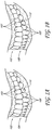
- Figure 2A illustrates an example impression 202 of the upper jaw 102 of Figures 1A and 1B in impression trays.
- the impression 202 of the upper jaw 102 includes a recess 203 where the impression material flowed around the plurality of maxillary teeth 103, each maxillary tooth 103 creating a recess portion that together form the recess 203.
- the recess 203 includes facial surfaces 220, occlusal surfaces 222, and lingual surfaces 224, and possibly fractions of mesial surfaces 226 and/or distal surfaces 228.
- the occlusal surfaces 222 include occlusive surfaces (i.e., surfaces that make contact with opposing teeth in the bite position).
- the impression 202 of the upper jaw 102 includes soft tissue features (e.g., the gingival boundary, gingival surfaces, etc.). In some embodiments, the impression 202 of the upper jaw 102 includes only soft tissue features (e.g., the gingival boundary, gingival surfaces, etc.).
- Figures 2B and 2C illustrate example impressions 204, 206 of the lower jaws 104, 106 of Figures 1A and 1B , respectively.
- the impressions 204, 206 of the lower jaws 104, 106 each include a recess 205 where the impression material flowed around the plurality of mandibular teeth 105, each mandibular tooth 105 creating a recess portion that together form the recess 205.
- the recess 205 includes facial surfaces 221, occlusal surfaces 223, and lingual surfaces 225, and possibly fractions of mesial surfaces 227 and/or distal surfaces 229.
- the occlusal surfaces 223 include occlusive surfaces (i.e., surfaces that make contact with opposing teeth in the bite position).
- the impressions 204, 206 of the lower jaws 104, 106 include soft tissue features (e.g., the gingival boundary, gingival surfaces, etc.). In some embodiments, the impressions 204, 206 of the lower jaws 104, 106 include only soft tissue features (e.g., the gingival boundary, gingival surfaces, etc.). In certain embodiments, the impressions of the upper jaw 102 and lower jaws 104, 106 may be formed simultaneously (e.g., by using a triple tray). In some embodiments, the recesses 203, 205 can be divided into one or more sub-recesses, for example when one or several teeth are missing inbetween other teeth of the same jaw.
- the impression 204 of the lower jaw 204 illustrated in Figure 2B does not include a recess portion in the edentulous area 110 of the lower jaw 104, but may include an impression of soft tissue features such as the illustrated shallow recess 210.
- the impression 204 of the lower jaw 104 may include an impression of the healing abutment.
- the implant may be attached to an implant position locator or impression coping and the impression 204 of the lower jaw 104 may include an impression of the position locator or impression coping.
- the impression 206 of the lower jaw 106 illustrated in Figure 2C includes an indentation 212 where the impression material flowed around the residual tooth 112 of the lower jaw 106.
- the impression 202 of the upper jaw 102 only comprises a portion of the upper jaw 102 and the impression 204, 206 of the lower jaw 104, 106 only comprises a portion of the lower jaw 104, 106.
- Certain such partial impressions may have advantages such as, for example, less impression material used, less patient discomfort during forming the impression, less time and material used for making physical models therefrom, less imaging or scan time upon conversion to a virtual model, and less data for a virtual model, possibly leading to faster manipulation of the virtual model.
- the impressions include a site where dental rehabilitation is to take place.
- the impression 202 of the upper jaw 102 and the impression 204 of the lower jaw 104 may comprise an impression of facial surfaces adjacent or near to the edentulous area 110.
- the impression 202 of the upper jaw 102 may comprise an impression of at least a portion of at least one maxillary tooth 103 proximate to the edentulous area 110 and the impression 204 of the lower jaw 104 may comprise an impression of at least a portion of at least one mandibular tooth 105 proximate to the edentulous area 110.
- the impression 204 of the lower jaw 104 may further comprise the shallow recess 210, which is an example impression of an edentulous area 110.
- the impression 204 of the lower jaw 104 may comprise a recess portion formed by a mandibular tooth 105 mesial to the edentulous area 110 and a recess portion formed by a mandibular tooth 105 distal to the edentulous area 110
- the impression 202 of the upper jaw 102 may comprise a recess portion formed by a maxillary tooth 103 opposing the edentulous area 110 or a recess formed by maxillary teeth 103 opposing the edentulous area 110, the mesial mandibular tooth 105, and the distal mandibular tooth 105.
- the impression 204 of the lower jaw 104 may further comprise the shallow recess 210, which is an example impression of an edentulous area 110.
- the impression 202 of the upper jaw 102 comprises the entire upper jaw 102 and the impression 204 of the lower jaw 104 comprises the entire lower jaw 104.
- the side impression may comprise an impression of facial surfaces adjacent to or near the edentulous area 110.
- the side impression may comprise an impression of at least a portion of at least one maxillary tooth 103 proximate to the edentulous area 110 and an impression of at least a portion of at least one mandibular tooth 105 proximate to the edentulous area 110.
- the side impression may further comprise an impression of the edentulous area 110.
- the side impression may comprise facial surfaces formed by a mandibular tooth 105 mesial to the edentulous area 110, facial surfaces formed by a mandibular tooth 105 distal to the edentulous area 110, facial surfaces formed by a maxillary tooth 103 opposing the edentulous area 110 or facial surfaces formed by maxillary teeth 103 opposing the edentulous area 110, the mesial mandibular tooth 105, and the distal mandibular tooth 105.
- the side impression may further comprise an impression of the edentulous area 110.
- the impression 202 of the upper jaw 102 and the impression 206 of the lower jaw 104 may comprise an impression of facial surfaces adjacent to the residual tooth 112.
- the impression 202 of the upper jaw 102 may comprise an impression of at least a portion of at least one maxillary tooth 103 proximate to the residual tooth 112 and the impression 206 of the lower jaw 106 may comprise an impression of at least a portion of at least one mandibular tooth 105 proximate to the residual tooth 112.
- the impression 206 of the lower jaw 106 may comprise the indentation 212.
- the impression 206 of the lower jaw 106 may comprise a recess portion formed by a mandibular tooth 105 mesial to the residual tooth 112 and a recess portion formed by a mandibular tooth 105 distal to the residual tooth 112, and the impression 202 of the upper jaw may comprise a recess portion formed by a maxillary tooth 103 opposing the residual tooth 112 or a recesses formed by maxillary teeth 103 opposing the residual tooth 112, the mesial mandibular tooth 105, and the distal mandibular tooth 105.
- the impression 206 of the lower jaw 106 may comprise the indentation 212.
- the impression 202 of the upper jaw 102 comprises the entire upper jaw 102 and the impression 206 of the lower jaw 106 comprises the entire lower jaw 106.
- the side impression described herein, may comprise an impression of facial surfaces adjacent to the residual tooth 112.
- the side impression may comprise an impression of at least a portion of at least one maxillary tooth 103 proximate to the residual tooth and an impression of at least a portion of at least one mandibular tooth 105 proximate to the residual tooth 112.
- the side impression may further comprise an impression of the residual tooth 112.
- the side impression may comprise facial surfaces formed by a mandibular tooth 105 mesial to the residual tooth 112, facial surfaces formed by a mandibular tooth 105 distal to the edentulous area 110, facial surfaces formed by a maxillary tooth 103 opposing the residual tooth 112 or facial surfaces formed by maxillary teeth 103 opposing the residual tooth 112, the mesial mandibular tooth 105, and the distal mandibular tooth 105.
- the side impression may further comprise an impression of the residual tooth 112.
- the side impression does not include a site where dental rehabilitation is to take place (e.g., the side impression does not comprise an impression of an edentulous area 110 or an impression of a residual tooth 112).
- areas of the dentition that may be more difficult to capture e.g., sensitive areas or less-easily accessed areas
- a wider scan area is used in order to improve accuracy of the alignment, thereby improving accuracy at the site and opposite to the site.
- the wider scan area can, e.g., comprise at least a portion of a tooth and adjacent soft tissue features, such as soft tissue boundary and/or soft tissue.
- Figure 3 illustrates an example embodiment of forming a side impression of upper and lower jaws in the bite position.
- impression material 300 which may be held by an applicator 302 is applied to the facial surfaces of the upper and lower jaws.
- the impression material 300 contacts at least a portion of a maxillary tooth 103 and at least a portion of a mandibular tooth 105.
- the impression material 300 contacts at least a portion of a plurality of maxillary teeth 103 and/or at least a portion of a plurality of mandibular teeth 105.
- the impression material 300 contacts the entire facial surface of a maxillary tooth 103 and/or the entire facial surface of a mandibular tooth 105. In some embodiments, the impression material 300 contacts the entire facial surface of a plurality of maxillary teeth 103 and/or the entire facial surface of a plurality of mandibular teeth 105. In some embodiments, the impression material 300 contacts the entire facial surface of a maxillary tooth 103 including soft tissue and/or the entire facial surface of a mandibular tooth 105 including soft tissue. In some embodiments, the impression material 300 contacts the entire facial surface of a plurality of maxillary teeth 103 including soft tissue and/or the entire facial surface of a plurality of mandibular teeth 105 including soft tissue.
- the impression material 300 contacts the entire facial surface of a plurality of maxillary teeth 103 including only soft tissue and/or the entire facial surface of a plurality of mandibular teeth 105 including only soft tissue.
- the side impression includes buccal surfaces.
- the maxillary tooth 103 and the mandibular tooth 105 comprise anterior teeth (incisors and/or cuspids)
- the side impression includes labial surfaces.
- the impression material 300 is applied to at least one quadrant and includes the entire facial surfaces of the teeth in that quadrant.
- the impression material 300 is substantially free of occlusive surfaces because the impression material 300 was applied with the upper jaw and the lower jaw in the bite position. That is, the patient did not bite down on the impression material 300, such that, while the impression material 300 may squeeze between occlusal surfaces and mesial/distal surfaces where there is not contact, the impression material 300 cannot squeeze between occlusive surfaces.
- forming a side impression may include occlusive surfaces by causing the patient to bite down on the impression material 300 during application.
- Figure 3A is an example cross-section taken along the line A-A of Figure 3 .
- the impression material 300 abuts the facial surfaces 220 of the upper jaw 102 (as illustrated, the facial surfaces 220 of the maxillary tooth 103) and the facial surfaces 221 of the lower jaw 104, 406 (as illustrated, the facial surfaces 221 of the mandibular tooth 105) such that the resulting side impression comprises an impression of the facial surfaces 220 of the maxillary tooth 103 and an impression of the facial surfaces 221 the mandibular tooth 105.
- the impression material 300 does not penetrate the occlusive surfaces of the occlusal surfaces 222, 223.
- the impression material 300 abuts the soft tissue above the maxillary tooth 103 and/or below the mandibular tooth 105 such that the resulting side impression comprises an impression of the soft tissue of the upper jaw 102 and/or an impression of the soft tissue of the lower jaw 104.
- the impression material 300 captures portions of the occlusal surfaces 222 of the maxillary tooth 103, for example in the area prior to contact with the mandibular tooth 105, such that the side impression is substantially free of occlusal surfaces and is substantially free (e.g., completely free) of occlusive surfaces.
- the impression is free from areas of opposing teeth that are in contact in the bite position.
- Figure 3Bi is an example cross-section taken along the line B-B of Figure 3 .
- the impression material 300 abuts the facial surfaces 220 of the upper jaw 102 (as illustrated, the facial surfaces 220 of the maxillary tooth 103) and the facial surfaces 221 of the lower jaw 104 (as illustrated, the soft tissue of the edentulous area 110) such that the resulting side impression comprises an impression of the facial surfaces 220 of the maxillary tooth 103 and an impression of the edentulous area 110.
- There are no occlusive surfaces because the maxillary tooth 103 does not contact a mandibular tooth, so the impression material 300 can penetrate the occlusal surfaces 222 of the maxillary tooth 103.
- the impression material 300 abuts the soft tissue above the maxillary tooth 103 such that the resulting side impression comprises an impression of the soft tissue of the upper jaw 102 and an impression of the soft tissue of the edentulous area 110 of the lower jaw 104.
- the impression material 300 may abut the facial surfaces 220 of the upper jaw 102 (e.g., facial surfaces 220 of a maxillary tooth 103) and the facial surfaces 221 of the lower jaw 104 (e.g., facial surfaces 221 of the impression coping) such that the resulting side impression comprises an impression of the facial surfaces 220 of the maxillary tooth 103 and an impression of the facial surfaces 221 of the impression coping.
- the impression material 300 captures portions of the occlusal surfaces 222 of the maxillary tooth 103.
- less impression material 300 may be used such that the side impression is substantially free of occlusal surfaces and is substantially free (e.g., completely free) of occlusive surfaces. In embodiments, the impression is free from areas of opposing teeth that are in contact in the bite position.
- Figure 3Bii is another example cross-section taken along the line B-B of Figure 3 .
- the impression material 300 abuts the facial surfaces 220 of the upper jaw 102 (as illustrated, the facial surfaces 220 of the maxillary tooth 103) and the facial surfaces 221 of the lower jaw 106 (as illustrated, the facial surfaces 220 of the residual tooth 112) such that the resulting side impression comprises an impression of the facial surfaces 220 of the maxillary tooth 103 and an impression of the facial surfaces 221 of the residual tooth 112.
- there are no occlusive surfaces because the maxillary tooth 103 does not contact the residual tooth 112, so the impression material 300 can penetrate the occlusal surfaces 222 of the maxillary tooth 103.
- the impression material 300 abuts the soft tissue above the maxillary tooth 103 and/or below the residual tooth 112 such that the resulting side impression comprises an impression of the soft tissue of the upper jaw 102 and/or an impression of the soft tissue of the lower jaw 104.
- the impression material 300 captures portions of the occlusal surfaces 222 of the maxillary tooth 103.
- less impression material 300 may be used such that the side impression is substantially free of occlusal surfaces and is substantially free (e.g., completely free) of occlusive surfaces.
- the impression is free from areas of opposing teeth that are in contact in the bite position.
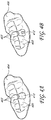
- Figure 4A illustrates an example embodiment of a side impression 404 of facial surfaces of the upper jaw 102 and of facial surfaces the lower jaw 104 of Figure 1A .
- Figure 4B illustrates an example embodiment of a side impression 406 of facial surfaces of the upper jaw 102 and of facial surfaces the lower jaw 106 of Figure 1B .
- the side impressions 404, 406 each include recesses 403 where the impression material 300 flowed around the facial surfaces 220 of a plurality of maxillary teeth 103 and recesses 405 where the impression material 300 flowed around the facial surfaces 221 of a plurality of mandibular teeth 105.
- the side impression 404 also includes a projection 410 where the impression material 300 flowed into the edentulous area 110.
- the projection 410 may include information about the occlusal surfaces 222 of the maxillary tooth 103 above the edentulous area 110
- the side impression 404 is substantially free of occlusive surfaces because the impression material 300 was applied while the patient was already in the bite position.
- the side impression 406 also includes a projection 412 where the impression material 300 flowed around the residual tooth 112.
- the projection 412 may include information about the occlusal surfaces 222 of the maxillary tooth 103 above the residual tooth 112, the side impression 406 is substantially free of occlusive surfaces because the impression material 300 was applied while the patient was already in the bite position.
- the side impressions 404, 406 may also include information about the mesial surfaces 226, 227, distal surfaces 228, 229, and lingual surfaces 224, 225 where the impression material 300 flowed through gaps between the teeth 103, 105.
- the impression material 300 for the side impression is applied proximate to a site where dental rehabilitation is to take place.
- the side impression 404 may comprise an impression of at least a portion of a maxillary tooth 103 proximate to the edentulous area 110 and an impression of at least a portion of a mandibular tooth 105 proximate to the edentulous area 110.
- the side impression 404 may further comprise the edentulous area 110.
- the side impression 404 may comprise impressions of a mandibular tooth 105 mesial to the edentulous area 110, a mandibular tooth 105 distal to the edentulous area 110, and the maxillary teeth 103 opposing each of the edentulous area 110, the mesial mandibular tooth 105, and the distal mandibular tooth 105.
- the side impression 406 may comprise an impression of at least a portion of a maxillary tooth 103 proximate to the residual tooth 112 and an impression of at least a portion of a mandibular tooth 105 proximate to the residual tooth 112.
- the side impression 406 may further comprise the residual tooth 112.
- the side impression 406 may comprise impressions of a mandibular tooth 105 mesial to the residual tooth 112, a mandibular tooth 105 distal to the residual tooth 112, and the maxillary teeth 103 opposing each of the residual tooth 112, the mesial mandibular tooth 105, and the distal mandibular tooth 105.
- the accuracy of the alignment of the virtual model of the upper jaw and the virtual model of the lower jaw in the bite position is generally most accurate at the position where matching takes place.
- accuracy is most desirable at the site where dental rehabilitation is to take place (e.g., at an edentulous area, at a residual tooth).
- matching is at a position proximate to, and preferably including, the site where dental rehabilitation is to take place in order to increase the accuracy of the alignment of the upper jaw and the virtual model of the lower jaw in the bite position where accuracy is most desired.
- a side impression the facial surfaces used for matching are non-opposing and generally face in the same direction. This allows the facial surfaces to be scanned at the same time (e.g., in a single scan).
- the occlusal surfaces used for matching are opposing each other, which requires the occlusal surfaces to be scanned at two different times (e.g., in two different scans).
- a side impression comprises facial surfaces and is substantially free of occlusive surfaces.
- a bite impression comprises occlusal and occlusive surfaces and is substantially free of facial surfaces.
- a side impression comprises a thickness greater than about 3 mm from facial surfaces because the impression material is only limited by the distance between the facial surfaces of the upper jaw and the lower jaw and the patient's cheek. This thickness can provide an impression in which the facial surfaces used for matching are not prone to deformation.
- a bite impression is thin and weak at the occlusal surfaces used for matching because the space between the upper jaw and the lower jaw in the bite position is generally very small and occlusive surfaces can cause perforations. This thinness can cause the bite impression to be prone to deformation at the surfaces that are used for matching, which can lead to inaccurate alignment of the virtual model of the upper jaw and the virtual model of the lower jaw.
- the material of the impressions 202, 204, 206, 304, 306 is the same.
- impression material may be selected based on a later process.
- the impression material may have properties suitable for such imaging (e.g., ImpregumTM or Impregum FTM, both available from 3M of St. Paul, Minnesota, for laser imaging).
- the impression material may have properties suitable for such casting.
- Three impressions, the side impression, the impression of the upper jaw, and the impression of the lower jaw, are converted into virtual or digital models, for example by laser scanning or white light scanning.
- the result is three independent data files: a data file for the side impression that is a virtual or digital model of the side impression, a data file for the impression of the upper jaw that is a virtual or digital model of the upper jaw, and a data file for the impression of the lower jaw that is a virtual or digital model of the lower jaw.
- the "negative” impressions may be scanned, a "positive" physical model formed from the impressions may be scanned, or a combination thereof.
- the impressions or physical models may each be scanned with destructive methods, non-destructive methods, or a combination thereof.
- the virtual model of the side impression comprises a model of facial surfaces 220 of at least a portion of the upper jaw (e.g., a maxillary tooth, soft tissue, a residual tooth, a prosthesis, an edentulous area, an impression coping, etc.) and facial surfaces 221 of at least a portion of the lower jaw (e.g., a mandibular tooth, soft tissue, a residual tooth, a prosthesis, an edentulous area, an impression coping, etc.).
- a model of facial surfaces 220 of at least a portion of the upper jaw e.g., a maxillary tooth, soft tissue, a residual tooth, a prosthesis, an edentulous area, an impression coping, etc.
- facial surfaces 221 e.g., a mandibular tooth, soft tissue, a residual tooth, a prosthesis, an edentulous area, an impression coping, etc.
- the virtual model of the side impression comprises a model of facial surfaces 220 of at least a portion of the plurality of maxillary teeth 103 and facial surfaces 221 at least a portion of the plurality of mandibular teeth 105.
- the virtual model of the side impression comprises a model of the entire facial surface of the maxillary tooth 103 and the entire facial surface of the mandibular tooth 105.
- the virtual model of the side impression comprises a model of the entire facial surface 220 of the plurality of maxillary teeth 103 and the entire facial surface 221 of the plurality of mandibular teeth 105.
- the virtual model of the side impression includes a model of buccal surfaces.
- the virtual model of the side impression includes a model of labial surfaces.
- the virtual model of the side impression comprises a model of the maxillary teeth 103 and the mandibular teeth 105 of at least one quadrant and includes the entire facial surfaces 220, 221 of the teeth 103, 105 in that quadrant.
- the virtual model of the side impression is substantially free of occlusive surfaces.
- the side impression comprises an impression of a site where dental rehabilitation is to take place, such as a site prepared to receive a prosthesis (e.g., the edentulous area 110, the residual tooth 112)
- the virtual model of the side impression comprises a model of the site prepared to receive the prosthesis.
- the site comprises an edentulous area 100 comprising at least one implant and/or at least one residual tooth 112.
- the virtual model of the side impression may comprise a model of at least a portion of a maxillary tooth 103 proximate to the edentulous area 110 and a model of at least a portion of a mandibular tooth 105 proximate to the edentulous area 110.
- the virtual model of the side impression may further comprise a model of the edentulous area 110.
- the virtual model of the side impression may comprise a model of a mandibular tooth 105 mesial to the edentulous area 110, a model of a mandibular tooth 105 distal to the edentulous area 110, and a model of the maxillary teeth 103 opposing each of the edentulous area 110, the mesial mandibular tooth 105, and the distal mandibular tooth 105.
- the virtual model of the side impression may comprise a model of at least a portion of a maxillary tooth 103 proximate to the residual tooth 112 and a model of at least a portion of a mandibular tooth 105 proximate to the residual tooth 112.
- the virtual model of the side impression may further comprise a model of the residual tooth 112.
- the virtual model of the side impression may comprise a model of a mandibular tooth 105 mesial to the residual tooth 112, a model of a mandibular tooth 105 distal to the residual tooth 112, and a model of the maxillary teeth 103 opposing each of the residual tooth 112, the mesial mandibular tooth 105, and the distal mandibular tooth 105.
- matching is at a position proximate to, and preferably including, the site where dental rehabilitation is to take place in order to increase the accuracy of the alignment of the upper jaw and the virtual model of the lower jaw in the bite position where accuracy is most desired.
- a virtual model of an upper jaw and a virtual model of a lower jaw are aligned in a bite position by matching facial surfaces of the upper jaw (e.g., facial surfaces of at least a portion of a maxillary tooth) with facial surfaces of a virtual model of a side impression (e.g., the facial surfaces of the portion of the maxillary tooth) and by matching facial surfaces of the lower jaw (e.g., facial surfaces of at least a portion of a mandibular tooth) with facial surfaces of the virtual model of the side impression (e.g., the facial surfaces of the portion of the mandibular tooth). That is, the same surfaces (e.g.,.
- facial surfaces on the upper jaw are represented by portions of the virtual model of the upper jaw and portions of the virtual model of the side impression.
- the same surfaces (e.g., facial surfaces) on the lower jaw are represented by portions of the virtual model of the lower jaw and portions of the virtual model of the side impression.
- the virtual upper and lower jaw can be aligned in their bite position by matching the common surfaces in the virtual models of the upper and lower jaw with their respective common surfaces in the virtual side impression.
- facial surfaces may include fossae, pits, soft tissue, crevasses, etc., facial surfaces are generally smooth and thus surface matching can have fewer complications than occlusal surface matching.
- matching facial surfaces are used to orient each of the virtual model of the upper jaw and the virtual model of the lower jaw with respect to the virtual model of the side impression, thereby aligning the virtual model of the upper jaw and the virtual model of the lower jaw in the bite position.
- matching facial surfaces may be performed using Geomagic Qualify, available from Geomagic, Inc. of Research Triangle Part, North Carolina.
- matching facial surfaces includes user input (e.g., selecting portions of the facial surfaces to be matched, such as the central portion of facial surfaces of teeth).
- matching facial surfaces may be fully automated such that the technician scans the three impressions and then views on a display a virtual model of the upper and lower jaws aligned in the bite position.
- the virtual model of the upper impression and the virtual model of the lower impression are aligned in the bite position by using geometric surface matching to match surfaces (e.g., facial surfaces) with the virtual model of the side impression.
- surfaces e.g., facial surfaces
- Facial surfaces of the upper jaw of the virtual model of the bite impression e.g., facial surfaces of at least a portion of a maxillary tooth
- facial surfaces of the upper jaw of the virtual model of the upper arch e.g., the facial surfaces of the portion of the maxillary tooth
- Facial surfaces of the lower jaw of the virtual model of the bite impression e.g., facial surfaces of at least a portion of a mandibular tooth
- facial surfaces of the virtual model of the lower jaw e.g., the facial surfaces of the portion of the mandibular tooth
- geometric matching includes iterating the following steps at least one time: select points on the facial surfaces of the virtual model of the bite impression (e.g., the points being evenly distributed across the facial surfaces, the points being clustered on a certain portion of the facial surfaces, the points spanning facial surfaces of hard tissue and soft tissue, etc.); remove any other points; optionally remove noisy data (e.g., by filtering based on distance distribution); compute the closest points on the virtual models of the upper and lower jaws; compute a transformation that matches the selected points to the facial surfaces of the virtual models of the upper and lower jaws; and minimizing the sum of squared distances between corresponding points.
- geometric matching includes iterating the following steps at least one time: select points on the facial surfaces of the virtual models of the upper and lower jaws (e.g., the points being evenly distributed across the facial surfaces, the points being clustered on a certain portion of the facial surfaces, the points spanning facial surfaces of hard tissue and soft tissue, etc.); remove any other points; optionally remove noisy data (e.g., by filtering based on distance distribution); compute the closest points on the virtual model of the bite impression; compute a transformation that matches the selected points to the facial surfaces of the virtual model of the bite impression; and minimizing the sum of squared distances between corresponding points.
- Combinations are also possible (e.g., selecting points on the facial surfaces of the virtual model of the bite impression corresponding to the upper jaw and selecting point on the facial surfaces of the virtual model of the lower jaw, selecting points on the facial surfaces of the virtual model of the bite impression corresponding to the lower jaw and selecting point on the facial surfaces of the virtual model of the upper jaw, etc.).
- the process may complete or repeat (e.g., to refine the matching). If the result is not acceptable the process may be repeated for at least one more iteration. Different points on the facial surfaces of the selected virtual model or models may be used, or other modifications may be made (e.g., adding random transformations). If the number of iterations reaches a limit without producing an acceptable result, the program may alert a technician that there may be a problem with the impressions or the models of the virtual impression.
- the technician can then utilize the aligned virtual model, for example, to design orthodontic appliances, to plan or adjust movement of teeth with orthodontic appliances, and to model dental prostheses (e.g., abutments, copings, crowns, inlays, overlays, veneers, bridges, frameworks, etc.).
- dental prostheses e.g., abutments, copings, crowns, inlays, overlays, veneers, bridges, frameworks, etc.
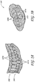
- Figure 5A is an example embodiment of a display of a virtual model of an upper jaw 502 and a virtual model of a lower jaw 504 aligned in the bite position.
- Figure 5B is an example embodiment of a display of a virtual model of a side impression 506.
- Such images can be obtained through scanning the side, upper and lower jaw impressions described above.
- the scanned data can then be displayed upon a computer display after suitable processing.
- the displayed data can be used by a user to aid or adjust matching or alignment of the virtual images of the lower and upper jaw in the bite position.
- only the display of the virtual models of the upper jaw and lower jaw 502, 504 are shown to the user.
- the matching described above provides an initial bite position between the virtual images of the upper and lower jaws that can be automatically and/or manually adjusted thereafter based upon user input and/or calculated contact points between occlusive surfaces.
- the methods and systems described herein may take the form of or be executed on a computing system (e.g., a computer) comprising at least one unit configured to align a virtual model of an upper jaw and a virtual model of a lower jaw in a bite position by matching facial surfaces of a virtual model of a side impression with facial surfaces of the virtual model of the upper jaw and with facial surfaces of the virtual model of the lower jaw.
- a computing system e.g., a computer
- Figures 6A and 6B schematically illustrate block diagrams of example computing systems 600, 601, respectively.
- the systems 600, 601 each comprise a modeling computer 602, a scanner 604, and an optional fabrication unit 606.
- the modeling computer 602 aligns the virtual models in the bite position and stores the aligned virtual model in a storage device such as the mass storage device 6021 or the memory 6026, each described more fully below.
- the modeling computer 602 is used to design orthodontic appliances, to plan or adjust movement of teeth with orthodontic appliances, to model dental prostheses (e.g., abutments, copings, crowns, inlays, overlays, veneers, bridges, frameworks, etc.), and other dental or orthodontic modeling.
- the scanner 604 is used to scan or image impressions of the patient's dentition. The impressions may be scanned by the entity that took the impression or may be transferred to a laboratory for scanning.
- the scanner 604 may comprise a laser scanner, a white light scanner, a destructive scanner, etc.
- the scanner 604 may be configured to scan negative impressions and/or positive impressions.
- the fabrication unit 606 can be used to fabricate orthodontic appliances or dental prostheses based on output from the modeling computer 602.
- the fabrication unit 606 may comprise tools for milling, stereolithography, laser machining, molding, etc.
- the fabrication unit 606 is configured to produce an abutment, for example as described in U.S. Patent Nos. 5,180,303 , 5,527,182 , and 5,674,069 .
- the fabrication unit 606 is configured to produce a coping and/or a crown, for example as described in U.S. Patent Nos. 5,092,022 and 6,398,554 and U.S. Patent Pub. No. 2005/0177266 .
- the fabrication unit 606 is configured to produce a framework and/or a bridge, for example as described in U.S. Patent Nos. 6,694,212 and 7,228,191 .
- the fabrication unit 606 is configured to produce a tooth model, for example as described in U.S. Patent No. 7,118,375 and U.S. Patent Pub. No. 2007/0154867 .
- the tooth model may comprise reference markers indicating that the upper jaw and the lower jaw are in the bite position.
- the systems 600, 601 can be a fixed system or mobile device.
- the computing systems 600, 601 may be used to implement one or more of the systems and methods described herein.
- the computing systems 600, 601 are configured to process image files.
- Those of skill in the art will appreciate that the functionality provided for in the units, components, and modules of computing systems 600, 601 may be combined into fewer units, components, and modules or further separated into additional units, components, and modules.
- the systems and methods described herein are embodied in part or in whole in software that is running on a computing device.
- the functionality provided for in the units, components, and modules of the computing device may comprise one or more units, components, and/or modules.
- the computing device may comprise multiple central processing units (CPUs) and a mass storage device, such as may be implemented in an array of servers.
- module refers to logic embodied in hardware or firmware, or to a collection of software instructions, possibly having entry and exit points, written in a programming language, such as, for example, Java, C, C++, combinations thereof, and the like.
- a software module may be compiled and linked into an executable program, installed in a dynamic link library, or may be written in an interpreted programming language such as, for example, BASIC, Perl, Lua, or Python. It will be appreciated that software modules may be callable from other modules or from themselves, and/or may be invoked in response to detected events or interrupts.
- Software instructions may be embedded in firmware, such as an EPROM.
- hardware modules may be comprised of connected logic units, such as gates and flip-flops, and/or may be comprised of programmable units, such as programmable gate arrays or processors.
- the modules described herein are preferably implemented as software modules, but may be represented in hardware or firmware. Generally, the modules described herein refer to logical modules that may be combined with other modules or divided into sub-modules despite their physical organization or storage.
- the modeling computer 602 comprises a central processing unit (“CPU”) 6024, which may comprise a conventional microprocessor.
- the modeling computer 602 further comprises a memory 6025, such as random access memory (“RAM”) for temporary storage of information and/or a read only memory (“ROM”) for permanent storage of information, and a mass storage device 6021, such as a hard drive, diskette, or optical media storage device.
- RAM random access memory
- ROM read only memory
- mass storage device 6021 such as a hard drive, diskette, or optical media storage device.
- the modules of the modeling computer 602 may be connected using a standards-based bus system such as, for example, Peripheral Component Interconnect (PCI), Microchannel, SCSI, Industrial Standard Architecture (ISA), and/or Extended ISA (EISA) architectures.
- PCI Peripheral Component Interconnect
- ISA Industrial Standard Architecture
- EISA Extended ISA
- the modeling computer 602 comprises one or more input/output (I/O) devices and interfaces 6023, such as a keyboard, mouse, trackball, touch pad, pen, stylus, graphics tablet, touch screen, voice recognition system, switch, button, and/or printer.
- I/O devices and interfaces 6023 comprise one or more display devices, such as a monitor, that allows the visual presentation of data to a user. More particularly, a display device may provide for the presentation of GUIs, application software data, and multimedia presentations.
- the display device may comprise a cathode-ray tube (CRT), a liquid crystal display (LCD), a plasma display, a digital light processor (DLP), or other types and/or combinations of displays.
- CTR cathode-ray tube
- LCD liquid crystal display
- DLP digital light processor
- the I/O devices and interfaces 6023 also provide a communications interface to various external devices through a network 608.
- the modeling computer 602 may also comprise one or more multimedia devices 6021, such as, for example, speakers, video cards, graphics accelerators, and microphones.
- the modeling computer 602 comprises a mainframe computer suitable for controlling and/or communicating with large databases, performing high volume transaction processing, and generating reports from large databases.
- the modeling computer 602 may run on a variety of computing devices, such as, for example, a server, a Windows server, a Structure Query Language (SQL) server, a Unix server, a personal computer, a mainframe computer, a laptop computer, a cell phone, a personal digital assistant, a kiosk, an audio player, and so forth.
- the modeling computer 602 is generally controlled and coordinated by operating system software, such as z/OS, Windows 95, Windows 98, Windows NT, Windows 2000, Windows XP, Windows Vista, Windows 7, Linux, BSD, SunOS, Solaris, or other compatible operating systems.
- the operating system may be any available operating system, such as MAC OS X.
- the modeling computer 602 is controlled by a proprietary operating system.
- Conventional operating systems control and schedule computer processes for execution, perform memory management, provide file system, networking, and I/O services, and provide a user interface, such as a graphical user interface (GUI), among other things.
- GUI graphical user interface
- the modeling computer 602 of certain embodiments comprises an alignment module 6027 configured to perform one or more of the alignment functions or method steps described herein.
- the alignment module 6027 is configured to align the virtual model of an upper jaw and a virtual model of a lower jaw in a bite position by matching facial surfaces of a virtual model of a side impression with the same facial surfaces of the virtual model of the upper jaw and with the same facial surfaces of the virtual model of the lower jaw.
- the alignment module 6027 or portions thereof may reside on a computer of the scanner 604 or a computer connected to the scanner 604 instead of or in addition to residing on the modeling computer 602.
- substantially all of the functionality of the alignment module 6027 resides on a computer of the scanner or a computer connected to the scanner 604. In other embodiments, some of the functionality of the alignment module 6027 resides on the modeling computer 602 and some of the functionality of the alignment module 6027 resides on a computer of the scanner 604 or a computer connected to the scanner 604. In some embodiments, one on more aspects and/or functionalities of the alignment module 6027 can be divided up into subcomponents that can reside within the same or different components.
- the modeling computer 602 is coupled to a network 608, such as a local area network, a wide area network, the Internet, etc. via, for example, a wired communication link, a wireless communication link, or combination thereof.
- the network 608 communicates with various computing devices and/or other electronic devices coupled to the network 608 via wired or wireless communication links.
- Access to the modeling computer 602 may be provided through a web-enabled user access point such as personal computer, cellular phone, laptop computer, server, computer workstation, local area network of individual computers, interactive kiosk, personal digital assistant, interactive wireless communication device, embedded computing device, or other device capable of connecting to the network 608.
- a web-enabled user access point such as personal computer, cellular phone, laptop computer, server, computer workstation, local area network of individual computers, interactive kiosk, personal digital assistant, interactive wireless communication device, embedded computing device, or other device capable of connecting to the network 608.
- Such a device may have a browser module implemented as a module that uses text, graphics, audio, video, and other media to present data and to allow interaction with data via the network 608.
- the network 608 is in communication with the scanner 604 and the fabrication unit 606.
- the scanner 604 comprises and/or is connected to a computer comprising some or all of the components described above with respect to the modeling computer 602 (e.g., mass storage device, multimedia devices, I/O devices and interfaces, central processing unit, system memory) and can communicate with the modeling computer 602 via the network 608.
- the computer connected to the scanner 604 aligns the virtual models of the impressions in the bite position and stores the aligned virtual model in a storage device.
- the bite position model may then be transferred to the modeling computer 602 over the network 608.
- the computer connected to the scanner 604 transfers scan data to the modeling computer 602 over the network 608, and then the modeling computer 602 aligns the virtual models of the impressions in the bite position and stores the aligned virtual model in a storage device.
- the fabrication unit 606 also comprises a computer comprising some or all of the components described above with respect to the modeling computer 602 (e.g., mass storage device, multimedia devices, I/O devices and interfaces, central processing unit, system memory) and can communicate with the modeling computer 602 via the network 608.
- data may be transferred between the modeling computer 602, the computer of the scanner 604, and the computer of the fabrication unit 606 using a portable storage medium or device (e.g., optical disk, magnetic disk, flash drive).
- the scanner 604 is proximate to the modeling computer 602 (e.g., being in the same office, building, or campus). In some embodiments comprising a fabrication unit 606, the modeling computer 602 is proximate to the fabrication unit 606 (e.g., being in the same office, building, or campus). In some embodiments comprising a fabrication unit 606, the scanner 604 and the modeling computer 602 are both proximate to the fabrication unit 606 (e.g., being in the same office, building, or campus).
- the modeling computer 602 comprises a physical or logical connection established between a remote microprocessor and a mainframe host computer for the express purpose of uploading, downloading, or viewing interactive data and databases on-line in real time.
- the remote microprocessor may be operated by an entity operating the modeling computer 602, including the client server systems or the main server system.
- terminal emulation software may be used on the microprocessor for participating in the microprocessor-mainframe link.
- a computer program product comprising computer program code means for executing the method steps described herein when the computer program code means are run by an electronic device having computer capabilities.
- the electronic device may e.g. be a computer, such as a lap top or desk top computer.
- the scanner 604 and the optional fabrication unit 606 are directly connected to the modeling computer 602.
- the scanner converts the impressions into virtual models of the impressions and provides the virtual models of the impressions to the modeling computer 602
- the modeling computer 602 aligns the virtual models of the impressions in the bite position and is used to design a dental prosthesis using the bite position model
- the modeling computer 602 provides the fabrication unit 606 with instructions for fabricating the dental prosthesis.
Claims (14)
- Procédé d'alignement d'un model virtuel d'une mâchoire supérieure (502) et d'un modèle virtuel d'une mâchoire inférieure (504) dans une position de morsure et de conception d'une prothèse à l'aide des modèles virtuels alignés, le procédé utilisant uniquement trois jeux de données d'empreintes balayées, dans lequel les trois jeux de données d'empreintes balayées correspondent à une empreinte d'au moins une partie de la mâchoire inférieure, une empreinte d'au moins une partie de la mâchoire supérieure, et une empreinte latérale comprenant les surfaces faciales d'une partie d'une mâchoire supérieure et les surfaces faciales d'une partie d'une mâchoire inférieure, le procédé comprenant l'appariement des premières surfaces faciales (520b) d'un modèle virtuel de l'empreinte latérale (506) avec les surfaces faciales (520a) du modèle virtuel de la mâchoire supérieure (502), au moins une partie des premières surfaces faciales (520b) du modèle virtuel de l'empreinte latérale (506) étant identique aux surfaces faciales (520a) du modèle virtuel de la mâchoire supérieure (502), et l'appariement des secondes surfaces faciales (521b) du modèle virtuel de l'empreinte latérale (506) avec les surfaces faciales (521a) du modèle virtuel de la mâchoire inférieure (504), au moins une partie des secondes surfaces faciales (521b) du modèle virtuel de l'empreinte latérale (506) étant identique aux surfaces faciales (521a) du modèle virtuel de la mâchoire inférieure (504), caractérisé en ce que le modèle virtuel de l'empreinte latérale comprend un modèle d'un site préparé pour recevoir une prothèse et des dents adjacentes, le procédé comprenant l'étape supplémentaire de conception de la prothèse à l'aide des modèles virtuels alignés.
- Procédé selon la revendication 1, dans lequel le modèle virtuel de l'empreinte latérale est sensiblement dépourvu de surfaces d'occlusion.
- Procédé selon l'une quelconque des revendications 1 ou 2, dans lequel le site comprend au moins l'une d'une dent résiduelle et d'une zone édentée.
- Procédé selon les revendications 1 à 3, dans lequel la prothèse comprend un pilier, un coiffage, une couronne, un inlay, un overlay, une facette, un bridge, ou une infrastructure.
- Procédé selon l'une quelconque des revendications 1 à 4, dans lequel le modèle virtuel de la mâchoire supérieure comprend un modèle d'une partie de la mâchoire supérieure à proximité du site et dans lequel le modèle virtuel de la mâchoire inférieure comprend un modèle d'une partie de la mâchoire inférieure à proximité du site, dans lequel l'appariement comprend l'utilisation d'au moins les unes : des surfaces faciales du modèle virtuel de la mâchoire supérieure au niveau de la partie de la mâchoire supérieure et des surfaces faciales du modèle virtuel de la mâchoire inférieure au niveau de la partie de la mâchoire inférieure.
- Procédé selon l'une quelconque des revendications 1 à 5, dans lequel les surfaces faciales du modèle virtuel de l'empreinte latérale comprennent au moins les unes de : surfaces dentaires et surfaces de tissus mous.
- Procédé selon l'une quelconque des revendications 1 à 6, dans lequel l'appariement comprend l'appariement de surfaces géométriques.
- Procédé selon la revendication 7, dans lequel l'appariement comprend l'itération des étapes suivantes au moins une fois :(a) la sélection de points sur les surfaces faciales du modèle virtuel de l'empreinte latérale (506) ;(b) la suppression de tout autre point ;(c) le calcul des points les plus proches sur les modèles virtuels des mâchoires supérieure et inférieure (502, 504) ;(d) le calcul d'une transformation qui apparie les points sélectionnés aux surfaces faciales des modèles virtuels des mâchoires supérieure et inférieure (502, 504) ; et(e) la minimisation de la somme des distances carrées entre les points correspondants,ou l'itération des étapes suivantes au moins une fois :(a) la sélection de points sur les surfaces faciales des modèles virtuels des mâchoires supérieure et inférieure (502, 504) ;(b) la suppression de tout autre point ;(c) le calcul des points les plus proches sur le modèle virtuel de l'empreinte latérale (506) ;(d) le calcul d'une transformation qui apparie les points sélectionnés aux surfaces faciales du modèle virtuel de l'empreinte latérale ; et(e) la minimisation de la somme des distances carrées entre les points correspondants.
- Procédé selon la revendication 1, dans lequel l'appariement est au niveau d'une position à proximité de, et facultativement comprenant, un site (110, 112) où la réhabilitation dentaire doit avoir lieu.
- Procédé selon l'une quelconque des revendications 1 à 9, comprenant en outre :l'obtention d'une empreinte de la mâchoire supérieure comprenant une empreinte des premières surfaces faciales d'une mâchoire supérieure ;l'obtention d'une empreinte de la mâchoire inférieure comprenant une empreinte des secondes surfaces faciales d'une mâchoire inférieure ; etl'obtention de l'empreinte latérale comprenant une empreinte d'au moins la partie des premières surfaces faciales de la mâchoire supérieure et d'une empreinte d'au moins la partie des secondes surfaces faciales de la mâchoire inférieure.
- Procédé selon la revendication 10, dans lequel la formation de l'empreinte latérale comprend l'application d'un matériau d'empreinte aux surfaces faciales de la mâchoire supérieure et aux surfaces faciales de la mâchoire inférieure une fois que le patient est en position de morsure.
- Procédé selon la revendication 10 ou 11, comprenant en outre :le balayage de l'empreinte latérale pour former le modèle virtuel de l'empreinte latérale ;le balayage de l'empreinte de la mâchoire supérieure pour former le modèle virtuel de la mâchoire supérieure ; etle balayage de l'empreinte de la mâchoire inférieure pour former le modèle virtuel de la mâchoire inférieure.
- Procédé selon la revendication 12, dans lequel le balayage de l'empreinte latérale comprend le balayage des premières surfaces faciales et des secondes surfaces faciales en un seul examen par balayage.
- Produit de programme informatique comprenant un moyen de code de programme informatique pour mettre en oeuvre le procédé selon l'un quelconque des revendications 1 à 9, lorsque le moyen de code de programme informatique est exécuté par un dispositif électronique ayant des capacités informatiques.
Priority Applications (6)
| Application Number | Priority Date | Filing Date | Title |
|---|---|---|---|
| EP09004003.1A EP2229914B1 (fr) | 2009-03-20 | 2009-03-20 | Système et procédé d'alignement des modèles virtuels |
| US13/257,944 US10398539B2 (en) | 2009-03-20 | 2010-03-19 | System and method for aligning virtual dental models |
| PCT/EP2010/001728 WO2010105837A1 (fr) | 2009-03-20 | 2010-03-19 | Système et procédé d'alignement de modèles dentaires virtuels |
| JP2012500148A JP5886740B2 (ja) | 2009-03-20 | 2010-03-19 | 仮想歯科模型を整列するためのシステム及び方法 |
| CN201080012390.4A CN102355868B (zh) | 2009-03-20 | 2010-03-19 | 用于对齐虚拟牙齿模型的系统和方法 |
| AU2010225147A AU2010225147B2 (en) | 2009-03-20 | 2010-03-19 | System and method for aligning virtual dental models |
Applications Claiming Priority (1)
| Application Number | Priority Date | Filing Date | Title |
|---|---|---|---|
| EP09004003.1A EP2229914B1 (fr) | 2009-03-20 | 2009-03-20 | Système et procédé d'alignement des modèles virtuels |
Publications (2)
| Publication Number | Publication Date |
|---|---|
| EP2229914A1 EP2229914A1 (fr) | 2010-09-22 |
| EP2229914B1 true EP2229914B1 (fr) | 2018-05-30 |
Family
ID=40941898
Family Applications (1)
| Application Number | Title | Priority Date | Filing Date |
|---|---|---|---|
| EP09004003.1A Active EP2229914B1 (fr) | 2009-03-20 | 2009-03-20 | Système et procédé d'alignement des modèles virtuels |
Country Status (6)
| Country | Link |
|---|---|
| US (1) | US10398539B2 (fr) |
| EP (1) | EP2229914B1 (fr) |
| JP (1) | JP5886740B2 (fr) |
| CN (1) | CN102355868B (fr) |
| AU (1) | AU2010225147B2 (fr) |
| WO (1) | WO2010105837A1 (fr) |
Families Citing this family (65)
| Publication number | Priority date | Publication date | Assignee | Title |
|---|---|---|---|---|
| BRPI0720906B8 (pt) | 2007-01-10 | 2021-06-22 | Nobel Biocare Services Ag | método e sistema para planejar um procedimento restaurativo dental e sistema de computador para realizar o método |
| US8108189B2 (en) * | 2008-03-25 | 2012-01-31 | Align Technologies, Inc. | Reconstruction of non-visible part of tooth |
| EP2229914B1 (fr) | 2009-03-20 | 2018-05-30 | Nobel Biocare Services AG | Système et procédé d'alignement des modèles virtuels |
| EP2254068B1 (fr) | 2009-05-18 | 2020-08-19 | Nobel Biocare Services AG | Procédé et système fournissant une correspondance de données améliorée pour une planification virtuelle |
| US8765031B2 (en) | 2009-08-13 | 2014-07-01 | Align Technology, Inc. | Method of forming a dental appliance |
| EP2322115B1 (fr) | 2009-11-16 | 2017-02-15 | Nobel Biocare Services AG | Procédé de planification et de production de prothèse dentaire |
| EP2322114A1 (fr) | 2009-11-16 | 2011-05-18 | Nobel Biocare Services AG | Système et procédé de planification d'une première et deuxième restauration dentaire |
| US9211166B2 (en) | 2010-04-30 | 2015-12-15 | Align Technology, Inc. | Individualized orthodontic treatment index |
| US9241774B2 (en) | 2010-04-30 | 2016-01-26 | Align Technology, Inc. | Patterned dental positioning appliance |
| US9403238B2 (en) | 2011-09-21 | 2016-08-02 | Align Technology, Inc. | Laser cutting |
| US9375300B2 (en) | 2012-02-02 | 2016-06-28 | Align Technology, Inc. | Identifying forces on a tooth |
| US9220580B2 (en) | 2012-03-01 | 2015-12-29 | Align Technology, Inc. | Determining a dental treatment difficulty |
| US9414897B2 (en) | 2012-05-22 | 2016-08-16 | Align Technology, Inc. | Adjustment of tooth position in a virtual dental model |
| DE102012214470B4 (de) | 2012-08-14 | 2021-12-30 | Sirona Dental Systems Gmbh | Verfahren zur Registrierung einzelner dreidimensionaler optischer Aufnahmen zu einer Gesamtaufnahme einer Zahnsituation |
| EP2908767B1 (fr) | 2012-10-18 | 2018-12-05 | 3Shape A/S | Système et méthode de conception d'un composant dentaire |
| JP2016513503A (ja) * | 2013-03-11 | 2016-05-16 | ケアストリーム ヘルス インク | 上顎及び下顎の模型を自動的に整合させる方法及びシステム |
| US9642686B1 (en) * | 2014-06-02 | 2017-05-09 | Whip-Mix Corporation | Method and system for recording characteristics of the occlusal arch of a patient using a portable computing device |
| US10449016B2 (en) | 2014-09-19 | 2019-10-22 | Align Technology, Inc. | Arch adjustment appliance |
| US9610141B2 (en) | 2014-09-19 | 2017-04-04 | Align Technology, Inc. | Arch expanding appliance |
| US9744001B2 (en) | 2014-11-13 | 2017-08-29 | Align Technology, Inc. | Dental appliance with cavity for an unerupted or erupting tooth |
| US10504386B2 (en) | 2015-01-27 | 2019-12-10 | Align Technology, Inc. | Training method and system for oral-cavity-imaging-and-modeling equipment |
| US11554000B2 (en) | 2015-11-12 | 2023-01-17 | Align Technology, Inc. | Dental attachment formation structure |
| US11931222B2 (en) | 2015-11-12 | 2024-03-19 | Align Technology, Inc. | Dental attachment formation structures |
| US11103330B2 (en) | 2015-12-09 | 2021-08-31 | Align Technology, Inc. | Dental attachment placement structure |
| US11596502B2 (en) | 2015-12-09 | 2023-03-07 | Align Technology, Inc. | Dental attachment placement structure |
| US10383705B2 (en) | 2016-06-17 | 2019-08-20 | Align Technology, Inc. | Orthodontic appliance performance monitor |
| WO2017218947A1 (fr) | 2016-06-17 | 2017-12-21 | Align Technology, Inc. | Appareils intraoraux avec détection |
| EP3490439B1 (fr) | 2016-07-27 | 2023-06-07 | Align Technology, Inc. | Scanner intra-buccal pouvant établir un diagnostic dentaire |
| CN117257492A (zh) | 2016-11-04 | 2023-12-22 | 阿莱恩技术有限公司 | 用于牙齿图像的方法和装置 |
| EP3547950A1 (fr) | 2016-12-02 | 2019-10-09 | Align Technology, Inc. | Procédés et appareils pour personnaliser des dispositifs d'expansion palatine rapides à l'aide de modèles numériques |
| WO2018102770A1 (fr) | 2016-12-02 | 2018-06-07 | Align Technology, Inc. | Commande de force, mécanisme d'arrêt, structure de régulation d'appareil de réglage d'arcade amovible |
| CN114224534A (zh) | 2016-12-02 | 2022-03-25 | 阿莱恩技术有限公司 | 腭扩张器和扩张腭的方法 |
| US11026831B2 (en) | 2016-12-02 | 2021-06-08 | Align Technology, Inc. | Dental appliance features for speech enhancement |
| US10548700B2 (en) | 2016-12-16 | 2020-02-04 | Align Technology, Inc. | Dental appliance etch template |
| US10779718B2 (en) | 2017-02-13 | 2020-09-22 | Align Technology, Inc. | Cheek retractor and mobile device holder |
| US10613515B2 (en) | 2017-03-31 | 2020-04-07 | Align Technology, Inc. | Orthodontic appliances including at least partially un-erupted teeth and method of forming them |
| US11045283B2 (en) | 2017-06-09 | 2021-06-29 | Align Technology, Inc. | Palatal expander with skeletal anchorage devices |
| WO2019005808A1 (fr) | 2017-06-26 | 2019-01-03 | Align Technology, Inc. | Indicateur de performance de biocapteur pour appareils intrabuccaux |
| US10885521B2 (en) | 2017-07-17 | 2021-01-05 | Align Technology, Inc. | Method and apparatuses for interactive ordering of dental aligners |
| WO2019018784A1 (fr) | 2017-07-21 | 2019-01-24 | Align Technology, Inc. | Ancrage de contour palatin |
| EP4278957A3 (fr) | 2017-07-27 | 2024-01-24 | Align Technology, Inc. | Système et procédés de traitement d'un aligneur orthodontique au moyen d'une tomographie par cohérence optique |
| CN115462921A (zh) | 2017-07-27 | 2022-12-13 | 阿莱恩技术有限公司 | 牙齿着色、透明度和上釉 |
| US11116605B2 (en) | 2017-08-15 | 2021-09-14 | Align Technology, Inc. | Buccal corridor assessment and computation |
| US11123156B2 (en) | 2017-08-17 | 2021-09-21 | Align Technology, Inc. | Dental appliance compliance monitoring |
| US10813720B2 (en) | 2017-10-05 | 2020-10-27 | Align Technology, Inc. | Interproximal reduction templates |
| WO2019084326A1 (fr) | 2017-10-27 | 2019-05-02 | Align Technology, Inc. | Autres structures de réglage de morsure |
| EP3703608B1 (fr) | 2017-10-31 | 2023-08-30 | Align Technology, Inc. | Détermination d'un appareil dentaire à chargement occlusif sélectif et intercuspidation contrôlée |
| WO2019089989A2 (fr) | 2017-11-01 | 2019-05-09 | Align Technology, Inc. | Planification automatique de traitement |
| WO2019100022A1 (fr) | 2017-11-17 | 2019-05-23 | Align Technology, Inc. | Dispositifs de retenue orthodontiques |
| US10861250B2 (en) * | 2017-11-29 | 2020-12-08 | Sdc U.S. Smilepay Spv | Technologies for merging three-dimensional models of dental impressions |
| US10109114B1 (en) | 2017-11-29 | 2018-10-23 | SmileDirectClub LLC | Technologies for merging three-dimensional models of dental impressions |
| US11270523B2 (en) | 2017-11-29 | 2022-03-08 | Sdc U.S. Smilepay Spv | Systems and methods for constructing a three-dimensional model from two-dimensional images |
| US11403813B2 (en) | 2019-11-26 | 2022-08-02 | Sdc U.S. Smilepay Spv | Systems and methods for constructing a three-dimensional model from two-dimensional images |
| EP3716885B1 (fr) | 2017-11-30 | 2023-08-30 | Align Technology, Inc. | Appareils buccaux orthodontiques comprenant des capteurs |
| WO2019118876A1 (fr) | 2017-12-15 | 2019-06-20 | Align Technology, Inc. | Méthodes et appareils de traitement orthodontique adaptatif à boucle fermée |
| US10980613B2 (en) | 2017-12-29 | 2021-04-20 | Align Technology, Inc. | Augmented reality enhancements for dental practitioners |
| ES2907213T3 (es) | 2018-01-26 | 2022-04-22 | Align Technology Inc | Escaneo y seguimiento intraoral de diagnóstico |
| US11937991B2 (en) | 2018-03-27 | 2024-03-26 | Align Technology, Inc. | Dental attachment placement structure |
| CA3096417A1 (fr) | 2018-04-11 | 2019-10-17 | Align Technology, Inc. | Appareils d'expansion palatine liberables |
| US20210038350A1 (en) * | 2018-05-02 | 2021-02-11 | Naruto OTAWA | Scanning jig and method and system for identifying spatial position of implant or suchlike |
| DE102019201115A1 (de) * | 2019-01-29 | 2020-07-30 | Merz Dental Gmbh | Digitale Zahnreihendatenbank |
| FR3093636B1 (fr) * | 2019-03-12 | 2022-08-12 | Modjaw | Procede de recalage de modeles virtuels des arcades dentaires d’un individu avec un referentiel dudit individu |
| US11030801B2 (en) | 2019-05-17 | 2021-06-08 | Standard Cyborg, Inc. | Three-dimensional modeling toolkit |
| CN110147647B (zh) * | 2019-06-15 | 2023-06-20 | 广西科技大学 | 基于颞下颌关节稳定性的牙颌骨三维数字建模方法 |
| US11364103B1 (en) * | 2021-05-13 | 2022-06-21 | Oxilio Ltd | Systems and methods for determining a bite position between teeth of a subject |
Family Cites Families (53)
| Publication number | Priority date | Publication date | Assignee | Title |
|---|---|---|---|---|
| US2171695A (en) * | 1939-02-08 | 1939-09-05 | Robert N Harper | Method and apparatus for procuring impressions of the surfaces of the anterior teeth or dental work |
| FR2536654B1 (fr) | 1982-11-30 | 1987-01-09 | Duret Francois | Procede de realisation d'une prothese dentaire |
| US5180303A (en) | 1988-09-21 | 1993-01-19 | Regents Of The University Of California | Retrievable dental prothesis apparatus and method of fabrication |
| US5527182A (en) | 1993-12-23 | 1996-06-18 | Adt Advanced Dental Technologies, Ltd. | Implant abutment systems, devices, and techniques |
| US5674069A (en) | 1995-01-13 | 1997-10-07 | Osorio; Julian | Customized dental abutment |
| US5833987A (en) * | 1995-06-07 | 1998-11-10 | Trustees Of Dartmouth College | Treatment of T cell mediated autoimmune disorders |
| CA2275368A1 (fr) | 1996-12-20 | 1998-07-02 | Jean-Marc Perot | Procede pour realiser une prothese dentaire |
| US6217334B1 (en) * | 1997-01-28 | 2001-04-17 | Iris Development Corporation | Dental scanning method and apparatus |
| US6152731A (en) * | 1997-09-22 | 2000-11-28 | 3M Innovative Properties Company | Methods for use in dental articulation |
| JP2000237335A (ja) * | 1999-02-17 | 2000-09-05 | Mitsubishi Electric Corp | 放射線治療方法及びそのシステム |
| US7068825B2 (en) * | 1999-03-08 | 2006-06-27 | Orametrix, Inc. | Scanning system and calibration method for capturing precise three-dimensional information of objects |
| US7234937B2 (en) | 1999-11-30 | 2007-06-26 | Orametrix, Inc. | Unified workstation for virtual craniofacial diagnosis, treatment planning and therapeutics |
| US6582229B1 (en) * | 2000-04-25 | 2003-06-24 | Align Technology, Inc. | Methods for modeling bite registration |
| US6915178B2 (en) * | 2000-09-06 | 2005-07-05 | O'brien Dental Lab, Inc. | Dental prosthesis manufacturing process, dental prosthesis pattern & dental prosthesis made thereby |
| US20020064759A1 (en) * | 2000-11-30 | 2002-05-30 | Durbin Duane Milford | Method and system for viewing, altering and archiving digital models of dental structures and computer integrated manufacturing of physical models of dental structures |
| US20020094509A1 (en) * | 2000-11-30 | 2002-07-18 | Duane Durbin | Method and system for digital occlusal determination |
| US6579095B2 (en) * | 2000-12-22 | 2003-06-17 | Geodigm Corporation | Mating parts scanning and registration methods |
| US7362890B2 (en) | 2001-05-24 | 2008-04-22 | Astra Tech Inc. | Registration of 3-D imaging of 3-D objects |
| US6671539B2 (en) | 2001-10-03 | 2003-12-30 | Board Of Regents University Of Texas System | Method and apparatus for fabricating orthognathic surgical splints |
| US6694212B1 (en) | 2002-03-27 | 2004-02-17 | James P. Kennedy | Computer-aided design of a pontic with retainers |
| JP4149189B2 (ja) | 2002-04-04 | 2008-09-10 | 株式会社日立メディコ | X線ct装置 |
| US6979196B2 (en) | 2002-06-21 | 2005-12-27 | Align Technology, Inc. | Systems and methods for automated bite-setting of tooth models |
| US7156661B2 (en) * | 2002-08-22 | 2007-01-02 | Align Technology, Inc. | Systems and methods for treatment analysis by teeth matching |
| US7220124B2 (en) * | 2002-10-03 | 2007-05-22 | Cadent Ltd. | Method for preparing a physical plaster model |
| US6882894B2 (en) * | 2003-01-06 | 2005-04-19 | Duane Milford Durbin | Method and system for automated mass manufacturing of custom tooth die models for use in the fabrication of dental prosthetics |
| US7014461B2 (en) | 2003-01-23 | 2006-03-21 | Tactile Technologies Llc | Hard tissue surface geometry determination |
| DK1610708T3 (da) * | 2003-04-03 | 2020-02-24 | Align Technology Inc | Fremgangsmåde og system til fabrikation af en tandkappe |
| US7228191B2 (en) | 2003-05-02 | 2007-06-05 | Geodigm Corporation | Method and apparatus for constructing crowns, bridges and implants for dental use |
| JP2005004045A (ja) * | 2003-06-13 | 2005-01-06 | Enplas Corp | 撮像レンズ |
| US20050021163A1 (en) * | 2003-06-19 | 2005-01-27 | University Technologies International Inc. | Alignment and comparison of free-form surfaces |
| SE526679C2 (sv) | 2003-11-12 | 2005-10-25 | Nobel Biocare Ab | System och anordning för framtagning av dental ersättningsutrustning samt sådan utrustning |
| US7118375B2 (en) | 2004-01-08 | 2006-10-10 | Duane Milford Durbin | Method and system for dental model occlusal determination using a replicate bite registration impression |
| US7536234B2 (en) | 2004-02-09 | 2009-05-19 | Cadent Ltd. | Method and system for manufacturing a dental prosthesis |
| US7333874B2 (en) * | 2004-02-24 | 2008-02-19 | Cadent Ltd. | Method and system for designing and producing dental prostheses and appliances |
| EP1570803B1 (fr) * | 2004-03-04 | 2018-12-05 | Align Technology, Inc. | Systèmes et procédés pour la fabrication d'un gabarit dentaire |
| US7762814B2 (en) | 2004-09-14 | 2010-07-27 | Oratio B.V. | Method of manufacturing and installing a ceramic dental implant with an aesthetic implant abutment |
| US7236842B2 (en) * | 2004-12-02 | 2007-06-26 | Cadent Ltd. | System and method for manufacturing a dental prosthesis and a dental prosthesis manufactured thereby |
| WO2006092800A2 (fr) * | 2005-03-03 | 2006-09-08 | Cadent Ltd. | Systeme et procede pour l'exploration d'une cavite intrabuccale |
| US7476100B2 (en) * | 2005-05-17 | 2009-01-13 | Align Technology, Inc. | Guide apparatus and methods for making tooth positioning appliances |
| CN101365396B (zh) * | 2005-11-30 | 2010-12-01 | 3形状股份有限公司 | 用于牙齿修复物制造的印模扫描 |
| US20070207441A1 (en) * | 2006-03-03 | 2007-09-06 | Lauren Mark D | Four dimensional modeling of jaw and tooth dynamics |
| US7653455B2 (en) | 2006-07-28 | 2010-01-26 | 3M Innovative Properties Company | Computer-aided implanting of orthodontic anchorage devices using surgical guides |
| CN100569195C (zh) * | 2006-09-15 | 2009-12-16 | 李晓峰 | 可描述牙齿咬合关系的精细个性化头颅模型的制造方法 |
| CN101553187B (zh) * | 2006-10-27 | 2013-06-19 | 诺贝尔生物服务公司 | 获得用于牙部件和物理牙模型的数据的方法和装置 |
| BRPI0720906B8 (pt) | 2007-01-10 | 2021-06-22 | Nobel Biocare Services Ag | método e sistema para planejar um procedimento restaurativo dental e sistema de computador para realizar o método |
| US7916911B2 (en) * | 2007-02-26 | 2011-03-29 | Align Technology, Inc. | System and method for digital tooth imaging |
| CN102084365B (zh) | 2007-05-25 | 2014-11-12 | 诺贝尔生物服务公司 | 用于牙设计的方法和系统 |
| US8439672B2 (en) | 2008-01-29 | 2013-05-14 | Align Technology, Inc. | Method and system for optimizing dental aligner geometry |
| US20100105011A1 (en) * | 2008-10-29 | 2010-04-29 | Inpronto Inc. | System, Method And Apparatus For Tooth Implant Planning And Tooth Implant Kits |
| US8255071B2 (en) | 2008-11-13 | 2012-08-28 | Innovative Health Technologies, Llc | Method and system for forming a dental prosthesis |
| EP2229914B1 (fr) | 2009-03-20 | 2018-05-30 | Nobel Biocare Services AG | Système et procédé d'alignement des modèles virtuels |
| US8457772B2 (en) | 2010-02-10 | 2013-06-04 | Biocad Medical, Inc. | Method for planning a dental component |
| FI129779B (fi) | 2010-07-19 | 2022-08-31 | Palodex Group Oy | Menetelmä ja laite intraoraalikuvan käsittelemiseksi |
-
2009
- 2009-03-20 EP EP09004003.1A patent/EP2229914B1/fr active Active
-
2010
- 2010-03-19 JP JP2012500148A patent/JP5886740B2/ja not_active Expired - Fee Related
- 2010-03-19 CN CN201080012390.4A patent/CN102355868B/zh active Active
- 2010-03-19 US US13/257,944 patent/US10398539B2/en active Active
- 2010-03-19 WO PCT/EP2010/001728 patent/WO2010105837A1/fr active Application Filing
- 2010-03-19 AU AU2010225147A patent/AU2010225147B2/en not_active Ceased
Non-Patent Citations (1)
| Title |
|---|
| None * |
Also Published As
| Publication number | Publication date |
|---|---|
| CN102355868B (zh) | 2015-01-21 |
| US20120040311A1 (en) | 2012-02-16 |
| JP2012520702A (ja) | 2012-09-10 |
| EP2229914A1 (fr) | 2010-09-22 |
| WO2010105837A1 (fr) | 2010-09-23 |
| US10398539B2 (en) | 2019-09-03 |
| JP5886740B2 (ja) | 2016-03-16 |
| AU2010225147A1 (en) | 2011-10-13 |
| AU2010225147B2 (en) | 2015-11-26 |
| CN102355868A (zh) | 2012-02-15 |
Similar Documents
| Publication | Publication Date | Title |
|---|---|---|
| EP2229914B1 (fr) | Système et procédé d'alignement des modèles virtuels | |
| US11464604B2 (en) | Dental arch width measurement tool | |
| US20230320819A1 (en) | Dental appliance hook placement and visualization | |
| EP2068748B1 (fr) | Système et procédé pour la construction automatique d'axes de dents | |
| US7156655B2 (en) | Method and system for comprehensive evaluation of orthodontic treatment using unified workstation | |
| US8352060B2 (en) | Computer-aided fabrication of a removable dental prosthesis | |
| US8152523B2 (en) | Method and system for comprehensive evaluation of orthodontic care using unified workstation | |
| EP2918240B1 (fr) | Dentisterie numérique | |
| KR20190125796A (ko) | 3차원 구강 모델 분석방법 및 이를 포함하는 보철물 디자인 방법 | |
| JP6757671B2 (ja) | 歯肉モデルの仮想二次加工方法 | |
| US20180078335A1 (en) | Combined orthodontic movement of teeth with cosmetic restoration | |
| Nayyar et al. | Using digitally coded healing abutments and an intraoral scanner to fabricate implant-supported, cement-retained restorations | |
| WO2012090211A1 (fr) | Système d'arc facial avec modèle informatique à réalité augmentée utilisable en dentisterie | |
| Caponi et al. | Silicone key device for maxilla orientation and occlusal plane recording in a digital workflow | |
| KR20210048756A (ko) | 교정 디자인 방법 및 그 장치 | |
| Park et al. | A completely digital indirect bonding technique using a customized virtual orthodontic bracket setup and 3-dimensional printing technology | |
| KR102347493B1 (ko) | 치아 배열 디자인 방법 및 그 장치 | |
| KR102573907B1 (ko) | 아치라인 수정방법 및 그 치아 배열 디자인 장치 | |
| Alsayed | Comparison of the accuracy of intraoral scanning systems with conventional impression in full dentate patient | |
| WO2023240333A1 (fr) | Système, procédé et appareil de planification de prothèses dentaires personnalisées | |
| KR20220067095A (ko) | 치아 배열 디자인 방법 및 그 장치 | |
| Slade | The Role of CAD/CAM in Modern Dentistry |
Legal Events
| Date | Code | Title | Description |
|---|---|---|---|
| PUAI | Public reference made under article 153(3) epc to a published international application that has entered the european phase |
Free format text: ORIGINAL CODE: 0009012 |
|
| AK | Designated contracting states |
Kind code of ref document: A1 Designated state(s): AT BE BG CH CY CZ DE DK EE ES FI FR GB GR HR HU IE IS IT LI LT LU LV MC MK MT NL NO PL PT RO SE SI SK TR |
|
| AX | Request for extension of the european patent |
Extension state: AL BA RS |
|
| 17P | Request for examination filed |
Effective date: 20110322 |
|
| 17Q | First examination report despatched |
Effective date: 20110413 |
|
| AKX | Designation fees paid |
Designated state(s): AT BE BG CH CY CZ DE DK EE ES FI FR GB GR HR HU IE IS IT LI LT LU LV MC MK MT NL NO PL PT RO SE SI SK TR |
|
| AXX | Extension fees paid |
Extension state: AL Payment date: 20110322 Extension state: RS Payment date: 20110322 Extension state: BA Payment date: 20110322 |
|
| STAA | Information on the status of an ep patent application or granted ep patent |
Free format text: STATUS: EXAMINATION IS IN PROGRESS |
|
| RIC1 | Information provided on ipc code assigned before grant |
Ipc: A61C 19/05 20060101ALI20171011BHEP Ipc: A61C 13/00 20060101AFI20171011BHEP Ipc: A61C 9/00 20060101ALN20171011BHEP |
|
| RIC1 | Information provided on ipc code assigned before grant |
Ipc: A61C 9/00 20060101ALN20171023BHEP Ipc: A61C 13/00 20060101AFI20171023BHEP Ipc: A61C 19/05 20060101ALI20171023BHEP |
|
| GRAP | Despatch of communication of intention to grant a patent |
Free format text: ORIGINAL CODE: EPIDOSNIGR1 |
|
| STAA | Information on the status of an ep patent application or granted ep patent |
Free format text: STATUS: GRANT OF PATENT IS INTENDED |
|
| RIC1 | Information provided on ipc code assigned before grant |
Ipc: A61C 9/00 20060101ALN20171116BHEP Ipc: A61C 19/05 20060101ALI20171116BHEP Ipc: A61C 13/00 20060101AFI20171116BHEP |
|
| INTG | Intention to grant announced |
Effective date: 20171207 |
|
| GRAS | Grant fee paid |
Free format text: ORIGINAL CODE: EPIDOSNIGR3 |
|
| GRAA | (expected) grant |
Free format text: ORIGINAL CODE: 0009210 |
|
| STAA | Information on the status of an ep patent application or granted ep patent |
Free format text: STATUS: THE PATENT HAS BEEN GRANTED |
|
| AK | Designated contracting states |
Kind code of ref document: B1 Designated state(s): AT BE BG CH CY CZ DE DK EE ES FI FR GB GR HR HU IE IS IT LI LT LU LV MC MK MT NL NO PL PT RO SE SI SK TR |
|
| AX | Request for extension of the european patent |
Extension state: AL BA RS |
|
| REG | Reference to a national code |
Ref country code: GB Ref legal event code: FG4D |
|
| REG | Reference to a national code |
Ref country code: CH Ref legal event code: EP |
|
| REG | Reference to a national code |
Ref country code: AT Ref legal event code: REF Ref document number: 1002774 Country of ref document: AT Kind code of ref document: T Effective date: 20180615 |
|
| REG | Reference to a national code |
Ref country code: IE Ref legal event code: FG4D |
|
| REG | Reference to a national code |
Ref country code: DE Ref legal event code: R096 Ref document number: 602009052474 Country of ref document: DE |
|
| REG | Reference to a national code |
Ref country code: NL Ref legal event code: MP Effective date: 20180530 |
|
| REG | Reference to a national code |
Ref country code: LT Ref legal event code: MG4D |
|
| PG25 | Lapsed in a contracting state [announced via postgrant information from national office to epo] |
Ref country code: SE Free format text: LAPSE BECAUSE OF FAILURE TO SUBMIT A TRANSLATION OF THE DESCRIPTION OR TO PAY THE FEE WITHIN THE PRESCRIBED TIME-LIMIT Effective date: 20180530 Ref country code: BG Free format text: LAPSE BECAUSE OF FAILURE TO SUBMIT A TRANSLATION OF THE DESCRIPTION OR TO PAY THE FEE WITHIN THE PRESCRIBED TIME-LIMIT Effective date: 20180830 Ref country code: FI Free format text: LAPSE BECAUSE OF FAILURE TO SUBMIT A TRANSLATION OF THE DESCRIPTION OR TO PAY THE FEE WITHIN THE PRESCRIBED TIME-LIMIT Effective date: 20180530 Ref country code: NO Free format text: LAPSE BECAUSE OF FAILURE TO SUBMIT A TRANSLATION OF THE DESCRIPTION OR TO PAY THE FEE WITHIN THE PRESCRIBED TIME-LIMIT Effective date: 20180830 Ref country code: CY Free format text: LAPSE BECAUSE OF FAILURE TO SUBMIT A TRANSLATION OF THE DESCRIPTION OR TO PAY THE FEE WITHIN THE PRESCRIBED TIME-LIMIT Effective date: 20180530 Ref country code: LT Free format text: LAPSE BECAUSE OF FAILURE TO SUBMIT A TRANSLATION OF THE DESCRIPTION OR TO PAY THE FEE WITHIN THE PRESCRIBED TIME-LIMIT Effective date: 20180530 Ref country code: ES Free format text: LAPSE BECAUSE OF FAILURE TO SUBMIT A TRANSLATION OF THE DESCRIPTION OR TO PAY THE FEE WITHIN THE PRESCRIBED TIME-LIMIT Effective date: 20180530 |
|
| PG25 | Lapsed in a contracting state [announced via postgrant information from national office to epo] |
Ref country code: GR Free format text: LAPSE BECAUSE OF FAILURE TO SUBMIT A TRANSLATION OF THE DESCRIPTION OR TO PAY THE FEE WITHIN THE PRESCRIBED TIME-LIMIT Effective date: 20180831 Ref country code: HR Free format text: LAPSE BECAUSE OF FAILURE TO SUBMIT A TRANSLATION OF THE DESCRIPTION OR TO PAY THE FEE WITHIN THE PRESCRIBED TIME-LIMIT Effective date: 20180530 Ref country code: LV Free format text: LAPSE BECAUSE OF FAILURE TO SUBMIT A TRANSLATION OF THE DESCRIPTION OR TO PAY THE FEE WITHIN THE PRESCRIBED TIME-LIMIT Effective date: 20180530 |
|
| REG | Reference to a national code |
Ref country code: AT Ref legal event code: MK05 Ref document number: 1002774 Country of ref document: AT Kind code of ref document: T Effective date: 20180530 |
|
| PG25 | Lapsed in a contracting state [announced via postgrant information from national office to epo] |
Ref country code: NL Free format text: LAPSE BECAUSE OF FAILURE TO SUBMIT A TRANSLATION OF THE DESCRIPTION OR TO PAY THE FEE WITHIN THE PRESCRIBED TIME-LIMIT Effective date: 20180530 |
|
| PG25 | Lapsed in a contracting state [announced via postgrant information from national office to epo] |
Ref country code: RO Free format text: LAPSE BECAUSE OF FAILURE TO SUBMIT A TRANSLATION OF THE DESCRIPTION OR TO PAY THE FEE WITHIN THE PRESCRIBED TIME-LIMIT Effective date: 20180530 Ref country code: CZ Free format text: LAPSE BECAUSE OF FAILURE TO SUBMIT A TRANSLATION OF THE DESCRIPTION OR TO PAY THE FEE WITHIN THE PRESCRIBED TIME-LIMIT Effective date: 20180530 Ref country code: EE Free format text: LAPSE BECAUSE OF FAILURE TO SUBMIT A TRANSLATION OF THE DESCRIPTION OR TO PAY THE FEE WITHIN THE PRESCRIBED TIME-LIMIT Effective date: 20180530 Ref country code: DK Free format text: LAPSE BECAUSE OF FAILURE TO SUBMIT A TRANSLATION OF THE DESCRIPTION OR TO PAY THE FEE WITHIN THE PRESCRIBED TIME-LIMIT Effective date: 20180530 Ref country code: AT Free format text: LAPSE BECAUSE OF FAILURE TO SUBMIT A TRANSLATION OF THE DESCRIPTION OR TO PAY THE FEE WITHIN THE PRESCRIBED TIME-LIMIT Effective date: 20180530 Ref country code: PL Free format text: LAPSE BECAUSE OF FAILURE TO SUBMIT A TRANSLATION OF THE DESCRIPTION OR TO PAY THE FEE WITHIN THE PRESCRIBED TIME-LIMIT Effective date: 20180530 Ref country code: SK Free format text: LAPSE BECAUSE OF FAILURE TO SUBMIT A TRANSLATION OF THE DESCRIPTION OR TO PAY THE FEE WITHIN THE PRESCRIBED TIME-LIMIT Effective date: 20180530 |
|
| PG25 | Lapsed in a contracting state [announced via postgrant information from national office to epo] |
Ref country code: IT Free format text: LAPSE BECAUSE OF FAILURE TO SUBMIT A TRANSLATION OF THE DESCRIPTION OR TO PAY THE FEE WITHIN THE PRESCRIBED TIME-LIMIT Effective date: 20180530 |
|
| REG | Reference to a national code |
Ref country code: DE Ref legal event code: R097 Ref document number: 602009052474 Country of ref document: DE |
|
| PLBE | No opposition filed within time limit |
Free format text: ORIGINAL CODE: 0009261 |
|
| STAA | Information on the status of an ep patent application or granted ep patent |
Free format text: STATUS: NO OPPOSITION FILED WITHIN TIME LIMIT |
|
| 26N | No opposition filed |
Effective date: 20190301 |
|
| PG25 | Lapsed in a contracting state [announced via postgrant information from national office to epo] |
Ref country code: SI Free format text: LAPSE BECAUSE OF FAILURE TO SUBMIT A TRANSLATION OF THE DESCRIPTION OR TO PAY THE FEE WITHIN THE PRESCRIBED TIME-LIMIT Effective date: 20180530 |
|
| PG25 | Lapsed in a contracting state [announced via postgrant information from national office to epo] |
Ref country code: MC Free format text: LAPSE BECAUSE OF FAILURE TO SUBMIT A TRANSLATION OF THE DESCRIPTION OR TO PAY THE FEE WITHIN THE PRESCRIBED TIME-LIMIT Effective date: 20180530 |
|
| PG25 | Lapsed in a contracting state [announced via postgrant information from national office to epo] |
Ref country code: LU Free format text: LAPSE BECAUSE OF NON-PAYMENT OF DUE FEES Effective date: 20190320 |
|
| REG | Reference to a national code |
Ref country code: BE Ref legal event code: MM Effective date: 20190331 |
|
| PG25 | Lapsed in a contracting state [announced via postgrant information from national office to epo] |
Ref country code: IE Free format text: LAPSE BECAUSE OF NON-PAYMENT OF DUE FEES Effective date: 20190320 |
|
| PG25 | Lapsed in a contracting state [announced via postgrant information from national office to epo] |
Ref country code: BE Free format text: LAPSE BECAUSE OF NON-PAYMENT OF DUE FEES Effective date: 20190331 |
|
| PG25 | Lapsed in a contracting state [announced via postgrant information from national office to epo] |
Ref country code: TR Free format text: LAPSE BECAUSE OF FAILURE TO SUBMIT A TRANSLATION OF THE DESCRIPTION OR TO PAY THE FEE WITHIN THE PRESCRIBED TIME-LIMIT Effective date: 20180530 |
|
| PG25 | Lapsed in a contracting state [announced via postgrant information from national office to epo] |
Ref country code: PT Free format text: LAPSE BECAUSE OF FAILURE TO SUBMIT A TRANSLATION OF THE DESCRIPTION OR TO PAY THE FEE WITHIN THE PRESCRIBED TIME-LIMIT Effective date: 20181001 Ref country code: MT Free format text: LAPSE BECAUSE OF NON-PAYMENT OF DUE FEES Effective date: 20190320 |
|
| PGFP | Annual fee paid to national office [announced via postgrant information from national office to epo] |
Ref country code: CH Payment date: 20210317 Year of fee payment: 13 |
|
| PG25 | Lapsed in a contracting state [announced via postgrant information from national office to epo] |
Ref country code: IS Free format text: LAPSE BECAUSE OF FAILURE TO SUBMIT A TRANSLATION OF THE DESCRIPTION OR TO PAY THE FEE WITHIN THE PRESCRIBED TIME-LIMIT Effective date: 20180930 |
|
| PG25 | Lapsed in a contracting state [announced via postgrant information from national office to epo] |
Ref country code: HU Free format text: LAPSE BECAUSE OF FAILURE TO SUBMIT A TRANSLATION OF THE DESCRIPTION OR TO PAY THE FEE WITHIN THE PRESCRIBED TIME-LIMIT; INVALID AB INITIO Effective date: 20090320 |
|
| PG25 | Lapsed in a contracting state [announced via postgrant information from national office to epo] |
Ref country code: MK Free format text: LAPSE BECAUSE OF FAILURE TO SUBMIT A TRANSLATION OF THE DESCRIPTION OR TO PAY THE FEE WITHIN THE PRESCRIBED TIME-LIMIT Effective date: 20180530 |
|
| REG | Reference to a national code |
Ref country code: CH Ref legal event code: PL |
|
| PG25 | Lapsed in a contracting state [announced via postgrant information from national office to epo] |
Ref country code: LI Free format text: LAPSE BECAUSE OF NON-PAYMENT OF DUE FEES Effective date: 20220331 Ref country code: CH Free format text: LAPSE BECAUSE OF NON-PAYMENT OF DUE FEES Effective date: 20220331 |
|
| PGFP | Annual fee paid to national office [announced via postgrant information from national office to epo] |
Ref country code: FR Payment date: 20230208 Year of fee payment: 15 |
|
| PGFP | Annual fee paid to national office [announced via postgrant information from national office to epo] |
Ref country code: GB Payment date: 20230126 Year of fee payment: 15 Ref country code: DE Payment date: 20230125 Year of fee payment: 15 |
|
| P01 | Opt-out of the competence of the unified patent court (upc) registered |
Effective date: 20230515 |