EP1570803B1 - Systèmes et procédés pour la fabrication d'un gabarit dentaire - Google Patents
Systèmes et procédés pour la fabrication d'un gabarit dentaire Download PDFInfo
- Publication number
- EP1570803B1 EP1570803B1 EP04254358.7A EP04254358A EP1570803B1 EP 1570803 B1 EP1570803 B1 EP 1570803B1 EP 04254358 A EP04254358 A EP 04254358A EP 1570803 B1 EP1570803 B1 EP 1570803B1
- Authority
- EP
- European Patent Office
- Prior art keywords
- tooth
- template
- patient
- teeth
- model
- Prior art date
- Legal status (The legal status is an assumption and is not a legal conclusion. Google has not performed a legal analysis and makes no representation as to the accuracy of the status listed.)
- Active
Links
- 238000000034 method Methods 0.000 title claims description 140
- 230000008569 process Effects 0.000 claims description 50
- 238000004519 manufacturing process Methods 0.000 claims description 20
- 238000004590 computer program Methods 0.000 claims description 8
- 238000009877 rendering Methods 0.000 claims description 2
- 239000007767 bonding agent Substances 0.000 claims 1
- 238000011282 treatment Methods 0.000 description 46
- 239000000463 material Substances 0.000 description 24
- 239000000853 adhesive Substances 0.000 description 19
- 230000001070 adhesive effect Effects 0.000 description 19
- 239000007787 solid Substances 0.000 description 15
- 238000005530 etching Methods 0.000 description 13
- 239000004568 cement Substances 0.000 description 6
- 230000000704 physical effect Effects 0.000 description 6
- 238000003860 storage Methods 0.000 description 6
- 238000004883 computer application Methods 0.000 description 5
- 238000011960 computer-aided design Methods 0.000 description 5
- 238000005520 cutting process Methods 0.000 description 5
- 238000010586 diagram Methods 0.000 description 5
- 230000002452 interceptive effect Effects 0.000 description 5
- 238000005304 joining Methods 0.000 description 5
- 239000011159 matrix material Substances 0.000 description 5
- 238000000465 moulding Methods 0.000 description 5
- 230000008901 benefit Effects 0.000 description 4
- 238000011284 combination treatment Methods 0.000 description 4
- 210000002455 dental arch Anatomy 0.000 description 4
- 210000004513 dentition Anatomy 0.000 description 4
- 239000000835 fiber Substances 0.000 description 4
- 239000000945 filler Substances 0.000 description 4
- 210000001847 jaw Anatomy 0.000 description 4
- 229920005989 resin Polymers 0.000 description 4
- 239000011347 resin Substances 0.000 description 4
- 239000000523 sample Substances 0.000 description 4
- 239000004575 stone Substances 0.000 description 4
- 230000036346 tooth eruption Effects 0.000 description 4
- 230000036339 tooth positioning Effects 0.000 description 4
- 239000004593 Epoxy Substances 0.000 description 3
- 230000006870 function Effects 0.000 description 3
- 230000003287 optical effect Effects 0.000 description 3
- 239000011505 plaster Substances 0.000 description 3
- 239000000126 substance Substances 0.000 description 3
- 239000000758 substrate Substances 0.000 description 3
- 230000008719 thickening Effects 0.000 description 3
- 238000013459 approach Methods 0.000 description 2
- 230000015572 biosynthetic process Effects 0.000 description 2
- 239000003795 chemical substances by application Substances 0.000 description 2
- 150000001875 compounds Chemical class 0.000 description 2
- -1 cord Substances 0.000 description 2
- 238000007418 data mining Methods 0.000 description 2
- 208000002925 dental caries Diseases 0.000 description 2
- 210000003298 dental enamel Anatomy 0.000 description 2
- 230000008021 deposition Effects 0.000 description 2
- 230000001815 facial effect Effects 0.000 description 2
- 238000005755 formation reaction Methods 0.000 description 2
- 230000008447 perception Effects 0.000 description 2
- 239000004033 plastic Substances 0.000 description 2
- 229920003023 plastic Polymers 0.000 description 2
- 239000002985 plastic film Substances 0.000 description 2
- 238000012549 training Methods 0.000 description 2
- 230000007704 transition Effects 0.000 description 2
- XLYOFNOQVPJJNP-UHFFFAOYSA-N water Substances O XLYOFNOQVPJJNP-UHFFFAOYSA-N 0.000 description 2
- 244000209710 Samanea saman Species 0.000 description 1
- MUMGGOZAMZWBJJ-DYKIIFRCSA-N Testostosterone Chemical compound O=C1CC[C@]2(C)[C@H]3CC[C@](C)([C@H](CC4)O)[C@@H]4[C@@H]3CCC2=C1 MUMGGOZAMZWBJJ-DYKIIFRCSA-N 0.000 description 1
- 210000003484 anatomy Anatomy 0.000 description 1
- 210000004763 bicuspid Anatomy 0.000 description 1
- 238000004364 calculation method Methods 0.000 description 1
- 238000005266 casting Methods 0.000 description 1
- 230000008859 change Effects 0.000 description 1
- 238000006243 chemical reaction Methods 0.000 description 1
- 238000005094 computer simulation Methods 0.000 description 1
- 238000011109 contamination Methods 0.000 description 1
- 230000003247 decreasing effect Effects 0.000 description 1
- 239000005548 dental material Substances 0.000 description 1
- 238000013461 design Methods 0.000 description 1
- 238000006073 displacement reaction Methods 0.000 description 1
- 238000005516 engineering process Methods 0.000 description 1
- 229940110436 fortesta Drugs 0.000 description 1
- 210000004195 gingiva Anatomy 0.000 description 1
- 238000003384 imaging method Methods 0.000 description 1
- 210000004283 incisor Anatomy 0.000 description 1
- 239000003999 initiator Substances 0.000 description 1
- 238000005305 interferometry Methods 0.000 description 1
- 230000001788 irregular Effects 0.000 description 1
- 239000007788 liquid Substances 0.000 description 1
- 230000014759 maintenance of location Effects 0.000 description 1
- 230000013011 mating Effects 0.000 description 1
- 238000005259 measurement Methods 0.000 description 1
- 239000000203 mixture Substances 0.000 description 1
- 238000012986 modification Methods 0.000 description 1
- 230000004048 modification Effects 0.000 description 1
- 230000035479 physiological effects, processes and functions Effects 0.000 description 1
- 238000010111 plaster casting Methods 0.000 description 1
- 238000007747 plating Methods 0.000 description 1
- 229920000307 polymer substrate Polymers 0.000 description 1
- 238000003825 pressing Methods 0.000 description 1
- 238000007639 printing Methods 0.000 description 1
- 230000008707 rearrangement Effects 0.000 description 1
- 230000009467 reduction Effects 0.000 description 1
- 210000003296 saliva Anatomy 0.000 description 1
- 230000035945 sensitivity Effects 0.000 description 1
- 238000012163 sequencing technique Methods 0.000 description 1
- 239000007921 spray Substances 0.000 description 1
- 238000012546 transfer Methods 0.000 description 1
- 230000009466 transformation Effects 0.000 description 1
Images


Classifications
-
- A—HUMAN NECESSITIES
- A61—MEDICAL OR VETERINARY SCIENCE; HYGIENE
- A61C—DENTISTRY; APPARATUS OR METHODS FOR ORAL OR DENTAL HYGIENE
- A61C7/00—Orthodontics, i.e. obtaining or maintaining the desired position of teeth, e.g. by straightening, evening, regulating, separating, or by correcting malocclusions
- A61C7/12—Brackets; Arch wires; Combinations thereof; Accessories therefor
- A61C7/14—Brackets; Fixing brackets to teeth
- A61C7/146—Positioning or placement of brackets; Tools therefor
-
- A—HUMAN NECESSITIES
- A61—MEDICAL OR VETERINARY SCIENCE; HYGIENE
- A61C—DENTISTRY; APPARATUS OR METHODS FOR ORAL OR DENTAL HYGIENE
- A61C7/00—Orthodontics, i.e. obtaining or maintaining the desired position of teeth, e.g. by straightening, evening, regulating, separating, or by correcting malocclusions
- A61C7/002—Orthodontic computer assisted systems
Definitions
- the present invention relates generally to the field of orthodontics.
- One objective in orthodontics is to move a patient's teeth to a position where the teeth function optimally and are also aesthetically pleasing.
- Conventional appliances such as braces and wires can be positioned on a patient's teeth by a treatment provider such as an orthodontist or a suitably trained dentist. Once mounted on the teeth, the hardware exerts continual forces on the teeth and gradually urges the teeth toward their ideal positions. Over a period of time, the treatment provider adjusts the braces and the wires to move the teeth toward their final destination.
- Orthodontic brackets are often bonded directly to the patient's teeth. Typically, a small quantity of adhesive is placed on the base of each bracket and the bracket is then placed on a selected tooth. Before the adhesive is set, the bracket is maneuvered to a desired location on the tooth. Once the adhesive has hardened, the bracket is bonded to the tooth with sufficient strength to withstand subsequent orthodontic forces as treatment progresses.
- One shortcoming with this technique is the difficulty in accessing the optimal surface for bracket placement on severely crowded teeth or in teeth where the bonding surface is obstructed by teeth in the opposing arch during jaw closure. With posterior teeth, the treatment provider may have difficulty seeing the precise position of the bracket relative to the tooth surface.
- the amount of time needed to carry out the bonding procedure may be a nuisance both to the patient as well as to the treatment provider. Also, the necessity of minimizing moisture contamination from the patient's saliva can prolong the procedure and also unduly impair the accuracy of placement of the brackets on the teeth. All of these factors increase the chance that the ultimate adhesive bond will not have sufficient strength to retain the brackets on the teeth during treatment.
- One way to overcome some of the limitations of direct bracket placement is with indirect bonding. Typically, an impression of each of the patient's dental arches is taken and a replica plaster or "stone" model is made from each impression and sealed. Brackets are bonded to the sealed stone models using a temporary cement. A transfer tray is then made by placing matrix material over both the model and the brackets on the model.
- a heated plastic sheet matrix material may be placed over the model and brackets and then under pressure.
- the plastic sheet material then assumes a configuration that precisely matches the shape of the replica teeth of the stone model with the brackets in the desired position.
- the plastic material is then allowed to cool and harden to form a tray.
- the temporary adhesive is removed, and permanent adhesive is placed on the base of each bracket in the tray, and the tray with the embedded brackets then placed over matching portions of the patient's dental arches. Since the configuration of the interior surface of the tray closely matches the respective portions of the patient's dental arches, each bracket is ultimately positioned on the patient's teeth at precisely the same location that corresponds to the previous location of the same bracket on the stone model.
- brackets are in the desired positions.
- This method is labor intensive.
- An additional problem with the indirect method is that brackets may become dislodged during the removal of the matrix from the dental arches.
- the problem of proper access to tooth surfaces for optimal placement in the event of severely crooked teeth or teeth which interfere with the opposing arch such that brackets cannot be placed is also not addressed.
- New methods such as those described in U.S. Patent 5,975,893 , commonly assigned to the assignee of the instant invention, allow the treatment to be planned in advance and a plurality of polymeric shell appliances are fabricated at the outset of treatment.
- the use of polymeric shell appliances provides treatments that are more comfortable; less visible, and removable by the patient, and greatly improves patient compliance, comfort, and satisfaction.
- a device would enable precise placement of brackets on teeth with minimal risk of displacing the brackets upon removal of the matrix and allow final placement to be independent of adjacent geometries. In other words, placement of obscured tooth surfaces may be accomplished at a later time when the tooth surfaces have been exposed through initial uncrowding of severely overlapped teeth.
- US 2003/0194677 describes a method and apparatus for generating an orthodontic template that assists in placement of an orthodontic apparatus.
- a digital model of an orthodontic structure of a patient is obtained and one of a plurality of orthodontic apparatus is selected for the orthodontic structure.
- a digital model of the placement of the selected orthodontic apparatus on the digital model of the orthodontic structure is produced and a digital image of a tooth mounting apparatus is then retrieved for a given tooth.
- An orthodontic template for holding a physical embodiment of the tooth mounting apparatus is then produced, based on the digital image of the tooth mounting apparatus, the digital model of the placement and at least a portion of the digital model of the orthodontic structure.
- the present invention provides a method as set out in claim 1.
- the present invention provides a computer program product as set out in claim 18.
- the present invention provides an apparatus as set out in claim 21.
- a dental template is provided to support positioning an object on a patient's tooth oriented in such a way that all the objects as a whole are lined up to a user defined ideal arrangement.
- a method for fabricating the template includes digitizing the patient's teeth; adding virtual objects to predetermined locations on the digitized teeth; and fabricating the dental template to locate the object on the patient's teeth.
- the dental template is designed to locate each object at a predetermined inclination or a predetermined angulation on the patient's tooth.
- the template can be used for etching or for positioning brackets on teeth.
- systems and methods are provided for fabricating a dental template to position an object on a patient's tooth to move the tooth from an initial position to a target position are disclosed.
- the system digitizes a model of the patient's tooth at the initial position; places an object on the tooth model at the target position; determines the position of the object at the initial position; and fabricates the dental template to locate the object on the patient's tooth.
- a method to position a bracket on a patient's tooth includes digitizing the patient's tooth at an initial tooth position; determining a final position for the tooth; placing the bracket on the final tooth position; determining the position of the bracket on the initial tooth position based on the bracket position on the final tooth position; and fabricating a dental appliance to mount the bracket on the patient's tooth.
- Implementations of the above aspects may include one or more of the following.
- the object can be a bracket and the bracket is positioned in its slot to receive an orthodontic wire.
- the method may include positioning a plurality of brackets on the patient's teeth at the target position, each bracket having a slot adapted to receive an orthodontic wire passing therethrough; and aligning the brackets to minimize strain on the wire at the target position.
- the wire at the target position may be arch-shaped and the wire at the initial position may be irregular.
- the method may include interactively adjusting the position of the object.
- the method may also include determining a deviation of the object from an ideal placement and iteratively adjusting the position of the object to minimize the deviation.
- the fabricating may include rendering a physical dental template using a rapid prototyping method.
- the object can be embedded in the dental template or can be inserted into an opening on the dental template prior to being bonded on the tooth.
- the template may be articulable with a plurality of flexibly linked cavities.
- the template can be used for treating teeth using a combination of removable and fixed appliances.
- the fixed appliance may cover two or more teeth on an arch (portion of arch) or the entire arch.
- the fixed appliance can also be positioned on a lingual side of the patient's teeth.
- an apparatus to fabricate a dental template to position an object on a patient's tooth to move the tooth from an initial position to a target position includes a scanner to digitize a model of the patient's tooth at the initial position; means for placing an object on the tooth model at the target position; means for determining the position of the object at the initial position; and a machine to fabricate the dental template to locate the object on the patient's tooth.
- Implementations of the above aspect may include one or more of the following.
- the machine can be a rapid prototyping machine.
- the apparatus can include means for determining a deviation of the object from an ideal placement and iteratively adjusting the position of the object to minimize the deviation.
- the template can be used for etching or for positioning brackets on teeth.
- the treatment can be done virtually and the placement of the brackets can be done using a template device that is a removable guide.
- This device allows precise placement of the bracket and enables bracket placement onto specific teeth independent of overall arch geometry.
- the template makes it easier for a less well-trained or an untrained person to bond a bracket.
- the system minimizes variations in the perception of distance and angles.
- the template provides a very precise control on the placement of the bracket. Since bracket placement is one of the critical variables to successful treatment, the template improves treatment precision from patient to patient and from tooth to tooth.
- a file may also be created by using some steps from one method and other steps from one or more other methods.
- the template can be used for etching or for positioning brackets on teeth.
- the template allows standardized brackets to be accurately positioned on teeth regardless of tooth surface variations from the norm that the bracket base is designed for.
- the treatment can be done virtually and the placement of the brackets can be done using a template device that is a removable guide.
- This device allows precise placement of the bracket and enables bracket placement onto specific teeth independent of overall arch geometry.
- the template makes it easier for a less well-trained or an untrained person to bond a bracket.
- the system minimizes variations in the perception of distance and angles.
- the template provides a very precise control on the placement of the bracket. Since bracket placement is one of the critical variables to successful treatment, the template improves treatment precision from patient to patient and from tooth to tooth.
- the device itself may not necessarily contain the bracket as with traditional indirect bonding (IDB) templates, but rather, directs the user as to the precise location where the bracket should be placed based on geometric fit.
- IDB indirect bonding
- Fig. 1 shows an exemplary method or process to fabricate a dental template to position an object on a patient's tooth.
- the process digitizes the patient's tooth (10).
- virtual objects are added to pre-determined locations on the digitized tooth (12).
- the process fabricates the dental template to locate the object on the patient's tooth (14).
- Figs. 3A and 3B One detailed implementation of Fig. 1 is described in Figs. 3A and 3B below.
- Fig. 2A shows an exemplary method or process for placing an orthodontic object on a patient's tooth.
- the process uses the template fabricated in the process of Fig. 1 .
- the process includes placing the template on the patient's teeth (20); mounting the orthodontic object between the template and the tooth (22); and bonding the orthodontic object to the tooth (24).
- chemical curing or light curing adhesives can be used.
- chemical curing separately supplied curing components are mixed together and a small quantity of the mixture is placed on the back of the bracket prior to placing the bracket on the tooth.
- Light-curable adhesives include a photo-initiator that initiates the curing reaction once the adhesive is exposed to a sufficient amount of light.
- a common method of using light-curable adhesives for direct bonding includes the steps of placing a small quantity of the adhesive on the base of the bracket and then placing the bracket on the patient's tooth. The practitioner then shifts the bracket on the tooth as may be needed. Once the bracket is in its precise, intended location, light from a dental curing unit is directed toward the adhesive for a time period sufficient to satisfactorily cure the adhesive.
- Fig. 2B shows a second method of placing the orthodontic object on a patient's tooth.
- the orthodontic object is placed in the template (30).
- the process includes inserting the template containing the orthodontic object onto the patient's teeth (32).
- the process includes bonding the orthodontic object to the tooth (34).
- Fig. 3A illustrates an exemplary process for fabricating the dental template.
- a digital model of a patient's teeth of a patient is obtained (102).
- the digital model can be obtained in a variety of ways.
- the patient's teeth may be scanned or imaged using well known technology, such as X-rays, three-dimensional x-rays, computer-aided tomographic images or data sets, magnetic resonance images, etc.
- range acquisition systems generally categorized by whether the process of acquisition requires contact with the three dimensional object.
- a contact-type range acquisition system utilizes a probe, having multiple degrees of translational and/or rotational freedom. By recording the physical displacement of the probe as it is drawn across the sample surface, a computer-readable representation of the sample object is made.
- a non-contact-type range acquisition device can be either a reflective-type or transmissive-type system.
- reflective systems There are a variety of reflective systems in use. Some of these reflective systems utilize non-optical incident energy sources such as microwave radar or sonar. Others utilize optical energy. Those non-contact-type systems working by reflected optical energy further contain special instrumentation configured to permit certain measuring techniques to be performed (e.g., imaging radar, triangulation and interferometry).
- the virtual brackets are 3D models of existing brackets.
- the 3D models may be a computer aided design (CAD) model or may be scanned using scanners described above.
- the brackets may be positioned on a digitized tooth using a computer or workstation having a suitable graphical user interface (GUI) and software appropriate for viewing and modifying the images.
- GUI graphical user interface
- the above-described component identification and component manipulation software is designed to operate at sophistication commensurate with the operator's training level.
- the component manipulation software can assist a computer operator, lacking orthodontic training, by providing feedback regarding permissible and forbidden manipulations of the teeth.
- an orthodontist having greater skill in intra-oral physiology and teeth-moving dynamics, can simply use the component identification and manipulation software as a tool and disable or otherwise ignore the advice.
- the dental templates or appliance may be produced by non-computer-aided techniques.
- plaster casts obtained as described above may be cut using knives, saws, or other cutting tools in order to permit repositioning of individual teeth within the casting.
- the disconnected teeth may then be held in place by soft wax or other malleable material, and a plurality of intermediate tooth arrangements can then be prepared using such a modified plaster casting of the patient's teeth.
- the different arrangements can be used to prepare the template using pressure and vacuum molding techniques. While such manual creation of the appliance systems of the present invention will generally be much less preferred, systems so produced will come within the scope of the present invention.
- one of four template embodiments can be selected: Direct-Articulated, Indirect-Articulated, Direct-Unified, and Indirect-Unified, as discussed in more detail in Fig. 3B .
- the system sets the template over the model of the patient's arches or otherwise positions the template in the approximate locations of their respective teeth.
- a thermoformed, cast, or otherwise formed layer of flexible material is deposited on the bodies.
- the layer makes intimate and relatively durable contact with the bodies of the templates. This may be accomplished, among other ways, by adding or subtracting geometries to the bodies to engage well with the material layer. This method could be performed either by a factory or in the orthodontist's office.
- the system produces both the template bodies and the inter-tooth portion(s) at the same time and subsequently alter the stiffness of the various parts.
- One way of achieving this would be to produce the entire arch with a 3-D printer, mask the tooth bodies from the inter-tooth portions, and embed the tooth bodies with a rigidifying agent and the inter-tooth portions with an agent to create flexibility.
- the process proceeds to 110 where, if a directly formed template is produced, the process proceeds to 114 where each tooth is scaled; a cavity is formed to enclose the tooth when the dental template or appliance is inserted over the patient's teeth.
- unnecessary structures are removed from the digital model.
- the digital model is produced as a physical model. A flexible pliable layer is formed and the resulting combination is trimmed to allow proper fit and function.
- the process forms an aligner, and cuts and removes excess material (112).
- a non-articulated template is to be indirectly fabricated (116)
- an aligner is formed and trimmed (118).
- the process proceeds to 120 where each tooth in the arch is scaled; cavities are formed to enclose the teeth when the dental template or appliance is inserted over the patient's teeth.
- unnecessary structures are removed from the digital model.
- the digital model is produced as a physical model.
- Fig. 3B shows a process for providing four possible templates.
- the process acquires a digital model of dentition, adds virtual brackets to teeth, and creates a combined model (180).
- one of four templates options can be selected.
- the first option is unified (or single piece) - direct fabrication option where the process scales the arch (est. 105-150%), locates original arch and scaled arch in same 3D space, creates cavity of original inside scaled arch, removes gingival portions, substantial part of lingual tooth surfaces, buccogingival surfaces covering virtual brackets, and produces real arch model from digital model (182).
- the process produces real arch model from digital model and forms a removable appliance (aligner) template on real model of arch.
- the template is removed from the real model, and the process then removes gingival portions, substantial part of lingual tooth surfaces, buccogingival surfaces covering virtual brackets (184).
- the process scales individual tooth (est. 105-150%), locates each original tooth and its scaled version in same 3D space, creates a cavity of each original inside its scaled version, removes gingival portions, substantial part of lingual tooth surfaces, buccogingival surfaces covering virtual brackets, produces real tooth models from digital models, positions teeth in appropriate locations and orientations, forms a flexible or pliable material over teeth, and trims excess material from the template (186).
- the process forms an aligner-like template on a mold of an arch.
- the template is removed from the mold and gingival portions, substantial part of lingual tooth surfaces, and buccogingival surface covering virtual brackets are trimmed.
- the process cuts an arch template onto an individual tooth. A flexible or pliable layer over the template is formed, and excess material is trimmed (188).
- a process obtains tooth geometries. If direct fabrication is to be used, the process performs the following:
- Figure 4A shows one embodiment of a dental template 220 or appliance formed over a mold 210.
- the template looks like a removable appliance; however, it has openings 222 or "port-holes" approximating the footprint, key portions of the footprint, and/or possibly other geometrical features of a bracket to guide the precise placement of the bracket on its respective tooth.
- the template 220 with the openings 222 or "port-holes” may also be a guide for enamel etching or adhesive placement.
- the mold 210 is a physical rendition of a digital model that has been fabricated using rapid prototyping methods.
- a bump or projection 212 rises from the mold 210 so when the dental template or appliance is thermal-formed, an opening 222 is formed on the template 220.
- the opening 222 is where the template is cut out along the edge of the bump or projection 212.
- the opening 222 has a bracket support edge 226, whose operation is described in more detail in Fig. 4B .
- the template 220 may have features that will minimize the retention of it on the dental anatomy. For example, the lingual side of the device may not have maximum coverage.
- Fabrication methods for the mold 210 employ a rapid prototyping device such as a stereolithography machine or a fused deposition modeling machine.
- a suitable rapid prototyping machine is Model SLA-250/50 available from 3D System, Valencia, Calif.
- the rapid prototyping machine selectively hardens a liquid or other non-hardened resin into a three-dimensional structure, which can be separated from the remaining non-hardened resin, washed, and used either directly as the appliance or indirectly as a mold for producing the appliance.
- the prototyping machine receives the individual digital data sets and produces one structure corresponding to each of the desired appliances.
- the stereolithography machine may utilize a resin having non-optimum mechanical properties and which may not be generally acceptable for patient use, the prototyping machine produces the mold 210.
- a conventional pressure or vacuum molding machine may be used to produce the appliances from a more suitable material, such as 0.03 inch thermal forming dental material, available from Tru-Tain Plastics, Rochester, Minn. 55902.
- Suitable pressure molding equipment is available under the trade name BIOSTAR from Great Lakes Orthodontics, Ltd., Tonawanda, N.Y. 14150.
- BIOSTAR Great Lakes Orthodontics, Ltd., Tonawanda, N.Y. 14150.
- the molding machine produces each of the appliances directly from the positive tooth model and the desired material.
- Suitable vacuum molding machines are available from Raintree Essix, Inc.
- the template is made from a thick material (for example 0.03 inches or more) to provide the user with more guidance in the depth direction. Furthermore, the thick template allows easier lining the bracket to the tooth.
- Fig. 4B the template 220 is separated from the mold 210.
- the opening 222 allows a bracket base to fit into the opening 222.
- Bracket support edge 226 is needed to securely position the bracket in the template 220.
- the bracket support edge 226 is curvaceous. If the edge 226 had been terminated as a simple flat edge, the bracket can be located in X and Y surfaces on the tooth, but the Z direction (buccal lingual direction) would not be controlled.
- the edge 226 provides the needed control of the bracket's degree of freedom in the Z direction to allow orientation of the bracket about any given axis. Those features allow the bracket to be secured in the proper position and orientation on its respective tooth.
- the edge 226 can change, depending on vendor-to-vendor or prescription-to-prescription.
- the template can be used for etching bonding chemicals on the patient's teeth.
- the etching template directs the user to predetermined locations on the teeth surfaces that need to be bonded.
- the etching template can be either the format of a windowed template or a concave surfaced template where bonding gel is loaded or preloaded into the concavity.
- Fig. 4C shows a template wherein each of the openings, cut-outs, port-holes, or slots 222 in the template 220 are designed to fit particular brackets 4A, 4B and a 4C, each of which fits into its respective portion on the template.
- Fig. 4D shows that the system is not limited to bracket design or shape.
- a molar tube bracket 215 can be placed on the opening 222.
- the template 220 is not limited to any specific bracket. Rather, any form of fixed orthodontic appliances placed on a tooth could be accommodated.
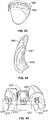
- Figs. 5A and 5B illustrate two exemplary embodiments of articulated templates.
- Fig. 5A shows two segments joined at the interproximal regions of two adjacent teeth.
- a number of alternate methods to join the teeth can be used, including that the joining methods could be alternate or vary from one interproximal region to the next. Further, the joining method could also be a layer or layers that cover additional or different surfaces of the teeth as depicted in Fig. 5B .
- the template is made up of a number of movable template components 250.
- Each of the template components 250 can be mounted on a patient's tooth to facilitate bracket bonding.
- the movable template components 250 are physically linked together by a sheet of material 252 deposited above the components 250 so that they do not break-up or otherwise become disassembled upon removal from its mold or stereolithography apparatus (SLA) model.
- SLA stereolithography apparatus
- the articulated templates are advantageous in that they provide greater adjustment flexibility.
- the template can additionally be used as an etching template.
- An etching template allows the doctor to precisely etch the areas of the teeth on which the brackets will be placed. The small windows bound the regions that will be etched to minimize teeth sensitivity to etching or unwanted enamel removal.
- the cut outs would not be formed. Instead those areas would be concavities facing the tooth surfaces. These concavities would contain an etching compound. The user would expose or activate the etching compound prior to setting the template on the teeth.
- the template 220 may be made from materials that contain physical property switches for ease of removal. These switches might include temperature responsive, pH responsive, moisture responsive or a multi-layer system wherein the layers have varying physical properties.
- the section 500 ( Fig. 5B ) represents a flexible or pliable material. Additionally, the material could be fiber, cord, fiber mesh, or a fiber-reinforced solid.
- the interproximal material can be homogenous or heterogeneous.
- the template section 252 may be made from materials that contain physical property switches for ease of removal. These switches might include temperature responsive, pH responsive, moisture responsive or a multi-layer system wherein the layers have varying physical properties.
- the section 252 represents a flexible or pliable material. Additionally, the material could be fiber, cord, fiber mesh, or a fiber-reinforced solid.
- the interproximal material can be homogenous or heterogeneous.
- a doctor can view the patient's arch(es) that require treatment during a consultation, and then select a particular wire that he/she will use to perform a portion of the treatment. Upon selection of the wire, the doctor submits this information to a virtual setup system based on the doctor's prescription.
- data mining can use previously stored data to indicate the likelihood of success, and failure rates, of tooth movement using the dental appliances. The data is categorized into three areas to describe the likelihood of successful treatment and movement: for example, a high likelihood of success; a decreased likelihood of success in treatment outcome; and little to no success. Based on the result of the data mining, the system recommends an appropriate sequence of dental appliance usage.
- Sequencing is the determination of which aligner feasible movements should be performed first, according to degree of ease or needs for effective treatment outcome.
- One exemplary implementation of combination treatment performs high-confidence movements earlier in the treatment, followed by more challenging movements. This can mean that removable appliances are used in the first phases of treatment, followed by attachment and wire treatments. Alternatively; attachment and wire treatments can be used first for a case, with removable appliances used in the final phase of treatment. Treatment methods can also be alternated (i.e. aligners, attachments and wires, followed by aligners) and combination treatments can be used simultaneously (i.e. aligners and attachments and wires uses at the same time). Attachments and wires can be placed on the buccal or lingual sides of the teeth.
- the appliances can also be partial (such as a 3-3 anterior arch), combined with partial attachments and wire treatments (i.e. placed on molars or posterior teeth).
- IPR internalproximal reduction
- a wire is mounted to pull the anterior teeth back to reduce the arch size and close the interproximal space, followed by 3-3 movement that is achieved using aligners.
- Fig. 6A illustrates a process of fabricating a dental template to position an object (such as a bracket) on a patient's tooth to move the tooth from an initial position to a target position.
- the process includes digitizing a model of the patient's tooth at the initial position (602).
- the target position is determined (604).
- the target position can be a final position for the teeth at the end of the treatment.
- each bracket having a slot adapted to receive an orthodontic wire passing therethrough (606) as illustrated in Fig. 6B showing the mounted brackets on the final position of the patient's teeth.
- the process optionally aligns the brackets to minimize strain on the wire at the target position (608).
- the process determines the position of the object at the initial position by backtracking from the tooth's final position one stage at a time until tooth reaches its the initial position (610).
- the coordinate transformation for moving the tooth from its final position to its initial position is applied to determine the position of the object's initial position.
- Fig. 6C shows an exemplary user interface that allows a user to visualize teeth at each treatment stage.
- the teeth can be backtracked one stage at a time to arrive at the initial positions. Since the brackets are secured to the teeth, the backtracked position of the brackets can also be determined.
- Fig. 6D shows the exemplary brackets when backtracked into their initial positions. The process can also determine a deviation of the object from an ideal placement and iteratively adjust the position of the object to minimize the deviation.
- the dental template is fabricated to allow the doctor to locate the object on the patient's tooth (612).
- the template can be fabricated using a rapid prototyping method.
- One or more bracket objects can be embedded in the dental template and the dental template can be inserted over the patient's teeth. Alternatively, the bracket objects can be inserted into an opening on the dental template prior to being bonded on the teeth.
- Fig. 7 describes one exemplary implementation of Combination Treatments.
- a stage of treatment is selected (step 702).
- the process makes a prediction of a treatment that is convenient for the doctor, to use either a removable appliance for treatment or to use attachments and wires (step 704).
- the proper attachments are selected (step 706).
- a predetermined fit value such as a FACC point is defined (step 708).
- Factors included in the determination of the FACC point include teeth, attachment, and wire collisions.
- the database provides the best-fit wire for use by the doctor (step 710).
- Dental practitioners use individual approaches when selecting wires for patients. Some doctors use a single type of wire, others choose from a number of different wires. Alternatively, a standard wire can be used.
- the wire is marked for proper placement of the attachments (step 712). Finally, the attachments and wire(s) are mounted on the patient's teeth (step 714).
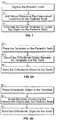
- Figure 8 describes Step 710.
- Fig. 9 describes more detail step 712, marking the wire for attachment placement by the doctor. Measurements are retrieved from the placement of the attachments on the jaw at the initial position. Distance and direction are measured between the points (742). Two additional areas can be measured: 1) the physical property of the wire, i.e. how much wire can bend (step 744), and 2) the curve distance from one bracket tip to the next (step 746). Finally, points are placed on the wire to show the place where the first attachment stops (step 748). The same iteration is repeated with each subsequent attachment.
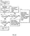
- Fig. 10 describes in more detail step 714.
- transition geometry is determined from the base of the tooth to the wire (752).
- Attachment object is placed inside the pocket area of the aligner (754).
- the filler material most likely cement, is placed in the aligner behind the attachment and in the remaining aligner area (756 and 758). This increases ease of removal of the aligner at the later stages when the attachments are placed on the teeth.
- the doctor snaps the aligner with the attachment and cement on the teeth (760).
- Ultraviolet light is used to secure the cement filler material to the teeth (762).
- hot water is sprayed on the aligner (step 764) because the Testa material responds to the heat by becoming more pliable.
- the doctor can remove it from the patient's mouth with relative ease (768).
- the attachment(s) are now fastened to the teeth, which follows standard orthodontics principles of placing brackets.
- the doctor connects the wire to each attachment using the designations that were marked on the wire in step 712 as a reference.
- the above process determines an optimum treatment sequence based on historical data; and fabricating one or more dental devices to move teeth, the devices being selected from either a computer-synthesized retainer or a combination of attachments and wire.
- the determining of an optimum treatment sequence can include capturing a digital model of a patient's teeth; and comparing the digital model to a library of historical treatment cases.
- the treatment can include moving teeth using the retainers and at the end of treatment with aligners, fabricate a retainer with the attachments embedded therein.
- Orthodontic brackets are designed and produced with a fixed base profile for a given manufacturer prescription, and usage.
- the bracket base is that surface that is the interface with the tooth. Since a patient's tooth morphologies are unique, the bracket base and its underlying tooth may not mate well. Typically, a gap exists between the bracket base and the tooth surface. This gap needs to be filled to form a "Custom Base".
- the custom base may involve adjusting the angulation and/or inclination of the bracket base when it is applied to the tooth.
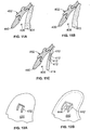
- Figs. 11A-11C show another embodiment that enables controlled placement of the bracket base on a tooth 404.
- Fig. 11A shows the template 400 over the tooth 404
- Fig. 11B shows the template 400 over a model 413.
- the template 400 contains a bracket 402.
- a gap 406 exists between the tooth 404 and the template 400.
- the gap 406 exists between bracket and model.
- the bracket is located in its preferred position with a predetermined torque (inclination) and a predetermined tip (angulation).
- Figure 11C shows the template on a shelled model which has through holes so the gap may be filled from within the model 414. A suitable epoxy is applied to fill the gap.
- the bonding template can spatially fix the bracket while still leaving access to the gap 406.
- the template can be applied to an actual tooth or a model of the tooth. This access could be through the appropriate geometry in the template with or without an applicator designed for the purpose.
- the model could be a shell that has hole(s) 412 to access the back of the bracket 402.
- the customized base could be formed by pressing one model into another while the bracket is spatially fixed by the template 400.
- the outer 'model' would be a structure similar to the template, but more rigid and covers more of the teeth's surfaces.
- the inner 'model' would represent of the actual teeth.
- the base gap would have been first filled with a bonding medium (e.g. adhesive). When the two models are fit together, the bonding medium is compacted into the gap and any excess flash around the bracket is removed.
- Yet another method would have a hollow model to represent the teeth, a template over this to fix the brackets in space, and a second model that nests in the first hollow model.
- adhesive is forced through holes in the hollow model that are located behind the brackets' bases. After curing the adhesive, the two models are removed so the brackets and their custom bases remain in the template.
- the template with the pre-specified or predetermined inclination or angulation is designed as follows. First, the system digitizes the patient's tooth. Next, an operator uses a dental CAD system to add a virtual object to a predetermined location on the digitized tooth. The CAD system is used to move the virtual object to a predetermined inclination or a predetermined angulation above the tooth. The resulting data is sent to a fabrication machine to fabricate the dental template to specifically locate the object on the patient's tooth with the determined inclination and/or angulation.
- a dental professional mounts the orthodontic object or bracket on the template and places the template on the patient's teeth or a model thereof. Since the template holds the bracket at the pre-specified angulation and/or inclination, the base of the bracket is accurately positioned above the tooth. The dental professional injects epoxy into the gap between the bracket and the tooth to bond the orthodontic object to the tooth with the desired angulation and/or inclination.
- Figs. 12A-12B show other embodiments to position the orthodontic object to the tooth with the desired angulation and/or inclination.
- a plurality of rails 432 is formed on a tooth model 430.
- rails 442 are also positioned on a tooth model 440.
- a plurality of openings 444 is provided on the model 440 to allow access to the base of a bracket that seats on or in the rails.
- the rails 432 and 442 are designed to provide proper angulation and/or inclination of the brackets on the tooth in addition to the proper locus.
- two or more rails or ridges are created along outside edges of a bracket on a suitable model substrate.
- the substrate can be Plaster, Resin, or Polymer substrate.
- a bonding medium is applied over the vicinity of the base. The bonding medium or epoxy may flow beyond the dimensions of the base.
- the bracket is then pressed against the rails or into channels in the rails which conform to the bracket base to force the correct spatial positioning and also limit it to the correct facial position.
- the rails also limit the base of the bracket to the correct facial position.
- the bonding medium is then cured.
- the bracket and custom base are removed from the substrate, which preferentially does not support or allow for a resilient bond to the adhesive.
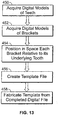
- Fig. 13 an exemplary process to form a template that can position a bracket in any arbitrary three-dimensional position is shown.
- the process acquires a digital model of teeth (450).
- the process acquires digital models of brackets to be supported by the template (452).
- the process positions in 3D space each bracket relative to its underlying tooth (454). Methods of determining these positions include: Andrews' Straight Wire, Roth, MBT, measuring the distance and angles between bracket geometries and biological referents, or based on doctors' specific theories or philosophies.
- the process then creates a template file as disclosed herein (456).
- the template is fabricated from the completed digital file 458.
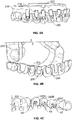
- Fig. 14 illustrates a presentation of three scanned or otherwise captured digital models or representations of human teeth 502, 504, 506, at 100% scale.
- Fig. 15 illustrates scaled tooth models from those of Fig. 14 . In this embodiment, the scaling factor is 140%, but the scaling can be between approximately 105% and 150%.
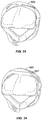
- Fig. 16 shows where the tooth models 508 and 512 overlap.
- a wire frame representation is used to show a common volume 510. This common volume identifies bodies that may conflict with creating a suitable template.
- Fig. 17 shows a solid representation of a septum 510.
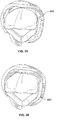
- Figs. 18 and 19 show a scaled tooth model 508, in this case the tooth model 508 is scaled up 140%.
- Fig. 18 shows a removal from the near side (side closest to viewer) of the model of the common volume 510 shared between the tooth model 508 and its adjacent tooth model 512.
- Fig. 19 shows the tooth model 508 with the common volume 510 removed from the near surface of the tooth and with the 100% tooth model subtracted from the tooth model 508.
- Fig. 19 thus is a shell that covers the 100% tooth model.
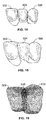
- Figs. 20 and 21 illustrate the need to remove the common volume 510 from adjacent tooth models.
- Fig. 20 illustrates the subtraction of original tooth models of Fig. 14 from scaled tooth models of Fig. 15 to form cavities 509 that are separated by the septa 510. Such formations would preclude the template from being placed over a patient's teeth.
- the common volumes 512 and 514 are positioned between the tooth model 511 and the tooth model 513 and between the tooth model 513 and the tooth model 515. The volumes 512 and 514 are shown prior to their removal or subtraction.
- Fig. 22 illustrates models with common volumes removed from the template model.
- the common volumes 520 and 522 are enlarged for clarity but in practice at volume size it would be defined by the scaling factor of the teeth that lead to the common volume shape.
- Figs. 23 and 24 show the addition of buttresses or means for connecting disjoint tooth models. Referring back to Fig. 22 , once those common volumes 520 and 522 have been removed, gaps 524 and 526 may exist between the tooth models 525, 527 and 529, respectively.
- Figs. 23-24 show a formation of a solid body that is one continuous template to be positioned on a patient's teeth.
- the joining elements or buttress elements 530-532 are inserted as separate bodies after the creation of the template model.
- Buttress element 530 is a circular element
- buttress element 532 is a crescent shaped element. These represent two possibilities for shapes, many others are possible.
- the surfaces of the buttress elements are joined to the surfaces of the template model.
- Fig. 24 shows the addition of buttressing elements 540-542 subsequent to the above operation for forming cavities. In this operation, one continuous body which is comprised of the three tooth models as well as the buttressing elements 540-542, is formed all at once. In both cases, the buttress elements are built into the template model. Subsequent steps may be taken to further shape the template model or elements thereof.
- Pseudo-code for generating a template using the tooth scaling approach is as follows:
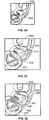
- Figs. 25-32 show various diagrams illustrating an overlaid cavities embodiment.
- a block 550 is used as an arbitrary body and a 100% scaled tooth model 552 has been placed inside that body.
- the same block 550 with the same dimensions in every aspect as the body of block 550 in Fig. 25 contains a scaled tooth 554 (such as a 140% scaled tooth model). In each case, the body fully encompasses the original and scaled tooth models.
- the 100% tooth has been cavitied or hollowed from the block 550
- the 140% scaled tooth model 554 is cavitied from the block 550.
- the cavitied block 550 that contained the 100% tooth model 552 is co-located with the cavitied block 550 that contained the 140% tooth model 554 so that the model 552 is inside the model 554.
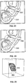
- Fig. 30 shows a subtraction of the cavity blocks 550 for the 100% tooth model and the cavity block 550 for the scaled tooth model to create a body defined by the area between the 100% scale and the 140% scale models 552 and 554, respectively.
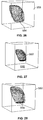
- a wire frame model of the scaled tooth model 554 with a solid model of the original 100% tooth model 552 is shown in Fig. 31.
- Fig. 32 is a cross sectional view of the models of Fig. 31 to show a shell 560 that surrounds the 100% scaled tooth model 552 with the outer surface being defined by the scaled tooth model 554.
- Fig. 33 illustrates another embodiment for scaling a tooth model.
- the original tooth model surface is off-set (565) using a predetermined mathematical formula or predetermined points or constraints.
- the embodiment offsets numerous surfaces to show alternative methods to enlarging the tooth model or creating a surface that bounds the same shape but in a large scale of the tooth model.
- Fig. 34 thickens the surface (565) from Fig. 33 inward towards the tooth to form body 567.
- Fig. 35 is that same surface (565) but now thickening it outward away from the tooth and Fig. 36 is showing thickening both inward and outward at the same time.
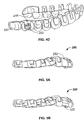
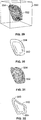
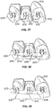
- Figs. 37-40 show another embodiment for creating a template.
- a geometric body 570 ( Fig. 37 ) is placed so that it abuts an orthodontic component 572 on a tooth 574.
- the component 572 is a bracket.
- the bracket position defines where this added body lies; in this case the corner of the body 570 abuts the bracket 572 on two sides.
- three brackets have been placed and three geometric bodies are positioned against the brackets 572 in Fig. 37 .
- bodies 570 are joined with the two joining elements 576 between bodies 570.
- Fig. 39 the structure of Fig.
- Figs. 39-40 show an occlusal view as well as a buccal view of the bodies 570 and joining elements 576 on teeth 574.
- an extended body 575 is linked to the bodies 507 and 576 to extend the height of the attachment combination.
- Figs. 41 and 42 show that once the bodies 570 have been extended as shown in Figs. 39 and 40 , an additional coverage body 580 can be positioned over the occlusal or incisal surfaces to fully define where the template is in space relative to the teeth and in this case a simple plate shape is shown. However, more complex geometries can be used.
- Figs. 43 and 44 show another embodiment of the surface off-set method.
- two surfaces 590 and 592 are used rather than just one surface.
- one surface 592 is offset at or near the tooth.
- a second surface 590 is offset at a distance larger than the distance from surface 592 resulting in two surfaces that are essentially congruent but located at a different distance.
- Fig. 44 shows the two surfaces 590 and 592 bounding a solid body.
- the solid body can be specified in a number of ways. For example, one surface can be extruded towards the other surface alternatively, the edges (591) where the surfaces gap can be closed.
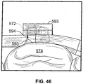
- Figs. 45 and 46 show one embodiment of template cutting.
- a cutting body 593 partially encompasses the underlying bracket 572 to create a 'window' in the template wherein the bracket can be positioned and affixed while still allowing for subsequent removal of the template.
- the cutting body 593 has a simple geometry. Other shapes could encompass more or less of the underlying orthodontic or dental component based on need or intent. Further, the shape of the body 593 could be more complex to create additional benefits such as a partial lock to hold the component 'hands free' in place, cause a seam along which the template is readily broken for removal, or allow for easier access for bonding or curing.
- the encompassing body 593 continues lingual to the template's buccal surface to cause a sharp-edged thin area 594 along whose buccal edge it is made easier to break the template.
- the body 593 creates a cutout in the template to position an orthodontic or dental component such as a bracket. It may not be necessary to capture all the geometry, rather to capture aspects of the geometry sufficient to locate that bracket or component in the right location.
- the central tooth has a body over the bracket. This body extends gingivally beyond the bracket body so the bracket can be placed in the template and bonded on the tooth and subsequently the template can be removed.
- Fig. 46 is an occlusal view of the same bracket, body, and template portion but showing other features that can be incorporated in the body. In this case, there is a triangular aspect in cutting body 593 that will cut into the template to create a breaking edge 594 or a break away line. More complex geometries can be used for severely rotated or severely tipped teeth since there might need to be different access paths to position one or more of the components and that may also facilitate template removal.
- the above templates can also position the bracket in any arbitrary 3D position to support a predetermined angulation and inclination specification for a bracket. In that case, the template would fix the bracket in space relative to the tooth.
- the techniques described here may be implemented in hardware or software, or a combination of the two.
- the techniques may be implemented in computer programs executing on programmable computers that each includes a processor, a storage medium readable by the processor (including volatile and nonvolatile memory and/or storage elements), and suitable input and output devices.
- Program code is applied to data entered using an input device to perform the functions described and to generate output information.
- the output information is applied to one or more output devices.
- Each program can be implemented in a high level procedural or object-oriented programming language to operate in conjunction with a computer system.
- the programs can be implemented in assembly or machine language, if desired. In any case, the language may be a compiled or interpreted language.
- Each such computer program can be stored on a storage medium or device (e.g., CD-ROM, hard disk or magnetic diskette) that is readable by a general or special purpose programmable computer for configuring and operating the computer when the storage medium or device is read by the computer to perform the procedures described.
- the system also may be implemented as a computer-readable storage medium, configured with a computer program, where the storage medium so configured causes a computer to operate in a specific and predefined manner.
Claims (21)
- Procédé de fabrication d'un gabarit dentaire pour le positionnement d'un objet sur la dent d'un patient, comprenant :la création d'un modèle de dent numérique de la dent du patient ;l'ajout d'un objet virtuel au niveau d'un emplacement prédéterminé sur le modèle de dent numérique ;la mise à l'échelle du modèle de dent numérique ;la superposition du modèle de dent numérique mis à l'échelle sur le modèle de dent numérique original ; etla fabrication du gabarit dentaire basé sur le modèle de dent numérique mis à l'échelle et le modèle de dent numérique original pour situer un dit objet sur la dent du patient.
- Procédé selon la revendication 1, dans lequel un objet virtuel est placé sur le modèle de dent numérique mis à l'échelle superposé.
- Procédé selon la revendication 1, dans lequel l'objet virtuel est placé au niveau d'un emplacement et selon une orientation prédéterminés dans le modèle de dent numérique mis à l'échelle superposé.
- Procédé selon la revendication 1, 2 ou 3, le procédé comprenant en outre l'élimination du modèle de dent numérique du modèle de dent numérique mis à l'échelle pour former un applicatif virtuel.
- Procédé selon l'une quelconque des revendications précédentes, le procédé comprenant en outre l'élimination des structures numérisées au niveau, au-dessous ou le long de la limite gingivale.
- Procédé selon l'une quelconque des revendications précédentes, comprenant en outre l'élimination de la structure numérisée en contact proximal avec une dent adjacente.
- Procédé selon l'une quelconque des revendications précédentes, dans lequel la fabrication comprend le rendu d'un gabarit dentaire physique en utilisant un procédé de prototypage rapide.
- Procédé selon la revendication 1, dans lequel :la création du modèle de dent numérique comprend la numérisation de la dent du patient ;l'objet virtuel est ajouté comme une représentation visuelle de l'objet à l'emplacement prédéterminé sur la dent numérisée ; etle gabarit dentaire situe l'objet sur la dent du patient.
- Procédé selon l'une quelconque des revendications précédentes, dans lequel des objets virtuels sont ajoutés à des emplacements prédéterminés sur une pluralité des modèles de dent numériques, et la fabrication du gabarit dentaire produit un gabarit de collage orthodontique comprenant une coque ayant une pluralité de cavités façonnée pour être insérée sur les dents du patient pour situer les objets sur les dents du patient.
- Procédé selon l'une quelconque des revendications 1 à 8, dans lequel la fabrication produit un gabarit de collage orthodontique comprenant une coque ayant une pluralité de cavités façonnée pour être insérée sur la dent d'un patient, la coque ayant une ouverture au niveau de l'emplacement prédéterminé pour recevoir comme un dit objet un dispositif orthodontique.
- Procédé selon la revendication 10, dans lequel l'ouverture comprend une fenêtre pour permettre qu'un agent collant soit appliqué à une zone prédéterminée sur la dent.
- Procédé selon la revendication 9, 10 ou 11, dans lequel la coque est polymérique.
- Procédé selon l'une quelconque des revendications 9 à 12, dans lequel la fabrication produit une coque comprenant un bord aux lignes courbées sur l'ouverture pour fixer le dispositif orthodontique à la coque.
- Procédé selon l'une quelconque des revendications 9 à 13, dans lequel le dispositif orthodontique est un boîtier orthodontique.
- Procédé selon l'une quelconque des revendications 9 à 14, dans lequel la fabrication est un processus de fabrication direct.
- Procédé selon l'une quelconque des revendications 9 à 15, dans lequel la coque est capable d'articulation avec une pluralité de cavités à liaison souple.
- Procédé selon l'une quelconque des revendications 9 à 15, dans lequel la fabrication produit la coque comme une unité non articulée.
- Produit de programme d'ordinateur pour réaliser le procédé selon l'une quelconque des revendications 1 à 17, le produit de programme d'ordinateur comprenant des instructions de programme pour amener un ordinateur à :
créer un modèle numérique de la dent d'un patient ; ajouter un objet virtuel au niveau d'un emplacement prédéterminé sur le modèle de dent numérique ; mettre à l'échelle le modèle de dent numérique ; et superposer le modèle de dent numérique mis à l'échelle sur le modèle de dent numérique original pour permettre la fabrication d'un gabarit dentaire basé sur le modèle de dent numérique mis à l'échelle et le modèle de dent numérique original pour situer un dit objet sur la position de la dent du patient. - Produit de programme d'ordinateur selon la revendication 18, comprenant en outre des instructions de programme pour amener un ordinateur à provoquer la fabrication du gabarit dentaire.
- Produit de programme d'ordinateur selon la revendication 19, dans lequel les instructions de programme amène un ordinateur à effectuer un procédé selon l'une quelconque des revendications 2 à 17.
- Appareil pour réaliser le procédé selon l'une quelconque des revendications 1 à 17, l'appareil comprenant : un moyen configuré pour créer un modèle numérique de la dent du patient ; un moyen configuré pour ajouter un objet virtuel à un emplacement prédéterminé sur le modèle de dent numérique ; mettre à l'échelle le modèle de dent numérique ; et un moyen configuré pour superposer le modèle de dent numérique mis à l'échelle sur le modèle de dent numérique original pour permettre la fabrication d'un gabarit dentaire basé sur le modèle de dent numérique mis à l'échelle et le modèle de dent numérique original pour situer un dit objet sur la dent du patient.
Priority Applications (3)
| Application Number | Priority Date | Filing Date | Title |
|---|---|---|---|
| DK18202114.7T DK3449865T3 (da) | 2004-03-04 | 2004-07-21 | Computerimplementeret fremgangsmåde til tilvejebringelse af en digital repræsentation af en ortodontisk skabelon til positionering af en genstand på en patients tand |
| EP18202114.7A EP3449865B1 (fr) | 2004-03-04 | 2004-07-21 | Méthode implémentée par ordinateur pour fournir une représentation numérique d'un gabarit orthodontique pour positionner un objet sur une dent d'un patient |
| EP10179634.0A EP2266494B1 (fr) | 2004-03-04 | 2004-07-21 | Gabarit orthodontique pour fixer des éléments orthodontiques |
Applications Claiming Priority (4)
| Application Number | Priority Date | Filing Date | Title |
|---|---|---|---|
| US794324 | 2004-03-04 | ||
| US10/794,325 US7600999B2 (en) | 2003-02-26 | 2004-03-04 | Systems and methods for fabricating a dental template |
| US10/794,324 US7658610B2 (en) | 2003-02-26 | 2004-03-04 | Systems and methods for fabricating a dental template with a 3-D object placement |
| US794325 | 2004-03-04 |
Related Child Applications (4)
| Application Number | Title | Priority Date | Filing Date |
|---|---|---|---|
| EP18202114.7A Division-Into EP3449865B1 (fr) | 2004-03-04 | 2004-07-21 | Méthode implémentée par ordinateur pour fournir une représentation numérique d'un gabarit orthodontique pour positionner un objet sur une dent d'un patient |
| EP18202114.7A Division EP3449865B1 (fr) | 2004-03-04 | 2004-07-21 | Méthode implémentée par ordinateur pour fournir une représentation numérique d'un gabarit orthodontique pour positionner un objet sur une dent d'un patient |
| EP10179634.0A Division-Into EP2266494B1 (fr) | 2004-03-04 | 2004-07-21 | Gabarit orthodontique pour fixer des éléments orthodontiques |
| EP10179634.0A Division EP2266494B1 (fr) | 2004-03-04 | 2004-07-21 | Gabarit orthodontique pour fixer des éléments orthodontiques |
Publications (3)
| Publication Number | Publication Date |
|---|---|
| EP1570803A2 EP1570803A2 (fr) | 2005-09-07 |
| EP1570803A3 EP1570803A3 (fr) | 2006-02-01 |
| EP1570803B1 true EP1570803B1 (fr) | 2018-12-05 |
Family
ID=34753207
Family Applications (3)
| Application Number | Title | Priority Date | Filing Date |
|---|---|---|---|
| EP04254358.7A Active EP1570803B1 (fr) | 2004-03-04 | 2004-07-21 | Systèmes et procédés pour la fabrication d'un gabarit dentaire |
| EP18202114.7A Active EP3449865B1 (fr) | 2004-03-04 | 2004-07-21 | Méthode implémentée par ordinateur pour fournir une représentation numérique d'un gabarit orthodontique pour positionner un objet sur une dent d'un patient |
| EP10179634.0A Active EP2266494B1 (fr) | 2004-03-04 | 2004-07-21 | Gabarit orthodontique pour fixer des éléments orthodontiques |
Family Applications After (2)
| Application Number | Title | Priority Date | Filing Date |
|---|---|---|---|
| EP18202114.7A Active EP3449865B1 (fr) | 2004-03-04 | 2004-07-21 | Méthode implémentée par ordinateur pour fournir une représentation numérique d'un gabarit orthodontique pour positionner un objet sur une dent d'un patient |
| EP10179634.0A Active EP2266494B1 (fr) | 2004-03-04 | 2004-07-21 | Gabarit orthodontique pour fixer des éléments orthodontiques |
Country Status (6)
| Country | Link |
|---|---|
| EP (3) | EP1570803B1 (fr) |
| JP (3) | JP4717390B2 (fr) |
| CN (1) | CN1663540B (fr) |
| DK (2) | DK1570803T3 (fr) |
| ES (3) | ES2714375T3 (fr) |
| HK (1) | HK1077727A1 (fr) |
Cited By (1)
| Publication number | Priority date | Publication date | Assignee | Title |
|---|---|---|---|---|
| EP3886756B1 (fr) * | 2019-11-11 | 2023-01-18 | Smylio Inc. | Système et procédé pour personnaliser l'aspect d'un appareil orthodontique |
Families Citing this family (47)
| Publication number | Priority date | Publication date | Assignee | Title |
|---|---|---|---|---|
| WO2007069881A1 (fr) * | 2005-12-12 | 2007-06-21 | Grotech B.V. | Dispositif de collage indirect de bagues orthodontiques sur les dents, procede de production de ce dispositif et procede de collage des bagues orthodontiques sur les dents |
| EP1991939B1 (fr) * | 2006-02-28 | 2018-09-05 | Ormco Corporation | Logiciel et procedes de planification de traitements dentaires |
| GB0703141D0 (en) * | 2007-02-19 | 2007-03-28 | Materialise Dental Nv | Dual transfer device for guided direct bonding |
| US7845938B2 (en) * | 2007-03-22 | 2010-12-07 | 3M Innovative Properties Company | Indirect bonding trays for orthodontic treatment and methods for making the same |
| US7726968B2 (en) | 2007-03-22 | 2010-06-01 | 3M Innovative Properties Company | Methods and assemblies for making an orthodontic bonding tray using rapid prototyping |
| US8535580B2 (en) | 2007-09-27 | 2013-09-17 | 3M Innovative Properties Company | Digitally forming a dental model for fabricating orthodontic laboratory appliances |
| US8113837B2 (en) | 2007-11-26 | 2012-02-14 | Peter John Zegarelli | Oral appliance for delivering a medicament |
| US8738165B2 (en) | 2007-12-21 | 2014-05-27 | 3M Innovative Properties Company | Methods of preparing a virtual dentition model and fabricating a dental retainer therefrom |
| CN101467920B (zh) * | 2007-12-25 | 2012-04-11 | 宝钰生技股份有限公司 | 支台齿的设计方法 |
| US20110091832A1 (en) * | 2008-06-26 | 2011-04-21 | Sung Kim | Rapid prototyped transfer tray for orthodontic appliances |
| WO2010070710A1 (fr) * | 2008-12-18 | 2010-06-24 | Hiro Toshiaki | Procédé d'assistance pour le placement d'un bracket orthodontique et appareil d'assistance au placement |
| US9687324B2 (en) * | 2009-02-25 | 2017-06-27 | 3Shape A/S | System and method for designing post and core |
| EP2229914B1 (fr) * | 2009-03-20 | 2018-05-30 | Nobel Biocare Services AG | Système et procédé d'alignement des modèles virtuels |
| CN101869510B (zh) * | 2009-04-21 | 2013-01-09 | 宝钰生技股份有限公司 | 植牙手术导引板的制作方法 |
| CN102232873A (zh) * | 2010-04-28 | 2011-11-09 | 黄正和 | 牙齿矫正器的定位方法及其结构 |
| WO2012136247A1 (fr) | 2011-04-05 | 2012-10-11 | Yong-Min Jo | Procédé de production de gouttières de transfert pour des brackets |
| CN102319124B (zh) * | 2011-09-26 | 2013-09-25 | 杭州六维齿科医疗技术有限公司 | 用于正畸托槽间接粘接的数字化导向模板 |
| JP5051561B1 (ja) * | 2012-02-20 | 2012-10-17 | 和之 岡▲崎▼ | 歯列矯正装置設置具 |
| CN102525669A (zh) * | 2012-03-04 | 2012-07-04 | 罗文平 | 一种托槽定位模板 |
| US8905757B2 (en) | 2012-12-03 | 2014-12-09 | E. Kats Enterprises Ltd. | Method and apparatus for measuring a location and orientation of a plurality of implants |
| BR112015013508B1 (pt) | 2012-12-11 | 2021-02-23 | 3M Innovative Properties Company | método de produção de um protótipo físico |
| US10537406B2 (en) | 2014-02-21 | 2020-01-21 | Align Technology, Inc. | Dental appliance with repositioning jaw elements |
| US9844424B2 (en) | 2014-02-21 | 2017-12-19 | Align Technology, Inc. | Dental appliance with repositioning jaw elements |
| CN111772834B (zh) * | 2014-03-21 | 2022-07-15 | 阿莱恩技术有限公司 | 具有弹性体的分段的正畸矫正器 |
| CN103948446B (zh) * | 2014-04-01 | 2016-01-13 | 上海时代天使医疗器械有限公司 | 一种牙齿附件自动粘贴的方法 |
| CN103948440A (zh) * | 2014-04-28 | 2014-07-30 | 统合数位股份有限公司 | 牙齿矫正器定位方法 |
| CH709687B1 (de) * | 2014-05-23 | 2018-03-29 | Digital Smile Gmbh | Kieferorthopädische Apparatur und Verfahren zur Herstellung einer kieferorthopädischen Apparatur. |
| EP3791824B1 (fr) * | 2014-09-19 | 2023-12-06 | Align Technology, Inc. | Méthode pour présenter des éléments de repositionnement de mâchoire |
| CN104224334B (zh) * | 2014-09-30 | 2017-01-25 | 武汉大学 | 一种舌侧托槽粘结法 |
| US10614174B2 (en) * | 2015-01-30 | 2020-04-07 | Dentsply Sirona Inc. | System and method for adding surface detail to digital crown models created using statistical techniques |
| CN106031661A (zh) * | 2015-03-17 | 2016-10-19 | 首都医科大学附属北京口腔医院 | 一种口腔正畸支抗体 |
| US11596502B2 (en) * | 2015-12-09 | 2023-03-07 | Align Technology, Inc. | Dental attachment placement structure |
| US11103330B2 (en) | 2015-12-09 | 2021-08-31 | Align Technology, Inc. | Dental attachment placement structure |
| CN105662615B (zh) * | 2016-03-14 | 2018-03-23 | 赵计林 | 一种正畸托槽间接粘接精确定位系统及应用方法 |
| CN106955087B (zh) * | 2017-03-29 | 2018-05-25 | 吉林大学 | 一种调整观察角度并定位托槽粘结位置眼镜 |
| US11737857B2 (en) | 2017-11-01 | 2023-08-29 | Align Technology, Inc. | Systems and methods for correcting malocclusions of teeth |
| US11273022B2 (en) | 2018-02-13 | 2022-03-15 | Emanate Biomedical, Inc. | Oral appliance in a blockchain system |
| US11937991B2 (en) | 2018-03-27 | 2024-03-26 | Align Technology, Inc. | Dental attachment placement structure |
| US11504214B2 (en) * | 2018-05-11 | 2022-11-22 | Align Technology, Inc. | Devices, systems, and computer-implemented methods for dental attachment templates |
| EP3572030B1 (fr) * | 2018-05-22 | 2022-11-02 | Dental Monitoring | Procede d'analyse d'une situation dentaire |
| EP3581143A1 (fr) * | 2018-06-12 | 2019-12-18 | 3C | Système orthodontique pour le traitement orthodontique des dents d'un patient, procédé de placement d'un appareil pour le traitement orthodontique des dents d'un patient et utilisation de l'appareil d'un tel système orthodontique |
| CN109620431B (zh) * | 2018-12-29 | 2020-11-10 | 广州欧欧医疗科技有限责任公司 | 数字化弓丝选择方法及其装置 |
| FR3095334A1 (fr) * | 2019-04-24 | 2020-10-30 | Dental Monitoring | Procede d’evaluation d’une gouttiere orthodontique |
| WO2021105878A1 (fr) * | 2019-11-26 | 2021-06-03 | 3M Innovative Properties Company | Gabarit dentaire pour la liaison directe d'appareils orthodontiques et procédés de fabrication et d'utilisation de celui-ci |
| WO2021214613A1 (fr) * | 2020-04-24 | 2021-10-28 | 3M Innovative Properties Company | Plateau de liaison indirecte pour lier des appareils orthodontiques et procédés de fabrication et d'utilisation de celui-ci |
| KR102340293B1 (ko) * | 2020-06-03 | 2021-12-16 | 디디에이치 주식회사 | 교정용 브라켓 모듈 제조 방법 및 이에 의해 제작된 교정용 브라켓 모듈 |
| CN112258654A (zh) * | 2020-11-03 | 2021-01-22 | 芯勍(上海)智能化科技股份有限公司 | 模型抽壳方法、终端设备及计算机可读存储介质 |
Family Cites Families (17)
| Publication number | Priority date | Publication date | Assignee | Title |
|---|---|---|---|---|
| US4183141A (en) * | 1977-12-05 | 1980-01-15 | Dellinger Eugene L | Method and apparatus for treating malocclusion |
| US5055039A (en) * | 1988-10-06 | 1991-10-08 | Great Lakes Orthodontics, Ltd. | Orthodontic positioner and methods of making and using same |
| NL9400968A (nl) * | 1994-06-14 | 1996-01-02 | Aptus Bv | Inrichting voor het aanbrengen van een tandheelkundig hulpmiddel op ten minste één tand van ten minste één rij tanden. |
| US5975893A (en) | 1997-06-20 | 1999-11-02 | Align Technology, Inc. | Method and system for incrementally moving teeth |
| US6309215B1 (en) | 1997-06-20 | 2001-10-30 | Align Technology Inc. | Attachment devices and method for a dental applicance |
| US6450807B1 (en) | 1997-06-20 | 2002-09-17 | Align Technology, Inc. | System and method for positioning teeth |
| US6471511B1 (en) | 1997-06-20 | 2002-10-29 | Align Technology, Inc. | Defining tooth-moving appliances computationally |
| JP3118213B2 (ja) * | 1997-09-26 | 2000-12-18 | 俊明 広 | 歯科矯正装置のブラケット取り付け方法 |
| US5971754A (en) * | 1998-07-30 | 1999-10-26 | Sondhi; Anoop | Indirect bonding method and adhesive for orthodontic treatment |
| US6488499B1 (en) | 2000-04-25 | 2002-12-03 | Align Technology, Inc. | Methods for correcting deviations in preplanned tooth rearrangements |
| US6227851B1 (en) | 1998-12-04 | 2001-05-08 | Align Technology, Inc. | Manipulable dental model system for fabrication of a dental appliance |
| US6123544A (en) * | 1998-12-18 | 2000-09-26 | 3M Innovative Properties Company | Method and apparatus for precise bond placement of orthodontic appliances |
| US6318994B1 (en) | 1999-05-13 | 2001-11-20 | Align Technology, Inc | Tooth path treatment plan |
| JP3265478B2 (ja) * | 1999-08-26 | 2002-03-11 | 照夫 江花 | 歯列矯正具の取付装置 |
| US6554613B1 (en) * | 2000-04-19 | 2003-04-29 | Ora Metrix, Inc. | Method and apparatus for generating an orthodontic template that assists in placement of orthodontic apparatus |
| US6733289B2 (en) * | 2001-07-30 | 2004-05-11 | 3M Innovative Properties Company | Method and apparatus for selecting a prescription for an orthodontic brace |
| US7387511B2 (en) * | 2002-01-22 | 2008-06-17 | Geodigm Corporation | Method and apparatus using a scanned image for automatically placing bracket in pre-determined locations |
-
2004
- 2004-07-21 EP EP04254358.7A patent/EP1570803B1/fr active Active
- 2004-07-21 EP EP18202114.7A patent/EP3449865B1/fr active Active
- 2004-07-21 DK DK04254358.7T patent/DK1570803T3/en active
- 2004-07-21 DK DK18202114.7T patent/DK3449865T3/da active
- 2004-07-21 ES ES04254358T patent/ES2714375T3/es active Active
- 2004-07-21 EP EP10179634.0A patent/EP2266494B1/fr active Active
- 2004-07-21 ES ES10179634.0T patent/ES2627430T3/es active Active
- 2004-07-21 ES ES18202114T patent/ES2803973T3/es active Active
- 2004-07-22 JP JP2004214985A patent/JP4717390B2/ja active Active
- 2004-08-10 CN CN2004100583213A patent/CN1663540B/zh active Active
-
2005
- 2005-11-01 HK HK05109721.2A patent/HK1077727A1/xx unknown
-
2010
- 2010-06-16 JP JP2010137742A patent/JP5196600B2/ja active Active
-
2011
- 2011-01-21 JP JP2011011431A patent/JP2011120928A/ja not_active Withdrawn
Non-Patent Citations (1)
| Title |
|---|
| None * |
Cited By (1)
| Publication number | Priority date | Publication date | Assignee | Title |
|---|---|---|---|---|
| EP3886756B1 (fr) * | 2019-11-11 | 2023-01-18 | Smylio Inc. | Système et procédé pour personnaliser l'aspect d'un appareil orthodontique |
Also Published As
| Publication number | Publication date |
|---|---|
| JP2005246035A (ja) | 2005-09-15 |
| ES2714375T3 (es) | 2019-05-28 |
| EP1570803A3 (fr) | 2006-02-01 |
| DK1570803T3 (en) | 2019-03-04 |
| CN1663540B (zh) | 2012-12-26 |
| HK1077727A1 (en) | 2006-02-24 |
| JP2011120928A (ja) | 2011-06-23 |
| JP5196600B2 (ja) | 2013-05-15 |
| JP4717390B2 (ja) | 2011-07-06 |
| ES2627430T3 (es) | 2017-07-28 |
| DK3449865T3 (da) | 2020-06-02 |
| EP2266494B1 (fr) | 2017-05-03 |
| ES2803973T3 (es) | 2021-02-01 |
| EP3449865B1 (fr) | 2020-04-01 |
| CN1663540A (zh) | 2005-09-07 |
| EP2266494A1 (fr) | 2010-12-29 |
| EP1570803A2 (fr) | 2005-09-07 |
| EP3449865A1 (fr) | 2019-03-06 |
| JP2010227607A (ja) | 2010-10-14 |
Similar Documents
| Publication | Publication Date | Title |
|---|---|---|
| EP1570803B1 (fr) | Systèmes et procédés pour la fabrication d'un gabarit dentaire | |
| US7658610B2 (en) | Systems and methods for fabricating a dental template with a 3-D object placement | |
| US7600999B2 (en) | Systems and methods for fabricating a dental template | |
| US7578673B2 (en) | System and methods for combination treatments of dental patients | |
| US10874487B2 (en) | Systems and methods for fabricating a dental template | |
| US20220401184A1 (en) | Reduced registration bonding template | |
| EP3649981B1 (fr) | Plateau de transfert prototypé rapide pour appareils orthodontiques |
Legal Events
| Date | Code | Title | Description |
|---|---|---|---|
| PUAI | Public reference made under article 153(3) epc to a published international application that has entered the european phase |
Free format text: ORIGINAL CODE: 0009012 |
|
| AK | Designated contracting states |
Kind code of ref document: A2 Designated state(s): AT BE BG CH CY CZ DE DK EE ES FI FR GB GR HU IE IT LI LU MC NL PL PT RO SE SI SK TR |
|
| AX | Request for extension of the european patent |
Extension state: AL HR LT LV MK |
|
| PUAL | Search report despatched |
Free format text: ORIGINAL CODE: 0009013 |
|
| AK | Designated contracting states |
Kind code of ref document: A3 Designated state(s): AT BE BG CH CY CZ DE DK EE ES FI FR GB GR HU IE IT LI LU MC NL PL PT RO SE SI SK TR |
|
| AX | Request for extension of the european patent |
Extension state: AL HR LT LV MK |
|
| 17P | Request for examination filed |
Effective date: 20060801 |
|
| AKX | Designation fees paid |
Designated state(s): AT BE BG CH CY CZ DE DK EE ES FI FR GB GR HU IE IT LI LU MC NL PL PT RO SE SI SK TR |
|
| 17Q | First examination report despatched |
Effective date: 20061012 |
|
| RAP1 | Party data changed (applicant data changed or rights of an application transferred) |
Owner name: ALIGN TECHNOLOGY, INC. |
|
| STAA | Information on the status of an ep patent application or granted ep patent |
Free format text: STATUS: EXAMINATION IS IN PROGRESS |
|
| RAP1 | Party data changed (applicant data changed or rights of an application transferred) |
Owner name: ALIGN TECHNOLOGY, INC. |
|
| GRAP | Despatch of communication of intention to grant a patent |
Free format text: ORIGINAL CODE: EPIDOSNIGR1 |
|
| STAA | Information on the status of an ep patent application or granted ep patent |
Free format text: STATUS: GRANT OF PATENT IS INTENDED |
|
| INTG | Intention to grant announced |
Effective date: 20180621 |
|
| GRAS | Grant fee paid |
Free format text: ORIGINAL CODE: EPIDOSNIGR3 |
|
| GRAA | (expected) grant |
Free format text: ORIGINAL CODE: 0009210 |
|
| GRAA | (expected) grant |
Free format text: ORIGINAL CODE: 0009210 |
|
| STAA | Information on the status of an ep patent application or granted ep patent |
Free format text: STATUS: THE PATENT HAS BEEN GRANTED |
|
| AK | Designated contracting states |
Kind code of ref document: B1 Designated state(s): AT BE BG CH CY CZ DE DK EE ES FI FR GB GR HU IE IT LI LU MC NL PL PT RO SE SI SK TR |
|
| REG | Reference to a national code |
Ref country code: GB Ref legal event code: FG4D |
|
| REG | Reference to a national code |
Ref country code: CH Ref legal event code: EP |
|
| REG | Reference to a national code |
Ref country code: AT Ref legal event code: REF Ref document number: 1072108 Country of ref document: AT Kind code of ref document: T Effective date: 20181215 |
|
| REG | Reference to a national code |
Ref country code: IE Ref legal event code: FG4D |
|
| REG | Reference to a national code |
Ref country code: DE Ref legal event code: R096 Ref document number: 602004053500 Country of ref document: DE |
|
| REG | Reference to a national code |
Ref country code: DK Ref legal event code: T3 Effective date: 20190225 |
|
| REG | Reference to a national code |
Ref country code: NL Ref legal event code: MP Effective date: 20181205 |
|
| REG | Reference to a national code |
Ref country code: AT Ref legal event code: MK05 Ref document number: 1072108 Country of ref document: AT Kind code of ref document: T Effective date: 20181205 |
|
| PG25 | Lapsed in a contracting state [announced via postgrant information from national office to epo] |
Ref country code: AT Free format text: LAPSE BECAUSE OF FAILURE TO SUBMIT A TRANSLATION OF THE DESCRIPTION OR TO PAY THE FEE WITHIN THE PRESCRIBED TIME-LIMIT Effective date: 20181205 Ref country code: FI Free format text: LAPSE BECAUSE OF FAILURE TO SUBMIT A TRANSLATION OF THE DESCRIPTION OR TO PAY THE FEE WITHIN THE PRESCRIBED TIME-LIMIT Effective date: 20181205 Ref country code: BG Free format text: LAPSE BECAUSE OF FAILURE TO SUBMIT A TRANSLATION OF THE DESCRIPTION OR TO PAY THE FEE WITHIN THE PRESCRIBED TIME-LIMIT Effective date: 20190305 |
|
| REG | Reference to a national code |
Ref country code: ES Ref legal event code: FG2A Ref document number: 2714375 Country of ref document: ES Kind code of ref document: T3 Effective date: 20190528 |
|
| PG25 | Lapsed in a contracting state [announced via postgrant information from national office to epo] |
Ref country code: GR Free format text: LAPSE BECAUSE OF FAILURE TO SUBMIT A TRANSLATION OF THE DESCRIPTION OR TO PAY THE FEE WITHIN THE PRESCRIBED TIME-LIMIT Effective date: 20190306 Ref country code: SE Free format text: LAPSE BECAUSE OF FAILURE TO SUBMIT A TRANSLATION OF THE DESCRIPTION OR TO PAY THE FEE WITHIN THE PRESCRIBED TIME-LIMIT Effective date: 20181205 |
|
| PG25 | Lapsed in a contracting state [announced via postgrant information from national office to epo] |
Ref country code: NL Free format text: LAPSE BECAUSE OF FAILURE TO SUBMIT A TRANSLATION OF THE DESCRIPTION OR TO PAY THE FEE WITHIN THE PRESCRIBED TIME-LIMIT Effective date: 20181205 |
|
| PG25 | Lapsed in a contracting state [announced via postgrant information from national office to epo] |
Ref country code: PT Free format text: LAPSE BECAUSE OF FAILURE TO SUBMIT A TRANSLATION OF THE DESCRIPTION OR TO PAY THE FEE WITHIN THE PRESCRIBED TIME-LIMIT Effective date: 20190405 Ref country code: PL Free format text: LAPSE BECAUSE OF FAILURE TO SUBMIT A TRANSLATION OF THE DESCRIPTION OR TO PAY THE FEE WITHIN THE PRESCRIBED TIME-LIMIT Effective date: 20181205 Ref country code: CZ Free format text: LAPSE BECAUSE OF FAILURE TO SUBMIT A TRANSLATION OF THE DESCRIPTION OR TO PAY THE FEE WITHIN THE PRESCRIBED TIME-LIMIT Effective date: 20181205 |
|
| PG25 | Lapsed in a contracting state [announced via postgrant information from national office to epo] |
Ref country code: RO Free format text: LAPSE BECAUSE OF FAILURE TO SUBMIT A TRANSLATION OF THE DESCRIPTION OR TO PAY THE FEE WITHIN THE PRESCRIBED TIME-LIMIT Effective date: 20181205 Ref country code: SK Free format text: LAPSE BECAUSE OF FAILURE TO SUBMIT A TRANSLATION OF THE DESCRIPTION OR TO PAY THE FEE WITHIN THE PRESCRIBED TIME-LIMIT Effective date: 20181205 Ref country code: EE Free format text: LAPSE BECAUSE OF FAILURE TO SUBMIT A TRANSLATION OF THE DESCRIPTION OR TO PAY THE FEE WITHIN THE PRESCRIBED TIME-LIMIT Effective date: 20181205 |
|
| REG | Reference to a national code |
Ref country code: DE Ref legal event code: R097 Ref document number: 602004053500 Country of ref document: DE |
|
| PLBE | No opposition filed within time limit |
Free format text: ORIGINAL CODE: 0009261 |
|
| STAA | Information on the status of an ep patent application or granted ep patent |
Free format text: STATUS: NO OPPOSITION FILED WITHIN TIME LIMIT |
|
| PG25 | Lapsed in a contracting state [announced via postgrant information from national office to epo] |
Ref country code: SI Free format text: LAPSE BECAUSE OF FAILURE TO SUBMIT A TRANSLATION OF THE DESCRIPTION OR TO PAY THE FEE WITHIN THE PRESCRIBED TIME-LIMIT Effective date: 20181205 |
|
| 26N | No opposition filed |
Effective date: 20190906 |
|
| PG25 | Lapsed in a contracting state [announced via postgrant information from national office to epo] |
Ref country code: MC Free format text: LAPSE BECAUSE OF FAILURE TO SUBMIT A TRANSLATION OF THE DESCRIPTION OR TO PAY THE FEE WITHIN THE PRESCRIBED TIME-LIMIT Effective date: 20181205 |
|
| REG | Reference to a national code |
Ref country code: CH Ref legal event code: PL |
|
| PG25 | Lapsed in a contracting state [announced via postgrant information from national office to epo] |
Ref country code: TR Free format text: LAPSE BECAUSE OF FAILURE TO SUBMIT A TRANSLATION OF THE DESCRIPTION OR TO PAY THE FEE WITHIN THE PRESCRIBED TIME-LIMIT Effective date: 20181205 |
|
| REG | Reference to a national code |
Ref country code: BE Ref legal event code: MM Effective date: 20190731 |
|
| PG25 | Lapsed in a contracting state [announced via postgrant information from national office to epo] |
Ref country code: LU Free format text: LAPSE BECAUSE OF NON-PAYMENT OF DUE FEES Effective date: 20190721 Ref country code: CH Free format text: LAPSE BECAUSE OF NON-PAYMENT OF DUE FEES Effective date: 20190731 Ref country code: LI Free format text: LAPSE BECAUSE OF NON-PAYMENT OF DUE FEES Effective date: 20190731 Ref country code: BE Free format text: LAPSE BECAUSE OF NON-PAYMENT OF DUE FEES Effective date: 20190731 |
|
| PG25 | Lapsed in a contracting state [announced via postgrant information from national office to epo] |
Ref country code: IE Free format text: LAPSE BECAUSE OF NON-PAYMENT OF DUE FEES Effective date: 20190721 |
|
| PG25 | Lapsed in a contracting state [announced via postgrant information from national office to epo] |
Ref country code: CY Free format text: LAPSE BECAUSE OF FAILURE TO SUBMIT A TRANSLATION OF THE DESCRIPTION OR TO PAY THE FEE WITHIN THE PRESCRIBED TIME-LIMIT Effective date: 20181205 |
|
| PG25 | Lapsed in a contracting state [announced via postgrant information from national office to epo] |
Ref country code: HU Free format text: LAPSE BECAUSE OF FAILURE TO SUBMIT A TRANSLATION OF THE DESCRIPTION OR TO PAY THE FEE WITHIN THE PRESCRIBED TIME-LIMIT; INVALID AB INITIO Effective date: 20040721 |
|
| REG | Reference to a national code |
Ref country code: DE Ref legal event code: R082 Ref document number: 602004053500 Country of ref document: DE Representative=s name: ZACCO LEGAL RECHTSANWALTSGESELLSCHAFT MBH, DE |
|
| P01 | Opt-out of the competence of the unified patent court (upc) registered |
Effective date: 20230523 |
|
| PGFP | Annual fee paid to national office [announced via postgrant information from national office to epo] |
Ref country code: IT Payment date: 20230612 Year of fee payment: 20 Ref country code: FR Payment date: 20230608 Year of fee payment: 20 Ref country code: DK Payment date: 20230627 Year of fee payment: 20 |
|
| PGFP | Annual fee paid to national office [announced via postgrant information from national office to epo] |
Ref country code: GB Payment date: 20230601 Year of fee payment: 20 Ref country code: ES Payment date: 20230809 Year of fee payment: 20 |
|
| PGFP | Annual fee paid to national office [announced via postgrant information from national office to epo] |
Ref country code: DE Payment date: 20230531 Year of fee payment: 20 |