EP3417806A1 - Techniques for adaptive control of motor velocity of a surgical stapling and cutting instrument - Google Patents
Techniques for adaptive control of motor velocity of a surgical stapling and cutting instrument Download PDFInfo
- Publication number
- EP3417806A1 EP3417806A1 EP17209565.5A EP17209565A EP3417806A1 EP 3417806 A1 EP3417806 A1 EP 3417806A1 EP 17209565 A EP17209565 A EP 17209565A EP 3417806 A1 EP3417806 A1 EP 3417806A1
- Authority
- EP
- European Patent Office
- Prior art keywords
- motor
- control circuit
- articulation
- surgical instrument
- displacement member
- Prior art date
- Legal status (The legal status is an assumption and is not a legal conclusion. Google has not performed a legal analysis and makes no representation as to the accuracy of the status listed.)
- Withdrawn
Links
Images
























Classifications
-
- A—HUMAN NECESSITIES
- A61—MEDICAL OR VETERINARY SCIENCE; HYGIENE
- A61B—DIAGNOSIS; SURGERY; IDENTIFICATION
- A61B17/00—Surgical instruments, devices or methods
- A61B17/068—Surgical staplers, e.g. containing multiple staples or clamps
- A61B17/0682—Surgical staplers, e.g. containing multiple staples or clamps for applying U-shaped staples or clamps, e.g. without a forming anvil
- A61B17/0686—Surgical staplers, e.g. containing multiple staples or clamps for applying U-shaped staples or clamps, e.g. without a forming anvil having a forming anvil staying below the tissue during stapling
-
- A—HUMAN NECESSITIES
- A61—MEDICAL OR VETERINARY SCIENCE; HYGIENE
- A61B—DIAGNOSIS; SURGERY; IDENTIFICATION
- A61B17/00—Surgical instruments, devices or methods
- A61B17/068—Surgical staplers, e.g. containing multiple staples or clamps
- A61B17/072—Surgical staplers, e.g. containing multiple staples or clamps for applying a row of staples in a single action, e.g. the staples being applied simultaneously
- A61B17/07207—Surgical staplers, e.g. containing multiple staples or clamps for applying a row of staples in a single action, e.g. the staples being applied simultaneously the staples being applied sequentially
-
- A—HUMAN NECESSITIES
- A61—MEDICAL OR VETERINARY SCIENCE; HYGIENE
- A61B—DIAGNOSIS; SURGERY; IDENTIFICATION
- A61B17/00—Surgical instruments, devices or methods
- A61B17/068—Surgical staplers, e.g. containing multiple staples or clamps
-
- A—HUMAN NECESSITIES
- A61—MEDICAL OR VETERINARY SCIENCE; HYGIENE
- A61B—DIAGNOSIS; SURGERY; IDENTIFICATION
- A61B17/00—Surgical instruments, devices or methods
- A61B17/11—Surgical instruments, devices or methods for performing anastomosis; Buttons for anastomosis
- A61B17/1114—Surgical instruments, devices or methods for performing anastomosis; Buttons for anastomosis of the digestive tract, e.g. bowels or oesophagus
-
- A—HUMAN NECESSITIES
- A61—MEDICAL OR VETERINARY SCIENCE; HYGIENE
- A61B—DIAGNOSIS; SURGERY; IDENTIFICATION
- A61B17/00—Surgical instruments, devices or methods
- A61B17/16—Instruments for performing osteoclasis; Drills or chisels for bones; Trepans
- A61B17/1613—Component parts
- A61B17/1626—Control means; Display units
-
- A—HUMAN NECESSITIES
- A61—MEDICAL OR VETERINARY SCIENCE; HYGIENE
- A61B—DIAGNOSIS; SURGERY; IDENTIFICATION
- A61B17/00—Surgical instruments, devices or methods
- A61B2017/00017—Electrical control of surgical instruments
-
- A—HUMAN NECESSITIES
- A61—MEDICAL OR VETERINARY SCIENCE; HYGIENE
- A61B—DIAGNOSIS; SURGERY; IDENTIFICATION
- A61B17/00—Surgical instruments, devices or methods
- A61B2017/00017—Electrical control of surgical instruments
- A61B2017/00115—Electrical control of surgical instruments with audible or visual output
-
- A—HUMAN NECESSITIES
- A61—MEDICAL OR VETERINARY SCIENCE; HYGIENE
- A61B—DIAGNOSIS; SURGERY; IDENTIFICATION
- A61B17/00—Surgical instruments, devices or methods
- A61B2017/00367—Details of actuation of instruments, e.g. relations between pushing buttons, or the like, and activation of the tool, working tip, or the like
- A61B2017/00398—Details of actuation of instruments, e.g. relations between pushing buttons, or the like, and activation of the tool, working tip, or the like using powered actuators, e.g. stepper motors, solenoids
-
- A—HUMAN NECESSITIES
- A61—MEDICAL OR VETERINARY SCIENCE; HYGIENE
- A61B—DIAGNOSIS; SURGERY; IDENTIFICATION
- A61B17/00—Surgical instruments, devices or methods
- A61B2017/0046—Surgical instruments, devices or methods with a releasable handle; with handle and operating part separable
-
- A—HUMAN NECESSITIES
- A61—MEDICAL OR VETERINARY SCIENCE; HYGIENE
- A61B—DIAGNOSIS; SURGERY; IDENTIFICATION
- A61B17/00—Surgical instruments, devices or methods
- A61B2017/00681—Aspects not otherwise provided for
- A61B2017/00734—Aspects not otherwise provided for battery operated
-
- A—HUMAN NECESSITIES
- A61—MEDICAL OR VETERINARY SCIENCE; HYGIENE
- A61B—DIAGNOSIS; SURGERY; IDENTIFICATION
- A61B17/00—Surgical instruments, devices or methods
- A61B17/068—Surgical staplers, e.g. containing multiple staples or clamps
- A61B17/072—Surgical staplers, e.g. containing multiple staples or clamps for applying a row of staples in a single action, e.g. the staples being applied simultaneously
- A61B2017/07214—Stapler heads
- A61B2017/07257—Stapler heads characterised by its anvil
-
- A—HUMAN NECESSITIES
- A61—MEDICAL OR VETERINARY SCIENCE; HYGIENE
- A61B—DIAGNOSIS; SURGERY; IDENTIFICATION
- A61B17/00—Surgical instruments, devices or methods
- A61B17/068—Surgical staplers, e.g. containing multiple staples or clamps
- A61B17/072—Surgical staplers, e.g. containing multiple staples or clamps for applying a row of staples in a single action, e.g. the staples being applied simultaneously
- A61B2017/07214—Stapler heads
- A61B2017/07278—Stapler heads characterised by its sled or its staple holder
-
- A—HUMAN NECESSITIES
- A61—MEDICAL OR VETERINARY SCIENCE; HYGIENE
- A61B—DIAGNOSIS; SURGERY; IDENTIFICATION
- A61B17/00—Surgical instruments, devices or methods
- A61B17/068—Surgical staplers, e.g. containing multiple staples or clamps
- A61B17/072—Surgical staplers, e.g. containing multiple staples or clamps for applying a row of staples in a single action, e.g. the staples being applied simultaneously
- A61B2017/07214—Stapler heads
- A61B2017/07285—Stapler heads characterised by its cutter
-
- A—HUMAN NECESSITIES
- A61—MEDICAL OR VETERINARY SCIENCE; HYGIENE
- A61B—DIAGNOSIS; SURGERY; IDENTIFICATION
- A61B17/00—Surgical instruments, devices or methods
- A61B17/28—Surgical forceps
- A61B17/29—Forceps for use in minimally invasive surgery
- A61B2017/2926—Details of heads or jaws
- A61B2017/2927—Details of heads or jaws the angular position of the head being adjustable with respect to the shaft
-
- A—HUMAN NECESSITIES
- A61—MEDICAL OR VETERINARY SCIENCE; HYGIENE
- A61B—DIAGNOSIS; SURGERY; IDENTIFICATION
- A61B17/00—Surgical instruments, devices or methods
- A61B17/28—Surgical forceps
- A61B17/29—Forceps for use in minimally invasive surgery
- A61B2017/2926—Details of heads or jaws
- A61B2017/2932—Transmission of forces to jaw members
- A61B2017/2933—Transmission of forces to jaw members camming or guiding means
-
- A—HUMAN NECESSITIES
- A61—MEDICAL OR VETERINARY SCIENCE; HYGIENE
- A61B—DIAGNOSIS; SURGERY; IDENTIFICATION
- A61B90/00—Instruments, implements or accessories specially adapted for surgery or diagnosis and not covered by any of the groups A61B1/00 - A61B50/00, e.g. for luxation treatment or for protecting wound edges
- A61B90/06—Measuring instruments not otherwise provided for
- A61B2090/064—Measuring instruments not otherwise provided for for measuring force, pressure or mechanical tension
-
- A—HUMAN NECESSITIES
- A61—MEDICAL OR VETERINARY SCIENCE; HYGIENE
- A61B—DIAGNOSIS; SURGERY; IDENTIFICATION
- A61B90/00—Instruments, implements or accessories specially adapted for surgery or diagnosis and not covered by any of the groups A61B1/00 - A61B50/00, e.g. for luxation treatment or for protecting wound edges
- A61B90/06—Measuring instruments not otherwise provided for
- A61B2090/067—Measuring instruments not otherwise provided for for measuring angles
-
- A—HUMAN NECESSITIES
- A61—MEDICAL OR VETERINARY SCIENCE; HYGIENE
- A61B—DIAGNOSIS; SURGERY; IDENTIFICATION
- A61B90/00—Instruments, implements or accessories specially adapted for surgery or diagnosis and not covered by any of the groups A61B1/00 - A61B50/00, e.g. for luxation treatment or for protecting wound edges
- A61B90/03—Automatic limiting or abutting means, e.g. for safety
Definitions
- the present disclosure relates to surgical instruments and, in various circumstances, to surgical stapling and cutting instruments and staple cartridges therefor that are designed to staple and cut tissue.
- Velocity of a displacement member may be determined by measuring elapsed time at predetermined position intervals of the displacement member or measuring the position of the displacement member at predetermined time intervals.
- the control may be open loop or closed loop. Such measurements may be useful to evaluate tissue conditions such as tissue thickness and adjust the velocity of the cutting member during a firing stroke to account for the tissue conditions. Tissue thickness may be determined by comparing expected velocity of the cutting member to the actual velocity of the cutting member. In some situations, it may be useful to articulate the end effector at a constant articulation velocity. In other situations, it may be useful to drive the end effector at a different articulation velocity than a default articulation velocity at one or more regions within a sweep range of the end effector.
- a motorized surgical stapling and cutting instrument it may be useful to adjust the velocity of a displacement member based on the actual velocity of the displacement member, which may vary from a set or command velocity due to external influences such as tissue type, tissue thickness, force exerted to fire the displacement member, or other external influences. Therefore, it would be desirable to control the firing speed of a displacement member in a surgical stapling and cutting instrument based on the time taken by the displacement member to move from a first location to a second location.
- a surgical instrument comprising a displacement member configured to translate, a motor coupled to the displacement member to translate the displacement member, a control circuit coupled to the motor, a position sensor coupled to the control circuit, the position sensor configured to measure the position of the displacement member, a timer coupled to the control circuit, the timer configured to measure elapsed time.
- control circuit is configured to receive a first position of a displacement member from a position sensor, start a timer, advance the displacement member to a second position by setting a motor velocity to a first velocity, receive the second positon from the position sensor, stop the timer when the displacement member reaches the second position, receive an elapsed time from the timer, wherein the elapsed time is the time taken by the displacement to move from the first position to the second positon, and control the velocity of the motor based on the elapsed time.
- a method of controlling motor velocity in a surgical instrument comprises a displacement member configured to translate, a motor coupled to the displacement member to translate the displacement member, a control circuit coupled to the motor, a position sensor coupled to the control circuit, the position sensor configured to measure the position of the displacement member, a timer coupled to the control circuit, the timer configured to measure elapsed time, the method comprising: receiving, by a control circuit, a first position of a displacement member from a position sensor; starting, by the control circuit, a timer; advancing, by the control circuit, the displacement member to a second position by setting a motor velocity to a first velocity; receiving, by the control circuit, the second positon from the position sensor; stopping, by the control circuit, the timer when the displacement member reaches the second position; receiving, by the control circuit, elapsed time from the timer, wherein the elapsed time is the time taken by the displacement to move from the first position to the second positon; and controlling, by the control circuit, velocity
- a motorized surgical stapling and cutting instrument it may be useful to adjust the velocity of a displacement member based on the actual velocity of the displacement member, which may vary from a set or command velocity due to external influences such as tissue type, tissue thickness, force exerted to fire the displacement member, or other external influences. Therefore, it would be desirable to control the firing speed of a displacement member in a surgical stapling and cutting instrument based on the time taken by the displacement member to move from a first location to a second location
- proximal and distal are relative to a clinician manipulating the handle of the surgical instrument where “proximal” refers to the portion closer to the clinician and “distal” refers to the portion located further from the clinician.
- proximal refers to the portion closer to the clinician and “distal” refers to the portion located further from the clinician.
- spatial terms “vertical,” “horizontal,” “up,” and “down” used with respect to the drawings are not intended to be limiting and/or absolute, because surgical instruments can used in many orientations and positions.
- Example devices and methods are provided for performing laparoscopic and minimally invasive surgical procedures. Such devices and methods, however, can be used in other surgical procedures and applications including open surgical procedures, for example.
- the surgical instruments can be inserted into a through a natural orifice or through an incision or puncture hole formed in tissue.
- the working portions or end effector portions of the instruments can be inserted directly into the body or through an access device that has a working channel through which the end effector and elongated shaft of the surgical instrument can be advanced.
- FIGS. 1-4 depict a motor-driven surgical instrument 10 for cutting and fastening that may or may not be reused.
- the surgical instrument 10 includes a housing 12 that comprises a handle assembly 14 that is configured to be grasped, manipulated, and actuated by the clinician.
- the housing 12 is configured for operable attachment to an interchangeable shaft assembly 200 that has an end effector 300 operably coupled thereto that is configured to perform one or more surgical tasks or procedures.
- various forms of interchangeable shaft assemblies may be effectively employed in connection with robotically controlled surgical systems.
- housing may encompass a housing or similar portion of a robotic system that houses or otherwise operably supports at least one drive system configured to generate and apply at least one control motion that could be used to actuate interchangeable shaft assemblies.
- frame may refer to a portion of a handheld surgical instrument.
- frame also may represent a portion of a robotically controlled surgical instrument and/or a portion of the robotic system that may be used to operably control a surgical instrument.
- Interchangeable shaft assemblies may be employed with various robotic systems, instruments, components, and methods disclosed in U.S. Patent No. 9,072,535 , entitled SURGICAL STAPLING INSTRUMENTS WITH ROTATABLE STAPLE DEPLOYMENT ARRANGEMENTS, which is herein incorporated by reference in its entirety.
- FIG. 1 is a perspective view of a surgical instrument 10 that has an interchangeable shaft assembly 200 operably coupled thereto according to one aspect of this disclosure.
- the housing 12 includes an end effector 300 that comprises a surgical cutting and fastening device configured to operably support a surgical staple cartridge 304 therein.
- the housing 12 may be configured for use in connection with interchangeable shaft assemblies that include end effectors that are adapted to support different sizes and types of staple cartridges, have different shaft lengths, sizes, and types.
- the housing 12 may be employed with a variety of interchangeable shaft assemblies, including assemblies configured to apply other motions and forms of energy such as, radio frequency (RF) energy, ultrasonic energy, and/or motion to end effector arrangements adapted for use in connection with various surgical applications and procedures.
- RF radio frequency
- the end effectors, shaft assemblies, handles, surgical instruments, and/or surgical instrument systems can utilize any suitable fastener, or fasteners, to fasten tissue.
- a fastener cartridge comprising a plurality of fasteners removably stored therein can be removably inserted into and/or attached to the end effector of a shaft assembly.
- the handle assembly 14 may comprise a pair of interconnectable handle housing segments 16, 18 interconnected by screws, snap features, adhesive, etc.
- the handle housing segments 16, 18 cooperate to form a pistol grip portion 19 that can be gripped and manipulated by the clinician.
- the handle assembly 14 operably supports a plurality of drive systems configured to generate and apply control motions to corresponding portions of the interchangeable shaft assembly that is operably attached thereto.
- a display may be provided below a cover 45.
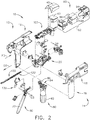
- FIG. 2 is an exploded assembly view of a portion of the surgical instrument 10 of FIG. 1 according to one aspect of this disclosure.
- the handle assembly 14 may include a frame 20 that operably supports a plurality of drive systems.
- the frame 20 can operably support a "first" or closure drive system 30, which can apply closing and opening motions to the interchangeable shaft assembly 200.
- the closure drive system 30 may include an actuator such as a closure trigger 32 pivotally supported by the frame 20.
- the closure trigger 32 is pivotally coupled to the handle assembly 14 by a pivot pin 33 to enable the closure trigger 32 to be manipulated by a clinician.
- the closure trigger 32 can pivot from a starting or "unactuated” position to an "actuated” position and more particularly to a fully compressed or fully actuated position.
- the handle assembly 14 and the frame 20 may operably support a firing drive system 80 configured to apply firing motions to corresponding portions of the interchangeable shaft assembly attached thereto.
- the firing drive system 80 may employ an electric motor 82 located in the pistol grip portion 19 of the handle assembly 14.
- the electric motor 82 may be a DC brushed motor having a maximum rotational speed of approximately 25,000 RPM, for example. In other arrangements, the motor may include a brushless motor, a cordless motor, a synchronous motor, a stepper motor, or any other suitable electric motor.
- the electric motor 82 may be powered by a power source 90 that may comprise a removable power pack 92.
- the removable power pack 92 may comprise a proximal housing portion 94 configured to attach to a distal housing portion 96.
- the proximal housing portion 94 and the distal housing portion 96 are configured to operably support a plurality of batteries 98 therein.
- Batteries 98 may each comprise, for example, a Lithium Ion (LI) or other suitable battery.
- the distal housing portion 96 is configured for removable operable attachment to a control circuit board 100, which is operably coupled to the electric motor 82. Several batteries 98 connected in series may power the surgical instrument 10.
- the power source 90 may be replaceable and/or rechargeable.
- a display 43 which is located below the cover 45, is electrically coupled to the control circuit board 100. The cover 45 may be removed to expose the display 43.
- the electric motor 82 can include a rotatable shaft (not shown) that operably interfaces with a gear reducer assembly 84 mounted in meshing engagement with a with a set, or rack, of drive teeth 122 on a longitudinally movable drive member 120.
- the longitudinally movable drive member 120 has a rack of drive teeth 122 formed thereon for meshing engagement with a corresponding drive gear 86 of the gear reducer assembly 84.
- a voltage polarity provided by the power source 90 can operate the electric motor 82 in a clockwise direction wherein the voltage polarity applied to the electric motor by the battery can be reversed in order to operate the electric motor 82 in a counter-clockwise direction.
- the longitudinally movable drive member 120 When the electric motor 82 is rotated in one direction, the longitudinally movable drive member 120 will be axially driven in the distal direction "DD.”
- the longitudinally movable drive member 120 will be axially driven in a proximal direction "PD.”
- the handle assembly 14 can include a switch that can be configured to reverse the polarity applied to the electric motor 82 by the power source 90.
- the handle assembly 14 may include a sensor configured to detect the position of the longitudinally movable drive member 120 and/or the direction in which the longitudinally movable drive member 120 is being moved.
- Actuation of the electric motor 82 can be controlled by a firing trigger 130 that is pivotally supported on the handle assembly 14.
- the firing trigger 130 may be pivoted between an unactuated position and an actuated position.
- the interchangeable shaft assembly 200 includes an end effector 300 comprising an elongated channel 302 configured to operably support a surgical staple cartridge 304 therein.
- the end effector 300 may include an anvil 306 that is pivotally supported relative to the elongated channel 302.
- the interchangeable shaft assembly 200 may include an articulation joint 270. Construction and operation of the end effector 300 and the articulation joint 270 are set forth in U.S. Patent Application Publication No. 2014/0263541 , entitled ARTICULATABLE SURGICAL INSTRUMENT COMPRISING AN ARTICULATION LOCK, which is herein incorporated by reference in its entirety.
- the interchangeable shaft assembly 200 may include a proximal housing or nozzle 201 comprised of nozzle portions 202, 203.
- the interchangeable shaft assembly 200 may include a closure tube 260 extending along a shaft axis SA that can be utilized to close and/or open the anvil 306 of the end effector 300.
- the closure tube 260 is translated distally (direction "DD") to close the anvil 306, for example, in response to the actuation of the closure trigger 32 in the manner described in the aforementioned reference U.S. Patent Application Publication No. 2014/0263541 .
- the anvil 306 is opened by proximally translating the closure tube 260. In the anvil-open position, the closure tube 260 is moved to its proximal position.
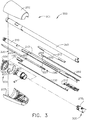
- FIG. 3 is another exploded assembly view of portions of the interchangeable shaft assembly 200 according to one aspect of this disclosure.
- the interchangeable shaft assembly 200 may include a firing member 220 supported for axial travel within the spine 210.
- the firing member 220 includes an intermediate firing shaft 222 configured to attach to a distal cutting portion or knife bar 280.
- the firing member 220 may be referred to as a "second shaft” or a "second shaft assembly”.
- the intermediate firing shaft 222 may include a longitudinal slot 223 in a distal end configured to receive a tab 284 on the proximal end 282 of the knife bar 280.
- the longitudinal slot 223 and the proximal end 282 may be configured to permit relative movement there between and can comprise a slip joint 286.
- the slip joint 286 can permit the intermediate firing shaft 222 of the firing member 220 to articulate the end effector 300 about the articulation joint 270 without moving, or at least substantially moving, the knife bar 280.
- the intermediate firing shaft 222 can be advanced distally until a proximal sidewall of the longitudinal slot 223 contacts the tab 284 to advance the knife bar 280 and fire the staple cartridge positioned within the channel 302.
- the spine 210 has an elongated opening or window 213 therein to facilitate assembly and insertion of the intermediate firing shaft 222 into the spine 210.
- a top frame segment 215 may be engaged with the shaft frame 212 to enclose the intermediate firing shaft 222 and knife bar 280 therein. Operation of the firing member 220 may be found in U.S. Patent Application Publication No. 2014/0263541 .
- a spine 210 can be configured to slidably support a firing member 220 and the closure tube 260 that extends around the spine 210. The spine 210 may slidably support an articulation driver 230.
- the interchangeable shaft assembly 200 can include a clutch assembly 400 configured to selectively and releasably couple the articulation driver 230 to the firing member 220.
- the clutch assembly 400 includes a lock collar, or lock sleeve 402, positioned around the firing member 220 wherein the lock sleeve 402 can be rotated between an engaged position in which the lock sleeve 402 couples the articulation driver 230 to the firing member 220 and a disengaged position in which the articulation driver 230 is not operably coupled to the firing member 220.
- the nozzle 201 may be employed to operably engage and disengage the articulation drive system with the firing drive system in the various manners described in U.S. Patent Application Publication No. 2014/0263541 .
- the interchangeable shaft assembly 200 can comprise a slip ring assembly 600 which can be configured to conduct electrical power to and/or from the end effector 300 and/or communicate signals to and/or from the end effector 300, for example.
- the slip ring assembly 600 can comprise a proximal connector flange 604 and a distal connector flange 601 positioned within a slot defined in the nozzle portions 202, 203.
- the proximal connector flange 604 can comprise a first face and the distal connector flange 601 can comprise a second face positioned adjacent to and movable relative to the first face.
- the distal connector flange 601 can rotate relative to the proximal connector flange 604 about the shaft axis SA-SA ( FIG. 1 ).
- the proximal connector flange 604 can comprise a plurality of concentric, or at least substantially concentric, conductors 602 defined in the first face thereof.
- a connector 607 can be mounted on the proximal side of the distal connector flange 601 and may have a plurality of contacts wherein each contact corresponds to and is in electrical contact with one of the conductors 602. Such an arrangement permits relative rotation between the proximal connector flange 604 and the distal connector flange 601 while maintaining electrical contact there between.
- the proximal connector flange 604 can include an electrical connector 606 that can place the conductors 602 in signal communication with a shaft circuit board, for example.
- a wiring harness comprising a plurality of conductors can extend between the electrical connector 606 and the shaft circuit board.
- the electrical connector 606 may extend proximally through a connector opening defined in the chassis mounting flange.
- U.S. Patent Application Publication No. 2014/0263551 entitled STAPLE CARTRIDGE TISSUE THICKNESS SENSOR SYSTEM, is incorporated herein by reference in its entirety.
- U.S. Patent Application Publication No. 2014/0263552 entitled STAPLE CARTRIDGE TISSUE THICKNESS SENSOR SYSTEM, is incorporated by reference in its entirety. Further details regarding slip ring assembly 600 may be found in U.S. Patent Application Publication No. 2014/0263541 .
- the interchangeable shaft assembly 200 can include a proximal portion fixably mounted to the handle assembly 14 and a distal portion that is rotatable about a longitudinal axis.
- the rotatable distal shaft portion can be rotated relative to the proximal portion about the slip ring assembly 600.
- the distal connector flange 601 of the slip ring assembly 600 can be positioned within the rotatable distal shaft portion.
- FIG. 4 is an exploded view of one aspect of an end effector 300 of the surgical instrument 10 of FIG. 1 according to one aspect of this disclosure.
- the end effector 300 may include the anvil 306 and the surgical staple cartridge 304.
- the anvil 306 may be coupled to an elongated channel 302.
- Apertures 199 can be defined in the elongated channel 302 to receive pins 152 extending from the anvil 306 to allow the anvil 306 to pivot from an open position to a closed position relative to the elongated channel 302 and surgical staple cartridge 304.
- a firing bar 172 is configured to longitudinally translate into the end effector 300.
- the firing bar 172 may be constructed from one solid section, or may include a laminate material comprising a stack of steel plates.
- the firing bar 172 comprises an I-beam 178 and a cutting edge 182 at a distal end thereof.
- a distally projecting end of the firing bar 172 can be attached to the I-beam 178 to assist in spacing the anvil 306 from a surgical staple cartridge 304 positioned in the elongated channel 302 when the anvil 306 is in a closed position.
- the I-beam 178 may include a sharpened cutting edge 182 to sever tissue as the I-beam 178 is advanced distally by the firing bar 172. In operation, the I-beam 178 may, or fire, the surgical staple cartridge 304.
- the surgical staple cartridge 304 can include a molded cartridge body 194 that holds a plurality of staples 191 resting upon staple drivers 192 within respective upwardly open staple cavities 195.
- a wedge sled 190 is driven distally by the I-beam 178, sliding upon a cartridge tray 196 of the surgical staple cartridge 304.
- the wedge sled 190 upwardly cams the staple drivers 192 to force out the staples 191 into deforming contact with the anvil 306 while the cutting edge 182 of the I-beam 178 severs clamped tissue.
- the I-beam 178 can include upper pins 180 that engage the anvil 306 during firing.
- the I-beam 178 may include middle pins 184 and a bottom foot 186 to engage portions of the cartridge body 194, cartridge tray 196, and elongated channel 302.
- a slot 193 defined in the cartridge body 194 can be aligned with a longitudinal slot 197 defined in the cartridge tray 196 and a slot 189 defined in the elongated channel 302.
- the I-beam 178 can slide through the aligned longitudinal slots 193, 197, and 189 wherein, as indicated in FIG.
- the bottom foot 186 of the I-beam 178 can engage a groove running along the bottom surface of elongated channel 302 along the length of slot 189, the middle pins 184 can engage the top surfaces of cartridge tray 196 along the length of longitudinal slot 197, and the upper pins 180 can engage the anvil 306.
- the I-beam 178 can space, or limit the relative movement between, the anvil 306 and the surgical staple cartridge 304 as the firing bar 172 is advanced distally to fire the staples from the surgical staple cartridge 304 and/or incise the tissue captured between the anvil 306 and the surgical staple cartridge 304.
- the firing bar 172 and the I-beam 178 can be retracted proximally allowing the anvil 306 to be opened to release the two stapled and severed tissue portions.
- FIGS. 5A-5B is a block diagram of a control circuit 700 of the surgical instrument 10 of FIG. 1 spanning two drawing sheets according to one aspect of this disclosure.
- a handle assembly 702 may include a motor 714 which can be controlled by a motor driver 715 and can be employed by the firing system of the surgical instrument 10.
- the motor 714 may be a DC brushed driving motor having a maximum rotational speed of approximately 25,000 RPM.
- the motor 714 may include a brushless motor, a cordless motor, a synchronous motor, a stepper motor, or any other suitable electric motor.
- the motor driver 715 may comprise an H-Bridge driver comprising field-effect transistors (FETs) 719, for example.
- the motor 714 can be powered by the power assembly 706 releasably mounted to the handle assembly 200 for supplying control power to the surgical instrument 10.
- the power assembly 706 may comprise a battery which may include a number of battery cells connected in series that can be used as the power source to power the surgical instrument 10. In certain circumstances, the battery cells of the power assembly 706 may be replaceable and/or rechargeable. In at least one example, the battery cells can be Lithium-Ion batteries which can be separably couplable to the power assembly 706.
- the shaft assembly 704 may include a shaft assembly controller 722 which can communicate with a safety controller and power management controller 716 through an interface while the shaft assembly 704 and the power assembly 706 are coupled to the handle assembly 702.
- the interface may comprise a first interface portion 725 which may include one or more electric connectors for coupling engagement with corresponding shaft assembly electric connectors and a second interface portion 727 which may include one or more electric connectors for coupling engagement with corresponding power assembly electric connectors to permit electrical communication between the shaft assembly controller 722 and the power management controller 716 while the shaft assembly 704 and the power assembly 706 are coupled to the handle assembly 702.
- One or more communication signals can be transmitted through the interface to communicate one or more of the power requirements of the attached interchangeable shaft assembly 704 to the power management controller 716.
- the power management controller may modulate the power output of the battery of the power assembly 706, as described below in greater detail, in accordance with the power requirements of the attached shaft assembly 704.
- the connectors may comprise switches which can be activated after mechanical coupling engagement of the handle assembly 702 to the shaft assembly 704 and/or to the power assembly 706 to allow electrical communication between the shaft assembly controller 722 and the power management controller 716.
- the interface can facilitate transmission of the one or more communication signals between the power management controller 716 and the shaft assembly controller 722 by routing such communication signals through a main controller 717 residing in the handle assembly 702, for example.
- the interface can facilitate a direct line of communication between the power management controller 716 and the shaft assembly controller 722 through the handle assembly 702 while the shaft assembly 704 and the power assembly 706 are coupled to the handle assembly 702.
- the main controller 717 may be any single core or multicore processor such as those known under the trade name ARM Cortex by Texas Instruments.
- the main controller 717 may be an LM4F230H5QR ARM Cortex-M4F Processor Core, available from Texas Instruments, for example, comprising on-chip memory of 256 KB single-cycle flash memory, or other non-volatile memory, up to 40 MHz, a prefetch buffer to improve performance above 40 MHz, a 32 KB single-cycle serial random access memory (SRAM), internal read-only memory (ROM) loaded with StellarisWare® software, 2 KB electrically erasable programmable read-only memory (EEPROM), one or more pulse width modulation (PWM) modules, one or more quadrature encoder inputs (QEI) analog, one or more 12-bit Analog-to-Digital Converters (ADC) with 12 analog input channels, details of which are available for the product datasheet.
- the safety controller may be a safety controller platform comprising two controller-based families such as TMS570 and RM4x known under the trade name Hercules ARM Cortex R4, also by Texas Instruments.
- the safety controller may be configured specifically for IEC 61508 and ISO 26262 safety critical applications, among others, to provide advanced integrated safety features while delivering scalable performance, connectivity, and memory options.
- the power assembly 706 may include a power management circuit which may comprise the power management controller 716, a power modulator 738, and a current sense circuit 736.
- the power management circuit can be configured to modulate power output of the battery based on the power requirements of the shaft assembly 704 while the shaft assembly 704 and the power assembly 706 are coupled to the handle assembly 702.
- the power management controller 716 can be programmed to control the power modulator 738 of the power output of the power assembly 706 and the current sense circuit 736 can be employed to monitor power output of the power assembly 706 to provide feedback to the power management controller 716 about the power output of the battery so that the power management controller 716 may adjust the power output of the power assembly 706 to maintain a desired output.
- the power management controller 716 and/or the shaft assembly controller 722 each may comprise one or more processors and/or memory units which may store a number of software modules.
- the surgical instrument 10 may comprise an output device 742 which may include devices for providing a sensory feedback to a user. Such devices may comprise, for example, visual feedback devices (e.g., an LCD display screen, LED indicators), audio feedback devices (e.g., a speaker, a buzzer) or tactile feedback devices (e.g., haptic actuators).
- the output device 742 may comprise a display 743 which may be included in the handle assembly 702.
- the shaft assembly controller 722 and/or the power management controller 716 can provide feedback to a user of the surgical instrument 10 through the output device 742.
- the interface can be configured to connect the shaft assembly controller 722 and/or the power management controller 716 to the output device 742.
- the output device 742 can instead be integrated with the power assembly 706. In such circumstances, communication between the output device 742 and the shaft assembly controller 722 may be accomplished through the interface while the shaft assembly 704 is coupled to the handle assembly 702.
- the control circuit 700 comprises circuit segments configured to control operations of the powered surgical instrument 10.
- a safety controller segment (Segment 1) comprises a safety controller and the main controller 717 segment (Segment 2).
- the safety controller and/or the main controller 717 are configured to interact with one or more additional circuit segments such as an acceleration segment, a display segment, a shaft segment, an encoder segment, a motor segment, and a power segment.
- Each of the circuit segments may be coupled to the safety controller and/or the main controller 717.
- the main controller 717 is also coupled to a flash memory.
- the main controller 717 also comprises a serial communication interface.
- the main controller 717 comprises a plurality of inputs coupled to, for example, one or more circuit segments, a battery, and/or a plurality of switches.
- the segmented circuit may be implemented by any suitable circuit, such as, for example, a printed circuit board assembly (PCBA) within the powered surgical instrument 10.
- PCBA printed circuit board assembly
- processor includes any microprocessor, processors, controller, controllers, or other basic computing device that incorporates the functions of a computer's central processing unit (CPU) on an integrated circuit or at most a few integrated circuits.
- the main controller 717 is a multipurpose, programmable device that accepts digital data as input, processes it according to instructions stored in its memory, and provides results as output. It is an example of sequential digital logic, as it has internal memory.
- the control circuit 700 can be configured to implement one or more of the processes described herein.
- the acceleration segment (Segment 3) comprises an accelerometer.
- the accelerometer is configured to detect movement or acceleration of the powered surgical instrument 10. Input from the accelerometer may be used to transition to and from a sleep mode, identify an orientation of the powered surgical instrument, and/or identify when the surgical instrument has been dropped.
- the acceleration segment is coupled to the safety controller and/or the main controller 717.
- the display segment (Segment 4) comprises a display connector coupled to the main controller 717.
- the display connector couples the main controller 717 to a display through one or more integrated circuit drivers of the display.
- the integrated circuit drivers of the display may be integrated with the display and/or may be located separately from the display.
- the display may comprise any suitable display, such as, for example, an organic light-emitting diode (OLED) display, a liquid-crystal display (LCD), and/or any other suitable display.
- the display segment is coupled to the safety controller.
- the shaft segment (Segment 5) comprises controls for an interchangeable shaft assembly 200 ( FIGS. 1 and 3 ) coupled to the surgical instrument 10 ( FIGS. 1-4 ) and/or one or more controls for an end effector 300 coupled to the interchangeable shaft assembly 200.
- the shaft segment comprises a shaft connector configured to couple the main controller 717 to a shaft PCBA.
- the shaft PCBA comprises a low-power microcontroller with a ferroelectric random access memory (FRAM), an articulation switch, a shaft release Hall effect switch, and a shaft PCBA EEPROM.
- the shaft PCBA EEPROM comprises one or more parameters, routines, and/or programs specific to the interchangeable shaft assembly 200 and/or the shaft PCBA.
- the shaft PCBA may be coupled to the interchangeable shaft assembly 200 and/or integral with the surgical instrument 10.
- the shaft segment comprises a second shaft EEPROM.
- the second shaft EEPROM comprises a plurality of algorithms, routines, parameters, and/or other data corresponding to one or more shaft assemblies 200 and/or end effectors 300 that may be interfaced with the powered surgical instrument 10.
- the position encoder segment (Segment 6) comprises one or more magnetic angle rotary position encoders.
- the one or more magnetic angle rotary position encoders are configured to identify the rotational position of the motor 714, an interchangeable shaft assembly 200 ( FIGS. 1 and 3 ), and/or an end effector 300 of the surgical instrument 10 ( FIGS. 1-4 ).
- the magnetic angle rotary position encoders may be coupled to the safety controller and/or the main controller 717.
- the motor circuit segment (Segment 7) comprises a motor 714 configured to control movements of the powered surgical instrument 10 ( FIGS. 1-4 ).
- the motor 714 is coupled to the main microcontroller processor 717 by an H-bridge driver comprising one or more H-bridge field-effect transistors (FETs) and a motor controller.
- the H-bridge driver is also coupled to the safety controller.
- a motor current sensor is coupled in series with the motor to measure the current draw of the motor.
- the motor current sensor is in signal communication with the main controller 717 and/or the safety controller.
- the motor 714 is coupled to a motor electromagnetic interference (EMI) filter.
- EMI motor electromagnetic interference
- the motor controller controls a first motor flag and a second motor flag to indicate the status and position of the motor 714 to the main controller 717.
- the main controller 717 provides a pulse-width modulation (PWM) high signal, a PWM low signal, a direction signal, a synchronize signal, and a motor reset signal to the motor controller through a buffer.
- PWM pulse-width modulation
- the power segment is configured to provide a segment voltage to each of the circuit segments.
- the power segment (Segment 8) comprises a battery coupled to the safety controller, the main controller 717, and additional circuit segments.
- the battery is coupled to the segmented circuit by a battery connector and a current sensor.
- the current sensor is configured to measure the total current draw of the segmented circuit.
- one or more voltage converters are configured to provide predetermined voltage values to one or more circuit segments.
- the segmented circuit may comprise 3.3V voltage converters and/or 5V voltage converters.
- a boost converter is configured to provide a boost voltage up to a predetermined amount, such as, for example, up to 13V.
- the boost converter is configured to provide additional voltage and/or current during power intensive operations and prevent brownout or low-power conditions.
- a plurality of switches are coupled to the safety controller and/or the main controller 717.
- the switches may be configured to control operations of the surgical instrument 10 ( FIGS. 1-4 ), of the segmented circuit, and/or indicate a status of the surgical instrument 10.
- a bail-out door switch and Hall effect switch for bailout are configured to indicate the status of a bail-out door.
- a plurality of articulation switches such as, for example, a left side articulation left switch, a left side articulation right switch, a left side articulation center switch, a right side articulation left switch, a right side articulation right switch, and a right side articulation center switch are configured to control articulation of an interchangeable shaft assembly 200 ( FIGS.
- a left side reverse switch and a right side reverse switch are coupled to the main controller 717.
- the left side switches comprising the left side articulation left switch, the left side articulation right switch, the left side articulation center switch, and the left side reverse switch are coupled to the main controller 717 by a left flex connector.
- the right side switches comprising the right side articulation left switch, the right side articulation right switch, the right side articulation center switch, and the right side reverse switch are coupled to the main controller 717 by a right flex connector.
- a firing switch, a clamp release switch, and a shaft engaged switch are coupled to the main controller 717.
- any suitable mechanical, electromechanical, or solid state switches may be employed to implement the plurality of switches, in any combination.
- the switches may be limit switches operated by the motion of components associated with the surgical instrument 10 ( FIGS. 1-4 ) or the presence of an object.
- Such switches may be employed to control various functions associated with the surgical instrument 10.
- a limit switch is an electromechanical device that consists of an actuator mechanically linked to a set of contacts. When an object comes into contact with the actuator, the device operates the contacts to make or break an electrical connection.
- Limit switches are used in a variety of applications and environments because of their ruggedness, ease of installation, and reliability of operation. They can determine the presence or absence, passing, positioning, and end of travel of an object.
- the switches may be solid state switches that operate under the influence of a magnetic field such as Hall-effect devices, magneto-resistive (MR) devices, giant magneto-resistive (GMR) devices, magnetometers, among others.
- the switches may be solid state switches that operate under the influence of light, such as optical sensors, infrared sensors, ultraviolet sensors, among others.
- the switches may be solid state devices such as transistors (e.g., FET, Junction-FET, metal-oxide semiconductor-FET (MOSFET), bipolar, and the like).
- Other switches may include wireless switches, ultrasonic switches, accelerometers, inertial sensors, among others.
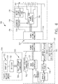
- FIG. 6 is another block diagram of the control circuit 700 of the surgical instrument of FIG. 1 illustrating interfaces between the handle assembly 702 and the power assembly 706 and between the handle assembly 702 and the interchangeable shaft assembly 704 according to one aspect of this disclosure.
- the handle assembly 702 may comprise a main controller 717, a shaft assembly connector 726 and a power assembly connector 730.
- the power assembly 706 may include a power assembly connector 732, a power management circuit 734 that may comprise the power management controller 716, a power modulator 738, and a current sense circuit 736.
- the shaft assembly connectors 730, 732 form an interface 727.
- the power management circuit 734 can be configured to modulate power output of the battery 707 based on the power requirements of the interchangeable shaft assembly 704 while the interchangeable shaft assembly 704 and the power assembly 706 are coupled to the handle assembly 702.
- the power management controller 716 can be programmed to control the power modulator 738 of the power output of the power assembly 706 and the current sense circuit 736 can be employed to monitor power output of the power assembly 706 to provide feedback to the power management controller 716 about the power output of the battery 707 so that the power management controller 716 may adjust the power output of the power assembly 706 to maintain a desired output.
- the shaft assembly 704 comprises a shaft processor 719 coupled to a non-volatile memory 721 and shaft assembly connector 728 to electrically couple the shaft assembly 704 to the handle assembly 702.
- the shaft assembly connectors 726, 728 form interface 725.
- the main controller 717, the shaft processor 719, and/or the power management controller 716 can be configured to implement one or more of the processes described herein.
- the surgical instrument 10 may comprise an output device 742 to a sensory feedback to a user.
- Such devices may comprise visual feedback devices (e.g., an LCD display screen, LED indicators), audio feedback devices (e.g., a speaker, a buzzer), or tactile feedback devices (e.g., haptic actuators).
- the output device 742 may comprise a display 743 that may be included in the handle assembly 702.
- the shaft assembly controller 722 and/or the power management controller 716 can provide feedback to a user of the surgical instrument 10 through the output device 742.
- the interface 727 can be configured to connect the shaft assembly controller 722 and/or the power management controller 716 to the output device 742.
- the output device 742 can be integrated with the power assembly 706.
- Communication between the output device 742 and the shaft assembly controller 722 may be accomplished through the interface 725 while the interchangeable shaft assembly 704 is coupled to the handle assembly 702.
- a control circuit 700 FIGS. 5A-5B and 6) for controlling the operation of the surgical instrument 10 ( FIGS. 1-4 )
- the disclosure now turns to various configurations of the surgical instrument 10 ( FIGS. 1-4 ) and control circuit 700.
- FIG. 7 illustrates a control circuit 800 configured to control aspects of the surgical instrument 10 ( FIGS. 1-4 ) according to one aspect of this disclosure.
- the control circuit 800 can be configured to implement various processes described herein.
- the control circuit 800 may comprise a controller comprising one or more processors 802 (e.g., microprocessor, microcontroller) coupled to at least one memory circuit 804.
- the memory circuit 804 stores machine executable instructions that when executed by the processor 802, cause the processor 802 to execute machine instructions to implement various processes described herein.
- the processor 802 may be any one of a number of single or multi-core processors known in the art.
- the memory circuit 804 may comprise volatile and non-volatile storage media.
- the processor 802 may include an instruction processing unit 806 and an arithmetic unit 808.
- the instruction processing unit may be configured to receive instructions from the memory circuit 804.
- FIG. 8 illustrates a combinational logic circuit 810 configured to control aspects of the surgical instrument 10 ( FIGS. 1-4 ) according to one aspect of this disclosure.
- the combinational logic circuit 810 can be configured to implement various processes described herein.
- the circuit 810 may comprise a finite state machine comprising a combinational logic circuit 812 configured to receive data associated with the surgical instrument 10 at an input 814, process the data by the combinational logic 812, and provide an output 816.
- FIG. 9 illustrates a sequential logic circuit 820 configured to control aspects of the surgical instrument 10 ( FIGS. 1-4 ) according to one aspect of this disclosure.
- the sequential logic circuit 820 or the combinational logic circuit 822 can be configured to implement various processes described herein.
- the circuit 820 may comprise a finite state machine.
- the sequential logic circuit 820 may comprise a combinational logic circuit 822, at least one memory circuit 824, and a clock 829, for example.
- the at least one memory circuit 820 can store a current state of the finite state machine.
- the sequential logic circuit 820 may be synchronous or asynchronous.
- the combinational logic circuit 822 is configured to receive data associated with the surgical instrument 10 an input 826, process the data by the combinational logic circuit 822, and provide an output 828.
- the circuit may comprise a combination of the processor 802 and the finite state machine to implement various processes herein.
- the finite state machine may comprise a combination of the combinational logic circuit 810 and the sequential logic circuit 820
- the article of manufacture may include a computer readable storage medium arranged to store logic, instructions, and/or data for performing various operations of one or more aspects.
- the article of manufacture may comprise a magnetic disk, optical disk, flash memory, or firmware containing computer program instructions suitable for execution by a general purpose processor or application specific processor.
- FIG. 10 is a diagram of an absolute positioning system 1100 of the surgical instrument 10 ( FIGS. 1-4 ) where the absolute positioning system 1100 comprises a controlled motor drive circuit arrangement comprising a sensor arrangement 1102 according to one aspect of this disclosure.
- the sensor arrangement 1102 for an absolute positioning system 1100 provides a unique position signal corresponding to the location of a displacement member 1111.
- the displacement member 1111 represents the longitudinally movable drive member 120 ( FIG. 2 ) comprising a rack of drive teeth 122 for meshing engagement with a corresponding drive gear 86 of the gear reducer assembly 84.
- the displacement member 1111 represents the firing member 220 ( FIG. 3 ), which could be adapted and configured to include a rack of drive teeth.
- the displacement member 1111 represents the firing bar 172 ( FIG. 4 ) or the I-beam 178 ( FIG. 4 ), each of which can be adapted and configured to include a rack of drive teeth.
- the term displacement member is used generically to refer to any movable member of the surgical instrument 10 such as the drive member 120, the firing member 220, the firing bar 172, the I-beam 178, or any element that can be displaced.
- the longitudinally movable drive member 120 is coupled to the firing member 220, the firing bar 172, and the I-beam 178.
- the absolute positioning system 1100 can, in effect, track the linear displacement of the I-beam 178 by tracking the linear displacement of the longitudinally movable drive member 120.
- the displacement member 1111 may be coupled to any sensor suitable for measuring linear displacement.
- the longitudinally movable drive member 120, the firing member 220, the firing bar 172, or the I-beam 178, or combinations may be coupled to any suitable linear displacement sensor.
- Linear displacement sensors may include contact or non-contact displacement sensors.
- Linear displacement sensors may comprise linear variable differential transformers (LVDT), differential variable reluctance transducers (DVRT), a slide potentiometer, a magnetic sensing system comprising a movable magnet and a series of linearly arranged Hall effect sensors, a magnetic sensing system comprising a fixed magnet and a series of movable linearly arranged Hall effect sensors, an optical sensing system comprising a movable light source and a series of linearly arranged photo diodes or photo detectors, or an optical sensing system comprising a fixed light source and a series of movable linearly arranged photo diodes or photo detectors, or any combination thereof.
- LVDT linear variable differential transformers
- DVRT differential variable reluctance transducers
- slide potentiometer a magnetic sensing system comprising a movable magnet and a series of linearly arranged Hall effect sensors
- a magnetic sensing system comprising a fixed magnet and a series of movable linearly arranged Hall effect sensors
- An electric motor 1120 can include a rotatable shaft 1116 that operably interfaces with a gear assembly 1114 that is mounted in meshing engagement with a set, or rack, of drive teeth on the displacement member 1111.
- a sensor element 1126 may be operably coupled to a gear assembly 1114 such that a single revolution of the sensor element 1126 corresponds to some linear longitudinal translation of the displacement member 1111.
- An arrangement of gearing and sensors 1118 can be connected to the linear actuator via a rack and pinion arrangement or a rotary actuator via a spur gear or other connection.
- a power source 1129 supplies power to the absolute positioning system 1100 and an output indicator 1128 may display the output of the absolute positioning system 1100. In FIG.
- the displacement member 1111 represents the longitudinally movable drive member 120 comprising a rack of drive teeth 122 formed thereon for meshing engagement with a corresponding drive gear 86 of the gear reducer assembly 84.
- the displacement member 1111 represents the longitudinally movable firing member 220, firing bar 172, I-beam 178, or combinations thereof.
- a single revolution of the sensor element 1126 associated with the position sensor 1112 is equivalent to a longitudinal linear displacement d1 of the of the displacement member 1111, where d1 is the longitudinal linear distance that the displacement member 1111 moves from point "a" to point "b” after a single revolution of the sensor element 1126 coupled to the displacement member 1111.
- the sensor arrangement 1102 may be connected via a gear reduction that results in the position sensor 1112 completing one or more revolutions for the full stroke of the displacement member 1111.
- the position sensor 1112 may complete multiple revolutions for the full stroke of the displacement member 1111.
- a series of switches 1122a-1122n may be employed alone or in combination with gear reduction to provide a unique position signal for more than one revolution of the position sensor 1112.
- the state of the switches 1122a-1122n are fed back to a controller 1104 that applies logic to determine a unique position signal corresponding to the longitudinal linear displacement d1 + d2 + ... dn of the displacement member 1111.
- the output 1124 of the position sensor 1112 is provided to the controller 1104.
- the position sensor 1112 of the sensor arrangement 1102 may comprise a magnetic sensor, an analog rotary sensor like a potentiometer, an array of analog Hall-effect elements, which output a unique combination of position signals or values.
- the absolute positioning system 1100 provides an absolute position of the displacement member 1111 upon power up of the instrument without retracting or advancing the displacement member 1111 to a reset (zero or home) position as may be required with conventional rotary encoders that merely count the number of steps forwards or backwards that the motor 1120 has taken to infer the position of a device actuator, drive bar, knife, and the like.
- the controller 1104 may be programmed to perform various functions such as precise control over the speed and position of the knife and articulation systems.
- the controller 1104 includes a processor 1108 and a memory 1106.
- the electric motor 1120 may be a brushed DC motor with a gearbox and mechanical links to an articulation or knife system.
- a motor driver 1110 may be an A3941 available from Allegro Microsystems, Inc. Other motor drivers may be readily substituted for use in the absolute positioning system 1100.
- a more detailed description of the absolute positioning system 1100 is described in U.S. Patent Application No. 15/130,590 , entitled SYSTEMS AND METHODS FOR CONTROLLING A SURGICAL STAPLING AND CUTTING INSTRUMENT, filed on April 15, 2016, the entire disclosure of which is herein incorporated by reference.
- the controller 1104 may be programmed to provide precise control over the speed and position of the displacement member 1111 and articulation systems.
- the controller 1104 may be configured to compute a response in the software of the controller 1104.
- the computed response is compared to a measured response of the actual system to obtain an "observed" response, which is used for actual feedback decisions.
- the observed response is a favorable, tuned, value that balances the smooth, continuous nature of the simulated response with the measured response, which can detect outside influences on the system.
- the absolute positioning system 1100 may comprise and/or be programmed to implement a feedback controller, such as a PID, state feedback, and adaptive controller.
- a power source 1129 converts the signal from the feedback controller into a physical input to the system, in this case voltage.
- Other examples include pulse width modulation (PWM) of the voltage, current, and force.
- Other sensor(s) 1118 may be provided to measure physical parameters of the physical system in addition to position measured by the position sensor 1112.
- absolute positioning system 1100 is coupled to a digital data acquisition system where the output of the absolute positioning system 1100 will have finite resolution and sampling frequency.
- the absolute positioning system 1100 may comprise a compare and combine circuit to combine a computed response with a measured response using algorithms such as weighted average and theoretical control loop that drives the computed response towards the measured response.
- the computed response of the physical system takes into account properties like mass, inertial, viscous friction, inductance resistance, etc., to predict what the states and outputs of the physical system will be by knowing the input.
- the controller 1104 may be a control circuit 700 ( FIGS. 5A-5B ).
- the motor driver 1110 may be an A3941 available from Allegro Microsystems, Inc.
- the A3941 driver 1110 is a full-bridge controller for use with external N-channel power metal oxide semiconductor field effect transistors (MOSFETs) specifically designed for inductive loads, such as brush DC motors.
- the driver 1110 comprises a unique charge pump regulator provides full (>10 V) gate drive for battery voltages down to 7 V and allows the A3941 to operate with a reduced gate drive, down to 5.5 V.
- a bootstrap capacitor may be employed to provide the above-battery supply voltage required for N-channel MOSFETs.
- An internal charge pump for the high-side drive allows DC (100% duty cycle) operation.
- the full bridge can be driven in fast or slow decay modes using diode or synchronous rectification.
- current recirculation can be through the high-side or the lowside FETs.
- the power FETs are protected from shoot-through by resistor adjustable dead time.
- Integrated diagnostics provide indication of undervoltage, overtemperature, and power bridge faults, and can be configured to protect the power MOSFETs under most short circuit conditions.
- Other motor drivers may be readily substituted for use in the absolute positioning system 1100.
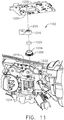
- FIG. 11 is an exploded perspective view of the sensor arrangement 1102 for the absolute positioning system 1100 showing a circuit 1205 and the relative alignment of the elements of the sensor arrangement 1102, according to one aspect.
- the sensor arrangement 1102 for an absolute positioning system 1100 comprises a position sensor 1200, a magnet 1202 sensor element, a magnet holder 1204 that turns once every full stroke of the displacement member 1111, and a gear assembly 1206 to provide a gear reduction.
- the displacement member 1111 may represent the longitudinally movable drive member 120 comprising a rack of drive teeth 122 for meshing engagement with a corresponding drive gear 86 of the gear reducer assembly 84.
- a structural element such as bracket 1216 is provided to support the gear assembly 1206, the magnet holder 1204, and the magnet 1202.
- the position sensor 1200 comprises magnetic sensing elements such as Hall elements and is placed in proximity to the magnet 1202. As the magnet 1202 rotates, the magnetic sensing elements of the position sensor 1200 determine the absolute angular position of the magnet 1202 over one revolution.
- the sensor arrangement 1102 may comprises any number of magnetic sensing elements, such as, for example, magnetic sensors classified according to whether they measure the total magnetic field or the vector components of the magnetic field.
- the techniques used to produce both types of magnetic sensors encompass many aspects of physics and electronics.
- the technologies used for magnetic field sensing include search coil, fluxgate, optically pumped, nuclear precession, SQUID, Hall-effect, anisotropic magnetoresistance, giant magnetoresistance, magnetic tunnel junctions, giant magnetoimpedance, magnetostrictive/piezoelectric composites, magnetodiode, magnetotransistor, fiber optic, magnetooptic, and microelectromechanical systems-based magnetic sensors, among others.
- a gear assembly comprises a first gear 1208 and a second gear 1210 in meshing engagement to provide a 3:1 gear ratio connection.
- a third gear 1212 rotates about a shaft 1214.
- the third gear 1212 is in meshing engagement with the displacement member 1111 (or 120 as shown in FIG. 2 ) and rotates in a first direction as the displacement member 1111 advances in a distal direction D and rotates in a second direction as the displacement member 1111 retracts in a proximal direction P.
- the second gear 1210 also rotates about the shaft 1214 and, therefore, rotation of the second gear 1210 about the shaft 1214 corresponds to the longitudinal translation of the displacement member 1111.
- one full stroke of the displacement member 1111 in either the distal or proximal directions D, P corresponds to three rotations of the second gear 1210 and a single rotation of the first gear 1208. Since the magnet holder 1204 is coupled to the first gear 1208, the magnet holder 1204 makes one full rotation with each full stroke of the displacement member 1111.
- the position sensor 1200 is supported by a position sensor holder 1218 defining an aperture 1220 suitable to contain the position sensor 1200 in precise alignment with a magnet 1202 rotating below within the magnet holder 1204.
- the fixture is coupled to the bracket 1216 and to the circuit 1205 and remains stationary while the magnet 1202 rotates with the magnet holder 1204.
- a hub 1222 is provided to mate with the first gear 1208 and the magnet holder 1204.
- the second gear 1210 and third gear 1212 coupled to shaft 1214 also are shown.
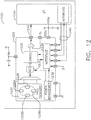
- FIG. 12 is a diagram of a position sensor 1200 for an absolute positioning system 1100 comprising a magnetic rotary absolute positioning system according to one aspect of this disclosure.
- the position sensor 1200 may be implemented as an AS5055EQFT single-chip magnetic rotary position sensor available from Austria Microsystems, AG.
- the position sensor 1200 is interfaced with the controller 1104 to provide an absolute positioning system 1100.
- the position sensor 1200 is a low-voltage and low-power component and includes four Hall-effect elements 1228A, 1228B, 1228C, 1228D in an area 1230 of the position sensor 1200 that is located above the magnet 1202 ( FIGS. 15 and 16 ).
- a high-resolution ADC 1232 and a smart power management controller 1238 are also provided on the chip.
- a CORDIC processor 1236 for Coordinate Rotation Digital Computer, also known as the digit-by-digit method and Volder's algorithm, is provided to implement a simple and efficient algorithm to calculate hyperbolic and trigonometric functions that require only addition, subtraction, bitshift, and table lookup operations.
- the angle position, alarm bits, and magnetic field information are transmitted over a standard serial communication interface such as an SPI interface 1234 to the controller 1104.
- the position sensor 1200 provides 12 or 14 bits of resolution.
- the position sensor 1200 may be an AS5055 chip provided in a small QFN 16-pin 4x4x0.85mm package.
- the Hall-effect elements 1228A, 1228B, 1228C, 1228D are located directly above the rotating magnet 1202 ( FIG. 11 ).
- the Hall-effect is a well-known effect and for expediency will not be described in detail herein, however, generally, the Hall-effect produces a voltage difference (the Hall voltage) across an electrical conductor transverse to an electric current in the conductor and a magnetic field perpendicular to the current.
- a Hall coefficient is defined as the ratio of the induced electric field to the product of the current density and the applied magnetic field. It is a characteristic of the material from which the conductor is made, since its value depends on the type, number, and properties of the charge carriers that constitute the current.
- the Hall-effect elements 1228A, 1228B, 1228C, 1228D are capable producing a voltage signal that is indicative of the absolute position of the magnet 1202 in terms of the angle over a single revolution of the magnet 1202.
- This value of the angle, which is unique position signal, is calculated by the CORDIC processor 1236 is stored onboard the AS5055 position sensor 1200 in a register or memory.
- the value of the angle that is indicative of the position of the magnet 1202 over one revolution is provided to the controller 1104 in a variety of techniques, e.g., upon power up or upon request by the controller 1104.
- the AS5055 position sensor 1200 requires only a few external components to operate when connected to the controller 1104. Six wires are needed for a simple application using a single power supply: two wires for power and four wires 1240 for the SPI interface 1234 with the controller 1104. A seventh connection can be added in order to send an interrupt to the controller 1104 to inform that a new valid angle can be read.
- the AS5055 position sensor 1200 Upon power-up, the AS5055 position sensor 1200 performs a full power-up sequence including one angle measurement. The completion of this cycle is indicated as an INT output 1242, and the angle value is stored in an internal register. Once this output is set, the AS5055 position sensor 1200 suspends to sleep mode.
- the controller 1104 can respond to the INT request at the INT output 1242 by reading the angle value from the AS5055 position sensor 1200 over the SPI interface 1234. Once the angle value is read by the controller 1104, the INT output 1242 is cleared again. Sending a "read angle" command by the SPI interface 1234 by the controller 1104 to the position sensor 1200 also automatically powers up the chip and starts another angle measurement. As soon as the controller 1104 has completed reading of the angle value, the INT output 1242 is cleared and a new result is stored in the angle register. The completion of the angle measurement is again indicated by setting the INT output 1242 and a corresponding flag in the status register.
- the angle jitter can be reduced by averaging of several angle samples in the controller 1104. For example, an averaging of four samples reduces the jitter by 6dB (50%).
- FIG. 13 is a section view of an end effector 2502 of the surgical instrument 10 ( FIGS. 1-4 ) showing an I-beam 2514 firing stroke relative to tissue 2526 grasped within the end effector 2502 according to one aspect of this disclosure.
- the end effector 2502 is configured to operate with the surgical instrument 10 shown in FIGS. 1-4 .
- the end effector 2502 comprises an anvil 2516 and an elongated channel 2503 with a staple cartridge 2518 positioned in the elongated channel 2503.
- a firing bar 2520 is translatable distally and proximally along a longitudinal axis 2515 of the end effector 2502. When the end effector 2502 is not articulated, the end effector 2502 is in line with the shaft of the instrument.
- An I-beam 2514 comprising a cutting edge 2509 is illustrated at a distal portion of the firing bar 2520.
- a wedge sled 2513 is positioned in the staple cartridge 2518.
- the cutting edge 2509 contacts and may cut tissue 2526 positioned between the anvil 2516 and the staple cartridge 2518.
- the I-beam 2514 contacts the wedge sled 2513 and pushes it distally, causing the wedge sled 2513 to contact staple drivers 2511.
- the staple drivers 2511 may be driven up into staples 2505, causing the staples 2505 to advance through tissue and into pockets 2507 defined in the anvil 2516, which shape the staples 2505.
- An example I-beam 2514 firing stroke is illustrated by a chart 2529 aligned with the end effector 2502.
- Example tissue 2526 is also shown aligned with the end effector 2502.
- the firing member stroke may comprise a stroke begin position 2527 and a stroke end position 2528.
- the I-beam 2514 may be advanced distally from the stroke begin position 2527 to the stroke end position 2528.
- the I-beam 2514 is shown at one example location of a stroke begin position 2527.
- the I-beam 2514 firing member stroke chart 2529 illustrates five firing member stroke regions 2517, 2519, 2521, 2523, 2525. In a first firing stroke region 2517, the I-beam 2514 may begin to advance distally.
- the I-beam 2514 may contact the wedge sled 2513 and begin to move it distally. While in the first region, however, the cutting edge 2509 may not contact tissue and the wedge sled 2513 may not contact a staple driver 2511. After static friction is overcome, the force to drive the I-beam 2514 in the first region 2517 may be substantially constant.
- the cutting edge 2509 may begin to contact and cut tissue 2526.
- the wedge sled 2513 may begin to contact staple drivers 2511 to drive staples 2505.
- Force to drive the I-beam 2514 may begin to ramp up.
- tissue encountered initially may be compressed and/or thinner because of the way that the anvil 2516 pivots relative to the staple cartridge 2518.
- the cutting edge 2509 may continuously contact and cut tissue 2526 and the wedge sled 2513 may repeatedly contact staple drivers 2511. Force to drive the I-beam 2514 may plateau in the third region 2521.
- force to drive the I-beam 2514 may begin to decline.
- tissue in the portion of the end effector 2502 corresponding to the fourth firing region 2523 may be less compressed than tissue closer to the pivot point of the anvil 2516, requiring less force to cut.
- the cutting edge 2509 and wedge sled 2513 may reach the end of the tissue 2526 while in the fourth region 2523.
- the wedge sled 2513 may contact one or more staple drivers 2511 at or near the end of the tissue. Force to advance the I-beam 2514 through the fifth region 2525 may be reduced and, in some examples, may be similar to the force to drive the I-beam 2514 in the first region 2517.
- the I-beam 2514 may reach the stroke end position 2528.
- the positioning of firing member stroke regions 2517, 2519, 2521, 2523, 2525 in FIG. 18 is just one example. In some examples, different regions may begin at different positions along the end effector longitudinal axis 2515, for example, based on the positioning of tissue between the anvil 2516 and the staple cartridge 2518.
- the electric motor 1122 positioned within the handle assembly of the surgical instrument 10 can be utilized to advance and/or retract the firing system of the shaft assembly, including the I-beam 2514, relative to the end effector 2502 of the shaft assembly in order to staple and/or incise tissue captured within the end effector 2502.
- the I-beam 2514 may be advanced or retracted at a desired speed, or within a range of desired speeds.
- the controller 1104 may be configured to control the speed of the I-beam 2514.
- the controller 1104 may be configured to predict the speed of the I-beam 2514 based on various parameters of the power supplied to the electric motor 1122, such as voltage and/or current, for example, and/or other operating parameters of the electric motor 1122 or external influences.
- the controller 1104 may be configured to predict the current speed of the I-beam 2514 based on the previous values of the current and/or voltage supplied to the electric motor 1122, and/or previous states of the system like velocity, acceleration, and/or position.
- the controller 1104 may be configured to sense the speed of the I-beam 2514 utilizing the absolute positioning sensor system described herein.
- the controller can be configured to compare the predicted speed of the I-beam 2514 and the sensed speed of the I-beam 2514 to determine whether the power to the electric motor 1122 should be increased in order to increase the speed of the I-beam 2514 and/or decreased in order to decrease the speed of the I-beam 2514.
- U.S. Patent No. 8,210,411 entitled MOTOR-DRIVEN SURGICAL CUTTING INSTRUMENT, which is incorporated herein by reference in its entirety.
- U.S. Patent No. 7,845,537 entitled SURGICAL INSTRUMENT HAVING RECORDING CAPABILITIES, which is incorporated herein by reference in its entirety.
- the I-beam 2514 force may be determined using various techniques.
- the I-beam 2514 force may be determined by measuring the motor 2504 current, where the motor 2504 current is based on the load experienced by the I-beam 2514 as it advances distally.
- the I-beam 2514 force may be determined by positioning a strain gauge on the drive member 120 ( FIG. 2 ), the firing member 220 ( FIG. 2 ), I-beam 2514 (I-beam 178, FIG. 20 ), the firing bar 172 ( FIG. 2 ), and/or on a proximal end of the cutting edge 2509.
- the I-beam 2514 force may be determined by monitoring the actual position of the I-beam 2514 moving at an expected velocity based on the current set velocity of the motor 2504 after a predetermined elapsed period T 1 and comparing the actual position of the I-beam 2514 relative to the expected position of the I-beam 2514 based on the current set velocity of the motor 2504 at the end of the period T 1 . Thus, if the actual position of the I-beam 2514 is less than the expected position of the I-beam 2514, the force on the I-beam 2514 is greater than a nominal force.
- FIG. 14 illustrates a block diagram of a surgical instrument 2500 programmed to control distal translation of a displacement member according to one aspect of this disclosure.
- the surgical instrument 2500 is programmed to control distal translation of a displacement member 1111 such as the I-beam 2514.
- the surgical instrument 2500 comprises an end effector 2502 that may comprise an anvil 2516, an I-beam 2514 (including a sharp cutting edge 2509), and a removable staple cartridge 2518.
- the end effector 2502, anvil 2516, I-beam 2514, and staple cartridge 2518 may be configured as described herein, for example, with respect to FIGS. 1-13 .
- the position, movement, displacement, and/or translation of a liner displacement member 1111, such as the I-beam 2514 can be measured by the absolute positioning system 1100, sensor arrangement 1102, and position sensor 1200 as shown in FIGS. 10-12 and represented as position sensor 2534 in FIG. 14 .
- the position of the I-beam 2514 can be determined by measuring the position of the longitudinally movable drive member 120 employing the position sensor 2534. Accordingly, in the following description, the position, displacement, and/or translation of the I-beam 2514 can be achieved by the position sensor 2534 as described herein.
- a control circuit 2510 such as the control circuit 700 described in FIGS.
- the control circuit 2510 may comprise one or more microcontrollers, microprocessors, or other suitable processors for executing instructions that cause the processor or processors to control the displacement member, e.g., the I-beam 2514, in the manner described.
- a timer/counter circuit 2531 provides an output signal, such as elapsed time or a digital count, to the control circuit 2510 to correlate the position of the I-beam 2514 as determined by the position sensor 2534 with the output of the timer/counter circuit 2531 such that the control circuit 2510 can determine the position of the I-beam 2514 at a specific time (t) relative to a starting position.
- the timer/counter circuit 2531 may be configured to measure elapsed time, count external evens, or time external events.
- the control circuit 2510 may generate a motor set point signal 2522.
- the motor set point signal 2522 may be provided to a motor controller 2508.
- the motor controller 2508 may comprise one or more circuits configured to provide a motor drive signal 2524 to the motor 2504 to drive the motor 2504 as described herein.
- the motor 2504 may be a brushed DC electric motor, such as the motor 82, 714, 1120 shown in FIGS. 1 , 5B , 10 .
- the velocity of the motor 2504 may be proportional to the motor drive signal 2524.
- the motor 2504 may be a brushless direct current (DC) electric motor and the motor drive signal 2524 may comprise a pulse-width-modulated (PWM) signal provided to one or more stator windings of the motor 2504.
- the motor controller 2508 may be omitted and the control circuit 2510 may generate the motor drive signal 2524 directly.
- the motor 2504 may receive power from an energy source 2512.
- the energy source 2512 may be or include a battery, a super capacitor, or any other suitable energy source 2512.
- the motor 2504 may be mechanically coupled to the I-beam 2514 via a transmission 2506.
- the transmission 2506 may include one or more gears or other linkage components to couple the motor 2504 to the I-beam 2514.
- a position sensor 2534 may sense a position of the I-beam 2514.
- the position sensor 2534 may be or include any type of sensor that is capable of generating position data that indicates a position of the I-beam 2514.
- the position sensor 2534 may include an encoder configured to provide a series of pulses to the control circuit 2510 as the I-beam 2514 translates distally and proximally.
- the control circuit 2510 may track the pulses to determine the position of the I-beam 2514.
- Other suitable position sensor may be used, including, for example, a proximity sensor.
- Other types of position sensors may provide other signals indicating motion of the I-beam 2514.
- the position sensor 2534 may be omitted. Where the motor 2504 is a stepper motor, the control circuit 2510 may track the position of the I-beam 2514 by aggregating the number and direction of steps that the motor 2504 has been instructed to execute.
- the position sensor 2534 may be located in the end effector 2502 or at any other portion of the instrument.
- the control circuit 2510 may be in communication with one or more sensors 2538.
- the sensors 2538 may be positioned on the end effector 2502 and adapted to operate with the surgical instrument 2500 to measure the various derived parameters such as gap distance versus time, tissue compression versus time, and anvil strain versus time.
- the sensors 2538 may comprise a magnetic sensor, a magnetic field sensor, a strain gauge, a pressure sensor, a force sensor, an inductive sensor such as an eddy current sensor, a resistive sensor, a capacitive sensor, an optical sensor, and/or any other suitable sensor for measuring one or more parameters of the end effector 2502.
- the sensors 2538 may include one or more sensors.
- the one or more sensors 2538 may comprise a strain gauge, such as a micro-strain gauge, configured to measure the magnitude of the strain in the anvil 2516 during a clamped condition.
- the strain gauge provides an electrical signal whose amplitude varies with the magnitude of the strain.
- the sensors 2538 may comprise a pressure sensor configured to detect a pressure generated by the presence of compressed tissue between the anvil 2516 and the staple cartridge 2518.
- the sensors 2538 may be configured to detect impedance of a tissue section located between the anvil 2516 and the staple cartridge 2518 that is indicative of the thickness and/or fullness of tissue located therebetween.
- the sensors 2538 may be is configured to measure forces exerted on the anvil 2516 by the closure drive system 30.
- one or more sensors 2538 can be at an interaction point between the closure tube 260 ( FIG. 3 ) and the anvil 2516 to detect the closure forces applied by the closure tube 260 to the anvil 2516.
- the forces exerted on the anvil 2516 can be representative of the tissue compression experienced by the tissue section captured between the anvil 2516 and the staple cartridge 2518.
- the one or more sensors 2538 can be positioned at various interaction points along the closure drive system 30 ( FIG. 2 ) to detect the closure forces applied to the anvil 2516 by the closure drive system 30.
- the one or more sensors 2538 may be sampled in real time during a clamping operation by a processor as described in FIGS. 5A-5B .
- the control circuit 2510 receives real-time sample measurements to provide analyze time based information and assess, in real time, closure forces applied to the anvil 2516.
- a current sensor 2536 can be employed to measure the current drawn by the motor 2504.
- the force required to advance the I-beam 2514 corresponds to the current drawn by the motor 2504.
- the force is converted to a digital signal and provided to the control circuit 2510.
- the control circuit 2510 can be configured to simulate the response of the actual system of the instrument in the software of the controller.
- a displacement member can be actuated to move an I-beam 2514 in the end effector 2502 at or near a target velocity.
- the surgical instrument 2500 can include a feedback controller, which can be one of any feedback controllers, including, but not limited to a PID, a State Feedback, LQR, and/or an Adaptive controller, for example.
- the surgical instrument 2500 can include a power source to convert the signal from the feedback controller into a physical input such as case voltage, pulse width modulated (PWM) voltage, frequency modulated voltage, current, torque, and/or force, for example.
- PWM pulse width modulated
- the actual drive system of the surgical instrument 2500 is configured to drive the displacement member, cutting member, or I-beam 2514, by a brushed DC motor with gearbox and mechanical links to an articulation and/or knife system.
- a brushed DC motor with gearbox and mechanical links to an articulation and/or knife system.
- the electric motor 2504 that operates the displacement member and the articulation driver, for example, of an interchangeable shaft assembly.
- An outside influence is an unmeasured, unpredictable influence of things like tissue, surrounding bodies and friction on the physical system. Such outside influence can be referred to as drag which acts in opposition to the electric motor 2504.
- the outside influence, such as drag may cause the operation of the physical system to deviate from a desired operation of the physical system.
- a surgical instrument 2500 comprising an end effector 2502 with motor-driven surgical stapling and cutting implements.
- a motor 2504 may drive a displacement member distally and proximally along a longitudinal axis of the end effector 2502.
- the end effector 2502 may comprise a pivotable anvil 2516 and, when configured for use, a staple cartridge 2518 positioned opposite the anvil 2516.
- a clinician may grasp tissue between the anvil 2516 and the staple cartridge 2518, as described herein.
- the clinician may provide a firing signal, for example by depressing a trigger of the instrument 2500.
- the motor 2504 may drive the displacement member distally along the longitudinal axis of the end effector 2502 from a proximal stroke begin position to a stroke end position distal of the stroke begin position.
- an I-beam 2514 with a cutting element positioned at a distal end may cut the tissue between the staple cartridge 2518 and the anvil 2516.
- the surgical instrument 2500 may comprise a control circuit 2510 programmed to control the distal translation of the displacement member, such as the I-beam 2514, for example, based on one or more tissue conditions.
- the control circuit 2510 may be programmed to sense tissue conditions, such as thickness, either directly or indirectly, as described herein.
- the control circuit 2510 may be programmed to select a firing control program based on tissue conditions.
- a firing control program may describe the distal motion of the displacement member. Different firing control programs may be selected to better treat different tissue conditions. For example, when thicker tissue is present, the control circuit 2510 may be programmed to translate the displacement member at a lower velocity and/or with lower power. When thinner tissue is present, the control circuit 2510 may be programmed to translate the displacement member at a higher velocity and/or with higher power.
- the control circuit 2510 may initially operate the motor 2504 in an open-loop configuration for a first open-loop portion of a stroke of the displacement member. Based on a response of the instrument 2500 during the open-loop portion of the stroke, the control circuit 2510 may select a firing control program. The response of the instrument may include, a translation distance of the displacement member during the open-loop portion, a time elapsed during the open-loop portion, energy provided to the motor 2504 during the open-loop portion, a sum of pulse widths of a motor drive signal, etc. After the open-loop portion, the control circuit 2510 may implement the selected firing control program for a second portion of the displacement member stroke. For example, during the closed loop portion of the stroke, the control circuit 2510 may modulate the motor 2504 based on translation data describing a position of the displacement member in a closed-loop manner to translate the displacement member at a constant velocity.
- FIG. 15 illustrates a diagram 2580 plotting two example displacement member strokes executed according to one aspect of this disclosure.
- the diagram 2580 comprises two axes.
- a horizontal axis 2584 indicates elapsed time.
- a vertical axis 2582 indicates the position of the I-beam 2514 between a stroke begin position 2586 and a stroke end position 2588.
- the control circuit 2510 may receive the firing signal and begin providing the initial motor setting at t 0 .
- the open-loop portion of the displacement member stroke is an initial time period that may elapse between t 0 and t 1 .
- a first example 2592 shows a response of the surgical instrument 2500 when thick tissue is positioned between the anvil 2516 and the staple cartridge 2518.
- the I-beam 2514 may traverse from the stroke begin position 2586 to position 2594.
- the control circuit 2510 may determine that position 2594 corresponds to a firing control program that advances the I-beam 2514 at a selected constant velocity (Vslow), indicated by the slope of the example 2592 after t 1 (e.g., in the closed loop portion).
- Vslow constant velocity
- the control circuit 2510 may drive I-beam 2514 to the velocity Vslow by monitoring the position of I-beam 2514 and modulating the motor set point 2522 and/or motor drive signal 2524 to maintain Vslow.
- a second example 2590 shows a response of the surgical instrument 2500 when thin tissue is positioned between the anvil 2516 and the staple cartridge 2518.
- the I-beam 2514 may traverse from the stroke begin position 2586 to position 2596.
- the control circuit may determine that position 2596 corresponds to a firing control program that advances the displacement member at a selected constant velocity (Vfast). Because the tissue in example 2590 is thinner than the tissue in example 2592, it may provide less resistance to the motion of the I-beam 2514. As a result, the I-beam 2514 may traverse a larger portion of the stroke during the initial time period. Also, in some examples, thinner tissue (e.g., a larger portion of the displacement member stroke traversed during the initial time period) may correspond to higher displacement member velocities after the initial time period.
- FIGS. 16-21 illustrate an end effector 2300 of a surgical instrument 2010 showing how the end effector 2300 may be articulated relative to the elongate shaft assembly 2200 about an articulation joint 2270 according to one aspect of this disclosure.
- FIG. 16 is a partial perspective view of a portion of the end effector 2300 showing an elongate shaft assembly 2200 in an unarticulated orientation with portions thereof omitted for clarity.
- FIG. 17 is a perspective view of the end effector 2300 of FIG. 16 showing the elongate shaft assembly 2200 in an unarticulated orientation.
- FIG. 18 is an exploded assembly perspective view of the end effector 2300 of FIG. 16 showing the elongate shaft assembly 2200.
- FIG. 19 is a top view of the end effector 2300 of FIG.
- FIG. 20 is a top view of the end effector 2300 of FIG. 16 showing the elongate shaft assembly 2200 in a first articulated orientation.
- FIG. 21 is a top view of the end effector 2300 of FIG. 16 showing the elongate shaft assembly 2200 in a second articulated orientation.
- the end effector 2300 is adapted to cut and staple tissue and includes a first jaw in the form of an elongate channel 2302 that is configured to operably support a surgical staple cartridge 2304 therein.
- the end effector 2300 further includes a second jaw in the form of an anvil 2310 that is supported on the elongate channel 2302 for movement relative thereto.
- the elongate shaft assembly 2200 includes an articulation system 2800 that employs an articulation lock 2810.
- the articulation lock 2810 can be configured and operated to selectively lock the surgical end effector 2300 in various articulated positions.
- the elongate shaft assembly 2200 includes a spine 210 that is configured to (1) slidably support a firing member 220 therein and, (2) slidably support the closure sleeve 260 ( FIG. 16 ), which extends around the spine 210.
- the shaft closure sleeve 260 is attached to an end effector closure sleeve 272 that is pivotally attached to the closure sleeve 260 by a double pivot closure sleeve assembly 271.
- the spine 210 also slidably supports a proximal articulation driver 230.
- the proximal articulation driver 230 has a distal end 231 that is configured to operably engage the articulation lock 2810.
- the articulation lock 2810 further comprises a shaft frame 2812 that is attached to the spine 210 in the various manners disclosed herein.
- the shaft frame 2812 is configured to movably support a proximal portion 2821 of a distal articulation driver 2820 therein.
- the distal articulation driver 2820 is movably supported within the elongate shaft assembly 2200 for selective longitudinal travel in a distal direction DD and a proximal direction PD along an articulation actuation axis AAA that is laterally offset and parallel to the shaft axis SA-SA in response to articulation control motions applied thereto.
- the shaft frame 2812 includes a distal end portion 2814 that has a pivot pin 2818 formed thereon.
- the pivot pin 2818 is adapted to be pivotally received within a pivot hole 2397 formed in pivot base portion 2395 of an end effector mounting assembly 2390.
- the end effector mounting assembly 2390 is attached to the proximal end 2303 of the elongate channel 2302 by a spring pin 2393 or equivalent.
- the pivot pin 2818 defines an articulation axis B-B transverse to the shaft axis SA-SA to facilitate pivotal travel (i.e., articulation) of the end effector 2300 about the articulation axis B-B relative to the shaft frame 2812.
- a link pin 2825 is formed on a distal end 2823 of the distal articulation link 2820 and is configured to be received within a hole 2904 in a proximal end 2902 of a cross link 2900.
- the cross link 2900 extends transversely across the shaft axis SA-SA and includes a distal end portion 2906.
- a distal link hole 2908 is provided through the distal end portion 2906 of the cross link 2900 and is configured to pivotally receive therein a base pin 2398 extending from the bottom of the pivot base portion 2395 of the end effector mounting assembly 2390.
- the base pin 2395 defines a link axis LA that is parallel to the articulation axis B-B.
- the end effector axis EA is defined by the elongate channel 2302 is aligned with the shaft axis SA-SA.
- the term “aligned with” may mean “coaxially aligned” with the shaft axis SA-SA or parallel with the shaft axis SA-SA. Movement of the distal articulation driver 2820 in the proximal direction PD will cause the cross link 2900 to draw the surgical end effector 2300 in a clockwise CW direction about the articulation axis B-B as shown in FIG. 19 .
- the cross link 2900 has a curved shape that permits the cross-link 2900 to curve around the articulation pin 2818 when the surgical end effector 2300 is articulated in that direction.
- the articulation angle 2700 between the end effector axis EA and the shaft axis SA-SA is approximately sixty-five degrees (65°).
- the range of articulation on either said of the shaft axis is from one degree (1 °) to sixty-five degrees (65°).
- FIG. 19 shows the articulation joint 2270 in a straight position, i.e., at a zero angle ⁇ 0 relative to the longitudinal direction depicted as shaft axis SA, according to one aspect.
- FIG. 20 shows the articulation joint 2270 of FIG. 19 articulated in one direction at a first angle ⁇ 1 defined between the shaft axis SA and the end effector axis EA, according to one aspect.
- FIG. 21 illustrates the articulation joint 2270 of FIG. 19 articulated in another direction at a second angle ⁇ 2 defined between the shaft axis SA and the end effector axis EA.
- the surgical end effector 2300 in FIGS. 16-21 comprises a surgical cutting and stapling device that employs a firing member 220 of the various types and configurations described herein.
- the surgical end effector 2300 may comprise other forms of surgical end effectors that do not cut and/or staple tissue.
- a middle support member 2950 is pivotally and slidably supported relative to the spine 210.
- the middle support member 2950 includes a slot 2952 that is adapted to receive therein a pin 2954 that protrudes from the spine 210. This enables the middle support member 2950 to pivot and translate relative to the pin 2954 when the surgical end effector 2300 is articulated.
- a pivot pin 2958 protrudes from the underside of the middle support member 2950 to be pivotally received within a corresponding pivot hole 2399 provided in the base portion 2395 of the end effector mounting assembly 2390.
- the middle support member 2950 further includes a slot 2960 for receiving a firing member 220 there through.
- the middle support member 2950 serves to provide lateral support to the firing member 220 as it flexes to accommodate articulation of the surgical end effector 2300.
- the surgical instrument can additionally be configured to determine the angle at which the end effector 2300 is oriented.
- the position sensor 1112 of the sensor arrangement 1102 may comprise one or more magnetic sensors, analog rotary sensors (such as potentiometers), arrays of analog Hall effect sensors, which output a unique combination of position signals or values, among others, for example.
- the articulation joint 2270 of the aspect illustrated in FIGS. 16-21 can additionally comprise an articulation sensor arrangement that is configured to determine the angular position, i.e., articulation angle, of the end effector 2300 and provide a unique position signal corresponding thereto.
- the articulation sensor arrangement can be similar to the sensor arrangement 1102 described above and illustrated in FIGS. 10-12 .
- the articulation sensor arrangement can comprise a position sensor and a magnet that is operatively coupled to the articulation joint 2270 such that it rotates in a manner consistent with the rotation of the articulation joint 2270.
- the magnet can, for example, be coupled to the pivot pin 2818.
- the position sensor comprises one or more magnetic sensing elements, such as Hall effect sensors, and is placed in proximity to the magnet, either within or adjacent to the articulation joint 2270. Accordingly, as the magnet rotates, the magnetic sensing elements of the position sensor determine the magnet's absolute angular position.
- the articulation sensor arrangement is able to determine the angular position of the end effector as the end effector articulates.
- the surgical instrument is configured to determine the angle at which the end effector 2300 is positioned in an indirect manner by monitoring the absolute position of the articulation driver 230 ( FIG. 3 ). As the position of the articulation driver 230 corresponds to the angle at which the end effector 2300 is oriented in a known manner, the absolute position of the articulation driver 230 can be tracked and then translated to the angular position of the end effector 2300.
- the surgical instrument comprises an articulation sensor arrangement that is configured to determine the absolute linear position of the articulation driver 230 and provide a unique position signal corresponding thereto.
- the articulation sensor arrangement or the controller operably coupled to the articulation sensor arrangement is configured additionally to translate or calculate the angular position of the end effector 2300 from the unique position signal.
- the articulation sensor arrangement in this aspect can likewise be similar to the sensor arrangement 1102 described above and illustrated in FIGS. 10-12 .
- the articulation sensor arrangement comprises a position sensor and a magnet that turns once every full stroke of the longitudinally-movable articulation driver 230.
- the position sensor comprises one or more magnetic sensing elements, such as Hall effect sensors, and is placed in proximity to the magnet. Accordingly, as the magnet rotates, the magnetic sensing elements of the position sensor determine the absolute angular position of the magnet over one revolution.
- a single revolution of a sensor element associated with the position sensor is equivalent to a longitudinal linear displacement d1 of the of the longitudinally-movable articulation driver 230.
- d1 is the longitudinal linear distance that the longitudinally-movable articulation driver 230 moves from point "a" to point "b” after a single revolution of a sensor element coupled to the longitudinally-movable articulation driver 230.
- the articulation sensor arrangement may be connected via a gear reduction that results in the position sensor completing only one revolution for the full stroke of the longitudinally-movable articulation driver 230.
- d1 can be equal to the full stroke of the articulation driver 230.
- the position sensor is configured to then transmit a unique position signal corresponding to the absolute position of the articulation driver 230 to the controller 1104, such as in those aspects depicted in FIG. 10
- the controller 1104 is then configured execute a logic to determine the angular position of the end effector corresponding to the linear position of the articulation driver 230 by, for example, querying a lookup table that returns the value of the pre-calculated angular position of the end effector 2300, calculating via an algorithm the angular position of the end effector 2300 utilizing the linear position of the articulation driver 230 as the input, or performing any other such method as is known in the field.
- any number of magnetic sensing elements may be employed on the articulation sensor arrangement, such as, for example, magnetic sensors classified according to whether they measure the total magnetic field or the vector components of the magnetic field.
- the number of magnetic sensing elements utilized corresponds to the desired resolution to be sensed by the articulation sensor arrangement. In other words, the larger number of magnetic sensing elements used, the finer degree of articulation that can be sensed by the articulation sensor arrangement.
- the techniques used to produce both types of magnetic sensors encompass many aspects of physics and electronics.
- the technologies used for magnetic field sensing include search coil, fluxgate, optically pumped, nuclear precession, SQUID, Hall-effect, anisotropic magnetoresistance, giant magnetoresistance, magnetic tunnel junctions, giant magnetoimpedance, magnetostrictive/piezoelectric composites, magnetodiode, magnetotransistor, fiber optic, magnetooptic, and microelectromechanical systems-based magnetic sensors, among others.
- the position sensor of the various aspects of the articulation sensor arrangement may be implemented in a manner similar to the positioning system illustrated in FIG. 12 for tracking the position of the displacement member 1111.
- the articulation sensor arrangement may be implemented as an AS5055EQFT single-chip magnetic rotary position sensor available from Austria Microsystems, AG.
- the position sensor is interfaced with the controller to provide an absolute positioning system for determining the absolute angular position of the end effector 2300, either directly or indirectly.
- the position sensor is a low voltage and low power component and includes four Hall-effect elements 1228A, 1228B, 1228C, 1228D in an area 1230 of the position sensor 1200 that is located above the magnet 1202 ( FIG. 11 ).
- a high resolution ADC 1232 and a smart power management controller 1238 are also provided on the chip.
- a CORDIC processor 1236 for Coordinate Rotation Digital Computer, also known as the digit-by-digit method and Volder's algorithm, is provided to implement a simple and efficient algorithm to calculate hyperbolic and trigonometric functions that require only addition, subtraction, bitshift, and table lookup operations.
- the angle position, alarm bits and magnetic field information are transmitted over a standard serial communication interface such as an SPI interface 1234 to the controller 1104.
- the position sensor 1200 provides 12 or 14 bits of resolution.
- the position sensor 1200 may be an AS5055 chip provided in a small QFN 16-pin 4x4x0.85mm package.
- the position of the articulation joint 2270 and the position of the I-beam 178 can be determined with the absolute position feedback signal/value from the absolute positioning system 1100.
- the articulation angle ⁇ can be determined fairly accurately based on the drive member 120 of the surgical instrument 10.
- the movement of the longitudinally movable drive member 120 FIG. 2
- the absolute positioning system 1100 can be tracked by the absolute positioning system 1100 wherein, when the articulation drive is operably coupled to the firing member 220 ( FIG. 3 ) by the clutch assembly 400 ( FIG. 3 ), for example, the absolute positioning system 1100 can, in effect, track the movement of the articulation system via the drive member 120.
- the controller of the surgical instrument can track the articulation angle ⁇ of the end effector 2300, such as the end effector 2300, for example.
- the articulation angle ⁇ can be determined as a function of longitudinal displacement DL of the drive member 120. Since the longitudinal displacement DL of the drive member 120 can be precisely determined based on the absolute position signal/value provided by the absolute positioning system 1100, the articulation angle ⁇ can be determined as a function of longitudinal displacement DL.
- the articulation angle ⁇ can be determined by locating sensors on the articulation joint 2270.
- the sensors can be configured to sense rotation of the articulation joint 2270 using the absolute positioning system 1100 adapted to measure absolute rotation of the articulation joint 2270.
- the sensor arrangement 1102 comprises a position sensor 1200, a magnet 1202, and a magnet holder 1204 adapted to sense rotation of the articulation joint 2270.
- the position sensor 1200 comprises one or more than one magnetic sensing elements such as Hall elements and is placed in proximity to the magnet 1202.
- the position sensor 1200 described in FIG. 12 can be adapted to measure the rotation angle of the articulation joint 2270.
- the magnetic sensing elements of the position sensor 1200 determine the absolute angular position of the magnet 1202 located on the articulation joint 2270. This information is provided to the microcontroller 1104 to calculate the articulation angle of the articulation joint 2270. Accordingly, the articulation angle of the end effector 2300 can be determined by the absolute positioning system 1100 adapted to measure absolute rotation of the articulation joint 2270.
- the firing rate or velocity of the I-beam 178 may be varied as a function of end effector 2300 articulation angle to lower the force-to-fire on the firing drive system 80 and, in particular, the force-to-fire of the I-beam 178, among other components of the firing drive system 80 discussed herein.
- a variable motor control voltage can be applied to the motor 82 to control the velocity of the motor 82.
- the velocity of the motor 82 may be controlled by comparing the I-beam 178 firing force to different maximum thresholds based on articulation angle of the end effector 2300.
- the velocity of the electric motor 82 can be varied by adjusting the voltage, current, pulse width modulation (PWM), or duty cycle (0-100%) applied to the motor 82, for example.
- PWM pulse width modulation
- the end effector may articulate or further articulate undesirably due to externally applied loads. Therefore, it may be desirable to maintain the articulation of the end effector stationary and prevent articulation or further articulation of the end effector due to the externally applied loads.
- Various aspects described herein are directed to surgical instruments comprising distally positioned, rotatable and articulatable jaw assemblies.
- the jaw assemblies may be utilized in lieu of or in addition to shaft articulation.
- the jaw assemblies may be utilized to grasp, staple, and cut tissue.
- a surgical instrument 2500 may comprise an end effector 2502 comprising a staple cartridge 2518 and anvil 2516 at a distal end and an I-beam 2514 comprising a cutting edge 2509 to sever tissue.
- the jaw assembly may be articulatable and may pivot about a longitudinal axis of the instrument shaft.
- the jaw assembly may pivot about a wrist pivot axis from a first position where the jaw assembly is substantially parallel to the staple cartridge 2518 to a second position where the jaw assembly is not substantially parallel to the staple cartridge 2518.
- the jaw assembly may comprise first and second jaw members that are pivotable about a second axis or jaw pivot axis.
- the jaw pivot axis may be substantially perpendicular to the wrist pivot axis.
- the jaw pivot axis itself may pivot as the jaw assembly pivots about the wrist pivot axis.
- the first and second jaw members may be pivotably relative to one another about the jaw pivot axis such that the first and second jaw members may "open” and "close.” Additionally, in some aspects, the first and second jaw members are also pivotable about the jaw pivot axis together such that the direction of the first and second jaw members may change.
- a surgical instrument 2500 may include an end effector 2502, an articulation joint and an articulation member.
- the articulation member may be translatable relative to the end effector 2502 a distance from a proximal position to a distal position, wherein the translation of the articulation member causes the articulation joint to articulate.
- the surgical instrument 2500 may include a motor 2504 operable to translate the articulation member along the distance from the proximal position to the distal position.
- the motor 2504 may include an engaged condition, a disengaged condition, and a hold condition.
- the surgical instrument 2500 may further include a control circuit 2510 coupled to the motor 2504 and a position sensor 2534 coupled to the control circuit 2510.
- the position sensor 2534 may be configured to detect a position of the articulation member along at least a portion of the distance.
- the control circuit 2510 may be configured to receive position input from the position sensor 2534 indicative of an articulation position of the articulation member.
- the control circuit 2510 may identify a predetermined threshold corresponding to the articulation position of the articulation member.
- the control circuit 2510 may determine a control action of the motor 2504, when the motor 2504 is in the disengaged condition, in response to a movement of the articulation member that exceeds the predetermined threshold.
- the control circuit 2510 may control the movement of the articulation member, wherein controlling the movement of the articulation member comprises engaging the motor 2504 to the hold condition.
- the control circuit 2510 may be configured to maintain the articulation position in response to the movement of the articulation member that exceeds the predetermined threshold. In maintaining the articulation position, the control circuit may supply pulse width modulation (PWM) of the current (e.g., the motor drive signal 2514) to the motor 2504 in the hold condition to resist the movement of the articulation member.
- PWM pulse width modulation
- the motor 2504 may include a DC brushed motor.
- the control circuit 2510 may be configured to inner connect leads to the DC brushed motor when the motor 2504 is in the hold condition.
- the control circuit 2510 may include a forward condition, a coast condition, and a brake condition. When the control circuit 2510 is in the forward condition, the DC motor is in the engaged condition.
- the control circuit 2510 may include a first switch, a second switch, a third switch, and a fourth switch.
- the control circuit 2510 When the control circuit 2510 is in the forward condition, the second switch and the third switch are in a closed configuration and the first switch and the fourth switch are in an open configuration.
- the control circuit When the control circuit is in the brake condition, the first switch and the second switch are in a closed configuration and the third switch and the fourth switch are in an open configuration.
- the control circuit 2510 is in the coast condition, the first switch, the second switch, the third switch, and the fourth switch are in an open configuration.
- a surgical instrument 2500 may include an end effector 2502 and a rotatable shaft assembly.
- the rotatable shaft assembly may include a longitudinal axis, a rotational position sensor 2534, and a gear assembly.
- the rotational position sensor 2534 may be configured to measure the rotation of the rotatable shaft assembly around the longitudinal axis.
- the surgical instrument 2500 may include a motor 2504 operably connected to the gear assembly of the rotatable shaft assembly.
- the motor 2504 may be configured to apply a rotary force to rotate the gear assembly.
- the rotation of the gear assembly rotates the rotatable shaft assembly around the longitudinal axis.
- the surgical instrument 2500 may further include a control circuit 2510 coupled to the motor 2504.
- the control circuit 2510 may be configured to monitor a rotational position of the rotatable shaft assembly based on a signal from the rotational position sensor 2534.
- the control circuit 2510 may also identify a predetermined threshold corresponding to the rotational position of the rotatable shaft assembly.
- the control circuit 2510 may further determine a control action of the motor 2504 in response to rotational movement of the rotatable shaft assembly that exceeds the predetermined threshold.
- the control circuit 2510 may control the rotation of the rotatable shaft assembly, wherein controlling the rotation of the rotatable shaft assembly may include resisting the rotation of the rotatable shaft assembly around the longitudinal axis.
- the control circuit may be configured to maintain a rotational position of the rotatable shaft assembly in response to rotation of the rotatable shaft assembly around the longitudinal axis that exceeds the predetermined threshold. Maintaining the rotational position may include suppling PWM of the current to the motor 2504 to resist the rotation of the rotatable shaft assembly.
- the motor 2504 may include a DC brushed motor.
- the control circuit 2510 may be configured to inner connect leads to the DC brushed motor when the motor 2504 to resist the rotation of the rotatable shaft assembly beyond the predetermined threshold.
- a surgical instrument 2500 may include a longitudinal shaft assembly.
- the longitudinal shaft assembly may include a rotatable shaft portion comprising a longitudinal axis and a drive gear and an articulation joint.
- the drive gear may be configured to rotate about the longitudinal axis.
- the articulation joint may include an articulation gear.
- the surgical instrument 2500 may further include a drive assembly.
- the drive assembly may include a motor 2504, a control circuit 2510 and a drive member.
- the motor 2504 may include a drive output.
- the control circuit 2510 may be configured to control the motor 2504.
- the drive member may be operably connected to the drive output. When the control circuit 2510 is in a rotational condition, the drive member is operably connected to the drive gear of the rotatable shaft portion.
- the surgical instrument 2500 may further include an energy source 2512.
- the control circuit 2510 may comprise an engaged condition, a disengaged condition, and a dynamic brake condition.
- the control circuit 2510 supplies the energy source 2512 to the motor 2504 in a series circuit configuration.
- the control circuit 2510 disconnects the energy source 2512 from the motor 2504.
- the control circuit 2510 places the energy source 2512 in a parallel circuit condition with the motor 2504.
- control circuit 2510 When the control circuit 2510 is in the rotational condition and the dynamic brake condition, the control circuit 2510 may be configured to monitor a rotational position of the rotatable shaft portion based on a signal from a rotational position sensor 2534. The control circuit 2510 may identify a predetermined threshold corresponding to a rotational position of the rotatable shaft portion. The control circuit 2510 may determine a control action of the motor 2504 in response to rotational movement of the rotatable shaft portion that exceeds the predetermined threshold. The control circuit 2510 may control the rotation of the rotatable shaft portion, wherein controlling the rotation of the rotatable shaft portion comprises resisting the rotation of the rotatable shaft portion around the longitudinal axis.
- the control circuit 2510 When the control circuit 2510 is in the articulation condition and the dynamic brake condition, the control circuit may be configured to monitor an articulation position of the articulation joint based on a signal from an articulation position sensor 2534.
- the control circuit 2510 may identify a predetermined threshold corresponding to an articulation position of the articulation joint.
- the control circuit 2510 may determine a control action of the motor 2504 in response to articulation of the articulation joint that exceeds the predetermined threshold.
- the control circuit 2510 may control the articulation of the articulation joint, wherein controlling the articulation of the articulation joint comprises resisting the articulation of the articulation joint.
- the motor 2504 may include a DC brushed motor, and the energy source 2512 may include a battery.
- the surgical instrument 2500 can include a single motor 2504 and a clutch or gear assembly.
- the single motor 2504 can be configured to articulate the end effector 2502, rotate the shaft of the surgical instrument 2500, and translate the firing member of the surgical instrument 2500.
- a gear or clutch system permits the motor 2504 to transfer its power to the various functions of the surgical instrument 2500.
- the motor 2504 and the clutch assembly may be configured to engage multiple surgical instrument 2500 functions at the same time. This permits, for example, the surgical instrument 2500 to maintain a dynamic hold or resistance condition with regard to the articulation or rotation of the end effector 2502 and shaft, while allowing the firing of the firing member.
- the surgical instrument 2500 can include separate motors 2504 for articulation of the end effector 2502, rotation of the shaft, and firing of the end effector 2502.
- FIG. 22 depicts an example of an articulation mechanism 3000 for articulating an end effector of a surgical instrument according to one aspect of this disclosure.
- the articulation mechanism 3000 includes an articulation joint 3006 which permits a distal arm 3014 of the surgical instrument 2500 to articulate or pivot with respect to a proximal arm 3016 of the surgical instrument 2500.
- the articulation joint 3006 may be articulated through the actuation of the articulation rod/member 3008.
- the articulation rod/member 3008 can have a degree of displacement 3012. In one aspect, the overall degree of displacement can be 0.304". However, in other aspects the degree of displacement 3012 can be greater or less.
- the articulation rod/member 3008 may be operably coupled to a motor 2504 or actuator which is controlled by a control circuit 2510.
- the surgical instrument 2500 may include sensors 2534 to detect the articulational movement.
- a distal arm sensor may detect the angle of articulation of the distal arm 3014 relative to the proximal arm 3016 of the surgical instrument 2500.
- the distal arm sensor may communicate to the control circuit 2510 through various communications means, for example, wired or wireless means, the location of the distal arm 3014 relative to the proximal arm 3016 of the surgical instrument 2500.
- the surgical instrument 2500 may include an articulation joint sensor 2534 that detects and communicates the articulated position of the distal arm 3014 relative to the proximal arm 3016 to the control circuit 2510.
- the surgical instrument 2500 may include an articulation rod sensor that measures and detects the displacement of the articulation member 3008 as discussed in reference with FIGS. 16-21 . The displacement measured by the articulation sensor 2534 can be related to the articulation displacement of the distal arm 3014 and communicated to the control circuit 2510.
- the articulation mechanism 3000 of the surgical instrument 2500 can be articulated by a technician to permit the end effector 2502 of the surgical instrument 2500 to reach a desired location within a patient.
- the motor 2504 can be deactivated and placed into a hold condition by the control circuit 2510 to allow the articulation mechanism 3000 to maintain its articulated position.
- outside resistance or force 3002 may act upon the end effector or the distal arm 3014 of the surgical instrument.
- the control circuit 2510 can monitor the articulation angle 3004 of the end effector 2502 and distal arm 3014 via the various sensors described above. If the change in the articulation angle 3004 exceeds a predetermined threshold of articulation, the control circuit 2510 can activate a holding feature of the motor 2504 to proportionally resist the translated forces 3010a-d acting on the surgical instrument 2500.
- FIG. 23 illustrates a graph 3100 of firing rod angle and motor duty cycle as a function of the articulation angle of the end effector according to one aspect of this disclosure.
- the top graph 3130 depicts firing rod displacement ( ⁇ ) along the vertical axis 3122 as a function of articulation angle in degrees (°) along the horizontal axis 3120.
- the control circuit 2510 triggers a deactivated condition of the motor 2504.
- the predetermined range of displacement 3108 of the articulation rod 3008 corresponds to an allowable range of articulation angles 3102 for articulation of the distal arm 3014.
- control circuit 2510 activates a resistive hold mode of the motor 2504 to resist or counteract forces being applied to the distal arm 3014 and holds the distal arm 3014 and articulation rod 3018 within the predetermined/allowable ranges 3108, 3102.
- the bottom graph 3132 in FIG. 23 depicts motor duty cycle (%) along the vertical axis 3126 as a function of articulation angle in degrees (°) along the horizontal axis 3120.
- the motor 2504 applies a force to resist the undesired articulation for an extended duration.
- the motor duty cycle increases as the articulation angle increasingly departs from predetermined threshold 3102.
- the bottom graph 3132 in FIG. 23 represents an end effector 2502 with a desired articulation angle of -60°.
- the allowable range 3102 of articulation angles extends to -55°.
- the motor duty cycle is minimal.
- the control circuit 2510 begins to respond in a more vigorous fashion by activating the resistive hold mode of the motor 2504, thereby increasing the motor duty cycle.
- articulating an end effector 2502 to a degree that departs from the allowable range 3102 can increase the driving force, or torque, of the motor 2504.
- Shaded region 3112 indicates an initial restraint required of the motor 2504 as the articulation angle begins to exceed the boundaries of the allowable range 3102.
- Shaded region 3110 indicates a progressive restraint required of the motor 2504 as the articulation angle continues to exceed the boundaries of the allowable range 3102.
- the energy applied to the motor 2504 to resist the externally applied forces does not induce further articulation and/or movement of the end effector 2502, but prevents any additional undesired movement outside of the predetermined range 3102.
- the energy applied to the motor 2504 to resist the externally applied force can cause the end effector 2502 to articulate or rotate back to the previously set position.
- FIG. 24 illustrates a graph 3200 of motor duty cycle as a function of shaft rotation according to one aspect of this disclosure according to one aspect of this disclosure.
- the graph 3200 depicts motor duty cycle along the vertical axis 3222 as a function of shaft rotation in degrees (°) along the horizontal axis 3220.
- the control circuit 2510 permits an initial rotation threshold 3202 before activating the hold features of the motor 2504.
- the hold features include current modulation proportional to the resistance required to restrict or limit the shaft rotation. As the required motor resistance 3208 increases along with the displacement of the shaft rotation, the current 3204 can be increased. Thus the motor resistance can be increased in a stepwise 3206 fashion.
- the leads to a DC motor of the surgical instrument 2500 when in the disengaged condition, can be inner connected.
- the inner connection of the DC motor leads can result in an internal magnetic resistance within the motor to prevent inadvertent back driving of the motor 2504 by externally applied forces applied to the end effector 2502.
- Dynamic and regenerative braking can be achieved with PWM DC motor, brushed, brushless, and/or stepper motors to hold the portions of articulation of the desired location of the end effector 2502.
- the various dynamic braking mechanisms can be combined with mechanical locks to maintain the desired articulational or rotational position of the end effector.
- the natural resistance of a motor 2504 with shorted coils can be combined with a mechanical brake or lock as a passive method to perform a station keeping function of an articulated or rotated system.
- FIG. 25 illustrates a control circuit 3300 in accordance with the various aspects discussed above according to one aspect of this disclosure.
- the circuit 3300 includes a power source 3306, a motor 3308, and a plurality of switches 3301, 3302, 3303, 3304.
- the circuit can further include alternative switch 3305.
- the switches 3301-3305 each permit the circuit 3300 to be configured to operate the motor 3308 in a forward mode, a reverse mode, a resistance or brake mode, and a coast mode.
- the switches 3301, 3304, and 3305 may be in the open condition while the switches 3302 and 3303 may be in the closed condition.
- the forward mode allows the motor 3308 and the power source 3306 to be operated in a series configuration with the motor 3308 operating in the forward direction.
- the switches 3302, 3303, and 3305 may be in the open condition while the switches 3301 and 3304 may be in the closed condition.
- the brake mode can use static holding load to provide resistance to outside forces on the articulation or rotation of the distal portion of a surgical instrument.
- the switches 3301, 3302, and 3305 may be in the open condition while the switches 3303 and 3304 may be in the closed condition.
- This brake mode allows the motor 3308 and the power source 3306 to be operated in a static configuration with the circuit configuration creating a static hold.
- the brake mode can use static holding load to provide resistance to outside forces on the articulation or rotation of the distal portion of a surgical instrument.
- the switches 3301, 3302, 3303, 3305 may be in the open condition while the switch 3305 may be in the closed condition.
- This brake mode allows the motor 3308 to be isolated from the power source 3306. While in this brake mode, the motor 3308 is in a closed loop configuration isolated from the power source with the circuit configuration creating a static hold.
- the brake mode can use a dynamic holding load to provide resistance to outside forces on the articulation or rotation of the distal portion of a surgical instrument.
- the switches 3303, 3304, and 3305 may be in the open condition while the switches 3301 and 3302 may be in the closed condition.
- This dynamic brake mode allows the motor 3308 and the power source 3306 to be operated in a parallel configuration with the circuit configuration creating a dynamic hold.
- the parallel configuration of the circuit creates resistance in output of the motor to resist any outside force operating on the motor.
- the coast mode can allow the motor to freely rotate without any resistance from the circuit.
- the switches 3301, 3302, 3303, 3304, 3305 may be in the open condition. This coast mode allows the motor 3308 and the power source 3306 to be completely disconnect from one another without any resistance created in the motor 3308.
- FIG. 26 illustrates a rotatable and articulatable shaft assembly 3400 of a surgical instrument according to one aspect of this disclosure.
- the shaft assembly 3400 includes a distal end effector portion 3416, a proximal portion 3420, and an articulation mechanism 3406 connecting the distal end effector portion 3416 and the proximal portion 3420.
- the proximal portion 3420 defines a longitudinal axis 3422.
- the proximal portion 3420 is configured to rotate about the longitudinal axis 3422.
- the output of the motor 3308 of the surgical instrument is configured to rotate a rotational drive shaft 3408.
- the rotational drive shaft includes a drive gear 3424 which operably interfaces with a driven gear 3418 of the proximal portion 3420.
- the control circuit 2510 can be connected to a rotational sensor 2534 that detects the rotation of the shaft assembly 3400.
- the shaft assembly 3400 may be permitted to be rotated within a float or gap threshold 3412. However, when an outside force 3402 causes the shaft assembly 3400 to rotate beyond a rotational threshold 3414, the control circuit 2510 can activate a resistance or hold condition on the motor 3308 (2504) as discussed above with respect to FIGS. 22-25 .
- the motor 3308 When the control circuit 2510 activates the hold condition, the motor 3308 (2504) may be energized and apply a force 3410 to oppose the outside rotation force 3402.
- the force 3410 applied by the motor 3308 (2504) may include a passive or active resistance force as discussed above with respect to FIGS. 22-25 .
- control circuit 2510 can resist unwanted rotation or articulation of an end effector from outside forces. These hold conditions of the control circuit 2510 permit the end effector to remain within a desired position during a surgical procedure.
- FIG. 27 illustrates a logic flow diagram showing one example of a process 3430 that may be executed by the surgical instrument 2500 (e.g., the control circuit 2510) to resist and control the articulation of the end effector 2502 from outside forces.
- the control circuit 2510 may receive 3432 an initial articulation signal.
- the initial articulation signal may be received 3432 from the articulation sensor once the end effector 2502 is in a desired articulation position.
- a clinician may place the end effector 2502 in a desired position and then clamp tissue between the anvil 2516 and staple cartridge 2518, and then actuate the trigger 32 to begin a firing stroke.
- the trigger 32 may be configured to provide the firing signal to the control circuit 2510 upon actuation.
- the control circuit 2510 may determine 3434 an initial articulation position of the end effector 2502 from the articulation signal. Upon determining 3434 the initial position, the control circuit 2510 may identify 3436 a predetermined threshold for allowable displacement of the end effector 2502. For example, the surgical instrument 2500 may transition from the articulation mode to the firing mode via the transmission 2506. When in the firing mode, the control circuit 2510 can monitor the articulation position of the end effector 2502.
- the control circuit 2510 may receive 3438 a current articulation signal.
- the current articulation signal may be received 3438 from the articulation sensor once the end effector 2502 is in the firing mode to monitor the position of the end effector 2502 during the firing mode.
- the current articulation signal may be received 3438 from the articulation sensor.
- the control circuit 2510 in response to the current articulation signal, may determine 3440 a current articulation position of the end effector 2502 from the current articulation signal.
- the control circuit 2510 may compare 3442 the current articulation position of the end effector 2502 against the initial articulation position and the predetermined threshold for allowable displacement of the end effector 2502.
- the control circuit 2510 controls 3452 the movement of the end effector 2502 by engaging 3452 the hold condition of the motor 3308 (2504). For example, when the control circuit compares 3512 the current position of the end effector 2502 against the predetermined threshold and the current position exceeds the predetermined threshold, the control circuit 2510 may switch the transmission 2506 from the firing mode to the control mode. When the control circuit 2510 switches into the control mode, the control circuit 2510 engages 3452 the hold condition of the motor 3308 (2504) to resist unwanted movement of the end effector 2502.
- the hold condition may include any of the hold conditions as discussed above with respect to FIGS. 22-25 .
- control circuit 2502 compares 3512 the current position of the end effector 2502 against the predetermined threshold and the current position is within the predetermined threshold 3446, the control circuit 2510 continues 3448 operation of the end effector function, for example, continues operating in the firing mode.
- the surgical instrument 2500 may have a second motor.
- the original motor 3308 (2504) may be configured to operate the articulation of the end effector 2502.
- the second motor may be configured to operate the firing drive of the end effector 2502.
- the surgical instrument 2500 may have a manual firing drive.
- the motor 3308 (2504) may remain engaged with the articulation mechanism during the firing mode.
- the motor 3308 (2504) may be configured to operate the articulation of the end effector 2502.
- the controlling 3450 can be completed independently of the firing mode.
- FIG. 28 illustrates a logic flow diagram showing one example of a process 3460 that may be executed by the surgical instrument 2500 (e.g., the control circuit 2510) to resist and control the rotation of the shaft assembly 200 from outside forces.
- the control circuit 2510 may receive an initial rotational signal 3462.
- the initial rotational signal may be received 3462 from the rotation sensor once the shaft assembly 200 is in a desired rotational position.
- a clinician may place the shaft assembly 200 in a desired rotational position and then clamp tissue between the anvil 2516 and staple cartridge 2518, and then actuate the trigger 32 to begin a firing stroke.
- the trigger 32 may be configured to provide the firing signal to the control circuit 2510 upon actuation.
- the control circuit 2510 may determine 3464 an initial rotational position of the shaft assembly 200 from the rotational signal. Upon determining 3464 the initial rotational position, the control circuit 2510 may identify 3466 a predetermined threshold for allowable displacement of the shaft assembly 200. For example, the surgical instrument 2500 may transition from the rotational mode to the firing mode via the transmission 2506. When in the firing mode, the control circuit 2510 can monitor the rotational position of the shaft assembly 200.
- the control circuit 2510 may receive 3468 a current rotational signal.
- the current rotational signal may be received 3468 from the rotation sensor once the shaft assembly 200 is in the firing mode to monitor the position of the shaft assembly 200 during the firing mode.
- the current rotational signal may be received 3468 from a rotation sensor.
- the control circuit 2510 in response to the current rotational signal, may determine 3470 a current rotational position of the shaft assembly 200 from the current rotational signal.
- the control circuit 2510 may compare 3472 the current rotational position of the shaft assembly 200 against the initial rotational position and the predetermined threshold for allowable rotational displacement of the shaft assembly 200.
- the control circuit 2510 will control 3480 the rotation of the shaft assembly 200 by engaging 3482 the hold condition of the motor 3308 (2504).
- the control circuit 2510 may switch the transmission 2506 from the firing mode to the control mode.
- the control circuit 2510 then engages 3482 the hold condition of the motor 3308 (2504) to resist unwanted rotation of the shaft assembly 200.
- the hold condition may include any of the hold conditions as discussed above with respect to FIGS. 22-25 and with respect to articulation of the end effector 2502.
- control circuit 2510 compares 3472 the current rotational position of the shaft assembly 200 against the predetermined threshold and the current rotational position is within the predetermined threshold 3476, the control circuit 2510 continues 3478 operation of the end effector function, for example, continues operating in the firing mode.
- the surgical instrument 2500 may have a second motor.
- the original motor 3308 (2504) may be configured to operate the rotation of the shaft assembly 200.
- the second motor may be configured to operate the firing drive of the end effector 2502.
- the controlling 3480 can be completed independently of the firing mode.
- the surgical instrument 2500 may have a manual firing drive.
- the motor 3308 (2504) may remain engaged with the transmission 2506 during the firing mode.
- the motor 3308 (2504) may be configured to operate the rotation of the shaft assembly 200.
- the controlling 3480 can be completed independently of the firing mode.
- control circuit 2510 of the surgical instrument 2500 may be configured to resist and control the articulation of the articulation mechanism and resist and control the rotation of the shaft assembly 200.
- the resistance and hold functions of the articulation control and the rotational control may operate independently or cooperate to control the overall spatial position of the end effector 2502.
- maximum current could be triggered by an instantaneous exceeding of a current limit during a predefined zone of a firing stroke of the cutting member or a closure stroke of an anvil. Nevertheless, outside of the predefined zone the current limit may be exceeded over a predefined period to minimize the likelihood that noise within a measurement inadvertently triggers the that maximum current event. Therefore, it may be desirable to set a predefined time period for a triggering event to cause a motor control program to change based on the location of the cutting member or anvil within a firing stroke or a closure stroke.
- a control circuit 2510 may be programmed to control the translation of the I-beam 2514.
- the knife 2509 contacts and may cut tissue between the anvil 2516 and the staple cartridge 2518.
- the I-beam 2514 contacts the wedge sled 2513 and pushes it distally, causing the wedge sled 2513 to contact staple drivers 2511.
- the staple drivers 2511 may be driven up into staples 2505, causing the staples 2505 to advance through tissue and into pockets 2507 defined in the anvil 2516, which shape the staples 2505.
- the I-beam stroke may comprise a stroke begin position 2527 and a stroke end position 2528. During an I-beam firing stroke, the I-beam 2514 may be advanced distally from the stroke begin position 2527 to the stroke end position 2528.
- the control circuit 2510 may generate a motor set point signal 2522.
- the motor set point signal 2522 may be provided to a motor controller 2508.
- the motor controller 2508 may comprise one or more circuits configured to provide a motor drive signal 2524 to a motor 2504 to drive the motor 2504.
- the motor 2504 may receive power from an energy source 2512.
- the motor 2504 may be mechanically coupled to the I-beam 2514 via a transmission 2506.
- the transmission 2506 may include one or more gears or other linkage components to couple the motor 2504 to the I-beam 2514.
- the I-beam 2514 force may be determined by measuring the motor 2504 current, where the motor 2504 current is based on the load experienced by the I-beam 2514 as it advances distally.
- a current sensor 2536 can be included to measure energy provided to the motor 2504.
- the current sensor 2536 may be positioned between the energy source 2512 and the motor 2504 to measure energy provided by the energy source 2512 to the motor 2504.
- the Current sensor 2536 may monitor current drawn by the motor 2504 and may provide data describing the current drawn by the motor 2504 to the control circuit 2510. Any suitable current sensor may be used such as, for example, a coulomb sensor.
- the control circuit 2510 may determine the current drawn by the motor 2504 indirectly.
- the I-beam 2514 force may be determined by positioning a strain gauge on the drive member 120 ( FIG. 2 ), the firing member 220 ( FIG. 2 ), I-beam 2514 ( FIGS. 13 and 14 ), the firing bar 172 ( FIG. 2 ), and/or on a proximal end of the cutting edge 2509.
- the I-beam 2514 force may be determined by monitoring the actual position of the I-beam 2514 moving at an expected velocity based on the current set velocity of the motor 2504 after a predetermined elapsed period T1 and comparing the actual position of the I-beam 2514 relative to the expected position of the I-beam 2514 based on the current set velocity of the motor 2504 at the end of the period T1, as described in detail in commonly owned attorney docket number END8195USNP, titled SYSTEMS AND METHODS FOR CONTROLLING MOTOR VELOCITY OF A SURGICAL STAPLING AND CUTTING INSTRUMENT, by inventors Frederick E. Shelton, IV et al., filed June 20, 2017, which is incorporated herein by reference in its entirety.
- a diagram 3500 plots an example 3503 of the force applied to fire (FTF) the surgical instrument 2500, the force to fire (FTF) represented by current (I) drawn by the motor 2504.
- the force to fire (FTF) can be applied to advance the I-beam 2514 during a firing stroke of the surgical instrument 2500.
- current (I) drawn by the motor 2504 is plotted as a function of the distance traveled by the I-beam 2514 during a firing stroke.
- the diagram 3500 comprises two axes.
- a vertical axis 3502 indicates the current (I) in milliamps, which corresponds to the force to fire (FTF).
- a horizontal axis 3504 represents I-beam stroke displacement (d) in millimeters.
- the control circuit 2510 employs a current sensor 2536 to sample the current (I) drawn by the motor 2504 at predetermined intervals along the distance traveled by the I-beam 2514 during the firing stroke.
- the current (I) is sampled in 1 mm intervals.
- the current (I) drawn by the motor 2504 can be sampled in suitable time intervals during a firing stroke.
- the control circuit 2510 may develop a digital current signal based on the sampled current (I) data.
- the sampled current (I) defines data points, wherein each data point constitutes a current (I) value greater than or equal to a predetermined threshold at a predetermined interval.
- Spikes in the current (I) signal can be treated as triggering events for various control actions of the surgical instrument 2500.
- current (I) spikes may indicate malfunctions during a firing stroke that require one or more motor control actions.
- certain current (I) spikes may be triggering events for motor control actions that include dynamic braking and/or retracting of the I-beam 2514.
- current (I) spikes occurring in particular portions or zones of the firing stroke may trigger a lockout of the surgical instrument 2500, for example. That said, noise in the current (I) signal may trigger unnecessary control actions during a firing stroke. Accordingly, discerning between signal noise and event-triggering current spikes improves the operation of the surgical instrument 2500.
- FIG. 30 is a logic flow diagram of a process 3600 depicting a control program or logic configuration representing a firing control program according to one aspect of this disclosure.
- the process 3600 may be executed by the surgical instrument 2500 (e.g., the control circuit 2510) to implement an I-beam stroke responsive to tissue conditions and/or staple cartridge type.
- the control circuit 2510 may receive 3601 a firing signal.
- the firing signal may be received from the trigger 32 ( FIG. 1 ) or other suitable actuation device.
- a clinician may place the end effector 2502, clamp tissue between the anvil 2516 and staple cartridge 2518 and then actuate the trigger 32 to begin a I-beam stroke.
- the trigger 32 may be configured to provide the firing signal to the control circuit 2510 upon actuation.
- the control circuit 2510 in response to the firing signal, may provide a motor setting.
- the motor setting may be a motor set point 2522 provided to the motor controller 2508.
- the motor controller 2508 may translate the motor set point 2522 into a PWM signal, voltage signal, or other suitable motor drive signal to drive 3602 the motor 2504 to translate the displacement member such as , for example, the I-beam 2414.
- the motor setting may be a motor drive signal 2524 provided directly to the motor 2504.
- the motor setting may correspond to a particular motor velocity, power, or other suitable variable.
- the initial motor setting may be a signal having a constant voltage. In some examples where the motor is a brushless DC motor, the initial motor setting may be a signal or set of signals having a constant phase, duty cycle, etc.
- the control circuit 2510 may receive 3604 I-beam movement data.
- I-beam movement data may comprise information (e.g., from the position sensor 2534) that describes the position and/or movement of the I-beam 2514.
- the control circuit 2510 may receive I-beam movement data while the I-beam 2514 is in motion.
- the control circuit 2510 may receive pulse signals from the encoder while the I-beam 2514 is moving with each pulse signal representing a quantum of motion.
- the control circuit 2510 may derive I-beam movement data based on the total number of steps that the control circuit 2510 instructs the motor 2504 to execute.
- I-beam movement data may indicate a distance that the I-beam 2514 moved during the initial time period, which may reflect the tissue conditions such as the thickness and/or toughness of the tissue present between the anvil 2516 and the staple cartridge 2518 because different types of tissue will offer different levels of resistance. For example, thicker or tougher tissue may provide more mechanical resistance to the knife and staples. More mechanical resistance may cause the motor 2504 to run more slowly while the initial motor setting is held substantially constant. Similarly, thinner or weaker tissue may provide less mechanical resistance to the knife and staples. This may cause the motor to run faster and traverse more distance while the initial motor setting is held substantially constant.
- the distance traveled by the I-beam 2514 during a firing stroke is divided into a plurality of zones.
- the distance is divided into six zones.
- the distance can be divided into more or less than six zones.
- the zones are equal, or at least substantially equal, in length. In other examples, the zones may comprise different lengths.
- the control circuit 2510 may also receive 3604 force to fire (FTF) data. Although receiving force to fire (FTF) data is depicted as a distinct function of the process 3600, the control circuit 2510 may receive 3604 the force to fire (FTF) data while the I-beam 2514 is in motion.
- the force to fire (FTF) data can be in the form of current (I) drawn by the motor, sampled at predetermined intervals.
- the control circuit 2510 determines 3605 whether the force to fire (FTF) is greater than or equal to a fault threshold.
- the current (I) drawn by the motor 2504 may represent the force to fire (FTF) applied to the I-beam 2514 during a firing stroke.
- the control circuit 2510 detects current (I) spikes that are greater than or equal to a predetermined threshold 3510 ( FIG. 29 ), which correspond to force to fire (FTF) values above the fault threshold.
- a predetermined threshold 3510 FIG. 29
- one threshold is assigned to all the zones. In some examples, different zones may be assigned the same or different thresholds.
- the process 3600 continues along the YES branch and the control circuit 2510 determines 3606 whether the position of the I-beam 2514 corresponding to the current (I) spike is in a predetermined zone or zones. If the force to fire (FTF) is less than the threshold, the process 3600 continues along the NO branch and the control circuit 2510 determines 3609 if the I-beam 2514 is at the end of stroke.
- the control circuit 2510 may include a memory storing the value or values of the predetermined thresholds. If the control circuit 2510 determines that a current (I) spike is greater than or equal to the predetermined threshold, the control circuit 2510 further determines 3606 whether the position of the I-beam 2514 corresponding to the current (I) spike is in a predetermined zone or zones. If the control circuit 2510 determines 3606 that a current (I) spike greater than or equal to the predetermined threshold is detected in a predetermined zone or zones, the control circuit 2510 proceeds along the YES branch and effects 3607 a motor control action.
- the control circuit 2510 determines 3609 whether the I-beam 2514 has reached the end of stroke. If the I-beam 2514 is at the end of the firing stroke, the process 3600 proceeds along the YES branch and ends 3611. If the I-beam 2514 is not at the end of the firing stroke, the process 3600 proceeds along the NO branch and continues to drive 3602 the motor to translate the I-beam 2514. The process 3600 continues until the I-beam 2514 reaches the end of stroke.
- the control circuit 2510 may determine whether a present position of the I-beam 2514 is in a predetermined zone or zones based on the movement data delivered by the position sensor 2534 ( FIG. 14 ).
- the control circuit 2510 may include a memory storing positions of the I-beam 2514 and corresponding zones.
- the control circuit 2510 may compare a current position of the I-beam 2514 against the data stored in the memory.
- current (I) spikes may be treated differently in different zones. As illustrated in FIG. 29 , a current (I) spike 3506 in an initial portion of the firing stroke such as, for example, zone 1 may be a triggering event for the control circuit 2510 to effect 3607 a motor control action.
- Example motor control actions include dynamic braking and/or retracting of the I-beam 2514.
- a suitable motor control action may involve slowing the motor 2504 to a predetermined velocity until the current (I) drawn by the motor 2504 drops below the predetermined threshold.
- control circuit 2510 can be configured to perform other suitable control actions of the surgical instrument 2500 in response to a current (I) spike occurring in a predetermined zone such as, for example, zone 1.
- Other suitable control actions of the surgical instrument 2500 may include alerting a user as to the status of the surgical instrument 2500.
- FIG. 31 illustrates an alternative logic flow diagram of another example of a process 3700 depicting a control program that may be executed by the surgical instrument 2500 (e.g., the control circuit 2510) or a logic configuration to implement an I-beam stroke responsive to tissue conditions and/or staple cartridge type.
- the process 3700 is similar in many respects to the process 3600 ( FIG. 30 ).
- the control circuit 2510 receives 3701 a firing signal, drives 3702 the motor 2504 to translate the displacement member such as, for example, the I-beam 2514, receives 3704 I-beam movement and force to fire (FTF) data, determines 3705 whether the force to fire (FTF) at a present position of the I-beam 2514 is greater than or equal to a predetermined threshold 3510, and determines 3706 whether the present position of the I-beam 2514 is within a predetermined zone or zones.
- a firing signal drives 3702 the motor 2504 to translate the displacement member such as, for example, the I-beam 2514
- receives 3704 I-beam movement and force to fire (FTF) data determines 3705 whether the force to fire (FTF) at a present position of the I-beam 2514 is greater than or equal to a predetermined threshold 3510, and determines 3706 whether the present position of the I-beam 2514 is within a predetermined zone or zones.
- the process 3700 proceeds along the YES branch and the control circuit 2510 determines 3708 if the time duration (t) is greater than or equal to (t1). Otherwise, if the force to fire (FTF) is less than the threshold, the process 3700 continues along the NO branch and the control circuit 2510 determines 3709 if the I-beam 2514 is at the end of stroke.
- the process 3700 differs from the process flow 3600 in that the process flow 3700 further considers the duration during which a spike of current (I) drawn by the motor 2504, as a representative of the force to fire (FTF), is maintained at a value greater than or equal to the predetermined threshold 3510 in determining whether the current (I) spike constitutes a triggering event. Outside of the predetermine zone or zones the current (I) trigger must be greater than or equal to the predetermined threshold 3510 by a predefined number of milliseconds in order to minimize the likelihood that noise within the measurement inadvertently become a triggering event.
- FFF force to fire
- the process 3700 proceeds along the YES branch and the control circuit 2510 effects 3707 a motor control action, as discussed above in connection with 3607. Otherwise, the process 3700 proceeds along the NO branch and the control circuit determines 3709 if the I-beam 2514 is at the end of stroke. If the I-beam 2514 is at the end of stroke the process continues along the YES branch and the process 3700 ends 3711. Otherwise, the process 3700 proceeds along the NO branch and drives 3702 the motor 2504 to translate the displacement member such as , for example, the I-beam 2514. The process continues until the I-beam 2514 reaches the end of the firing stroke.
- a current (I) spike is only considered an event triggering spike if it maintained at a value greater than or equal to the predetermined threshold 3510 for a time duration (t) that is greater than or equal to the predetermined time period (t1).
- Spikes 3507 and 3508 of the example 3503 of the diagram 3500 represent example current (I) spikes that exceed the predetermined threshold 3510 but are outside a predetermined zone or zones and are only maintained above the predetermined threshold 3510 for time periods that are less than the predetermined time period (t1). Accordingly, under the process flow 3700 the current (I) spikes 3507 and 3508 are not event triggering spikes.
- an alternative current (I) spike 3509 constitutes an event triggering spike in accordance with the process flow 3700 even though the current (I) spike 3509 is outside the predetermined zone or zones because the current (I) spike 3509 is maintained above the predetermined threshold 3510 for a time duration (t) that is greater than the predetermined time period (t1).
- the predetermined time period (t1) can be selected from a range of about 1 millisecond to about 1 second. In some examples, the predetermined time period (t1) can be selected from a range of about 1 millisecond to about 500 milliseconds. In some examples, the predetermined time period (t1) can be selected from a range of about 1 millisecond to about 100 milliseconds. Other suitable values for the predetermined time period (t1) can be utilized.
- control circuit 2510 determines the time duration (t) by maintaining a running counter or timer 2531 ( FIG. 29 ) upon detection of a current (I) value greater than or equal to the predetermined threshold 3510.
- the control circuit 2510 maintains the running counter or timer 2531 as long as subsequent current (I) values are also greater than or equal to the predetermined threshold 3510.
- the control circuit 2510 may stop or reset the timer 2531 when a subsequent current (I) value is less than the predetermined threshold 3510 indicating an end of the time duration (t).
- the control circuit 2510 comprises a processor which may perform the function of the timer 2531.
- FIG. 32 illustrates an alternative logic flow diagram of a process 3800 depicting a control program that may be executed by the surgical instrument 2500 (e.g., the control circuit 2510) or a logic configuration to implement an I-beam stroke responsive to tissue conditions and/or staple cartridge type.
- the process 3800 is similar in many respects to the process 3600 ( FIG. 30 ).
- the control circuit 2510 receives 3801 a firing signal, drives 3802 the motor 2504 to translate the displacement member such as, for example, the I-beam 2514, receives 3804 I-beam movement and force to fire (FTF) data, determines 3805 whether the force to fire (FTF) at a present position of the I-beam 2514 is greater than or equal to a predetermined threshold 3510, and determines whether the present position of the I-beam 2514 is within a predetermined zone.
- a firing signal drives 3802 the motor 2504 to translate the displacement member such as, for example, the I-beam 2514
- receives 3804 I-beam movement and force to fire (FTF) data determines 3805 whether the force to fire (FTF) at a present position of the I-beam 2514 is greater than or equal to a predetermined threshold 3510, and determines whether the present position of the I-beam 2514 is within a predetermined zone.
- the process 3800 proceeds along the YES branch and the control circuit 2510 determines 3820 if the time duration (t) is greater than or equal to (t1). Otherwise, if the force to fire (FTF) at a present position of the I-beam 2514 is less than a predetermined threshold 3510, the process 3800 proceeds along the NO branch and the control circuit 2510 determines 3809 if the I-beam 2514 is at the end of stroke. If the I-beam 2514 is the end of stroke, the process 3800 continues along the YES branch and ends 3811.
- the process 3800 continues along the NO branch and the control circuit 2510 receives 3804 the I-beam movement and force to fire (FTF) data.
- the process 3800 continues until the displacement member such as, for example, the I-beam 2514 reaches the end of stroke.
- the process 3800 differs from the process 3600 in that the process 3800 further considers the time duration (t) during which a spike of current (I) drawn by the motor 2504, as a representative of the force to fire (FTF), is maintained at a value greater than or equal to the predetermined threshold 3510 in determining whether the current (I) spike constitutes a triggering event.
- the process 3800 further selects between different motor control actions.
- the control circuit 2510 determines 3820 whether the time duration (t) during which the current (I) spike is maintained at a value greater than or equal to the predetermined threshold 3510 is greater than or equal to a first time period (t1).
- the process 3800 proceeds along the YES branch and further selects 3807 a first motor control action in response to a current (I) spike if the time duration (t) during which the current (I) spike is maintained at a value greater than or equal to the predetermined threshold 3510 is greater than or equal to a first time period (t1).
- the control circuit 2510 proceeds along the NO branch and further determines 3821 if the time duration (t) is greater than or equal than a second time period (t2).
- the second time period (t2) is less than the first time period (t1).
- the I-beam 2514 proceeds along the NO branch and the control circuit 2510 determines 3809 if the I-beam 2514 is a the end stroke 3811 and is allowed to continue to the end of the stroke 3811 unless it is determined 3822 that the position of the I-beam 2514 where the current (I) spike occurred is in either an initial zone such as, for example, zone 1 or a final zone such as, for example, zone 6. If the I-beam 2514 is not at the end of stroke, the process 3800 continues along the NO branch and the control circuit 2510 receives 3804 I-beam movement and force to fire (FTF) data. In some examples, the current (I) spikes in initial and final portions of the firing stroke are less tolerated than current (I) spikes in an intermediate portion of the firing stroke.
- the process continues along the YES branch and the control circuit 2510 further determines 3822 whether the current (I) spike occurred in the initial zone or the final zone. If the position is outside the initial and final predetermined zone the process 3800 proceeds along the NO branch to determine 3809 if the I-beam 2514 is at the end of stroke.
- the process 3800 continues along the YES branch and determines 3824 if the position is in the initial predetermined zone and if not true, the process 3800 proceeds along the NO branch and the control circuit 2510 selects 3807 a first motor control action. If, however, the control circuit 2510 determines that the current (I) spike occurred in an initial zone, the process 3800 continues along the YES branch and the control circuit 2510 selects 3825 a second motor control action different from the first motor control action. Examples of suitable fist control actions may include dynamic braking and/or retracting of the I-beam 2514.
- a suitable first motor control action may involve slowing the motor 2504 to a predetermined velocity until the current (I) drawn by the motor 2504 drops below the predetermined threshold.
- An example of a suitable second motor control action may include dynamic braking and/or retracting of the I-beam 2514.
- the first or initial zone of the firing stroke may be a lockout zone, and the second motor control action may include entering a lockout state then retracting the I-beam 2514. In the lockout zone, the second motor control action may be triggered by any current (I) spike instantaneously exceeding the predetermined threshold 3510.
- the current (I) is sampled in discrete data points, as described above.
- the number of data points above the predetermined threshold 3510 can be used with or instead of the time duration (t), in the process 3700 and/or the process 3800, to determine triggering events that cause the control circuit 2510 to effect specified motor control actions.
- the time duration (t) a current spike is maintained above the predetermined threshold can be substituted with the number of data points above the predetermined threshold 3510 in connection with the process 3700 and/or the process 3800.
- the determination 3708 ( FIG. 31 ) of whether the time duration (t) is greater than or equal a predetermined time threshold t 1 is substituted with a determination of whether the number of data points above the predetermined threshold 3510 is greater than or equal to a predetermined number N1.
- the determination 3820 ( FIG. 32 ) of whether the time duration (t) is greater than or equal a predetermined time threshold t 1 is substituted with a determination of whether the number of data points above the predetermined threshold 3510 is greater than or equal to a predetermined number N1.
- the determination 3821 ( FIG. 31 ) of whether the time duration (t) is greater than or equal a predetermined time threshold t 1 is substituted with a determination of whether the number of data points above the predetermined threshold 3510 is greater than or equal to a predetermined number N1.
- the number of data points above the predetermined threshold 3510 that are counted can be the number consecutive data points above the predetermined threshold 3510. In some examples, every occurrence of a data point below the predetermined threshold 3510 resets the count. In some examples, the number of data points above the predetermined threshold 3510 that are counted can be the number of data points occurring in a predetermined time period. At the end of the predetermined time period, the count is reset.
- the force to fire on the cutting member and firing member may vary based on the stroke location of the cutting member during the firing process, tissue thickness encountered by the cutting member, and the overall length of the firing stroke of the cutting member. Therefore, it may be desirable to provide variable firing pauses based on the stroke location of the cutting member. Therefore, it may be desirable to provide powered firing actuation with variable automatic pauses where the pause number, pause duration, and stroke location are based on the force and the stroke location of the firing system.
- FIG. 33 illustrates a cross-sectional view of an end effector 912 of a surgical instrument according to one aspect of this disclosure.
- the end effector 912 is one aspect of the end effector 300 ( FIGS. 1 and 4 ) that may be adapted to operate with surgical instrument 10 ( FIG. 1 ) to measure the various derived parameters such as gap distance versus time, tissue compression versus time, and anvil strain versus time.
- the end effector 912 may include one or more sensors configured to measure one or more parameters or characteristics associated with the end effector 912 and/or a tissue section captured by the end effector 912.
- the end effector 912 may comprise a first sensor 920 and a second sensor 926.
- the first sensor 920 and/or the second sensor 926 may comprise, for example, a magnetic sensor such as, for example, a magnetic field sensor, a strain gauge, a pressure sensor, a force sensor, an inductive sensor such as, for example, an eddy current sensor, a resistive sensor, a capacitive sensor, an optical sensor, and/or any other suitable sensor for measuring one or more parameters of the end effector 912.
- a magnetic sensor such as, for example, a magnetic field sensor, a strain gauge, a pressure sensor, a force sensor, an inductive sensor such as, for example, an eddy current sensor, a resistive sensor, a capacitive sensor, an optical sensor, and/or any other suitable sensor for measuring one or more parameters of the end effector 912.
- a magnetic sensor such as, for example, a magnetic field sensor, a strain gauge, a pressure sensor, a force sensor, an inductive sensor such as, for example, an eddy current sensor, a resistive sensor, a capacitive sensor,
- the first sensor 920 and/or the second sensor 926 may comprise, for example, a magnetic field sensor embedded in an anvil 914 and configured to detect a magnetic field generated by a magnet 924 embedded in a jaw member 916 and/or the staple cartridge 918.
- the anvil 914 is pivotally rotatable between open and closed positions.
- the strength of the detected magnetic field may correspond to, for example, the thickness and/or fullness of a bite of tissue located between the anvil 914 and the jaw member 916.
- the first sensor 920 and/or the second sensor 926 may comprise a strain gauge, such as, for example, a micro-strain gauge, configured to measure the magnitude of the strain in the anvil 914 during a clamped condition.
- the strain gauge provides an electrical signal whose amplitude varies with the magnitude of the strain.
- one or more sensors of the end effector 912 such as, for example, the first sensor 920 and/or the second sensor 926 may comprise a pressure sensor configured to detect a pressure generated by the presence of compressed tissue between the anvil 914 and the jaw member 916.
- one or more sensors of the end effector 912 such as, for example, the first sensor 920 and/or the second sensor 926 are configured to detect the impedance of a tissue section located between the anvil 914 and the jaw member 916. The detected impedance may be indicative of the thickness and/or fullness of tissue located between the anvil 914 and the jaw member 916.
- the sensors of the end effector 912 such as, for example, the first sensor 920 may be configured to measure the gap 922 between the anvil 914 and the jaw member 916.
- the gap 922 can be representative of the thickness and/or compressibility of a tissue section clamped between the anvil 914 and the jaw member 916.
- the gap 922 can be representative of the force applied to the anvil 914 to compress the tissue.
- the gap 922 between the anvil 914 and the jaw member 916 can be measured by positioning a magnetic field sensor on the anvil 914 and positioning a magnet on the jaw member 916 such that the gap 922 is proportional to the signal detected by the magnetic field sensor and the signal is proportional to the distance between the magnet and the magnetic field sensor. It will be appreciated that the location of the magnetic field sensor and the magnet may be swapped such that the magnetic field sensor is positioned on the jaw member 916 and the magnet is placed on the anvil 914.
- the sensors of the end effector 912 such as, for example, the first sensor 920 may be configured to measure one or more forces exerted on the anvil 914 by the closure drive system 30.
- the first sensor 920 can be at an interaction point between the closure tube 260 ( FIG. 3 ) and the anvil 914 to detect the closure forces applied by the closure tube 260 to the anvil 914.
- the forces exerted on the anvil 914 can be representative of the tissue compression experienced by the tissue section captured between the anvil 914 and the jaw member 916.
- the first sensor 920 and/or other sensors can be positioned at various interaction points along the closure drive system 30 ( FIG. 2 ) to detect the closure forces applied to the anvil 914 by the closure drive system 30.
- the first sensor 920 and/or the second sensor 926 may be sampled in real time during a clamping operation by a processor as described in FIGS. 5-10 , for example, and more particularly, the system 970.
- the processor receives real-time sample measurements to provide analyze time based information and assess, in real time, closure forces applied to the anvil 914.
- FIG. 34 is a logic flow diagram depicting a process 4070 of a control program or a logic configuration for controlling the duty cycle of the motor 2504 in accordance with one or more aspects of the present disclosure.
- the control circuit 2510 retrieves 4072 the expected tissue thickness TCe of the tissue that is grasped or is to be grasped upon use of the surgical instrument 2500.
- the expected tissue thickness TCe can be stored, for example, in a memory of the surgical instrument 2500.
- the expected tissue thickness TCe can additionally be input or pre-programmed by an operator of the surgical instrument 2500 or can be downloaded, or otherwise received, by the surgical instrument 2500 from an external source prior to use.
- One such external source can include a staple cartridge 2518 that is configured to store the expected tissue thickness TCe with which the staple cartridge 2518 is intended to be used and then transmit the expected tissue thickness to the control circuit 2510 upon the staple cartridge 2518 being engaged with the surgical instrument 2500.
- the control circuit 2510 determines 4074 the actual thickness TCa of the tissue grasped by the surgical instrument 2500 at or by the end effector 2502.
- the actual tissue thickness can be determined 4074 either directly or via one or more proxy measurements carried out by the surgical instrument 2500 prior to or during operation.
- the surgical instrument 2500 comprises a tissue thickness sensor disposed at the distal end of the end effector 2502.
- the tissue thickness sensor can comprise a Hall-effect sensor, a reed switch sensor, an optical sensor, a magneto-inductive sensor, a force sensor, a pressure sensor, a piezo-resistive film sensor, an ultrasonic sensor, an eddy current sensor, an accelerometer, a pulse oximetry sensor, a temperature sensor, a sensor configured to detect an electrical characteristic of a tissue path (such as capacitance or resistance), or any combination thereof.
- the tissue thickness sensor can be configured to measure a thickness of a tissue located between the anvil 2516 and the staple cartridge 2518, a gap or distance between the anvil 2516 and the staple cartridge 2518, a gap or distance between the jaw members of the surgical instrument 2500, and a variety of other parameters indicating the thickness of the grasped tissue.
- the surgical instrument 2500 can alternatively be configured to measure a proxy for the tissue thickness either prior to initiating the firing stroke or during an initial portion of the firing stroke.
- a proxy can include the force on a displacement member such as the drive member 120 ( FIG. 2 ); the firing member 220 ( FIG. 3 ), 2520 ( FIG. 13 ); I-beam 2514, 178 ( FIG. 4 ); the firing bar 172 ( FIG. 4 ); and/or on a proximal end of the cutting edge 182 ( FIG. 4 ), 2509 ( FIG. 13 ).
- a displacement member such as the drive member 120 ( FIG. 2 ); the firing member 220 ( FIG. 3 ), 2520 ( FIG. 13 ); I-beam 2514, 178 ( FIG. 4 ); the firing bar 172 ( FIG. 4 ); and/or on a proximal end of the cutting edge 182 ( FIG. 4 ), 2509 ( FIG. 13 ).
- a proxy for the tissue thickness can be determined by the I-beam 2514 force, which may be determined using various techniques.
- the I-beam 2514 force may be determined by measuring the motor 2504 current, where motor 2504 current is based on the load experienced by the I-beam 2514 as it advances distally.
- the I-beam 2514 force may be determined by way of a strain gauge positioned on the displacement member such as the drive member 120 ( FIG. 2 ); the firing member 220 ( FIG. 3 ), 2520 ( FIG. 13 ); I-beam 2514, 178 ( FIG. 4 ); the firing bar 172 ( FIG. 4 ); and/or on a proximal end of the cutting edge 182 ( FIG.
- the I-beam 2514 force may be determined by monitoring the actual position of the I-beam 2514 moving at an expected velocity based on motor 2504 set speed after a predetermined elapsed period t 1 and comparing the actual position of the I-beam 2514 relative to the expected position of the I-beam 2514 based on the set velocity of the motor 2504 at time t 1 . Thus, if the actual position of the I-beam 2514 is less than the expected position of the I-beam 2514, the I-beam 2514 is experiencing greater than a nominal force.
- the I-beam 2514 force is less than the nominal force.
- the difference between the actual and expected positions of the I-beam 2514 is proportional to the deviation of the I-beam 2514 force from the nominal force.
- the control circuit 2510 then provides a motor set point 2522 to the motor controller 2508, which provides the motor drive signal 2524 to set 4076 the initial duty cycle of the motor 2504 to a value corresponding to actual tissue thickness relative to the expected tissue thickness. If the actual tissue thickness TCa is greater than the expected tissue thickness TCe, then the initial duty cycle will be set to a lower value than the default duty cycle. The relative degree to which the actual tissue thickness TCa is greater than the expected tissue thickness TCe can additionally affect the value to which the initial duty cycle is set. In some aspects, the thicker the actual tissue thickness TCa is relative to the expected tissue thickness TCe, the lower the initial duty cycle will be set. Therefore, for increasingly thicker tissue, the I-beam 2514 will be initially advanced increasingly slower. If the actual tissue thickness TCa is not greater than the expected tissue thickness TCe, then the initial duty cycle will be set to a default duty cycle. The default duty cycle can be, for example, 100%.
- the process 4070 as executed by the control circuit 2510 is configured to establish one or more discrete zones covering a range of tissue thickness values and then set 4076 the initial duty cycle of the motor 2504 according to which zone the actual tissue thickness TCa falls within. For example, if the expected tissue thickness TCe is 2 mm, then a first zone can include tissue thickness of 0-2 mm, a second zone can include tissue thickness of 2-4 mm, and a third zone can include tissue thickness of greater than 4 mm. In this example, if the actual tissue thickness TCa falls within the first zone, then the motor 2504 duty cycle is set to a default or first duty cycle.
- the motor 2504 duty cycle is set to a second duty cycle that is lower than the first duty cycle.
- the motor 2504 duty cycle is set to a third duty cycle that is lower than the second duty cycle.
- the zones can be defined in terms of explicit ranges of values, ratios to the expected tissue thickness TCe, or in any other such manner according to various aspects. The number and ranges of such zones can likewise various according to various aspects.
- the process 4070 as executed by the control circuit 2510 is configured to calculate the initial duty cycle according to the actual tissue thickness TCa, the expected tissue thickness TCe, and the ratio therebetween.
- the initial duty cycle set by the control circuit 2510 is a unique value according to the inputs, rather than having a set value for a range of inputs.
- the control circuit 2510 then causes the motor 2504 to initiate 4078 a firing stroke by advancing the displacement member such as, for example, the I-beam 2514 distally.
- the control circuit 2510 determines 4080 the position of the I-beam 2514 and updates 4082 the duty cycle of the motor 2504 according to the determined 4080 I-beam 2514 position.
- the position of the I-beam 2514 can be determined 4080 via a number of different techniques.
- the surgical instrument 2500 can comprise a position sensor 1112 ( FIG. 10 ) that is configured to track the longitudinal displacement of the I-beam 2514, as described above.
- the duty cycle of the motor 2504 can be updated according to an algorithm executed by the control circuit 2510, a look-up table stored in a memory that is accessed by the control circuit 2510, or any other such technique for retrieving or calculating an updated value according to one or more inputs.
- the duty cycle of the motor 2504 is updated 4082 such that it increases over the course of the stroke of the I-beam 2514, i.e., the duty cycle directionally corresponds to the magnitude of the linear displacement of the I-beam 2514.
- the control circuit 2510 next determines 4084 whether the stroke of the I-beam 2514 is completed. If the firing stroke is complete, then the process 4070 proceeds along the YES branch and the process 4070 is completed 4086.
- the process 4070 proceeds along the NO branch and continues a loop of determining 4080 the position of the I-beam 2514 and updating 4082 the duty cycle of the motor 2504, as described above. Stated differently, the process 4070 continues to update the duty cycle of the motor 2504 as the position of the I-beam 2514 changes throughout its firing stroke. In one aspect, the process 4070 can additionally be configured to exit the loop of determining 4080 the I-beam 2514 position and updating 4082 the duty cycle if the duty cycle reaches 100% as the duty cycle cannot exceed that value.
- FIG. 35 is a first diagram 4030 plotting three example firing member strokes executed according to the process 4070 of FIG. 34 according to one or more aspects of this disclosure.
- the first diagram 4030 includes a horizontal axis 4034 representing the displacement or position of the displacement member, e.g., the I-beam 2514, over a stroke between a stroke begin position 4006 and a stroke end position 4008 and a vertical axis 4032 representing the duty cycle of the motor 2504.
- the stroke end position 4008 depends, in part, upon the type of staple cartridge 2518 utilized by the surgical instrument 2500 as the staple cartridges 2518 can vary in length. In one illustrative aspect, the stroke end position 4008 is 60 mm from a stroke begin position 4006 of 0 mm.
- a first example 4022 shows a response of the surgical instrument 2500 when the tissue grasped by the end effector 2502 is not greater than the expected thickness TCe.
- the motor 2504 drives the I-beam 2514 from the stroke begin position 4006 to the stroke end position 4008 at the default duty cycle DC 0 over time t 1 .
- the default duty cycle DC 0 is equal to 100%. It should be noted that in alternative aspects, the default duty cycle DC 0 can be less than 100%.
- a second example 4024 shows a response of the surgical instrument 2500 when the tissue grasped by the end effector 2502 is greater than the expected thickness TCe.
- the control circuit 2510 causes the motor control 2508 to drive the motor 2504 at an initial duty cycle DC 3 that is less than the default duty cycle DC 0 .
- the initial duty cycle can be a function of the degree to which the actual thickness TCa is greater than the expected thickness TCe.
- the motor control 2508 drives the motor 2504 at a duty cycle that is less than 100%, the I-beam 2514 translates at a comparatively lower velocity.
- the control circuit 2510 updates or adjusts the duty cycle at which the motor control 2508 drives the motor 2504 over the course of the I-beam 2514 stroke.
- the control circuit 2510 is configured to increase the motor 2504 duty cycle over the course of the stroke.
- the control circuit 2510 causes the duty cycle of the motor 2504 to increase from the initial value DC 3 to an ending value DC 1 , as illustrated in the first diagram 4030.
- the velocity of the I-beam 2514 corresponds to the duty cycle of the motor 2504, the velocity of the I-beam 2514 accordingly increases over the course of the firing stroke.
- the third example 4026 shows a response of the surgical instrument 2500 when the tissue grasped by the end effector 2502 is greater than the expected thickness TCe.
- the difference in the third example 4026 being that the actual thickness TCa of the grasped tissue is greater relative to the expected thickness TCe than in the second example 4024. In other words, the tissue is even thicker in the third example 4026 than the second example 4024.
- the control circuit 2510 therefore causes the motor control 2508 to drive the motor 2504 at an initial duty cycle DC 4 that is less than the initial duty cycle DC 3 of the second example 4024.
- the average motor 2504 duty cycles are lower over the course of the firing strokes of the second example 2024 and the third example 2026 as compared to the first example 4022, the average velocities of the I-beam 2514 over the firing strokes in the second example 4024 and the third example 4026 are likewise comparatively lower. It can be desirable to translate the I-beam 2514 at a reduced velocity when the actual thickness TCa of the tissue is greater than the expected thickness TCe to ensure proper staple formation in the tissue.
- translating the I-beam 2514 at a lower velocity can provide time for fluid in the tissue that is being cut and/or stapled to escape away from the surgical site and for the tissue itself to elastically respond to the clamping, stapling, and/or cutting operations, both of which can improve the performance of the surgical instrument 2500 and the quality of the staple formation.
- it can be desirable to increase the duty cycle of the motor 2504 over the course of the stroke of the I-beam 2514 because the resistance encountered from clamped tissue decreases as the tissue is cut and/or staples are formed in the tissue by the I-beam 2514.
- the I-beam 2514 can be translated at a correspondingly increased velocity without negatively impacting staple formation.
- the various duty cycle values depicted in FIG. 35 are intended solely for illustrative purposes and no relationship between the values beyond that which is described herein should be implied.
- the ending duty cycle of the third example 4026 DC 2 is depicted as greater than the initial duty cycle of the second example 4024 DC 3 , no such specific relationship is intended or implied.
- the ending values DC 1 and DC 2 of the first example 4022 and the second example 4024, respectively are depicted as less than the default duty cycle DC 0 , it is not intended to be implied that in any situation wherein the actual tissue thickness is greater than the expected tissue thickness that the duty cycle of the motor 2504 will never reach the default duty cycle DC 0 over the course of the firing stroke.
- the relationship between the firing stroke displacement and the motor duty cycle is depicted as roughly exponential in FIG. 37 , their relationship can alternatively be linear or described via any other type of mathematical function.
- FIG. 36 is a logic flow diagram depicting a process 4200 of a control program or a logic configuration for controlling the displacement of the displacement member according to one or more aspects of this disclosure.
- the control circuit 2510 initiates 4202 the stroke of the displacement member.
- the displacement member can include the drive member 120 ( FIG. 2 ); the firing member 220 ( FIG. 3 ), 2520 ( FIG. 13 ); I-beam 2514, 178 ( FIG. 4 ); the firing bar 172 ( FIG. 4 ); and/or on a proximal end of the cutting edge 182 ( FIG. 4 ), 2509 ( FIG. 13 ).
- the displacement member in the process 4200 will primarily be discussed in terms of the I-beam 2514.
- the initial velocity or duty cycle at which the motor 2504 is set can vary according to the detected tissue thickness or another such tissue parameter, as discussed above with respect to the process 4070 ( FIG. 34 ).
- the initial velocity or duty cycle at which the motor 2504 is set upon initiation 4202 of the displacement member stroke can be a fixed or default value.
- the control circuit 2510 monitors the I-beam 2514 force through the firing stroke and determines 4204 whether the force is greater than or equal to a threshold force.
- the I-beam 2514 force can be determined in several different ways in different aspects.
- the I-beam 2514 force can be determined by measuring the motor 2504 current, where motor 2504 current is based on the load experienced by the I-beam 2514 as it advances distally.
- the I-beam 2514 force can be determined by way of a strain gauge positioned on one or more components of the firing drive system.
- the I-beam 2514 force may be determined by monitoring the actual position of the I-beam 2514 compared to an expected position. In this aspect, when the actual position of the I-beam 2514 is less than the expected position, then the I-beam 2514 is experiencing a greater than expected force.
- the threshold force can be, for example, a fixed value stored in a memory of the surgical instrument 2500.
- the threshold force can additionally be input or pre-programmed by an operator of the surgical instrument 2500 or can be downloaded, or otherwise received, by the surgical instrument 2500 from an external source prior to use.
- control circuit 2510 determines 4204 that the I-beam 2514 force exceeds a threshold force, then the process 4200 proceeds down the YES branch and the control circuit 2510 pauses 4206 the I-beam 2514 for a length of time.
- the control circuit 2510 pauses 4206 the I-beam 2514 by deactivating the motor 2504.
- the length of time for which the I-beam 2514 is paused 4206 can be fixed or variable.
- the pause length is a fixed value that is stored in a memory of the surgical instrument 2500, input or pre-programmed by an operator of the surgical instrument 2500, or received by the surgical instrument 2500 from an external source prior to use.
- the pause length can vary according to a position of the I-beam 2514.
- the pause length can decrease as a function of the I-beam 2514 position from the begin position 4006 to the end position 4008 of the firing stroke.
- the pause length can vary according to one or more parameters or characteristics associated with the end effector 912 and/or a tissue section captured by the end effector 2502 as measured, for example, by the sensors 920, 926 ( FIG. 33 ) at the end effector 2502.
- the pause length can increase as a function of the thickness of the tissue detected by the sensors 920, 926.
- the pause length can vary according to a combination of multiple variables.
- the control circuit 2510 next determines 4208 whether the stroke of the I-beam 2514 is completed. If the firing stroke is complete, then the process 4070 proceeds along the YES branch and the process 4200 is completed 4210. If the firing stroke is not complete, then the process 4200 proceeds along the NO branch and continues a loop of determining 4204 whether I-beam 2514 force exceeds a threshold force and pausing 4206 the translation of the I-beam 2514 accordingly, as described above. Stated differently, the process 4200 continues to monitor the I-beam 2514 force throughout its firing stroke.
- control circuit 2510 determines 4204 that the I-beam 2514 force was less than a threshold force, then the process 4200 proceeds down the NO branch, which skips the pausing 4206 the translation of the I-beam 2514 and proceeds directly to determining 4208 whether the stroke of the I-beam 2514 is completed, which then proceeds as described above.
- FIG. 37 is a second diagram 4300 plotting three examples of I-beam 2514 firing stroke displacement executed according to the process 4200 of FIG. 36 in accordance with one or mare aspects of the present disclosure.
- a third diagram 4400 in FIG. 38 further includes a waveform of the motor activation status 4402 of each of the three examples in FIG. 37 .
- the second diagram 4300 includes a horizontal axis 4002 representing elapsed time and a vertical axis 4004 representing the displacement or position of the I-beam 2514 over a stroke between a stroke begin position 4006 and a stroke end position 4008.
- the control circuit 2510 can be causing the motor control 2508 to apply a voltage or current to the motor 2504.
- the control circuit 2510 can be causing the motor control 2508 to not apply a voltage or current to the motor 2504.
- a first example 4302 shows a response of the surgical instrument 2500 when the I-beam 2514 force does not exceed a threshold force for the entire length of the firing stroke of the I-beam 2514. Accordingly, the process 4200 executed by the control circuit 2510 does not pause the I-beam 2514 at any point and thus the motor 2504 driving the I-beam 2514 is activated 4404 during the entire length of the firing stroke, which ends at time t 1 .
- a second example 4304 shows a response of the surgical instrument 2500 when the I-beam 2514 force exceeds a threshold force at various points. This can be visualized by the fact that the initial slope 4322 of the second example 4304 is smaller than the slope 4320 of the first example 4302. In other words, the I-beam 2514 is advancing at a lower velocity in the second example 4304 than the first example 4302. When all other factors are held constant, when the I-beam 2514 is advancing at a lower than expected velocity, the I-beam 2514 can be correspondingly experiencing a larger than expected force. Accordingly, the process 4200 executed by the control circuit 2510 pauses the I-beam 2514 when the I-beam 2514 force exceeds a threshold.
- the motor 2504 thus alternates between periods of activation 4404 and deactivation 4406, separated by a first pause p 1 and a second pause p 2 .
- the periods of motor activation 4404 correspond to translation of the I-beam 2514 and the periods of motor deactivation 4406 correspond to the I-beam 2514 not translating, i.e., pausing.
- the second example 4304 illustrates an aspect wherein the length of the pauses is a function of the displacement position of the I-beam 2514. Specifically, the lengths of the pauses decrease as the I-beam 2514 translates from the first or begin position 4006 to the second or end position 4008 of the firing stroke such that p 2 ⁇ p 1 .
- the introduction of the pauses to the firing stroke decreases the average velocity of the I-beam 2514 over the course of the firing stroke, causing the firing stroke to end at time t 2 , which is larger than t 1 .
- a third example 4306 likewise shows a response of the surgical instrument 2500 when the I-beam 2514 force exceeds a threshold force at various points. Accordingly, the process 4200 executed by the control circuit 2510 pauses the I-beam 2514 and the motor 2504 thus alternates between periods of activation 4404 and deactivation 4406, separated by a first pause p 1' , a second pause p 2' , and a third pause p 3' .
- the third example 4306 represents a situation wherein the I-beam 2514 force exceeds the threshold force to a greater degree than in the second example 4304. This can be visualized by the fact that the initial slope 4324 of the third example 4306 is smaller than the corresponding initial slope 4322 of the second example 4304.
- the I-beam 2514 is advancing at a lower velocity in the third example 4306 than the second example 4304, which can be indicative of the thickness of the tissue being cut by the I-beam 2514 being greater in the third example 4306.
- the third example 4306 illustrates an aspect wherein the length of the pauses is a function of both the tissue thickness and the displacement position of the I-beam 2514. Specifically, the number of pauses increases and the pause length increases as the tissue thickness increases, such that p 1' > p 1 . Furthermore, the pause length decreases as the I-beam 2514 translates from the first or begin position 4006 to the second or end position 4008 of the firing stroke such that p 3' ⁇ p 2' ⁇ p 1' .
- t 3 is likewise larger than t 2 .
- the functions or processes 4070, 4200 described herein may be executed by any of the processing circuits described herein, such as the control circuit 700 described in with FIGS. 5-6 , the circuits 800, 810, 820 described in FIGS. 7-9 , the microcontroller 1104 described in with FIGS. 10 and 12 , and/or the control circuit 2510 described in FIG. 14 .
- FIGS. 13 , 14 , and 39-44 for a description of various techniques for controlling the firing rate or velocity of the I-beam 2514, or the firing bar 2520, based on the articulation angle of the end effector 2502.
- FIG. 39 is a graph 4500 of the I-beam 2514 firing rate (velocity) as a function of the end effector 2502 articulation angle, in accordance with one or more aspects of the present disclosure.
- the curve 4506 shows that as the end effector 2502 articulation angle varies from -65° to + 65° the E-bema 2514 firing rate varies nonlinearly and is symmetric about 0°.
- the maximum I-beam 2514 firing rate of 1.0Y occurs at an end effector 2300 articulation angle of 0°, in other words, when the end effector axis EA and the shaft axis SA are aligned.
- the I-beam 2514 firing rate decrease nonlinearly from 1.0Y to 0.5Y.
- FIG. 40 is a graph 4510 of I-beam 2514 firing force as a function of firing stroke displacement of the I-beam 2514, in accordance with one or more aspects of the present disclosure.
- the horizontal axis 4512 represents firing stroke displacement of the I-beam 2514 from 0 mm (the beginning of the firing stroke) to 1.0X mm (the end of the firing stroke), where X is a scaling factor associated with the nominal length of a stapler cartridge. Nominal lengths of stapler cartridges range from 10-60mm, for example.
- the vertical axis 4514 represents I-beam 2514 firing force from 0-1.00Y N (Newton), where Y is a scaling factor.
- the firing member 2520 force varies from 0-900 N (0-202.328 lbs-force).
- the graph 4510 shows three curves 4516, 4518, 4520.
- the first curve 4516 represents I-beam 2514 firing force as a function of firing stroke displacement of the I-beam 2514 at an end effector 2502 articulation angle of 0° (the end effector axis EA and the shaft axis SA are aligned) as the I-beam 2514 advances distally at a constant velocity.
- the second curve 4518 represents I-beam 2514 firing force as a function of firing stroke displacement of the I-beam 2514 at an end effector 2502 articulation angle of ⁇ 65° as the I-beam 2514 advances distally at a constant velocity.
- the I-beam 2514 force as a function of firing stroke displacement of the I-beam 2514 is greater when the I-beam 2514 advances distally at a constant velocity at an end effector 2502 articulation angle of ⁇ 65°.
- the third curve 4520 shows an overall lower I-beam 2514 firing force as a function of firing stroke displacement of the I-beam 2514 that is achieved by varying the velocity of the motor 2504 as a function of end effector 2502 articulation angle from ⁇ 65° as shown in FIG. 39 , for example.
- the firing member force may be determined by measuring the motor 2504 current, where the motor 2504 current is based on the load experienced by the firing member 2520 as it advances distally.
- the I-beam 2514 firing force may be determined by positioning a strain gauge on the drive member 120 ( FIG. 2 ), the firing member 220 ( FIG. 2 ), the firing member 2520, the firing bar 172 ( FIG. 2 ), and/or the I-beam 2514, 178 ( FIG. 4 ).
- the I-beam 2514 firing force may be determined by monitoring the actual position of the I-beam 2514 moving at an expected velocity based on the current set velocity of the motor 2504 after a predetermined elapsed period T 1 and comparing the actual position of the I-beam 2514 relative to the expected position of the I-beam 2514 based on the current set velocity of the motor 2504 at the end of the period T 1 . Thus, if the actual position of the I-beam 2514 is less than the expected position of the I-beam 2514, the force on the I-beam 2514 is greater than a nominal force.
- varying the control voltage applied to the motor 2504 to control the velocity of the motor 2504 through differing maximum current thresholds related to end effector 2502 articulation angle can be employed to reduce the firing force on the I-beam 2514 and force-to-fire the I-beam 2514 generally. This is technique is described below in connection with FIG. 40 .
- FIG. 41 is a graph 4530 of I-beam 2514 firing force as a function of firing stroke displacement of the I-beam 2514, in accordance with one or more aspects of the present disclosure.
- the horizontal axis 4532 represents firing stroke displacement from 0-1.0X mm, where X is a scaling factor associated with the nominal length of a stapler cartridge. Nominal lengths of stapler cartridges range from 10-60mm, for example.
- the vertical axis 4534 represents I-beam 2514 firing force from 0-1.00Y N, where Y is a scaling factor. In one aspect, the I-beam 2514 firing force varies from 0-900 N (0-202.328 lbs-force).
- the graph 4530 shows three curves 4536, 4538, 4540 and two thresholds 4542, 4544 based on end effector 2502 articulation angle to reduce the firing force and force-to-fire on the I-beam 2514.
- the first curve 4536 represents I-beam 2514 firing force as a function of firing stroke displacement at an end effector 2502 articulation angle of 0° (the end effector axis EA and the shaft axis SA are aligned) as the I-beam 2514 advances distally at a constant velocity.
- the second curve 4538 represents I-beam 2514 firing force as a function of firing stroke displacement of the I-beam 2514 at an end effector 2502 articulation angle of 65° as the firing member advances distally at a variable velocity set by articulation angle.
- the third curve 4540 represents I-beam 2514 firing force as a function of firing stroke displacement of the I-beam 2514 at an end effector 2502 articulation angle of 65° as the I-beam 2514 advances at a constant desired velocity with actual battery capacity (V-A) limitations.
- the graph 4530 also shows variable I-beam 2514 firing force trigger thresholds 4542, 4544 based on the articulation angle of the end effector 2502, which results in a variable I-beam 2514 firing rate throughout the I-beam 2514 firing stroke.
- the upper threshold 4542 is for an end effector 2502 articulation angle of 65° and the lower threshold 4544 for an end effector 2502 articulation angle of 0°.
- the I-beam 2514 advances at a variable velocity until the I-beam 2514 firing force crosses the upper threshold 4542, at which time, an algorithm adjusts the velocity of the motor 2504 to a desired velocity until the I-beam 2514 firing force drops below the I-beam 2514 firing force upper threshold 4542 and then holds the velocity of the motor 2054 constant.
- the I-beam 2514 then advances distally at the constant desired velocity.
- the end effector 2502 articulation angle set to 0° the I-beam 2514 advances at a variable velocity until the I-beam 2514 firing force crosses the lower threshold 4544, at which time, an algorithm adjusts the velocity of the motor 2504 to a constant desired velocity.
- the I-beam 2514 advances distally at the constant desired velocity. This operation is further described below in connection with FIG. 41 .
- the upper threshold 4542 and the lower threshold 4544 as well as intervening threshold therebetween that vary based on the articulation angle of the end effector 2502, are nonlinear across the firing stroke displacement of the stapler cartridge 2518.
- the thresholds 4542, 4544 may be a straight line constant or may be a straight line with a slope.
- the thresholds 4542, 4544 represent I-beam 2514 firing force regardless how the I-beam 2514 firing force is determined.
- the I-beam 2514 firing force may be determined by motor 2504 current, strain gauge, or represented by comparing the actual position of the I-beam 2514 over a predetermined period t 1 relative to the expected position of the I-beam 2514 advancing distally at a set motor 2504 velocity.
- the surgical instrument further comprises a timer/counter circuit 2531 coupled to the control circuit 2510, where the timer/counter circuit 2531 is configured to measure elapsed time.
- the control circuit 2510 is configured to set the motor 2504 velocity, receive an initial position of the I-beam 2514 from the position sensor 2534, receive a reference time t1 from the timer/counter circuit 2531 corresponding to the initial position of the I-beam 2514, and determine an anticipated position of the I-beam 2514 at a time t 2 based on the set motor 2504 velocity.
- the control circuit 2510 is further is configured to receive an actual position of the I-beam 2514 at the time t 2 from the position sensor 2534, compare the actual position of the I-beam 2514 at the time t 2 with the anticipated position of the I-beam 2514 at the time t 2 , and determine the firing force on the I-beam 2514 based on a difference between the actual position of the I-beam 2514 at the time t 2 with the anticipated position of the I-beam 2514 at the time t 2 .
- FIG. 42 is a graph 4550 of I-beam 2514 firing rate as a function of firing stroke displacement of the I-beam 2514, in accordance with one or more aspects of the present disclosure.
- the horizontal axis 4552 represents I-beam 2514 firing stroke displacement from 0-1.0X mm, where X is a scaling factor associated with the nominal length of a stapler cartridge. Nominal lengths of stapler cartridges range from 10-60mm, for example.
- the vertical axis 4554 represents I-beam 2514 firing rate from 0-1.00Y N, where Y is a scaling factor. In one aspect, the I-beam 2514 force varies from 0-20 mm/sec.
- the graph 4550 shows three curves 4556, 4558, 4559.
- the first curve 4556 is the I-beam 2514 rate set at an end effector articulation angle of 0°.
- the firing rate of the I-beam 2514 increases over the initial displacement and remains constant throughout the remaining stroke with the motor 2504 set to a constant velocity.
- the second curve 4558 is the firing rate of the I-beam 2514 set at an end effector 2502 articulation angle of 65°.
- the I-beam 2514 firing rate increases over the initial displacement and remains constant throughout the remaining stroke with the motor 2504 set to a variable velocity based on the articulation angle of the end effector 2502.
- the third curve 4559 is the firing rate of the I-beam 2514 set at an end effector 2502 articulation angle of 65°.
- the I-beam 2514 increases over the initial displacement and varies throughout the remaining stroke with the motor 2504 set to a constant desired velocity with actual battery capacity (V-A) limitations.
- FIG. 43 is a logic flow diagram depicting a process 4560 of a control program or a logic configuration for controlling the rate of a displacement member such as an I-beam 2514, for example, based on articulation angle of the end effector 2502, in accordance with one or more aspects of the present disclosure.
- the control circuit 2510 determines 4562 the current articulation angle of the end effector 2502 based on information received from the position sensor 2534.
- the control circuit 2510 sets 4564 the velocity of the motor 2504 based on the articulation angle.
- the control circuit 2510 compares 4565 the current articulation angle to the previous articulation angle.
- the process 4560 continues along no branch (N) and the control circuit 2510 determines 4562 the articulation angle while maintaining the velocity of the motor 2504 constant. If there is a change in articulation angle of the end effector 2502, the process 4560 continues along yes branch (Y) and the control circuit 2501 adjusts 4566 the velocity of the motor 2504 based on the new articulation angle.
- the control circuit 2510 compares 4567 the actual position of the I-beam 2514 to the end of the firing stroke position. If the I-beam 2514 is at the end of the firing stroke, the process 4560 continues along the yes branch (Y) and ends 4568.
- the process 4560 continues along the no branch (N) and determines 4562 the articulation angle. The process 4560 continues until the position of the I-beam 2514 reaches 4569 the end of the firing stroke of the I-beam 2514.
- FIG. 44 is a logic flow diagram depicting a process 4570 of a control program or a logic configuration for controlling the rate of a displacement member such as an I-beam 2514, for example, based on articulation angle of the end effector 2502, in accordance with one or more aspects of the present disclosure.
- the control circuit 2510 determines 4572 the articulation angle of the end effector 2502 based on information received from the position sensor 2534.
- the control circuit 2510 selects 4574 an I-beam 2514 force threshold based on the articulation angle of the end effector 2502.
- the control circuit 2510 provides a motor set point signal 2522 to the motor controller 2508, which provides the motor drive signal 2524 to set 4576 the velocity of the motor 2504 based on the articulation angle of the end effector 2502.
- the control circuit 2510 determines 4578 the actual position of the I-beam 2514 and determines 4580 the I-beam 2514 firing force and compares 4582 the I-beam 2514 firing force with the threshold. If the I-beam 2514 firing force exceeds the threshold, the process continues along yes (Y) branch and the lowers 4584 the velocity of the motor 2504 until the I-beam 2514 firing force drops below the I-beam 2514 firing force threshold.
- the motor drive signal 2524 may be a varying voltage or current signal, a pulse-width-modulated (PWM) signal, and/or a variable duty cycle signal.
- the control circuit 2510 compares the actual position of the I-beam 2514 to the end of I-beam 2514 firing stroke position.
- the process 4570 continues along the yes branch (Y) and ends 4588. If the I-beam 2514 has not reached the end of the firing stroke, the process 4570 continues along the no branch (N) and determines 4572 the articulation angle of the end effector 2502. The process 4570 continues until the I-beam 2514 reaches the end of the firing stroke.
- the functions or processes 4560, 4570 described herein may be executed by any of the processing circuits described herein, such as the control circuit 700 described in with FIGS. 5-6 , the circuits 800, 810, 820 described in FIGS. 7-9 , the microcontroller 1104 described in with FIGS. 10 and 12 , and/or the control circuit 2510 described in FIG. 14 .
- the force to fire load on a cutting member or a firing member may vary as a function of tissue thickness.
- the force to fire exerted on the cutting member or the firing member will increase as the tissue thickness increases. Therefore, it may be necessary at the initial staging of the cutting member onto a ramp of the closure anvil slot to determine the initial tissue thickness and to set the firing velocity of the cutting member based on the determined tissue thickness to reduce the force to fire load on the cutting member or the firing member. It also may be desirable to provide continuous velocity control of the firing motor based on cutting member stroke over a fixed time interval as a proxy for force to fire load on exerted on the cutting member or the firing member.
- FIG. 45 is a graph 5000 depicting motor current (I) as a function of displacement member travel (d) according to one aspect of this disclosure.
- FIG. 45 will now be described with reference also to FIGS. 10-15 .
- the horizontal axis 5002 represents the displacement of the I-beam 2514 over the length of a stapler cartridge 2518.
- the horizontal axis 5002 is scaled to represent the displacement of the I-beam 2514 over the length X of the stapler cartridge 2518, such as 10-60mm stapler cartridges, for example.
- the horizontal axis 5002 of the graph 5000 represents travel of the I-beam 2514 and the vertical axis 5004 represents the current (I) drawn by the motor 2504.
- the surgical instrument 2500 is programmed to control firing motor current (I) as a function of the position, displacement, or travel of the displacement member, e.g., the I-beam 2514, as it traverses the stapler cartridge 2518.
- the control circuit 2510 monitors the position sensor 2534 output to determine the location of the I-beam 2514.
- the position sensor 2534 employs the absolute positioning system 1100 described in connection with FIGS. 10-15 .
- the displacement of the I-beam 2514 is determined over a predetermined time interval as measured by the timer/counter 2531 can be used as a proxy for the force applied to the I-beam 2514 to control the displacement rate or velocity of the I-beam 2514 to control the force-to-fire on the I-beam 2514.
- the time (t) it takes for the I-beam 2514 to get a known distance is determined by the timer/counter 2531 and the distance traveled during that time (t) is determined by the position sensor 2534, as described in connection with the absolute positioning system 1100.
- the time (t) it takes for the I-beam 2514 to reach a known distance and the distance traveled during that time (t) can be employed by a control algorithm or process to maximize the motor current (I) without overly elevating the force load on the I-beam 2514. This enables the proper staple formation through the tissue.
- the surgical instrument 2500 is configured to make ongoing measurements of the expected displacement of the I-beam 2514, at its current programmed velocity, against a predefined time interval to be a proxy for the force applied to the I-beam 2514.
- the difference between the measured distance traveled by the I-beam 2514 and the anticipated distance traveled by the I-beam 2514 multiplied by a function e.g., frictional coefficient of the cutting edge 2509, articulation angle, location of the cutting edge 2509 within the stroke
- a function e.g., frictional coefficient of the cutting edge 2509, articulation angle, location of the cutting edge 2509 within the stroke
- the motor 2504 can be controlled by a proxy of the load experienced by the motor 2504.
- FIG. 45 shows three different force-to-fire curves based on the motor current (I) as a function of the displacement of the I-beam 2514.
- the first curve 5006 is an ideal force-to-fire curve (shown in dashed line form) that is characteristic of good staple formation through tissue having a nominal tissue thickness.
- the motor current (I) initially increases rapidly to a peak current Imax1 as the displacement member advances distally through the first and second stroke regions 2517, 2519 ( FIG. 13 ) from about 0.1X to about 0.25X and traverses the closure ramp of the anvil 2516.
- I-beam 2514 transitions to the third displacement member stroke region 2521 ( FIG.
- the I-beam 2514 may continuously contact and cut tissue 2526 and the wedge sled 2513 may repeatedly contact staple drivers 2511.
- the motor current (I) steadily decreases from the peak current Imax1 as the less tissue resistance load decreases.
- the motor current (I) exhibits ripples 5012 indicative of staples driven through the tissue and formed by the anvil 2516.
- the second curve 5008 is a force-to-fire curve (shown in dashed-dot line form) that is characteristic of staple formation through tissue that is thicker than the nominal tissue thickness shown in the first curve 5006.
- the motor current (I) rapidly increases and reaches a peak current Imax2 as it advances distally through the first and second displacement member stroke regions 2517, 2519 ( FIG. 13 ).
- the motor current (I) ripples 5014 as the I-beam 2514 advances through the third displacement member stroke region 2521 ( FIG. 13 ) and eventually drops to zero as the I-beam 2514 reaches the end of stroke.
- the third curve 5010 is a force-to-fire curve (shown in solid line form) that is characteristic of staple formation through tissue that is thinner than the nominal tissue thickness shown in the first curve 5006.
- the motor current (I) rapidly increases and reaches a peak current Imax3 as it advances distally through the first and second displacement member stroke regions 2517, 2519 ( FIG. 13 ).
- the motor current (I) ripples 5016 as the I-beam 2514 advances through the third displacement member stroke region 2521 ( FIG. 13 ) and eventually drops to zero as the I-beam 2514 reaches the end of stroke.
- the surgical instrument 2500 is configured to make ongoing measurements of the expected position A 1 , A 2 of the I-beam 2514 or the cutting edge 2509, at its current programmed velocity V EXP , over a predefined time interval (t 2 - t 1 ) to be a proxy for the force applied to the cutting edge 2509 of the I-beam 2514, and accordingly to the I-beam 2514.
- the difference between the measured distance B, B' traveled by the I-beam 2514 and the anticipated position A 1 , A 2 traveled by the I-beam 2514 during the predetermined period (t 2 - t 1 ) multiplied by a function (e.g., frictional coefficient of the cutting edge 2509, articulation angle, location of the I-beam 2514 within the stroke) can be employed to calculate the load on the I-beam 2514 and provide the load as feedback to adjust the current duty cycle (e.g., PWM) to control the motor 2504. Accordingly, the motor 2504 can be controlled by a proxy of the load experienced by the motor 2504.
- a function e.g., frictional coefficient of the cutting edge 2509, articulation angle, location of the I-beam 2514 within the stroke
- An initial velocity V i of the motor 2504 is determined during the initial stroke regions of the I-beam 2514 by the control circuit 2510 and is set by the motor controller 2508 to set the initial velocity of the motor 2504, which, in one aspect, may be based on tissue thickness or tissue resistance to the I-beam 2514.
- An initial position A o (t 1 ) of the I-beam 2514 is determined at time t 1 based on the output of the position sensor 2534 and the output of the timer/counter circuit 2531.
- the actual position B 1 (t 2 ) of the I-beam 2514 as measured by the position sensor 2534 at time t 2 as measured by the timer/counter circuit 2531 is less than the anticipated position A 1 (t 2 ) calculated by the control circuit 2510 based upon initial expected velocity V EXP .
- the control circuit 2510 determines that if the actual position of the I-beam 2514 B 1 (t 2 ) is less than the anticipated position A 1 (t 2 ) the tissue is thicker than expected and adjusts the motor velocity set point 2522 to reduce the current (I) of the motor drive signal 2524 provided to the motor 2504 by the motor controller 2508 and hence reduces the velocity of the I-beam 2514.
- the actual position B 2 (t 2 ) of the I-beam 2514 as measured by the position sensor 2534 at time t 2 as measured by the timer/counter circuit 2531 is greater than the anticipated position A 2 (t 2 ) calculated by the control circuit 2510 based upon initial velocity V EXP .
- the control circuit 2510 determines that if the actual position of the I-beam 2514 B 2 (t 2 ) is greater than the anticipated position A 2 (t 2 ) the tissue is thinner than expected and adjusts the motor velocity set point 2522 to increase the current (I) of the motor drive signal 2524 provided to the motor 2504 by the motor controller 2508 and hence increases the velocity of the I-beam 2514.
- FIG. 46 is a logic flow diagram depicting a process 5100 of a control program or a logic configuration for controlling the rate of a displacement member such as the I-beam 2514 according to one aspect of this disclosure.
- the control circuit 2510 sets 5102 the initial velocity V EXP of the motor 2504.
- the control circuit 2510 then provides the motor set point 2522 to the motor controller 2508 which then applies the motor drive signal 2524 to the motor 2504.
- the control circuit 2510 determines 5104 the initial position A o of a displacement member, e.g., the I-beam 2514, based on the position sensor 2534 at time t n and based on the timer/counter circuit 2531.
- the control circuit 2510 upon determining 5104 the initial position A o of the I-beam 2514, determines 5106 the anticipated position A of the I-beam 2514 at time t n+1 based on the current motor velocity V EXP .
- the control circuit 2510 determines 5108 the actual position B of the I-beam 2514 based on information from the timer/counter circuit 2531 and the position sensor 2534.
- the control circuit 2510 compares 5110 the actual position B of the I-beam 2514 at t n+1 and the anticipated position A of the I-beam 2514 at t n+1 .
- the process 5100 continues along the Yes (Y) branch and the control circuit 2510 increases the velocity set point 2522 of the motor 2504.
- the motor velocity set point 2522 is increased proportionally to the difference between the actual position B and the anticipated position A.
- the control circuit 2510 provides the new motor velocity set point 2522 to the motor controller 2508, which applies a new motor drive signal 2524 to the motor 2504 to increase the velocity of the motor 2504.
- the process 5100 continues along the No (N) branch and the control circuit 2510 decreases the velocity set point 2522 of the motor 2504.
- the motor velocity set point 2522 is decreased proportionally to the difference between the actual position B and the anticipated position A.
- the control circuit 2510 provides the new motor velocity set point 2522 to the motor controller 2508, which applies a new motor drive signal 2524 to the motor 2504 to decrease the velocity of the motor 2504.
- the velocity of the motor 2504 may be maintained at the current set velocity in the event that the actual position B of the I-beam 2514 at t n+1 is equal to the anticipated position A of the I-beam 2514 at t n+1 .
- the I-beam 2514 is an integral element of a rigid I-beam 2514, determining the position and/or translation of the I-beam 2514 can be used to determine the position and/or translation of the I-beam 2514. Accordingly, the process 5100 may be implemented by determining the position and/or translation of the I-beam 2514.
- the position of the I-beam 2514 is compared 5116 to the end of stroke. If the I-beam 2514 has reached the end of stroke, the process 5100 ends 5118. If the I-beam 2514 has not reached the end of stroke, the process 5100 increments 5120 the counter index and continues until the I-beam 2514 reaches the end of stroke.
- the function or process 5100 described herein may be executed by any of the processing circuits described herein, such as the control circuit 700 described in with FIGS. 5-6 , the circuits 800, 810, 820 described in FIGS. 7-9 , the microcontroller 1104 described in with FIGS. 10 and 12 , and/or the control circuit 2510 described in FIG. 14 .
- the end effector sweep rate may vary undesirably in areas of interest such as near the end of stroke or near the home position for removal from a trocar. Therefore, it may be desirable to provide articulation velocity control to improve user control. It may be desirable to vary the end effector articulation by varying the duty cycle of the motor drive signal to vary the articulation head angle rate as a function of the end effector articulation angle.
- each axis in each of these figures are normalized such that each axis represents a ratio between a minimum value and a maximum value, rather than set values.
- the minimum and maximum values of the variables represented in these graphs can vary according to different aspects of the surgical instrument.
- the minimum articulation angle of the sweep range of the end effector can in various aspects include -65°, -60°, and -45° and the maximum articulation angle of the end effector of the sweep range of the end effector can in various aspects include +45°, +60°, and +65° relative to the longitudinal axis of the elongated shaft assembly.
- angular position can additionally be represented in terms of radians or any other unit of angular position.
- the minimum and maximum position of the articulation driver can include 0.0m and 0.304m, respectively.
- linear position can additionally be represented in terms of feet, inches, or any other unit of linear position.
- a diagram 5500 illustrating articulation driver displacement 5508 relative to end an effector articulation angle 5506 for constant articulation driver velocity and variable articulation drive velocity according to one aspect of this disclosure.
- the articulation driver is driven from a first position 5526 to a second position 5528 at a constant rate, as depicted by line 5504, that is independent of the articulation angle of the end effector.
- the articulation velocity i.e., rate of angular displacement of the end effector, varies according to the particular articulation angle of the end effector due to the non-linear relationship with the displacement of the articulation driver.
- the natural response of the linkage between the end effector and the articulation driver in some such aspects is to cause the articulation velocity of the end effector to increase from a midpoint 5516 towards the ends 5522, 5524 of the end effector articulation range, if the articulation driver is being translated at a constant rate.
- the articulation driver is driven at a variable rate, as depicted by line 5502, as a function of the articulation angle.
- FIG. 48 depicts a first diagram 5510 illustrating articulation velocity 5518 relative to the articulation angle of the end effector 5506 and a second diagram 5520 illustrating motor duty cycle 5530 relative to the articulation angle of the end effector 5506.
- the articulation velocity can additionally be adjusted to a fixed value when the end effector is positioned at or near certain locations within the end effector articulation range.
- the articulation range can include a first zone, wherein the articulation velocity is a fixed value, and a second zone, wherein the articulation velocity is a function of the particular position or articulation angle of the end effector.
- Line 5514 exemplifies a control scheme for a surgical instrument that includes one or more zones wherein the articulation velocity is a fixed value.
- line 5512 exemplifies a control scheme for a surgical instrument wherein the displacement of the articulation driver is constant, as depicted by line 5504 in FIG. 47 .
- the end effector can be slowed when it reaches within a threshold distance from a predefined location.
- the end effector is slowed to V 2 , which is less than the default or steady state velocity, V 0 , when the end effector falls within ⁇ 1 degrees of the home or default position.
- the home or default position can be, for example, the 0° position 5516, which is the position in which the end effector is aligned with the longitudinal axis of the shaft.
- the end effector is slowed to V 1 , which is less than the default or steady state velocity, V 0 , when the end effector is positioned in excess of ⁇ 2 degrees from the default or home position.
- V 1 the default or steady state velocity
- V 0 the default or steady state velocity
- the end effector slows near the ends 5522, 5524 of its articulation range
- Line 5532 in the second diagram 5520 indicating the change in the duty cycle at which the motor is driven corresponds to line 5514 in the first diagram 5510.
- the duty cycle at which the motor is driven can be adjusted according to the desired articulation velocity of the end effector.
- the articulation velocity of the end effector can also be increased, as opposed to decreased as described above, relative to the default or steady state velocity according to the position of the end effector. Aspects utilizing combinations of positional ranges where the articulation velocity of the end effector is adjusted are also within the scope of the present disclosure.
- PWM pulse width modulation
- line 5532 which corresponds to line 5514 depicting the change in articulation velocity of the end effector 2502 as a function of the articulation angle.
- Another method is varying the magnitude of the voltage supplied to the motor driving the articulation driver.
- a third method is utilizing a combination of PWM and varying the magnitude of the voltage supplied to the motor.
- each of the aforementioned methods allows the surgical instrument to control the velocity of the articulation driver 230 and, thus, the angular velocity of the end effector.
- FIG. 49 illustrates a logic flow diagram depicting a process of a control program or a logic configuration for controlling end effector articulation velocity according to one aspect of this disclosure.
- the logic 5550 in FIG. 49 reference should also be made to FIG. 14-21 .
- the relationship between the articulation angle of the end effector 2502 and a property of the motor 2504 affecting the articulation velocity of the end effector 2502 is initially characterized and the characterization data is stored in the memory of the surgical instrument 2500.
- the property of the motor 2504 affecting the articulation velocity of the end effector 2502 can include the duty cycle of the motor, the magnitude of the voltage supplied to the motor, a combination thereof, or other such methods.
- the memory is a nonvolatile memory such as flash memory, EEPROM, and the like.
- the relationship between the position of the articulation driver 230 and the property of the motor can instead be initially characterized in order to reduce the processing power that would otherwise be required to first translate the position of the articulation driver 230 to the angular position of the end effector 2502, prior to accessing 5552 the characterized data stored in the memory according to the translated angular position of the end effector 2502.
- the output of the characterization process is an algorithm implemented in computer readable instructions stored in memory and executed by the control circuit 2510. Accordingly, in one aspect, the control circuit 2510 accesses 5552 the characterization data of the algorithm implemented in the memory, inputs either the angular position of the end effector 2502 (which is determined either directly or indirectly) or the position of the articulation driver 230, and then performs a run-time calculation to determine the output, which is the value the particular motor property is to be set at to effectuate the desired articulation velocity of the end effector 2502.
- the output of the characterization process is a lookup table implemented in the memory.
- the control circuit 2510 accesses 5552 the characterization data from the lookup table implemented in the memory.
- the lookup table comprises an array that replaces runtime computation with a simpler array indexing operation. The savings in terms of processing time can be significant, since retrieving a value from the memory by the control circuit 2510 is generally faster than undergoing an "expensive" computation or input/output operation.
- the lookup table may be precalculated and stored in static program storage, calculated (or "pre-fetched") as part of a program's initialization phase (memoization), or even stored in hardware in application-specific platforms.
- the lookup table stores the output values of the characterization of the relationship between articulation angle of the end effector 2502 and the property of the motor 2504 dictating the articulation velocity of the end effector 2502.
- the lookup table stores these output values in an array and, in some programming languages, may include pointer functions (or offsets to labels) to process the matching input.
- pointer functions or offsets to labels
- the corresponding motor 2504 duty cycle value is stored in the lookup table and is used by the control circuit 2510 to determine what duty cycle the motor 2504 should be set to according to the angular position of the end effector 2502.
- Other lookup table techniques are contemplated within the scope of the present disclosure.
- the output of the characterization process is a best curve fit formula, linear or nonlinear.
- the control circuit 2510 is operative to execute computer readable instructions to implement a best curve fit formula based on the characterization data.
- Curve fitting is the process of constructing a curve, or mathematical function that has the best fit to a series of data points, possibly subject to constraints. Curve fitting can involve either interpolation, where an exact fit to the data is required.
- the curve represents the motor 2504 duty cycle at which the motor is to be set as a function of the articulation angle of the end effector 2502.
- the data points such as the articulation angle of the end effector 2502, the position of the articulation driver 230, and the motor 2504 duty cycle can be measured and used to generate a best fit curve in the form of an n th order polynomial (usually a 3 rd order polynomial would provide a suitable curve fit to the measured data).
- the control circuit 2510 can be programmed to implement the n th order polynomial.
- the input of the n th order polynomial is the angular position of the end effector 2502 and/or the position of the articulation driver 230.
- the surgical instrument tracks 5554 the articulation angle of the end effector 2502, either directly or indirectly, via an articulation sensor arrangement, as described above.
- the surgical instrument adjusts 5556 one or more properties of the motor 2504, such as the duty cycle of the motor 2504, to in turn adjust the articulation velocity at which the motor 2504 drives the end effector 2502.
- the property (or properties) of the motor 2504 that is adjusted according to the characterization data to control the articulation velocity of the end effector 2502 includes, for example, varying the motor duty cycle, varying the magnitude of the voltage supplied to the motor, or a combination thereof.
- the logic 5550 therefore provides a dynamic system wherein the motor is controlled to continuously or regularly adjust the articulation velocity of the end effector 2502 according to the pre-characterized data.
- the memory for storing the characterization may be a nonvolatile memory located on the on the shaft, the handle, or both, of the surgical instrument.
- the characterization is utilized by control software of the microcontroller communicating with the non-volatile memory to gain access to the characterization.
- FIG. 50 illustrates another aspect of a logic flow diagram depicting a process of a control program or a logic configuration for controlling the end effector articulation velocity.
- the logic 5560 for controlling the articulation velocity of the end effector 2502 comprises accessing 5562 characterization data of the relationship between the articulation angle of the end effector 2502 and a property of the motor 2504 affecting the articulation velocity of the end effector 2502.
- the characterization data can be accessed 5562 prior to or during use of the surgical instrument 2500.
- the relationship between the articulation angle of the end effector 2502 and the property of the motor 2504 can initially be stored in the memory of the surgical instrument.
- the property of the motor 2504 affecting the articulation velocity of the end effector 2502 can include the duty cycle of the motor, the magnitude of the voltage received by the motor, and a combination thereof.
- the logic 5560 determines 5564 the present position or articulation angle of the end effector 2502 via an articulation sensor arrangement.
- the logic 5560 determines 5566 whether the end effector 2502 is positioned within one or more designated zones within the angular articulation range or sweep of the end effector 2502.
- the designated zones within the articulation range of the end effector 2502 correspond to areas where the end effector 2502 is driven at a certain fixed velocity, rather than at a velocity that corresponds to the articulation angle at which the end effector 2502 is positioned.
- a designated zone includes when the end effector 2502 is positioned within a threshold distance of a set position, as illustrated in FIG. 48 .
- the designated zone or zones are also referred to collectively as a "first zone” and the remaining portion or portions of the articulation range of the end effector are also referred to collectively as a "second zone.”
- the first zone can include multiple discrete portions of the angular articulation range of the end effector 2502, as also illustrated in FIG. 48 . If the end effector 2502 is within the first zone, the logic 5560 then retrieves 5568 a fixed value for the particular motor 2504 property and then sets 5570 the motor 2504 property to that value.
- the fixed value can be stored in, for example, a lookup table implemented in memory. In the aspect of the logic 5560 corresponding to FIG.
- the logic 5560 retrieves 5568 the motor 2504 duty cycle value DC 2 and then sets 5570 the motor 2504 duty cycle to that value for the duration of the time that the end effector 2502 is within that particular portion of the first zone.
- a motor 2504 property such as the duty cycle at which the motor 2504 is driven
- the sweep range can include additional zones where the motor is set to duty cycle DC 1 if the end effector 2502 is greater than ⁇ 2 degrees from a position 5516. If the end effector 2502 is not within the first zone, i.e., is in the second zone, the logic 5560 instead determines 5572 the value of the motor property corresponding to the particular position of the end effector 2502 and then sets 5574 the motor property to the determined value.
- the logic 5560 can determine 5572 the motor property value by accessing the output characterization data in a variety of manners, as described above.
- the logic 5560 determines 5576 whether the sweep of the end effector 2502 is completed or whether the operator is otherwise finished using the surgical instrument 2500.
- the logic 5560 can determine whether the end effector 2502 is no longer in use by, for example, monitoring whether the articulation lock 2810 is engaged. If the sweep of the end effector 2502 is completed, then the logic 5560 is likewise completed 5578 for the particular sweep of the end effector 2502.
- the logic 5560 continues monitoring the position of the end effector 2502 and adjusting the articulation velocity of the end effector 2502 until the sweep is completed 5578. In some aspects, the logic 5560 continuously monitors the position of the end effector. In other aspects, the logic 5560 implements a delay between instances of sampling the articulation angle of the end effector. The delay between instances of sampling the end effector 2502 position can be determined by, for example, a timer or counter circuit 2531.
- FIG. 51 depicts a diagram 5580 illustrating the motor duty cycle 5584 relative to the articulation angle of the end effector for aspects utilizing a constant motor duty cycle, a constantly variable motor duty cycle, and a discretely variable motor duty cycle.
- the duty cycle of the motor is held constant throughout the sweep of the end effector 2502, as represented by line 5594.
- the duty cycle of the motor 2504 is not a function of the position or articulation angle of the end effector 2502.
- the constant duty cycle 5588 can be less than or equal to a maximum duty cycle 5586 at which the motor 2504 can be driven.
- the motor 2504 duty cycle is varied according to the articulation angle of the end effector 2502.
- the articulation angle of the end effector 2502 is sampled continuously and the articulation sensor arrangement has a correspondingly high resolution that is able to detect the articulation angle of the end effector 2502 throughout its angular sweep.
- the motor 2504 duty cycle can be updated at a very high rate, illustrated by the smooth, continuous curvature of the line 5596.
- the articulation angle of the end effector 2502 is sampled at a relatively low rate and/or the articulation sensor arrangement has a relatively low resolution.
- the motor 2504 duty cycle is updated at discrete points, rather than continuously over the course of the angular sweep of the end effector 2502. Aspects that sample the position of the end effector 2502 at a high rate and update the motor 2504 duty cycle at a corresponding high rate can be computationally expensive, but can also produce smoother, more consistent movement for the end effector 2502 as it articulates.
- FIG. 51 Although the aspects illustrated in FIG. 51 were described in terms of the motor duty cycle, it is to be understood that the principles are equally applicable to aspects wherein either the magnitude of the voltage supplied to the motor is adjusted or a combination of the motor duty cycle and the motor duty cycle are adjusted as a function of the articulation angle of the end effector.
- FIG. 52 shows a diagram 5529 illustrating torque 5535 relative to articulation velocity of an end effector 5533 according to one aspect of this disclosure.
- Line 5531 depicts the relationship between the articulation velocity of the end effector and the torque generated by the movement of the end effector.
- the logic executed by the surgical instrument can be configured to maintain the articulation velocity between V min and V max throughout the articulation range of the end effector.
- the articulation velocity is set to certain fixed values within designated zones of the articulation range of the end effector, such as is depicted in FIG. 48 , the fixed values can fall within the upper and lower bounds set by V min and V max .
- the end effector is articulated at a constant articulation velocity either throughout is articulation range or when the end effector is not located in one or more of the aforementioned designated zones, then the velocity at which the end effector is articulated can likewise fall within the upper and lower bounds set by V min and V max .
- FIG. 53 shows a diagram 5540 depicting the articulation velocity 5543 of the end effector relative to the articulation angle 5541 according to various control algorithms according to one aspect of this disclosure.
- Line 5542 depicts an aspect of the surgical instrument wherein the articulation driver is driven by the motor at a constant rate, which causes the articulation velocity of the end effector to vary from a first end 5522 to a second end 5524 of its articulation range.
- the motor voltage and the motor duty cycle are held constant regardless of the articulation angle of the end effector, as illustrated in FIG. 57.
- FIG. 57 is a diagram 5523 that depicts a control algorithm for controlling an articulation velocity of an end effector utilizing constant voltage and no pulse width modulation.
- the motor is held at a constant voltage 5525, which results in the articulation velocity represented by line 5527 increasing towards the ends 5522, 5524 of the articulation range of the end effector.
- FIG. 54 is a diagram 5501 that depicts voltage 5505 relative to the articulation angle of the end effector 5503 for a control algorithm for controlling an articulation velocity of an end effector utilizing variable voltage and no pulse width modulation.
- the duty cycle is held constant, but the magnitude of the voltage supplied to the motor is varied as a function of the articulation angle of the end effector.
- the articulation velocity of the end effector tends to increase at the ends of the articulation range of movement. Therefore, to counteract this natural tendency and hold the articulation velocity of the end effector constant throughout the entire range of movement, the magnitude of the voltage supplied to the motor varies between a maximum voltage 5511 and a minimum voltage 5509, such that the voltage is decreased as the articulation angle of the end effector approaches the ends 5522, 5524 of the range of movement in order to slow the articulation driver and thus hold the articulation velocity constant.
- the voltage at each of the ends 5522, 5524 can be equal or unequal in various aspects of the surgical instrument.
- FIG. 55 is a diagram 5513 that depicts voltage 5505 relative to the articulation angle of the end effector 5503 for a control algorithm for controlling an articulation velocity of an end effector utilizing constant voltage and pulse width modulation.
- the voltage supplied to the motor is held at a constant voltage 5515 and the duty cycle of the motor is decreased (such that x 1 > x 2 > x 3 and so on) as the articulation angle of the end effector approaches the ends 5522, 5524 of the range of movement in order to slow the articulation driver at the ends 5522, 5524 of the articulation range.
- FIG. 56 Yet another such aspect is illustrated in FIG. 56.
- FIG. 56 is a diagram 5513 that depicts voltage 5505 relative to the articulation angle of the end effector 5503 for a control algorithm for controlling an articulation velocity of an end effector utilizing constant voltage and pulse width modulation.
- the voltage supplied to the motor is held at a constant voltage 5515 and the duty cycle of the motor is decreased (such that x 1
- both the magnitude of the motor voltage and the motor duty cycle are varied as a function of the articulation angle of the end effector to the same general effect as was described with respect to FIGS. 54 and 55 .
- the motor voltage is varied between a maximum voltage 5521 and a minimum voltage 5519. Accordingly, the duty cycle of the motor decreases (such that x 1 ⁇ x 2 ⁇ x 3 ... ⁇ x n ).
- the net effect between the varying motor voltage and the motor duty cycle is that the end effector is driven at a constant articulation velocity from the first end 5522 to the second end 5524 of its articulation range.
- the functions or processes 5550, 5560 described herein may be executed by any of the processing circuits described herein, such as the control circuit 700 described in with FIGS. 5-6 , the circuits 800, 810, 820 described in FIGS. 7-9 , the microcontroller 1104 described in with FIGS. 10 and 12 , and/or the control circuit 2510 described in FIG. 14 .
- the force to fire experienced by the cutting member or firing member may be substantially different based on the location of the cutting member or firing during the firing stroke.
- the first zone is the most highly loaded and the last zone is the least highly loaded. Therefore, it may be desirable to define the firing stroke into distinct zones with varying cutting member advancement velocity in each zone based on the force to fire load experienced by the firing system and to vary the firing velocity of the cutting member based on the position of the cutting member along the firing stroke. It would be desirable to set the firing velocity at the slowest velocity during in the first zone where the cutting member or firing member is under the highest load and increase the velocity in each subsequent zone.
- a diagram 6040 plots an example of the force applied during a closure stroke to close the end effector 2502 around tissue grasped between the anvil 2516 and the staple cartridge 2518, the closure force plotted as a function of the closure stroke displacement (d).
- the diagram 6040 comprises two axes.
- a vertical axis 6042 indicates the force to close (FTC) the end effector 2502 in newtons (N).
- a horizontal axis 6044 indicates a distance traveled by a closure member such as, for example, the closure tube 260 ( FIG. 1 ) to cause the closure of the end effector 2502.
- the closure tube 260 is translated distally (direction "DD") to move the anvil 2516, for example, relative to the staple cartridge 2518 in response to the actuation of the closure trigger 32 ( FIG. 1 ) in the manner described in the aforementioned reference U.S. Patent Application Publication No. 2014/0263541 .
- the closure stroke involves moving a staple cartridge relative to an anvil in response to the actuation of the closure trigger 32.
- the closure stroke involves moving the staple cartridge and the anvil in response to the actuation of the closure trigger 32.
- the diagram 6040 indicates that the force to close (FTC) the end effector 2502 increases as the closure tube 260 travels distally.
- the force to close (FTC) reaches a maximum force (F max ) at a distance (d) traveled by the closure tube 260 from a starting position.
- An end effector 300 which is similar in many respects to the end effector 2502, compresses tissue to a maximum threshold corresponding to the maximum force (F max ).
- the maximum force (F max ) depends, at least in part, on the thickness of the tissue grasped by the end effector 2502.
- the closure member is configured to travel a distance (d1) of about 0.210" (5.334 mm) to reach a maximum force (F max ) of about 160 pound-force (711.715 newtons).
- FIG. 58 also depicts a diagram 6046 that plots an example of the force applied to fire (FTF) the surgical instrument 2500.
- the force to fire (FTF) can be applied to advance the I-beam 2514 during a firing stroke of the surgical instrument 2500.
- the diagram 6046 comprises two axes.
- a vertical axis 6048 indicates the force, in newtons (N), applied to advance the I-beam 2514 during the firing stroke.
- the I-beam 2514 is configured to advance the knife 2509 and motivate the drivers 2511 to deploy the staples 2505 during the firing stroke.
- a horizontal axis 6050 indicates the time in seconds.
- FTC force to close
- F max maximum force
- a waiting period can be applied prior to starting the firing stroke. The waiting period allows fluid egress from the compressed tissue which reduces the thickness of the compressed tissue yielding a reduction in the maximum force (F max ).
- the diagram 6046 indicates that the force to fire (FTF) the surgical instrument 2500 increases to a maximum force (F 2 ) at the top of the highest peak 6052.
- the maximum force (F 2 ) is at an initial section of the firing stroke when the wedge sled 2513.
- the top of the lowest peak 6054 represents a maximum force (F 1 ), which occurs at final section of the firing stroke.
- the maximum force (F 1 ) is applied to the I-beam 2514 during engagement of the wedge sled 2513 with the distal staple drivers 2511.
- intermediate peaks 6056 which occur at an intermediate section of the firing stroke, between the peak 6052 and the peak 6054, outline a downward slope of 6053 the force needed to fire (FTF) the surgical instrument 2500 during the intermediate section of the firing stroke.
- the downward slope 6053 begins at a time (t 1 ) corresponding to the maximum force (F 1 ) at the top of the highest peak 6052.
- the downward slope 6053 generally results from a gradual reduction in the load as the I-beam 2514 advances the wedge sled 2513 through the intermediate portion of the firing stroke beyond the time (t 1 ).
- FIG. 59 illustrates a logic flow diagram showing one example of a process 6030 of a control program or logic configuration that may be executed by the surgical instrument 2500 (e.g., the control circuit 2510) to implement an I-beam stroke responsive to tissue conditions and/or staple cartridge type.
- the control circuit 2510 may receive 6031 a firing signal.
- the firing signal may be received 6031 from the trigger 32 ( FIG. 1 ) or other suitable actuation device.
- a clinician may place the end effector 2502, clamp tissue between the anvil 2516 and staple cartridge 2518 and then actuate the trigger 32 to begin an I-beam stroke.
- the trigger 32 may be configured to provide the firing signal to the control circuit 2510 upon actuation.
- the control circuit 2510 in response to the firing signal, may provide 6032 an initial motor setting.
- the initial motor setting may be a motor set point 2522 provided to the motor controller 2508.
- the motor controller 2508 may translate the initial motor set point 2522 into a PWM signal, voltage signal, or other suitable motor drive signal to drive the motor 2504.
- the initial motor setting may be a motor drive signal 2524 provided directly to the motor 2504.
- the initial motor setting may correspond to a particular motor velocity, power, or other suitable variable.
- the initial motor setting may be a signal having a constant voltage.
- the initial motor setting may be a signal or set of signals having a constant phase, duty cycle, etc.
- the control circuit 2510 may receive 6036 I-beam member movement data.
- E-member beam movement data may comprise information (e.g., from the position sensor 2534) that describes the position and/or movement of the I-beam 2514.
- receiving 6036 I-beam member movement data may be a portion of the process 6030, in some examples, the control circuit 2510 may receive 6036 I-beam member movement data while the I-beam 2514 is in motion.
- the position sensor 2534 is an encoder
- the control circuit 2510 may receive pulse signals from the encoder while the I-beam 2514 is moving with each pulse signal representing a quantum of motion.
- the control circuit 2510 may derive I-beam member movement data based on the total number of steps that the control circuit 2510 instructs the motor 2504 to execute.
- I-beam member movement data may indicate a distance that the I-beam 2514 moved during the initial time period, which may reflect the tissue conditions such as the thickness and/or toughness of the tissue present between the anvil 2516 and the staple cartridge 2518 because different types of tissue will offer different levels of resistance. For example, thicker or tougher tissue may provide more mechanical resistance to the knife and staples. More mechanical resistance may cause the motor 2504 to run more slowly while the initial motor setting is held substantially constant. Similarly, thinner or weaker tissue may provide less mechanical resistance to the knife and staples. This may cause the motor to run faster and traverse more distance while the initial motor setting is held substantially constant.
- the instrument 2500 may run in an open-loop configuration in a diagnostic first portion (1a) of zone 1, as illustrated in FIG. 60 .
- the motor drive signal 2524 may be held substantially constant.
- the actual properties of the motor 2504, such as motor velocity may drift based on factors including tissue conditions (e.g., tissue thickness, tissue toughness, etc.)
- tissue conditions e.g., tissue thickness, tissue toughness, etc.
- tissue may provide more mechanical resistance to the knife and/or staples, which may tend to slow the velocity of the I-beam 2514 as the motor setting is held substantially constant.
- the control circuit 2510 may be configured to maintain the initial motor setting for an open-loop portion of the I-beam stroke.
- the open-loop portion of the I-beam stroke may continue until the I-beam 2514 has traversed an initial distance.
- the control circuit 2510 may be configured to maintain the initial motor setting until the I-beam has traversed the initial distance.
- the initial distance may be, for example, a predetermined portion of the total distance between the firing stroke begin position and the firing stroke end position (e.g., 1/6, 1/4, 1/3, etc.).
- the initial open-loop distance is a first initial portion (1a) of zone 1 spanning a distance of about 0.200" (5.08 millimeters) from the stroke begin position 2527 ( FIG. 13 ).
- the control circuit 2510 may determine 6034 from the received I-beam member movement data whether the I-beam 2514 has traversed the initial distance. If not, the control circuit 2510 may continue to provide 6032 the initial motor setting and receive 6036 additional I-beam member movement data.
- the initial open-loop distance is a diagnostic first portion (1a) of zone 1 spanning a distance selected from range of about 1 millimeter to about 10 millimeters. In some examples, the initial open-loop distance spans a distance selected from range of about 3 millimeters to about 7 millimeters.
- the process 6030 may proceed if the control circuit 2510 determines 6034 that the I-beam has traversed the initial distance.
- the control circuit 2510 may maintain a running counter or timer 2531 ( FIG. 14 ) while the initial distance is traversed.
- the control circuit 2510 may stop the timer 2531.
- the control circuit 2510 may determine 6039 an I-beam velocity over the initial distance.
- the control circuit 2510 may find the I-beam velocity by taking the initial distance divided by the time required to traverse the distance.
- the open-loop portion may be an initial time period, which may also be referred to as an open-loop time period.
- the initial time period may be of any suitable length including, for example, 100 milliseconds.
- a position sensor such as, for example, the position sensor 2534 ( FIG. 14 ) may track the position of the I-beam 2514 during the initial time period.
- the control circuit 2510 may determine an I-beam velocity over the initial time period.
- the control circuit 2510 may find the I-beam velocity by taking the distance traversed by the I-beam 2514 during the initial time period divided by the initial time period.
- the velocity of the I-beam 2514 in the diagnostic first portion (1a) of zone 1 can be indicative of the tissue conditions such as the thickness and/or toughness of the tissue present between the anvil 2516 and the staple cartridge 2518.
- current (I) drawn by the motor 2504 in the open-loop portion can be used to assess the tissue conditions such as the thickness and/or toughness of the tissue present between the anvil 2516 and the staple cartridge 2518.
- a sensor such as, for example, a current sensor can be employed to track the current (I) drawn by the motor 2504 in the open-loop portion.
- a current sensor 2536 is shown in FIG. 14 .
- control circuit 2510 may select 6038 a firing control program or configuration, for example, based on the determined I-beam velocity and/or the current (I) drawn by the motor 2504 in the open-loop portion in the diagnostic first portion (1a) of zone 1.
- the control circuit 2510 may execute 6041 the selected firing control program or logic configuration.
- the firing control program may determine a target value for the movement of the I-beam 2514 during the remainder of the I-beam stroke.
- FIG. 60 illustrates a diagram 6100 plotting velocity versus distance traveled along a firing stroke for three example I-beam strokes 6106, 6108, 6110, which can be implemented by the firing control programs selected at 6038.
- the diagram 6100 includes two axes.
- a horizontal axis 6102 represents the firing stroke displacement in millimeters.
- a vertical axis 6104 indicates velocity of the I-beam 2514 in millimeters per second.
- the examples 6106, 6108, 6110 initially have the same I-beam velocity in the diagnostic first portion (1a) of zone 1 of the firing stroke distance.
- the firing control program is configured to maintain the velocity of the I-beam 2514 at a predetermined constant, or substantially constant, velocity.
- the constant velocity may be selected based on the movement of the I-beam during the diagnostic first portion (1a) of zone 1.
- the firing control program may include driving the I-beam 2514 with a constant power.
- the control circuit 2510 may implement 6041 the firing control program or logic configuration previously selected 6038.
- the control circuit 2510 may drive the I-beam 2514 with constant velocity by monitoring the position of the I-beam 2514 indicated by the position sensor 2534 and modulating the motor set point 2522 and/or motor drive signal 2524 to maintain a constant velocity.
- the control circuit 2510 may drive the I-beam 2514 with constant power by monitoring the voltage and/or current drawn by the motor 2504 and modulating the motor set point 2522 and/or motor drive signal 2524 to maintain a constant power draw.
- the force to fire (FTF) gradually decreases as the I-beam 2514 is advanced during the firing stroke.
- the force to fire (FTF) the I-beam 2514 is generally higher at the beginning of the firing stroke than the middle of the firing stroke, and generally higher at the middle of the firing stroke than the end of the firing stroke. Maintaining a reduced velocity of the I-beam 2514 in portions of the firing stroke where the I-beam 2514 experiences higher loads improves the performance of the motor 2504 and the energy source 2512. First, the total current (I) drawn by the motor 2504 during the firing stroke is reduced, which prolongs the life of the energy source 2512 ( FIG. 14 ).
- the increased resistance may cause the motor 2504 to stall.
- Stalling is a condition when the motor stops rotating. This condition occurs when the load torque is greater than the motor shaft torque.
- FIG. 61B illustrates a logic flow diagram showing one example of a process 6131 of a control program or logic configuration that may be selected 6038 and executed 6041 by the surgical instrument 2500 (e.g., the control circuit 2510) at 6041 to implement an I-beam stroke responsive to tissue conditions and/or staple cartridge type.
- the firing process 6131 may include driving the I-beam 2514 at a velocity that increases linearly as the I-beam 2514 is advanced along the firing stroke, as illustrated in an example 6108 of FIG. 60 .
- the control circuit 2510 controls 6132 the motor 2504 to reach a starting velocity (v1) at a predetermined position at a starting point 6101.
- the control circuit 2510 drives 6134 the I-beam 2514 with a velocity that increases linearly at a predetermined rate as the I-beam 2514 is advanced along the firing stroke by modulating the motor set point 2522 and/or motor drive signal 2524 to yield a linear, or substantially linear, increase in the velocity of the I-beam 2514 as the I-beam 2514 is advanced along the firing stroke.
- the velocity rate of the I-beam 2514 is maintained 6135 until the end of the firing stroke.
- the control circuit 2510 may monitor the position of the I-beam 2514 indicated by the position sensor 2534 and time as indicated by the timer 2531.
- the data from the position sensor 2534 and the timer 2531 can be employed by the control circuit 2510 to sample the velocity of the I-beam 2514 at discrete positions along the firing stroke.
- the sampled velocity can be compared against predetermined thresholds to determine how to modulate the motor set point 2522 and/or motor drive signal 2524 to yield the linear, or substantially linear, increase in the velocity of the I-beam 2514 as the I-beam 2514 is advanced along the firing stroke.
- the velocity of the I-beam 2520 is sampled in intervals of 1 millimeter.
- the absolute positioning system 1100 ( FIGS. 10-12 ) can be employed to sense the position of the I-beam 2514, and the velocity of the I-beam 2520 is sampled in intervals defined by the revolution(s) of the sensor element 1126.
- control circuit 2510 is configured to increase the velocity of the I-beam 2514 at a constant, or substantially constant, rate as the I-beam 2514 is advanced through the firing stroke.
- the rate of increase of the velocity of the I-beam 2514 may be selected based on the movement of the I-beam during the diagnostic first portion (1a) of zone 1.
- a look-up table can be employed to determine the rate of increase of the velocity of the I-beam 2514 based on measurements representing the movement of the I-beam during the diagnostic first portion (1a) of zone 1.
- the linear increase in the velocity of the I-beam 2514 begins at a starting point 6101 representing a starting velocity (v1) at a predetermined position in the beginning of a second portion (1b) of zone 1.
- the starting velocity v1 also can be determined based the movement of the I-beam 2514 during the diagnostic first portion (1a) of zone 1.
- a look-up table can be employed to determine the starting velocity v1 based on measurements representing the movement of the I-beam 2514 during the diagnostic first portion (1a) of zone 1.
- the starting velocity (v1) of the example 6108 is significantly lower than the constant velocity of the example 6110, which yields a reduced force to fire (FTF) in the example 6108.
- the control circuit 2510 also can be configured to determine the starting velocity v1 and/or the rate of increase of the velocity of the I-beam 2514 based on tissue conditions.
- tissue conditions such as the thickness and/or toughness of the tissue present between the anvil 2516 and the staple cartridge 2518 can influence the movement of the I-beam 2514 because different types of tissue will offer different levels of resistance.
- thicker or tougher tissue may provide more mechanical resistance to the I-beam 2520. More mechanical resistance may cause the motor 2504 to run more slowly while the initial motor setting is held substantially constant.
- thinner or weaker tissue may provide less mechanical resistance to the I-beam 2520. This may cause the motor to run faster and traverse more distance while the initial motor setting is held substantially constant.
- a firing control program may include driving or maintaining the I-beam 2514 at a plurality of constant, or substantially constant, velocities at a plurality of discrete or continuous portions or zones within the firing stroke to reduce the load or force to fire (FTF) as the I-beam 2514 is advanced through the firing stroke.
- the firing stroke distance is divided into three zones: zone 1, zone 2, and zone 3.
- zone 1, zone 2, and zone 3 The load experienced by the I-beam 2514 in zone 1 is greater than zone 2, and the load experienced by the I-beam 2514 in zone 2 is greater than zone 3.
- the I-beam 2514 is driven at three constant, or substantially constant, velocities v1, v2, and v3 in zone 1, zone 2, and zone3, respectively.
- the number of zones and corresponding velocities can be more or less than three depending on the staple cartridge size and/or tissue conditions.
- the positioning of I-beam stroke zones in FIG. 60 is just one example. In some examples, different zones may begin at different positions along the end effector longitudinal axis 2515, for example, based on the positioning of tissue between the anvil 2516 and the staple cartridge 2518.
- FIG. 61A illustrates a logic flow diagram showing one example of a process 6111 of a control program or logic configuration that may be selected 6038 and executed 6041 by the surgical instrument 2500 (e.g., the control circuit 2510) at 6041 to implement an I-beam stroke responsive to tissue conditions and/or staple cartridge type.
- the surgical instrument 2500 e.g., the control circuit 2510
- zone 1 where the I-beam 2514 experiences the highest load, the I-beam 2514 is driven at a slow constant, or substantially constant, velocity (v1).
- the control circuit 2510 controls 6114 the motor 2504 to reach a velocity (v1) at starting point 6101 ( FIG. 60 ), which represents a predetermined position at the beginning of a second portion (1b) of zone 1.
- the control circuit 2510 maintains 6116 the velocity of the I-beam 2514 at the velocity (v1) for the remainder of zone 1 beginning at the starting point 6101. At 6115, if the I-beam 2514 is in zone 1, the control circuit 2510 maintains 6116 the velocity of the I-beam 2514 at the velocity (v1). If, however, the I-beam 2514 is no longer in zone 1, the control circuit 2510 controls 6117 the motor 2504 to reach a velocity (v2) at the starting point 6103 ( FIG. 60 ), which represents a predetermined position in zone 2.
- the velocity (v1) is significantly lower than the constant velocity of the example 6106, which reduces the force to fire (FTF) in the example 6110 relative to the example 6106.
- the I-beam 2514 is maintained 6119 at a constant, or substantially constant, velocity (v2) that is higher than the velocity (v1) for the remainder of zone 2. If the control circuit 2510 determines 6118 that the I-beam 2514 is in zone 2, the control circuit 2510 maintains 6119 the velocity of the I-beam 2514 at the velocity (v2). If, however, the I-beam 2514 is no longer in zone 2, the control circuit 2510 controls 6120 the motor 2504 to reach a predetermined velocity (v3) at the starting point 6105 ( FIG. 60 ), which represents a predetermined position in zone 3. The control circuit 2510 maintains 6121 the velocity (v3) until the I-beam 2514 reaches an end of stroke 6122.
- control circuit 2510 may drive the I-beam 2514 with a constant velocity by monitoring the position of the I-beam 2514 indicated by the position sensor 2534 and modulating the motor set point 2522 and/or motor drive signal 2524 to maintain a constant velocity.
- the control circuit 2510 may select the velocity (v1), velocity (v2), and/or velocity (v3) based on the movement of the I-beam 2514 during the diagnostic first portion (1a) of zone 1. In some examples, the control circuit 2510 may select the velocity (v1), velocity (v2), and/or velocity (v3) based on the determined I-beam velocity and/or the current (I) drawn by the motor 2504 in the open-loop portion in the diagnostic first portion (1a) of zone 1. In one example, a look-up table can be employed to determine the velocity (v1), velocity (v2), and/or velocity (v3) based on measurements representing the movement of the I-beam 2514 during the diagnostic first portion (1a) of zone 1.
- control circuit 2510 may select the constant, or substantially constant, velocity of a zone of the firing stroke based on movement of the I-beam 2514 in one or more previous zones of the firing stroke. For example, the control circuit 2510 may select the velocity of second or intermediate zone based on the movement of the I-beam 2514 in a first zone. Also, the control circuit 2510 may select the velocity of a third zone based on the movement of the I-beam 2514 in a first zone and/or a second zone.
- control circuit 2510 can be configured to maintain a linear, or substantially linear, transition from the velocity (v1) to the higher velocity (v2) in the initial portion of zone 2.
- the control circuit 2510 may increase the velocity of the I-beam 2514 at a constant rate to yield the linear, or substantially linear, transition from the velocity (v1) to the higher velocity (v2).
- the control circuit 2510 can be configured to maintain a non-linear transition from the velocity (v1) to the higher velocity (v2) in the initial portion of zone 2.
- control circuit 2510 can be configured to maintain a linear, or substantially linear, transition from the velocity (v2) to the higher velocity (v3) in the initial portion of zone 3.
- the control circuit 2510 may increase the velocity of the I-beam 2514 at a constant rate to yield the linear, or substantially linear, transition from the velocity (v2) to the higher velocity (v3).
- control circuit 2510 can be configured to maintain a non-linear transition from the velocity (v2) to the higher velocity (v3) in the initial portion of zone 3.
- the force to fire (FTF) gradually decreases as the I-beam 2514 is advanced during the firing stroke.
- the force to fire (FTF) applied to the I-beam 2514 is generally higher at the beginning of the firing stroke than the middle of the firing stroke, and generally higher at the middle of the firing stroke than the end of the firing stroke.
- Running the motor 2504 at a reduced or low duty cycle in portions of the firing stroke where the I-beam 2514 experiences higher loads improves the performance of the motor 2504 and the energy source 2512. As described above, the total current (I) drawn by the motor 2504 during the firing stroke is reduced, which prolongs the life of the energy source 2512 ( FIG. 14 ). Second, running the motor 2504 at a reduced duty cycle in portions of the firing stroke with the higher loads protects the motor 2504 from stalling.
- a firing control program may determine a target value for the duty cycle of the motor 2504 based on the position of the I-beam 2514 along the firing stroke.
- FIG. 62 illustrates a diagram 6200 plotting the duty cycle of the motor 2504 versus distance traveled along a firing stroke for three example firing strokes 6206, 6208, 6210, which can be implemented by the firing control programs selected at 6038.
- a horizontal axis 6202 represents the firing stroke displacement in millimeters.
- the vertical axis 6204 indicates the duty cycle of the motor 2504 expressed as a percentage.
- the examples 6206, 6208, 6210 initially have the same duty cycle in a diagnostic first portion (1a) of zone 1 of the firing stroke distance.
- FIG. 62 illustrates a diagram 6230 which includes examples 6206', 6208', and 6210' corresponding to the examples 6206, 6208, and 6210 of the diagram 6200, respectively.
- a horizontal axis 6234 represents the time in seconds.
- the vertical axis 6232 indicates the force to fire (FTF) applied as the I-beam 2514 is advanced through the firing stroke.
- FTF force to fire
- a firing control program is configured to run the motor 2504 at a predetermined constant, or substantially constant, duty cycle.
- the constant duty cycle may be selected based on the movement of the I-beam during the diagnostic first portion (1a) of zone 1.
- the example 6206' represents the force to fire (FTF) associated running the motor 2504 during the firing stroke at a predetermined constant, or substantially constant, duty cycle.
- alternative firing control programs are selected at 6038 corresponding to the examples 6208 and 6210 of the diagram 6100.
- the examples 6208' and 6210' have lower force to fire (FTF) profiles than the example 6206' and lower maximum force thresholds (F 1 ) and (F 2 ) than the maximum force threshold (F 3 ) of the example 6206'.
- the example 6210' represents the force to fire (FTF) profile associated with running the motor 2504 in a closed-loop.
- the control circuit 2510 may modulate the duty cycle of the motor 2504 based on translation data describing a position of the I-beam 2514.
- the control circuit 2510 is configured to gradually increase the duty cycle of the motor 2504 as the I-beam 2514 is advanced along the firing stroke.
- the control circuit 2510 may monitor the position of the I-beam 2514 indicated by the position sensor 2534.
- the data from the position sensor 2534 can be employed by the control circuit 2510 to set the duty cycle of the motor 2504.
- the duty cycle of the motor 2504 is changed by the control circuit 2510 in intervals of 1 millimeter.
- the control circuit 2510 is configured to maintain a substantially linear increase in the duty cycle of the motor 2504 as the I-beam 2514 is advanced through the firing stroke.
- the absolute positioning system 1100 ( FIGS. 10-12 ) can be employed to sense the position of the I-beam 2514, and the duty cycle of the motor 2504 can be set based on the position of the I-beam 2514 as assessed by the revolution(s) of the sensor element 1126.
- control circuit 2510 is configured to increase the duty cycle of the motor 2504 at a substantially constant rate as the I-beam 2514 is advanced through the firing stroke.
- the rate of increase of the duty cycle of the motor 2504 may be selected based on the movement of the I-beam 2514 during a diagnostic time (t1) in the diagnostic first portion (1a) of zone 1.
- a look-up table can be employed to determine the rate of increase of the velocity of the I-beam 2514 based on measurements representing the movement of the I-beam 2514 during a diagnostic time (t1) in the diagnostic first portion (1a) of zone 1.
- a look-up table can be employed to determine the duty cycle of the motor 2504 based on measurements representing the movement of the I-beam 2514 during the diagnostic first portion (1a) of zone 1.
- the control circuit 2510 also can be configured to determine the duty cycle of the motor 2504 at various positions of the I-beam 2514 along the firing stroke based on tissue conditions.
- tissue conditions such as the thickness and/or toughness of the tissue present between the anvil 2516 and the staple cartridge 2518 can influence the movement of the I-beam 2514 because different types of tissue will offer different levels of resistance.
- An alternative example 6208' represents the reduced force to fire (FTF) profile associated with running the motor 2504 at a plurality of constant, or substantially constant, duty cycles at a plurality of discrete or continuous portions or zones within the firing stroke.
- the firing stroke distance is divided into three zones: zone 1, zone 2, and zone 3.
- zone 1, zone 2, and zone 3 The load experienced by the I-beam 2514 in zone 1 is greater than zone 2, and the load experienced by the I-beam 2514 in zone 2 is greater than zone 3.
- the motor 2504 is run at three different duty cycles set at predetermined positions at points 6201, 6203, and 6205 of zone 1, zone 2, and zone 3, respectively, as illustrated in FIG. 62 .
- the number of zones and corresponding duty cycles can be more or less than three depending on the staple cartridge size and/or tissue conditions.
- the positioning of I-beam stroke zones in FIG. 62 is just one example. In some examples, different zones may begin at different positions along the end effector longitudinal axis 2515, for example, based on the positioning of tissue between the anvil 2516 and the staple cartridge 2518.
- the motor 2504 is run at a low duty cycle.
- the control circuit 2510 is configured to maintain the duty cycle of the motor 2504 at about 45%, for example, for the remainder of zone 1 beginning at the point 6201, which represents a predetermined position in the beginning of a second portion (1b) of zone 1.
- the motor 2504 is run at an intermediate duty cycle greater than the duty cycle maintained in zone 1.
- the control circuit 2510 is configured to increase the duty cycle of the motor 2504 up to a predetermined duty cycle, which is maintained at a constant, or substantially constant, value by the control circuit 2510 for the remainder of zone 2.
- the control circuit 2510 is configured to maintain the duty cycle of the motor 2504 at about 75%, for example, for the remainder of zone 2 beginning at the point 6203, which represents a predetermined position.
- the motor 2504 is run at a duty cycle greater than the duty cycle maintained in zone 2.
- the control circuit 2510 is configured to increase the duty cycle of the motor 2504 up to a predetermined duty cycle, which is maintained at a constant, or substantially constant, value by the control circuit 2510 for the remainder of zone 3.
- the control circuit 2510 is configured to maintain the duty cycle of the motor 2504 at about 100%, for example, for the remainder of zone 3 beginning at the point 6205, which represents a predetermined position.
- the control circuit 2510 may select the duty cycles for zones 1, 2, and 3 based on the movement of the I-beam 2514 during the diagnostic first portion (1a) of zone 1. In some examples, the control circuit 2510 may select the duty cycles for zones 1, 2, and 3 based on the determined I-beam velocity and/or the current (I) drawn by the motor 2504 in the open-loop portion in the diagnostic first portion (1a) of zone 1. In one example, a look-up table can be employed to determine the duty cycles for zones 1, 2, and 3 based on measurements representing the movement of the I-beam 2514 during the diagnostic first portion (1a) of zone 1.
- a firing control program may include running the motor 2504 at a duty cycle of about 33% in a first zone of the firing stroke, a duty cycle of about 66% in a second zone of the firing stroke, and a duty cycle of about 100% at a third zone of the firing stroke.
- the different duty cycles can be set to begin at different I-beam positions along the firing stroke, for example.
- control circuit 2510 may select the constant, or substantially constant, duty cycle of the motor 2504 of a zone of the firing stroke based on movement of the duty cycle of the motor 2504 in one or more previous zones of the firing stroke. For example, the control circuit 2510 may select the duty cycle of a second or intermediate zone based on the duty cycle in a first zone. Also, the control circuit 2510 may select the duty cycle of a third zone based on the duty cycle in a first zone and/or a second zone.
- the diagram 6300 illustrates a plot of the duty cycle of the motor 2504 versus distance traveled along a firing stroke for an example firing stroke 6310, which can be implemented by a firing control programs selected at 6038.
- a horizontal axis 6302 represents the firing stroke displacement in millimeters.
- the vertical axis 6304 indicates the duty cycle of the motor 2504 expressed as a percentage.
- the example 6310 indicates running the motor 2504 at a duty cycle of about 33% in zone 1 of the firing stroke, a duty cycle of about 66% in zone 2 of the firing stroke, and a duty cycle of about 100% at zone 3 of the firing stroke.
- Other values for the duty cycles at zone 1, zone 2, and/or zone 3 are contemplated by the present disclosure.
- the motor 2504 can be run, in an initial zone of the firing stroke, at a duty cycle selected from a range of about 25% to about 50%. In one example, the motor 2504 can be run, in intermediate zone of the firing stroke, at a duty cycle selected from a range of about 50% to about 80%. In one example, the motor 2504 can be run, final zone of the firing stroke, at a duty cycle selected from a range of about 75% to about 100%.
- the motor 2504 may be a brushless direct current (DC) electric motor and the motor drive signal 2524 may comprise a pulse-width-modulated (PWM) signal provided to one or more stator windings of the motor 2504.
- FIG. 63 further illustrates a diagram 6350 depicting an example 6360 indicating pulse-width modulated signals corresponding to the motor duty cycles of zone 1, zone 2, and zone3 of the example 6310.
- the diagram 6350 includes two axes.
- a horizontal axis 6354 represents the firing stroke displacement in millimeters.
- a vertical axis 6352 indicates pulse-width modulation signals.
- a firing control program of the example 6310 may vary the pulse-width of the signal supplied to the motor 2504 depending on the position of the I-beam 2514 along the firing stroke.
- a first pulse width can be maintained in zone 1.
- a second pulse width greater than the first pulse width can be maintained in zone 2.
- a third pulse width greater than the second pulse-width can be maintained in zone 3.
- the above-described zones 1, 2, and 3 of the firing stroke can be equal, or substantially equal, in distance.
- each of the three zones can be about a third of the total distance traveled by the I-beam 2514 during a firing stroke.
- the firing stroke distance can be divided into more or less than three zones that are equal or different in distance.
- a diagram 6400 plots an example 6408 of the force applied during a closure stroke to close the end effector 2502 relative to tissue grasped between the anvil 2516 and the staple cartridge 2518, the closure force plotted as a function of time.
- the diagram 6400 comprises two axes.
- a vertical axis 6402 indicates the force to close (FTC) the end effector 2502 in newtons (N).
- a horizontal axis 6404 indicates time in seconds.
- the closure tube 260 is translated distally (direction "DD") to move the anvil 2516, for example, relative to the staple cartridge 2518 in response to the actuation of the closure trigger 32 ( FIG. 1 ) in the manner described in the aforementioned reference U.S.
- the closure stroke involves moving a staple cartridge relative to an anvil in response to the actuation of the closure trigger 32. In other instances, the closure stroke involves moving the staple cartridge and the anvil in response to the actuation of the closure trigger 32.
- the example 6408 indicates that the force to close (FTC) the end effector 2502 increases during an initial clamping time period ending at a time (t 0 ).
- the force to close (FTC) reaches a maximum force (F 3 ) at the time (t 0 ).
- the initial clamping time period can be about one second, for example.
- a waiting period can be applied prior to initiating a firing stroke. The waiting period allows fluid egress from tissue compressed by the end effector 2502, which reduces the thickness of the compressed tissue yielding a smaller gap between the anvil 2516 and the staple cartridge 2518 and a reduced closure force (F 1 ) at the end of the waiting period.
- a waiting period selected from a range of about 10 seconds to about 20 seconds is typically employed.
- a period of time of about 15 seconds is employed.
- the waiting period is followed by the firing stroke, which typically lasts a period of time selected from a range of about 3 seconds, for example, to about 5 seconds, for example.
- the force to close (FTC) decreases as the I-beam 2514 is advanced relative to the end effector through the firing stroke.
- FIG. 64 also depicts a diagram 6450 that plots three examples 6456, 6458, 6460 of the force applied to advance the I-beam 2514 during the firing stroke of the surgical instrument 2500.
- the diagram 6450 comprises two axes.
- a vertical axis 66452 indicates the force, in newtons (N), applied to advance the I-beam 2514 during the firing stroke.
- the I-beam 2514 is configured to advance the knife 2509 and motivate the drivers 2511 to deploy the staples 2505 during the firing stroke.
- a horizontal axis 6050 indicates the time in seconds.
- FTF force to fire
- FTC force to close
- a stiffer anvil 6410 ( FIG. 65 ) is employed.
- the stiffness of the anvil 6410 of the example 6406 is greater than the stiffness of the anvil of the example 6408.
- the stiffer anvil 6410 yields greater maximum closure forces (F 4 ) at time (t 0 ) and (F 2 ) at the end of the waiting period than the maximum closure forces (F 3 ) and (F 1 ) associated with the anvil of the example 6408. Because of the increased stiffness, the ability of the anvil 6410 of the example 6406 to deflect or bend away from the compressed tissue is less than that of the anvil of the example 6408. Accordingly, the anvil 6410 of the example 6406 experiences a greater load than the anvil of the example 6408 throughout the closure stroke.
- the examples 6456 and 6458 of the diagram 6450 are force to fire (FTF) corresponding to the examples 6406 and 6408, respectively, of the diagram 6400.
- FTF force to fire
- FTC force to close
- the force to fire (FTF) profile is reduced by about 20% because of the increased stiffness of the anvil 6410.
- the stiffer anvil 6410 has an elongate anvil body 6412 that has an upper body portion 6414 that has an anvil cap 6416 attached thereto.
- the anvil cap 6416 is roughly rectangular in shape and has an outer cap perimeter 6418.
- the perimeter 6418 of the anvil cap 6416 is configured to be inserted through the correspondingly-shaped opening formed in an upper body portion and received on axially extending internal ledge portions of the anvil body 6412.
- the anvil body 6412 and the anvil cap 6416 may be fabricated from suitable metal that is conducive to welding.
- a first weld 6420 may extend around the entire cap perimeter 6418 of the anvil cap 6416 or it may only be located along the long sides 6422 of the anvil cap 6416 and not the distal end 6424 and/or proximal end 6426 thereof.
- the first weld 6418 may be continuous or it may be discontinuous or intermittent.
- the efficient force to fire (FTF) profile of the example 6458 can be further improved, as indicated in the example 6460, by employing a firing control program, which can be selected at 6038 ( FIG. 59 ), in combination with the stiffer anvil 6410. Any of the firing control programs associated with the previously described examples 6108, 6110, 6208, or 6210 can be employed with the stiffer anvil 6410 to yield a more efficient force to fire profile.
- the stiffer anvil 6410 is combined with a firing control program that runs the I-beam 2514 at a faster velocity initially followed by a slower velocity when thicker tissue is encountered.
- the combination of the stiffer anvil 6410 and the firing program can yield a shorter time (t 1 ) to a maximum force to fire (FTF) relative to corresponding times (t 2 ), (t 3 ) of the examples 6456 and 6458.
- the combination can yield a shorter time (t4) to the stroke end position 2528 ( FIG. 13 ) of the firing stroke relative to corresponding times (t 5 ) and (t 6 ) of the examples 6456 and 6458.
- the combination yields an additional 20% reduction in the maximum (FTF) compared to the maximum (FTF) of the example 6458.
- the selected firing control program is configured to reduce the velocity of the I-beam 2514 in a first portion of the firing stroke by about one third relative to the velocity employed in connection with the example 6458.
- the functions or processes 6030, 6111, 6131 described herein may be executed by any of the processing circuits described herein, such as the control circuit 700 described in with FIGS. 5-6 , the circuits 800, 810, 820 described in FIGS. 7-9 , the microcontroller 1104 described in with FIGS. 10 and 12 , and/or the control circuit 2510 described in FIG. 14 .
- the force to close the closure member and the rate of change of closure force experienced by the end effector may vary and the firing velocity may not be suitable. Therefore, it may be desirable to control the firing velocity of the cutting member or the firing member based on the closure force experienced by the end effector. It also may be desirable to measure the load experienced by the closure member and control the velocity or rate of the cutting member or the firing member based on decreasing load on the closure member.
- FIG. 66 illustrates a cross-sectional view of an end effector 912 of a surgical instrument according to one aspect of this disclosure.
- the end effector 912 is one aspect of the end effector 300 ( FIGS. 1 and 4 ) that may be adapted to operate with surgical instrument 10 ( FIG. 1 ) to measure the various derived parameters such as gap distance versus time, tissue compression versus time, and anvil strain versus time.
- the end effector 912 may include one or more sensors configured to measure one or more parameters or characteristics associated with the end effector 912 and/or a tissue section captured by the end effector 912.
- the end effector 912 may comprise a first sensor 920 and a second sensor 926.
- the first sensor 920 and/or the second sensor 926 may comprise, for example, a magnetic sensor such as, for example, a magnetic field sensor, a strain gauge, a pressure sensor, a force sensor, an inductive sensor such as, for example, an eddy current sensor, a resistive sensor, a capacitive sensor, an optical sensor, and/or any other suitable sensor for measuring one or more parameters of the end effector 912.
- a magnetic sensor such as, for example, a magnetic field sensor, a strain gauge, a pressure sensor, a force sensor, an inductive sensor such as, for example, an eddy current sensor, a resistive sensor, a capacitive sensor, an optical sensor, and/or any other suitable sensor for measuring one or more parameters of the end effector 912.
- a magnetic sensor such as, for example, a magnetic field sensor, a strain gauge, a pressure sensor, a force sensor, an inductive sensor such as, for example, an eddy current sensor, a resistive sensor, a capacitive sensor,
- the first sensor 920 and/or the second sensor 926 may comprise, for example, a magnetic field sensor embedded in an anvil 914 and configured to detect a magnetic field generated by a magnet 924 embedded in a jaw member 916 and/or the staple cartridge 918.
- the anvil 914 is pivotally rotatable between open and closed positions.
- the strength of the detected magnetic field may correspond to, for example, the thickness and/or fullness of a bite of tissue located between the anvil 914 and the jaw member 916.
- the first sensor 920 and/or the second sensor 926 may comprise a strain gauge, such as, for example, a micro-strain gauge, configured to measure the magnitude of the strain in the anvil 914 during a clamped condition.
- the strain gauge provides an electrical signal whose amplitude varies with the magnitude of the strain.
- one or more sensors of the end effector 912 such as, for example, the first sensor 920 and/or the second sensor 926 may comprise a pressure sensor configured to detect a pressure generated by the presence of compressed tissue between the anvil 914 and the jaw member 916.
- one or more sensors of the end effector 912 such as, for example, the first sensor 920 and/or the second sensor 926 are configured to detect the impedance of a tissue section located between the anvil 914 and the jaw member 916. The detected impedance may be indicative of the thickness and/or fullness of tissue located between the anvil 914 and the jaw member 916.
- the sensors of the end effector 912 such as, for example, the first sensor 920 may be configured to measure the gap 922 between the anvil 914 and the jaw member 916.
- the gap 922 can be representative of the thickness and/or compressibility of a tissue section clamped between the anvil 914 and the jaw member 916.
- the gap 922 can be representative of the force applied to the anvil 914 to compress the tissue.
- the gap 922 between the anvil 914 and the jaw member 916 can be measured by positioning a magnetic field sensor on the anvil 914 and positioning a magnet on the jaw member 916 such that the gap 922 is proportional to the signal detected by the magnetic field sensor and the signal is proportional to the distance between the magnet and the magnetic field sensor. It will be appreciated that the location of the magnetic field sensor and the magnet may be swapped such that the magnetic field sensor is positioned on the jaw member 916 and the magnet is placed on the anvil 914.
- the sensors of the end effector 912 such as, for example, the first sensor 920 may be configured to measure one or more forces exerted on the anvil 914 by the closure drive system 30.
- the first sensor 920 can be at an interaction point between the closure tube 260 ( FIG. 3 ) and the anvil 914 to detect the closure forces applied by the closure tube 260 to the anvil 914.
- the forces exerted on the anvil 914 can be representative of the tissue compression experienced by the tissue section captured between the anvil 914 and the jaw member 916.
- the first sensor 920 and/or other sensors can be positioned at various interaction points along the closure drive system 30 ( FIG. 2 ) to detect the closure forces applied to the anvil 914 by the closure drive system 30.
- the first sensor 920 and/or the second sensor 926 may be sampled in real time during a clamping operation by a processor as described in FIGS. 5-10 , for example, and more particularly, the system 970.
- the processor receives real-time sample measurements to provide analyze time based information and assess, in real time, closure forces applied to the anvil 914.
- FIGS. 67-70 are sectional views of an anvil and closure tube sensor arrangement with the anvil 914 in opened and closed positions according to one aspect of this disclosure.
- the surgical instrument can include a sensor 6600 or a sensor assembly that is configured to measure a force exerted on the anvil 914 by the closure system.
- the closure system comprises a closure tube 260.
- the sensor 6600 can be positioned at an interaction point between the proximal end 6500 of the anvil 914 and the distal end 6502 of the closure tube 260.
- the sensor 6600 positioned at this interaction point can therefore measure the absolute or relative degree of force exerted by and between the closure tube 260 and the anvil 914.
- the sensor 6600 may include strain gauges; hydraulic, pneumatic, piezoelectric, and capacitive load cells; piezoelectric crystal force transducers; and any other type of device capable of sensing pressure or force exerted between the anvil 914 and the closure tube 260.
- the sensor 6600 can be operably coupled to a processor and/or control circuit as described in FIGS. 5-10 and 14 , for example, such that the output from the sensor 6600 is sampled or received by the processor and/or control circuit for utilization thereby.
- the output of the sensor 6600 can be provided as a digital signal.
- the sensor 6600 may be positioned at the distal end 6502 of the closure tube 260 as depicted in FIGS. 67-68 .
- the sensor 6600 may comprise one or more strain gauges 6504.
- the strain gauges 6504 can be configured to sense an axial or longitudinal strain experienced by the closure tube 260 as it contacts the anvil 914.
- the strain gauges 6504 may be arranged in a Wheatstone bridge.
- the sensor 920 may be positioned at the proximal end 6500 of the anvil 914, as depicted in FIGS. 69-70 .
- the senor 6600 can, for example, comprise a movable member 6512 that is operably coupled to a load cell 6514 that is configured to sense a degree of force from contact with the distal end 6502 of the closure tube 260.
- the aforementioned examples can additionally be applied interchangeably to either of the anvil proximal end 6500 and the closure tube distal end 6502.
- the sensor 6600 can comprise one or more force sensing devices disposed on both the anvil proximal end 6500 and the closure tube distal end 6502.
- FIG. 71 is a diagram 6700 plotting expected versus actual closure tube force, displacement member force, and motor velocity over the course of a clamping and firing operation of the surgical instrument.
- the diagram 6700 includes a first graph 6702 plotting closure tube force 6710 relative to time 6708, a second graph 6704 plotting displacement member force 6712 relative to time 6708, and a third graph 6706 plotting motor velocity 6714 relative to time 6708.
- the x-axis plotting time 6708 for each of the first graph 6702, the second graph 6704, an the third graph 6706 are normalized and aligned such that they correspond to a single clamping and firing operation executed by the surgical instrument.
- Each clamping and firing operation executed by the surgical instrument is delineated into three time periods between the start time 6750 and the end time 6752: the closure time period t c , the transition time period t t , and the firing time period t f .
- the expected closure tube force 6716 is plotted across each of the closure time period t c , the transition time period t t , and the firing time period t f .
- the expected closure tube force 6716 is the expected force that is exerted or experienced by the closure tube 260 when the closure tube 260 is holding the end effector clamped shut.
- the expected closure tube force 6716 can be measured, for example, by a sensor 6600 configured to detect a force at an interaction point between the closure tube 260 and the anvil 914, as described above.
- the expected displacement member force 6720 is likewise plotted across these successive time periods.
- the expected displacement member force 6720 is the expected force that the displacement member 1111 ( FIG. 10 ) is exerted or experienced by the displacement member 1111 as it is translated distally through the end effector to cut and/or staple clamped tissue.
- the expected closure tube force 6716, the expected displacement member force 6720, and the expected motor velocity 6724 have been modeled or determined experimentally for a given set of conditions, such as the tissue thickness, the type of operation being performed (cutting, stapling, or a combination thereof), and the type of cartridge.
- the particular expected closure tube force 6716, expected displacement member force 6720, and expected motor velocity 6724 depicted in FIGS. 71-74 are merely illustrative, however.
- the expected closure tube force 6716, the expected displacement member force 6720, and the expected motor velocity 6720 can be stored in the memory of the surgical instrument of the surgical instrument and accessed during the operation thereof.
- the expected closure tube force 6716, the expected displacement member force 6720, and the expected motor velocity 6720 can be stored as algorithms executed by the processor performing run-time calculations, a series of discrete values in a look-up table, a linear or nonlinear best curve fit formula based on the characterization data, or any other such format.
- the closure time period t c begins at the start time 6750 when the operator initiates the use of the surgical instrument by closing the anvil 914, jaw member 916, and/or staple cartridge 918 ( FIG. 66 ) to clamp a tissue at the end effector.
- the end effector is closed by a closure system that receives an input from the operator and exerts a closure force on the end effector.
- the closure system comprises a closure tube 260 configured to exert a closure force on the end effector as the closure tube 260 is translated distally.
- the expected closure tube force 6716 has an initial ramp up period 6754 as the closure tube 260 bears against the corresponding portion of the end effector, causing the end effector to close and clamp or engage the tissue.
- the expected closure tube force 6716 After the initial ramp up phase 6754, the expected closure tube force 6716 then has a decline phase 6756 as the clamped tissue relaxes. When the clamped tissue relaxes, the closure tube 260 is required to exert less force to keep the tissue clamped by the end effector.
- the relaxation response from the clamped tissue can be due to, for example, fluid egress from the clamped area and/or a mechanical response from the clamped tissue.
- the decline phase 6756 of the expected closure tube force 6716 asymptotically approaches a steady state value CTF 1 over the closure time period t c until the displacement member 1111 begins advancing.
- the displacement member 1111 begins advancing, i.e., is fired, there is a transition time period t t in the expected closure tube force 6716 as the end effector transitions from being held clamped shut solely by the closure tube 260 to being held clamped shut by a combination of the closure tube 260 and the I-beam 178 ( FIG. 4 ).
- t t transition time period
- portions of the I-beam 178 engage the staple cartridge 304 and/or anvil 306, causing the I-beam 178 to hold the end effector shut during the stapling and/or cutting operation.
- the I-beam 178 holding the end effector shut as it translates therethrough causes the expected closure tube force 6716 to decline 6758 from CTF 1 to CTF 2 because less force is required to be exerted by the closure tube 260 to maintain the end effector in the clamped position.
- the expected displacement member force 6720 increases 6762 through the transition time period t t .
- the increase 6762 in the expected displacement member force 6720 is caused by the increased load experienced by the displacement member 1111 as it exerts a force to maintain the end effector in the clamped position and experiences a load or resistance from the tissue being cut and/or stapled by the I-beam 178.
- the closure tube force and the displacement member force are thus inversely related to each other.
- the firing of the displacement member 1111 is initiated by a corresponding increase 6766 in the expected motor velocity 6724.
- the expected closure tube force 6716 gradually declines 6760 during the firing time period t f when the I-beam 178 advances through the end effector to staple and/or cut the clamped tissue.
- the expected linear displacement force 6720 has a generally sinusoidally shaped decline phase 6764 through the firing time period t f .
- each peak during the sinusoidal decline phase 6764 corresponds with, for example, the firing of a staple into the clamped tissue by the I-beam 178.
- the force experienced or exerted by the displacement member 1111 decreases for a time period, prior to ramping up again prior to the firing of a subsequent staple.
- the overall expected displacement member force 6720 gradually declines over the sinusoidal decline phase 6764 because the amount of force required to advance the I-beam 178 through tissue decreases as the tissue is clamped and/or stapled. The stapling and/or cutting operation of the clamped tissue is completed at the end time 6752.
- the force experienced by the closure tube 260 and the force experienced by the displacement member 1111 are inversely related to each other during the transition time period t t because the more force the displacement member 1111 experiences, the more slowly it advances through the clamped tissue.
- the more slowly the displacement member 1111 advances the less the I-beam 178 takes over from the closure tube 260 in holding the end effector shut.
- the actual closure tube force 6718 is higher than the expected closure tube force 6716, then that means that the actual displacement member force 6722 is lower than the expected displacement member force 6720.
- the load experienced by the displacement member 1111 i.e., the tissue resistance experienced by the I-beam 178
- the motor velocity can be increased in order to advance the I-beam 178 faster. It can be desirable to increase the velocity of the I-beam 178 when low tissue resistances are encountered in order to decrease the amount of time taken by the cutting and/or stapling operation by the surgical instrument.
- the actual closure tube force 6718 is lower than the expected closure tube force 6716, then that means that the actual displacement member force 6722 is higher than the expected displacement member force 6720.
- the load experienced by the displacement member 1111 i.e., the tissue resistance experienced by the I-beam 178
- the motor velocity can be decreased in order to advance the I-beam 178 at a slower rate. It can be desirable to decrease the velocity of the I-beam 178 when high tissue resistances are encountered in order to avoid overloading the motor and to avoid staple malformations caused by the staples not being sufficiently driven through the tissue.
- FIG. 72 is a detail view of the transition period t t of the first graph 6702 depicted in FIG. 71 according to one aspect of this disclosure.
- the closure tube force behaves in a known manner that is illustrated in one aspect by the expected closure tube force 6716; however, when the surgical instrument is utilized in practice, the actual performance of the surgical instrument will vary due to deviations from expected tissue conditions, environmental factors, and other such variables.
- the surgical instrument can, in some aspects, be configured to adjust the motor driving the displacement member 1111 to compensate for the variable or unexpected load encountered thereby when deviations in the actual closure tube force 6718 from the expected closure tube force 6716 are detected.
- the expected closure tube force 6716 can represent the preferred operational state for the surgical instrument, it can thus be desirable to adjust the actual closure tube force 6718 to match the expected closure tube force 6716 throughout the course of a clamping and firing operation executed by the surgical instrument.
- FIGS. 71-74 merely depict examples for the actual closure tube force 6718 and the actual displacement member force 6722 in order to illustrate the principles of various aspects of the surgical instrument.
- the actual closure tube force 6718 and the actual displacement member force 6722 will vary with each use of the surgical instrument according to varying tissue conditions, varying environmental conditions, the types of operations being performed by the surgical instrument, and so on.
- the transition time period t t is divided into a series of discrete time intervals t 0 , t 1 , ... t n .
- the control circuit samples the actual closure tube force 6718, calculates or retrieves the expected closure tube force 6716 for the given time interval, and then compares the actual closure tube force 6718 to the expected closure tube force 6716. If the actual closure tube force 6718 is within a threshold of the expected closure tube force 6716, then no action is taken by the surgical instrument.
- the surgical instrument can adjust the velocity at which the displacement member 1111 is translated in order to compensate.
- the threshold can include, for example, a percentage range or a set value from the expected closure tube force 6716.
- the third graph 6706 depicts various examples of the behavior of the motor velocity driving the I-beam 178 during the firing time period t f reflecting the relationship between the actual closure tube force 6718 and the actual displacement member force 6722.
- the motor velocity will correspond to whether the actual closure tube force 6718 is above, within, or below a threshold of the expected closure tube force 6716.
- the motor velocity will quickly increase 6772 to a maximum velocity V 1 to translate the I-beam 178 at the fastest possible velocity. If the I-beam 178 is encountering expected resistance, i.e., the displacement member and closure tube forces are within acceptable tolerance ranges, then the motor velocity will gradually increase 6768 over the course of the firing stroke of the I-beam 178. If the I-beam is encountering higher than expected resistance, then the motor velocity will dip 6726 one or more times as the higher than expected resistance is encountered by the I-beam 178 in order to avoid overloading the motor. In some aspects, the surgical instrument can be configured to not dip 6726 the motor velocity below a set minimum velocity V 2 . The motor velocity decreases 6770 to zero as the completion of the firing stroke of the I-beam 178.
- FIG. 75 is a logic flow diagram of a process 6800 depicting a control program or a logic configuration for controlling the velocity of the displacement member according to the closure tube force according to one aspect of this disclosure.
- the process 6800 first initiates 6802 a firing stroke of the displacement member 2520, which causes the displacement member 2520 to advance distally into the end effector 2502. Prior to the firing stroke being initiated 6802, tissue has already been clamped by the end effector 2502 due to the action of the closure tube 260.
- the control circuit 2510 determines 6804 the actual closure force CF a applied by the closure drive system 30 at a time t x .
- the actual closure force CF a can be sensed directly by a sensor configured to detect a force or strain exerted or experienced by the closure tube 260 against the anvil 834 or staple cartridge 2518 at an interaction point.
- the actual closure tube force CF a can be determined indirectly by, for example, sensing a force or strain exerted or experienced by a mechanical linkage connecting the closure trigger 32 and the closure tube 260 in maintaining the end effector 2502 in a clamped position.
- the process 6800 as executed by the control circuit 2510 next determines 6806 the expected closure tube force CF e corresponding to the particular time t x .
- the control circuit 2510 determines 6806 the expected closure tube force CF e by retrieving the value of the expected closure tube force CF e corresponding to the time t x from a look-up table stored, for example, in a memory of the surgical instrument.
- the control circuit 2510 determines 6806 the expected closure tube force CF e by calculating the value of the expected closure tube force CF e according to an algorithm executed by the control circuit 2510.
- the process 6800 as executed by the control circuit 2510 next determines 6808 whether the actual closure force CF a falls within a threshold of the expected closure tube force CF e .
- the control circuit 2510 determines 6808 whether the actual closure force CF a falls within a threshold of the expected closure tube force CF e by directly comparing the two values to determine whether they fall within a threshold of each other.
- the control circuit takes a derivative of a best fit curve of the expected closure tube force 6716 and the actual closure tube force 6718 over a time interval from a preceding time t x-1 to the current time t x to determine whether the rate of change of the actual closure tube force 6718 is within a threshold of the expected closure tube force 6716.
- the control circuit calculates a first difference ⁇ a between the actual closure tube force value the expected closure tube force value of the prior time t x-1 and a second difference ⁇ e between the expected closure tube force value and the expected closure tube force value of the prior time t x-1 .
- the control circuit compares the differences ⁇ a , ⁇ e at the time t x to determine whether the first difference ⁇ a falls within a threshold ⁇ x of the second difference ⁇ e .
- FIG. 73 depicts a time interval wherein the actual closure tube force 6718 exceeds the expected closure tube force 6716.
- the control circuit 2510 determines the actual closure tube force value 6902 and the expected closure tube force value 6900 corresponding to time t 1 .
- the control circuit 2510 next calculates a first difference ⁇ 1a between the actual closure tube force value 6902 the expected closure tube force value 6904 of the prior time to and a second difference ⁇ 1e between the expected closure tube force value 6900 and the expected closure tube force value 6904 of the prior time t 0 .
- the control circuit compares the differences ⁇ 1a , ⁇ 1e at the time t 1 to determine whether the first difference ⁇ 1a falls within a threshold ⁇ x of the second difference ⁇ 1e .
- the first difference ⁇ 1a is greater than the second difference ⁇ 1e + x (i.e., the actual closure tube force value 6902 is above the tolerance threshold from the expected closure tube force value 6900 at time ti)
- the actual displacement member force 6722 is less than the expected displacement member force 6720 and the control circuit 2510 of the surgical instrument can compensate by increasing the velocity at which the I-beam 2514 is translated.
- FIG. 74 depicts a time interval wherein the actual closure tube force 6718 is less than the expected closure tube force 6716.
- the control circuit 2510 determines the actual closure tube force value 6908 and the expected closure tube force value 6906 corresponding to time t 3 .
- the control circuit 2510 next calculates a first difference ⁇ 3a between the actual closure tube force value 6908 the expected closure tube force value 6910 of the prior time t 2 and a second difference ⁇ 3e between the expected closure tube force value 6906 and the expected closure tube force value 6910 of the prior time t 2 .
- the control circuit compares the differences ⁇ 3a , ⁇ 3e at the time t 3 to determine whether the first difference ⁇ 3a falls within a threshold ⁇ x of the second difference ⁇ 3e . As the first difference ⁇ 3a is less than the second difference ⁇ 3e - x, then the actual displacement member force 6722 is greater than the expected displacement member force 6720 and the control circuit 2510 of the surgical instrument can compensate by decreasing the velocity at which the displacement member 1111 is translated.
- the process 6800 proceeds along the NO branch and the control circuit 2510 adjusts 6810 the velocity of the displacement member, such as, for example, the I-beam 2514.
- the velocity at which the I-beam 2514 is translated is adjusted according to whether the actual closure tube force CF a fell above or below the threshold range of the expected closure tube force CF e . If the actual closure tube force CF a was above the threshold range of the expected closure tube force CF e , as depicted in FIG.
- the control circuit 2510 generates a motor set point signal 2522 that is provided to the motor controller 2508 to drive the motor 2504 at a velocity that is greater than the current velocity at which the motor 2504 is set. Conversely, if the actual closure tube force CF a was below the threshold range of the expected closure tube force CF e , as depicted in FIG. 74 , then the control circuit 2510 generates a motor set point signal 2522 that is provided to the motor controller 2508 to drive the motor 2504 at a velocity that is less than the current velocity at which the motor 2504 is set.
- the adjustment applied to the motor 2504 can be a fixed value.
- the adjustment applied to the motor 2504 can be proportional to the degree to which the actual closure tube force CF a is above or below the threshold range of the expected closure tube force CF e .
- the adjustment applied to the motor 2504 can be calculated by the control circuit 2510 according to a linear or nonlinear function.
- the process 6800 proceeds along the YES branch and the control circuit 2510 next determines 4084 whether the stroke of the I-beam 2514 is completed. Alternatively, after the velocity of the I-beam 2514 is adjusted 6810, the control circuit 2510 likewise next determines 6812 whether the stroke of the I-beam 2514 is completed. If the firing stroke is complete, then the process 6800 proceeds along the YES branch and the process 6800 is completed 6814.
- the process 6800 proceeds along the NO branch and continues a loop of determining 6804 the actual closure tube force CF a , determining 6806 the expected closure tube force CF e , determining 6808 whether they are within a threshold of each other, and adjusting 6810 to the velocity of the I-beam 2514 accordingly for each subsequent time interval t x+1 , t x+2 , ... t x+n . Stated differently, the process 6800 continues to monitor the closure tube force and adjust the velocity of the I-beam 2514 accordingly until the cutting and/or stapling operation is completed.
- the functions or processes 6800 described herein may be executed by any of the processing circuits described herein, such as the control circuit 700 described in with FIGS. 5-6 , the circuits 800, 810, 820 described in FIGS. 7-9 , the microcontroller 1104 described in with FIGS. 10 and 12 , and/or the control circuit 2510 described in FIG. 14 .
- the end effector may articulate or further articulate undesirably. Therefore, it may be desirable to provide a holding load to create a dynamic brake to hold when the end effector is not articulating but the end effector jaws are open to synchronize the motor to the articulation member.
- a surgical instrument 2500 may comprise an end effector 2502 comprising a staple cartridge 2518 and anvil 2516 at a distal end and an I-beam 2514 comprising a cutting edge 2509 to sever tissue.
- the jaw assembly may be articulatable and may pivot about a longitudinal axis of the instrument shaft.
- the jaw assembly may pivot about a wrist pivot axis from a first position where the jaw assembly is substantially parallel to the staple cartridge 2518 to a second position where the jaw assembly is not substantially parallel to the staple cartridge 2518.
- the jaw assembly may comprise first and second jaw members that are pivotable about a second axis or jaw pivot axis.
- the jaw pivot axis may be substantially perpendicular to the wrist pivot axis.
- the jaw pivot axis itself may pivot as the jaw assembly pivots about the wrist pivot axis.
- the first and second jaw members may be pivotable relative to one another about the jaw pivot axis such that the first and second jaw members may "open” and "close.” Additionally, in some aspects, the first and second jaw members are also pivotable about the jaw pivot axis together such that the direction of the first and second jaw members may change.
- a surgical instrument 2500 may include an end effector 2502, an articulation joint and an articulation member.
- the articulation member may be translatable relative to the end effector 2502 a distance from a proximal position to a distal position, wherein the translation of the articulation member causes the articulation joint to articulate.
- the surgical instrument 2500 may include a motor 2504 operable to translate the articulation member along the distance from the proximal position to the distal position.
- the motor 2504 may include an engaged condition, a disengaged condition, and a hold condition.
- the surgical instrument 2500 may further include a control circuit 2510 coupled to the motor 2504 and a position sensor 2534 coupled to the control circuit 2510.
- the position sensor 2534 may be configured to detect a position of the articulation member along at least a portion of the distance.
- the control circuit 2510 may be configured to receive position input from the position sensor 2534 indicative of an articulation position of the articulation member.
- the control circuit 2510 may identify a predetermined threshold corresponding to the articulation position of the articulation member.
- the control circuit 2510 may determine a control action of the motor 2504, when the motor 2504 is in the disengaged condition, in response to a movement of the articulation member that exceeds the predetermined threshold.
- the control circuit 2510 may control the movement of the articulation member, wherein controlling the movement of the articulation member comprises engaging the motor 2504 to the hold condition.
- the control circuit 2510 may be configured to maintain the articulation position in response to the movement of the articulation member that exceeds the predetermined threshold. In maintaining the articulation position, the control circuit may supply pulse width modulation (PWM) of the current (e.g., the motor drive signal 2514) to the motor 2504 in the hold condition to resist the movement of the articulation member.
- PWM pulse width modulation
- the motor 2504 may include a DC brushed motor.
- the control circuit 2510 may be configured to inner connect leads to the DC brushed motor when the motor 2504 is in the hold condition.
- the control circuit 2510 may include a forward condition, a coast condition, and a brake condition. When the control circuit 2510 is in the forward condition, the DC motor is in the engaged condition.
- the control circuit 2510 may include a first switch, a second switch, a third switch, and a fourth switch.
- the control circuit 2510 When the control circuit 2510 is in the forward condition, the second switch and the third switch are in a closed configuration and the first switch and the fourth switch are in an open configuration.
- the control circuit When the control circuit is in the brake condition, the first switch and the second switch are in a closed configuration and the third switch and the fourth switch are in an open configuration.
- the control circuit 2510 is in the coast condition, the first switch, the second switch, the third switch, and the fourth switch are in an open configuration.
- a surgical instrument 2500 may include an end effector 2502 and a rotatable shaft assembly.
- the rotatable shaft assembly may include a longitudinal axis, a rotational position sensor 2534, and a gear assembly.
- the rotational position sensor 2534 may be configured to measure the rotation of the rotatable shaft assembly around the longitudinal axis.
- the surgical instrument 2500 may include a motor 2504 operably connected to the gear assembly of the rotatable shaft assembly.
- the motor 2504 may be configured to apply a rotary force to rotate the gear assembly.
- the rotation of the gear assembly rotates the rotatable shaft assembly around the longitudinal axis.
- the surgical instrument 2500 may further include a control circuit 2510 coupled to the motor 2504.
- the control circuit 2510 may be configured to monitor a rotational position of the rotatable shaft assembly based on a signal from the rotational position sensor 2534.
- the control circuit 2510 may also identify a predetermined threshold corresponding to the rotational position of the rotatable shaft assembly.
- the control circuit 2510 may further determine a control action of the motor 2504 in response to rotational movement of the rotatable shaft assembly that exceeds the predetermined threshold.
- the control circuit 2510 may control the rotation of the rotatable shaft assembly, wherein controlling the rotation of the rotatable shaft assembly may include resisting the rotation of the rotatable shaft assembly around the longitudinal axis.
- the control circuit may be configured to maintain a rotational position of the rotatable shaft assembly in response to rotation of the rotatable shaft assembly around the longitudinal axis that exceeds the predetermined threshold. Maintaining the rotational position may include suppling PWM of the current to the motor 2504 to resist the rotation of the rotatable shaft assembly.
- the motor 2504 may include a DC brushed motor.
- the control circuit 2510 may be configured to inner connect leads to the DC brushed motor when the motor 2504 to resist the rotation of the rotatable shaft assembly beyond the predetermined threshold.
- a surgical instrument 2500 may include a longitudinal shaft assembly.
- the longitudinal shaft assembly may include a rotatable shaft portion comprising a longitudinal axis and a drive gear and an articulation joint.
- the drive gear may be configured to rotate about the longitudinal axis.
- the articulation joint may include an articulation gear.
- the surgical instrument 2500 may further include a drive assembly.
- the drive assembly may include a motor 2504, a control circuit 2510 and a drive member.
- the motor 2504 may include a drive output.
- the control circuit 2510 may be configured to control the motor 2504.
- the drive member may be operably connected to the drive output. When the control circuit 2510 is in a rotational condition, the drive member is operably connected to the drive gear of the rotatable shaft portion.
- the surgical instrument 2500 may further include an energy source 2512.
- the control circuit 2510 may comprise an engaged condition, a disengaged condition, and a dynamic brake condition.
- the control circuit 2510 supplies the energy source 2512 to the motor 2504 in a series circuit configuration.
- the control circuit 2510 disconnects the energy source 2512 from the motor 2504.
- the control circuit 2510 places the energy source 2512 in a parallel circuit condition with the motor 2504.
- control circuit 2510 When the control circuit 2510 is in the rotational condition and the dynamic brake condition, the control circuit 2510 may be configured to monitor a rotational position of the rotatable shaft portion based on a signal from a rotational position sensor 2534. The control circuit 2510 may identify a predetermined threshold corresponding to a rotational position of the rotatable shaft portion. The control circuit 2510 may determine a control action of the motor 2504 in response to rotational movement of the rotatable shaft portion that exceeds the predetermined threshold. The control circuit 2510 may control the rotation of the rotatable shaft portion, wherein controlling the rotation of the rotatable shaft portion comprises resisting the rotation of the rotatable shaft portion around the longitudinal axis.
- the control circuit 2510 When the control circuit 2510 is in the articulation condition and the dynamic brake condition, the control circuit may be configured to monitor an articulation position of the articulation joint based on a signal from an articulation position sensor 2534.
- the control circuit 2510 may identify a predetermined threshold corresponding to an articulation position of the articulation joint.
- the control circuit 2510 may determine a control action of the motor 2504 in response to articulation of the articulation joint that exceeds the predetermined threshold.
- the control circuit 2510 may control the articulation of the articulation joint, wherein controlling the articulation of the articulation joint comprises resisting the articulation of the articulation joint.
- the motor 2504 may include a DC brushed motor, and the energy source 2512 may include a battery.
- a surgical instrument 2500 may include an end effector 2502, an articulation joint and an articulation member.
- the articulation member may be translatable relative to the end effector 2502 a distance from a proximal position to a distal position, wherein the translation of the articulation member causes the articulation joint to articulate.
- the surgical instrument 2500 may include a motor 2504 operable to translate the articulation member along the distance from the proximal position to the distal position.
- the motor 2504 may include an energized condition and a de-energized condition.
- the surgical instrument 2500 may further include a control circuit 2510 coupled to the motor 2504 and a position sensor 2534 coupled to the control circuit 2510.
- a user may desire to articulate the end effector 2502 to a predetermined, desired position.
- the control circuit 2510 may place the motor 2504 in the energized condition.
- the position sensor 2534 may be configured to detect a current position of the articulation member along at least a portion of the distance.
- the control circuit 2510 may be configured to receive position input from the position sensor 2534 indicative of a current articulation position of the articulation member.
- the control circuit 2510 may identify the current articulation position corresponding to the articulation position of the articulation member.
- the control circuit 2510 may determine a control action of the motor 2504 in response to a current position that does not correspond to a desired position.
- the control circuit 2510 may control the movement of the articulation member when the current position corresponds to the desired position, wherein controlling the movement of the articulation member comprises placing the motor 2504 in the de-energized condition.
- the control circuit 2510 may be configured to maintain the articulation position in response to the current position of the articulation member corresponding to the desired articulation position. In maintaining the articulation position, the control circuit may engage an electromagnetic lock.
- the electromagnetic lock may be created by shorting the motor 2504 when the motor is placed in the de-energized condition.
- the motor 2504 may include a DC brushed motor.
- the control circuit 2510 may be configured to inner connect leads to the DC brushed motor when the motor 2504 is in the de-energized to resist the articulation of the end effector 2502 beyond the desired position. Inner connecting the leads to the DC brushed motor creates an internal magnetic resistance within the motor 2504.
- the internal magnetic resistance prevents any inadvertent back-driving of the motor 2504 by externally applied forces when the end effector 2502 is in operation. Shorting the contacts of the motor 2504 creates a brake to hold the end effector 2502 in its current position, as the mechanical back-drive is combined with the natural resistance of a motor 2504 with shorted coils to passively hold a current articulation position.
- a surgical instrument 2500 may include an end effector 2502 and a rotatable shaft assembly.
- the rotatable shaft assembly may be configured to rotate about a longitudinal axis.
- the rotatable shaft assembly may comprise a rotational position sensor 2534 and a gear assembly.
- the rotational position sensor 2534 may be configured to monitor the rotation of the rotatable shaft assembly about the longitudinal axis.
- the surgical instrument 2500 may include a motor 2504 operably connected to the gear assembly of the rotatable shaft assembly.
- the motor 2504 may be configured to apply a rotary force to rotate the gear assembly.
- the rotation of the gear assembly rotates the rotatable shaft assembly around the longitudinal axis.
- the surgical instrument 2500 may further include a control circuit 2510 coupled to the motor 2504.
- the control circuit 2510 may be configured to monitor a rotational position of the rotatable shaft assembly based on a signal from the rotational position sensor 2534. The control circuit 2510 may also identify a predetermined desired position corresponding to the rotational position of the rotatable shaft assembly. The control circuit 2510 may be configured to receive position input from the position sensor 2534 indicative of a current rotational position of the rotatable shaft assembly. The control circuit 2510 may identify the current rotational position corresponding to the rotational position of the rotatable shaft assembly. The control circuit 2510 may determine a control action of the motor 2504 in response to a current position that does not correspond to a desired position. The control circuit 2510 may control the movement of the rotatable shaft assembly when the current position corresponds to the desired position, wherein controlling the movement of the rotatable shaft assembly comprises placing the motor 2504 in the de-energized condition.
- the control circuit 2510 may be configured to maintain the rotational position in response to the current position of the rotatable shaft assembly corresponding to the desired rotational position. In maintaining the rotational position, the control circuit may engage an electromagnetic lock.
- the electromagnetic lock may be created by shorting the motor 2504 when the motor is placed in the de-energized condition.
- the motor 2504 may include a DC brushed motor.
- the control circuit 2510 may be configured to inner connect leads to the DC brushed motor when the motor 2504 is in the de-energized to resist the articulation of the end effector 2502 beyond the desired position. Inner connecting the leads to the DC brushed motor creates an internal magnetic resistance within the motor 2504.
- the internal magnetic resistance prevents any inadvertent back-driving of the motor 2504 by externally applied forces when the surgical instrument 2500 is in operation. Shorting the contacts of the motor 2504 creates a brake to hold the shaft assembly in its current position, as the mechanical back-drive is combined with the natural resistance of a motor 2504 with shorted coils to passively hold a current rotational position.
- a surgical instrument 2500 may include a longitudinal shaft assembly.
- the longitudinal shaft assembly may include a rotatable shaft portion extending along a longitudinal axis.
- the longitudinal shaft assembly may further include a drive gear and an articulation joint.
- the drive gear may be configured to rotate the rotatable shaft portion about the longitudinal axis.
- the articulation joint may include an articulation gear.
- the surgical instrument 2500 may further include a drive assembly.
- the drive assembly may include a motor 2504, a control circuit 2510 and a drive member.
- the motor 2504 may include a drive output.
- the control circuit 2510 may be configured to control the motor 2504.
- the drive member may be operably connected to the drive output.
- the surgical instrument 2500 may further include an energy source 2512.
- the motor 2504 may comprise an energized condition and a de-energized condition. When the motor 2504 is in the energized condition, the control circuit 2510 supplies the energy source 2512 to the motor 2504 in a series circuit configuration. When the motor 2504 is in the de-energized condition, the control circuit 2510 disconnects the energy source 2512 from the motor 2504.
- control circuit 2510 When the control circuit 2510 is in the rotational condition and the motor 2504 is in the energized condition, the control circuit 2510 may be configured to monitor a current rotational position of the rotatable shaft portion based on a signal from a rotational position sensor 2534. The control circuit 2510 may identify a predetermined desired position corresponding to a rotational position of the rotatable shaft portion. The control circuit 2510 may determine a control action of the motor 2504 in response to a current position of the rotatable shaft portion that does not correspond to a desired position.
- the control circuit 2510 may control the rotation of the rotatable shaft portion when the current position corresponds to the desired position, wherein controlling the rotation of the rotatable shaft portion comprises placing the motor in the de-energized condition.
- the control circuit 2510 When the control circuit 2510 is in the articulation condition and the motor is in the energized condition, the control circuit may be configured to monitor a current articulation position of the articulation joint based on a signal from an articulation position sensor 2534.
- the control circuit 2510 may identify a predetermined desired position corresponding to an articulation position of the articulation joint.
- the control circuit 2510 may determine a control action of the motor 2504 in response to a current position that does not correspond with a desired position.
- the control circuit 2510 may control the articulation of the articulation joint when the current position corresponds with the desired position, wherein controlling the articulation of the articulation joint comprises placing the motor in a de-energized state.
- the control circuit 2510 may be configured to maintain the rotational position or articulation position in response to the current position of the rotatable shaft assembly or articulation member corresponding to the desired rotational or articulation position. In maintaining the desired position(s), the control circuit may engage an electromagnetic lock.
- the electromagnetic lock may be created by shorting the motor 2504 when the motor is placed in the de-energized condition.
- the motor 2504 may include a DC brushed motor.
- the control circuit 2510 may be configured to inner connect leads to the DC brushed motor when the motor 2504 is in the de-energized to resist the movement of the rotatable shaft assembly or the end effector 2502 beyond the desired position(s). Inner connecting the leads to the DC brushed motor creates an internal magnetic resistance within the motor 2504. The internal magnetic resistance prevents any inadvertent back-driving of the motor 2504 by externally applied forces when the surgical instrument 2500 is in operation. Shorting the contacts of the motor 2504 creates a brake to hold the shaft assembly and end effector 2502 in their current position, as the mechanical back-drive is combined with the natural resistance of a motor 2504 with shorted coils to passively hold a current rotational/articulation position.
- the surgical instrument 2500 can include a single motor 2504 and a clutch or gear assembly.
- the single motor 2504 can be configured to articulate the end effector 2502, rotate the shaft of the surgical instrument 2500, and translate the firing member of the surgical instrument 2500.
- a gear or clutch system permits the motor 2504 to transfer its power to the various functions of the surgical instrument 2500.
- the motor 2504 and the clutch assembly may be configured to engage multiple surgical instrument 2500 functions at the same time. This permits, for example, the surgical instrument 2500 to maintain a dynamic hold or resistance condition with regard to the articulation or rotation of the end effector 2502 and shaft, while allowing the firing of the firing member.
- the surgical instrument 2500 can include separate motors 2504 for articulation of the end effector 2502, rotation of the shaft, and firing of the end effector 2502.
- FIG. 76 depicts an example of an articulation mechanism 3000 for articulating an end effector of a surgical instrument according to one aspect of this disclosure.
- the articulation mechanism 3000 includes an articulation joint 3006 which permits a distal arm 3014 of the surgical instrument 2500 to articulate or pivot with respect to a proximal arm 3016 of the surgical instrument 2500.
- the articulation joint 3006 may be articulated through the actuation of the articulation rod/member 3008.
- the articulation rod/member 3008 can have a degree of displacement 3012. In one aspect, the overall degree of displacement can be 0.304". However, in other aspects the degree of displacement 3012 can be greater or less.
- the articulation rod/member 3008 may be operably coupled to a motor 2504 or actuator which is controlled by a control circuit 2510.
- the surgical instrument 2500 may include sensors 2534 to detect the articulational movement.
- a distal arm sensor may detect the angle of articulation of the distal arm 3014 relative to the proximal arm 3016 of the surgical instrument 2500.
- the distal arm sensor may communicate to the control circuit 2510 through various communications means, for example, wired or wireless means, the location of the distal arm 3014 relative to the proximal arm 3016 of the surgical instrument 2500.
- the surgical instrument 2500 may include an articulation joint sensor 2534 that detects and communicates the articulated position of the distal arm 3014 relative to the proximal arm 3016 to the control circuit 2510.
- the surgical instrument 2500 may include an articulation rod sensor that measures and detects the displacement of the articulation member 3008 as discussed in reference with FIGS. 16-21 . The displacement measured by the articulation sensor 2534 can be related to the articulation displacement of the distal arm 3014 and communicated to the control circuit 2510.
- the articulation mechanism 3000 of the surgical instrument 2500 can be articulated by a technician to permit the end effector 2502 of the surgical instrument 2500 to reach a desired location within a patient.
- the motor 2504 can be deactivated and placed into a de-energized condition by the control circuit 2510 to allow the articulation mechanism 3000 to maintain its articulated position.
- outside resistance or force 3002 may act upon the end effector or the distal arm 3014 of the surgical instrument.
- the control circuit 2510 can energize an electromagnetic lock to maintain the end effector 2502 in its current articulated position.
- control circuit 2510 may be configured to inner connect leads to the motor 2504 when the motor 2504 is in the de-energized condition to resist the articulation of the end effector 2502 beyond the current position.
- Inner connecting the leads to the motor 2504 creates an internal magnetic resistance within the motor 2504.
- the internal magnetic resistance prevents any inadvertent back-driving of the motor 2504 by externally applied forces 3010a-d when the end effector 2502 is in operation.
- Shorting the contacts of the motor 2504 creates a brake to hold the end effector 2502 in its current position, as the mechanical back-drive is combined with the natural resistance of a motor 2504 with shorted coils to passively hold a current articulation position.
- the control circuit 2510 can continue to monitor the articulation angle 3004 of the end effector 2502 and distal arm 3014 via the various sensors described above. If the change in the articulation angle 3004 no longer corresponds to the desired position, the control circuit 2510 can activate the energized condition of the motor 2504 to articulate the end effector 2502 back into a desired position. By activating the energized condition of the motor 2504, the electromagnetic lock is disabled. When the end effector 2502 is repositioned into a desired position, the control circuit 2510 can, once again, activate the de-energized condition of the motor 2504, thereby energizing the electromagnetic lock to prevent further movement.
- FIG. 77 illustrates a graph 3100 of firing rod angle and motor duty cycle as a function of the articulation angle of the end effector according to one aspect of this disclosure.
- the top graph 3130 depicts firing rod displacement ( ⁇ ) along the vertical axis 3122 as a function of articulation angle in degrees (°) along the horizontal axis 3120.
- the control circuit 2510 triggers a deactivated condition of the motor 2504.
- the predetermined range of displacement 3108 of the articulation rod 3008 corresponds to an allowable range of articulation angles 3102 for articulation of the distal arm 3014.
- control circuit 2510 activates a resistive hold mode of the motor 2504 to resist or counteract forces being applied to the distal arm 3014 and holds the distal arm 3014 and articulation rod 3018 within the predetermined/allowable ranges 3108, 3102.
- the bottom graph 3132 in FIG. 77 depicts motor duty cycle (%) along the vertical axis 3126 as a function of articulation angle in degrees (°) along the horizontal axis 3120.
- the motor 2504 applies a force to resist the undesired articulation for an extended duration.
- the motor duty cycle increases as the articulation angle increasingly departs from predetermined threshold 3102.
- the bottom graph 3132 in FIG. 77 represents an end effector 2502 with a desired articulation angle of -60°.
- the allowable range 3102 of articulation angles extends to -55°.
- the motor duty cycle is minimal.
- the control circuit 2510 begins to respond in a more vigorous fashion by activating the resistive hold mode of the motor 2504, thereby increasing the motor duty cycle.
- articulating an end effector 2502 to a degree that departs from the allowable range 3102 can increase the driving force, or torque, of the motor 2504.
- Shaded region 3112 indicates an initial restraint required of the motor 2504 as the articulation angle begins to exceed the boundaries of the allowable range 3102.
- Shaded region 3110 indicates a progressive restraint required of the motor 2504 as the articulation angle continues to exceed the boundaries of the allowable range 3102.
- the energy applied to the motor 2504 to resist the externally applied forces does not induce further articulation and/or movement of the end effector 2502, but prevents any additional undesired movement outside of the predetermined range 3102.
- the energy applied to the motor 2504 to resist the externally applied force can cause the end effector 2502 to articulate or rotate back to the previously set position.
- FIG. 78 illustrates a graph 3200 of motor duty cycle as a function of shaft rotation according to one aspect of this disclosure according to one aspect of this disclosure.
- the graph 3200 depicts motor duty cycle along the vertical axis 3222 as a function of shaft rotation in degrees (°) along the horizontal axis 3220.
- the control circuit 2510 permits an initial rotation threshold 3202 before activating the hold features of the motor 2504.
- the hold features include current modulation proportional to the resistance required to restrict or limit the shaft rotation. As the required motor resistance 3208 increases along with the displacement of the shaft rotation, the current 3204 can be increased. Thus the motor resistance can be increased in a stepwise 3206 fashion.
- the leads to the motor 2504 can be inner connected whenever the motor 2504 is in the de-energized state. This creates an internal magnetic resistance within the motor 2504 to prevent any inadvertent back-driving of the motor by externally applied forces.
- the mechanical back-drive is combined with the natural resistance of the motor with shorted coils to passively hold rotation.
- the leads to a DC motor of the surgical instrument 2500 when in the de-energized condition, can be inner connected.
- the inner connection of the DC motor leads can result in an internal magnetic resistance within the motor to prevent inadvertent back driving of the motor 2504 by externally applied forces applied to the end effector 2502.
- Dynamic and regenerative braking can be achieved with PWM DC motor, brushed, brushless, and/or stepper motors to hold the portions of articulation of the desired location of the end effector 2502.
- the various dynamic braking mechanisms can be combined with mechanical locks to maintain the desired articulational or rotational position of the end effector.
- the natural resistance of a motor 2504 with shorted coils can be combined with a mechanical brake or lock as a passive method to perform a station keeping function of an articulated or rotated system.
- FIG. 79 illustrates a control circuit 3300 in accordance with the various aspects discussed above according to one aspect of this disclosure.
- the circuit 3300 includes a power source 3306, a motor 3308, and a plurality of switches 3301, 3302, 3303, 3304.
- the circuit can further include alternative switch 3305.
- the switches 3301-3305 each permit the circuit 3300 to be configured to operate the motor 3308 in a forward mode, a reverse mode, and a resistance or brake mode.
- the switches 3301, 3304, and 3305 may be in the open condition while the switches 3302 and 3303 may be in the closed condition.
- the forward mode allows the motor 3308 and the power source 3306 to be operated in a series configuration with the motor 3308 operating in the forward direction.
- the brake mode can use static holding load to provide resistance to outside forces on the articulation or rotation of the distal portion of a surgical instrument.
- the switches 3301, 3302, and 3305 may be in the open condition while the switches 3303 and 3304 may be in the closed condition.
- This brake mode allows the motor 3308 and the power source 3306 to be operated in a static configuration with the circuit configuration creating a static hold.
- the brake mode can use static holding load to provide resistance to outside forces on the articulation or rotation of the distal portion of a surgical instrument.
- the switches 3301, 3302, 3303, 3304 may be in the open condition while the switch 3305 may be in the closed condition.
- This brake mode allows the motor 3308 to be isolated from the power source 3306. While in this brake mode, the motor 3308 is in a closed loop configuration isolated from the power source with the circuit configuration creating a static hold.
- FIG. 80 illustrates a rotatable and articulatable shaft assembly 3400 of a surgical instrument according to one aspect of this disclosure.
- the shaft assembly 3400 includes a distal end effector portion 3416, a proximal portion 3420, and an articulation mechanism 3406 connecting the distal end effector portion 3416 and the proximal portion 3420.
- the proximal portion 3420 defines a longitudinal axis 3422.
- the proximal portion 3420 is configured to rotate about the longitudinal axis 3422.
- the output of the motor 3308 of the surgical instrument is configured to rotate a rotational drive shaft 3408.
- the rotational drive shaft includes a drive gear 3424 which operably interfaces with a driven gear 3418 of the proximal portion 3420.
- the control circuit 2510 can be connected to a rotational sensor 2534 that detects the rotation of the shaft assembly 3400. However, when an outside force 3402 causes the shaft assembly 3400 to rotate beyond a desired position, the control circuit 2510 can activate an energized condition on the motor 3308 (2504) as discussed above with respect to FIGS. 76-79 . When the control circuit 2510 activates the energized, the motor 3308 (2504) may apply a force 3410 to oppose the outside rotation force 3402 and/or rotate the shaft assembly 3400 to the desired position.
- the force 3410 applied by the motor 3308 (2504) may include a passive or active resistance force as discussed above with respect to FIGS. 76-79 .
- control circuit 2510 can resist unwanted rotation or articulation of an end effector from outside forces.
- the control circuit 2510 can permit the end effector and shaft assembly to remain within a desired position during a surgical procedure.
- FIG. 81 illustrates a logic flow diagram showing one example of a process 3430 that may be executed by the surgical instrument 2500 (e.g., the control circuit 2510) to resist and control the articulation of the end effector 2502 from outside forces.
- the control circuit 2510 may receive 3432 an initial articulation signal.
- the initial articulation signal may be received 3432 from the articulation sensor once the end effector 2502 is in a desired articulation position.
- a clinician may place the end effector 2502 in a desired position and then clamp tissue between the anvil 2516 and staple cartridge 2518, and then actuate the trigger 32 to begin a firing stroke.
- the trigger 32 may be configured to provide the firing signal to the control circuit 2510 upon actuation.
- the control circuit 2510 may determine 3434 an initial articulation position of the end effector 2502 from the articulation signal. Upon determining 3434 the initial position, the control circuit 2510 may identify 3436 a predetermined threshold for allowable displacement of the end effector 2502. For example, the surgical instrument 2500 may transition from the articulation mode to the firing mode via the transmission 2506. When in the firing mode, the control circuit 2510 can monitor the articulation position of the end effector 2502.
- the control circuit 2510 may receive 3438 a current articulation signal.
- the current articulation signal may be received 3438 from the articulation sensor once the end effector 2502 is in the firing mode to monitor the position of the end effector 2502 during the firing mode.
- the current articulation signal may be received 3438 from the articulation sensor.
- the control circuit 2510 in response to the current articulation signal, may determine 3440 a current articulation position of the end effector 2502 from the current articulation signal.
- the control circuit 2510 may compare 3442 the current articulation position of the end effector 2502 against the initial articulation position and the predetermined threshold for allowable displacement of the end effector 2502.
- the control circuit 2510 controls 3450 the movement of the end effector 2502 by engaging 3452 the hold condition of the motor 3308 (2504). For example, when the control circuit compares 3442 the current position of the end effector 2502 against the predetermined threshold and the current position exceeds the predetermined threshold, the control circuit 2510 may switch the transmission 2506 from the firing mode to the control mode. When the control circuit 2510 switches into the control mode, the control circuit 2510 engages 3452 the hold condition of the motor 3308 (2504) to resist unwanted movement of the end effector 2502.
- the hold condition may include any of the hold conditions as discussed above with respect to FIGS. 76-79 .
- control circuit 2502 compares 3442 the current position of the end effector 2502 against the predetermined threshold and the current position is within the predetermined threshold 3446, the control circuit 2510 continues 3448 operation of the end effector function, for example, continues operating in the firing mode.
- the surgical instrument 2500 may have a second motor.
- the original motor 3308 (2504) may be configured to operate the articulation of the end effector 2502.
- the second motor may be configured to operate the firing drive of the end effector 2502.
- the surgical instrument 2500 may have a manual firing drive.
- the motor 3308 (2504) may remain engaged with the articulation mechanism during the firing mode.
- the motor 3308 (2504) may be configured to operate the articulation of the end effector 2502.
- the controlling 3450 can be completed independently of the firing mode.
- FIG. 82 illustrates a logic flow diagram showing one example of a process 3460 that may be executed by the surgical instrument 2500 (e.g., the control circuit 2510) to resist and control the rotation of the shaft assembly 200 from outside forces.
- the control circuit 2510 may receive an initial rotational signal 3462.
- the initial rotational signal may be received 3462 from the rotation sensor once the shaft assembly 200 is in a desired rotational position.
- a clinician may place the shaft assembly 200 in a desired rotational position and then clamp tissue between the anvil 2516 and staple cartridge 2518, and then actuate the trigger 32 to begin a firing stroke.
- the trigger 32 may be configured to provide the firing signal to the control circuit 2510 upon actuation.
- the control circuit 2510 may determine 3464 an initial rotational position of the shaft assembly 200 from the rotational signal. Upon determining 3464 the initial rotational position, the control circuit 2510 may identify 3466 a predetermined threshold for allowable displacement of the shaft assembly 200. For example, the surgical instrument 2500 may transition from the rotational mode to the firing mode via the transmission 2506. When in the firing mode, the control circuit 2510 can monitor the rotational position of the shaft assembly 200.
- the control circuit 2510 may receive 3468 a current rotational signal.
- the current rotational signal may be received 3468 from the rotation sensor once the shaft assembly 200 is in the firing mode to monitor the position of the shaft assembly 200 during the firing mode.
- the current rotational signal may be received 3468 from a rotation sensor.
- the control circuit 2510 in response to the current rotational signal, may determine 3470 a current rotational position of the shaft assembly 200 from the current rotational signal.
- the control circuit 2510 may compare 3472 the current rotational position of the shaft assembly 200 against the initial rotational position and the predetermined threshold for allowable rotational displacement of the shaft assembly 200.
- the control circuit 2510 will control 3480 the rotation of the shaft assembly 200 by engaging 3482 the hold condition of the motor 3308 (2504).
- the control circuit 2510 may switch the transmission 2506 from the firing mode to the control mode.
- the control circuit 2510 switches into the control mode, the control circuit 2510 then engages 3482 the hold condition of the motor 3308 (2504) to resist unwanted rotation of the shaft assembly 200.
- the hold condition may include any of the hold conditions as discussed above with respect to FIGS. 76-79 and with respect to articulation of the end effector 2502.
- control circuit 2510 compares 3472 the current rotational position of the shaft assembly 200 against the predetermined threshold and the current rotational position is within the predetermined threshold 3476, the control circuit 2510 continues 3478 operation of the end effector function, for example, continues operating in the firing mode.
- FIG. 83 illustrates a logic flow diagram showing one example of a process 7000 that may be executed by the surgical instrument 2500 (e.g., the control circuit 2510) to resist and control the articulation of the end effector 2502 from outside forces.
- the control circuit 2510 may determine a desired articulation position of the end effector 7002.
- the control circuit 2510 may place the motor in an energized condition to control the movement of the end effector to the desired position 7004.
- An initial articulation position may be received from the articulation sensor once the end effector 2502 is in a desired articulated position.
- the control circuit 2510 may be configured to determine a current articulation position of the end effector 7006.
- control circuit 2510 may be configured to place the motor in the energized condition to control movement of the end effector to the desired position 7004. Once the current position corresponds to the desired position 7008, the control circuit 2510 may be configured to place the motor in the de-energized condition 7012. When the motor is in the de-energized condition 7012, the control circuit 2510 may be configured to energize an electromagnetic lock to prevent movement of the end effector 7014.
- FIG. 84 illustrates a logic flow diagram showing one example of a process 7100 that may be executed by the surgical instrument 2500 (e.g., the control circuit 2510) to resist and control the rotation of the shaft assembly from outside forces.
- the control circuit 2510 may determine a desired rotation position of the shaft assembly 7102.
- the control circuit 2510 may place the motor in an energized condition to control the movement of the shaft assembly to the desired position 7104.
- An initial rotation position may be received from the rotational position sensor once the shaft assembly is in a desired rotational position.
- the control circuit 2510 may be configured to determine 7106 a current rotation position of the shaft assembly.
- control circuit 2510 may be configured to place the motor in the energized condition to control movement of the shaft assembly to the desired position 7104. Once the current position corresponds to the desired position 7108, the control circuit 2510 may be configured to place the motor in the de-energized condition 7112. When the motor is in the de-energized condition 7112, the control circuit 2510 may be configured to energize an electromagnetic lock to prevent movement of the shaft assembly 7114.
- the surgical instrument 2500 may have a second motor.
- the original motor 3308 (2504) may be configured to operate the rotation of the shaft assembly 200.
- the second motor may be configured to operate the firing drive of the end effector 2502.
- the controlling 3480 can be completed independently of the firing mode.
- the surgical instrument 2500 may have a manual firing drive.
- the motor 3308 (2504) may remain engaged with the transmission 2506 during the firing mode.
- the motor 3308 (2504) may be configured to operate the rotation of the shaft assembly 200.
- the controlling 3480 can be completed independently of the firing mode.
- control circuit 2510 of the surgical instrument 2500 may be configured to resist and control the articulation of the articulation mechanism and resist and control the rotation of the shaft assembly 200.
- the resistance and hold functions of the articulation control and the rotational control may operate independently or cooperate to control the overall spatial position of the end effector 2502.
- the functions or processes 3430, 3460, 7000, 7100 described herein may be executed by any of the processing circuits described herein, such as the control circuit 700 described in with FIGS. 5-6 , the circuits 800, 810, 820 described in FIGS. 7-9 , the microcontroller 1104 described in with FIGS. 10 and 12 , and/or the control circuit 2510 described in FIG. 14 .
- FIG. 85 illustrates a logic flow diagram showing one example of a process 7500 that may be executed by the surgical instrument 2500 (e.g., the control circuit 2510).
- the control circuit 2510 receives 7502 a first position of a displacement member, such as, for example, the I-beam 2514, from the position sensor 2534.
- the control circuit 2510 starts 7504 a timer 2531 and advances 7506 the displacement member to a second position at a first velocity.
- the control circuit 2510 applies a motor set point 2522 to a motor control 2508 which applies a motor drive signal 2524 to the motor 2504 to advance the displacement member (e.g., I-beam 2514) through a transmission 2506.
- the position sensor 2534 tracks the position of the of the displacement member and provides the tracking information as feedback to the control circuit 2510. Accordingly, the control circuit 2510 receives 7508 a second position of the displacement member from the position sensor 2534. At that time, the control circuit 2510 stops 7510 the timer and receives 7512 the elapsed time from the timer 2531. The control circuit 2510 then controls 7514 the velocity of the displacement member based on the elapsed time.
- the control circuit 2510 may determine an anticipated second position of the displacement member based on the first velocity, compare the actual second position of the displacement member with the anticipated second position of the displacement member, and adjust the velocity of the motor to a second velocity based on a difference between the actual second position of the displacement member and the anticipated second position of the displacement.
- the control circuit 2510 may increase the velocity of the motor 2504 when the actual second position of the displacement member is greater than the anticipated second position of the displacement member.
- the control circuit 2510 may decrease the velocity of the motor 2504 when the actual second position of the displacement member is less than the anticipated second position of the displacement member.
- the functions or processes 3430, 3460, 3600, 3700, 3800, 4070, 4200, 4560, 4570, 5100, 5550, 5560, 6030, 6111, 6131, 6800, 7000, 7100, 7500 described herein may be executed by any of the processing circuits described herein, such as the control circuit 700 described in connection with FIGS. 5-6 , the circuits 800, 810, 820 described in FIGS. 7-9 , the microcontroller 1104 described in connection with FIGS. 10 and 12 , and/or the control circuit 2510 described in FIG. 14 .
- electrical circuitry includes electrical circuitry having at least one discrete electrical circuit, electrical circuitry having at least one integrated circuit, electrical circuitry having at least one application specific integrated circuit, electrical circuitry forming a general purpose computing device configured by a computer program (e.g., a general purpose computer or processor configured by a computer program which at least partially carries out processes and/or devices described herein, electrical circuitry forming a memory device (e.g., forms of random access memory), and/or electrical circuitry forming a communications device (e.g., a modem, communications switch, or optical-electrical equipment).
- a computer program e.g., a general purpose computer or processor configured by a computer program which at least partially carries out processes and/or devices described herein
- electrical circuitry forming a memory device e.g., forms of random access memory
- communications device e.g., a modem, communications switch, or optical-electrical equipment
- ASICs Application Specific Integrated Circuits
- FPGAs Field Programmable Gate Arrays
- DSPs digital signal processors
- PLDs Programmable Logic Devices
- a signal bearing medium examples include the following: a recordable type medium such as a floppy disk, a hard disk drive, a Compact Disc (CD), a Digital Video Disk (DVD), a digital tape, a computer memory, etc.; and a transmission type medium such as a digital and/or an analog communication medium (e.g., a fiber optic cable, a waveguide, a wired communications link, a wireless communication link (e.g., transmitter, receiver, transmission logic, reception logic, etc.).
- a recordable type medium such as a floppy disk, a hard disk drive, a Compact Disc (CD), a Digital Video Disk (DVD), a digital tape, a computer memory, etc.
- a transmission type medium such as a digital and/or an analog communication medium (e.g., a fiber optic cable, a waveguide, a wired communications link, a wireless communication link (e.g., transmitter, receiver, transmission logic, reception logic, etc.).
Landscapes
- Health & Medical Sciences (AREA)
- Life Sciences & Earth Sciences (AREA)
- Surgery (AREA)
- Heart & Thoracic Surgery (AREA)
- Engineering & Computer Science (AREA)
- Biomedical Technology (AREA)
- Nuclear Medicine, Radiotherapy & Molecular Imaging (AREA)
- Medical Informatics (AREA)
- Molecular Biology (AREA)
- Animal Behavior & Ethology (AREA)
- General Health & Medical Sciences (AREA)
- Public Health (AREA)
- Veterinary Medicine (AREA)
- Physiology (AREA)
- Surgical Instruments (AREA)
Abstract
Description
- The present disclosure relates to surgical instruments and, in various circumstances, to surgical stapling and cutting instruments and staple cartridges therefor that are designed to staple and cut tissue.
- In a motorized surgical stapling and cutting instrument it may be useful to control the velocity of a cutting member or to control the articulation velocity of an end effector. Velocity of a displacement member may be determined by measuring elapsed time at predetermined position intervals of the displacement member or measuring the position of the displacement member at predetermined time intervals. The control may be open loop or closed loop. Such measurements may be useful to evaluate tissue conditions such as tissue thickness and adjust the velocity of the cutting member during a firing stroke to account for the tissue conditions. Tissue thickness may be determined by comparing expected velocity of the cutting member to the actual velocity of the cutting member. In some situations, it may be useful to articulate the end effector at a constant articulation velocity. In other situations, it may be useful to drive the end effector at a different articulation velocity than a default articulation velocity at one or more regions within a sweep range of the end effector.
- In a motorized surgical stapling and cutting instrument it may be useful to adjust the velocity of a displacement member based on the actual velocity of the displacement member, which may vary from a set or command velocity due to external influences such as tissue type, tissue thickness, force exerted to fire the displacement member, or other external influences. Therefore, it would be desirable to control the firing speed of a displacement member in a surgical stapling and cutting instrument based on the time taken by the displacement member to move from a first location to a second location.
- A surgical instrument is provided. The surgical instrument comprising a displacement member configured to translate, a motor coupled to the displacement member to translate the displacement member, a control circuit coupled to the motor, a position sensor coupled to the control circuit, the position sensor configured to measure the position of the displacement member, a timer coupled to the control circuit, the timer configured to measure elapsed time. Wherein the control circuit is configured to receive a first position of a displacement member from a position sensor, start a timer, advance the displacement member to a second position by setting a motor velocity to a first velocity, receive the second positon from the position sensor, stop the timer when the displacement member reaches the second position, receive an elapsed time from the timer, wherein the elapsed time is the time taken by the displacement to move from the first position to the second positon, and control the velocity of the motor based on the elapsed time.
- A method of controlling motor velocity in a surgical instrument is provided. The surgical instrument comprises a displacement member configured to translate, a motor coupled to the displacement member to translate the displacement member, a control circuit coupled to the motor, a position sensor coupled to the control circuit, the position sensor configured to measure the position of the displacement member, a timer coupled to the control circuit, the timer configured to measure elapsed time, the method comprising: receiving, by a control circuit, a first position of a displacement member from a position sensor; starting, by the control circuit, a timer; advancing, by the control circuit, the displacement member to a second position by setting a motor velocity to a first velocity; receiving, by the control circuit, the second positon from the position sensor; stopping, by the control circuit, the timer when the displacement member reaches the second position; receiving, by the control circuit, elapsed time from the timer, wherein the elapsed time is the time taken by the displacement to move from the first position to the second positon; and controlling, by the control circuit, velocity of the motor based on the elapsed time.
- In a motorized surgical stapling and cutting instrument it may be useful to adjust the velocity of a displacement member based on the actual velocity of the displacement member, which may vary from a set or command velocity due to external influences such as tissue type, tissue thickness, force exerted to fire the displacement member, or other external influences. Therefore, it would be desirable to control the firing speed of a displacement member in a surgical stapling and cutting instrument based on the time taken by the displacement member to move from a first location to a second location
- The novel features of the aspects described herein are set forth with particularity in the appended claims. These aspects, however, both as to organization and methods of operation may be better understood by reference to the following description, taken in conjunction with the accompanying drawings.
-
FIG. 1 is a perspective view of a surgical instrument that has an interchangeable shaft assembly operably coupled thereto according to one aspect of this disclosure. -
FIG. 2 is an exploded assembly view of a portion of the surgical instrument ofFIG. 1 according to one aspect of this disclosure. -
FIG. 3 is an exploded assembly view of portions of the interchangeable shaft assembly according to one aspect of this disclosure. -
FIG. 4 is an exploded view of an end effector of the surgical instrument ofFIG. 1 according to one aspect of this disclosure. -
FIGS. 5A-5B is a block diagram of a control circuit of the surgical instrument ofFIG. 1 spanning two drawing sheets according to one aspect of this disclosure. -
FIG. 6 is a block diagram of the control circuit of the surgical instrument ofFIG. 1 illustrating interfaces between the handle assembly, the power assembly, and the handle assembly and the interchangeable shaft assembly according to one aspect of this disclosure. -
FIG. 7 illustrates a control circuit configured to control aspects of the surgical instrument ofFIG. 1 according to one aspect of this disclosure. -
FIG. 8 illustrates a combinational logic circuit configured to control aspects of the surgical instrument ofFIG. 1 according to one aspect of this disclosure. -
FIG. 9 illustrates a sequential logic circuit configured to control aspects of the surgical instrument ofFIG. 1 according to one aspect of this disclosure. -
FIG. 10 is a diagram of an absolute positioning system of the surgical instrument ofFIG. 1 where the absolute positioning system comprises a controlled motor drive circuit arrangement comprising a sensor arrangement according to one aspect of this disclosure. -
FIG. 11 is an exploded perspective view of the sensor arrangement for an absolute positioning system showing a control circuit board assembly and the relative alignment of the elements of the sensor arrangement according to one aspect of this disclosure. -
FIG. 12 is a diagram of a position sensor comprising a magnetic rotary absolute positioning system according to one aspect of this disclosure. -
FIG. 13 is a section view of an end effector of the surgical instrument ofFIG. 1 showing a firing member stroke relative to tissue grasped within the end effector according to one aspect of this disclosure. -
FIG. 14 illustrates a block diagram of a surgical instrument programmed to control distal translation of a displacement member according to one aspect of this disclosure. -
FIG. 15 illustrates a diagram plotting two example displacement member strokes executed according to one aspect of this disclosure. -
FIG. 16 is a partial perspective view of a portion of an end effector of a surgical instrument showing an elongate shaft assembly in an unarticulated orientation with portions thereof omitted for clarity, according to one aspect of this disclosure. -
FIG. 17 is another perspective view of the end effector ofFIG. 16 showing the elongate shaft assembly an unarticulated orientation, according to one aspect of this disclosure. -
FIG. 18 is an exploded assembly perspective view of the end effector ofFIG. 16 showing the elongate shaft assembly aspect, according to one aspect of this disclosure. -
FIG. 19 is a top view of the end effector ofFIG. 16 showing the elongate shaft assembly in an unarticulated orientation, according to one aspect of this disclosure. -
FIG. 20 is another top view of the end effector ofFIG. 16 showing the elongate shaft assembly in a first articulated orientation, according to one aspect of this disclosure. -
FIG. 21 is another top view of the end effector ofFIG. 16 showing the elongate shaft assembly in a second articulated orientation, according to one aspect of this disclosure. -
FIG. 22 depicts an example of an articulation mechanism for articulating an end effector of a surgical instrument according to one aspect of this disclosure. -
FIG. 23 is a graph of firing rod angle and motor duty cycle as a function of the articulation angle of the end effector according to one aspect of this disclosure. -
FIG. 24 is a graph of motor duty cycle as a function of the shaft rotation of a surgical instrument according to one aspect of this disclosure. -
FIG. 25 is a circuit diagram and chart illustrating the circuit configurations of a dynamic motor braking system of a surgical instrument according to one aspect of this disclosure. -
FIG. 26 depicts an example of an articulation mechanism for articulating an end effector of a surgical instrument according to one aspect of this disclosure. -
FIG. 27 is a logic flow diagram of a process depicting a control program or logic configuration representing an articulation control program according to one aspect of this disclosure. -
FIG. 28 is a logic flow diagram of a process depicting a control program or logic configuration representing a rotational control program according to one aspect of this disclosure. -
FIG. 29 is a diagram of current (I) drawn by a motor to translate an I-beam of the surgical instrument ofFIG. 1 in a firing stroke, which represents the force to fire (FTF) the surgical instrument, as a function of the distance traveled by the I-beam during the firing stroke according to one aspect of this disclosure. -
FIG. 30 is a logic flow diagram of a process depicting a control program or logic configuration representing a firing control program according to one aspect of this disclosure. -
FIG. 31 is a logic flow diagram of a process depicting a control program or logic configuration representing a firing control program according to one aspect of this disclosure. -
FIG. 32 is a logic flow diagram of a process depicting a control program or logic configuration representing a firing control program according to one aspect of this disclosure. -
FIG. 33 illustrates a cross-sectional view of an end effector of a surgical instrument according to one or more aspects of this disclosure. -
FIG. 34 is a logic flow diagram depicting a process of a control program or a logic configuration for controlling the duty cycle of the motor according to one or more aspects of this disclosure. -
FIG. 35 is a diagram plotting three example firing member strokes executed according to the process ofFIG. 34 according to one or more aspects of this disclosure. -
FIG. 36 is a logic flow diagram depicting a process of a control program or a logic configuration for controlling the displacement of the displacement member according to one or more aspects of this disclosure. -
FIG. 37 is a diagram plotting three example firing member strokes executed according to the process ofFIG. 36 according to one or more aspects of this disclosure. -
FIG. 38 is the diagram ofFIG. 37 including a waveform of the motor activation of each of the three examples according to one or more aspects of this disclosure. -
FIG. 39 is a graph of a displacement member rate (velocity) as a function of end effector articulation angle, in accordance with one or more aspects of the present disclosure. -
FIG. 40 is a graph of a displacement member force as a function of firing stroke displacement of the displacement member, in accordance with one or more aspects of the present disclosure. -
FIG. 41 is a graph of a displacement member force as a function of firing stroke displacement of the displacement member, in accordance with one or more aspects of the present disclosure. -
FIG. 42 is a graph of a displacement member rate as a function of a linear displacement stroke displacement of the displacement member, in accordance with one or more aspects of the present disclosure. -
FIG. 43 is a logic flow diagram depicting a process of a control program or a logic configuration for controlling the rate of a displacement member such as an I-beam member based on articulation angle of the end effector, in accordance with one or more aspects of the present disclosure. -
FIG. 44 is a logic flow diagram depicting a process of a control program or a logic configuration for controlling the rate of a displacement member such as a I-beam member based on articulation angle of the end effector, in accordance with one or more aspects of the present disclosure. -
FIG. 45 is a graph depicting motor current (I) as a function of displacement member travel (d) according to one aspect of this disclosure. -
FIG. 46 is a logic flow diagram depicting a process of a control program or a logic configuration for controlling the rate of a displacement member according to one aspect of this disclosure. -
FIG. 47 is a diagram illustrating displacement of an articulation driver relative to end an effector articulation angle for constant articulation driver velocity and variable articulation drive velocity according to one aspect of this disclosure. -
FIG. 48 is a first diagram illustrating articulation velocity relative to articulation angle of an end effector and a second diagram illustrating motor duty cycle relative to articulation angle of an end effector according to one aspect of this disclosure. -
FIG. 49 is a logic flow diagram depicting a process of a control program or a logic configuration for controlling end effector articulation velocity according to one aspect of this disclosure. -
FIG. 50 is a logic flow diagram depicting a process of a control program or a logic configuration for controlling end effector articulation velocity according to one aspect of this disclosure. -
FIG. 51 is a diagram illustrating motor duty cycle relative to articulation angle of an end effector for aspects utilizing a constant motor duty cycle, a constantly variable motor duty cycle, and a discretely variable motor duty cycle according to one aspect of this disclosure. -
FIG. 52 is a diagram illustrating torque relative to articulation velocity of an end effector according to one aspect of this disclosure. -
FIG. 53 is a diagram depicting articulation velocity of an end effector relative to articulation angle based on various control algorithms according to one aspect of this disclosure. -
FIGS. 54-57 are diagrams depicting motor voltage and duty cycle relative to articulation angle of an end effector based on various control algorithms according to one aspect of this disclosure, where: -
FIG. 54 depicts a control algorithm for controlling an articulation velocity of an end effector utilizing variable voltage and no pulse width modulation. -
FIG. 55 depicts a control algorithm for controlling an articulation velocity of an end effector utilizing constant voltage and pulse width modulation. -
FIG. 56 depicts a control algorithm for controlling an articulation velocity of an end effector utilizing variable voltage and pulse width modulation. -
FIG. 57 depicts a control algorithm for controlling an articulation velocity of an end effector utilizing constant voltage and no pulse width modulation. -
FIG. 58 depicts two diagrams illustrating the force to close (FTC) the anvil of the surgical instrument ofFIG. 1 as a function of closure stroke displacement (d) and the force to fire (FTF) the surgical instrument ofFIG. 1 as a function of time according to one aspect of this disclosure. -
FIG. 59 illustrates a logic flow diagram showing an example of a process of a control program or logic configuration that may be executed by a surgical instrument (e.g., a control circuit of a surgical instrument) to implement an I-beam firing stroke according to one aspect of this disclosure. -
FIG. 60 is a diagram illustrating velocity (v) of the I-beam as a function of firing stroke displacement (d)according to one aspect of this disclosure. -
FIG. 61A is a logic flow diagram representing a firing control program or logic configuration according to one aspect of this disclosure. -
FIG. 61B is a logic flow diagram representing a firing control program or logic configuration according to one aspect of this disclosure. -
FIG. 62 depicts two diagrams illustrating the force to fire (FTF) the surgical instrument ofFIG. 1 as a function of time, and motor duty cycle (velocity %) of a motor driving the I-beam as a function of I-beam displacement (d) according to one aspect of this disclosure. -
FIG. 63 depicts two diagrams illustrating motor duty cycle (velocity %) of a motor driving the I-beam as a function of I-beam displacement (d), and Pulse-Width Modulation (PWM) as a function of the I-beam displacement (d) according to one aspect of this disclosure. -
FIG. 64 depicts two diagrams illustrating the force to close the anvil of the surgical instrument ofFIG. 1 as a function of time and the force to fire the surgical instrument ofFIG. 1 as a function of time according to one aspect of this disclosure. -
FIG. 65 illustrates an anvil according to one aspect of this disclosure. -
FIG. 66 illustrates a cross-sectional view of an end effector of a surgical instrument according to one aspect of this disclosure. -
FIG. 67 is a sectional view of an anvil and closure tube sensor arrangement, wherein the anvil is in an open position according to one aspect of this disclosure. -
FIG. 67A is a detail view of a distal end of a closure tube including a sensor arrangement according to one aspect of this disclosure. -
FIG. 68 is a sectional view of an anvil and closure tube sensor arrangement, wherein the anvil is in a closed position according to one aspect of this disclosure. -
FIG. 69 is a sectional view of an anvil and closure tube sensor arrangement, wherein the anvil is in an open position according to one aspect of this disclosure. -
FIG. 70 is a sectional view of an anvil and closure tube sensor arrangement, wherein the anvil is in a closed position according to one aspect of this disclosure. -
FIG. 71 is a diagram plotting expected versus actual closure tube force, displacement member force, and motor velocity over the course of a clamping and firing operation of the surgical instrument according to one aspect of this disclosure. -
FIG. 72 is a detail view of the transition period of the diagram plotting closure tube force over the course of a clamping and firing operation of the surgical instrument depicted inFIG. 71 according to one aspect of this disclosure. -
FIG. 73 is a detail is a detail view of a time interval of the transition period of the diagram plotting closure tube force over the course of a clamping and firing operation of the surgical instrument depicted inFIG. 71 according to one aspect of this disclosure. -
FIG. 74 is a detail is a detail view of a time interval of the transition period of the diagram plotting closure tube force over the course of a clamping and firing operation of the surgical instrument inFIG. 71 according to one aspect of this disclosure. -
FIG. 75 is a logic flow diagram of a process depicting a control program or a logic configuration for controlling the velocity of the displacement member according to the closure tube force according to one aspect of this disclosure. -
FIG. 76 depicts an example of an articulation mechanism for articulating an end effector of a surgical instrument according to one aspect of this disclosure. -
FIG. 77 is a graph of firing rod angle and motor duty cycle as a function of the articulation angle of the end effector according to one aspect of this disclosure. -
FIG. 78 is a graph of motor duty cycle as a function of the shaft rotation of a surgical instrument according to one aspect of this disclosure. -
FIG. 79 is a circuit diagram illustrating the circuit configurations of a motor system of a surgical instrument according to one aspect of this disclosure. -
FIG. 80 depicts an example of an articulation mechanism for articulating an end effector of a surgical instrument according to one aspect of this disclosure. -
FIG. 81 is a logic flow diagram of a process depicting a control program or logic configuration representing a dynamic articulation control program according to one aspect of this disclosure. -
FIG. 82 is a logic flow diagram of a process depicting a control program or logic configuration representing a dynamic rotational control program according to one aspect of this disclosure. -
FIG. 83 is a logic flow diagram of a process depicting a control program or logic configuration representing a passive articulation control program according to one aspect of this disclosure. -
FIG. 84 is a logic flow diagram of a process depicting a control program or logic configuration representing a passive rotational control program according to one aspect of this disclosure. -
FIG. 85 is a logic flow diagram depicting a process of a control program or a logic configuration for controlling the velocity of a displacement member based on the time taken by the displacement member to move from a first location to a second location according to one aspect of this disclosure. - Certain aspects are shown and described to provide an understanding of the structure, function, manufacture, and use of the disclosed devices and methods. Features shown or described in one example may be combined with features of other examples and modifications and variations are within the scope of this disclosure.
- The terms "proximal" and "distal" are relative to a clinician manipulating the handle of the surgical instrument where "proximal" refers to the portion closer to the clinician and "distal" refers to the portion located further from the clinician. For expediency, spatial terms "vertical," "horizontal," "up," and "down" used with respect to the drawings are not intended to be limiting and/or absolute, because surgical instruments can used in many orientations and positions.
- Example devices and methods are provided for performing laparoscopic and minimally invasive surgical procedures. Such devices and methods, however, can be used in other surgical procedures and applications including open surgical procedures, for example. The surgical instruments can be inserted into a through a natural orifice or through an incision or puncture hole formed in tissue. The working portions or end effector portions of the instruments can be inserted directly into the body or through an access device that has a working channel through which the end effector and elongated shaft of the surgical instrument can be advanced.
-
FIGS. 1-4 depict a motor-drivensurgical instrument 10 for cutting and fastening that may or may not be reused. In the illustrated examples, thesurgical instrument 10 includes ahousing 12 that comprises ahandle assembly 14 that is configured to be grasped, manipulated, and actuated by the clinician. Thehousing 12 is configured for operable attachment to aninterchangeable shaft assembly 200 that has anend effector 300 operably coupled thereto that is configured to perform one or more surgical tasks or procedures. In accordance with the present disclosure, various forms of interchangeable shaft assemblies may be effectively employed in connection with robotically controlled surgical systems. The term "housing" may encompass a housing or similar portion of a robotic system that houses or otherwise operably supports at least one drive system configured to generate and apply at least one control motion that could be used to actuate interchangeable shaft assemblies. The term "frame" may refer to a portion of a handheld surgical instrument. The term "frame" also may represent a portion of a robotically controlled surgical instrument and/or a portion of the robotic system that may be used to operably control a surgical instrument. Interchangeable shaft assemblies may be employed with various robotic systems, instruments, components, and methods disclosed inU.S. Patent No. 9,072,535 -
FIG. 1 is a perspective view of asurgical instrument 10 that has aninterchangeable shaft assembly 200 operably coupled thereto according to one aspect of this disclosure. Thehousing 12 includes anend effector 300 that comprises a surgical cutting and fastening device configured to operably support a surgicalstaple cartridge 304 therein. Thehousing 12 may be configured for use in connection with interchangeable shaft assemblies that include end effectors that are adapted to support different sizes and types of staple cartridges, have different shaft lengths, sizes, and types. Thehousing 12 may be employed with a variety of interchangeable shaft assemblies, including assemblies configured to apply other motions and forms of energy such as, radio frequency (RF) energy, ultrasonic energy, and/or motion to end effector arrangements adapted for use in connection with various surgical applications and procedures. The end effectors, shaft assemblies, handles, surgical instruments, and/or surgical instrument systems can utilize any suitable fastener, or fasteners, to fasten tissue. For instance, a fastener cartridge comprising a plurality of fasteners removably stored therein can be removably inserted into and/or attached to the end effector of a shaft assembly. - The
handle assembly 14 may comprise a pair of interconnectable handlehousing segments handle housing segments pistol grip portion 19 that can be gripped and manipulated by the clinician. Thehandle assembly 14 operably supports a plurality of drive systems configured to generate and apply control motions to corresponding portions of the interchangeable shaft assembly that is operably attached thereto. A display may be provided below acover 45. -
FIG. 2 is an exploded assembly view of a portion of thesurgical instrument 10 ofFIG. 1 according to one aspect of this disclosure. Thehandle assembly 14 may include aframe 20 that operably supports a plurality of drive systems. Theframe 20 can operably support a "first" orclosure drive system 30, which can apply closing and opening motions to theinterchangeable shaft assembly 200. Theclosure drive system 30 may include an actuator such as aclosure trigger 32 pivotally supported by theframe 20. Theclosure trigger 32 is pivotally coupled to thehandle assembly 14 by apivot pin 33 to enable theclosure trigger 32 to be manipulated by a clinician. When the clinician grips thepistol grip portion 19 of thehandle assembly 14, theclosure trigger 32 can pivot from a starting or "unactuated" position to an "actuated" position and more particularly to a fully compressed or fully actuated position. - The
handle assembly 14 and theframe 20 may operably support afiring drive system 80 configured to apply firing motions to corresponding portions of the interchangeable shaft assembly attached thereto. The firingdrive system 80 may employ anelectric motor 82 located in thepistol grip portion 19 of thehandle assembly 14. Theelectric motor 82 may be a DC brushed motor having a maximum rotational speed of approximately 25,000 RPM, for example. In other arrangements, the motor may include a brushless motor, a cordless motor, a synchronous motor, a stepper motor, or any other suitable electric motor. Theelectric motor 82 may be powered by apower source 90 that may comprise aremovable power pack 92. Theremovable power pack 92 may comprise a proximal housing portion 94 configured to attach to adistal housing portion 96. The proximal housing portion 94 and thedistal housing portion 96 are configured to operably support a plurality ofbatteries 98 therein.Batteries 98 may each comprise, for example, a Lithium Ion (LI) or other suitable battery. Thedistal housing portion 96 is configured for removable operable attachment to acontrol circuit board 100, which is operably coupled to theelectric motor 82.Several batteries 98 connected in series may power thesurgical instrument 10. Thepower source 90 may be replaceable and/or rechargeable. A display 43, which is located below thecover 45, is electrically coupled to thecontrol circuit board 100. Thecover 45 may be removed to expose the display 43. - The
electric motor 82 can include a rotatable shaft (not shown) that operably interfaces with agear reducer assembly 84 mounted in meshing engagement with a with a set, or rack, ofdrive teeth 122 on a longitudinallymovable drive member 120. The longitudinallymovable drive member 120 has a rack ofdrive teeth 122 formed thereon for meshing engagement with acorresponding drive gear 86 of thegear reducer assembly 84. - In use, a voltage polarity provided by the
power source 90 can operate theelectric motor 82 in a clockwise direction wherein the voltage polarity applied to the electric motor by the battery can be reversed in order to operate theelectric motor 82 in a counter-clockwise direction. When theelectric motor 82 is rotated in one direction, the longitudinallymovable drive member 120 will be axially driven in the distal direction "DD." When theelectric motor 82 is driven in the opposite rotary direction, the longitudinallymovable drive member 120 will be axially driven in a proximal direction "PD." Thehandle assembly 14 can include a switch that can be configured to reverse the polarity applied to theelectric motor 82 by thepower source 90. Thehandle assembly 14 may include a sensor configured to detect the position of the longitudinallymovable drive member 120 and/or the direction in which the longitudinallymovable drive member 120 is being moved. - Actuation of the
electric motor 82 can be controlled by a firingtrigger 130 that is pivotally supported on thehandle assembly 14. The firingtrigger 130 may be pivoted between an unactuated position and an actuated position. - Turning back to
FIG. 1 , theinterchangeable shaft assembly 200 includes anend effector 300 comprising anelongated channel 302 configured to operably support a surgicalstaple cartridge 304 therein. Theend effector 300 may include ananvil 306 that is pivotally supported relative to theelongated channel 302. Theinterchangeable shaft assembly 200 may include an articulation joint 270. Construction and operation of theend effector 300 and the articulation joint 270 are set forth inU.S. Patent Application Publication No. 2014/0263541 , entitled ARTICULATABLE SURGICAL INSTRUMENT COMPRISING AN ARTICULATION LOCK, which is herein incorporated by reference in its entirety. Theinterchangeable shaft assembly 200 may include a proximal housing ornozzle 201 comprised ofnozzle portions interchangeable shaft assembly 200 may include aclosure tube 260 extending along a shaft axis SA that can be utilized to close and/or open theanvil 306 of theend effector 300. - Turning back to
FIG. 1 , theclosure tube 260 is translated distally (direction "DD") to close theanvil 306, for example, in response to the actuation of theclosure trigger 32 in the manner described in the aforementioned referenceU.S. Patent Application Publication No. 2014/0263541 . Theanvil 306 is opened by proximally translating theclosure tube 260. In the anvil-open position, theclosure tube 260 is moved to its proximal position. -
FIG. 3 is another exploded assembly view of portions of theinterchangeable shaft assembly 200 according to one aspect of this disclosure. Theinterchangeable shaft assembly 200 may include a firingmember 220 supported for axial travel within thespine 210. The firingmember 220 includes an intermediate firing shaft 222 configured to attach to a distal cutting portion orknife bar 280. The firingmember 220 may be referred to as a "second shaft" or a "second shaft assembly". The intermediate firing shaft 222 may include alongitudinal slot 223 in a distal end configured to receive atab 284 on theproximal end 282 of theknife bar 280. Thelongitudinal slot 223 and theproximal end 282 may be configured to permit relative movement there between and can comprise a slip joint 286. The slip joint 286 can permit the intermediate firing shaft 222 of the firingmember 220 to articulate theend effector 300 about the articulation joint 270 without moving, or at least substantially moving, theknife bar 280. Once theend effector 300 has been suitably oriented, the intermediate firing shaft 222 can be advanced distally until a proximal sidewall of thelongitudinal slot 223 contacts thetab 284 to advance theknife bar 280 and fire the staple cartridge positioned within thechannel 302. Thespine 210 has an elongated opening orwindow 213 therein to facilitate assembly and insertion of the intermediate firing shaft 222 into thespine 210. Once the intermediate firing shaft 222 has been inserted therein, atop frame segment 215 may be engaged with theshaft frame 212 to enclose the intermediate firing shaft 222 andknife bar 280 therein. Operation of the firingmember 220 may be found inU.S. Patent Application Publication No. 2014/0263541 . Aspine 210 can be configured to slidably support a firingmember 220 and theclosure tube 260 that extends around thespine 210. Thespine 210 may slidably support anarticulation driver 230. - The
interchangeable shaft assembly 200 can include aclutch assembly 400 configured to selectively and releasably couple thearticulation driver 230 to the firingmember 220. Theclutch assembly 400 includes a lock collar, or locksleeve 402, positioned around the firingmember 220 wherein thelock sleeve 402 can be rotated between an engaged position in which thelock sleeve 402 couples thearticulation driver 230 to the firingmember 220 and a disengaged position in which thearticulation driver 230 is not operably coupled to the firingmember 220. When thelock sleeve 402 is in the engaged position, distal movement of the firingmember 220 can move thearticulation driver 230 distally and, correspondingly, proximal movement of the firingmember 220 can move thearticulation driver 230 proximally. When thelock sleeve 402 is in the disengaged position, movement of the firingmember 220 is not transmitted to thearticulation driver 230 and, as a result, the firingmember 220 can move independently of thearticulation driver 230. Thenozzle 201 may be employed to operably engage and disengage the articulation drive system with the firing drive system in the various manners described inU.S. Patent Application Publication No. 2014/0263541 . - The
interchangeable shaft assembly 200 can comprise a slip ring assembly 600 which can be configured to conduct electrical power to and/or from theend effector 300 and/or communicate signals to and/or from theend effector 300, for example. The slip ring assembly 600 can comprise aproximal connector flange 604 and adistal connector flange 601 positioned within a slot defined in thenozzle portions proximal connector flange 604 can comprise a first face and thedistal connector flange 601 can comprise a second face positioned adjacent to and movable relative to the first face. Thedistal connector flange 601 can rotate relative to theproximal connector flange 604 about the shaft axis SA-SA (FIG. 1 ). Theproximal connector flange 604 can comprise a plurality of concentric, or at least substantially concentric,conductors 602 defined in the first face thereof. Aconnector 607 can be mounted on the proximal side of thedistal connector flange 601 and may have a plurality of contacts wherein each contact corresponds to and is in electrical contact with one of theconductors 602. Such an arrangement permits relative rotation between theproximal connector flange 604 and thedistal connector flange 601 while maintaining electrical contact there between. Theproximal connector flange 604 can include anelectrical connector 606 that can place theconductors 602 in signal communication with a shaft circuit board, for example. In at least one instance, a wiring harness comprising a plurality of conductors can extend between theelectrical connector 606 and the shaft circuit board. Theelectrical connector 606 may extend proximally through a connector opening defined in the chassis mounting flange.U.S. Patent Application Publication No. 2014/0263551 , entitled STAPLE CARTRIDGE TISSUE THICKNESS SENSOR SYSTEM, is incorporated herein by reference in its entirety.U.S. Patent Application Publication No. 2014/0263552 , entitled STAPLE CARTRIDGE TISSUE THICKNESS SENSOR SYSTEM, is incorporated by reference in its entirety. Further details regarding slip ring assembly 600 may be found inU.S. Patent Application Publication No. 2014/0263541 . - The
interchangeable shaft assembly 200 can include a proximal portion fixably mounted to thehandle assembly 14 and a distal portion that is rotatable about a longitudinal axis. The rotatable distal shaft portion can be rotated relative to the proximal portion about the slip ring assembly 600. Thedistal connector flange 601 of the slip ring assembly 600 can be positioned within the rotatable distal shaft portion. -
FIG. 4 is an exploded view of one aspect of anend effector 300 of thesurgical instrument 10 ofFIG. 1 according to one aspect of this disclosure. Theend effector 300 may include theanvil 306 and the surgicalstaple cartridge 304. Theanvil 306 may be coupled to anelongated channel 302.Apertures 199 can be defined in theelongated channel 302 to receivepins 152 extending from theanvil 306 to allow theanvil 306 to pivot from an open position to a closed position relative to theelongated channel 302 and surgicalstaple cartridge 304. A firingbar 172 is configured to longitudinally translate into theend effector 300. The firingbar 172 may be constructed from one solid section, or may include a laminate material comprising a stack of steel plates. The firingbar 172 comprises an I-beam 178 and acutting edge 182 at a distal end thereof. A distally projecting end of the firingbar 172 can be attached to the I-beam 178 to assist in spacing theanvil 306 from a surgicalstaple cartridge 304 positioned in theelongated channel 302 when theanvil 306 is in a closed position. The I-beam 178 may include a sharpenedcutting edge 182 to sever tissue as the I-beam 178 is advanced distally by the firingbar 172. In operation, the I-beam 178 may, or fire, the surgicalstaple cartridge 304. The surgicalstaple cartridge 304 can include a moldedcartridge body 194 that holds a plurality ofstaples 191 resting uponstaple drivers 192 within respective upwardly openstaple cavities 195. Awedge sled 190 is driven distally by the I-beam 178, sliding upon acartridge tray 196 of the surgicalstaple cartridge 304. Thewedge sled 190 upwardly cams thestaple drivers 192 to force out thestaples 191 into deforming contact with theanvil 306 while thecutting edge 182 of the I-beam 178 severs clamped tissue. - The I-
beam 178 can includeupper pins 180 that engage theanvil 306 during firing. The I-beam 178 may includemiddle pins 184 and abottom foot 186 to engage portions of thecartridge body 194,cartridge tray 196, andelongated channel 302. When a surgicalstaple cartridge 304 is positioned within theelongated channel 302, aslot 193 defined in thecartridge body 194 can be aligned with alongitudinal slot 197 defined in thecartridge tray 196 and aslot 189 defined in theelongated channel 302. In use, the I-beam 178 can slide through the alignedlongitudinal slots FIG. 4 , thebottom foot 186 of the I-beam 178 can engage a groove running along the bottom surface ofelongated channel 302 along the length ofslot 189, themiddle pins 184 can engage the top surfaces ofcartridge tray 196 along the length oflongitudinal slot 197, and theupper pins 180 can engage theanvil 306. The I-beam 178 can space, or limit the relative movement between, theanvil 306 and the surgicalstaple cartridge 304 as the firingbar 172 is advanced distally to fire the staples from the surgicalstaple cartridge 304 and/or incise the tissue captured between theanvil 306 and the surgicalstaple cartridge 304. The firingbar 172 and the I-beam 178 can be retracted proximally allowing theanvil 306 to be opened to release the two stapled and severed tissue portions. -
FIGS. 5A-5B is a block diagram of acontrol circuit 700 of thesurgical instrument 10 ofFIG. 1 spanning two drawing sheets according to one aspect of this disclosure. Referring primarily toFIGS. 5A-5B , ahandle assembly 702 may include amotor 714 which can be controlled by amotor driver 715 and can be employed by the firing system of thesurgical instrument 10. In various forms, themotor 714 may be a DC brushed driving motor having a maximum rotational speed of approximately 25,000 RPM. In other arrangements, themotor 714 may include a brushless motor, a cordless motor, a synchronous motor, a stepper motor, or any other suitable electric motor. Themotor driver 715 may comprise an H-Bridge driver comprising field-effect transistors (FETs) 719, for example. Themotor 714 can be powered by thepower assembly 706 releasably mounted to thehandle assembly 200 for supplying control power to thesurgical instrument 10. Thepower assembly 706 may comprise a battery which may include a number of battery cells connected in series that can be used as the power source to power thesurgical instrument 10. In certain circumstances, the battery cells of thepower assembly 706 may be replaceable and/or rechargeable. In at least one example, the battery cells can be Lithium-Ion batteries which can be separably couplable to thepower assembly 706. - The
shaft assembly 704 may include ashaft assembly controller 722 which can communicate with a safety controller andpower management controller 716 through an interface while theshaft assembly 704 and thepower assembly 706 are coupled to thehandle assembly 702. For example, the interface may comprise afirst interface portion 725 which may include one or more electric connectors for coupling engagement with corresponding shaft assembly electric connectors and asecond interface portion 727 which may include one or more electric connectors for coupling engagement with corresponding power assembly electric connectors to permit electrical communication between theshaft assembly controller 722 and thepower management controller 716 while theshaft assembly 704 and thepower assembly 706 are coupled to thehandle assembly 702. One or more communication signals can be transmitted through the interface to communicate one or more of the power requirements of the attachedinterchangeable shaft assembly 704 to thepower management controller 716. In response, the power management controller may modulate the power output of the battery of thepower assembly 706, as described below in greater detail, in accordance with the power requirements of the attachedshaft assembly 704. The connectors may comprise switches which can be activated after mechanical coupling engagement of thehandle assembly 702 to theshaft assembly 704 and/or to thepower assembly 706 to allow electrical communication between theshaft assembly controller 722 and thepower management controller 716. - The interface can facilitate transmission of the one or more communication signals between the
power management controller 716 and theshaft assembly controller 722 by routing such communication signals through amain controller 717 residing in thehandle assembly 702, for example. In other circumstances, the interface can facilitate a direct line of communication between thepower management controller 716 and theshaft assembly controller 722 through thehandle assembly 702 while theshaft assembly 704 and thepower assembly 706 are coupled to thehandle assembly 702. - The
main controller 717 may be any single core or multicore processor such as those known under the trade name ARM Cortex by Texas Instruments. In one aspect, themain controller 717 may be an LM4F230H5QR ARM Cortex-M4F Processor Core, available from Texas Instruments, for example, comprising on-chip memory of 256 KB single-cycle flash memory, or other non-volatile memory, up to 40 MHz, a prefetch buffer to improve performance above 40 MHz, a 32 KB single-cycle serial random access memory (SRAM), internal read-only memory (ROM) loaded with StellarisWare® software, 2 KB electrically erasable programmable read-only memory (EEPROM), one or more pulse width modulation (PWM) modules, one or more quadrature encoder inputs (QEI) analog, one or more 12-bit Analog-to-Digital Converters (ADC) with 12 analog input channels, details of which are available for the product datasheet. - The safety controller may be a safety controller platform comprising two controller-based families such as TMS570 and RM4x known under the trade name Hercules ARM Cortex R4, also by Texas Instruments. The safety controller may be configured specifically for IEC 61508 and ISO 26262 safety critical applications, among others, to provide advanced integrated safety features while delivering scalable performance, connectivity, and memory options.
- The
power assembly 706 may include a power management circuit which may comprise thepower management controller 716, apower modulator 738, and acurrent sense circuit 736. The power management circuit can be configured to modulate power output of the battery based on the power requirements of theshaft assembly 704 while theshaft assembly 704 and thepower assembly 706 are coupled to thehandle assembly 702. Thepower management controller 716 can be programmed to control thepower modulator 738 of the power output of thepower assembly 706 and thecurrent sense circuit 736 can be employed to monitor power output of thepower assembly 706 to provide feedback to thepower management controller 716 about the power output of the battery so that thepower management controller 716 may adjust the power output of thepower assembly 706 to maintain a desired output. Thepower management controller 716 and/or theshaft assembly controller 722 each may comprise one or more processors and/or memory units which may store a number of software modules. - The surgical instrument 10 (
FIGS. 1-4 ) may comprise anoutput device 742 which may include devices for providing a sensory feedback to a user. Such devices may comprise, for example, visual feedback devices (e.g., an LCD display screen, LED indicators), audio feedback devices (e.g., a speaker, a buzzer) or tactile feedback devices (e.g., haptic actuators). In certain circumstances, theoutput device 742 may comprise adisplay 743 which may be included in thehandle assembly 702. Theshaft assembly controller 722 and/or thepower management controller 716 can provide feedback to a user of thesurgical instrument 10 through theoutput device 742. The interface can be configured to connect theshaft assembly controller 722 and/or thepower management controller 716 to theoutput device 742. Theoutput device 742 can instead be integrated with thepower assembly 706. In such circumstances, communication between theoutput device 742 and theshaft assembly controller 722 may be accomplished through the interface while theshaft assembly 704 is coupled to thehandle assembly 702. - The
control circuit 700 comprises circuit segments configured to control operations of the poweredsurgical instrument 10. A safety controller segment (Segment 1) comprises a safety controller and themain controller 717 segment (Segment 2). The safety controller and/or themain controller 717 are configured to interact with one or more additional circuit segments such as an acceleration segment, a display segment, a shaft segment, an encoder segment, a motor segment, and a power segment. Each of the circuit segments may be coupled to the safety controller and/or themain controller 717. Themain controller 717 is also coupled to a flash memory. Themain controller 717 also comprises a serial communication interface. Themain controller 717 comprises a plurality of inputs coupled to, for example, one or more circuit segments, a battery, and/or a plurality of switches. The segmented circuit may be implemented by any suitable circuit, such as, for example, a printed circuit board assembly (PCBA) within the poweredsurgical instrument 10. It should be understood that the term processor as used herein includes any microprocessor, processors, controller, controllers, or other basic computing device that incorporates the functions of a computer's central processing unit (CPU) on an integrated circuit or at most a few integrated circuits. Themain controller 717 is a multipurpose, programmable device that accepts digital data as input, processes it according to instructions stored in its memory, and provides results as output. It is an example of sequential digital logic, as it has internal memory. Thecontrol circuit 700 can be configured to implement one or more of the processes described herein. - The acceleration segment (Segment 3) comprises an accelerometer. The accelerometer is configured to detect movement or acceleration of the powered
surgical instrument 10. Input from the accelerometer may be used to transition to and from a sleep mode, identify an orientation of the powered surgical instrument, and/or identify when the surgical instrument has been dropped. In some examples, the acceleration segment is coupled to the safety controller and/or themain controller 717. - The display segment (Segment 4) comprises a display connector coupled to the
main controller 717. The display connector couples themain controller 717 to a display through one or more integrated circuit drivers of the display. The integrated circuit drivers of the display may be integrated with the display and/or may be located separately from the display. The display may comprise any suitable display, such as, for example, an organic light-emitting diode (OLED) display, a liquid-crystal display (LCD), and/or any other suitable display. In some examples, the display segment is coupled to the safety controller. - The shaft segment (Segment 5) comprises controls for an interchangeable shaft assembly 200 (
FIGS. 1 and3 ) coupled to the surgical instrument 10 (FIGS. 1-4 ) and/or one or more controls for anend effector 300 coupled to theinterchangeable shaft assembly 200. The shaft segment comprises a shaft connector configured to couple themain controller 717 to a shaft PCBA. The shaft PCBA comprises a low-power microcontroller with a ferroelectric random access memory (FRAM), an articulation switch, a shaft release Hall effect switch, and a shaft PCBA EEPROM. The shaft PCBA EEPROM comprises one or more parameters, routines, and/or programs specific to theinterchangeable shaft assembly 200 and/or the shaft PCBA. The shaft PCBA may be coupled to theinterchangeable shaft assembly 200 and/or integral with thesurgical instrument 10. In some examples, the shaft segment comprises a second shaft EEPROM. The second shaft EEPROM comprises a plurality of algorithms, routines, parameters, and/or other data corresponding to one ormore shaft assemblies 200 and/or endeffectors 300 that may be interfaced with the poweredsurgical instrument 10. - The position encoder segment (Segment 6) comprises one or more magnetic angle rotary position encoders. The one or more magnetic angle rotary position encoders are configured to identify the rotational position of the
motor 714, an interchangeable shaft assembly 200 (FIGS. 1 and3 ), and/or anend effector 300 of the surgical instrument 10 (FIGS. 1-4 ). In some examples, the magnetic angle rotary position encoders may be coupled to the safety controller and/or themain controller 717. - The motor circuit segment (Segment 7) comprises a
motor 714 configured to control movements of the powered surgical instrument 10 (FIGS. 1-4 ). Themotor 714 is coupled to themain microcontroller processor 717 by an H-bridge driver comprising one or more H-bridge field-effect transistors (FETs) and a motor controller. The H-bridge driver is also coupled to the safety controller. A motor current sensor is coupled in series with the motor to measure the current draw of the motor. The motor current sensor is in signal communication with themain controller 717 and/or the safety controller. In some examples, themotor 714 is coupled to a motor electromagnetic interference (EMI) filter. - The motor controller controls a first motor flag and a second motor flag to indicate the status and position of the
motor 714 to themain controller 717. Themain controller 717 provides a pulse-width modulation (PWM) high signal, a PWM low signal, a direction signal, a synchronize signal, and a motor reset signal to the motor controller through a buffer. The power segment is configured to provide a segment voltage to each of the circuit segments. - The power segment (Segment 8) comprises a battery coupled to the safety controller, the
main controller 717, and additional circuit segments. The battery is coupled to the segmented circuit by a battery connector and a current sensor. The current sensor is configured to measure the total current draw of the segmented circuit. In some examples, one or more voltage converters are configured to provide predetermined voltage values to one or more circuit segments. For example, in some examples, the segmented circuit may comprise 3.3V voltage converters and/or 5V voltage converters. A boost converter is configured to provide a boost voltage up to a predetermined amount, such as, for example, up to 13V. The boost converter is configured to provide additional voltage and/or current during power intensive operations and prevent brownout or low-power conditions. - A plurality of switches are coupled to the safety controller and/or the
main controller 717. The switches may be configured to control operations of the surgical instrument 10 (FIGS. 1-4 ), of the segmented circuit, and/or indicate a status of thesurgical instrument 10. A bail-out door switch and Hall effect switch for bailout are configured to indicate the status of a bail-out door. A plurality of articulation switches, such as, for example, a left side articulation left switch, a left side articulation right switch, a left side articulation center switch, a right side articulation left switch, a right side articulation right switch, and a right side articulation center switch are configured to control articulation of an interchangeable shaft assembly 200 (FIGS. 1 and3 ) and/or the end effector 300 (FIGS. 1 and4 ). A left side reverse switch and a right side reverse switch are coupled to themain controller 717. The left side switches comprising the left side articulation left switch, the left side articulation right switch, the left side articulation center switch, and the left side reverse switch are coupled to themain controller 717 by a left flex connector. The right side switches comprising the right side articulation left switch, the right side articulation right switch, the right side articulation center switch, and the right side reverse switch are coupled to themain controller 717 by a right flex connector. A firing switch, a clamp release switch, and a shaft engaged switch are coupled to themain controller 717. - Any suitable mechanical, electromechanical, or solid state switches may be employed to implement the plurality of switches, in any combination. For example, the switches may be limit switches operated by the motion of components associated with the surgical instrument 10 (
FIGS. 1-4 ) or the presence of an object. Such switches may be employed to control various functions associated with thesurgical instrument 10. A limit switch is an electromechanical device that consists of an actuator mechanically linked to a set of contacts. When an object comes into contact with the actuator, the device operates the contacts to make or break an electrical connection. Limit switches are used in a variety of applications and environments because of their ruggedness, ease of installation, and reliability of operation. They can determine the presence or absence, passing, positioning, and end of travel of an object. In other implementations, the switches may be solid state switches that operate under the influence of a magnetic field such as Hall-effect devices, magneto-resistive (MR) devices, giant magneto-resistive (GMR) devices, magnetometers, among others. In other implementations, the switches may be solid state switches that operate under the influence of light, such as optical sensors, infrared sensors, ultraviolet sensors, among others. Still, the switches may be solid state devices such as transistors (e.g., FET, Junction-FET, metal-oxide semiconductor-FET (MOSFET), bipolar, and the like). Other switches may include wireless switches, ultrasonic switches, accelerometers, inertial sensors, among others. -
FIG. 6 is another block diagram of thecontrol circuit 700 of the surgical instrument ofFIG. 1 illustrating interfaces between thehandle assembly 702 and thepower assembly 706 and between thehandle assembly 702 and theinterchangeable shaft assembly 704 according to one aspect of this disclosure. Thehandle assembly 702 may comprise amain controller 717, ashaft assembly connector 726 and apower assembly connector 730. Thepower assembly 706 may include apower assembly connector 732, apower management circuit 734 that may comprise thepower management controller 716, apower modulator 738, and acurrent sense circuit 736. Theshaft assembly connectors interface 727. Thepower management circuit 734 can be configured to modulate power output of thebattery 707 based on the power requirements of theinterchangeable shaft assembly 704 while theinterchangeable shaft assembly 704 and thepower assembly 706 are coupled to thehandle assembly 702. Thepower management controller 716 can be programmed to control thepower modulator 738 of the power output of thepower assembly 706 and thecurrent sense circuit 736 can be employed to monitor power output of thepower assembly 706 to provide feedback to thepower management controller 716 about the power output of thebattery 707 so that thepower management controller 716 may adjust the power output of thepower assembly 706 to maintain a desired output. Theshaft assembly 704 comprises ashaft processor 719 coupled to anon-volatile memory 721 andshaft assembly connector 728 to electrically couple theshaft assembly 704 to thehandle assembly 702. Theshaft assembly connectors form interface 725. Themain controller 717, theshaft processor 719, and/or thepower management controller 716 can be configured to implement one or more of the processes described herein. - The surgical instrument 10 (
FIGS. 1-4 ) may comprise anoutput device 742 to a sensory feedback to a user. Such devices may comprise visual feedback devices (e.g., an LCD display screen, LED indicators), audio feedback devices (e.g., a speaker, a buzzer), or tactile feedback devices (e.g., haptic actuators). In certain circumstances, theoutput device 742 may comprise adisplay 743 that may be included in thehandle assembly 702. Theshaft assembly controller 722 and/or thepower management controller 716 can provide feedback to a user of thesurgical instrument 10 through theoutput device 742. Theinterface 727 can be configured to connect theshaft assembly controller 722 and/or thepower management controller 716 to theoutput device 742. Theoutput device 742 can be integrated with thepower assembly 706. Communication between theoutput device 742 and theshaft assembly controller 722 may be accomplished through theinterface 725 while theinterchangeable shaft assembly 704 is coupled to thehandle assembly 702. Having described a control circuit 700 (FIGS. 5A-5B and 6) for controlling the operation of the surgical instrument 10 (FIGS. 1-4 ), the disclosure now turns to various configurations of the surgical instrument 10 (FIGS. 1-4 ) andcontrol circuit 700. -
FIG. 7 illustrates acontrol circuit 800 configured to control aspects of the surgical instrument 10 (FIGS. 1-4 ) according to one aspect of this disclosure. Thecontrol circuit 800 can be configured to implement various processes described herein. Thecontrol circuit 800 may comprise a controller comprising one or more processors 802 (e.g., microprocessor, microcontroller) coupled to at least onememory circuit 804. Thememory circuit 804 stores machine executable instructions that when executed by theprocessor 802, cause theprocessor 802 to execute machine instructions to implement various processes described herein. Theprocessor 802 may be any one of a number of single or multi-core processors known in the art. Thememory circuit 804 may comprise volatile and non-volatile storage media. Theprocessor 802 may include aninstruction processing unit 806 and anarithmetic unit 808. The instruction processing unit may be configured to receive instructions from thememory circuit 804. -
FIG. 8 illustrates acombinational logic circuit 810 configured to control aspects of the surgical instrument 10 (FIGS. 1-4 ) according to one aspect of this disclosure. Thecombinational logic circuit 810 can be configured to implement various processes described herein. Thecircuit 810 may comprise a finite state machine comprising acombinational logic circuit 812 configured to receive data associated with thesurgical instrument 10 at aninput 814, process the data by thecombinational logic 812, and provide anoutput 816. -
FIG. 9 illustrates asequential logic circuit 820 configured to control aspects of the surgical instrument 10 (FIGS. 1-4 ) according to one aspect of this disclosure. Thesequential logic circuit 820 or thecombinational logic circuit 822 can be configured to implement various processes described herein. Thecircuit 820 may comprise a finite state machine. Thesequential logic circuit 820 may comprise acombinational logic circuit 822, at least onememory circuit 824, and aclock 829, for example. The at least onememory circuit 820 can store a current state of the finite state machine. In certain instances, thesequential logic circuit 820 may be synchronous or asynchronous. Thecombinational logic circuit 822 is configured to receive data associated with thesurgical instrument 10 aninput 826, process the data by thecombinational logic circuit 822, and provide anoutput 828. In other aspects, the circuit may comprise a combination of theprocessor 802 and the finite state machine to implement various processes herein. In other aspects, the finite state machine may comprise a combination of thecombinational logic circuit 810 and thesequential logic circuit 820. - Aspects may be implemented as an article of manufacture. The article of manufacture may include a computer readable storage medium arranged to store logic, instructions, and/or data for performing various operations of one or more aspects. For example, the article of manufacture may comprise a magnetic disk, optical disk, flash memory, or firmware containing computer program instructions suitable for execution by a general purpose processor or application specific processor.
-
FIG. 10 is a diagram of anabsolute positioning system 1100 of the surgical instrument 10 (FIGS. 1-4 ) where theabsolute positioning system 1100 comprises a controlled motor drive circuit arrangement comprising asensor arrangement 1102 according to one aspect of this disclosure. Thesensor arrangement 1102 for anabsolute positioning system 1100 provides a unique position signal corresponding to the location of adisplacement member 1111. Turning briefly toFIGS. 2-4 , in one aspect thedisplacement member 1111 represents the longitudinally movable drive member 120 (FIG. 2 ) comprising a rack ofdrive teeth 122 for meshing engagement with acorresponding drive gear 86 of thegear reducer assembly 84. In other aspects, thedisplacement member 1111 represents the firing member 220 (FIG. 3 ), which could be adapted and configured to include a rack of drive teeth. In yet another aspect, thedisplacement member 1111 represents the firing bar 172 (FIG. 4 ) or the I-beam 178 (FIG. 4 ), each of which can be adapted and configured to include a rack of drive teeth. Accordingly, as used herein, the term displacement member is used generically to refer to any movable member of thesurgical instrument 10 such as thedrive member 120, the firingmember 220, the firingbar 172, the I-beam 178, or any element that can be displaced. In one aspect, the longitudinallymovable drive member 120 is coupled to the firingmember 220, the firingbar 172, and the I-beam 178. Accordingly, theabsolute positioning system 1100 can, in effect, track the linear displacement of the I-beam 178 by tracking the linear displacement of the longitudinallymovable drive member 120. In various other aspects, thedisplacement member 1111 may be coupled to any sensor suitable for measuring linear displacement. Thus, the longitudinallymovable drive member 120, the firingmember 220, the firingbar 172, or the I-beam 178, or combinations, may be coupled to any suitable linear displacement sensor. Linear displacement sensors may include contact or non-contact displacement sensors. Linear displacement sensors may comprise linear variable differential transformers (LVDT), differential variable reluctance transducers (DVRT), a slide potentiometer, a magnetic sensing system comprising a movable magnet and a series of linearly arranged Hall effect sensors, a magnetic sensing system comprising a fixed magnet and a series of movable linearly arranged Hall effect sensors, an optical sensing system comprising a movable light source and a series of linearly arranged photo diodes or photo detectors, or an optical sensing system comprising a fixed light source and a series of movable linearly arranged photo diodes or photo detectors, or any combination thereof. - An
electric motor 1120 can include arotatable shaft 1116 that operably interfaces with agear assembly 1114 that is mounted in meshing engagement with a set, or rack, of drive teeth on thedisplacement member 1111. Asensor element 1126 may be operably coupled to agear assembly 1114 such that a single revolution of thesensor element 1126 corresponds to some linear longitudinal translation of thedisplacement member 1111. An arrangement of gearing andsensors 1118 can be connected to the linear actuator via a rack and pinion arrangement or a rotary actuator via a spur gear or other connection. Apower source 1129 supplies power to theabsolute positioning system 1100 and anoutput indicator 1128 may display the output of theabsolute positioning system 1100. InFIG. 2 , thedisplacement member 1111 represents the longitudinallymovable drive member 120 comprising a rack ofdrive teeth 122 formed thereon for meshing engagement with acorresponding drive gear 86 of thegear reducer assembly 84. Thedisplacement member 1111 represents the longitudinallymovable firing member 220, firingbar 172, I-beam 178, or combinations thereof. - A single revolution of the
sensor element 1126 associated with theposition sensor 1112 is equivalent to a longitudinal linear displacement d1 of the of thedisplacement member 1111, where d1 is the longitudinal linear distance that thedisplacement member 1111 moves from point "a" to point "b" after a single revolution of thesensor element 1126 coupled to thedisplacement member 1111. Thesensor arrangement 1102 may be connected via a gear reduction that results in theposition sensor 1112 completing one or more revolutions for the full stroke of thedisplacement member 1111. Theposition sensor 1112 may complete multiple revolutions for the full stroke of thedisplacement member 1111. - A series of switches 1122a-1122n, where n is an integer greater than one, may be employed alone or in combination with gear reduction to provide a unique position signal for more than one revolution of the
position sensor 1112. The state of the switches 1122a-1122n are fed back to acontroller 1104 that applies logic to determine a unique position signal corresponding to the longitudinal linear displacement d1 + d2 + ... dn of thedisplacement member 1111. Theoutput 1124 of theposition sensor 1112 is provided to thecontroller 1104. Theposition sensor 1112 of thesensor arrangement 1102 may comprise a magnetic sensor, an analog rotary sensor like a potentiometer, an array of analog Hall-effect elements, which output a unique combination of position signals or values. - The
absolute positioning system 1100 provides an absolute position of thedisplacement member 1111 upon power up of the instrument without retracting or advancing thedisplacement member 1111 to a reset (zero or home) position as may be required with conventional rotary encoders that merely count the number of steps forwards or backwards that themotor 1120 has taken to infer the position of a device actuator, drive bar, knife, and the like. - The
controller 1104 may be programmed to perform various functions such as precise control over the speed and position of the knife and articulation systems. In one aspect, thecontroller 1104 includes aprocessor 1108 and amemory 1106. Theelectric motor 1120 may be a brushed DC motor with a gearbox and mechanical links to an articulation or knife system. In one aspect, amotor driver 1110 may be an A3941 available from Allegro Microsystems, Inc. Other motor drivers may be readily substituted for use in theabsolute positioning system 1100. A more detailed description of theabsolute positioning system 1100 is described inU.S. Patent Application No. 15/130,590 - The
controller 1104 may be programmed to provide precise control over the speed and position of thedisplacement member 1111 and articulation systems. Thecontroller 1104 may be configured to compute a response in the software of thecontroller 1104. The computed response is compared to a measured response of the actual system to obtain an "observed" response, which is used for actual feedback decisions. The observed response is a favorable, tuned, value that balances the smooth, continuous nature of the simulated response with the measured response, which can detect outside influences on the system. - The
absolute positioning system 1100 may comprise and/or be programmed to implement a feedback controller, such as a PID, state feedback, and adaptive controller. Apower source 1129 converts the signal from the feedback controller into a physical input to the system, in this case voltage. Other examples include pulse width modulation (PWM) of the voltage, current, and force. Other sensor(s) 1118 may be provided to measure physical parameters of the physical system in addition to position measured by theposition sensor 1112. In a digital signal processing system,absolute positioning system 1100 is coupled to a digital data acquisition system where the output of theabsolute positioning system 1100 will have finite resolution and sampling frequency. Theabsolute positioning system 1100 may comprise a compare and combine circuit to combine a computed response with a measured response using algorithms such as weighted average and theoretical control loop that drives the computed response towards the measured response. The computed response of the physical system takes into account properties like mass, inertial, viscous friction, inductance resistance, etc., to predict what the states and outputs of the physical system will be by knowing the input. Thecontroller 1104 may be a control circuit 700 (FIGS. 5A-5B ). - The
motor driver 1110 may be an A3941 available from Allegro Microsystems, Inc. TheA3941 driver 1110 is a full-bridge controller for use with external N-channel power metal oxide semiconductor field effect transistors (MOSFETs) specifically designed for inductive loads, such as brush DC motors. Thedriver 1110 comprises a unique charge pump regulator provides full (>10 V) gate drive for battery voltages down to 7 V and allows the A3941 to operate with a reduced gate drive, down to 5.5 V. A bootstrap capacitor may be employed to provide the above-battery supply voltage required for N-channel MOSFETs. An internal charge pump for the high-side drive allows DC (100% duty cycle) operation. The full bridge can be driven in fast or slow decay modes using diode or synchronous rectification. In the slow decay mode, current recirculation can be through the high-side or the lowside FETs. The power FETs are protected from shoot-through by resistor adjustable dead time. Integrated diagnostics provide indication of undervoltage, overtemperature, and power bridge faults, and can be configured to protect the power MOSFETs under most short circuit conditions. Other motor drivers may be readily substituted for use in theabsolute positioning system 1100. - Having described a general architecture for implementing aspects of an
absolute positioning system 1100 for asensor arrangement 1102, the disclosure now turns toFIGS. 11 and12 for a description of one aspect of asensor arrangement 1102 for theabsolute positioning system 1100.FIG. 11 is an exploded perspective view of thesensor arrangement 1102 for theabsolute positioning system 1100 showing acircuit 1205 and the relative alignment of the elements of thesensor arrangement 1102, according to one aspect. Thesensor arrangement 1102 for anabsolute positioning system 1100 comprises aposition sensor 1200, amagnet 1202 sensor element, amagnet holder 1204 that turns once every full stroke of thedisplacement member 1111, and a gear assembly 1206 to provide a gear reduction. With reference briefly toFIG. 2 , thedisplacement member 1111 may represent the longitudinallymovable drive member 120 comprising a rack ofdrive teeth 122 for meshing engagement with acorresponding drive gear 86 of thegear reducer assembly 84. Returning toFIG. 11 , a structural element such asbracket 1216 is provided to support the gear assembly 1206, themagnet holder 1204, and themagnet 1202. Theposition sensor 1200 comprises magnetic sensing elements such as Hall elements and is placed in proximity to themagnet 1202. As themagnet 1202 rotates, the magnetic sensing elements of theposition sensor 1200 determine the absolute angular position of themagnet 1202 over one revolution. - The
sensor arrangement 1102 may comprises any number of magnetic sensing elements, such as, for example, magnetic sensors classified according to whether they measure the total magnetic field or the vector components of the magnetic field. The techniques used to produce both types of magnetic sensors encompass many aspects of physics and electronics. The technologies used for magnetic field sensing include search coil, fluxgate, optically pumped, nuclear precession, SQUID, Hall-effect, anisotropic magnetoresistance, giant magnetoresistance, magnetic tunnel junctions, giant magnetoimpedance, magnetostrictive/piezoelectric composites, magnetodiode, magnetotransistor, fiber optic, magnetooptic, and microelectromechanical systems-based magnetic sensors, among others. - A gear assembly comprises a
first gear 1208 and asecond gear 1210 in meshing engagement to provide a 3:1 gear ratio connection. A third gear 1212 rotates about ashaft 1214. The third gear 1212 is in meshing engagement with the displacement member 1111 (or 120 as shown inFIG. 2 ) and rotates in a first direction as thedisplacement member 1111 advances in a distal direction D and rotates in a second direction as thedisplacement member 1111 retracts in a proximal direction P. Thesecond gear 1210 also rotates about theshaft 1214 and, therefore, rotation of thesecond gear 1210 about theshaft 1214 corresponds to the longitudinal translation of thedisplacement member 1111. Thus, one full stroke of thedisplacement member 1111 in either the distal or proximal directions D, P corresponds to three rotations of thesecond gear 1210 and a single rotation of thefirst gear 1208. Since themagnet holder 1204 is coupled to thefirst gear 1208, themagnet holder 1204 makes one full rotation with each full stroke of thedisplacement member 1111. - The
position sensor 1200 is supported by aposition sensor holder 1218 defining anaperture 1220 suitable to contain theposition sensor 1200 in precise alignment with amagnet 1202 rotating below within themagnet holder 1204. The fixture is coupled to thebracket 1216 and to thecircuit 1205 and remains stationary while themagnet 1202 rotates with themagnet holder 1204. Ahub 1222 is provided to mate with thefirst gear 1208 and themagnet holder 1204. Thesecond gear 1210 and third gear 1212 coupled toshaft 1214 also are shown. -
FIG. 12 is a diagram of aposition sensor 1200 for anabsolute positioning system 1100 comprising a magnetic rotary absolute positioning system according to one aspect of this disclosure. Theposition sensor 1200 may be implemented as an AS5055EQFT single-chip magnetic rotary position sensor available from Austria Microsystems, AG. Theposition sensor 1200 is interfaced with thecontroller 1104 to provide anabsolute positioning system 1100. Theposition sensor 1200 is a low-voltage and low-power component and includes four Hall-effect elements area 1230 of theposition sensor 1200 that is located above the magnet 1202 (FIGS. 15 and16 ). A high-resolution ADC 1232 and a smartpower management controller 1238 are also provided on the chip. A CORDIC processor 1236 (for Coordinate Rotation Digital Computer), also known as the digit-by-digit method and Volder's algorithm, is provided to implement a simple and efficient algorithm to calculate hyperbolic and trigonometric functions that require only addition, subtraction, bitshift, and table lookup operations. The angle position, alarm bits, and magnetic field information are transmitted over a standard serial communication interface such as anSPI interface 1234 to thecontroller 1104. Theposition sensor 1200 provides 12 or 14 bits of resolution. Theposition sensor 1200 may be an AS5055 chip provided in a small QFN 16-pin 4x4x0.85mm package. - The Hall-
effect elements FIG. 11 ). The Hall-effect is a well-known effect and for expediency will not be described in detail herein, however, generally, the Hall-effect produces a voltage difference (the Hall voltage) across an electrical conductor transverse to an electric current in the conductor and a magnetic field perpendicular to the current. A Hall coefficient is defined as the ratio of the induced electric field to the product of the current density and the applied magnetic field. It is a characteristic of the material from which the conductor is made, since its value depends on the type, number, and properties of the charge carriers that constitute the current. In theAS5055 position sensor 1200, the Hall-effect elements magnet 1202 in terms of the angle over a single revolution of themagnet 1202. This value of the angle, which is unique position signal, is calculated by theCORDIC processor 1236 is stored onboard theAS5055 position sensor 1200 in a register or memory. The value of the angle that is indicative of the position of themagnet 1202 over one revolution is provided to thecontroller 1104 in a variety of techniques, e.g., upon power up or upon request by thecontroller 1104. - The
AS5055 position sensor 1200 requires only a few external components to operate when connected to thecontroller 1104. Six wires are needed for a simple application using a single power supply: two wires for power and fourwires 1240 for theSPI interface 1234 with thecontroller 1104. A seventh connection can be added in order to send an interrupt to thecontroller 1104 to inform that a new valid angle can be read. Upon power-up, theAS5055 position sensor 1200 performs a full power-up sequence including one angle measurement. The completion of this cycle is indicated as anINT output 1242, and the angle value is stored in an internal register. Once this output is set, theAS5055 position sensor 1200 suspends to sleep mode. Thecontroller 1104 can respond to the INT request at theINT output 1242 by reading the angle value from theAS5055 position sensor 1200 over theSPI interface 1234. Once the angle value is read by thecontroller 1104, theINT output 1242 is cleared again. Sending a "read angle" command by theSPI interface 1234 by thecontroller 1104 to theposition sensor 1200 also automatically powers up the chip and starts another angle measurement. As soon as thecontroller 1104 has completed reading of the angle value, theINT output 1242 is cleared and a new result is stored in the angle register. The completion of the angle measurement is again indicated by setting theINT output 1242 and a corresponding flag in the status register. - Due to the measurement principle of the
AS5055 position sensor 1200, only a single angle measurement is performed in very short time (∼600µs) after each power-up sequence. As soon as the measurement of one angle is completed, theAS5055 position sensor 1200 suspends to power-down state. An on-chip filtering of the angle value by digital averaging is not implemented, as this would require more than one angle measurement and, consequently, a longer power-up time that is not desired in low-power applications. The angle jitter can be reduced by averaging of several angle samples in thecontroller 1104. For example, an averaging of four samples reduces the jitter by 6dB (50%). -
FIG. 13 is a section view of anend effector 2502 of the surgical instrument 10 (FIGS. 1-4 ) showing an I-beam 2514 firing stroke relative totissue 2526 grasped within theend effector 2502 according to one aspect of this disclosure. Theend effector 2502 is configured to operate with thesurgical instrument 10 shown inFIGS. 1-4 . Theend effector 2502 comprises ananvil 2516 and anelongated channel 2503 with astaple cartridge 2518 positioned in theelongated channel 2503. Afiring bar 2520 is translatable distally and proximally along alongitudinal axis 2515 of theend effector 2502. When theend effector 2502 is not articulated, theend effector 2502 is in line with the shaft of the instrument. An I-beam 2514 comprising acutting edge 2509 is illustrated at a distal portion of thefiring bar 2520. Awedge sled 2513 is positioned in thestaple cartridge 2518. As the I-beam 2514 translates distally, thecutting edge 2509 contacts and may cuttissue 2526 positioned between theanvil 2516 and thestaple cartridge 2518. Also, the I-beam 2514 contacts thewedge sled 2513 and pushes it distally, causing thewedge sled 2513 to contactstaple drivers 2511. Thestaple drivers 2511 may be driven up intostaples 2505, causing thestaples 2505 to advance through tissue and intopockets 2507 defined in theanvil 2516, which shape thestaples 2505. - An example I-
beam 2514 firing stroke is illustrated by achart 2529 aligned with theend effector 2502.Example tissue 2526 is also shown aligned with theend effector 2502. The firing member stroke may comprise astroke begin position 2527 and astroke end position 2528. During an I-beam 2514 firing stroke, the I-beam 2514 may be advanced distally from the stroke beginposition 2527 to thestroke end position 2528. The I-beam 2514 is shown at one example location of astroke begin position 2527. The I-beam 2514 firingmember stroke chart 2529 illustrates five firingmember stroke regions firing stroke region 2517, the I-beam 2514 may begin to advance distally. In the firstfiring stroke region 2517, the I-beam 2514 may contact thewedge sled 2513 and begin to move it distally. While in the first region, however, thecutting edge 2509 may not contact tissue and thewedge sled 2513 may not contact astaple driver 2511. After static friction is overcome, the force to drive the I-beam 2514 in thefirst region 2517 may be substantially constant. - In the second firing
member stroke region 2519, thecutting edge 2509 may begin to contact and cuttissue 2526. Also, thewedge sled 2513 may begin to contactstaple drivers 2511 to drivestaples 2505. Force to drive the I-beam 2514 may begin to ramp up. As shown, tissue encountered initially may be compressed and/or thinner because of the way that theanvil 2516 pivots relative to thestaple cartridge 2518. In the third firingmember stroke region 2521, thecutting edge 2509 may continuously contact and cuttissue 2526 and thewedge sled 2513 may repeatedly contactstaple drivers 2511. Force to drive the I-beam 2514 may plateau in thethird region 2521. By the fourthfiring stroke region 2523, force to drive the I-beam 2514 may begin to decline. For example, tissue in the portion of theend effector 2502 corresponding to thefourth firing region 2523 may be less compressed than tissue closer to the pivot point of theanvil 2516, requiring less force to cut. Also, thecutting edge 2509 andwedge sled 2513 may reach the end of thetissue 2526 while in thefourth region 2523. When the I-beam 2514 reaches thefifth region 2525, thetissue 2526 may be completely severed. Thewedge sled 2513 may contact one or morestaple drivers 2511 at or near the end of the tissue. Force to advance the I-beam 2514 through thefifth region 2525 may be reduced and, in some examples, may be similar to the force to drive the I-beam 2514 in thefirst region 2517. At the conclusion of the firing member stroke, the I-beam 2514 may reach thestroke end position 2528. The positioning of firingmember stroke regions FIG. 18 is just one example. In some examples, different regions may begin at different positions along the end effectorlongitudinal axis 2515, for example, based on the positioning of tissue between theanvil 2516 and thestaple cartridge 2518. - As discussed above and with reference now to
FIGS. 10-13 , the electric motor 1122 positioned within the handle assembly of the surgical instrument 10 (FIGS. 1-4 ) can be utilized to advance and/or retract the firing system of the shaft assembly, including the I-beam 2514, relative to theend effector 2502 of the shaft assembly in order to staple and/or incise tissue captured within theend effector 2502. The I-beam 2514 may be advanced or retracted at a desired speed, or within a range of desired speeds. Thecontroller 1104 may be configured to control the speed of the I-beam 2514. Thecontroller 1104 may be configured to predict the speed of the I-beam 2514 based on various parameters of the power supplied to the electric motor 1122, such as voltage and/or current, for example, and/or other operating parameters of the electric motor 1122 or external influences. Thecontroller 1104 may be configured to predict the current speed of the I-beam 2514 based on the previous values of the current and/or voltage supplied to the electric motor 1122, and/or previous states of the system like velocity, acceleration, and/or position. Thecontroller 1104 may be configured to sense the speed of the I-beam 2514 utilizing the absolute positioning sensor system described herein. The controller can be configured to compare the predicted speed of the I-beam 2514 and the sensed speed of the I-beam 2514 to determine whether the power to the electric motor 1122 should be increased in order to increase the speed of the I-beam 2514 and/or decreased in order to decrease the speed of the I-beam 2514.U.S. Patent No. 8,210,411 , entitled MOTOR-DRIVEN SURGICAL CUTTING INSTRUMENT, which is incorporated herein by reference in its entirety.U.S. Patent No. 7,845,537 , entitled SURGICAL INSTRUMENT HAVING RECORDING CAPABILITIES, which is incorporated herein by reference in its entirety. - Force acting on the I-
beam 2514 may be determined using various techniques. The I-beam 2514 force may be determined by measuring themotor 2504 current, where themotor 2504 current is based on the load experienced by the I-beam 2514 as it advances distally. The I-beam 2514 force may be determined by positioning a strain gauge on the drive member 120 (FIG. 2 ), the firing member 220 (FIG. 2 ), I-beam 2514 (I-beam 178,FIG. 20 ), the firing bar 172 (FIG. 2 ), and/or on a proximal end of thecutting edge 2509. The I-beam 2514 force may be determined by monitoring the actual position of the I-beam 2514 moving at an expected velocity based on the current set velocity of themotor 2504 after a predetermined elapsed period T1 and comparing the actual position of the I-beam 2514 relative to the expected position of the I-beam 2514 based on the current set velocity of themotor 2504 at the end of the period T1. Thus, if the actual position of the I-beam 2514 is less than the expected position of the I-beam 2514, the force on the I-beam 2514 is greater than a nominal force. Conversely, if the actual position of the I-beam 2514 is greater than the expected position of the I-beam 2514, the force on the I-beam 2514 is less than the nominal force. The difference between the actual and expected positions of the I-beam 2514 is proportional to the deviation of the force on the I-beam 2514 from the nominal force. Such techniques are described in attorney docket number END8195USNP, titled SYSTEMS AND METHODS FOR CONTROLLING MOTOR VELOCITY OF A SURGICAL STAPLING AND CUTTING INSTRUMENT, by inventors Frederick E. Shelton, IV et al., filed June 20, 2017, which is incorporated herein by reference in its entirety. -
FIG. 14 illustrates a block diagram of asurgical instrument 2500 programmed to control distal translation of a displacement member according to one aspect of this disclosure. In one aspect, thesurgical instrument 2500 is programmed to control distal translation of adisplacement member 1111 such as the I-beam 2514. Thesurgical instrument 2500 comprises anend effector 2502 that may comprise ananvil 2516, an I-beam 2514 (including a sharp cutting edge 2509), and aremovable staple cartridge 2518. Theend effector 2502,anvil 2516, I-beam 2514, andstaple cartridge 2518 may be configured as described herein, for example, with respect toFIGS. 1-13 . - The position, movement, displacement, and/or translation of a
liner displacement member 1111, such as the I-beam 2514, can be measured by theabsolute positioning system 1100,sensor arrangement 1102, andposition sensor 1200 as shown inFIGS. 10-12 and represented asposition sensor 2534 inFIG. 14 . Because the I-beam 2514 is coupled to the longitudinallymovable drive member 120, the position of the I-beam 2514 can be determined by measuring the position of the longitudinallymovable drive member 120 employing theposition sensor 2534. Accordingly, in the following description, the position, displacement, and/or translation of the I-beam 2514 can be achieved by theposition sensor 2534 as described herein. Acontrol circuit 2510, such as thecontrol circuit 700 described inFIGS. 5A and5B , may be programmed to control the translation of thedisplacement member 1111, such as the I-beam 2514, as described in connection withFIGS. 10-12 . Thecontrol circuit 2510, in some examples, may comprise one or more microcontrollers, microprocessors, or other suitable processors for executing instructions that cause the processor or processors to control the displacement member, e.g., the I-beam 2514, in the manner described. In one aspect, a timer/counter circuit 2531 provides an output signal, such as elapsed time or a digital count, to thecontrol circuit 2510 to correlate the position of the I-beam 2514 as determined by theposition sensor 2534 with the output of the timer/counter circuit 2531 such that thecontrol circuit 2510 can determine the position of the I-beam 2514 at a specific time (t) relative to a starting position. The timer/counter circuit 2531 may be configured to measure elapsed time, count external evens, or time external events. - The
control circuit 2510 may generate a motor setpoint signal 2522. The motor setpoint signal 2522 may be provided to amotor controller 2508. Themotor controller 2508 may comprise one or more circuits configured to provide amotor drive signal 2524 to themotor 2504 to drive themotor 2504 as described herein. In some examples, themotor 2504 may be a brushed DC electric motor, such as themotor FIGS. 1 ,5B ,10 . For example, the velocity of themotor 2504 may be proportional to themotor drive signal 2524. In some examples, themotor 2504 may be a brushless direct current (DC) electric motor and themotor drive signal 2524 may comprise a pulse-width-modulated (PWM) signal provided to one or more stator windings of themotor 2504. Also, in some examples, themotor controller 2508 may be omitted and thecontrol circuit 2510 may generate themotor drive signal 2524 directly. - The
motor 2504 may receive power from anenergy source 2512. Theenergy source 2512 may be or include a battery, a super capacitor, or any othersuitable energy source 2512. Themotor 2504 may be mechanically coupled to the I-beam 2514 via atransmission 2506. Thetransmission 2506 may include one or more gears or other linkage components to couple themotor 2504 to the I-beam 2514. Aposition sensor 2534 may sense a position of the I-beam 2514. Theposition sensor 2534 may be or include any type of sensor that is capable of generating position data that indicates a position of the I-beam 2514. In some examples, theposition sensor 2534 may include an encoder configured to provide a series of pulses to thecontrol circuit 2510 as the I-beam 2514 translates distally and proximally. Thecontrol circuit 2510 may track the pulses to determine the position of the I-beam 2514. Other suitable position sensor may be used, including, for example, a proximity sensor. Other types of position sensors may provide other signals indicating motion of the I-beam 2514. Also, in some examples, theposition sensor 2534 may be omitted. Where themotor 2504 is a stepper motor, thecontrol circuit 2510 may track the position of the I-beam 2514 by aggregating the number and direction of steps that themotor 2504 has been instructed to execute. Theposition sensor 2534 may be located in theend effector 2502 or at any other portion of the instrument. - The
control circuit 2510 may be in communication with one ormore sensors 2538. Thesensors 2538 may be positioned on theend effector 2502 and adapted to operate with thesurgical instrument 2500 to measure the various derived parameters such as gap distance versus time, tissue compression versus time, and anvil strain versus time. Thesensors 2538 may comprise a magnetic sensor, a magnetic field sensor, a strain gauge, a pressure sensor, a force sensor, an inductive sensor such as an eddy current sensor, a resistive sensor, a capacitive sensor, an optical sensor, and/or any other suitable sensor for measuring one or more parameters of theend effector 2502. Thesensors 2538 may include one or more sensors. - The one or
more sensors 2538 may comprise a strain gauge, such as a micro-strain gauge, configured to measure the magnitude of the strain in theanvil 2516 during a clamped condition. The strain gauge provides an electrical signal whose amplitude varies with the magnitude of the strain. Thesensors 2538 may comprise a pressure sensor configured to detect a pressure generated by the presence of compressed tissue between theanvil 2516 and thestaple cartridge 2518. Thesensors 2538 may be configured to detect impedance of a tissue section located between theanvil 2516 and thestaple cartridge 2518 that is indicative of the thickness and/or fullness of tissue located therebetween. - The
sensors 2538 may be is configured to measure forces exerted on theanvil 2516 by theclosure drive system 30. For example, one ormore sensors 2538 can be at an interaction point between the closure tube 260 (FIG. 3 ) and theanvil 2516 to detect the closure forces applied by theclosure tube 260 to theanvil 2516. The forces exerted on theanvil 2516 can be representative of the tissue compression experienced by the tissue section captured between theanvil 2516 and thestaple cartridge 2518. The one ormore sensors 2538 can be positioned at various interaction points along the closure drive system 30 (FIG. 2 ) to detect the closure forces applied to theanvil 2516 by theclosure drive system 30. The one ormore sensors 2538 may be sampled in real time during a clamping operation by a processor as described inFIGS. 5A-5B . Thecontrol circuit 2510 receives real-time sample measurements to provide analyze time based information and assess, in real time, closure forces applied to theanvil 2516. - A
current sensor 2536 can be employed to measure the current drawn by themotor 2504. The force required to advance the I-beam 2514 corresponds to the current drawn by themotor 2504. The force is converted to a digital signal and provided to thecontrol circuit 2510. - Using the physical properties of the instruments disclosed herein in connection with
FIGS. 1-14 , and with reference toFIG. 14 , thecontrol circuit 2510 can be configured to simulate the response of the actual system of the instrument in the software of the controller. A displacement member can be actuated to move an I-beam 2514 in theend effector 2502 at or near a target velocity. Thesurgical instrument 2500 can include a feedback controller, which can be one of any feedback controllers, including, but not limited to a PID, a State Feedback, LQR, and/or an Adaptive controller, for example. Thesurgical instrument 2500 can include a power source to convert the signal from the feedback controller into a physical input such as case voltage, pulse width modulated (PWM) voltage, frequency modulated voltage, current, torque, and/or force, for example. - The actual drive system of the
surgical instrument 2500 is configured to drive the displacement member, cutting member, or I-beam 2514, by a brushed DC motor with gearbox and mechanical links to an articulation and/or knife system. Another example is theelectric motor 2504 that operates the displacement member and the articulation driver, for example, of an interchangeable shaft assembly. An outside influence is an unmeasured, unpredictable influence of things like tissue, surrounding bodies and friction on the physical system. Such outside influence can be referred to as drag which acts in opposition to theelectric motor 2504. The outside influence, such as drag, may cause the operation of the physical system to deviate from a desired operation of the physical system. - Before explaining aspects of the
surgical instrument 2500 in detail, it should be noted that the example aspects are not limited in application or use to the details of construction and arrangement of parts illustrated in the accompanying drawings and description. The example aspects may be implemented or incorporated in other aspects, variations and modifications, and may be practiced or carried out in various ways. Further, unless otherwise indicated, the terms and expressions employed herein have been chosen for the purpose of describing the example aspects for the convenience of the reader and are not for the purpose of limitation thereof. Also, it will be appreciated that one or more of the following-described aspects, expressions of aspects and/or examples, can be combined with any one or more of the other following-described aspects, expressions of aspects and/or examples. - Various example aspects are directed to a
surgical instrument 2500 comprising anend effector 2502 with motor-driven surgical stapling and cutting implements. For example, amotor 2504 may drive a displacement member distally and proximally along a longitudinal axis of theend effector 2502. Theend effector 2502 may comprise apivotable anvil 2516 and, when configured for use, astaple cartridge 2518 positioned opposite theanvil 2516. A clinician may grasp tissue between theanvil 2516 and thestaple cartridge 2518, as described herein. When ready to use theinstrument 2500, the clinician may provide a firing signal, for example by depressing a trigger of theinstrument 2500. In response to the firing signal, themotor 2504 may drive the displacement member distally along the longitudinal axis of theend effector 2502 from a proximal stroke begin position to a stroke end position distal of the stroke begin position. As the displacement member translates distally, an I-beam 2514 with a cutting element positioned at a distal end, may cut the tissue between thestaple cartridge 2518 and theanvil 2516. - In various examples, the
surgical instrument 2500 may comprise acontrol circuit 2510 programmed to control the distal translation of the displacement member, such as the I-beam 2514, for example, based on one or more tissue conditions. Thecontrol circuit 2510 may be programmed to sense tissue conditions, such as thickness, either directly or indirectly, as described herein. Thecontrol circuit 2510 may be programmed to select a firing control program based on tissue conditions. A firing control program may describe the distal motion of the displacement member. Different firing control programs may be selected to better treat different tissue conditions. For example, when thicker tissue is present, thecontrol circuit 2510 may be programmed to translate the displacement member at a lower velocity and/or with lower power. When thinner tissue is present, thecontrol circuit 2510 may be programmed to translate the displacement member at a higher velocity and/or with higher power. - In some examples, the
control circuit 2510 may initially operate themotor 2504 in an open-loop configuration for a first open-loop portion of a stroke of the displacement member. Based on a response of theinstrument 2500 during the open-loop portion of the stroke, thecontrol circuit 2510 may select a firing control program. The response of the instrument may include, a translation distance of the displacement member during the open-loop portion, a time elapsed during the open-loop portion, energy provided to themotor 2504 during the open-loop portion, a sum of pulse widths of a motor drive signal, etc. After the open-loop portion, thecontrol circuit 2510 may implement the selected firing control program for a second portion of the displacement member stroke. For example, during the closed loop portion of the stroke, thecontrol circuit 2510 may modulate themotor 2504 based on translation data describing a position of the displacement member in a closed-loop manner to translate the displacement member at a constant velocity. -
FIG. 15 illustrates a diagram 2580 plotting two example displacement member strokes executed according to one aspect of this disclosure. The diagram 2580 comprises two axes. Ahorizontal axis 2584 indicates elapsed time. Avertical axis 2582 indicates the position of the I-beam 2514 between astroke begin position 2586 and astroke end position 2588. On thehorizontal axis 2584, thecontrol circuit 2510 may receive the firing signal and begin providing the initial motor setting at t0. The open-loop portion of the displacement member stroke is an initial time period that may elapse between t0 and t1. - A first example 2592 shows a response of the
surgical instrument 2500 when thick tissue is positioned between theanvil 2516 and thestaple cartridge 2518. During the open-loop portion of the displacement member stroke, e.g., the initial time period between to and ti, the I-beam 2514 may traverse from the stroke beginposition 2586 toposition 2594. Thecontrol circuit 2510 may determine thatposition 2594 corresponds to a firing control program that advances the I-beam 2514 at a selected constant velocity (Vslow), indicated by the slope of the example 2592 after t1 (e.g., in the closed loop portion). Thecontrol circuit 2510 may drive I-beam 2514 to the velocity Vslow by monitoring the position of I-beam 2514 and modulating themotor set point 2522 and/ormotor drive signal 2524 to maintain Vslow. A second example 2590 shows a response of thesurgical instrument 2500 when thin tissue is positioned between theanvil 2516 and thestaple cartridge 2518. - During the initial time period (e.g., the open-loop period) between t0 and t1, the I-
beam 2514 may traverse from the stroke beginposition 2586 toposition 2596. The control circuit may determine thatposition 2596 corresponds to a firing control program that advances the displacement member at a selected constant velocity (Vfast). Because the tissue in example 2590 is thinner than the tissue in example 2592, it may provide less resistance to the motion of the I-beam 2514. As a result, the I-beam 2514 may traverse a larger portion of the stroke during the initial time period. Also, in some examples, thinner tissue (e.g., a larger portion of the displacement member stroke traversed during the initial time period) may correspond to higher displacement member velocities after the initial time period. -
FIGS. 16-21 illustrate anend effector 2300 of asurgical instrument 2010 showing how theend effector 2300 may be articulated relative to theelongate shaft assembly 2200 about an articulation joint 2270 according to one aspect of this disclosure.FIG. 16 is a partial perspective view of a portion of theend effector 2300 showing anelongate shaft assembly 2200 in an unarticulated orientation with portions thereof omitted for clarity.FIG. 17 is a perspective view of theend effector 2300 ofFIG. 16 showing theelongate shaft assembly 2200 in an unarticulated orientation.FIG. 18 is an exploded assembly perspective view of theend effector 2300 ofFIG. 16 showing theelongate shaft assembly 2200.FIG. 19 is a top view of theend effector 2300 ofFIG. 16 showing theelongate shaft assembly 2200 in an unarticulated orientation.FIG. 20 is a top view of theend effector 2300 ofFIG. 16 showing theelongate shaft assembly 2200 in a first articulated orientation.FIG. 21 is a top view of theend effector 2300 ofFIG. 16 showing theelongate shaft assembly 2200 in a second articulated orientation. - With reference now to
FIGS. 16-21 , theend effector 2300 is adapted to cut and staple tissue and includes a first jaw in the form of anelongate channel 2302 that is configured to operably support asurgical staple cartridge 2304 therein. Theend effector 2300 further includes a second jaw in the form of ananvil 2310 that is supported on theelongate channel 2302 for movement relative thereto. Theelongate shaft assembly 2200 includes anarticulation system 2800 that employs anarticulation lock 2810. Thearticulation lock 2810 can be configured and operated to selectively lock thesurgical end effector 2300 in various articulated positions. Such arrangement enables thesurgical end effector 2300 to be rotated, or articulated, relative to theshaft closure sleeve 260 when thearticulation lock 2810 is in its unlocked state. Referring specifically toFIG. 18 , theelongate shaft assembly 2200 includes aspine 210 that is configured to (1) slidably support a firingmember 220 therein and, (2) slidably support the closure sleeve 260 (FIG. 16 ), which extends around thespine 210. Theshaft closure sleeve 260 is attached to an endeffector closure sleeve 272 that is pivotally attached to theclosure sleeve 260 by a double pivotclosure sleeve assembly 271. - The
spine 210 also slidably supports aproximal articulation driver 230. Theproximal articulation driver 230 has adistal end 231 that is configured to operably engage thearticulation lock 2810. Thearticulation lock 2810 further comprises ashaft frame 2812 that is attached to thespine 210 in the various manners disclosed herein. Theshaft frame 2812 is configured to movably support aproximal portion 2821 of adistal articulation driver 2820 therein. Thedistal articulation driver 2820 is movably supported within theelongate shaft assembly 2200 for selective longitudinal travel in a distal direction DD and a proximal direction PD along an articulation actuation axis AAA that is laterally offset and parallel to the shaft axis SA-SA in response to articulation control motions applied thereto. - In
FIGS. 17 and18 , theshaft frame 2812 includes adistal end portion 2814 that has apivot pin 2818 formed thereon. Thepivot pin 2818 is adapted to be pivotally received within apivot hole 2397 formed inpivot base portion 2395 of an endeffector mounting assembly 2390. The endeffector mounting assembly 2390 is attached to theproximal end 2303 of theelongate channel 2302 by aspring pin 2393 or equivalent. Thepivot pin 2818 defines an articulation axis B-B transverse to the shaft axis SA-SA to facilitate pivotal travel (i.e., articulation) of theend effector 2300 about the articulation axis B-B relative to theshaft frame 2812. - As shown in
FIG. 18 , alink pin 2825 is formed on adistal end 2823 of thedistal articulation link 2820 and is configured to be received within ahole 2904 in aproximal end 2902 of across link 2900. Thecross link 2900 extends transversely across the shaft axis SA-SA and includes adistal end portion 2906. Adistal link hole 2908 is provided through thedistal end portion 2906 of thecross link 2900 and is configured to pivotally receive therein abase pin 2398 extending from the bottom of thepivot base portion 2395 of the endeffector mounting assembly 2390. Thebase pin 2395 defines a link axis LA that is parallel to the articulation axis B-B.FIGS. 17 and20 illustrate thesurgical end effector 2300 in an unarticulated position. The end effector axis EA is defined by theelongate channel 2302 is aligned with the shaft axis SA-SA. The term "aligned with" may mean "coaxially aligned" with the shaft axis SA-SA or parallel with the shaft axis SA-SA. Movement of thedistal articulation driver 2820 in the proximal direction PD will cause thecross link 2900 to draw thesurgical end effector 2300 in a clockwise CW direction about the articulation axis B-B as shown inFIG. 19 . Movement of thedistal articulation driver 2820 in the distal direction DD will cause thecross link 2900 to move thesurgical end effector 2300 in the counterclockwise CCW direction about the articulation axis B-B as shown inFIG. 21 . As shown inFIG. 21 , thecross link 2900 has a curved shape that permits thecross-link 2900 to curve around thearticulation pin 2818 when thesurgical end effector 2300 is articulated in that direction. When thesurgical end effector 2300 is in a fully articulated position on either side of the shaft axis SA-SA, thearticulation angle 2700 between the end effector axis EA and the shaft axis SA-SA is approximately sixty-five degrees (65°). Thus, the range of articulation on either said of the shaft axis is from one degree (1 °) to sixty-five degrees (65°). -
FIG. 19 shows the articulation joint 2270 in a straight position, i.e., at a zero angle θ0 relative to the longitudinal direction depicted as shaft axis SA, according to one aspect.FIG. 20 shows the articulation joint 2270 ofFIG. 19 articulated in one direction at a first angle θ1 defined between the shaft axis SA and the end effector axis EA, according to one aspect.FIG. 21 illustrates the articulation joint 2270 ofFIG. 19 articulated in another direction at a second angle θ2 defined between the shaft axis SA and the end effector axis EA. - The
surgical end effector 2300 inFIGS. 16-21 comprises a surgical cutting and stapling device that employs a firingmember 220 of the various types and configurations described herein. However, thesurgical end effector 2300 may comprise other forms of surgical end effectors that do not cut and/or staple tissue. Amiddle support member 2950 is pivotally and slidably supported relative to thespine 210. InFIG. 18 , themiddle support member 2950 includes aslot 2952 that is adapted to receive therein apin 2954 that protrudes from thespine 210. This enables themiddle support member 2950 to pivot and translate relative to thepin 2954 when thesurgical end effector 2300 is articulated. Apivot pin 2958 protrudes from the underside of themiddle support member 2950 to be pivotally received within acorresponding pivot hole 2399 provided in thebase portion 2395 of the endeffector mounting assembly 2390. Themiddle support member 2950 further includes aslot 2960 for receiving a firingmember 220 there through. Themiddle support member 2950 serves to provide lateral support to the firingmember 220 as it flexes to accommodate articulation of thesurgical end effector 2300. - The surgical instrument can additionally be configured to determine the angle at which the
end effector 2300 is oriented. In various aspects, theposition sensor 1112 of thesensor arrangement 1102 may comprise one or more magnetic sensors, analog rotary sensors (such as potentiometers), arrays of analog Hall effect sensors, which output a unique combination of position signals or values, among others, for example. In one aspect, the articulation joint 2270 of the aspect illustrated inFIGS. 16-21 can additionally comprise an articulation sensor arrangement that is configured to determine the angular position, i.e., articulation angle, of theend effector 2300 and provide a unique position signal corresponding thereto. - The articulation sensor arrangement can be similar to the
sensor arrangement 1102 described above and illustrated inFIGS. 10-12 . In this aspect, the articulation sensor arrangement can comprise a position sensor and a magnet that is operatively coupled to the articulation joint 2270 such that it rotates in a manner consistent with the rotation of the articulation joint 2270. The magnet can, for example, be coupled to thepivot pin 2818. The position sensor comprises one or more magnetic sensing elements, such as Hall effect sensors, and is placed in proximity to the magnet, either within or adjacent to the articulation joint 2270. Accordingly, as the magnet rotates, the magnetic sensing elements of the position sensor determine the magnet's absolute angular position. As the magnet is coupled to the articulation joint 2270, the angular position of the magnet with respect to the position sensor corresponds to the angular position of theend effector 2300. Therefore, the articulation sensor arrangement is able to determine the angular position of the end effector as the end effector articulates. - In another aspect, the surgical instrument is configured to determine the angle at which the
end effector 2300 is positioned in an indirect manner by monitoring the absolute position of the articulation driver 230 (FIG. 3 ). As the position of thearticulation driver 230 corresponds to the angle at which theend effector 2300 is oriented in a known manner, the absolute position of thearticulation driver 230 can be tracked and then translated to the angular position of theend effector 2300. In this aspect, the surgical instrument comprises an articulation sensor arrangement that is configured to determine the absolute linear position of thearticulation driver 230 and provide a unique position signal corresponding thereto. In some aspects, the articulation sensor arrangement or the controller operably coupled to the articulation sensor arrangement is configured additionally to translate or calculate the angular position of theend effector 2300 from the unique position signal. - The articulation sensor arrangement in this aspect can likewise be similar to the
sensor arrangement 1102 described above and illustrated inFIGS. 10-12 . In one aspect similar to the aspect illustrated inFIG. 10 with respect to thedisplacement member 1111, the articulation sensor arrangement comprises a position sensor and a magnet that turns once every full stroke of the longitudinally-movable articulation driver 230. The position sensor comprises one or more magnetic sensing elements, such as Hall effect sensors, and is placed in proximity to the magnet. Accordingly, as the magnet rotates, the magnetic sensing elements of the position sensor determine the absolute angular position of the magnet over one revolution. - In one aspect, a single revolution of a sensor element associated with the position sensor is equivalent to a longitudinal linear displacement d1 of the of the longitudinally-
movable articulation driver 230. In other words, d1 is the longitudinal linear distance that the longitudinally-movable articulation driver 230 moves from point "a" to point "b" after a single revolution of a sensor element coupled to the longitudinally-movable articulation driver 230. The articulation sensor arrangement may be connected via a gear reduction that results in the position sensor completing only one revolution for the full stroke of the longitudinally-movable articulation driver 230. In other words, d1 can be equal to the full stroke of thearticulation driver 230. The position sensor is configured to then transmit a unique position signal corresponding to the absolute position of thearticulation driver 230 to thecontroller 1104, such as in those aspects depicted inFIG. 10 Upon receiving the unique position signal, thecontroller 1104 is then configured execute a logic to determine the angular position of the end effector corresponding to the linear position of thearticulation driver 230 by, for example, querying a lookup table that returns the value of the pre-calculated angular position of theend effector 2300, calculating via an algorithm the angular position of theend effector 2300 utilizing the linear position of thearticulation driver 230 as the input, or performing any other such method as is known in the field. - In various aspects, any number of magnetic sensing elements may be employed on the articulation sensor arrangement, such as, for example, magnetic sensors classified according to whether they measure the total magnetic field or the vector components of the magnetic field. The number of magnetic sensing elements utilized corresponds to the desired resolution to be sensed by the articulation sensor arrangement. In other words, the larger number of magnetic sensing elements used, the finer degree of articulation that can be sensed by the articulation sensor arrangement. The techniques used to produce both types of magnetic sensors encompass many aspects of physics and electronics. The technologies used for magnetic field sensing include search coil, fluxgate, optically pumped, nuclear precession, SQUID, Hall-effect, anisotropic magnetoresistance, giant magnetoresistance, magnetic tunnel junctions, giant magnetoimpedance, magnetostrictive/piezoelectric composites, magnetodiode, magnetotransistor, fiber optic, magnetooptic, and microelectromechanical systems-based magnetic sensors, among others.
- In one aspect, the position sensor of the various aspects of the articulation sensor arrangement may be implemented in a manner similar to the positioning system illustrated in
FIG. 12 for tracking the position of thedisplacement member 1111. In one such aspect, the articulation sensor arrangement may be implemented as an AS5055EQFT single-chip magnetic rotary position sensor available from Austria Microsystems, AG. The position sensor is interfaced with the controller to provide an absolute positioning system for determining the absolute angular position of theend effector 2300, either directly or indirectly. The position sensor is a low voltage and low power component and includes four Hall-effect elements area 1230 of theposition sensor 1200 that is located above the magnet 1202 (FIG. 11 ). Ahigh resolution ADC 1232 and a smartpower management controller 1238 are also provided on the chip. A CORDIC processor 1236 (for Coordinate Rotation Digital Computer), also known as the digit-by-digit method and Volder's algorithm, is provided to implement a simple and efficient algorithm to calculate hyperbolic and trigonometric functions that require only addition, subtraction, bitshift, and table lookup operations. The angle position, alarm bits and magnetic field information are transmitted over a standard serial communication interface such as anSPI interface 1234 to thecontroller 1104. Theposition sensor 1200 provides 12 or 14 bits of resolution. Theposition sensor 1200 may be an AS5055 chip provided in a small QFN 16-pin 4x4x0.85mm package. - With reference to
FIGS. 1-4 and10-21 , the position of the articulation joint 2270 and the position of the I-beam 178 (FIG. 4 ) can be determined with the absolute position feedback signal/value from theabsolute positioning system 1100. In one aspect, the articulation angle θ can be determined fairly accurately based on thedrive member 120 of thesurgical instrument 10. As described above, the movement of the longitudinally movable drive member 120 (FIG. 2 ) can be tracked by theabsolute positioning system 1100 wherein, when the articulation drive is operably coupled to the firing member 220 (FIG. 3 ) by the clutch assembly 400 (FIG. 3 ), for example, theabsolute positioning system 1100 can, in effect, track the movement of the articulation system via thedrive member 120. As a result of tracking the movement of the articulation system, the controller of the surgical instrument can track the articulation angle θ of theend effector 2300, such as theend effector 2300, for example. In various circumstances, as a result, the articulation angle θ can be determined as a function of longitudinal displacement DL of thedrive member 120. Since the longitudinal displacement DL of thedrive member 120 can be precisely determined based on the absolute position signal/value provided by theabsolute positioning system 1100, the articulation angle θ can be determined as a function of longitudinal displacement DL. - In another aspect, the articulation angle θ can be determined by locating sensors on the articulation joint 2270. The sensors can be configured to sense rotation of the articulation joint 2270 using the
absolute positioning system 1100 adapted to measure absolute rotation of the articulation joint 2270. For example, thesensor arrangement 1102 comprises aposition sensor 1200, amagnet 1202, and amagnet holder 1204 adapted to sense rotation of the articulation joint 2270. Theposition sensor 1200 comprises one or more than one magnetic sensing elements such as Hall elements and is placed in proximity to themagnet 1202. Theposition sensor 1200 described inFIG. 12 can be adapted to measure the rotation angle of the articulation joint 2270. Accordingly, as themagnet 1202 rotates, the magnetic sensing elements of theposition sensor 1200 determine the absolute angular position of themagnet 1202 located on the articulation joint 2270. This information is provided to themicrocontroller 1104 to calculate the articulation angle of the articulation joint 2270. Accordingly, the articulation angle of theend effector 2300 can be determined by theabsolute positioning system 1100 adapted to measure absolute rotation of the articulation joint 2270. - In one aspect, the firing rate or velocity of the I-
beam 178 may be varied as a function ofend effector 2300 articulation angle to lower the force-to-fire on thefiring drive system 80 and, in particular, the force-to-fire of the I-beam 178, among other components of thefiring drive system 80 discussed herein. To adapt to the variable firing force of the I-beam 178 as a function ofend effector 2300 articulation angle, a variable motor control voltage can be applied to themotor 82 to control the velocity of themotor 82. The velocity of themotor 82 may be controlled by comparing the I-beam 178 firing force to different maximum thresholds based on articulation angle of theend effector 2300. The velocity of theelectric motor 82 can be varied by adjusting the voltage, current, pulse width modulation (PWM), or duty cycle (0-100%) applied to themotor 82, for example. - During use of a motorized surgical stapling and cutting instrument it is possible that the end effector may articulate or further articulate undesirably due to externally applied loads. Therefore, it may be desirable to maintain the articulation of the end effector stationary and prevent articulation or further articulation of the end effector due to the externally applied loads.
- Various aspects described herein are directed to surgical instruments comprising distally positioned, rotatable and articulatable jaw assemblies. The jaw assemblies may be utilized in lieu of or in addition to shaft articulation. For example, the jaw assemblies may be utilized to grasp, staple, and cut tissue.
- With reference to
FIGS. 13 and14 , in one aspect, asurgical instrument 2500 may comprise anend effector 2502 comprising astaple cartridge 2518 andanvil 2516 at a distal end and an I-beam 2514 comprising acutting edge 2509 to sever tissue. The jaw assembly may be articulatable and may pivot about a longitudinal axis of the instrument shaft. The jaw assembly may pivot about a wrist pivot axis from a first position where the jaw assembly is substantially parallel to thestaple cartridge 2518 to a second position where the jaw assembly is not substantially parallel to thestaple cartridge 2518. In addition, the jaw assembly may comprise first and second jaw members that are pivotable about a second axis or jaw pivot axis. The jaw pivot axis may be substantially perpendicular to the wrist pivot axis. In some aspects, the jaw pivot axis itself may pivot as the jaw assembly pivots about the wrist pivot axis. The first and second jaw members may be pivotably relative to one another about the jaw pivot axis such that the first and second jaw members may "open" and "close." Additionally, in some aspects, the first and second jaw members are also pivotable about the jaw pivot axis together such that the direction of the first and second jaw members may change. - In one aspect, a
surgical instrument 2500 may include anend effector 2502, an articulation joint and an articulation member. The articulation member may be translatable relative to the end effector 2502 a distance from a proximal position to a distal position, wherein the translation of the articulation member causes the articulation joint to articulate. Thesurgical instrument 2500 may include amotor 2504 operable to translate the articulation member along the distance from the proximal position to the distal position. Themotor 2504 may include an engaged condition, a disengaged condition, and a hold condition. Thesurgical instrument 2500 may further include acontrol circuit 2510 coupled to themotor 2504 and aposition sensor 2534 coupled to thecontrol circuit 2510. Theposition sensor 2534 may be configured to detect a position of the articulation member along at least a portion of the distance. Thecontrol circuit 2510 may be configured to receive position input from theposition sensor 2534 indicative of an articulation position of the articulation member. Thecontrol circuit 2510 may identify a predetermined threshold corresponding to the articulation position of the articulation member. Thecontrol circuit 2510 may determine a control action of themotor 2504, when themotor 2504 is in the disengaged condition, in response to a movement of the articulation member that exceeds the predetermined threshold. Thecontrol circuit 2510 may control the movement of the articulation member, wherein controlling the movement of the articulation member comprises engaging themotor 2504 to the hold condition. - One or more of the following features may be included. The
control circuit 2510 may be configured to maintain the articulation position in response to the movement of the articulation member that exceeds the predetermined threshold. In maintaining the articulation position, the control circuit may supply pulse width modulation (PWM) of the current (e.g., the motor drive signal 2514) to themotor 2504 in the hold condition to resist the movement of the articulation member. Themotor 2504 may include a DC brushed motor. Thecontrol circuit 2510 may be configured to inner connect leads to the DC brushed motor when themotor 2504 is in the hold condition. Thecontrol circuit 2510 may include a forward condition, a coast condition, and a brake condition. When thecontrol circuit 2510 is in the forward condition, the DC motor is in the engaged condition. When thecontrol circuit 2510 is in the coast condition, the DC motor is in the disengaged condition. When thecontrol circuit 2510 is in the brake condition, the DC motor is in the hold condition. Thecontrol circuit 2510 may include a first switch, a second switch, a third switch, and a fourth switch. When thecontrol circuit 2510 is in the forward condition, the second switch and the third switch are in a closed configuration and the first switch and the fourth switch are in an open configuration. When the control circuit is in the brake condition, the first switch and the second switch are in a closed configuration and the third switch and the fourth switch are in an open configuration. When thecontrol circuit 2510 is in the coast condition, the first switch, the second switch, the third switch, and the fourth switch are in an open configuration. - In one aspect, a
surgical instrument 2500 may include anend effector 2502 and a rotatable shaft assembly. The rotatable shaft assembly may include a longitudinal axis, arotational position sensor 2534, and a gear assembly. Therotational position sensor 2534 may be configured to measure the rotation of the rotatable shaft assembly around the longitudinal axis. Thesurgical instrument 2500 may include amotor 2504 operably connected to the gear assembly of the rotatable shaft assembly. Themotor 2504 may be configured to apply a rotary force to rotate the gear assembly. The rotation of the gear assembly rotates the rotatable shaft assembly around the longitudinal axis. Thesurgical instrument 2500 may further include acontrol circuit 2510 coupled to themotor 2504. Thecontrol circuit 2510 may be configured to monitor a rotational position of the rotatable shaft assembly based on a signal from therotational position sensor 2534. Thecontrol circuit 2510 may also identify a predetermined threshold corresponding to the rotational position of the rotatable shaft assembly. Thecontrol circuit 2510 may further determine a control action of themotor 2504 in response to rotational movement of the rotatable shaft assembly that exceeds the predetermined threshold. Thecontrol circuit 2510 may control the rotation of the rotatable shaft assembly, wherein controlling the rotation of the rotatable shaft assembly may include resisting the rotation of the rotatable shaft assembly around the longitudinal axis. - One or more of the following features may be included. The control circuit may be configured to maintain a rotational position of the rotatable shaft assembly in response to rotation of the rotatable shaft assembly around the longitudinal axis that exceeds the predetermined threshold. Maintaining the rotational position may include suppling PWM of the current to the
motor 2504 to resist the rotation of the rotatable shaft assembly. Themotor 2504 may include a DC brushed motor. Thecontrol circuit 2510 may be configured to inner connect leads to the DC brushed motor when themotor 2504 to resist the rotation of the rotatable shaft assembly beyond the predetermined threshold. - In one aspect, a
surgical instrument 2500 may include a longitudinal shaft assembly. The longitudinal shaft assembly may include a rotatable shaft portion comprising a longitudinal axis and a drive gear and an articulation joint. The drive gear may be configured to rotate about the longitudinal axis. The articulation joint may include an articulation gear. Thesurgical instrument 2500 may further include a drive assembly. The drive assembly may include amotor 2504, acontrol circuit 2510 and a drive member. Themotor 2504 may include a drive output. Thecontrol circuit 2510 may be configured to control themotor 2504. The drive member may be operably connected to the drive output. When thecontrol circuit 2510 is in a rotational condition, the drive member is operably connected to the drive gear of the rotatable shaft portion. When thecontrol circuit 2510 is in an articulation condition, the drive member is operably connected to the articulation gear of the articulation joint. Thesurgical instrument 2500 may further include anenergy source 2512. Thecontrol circuit 2510 may comprise an engaged condition, a disengaged condition, and a dynamic brake condition. When thecontrol circuit 2510 is in the engaged condition, thecontrol circuit 2510 supplies theenergy source 2512 to themotor 2504 in a series circuit configuration. When thecontrol circuit 2510 is in the disengaged condition, thecontrol circuit 2510 disconnects theenergy source 2512 from themotor 2504. When thecontrol circuit 2510 is in the dynamic brake condition, thecontrol circuit 2510 places theenergy source 2512 in a parallel circuit condition with themotor 2504. - One or more of the following features may be included. When the
control circuit 2510 is in the rotational condition and the dynamic brake condition, thecontrol circuit 2510 may be configured to monitor a rotational position of the rotatable shaft portion based on a signal from arotational position sensor 2534. Thecontrol circuit 2510 may identify a predetermined threshold corresponding to a rotational position of the rotatable shaft portion. Thecontrol circuit 2510 may determine a control action of themotor 2504 in response to rotational movement of the rotatable shaft portion that exceeds the predetermined threshold. Thecontrol circuit 2510 may control the rotation of the rotatable shaft portion, wherein controlling the rotation of the rotatable shaft portion comprises resisting the rotation of the rotatable shaft portion around the longitudinal axis. When thecontrol circuit 2510 is in the articulation condition and the dynamic brake condition, the control circuit may be configured to monitor an articulation position of the articulation joint based on a signal from anarticulation position sensor 2534. Thecontrol circuit 2510 may identify a predetermined threshold corresponding to an articulation position of the articulation joint. Thecontrol circuit 2510 may determine a control action of themotor 2504 in response to articulation of the articulation joint that exceeds the predetermined threshold. Thecontrol circuit 2510 may control the articulation of the articulation joint, wherein controlling the articulation of the articulation joint comprises resisting the articulation of the articulation joint. Themotor 2504 may include a DC brushed motor, and theenergy source 2512 may include a battery. - In various aspects, the
surgical instrument 2500 can include asingle motor 2504 and a clutch or gear assembly. Thesingle motor 2504 can be configured to articulate theend effector 2502, rotate the shaft of thesurgical instrument 2500, and translate the firing member of thesurgical instrument 2500. A gear or clutch system permits themotor 2504 to transfer its power to the various functions of thesurgical instrument 2500. In one aspect, themotor 2504 and the clutch assembly may be configured to engage multiplesurgical instrument 2500 functions at the same time. This permits, for example, thesurgical instrument 2500 to maintain a dynamic hold or resistance condition with regard to the articulation or rotation of theend effector 2502 and shaft, while allowing the firing of the firing member. In another aspect, thesurgical instrument 2500 can includeseparate motors 2504 for articulation of theend effector 2502, rotation of the shaft, and firing of theend effector 2502. - Reference will now be made in detail to several aspects, including aspects showing example implementations of manual and robotic
surgical instruments 2500 withend effectors 2502 comprising sealing and cutting elements. Wherever practicable similar or like reference numbers may be used in the figures and may indicate similar or like functionality. The figures depict example aspects of the disclosed surgical instruments and/or methods of use for purposes of illustration only. Alternative example aspects of the structures and methods illustrated herein may be employed without departing from the scope of this disclosure. -
FIG. 22 depicts an example of anarticulation mechanism 3000 for articulating an end effector of a surgical instrument according to one aspect of this disclosure. With reference also toFIG. 14 , thearticulation mechanism 3000 includes an articulation joint 3006 which permits adistal arm 3014 of thesurgical instrument 2500 to articulate or pivot with respect to aproximal arm 3016 of thesurgical instrument 2500. The articulation joint 3006 may be articulated through the actuation of the articulation rod/member 3008. The articulation rod/member 3008 can have a degree ofdisplacement 3012. In one aspect, the overall degree of displacement can be 0.304". However, in other aspects the degree ofdisplacement 3012 can be greater or less. The articulation rod/member 3008 may be operably coupled to amotor 2504 or actuator which is controlled by acontrol circuit 2510. In controlling the desired articulation of thedistal arm 3014 relative to theproximal arm 3016 of thesurgical instrument 2500, thesurgical instrument 2500 may includesensors 2534 to detect the articulational movement. In one aspect, a distal arm sensor may detect the angle of articulation of thedistal arm 3014 relative to theproximal arm 3016 of thesurgical instrument 2500. The distal arm sensor may communicate to thecontrol circuit 2510 through various communications means, for example, wired or wireless means, the location of thedistal arm 3014 relative to theproximal arm 3016 of thesurgical instrument 2500. In addition, or in the alternative, thesurgical instrument 2500 may include an articulationjoint sensor 2534 that detects and communicates the articulated position of thedistal arm 3014 relative to theproximal arm 3016 to thecontrol circuit 2510. Additionally, or in the alternative, thesurgical instrument 2500 may include an articulation rod sensor that measures and detects the displacement of thearticulation member 3008 as discussed in reference withFIGS. 16-21 . The displacement measured by thearticulation sensor 2534 can be related to the articulation displacement of thedistal arm 3014 and communicated to thecontrol circuit 2510. - In operation, the
articulation mechanism 3000 of thesurgical instrument 2500 can be articulated by a technician to permit theend effector 2502 of thesurgical instrument 2500 to reach a desired location within a patient. Once the desired articulation is achieved, themotor 2504 can be deactivated and placed into a hold condition by thecontrol circuit 2510 to allow thearticulation mechanism 3000 to maintain its articulated position. During surgery, outside resistance orforce 3002 may act upon the end effector or thedistal arm 3014 of the surgical instrument. With the motor in the hold condition, thecontrol circuit 2510 can monitor thearticulation angle 3004 of theend effector 2502 anddistal arm 3014 via the various sensors described above. If the change in thearticulation angle 3004 exceeds a predetermined threshold of articulation, thecontrol circuit 2510 can activate a holding feature of themotor 2504 to proportionally resist the translatedforces 3010a-d acting on thesurgical instrument 2500. -
FIG. 23 illustrates agraph 3100 of firing rod angle and motor duty cycle as a function of the articulation angle of the end effector according to one aspect of this disclosure. Thetop graph 3130 depicts firing rod displacement (δ) along thevertical axis 3122 as a function of articulation angle in degrees (°) along thehorizontal axis 3120. With reference also toFIG. 14 , when the articulation rod/member 3008 is within a predetermined range ofdisplacement 3108, thecontrol circuit 2510 triggers a deactivated condition of themotor 2504. The predetermined range ofdisplacement 3108 of thearticulation rod 3008 corresponds to an allowable range ofarticulation angles 3102 for articulation of thedistal arm 3014. When thepredetermined range 3108 and/or theallowable range 3102 are exceeded, thecontrol circuit 2510 activates a resistive hold mode of themotor 2504 to resist or counteract forces being applied to thedistal arm 3014 and holds thedistal arm 3014 and articulation rod 3018 within the predetermined/allowable ranges - The
bottom graph 3132 inFIG. 23 depicts motor duty cycle (%) along thevertical axis 3126 as a function of articulation angle in degrees (°) along thehorizontal axis 3120. As the degree of the articulation angle of thedistal arm 3104 increasingly departs the predetermined threshold ofarticulation angles 3102 due to externally applied forces, themotor 2504 applies a force to resist the undesired articulation for an extended duration. In other word, the motor duty cycle increases as the articulation angle increasingly departs frompredetermined threshold 3102. By way of example, thebottom graph 3132 inFIG. 23 represents anend effector 2502 with a desired articulation angle of -60°. Theallowable range 3102 of articulation angles extends to -55°. When theend effector 2502 is articulated to a degree that falls within theallowable range 3102, the motor duty cycle is minimal. However, as the articulation angle exceeds the boundaries of theallowable range 3102, thecontrol circuit 2510 begins to respond in a more vigorous fashion by activating the resistive hold mode of themotor 2504, thereby increasing the motor duty cycle. In addition to increasing the motor duty cycle, articulating anend effector 2502 to a degree that departs from theallowable range 3102 can increase the driving force, or torque, of themotor 2504.Shaded region 3112 indicates an initial restraint required of themotor 2504 as the articulation angle begins to exceed the boundaries of theallowable range 3102.Shaded region 3110 indicates a progressive restraint required of themotor 2504 as the articulation angle continues to exceed the boundaries of theallowable range 3102. In one aspect, the energy applied to themotor 2504 to resist the externally applied forces does not induce further articulation and/or movement of theend effector 2502, but prevents any additional undesired movement outside of thepredetermined range 3102. In other aspects of this disclosure, the energy applied to themotor 2504 to resist the externally applied force can cause theend effector 2502 to articulate or rotate back to the previously set position. -
FIG. 24 illustrates agraph 3200 of motor duty cycle as a function of shaft rotation according to one aspect of this disclosure according to one aspect of this disclosure. Thegraph 3200 depicts motor duty cycle along thevertical axis 3222 as a function of shaft rotation in degrees (°) along the horizontal axis 3220. With reference also toFIG. 14 , thecontrol circuit 2510 permits aninitial rotation threshold 3202 before activating the hold features of themotor 2504. In one aspect, the hold features include current modulation proportional to the resistance required to restrict or limit the shaft rotation. As the requiredmotor resistance 3208 increases along with the displacement of the shaft rotation, the current 3204 can be increased. Thus the motor resistance can be increased in a stepwise 3206 fashion. - In one aspect, the leads to a DC motor of the
surgical instrument 2500, when in the disengaged condition, can be inner connected. The inner connection of the DC motor leads can result in an internal magnetic resistance within the motor to prevent inadvertent back driving of themotor 2504 by externally applied forces applied to theend effector 2502. Dynamic and regenerative braking can be achieved with PWM DC motor, brushed, brushless, and/or stepper motors to hold the portions of articulation of the desired location of theend effector 2502. Additionally, or in the alternative, the various dynamic braking mechanisms can be combined with mechanical locks to maintain the desired articulational or rotational position of the end effector. In addition, or in the alternative, the natural resistance of amotor 2504 with shorted coils can be combined with a mechanical brake or lock as a passive method to perform a station keeping function of an articulated or rotated system. -
FIG. 25 illustrates acontrol circuit 3300 in accordance with the various aspects discussed above according to one aspect of this disclosure. Thecircuit 3300 includes apower source 3306, amotor 3308, and a plurality ofswitches alternative switch 3305. The switches 3301-3305 each permit thecircuit 3300 to be configured to operate themotor 3308 in a forward mode, a reverse mode, a resistance or brake mode, and a coast mode. When thecircuit 3300 is in the forward mode, theswitches switches motor 3308 and thepower source 3306 to be operated in a series configuration with themotor 3308 operating in the forward direction. When thecircuit 3300 is in the reverse mode, theswitches switches motor 3308 and thepower source 3306 to be operated in a series configuration with themotor 3308 operating in the reverse direction. Table 1, below, illustrates thevarious circuit 3300 configurations discussed herein.Table 1. Various Circuit Configurations. 1 = Closed; 0 = Open. 1 2 3 4 0 1 1 0 Forward 1 0 0 1 Reverse 0 0 1 1 Brake (Static Holding Load) 0 0 0 0 Brake (Switch3305 Closed) 1 1 0 0 Brake 0 0 0 0 Coast ( Switch 3305 Open) - In one aspect, the brake mode can use static holding load to provide resistance to outside forces on the articulation or rotation of the distal portion of a surgical instrument. When the
circuit 3300 is in the brake mode that provides a static holding load, theswitches switches motor 3308 and thepower source 3306 to be operated in a static configuration with the circuit configuration creating a static hold. In another aspect, the brake mode can use static holding load to provide resistance to outside forces on the articulation or rotation of the distal portion of a surgical instrument. When thecircuit 3300 is in the brake mode that provides a static holding load, theswitches switch 3305 may be in the closed condition. This brake mode allows themotor 3308 to be isolated from thepower source 3306. While in this brake mode, themotor 3308 is in a closed loop configuration isolated from the power source with the circuit configuration creating a static hold. - In another aspect, the brake mode can use a dynamic holding load to provide resistance to outside forces on the articulation or rotation of the distal portion of a surgical instrument. When the
circuit 3300 is in the dynamic brake mode, theswitches switches motor 3308 and thepower source 3306 to be operated in a parallel configuration with the circuit configuration creating a dynamic hold. When forces act upon the motor while in the dynamic brake mode, the parallel configuration of the circuit creates resistance in output of the motor to resist any outside force operating on the motor. In another aspect, the coast mode can allow the motor to freely rotate without any resistance from the circuit. When thecircuit 3300 is in the coast mode, theswitches motor 3308 and thepower source 3306 to be completely disconnect from one another without any resistance created in themotor 3308. -
FIG. 26 illustrates a rotatable andarticulatable shaft assembly 3400 of a surgical instrument according to one aspect of this disclosure. With reference also toFIG. 25 , theshaft assembly 3400 includes a distalend effector portion 3416, aproximal portion 3420, and anarticulation mechanism 3406 connecting the distalend effector portion 3416 and theproximal portion 3420. Theproximal portion 3420 defines alongitudinal axis 3422. Theproximal portion 3420 is configured to rotate about thelongitudinal axis 3422. The output of themotor 3308 of the surgical instrument is configured to rotate arotational drive shaft 3408. The rotational drive shaft includes adrive gear 3424 which operably interfaces with a drivengear 3418 of theproximal portion 3420. As discussed with reference toFIG. 14 , thecontrol circuit 2510 can be connected to arotational sensor 2534 that detects the rotation of theshaft assembly 3400. Theshaft assembly 3400 may be permitted to be rotated within a float orgap threshold 3412. However, when anoutside force 3402 causes theshaft assembly 3400 to rotate beyond arotational threshold 3414, thecontrol circuit 2510 can activate a resistance or hold condition on the motor 3308 (2504) as discussed above with respect toFIGS. 22-25 . When thecontrol circuit 2510 activates the hold condition, the motor 3308 (2504) may be energized and apply aforce 3410 to oppose theoutside rotation force 3402. Theforce 3410 applied by the motor 3308 (2504) may include a passive or active resistance force as discussed above with respect toFIGS. 22-25 . - Through the active PWM and current step resistance of the
control circuit 2510 and the dynamic and passive resistance of the control circuit configurations, thecontrol circuit 2510 can resist unwanted rotation or articulation of an end effector from outside forces. These hold conditions of thecontrol circuit 2510 permit the end effector to remain within a desired position during a surgical procedure. -
FIG. 27 illustrates a logic flow diagram showing one example of aprocess 3430 that may be executed by the surgical instrument 2500 (e.g., the control circuit 2510) to resist and control the articulation of theend effector 2502 from outside forces. Thecontrol circuit 2510 may receive 3432 an initial articulation signal. The initial articulation signal may be received 3432 from the articulation sensor once theend effector 2502 is in a desired articulation position. For example, a clinician may place theend effector 2502 in a desired position and then clamp tissue between theanvil 2516 andstaple cartridge 2518, and then actuate thetrigger 32 to begin a firing stroke. Thetrigger 32 may be configured to provide the firing signal to thecontrol circuit 2510 upon actuation. - Once the
end effector 2502 is placed in the desired position, thecontrol circuit 2510, in response to the initial articulation signal, may determine 3434 an initial articulation position of theend effector 2502 from the articulation signal. Upon determining 3434 the initial position, thecontrol circuit 2510 may identify 3436 a predetermined threshold for allowable displacement of theend effector 2502. For example, thesurgical instrument 2500 may transition from the articulation mode to the firing mode via thetransmission 2506. When in the firing mode, thecontrol circuit 2510 can monitor the articulation position of theend effector 2502. - The
control circuit 2510 may receive 3438 a current articulation signal. The current articulation signal may be received 3438 from the articulation sensor once theend effector 2502 is in the firing mode to monitor the position of theend effector 2502 during the firing mode. The current articulation signal may be received 3438 from the articulation sensor. Thecontrol circuit 2510, in response to the current articulation signal, may determine 3440 a current articulation position of theend effector 2502 from the current articulation signal. Thecontrol circuit 2510 may compare 3442 the current articulation position of theend effector 2502 against the initial articulation position and the predetermined threshold for allowable displacement of theend effector 2502. If the current position exceeds thepredetermined threshold 3444, then thecontrol circuit 2510controls 3452 the movement of theend effector 2502 by engaging 3452 the hold condition of the motor 3308 (2504). For example, when the control circuit compares 3512 the current position of theend effector 2502 against the predetermined threshold and the current position exceeds the predetermined threshold, thecontrol circuit 2510 may switch thetransmission 2506 from the firing mode to the control mode. When thecontrol circuit 2510 switches into the control mode, thecontrol circuit 2510 engages 3452 the hold condition of the motor 3308 (2504) to resist unwanted movement of theend effector 2502. The hold condition may include any of the hold conditions as discussed above with respect toFIGS. 22-25 . When thecontrol circuit 2502 compares 3512 the current position of theend effector 2502 against the predetermined threshold and the current position is within the predetermined threshold 3446, thecontrol circuit 2510 continues 3448 operation of the end effector function, for example, continues operating in the firing mode. - In another aspect, the
surgical instrument 2500 may have a second motor. The original motor 3308 (2504) may be configured to operate the articulation of theend effector 2502. The second motor may be configured to operate the firing drive of theend effector 2502. When the surgical instrument comprises two motors, the controlling 3450 can be completed independently of the firing mode. - In another aspect, the
surgical instrument 2500 may have a manual firing drive. Where the surgical instrument has a manual firing drive, the motor 3308 (2504) may remain engaged with the articulation mechanism during the firing mode. The motor 3308 (2504) may be configured to operate the articulation of theend effector 2502. When the surgical instrument comprises a manual firing drive, the controlling 3450 can be completed independently of the firing mode. -
FIG. 28 illustrates a logic flow diagram showing one example of aprocess 3460 that may be executed by the surgical instrument 2500 (e.g., the control circuit 2510) to resist and control the rotation of theshaft assembly 200 from outside forces. Thecontrol circuit 2510 may receive an initialrotational signal 3462. The initial rotational signal may be received 3462 from the rotation sensor once theshaft assembly 200 is in a desired rotational position. For example, a clinician may place theshaft assembly 200 in a desired rotational position and then clamp tissue between theanvil 2516 andstaple cartridge 2518, and then actuate thetrigger 32 to begin a firing stroke. Thetrigger 32 may be configured to provide the firing signal to thecontrol circuit 2510 upon actuation. - Once the
shaft assembly 200 is placed in the desired rotational position, thecontrol circuit 2510, in response to the initial rotational signal, may determine 3464 an initial rotational position of theshaft assembly 200 from the rotational signal. Upon determining 3464 the initial rotational position, thecontrol circuit 2510 may identify 3466 a predetermined threshold for allowable displacement of theshaft assembly 200. For example, thesurgical instrument 2500 may transition from the rotational mode to the firing mode via thetransmission 2506. When in the firing mode, thecontrol circuit 2510 can monitor the rotational position of theshaft assembly 200. - The
control circuit 2510 may receive 3468 a current rotational signal. The current rotational signal may be received 3468 from the rotation sensor once theshaft assembly 200 is in the firing mode to monitor the position of theshaft assembly 200 during the firing mode. The current rotational signal may be received 3468 from a rotation sensor. Thecontrol circuit 2510, in response to the current rotational signal, may determine 3470 a current rotational position of theshaft assembly 200 from the current rotational signal. Thecontrol circuit 2510 may compare 3472 the current rotational position of theshaft assembly 200 against the initial rotational position and the predetermined threshold for allowable rotational displacement of theshaft assembly 200. If the current rotational position of theshaft assembly 200 exceeds thepredetermined threshold 3474, then thecontrol circuit 2510 will control 3480 the rotation of theshaft assembly 200 by engaging 3482 the hold condition of the motor 3308 (2504). For example, when the control circuit compares 3472 the current position of theshaft assembly 200 against the predetermined threshold and the current position exceeds a boundary of the predetermined threshold, thecontrol circuit 2510 may switch thetransmission 2506 from the firing mode to the control mode. When thecontrol circuit 2510 switches into the control mode, thecontrol circuit 2510 then engages 3482 the hold condition of the motor 3308 (2504) to resist unwanted rotation of theshaft assembly 200. The hold condition may include any of the hold conditions as discussed above with respect toFIGS. 22-25 and with respect to articulation of theend effector 2502. When thecontrol circuit 2510 compares 3472 the current rotational position of theshaft assembly 200 against the predetermined threshold and the current rotational position is within the predetermined threshold 3476, thecontrol circuit 2510 continues 3478 operation of the end effector function, for example, continues operating in the firing mode. - In another aspect, the
surgical instrument 2500 may have a second motor. The original motor 3308 (2504) may be configured to operate the rotation of theshaft assembly 200. The second motor may be configured to operate the firing drive of theend effector 2502. When the surgical instrument comprises two motors, the controlling 3480 can be completed independently of the firing mode. - In another aspect, the
surgical instrument 2500 may have a manual firing drive. Where the surgical instrument has a manual firing drive, the motor 3308 (2504) may remain engaged with thetransmission 2506 during the firing mode. The motor 3308 (2504) may be configured to operate the rotation of theshaft assembly 200. When the surgical instrument comprises a manual firing drive, the controlling 3480 can be completed independently of the firing mode. - In another aspect,
control circuit 2510 of thesurgical instrument 2500 may be configured to resist and control the articulation of the articulation mechanism and resist and control the rotation of theshaft assembly 200. The resistance and hold functions of the articulation control and the rotational control may operate independently or cooperate to control the overall spatial position of theend effector 2502. - Various aspects of the subject matter described herein are set out in the following numbered examples:
- Example 1. A surgical instrument, comprising: a motor operable to translate an articulation member along a distance from a proximal position to a distal position, wherein the articulation member is translatable relative to an end effector a distance from a proximal position to a distal position, wherein the translation of the articulation member causes an articulation joint to articulate, and wherein the motor comprises an engaged condition, a disengaged condition, and a hold condition; a control circuit coupled to the motor; a position sensor coupled to the control circuit, the position sensor configured to detect a position of the articulation member along at least a portion of the distance; and wherein the control circuit is configured to: receive position input from the position sensor indicative of an articulation position of the articulation member; identify a predetermined threshold corresponding to the articulation position of the articulation member; determine a control action of the motor, when the motor is in the disengaged condition, in response to a movement of the articulation member that exceeds the predetermined threshold; and control the movement of the articulation member, wherein controlling the movement of the articulation member comprises engaging the motor to the hold condition.
- Example 2. The surgical instrument of Example 1, wherein the control circuit is configured to maintain the articulation position in response to the movement of the articulation member that exceeds the predetermined threshold.
- Example 3. The surgical instrument of Example 2, wherein the control circuit is configured to apply pulse width modulated (PWM) current to the motor in the hold condition to resist the movement of the articulation member.
- Example 4. The surgical instrument of Example 1 through Example 3, wherein the motor comprises a DC brushed motor.
- Example 5. The surgical instrument of Example 4, wherein the control circuit is configured to inner connect leads to the direct current (DC) brushed motor when the motor is in the hold condition.
- Example 6. The surgical instrument of Example 4 through Example 5, wherein the control circuit comprises a forward condition, a coast condition, and a brake condition, wherein when the control circuit is in the forward condition, the DC motor is in the engaged condition, wherein when the control circuit is in the coast condition, the DC motor is in the disengaged condition, and wherein when the control circuit is in the brake condition, the DC motor is in the hold condition.
- Example 7. The surgical instrument of Example 6, wherein the control circuit comprises a first switch, a second switch, a third switch and a fourth switch, wherein when the control circuit is in the forward condition, the second switch and the third switch are in a closed configuration and the first switch and the fourth switch are in an open configuration.
- Example 8. The surgical instrument of Example 7, wherein when the control circuit is in the brake condition, the first switch and the second switch are in a closed configuration and the third switch and the fourth switch are in an open configuration.
- Example 9. The surgical instrument of Example 8, wherein when the control circuit is in the coast condition, the first switch, the second switch, the third switch, and the fourth switch are in an open configuration.
- Example 10. A surgical instrument, comprising: a motor configured to couple to a gear assembly of a rotatable shaft assembly, wherein the a rotatable shaft assembly, comprises a longitudinal axis, a rotational position sensor configured to measure the rotation of the rotatable shaft assembly around the longitudinal axis, wherein the motor is configured to apply a rotary force to rotate the gear assembly, and wherein the rotation of the gear assembly rotates the rotatable shaft assembly around the longitudinal axis; a control circuit coupled to the motor, wherein the control circuit is configured to: monitor a rotational position of the rotatable shaft assembly based on a signal from the rotational position sensor; identify a predetermined threshold corresponding to the rotational position of the rotatable shaft assembly; determine a control action of the motor in response to rotational movement of the rotatable shaft assembly that exceeds the predetermined threshold; and control the rotation of the rotatable shaft assembly, wherein controlling the rotation of the rotatable shaft assembly comprises resisting the rotation of the rotatable shaft assembly around the longitudinal axis.
- Example 11. The surgical instrument of Example 10, wherein the control circuit is configured to maintain a rotational position of the rotatable shaft assembly in response to rotation of the rotatable shaft assembly around the longitudinal axis that exceeds the predetermined threshold.
- Example 12. The surgical instrument of Example 11, wherein the control circuit is configured to apply pulse width modulated (PWM) current to the motor to resist the rotation of the rotatable shaft assembly.
- Example 13. The surgical instrument of Example 10 through Example 12, wherein the motor comprises a direct current (DC) brushed motor.
- Example 14. The surgical instrument of Example 13, wherein the control circuit is configured to inner connect leads to the DC brushed motor when the motor to resist the rotation of the rotatable shaft assembly beyond the predetermined threshold.
- Example 15. A surgical instrument, comprising: a longitudinal shaft assembly, comprising: a rotatable shaft portion comprising a longitudinal axis and a drive gear, wherein the rotatable shaft portion is configured to rotate about the longitudinal axis; and an articulation joint comprising an articulation gear; a drive assembly, comprising: a motor comprising a drive output; a control circuit configured to control the motor; and a drive member operably connected to the drive output, wherein when the control circuit is in a rotational condition, the drive member is operably connected to the drive gear of the rotatable shaft portion, and wherein when the control circuit is in an articulation condition, the drive member is operably connected to the articulation gear of the articulation joint; and a power source; wherein the control circuit comprises an engaged condition, a disengaged condition, and a dynamic brake condition, wherein when the control circuit is in the engage condition, the control circuit supplies the power source to the motor in a series circuit configuration, wherein when the control circuit is in the disengaged condition, the control circuit disconnects the power source from the motor, and wherein when the control circuit is in the dynamic brake condition, the control circuit places the power source in a parallel circuit condition with the motor.
- Example 16. The surgical instrument of Example 15, wherein when the control circuit is in the rotational condition and the dynamic brake condition, the control circuit is configured to: monitor a rotational position of the rotatable shaft portion based on a signal from a rotational position sensor; identify a predetermined threshold corresponding to a rotational position of the rotatable shaft portion; determine a control action of the motor in response to rotational movement of the rotatable shaft portion that exceeds the predetermined threshold; control the rotation of the rotatable shaft portion, wherein controlling the rotation of the rotatable shaft portion comprises resisting the rotation of the rotatable shaft portion around the longitudinal axis.
- Example 17. The surgical instrument of Example 16, wherein the motor comprises a DC brushed motor, and wherein the power supply comprises a battery.
- Example 18. The surgical instrument of Example 15 through Example 17, wherein when the control circuit is in the articulation condition and the dynamic brake condition, the control circuit is configured to: monitor an articulation position of the articulation joint based on a signal from an articulation position sensor; identify a predetermined threshold corresponding to an articulation position of the articulation joint; determine a control action of the motor in response to articulation of the articulation joint that exceeds the predetermined threshold; control the articulation of the articulation joint, wherein controlling the articulation of the articulation joint comprises resisting the articulation of the articulation joint.
- Example 19. The surgical instrument of Example 18, wherein the motor comprises a DC brushed motor, and wherein the power supply comprises a battery.
- Example 20. The surgical instrument of Example 16 through Example 19, wherein when the control circuit is in the articulation condition and the dynamic brake condition, the control circuit is configured to: monitor an articulation position of the articulation joint based on a signal from an articulation position sensor; identify a predetermined threshold corresponding to an articulation position of the articulation joint; determine a control action of the motor in response to articulation of the articulation joint that exceeds the predetermined threshold; control the articulation of the articulation joint, wherein controlling the articulation of the articulation joint comprises resisting the articulation of the articulation joint.
- During use of a motorized surgical stapling and cutting instrument it is possible that maximum current could be triggered by an instantaneous exceeding of a current limit during a predefined zone of a firing stroke of the cutting member or a closure stroke of an anvil. Nevertheless, outside of the predefined zone the current limit may be exceeded over a predefined period to minimize the likelihood that noise within a measurement inadvertently triggers the that maximum current event. Therefore, it may be desirable to set a predefined time period for a triggering event to cause a motor control program to change based on the location of the cutting member or anvil within a firing stroke or a closure stroke.
- As described above in connection with
FIG. 13-15 , acontrol circuit 2510 may be programmed to control the translation of the I-beam 2514. As the I-beam 2514 translates distally, theknife 2509 contacts and may cut tissue between theanvil 2516 and thestaple cartridge 2518. Also, the I-beam 2514 contacts thewedge sled 2513 and pushes it distally, causing thewedge sled 2513 to contactstaple drivers 2511. Thestaple drivers 2511 may be driven up intostaples 2505, causing thestaples 2505 to advance through tissue and intopockets 2507 defined in theanvil 2516, which shape thestaples 2505. The I-beam stroke may comprise astroke begin position 2527 and astroke end position 2528. During an I-beam firing stroke, the I-beam 2514 may be advanced distally from the stroke beginposition 2527 to thestroke end position 2528. - The
control circuit 2510 may generate a motor setpoint signal 2522. The motor setpoint signal 2522 may be provided to amotor controller 2508. Themotor controller 2508 may comprise one or more circuits configured to provide amotor drive signal 2524 to amotor 2504 to drive themotor 2504. Themotor 2504 may receive power from anenergy source 2512. Themotor 2504 may be mechanically coupled to the I-beam 2514 via atransmission 2506. Thetransmission 2506 may include one or more gears or other linkage components to couple themotor 2504 to the I-beam 2514. - Force acting on the I-
beam 2514, the force to fire (FTF), may be determined using various techniques. In one aspect, the I-beam 2514 force may be determined by measuring themotor 2504 current, where themotor 2504 current is based on the load experienced by the I-beam 2514 as it advances distally. As illustrated inFIG. 14 , acurrent sensor 2536 can be included to measure energy provided to themotor 2504. Thecurrent sensor 2536 may be positioned between theenergy source 2512 and themotor 2504 to measure energy provided by theenergy source 2512 to themotor 2504. TheCurrent sensor 2536 may monitor current drawn by themotor 2504 and may provide data describing the current drawn by themotor 2504 to thecontrol circuit 2510. Any suitable current sensor may be used such as, for example, a coulomb sensor. Alternatively, in some examples, thecontrol circuit 2510 may determine the current drawn by themotor 2504 indirectly. - In another aspect, the I-
beam 2514 force may be determined by positioning a strain gauge on the drive member 120 (FIG. 2 ), the firing member 220 (FIG. 2 ), I-beam 2514 (FIGS. 13 and14 ), the firing bar 172 (FIG. 2 ), and/or on a proximal end of thecutting edge 2509. In yet another aspect, the I-beam 2514 force may be determined by monitoring the actual position of the I-beam 2514 moving at an expected velocity based on the current set velocity of themotor 2504 after a predetermined elapsed period T1 and comparing the actual position of the I-beam 2514 relative to the expected position of the I-beam 2514 based on the current set velocity of themotor 2504 at the end of the period T1, as described in detail in commonly owned attorney docket number END8195USNP, titled SYSTEMS AND METHODS FOR CONTROLLING MOTOR VELOCITY OF A SURGICAL STAPLING AND CUTTING INSTRUMENT, by inventors Frederick E. Shelton, IV et al., filed June 20, 2017, which is incorporated herein by reference in its entirety. - Referring to
FIG. 29 , a diagram 3500 plots an example 3503 of the force applied to fire (FTF) thesurgical instrument 2500, the force to fire (FTF) represented by current (I) drawn by themotor 2504. The force to fire (FTF) can be applied to advance the I-beam 2514 during a firing stroke of thesurgical instrument 2500. In the diagram 3500, current (I) drawn by themotor 2504 is plotted as a function of the distance traveled by the I-beam 2514 during a firing stroke. The diagram 3500 comprises two axes. Avertical axis 3502 indicates the current (I) in milliamps, which corresponds to the force to fire (FTF). Ahorizontal axis 3504 represents I-beam stroke displacement (d) in millimeters. - In some examples, the
control circuit 2510 employs acurrent sensor 2536 to sample the current (I) drawn by themotor 2504 at predetermined intervals along the distance traveled by the I-beam 2514 during the firing stroke. In at least one example, the current (I) is sampled in 1 mm intervals. In other examples, the current (I) drawn by themotor 2504 can be sampled in suitable time intervals during a firing stroke. Thecontrol circuit 2510 may develop a digital current signal based on the sampled current (I) data. In various aspects, the sampled current (I) defines data points, wherein each data point constitutes a current (I) value greater than or equal to a predetermined threshold at a predetermined interval. - Spikes in the current (I) signal can be treated as triggering events for various control actions of the
surgical instrument 2500. In some examples, current (I) spikes may indicate malfunctions during a firing stroke that require one or more motor control actions. For example, certain current (I) spikes may be triggering events for motor control actions that include dynamic braking and/or retracting of the I-beam 2514. Furthermore, current (I) spikes occurring in particular portions or zones of the firing stroke may trigger a lockout of thesurgical instrument 2500, for example. That said, noise in the current (I) signal may trigger unnecessary control actions during a firing stroke. Accordingly, discerning between signal noise and event-triggering current spikes improves the operation of thesurgical instrument 2500. -
FIG. 30 is a logic flow diagram of aprocess 3600 depicting a control program or logic configuration representing a firing control program according to one aspect of this disclosure. Theprocess 3600 may be executed by the surgical instrument 2500 (e.g., the control circuit 2510) to implement an I-beam stroke responsive to tissue conditions and/or staple cartridge type. Thecontrol circuit 2510 may receive 3601 a firing signal. The firing signal may be received from the trigger 32 (FIG. 1 ) or other suitable actuation device. For example, a clinician may place theend effector 2502, clamp tissue between theanvil 2516 andstaple cartridge 2518 and then actuate thetrigger 32 to begin a I-beam stroke. Thetrigger 32 may be configured to provide the firing signal to thecontrol circuit 2510 upon actuation. - The
control circuit 2510, in response to the firing signal, may provide a motor setting. For example, the motor setting may be amotor set point 2522 provided to themotor controller 2508. Themotor controller 2508 may translate themotor set point 2522 into a PWM signal, voltage signal, or other suitable motor drive signal to drive 3602 themotor 2504 to translate the displacement member such as , for example, the I-beam 2414. In some examples, (e.g., when thecontrol circuit 2510 directly generates the motor drive signal 2524), the motor setting may be amotor drive signal 2524 provided directly to themotor 2504. The motor setting may correspond to a particular motor velocity, power, or other suitable variable. In some examples where themotor 2504 is a brushed DC motor, the initial motor setting may be a signal having a constant voltage. In some examples where the motor is a brushless DC motor, the initial motor setting may be a signal or set of signals having a constant phase, duty cycle, etc. - In the example where the displacement member is the I-
beam 2514, thecontrol circuit 2510 may receive 3604 I-beam movement data. I-beam movement data may comprise information (e.g., from the position sensor 2534) that describes the position and/or movement of the I-beam 2514. Although receiving I-beam movement data is displayed as a distinct box in theprocess 3600, thecontrol circuit 2510 may receive I-beam movement data while the I-beam 2514 is in motion. For example, when theposition sensor 2534 is an encoder, thecontrol circuit 2510 may receive pulse signals from the encoder while the I-beam 2514 is moving with each pulse signal representing a quantum of motion. Also, in examples where themotor 2504 is a stepper motor, thecontrol circuit 2510 may derive I-beam movement data based on the total number of steps that thecontrol circuit 2510 instructs themotor 2504 to execute. - I-beam movement data may indicate a distance that the I-
beam 2514 moved during the initial time period, which may reflect the tissue conditions such as the thickness and/or toughness of the tissue present between theanvil 2516 and thestaple cartridge 2518 because different types of tissue will offer different levels of resistance. For example, thicker or tougher tissue may provide more mechanical resistance to the knife and staples. More mechanical resistance may cause themotor 2504 to run more slowly while the initial motor setting is held substantially constant. Similarly, thinner or weaker tissue may provide less mechanical resistance to the knife and staples. This may cause the motor to run faster and traverse more distance while the initial motor setting is held substantially constant. - In some examples, the distance traveled by the I-
beam 2514 during a firing stroke is divided into a plurality of zones. In the example 3503 of the diagram 3500, the distance is divided into six zones. In other examples, the distance can be divided into more or less than six zones. In the example 3503 the zones are equal, or at least substantially equal, in length. In other examples, the zones may comprise different lengths. - The
control circuit 2510 may also receive 3604 force to fire (FTF) data. Although receiving force to fire (FTF) data is depicted as a distinct function of theprocess 3600, thecontrol circuit 2510 may receive 3604 the force to fire (FTF) data while the I-beam 2514 is in motion. For example, as described above, the force to fire (FTF) data can be in the form of current (I) drawn by the motor, sampled at predetermined intervals. - The
control circuit 2510 determines 3605 whether the force to fire (FTF) is greater than or equal to a fault threshold. As described above, the current (I) drawn by themotor 2504 may represent the force to fire (FTF) applied to the I-beam 2514 during a firing stroke. Through the sampled current (I) values provided by thecurrent sensor 2536, thecontrol circuit 2510 detects current (I) spikes that are greater than or equal to a predetermined threshold 3510 (FIG. 29 ), which correspond to force to fire (FTF) values above the fault threshold. In the example 3503, one threshold is assigned to all the zones. In some examples, different zones may be assigned the same or different thresholds. If the force to fire (FTF) is greater than or equal to the threshold, theprocess 3600 continues along the YES branch and thecontrol circuit 2510 determines 3606 whether the position of the I-beam 2514 corresponding to the current (I) spike is in a predetermined zone or zones. If the force to fire (FTF) is less than the threshold, theprocess 3600 continues along the NO branch and thecontrol circuit 2510 determines 3609 if the I-beam 2514 is at the end of stroke. - The
control circuit 2510 may include a memory storing the value or values of the predetermined thresholds. If thecontrol circuit 2510 determines that a current (I) spike is greater than or equal to the predetermined threshold, thecontrol circuit 2510 further determines 3606 whether the position of the I-beam 2514 corresponding to the current (I) spike is in a predetermined zone or zones. If thecontrol circuit 2510 determines 3606 that a current (I) spike greater than or equal to the predetermined threshold is detected in a predetermined zone or zones, thecontrol circuit 2510 proceeds along the YES branch and effects 3607 a motor control action. If, however, no current (I) spikes greater than or equal to thepredetermined threshold 3510 are detected in the predetermined zone or zones, or a current (I) spike greater than or equal to thepredetermined threshold 3510 are detected outside the predetermined zone or zones, thecontrol circuit 2510 determines 3609 whether the I-beam 2514 has reached the end of stroke. If the I-beam 2514 is at the end of the firing stroke, theprocess 3600 proceeds along the YES branch and ends 3611. If the I-beam 2514 is not at the end of the firing stroke, theprocess 3600 proceeds along the NO branch and continues to drive 3602 the motor to translate the I-beam 2514. Theprocess 3600 continues until the I-beam 2514 reaches the end of stroke. - The
control circuit 2510 may determine whether a present position of the I-beam 2514 is in a predetermined zone or zones based on the movement data delivered by the position sensor 2534 (FIG. 14 ). Thecontrol circuit 2510 may include a memory storing positions of the I-beam 2514 and corresponding zones. Thecontrol circuit 2510 may compare a current position of the I-beam 2514 against the data stored in the memory. In some examples, current (I) spikes may be treated differently in different zones. As illustrated inFIG. 29 , a current (I) spike 3506 in an initial portion of the firing stroke such as, for example,zone 1 may be a triggering event for thecontrol circuit 2510 to effect 3607 a motor control action. Example motor control actions include dynamic braking and/or retracting of the I-beam 2514. In one example, a suitable motor control action may involve slowing themotor 2504 to a predetermined velocity until the current (I) drawn by themotor 2504 drops below the predetermined threshold. - In some examples, the
control circuit 2510 can be configured to perform other suitable control actions of thesurgical instrument 2500 in response to a current (I) spike occurring in a predetermined zone such as, for example,zone 1. Other suitable control actions of thesurgical instrument 2500 may include alerting a user as to the status of thesurgical instrument 2500. - Referring to
FIG. 31 , in various examples, the duration during which the force to fire (FTF) is maintained at a value greater than or equal to thepredetermined threshold 3510 can aid in discerning between signal noise and event-triggering spikes improves the operation of thesurgical instrument 2500.FIG. 31 illustrates an alternative logic flow diagram of another example of aprocess 3700 depicting a control program that may be executed by the surgical instrument 2500 (e.g., the control circuit 2510) or a logic configuration to implement an I-beam stroke responsive to tissue conditions and/or staple cartridge type. Theprocess 3700 is similar in many respects to the process 3600 (FIG. 30 ). Like theprocess 3600, in accordance with theprocess 3700, thecontrol circuit 2510 receives 3701 a firing signal, drives 3702 themotor 2504 to translate the displacement member such as, for example, the I-beam 2514, receives 3704 I-beam movement and force to fire (FTF) data, determines 3705 whether the force to fire (FTF) at a present position of the I-beam 2514 is greater than or equal to apredetermined threshold 3510, and determines 3706 whether the present position of the I-beam 2514 is within a predetermined zone or zones. If the force to fire (FTF) at a present position of the I-beam 2514 is greater than or equal to apredetermined threshold 3510, theprocess 3700 proceeds along the YES branch and thecontrol circuit 2510 determines 3708 if the time duration (t) is greater than or equal to (t1). Otherwise, if the force to fire (FTF) is less than the threshold, theprocess 3700 continues along the NO branch and thecontrol circuit 2510 determines 3709 if the I-beam 2514 is at the end of stroke. - The
process 3700, however, differs from theprocess flow 3600 in that theprocess flow 3700 further considers the duration during which a spike of current (I) drawn by themotor 2504, as a representative of the force to fire (FTF), is maintained at a value greater than or equal to thepredetermined threshold 3510 in determining whether the current (I) spike constitutes a triggering event. Outside of the predetermine zone or zones the current (I) trigger must be greater than or equal to thepredetermined threshold 3510 by a predefined number of milliseconds in order to minimize the likelihood that noise within the measurement inadvertently become a triggering event. - If the
control circuit 2510 determines 3708 that such time duration (t) is greater than or equal to a predetermined time period (t1), theprocess 3700 proceeds along the YES branch and thecontrol circuit 2510 effects 3707 a motor control action, as discussed above in connection with 3607. Otherwise, theprocess 3700 proceeds along the NO branch and the control circuit determines 3709 if the I-beam 2514 is at the end of stroke. If the I-beam 2514 is at the end of stroke the process continues along the YES branch and theprocess 3700 ends 3711. Otherwise, theprocess 3700 proceeds along the NO branch and drives 3702 themotor 2504 to translate the displacement member such as , for example, the I-beam 2514. The process continues until the I-beam 2514 reaches the end of the firing stroke. In other words, a current (I) spike is only considered an event triggering spike if it maintained at a value greater than or equal to thepredetermined threshold 3510 for a time duration (t) that is greater than or equal to the predetermined time period (t1).Spikes FIG. 29 ) represent example current (I) spikes that exceed thepredetermined threshold 3510 but are outside a predetermined zone or zones and are only maintained above thepredetermined threshold 3510 for time periods that are less than the predetermined time period (t1). Accordingly, under theprocess flow 3700 the current (I) spikes 3507 and 3508 are not event triggering spikes. - In comparison, an alternative current (I) spike 3509 constitutes an event triggering spike in accordance with the
process flow 3700 even though the current (I) spike 3509 is outside the predetermined zone or zones because the current (I) spike 3509 is maintained above thepredetermined threshold 3510 for a time duration (t) that is greater than the predetermined time period (t1). In some examples, the predetermined time period (t1) can be selected from a range of about 1 millisecond to about 1 second. In some examples, the predetermined time period (t1) can be selected from a range of about 1 millisecond to about 500 milliseconds. In some examples, the predetermined time period (t1) can be selected from a range of about 1 millisecond to about 100 milliseconds. Other suitable values for the predetermined time period (t1) can be utilized. - In some examples, the
control circuit 2510 determines the time duration (t) by maintaining a running counter or timer 2531 (FIG. 29 ) upon detection of a current (I) value greater than or equal to thepredetermined threshold 3510. Thecontrol circuit 2510 maintains the running counter ortimer 2531 as long as subsequent current (I) values are also greater than or equal to thepredetermined threshold 3510. Thecontrol circuit 2510 may stop or reset thetimer 2531 when a subsequent current (I) value is less than thepredetermined threshold 3510 indicating an end of the time duration (t). In some examples, thecontrol circuit 2510 comprises a processor which may perform the function of thetimer 2531. - Referring to
FIG. 32 , in various examples, current (I) spikes in different zones along the distance traveled by the I-beam 2514 constitute triggering events for different motor control actions.FIG. 32 illustrates an alternative logic flow diagram of aprocess 3800 depicting a control program that may be executed by the surgical instrument 2500 (e.g., the control circuit 2510) or a logic configuration to implement an I-beam stroke responsive to tissue conditions and/or staple cartridge type. Theprocess 3800 is similar in many respects to the process 3600 (FIG. 30 ). Like theprocess 3600, in accordance with theprocess 3800 thecontrol circuit 2510 receives 3801 a firing signal, drives 3802 themotor 2504 to translate the displacement member such as, for example, the I-beam 2514, receives 3804 I-beam movement and force to fire (FTF) data, determines 3805 whether the force to fire (FTF) at a present position of the I-beam 2514 is greater than or equal to apredetermined threshold 3510, and determines whether the present position of the I-beam 2514 is within a predetermined zone. If the force to fire (FTF) at a present position of the I-beam 2514 is greater than or equal to apredetermined threshold 3510, theprocess 3800 proceeds along the YES branch and thecontrol circuit 2510 determines 3820 if the time duration (t) is greater than or equal to (t1). Otherwise, if the force to fire (FTF) at a present position of the I-beam 2514 is less than apredetermined threshold 3510, theprocess 3800 proceeds along the NO branch and thecontrol circuit 2510 determines 3809 if the I-beam 2514 is at the end of stroke. If the I-beam 2514 is the end of stroke, theprocess 3800 continues along the YES branch and ends 3811. Otherwise, theprocess 3800 continues along the NO branch and thecontrol circuit 2510 receives 3804 the I-beam movement and force to fire (FTF) data. Theprocess 3800 continues until the displacement member such as, for example, the I-beam 2514 reaches the end of stroke. - The
process 3800, however, differs from theprocess 3600 in that theprocess 3800 further considers the time duration (t) during which a spike of current (I) drawn by themotor 2504, as a representative of the force to fire (FTF), is maintained at a value greater than or equal to thepredetermined threshold 3510 in determining whether the current (I) spike constitutes a triggering event. Theprocess 3800 further selects between different motor control actions. - Accordingly, the
control circuit 2510 determines 3820 whether the time duration (t) during which the current (I) spike is maintained at a value greater than or equal to thepredetermined threshold 3510 is greater than or equal to a first time period (t1). Theprocess 3800 proceeds along the YES branch and further selects 3807 a first motor control action in response to a current (I) spike if the time duration (t) during which the current (I) spike is maintained at a value greater than or equal to thepredetermined threshold 3510 is greater than or equal to a first time period (t1). If, however, the time duration (t) is less is less than the first time period (t1), thecontrol circuit 2510 proceeds along the NO branch and further determines 3821 if the time duration (t) is greater than or equal than a second time period (t2). The second time period (t2) is less than the first time period (t1). If the time duration (t) is less than the first duration (t1) and the second duration (t2), the I-beam 2514 proceeds along the NO branch and thecontrol circuit 2510 determines 3809 if the I-beam 2514 is a theend stroke 3811 and is allowed to continue to the end of thestroke 3811 unless it is determined 3822 that the position of the I-beam 2514 where the current (I) spike occurred is in either an initial zone such as, for example,zone 1 or a final zone such as, for example, zone 6. If the I-beam 2514 is not at the end of stroke, theprocess 3800 continues along the NO branch and thecontrol circuit 2510 receives 3804 I-beam movement and force to fire (FTF) data. In some examples, the current (I) spikes in initial and final portions of the firing stroke are less tolerated than current (I) spikes in an intermediate portion of the firing stroke. - If the time duration (t) during which the current (I) spike is maintained at a value greater than or equal to the
predetermined threshold 3510 is greater than or equal to a second time period (t2), the process continues along the YES branch and thecontrol circuit 2510 further determines 3822 whether the current (I) spike occurred in the initial zone or the final zone. If the position is outside the initial and final predetermined zone theprocess 3800 proceeds along the NO branch to determine 3809 if the I-beam 2514 is at the end of stroke. If the current (I) spike occurred in the initial zone or the final predetermined zone, theprocess 3800 continues along the YES branch and determines 3824 if the position is in the initial predetermined zone and if not true, theprocess 3800 proceeds along the NO branch and thecontrol circuit 2510 selects 3807 a first motor control action. If, however, thecontrol circuit 2510 determines that the current (I) spike occurred in an initial zone, theprocess 3800 continues along the YES branch and thecontrol circuit 2510 selects 3825 a second motor control action different from the first motor control action. Examples of suitable fist control actions may include dynamic braking and/or retracting of the I-beam 2514. In one example, a suitable first motor control action may involve slowing themotor 2504 to a predetermined velocity until the current (I) drawn by themotor 2504 drops below the predetermined threshold. An example of a suitable second motor control action may include dynamic braking and/or retracting of the I-beam 2514. In one example, the first or initial zone of the firing stroke may be a lockout zone, and the second motor control action may include entering a lockout state then retracting the I-beam 2514. In the lockout zone, the second motor control action may be triggered by any current (I) spike instantaneously exceeding thepredetermined threshold 3510. - In various examples, the current (I) is sampled in discrete data points, as described above. In such examples, the number of data points above the
predetermined threshold 3510 can be used with or instead of the time duration (t), in theprocess 3700 and/or theprocess 3800, to determine triggering events that cause thecontrol circuit 2510 to effect specified motor control actions. In some examples, the time duration (t) a current spike is maintained above the predetermined threshold can be substituted with the number of data points above thepredetermined threshold 3510 in connection with theprocess 3700 and/or theprocess 3800. - In at least one example pertaining to the
process 3700, the determination 3708 (FIG. 31 ) of whether the time duration (t) is greater than or equal a predetermined time threshold t1 is substituted with a determination of whether the number of data points above thepredetermined threshold 3510 is greater than or equal to a predetermined number N1. In another example, pertaining to theprocess 3800, the determination 3820 (FIG. 32 ) of whether the time duration (t) is greater than or equal a predetermined time threshold t1 is substituted with a determination of whether the number of data points above thepredetermined threshold 3510 is greater than or equal to a predetermined number N1. In addition, the determination 3821 (FIG. 32 ) of whether the time duration (t) is further greater than or equal a predetermined time threshold t2 is substituted with a determination of whether the number of data points above thepredetermined threshold 3510 is further greater than or equal to a predetermined number N2 greater than the predetermined number N1. - In various examples, the number of data points above the
predetermined threshold 3510 that are counted can be the number consecutive data points above thepredetermined threshold 3510. In some examples, every occurrence of a data point below thepredetermined threshold 3510 resets the count. In some examples, the number of data points above thepredetermined threshold 3510 that are counted can be the number of data points occurring in a predetermined time period. At the end of the predetermined time period, the count is reset. - Various aspects of the subject matter described herein are set out in the following numbered examples:
- Example 1. A surgical instrument, comprising: a displacement member; a motor coupled to displacement member, the motor operable to translate the displacement member; a control circuit coupled to the motor; a parameter sensor coupled to the control circuit; and a position sensor coupled to the control circuit, wherein the control circuit is configured to: receive a parameter output of the parameter sensor indicative of a force applied to translate the displacement member; determine a duration during which the parameter output is maintained at or above a predetermined fault threshold; receive a position output of the position sensor indicative of at least one position of the displacement member during the duration; and effect a motor control action based on the duration and the at least one position.
- Example 2. The surgical instrument of Example 1, wherein the motor control action comprises a dynamic brake.
- Example 3. The surgical instrument of Example 1 through Example 2 wherein the motor control action comprises retracting the displacement member.
- Example 4. The surgical instrument of Example 1 through Example 3, wherein the motor control action comprises changing velocity of the motor.
- Example 5. The surgical instrument of Example 1 through Example 4, further comprising a timer circuit coupled to the control circuit, wherein the timer circuit is configured to measure the duration.
- Example 6. The surgical instrument of Example 1 through Example 5, wherein the control circuit is configured to effect the motor control action when the duration is equal to or exceeds a predetermined time period.
- Example 7. The surgical instrument of Example 6, wherein the predetermined time period is a first predetermined time period, wherein the control circuit is configured to effect the motor control action when the time period is less than the first predetermined time period but greater than a second predetermined time period, and when the at least one position is in a predetermined zone along the distance.
- Example 8. The surgical instrument of Example 1 through Example 7, further comprising and end effector coupled to the displacement member.
- Example 9. The surgical instrument of Example 8, wherein the end effector comprises a staple cartridge housing a plurality of staples, and wherein translation of the displacement member causes the staples to be deployed form the staple cartridge.
- Example 10. A surgical instrument, comprising: a displacement member; a motor coupled to the displacement member; a current sensor coupled to the motor, the current sensor configured to measure current drawn by the motor while translating the displacement member; a position sensor; and a control circuit coupled to the motor, the current sensor, and the position sensor, wherein the control circuit is configured to: determine a duration during which the current drawn by the motor is maintained at or above a predetermined fault threshold; receive a position output of the position sensor indicative of at least one position of the displacement member during the duration; and effect a motor control action based on the duration and the at least one position.
- Example 11. The surgical instrument of Example 10, wherein the motor control action comprises a dynamic brake.
- Example 12. The surgical instrument of Example 10 through Example 11, wherein the motor control action comprises retracting the displacement member.
- Example 13. The surgical instrument of Example 10 through Example 12, wherein the motor control action comprises changing velocity of the motor.
- Example 14. The surgical instrument of Example 10 through Example 13, further comprising a timer circuit coupled to the control circuit, wherein the timer circuit is configured to measure the duration.
- Example 15. The surgical instrument of Example 10 through Example 14, wherein the control circuit is configured to effect the motor control action when the duration is equal to or exceeds a predetermined time period.
- Example 16. The surgical instrument of Example 15, wherein the predetermined time period is a first predetermined time period, wherein the control circuit is configured to effect the motor control action when the duration is less than the first predetermined time period but greater than a second predetermined time period, and when the at least one position is in a predetermined zone along the distance.
- Example 17. The surgical instrument of Example 10 through Example 16, further comprising an end effector coupled to the displacement member.
- Example 18. The surgical instrument of Example 17, wherein the end effector comprises a staple cartridge housing a plurality of staples, and wherein translation of the displacement member causes the staples to be deployed form the staple cartridge.
- Example 19. A method of controlling a motor in a surgical instrument, the surgical instrument comprising a displacement member, a motor coupled to displacement member, the motor operable to translate the displacement member, a control circuit coupled to the motor, a parameter sensor coupled to the control circuit, and a position sensor coupled to the control circuit, the method comprising: receiving, by the control circuit, a parameter output of the parameter sensor indicative of a force applied to translate the displacement member; determining, by the control circuit, a duration during which the parameter output is maintained at or above a predetermined fault threshold; receiving, by the control circuit, a position output of the position sensor indicative of at least one position of the displacement member during the duration; and effecting, by the control circuit, a motor control action based on the duration and the at least one position.
- Example 20. The method of Example 19, further comprising dynamically braking the motor by the control circuit.
- Example 21. The method of Example 19 through Example 20, further comprising retracting the displacement member by the control circuit.
- Example 22. The method of Example 19 through Example 21, further comprising changing velocity of the motor by the control circuit.
- Example 23. The method of Example 19 through Example 22, further comprising a timer circuit coupled to the control circuit, the method comprising measuring the duration by the timer circuit.
- Example 24. The method of Example 19 through Example 23, further comprising effecting the motor control action when the duration is equal to or exceeds a predetermined time period.
- Example 25. The method of Example 24, wherein the predetermined time period is a first predetermined time period, the method comprising effecting the motor control action when the time period is less than the first predetermined time period but greater than a second predetermined time period, and when the at least one position is in a predetermined zone along the distance.
- Example 26. A surgical instrument, comprising: a displacement member; a motor coupled to the displacement member; a current sensor coupled to the motor, the current sensor configured to measure current drawn by the motor while translating the displacement member; a position sensor; and a control circuit coupled to the motor, the current sensor, and the position sensor, wherein the control circuit is configured to: count data points representing current (t) values at or above a predetermined current threshold; receive a position output of the position sensor indicative of at least one position of the displacement member corresponding to at least one of the data points; and effect a motor control action based on the number of data points counted and the at least one position.
- Example 27. The surgical instrument of Example 26, wherein the motor control action comprises a dynamic brake.
- Example 28. The surgical instrument of Example 26 through Example 27, wherein the motor control action comprises retracting the displacement member.
- Example 29. The surgical instrument of Example 26 through Example 28, wherein the motor control action comprises changing velocity of the motor.
- Example 30. The surgical instrument of Example 26 through Example 29, further comprising a timer circuit coupled to the control circuit.
- Example 31. The surgical instrument of Example 26 through Example 30, wherein the control circuit is configured to effect the motor control action if the counted number of data points is equal to or exceeds a predetermined number.
- Example 32. The surgical instrument of Example 31, wherein the predetermined number is a first predetermined number, wherein the control circuit is configured to effect the motor control action when the counted number of data points is less than the first predetermined number but greater than a second predetermined number, and when the at least one position is in a predetermined zone along the distance.
- Example 33. The surgical instrument of Example 26 through Example 32, further comprising an end effector coupled to the displacement member.
- Example 34. The surgical instrument of Example 33, wherein the end effector comprises a staple cartridge housing a plurality of staples, and wherein translation of the displacement member causes the staples to be deployed form the staple cartridge.
- During use of a motorized surgical stapling and cutting instrument it is possible that the force to fire on the cutting member and firing member may vary based on the stroke location of the cutting member during the firing process, tissue thickness encountered by the cutting member, and the overall length of the firing stroke of the cutting member. Therefore, it may be desirable to provide variable firing pauses based on the stroke location of the cutting member. Therefore, it may be desirable to provide powered firing actuation with variable automatic pauses where the pause number, pause duration, and stroke location are based on the force and the stroke location of the firing system.
-
FIG. 33 illustrates a cross-sectional view of anend effector 912 of a surgical instrument according to one aspect of this disclosure. Theend effector 912 is one aspect of the end effector 300 (FIGS. 1 and4 ) that may be adapted to operate with surgical instrument 10 (FIG. 1 ) to measure the various derived parameters such as gap distance versus time, tissue compression versus time, and anvil strain versus time. Accordingly, theend effector 912 may include one or more sensors configured to measure one or more parameters or characteristics associated with theend effector 912 and/or a tissue section captured by theend effector 912. Theend effector 912 may comprise afirst sensor 920 and asecond sensor 926. In various examples, thefirst sensor 920 and/or thesecond sensor 926 may comprise, for example, a magnetic sensor such as, for example, a magnetic field sensor, a strain gauge, a pressure sensor, a force sensor, an inductive sensor such as, for example, an eddy current sensor, a resistive sensor, a capacitive sensor, an optical sensor, and/or any other suitable sensor for measuring one or more parameters of theend effector 912. Although theillustrated end effector 912 comprises two sensors, additional or fewer sensors can be employed. - The
first sensor 920 and/or thesecond sensor 926 may comprise, for example, a magnetic field sensor embedded in ananvil 914 and configured to detect a magnetic field generated by amagnet 924 embedded in ajaw member 916 and/or thestaple cartridge 918. Theanvil 914 is pivotally rotatable between open and closed positions. The strength of the detected magnetic field may correspond to, for example, the thickness and/or fullness of a bite of tissue located between theanvil 914 and thejaw member 916. In certain instances, thefirst sensor 920 and/or thesecond sensor 926 may comprise a strain gauge, such as, for example, a micro-strain gauge, configured to measure the magnitude of the strain in theanvil 914 during a clamped condition. The strain gauge provides an electrical signal whose amplitude varies with the magnitude of the strain. - In some aspects, one or more sensors of the
end effector 912 such as, for example, thefirst sensor 920 and/or thesecond sensor 926 may comprise a pressure sensor configured to detect a pressure generated by the presence of compressed tissue between theanvil 914 and thejaw member 916. In some examples, one or more sensors of theend effector 912 such as, for example, thefirst sensor 920 and/or thesecond sensor 926 are configured to detect the impedance of a tissue section located between theanvil 914 and thejaw member 916. The detected impedance may be indicative of the thickness and/or fullness of tissue located between theanvil 914 and thejaw member 916. - The sensors of the
end effector 912 such as, for example, thefirst sensor 920 may be configured to measure thegap 922 between theanvil 914 and thejaw member 916. In certain instances, thegap 922 can be representative of the thickness and/or compressibility of a tissue section clamped between theanvil 914 and thejaw member 916. Thegap 922 can be representative of the force applied to theanvil 914 to compress the tissue. In one aspect, thegap 922 between theanvil 914 and thejaw member 916 can be measured by positioning a magnetic field sensor on theanvil 914 and positioning a magnet on thejaw member 916 such that thegap 922 is proportional to the signal detected by the magnetic field sensor and the signal is proportional to the distance between the magnet and the magnetic field sensor. It will be appreciated that the location of the magnetic field sensor and the magnet may be swapped such that the magnetic field sensor is positioned on thejaw member 916 and the magnet is placed on theanvil 914. - The sensors of the
end effector 912 such as, for example, thefirst sensor 920 may be configured to measure one or more forces exerted on theanvil 914 by theclosure drive system 30. For example, thefirst sensor 920 can be at an interaction point between the closure tube 260 (FIG. 3 ) and theanvil 914 to detect the closure forces applied by theclosure tube 260 to theanvil 914. The forces exerted on theanvil 914 can be representative of the tissue compression experienced by the tissue section captured between theanvil 914 and thejaw member 916. In certain aspects, thefirst sensor 920 and/or other sensors can be positioned at various interaction points along the closure drive system 30 (FIG. 2 ) to detect the closure forces applied to theanvil 914 by theclosure drive system 30. Thefirst sensor 920 and/or thesecond sensor 926 may be sampled in real time during a clamping operation by a processor as described inFIGS. 5-10 , for example, and more particularly, the system 970. The processor receives real-time sample measurements to provide analyze time based information and assess, in real time, closure forces applied to theanvil 914. -
FIG. 34 is a logic flow diagram depicting aprocess 4070 of a control program or a logic configuration for controlling the duty cycle of themotor 2504 in accordance with one or more aspects of the present disclosure. In the following description of theprocess 4070 inFIG. 15 , reference should also be made toFIG. 14 andFIG. 15 . Accordingly, thecontrol circuit 2510 retrieves 4072 the expected tissue thickness TCe of the tissue that is grasped or is to be grasped upon use of thesurgical instrument 2500. The expected tissue thickness TCe can be stored, for example, in a memory of thesurgical instrument 2500. The expected tissue thickness TCe can additionally be input or pre-programmed by an operator of thesurgical instrument 2500 or can be downloaded, or otherwise received, by thesurgical instrument 2500 from an external source prior to use. One such external source can include astaple cartridge 2518 that is configured to store the expected tissue thickness TCe with which thestaple cartridge 2518 is intended to be used and then transmit the expected tissue thickness to thecontrol circuit 2510 upon thestaple cartridge 2518 being engaged with thesurgical instrument 2500. - The
control circuit 2510 then determines 4074 the actual thickness TCa of the tissue grasped by thesurgical instrument 2500 at or by theend effector 2502. In various aspects, the actual tissue thickness can be determined 4074 either directly or via one or more proxy measurements carried out by thesurgical instrument 2500 prior to or during operation. In one aspect, thesurgical instrument 2500 comprises a tissue thickness sensor disposed at the distal end of theend effector 2502. The tissue thickness sensor can comprise a Hall-effect sensor, a reed switch sensor, an optical sensor, a magneto-inductive sensor, a force sensor, a pressure sensor, a piezo-resistive film sensor, an ultrasonic sensor, an eddy current sensor, an accelerometer, a pulse oximetry sensor, a temperature sensor, a sensor configured to detect an electrical characteristic of a tissue path (such as capacitance or resistance), or any combination thereof. The tissue thickness sensor can be configured to measure a thickness of a tissue located between theanvil 2516 and thestaple cartridge 2518, a gap or distance between theanvil 2516 and thestaple cartridge 2518, a gap or distance between the jaw members of thesurgical instrument 2500, and a variety of other parameters indicating the thickness of the grasped tissue. - In another aspect, the
surgical instrument 2500 can alternatively be configured to measure a proxy for the tissue thickness either prior to initiating the firing stroke or during an initial portion of the firing stroke. One such proxy can include the force on a displacement member such as the drive member 120 (FIG. 2 ); the firing member 220 (FIG. 3 ), 2520 (FIG. 13 ); I-beam 2514, 178 (FIG. 4 ); the firing bar 172 (FIG. 4 ); and/or on a proximal end of the cutting edge 182 (FIG. 4 ), 2509 (FIG. 13 ). For conciseness and clarity, the proxy for the tissue thickness will be described in connection with the force experienced by the I-beam 2514. Accordingly, a proxy for the tissue thickness can be determined by the I-beam 2514 force, which may be determined using various techniques. In one aspect, the I-beam 2514 force may be determined by measuring themotor 2504 current, wheremotor 2504 current is based on the load experienced by the I-beam 2514 as it advances distally. In another aspect, the I-beam 2514 force may be determined by way of a strain gauge positioned on the displacement member such as the drive member 120 (FIG. 2 ); the firing member 220 (FIG. 3 ), 2520 (FIG. 13 ); I-beam 2514, 178 (FIG. 4 ); the firing bar 172 (FIG. 4 ); and/or on a proximal end of the cutting edge 182 (FIG. 4 ), 2509 (FIG. 13 ). In yet another aspect, the I-beam 2514 force may be determined by monitoring the actual position of the I-beam 2514 moving at an expected velocity based onmotor 2504 set speed after a predetermined elapsed period t1 and comparing the actual position of the I-beam 2514 relative to the expected position of the I-beam 2514 based on the set velocity of themotor 2504 at time t1. Thus, if the actual position of the I-beam 2514 is less than the expected position of the I-beam 2514, the I-beam 2514 is experiencing greater than a nominal force. Conversely, if the actual position of the I-beam 2514 is greater than the expected position of the I-beam 2514, the I-beam 2514 force is less than the nominal force. The difference between the actual and expected positions of the I-beam 2514 is proportional to the deviation of the I-beam 2514 force from the nominal force. The latter technique is described in detail in commonly owned attorney docket number END8195USNP titled SYSTEMS AND METHODS FOR CONTROLLING MOTOR VELOCITY OF A SURGICAL STAPLING AND CUTTING INSTRUMENT, by inventors Frederick E. Shelton, IV et al., filed June 20, 2017., which is incorporated herein by reference in its entirety. - The
control circuit 2510 then provides amotor set point 2522 to themotor controller 2508, which provides themotor drive signal 2524 to set 4076 the initial duty cycle of themotor 2504 to a value corresponding to actual tissue thickness relative to the expected tissue thickness. If the actual tissue thickness TCa is greater than the expected tissue thickness TCe, then the initial duty cycle will be set to a lower value than the default duty cycle. The relative degree to which the actual tissue thickness TCa is greater than the expected tissue thickness TCe can additionally affect the value to which the initial duty cycle is set. In some aspects, the thicker the actual tissue thickness TCa is relative to the expected tissue thickness TCe, the lower the initial duty cycle will be set. Therefore, for increasingly thicker tissue, the I-beam 2514 will be initially advanced increasingly slower. If the actual tissue thickness TCa is not greater than the expected tissue thickness TCe, then the initial duty cycle will be set to a default duty cycle. The default duty cycle can be, for example, 100%. - In one aspect, the
process 4070 as executed by thecontrol circuit 2510 is configured to establish one or more discrete zones covering a range of tissue thickness values and then set 4076 the initial duty cycle of themotor 2504 according to which zone the actual tissue thickness TCa falls within. For example, if the expected tissue thickness TCe is 2 mm, then a first zone can include tissue thickness of 0-2 mm, a second zone can include tissue thickness of 2-4 mm, and a third zone can include tissue thickness of greater than 4 mm. In this example, if the actual tissue thickness TCa falls within the first zone, then themotor 2504 duty cycle is set to a default or first duty cycle. If the actual tissue thickness TCa falls within the second zone, then themotor 2504 duty cycle is set to a second duty cycle that is lower than the first duty cycle. Lastly, if the actual tissue thickness TCa falls within the third zone, then themotor 2504 duty cycle is set to a third duty cycle that is lower than the second duty cycle. The zones can be defined in terms of explicit ranges of values, ratios to the expected tissue thickness TCe, or in any other such manner according to various aspects. The number and ranges of such zones can likewise various according to various aspects. In another aspect, theprocess 4070 as executed by thecontrol circuit 2510 is configured to calculate the initial duty cycle according to the actual tissue thickness TCa, the expected tissue thickness TCe, and the ratio therebetween. In this aspect, the initial duty cycle set by thecontrol circuit 2510 is a unique value according to the inputs, rather than having a set value for a range of inputs. - Once the initial duty cycle is set 4076, the
control circuit 2510 then causes themotor 2504 to initiate 4078 a firing stroke by advancing the displacement member such as, for example, the I-beam 2514 distally. In the example where the displacement member is the I-beam 2514, during the course of the firing stroke, thecontrol circuit 2510 determines 4080 the position of the I-beam 2514 andupdates 4082 the duty cycle of themotor 2504 according to the determined 4080 I-beam 2514 position. The position of the I-beam 2514 can be determined 4080 via a number of different techniques. In one aspect, thesurgical instrument 2500 can comprise a position sensor 1112 (FIG. 10 ) that is configured to track the longitudinal displacement of the I-beam 2514, as described above. The duty cycle of themotor 2504 can be updated according to an algorithm executed by thecontrol circuit 2510, a look-up table stored in a memory that is accessed by thecontrol circuit 2510, or any other such technique for retrieving or calculating an updated value according to one or more inputs. In one aspect, the duty cycle of themotor 2504 is updated 4082 such that it increases over the course of the stroke of the I-beam 2514, i.e., the duty cycle directionally corresponds to the magnitude of the linear displacement of the I-beam 2514. Thecontrol circuit 2510 next determines 4084 whether the stroke of the I-beam 2514 is completed. If the firing stroke is complete, then theprocess 4070 proceeds along the YES branch and theprocess 4070 is completed 4086. If the firing stroke is not complete, then theprocess 4070 proceeds along the NO branch and continues a loop of determining 4080 the position of the I-beam 2514 and updating 4082 the duty cycle of themotor 2504, as described above. Stated differently, theprocess 4070 continues to update the duty cycle of themotor 2504 as the position of the I-beam 2514 changes throughout its firing stroke. In one aspect, theprocess 4070 can additionally be configured to exit the loop of determining 4080 the I-beam 2514 position and updating 4082 the duty cycle if the duty cycle reaches 100% as the duty cycle cannot exceed that value. -
FIG. 35 is a first diagram 4030 plotting three example firing member strokes executed according to theprocess 4070 ofFIG. 34 according to one or more aspects of this disclosure. The first diagram 4030 includes ahorizontal axis 4034 representing the displacement or position of the displacement member, e.g., the I-beam 2514, over a stroke between astroke begin position 4006 and astroke end position 4008 and avertical axis 4032 representing the duty cycle of themotor 2504. Thestroke end position 4008 depends, in part, upon the type ofstaple cartridge 2518 utilized by thesurgical instrument 2500 as thestaple cartridges 2518 can vary in length. In one illustrative aspect, thestroke end position 4008 is 60 mm from astroke begin position 4006 of 0 mm. - A first example 4022 shows a response of the
surgical instrument 2500 when the tissue grasped by theend effector 2502 is not greater than the expected thickness TCe. When the actual tissue thickness TCa is not greater than the expected tissue thickness TCe, then themotor 2504 drives the I-beam 2514 from the stroke beginposition 4006 to thestroke end position 4008 at the default duty cycle DC0 over time t1. In the illustrated aspect, the default duty cycle DC0 is equal to 100%. It should be noted that in alternative aspects, the default duty cycle DC0 can be less than 100%. As the duty cycle DC0 is 100% throughout the stroke of the I-beam 2514 in the first example 4022, there are no periods in which themotor 2504 is inactive; thus, there are no pauses in the first example 4022 from the stroke beginposition 4006 to thestroke end position 4008, as there are in the second example 4024 and the third example 4026. - A second example 4024 shows a response of the
surgical instrument 2500 when the tissue grasped by theend effector 2502 is greater than the expected thickness TCe. When the actual tissue thickness TCa is greater than the expected tissue thickness TCe, thecontrol circuit 2510 causes themotor control 2508 to drive themotor 2504 at an initial duty cycle DC3 that is less than the default duty cycle DC0. The initial duty cycle can be a function of the degree to which the actual thickness TCa is greater than the expected thickness TCe. When themotor control 2508 drives themotor 2504 at a duty cycle that is less than 100%, the I-beam 2514 translates at a comparatively lower velocity. After the initial duty cycle is set and the I-beam 2514 begins its stroke, thecontrol circuit 2510 updates or adjusts the duty cycle at which themotor control 2508 drives themotor 2504 over the course of the I-beam 2514 stroke. In one aspect, thecontrol circuit 2510 is configured to increase themotor 2504 duty cycle over the course of the stroke. In the case of the second example 4024, thecontrol circuit 2510 causes the duty cycle of themotor 2504 to increase from the initial value DC3 to an ending value DC1, as illustrated in the first diagram 4030. As the velocity of the I-beam 2514 corresponds to the duty cycle of themotor 2504, the velocity of the I-beam 2514 accordingly increases over the course of the firing stroke. - As with the second example 4024, the third example 4026 shows a response of the
surgical instrument 2500 when the tissue grasped by theend effector 2502 is greater than the expected thickness TCe. The difference in the third example 4026 being that the actual thickness TCa of the grasped tissue is greater relative to the expected thickness TCe than in the second example 4024. In other words, the tissue is even thicker in the third example 4026 than the second example 4024. As the initial duty cycle is a function of the degree to which the actual thickness TCa is greater than the expected thickness TCe and the tissue in third example 4026 is thicker than in the second example 4024, thecontrol circuit 2510 therefore causes themotor control 2508 to drive themotor 2504 at an initial duty cycle DC4 that is less than the initial duty cycle DC3 of the second example 4024. - Because the
average motor 2504 duty cycles are lower over the course of the firing strokes of the second example 2024 and the third example 2026 as compared to the first example 4022, the average velocities of the I-beam 2514 over the firing strokes in the second example 4024 and the third example 4026 are likewise comparatively lower. It can be desirable to translate the I-beam 2514 at a reduced velocity when the actual thickness TCa of the tissue is greater than the expected thickness TCe to ensure proper staple formation in the tissue. Furthermore, translating the I-beam 2514 at a lower velocity can provide time for fluid in the tissue that is being cut and/or stapled to escape away from the surgical site and for the tissue itself to elastically respond to the clamping, stapling, and/or cutting operations, both of which can improve the performance of thesurgical instrument 2500 and the quality of the staple formation. Additionally, it can be desirable to increase the duty cycle of themotor 2504 over the course of the stroke of the I-beam 2514 because the resistance encountered from clamped tissue decreases as the tissue is cut and/or staples are formed in the tissue by the I-beam 2514. As resistance from the tissue decreases, the I-beam 2514 can be translated at a correspondingly increased velocity without negatively impacting staple formation. - It should be noted that the various duty cycle values depicted in
FIG. 35 are intended solely for illustrative purposes and no relationship between the values beyond that which is described herein should be implied. For example, although the ending duty cycle of the third example 4026 DC2 is depicted as greater than the initial duty cycle of the second example 4024 DC3, no such specific relationship is intended or implied. As another example, although the ending values DC1 and DC2 of the first example 4022 and the second example 4024, respectively, are depicted as less than the default duty cycle DC0, it is not intended to be implied that in any situation wherein the actual tissue thickness is greater than the expected tissue thickness that the duty cycle of themotor 2504 will never reach the default duty cycle DC0 over the course of the firing stroke. Furthermore, although the relationship between the firing stroke displacement and the motor duty cycle is depicted as roughly exponential inFIG. 37 , their relationship can alternatively be linear or described via any other type of mathematical function. -
FIG. 36 is a logic flow diagram depicting aprocess 4200 of a control program or a logic configuration for controlling the displacement of the displacement member according to one or more aspects of this disclosure. In the following description of theprocess 4200 inFIG. 15 , reference should also be made toFIG. 14 andFIG. 15 . Accordingly, thecontrol circuit 2510 initiates 4202 the stroke of the displacement member. As discussed above, the displacement member can include the drive member 120 (FIG. 2 ); the firing member 220 (FIG. 3 ), 2520 (FIG. 13 ); I-beam 2514, 178 (FIG. 4 ); the firing bar 172 (FIG. 4 ); and/or on a proximal end of the cutting edge 182 (FIG. 4 ), 2509 (FIG. 13 ). For conciseness and clarity, the displacement member in theprocess 4200 will primarily be discussed in terms of the I-beam 2514. In one aspect, the initial velocity or duty cycle at which themotor 2504 is set can vary according to the detected tissue thickness or another such tissue parameter, as discussed above with respect to the process 4070 (FIG. 34 ). In another aspect, the initial velocity or duty cycle at which themotor 2504 is set upon initiation 4202 of the displacement member stroke can be a fixed or default value. - After the displacement member stroke is initiated 4202, the
control circuit 2510 monitors the I-beam 2514 force through the firing stroke and determines 4204 whether the force is greater than or equal to a threshold force. As discussed above, the I-beam 2514 force can be determined in several different ways in different aspects. In one aspect, the I-beam 2514 force can be determined by measuring themotor 2504 current, wheremotor 2504 current is based on the load experienced by the I-beam 2514 as it advances distally. In another aspect, the I-beam 2514 force can be determined by way of a strain gauge positioned on one or more components of the firing drive system. In yet another aspect, the I-beam 2514 force may be determined by monitoring the actual position of the I-beam 2514 compared to an expected position. In this aspect, when the actual position of the I-beam 2514 is less than the expected position, then the I-beam 2514 is experiencing a greater than expected force. - The threshold force can be, for example, a fixed value stored in a memory of the
surgical instrument 2500. The threshold force can additionally be input or pre-programmed by an operator of thesurgical instrument 2500 or can be downloaded, or otherwise received, by thesurgical instrument 2500 from an external source prior to use. - If the
control circuit 2510 determines 4204 that the I-beam 2514 force exceeds a threshold force, then theprocess 4200 proceeds down the YES branch and thecontrol circuit 2510 pauses 4206 the I-beam 2514 for a length of time. In one aspect, thecontrol circuit 2510 pauses 4206 the I-beam 2514 by deactivating themotor 2504. The length of time for which the I-beam 2514 is paused 4206 can be fixed or variable. In one aspect, the pause length is a fixed value that is stored in a memory of thesurgical instrument 2500, input or pre-programmed by an operator of thesurgical instrument 2500, or received by thesurgical instrument 2500 from an external source prior to use. In another aspect, the pause length can vary according to a position of the I-beam 2514. For example, the pause length can decrease as a function of the I-beam 2514 position from thebegin position 4006 to theend position 4008 of the firing stroke. In another aspect, the pause length can vary according to one or more parameters or characteristics associated with theend effector 912 and/or a tissue section captured by theend effector 2502 as measured, for example, by thesensors 920, 926 (FIG. 33 ) at theend effector 2502. For example, the pause length can increase as a function of the thickness of the tissue detected by thesensors - The
control circuit 2510 next determines 4208 whether the stroke of the I-beam 2514 is completed. If the firing stroke is complete, then theprocess 4070 proceeds along the YES branch and theprocess 4200 is completed 4210. If the firing stroke is not complete, then theprocess 4200 proceeds along the NO branch and continues a loop of determining 4204 whether I-beam 2514 force exceeds a threshold force and pausing 4206 the translation of the I-beam 2514 accordingly, as described above. Stated differently, theprocess 4200 continues to monitor the I-beam 2514 force throughout its firing stroke. If thecontrol circuit 2510 determined 4204 that the I-beam 2514 force was less than a threshold force, then theprocess 4200 proceeds down the NO branch, which skips the pausing 4206 the translation of the I-beam 2514 and proceeds directly to determining 4208 whether the stroke of the I-beam 2514 is completed, which then proceeds as described above. -
FIG. 37 is a second diagram 4300 plotting three examples of I-beam 2514 firing stroke displacement executed according to theprocess 4200 ofFIG. 36 in accordance with one or mare aspects of the present disclosure. For clarity, a third diagram 4400 inFIG. 38 further includes a waveform of themotor activation status 4402 of each of the three examples inFIG. 37 . The second diagram 4300 includes ahorizontal axis 4002 representing elapsed time and avertical axis 4004 representing the displacement or position of the I-beam 2514 over a stroke between astroke begin position 4006 and astroke end position 4008. When themotor 2504 is activated 4404, thecontrol circuit 2510 can be causing themotor control 2508 to apply a voltage or current to themotor 2504. When themotor 2504 is deactivated 4406, thecontrol circuit 2510 can be causing themotor control 2508 to not apply a voltage or current to themotor 2504. - A first example 4302 shows a response of the
surgical instrument 2500 when the I-beam 2514 force does not exceed a threshold force for the entire length of the firing stroke of the I-beam 2514. Accordingly, theprocess 4200 executed by thecontrol circuit 2510 does not pause the I-beam 2514 at any point and thus themotor 2504 driving the I-beam 2514 is activated 4404 during the entire length of the firing stroke, which ends at time t1. - A second example 4304 shows a response of the
surgical instrument 2500 when the I-beam 2514 force exceeds a threshold force at various points. This can be visualized by the fact that theinitial slope 4322 of the second example 4304 is smaller than theslope 4320 of the first example 4302. In other words, the I-beam 2514 is advancing at a lower velocity in the second example 4304 than the first example 4302. When all other factors are held constant, when the I-beam 2514 is advancing at a lower than expected velocity, the I-beam 2514 can be correspondingly experiencing a larger than expected force. Accordingly, theprocess 4200 executed by thecontrol circuit 2510 pauses the I-beam 2514 when the I-beam 2514 force exceeds a threshold. Themotor 2504 thus alternates between periods ofactivation 4404 anddeactivation 4406, separated by a first pause p1 and a second pause p2. Note that the periods ofmotor activation 4404 correspond to translation of the I-beam 2514 and the periods ofmotor deactivation 4406 correspond to the I-beam 2514 not translating, i.e., pausing. The second example 4304 illustrates an aspect wherein the length of the pauses is a function of the displacement position of the I-beam 2514. Specifically, the lengths of the pauses decrease as the I-beam 2514 translates from the first or beginposition 4006 to the second orend position 4008 of the firing stroke such that p2 < p1. The introduction of the pauses to the firing stroke decreases the average velocity of the I-beam 2514 over the course of the firing stroke, causing the firing stroke to end at time t2, which is larger than t1. - A third example 4306 likewise shows a response of the
surgical instrument 2500 when the I-beam 2514 force exceeds a threshold force at various points. Accordingly, theprocess 4200 executed by thecontrol circuit 2510 pauses the I-beam 2514 and themotor 2504 thus alternates between periods ofactivation 4404 anddeactivation 4406, separated by a first pause p1', a second pause p2', and a third pause p3'. The third example 4306 represents a situation wherein the I-beam 2514 force exceeds the threshold force to a greater degree than in the second example 4304. This can be visualized by the fact that theinitial slope 4324 of the third example 4306 is smaller than the correspondinginitial slope 4322 of the second example 4304. Therefore, the I-beam 2514 is advancing at a lower velocity in the third example 4306 than the second example 4304, which can be indicative of the thickness of the tissue being cut by the I-beam 2514 being greater in the third example 4306. The third example 4306 illustrates an aspect wherein the length of the pauses is a function of both the tissue thickness and the displacement position of the I-beam 2514. Specifically, the number of pauses increases and the pause length increases as the tissue thickness increases, such that p1' > p1. Furthermore, the pause length decreases as the I-beam 2514 translates from the first or beginposition 4006 to the second orend position 4008 of the firing stroke such that p3' < p2' < p1'. The introduction of the pauses to the firing stroke decreases the average velocity of the I-beam 2514 over the course of the firing stroke, causing the firing stroke to end at time t3, which is larger than t1. As the lengths of the pauses are larger and the pauses are more numerous than in the second example 4304, t3 is likewise larger than t2. - The functions or
processes control circuit 700 described in withFIGS. 5-6 , thecircuits FIGS. 7-9 , themicrocontroller 1104 described in withFIGS. 10 and12 , and/or thecontrol circuit 2510 described inFIG. 14 . - Various aspects of the subject matter described herein are set out in the following numbered examples:
- Example 1. A surgical instrument comprising: a displacement member configured to translate within the surgical instrument; a motor coupled to the displacement member to translate the displacement member; a sensor configured to sense a thickness of a tissue grasped by an end effector; and a control circuit coupled to the motor and the sensor, the control circuit configured to: retrieve an expected thickness of the tissue; determine the thickness of the tissue via the sensor; and set a duty cycle for driving the motor, wherein the duty cycle corresponds to the thickness of the tissue relative to the expected thickness of the tissue.
- Example 2. The surgical instrument of Example 1, wherein the control circuit is configured to update the duty cycle based on a position of the displacement member.
- Example 3. The surgical instrument of Example 1 through Example 2, wherein the control circuit is configured to increase the duty cycle as the displacement member is translated.
- Example 4. The surgical instrument of Example 1 through Example 3, wherein the control circuit is configured to set the duty cycle to a default duty cycle when the thickness of the tissue is less than or equal to the expected thickness of the tissue.
- Example 5. The surgical instrument of Example 4, wherein the control circuit is configured to set the default duty cycle to 100%.
- Example 6. The surgical instrument of Example 1 through Example 5, wherein the control circuit is configured to retrieve the expected thickness of the tissue is retrieved from a memory.
- Example 7. A surgical instrument comprising: a displacement member configured to translate within the surgical instrument; a motor coupled to the displacement member to translate the displacement member; and a control circuit coupled to the motor, the control circuit configured to: determine a force on the displacement member; and pause the motor according to whether the force is greater than a threshold force.
- Example 8. The surgical instrument of Example 7, wherein the control circuit is configured to pause the motor for a fixed length of time.
- Example 9. The surgical instrument of Example 7 through Example 8, wherein the control circuit is configured to pause the motor for a variable length of time.
- Example 10. The surgical instrument of Example 9, wherein the variable length of time corresponds to a position of the displacement member.
- Example 11. The surgical instrument of Example 9 through Example 10, wherein the variable length of time corresponds to the force compared to the threshold force.
- Example 12. The surgical instrument of Example 9 through Example 11, further comprising: a sensor configured to detect a tissue parameter, the sensor operably coupled to the control circuit; wherein the variable length of time corresponds to the tissue parameter.
- Example 13. The surgical instrument of Example 12, wherein the sensor comprises a tissue thickness sensor.
- Example 14. The surgical instrument of Example 7 through Example 13, wherein the control circuit determines the force on the displacement member according to a current drawn by the motor.
- Example 15. A method of controlling a motor in a surgical instrument, the surgical instrument comprising a displacement member configured to translate within the surgical instrument, a motor coupled to the displacement member to translate the displacement member, a sensor configured to sense a thickness of a tissue grasped by an end effector, and a control circuit coupled to the motor, the method comprising: retrieving, by the control circuit, an expected thickness of the tissue; determining, by the control circuit, the thickness of the tissue via the sensor; and setting, by the control circuit, a duty cycle for driving the motor, wherein the duty cycle corresponds to the thickness of the tissue relative to the expected thickness of the tissue.
- Example 16. The method of Example 15, further comprising updating, by the control circuit, the duty cycle based a position of the displacement member.
- Example 17. The method of Example 15 through Example 16, further comprising setting, by the control circuit, the duty cycle to a default duty cycle when the thickness of the tissue is less than or equal to the expected thickness of the tissue.
- Example 18. The method of Example 17, further comprising setting, by the control circuit, the default duty cycle to 100%.
- Example 19. The method of Example 15 through Example 18, further comprising retrieving, by the control circuit, the expected thickness of the tissue from a memory.
- Example 20. The method of Example 15 through Example 19, further comprising detecting, by the control circuit, a position of the displacement member by another sensor.
- During use of a motorized surgical stapling and cutting instrument it is possible that the force to fire or load experienced by the cutting member or the firing member will vary or increase based on the articulation angle of the end effector. Therefore, it may be desirable to vary the firing velocity the cutting member or the firing member as a function of articulation angle of the end effector to reduce the force to fire load on the cutting member or the firing member due as a function of increasing end effector articulation angle.
- Having described techniques for measuring the articulation angle of the articulation joint 2270 and driving the longitudinally
movable drive member 120, the firingmember 220, the firingbar 172, or the I-beam 178 employing thefiring drive system 80 of the surgical instrument 10 (FIGS. 1-4 ) the description now turns toFIGS. 13 ,14 , and39-44 for a description of various techniques for controlling the firing rate or velocity of the I-beam 2514, or thefiring bar 2520, based on the articulation angle of theend effector 2502. -
FIG. 39 is agraph 4500 of the I-beam 2514 firing rate (velocity) as a function of theend effector 2502 articulation angle, in accordance with one or more aspects of the present disclosure. Thehorizontal axis 4502 representsend effector 2502 articulation angle varying from -65° to + 65° degrees, for example, and thevertical axis 4504 represents the I-beam 2514 firing rate from 0 to 1.0Y mm/sec, where Y is a scaling factor. For example, when Y = 20, thevertical axis 4504 is scaled from 0 to 20 mm/sec. Thecurve 4506 shows that as theend effector 2502 articulation angle varies from -65° to + 65° theE-bema 2514 firing rate varies nonlinearly and is symmetric about 0°. The maximum I-beam 2514 firing rate of 1.0Y occurs at anend effector 2300 articulation angle of 0°, in other words, when the end effector axis EA and the shaft axis SA are aligned. As theend effector 2502 is articulated from 0° to +65° or from or 0° to -65° the I-beam 2514 firing rate decrease nonlinearly from 1.0Y to 0.5Y. -
FIG. 40 is agraph 4510 of I-beam 2514 firing force as a function of firing stroke displacement of the I-beam 2514, in accordance with one or more aspects of the present disclosure. Thehorizontal axis 4512 represents firing stroke displacement of the I-beam 2514 from 0 mm (the beginning of the firing stroke) to 1.0X mm (the end of the firing stroke), where X is a scaling factor associated with the nominal length of a stapler cartridge. Nominal lengths of stapler cartridges range from 10-60mm, for example. Thevertical axis 4514 represents I-beam 2514 firing force from 0-1.00Y N (Newton), where Y is a scaling factor. In one aspect, the firingmember 2520 force varies from 0-900 N (0-202.328 lbs-force). Thegraph 4510 shows threecurves first curve 4516 represents I-beam 2514 firing force as a function of firing stroke displacement of the I-beam 2514 at anend effector 2502 articulation angle of 0° (the end effector axis EA and the shaft axis SA are aligned) as the I-beam 2514 advances distally at a constant velocity. Thesecond curve 4518 represents I-beam 2514 firing force as a function of firing stroke displacement of the I-beam 2514 at anend effector 2502 articulation angle of ±65° as the I-beam 2514 advances distally at a constant velocity. In other words, without varying the velocity of themotor 2504 as a function of the articulation angle of theend effector 2502. As shown by thesecond curve 4520 relative to thefirst curve 4516, the I-beam 2514 force as a function of firing stroke displacement of the I-beam 2514 is greater when the I-beam 2514 advances distally at a constant velocity at anend effector 2502 articulation angle of ±65°. Thethird curve 4520 shows an overall lower I-beam 2514 firing force as a function of firing stroke displacement of the I-beam 2514 that is achieved by varying the velocity of themotor 2504 as a function ofend effector 2502 articulation angle from ±65° as shown inFIG. 39 , for example. - Force acting on the firing
member 2520 may be determined using various techniques. In one aspect, the firing member force may be determined by measuring themotor 2504 current, where themotor 2504 current is based on the load experienced by the firingmember 2520 as it advances distally. In another aspect, the I-beam 2514 firing force may be determined by positioning a strain gauge on the drive member 120 (FIG. 2 ), the firing member 220 (FIG. 2 ), the firingmember 2520, the firing bar 172 (FIG. 2 ), and/or the I-beam 2514, 178 (FIG. 4 ). In yet another aspect, the I-beam 2514 firing force may be determined by monitoring the actual position of the I-beam 2514 moving at an expected velocity based on the current set velocity of themotor 2504 after a predetermined elapsed period T1 and comparing the actual position of the I-beam 2514 relative to the expected position of the I-beam 2514 based on the current set velocity of themotor 2504 at the end of the period T1. Thus, if the actual position of the I-beam 2514 is less than the expected position of the I-beam 2514, the force on the I-beam 2514 is greater than a nominal force. Conversely, if the actual position of the I-beam 2514 is greater than the expected position of the I-beam 2514, the force on the I-beam 2514 is less than the nominal force. The difference between the actual and expected positions of the I-beam 2514 is proportional to the deviation of the force on the I-beam 2514 from the nominal force. The latter technique is described in detail in commonly owned attorney docket number END8195USNP, titled SYSTEMS AND METHODS FOR CONTROLLING MOTOR VELOCITY OF A SURGICAL STAPLING AND CUTTING INSTRUMENT, by inventors Frederick E. Shelton, IV et al., filed June 20, 2017, which is incorporated herein by reference in its entirety. As the firing force of the I-beam 2514 varies as a function ofend effector 2502 articulation angle, varying the control voltage applied to themotor 2504 to control the velocity of themotor 2504 through differing maximum current thresholds related toend effector 2502 articulation angle can be employed to reduce the firing force on the I-beam 2514 and force-to-fire the I-beam 2514 generally. This is technique is described below in connection withFIG. 40 . -
FIG. 41 is agraph 4530 of I-beam 2514 firing force as a function of firing stroke displacement of the I-beam 2514, in accordance with one or more aspects of the present disclosure. Thehorizontal axis 4532 represents firing stroke displacement from 0-1.0X mm, where X is a scaling factor associated with the nominal length of a stapler cartridge. Nominal lengths of stapler cartridges range from 10-60mm, for example. Thevertical axis 4534 represents I-beam 2514 firing force from 0-1.00Y N, where Y is a scaling factor. In one aspect, the I-beam 2514 firing force varies from 0-900 N (0-202.328 lbs-force). Thegraph 4530 shows threecurves thresholds end effector 2502 articulation angle to reduce the firing force and force-to-fire on the I-beam 2514. Thefirst curve 4536 represents I-beam 2514 firing force as a function of firing stroke displacement at anend effector 2502 articulation angle of 0° (the end effector axis EA and the shaft axis SA are aligned) as the I-beam 2514 advances distally at a constant velocity. Thesecond curve 4538 represents I-beam 2514 firing force as a function of firing stroke displacement of the I-beam 2514 at anend effector 2502 articulation angle of 65° as the firing member advances distally at a variable velocity set by articulation angle. Thethird curve 4540 represents I-beam 2514 firing force as a function of firing stroke displacement of the I-beam 2514 at anend effector 2502 articulation angle of 65° as the I-beam 2514 advances at a constant desired velocity with actual battery capacity (V-A) limitations. - The
graph 4530 also shows variable I-beam 2514 firingforce trigger thresholds end effector 2502, which results in a variable I-beam 2514 firing rate throughout the I-beam 2514 firing stroke. Theupper threshold 4542 is for anend effector 2502 articulation angle of 65° and thelower threshold 4544 for anend effector 2502 articulation angle of 0°. With theend effector 2502 articulation angle set to 65° the I-beam 2514 advances at a variable velocity until the I-beam 2514 firing force crosses theupper threshold 4542, at which time, an algorithm adjusts the velocity of themotor 2504 to a desired velocity until the I-beam 2514 firing force drops below the I-beam 2514 firing forceupper threshold 4542 and then holds the velocity of the motor 2054 constant. The I-beam 2514 then advances distally at the constant desired velocity. With theend effector 2502 articulation angle set to 0° the I-beam 2514 advances at a variable velocity until the I-beam 2514 firing force crosses thelower threshold 4544, at which time, an algorithm adjusts the velocity of themotor 2504 to a constant desired velocity. The I-beam 2514 advances distally at the constant desired velocity. This operation is further described below in connection withFIG. 41 . Theupper threshold 4542 and thelower threshold 4544 as well as intervening threshold therebetween that vary based on the articulation angle of theend effector 2502, are nonlinear across the firing stroke displacement of thestapler cartridge 2518. In other aspects, thethresholds thresholds beam 2514 firing force regardless how the I-beam 2514 firing force is determined. - As discussed above, the I-
beam 2514 firing force may be determined bymotor 2504 current, strain gauge, or represented by comparing the actual position of the I-beam 2514 over a predetermined period t1 relative to the expected position of the I-beam 2514 advancing distally at aset motor 2504 velocity. In the latter configuration, with reference also toFIG. 42 , the surgical instrument further comprises a timer/counter circuit 2531 coupled to thecontrol circuit 2510, where the timer/counter circuit 2531 is configured to measure elapsed time. Thecontrol circuit 2510 is configured to set themotor 2504 velocity, receive an initial position of the I-beam 2514 from theposition sensor 2534, receive a reference time t1 from the timer/counter circuit 2531 corresponding to the initial position of the I-beam 2514, and determine an anticipated position of the I-beam 2514 at a time t2 based on theset motor 2504 velocity. Thecontrol circuit 2510 is further is configured to receive an actual position of the I-beam 2514 at the time t2 from theposition sensor 2534, compare the actual position of the I-beam 2514 at the time t2 with the anticipated position of the I-beam 2514 at the time t2, and determine the firing force on the I-beam 2514 based on a difference between the actual position of the I-beam 2514 at the time t2 with the anticipated position of the I-beam 2514 at the time t2. -
FIG. 42 is agraph 4550 of I-beam 2514 firing rate as a function of firing stroke displacement of the I-beam 2514, in accordance with one or more aspects of the present disclosure. Thehorizontal axis 4552 represents I-beam 2514 firing stroke displacement from 0-1.0X mm, where X is a scaling factor associated with the nominal length of a stapler cartridge. Nominal lengths of stapler cartridges range from 10-60mm, for example. Thevertical axis 4554 represents I-beam 2514 firing rate from 0-1.00Y N, where Y is a scaling factor. In one aspect, the I-beam 2514 force varies from 0-20 mm/sec. Thegraph 4550 shows threecurves first curve 4556 is the I-beam 2514 rate set at an end effector articulation angle of 0°. The firing rate of the I-beam 2514 increases over the initial displacement and remains constant throughout the remaining stroke with themotor 2504 set to a constant velocity. Thesecond curve 4558 is the firing rate of the I-beam 2514 set at anend effector 2502 articulation angle of 65°. The I-beam 2514 firing rate increases over the initial displacement and remains constant throughout the remaining stroke with themotor 2504 set to a variable velocity based on the articulation angle of theend effector 2502. The third curve 4559 is the firing rate of the I-beam 2514 set at anend effector 2502 articulation angle of 65°. The I-beam 2514 increases over the initial displacement and varies throughout the remaining stroke with themotor 2504 set to a constant desired velocity with actual battery capacity (V-A) limitations. -
FIG. 43 is a logic flow diagram depicting aprocess 4560 of a control program or a logic configuration for controlling the rate of a displacement member such as an I-beam 2514, for example, based on articulation angle of theend effector 2502, in accordance with one or more aspects of the present disclosure. In the following description of theprocess 4560 inFIG. 43 reference also should be made toFIGS. 15-21 and39-42 . Accordingly, thecontrol circuit 2510 determines 4562 the current articulation angle of theend effector 2502 based on information received from theposition sensor 2534. Thecontrol circuit 2510 sets 4564 the velocity of themotor 2504 based on the articulation angle. Thecontrol circuit 2510 compares 4565 the current articulation angle to the previous articulation angle. If there is no change in articulation angle, theprocess 4560 continues along no branch (N) and thecontrol circuit 2510 determines 4562 the articulation angle while maintaining the velocity of themotor 2504 constant. If there is a change in articulation angle of theend effector 2502, theprocess 4560 continues along yes branch (Y) and the control circuit 2501 adjusts 4566 the velocity of themotor 2504 based on the new articulation angle. Thecontrol circuit 2510 compares 4567 the actual position of the I-beam 2514 to the end of the firing stroke position. If the I-beam 2514 is at the end of the firing stroke, theprocess 4560 continues along the yes branch (Y) and ends 4568. If the I-beam 2514 has not reached the end of the firing stroke, theprocess 4560 continues along the no branch (N) and determines 4562 the articulation angle. Theprocess 4560 continues until the position of the I-beam 2514 reaches 4569 the end of the firing stroke of the I-beam 2514. -
FIG. 44 is a logic flow diagram depicting aprocess 4570 of a control program or a logic configuration for controlling the rate of a displacement member such as an I-beam 2514, for example, based on articulation angle of theend effector 2502, in accordance with one or more aspects of the present disclosure. In the following description of theprocess 4570 inFIG. 44 reference also should be made toFIGS. 15-21 and39-42 . Accordingly, thecontrol circuit 2510 determines 4572 the articulation angle of theend effector 2502 based on information received from theposition sensor 2534. In the example where the displacement member is the I-beam 2514, thecontrol circuit 2510 selects 4574 an I-beam 2514 force threshold based on the articulation angle of theend effector 2502. Thecontrol circuit 2510 provides a motor setpoint signal 2522 to themotor controller 2508, which provides themotor drive signal 2524 to set 4576 the velocity of themotor 2504 based on the articulation angle of theend effector 2502. Thecontrol circuit 2510 determines 4578 the actual position of the I-beam 2514 and determines 4580 the I-beam 2514 firing force and compares 4582 the I-beam 2514 firing force with the threshold. If the I-beam 2514 firing force exceeds the threshold, the process continues along yes (Y) branch and the lowers 4584 the velocity of themotor 2504 until the I-beam 2514 firing force drops below the I-beam 2514 firing force threshold. If the I-beam 2514 firing force is less than the threshold, the process continues along no (N) branch and continues to determine 4578 the actual position of the I-beam 2514, determine 4580 the I-beam 2514 firing force, and compare 4582 the I-beam 2514 firing force with the threshold until the I-beam 2514 firing force exceeds the threshold. Themotor drive signal 2524 may be a varying voltage or current signal, a pulse-width-modulated (PWM) signal, and/or a variable duty cycle signal. Thecontrol circuit 2510 compares the actual position of the I-beam 2514 to the end of I-beam 2514 firing stroke position. If the I-beam 2514 is at the end of the firing stroke, theprocess 4570 continues along the yes branch (Y) and ends 4588. If the I-beam 2514 has not reached the end of the firing stroke, theprocess 4570 continues along the no branch (N) and determines 4572 the articulation angle of theend effector 2502. Theprocess 4570 continues until the I-beam 2514 reaches the end of the firing stroke. - The functions or
processes control circuit 700 described in withFIGS. 5-6 , thecircuits FIGS. 7-9 , themicrocontroller 1104 described in withFIGS. 10 and12 , and/or thecontrol circuit 2510 described inFIG. 14 . - Various aspects of the subject matter described herein are set out in the following numbered examples:
- Example 1. A surgical instrument, comprising: a displacement member; a motor coupled to the displacement member to translate the displacement member; a control circuit coupled to the motor; a position sensor coupled to the control circuit, the position sensor configured to measure the position of the displacement member and configured to measure an articulation angle of an end effector relative to a longitudinally extending shaft; wherein the control circuit is configured to: determine the articulation angle between the end effector and the shaft; select a force threshold based on the articulation angle; set motor velocity based on the articulation angle; determine force on the displacement member; and adjust the motor velocity when the force on the displacement member is greater than the force threshold.
- Example 2. The surgical instrument of Example 1, wherein the control circuit is configured to determine actual position of the displacement member.
- Example 3. The surgical instrument of Example 1 through Example 2, wherein the control circuit is configured to determine end of firing stroke of the displacement member.
- Example 4. The surgical instrument of Example 1 through Example 3, wherein the control circuit is configured to compare the force on the displacement member to the force threshold.
- Example 5. The surgical instrument of Example 1 through Example 4, further comprising a timer/counter circuit coupled to the control circuit, the timer/counter circuit configured to measure elapsed time; wherein the control circuit is configured to: set the motor velocity; receive an initial position of the displacement member from the position sensor; receive a reference time t1 from the timer/counter circuit corresponding to the initial position of the displacement member; and determine an anticipated position of the displacement member at a time t2 based on the motor velocity.
- Example 6. The surgical instrument of Example 5, wherein the control circuit is configured to: receive an actual position of the displacement member at the time t2 from the position sensor; compare the actual position of the displacement member at the time t2 with the anticipated position of the displacement member at the time t2; and determine the force on the displacement member based on a difference between the actual position of the displacement member at the time t2 and the anticipated position of the displacement member at the time t2.
- Example 7. The surgical instrument of Example 1 through Example 6, wherein the control circuit is configured to lower the motor velocity until the force on the displacement member is less than the force threshold.
- Example 8. A surgical instrument, comprising: a displacement member; a motor coupled to a proximal end of the displacement member to translate the displacement member; a control circuit coupled to the motor; a position sensor coupled to the control circuit, the position sensor configured to measure a position of the displacement member relative to an end effector and configured to measure an articulation angle of the end effector relative to a longitudinally extending shaft; wherein the control circuit is configured to: determine the articulation angle between the end effector and the longitudinally extending shaft; and set motor velocity based on the articulation angle.
- Example 9. The surgical instrument of Example 8, wherein the control circuit is configured to determine actual position of the displacement member.
- Example 10. The surgical instrument of Example 8 through Example 9, wherein the control circuit is configured to determine end of firing stroke of the displacement member.
- Example 11. The surgical instrument of Example 8 through Example 10, wherein the control circuit is configured to compare the articulation angle with a previous articulation angle.
- Example 12. The surgical instrument of Example 11, wherein the control circuit is configured to adjust the set motor velocity based on a new articulation angle.
- Example 13. The surgical instrument of Example 8 through Example 12, further comprising a timer/counter circuit coupled to the control circuit, the timer/counter circuit configured to measure elapsed time; wherein the control circuit is configured to: set the motor velocity; receive an initial position of the displacement member from the position sensor; receive a reference time t1 from the timer/counter circuit corresponding to the initial position of the displacement member; and determine an anticipated position of the displacement member at a time t2 based on the set motor velocity.
- Example 14. The surgical instrument of Example 13, wherein the control circuit is configured to: receive an actual position of the displacement member at the time t2 from the position sensor; compare the actual position of the displacement member at the time t2 with the anticipated position of the I-beam member at the time t2; and determine a force on the displacement member based on a difference between the actual position of the displacement member at the time t2 and the anticipated position of the displacement member at the time t2.
- Example 15. A method of controlling motor velocity in a surgical instrument, the surgical instrument comprising a displacement member, a motor coupled to the displacement member to translate the displacement member, a control circuit coupled to the motor, and a position sensor coupled to the control circuit, the position sensor configured to measure a position of the displacement member and configured to measure an articulation angle of an end effector relative to a longitudinally extending shaft, the method comprising: determining, by the control circuit, an articulation angle between an end effector and a longitudinally extending shaft; and setting, by the control circuit, motor velocity based on the articulation angle.
- Example 16. The method of Example 15, further comprising: selecting, by the control circuit, a force threshold based on the articulation angle; determining, by the control circuit, force on the displacement member; and adjusting, by the control circuit, the motor velocity when the force on the displacement member is greater than the force threshold.
- Example 17. The method of Example 15 through Example 16, further comprising determining, by the control circuit, actual position of the displacement member.
- Example 18. The method of Example 15 through Example 17, further comprising determining, by the control circuit, end of firing stroke of the displacement member.
- Example 19. The method of Example 15 through Example 18, further comprising comparing, by the control circuit, the articulation angle with a previous articulation angle.
- Example 20. The method of Example 19, further comprising adjusting, by the control circuit, the motor velocity based on a new articulation angle.
- During use of a motorized surgical stapling and cutting instrument the force to fire load on a cutting member or a firing member may vary as a function of tissue thickness. Generally, the force to fire exerted on the cutting member or the firing member will increase as the tissue thickness increases. Therefore, it may be necessary at the initial staging of the cutting member onto a ramp of the closure anvil slot to determine the initial tissue thickness and to set the firing velocity of the cutting member based on the determined tissue thickness to reduce the force to fire load on the cutting member or the firing member. It also may be desirable to provide continuous velocity control of the firing motor based on cutting member stroke over a fixed time interval as a proxy for force to fire load on exerted on the cutting member or the firing member.
-
FIG. 45 is agraph 5000 depicting motor current (I) as a function of displacement member travel (d) according to one aspect of this disclosure.FIG. 45 will now be described with reference also toFIGS. 10-15 . In the example illustrated inFIG. 45 , thehorizontal axis 5002 represents the displacement of the I-beam 2514 over the length of astapler cartridge 2518. Thehorizontal axis 5002 is scaled to represent the displacement of the I-beam 2514 over the length X of thestapler cartridge 2518, such as 10-60mm stapler cartridges, for example. Thehorizontal axis 5002 of thegraph 5000 represents travel of the I-beam 2514 and thevertical axis 5004 represents the current (I) drawn by themotor 2504. - In one aspect, the
surgical instrument 2500 is programmed to control firing motor current (I) as a function of the position, displacement, or travel of the displacement member, e.g., the I-beam 2514, as it traverses thestapler cartridge 2518. Thecontrol circuit 2510 monitors theposition sensor 2534 output to determine the location of the I-beam 2514. Theposition sensor 2534 employs theabsolute positioning system 1100 described in connection withFIGS. 10-15 . The displacement of the I-beam 2514 is determined over a predetermined time interval as measured by the timer/counter 2531 can be used as a proxy for the force applied to the I-beam 2514 to control the displacement rate or velocity of the I-beam 2514 to control the force-to-fire on the I-beam 2514. Accordingly, the time (t) it takes for the I-beam 2514 to get a known distance is determined by the timer/counter 2531 and the distance traveled during that time (t) is determined by theposition sensor 2534, as described in connection with theabsolute positioning system 1100. The time (t) it takes for the I-beam 2514 to reach a known distance and the distance traveled during that time (t) can be employed by a control algorithm or process to maximize the motor current (I) without overly elevating the force load on the I-beam 2514. This enables the proper staple formation through the tissue. - Accordingly, the
surgical instrument 2500 is configured to make ongoing measurements of the expected displacement of the I-beam 2514, at its current programmed velocity, against a predefined time interval to be a proxy for the force applied to the I-beam 2514. The difference between the measured distance traveled by the I-beam 2514 and the anticipated distance traveled by the I-beam 2514 multiplied by a function (e.g., frictional coefficient of thecutting edge 2509, articulation angle, location of thecutting edge 2509 within the stroke) can be employed to calculate the load on the I-beam 2514 and provide the load as feedback to thecontrol circuit 2510 and themotor control 2508 to adjust themotor drive signal 2524 current duty cycle (e.g., PWM) to control the velocity of themotor 2504. Accordingly, themotor 2504 can be controlled by a proxy of the load experienced by themotor 2504. - Turning back to the
graph 5000 shown inFIG. 45 and with reference also toFIG. 13 ,FIG. 45 shows three different force-to-fire curves based on the motor current (I) as a function of the displacement of the I-beam 2514. Thefirst curve 5006 is an ideal force-to-fire curve (shown in dashed line form) that is characteristic of good staple formation through tissue having a nominal tissue thickness. The motor current (I) initially increases rapidly to a peak current Imax1 as the displacement member advances distally through the first andsecond stroke regions 2517, 2519 (FIG. 13 ) from about 0.1X to about 0.25X and traverses the closure ramp of theanvil 2516. As the I-beam 2514 transitions to the third displacement member stroke region 2521 (FIG. 13 ), the I-beam 2514 may continuously contact and cuttissue 2526 and thewedge sled 2513 may repeatedly contactstaple drivers 2511. As the I-beam 2514 advances distally and encounters a tissue resistance load in the third displacementmember stroke region 2521, the motor current (I) steadily decreases from the peak current Imax1 as the less tissue resistance load decreases. During the third displacementmember stroke region 2521, the motor current (I) exhibits ripples 5012 indicative of staples driven through the tissue and formed by theanvil 2516. By the fourth firing stroke region 2523 (FIG. 13 ), the force to drive the I-beam 2514 begins to steadily decline to zero and the motor current (I) decrease to zero. - The
second curve 5008 is a force-to-fire curve (shown in dashed-dot line form) that is characteristic of staple formation through tissue that is thicker than the nominal tissue thickness shown in thefirst curve 5006. The motor current (I) rapidly increases and reaches a peak current Imax2 as it advances distally through the first and second displacementmember stroke regions 2517, 2519 (FIG. 13 ). The motor current (I) ripples 5014 as the I-beam 2514 advances through the third displacement member stroke region 2521 (FIG. 13 ) and eventually drops to zero as the I-beam 2514 reaches the end of stroke. - The
third curve 5010 is a force-to-fire curve (shown in solid line form) that is characteristic of staple formation through tissue that is thinner than the nominal tissue thickness shown in thefirst curve 5006. The motor current (I) rapidly increases and reaches a peak current Imax3 as it advances distally through the first and second displacementmember stroke regions 2517, 2519 (FIG. 13 ). The motor current (I) ripples 5016 as the I-beam 2514 advances through the third displacement member stroke region 2521 (FIG. 13 ) and eventually drops to zero as the I-beam 2514 reaches the end of stroke. - With reference now to
FIGS. 13 ,14 , and45 , a process for controlling the rate of the displacement member such as the I-beam 2514 will be described, in accordance with one aspect of the present disclosure. In one aspect, thesurgical instrument 2500 is configured to make ongoing measurements of the expected position A1, A2 of the I-beam 2514 or thecutting edge 2509, at its current programmed velocity VEXP, over a predefined time interval (t2 - t1) to be a proxy for the force applied to thecutting edge 2509 of the I-beam 2514, and accordingly to the I-beam 2514. The difference between the measured distance B, B' traveled by the I-beam 2514 and the anticipated position A1, A2 traveled by the I-beam 2514 during the predetermined period (t2 - t1) multiplied by a function (e.g., frictional coefficient of thecutting edge 2509, articulation angle, location of the I-beam 2514 within the stroke) can be employed to calculate the load on the I-beam 2514 and provide the load as feedback to adjust the current duty cycle (e.g., PWM) to control themotor 2504. Accordingly, themotor 2504 can be controlled by a proxy of the load experienced by themotor 2504. - An initial velocity Vi of the
motor 2504 is determined during the initial stroke regions of the I-beam 2514 by thecontrol circuit 2510 and is set by themotor controller 2508 to set the initial velocity of themotor 2504, which, in one aspect, may be based on tissue thickness or tissue resistance to the I-beam 2514. An initial position Ao(t1) of the I-beam 2514 is determined at time t1 based on the output of theposition sensor 2534 and the output of the timer/counter circuit 2531. Thecontrol circuit 2510 can determine an anticipated position A1 or A2, depending on tissue thickness, over a predetermined period (t2 - t1) based on the current programmed velocity VEXP as follows:

control circuit 2510 determines a motor velocity adjustment factor to velocity up or slow down themotor 2504. Themotor controller 2508 applies the adjustedmotor drive signal 2524 to speed up or slow down themotor 2504. The value of the current programmed velocity VEXP changes based on tissue thickness as the I-beam 2514 advances distally. - With reference first to the case depicted by the
second curve 5008 where the tissue is thicker than expected (e.g., relative to a nominal thickness depicted in curve 5006), the actual position B1(t2) of the I-beam 2514 as measured by theposition sensor 2534 at time t2 as measured by the timer/counter circuit 2531 is less than the anticipated position A1(t2) calculated by thecontrol circuit 2510 based upon initial expected velocity VEXP. Thecontrol circuit 2510 determines that if the actual position of the I-beam 2514 B1(t2) is less than the anticipated position A1(t2) the tissue is thicker than expected and adjusts the motor velocity setpoint 2522 to reduce the current (I) of themotor drive signal 2524 provided to themotor 2504 by themotor controller 2508 and hence reduces the velocity of the I-beam 2514. The amount that the current (I) of themotor drive signal 2524 is reduced is proportional to the difference between the actual position B1(t2) of the I-beam 2514 and δ1 = VEXP(t2 - t1). In short hand notation: - If B1(t2) < A1(t2), tissue is greater than expected;
- Reduce motor current (I) by an amount proportional to B1(t2) - δ1.
- With reference now to the case depicted by the
third curve 5010 where the tissue is thinner than expected (e.g., relative to a nominal thickness depicted in curve 5006), the actual position B2(t2) of the I-beam 2514 as measured by theposition sensor 2534 at time t2 as measured by the timer/counter circuit 2531 is greater than the anticipated position A2(t2) calculated by thecontrol circuit 2510 based upon initial velocity VEXP. Thecontrol circuit 2510 determines that if the actual position of the I-beam 2514 B2(t2) is greater than the anticipated position A2(t2) the tissue is thinner than expected and adjusts the motor velocity setpoint 2522 to increase the current (I) of themotor drive signal 2524 provided to themotor 2504 by themotor controller 2508 and hence increases the velocity of the I-beam 2514. The amount that the current (I) of themotor drive signal 2524 is increased is proportional to the difference between the actual position B2(t2) of the I-beam 2514 and δ2 = VEXP(t2 - t1). In short hand notation: - If B2(t2) > A2(t2), tissue is greater than expected;
- Increase motor current (I) by an amount proportional to B2(t2) - δ2.
-
FIG. 46 is a logic flow diagram depicting aprocess 5100 of a control program or a logic configuration for controlling the rate of a displacement member such as the I-beam 2514 according to one aspect of this disclosure. In the following desorption of theprocess 5100 inFIG. 46 reference also should be made toFIGS. 13 ,14 , and45 . Initially, thecontrol circuit 2510 sets 5102 the initial velocity VEXP of themotor 2504. Thecontrol circuit 2510 then provides themotor set point 2522 to themotor controller 2508 which then applies themotor drive signal 2524 to themotor 2504. Once the motor velocity VEXP is set thecontrol circuit 2510 determines 5104 the initial position Ao of a displacement member, e.g., the I-beam 2514, based on theposition sensor 2534 at time tn and based on the timer/counter circuit 2531. In the example where the displacement member is the I-beam 2514, upon determining 5104 the initial position Ao of the I-beam 2514, thecontrol circuit 2510 determines 5106 the anticipated position A of the I-beam 2514 at time tn+1 based on the current motor velocity VEXP. At time tn+1, thecontrol circuit 2510 determines 5108 the actual position B of the I-beam 2514 based on information from the timer/counter circuit 2531 and theposition sensor 2534. Thecontrol circuit 2510 compares 5110 the actual position B of the I-beam 2514 at tn+1 and the anticipated position A of the I-beam 2514 at tn+1. - If the actual position B of the I-
beam 2514 at tn+1 is greater than the anticipated position A of the I-beam 2514 at tn+1, theprocess 5100 continues along the Yes (Y) branch and thecontrol circuit 2510 increases the velocity setpoint 2522 of themotor 2504. The motor velocity setpoint 2522 is increased proportionally to the difference between the actual position B and the anticipated position A. Thecontrol circuit 2510 provides the new motor velocity setpoint 2522 to themotor controller 2508, which applies a newmotor drive signal 2524 to themotor 2504 to increase the velocity of themotor 2504. - If the actual position B of the I-
beam 2514 at tn+1 is less than the anticipated position A of the I-beam 2514 at tn+1, theprocess 5100 continues along the No (N) branch and thecontrol circuit 2510 decreases the velocity setpoint 2522 of themotor 2504. The motor velocity setpoint 2522 is decreased proportionally to the difference between the actual position B and the anticipated position A. Thecontrol circuit 2510 provides the new motor velocity setpoint 2522 to themotor controller 2508, which applies a newmotor drive signal 2524 to themotor 2504 to decrease the velocity of themotor 2504. - The velocity of the
motor 2504 may be maintained at the current set velocity in the event that the actual position B of the I-beam 2514 at tn+1 is equal to the anticipated position A of the I-beam 2514 at tn+1. Further, it will be appreciated that since the I-beam 2514 is an integral element of a rigid I-beam 2514, determining the position and/or translation of the I-beam 2514 can be used to determine the position and/or translation of the I-beam 2514. Accordingly, theprocess 5100 may be implemented by determining the position and/or translation of the I-beam 2514. - Once the new motor velocity is adjusted up or down, the position of the I-
beam 2514 is compared 5116 to the end of stroke. If the I-beam 2514 has reached the end of stroke, theprocess 5100 ends 5118. If the I-beam 2514 has not reached the end of stroke, theprocess 5100increments 5120 the counter index and continues until the I-beam 2514 reaches the end of stroke. - The function or
process 5100 described herein may be executed by any of the processing circuits described herein, such as thecontrol circuit 700 described in withFIGS. 5-6 , thecircuits FIGS. 7-9 , themicrocontroller 1104 described in withFIGS. 10 and12 , and/or thecontrol circuit 2510 described inFIG. 14 . - Various aspects of the subject matter described herein are set out in the following numbered examples:
- Example 1. A surgical instrument, comprising: a displacement member configured to translate within the surgical instrument; a motor coupled to the displacement member to translate the displacement member; a control circuit coupled to the motor; a position sensor coupled to the control circuit, the position sensor configured to measure the position of the displacement member; a timer circuit coupled to the control circuit, the timer/counter circuit configured to measure elapsed time; wherein the control circuit is configured to: receive the position of the displacement member from the position sensor; receive elapsed time from the timer circuit; and control velocity of the motor based on the position of the displacement member and the elapsed time.
- Example 2. The surgical instrument of Example 1, wherein the control circuit is configured to: set the velocity of the motor to a first velocity; receive an initial position Ao of the displacement member from the position sensor; receive a reference time t1 from the timer circuit corresponding to the initial position Ao of the displacement member; and determine an anticipated position A1 of the displacement member at a time t2 based on the first velocity.
- Example 3. The surgical instrument of Example 2, wherein the control circuit is configured to: receive an actual position B1 of the displacement member at the time t2 from the position sensor; compare the actual position B1 of the displacement member at the time t2 with the anticipated position A1 of the linear displacement sensor at the time t2; and adjust the velocity of the motor to a second velocity based on a difference between the actual position B1 of the displacement member at the time t2 with the anticipated position A1 of the displacement member at the time t2.
- Example 4. The surgical instrument of Example 3, wherein the control circuit is configured to: increase the velocity of the motor when the actual position B1 of the displacement member at the time t2 is greater than the anticipated position A1 of the displacement member at the time t2.
- Example 5. The surgical instrument of Example 3 through Example 4, wherein the control circuit is configured to: decrease the velocity of the motor when the actual position B1 of the displacement member at the time t2 is less than the anticipated position A1 of the displacement member at the time t2.
- Example 6. The surgical instrument of Example 3 through Example 5, wherein the control circuit is configured to: determine actual tissue thickness adjust based on a difference between the actual position B1 of the displacement member at the time t2 with the anticipated position A1 of the displacement member at the time t2.
- Example 7. The surgical instrument of Example 6, wherein the control circuit is configured to: determine that the actual tissue thickness is less than anticipated when the actual position B1 of the displacement member at the time t2 is greater than the anticipated position A1 of the displacement member at the time t2.
- Example 8. The surgical instrument of Example 6 through Example 7, wherein the control circuit is configured to: determine that the actual tissue thickness is greater than anticipated when the actual position B1 of the displacement member at the time t2 is less than the anticipated position A1 of the displacement member at the time t2.
- Example 9. A surgical instrument, comprising: an I-beam member configured to translate within an end effector of the surgical instrument; a motor coupled to the I-beam member to translate the I-beam member within the end effector; a control circuit coupled to the motor; a position sensor coupled to the control circuit, the position sensor configured to measure the position of the I-beam member; a timer circuit coupled to the control circuit, the timer/counter circuit configured to measure elapsed time; wherein the control circuit is configured to: receive the position of the I-beam member from the position sensor; receive elapsed time from the timer circuit; and control velocity of the motor based on the position of the I-beam member and the elapsed time.
- Example 10. The surgical instrument of Example 9, wherein the control circuit is configured to: set the velocity of the motor to a first velocity; receive an initial position Ao of the I-beam member from the position sensor; receive a reference time t1 from the timer circuit corresponding to the initial position Ao of the I-beam member; and determine an anticipated position A1 of the I-beam member at a time t2 based on the first velocity.
- Example 11. The surgical instrument of Example 10, wherein the control circuit is configured to: receive an actual position B1 of the I-beam member at the time t2 from the position sensor; compare the actual position B1 of the I-beam member at the time t2 with the anticipated position A1 of the I-beam member at the time t2; and adjust the velocity of the motor to a second velocity based on a difference between the actual position B1 of the I-beam member at the time t2 with the anticipated position A1 of the I-beam member at the time t2.
- Example 12. The surgical instrument of Example 11, wherein the control circuit is configured to: increase the velocity of the motor when the actual position B1 of the I-beam member at the time t2 is greater than the anticipated position A1 of the I-beam member at the time t2.
- Example 13. The surgical instrument of Example 11 through Example 12, wherein the control circuit is configured to: decrease the velocity of the motor when the actual position B1 of the I-beam member at the time t2 is less than the anticipated position A1 of the I-beam member at the time t2.
- Example 14. The surgical instrument of Example 11 through Example 13, wherein the control circuit is configured to: determine actual tissue thickness adjust based on a difference between the actual position B1 of the I-beam member at the time t2 with the anticipated position A1 of the I-beam member at the time t2.
- Example 15. The surgical instrument of Example 14, wherein the control circuit is configured to: determine that the actual tissue thickness is less than anticipated when the actual position B1 of the I-beam member at the time t2 is greater than the anticipated position A1 of the I-beam member at the time t2.
- Example 16. The surgical instrument of Example 14 through Example 15, wherein the control circuit is configured to: determine that the actual tissue thickness is greater than anticipated when the actual position B1 of the I-beam member at the time t2 is less than the anticipated position A1 of the I-beam member at the time t2.
- Example 17. A method of controlling motor velocity in a surgical instrument, the surgical instrument comprising a displacement member configured to translate, a motor coupled to the displacement member to translate the displacement member, a control circuit coupled to the motor, a position sensor coupled to the control circuit, the position sensor configured to measure the position of the displacement member, a timer circuit coupled to the control circuit, the timer/counter circuit configured to measure elapsed time, the method comprising: receiving, by a control circuit, a position of a displacement member from a position sensor; receiving, by the control circuit, elapsed time from a timer circuit; and controlling, by the control circuit, velocity of a motor based on the position of the displacement member and the elapsed time.
- Example 18. The method of Example 17, comprising: setting, by the control circuit, the velocity of the motor to a first velocity; receiving, by the control circuit, an initial position Ao of the displacement member from the position sensor; receiving, by the control circuit, a reference time t1 from the timer circuit corresponding to the initial position Ao of the displacement member; and determining, by the control circuit, an anticipated position A1 of the displacement member at a time t2 based on the first velocity.
- Example 19. The method of Example 18, comprising: receiving, by the control circuit, an actual position B1 of the displacement member at the time t2 from the position sensor; comparing, by the control circuit, the actual position B1 of the displacement member at the time t2 with the anticipated position A1 of the displacement member at the time t2; and adjusting, by the control circuit, the velocity of the motor to a second velocity based on a difference between the actual position B1 of the displacement member at the time t2 with the anticipated position A1 of the displacement member at the time t2.
- Example 20. The method of Example 19, comprising: increasing, by the control circuit, the velocity of the motor when the actual position B1 of the displacement member at the time t2 is greater than the anticipated position A1 of the displacement member at the time t2.
- Example 21. The method of Example 19 through Example 20, comprising: decreasing, by the control circuit, the velocity of the motor when the actual position B1 of the displacement member at the time t2 is less than the anticipated position A1 of the displacement member at the time t2.
- Example 22. The method of Example 19 through Example 21, comprising: determining, by the control circuit, actual tissue thickness adjust based on a difference between the actual position B1 of the displacement member at the time t2 with the anticipated position A1 of the displacement member at the time t2.
- Example 23. The method of Example 22, comprising: determining, by the control circuit, that the actual tissue thickness is less than anticipated when the actual position B1 of the displacement member at the time t2 is greater than the anticipated position A1 of the displacement member at the time t2.
- Example 24. The method of Example 22 through Example 23, comprising: determining, by the control circuit, that the actual tissue thickness is greater than anticipated when the actual position B1 of the displacement member at the time t2 is less than the anticipated position A1 of the displacement member at the time t2.
- During use of a motorized surgical stapling and cutting instrument it is possible that the end effector sweep rate may vary undesirably in areas of interest such as near the end of stroke or near the home position for removal from a trocar. Therefore, it may be desirable to provide articulation velocity control to improve user control. It may be desirable to vary the end effector articulation by varying the duty cycle of the motor drive signal to vary the articulation head angle rate as a function of the end effector articulation angle.
- Referring now to
FIGS. 47-48 and51-57 , there are shown a variety of diagrams. The axes in each of these figures are normalized such that each axis represents a ratio between a minimum value and a maximum value, rather than set values. The minimum and maximum values of the variables represented in these graphs can vary according to different aspects of the surgical instrument. For example, the minimum articulation angle of the sweep range of the end effector can in various aspects include -65°, -60°, and -45° and the maximum articulation angle of the end effector of the sweep range of the end effector can in various aspects include +45°, +60°, and +65° relative to the longitudinal axis of the elongated shaft assembly. Furthermore, it can be understood that although the above examples were discussed in terms of degrees, angular position can additionally be represented in terms of radians or any other unit of angular position. As another example, the minimum and maximum position of the articulation driver can include 0.0m and 0.304m, respectively. Furthermore, it can be understood that although the above example was discussed in terms of meters, linear position can additionally be represented in terms of feet, inches, or any other unit of linear position. - In some aspects of the surgical instrument wherein the angular displacement of the end effector through the articulation joint is driven by the displacement of the articulation driver, such as the aspect depicted in
FIGS. 19-21 , there exists a non-linear relationship between the displacement of the articulation driver 230 (FIG. 17 ) and the angular displacement of the end effector 2300 (FIGS. 19-21 ). Stated differently, there may not be a 1:1 relationship between the displacement of the articulation driver and the angular displacement of the end effector due to the kinematics of the linkage between the components. Referring specifically now toFIG. 47 , there is shown a diagram 5500 illustratingarticulation driver displacement 5508 relative to end aneffector articulation angle 5506 for constant articulation driver velocity and variable articulation drive velocity according to one aspect of this disclosure. In some aspects of the surgical instrument, the articulation driver is driven from afirst position 5526 to asecond position 5528 at a constant rate, as depicted byline 5504, that is independent of the articulation angle of the end effector. In these aspects, the articulation velocity, i.e., rate of angular displacement of the end effector, varies according to the particular articulation angle of the end effector due to the non-linear relationship with the displacement of the articulation driver. Notably, the natural response of the linkage between the end effector and the articulation driver in some such aspects is to cause the articulation velocity of the end effector to increase from amidpoint 5516 towards theends first end 5522 to thesecond end 5524 of the articulation range. In such aspects where it is desired to compensate for the kinematics of the linkage between the articulation driver and the end effector, the articulation driver is driven at a variable rate, as depicted byline 5502, as a function of the articulation angle. -
FIG. 48 depicts a first diagram 5510 illustratingarticulation velocity 5518 relative to the articulation angle of theend effector 5506 and a second diagram 5520 illustratingmotor duty cycle 5530 relative to the articulation angle of theend effector 5506. In addition to controlling the articulation of the end effector to provide a constant angular displacement rate over the articulation range of the end effector or a portion of the articulation range of the end effector, the articulation velocity can additionally be adjusted to a fixed value when the end effector is positioned at or near certain locations within the end effector articulation range. Stated differently, in certain aspects the articulation range can include a first zone, wherein the articulation velocity is a fixed value, and a second zone, wherein the articulation velocity is a function of the particular position or articulation angle of the end effector.Line 5514 exemplifies a control scheme for a surgical instrument that includes one or more zones wherein the articulation velocity is a fixed value. Comparatively,line 5512 exemplifies a control scheme for a surgical instrument wherein the displacement of the articulation driver is constant, as depicted byline 5504 inFIG. 47 . As exemplified byline 5514, the end effector can be slowed when it reaches within a threshold distance from a predefined location. In one such aspect, the end effector is slowed to V2, which is less than the default or steady state velocity, V0, when the end effector falls within θ1 degrees of the home or default position. The home or default position can be, for example, the 0°position 5516, which is the position in which the end effector is aligned with the longitudinal axis of the shaft. Such an aspect wherein the end effector slows when it nears the home position can be beneficial in making it easier to remove the surgical instrument from a trocar through which the instrument is positioned. In another aspect, the end effector is slowed to V1, which is less than the default or steady state velocity, V0, when the end effector is positioned in excess of θ2 degrees from the default or home position. Such an aspect wherein the end effector slows near theends Line 5532 in the second diagram 5520 indicating the change in the duty cycle at which the motor is driven corresponds toline 5514 in the first diagram 5510. In various aspects, the duty cycle at which the motor is driven can be adjusted according to the desired articulation velocity of the end effector. In various other aspects, the articulation velocity of the end effector can also be increased, as opposed to decreased as described above, relative to the default or steady state velocity according to the position of the end effector. Aspects utilizing combinations of positional ranges where the articulation velocity of the end effector is adjusted are also within the scope of the present disclosure. - There are several possible methods for controlling the angular velocity of the end effector by varying the velocity of the
articulation driver 230 according to the articulation angle at which the end effector is positioned. One such method is varying the duty cycle of the motor driving thearticulation driver 230, which is referred to as pulse width modulation (PWM). One aspect utilizing this method is illustrated asline 5532, which corresponds toline 5514 depicting the change in articulation velocity of theend effector 2502 as a function of the articulation angle. Another method is varying the magnitude of the voltage supplied to the motor driving the articulation driver. A third method is utilizing a combination of PWM and varying the magnitude of the voltage supplied to the motor. As the velocity at which the motor drives thearticulation driver 230 corresponds to both the duty cycle at which the motor is operating and the magnitude of the voltage received by the motor, each of the aforementioned methods allows the surgical instrument to control the velocity of thearticulation driver 230 and, thus, the angular velocity of the end effector. -
FIG. 49 illustrates a logic flow diagram depicting a process of a control program or a logic configuration for controlling end effector articulation velocity according to one aspect of this disclosure. In the following description of thelogic 5550 inFIG. 49 , reference should also be made toFIG. 14-21 . In one aspect of alogic 5550 for controlling the articulation velocity of theend effector 2502, the relationship between the articulation angle of theend effector 2502 and a property of themotor 2504 affecting the articulation velocity of theend effector 2502 is initially characterized and the characterization data is stored in the memory of thesurgical instrument 2500. The property of themotor 2504 affecting the articulation velocity of theend effector 2502 can include the duty cycle of the motor, the magnitude of the voltage supplied to the motor, a combination thereof, or other such methods. In one aspect, the memory is a nonvolatile memory such as flash memory, EEPROM, and the like. When the surgical instrument is being utilized, thecontrol circuit 2510 accesses 5552 the characterization data stored in the memory. In aspects wherein the position of thearticulation driver 230 is tracked by the articulation sensor arrangement as a proxy for the articulation angle of theend effector 2502, the relationship between the position of thearticulation driver 230 and the property of the motor can instead be initially characterized in order to reduce the processing power that would otherwise be required to first translate the position of thearticulation driver 230 to the angular position of theend effector 2502, prior to accessing 5552 the characterized data stored in the memory according to the translated angular position of theend effector 2502. - In one aspect, the output of the characterization process is an algorithm implemented in computer readable instructions stored in memory and executed by the
control circuit 2510. Accordingly, in one aspect, thecontrol circuit 2510 accesses 5552 the characterization data of the algorithm implemented in the memory, inputs either the angular position of the end effector 2502 (which is determined either directly or indirectly) or the position of thearticulation driver 230, and then performs a run-time calculation to determine the output, which is the value the particular motor property is to be set at to effectuate the desired articulation velocity of theend effector 2502. - In one aspect, the output of the characterization process is a lookup table implemented in the memory. Accordingly, in one aspect, the
control circuit 2510 accesses 5552 the characterization data from the lookup table implemented in the memory. In one aspect, the lookup table comprises an array that replaces runtime computation with a simpler array indexing operation. The savings in terms of processing time can be significant, since retrieving a value from the memory by thecontrol circuit 2510 is generally faster than undergoing an "expensive" computation or input/output operation. The lookup table may be precalculated and stored in static program storage, calculated (or "pre-fetched") as part of a program's initialization phase (memoization), or even stored in hardware in application-specific platforms. In the instant application, the lookup table stores the output values of the characterization of the relationship between articulation angle of theend effector 2502 and the property of themotor 2504 dictating the articulation velocity of theend effector 2502. The lookup table stores these output values in an array and, in some programming languages, may include pointer functions (or offsets to labels) to process the matching input. Thus, for each unique value of the articulation angle of theend effector 2502 or the position of the articulation driver 230 (as a proxy for the articulation angle), there exists acorresponding motor 2504 duty cycle value. Thecorresponding motor 2504 duty cycle value is stored in the lookup table and is used by thecontrol circuit 2510 to determine what duty cycle themotor 2504 should be set to according to the angular position of theend effector 2502. Other lookup table techniques are contemplated within the scope of the present disclosure. - In one aspect, the output of the characterization process is a best curve fit formula, linear or nonlinear. Accordingly, in one aspect, the
control circuit 2510 is operative to execute computer readable instructions to implement a best curve fit formula based on the characterization data. Curve fitting is the process of constructing a curve, or mathematical function that has the best fit to a series of data points, possibly subject to constraints. Curve fitting can involve either interpolation, where an exact fit to the data is required. In one aspect, the curve represents themotor 2504 duty cycle at which the motor is to be set as a function of the articulation angle of theend effector 2502. The data points such as the articulation angle of theend effector 2502, the position of thearticulation driver 230, and themotor 2504 duty cycle can be measured and used to generate a best fit curve in the form of an nth order polynomial (usually a 3rd order polynomial would provide a suitable curve fit to the measured data). Thecontrol circuit 2510 can be programmed to implement the nth order polynomial. In use, the input of the nth order polynomial is the angular position of theend effector 2502 and/or the position of thearticulation driver 230. - As the surgical instrument is operated, the surgical instrument tracks 5554 the articulation angle of the
end effector 2502, either directly or indirectly, via an articulation sensor arrangement, as described above. As the articulation angle is tracked 5554, the surgical instrument adjusts 5556 one or more properties of themotor 2504, such as the duty cycle of themotor 2504, to in turn adjust the articulation velocity at which themotor 2504 drives theend effector 2502. The property (or properties) of themotor 2504 that is adjusted according to the characterization data to control the articulation velocity of theend effector 2502 includes, for example, varying the motor duty cycle, varying the magnitude of the voltage supplied to the motor, or a combination thereof. Thelogic 5550 therefore provides a dynamic system wherein the motor is controlled to continuously or regularly adjust the articulation velocity of theend effector 2502 according to the pre-characterized data. - In various aspects, the memory for storing the characterization may be a nonvolatile memory located on the on the shaft, the handle, or both, of the surgical instrument.
- In one aspect, the characterization is utilized by control software of the microcontroller communicating with the non-volatile memory to gain access to the characterization.
-
FIG. 50 illustrates another aspect of a logic flow diagram depicting a process of a control program or a logic configuration for controlling the end effector articulation velocity. As above, in the following description of thelogic 5560 inFIG. 50 , reference should also be made toFIG. 14-21 . In one aspect, thelogic 5560 for controlling the articulation velocity of theend effector 2502 comprises accessing 5562 characterization data of the relationship between the articulation angle of theend effector 2502 and a property of themotor 2504 affecting the articulation velocity of theend effector 2502. The characterization data can be accessed 5562 prior to or during use of thesurgical instrument 2500. The relationship between the articulation angle of theend effector 2502 and the property of themotor 2504 can initially be stored in the memory of the surgical instrument. The property of themotor 2504 affecting the articulation velocity of theend effector 2502 can include the duty cycle of the motor, the magnitude of the voltage received by the motor, and a combination thereof. - Once the characterization data is accessed 5562, the
logic 5560 then determines 5564 the present position or articulation angle of theend effector 2502 via an articulation sensor arrangement. Thelogic 5560 then determines 5566 whether theend effector 2502 is positioned within one or more designated zones within the angular articulation range or sweep of theend effector 2502. The designated zones within the articulation range of theend effector 2502 correspond to areas where theend effector 2502 is driven at a certain fixed velocity, rather than at a velocity that corresponds to the articulation angle at which theend effector 2502 is positioned. In one aspect, a designated zone includes when theend effector 2502 is positioned within a threshold distance of a set position, as illustrated inFIG. 48 . The designated zone or zones are also referred to collectively as a "first zone" and the remaining portion or portions of the articulation range of the end effector are also referred to collectively as a "second zone." - The first zone can include multiple discrete portions of the angular articulation range of the
end effector 2502, as also illustrated inFIG. 48 . If theend effector 2502 is within the first zone, thelogic 5560 then retrieves 5568 a fixed value for theparticular motor 2504 property and then sets 5570 themotor 2504 property to that value. The fixed value can be stored in, for example, a lookup table implemented in memory. In the aspect of thelogic 5560 corresponding toFIG. 48 , for example, if theend effector 2502 is within θ1 degrees of a position, then thelogic 5560 retrieves 5568 themotor 2504 duty cycle value DC2 and then sets 5570 themotor 2504 duty cycle to that value for the duration of the time that theend effector 2502 is within that particular portion of the first zone. In one aspect of thelogic 5560, there can be multiple designated zones wherein amotor 2504 property, such as the duty cycle at which themotor 2504 is driven, is set to a fixed value. In the aspect of thelogic 5560 corresponding toFIG. 48 , for example, in addition to the motor being set to duty cycle DC2 if it is within θ1 degrees of aposition 5516, the sweep range can include additional zones where the motor is set to duty cycle DC1 if theend effector 2502 is greater than θ2 degrees from aposition 5516. If theend effector 2502 is not within the first zone, i.e., is in the second zone, thelogic 5560 instead determines 5572 the value of the motor property corresponding to the particular position of theend effector 2502 and then sets 5574 the motor property to the determined value. Thelogic 5560 can determine 5572 the motor property value by accessing the output characterization data in a variety of manners, as described above. - Once the property of the
motor 2504 has been set 5570 to a fixed value or set 5574 to a value that is a function of the position of theend effector 5572, thelogic 5560 then determines 5576 whether the sweep of theend effector 2502 is completed or whether the operator is otherwise finished using thesurgical instrument 2500. Thelogic 5560 can determine whether theend effector 2502 is no longer in use by, for example, monitoring whether thearticulation lock 2810 is engaged. If the sweep of theend effector 2502 is completed, then thelogic 5560 is likewise completed 5578 for the particular sweep of theend effector 2502. If the sweep of theend effector 2502 is not completed, then thelogic 5560 continues monitoring the position of theend effector 2502 and adjusting the articulation velocity of theend effector 2502 until the sweep is completed 5578. In some aspects, thelogic 5560 continuously monitors the position of the end effector. In other aspects, thelogic 5560 implements a delay between instances of sampling the articulation angle of the end effector. The delay between instances of sampling theend effector 2502 position can be determined by, for example, a timer orcounter circuit 2531. -
FIG. 51 depicts a diagram 5580 illustrating themotor duty cycle 5584 relative to the articulation angle of the end effector for aspects utilizing a constant motor duty cycle, a constantly variable motor duty cycle, and a discretely variable motor duty cycle. In some aspects of thesurgical instrument 2500, the duty cycle of the motor is held constant throughout the sweep of theend effector 2502, as represented byline 5594. In other words, the duty cycle of themotor 2504 is not a function of the position or articulation angle of theend effector 2502. Theconstant duty cycle 5588 can be less than or equal to amaximum duty cycle 5586 at which themotor 2504 can be driven. In other aspects, themotor 2504 duty cycle is varied according to the articulation angle of theend effector 2502. In one such aspect represented byline 5596, the articulation angle of theend effector 2502 is sampled continuously and the articulation sensor arrangement has a correspondingly high resolution that is able to detect the articulation angle of theend effector 2502 throughout its angular sweep. In this aspect, themotor 2504 duty cycle can be updated at a very high rate, illustrated by the smooth, continuous curvature of theline 5596. In another such aspect represented byline 5598, the articulation angle of theend effector 2502 is sampled at a relatively low rate and/or the articulation sensor arrangement has a relatively low resolution. In this aspect, themotor 2504 duty cycle is updated at discrete points, rather than continuously over the course of the angular sweep of theend effector 2502. Aspects that sample the position of theend effector 2502 at a high rate and update themotor 2504 duty cycle at a corresponding high rate can be computationally expensive, but can also produce smoother, more consistent movement for theend effector 2502 as it articulates. - Although the aspects illustrated in
FIG. 51 were described in terms of the motor duty cycle, it is to be understood that the principles are equally applicable to aspects wherein either the magnitude of the voltage supplied to the motor is adjusted or a combination of the motor duty cycle and the motor duty cycle are adjusted as a function of the articulation angle of the end effector. -
FIG. 52 shows a diagram 5529illustrating torque 5535 relative to articulation velocity of anend effector 5533 according to one aspect of this disclosure.Line 5531 depicts the relationship between the articulation velocity of the end effector and the torque generated by the movement of the end effector. In some aspects, it can be beneficial to maintain the torque generated by the end effector between a first value Tmin and a second value Tmax. Therefore, in order to maintain the torque generated by the articulation of the end effector between Tmin and Tmax, the articulation velocity of the end effector is correspondingly maintained between a first value Vmin and a second value Vmax. In such aspects, the logic executed by the surgical instrument can be configured to maintain the articulation velocity between Vmin and Vmax throughout the articulation range of the end effector. In aspects where the articulation velocity is set to certain fixed values within designated zones of the articulation range of the end effector, such as is depicted inFIG. 48 , the fixed values can fall within the upper and lower bounds set by Vmin and Vmax. In aspects where the end effector is articulated at a constant articulation velocity either throughout is articulation range or when the end effector is not located in one or more of the aforementioned designated zones, then the velocity at which the end effector is articulated can likewise fall within the upper and lower bounds set by Vmin and Vmax. -
FIG. 53 shows a diagram 5540 depicting the articulation velocity 5543 of the end effector relative to the articulation angle 5541 according to various control algorithms according to one aspect of this disclosure. Line 5542 depicts an aspect of the surgical instrument wherein the articulation driver is driven by the motor at a constant rate, which causes the articulation velocity of the end effector to vary from afirst end 5522 to asecond end 5524 of its articulation range. In this aspect, the motor voltage and the motor duty cycle are held constant regardless of the articulation angle of the end effector, as illustrated inFIG. 57. FIG. 57 is a diagram 5523 that depicts a control algorithm for controlling an articulation velocity of an end effector utilizing constant voltage and no pulse width modulation. In this aspect, the motor is held at aconstant voltage 5525, which results in the articulation velocity represented byline 5527 increasing towards theends - Conversely, lines 5544, 5546, 5548 in
FIG. 53 depict aspects of the surgical instrument utilizing control algorithms, such as the logic described inFIGS. 49 and50 , to cause the end effector to have a constant articulation velocity throughout its entire range of movement. One such aspect is illustrated inFIG. 54. FIG. 54 is a diagram 5501 that depictsvoltage 5505 relative to the articulation angle of theend effector 5503 for a control algorithm for controlling an articulation velocity of an end effector utilizing variable voltage and no pulse width modulation. In this aspect, the duty cycle is held constant, but the magnitude of the voltage supplied to the motor is varied as a function of the articulation angle of the end effector. For the particular linkage of the articulation pivot assembly described inFIGS. 14-21 , the articulation velocity of the end effector tends to increase at the ends of the articulation range of movement. Therefore, to counteract this natural tendency and hold the articulation velocity of the end effector constant throughout the entire range of movement, the magnitude of the voltage supplied to the motor varies between amaximum voltage 5511 and aminimum voltage 5509, such that the voltage is decreased as the articulation angle of the end effector approaches theends ends - Another such aspect is illustrated in
FIG. 55. FIG. 55 is a diagram 5513 that depictsvoltage 5505 relative to the articulation angle of theend effector 5503 for a control algorithm for controlling an articulation velocity of an end effector utilizing constant voltage and pulse width modulation. In this aspect, the voltage supplied to the motor is held at aconstant voltage 5515 and the duty cycle of the motor is decreased (such that x1 > x2 > x3 and so on) as the articulation angle of the end effector approaches theends ends FIG. 56. FIG. 56 is a diagram 5517 that depicts a control algorithm for controlling an articulation velocity of an end effector utilizing variable voltage and pulse width modulation. In this aspect, both the magnitude of the motor voltage and the motor duty cycle are varied as a function of the articulation angle of the end effector to the same general effect as was described with respect toFIGS. 54 and55 . The motor voltage is varied between amaximum voltage 5521 and aminimum voltage 5519. Accordingly, the duty cycle of the motor decreases (such that x1 < x2 < x3... < xn). The net effect between the varying motor voltage and the motor duty cycle is that the end effector is driven at a constant articulation velocity from thefirst end 5522 to thesecond end 5524 of its articulation range. - The functions or
processes control circuit 700 described in withFIGS. 5-6 , thecircuits FIGS. 7-9 , themicrocontroller 1104 described in withFIGS. 10 and12 , and/or thecontrol circuit 2510 described inFIG. 14 . - Various aspects of the subject matter described herein are set out in the following numbered examples:
- Example 1. A surgical instrument comprising: a motor configured to drive an end effector between an unarticulated position and an articulated position; a sensor configured to detect an articulation position of the end effector and provide a signal indicative of the articulation position of the end effector; and a control circuit coupled to the sensor and the motor, the control circuit configured to: determine the articulation position of the end effector via the signal provided by the sensor; and provide a drive signal to the motor to articulate the end effector at a velocity corresponding to the signal indicative of the articulation position of the end effector.
- Example 2. The surgical instrument of Example 1, wherein the drive signal causes the motor to drive the end effector at a fixed velocity when the articulation position of the end effector is within a designated zone between the unarticulated position and the articulated position.
- Example 3. The surgical instrument of Example 2, wherein the designated zone corresponds to a threshold distance from a position between the unarticulated position and the articulated position.
- Example 4. The surgical instrument of Example 1 through Example 3, wherein the drive signal varies according to the articulation position of the end effector and the drive signal causes the motor to drive the end effector at a variable velocity according to the articulation position of the end effector.
- Example 5. The surgical instrument of Example 1 through Example 4, wherein the drive signal has a variable duty cycle and the duty cycle varies according to the position of the end effector.
- Example 6. The surgical instrument of Example 1 through Example 5, wherein the drive signal causes the motor to articulate the end effector at a constant velocity from the unarticulated position to the articulated position.
- Example 7. A surgical instrument comprising: an articulation driver configured to drive an end effector that is articulatable between a first position and a second position, the articulation driver configured to drive the end effector from the first position to the second position; a motor coupled to the articulation driver, the motor configured to drive the articulation driver; a sensor configured to detect a position of the articulation driver and provide a signal indicative of the position of the articulation driver; and a control circuit coupled to the motor and the sensor, the control circuit configured to: determine a position of the articulation driver via the signal provided by the sensor; determine an angular position of the end effector according to the signal indicative of the position of the articulation driver; and provide a drive signal to the motor to drive the motor at a velocity corresponding to the angular position of the end effector.
- Example 8. The surgical instrument of Example 7, wherein the drive signal causes the motor to drive the end effector at a fixed velocity when the angular position of the end effector is within a designated zone between the first position and the second position.
- Example 9. The surgical instrument of Example 8, wherein the designated zone corresponds to a threshold distance from a position between the first position and the second position.
- Example 10. The surgical instrument of Example 7 through Example 9, wherein the drive signal varies according to the position of the end effector and the drive signal causes the motor to drive the end effector at a variable velocity according to the position of the end effector.
- Example 11. The surgical instrument of Example 7 through Example 10, wherein the drive signal has a variable duty cycle that varies according to the position of the end effector.
- Example 12. The surgical instrument of Example 7 through Example 11, wherein the first position is aligned with a longitudinal axis of a shaft.
- Example 13. The surgical instrument of Example 7 through Example 12, wherein the first position is a first end of an articulation range of the end effector and the second position is a second end of the articulation range of the end effector.
- Example 14. A method of controlling a motor in a surgical instrument, the surgical instrument comprising a motor configured to drive an end effector between an unarticulated position and an articulated position, a sensor configured to detect an articulation position of the end effector and provide a signal indicative of the articulation position of the end effector, and a control circuit coupled to the sensor and the motor, the method comprising: determining, by the control circuit, the articulation position of the end effector via the signal provided by the sensor; and providing, by the control circuit, a drive signal to the motor to articulate the end effector at a velocity corresponding to the signal indicative of the articulation position of the end effector.
- Example 15. The method of Example 14, driving, by the control circuit, the motor at a fixed velocity when the articulation position of the end effector is within a designated zone between the unarticulated position and the articulated position.
- Example 16. The surgical instrument of Example 15, wherein the designated zone corresponds to a threshold distance from a position between the first position and the second position.
- Example 17. The method of Example 14 through Example 16, driving, by the control circuit, the motor at a variable voltage according to the articulation position of the end effector.
- Example 18. The method of Example 14 through Example 17, driving, by the control circuit, the motor at a variable duty cycle according to the articulation position of the end effector.
- Example 19. The method of Example 14 through Example 18, driving, by the control circuit, the motor at a constant velocity from the first position to the second position.
- During use of a motorized surgical stapling and cutting instrument it is possible that the force to fire experienced by the cutting member or firing member may be substantially different based on the location of the cutting member or firing during the firing stroke. Generally, the first zone is the most highly loaded and the last zone is the least highly loaded. Therefore, it may be desirable to define the firing stroke into distinct zones with varying cutting member advancement velocity in each zone based on the force to fire load experienced by the firing system and to vary the firing velocity of the cutting member based on the position of the cutting member along the firing stroke. It would be desirable to set the firing velocity at the slowest velocity during in the first zone where the cutting member or firing member is under the highest load and increase the velocity in each subsequent zone. It may be desirable to set the velocity in the first zone by determining the tissue thickness or tissue gap by measuring any combination of current through the motor, time to advance the cutting member to a predefined distance, displacement of the cutting member over a predefined time, or any proxy for load on the motor.
- Referring to
FIG. 58 , a diagram 6040 plots an example of the force applied during a closure stroke to close theend effector 2502 around tissue grasped between theanvil 2516 and thestaple cartridge 2518, the closure force plotted as a function of the closure stroke displacement (d). The diagram 6040 comprises two axes. Avertical axis 6042 indicates the force to close (FTC) theend effector 2502 in newtons (N). Ahorizontal axis 6044 indicates a distance traveled by a closure member such as, for example, the closure tube 260 (FIG. 1 ) to cause the closure of theend effector 2502. During the closure stroke, theclosure tube 260 is translated distally (direction "DD") to move theanvil 2516, for example, relative to thestaple cartridge 2518 in response to the actuation of the closure trigger 32 (FIG. 1 ) in the manner described in the aforementioned referenceU.S. Patent Application Publication No. 2014/0263541 . In other instances, the closure stroke involves moving a staple cartridge relative to an anvil in response to the actuation of theclosure trigger 32. In other instances, the closure stroke involves moving the staple cartridge and the anvil in response to the actuation of theclosure trigger 32. - The diagram 6040 indicates that the force to close (FTC) the
end effector 2502 increases as theclosure tube 260 travels distally. The force to close (FTC) reaches a maximum force (Fmax) at a distance (d) traveled by theclosure tube 260 from a starting position. Anend effector 300, which is similar in many respects to theend effector 2502, compresses tissue to a maximum threshold corresponding to the maximum force (Fmax). The maximum force (Fmax) depends, at least in part, on the thickness of the tissue grasped by theend effector 2502. In one example, the closure member is configured to travel a distance (d1) of about 0.210" (5.334 mm) to reach a maximum force (Fmax) of about 160 pound-force (711.715 newtons). -
FIG. 58 also depicts a diagram 6046 that plots an example of the force applied to fire (FTF) thesurgical instrument 2500. The force to fire (FTF) can be applied to advance the I-beam 2514 during a firing stroke of thesurgical instrument 2500. The diagram 6046 comprises two axes. Avertical axis 6048 indicates the force, in newtons (N), applied to advance the I-beam 2514 during the firing stroke. The I-beam 2514 is configured to advance theknife 2509 and motivate thedrivers 2511 to deploy thestaples 2505 during the firing stroke. Ahorizontal axis 6050 indicates the time in seconds. - The I-
beam 2514 is advanced from a starting time (t=0). The advancement of the I-beam 2514 is initiated when the force to close (FTC) theend effector 2502 reaches a maximum force (Fmax). Alternatively, as illustrated inFIG. 64 , a waiting period can be applied prior to starting the firing stroke. The waiting period allows fluid egress from the compressed tissue which reduces the thickness of the compressed tissue yielding a reduction in the maximum force (Fmax). - The diagram 6046 indicates that the force to fire (FTF) the
surgical instrument 2500 increases to a maximum force (F2) at the top of thehighest peak 6052. The maximum force (F2) is at an initial section of the firing stroke when thewedge sled 2513. The top of thelowest peak 6054 represents a maximum force (F1), which occurs at final section of the firing stroke. The maximum force (F1) is applied to the I-beam 2514 during engagement of thewedge sled 2513 with thedistal staple drivers 2511. In addition,intermediate peaks 6056, which occur at an intermediate section of the firing stroke, between the peak 6052 and thepeak 6054, outline a downward slope of 6053 the force needed to fire (FTF) thesurgical instrument 2500 during the intermediate section of the firing stroke. Thedownward slope 6053 begins at a time (t1) corresponding to the maximum force (F1) at the top of thehighest peak 6052. Thedownward slope 6053 generally results from a gradual reduction in the load as the I-beam 2514 advances thewedge sled 2513 through the intermediate portion of the firing stroke beyond the time (t1). -
FIG. 59 illustrates a logic flow diagram showing one example of aprocess 6030 of a control program or logic configuration that may be executed by the surgical instrument 2500 (e.g., the control circuit 2510) to implement an I-beam stroke responsive to tissue conditions and/or staple cartridge type. Thecontrol circuit 2510 may receive 6031 a firing signal. The firing signal may be received 6031 from the trigger 32 (FIG. 1 ) or other suitable actuation device. For example, a clinician may place theend effector 2502, clamp tissue between theanvil 2516 andstaple cartridge 2518 and then actuate thetrigger 32 to begin an I-beam stroke. Thetrigger 32 may be configured to provide the firing signal to thecontrol circuit 2510 upon actuation. - The
control circuit 2510, in response to the firing signal, may provide 6032 an initial motor setting. For example, the initial motor setting may be amotor set point 2522 provided to themotor controller 2508. Themotor controller 2508 may translate the initialmotor set point 2522 into a PWM signal, voltage signal, or other suitable motor drive signal to drive themotor 2504. In some examples, (e.g., when thecontrol circuit 2510 directly generates the motor drive signal 2524), the initial motor setting may be amotor drive signal 2524 provided directly to themotor 2504. The initial motor setting may correspond to a particular motor velocity, power, or other suitable variable. In some examples where themotor 2504 is a brushed DC motor, the initial motor setting may be a signal having a constant voltage. In some examples where the motor is a brushless DC motor, the initial motor setting may be a signal or set of signals having a constant phase, duty cycle, etc. - The
control circuit 2510 may receive 6036 I-beam member movement data. E-member beam movement data may comprise information (e.g., from the position sensor 2534) that describes the position and/or movement of the I-beam 2514. Although receiving 6036 I-beam member movement data may be a portion of theprocess 6030, in some examples, thecontrol circuit 2510 may receive 6036 I-beam member movement data while the I-beam 2514 is in motion. For example, when theposition sensor 2534 is an encoder, thecontrol circuit 2510 may receive pulse signals from the encoder while the I-beam 2514 is moving with each pulse signal representing a quantum of motion. Also, in examples where themotor 2504 is a stepper motor, thecontrol circuit 2510 may derive I-beam member movement data based on the total number of steps that thecontrol circuit 2510 instructs themotor 2504 to execute. - I-beam member movement data may indicate a distance that the I-
beam 2514 moved during the initial time period, which may reflect the tissue conditions such as the thickness and/or toughness of the tissue present between theanvil 2516 and thestaple cartridge 2518 because different types of tissue will offer different levels of resistance. For example, thicker or tougher tissue may provide more mechanical resistance to the knife and staples. More mechanical resistance may cause themotor 2504 to run more slowly while the initial motor setting is held substantially constant. Similarly, thinner or weaker tissue may provide less mechanical resistance to the knife and staples. This may cause the motor to run faster and traverse more distance while the initial motor setting is held substantially constant. - After the initial motor setting is provided, the
instrument 2500 may run in an open-loop configuration in a diagnostic first portion (1a) ofzone 1, as illustrated inFIG. 60 . For example, themotor drive signal 2524 may be held substantially constant. As a result, the actual properties of themotor 2504, such as motor velocity, may drift based on factors including tissue conditions (e.g., tissue thickness, tissue toughness, etc.) For example, when thicker or tougher tissue is present between theanvil 2516 and thestaple cartridge 2518, the tissue may provide more mechanical resistance to the knife and/or staples, which may tend to slow the velocity of the I-beam 2514 as the motor setting is held substantially constant. - The
control circuit 2510 may be configured to maintain the initial motor setting for an open-loop portion of the I-beam stroke. In the example ofFIG. 59 , the open-loop portion of the I-beam stroke may continue until the I-beam 2514 has traversed an initial distance. Accordingly, thecontrol circuit 2510 may be configured to maintain the initial motor setting until the I-beam has traversed the initial distance. The initial distance may be, for example, a predetermined portion of the total distance between the firing stroke begin position and the firing stroke end position (e.g., 1/6, 1/4, 1/3, etc.). In one example, the initial open-loop distance is a first initial portion (1a) ofzone 1 spanning a distance of about 0.200" (5.08 millimeters) from the stroke begin position 2527 (FIG. 13 ). Thecontrol circuit 2510 may determine 6034 from the received I-beam member movement data whether the I-beam 2514 has traversed the initial distance. If not, thecontrol circuit 2510 may continue to provide 6032 the initial motor setting and receive 6036 additional I-beam member movement data. - In some examples, the initial open-loop distance is a diagnostic first portion (1a) of
zone 1 spanning a distance selected from range of about 1 millimeter to about 10 millimeters. In some examples, the initial open-loop distance spans a distance selected from range of about 3 millimeters to about 7 millimeters. - The
process 6030 may proceed if thecontrol circuit 2510 determines 6034 that the I-beam has traversed the initial distance. In some examples, thecontrol circuit 2510 may maintain a running counter or timer 2531 (FIG. 14 ) while the initial distance is traversed. When thecontrol circuit 2510 determines that the I-beam has traversed the initial distance, thecontrol circuit 2510 may stop thetimer 2531. Thecontrol circuit 2510 may determine 6039 an I-beam velocity over the initial distance. Thecontrol circuit 2510 may find the I-beam velocity by taking the initial distance divided by the time required to traverse the distance. - Alternatively, in some examples, the open-loop portion may be an initial time period, which may also be referred to as an open-loop time period. The initial time period may be of any suitable length including, for example, 100 milliseconds. A position sensor such as, for example, the position sensor 2534 (
FIG. 14 ) may track the position of the I-beam 2514 during the initial time period. Thecontrol circuit 2510 may determine an I-beam velocity over the initial time period. Thecontrol circuit 2510 may find the I-beam velocity by taking the distance traversed by the I-beam 2514 during the initial time period divided by the initial time period. The velocity of the I-beam 2514 in the diagnostic first portion (1a) ofzone 1 can be indicative of the tissue conditions such as the thickness and/or toughness of the tissue present between theanvil 2516 and thestaple cartridge 2518. - Alternatively, in some examples, current (I) drawn by the
motor 2504 in the open-loop portion can be used to assess the tissue conditions such as the thickness and/or toughness of the tissue present between theanvil 2516 and thestaple cartridge 2518. A sensor such as, for example, a current sensor can be employed to track the current (I) drawn by themotor 2504 in the open-loop portion. One example of acurrent sensor 2536 is shown inFIG. 14 . - Returning now to
FIG. 59 , thecontrol circuit 2510 may select 6038 a firing control program or configuration, for example, based on the determined I-beam velocity and/or the current (I) drawn by themotor 2504 in the open-loop portion in the diagnostic first portion (1a) ofzone 1. Thecontrol circuit 2510 may execute 6041 the selected firing control program or logic configuration. - In some examples, the firing control program may determine a target value for the movement of the I-
beam 2514 during the remainder of the I-beam stroke.FIG. 60 illustrates a diagram 6100 plotting velocity versus distance traveled along a firing stroke for three example I-beam strokes horizontal axis 6102 represents the firing stroke displacement in millimeters. Avertical axis 6104 indicates velocity of the I-beam 2514 in millimeters per second. As illustrated, inFIG. 60 , the examples 6106, 6108, 6110 initially have the same I-beam velocity in the diagnostic first portion (1a) ofzone 1 of the firing stroke distance. - In the example 6106 of
FIG. 60 , the firing control program is configured to maintain the velocity of the I-beam 2514 at a predetermined constant, or substantially constant, velocity. The constant velocity may be selected based on the movement of the I-beam during the diagnostic first portion (1a) ofzone 1. In some examples, the firing control program may include driving the I-beam 2514 with a constant power. Thecontrol circuit 2510 may implement 6041 the firing control program or logic configuration previously selected 6038. For example, thecontrol circuit 2510 may drive the I-beam 2514 with constant velocity by monitoring the position of the I-beam 2514 indicated by theposition sensor 2534 and modulating themotor set point 2522 and/ormotor drive signal 2524 to maintain a constant velocity. Similarly, thecontrol circuit 2510 may drive the I-beam 2514 with constant power by monitoring the voltage and/or current drawn by themotor 2504 and modulating themotor set point 2522 and/ormotor drive signal 2524 to maintain a constant power draw. - As described above in connection with the diagram 6046 of
FIG. 58 , the force to fire (FTF) gradually decreases as the I-beam 2514 is advanced during the firing stroke. As such, the force to fire (FTF) the I-beam 2514 is generally higher at the beginning of the firing stroke than the middle of the firing stroke, and generally higher at the middle of the firing stroke than the end of the firing stroke. Maintaining a reduced velocity of the I-beam 2514 in portions of the firing stroke where the I-beam 2514 experiences higher loads improves the performance of themotor 2504 and theenergy source 2512. First, the total current (I) drawn by themotor 2504 during the firing stroke is reduced, which prolongs the life of the energy source 2512 (FIG. 14 ). Second, reducing the velocity of the I-beam 2514 in portions of the firing stroke with the higher loads protects themotor 2504 from stalling. The increased resistance may cause themotor 2504 to stall. Stalling is a condition when the motor stops rotating. This condition occurs when the load torque is greater than the motor shaft torque. - To reduce the load or force to fire (FTF) applied to the I-
beam 2514, alternative firing control programs are employed by thecontrol circuit 2510. Two of the alternative firing control programs are represented in the examples 6108, 6110 ofFIG. 60 .FIG. 61B illustrates a logic flow diagram showing one example of aprocess 6131 of a control program or logic configuration that may be selected 6038 and executed 6041 by the surgical instrument 2500 (e.g., the control circuit 2510) at 6041 to implement an I-beam stroke responsive to tissue conditions and/or staple cartridge type. Thefiring process 6131 may include driving the I-beam 2514 at a velocity that increases linearly as the I-beam 2514 is advanced along the firing stroke, as illustrated in an example 6108 ofFIG. 60 . - The
control circuit 2510controls 6132 themotor 2504 to reach a starting velocity (v1) at a predetermined position at astarting point 6101. Thecontrol circuit 2510 drives 6134 the I-beam 2514 with a velocity that increases linearly at a predetermined rate as the I-beam 2514 is advanced along the firing stroke by modulating themotor set point 2522 and/ormotor drive signal 2524 to yield a linear, or substantially linear, increase in the velocity of the I-beam 2514 as the I-beam 2514 is advanced along the firing stroke. The velocity rate of the I-beam 2514 is maintained 6135 until the end of the firing stroke. - The
control circuit 2510 may monitor the position of the I-beam 2514 indicated by theposition sensor 2534 and time as indicated by thetimer 2531. The data from theposition sensor 2534 and thetimer 2531 can be employed by thecontrol circuit 2510 to sample the velocity of the I-beam 2514 at discrete positions along the firing stroke. The sampled velocity can be compared against predetermined thresholds to determine how to modulate themotor set point 2522 and/ormotor drive signal 2524 to yield the linear, or substantially linear, increase in the velocity of the I-beam 2514 as the I-beam 2514 is advanced along the firing stroke. In some examples, the velocity of the I-beam 2520 is sampled in intervals of 1 millimeter. - In some examples, the absolute positioning system 1100 (
FIGS. 10-12 ) can be employed to sense the position of the I-beam 2514, and the velocity of the I-beam 2520 is sampled in intervals defined by the revolution(s) of thesensor element 1126. - In some examples, the
control circuit 2510 is configured to increase the velocity of the I-beam 2514 at a constant, or substantially constant, rate as the I-beam 2514 is advanced through the firing stroke. The rate of increase of the velocity of the I-beam 2514 may be selected based on the movement of the I-beam during the diagnostic first portion (1a) ofzone 1. In one example, a look-up table can be employed to determine the rate of increase of the velocity of the I-beam 2514 based on measurements representing the movement of the I-beam during the diagnostic first portion (1a) ofzone 1. - As illustrated in
FIG. 60 , the linear increase in the velocity of the I-beam 2514 begins at astarting point 6101 representing a starting velocity (v1) at a predetermined position in the beginning of a second portion (1b) ofzone 1. The starting velocity v1 also can be determined based the movement of the I-beam 2514 during the diagnostic first portion (1a) ofzone 1. In one example, a look-up table can be employed to determine the starting velocity v1 based on measurements representing the movement of the I-beam 2514 during the diagnostic first portion (1a) ofzone 1. Notably, the starting velocity (v1) of the example 6108 is significantly lower than the constant velocity of the example 6110, which yields a reduced force to fire (FTF) in the example 6108. - The
control circuit 2510 also can be configured to determine the starting velocity v1 and/or the rate of increase of the velocity of the I-beam 2514 based on tissue conditions. As described above, the tissue conditions such as the thickness and/or toughness of the tissue present between theanvil 2516 and thestaple cartridge 2518 can influence the movement of the I-beam 2514 because different types of tissue will offer different levels of resistance. For example, thicker or tougher tissue may provide more mechanical resistance to the I-beam 2520. More mechanical resistance may cause themotor 2504 to run more slowly while the initial motor setting is held substantially constant. Similarly, thinner or weaker tissue may provide less mechanical resistance to the I-beam 2520. This may cause the motor to run faster and traverse more distance while the initial motor setting is held substantially constant. - In the example 6110 of
FIG. 60 , a firing control program may include driving or maintaining the I-beam 2514 at a plurality of constant, or substantially constant, velocities at a plurality of discrete or continuous portions or zones within the firing stroke to reduce the load or force to fire (FTF) as the I-beam 2514 is advanced through the firing stroke. The firing stroke distance is divided into three zones:zone 1,zone 2, andzone 3. The load experienced by the I-beam 2514 inzone 1 is greater thanzone 2, and the load experienced by the I-beam 2514 inzone 2 is greater thanzone 3. To reduce the force to fire (FTF), as illustrated in the example 6110 ofFIG. 60 , the I-beam 2514 is driven at three constant, or substantially constant, velocities v1, v2, and v3 inzone 1,zone 2, and zone3, respectively. - In some examples, the number of zones and corresponding velocities can be more or less than three depending on the staple cartridge size and/or tissue conditions. The positioning of I-beam stroke zones in
FIG. 60 is just one example. In some examples, different zones may begin at different positions along the end effectorlongitudinal axis 2515, for example, based on the positioning of tissue between theanvil 2516 and thestaple cartridge 2518. -
FIG. 61A illustrates a logic flow diagram showing one example of aprocess 6111 of a control program or logic configuration that may be selected 6038 and executed 6041 by the surgical instrument 2500 (e.g., the control circuit 2510) at 6041 to implement an I-beam stroke responsive to tissue conditions and/or staple cartridge type. Inzone 1, where the I-beam 2514 experiences the highest load, the I-beam 2514 is driven at a slow constant, or substantially constant, velocity (v1). Thecontrol circuit 2510controls 6114 themotor 2504 to reach a velocity (v1) at starting point 6101 (FIG. 60 ), which represents a predetermined position at the beginning of a second portion (1b) ofzone 1. Thecontrol circuit 2510 maintains 6116 the velocity of the I-beam 2514 at the velocity (v1) for the remainder ofzone 1 beginning at thestarting point 6101. At 6115, if the I-beam 2514 is inzone 1, thecontrol circuit 2510 maintains 6116 the velocity of the I-beam 2514 at the velocity (v1). If, however, the I-beam 2514 is no longer inzone 1, thecontrol circuit 2510controls 6117 themotor 2504 to reach a velocity (v2) at the starting point 6103 (FIG. 60 ), which represents a predetermined position inzone 2. Notably, the velocity (v1) is significantly lower than the constant velocity of the example 6106, which reduces the force to fire (FTF) in the example 6110 relative to the example 6106. - In
zone 2, where the I-beam 2514 experiences an intermediate load, the I-beam 2514 is maintained 6119 at a constant, or substantially constant, velocity (v2) that is higher than the velocity (v1) for the remainder ofzone 2. If thecontrol circuit 2510 determines 6118 that the I-beam 2514 is inzone 2, thecontrol circuit 2510 maintains 6119 the velocity of the I-beam 2514 at the velocity (v2). If, however, the I-beam 2514 is no longer inzone 2, thecontrol circuit 2510controls 6120 themotor 2504 to reach a predetermined velocity (v3) at the starting point 6105 (FIG. 60 ), which represents a predetermined position inzone 3. Thecontrol circuit 2510 maintains 6121 the velocity (v3) until the I-beam 2514 reaches an end ofstroke 6122. - As described above, the
control circuit 2510 may drive the I-beam 2514 with a constant velocity by monitoring the position of the I-beam 2514 indicated by theposition sensor 2534 and modulating themotor set point 2522 and/ormotor drive signal 2524 to maintain a constant velocity. - The
control circuit 2510 may select the velocity (v1), velocity (v2), and/or velocity (v3) based on the movement of the I-beam 2514 during the diagnostic first portion (1a) ofzone 1. In some examples, thecontrol circuit 2510 may select the velocity (v1), velocity (v2), and/or velocity (v3) based on the determined I-beam velocity and/or the current (I) drawn by themotor 2504 in the open-loop portion in the diagnostic first portion (1a) ofzone 1. In one example, a look-up table can be employed to determine the velocity (v1), velocity (v2), and/or velocity (v3) based on measurements representing the movement of the I-beam 2514 during the diagnostic first portion (1a) ofzone 1. - In one example, the
control circuit 2510 may select the constant, or substantially constant, velocity of a zone of the firing stroke based on movement of the I-beam 2514 in one or more previous zones of the firing stroke. For example, thecontrol circuit 2510 may select the velocity of second or intermediate zone based on the movement of the I-beam 2514 in a first zone. Also, thecontrol circuit 2510 may select the velocity of a third zone based on the movement of the I-beam 2514 in a first zone and/or a second zone. - As indicated in the example of
FIG. 60 , thecontrol circuit 2510 can be configured to maintain a linear, or substantially linear, transition from the velocity (v1) to the higher velocity (v2) in the initial portion ofzone 2. Thecontrol circuit 2510 may increase the velocity of the I-beam 2514 at a constant rate to yield the linear, or substantially linear, transition from the velocity (v1) to the higher velocity (v2). Alternatively, thecontrol circuit 2510 can be configured to maintain a non-linear transition from the velocity (v1) to the higher velocity (v2) in the initial portion ofzone 2. - In addition, the
control circuit 2510 can be configured to maintain a linear, or substantially linear, transition from the velocity (v2) to the higher velocity (v3) in the initial portion ofzone 3. Thecontrol circuit 2510 may increase the velocity of the I-beam 2514 at a constant rate to yield the linear, or substantially linear, transition from the velocity (v2) to the higher velocity (v3). Alternatively, thecontrol circuit 2510 can be configured to maintain a non-linear transition from the velocity (v2) to the higher velocity (v3) in the initial portion ofzone 3. - As illustrated in diagram 6230 of
FIG. 62 , the force to fire (FTF) gradually decreases as the I-beam 2514 is advanced during the firing stroke. As such, the force to fire (FTF) applied to the I-beam 2514 is generally higher at the beginning of the firing stroke than the middle of the firing stroke, and generally higher at the middle of the firing stroke than the end of the firing stroke. Running themotor 2504 at a reduced or low duty cycle in portions of the firing stroke where the I-beam 2514 experiences higher loads improves the performance of themotor 2504 and theenergy source 2512. As described above, the total current (I) drawn by themotor 2504 during the firing stroke is reduced, which prolongs the life of the energy source 2512 (FIG. 14 ). Second, running themotor 2504 at a reduced duty cycle in portions of the firing stroke with the higher loads protects themotor 2504 from stalling. - In some examples, a firing control program may determine a target value for the duty cycle of the
motor 2504 based on the position of the I-beam 2514 along the firing stroke.FIG. 62 illustrates a diagram 6200 plotting the duty cycle of themotor 2504 versus distance traveled along a firing stroke for threeexample firing strokes horizontal axis 6202 represents the firing stroke displacement in millimeters. Thevertical axis 6204 indicates the duty cycle of themotor 2504 expressed as a percentage. As illustrated, inFIG. 62 , the examples 6206, 6208, 6210 initially have the same duty cycle in a diagnostic first portion (1a) ofzone 1 of the firing stroke distance.FIG. 62 illustrates a diagram 6230 which includes examples 6206', 6208', and 6210' corresponding to the examples 6206, 6208, and 6210 of the diagram 6200, respectively. In the diagram 6200, ahorizontal axis 6234 represents the time in seconds. Thevertical axis 6232 indicates the force to fire (FTF) applied as the I-beam 2514 is advanced through the firing stroke. - In the example 6206 of
FIG. 62 , a firing control program is configured to run themotor 2504 at a predetermined constant, or substantially constant, duty cycle. The constant duty cycle may be selected based on the movement of the I-beam during the diagnostic first portion (1a) ofzone 1. The example 6206' represents the force to fire (FTF) associated running themotor 2504 during the firing stroke at a predetermined constant, or substantially constant, duty cycle. - To reduce the load or force to fire (FTF), as illustrated in the force to fire (FTF) profiles of examples 6208' and 6210', alternative firing control programs are selected at 6038 corresponding to the examples 6208 and 6210 of the diagram 6100. As depicted in the diagram 6230, the examples 6208' and 6210' have lower force to fire (FTF) profiles than the example 6206' and lower maximum force thresholds (F1) and (F2) than the maximum force threshold (F3) of the example 6206'.
- The example 6210' represents the force to fire (FTF) profile associated with running the
motor 2504 in a closed-loop. During the closed loop portion of the stroke, thecontrol circuit 2510 may modulate the duty cycle of themotor 2504 based on translation data describing a position of the I-beam 2514. During closed loop, thecontrol circuit 2510 is configured to gradually increase the duty cycle of themotor 2504 as the I-beam 2514 is advanced along the firing stroke. - The
control circuit 2510 may monitor the position of the I-beam 2514 indicated by theposition sensor 2534. The data from theposition sensor 2534 can be employed by thecontrol circuit 2510 to set the duty cycle of themotor 2504. In some examples, the duty cycle of themotor 2504 is changed by thecontrol circuit 2510 in intervals of 1 millimeter. In one example, thecontrol circuit 2510 is configured to maintain a substantially linear increase in the duty cycle of themotor 2504 as the I-beam 2514 is advanced through the firing stroke. - In some examples, the absolute positioning system 1100 (
FIGS. 10-12 ) can be employed to sense the position of the I-beam 2514, and the duty cycle of themotor 2504 can be set based on the position of the I-beam 2514 as assessed by the revolution(s) of thesensor element 1126. - In some examples, the
control circuit 2510 is configured to increase the duty cycle of themotor 2504 at a substantially constant rate as the I-beam 2514 is advanced through the firing stroke. The rate of increase of the duty cycle of themotor 2504 may be selected based on the movement of the I-beam 2514 during a diagnostic time (t1) in the diagnostic first portion (1a) ofzone 1. In one example, a look-up table can be employed to determine the rate of increase of the velocity of the I-beam 2514 based on measurements representing the movement of the I-beam 2514 during a diagnostic time (t1) in the diagnostic first portion (1a) ofzone 1. - In one example, a look-up table can be employed to determine the duty cycle of the
motor 2504 based on measurements representing the movement of the I-beam 2514 during the diagnostic first portion (1a) ofzone 1. Thecontrol circuit 2510 also can be configured to determine the duty cycle of themotor 2504 at various positions of the I-beam 2514 along the firing stroke based on tissue conditions. As described above, the tissue conditions such as the thickness and/or toughness of the tissue present between theanvil 2516 and thestaple cartridge 2518 can influence the movement of the I-beam 2514 because different types of tissue will offer different levels of resistance. - An alternative example 6208' represents the reduced force to fire (FTF) profile associated with running the
motor 2504 at a plurality of constant, or substantially constant, duty cycles at a plurality of discrete or continuous portions or zones within the firing stroke. As described above in connection with the diagram 6100, the firing stroke distance is divided into three zones:zone 1,zone 2, andzone 3. The load experienced by the I-beam 2514 inzone 1 is greater thanzone 2, and the load experienced by the I-beam 2514 inzone 2 is greater thanzone 3. To reduce the force to fire (FTF), themotor 2504 is run at three different duty cycles set at predetermined positions atpoints zone 1,zone 2, andzone 3, respectively, as illustrated inFIG. 62 . In some examples, the number of zones and corresponding duty cycles can be more or less than three depending on the staple cartridge size and/or tissue conditions. The positioning of I-beam stroke zones inFIG. 62 is just one example. In some examples, different zones may begin at different positions along the end effectorlongitudinal axis 2515, for example, based on the positioning of tissue between theanvil 2516 and thestaple cartridge 2518. - In
zone 1, where the I-beam 2514 experiences the highest load, themotor 2504 is run at a low duty cycle. As indicated in the example 6208 ofFIG. 62 , thecontrol circuit 2510 is configured to maintain the duty cycle of themotor 2504 at about 45%, for example, for the remainder ofzone 1 beginning at thepoint 6201, which represents a predetermined position in the beginning of a second portion (1b) ofzone 1. - In
zone 2, where the I-beam 2514 experiences an intermediate load, themotor 2504 is run at an intermediate duty cycle greater than the duty cycle maintained inzone 1. At the onset ofzone 2, thecontrol circuit 2510 is configured to increase the duty cycle of themotor 2504 up to a predetermined duty cycle, which is maintained at a constant, or substantially constant, value by thecontrol circuit 2510 for the remainder ofzone 2. As indicated in the example 6208 ofFIG. 62 , thecontrol circuit 2510 is configured to maintain the duty cycle of themotor 2504 at about 75%, for example, for the remainder ofzone 2 beginning at thepoint 6203, which represents a predetermined position. - In
zone 3, where the I-beam 2514 experiences the lowest load, themotor 2504 is run at a duty cycle greater than the duty cycle maintained inzone 2. At the onset ofzone 3, thecontrol circuit 2510 is configured to increase the duty cycle of themotor 2504 up to a predetermined duty cycle, which is maintained at a constant, or substantially constant, value by thecontrol circuit 2510 for the remainder ofzone 3. As indicated in the example 6208 ofFIG. 62 , thecontrol circuit 2510 is configured to maintain the duty cycle of themotor 2504 at about 100%, for example, for the remainder ofzone 3 beginning at thepoint 6205, which represents a predetermined position. - The
control circuit 2510 may select the duty cycles forzones beam 2514 during the diagnostic first portion (1a) ofzone 1. In some examples, thecontrol circuit 2510 may select the duty cycles forzones motor 2504 in the open-loop portion in the diagnostic first portion (1a) ofzone 1. In one example, a look-up table can be employed to determine the duty cycles forzones beam 2514 during the diagnostic first portion (1a) ofzone 1. - Although the firing control program or logic configuration of the example 6208 depicts three steps with constant, or substantially constant, duty cycles at 45%, 75%, and 100%, other duty cycles are contemplated by the present disclosure. In one example, as illustrated in a diagram 6300 of
FIG. 63 , a firing control program may include running themotor 2504 at a duty cycle of about 33% in a first zone of the firing stroke, a duty cycle of about 66% in a second zone of the firing stroke, and a duty cycle of about 100% at a third zone of the firing stroke. The different duty cycles can be set to begin at different I-beam positions along the firing stroke, for example. - In one example, the
control circuit 2510 may select the constant, or substantially constant, duty cycle of themotor 2504 of a zone of the firing stroke based on movement of the duty cycle of themotor 2504 in one or more previous zones of the firing stroke. For example, thecontrol circuit 2510 may select the duty cycle of a second or intermediate zone based on the duty cycle in a first zone. Also, thecontrol circuit 2510 may select the duty cycle of a third zone based on the duty cycle in a first zone and/or a second zone. - The diagram 6300 illustrates a plot of the duty cycle of the
motor 2504 versus distance traveled along a firing stroke for anexample firing stroke 6310, which can be implemented by a firing control programs selected at 6038. In the diagram 6300, ahorizontal axis 6302 represents the firing stroke displacement in millimeters. Thevertical axis 6304 indicates the duty cycle of themotor 2504 expressed as a percentage. As illustrated in theFIG. 63 , the example 6310 indicates running themotor 2504 at a duty cycle of about 33% inzone 1 of the firing stroke, a duty cycle of about 66% inzone 2 of the firing stroke, and a duty cycle of about 100% atzone 3 of the firing stroke. Other values for the duty cycles atzone 1,zone 2, and/orzone 3 are contemplated by the present disclosure. - In one example, the
motor 2504 can be run, in an initial zone of the firing stroke, at a duty cycle selected from a range of about 25% to about 50%. In one example, themotor 2504 can be run, in intermediate zone of the firing stroke, at a duty cycle selected from a range of about 50% to about 80%. In one example, themotor 2504 can be run, final zone of the firing stroke, at a duty cycle selected from a range of about 75% to about 100%. - In some examples, the
motor 2504 may be a brushless direct current (DC) electric motor and themotor drive signal 2524 may comprise a pulse-width-modulated (PWM) signal provided to one or more stator windings of themotor 2504.FIG. 63 further illustrates a diagram 6350 depicting an example 6360 indicating pulse-width modulated signals corresponding to the motor duty cycles ofzone 1,zone 2, and zone3 of the example 6310. The diagram 6350 includes two axes. Ahorizontal axis 6354 represents the firing stroke displacement in millimeters. Avertical axis 6352 indicates pulse-width modulation signals. - A firing control program of the example 6310 may vary the pulse-width of the signal supplied to the
motor 2504 depending on the position of the I-beam 2514 along the firing stroke. A first pulse width can be maintained inzone 1. A second pulse width greater than the first pulse width can be maintained inzone 2. A third pulse width greater than the second pulse-width can be maintained inzone 3. - In various examples, the above-described
zones beam 2514 during a firing stroke. In other examples, the firing stroke distance can be divided into more or less than three zones that are equal or different in distance. - Referring to
FIG. 64 , a diagram 6400 plots an example 6408 of the force applied during a closure stroke to close theend effector 2502 relative to tissue grasped between theanvil 2516 and thestaple cartridge 2518, the closure force plotted as a function of time. The diagram 6400 comprises two axes. Avertical axis 6402 indicates the force to close (FTC) theend effector 2502 in newtons (N). Ahorizontal axis 6404 indicates time in seconds. During the closure stroke, theclosure tube 260 is translated distally (direction "DD") to move theanvil 2516, for example, relative to thestaple cartridge 2518 in response to the actuation of the closure trigger 32 (FIG. 1 ) in the manner described in the aforementioned referenceU.S. Patent Application Publication No. 2014/0263541 . In other instances, the closure stroke involves moving a staple cartridge relative to an anvil in response to the actuation of theclosure trigger 32. In other instances, the closure stroke involves moving the staple cartridge and the anvil in response to the actuation of theclosure trigger 32. - The example 6408 indicates that the force to close (FTC) the
end effector 2502 increases during an initial clamping time period ending at a time (t0). The force to close (FTC) reaches a maximum force (F3) at the time (t0). The initial clamping time period can be about one second, for example. A waiting period can be applied prior to initiating a firing stroke. The waiting period allows fluid egress from tissue compressed by theend effector 2502, which reduces the thickness of the compressed tissue yielding a smaller gap between theanvil 2516 and thestaple cartridge 2518 and a reduced closure force (F1) at the end of the waiting period. In some examples, a waiting period selected from a range of about 10 seconds to about 20 seconds is typically employed. In the example 6408, a period of time of about 15 seconds is employed. The waiting period is followed by the firing stroke, which typically lasts a period of time selected from a range of about 3 seconds, for example, to about 5 seconds, for example. The force to close (FTC) decreases as the I-beam 2514 is advanced relative to the end effector through the firing stroke. -
FIG. 64 also depicts a diagram 6450 that plots three examples 6456, 6458, 6460 of the force applied to advance the I-beam 2514 during the firing stroke of thesurgical instrument 2500. The diagram 6450 comprises two axes. A vertical axis 66452 indicates the force, in newtons (N), applied to advance the I-beam 2514 during the firing stroke. The I-beam 2514 is configured to advance theknife 2509 and motivate thedrivers 2511 to deploy thestaples 2505 during the firing stroke. Ahorizontal axis 6050 indicates the time in seconds. - The I-
beam 2514 is advanced from the stroke begin position 2527 (FIG. 13 ) at a starting time (t=0) to the stroke end position 2528 (FIG. 13 ). As the I-beam 2514 is advanced through the firing stroke, the closure assembly surrenders control of thestaple cartridge 2518 and theanvil 2516 to the firing assembly, which causes the force to fire (FTF) to increase and the force to close (FTC) to decrease. - In an alternative example 6406, a stiffer anvil 6410 (
FIG. 65 ) is employed. The stiffness of theanvil 6410 of the example 6406 is greater than the stiffness of the anvil of the example 6408. Thestiffer anvil 6410 yields greater maximum closure forces (F4) at time (t0) and (F2) at the end of the waiting period than the maximum closure forces (F3) and (F1) associated with the anvil of the example 6408. Because of the increased stiffness, the ability of theanvil 6410 of the example 6406 to deflect or bend away from the compressed tissue is less than that of the anvil of the example 6408. Accordingly, theanvil 6410 of the example 6406 experiences a greater load than the anvil of the example 6408 throughout the closure stroke. - The examples 6456 and 6458 of the diagram 6450 are force to fire (FTF) corresponding to the examples 6406 and 6408, respectively, of the diagram 6400. The
stiffer anvil 6410 of the examples 6406 and 5458, while encountering a greater force to close (FTC) profile than the anvil of the examples 6408 and 6456, experiences a lesser force to fire (FTF) profile. In the examples 6456 and 6458, the force to fire (FTF) profile is reduced by about 20% because of the increased stiffness of theanvil 6410. Various techniques can be employed in increasing the stiffness of an anvil as described inU.S. Patent Application Serial No. 15/385,922 - The
stiffer anvil 6410 has anelongate anvil body 6412 that has anupper body portion 6414 that has ananvil cap 6416 attached thereto. In the aspect depicted inFIG. 64 , theanvil cap 6416 is roughly rectangular in shape and has anouter cap perimeter 6418. Theperimeter 6418 of theanvil cap 6416 is configured to be inserted through the correspondingly-shaped opening formed in an upper body portion and received on axially extending internal ledge portions of theanvil body 6412. Theanvil body 6412 and theanvil cap 6416 may be fabricated from suitable metal that is conducive to welding. Afirst weld 6420 may extend around theentire cap perimeter 6418 of theanvil cap 6416 or it may only be located along thelong sides 6422 of theanvil cap 6416 and not thedistal end 6424 and/orproximal end 6426 thereof. Thefirst weld 6418 may be continuous or it may be discontinuous or intermittent. - The efficient force to fire (FTF) profile of the example 6458 can be further improved, as indicated in the example 6460, by employing a firing control program, which can be selected at 6038 (
FIG. 59 ), in combination with thestiffer anvil 6410. Any of the firing control programs associated with the previously described examples 6108, 6110, 6208, or 6210 can be employed with thestiffer anvil 6410 to yield a more efficient force to fire profile. In the aspect of the example 6460, thestiffer anvil 6410 is combined with a firing control program that runs the I-beam 2514 at a faster velocity initially followed by a slower velocity when thicker tissue is encountered. The combination of thestiffer anvil 6410 and the firing program can yield a shorter time (t1) to a maximum force to fire (FTF) relative to corresponding times (t2), (t3) of the examples 6456 and 6458. In addition, the combination can yield a shorter time (t4) to the stroke end position 2528 (FIG. 13 ) of the firing stroke relative to corresponding times (t5) and (t6) of the examples 6456 and 6458. As illustrated in the diagram 6450, the combination yields an additional 20% reduction in the maximum (FTF) compared to the maximum (FTF) of the example 6458. In some examples, the selected firing control program is configured to reduce the velocity of the I-beam 2514 in a first portion of the firing stroke by about one third relative to the velocity employed in connection with the example 6458. - The functions or
processes control circuit 700 described in withFIGS. 5-6 , thecircuits FIGS. 7-9 , themicrocontroller 1104 described in withFIGS. 10 and12 , and/or thecontrol circuit 2510 described inFIG. 14 . - Various aspects of the subject matter described herein are set out in the following numbered examples:
- Example 1. A surgical instrument, comprising: a displacement member; a motor coupled to the displacement member, the motor operable to translate the displacement member; a control circuit coupled to the motor; and a position sensor coupled to the control circuit; wherein the control circuit is configured to: receive a position output of the position sensor indicative of at least one position of the displacement member; and control velocity of the motor to translate the displacement member at a plurality of velocities corresponding to the position output, wherein each of the plurality of velocities is maintained in a predetermined zone.
- Example 2. The surgical instrument of Example 1, wherein the control circuit is configured to maintain the translation of the displacement member at a first velocity in a first zone and a second velocity in a second zone, and wherein the second zone is distal to the first zone.
- Example 3. The surgical instrument of Example 2, wherein the second velocity is greater than the first velocity.
- Example 4. The surgical instrument of Example 3, wherein the control circuit is configured to maintain the translation of the displacement member at a third velocity in a third zone, and wherein the third zone is distal to the second zone.
- Example 5. The surgical instrument of Example 4, wherein the third velocity is greater than the second velocity.
- Example 6. The surgical instrument of Example 2 through Example 5, further comprising a timer circuit coupled to the control circuit, wherein the timer circuit is configured to measure time elapsed during translation of the displacement member to a predetermined initial position.
- Example 7. The surgical instrument of Example 6, wherein the control circuit is configured to determine the first velocity based on the time elapsed during translation of the displacement member to the predetermined initial position.
- Example 8. The surgical instrument of Example 1 through Example 7, further comprising an end effector comprising a staple cartridge housing a plurality of staples, and wherein the translation of the displacement member from the proximal position to the distal position causes the staples to be deployed from the staple cartridge.
- Example 9. The surgical instrument of Example 1 through Example 8, wherein the control circuit is configured to determine the first velocity based on force or current experienced by the motor.
- Example 10. A surgical instrument, comprising: a displacement member; a motor coupled to the displacement member, the motor operable to translate the displacement member; a control circuit coupled to the motor; and a position sensor coupled to the control circuit; wherein the control circuit is configured to: receive a position output of the position sensor indicative of at least one position of the displacement member; and drive the motor to translate the displacement member at a displacement member velocity corresponding to the position of the displacement member.
- Example 11. The surgical instrument of Example 10, wherein the control circuit is configured to increase the displacement member velocity at a linear rate from a starting velocity.
- Example 12. The surgical instrument of Example 11, further comprising a timer circuit coupled to the control circuit, wherein the timer circuit is configured to measure time elapsed during translation of the displacement member to a predetermined initial position.
- Example 13. The surgical instrument of Example 12, wherein the control circuit is configured to determine the starting velocity based on the time elapsed during translation of the displacement member to the predetermined initial position.
- Example 14. The surgical instrument of Example 10 through Example 13, further comprising an end effector comprising a staple cartridge housing a plurality of staples, and wherein the translation of the displacement member from the proximal position to the distal position causes the staples to be deployed form the staple cartridge.
- Example 15. The surgical instrument of Example 10 through Example 14, wherein the control circuit is configured to determine the first velocity based on force or current experienced by the motor.
- Example 16. A surgical instrument, comprising: a displacement member; a motor coupled to the displacement member, the motor operable to translate the displacement member; a control circuit coupled to the motor; and a position sensor coupled to the control circuit; wherein the control circuit is configured to: receive a position output of the position sensor indicative of at least one position of the displacement member along the distance between the proximal position and the distal positon; and drive the motor at a plurality of duty cycles corresponding to the position output, wherein each of the plurality of duty cycles is maintained in a predetermined zone between the proximal position and the distal position.
- Example 17. The surgical instrument of Example 16, wherein the control circuit is configured to drive the motor at a first duty cycle in a first zone and a second duty cycle in a second zone, and wherein the second zone is distal to the first zone.
- Example 18. The surgical instrument of Example 17, wherein the second duty cycle is greater than the first duty cycle.
- Example 19. The surgical instrument of Example 18, wherein the control circuit is configured to drive the motor at a third duty cycle in a third zone, and wherein the third zone is distal to the second zone.
- Example 20. The surgical instrument of Example 19, wherein the third duty cycle is greater than the second duty cycle.
- Example 21. The surgical instrument of Example 17 through Example 20, further comprising a timer circuit coupled to the control circuit, wherein the timer circuit is configured to measure time elapsed during translation of the displacement member to a predetermined initial position.
- Example 22. The surgical instrument of Example 21, wherein the control circuit is configured to determine the first duty cycle based on the time elapsed during translation of the displacement member to the predetermined initial position.
- Example 23. The surgical instrument of Example 16 through Example 22, wherein the control circuit is configured to determine the first velocity based on force or current experienced by the motor.
- During use of a motorized surgical stapling and cutting instrument it is possible that the force to close the closure member and the rate of change of closure force experienced by the end effector may vary and the firing velocity may not be suitable. Therefore, it may be desirable to control the firing velocity of the cutting member or the firing member based on the closure force experienced by the end effector. It also may be desirable to measure the load experienced by the closure member and control the velocity or rate of the cutting member or the firing member based on decreasing load on the closure member.
-
FIG. 66 illustrates a cross-sectional view of anend effector 912 of a surgical instrument according to one aspect of this disclosure. Theend effector 912 is one aspect of the end effector 300 (FIGS. 1 and4 ) that may be adapted to operate with surgical instrument 10 (FIG. 1 ) to measure the various derived parameters such as gap distance versus time, tissue compression versus time, and anvil strain versus time. Accordingly, theend effector 912 may include one or more sensors configured to measure one or more parameters or characteristics associated with theend effector 912 and/or a tissue section captured by theend effector 912. Theend effector 912 may comprise afirst sensor 920 and asecond sensor 926. In various examples, thefirst sensor 920 and/or thesecond sensor 926 may comprise, for example, a magnetic sensor such as, for example, a magnetic field sensor, a strain gauge, a pressure sensor, a force sensor, an inductive sensor such as, for example, an eddy current sensor, a resistive sensor, a capacitive sensor, an optical sensor, and/or any other suitable sensor for measuring one or more parameters of theend effector 912. Although theillustrated end effector 912 comprises two sensors, additional or fewer sensors can be employed. - The
first sensor 920 and/or thesecond sensor 926 may comprise, for example, a magnetic field sensor embedded in ananvil 914 and configured to detect a magnetic field generated by amagnet 924 embedded in ajaw member 916 and/or thestaple cartridge 918. Theanvil 914 is pivotally rotatable between open and closed positions. The strength of the detected magnetic field may correspond to, for example, the thickness and/or fullness of a bite of tissue located between theanvil 914 and thejaw member 916. In certain instances, thefirst sensor 920 and/or thesecond sensor 926 may comprise a strain gauge, such as, for example, a micro-strain gauge, configured to measure the magnitude of the strain in theanvil 914 during a clamped condition. The strain gauge provides an electrical signal whose amplitude varies with the magnitude of the strain. - In some aspects, one or more sensors of the
end effector 912 such as, for example, thefirst sensor 920 and/or thesecond sensor 926 may comprise a pressure sensor configured to detect a pressure generated by the presence of compressed tissue between theanvil 914 and thejaw member 916. In some examples, one or more sensors of theend effector 912 such as, for example, thefirst sensor 920 and/or thesecond sensor 926 are configured to detect the impedance of a tissue section located between theanvil 914 and thejaw member 916. The detected impedance may be indicative of the thickness and/or fullness of tissue located between theanvil 914 and thejaw member 916. - The sensors of the
end effector 912 such as, for example, thefirst sensor 920 may be configured to measure thegap 922 between theanvil 914 and thejaw member 916. In certain instances, thegap 922 can be representative of the thickness and/or compressibility of a tissue section clamped between theanvil 914 and thejaw member 916. Thegap 922 can be representative of the force applied to theanvil 914 to compress the tissue. In one aspect, thegap 922 between theanvil 914 and thejaw member 916 can be measured by positioning a magnetic field sensor on theanvil 914 and positioning a magnet on thejaw member 916 such that thegap 922 is proportional to the signal detected by the magnetic field sensor and the signal is proportional to the distance between the magnet and the magnetic field sensor. It will be appreciated that the location of the magnetic field sensor and the magnet may be swapped such that the magnetic field sensor is positioned on thejaw member 916 and the magnet is placed on theanvil 914. - The sensors of the
end effector 912 such as, for example, thefirst sensor 920 may be configured to measure one or more forces exerted on theanvil 914 by theclosure drive system 30. For example, thefirst sensor 920 can be at an interaction point between the closure tube 260 (FIG. 3 ) and theanvil 914 to detect the closure forces applied by theclosure tube 260 to theanvil 914. The forces exerted on theanvil 914 can be representative of the tissue compression experienced by the tissue section captured between theanvil 914 and thejaw member 916. In certain aspects, thefirst sensor 920 and/or other sensors can be positioned at various interaction points along the closure drive system 30 (FIG. 2 ) to detect the closure forces applied to theanvil 914 by theclosure drive system 30. Thefirst sensor 920 and/or thesecond sensor 926 may be sampled in real time during a clamping operation by a processor as described inFIGS. 5-10 , for example, and more particularly, the system 970. The processor receives real-time sample measurements to provide analyze time based information and assess, in real time, closure forces applied to theanvil 914. -
FIGS. 67-70 are sectional views of an anvil and closure tube sensor arrangement with theanvil 914 in opened and closed positions according to one aspect of this disclosure. As discussed above in respect toFIG. 66 , the surgical instrument can include asensor 6600 or a sensor assembly that is configured to measure a force exerted on theanvil 914 by the closure system. In one aspect, the closure system comprises aclosure tube 260. In one such example, thesensor 6600 can be positioned at an interaction point between theproximal end 6500 of theanvil 914 and thedistal end 6502 of theclosure tube 260. When theclosure tube 260 is translated distally to close theanvil 914, thedistal end 6502 of theclosure tube 260 contacts theproximal end 6500 of theanvil 914, as depicted inFIGS. 68 and70 . Thesensor 6600 positioned at this interaction point can therefore measure the absolute or relative degree of force exerted by and between theclosure tube 260 and theanvil 914. Thesensor 6600 may include strain gauges; hydraulic, pneumatic, piezoelectric, and capacitive load cells; piezoelectric crystal force transducers; and any other type of device capable of sensing pressure or force exerted between theanvil 914 and theclosure tube 260. Thesensor 6600 can be operably coupled to a processor and/or control circuit as described inFIGS. 5-10 and14 , for example, such that the output from thesensor 6600 is sampled or received by the processor and/or control circuit for utilization thereby. The output of thesensor 6600 can be provided as a digital signal. - The
sensor 6600 may be positioned at thedistal end 6502 of theclosure tube 260 as depicted inFIGS. 67-68 . Thesensor 6600 may comprise one ormore strain gauges 6504. Thestrain gauges 6504 can be configured to sense an axial or longitudinal strain experienced by theclosure tube 260 as it contacts theanvil 914. Thestrain gauges 6504 may be arranged in a Wheatstone bridge. In another aspect, thesensor 920 may be positioned at theproximal end 6500 of theanvil 914, as depicted inFIGS. 69-70 . In this aspect, thesensor 6600 can, for example, comprise amovable member 6512 that is operably coupled to aload cell 6514 that is configured to sense a degree of force from contact with thedistal end 6502 of theclosure tube 260. The aforementioned examples can additionally be applied interchangeably to either of the anvilproximal end 6500 and the closure tubedistal end 6502. In still other aspects, thesensor 6600 can comprise one or more force sensing devices disposed on both the anvilproximal end 6500 and the closure tubedistal end 6502. -
FIG. 71 is a diagram 6700 plotting expected versus actual closure tube force, displacement member force, and motor velocity over the course of a clamping and firing operation of the surgical instrument. In the following description of the diagram 6700, reference should also be made toFIGS. 67-70 . The diagram 6700 includes afirst graph 6702 plottingclosure tube force 6710 relative totime 6708, asecond graph 6704 plottingdisplacement member force 6712 relative totime 6708, and athird graph 6706 plottingmotor velocity 6714 relative totime 6708. Thex-axis plotting time 6708 for each of thefirst graph 6702, thesecond graph 6704, an thethird graph 6706 are normalized and aligned such that they correspond to a single clamping and firing operation executed by the surgical instrument. Each clamping and firing operation executed by the surgical instrument is delineated into three time periods between thestart time 6750 and the end time 6752: the closure time period tc, the transition time period tt, and the firing time period tf. - In the
first graph 6702, the expectedclosure tube force 6716 is plotted across each of the closure time period tc, the transition time period tt, and the firing time period tf. The expectedclosure tube force 6716 is the expected force that is exerted or experienced by theclosure tube 260 when theclosure tube 260 is holding the end effector clamped shut. The expectedclosure tube force 6716 can be measured, for example, by asensor 6600 configured to detect a force at an interaction point between theclosure tube 260 and theanvil 914, as described above. In thesecond graph 6704, the expecteddisplacement member force 6720 is likewise plotted across these successive time periods. The expecteddisplacement member force 6720 is the expected force that the displacement member 1111 (FIG. 10 ) is exerted or experienced by thedisplacement member 1111 as it is translated distally through the end effector to cut and/or staple clamped tissue. - In various aspects, the expected
closure tube force 6716, the expecteddisplacement member force 6720, and the expectedmotor velocity 6724 have been modeled or determined experimentally for a given set of conditions, such as the tissue thickness, the type of operation being performed (cutting, stapling, or a combination thereof), and the type of cartridge. The particular expectedclosure tube force 6716, expecteddisplacement member force 6720, and expectedmotor velocity 6724 depicted inFIGS. 71-74 are merely illustrative, however. The expectedclosure tube force 6716, the expecteddisplacement member force 6720, and the expectedmotor velocity 6720 can be stored in the memory of the surgical instrument of the surgical instrument and accessed during the operation thereof. The expectedclosure tube force 6716, the expecteddisplacement member force 6720, and the expectedmotor velocity 6720 can be stored as algorithms executed by the processor performing run-time calculations, a series of discrete values in a look-up table, a linear or nonlinear best curve fit formula based on the characterization data, or any other such format. - The closure time period tc begins at the
start time 6750 when the operator initiates the use of the surgical instrument by closing theanvil 914,jaw member 916, and/or staple cartridge 918 (FIG. 66 ) to clamp a tissue at the end effector. The end effector is closed by a closure system that receives an input from the operator and exerts a closure force on the end effector. In one aspect, the closure system comprises aclosure tube 260 configured to exert a closure force on the end effector as theclosure tube 260 is translated distally. The expectedclosure tube force 6716 has an initial ramp upperiod 6754 as theclosure tube 260 bears against the corresponding portion of the end effector, causing the end effector to close and clamp or engage the tissue. After the initial ramp upphase 6754, the expectedclosure tube force 6716 then has adecline phase 6756 as the clamped tissue relaxes. When the clamped tissue relaxes, theclosure tube 260 is required to exert less force to keep the tissue clamped by the end effector. The relaxation response from the clamped tissue can be due to, for example, fluid egress from the clamped area and/or a mechanical response from the clamped tissue. Thedecline phase 6756 of the expectedclosure tube force 6716 asymptotically approaches a steady state value CTF1 over the closure time period tc until thedisplacement member 1111 begins advancing. - Once the
displacement member 1111 begins advancing, i.e., is fired, there is a transition time period tt in the expectedclosure tube force 6716 as the end effector transitions from being held clamped shut solely by theclosure tube 260 to being held clamped shut by a combination of theclosure tube 260 and the I-beam 178 (FIG. 4 ). As described in more detail above, as thedisplacement member 1111 is advanced distally, portions of the I-beam 178 engage thestaple cartridge 304 and/oranvil 306, causing the I-beam 178 to hold the end effector shut during the stapling and/or cutting operation. The I-beam 178 holding the end effector shut as it translates therethrough causes the expectedclosure tube force 6716 to decline 6758 from CTF1 to CTF2 because less force is required to be exerted by theclosure tube 260 to maintain the end effector in the clamped position. Conversely, the expecteddisplacement member force 6720increases 6762 through the transition time period tt. Theincrease 6762 in the expecteddisplacement member force 6720 is caused by the increased load experienced by thedisplacement member 1111 as it exerts a force to maintain the end effector in the clamped position and experiences a load or resistance from the tissue being cut and/or stapled by the I-beam 178. As described in further detail below, the closure tube force and the displacement member force are thus inversely related to each other. The firing of thedisplacement member 1111 is initiated by acorresponding increase 6766 in the expectedmotor velocity 6724. - Once the transition time period tt has ended, the expected
closure tube force 6716 gradually declines 6760 during the firing time period tf when the I-beam 178 advances through the end effector to staple and/or cut the clamped tissue. Conversely, the expectedlinear displacement force 6720 has a generally sinusoidally shapeddecline phase 6764 through the firing time period tf. In one aspect, each peak during thesinusoidal decline phase 6764 corresponds with, for example, the firing of a staple into the clamped tissue by the I-beam 178. With each staple, the force experienced or exerted by thedisplacement member 1111 decreases for a time period, prior to ramping up again prior to the firing of a subsequent staple. Furthermore, the overall expecteddisplacement member force 6720 gradually declines over thesinusoidal decline phase 6764 because the amount of force required to advance the I-beam 178 through tissue decreases as the tissue is clamped and/or stapled. The stapling and/or cutting operation of the clamped tissue is completed at theend time 6752. - The force experienced by the
closure tube 260 and the force experienced by thedisplacement member 1111 are inversely related to each other during the transition time period tt because the more force thedisplacement member 1111 experiences, the more slowly it advances through the clamped tissue. The more slowly thedisplacement member 1111 advances, the less the I-beam 178 takes over from theclosure tube 260 in holding the end effector shut. The less the I-beam 178 takes over from theclosure tube 260, the more force is experienced by theclosure tube 260. Therefore, monitoring the actualclosure tube force 6718 can effectively be utilized as a proxy to indirectly monitor the function of thedisplacement member 1111, which is characterized by the force it experiences at it advances, i.e., the actualdisplacement member force 6722. In one aspect, if the actualclosure tube force 6718 is higher than the expectedclosure tube force 6716, then that means that the actualdisplacement member force 6722 is lower than the expecteddisplacement member force 6720. When the actualdisplacement member force 6722 is low, then the load experienced by thedisplacement member 1111, i.e., the tissue resistance experienced by the I-beam 178, may correspondingly be lower than expected. When the I-beam 178 is encountering low resistance from the tissue, then the motor velocity can be increased in order to advance the I-beam 178 faster. It can be desirable to increase the velocity of the I-beam 178 when low tissue resistances are encountered in order to decrease the amount of time taken by the cutting and/or stapling operation by the surgical instrument. Accordingly, if the actualclosure tube force 6718 is lower than the expectedclosure tube force 6716, then that means that the actualdisplacement member force 6722 is higher than the expecteddisplacement member force 6720. When the actualdisplacement member force 6722 is high, then the load experienced by thedisplacement member 1111, i.e., the tissue resistance experienced by the I-beam 178, may correspondingly be higher than expected. When the I-beam 178 is encountering high resistance from the tissue, then the motor velocity can be decreased in order to advance the I-beam 178 at a slower rate. It can be desirable to decrease the velocity of the I-beam 178 when high tissue resistances are encountered in order to avoid overloading the motor and to avoid staple malformations caused by the staples not being sufficiently driven through the tissue. -
FIG. 72 is a detail view of the transition period tt of thefirst graph 6702 depicted inFIG. 71 according to one aspect of this disclosure. In ideal conditions, the closure tube force behaves in a known manner that is illustrated in one aspect by the expectedclosure tube force 6716; however, when the surgical instrument is utilized in practice, the actual performance of the surgical instrument will vary due to deviations from expected tissue conditions, environmental factors, and other such variables. As the actualclosure tube force 6718 is detectable and the inverse relationship between the closure tube force and the displacement member force is known, the surgical instrument can, in some aspects, be configured to adjust the motor driving thedisplacement member 1111 to compensate for the variable or unexpected load encountered thereby when deviations in the actualclosure tube force 6718 from the expectedclosure tube force 6716 are detected. As the expectedclosure tube force 6716 can represent the preferred operational state for the surgical instrument, it can thus be desirable to adjust the actualclosure tube force 6718 to match the expectedclosure tube force 6716 throughout the course of a clamping and firing operation executed by the surgical instrument. - It should be noted that
FIGS. 71-74 merely depict examples for the actualclosure tube force 6718 and the actualdisplacement member force 6722 in order to illustrate the principles of various aspects of the surgical instrument. The actualclosure tube force 6718 and the actualdisplacement member force 6722 will vary with each use of the surgical instrument according to varying tissue conditions, varying environmental conditions, the types of operations being performed by the surgical instrument, and so on. - In one aspect, the transition time period tt is divided into a series of discrete time intervals t0, t1, ... tn. At each time interval, the control circuit samples the actual
closure tube force 6718, calculates or retrieves the expectedclosure tube force 6716 for the given time interval, and then compares the actualclosure tube force 6718 to the expectedclosure tube force 6716. If the actualclosure tube force 6718 is within a threshold of the expectedclosure tube force 6716, then no action is taken by the surgical instrument. No action is taken by the surgical instrument because, as is discussed above, if the actualclosure tube force 6718 is equal or within a tolerance range of the expectedclosure tube force 6716, then the actualdisplacement member force 6722 is within an acceptable range of the expecteddisplacement member force 6720. Conversely, if the actualclosure tube force 6718 is not within a threshold of the expectedclosure tube force 6716, then it is known that the actualdisplacement member force 6722 is not within an acceptable range of the expecteddisplacement member force 6720 and the surgical instrument can adjust the velocity at which thedisplacement member 1111 is translated in order to compensate. The threshold can include, for example, a percentage range or a set value from the expectedclosure tube force 6716. - Referring back to
FIG. 71 , thethird graph 6706 depicts various examples of the behavior of the motor velocity driving the I-beam 178 during the firing time period tf reflecting the relationship between the actualclosure tube force 6718 and the actualdisplacement member force 6722. After theinitial incline phase 6766 as the I-beam 178 is fired during the transition time period tt, the motor velocity will correspond to whether the actualclosure tube force 6718 is above, within, or below a threshold of the expectedclosure tube force 6716. If the I-beam 178 is encountering lower than expected resistance, i.e., the displacement member force is less than expected and the closure tube force is greater than expected, then the motor velocity will quickly increase 6772 to a maximum velocity V1 to translate the I-beam 178 at the fastest possible velocity. If the I-beam 178 is encountering expected resistance, i.e., the displacement member and closure tube forces are within acceptable tolerance ranges, then the motor velocity will gradually increase 6768 over the course of the firing stroke of the I-beam 178. If the I-beam is encountering higher than expected resistance, then the motor velocity will dip 6726 one or more times as the higher than expected resistance is encountered by the I-beam 178 in order to avoid overloading the motor. In some aspects, the surgical instrument can be configured to not dip 6726 the motor velocity below a set minimum velocity V2. The motor velocity decreases 6770 to zero as the completion of the firing stroke of the I-beam 178. -
FIG. 75 is a logic flow diagram of aprocess 6800 depicting a control program or a logic configuration for controlling the velocity of the displacement member according to the closure tube force according to one aspect of this disclosure. In the following description of theprocess 6800, reference also should be made toFIGS. 14 and67-70 . Accordingly, theprocess 6800 first initiates 6802 a firing stroke of thedisplacement member 2520, which causes thedisplacement member 2520 to advance distally into theend effector 2502. Prior to the firing stroke being initiated 6802, tissue has already been clamped by theend effector 2502 due to the action of theclosure tube 260. - After the firing stroke has been initiated 6802, in one aspect, the
control circuit 2510 then determines 6804 the actual closure force CFa applied by theclosure drive system 30 at a time tx. In some aspects, the actual closure force CFa can be sensed directly by a sensor configured to detect a force or strain exerted or experienced by theclosure tube 260 against the anvil 834 orstaple cartridge 2518 at an interaction point. In other aspects, the actual closure tube force CFa can be determined indirectly by, for example, sensing a force or strain exerted or experienced by a mechanical linkage connecting theclosure trigger 32 and theclosure tube 260 in maintaining theend effector 2502 in a clamped position. - The
process 6800 as executed by thecontrol circuit 2510 next determines 6806 the expected closure tube force CFe corresponding to the particular time tx. In one aspect, thecontrol circuit 2510 determines 6806 the expected closure tube force CFe by retrieving the value of the expected closure tube force CFe corresponding to the time tx from a look-up table stored, for example, in a memory of the surgical instrument. In another aspect, thecontrol circuit 2510 determines 6806 the expected closure tube force CFe by calculating the value of the expected closure tube force CFe according to an algorithm executed by thecontrol circuit 2510. - The
process 6800 as executed by thecontrol circuit 2510 next determines 6808 whether the actual closure force CFa falls within a threshold of the expected closure tube force CFe. In one aspect, thecontrol circuit 2510 determines 6808 whether the actual closure force CFa falls within a threshold of the expected closure tube force CFe by directly comparing the two values to determine whether they fall within a threshold of each other. In another aspect, the control circuit takes a derivative of a best fit curve of the expectedclosure tube force 6716 and the actualclosure tube force 6718 over a time interval from a preceding time tx-1 to the current time tx to determine whether the rate of change of the actualclosure tube force 6718 is within a threshold of the expectedclosure tube force 6716. In another aspect as illustrated inFIGS. 73 and 74 , the control circuit calculates a first difference δa between the actual closure tube force value the expected closure tube force value of the prior time tx-1 and a second difference δe between the expected closure tube force value and the expected closure tube force value of the prior time tx-1. The control circuit then compares the differences δa, δe at the time tx to determine whether the first difference δa falls within a threshold ± x of the second difference δe. - For example,
FIG. 73 depicts a time interval wherein the actualclosure tube force 6718 exceeds the expectedclosure tube force 6716. As illustrated inFIG. 73 , at time t1 thecontrol circuit 2510 determines the actual closuretube force value 6902 and the expected closuretube force value 6900 corresponding to time t1. Thecontrol circuit 2510 next calculates a first difference δ1a between the actual closuretube force value 6902 the expected closuretube force value 6904 of the prior time to and a second difference δ1e between the expected closuretube force value 6900 and the expected closuretube force value 6904 of the prior time t0. The control circuit then compares the differences δ1a, δ1e at the time t1 to determine whether the first difference δ1a falls within a threshold ± x of the second difference δ1e. As the first difference δ1a is greater than the second difference δ1e + x (i.e., the actual closuretube force value 6902 is above the tolerance threshold from the expected closuretube force value 6900 at time ti), then the actualdisplacement member force 6722 is less than the expecteddisplacement member force 6720 and thecontrol circuit 2510 of the surgical instrument can compensate by increasing the velocity at which the I-beam 2514 is translated. - As another example,
FIG. 74 depicts a time interval wherein the actualclosure tube force 6718 is less than the expectedclosure tube force 6716. As illustrated inFIG. 74 , at time t3 thecontrol circuit 2510 determines the actual closuretube force value 6908 and the expected closuretube force value 6906 corresponding to time t3. Thecontrol circuit 2510 next calculates a first difference δ3a between the actual closuretube force value 6908 the expected closuretube force value 6910 of the prior time t2 and a second difference δ3e between the expected closuretube force value 6906 and the expected closuretube force value 6910 of the prior time t2. The control circuit then compares the differences δ3a, δ3e at the time t3 to determine whether the first difference δ3a falls within a threshold ± x of the second difference δ3e. As the first difference δ3a is less than the second difference δ3e - x, then the actualdisplacement member force 6722 is greater than the expecteddisplacement member force 6720 and thecontrol circuit 2510 of the surgical instrument can compensate by decreasing the velocity at which thedisplacement member 1111 is translated. - If the actual closure tube force CFa falls outside the tolerance range of the expected closure tube force CFe, then the
process 6800 proceeds along the NO branch and thecontrol circuit 2510 adjusts 6810 the velocity of the displacement member, such as, for example, the I-beam 2514. In the example in which the displacement member is the I-beam 2514, the velocity at which the I-beam 2514 is translated is adjusted according to whether the actual closure tube force CFa fell above or below the threshold range of the expected closure tube force CFe. If the actual closure tube force CFa was above the threshold range of the expected closure tube force CFe, as depicted inFIG. 73 , then thecontrol circuit 2510 generates a motor setpoint signal 2522 that is provided to themotor controller 2508 to drive themotor 2504 at a velocity that is greater than the current velocity at which themotor 2504 is set. Conversely, if the actual closure tube force CFa was below the threshold range of the expected closure tube force CFe, as depicted inFIG. 74 , then thecontrol circuit 2510 generates a motor setpoint signal 2522 that is provided to themotor controller 2508 to drive themotor 2504 at a velocity that is less than the current velocity at which themotor 2504 is set. In one aspect, the adjustment applied to themotor 2504 can be a fixed value. In another aspect, the adjustment applied to themotor 2504 can be proportional to the degree to which the actual closure tube force CFa is above or below the threshold range of the expected closure tube force CFe. In yet another aspect, the adjustment applied to themotor 2504 can be calculated by thecontrol circuit 2510 according to a linear or nonlinear function. - If the actual closure tube force CFa is within the tolerance range of the expected closure tube force CFe, then the
process 6800 proceeds along the YES branch and thecontrol circuit 2510 next determines 4084 whether the stroke of the I-beam 2514 is completed. Alternatively, after the velocity of the I-beam 2514 is adjusted 6810, thecontrol circuit 2510 likewise next determines 6812 whether the stroke of the I-beam 2514 is completed. If the firing stroke is complete, then theprocess 6800 proceeds along the YES branch and theprocess 6800 is completed 6814. If the firing stroke is not complete, then theprocess 6800 proceeds along the NO branch and continues a loop of determining 6804 the actual closure tube force CFa, determining 6806 the expected closure tube force CFe, determining 6808 whether they are within a threshold of each other, and adjusting 6810 to the velocity of the I-beam 2514 accordingly for each subsequent time interval tx+1, tx+2, ... tx+n. Stated differently, theprocess 6800 continues to monitor the closure tube force and adjust the velocity of the I-beam 2514 accordingly until the cutting and/or stapling operation is completed. - The functions or
processes 6800 described herein may be executed by any of the processing circuits described herein, such as thecontrol circuit 700 described in withFIGS. 5-6 , thecircuits FIGS. 7-9 , themicrocontroller 1104 described in withFIGS. 10 and12 , and/or thecontrol circuit 2510 described inFIG. 14 . - Various aspects of the subject matter described herein are set out in the following numbered examples:
- Example 1. A surgical instrument comprising: a displacement member movable between a first position and a second position to effect a motion at an end effector; a motor coupled to the displacement member, the motor configured to drive the displacement member between the first position and the second position; and a control circuit coupled to the motor, the control circuit configured to: receive a signal indicative of force from a sensor, the signal indicative of the force applied by a closure tube to the end effector; determine a closure force applied by the closure tube to the end effector; determine whether the closure force is within a threshold of an expected closure force; and set a motor velocity to drive the motor at a velocity that corresponds to the closure force relative to the expected force.
- Example 2. The surgical instrument of Example 1, further comprising a sensor coupled to the control circuit, the sensor configured to detect a force exerted at an interaction point between the end effector and the closure tube.
- Example 3. The surgical instrument of Example 2, wherein the closure force comprises the force exerted at the interaction point between the end effector and the closure tube.
- Example 4. The surgical instrument of Example 1 through Example 3, wherein the control circuit is configured to retrieve the expected closure force from a memory.
- Example 5. The surgical instrument of Example 1 through Example 4, wherein the control circuit is configured to compare a value of the closure force to a value of the expected closure force and to determine whether the closure force is within a threshold of the expected closure force based on the results of the comparison.
- Example 6. The surgical instrument of Example 1 through Example 5, wherein the control circuit is configured to compare a first difference between the closure force and a prior expected closure force and a second difference between the expected closure force and the prior expected closure force and to determine whether the closure force is within a threshold of the expected closure force based on the results of the comparison.
- Example 7. The surgical instrument of Example 1 through Example 6, further comprising: an end effector; and a closure tube coupled to the end effector, the closure tube configured to apply a closure force to the end effector.
- Example 8. A surgical instrument comprising: a closure system configured to apply a closure force to an end effector to transition the end effector between an open position and a closed position; a displacement member coupled to the closure system, the displacement member movable between a first position and a second position to effect a motion at the end effector; a motor coupled to the displacement member, the motor configured to drive the displacement member between the first position and the second position; and a control circuit coupled to the motor, the control circuit configured to: determine the closure force exerted by the closure system; retrieve an expected closure force; determine whether the closure force is within a tolerance of the expected closure force; and set the motor to drive the displacement member at a velocity, wherein the velocity corresponds to the closure force relative to the expected closure force.
- Example 9. The surgical instrument of Example 8, further comprising a sensor coupled to the control circuit, the sensor configured to detect the closure force.
- Example 10. The surgical instrument of Example 9, wherein the sensor is disposed at an interaction point between the closure system and the end effector.
- Example 11. The surgical instrument of Example 8 through Example 10, wherein the control circuit is configured to retrieve the expected closure force from a memory.
- Example 12. The surgical instrument of Example 8 through Example 11, wherein the control circuit is configured to compare a value of the closure force to a value of the expected closure force and to determine whether the closure force is within a threshold of the expected closure force based on the comparing.
- Example 13. The surgical instrument of Example 8 through Example 12, wherein the control circuit is configured to compare a first difference between the closure force and a prior expected closure force and a second difference between the expected closure force and the prior expected force and to determine whether the closure force is within a threshold of the expected closure force based on the results of the comparison.
- Example 14. The surgical instrument of
claim 8 through Example 13, further comprising: an end effector; and a closure tube coupled to the end effector, the closure tube configured to apply a closure force to the end effector. - Example 15. A method of controlling a motor in a surgical instrument, the surgical instrument comprising a closure system configured to apply a closure force to an end effector to transition the end effector between an open position and a closed position, a displacement member coupled to the closure system, the displacement member movable between a first position and a second position to effect a motion at the end effector, a motor coupled to the displacement member, the motor configured to drive the displacement member between the first position and the second position; and a control circuit coupled to the motor, the method comprising: determining the closure force exerted by the closure system; retrieving an expected closure force; determining whether the closure force is within a tolerance of the expected closure force; and setting a motor velocity for driving the motor, wherein the motor velocity corresponds to the closure force relative to the expected closure force.
- Example 16. The method of Example 15, further comprising retrieving, by the control circuit, the expected closure force from the memory.
- Example 17. The method of Example 15 through Example 16, further comprising sensing, by a sensor coupled to the control circuit, a force exerted by the closure system at an interaction point with the end effector.
- Example 18. The method of Example 17, further comprising determining, by the control circuit, the closure force exerted by the closure system.
- Example 19. The method of Example 15 through Example 18, further comprising comparing, by the control circuit, a value of the closure force to a value of the expected closure force and determining, by the control circuit, whether the closure force is within a threshold of the expected closure force based on the results of the comparison.
- Example 20. The method of Example 15 through Example 19, further comprising comparing, by the control circuit, a first difference between the closure force and a prior expected closure force and a second difference between the expected closure force and the prior expected force and determining, by the control circuit, whether closure force is within a threshold of the expected closure force based on the results of the comparison.
- During use of a motorized surgical stapling and cutting instrument it is possible that the end effector may articulate or further articulate undesirably. Therefore, it may be desirable to provide a holding load to create a dynamic brake to hold when the end effector is not articulating but the end effector jaws are open to synchronize the motor to the articulation member.
- With reference to
FIGS. 13 and14 , in one aspect, asurgical instrument 2500 may comprise anend effector 2502 comprising astaple cartridge 2518 andanvil 2516 at a distal end and an I-beam 2514 comprising acutting edge 2509 to sever tissue. The jaw assembly may be articulatable and may pivot about a longitudinal axis of the instrument shaft. The jaw assembly may pivot about a wrist pivot axis from a first position where the jaw assembly is substantially parallel to thestaple cartridge 2518 to a second position where the jaw assembly is not substantially parallel to thestaple cartridge 2518. In addition, the jaw assembly may comprise first and second jaw members that are pivotable about a second axis or jaw pivot axis. The jaw pivot axis may be substantially perpendicular to the wrist pivot axis. In some aspects, the jaw pivot axis itself may pivot as the jaw assembly pivots about the wrist pivot axis. The first and second jaw members may be pivotable relative to one another about the jaw pivot axis such that the first and second jaw members may "open" and "close." Additionally, in some aspects, the first and second jaw members are also pivotable about the jaw pivot axis together such that the direction of the first and second jaw members may change. - In one aspect, a
surgical instrument 2500 may include anend effector 2502, an articulation joint and an articulation member. The articulation member may be translatable relative to the end effector 2502 a distance from a proximal position to a distal position, wherein the translation of the articulation member causes the articulation joint to articulate. Thesurgical instrument 2500 may include amotor 2504 operable to translate the articulation member along the distance from the proximal position to the distal position. Themotor 2504 may include an engaged condition, a disengaged condition, and a hold condition. Thesurgical instrument 2500 may further include acontrol circuit 2510 coupled to themotor 2504 and aposition sensor 2534 coupled to thecontrol circuit 2510. Theposition sensor 2534 may be configured to detect a position of the articulation member along at least a portion of the distance. Thecontrol circuit 2510 may be configured to receive position input from theposition sensor 2534 indicative of an articulation position of the articulation member. Thecontrol circuit 2510 may identify a predetermined threshold corresponding to the articulation position of the articulation member. Thecontrol circuit 2510 may determine a control action of themotor 2504, when themotor 2504 is in the disengaged condition, in response to a movement of the articulation member that exceeds the predetermined threshold. Thecontrol circuit 2510 may control the movement of the articulation member, wherein controlling the movement of the articulation member comprises engaging themotor 2504 to the hold condition. - One or more of the following features may be included. The
control circuit 2510 may be configured to maintain the articulation position in response to the movement of the articulation member that exceeds the predetermined threshold. In maintaining the articulation position, the control circuit may supply pulse width modulation (PWM) of the current (e.g., the motor drive signal 2514) to themotor 2504 in the hold condition to resist the movement of the articulation member. Themotor 2504 may include a DC brushed motor. Thecontrol circuit 2510 may be configured to inner connect leads to the DC brushed motor when themotor 2504 is in the hold condition. Thecontrol circuit 2510 may include a forward condition, a coast condition, and a brake condition. When thecontrol circuit 2510 is in the forward condition, the DC motor is in the engaged condition. When thecontrol circuit 2510 is in the coast condition, the DC motor is in the disengaged condition. When thecontrol circuit 2510 is in the brake condition, the DC motor is in the hold condition. Thecontrol circuit 2510 may include a first switch, a second switch, a third switch, and a fourth switch. When thecontrol circuit 2510 is in the forward condition, the second switch and the third switch are in a closed configuration and the first switch and the fourth switch are in an open configuration. When the control circuit is in the brake condition, the first switch and the second switch are in a closed configuration and the third switch and the fourth switch are in an open configuration. When thecontrol circuit 2510 is in the coast condition, the first switch, the second switch, the third switch, and the fourth switch are in an open configuration. - In one aspect, a
surgical instrument 2500 may include anend effector 2502 and a rotatable shaft assembly. The rotatable shaft assembly may include a longitudinal axis, arotational position sensor 2534, and a gear assembly. Therotational position sensor 2534 may be configured to measure the rotation of the rotatable shaft assembly around the longitudinal axis. Thesurgical instrument 2500 may include amotor 2504 operably connected to the gear assembly of the rotatable shaft assembly. Themotor 2504 may be configured to apply a rotary force to rotate the gear assembly. The rotation of the gear assembly rotates the rotatable shaft assembly around the longitudinal axis. Thesurgical instrument 2500 may further include acontrol circuit 2510 coupled to themotor 2504. Thecontrol circuit 2510 may be configured to monitor a rotational position of the rotatable shaft assembly based on a signal from therotational position sensor 2534. Thecontrol circuit 2510 may also identify a predetermined threshold corresponding to the rotational position of the rotatable shaft assembly. Thecontrol circuit 2510 may further determine a control action of themotor 2504 in response to rotational movement of the rotatable shaft assembly that exceeds the predetermined threshold. Thecontrol circuit 2510 may control the rotation of the rotatable shaft assembly, wherein controlling the rotation of the rotatable shaft assembly may include resisting the rotation of the rotatable shaft assembly around the longitudinal axis. - One or more of the following features may be included. The control circuit may be configured to maintain a rotational position of the rotatable shaft assembly in response to rotation of the rotatable shaft assembly around the longitudinal axis that exceeds the predetermined threshold. Maintaining the rotational position may include suppling PWM of the current to the
motor 2504 to resist the rotation of the rotatable shaft assembly. Themotor 2504 may include a DC brushed motor. Thecontrol circuit 2510 may be configured to inner connect leads to the DC brushed motor when themotor 2504 to resist the rotation of the rotatable shaft assembly beyond the predetermined threshold. - In one aspect, a
surgical instrument 2500 may include a longitudinal shaft assembly. The longitudinal shaft assembly may include a rotatable shaft portion comprising a longitudinal axis and a drive gear and an articulation joint. The drive gear may be configured to rotate about the longitudinal axis. The articulation joint may include an articulation gear. Thesurgical instrument 2500 may further include a drive assembly. The drive assembly may include amotor 2504, acontrol circuit 2510 and a drive member. Themotor 2504 may include a drive output. Thecontrol circuit 2510 may be configured to control themotor 2504. The drive member may be operably connected to the drive output. When thecontrol circuit 2510 is in a rotational condition, the drive member is operably connected to the drive gear of the rotatable shaft portion. When thecontrol circuit 2510 is in an articulation condition, the drive member is operably connected to the articulation gear of the articulation joint. Thesurgical instrument 2500 may further include anenergy source 2512. Thecontrol circuit 2510 may comprise an engaged condition, a disengaged condition, and a dynamic brake condition. When thecontrol circuit 2510 is in the engaged condition, thecontrol circuit 2510 supplies theenergy source 2512 to themotor 2504 in a series circuit configuration. When thecontrol circuit 2510 is in the disengaged condition, thecontrol circuit 2510 disconnects theenergy source 2512 from themotor 2504. When thecontrol circuit 2510 is in the dynamic brake condition, thecontrol circuit 2510 places theenergy source 2512 in a parallel circuit condition with themotor 2504. - One or more of the following features may be included. When the
control circuit 2510 is in the rotational condition and the dynamic brake condition, thecontrol circuit 2510 may be configured to monitor a rotational position of the rotatable shaft portion based on a signal from arotational position sensor 2534. Thecontrol circuit 2510 may identify a predetermined threshold corresponding to a rotational position of the rotatable shaft portion. Thecontrol circuit 2510 may determine a control action of themotor 2504 in response to rotational movement of the rotatable shaft portion that exceeds the predetermined threshold. Thecontrol circuit 2510 may control the rotation of the rotatable shaft portion, wherein controlling the rotation of the rotatable shaft portion comprises resisting the rotation of the rotatable shaft portion around the longitudinal axis. When thecontrol circuit 2510 is in the articulation condition and the dynamic brake condition, the control circuit may be configured to monitor an articulation position of the articulation joint based on a signal from anarticulation position sensor 2534. Thecontrol circuit 2510 may identify a predetermined threshold corresponding to an articulation position of the articulation joint. Thecontrol circuit 2510 may determine a control action of themotor 2504 in response to articulation of the articulation joint that exceeds the predetermined threshold. Thecontrol circuit 2510 may control the articulation of the articulation joint, wherein controlling the articulation of the articulation joint comprises resisting the articulation of the articulation joint. Themotor 2504 may include a DC brushed motor, and theenergy source 2512 may include a battery. - In one aspect, a
surgical instrument 2500 may include anend effector 2502, an articulation joint and an articulation member. The articulation member may be translatable relative to the end effector 2502 a distance from a proximal position to a distal position, wherein the translation of the articulation member causes the articulation joint to articulate. Thesurgical instrument 2500 may include amotor 2504 operable to translate the articulation member along the distance from the proximal position to the distal position. Themotor 2504 may include an energized condition and a de-energized condition. Thesurgical instrument 2500 may further include acontrol circuit 2510 coupled to themotor 2504 and aposition sensor 2534 coupled to thecontrol circuit 2510. A user may desire to articulate theend effector 2502 to a predetermined, desired position. To articulate theend effector 2502 to the desired position, thecontrol circuit 2510 may place themotor 2504 in the energized condition. Theposition sensor 2534 may be configured to detect a current position of the articulation member along at least a portion of the distance. Thecontrol circuit 2510 may be configured to receive position input from theposition sensor 2534 indicative of a current articulation position of the articulation member. Thecontrol circuit 2510 may identify the current articulation position corresponding to the articulation position of the articulation member. Thecontrol circuit 2510 may determine a control action of themotor 2504 in response to a current position that does not correspond to a desired position. Thecontrol circuit 2510 may control the movement of the articulation member when the current position corresponds to the desired position, wherein controlling the movement of the articulation member comprises placing themotor 2504 in the de-energized condition. - One or more of the following features may be included. The
control circuit 2510 may be configured to maintain the articulation position in response to the current position of the articulation member corresponding to the desired articulation position. In maintaining the articulation position, the control circuit may engage an electromagnetic lock. The electromagnetic lock may be created by shorting themotor 2504 when the motor is placed in the de-energized condition. Themotor 2504 may include a DC brushed motor. Thecontrol circuit 2510 may be configured to inner connect leads to the DC brushed motor when themotor 2504 is in the de-energized to resist the articulation of theend effector 2502 beyond the desired position. Inner connecting the leads to the DC brushed motor creates an internal magnetic resistance within themotor 2504. The internal magnetic resistance prevents any inadvertent back-driving of themotor 2504 by externally applied forces when theend effector 2502 is in operation. Shorting the contacts of themotor 2504 creates a brake to hold theend effector 2502 in its current position, as the mechanical back-drive is combined with the natural resistance of amotor 2504 with shorted coils to passively hold a current articulation position. - In one aspect, a
surgical instrument 2500 may include anend effector 2502 and a rotatable shaft assembly. The rotatable shaft assembly may be configured to rotate about a longitudinal axis. The rotatable shaft assembly may comprise arotational position sensor 2534 and a gear assembly. Therotational position sensor 2534 may be configured to monitor the rotation of the rotatable shaft assembly about the longitudinal axis. Thesurgical instrument 2500 may include amotor 2504 operably connected to the gear assembly of the rotatable shaft assembly. Themotor 2504 may be configured to apply a rotary force to rotate the gear assembly. The rotation of the gear assembly rotates the rotatable shaft assembly around the longitudinal axis. Thesurgical instrument 2500 may further include acontrol circuit 2510 coupled to themotor 2504. Thecontrol circuit 2510 may be configured to monitor a rotational position of the rotatable shaft assembly based on a signal from therotational position sensor 2534. Thecontrol circuit 2510 may also identify a predetermined desired position corresponding to the rotational position of the rotatable shaft assembly. Thecontrol circuit 2510 may be configured to receive position input from theposition sensor 2534 indicative of a current rotational position of the rotatable shaft assembly. Thecontrol circuit 2510 may identify the current rotational position corresponding to the rotational position of the rotatable shaft assembly. Thecontrol circuit 2510 may determine a control action of themotor 2504 in response to a current position that does not correspond to a desired position. Thecontrol circuit 2510 may control the movement of the rotatable shaft assembly when the current position corresponds to the desired position, wherein controlling the movement of the rotatable shaft assembly comprises placing themotor 2504 in the de-energized condition. - One or more of the following features may be included. The
control circuit 2510 may be configured to maintain the rotational position in response to the current position of the rotatable shaft assembly corresponding to the desired rotational position. In maintaining the rotational position, the control circuit may engage an electromagnetic lock. The electromagnetic lock may be created by shorting themotor 2504 when the motor is placed in the de-energized condition. Themotor 2504 may include a DC brushed motor. Thecontrol circuit 2510 may be configured to inner connect leads to the DC brushed motor when themotor 2504 is in the de-energized to resist the articulation of theend effector 2502 beyond the desired position. Inner connecting the leads to the DC brushed motor creates an internal magnetic resistance within themotor 2504. The internal magnetic resistance prevents any inadvertent back-driving of themotor 2504 by externally applied forces when thesurgical instrument 2500 is in operation. Shorting the contacts of themotor 2504 creates a brake to hold the shaft assembly in its current position, as the mechanical back-drive is combined with the natural resistance of amotor 2504 with shorted coils to passively hold a current rotational position. - In one aspect, a
surgical instrument 2500 may include a longitudinal shaft assembly. The longitudinal shaft assembly may include a rotatable shaft portion extending along a longitudinal axis. The longitudinal shaft assembly may further include a drive gear and an articulation joint. The drive gear may be configured to rotate the rotatable shaft portion about the longitudinal axis. The articulation joint may include an articulation gear. Thesurgical instrument 2500 may further include a drive assembly. The drive assembly may include amotor 2504, acontrol circuit 2510 and a drive member. Themotor 2504 may include a drive output. Thecontrol circuit 2510 may be configured to control themotor 2504. The drive member may be operably connected to the drive output. When thecontrol circuit 2510 is in a rotational condition, the drive member is operably connected to the drive gear of the rotatable shaft portion. When thecontrol circuit 2510 is in an articulation condition, the drive member is operably connected to the articulation gear of the articulation joint. Thesurgical instrument 2500 may further include anenergy source 2512. Themotor 2504 may comprise an energized condition and a de-energized condition. When themotor 2504 is in the energized condition, thecontrol circuit 2510 supplies theenergy source 2512 to themotor 2504 in a series circuit configuration. When themotor 2504 is in the de-energized condition, thecontrol circuit 2510 disconnects theenergy source 2512 from themotor 2504. - One or more of the following features may be included. When the
control circuit 2510 is in the rotational condition and themotor 2504 is in the energized condition, thecontrol circuit 2510 may be configured to monitor a current rotational position of the rotatable shaft portion based on a signal from arotational position sensor 2534. Thecontrol circuit 2510 may identify a predetermined desired position corresponding to a rotational position of the rotatable shaft portion. Thecontrol circuit 2510 may determine a control action of themotor 2504 in response to a current position of the rotatable shaft portion that does not correspond to a desired position. Thecontrol circuit 2510 may control the rotation of the rotatable shaft portion when the current position corresponds to the desired position, wherein controlling the rotation of the rotatable shaft portion comprises placing the motor in the de-energized condition. When thecontrol circuit 2510 is in the articulation condition and the motor is in the energized condition, the control circuit may be configured to monitor a current articulation position of the articulation joint based on a signal from anarticulation position sensor 2534. Thecontrol circuit 2510 may identify a predetermined desired position corresponding to an articulation position of the articulation joint. Thecontrol circuit 2510 may determine a control action of themotor 2504 in response to a current position that does not correspond with a desired position. Thecontrol circuit 2510 may control the articulation of the articulation joint when the current position corresponds with the desired position, wherein controlling the articulation of the articulation joint comprises placing the motor in a de-energized state. Thecontrol circuit 2510 may be configured to maintain the rotational position or articulation position in response to the current position of the rotatable shaft assembly or articulation member corresponding to the desired rotational or articulation position. In maintaining the desired position(s), the control circuit may engage an electromagnetic lock. The electromagnetic lock may be created by shorting themotor 2504 when the motor is placed in the de-energized condition. Themotor 2504 may include a DC brushed motor. Thecontrol circuit 2510 may be configured to inner connect leads to the DC brushed motor when themotor 2504 is in the de-energized to resist the movement of the rotatable shaft assembly or theend effector 2502 beyond the desired position(s). Inner connecting the leads to the DC brushed motor creates an internal magnetic resistance within themotor 2504. The internal magnetic resistance prevents any inadvertent back-driving of themotor 2504 by externally applied forces when thesurgical instrument 2500 is in operation. Shorting the contacts of themotor 2504 creates a brake to hold the shaft assembly andend effector 2502 in their current position, as the mechanical back-drive is combined with the natural resistance of amotor 2504 with shorted coils to passively hold a current rotational/articulation position. - In various aspects, the
surgical instrument 2500 can include asingle motor 2504 and a clutch or gear assembly. Thesingle motor 2504 can be configured to articulate theend effector 2502, rotate the shaft of thesurgical instrument 2500, and translate the firing member of thesurgical instrument 2500. A gear or clutch system permits themotor 2504 to transfer its power to the various functions of thesurgical instrument 2500. In one aspect, themotor 2504 and the clutch assembly may be configured to engage multiplesurgical instrument 2500 functions at the same time. This permits, for example, thesurgical instrument 2500 to maintain a dynamic hold or resistance condition with regard to the articulation or rotation of theend effector 2502 and shaft, while allowing the firing of the firing member. In another aspect, thesurgical instrument 2500 can includeseparate motors 2504 for articulation of theend effector 2502, rotation of the shaft, and firing of theend effector 2502. - Reference will now be made in detail to several aspects, including aspects showing example implementations of manual and robotic
surgical instruments 2500 withend effectors 2502 comprising sealing and cutting elements. Wherever practicable similar or like reference numbers may be used in the figures and may indicate similar or like functionality. The figures depict example aspects of the disclosed surgical instruments and/or methods of use for purposes of illustration only. Alternative example aspects of the structures and methods illustrated herein may be employed without departing from the scope of this disclosure. -
FIG. 76 depicts an example of anarticulation mechanism 3000 for articulating an end effector of a surgical instrument according to one aspect of this disclosure. With reference also toFIG. 14 , thearticulation mechanism 3000 includes an articulation joint 3006 which permits adistal arm 3014 of thesurgical instrument 2500 to articulate or pivot with respect to aproximal arm 3016 of thesurgical instrument 2500. The articulation joint 3006 may be articulated through the actuation of the articulation rod/member 3008. The articulation rod/member 3008 can have a degree ofdisplacement 3012. In one aspect, the overall degree of displacement can be 0.304". However, in other aspects the degree ofdisplacement 3012 can be greater or less. The articulation rod/member 3008 may be operably coupled to amotor 2504 or actuator which is controlled by acontrol circuit 2510. In controlling the desired articulation of thedistal arm 3014 relative to theproximal arm 3016 of thesurgical instrument 2500, thesurgical instrument 2500 may includesensors 2534 to detect the articulational movement. In one aspect, a distal arm sensor may detect the angle of articulation of thedistal arm 3014 relative to theproximal arm 3016 of thesurgical instrument 2500. The distal arm sensor may communicate to thecontrol circuit 2510 through various communications means, for example, wired or wireless means, the location of thedistal arm 3014 relative to theproximal arm 3016 of thesurgical instrument 2500. In addition, or in the alternative, thesurgical instrument 2500 may include an articulationjoint sensor 2534 that detects and communicates the articulated position of thedistal arm 3014 relative to theproximal arm 3016 to thecontrol circuit 2510. Additionally, or in the alternative, thesurgical instrument 2500 may include an articulation rod sensor that measures and detects the displacement of thearticulation member 3008 as discussed in reference withFIGS. 16-21 . The displacement measured by thearticulation sensor 2534 can be related to the articulation displacement of thedistal arm 3014 and communicated to thecontrol circuit 2510. - In operation, the
articulation mechanism 3000 of thesurgical instrument 2500 can be articulated by a technician to permit theend effector 2502 of thesurgical instrument 2500 to reach a desired location within a patient. Once the desired articulation is achieved, themotor 2504 can be deactivated and placed into a de-energized condition by thecontrol circuit 2510 to allow thearticulation mechanism 3000 to maintain its articulated position. During surgery, outside resistance orforce 3002 may act upon the end effector or thedistal arm 3014 of the surgical instrument. With the motor in the de-energized condition, thecontrol circuit 2510 can energize an electromagnetic lock to maintain theend effector 2502 in its current articulated position. To create the electromagnetic lock, thecontrol circuit 2510 may be configured to inner connect leads to themotor 2504 when themotor 2504 is in the de-energized condition to resist the articulation of theend effector 2502 beyond the current position. Inner connecting the leads to themotor 2504 creates an internal magnetic resistance within themotor 2504. The internal magnetic resistance prevents any inadvertent back-driving of themotor 2504 by externally appliedforces 3010a-d when theend effector 2502 is in operation. Shorting the contacts of themotor 2504 creates a brake to hold theend effector 2502 in its current position, as the mechanical back-drive is combined with the natural resistance of amotor 2504 with shorted coils to passively hold a current articulation position. With the motor in the de-energized condition, thecontrol circuit 2510 can continue to monitor thearticulation angle 3004 of theend effector 2502 anddistal arm 3014 via the various sensors described above. If the change in thearticulation angle 3004 no longer corresponds to the desired position, thecontrol circuit 2510 can activate the energized condition of themotor 2504 to articulate theend effector 2502 back into a desired position. By activating the energized condition of themotor 2504, the electromagnetic lock is disabled. When theend effector 2502 is repositioned into a desired position, thecontrol circuit 2510 can, once again, activate the de-energized condition of themotor 2504, thereby energizing the electromagnetic lock to prevent further movement. -
FIG. 77 illustrates agraph 3100 of firing rod angle and motor duty cycle as a function of the articulation angle of the end effector according to one aspect of this disclosure. Thetop graph 3130 depicts firing rod displacement (δ) along thevertical axis 3122 as a function of articulation angle in degrees (°) along thehorizontal axis 3120. With reference also toFIG. 14 , when the articulation rod/member 3008 is within a predetermined range ofdisplacement 3108, thecontrol circuit 2510 triggers a deactivated condition of themotor 2504. The predetermined range ofdisplacement 3108 of thearticulation rod 3008 corresponds to an allowable range ofarticulation angles 3102 for articulation of thedistal arm 3014. When thepredetermined range 3108 and/or theallowable range 3102 are exceeded, thecontrol circuit 2510 activates a resistive hold mode of themotor 2504 to resist or counteract forces being applied to thedistal arm 3014 and holds thedistal arm 3014 and articulation rod 3018 within the predetermined/allowable ranges - The
bottom graph 3132 inFIG. 77 depicts motor duty cycle (%) along thevertical axis 3126 as a function of articulation angle in degrees (°) along thehorizontal axis 3120. As the degree of the articulation angle of thedistal arm 3104 increasingly departs the predetermined threshold ofarticulation angles 3102 due to externally applied forces, themotor 2504 applies a force to resist the undesired articulation for an extended duration. In other word, the motor duty cycle increases as the articulation angle increasingly departs frompredetermined threshold 3102. By way of example, thebottom graph 3132 inFIG. 77 represents anend effector 2502 with a desired articulation angle of -60°. Theallowable range 3102 of articulation angles extends to -55°. When theend effector 2502 is articulated to a degree that falls within theallowable range 3102, the motor duty cycle is minimal. However, as the articulation angle exceeds the boundaries of theallowable range 3102, thecontrol circuit 2510 begins to respond in a more vigorous fashion by activating the resistive hold mode of themotor 2504, thereby increasing the motor duty cycle. In addition to increasing the motor duty cycle, articulating anend effector 2502 to a degree that departs from theallowable range 3102 can increase the driving force, or torque, of themotor 2504.Shaded region 3112 indicates an initial restraint required of themotor 2504 as the articulation angle begins to exceed the boundaries of theallowable range 3102.Shaded region 3110 indicates a progressive restraint required of themotor 2504 as the articulation angle continues to exceed the boundaries of theallowable range 3102. In one aspect, the energy applied to themotor 2504 to resist the externally applied forces does not induce further articulation and/or movement of theend effector 2502, but prevents any additional undesired movement outside of thepredetermined range 3102. In other aspects of this disclosure, the energy applied to themotor 2504 to resist the externally applied force can cause theend effector 2502 to articulate or rotate back to the previously set position. -
FIG. 78 illustrates agraph 3200 of motor duty cycle as a function of shaft rotation according to one aspect of this disclosure according to one aspect of this disclosure. Thegraph 3200 depicts motor duty cycle along thevertical axis 3222 as a function of shaft rotation in degrees (°) along the horizontal axis 3220. With reference also toFIG. 14 , thecontrol circuit 2510 permits aninitial rotation threshold 3202 before activating the hold features of themotor 2504. In one aspect, the hold features include current modulation proportional to the resistance required to restrict or limit the shaft rotation. As the requiredmotor resistance 3208 increases along with the displacement of the shaft rotation, the current 3204 can be increased. Thus the motor resistance can be increased in a stepwise 3206 fashion. Alternatively, the leads to themotor 2504 can be inner connected whenever themotor 2504 is in the de-energized state. This creates an internal magnetic resistance within themotor 2504 to prevent any inadvertent back-driving of the motor by externally applied forces. The mechanical back-drive is combined with the natural resistance of the motor with shorted coils to passively hold rotation. - In one aspect, the leads to a DC motor of the
surgical instrument 2500, when in the de-energized condition, can be inner connected. The inner connection of the DC motor leads can result in an internal magnetic resistance within the motor to prevent inadvertent back driving of themotor 2504 by externally applied forces applied to theend effector 2502. Dynamic and regenerative braking can be achieved with PWM DC motor, brushed, brushless, and/or stepper motors to hold the portions of articulation of the desired location of theend effector 2502. Additionally, or in the alternative, the various dynamic braking mechanisms can be combined with mechanical locks to maintain the desired articulational or rotational position of the end effector. In addition, or in the alternative, the natural resistance of amotor 2504 with shorted coils can be combined with a mechanical brake or lock as a passive method to perform a station keeping function of an articulated or rotated system. -
FIG. 79 illustrates acontrol circuit 3300 in accordance with the various aspects discussed above according to one aspect of this disclosure. Thecircuit 3300 includes apower source 3306, amotor 3308, and a plurality ofswitches alternative switch 3305. The switches 3301-3305 each permit thecircuit 3300 to be configured to operate themotor 3308 in a forward mode, a reverse mode, and a resistance or brake mode. When thecircuit 3300 is in the forward mode, theswitches switches motor 3308 and thepower source 3306 to be operated in a series configuration with themotor 3308 operating in the forward direction. When thecircuit 3300 is in the reverse mode, theswitches switches motor 3308 and thepower source 3306 to be operated in a series configuration with themotor 3308 operating in the reverse direction. Table 1, below, illustrates thevarious circuit 3300 configurations discussed herein.Table 1. Various Circuit Configurations. 1 = Closed; 0 = Open. 1 2 3 4 0 1 1 0 Forward 1 0 0 1 Reverse 0 0 1 1 Brake (Static Holding Load) 0 0 0 0 Alternate Switch 3305 - In one aspect, the brake mode can use static holding load to provide resistance to outside forces on the articulation or rotation of the distal portion of a surgical instrument. When the
circuit 3300 is in the brake mode that provides a static holding load, theswitches switches motor 3308 and thepower source 3306 to be operated in a static configuration with the circuit configuration creating a static hold. In another aspect, the brake mode can use static holding load to provide resistance to outside forces on the articulation or rotation of the distal portion of a surgical instrument. When thecircuit 3300 is in the brake mode that provides a static holding load, theswitches switch 3305 may be in the closed condition. This brake mode allows themotor 3308 to be isolated from thepower source 3306. While in this brake mode, themotor 3308 is in a closed loop configuration isolated from the power source with the circuit configuration creating a static hold. -
FIG. 80 illustrates a rotatable andarticulatable shaft assembly 3400 of a surgical instrument according to one aspect of this disclosure. With reference also toFIG. 79 , theshaft assembly 3400 includes a distalend effector portion 3416, aproximal portion 3420, and anarticulation mechanism 3406 connecting the distalend effector portion 3416 and theproximal portion 3420. Theproximal portion 3420 defines alongitudinal axis 3422. Theproximal portion 3420 is configured to rotate about thelongitudinal axis 3422. The output of themotor 3308 of the surgical instrument is configured to rotate arotational drive shaft 3408. The rotational drive shaft includes adrive gear 3424 which operably interfaces with a drivengear 3418 of theproximal portion 3420. As discussed with reference toFIG. 14 , thecontrol circuit 2510 can be connected to arotational sensor 2534 that detects the rotation of theshaft assembly 3400. However, when anoutside force 3402 causes theshaft assembly 3400 to rotate beyond a desired position, thecontrol circuit 2510 can activate an energized condition on the motor 3308 (2504) as discussed above with respect toFIGS. 76-79 . When thecontrol circuit 2510 activates the energized, the motor 3308 (2504) may apply aforce 3410 to oppose theoutside rotation force 3402 and/or rotate theshaft assembly 3400 to the desired position. Theforce 3410 applied by the motor 3308 (2504) may include a passive or active resistance force as discussed above with respect toFIGS. 76-79 . - In addition or in the alternative, through the active PWM and current step resistance of the
control circuit 2510 and the dynamic and passive resistance of the control circuit configurations, thecontrol circuit 2510 can resist unwanted rotation or articulation of an end effector from outside forces. Thecontrol circuit 2510 can permit the end effector and shaft assembly to remain within a desired position during a surgical procedure. -
FIG. 81 illustrates a logic flow diagram showing one example of aprocess 3430 that may be executed by the surgical instrument 2500 (e.g., the control circuit 2510) to resist and control the articulation of theend effector 2502 from outside forces. Thecontrol circuit 2510 may receive 3432 an initial articulation signal. The initial articulation signal may be received 3432 from the articulation sensor once theend effector 2502 is in a desired articulation position. For example, a clinician may place theend effector 2502 in a desired position and then clamp tissue between theanvil 2516 andstaple cartridge 2518, and then actuate thetrigger 32 to begin a firing stroke. Thetrigger 32 may be configured to provide the firing signal to thecontrol circuit 2510 upon actuation. - Once the
end effector 2502 is placed in the desired position, thecontrol circuit 2510, in response to the initial articulation signal, may determine 3434 an initial articulation position of theend effector 2502 from the articulation signal. Upon determining 3434 the initial position, thecontrol circuit 2510 may identify 3436 a predetermined threshold for allowable displacement of theend effector 2502. For example, thesurgical instrument 2500 may transition from the articulation mode to the firing mode via thetransmission 2506. When in the firing mode, thecontrol circuit 2510 can monitor the articulation position of theend effector 2502. - The
control circuit 2510 may receive 3438 a current articulation signal. The current articulation signal may be received 3438 from the articulation sensor once theend effector 2502 is in the firing mode to monitor the position of theend effector 2502 during the firing mode. The current articulation signal may be received 3438 from the articulation sensor. Thecontrol circuit 2510, in response to the current articulation signal, may determine 3440 a current articulation position of theend effector 2502 from the current articulation signal. Thecontrol circuit 2510 may compare 3442 the current articulation position of theend effector 2502 against the initial articulation position and the predetermined threshold for allowable displacement of theend effector 2502. If the current position exceeds thepredetermined threshold 3444, then thecontrol circuit 2510 controls 3450 the movement of theend effector 2502 by engaging 3452 the hold condition of the motor 3308 (2504). For example, when the control circuit compares 3442 the current position of theend effector 2502 against the predetermined threshold and the current position exceeds the predetermined threshold, thecontrol circuit 2510 may switch thetransmission 2506 from the firing mode to the control mode. When thecontrol circuit 2510 switches into the control mode, thecontrol circuit 2510 engages 3452 the hold condition of the motor 3308 (2504) to resist unwanted movement of theend effector 2502. The hold condition may include any of the hold conditions as discussed above with respect toFIGS. 76-79 . When thecontrol circuit 2502 compares 3442 the current position of theend effector 2502 against the predetermined threshold and the current position is within the predetermined threshold 3446, thecontrol circuit 2510 continues 3448 operation of the end effector function, for example, continues operating in the firing mode. - In another aspect, the
surgical instrument 2500 may have a second motor. The original motor 3308 (2504) may be configured to operate the articulation of theend effector 2502. The second motor may be configured to operate the firing drive of theend effector 2502. When the surgical instrument comprises two motors, the controlling 3450 can be completed independently of the firing mode. - In another aspect, the
surgical instrument 2500 may have a manual firing drive. Where the surgical instrument has a manual firing drive, the motor 3308 (2504) may remain engaged with the articulation mechanism during the firing mode. The motor 3308 (2504) may be configured to operate the articulation of theend effector 2502. When the surgical instrument comprises a manual firing drive, the controlling 3450 can be completed independently of the firing mode. -
FIG. 82 illustrates a logic flow diagram showing one example of aprocess 3460 that may be executed by the surgical instrument 2500 (e.g., the control circuit 2510) to resist and control the rotation of theshaft assembly 200 from outside forces. Thecontrol circuit 2510 may receive an initialrotational signal 3462. The initial rotational signal may be received 3462 from the rotation sensor once theshaft assembly 200 is in a desired rotational position. For example, a clinician may place theshaft assembly 200 in a desired rotational position and then clamp tissue between theanvil 2516 andstaple cartridge 2518, and then actuate thetrigger 32 to begin a firing stroke. Thetrigger 32 may be configured to provide the firing signal to thecontrol circuit 2510 upon actuation. - Once the
shaft assembly 200 is placed in the desired rotational position, thecontrol circuit 2510, in response to the initial rotational signal, may determine 3464 an initial rotational position of theshaft assembly 200 from the rotational signal. Upon determining 3464 the initial rotational position, thecontrol circuit 2510 may identify 3466 a predetermined threshold for allowable displacement of theshaft assembly 200. For example, thesurgical instrument 2500 may transition from the rotational mode to the firing mode via thetransmission 2506. When in the firing mode, thecontrol circuit 2510 can monitor the rotational position of theshaft assembly 200. - The
control circuit 2510 may receive 3468 a current rotational signal. The current rotational signal may be received 3468 from the rotation sensor once theshaft assembly 200 is in the firing mode to monitor the position of theshaft assembly 200 during the firing mode. The current rotational signal may be received 3468 from a rotation sensor. Thecontrol circuit 2510, in response to the current rotational signal, may determine 3470 a current rotational position of theshaft assembly 200 from the current rotational signal. Thecontrol circuit 2510 may compare 3472 the current rotational position of theshaft assembly 200 against the initial rotational position and the predetermined threshold for allowable rotational displacement of theshaft assembly 200. If the current rotational position of theshaft assembly 200 exceeds thepredetermined threshold 3474, then thecontrol circuit 2510 will control 3480 the rotation of theshaft assembly 200 by engaging 3482 the hold condition of the motor 3308 (2504). For example, when the control circuit compares 3472 the current position of theshaft assembly 200 against the predetermined threshold and the current position exceeds a boundary of the predetermined threshold, thecontrol circuit 2510 may switch thetransmission 2506 from the firing mode to the control mode. When thecontrol circuit 2510 switches into the control mode, thecontrol circuit 2510 then engages 3482 the hold condition of the motor 3308 (2504) to resist unwanted rotation of theshaft assembly 200. The hold condition may include any of the hold conditions as discussed above with respect toFIGS. 76-79 and with respect to articulation of theend effector 2502. When thecontrol circuit 2510 compares 3472 the current rotational position of theshaft assembly 200 against the predetermined threshold and the current rotational position is within the predetermined threshold 3476, thecontrol circuit 2510 continues 3478 operation of the end effector function, for example, continues operating in the firing mode. -
FIG. 83 illustrates a logic flow diagram showing one example of aprocess 7000 that may be executed by the surgical instrument 2500 (e.g., the control circuit 2510) to resist and control the articulation of theend effector 2502 from outside forces. Thecontrol circuit 2510 may determine a desired articulation position of theend effector 7002. Thecontrol circuit 2510 may place the motor in an energized condition to control the movement of the end effector to the desiredposition 7004. An initial articulation position may be received from the articulation sensor once theend effector 2502 is in a desired articulated position. Thecontrol circuit 2510 may be configured to determine a current articulation position of theend effector 7006. If the current position does not correspond to the desiredposition 7010, thecontrol circuit 2510 may be configured to place the motor in the energized condition to control movement of the end effector to the desiredposition 7004. Once the current position corresponds to the desiredposition 7008, thecontrol circuit 2510 may be configured to place the motor in thede-energized condition 7012. When the motor is in thede-energized condition 7012, thecontrol circuit 2510 may be configured to energize an electromagnetic lock to prevent movement of theend effector 7014. -
FIG. 84 illustrates a logic flow diagram showing one example of aprocess 7100 that may be executed by the surgical instrument 2500 (e.g., the control circuit 2510) to resist and control the rotation of the shaft assembly from outside forces. Thecontrol circuit 2510 may determine a desired rotation position of theshaft assembly 7102. Thecontrol circuit 2510 may place the motor in an energized condition to control the movement of the shaft assembly to the desiredposition 7104. An initial rotation position may be received from the rotational position sensor once the shaft assembly is in a desired rotational position. Thecontrol circuit 2510 may be configured to determine 7106 a current rotation position of the shaft assembly. If the current position does not correspond to the desiredposition 7110, thecontrol circuit 2510 may be configured to place the motor in the energized condition to control movement of the shaft assembly to the desiredposition 7104. Once the current position corresponds to the desiredposition 7108, thecontrol circuit 2510 may be configured to place the motor in thede-energized condition 7112. When the motor is in thede-energized condition 7112, thecontrol circuit 2510 may be configured to energize an electromagnetic lock to prevent movement of theshaft assembly 7114. - In another aspect, the
surgical instrument 2500 may have a second motor. The original motor 3308 (2504) may be configured to operate the rotation of theshaft assembly 200. The second motor may be configured to operate the firing drive of theend effector 2502. When the surgical instrument comprises two motors, the controlling 3480 can be completed independently of the firing mode. - In another aspect, the
surgical instrument 2500 may have a manual firing drive. Where the surgical instrument has a manual firing drive, the motor 3308 (2504) may remain engaged with thetransmission 2506 during the firing mode. The motor 3308 (2504) may be configured to operate the rotation of theshaft assembly 200. When the surgical instrument comprises a manual firing drive, the controlling 3480 can be completed independently of the firing mode. - In another aspect,
control circuit 2510 of thesurgical instrument 2500 may be configured to resist and control the articulation of the articulation mechanism and resist and control the rotation of theshaft assembly 200. The resistance and hold functions of the articulation control and the rotational control may operate independently or cooperate to control the overall spatial position of theend effector 2502. - The functions or
processes control circuit 700 described in withFIGS. 5-6 , thecircuits FIGS. 7-9 , themicrocontroller 1104 described in withFIGS. 10 and12 , and/or thecontrol circuit 2510 described inFIG. 14 . - Various aspects of the subject matter described herein are set out in the following numbered examples:
- Example 1. A surgical instrument, comprising: a motor operable to translate an articulation member along a distance from a proximal position to a distal position, wherein the articulation member is translatable relative to an end effector a distance from a proximal position to a distal position, wherein the translation of the articulation member causes an articulation joint to articulate, and wherein the motor comprises an energized condition and a de-energized condition; a control circuit coupled to the motor; a position sensor coupled to the control circuit, the position sensor configured to detect a position of the articulation member along at least a portion of the distance; and wherein the control circuit is configured to: identify a predetermined desired position corresponding to the articulation position of the articulation member; receive position input from the position sensor indicative of a current articulation position of the articulation member; identify the current articulation position corresponding to the articulation position of the articulation member; determine a control action of the motor in response to a current articulation position of the articulation member that does not correspond to the desired position; and control the movement of the articulation member when the current articulation position corresponds to the desired position, wherein controlling the movement of the articulation member comprises placing the motor in the de-energized condition.
- Example 2. The surgical instrument of Example 1, wherein the control circuit is configured to maintain the current position of the articulation member by engaging an electromagnetic lock when the motor is in the de-energized condition.
- Example 3. The surgical instrument of Example 2, wherein the electromagnetic lock is created by shorting the motor.
- Example 4. The surgical instrument of Example 1 through Example 3, wherein the motor comprises a DC brushed motor.
- Example 5. The surgical instrument of Example 4, wherein the control circuit is configured to inner connect leads to the direct current (DC) brushed motor when the motor is in the de-energized condition.
- Example 6. The surgical instrument of Example 4 through Example 5, wherein the control circuit comprises a forward condition, a reverse condition, and a brake condition.
- Example 7. The surgical instrument of Example 6, wherein the control circuit comprises a first switch, a second switch, a third switch and a fourth switch, wherein when the control circuit is in the forward condition, the second switch and the third switch are in a closed configuration and the first switch and the fourth switch are in an open configuration.
- Example 8. The surgical instrument of Example 7, wherein when the control circuit is in the brake condition, the first switch and the second switch are in an open configuration and the third switch and the fourth switch are in a closed configuration.
- Example 9. The surgical instrument of Example 7 through Example 8, wherein when the control circuit is in the reverse condition, the first switch and the fourth switch are in a closed configuration and the second switch and the third switch are in an open configuration.
- Example 10. A surgical instrument, comprising: a motor configured to couple to a gear assembly of a rotatable shaft assembly, wherein the rotatable shaft assembly is configured to rotate about a longitudinal axis, wherein the rotatable shaft assembly comprises a rotational position sensor configured to measure the rotation of the rotatable shaft assembly around the longitudinal axis, wherein the motor is configured to apply a rotary force to rotate the gear assembly, wherein the rotation of the gear assembly rotates the rotatable shaft assembly about the longitudinal axis, and wherein the motor comprises an energized condition and a de-energized condition; a control circuit coupled to the motor, wherein the control circuit is configured to: monitor a rotational position of the rotatable shaft assembly based on a signal from the rotational position sensor; identify a predetermined desired position corresponding to the rotational position of the rotatable shaft assembly; receive rotational input from the rotational position sensor indicative of a current rotational position of the rotatable shaft assembly; determine a control action of the motor in response to a current rotational position of the rotatable shaft assembly that does not correspond to the desired position; and control the rotation of the rotatable shaft assembly when the current rotational position corresponds to the desired position, wherein controlling the rotation of the rotatable shaft assembly comprises placing the motor in the de-energized condition.
- Example 11. The surgical instrument of Example 10, wherein the control circuit is configured to maintain the current position of the rotatable shaft assembly by engaging an electromagnetic lock when the motor is in the de-energized condition.
- Example 12. The surgical instrument of Example 11, wherein the electromagnetic lock is created by shorting the motor.
- Example 13. The surgical instrument of Example 10 through Example 12, wherein the motor comprises a direct current (DC) brushed motor.
- Example 14. The surgical instrument of Example 13, wherein the control circuit is configured to inner connect leads to the DC brushed motor when the motor is in the de-energized condition.
- Example 15. A surgical instrument, comprising: a longitudinal shaft assembly, comprising: a rotatable shaft portion comprising a longitudinal axis and a drive gear, wherein the rotatable shaft portion is configured to rotate about the longitudinal axis; and an articulation joint comprising an articulation gear; a drive assembly, comprising: a motor comprising a drive output; a control circuit configured to control the motor; and a drive member operably connected to the drive output, wherein when the control circuit is in a rotational condition, the drive member is operably connected to the drive gear of the rotatable shaft portion, and wherein when the control circuit is in an articulation condition, the drive member is operably connected to the articulation gear of the articulation joint; and a power source; wherein the motor comprises an energized condition and a de-energized condition, wherein when the motor is in the engaged condition, the control circuit supplies the power source to the motor in a series circuit configuration, wherein when the motor is in the de-energized condition, the control circuit disconnects the power source from the motor, and wherein when the motor is in the de-energized condition, an electromagnetic lock is engaged.
- Example 16. The surgical instrument of Example 15, wherein when the control circuit is in the rotational condition, the control circuit is configured to: monitor a rotational position of the rotatable shaft portion based on a signal from a rotational position sensor; identify a predetermined desired position corresponding to a rotational position of the rotatable shaft portion; receive rotational input from the rotational position sensor indicative of a current rotational position of the rotatable shaft portion determine a control action of the motor in response to a current rotational position of the rotatable shaft portion that does not correspond to the desired position; control the rotation of the rotatable shaft portion when the current rotational position corresponds to the desired position, wherein controlling the rotation of the rotatable shaft portion comprises placing the motor in the de-energized condition.
- Example 17. The surgical instrument of Example 16, wherein the control circuit is configured to maintain the current position of the rotatable shaft portion by engaging an electromagnetic lock when the motor is in the de-energized condition.
- Example 18. The surgical instrument of Example 15 through Example 17, wherein when the control circuit is in the articulation condition, the control circuit is configured to: monitor an articulation position of the articulation joint based on a signal from an articulation position sensor; identify a predetermined desired position corresponding to an articulation position of the articulation joint; receive position input from the articulation position sensor indicative of a current articulation position of the articulation joint; determine a control action of the motor in response to a current articulation position of the articulation joint that does not correspond to a desired position; control the articulation of the articulation joint when the current articulation position corresponds to the desired position, wherein controlling the articulation of the articulation joint comprises placing the motor in the de-energized condition.
- Example 19. The surgical instrument of Example 18, wherein the control circuit is configured to maintain the current position of the rotatable shaft assembly by engaging an electromagnetic lock when the motor is in the de-energized condition.
- Example 20. The surgical instrument of Example 18 through Example 19, wherein the motor comprises a DC brushed motor, and wherein the power supply comprises a battery.
-
FIG. 85 illustrates a logic flow diagram showing one example of aprocess 7500 that may be executed by the surgical instrument 2500 (e.g., the control circuit 2510). Accordingly, with reference also toFIG. 14 , thecontrol circuit 2510 receives 7502 a first position of a displacement member, such as, for example, the I-beam 2514, from theposition sensor 2534. At the same time, thecontrol circuit 2510 starts 7504 atimer 2531 and advances 7506 the displacement member to a second position at a first velocity. As previously discussed, thecontrol circuit 2510 applies amotor set point 2522 to amotor control 2508 which applies amotor drive signal 2524 to themotor 2504 to advance the displacement member (e.g., I-beam 2514) through atransmission 2506. Theposition sensor 2534 tracks the position of the of the displacement member and provides the tracking information as feedback to thecontrol circuit 2510. Accordingly, thecontrol circuit 2510 receives 7508 a second position of the displacement member from theposition sensor 2534. At that time, thecontrol circuit 2510 stops 7510 the timer and receives 7512 the elapsed time from thetimer 2531. Thecontrol circuit 2510 then controls 7514 the velocity of the displacement member based on the elapsed time. - In accordance with the
process 7500, thecontrol circuit 2510 may determine an anticipated second position of the displacement member based on the first velocity, compare the actual second position of the displacement member with the anticipated second position of the displacement member, and adjust the velocity of the motor to a second velocity based on a difference between the actual second position of the displacement member and the anticipated second position of the displacement. Thecontrol circuit 2510 may increase the velocity of themotor 2504 when the actual second position of the displacement member is greater than the anticipated second position of the displacement member. Alternatively, thecontrol circuit 2510 may decrease the velocity of themotor 2504 when the actual second position of the displacement member is less than the anticipated second position of the displacement member. - Various aspects of the subject matter described herein are set out in the following numbered examples:
- Example 1. A method of controlling motor velocity in a surgical instrument, the surgical instrument comprising a displacement member configured to translate, a motor coupled to the displacement member to translate the displacement member, a control circuit coupled to the motor, a position sensor coupled to the control circuit, the position sensor configured to measure the position of the displacement member, a timer coupled to the control circuit, the timer configured to measure elapsed time, the method comprising: receiving, by a control circuit,
a first position of a displacement member from a position sensor; starting, by the control circuit, a timer; advancing, by the control circuit, the displacement member to a second position by setting a motor velocity to a first velocity; receiving, by the control circuit, the second positon from the position sensor; stopping, by the control circuit, the timer when the displacement member reaches the second position; receiving, by the control circuit, elapsed time from the timer, wherein the elapsed time is the time taken by the displacement to move from the first position to the second positon; and controlling, by the control circuit, velocity of the motor based on the elapsed time. - Example 2. The method of Example 1, comprising: determining, by the control circuit, an anticipated second position of the displacement member based on the first velocity.
- Example 3. The method of Example 2, comprising: comparing, by the control circuit, the actual second position of the displacement member with the anticipated second position of the displacement member; and adjusting, by the control circuit, the velocity of the motor to a second velocity based on a difference between the actual second position of the displacement member and the anticipated second position of the displacement.
- Example 4. The method of Example 3, comprising: increasing, by the control circuit, the velocity of the motor when the actual second position of the displacement member is greater than the anticipated second position of the displacement member.
- Example 5. The method of Example 3, comprising: decreasing, by the control circuit, the velocity of the motor when the actual second position of the displacement member is less than the anticipated second position of the displacement member.
- The functions or
processes control circuit 700 described in connection withFIGS. 5-6 , thecircuits FIGS. 7-9 , themicrocontroller 1104 described in connection withFIGS. 10 and12 , and/or thecontrol circuit 2510 described inFIG. 14 . - Aspects of the motorized surgical instrument may be practiced without the specific details disclosed herein. Some aspects have been shown as block diagrams rather than detail. Parts of this disclosure may be presented in terms of instructions that operate on data stored in a computer memory. An algorithm refers to a self-consistent sequence of steps leading to a desired result, where a "step" refers to a manipulation of physical quantities which may take the form of electrical or magnetic signals capable of being stored, transferred, combined, compared, and otherwise manipulated. These signals may be referred to as bits, values, elements, symbols, characters, terms, numbers. These and similar terms may be associated with the appropriate physical quantities and are merely convenient labels applied to these quantities.
- Generally, aspects described herein which can be implemented, individually and/or collectively, by a wide range of hardware, software, firmware, or any combination thereof can be viewed as being composed of various types of "electrical circuitry." Consequently, "electrical circuitry" includes electrical circuitry having at least one discrete electrical circuit, electrical circuitry having at least one integrated circuit, electrical circuitry having at least one application specific integrated circuit, electrical circuitry forming a general purpose computing device configured by a computer program (e.g., a general purpose computer or processor configured by a computer program which at least partially carries out processes and/or devices described herein, electrical circuitry forming a memory device (e.g., forms of random access memory), and/or electrical circuitry forming a communications device (e.g., a modem, communications switch, or optical-electrical equipment). These aspects may be implemented in analog or digital form, or combinations thereof.
- The foregoing description has set forth aspects of devices and/or processes via the use of block diagrams, flowcharts, and/or examples, which may contain one or more functions and/or operation. Each function and/or operation within such block diagrams, flowcharts, or examples can be implemented, individually and/or collectively, by a wide range of hardware, software, firmware, or virtually any combination thereof. In one aspect, several portions of the subject matter described herein may be implemented via Application Specific Integrated Circuits (ASICs), Field Programmable Gate Arrays (FPGAs), digital signal processors (DSPs), Programmable Logic Devices (PLDs), circuits, registers and/or software components, e.g., programs, subroutines, logic and/or combinations of hardware and software components. logic gates, or other integrated formats. Some aspects disclosed herein, in whole or in part, can be equivalently implemented in integrated circuits, as one or more computer programs running on one or more computers (e.g., as one or more programs running on one or more computer systems), as one or more programs running on one or more processors (e.g., as one or more programs running on one or more microprocessors), as firmware, or as virtually any combination thereof, and that designing the circuitry and/or writing the code for the software and or firmware would be well within the skill of one of skill in the art in light of this disclosure.
- The mechanisms of the disclosed subject matter are capable of being distributed as a program product in a variety of forms, and that an illustrative aspect of the subject matter described herein applies regardless of the particular type of signal bearing medium used to actually carry out the distribution. Examples of a signal bearing medium include the following: a recordable type medium such as a floppy disk, a hard disk drive, a Compact Disc (CD), a Digital Video Disk (DVD), a digital tape, a computer memory, etc.; and a transmission type medium such as a digital and/or an analog communication medium (e.g., a fiber optic cable, a waveguide, a wired communications link, a wireless communication link (e.g., transmitter, receiver, transmission logic, reception logic, etc.).
- The foregoing description of these aspects has been presented for purposes of illustration and description. It is not intended to be exhaustive or limiting to the precise form disclosed. Modifications or variations are possible in light of the above teachings. These aspects were chosen and described in order to illustrate principles and practical application to thereby enable one of ordinary skill in the art to utilize the aspects and with modifications as are suited to the particular use contemplated. It is intended that the claims submitted herewith define the overall scope.
Claims (10)
- A surgical instrument comprising:a displacement member configured to translate;a motor coupled to the displacement member to translate the displacement member;a control circuit coupled to the motor;a position sensor coupled to the control circuit, the position sensor configured to measure the position of the displacement member;a timer coupled to the control circuit, the timer configured to measure elapsed time;
wherein the control circuit is configured to:receive a first position of a displacement member from a position sensor;start a timer;advance the displacement member to a second position by setting a motor velocity to a first velocity;receive the second positon from the position sensor;stop the timer when the displacement member reaches the second position;receive an elapsed time from the timer, wherein the elapsed time is the time taken by the displacement to move from the first position to the second positon; andcontrol the velocity of the motor based on the elapsed time. - The surgical instrument of claim 1, wherein the control circuit is additionally configured to determine an anticipated second position of the displacement member based on the first velocity.
- The surgical instrument of claim 2, wherein the control circuit is additionally configured to:compare the actual second position of the displacement member with the anticipated second position of the displacement member; andadjust the velocity of the motor to a second velocity based on a difference between the actual second position of the displacement member and the anticipated second position of the displacement member.
- The surgical instrument of claim 3, wherein the control circuit is additionally configured to increase the velocity of the motor when the actual second position of the displacement member is greater than the anticipated second position of the displacement member.
- The surgical instrument of claim 3, wherein the control circuit is additionally configured to decrease the velocity of the motor when the actual second position of the displacement member is less than the anticipated second position of the displacement member.
- A method of controlling motor velocity in a surgical instrument, the surgical instrument comprising a displacement member configured to translate, a motor coupled to the displacement member to translate the displacement member, a control circuit coupled to the motor, a position sensor coupled to the control circuit, the position sensor configured to measure the position of the displacement member, a timer coupled to the control circuit, the timer configured to measure elapsed time, the method comprising:receiving, by a control circuit, a first position of a displacement member from a position sensor;starting, by the control circuit, a timer;advancing, by the control circuit, the displacement member to a second position by setting a motor velocity to a first velocity;receiving, by the control circuit, the second positon from the position sensor;stopping, by the control circuit, the timer when the displacement member reaches the second position;receiving, by the control circuit, elapsed time from the timer, wherein the elapsed time is the time taken by the displacement to move from the first position to the second positon; andcontrolling, by the control circuit, velocity of the motor based on the elapsed time.
- The method of claim 6, comprising:determining, by the control circuit, an anticipated second position of the displacement member based on the first velocity.
- The method of claim 7 comprising:comparing, by the control circuit, the actual second position of the displacement member with the anticipated second position of the displacement member; andadjusting, by the control circuit, the velocity of the motor to a second velocity based on a difference between the actual second position of the displacement member and the anticipated second position of the displacement member.
- The method of claim 8, comprising:increasing, by the control circuit, the velocity of the motor when the actual second position of the displacement member is greater than the anticipated second position of the displacement member.
- The method of claim 8, comprising:decreasing, by the control circuit, the velocity of the motor when the actual second position of the displacement member is less than the anticipated second position of the displacement member.
Applications Claiming Priority (1)
| Application Number | Priority Date | Filing Date | Title |
|---|---|---|---|
| US15/628,175 US10881399B2 (en) | 2017-06-20 | 2017-06-20 | Techniques for adaptive control of motor velocity of a surgical stapling and cutting instrument |
Publications (1)
| Publication Number | Publication Date |
|---|---|
| EP3417806A1 true EP3417806A1 (en) | 2018-12-26 |
Family
ID=60781883
Family Applications (1)
| Application Number | Title | Priority Date | Filing Date |
|---|---|---|---|
| EP17209565.5A Withdrawn EP3417806A1 (en) | 2017-06-20 | 2017-12-21 | Techniques for adaptive control of motor velocity of a surgical stapling and cutting instrument |
Country Status (2)
| Country | Link |
|---|---|
| US (4) | US10881399B2 (en) |
| EP (1) | EP3417806A1 (en) |
Cited By (7)
| Publication number | Priority date | Publication date | Assignee | Title |
|---|---|---|---|---|
| WO2019133140A1 (en) * | 2017-12-28 | 2019-07-04 | Ethicon Llc | Powered stapling device configured to adjust force, advancement speed, and overall stroke of cutting member based on sensed parameter of firing or clamping |
| WO2021137050A1 (en) * | 2019-12-30 | 2021-07-08 | Ethicon Llc | Surgical instrument comprising a feedback control circuit |
| WO2024069560A1 (en) * | 2022-09-29 | 2024-04-04 | Cilag Gmbh International | Surgical systems with dynamic force to fire adjustments |
| WO2024069556A1 (en) * | 2022-09-29 | 2024-04-04 | Cilag Gmbh International | Motor adjustments in absence of motor drive signal |
| WO2024069567A1 (en) * | 2022-09-29 | 2024-04-04 | Cilag Gmbh International | Surgical system with motor relative capacity interrogations |
| EP3501416B1 (en) * | 2017-12-21 | 2025-01-29 | Ethicon LLC | Systems of displaying a knife position during transection for a surgical instrument |
| US12239319B2 (en) | 2022-09-29 | 2025-03-04 | Cilag Gmbh International | Adjustment of a motor control command signal to adapt to system changes |
Families Citing this family (734)
| Publication number | Priority date | Publication date | Assignee | Title |
|---|---|---|---|---|
| US20070084897A1 (en) | 2003-05-20 | 2007-04-19 | Shelton Frederick E Iv | Articulating surgical stapling instrument incorporating a two-piece e-beam firing mechanism |
| US9060770B2 (en) | 2003-05-20 | 2015-06-23 | Ethicon Endo-Surgery, Inc. | Robotically-driven surgical instrument with E-beam driver |
| US11998198B2 (en) | 2004-07-28 | 2024-06-04 | Cilag Gmbh International | Surgical stapling instrument incorporating a two-piece E-beam firing mechanism |
| US8215531B2 (en) | 2004-07-28 | 2012-07-10 | Ethicon Endo-Surgery, Inc. | Surgical stapling instrument having a medical substance dispenser |
| US11890012B2 (en) | 2004-07-28 | 2024-02-06 | Cilag Gmbh International | Staple cartridge comprising cartridge body and attached support |
| US9072535B2 (en) | 2011-05-27 | 2015-07-07 | Ethicon Endo-Surgery, Inc. | Surgical stapling instruments with rotatable staple deployment arrangements |
| US11291443B2 (en) * | 2005-06-03 | 2022-04-05 | Covidien Lp | Surgical stapler with timer and feedback display |
| US11484312B2 (en) | 2005-08-31 | 2022-11-01 | Cilag Gmbh International | Staple cartridge comprising a staple driver arrangement |
| US11246590B2 (en) | 2005-08-31 | 2022-02-15 | Cilag Gmbh International | Staple cartridge including staple drivers having different unfired heights |
| US9237891B2 (en) | 2005-08-31 | 2016-01-19 | Ethicon Endo-Surgery, Inc. | Robotically-controlled surgical stapling devices that produce formed staples having different lengths |
| US10159482B2 (en) | 2005-08-31 | 2018-12-25 | Ethicon Llc | Fastener cartridge assembly comprising a fixed anvil and different staple heights |
| US7934630B2 (en) | 2005-08-31 | 2011-05-03 | Ethicon Endo-Surgery, Inc. | Staple cartridges for forming staples having differing formed staple heights |
| US7669746B2 (en) | 2005-08-31 | 2010-03-02 | Ethicon Endo-Surgery, Inc. | Staple cartridges for forming staples having differing formed staple heights |
| US20070106317A1 (en) | 2005-11-09 | 2007-05-10 | Shelton Frederick E Iv | Hydraulically and electrically actuated articulation joints for surgical instruments |
| US11793518B2 (en) | 2006-01-31 | 2023-10-24 | Cilag Gmbh International | Powered surgical instruments with firing system lockout arrangements |
| US20110024477A1 (en) | 2009-02-06 | 2011-02-03 | Hall Steven G | Driven Surgical Stapler Improvements |
| US11278279B2 (en) | 2006-01-31 | 2022-03-22 | Cilag Gmbh International | Surgical instrument assembly |
| US11224427B2 (en) | 2006-01-31 | 2022-01-18 | Cilag Gmbh International | Surgical stapling system including a console and retraction assembly |
| US8820603B2 (en) | 2006-01-31 | 2014-09-02 | Ethicon Endo-Surgery, Inc. | Accessing data stored in a memory of a surgical instrument |
| US8186555B2 (en) | 2006-01-31 | 2012-05-29 | Ethicon Endo-Surgery, Inc. | Motor-driven surgical cutting and fastening instrument with mechanical closure system |
| US20120292367A1 (en) | 2006-01-31 | 2012-11-22 | Ethicon Endo-Surgery, Inc. | Robotically-controlled end effector |
| US7845537B2 (en) | 2006-01-31 | 2010-12-07 | Ethicon Endo-Surgery, Inc. | Surgical instrument having recording capabilities |
| US7753904B2 (en) | 2006-01-31 | 2010-07-13 | Ethicon Endo-Surgery, Inc. | Endoscopic surgical instrument with a handle that can articulate with respect to the shaft |
| US8708213B2 (en) | 2006-01-31 | 2014-04-29 | Ethicon Endo-Surgery, Inc. | Surgical instrument having a feedback system |
| US20110290856A1 (en) | 2006-01-31 | 2011-12-01 | Ethicon Endo-Surgery, Inc. | Robotically-controlled surgical instrument with force-feedback capabilities |
| US8992422B2 (en) | 2006-03-23 | 2015-03-31 | Ethicon Endo-Surgery, Inc. | Robotically-controlled endoscopic accessory channel |
| US8322455B2 (en) | 2006-06-27 | 2012-12-04 | Ethicon Endo-Surgery, Inc. | Manually driven surgical cutting and fastening instrument |
| US8485412B2 (en) | 2006-09-29 | 2013-07-16 | Ethicon Endo-Surgery, Inc. | Surgical staples having attached drivers and stapling instruments for deploying the same |
| US10568652B2 (en) | 2006-09-29 | 2020-02-25 | Ethicon Llc | Surgical staples having attached drivers of different heights and stapling instruments for deploying the same |
| US11980366B2 (en) | 2006-10-03 | 2024-05-14 | Cilag Gmbh International | Surgical instrument |
| US8652120B2 (en) | 2007-01-10 | 2014-02-18 | Ethicon Endo-Surgery, Inc. | Surgical instrument with wireless communication between control unit and sensor transponders |
| US11291441B2 (en) | 2007-01-10 | 2022-04-05 | Cilag Gmbh International | Surgical instrument with wireless communication between control unit and remote sensor |
| US8684253B2 (en) | 2007-01-10 | 2014-04-01 | Ethicon Endo-Surgery, Inc. | Surgical instrument with wireless communication between a control unit of a robotic system and remote sensor |
| US8632535B2 (en) | 2007-01-10 | 2014-01-21 | Ethicon Endo-Surgery, Inc. | Interlock and surgical instrument including same |
| US11039836B2 (en) | 2007-01-11 | 2021-06-22 | Cilag Gmbh International | Staple cartridge for use with a surgical stapling instrument |
| US20080169332A1 (en) | 2007-01-11 | 2008-07-17 | Shelton Frederick E | Surgical stapling device with a curved cutting member |
| US8727197B2 (en) | 2007-03-15 | 2014-05-20 | Ethicon Endo-Surgery, Inc. | Staple cartridge cavity configuration with cooperative surgical staple |
| US8893946B2 (en) | 2007-03-28 | 2014-11-25 | Ethicon Endo-Surgery, Inc. | Laparoscopic tissue thickness and clamp load measuring devices |
| US11857181B2 (en) | 2007-06-04 | 2024-01-02 | Cilag Gmbh International | Robotically-controlled shaft based rotary drive systems for surgical instruments |
| US8931682B2 (en) | 2007-06-04 | 2015-01-13 | Ethicon Endo-Surgery, Inc. | Robotically-controlled shaft based rotary drive systems for surgical instruments |
| US7753245B2 (en) | 2007-06-22 | 2010-07-13 | Ethicon Endo-Surgery, Inc. | Surgical stapling instruments |
| US11849941B2 (en) | 2007-06-29 | 2023-12-26 | Cilag Gmbh International | Staple cartridge having staple cavities extending at a transverse angle relative to a longitudinal cartridge axis |
| RU2493788C2 (en) | 2008-02-14 | 2013-09-27 | Этикон Эндо-Серджери, Инк. | Surgical cutting and fixing instrument, which has radio-frequency electrodes |
| US7866527B2 (en) | 2008-02-14 | 2011-01-11 | Ethicon Endo-Surgery, Inc. | Surgical stapling apparatus with interlockable firing system |
| US8573465B2 (en) | 2008-02-14 | 2013-11-05 | Ethicon Endo-Surgery, Inc. | Robotically-controlled surgical end effector system with rotary actuated closure systems |
| US9179912B2 (en) | 2008-02-14 | 2015-11-10 | Ethicon Endo-Surgery, Inc. | Robotically-controlled motorized surgical cutting and fastening instrument |
| US11986183B2 (en) | 2008-02-14 | 2024-05-21 | Cilag Gmbh International | Surgical cutting and fastening instrument comprising a plurality of sensors to measure an electrical parameter |
| US8758391B2 (en) | 2008-02-14 | 2014-06-24 | Ethicon Endo-Surgery, Inc. | Interchangeable tools for surgical instruments |
| US7819298B2 (en) | 2008-02-14 | 2010-10-26 | Ethicon Endo-Surgery, Inc. | Surgical stapling apparatus with control features operable with one hand |
| US8636736B2 (en) | 2008-02-14 | 2014-01-28 | Ethicon Endo-Surgery, Inc. | Motorized surgical cutting and fastening instrument |
| US20130153641A1 (en) | 2008-02-15 | 2013-06-20 | Ethicon Endo-Surgery, Inc. | Releasable layer of material and surgical end effector having the same |
| US9386983B2 (en) | 2008-09-23 | 2016-07-12 | Ethicon Endo-Surgery, Llc | Robotically-controlled motorized surgical instrument |
| US11648005B2 (en) | 2008-09-23 | 2023-05-16 | Cilag Gmbh International | Robotically-controlled motorized surgical instrument with an end effector |
| US9005230B2 (en) | 2008-09-23 | 2015-04-14 | Ethicon Endo-Surgery, Inc. | Motorized surgical instrument |
| US8210411B2 (en) | 2008-09-23 | 2012-07-03 | Ethicon Endo-Surgery, Inc. | Motor-driven surgical cutting instrument |
| US8608045B2 (en) | 2008-10-10 | 2013-12-17 | Ethicon Endo-Sugery, Inc. | Powered surgical cutting and stapling apparatus with manually retractable firing system |
| US8517239B2 (en) | 2009-02-05 | 2013-08-27 | Ethicon Endo-Surgery, Inc. | Surgical stapling instrument comprising a magnetic element driver |
| US8444036B2 (en) | 2009-02-06 | 2013-05-21 | Ethicon Endo-Surgery, Inc. | Motor driven surgical fastener device with mechanisms for adjusting a tissue gap within the end effector |
| JP2012517287A (en) | 2009-02-06 | 2012-08-02 | エシコン・エンド−サージェリィ・インコーポレイテッド | Improvement of driven surgical stapler |
| US8663220B2 (en) | 2009-07-15 | 2014-03-04 | Ethicon Endo-Surgery, Inc. | Ultrasonic surgical instruments |
| US11090104B2 (en) | 2009-10-09 | 2021-08-17 | Cilag Gmbh International | Surgical generator for ultrasonic and electrosurgical devices |
| US8220688B2 (en) | 2009-12-24 | 2012-07-17 | Ethicon Endo-Surgery, Inc. | Motor-driven surgical cutting instrument with electric actuator directional control assembly |
| US8851354B2 (en) | 2009-12-24 | 2014-10-07 | Ethicon Endo-Surgery, Inc. | Surgical cutting instrument that analyzes tissue thickness |
| US8783543B2 (en) | 2010-07-30 | 2014-07-22 | Ethicon Endo-Surgery, Inc. | Tissue acquisition arrangements and methods for surgical stapling devices |
| US9364233B2 (en) | 2010-09-30 | 2016-06-14 | Ethicon Endo-Surgery, Llc | Tissue thickness compensators for circular surgical staplers |
| US9629814B2 (en) | 2010-09-30 | 2017-04-25 | Ethicon Endo-Surgery, Llc | Tissue thickness compensator configured to redistribute compressive forces |
| US9241714B2 (en) | 2011-04-29 | 2016-01-26 | Ethicon Endo-Surgery, Inc. | Tissue thickness compensator and method for making the same |
| US10945731B2 (en) | 2010-09-30 | 2021-03-16 | Ethicon Llc | Tissue thickness compensator comprising controlled release and expansion |
| US9113865B2 (en) | 2010-09-30 | 2015-08-25 | Ethicon Endo-Surgery, Inc. | Staple cartridge comprising a layer |
| US9320523B2 (en) | 2012-03-28 | 2016-04-26 | Ethicon Endo-Surgery, Llc | Tissue thickness compensator comprising tissue ingrowth features |
| US10405854B2 (en) | 2010-09-30 | 2019-09-10 | Ethicon Llc | Surgical stapling cartridge with layer retention features |
| US11812965B2 (en) | 2010-09-30 | 2023-11-14 | Cilag Gmbh International | Layer of material for a surgical end effector |
| US11298125B2 (en) | 2010-09-30 | 2022-04-12 | Cilag Gmbh International | Tissue stapler having a thickness compensator |
| US11925354B2 (en) | 2010-09-30 | 2024-03-12 | Cilag Gmbh International | Staple cartridge comprising staples positioned within a compressible portion thereof |
| US12213666B2 (en) | 2010-09-30 | 2025-02-04 | Cilag Gmbh International | Tissue thickness compensator comprising layers |
| US8695866B2 (en) | 2010-10-01 | 2014-04-15 | Ethicon Endo-Surgery, Inc. | Surgical instrument having a power control circuit |
| BR112013027794B1 (en) | 2011-04-29 | 2020-12-15 | Ethicon Endo-Surgery, Inc | CLAMP CARTRIDGE SET |
| US11207064B2 (en) | 2011-05-27 | 2021-12-28 | Cilag Gmbh International | Automated end effector component reloading system for use with a robotic system |
| US9044230B2 (en) | 2012-02-13 | 2015-06-02 | Ethicon Endo-Surgery, Inc. | Surgical cutting and fastening instrument with apparatus for determining cartridge and firing motion status |
| MX350846B (en) | 2012-03-28 | 2017-09-22 | Ethicon Endo Surgery Inc | Tissue thickness compensator comprising capsules defining a low pressure environment. |
| MX358135B (en) | 2012-03-28 | 2018-08-06 | Ethicon Endo Surgery Inc | Tissue thickness compensator comprising a plurality of layers. |
| CN104379068B (en) | 2012-03-28 | 2017-09-22 | 伊西康内外科公司 | Holding device assembly including tissue thickness compensation part |
| US9439668B2 (en) | 2012-04-09 | 2016-09-13 | Ethicon Endo-Surgery, Llc | Switch arrangements for ultrasonic surgical instruments |
| US11871901B2 (en) | 2012-05-20 | 2024-01-16 | Cilag Gmbh International | Method for situational awareness for surgical network or surgical network connected device capable of adjusting function based on a sensed situation or usage |
| US9101358B2 (en) | 2012-06-15 | 2015-08-11 | Ethicon Endo-Surgery, Inc. | Articulatable surgical instrument comprising a firing drive |
| US20140005705A1 (en) | 2012-06-29 | 2014-01-02 | Ethicon Endo-Surgery, Inc. | Surgical instruments with articulating shafts |
| US9226751B2 (en) | 2012-06-28 | 2016-01-05 | Ethicon Endo-Surgery, Inc. | Surgical instrument system including replaceable end effectors |
| JP6290201B2 (en) | 2012-06-28 | 2018-03-07 | エシコン・エンド−サージェリィ・インコーポレイテッドEthicon Endo−Surgery,Inc. | Lockout for empty clip cartridge |
| US9282974B2 (en) | 2012-06-28 | 2016-03-15 | Ethicon Endo-Surgery, Llc | Empty clip cartridge lockout |
| US9204879B2 (en) | 2012-06-28 | 2015-12-08 | Ethicon Endo-Surgery, Inc. | Flexible drive member |
| US12383267B2 (en) | 2012-06-28 | 2025-08-12 | Cilag Gmbh International | Robotically powered surgical device with manually-actuatable reversing system |
| US20140001231A1 (en) | 2012-06-28 | 2014-01-02 | Ethicon Endo-Surgery, Inc. | Firing system lockout arrangements for surgical instruments |
| US20140005640A1 (en) | 2012-06-28 | 2014-01-02 | Ethicon Endo-Surgery, Inc. | Surgical end effector jaw and electrode configurations |
| BR112014032776B1 (en) | 2012-06-28 | 2021-09-08 | Ethicon Endo-Surgery, Inc | SURGICAL INSTRUMENT SYSTEM AND SURGICAL KIT FOR USE WITH A SURGICAL INSTRUMENT SYSTEM |
| US9289256B2 (en) | 2012-06-28 | 2016-03-22 | Ethicon Endo-Surgery, Llc | Surgical end effectors having angled tissue-contacting surfaces |
| US11197671B2 (en) | 2012-06-28 | 2021-12-14 | Cilag Gmbh International | Stapling assembly comprising a lockout |
| US9408622B2 (en) | 2012-06-29 | 2016-08-09 | Ethicon Endo-Surgery, Llc | Surgical instruments with articulating shafts |
| US9393037B2 (en) | 2012-06-29 | 2016-07-19 | Ethicon Endo-Surgery, Llc | Surgical instruments with articulating shafts |
| US9095367B2 (en) | 2012-10-22 | 2015-08-04 | Ethicon Endo-Surgery, Inc. | Flexible harmonic waveguides/blades for surgical instruments |
| MX368026B (en) | 2013-03-01 | 2019-09-12 | Ethicon Endo Surgery Inc | Articulatable surgical instruments with conductive pathways for signal communication. |
| RU2669463C2 (en) | 2013-03-01 | 2018-10-11 | Этикон Эндо-Серджери, Инк. | Surgical instrument with soft stop |
| US9629629B2 (en) | 2013-03-14 | 2017-04-25 | Ethicon Endo-Surgey, LLC | Control systems for surgical instruments |
| US9351726B2 (en) | 2013-03-14 | 2016-05-31 | Ethicon Endo-Surgery, Llc | Articulation control system for articulatable surgical instruments |
| BR112015026109B1 (en) | 2013-04-16 | 2022-02-22 | Ethicon Endo-Surgery, Inc | surgical instrument |
| US9801626B2 (en) | 2013-04-16 | 2017-10-31 | Ethicon Llc | Modular motor driven surgical instruments with alignment features for aligning rotary drive shafts with surgical end effector shafts |
| MX369362B (en) | 2013-08-23 | 2019-11-06 | Ethicon Endo Surgery Llc | Firing member retraction devices for powered surgical instruments. |
| US20150053737A1 (en) | 2013-08-23 | 2015-02-26 | Ethicon Endo-Surgery, Inc. | End effector detection systems for surgical instruments |
| US9962161B2 (en) | 2014-02-12 | 2018-05-08 | Ethicon Llc | Deliverable surgical instrument |
| US9750499B2 (en) | 2014-03-26 | 2017-09-05 | Ethicon Llc | Surgical stapling instrument system |
| US20150272557A1 (en) | 2014-03-26 | 2015-10-01 | Ethicon Endo-Surgery, Inc. | Modular surgical instrument system |
| US10013049B2 (en) | 2014-03-26 | 2018-07-03 | Ethicon Llc | Power management through sleep options of segmented circuit and wake up control |
| US12232723B2 (en) | 2014-03-26 | 2025-02-25 | Cilag Gmbh International | Systems and methods for controlling a segmented circuit |
| BR112016021943B1 (en) | 2014-03-26 | 2022-06-14 | Ethicon Endo-Surgery, Llc | SURGICAL INSTRUMENT FOR USE BY AN OPERATOR IN A SURGICAL PROCEDURE |
| JP6518686B2 (en) * | 2014-03-26 | 2019-05-22 | エシコン エルエルシー | Feedback algorithm of manual escape system of surgical instrument |
| US9737355B2 (en) | 2014-03-31 | 2017-08-22 | Ethicon Llc | Controlling impedance rise in electrosurgical medical devices |
| US10561422B2 (en) | 2014-04-16 | 2020-02-18 | Ethicon Llc | Fastener cartridge comprising deployable tissue engaging members |
| CN106456176B (en) | 2014-04-16 | 2019-06-28 | 伊西康内外科有限责任公司 | Fastener Cartridge Including Extensions With Different Configurations |
| US20150297223A1 (en) | 2014-04-16 | 2015-10-22 | Ethicon Endo-Surgery, Inc. | Fastener cartridges including extensions having different configurations |
| US10327764B2 (en) | 2014-09-26 | 2019-06-25 | Ethicon Llc | Method for creating a flexible staple line |
| CN106456158B (en) | 2014-04-16 | 2019-02-05 | 伊西康内外科有限责任公司 | Fastener magazines including non-conforming fasteners |
| JP6532889B2 (en) | 2014-04-16 | 2019-06-19 | エシコン エルエルシーEthicon LLC | Fastener cartridge assembly and staple holder cover arrangement |
| US11311294B2 (en) | 2014-09-05 | 2022-04-26 | Cilag Gmbh International | Powered medical device including measurement of closure state of jaws |
| BR112017004361B1 (en) | 2014-09-05 | 2023-04-11 | Ethicon Llc | ELECTRONIC SYSTEM FOR A SURGICAL INSTRUMENT |
| US9724094B2 (en) | 2014-09-05 | 2017-08-08 | Ethicon Llc | Adjunct with integrated sensors to quantify tissue compression |
| US10105142B2 (en) | 2014-09-18 | 2018-10-23 | Ethicon Llc | Surgical stapler with plurality of cutting elements |
| US11523821B2 (en) | 2014-09-26 | 2022-12-13 | Cilag Gmbh International | Method for creating a flexible staple line |
| JP6648119B2 (en) | 2014-09-26 | 2020-02-14 | エシコン エルエルシーEthicon LLC | Surgical stapling buttress and accessory materials |
| US10076325B2 (en) | 2014-10-13 | 2018-09-18 | Ethicon Llc | Surgical stapling apparatus comprising a tissue stop |
| US9924944B2 (en) | 2014-10-16 | 2018-03-27 | Ethicon Llc | Staple cartridge comprising an adjunct material |
| US11141153B2 (en) | 2014-10-29 | 2021-10-12 | Cilag Gmbh International | Staple cartridges comprising driver arrangements |
| US10517594B2 (en) | 2014-10-29 | 2019-12-31 | Ethicon Llc | Cartridge assemblies for surgical staplers |
| US11504192B2 (en) | 2014-10-30 | 2022-11-22 | Cilag Gmbh International | Method of hub communication with surgical instrument systems |
| US9844376B2 (en) | 2014-11-06 | 2017-12-19 | Ethicon Llc | Staple cartridge comprising a releasable adjunct material |
| US10736636B2 (en) | 2014-12-10 | 2020-08-11 | Ethicon Llc | Articulatable surgical instrument system |
| US9844374B2 (en) | 2014-12-18 | 2017-12-19 | Ethicon Llc | Surgical instrument systems comprising an articulatable end effector and means for adjusting the firing stroke of a firing member |
| US9987000B2 (en) | 2014-12-18 | 2018-06-05 | Ethicon Llc | Surgical instrument assembly comprising a flexible articulation system |
| US10245027B2 (en) | 2014-12-18 | 2019-04-02 | Ethicon Llc | Surgical instrument with an anvil that is selectively movable about a discrete non-movable axis relative to a staple cartridge |
| US9844375B2 (en) | 2014-12-18 | 2017-12-19 | Ethicon Llc | Drive arrangements for articulatable surgical instruments |
| RU2703684C2 (en) | 2014-12-18 | 2019-10-21 | ЭТИКОН ЭНДО-СЕРДЖЕРИ, ЭлЭлСи | Surgical instrument with anvil which is selectively movable relative to staple cartridge around discrete fixed axis |
| US10085748B2 (en) | 2014-12-18 | 2018-10-02 | Ethicon Llc | Locking arrangements for detachable shaft assemblies with articulatable surgical end effectors |
| US11154301B2 (en) | 2015-02-27 | 2021-10-26 | Cilag Gmbh International | Modular stapling assembly |
| US9808246B2 (en) | 2015-03-06 | 2017-11-07 | Ethicon Endo-Surgery, Llc | Method of operating a powered surgical instrument |
| US9924961B2 (en) | 2015-03-06 | 2018-03-27 | Ethicon Endo-Surgery, Llc | Interactive feedback system for powered surgical instruments |
| JP2020121162A (en) | 2015-03-06 | 2020-08-13 | エシコン エルエルシーEthicon LLC | Time dependent evaluation of sensor data to determine stability element, creep element and viscoelastic element of measurement |
| US10617412B2 (en) | 2015-03-06 | 2020-04-14 | Ethicon Llc | System for detecting the mis-insertion of a staple cartridge into a surgical stapler |
| US10548504B2 (en) | 2015-03-06 | 2020-02-04 | Ethicon Llc | Overlaid multi sensor radio frequency (RF) electrode system to measure tissue compression |
| US9901342B2 (en) | 2015-03-06 | 2018-02-27 | Ethicon Endo-Surgery, Llc | Signal and power communication system positioned on a rotatable shaft |
| US10245033B2 (en) | 2015-03-06 | 2019-04-02 | Ethicon Llc | Surgical instrument comprising a lockable battery housing |
| US10441279B2 (en) | 2015-03-06 | 2019-10-15 | Ethicon Llc | Multiple level thresholds to modify operation of powered surgical instruments |
| US10687806B2 (en) | 2015-03-06 | 2020-06-23 | Ethicon Llc | Adaptive tissue compression techniques to adjust closure rates for multiple tissue types |
| US9993248B2 (en) | 2015-03-06 | 2018-06-12 | Ethicon Endo-Surgery, Llc | Smart sensors with local signal processing |
| US10390825B2 (en) | 2015-03-31 | 2019-08-27 | Ethicon Llc | Surgical instrument with progressive rotary drive systems |
| US11058425B2 (en) | 2015-08-17 | 2021-07-13 | Ethicon Llc | Implantable layers for a surgical instrument |
| US10105139B2 (en) | 2015-09-23 | 2018-10-23 | Ethicon Llc | Surgical stapler having downstream current-based motor control |
| US10327769B2 (en) | 2015-09-23 | 2019-06-25 | Ethicon Llc | Surgical stapler having motor control based on a drive system component |
| US10238386B2 (en) | 2015-09-23 | 2019-03-26 | Ethicon Llc | Surgical stapler having motor control based on an electrical parameter related to a motor current |
| US10299878B2 (en) | 2015-09-25 | 2019-05-28 | Ethicon Llc | Implantable adjunct systems for determining adjunct skew |
| US10980539B2 (en) | 2015-09-30 | 2021-04-20 | Ethicon Llc | Implantable adjunct comprising bonded layers |
| US10736633B2 (en) | 2015-09-30 | 2020-08-11 | Ethicon Llc | Compressible adjunct with looping members |
| US10687884B2 (en) | 2015-09-30 | 2020-06-23 | Ethicon Llc | Circuits for supplying isolated direct current (DC) voltage to surgical instruments |
| US10172620B2 (en) | 2015-09-30 | 2019-01-08 | Ethicon Llc | Compressible adjuncts with bonding nodes |
| US11890015B2 (en) | 2015-09-30 | 2024-02-06 | Cilag Gmbh International | Compressible adjunct with crossing spacer fibers |
| US10548655B2 (en) | 2015-10-16 | 2020-02-04 | Ethicon Llc | Control and electrical connections for electrode endocutter device |
| US10595930B2 (en) | 2015-10-16 | 2020-03-24 | Ethicon Llc | Electrode wiping surgical device |
| US10265068B2 (en) | 2015-12-30 | 2019-04-23 | Ethicon Llc | Surgical instruments with separable motors and motor control circuits |
| US10368865B2 (en) | 2015-12-30 | 2019-08-06 | Ethicon Llc | Mechanisms for compensating for drivetrain failure in powered surgical instruments |
| US10292704B2 (en) | 2015-12-30 | 2019-05-21 | Ethicon Llc | Mechanisms for compensating for battery pack failure in powered surgical instruments |
| US11058448B2 (en) | 2016-01-15 | 2021-07-13 | Cilag Gmbh International | Modular battery powered handheld surgical instrument with multistage generator circuits |
| US11129670B2 (en) | 2016-01-15 | 2021-09-28 | Cilag Gmbh International | Modular battery powered handheld surgical instrument with selective application of energy based on button displacement, intensity, or local tissue characterization |
| US11229471B2 (en) | 2016-01-15 | 2022-01-25 | Cilag Gmbh International | Modular battery powered handheld surgical instrument with selective application of energy based on tissue characterization |
| US12193698B2 (en) | 2016-01-15 | 2025-01-14 | Cilag Gmbh International | Method for self-diagnosing operation of a control switch in a surgical instrument system |
| BR112018016098B1 (en) | 2016-02-09 | 2023-02-23 | Ethicon Llc | SURGICAL INSTRUMENT |
| US11213293B2 (en) | 2016-02-09 | 2022-01-04 | Cilag Gmbh International | Articulatable surgical instruments with single articulation link arrangements |
| US10413291B2 (en) | 2016-02-09 | 2019-09-17 | Ethicon Llc | Surgical instrument articulation mechanism with slotted secondary constraint |
| US11224426B2 (en) | 2016-02-12 | 2022-01-18 | Cilag Gmbh International | Mechanisms for compensating for drivetrain failure in powered surgical instruments |
| US10448948B2 (en) | 2016-02-12 | 2019-10-22 | Ethicon Llc | Mechanisms for compensating for drivetrain failure in powered surgical instruments |
| US11064997B2 (en) | 2016-04-01 | 2021-07-20 | Cilag Gmbh International | Surgical stapling instrument |
| US10617413B2 (en) | 2016-04-01 | 2020-04-14 | Ethicon Llc | Closure system arrangements for surgical cutting and stapling devices with separate and distinct firing shafts |
| US10828028B2 (en) | 2016-04-15 | 2020-11-10 | Ethicon Llc | Surgical instrument with multiple program responses during a firing motion |
| US10405859B2 (en) | 2016-04-15 | 2019-09-10 | Ethicon Llc | Surgical instrument with adjustable stop/start control during a firing motion |
| US11179150B2 (en) | 2016-04-15 | 2021-11-23 | Cilag Gmbh International | Systems and methods for controlling a surgical stapling and cutting instrument |
| US10426467B2 (en) | 2016-04-15 | 2019-10-01 | Ethicon Llc | Surgical instrument with detection sensors |
| US10492783B2 (en) | 2016-04-15 | 2019-12-03 | Ethicon, Llc | Surgical instrument with improved stop/start control during a firing motion |
| US11607239B2 (en) | 2016-04-15 | 2023-03-21 | Cilag Gmbh International | Systems and methods for controlling a surgical stapling and cutting instrument |
| US10357247B2 (en) | 2016-04-15 | 2019-07-23 | Ethicon Llc | Surgical instrument with multiple program responses during a firing motion |
| US10335145B2 (en) | 2016-04-15 | 2019-07-02 | Ethicon Llc | Modular surgical instrument with configurable operating mode |
| US10456137B2 (en) | 2016-04-15 | 2019-10-29 | Ethicon Llc | Staple formation detection mechanisms |
| US20170296173A1 (en) | 2016-04-18 | 2017-10-19 | Ethicon Endo-Surgery, Llc | Method for operating a surgical instrument |
| US10433840B2 (en) | 2016-04-18 | 2019-10-08 | Ethicon Llc | Surgical instrument comprising a replaceable cartridge jaw |
| US11317917B2 (en) | 2016-04-18 | 2022-05-03 | Cilag Gmbh International | Surgical stapling system comprising a lockable firing assembly |
| US10456193B2 (en) | 2016-05-03 | 2019-10-29 | Ethicon Llc | Medical device with a bilateral jaw configuration for nerve stimulation |
| US10376305B2 (en) | 2016-08-05 | 2019-08-13 | Ethicon Llc | Methods and systems for advanced harmonic energy |
| US10500000B2 (en) | 2016-08-16 | 2019-12-10 | Ethicon Llc | Surgical tool with manual control of end effector jaws |
| US11266430B2 (en) | 2016-11-29 | 2022-03-08 | Cilag Gmbh International | End effector control and calibration |
| US10639035B2 (en) | 2016-12-21 | 2020-05-05 | Ethicon Llc | Surgical stapling instruments and replaceable tool assemblies thereof |
| US11419606B2 (en) | 2016-12-21 | 2022-08-23 | Cilag Gmbh International | Shaft assembly comprising a clutch configured to adapt the output of a rotary firing member to two different systems |
| US20180168609A1 (en) | 2016-12-21 | 2018-06-21 | Ethicon Endo-Surgery, Llc | Firing assembly comprising a fuse |
| US10779823B2 (en) | 2016-12-21 | 2020-09-22 | Ethicon Llc | Firing member pin angle |
| JP7010957B2 (en) | 2016-12-21 | 2022-01-26 | エシコン エルエルシー | Shaft assembly with lockout |
| US10667811B2 (en) | 2016-12-21 | 2020-06-02 | Ethicon Llc | Surgical stapling instruments and staple-forming anvils |
| US10499914B2 (en) | 2016-12-21 | 2019-12-10 | Ethicon Llc | Staple forming pocket arrangements |
| US11090048B2 (en) | 2016-12-21 | 2021-08-17 | Cilag Gmbh International | Method for resetting a fuse of a surgical instrument shaft |
| US11134942B2 (en) | 2016-12-21 | 2021-10-05 | Cilag Gmbh International | Surgical stapling instruments and staple-forming anvils |
| US10758230B2 (en) | 2016-12-21 | 2020-09-01 | Ethicon Llc | Surgical instrument with primary and safety processors |
| US10918385B2 (en) | 2016-12-21 | 2021-02-16 | Ethicon Llc | Surgical system comprising a firing member rotatable into an articulation state to articulate an end effector of the surgical system |
| US10617414B2 (en) | 2016-12-21 | 2020-04-14 | Ethicon Llc | Closure member arrangements for surgical instruments |
| US10426471B2 (en) | 2016-12-21 | 2019-10-01 | Ethicon Llc | Surgical instrument with multiple failure response modes |
| CN110114014B (en) | 2016-12-21 | 2022-08-09 | 爱惜康有限责任公司 | Surgical instrument system including end effector and firing assembly lockout |
| JP2020501815A (en) | 2016-12-21 | 2020-01-23 | エシコン エルエルシーEthicon LLC | Surgical stapling system |
| US10568626B2 (en) | 2016-12-21 | 2020-02-25 | Ethicon Llc | Surgical instruments with jaw opening features for increasing a jaw opening distance |
| JP7010956B2 (en) | 2016-12-21 | 2022-01-26 | エシコン エルエルシー | How to staple tissue |
| CN110099619B (en) | 2016-12-21 | 2022-07-15 | 爱惜康有限责任公司 | Latching device for surgical end effector and replaceable tool assembly |
| US20180168623A1 (en) | 2016-12-21 | 2018-06-21 | Ethicon Endo-Surgery, Llc | Surgical stapling systems |
| MX2019007311A (en) | 2016-12-21 | 2019-11-18 | Ethicon Llc | Surgical stapling systems. |
| US10881401B2 (en) | 2016-12-21 | 2021-01-05 | Ethicon Llc | Staple firing member comprising a missing cartridge and/or spent cartridge lockout |
| US20180168615A1 (en) | 2016-12-21 | 2018-06-21 | Ethicon Endo-Surgery, Llc | Method of deforming staples from two different types of staple cartridges with the same surgical stapling instrument |
| US11517325B2 (en) * | 2017-06-20 | 2022-12-06 | Cilag Gmbh International | Closed loop feedback control of motor velocity of a surgical stapling and cutting instrument based on measured displacement distance traveled over a specified time interval |
| US10307170B2 (en) | 2017-06-20 | 2019-06-04 | Ethicon Llc | Method for closed loop control of motor velocity of a surgical stapling and cutting instrument |
| US10881399B2 (en) * | 2017-06-20 | 2021-01-05 | Ethicon Llc | Techniques for adaptive control of motor velocity of a surgical stapling and cutting instrument |
| US10888321B2 (en) | 2017-06-20 | 2021-01-12 | Ethicon Llc | Systems and methods for controlling velocity of a displacement member of a surgical stapling and cutting instrument |
| US11071554B2 (en) | 2017-06-20 | 2021-07-27 | Cilag Gmbh International | Closed loop feedback control of motor velocity of a surgical stapling and cutting instrument based on magnitude of velocity error measurements |
| US10646220B2 (en) | 2017-06-20 | 2020-05-12 | Ethicon Llc | Systems and methods for controlling displacement member velocity for a surgical instrument |
| US10624633B2 (en) | 2017-06-20 | 2020-04-21 | Ethicon Llc | Systems and methods for controlling motor velocity of a surgical stapling and cutting instrument |
| US10980537B2 (en) | 2017-06-20 | 2021-04-20 | Ethicon Llc | Closed loop feedback control of motor velocity of a surgical stapling and cutting instrument based on measured time over a specified number of shaft rotations |
| US10368864B2 (en) | 2017-06-20 | 2019-08-06 | Ethicon Llc | Systems and methods for controlling displaying motor velocity for a surgical instrument |
| US11382638B2 (en) | 2017-06-20 | 2022-07-12 | Cilag Gmbh International | Closed loop feedback control of motor velocity of a surgical stapling and cutting instrument based on measured time over a specified displacement distance |
| USD890784S1 (en) | 2017-06-20 | 2020-07-21 | Ethicon Llc | Display panel with changeable graphical user interface |
| US11090046B2 (en) | 2017-06-20 | 2021-08-17 | Cilag Gmbh International | Systems and methods for controlling displacement member motion of a surgical stapling and cutting instrument |
| US10327767B2 (en) | 2017-06-20 | 2019-06-25 | Ethicon Llc | Control of motor velocity of a surgical stapling and cutting instrument based on angle of articulation |
| US10779820B2 (en) | 2017-06-20 | 2020-09-22 | Ethicon Llc | Systems and methods for controlling motor speed according to user input for a surgical instrument |
| USD879808S1 (en) | 2017-06-20 | 2020-03-31 | Ethicon Llc | Display panel with graphical user interface |
| US11653914B2 (en) | 2017-06-20 | 2023-05-23 | Cilag Gmbh International | Systems and methods for controlling motor velocity of a surgical stapling and cutting instrument according to articulation angle of end effector |
| US12490980B2 (en) | 2017-06-20 | 2025-12-09 | Cilag Gmbh International | Surgical instrument having controllable articulation velocity |
| US10881396B2 (en) | 2017-06-20 | 2021-01-05 | Ethicon Llc | Surgical instrument with variable duration trigger arrangement |
| US10813639B2 (en) | 2017-06-20 | 2020-10-27 | Ethicon Llc | Closed loop feedback control of motor velocity of a surgical stapling and cutting instrument based on system conditions |
| USD879809S1 (en) | 2017-06-20 | 2020-03-31 | Ethicon Llc | Display panel with changeable graphical user interface |
| US11266405B2 (en) | 2017-06-27 | 2022-03-08 | Cilag Gmbh International | Surgical anvil manufacturing methods |
| US11324503B2 (en) | 2017-06-27 | 2022-05-10 | Cilag Gmbh International | Surgical firing member arrangements |
| US10856869B2 (en) | 2017-06-27 | 2020-12-08 | Ethicon Llc | Surgical anvil arrangements |
| US11090049B2 (en) | 2017-06-27 | 2021-08-17 | Cilag Gmbh International | Staple forming pocket arrangements |
| US10772629B2 (en) | 2017-06-27 | 2020-09-15 | Ethicon Llc | Surgical anvil arrangements |
| US10993716B2 (en) | 2017-06-27 | 2021-05-04 | Ethicon Llc | Surgical anvil arrangements |
| US11103301B2 (en) | 2017-06-28 | 2021-08-31 | Cilag Gmbh International | Surgical system coupleable with staple cartridge and radio frequency cartridge, and having a plurality of radio-frequency energy return paths |
| US11272976B2 (en) | 2017-06-28 | 2022-03-15 | Cilag Gmbh International | Surgical end effector for applying electrosurgical energy to different electrodes on different time periods |
| US11160604B2 (en) | 2017-06-28 | 2021-11-02 | Cilag Gmbh International | Surgical end effector to adjust jaw compression |
| US10813640B2 (en) | 2017-06-28 | 2020-10-27 | Ethicon Llc | Method of coating slip rings |
| US11246592B2 (en) | 2017-06-28 | 2022-02-15 | Cilag Gmbh International | Surgical instrument comprising an articulation system lockable to a frame |
| US10888325B2 (en) | 2017-06-28 | 2021-01-12 | Ethicon Llc | Cartridge arrangements for surgical cutting and fastening instruments with lockout disablement features |
| USD908216S1 (en) | 2017-06-28 | 2021-01-19 | Ethicon Llc | Surgical instrument |
| US10716614B2 (en) | 2017-06-28 | 2020-07-21 | Ethicon Llc | Surgical shaft assemblies with slip ring assemblies with increased contact pressure |
| EP4070740B1 (en) | 2017-06-28 | 2025-03-26 | Cilag GmbH International | Surgical instrument comprising selectively actuatable rotatable couplers |
| US20190000461A1 (en) | 2017-06-28 | 2019-01-03 | Ethicon Llc | Surgical cutting and fastening devices with pivotable anvil with a tissue locating arrangement in close proximity to an anvil pivot axis |
| US11000279B2 (en) | 2017-06-28 | 2021-05-11 | Ethicon Llc | Surgical instrument comprising an articulation system ratio |
| USD865175S1 (en) | 2017-06-28 | 2019-10-29 | Ethicon Llc | Staple cartridge for surgical instrument |
| US11058477B2 (en) | 2017-06-28 | 2021-07-13 | Cilag Gmbh International | Surgical cutting and fastening instruments with dual power sources |
| US10888369B2 (en) | 2017-06-28 | 2021-01-12 | Ethicon Llc | Systems and methods for controlling control circuits for independent energy delivery over segmented sections |
| USD893717S1 (en) | 2017-06-28 | 2020-08-18 | Ethicon Llc | Staple cartridge for surgical instrument |
| US11065048B2 (en) | 2017-06-28 | 2021-07-20 | Cilag Gmbh International | Flexible circuit arrangement for surgical fastening instruments |
| USD854151S1 (en) | 2017-06-28 | 2019-07-16 | Ethicon Llc | Surgical instrument shaft |
| BR112019027065B1 (en) | 2017-06-28 | 2023-12-26 | Ethicon Llc | SURGICAL INSTRUMENT AND SURGICAL SYSTEM |
| USD869655S1 (en) | 2017-06-28 | 2019-12-10 | Ethicon Llc | Surgical fastener cartridge |
| US11298128B2 (en) | 2017-06-28 | 2022-04-12 | Cilag Gmbh International | Surgical system couplable with staple cartridge and radio frequency cartridge, and method of using same |
| US11259805B2 (en) | 2017-06-28 | 2022-03-01 | Cilag Gmbh International | Surgical instrument comprising firing member supports |
| US10765427B2 (en) | 2017-06-28 | 2020-09-08 | Ethicon Llc | Method for articulating a surgical instrument |
| US11278346B2 (en) | 2017-06-28 | 2022-03-22 | Cilag Gmbh International | Systems and methods of displaying surgical instrument status |
| US11564686B2 (en) | 2017-06-28 | 2023-01-31 | Cilag Gmbh International | Surgical shaft assemblies with flexible interfaces |
| US10903685B2 (en) | 2017-06-28 | 2021-01-26 | Ethicon Llc | Surgical shaft assemblies with slip ring assemblies forming capacitive channels |
| US11013552B2 (en) | 2017-06-28 | 2021-05-25 | Cilag Gmbh International | Electrosurgical cartridge for use in thin profile surgical cutting and stapling instrument |
| US11129666B2 (en) | 2017-06-28 | 2021-09-28 | Cilag Gmbh International | Shaft module circuitry arrangements |
| USD906355S1 (en) | 2017-06-28 | 2020-12-29 | Ethicon Llc | Display screen or portion thereof with a graphical user interface for a surgical instrument |
| US10932772B2 (en) | 2017-06-29 | 2021-03-02 | Ethicon Llc | Methods for closed loop velocity control for robotic surgical instrument |
| US10398434B2 (en) | 2017-06-29 | 2019-09-03 | Ethicon Llc | Closed loop velocity control of closure member for robotic surgical instrument |
| US11007022B2 (en) | 2017-06-29 | 2021-05-18 | Ethicon Llc | Closed loop velocity control techniques based on sensed tissue parameters for robotic surgical instrument |
| US10898183B2 (en) | 2017-06-29 | 2021-01-26 | Ethicon Llc | Robotic surgical instrument with closed loop feedback techniques for advancement of closure member during firing |
| US11974742B2 (en) | 2017-08-03 | 2024-05-07 | Cilag Gmbh International | Surgical system comprising an articulation bailout |
| US11471155B2 (en) | 2017-08-03 | 2022-10-18 | Cilag Gmbh International | Surgical system bailout |
| US11944300B2 (en) | 2017-08-03 | 2024-04-02 | Cilag Gmbh International | Method for operating a surgical system bailout |
| US11304695B2 (en) | 2017-08-03 | 2022-04-19 | Cilag Gmbh International | Surgical system shaft interconnection |
| US11399829B2 (en) | 2017-09-29 | 2022-08-02 | Cilag Gmbh International | Systems and methods of initiating a power shutdown mode for a surgical instrument |
| US10765429B2 (en) | 2017-09-29 | 2020-09-08 | Ethicon Llc | Systems and methods for providing alerts according to the operational state of a surgical instrument |
| USD907647S1 (en) | 2017-09-29 | 2021-01-12 | Ethicon Llc | Display screen or portion thereof with animated graphical user interface |
| US10796471B2 (en) | 2017-09-29 | 2020-10-06 | Ethicon Llc | Systems and methods of displaying a knife position for a surgical instrument |
| USD907648S1 (en) | 2017-09-29 | 2021-01-12 | Ethicon Llc | Display screen or portion thereof with animated graphical user interface |
| US10743872B2 (en) | 2017-09-29 | 2020-08-18 | Ethicon Llc | System and methods for controlling a display of a surgical instrument |
| US10729501B2 (en) | 2017-09-29 | 2020-08-04 | Ethicon Llc | Systems and methods for language selection of a surgical instrument |
| USD917500S1 (en) | 2017-09-29 | 2021-04-27 | Ethicon Llc | Display screen or portion thereof with graphical user interface |
| US10932804B2 (en) | 2017-10-30 | 2021-03-02 | Ethicon Llc | Surgical instrument with sensor and/or control systems |
| US11793537B2 (en) | 2017-10-30 | 2023-10-24 | Cilag Gmbh International | Surgical instrument comprising an adaptive electrical system |
| US11317919B2 (en) | 2017-10-30 | 2022-05-03 | Cilag Gmbh International | Clip applier comprising a clip crimping system |
| US11134944B2 (en) | 2017-10-30 | 2021-10-05 | Cilag Gmbh International | Surgical stapler knife motion controls |
| US11116485B2 (en) | 2017-10-30 | 2021-09-14 | Cilag Gmbh International | Surgical instrument with modular power sources |
| US11510741B2 (en) | 2017-10-30 | 2022-11-29 | Cilag Gmbh International | Method for producing a surgical instrument comprising a smart electrical system |
| US11026687B2 (en) | 2017-10-30 | 2021-06-08 | Cilag Gmbh International | Clip applier comprising clip advancing systems |
| US11229436B2 (en) | 2017-10-30 | 2022-01-25 | Cilag Gmbh International | Surgical system comprising a surgical tool and a surgical hub |
| US11090075B2 (en) | 2017-10-30 | 2021-08-17 | Cilag Gmbh International | Articulation features for surgical end effector |
| US11564756B2 (en) | 2017-10-30 | 2023-01-31 | Cilag Gmbh International | Method of hub communication with surgical instrument systems |
| US11911045B2 (en) | 2017-10-30 | 2024-02-27 | Cllag GmbH International | Method for operating a powered articulating multi-clip applier |
| US11291510B2 (en) | 2017-10-30 | 2022-04-05 | Cilag Gmbh International | Method of hub communication with surgical instrument systems |
| US11129634B2 (en) | 2017-10-30 | 2021-09-28 | Cilag Gmbh International | Surgical instrument with rotary drive selectively actuating multiple end effector functions |
| US11311342B2 (en) | 2017-10-30 | 2022-04-26 | Cilag Gmbh International | Method for communicating with surgical instrument systems |
| US11801098B2 (en) | 2017-10-30 | 2023-10-31 | Cilag Gmbh International | Method of hub communication with surgical instrument systems |
| US10842490B2 (en) | 2017-10-31 | 2020-11-24 | Ethicon Llc | Cartridge body design with force reduction based on firing completion |
| US10779903B2 (en) | 2017-10-31 | 2020-09-22 | Ethicon Llc | Positive shaft rotation lock activated by jaw closure |
| US11006955B2 (en) | 2017-12-15 | 2021-05-18 | Ethicon Llc | End effectors with positive jaw opening features for use with adapters for electromechanical surgical instruments |
| US11033267B2 (en) | 2017-12-15 | 2021-06-15 | Ethicon Llc | Systems and methods of controlling a clamping member firing rate of a surgical instrument |
| US10966718B2 (en) | 2017-12-15 | 2021-04-06 | Ethicon Llc | Dynamic clamping assemblies with improved wear characteristics for use in connection with electromechanical surgical instruments |
| US10779826B2 (en) | 2017-12-15 | 2020-09-22 | Ethicon Llc | Methods of operating surgical end effectors |
| US10743874B2 (en) | 2017-12-15 | 2020-08-18 | Ethicon Llc | Sealed adapters for use with electromechanical surgical instruments |
| US10828033B2 (en) | 2017-12-15 | 2020-11-10 | Ethicon Llc | Handheld electromechanical surgical instruments with improved motor control arrangements for positioning components of an adapter coupled thereto |
| US10779825B2 (en) | 2017-12-15 | 2020-09-22 | Ethicon Llc | Adapters with end effector position sensing and control arrangements for use in connection with electromechanical surgical instruments |
| US11197670B2 (en) | 2017-12-15 | 2021-12-14 | Cilag Gmbh International | Surgical end effectors with pivotal jaws configured to touch at their respective distal ends when fully closed |
| US10869666B2 (en) | 2017-12-15 | 2020-12-22 | Ethicon Llc | Adapters with control systems for controlling multiple motors of an electromechanical surgical instrument |
| US11071543B2 (en) | 2017-12-15 | 2021-07-27 | Cilag Gmbh International | Surgical end effectors with clamping assemblies configured to increase jaw aperture ranges |
| US10743875B2 (en) | 2017-12-15 | 2020-08-18 | Ethicon Llc | Surgical end effectors with jaw stiffener arrangements configured to permit monitoring of firing member |
| US10687813B2 (en) | 2017-12-15 | 2020-06-23 | Ethicon Llc | Adapters with firing stroke sensing arrangements for use in connection with electromechanical surgical instruments |
| US10716565B2 (en) | 2017-12-19 | 2020-07-21 | Ethicon Llc | Surgical instruments with dual articulation drivers |
| US10729509B2 (en) | 2017-12-19 | 2020-08-04 | Ethicon Llc | Surgical instrument comprising closure and firing locking mechanism |
| US11045270B2 (en) | 2017-12-19 | 2021-06-29 | Cilag Gmbh International | Robotic attachment comprising exterior drive actuator |
| US11020112B2 (en) | 2017-12-19 | 2021-06-01 | Ethicon Llc | Surgical tools configured for interchangeable use with different controller interfaces |
| USD910847S1 (en) | 2017-12-19 | 2021-02-16 | Ethicon Llc | Surgical instrument assembly |
| US10835330B2 (en) | 2017-12-19 | 2020-11-17 | Ethicon Llc | Method for determining the position of a rotatable jaw of a surgical instrument attachment assembly |
| US11751867B2 (en) | 2017-12-21 | 2023-09-12 | Cilag Gmbh International | Surgical instrument comprising sequenced systems |
| US12336705B2 (en) | 2017-12-21 | 2025-06-24 | Cilag Gmbh International | Continuous use self-propelled stapling instrument |
| US11129680B2 (en) | 2017-12-21 | 2021-09-28 | Cilag Gmbh International | Surgical instrument comprising a projector |
| US11311290B2 (en) | 2017-12-21 | 2022-04-26 | Cilag Gmbh International | Surgical instrument comprising an end effector dampener |
| US11213359B2 (en) | 2017-12-28 | 2022-01-04 | Cilag Gmbh International | Controllers for robot-assisted surgical platforms |
| US11666331B2 (en) | 2017-12-28 | 2023-06-06 | Cilag Gmbh International | Systems for detecting proximity of surgical end effector to cancerous tissue |
| US11278281B2 (en) | 2017-12-28 | 2022-03-22 | Cilag Gmbh International | Interactive surgical system |
| US11659023B2 (en) | 2017-12-28 | 2023-05-23 | Cilag Gmbh International | Method of hub communication |
| US11464535B2 (en) | 2017-12-28 | 2022-10-11 | Cilag Gmbh International | Detection of end effector emersion in liquid |
| US11410259B2 (en) | 2017-12-28 | 2022-08-09 | Cilag Gmbh International | Adaptive control program updates for surgical devices |
| US10944728B2 (en) | 2017-12-28 | 2021-03-09 | Ethicon Llc | Interactive surgical systems with encrypted communication capabilities |
| US11786245B2 (en) | 2017-12-28 | 2023-10-17 | Cilag Gmbh International | Surgical systems with prioritized data transmission capabilities |
| US10755813B2 (en) | 2017-12-28 | 2020-08-25 | Ethicon Llc | Communication of smoke evacuation system parameters to hub or cloud in smoke evacuation module for interactive surgical platform |
| US11308075B2 (en) | 2017-12-28 | 2022-04-19 | Cilag Gmbh International | Surgical network, instrument, and cloud responses based on validation of received dataset and authentication of its source and integrity |
| JP2021509061A (en) | 2017-12-28 | 2021-03-18 | エシコン エルエルシーEthicon LLC | Adjusting the function of surgical devices based on situational awareness |
| US11424027B2 (en) | 2017-12-28 | 2022-08-23 | Cilag Gmbh International | Method for operating surgical instrument systems |
| US11633237B2 (en) | 2017-12-28 | 2023-04-25 | Cilag Gmbh International | Usage and technique analysis of surgeon / staff performance against a baseline to optimize device utilization and performance for both current and future procedures |
| US11147607B2 (en) | 2017-12-28 | 2021-10-19 | Cilag Gmbh International | Bipolar combination device that automatically adjusts pressure based on energy modality |
| US11832899B2 (en) | 2017-12-28 | 2023-12-05 | Cilag Gmbh International | Surgical systems with autonomously adjustable control programs |
| US11857152B2 (en) | 2017-12-28 | 2024-01-02 | Cilag Gmbh International | Surgical hub spatial awareness to determine devices in operating theater |
| US10892995B2 (en) | 2017-12-28 | 2021-01-12 | Ethicon Llc | Surgical network determination of prioritization of communication, interaction, or processing based on system or device needs |
| US11069012B2 (en) | 2017-12-28 | 2021-07-20 | Cilag Gmbh International | Interactive surgical systems with condition handling of devices and data capabilities |
| US11678881B2 (en) | 2017-12-28 | 2023-06-20 | Cilag Gmbh International | Spatial awareness of surgical hubs in operating rooms |
| US10695081B2 (en) | 2017-12-28 | 2020-06-30 | Ethicon Llc | Controlling a surgical instrument according to sensed closure parameters |
| US11446052B2 (en) | 2017-12-28 | 2022-09-20 | Cilag Gmbh International | Variation of radio frequency and ultrasonic power level in cooperation with varying clamp arm pressure to achieve predefined heat flux or power applied to tissue |
| US11832840B2 (en) | 2017-12-28 | 2023-12-05 | Cilag Gmbh International | Surgical instrument having a flexible circuit |
| US11576677B2 (en) | 2017-12-28 | 2023-02-14 | Cilag Gmbh International | Method of hub communication, processing, display, and cloud analytics |
| US11051876B2 (en) | 2017-12-28 | 2021-07-06 | Cilag Gmbh International | Surgical evacuation flow paths |
| US11056244B2 (en) | 2017-12-28 | 2021-07-06 | Cilag Gmbh International | Automated data scaling, alignment, and organizing based on predefined parameters within surgical networks |
| US11376002B2 (en) | 2017-12-28 | 2022-07-05 | Cilag Gmbh International | Surgical instrument cartridge sensor assemblies |
| US11896322B2 (en) | 2017-12-28 | 2024-02-13 | Cilag Gmbh International | Sensing the patient position and contact utilizing the mono-polar return pad electrode to provide situational awareness to the hub |
| US11013563B2 (en) | 2017-12-28 | 2021-05-25 | Ethicon Llc | Drive arrangements for robot-assisted surgical platforms |
| US11786251B2 (en) | 2017-12-28 | 2023-10-17 | Cilag Gmbh International | Method for adaptive control schemes for surgical network control and interaction |
| US11100631B2 (en) | 2017-12-28 | 2021-08-24 | Cilag Gmbh International | Use of laser light and red-green-blue coloration to determine properties of back scattered light |
| US11432885B2 (en) | 2017-12-28 | 2022-09-06 | Cilag Gmbh International | Sensing arrangements for robot-assisted surgical platforms |
| US11571234B2 (en) | 2017-12-28 | 2023-02-07 | Cilag Gmbh International | Temperature control of ultrasonic end effector and control system therefor |
| US20190201112A1 (en) | 2017-12-28 | 2019-07-04 | Ethicon Llc | Computer implemented interactive surgical systems |
| US11969216B2 (en) | 2017-12-28 | 2024-04-30 | Cilag Gmbh International | Surgical network recommendations from real time analysis of procedure variables against a baseline highlighting differences from the optimal solution |
| US12290231B2 (en) | 2017-12-28 | 2025-05-06 | Cilag Gmbh International | Method of hub communication, processing, storage and display |
| US11419630B2 (en) | 2017-12-28 | 2022-08-23 | Cilag Gmbh International | Surgical system distributed processing |
| US11423007B2 (en) | 2017-12-28 | 2022-08-23 | Cilag Gmbh International | Adjustment of device control programs based on stratified contextual data in addition to the data |
| US12127729B2 (en) | 2017-12-28 | 2024-10-29 | Cilag Gmbh International | Method for smoke evacuation for surgical hub |
| US10943454B2 (en) | 2017-12-28 | 2021-03-09 | Ethicon Llc | Detection and escalation of security responses of surgical instruments to increasing severity threats |
| US11166772B2 (en) | 2017-12-28 | 2021-11-09 | Cilag Gmbh International | Surgical hub coordination of control and communication of operating room devices |
| US11464559B2 (en) | 2017-12-28 | 2022-10-11 | Cilag Gmbh International | Estimating state of ultrasonic end effector and control system therefor |
| US11818052B2 (en) | 2017-12-28 | 2023-11-14 | Cilag Gmbh International | Surgical network determination of prioritization of communication, interaction, or processing based on system or device needs |
| US11045591B2 (en) | 2017-12-28 | 2021-06-29 | Cilag Gmbh International | Dual in-series large and small droplet filters |
| US10892899B2 (en) | 2017-12-28 | 2021-01-12 | Ethicon Llc | Self describing data packets generated at an issuing instrument |
| US11744604B2 (en) | 2017-12-28 | 2023-09-05 | Cilag Gmbh International | Surgical instrument with a hardware-only control circuit |
| US11304699B2 (en) | 2017-12-28 | 2022-04-19 | Cilag Gmbh International | Method for adaptive control schemes for surgical network control and interaction |
| US11257589B2 (en) | 2017-12-28 | 2022-02-22 | Cilag Gmbh International | Real-time analysis of comprehensive cost of all instrumentation used in surgery utilizing data fluidity to track instruments through stocking and in-house processes |
| US11304720B2 (en) | 2017-12-28 | 2022-04-19 | Cilag Gmbh International | Activation of energy devices |
| US11540855B2 (en) | 2017-12-28 | 2023-01-03 | Cilag Gmbh International | Controlling activation of an ultrasonic surgical instrument according to the presence of tissue |
| US11160605B2 (en) | 2017-12-28 | 2021-11-02 | Cilag Gmbh International | Surgical evacuation sensing and motor control |
| US10918310B2 (en) | 2018-01-03 | 2021-02-16 | Biosense Webster (Israel) Ltd. | Fast anatomical mapping (FAM) using volume filling |
| US11864728B2 (en) | 2017-12-28 | 2024-01-09 | Cilag Gmbh International | Characterization of tissue irregularities through the use of mono-chromatic light refractivity |
| US11998193B2 (en) | 2017-12-28 | 2024-06-04 | Cilag Gmbh International | Method for usage of the shroud as an aspect of sensing or controlling a powered surgical device, and a control algorithm to adjust its default operation |
| WO2019133143A1 (en) | 2017-12-28 | 2019-07-04 | Ethicon Llc | Surgical hub and modular device response adjustment based on situational awareness |
| US11419667B2 (en) | 2017-12-28 | 2022-08-23 | Cilag Gmbh International | Ultrasonic energy device which varies pressure applied by clamp arm to provide threshold control pressure at a cut progression location |
| US11266468B2 (en) | 2017-12-28 | 2022-03-08 | Cilag Gmbh International | Cooperative utilization of data derived from secondary sources by intelligent surgical hubs |
| US12376855B2 (en) | 2017-12-28 | 2025-08-05 | Cilag Gmbh International | Safety systems for smart powered surgical stapling |
| US11317937B2 (en) | 2018-03-08 | 2022-05-03 | Cilag Gmbh International | Determining the state of an ultrasonic end effector |
| US11559308B2 (en) | 2017-12-28 | 2023-01-24 | Cilag Gmbh International | Method for smart energy device infrastructure |
| US12096916B2 (en) | 2017-12-28 | 2024-09-24 | Cilag Gmbh International | Method of sensing particulate from smoke evacuated from a patient, adjusting the pump speed based on the sensed information, and communicating the functional parameters of the system to the hub |
| US11253315B2 (en) | 2017-12-28 | 2022-02-22 | Cilag Gmbh International | Increasing radio frequency to create pad-less monopolar loop |
| US10966791B2 (en) | 2017-12-28 | 2021-04-06 | Ethicon Llc | Cloud-based medical analytics for medical facility segmented individualization of instrument function |
| US11529187B2 (en) | 2017-12-28 | 2022-12-20 | Cilag Gmbh International | Surgical evacuation sensor arrangements |
| US12396806B2 (en) | 2017-12-28 | 2025-08-26 | Cilag Gmbh International | Adjustment of a surgical device function based on situational awareness |
| US11903601B2 (en) | 2017-12-28 | 2024-02-20 | Cilag Gmbh International | Surgical instrument comprising a plurality of drive systems |
| US11311306B2 (en) | 2017-12-28 | 2022-04-26 | Cilag Gmbh International | Surgical systems for detecting end effector tissue distribution irregularities |
| US10758310B2 (en) | 2017-12-28 | 2020-09-01 | Ethicon Llc | Wireless pairing of a surgical device with another device within a sterile surgical field based on the usage and situational awareness of devices |
| US11273001B2 (en) | 2017-12-28 | 2022-03-15 | Cilag Gmbh International | Surgical hub and modular device response adjustment based on situational awareness |
| US11969142B2 (en) | 2017-12-28 | 2024-04-30 | Cilag Gmbh International | Method of compressing tissue within a stapling device and simultaneously displaying the location of the tissue within the jaws |
| US12062442B2 (en) | 2017-12-28 | 2024-08-13 | Cilag Gmbh International | Method for operating surgical instrument systems |
| US11896443B2 (en) | 2017-12-28 | 2024-02-13 | Cilag Gmbh International | Control of a surgical system through a surgical barrier |
| US11284936B2 (en) | 2017-12-28 | 2022-03-29 | Cilag Gmbh International | Surgical instrument having a flexible electrode |
| US11304763B2 (en) | 2017-12-28 | 2022-04-19 | Cilag Gmbh International | Image capturing of the areas outside the abdomen to improve placement and control of a surgical device in use |
| US10849697B2 (en) | 2017-12-28 | 2020-12-01 | Ethicon Llc | Cloud interface for coupled surgical devices |
| US11234756B2 (en) | 2017-12-28 | 2022-02-01 | Cilag Gmbh International | Powered surgical tool with predefined adjustable control algorithm for controlling end effector parameter |
| US11559307B2 (en) | 2017-12-28 | 2023-01-24 | Cilag Gmbh International | Method of robotic hub communication, detection, and control |
| US10932872B2 (en) | 2017-12-28 | 2021-03-02 | Ethicon Llc | Cloud-based medical analytics for linking of local usage trends with the resource acquisition behaviors of larger data set |
| US20190201090A1 (en) | 2017-12-28 | 2019-07-04 | Ethicon Llc | Capacitive coupled return path pad with separable array elements |
| US11132462B2 (en) | 2017-12-28 | 2021-09-28 | Cilag Gmbh International | Data stripping method to interrogate patient records and create anonymized record |
| US11076921B2 (en) | 2017-12-28 | 2021-08-03 | Cilag Gmbh International | Adaptive control program updates for surgical hubs |
| US11771487B2 (en) | 2017-12-28 | 2023-10-03 | Cilag Gmbh International | Mechanisms for controlling different electromechanical systems of an electrosurgical instrument |
| US11389164B2 (en) | 2017-12-28 | 2022-07-19 | Cilag Gmbh International | Method of using reinforced flexible circuits with multiple sensors to optimize performance of radio frequency devices |
| US10987178B2 (en) | 2017-12-28 | 2021-04-27 | Ethicon Llc | Surgical hub control arrangements |
| US11612444B2 (en) | 2017-12-28 | 2023-03-28 | Cilag Gmbh International | Adjustment of a surgical device function based on situational awareness |
| US11291495B2 (en) | 2017-12-28 | 2022-04-05 | Cilag Gmbh International | Interruption of energy due to inadvertent capacitive coupling |
| US10595887B2 (en) | 2017-12-28 | 2020-03-24 | Ethicon Llc | Systems for adjusting end effector parameters based on perioperative information |
| US11602393B2 (en) | 2017-12-28 | 2023-03-14 | Cilag Gmbh International | Surgical evacuation sensing and generator control |
| US11109866B2 (en) | 2017-12-28 | 2021-09-07 | Cilag Gmbh International | Method for circular stapler control algorithm adjustment based on situational awareness |
| US20190206569A1 (en) | 2017-12-28 | 2019-07-04 | Ethicon Llc | Method of cloud based data analytics for use with the hub |
| US11304745B2 (en) | 2017-12-28 | 2022-04-19 | Cilag Gmbh International | Surgical evacuation sensing and display |
| US11364075B2 (en) | 2017-12-28 | 2022-06-21 | Cilag Gmbh International | Radio frequency energy device for delivering combined electrical signals |
| US11096693B2 (en) | 2017-12-28 | 2021-08-24 | Cilag Gmbh International | Adjustment of staple height of at least one row of staples based on the sensed tissue thickness or force in closing |
| US11026751B2 (en) | 2017-12-28 | 2021-06-08 | Cilag Gmbh International | Display of alignment of staple cartridge to prior linear staple line |
| US20190201042A1 (en) | 2017-12-28 | 2019-07-04 | Ethicon Llc | Determining the state of an ultrasonic electromechanical system according to frequency shift |
| US11202570B2 (en) | 2017-12-28 | 2021-12-21 | Cilag Gmbh International | Communication hub and storage device for storing parameters and status of a surgical device to be shared with cloud based analytics systems |
| US11937769B2 (en) | 2017-12-28 | 2024-03-26 | Cilag Gmbh International | Method of hub communication, processing, storage and display |
| US11589888B2 (en) | 2017-12-28 | 2023-02-28 | Cilag Gmbh International | Method for controlling smart energy devices |
| US11324557B2 (en) | 2017-12-28 | 2022-05-10 | Cilag Gmbh International | Surgical instrument with a sensing array |
| US11179208B2 (en) | 2017-12-28 | 2021-11-23 | Cilag Gmbh International | Cloud-based medical analytics for security and authentication trends and reactive measures |
| US12458351B2 (en) | 2017-12-28 | 2025-11-04 | Cilag Gmbh International | Variable output cartridge sensor assembly |
| US11464532B2 (en) | 2018-03-08 | 2022-10-11 | Cilag Gmbh International | Methods for estimating and controlling state of ultrasonic end effector |
| US11986233B2 (en) | 2018-03-08 | 2024-05-21 | Cilag Gmbh International | Adjustment of complex impedance to compensate for lost power in an articulating ultrasonic device |
| US11259830B2 (en) | 2018-03-08 | 2022-03-01 | Cilag Gmbh International | Methods for controlling temperature in ultrasonic device |
| US12303159B2 (en) | 2018-03-08 | 2025-05-20 | Cilag Gmbh International | Methods for estimating and controlling state of ultrasonic end effector |
| US11207067B2 (en) | 2018-03-28 | 2021-12-28 | Cilag Gmbh International | Surgical stapling device with separate rotary driven closure and firing systems and firing member that engages both jaws while firing |
| US10973520B2 (en) | 2018-03-28 | 2021-04-13 | Ethicon Llc | Surgical staple cartridge with firing member driven camming assembly that has an onboard tissue cutting feature |
| US11090047B2 (en) | 2018-03-28 | 2021-08-17 | Cilag Gmbh International | Surgical instrument comprising an adaptive control system |
| US11129611B2 (en) | 2018-03-28 | 2021-09-28 | Cilag Gmbh International | Surgical staplers with arrangements for maintaining a firing member thereof in a locked configuration unless a compatible cartridge has been installed therein |
| US11278280B2 (en) | 2018-03-28 | 2022-03-22 | Cilag Gmbh International | Surgical instrument comprising a jaw closure lockout |
| US11471156B2 (en) | 2018-03-28 | 2022-10-18 | Cilag Gmbh International | Surgical stapling devices with improved rotary driven closure systems |
| US11219453B2 (en) | 2018-03-28 | 2022-01-11 | Cilag Gmbh International | Surgical stapling devices with cartridge compatible closure and firing lockout arrangements |
| US11259806B2 (en) | 2018-03-28 | 2022-03-01 | Cilag Gmbh International | Surgical stapling devices with features for blocking advancement of a camming assembly of an incompatible cartridge installed therein |
| US11096688B2 (en) | 2018-03-28 | 2021-08-24 | Cilag Gmbh International | Rotary driven firing members with different anvil and channel engagement features |
| US11497490B2 (en) * | 2018-07-09 | 2022-11-15 | Covidien Lp | Powered surgical devices including predictive motor control |
| US11045192B2 (en) | 2018-08-20 | 2021-06-29 | Cilag Gmbh International | Fabricating techniques for surgical stapler anvils |
| US11083458B2 (en) | 2018-08-20 | 2021-08-10 | Cilag Gmbh International | Powered surgical instruments with clutching arrangements to convert linear drive motions to rotary drive motions |
| US10856870B2 (en) | 2018-08-20 | 2020-12-08 | Ethicon Llc | Switching arrangements for motor powered articulatable surgical instruments |
| US11324501B2 (en) | 2018-08-20 | 2022-05-10 | Cilag Gmbh International | Surgical stapling devices with improved closure members |
| US11039834B2 (en) | 2018-08-20 | 2021-06-22 | Cilag Gmbh International | Surgical stapler anvils with staple directing protrusions and tissue stability features |
| US10779821B2 (en) | 2018-08-20 | 2020-09-22 | Ethicon Llc | Surgical stapler anvils with tissue stop features configured to avoid tissue pinch |
| US10842492B2 (en) | 2018-08-20 | 2020-11-24 | Ethicon Llc | Powered articulatable surgical instruments with clutching and locking arrangements for linking an articulation drive system to a firing drive system |
| USD914878S1 (en) | 2018-08-20 | 2021-03-30 | Ethicon Llc | Surgical instrument anvil |
| US11253256B2 (en) | 2018-08-20 | 2022-02-22 | Cilag Gmbh International | Articulatable motor powered surgical instruments with dedicated articulation motor arrangements |
| US10912559B2 (en) | 2018-08-20 | 2021-02-09 | Ethicon Llc | Reinforced deformable anvil tip for surgical stapler anvil |
| US11291440B2 (en) | 2018-08-20 | 2022-04-05 | Cilag Gmbh International | Method for operating a powered articulatable surgical instrument |
| US20200054321A1 (en) | 2018-08-20 | 2020-02-20 | Ethicon Llc | Surgical instruments with progressive jaw closure arrangements |
| US11207065B2 (en) | 2018-08-20 | 2021-12-28 | Cilag Gmbh International | Method for fabricating surgical stapler anvils |
| US11923084B2 (en) | 2018-09-07 | 2024-03-05 | Cilag Gmbh International | First and second communication protocol arrangement for driving primary and secondary devices through a single port |
| US11804679B2 (en) | 2018-09-07 | 2023-10-31 | Cilag Gmbh International | Flexible hand-switch circuit |
| US11696789B2 (en) | 2018-09-07 | 2023-07-11 | Cilag Gmbh International | Consolidated user interface for modular energy system |
| US11896279B2 (en) | 2018-09-07 | 2024-02-13 | Cilag Gmbh International | Surgical modular energy system with footer module |
| US12144136B2 (en) | 2018-09-07 | 2024-11-12 | Cilag Gmbh International | Modular surgical energy system with module positional awareness with digital logic |
| US11317915B2 (en) | 2019-02-19 | 2022-05-03 | Cilag Gmbh International | Universal cartridge based key feature that unlocks multiple lockout arrangements in different surgical staplers |
| US11259807B2 (en) | 2019-02-19 | 2022-03-01 | Cilag Gmbh International | Staple cartridges with cam surfaces configured to engage primary and secondary portions of a lockout of a surgical stapling device |
| US11369377B2 (en) | 2019-02-19 | 2022-06-28 | Cilag Gmbh International | Surgical stapling assembly with cartridge based retainer configured to unlock a firing lockout |
| US11464511B2 (en) | 2019-02-19 | 2022-10-11 | Cilag Gmbh International | Surgical staple cartridges with movable authentication key arrangements |
| US11357503B2 (en) | 2019-02-19 | 2022-06-14 | Cilag Gmbh International | Staple cartridge retainers with frangible retention features and methods of using same |
| US11147553B2 (en) | 2019-03-25 | 2021-10-19 | Cilag Gmbh International | Firing drive arrangements for surgical systems |
| US11147551B2 (en) | 2019-03-25 | 2021-10-19 | Cilag Gmbh International | Firing drive arrangements for surgical systems |
| US11696761B2 (en) | 2019-03-25 | 2023-07-11 | Cilag Gmbh International | Firing drive arrangements for surgical systems |
| US11172929B2 (en) | 2019-03-25 | 2021-11-16 | Cilag Gmbh International | Articulation drive arrangements for surgical systems |
| JP7297489B2 (en) * | 2019-03-26 | 2023-06-26 | キヤノン株式会社 | Vibration type actuator and driving device for vibration type actuator |
| US11218822B2 (en) | 2019-03-29 | 2022-01-04 | Cilag Gmbh International | Audio tone construction for an energy module of a modular energy system |
| US11471157B2 (en) | 2019-04-30 | 2022-10-18 | Cilag Gmbh International | Articulation control mapping for a surgical instrument |
| US20200345356A1 (en) * | 2019-04-30 | 2020-11-05 | Ethicon Llc | Intelligent firing associated with a surgical instrument |
| US11903581B2 (en) * | 2019-04-30 | 2024-02-20 | Cilag Gmbh International | Methods for stapling tissue using a surgical instrument |
| US11253254B2 (en) | 2019-04-30 | 2022-02-22 | Cilag Gmbh International | Shaft rotation actuator on a surgical instrument |
| US11648009B2 (en) | 2019-04-30 | 2023-05-16 | Cilag Gmbh International | Rotatable jaw tip for a surgical instrument |
| US11432816B2 (en) | 2019-04-30 | 2022-09-06 | Cilag Gmbh International | Articulation pin for a surgical instrument |
| US20200345357A1 (en) * | 2019-04-30 | 2020-11-05 | Ethicon Llc | Intelligent firing associated with a surgical instrument |
| US11426251B2 (en) * | 2019-04-30 | 2022-08-30 | Cilag Gmbh International | Articulation directional lights on a surgical instrument |
| US11452528B2 (en) | 2019-04-30 | 2022-09-27 | Cilag Gmbh International | Articulation actuators for a surgical instrument |
| USD950728S1 (en) | 2019-06-25 | 2022-05-03 | Cilag Gmbh International | Surgical staple cartridge |
| USD952144S1 (en) | 2019-06-25 | 2022-05-17 | Cilag Gmbh International | Surgical staple cartridge retainer with firing system authentication key |
| USD964564S1 (en) | 2019-06-25 | 2022-09-20 | Cilag Gmbh International | Surgical staple cartridge retainer with a closure system authentication key |
| US11607278B2 (en) | 2019-06-27 | 2023-03-21 | Cilag Gmbh International | Cooperative robotic surgical systems |
| US11413102B2 (en) | 2019-06-27 | 2022-08-16 | Cilag Gmbh International | Multi-access port for surgical robotic systems |
| US11376083B2 (en) | 2019-06-27 | 2022-07-05 | Cilag Gmbh International | Determining robotic surgical assembly coupling status |
| US11612445B2 (en) | 2019-06-27 | 2023-03-28 | Cilag Gmbh International | Cooperative operation of robotic arms |
| US11376082B2 (en) | 2019-06-27 | 2022-07-05 | Cilag Gmbh International | Robotic surgical system with local sensing of functional parameters based on measurements of multiple physical inputs |
| US11723729B2 (en) | 2019-06-27 | 2023-08-15 | Cilag Gmbh International | Robotic surgical assembly coupling safety mechanisms |
| US11399906B2 (en) | 2019-06-27 | 2022-08-02 | Cilag Gmbh International | Robotic surgical system for controlling close operation of end-effectors |
| US11278362B2 (en) | 2019-06-27 | 2022-03-22 | Cilag Gmbh International | Surgical instrument drive systems |
| US11369443B2 (en) | 2019-06-27 | 2022-06-28 | Cilag Gmbh International | Method of using a surgical modular robotic assembly |
| US11207146B2 (en) | 2019-06-27 | 2021-12-28 | Cilag Gmbh International | Surgical instrument drive systems with cable-tightening system |
| US11547468B2 (en) | 2019-06-27 | 2023-01-10 | Cilag Gmbh International | Robotic surgical system with safety and cooperative sensing control |
| US11013569B2 (en) | 2019-06-27 | 2021-05-25 | Cilag Gmbh International | Surgical systems with interchangeable motor packs |
| US11553971B2 (en) | 2019-06-28 | 2023-01-17 | Cilag Gmbh International | Surgical RFID assemblies for display and communication |
| US11376098B2 (en) | 2019-06-28 | 2022-07-05 | Cilag Gmbh International | Surgical instrument system comprising an RFID system |
| US11660163B2 (en) | 2019-06-28 | 2023-05-30 | Cilag Gmbh International | Surgical system with RFID tags for updating motor assembly parameters |
| US11246678B2 (en) | 2019-06-28 | 2022-02-15 | Cilag Gmbh International | Surgical stapling system having a frangible RFID tag |
| US11478241B2 (en) | 2019-06-28 | 2022-10-25 | Cilag Gmbh International | Staple cartridge including projections |
| US12004740B2 (en) | 2019-06-28 | 2024-06-11 | Cilag Gmbh International | Surgical stapling system having an information decryption protocol |
| US11291451B2 (en) | 2019-06-28 | 2022-04-05 | Cilag Gmbh International | Surgical instrument with battery compatibility verification functionality |
| US11426167B2 (en) | 2019-06-28 | 2022-08-30 | Cilag Gmbh International | Mechanisms for proper anvil attachment surgical stapling head assembly |
| US11771419B2 (en) | 2019-06-28 | 2023-10-03 | Cilag Gmbh International | Packaging for a replaceable component of a surgical stapling system |
| US11464601B2 (en) | 2019-06-28 | 2022-10-11 | Cilag Gmbh International | Surgical instrument comprising an RFID system for tracking a movable component |
| US11241235B2 (en) | 2019-06-28 | 2022-02-08 | Cilag Gmbh International | Method of using multiple RFID chips with a surgical assembly |
| US11497492B2 (en) | 2019-06-28 | 2022-11-15 | Cilag Gmbh International | Surgical instrument including an articulation lock |
| US11523822B2 (en) | 2019-06-28 | 2022-12-13 | Cilag Gmbh International | Battery pack including a circuit interrupter |
| US11627959B2 (en) | 2019-06-28 | 2023-04-18 | Cilag Gmbh International | Surgical instruments including manual and powered system lockouts |
| US11361176B2 (en) | 2019-06-28 | 2022-06-14 | Cilag Gmbh International | Surgical RFID assemblies for compatibility detection |
| US11684434B2 (en) | 2019-06-28 | 2023-06-27 | Cilag Gmbh International | Surgical RFID assemblies for instrument operational setting control |
| US11219455B2 (en) | 2019-06-28 | 2022-01-11 | Cilag Gmbh International | Surgical instrument including a lockout key |
| US11298127B2 (en) | 2019-06-28 | 2022-04-12 | Cilag GmbH Interational | Surgical stapling system having a lockout mechanism for an incompatible cartridge |
| US11259803B2 (en) | 2019-06-28 | 2022-03-01 | Cilag Gmbh International | Surgical stapling system having an information encryption protocol |
| US11224497B2 (en) | 2019-06-28 | 2022-01-18 | Cilag Gmbh International | Surgical systems with multiple RFID tags |
| US11638587B2 (en) | 2019-06-28 | 2023-05-02 | Cilag Gmbh International | RFID identification systems for surgical instruments |
| US11399837B2 (en) | 2019-06-28 | 2022-08-02 | Cilag Gmbh International | Mechanisms for motor control adjustments of a motorized surgical instrument |
| US11298132B2 (en) | 2019-06-28 | 2022-04-12 | Cilag GmbH Inlernational | Staple cartridge including a honeycomb extension |
| US11051807B2 (en) | 2019-06-28 | 2021-07-06 | Cilag Gmbh International | Packaging assembly including a particulate trap |
| US11853835B2 (en) | 2019-06-28 | 2023-12-26 | Cilag Gmbh International | RFID identification systems for surgical instruments |
| USD939545S1 (en) | 2019-09-05 | 2021-12-28 | Cilag Gmbh International | Display panel or portion thereof with graphical user interface for energy module |
| USD928725S1 (en) | 2019-09-05 | 2021-08-24 | Cilag Gmbh International | Energy module |
| USD928726S1 (en) | 2019-09-05 | 2021-08-24 | Cilag Gmbh International | Energy module monopolar port |
| US11464516B2 (en) | 2019-09-18 | 2022-10-11 | Cilag Gmbh International | Method for calibrating movements of actuated members of powered surgical stapler |
| US11304696B2 (en) | 2019-12-19 | 2022-04-19 | Cilag Gmbh International | Surgical instrument comprising a powered articulation system |
| US11607219B2 (en) | 2019-12-19 | 2023-03-21 | Cilag Gmbh International | Staple cartridge comprising a detachable tissue cutting knife |
| US11464512B2 (en) | 2019-12-19 | 2022-10-11 | Cilag Gmbh International | Staple cartridge comprising a curved deck surface |
| US11504122B2 (en) | 2019-12-19 | 2022-11-22 | Cilag Gmbh International | Surgical instrument comprising a nested firing member |
| US11701111B2 (en) | 2019-12-19 | 2023-07-18 | Cilag Gmbh International | Method for operating a surgical stapling instrument |
| US11291447B2 (en) | 2019-12-19 | 2022-04-05 | Cilag Gmbh International | Stapling instrument comprising independent jaw closing and staple firing systems |
| US12035913B2 (en) | 2019-12-19 | 2024-07-16 | Cilag Gmbh International | Staple cartridge comprising a deployable knife |
| US11576672B2 (en) | 2019-12-19 | 2023-02-14 | Cilag Gmbh International | Surgical instrument comprising a closure system including a closure member and an opening member driven by a drive screw |
| US11931033B2 (en) | 2019-12-19 | 2024-03-19 | Cilag Gmbh International | Staple cartridge comprising a latch lockout |
| US11559304B2 (en) | 2019-12-19 | 2023-01-24 | Cilag Gmbh International | Surgical instrument comprising a rapid closure mechanism |
| US11234698B2 (en) | 2019-12-19 | 2022-02-01 | Cilag Gmbh International | Stapling system comprising a clamp lockout and a firing lockout |
| US11844520B2 (en) | 2019-12-19 | 2023-12-19 | Cilag Gmbh International | Staple cartridge comprising driver retention members |
| US11911032B2 (en) | 2019-12-19 | 2024-02-27 | Cilag Gmbh International | Staple cartridge comprising a seating cam |
| US11446029B2 (en) | 2019-12-19 | 2022-09-20 | Cilag Gmbh International | Staple cartridge comprising projections extending from a curved deck surface |
| US11529139B2 (en) | 2019-12-19 | 2022-12-20 | Cilag Gmbh International | Motor driven surgical instrument |
| US11529137B2 (en) | 2019-12-19 | 2022-12-20 | Cilag Gmbh International | Staple cartridge comprising driver retention members |
| US11986201B2 (en) | 2019-12-30 | 2024-05-21 | Cilag Gmbh International | Method for operating a surgical instrument |
| US12053224B2 (en) | 2019-12-30 | 2024-08-06 | Cilag Gmbh International | Variation in electrode parameters and deflectable electrode to modify energy density and tissue interaction |
| US11707318B2 (en) | 2019-12-30 | 2023-07-25 | Cilag Gmbh International | Surgical instrument with jaw alignment features |
| US12262937B2 (en) | 2019-12-30 | 2025-04-01 | Cilag Gmbh International | User interface for surgical instrument with combination energy modality end-effector |
| US11950797B2 (en) | 2019-12-30 | 2024-04-09 | Cilag Gmbh International | Deflectable electrode with higher distal bias relative to proximal bias |
| US12023086B2 (en) | 2019-12-30 | 2024-07-02 | Cilag Gmbh International | Electrosurgical instrument for delivering blended energy modalities to tissue |
| US11986234B2 (en) | 2019-12-30 | 2024-05-21 | Cilag Gmbh International | Surgical system communication pathways |
| US12336747B2 (en) | 2019-12-30 | 2025-06-24 | Cilag Gmbh International | Method of operating a combination ultrasonic / bipolar RF surgical device with a combination energy modality end-effector |
| US11779329B2 (en) | 2019-12-30 | 2023-10-10 | Cilag Gmbh International | Surgical instrument comprising a flex circuit including a sensor system |
| US12076006B2 (en) | 2019-12-30 | 2024-09-03 | Cilag Gmbh International | Surgical instrument comprising an orientation detection system |
| US12349961B2 (en) | 2019-12-30 | 2025-07-08 | Cilag Gmbh International | Electrosurgical instrument with electrodes operable in bipolar and monopolar modes |
| US11937863B2 (en) | 2019-12-30 | 2024-03-26 | Cilag Gmbh International | Deflectable electrode with variable compression bias along the length of the deflectable electrode |
| US11723716B2 (en) | 2019-12-30 | 2023-08-15 | Cilag Gmbh International | Electrosurgical instrument with variable control mechanisms |
| US11696776B2 (en) | 2019-12-30 | 2023-07-11 | Cilag Gmbh International | Articulatable surgical instrument |
| US11452525B2 (en) | 2019-12-30 | 2022-09-27 | Cilag Gmbh International | Surgical instrument comprising an adjustment system |
| US12343063B2 (en) | 2019-12-30 | 2025-07-01 | Cilag Gmbh International | Multi-layer clamp arm pad for enhanced versatility and performance of a surgical device |
| US11660089B2 (en) | 2019-12-30 | 2023-05-30 | Cilag Gmbh International | Surgical instrument comprising a sensing system |
| US11812957B2 (en) | 2019-12-30 | 2023-11-14 | Cilag Gmbh International | Surgical instrument comprising a signal interference resolution system |
| US12114912B2 (en) | 2019-12-30 | 2024-10-15 | Cilag Gmbh International | Non-biased deflectable electrode to minimize contact between ultrasonic blade and electrode |
| US11779387B2 (en) | 2019-12-30 | 2023-10-10 | Cilag Gmbh International | Clamp arm jaw to minimize tissue sticking and improve tissue control |
| US11944366B2 (en) | 2019-12-30 | 2024-04-02 | Cilag Gmbh International | Asymmetric segmented ultrasonic support pad for cooperative engagement with a movable RF electrode |
| US11786291B2 (en) | 2019-12-30 | 2023-10-17 | Cilag Gmbh International | Deflectable support of RF energy electrode with respect to opposing ultrasonic blade |
| US12082808B2 (en) | 2019-12-30 | 2024-09-10 | Cilag Gmbh International | Surgical instrument comprising a control system responsive to software configurations |
| US20210196361A1 (en) | 2019-12-30 | 2021-07-01 | Ethicon Llc | Electrosurgical instrument with monopolar and bipolar energy capabilities |
| CN113133795A (en) * | 2020-02-27 | 2021-07-20 | 北京派尔特医疗科技股份有限公司 | Bendable endoscopic linear cutting anastomat and assembly thereof |
| USD975850S1 (en) | 2020-06-02 | 2023-01-17 | Cilag Gmbh International | Staple cartridge |
| USD974560S1 (en) | 2020-06-02 | 2023-01-03 | Cilag Gmbh International | Staple cartridge |
| USD975851S1 (en) | 2020-06-02 | 2023-01-17 | Cilag Gmbh International | Staple cartridge |
| USD966512S1 (en) | 2020-06-02 | 2022-10-11 | Cilag Gmbh International | Staple cartridge |
| USD967421S1 (en) | 2020-06-02 | 2022-10-18 | Cilag Gmbh International | Staple cartridge |
| USD976401S1 (en) | 2020-06-02 | 2023-01-24 | Cilag Gmbh International | Staple cartridge |
| USD975278S1 (en) | 2020-06-02 | 2023-01-10 | Cilag Gmbh International | Staple cartridge |
| US11638582B2 (en) | 2020-07-28 | 2023-05-02 | Cilag Gmbh International | Surgical instruments with torsion spine drive arrangements |
| CN111772705B (en) * | 2020-08-07 | 2025-06-27 | 山东威瑞外科医用制品有限公司 | An electric stapler |
| WO2022027880A1 (en) * | 2020-08-07 | 2022-02-10 | 山东威瑞外科医用制品有限公司 | Electric anastomat |
| US11883022B2 (en) | 2020-10-02 | 2024-01-30 | Cilag Gmbh International | Shared situational awareness of the device actuator activity to prioritize certain aspects of displayed information |
| US11992372B2 (en) | 2020-10-02 | 2024-05-28 | Cilag Gmbh International | Cooperative surgical displays |
| US20220104820A1 (en) | 2020-10-02 | 2022-04-07 | Ethicon Llc | Surgical instrument with adaptive motor control |
| US11748924B2 (en) | 2020-10-02 | 2023-09-05 | Cilag Gmbh International | Tiered system display control based on capacity and user operation |
| US12213801B2 (en) | 2020-10-02 | 2025-02-04 | Cilag Gmbh International | Surgical visualization and particle trend analysis system |
| US12484897B2 (en) | 2020-10-02 | 2025-12-02 | Cilag Gmbh International | Surgical instrument with adaptive configuration control |
| US11877792B2 (en) | 2020-10-02 | 2024-01-23 | Cilag Gmbh International | Smart energy combo control options |
| US11911030B2 (en) | 2020-10-02 | 2024-02-27 | Cilag Gmbh International | Communication capability of a surgical device with component |
| US12016566B2 (en) | 2020-10-02 | 2024-06-25 | Cilag Gmbh International | Surgical instrument with adaptive function controls |
| US11830602B2 (en) | 2020-10-02 | 2023-11-28 | Cilag Gmbh International | Surgical hub having variable interconnectivity capabilities |
| US11672534B2 (en) | 2020-10-02 | 2023-06-13 | Cilag Gmbh International | Communication capability of a smart stapler |
| US11963683B2 (en) | 2020-10-02 | 2024-04-23 | Cilag Gmbh International | Method for operating tiered operation modes in a surgical system |
| US12064293B2 (en) | 2020-10-02 | 2024-08-20 | Cilag Gmbh International | Field programmable surgical visualization system |
| US12580072B2 (en) | 2020-10-02 | 2026-03-17 | Cilag Gmbh International | Cloud analytics packages |
| US11877897B2 (en) | 2020-10-02 | 2024-01-23 | Cilag Gmbh International | Situational awareness of instruments location and individualization of users to control displays |
| US11883052B2 (en) | 2020-10-02 | 2024-01-30 | Cilag Gmbh International | End effector updates |
| US12472032B2 (en) | 2020-10-02 | 2025-11-18 | Cilag Gmbh International | Monitoring of user visual gaze to control which display system displays the primary information |
| US11510743B2 (en) | 2020-10-02 | 2022-11-29 | Cilag Gmbh International | Communication control for a surgeon controlled secondary display and primary display |
| US11931025B2 (en) | 2020-10-29 | 2024-03-19 | Cilag Gmbh International | Surgical instrument comprising a releasable closure drive lock |
| US11844518B2 (en) | 2020-10-29 | 2023-12-19 | Cilag Gmbh International | Method for operating a surgical instrument |
| USD1013170S1 (en) | 2020-10-29 | 2024-01-30 | Cilag Gmbh International | Surgical instrument assembly |
| US11517390B2 (en) | 2020-10-29 | 2022-12-06 | Cilag Gmbh International | Surgical instrument comprising a limited travel switch |
| US11779330B2 (en) | 2020-10-29 | 2023-10-10 | Cilag Gmbh International | Surgical instrument comprising a jaw alignment system |
| USD980425S1 (en) | 2020-10-29 | 2023-03-07 | Cilag Gmbh International | Surgical instrument assembly |
| US11534259B2 (en) | 2020-10-29 | 2022-12-27 | Cilag Gmbh International | Surgical instrument comprising an articulation indicator |
| US11617577B2 (en) * | 2020-10-29 | 2023-04-04 | Cilag Gmbh International | Surgical instrument comprising a sensor configured to sense whether an articulation drive of the surgical instrument is actuatable |
| US12053175B2 (en) | 2020-10-29 | 2024-08-06 | Cilag Gmbh International | Surgical instrument comprising a stowed closure actuator stop |
| US11452526B2 (en) | 2020-10-29 | 2022-09-27 | Cilag Gmbh International | Surgical instrument comprising a staged voltage regulation start-up system |
| US11717289B2 (en) | 2020-10-29 | 2023-08-08 | Cilag Gmbh International | Surgical instrument comprising an indicator which indicates that an articulation drive is actuatable |
| US11896217B2 (en) | 2020-10-29 | 2024-02-13 | Cilag Gmbh International | Surgical instrument comprising an articulation lock |
| US11744581B2 (en) | 2020-12-02 | 2023-09-05 | Cilag Gmbh International | Powered surgical instruments with multi-phase tissue treatment |
| US11944296B2 (en) | 2020-12-02 | 2024-04-02 | Cilag Gmbh International | Powered surgical instruments with external connectors |
| US11653915B2 (en) | 2020-12-02 | 2023-05-23 | Cilag Gmbh International | Surgical instruments with sled location detection and adjustment features |
| US11890010B2 (en) | 2020-12-02 | 2024-02-06 | Cllag GmbH International | Dual-sided reinforced reload for surgical instruments |
| US11737751B2 (en) | 2020-12-02 | 2023-08-29 | Cilag Gmbh International | Devices and methods of managing energy dissipated within sterile barriers of surgical instrument housings |
| US12471982B2 (en) | 2020-12-02 | 2025-11-18 | Cilag Gmbh International | Method for tissue treatment by surgical instrument |
| US11627960B2 (en) | 2020-12-02 | 2023-04-18 | Cilag Gmbh International | Powered surgical instruments with smart reload with separately attachable exteriorly mounted wiring connections |
| US11849943B2 (en) | 2020-12-02 | 2023-12-26 | Cilag Gmbh International | Surgical instrument with cartridge release mechanisms |
| US11653920B2 (en) | 2020-12-02 | 2023-05-23 | Cilag Gmbh International | Powered surgical instruments with communication interfaces through sterile barrier |
| US11678882B2 (en) | 2020-12-02 | 2023-06-20 | Cilag Gmbh International | Surgical instruments with interactive features to remedy incidental sled movements |
| US20220233253A1 (en) | 2021-01-22 | 2022-07-28 | Ethicon Llc | Situation adaptable surgical instrument control |
| US11694533B2 (en) | 2021-01-22 | 2023-07-04 | Cilag Gmbh International | Predictive based system adjustments based on biomarker trending |
| US12239407B2 (en) | 2021-01-22 | 2025-03-04 | Cilag Gmbh International | Adaptable surgical instrument control |
| US12543982B2 (en) | 2021-01-22 | 2026-02-10 | Cilag Gmbh International | Method of adjusting a surgical parameter based on biomarker measurements |
| US12011163B2 (en) | 2021-01-22 | 2024-06-18 | Cilag Gmbh International | Prediction of tissue irregularities based on biomarker monitoring |
| US12440285B2 (en) | 2021-01-22 | 2025-10-14 | Cilag Gmbh International | Prediction of hemostasis issues based on biomarker monitoring |
| US11682487B2 (en) | 2021-01-22 | 2023-06-20 | Cilag Gmbh International | Active recognition and pairing sensing systems |
| US20220233241A1 (en) | 2021-01-22 | 2022-07-28 | Ethicon Llc | Surgical procedure monitoring |
| US12527515B2 (en) | 2021-01-22 | 2026-01-20 | Cilag Gmbh International | Colorectal surgery post-surgical monitoring |
| US12569203B2 (en) | 2021-01-22 | 2026-03-10 | Cilag Gmbh International | Bariatric surgery post-surgical monitoring |
| US12100496B2 (en) | 2021-01-22 | 2024-09-24 | Cilag Gmbh International | Patient biomarker monitoring with outcomes to monitor overall healthcare delivery |
| US11980362B2 (en) | 2021-02-26 | 2024-05-14 | Cilag Gmbh International | Surgical instrument system comprising a power transfer coil |
| US11730473B2 (en) | 2021-02-26 | 2023-08-22 | Cilag Gmbh International | Monitoring of manufacturing life-cycle |
| US11696757B2 (en) | 2021-02-26 | 2023-07-11 | Cilag Gmbh International | Monitoring of internal systems to detect and track cartridge motion status |
| US12324580B2 (en) | 2021-02-26 | 2025-06-10 | Cilag Gmbh International | Method of powering and communicating with a staple cartridge |
| US11950777B2 (en) | 2021-02-26 | 2024-04-09 | Cilag Gmbh International | Staple cartridge comprising an information access control system |
| US11744583B2 (en) | 2021-02-26 | 2023-09-05 | Cilag Gmbh International | Distal communication array to tune frequency of RF systems |
| US11749877B2 (en) | 2021-02-26 | 2023-09-05 | Cilag Gmbh International | Stapling instrument comprising a signal antenna |
| US12108951B2 (en) | 2021-02-26 | 2024-10-08 | Cilag Gmbh International | Staple cartridge comprising a sensing array and a temperature control system |
| US11793514B2 (en) | 2021-02-26 | 2023-10-24 | Cilag Gmbh International | Staple cartridge comprising sensor array which may be embedded in cartridge body |
| US11701113B2 (en) | 2021-02-26 | 2023-07-18 | Cilag Gmbh International | Stapling instrument comprising a separate power antenna and a data transfer antenna |
| US11723657B2 (en) | 2021-02-26 | 2023-08-15 | Cilag Gmbh International | Adjustable communication based on available bandwidth and power capacity |
| US11925349B2 (en) | 2021-02-26 | 2024-03-12 | Cilag Gmbh International | Adjustment to transfer parameters to improve available power |
| US11950779B2 (en) | 2021-02-26 | 2024-04-09 | Cilag Gmbh International | Method of powering and communicating with a staple cartridge |
| US11812964B2 (en) | 2021-02-26 | 2023-11-14 | Cilag Gmbh International | Staple cartridge comprising a power management circuit |
| US11751869B2 (en) | 2021-02-26 | 2023-09-12 | Cilag Gmbh International | Monitoring of multiple sensors over time to detect moving characteristics of tissue |
| US11759202B2 (en) | 2021-03-22 | 2023-09-19 | Cilag Gmbh International | Staple cartridge comprising an implantable layer |
| US11717291B2 (en) | 2021-03-22 | 2023-08-08 | Cilag Gmbh International | Staple cartridge comprising staples configured to apply different tissue compression |
| US11723658B2 (en) | 2021-03-22 | 2023-08-15 | Cilag Gmbh International | Staple cartridge comprising a firing lockout |
| US11826042B2 (en) | 2021-03-22 | 2023-11-28 | Cilag Gmbh International | Surgical instrument comprising a firing drive including a selectable leverage mechanism |
| US11737749B2 (en) | 2021-03-22 | 2023-08-29 | Cilag Gmbh International | Surgical stapling instrument comprising a retraction system |
| US11826012B2 (en) | 2021-03-22 | 2023-11-28 | Cilag Gmbh International | Stapling instrument comprising a pulsed motor-driven firing rack |
| US11806011B2 (en) | 2021-03-22 | 2023-11-07 | Cilag Gmbh International | Stapling instrument comprising tissue compression systems |
| US11744603B2 (en) | 2021-03-24 | 2023-09-05 | Cilag Gmbh International | Multi-axis pivot joints for surgical instruments and methods for manufacturing same |
| US11793516B2 (en) | 2021-03-24 | 2023-10-24 | Cilag Gmbh International | Surgical staple cartridge comprising longitudinal support beam |
| US11849944B2 (en) | 2021-03-24 | 2023-12-26 | Cilag Gmbh International | Drivers for fastener cartridge assemblies having rotary drive screws |
| US11944336B2 (en) | 2021-03-24 | 2024-04-02 | Cilag Gmbh International | Joint arrangements for multi-planar alignment and support of operational drive shafts in articulatable surgical instruments |
| US11832816B2 (en) | 2021-03-24 | 2023-12-05 | Cilag Gmbh International | Surgical stapling assembly comprising nonplanar staples and planar staples |
| US11786239B2 (en) | 2021-03-24 | 2023-10-17 | Cilag Gmbh International | Surgical instrument articulation joint arrangements comprising multiple moving linkage features |
| US11857183B2 (en) | 2021-03-24 | 2024-01-02 | Cilag Gmbh International | Stapling assembly components having metal substrates and plastic bodies |
| US11786243B2 (en) | 2021-03-24 | 2023-10-17 | Cilag Gmbh International | Firing members having flexible portions for adapting to a load during a surgical firing stroke |
| US11903582B2 (en) | 2021-03-24 | 2024-02-20 | Cilag Gmbh International | Leveraging surfaces for cartridge installation |
| US11849945B2 (en) | 2021-03-24 | 2023-12-26 | Cilag Gmbh International | Rotary-driven surgical stapling assembly comprising eccentrically driven firing member |
| US11896219B2 (en) | 2021-03-24 | 2024-02-13 | Cilag Gmbh International | Mating features between drivers and underside of a cartridge deck |
| US11896218B2 (en) | 2021-03-24 | 2024-02-13 | Cilag Gmbh International | Method of using a powered stapling device |
| US12102323B2 (en) | 2021-03-24 | 2024-10-01 | Cilag Gmbh International | Rotary-driven surgical stapling assembly comprising a floatable component |
| US12369994B2 (en) | 2021-03-30 | 2025-07-29 | Cilag Gmbh International | Modular energy system with multi-energy port splitter for multiple energy devices |
| US12040749B2 (en) | 2021-03-30 | 2024-07-16 | Cilag Gmbh International | Modular energy system with dual amplifiers and techniques for updating parameters thereof |
| US12329437B2 (en) | 2021-03-30 | 2025-06-17 | Cilag Gmbh International | Surgical proceduralization via modular energy system |
| US12127777B2 (en) | 2021-03-30 | 2024-10-29 | Cilag Gmbh International | Energy delivery mitigations for modular energy systems |
| US11963727B2 (en) | 2021-03-30 | 2024-04-23 | Cilag Gmbh International | Method for system architecture for modular energy system |
| US11968776B2 (en) | 2021-03-30 | 2024-04-23 | Cilag Gmbh International | Method for mechanical packaging for modular energy system |
| US11950860B2 (en) | 2021-03-30 | 2024-04-09 | Cilag Gmbh International | User interface mitigation techniques for modular energy systems |
| US12235697B2 (en) | 2021-03-30 | 2025-02-25 | Cilag Gmbh International | Backplane connector attachment mechanism for modular energy system |
| US11978554B2 (en) | 2021-03-30 | 2024-05-07 | Cilag Gmbh International | Radio frequency identification token for wireless surgical instruments |
| US11857252B2 (en) | 2021-03-30 | 2024-01-02 | Cilag Gmbh International | Bezel with light blocking features for modular energy system |
| US12228987B2 (en) | 2021-03-30 | 2025-02-18 | Cilag Gmbh International | Method for energy delivery for modular energy system |
| US12142373B2 (en) | 2021-03-30 | 2024-11-12 | Cilag Gmbh International | Modular energy system with hardware mitigated communication |
| US11980411B2 (en) | 2021-03-30 | 2024-05-14 | Cilag Gmbh International | Header for modular energy system |
| US12004824B2 (en) | 2021-03-30 | 2024-06-11 | Cilag Gmbh International | Architecture for modular energy system |
| US20220331050A1 (en) | 2021-04-14 | 2022-10-20 | Cilag Gmbh International | Systems and methods for changing display overlay of surgical field view based on triggering events |
| US11826043B2 (en) | 2021-04-30 | 2023-11-28 | Cilag Gmbh International | Staple cartridge comprising formation support features |
| US12232796B2 (en) | 2021-04-30 | 2025-02-25 | Cilag Gmbh International | Electrosurgical techniques for sealing, short circuit detection, and system determination of power level |
| US11918275B2 (en) | 2021-04-30 | 2024-03-05 | Cilag Gmbh International | Electrosurgical adaptation techniques of energy modality for combination electrosurgical instruments based on shorting or tissue impedance irregularity |
| US11944295B2 (en) | 2021-04-30 | 2024-04-02 | Cilag Gmbh International | Surgical instrument comprising end effector with longitudinal sealing step |
| US11931035B2 (en) | 2021-04-30 | 2024-03-19 | Cilag Gmbh International | Articulation system for surgical instrument |
| US11857184B2 (en) | 2021-04-30 | 2024-01-02 | Cilag Gmbh International | Surgical instrument comprising a rotation-driven and translation-driven tissue cutting knife |
| US20220354488A1 (en) | 2021-05-10 | 2022-11-10 | Cilag Gmbh International | Absorbable surgical staples comprising sufficient structural properties during a tissue healing window |
| US20220384017A1 (en) | 2021-05-28 | 2022-12-01 | Cilag Gmbh International | Aggregated network of surgical hubs for efficiency analysis |
| US20220378425A1 (en) | 2021-05-28 | 2022-12-01 | Cilag Gmbh International | Stapling instrument comprising a control system that controls a firing stroke length |
| US11931026B2 (en) | 2021-06-30 | 2024-03-19 | Cilag Gmbh International | Staple cartridge replacement |
| US12358136B2 (en) | 2021-06-30 | 2025-07-15 | Cilag Gmbh International | Grasping work determination and indications thereof |
| US11974829B2 (en) | 2021-06-30 | 2024-05-07 | Cilag Gmbh International | Link-driven articulation device for a surgical device |
| US12046358B2 (en) | 2021-07-22 | 2024-07-23 | Cilag Gmbh International | Configuration of the display settings and displayed information based on the recognition of the user(s) and awareness of procedure, location or usage |
| US12154682B2 (en) | 2021-07-22 | 2024-11-26 | Cilag Gmbh International | Monitoring power utilization and needs within surgical systems |
| US11601232B2 (en) | 2021-07-22 | 2023-03-07 | Cilag Gmbh International | Redundant communication channels and processing of imaging feeds |
| US12205712B2 (en) | 2021-07-22 | 2025-01-21 | Cilag Gmbh International | Method of surgical system power management, communication, processing, storage and display |
| US12482555B2 (en) | 2021-07-22 | 2025-11-25 | Cilag Gmbh International | Surgical data system and classification |
| US12057219B2 (en) | 2021-07-22 | 2024-08-06 | Cilag Gmbh International | Surgical data processing and metadata annotation |
| US12260953B2 (en) | 2021-07-22 | 2025-03-25 | Cilag Gmbh International | Detection of surgical devices within surgical systems |
| US12154683B2 (en) | 2021-07-22 | 2024-11-26 | Cilag Gmbh International | Intercommunication and cooperative operation of surgical devices |
| US11783938B2 (en) | 2021-07-22 | 2023-10-10 | Cilag Gmbh International | Integrated hub systems control interfaces and connections |
| US12068068B2 (en) | 2021-07-22 | 2024-08-20 | Cilag Gmbh International | Cooperative composite video streams layered onto the surgical site and instruments |
| US12462925B2 (en) | 2021-07-22 | 2025-11-04 | Cilag Gmbh International | Location and surgical procedure specific data storage and retrieval |
| US12592312B2 (en) | 2021-07-22 | 2026-03-31 | Cilag Gmbh International | Surgical data system and control |
| US11980363B2 (en) | 2021-10-18 | 2024-05-14 | Cilag Gmbh International | Row-to-row staple array variations |
| US11877745B2 (en) | 2021-10-18 | 2024-01-23 | Cilag Gmbh International | Surgical stapling assembly having longitudinally-repeating staple leg clusters |
| US11957337B2 (en) | 2021-10-18 | 2024-04-16 | Cilag Gmbh International | Surgical stapling assembly with offset ramped drive surfaces |
| US12239317B2 (en) | 2021-10-18 | 2025-03-04 | Cilag Gmbh International | Anvil comprising an arrangement of forming pockets proximal to tissue stop |
| US20230134883A1 (en) * | 2021-10-28 | 2023-05-04 | Cilag Gmbh International | Alternate means to establish resistive load force |
| US11937816B2 (en) | 2021-10-28 | 2024-03-26 | Cilag Gmbh International | Electrical lead arrangements for surgical instruments |
| US12432790B2 (en) | 2021-10-28 | 2025-09-30 | Cilag Gmbh International | Method and device for transmitting UART communications over a security short range wireless communication |
| US12089841B2 (en) | 2021-10-28 | 2024-09-17 | Cilag CmbH International | Staple cartridge identification systems |
| US12551312B2 (en) | 2022-05-18 | 2026-02-17 | Cilag Gmbh International | Autonomous adaptation of surgical device control algorithm |
| US12279837B2 (en) | 2022-05-18 | 2025-04-22 | Cilag Gmbh International | Identification of images shapes based on situational awareness of a surgical image and annotation of shapes or pixels |
| US20230372013A1 (en) * | 2022-05-18 | 2023-11-23 | Cilag Gmbh International | Aggregation of patient, procedure, surgeon, and facility pre-surgical data and population and adaptation of a starting procedure plan template |
| US12079460B2 (en) | 2022-06-28 | 2024-09-03 | Cilag Gmbh International | Profiles for modular energy system |
| US12243629B2 (en) * | 2022-09-30 | 2025-03-04 | Cilag Gmbh International | Capacity to adjust patient consent |
| EP4445269A1 (en) | 2022-09-30 | 2024-10-16 | Cilag GmbH International | Systems and methods for processing health data |
| WO2024069562A1 (en) | 2022-09-30 | 2024-04-04 | Cilag Gmbh International | Systems and methods for managing data subject to patient consent |
| US12499266B2 (en) | 2022-09-30 | 2025-12-16 | Cilag Gmbh International | Patient data removal |
| EP4490747A1 (en) | 2022-12-30 | 2025-01-15 | Cilag GmbH International | Surgical computing system with support for interrelated machine learning models |
| US20240216065A1 (en) | 2022-12-30 | 2024-07-04 | Cilag Gmbh International | Surgical computing system with intermediate model support |
| US12573495B2 (en) | 2022-12-30 | 2026-03-10 | Cilag Gmbh International | Surgical computing system with support for interrelated machine learning models |
| US12315617B2 (en) | 2022-12-30 | 2025-05-27 | Cilag Gmbh International | Surgical data processing associated with multiple system hierarchy levels |
| EP4500542A1 (en) | 2022-12-30 | 2025-02-05 | Cilag GmbH International | Surgical data for machine learning |
| US12531156B2 (en) | 2022-12-30 | 2026-01-20 | Cilag Gmbh International | Method for advanced algorithm support |
| US12254977B2 (en) | 2022-12-30 | 2025-03-18 | Cilag Gmbh International | Detection of knock-off or counterfeit surgical devices |
| US12475978B2 (en) | 2022-12-30 | 2025-11-18 | Cilag GmbH Intenational | Adaptable operation range for a surgical device |
| WO2024141967A1 (en) | 2022-12-30 | 2024-07-04 | Cilag Gmbh International | Surgical data processing associated with multiple system hierarchy levels |
| US12573496B2 (en) | 2022-12-30 | 2026-03-10 | Cilag Gmbh International | Advanced data timing in a surgical computing system |
| US12562254B2 (en) | 2022-12-30 | 2026-02-24 | Cilag Gmbh International | Surgical data specialty harmonization for training machine learning models |
| US12471915B2 (en) | 2023-10-13 | 2025-11-18 | Cilag Gmbh International | Surgical stapling systems with adaptive staple firing algorithms |
| US20250247036A1 (en) * | 2024-01-31 | 2025-07-31 | Milwaukee Electric Tool Corporation | Power tool control for shutdown event |
| CN118634042A (en) * | 2024-06-07 | 2024-09-13 | 宁波维尔凯迪医疗器械有限公司 | Interventional device, interventional device control method, storage medium and controller |
| US12419638B1 (en) | 2024-06-25 | 2025-09-23 | Cilag Gmbh International | Adaptive knife-based closure methods for surgical stapler |
| WO2026042000A1 (en) | 2024-08-20 | 2026-02-26 | Cilag Gmbh International | Method for activation mode determination of an energy device |
| WO2026041981A1 (en) | 2024-08-20 | 2026-02-26 | Cilag Gmbh International | Mechanical data-based activation mode determination of an energy device |
| WO2026042001A1 (en) | 2024-08-20 | 2026-02-26 | Cilag Gmbh International | Multi-sourced data-based activation mode determination of an energy device |
| WO2026041985A1 (en) | 2024-08-20 | 2026-02-26 | Cilag Gmbh International | Conflict resolution for activation mode determination of an energy device |
| WO2026042002A1 (en) | 2024-08-20 | 2026-02-26 | Cilag Gmbh International | Visual data-based activation mode determination of an energy device |
| WO2026041987A1 (en) | 2024-08-20 | 2026-02-26 | Cilag Gmbh International | Electrical data-based activation mode determination of an energy device |
Citations (7)
| Publication number | Priority date | Publication date | Assignee | Title |
|---|---|---|---|---|
| US7845537B2 (en) | 2006-01-31 | 2010-12-07 | Ethicon Endo-Surgery, Inc. | Surgical instrument having recording capabilities |
| US20110139851A1 (en) * | 2007-10-05 | 2011-06-16 | Tyco Healthcare Group Lp | Method and apparatus for determining parameters of linear motion in a surgical instrument |
| US8210411B2 (en) | 2008-09-23 | 2012-07-03 | Ethicon Endo-Surgery, Inc. | Motor-driven surgical cutting instrument |
| US20140263551A1 (en) | 2013-03-13 | 2014-09-18 | Ethicon Endo-Surgery, Inc. | Staple cartridge tissue thickness sensor system |
| US20140263541A1 (en) | 2013-03-14 | 2014-09-18 | Ethicon Endo-Surgery, Inc. | Articulatable surgical instrument comprising an articulation lock |
| US9072535B2 (en) | 2011-05-27 | 2015-07-07 | Ethicon Endo-Surgery, Inc. | Surgical stapling instruments with rotatable staple deployment arrangements |
| EP3078334A1 (en) * | 2007-10-05 | 2016-10-12 | Covidien LP | Methods to shorten calibration times for powered devices |
Family Cites Families (6210)
| Publication number | Priority date | Publication date | Assignee | Title |
|---|---|---|---|---|
| US2120951A (en) | 1938-06-14 | Steering repeater compass | ||
| US1314601A (en) | 1919-09-02 | Flexible shaft | ||
| DE273689C (en) | 1913-08-07 | 1914-05-08 | ||
| US66052A (en) | 1867-06-25 | smith | ||
| US1306107A (en) | 1919-06-10 | Assigotob to amebxcak | ||
| US662587A (en) | 1900-05-18 | 1900-11-27 | Charles Chandler Blake | Insulated support for electric conductors. |
| US670748A (en) | 1900-10-25 | 1901-03-26 | Paul Weddeler | Flexible shafting. |
| US719487A (en) | 1901-09-16 | 1903-02-03 | William E Minor | Dilator. |
| US804229A (en) | 1904-07-27 | 1905-11-14 | Thomas C Hutchinson | Forceps and the like. |
| US903739A (en) | 1908-07-30 | 1908-11-10 | William Lesemann | Gearing. |
| US951393A (en) | 1909-04-06 | 1910-03-08 | John N Hahn | Staple. |
| FR459743A (en) | 1912-09-14 | 1913-11-12 | Bariquant Et Marre Des Atel | Flexible transmission |
| US1082105A (en) | 1912-10-17 | 1913-12-23 | George A Anderson | Releasable driving mechanism. |
| US1075556A (en) | 1913-05-12 | 1913-10-14 | American Carbon & Battery Company | Battery. |
| US1188721A (en) | 1915-05-05 | 1916-06-27 | Frank Bittner | Pipe-wrench. |
| US1466128A (en) | 1921-11-28 | 1923-08-28 | Baker Bros | Drill-press control |
| US1677337A (en) | 1924-09-27 | 1928-07-17 | Thomas E Grove | Antrum drill |
| US1849427A (en) | 1927-10-17 | 1932-03-15 | Westminster Tool And Electric | Handle of tools driven by flexible shafts |
| US1794907A (en) | 1929-07-19 | 1931-03-03 | Joseph N Kelly | Worm and gear |
| US1944116A (en) | 1930-05-26 | 1934-01-16 | Edward A Stratman | Lever locking device |
| US1954048A (en) | 1931-01-06 | 1934-04-10 | Jeffrey Mfg Co | Tool holder |
| US1912783A (en) | 1931-04-20 | 1933-06-06 | Meyer Josephine | Sanitary pad holder |
| US2028635A (en) | 1933-09-11 | 1936-01-21 | Wappler Frederick Charles | Forcipated surgical instrument |
| US2037727A (en) | 1934-12-27 | 1936-04-21 | United Shoe Machinery Corp | Fastening |
| US2132295A (en) | 1937-05-05 | 1938-10-04 | Hawkins Earl | Stapling device |
| US2211117A (en) | 1937-09-06 | 1940-08-13 | Rieter Joh Jacob & Cie Ag | Device for drawing rovings in speeders and spinning machines |
| US2256295A (en) | 1937-11-26 | 1941-09-16 | H A Douglas Mfg Co | Electric switch |
| US2161632A (en) | 1937-12-20 | 1939-06-06 | Martin L Nattenheimer | Fastening device |
| US2214870A (en) | 1938-08-10 | 1940-09-17 | William J West | Siding cutter |
| US2224108A (en) | 1939-04-15 | 1940-12-03 | Ingersoll Milling Machine Co | Machine tool |
| US2224882A (en) | 1939-08-01 | 1940-12-17 | Herbert G Peck | Umbrella |
| US2329440A (en) | 1941-04-02 | 1943-09-14 | Bocjl Corp | Fastener |
| US2318379A (en) | 1941-04-17 | 1943-05-04 | Walter S Davis | Suture package |
| US2406389A (en) | 1942-11-30 | 1946-08-27 | Lee Engineering Res Corp | Electric motor |
| US2420552A (en) | 1942-12-05 | 1947-05-13 | Gen Electric | Driving mechanism |
| US2377581A (en) | 1944-03-09 | 1945-06-05 | Matthew J Shaffrey | Divided nut construction |
| US2441096A (en) | 1944-09-04 | 1948-05-04 | Singer Mfg Co | Control means for portable electric tools |
| US2448741A (en) | 1945-04-25 | 1948-09-07 | American Cystoscope Makers Inc | Endoscopic surgical instrument |
| US2578686A (en) | 1945-04-27 | 1951-12-18 | Tubing Appliance Co Inc | Open-sided-socket ratchet wrench |
| US2450527A (en) | 1945-10-27 | 1948-10-05 | P & V Quicklocking Co | Semiautomatic coupling |
| US2507872A (en) | 1946-01-18 | 1950-05-16 | Unsinger Ap Corp | Implement or toolholder |
| US2491872A (en) | 1946-06-15 | 1949-12-20 | Int Resistance Co | Liquid cooled resistor |
| US2526902A (en) | 1947-07-31 | 1950-10-24 | Norman C Rublee | Insulating staple |
| US2527256A (en) | 1947-11-07 | 1950-10-24 | Earle R Jackson | Connector for brushes, brooms, and the like |
| FR999646A (en) | 1949-11-16 | 1952-02-04 | Cable clamp device | |
| US2742955A (en) | 1951-01-13 | 1956-04-24 | Richard A Dominguez | Collapsible seat structure |
| US2638901A (en) | 1951-07-30 | 1953-05-19 | Everett D Sugarbaker | Surgical clamp |
| US2701489A (en) | 1951-09-12 | 1955-02-08 | Leonard C Osborn | Cam-actuated slidable jaw wrench |
| US2674149A (en) | 1952-03-01 | 1954-04-06 | Jerry S Benson | Multiple pronged fastener device with spreading means |
| US2711461A (en) | 1953-12-24 | 1955-06-21 | Singer Mfg Co | Portable electric tool handle assemblies |
| US2724289A (en) | 1954-04-27 | 1955-11-22 | Janette Electric Mfg Co | Coupling apparatus |
| US2804848A (en) | 1954-09-30 | 1957-09-03 | Chicago Pneumatic Tool Co | Drilling apparatus |
| FR1112936A (en) | 1954-10-20 | 1956-03-20 | Electric motor and three-speed control enclosed in a sheath | |
| US2887004A (en) | 1954-11-04 | 1959-05-19 | William H Stewart | Staple having flat depressed head with reinforcing ridge |
| US2825178A (en) | 1955-10-07 | 1958-03-04 | Havilah S Hawkins | Articulated toy set of building blocks |
| US2808482A (en) | 1956-04-12 | 1957-10-01 | Miniature Switch Corp | Toggle switch construction |
| US2853074A (en) | 1956-06-15 | 1958-09-23 | Edward A Olson | Stapling instrument for surgical purposes |
| US2856192A (en) | 1956-10-29 | 1958-10-14 | Hi Shear Rivet Tool Company | Collet with spring jaws |
| US3060972A (en) | 1957-08-22 | 1962-10-30 | Bausch & Lomb | Flexible tube structures |
| US3972734A (en) | 1957-12-27 | 1976-08-03 | Catalyst Research Corporation | Thermal deferred action battery |
| US2959974A (en) | 1958-05-28 | 1960-11-15 | Melvin H Emrick | Forward and reverse friction drive tapping attachment |
| US2957353A (en) | 1958-08-26 | 1960-10-25 | Teleflex Inc | Connector |
| US3032769A (en) | 1959-08-18 | 1962-05-08 | John R Palmer | Method of making a bracket |
| US3078465A (en) | 1959-09-09 | 1963-02-26 | Bobrov Boris Sergueevitch | Instrument for stitching gastric stump |
| US3080564A (en) | 1959-09-10 | 1963-03-12 | Strekopitov Alexey Alexeevich | Instrument for stitching hollow organs |
| GB939929A (en) | 1959-10-30 | 1963-10-16 | Vasilii Fedotovich Goodov | Instrument for stitching blood vessels, intestines, bronchi and other soft tissues |
| US3079606A (en) | 1960-01-04 | 1963-03-05 | Bobrov Boris Sergeevich | Instrument for placing lateral gastrointestinal anastomoses |
| US3075062A (en) | 1960-02-02 | 1963-01-22 | J B T Instr Inc | Toggle switch |
| US3035256A (en) | 1960-02-02 | 1962-05-15 | Thompson Ramo Wooldridge Inc | Remote frequency indicator |
| US4034143A (en) | 1960-02-24 | 1977-07-05 | Catalyst Research Corporation | Thermal deferred action battery with interconnecting, foldable electrodes |
| SU143738A1 (en) | 1960-06-15 | 1960-11-30 | А.А. Стрекопытов | Method of suturing lung tissue by double-sided immersion sutures |
| US3026744A (en) | 1960-07-14 | 1962-03-27 | Cutler Hammer Inc | Motor operated and overriding manual drive for rotatable shaft operated devices |
| US3204731A (en) | 1961-05-26 | 1965-09-07 | Gardner Denver Co | Positive engaging jaw clutch or brake |
| US3196869A (en) | 1962-06-13 | 1965-07-27 | William M Scholl | Buttress pad and method of making the same |
| US3166072A (en) | 1962-10-22 | 1965-01-19 | Jr John T Sullivan | Barbed clips |
| US3180236A (en) | 1962-12-20 | 1965-04-27 | Beckett Harcum Co | Fluid motor construction |
| US3252643A (en) | 1962-12-24 | 1966-05-24 | Strekopytov Alexey Alexcevich | Instrument for suturing living tissue |
| US3266494A (en) | 1963-08-26 | 1966-08-16 | Possis Machine Corp | Powered forceps |
| US3317105A (en) | 1964-03-25 | 1967-05-02 | Niiex Khirurgicheskoi Apparatu | Instrument for placing lateral intestinal anastomoses |
| US3269630A (en) | 1964-04-30 | 1966-08-30 | Fleischer Harry | Stapling instrument |
| US3269631A (en) | 1964-06-19 | 1966-08-30 | Takaro Timothy | Surgical stapler |
| US3359978A (en) | 1964-10-26 | 1967-12-26 | Jr Raymond M Smith | Guide needle for flexible catheters |
| US3317103A (en) | 1965-05-03 | 1967-05-02 | Cullen | Apparatus for handling hose or similar elongate members |
| US3275211A (en) | 1965-05-10 | 1966-09-27 | United States Surgical Corp | Surgical stapler with replaceable cartridge |
| US3357296A (en) | 1965-05-14 | 1967-12-12 | Keuneth W Lefever | Staple fastener |
| US3315863A (en) | 1965-07-06 | 1967-04-25 | United States Surgical Corp | Medical instrument |
| US3726755A (en) | 1966-09-29 | 1973-04-10 | Owens Corning Fiberglass Corp | High-strength foam material |
| US3509629A (en) | 1966-10-01 | 1970-05-05 | Mitsubishi Electric Corp | Portable and adjustable contra-angle dental instrument |
| GB1210522A (en) | 1966-10-10 | 1970-10-28 | United States Surgical Corp | Instrument for placing lateral gastro-intestinal anastomoses |
| US3494533A (en) | 1966-10-10 | 1970-02-10 | United States Surgical Corp | Surgical stapler for stitching body organs |
| US3490675A (en) | 1966-10-10 | 1970-01-20 | United States Surgical Corp | Instrument for placing lateral gastrointestinal anastomoses |
| US3377893A (en) | 1967-03-06 | 1968-04-16 | John A. Shorb | Wrench having pivoted jaws adjustable by a lockable exterior camming sleeve |
| US3499591A (en) | 1967-06-23 | 1970-03-10 | United States Surgical Corp | Instrument for placing lateral gastro-intestinal anastomoses |
| US3480193A (en) | 1967-09-15 | 1969-11-25 | Robert E Ralston | Power-operable fastener applying device |
| DE1791114B1 (en) | 1967-09-19 | 1971-12-02 | Vnii Chirurgitscheskoj Apparat | Surgical device for stapling tissues |
| US3503396A (en) | 1967-09-21 | 1970-03-31 | American Hospital Supply Corp | Atraumatic surgical clamp |
| GB1217159A (en) | 1967-12-05 | 1970-12-31 | Coventry Gauge & Tool Co Ltd | Torque limiting device |
| US3583393A (en) | 1967-12-26 | 1971-06-08 | Olympus Optical Co | Bendable tube assembly |
| JPS4711908Y1 (en) | 1968-01-18 | 1972-05-02 | ||
| DE1775926A1 (en) | 1968-08-28 | 1972-01-27 | Ver Deutsche Metallwerke Ag | Verfaerkungen for plastic Bowden cable guide hoses without wire reinforcement |
| US3568675A (en) | 1968-08-30 | 1971-03-09 | Clyde B Harvey | Fistula and penetrating wound dressing |
| US3551987A (en) | 1968-09-12 | 1971-01-05 | Jack E Wilkinson | Stapling clamp for gastrointestinal surgery |
| US4369013A (en) | 1969-02-13 | 1983-01-18 | Velo-Bind, Inc. | Bookbinding strips |
| US3640317A (en) | 1969-03-21 | 1972-02-08 | Jack Panfili | Clip for closing fragile stuffed casings |
| US3661339A (en) | 1969-03-27 | 1972-05-09 | Nippon Kogaku Kk | Film rewinding mechanism for cameras |
| US3572159A (en) | 1969-06-12 | 1971-03-23 | Teleflex Inc | Motion transmitting remote control assembly |
| US3635394A (en) | 1969-07-30 | 1972-01-18 | Rohe Scientific Corp | Automated clinical laboratory |
| US3604561A (en) | 1969-08-07 | 1971-09-14 | Codman & Shurtleff | Multiple stapler cartridge |
| US3643851A (en) | 1969-08-25 | 1972-02-22 | United States Surgical Corp | Skin stapler |
| US3688966A (en) | 1969-11-10 | 1972-09-05 | Spotnails | Magazine and feed assembly for a fastener-driving tool |
| US3709221A (en) | 1969-11-21 | 1973-01-09 | Pall Corp | Microporous nonadherent surgical dressing |
| US3598943A (en) | 1969-12-01 | 1971-08-10 | Illinois Tool Works | Actuator assembly for toggle switch |
| US3744495A (en) | 1970-01-02 | 1973-07-10 | M Johnson | Method of securing prolapsed vagina in cattle |
| US3608549A (en) | 1970-01-15 | 1971-09-28 | Merrill Edward Wilson | Method of administering drugs and capsule therefor |
| US3662939A (en) | 1970-02-26 | 1972-05-16 | United States Surgical Corp | Surgical stapler for skin and fascia |
| FR2084475A5 (en) | 1970-03-16 | 1971-12-17 | Brumlik George | |
| US3618842A (en) | 1970-03-20 | 1971-11-09 | United States Surgical Corp | Surgical stapling cartridge with cylindrical driving cams |
| US3902247A (en) | 1970-05-15 | 1975-09-02 | Siemens Ag | Device for operating dental hand pieces |
| US3638652A (en) | 1970-06-01 | 1972-02-01 | James L Kelley | Surgical instrument for intraluminal anastomosis |
| US3695646A (en) | 1970-06-18 | 1972-10-03 | Metal Matic Inc | Ball and socket pipe joint with clip spring |
| US3685250A (en) | 1970-07-09 | 1972-08-22 | Woodman Co | Cam interrupted sealing jaws for product stripping |
| US3661666A (en) | 1970-08-06 | 1972-05-09 | Philip Morris Inc | Method for making swab applicators |
| US3650453A (en) | 1970-08-13 | 1972-03-21 | United States Surgical Corp | Staple cartridge with drive belt |
| US3740994A (en) | 1970-10-13 | 1973-06-26 | Surgical Corp | Three stage medical instrument |
| BE758685A (en) | 1970-10-14 | 1971-05-10 | Vnii Khirurgicheskoi Apparatur | SURGICAL APPARATUS FOR TISSUE SUTURE WITH STAPLES |
| US3837555A (en) | 1970-12-14 | 1974-09-24 | Surgical Corp | Powering instrument for stapling skin and fascia |
| US3717294A (en) | 1970-12-14 | 1973-02-20 | Surgical Corp | Cartridge and powering instrument for stapling skin and fascia |
| US3799151A (en) | 1970-12-21 | 1974-03-26 | Olympus Optical Co | Controllably bendable tube of an endoscope |
| US3727904A (en) | 1971-03-12 | 1973-04-17 | E Gabbey | Concentricity coil for screw threads |
| US3746002A (en) | 1971-04-29 | 1973-07-17 | J Haller | Atraumatic surgical clamp |
| US3724237A (en) | 1971-06-07 | 1973-04-03 | Black & Decker Mfg Co | Attachment coupling for power tool |
| US3836171A (en) | 1971-07-07 | 1974-09-17 | Tokai Rika Co Ltd | Safety belt locking device |
| CA960189A (en) | 1971-07-12 | 1974-12-31 | Hilti Aktiengesellschaft | Nail holder assembly |
| US3752161A (en) | 1971-08-02 | 1973-08-14 | Minnesota Mining & Mfg | Fluid operated surgical tool |
| US3747692A (en) | 1971-08-30 | 1973-07-24 | Parrott Bell Seltzer Park & Gi | Stonesetter{40 s hand tool |
| US3851196A (en) | 1971-09-08 | 1974-11-26 | Xynetics Inc | Plural axis linear motor structure |
| US3747603A (en) | 1971-11-03 | 1973-07-24 | B Adler | Cervical dilators |
| US3883624A (en) | 1971-11-18 | 1975-05-13 | Grandview Ind Limited | Recovery and utilization of scrap in production of foamed thermoplastic polymeric products |
| US3734207A (en) | 1971-12-27 | 1973-05-22 | M Fishbein | Battery powered orthopedic cutting tool |
| US3940844A (en) | 1972-02-22 | 1976-03-02 | Pci Group, Inc. | Method of installing an insulating sleeve on a staple |
| US3751902A (en) | 1972-02-22 | 1973-08-14 | Emhart Corp | Apparatus for installing insulation on a staple |
| US4198734A (en) | 1972-04-04 | 1980-04-22 | Brumlik George C | Self-gripping devices with flexible self-gripping means and method |
| GB1339394A (en) | 1972-04-06 | 1973-12-05 | Vnii Khirurgicheskoi Apparatur | Dies for surgical stapling instruments |
| USRE28932E (en) | 1972-09-29 | 1976-08-17 | United States Surgical Corporation | Surgical stapling instrument |
| US3819100A (en) | 1972-09-29 | 1974-06-25 | United States Surgical Corp | Surgical stapling instrument |
| US3892228A (en) | 1972-10-06 | 1975-07-01 | Olympus Optical Co | Apparatus for adjusting the flexing of the bending section of an endoscope |
| US3821919A (en) | 1972-11-10 | 1974-07-02 | Illinois Tool Works | Staple |
| US3887393A (en) | 1972-12-15 | 1975-06-03 | Bell & Howell Co | Battery holder assembly |
| US3822818A (en) | 1973-02-20 | 1974-07-09 | A Strekopytov | Surgical instrument for joining osseous tissues by staples |
| US3959879A (en) | 1973-02-26 | 1976-06-01 | Rockwell International Corporation | Electrically powered grass trimmer |
| US3944163A (en) | 1973-03-24 | 1976-03-16 | Kabushiki Kaisha Tokai Rika Denki Seisakusho | Seat belt retractor |
| US3826978A (en) | 1973-04-03 | 1974-07-30 | Dynalysis Of Princeton | Waveguide refractometer |
| US3863940A (en) | 1973-04-04 | 1975-02-04 | Philip T Cummings | Wide opening collet |
| US3808452A (en) | 1973-06-04 | 1974-04-30 | Gte Automatic Electric Lab Inc | Power supply system having redundant d. c. power supplies |
| SU511939A1 (en) | 1973-07-13 | 1976-04-30 | Центральная Научно-Исследовательская Лаборатория При 4-М Главном Управлении | Apparatus for imposing arcuate suture on the greater curvature of the stomach |
| JPS5033988U (en) | 1973-07-21 | 1975-04-11 | ||
| US3885491A (en) | 1973-12-21 | 1975-05-27 | Illinois Tool Works | Locking staple |
| US3899829A (en) | 1974-02-07 | 1975-08-19 | Fred Storm Ind Designs Inc | Holder and actuator means for surgical instruments |
| JPS552966Y2 (en) | 1974-02-08 | 1980-01-24 | ||
| JPS543B2 (en) | 1974-02-28 | 1979-01-05 | ||
| US3952747A (en) | 1974-03-28 | 1976-04-27 | Kimmell Jr Garman O | Filter and filter insertion instrument |
| US3863639A (en) | 1974-04-04 | 1975-02-04 | Richard N Kleaveland | Disposable visceral retainer |
| CA1015829A (en) | 1974-05-23 | 1977-08-16 | Kurt Pokrandt | Current sensing circuitry |
| US4169990A (en) | 1974-06-24 | 1979-10-02 | General Electric Company | Electronically commutated motor |
| US4459519A (en) | 1974-06-24 | 1984-07-10 | General Electric Company | Electronically commutated motor systems and control therefor |
| US3894174A (en) | 1974-07-03 | 1975-07-08 | Emhart Corp | Insulated staple and method of making the same |
| US3973179A (en) | 1974-08-23 | 1976-08-03 | The Black And Decker Manufacturing Company | Modular cordless tools |
| DE2442260A1 (en) | 1974-09-04 | 1976-03-18 | Bosch Gmbh Robert | CRAFT MACHINE |
| US3955581A (en) | 1974-10-18 | 1976-05-11 | United States Surgical Corporation | Three-stage surgical instrument |
| DE2530261C2 (en) | 1974-10-22 | 1986-10-23 | Asea S.p.A., Mailand/Milano | Programming device for a manipulator |
| US4129059A (en) | 1974-11-07 | 1978-12-12 | Eck William F Van | Staple-type fastener |
| US3950686A (en) | 1974-12-11 | 1976-04-13 | Trw Inc. | Series redundant drive system |
| US3999110A (en) | 1975-02-06 | 1976-12-21 | The Black And Decker Manufacturing Company | Battery pack and latch |
| GB1491083A (en) | 1975-03-19 | 1977-11-09 | Newage Kitchens Ltd | Joint assemblies |
| US4108211A (en) | 1975-04-28 | 1978-08-22 | Fuji Photo Optical Co., Ltd. | Articulated, four-way bendable tube structure |
| SU566574A1 (en) | 1975-05-04 | 1977-07-30 | Всесоюзный научно-исследовательский и испытательный институт медицинской техники | Apparatus for applying linear agraffe suture on organs and tissue |
| US4185701A (en) | 1975-05-19 | 1980-01-29 | Sps Technologies, Inc. | Tightening apparatus |
| US4060089A (en) | 1975-09-03 | 1977-11-29 | United States Surgical Corporation | Surgical fastening method and device therefor |
| US4027746A (en) | 1975-09-05 | 1977-06-07 | Shimano Industrial Company, Limited | Center-pull type caliper brake for a bicycle |
| US4085337A (en) | 1975-10-07 | 1978-04-18 | Moeller Wolfgang W | Electric drill multi-functional apparatus |
| US4047654A (en) | 1976-06-23 | 1977-09-13 | Alfredo Alvarado | Surgical stapler |
| DE2628508A1 (en) | 1976-06-25 | 1977-12-29 | Hilti Ag | SWIVEL NUT WITH TWO U-SHAPED DISCS |
| US4054108A (en) | 1976-08-02 | 1977-10-18 | General Motors Corporation | Internal combustion engine |
| US4100820A (en) | 1976-09-13 | 1978-07-18 | Joel Evett | Shift lever and integral handbrake apparatus |
| US4127227A (en) | 1976-10-08 | 1978-11-28 | United States Surgical Corporation | Wide fascia staple cartridge |
| US4226242A (en) | 1977-09-13 | 1980-10-07 | United States Surgical Corporation | Repeating hemostatic clip applying instruments and multi-clip cartridges therefor |
| AU518664B2 (en) | 1976-10-08 | 1981-10-15 | K. Jarvik Robert | Surgical' clip applicator |
| DE2649052C2 (en) | 1976-10-28 | 1979-01-25 | Roland Offsetmaschinenfabrik Faber & Schleicher Ag, 6050 Offenbach | Device for switching off the bearing play on printing cylinders of printing machines, in particular rotary offset printing machines |
| SU674747A1 (en) | 1976-11-24 | 1979-07-25 | Всесоюзный научно-исследовательский и испытательный институт медицинской техники | Apparatus for mechanical suturing of tissues |
| FR2446509A1 (en) | 1977-04-29 | 1980-08-08 | Garret Roger | PROGRAMMER |
| SU728848A1 (en) | 1977-05-24 | 1980-04-25 | Всесоюзный научно-исследовательский и испытательный институт медицинской техники | Surgical suturing arrangement |
| US4573468A (en) | 1977-05-26 | 1986-03-04 | United States Surgical Corporation | Hollow body organ stapling instrument and disposable cartridge employing relief vents |
| US4304236A (en) | 1977-05-26 | 1981-12-08 | United States Surgical Corporation | Stapling instrument having an anvil-carrying part of particular geometric shape |
| US4135517A (en) | 1977-07-21 | 1979-01-23 | Minnesota Mining And Manufacturing Company | Femoral prosthesis trial fitting device |
| US4452376A (en) | 1977-08-05 | 1984-06-05 | Charles H. Klieman | Hemostatic clip applicator |
| CA1124605A (en) | 1977-08-05 | 1982-06-01 | Charles H. Klieman | Surgical stapler |
| USD261356S (en) | 1977-09-07 | 1981-10-20 | Ofrex Group Limited | Strip of insulated cable clips |
| US5133727A (en) | 1990-05-10 | 1992-07-28 | Symbiosis Corporation | Radial jaw biopsy forceps |
| US6264617B1 (en) | 1977-09-12 | 2001-07-24 | Symbiosis Corporation | Radial jaw biopsy forceps |
| US4154122A (en) | 1977-09-16 | 1979-05-15 | Severin Hubert J | Hand-powered tool |
| US4106620A (en) | 1977-10-03 | 1978-08-15 | Brimmer Frances M | Surgical blade dispenser |
| JPS6060024B2 (en) | 1977-10-19 | 1985-12-27 | 株式会社日立製作所 | Engine control method |
| US4203444A (en) | 1977-11-07 | 1980-05-20 | Dyonics, Inc. | Surgical instrument suitable for closed surgery such as of the knee |
| US4241861A (en) | 1977-12-20 | 1980-12-30 | Fleischer Harry N | Scissor-type surgical stapler |
| US4160857A (en) | 1978-02-16 | 1979-07-10 | Codman & Shurtleff, Inc. | Canister and removable battery pack unit therefor |
| US4900303A (en) | 1978-03-10 | 1990-02-13 | Lemelson Jerome H | Dispensing catheter and method |
| US4190042A (en) | 1978-03-16 | 1980-02-26 | Manfred Sinnreich | Surgical retractor for endoscopes |
| US4321002A (en) | 1978-03-27 | 1982-03-23 | Minnesota Mining And Manufacturing Company | Medical stapling device |
| US4207898A (en) | 1978-03-27 | 1980-06-17 | Senco Products, Inc. | Intralumenal anastomosis surgical stapling instrument |
| US4274304A (en) | 1978-03-29 | 1981-06-23 | Cooper Industries, Inc. | In-line reversing mechanism |
| SU1036324A1 (en) | 1978-03-31 | 1983-08-23 | Всесоюзный научно-исследовательский и испытательный институт медицинской техники | Surgical suturing device |
| US4198982A (en) | 1978-03-31 | 1980-04-22 | Memorial Hospital For Cancer And Allied Diseases | Surgical stapling instrument and method |
| GB2024012B (en) | 1978-04-10 | 1982-07-28 | Johnson & Johnson | Oxygen-generating surgical dressing |
| DE2815486C2 (en) | 1978-04-10 | 1986-10-30 | Thermo Murg KG Apparatebau, 7886 Murg | Burner furnace |
| US4180285A (en) | 1978-05-11 | 1979-12-25 | Reneau Bobby J | Articulated ball connector for use with pipeline |
| DE2839990C2 (en) | 1978-09-14 | 1980-05-14 | Audi Nsu Auto Union Ag, 7107 Neckarsulm | Method for remelt hardening the surface of a workpiece rotating about its axis of rotation, which surface is at a different distance from the axis of rotation |
| US4321746A (en) | 1978-11-01 | 1982-03-30 | White Consolidated Industries, Inc. | Tool changer for vertical boring machine |
| SU886897A1 (en) | 1978-12-25 | 1981-12-07 | Всесоюзный Научно-Исследовательский Институт Медицинской Техники | Surgical apparatus for applying side gastroenterostomy |
| SE419421B (en) | 1979-03-16 | 1981-08-03 | Ove Larson | RESIDENTIAL ARM IN SPECIAL ROBOT ARM |
| US4340331A (en) | 1979-03-26 | 1982-07-20 | Savino Dominick J | Staple and anviless stapling apparatus therefor |
| SU886900A1 (en) | 1979-03-26 | 1981-12-07 | Всесоюзный научно-исследовательский и испытательный институт медицинской техники | Surgical apparatus for applying line sutures |
| JPS55138634A (en) | 1979-04-16 | 1980-10-29 | Kansai Electric Power Co Inc:The | Fault diagnosis apparatus of apparatus |
| US4512038A (en) | 1979-04-27 | 1985-04-23 | University Of Medicine And Dentistry Of New Jersey | Bio-absorbable composite tissue scaffold |
| US4274398A (en) | 1979-05-14 | 1981-06-23 | Scott Jr Frank B | Surgical retractor utilizing elastic tubes frictionally held in spaced notches |
| US4261244A (en) | 1979-05-14 | 1981-04-14 | Senco Products, Inc. | Surgical staple |
| US4289131A (en) | 1979-05-17 | 1981-09-15 | Ergo Instruments, Inc. | Surgical power tool |
| US4272662A (en) | 1979-05-21 | 1981-06-09 | C & K Components, Inc. | Toggle switch with shaped wire spring contact |
| US4275813A (en) | 1979-06-04 | 1981-06-30 | United States Surgical Corporation | Coherent surgical staple array |
| US4272002A (en) | 1979-07-23 | 1981-06-09 | Lawrence M. Smith | Internal surgical stapler |
| US4296654A (en) | 1979-08-20 | 1981-10-27 | Mercer Albert E | Adjustable angled socket wrench extension |
| US4250436A (en) | 1979-09-24 | 1981-02-10 | The Singer Company | Motor braking arrangement and method |
| SU942719A1 (en) | 1979-11-23 | 1982-07-15 | Всесоюзный научно-исследовательский и испытательный институт медицинской техники | Surgical suturing apparatus for application of linear sutures |
| US4357940A (en) | 1979-12-13 | 1982-11-09 | Detroit Neurosurgical Foundation | Tissue pneumatic separator structure |
| SU1022703A1 (en) | 1979-12-20 | 1983-06-15 | Всесоюзный научно-исследовательский и испытательный институт медицинской техники | Device for correcting and fixing vertebral column of patients ill with scoliosis surgical apparatus for applying compression sutures |
| CA1205525A (en) | 1980-02-01 | 1986-06-03 | Russell H. Taggart | Current detector |
| US4278091A (en) | 1980-02-01 | 1981-07-14 | Howmedica, Inc. | Soft tissue retainer for use with bone implants, especially bone staples |
| US4429695A (en) | 1980-02-05 | 1984-02-07 | United States Surgical Corporation | Surgical instruments |
| US4376380A (en) | 1980-02-05 | 1983-03-15 | John D. Brush & Co., Inc. | Combination lock |
| AU534210B2 (en) | 1980-02-05 | 1984-01-12 | United States Surgical Corporation | Surgical staples |
| JPS56112235A (en) | 1980-02-07 | 1981-09-04 | Vnii Ispytatel Med Tech | Surgical suturing implement for suturing staple |
| SU1042742A1 (en) | 1980-02-08 | 1983-09-23 | Всесоюзный Научно-Исследовательский Институт Клинической И Экспериментальной Хирургии | Surgical suturing apparatus for application of linear suture |
| US4368731A (en) | 1980-02-12 | 1983-01-18 | Schramm Heinrich W | Pistol-type syringe |
| US4396139A (en) | 1980-02-15 | 1983-08-02 | Technalytics, Inc. | Surgical stapling system, apparatus and staple |
| US4317451A (en) | 1980-02-19 | 1982-03-02 | Ethicon, Inc. | Plastic surgical staple |
| US4312363A (en) | 1980-02-26 | 1982-01-26 | Senco Products, Inc. | Surgical tissue thickness measuring instrument |
| US4319576A (en) | 1980-02-26 | 1982-03-16 | Senco Products, Inc. | Intralumenal anastomosis surgical stapling instrument |
| US4361057A (en) | 1980-02-28 | 1982-11-30 | John Sigan | Handlebar adjusting device |
| US4289133A (en) | 1980-02-28 | 1981-09-15 | Senco Products, Inc. | Cut-through backup washer for the scalpel of an intraluminal surgical stapling instrument |
| US4296881A (en) | 1980-04-03 | 1981-10-27 | Sukoo Lee | Surgical stapler using cartridge |
| US4428376A (en) | 1980-05-02 | 1984-01-31 | Ethicon Inc. | Plastic surgical staple |
| US4331277A (en) | 1980-05-23 | 1982-05-25 | United States Surgical Corporation | Self-contained gas powered surgical stapler |
| US5445604A (en) | 1980-05-22 | 1995-08-29 | Smith & Nephew Associated Companies, Ltd. | Wound dressing with conformable elastomeric wound contact layer |
| US4293604A (en) | 1980-07-11 | 1981-10-06 | Minnesota Mining And Manufacturing Company | Flocked three-dimensional network mat |
| US4380312A (en) | 1980-07-17 | 1983-04-19 | Minnesota Mining And Manufacturing Company | Stapling tool |
| US4606343A (en) | 1980-08-18 | 1986-08-19 | United States Surgical Corporation | Self-powered surgical fastening instrument |
| US4328839A (en) | 1980-09-19 | 1982-05-11 | Drilling Development, Inc. | Flexible drill pipe |
| US4353371A (en) | 1980-09-24 | 1982-10-12 | Cosman Eric R | Longitudinally, side-biting, bipolar coagulating, surgical instrument |
| DE3036217C2 (en) | 1980-09-25 | 1986-12-18 | Siemens AG, 1000 Berlin und 8000 München | Remote-controlled medical device |
| US4349028A (en) | 1980-10-03 | 1982-09-14 | United States Surgical Corporation | Surgical stapling apparatus having self-contained pneumatic system for completing manually initiated motion sequence |
| AU542936B2 (en) | 1980-10-17 | 1985-03-28 | United States Surgical Corporation | Self centering staple |
| JPS5778844A (en) | 1980-11-04 | 1982-05-17 | Kogyo Gijutsuin | Lasre knife |
| US4430997A (en) | 1980-11-19 | 1984-02-14 | Ethicon, Inc. | Multiple clip applier |
| US4500024A (en) | 1980-11-19 | 1985-02-19 | Ethicon, Inc. | Multiple clip applier |
| US4347450A (en) | 1980-12-10 | 1982-08-31 | Colligan Wallace M | Portable power tool |
| US4451743A (en) | 1980-12-29 | 1984-05-29 | Citizen Watch Company Limited | DC-to-DC Voltage converter |
| SU1235495A1 (en) | 1980-12-29 | 1986-06-07 | Всесоюзный научно-исследовательский и испытательный институт медицинской техники | Apparatus for placing compression anastomoses |
| US4409057A (en) | 1981-01-19 | 1983-10-11 | Minnesota Mining & Manufacturing Company | Staple supporting and removing strip |
| US4382326A (en) | 1981-01-19 | 1983-05-10 | Minnesota Mining & Manufacturing Company | Staple supporting and staple removing strip |
| US4394613A (en) | 1981-01-19 | 1983-07-19 | California Institute Of Technology | Full-charge indicator for battery chargers |
| US4348603A (en) | 1981-01-29 | 1982-09-07 | Black & Decker Inc. | Printed-circuit board and trigger-switch arrangement for a portable electric tool |
| FR2499395A1 (en) | 1981-02-10 | 1982-08-13 | Amphoux Andre | DEFORMABLE CONDUIT SUCH AS GAS FLUID SUCTION ARM |
| FR2499782A1 (en) | 1981-02-11 | 1982-08-13 | Faiveley Sa | METHOD FOR ADJUSTING THE POWER SUPPLY OF A DC MOTOR AND DEVICE FOR IMPLEMENTING SAID METHOD |
| US4379457A (en) | 1981-02-17 | 1983-04-12 | United States Surgical Corporation | Indicator for surgical stapler |
| US4350151A (en) | 1981-03-12 | 1982-09-21 | Lone Star Medical Products, Inc. | Expanding dilator |
| SU1009439A1 (en) | 1981-03-24 | 1983-04-07 | Предприятие П/Я Р-6094 | Surgical suturing device for application of anastomosis on digestive tract |
| US4389963A (en) | 1981-03-26 | 1983-06-28 | Pearson Richard W | Apparatus and method for monitoring periodic dispensation of pills |
| US4526174A (en) | 1981-03-27 | 1985-07-02 | Minnesota Mining And Manufacturing Company | Staple and cartridge for use in a tissue stapling device and a tissue closing method |
| SU982676A1 (en) | 1981-04-07 | 1982-12-23 | Всесоюзный научно-исследовательский и испытательный институт медицинской техники | Surgical cramp |
| DE3115192C2 (en) | 1981-04-15 | 1983-05-19 | Christian Prof. Dr.med. 2400 Lübeck Krüger | Medical instrument |
| US4406621A (en) | 1981-05-04 | 1983-09-27 | Young Dental Manufacturing Company, Inc. | Coupling ensemble for dental handpiece |
| US4383634A (en) | 1981-05-26 | 1983-05-17 | United States Surgical Corporation | Surgical stapler apparatus with pivotally mounted actuator assemblies |
| JPS57211361A (en) | 1981-06-23 | 1982-12-25 | Terumo Corp | Liquid injecting apparatus |
| US4485816A (en) | 1981-06-25 | 1984-12-04 | Alchemia | Shape-memory surgical staple apparatus and method for use in surgical suturing |
| US4421264A (en) | 1981-06-26 | 1983-12-20 | International Business Machines Corporation | Variable thickness set compensation for stapler |
| FR2509490B1 (en) | 1981-07-09 | 1985-02-22 | Tractel Sa | RELEASE MECHANISM FOR TRACTION EQUIPMENT ACTING ON A CABLE THROUGH IT |
| US4486928A (en) | 1981-07-09 | 1984-12-11 | Magnavox Government And Industrial Electronics Company | Apparatus for tool storage and selection |
| US4373147A (en) | 1981-07-23 | 1983-02-08 | General Signal Corporation | Torque compensated electric motor |
| US4475679A (en) | 1981-08-07 | 1984-10-09 | Fleury Jr George J | Multi-staple cartridge for surgical staplers |
| US4417890A (en) | 1981-08-17 | 1983-11-29 | Baxter Travenol Laboratories, Inc. | Antibacterial closure |
| US4632290A (en) | 1981-08-17 | 1986-12-30 | United States Surgical Corporation | Surgical stapler apparatus |
| US4576167A (en) | 1981-09-03 | 1986-03-18 | United States Surgical Corporation | Surgical stapler apparatus with curved shaft |
| US4461305A (en) | 1981-09-04 | 1984-07-24 | Cibley Leonard J | Automated biopsy device |
| JPS5844033A (en) | 1981-09-11 | 1983-03-14 | 富士写真光機株式会社 | Adaptor type treating tool introducing apparatus for endoscope |
| JPS5861747A (en) | 1981-10-08 | 1983-04-12 | 馬渕 健一 | Beauty tool |
| US4402445A (en) | 1981-10-09 | 1983-09-06 | United States Surgical Corporation | Surgical fastener and means for applying same |
| EP0077526B1 (en) | 1981-10-15 | 1987-09-16 | Olympus Optical Co., Ltd. | Endoscope system with an electric bending mechanism |
| US4483562A (en) | 1981-10-16 | 1984-11-20 | Arnold Schoolman | Locking flexible shaft device with live distal end attachment |
| US4809695A (en) | 1981-10-21 | 1989-03-07 | Owen M. Gwathmey | Suturing assembly and method |
| US4416276A (en) | 1981-10-26 | 1983-11-22 | Valleylab, Inc. | Adaptive, return electrode monitoring system |
| US4415112A (en) | 1981-10-27 | 1983-11-15 | United States Surgical Corporation | Surgical stapling assembly having resiliently mounted anvil |
| JPS5878639A (en) | 1981-11-04 | 1983-05-12 | オリンパス光学工業株式会社 | Endoscope |
| US4423456A (en) | 1981-11-13 | 1983-12-27 | Medtronic, Inc. | Battery reversal protection |
| JPS5887494U (en) | 1981-12-05 | 1983-06-14 | 株式会社モリタ製作所 | Speed control device for small medical motors |
| US4442964A (en) | 1981-12-07 | 1984-04-17 | Senco Products, Inc. | Pressure sensitive and working-gap controlled surgical stapling instrument |
| US4448194A (en) | 1982-02-03 | 1984-05-15 | Ethicon, Inc. | Full stroke compelling mechanism for surgical instrument with drum drive |
| US4724840A (en) | 1982-02-03 | 1988-02-16 | Ethicon, Inc. | Surgical fastener applier with rotatable front housing and laterally extending curved needle for guiding a flexible pusher |
| US4471781A (en) | 1982-02-03 | 1984-09-18 | Ethicon, Inc. | Surgical instrument with rotatable front housing and latch mechanism |
| US4586502A (en) | 1982-02-03 | 1986-05-06 | Ethicon, Inc. | Surgical instrument actuator with non-collinear hydraulic pistons |
| US4471780A (en) | 1982-02-05 | 1984-09-18 | Ethicon, Inc. | Multiple ligating clip applier instrument |
| US4478220A (en) | 1982-02-05 | 1984-10-23 | Ethicon, Inc. | Ligating clip cartridge |
| US4480641A (en) | 1982-02-05 | 1984-11-06 | Ethicon, Inc. | Tip configuration for a ligating clip applier |
| DE3204532C2 (en) | 1982-02-10 | 1983-12-08 | B. Braun Melsungen Ag, 3508 Melsungen | Surgical skin staple |
| SU1114405A1 (en) | 1982-02-23 | 1984-09-23 | Всесоюзный научно-исследовательский и испытательный институт медицинской техники | Surgical suturing apparatus for placing compression anastomoses on the organs of digestive tract |
| US4425915A (en) | 1982-02-26 | 1984-01-17 | Ethicon, Inc. | Surgical clip applier with in-line cartridge and interruptable biased feeder |
| DE3210466A1 (en) | 1982-03-22 | 1983-09-29 | Peter Dipl.-Kfm. Dr. 6230 Frankfurt Gschaider | Method and device for carrying out handling processes |
| USD278081S (en) | 1982-04-02 | 1985-03-19 | United States Surgical Corporation | Linear anastomosis surgical staple cartridge |
| US4408692A (en) | 1982-04-12 | 1983-10-11 | The Kendall Company | Sterile cover for instrument |
| US4664305A (en) | 1982-05-04 | 1987-05-12 | Blake Joseph W Iii | Surgical stapler |
| US4473077A (en) | 1982-05-28 | 1984-09-25 | United States Surgical Corporation | Surgical stapler apparatus with flexible shaft |
| US4485817A (en) | 1982-05-28 | 1984-12-04 | United States Surgical Corporation | Surgical stapler apparatus with flexible shaft |
| US4467805A (en) | 1982-08-25 | 1984-08-28 | Mamoru Fukuda | Skin closure stapling device for surgical procedures |
| US4488523A (en) | 1982-09-24 | 1984-12-18 | United States Surgical Corporation | Flexible, hydraulically actuated device for applying surgical fasteners |
| JPS5949356U (en) | 1982-09-25 | 1984-04-02 | 新正工業株式会社 | Cassette type battery case |
| US4476864A (en) | 1982-09-29 | 1984-10-16 | Jirayr Tezel | Combined multiple punch and single punch hair transplant cutting device |
| FR2534801A1 (en) | 1982-10-21 | 1984-04-27 | Claracq Michel | DEVICE FOR PARTIALLY OCCLUDING A VESSEL, PARTICULARLY OF THE CAUDAL CAVE VEIN, AND CONSTITUENT PART THEREOF |
| US4604786A (en) | 1982-11-05 | 1986-08-12 | The Grigoleit Company | Method of making a composite article including a body having a decorative metal plate attached thereto |
| US4790225A (en) | 1982-11-24 | 1988-12-13 | Panduit Corp. | Dispenser of discrete cable ties provided on a continuous ribbon of cable ties |
| US4676245A (en) | 1983-02-09 | 1987-06-30 | Mamoru Fukuda | Interlocking surgical staple assembly |
| JPS59163608A (en) | 1983-03-08 | 1984-09-14 | Hitachi Koki Co Ltd | Jigsaw |
| JPS59168848A (en) | 1983-03-11 | 1984-09-22 | エチコン・インコ−ポレ−テツド | Antiseptic surgical apparatus made of nonmetal having affinity to organism |
| US4652820A (en) | 1983-03-23 | 1987-03-24 | North American Philips Corporation | Combined position sensor and magnetic motor or bearing |
| US4556058A (en) | 1983-08-17 | 1985-12-03 | United States Surgical Corporation | Apparatus for ligation and division with fixed jaws |
| US4506671A (en) | 1983-03-30 | 1985-03-26 | United States Surgical Corporation | Apparatus for applying two-part surgical fasteners |
| US4569346A (en) | 1983-03-30 | 1986-02-11 | United States Surgical Corporation | Safety apparatus for surgical occluding and cutting device |
| US4481458A (en) | 1983-04-11 | 1984-11-06 | Levitt-Safety Limited | Miners lamp power pack |
| US4530357A (en) | 1983-04-18 | 1985-07-23 | Pawloski James A | Fluid actuated orthopedic tool |
| GB2138298B (en) | 1983-04-21 | 1986-11-05 | Hundon Forge Ltd | Pellet implanter |
| US4522327A (en) | 1983-05-18 | 1985-06-11 | United States Surgical Corporation | Surgical fastener applying apparatus |
| US4527724A (en) | 1983-06-10 | 1985-07-09 | Senmed, Inc. | Disposable linear surgical stapling instrument |
| US4548202A (en) | 1983-06-20 | 1985-10-22 | Ethicon, Inc. | Mesh tissue fasteners |
| US4532927A (en) | 1983-06-20 | 1985-08-06 | Ethicon, Inc. | Two-piece tissue fastener with non-reentry bent leg staple and retaining receiver |
| US4573469A (en) | 1983-06-20 | 1986-03-04 | Ethicon, Inc. | Two-piece tissue fastener with coinable leg staple and retaining receiver and method and instrument for applying same |
| US4531522A (en) | 1983-06-20 | 1985-07-30 | Ethicon, Inc. | Two-piece tissue fastener with locking top and method for applying same |
| US4693248A (en) | 1983-06-20 | 1987-09-15 | Ethicon, Inc. | Two-piece tissue fastener with deformable retaining receiver |
| GR81919B (en) | 1983-06-20 | 1984-12-12 | Ethicon Inc | |
| DE3325282C2 (en) | 1983-07-13 | 1986-09-25 | Howmedica International, Inc., 2301 Schönkirchen | Procedure for charging an accumulator |
| SU1175891A1 (en) | 1983-08-16 | 1985-08-30 | Предприятие П/Я А-7840 | Device for moulding articles |
| US4944443A (en) | 1988-04-22 | 1990-07-31 | Innovative Surgical Devices, Inc. | Surgical suturing instrument and method |
| US4669647A (en) | 1983-08-26 | 1987-06-02 | Technalytics, Inc. | Surgical stapler |
| US4667674A (en) | 1983-10-04 | 1987-05-26 | United States Surgical Corporation | Surgical fastener exhibiting improved hemostasis |
| US4589416A (en) | 1983-10-04 | 1986-05-20 | United States Surgical Corporation | Surgical fastener retainer member assembly |
| US4530453A (en) | 1983-10-04 | 1985-07-23 | United States Surgical Corporation | Surgical fastener applying apparatus |
| US4505414A (en) | 1983-10-12 | 1985-03-19 | Filipi Charles J | Expandable anvil surgical stapler |
| US4610383A (en) | 1983-10-14 | 1986-09-09 | Senmed, Inc. | Disposable linear surgical stapler |
| US4571213A (en) | 1983-11-17 | 1986-02-18 | Nikko Co., Ltd. | Direction-converting device for a toy car |
| JPS60113007A (en) | 1983-11-24 | 1985-06-19 | Nissan Motor Co Ltd | Control device of intake and exhaust valve in internal- combustion engine |
| US4565109A (en) | 1983-12-27 | 1986-01-21 | Tsay Chi Chour | Instantaneous direction changing rotation mechanism |
| US4576165A (en) | 1984-01-23 | 1986-03-18 | United States Surgical Corporation | Surgical ligation and cutting device with safety means |
| US4635638A (en) | 1984-02-07 | 1987-01-13 | Galil Advanced Technologies Ltd. | Power-driven gripping tool particularly useful as a suturing device |
| US4589870A (en) | 1984-02-21 | 1986-05-20 | Indicon, Inc. | Incremental actuator for syringe |
| USD287278S (en) | 1984-02-21 | 1986-12-16 | Senmed, Inc. | Flexible surgical stapler |
| JPS60137406U (en) | 1984-02-24 | 1985-09-11 | シ−アイ化成株式会社 | magnetic sheet |
| US4600037A (en) | 1984-03-19 | 1986-07-15 | Texas Eastern Drilling Systems, Inc. | Flexible drill pipe |
| US4612933A (en) | 1984-03-30 | 1986-09-23 | Senmed, Inc. | Multiple-load cartridge assembly for a linear surgical stapling instrument |
| US4608980A (en) | 1984-04-13 | 1986-09-02 | Osada Electric Co., Ltd. | Laser hand piece |
| US4619391A (en) | 1984-04-18 | 1986-10-28 | Acme United Corporation | Surgical stapling instrument |
| US4607638A (en) | 1984-04-20 | 1986-08-26 | Design Standards Corporation | Surgical staples |
| JPS60232124A (en) | 1984-05-04 | 1985-11-18 | 旭光学工業株式会社 | Curving operation apparatus of endoscope |
| US4894051A (en) | 1984-05-14 | 1990-01-16 | Surgical Systems & Instruments, Inc. | Atherectomy system with a biasing sleeve and method of using the same |
| US5002553A (en) | 1984-05-14 | 1991-03-26 | Surgical Systems & Instruments, Inc. | Atherectomy system with a clutch |
| US4628636A (en) | 1984-05-18 | 1986-12-16 | Holmes-Hally Industries, Inc. | Garage door operator mechanism |
| US5464013A (en) | 1984-05-25 | 1995-11-07 | Lemelson; Jerome H. | Medical scanning and treatment system and method |
| US4781186A (en) | 1984-05-30 | 1988-11-01 | Devices For Vascular Intervention, Inc. | Atherectomy device having a flexible housing |
| GB8417562D0 (en) | 1984-07-10 | 1984-08-15 | Surgical Design Services | Fasteners |
| US4741336A (en) | 1984-07-16 | 1988-05-03 | Ethicon, Inc. | Shaped staples and slotted receivers (case VII) |
| IN165375B (en) | 1984-07-16 | 1989-10-07 | Ethicon Inc | |
| US4585153A (en) | 1984-07-16 | 1986-04-29 | Ethicon, Inc. | Surgical instrument for applying two-piece fasteners comprising frictionally held U-shaped staples and receivers (Case III) |
| US4591085A (en) | 1984-07-16 | 1986-05-27 | Ethicon, Inc. | Surgical instrument for applying fasteners, said instrument having an improved trigger interlocking mechanism (Case VI) |
| DE3426173A1 (en) | 1984-07-16 | 1986-01-23 | Hilti Ag, Schaan | DRIVING DEVICE FOR FASTENING ELEMENTS, LIKE NAILS, CLIPS AND THE LIKE |
| US4605004A (en) | 1984-07-16 | 1986-08-12 | Ethicon, Inc. | Surgical instrument for applying fasteners said instrument including force supporting means (case IV) |
| US4607636A (en) | 1984-07-16 | 1986-08-26 | Ethicon, Inc. | Surgical instrument for applying fasteners having tissue locking means for maintaining the tissue in the instrument while applying the fasteners (case I) |
| DE3427329A1 (en) | 1984-07-25 | 1986-01-30 | Mannesmann Kienzle GmbH, 7730 Villingen-Schwenningen | METHOD FOR POSITIONING A SWITCH ASSOCIATED WITH A SPEED LIMITER |
| US4655222A (en) | 1984-07-30 | 1987-04-07 | Ethicon, Inc. | Coated surgical staple |
| US4754909A (en) | 1984-08-09 | 1988-07-05 | Barker John M | Flexible stapler |
| US4671445A (en) | 1984-08-09 | 1987-06-09 | Baxter Travenol Laboratories, Inc. | Flexible surgical stapler assembly |
| US4560915A (en) | 1984-08-23 | 1985-12-24 | Wen Products, Inc. | Electronic charging circuit for battery operated appliances |
| US4589582A (en) | 1984-08-23 | 1986-05-20 | Senmed, Inc. | Cartridge and driver assembly for a surgical stapling instrument |
| IL73079A (en) | 1984-09-26 | 1989-01-31 | Porat Michael | Gripper means for medical instruments |
| USD286180S (en) | 1984-10-16 | 1986-10-14 | United States Surgical Corporation | Surgical fastener |
| US4633874A (en) | 1984-10-19 | 1987-01-06 | Senmed, Inc. | Surgical stapling instrument with jaw latching mechanism and disposable staple cartridge |
| US4767044A (en) | 1984-10-19 | 1988-08-30 | United States Surgical Corporation | Surgical fastener applying apparatus |
| US4566620A (en) | 1984-10-19 | 1986-01-28 | United States Surgical Corporation | Articulated surgical fastener applying apparatus |
| US4608981A (en) | 1984-10-19 | 1986-09-02 | Senmed, Inc. | Surgical stapling instrument with staple height adjusting mechanism |
| US4633861A (en) | 1984-10-19 | 1987-01-06 | Senmed, Inc. | Surgical stapling instrument with jaw clamping mechanism |
| US4573622A (en) | 1984-10-19 | 1986-03-04 | United States Surgical Corporation | Surgical fastener applying apparatus with variable fastener arrays |
| US4605001A (en) | 1984-10-19 | 1986-08-12 | Senmed, Inc. | Surgical stapling instrument with dual staple height mechanism |
| US4580712A (en) | 1984-10-19 | 1986-04-08 | United States Surgical Corporation | Surgical fastener applying apparatus with progressive application of fastener |
| IT1180106B (en) | 1984-11-05 | 1987-09-23 | Olivetti & Co Spa | CIRCUIT FOR PILOTING ELECTRIC MOTORS OF TABULATION SELECTION AND INTERLINE OF A ELECTRONIC WRITING MACHINE |
| US4949707A (en) | 1984-11-08 | 1990-08-21 | Minnesota Scientific, Inc. | Retractor apparatus |
| US4787387A (en) | 1984-11-08 | 1988-11-29 | American Cyanamid Company | Surgical closure element |
| DE3543096A1 (en) | 1984-12-05 | 1986-06-05 | Olympus Optical Co., Ltd., Tokio/Tokyo | DEVICE FOR THE CRUSHING OF STONES, LIKE KIDNEY AND GALLET STONES OR THE LIKE |
| US4646722A (en) | 1984-12-10 | 1987-03-03 | Opielab, Inc. | Protective endoscope sheath and method of installing same |
| SU1271497A1 (en) | 1985-01-07 | 1986-11-23 | Научно-производственное объединение "Мединструмент" | Apparatus for bringing together the wound edges |
| US4828542A (en) | 1986-08-29 | 1989-05-09 | Twin Rivers Engineering | Foam substrate and micropackaged active ingredient particle composite dispensing materials |
| US4671278A (en) | 1985-01-14 | 1987-06-09 | Thomas J. Fogarty | Scalp hemostatic clip and dispenser therefor |
| US4641076A (en) | 1985-01-23 | 1987-02-03 | Hall Surgical-Division Of Zimmer, Inc. | Method and apparatus for sterilizing and charging batteries |
| US4705038A (en) | 1985-01-23 | 1987-11-10 | Dyonics, Inc. | Surgical system for powered instruments |
| US4643173A (en) | 1985-01-29 | 1987-02-17 | Bell John H | Heated traction belt |
| JPS61129692U (en) | 1985-02-02 | 1986-08-14 | ||
| US4651734A (en) | 1985-02-08 | 1987-03-24 | The United States Of America As Represented By The United States Department Of Energy | Electrosurgical device for both mechanical cutting and coagulation of bleeding |
| JPH0663165B2 (en) | 1985-11-20 | 1994-08-17 | ユニ・チヤ−ム株式会社 | Nonwoven fabric manufacturing method and apparatus |
| US4569469A (en) | 1985-02-15 | 1986-02-11 | Minnesota Mining And Manufacturing Company | Bone stapler cartridge |
| IL74405A0 (en) | 1985-02-21 | 1985-05-31 | Moshe Meller | Illuminated dental drill |
| JPS61209647A (en) | 1985-03-14 | 1986-09-17 | 須广 久善 | Incision opening retractor for connecting blood vessel |
| JPS635697Y2 (en) | 1985-04-04 | 1988-02-17 | ||
| JPS61235446A (en) | 1985-04-11 | 1986-10-20 | Karupu Kogyo Kk | Jacket tube for industrial robot |
| SU1377052A1 (en) | 1985-04-17 | 1988-02-28 | Всесоюзный онкологический научный центр | Arrangement for connecting hollow organs |
| US4833937A (en) | 1985-04-22 | 1989-05-30 | Shimano Industrial Company Limited | Adjusting device for a control cable for a bicycle |
| US4807628A (en) | 1985-04-26 | 1989-02-28 | Edward Weck & Company, Inc. | Method and apparatus for storing, dispensing, and applying surgical staples |
| DE3515659C1 (en) | 1985-05-02 | 1986-08-28 | Goetze Ag, 5093 Burscheid | Piston ring |
| US4671280A (en) | 1985-05-13 | 1987-06-09 | Ethicon, Inc. | Surgical fastening device and method for manufacture |
| US4642618A (en) | 1985-07-23 | 1987-02-10 | Ibm Corporation | Tool failure detector |
| US5012411A (en) | 1985-07-23 | 1991-04-30 | Charles J. Policastro | Apparatus for monitoring, storing and transmitting detected physiological information |
| US4665916A (en) | 1985-08-09 | 1987-05-19 | United States Surgical Corporation | Surgical stapler apparatus |
| US4643731A (en) | 1985-08-16 | 1987-02-17 | Alza Corporation | Means for providing instant agent from agent dispensing system |
| US4750488A (en) | 1986-05-19 | 1988-06-14 | Sonomed Technology, Inc. | Vibration apparatus preferably for endoscopic ultrasonic aspirator |
| US4750902A (en) | 1985-08-28 | 1988-06-14 | Sonomed Technology, Inc. | Endoscopic ultrasonic aspirators |
| US4728020A (en) | 1985-08-30 | 1988-03-01 | United States Surgical Corporation | Articulated surgical fastener applying apparatus |
| SE457228B (en) | 1985-09-10 | 1988-12-12 | Vnii Ispytatel Med Tech | SURGICAL INSTRUMENT FOR APPLICATION OF LINERABLE HANGING SEWINGS |
| SU1377053A1 (en) | 1985-10-02 | 1988-02-28 | В. Г. Сахаутдинов, Р. А. Талипов, Р. М. Халиков и 3. X. Гарифуллин | Surgical suturing apparatus |
| US4610250A (en) | 1985-10-08 | 1986-09-09 | United States Surgical Corporation | Two-part surgical fastener for fascia wound approximation |
| US4715520A (en) | 1985-10-10 | 1987-12-29 | United States Surgical Corporation | Surgical fastener applying apparatus with tissue edge control |
| US4721099A (en) | 1985-10-30 | 1988-01-26 | Kabushiki Kaisha Machida Seisakusho | Operating mechanism for bendable section of endoscope |
| US4729260A (en) | 1985-12-06 | 1988-03-08 | Desoutter Limited | Two speed gearbox |
| SU1333319A2 (en) | 1985-12-10 | 1987-08-30 | Петрозаводский государственный университет им.О.В.Куусинена | Suture appliance for hollow organs |
| US4634419A (en) | 1985-12-13 | 1987-01-06 | Cooper Lasersonics, Inc. | Angulated ultrasonic surgical handpieces and method for their production |
| USD297764S (en) | 1985-12-18 | 1988-09-20 | Ethicon, Inc. | Surgical staple cartridge |
| US4679719A (en) | 1985-12-27 | 1987-07-14 | Senco Products, Inc. | Electronic control for a pneumatic fastener driving tool |
| USD286442S (en) | 1985-12-31 | 1986-10-28 | United States Surgical Corporation | Surgical fastener |
| US4763669A (en) | 1986-01-09 | 1988-08-16 | Jaeger John C | Surgical instrument with adjustable angle of operation |
| US4728876A (en) | 1986-02-19 | 1988-03-01 | Minnesota Mining And Manufacturing Company | Orthopedic drive assembly |
| US4672964A (en) | 1986-02-21 | 1987-06-16 | Dee Robert N | Scalpel with universally adjustable blade |
| US4662555A (en) | 1986-03-11 | 1987-05-05 | Edward Weck & Company, Inc. | Surgical stapler |
| US4675944A (en) | 1986-03-17 | 1987-06-30 | Wells Daryl F | Pneumatic meat saw |
| JPS62221897A (en) | 1986-03-24 | 1987-09-29 | Mitsubishi Electric Corp | Motor control apparatus |
| US4700703A (en) | 1986-03-27 | 1987-10-20 | Semion Resnick | Cartridge assembly for a surgical stapling instrument |
| US4903697A (en) | 1986-03-27 | 1990-02-27 | Semion Resnick | Cartridge assembly for a surgical stapling instrument |
| US4909789A (en) | 1986-03-28 | 1990-03-20 | Olympus Optical Co., Ltd. | Observation assisting forceps |
| US4827911A (en) | 1986-04-02 | 1989-05-09 | Cooper Lasersonics, Inc. | Method and apparatus for ultrasonic surgical fragmentation and removal of tissue |
| US4747820A (en) | 1986-04-09 | 1988-05-31 | Cooper Lasersonics, Inc. | Irrigation/aspiration manifold and fittings for ultrasonic surgical aspiration system |
| US4988334A (en) | 1986-04-09 | 1991-01-29 | Valleylab, Inc. | Ultrasonic surgical system with aspiration tubulation connector |
| JPS62170011U (en) | 1986-04-16 | 1987-10-28 | ||
| JPH01500966A (en) | 1986-04-21 | 1989-04-06 | グローベ コントロール フイナンツ アクチエンゲゼルシヤフト | Device and method for creating an anastomosis |
| SU1561964A1 (en) | 1986-04-24 | 1990-05-07 | Благовещенский государственный медицинский институт | Surgical suturing apparatus |
| US4688555A (en) | 1986-04-25 | 1987-08-25 | Circon Corporation | Endoscope with cable compensating mechanism |
| US4691703A (en) | 1986-04-25 | 1987-09-08 | Board Of Regents, University Of Washington | Thermal cautery system |
| EP0251444A1 (en) | 1986-04-30 | 1988-01-07 | Minnesota Mining And Manufacturing Company | Anvil assembly |
| FR2598905B1 (en) | 1986-05-22 | 1993-08-13 | Chevalier Jean Michel | DEVICE FOR INTERRUPTING THE CIRCULATION OF A FLUID IN A FLEXIBLE WALL CONDUIT, IN PARTICULAR A HOLLOW VISCERE AND CLIP ASSEMBLY COMPRISING THIS DEVICE |
| US4709120A (en) | 1986-06-06 | 1987-11-24 | Pearson Dean C | Underground utility equipment vault |
| USD298967S (en) | 1986-06-09 | 1988-12-13 | Ethicon, Inc. | Surgical staple cartridge |
| US5190544A (en) | 1986-06-23 | 1993-03-02 | Pfizer Hospital Products Group, Inc. | Modular femoral fixation system |
| US4744363A (en) | 1986-07-07 | 1988-05-17 | Hasson Harrith M | Intra-abdominal organ stabilizer, retractor and tissue manipulator |
| DE8620714U1 (en) | 1986-08-01 | 1986-11-20 | C. & E. Fein GmbH & Co KG, 70176 Stuttgart | Sterilizable battery |
| US4727308A (en) | 1986-08-28 | 1988-02-23 | International Business Machines Corporation | FET power converter with reduced switching loss |
| US4743214A (en) | 1986-09-03 | 1988-05-10 | Tai Cheng Yang | Steering control for toy electric vehicles |
| US4875486A (en) | 1986-09-04 | 1989-10-24 | Advanced Techtronics, Inc. | Instrument and method for non-invasive in vivo testing for body fluid constituents |
| US4890613A (en) | 1986-09-19 | 1990-01-02 | Ethicon, Inc. | Two piece internal organ fastener |
| US4893622A (en) | 1986-10-17 | 1990-01-16 | United States Surgical Corporation | Method of stapling tubular body organs |
| US4752024A (en) | 1986-10-17 | 1988-06-21 | Green David T | Surgical fastener and surgical stapling apparatus |
| CH674058A5 (en) | 1986-10-22 | 1990-04-30 | Festo Kg | |
| US4933843A (en) | 1986-11-06 | 1990-06-12 | Storz Instrument Company | Control system for ophthalmic surgical instruments |
| US4970656A (en) | 1986-11-07 | 1990-11-13 | Alcon Laboratories, Inc. | Analog drive for ultrasonic probe with tunable phase angle |
| US4954960A (en) | 1986-11-07 | 1990-09-04 | Alcon Laboratories | Linear power control for ultrasonic probe with tuned reactance |
| JPH0418209Y2 (en) | 1986-11-14 | 1992-04-23 | ||
| JPH0755222B2 (en) | 1986-12-12 | 1995-06-14 | オリンパス光学工業株式会社 | Treatment tool |
| SE457680B (en) | 1987-01-15 | 1989-01-16 | Toecksfors Verkstads Ab | ELECTRONIC SWITCH INCLUDING ONE IN A MUCH MOVABLE MANUAL |
| US4832158A (en) | 1987-01-20 | 1989-05-23 | Delaware Capital Formation, Inc. | Elevator system having microprocessor-based door operator |
| US4865030A (en) | 1987-01-21 | 1989-09-12 | American Medical Systems, Inc. | Apparatus for removal of objects from body passages |
| JP2553390B2 (en) | 1987-02-10 | 1996-11-13 | ヴァーソ プロダクツ オーストラリア ピーティワイ.リミテッド | IV cuff mount |
| US4873977A (en) | 1987-02-11 | 1989-10-17 | Odis L. Avant | Stapling method and apparatus for vesicle-urethral re-anastomosis following retropubic prostatectomy and other tubular anastomosis |
| US4719917A (en) | 1987-02-17 | 1988-01-19 | Minnesota Mining And Manufacturing Company | Surgical staple |
| US5217478A (en) | 1987-02-18 | 1993-06-08 | Linvatec Corporation | Arthroscopic surgical instrument drive system |
| GB8704265D0 (en) | 1987-02-24 | 1987-04-01 | Yang T H | Manual electric tools(1) |
| US4950268A (en) | 1987-02-27 | 1990-08-21 | Xintec Corporation | Laser driver and control circuit |
| DE3807004A1 (en) | 1987-03-02 | 1988-09-15 | Olympus Optical Co | ULTRASONIC TREATMENT DEVICE |
| DE3709067A1 (en) | 1987-03-19 | 1988-09-29 | Ewald Hensler | Medical, especially surgical, instrument |
| US5001649A (en) | 1987-04-06 | 1991-03-19 | Alcon Laboratories, Inc. | Linear power control for ultrasonic probe with tuned reactance |
| US4777780A (en) | 1987-04-21 | 1988-10-18 | United States Surgical Corporation | Method for forming a sealed sterile package |
| US4730726A (en) | 1987-04-21 | 1988-03-15 | United States Surgical Corporation | Sealed sterile package |
| SU1443874A1 (en) | 1987-04-23 | 1988-12-15 | Всесоюзный научно-исследовательский и испытательный институт медицинской техники | Surgical apparatus for applying compression anastomoses |
| JPS63270040A (en) | 1987-04-28 | 1988-11-08 | Haruo Takase | Suturing method and device in surgical operation |
| US4941623A (en) | 1987-05-12 | 1990-07-17 | United States Surgical Corporation | Stapling process and device for use on the mesentery of the abdomen |
| US5542949A (en) | 1987-05-14 | 1996-08-06 | Yoon; Inbae | Multifunctional clip applier instrument |
| US4928699A (en) | 1987-05-18 | 1990-05-29 | Olympus Optical Co., Ltd. | Ultrasonic diagnosis device |
| US4838859A (en) | 1987-05-19 | 1989-06-13 | Steve Strassmann | Steerable catheter |
| US5158222A (en) | 1987-05-26 | 1992-10-27 | United States Surgical Corp. | Surgical stapler apparatus |
| US5285944A (en) | 1987-05-26 | 1994-02-15 | United States Surgical Corporation | Surgical stapler apparatus |
| USD309350S (en) | 1987-06-01 | 1990-07-17 | Pfizer Hospital Products Group, Inc. | Surgical sternotomy band tightening instrument |
| US4844068A (en) | 1987-06-05 | 1989-07-04 | Ethicon, Inc. | Bariatric surgical instrument |
| US4761326A (en) | 1987-06-09 | 1988-08-02 | Precision Fabrics Group, Inc. | Foam coated CSR/surgical instrument wrap fabric |
| SU1475611A1 (en) | 1987-06-10 | 1989-04-30 | Предприятие П/Я А-3697 | Device for joining tubular organs |
| US4848637A (en) | 1987-06-11 | 1989-07-18 | Pruitt J Crayton | Staple device for use on the mesenteries of the abdomen |
| US4930503A (en) | 1987-06-11 | 1990-06-05 | Pruitt J Crayton | Stapling process and device for use on the mesenteries of the abdomen |
| US5027834A (en) | 1987-06-11 | 1991-07-02 | United States Surgical Corporation | Stapling process for use on the mesenteries of the abdomen |
| JPS63318824A (en) | 1987-06-22 | 1988-12-27 | Oki Electric Ind Co Ltd | Capacity coupled rotary coupler |
| US4773420A (en) | 1987-06-22 | 1988-09-27 | U.S. Surgical Corporation | Purse string applicator |
| DE3723310A1 (en) | 1987-07-15 | 1989-01-26 | John Urquhart | PHARMACEUTICAL PREPARATION AND METHOD FOR THE PRODUCTION THEREOF |
| US4817643A (en) | 1987-07-30 | 1989-04-04 | Olson Mary Lou C | Chinese finger cuff dental floss |
| US5158567A (en) | 1987-09-02 | 1992-10-27 | United States Surgical Corporation | One-piece surgical staple |
| US4821939A (en) | 1987-09-02 | 1989-04-18 | United States Surgical Corporation | Staple cartridge and an anvilless surgical stapler |
| SU1509051A1 (en) | 1987-09-14 | 1989-09-23 | Институт прикладной физики АН СССР | Appliance for suturing organs |
| GB2209673B (en) | 1987-09-15 | 1991-06-12 | Wallace Ltd H G | Catheter and cannula assembly |
| US5025559A (en) | 1987-09-29 | 1991-06-25 | Food Industry Equipment International, Inc. | Pneumatic control system for meat trimming knife |
| US5015227A (en) | 1987-09-30 | 1991-05-14 | Valleylab Inc. | Apparatus for providing enhanced tissue fragmentation and/or hemostasis |
| US4931047A (en) | 1987-09-30 | 1990-06-05 | Cavitron, Inc. | Method and apparatus for providing enhanced tissue fragmentation and/or hemostasis |
| US4921479A (en) | 1987-10-02 | 1990-05-01 | Joseph Grayzel | Catheter sheath with longitudinal seam |
| US4834096A (en) | 1987-10-26 | 1989-05-30 | Edward Weck Incorporated | Plastic ligating clips |
| US4805617A (en) | 1987-11-05 | 1989-02-21 | Ethicon, Inc. | Surgical fastening systems made from polymeric materials |
| US4830855A (en) | 1987-11-13 | 1989-05-16 | Landec Labs, Inc. | Temperature-controlled active agent dispenser |
| FR2622429A1 (en) | 1987-11-16 | 1989-05-05 | Blagoveschensky G | SURGICAL SUTURE APPARATUS |
| GB2212433B (en) | 1987-11-16 | 1992-07-29 | Canon Kk | A sheet stapler |
| US5106627A (en) | 1987-11-17 | 1992-04-21 | Brown University Research Foundation | Neurological therapy devices |
| US5018515A (en) | 1987-12-14 | 1991-05-28 | The Kendall Company | See through absorbent dressing |
| US5062491A (en) | 1987-12-23 | 1991-11-05 | Honda Giken Kogyo Kabushiki Kaisha | Apparatus for controlling nut runner |
| US4834720A (en) | 1987-12-24 | 1989-05-30 | Becton, Dickinson And Company | Implantable port septum |
| US4951860A (en) | 1987-12-28 | 1990-08-28 | Edward Weck & Co. | Method and apparatus for storing, dispensing and applying surgical staples |
| US4819853A (en) | 1987-12-31 | 1989-04-11 | United States Surgical Corporation | Surgical fastener cartridge |
| US5100420A (en) | 1989-07-18 | 1992-03-31 | United States Surgical Corporation | Apparatus and method for applying surgical clips in laparoscopic or endoscopic procedures |
| US5383881A (en) | 1989-07-18 | 1995-01-24 | United States Surgical Corporation | Safety device for use with endoscopic instrumentation |
| GB8800909D0 (en) | 1988-01-15 | 1988-02-17 | Ethicon Inc | Gas powered surgical stapler |
| US5030226A (en) | 1988-01-15 | 1991-07-09 | United States Surgical Corporation | Surgical clip applicator |
| US5084057A (en) | 1989-07-18 | 1992-01-28 | United States Surgical Corporation | Apparatus and method for applying surgical clips in laparoscopic or endoscopic procedures |
| US5197970A (en) | 1988-01-15 | 1993-03-30 | United States Surgical Corporation | Surgical clip applicator |
| JPH01182196A (en) | 1988-01-18 | 1989-07-20 | Sanshin Ind Co Ltd | Auxiliary shift device |
| DE3805179A1 (en) | 1988-02-19 | 1989-08-31 | Wolf Gmbh Richard | DEVICE WITH A ROTATING DRIVEN SURGICAL INSTRUMENT |
| US5060658A (en) | 1988-02-23 | 1991-10-29 | Vance Products Incorporated | Fine-needle aspiration cell sampling apparatus |
| US4860644A (en) | 1988-02-29 | 1989-08-29 | Donaldson Company, Inc. | Articulatable fume exhauster trunk |
| US4827552A (en) | 1988-03-14 | 1989-05-09 | Better Health Concepts, Inc. | Rotary electric toothbrush |
| FR2628488B1 (en) | 1988-03-14 | 1990-12-28 | Ecia Equip Composants Ind Auto | QUICK ATTACHMENT OF THE IMPROVED BAYONET TYPE |
| US4862891A (en) | 1988-03-14 | 1989-09-05 | Canyon Medical Products | Device for sequential percutaneous dilation |
| US4790314A (en) | 1988-03-16 | 1988-12-13 | Kenneth Weaver | Orifice dilator |
| US4805823A (en) | 1988-03-18 | 1989-02-21 | Ethicon, Inc. | Pocket configuration for internal organ staplers |
| US4856078A (en) | 1988-03-23 | 1989-08-08 | Zenith Electronics Corporation | DC fan speed control |
| FR2631396B1 (en) | 1988-05-11 | 1991-01-04 | Marot Jacques | ASSEMBLY DEVICE FOR REMOVABLE OR MODULAR ELEMENTS |
| US4933800A (en) | 1988-06-03 | 1990-06-12 | Yang Tai Her | Motor overload detection with predetermined rotation reversal |
| US4880015A (en) | 1988-06-03 | 1989-11-14 | Nierman David M | Biopsy forceps |
| GB2220919B (en) | 1988-06-10 | 1992-04-08 | Seikosha Kk | Automatic feeder |
| JPH01313783A (en) | 1988-06-14 | 1989-12-19 | Philips Kk | Measuring circuit for capacity of battery |
| US5193731A (en) | 1988-07-01 | 1993-03-16 | United States Surgical Corporation | Anastomosis surgical stapling instrument |
| KR920001244Y1 (en) | 1988-07-06 | 1992-02-20 | 이재희 | Stapler |
| US5185717A (en) | 1988-08-05 | 1993-02-09 | Ryoichi Mori | Tamper resistant module having logical elements arranged in multiple layers on the outer surface of a substrate to protect stored information |
| US5444113A (en) | 1988-08-08 | 1995-08-22 | Ecopol, Llc | End use applications of biodegradable polymers |
| ES2011110A6 (en) | 1988-09-02 | 1989-12-16 | Lopez Hervas Pedro | Hydraulic device with flexible body for surgical anastomosts |
| CA1327424C (en) | 1988-09-16 | 1994-03-08 | James C. Armour | Compact tampon applicator |
| DE3831607A1 (en) | 1988-09-17 | 1990-03-22 | Haubold Kihlberg Gmbh | STRIKE DEVICE OPERATED BY COMPRESSED AIR WITH BLEEDING VALVE FOR THE MAIN VALVE |
| US5024671A (en) | 1988-09-19 | 1991-06-18 | Baxter International Inc. | Microporous vascular graft |
| US5071052A (en) | 1988-09-22 | 1991-12-10 | United States Surgical Corporation | Surgical fastening apparatus with activation lockout |
| US5024652A (en) | 1988-09-23 | 1991-06-18 | Dumenek Vladimir A | Ophthalmological device |
| DE3832528C1 (en) | 1988-09-24 | 1989-11-16 | Fresenius Ag, 6380 Bad Homburg, De | |
| US4869415A (en) | 1988-09-26 | 1989-09-26 | Ethicon, Inc. | Energy storage means for a surgical stapler |
| US4948327A (en) | 1988-09-28 | 1990-08-14 | Crupi Jr Theodore P | Towing apparatus for coupling to towed vehicle undercarriage |
| CA1308782C (en) | 1988-10-13 | 1992-10-13 | Gyrus Medical Limited | Screening and monitoring instrument |
| JP2625176B2 (en) | 1988-10-14 | 1997-07-02 | 株式会社テック | Rechargeable electric razor |
| US4892244A (en) | 1988-11-07 | 1990-01-09 | Ethicon, Inc. | Surgical stapler cartridge lockout device |
| US4962681A (en) | 1988-11-09 | 1990-10-16 | Yang Tai Her | Modular manual electric appliance |
| ATE129622T1 (en) | 1988-11-11 | 1995-11-15 | United States Surgical Corp | SURGICAL INSTRUMENT. |
| US5197648A (en) | 1988-11-29 | 1993-03-30 | Gingold Bruce S | Surgical stapling apparatus |
| US4915100A (en) | 1988-12-19 | 1990-04-10 | United States Surgical Corporation | Surgical stapler apparatus with tissue shield |
| US4978333A (en) | 1988-12-20 | 1990-12-18 | Valleylab, Inc. | Resonator for surgical handpiece |
| US4986808A (en) | 1988-12-20 | 1991-01-22 | Valleylab, Inc. | Magnetostrictive transducer |
| US5098360A (en) | 1988-12-26 | 1992-03-24 | Tochigifujisangyo Kabushiki Kaisha | Differential gear with limited slip and locking mechanism |
| US5108368A (en) | 1990-01-04 | 1992-04-28 | Pilot Cardiovascular System, Inc. | Steerable medical device |
| US5111987A (en) | 1989-01-23 | 1992-05-12 | Moeinzadeh Manssour H | Semi-disposable surgical stapler |
| US5089606A (en) | 1989-01-24 | 1992-02-18 | Minnesota Mining And Manufacturing Company | Water-insoluble polysaccharide hydrogel foam for medical applications |
| US4919679A (en) | 1989-01-31 | 1990-04-24 | Osteonics Corp. | Femoral stem surgical instrument system |
| US5077506A (en) | 1989-02-03 | 1991-12-31 | Dyonics, Inc. | Microprocessor controlled arthroscopic surgical system |
| US5061269A (en) | 1989-02-07 | 1991-10-29 | Joseph J. Berke | Surgical rongeur power grip structure and method |
| EP0389102B1 (en) | 1989-02-22 | 1995-05-10 | United States Surgical Corporation | Skin fastener |
| US4930674A (en) | 1989-02-24 | 1990-06-05 | Abiomed, Inc. | Surgical stapler |
| US5186711A (en) | 1989-03-07 | 1993-02-16 | Albert Einstein College Of Medicine Of Yeshiva University | Hemostasis apparatus and method |
| US5522817A (en) | 1989-03-31 | 1996-06-04 | United States Surgical Corporation | Absorbable surgical fastener with bone penetrating elements |
| US5062563A (en) | 1989-04-10 | 1991-11-05 | United States Surgical Corporation | Fascia stapler |
| US5104397A (en) | 1989-04-14 | 1992-04-14 | Codman & Shurtleff, Inc. | Multi-position latching mechanism for forceps |
| US5038247A (en) | 1989-04-17 | 1991-08-06 | Delco Electronics Corporation | Method and apparatus for inductive load control with current simulation |
| US5119009A (en) | 1989-04-20 | 1992-06-02 | Motorola, Inc. | Lithium battery deactivator |
| US5164652A (en) | 1989-04-21 | 1992-11-17 | Motorola, Inc. | Method and apparatus for determining battery type and modifying operating characteristics |
| US6200320B1 (en) | 1989-04-24 | 2001-03-13 | Gary Karlin Michelson | Surgical rongeur |
| US5009661A (en) | 1989-04-24 | 1991-04-23 | Michelson Gary K | Protective mechanism for surgical rongeurs |
| CA2053909A1 (en) | 1989-05-03 | 1990-11-04 | Robert A. Roth | Instrument and method for intraluminally relieving stenosis |
| SU1708312A1 (en) | 1989-05-16 | 1992-01-30 | Всесоюзный научно-исследовательский и испытательный институт медицинской техники | Surgical apparatus for suturing bone tissue |
| US5222976A (en) | 1989-05-16 | 1993-06-29 | Inbae Yoon | Suture devices particularly useful in endoscopic surgery |
| US5106008A (en) | 1989-05-26 | 1992-04-21 | United States Surgical Corporation | Locking mechanism for a surgical fastening apparatus |
| US4955959A (en) | 1989-05-26 | 1990-09-11 | United States Surgical Corporation | Locking mechanism for a surgical fastening apparatus |
| US5100422A (en) | 1989-05-26 | 1992-03-31 | Impra, Inc. | Blood vessel patch |
| US5505363A (en) | 1989-05-26 | 1996-04-09 | United States Surgical Corporation | Surgical staples with plated anvils |
| US5031814A (en) | 1989-05-26 | 1991-07-16 | United States Surgical Corporation | Locking mechanism for surgical fastening apparatus |
| US5104400A (en) | 1989-05-26 | 1992-04-14 | Impra, Inc. | Blood vessel patch |
| US5413268A (en) | 1989-05-26 | 1995-05-09 | United States Surgical Corporation | Apparatus and method for placing stables in laparoscopic or endoscopic procedures |
| US4978049A (en) | 1989-05-26 | 1990-12-18 | United States Surgical Corporation | Three staple drive member |
| US5318221A (en) | 1989-05-26 | 1994-06-07 | United States Surgical Corporation | Apparatus and method for placing staples in laparoscopic or endoscopic procedures |
| US5040715B1 (en) | 1989-05-26 | 1994-04-05 | United States Surgical Corp | Apparatus and method for placing staples in laparoscopic or endoscopic procedures |
| US5035040A (en) | 1989-05-30 | 1991-07-30 | Duo-Fast Corporation | Hog ring fastener, tool and methods |
| DE4017626A1 (en) | 1989-05-31 | 1990-12-06 | Kyocera Corp | BLUTGEFAESSKOAGULATIONS - / - hemostatic DEVICE |
| JPH034831A (en) | 1989-06-01 | 1991-01-10 | Toshiba Corp | Endoscope device |
| US4946067A (en) | 1989-06-07 | 1990-08-07 | Wickes Manufacturing Company | Inflation valve with actuating lever interlock |
| US4987049A (en) | 1989-07-21 | 1991-01-22 | Konica Corporation | Image-receiving element for heat transfer type dye image |
| AU614401B2 (en) | 1989-07-24 | 1991-08-29 | Ming-Long Her | Diving case massager |
| USD327323S (en) | 1989-08-02 | 1992-06-23 | Ethicon,Inc. | Combination skin stapler and rotating head |
| US6004330A (en) | 1989-08-16 | 1999-12-21 | Medtronic, Inc. | Device or apparatus for manipulating matter |
| US4932960A (en) | 1989-09-01 | 1990-06-12 | United States Surgical Corporation | Absorbable surgical fastener |
| DE3929575A1 (en) | 1989-09-06 | 1991-03-07 | Vascomed Kathetertech | DILATATION CATHETER FOR EXTENDING BLOOD VESSELS WITH MOTOR DRIVE |
| US5155941A (en) | 1989-09-18 | 1992-10-20 | Olympus Optical Co., Ltd. | Industrial endoscope system having a rotary treatment member |
| US4965709A (en) | 1989-09-25 | 1990-10-23 | General Electric Company | Switching converter with pseudo-resonant DC link |
| US4984564A (en) | 1989-09-27 | 1991-01-15 | Frank Yuen | Surgical retractor device |
| CH677728A5 (en) | 1989-10-17 | 1991-06-28 | Bieffe Medital Sa | |
| US5264218A (en) | 1989-10-25 | 1993-11-23 | C. R. Bard, Inc. | Modifiable, semi-permeable, wound dressing |
| GB8924806D0 (en) | 1989-11-03 | 1989-12-20 | Neoligaments Ltd | Prosthectic ligament system |
| US5188126A (en) | 1989-11-16 | 1993-02-23 | Fabian Carl E | Surgical implement detector utilizing capacitive coupling |
| US5239981A (en) | 1989-11-16 | 1993-08-31 | Effner Biomet Gmbh | Film covering to protect a surgical instrument and an endoscope to be used with the film covering |
| US5176677A (en) | 1989-11-17 | 1993-01-05 | Sonokinetics Group | Endoscopic ultrasonic rotary electro-cauterizing aspirator |
| JPH0737603Y2 (en) | 1989-11-30 | 1995-08-30 | 晴夫 高瀬 | Surgical suture instrument |
| US5922001A (en) | 1989-12-05 | 1999-07-13 | Yoon; Inbae | Surgical instrument with jaws and a movable internal blade member and method for use thereof |
| JPH0527929Y2 (en) | 1989-12-19 | 1993-07-16 | ||
| US5098004A (en) | 1989-12-19 | 1992-03-24 | Duo-Fast Corporation | Fastener driving tool |
| US5156609A (en) | 1989-12-26 | 1992-10-20 | Nakao Naomi L | Endoscopic stapling device and method |
| US5109722A (en) | 1990-01-12 | 1992-05-05 | The Toro Company | Self-detenting transmission shift key |
| US5195968A (en) | 1990-02-02 | 1993-03-23 | Ingemar Lundquist | Catheter steering mechanism |
| JP3021571B2 (en) | 1990-07-31 | 2000-03-15 | オリンパス光学工業株式会社 | Ultrasound surgical handpiece |
| US6033378A (en) | 1990-02-02 | 2000-03-07 | Ep Technologies, Inc. | Catheter steering mechanism |
| AU7082091A (en) | 1990-02-13 | 1991-08-15 | Ethicon Inc. | Rotating head skin stapler |
| US5100042A (en) | 1990-03-05 | 1992-03-31 | United States Surgical Corporation | Surgical fastener apparatus |
| US5217457A (en) | 1990-03-15 | 1993-06-08 | Valleylab Inc. | Enhanced electrosurgical apparatus |
| US5088997A (en) | 1990-03-15 | 1992-02-18 | Valleylab, Inc. | Gas coagulation device |
| US5244462A (en) | 1990-03-15 | 1993-09-14 | Valleylab Inc. | Electrosurgical apparatus |
| US5014899A (en) | 1990-03-30 | 1991-05-14 | United States Surgical Corporation | Surgical stapling apparatus |
| SU1722476A1 (en) | 1990-04-02 | 1992-03-30 | Свердловский Филиал Научно-Производственного Объединения "Фтизиопульмонология" | Appliance for temporary occlusion of tubular organs |
| US5005754A (en) | 1990-04-04 | 1991-04-09 | Ethicon, Inc. | Bladder and mandrel for use with surgical stapler |
| US5002543A (en) | 1990-04-09 | 1991-03-26 | Bradshaw Anthony J | Steerable intramedullary fracture reduction device |
| US5343391A (en) | 1990-04-10 | 1994-08-30 | Mushabac David R | Device for obtaining three dimensional contour data and for operating on a patient and related method |
| US5124990A (en) | 1990-05-08 | 1992-06-23 | Caterpillar Inc. | Diagnostic hardware for serial datalink |
| US5454378A (en) | 1993-02-11 | 1995-10-03 | Symbiosis Corporation | Biopsy forceps having a detachable proximal handle and distal jaws |
| US5613499A (en) | 1990-05-10 | 1997-03-25 | Symbiosis Corporation | Endoscopic biopsy forceps jaws and instruments incorporating same |
| US5431645A (en) | 1990-05-10 | 1995-07-11 | Symbiosis Corporation | Remotely activated endoscopic tools such as endoscopic biopsy forceps |
| US5331971A (en) | 1990-05-10 | 1994-07-26 | Symbiosis Corporation | Endoscopic surgical instruments |
| CA2042006C (en) | 1990-05-11 | 1995-08-29 | Morito Idemoto | Surgical ultrasonic horn |
| US5086401A (en) | 1990-05-11 | 1992-02-04 | International Business Machines Corporation | Image-directed robotic system for precise robotic surgery including redundant consistency checking |
| US5290271A (en) | 1990-05-14 | 1994-03-01 | Jernberg Gary R | Surgical implant and method for controlled release of chemotherapeutic agents |
| US5116349A (en) | 1990-05-23 | 1992-05-26 | United States Surgical Corporation | Surgical fastener apparatus |
| US5396635A (en) | 1990-06-01 | 1995-03-07 | Vadem Corporation | Power conservation apparatus having multiple power reduction levels dependent upon the activity of the computer system |
| US5074454A (en) | 1990-06-04 | 1991-12-24 | Peters Ronald L | Surgical stapler |
| US5342395A (en) | 1990-07-06 | 1994-08-30 | American Cyanamid Co. | Absorbable surgical repair devices |
| NL9001564A (en) | 1990-07-09 | 1992-02-03 | Optische Ind De Oude Delft Nv | BODY CONTAINABLE TUBE EQUIPPED WITH A MANIPULATOR. |
| SU1752361A1 (en) | 1990-07-10 | 1992-08-07 | Производственное Объединение "Челябинский Тракторный Завод Им.В.И.Ленина" | Surgical sutural material |
| RU2008830C1 (en) | 1990-07-13 | 1994-03-15 | Константин Алексеевич Додонов | Electrosurgical apparatus |
| US5163598A (en) | 1990-07-23 | 1992-11-17 | Rudolph Peters | Sternum stapling apparatus |
| US5033552A (en) | 1990-07-24 | 1991-07-23 | Hu Cheng Te | Multi-function electric tool |
| US5234447A (en) | 1990-08-28 | 1993-08-10 | Robert L. Kaster | Side-to-end vascular anastomotic staple apparatus |
| US5094247A (en) | 1990-08-31 | 1992-03-10 | Cordis Corporation | Biopsy forceps with handle having a flexible coupling |
| US5389102A (en) | 1990-09-13 | 1995-02-14 | United States Surgical Corporation | Apparatus and method for subcuticular stapling of body tissue |
| US5653373A (en) | 1990-09-17 | 1997-08-05 | United States Surgical Corporation | Arcuate apparatus for applying two-part surgical fasteners |
| US5156614A (en) | 1990-09-17 | 1992-10-20 | United States Surgical Corporation | Apparatus for applying two-part surgical fasteners |
| US5156315A (en) | 1990-09-17 | 1992-10-20 | United States Surgical Corporation | Arcuate apparatus for applying two-part surgical fasteners |
| US5253793A (en) | 1990-09-17 | 1993-10-19 | United States Surgical Corporation | Apparatus for applying two-part surgical fasteners |
| US5104025A (en) | 1990-09-28 | 1992-04-14 | Ethicon, Inc. | Intraluminal anastomotic surgical stapler with detached anvil |
| US5080556A (en) | 1990-09-28 | 1992-01-14 | General Electric Company | Thermal seal for a gas turbine spacer disc |
| DE484677T1 (en) | 1990-10-05 | 1993-11-25 | United States Surgical Corp | Method and device for attaching clips during laparoscopic or endoscopic procedures. |
| US5088979A (en) | 1990-10-11 | 1992-02-18 | Wilson-Cook Medical Inc. | Method for esophageal invagination and devices useful therein |
| US5042707A (en) | 1990-10-16 | 1991-08-27 | Taheri Syde A | Intravascular stapler, and method of operating same |
| USD330699S (en) | 1990-10-19 | 1992-11-03 | W. W. Cross, Inc. | Insulated staple |
| FR2668361A1 (en) | 1990-10-30 | 1992-04-30 | Mai Christian | OSTEOSYNTHESIS CLIP AND PLATE WITH SELF-RETENTIVE DYNAMIC COMPRESSION. |
| US5344454A (en) | 1991-07-24 | 1994-09-06 | Baxter International Inc. | Closed porous chambers for implanting tissue in a host |
| US5658307A (en) | 1990-11-07 | 1997-08-19 | Exconde; Primo D. | Method of using a surgical dissector instrument |
| GB9025131D0 (en) | 1990-11-19 | 1991-01-02 | Ofrex Group Holdings Plc | Improvements in or relating to a stapling machine |
| US5129570A (en) | 1990-11-30 | 1992-07-14 | Ethicon, Inc. | Surgical stapler |
| US5470009A (en) | 1990-12-06 | 1995-11-28 | United States Surgical Corporation | Surgical fastening apparatus with locking mechanism |
| CA2055943C (en) | 1990-12-06 | 2003-09-23 | Daniel P. Rodak | Surgical fastening apparatus with locking mechanism |
| USRE36720E (en) | 1990-12-13 | 2000-05-30 | United States Surgical Corporation | Apparatus and method for applying latchless surgical clips |
| US5209747A (en) | 1990-12-13 | 1993-05-11 | Knoepfler Dennis J | Adjustable angle medical forceps |
| US7384417B2 (en) | 1990-12-14 | 2008-06-10 | Cucin Robert L | Air-powered tissue-aspiration instrument system employing curved bipolar-type electro-cauterizing dual cannula assembly |
| US5122156A (en) | 1990-12-14 | 1992-06-16 | United States Surgical Corporation | Apparatus for securement and attachment of body organs |
| US5141144A (en) | 1990-12-18 | 1992-08-25 | Minnesota Mining And Manufacturing Company | Stapler and firing device |
| US5083695A (en) | 1990-12-18 | 1992-01-28 | Minnesota Mining And Manufacturing Company | Stapler and firing device |
| JP3310668B2 (en) | 1990-12-18 | 2002-08-05 | ユナイテッド ステイツ サージカル コーポレイション | Safety device for surgical stapler cartridge |
| CA2055985A1 (en) | 1990-12-20 | 1992-06-21 | Daniel Shichman | Fascia clip |
| US5195505A (en) | 1990-12-27 | 1993-03-23 | United States Surgical Corporation | Surgical retractor |
| EP0566694A1 (en) | 1991-01-09 | 1993-10-27 | EndoMedix Corporation | Method and device for intracorporeal liquidization of tissue and/or intracorporeal fragmentation of calculi during endoscopic surgical procedures |
| US5354303A (en) | 1991-01-09 | 1994-10-11 | Endomedix Corporation | Devices for enclosing, manipulating, debulking and removing tissue through minimal incisions |
| US5222963A (en) | 1991-01-17 | 1993-06-29 | Ethicon, Inc. | Pull-through circular anastomosic intraluminal stapler with absorbable fastener means |
| US5188111A (en) | 1991-01-18 | 1993-02-23 | Catheter Research, Inc. | Device for seeking an area of interest within a body |
| US5425355A (en) | 1991-01-28 | 1995-06-20 | Laserscope | Energy discharging surgical probe and surgical process having distal energy application without concomitant proximal movement |
| US5342385A (en) | 1991-02-05 | 1994-08-30 | Norelli Robert A | Fluid-expandable surgical retractor |
| CA2060635A1 (en) | 1991-02-12 | 1992-08-13 | Keith D'alessio | Bioabsorbable medical implants |
| US5690675A (en) | 1991-02-13 | 1997-11-25 | Fusion Medical Technologies, Inc. | Methods for sealing of staples and other fasteners in tissue |
| US5168605A (en) | 1991-02-15 | 1992-12-08 | Russell Bartlett | Method and apparatus for securing a tarp |
| DE4104755A1 (en) | 1991-02-15 | 1992-08-20 | Heidmueller Harald | SURGICAL INSTRUMENT |
| US5329923A (en) | 1991-02-15 | 1994-07-19 | Lundquist Ingemar H | Torquable catheter |
| AU1102192A (en) | 1991-02-19 | 1992-08-27 | Ethicon Inc. | Surgical staple for insertion into tissue |
| US5571285A (en) | 1991-02-19 | 1996-11-05 | Ethicon, Inc. | Surgical staple for insertion into tissue |
| US5324489A (en) | 1991-03-04 | 1994-06-28 | Johnson & Johnson Medical, Inc. | Medical instrument sterilization container with a contaminant plug |
| US5219111A (en) | 1991-03-11 | 1993-06-15 | Ethicon, Inc. | Pneumatically actuated linear stapling device |
| US5445155A (en) | 1991-03-13 | 1995-08-29 | Scimed Life Systems Incorporated | Intravascular imaging apparatus and methods for use and manufacture |
| US5353798A (en) | 1991-03-13 | 1994-10-11 | Scimed Life Systems, Incorporated | Intravascular imaging apparatus and methods for use and manufacture |
| US5438997A (en) | 1991-03-13 | 1995-08-08 | Sieben; Wayne | Intravascular imaging apparatus and methods for use and manufacture |
| CA2061885A1 (en) | 1991-03-14 | 1992-09-15 | David T. Green | Approximating apparatus for surgical jaw structure |
| US5336232A (en) | 1991-03-14 | 1994-08-09 | United States Surgical Corporation | Approximating apparatus for surgical jaw structure and method of using the same |
| JP2760666B2 (en) | 1991-03-15 | 1998-06-04 | 株式会社東芝 | Method and apparatus for controlling PWM converter |
| US5217453A (en) | 1991-03-18 | 1993-06-08 | Wilk Peter J | Automated surgical system and apparatus |
| US5170925A (en) | 1991-03-18 | 1992-12-15 | Ethicon, Inc. | Laparoscopic stapler with knife means |
| SU1814161A1 (en) | 1991-03-19 | 1993-05-07 | Penzen Nii Elektronno Mekh Pri | Electric motor |
| USD338729S (en) | 1991-03-22 | 1993-08-24 | Ethicon, Inc. | Linear surgical stapler |
| US5171253A (en) | 1991-03-22 | 1992-12-15 | Klieman Charles H | Velcro-like closure system with absorbable suture materials for absorbable hemostatic clips and surgical strips |
| US5065929A (en) | 1991-04-01 | 1991-11-19 | Ethicon, Inc. | Surgical stapler with locking means |
| US5470010A (en) | 1991-04-04 | 1995-11-28 | Ethicon, Inc. | Multiple fire endoscopic stapling mechanism |
| US5246156A (en) | 1991-09-12 | 1993-09-21 | Ethicon, Inc. | Multiple fire endoscopic stapling mechanism |
| US5171247A (en) | 1991-04-04 | 1992-12-15 | Ethicon, Inc. | Endoscopic multiple ligating clip applier with rotating shaft |
| US5171249A (en) | 1991-04-04 | 1992-12-15 | Ethicon, Inc. | Endoscopic multiple ligating clip applier |
| US5359993A (en) | 1992-12-31 | 1994-11-01 | Symbiosis Corporation | Apparatus for counting the number of times a medical instrument has been used |
| JPH05226945A (en) | 1991-04-09 | 1993-09-03 | Olympus Optical Co Ltd | Voltage current conversion circuit and differential amplifier circuit having same circuit |
| JPH05208014A (en) | 1991-04-10 | 1993-08-20 | Olympus Optical Co Ltd | Treating tool |
| US5297714A (en) | 1991-04-17 | 1994-03-29 | Ethicon, Inc. | Surgical staple with modified "B" shaped configuration |
| US5339799A (en) | 1991-04-23 | 1994-08-23 | Olympus Optical Co., Ltd. | Medical system for reproducing a state of contact of the treatment section in the operation unit |
| US5338317A (en) | 1991-05-03 | 1994-08-16 | Vance Products Incorporated | Rotational surgical instrument handle |
| US5257713A (en) | 1991-05-07 | 1993-11-02 | United States Surgical Corporation | Surgical fastening device |
| US5413267A (en) | 1991-05-14 | 1995-05-09 | United States Surgical Corporation | Surgical stapler with spent cartridge sensing and lockout means |
| AU671685B2 (en) | 1991-05-14 | 1996-09-05 | United States Surgical Corporation | Surgical stapler with spent cartridge sensing and lockout means |
| US5137198A (en) | 1991-05-16 | 1992-08-11 | Ethicon, Inc. | Fast closure device for linear surgical stapling instrument |
| DE4116343A1 (en) | 1991-05-18 | 1992-11-19 | Bosch Gmbh Robert | HAND-MADE ELECTRIC TOOL, ESPECIALLY DRILLING MACHINE |
| US5181514A (en) | 1991-05-21 | 1993-01-26 | Hewlett-Packard Company | Transducer positioning system |
| FI93607C (en) | 1991-05-24 | 1995-05-10 | John Koivukangas | Cutting Remedy |
| JP2581082Y2 (en) | 1991-05-24 | 1998-09-17 | 三洋電機株式会社 | Battery device |
| US5527264A (en) | 1991-05-29 | 1996-06-18 | Origin Medsystem, Inc. | Methods of using endoscopic inflatable retraction devices |
| US5361752A (en) | 1991-05-29 | 1994-11-08 | Origin Medsystems, Inc. | Retraction apparatus and methods for endoscopic surgery |
| US5370134A (en) | 1991-05-29 | 1994-12-06 | Orgin Medsystems, Inc. | Method and apparatus for body structure manipulation and dissection |
| FR2677167B1 (en) | 1991-05-29 | 1994-07-08 | Dav | ELECTRIC SWITCH, PARTICULARLY FOR THE CONTROL OF AUTOMOTIVE EQUIPMENT AND ACCESSORIES. |
| US5258010A (en) | 1991-05-30 | 1993-11-02 | United States Surgical Corporation | Anvilless surgical apparatus for applying surgical fasteners |
| US5190517A (en) | 1991-06-06 | 1993-03-02 | Valleylab Inc. | Electrosurgical and ultrasonic surgical system |
| US5221036A (en) | 1991-06-11 | 1993-06-22 | Haruo Takase | Surgical stapler |
| US5190560A (en) | 1991-06-20 | 1993-03-02 | Woods John B | Instrument for ligation and castration |
| US5262678A (en) | 1991-06-21 | 1993-11-16 | Lutron Electronics Co., Inc. | Wallbox-mountable switch and dimmer |
| US5268622A (en) | 1991-06-27 | 1993-12-07 | Stryker Corporation | DC powered surgical handpiece having a motor control circuit |
| US5207697A (en) | 1991-06-27 | 1993-05-04 | Stryker Corporation | Battery powered surgical handpiece |
| US5735290A (en) | 1993-02-22 | 1998-04-07 | Heartport, Inc. | Methods and systems for performing thoracoscopic coronary bypass and other procedures |
| US5176688A (en) | 1991-07-17 | 1993-01-05 | Perinchery Narayan | Stone extractor and method |
| US5261877A (en) | 1991-07-22 | 1993-11-16 | Dow Corning Wright | Method of performing a thrombectomy procedure |
| US5190657A (en) | 1991-07-22 | 1993-03-02 | Lydall, Inc. | Blood filter and method of filtration |
| US5173133A (en) | 1991-07-23 | 1992-12-22 | United States Surgical Corporation | Method for annealing stapler anvils |
| US5187422A (en) | 1991-07-31 | 1993-02-16 | Stryker Corporation | Charger for batteries of different type |
| US5391180A (en) | 1991-08-05 | 1995-02-21 | United States Surgical Corporation | Articulating endoscopic surgical apparatus |
| US5251801A (en) | 1991-08-05 | 1993-10-12 | Edward Weck Incorporated | Surgical stapler |
| US5383888A (en) | 1992-02-12 | 1995-01-24 | United States Surgical Corporation | Articulating endoscopic surgical apparatus |
| US5490819A (en) | 1991-08-05 | 1996-02-13 | United States Surgical Corporation | Articulating endoscopic surgical apparatus |
| AU2063592A (en) | 1991-08-09 | 1993-02-11 | Emerson Electric Co. | Cordless power tool |
| US5282829A (en) | 1991-08-15 | 1994-02-01 | United States Surgical Corporation | Hollow body implants |
| US5302148A (en) | 1991-08-16 | 1994-04-12 | Ted Heinz | Rotatable demountable blocks of several shapes on a central elastic anchor |
| US5350104A (en) | 1991-08-23 | 1994-09-27 | Ethicon, Inc. | Sealing means for endoscopic surgical anastomosis stapling instrument |
| GR920100358A (en) | 1991-08-23 | 1993-06-07 | Ethicon Inc | Surgical anastomosis stapling instrument. |
| US5333773A (en) | 1991-08-23 | 1994-08-02 | Ethicon, Inc. | Sealing means for endoscopic surgical anastomosis stapling instrument |
| US5259835A (en) | 1991-08-29 | 1993-11-09 | Tri-Point Medical L.P. | Wound closure means and method using flowable adhesive |
| US5263973A (en) | 1991-08-30 | 1993-11-23 | Cook Melvin S | Surgical stapling method |
| US5142932A (en) | 1991-09-04 | 1992-09-01 | The United States Of America As Represented By The Administrator Of The National Aeronautics And Space Administration | Flexible robotic arm |
| US5200280A (en) | 1991-09-05 | 1993-04-06 | Black & Decker Inc. | Terminal cover for a battery pack |
| IT1251206B (en) | 1991-09-18 | 1995-05-04 | Magneti Marelli Spa | ELECTRICAL SYSTEM OF A MOTOR VEHICLE, INCLUDING AT LEAST A SUPER CAPACITOR. |
| US5476479A (en) | 1991-09-26 | 1995-12-19 | United States Surgical Corporation | Handle for endoscopic surgical instruments and jaw structure |
| CA2075319C (en) | 1991-09-26 | 1998-06-30 | Ernie Aranyi | Handle for surgical instruments |
| US5431654A (en) | 1991-09-30 | 1995-07-11 | Stryker Corporation | Bone cement injector |
| US5369565A (en) | 1991-10-04 | 1994-11-29 | Innova Electronics Corp. | Modular power supply system |
| US5220269A (en) | 1991-10-04 | 1993-06-15 | Innova Electronics Corporation | Power supply unit |
| JP2817749B2 (en) | 1991-10-07 | 1998-10-30 | 三菱電機株式会社 | Laser processing equipment |
| US5697909A (en) | 1992-01-07 | 1997-12-16 | Arthrocare Corporation | Methods and apparatus for surgical cutting |
| USD348930S (en) | 1991-10-11 | 1994-07-19 | Ethicon, Inc. | Endoscopic stapler |
| USD347474S (en) | 1991-10-11 | 1994-05-31 | Ethicon, Inc. | Endoscopic stapler |
| US5275608A (en) | 1991-10-16 | 1994-01-04 | Implemed, Inc. | Generic endoscopic instrument |
| CA2075141C (en) | 1991-10-17 | 1998-06-30 | Donald A. Morin | Anvil for surgical staplers |
| US5397046A (en) | 1991-10-18 | 1995-03-14 | United States Surgical Corporation | Lockout mechanism for surgical apparatus |
| US5326013A (en) | 1991-10-18 | 1994-07-05 | United States Surgical Corporation | Self contained gas powered surgical apparatus |
| CA2078794C (en) | 1991-10-18 | 1998-10-06 | Frank J. Viola | Locking device for an apparatus for applying surgical fasteners |
| US5474223A (en) | 1991-10-18 | 1995-12-12 | United States Surgical Corporation | Surgical fastener applying apparatus |
| US5364001A (en) | 1991-10-18 | 1994-11-15 | United States Surgical Corporation | Self contained gas powered surgical apparatus |
| AU660712B2 (en) | 1991-10-18 | 1995-07-06 | United States Surgical Corporation | Apparatus for applying surgical fasteners |
| US5312023A (en) | 1991-10-18 | 1994-05-17 | United States Surgical Corporation | Self contained gas powered surgical apparatus |
| US5443198A (en) | 1991-10-18 | 1995-08-22 | United States Surgical Corporation | Surgical fastener applying apparatus |
| US6250532B1 (en) | 1991-10-18 | 2001-06-26 | United States Surgical Corporation | Surgical stapling apparatus |
| US5356064A (en) | 1991-10-18 | 1994-10-18 | United States Surgical Corporation | Apparatus and method for applying surgical staples to attach an object to body tissue |
| US5289963A (en) | 1991-10-18 | 1994-03-01 | United States Surgical Corporation | Apparatus and method for applying surgical staples to attach an object to body tissue |
| US5431322A (en) | 1991-10-18 | 1995-07-11 | United States Surgical Corporation | Self contained gas powered surgical apparatus |
| US5395312A (en) | 1991-10-18 | 1995-03-07 | Desai; Ashvin | Surgical tool |
| US5308576A (en) | 1991-10-18 | 1994-05-03 | United States Surgical Corporation | Injection molded anvils |
| US5579978A (en) | 1991-10-18 | 1996-12-03 | United States Surgical Corporation | Apparatus for applying surgical fasteners |
| CA2075227C (en) | 1991-10-18 | 2004-02-10 | Robert J. Geiste | Surgical fastening apparatus with shipping interlock |
| US5478003A (en) | 1991-10-18 | 1995-12-26 | United States Surgical Corporation | Surgical apparatus |
| AU657364B2 (en) | 1991-10-18 | 1995-03-09 | United States Surgical Corporation | Self contained gas powered surgical apparatus |
| DE69217808T2 (en) | 1991-10-18 | 1997-07-24 | United States Surgical Corp | Device for attaching surgical fasteners |
| US5332142A (en) | 1991-10-18 | 1994-07-26 | Ethicon, Inc. | Linear stapling mechanism with cutting means |
| US5497933A (en) | 1991-10-18 | 1996-03-12 | United States Surgical Corporation | Apparatus and method for applying surgical staples to attach an object to body tissue |
| US5711472A (en) | 1991-10-18 | 1998-01-27 | United States Surgical Corporation | Self contained gas powered surgical apparatus |
| US5366134A (en) | 1991-10-18 | 1994-11-22 | United States Surgical Corporation | Surgical fastening apparatus |
| US5307976A (en) | 1991-10-18 | 1994-05-03 | Ethicon, Inc. | Linear stapling mechanism with cutting means |
| US5197649A (en) | 1991-10-29 | 1993-03-30 | The Trustees Of Columbia University In The City Of New York | Gastrointestinal endoscoptic stapler |
| EP0540461A1 (en) | 1991-10-29 | 1993-05-05 | SULZER Medizinaltechnik AG | Sterile puncturing apparatus for blood vessels with non-sterile ultrasound probe and device for preparing the apparatus |
| US5290310A (en) | 1991-10-30 | 1994-03-01 | Howmedica, Inc. | Hemostatic implant introducer |
| DE69233321T2 (en) | 1991-10-30 | 2005-03-17 | Sherwood Services Ag | Stapler comprising staples made of stretchable bioabsorbable plastic |
| US5350400A (en) | 1991-10-30 | 1994-09-27 | American Cyanamid Company | Malleable, bioabsorbable, plastic staple; and method and apparatus for deforming such staple |
| US5240163A (en) | 1991-10-30 | 1993-08-31 | American Cyanamid Company | Linear surgical stapling instrument |
| US5665085A (en) | 1991-11-01 | 1997-09-09 | Medical Scientific, Inc. | Electrosurgical cutting tool |
| EP0610326B1 (en) | 1991-11-01 | 2002-09-18 | Medical Scientific, Inc. | Electrosurgical cutting tool |
| JPH05123325A (en) | 1991-11-01 | 1993-05-21 | Olympus Optical Co Ltd | Treating tool |
| US5531744A (en) | 1991-11-01 | 1996-07-02 | Medical Scientific, Inc. | Alternative current pathways for bipolar surgical cutting tool |
| US5713896A (en) | 1991-11-01 | 1998-02-03 | Medical Scientific, Inc. | Impedance feedback electrosurgical system |
| US5741271A (en) | 1991-11-05 | 1998-04-21 | Nakao; Naomi L. | Surgical retrieval assembly and associated method |
| US5395034A (en) | 1991-11-07 | 1995-03-07 | American Cyanamid Co. | Linear surgical stapling instrument |
| US5383874A (en) | 1991-11-08 | 1995-01-24 | Ep Technologies, Inc. | Systems for identifying catheters and monitoring their use |
| DE69233091T2 (en) | 1991-11-08 | 2004-05-06 | Boston Scientific Ltd., St. Michael | ABLATION ELECTRODE WITH INSULATED TEMPERATURE MEASURING ELEMENT |
| US5236629A (en) | 1991-11-15 | 1993-08-17 | Xerox Corporation | Conductive composite particles and processes for the preparation thereof |
| US5476481A (en) | 1991-11-15 | 1995-12-19 | Robert Ley | Electrotherapy apparatus with superimposed AC fields |
| RU2069981C1 (en) | 1991-11-15 | 1996-12-10 | Ялмар Яковлевич Татти | Surgical suture appliance |
| US5242456A (en) | 1991-11-21 | 1993-09-07 | Kensey Nash Corporation | Apparatus and methods for clamping tissue and reflecting the same |
| US5173053A (en) | 1991-11-26 | 1992-12-22 | Caterpillar Inc. | Electrical connector for an electromechanical device |
| US5439467A (en) | 1991-12-03 | 1995-08-08 | Vesica Medical, Inc. | Suture passer |
| US5458579A (en) | 1991-12-31 | 1995-10-17 | Technalytics, Inc. | Mechanical trocar insertion apparatus |
| WO1993013704A1 (en) | 1992-01-09 | 1993-07-22 | Endomedix Corporation | Bi-directional miniscope |
| US5383880A (en) | 1992-01-17 | 1995-01-24 | Ethicon, Inc. | Endoscopic surgical system with sensing means |
| US5433721A (en) | 1992-01-17 | 1995-07-18 | Ethicon, Inc. | Endoscopic instrument having a torsionally stiff drive shaft for applying fasteners to tissue |
| US5631973A (en) | 1994-05-05 | 1997-05-20 | Sri International | Method for telemanipulation with telepresence |
| US6963792B1 (en) | 1992-01-21 | 2005-11-08 | Sri International | Surgical method |
| JP2547520B2 (en) | 1992-01-21 | 1996-10-23 | ヴァリーラブ・インコーポレーテッド | Electrosurgical controller for trocar |
| ATE215430T1 (en) | 1992-01-21 | 2002-04-15 | Stanford Res Inst Int | ENDOSCOPIC SURGICAL INSTRUMENT |
| US5284128A (en) | 1992-01-24 | 1994-02-08 | Applied Medical Resources Corporation | Surgical manipulator |
| AU663543B2 (en) | 1992-02-07 | 1995-10-12 | Sherwood Services Ag | Ultrasonic surgical apparatus |
| US5271543A (en) | 1992-02-07 | 1993-12-21 | Ethicon, Inc. | Surgical anastomosis stapling instrument with flexible support shaft and anvil adjusting mechanism |
| WO1993015648A1 (en) | 1992-02-07 | 1993-08-19 | Wilk Peter J | Endoscope with disposable insertion member |
| US5348259A (en) | 1992-02-10 | 1994-09-20 | Massachusetts Institute Of Technology | Flexible, articulable column |
| US5514157A (en) | 1992-02-12 | 1996-05-07 | United States Surgical Corporation | Articulating endoscopic surgical apparatus |
| US5626595A (en) | 1992-02-14 | 1997-05-06 | Automated Medical Instruments, Inc. | Automated surgical instrument |
| US5350355A (en) | 1992-02-14 | 1994-09-27 | Automated Medical Instruments, Inc. | Automated surgical instrument |
| CA2117379C (en) | 1992-02-14 | 1999-11-16 | Kypriacos A. Athanasiou | Multi-phase bioerodible implant/carrier and method of manufacturing and using same |
| US5261922A (en) | 1992-02-20 | 1993-11-16 | Hood Larry L | Improved ultrasonic knife |
| US5282806A (en) | 1992-08-21 | 1994-02-01 | Habley Medical Technology Corporation | Endoscopic surgical instrument having a removable, rotatable, end effector assembly |
| CA2089999A1 (en) | 1992-02-24 | 1993-08-25 | H. Jonathan Tovey | Resilient arm mesh deployer |
| US5658238A (en) | 1992-02-25 | 1997-08-19 | Olympus Optical Co., Ltd. | Endoscope apparatus capable of being switched to a mode in which a curvature operating lever is returned and to a mode in which the curvature operating lever is not returned |
| US5282826A (en) | 1992-03-05 | 1994-02-01 | Quadtello Corporation | Dissector for endoscopic and laparoscopic use |
| US5352235A (en) | 1992-03-16 | 1994-10-04 | Tibor Koros | Laparoscopic grasper and cutter |
| GR1002537B (en) | 1992-03-30 | 1997-01-27 | Ethicon Inc. | Surgical staple for insertion into tissue. |
| US5281216A (en) | 1992-03-31 | 1994-01-25 | Valleylab, Inc. | Electrosurgical bipolar treating apparatus |
| US5484095A (en) | 1992-03-31 | 1996-01-16 | United States Surgical Corporation | Apparatus for endoscopically applying staples individually to body tissue |
| US5478308A (en) | 1992-04-02 | 1995-12-26 | New Dimensions In Medicine, Inc. | Wound packing and package therefor |
| US5223675A (en) | 1992-04-02 | 1993-06-29 | Taft Anthony W | Cable fastener |
| DE4211230C2 (en) | 1992-04-03 | 1997-06-26 | Ivoclar Ag | Rechargeable light curing device |
| US5314424A (en) | 1992-04-06 | 1994-05-24 | United States Surgical Corporation | Surgical instrument locking mechanism |
| US5411481A (en) | 1992-04-08 | 1995-05-02 | American Cyanamid Co. | Surgical purse string suturing instrument and method |
| FR2689749B1 (en) | 1992-04-13 | 1994-07-22 | Toledano Haviv | FLEXIBLE SURGICAL STAPLING INSTRUMENT FOR CIRCULAR ANASTOMOSES. |
| US5314466A (en) | 1992-04-13 | 1994-05-24 | Ep Technologies, Inc. | Articulated unidirectional microwave antenna systems for cardiac ablation |
| WO1993020886A1 (en) | 1992-04-13 | 1993-10-28 | Ep Technologies, Inc. | Articulated systems for cardiac ablation |
| US5602449A (en) | 1992-04-13 | 1997-02-11 | Smith & Nephew Endoscopy, Inc. | Motor controlled surgical system and method having positional control |
| US5672945A (en) | 1992-04-13 | 1997-09-30 | Smith & Nephew Endoscopy, Inc. | Motor controlled surgical system and method having self clearing motor control |
| US5563481A (en) | 1992-04-13 | 1996-10-08 | Smith & Nephew Endoscopy, Inc. | Brushless motor |
| US5236440A (en) | 1992-04-14 | 1993-08-17 | American Cyanamid Company | Surgical fastener |
| US5620459A (en) | 1992-04-15 | 1997-04-15 | Microsurge, Inc. | Surgical instrument |
| DK50592A (en) | 1992-04-15 | 1993-10-16 | Jane Noeglebaek Christensen | BACENTIAL TRAINING APPARATUS |
| US5355897A (en) | 1992-04-16 | 1994-10-18 | Ethicon, Inc. | Method of performing a pyloroplasty/pylorectomy using a stapler having a shield |
| US5603318A (en) | 1992-04-21 | 1997-02-18 | University Of Utah Research Foundation | Apparatus and method for photogrammetric surgical localization |
| US5417203A (en) | 1992-04-23 | 1995-05-23 | United States Surgical Corporation | Articulating endoscopic surgical apparatus |
| US5261135A (en) | 1992-05-01 | 1993-11-16 | Mitchell Brent R | Screw gun router for drywall installation |
| US5443463A (en) | 1992-05-01 | 1995-08-22 | Vesta Medical, Inc. | Coagulating forceps |
| GR1002336B (en) | 1992-05-06 | 1996-05-21 | Ethicon Inc. | Endoscopic surgical apparatus capable of ligation and division. |
| US5242457A (en) | 1992-05-08 | 1993-09-07 | Ethicon, Inc. | Surgical instrument and staples for applying purse string sutures |
| US5484451A (en) | 1992-05-08 | 1996-01-16 | Ethicon, Inc. | Endoscopic surgical instrument and staples for applying purse string sutures |
| US5211655A (en) | 1992-05-08 | 1993-05-18 | Hasson Harrith M | Multiple use forceps for endoscopy |
| US5258007A (en) | 1992-05-14 | 1993-11-02 | Robert F. Spetzler | Powered surgical instrument |
| US5389098A (en) | 1992-05-19 | 1995-02-14 | Olympus Optical Co., Ltd. | Surgical device for stapling and/or fastening body tissues |
| US5344059A (en) | 1992-05-19 | 1994-09-06 | United States Surgical Corporation | Surgical apparatus and anvil delivery system therefor |
| JPH0630945A (en) | 1992-05-19 | 1994-02-08 | Olympus Optical Co Ltd | Suturing apparatus |
| US5405378A (en) | 1992-05-20 | 1995-04-11 | Strecker; Ernst P. | Device with a prosthesis implantable in the body of a patient |
| US5197966A (en) | 1992-05-22 | 1993-03-30 | Sommerkamp T Greg | Radiodorsal buttress blade plate implant for repairing distal radius fractures |
| US5192288A (en) | 1992-05-26 | 1993-03-09 | Origin Medsystems, Inc. | Surgical clip applier |
| US5906625A (en) | 1992-06-04 | 1999-05-25 | Olympus Optical Co., Ltd. | Tissue-fixing surgical instrument, tissue-fixing device, and method of fixing tissue |
| US5658300A (en) | 1992-06-04 | 1997-08-19 | Olympus Optical Co., Ltd. | Tissue fixing surgical instrument, tissue-fixing device, and method of fixing tissues |
| JPH0647050A (en) | 1992-06-04 | 1994-02-22 | Olympus Optical Co Ltd | Tissue suture and ligature device |
| US5236424A (en) | 1992-06-05 | 1993-08-17 | Cardiac Pathways Corporation | Catheter with retractable cannula for delivering a plurality of chemicals |
| US5361902A (en) | 1992-06-05 | 1994-11-08 | Leonard Bloom | Surgical blade dispenser and disposal system for use during an operating procedure and method thereof |
| JP3442423B2 (en) | 1992-06-05 | 2003-09-02 | 積水化学工業株式会社 | Simple corset and simple corset stuck body |
| US5279416A (en) | 1992-06-05 | 1994-01-18 | Edward Weck Incorporated | Ligating device cartridge with separable retainer |
| US5389072A (en) | 1992-06-05 | 1995-02-14 | Mircor Biomedical, Inc. | Mechanism for manipulating a tool and flexible elongate device using the same |
| US7928281B2 (en) | 1992-06-19 | 2011-04-19 | Arizant Technologies Llc | Wound covering |
| US5263629A (en) | 1992-06-29 | 1993-11-23 | Ethicon, Inc. | Method and apparatus for achieving hemostasis along a staple line |
| US5258012A (en) | 1992-06-30 | 1993-11-02 | Ethicon, Inc. | Surgical fasteners |
| US5258009A (en) | 1992-06-30 | 1993-11-02 | American Cyanamid Company | Malleable, bioabsorbable,plastic staple having a knotted configuration; and method and apparatus for deforming such staple |
| US5341807A (en) | 1992-06-30 | 1994-08-30 | American Cardiac Ablation Co., Inc. | Ablation catheter positioning system |
| US5221281A (en) | 1992-06-30 | 1993-06-22 | Valleylab Inc. | Electrosurgical tubular trocar |
| US5368606A (en) | 1992-07-02 | 1994-11-29 | Marlow Surgical Technologies, Inc. | Endoscopic instrument system |
| US5222975A (en) | 1992-07-13 | 1993-06-29 | Lawrence Crainich | Surgical staples |
| JPH0636757A (en) | 1992-07-21 | 1994-02-10 | Ricoh Co Ltd | Battery pack device |
| US5360428A (en) | 1992-07-22 | 1994-11-01 | Hutchinson Jr William B | Laparoscopic instrument with electrical cutting wires |
| US5313967A (en) | 1992-07-24 | 1994-05-24 | Medtronic, Inc. | Helical guidewire |
| US5511564A (en) | 1992-07-29 | 1996-04-30 | Valleylab Inc. | Laparoscopic stretching instrument and associated method |
| US5330486A (en) | 1992-07-29 | 1994-07-19 | Wilk Peter J | Laparoscopic or endoscopic anastomosis technique and associated instruments |
| US5258008A (en) | 1992-07-29 | 1993-11-02 | Wilk Peter J | Surgical stapling device and associated method |
| US5762458A (en) | 1996-02-20 | 1998-06-09 | Computer Motion, Inc. | Method and apparatus for performing minimally invasive cardiac procedures |
| US5524180A (en) | 1992-08-10 | 1996-06-04 | Computer Motion, Inc. | Automated endoscope system for optimal positioning |
| US5657429A (en) | 1992-08-10 | 1997-08-12 | Computer Motion, Inc. | Automated endoscope system optimal positioning |
| JP3432825B2 (en) | 1992-08-14 | 2003-08-04 | ブリテイッシュ・テレコミュニケーションズ・パブリック・リミテッド・カンパニー | Positioning system |
| US5375588A (en) | 1992-08-17 | 1994-12-27 | Yoon; Inbae | Method and apparatus for use in endoscopic procedures |
| US5291133A (en) | 1992-08-24 | 1994-03-01 | General Motors Corporation | Multi-bit encoder signal conditioning circuit having common mode disturbance compensation |
| US5308358A (en) | 1992-08-25 | 1994-05-03 | Bond Albert L | Rigid-shaft surgical instruments that can be disassembled for improved cleaning |
| DE4228909C2 (en) | 1992-08-28 | 1994-06-09 | Ethicon Gmbh | Endoscopic instrument for the application of ligature binders and ligature binders |
| US5308353A (en) | 1992-08-31 | 1994-05-03 | Merrimac Industries, Inc. | Surgical suturing device |
| US5630782A (en) | 1992-09-01 | 1997-05-20 | Adair; Edwin L. | Sterilizable endoscope with separable auxiliary assembly |
| EP0658090B1 (en) | 1992-09-01 | 1998-11-04 | Edwin L. Adair | Sterilizable endoscope with separable disposable tube assembly |
| CA2104345A1 (en) | 1992-09-02 | 1994-03-03 | David T. Green | Surgical clamp apparatus |
| US5368215A (en) | 1992-09-08 | 1994-11-29 | United States Surgical Corporation | Surgical apparatus and detachable anvil rod therefor |
| US5285381A (en) | 1992-09-09 | 1994-02-08 | Vanderbilt University | Multiple control-point control system and method of use |
| US5772597A (en) | 1992-09-14 | 1998-06-30 | Sextant Medical Corporation | Surgical tool end effector |
| CA2100532C (en) | 1992-09-21 | 2004-04-20 | David T. Green | Device for applying a meniscal staple |
| US5485952A (en) | 1992-09-23 | 1996-01-23 | United States Surgical Corporation | Apparatus for applying surgical fasteners |
| US5465819A (en) | 1992-09-29 | 1995-11-14 | Borg-Warner Automotive, Inc. | Power transmitting assembly |
| US5281400A (en) | 1992-09-30 | 1994-01-25 | Carr Metal Products | Plastic autoclave tray and lid combination |
| US5423471A (en) | 1992-10-02 | 1995-06-13 | United States Surgical Corporation | Apparatus for applying two-part surgical fasteners in laparoscopic or endoscopic procedures |
| US5573169A (en) | 1992-10-02 | 1996-11-12 | United States Surgical Corporation | Apparatus for applying two-part surgical fasteners in laparoscopic or endoscopic procedures |
| US5383460A (en) | 1992-10-05 | 1995-01-24 | Cardiovascular Imaging Systems, Inc. | Method and apparatus for ultrasound imaging and atherectomy |
| US5569161A (en) | 1992-10-08 | 1996-10-29 | Wendell V. Ebling | Endoscope with sterile sleeve |
| US5368599A (en) | 1992-10-08 | 1994-11-29 | United States Surgical Corporation | Surgical fastening apparatus with suture array |
| US5330502A (en) | 1992-10-09 | 1994-07-19 | Ethicon, Inc. | Rotational endoscopic mechanism with jointed drive mechanism |
| US5286253A (en) | 1992-10-09 | 1994-02-15 | Linvatec Corporation | Angled rotating surgical instrument |
| US5431323A (en) | 1992-10-09 | 1995-07-11 | Ethicon, Inc. | Endoscopic surgical instrument with pivotable and rotatable staple cartridge |
| US5381943A (en) | 1992-10-09 | 1995-01-17 | Ethicon, Inc. | Endoscopic surgical stapling instrument with pivotable and rotatable staple cartridge |
| US5601224A (en) | 1992-10-09 | 1997-02-11 | Ethicon, Inc. | Surgical instrument |
| US5626587A (en) | 1992-10-09 | 1997-05-06 | Ethicon Endo-Surgery, Inc. | Method for operating a surgical instrument |
| US5454824A (en) | 1992-10-09 | 1995-10-03 | United States Surgical Corporation | Fragmentable ring applier |
| US5374277A (en) | 1992-10-09 | 1994-12-20 | Ethicon, Inc. | Surgical instrument |
| US5662662A (en) | 1992-10-09 | 1997-09-02 | Ethicon Endo-Surgery, Inc. | Surgical instrument and method |
| US5222945A (en) | 1992-10-13 | 1993-06-29 | Basnight Robert W | Hypodermic syringe with protective shield |
| US5350391A (en) | 1992-10-19 | 1994-09-27 | Benedetto Iacovelli | Laparoscopic instruments |
| US5718548A (en) | 1992-10-20 | 1998-02-17 | Clipmaster Corporation Pty Ltd | Staple assembly |
| CA2108605A1 (en) | 1992-10-21 | 1994-04-22 | Nagabhushanam Totakura | Bioabsorbable foam pledget |
| US5309927A (en) | 1992-10-22 | 1994-05-10 | Ethicon, Inc. | Circular stapler tissue retention spring method |
| US5578052A (en) | 1992-10-27 | 1996-11-26 | Koros; Tibor | Insulated laparoscopic grasper with removable shaft |
| US5259366A (en) | 1992-11-03 | 1993-11-09 | Boris Reydel | Method of using a catheter-sleeve assembly for an endoscope |
| US5409498A (en) | 1992-11-05 | 1995-04-25 | Ethicon, Inc. | Rotatable articulating endoscopic fastening instrument |
| GB2272159A (en) | 1992-11-10 | 1994-05-11 | Andreas G Constantinides | Surgical/diagnostic aid |
| IL103737A (en) | 1992-11-13 | 1997-02-18 | Technion Res & Dev Foundation | Stapler device particularly useful in medical suturing |
| US5441483A (en) | 1992-11-16 | 1995-08-15 | Avitall; Boaz | Catheter deflection control |
| US5389104A (en) | 1992-11-18 | 1995-02-14 | Symbiosis Corporation | Arthroscopic surgical instruments |
| US5346504A (en) | 1992-11-19 | 1994-09-13 | Ethicon, Inc. | Intraluminal manipulator with a head having articulating links |
| US5372602A (en) | 1992-11-30 | 1994-12-13 | Device For Vascular Intervention, Inc. | Method of removing plaque using catheter cutter with torque control |
| AU672227B2 (en) | 1992-11-30 | 1996-09-26 | Sherwood Services Ag | An ultrasonic surgical handpiece and an energy initiator to maintain the vibration and linear dynamics |
| US5333422A (en) | 1992-12-02 | 1994-08-02 | The United States Of America As Represented By The United States Department Of Energy | Lightweight extendable and retractable pole |
| US5769640A (en) | 1992-12-02 | 1998-06-23 | Cybernet Systems Corporation | Method and system for simulating medical procedures including virtual reality and control method and system for use therein |
| US5400267A (en) | 1992-12-08 | 1995-03-21 | Hemostatix Corporation | Local in-device memory feature for electrically powered medical equipment |
| US5356006A (en) | 1992-12-16 | 1994-10-18 | Ethicon, Inc. | Sterile package for surgical devices |
| US5330487A (en) | 1992-12-17 | 1994-07-19 | Tfi Acquistion Corp. | Drive mechanism for surgical instruments |
| JP3042816B2 (en) | 1992-12-18 | 2000-05-22 | 矢崎総業株式会社 | Power supply connector |
| US5807393A (en) | 1992-12-22 | 1998-09-15 | Ethicon Endo-Surgery, Inc. | Surgical tissue treating device with locking mechanism |
| US5403312A (en) | 1993-07-22 | 1995-04-04 | Ethicon, Inc. | Electrosurgical hemostatic device |
| US5558671A (en) | 1993-07-22 | 1996-09-24 | Yates; David C. | Impedance feedback monitor for electrosurgical instrument |
| FR2699806B1 (en) | 1992-12-30 | 1995-03-24 | Duthoit Francois | Instrument, intended in particular to allow the extraction of pathological venous sections such as varicose veins. |
| US5313935A (en) | 1992-12-31 | 1994-05-24 | Symbiosis Corporation | Apparatus for counting the number of times a surgical instrument has been used |
| EP0604789A1 (en) | 1992-12-31 | 1994-07-06 | K. Widmann Ag | Surgical clamping element for making a purse string |
| US5236269A (en) | 1993-01-14 | 1993-08-17 | Mattel, Inc. | Battery-powered dispenser for hot melt adhesive |
| US5468253A (en) | 1993-01-21 | 1995-11-21 | Ethicon, Inc. | Elastomeric medical device |
| US5358510A (en) | 1993-01-26 | 1994-10-25 | Ethicon, Inc. | Two part surgical fastener |
| JP2857555B2 (en) | 1993-01-27 | 1999-02-17 | 三菱電機株式会社 | Electric power steering device |
| CA2114282A1 (en) | 1993-01-28 | 1994-07-29 | Lothar Schilder | Multi-layered implant |
| US5336229A (en) | 1993-02-09 | 1994-08-09 | Laparomed Corporation | Dual ligating and dividing apparatus |
| US5304204A (en) | 1993-02-09 | 1994-04-19 | Ethicon, Inc. | Receiverless surgical fasteners |
| US5383895A (en) | 1993-02-10 | 1995-01-24 | Unisurge, Inc. | Endoscopic surgical grasper and method |
| US5342381A (en) | 1993-02-11 | 1994-08-30 | Everest Medical Corporation | Combination bipolar scissors and forceps instrument |
| US5553624A (en) | 1993-02-11 | 1996-09-10 | Symbiosis Corporation | Endoscopic biopsy forceps jaws and instruments incorporating same |
| US5263937A (en) | 1993-02-11 | 1993-11-23 | Shipp John I | Trocar with profile to reduce insertion force |
| JPH06237937A (en) | 1993-02-12 | 1994-08-30 | Olympus Optical Co Ltd | Suturing device for surgery |
| DE4304571A1 (en) | 1993-02-16 | 1994-08-18 | Mdc Med Diagnostic Computing | Procedures for planning and controlling a surgical procedure |
| US5403276A (en) | 1993-02-16 | 1995-04-04 | Danek Medical, Inc. | Apparatus for minimally invasive tissue removal |
| US5613937A (en) | 1993-02-22 | 1997-03-25 | Heartport, Inc. | Method of retracting heart tissue in closed-chest heart surgery using endo-scopic retraction |
| EP0684789A1 (en) | 1993-02-22 | 1995-12-06 | Valleylab, Inc. | A laparoscopic dissection tension retractor device and method |
| US5643294A (en) | 1993-03-01 | 1997-07-01 | United States Surgical Corporation | Surgical apparatus having an increased range of operability |
| US5749968A (en) | 1993-03-01 | 1998-05-12 | Focal, Inc. | Device for priming for improved adherence of gels to substrates |
| CA2155750C (en) | 1993-03-02 | 1998-08-18 | Melvin S. Cook | Improved staples |
| US5342396A (en) | 1993-03-02 | 1994-08-30 | Cook Melvin S | Staples |
| US5336130A (en) | 1993-03-04 | 1994-08-09 | Metal-Fab, Inc. | Adjustable exhauster arm assembly |
| DE4306786C1 (en) | 1993-03-04 | 1994-02-10 | Wolfgang Daum | Hand-type surgical manipulator for areas hard to reach - has distal components actuated by fingers via Bowden cables |
| US5431676A (en) | 1993-03-05 | 1995-07-11 | Innerdyne Medical, Inc. | Trocar system having expandable port |
| US5397324A (en) | 1993-03-10 | 1995-03-14 | Carroll; Brendan J. | Surgical stapler instrument and method for vascular hemostasis |
| DE4308454A1 (en) | 1993-03-17 | 1994-09-22 | Ferdinand Dr Koeckerling | Surgical suture clip, in particular tobacco pouch suture clip |
| US5360305A (en) | 1993-03-19 | 1994-11-01 | Duo-Fast Corporation | Clinch staples and method of manufacturing and applying clinch staples |
| US5343382A (en) | 1993-04-05 | 1994-08-30 | Delco Electronics Corp. | Adaptive current control |
| US5312329A (en) | 1993-04-07 | 1994-05-17 | Valleylab Inc. | Piezo ultrasonic and electrosurgical handpiece |
| US5456917A (en) | 1993-04-12 | 1995-10-10 | Cambridge Scientific, Inc. | Method for making a bioerodible material for the sustained release of a medicament and the material made from the method |
| US5303606A (en) | 1993-04-15 | 1994-04-19 | Kokinda Mark A | Anti-backlash nut having a free floating insert for applying an axial force to a lead screw |
| USD352780S (en) | 1993-04-19 | 1994-11-22 | Valleylab Inc. | Combined suction, irrigation and electrosurgical handle |
| US5370645A (en) | 1993-04-19 | 1994-12-06 | Valleylab Inc. | Electrosurgical processor and method of use |
| US5540375A (en) | 1993-04-20 | 1996-07-30 | United States Surgical Corporation | Endoscopic stapler |
| EP0625335B1 (en) | 1993-04-20 | 1997-11-19 | United States Surgical Corporation | Surgical stapler |
| CA2121861A1 (en) | 1993-04-23 | 1994-10-24 | William D. Fox | Mechanical morcellator |
| US5467911A (en) | 1993-04-27 | 1995-11-21 | Olympus Optical Co., Ltd. | Surgical device for stapling and fastening body tissues |
| JPH06304176A (en) | 1993-04-27 | 1994-11-01 | Olympus Optical Co Ltd | Suturing and ligating device |
| EP0622048B1 (en) | 1993-04-27 | 1997-05-21 | American Cyanamid Company | Automatic laparoscopic ligation clip applicator |
| US5431668A (en) | 1993-04-29 | 1995-07-11 | Ethicon, Inc. | Ligating clip applier |
| US5464300A (en) | 1993-04-29 | 1995-11-07 | Crainich; Lawrence | Medical instrument and coupling apparatus for same |
| US5407293A (en) | 1993-04-29 | 1995-04-18 | Crainich; Lawrence | Coupling apparatus for medical instrument |
| US6716232B1 (en) | 1993-04-30 | 2004-04-06 | United States Surgical Corporation | Surgical instrument having an articulated jaw structure and a detachable knife |
| DE69414244T2 (en) | 1993-04-30 | 1999-04-22 | United States Surgical Corp., Norwalk, Conn. | SURGICAL INSTRUMENT WITH A SWIVELING JAW STRUCTURE |
| US5447265A (en) | 1993-04-30 | 1995-09-05 | Minnesota Mining And Manufacturing Company | Laparoscopic surgical instrument with a mechanism for preventing its entry into the abdominal cavity once it is depleted and removed from the abdominal cavity |
| GB9309151D0 (en) | 1993-05-04 | 1993-06-16 | Zeneca Ltd | Syringes and syringe pumps |
| GB9309142D0 (en) | 1993-05-04 | 1993-06-16 | Gyrus Medical Ltd | Laparoscopic instrument |
| US5364003A (en) | 1993-05-05 | 1994-11-15 | Ethicon Endo-Surgery | Staple cartridge for a surgical stapler |
| US5415334A (en) | 1993-05-05 | 1995-05-16 | Ethicon Endo-Surgery | Surgical stapler and staple cartridge |
| US5509918A (en) | 1993-05-11 | 1996-04-23 | David Romano | Method and apparatus for drilling a curved bore in an object |
| US5449370A (en) | 1993-05-12 | 1995-09-12 | Ethicon, Inc. | Blunt tipped ultrasonic trocar |
| US5352229A (en) | 1993-05-12 | 1994-10-04 | Marlowe Goble E | Arbor press staple and washer and method for its use |
| DE69417229T2 (en) | 1993-05-14 | 1999-07-08 | Sri International, Menlo Park, Calif. | SURGERY DEVICE |
| US6406472B1 (en) | 1993-05-14 | 2002-06-18 | Sri International, Inc. | Remote center positioner |
| US5549621A (en) | 1993-05-14 | 1996-08-27 | Byron C. Sutherland | Apparatus and method for performing vertical banded gastroplasty |
| US5791231A (en) | 1993-05-17 | 1998-08-11 | Endorobotics Corporation | Surgical robotic system and hydraulic actuator therefor |
| JPH06327684A (en) | 1993-05-19 | 1994-11-29 | Olympus Optical Co Ltd | Surgical suture instrument |
| CA2124109A1 (en) | 1993-05-24 | 1994-11-25 | Mark T. Byrne | Endoscopic surgical instrument with electromagnetic sensor |
| JP3172977B2 (en) | 1993-05-26 | 2001-06-04 | 富士重工業株式会社 | In-vehicle battery capacity meter |
| US5601604A (en) | 1993-05-27 | 1997-02-11 | Inamed Development Co. | Universal gastric band |
| US5489290A (en) | 1993-05-28 | 1996-02-06 | Snowden-Pencer, Inc. | Flush port for endoscopic surgical instruments |
| US5404870A (en) | 1993-05-28 | 1995-04-11 | Ethicon, Inc. | Method of using a transanal inserter |
| US5381649A (en) | 1993-06-04 | 1995-01-17 | Webb; Stephen A. | Medical staple forming die and punch |
| US5443197A (en) | 1993-06-16 | 1995-08-22 | United States Surgical Corporation | Locking mechanism for a skin stapler cartridge |
| RU2066128C1 (en) | 1993-06-21 | 1996-09-10 | Иван Александрович Корольков | Surgical suture appliance |
| US5409703A (en) | 1993-06-24 | 1995-04-25 | Carrington Laboratories, Inc. | Dried hydrogel from hydrophilic-hygroscopic polymer |
| US5341724A (en) | 1993-06-28 | 1994-08-30 | Bronislav Vatel | Pneumatic telescoping cylinder and method |
| US6063025A (en) | 1993-07-09 | 2000-05-16 | Bioenterics Corporation | Apparatus for holding intestines out of an operative field |
| US5651762A (en) | 1993-07-09 | 1997-07-29 | Bridges; Doye R. | Apparatus for holding intestines out of an operative field |
| GB9314391D0 (en) | 1993-07-12 | 1993-08-25 | Gyrus Medical Ltd | A radio frequency oscillator and an electrosurgical generator incorporating such an oscillator |
| DE4323585A1 (en) | 1993-07-14 | 1995-01-19 | Delma Elektro Med App | Bipolar high-frequency surgical instrument |
| US5478354A (en) | 1993-07-14 | 1995-12-26 | United States Surgical Corporation | Wound closing apparatus and method |
| DE9310601U1 (en) | 1993-07-15 | 1993-09-02 | Siemens AG, 80333 München | Cassette for holding medical, in particular dental, instruments |
| DE4323815C2 (en) | 1993-07-15 | 1997-09-25 | Siemens Ag | Method and device for the hygienic preparation of medical, in particular dental, instruments |
| US5501654A (en) | 1993-07-15 | 1996-03-26 | Ethicon, Inc. | Endoscopic instrument having articulating element |
| US5805140A (en) | 1993-07-16 | 1998-09-08 | Immersion Corporation | High bandwidth force feedback interface using voice coils and flexures |
| CA2124505C (en) | 1993-07-21 | 2000-01-04 | William A. S. Buxton | User interface having simultaneously movable tools and cursor |
| US5582617A (en) | 1993-07-21 | 1996-12-10 | Charles H. Klieman | Surgical instrument for endoscopic and general surgery |
| US5792165A (en) | 1993-07-21 | 1998-08-11 | Charles H. Klieman | Endoscopic instrument with detachable end effector |
| US5827323A (en) | 1993-07-21 | 1998-10-27 | Charles H. Klieman | Surgical instrument for endoscopic and general surgery |
| JPH09501333A (en) | 1993-07-21 | 1997-02-10 | エイチ. クリーマン,チャールズ | Surgical instruments for endoscopy and surgery |
| US5810811A (en) | 1993-07-22 | 1998-09-22 | Ethicon Endo-Surgery, Inc. | Electrosurgical hemostatic device |
| US5709680A (en) | 1993-07-22 | 1998-01-20 | Ethicon Endo-Surgery, Inc. | Electrosurgical hemostatic device |
| US5688270A (en) | 1993-07-22 | 1997-11-18 | Ethicon Endo-Surgery,Inc. | Electrosurgical hemostatic device with recessed and/or offset electrodes |
| GR940100335A (en) | 1993-07-22 | 1996-05-22 | Ethicon Inc. | Electrosurgical device for placing staples. |
| US5817093A (en) | 1993-07-22 | 1998-10-06 | Ethicon Endo-Surgery, Inc. | Impedance feedback monitor with query electrode for electrosurgical instrument |
| US5693051A (en) | 1993-07-22 | 1997-12-02 | Ethicon Endo-Surgery, Inc. | Electrosurgical hemostatic device with adaptive electrodes |
| US5372596A (en) | 1993-07-27 | 1994-12-13 | Valleylab Inc. | Apparatus for leakage control and method for its use |
| JPH079622U (en) | 1993-07-27 | 1995-02-10 | 和光化成工業株式会社 | Vehicle sun visor holder structure |
| US5441494A (en) | 1993-07-29 | 1995-08-15 | Ethicon, Inc. | Manipulable hand for laparoscopy |
| US5503320A (en) | 1993-08-19 | 1996-04-02 | United States Surgical Corporation | Surgical apparatus with indicator |
| US5447417A (en) | 1993-08-31 | 1995-09-05 | Valleylab Inc. | Self-adjusting pump head and safety manifold cartridge for a peristaltic pump |
| USD357981S (en) | 1993-09-01 | 1995-05-02 | United States Surgical Corporation | Surgical stapler |
| CH689906A5 (en) | 1993-09-16 | 2000-01-14 | Whitaker Corp | Module-like electrical contact arrangement. |
| US5441193A (en) | 1993-09-23 | 1995-08-15 | United States Surgical Corporation | Surgical fastener applying apparatus with resilient film |
| CA2149900C (en) | 1993-09-24 | 2003-06-24 | Yasuo Shikinami | Implant material |
| US5419766A (en) | 1993-09-28 | 1995-05-30 | Critikon, Inc. | Catheter with stick protection |
| US5405344A (en) | 1993-09-30 | 1995-04-11 | Ethicon, Inc. | Articulable socket joint assembly for an endoscopic instrument for surgical fastner track therefor |
| CA2133159A1 (en) | 1993-09-30 | 1995-03-31 | Eric J. Butterfield | Surgical instrument having improved manipulating means |
| DE4333983A1 (en) | 1993-10-05 | 1995-04-06 | Delma Elektro Med App | High frequency electrosurgical instrument |
| US5542594A (en) | 1993-10-06 | 1996-08-06 | United States Surgical Corporation | Surgical stapling apparatus with biocompatible surgical fabric |
| US5496312A (en) | 1993-10-07 | 1996-03-05 | Valleylab Inc. | Impedance and temperature generator control |
| US6210403B1 (en) | 1993-10-07 | 2001-04-03 | Sherwood Services Ag | Automatic control for energy from an electrosurgical generator |
| US5439155A (en) | 1993-10-07 | 1995-08-08 | United States Surgical Corporation | Cartridge for surgical fastener applying apparatus |
| CA2132917C (en) | 1993-10-07 | 2004-12-14 | John Charles Robertson | Circular anastomosis device |
| US5487499A (en) | 1993-10-08 | 1996-01-30 | United States Surgical Corporation | Surgical apparatus for applying surgical fasteners including a counter |
| US5560532A (en) | 1993-10-08 | 1996-10-01 | United States Surgical Corporation | Apparatus and method for applying surgical staples to body tissue |
| US5725554A (en) | 1993-10-08 | 1998-03-10 | Richard-Allan Medical Industries, Inc. | Surgical staple and stapler |
| US5562682A (en) | 1993-10-08 | 1996-10-08 | Richard-Allan Medical Industries, Inc. | Surgical Instrument with adjustable arms |
| US5607436A (en) | 1993-10-08 | 1997-03-04 | United States Surgical Corporation | Apparatus for applying surgical clips |
| RU2098025C1 (en) | 1993-10-11 | 1997-12-10 | Аркадий Вениаминович Дубровский | Rotary device |
| US5556416A (en) | 1993-10-12 | 1996-09-17 | Valleylab, Inc. | Endoscopic instrument |
| US5724025A (en) | 1993-10-21 | 1998-03-03 | Tavori; Itzchak | Portable vital signs monitor |
| US5427298A (en) | 1993-10-28 | 1995-06-27 | Tegtmeier; C. Allen | Method and apparatus for indicating quantity of fasteners in a fastening device |
| US5571100B1 (en) | 1993-11-01 | 1998-01-06 | Gyrus Medical Ltd | Electrosurgical apparatus |
| GB9322464D0 (en) | 1993-11-01 | 1993-12-22 | Gyrus Medical Ltd | Electrosurgical apparatus |
| JP3414455B2 (en) | 1993-11-02 | 2003-06-09 | オリンパス光学工業株式会社 | Suture device |
| US5376095A (en) | 1993-11-04 | 1994-12-27 | Ethicon Endo-Surgery | Endoscopic multi-fire flat stapler with low profile |
| US5531305A (en) | 1993-11-05 | 1996-07-02 | Borg-Warner Automotive, Inc. | Synchronizer clutch assembly for multiple ratio gearing |
| US5487377A (en) | 1993-11-05 | 1996-01-30 | Clinical Innovation Associates, Inc. | Uterine manipulator and manipulator tip assembly |
| US5658298A (en) | 1993-11-09 | 1997-08-19 | Inamed Development Company | Laparoscopic tool |
| US5562690A (en) | 1993-11-12 | 1996-10-08 | United States Surgical Corporation | Apparatus and method for performing compressional anastomoses |
| US5503635A (en) | 1993-11-12 | 1996-04-02 | United States Surgical Corporation | Apparatus and method for performing compressional anastomoses |
| US5449355A (en) | 1993-11-24 | 1995-09-12 | Valleylab Inc. | Retrograde tissue splitter and method |
| US5633374A (en) | 1993-11-26 | 1997-05-27 | The Upjohn Company | Pyrimidine, cyanoguanidines as K-channel blockers |
| DE4340707C2 (en) | 1993-11-30 | 1997-03-27 | Wolf Gmbh Richard | manipulator |
| US5514129A (en) | 1993-12-03 | 1996-05-07 | Valleylab Inc. | Automatic bipolar control for an electrosurgical generator |
| US5465894A (en) | 1993-12-06 | 1995-11-14 | Ethicon, Inc. | Surgical stapling instrument with articulated stapling head assembly on rotatable and flexible support shaft |
| US5405073A (en) | 1993-12-06 | 1995-04-11 | Ethicon, Inc. | Flexible support shaft assembly |
| US5543695A (en) | 1993-12-15 | 1996-08-06 | Stryker Corporation | Medical instrument with programmable torque control |
| US5743456A (en) | 1993-12-16 | 1998-04-28 | Stryker Corporation | Hand actuable surgical handpiece |
| US5470008A (en) | 1993-12-20 | 1995-11-28 | United States Surgical Corporation | Apparatus for applying surgical fasteners |
| US5422567A (en) | 1993-12-27 | 1995-06-06 | Valleylab Inc. | High frequency power measurement |
| US5564658A (en) | 1993-12-29 | 1996-10-15 | B-Line Systems, Inc. | Support system for data transmission lines |
| US5643293A (en) | 1993-12-29 | 1997-07-01 | Olympus Optical Co., Ltd. | Suturing instrument |
| JPH09500812A (en) | 1993-12-30 | 1997-01-28 | ヴァリーラブ・インコーポレーテッド | Bipolar ultrasonic surgery |
| US5441191A (en) | 1993-12-30 | 1995-08-15 | Linden; Gerald E. | Indicating "staples low" in a paper stapler |
| US5782397A (en) | 1994-01-04 | 1998-07-21 | Alpha Surgical Technologies, Inc. | Stapling device |
| US5437681A (en) | 1994-01-13 | 1995-08-01 | Suturtek Inc. | Suturing instrument with thread management |
| US5452837A (en) | 1994-01-21 | 1995-09-26 | Ethicon Endo-Surgery, Inc. | Surgical stapler with tissue gripping ridge |
| US5382247A (en) | 1994-01-21 | 1995-01-17 | Valleylab Inc. | Technique for electrosurgical tips and method of manufacture and use |
| WO1995020360A1 (en) | 1994-01-31 | 1995-08-03 | Valleylab, Inc. | Telescoping bipolar electrode for non-invasive medical procedures |
| US5597107A (en) | 1994-02-03 | 1997-01-28 | Ethicon Endo-Surgery, Inc. | Surgical stapler instrument |
| US5487500A (en) | 1994-02-03 | 1996-01-30 | Ethicon Endo-Surgery, Inc. | Surgical stapler instrument |
| US5465895A (en) | 1994-02-03 | 1995-11-14 | Ethicon Endo-Surgery, Inc. | Surgical stapler instrument |
| US5452836A (en) | 1994-02-07 | 1995-09-26 | Ethicon Endo-Surgery, Inc. | Surgical stapling instrument with improved jaw closure and staple firing actuator mechanism |
| US5503638A (en) | 1994-02-10 | 1996-04-02 | Bio-Vascular, Inc. | Soft tissue stapling buttress |
| US5527320A (en) | 1994-02-10 | 1996-06-18 | Pilling Weck Inc. | Surgical clip applying instrument |
| US5413107A (en) | 1994-02-16 | 1995-05-09 | Tetrad Corporation | Ultrasonic probe having articulated structure and rotatable transducer head |
| US5507773A (en) | 1994-02-18 | 1996-04-16 | Ethicon Endo-Surgery | Cable-actuated jaw assembly for surgical instruments |
| US5431666A (en) | 1994-02-24 | 1995-07-11 | Lasersurge, Inc. | Surgical suture instrument |
| JPH0833642A (en) | 1994-02-25 | 1996-02-06 | Ethicon Endo Surgery Inc | Improved anvil receiving port for surgical stapler |
| WO1995023557A1 (en) | 1994-03-01 | 1995-09-08 | United States Surgical Corporation | Surgical stapler with anvil sensor and lockout |
| CA2143560C (en) | 1994-03-02 | 2007-01-16 | Mark Fogelberg | Sterile occlusion fasteners and instrument and method for their placement |
| US5445142A (en) | 1994-03-15 | 1995-08-29 | Ethicon Endo-Surgery, Inc. | Surgical trocars having optical tips defining one or more viewing ports |
| DE9404459U1 (en) | 1994-03-16 | 1994-07-14 | Chr. Renz GmbH & Co, 73540 Heubach | Device for packaging binding elements |
| CA2144211C (en) | 1994-03-16 | 2005-05-24 | David T. Green | Surgical instruments useful for endoscopic spinal procedures |
| JP3421117B2 (en) | 1994-03-17 | 2003-06-30 | テルモ株式会社 | Surgical instruments |
| US5484398A (en) | 1994-03-17 | 1996-01-16 | Valleylab Inc. | Methods of making and using ultrasonic handpiece |
| US5561881A (en) | 1994-03-22 | 1996-10-08 | U.S. Philips Corporation | Electric toothbrush |
| RU2052979C1 (en) | 1994-03-22 | 1996-01-27 | Товарищество с ограниченной ответственностью "Дипы" ЛТД | Apparatus for application of clamping clips and magazine for suturing staples or clamping clips |
| US5472442A (en) | 1994-03-23 | 1995-12-05 | Valleylab Inc. | Moveable switchable electrosurgical handpiece |
| US5860581A (en) | 1994-03-24 | 1999-01-19 | United States Surgical Corporation | Anvil for circular stapler |
| US5541376A (en) | 1994-03-28 | 1996-07-30 | Valleylab Inc | Switch and connector |
| CA2145723A1 (en) | 1994-03-30 | 1995-10-01 | Steven W. Hamblin | Surgical stapling instrument with remotely articulated stapling head assembly on rotatable support shaft |
| US5695524A (en) | 1994-04-05 | 1997-12-09 | Tracor Aerospace, Inc. | Constant width, adjustable grip, staple apparatus and method |
| US5715987A (en) | 1994-04-05 | 1998-02-10 | Tracor Incorporated | Constant width, adjustable grip, staple apparatus and method |
| CA2144818C (en) | 1994-04-07 | 2006-07-11 | Henry Bolanos | Graduated anvil for surgical stapling instruments |
| US5415335A (en) | 1994-04-07 | 1995-05-16 | Ethicon Endo-Surgery | Surgical stapler cartridge containing lockout mechanism |
| US5626979A (en) | 1994-04-08 | 1997-05-06 | Sony Corporation | Battery device and electronic equipment employing the battery device as power source |
| US5653677A (en) | 1994-04-12 | 1997-08-05 | Fuji Photo Optical Co. Ltd | Electronic endoscope apparatus with imaging unit separable therefrom |
| JPH07285089A (en) | 1994-04-14 | 1995-10-31 | Mitsubishi Heavy Ind Ltd | Pentadactylic hand arm mechanism |
| US5529235A (en) | 1994-04-28 | 1996-06-25 | Ethicon Endo-Surgery, Inc. | Identification device for surgical instrument |
| US5489058A (en) | 1994-05-02 | 1996-02-06 | Minnesota Mining And Manufacturing Company | Surgical stapler with mechanisms for reducing the firing force |
| US5470007A (en) | 1994-05-02 | 1995-11-28 | Minnesota Mining And Manufacturing Company | Laparoscopic stapler with overload sensor and interlock |
| US5628446A (en) | 1994-05-05 | 1997-05-13 | United States Surgical Corporation | Self-contained powered surgical apparatus |
| CA2148667A1 (en) | 1994-05-05 | 1995-11-06 | Carlo A. Mililli | Self-contained powered surgical apparatus |
| US5474566A (en) | 1994-05-05 | 1995-12-12 | United States Surgical Corporation | Self-contained powered surgical apparatus |
| US5843021A (en) | 1994-05-09 | 1998-12-01 | Somnus Medical Technologies, Inc. | Cell necrosis apparatus |
| US5498164A (en) | 1994-05-09 | 1996-03-12 | Ward; Mark C. | Automotive steering column electrical connector |
| US5480409A (en) | 1994-05-10 | 1996-01-02 | Riza; Erol D. | Laparoscopic surgical instrument |
| US5782749A (en) | 1994-05-10 | 1998-07-21 | Riza; Erol D. | Laparoscopic surgical instrument with adjustable grip |
| US6704210B1 (en) | 1994-05-20 | 2004-03-09 | Medtronic, Inc. | Bioprothesis film strip for surgical stapler and method of attaching the same |
| USRE38335E1 (en) | 1994-05-24 | 2003-11-25 | Endius Incorporated | Surgical instrument |
| US5454827A (en) | 1994-05-24 | 1995-10-03 | Aust; Gilbert M. | Surgical instrument |
| ES2135012T3 (en) | 1994-05-30 | 1999-10-16 | Canon Kk | RECHARGEABLE BATTERIES. |
| US5814057A (en) | 1994-06-03 | 1998-09-29 | Gunze Limited | Supporting element for staple region |
| GB9411429D0 (en) | 1994-06-08 | 1994-07-27 | Seton Healthcare Group Plc | Wound dressings |
| US5553675A (en) | 1994-06-10 | 1996-09-10 | Minnesota Mining And Manufacturing Company | Orthopedic surgical device |
| US5522831A (en) | 1994-06-13 | 1996-06-04 | Dennis R. Sleister | Incising trocar and cannula assembly |
| US5473204A (en) | 1994-06-16 | 1995-12-05 | Temple; Thomas D. | Time delay switch |
| WO1995035065A1 (en) | 1994-06-17 | 1995-12-28 | Heartport, Inc. | Surgical stapling instrument and method thereof |
| US5881943A (en) | 1994-06-17 | 1999-03-16 | Heartport, Inc. | Surgical anastomosis apparatus and method thereof |
| US5732872A (en) | 1994-06-17 | 1998-03-31 | Heartport, Inc. | Surgical stapling instrument |
| US5558665A (en) | 1994-06-24 | 1996-09-24 | Archimedes Surgical, Inc. | Surgical instrument and method for intraluminal retraction of an anatomic structure |
| US5800429A (en) | 1994-06-24 | 1998-09-01 | Somnus Medical Technologies, Inc. | Noninvasive apparatus for ablating turbinates |
| US5807376A (en) | 1994-06-24 | 1998-09-15 | United States Surgical Corporation | Apparatus and method for performing surgical tasks during laparoscopic procedures |
| US5651821A (en) | 1994-06-27 | 1997-07-29 | Ricoh Company, Ltd. | Battery disposal and collection apparatus |
| DE4422621C1 (en) | 1994-06-28 | 1995-08-31 | Aesculap Ag | Surgical instrument for gripping, transporting or fixing objects |
| GB9413070D0 (en) | 1994-06-29 | 1994-08-17 | Gyrus Medical Ltd | Electrosurgical apparatus |
| US5833695A (en) | 1994-07-13 | 1998-11-10 | Yoon; Inbae | Surgical stapling system and method of applying staples from multiple staple cartridges |
| US5551622A (en) | 1994-07-13 | 1996-09-03 | Yoon; Inbae | Surgical stapler |
| US5623582A (en) | 1994-07-14 | 1997-04-22 | Immersion Human Interface Corporation | Computer interface or control input device for laparoscopic surgical instrument and other elongated mechanical objects |
| US5629577A (en) | 1994-07-15 | 1997-05-13 | Micro Medical Devices | Miniature linear motion actuator |
| US5533521A (en) | 1994-07-15 | 1996-07-09 | United States Surgical Corporation | Interchangeable tissue measuring device |
| US5712460A (en) | 1994-07-19 | 1998-01-27 | Linvatec Corporation | Multi-function surgical device control system |
| US5544802A (en) | 1994-07-27 | 1996-08-13 | Crainich; Lawrence | Surgical staple and stapler device therefor |
| US5583114A (en) | 1994-07-27 | 1996-12-10 | Minnesota Mining And Manufacturing Company | Adhesive sealant composition |
| DE9412228U1 (en) | 1994-07-28 | 1994-09-22 | Loctite Europa E.E.I.G. (E.W.I.V.), 85748 Garching | Peristaltic pump for precise dosing of small amounts of liquid |
| US5582907A (en) | 1994-07-28 | 1996-12-10 | Pall Corporation | Melt-blown fibrous web |
| AU694225B2 (en) | 1994-08-02 | 1998-07-16 | Ethicon Endo-Surgery, Inc. | Ultrasonic hemostatic and cutting instrument |
| RU2104671C1 (en) | 1994-08-03 | 1998-02-20 | Виктор Алексеевич Липатов | Surgical suturing device |
| US5779130A (en) | 1994-08-05 | 1998-07-14 | United States Surgical Corporation | Self-contained powered surgical apparatus |
| EP0699418A1 (en) | 1994-08-05 | 1996-03-06 | United States Surgical Corporation | Self-contained powered surgical apparatus |
| US5507426A (en) | 1994-08-05 | 1996-04-16 | United States Surgical Corporation | Apparatus for applying surgical fasteners |
| US5509916A (en) | 1994-08-12 | 1996-04-23 | Valleylab Inc. | Laser-assisted electrosurgery system |
| US5480089A (en) | 1994-08-19 | 1996-01-02 | United States Surgical Corporation | Surgical stapler apparatus with improved staple pockets |
| CA2146508C (en) | 1994-08-25 | 2006-11-14 | Robert H. Schnut | Anvil for circular stapler |
| US6120433A (en) | 1994-09-01 | 2000-09-19 | Olympus Optical Co., Ltd. | Surgical manipulator system |
| JPH08136626A (en) | 1994-09-16 | 1996-05-31 | Seiko Epson Corp | Battery remaining capacity meter and method for calculating battery remaining capacity |
| US5569284A (en) | 1994-09-23 | 1996-10-29 | United States Surgical Corporation | Morcellator |
| US5609601A (en) | 1994-09-23 | 1997-03-11 | United States Surgical Corporation | Endoscopic surgical apparatus with rotation lock |
| US5916225A (en) | 1994-09-29 | 1999-06-29 | Surgical Sense, Inc. | Hernia mesh patch |
| DE4434864C2 (en) | 1994-09-29 | 1997-06-19 | United States Surgical Corp | Surgical staple applicator with interchangeable staple magazine |
| US5571116A (en) | 1994-10-02 | 1996-11-05 | United States Surgical Corporation | Non-invasive treatment of gastroesophageal reflux disease |
| US5685474A (en) | 1994-10-04 | 1997-11-11 | United States Surgical Corporation | Tactile indicator for surgical instrument |
| US5797538A (en) | 1994-10-05 | 1998-08-25 | United States Surgical Corporation | Articulating apparatus for applying surgical fasteners to body tissue |
| US5901895A (en) | 1994-10-05 | 1999-05-11 | United States Surgical Corporation | Articulating apparatus for applying surgical fasteners to body tissue |
| US5540374A (en) | 1994-10-06 | 1996-07-30 | Minnesota Mining And Manufacturing Company | Bone stapler cartridge |
| EP0705571A1 (en) | 1994-10-07 | 1996-04-10 | United States Surgical Corporation | Self-contained powered surgical apparatus |
| US5571090A (en) | 1994-10-07 | 1996-11-05 | United States Surgical Corporation | Vascular suturing apparatus |
| CA2157744C (en) | 1994-10-07 | 2005-08-23 | Charles R. Sherts | Endoscopic vascular suturing apparatus |
| US5575805A (en) | 1994-10-07 | 1996-11-19 | Li Medical Technologies, Inc. | Variable tip-pressure surgical grasper |
| US5562694A (en) | 1994-10-11 | 1996-10-08 | Lasersurge, Inc. | Morcellator |
| CN1163558A (en) | 1994-10-11 | 1997-10-29 | 查尔斯·H·克利曼 | Endoscopic instrument with detachable end effector |
| US5718714A (en) | 1994-10-11 | 1998-02-17 | Circon Corporation | Surgical instrument with removable shaft assembly |
| US5591170A (en) | 1994-10-14 | 1997-01-07 | Genesis Orthopedics | Intramedullary bone cutting saw |
| US5599852A (en) | 1994-10-18 | 1997-02-04 | Ethicon, Inc. | Injectable microdispersions for soft tissue repair and augmentation |
| US5549627A (en) | 1994-10-21 | 1996-08-27 | Kieturakis; Maciej J. | Surgical instruments and method for applying progressive intracorporeal traction |
| AU706434B2 (en) | 1994-10-18 | 1999-06-17 | Ethicon Inc. | Injectable liquid copolymers for soft tissue repair and augmentation |
| US5752973A (en) | 1994-10-18 | 1998-05-19 | Archimedes Surgical, Inc. | Endoscopic surgical gripping instrument with universal joint jaw coupler |
| USD381077S (en) | 1994-10-25 | 1997-07-15 | Ethicon Endo-Surgery | Multifunctional surgical stapling instrument |
| US5620454A (en) | 1994-10-25 | 1997-04-15 | Becton, Dickinson And Company | Guarded surgical scalpel |
| US5575789A (en) | 1994-10-27 | 1996-11-19 | Valleylab Inc. | Energizable surgical tool safety device and method |
| US5549637A (en) | 1994-11-10 | 1996-08-27 | Crainich; Lawrence | Articulated medical instrument |
| JPH08136628A (en) | 1994-11-11 | 1996-05-31 | Fujitsu Ltd | Battery capacity monitor |
| US5989244A (en) | 1994-11-15 | 1999-11-23 | Gregory; Kenton W. | Method of use of a sheet of elastin or elastin-based material |
| US5709934A (en) | 1994-11-22 | 1998-01-20 | Tissue Engineering, Inc. | Bipolymer foams having extracellular matrix particulates |
| US5891558A (en) | 1994-11-22 | 1999-04-06 | Tissue Engineering, Inc. | Biopolymer foams for use in tissue repair and reconstruction |
| US6206897B1 (en) | 1994-12-02 | 2001-03-27 | Ethicon, Inc. | Enhanced visualization of the latching mechanism of latching surgical devices |
| US7235089B1 (en) | 1994-12-07 | 2007-06-26 | Boston Scientific Corporation | Surgical apparatus and method |
| US5868760A (en) | 1994-12-07 | 1999-02-09 | Mcguckin, Jr.; James F. | Method and apparatus for endolumenally resectioning tissue |
| US5636779A (en) | 1994-12-13 | 1997-06-10 | United States Surgical Corporation | Apparatus for applying surgical fasteners |
| US5569270A (en) | 1994-12-13 | 1996-10-29 | Weng; Edward E. | Laparoscopic surgical instrument |
| US5988479A (en) | 1994-12-13 | 1999-11-23 | United States Surgical Corporation | Apparatus for applying surgical fasteners |
| JPH08164141A (en) | 1994-12-13 | 1996-06-25 | Olympus Optical Co Ltd | Treating tool |
| US5541489A (en) | 1994-12-15 | 1996-07-30 | Intel Corporation | Smart battery power availability feature based on battery-specific characteristics |
| US5704534A (en) | 1994-12-19 | 1998-01-06 | Ethicon Endo-Surgery, Inc. | Articulation assembly for surgical instruments |
| US5713505A (en) | 1996-05-13 | 1998-02-03 | Ethicon Endo-Surgery, Inc. | Articulation transmission mechanism for surgical instruments |
| US5632432A (en) | 1994-12-19 | 1997-05-27 | Ethicon Endo-Surgery, Inc. | Surgical instrument |
| US5492671A (en) | 1994-12-20 | 1996-02-20 | Zimmer, Inc. | Sterilization case and method of sterilization |
| US5628743A (en) | 1994-12-21 | 1997-05-13 | Valleylab Inc. | Dual mode ultrasonic surgical apparatus |
| US5613966A (en) | 1994-12-21 | 1997-03-25 | Valleylab Inc | System and method for accessory rate control |
| GB9425781D0 (en) | 1994-12-21 | 1995-02-22 | Gyrus Medical Ltd | Electrosurgical instrument |
| US5695494A (en) | 1994-12-22 | 1997-12-09 | Valleylab Inc | Rem output stage topology |
| US5620452A (en) | 1994-12-22 | 1997-04-15 | Yoon; Inbae | Surgical clip with ductile tissue penetrating members |
| AU701320B2 (en) | 1994-12-22 | 1999-01-28 | Ethicon Endo-Surgery, Inc. | Impedance feedback monitor with query electrode for electrosurgical instrument |
| US5466020A (en) | 1994-12-30 | 1995-11-14 | Valleylab Inc. | Bayonet connector for surgical handpiece |
| US5713895A (en) | 1994-12-30 | 1998-02-03 | Valleylab Inc | Partially coated electrodes |
| US6430298B1 (en) | 1995-01-13 | 2002-08-06 | Lonnie Joe Kettl | Microphone mounting structure for a sound amplifying respirator and/or bubble suit |
| US5637110A (en) | 1995-01-31 | 1997-06-10 | Stryker Corporation | Electrocautery surgical tool with relatively pivoted tissue engaging jaws |
| CA2168404C (en) | 1995-02-01 | 2007-07-10 | Dale Schulze | Surgical instrument with expandable cutting element |
| AU4763296A (en) | 1995-02-03 | 1996-08-21 | Inbae Yoon | Cannula with distal end valve |
| WO1996023448A1 (en) | 1995-02-03 | 1996-08-08 | Valleylab, Inc. | Electrosurgical aspirator combined with a pencil |
| USD372086S (en) | 1995-02-03 | 1996-07-23 | Valleylab Inc. | Aspirator attachment for a surgical device |
| DE69610723T2 (en) | 1995-02-10 | 2001-10-18 | The Raymond Corp., Greene | Industrial truck with internal temperature monitoring |
| US5669907A (en) | 1995-02-10 | 1997-09-23 | Valleylab Inc. | Plasma enhanced bipolar electrosurgical system |
| US6409722B1 (en) | 1998-07-07 | 2002-06-25 | Medtronic, Inc. | Apparatus and method for creating, maintaining, and controlling a virtual electrode used for the ablation of tissue |
| US5695504A (en) | 1995-02-24 | 1997-12-09 | Heartport, Inc. | Devices and methods for performing a vascular anastomosis |
| US6110187A (en) | 1995-02-24 | 2000-08-29 | Heartport, Inc. | Device and method for minimizing heart displacements during a beating heart surgical procedure |
| US5669904A (en) | 1995-03-07 | 1997-09-23 | Valleylab Inc. | Surgical gas plasma ignition apparatus and method |
| US5735445A (en) | 1995-03-07 | 1998-04-07 | United States Surgical Corporation | Surgical stapler |
| US6213999B1 (en) | 1995-03-07 | 2001-04-10 | Sherwood Services Ag | Surgical gas plasma ignition apparatus and method |
| US5681341A (en) | 1995-03-14 | 1997-10-28 | Origin Medsystems, Inc. | Flexible lifting apparatus |
| DE19509115C2 (en) | 1995-03-16 | 1997-11-27 | Deutsche Forsch Luft Raumfahrt | Surgical device for preparing an anastomosis using minimally invasive surgical techniques |
| DE19509116C2 (en) | 1995-03-16 | 2000-01-05 | Deutsch Zentr Luft & Raumfahrt | Flexible structure |
| US5575799A (en) | 1995-03-30 | 1996-11-19 | United States Surgical Corporation | Articulating surgical apparatus |
| AU5528296A (en) | 1995-03-31 | 1996-10-16 | Rockwell International Corporation | Yoke connections for universal joints |
| US5599350A (en) | 1995-04-03 | 1997-02-04 | Ethicon Endo-Surgery, Inc. | Electrosurgical clamping device with coagulation feedback |
| US5618307A (en) | 1995-04-03 | 1997-04-08 | Heartport, Inc. | Clamp assembly and method of use |
| US6669690B1 (en) | 1995-04-06 | 2003-12-30 | Olympus Optical Co., Ltd. | Ultrasound treatment system |
| US5619992A (en) | 1995-04-06 | 1997-04-15 | Guthrie; Robert B. | Methods and apparatus for inhibiting contamination of reusable pulse oximetry sensors |
| US6056735A (en) | 1996-04-04 | 2000-05-02 | Olympus Optical Co., Ltd. | Ultrasound treatment system |
| US5624452A (en) | 1995-04-07 | 1997-04-29 | Ethicon Endo-Surgery, Inc. | Hemostatic surgical cutting or stapling instrument |
| JPH08282684A (en) | 1995-04-13 | 1996-10-29 | Utsunomiya Atsushi | Seasoning liquid bag for preventing finger from being soiled |
| DE69625660T2 (en) | 1995-04-21 | 2003-11-06 | W.L. Gore & Associates, Inc. | DISPENSING DEVICE FOR SURGICAL FIXING PLATES |
| JPH08289895A (en) | 1995-04-21 | 1996-11-05 | Olympus Optical Co Ltd | Suture device |
| US5553765A (en) | 1995-04-28 | 1996-09-10 | Ethicon Endo-Surgery, Inc. | Surgical stapler with improved operating lever mounting arrangement |
| US5773991A (en) | 1995-05-02 | 1998-06-30 | Texas Instruments Incorporated | Motor current sense circuit using H bridge circuits |
| US5657417A (en) | 1995-05-02 | 1997-08-12 | Burndy Corporation | Control for battery powered tool |
| JP3526487B2 (en) | 1995-05-08 | 2004-05-17 | 株式会社伊垣医療設計 | Medical sutures |
| JP3795100B2 (en) | 1995-05-08 | 2006-07-12 | 株式会社伊垣医療設計 | Medical suture material |
| WO1996035464A1 (en) | 1995-05-12 | 1996-11-14 | Perkins Rodney C | Translumenal circumferential injector |
| US5540705A (en) | 1995-05-19 | 1996-07-30 | Suturtek, Inc. | Suturing instrument with thread management |
| CA2176047C (en) | 1995-05-22 | 2000-04-11 | Mohi Sobhani | Spring loaded rotary connector |
| US6123241A (en) | 1995-05-23 | 2000-09-26 | Applied Tool Development Corporation | Internal combustion powered tool |
| US5678748A (en) | 1995-05-24 | 1997-10-21 | Vir Engineering | Surgical stapler with improved safety mechanism |
| US5630540A (en) | 1995-05-24 | 1997-05-20 | United States Surgical Corporation | Surgical staple and staple drive member |
| US5720744A (en) | 1995-06-06 | 1998-02-24 | Valleylab Inc | Control system for neurosurgery |
| WO1996039086A1 (en) | 1995-06-06 | 1996-12-12 | Valleylab Inc. | Power control for an electrosurgical generator |
| US5628745A (en) | 1995-06-06 | 1997-05-13 | Bek; Robin B. | Exit spark control for an electrosurgical generator |
| JPH10506564A (en) | 1995-06-06 | 1998-06-30 | ヴァリーラブ・インコーポレーテッド | Digital waveform generation for electrosurgical generators |
| US5599344A (en) | 1995-06-06 | 1997-02-04 | Valleylab Inc. | Control apparatus for electrosurgical generator power output |
| US5614887A (en) | 1995-06-07 | 1997-03-25 | Buchbinder; Dale | Patient monitoring system and method thereof |
| US5667864A (en) | 1995-06-07 | 1997-09-16 | Landoll; Leo M. | Absorbant laminates and method of making same |
| US5649956A (en) | 1995-06-07 | 1997-07-22 | Sri International | System and method for releasably holding a surgical instrument |
| US5814038A (en) | 1995-06-07 | 1998-09-29 | Sri International | Surgical manipulator for a telerobotic system |
| US5620326A (en) | 1995-06-09 | 1997-04-15 | Simulab Corporation | Anatomical simulator for videoendoscopic surgical training |
| DE19521257C2 (en) | 1995-06-10 | 1999-01-28 | Winter & Ibe Olympus | Surgical forceps |
| FR2735350B1 (en) | 1995-06-15 | 1997-12-26 | Maurice Lanzoni | DEVICE FOR DEVELOPING EFFORTS OF A CUTTER |
| US5849011A (en) | 1995-06-19 | 1998-12-15 | Vidamed, Inc. | Medical device with trigger actuation assembly |
| GB9526627D0 (en) | 1995-12-29 | 1996-02-28 | Gyrus Medical Ltd | An electrosurgical instrument and an electrosurgical electrode assembly |
| GB9600377D0 (en) | 1996-01-09 | 1996-03-13 | Gyrus Medical Ltd | Electrosurgical instrument |
| US6293942B1 (en) | 1995-06-23 | 2001-09-25 | Gyrus Medical Limited | Electrosurgical generator method |
| ES2154824T5 (en) | 1995-06-23 | 2005-04-01 | Gyrus Medical Limited | ELECTROCHIRURGICAL INSTRUMENT. |
| GB9604770D0 (en) | 1995-06-23 | 1996-05-08 | Gyrus Medical Ltd | An electrosurgical generator and system |
| US6015406A (en) | 1996-01-09 | 2000-01-18 | Gyrus Medical Limited | Electrosurgical instrument |
| ES2150676T5 (en) | 1995-06-23 | 2006-04-16 | Gyrus Medical Limited | ELECTROCHIRURGICAL INSTRUMENT. |
| US6780180B1 (en) | 1995-06-23 | 2004-08-24 | Gyrus Medical Limited | Electrosurgical instrument |
| US6185356B1 (en) | 1995-06-27 | 2001-02-06 | Lumitex, Inc. | Protective cover for a lighting device |
| US6077280A (en) | 1995-06-29 | 2000-06-20 | Thomas Jefferson University | Surgical clamp |
| EP0861048A4 (en) | 1995-07-03 | 2000-05-17 | Dirk A Frater | System for mounting bolster material on tissue staplers |
| US5878607A (en) | 1995-07-06 | 1999-03-09 | Johnson & Johnson Professional, Inc. | Surgical cast cutter |
| USRE38708E1 (en) | 1995-07-11 | 2005-03-01 | United States Surgical Corporation | Disposable loading unit for surgical stapler |
| US5752644A (en) | 1995-07-11 | 1998-05-19 | United States Surgical Corporation | Disposable loading unit for surgical stapler |
| US5591187A (en) | 1995-07-14 | 1997-01-07 | Dekel; Moshe | Laparoscopic tissue retrieval device and method |
| US5706998A (en) | 1995-07-17 | 1998-01-13 | United States Surgical Corporation | Surgical stapler with alignment pin locking mechanism |
| US6447518B1 (en) | 1995-07-18 | 2002-09-10 | William R. Krause | Flexible shaft components |
| AU6499596A (en) | 1995-07-18 | 1997-02-18 | Edwards, Garland U. | Flexible shaft |
| US5749896A (en) | 1995-07-18 | 1998-05-12 | Cook; Melvin S. | Staple overlap |
| US5556020A (en) | 1995-07-21 | 1996-09-17 | Hou; Chang F. | Power staple gun |
| US5810855A (en) | 1995-07-21 | 1998-09-22 | Gore Enterprise Holdings, Inc. | Endoscopic device and method for reinforcing surgical staples |
| US5702409A (en) | 1995-07-21 | 1997-12-30 | W. L. Gore & Associates, Inc. | Device and method for reinforcing surgical staples |
| US6023638A (en) | 1995-07-28 | 2000-02-08 | Scimed Life Systems, Inc. | System and method for conducting electrophysiological testing using high-voltage energy pulses to stun tissue |
| JP3264607B2 (en) | 1995-07-28 | 2002-03-11 | 株式会社モリタ製作所 | Motor control device for dental handpiece |
| US5810846A (en) | 1995-08-03 | 1998-09-22 | United States Surgical Corporation | Vascular hole closure |
| RU2110965C1 (en) | 1995-08-03 | 1998-05-20 | Ярослав Петрович Кулик | Apparatus for laparoscopic interventions |
| US5549583A (en) | 1995-08-04 | 1996-08-27 | Adam Spence Corporation | Surgical connector |
| JP3359472B2 (en) | 1995-08-07 | 2002-12-24 | 京セラ株式会社 | Battery pack |
| US5611709A (en) | 1995-08-10 | 1997-03-18 | Valleylab Inc | Method and assembly of member and terminal |
| US5715988A (en) | 1995-08-14 | 1998-02-10 | United States Surgical Corporation | Surgical stapler with lockout mechanism |
| US5718359A (en) | 1995-08-14 | 1998-02-17 | United States Of America Surgical Corporation | Surgical stapler with lockout mechanism |
| US5839639A (en) | 1995-08-17 | 1998-11-24 | Lasersurge, Inc. | Collapsible anvil assembly and applicator instrument |
| US5931853A (en) | 1995-08-25 | 1999-08-03 | Mcewen; James A. | Physiologic tourniquet with safety circuit |
| US5762256A (en) | 1995-08-28 | 1998-06-09 | United States Surgical Corporation | Surgical stapler |
| US5782396A (en) | 1995-08-28 | 1998-07-21 | United States Surgical Corporation | Surgical stapler |
| US6032849A (en) | 1995-08-28 | 2000-03-07 | United States Surgical | Surgical stapler |
| US5574431A (en) | 1995-08-29 | 1996-11-12 | Checkpoint Systems, Inc. | Deactivateable security tag |
| US5664404A (en) | 1995-08-31 | 1997-09-09 | Ethicon, Inc. | Automatic zipper package winding and packaging machine |
| US5667526A (en) | 1995-09-07 | 1997-09-16 | Levin; John M. | Tissue retaining clamp |
| US5891094A (en) | 1995-09-07 | 1999-04-06 | Innerdyne, Inc. | System for direct heating of fluid solution in a hollow body organ and methods |
| US6075441A (en) | 1996-09-05 | 2000-06-13 | Key-Trak, Inc. | Inventoriable-object control and tracking system |
| DE19534112A1 (en) | 1995-09-14 | 1997-03-20 | Wolf Gmbh Richard | Endoscopic instrument with steerable distal end |
| DE19534043A1 (en) | 1995-09-14 | 1997-03-20 | Carisius Christensen Gmbh Dr | Surgical machine with inductively stored electric energy driven electric motor |
| US5827271A (en) | 1995-09-19 | 1998-10-27 | Valleylab | Energy delivery system for vessel sealing |
| US5776130A (en) | 1995-09-19 | 1998-07-07 | Valleylab, Inc. | Vascular tissue sealing pressure control |
| US5814055A (en) | 1995-09-19 | 1998-09-29 | Ethicon Endo-Surgery, Inc. | Surgical clamping mechanism |
| US5662667A (en) | 1995-09-19 | 1997-09-02 | Ethicon Endo-Surgery, Inc. | Surgical clamping mechanism |
| US5704087A (en) | 1995-09-19 | 1998-01-06 | Strub; Richard | Dental care apparatus and technique |
| US5797959A (en) | 1995-09-21 | 1998-08-25 | United States Surgical Corporation | Surgical apparatus with articulating jaw structure |
| US5797927A (en) | 1995-09-22 | 1998-08-25 | Yoon; Inbae | Combined tissue clamping and suturing instrument |
| DE19535179A1 (en) | 1995-09-22 | 1997-03-27 | Wolf Gmbh Richard | Angled pipe and process for its manufacture |
| US5772659A (en) | 1995-09-26 | 1998-06-30 | Valleylab Inc. | Electrosurgical generator power control circuit and method |
| US5702387A (en) | 1995-09-27 | 1997-12-30 | Valleylab Inc | Coated electrosurgical electrode |
| US5732821A (en) | 1995-09-28 | 1998-03-31 | Biomet, Inc. | System for sterilizing medical devices |
| US5707392A (en) | 1995-09-29 | 1998-01-13 | Symbiosis Corporation | Hermaphroditic stamped forceps jaw for disposable endoscopic biopsy forceps and method of making the same |
| US5796188A (en) | 1995-10-05 | 1998-08-18 | Xomed Surgical Products, Inc. | Battery-powered medical instrument with power booster |
| US5804726A (en) | 1995-10-16 | 1998-09-08 | Mtd Products Inc. | Acoustic signature analysis for a noisy enviroment |
| US5697542A (en) | 1995-10-19 | 1997-12-16 | Ethicon Endo-Surgery, Inc. | Endoscopic surgical stapler with compact profile |
| US5653721A (en) | 1995-10-19 | 1997-08-05 | Ethicon Endo-Surgery, Inc. | Override mechanism for an actuator on a surgical instrument |
| US5809441A (en) | 1995-10-19 | 1998-09-15 | Case Corporation | Apparatus and method of neutral start control of a power transmission |
| US5700270A (en) | 1995-10-20 | 1997-12-23 | United States Surgical Corporation | Surgical clip applier |
| US5839369A (en) | 1995-10-20 | 1998-11-24 | Eastman Kodak Company | Method of controlled laser imaging of zirconia alloy ceramic lithographic member to provide localized melting in exposed areas |
| US5997552A (en) | 1995-10-20 | 1999-12-07 | United States Surgical Corporation | Meniscal fastener applying device |
| GB9521772D0 (en) | 1995-10-24 | 1996-01-03 | Gyrus Medical Ltd | An electrosurgical instrument |
| US5941442A (en) | 1995-10-27 | 1999-08-24 | United States Surgical | Surgical stapler |
| US5651491A (en) | 1995-10-27 | 1997-07-29 | United States Surgical Corporation | Surgical stapler having interchangeable loading units |
| CA2188738A1 (en) | 1995-10-27 | 1997-04-28 | Lisa W. Heaton | Surgical stapler having interchangeable loading units |
| US5804936A (en) | 1995-10-31 | 1998-09-08 | Smith & Nephew, Inc. | Motor controlled surgical system |
| US5827298A (en) | 1995-11-17 | 1998-10-27 | Innovasive Devices, Inc. | Surgical fastening system and method for using the same |
| US5860953A (en) | 1995-11-21 | 1999-01-19 | Catheter Imaging Systems, Inc. | Steerable catheter having disposable module and sterilizable handle and method of connecting same |
| US5746770A (en) | 1995-11-22 | 1998-05-05 | Zeitels; Jerrold Roy | Endoscopic retriever |
| JPH09149941A (en) | 1995-12-01 | 1997-06-10 | Tokai Rika Co Ltd | Sensor for intra-corporeal medical instrument |
| US5658281A (en) | 1995-12-04 | 1997-08-19 | Valleylab Inc | Bipolar electrosurgical scissors and method of manufacture |
| US5656917A (en) | 1995-12-14 | 1997-08-12 | Motorola, Inc. | Battery identification apparatus and associated method |
| US5638582A (en) | 1995-12-20 | 1997-06-17 | Flexible Steel Lacing Company | Belt fastener with pre-set staples |
| US5865638A (en) | 1995-12-21 | 1999-02-02 | Alcoa Fujikura Ltd. | Electrical connector |
| US5971916A (en) | 1995-12-27 | 1999-10-26 | Koren; Arie | Video camera cover |
| BR9612395A (en) | 1995-12-29 | 1999-07-13 | Gyrus Medical Ltd | Electrosurgical instrument and an electrosurgical electrode set |
| GB9600354D0 (en) | 1996-01-09 | 1996-03-13 | Gyrus Medical Ltd | Electrosurgical instrument |
| US6090106A (en) | 1996-01-09 | 2000-07-18 | Gyrus Medical Limited | Electrosurgical instrument |
| US6013076A (en) | 1996-01-09 | 2000-01-11 | Gyrus Medical Limited | Electrosurgical instrument |
| US5755717A (en) | 1996-01-16 | 1998-05-26 | Ethicon Endo-Surgery, Inc. | Electrosurgical clamping device with improved coagulation feedback |
| US5738648A (en) | 1996-01-23 | 1998-04-14 | Valleylab Inc | Method and apparatus for a valve and irrigator |
| US6015417A (en) | 1996-01-25 | 2000-01-18 | Reynolds, Jr.; Walker | Surgical fastener |
| DE19603889C2 (en) | 1996-02-03 | 1999-05-06 | Aesculap Ag & Co Kg | Surgical application device |
| US20070244496A1 (en) | 1996-02-07 | 2007-10-18 | Hellenkamp Johann F | Automatic surgical device and control assembly for cutting a cornea |
| US7166117B2 (en) | 1996-02-07 | 2007-01-23 | Hellenkamp Johann F | Automatic surgical device and control assembly for cutting a cornea |
| GB9602580D0 (en) | 1996-02-08 | 1996-04-10 | Dual Voltage Ltd | Plastics flexible core |
| US5624398A (en) | 1996-02-08 | 1997-04-29 | Symbiosis Corporation | Endoscopic robotic surgical tools and methods |
| US5620289A (en) | 1996-02-09 | 1997-04-15 | Curry; Rinda M. | Colored staples |
| EP0880338B1 (en) | 1996-02-13 | 2005-10-26 | ConMed Corporation | Surgical access device |
| US5749889A (en) | 1996-02-13 | 1998-05-12 | Imagyn Medical, Inc. | Method and apparatus for performing biopsy |
| US5713128A (en) | 1996-02-16 | 1998-02-03 | Valleylab Inc | Electrosurgical pad apparatus and method of manufacture |
| US5855583A (en) | 1996-02-20 | 1999-01-05 | Computer Motion, Inc. | Method and apparatus for performing minimally invasive cardiac procedures |
| US6063095A (en) | 1996-02-20 | 2000-05-16 | Computer Motion, Inc. | Method and apparatus for performing minimally invasive surgical procedures |
| US5725536A (en) | 1996-02-20 | 1998-03-10 | Richard-Allen Medical Industries, Inc. | Articulated surgical instrument with improved articulation control mechanism |
| US5762255A (en) | 1996-02-20 | 1998-06-09 | Richard-Allan Medical Industries, Inc. | Surgical instrument with improvement safety lockout mechanisms |
| US5820009A (en) | 1996-02-20 | 1998-10-13 | Richard-Allan Medical Industries, Inc. | Articulated surgical instrument with improved jaw closure mechanism |
| CA2197614C (en) | 1996-02-20 | 2002-07-02 | Charles S. Taylor | Surgical instruments and procedures for stabilizing the beating heart during coronary artery bypass graft surgery |
| US6436107B1 (en) | 1996-02-20 | 2002-08-20 | Computer Motion, Inc. | Method and apparatus for performing minimally invasive surgical procedures |
| US5797537A (en) | 1996-02-20 | 1998-08-25 | Richard-Allan Medical Industries, Inc. | Articulated surgical instrument with improved firing mechanism |
| US6010054A (en) | 1996-02-20 | 2000-01-04 | Imagyn Medical Technologies | Linear stapling instrument with improved staple cartridge |
| US5894843A (en) | 1996-02-20 | 1999-04-20 | Cardiothoracic Systems, Inc. | Surgical method for stabilizing the beating heart during coronary artery bypass graft surgery |
| US6699177B1 (en) | 1996-02-20 | 2004-03-02 | Computer Motion, Inc. | Method and apparatus for performing minimally invasive surgical procedures |
| US5800379A (en) | 1996-02-23 | 1998-09-01 | Sommus Medical Technologies, Inc. | Method for ablating interior sections of the tongue |
| US5868664A (en) | 1996-02-23 | 1999-02-09 | Envision Medical Corporation | Electrically isolated sterilizable endoscopic video camera head |
| US5716370A (en) | 1996-02-23 | 1998-02-10 | Williamson, Iv; Warren | Means for replacing a heart valve in a minimally invasive manner |
| US5891160A (en) | 1996-02-23 | 1999-04-06 | Cardiovascular Technologies, Llc | Fastener delivery and deployment mechanism and method for placing the fastener in minimally invasive surgery |
| US6402780B2 (en) | 1996-02-23 | 2002-06-11 | Cardiovascular Technologies, L.L.C. | Means and method of replacing a heart valve in a minimally invasive manner |
| US6099537A (en) | 1996-02-26 | 2000-08-08 | Olympus Optical Co., Ltd. | Medical treatment instrument |
| DE29603447U1 (en) | 1996-02-26 | 1996-04-18 | Aesculap Ag, 78532 Tuttlingen | Drilling machine for surgical purposes |
| US5951575A (en) | 1996-03-01 | 1999-09-14 | Heartport, Inc. | Apparatus and methods for rotationally deploying needles |
| US5810721A (en) | 1996-03-04 | 1998-09-22 | Heartport, Inc. | Soft tissue retractor and method for providing surgical access |
| US5673842A (en) | 1996-03-05 | 1997-10-07 | Ethicon Endo-Surgery | Surgical stapler with locking mechanism |
| US5697543A (en) | 1996-03-12 | 1997-12-16 | Ethicon Endo-Surgery, Inc. | Linear stapler with improved firing stroke |
| US5605272A (en) | 1996-03-12 | 1997-02-25 | Ethicon Endo-Surgery, Inc. | Trigger mechanism for surgical instruments |
| US5810240A (en) | 1996-03-15 | 1998-09-22 | United States Surgical Corporation | Surgical fastener applying device |
| IL117607A0 (en) | 1996-03-21 | 1996-07-23 | Dev Of Advanced Medical Produc | Surgical stapler and method of surgical fastening |
| WO1997035533A1 (en) | 1996-03-25 | 1997-10-02 | Enrico Nicolo | Surgical mesh prosthetic material and methods of use |
| US5747953A (en) | 1996-03-29 | 1998-05-05 | Stryker Corporation | Cordless, battery operated surical tool |
| US5772099A (en) | 1996-04-01 | 1998-06-30 | United States Surgical Corporation | Surgical fastening apparatus with alignment pin |
| USD416089S (en) | 1996-04-08 | 1999-11-02 | Richard-Allan Medical Industries, Inc. | Endoscopic linear stapling and dividing surgical instrument |
| US5785232A (en) | 1996-04-17 | 1998-07-28 | Vir Engineering | Surgical stapler |
| US5728121A (en) | 1996-04-17 | 1998-03-17 | Teleflex Medical, Inc. | Surgical grasper devices |
| US6149660A (en) | 1996-04-22 | 2000-11-21 | Vnus Medical Technologies, Inc. | Method and apparatus for delivery of an appliance in a vessel |
| US5836503A (en) | 1996-04-22 | 1998-11-17 | United States Surgical Corporation | Insertion device for surgical apparatus |
| JP3791856B2 (en) | 1996-04-26 | 2006-06-28 | オリンパス株式会社 | Medical suture device |
| US6050472A (en) | 1996-04-26 | 2000-04-18 | Olympus Optical Co., Ltd. | Surgical anastomosis stapler |
| US5880733A (en) | 1996-04-30 | 1999-03-09 | Microsoft Corporation | Display system and method for displaying windows of an operating system to provide a three-dimensional workspace for a computer system |
| US5928137A (en) | 1996-05-03 | 1999-07-27 | Green; Philip S. | System and method for endoscopic imaging and endosurgery |
| US6221007B1 (en) | 1996-05-03 | 2001-04-24 | Philip S. Green | System and method for endoscopic imaging and endosurgery |
| US5741305A (en) | 1996-05-06 | 1998-04-21 | Physio-Control Corporation | Keyed self-latching battery pack for a portable defibrillator |
| DE19618291A1 (en) | 1996-05-07 | 1998-01-29 | Storz Karl Gmbh & Co | Instrument with a bendable handle |
| US5823066A (en) | 1996-05-13 | 1998-10-20 | Ethicon Endo-Surgery, Inc. | Articulation transmission mechanism for surgical instruments |
| US5792135A (en) | 1996-05-20 | 1998-08-11 | Intuitive Surgical, Inc. | Articulated surgical instrument for performing minimally invasive surgery with enhanced dexterity and sensitivity |
| US6786896B1 (en) | 1997-09-19 | 2004-09-07 | Massachusetts Institute Of Technology | Robotic apparatus |
| US5797900A (en) | 1996-05-20 | 1998-08-25 | Intuitive Surgical, Inc. | Wrist mechanism for surgical instrument for performing minimally invasive surgery with enhanced dexterity and sensitivity |
| US5772379A (en) | 1996-05-24 | 1998-06-30 | Evensen; Kenneth | Self-filling staple fastener |
| JPH09323068A (en) | 1996-06-07 | 1997-12-16 | Chowa Kogyo Kk | Method for controlling phase difference of eccentric weight for excitation and mechanism for controlling the same phase |
| US6119913A (en) | 1996-06-14 | 2000-09-19 | Boston Scientific Corporation | Endoscopic stapler |
| GB2314274A (en) | 1996-06-20 | 1997-12-24 | Gyrus Medical Ltd | Electrode construction for an electrosurgical instrument |
| US5735874A (en) | 1996-06-21 | 1998-04-07 | Ethicon Endo-Surgery, Inc. | Variable position handle locking mechanism |
| US6911916B1 (en) | 1996-06-24 | 2005-06-28 | The Cleveland Clinic Foundation | Method and apparatus for accessing medical data over a network |
| US5736271A (en) | 1996-06-28 | 1998-04-07 | Telxon Corporation | Battery pack for portable electronic device |
| US5853366A (en) | 1996-07-08 | 1998-12-29 | Kelsey, Inc. | Marker element for interstitial treatment and localizing device and method using same |
| US5782748A (en) | 1996-07-10 | 1998-07-21 | Symbiosis Corporation | Endoscopic surgical instruments having detachable proximal and distal portions |
| US5732712A (en) | 1996-07-12 | 1998-03-31 | Adair; Edwin L. | Sterile encapsulated operating room video monitor and video monitor support device |
| US5765565A (en) | 1996-07-12 | 1998-06-16 | Adair; Edwin L. | Sterile encapsulated operating room video monitor and video monitor support device |
| US5957831A (en) | 1996-07-12 | 1999-09-28 | Adair; Edwin L. | Sterile encapsulated endoscopic video monitor |
| US5812188A (en) | 1996-07-12 | 1998-09-22 | Adair; Edwin L. | Sterile encapsulated endoscopic video monitor |
| US5702408A (en) | 1996-07-17 | 1997-12-30 | Ethicon Endo-Surgery, Inc. | Articulating surgical instrument |
| US6440146B2 (en) | 1996-07-23 | 2002-08-27 | United States Surgical Corporation | Anastomosis instrument and method |
| US6083234A (en) | 1996-07-23 | 2000-07-04 | Surgical Dynamics, Inc. | Anastomosis instrument and method |
| US6024748A (en) | 1996-07-23 | 2000-02-15 | United States Surgical Corporation | Singleshot anastomosis instrument with detachable loading unit and method |
| US5785647A (en) | 1996-07-31 | 1998-07-28 | United States Surgical Corporation | Surgical instruments useful for spinal surgery |
| US6054142A (en) | 1996-08-01 | 2000-04-25 | Cyto Therapeutics, Inc. | Biocompatible devices with foam scaffolds |
| JP3752737B2 (en) | 1996-08-12 | 2006-03-08 | トヨタ自動車株式会社 | Angular velocity detector |
| US6017354A (en) | 1996-08-15 | 2000-01-25 | Stryker Corporation | Integrated system for powered surgical tools |
| US5830598A (en) | 1996-08-15 | 1998-11-03 | Ericsson Inc. | Battery pack incorporating battery pack contact assembly and method |
| USD393067S (en) | 1996-08-27 | 1998-03-31 | Valleylab Inc. | Electrosurgical pencil |
| US5997528A (en) | 1996-08-29 | 1999-12-07 | Bausch & Lomb Surgical, Inc. | Surgical system providing automatic reconfiguration |
| US5873885A (en) | 1996-08-29 | 1999-02-23 | Storz Instrument Company | Surgical handpiece |
| US6065679A (en) | 1996-09-06 | 2000-05-23 | Ivi Checkmate Inc. | Modular transaction terminal |
| US6364888B1 (en) | 1996-09-09 | 2002-04-02 | Intuitive Surgical, Inc. | Alignment of master and slave in a minimally invasive surgical apparatus |
| US5730758A (en) | 1996-09-12 | 1998-03-24 | Allgeyer; Dean O. | Staple and staple applicator for use in skin fixation of catheters |
| US20050143769A1 (en) | 2002-08-19 | 2005-06-30 | White Jeffrey S. | Ultrasonic dissector |
| US5833696A (en) | 1996-10-03 | 1998-11-10 | United States Surgical Corporation | Apparatus for applying surgical clips |
| US6036667A (en) | 1996-10-04 | 2000-03-14 | United States Surgical Corporation | Ultrasonic dissection and coagulation system |
| US6109500A (en) | 1996-10-04 | 2000-08-29 | United States Surgical Corporation | Lockout mechanism for a surgical stapler |
| US5843132A (en) | 1996-10-07 | 1998-12-01 | Ilvento; Joseph P. | Self-contained, self-powered temporary intravenous pacing catheter assembly |
| US5904647A (en) | 1996-10-08 | 1999-05-18 | Asahi Kogyo Kabushiki Kaisha | Treatment accessories for an endoscope |
| US5851179A (en) | 1996-10-10 | 1998-12-22 | Nellcor Puritan Bennett Incorporated | Pulse oximeter sensor with articulating head |
| JP3091420B2 (en) | 1996-10-18 | 2000-09-25 | 株式会社貝印刃物開発センター | Endoscope treatment tool |
| US5752965A (en) | 1996-10-21 | 1998-05-19 | Bio-Vascular, Inc. | Apparatus and method for producing a reinforced surgical fastener suture line |
| US5769892A (en) | 1996-10-22 | 1998-06-23 | Mitroflow International Inc. | Surgical stapler sleeve for reinforcing staple lines |
| US6043626A (en) | 1996-10-29 | 2000-03-28 | Ericsson Inc. | Auxiliary battery holder with multicharger functionality |
| US6162537A (en) | 1996-11-12 | 2000-12-19 | Solutia Inc. | Implantable fibers and medical articles |
| ATE303720T1 (en) | 1996-11-15 | 2005-09-15 | Michael Stuart Gardner | TOOL FOR ATTACHING EARTAGS |
| US6033105A (en) | 1996-11-15 | 2000-03-07 | Barker; Donald | Integrated bone cement mixing and dispensing system |
| US6165184A (en) | 1996-11-18 | 2000-12-26 | Smith & Nephew, Inc. | Systems methods and instruments for minimally invasive surgery |
| ATE320217T1 (en) | 1996-11-18 | 2006-04-15 | Univ Massachusetts | SYSTEMS AND INSTRUMENTS FOR MINIMALLY INVASIVE SURGERY |
| US5993466A (en) | 1997-06-17 | 1999-11-30 | Yoon; Inbae | Suturing instrument with multiple rotatably mounted spreadable needle holders |
| US6159224A (en) | 1996-11-27 | 2000-12-12 | Yoon; Inbae | Multiple needle suturing instrument and method |
| FR2756574B1 (en) | 1996-11-29 | 1999-01-08 | Staubli Lyon | SELECTION DEVICE, THREE POSITION WEAPON MECHANICS AND WEAVING MACHINE EQUIPPED WITH SUCH WEAPON MECHANICS |
| US6102926A (en) | 1996-12-02 | 2000-08-15 | Angiotrax, Inc. | Apparatus for percutaneously performing myocardial revascularization having means for sensing tissue parameters and methods of use |
| US6165188A (en) | 1996-12-02 | 2000-12-26 | Angiotrax, Inc. | Apparatus for percutaneously performing myocardial revascularization having controlled cutting depth and methods of use |
| US5899915A (en) | 1996-12-02 | 1999-05-04 | Angiotrax, Inc. | Apparatus and method for intraoperatively performing surgery |
| US5766186A (en) | 1996-12-03 | 1998-06-16 | Simon Fraser University | Suturing device |
| US6050990A (en) | 1996-12-05 | 2000-04-18 | Thermolase Corporation | Methods and devices for inhibiting hair growth and related skin treatments |
| CA2224366C (en) | 1996-12-11 | 2006-10-31 | Ethicon, Inc. | Meniscal repair device |
| US9050119B2 (en) | 2005-12-20 | 2015-06-09 | Intuitive Surgical Operations, Inc. | Cable tensioning in a robotic surgical system |
| US8206406B2 (en) | 1996-12-12 | 2012-06-26 | Intuitive Surgical Operations, Inc. | Disposable sterile surgical adaptor |
| US6331181B1 (en) | 1998-12-08 | 2001-12-18 | Intuitive Surgical, Inc. | Surgical robotic tools, data architecture, and use |
| US6132368A (en) | 1996-12-12 | 2000-10-17 | Intuitive Surgical, Inc. | Multi-component telepresence system and method |
| US6019780A (en) | 1996-12-17 | 2000-02-01 | Tnco, Inc. | Dual pin and groove pivot for micro-instrument |
| GB9626512D0 (en) | 1996-12-20 | 1997-02-05 | Gyrus Medical Ltd | An improved electrosurgical generator and system |
| US6063098A (en) | 1996-12-23 | 2000-05-16 | Houser; Kevin | Articulable ultrasonic surgical apparatus |
| US5966126A (en) | 1996-12-23 | 1999-10-12 | Szabo; Andrew J. | Graphic user interface for database system |
| IL119883A0 (en) | 1996-12-23 | 1997-03-18 | Dev Of Advanced Medical Produc | Connector of rod posts in surgical stapler apparatus |
| US5849023A (en) | 1996-12-27 | 1998-12-15 | Mericle; Robert William | Disposable remote flexible drive cutting apparatus |
| US6007521A (en) | 1997-01-07 | 1999-12-28 | Bidwell; Robert E. | Drainage catheter system |
| DE19700402C2 (en) | 1997-01-08 | 1999-12-30 | Ferdinand Peer | Instrument to compensate for hand tremors when manipulating fine structures |
| US5931847A (en) | 1997-01-09 | 1999-08-03 | Ethicon Endo-Surgery, Inc. | Surgical cutting instrument with improved cutting edge |
| US6074401A (en) | 1997-01-09 | 2000-06-13 | Coalescent Surgical, Inc. | Pinned retainer surgical fasteners, instruments and methods for minimally invasive vascular and endoscopic surgery |
| US5769748A (en) | 1997-01-16 | 1998-06-23 | Hughes Electronics Corporation | Gimbal employing differential combination of offset drives |
| JPH10200699A (en) | 1997-01-16 | 1998-07-31 | Ricoh Co Ltd | Servo control device in scanner of image forming apparatus |
| GB2323744B (en) | 1997-01-17 | 1999-03-24 | Connell Anne O | Method of supporting unknown addresses in an interface for data transmission in an asynchronous transfer mode |
| US6485667B1 (en) | 1997-01-17 | 2002-11-26 | Rayonier Products And Financial Services Company | Process for making a soft, strong, absorbent material for use in absorbent articles |
| US5784934A (en) | 1997-01-30 | 1998-07-28 | Shinano Pneumatic Industries, Inc. | Ratchet wrench with pivotable head |
| US5908402A (en) | 1997-02-03 | 1999-06-01 | Valleylab | Method and apparatus for detecting tube occlusion in argon electrosurgery system |
| US6545384B1 (en) | 1997-02-07 | 2003-04-08 | Sri International | Electroactive polymer devices |
| US6376971B1 (en) | 1997-02-07 | 2002-04-23 | Sri International | Electroactive polymer electrodes |
| US5899824A (en) | 1997-02-12 | 1999-05-04 | Accudart Corporation | Snap-fit dart and adapter |
| US5797637A (en) | 1997-02-21 | 1998-08-25 | Ervin; Scott P. | Roll mover and method of using |
| DE19707373C1 (en) | 1997-02-25 | 1998-02-05 | Storz Karl Gmbh & Co | Releasable connection of two tube shaft instruments or instrument parts |
| US5907211A (en) | 1997-02-28 | 1999-05-25 | Massachusetts Institute Of Technology | High-efficiency, large stroke electromechanical actuator |
| IT1291164B1 (en) | 1997-03-04 | 1998-12-29 | Coral Spa | UNIVERSAL DUCT FOR THE CONVEYANCE OF HARMFUL SMOKES OR GAS FROM A WORKING PLACE. |
| ES2279570T3 (en) | 1997-03-05 | 2007-08-16 | The Trustees Of Columbia University In The City Of New York | ELECTROTHERIC DEVICE FOR CLOSING AND JOINING OR CUTTING FABRIC. |
| US5810821A (en) | 1997-03-28 | 1998-09-22 | Biomet Inc. | Bone fixation screw system |
| WO1998043543A1 (en) | 1997-03-31 | 1998-10-08 | Kabushikikaisha Igaki Iryo Sekkei | Suture retaining member for use in medical treatment |
| US6050172A (en) | 1997-04-04 | 2000-04-18 | Emhart Glass S.A. | Pneumatically operated mechanism |
| US5843169A (en) | 1997-04-08 | 1998-12-01 | Taheri; Syde A. | Apparatus and method for stapling graft material to a blood vessel wall while preserving the patency of orifices |
| US5846254A (en) | 1997-04-08 | 1998-12-08 | Ethicon Endo-Surgery, Inc. | Surgical instrument for forming a knot |
| US6033399A (en) | 1997-04-09 | 2000-03-07 | Valleylab, Inc. | Electrosurgical generator with adaptive power control |
| US6270916B1 (en) | 1997-04-10 | 2001-08-07 | Alcatel | Complete discharge device for lithium battery |
| RU2144791C1 (en) | 1997-04-14 | 2000-01-27 | Дубровский Аркадий Вениаминович | Gently sloping turning device |
| USD462758S1 (en) | 1997-04-14 | 2002-09-10 | Baxter International Inc. | Pistol grip manually operable irrigation surgical instrument |
| TW473600B (en) | 1997-04-15 | 2002-01-21 | Swagelok Co | Tube fitting, rear ferrule for a two ferrule tube fitting and ferrule for a tube fitting and a non-flared tube fitting |
| US5919198A (en) | 1997-04-17 | 1999-07-06 | Ethicon Endo-Surgery, Inc. | Disposable cartridge with drivers |
| DE29720616U1 (en) | 1997-04-18 | 1998-08-20 | Kaltenbach & Voigt Gmbh & Co, 88400 Biberach | Handpiece for medical purposes, in particular for a medical or dental treatment facility, preferably for machining a tooth root canal |
| GB9708268D0 (en) | 1997-04-24 | 1997-06-18 | Gyrus Medical Ltd | An electrosurgical instrument |
| US5893878A (en) | 1997-04-24 | 1999-04-13 | Pierce; Javin | Micro traumatic tissue manipulator apparatus |
| JPH10296660A (en) | 1997-04-25 | 1998-11-10 | Hitachi Koki Co Ltd | Battery-powered portable tools |
| US6157169A (en) | 1997-04-30 | 2000-12-05 | Samsung Electronics Co., Ltd. | Monitoring technique for accurately determining residual capacity of a battery |
| US5906577A (en) | 1997-04-30 | 1999-05-25 | University Of Massachusetts | Device, surgical access port, and method of retracting an incision into an opening and providing a channel through the incision |
| US6017358A (en) | 1997-05-01 | 2000-01-25 | Inbae Yoon | Surgical instrument with multiple rotatably mounted offset end effectors |
| US6037724A (en) | 1997-05-01 | 2000-03-14 | Osteomed Corporation | Electronic controlled surgical power tool |
| US5922003A (en) | 1997-05-09 | 1999-07-13 | Xomed Surgical Products, Inc. | Angled rotary tissue cutting instrument and method of fabricating the same |
| US6867248B1 (en) | 1997-05-12 | 2005-03-15 | Metabolix, Inc. | Polyhydroxyalkanoate compositions having controlled degradation rates |
| USH1904H (en) | 1997-05-14 | 2000-10-03 | Ethicon Endo-Surgery, Inc. | Electrosurgical hemostatic method and device |
| USH2037H1 (en) | 1997-05-14 | 2002-07-02 | David C. Yates | Electrosurgical hemostatic device including an anvil |
| US7048716B1 (en) | 1997-05-15 | 2006-05-23 | Stanford University | MR-compatible devices |
| US5817091A (en) | 1997-05-20 | 1998-10-06 | Medical Scientific, Inc. | Electrosurgical device having a visible indicator |
| DE19721076A1 (en) | 1997-05-20 | 1998-11-26 | Trw Repa Gmbh | Method for producing a rope section with a fastening element for a vehicle occupant restraint system, and rope section produced with this method |
| US5997952A (en) | 1997-05-23 | 1999-12-07 | The Dow Chemical Company | Fast-setting latex coating and formulations |
| US5899914A (en) | 1997-06-11 | 1999-05-04 | Endius Incorporated | Surgical instrument |
| US5851212A (en) | 1997-06-11 | 1998-12-22 | Endius Incorporated | Surgical instrument |
| US6231565B1 (en) | 1997-06-18 | 2001-05-15 | United States Surgical Corporation | Robotic arm DLUs for performing surgical tasks |
| US5947996A (en) | 1997-06-23 | 1999-09-07 | Medicor Corporation | Yoke for surgical instrument |
| US5849020A (en) | 1997-06-30 | 1998-12-15 | Ethicon Endo-Surgery, Inc. | Inductively coupled electrosurgical instrument |
| US5951552A (en) | 1997-06-30 | 1999-09-14 | Ethicon Endo-Surgery, Inc. | Capacitively coupled cordless electrosurgical instrument |
| US7021878B1 (en) | 1997-07-03 | 2006-04-04 | Trackers Company | Categorizing fasteners and construction connectors using visual identifiers |
| US6049145A (en) | 1997-07-07 | 2000-04-11 | Motorola, Inc. | Tamper proof safety circuit |
| FR2765794B1 (en) | 1997-07-11 | 1999-09-03 | Joel Bardeau | DRAINAGE DEVICE, PARTICULARLY FOR COVERING |
| US6338737B1 (en) | 1997-07-17 | 2002-01-15 | Haviv Toledano | Flexible annular stapler for closed surgery of hollow organs |
| GB9900964D0 (en) | 1999-01-15 | 1999-03-10 | Gyrus Medical Ltd | An electrosurgical system |
| GB2327352A (en) | 1997-07-18 | 1999-01-27 | Gyrus Medical Ltd | Electrosurgical instrument |
| EP0996376A1 (en) | 1997-07-18 | 2000-05-03 | Gyrus Medical Limited | An electrosurgical instrument |
| US7278994B2 (en) | 1997-07-18 | 2007-10-09 | Gyrus Medical Limited | Electrosurgical instrument |
| US5937951A (en) | 1997-07-18 | 1999-08-17 | Ethicon Endo-Surgery, Inc. | Skin stapler with rack and pinion staple feed mechanism |
| DE19731021A1 (en) | 1997-07-18 | 1999-01-21 | Meyer Joerg | In vivo degradable metallic implant |
| CA2297078A1 (en) | 1997-07-18 | 1999-01-28 | Nigel Mark Goble | An electrosurgical instrument |
| DE69824851T2 (en) | 1997-07-18 | 2005-07-21 | Gyrus Medical Ltd., St. Mellons | AN ELECTRO-SURGICAL INSTRUMENT |
| US6923803B2 (en) | 1999-01-15 | 2005-08-02 | Gyrus Medical Limited | Electrosurgical system and method |
| CA2297122A1 (en) | 1997-07-24 | 1999-02-04 | James F. Mcguckin, Jr. | Stationary central tunnel dialysis catheter with optional separable sheath |
| US5948030A (en) | 1997-07-25 | 1999-09-07 | General Motors Corporation | Steering angle determaination method and apparatus |
| DE69829969T2 (en) | 1997-07-25 | 2006-03-09 | Minnesota Innovative Technologies & Instruments Corp. (Miti), Lino Lakes | CONTROL DEVICE FOR SUPPLYING ADDITIONAL BREATHING OXYGEN |
| US6371114B1 (en) | 1998-07-24 | 2002-04-16 | Minnesota Innovative Technologies & Instruments Corporation | Control device for supplying supplemental respiratory oxygen |
| AU8586298A (en) | 1997-07-25 | 1999-02-16 | University Of Massachusetts | Designed protein pores as components for biosensors |
| US6532958B1 (en) | 1997-07-25 | 2003-03-18 | Minnesota Innovative Technologies & Instruments Corporation | Automated control and conservation of supplemental respiratory oxygen |
| WO1999006309A2 (en) | 1997-07-29 | 1999-02-11 | Thomas & Betts International, Inc. | Improved cable tie dispensing apparatus |
| JP3811291B2 (en) | 1998-07-02 | 2006-08-16 | オリンパス株式会社 | Endoscope system |
| US5878938A (en) | 1997-08-11 | 1999-03-09 | Ethicon Endo-Surgery, Inc. | Surgical stapler with improved locking mechanism |
| US6024750A (en) | 1997-08-14 | 2000-02-15 | United States Surgical | Ultrasonic curved blade |
| US5904702A (en) | 1997-08-14 | 1999-05-18 | University Of Massachusetts | Instrument for thoracic surgical procedures |
| US6024764A (en) | 1997-08-19 | 2000-02-15 | Intermedics, Inc. | Apparatus for imparting physician-determined shapes to implantable tubular devices |
| US6211626B1 (en) | 1997-08-26 | 2001-04-03 | Color Kinetics, Incorporated | Illumination components |
| US6083223A (en) | 1997-08-28 | 2000-07-04 | Baker; James A. | Methods and apparatus for welding blood vessels |
| AUPO889497A0 (en) | 1997-09-01 | 1997-09-25 | N.J. Phillips Pty. Limited | An applicator |
| US6731976B2 (en) | 1997-09-03 | 2004-05-04 | Medtronic, Inc. | Device and method to measure and communicate body parameters |
| US6267761B1 (en) | 1997-09-09 | 2001-07-31 | Sherwood Services Ag | Apparatus and method for sealing and cutting tissue |
| ES2238768T3 (en) | 1997-09-10 | 2005-09-01 | Sherwood Services Ag | BIPOLAR INSTRUMENT FOR THE FUSION OF GLASSES. |
| US6162208A (en) | 1997-09-11 | 2000-12-19 | Genzyme Corporation | Articulating endoscopic implant rotator surgical apparatus and method for using same |
| US6214001B1 (en) | 1997-09-19 | 2001-04-10 | Oratec Interventions, Inc. | Electrocauterizing tool for orthopedic shave devices |
| US6017356A (en) | 1997-09-19 | 2000-01-25 | Ethicon Endo-Surgery Inc. | Method for using a trocar for penetration and skin incision |
| US20040236352A1 (en) | 1997-09-22 | 2004-11-25 | Yulun Wang | Method and apparatus for performing minimally invasive cardiac procedures |
| US5865361A (en) | 1997-09-23 | 1999-02-02 | United States Surgical Corporation | Surgical stapling apparatus |
| US5921956A (en) | 1997-09-24 | 1999-07-13 | Smith & Nephew, Inc. | Surgical instrument |
| JP3748511B2 (en) | 1997-09-29 | 2006-02-22 | ボストン・サイエンティフィック・サイメド・インコーポレイテッド | Image guide wire |
| US6173074B1 (en) | 1997-09-30 | 2001-01-09 | Lucent Technologies, Inc. | Acoustic signature recognition and identification |
| US6174318B1 (en) | 1998-04-23 | 2001-01-16 | Scimed Life Systems, Inc. | Basket with one or more moveable legs |
| WO1999017663A1 (en) | 1997-10-02 | 1999-04-15 | Boston Scientific Corporation | Device and method for delivering fiber into a body |
| GB2329840C (en) | 1997-10-03 | 2007-10-05 | Johnson & Johnson Medical | Biopolymer sponge tubes |
| US5944172A (en) | 1997-10-06 | 1999-08-31 | Allen-Bradley Company, Llc | Biasing assembly for a switching device |
| US7030904B2 (en) | 1997-10-06 | 2006-04-18 | Micro-Medical Devices, Inc. | Reduced area imaging device incorporated within wireless endoscopic devices |
| US6231569B1 (en) | 1997-10-06 | 2001-05-15 | Somnus Medical Technologies, Inc. | Dual processor architecture for electro generator |
| US5984949A (en) | 1997-10-06 | 1999-11-16 | Levin; John M. | Tissue hooks and tools for applying same |
| AU1187899A (en) | 1997-10-09 | 1999-05-03 | Camran Nezhat | Methods and systems for organ resection |
| US6206894B1 (en) | 1997-10-09 | 2001-03-27 | Ethicon Endo-Surgery, Inc. | Electrically powered needle holder to assist in suturing |
| US5947984A (en) | 1997-10-10 | 1999-09-07 | Ethicon Endo-Surger, Inc. | Ultrasonic clamp coagulator apparatus having force limiting clamping mechanism |
| US5893835A (en) | 1997-10-10 | 1999-04-13 | Ethicon Endo-Surgery, Inc. | Ultrasonic clamp coagulator apparatus having dual rotational positioning |
| US6171316B1 (en) | 1997-10-10 | 2001-01-09 | Origin Medsystems, Inc. | Endoscopic surgical instrument for rotational manipulation |
| US6241723B1 (en) | 1997-10-15 | 2001-06-05 | Team Medical Llc | Electrosurgical system |
| US6224617B1 (en) | 1997-10-17 | 2001-05-01 | Angiotrax, Inc. | Methods and apparatus for defibrillating a heart refractory to electrical stimuli |
| US6511468B1 (en) | 1997-10-17 | 2003-01-28 | Micro Therapeutics, Inc. | Device and method for controlling injection of liquid embolic composition |
| US6117148A (en) | 1997-10-17 | 2000-09-12 | Ravo; Biagio | Intraluminal anastomotic device |
| US6142149A (en) | 1997-10-23 | 2000-11-07 | Steen; Scot Kenneth | Oximetry device, open oxygen delivery system oximetry device and method of controlling oxygen saturation |
| US5903117A (en) | 1997-10-28 | 1999-05-11 | Xomed Surgical Products, Inc. | Method and adaptor for connecting a powered surgical instrument to a medical console |
| JP4121615B2 (en) | 1997-10-31 | 2008-07-23 | オリンパス株式会社 | Endoscope |
| US6086600A (en) | 1997-11-03 | 2000-07-11 | Symbiosis Corporation | Flexible endoscopic surgical instrument for invagination and fundoplication |
| US6187003B1 (en) | 1997-11-12 | 2001-02-13 | Sherwood Services Ag | Bipolar electrosurgical instrument for sealing vessels |
| US6050996A (en) | 1997-11-12 | 2000-04-18 | Sherwood Services Ag | Bipolar electrosurgical instrument with replaceable electrodes |
| US7435249B2 (en) | 1997-11-12 | 2008-10-14 | Covidien Ag | Electrosurgical instruments which reduces collateral damage to adjacent tissue |
| US5946978A (en) | 1997-11-13 | 1999-09-07 | Shimano Inc. | Cable adjustment device |
| US6228083B1 (en) | 1997-11-14 | 2001-05-08 | Sherwood Services Ag | Laparoscopic bipolar electrosurgical instrument |
| FR2771145B1 (en) | 1997-11-19 | 2000-02-25 | Car X | FLEXIBLE SHEATH WITH BELLOWS FOR ARTICULATED JOINT AND TOOLS FOR PLACING THIS SHEATH |
| US6010513A (en) | 1997-11-26 | 2000-01-04 | Bionx Implants Oy | Device for installing a tissue fastener |
| US6273876B1 (en) | 1997-12-05 | 2001-08-14 | Intratherapeutics, Inc. | Catheter segments having circumferential supports with axial projection |
| US6254642B1 (en) | 1997-12-09 | 2001-07-03 | Thomas V. Taylor | Perorally insertable gastroesophageal anti-reflux valve prosthesis and tool for implantation thereof |
| US6068627A (en) | 1997-12-10 | 2000-05-30 | Valleylab, Inc. | Smart recognition apparatus and method |
| US6171330B1 (en) | 1997-12-15 | 2001-01-09 | Sofradim Production | Pneumatic surgical instrument for the distribution and placement of connecting or fastening means |
| US6472784B2 (en) | 1997-12-16 | 2002-10-29 | Fred N. Miekka | Methods and apparatus for increasing power of permanent magnet motors |
| US6248116B1 (en) | 1997-12-16 | 2001-06-19 | B. Braun Celsa | Medical treatment of a diseased anatomical duct |
| US6228089B1 (en) | 1997-12-19 | 2001-05-08 | Depuy International Limited | Device for positioning and guiding a surgical instrument during orthopaedic interventions |
| US6055062A (en) | 1997-12-19 | 2000-04-25 | Hewlett-Packard Company | Electronic printer having wireless power and communications connections to accessory units |
| EP0923907A1 (en) | 1997-12-19 | 1999-06-23 | Gyrus Medical Limited | An electrosurgical instrument |
| JPH11178833A (en) | 1997-12-24 | 1999-07-06 | Olympus Optical Co Ltd | Ultrasonic treatment implement |
| US6033427A (en) | 1998-01-07 | 2000-03-07 | Lee; Benjamin I. | Method and device for percutaneous sealing of internal puncture sites |
| US6245081B1 (en) | 1998-01-09 | 2001-06-12 | Steven M. Bowman | Suture buttress |
| US6620166B1 (en) | 1998-01-09 | 2003-09-16 | Ethicon, Inc. | Suture buttress system |
| US6156056A (en) | 1998-01-09 | 2000-12-05 | Ethicon, Inc. | Suture buttress |
| GB2336214A (en) | 1998-01-16 | 1999-10-13 | David William Taylor | Preventionof multiple use of limited use devices |
| US6200311B1 (en) | 1998-01-20 | 2001-03-13 | Eclipse Surgical Technologies, Inc. | Minimally invasive TMR device |
| US6072299A (en) | 1998-01-26 | 2000-06-06 | Medtronic Physio-Control Manufacturing Corp. | Smart battery with maintenance and testing functions |
| US6096074A (en) | 1998-01-27 | 2000-08-01 | United States Surgical | Stapling apparatus and method for heart valve replacement |
| US6228454B1 (en) | 1998-02-02 | 2001-05-08 | Fort James Corporation | Sheet material having weakness zones and a system for dispensing the material |
| US6296640B1 (en) | 1998-02-06 | 2001-10-02 | Ethicon Endo-Surgery, Inc. | RF bipolar end effector for use in electrosurgical instruments |
| US6165175A (en) | 1999-02-02 | 2000-12-26 | Ethicon Endo-Surgery, Inc. | RF bipolar mesentery takedown device including improved bipolar end effector |
| US6457625B1 (en) | 1998-02-17 | 2002-10-01 | Bionx Implants, Oy | Device for installing a tissue fastener |
| US7052499B2 (en) | 1998-02-18 | 2006-05-30 | Walter Lorenz Surgical, Inc. | Method and apparatus for bone fracture fixation |
| US6645201B1 (en) | 1998-02-19 | 2003-11-11 | Curon Medical, Inc. | Systems and methods for treating dysfunctions in the intestines and rectum |
| US7169141B2 (en) | 1998-02-24 | 2007-01-30 | Hansen Medical, Inc. | Surgical instrument |
| US7090683B2 (en) | 1998-02-24 | 2006-08-15 | Hansen Medical, Inc. | Flexible instrument |
| US7789875B2 (en) | 1998-02-24 | 2010-09-07 | Hansen Medical, Inc. | Surgical instruments |
| US8414598B2 (en) | 1998-02-24 | 2013-04-09 | Hansen Medical, Inc. | Flexible instrument |
| WO2002074178A2 (en) | 2001-02-15 | 2002-09-26 | Endovia Medical, Inc. | Flexible surgical instrument |
| US6554844B2 (en) | 1998-02-24 | 2003-04-29 | Endovia Medical, Inc. | Surgical instrument |
| US20020087048A1 (en) | 1998-02-24 | 2002-07-04 | Brock David L. | Flexible instrument |
| US7713190B2 (en) | 1998-02-24 | 2010-05-11 | Hansen Medical, Inc. | Flexible instrument |
| US20020095175A1 (en) | 1998-02-24 | 2002-07-18 | Brock David L. | Flexible instrument |
| US20020128662A1 (en) | 1998-02-24 | 2002-09-12 | Brock David L. | Surgical instrument |
| US7775972B2 (en) | 1998-02-24 | 2010-08-17 | Hansen Medical, Inc. | Flexible instrument |
| US6183442B1 (en) | 1998-03-02 | 2001-02-06 | Board Of Regents Of The University Of Texas System | Tissue penetrating device and methods for using same |
| US5909062A (en) | 1998-03-10 | 1999-06-01 | Krietzman; Mark Howard | Secondary power supply for use with handheld illumination devices |
| RU2141279C1 (en) | 1998-03-11 | 1999-11-20 | Кондратюк Георгий Константинович | Multipurpose attachment |
| US6099551A (en) | 1998-03-12 | 2000-08-08 | Shelhigh, Inc. | Pericardial strip and stapler assembly for dividing and sealing visceral tissues and method of use thereof |
| US7491232B2 (en) | 1998-09-18 | 2009-02-17 | Aptus Endosystems, Inc. | Catheter-based fastener implantation apparatus and methods with implantation force resolution |
| US6042601A (en) | 1998-03-18 | 2000-03-28 | United States Surgical Corporation | Apparatus for vascular hole closure |
| US6592538B1 (en) | 1998-03-20 | 2003-07-15 | New York Society For The Ruptured And Crippled Maintaining The Hospital For Special Surgery | Dynamic orthopedic braces |
| US20020025921A1 (en) | 1999-07-26 | 2002-02-28 | Petito George D. | Composition and method for growing, protecting, and healing tissues and cells |
| GB9807303D0 (en) | 1998-04-03 | 1998-06-03 | Gyrus Medical Ltd | An electrode assembly for an electrosurgical instrument |
| AU3157599A (en) | 1998-03-26 | 1999-10-18 | Gyrus Medical Limited | An electrosurgical instrument |
| US6626938B1 (en) | 2000-11-16 | 2003-09-30 | Cordis Corporation | Stent graft having a pleated graft member |
| GB2335858A (en) | 1998-04-03 | 1999-10-06 | Gyrus Medical Ltd | Resectoscope having pivoting electrode assembly |
| US6347241B2 (en) | 1999-02-02 | 2002-02-12 | Senorx, Inc. | Ultrasonic and x-ray detectable biopsy site marker and apparatus for applying it |
| US6001112A (en) | 1998-04-10 | 1999-12-14 | Endicor Medical, Inc. | Rotational atherectomy device |
| US6482217B1 (en) | 1998-04-10 | 2002-11-19 | Endicor Medical, Inc. | Neuro thrombectomy catheter |
| US6249076B1 (en) | 1998-04-14 | 2001-06-19 | Massachusetts Institute Of Technology | Conducting polymer actuator |
| US6047861A (en) | 1998-04-15 | 2000-04-11 | Vir Engineering, Inc. | Two component fluid dispenser |
| FR2777443B1 (en) | 1998-04-21 | 2000-06-30 | Tornier Sa | ANCILLARY FOR THE PLACEMENT AND REMOVAL OF AN IMPLANT AND MORE PARTICULARLY A SUTURE ANCHOR |
| US6450989B2 (en) | 1998-04-27 | 2002-09-17 | Artemis Medical, Inc. | Dilating and support apparatus with disease inhibitors and methods for use |
| US6023641A (en) | 1998-04-29 | 2000-02-08 | Medtronic, Inc. | Power consumption reduction in medical devices employing multiple digital signal processors |
| US6003517A (en) | 1998-04-30 | 1999-12-21 | Ethicon Endo-Surgery, Inc. | Method for using an electrosurgical device on lung tissue |
| US6010520A (en) | 1998-05-01 | 2000-01-04 | Pattison; C. Phillip | Double tapered esophageal dilator |
| US6030384A (en) | 1998-05-01 | 2000-02-29 | Nezhat; Camran | Bipolar surgical instruments having focused electrical fields |
| US6514252B2 (en) | 1998-05-01 | 2003-02-04 | Perfect Surgical Techniques, Inc. | Bipolar surgical instruments having focused electrical fields |
| US6558378B2 (en) | 1998-05-05 | 2003-05-06 | Cardiac Pacemakers, Inc. | RF ablation system and method having automatic temperature control |
| US6171305B1 (en) | 1998-05-05 | 2001-01-09 | Cardiac Pacemakers, Inc. | RF ablation apparatus and method having high output impedance drivers |
| US6517566B1 (en) | 1998-05-11 | 2003-02-11 | Surgical Connections, Inc. | Devices and methods for treating e.g. urinary stress incontinence |
| US6062360A (en) | 1998-05-13 | 2000-05-16 | Brunswick Corporation | Synchronizer for a gear shift mechanism for a marine propulsion system |
| US6039126A (en) | 1998-05-15 | 2000-03-21 | Hsieh; An-Fu | Multi-usage electric tool with angle-changeable grip |
| US6165929A (en) | 1998-05-18 | 2000-12-26 | Phillips Petroleum Company | Compositions that can produce polymers |
| US6261679B1 (en) | 1998-05-22 | 2001-07-17 | Kimberly-Clark Worldwide, Inc. | Fibrous absorbent material and methods of making the same |
| US20050283188A1 (en) | 1998-05-29 | 2005-12-22 | By-Pass, Inc. | Vascular closure device |
| WO1999062415A1 (en) | 1998-05-29 | 1999-12-09 | By-Pass, Inc. | Methods and devices for vascular surgery |
| US6309403B1 (en) | 1998-06-01 | 2001-10-30 | Board Of Trustees Operating Michigan State University | Dexterous articulated linkage for surgical applications |
| US6361559B1 (en) | 1998-06-10 | 2002-03-26 | Converge Medical, Inc. | Thermal securing anastomosis systems |
| JP3331172B2 (en) | 1998-06-12 | 2002-10-07 | 旭光学工業株式会社 | Endoscope foreign matter collection tool |
| JP2000002228A (en) | 1998-06-12 | 2000-01-07 | Chuo Spring Co Ltd | End structure of pull cable |
| US6601749B2 (en) | 1998-06-19 | 2003-08-05 | Scimed Life Systems, Inc. | Multi fire full thickness resectioning device |
| US6585144B2 (en) | 1998-06-19 | 2003-07-01 | Acimed Life Systems, Inc. | Integrated surgical staple retainer for a full thickness resectioning device |
| US6478210B2 (en) | 2000-10-25 | 2002-11-12 | Scimed Life Systems, Inc. | Method and device for full thickness resectioning of an organ |
| US6126058A (en) | 1998-06-19 | 2000-10-03 | Scimed Life Systems, Inc. | Method and device for full thickness resectioning of an organ |
| US6629630B2 (en) | 1998-06-19 | 2003-10-07 | Scimed Life Systems, Inc. | Non-circular resection device and endoscope |
| US6018227A (en) | 1998-06-22 | 2000-01-25 | Stryker Corporation | Battery charger especially useful with sterilizable, rechargeable battery packs |
| US5941890A (en) | 1998-06-26 | 1999-08-24 | Ethicon Endo-Surgery, Inc. | Implantable surgical marker |
| US6309400B2 (en) | 1998-06-29 | 2001-10-30 | Ethicon Endo-Surgery, Inc. | Curved ultrasonic blade having a trapezoidal cross section |
| CA2276316C (en) | 1998-06-29 | 2008-02-12 | Ethicon Endo-Surgery, Inc. | Method of balancing asymmetric ultrasonic surgical blades |
| CA2276313C (en) | 1998-06-29 | 2008-01-29 | Ethicon Endo-Surgery, Inc. | Balanced ultrasonic blade including a plurality of balance asymmetries |
| US6066132A (en) | 1998-06-30 | 2000-05-23 | Ethicon, Inc. | Articulating endometrial ablation device |
| US6228098B1 (en) | 1998-07-10 | 2001-05-08 | General Surgical Innovations, Inc. | Apparatus and method for surgical fastening |
| JP3806518B2 (en) | 1998-07-17 | 2006-08-09 | オリンパス株式会社 | Endoscopic treatment device |
| US6352503B1 (en) | 1998-07-17 | 2002-03-05 | Olympus Optical Co., Ltd. | Endoscopic surgery apparatus |
| US5977746A (en) | 1998-07-21 | 1999-11-02 | Stryker Corporation | Rechargeable battery pack and method for manufacturing same |
| JP2000055752A (en) | 1998-08-03 | 2000-02-25 | Kayaba Ind Co Ltd | Torque detector |
| US6246200B1 (en) | 1998-08-04 | 2001-06-12 | Intuitive Surgical, Inc. | Manipulator positioning linkage for robotic surgery |
| US6818018B1 (en) | 1998-08-14 | 2004-11-16 | Incept Llc | In situ polymerizable hydrogels |
| KR20010082172A (en) | 1998-08-14 | 2001-08-29 | 추후제출 | Methods, instruments and materials for chondrocyte cell transplantation |
| DE19837258A1 (en) | 1998-08-17 | 2000-03-02 | Deutsch Zentr Luft & Raumfahrt | Device for operating a surgical instrument for anastomosis of hollow organs |
| DE19836950B4 (en) | 1998-08-17 | 2004-09-02 | Deutsches Zentrum für Luft- und Raumfahrt e.V. | Surgical instrument in the form of a suturing device |
| US6554798B1 (en) | 1998-08-18 | 2003-04-29 | Medtronic Minimed, Inc. | External infusion device with remote programming, bolus estimator and/or vibration alarm capabilities |
| US6050989A (en) | 1998-08-24 | 2000-04-18 | Linvatec Corporation | Angularly adjustable powered surgical handpiece |
| US6458147B1 (en) | 1998-11-06 | 2002-10-01 | Neomend, Inc. | Compositions, systems, and methods for arresting or controlling bleeding or fluid leakage in body tissue |
| USH2086H1 (en) | 1998-08-31 | 2003-10-07 | Kimberly-Clark Worldwide | Fine particle liquid filtration media |
| US6726651B1 (en) | 1999-08-04 | 2004-04-27 | Cardeon Corporation | Method and apparatus for differentially perfusing a patient during cardiopulmonary bypass |
| US6131790A (en) | 1998-09-02 | 2000-10-17 | Piraka; Hadi A. | Surgical stapler and cartridge |
| DE19840163A1 (en) | 1998-09-03 | 2000-03-16 | Webasto Karosseriesysteme | Drive device and method for adjusting a vehicle part |
| US6924781B1 (en) | 1998-09-11 | 2005-08-02 | Visible Tech-Knowledgy, Inc. | Smart electronic label employing electronic ink |
| JP4153167B2 (en) | 1998-09-15 | 2008-09-17 | メドトロニック・インコーポレーテッド | Method and apparatus for temporarily securing a local area of tissue |
| FR2783429B1 (en) | 1998-09-18 | 2002-04-12 | Imedex Biomateriaux | BICOMPOSITE COLLAGENIC MATERIAL, ITS OBTAINING PROCESS AND ITS THERAPEUTIC APPLICATIONS |
| US6402748B1 (en) | 1998-09-23 | 2002-06-11 | Sherwood Services Ag | Electrosurgical device having a dielectrical seal |
| US6445530B1 (en) | 1998-09-25 | 2002-09-03 | Seagate Technology Llc | Class AB H-bridge using current sensing MOSFETs |
| JP3766552B2 (en) | 1998-10-01 | 2006-04-12 | 富士写真フイルム株式会社 | Film unit with lens with data imprinting device |
| US6262216B1 (en) | 1998-10-13 | 2001-07-17 | Affymetrix, Inc. | Functionalized silicon compounds and methods for their synthesis and use |
| US6245084B1 (en) | 1998-10-20 | 2001-06-12 | Promex, Inc. | System for controlling a motor driven surgical cutting instrument |
| ES2241369T3 (en) | 1998-10-23 | 2005-10-16 | Sherwood Services Ag | ENDOSCOPIC ELECTROCHIRURGICAL BIPOLAR FORCEPS. |
| US6398779B1 (en) | 1998-10-23 | 2002-06-04 | Sherwood Services Ag | Vessel sealing system |
| CA2347014C (en) | 1998-10-23 | 2011-01-04 | Sherwood Services Ag | Open vessel sealing forceps with disposable electrodes |
| US7267677B2 (en) | 1998-10-23 | 2007-09-11 | Sherwood Services Ag | Vessel sealing instrument |
| US5951574A (en) | 1998-10-23 | 1999-09-14 | Ethicon Endo-Surgery, Inc. | Multiple clip applier having a split feeding mechanism |
| US7137980B2 (en) | 1998-10-23 | 2006-11-21 | Sherwood Services Ag | Method and system for controlling output of RF medical generator |
| EP1123051A4 (en) | 1998-10-23 | 2003-01-02 | Applied Med Resources | Surgical grasper with inserts and method of using same |
| WO2000024448A2 (en) | 1998-10-23 | 2000-05-04 | Boston Scientific Limited | Improved system and method for intraluminal imaging |
| US6270508B1 (en) | 1998-10-26 | 2001-08-07 | Charles H. Klieman | End effector and instrument for endoscopic and general surgery needle control |
| JP2000210299A (en) | 1999-01-20 | 2000-08-02 | Olympus Optical Co Ltd | Surgical operation instrument |
| DE19851291A1 (en) | 1998-11-06 | 2000-01-05 | Siemens Ag | Data input unit suitable for use in operating theatre |
| JP3034508B1 (en) | 1998-11-12 | 2000-04-17 | 本田技研工業株式会社 | Motor drive |
| US6887710B2 (en) | 1998-11-13 | 2005-05-03 | Mesosystems Technology, Inc. | Robust system for screening mail for biological agents |
| US6249105B1 (en) | 1998-11-13 | 2001-06-19 | Neal Andrews | System and method for detecting performance components of a battery pack |
| US6459926B1 (en) | 1998-11-20 | 2002-10-01 | Intuitive Surgical, Inc. | Repositioning and reorientation of master/slave relationship in minimally invasive telesurgery |
| US6659939B2 (en) | 1998-11-20 | 2003-12-09 | Intuitive Surgical, Inc. | Cooperative minimally invasive telesurgical system |
| US6398726B1 (en) | 1998-11-20 | 2002-06-04 | Intuitive Surgical, Inc. | Stabilizer for robotic beating-heart surgery |
| US6200330B1 (en) | 1998-11-23 | 2001-03-13 | Theodore V. Benderev | Systems for securing sutures, grafts and soft tissue to bone and periosteum |
| WO2000030557A1 (en) | 1998-11-23 | 2000-06-02 | Microdexterity Systems, Inc. | Surgical manipulator |
| US6102271A (en) | 1998-11-23 | 2000-08-15 | Ethicon Endo-Surgery, Inc. | Circular stapler for hemorrhoidal surgery |
| US6142933A (en) | 1998-11-23 | 2000-11-07 | Ethicon Endo-Surgery, Inc. | Anoscope for hemorrhoidal surgery |
| US6167185A (en) | 1998-11-24 | 2000-12-26 | Jds Fitel Inc. | Adjustable optical attenuator |
| US7537564B2 (en) | 1998-12-01 | 2009-05-26 | Atropos Limited | Wound retractor device |
| US6309397B1 (en) | 1999-12-02 | 2001-10-30 | Sri International | Accessories for minimally invasive robotic surgery and methods |
| US7125403B2 (en) | 1998-12-08 | 2006-10-24 | Intuitive Surgical | In vivo accessories for minimally invasive robotic surgery |
| JP2000171730A (en) | 1998-12-08 | 2000-06-23 | Olympus Optical Co Ltd | Battery type portable endoscopic device |
| JP4233656B2 (en) | 1998-12-11 | 2009-03-04 | ジョンソン・エンド・ジョンソン株式会社 | Automatic anastomosis instrument and guide balloon attachable to the anastomosis instrument |
| US6828902B2 (en) | 1998-12-14 | 2004-12-07 | Soundcraft, Inc. | Wireless data input to RFID reader |
| WO2000036692A1 (en) | 1998-12-15 | 2000-06-22 | Electric Fuel Limited | Battery pack design for metal-air battery cells |
| US6126670A (en) | 1998-12-16 | 2000-10-03 | Medtronic, Inc. | Cordless surgical handpiece with disposable battery; and method |
| US6887244B1 (en) | 1998-12-16 | 2005-05-03 | Medtronic, Inc. | Cordless surgical handpiece with disposable battery; and method |
| DE19858512C1 (en) | 1998-12-18 | 2000-05-25 | Storz Karl Gmbh & Co Kg | Bipolar medical instrument for minimally invasive surgery for endoscopic operations; has mutually insulated leads passing through tubular shaft to conductor elements on linked jaw parts |
| DE19860444C2 (en) | 1998-12-28 | 2001-03-29 | Storz Karl Gmbh & Co Kg | Handle for a medical tubular shaft instrument |
| DE19860611C1 (en) | 1998-12-29 | 2000-03-23 | Fraunhofer Ges Forschung | Particulate polymer foam product molding process for impact resisting cushions, models, prototypes, involving shaping and microwave fusing of foam particles in evacuated bag |
| US6147135A (en) | 1998-12-31 | 2000-11-14 | Ethicon, Inc. | Fabrication of biocompatible polymeric composites |
| US6806867B1 (en) | 1998-12-31 | 2004-10-19 | A.T.X. International, Inc. | Palm pad system |
| US6113618A (en) | 1999-01-13 | 2000-09-05 | Stryker Corporation | Surgical saw with spring-loaded, low-noise cutting blade |
| US20040030333A1 (en) | 1999-01-15 | 2004-02-12 | Gyrus Medical Ltd. | Electrosurgical system and method |
| US7001380B2 (en) | 1999-01-15 | 2006-02-21 | Gyrus Medical Limited | Electrosurgical system and method |
| US6554861B2 (en) | 1999-01-19 | 2003-04-29 | Gyrus Ent L.L.C. | Otologic prosthesis |
| US6273252B1 (en) | 1999-01-20 | 2001-08-14 | Burke H. Mitchell | Protective covering for a hand-held device |
| ES2153313B1 (en) | 1999-01-21 | 2001-11-16 | Biomed S A | APPARATUS FOR THE GUIDED APPLICATION OF A RETRACTABLE CLAMP FOR THE PRECUTE CLOSURE OF ORIFICES, INCISIONS OR LACERATIONS IN VESSELS, DUCTS OR ANATOMICAL STRUCTURES, HUMAN RETRACTABLE AND PROCEDURE FOR APPLICATION. |
| US6394998B1 (en) | 1999-01-22 | 2002-05-28 | Intuitive Surgical, Inc. | Surgical tools for use in minimally invasive telesurgical applications |
| US8529588B2 (en) | 1999-01-25 | 2013-09-10 | Applied Medical Resources Corporation | Multiple clip applier apparatus and method |
| DE19905085A1 (en) | 1999-01-29 | 2000-08-03 | Black & Decker Inc N D Ges D S | Battery operated, hand-held power tool |
| US6387113B1 (en) | 1999-02-02 | 2002-05-14 | Biomet, Inc. | Method and apparatus for repairing a torn meniscus |
| US6174309B1 (en) | 1999-02-11 | 2001-01-16 | Medical Scientific, Inc. | Seal & cut electrosurgical instrument |
| DE19906191A1 (en) | 1999-02-15 | 2000-08-17 | Ingo F Herrmann | Mouldable endoscope for transmitting light and images with supplementary device has non-round cross section along longitudinal section for inserting in human or animal body opening |
| US6295888B1 (en) | 1999-02-16 | 2001-10-02 | Shimano Inc. | Gear indicator for a bicycle |
| US6083242A (en) | 1999-02-17 | 2000-07-04 | Holobeam, Inc. | Surgical staples with deformation zones of non-uniform cross section |
| US6065919A (en) | 1999-02-18 | 2000-05-23 | Peck; Philip D. | Self-tapping screw with an improved thread design |
| USD429252S (en) | 1999-02-22 | 2000-08-08 | 3Com Corporation | Computer icon for a display screen |
| US6806808B1 (en) | 1999-02-26 | 2004-10-19 | Sri International | Wireless event-recording device with identification codes |
| GB9905211D0 (en) | 1999-03-05 | 1999-04-28 | Gyrus Medical Ltd | Electrosurgery system and instrument |
| GB9905209D0 (en) | 1999-03-05 | 1999-04-28 | Gyrus Medical Ltd | Electrosurgery system |
| US6398781B1 (en) | 1999-03-05 | 2002-06-04 | Gyrus Medical Limited | Electrosurgery system |
| GB9905210D0 (en) | 1999-03-05 | 1999-04-28 | Gyrus Medical Ltd | Electrosurgical system |
| US6582427B1 (en) | 1999-03-05 | 2003-06-24 | Gyrus Medical Limited | Electrosurgery system |
| US6666875B1 (en) | 1999-03-05 | 2003-12-23 | Olympus Optical Co., Ltd. | Surgical apparatus permitting recharge of battery-driven surgical instrument in noncontact state |
| US20020022836A1 (en) | 1999-03-05 | 2002-02-21 | Gyrus Medical Limited | Electrosurgery system |
| US6190386B1 (en) | 1999-03-09 | 2001-02-20 | Everest Medical Corporation | Electrosurgical forceps with needle electrodes |
| US6179776B1 (en) | 1999-03-12 | 2001-01-30 | Scimed Life Systems, Inc. | Controllable endoscopic sheath apparatus and related method of use |
| US6159146A (en) | 1999-03-12 | 2000-12-12 | El Gazayerli; Mohamed Mounir | Method and apparatus for minimally-invasive fundoplication |
| US6512360B1 (en) | 1999-03-15 | 2003-01-28 | Amiteq Co., Ltd | Self-induction-type stroke sensor |
| DE19912038C1 (en) | 1999-03-17 | 2001-01-25 | Storz Karl Gmbh & Co Kg | Handle for a medical instrument |
| JP2000271141A (en) | 1999-03-23 | 2000-10-03 | Olympus Optical Co Ltd | Surgical equipment |
| JP5031144B2 (en) | 1999-03-25 | 2012-09-19 | メタボリックス,インコーポレイテッド | Medical devices and medical applications of polyhydroxyalkanoate polymers |
| US6186957B1 (en) | 1999-03-30 | 2001-02-13 | Michael W. Milam | Stethoscope cover |
| US6416486B1 (en) | 1999-03-31 | 2002-07-09 | Ethicon Endo-Surgery, Inc. | Ultrasonic surgical device having an embedding surface and a coagulating surface |
| US6120462A (en) | 1999-03-31 | 2000-09-19 | Ethicon Endo-Surgery, Inc. | Control method for an automated surgical biopsy device |
| AU4187800A (en) | 1999-03-31 | 2000-10-16 | Peter L. Rosenblatt | Systems and methods for soft tissue reconstruction |
| US6086544A (en) | 1999-03-31 | 2000-07-11 | Ethicon Endo-Surgery, Inc. | Control apparatus for an automated surgical biopsy device |
| JP2000287987A (en) | 1999-04-01 | 2000-10-17 | Olympus Optical Co Ltd | Rechargeable medical device |
| DE19915291A1 (en) | 1999-04-03 | 2000-10-05 | Gardena Kress & Kastner Gmbh | Pipe connector comprises two connecting sections and locking sleeve which can be slid back to undo joint, sleeve and one part of the coupling having stops which fit into sockets on other part to lock connector together |
| US6228084B1 (en) | 1999-04-06 | 2001-05-08 | Kirwan Surgical Products, Inc. | Electro-surgical forceps having recessed irrigation channel |
| US6424885B1 (en) | 1999-04-07 | 2002-07-23 | Intuitive Surgical, Inc. | Camera referenced control in a minimally invasive surgical apparatus |
| US6565554B1 (en) | 1999-04-07 | 2003-05-20 | Intuitive Surgical, Inc. | Friction compensation in a minimally invasive surgical apparatus |
| US6594552B1 (en) | 1999-04-07 | 2003-07-15 | Intuitive Surgical, Inc. | Grip strength with tactile feedback for robotic surgery |
| CA2620783C (en) | 1999-04-09 | 2011-04-05 | Evalve, Inc. | Methods and apparatus for cardiac valve repair |
| US7226467B2 (en) | 1999-04-09 | 2007-06-05 | Evalve, Inc. | Fixation device delivery catheter, systems and methods of use |
| US10327743B2 (en) | 1999-04-09 | 2019-06-25 | Evalve, Inc. | Device and methods for endoscopic annuloplasty |
| US6182673B1 (en) | 1999-04-12 | 2001-02-06 | Mike Kindermann Marketing/Vertriebs Gmbh | Dump facility for cassette sewage tanks |
| US6308089B1 (en) | 1999-04-14 | 2001-10-23 | O.B. Scientific, Inc. | Limited use medical probe |
| US6248117B1 (en) | 1999-04-16 | 2001-06-19 | Vital Access Corp | Anastomosis apparatus for use in intraluminally directed vascular anastomosis |
| US6569173B1 (en) | 1999-12-14 | 2003-05-27 | Integrated Vascular Interventional Technologies, L.C. | Compression plate anastomosis apparatus |
| US7160311B2 (en) | 1999-04-16 | 2007-01-09 | Integrated Vascular Interventional Technologies, L.C. (Ivit Lc) | Locking compression plate anastomosis apparatus |
| US6689153B1 (en) | 1999-04-16 | 2004-02-10 | Orthopaedic Biosystems Ltd, Inc. | Methods and apparatus for a coated anchoring device and/or suture |
| JP2000304153A (en) | 1999-04-19 | 2000-11-02 | Honda Motor Co Ltd | Electromagnetic actuator drive |
| US6319510B1 (en) | 1999-04-20 | 2001-11-20 | Alayne Yates | Gum pad for delivery of medication to mucosal tissues |
| US20050222665A1 (en) | 1999-04-23 | 2005-10-06 | Ernest Aranyi | Endovascular fastener applicator |
| US6325805B1 (en) | 1999-04-23 | 2001-12-04 | Sdgi Holdings, Inc. | Shape memory alloy staple |
| US6181105B1 (en) | 1999-04-26 | 2001-01-30 | Exonix Corporation | Self contained transportable power source maintenance and charge |
| TNSN00091A1 (en) | 1999-04-26 | 2002-05-30 | Int Paper Co | PACKAGING MACHINE |
| DE59900101D1 (en) | 1999-04-29 | 2001-06-28 | Storz Karl Gmbh & Co Kg | Medical instrument for tissue preparation |
| US6383201B1 (en) | 1999-05-14 | 2002-05-07 | Tennison S. Dong | Surgical prosthesis for repairing a hernia |
| JP4503725B2 (en) | 1999-05-17 | 2010-07-14 | オリンパス株式会社 | Endoscopic treatment device |
| US6921412B1 (en) | 1999-05-18 | 2005-07-26 | Cryolife, Inc. | Self-supporting, shaped, three-dimensional biopolymeric materials and methods |
| AU5150600A (en) | 1999-05-18 | 2000-12-05 | Vascular Innovations, Inc. | Tissue punch |
| US6762339B1 (en) | 1999-05-21 | 2004-07-13 | 3M Innovative Properties Company | Hydrophilic polypropylene fibers having antimicrobial activity |
| GB9911954D0 (en) | 1999-05-21 | 1999-07-21 | Gyrus Medical Ltd | Electrosurgery system and instrument |
| US6547786B1 (en) | 1999-05-21 | 2003-04-15 | Gyrus Medical | Electrosurgery system and instrument |
| US6063020A (en) | 1999-05-21 | 2000-05-16 | Datex-Ohmeda, Inc. | Heater door safety interlock for infant warming apparatus |
| GB9911956D0 (en) | 1999-05-21 | 1999-07-21 | Gyrus Medical Ltd | Electrosurgery system and method |
| US6454781B1 (en) | 1999-05-26 | 2002-09-24 | Ethicon Endo-Surgery, Inc. | Feedback control in an ultrasonic surgical instrument for improved tissue effects |
| DE19924311A1 (en) | 1999-05-27 | 2000-11-30 | Walter A Rau | Clip cutting device to cut body tissue and place staple on at least one side of cut line; has clamp head with staples and pressure plate part, with collagen and fibrin fleece underlay covering staples |
| GB9912627D0 (en) | 1999-05-28 | 1999-07-28 | Gyrus Medical Ltd | An electrosurgical instrument |
| GB9912625D0 (en) | 1999-05-28 | 1999-07-28 | Gyrus Medical Ltd | An electrosurgical generator and system |
| US6409724B1 (en) | 1999-05-28 | 2002-06-25 | Gyrus Medical Limited | Electrosurgical instrument |
| US6491201B1 (en) | 2000-02-22 | 2002-12-10 | Power Medical Interventions, Inc. | Fluid delivery mechanism for use with anastomosing, stapling, and resecting instruments |
| US6443973B1 (en) | 1999-06-02 | 2002-09-03 | Power Medical Interventions, Inc. | Electromechanical driver device for use with anastomosing, stapling, and resecting instruments |
| US6315184B1 (en) | 1999-06-02 | 2001-11-13 | Powermed, Inc. | Stapling device for use with an electromechanical driver device for use with anastomosing, stapling, and resecting instruments |
| US7951071B2 (en) | 1999-06-02 | 2011-05-31 | Tyco Healthcare Group Lp | Moisture-detecting shaft for use with an electro-mechanical surgical device |
| US6264087B1 (en) | 1999-07-12 | 2001-07-24 | Powermed, Inc. | Expanding parallel jaw device for use with an electromechanical driver device |
| US8241322B2 (en) | 2005-07-27 | 2012-08-14 | Tyco Healthcare Group Lp | Surgical device |
| US6981941B2 (en) | 1999-06-02 | 2006-01-03 | Power Medical Interventions | Electro-mechanical surgical device |
| US8960519B2 (en) | 1999-06-02 | 2015-02-24 | Covidien Lp | Shaft, e.g., for an electro-mechanical surgical device |
| US8229549B2 (en) | 2004-07-09 | 2012-07-24 | Tyco Healthcare Group Lp | Surgical imaging device |
| US6716233B1 (en) | 1999-06-02 | 2004-04-06 | Power Medical Interventions, Inc. | Electromechanical driver and remote surgical instrument attachment having computer assisted control capabilities |
| US8025199B2 (en) | 2004-02-23 | 2011-09-27 | Tyco Healthcare Group Lp | Surgical cutting and stapling device |
| US6793652B1 (en) | 1999-06-02 | 2004-09-21 | Power Medical Interventions, Inc. | Electro-mechanical surgical device |
| US7032798B2 (en) | 1999-06-02 | 2006-04-25 | Power Medical Interventions, Inc. | Electro-mechanical surgical device |
| US6517565B1 (en) | 1999-06-02 | 2003-02-11 | Power Medical Interventions, Inc. | Carriage assembly for controlling a steering wire steering mechanism within a flexible shaft |
| US7695485B2 (en) | 2001-11-30 | 2010-04-13 | Power Medical Interventions, Llc | Surgical device |
| US6223833B1 (en) | 1999-06-03 | 2001-05-01 | One World Technologies, Inc. | Spindle lock and chipping mechanism for hammer drill |
| EP1058177A1 (en) | 1999-06-04 | 2000-12-06 | Alps Electric Co., Ltd. | Input device for game machine |
| GB9913652D0 (en) | 1999-06-11 | 1999-08-11 | Gyrus Medical Ltd | An electrosurgical generator |
| US6273902B1 (en) | 1999-06-18 | 2001-08-14 | Novare Surgical Systems, Inc. | Surgical clamp having replaceable pad |
| SE519023C2 (en) | 1999-06-21 | 2002-12-23 | Micromuscle Ab | Catheter-borne microsurgical tool kit |
| US6494888B1 (en) | 1999-06-22 | 2002-12-17 | Ndo Surgical, Inc. | Tissue reconfiguration |
| US7637905B2 (en) | 2003-01-15 | 2009-12-29 | Usgi Medical, Inc. | Endoluminal tool deployment system |
| FR2795301B1 (en) | 1999-06-25 | 2001-08-31 | Prec | ENDOSCOPIC SURGERY INSTRUMENT |
| US6257351B1 (en) | 1999-06-29 | 2001-07-10 | Microaire Surgical Instruments, Inc. | Powered surgical instrument having locking systems and a clutch mechanism |
| US6175290B1 (en) | 1999-06-30 | 2001-01-16 | Gt Development Corporation | Contactless stalk mounted control switch |
| US6355699B1 (en) | 1999-06-30 | 2002-03-12 | Ethicon, Inc. | Process for manufacturing biomedical foams |
| US6488196B1 (en) | 1999-06-30 | 2002-12-03 | Axya Medical, Inc. | Surgical stapler and method of applying plastic staples to body tissue |
| US6306424B1 (en) | 1999-06-30 | 2001-10-23 | Ethicon, Inc. | Foam composite for the repair or regeneration of tissue |
| US6325810B1 (en) | 1999-06-30 | 2001-12-04 | Ethicon, Inc. | Foam buttress for stapling apparatus |
| US6333029B1 (en) | 1999-06-30 | 2001-12-25 | Ethicon, Inc. | Porous tissue scaffoldings for the repair of regeneration of tissue |
| US6104304A (en) | 1999-07-06 | 2000-08-15 | Conexant Systems, Inc. | Self-test and status reporting system for microcontroller-controlled devices |
| JP3293802B2 (en) | 1999-07-07 | 2002-06-17 | エスエムシー株式会社 | Chuck with position detection function |
| US6117158A (en) | 1999-07-07 | 2000-09-12 | Ethicon Endo-Surgery, Inc. | Ratchet release mechanism for hand held instruments |
| US6168605B1 (en) | 1999-07-08 | 2001-01-02 | Ethicon Endo-Surgery, Inc. | Curved laparoscopic scissor having arcs of curvature |
| JP2001035827A (en) | 1999-07-16 | 2001-02-09 | Memc Kk | High-concentration ozone water, method for preparing ozone water, and cleaning method using the ozone water |
| RU2161450C1 (en) | 1999-07-22 | 2001-01-10 | Каншин Николай Николаевич | Surgical suturing device |
| US6402766B2 (en) | 1999-07-23 | 2002-06-11 | Ethicon, Inc. | Graft fixation device combination |
| US6436110B2 (en) | 1999-07-23 | 2002-08-20 | Ethicon, Inc. | Method of securing a graft using a graft fixation device |
| US7682368B1 (en) | 1999-07-28 | 2010-03-23 | Cardica, Inc. | Anastomosis tool actuated with stored energy |
| US7285131B1 (en) | 1999-07-28 | 2007-10-23 | Cardica, Inc. | System for performing anastomosis |
| US7303570B2 (en) | 1999-07-28 | 2007-12-04 | Cardica, Inc. | Anastomosis tool having a connector holder |
| US7766924B1 (en) | 1999-07-28 | 2010-08-03 | Cardica, Inc. | System for performing anastomosis |
| US7063712B2 (en) | 2001-04-27 | 2006-06-20 | Cardica, Inc. | Anastomosis method |
| US6391038B2 (en) | 1999-07-28 | 2002-05-21 | Cardica, Inc. | Anastomosis system and method for controlling a tissue site |
| DE19935725C2 (en) | 1999-07-29 | 2003-11-13 | Wolf Gmbh Richard | Medical instrument, especially a rectoscope |
| DE19935904C1 (en) | 1999-07-30 | 2001-07-12 | Karlsruhe Forschzent | Applicator tip of a surgical applicator for placing clips / clips for the connection of tissue |
| US6927315B1 (en) | 1999-07-30 | 2005-08-09 | 3M Innovative Properties Company | Adhesive composite having distinct phases |
| US20020116063A1 (en) | 1999-08-02 | 2002-08-22 | Bruno Giannetti | Kit for chondrocyte cell transplantation |
| US6788018B1 (en) | 1999-08-03 | 2004-09-07 | Intuitive Surgical, Inc. | Ceiling and floor mounted surgical robot set-up arms |
| US6527785B2 (en) | 1999-08-03 | 2003-03-04 | Onux Medical, Inc. | Surgical suturing instrument and method of use |
| AU6517900A (en) | 1999-08-03 | 2001-02-19 | Smith & Nephew, Inc. | Controlled release implantable devices |
| IT1307263B1 (en) | 1999-08-05 | 2001-10-30 | Sorin Biomedica Cardio Spa | ANGIOPLASTIC STENT WITH RESTENOSIS ANTAGONIST ACTION, RELATED KIT AND COMPONENTS. |
| WO2001010482A1 (en) | 1999-08-05 | 2001-02-15 | Biocardia, Inc. | A system and method for delivering thermally sensitive and reverse-thermal gelation matrials |
| AU6526100A (en) | 1999-08-06 | 2001-03-05 | Board Of Regents, The University Of Texas System | Drug releasing biodegradable fiber implant |
| US6358197B1 (en) | 1999-08-13 | 2002-03-19 | Enteric Medical Technologies, Inc. | Apparatus for forming implants in gastrointestinal tract and kit for use therewith |
| US6666860B1 (en) | 1999-08-24 | 2003-12-23 | Olympus Optical Co., Ltd. | Electric treatment system |
| JP2001069758A (en) | 1999-08-26 | 2001-03-16 | Asahi Optical Co Ltd | Power supply for endoscope |
| DE19941859C2 (en) | 1999-09-02 | 2002-06-13 | Siemens Audiologische Technik | Digital hearing aid |
| US6387092B1 (en) | 1999-09-07 | 2002-05-14 | Scimed Life Systems, Inc. | Systems and methods to identify and disable re-used single use devices based on time elapsed from first therapeutic use |
| US6611793B1 (en) | 1999-09-07 | 2003-08-26 | Scimed Life Systems, Inc. | Systems and methods to identify and disable re-use single use devices based on detecting environmental changes |
| US6237604B1 (en) | 1999-09-07 | 2001-05-29 | Scimed Life Systems, Inc. | Systems and methods for preventing automatic identification of re-used single use devices |
| ATE363235T1 (en) | 1999-09-09 | 2007-06-15 | Tuebingen Scient Medical Gmbh | SURGICAL INSTRUMENT FOR MINIMALLY INVASIVE PROCEDURES |
| US6077290A (en) | 1999-09-10 | 2000-06-20 | Tnco, Incorporated | Endoscopic instrument with removable front end |
| US6104162A (en) | 1999-09-11 | 2000-08-15 | Sainsbury; Simon R. | Method and apparatus for multi-power source for power tools |
| US7662161B2 (en) | 1999-09-13 | 2010-02-16 | Rex Medical, L.P | Vascular hole closure device |
| US7267679B2 (en) | 1999-09-13 | 2007-09-11 | Rex Medical, L.P | Vascular hole closure device |
| US6317616B1 (en) | 1999-09-15 | 2001-11-13 | Neil David Glossop | Method and system to facilitate image guided surgery |
| US7075770B1 (en) | 1999-09-17 | 2006-07-11 | Taser International, Inc. | Less lethal weapons and methods for halting locomotion |
| US6636412B2 (en) | 1999-09-17 | 2003-10-21 | Taser International, Inc. | Hand-held stun gun for incapacitating a human target |
| JP2001087272A (en) | 1999-09-24 | 2001-04-03 | Motoko Iwabuchi | Automatic suturing unit for excising living body tissue |
| US6356072B1 (en) | 1999-09-24 | 2002-03-12 | Jacob Chass | Hall effect sensor of displacement of magnetic core |
| US6358224B1 (en) | 1999-09-24 | 2002-03-19 | Tyco Healthcare Group Lp | Irrigation system for endoscopic surgery |
| CA2322061A1 (en) | 1999-10-05 | 2001-04-05 | Anil K. Nalagatla | Stapling instrument having two staple forming surfaces |
| US6325811B1 (en) | 1999-10-05 | 2001-12-04 | Ethicon Endo-Surgery, Inc. | Blades with functional balance asymmetries for use with ultrasonic surgical instruments |
| US6458142B1 (en) | 1999-10-05 | 2002-10-01 | Ethicon Endo-Surgery, Inc. | Force limiting mechanism for an ultrasonic surgical instrument |
| US6312435B1 (en) | 1999-10-08 | 2001-11-06 | Intuitive Surgical, Inc. | Surgical instrument with extended reach for use in minimally invasive surgery |
| US6206903B1 (en) | 1999-10-08 | 2001-03-27 | Intuitive Surgical, Inc. | Surgical tool with mechanical advantage |
| IE20000833A1 (en) | 1999-10-14 | 2002-02-06 | Atropos Ltd | A wound retractor |
| EP1092487A3 (en) | 1999-10-15 | 2004-08-25 | Gustav Klauke GmbH | Pressing tool with pressure jaws |
| US7887535B2 (en) | 1999-10-18 | 2011-02-15 | Covidien Ag | Vessel sealing wave jaw |
| US6320123B1 (en) | 1999-10-20 | 2001-11-20 | Steven S. Reimers | System and method for shielding electrical components from electromagnetic waves |
| US6749560B1 (en) | 1999-10-26 | 2004-06-15 | Circon Corporation | Endoscope shaft with slotted tube |
| US6780151B2 (en) | 1999-10-26 | 2004-08-24 | Acmi Corporation | Flexible ureteropyeloscope |
| EP1095627A1 (en) | 1999-10-27 | 2001-05-02 | Everest Medical Corporation | Electrosurgical probe for surface treatment |
| US6471659B2 (en) | 1999-12-27 | 2002-10-29 | Neothermia Corporation | Minimally invasive intact recovery of tissue |
| DE19951940C2 (en) | 1999-10-28 | 2001-11-29 | Karlsruhe Forschzent | Clamping device that can be used endoscopically |
| US6716215B1 (en) | 1999-10-29 | 2004-04-06 | Image-Guided Neurologics | Cranial drill with sterile barrier |
| SE515391C2 (en) | 1999-11-08 | 2001-07-23 | Tagmaster Ab | Identification tag and reader with interference protection |
| DE19954497C1 (en) | 1999-11-11 | 2001-04-19 | Norbert Lemke | Electrical apparatus operating device for use in sterile area uses magnetic field device within sterile device cooperating with magnetic field sensor outside sterile area |
| US6666846B1 (en) | 1999-11-12 | 2003-12-23 | Edwards Lifesciences Corporation | Medical device introducer and obturator and methods of use |
| DE19955412A1 (en) | 1999-11-18 | 2001-05-23 | Hilti Ag | Drilling and chiseling device |
| GB9927338D0 (en) | 1999-11-18 | 2000-01-12 | Gyrus Medical Ltd | Electrosurgical system |
| US6482063B1 (en) | 1999-11-18 | 2002-11-19 | Charles Raymond Frigard | Articulating blocks toy |
| US6592572B1 (en) | 1999-11-22 | 2003-07-15 | Olympus Optical Co., Ltd. | Surgical operation apparatus |
| US6324339B1 (en) | 1999-11-29 | 2001-11-27 | Eveready Battery Company, Inc. | Battery pack including input and output waveform modification capability |
| US7347849B2 (en) | 2001-05-24 | 2008-03-25 | Nxstage Medical, Inc. | Modular medical treatment replaceable component |
| US6494896B1 (en) | 1999-11-30 | 2002-12-17 | Closure Medical Corporation | Applicator for laparoscopic or endoscopic surgery |
| US20020022810A1 (en) | 1999-12-07 | 2002-02-21 | Alex Urich | Non-linear flow restrictor for a medical aspiration system |
| US6184655B1 (en) | 1999-12-10 | 2001-02-06 | Stryker Corporation | Battery charging system with internal power manager |
| US6736825B2 (en) | 1999-12-14 | 2004-05-18 | Integrated Vascular Interventional Technologies, L C (Ivit Lc) | Paired expandable anastomosis devices and related methods |
| US6352532B1 (en) | 1999-12-14 | 2002-03-05 | Ethicon Endo-Surgery, Inc. | Active load control of ultrasonic surgical instruments |
| US6432065B1 (en) | 1999-12-17 | 2002-08-13 | Ethicon Endo-Surgery, Inc. | Method for using a surgical biopsy system with remote control for selecting and operational mode |
| US6428487B1 (en) | 1999-12-17 | 2002-08-06 | Ethicon Endo-Surgery, Inc. | Surgical biopsy system with remote control for selecting an operational mode |
| TW429637B (en) | 1999-12-17 | 2001-04-11 | Synergy Scientech Corp | Electrical energy storage device |
| USD535657S1 (en) | 1999-12-20 | 2007-01-23 | Apple Computer, Inc. | User interface for computer display |
| US6254619B1 (en) | 1999-12-28 | 2001-07-03 | Antoine Garabet | Microkeratome |
| US6942674B2 (en) | 2000-01-05 | 2005-09-13 | Integrated Vascular Systems, Inc. | Apparatus and methods for delivering a closure device |
| US6197042B1 (en) | 2000-01-05 | 2001-03-06 | Medical Technology Group, Inc. | Vascular sheath with puncture site closure apparatus and methods of use |
| US6364828B1 (en) | 2000-01-06 | 2002-04-02 | Hubert K. Yeung | Elongated flexible inspection neck |
| RU2181566C2 (en) | 2000-01-10 | 2002-04-27 | Дубровский Аркадий Вениаминович | Controllable pivoting mechanism |
| US6361546B1 (en) | 2000-01-13 | 2002-03-26 | Endotex Interventional Systems, Inc. | Deployable recoverable vascular filter and methods for use |
| US6770078B2 (en) | 2000-01-14 | 2004-08-03 | Peter M. Bonutti | Movable knee implant and methods therefor |
| US6699214B2 (en) | 2000-01-19 | 2004-03-02 | Scimed Life Systems, Inc. | Shear-sensitive injectable delivery system |
| US8221402B2 (en) | 2000-01-19 | 2012-07-17 | Medtronic, Inc. | Method for guiding a medical device |
| CA2397949C (en) | 2000-01-20 | 2009-04-21 | Bioaccess, Inc. | A method and apparatus for introducing a non-sterile component into a sterile device |
| HU225908B1 (en) | 2000-01-24 | 2007-12-28 | Ethicon Endo Surgery Europe | Surgical circular stapling head |
| US6193129B1 (en) | 2000-01-24 | 2001-02-27 | Ethicon Endo-Surgery, Inc. | Cutting blade for a surgical anastomosis stapling instrument |
| DE10003020C2 (en) | 2000-01-25 | 2001-12-06 | Aesculap Ag & Co Kg | Bipolar barrel instrument |
| US6377011B1 (en) | 2000-01-26 | 2002-04-23 | Massachusetts Institute Of Technology | Force feedback user interface for minimally invasive surgical simulator and teleoperator and other similar apparatus |
| US20010034530A1 (en) | 2000-01-27 | 2001-10-25 | Malackowski Donald W. | Surgery system |
| JP2001208655A (en) | 2000-01-28 | 2001-08-03 | Rion Co Ltd | Failure diagnosis method and device |
| US6429611B1 (en) | 2000-01-28 | 2002-08-06 | Hui Li | Rotary and linear motor |
| DE10004264C2 (en) | 2000-02-01 | 2002-06-13 | Storz Karl Gmbh & Co Kg | Device for the intracorporeal, minimally invasive treatment of a patient |
| CN1302754C (en) | 2000-02-04 | 2007-03-07 | 康曼德公司 | Surgical clip applier |
| US20040181219A1 (en) | 2000-02-08 | 2004-09-16 | Gyrus Medical Limited | Electrosurgical instrument and an electrosugery system including such an instrument |
| GB0002849D0 (en) | 2000-02-08 | 2000-03-29 | Gyrus Medical Ltd | An electrosurgical instrument and an electosurgery system including such an instrument |
| US20040068307A1 (en) | 2000-02-08 | 2004-04-08 | Gyrus Medical Limited | Surgical instrument |
| GB0223348D0 (en) | 2002-10-08 | 2002-11-13 | Gyrus Medical Ltd | A surgical instrument |
| US6758846B2 (en) | 2000-02-08 | 2004-07-06 | Gyrus Medical Limited | Electrosurgical instrument and an electrosurgery system including such an instrument |
| US7963964B2 (en) | 2000-02-10 | 2011-06-21 | Santilli Albert N | Surgical clamp assembly with electrodes |
| US6756705B2 (en) | 2000-02-10 | 2004-06-29 | Tri-Tech., Inc | Linear stepper motor |
| US6569171B2 (en) | 2001-02-28 | 2003-05-27 | Microline, Inc. | Safety locking mechanism for a medical clip device |
| US6306149B1 (en) | 2000-02-15 | 2001-10-23 | Microline, Inc. | Medical clip device with cyclical pusher mechanism |
| US6589164B1 (en) | 2000-02-15 | 2003-07-08 | Transvascular, Inc. | Sterility barriers for insertion of non-sterile apparatus into catheters or other medical devices |
| US6911033B2 (en) | 2001-08-21 | 2005-06-28 | Microline Pentax Inc. | Medical clip applying device |
| DE10007919C2 (en) | 2000-02-21 | 2003-07-17 | Wolf Gmbh Richard | Forceps for free preparation of tissue in a body cavity |
| US7770773B2 (en) | 2005-07-27 | 2010-08-10 | Power Medical Interventions, Llc | Surgical device |
| US6723091B2 (en) | 2000-02-22 | 2004-04-20 | Gyrus Medical Limited | Tissue resurfacing |
| US6488197B1 (en) | 2000-02-22 | 2002-12-03 | Power Medical Interventions, Inc. | Fluid delivery device for use with anastomosing resecting and stapling instruments |
| US8016855B2 (en) | 2002-01-08 | 2011-09-13 | Tyco Healthcare Group Lp | Surgical device |
| US6533157B1 (en) | 2000-02-22 | 2003-03-18 | Power Medical Interventions, Inc. | Tissue stapling attachment for use with an electromechanical driver device |
| GB0004179D0 (en) | 2000-02-22 | 2000-04-12 | Gyrus Medical Ltd | Tissue resurfacing |
| US6629974B2 (en) | 2000-02-22 | 2003-10-07 | Gyrus Medical Limited | Tissue treatment method |
| WO2001062164A2 (en) | 2000-02-22 | 2001-08-30 | Power Medical Interventions, Inc. | An electromechanical driver and remote surgical instrument attachment having computer assisted control capabilities |
| US7335199B2 (en) | 2000-02-22 | 2008-02-26 | Rhytec Limited | Tissue resurfacing |
| US6348061B1 (en) | 2000-02-22 | 2002-02-19 | Powermed, Inc. | Vessel and lumen expander attachment for use with an electromechanical driver device |
| US6603050B2 (en) | 2000-02-23 | 2003-08-05 | Uxb International, Inc. | Destruction of energetic materials |
| US6582441B1 (en) | 2000-02-24 | 2003-06-24 | Advanced Bionics Corporation | Surgical insertion tool |
| US20010025183A1 (en) | 2000-02-25 | 2001-09-27 | Ramin Shahidi | Methods and apparatuses for maintaining a trajectory in sterotaxi for tracking a target inside a body |
| US6273897B1 (en) | 2000-02-29 | 2001-08-14 | Ethicon, Inc. | Surgical bettress and surgical stapling apparatus |
| US6904909B2 (en) | 2000-03-04 | 2005-06-14 | Emphasys Medical, Inc. | Methods and devices for use in performing pulmonary procedures |
| AU4729201A (en) | 2000-03-06 | 2001-09-17 | Us Surgical | Apparatus and method for performing a bypass procedure in a digestive system |
| US6953461B2 (en) | 2002-05-16 | 2005-10-11 | Tissuelink Medical, Inc. | Fluid-assisted medical devices, systems and methods |
| US6763307B2 (en) | 2000-03-06 | 2004-07-13 | Bioseek, Inc. | Patient classification |
| US6423079B1 (en) | 2000-03-07 | 2002-07-23 | Blake, Iii Joseph W | Repeating multi-clip applier |
| USD455758S1 (en) | 2000-03-08 | 2002-04-16 | Ethicon Endo-Surgery, Inc. | Operational mode icon for a display screen of a control unit for a surgical device |
| GB0005897D0 (en) | 2000-03-10 | 2000-05-03 | Black & Decker Inc | Power tool |
| US6663623B1 (en) | 2000-03-13 | 2003-12-16 | Olympus Optical Co., Ltd. | Electric surgical operation apparatus |
| US6525499B2 (en) | 2000-03-15 | 2003-02-25 | Keihin Corporation | System for controlling vehicle power sliding door |
| IL138632A (en) | 2000-09-21 | 2008-06-05 | Minelu Zonnenschein | Multiple view endoscopes |
| NZ521288A (en) | 2000-03-16 | 2004-12-24 | Medigus Ltd | Fundoplication apparatus and method |
| IL139788A (en) | 2000-11-20 | 2006-10-05 | Minelu Zonnenschein | Stapler for endoscopes |
| US6510854B2 (en) | 2000-03-16 | 2003-01-28 | Gyrus Medical Limited | Method of treatment of prostatic adenoma |
| US7819799B2 (en) | 2000-03-16 | 2010-10-26 | Immersion Medical, Inc. | System and method for controlling force applied to and manipulation of medical instruments |
| US6770070B1 (en) | 2000-03-17 | 2004-08-03 | Rita Medical Systems, Inc. | Lung treatment apparatus and method |
| US9314339B2 (en) | 2000-03-27 | 2016-04-19 | Formae, Inc. | Implants for replacing cartilage, with negatively-charged hydrogel surfaces and flexible matrix reinforcement |
| DE10015398A1 (en) | 2000-03-28 | 2001-10-11 | Bosch Gmbh Robert | Electrical device, especially hand-held tool, has connection point for transfer of information via information link for evaluation in power supply unit |
| JP2001276091A (en) | 2000-03-29 | 2001-10-09 | Toshiba Corp | Medical manipulator |
| US6778846B1 (en) | 2000-03-30 | 2004-08-17 | Medtronic, Inc. | Method of guiding a medical device and system regarding same |
| JP2001275941A (en) | 2000-03-31 | 2001-10-09 | Olympus Optical Co Ltd | Motor-driven bending endoscopic apparatus |
| AU2001251134B2 (en) | 2000-03-31 | 2006-02-02 | Angiodynamics, Inc. | Tissue biopsy and treatment apparatus and method |
| US6802822B1 (en) | 2000-03-31 | 2004-10-12 | 3M Innovative Properties Company | Dispenser for an adhesive tissue sealant having a flexible link |
| US6858005B2 (en) | 2000-04-03 | 2005-02-22 | Neo Guide Systems, Inc. | Tendon-driven endoscope and methods of insertion |
| US6984203B2 (en) | 2000-04-03 | 2006-01-10 | Neoguide Systems, Inc. | Endoscope with adjacently positioned guiding apparatus |
| US6837846B2 (en) | 2000-04-03 | 2005-01-04 | Neo Guide Systems, Inc. | Endoscope having a guide tube |
| EP1662972A4 (en) | 2000-04-03 | 2010-08-25 | Intuitive Surgical Inc | Activated polymer articulated instruments and methods of insertion |
| US8888688B2 (en) | 2000-04-03 | 2014-11-18 | Intuitive Surgical Operations, Inc. | Connector device for a controllable instrument |
| IL135571A0 (en) | 2000-04-10 | 2001-05-20 | Doron Adler | Minimal invasive surgery imaging system |
| US6517528B1 (en) | 2000-04-13 | 2003-02-11 | Scimed Life Systems, Inc. | Magnetic catheter drive shaft clutch |
| JP4716594B2 (en) | 2000-04-17 | 2011-07-06 | オリンパス株式会社 | Endoscope |
| USD445745S1 (en) | 2000-04-18 | 2001-07-31 | Honda Giken Kogyo Kabushiki Kaisha | Indicator icon for a vehicle display screen |
| US6415542B1 (en) | 2000-04-19 | 2002-07-09 | International Business Machines Corporation | Location-based firearm discharge prevention |
| EP1278471B1 (en) | 2000-04-27 | 2005-06-15 | Medtronic, Inc. | Vibration sensitive ablation apparatus |
| RU2187249C2 (en) | 2000-04-27 | 2002-08-20 | Общество с ограниченной ответственностью "ЭНДОМЕДИУМ+" | Surgical instrument |
| US6905498B2 (en) | 2000-04-27 | 2005-06-14 | Atricure Inc. | Transmural ablation device with EKG sensor and pacing electrode |
| US6412639B1 (en) | 2000-04-28 | 2002-07-02 | Closure Medical Corporation | Medical procedure kit having medical adhesive |
| US6387114B2 (en) | 2000-04-28 | 2002-05-14 | Scimed Life Systems, Inc. | Gastrointestinal compression clips |
| DE10058796A1 (en) | 2000-05-09 | 2001-11-15 | Heidelberger Druckmasch Ag | Saddle stitcher with separate drives |
| FR2808674B1 (en) | 2000-05-12 | 2002-08-02 | Cie Euro Etude Rech Paroscopie | GASTROPLASTY RING WITH GRIPPED LEGS |
| US6305891B1 (en) | 2000-05-15 | 2001-10-23 | Mark S. Burlingame | Fastening device and a spacer, and a method of using the same |
| US6361542B1 (en) | 2000-05-17 | 2002-03-26 | Prism Enterprises, Inc. | Obstetrical vacuum extractor cup with force measuring capabilities |
| US6485503B2 (en) | 2000-05-19 | 2002-11-26 | Coapt Systems, Inc. | Multi-point tissue tension distribution device, a brow and face lift variation, and a method of tissue approximation using the device |
| US7172615B2 (en) | 2000-05-19 | 2007-02-06 | Coapt Systems, Inc. | Remotely anchored tissue fixation device |
| US7510566B2 (en) | 2000-05-19 | 2009-03-31 | Coapt Systems, Inc. | Multi-point tissue tension distribution device and method, a chin lift variation |
| US6419695B1 (en) | 2000-05-22 | 2002-07-16 | Shlomo Gabbay | Cardiac prosthesis for helping improve operation of a heart valve |
| DE10026683C2 (en) | 2000-05-30 | 2003-07-10 | Ethicon Endo Surgery Europe | Surgical stapling device |
| US6805273B2 (en) | 2002-11-04 | 2004-10-19 | Federico Bilotti | Surgical stapling instrument |
| WO2001093025A2 (en) | 2000-06-01 | 2001-12-06 | Allegrix, Inc. | Systems and methods for application service provision |
| US6306423B1 (en) | 2000-06-02 | 2001-10-23 | Allergan Sales, Inc. | Neurotoxin implant |
| US6602262B2 (en) | 2000-06-02 | 2003-08-05 | Scimed Life Systems, Inc. | Medical device having linear to rotation control |
| US6883199B1 (en) | 2000-06-06 | 2005-04-26 | Koninklijke Philips Electronics, N.V. | Short-life power toothbrush for trial use |
| WO2001093766A1 (en) | 2000-06-07 | 2001-12-13 | Stereotaxis, Inc. | Guide for medical devices |
| GB0014059D0 (en) | 2000-06-09 | 2000-08-02 | Chumas Paul D | Method and apparatus |
| GB0014120D0 (en) | 2000-06-10 | 2000-08-02 | Sinton Richard T | Hand instrument |
| US6492785B1 (en) | 2000-06-27 | 2002-12-10 | Deere & Company | Variable current limit control for vehicle electric drive system |
| DE10031436A1 (en) | 2000-06-28 | 2002-01-10 | Alexander Von Fuchs | Anti-slip protection for a housing head of medical instruments |
| US6863694B1 (en) | 2000-07-03 | 2005-03-08 | Osteotech, Inc. | Osteogenic implants derived from bone |
| JP3789733B2 (en) | 2000-07-06 | 2006-06-28 | アルプス電気株式会社 | Compound operation switch |
| DE10033344B4 (en) | 2000-07-08 | 2011-04-07 | Robert Bosch Gmbh | Method and device for evaluating a sensor signal |
| US6660008B1 (en) | 2001-06-07 | 2003-12-09 | Opus Medical, Inc. | Method and apparatus for attaching connective tissues to bone using a suture anchoring device |
| JP3897962B2 (en) | 2000-07-19 | 2007-03-28 | 株式会社モリタ製作所 | Identification-type instrument body, identification-type adapter, identification-type tube, and medical device using these |
| US20100241137A1 (en) | 2000-07-20 | 2010-09-23 | Mark Doyle | Hand-actuated articulating surgical tool |
| WO2002007608A2 (en) | 2000-07-20 | 2002-01-31 | Tiva Medical, Inc. | Hand-actuated articulating surgical tool |
| WO2002007618A1 (en) | 2000-07-21 | 2002-01-31 | Atropos Limited | A cannula |
| US6447799B1 (en) | 2000-07-24 | 2002-09-10 | Joseph M. Ullman | Thromboplastic system |
| US6494882B1 (en) | 2000-07-25 | 2002-12-17 | Verimetra, Inc. | Cutting instrument having integrated sensors |
| AU2001279026B2 (en) | 2000-07-25 | 2005-12-22 | Angiodynamics, Inc. | Apparatus for detecting and treating tumors using localized impedance measurement |
| US6902560B1 (en) | 2000-07-27 | 2005-06-07 | Intuitive Surgical, Inc. | Roll-pitch-roll surgical tool |
| US6392854B1 (en) | 2000-07-27 | 2002-05-21 | Motorola, Inc. | Method and system for testing continuity of a motor and associated drive circuitry |
| US6746443B1 (en) | 2000-07-27 | 2004-06-08 | Intuitive Surgical Inc. | Roll-pitch-roll surgical tool |
| US6585664B2 (en) | 2000-08-02 | 2003-07-01 | Ethicon Endo-Surgery, Inc. | Calibration method for an automated surgical biopsy device |
| US8366787B2 (en) | 2000-08-04 | 2013-02-05 | Depuy Products, Inc. | Hybrid biologic-synthetic bioabsorbable scaffolds |
| JP5162782B2 (en) | 2000-08-07 | 2013-03-13 | 株式会社小松製作所 | Work machine display |
| JP2002054903A (en) | 2000-08-10 | 2002-02-20 | Nippon Densan Corp | Displacement detecting device |
| JP2002051974A (en) | 2000-08-14 | 2002-02-19 | Fuji Photo Optical Co Ltd | Endoscope manipulator |
| US6572629B2 (en) | 2000-08-17 | 2003-06-03 | Johns Hopkins University | Gastric reduction endoscopy |
| GB0020461D0 (en) | 2000-08-18 | 2000-10-11 | Oliver Crispin Consulting Ltd | Improvements in and relating to the robotic positioning of a work tool to a sensor |
| US6533723B1 (en) | 2000-08-25 | 2003-03-18 | Ge Marquette Medical Systems, Inc. | Multiple-link cable management apparatus |
| WO2002017799A1 (en) | 2000-08-30 | 2002-03-07 | Cerebral Vascular Applications Inc. | Medical instrument |
| US6876850B2 (en) | 2000-08-30 | 2005-04-05 | Sony Corporation | Communication apparatus and communication method |
| JP2002074322A (en) | 2000-08-31 | 2002-03-15 | Sony Corp | Information processing apparatus, information processing method, and data recording medium |
| US6767356B2 (en) | 2000-09-01 | 2004-07-27 | Angiolink Corporation | Advanced wound site management systems and methods |
| US20040093024A1 (en) | 2000-09-01 | 2004-05-13 | James Lousararian | Advanced wound site management systems and methods |
| GB0021799D0 (en) | 2000-09-05 | 2000-10-18 | Gyrus Medical Ltd | Electrosurgery system |
| AU2001288945A1 (en) | 2000-09-07 | 2002-03-22 | Eva Arkin | Fluorescent surgical device |
| JP2002078674A (en) | 2000-09-08 | 2002-03-19 | Fuji Photo Optical Co Ltd | Curved surface structure of endoscope |
| US6669714B2 (en) | 2000-09-08 | 2003-12-30 | James Coleman | Device for locating a puncture hole in a liquid-carrying vessel |
| US6712773B1 (en) | 2000-09-11 | 2004-03-30 | Tyco Healthcare Group Lp | Biopsy system |
| JP4297603B2 (en) | 2000-09-19 | 2009-07-15 | 株式会社トップ | Surgical stapler |
| WO2002024082A2 (en) | 2000-09-24 | 2002-03-28 | Medtronic Inc | Motor control system for a surgical handpiece |
| WO2002026143A1 (en) | 2000-09-27 | 2002-04-04 | Applied Medical Resources | Surgical apparatus with detachable handle assembly |
| US6755843B2 (en) | 2000-09-29 | 2004-06-29 | Olympus Optical Co., Ltd. | Endoscopic suturing device |
| JP4014792B2 (en) | 2000-09-29 | 2007-11-28 | 株式会社東芝 | manipulator |
| BR0017336B1 (en) | 2000-10-04 | 2008-11-18 | device for supplying electric power to an electric pen, electric pen for use with such a device as well as device with such an electric pen. | |
| US7007176B2 (en) | 2000-10-10 | 2006-02-28 | Primarion, Inc. | System and method for highly phased power regulation using adaptive compensation control |
| US6817508B1 (en) | 2000-10-13 | 2004-11-16 | Tyco Healthcare Group, Lp | Surgical stapling device |
| US7334717B2 (en) | 2001-10-05 | 2008-02-26 | Tyco Healthcare Group Lp | Surgical fastener applying apparatus |
| WO2003079909A2 (en) | 2002-03-19 | 2003-10-02 | Tyco Healthcare Group, Lp | Surgical fastener applying apparatus |
| US7407076B2 (en) | 2000-10-13 | 2008-08-05 | Tyco Healthcare Group Lp | Surgical stapling device |
| AU2002211761B2 (en) | 2000-10-13 | 2006-04-27 | Covidien Lp | Surgical fastener applying apparatus |
| US6551333B2 (en) | 2000-10-19 | 2003-04-22 | Ethicon Endo-Surgery, Inc. | Method for attaching hernia mesh |
| US7485124B2 (en) | 2000-10-19 | 2009-02-03 | Ethicon Endo-Surgery, Inc. | Surgical instrument having a fastener delivery mechanism |
| US6773438B1 (en) | 2000-10-19 | 2004-08-10 | Ethicon Endo-Surgery | Surgical instrument having a rotary lockout mechanism |
| US7473221B2 (en) | 2000-10-19 | 2009-01-06 | Applied Medical Resources Corporation | Surgical access apparatus and method |
| US6908472B2 (en) | 2000-10-20 | 2005-06-21 | Ethicon Endo-Surgery, Inc. | Apparatus and method for altering generator functions in an ultrasonic surgical system |
| AU2002234140A1 (en) | 2000-10-20 | 2002-05-06 | Onux Medical, Inc. | Surgical suturing instrument and method of use |
| US7273483B2 (en) | 2000-10-20 | 2007-09-25 | Ethicon Endo-Surgery, Inc. | Apparatus and method for alerting generator functions in an ultrasonic surgical system |
| US20040267310A1 (en) | 2000-10-20 | 2004-12-30 | Racenet David C | Directionally biased staple and anvil assembly for forming the staple |
| US6945981B2 (en) | 2000-10-20 | 2005-09-20 | Ethicon-Endo Surgery, Inc. | Finger operated switch for controlling a surgical handpiece |
| US7665995B2 (en) | 2000-10-23 | 2010-02-23 | Toly Christopher C | Medical training simulator including contact-less sensors |
| US6913608B2 (en) | 2000-10-23 | 2005-07-05 | Viacor, Inc. | Automated annular plication for mitral valve repair |
| US6500176B1 (en) | 2000-10-23 | 2002-12-31 | Csaba Truckai | Electrosurgical systems and techniques for sealing tissue |
| US6656177B2 (en) | 2000-10-23 | 2003-12-02 | Csaba Truckai | Electrosurgical systems and techniques for sealing tissue |
| US20020188287A1 (en) | 2001-05-21 | 2002-12-12 | Roni Zvuloni | Apparatus and method for cryosurgery within a body cavity |
| US6605090B1 (en) | 2000-10-25 | 2003-08-12 | Sdgi Holdings, Inc. | Non-metallic implant devices and intra-operative methods for assembly and fixation |
| US6793661B2 (en) | 2000-10-30 | 2004-09-21 | Vision Sciences, Inc. | Endoscopic sheath assemblies having longitudinal expansion inhibiting mechanisms |
| US20030139741A1 (en) | 2000-10-31 | 2003-07-24 | Gyrus Medical Limited | Surgical instrument |
| FR2815842B1 (en) | 2000-10-31 | 2003-05-09 | Assist Publ Hopitaux De Paris | MECHANICAL STAPLER FOR RECTUM SURGERY |
| US6893435B2 (en) | 2000-10-31 | 2005-05-17 | Gyrus Medical Limited | Electrosurgical system |
| GB0026586D0 (en) | 2000-10-31 | 2000-12-13 | Gyrus Medical Ltd | An electrosurgical system |
| US6843789B2 (en) | 2000-10-31 | 2005-01-18 | Gyrus Medical Limited | Electrosurgical system |
| JP2002149860A (en) | 2000-11-07 | 2002-05-24 | Japan Institute Of Plant Maintenance | Maintenance management method and maintenance management support system for equipment in manufacturing operations |
| JP2002143078A (en) | 2000-11-08 | 2002-05-21 | Olympus Optical Co Ltd | Outside tube for endoscope |
| US6749600B1 (en) | 2000-11-15 | 2004-06-15 | Impulse Dynamics N.V. | Braided splittable catheter sheath |
| US6506197B1 (en) | 2000-11-15 | 2003-01-14 | Ethicon, Inc. | Surgical method for affixing a valve to a heart using a looped suture combination |
| JP3822433B2 (en) | 2000-11-16 | 2006-09-20 | オリンパス株式会社 | TREATMENT TOOL, TREATMENT TOOL CONTROL DEVICE AND MEDICAL TREATMENT SYSTEM |
| US6498480B1 (en) | 2000-11-22 | 2002-12-24 | Wabash Technologies, Inc. | Magnetic non-contacting rotary transducer |
| US6520971B1 (en) | 2000-11-27 | 2003-02-18 | Scimed Life Systems, Inc. | Full thickness resection device control handle |
| US6821282B2 (en) | 2000-11-27 | 2004-11-23 | Scimed Life Systems, Inc. | Full thickness resection device control handle |
| US8286845B2 (en) | 2000-11-27 | 2012-10-16 | Boston Scientific Scimed, Inc. | Full thickness resection device control handle |
| JP2002159500A (en) | 2000-11-28 | 2002-06-04 | Koseki Ika Kk | Ligament fixing system |
| US6899915B2 (en) | 2000-11-29 | 2005-05-31 | President And Fellows Of Harvard College | Methods and compositions for culturing a biological tooth |
| US7081114B2 (en) | 2000-11-29 | 2006-07-25 | St. Jude Medical, Atrial Fibrillation Division, Inc. | Electrophysiology/ablation catheter having lariat configuration of variable radius |
| JP2002170622A (en) | 2000-11-30 | 2002-06-14 | Sumitomo Wiring Syst Ltd | Connector |
| US6398795B1 (en) | 2000-11-30 | 2002-06-04 | Scimed Life Systems, Inc. | Stapling and cutting in resectioning for full thickness resection devices |
| US6439446B1 (en) | 2000-12-01 | 2002-08-27 | Stephen J. Perry | Safety lockout for actuator shaft |
| US20020138086A1 (en) | 2000-12-06 | 2002-09-26 | Robert Sixto | Surgical clips particularly useful in the endoluminal treatment of gastroesophageal reflux disease (GERD) |
| US6569085B2 (en) | 2001-08-16 | 2003-05-27 | Syntheon, Llc | Methods and apparatus for delivering a medical instrument over an endoscope while the endoscope is in a body lumen |
| US6588931B2 (en) | 2000-12-07 | 2003-07-08 | Delphi Technologies, Inc. | Temperature sensor with flexible circuit substrate |
| US8758438B2 (en) | 2000-12-08 | 2014-06-24 | Warsaw Orthopedic, Inc. | Implant for orthopedic applications |
| US6852330B2 (en) | 2000-12-21 | 2005-02-08 | Depuy Mitek, Inc. | Reinforced foam implants with enhanced integrity for soft tissue repair and regeneration |
| US6406440B1 (en) | 2000-12-21 | 2002-06-18 | Ethicon Endo-Surgery, Inc. | Specimen retrieval bag |
| CA2365376C (en) | 2000-12-21 | 2006-03-28 | Ethicon, Inc. | Use of reinforced foam implants with enhanced integrity for soft tissue repair and regeneration |
| US6599323B2 (en) | 2000-12-21 | 2003-07-29 | Ethicon, Inc. | Reinforced tissue implants and methods of manufacture and use |
| US20020127265A1 (en) | 2000-12-21 | 2002-09-12 | Bowman Steven M. | Use of reinforced foam implants with enhanced integrity for soft tissue repair and regeneration |
| US20020185514A1 (en) | 2000-12-22 | 2002-12-12 | Shane Adams | Control module for flywheel operated hand tool |
| US6503259B2 (en) | 2000-12-27 | 2003-01-07 | Ethicon, Inc. | Expandable anastomotic device |
| KR100498302B1 (en) | 2000-12-27 | 2005-07-01 | 엘지전자 주식회사 | Copacity variable motor for linear compressor |
| US7041868B2 (en) | 2000-12-29 | 2006-05-09 | Kimberly-Clark Worldwide, Inc. | Bioabsorbable wound dressing |
| US6840938B1 (en) | 2000-12-29 | 2005-01-11 | Intuitive Surgical, Inc. | Bipolar cauterizing instrument |
| EP1348045B1 (en) | 2001-01-03 | 2007-03-14 | Santa Fe Science & Technology, Inc. | Stable conjugated polymer electrochromic devices incorporating ionic liquids |
| US6482200B2 (en) | 2001-01-03 | 2002-11-19 | Ronald D. Shippert | Cautery apparatus and method |
| US20020105534A1 (en) | 2001-01-04 | 2002-08-08 | Edward Balassanian | Universal media bar for controlling different types of media |
| EP1349492A2 (en) | 2001-01-04 | 2003-10-08 | Medtronic, Inc. | Implantable medical device with sensor |
| US20020133131A1 (en) | 2001-01-09 | 2002-09-19 | Krishnakumar Rangachari | Absorbent material incorporating synthetic fibers and process for making the material |
| US7037314B2 (en) | 2001-01-09 | 2006-05-02 | Armstrong David N | Multiple band ligator and anoscope system and method for using same |
| EP1399201B1 (en) | 2001-01-11 | 2012-04-11 | Given Imaging Ltd. | Device for in-vivo procedures |
| US6439439B1 (en) | 2001-01-12 | 2002-08-27 | Telios Orthopedic Systems, Inc. | Bone cement delivery apparatus and hand-held fluent material dispensing apparatus |
| US6494885B1 (en) | 2001-01-17 | 2002-12-17 | Avtar S. Dhindsa | Endoscopic stone extraction device with rotatable basket |
| JP4121730B2 (en) | 2001-01-19 | 2008-07-23 | 富士通コンポーネント株式会社 | Pointing device and portable information device |
| US6695774B2 (en) | 2001-01-19 | 2004-02-24 | Endactive, Inc. | Apparatus and method for controlling endoscopic instruments |
| US6620161B2 (en) | 2001-01-24 | 2003-09-16 | Ethicon, Inc. | Electrosurgical instrument with an operational sequencing element |
| WO2002058568A1 (en) | 2001-01-24 | 2002-08-01 | Tyco Healthcare Group Lp | Anastomosis instrument and method for performing same |
| US6626834B2 (en) | 2001-01-25 | 2003-09-30 | Shane Dunne | Spiral scanner with electronic control |
| US20020111624A1 (en) | 2001-01-26 | 2002-08-15 | Witt David A. | Coagulating electrosurgical instrument with tissue dam |
| ATE394719T1 (en) | 2001-01-29 | 2008-05-15 | Acrobot Company Ltd | ROBOTS WITH ACTIVE LIMITATIONS |
| US20020134811A1 (en) | 2001-01-29 | 2002-09-26 | Senco Products, Inc. | Multi-mode power tool utilizing attachment |
| JP4202138B2 (en) | 2001-01-31 | 2008-12-24 | レックス メディカル インコーポレイテッド | Apparatus and method for stapling and ablating gastroesophageal tissue |
| US20020103494A1 (en) | 2001-01-31 | 2002-08-01 | Pacey John Allen | Percutaneous cannula delvery system for hernia patch |
| US8313496B2 (en) | 2001-02-02 | 2012-11-20 | Lsi Solutions, Inc. | System for endoscopic suturing |
| US6997931B2 (en) | 2001-02-02 | 2006-02-14 | Lsi Solutions, Inc. | System for endoscopic suturing |
| US9050192B2 (en) | 2001-02-05 | 2015-06-09 | Formae, Inc. | Cartilage repair implant with soft bearing surface and flexible anchoring device |
| JP3939158B2 (en) | 2001-02-06 | 2007-07-04 | オリンパス株式会社 | Endoscope device |
| US6723109B2 (en) | 2001-02-07 | 2004-04-20 | Karl Storz Endoscopy-America, Inc. | Deployable surgical clamp with delivery/retrieval device and actuator |
| US6302743B1 (en) | 2001-02-09 | 2001-10-16 | Pen-Li Chiu | Electric outlet assembly with rotary receptacles |
| US20030135204A1 (en) | 2001-02-15 | 2003-07-17 | Endo Via Medical, Inc. | Robotically controlled medical instrument with a flexible section |
| US7699835B2 (en) | 2001-02-15 | 2010-04-20 | Hansen Medical, Inc. | Robotically controlled surgical instruments |
| US7766894B2 (en) | 2001-02-15 | 2010-08-03 | Hansen Medical, Inc. | Coaxial catheter system |
| AU2002251958A1 (en) | 2001-02-15 | 2002-09-04 | Brock Rogers Surgical, Inc. | Surgical master/slave system |
| US7008433B2 (en) | 2001-02-15 | 2006-03-07 | Depuy Acromed, Inc. | Vertebroplasty injection device |
| DE10108732A1 (en) | 2001-02-23 | 2002-09-05 | Philips Corp Intellectual Pty | Device with a magnetic position sensor |
| US6533784B2 (en) | 2001-02-24 | 2003-03-18 | Csaba Truckai | Electrosurgical working end for transecting and sealing tissue |
| DE60115192T2 (en) | 2001-02-26 | 2006-08-10 | Ethicon, Inc. | Biocompatible composite foam |
| WO2002067798A1 (en) | 2001-02-26 | 2002-09-06 | Ntero Surgical, Inc. | System and method for reducing post-surgical complications |
| CA2766682A1 (en) | 2001-02-27 | 2002-09-06 | Tyco Healthcare Group Lp | External mixer assembly |
| USD454951S1 (en) | 2001-02-27 | 2002-03-26 | Visionary Biomedical, Inc. | Steerable catheter |
| US7139016B2 (en) | 2001-02-28 | 2006-11-21 | Eastman Kodak Company | Intra-oral camera system with chair-mounted display |
| US6682527B2 (en) | 2001-03-13 | 2004-01-27 | Perfect Surgical Techniques, Inc. | Method and system for heating tissue with a bipolar instrument |
| US6582387B2 (en) | 2001-03-20 | 2003-06-24 | Therox, Inc. | System for enriching a bodily fluid with a gas |
| US20020135474A1 (en) | 2001-03-21 | 2002-09-26 | Sylliassen Douglas G. | Method and device for sensor-based power management of a consumer electronic device |
| US6802844B2 (en) | 2001-03-26 | 2004-10-12 | Nuvasive, Inc | Spinal alignment apparatus and methods |
| US7605826B2 (en) | 2001-03-27 | 2009-10-20 | Siemens Corporate Research, Inc. | Augmented reality guided instrument positioning with depth determining graphics |
| JP2002282269A (en) | 2001-03-28 | 2002-10-02 | Gc Corp | Pin for fixing dental tissue regenerated membrane |
| US20030181900A1 (en) | 2002-03-25 | 2003-09-25 | Long Gary L. | Endoscopic ablation system with a plurality of electrodes |
| US7097644B2 (en) | 2001-03-30 | 2006-08-29 | Ethicon Endo-Surgery, Inc. | Medical device with improved wall construction |
| US6861954B2 (en) | 2001-03-30 | 2005-03-01 | Bruce H. Levin | Tracking medical products with integrated circuits |
| US6769590B2 (en) | 2001-04-02 | 2004-08-03 | Susan E. Vresh | Luminal anastomotic device and method |
| US6605669B2 (en) | 2001-04-03 | 2003-08-12 | E. I. Du Pont De Nemours And Company | Radiation-curable coating compounds |
| ES2372164T3 (en) | 2001-04-03 | 2012-01-16 | Tyco Healthcare Group Lp | SURGICAL STAPLING DEVICE. |
| JP2004525707A (en) | 2001-04-05 | 2004-08-26 | ヒースレイ、ジョン、マーティン | General field isolation rubber dam |
| US7101371B2 (en) | 2001-04-06 | 2006-09-05 | Dycus Sean T | Vessel sealer and divider |
| US7090673B2 (en) | 2001-04-06 | 2006-08-15 | Sherwood Services Ag | Vessel sealer and divider |
| US7473253B2 (en) | 2001-04-06 | 2009-01-06 | Covidien Ag | Vessel sealer and divider with non-conductive stop members |
| US7101372B2 (en) | 2001-04-06 | 2006-09-05 | Sherwood Sevices Ag | Vessel sealer and divider |
| DE10117597C1 (en) | 2001-04-07 | 2002-11-28 | Itt Mfg Enterprises Inc | Switch |
| US6638285B2 (en) | 2001-04-16 | 2003-10-28 | Shlomo Gabbay | Biological tissue strip and system and method to seal tissue |
| JP2002314298A (en) | 2001-04-18 | 2002-10-25 | Matsushita Electric Ind Co Ltd | Electronic component mounting equipment |
| US7367973B2 (en) | 2003-06-30 | 2008-05-06 | Intuitive Surgical, Inc. | Electro-surgical instrument with replaceable end-effectors and inhibited surface conduction |
| US7824401B2 (en) | 2004-10-08 | 2010-11-02 | Intuitive Surgical Operations, Inc. | Robotic tool with wristed monopolar electrosurgical end effectors |
| US6783524B2 (en) | 2001-04-19 | 2004-08-31 | Intuitive Surgical, Inc. | Robotic surgical tool with ultrasound cauterizing and cutting instrument |
| US6994708B2 (en) | 2001-04-19 | 2006-02-07 | Intuitive Surgical | Robotic tool with monopolar electro-surgical scissors |
| EP1381321B1 (en) | 2001-04-20 | 2012-04-04 | Tyco Healthcare Group LP | Bipolar or ultrasonic surgical device |
| US20040110439A1 (en) | 2001-04-20 | 2004-06-10 | Chaikof Elliot L | Native protein mimetic fibers, fiber networks and fabrics for medical use |
| US6620111B2 (en) | 2001-04-20 | 2003-09-16 | Ethicon Endo-Surgery, Inc. | Surgical biopsy device having automatic rotation of the probe for taking multiple samples |
| WO2002085254A1 (en) | 2001-04-20 | 2002-10-31 | The Research Foundation Of State University Of Newyork | Apparatus and method for fixation of vascular grafts |
| DE60227162D1 (en) | 2001-04-20 | 2008-07-31 | Power Med Interventions Inc | ILLUSTRATION DEVICE |
| US7578825B2 (en) | 2004-04-19 | 2009-08-25 | Acumed Llc | Placement of fasteners into bone |
| NZ528994A (en) | 2001-04-26 | 2006-02-24 | Control Delivery Sys Inc | Sustained release drug delivery system containing codrugs |
| US20020188170A1 (en) | 2001-04-27 | 2002-12-12 | Santamore William P. | Prevention of myocardial infarction induced ventricular expansion and remodeling |
| US20020158593A1 (en) | 2001-04-27 | 2002-10-31 | Henderson Jeffery L. | Circuit for controlling dynamic braking of a motor shaft in a power tool |
| US7225959B2 (en) | 2001-04-30 | 2007-06-05 | Black & Decker, Inc. | Portable, battery-powered air compressor for a pneumatic tool system |
| US6586898B2 (en) | 2001-05-01 | 2003-07-01 | Magnon Engineering, Inc. | Systems and methods of electric motor control |
| US6535764B2 (en) | 2001-05-01 | 2003-03-18 | Intrapace, Inc. | Gastric treatment and diagnosis device and method |
| US6913579B2 (en) | 2001-05-01 | 2005-07-05 | Surgrx, Inc. | Electrosurgical working end and method for obtaining tissue samples for biopsy |
| NZ511444A (en) | 2001-05-01 | 2004-01-30 | Deep Video Imaging Ltd | Information display |
| DE10121305A1 (en) | 2001-05-02 | 2002-12-12 | Ethicon Endo Surgery Europe | Surgical instrument |
| US6349868B1 (en) | 2001-05-03 | 2002-02-26 | Chris A. Mattingly | Multipurpose stapler |
| DE60229630D1 (en) | 2001-05-06 | 2008-12-11 | Stereotaxis Inc | System for advancing a catheter |
| US6656193B2 (en) | 2001-05-07 | 2003-12-02 | Ethicon Endo-Surgery, Inc. | Device for attachment of buttress material to a surgical fastening device |
| US6503257B2 (en) | 2001-05-07 | 2003-01-07 | Ethicon Endo-Surgery, Inc. | Method for releasing buttress material attached to a surgical fastening device |
| US6827725B2 (en) | 2001-05-10 | 2004-12-07 | Gyrus Medical Limited | Surgical instrument |
| EP1385439A1 (en) | 2001-05-10 | 2004-02-04 | Rita Medical Systems, Inc. | Rf tissue ablation apparatus and method |
| US6630047B2 (en) | 2001-05-21 | 2003-10-07 | 3M Innovative Properties Company | Fluoropolymer bonding composition and method |
| US6588277B2 (en) | 2001-05-21 | 2003-07-08 | Ethicon Endo-Surgery | Method for detecting transverse mode vibrations in an ultrasonic hand piece/blade |
| US20020177848A1 (en) | 2001-05-24 | 2002-11-28 | Csaba Truckai | Electrosurgical working end for sealing tissue |
| US6766957B2 (en) | 2001-05-25 | 2004-07-27 | Sony Corporation | Optical device for bar-code reading, method for manufacturing an optical device, and light projection/receiving package |
| US6558400B2 (en) | 2001-05-30 | 2003-05-06 | Satiety, Inc. | Obesity treatment tools and methods |
| IES20010547A2 (en) | 2001-06-07 | 2002-12-11 | Christy Cummins | Surgical Staple |
| EP1392193B1 (en) | 2001-06-07 | 2009-12-09 | Kaltenbach & Voigt GmbH | Medical or dental instrument and/or supply unit and/or care unit for the medical or dental instrument |
| US7041068B2 (en) | 2001-06-12 | 2006-05-09 | Pelikan Technologies, Inc. | Sampling module device and method |
| US7371403B2 (en) | 2002-06-14 | 2008-05-13 | Providence Health System-Oregon | Wound dressing and method for controlling severe, life-threatening bleeding |
| EP1406545B1 (en) | 2001-06-14 | 2015-10-28 | Endoevolution, Llc | Apparatus and method for surgical suturing with thread management |
| DE20121753U1 (en) | 2001-06-15 | 2003-04-17 | BEMA GmbH + Co. KG Endochirurgische Instrumente, 78576 Emmingen-Liptingen | Handle for a surgical instrument comprises a locking device having a sliding element attached to one handle part and axially moving in a clamping housing attached to the other handle part |
| US20030040670A1 (en) | 2001-06-15 | 2003-02-27 | Assaf Govari | Method for measuring temperature and of adjusting for temperature sensitivity with a medical device having a position sensor |
| USD465226S1 (en) | 2001-06-18 | 2002-11-05 | Bellsouth Intellecutal Property Corporation | Display screen with a user interface icon |
| WO2003001329A2 (en) | 2001-06-20 | 2003-01-03 | Power Medical Interventions, Inc. | A method and system for integrated medical tracking |
| JP4268038B2 (en) | 2001-06-22 | 2009-05-27 | パワー メディカル インターベンションズ,インコーポレイテッド | Electromechanical surgical device |
| US7000911B2 (en) | 2001-06-22 | 2006-02-21 | Delaware Capital Formation, Inc. | Motor pack for automated machinery |
| US6726706B2 (en) | 2001-06-26 | 2004-04-27 | Steven Dominguez | Suture tape and method for use |
| US6817974B2 (en) | 2001-06-29 | 2004-11-16 | Intuitive Surgical, Inc. | Surgical tool having positively positionable tendon-actuated multi-disk wrist joint |
| ATE547992T1 (en) | 2001-06-29 | 2012-03-15 | Intuitive Surgical Operations | JOINT MECHANISM FOR PLATFORM CONNECTION |
| US20060178556A1 (en) | 2001-06-29 | 2006-08-10 | Intuitive Surgical, Inc. | Articulate and swapable endoscope for a surgical robot |
| US20060199999A1 (en) | 2001-06-29 | 2006-09-07 | Intuitive Surgical Inc. | Cardiac tissue ablation instrument with flexible wrist |
| US20050182298A1 (en) | 2002-12-06 | 2005-08-18 | Intuitive Surgical Inc. | Cardiac tissue ablation instrument with flexible wrist |
| US20040243147A1 (en) | 2001-07-03 | 2004-12-02 | Lipow Kenneth I. | Surgical robot and robotic controller |
| US7607189B2 (en) | 2004-07-14 | 2009-10-27 | Colgate-Palmolive | Oral care implement |
| JP3646162B2 (en) | 2001-07-04 | 2005-05-11 | 独立行政法人産業技術総合研究所 | Transplant for cartilage tissue regeneration |
| CN2488482Y (en) | 2001-07-05 | 2002-05-01 | 天津市华志计算机应用有限公司 | Joint locking mechanism for mechanical arm |
| EP1404231B1 (en) | 2001-07-09 | 2012-09-05 | Tyco Healthcare Group LP | Right angle clip applier |
| US6696814B2 (en) | 2001-07-09 | 2004-02-24 | Tyco Electronics Corporation | Microprocessor for controlling the speed and frequency of a motor shaft in a power tool |
| WO2003007805A2 (en) | 2001-07-16 | 2003-01-30 | Depuy Products, Inc. | Cartilage repair apparatus and method |
| US7163563B2 (en) | 2001-07-16 | 2007-01-16 | Depuy Products, Inc. | Unitary surgical device and method |
| US8025896B2 (en) | 2001-07-16 | 2011-09-27 | Depuy Products, Inc. | Porous extracellular matrix scaffold and method |
| US7056123B2 (en) | 2001-07-16 | 2006-06-06 | Immersion Corporation | Interface apparatus with cable-driven force feedback and grounded actuators |
| IL144446A0 (en) | 2001-07-19 | 2002-05-23 | Prochon Biotech Ltd | Plasma protein matrices and methods for their preparation |
| EP1277548B1 (en) | 2001-07-19 | 2006-05-17 | HILTI Aktiengesellschaft | Bolt driving tool with setting depth control |
| US7510534B2 (en) | 2001-07-20 | 2009-03-31 | Ethicon Endo-Surgery, Inc. | Method for operating biopsy device |
| US7011668B2 (en) | 2001-07-23 | 2006-03-14 | Dvl Acquistion Sub, Inc. | Surgical suturing instrument and method of use |
| JP3646163B2 (en) | 2001-07-31 | 2005-05-11 | 国立大学法人 東京大学 | Active forceps |
| US6755854B2 (en) | 2001-07-31 | 2004-06-29 | Advanced Cardiovascular Systems, Inc. | Control device and mechanism for deploying a self-expanding medical device |
| DE20112837U1 (en) | 2001-08-02 | 2001-10-04 | Aesculap AG & Co. KG, 78532 Tuttlingen | Forceps or tweezers shaped surgical instrument |
| WO2003013374A1 (en) | 2001-08-06 | 2003-02-20 | Penn State Research Foundation | Multifunctional tool and method for minimally invasive surgery |
| ATE347862T1 (en) | 2001-08-07 | 2007-01-15 | Univ Medisch Centrum Utrecht | DEVICE FOR CONNECTING A SURGICAL DEVICE TO A STABLE BASE |
| US6744385B2 (en) | 2001-08-07 | 2004-06-01 | Namiki Seimitsu Houseki Kabushiki Kaisha | Magnetic micro-encoder and micro motor |
| EP2305143B1 (en) | 2001-08-08 | 2016-11-09 | Stryker Corporation | Motorized surgical handpiece that drives a cutting accessory and that includes a coil for reading data from the accessory |
| DE10139153A1 (en) | 2001-08-09 | 2003-02-27 | Ingo F Herrmann | Disposable endoscope sheath |
| US6592608B2 (en) | 2001-12-07 | 2003-07-15 | Biopsy Sciences, Llc | Bioabsorbable sealant |
| IES20010748A2 (en) | 2001-08-09 | 2003-02-19 | Christy Cummins | Surgical Stapling Device and Method |
| EP1419386B1 (en) | 2001-08-10 | 2006-07-12 | Roche Diagnostics GmbH | Method for producing microparticles loaded with proteins |
| JP3926119B2 (en) | 2001-08-10 | 2007-06-06 | 株式会社東芝 | Medical manipulator |
| US6705503B1 (en) | 2001-08-20 | 2004-03-16 | Tricord Solutions, Inc. | Electrical motor driven nail gun |
| US6692507B2 (en) | 2001-08-23 | 2004-02-17 | Scimed Life Systems, Inc. | Impermanent biocompatible fastener |
| US7563862B2 (en) | 2001-08-24 | 2009-07-21 | Neuren Pharmaceuticals Limited | Neural regeneration peptides and methods for their use in treatment of brain damage |
| US6808525B2 (en) | 2001-08-27 | 2004-10-26 | Gyrus Medical, Inc. | Bipolar electrosurgical hook probe for cutting and coagulating tissue |
| US6966907B2 (en) | 2001-08-27 | 2005-11-22 | Gyrus Medical Limited | Electrosurgical generator and system |
| US6929641B2 (en) | 2001-08-27 | 2005-08-16 | Gyrus Medical Limited | Electrosurgical system |
| WO2004078051A2 (en) | 2001-08-27 | 2004-09-16 | Gyrus Medial Limited | Electrosurgical system |
| GB0425051D0 (en) | 2004-11-12 | 2004-12-15 | Gyrus Medical Ltd | Electrosurgical generator and system |
| DE60239778D1 (en) | 2001-08-27 | 2011-06-01 | Gyrus Medical Ltd | Electrosurgical device |
| US7282048B2 (en) | 2001-08-27 | 2007-10-16 | Gyrus Medical Limited | Electrosurgical generator and system |
| US7344532B2 (en) | 2001-08-27 | 2008-03-18 | Gyrus Medical Limited | Electrosurgical generator and system |
| US6629988B2 (en) | 2001-08-28 | 2003-10-07 | Ethicon, Inc. | Composite staple for completing an anastomosis |
| US6755338B2 (en) | 2001-08-29 | 2004-06-29 | Cerebral Vascular Applications, Inc. | Medical instrument |
| US20030045835A1 (en) | 2001-08-30 | 2003-03-06 | Vascular Solutions, Inc. | Method and apparatus for coagulation and closure of pseudoaneurysms |
| NL1018874C2 (en) | 2001-09-03 | 2003-03-05 | Michel Petronella Hub Vleugels | Surgical instrument. |
| JP2003070804A (en) | 2001-09-05 | 2003-03-11 | Olympus Optical Co Ltd | Remote medical support system |
| US6747121B2 (en) | 2001-09-05 | 2004-06-08 | Synthes (Usa) | Poly(L-lactide-co-glycolide) copolymers, methods for making and using same, and devices containing same |
| JP4857504B2 (en) | 2001-09-10 | 2012-01-18 | マックス株式会社 | Electric stapler staple detection mechanism |
| KR100431690B1 (en) | 2001-09-12 | 2004-05-17 | 김중한 | Apparatus for binding wire |
| US6802843B2 (en) | 2001-09-13 | 2004-10-12 | Csaba Truckai | Electrosurgical working end with resistive gradient electrodes |
| US6799669B2 (en) | 2001-09-13 | 2004-10-05 | Siemens Vdo Automotive Corporation | Dynamic clutch control |
| US6773409B2 (en) | 2001-09-19 | 2004-08-10 | Surgrx Llc | Surgical system for applying ultrasonic energy to tissue |
| GB2379878B (en) | 2001-09-21 | 2004-11-10 | Gyrus Medical Ltd | Electrosurgical system and method |
| US6955864B1 (en) | 2001-09-21 | 2005-10-18 | Defibtech, Llc | Medical device battery pack with active status indication |
| US6587750B2 (en) | 2001-09-25 | 2003-07-01 | Intuitive Surgical, Inc. | Removable infinite roll master grip handle and touch sensor for robotic surgery |
| DE10147145C2 (en) | 2001-09-25 | 2003-12-18 | Kunz Reiner | Multi-function instrument for micro-invasive surgery |
| US6578751B2 (en) | 2001-09-26 | 2003-06-17 | Scimed Life Systems, Inc. | Method of sequentially firing staples using springs and a rotary or linear shutter |
| JP3557186B2 (en) | 2001-09-26 | 2004-08-25 | 三洋電機株式会社 | DC-DC converter |
| DE60210111T2 (en) | 2001-09-28 | 2007-03-29 | Rita Medical Systems, Inc., Mountain View | IMPEDANCE-CONTROLLED DEVICE FOR THE ABLATION OF TISSUE |
| US7108701B2 (en) | 2001-09-28 | 2006-09-19 | Ethicon, Inc. | Drug releasing anastomosis devices and methods for treating anastomotic sites |
| SE523684C2 (en) | 2001-10-04 | 2004-05-11 | Isaberg Rapid Ab | Control device for a drive motor in a stapler |
| EP2550920B1 (en) | 2001-10-05 | 2015-01-28 | Covidien LP | Surgical stapling apparatus adjustment method |
| US6770027B2 (en) | 2001-10-05 | 2004-08-03 | Scimed Life Systems, Inc. | Robotic endoscope with wireless interface |
| US8158106B2 (en) | 2001-10-05 | 2012-04-17 | Surmodics, Inc. | Particle immobilized coatings and uses thereof |
| US6835173B2 (en) | 2001-10-05 | 2004-12-28 | Scimed Life Systems, Inc. | Robotic endoscope |
| US6957758B2 (en) | 2001-10-05 | 2005-10-25 | Tyco Healthcare Group, Lp | Tilt top anvil for a surgical fastener device |
| JP4252454B2 (en) | 2001-10-05 | 2009-04-08 | タイコ ヘルスケア グループ エルピー | Surgical stapling device |
| US6929644B2 (en) | 2001-10-22 | 2005-08-16 | Surgrx Inc. | Electrosurgical jaw structure for controlled energy delivery |
| US7070597B2 (en) | 2001-10-18 | 2006-07-04 | Surgrx, Inc. | Electrosurgical working end for controlled energy delivery |
| US7464847B2 (en) | 2005-06-03 | 2008-12-16 | Tyco Healthcare Group Lp | Surgical stapler with timer and feedback display |
| US10285694B2 (en) | 2001-10-20 | 2019-05-14 | Covidien Lp | Surgical stapler with timer and feedback display |
| US7052454B2 (en) | 2001-10-20 | 2006-05-30 | Applied Medical Resources Corporation | Sealed surgical access device |
| US7461767B2 (en) | 2005-06-03 | 2008-12-09 | Tyco Healthcare Group Lp | Battery powered surgical instrument |
| US7083619B2 (en) | 2001-10-22 | 2006-08-01 | Surgrx, Inc. | Electrosurgical instrument and method of use |
| US20030216732A1 (en) | 2002-05-20 | 2003-11-20 | Csaba Truckai | Medical instrument with thermochromic or piezochromic surface indicators |
| US7041102B2 (en) | 2001-10-22 | 2006-05-09 | Surgrx, Inc. | Electrosurgical working end with replaceable cartridges |
| US6905497B2 (en) | 2001-10-22 | 2005-06-14 | Surgrx, Inc. | Jaw structure for electrosurgical instrument |
| US6770072B1 (en) | 2001-10-22 | 2004-08-03 | Surgrx, Inc. | Electrosurgical jaw structure for controlled energy delivery |
| US7125409B2 (en) | 2001-10-22 | 2006-10-24 | Surgrx, Inc. | Electrosurgical working end for controlled energy delivery |
| US6926716B2 (en) | 2001-11-09 | 2005-08-09 | Surgrx Inc. | Electrosurgical instrument |
| US7011657B2 (en) | 2001-10-22 | 2006-03-14 | Surgrx, Inc. | Jaw structure for electrosurgical instrument and method of use |
| CN1571989B (en) | 2001-10-23 | 2012-04-04 | 伊梅森公司 | Method for conveying silent state information to electronic equipment user by using tactile feedback |
| US20060020336A1 (en) | 2001-10-23 | 2006-01-26 | Liddicoat John R | Automated annular plication for mitral valve repair |
| US6677687B2 (en) | 2001-10-23 | 2004-01-13 | Sun Microsystems, Inc. | System for distributing power in CPCI computer architecture |
| FR2831417B1 (en) | 2001-10-30 | 2004-08-06 | Eurosurgical | SURGICAL INSTRUMENT |
| JP2003135473A (en) | 2001-11-01 | 2003-05-13 | Mizuho Co Ltd | Active forceps for endoscopic surgery |
| AUPR865901A0 (en) | 2001-11-02 | 2002-01-24 | Poly Systems Pty Ltd | Projectile firing device |
| FR2832262A1 (en) | 2001-11-09 | 2003-05-16 | France Telecom | METHOD AND DEVICE FOR SUPPLYING ELECTRICAL ENERGY TO AN APPARATUS |
| US6716223B2 (en) | 2001-11-09 | 2004-04-06 | Micrus Corporation | Reloadable sheath for catheter system for deploying vasoocclusive devices |
| US8089509B2 (en) | 2001-11-09 | 2012-01-03 | Karl Storz Imaging, Inc. | Programmable camera control unit with updatable program |
| US6471106B1 (en) | 2001-11-15 | 2002-10-29 | Intellectual Property Llc | Apparatus and method for restricting the discharge of fasteners from a tool |
| US6997935B2 (en) | 2001-11-20 | 2006-02-14 | Advanced Medical Optics, Inc. | Resonant converter tuning for maintaining substantially constant phaco handpiece power under increased load |
| GB2382226A (en) | 2001-11-20 | 2003-05-21 | Black & Decker Inc | Switch mechanism for a power tool |
| US6993200B2 (en) | 2001-11-20 | 2006-01-31 | Sony Corporation | System and method for effectively rendering high dynamic range images |
| JP2003164066A (en) | 2001-11-21 | 2003-06-06 | Hitachi Koki Co Ltd | Battery pack |
| US6605078B2 (en) | 2001-11-26 | 2003-08-12 | Scimed Life Systems, Inc. | Full thickness resection device |
| US6671185B2 (en) | 2001-11-28 | 2003-12-30 | Landon Duval | Intelligent fasteners |
| US9320503B2 (en) | 2001-11-28 | 2016-04-26 | Medtronic Vascular, Inc. | Devices, system, and methods for guiding an operative tool into an interior body region |
| US20070073389A1 (en) | 2001-11-28 | 2007-03-29 | Aptus Endosystems, Inc. | Endovascular aneurysm devices, systems, and methods |
| DE10158246C1 (en) | 2001-11-28 | 2003-08-21 | Ethicon Endo Surgery Europe | Surgical stapling instrument |
| DE60238362D1 (en) | 2001-11-29 | 2010-12-30 | Max Co Ltd | Electric stapler |
| JP2003170381A (en) | 2001-11-30 | 2003-06-17 | Seiko Epson Corp | Operation device |
| US10098640B2 (en) | 2001-12-04 | 2018-10-16 | Atricure, Inc. | Left atrial appendage devices and methods |
| AU2002365604A1 (en) | 2001-12-04 | 2003-06-17 | Power Medical Interventions Inc. | System and method for calibrating a surgical instrument |
| US7591818B2 (en) | 2001-12-04 | 2009-09-22 | Endoscopic Technologies, Inc. | Cardiac ablation devices and methods |
| US7542807B2 (en) | 2001-12-04 | 2009-06-02 | Endoscopic Technologies, Inc. | Conduction block verification probe and method of use |
| US7357806B2 (en) | 2001-12-06 | 2008-04-15 | Ethicon Endo-Surgery, Inc. | Clip ejector for endoscopic clip applier |
| US7918867B2 (en) | 2001-12-07 | 2011-04-05 | Abbott Laboratories | Suture trimmer |
| US20030121586A1 (en) | 2001-12-11 | 2003-07-03 | 3M Innovative Properties Company | Tack-on-pressure films for temporary surface protection and surface modification |
| GB2383006A (en) | 2001-12-13 | 2003-06-18 | Black & Decker Inc | Mechanism for use in a power tool and a power tool including such a mechanism |
| US20030114851A1 (en) | 2001-12-13 | 2003-06-19 | Csaba Truckai | Electrosurgical jaws for controlled application of clamping pressure |
| US6723087B2 (en) | 2001-12-14 | 2004-04-20 | Medtronic, Inc. | Apparatus and method for performing surgery on a patient |
| US7122028B2 (en) | 2001-12-19 | 2006-10-17 | Allegiance Corporation | Reconfiguration surgical apparatus |
| US6974462B2 (en) | 2001-12-19 | 2005-12-13 | Boston Scientific Scimed, Inc. | Surgical anchor implantation device |
| US6939358B2 (en) | 2001-12-20 | 2005-09-06 | Gore Enterprise Holdings, Inc. | Apparatus and method for applying reinforcement material to a surgical stapler |
| WO2003053289A1 (en) | 2001-12-21 | 2003-07-03 | Simcha Milo | Implantation system for annuloplasty rings |
| US7729742B2 (en) | 2001-12-21 | 2010-06-01 | Biosense, Inc. | Wireless position sensor |
| DE10163106A1 (en) | 2001-12-24 | 2003-07-10 | Univ Hannover | Medical implants, prostheses, prosthesis parts, medical instruments, devices and aids made of a halide-modified magnesium material |
| RU2225170C2 (en) | 2001-12-25 | 2004-03-10 | Дубровский Аркадий Вениаминович | Instrument having rotation device |
| JP4313205B2 (en) | 2001-12-27 | 2009-08-12 | ジラス メディカル リミティド | Surgical instruments |
| US20060264929A1 (en) | 2001-12-27 | 2006-11-23 | Gyrus Group Plc | Surgical system |
| GB0425842D0 (en) | 2004-11-24 | 2004-12-29 | Gyrus Group Plc | An electrosurgical instrument |
| GB0130975D0 (en) | 2001-12-27 | 2002-02-13 | Gyrus Group Plc | A surgical instrument |
| US6942662B2 (en) | 2001-12-27 | 2005-09-13 | Gyrus Group Plc | Surgical Instrument |
| US6729119B2 (en) | 2001-12-28 | 2004-05-04 | The Schnipke Family Limited Liability Company | Robotic loader for surgical stapling cartridge |
| US6913594B2 (en) | 2001-12-31 | 2005-07-05 | Biosense Webster, Inc. | Dual-function catheter handle |
| US6602252B2 (en) | 2002-01-03 | 2003-08-05 | Starion Instruments Corporation | Combined dissecting, cauterizing, and stapling device |
| US6740030B2 (en) | 2002-01-04 | 2004-05-25 | Vision Sciences, Inc. | Endoscope assemblies having working channels with reduced bending and stretching resistance |
| JP2005514145A (en) | 2002-01-09 | 2005-05-19 | ネオガイド システムズ, インコーポレイテッド | Apparatus and method for endoscopic colectomy |
| DE60335080D1 (en) | 2002-01-16 | 2011-01-05 | Toyota Motor Co Ltd | TESTING PROCEDURE, STORAGE MEDIUM, PROGRAM, DRIVE |
| WO2003061724A2 (en) | 2002-01-16 | 2003-07-31 | Eva Corporation | Catheter hand-piece apparatus and method of using the same |
| US6869435B2 (en) | 2002-01-17 | 2005-03-22 | Blake, Iii John W | Repeating multi-clip applier |
| US6999821B2 (en) | 2002-01-18 | 2006-02-14 | Pacesetter, Inc. | Body implantable lead including one or more conductive polymer electrodes and methods for fabricating same |
| US7091412B2 (en) | 2002-03-04 | 2006-08-15 | Nanoset, Llc | Magnetically shielded assembly |
| US6676660B2 (en) | 2002-01-23 | 2004-01-13 | Ethicon Endo-Surgery, Inc. | Feedback light apparatus and method for use with an electrosurgical instrument |
| DE10203282A1 (en) | 2002-01-29 | 2003-08-21 | Behrens Ag Friedrich Joh | Fasteners and process for its manufacture |
| DE60336303D1 (en) | 2002-01-30 | 2011-04-21 | Tyco Healthcare | SURGICAL IMAGING DEVICE |
| US7530985B2 (en) | 2002-01-30 | 2009-05-12 | Olympus Corporation | Endoscopic suturing system |
| US7501198B2 (en) | 2002-02-07 | 2009-03-10 | Linvatec Corporation | Sterile transfer battery container |
| US20030149406A1 (en) | 2002-02-07 | 2003-08-07 | Lucie Martineau | Multi-layer dressing as medical drug delivery system |
| WO2003068046A2 (en) | 2002-02-13 | 2003-08-21 | Applied Medical Resources Corporation | Tissue fusion/welder apparatus corporation |
| EP1336392A1 (en) | 2002-02-14 | 2003-08-20 | John S. Geis | Body vessel support and catheter system |
| US7494499B2 (en) | 2002-02-15 | 2009-02-24 | Olympus Corporation | Surgical therapeutic instrument |
| US6524180B1 (en) | 2002-02-19 | 2003-02-25 | Maury Simms | Adjustable duct assembly for fume and dust removal |
| JP4474165B2 (en) | 2002-02-20 | 2010-06-02 | 株式会社ネクスト21 | Preparation method for spraying medicine |
| US6646307B1 (en) | 2002-02-21 | 2003-11-11 | Advanced Micro Devices, Inc. | MOSFET having a double gate |
| US7400752B2 (en) | 2002-02-21 | 2008-07-15 | Alcon Manufacturing, Ltd. | Video overlay system for surgical apparatus |
| US7197965B1 (en) | 2002-02-25 | 2007-04-03 | Anderson Steven P | Hinged socket wrench speed handle |
| US6847190B2 (en) | 2002-02-26 | 2005-01-25 | Linvatec Corporation | Method and apparatus for charging sterilizable rechargeable batteries |
| US6747300B2 (en) | 2002-03-04 | 2004-06-08 | Ternational Rectifier Corporation | H-bridge drive utilizing a pair of high and low side MOSFETs in a common insulation housing |
| US8010180B2 (en) | 2002-03-06 | 2011-08-30 | Mako Surgical Corp. | Haptic guidance system and method |
| US7831292B2 (en) | 2002-03-06 | 2010-11-09 | Mako Surgical Corp. | Guidance system and method for surgical procedures with improved feedback |
| US7747311B2 (en) | 2002-03-06 | 2010-06-29 | Mako Surgical Corp. | System and method for interactive haptic positioning of a medical device |
| TWD102593S1 (en) | 2002-03-08 | 2005-01-21 | 設計國際有限公司 | Lcd display panel |
| US7289139B2 (en) | 2002-03-12 | 2007-10-30 | Karl Storz Imaging, Inc. | Endoscope reader |
| GB0206208D0 (en) | 2002-03-15 | 2002-05-01 | Gyrus Medical Ltd | A surgical instrument |
| WO2003079888A2 (en) | 2002-03-18 | 2003-10-02 | Optim, Inc. | Charing a client for the use of a reusable instrument |
| US7660988B2 (en) | 2002-03-18 | 2010-02-09 | Cognomina, Inc. | Electronic notary |
| US9155544B2 (en) | 2002-03-20 | 2015-10-13 | P Tech, Llc | Robotic systems and methods |
| USD484243S1 (en) | 2002-03-22 | 2003-12-23 | Gyrus Ent L.L.C. | Surgical tool blade holder |
| USD484596S1 (en) | 2002-03-22 | 2003-12-30 | Gyrus Ent L.L.C. | Surgical tool blade holder |
| USD478986S1 (en) | 2002-03-22 | 2003-08-26 | Gyrus Ent L.L.C. | Surgical tool |
| USD484595S1 (en) | 2002-03-22 | 2003-12-30 | Gyrus Ent L.L.C. | Surgical tool blade holder |
| USD478665S1 (en) | 2002-03-22 | 2003-08-19 | Gyrus Ent L.L.C. | Disposable trigger |
| USD484977S1 (en) | 2002-03-22 | 2004-01-06 | Gyrus Ent L.L.C. | Surgical tool blade holder |
| US7247161B2 (en) | 2002-03-22 | 2007-07-24 | Gyrus Ent L.L.C. | Powered surgical apparatus, method of manufacturing powered surgical apparatus, and method of using powered surgical apparatus |
| US7137981B2 (en) | 2002-03-25 | 2006-11-21 | Ethicon Endo-Surgery, Inc. | Endoscopic ablation system with a distally mounted image sensor |
| US6991146B2 (en) | 2002-03-25 | 2006-01-31 | Design Circle, Inc. | Stapler having detached base |
| JP4071642B2 (en) | 2002-03-25 | 2008-04-02 | 株式会社リコー | Paper processing apparatus and image forming system |
| US7128748B2 (en) | 2002-03-26 | 2006-10-31 | Synovis Life Technologies, Inc. | Circular stapler buttress combination |
| CA2461658C (en) | 2002-04-09 | 2007-03-13 | Jae-Hwang Kim | Indwelling fecal diverting device |
| JP2003300416A (en) | 2002-04-10 | 2003-10-21 | Kyowa Sangyo Kk | Sun visor for vehicles |
| AU2003226050A1 (en) | 2002-04-11 | 2003-10-27 | Tyco Healthcare Group, Lp | Surgical stapling apparatus including an anvil and cartridge each having cooperating mating surfaces |
| WO2003088844A1 (en) | 2002-04-15 | 2003-10-30 | Cook Biotech Incorporated | Apparatus and method for producing a reinforced surgical staple line |
| AU2003234718A1 (en) | 2002-04-15 | 2003-11-03 | Tyco Healthcare Group, Lp | Instrument introducer |
| CA2703164C (en) | 2002-04-16 | 2013-10-08 | Tyco Healthcare Group Lp | Surgical stapler and method |
| US7547287B2 (en) | 2002-04-19 | 2009-06-16 | Pelikan Technologies, Inc. | Method and apparatus for penetrating tissue |
| EP1565100A4 (en) | 2002-04-22 | 2008-11-19 | Marcio Marc Abreu | Apparatus and method for measuring biologic parameters |
| US6846811B2 (en) | 2002-04-22 | 2005-01-25 | Wisconsin Alumni Research Foundation | (20S) 1α-hydroxy-2α-methyl and 2β-methyl-19-nor-vitamin D3 and their uses |
| US8241308B2 (en) | 2002-04-24 | 2012-08-14 | Boston Scientific Scimed, Inc. | Tissue fastening devices and processes that promote tissue adhesion |
| AU2003234239A1 (en) | 2002-04-24 | 2003-11-10 | Surgical Connections, Inc. | Resection and anastomosis devices and methods |
| US7161580B2 (en) | 2002-04-25 | 2007-01-09 | Immersion Corporation | Haptic feedback using rotary harmonic moving mass |
| WO2003090630A2 (en) | 2002-04-25 | 2003-11-06 | Tyco Healthcare Group, Lp | Surgical instruments including micro-electromechanical systems (mems) |
| US8603110B2 (en) | 2002-04-25 | 2013-12-10 | Terumo Kabushiki Kaisha | Organism tissue suturing apparatus |
| US6692692B2 (en) | 2002-04-29 | 2004-02-17 | Eric J. Stetzel | Dental drill sterilization through application of high amperage current |
| US6969385B2 (en) | 2002-05-01 | 2005-11-29 | Manuel Ricardo Moreyra | Wrist with decoupled motion transmission |
| US7674270B2 (en) | 2002-05-02 | 2010-03-09 | Laparocision, Inc | Apparatus for positioning a medical instrument |
| US7101394B2 (en) | 2002-05-02 | 2006-09-05 | Boston Scientific Scimed, Inc. | Energetically-controlled delivery of biologically active material from an implanted medical device |
| JP4350646B2 (en) | 2002-05-08 | 2009-10-21 | ラディ・メディカル・システムズ・アクチェボラーグ | Decomposable medical sealing device |
| CN1457139A (en) | 2002-05-08 | 2003-11-19 | 精工爱普生株式会社 | Stabilized voltage swtich supply with overpressure output protective circuit and electronic device |
| JPWO2003095152A1 (en) | 2002-05-09 | 2005-09-08 | 俊之 亀山 | Stapler cartridge and stapler |
| EP2289429B1 (en) | 2002-05-10 | 2015-06-17 | Covidien LP | Surgical stapling apparatus having a wound closure material applicator assembly |
| US6736854B2 (en) | 2002-05-10 | 2004-05-18 | C. R. Bard, Inc. | Prosthetic repair fabric with erosion resistant edge |
| EP1503671B1 (en) | 2002-05-10 | 2006-10-11 | Tyco Healthcare Group Lp | Wound closure material applicator and stapler |
| JP4461008B2 (en) | 2002-05-10 | 2010-05-12 | タイコ ヘルスケア グループ エルピー | Electrosurgical stapling device |
| WO2003094747A1 (en) | 2002-05-13 | 2003-11-20 | Tyco Healthcare Group, Lp | Surgical stapler and disposable loading unit having different size staples |
| TWI237916B (en) | 2002-05-13 | 2005-08-11 | Sun Bridge Corp | Cordless device system |
| US20040254455A1 (en) | 2002-05-15 | 2004-12-16 | Iddan Gavriel J. | Magneic switch for use in a system that includes an in-vivo device, and method of use thereof |
| US20040158261A1 (en) | 2002-05-15 | 2004-08-12 | Vu Dinh Q. | Endoscopic device for spill-proof laparoscopic ovarian cystectomy |
| MXPA04011420A (en) | 2002-05-16 | 2005-02-17 | Scott Lab Inc | System and method for permitting sterile operation of a sedation and analgesia system. |
| US7968569B2 (en) | 2002-05-17 | 2011-06-28 | Celgene Corporation | Methods for treatment of multiple myeloma using 3-(4-amino-1-oxo-1,3-dihydro-isoindol-2-yl)-piperidine-2,6-dione |
| US7967839B2 (en) | 2002-05-20 | 2011-06-28 | Rocky Mountain Biosystems, Inc. | Electromagnetic treatment of tissues and cells |
| US8147421B2 (en) | 2003-01-15 | 2012-04-03 | Nuvasive, Inc. | System and methods for determining nerve direction to a surgical instrument |
| US7075412B1 (en) | 2002-05-30 | 2006-07-11 | Thingmagic L.L.C. | Methods and apparatus for operating a radio device |
| US6638297B1 (en) | 2002-05-30 | 2003-10-28 | Ethicon Endo-Surgery, Inc. | Surgical staple |
| US20030225439A1 (en) | 2002-05-31 | 2003-12-04 | Cook Alonzo D. | Implantable product with improved aqueous interface characteristics and method for making and using same |
| US7004174B2 (en) | 2002-05-31 | 2006-02-28 | Neothermia Corporation | Electrosurgery with infiltration anesthesia |
| US7056330B2 (en) | 2002-05-31 | 2006-06-06 | Ethicon Endo-Surgery, Inc. | Method for applying tissue fastener |
| US6769594B2 (en) | 2002-05-31 | 2004-08-03 | Tyco Healthcare Group, Lp | End-to-end anastomosis instrument and method for performing same |
| US6543456B1 (en) | 2002-05-31 | 2003-04-08 | Ethicon Endo-Surgery, Inc. | Method for minimally invasive surgery in the digestive system |
| US6989034B2 (en) | 2002-05-31 | 2006-01-24 | Ethicon, Inc. | Attachment of absorbable tissue scaffolds to fixation devices |
| US6861142B1 (en) | 2002-06-06 | 2005-03-01 | Hills, Inc. | Controlling the dissolution of dissolvable polymer components in plural component fibers |
| DE60320484T2 (en) | 2002-06-07 | 2009-05-14 | Black & Decker Inc., Newark | Powered tool with blocking device |
| JP3738843B2 (en) | 2002-06-11 | 2006-01-25 | ソニー株式会社 | Image detection apparatus, image detection method, and image detection program |
| US6790173B2 (en) | 2002-06-13 | 2004-09-14 | Usgi Medical, Inc. | Shape lockable apparatus and method for advancing an instrument through unsupported anatomy |
| US20050137455A1 (en) | 2002-06-13 | 2005-06-23 | Usgi Medical Corp. | Shape lockable apparatus and method for advancing an instrument through unsupported anatomy |
| US7166133B2 (en) | 2002-06-13 | 2007-01-23 | Kensey Nash Corporation | Devices and methods for treating defects in the tissue of a living being |
| US7717873B2 (en) | 2002-06-14 | 2010-05-18 | Mcneil-Ppc, Inc. | Applicator device for suppositories and the like |
| ATE347316T1 (en) | 2002-06-14 | 2006-12-15 | Power Med Interventions Inc | DEVICE FOR CLAMPING, CUTTING AND STAPING TISSUE TOGETHER |
| EP1719461B1 (en) | 2002-06-17 | 2009-06-03 | Tyco Healthcare Group Lp | Annular support structures |
| EP2228018B1 (en) | 2002-06-17 | 2012-05-09 | Tyco Healthcare Group LP | Annular support structures |
| US20030234194A1 (en) | 2002-06-21 | 2003-12-25 | Clark Dan Warren | Protective shield for a patient control unit |
| US7063671B2 (en) | 2002-06-21 | 2006-06-20 | Boston Scientific Scimed, Inc. | Electronically activated capture device |
| RU2284160C2 (en) | 2002-06-24 | 2006-09-27 | Аркадий Вениаминович Дубровский | Device for rotating remote control instrument |
| US6635838B1 (en) | 2002-06-24 | 2003-10-21 | Brent A. Kornelson | Switch actuating device and method of mounting same |
| US7112214B2 (en) | 2002-06-25 | 2006-09-26 | Incisive Surgical, Inc. | Dynamic bioabsorbable fastener for use in wound closure |
| US6726705B2 (en) | 2002-06-25 | 2004-04-27 | Incisive Surgical, Inc. | Mechanical method and apparatus for bilateral tissue fastening |
| GB2390024B (en) | 2002-06-27 | 2005-09-21 | Gyrus Medical Ltd | Electrosurgical system |
| US7699856B2 (en) | 2002-06-27 | 2010-04-20 | Van Wyk Robert A | Method, apparatus, and kit for thermal suture cutting |
| US7220260B2 (en) | 2002-06-27 | 2007-05-22 | Gyrus Medical Limited | Electrosurgical system |
| US9126317B2 (en) | 2002-06-27 | 2015-09-08 | Snap-On Incorporated | Tool apparatus system and method of use |
| AUPS322702A0 (en) | 2002-06-28 | 2002-07-18 | Cochlear Limited | Cochlear implant electrode array |
| US8287561B2 (en) | 2002-06-28 | 2012-10-16 | Boston Scientific Scimed, Inc. | Balloon-type actuator for surgical applications |
| US20040006340A1 (en) | 2002-07-02 | 2004-01-08 | Gyrus Medical, Inc. | Bipolar electrosurgical instrument for cutting, desiccating and sealing tissue |
| US7033356B2 (en) | 2002-07-02 | 2006-04-25 | Gyrus Medical, Inc. | Bipolar electrosurgical instrument for cutting desiccating and sealing tissue |
| US7111768B2 (en) | 2002-07-03 | 2006-09-26 | Christy Cummins | Surgical stapling device |
| US6932218B2 (en) | 2002-07-03 | 2005-08-23 | Monica Rich Kosann Photography Llc | Folding photo case |
| US20040006335A1 (en) | 2002-07-08 | 2004-01-08 | Garrison Lawrence L. | Cauterizing surgical saw |
| US7029439B2 (en) | 2002-07-09 | 2006-04-18 | Welch Allyn, Inc. | Medical diagnostic instrument |
| US7035762B2 (en) | 2002-07-11 | 2006-04-25 | Alcatel Canada Inc. | System and method for tracking utilization data for an electronic device |
| US20060089535A1 (en) | 2002-07-11 | 2006-04-27 | Dan Raz | Piston-actuated endoscopic steering system |
| US20040006860A1 (en) | 2002-07-15 | 2004-01-15 | Haytayan Harry M. | Method and apparatus for attaching structural components with fasteners |
| US20040166169A1 (en) | 2002-07-15 | 2004-08-26 | Prasanna Malaviya | Porous extracellular matrix scaffold and method |
| US7769427B2 (en) | 2002-07-16 | 2010-08-03 | Magnetics, Inc. | Apparatus and method for catheter guidance control and imaging |
| US7054696B2 (en) | 2002-07-18 | 2006-05-30 | Black & Decker Inc. | System and method for data retrieval in AC power tools via an AC line cord |
| IL150853A0 (en) | 2002-07-22 | 2003-02-12 | Niti Medical Technologies Ltd | Imppoved intussusception and anastomosis apparatus |
| EP3656802A1 (en) | 2002-07-22 | 2020-05-27 | Aspen Aerogels Inc. | Polyimide aerogels, carbon aerogels, and metal carbide aerogels and methods of making same |
| JP4046569B2 (en) | 2002-07-30 | 2008-02-13 | オリンパス株式会社 | Surgical instrument |
| JP4063166B2 (en) | 2002-07-31 | 2008-03-19 | 日産自動車株式会社 | Electric motor control device |
| US8016881B2 (en) | 2002-07-31 | 2011-09-13 | Icon Interventional Systems, Inc. | Sutures and surgical staples for anastamoses, wound closures, and surgical closures |
| WO2004011037A2 (en) | 2002-07-31 | 2004-02-05 | Tyco Heathcare Group, Lp | Tool member cover and cover deployment device |
| US7179223B2 (en) | 2002-08-06 | 2007-02-20 | Olympus Optical Co., Ltd. | Endoscope apparatus having an internal channel |
| US6969395B2 (en) | 2002-08-07 | 2005-11-29 | Boston Scientific Scimed, Inc. | Electroactive polymer actuated medical devices |
| JP4142369B2 (en) | 2002-08-07 | 2008-09-03 | オリンパス株式会社 | Endoscopic treatment system |
| US9271753B2 (en) | 2002-08-08 | 2016-03-01 | Atropos Limited | Surgical device |
| US6720734B2 (en) | 2002-08-08 | 2004-04-13 | Datex-Ohmeda, Inc. | Oximeter with nulled op-amp current feedback |
| CA2437286C (en) | 2002-08-13 | 2008-04-29 | Garnette Roy Sutherland | Microsurgical robot system |
| US6863668B2 (en) | 2002-08-16 | 2005-03-08 | Edwards Lifesciences Corporation | Articulation mechanism for medical devices |
| US20040044295A1 (en) | 2002-08-19 | 2004-03-04 | Orthosoft Inc. | Graphical user interface for computer-assisted surgery |
| US7494460B2 (en) | 2002-08-21 | 2009-02-24 | Medtronic, Inc. | Methods and apparatus providing suction-assisted tissue engagement through a minimally invasive incision |
| EP1558161A1 (en) | 2002-08-21 | 2005-08-03 | Neothermia Corporation | Device and method for minimally invasive and intact recovery of tissue |
| EP1531750B1 (en) | 2002-08-28 | 2014-08-27 | Heribert Schmid | Dental treatment system |
| US20040044364A1 (en) | 2002-08-29 | 2004-03-04 | Devries Robert | Tissue fasteners and related deployment systems and methods |
| US6784775B2 (en) | 2002-08-29 | 2004-08-31 | Ljm Associates, Inc. | Proximity safety switch suitable for use in a hair dryer for disabling operation |
| US6981978B2 (en) | 2002-08-30 | 2006-01-03 | Satiety, Inc. | Methods and devices for maintaining a space occupying device in a relatively fixed location within a stomach |
| DE10240719B4 (en) | 2002-09-04 | 2006-01-19 | Hilti Ag | Electric hand tool with soft start |
| US7174636B2 (en) | 2002-09-04 | 2007-02-13 | Scimed Life Systems, Inc. | Method of making an embolic filter |
| JP4657718B2 (en) | 2002-09-06 | 2011-03-23 | シー・アール・バード・インク | Endoscope accessory control system outside the endoscope |
| US20040049121A1 (en) | 2002-09-06 | 2004-03-11 | Uri Yaron | Positioning system for neurological procedures in the brain |
| ATE538727T1 (en) | 2002-09-09 | 2012-01-15 | Brian Kelleher | DEVICE FOR ENDOLUMINAL THERAPY |
| US6925849B2 (en) | 2002-09-10 | 2005-08-09 | Acco Brands, Inc. | Stapler anvil |
| US6895176B2 (en) | 2002-09-12 | 2005-05-17 | General Electric Company | Method and apparatus for controlling electronically commutated motor operating characteristics |
| US8298161B2 (en) | 2002-09-12 | 2012-10-30 | Intuitive Surgical Operations, Inc. | Shape-transferring cannula system and method of use |
| US7096972B2 (en) | 2002-09-17 | 2006-08-29 | Orozco Jr Efrem | Hammer drill attachment |
| KR100450086B1 (en) | 2002-09-18 | 2004-09-30 | 삼성테크윈 주식회사 | Means for containing batteries |
| GB0221707D0 (en) | 2002-09-18 | 2002-10-30 | Gyrus Medical Ltd | Electrical system |
| JP3680050B2 (en) | 2002-09-18 | 2005-08-10 | 株式会社東芝 | Medical manipulator and control method thereof |
| US7001408B2 (en) | 2002-09-20 | 2006-02-21 | Ethicon Endo-Surgery,Inc. | Surgical device with expandable member |
| US8454628B2 (en) | 2002-09-20 | 2013-06-04 | Syntheon, Llc | Surgical fastener aligning instrument particularly for transoral treatment of gastroesophageal reflux disease |
| US7033378B2 (en) | 2002-09-20 | 2006-04-25 | Id, Llc | Surgical fastener, particularly for the endoluminal treatment of gastroesophageal reflux disease (GERD) |
| US6814154B2 (en) | 2002-09-23 | 2004-11-09 | Wen San Chou | Power tool having automatically selective driving direction |
| US7256695B2 (en) | 2002-09-23 | 2007-08-14 | Microstrain, Inc. | Remotely powered and remotely interrogated wireless digital sensor telemetry system |
| WO2004028402A2 (en) | 2002-09-26 | 2004-04-08 | Bioaccess, Inc. | Orthopedic medical device with unitary components |
| AU2002368279A1 (en) | 2002-09-27 | 2004-05-04 | Aesculap Ag And Co. Kg | Set of instruments for performing a surgical operation |
| US7666186B2 (en) | 2002-09-27 | 2010-02-23 | Surgitech, Llc | Surgical system with a blade |
| US20060235368A1 (en) | 2002-09-30 | 2006-10-19 | Sightline Technologies Ltd. | Piston-actuated endoscopic tool |
| US7326203B2 (en) | 2002-09-30 | 2008-02-05 | Depuy Acromed, Inc. | Device for advancing a functional element through tissue |
| US7087054B2 (en) | 2002-10-01 | 2006-08-08 | Surgrx, Inc. | Electrosurgical instrument and method of use |
| JP3912251B2 (en) | 2002-10-02 | 2007-05-09 | 株式会社日立製作所 | manipulator |
| US20040068224A1 (en) | 2002-10-02 | 2004-04-08 | Couvillon Lucien Alfred | Electroactive polymer actuated medication infusion pumps |
| US20040068161A1 (en) | 2002-10-02 | 2004-04-08 | Couvillon Lucien Alfred | Thrombolysis catheter |
| JP4049217B2 (en) | 2002-10-02 | 2008-02-20 | イーメックス株式会社 | Conductive polymer molded article and apparatus using laminate |
| US6836611B2 (en) | 2002-10-03 | 2004-12-28 | J. W. Speaker Corporation | Light guide and lateral illuminator |
| US7303106B2 (en) | 2002-10-04 | 2007-12-04 | Tyco Healthcare Group Lp | Surgical stapling device with visual indicator |
| AU2012268848B2 (en) | 2002-10-04 | 2016-01-28 | Covidien Lp | Surgical stapler with universal articulation and tissue pre-clamp |
| ES2379225T3 (en) | 2002-10-04 | 2012-04-24 | Tyco Healthcare Group Lp | Surgical stapler with universal joint and prior tissue retention |
| AU2003279151A1 (en) | 2002-10-04 | 2004-05-04 | Tyco Healthcare Group, Lp | Pneumatic powered surgical stapling device |
| DE60319443T2 (en) | 2002-10-04 | 2009-02-19 | Tyco Healthcare Group Lp, Norwalk | Assembly of surgical stapling tool |
| US7276068B2 (en) | 2002-10-04 | 2007-10-02 | Sherwood Services Ag | Vessel sealing instrument with electrical cutting mechanism |
| US7083626B2 (en) | 2002-10-04 | 2006-08-01 | Applied Medical Resources Corporation | Surgical access device with pendent valve |
| US7135027B2 (en) | 2002-10-04 | 2006-11-14 | Baxter International, Inc. | Devices and methods for mixing and extruding medically useful compositions |
| EP2241266B1 (en) | 2002-10-04 | 2013-05-29 | Covidien LP | Tool assembly for a surgical stapling device |
| US20040070369A1 (en) | 2002-10-11 | 2004-04-15 | Makita Corporation | Adapters for battery chargers |
| US7041088B2 (en) | 2002-10-11 | 2006-05-09 | Ethicon, Inc. | Medical devices having durable and lubricious polymeric coating |
| US6958035B2 (en) | 2002-10-15 | 2005-10-25 | Dusa Pharmaceuticals, Inc | Medical device sheath apparatus and method of making and using same |
| US7023159B2 (en) | 2002-10-18 | 2006-04-04 | Black & Decker Inc. | Method and device for braking a motor |
| US20040092992A1 (en) | 2002-10-23 | 2004-05-13 | Kenneth Adams | Disposable battery powered rotary tissue cutting instruments and methods therefor |
| US8100872B2 (en) | 2002-10-23 | 2012-01-24 | Tyco Healthcare Group Lp | Medical dressing containing antimicrobial agent |
| JP4086621B2 (en) | 2002-10-28 | 2008-05-14 | 株式会社トップ | Surgical instrument handle structure |
| US6894140B2 (en) | 2002-10-28 | 2005-05-17 | Tyco Healthecare Gropu Lp | Fast curing compositions |
| US6923093B2 (en) | 2002-10-29 | 2005-08-02 | Rizwan Ullah | Tool drive system |
| US20040085180A1 (en) | 2002-10-30 | 2004-05-06 | Cyntec Co., Ltd. | Current sensor, its production substrate, and its production process |
| US7083620B2 (en) | 2002-10-30 | 2006-08-01 | Medtronic, Inc. | Electrosurgical hemostat |
| US7037344B2 (en) | 2002-11-01 | 2006-05-02 | Valentx, Inc. | Apparatus and methods for treatment of morbid obesity |
| US20090149871A9 (en) | 2002-11-01 | 2009-06-11 | Jonathan Kagan | Devices and methods for treating morbid obesity |
| US8070743B2 (en) | 2002-11-01 | 2011-12-06 | Valentx, Inc. | Devices and methods for attaching an endolumenal gastrointestinal implant |
| US8142515B2 (en) | 2002-11-04 | 2012-03-27 | Sofradim Production | Prosthesis for reinforcement of tissue structures |
| US20040218451A1 (en) | 2002-11-05 | 2004-11-04 | Said Joe P. | Accessible user interface and navigation system and method |
| US6884392B2 (en) | 2002-11-12 | 2005-04-26 | Minntech Corporation | Apparatus and method for steam reprocessing flexible endoscopes |
| US6951562B2 (en) | 2002-11-13 | 2005-10-04 | Ralph Fritz Zwirnmann | Adjustable length tap and method for drilling and tapping a bore in bone |
| EP1565107A4 (en) | 2002-11-14 | 2008-03-05 | Ethicon Endo Surgery Inc | Methods and devices for detecting tissue cells |
| DE10253572A1 (en) | 2002-11-15 | 2004-07-29 | Vega Grieshaber Kg | Wireless communication |
| US20050256452A1 (en) | 2002-11-15 | 2005-11-17 | Demarchi Thomas | Steerable vascular sheath |
| US7211092B2 (en) | 2002-11-19 | 2007-05-01 | Pilling Weck Incorporated | Automated-feed surgical clip applier and related methods |
| EP1562493B1 (en) | 2002-11-22 | 2010-02-24 | Tyco Healthcare Group Lp | Medical System of Sheaths |
| CN1486667A (en) | 2002-11-22 | 2004-04-07 | Endoscope system with disposable sheath | |
| DE10257760A1 (en) | 2002-11-26 | 2004-06-17 | Stefan Koscher | Surgical instrument |
| US20040101822A1 (en) | 2002-11-26 | 2004-05-27 | Ulrich Wiesner | Fluorescent silica-based nanoparticles |
| US20040102783A1 (en) | 2002-11-27 | 2004-05-27 | Sutterlin Chester E. | Powered Kerrison-like Rongeur system |
| US6801009B2 (en) | 2002-11-27 | 2004-10-05 | Siemens Vdo Automotive Inc. | Current limitation process of brush and brushless DC motors during severe voltage changes |
| AU2003293191B2 (en) | 2002-11-29 | 2008-08-07 | William E. Cohn | Apparatus and method for manipulating tissue |
| AU2003286425A1 (en) | 2002-12-05 | 2004-06-23 | Cardio Incorporated | Layered bioresorbable implant |
| US7386365B2 (en) | 2004-05-04 | 2008-06-10 | Intuitive Surgical, Inc. | Tool grip calibration for robotic surgery |
| KR100486596B1 (en) | 2002-12-06 | 2005-05-03 | 엘지전자 주식회사 | Apparatus and control method for driving of reciprocating compressor |
| JP3686947B2 (en) | 2002-12-09 | 2005-08-24 | 国立大学法人 東京大学 | High-rigid forceps tip structure for active forceps and active forceps including the same |
| US7718556B2 (en) | 2002-12-16 | 2010-05-18 | Gunze Limited | Medical film |
| US20060100649A1 (en) | 2002-12-17 | 2006-05-11 | Hart Charles C | Surgical staple-clip and applier |
| US20040122419A1 (en) | 2002-12-18 | 2004-06-24 | Ceramoptec Industries, Inc. | Medical device recognition system with write-back feature |
| AU2003302983A1 (en) | 2002-12-18 | 2004-07-09 | Koninklijke Philips Electronics N.V. | Magnetic position sensor |
| US7682686B2 (en) | 2002-12-20 | 2010-03-23 | The Procter & Gamble Company | Tufted fibrous web |
| US7343920B2 (en) | 2002-12-20 | 2008-03-18 | Toby E Bruce | Connective tissue repair system |
| US7348763B1 (en) | 2002-12-20 | 2008-03-25 | Linvatec Corporation | Method for utilizing temperature to determine a battery state |
| US20040147909A1 (en) | 2002-12-20 | 2004-07-29 | Gyrus Ent L.L.C. | Surgical instrument |
| US7249267B2 (en) | 2002-12-21 | 2007-07-24 | Power-One, Inc. | Method and system for communicating filter compensation coefficients for a digital power control system |
| US6863924B2 (en) | 2002-12-23 | 2005-03-08 | Kimberly-Clark Worldwide, Inc. | Method of making an absorbent composite |
| US20040119185A1 (en) | 2002-12-23 | 2004-06-24 | Chen Ching Hsi | Method for manufacturing opened-cell plastic foams |
| US7131445B2 (en) | 2002-12-23 | 2006-11-07 | Gyrus Medical Limited | Electrosurgical method and apparatus |
| US6931830B2 (en) | 2002-12-23 | 2005-08-23 | Chase Liao | Method of forming a wire package |
| GB0230055D0 (en) | 2002-12-23 | 2003-01-29 | Gyrus Medical Ltd | Electrosurgical method and apparatus |
| US20040186349A1 (en) | 2002-12-24 | 2004-09-23 | Usgi Medical Corp. | Apparatus and methods for achieving endoluminal access |
| JP2004208922A (en) | 2002-12-27 | 2004-07-29 | Olympus Corp | Medical apparatus, medical manipulator and control process for medical apparatus |
| JP4160381B2 (en) | 2002-12-27 | 2008-10-01 | ローム株式会社 | Electronic device having audio output device |
| US7455687B2 (en) | 2002-12-30 | 2008-11-25 | Advanced Cardiovascular Systems, Inc. | Polymer link hybrid stent |
| US7914561B2 (en) | 2002-12-31 | 2011-03-29 | Depuy Spine, Inc. | Resilient bone plate and screw system allowing bi-directional assembly |
| JP2004209042A (en) | 2003-01-06 | 2004-07-29 | Olympus Corp | Ultrasonic treatment apparatus |
| US7195627B2 (en) | 2003-01-09 | 2007-03-27 | Gyrus Medical Limited | Electrosurgical generator |
| DE60314184T2 (en) | 2003-01-09 | 2008-01-24 | Gyrus Medical Ltd., St. Mellons | ELECTRO-SURGICAL GENERATOR |
| GB0426648D0 (en) | 2004-12-03 | 2005-01-05 | Gyrus Medical Ltd | An electrosurgical generator |
| US7287682B1 (en) | 2003-01-20 | 2007-10-30 | Hazem Ezzat | Surgical device and method |
| US20040143297A1 (en) | 2003-01-21 | 2004-07-22 | Maynard Ramsey | Advanced automatic external defibrillator powered by alternative and optionally multiple electrical power sources and a new business method for single use AED distribution and refurbishment |
| US7028570B2 (en) | 2003-01-21 | 2006-04-18 | Honda Motor Co., Ltd. | Transmission |
| US6960220B2 (en) | 2003-01-22 | 2005-11-01 | Cardia, Inc. | Hoop design for occlusion device |
| US6821284B2 (en) | 2003-01-22 | 2004-11-23 | Novare Surgical Systems, Inc. | Surgical clamp inserts with micro-tractive surfaces |
| US6852122B2 (en) | 2003-01-23 | 2005-02-08 | Cordis Corporation | Coated endovascular AAA device |
| US20040225186A1 (en) | 2003-01-29 | 2004-11-11 | Horne Guy E. | Composite flexible endoscope insertion shaft with tubular substructure |
| US7341591B2 (en) | 2003-01-30 | 2008-03-11 | Depuy Spine, Inc. | Anterior buttress staple |
| EP1442720A1 (en) | 2003-01-31 | 2004-08-04 | Tre Esse Progettazione Biomedica S.r.l | Apparatus for the maneuvering of flexible catheters in the human cardiovascular system |
| JP2004229976A (en) | 2003-01-31 | 2004-08-19 | Nippon Zeon Co Ltd | Forceps type electric treatment instrument |
| DE602004032279D1 (en) | 2003-02-05 | 2011-06-01 | Makita Corp | Power-driven tool with torque limitation using only a rotation angle sensor |
| US7067038B2 (en) | 2003-02-06 | 2006-06-27 | The Procter & Gamble Company | Process for making unitary fibrous structure comprising randomly distributed cellulosic fibers and non-randomly distributed synthetic fibers |
| US20090318557A1 (en) | 2003-12-22 | 2009-12-24 | Stockel Richard F | Dermatological compositions |
| US7045026B2 (en) | 2003-02-06 | 2006-05-16 | The Procter & Gamble Company | Process for making a fibrous structure comprising cellulosic and synthetic fibers |
| EP2196289B1 (en) | 2003-02-07 | 2013-04-10 | MAX Kabushiki Kaisha | Staple refill |
| JP4481247B2 (en) | 2003-02-11 | 2010-06-16 | オリンパス株式会社 | Overtube and method of manufacturing overtube |
| US7133601B2 (en) | 2003-02-18 | 2006-11-07 | Black & Decker Inc. | Amperage control for protection of battery over current in power tools |
| US20040167572A1 (en) | 2003-02-20 | 2004-08-26 | Roth Noah M. | Coated medical devices |
| EP1949867B1 (en) | 2003-02-20 | 2013-07-31 | Covidien AG | Motion detector for controlling electrosurgical output |
| US7083615B2 (en) | 2003-02-24 | 2006-08-01 | Intuitive Surgical Inc | Surgical tool having electrocautery energy supply conductor with inhibited current leakage |
| ES2570987T3 (en) | 2003-02-25 | 2016-05-23 | Tria Beauty Inc | Dermatological treatment device, based on diode laser and autonomous |
| CA2877504C (en) | 2003-02-25 | 2017-07-25 | Bennie Thompson | Biopsy device with variable speed cutter advance |
| EP2604215B1 (en) | 2003-02-25 | 2017-10-11 | Tria Beauty, Inc. | Eye-safe dermatologic treatment apparatus and method |
| BRPI0407847A (en) | 2003-02-25 | 2006-02-14 | Ethicon Endo Surgery Inc | variable speed cutter feed biopsy device |
| JP4231707B2 (en) | 2003-02-25 | 2009-03-04 | オリンパス株式会社 | Capsule medical device |
| US7476237B2 (en) | 2003-02-27 | 2009-01-13 | Olympus Corporation | Surgical instrument |
| CA2515239A1 (en) | 2003-03-04 | 2004-10-21 | Steven P. Anderson | Hinged socket wrench speed handle |
| AU2004218347B2 (en) | 2003-03-04 | 2009-09-10 | Norton Healthcare Limited | Medicament dispensing device with a display indicative of the state of an internal medicament reservoir |
| AU2004216886B9 (en) | 2003-03-05 | 2010-02-25 | Gyrus Medical Limited | Electrosurgical generator and system |
| US7368124B2 (en) | 2003-03-07 | 2008-05-06 | Depuy Mitek, Inc. | Method of preparation of bioabsorbable porous reinforced tissue implants and implants thereof |
| US8197837B2 (en) | 2003-03-07 | 2012-06-12 | Depuy Mitek, Inc. | Method of preparation of bioabsorbable porous reinforced tissue implants and implants thereof |
| IL154814A0 (en) | 2003-03-09 | 2003-10-31 | Edward G Shifrin | Sternal closure system, method and apparatus therefor |
| FR2852226B1 (en) | 2003-03-10 | 2005-07-15 | Univ Grenoble 1 | LOCALIZED MEDICAL INSTRUMENT WITH ORIENTABLE SCREEN |
| US7126879B2 (en) | 2003-03-10 | 2006-10-24 | Healthtrac Systems, Inc. | Medication package and method |
| US20060064086A1 (en) | 2003-03-13 | 2006-03-23 | Darren Odom | Bipolar forceps with multiple electrode array end effector assembly |
| WO2004082462A2 (en) | 2003-03-17 | 2004-09-30 | Tyco Healthcare Group, Lp | Endoscopic tissue removal apparatus and method |
| CA2433205A1 (en) | 2003-03-18 | 2004-09-18 | James Alexander Keenan | Drug delivery, bodily fluid drainage, and biopsy device with enhanced ultrasonic visibility |
| US6928902B1 (en) | 2003-03-20 | 2005-08-16 | Luis P. Eyssallenne | Air powered wrench device with pivotable head and method of using |
| US20040193189A1 (en) | 2003-03-25 | 2004-09-30 | Kortenbach Juergen A. | Passive surgical clip |
| US20060041188A1 (en) | 2003-03-25 | 2006-02-23 | Dirusso Carlo A | Flexible endoscope |
| DE602004030891D1 (en) | 2003-03-26 | 2011-02-17 | Tyco Healthcare | IN SPRING SAVED ENERGY WITH CONTROLLED RELEASE |
| US7014640B2 (en) | 2003-03-28 | 2006-03-21 | Depuy Products, Inc. | Bone graft delivery device and method of use |
| US7572298B2 (en) | 2003-03-28 | 2009-08-11 | Ethicon, Inc. | Implantable medical devices and methods for making same |
| DE10314072B4 (en) | 2003-03-28 | 2009-01-15 | Aesculap Ag | Surgical instrument |
| JP3944108B2 (en) | 2003-03-31 | 2007-07-11 | 株式会社東芝 | Power transmission mechanism and manipulator for medical manipulator |
| US7527632B2 (en) | 2003-03-31 | 2009-05-05 | Cordis Corporation | Modified delivery device for coated medical devices |
| US7295893B2 (en) | 2003-03-31 | 2007-11-13 | Kabushiki Kaisha Toshiba | Manipulator and its control apparatus and method |
| JP3752494B2 (en) | 2003-03-31 | 2006-03-08 | 株式会社東芝 | Master-slave manipulator, control device and control method thereof |
| US7591783B2 (en) | 2003-04-01 | 2009-09-22 | Boston Scientific Scimed, Inc. | Articulation joint for video endoscope |
| DE10314827B3 (en) | 2003-04-01 | 2004-04-22 | Tuebingen Scientific Surgical Products Gmbh | Surgical instrument used in minimal invasive surgery comprises an effector-operating gear train having a push bar displaceably arranged in a tubular shaft and lying in contact with a push bolt interacting with an engaging element |
| DE10330604A1 (en) | 2003-04-01 | 2004-10-28 | Tuebingen Scientific Surgical Products Gmbh | Surgical instrument |
| DE10324844A1 (en) | 2003-04-01 | 2004-12-23 | Tuebingen Scientific Surgical Products Gmbh | Surgical instrument with instrument handle and zero point adjustment |
| US20040243163A1 (en) | 2003-04-02 | 2004-12-02 | Gyrus Ent L.L.C | Surgical instrument |
| US20040199181A1 (en) | 2003-04-02 | 2004-10-07 | Knodel Bryan D. | Surgical device for anastomosis |
| US20040197375A1 (en) | 2003-04-02 | 2004-10-07 | Alireza Rezania | Composite scaffolds seeded with mammalian cells |
| US20070010702A1 (en) | 2003-04-08 | 2007-01-11 | Xingwu Wang | Medical device with low magnetic susceptibility |
| US20040204735A1 (en) | 2003-04-11 | 2004-10-14 | Shiroff Jason Alan | Subcutaneous dissection tool incorporating pharmacological agent delivery |
| US6754959B1 (en) | 2003-04-15 | 2004-06-29 | Guiette, Iii William E. | Hand-held, cartridge-actuated cutter |
| US20050116673A1 (en) | 2003-04-18 | 2005-06-02 | Rensselaer Polytechnic Institute | Methods and systems for controlling the operation of a tool |
| EP1616549B1 (en) | 2003-04-23 | 2012-10-10 | Otsuka Pharmaceutical Factory, Inc. | Drug solution filling plastic ampoule and process for producing the same |
| CN100515381C (en) | 2003-04-23 | 2009-07-22 | 株式会社大塚制药工厂 | Plastic ampoule filled with medicinal liquid and its manufacturing method |
| AU2004233987A1 (en) | 2003-04-25 | 2004-11-11 | Applied Medical Resources Corporation | Steerable kink-resistant sheath |
| US8714429B2 (en) | 2003-04-29 | 2014-05-06 | Covidien Lp | Dissecting tip for surgical stapler |
| TWI231076B (en) | 2003-04-29 | 2005-04-11 | Univ Nat Chiao Tung | Evanescent-field optical amplifiers and lasers |
| US9597078B2 (en) | 2003-04-29 | 2017-03-21 | Covidien Lp | Surgical stapling device with dissecting tip |
| US20040243151A1 (en) | 2003-04-29 | 2004-12-02 | Demmy Todd L. | Surgical stapling device with dissecting tip |
| RU32984U1 (en) | 2003-04-30 | 2003-10-10 | Институт экспериментальной ветеринарии Сибири и Дальнего Востока СО РАСХН | CUTIMETER |
| US8128624B2 (en) | 2003-05-01 | 2012-03-06 | Covidien Ag | Electrosurgical instrument that directs energy delivery and protects adjacent tissue |
| US7160299B2 (en) | 2003-05-01 | 2007-01-09 | Sherwood Services Ag | Method of fusing biomaterials with radiofrequency energy |
| ATE359101T1 (en) | 2003-05-06 | 2007-05-15 | Enpath Medical Inc | ROTATING LINE INSERTER |
| JP4391762B2 (en) | 2003-05-08 | 2009-12-24 | オリンパス株式会社 | Surgical instrument |
| US6722550B1 (en) | 2003-05-09 | 2004-04-20 | Illinois Tool Works Inc. | Fuel level indicator for combustion tools |
| ES2279231T3 (en) | 2003-05-09 | 2007-08-16 | Tyco Healthcare Group Lp | ANASTOMOTIC STAPLE WITH CAPILLARY TUBE THAT DISPENSES FLUIDS. |
| US7404449B2 (en) | 2003-05-12 | 2008-07-29 | Bermingham Construction Limited | Pile driving control apparatus and pile driving system |
| US7025775B2 (en) | 2003-05-15 | 2006-04-11 | Applied Medical Resources Corporation | Surgical instrument with removable shaft apparatus and method |
| US7431694B2 (en) | 2003-05-16 | 2008-10-07 | Ethicon Endo-Surgery, Inc. | Method of guiding medical devices |
| US7815565B2 (en) | 2003-05-16 | 2010-10-19 | Ethicon Endo-Surgery, Inc. | Endcap for use with an endoscope |
| US7615003B2 (en) | 2005-05-13 | 2009-11-10 | Ethicon Endo-Surgery, Inc. | Track for medical devices |
| JP4444961B2 (en) | 2003-05-19 | 2010-03-31 | テレフオンアクチーボラゲット エル エム エリクソン(パブル) | Determining the channel rating of a transmission channel |
| US7140528B2 (en) | 2003-05-20 | 2006-11-28 | Ethicon Endo-Surgery, Inc. | Surgical stapling instrument having an electroactive polymer actuated single lockout mechanism for prevention of firing |
| US7000818B2 (en) | 2003-05-20 | 2006-02-21 | Ethicon, Endo-Surger, Inc. | Surgical stapling instrument having separate distinct closing and firing systems |
| US7286850B2 (en) | 2003-05-20 | 2007-10-23 | Agere Systems Inc. | Wireless communication module system and method for performing a wireless communication |
| US7044352B2 (en) | 2003-05-20 | 2006-05-16 | Ethicon Endo-Surgery, Inc. | Surgical stapling instrument having a single lockout mechanism for prevention of firing |
| US6988649B2 (en) | 2003-05-20 | 2006-01-24 | Ethicon Endo-Surgery, Inc. | Surgical stapling instrument having a spent cartridge lockout |
| US20070010838A1 (en) | 2003-05-20 | 2007-01-11 | Shelton Frederick E Iv | Surgical stapling instrument having a firing lockout for an unclosed anvil |
| US20070084897A1 (en) | 2003-05-20 | 2007-04-19 | Shelton Frederick E Iv | Articulating surgical stapling instrument incorporating a two-piece e-beam firing mechanism |
| US7143923B2 (en) | 2003-05-20 | 2006-12-05 | Ethicon Endo-Surgery, Inc. | Surgical stapling instrument having a firing lockout for an unclosed anvil |
| US7380695B2 (en) | 2003-05-20 | 2008-06-03 | Ethicon Endo-Surgery, Inc. | Surgical stapling instrument having a single lockout mechanism for prevention of firing |
| US9060770B2 (en) | 2003-05-20 | 2015-06-23 | Ethicon Endo-Surgery, Inc. | Robotically-driven surgical instrument with E-beam driver |
| US7380696B2 (en) | 2003-05-20 | 2008-06-03 | Ethicon Endo-Surgery, Inc. | Articulating surgical stapling instrument incorporating a two-piece E-beam firing mechanism |
| USD502994S1 (en) | 2003-05-21 | 2005-03-15 | Blake, Iii Joseph W | Repeating multi-clip applier |
| US8100824B2 (en) | 2003-05-23 | 2012-01-24 | Intuitive Surgical Operations, Inc. | Tool with articulation lock |
| US7090637B2 (en) | 2003-05-23 | 2006-08-15 | Novare Surgical Systems, Inc. | Articulating mechanism for remote manipulation of a surgical or diagnostic tool |
| US7410483B2 (en) | 2003-05-23 | 2008-08-12 | Novare Surgical Systems, Inc. | Hand-actuated device for remote manipulation of a grasping tool |
| NL1023532C2 (en) | 2003-05-26 | 2004-11-29 | Innosource B V | Speed control for a brushless DC motor. |
| US7583063B2 (en) | 2003-05-27 | 2009-09-01 | Pratt & Whitney Canada Corp. | Architecture for electric machine |
| US6921397B2 (en) | 2003-05-27 | 2005-07-26 | Cardia, Inc. | Flexible delivery device |
| US6965183B2 (en) | 2003-05-27 | 2005-11-15 | Pratt & Whitney Canada Corp. | Architecture for electric machine |
| US7413563B2 (en) | 2003-05-27 | 2008-08-19 | Cardia, Inc. | Flexible medical device |
| DE10325393B3 (en) | 2003-05-28 | 2005-01-05 | Karl Storz Gmbh & Co. Kg | retractor |
| CN100398061C (en) | 2003-05-28 | 2008-07-02 | 皇家飞利浦电子股份有限公司 | Personnel inspection device comprising a mobile support |
| JP3521910B1 (en) | 2003-05-29 | 2004-04-26 | 清輝 司馬 | External forceps channel device for endoscope |
| US6796921B1 (en) | 2003-05-30 | 2004-09-28 | One World Technologies Limited | Three speed rotary power tool |
| US7346344B2 (en) | 2003-05-30 | 2008-03-18 | Aol Llc, A Delaware Limited Liability Company | Identity-based wireless device configuration |
| US20040247415A1 (en) | 2003-06-04 | 2004-12-09 | Mangone Peter G. | Slotted fastener and fastening method |
| US8007511B2 (en) | 2003-06-06 | 2011-08-30 | Hansen Medical, Inc. | Surgical instrument design |
| WO2004110553A1 (en) | 2003-06-09 | 2004-12-23 | The University Of Cincinnati | Actuation mechanisms for a heart actuation device |
| US7043852B2 (en) | 2003-06-09 | 2006-05-16 | Mitutoyo Corporation | Measuring instrument |
| WO2005006939A2 (en) | 2003-06-11 | 2005-01-27 | Pelikan Technologies, Inc. | Method and apparatus for body fluid sampling and analyte sensing |
| DE10326677A1 (en) | 2003-06-13 | 2005-01-20 | Zf Friedrichshafen Ag | planetary gear |
| US7597693B2 (en) | 2003-06-13 | 2009-10-06 | Covidien Ag | Vessel sealer and divider for use with small trocars and cannulas |
| US7862546B2 (en) | 2003-06-16 | 2011-01-04 | Ethicon Endo-Surgery, Inc. | Subcutaneous self attaching injection port with integral moveable retention members |
| US20040254590A1 (en) | 2003-06-16 | 2004-12-16 | Hoffman Gary H. | Method and instrument for the performance of stapled anastamoses |
| US20060052825A1 (en) | 2003-06-16 | 2006-03-09 | Ransick Mark H | Surgical implant alloy |
| US7905902B2 (en) | 2003-06-16 | 2011-03-15 | Ethicon Endo-Surgery, Inc. | Surgical implant with preferential corrosion zone |
| US20060052824A1 (en) | 2003-06-16 | 2006-03-09 | Ransick Mark H | Surgical implant |
| US7494039B2 (en) | 2003-06-17 | 2009-02-24 | Tyco Healthcare Group Lp | Surgical stapling device |
| US20040260315A1 (en) | 2003-06-17 | 2004-12-23 | Dell Jeffrey R. | Expandable tissue support member and method of forming the support member |
| AU2012200594B2 (en) | 2003-06-17 | 2014-03-27 | Covidien Lp | Surgical stapling device |
| EP2428168B1 (en) | 2003-06-17 | 2014-09-17 | Covidien LP | Surgical stapling device |
| US7038421B2 (en) | 2003-06-17 | 2006-05-02 | International Business Machines Corporation | Method and system for multiple servo motor control |
| WO2004112652A2 (en) | 2003-06-20 | 2004-12-29 | Medtronic Vascular, Inc. | Device, system, and method for contracting tissue in a mammalian body |
| JP4665432B2 (en) | 2003-06-20 | 2011-04-06 | 日立工機株式会社 | Combustion power tool |
| JP2007516730A (en) | 2003-06-20 | 2007-06-28 | タイコ・ヘルスケア・グループ・リミテッド・パートナーシップ | Surgical stapling device |
| US20060154546A1 (en) | 2003-06-25 | 2006-07-13 | Andover Coated Products, Inc. | Air permeable pressure-sensitive adhesive tapes |
| GB0314863D0 (en) | 2003-06-26 | 2003-07-30 | Univ Dundee | Medical apparatus and method |
| SE526852C2 (en) | 2003-06-26 | 2005-11-08 | Kongsberg Automotive Ab | Method and arrangement for controlling DC motor |
| JP2005013573A (en) | 2003-06-27 | 2005-01-20 | Olympus Corp | Electronic endoscope system |
| DE10328934B4 (en) | 2003-06-27 | 2005-06-02 | Christoph Zepf | Motor drive for surgical instruments |
| US6998816B2 (en) | 2003-06-30 | 2006-02-14 | Sony Electronics Inc. | System and method for reducing external battery capacity requirement for a wireless card |
| US9002518B2 (en) | 2003-06-30 | 2015-04-07 | Intuitive Surgical Operations, Inc. | Maximum torque driving of robotic surgical tools in robotic surgical systems |
| DE102004063606B4 (en) | 2004-02-20 | 2015-10-22 | Carl Zeiss Meditec Ag | Holding device, in particular for a medical-optical instrument, with a device for active vibration damping |
| US8226715B2 (en) | 2003-06-30 | 2012-07-24 | Depuy Mitek, Inc. | Scaffold for connective tissue repair |
| US20050010213A1 (en) | 2003-07-08 | 2005-01-13 | Depuy Spine, Inc. | Attachment mechanism for surgical instrument |
| US7147648B2 (en) | 2003-07-08 | 2006-12-12 | Board Of Supervisors Of Louisiana State University And Agricultural And Mechanical College | Device for cutting and holding a cornea during a transplant procedure |
| US7126303B2 (en) | 2003-07-08 | 2006-10-24 | Board Of Regents Of The University Of Nebraska | Robot for surgical applications |
| US7042184B2 (en) | 2003-07-08 | 2006-05-09 | Board Of Regents Of The University Of Nebraska | Microrobot for surgical applications |
| US7111769B2 (en) | 2003-07-09 | 2006-09-26 | Ethicon Endo-Surgery, Inc. | Surgical instrument incorporating an articulation mechanism having rotation about the longitudinal axis |
| US6981628B2 (en) | 2003-07-09 | 2006-01-03 | Ethicon Endo-Surgery, Inc. | Surgical instrument with a lateral-moving articulation control |
| US7055731B2 (en) | 2003-07-09 | 2006-06-06 | Ethicon Endo-Surgery Inc. | Surgical stapling instrument incorporating a tapered firing bar for increased flexibility around the articulation joint |
| US6964363B2 (en) | 2003-07-09 | 2005-11-15 | Ethicon Endo-Surgery, Inc. | Surgical stapling instrument having articulation joint support plates for supporting a firing bar |
| US7213736B2 (en) | 2003-07-09 | 2007-05-08 | Ethicon Endo-Surgery, Inc. | Surgical stapling instrument incorporating an electroactive polymer actuated firing bar track through an articulation joint |
| US6786382B1 (en) | 2003-07-09 | 2004-09-07 | Ethicon Endo-Surgery, Inc. | Surgical stapling instrument incorporating an articulation joint for a firing bar track |
| US7931695B2 (en) | 2003-07-15 | 2011-04-26 | Kensey Nash Corporation | Compliant osteosynthesis fixation plate |
| EP1498077B8 (en) | 2003-07-15 | 2005-12-28 | University Of Dundee | Medical gripping and/or cutting instrument |
| US7066879B2 (en) | 2003-07-15 | 2006-06-27 | The Trustees Of Columbia University In The City Of New York | Insertable device and system for minimal access procedure |
| KR100582697B1 (en) | 2003-07-16 | 2006-05-23 | 동경 엘렉트론 주식회사 | Transportation apparatus and drive mechanism |
| AU2004259237B2 (en) | 2003-07-16 | 2009-10-22 | Covidien Lp | Surgical stapling device with tissue tensioner |
| US7183737B2 (en) | 2003-07-17 | 2007-02-27 | Asmo Co., Ltd. | Motor control device and motor control method |
| DE602004029366D1 (en) | 2003-07-17 | 2010-11-11 | Gunze Kk | SEAM REINFORCEMENT MATERIAL FOR AN AUTOMATIC SEWING DEVICE |
| DE102004034444A1 (en) | 2003-07-18 | 2005-02-03 | Pentax Corp. | Endoscope capsule for digestive tract investigations has power coupling coils at different angles to provide stable output and orientation information |
| JP4124041B2 (en) | 2003-07-18 | 2008-07-23 | 日立工機株式会社 | DC power supply with charging function |
| US7712182B2 (en) | 2003-07-25 | 2010-05-11 | Milwaukee Electric Tool Corporation | Air flow-producing device, such as a vacuum cleaner or a blower |
| US6949196B2 (en) | 2003-07-28 | 2005-09-27 | Fkos, Llc | Methods and systems for improved dosing of a chemical treatment, such as chlorine dioxide, into a fluid stream, such as a wastewater stream |
| US7121773B2 (en) | 2003-08-01 | 2006-10-17 | Nitto Kohki Co., Ltd. | Electric drill apparatus |
| US20050032511A1 (en) | 2003-08-07 | 2005-02-10 | Cardiac Pacemakers, Inc. | Wireless firmware download to an external device |
| JP4472395B2 (en) | 2003-08-07 | 2010-06-02 | オリンパス株式会社 | Ultrasonic surgery system |
| FI120333B (en) | 2003-08-20 | 2009-09-30 | Bioretec Oy | Porous medical agent and process for its manufacture |
| US7313430B2 (en) | 2003-08-28 | 2007-12-25 | Medtronic Navigation, Inc. | Method and apparatus for performing stereotactic surgery |
| JP3853807B2 (en) | 2003-08-28 | 2006-12-06 | 本田技研工業株式会社 | Sound vibration analysis apparatus, sound vibration analysis method, computer-readable recording medium recording sound vibration analysis program, and program for sound vibration analysis |
| US7686201B2 (en) | 2003-09-01 | 2010-03-30 | Tyco Healthcare Group Lp | Circular stapler for hemorrhoid operations |
| CA2439536A1 (en) | 2003-09-04 | 2005-03-04 | Jacek Krzyzanowski | Variations of biopsy jaw and clevis and method of manufacture |
| JP4190983B2 (en) | 2003-09-04 | 2008-12-03 | ジョンソン・エンド・ジョンソン株式会社 | Staple device |
| US7205959B2 (en) | 2003-09-09 | 2007-04-17 | Sony Ericsson Mobile Communications Ab | Multi-layered displays providing different focal lengths with optically shiftable viewing formats and terminals incorporating the same |
| JP4722849B2 (en) | 2003-09-12 | 2011-07-13 | マイルストーン サイアンティフィック インク | Drug injection device that identifies tissue using pressure sensing |
| JP4722850B2 (en) | 2003-09-15 | 2011-07-13 | アラーガン、インコーポレイテッド | Implantable device clamping system and method of use |
| US20050058890A1 (en) | 2003-09-15 | 2005-03-17 | Kenneth Brazell | Removable battery pack for a portable electric power tool |
| US20050059997A1 (en) | 2003-09-17 | 2005-03-17 | Bauman Ann M. | Circular stapler buttress |
| US7547312B2 (en) | 2003-09-17 | 2009-06-16 | Gore Enterprise Holdings, Inc. | Circular stapler buttress |
| US20090325859A1 (en) | 2003-09-19 | 2009-12-31 | Northwestern University | Citric acid polymers |
| JP4533695B2 (en) | 2003-09-23 | 2010-09-01 | オリンパス株式会社 | Treatment endoscope |
| US7364061B2 (en) | 2003-09-29 | 2008-04-29 | Ethicon Endo-Surgery, Inc. | Surgical stapling instrument incorporating a multistroke firing position indicator and retraction mechanism |
| US6959852B2 (en) | 2003-09-29 | 2005-11-01 | Ethicon Endo-Surgery, Inc. | Surgical stapling instrument with multistroke firing incorporating an anti-backup mechanism |
| US7000819B2 (en) | 2003-09-29 | 2006-02-21 | Ethicon Endo-Surgery, Inc. | Surgical stapling instrument having multistroke firing incorporating a traction-biased ratcheting mechanism |
| DE20321117U1 (en) | 2003-09-29 | 2005-12-22 | Robert Bosch Gmbh | Cordless drill/driver, comprising spring supported switch extending across full front of handle |
| US6905057B2 (en) | 2003-09-29 | 2005-06-14 | Ethicon Endo-Surgery, Inc. | Surgical stapling instrument incorporating a firing mechanism having a linked rack transmission |
| US7434715B2 (en) | 2003-09-29 | 2008-10-14 | Ethicon Endo-Surgery, Inc. | Surgical stapling instrument having multistroke firing with opening lockout |
| US7303108B2 (en) | 2003-09-29 | 2007-12-04 | Ethicon Endo-Surgery, Inc. | Surgical stapling instrument incorporating a multi-stroke firing mechanism with a flexible rack |
| US7083075B2 (en) | 2003-09-29 | 2006-08-01 | Ethicon Endo-Surgery, Inc. | Multi-stroke mechanism with automatic end of stroke retraction |
| US7094202B2 (en) | 2003-09-29 | 2006-08-22 | Ethicon Endo-Surgery, Inc. | Method of operating an endoscopic device with one hand |
| JP4296894B2 (en) | 2003-09-30 | 2009-07-15 | 東海ゴム工業株式会社 | Fluid transfer tube bracket |
| US20050070929A1 (en) | 2003-09-30 | 2005-03-31 | Dalessandro David A. | Apparatus and method for attaching a surgical buttress to a stapling apparatus |
| US20050075561A1 (en) | 2003-10-01 | 2005-04-07 | Lucent Medical Systems, Inc. | Method and apparatus for indicating an encountered obstacle during insertion of a medical device |
| US7202576B1 (en) | 2003-10-03 | 2007-04-10 | American Power Conversion Corporation | Uninterruptible power supply systems and enclosures |
| US7556647B2 (en) | 2003-10-08 | 2009-07-07 | Arbor Surgical Technologies, Inc. | Attachment device and methods of using the same |
| US7097650B2 (en) | 2003-10-14 | 2006-08-29 | Satiety, Inc. | System for tissue approximation and fixation |
| US7914543B2 (en) | 2003-10-14 | 2011-03-29 | Satiety, Inc. | Single fold device for tissue fixation |
| US7533906B2 (en) | 2003-10-14 | 2009-05-19 | Water Pik, Inc. | Rotatable and pivotable connector |
| US20060161050A1 (en) | 2003-10-15 | 2006-07-20 | John Butler | A surgical sealing device |
| US7029435B2 (en) | 2003-10-16 | 2006-04-18 | Granit Medical Innovation, Llc | Endoscope having multiple working segments |
| US9055943B2 (en) | 2007-09-21 | 2015-06-16 | Covidien Lp | Hand held surgical handle assembly, surgical adapters for use between surgical handle assembly and surgical end effectors, and methods of use |
| USD509589S1 (en) | 2003-10-17 | 2005-09-13 | Tyco Healthcare Group, Lp | Handle for surgical instrument |
| US7840253B2 (en) | 2003-10-17 | 2010-11-23 | Medtronic Navigation, Inc. | Method and apparatus for surgical navigation |
| US8806973B2 (en) | 2009-12-02 | 2014-08-19 | Covidien Lp | Adapters for use between surgical handle assembly and surgical end effector |
| US7364060B2 (en) | 2003-10-17 | 2008-04-29 | Tyco Healthcare Group Lp | Surgical stapling device with tiltable anvil head |
| US10105140B2 (en) | 2009-11-20 | 2018-10-23 | Covidien Lp | Surgical console and hand-held surgical device |
| US9113880B2 (en) | 2007-10-05 | 2015-08-25 | Covidien Lp | Internal backbone structural chassis for a surgical device |
| US10588629B2 (en) | 2009-11-20 | 2020-03-17 | Covidien Lp | Surgical console and hand-held surgical device |
| USD509297S1 (en) | 2003-10-17 | 2005-09-06 | Tyco Healthcare Group, Lp | Surgical instrument |
| US10022123B2 (en) | 2012-07-09 | 2018-07-17 | Covidien Lp | Surgical adapter assemblies for use between surgical handle assembly and surgical end effectors |
| WO2005037329A2 (en) | 2003-10-17 | 2005-04-28 | Tyco Healthcare Group, Lp | Surgical stapling device with independent tip rotation |
| US8968276B2 (en) | 2007-09-21 | 2015-03-03 | Covidien Lp | Hand held surgical handle assembly, surgical adapters for use between surgical handle assembly and surgical end effectors, and methods of use |
| US7296722B2 (en) | 2003-10-17 | 2007-11-20 | Tyco Healthcare Group Lp | Surgical fastener applying apparatus with controlled beam deflection |
| US20090090763A1 (en) | 2007-10-05 | 2009-04-09 | Tyco Healthcare Group Lp | Powered surgical stapling device |
| US20050090817A1 (en) | 2003-10-22 | 2005-04-28 | Scimed Life Systems, Inc. | Bendable endoscopic bipolar device |
| EP2258294B1 (en) | 2003-10-23 | 2013-01-09 | Covidien AG | Redundant temperature monitoring in electrosurgical systems for safety mitigation |
| US20050112139A1 (en) | 2003-10-23 | 2005-05-26 | Nmk Research, Llc | Immunogenic composition and method of developing a vaccine based on factor H binding sites |
| US7190147B2 (en) | 2003-10-24 | 2007-03-13 | Eagle-Picher Technologies, Llc | Battery with complete discharge device |
| US20070018958A1 (en) | 2003-10-24 | 2007-01-25 | Tavakoli Seyed M | Force reflective robotic control system and minimally invasive surgical device |
| NZ547208A (en) | 2003-10-28 | 2009-10-30 | Ibex Ind Ltd | Powered hand tool |
| US7842028B2 (en) | 2005-04-14 | 2010-11-30 | Cambridge Endoscopic Devices, Inc. | Surgical instrument guide device |
| US7686826B2 (en) | 2003-10-30 | 2010-03-30 | Cambridge Endoscopic Devices, Inc. | Surgical instrument |
| US7147650B2 (en) | 2003-10-30 | 2006-12-12 | Woojin Lee | Surgical instrument |
| DE602004016022D1 (en) | 2003-10-30 | 2008-10-02 | Mcneil Ppc Inc | COMPOSITE MATERIALS OF METAL LOADED FENDERED NANOTEILES |
| US7338513B2 (en) | 2003-10-30 | 2008-03-04 | Cambridge Endoscopic Devices, Inc. | Surgical instrument |
| JP2005131173A (en) | 2003-10-31 | 2005-05-26 | Olympus Corp | Externally mounted channel for endoscope |
| JP2005131163A (en) | 2003-10-31 | 2005-05-26 | Olympus Corp | External channel for endoscope |
| JP2005131211A (en) | 2003-10-31 | 2005-05-26 | Olympus Corp | Externally mounted channel for endoscope |
| JP2005131164A (en) | 2003-10-31 | 2005-05-26 | Olympus Corp | External channel for endoscope |
| JP2005131212A (en) | 2003-10-31 | 2005-05-26 | Olympus Corp | External channel for endoscope and endoscope device |
| US20050096683A1 (en) | 2003-11-01 | 2005-05-05 | Medtronic, Inc. | Using thinner laminations to reduce operating temperature in a high speed hand-held surgical power tool |
| JP2005137423A (en) | 2003-11-04 | 2005-06-02 | Olympus Corp | External channel for endoscope and branch member for external channel |
| US7397364B2 (en) | 2003-11-11 | 2008-07-08 | Biosense Webster, Inc. | Digital wireless position sensor |
| EP2269520B1 (en) | 2003-11-12 | 2011-11-09 | Applied Medical Resources Corporation | Surgical grasping instrument |
| US6899593B1 (en) | 2003-11-18 | 2005-05-31 | Dieter Moeller | Grinding apparatus for blending defects on turbine blades and associated method of use |
| WO2005050378A2 (en) | 2003-11-18 | 2005-06-02 | Burke Robert M Ii | System for regulating access to and distributing content in a network |
| DE10353846A1 (en) | 2003-11-18 | 2005-06-16 | Maquet Gmbh & Co. Kg | Method of preparation of equipment intended for the performance of medical or surgical procedures |
| JP4594612B2 (en) | 2003-11-27 | 2010-12-08 | オリンパス株式会社 | Insertion aid |
| GB0327904D0 (en) | 2003-12-02 | 2004-01-07 | Qinetiq Ltd | Gear change mechanism |
| US8389588B2 (en) | 2003-12-04 | 2013-03-05 | Kensey Nash Corporation | Bi-phasic compressed porous reinforcement materials suitable for implant |
| US8257393B2 (en) | 2003-12-04 | 2012-09-04 | Ethicon, Inc. | Active suture for the delivery of therapeutic fluids |
| US8133500B2 (en) | 2003-12-04 | 2012-03-13 | Kensey Nash Bvf Technology, Llc | Compressed high density fibrous polymers suitable for implant |
| GB2408936B (en) | 2003-12-09 | 2007-07-18 | Gyrus Group Plc | A surgical instrument |
| US7439354B2 (en) | 2003-12-11 | 2008-10-21 | E.I. Du Pont De Nemours And Company | Process for preparing amide acetals |
| US7246719B2 (en) | 2003-12-12 | 2007-07-24 | Automated Merchandising Systems Inc. | Adjustable storage rack for a vending machine |
| US7378817B2 (en) | 2003-12-12 | 2008-05-27 | Microsoft Corporation | Inductive power adapter |
| US7375493B2 (en) | 2003-12-12 | 2008-05-20 | Microsoft Corporation | Inductive battery charger |
| JP4460890B2 (en) | 2003-12-15 | 2010-05-12 | 衛 光石 | Multi-DOF manipulator |
| US7604118B2 (en) | 2003-12-15 | 2009-10-20 | Panasonic Corporation | Puncture needle cartridge and lancet for blood collection |
| US20050131457A1 (en) | 2003-12-15 | 2005-06-16 | Ethicon, Inc. | Variable stiffness shaft |
| US8221424B2 (en) | 2004-12-20 | 2012-07-17 | Spinascope, Inc. | Surgical instrument for orthopedic surgery |
| US7091191B2 (en) | 2003-12-19 | 2006-08-15 | Ethicon, Inc. | Modified hyaluronic acid for use in musculoskeletal tissue repair |
| EP1701672A4 (en) | 2003-12-19 | 2011-04-27 | Osteotech Inc | Tissue-derived mesh for orthopedic regeneration |
| US7742036B2 (en) | 2003-12-22 | 2010-06-22 | Immersion Corporation | System and method for controlling haptic devices having multiple operational modes |
| JP4552435B2 (en) | 2003-12-22 | 2010-09-29 | 住友化学株式会社 | Oxime production method |
| US8590764B2 (en) | 2003-12-24 | 2013-11-26 | Boston Scientific Scimed, Inc. | Circumferential full thickness resectioning device |
| DE10361942A1 (en) | 2003-12-24 | 2005-07-21 | Restate Patent Ag | Radioopaque marker for medical implants |
| JP4398716B2 (en) | 2003-12-24 | 2010-01-13 | 呉羽テック株式会社 | Highly stretchable nonwoven fabric provided with a clear embossed pattern and method for producing the same |
| CN1634601A (en) | 2003-12-26 | 2005-07-06 | 吉林省中立实业有限公司 | Method for sterilizing medical appliance |
| US7618427B2 (en) | 2003-12-29 | 2009-11-17 | Ethicon Endo-Surgery, Inc. | Device and method for intralumenal anastomosis |
| US20050143759A1 (en) | 2003-12-30 | 2005-06-30 | Kelly William D. | Curved cutter stapler shaped for male pelvis |
| US7147140B2 (en) | 2003-12-30 | 2006-12-12 | Ethicon Endo - Surgery, Inc. | Cartridge retainer for a curved cutter stapler |
| US7147139B2 (en) | 2003-12-30 | 2006-12-12 | Ethicon Endo-Surgery, Inc | Closure plate lockout for a curved cutter stapler |
| US7207472B2 (en) | 2003-12-30 | 2007-04-24 | Ethicon Endo-Surgery, Inc. | Cartridge with locking knife for a curved cutter stapler |
| US20050145672A1 (en) | 2003-12-30 | 2005-07-07 | Schwemberger Richard F. | Curved cutter stapler with aligned tissue retention feature |
| US20050139636A1 (en) | 2003-12-30 | 2005-06-30 | Schwemberger Richard F. | Replaceable cartridge module for a surgical stapling and cutting instrument |
| US6988650B2 (en) | 2003-12-30 | 2006-01-24 | Ethicon Endo-Surgery, Inc. | Retaining pin lever advancement mechanism for a curved cutter stapler |
| US7766207B2 (en) | 2003-12-30 | 2010-08-03 | Ethicon Endo-Surgery, Inc. | Articulating curved cutter stapler |
| US7204404B2 (en) | 2003-12-30 | 2007-04-17 | Ethicon Endo-Surgery, Inc. | Slotted pins guiding knife in a curved cutter stapler |
| US7134587B2 (en) | 2003-12-30 | 2006-11-14 | Ethicon Endo-Surgery, Inc. | Knife retraction arm for a curved cutter stapler |
| US7549563B2 (en) | 2003-12-30 | 2009-06-23 | Ethicon Endo-Surgery, Inc. | Rotating curved cutter stapler |
| US20050191936A1 (en) | 2004-01-07 | 2005-09-01 | Marine Jon C. | Doll |
| US6995729B2 (en) | 2004-01-09 | 2006-02-07 | Biosense Webster, Inc. | Transponder with overlapping coil antennas on a common core |
| TWI228850B (en) | 2004-01-14 | 2005-03-01 | Asia Optical Co Inc | Laser driver circuit for burst mode and making method thereof |
| GB2410161B (en) | 2004-01-16 | 2008-09-03 | Btg Int Ltd | Method and system for calculating and verifying the integrity of data in data transmission system |
| US7146191B2 (en) | 2004-01-16 | 2006-12-05 | United States Thermoelectric Consortium | Wireless communications apparatus and method |
| US7219980B2 (en) | 2004-01-21 | 2007-05-22 | Silverbrook Research Pty Ltd | Printhead assembly with removable cover |
| PL1670362T3 (en) | 2004-01-23 | 2011-05-31 | Apollo Endosurgery Inc | Implantable device fastening system and methods of use |
| US20050171522A1 (en) | 2004-01-30 | 2005-08-04 | Christopherson Mark A. | Transurethral needle ablation system with needle position indicator |
| JP2005211455A (en) | 2004-01-30 | 2005-08-11 | Olympus Corp | Surgical excision apparatus |
| US7204835B2 (en) | 2004-02-02 | 2007-04-17 | Gyrus Medical, Inc. | Surgical instrument |
| US20050177176A1 (en) | 2004-02-05 | 2005-08-11 | Craig Gerbi | Single-fold system for tissue approximation and fixation |
| DE102004005709A1 (en) | 2004-02-05 | 2005-08-25 | Polydiagnost Gmbh | Endoscope with a flexible probe |
| JP4845382B2 (en) | 2004-02-06 | 2011-12-28 | キヤノン株式会社 | Image processing apparatus, control method therefor, computer program, and computer-readable storage medium |
| DE102004029611A1 (en) | 2004-02-06 | 2005-08-25 | Restate Patent Ag | Implant for e.g. releasing active substances into a vessel through which body fluids flow, comprises a base consisting of a biodegradable material as the carrier of the active substances |
| KR100855957B1 (en) | 2004-02-09 | 2008-09-02 | 삼성전자주식회사 | Solid-state image sensor and its driving method for compensating the brightness of the periphery of the screen |
| US11395865B2 (en) | 2004-02-09 | 2022-07-26 | DePuy Synthes Products, Inc. | Scaffolds with viable tissue |
| JP4680939B2 (en) | 2004-02-10 | 2011-05-11 | シネコー・エルエルシー | Therapeutic intravascular delivery system |
| GB0403020D0 (en) | 2004-02-11 | 2004-03-17 | Pa Consulting Services | Portable charging device |
| US7979137B2 (en) | 2004-02-11 | 2011-07-12 | Ethicon, Inc. | System and method for nerve stimulation |
| ATE520440T1 (en) | 2004-02-12 | 2011-09-15 | Ndi Medical Llc | WEARABLE ARRANGEMENTS AND SYSTEMS FOR FUNCTIONAL OR THERAPEUTIC NEUROMUSCULAR STIMULATION |
| AU2005215811A1 (en) | 2004-02-17 | 2005-09-01 | Cook Biotech Incorporated | Medical devices and methods for applying bolster material |
| DE602005000938T2 (en) | 2004-02-17 | 2008-01-17 | Tyco Healthcare Group Lp, Norwalk | Surgical stapler with locking mechanism |
| DE602005001328T2 (en) | 2004-02-17 | 2008-02-14 | Tyco Healthcare Group Lp, Norwalk | Surgical stapler |
| EP1563792B1 (en) | 2004-02-17 | 2007-04-18 | Tyco Healthcare Group Lp | Surgical stapling apparatus with locking mechanism |
| US7886952B2 (en) | 2004-02-17 | 2011-02-15 | Tyco Healthcare Group Lp | Surgical stapling apparatus with locking mechanism |
| US20100191292A1 (en) | 2004-02-17 | 2010-07-29 | Demeo Joseph | Oriented polymer implantable device and process for making same |
| ES2395916T3 (en) | 2004-02-17 | 2013-02-18 | Covidien Lp | Surgical stapling device with locking mechanism |
| US6953138B1 (en) | 2004-02-18 | 2005-10-11 | Frank W. Dworak | Surgical stapler anvil with nested staple forming pockets |
| US20050182443A1 (en) | 2004-02-18 | 2005-08-18 | Closure Medical Corporation | Adhesive-containing wound closure device and method |
| US7086267B2 (en) | 2004-02-18 | 2006-08-08 | Frank W. Dworak | Metal-forming die and method for manufacturing same |
| US20050187545A1 (en) | 2004-02-20 | 2005-08-25 | Hooven Michael D. | Magnetic catheter ablation device and method |
| US8046049B2 (en) | 2004-02-23 | 2011-10-25 | Biosense Webster, Inc. | Robotically guided catheter |
| US20050186240A1 (en) | 2004-02-23 | 2005-08-25 | Ringeisen Timothy A. | Gel suitable for implantation and delivery system |
| GB2411527B (en) | 2004-02-26 | 2006-06-28 | Itt Mfg Enterprises Inc | Electrical connector |
| JP2005279253A (en) | 2004-03-02 | 2005-10-13 | Olympus Corp | Endoscope |
| US20050209614A1 (en) | 2004-03-04 | 2005-09-22 | Fenter Felix W | Anastomosis apparatus and methods with computer-aided, automated features |
| JP4755638B2 (en) | 2004-03-05 | 2011-08-24 | ハンセン メディカル,インク. | Robotic guide catheter system |
| US8052636B2 (en) | 2004-03-05 | 2011-11-08 | Hansen Medical, Inc. | Robotic catheter system and methods |
| US7974681B2 (en) | 2004-03-05 | 2011-07-05 | Hansen Medical, Inc. | Robotic catheter system |
| US8252009B2 (en) | 2004-03-09 | 2012-08-28 | Ethicon Endo-Surgery, Inc. | Devices and methods for placement of partitions within a hollow body organ |
| US8449560B2 (en) | 2004-03-09 | 2013-05-28 | Satiety, Inc. | Devices and methods for placement of partitions within a hollow body organ |
| US9028511B2 (en) | 2004-03-09 | 2015-05-12 | Ethicon Endo-Surgery, Inc. | Devices and methods for placement of partitions within a hollow body organ |
| EP1723913A1 (en) | 2004-03-10 | 2006-11-22 | Olympus Corporation | Treatment tool for surgery |
| JP4610934B2 (en) | 2004-06-03 | 2011-01-12 | オリンパス株式会社 | Surgical instrument |
| US20080269596A1 (en) | 2004-03-10 | 2008-10-30 | Ian Revie | Orthpaedic Monitoring Systems, Methods, Implants and Instruments |
| US7066944B2 (en) | 2004-03-11 | 2006-06-27 | Laufer Michael D | Surgical fastening system |
| GB2412232A (en) | 2004-03-15 | 2005-09-21 | Ims Nanofabrication Gmbh | Particle-optical projection system |
| US7118528B1 (en) | 2004-03-16 | 2006-10-10 | Gregory Piskun | Hemorrhoids treatment method and associated instrument assembly including anoscope and cofunctioning tissue occlusion device |
| FI20040415A7 (en) | 2004-03-18 | 2005-09-19 | Stora Enso Oyj | Food packaging and its manufacturing method |
| DE602005026636D1 (en) | 2004-03-18 | 2011-04-14 | Contipi Ltd | DEVICE FOR PREVENTING HARNINE INCONTINENCE IN WOMEN |
| CA2560070C (en) | 2004-03-19 | 2012-10-23 | Tyco Healthcare Group Lp | Anvil assembly with improved cut ring |
| US7093492B2 (en) | 2004-03-19 | 2006-08-22 | Mechworks Systems Inc. | Configurable vibration sensor |
| US8181840B2 (en) | 2004-03-19 | 2012-05-22 | Tyco Healthcare Group Lp | Tissue tensioner assembly and approximation mechanism for surgical stapling device |
| US7625388B2 (en) | 2004-03-22 | 2009-12-01 | Alcon, Inc. | Method of controlling a surgical system based on a load on the cutting tip of a handpiece |
| WO2005092177A1 (en) | 2004-03-22 | 2005-10-06 | Bodymedia, Inc. | Non-invasive temperature monitoring device |
| DE102004014011A1 (en) | 2004-03-23 | 2005-10-20 | Airtec Pneumatic Gmbh | Multifunctional therapy device for shock wave or massage therapy comprises a module with a housing containing a rear and a front cylinder head and a cylinder tube, a piston, a control unit, a piston rod, and an adaptable treatment head |
| JP4727158B2 (en) | 2004-03-23 | 2011-07-20 | オリンパス株式会社 | Endoscope system |
| TWI234339B (en) | 2004-03-25 | 2005-06-11 | Richtek Techohnology Corp | High-efficiency voltage transformer |
| EP1584300A3 (en) | 2004-03-30 | 2006-07-05 | Kabushiki Kaisha Toshiba | Manipulator apparatus |
| DE102004015667B3 (en) | 2004-03-31 | 2006-01-19 | Sutter Medizintechnik Gmbh | Bipolar double jointed instrument |
| EP1584418B1 (en) | 2004-04-02 | 2008-05-07 | BLACK & DECKER INC. | Fastening tool with mode selector switch |
| US7331403B2 (en) | 2004-04-02 | 2008-02-19 | Black & Decker Inc. | Lock-out for activation arm mechanism in a power tool |
| US7036680B1 (en) | 2004-04-07 | 2006-05-02 | Avery Dennison Corporation | Device for dispensing plastic fasteners |
| JP2005296412A (en) | 2004-04-13 | 2005-10-27 | Olympus Corp | Endoscopic treatment apparatus |
| EP1740084A2 (en) | 2004-04-15 | 2007-01-10 | Wilson-Cook Medical Inc. | Endoscopic surgical access devices and methods of articulating an external accessory channel |
| US6960107B1 (en) | 2004-04-16 | 2005-11-01 | Brunswick Corporation | Marine transmission with a cone clutch used for direct transfer of torque |
| US7361168B2 (en) | 2004-04-21 | 2008-04-22 | Acclarent, Inc. | Implantable device and methods for delivering drugs and other substances to treat sinusitis and other disorders |
| US7758612B2 (en) | 2004-04-27 | 2010-07-20 | Tyco Healthcare Group Lp | Surgery delivery device and mesh anchor |
| US7377918B2 (en) | 2004-04-28 | 2008-05-27 | Gyrus Medical Limited | Electrosurgical method and apparatus |
| US7336183B2 (en) | 2004-04-30 | 2008-02-26 | Kimberly-Clark Worldwide, Inc. | Decommissioning an electronic data tag |
| US7151455B2 (en) | 2004-04-30 | 2006-12-19 | Kimberly-Clark Worldwide, Inc. | Activating a data tag by load or orientation or user control |
| US7948381B2 (en) | 2004-04-30 | 2011-05-24 | Binforma Group Limited Liability Company | Reversibly deactivating a radio frequency identification data tag |
| US7098794B2 (en) | 2004-04-30 | 2006-08-29 | Kimberly-Clark Worldwide, Inc. | Deactivating a data tag for user privacy or tamper-evident packaging |
| EP1744679A2 (en) | 2004-05-03 | 2007-01-24 | AMS Research Corporation | Surgical implants and related methods |
| US7348875B2 (en) | 2004-05-04 | 2008-03-25 | Battelle Memorial Institute | Semi-passive radio frequency identification (RFID) tag with active beacon |
| CA2828619C (en) | 2004-05-05 | 2018-09-25 | Direct Flow Medical, Inc. | Prosthetic valve with an elastic stent and a sealing structure |
| US20050251063A1 (en) | 2004-05-07 | 2005-11-10 | Raghuveer Basude | Safety device for sampling tissue |
| US7736374B2 (en) | 2004-05-07 | 2010-06-15 | Usgi Medical, Inc. | Tissue manipulation and securement system |
| US8333764B2 (en) | 2004-05-12 | 2012-12-18 | Medtronic, Inc. | Device and method for determining tissue thickness and creating cardiac ablation lesions |
| US8251891B2 (en) | 2004-05-14 | 2012-08-28 | Nathan Moskowitz | Totally wireless electronically embedded action-ended endoscope utilizing differential directional illumination with digitally controlled mirrors and/or prisms |
| JP2005328882A (en) | 2004-05-18 | 2005-12-02 | Olympus Corp | Treatment instrument for endoscope, and endoscopic system |
| US7260431B2 (en) | 2004-05-20 | 2007-08-21 | Cardiac Pacemakers, Inc. | Combined remodeling control therapy and anti-remodeling therapy by implantable cardiac device |
| GB2414185A (en) | 2004-05-20 | 2005-11-23 | Gyrus Medical Ltd | Morcellating device using cutting electrodes on end-face of tube |
| US7158032B2 (en) | 2004-05-20 | 2007-01-02 | Xerox Corporation | Diagnosis of programmable modules |
| JP2005335432A (en) | 2004-05-24 | 2005-12-08 | Nissan Motor Co Ltd | Rear wheel steering control device |
| IES20040368A2 (en) | 2004-05-25 | 2005-11-30 | James E Coleman | Surgical stapler |
| IL162187A (en) | 2004-05-27 | 2010-05-31 | Elazar Sonnenschein | Stapling device |
| US7450991B2 (en) | 2004-05-28 | 2008-11-11 | Advanced Neuromodulation Systems, Inc. | Systems and methods used to reserve a constant battery capacity |
| US7828808B2 (en) | 2004-06-07 | 2010-11-09 | Novare Surgical Systems, Inc. | Link systems and articulation mechanisms for remote manipulation of surgical or diagnostic tools |
| DE102004027850A1 (en) | 2004-06-08 | 2006-01-05 | Henke-Sass Wolf Gmbh | Bendable section of an introducer tube of an endoscope and method for its manufacture |
| US7695493B2 (en) | 2004-06-09 | 2010-04-13 | Usgi Medical, Inc. | System for optimizing anchoring force |
| US7446131B1 (en) | 2004-06-10 | 2008-11-04 | The United States Of America As Represented By The Secretary Of Agriculture | Porous polymeric matrices made of natural polymers and synthetic polymers and optionally at least one cation and methods of making |
| US20050283226A1 (en) | 2004-06-18 | 2005-12-22 | Scimed Life Systems, Inc. | Medical devices |
| GB2415140A (en) | 2004-06-18 | 2005-12-21 | Gyrus Medical Ltd | A surgical instrument |
| US8663245B2 (en) | 2004-06-18 | 2014-03-04 | Medtronic, Inc. | Device for occlusion of a left atrial appendage |
| US7331406B2 (en) | 2004-06-21 | 2008-02-19 | Duraspin Products Llc | Apparatus for controlling a fastener driving tool, with user-adjustable torque limiting control |
| USD530339S1 (en) | 2004-06-23 | 2006-10-17 | Cellco Partnership | Animated icon for a cellularly communicative electronic device |
| USD511525S1 (en) | 2004-06-24 | 2005-11-15 | Verizon Wireless | Icon for the display screen of a cellulary communicative electronic device |
| US20060020272A1 (en) | 2004-06-24 | 2006-01-26 | Gildenberg Philip L | Semi-robotic suturing device |
| US7229408B2 (en) | 2004-06-30 | 2007-06-12 | Ethicon, Inc. | Low profile surgical retractor |
| US7367485B2 (en) | 2004-06-30 | 2008-05-06 | Ethicon Endo-Surgery, Inc. | Surgical stapling instrument incorporating a multistroke firing mechanism having a rotary transmission |
| WO2006005061A2 (en) | 2004-06-30 | 2006-01-12 | Sitzmann James V | Medical devices for minimally invasive surgeries and other internal procedures |
| US7059508B2 (en) | 2004-06-30 | 2006-06-13 | Ethicon Endo-Surgery, Inc. | Surgical stapling instrument incorporating an uneven multistroke firing mechanism having a rotary transmission |
| EP1614394A3 (en) | 2004-07-02 | 2006-11-02 | Discus Dental Impressions Inc. | Support system for dentistry |
| US7443547B2 (en) | 2004-07-03 | 2008-10-28 | Science Forge, Inc. | Portable electronic faxing, scanning, copying, and printing device |
| US7966236B2 (en) | 2004-07-07 | 2011-06-21 | Ubs Financial Services Inc. | Method and system for real time margin calculation |
| US7485133B2 (en) | 2004-07-14 | 2009-02-03 | Warsaw Orthopedic, Inc. | Force diffusion spinal hook |
| JP4257270B2 (en) | 2004-07-14 | 2009-04-22 | オリンパス株式会社 | Biological tissue suturing method and biological tissue suturing device |
| US20060020258A1 (en) | 2004-07-20 | 2006-01-26 | Medtronic, Inc. | Surgical apparatus with a manually actuatable assembly and a method of operating same |
| JP4596844B2 (en) | 2004-07-23 | 2010-12-15 | テルモ株式会社 | Medical article and ordering system for medical article |
| RU42750U1 (en) | 2004-07-26 | 2004-12-20 | Альбертин Сергей Викторович | DEVICE FOR DOSED SUBMISSION OF SUBSTANCES |
| US20090078736A1 (en) | 2004-07-26 | 2009-03-26 | Van Lue Stephen J | Surgical stapler with magnetically secured components |
| US8075476B2 (en) | 2004-07-27 | 2011-12-13 | Intuitive Surgical Operations, Inc. | Cannula system and method of use |
| US7404509B2 (en) | 2004-07-28 | 2008-07-29 | Ethicon Endo-Surgery, Inc. | Electroactive polymer-based articulation mechanism for linear stapler |
| US7513408B2 (en) | 2004-07-28 | 2009-04-07 | Ethicon Endo-Surgery, Inc. | Multiple firing stroke surgical instrument incorporating electroactive polymer anti-backup mechanism |
| US7143926B2 (en) | 2005-02-07 | 2006-12-05 | Ethicon Endo-Surgery, Inc. | Surgical stapling instrument incorporating a multi-stroke firing mechanism with return spring rotary manual retraction system |
| US8215531B2 (en) | 2004-07-28 | 2012-07-10 | Ethicon Endo-Surgery, Inc. | Surgical stapling instrument having a medical substance dispenser |
| US7506790B2 (en) | 2004-07-28 | 2009-03-24 | Ethicon Endo-Surgery, Inc. | Surgical instrument incorporating an electrically actuated articulation mechanism |
| US7487899B2 (en) | 2004-07-28 | 2009-02-10 | Ethicon Endo-Surgery, Inc. | Surgical instrument incorporating EAP complete firing system lockout mechanism |
| US7354447B2 (en) | 2005-11-10 | 2008-04-08 | Ethicon Endo-Surgery, Inc. | Disposable loading unit and surgical instruments including same |
| US7147138B2 (en) | 2004-07-28 | 2006-12-12 | Ethicon Endo-Surgery, Inc. | Surgical stapling instrument having an electroactive polymer actuated buttress deployment mechanism |
| US20060025812A1 (en) | 2004-07-28 | 2006-02-02 | Ethicon Endo-Surgery, Inc. | Surgical instrument incorporating an electrically actuated pivoting articulation mechanism |
| US11998198B2 (en) | 2004-07-28 | 2024-06-04 | Cilag Gmbh International | Surgical stapling instrument incorporating a two-piece E-beam firing mechanism |
| CA2512948C (en) | 2004-07-28 | 2013-10-01 | Ethicon Endo-Surgery, Inc. | Surgical stapling instrument having an electroactive polymer actuated medical substance dispenser |
| US11890012B2 (en) | 2004-07-28 | 2024-02-06 | Cilag Gmbh International | Staple cartridge comprising cartridge body and attached support |
| US7407074B2 (en) | 2004-07-28 | 2008-08-05 | Ethicon Endo-Surgery, Inc. | Electroactive polymer-based actuation mechanism for multi-fire surgical fastening instrument |
| US7862579B2 (en) | 2004-07-28 | 2011-01-04 | Ethicon Endo-Surgery, Inc. | Electroactive polymer-based articulation mechanism for grasper |
| US8057508B2 (en) | 2004-07-28 | 2011-11-15 | Ethicon Endo-Surgery, Inc. | Surgical instrument incorporating an electrically actuated articulation locking mechanism |
| US7857183B2 (en) | 2004-07-28 | 2010-12-28 | Ethicon Endo-Surgery, Inc. | Surgical instrument incorporating an electrically actuated articulation mechanism |
| US7143925B2 (en) | 2004-07-28 | 2006-12-05 | Ethicon Endo-Surgery, Inc. | Surgical instrument incorporating EAP blocking lockout mechanism |
| US8905977B2 (en) | 2004-07-28 | 2014-12-09 | Ethicon Endo-Surgery, Inc. | Surgical stapling instrument having an electroactive polymer actuated medical substance dispenser |
| US7410086B2 (en) | 2004-07-28 | 2008-08-12 | Ethicon Endo-Surgery, Inc. | Electroactive polymer-based actuation mechanism for circular stapler |
| DE102004038414A1 (en) | 2004-07-30 | 2006-03-23 | Aesculap Ag & Co. Kg | Surgical machine and method for operating a surgical machine |
| US7210609B2 (en) | 2004-07-30 | 2007-05-01 | Tools For Surgery, Llc | Stapling apparatus having a curved anvil and driver |
| DE202004012389U1 (en) | 2004-07-30 | 2004-09-30 | Aesculap Ag & Co. Kg | Surgical machine has brushless electric motor with space vector pulse width modulation control using rotor position sensing by reverse EMF during coil disconnection |
| DE102004038415A1 (en) | 2004-07-30 | 2006-03-23 | Aesculap Ag & Co. Kg | Surgical machine and method for controlling and / or regulating a surgical machine |
| CN101061238B (en) | 2004-08-06 | 2013-11-20 | 健泰科生物技术公司 | Assays and methods using biomarkers |
| CN2716900Y (en) | 2004-08-09 | 2005-08-10 | 陈永 | Novel feeling mouse |
| US7779737B2 (en) | 2004-08-12 | 2010-08-24 | The Chisel Works, LLC. | Multi-axis panel saw |
| JP2008510515A (en) | 2004-08-17 | 2008-04-10 | タイコ ヘルスケア グループ エルピー | Stapling support structure |
| US7395116B2 (en) | 2004-08-19 | 2008-07-01 | Medtronic, Inc. | Lead body-to-connector transition zone |
| EP2143740B1 (en) | 2004-08-19 | 2013-06-19 | Covidien LP | Water-swellable copolymers and articles and coating made therefrom |
| US7182239B1 (en) | 2004-08-27 | 2007-02-27 | Myers Stephan R | Segmented introducer device for a circular surgical stapler |
| DE102004041871B4 (en) | 2004-08-27 | 2014-01-30 | W.O.M. World Of Medicine Ag | Method for producing an autoclavable remote control and autoclavable remote control |
| US8157839B2 (en) | 2004-08-31 | 2012-04-17 | Wadsworth Medical Technologies, Inc. | Systems and methods for closing a tissue opening |
| WO2006026520A2 (en) | 2004-08-31 | 2006-03-09 | Surgical Solutions Llc | Medical device with articulating shaft |
| US8657808B2 (en) | 2004-08-31 | 2014-02-25 | Medtronic, Inc. | Surgical apparatus including a hand-activated, cable assembly and method of using same |
| DE102004042886A1 (en) | 2004-09-04 | 2006-03-30 | Roche Diagnostics Gmbh | Lancet device for creating a puncture wound |
| US8066158B2 (en) | 2004-09-05 | 2011-11-29 | Gateway Plastics, Inc. | Closure for a container |
| US7128254B2 (en) | 2004-09-07 | 2006-10-31 | Ethicon Endo-Surgery, Inc. | Surgical stapling instrument incorporating a multistroke firing mechanism having a rotary slip-clutch transmission |
| KR100646762B1 (en) | 2004-09-10 | 2006-11-23 | 인하대학교 산학협력단 | Surgical staples and surgical anastomosis device having the same |
| AU2004323140B2 (en) | 2004-09-10 | 2011-11-24 | Ethicon Endo-Surgery, Inc. | Surgical stapling instrument |
| US7162758B2 (en) | 2004-09-14 | 2007-01-16 | Skinner Lyle J | Multipurpose gripping tool |
| US7391164B2 (en) | 2004-09-15 | 2008-06-24 | Research In Motion Limited | Visual notification methods for candy-bar type cellphones |
| AU2004323338B2 (en) | 2004-09-15 | 2011-01-20 | Ao Technology Ag | Calibrating device |
| JP2006081687A (en) | 2004-09-15 | 2006-03-30 | Max Co Ltd | Medical stapler |
| US8123764B2 (en) | 2004-09-20 | 2012-02-28 | Endoevolution, Llc | Apparatus and method for minimally invasive suturing |
| US7540872B2 (en) | 2004-09-21 | 2009-06-02 | Covidien Ag | Articulating bipolar electrosurgical instrument |
| GB0519252D0 (en) | 2005-09-21 | 2005-10-26 | Dezac Ltd | Laser hair removal device |
| US20070055305A1 (en) | 2004-09-23 | 2007-03-08 | Guido Schnyder | Biodegradable and/or bioabsorbable member for vascular sealing |
| US7336184B2 (en) | 2004-09-24 | 2008-02-26 | Intel Corporation | Inertially controlled switch and RFID tag |
| EP1804776A2 (en) | 2004-09-30 | 2007-07-11 | Cytori Therapeutics, Inc. | Methods for making and using composites, polymer scaffolds, and composite scaffolds |
| DK1793872T3 (en) | 2004-09-30 | 2016-07-25 | Covalon Tech Inc | NON-ADHESIVE ELASTIC GELATIN Matrices |
| EP1793742B1 (en) | 2004-09-30 | 2008-03-19 | Ethicon Endo-Surgery, Inc. | Surgical stapling instrument |
| US9261172B2 (en) | 2004-09-30 | 2016-02-16 | Intuitive Surgical Operations, Inc. | Multi-ply strap drive trains for surgical robotic arms |
| US10646292B2 (en) | 2004-09-30 | 2020-05-12 | Intuitive Surgical Operations, Inc. | Electro-mechanical strap stack in robotic arms |
| FR2876020B1 (en) | 2004-10-06 | 2007-03-09 | Sofradim Production Sa | APPARATUS FOR STORAGE, DISTRIBUTION AND INSTALLATION OF SURGICAL ATTACHES |
| USD541418S1 (en) | 2004-10-06 | 2007-04-24 | Sherwood Services Ag | Lung sealing device |
| US20120046547A1 (en) | 2004-10-06 | 2012-02-23 | Guided Therapy Systems, Llc | System and method for cosmetic treatment |
| US9763668B2 (en) | 2004-10-08 | 2017-09-19 | Covidien Lp | Endoscopic surgical clip applier |
| JP4833988B2 (en) | 2004-10-08 | 2011-12-07 | タイコ ヘルスケア グループ リミテッド パートナーシップ | Endoscopic surgical clip applier |
| EP3162309B1 (en) | 2004-10-08 | 2022-10-26 | Ethicon LLC | Ultrasonic surgical instrument |
| US7819886B2 (en) | 2004-10-08 | 2010-10-26 | Tyco Healthcare Group Lp | Endoscopic surgical clip applier |
| US8409222B2 (en) | 2004-10-08 | 2013-04-02 | Covidien Lp | Endoscopic surgical clip applier |
| ES2616731T3 (en) | 2004-10-08 | 2017-06-14 | Covidien Lp | Apparatus for applying surgical bras |
| WO2006044581A2 (en) | 2004-10-13 | 2006-04-27 | Medtronic, Inc. | Single-use transurethral needle ablation device |
| US7857813B2 (en) | 2006-08-29 | 2010-12-28 | Baxano, Inc. | Tissue access guidewire system and method |
| US20100331883A1 (en) | 2004-10-15 | 2010-12-30 | Schmitz Gregory P | Access and tissue modification systems and methods |
| US8372094B2 (en) | 2004-10-15 | 2013-02-12 | Covidien Lp | Seal element for anastomosis |
| US8257356B2 (en) | 2004-10-15 | 2012-09-04 | Baxano, Inc. | Guidewire exchange systems to treat spinal stenosis |
| US7455682B2 (en) | 2004-10-18 | 2008-11-25 | Tyco Healthcare Group Lp | Structure containing wound treatment material |
| US7938307B2 (en) | 2004-10-18 | 2011-05-10 | Tyco Healthcare Group Lp | Support structures and methods of using the same |
| AU2005295477B2 (en) | 2004-10-18 | 2011-11-24 | Covidien Lp | Structure for applying sprayable wound treatment material |
| EP1805863B1 (en) | 2004-10-18 | 2013-06-26 | Black & Decker, Inc. | Cordless power system |
| ES2748926T3 (en) | 2004-10-18 | 2020-03-18 | Covidien Lp | Surgical fixings coated with wound treatment materials |
| US7845536B2 (en) | 2004-10-18 | 2010-12-07 | Tyco Healthcare Group Lp | Annular adhesive structure |
| US8016849B2 (en) | 2004-10-18 | 2011-09-13 | Tyco Healthcare Group Lp | Apparatus for applying wound treatment material using tissue-penetrating needles |
| US7717313B2 (en) | 2004-10-18 | 2010-05-18 | Tyco Healthcare Group Lp | Surgical apparatus and structure for applying sprayable wound treatment material |
| EP3095396B1 (en) | 2004-10-18 | 2018-04-18 | Covidien LP | Extraluminal sealant applicator |
| ES2530775T3 (en) | 2004-10-18 | 2015-03-05 | Covidien Lp | Annular adhesive structure |
| DE102004052204A1 (en) | 2004-10-19 | 2006-05-04 | Karl Storz Gmbh & Co. Kg | Deflectible endoscopic instrument |
| US9070068B2 (en) | 2004-10-19 | 2015-06-30 | Michael E. Coveley | Passive tamper-resistant seal and applications therefor |
| US8128662B2 (en) | 2004-10-20 | 2012-03-06 | Vertiflex, Inc. | Minimally invasive tooling for delivery of interspinous spacer |
| JP5058808B2 (en) | 2004-10-20 | 2012-10-24 | エシコン・インコーポレイテッド | Reinforced absorbent multilayer fabric for medical devices and method for producing the same |
| WO2006055166A2 (en) | 2004-10-20 | 2006-05-26 | Atricure, Inc. | Surgical clamp |
| US20060087746A1 (en) | 2004-10-22 | 2006-04-27 | Kenneth Lipow | Remote augmented motor-sensory interface for surgery |
| US9463012B2 (en) | 2004-10-26 | 2016-10-11 | P Tech, Llc | Apparatus for guiding and positioning an implant |
| US20060086032A1 (en) | 2004-10-27 | 2006-04-27 | Joseph Valencic | Weapon and input device to record information |
| US8478417B2 (en) | 2004-11-02 | 2013-07-02 | Medtronic, Inc. | Techniques for data reporting in an implantable medical device |
| US20060097699A1 (en) | 2004-11-05 | 2006-05-11 | Mathews Associates, Inc. | State of charge indicator for battery |
| KR20060046933A (en) | 2004-11-12 | 2006-05-18 | 노틸러스효성 주식회사 | Pinpad module protector |
| US20060106369A1 (en) | 2004-11-12 | 2006-05-18 | Desai Jaydev P | Haptic interface for force reflection in manipulation tasks |
| US20060226957A1 (en) | 2004-11-15 | 2006-10-12 | Miller Ronald H | Health care operating system with radio frequency information transfer |
| CN2738962Y (en) | 2004-11-15 | 2005-11-09 | 胡建坤 | Electric shaver and electric shaver with charger |
| US7492261B2 (en) | 2004-11-22 | 2009-02-17 | Warsaw Orthopedic, Inc. | Control system for an RFID-based system for assembling and verifying outbound surgical equipment corresponding to a particular surgery |
| US7641671B2 (en) | 2004-11-22 | 2010-01-05 | Design Standards Corporation | Closing assemblies for clamping device |
| US7182763B2 (en) | 2004-11-23 | 2007-02-27 | Instrasurgical, Llc | Wound closure device |
| US9700334B2 (en) | 2004-11-23 | 2017-07-11 | Intuitive Surgical Operations, Inc. | Articulating mechanisms and link systems with torque transmission in remote manipulation of instruments and tools |
| WO2006073581A2 (en) | 2004-11-23 | 2006-07-13 | Novare Surgical Systems, Inc. | Articulating mechanisms and link systems with torque transmission in remote manipulation of instruments and tools |
| GB0425843D0 (en) | 2004-11-24 | 2004-12-29 | Gyrus Group Plc | An electrosurgical instrument |
| US7255012B2 (en) | 2004-12-01 | 2007-08-14 | Rosemount Inc. | Process fluid flow device with variable orifice |
| CA2526541C (en) | 2004-12-01 | 2013-09-03 | Tyco Healthcare Group Lp | Novel biomaterial drug delivery and surface modification compositions |
| JP2006158525A (en) | 2004-12-03 | 2006-06-22 | Olympus Medical Systems Corp | Ultrasonic surgical apparatus and driving method of ultrasonic treatment instrument |
| US7328829B2 (en) | 2004-12-13 | 2008-02-12 | Niti Medical Technologies Ltd. | Palm size surgical stapler for single hand operation |
| US7121446B2 (en) | 2004-12-13 | 2006-10-17 | Niti Medical Technologies Ltd. | Palm-size surgical stapler for single hand operation |
| US7568619B2 (en) | 2004-12-15 | 2009-08-04 | Alcon, Inc. | System and method for identifying and controlling ophthalmic surgical devices and components |
| US7384403B2 (en) | 2004-12-17 | 2008-06-10 | Depuy Products, Inc. | Wireless communication system for transmitting information from a medical device |
| US7678121B1 (en) | 2004-12-23 | 2010-03-16 | Cardica, Inc. | Surgical stapling tool |
| US20060142772A1 (en) | 2004-12-29 | 2006-06-29 | Ralph James D | Surgical fasteners and related implant devices having bioabsorbable components |
| US7896869B2 (en) | 2004-12-29 | 2011-03-01 | Depuy Products, Inc. | System and method for ensuring proper medical instrument use in an operating room |
| US7611474B2 (en) | 2004-12-29 | 2009-11-03 | Ethicon Endo-Surgery, Inc. | Core sampling biopsy device with short coupled MRI-compatible driver |
| US7419321B2 (en) | 2005-01-05 | 2008-09-02 | Misha Tereschouk | Hand applicator of encapsulated liquids |
| US8182422B2 (en) | 2005-12-13 | 2012-05-22 | Avantis Medical Systems, Inc. | Endoscope having detachable imaging device and method of using |
| US7118020B2 (en) | 2005-01-05 | 2006-10-10 | Chung-Heng Lee | Stapler |
| JP4681961B2 (en) | 2005-01-14 | 2011-05-11 | オリンパスメディカルシステムズ株式会社 | Surgical instrument |
| US7713542B2 (en) | 2005-01-14 | 2010-05-11 | Ada Foundation | Three dimensional cell protector/pore architecture formation for bone and tissue constructs |
| US20060161185A1 (en) | 2005-01-14 | 2006-07-20 | Usgi Medical Inc. | Methods and apparatus for transmitting force to an end effector over an elongate member |
| US7686804B2 (en) | 2005-01-14 | 2010-03-30 | Covidien Ag | Vessel sealer and divider with rotating sealer and cutter |
| EP1847225B1 (en) | 2005-01-26 | 2011-12-21 | Suzhou Touchstone International Medical Science Co., Ltd. | Surgical stapler having a stapling head with a rotatable cutter |
| WO2006081491A2 (en) | 2005-01-27 | 2006-08-03 | Vector Surgical | Surgical marker |
| US20060173470A1 (en) | 2005-01-31 | 2006-08-03 | Oray B N | Surgical fastener buttress material |
| US20060176031A1 (en) | 2005-02-04 | 2006-08-10 | Ess Technology, Inc. | Dual output switching regulator and method of operation |
| US8007440B2 (en) | 2005-02-08 | 2011-08-30 | Volcano Corporation | Apparatus and methods for low-cost intravascular ultrasound imaging and for crossing severe vascular occlusions |
| US20060176242A1 (en) | 2005-02-08 | 2006-08-10 | Blue Belt Technologies, Inc. | Augmented reality device and method |
| WO2006085389A1 (en) | 2005-02-09 | 2006-08-17 | Johnson & Johnson Kabushiki Kaisha | Stapling instrument |
| EP1690638A1 (en) | 2005-02-09 | 2006-08-16 | BLACK & DECKER INC. | Power tool gear-train and torque overload clutch therefor |
| JP2006218129A (en) | 2005-02-10 | 2006-08-24 | Olympus Corp | Surgery supporting system |
| US7706853B2 (en) | 2005-02-10 | 2010-04-27 | Terumo Cardiovascular Systems Corporation | Near infrared spectroscopy device with reusable portion |
| GB2423199B (en) | 2005-02-11 | 2009-05-13 | Pa Consulting Services | Power supply systems for electrical devices |
| EP1854170B8 (en) | 2005-02-11 | 2018-10-17 | Meggitt SA | Microstrip patch antenna for high temperature environments |
| JP2006218228A (en) | 2005-02-14 | 2006-08-24 | Olympus Corp | Battery unit, battery device having the battery unit, medical device, and endoscope |
| US20060180633A1 (en) | 2005-02-17 | 2006-08-17 | Tyco Healthcare Group, Lp | Surgical staple |
| US7559452B2 (en) | 2005-02-18 | 2009-07-14 | Ethicon Endo-Surgery, Inc. | Surgical instrument having fluid actuated opposing jaws |
| US7559450B2 (en) | 2005-02-18 | 2009-07-14 | Ethicon Endo-Surgery, Inc. | Surgical instrument incorporating a fluid transfer controlled articulation mechanism |
| US7572285B2 (en) | 2005-02-18 | 2009-08-11 | Smiths Medical Asd, Inc. | System for providing actuated optimal inflation to multiple temperature regulated blankets and method therefor |
| US7780054B2 (en) | 2005-02-18 | 2010-08-24 | Ethicon Endo-Surgery, Inc. | Surgical instrument with laterally moved shaft actuator coupled to pivoting articulation joint |
| US20060289602A1 (en) | 2005-06-23 | 2006-12-28 | Ethicon Endo-Surgery, Inc. | Surgical instrument with articulating shaft with double pivot closure and single pivot frame ground |
| US7784662B2 (en) | 2005-02-18 | 2010-08-31 | Ethicon Endo-Surgery, Inc. | Surgical instrument with articulating shaft with single pivot closure and double pivot frame ground |
| US7654431B2 (en) | 2005-02-18 | 2010-02-02 | Ethicon Endo-Surgery, Inc. | Surgical instrument with guided laterally moving articulation member |
| US7878981B2 (en) | 2005-03-01 | 2011-02-01 | Checkpoint Surgical, Llc | Systems and methods for intra-operative stimulation |
| GB2423931B (en) | 2005-03-03 | 2009-08-26 | Michael John Radley Young | Ultrasonic cutting tool |
| US7699846B2 (en) | 2005-03-04 | 2010-04-20 | Gyrus Ent L.L.C. | Surgical instrument and method |
| US7674263B2 (en) | 2005-03-04 | 2010-03-09 | Gyrus Ent, L.L.C. | Surgical instrument and method |
| US7785302B2 (en) | 2005-03-04 | 2010-08-31 | C. R. Bard, Inc. | Access port identification systems and methods |
| US20060217729A1 (en) | 2005-03-09 | 2006-09-28 | Brasseler Usa Medical Llc | Surgical apparatus and tools for same |
| US20060206100A1 (en) | 2005-03-09 | 2006-09-14 | Brasseler Usa Medical Llc | Surgical apparatus and power module for same, and a method of preparing a surgical apparatus |
| US20060201989A1 (en) | 2005-03-11 | 2006-09-14 | Ojeda Herminio F | Surgical anvil and system for deploying the same |
| US7064509B1 (en) | 2005-03-14 | 2006-06-20 | Visteon Global Technologies, Inc. | Apparatus for DC motor position detection with capacitive ripple current extraction |
| US20070203510A1 (en) | 2006-02-28 | 2007-08-30 | Bettuchi Michael J | Annular disk for reduction of anastomotic tension and methods of using the same |
| AU2012200178B2 (en) | 2005-03-15 | 2013-07-11 | Covidien Lp | Anastomosis composite gasket |
| US7942890B2 (en) | 2005-03-15 | 2011-05-17 | Tyco Healthcare Group Lp | Anastomosis composite gasket |
| US9364229B2 (en) | 2005-03-15 | 2016-06-14 | Covidien Lp | Circular anastomosis structures |
| US7431230B2 (en) | 2005-03-16 | 2008-10-07 | Medtronic Ps Medical, Inc. | Apparatus and method for bone morselization for surgical grafting |
| CN2785249Y (en) | 2005-03-16 | 2006-05-31 | 刘文辉 | H bridge power module bypassing circuit in H bridge series connection voltage type inverter |
| US9504521B2 (en) | 2005-03-17 | 2016-11-29 | Stryker Corporation | Surgical tool arrangement |
| US7784663B2 (en) | 2005-03-17 | 2010-08-31 | Ethicon Endo-Surgery, Inc. | Surgical stapling instrument having load sensing control circuitry |
| JP4887838B2 (en) | 2005-03-18 | 2012-02-29 | 株式会社ジェイ・エム・エス | Method for producing porous body and porous body using the same |
| CN2796654Y (en) | 2005-03-21 | 2006-07-19 | 强生(上海)医疗器材有限公司 | Linear cutting and suturing instrument |
| US7116100B1 (en) | 2005-03-21 | 2006-10-03 | Hr Textron, Inc. | Position sensing for moveable mechanical systems and associated methods and apparatus |
| WO2006100658A2 (en) | 2005-03-22 | 2006-09-28 | Atropos Limited | A surgical instrument |
| US20060252993A1 (en) | 2005-03-23 | 2006-11-09 | Freed David I | Medical devices and systems |
| US7670337B2 (en) | 2005-03-25 | 2010-03-02 | Boston Scientific Scimed, Inc. | Ablation probe having a plurality of arrays of electrodes |
| US7918848B2 (en) | 2005-03-25 | 2011-04-05 | Maquet Cardiovascular, Llc | Tissue welding and cutting apparatus and method |
| ATE543455T1 (en) | 2005-03-29 | 2012-02-15 | Toshiba Kk | MANIPULATOR |
| JP2006271697A (en) | 2005-03-29 | 2006-10-12 | Fujinon Corp | Electronic endoscope |
| US8945095B2 (en) | 2005-03-30 | 2015-02-03 | Intuitive Surgical Operations, Inc. | Force and torque sensing for surgical instruments |
| US9138226B2 (en) | 2005-03-30 | 2015-09-22 | Covidien Lp | Cartridge assembly for a surgical stapling device |
| JP4857585B2 (en) | 2005-04-04 | 2012-01-18 | 日立工機株式会社 | Cordless power tool |
| US7780055B2 (en) | 2005-04-06 | 2010-08-24 | Tyco Healthcare Group Lp | Loading unit having drive assembly locking mechanism |
| US7408310B2 (en) | 2005-04-08 | 2008-08-05 | Lg Electronics Inc. | Apparatus for controlling driving of reciprocating compressor and method thereof |
| US7211979B2 (en) | 2005-04-13 | 2007-05-01 | The Broad Of Trustees Of The Leland Stanford Junior University | Torque-position transformer for task control of position controlled robots |
| US7731724B2 (en) | 2005-04-14 | 2010-06-08 | Ethicon Endo-Surgery, Inc. | Surgical clip advancement and alignment mechanism |
| US8523882B2 (en) | 2005-04-14 | 2013-09-03 | Ethicon Endo-Surgery, Inc. | Clip advancer mechanism with alignment features |
| US8038686B2 (en) | 2005-04-14 | 2011-10-18 | Ethicon Endo-Surgery, Inc. | Clip applier configured to prevent clip fallout |
| US7699860B2 (en) | 2005-04-14 | 2010-04-20 | Ethicon Endo-Surgery, Inc. | Surgical clip |
| US7297149B2 (en) | 2005-04-14 | 2007-11-20 | Ethicon Endo-Surgery, Inc. | Surgical clip applier methods |
| EP1868485B1 (en) | 2005-04-15 | 2016-06-08 | Surgisense Corporation | Surgical instruments with sensors for detecting tissue properties, and systems using such instruments |
| EP1871242B1 (en) | 2005-04-16 | 2017-09-27 | Aesculap AG | Surgical machine and method for controlling and/or regulating the same |
| CA2605360C (en) | 2005-04-21 | 2017-03-28 | Asthmatx, Inc. | Control methods and devices for energy delivery |
| US20080206186A1 (en) | 2005-04-26 | 2008-08-28 | Rimon Therapeutics Ltd. | Pro-Angiogenic Polymer Scaffolds |
| US8268344B2 (en) | 2005-04-27 | 2012-09-18 | The Regents Of The University Of Michigan | Particle-containing complex porous materials |
| US7837694B2 (en) | 2005-04-28 | 2010-11-23 | Warsaw Orthopedic, Inc. | Method and apparatus for surgical instrument identification |
| US20060244460A1 (en) | 2005-04-29 | 2006-11-02 | Weaver Jeffrey S | System and method for battery management |
| US8084001B2 (en) | 2005-05-02 | 2011-12-27 | Cornell Research Foundation, Inc. | Photoluminescent silica-based sensors and methods of use |
| DE102005020377B4 (en) | 2005-05-02 | 2021-08-12 | Robert Bosch Gmbh | Method for operating an electric machine tool |
| US20100012703A1 (en) | 2005-05-05 | 2010-01-21 | Allison Calabrese | Surgical Gasket |
| US20100100124A1 (en) | 2005-05-05 | 2010-04-22 | Tyco Healthcare Group Lp | Bioabsorbable surgical composition |
| US20090177226A1 (en) | 2005-05-05 | 2009-07-09 | Jon Reinprecht | Bioabsorbable Surgical Compositions |
| US20100016888A1 (en) | 2005-05-05 | 2010-01-21 | Allison Calabrese | Surgical Gasket |
| US7418078B2 (en) | 2005-05-06 | 2008-08-26 | Siemens Medical Solutions Usa, Inc. | Spot-size effect reduction |
| US20060252990A1 (en) | 2005-05-06 | 2006-11-09 | Melissa Kubach | Systems and methods for endoscope integrity testing |
| US7806871B2 (en) | 2005-05-09 | 2010-10-05 | Boston Scientific Scimed, Inc. | Method and device for tissue removal and for delivery of a therapeutic agent or bulking agent |
| JP5113742B2 (en) | 2005-05-10 | 2013-01-09 | ケアフュージョン 303、インコーポレイテッド | Medication safety system with multiplexed RFID interrogator panel |
| JP4339275B2 (en) | 2005-05-12 | 2009-10-07 | 株式会社エスティック | Method and apparatus for controlling impact type screw fastening device |
| US20060258904A1 (en) | 2005-05-13 | 2006-11-16 | David Stefanchik | Feeding tube and track |
| US7648457B2 (en) | 2005-05-13 | 2010-01-19 | Ethicon Endo-Surgery, Inc. | Method of positioning a device on an endoscope |
| US8108072B2 (en) | 2007-09-30 | 2012-01-31 | Intuitive Surgical Operations, Inc. | Methods and systems for robotic instrument tool tracking with adaptive fusion of kinematics information and image information |
| JP2006325395A (en) | 2005-05-17 | 2006-11-30 | Milwaukee Electric Tool Corp | Power tool, battery, charger and method for operating them |
| SG127831A1 (en) | 2005-05-17 | 2006-12-29 | Ethicon Endo Surgery Inc | Surgical stapler having a plastic closure plate |
| DE102005000062A1 (en) | 2005-05-18 | 2006-11-23 | Hilti Ag | Electrically operated tacker |
| US7415827B2 (en) | 2005-05-18 | 2008-08-26 | United Technologies Corporation | Arrangement for controlling fluid jets injected into a fluid stream |
| US7682561B2 (en) | 2005-05-19 | 2010-03-23 | Sage Products, Inc. | Needleless hub disinfection device and method |
| US8840876B2 (en) | 2005-05-19 | 2014-09-23 | Ethicon, Inc. | Antimicrobial polymer compositions and the use thereof |
| US20060263444A1 (en) | 2005-05-19 | 2006-11-23 | Xintian Ming | Antimicrobial composition |
| US20060265031A1 (en) | 2005-05-20 | 2006-11-23 | Medtronic, Inc. | Operation indicator for a portable therapy delivery device |
| US7758594B2 (en) | 2005-05-20 | 2010-07-20 | Neotract, Inc. | Devices, systems and methods for treating benign prostatic hyperplasia and other conditions |
| US8157815B2 (en) | 2005-05-20 | 2012-04-17 | Neotract, Inc. | Integrated handle assembly for anchor delivery system |
| US20060261763A1 (en) | 2005-05-23 | 2006-11-23 | Masco Corporation | Brushed motor position control based upon back current detection |
| CA2508161C (en) | 2005-05-24 | 2010-03-30 | Lawrence Wayne Vereschagin | Automatic banding device and method |
| ATE450215T1 (en) | 2005-05-25 | 2009-12-15 | Gyrus Medical Inc | OPERATIONAL INSTRUMENT |
| US20060271042A1 (en) | 2005-05-26 | 2006-11-30 | Gyrus Medical, Inc. | Cutting and coagulating electrosurgical forceps having cam controlled jaw closure |
| DE202005009061U1 (en) | 2005-05-31 | 2006-10-12 | Karl Storz Gmbh & Co. Kg | Clip and clip setter for closing blood vessels |
| JP2006334029A (en) | 2005-05-31 | 2006-12-14 | Olympus Medical Systems Corp | Surgical surgical device |
| CA2549209C (en) | 2005-06-02 | 2014-03-25 | Tyco Healthcare Group Lp | Multiple coil staple and staple applier |
| US20060291981A1 (en) | 2005-06-02 | 2006-12-28 | Viola Frank J | Expandable backspan staple |
| US11291443B2 (en) | 2005-06-03 | 2022-04-05 | Covidien Lp | Surgical stapler with timer and feedback display |
| WO2007142625A2 (en) | 2006-06-02 | 2007-12-13 | Tyco Healthcare Group Lp | Surgical stapler with timer and feedback display |
| US7909191B2 (en) | 2005-06-03 | 2011-03-22 | Greatbatch Ltd. | Connectable instrument trays for creating a modular case |
| AU2012203035B2 (en) | 2005-06-03 | 2014-10-23 | Covidien Lp | Surgical stapler with timer and feedback display |
| US20060276726A1 (en) | 2005-06-03 | 2006-12-07 | Holsten Henry E | Tissue tension detection system |
| US7717312B2 (en) | 2005-06-03 | 2010-05-18 | Tyco Healthcare Group Lp | Surgical instruments employing sensors |
| MX2007015387A (en) | 2005-06-06 | 2008-02-19 | Lutron Electronics Co | Method and apparatus for quiet variable motor speed control. |
| US7824579B2 (en) | 2005-06-07 | 2010-11-02 | E. I. Du Pont De Nemours And Company | Aluminum thick film composition(s), electrode(s), semiconductor device(s) and methods of making thereof |
| TW200642841A (en) | 2005-06-08 | 2006-12-16 | Nanoforce Technologies Corp | After glow lighting film having UV filtering and explosion-proof |
| US7265374B2 (en) | 2005-06-10 | 2007-09-04 | Arima Computer Corporation | Light emitting semiconductor device |
| US7295907B2 (en) | 2005-06-14 | 2007-11-13 | Trw Automotive U.S. Llc | Recovery of calibrated center steering position after loss of battery power |
| EP1736112B1 (en) | 2005-06-20 | 2011-08-17 | Heribert Schmid | Medical device |
| US7655003B2 (en) | 2005-06-22 | 2010-02-02 | Smith & Nephew, Inc. | Electrosurgical power control |
| KR101440740B1 (en) | 2005-06-28 | 2014-09-18 | 스트리커 코포레이션 | Control assembly for a motorized surgical tool that contains a sensor that monitors the state of the motor rotor |
| KR100846472B1 (en) | 2005-06-29 | 2008-07-17 | 엘지전자 주식회사 | Linear motor |
| US7898198B2 (en) | 2005-06-29 | 2011-03-01 | Drs Test & Energy Management, Llc | Torque controller in an electric motor |
| US20070005002A1 (en) | 2005-06-30 | 2007-01-04 | Intuitive Surgical Inc. | Robotic surgical instruments for irrigation, aspiration, and blowing |
| US9597063B2 (en) | 2006-06-28 | 2017-03-21 | Abbott Laboratories | Expandable introducer sheath to preserve guidewire access |
| EP3395508A1 (en) | 2005-06-30 | 2018-10-31 | Intuitive Surgical Operations Inc. | Indicator for tool state communication in multi-arm robotic telesurgery |
| US7709136B2 (en) | 2005-07-01 | 2010-05-04 | Perimeter Technologies Incorporated | Battery pack assembly |
| USD605201S1 (en) | 2005-07-01 | 2009-12-01 | Roche Diagnostics Operations, Inc. | Image for a risk evaluation system for a portion of a computer screen |
| US20080312686A1 (en) | 2005-07-01 | 2008-12-18 | Abbott Laboratories | Antimicrobial closure element and closure element applier |
| KR100751733B1 (en) | 2005-07-07 | 2007-08-24 | 한국과학기술연구원 | Method of preparing porous polymer scaffold for tissue engineering using gel spinning technique |
| JP4879645B2 (en) | 2005-07-12 | 2012-02-22 | ローム株式会社 | Motor drive device and electric apparatus using the same |
| US7837685B2 (en) | 2005-07-13 | 2010-11-23 | Covidien Ag | Switch mechanisms for safe activation of energy on an electrosurgical instrument |
| US8409175B2 (en) | 2005-07-20 | 2013-04-02 | Woojin Lee | Surgical instrument guide device |
| JP4756943B2 (en) | 2005-07-22 | 2011-08-24 | オリンパス株式会社 | Endoscopic suturing device |
| US20070055228A1 (en) | 2005-07-22 | 2007-03-08 | Berg Howard K | Ultrasonic scalpel device |
| US7554343B2 (en) | 2005-07-25 | 2009-06-30 | Piezoinnovations | Ultrasonic transducer control method and system |
| US7597699B2 (en) | 2005-07-25 | 2009-10-06 | Rogers William G | Motorized surgical handpiece |
| US9554803B2 (en) | 2005-07-26 | 2017-01-31 | Ethicon Endo-Surgery, Llc | Electrically self-powered surgical instrument with manual release |
| US8679154B2 (en) | 2007-01-12 | 2014-03-25 | Ethicon Endo-Surgery, Inc. | Adjustable compression staple and method for stapling with adjustable compression |
| US8627993B2 (en) | 2007-02-12 | 2014-01-14 | Ethicon Endo-Surgery, Inc. | Active braking electrical surgical instrument and method for braking such an instrument |
| US8579176B2 (en) | 2005-07-26 | 2013-11-12 | Ethicon Endo-Surgery, Inc. | Surgical stapling and cutting device and method for using the device |
| US9662116B2 (en) | 2006-05-19 | 2017-05-30 | Ethicon, Llc | Electrically self-powered surgical instrument with cryptographic identification of interchangeable part |
| US7959050B2 (en) | 2005-07-26 | 2011-06-14 | Ethicon Endo-Surgery, Inc | Electrically self-powered surgical instrument with manual release |
| US7479608B2 (en) | 2006-05-19 | 2009-01-20 | Ethicon Endo-Surgery, Inc. | Force switch |
| JP4336386B2 (en) | 2005-07-26 | 2009-09-30 | エシコン エンド−サージェリー,インク. | Surgical stapling and cutting device and method of using the device |
| US8123523B2 (en) | 2005-07-26 | 2012-02-28 | Angstrom Manufacturing, Inc. | Prophy angle and adapter |
| US8038046B2 (en) | 2006-05-19 | 2011-10-18 | Ethicon Endo-Surgery, Inc. | Electrical surgical instrument with optimized power supply and drive |
| US8627995B2 (en) | 2006-05-19 | 2014-01-14 | Ethicon Endo-Sugery, Inc. | Electrically self-powered surgical instrument with cryptographic identification of interchangeable part |
| CA2617120C (en) | 2005-07-27 | 2014-10-07 | Power Medical Interventions, Inc. | System and method for forming staple pockets of a surgical stapler |
| ATE523298T1 (en) | 2005-07-27 | 2011-09-15 | Tyco Healthcare | STAPLET POCKET ARRANGEMENT FOR SURGICAL STAPLES |
| US7604668B2 (en) | 2005-07-29 | 2009-10-20 | Gore Enterprise Holdings, Inc. | Composite self-cohered web materials |
| US20070155010A1 (en) | 2005-07-29 | 2007-07-05 | Farnsworth Ted R | Highly porous self-cohered fibrous tissue engineering scaffold |
| US7655584B2 (en) | 2005-07-29 | 2010-02-02 | Gore Enterprise Holdings, Inc. | Highly porous self-cohered web materials |
| US20070026040A1 (en) | 2005-07-29 | 2007-02-01 | Crawley Jerald M | Composite self-cohered web materials |
| US20070026039A1 (en) | 2005-07-29 | 2007-02-01 | Drumheller Paul D | Composite self-cohered web materials |
| US7655288B2 (en) | 2005-07-29 | 2010-02-02 | Gore Enterprise Holdings, Inc. | Composite self-cohered web materials |
| US8048503B2 (en) | 2005-07-29 | 2011-11-01 | Gore Enterprise Holdings, Inc. | Highly porous self-cohered web materials |
| US20070027551A1 (en) | 2005-07-29 | 2007-02-01 | Farnsworth Ted R | Composite self-cohered web materials |
| AU2006276044B2 (en) | 2005-07-29 | 2010-02-11 | W. L. Gore & Associates, Inc. | Highly porous self-cohered web materials having haemostatic properties |
| JP2009502181A (en) | 2005-08-01 | 2009-01-29 | ラボラトリオス ミレ, エス.ア. | Preservation system containing cationic surfactant |
| US20070027468A1 (en) | 2005-08-01 | 2007-02-01 | Wales Kenneth S | Surgical instrument with an articulating shaft locking mechanism |
| JP4675709B2 (en) | 2005-08-03 | 2011-04-27 | 株式会社リコー | Optical scanning apparatus and image forming apparatus |
| US7641092B2 (en) | 2005-08-05 | 2010-01-05 | Ethicon Endo - Surgery, Inc. | Swing gate for device lockout in a curved cutter stapler |
| US7559937B2 (en) | 2005-08-09 | 2009-07-14 | Towertech Research Group | Surgical fastener apparatus and reinforcing material |
| US7101187B1 (en) | 2005-08-11 | 2006-09-05 | Protex International Corp. | Rotatable electrical connector |
| US8579178B2 (en) | 2005-08-15 | 2013-11-12 | Covidien Lp | Surgical stapling instruments including a cartridge having multiple staples sizes |
| US7398908B2 (en) | 2005-08-15 | 2008-07-15 | Tyco Healthcare Group Lp | Surgical stapling instruments including a cartridge having multiple staple sizes |
| US7401721B2 (en) | 2005-08-15 | 2008-07-22 | Tyco Healthcare Group Lp | Surgical stapling instruments including a cartridge having multiple staple sizes |
| US7407075B2 (en) | 2005-08-15 | 2008-08-05 | Tyco Healthcare Group Lp | Staple cartridge having multiple staple sizes for a surgical stapling instrument |
| US7388484B2 (en) | 2005-08-16 | 2008-06-17 | Honeywell International Inc. | Conductive tamper switch for security devices |
| DE102005038919A1 (en) | 2005-08-17 | 2007-03-15 | BSH Bosch und Siemens Hausgeräte GmbH | Electric motor kitchen appliance with electrical or electronic interlock |
| JP4402629B2 (en) | 2005-08-19 | 2010-01-20 | オリンパスメディカルシステムズ株式会社 | Ultrasonic coagulation and incision device |
| US8657814B2 (en) | 2005-08-22 | 2014-02-25 | Medtronic Ablation Frontiers Llc | User interface for tissue ablation system |
| EP1924197B1 (en) | 2005-08-24 | 2017-10-11 | Philips Electronics LTD | System for navigated flexible endoscopy |
| US20070049949A1 (en) | 2005-08-25 | 2007-03-01 | Microline Pentax Inc | Clip feeder mechanism for clip applying device |
| US7828794B2 (en) | 2005-08-25 | 2010-11-09 | Covidien Ag | Handheld electrosurgical apparatus for controlling operating room equipment |
| US20080177392A1 (en) | 2005-08-30 | 2008-07-24 | Williams Michael S | Closed system artificial intervertebral disc |
| US11484312B2 (en) | 2005-08-31 | 2022-11-01 | Cilag Gmbh International | Staple cartridge comprising a staple driver arrangement |
| US10159482B2 (en) | 2005-08-31 | 2018-12-25 | Ethicon Llc | Fastener cartridge assembly comprising a fixed anvil and different staple heights |
| US8800838B2 (en) | 2005-08-31 | 2014-08-12 | Ethicon Endo-Surgery, Inc. | Robotically-controlled cable-based surgical end effectors |
| US7673781B2 (en) | 2005-08-31 | 2010-03-09 | Ethicon Endo-Surgery, Inc. | Surgical stapling device with staple driver that supports multiple wire diameter staples |
| US7500979B2 (en) | 2005-08-31 | 2009-03-10 | Ethicon Endo-Surgery, Inc. | Surgical stapling device with multiple stacked actuator wedge cams for driving staple drivers |
| US11246590B2 (en) | 2005-08-31 | 2022-02-15 | Cilag Gmbh International | Staple cartridge including staple drivers having different unfired heights |
| US7934630B2 (en) | 2005-08-31 | 2011-05-03 | Ethicon Endo-Surgery, Inc. | Staple cartridges for forming staples having differing formed staple heights |
| US9237891B2 (en) | 2005-08-31 | 2016-01-19 | Ethicon Endo-Surgery, Inc. | Robotically-controlled surgical stapling devices that produce formed staples having different lengths |
| US7669746B2 (en) | 2005-08-31 | 2010-03-02 | Ethicon Endo-Surgery, Inc. | Staple cartridges for forming staples having differing formed staple heights |
| CN2815700Y (en) | 2005-09-01 | 2006-09-13 | 煜日升电子(深圳)有限公司 | Electric book binding machine |
| US20070051375A1 (en) | 2005-09-06 | 2007-03-08 | Milliman Keith L | Instrument introducer |
| US7778004B2 (en) | 2005-09-13 | 2010-08-17 | Taser International, Inc. | Systems and methods for modular electronic weaponry |
| WO2007033379A2 (en) | 2005-09-14 | 2007-03-22 | Neoguide Systems, Inc. | Methods and apparatus for performing transluminal and other procedures |
| US7472815B2 (en) | 2005-09-21 | 2009-01-06 | Ethicon Endo-Surgery, Inc. | Surgical stapling instruments with collapsible features for controlling staple height |
| CA2520413C (en) | 2005-09-21 | 2016-10-11 | Sherwood Services Ag | Bipolar forceps with multiple electrode array end effector assembly |
| US7407078B2 (en) | 2005-09-21 | 2008-08-05 | Ehthicon Endo-Surgery, Inc. | Surgical stapling instrument having force controlled spacing end effector |
| EP1948044A1 (en) | 2005-09-21 | 2008-07-30 | BHC Pharmaceuticals Pty Ltd | Cutting instrument |
| US7772725B2 (en) | 2005-09-22 | 2010-08-10 | Eastman Kodak Company | Apparatus and method for current control in H-Bridge load drivers |
| EP1767163A1 (en) | 2005-09-22 | 2007-03-28 | Sherwood Services AG | Bipolar forceps with multiple electrode array end effector assembly |
| US7691106B2 (en) | 2005-09-23 | 2010-04-06 | Synvasive Technology, Inc. | Transverse acting surgical saw blade |
| JP4190530B2 (en) | 2005-09-26 | 2008-12-03 | オリンパスメディカルシステムズ株式会社 | Ultrasonic diagnostic equipment |
| US7451904B2 (en) | 2005-09-26 | 2008-11-18 | Ethicon Endo-Surgery, Inc. | Surgical stapling instrument having end effector gripping surfaces |
| JP2007097252A (en) | 2005-09-27 | 2007-04-12 | Nayuta:Kk | Power supply device and bidirectional buck-boost converter |
| JP4927371B2 (en) | 2005-09-28 | 2012-05-09 | 興和株式会社 | Intraocular lens |
| US8079950B2 (en) | 2005-09-29 | 2011-12-20 | Intuitive Surgical Operations, Inc. | Autofocus and/or autoscaling in telesurgery |
| US7357287B2 (en) | 2005-09-29 | 2008-04-15 | Ethicon Endo-Surgery, Inc. | Surgical stapling instrument having preloaded firing assistance mechanism |
| DE102005047320A1 (en) | 2005-09-30 | 2007-04-05 | Biotronik Crm Patent Ag | Detector for atrial flicker and flutter |
| US7722607B2 (en) | 2005-09-30 | 2010-05-25 | Covidien Ag | In-line vessel sealer and divider |
| US7846161B2 (en) | 2005-09-30 | 2010-12-07 | Covidien Ag | Insulating boot for electrosurgical forceps |
| AU2006222753B2 (en) | 2005-09-30 | 2012-09-27 | Ethicon Endo-Surgery, Inc. | Electroactive polymer-based actuation mechanism for linear surgical stapler |
| US20070078484A1 (en) | 2005-10-03 | 2007-04-05 | Joseph Talarico | Gentle touch surgical instrument and method of using same |
| US20080190989A1 (en) | 2005-10-03 | 2008-08-14 | Crews Samuel T | Endoscopic plication device and method |
| US9055942B2 (en) | 2005-10-03 | 2015-06-16 | Boston Scienctific Scimed, Inc. | Endoscopic plication devices and methods |
| US7641091B2 (en) | 2005-10-04 | 2010-01-05 | Tyco Healthcare Group Lp | Staple drive assembly |
| US7635074B2 (en) | 2005-10-04 | 2009-12-22 | Tyco Healthcare Group Lp | Staple drive assembly |
| US8096459B2 (en) | 2005-10-11 | 2012-01-17 | Ethicon Endo-Surgery, Inc. | Surgical stapler with an end effector support |
| CA2625734C (en) | 2005-10-14 | 2013-02-19 | Applied Medical Resources Corporation | Method of making a hand access laparoscopic device |
| AU2006228045B2 (en) | 2005-10-14 | 2011-11-24 | Covidien Lp | Apparatus for laparoscopic or endoscopic procedures |
| CA2563147C (en) | 2005-10-14 | 2014-09-23 | Tyco Healthcare Group Lp | Surgical stapling device |
| US8266232B2 (en) | 2005-10-15 | 2012-09-11 | International Business Machines Corporation | Hardware processing of commands within virtual client computing environment |
| US20070173870A2 (en) | 2005-10-18 | 2007-07-26 | Jaime Zacharias | Precision Surgical System |
| US7966269B2 (en) | 2005-10-20 | 2011-06-21 | Bauer James D | Intelligent human-machine interface |
| CA2915847C (en) | 2005-10-21 | 2019-01-08 | Stryker Corporation | System and method for recharging a battery exposed to a harsh environment |
| US20070244471A1 (en) | 2005-10-21 | 2007-10-18 | Don Malackowski | System and method for managing the operation of a battery powered surgical tool and the battery used to power the tool |
| US20070103437A1 (en) | 2005-10-26 | 2007-05-10 | Outland Research, Llc | Haptic metering for minimally invasive medical procedures |
| US8080004B2 (en) | 2005-10-26 | 2011-12-20 | Earl Downey | Laparoscopic surgical instrument |
| US7850623B2 (en) | 2005-10-27 | 2010-12-14 | Boston Scientific Scimed, Inc. | Elongate medical device with continuous reinforcement member |
| EP1780867B1 (en) | 2005-10-28 | 2016-11-30 | Black & Decker Inc. | Battery pack for cordless power tools |
| US7656131B2 (en) | 2005-10-31 | 2010-02-02 | Black & Decker Inc. | Methods of charging battery packs for cordless power tool systems |
| EP2919295B1 (en) | 2005-10-31 | 2018-08-29 | Black & Decker, Inc. | Method of arranging the components of a battery pack |
| EP1780937A1 (en) | 2005-11-01 | 2007-05-02 | Black & Decker, Inc. | Method and system for authenticating a smart battery system |
| US20070102472A1 (en) | 2005-11-04 | 2007-05-10 | Ethicon Endo-Surgery, Inc. | Electrosurgical stapling instrument with disposable severing / stapling unit |
| US7607557B2 (en) | 2005-11-04 | 2009-10-27 | Ethicon Endo-Surgery, Inc. | Surgical stapling instruments structured for pump-assisted delivery of medical agents |
| US8182444B2 (en) | 2005-11-04 | 2012-05-22 | Medrad, Inc. | Delivery of agents such as cells to tissue |
| US7328828B2 (en) | 2005-11-04 | 2008-02-12 | Ethicon Endo-Surgery, Inc, | Lockout mechanisms and surgical instruments including same |
| US7673783B2 (en) | 2005-11-04 | 2010-03-09 | Ethicon Endo-Surgery, Inc. | Surgical stapling instruments structured for delivery of medical agents |
| US20070106113A1 (en) | 2005-11-07 | 2007-05-10 | Biagio Ravo | Combination endoscopic operative delivery system |
| US7673780B2 (en) | 2005-11-09 | 2010-03-09 | Ethicon Endo-Surgery, Inc. | Articulation joint with improved moment arm extension for articulating an end effector of a surgical instrument |
| US7799039B2 (en) | 2005-11-09 | 2010-09-21 | Ethicon Endo-Surgery, Inc. | Surgical instrument having a hydraulically actuated end effector |
| US20070106317A1 (en) | 2005-11-09 | 2007-05-10 | Shelton Frederick E Iv | Hydraulically and electrically actuated articulation joints for surgical instruments |
| CN2868212Y (en) | 2005-11-11 | 2007-02-14 | 钟李宽 | Random-replaceable laparoscope surgical forceps |
| CA2630061C (en) | 2005-11-15 | 2015-03-17 | Johns Hopkins University | An active cannula for bio-sensing and surgical intervention |
| EP1785703B1 (en) | 2005-11-15 | 2011-12-21 | Mettler-Toledo AG | Method for monitoring and/or determining the condition of a force measuring device and force measuring device |
| US7272002B2 (en) | 2005-11-16 | 2007-09-18 | Adc Dsl Systems, Inc. | Auxiliary cooling methods and systems for electrical device housings |
| US20090216113A1 (en) | 2005-11-17 | 2009-08-27 | Eric Meier | Apparatus and Methods for Using an Electromagnetic Transponder in Orthopedic Procedures |
| US20070118115A1 (en) | 2005-11-22 | 2007-05-24 | Sherwood Services Ag | Bipolar electrosurgical sealing instrument having an improved tissue gripping device |
| US7651017B2 (en) | 2005-11-23 | 2010-01-26 | Ethicon Endo-Surgery, Inc. | Surgical stapler with a bendable end effector |
| US7896895B2 (en) | 2005-11-23 | 2011-03-01 | Ethicon Endo-Surgery, Inc. | Surgical clip and applier device and method of use |
| DE102005058107A1 (en) | 2005-12-05 | 2007-07-26 | Müller, Erich Johann, Dr. med. | Surgical processing tool |
| US7246734B2 (en) | 2005-12-05 | 2007-07-24 | Ethicon Endo-Surgery, Inc. | Rotary hydraulic pump actuated multi-stroke surgical instrument |
| WO2007066339A1 (en) | 2005-12-07 | 2007-06-14 | Ramot At Tel Aviv University Ltd. | Drug-delivering composite structures |
| US8498691B2 (en) | 2005-12-09 | 2013-07-30 | Hansen Medical, Inc. | Robotic catheter system and methods |
| US8190238B2 (en) | 2005-12-09 | 2012-05-29 | Hansen Medical, Inc. | Robotic catheter system and methods |
| US20070135686A1 (en) | 2005-12-14 | 2007-06-14 | Pruitt John C Jr | Tools and methods for epicardial access |
| CN2868208Y (en) | 2005-12-14 | 2007-02-14 | 苏州天臣国际医疗科技有限公司 | Round Tube Binding Instrument with Automatic Safety Mechanism |
| ATE547059T1 (en) | 2005-12-20 | 2012-03-15 | Intuitive Surgical Operations | INSTRUMENT INTERFACE OF A ROBOTIC SURGERY SYSTEM |
| US8672922B2 (en) | 2005-12-20 | 2014-03-18 | Intuitive Surgical Operations, Inc. | Wireless communication in a robotic surgical system |
| US7464845B2 (en) | 2005-12-22 | 2008-12-16 | Welcome Co., Ltd. | Hand-held staple gun having a safety device |
| RU61114U1 (en) | 2005-12-23 | 2007-02-27 | Мирзакарим Санакулович Норбеков | DEVICE FOR THE DEVELOPMENT OF BRAIN ACTIVITY |
| WO2007074647A1 (en) | 2005-12-26 | 2007-07-05 | Nitto Kohki Co., Ltd. | Portable drilling machine |
| WO2007074430A1 (en) | 2005-12-28 | 2007-07-05 | Given Imaging Ltd. | Device, system and method for activation of an in vivo device |
| US20100145146A1 (en) | 2005-12-28 | 2010-06-10 | Envisionier Medical Technologies, Inc. | Endoscopic digital recording system with removable screen and storage device |
| US7481824B2 (en) | 2005-12-30 | 2009-01-27 | Ethicon Endo-Surgery, Inc. | Surgical instrument with bending articulation controlled articulation pivot joint |
| TWI288526B (en) | 2005-12-30 | 2007-10-11 | Yen Sun Technology Corp | Speed transmission control circuit of a brushless DC motor |
| US7553173B2 (en) | 2005-12-30 | 2009-06-30 | Click, Inc. | Vehicle connector lockout apparatus and method of using same |
| US7930065B2 (en) | 2005-12-30 | 2011-04-19 | Intuitive Surgical Operations, Inc. | Robotic surgery system including position sensors using fiber bragg gratings |
| US8628518B2 (en) | 2005-12-30 | 2014-01-14 | Intuitive Surgical Operations, Inc. | Wireless force sensor on a distal portion of a surgical instrument and method |
| USD552623S1 (en) | 2006-01-04 | 2007-10-09 | Microsoft Corporation | User interface for a portion of a display screen |
| JP4597871B2 (en) | 2006-01-05 | 2010-12-15 | 富士フイルム株式会社 | Digital camera |
| US7955257B2 (en) | 2006-01-05 | 2011-06-07 | Depuy Spine, Inc. | Non-rigid surgical retractor |
| US7835823B2 (en) | 2006-01-05 | 2010-11-16 | Intuitive Surgical Operations, Inc. | Method for tracking and reporting usage events to determine when preventive maintenance is due for a medical robotic system |
| US8202535B2 (en) | 2006-01-06 | 2012-06-19 | Acelrx Pharmaceuticals, Inc. | Small-volume oral transmucosal dosage forms |
| US7670334B2 (en) | 2006-01-10 | 2010-03-02 | Ethicon Endo-Surgery, Inc. | Surgical instrument having an articulating end effector |
| KR100752548B1 (en) | 2006-01-10 | 2007-08-29 | (주)이앤아이 | Control device of hybrid electric motor and control method thereof |
| DE102006001677B3 (en) | 2006-01-12 | 2007-05-03 | Gebr. Brasseler Gmbh & Co. Kg | Surgical connection device e.g. for removable connection of hand piece to surgical instrument, has recess in which coupling part of instrument can be inserted and at wall on inside of recess resting recess is provided |
| WO2007080783A1 (en) | 2006-01-13 | 2007-07-19 | Olympus Medical Systems Corp. | Rotary self-running endoscope system, program, and method of driving rotary self-running endoscope system |
| US20120064483A1 (en) | 2010-09-13 | 2012-03-15 | Kevin Lint | Hard-wired and wireless system with footswitch for operating a dental or medical treatment apparatus |
| US20070173872A1 (en) | 2006-01-23 | 2007-07-26 | Ethicon Endo-Surgery, Inc. | Surgical instrument for cutting and coagulating patient tissue |
| CA2574934C (en) | 2006-01-24 | 2015-12-29 | Sherwood Services Ag | System and method for closed loop monitoring of monopolar electrosurgical apparatus |
| US8147485B2 (en) | 2006-01-24 | 2012-04-03 | Covidien Ag | System and method for tissue sealing |
| US20070173813A1 (en) | 2006-01-24 | 2007-07-26 | Sherwood Services Ag | System and method for tissue sealing |
| US7705559B2 (en) | 2006-01-27 | 2010-04-27 | Stryker Corporation | Aseptic battery with a removal cell cluster, the cell cluster configured for charging in a socket that receives a sterilizable battery |
| CA2640148C (en) | 2006-01-27 | 2014-09-09 | Suturtek Incorporated | Apparatus and method for tissue closure |
| US20070198039A1 (en) | 2006-01-27 | 2007-08-23 | Wilson-Cook Medical, Inc. | Intragastric device for treating obesity |
| US20110006101A1 (en) | 2009-02-06 | 2011-01-13 | EthiconEndo-Surgery, Inc. | Motor driven surgical fastener device with cutting member lockout arrangements |
| US7575144B2 (en) | 2006-01-31 | 2009-08-18 | Ethicon Endo-Surgery, Inc. | Surgical fastener and cutter with single cable actuator |
| US7891531B1 (en) | 2006-01-31 | 2011-02-22 | Ward Gary L | Sub-miniature surgical staple cartridge |
| US7766210B2 (en) | 2006-01-31 | 2010-08-03 | Ethicon Endo-Surgery, Inc. | Motor-driven surgical cutting and fastening instrument with user feedback system |
| US8708213B2 (en) | 2006-01-31 | 2014-04-29 | Ethicon Endo-Surgery, Inc. | Surgical instrument having a feedback system |
| US7770775B2 (en) | 2006-01-31 | 2010-08-10 | Ethicon Endo-Surgery, Inc. | Motor-driven surgical cutting and fastening instrument with adaptive user feedback |
| US8763879B2 (en) | 2006-01-31 | 2014-07-01 | Ethicon Endo-Surgery, Inc. | Accessing data stored in a memory of surgical instrument |
| GB2435214B (en) | 2006-01-31 | 2010-01-20 | Michael John Radley Young | Ultrasonic Cutting Tool |
| US7568603B2 (en) | 2006-01-31 | 2009-08-04 | Ethicon Endo-Surgery, Inc. | Motor-driven surgical cutting and fastening instrument with articulatable end effector |
| US11224427B2 (en) | 2006-01-31 | 2022-01-18 | Cilag Gmbh International | Surgical stapling system including a console and retraction assembly |
| US8161977B2 (en) | 2006-01-31 | 2012-04-24 | Ethicon Endo-Surgery, Inc. | Accessing data stored in a memory of a surgical instrument |
| US20070175950A1 (en) | 2006-01-31 | 2007-08-02 | Shelton Frederick E Iv | Disposable staple cartridge having an anvil with tissue locator for use with a surgical cutting and fastening instrument and modular end effector system therefor |
| US8820603B2 (en) | 2006-01-31 | 2014-09-02 | Ethicon Endo-Surgery, Inc. | Accessing data stored in a memory of a surgical instrument |
| US7644848B2 (en) | 2006-01-31 | 2010-01-12 | Ethicon Endo-Surgery, Inc. | Electronic lockouts and surgical instrument including same |
| US7753904B2 (en) | 2006-01-31 | 2010-07-13 | Ethicon Endo-Surgery, Inc. | Endoscopic surgical instrument with a handle that can articulate with respect to the shaft |
| US7464849B2 (en) | 2006-01-31 | 2008-12-16 | Ethicon Endo-Surgery, Inc. | Electro-mechanical surgical instrument with closure system and anvil alignment components |
| US9861359B2 (en) | 2006-01-31 | 2018-01-09 | Ethicon Llc | Powered surgical instruments with firing system lockout arrangements |
| US20070175955A1 (en) | 2006-01-31 | 2007-08-02 | Shelton Frederick E Iv | Surgical cutting and fastening instrument with closure trigger locking mechanism |
| US20110290856A1 (en) | 2006-01-31 | 2011-12-01 | Ethicon Endo-Surgery, Inc. | Robotically-controlled surgical instrument with force-feedback capabilities |
| US7422139B2 (en) | 2006-01-31 | 2008-09-09 | Ethicon Endo-Surgery, Inc. | Motor-driven surgical cutting fastening instrument with tactile position feedback |
| US20120292367A1 (en) | 2006-01-31 | 2012-11-22 | Ethicon Endo-Surgery, Inc. | Robotically-controlled end effector |
| US8186555B2 (en) | 2006-01-31 | 2012-05-29 | Ethicon Endo-Surgery, Inc. | Motor-driven surgical cutting and fastening instrument with mechanical closure system |
| US11793518B2 (en) | 2006-01-31 | 2023-10-24 | Cilag Gmbh International | Powered surgical instruments with firing system lockout arrangements |
| US20070175951A1 (en) | 2006-01-31 | 2007-08-02 | Shelton Frederick E Iv | Gearing selector for a powered surgical cutting and fastening instrument |
| US11278279B2 (en) | 2006-01-31 | 2022-03-22 | Cilag Gmbh International | Surgical instrument assembly |
| US20110024477A1 (en) | 2009-02-06 | 2011-02-03 | Hall Steven G | Driven Surgical Stapler Improvements |
| US7464846B2 (en) | 2006-01-31 | 2008-12-16 | Ethicon Endo-Surgery, Inc. | Surgical instrument having a removable battery |
| US7416101B2 (en) | 2006-01-31 | 2008-08-26 | Ethicon Endo-Surgery, Inc. | Motor-driven surgical cutting and fastening instrument with loading force feedback |
| US7595642B2 (en) | 2006-02-01 | 2009-09-29 | Qualcomm Incorporated | Battery management system for determining battery charge sufficiency for a task |
| US7422138B2 (en) | 2006-02-01 | 2008-09-09 | Ethicon Endo-Surgery, Inc. | Elliptical intraluminal surgical stapler for anastomosis |
| US9629626B2 (en) | 2006-02-02 | 2017-04-25 | Covidien Lp | Mechanically tuned buttress material to assist with proper formation of surgical element in diseased tissue |
| US8062236B2 (en) | 2006-02-02 | 2011-11-22 | Tyco Healthcare Group, Lp | Method and system to determine an optimal tissue compression time to implant a surgical element |
| EP1837041A1 (en) | 2006-03-20 | 2007-09-26 | Tissuemed Limited | Tissue-adhesive materials |
| GB0602192D0 (en) | 2006-02-03 | 2006-03-15 | Tissuemed Ltd | Tissue-adhesive materials |
| EP1815950A1 (en) | 2006-02-03 | 2007-08-08 | The European Atomic Energy Community (EURATOM), represented by the European Commission | Robotic surgical system for performing minimally invasive medical procedures |
| US20070185545A1 (en) | 2006-02-06 | 2007-08-09 | Medtronic Emergency Response Systems, Inc. | Post-download patient data protection in a medical device |
| WO2007092852A2 (en) | 2006-02-06 | 2007-08-16 | Mynosys Cellular Devices, Inc. | Microsurgical cutting instruments |
| DE102006005998B4 (en) | 2006-02-08 | 2008-05-08 | Schnier, Dietmar, Dr. | Nut with at least two parts |
| US20070190110A1 (en) | 2006-02-10 | 2007-08-16 | Pameijer Cornelis H | Agents and devices for providing blood clotting functions to wounds |
| US7854735B2 (en) | 2006-02-16 | 2010-12-21 | Ethicon Endo-Surgery, Inc. | Energy-based medical treatment system and method |
| US7893586B2 (en) | 2006-02-20 | 2011-02-22 | Black & Decker Inc. | DC motor with dual commutator bar set and selectable series and parallel connected coils |
| US9186046B2 (en) | 2007-08-14 | 2015-11-17 | Koninklijke Philips Electronics N.V. | Robotic instrument systems and methods utilizing optical fiber sensor |
| US20070208375A1 (en) | 2006-02-23 | 2007-09-06 | Kouji Nishizawa | Surgical device |
| JP4910423B2 (en) | 2006-02-27 | 2012-04-04 | ソニー株式会社 | Battery pack, electronic device, and battery remaining amount detection method |
| US8500628B2 (en) | 2006-02-28 | 2013-08-06 | Olympus Endo Technology America, Inc. | Rotate-to-advance catheterization system |
| US20070208359A1 (en) | 2006-03-01 | 2007-09-06 | Hoffman Douglas B | Method for stapling tissue |
| US20070207010A1 (en) | 2006-03-03 | 2007-09-06 | Roni Caspi | Split nut with magnetic coupling |
| US8706316B1 (en) | 2006-03-14 | 2014-04-22 | Snap-On Incorporated | Method and system for enhanced scanner user interface |
| US7955380B2 (en) | 2006-03-17 | 2011-06-07 | Medtronic Vascular, Inc. | Prosthesis fixation apparatus and methods |
| US7771396B2 (en) | 2006-03-22 | 2010-08-10 | Ethicon Endo-Surgery, Inc. | Intubation device for enteral feeding |
| US20070225562A1 (en) | 2006-03-23 | 2007-09-27 | Ethicon Endo-Surgery, Inc. | Articulating endoscopic accessory channel |
| US8992422B2 (en) | 2006-03-23 | 2015-03-31 | Ethicon Endo-Surgery, Inc. | Robotically-controlled endoscopic accessory channel |
| US8721630B2 (en) | 2006-03-23 | 2014-05-13 | Ethicon Endo-Surgery, Inc. | Methods and devices for controlling articulation |
| US20110163146A1 (en) | 2006-03-23 | 2011-07-07 | Ortiz Mark S | Surgical Stapling And Cuttting Device |
| US8348959B2 (en) | 2006-03-23 | 2013-01-08 | Symmetry Medical Manufacturing, Inc. | Angled surgical driver |
| JP4689511B2 (en) | 2006-03-24 | 2011-05-25 | 株式会社エヌ・ティ・ティ・ドコモ | Portable base station equipment |
| US20070270660A1 (en) | 2006-03-29 | 2007-11-22 | Caylor Edward J Iii | System and method for determining a location of an orthopaedic medical device |
| US9675375B2 (en) | 2006-03-29 | 2017-06-13 | Ethicon Llc | Ultrasonic surgical system and method |
| US20090020958A1 (en) | 2006-03-31 | 2009-01-22 | Soul David F | Methods and apparatus for operating an internal combustion engine |
| US7836400B2 (en) | 2006-03-31 | 2010-11-16 | Research In Motion Limited | Snooze support for event reminders |
| WO2007123770A2 (en) | 2006-03-31 | 2007-11-01 | Automated Medical Instruments, Inc. | System and method for advancing, orienting, and immobilizing on internal body tissue a catheter or therapeutic device |
| JP4102409B2 (en) | 2006-04-03 | 2008-06-18 | オリンパス株式会社 | Suture and ligature applier |
| US7635922B2 (en) | 2006-04-03 | 2009-12-22 | C.E. Niehoff & Co. | Power control system and method |
| US8915842B2 (en) | 2008-07-14 | 2014-12-23 | Ethicon Endo-Surgery, Inc. | Methods and devices for maintaining visibility and providing irrigation and/or suction during surgical procedures |
| US9005116B2 (en) | 2006-04-05 | 2015-04-14 | Ethicon Endo-Surgery, Inc. | Access device |
| US8485970B2 (en) | 2008-09-30 | 2013-07-16 | Ethicon Endo-Surgery, Inc. | Surgical access device |
| US8926506B2 (en) | 2009-03-06 | 2015-01-06 | Ethicon Endo-Surgery, Inc. | Methods and devices for providing access into a body cavity |
| US20100081883A1 (en) | 2008-09-30 | 2010-04-01 | Ethicon Endo-Surgery, Inc. | Methods and devices for performing gastroplasties using a multiple port access device |
| CA2648283A1 (en) | 2006-04-07 | 2007-10-18 | Societe De Commercialisation Des Produits De La Recherche Appliquee Socp Ra Sciences Et Genie S.E.C. | Integrated cement delivery system for bone augmentation procedures and methods |
| WO2007119757A1 (en) | 2006-04-11 | 2007-10-25 | Nsk Ltd. | Electric power steering device and method of assembling the same |
| WO2007120616A2 (en) | 2006-04-11 | 2007-10-25 | Tyco Healthcare Group Lp | Wound dressings with anti-microbial and zinc-containing agents |
| US7741273B2 (en) | 2006-04-13 | 2010-06-22 | Warsaw Orthopedic, Inc. | Drug depot implant designs |
| KR100739165B1 (en) | 2006-04-13 | 2007-07-13 | 엘지전자 주식회사 | Operation control device and method of linear compressor |
| US20070243227A1 (en) | 2006-04-14 | 2007-10-18 | Michael Gertner | Coatings for surgical staplers |
| US7450010B1 (en) | 2006-04-17 | 2008-11-11 | Tc License Ltd. | RFID mutual authentication verification session |
| US8267849B2 (en) | 2006-04-18 | 2012-09-18 | Wazer David E | Radioactive therapeutic fastening instrument |
| NZ572043A (en) | 2006-04-20 | 2010-05-28 | Illinois Tool Works | Fastener-driving tool having trigger control mechanism for alternatively permitting bump firing and sequential firing modes of operation |
| US20070246505A1 (en) | 2006-04-24 | 2007-10-25 | Medical Ventures Inc. | Surgical buttress assemblies and methods of uses thereof |
| US8518024B2 (en) | 2006-04-24 | 2013-08-27 | Transenterix, Inc. | System and method for multi-instrument surgical access using a single access port |
| US7650185B2 (en) | 2006-04-25 | 2010-01-19 | Cardiac Pacemakers, Inc. | System and method for walking an implantable medical device from a sleep state |
| US7278563B1 (en) | 2006-04-25 | 2007-10-09 | Green David T | Surgical instrument for progressively stapling and incising tissue |
| JP4566943B2 (en) | 2006-04-26 | 2010-10-20 | 株式会社マキタ | Charger |
| KR20080113280A (en) | 2006-04-28 | 2008-12-29 | 바이오마그네슘 시스템즈 리미티드 | Biodegradable magnesium alloys and uses thereof |
| EP2012697A4 (en) | 2006-04-29 | 2010-07-21 | Univ Texas | DEVICE FOR USE IN TRANSLUMINAL AND ENDOLUMINAL SURGERY |
| EP2015681B1 (en) | 2006-05-03 | 2018-03-28 | Datascope Corp. | Tissue closure device |
| US20070260132A1 (en) | 2006-05-04 | 2007-11-08 | Sterling Bernhard B | Method and apparatus for processing signals reflecting physiological characteristics from multiple sensors |
| US20070262592A1 (en) | 2006-05-08 | 2007-11-15 | Shih-Ming Hwang | Mounting plate for lock and lock therewith |
| WO2007129121A1 (en) | 2006-05-08 | 2007-11-15 | Tayside Health Board | Device and method for improved surgical suturing |
| JP2007306710A (en) | 2006-05-11 | 2007-11-22 | Mitsubishi Electric Corp | Electric power steering device |
| JP4829005B2 (en) | 2006-05-12 | 2011-11-30 | テルモ株式会社 | manipulator |
| JP4584186B2 (en) | 2006-05-15 | 2010-11-17 | トヨタ自動車株式会社 | Failure diagnosis method and failure diagnosis apparatus |
| JP2007312515A (en) | 2006-05-18 | 2007-11-29 | Sony Corp | Switching power supply device, electronic apparatus, and switching power supply circuit control method |
| AU2007254159B2 (en) | 2006-05-19 | 2013-07-04 | Mako Surgical Corp. | System and method for verifying calibration of a surgical device |
| EP2842500B1 (en) | 2006-05-19 | 2020-09-09 | Ethicon Endo-Surgery, Inc. | Surgical device |
| WO2007137304A2 (en) | 2006-05-19 | 2007-11-29 | Ethicon Endo-Surgery, Inc. | Electrical surgical instrument |
| CA2851239C (en) | 2006-05-19 | 2017-09-26 | Ethicon Endo-Surgery Inc. | Electrical surgical instrument |
| US7552854B2 (en) | 2006-05-19 | 2009-06-30 | Applied Medical Resources Corporation | Surgical stapler with firing lock mechanism |
| US8105350B2 (en) | 2006-05-23 | 2012-01-31 | Cambridge Endoscopic Devices, Inc. | Surgical instrument |
| US7586289B2 (en) | 2006-05-23 | 2009-09-08 | Ultralife Corporation | Complete discharge device |
| US20070275035A1 (en) | 2006-05-24 | 2007-11-29 | Microchips, Inc. | Minimally Invasive Medical Implant Devices for Controlled Drug Delivery |
| US20070276409A1 (en) | 2006-05-25 | 2007-11-29 | Ethicon Endo-Surgery, Inc. | Endoscopic gastric restriction methods and devices |
| US20080039746A1 (en) | 2006-05-25 | 2008-02-14 | Medtronic, Inc. | Methods of using high intensity focused ultrasound to form an ablated tissue area containing a plurality of lesions |
| US20090188964A1 (en) | 2006-06-01 | 2009-07-30 | Boris Orlov | Membrane augmentation, such as of for treatment of cardiac valves, and fastening devices for membrane augmentation |
| US7530984B2 (en) | 2006-06-05 | 2009-05-12 | Medigus Ltd. | Transgastric method for carrying out a partial fundoplication |
| IL176133A0 (en) | 2006-06-05 | 2006-10-05 | Medigus Ltd | Stapler |
| US7615067B2 (en) | 2006-06-05 | 2009-11-10 | Cambridge Endoscopic Devices, Inc. | Surgical instrument |
| US8551076B2 (en) | 2006-06-13 | 2013-10-08 | Intuitive Surgical Operations, Inc. | Retrograde instrument |
| US9561045B2 (en) | 2006-06-13 | 2017-02-07 | Intuitive Surgical Operations, Inc. | Tool with rotation lock |
| EP2038712B2 (en) | 2006-06-13 | 2019-08-28 | Intuitive Surgical Operations, Inc. | Control system configured to compensate for non-ideal actuator-to-joint linkage characteristics in a medical robotic system |
| US20070286892A1 (en) | 2006-06-13 | 2007-12-13 | Uri Herzberg | Compositions and methods for preventing or reducing postoperative ileus and gastric stasis in mammals |
| DE202007003114U1 (en) | 2006-06-13 | 2007-06-21 | Olympus Winter & Ibe Gmbh | Medical forceps has a removable tool that fits into a retaining sleeve that has a snap action element that prevents rotation |
| US7862554B2 (en) | 2007-04-16 | 2011-01-04 | Intuitive Surgical Operations, Inc. | Articulating tool with improved tension member system |
| US20080064927A1 (en) | 2006-06-13 | 2008-03-13 | Intuitive Surgical, Inc. | Minimally invasrive surgery guide tube |
| JP2009539509A (en) | 2006-06-14 | 2009-11-19 | マクドナルド デットワイラー アンド アソシエイツ インコーポレーテッド | Surgical manipulator with right angle pulley drive mechanism |
| WO2007147058A2 (en) | 2006-06-14 | 2007-12-21 | Cornova, Inc. | Method and apparatus for identifying and treating myocardial infarction |
| US8560047B2 (en) | 2006-06-16 | 2013-10-15 | Board Of Regents Of The University Of Nebraska | Method and apparatus for computer aided surgery |
| WO2007149841A2 (en) | 2006-06-20 | 2007-12-27 | Aortx, Inc. | Torque shaft and torque drive |
| AU2006344926B2 (en) | 2006-06-21 | 2013-02-14 | Rudolf Steffen | Device for introducing and positioning surgical instruments and corresponding method |
| US9579088B2 (en) | 2007-02-20 | 2017-02-28 | Board Of Regents Of The University Of Nebraska | Methods, systems, and devices for surgical visualization and device manipulation |
| US8974542B2 (en) | 2006-06-27 | 2015-03-10 | University of Pittsburgh—of the Commonwealth System of Higher Education | Biodegradable elastomeric patch for treating cardiac or cardiovascular conditions |
| US8322455B2 (en) | 2006-06-27 | 2012-12-04 | Ethicon Endo-Surgery, Inc. | Manually driven surgical cutting and fastening instrument |
| US9718190B2 (en) | 2006-06-29 | 2017-08-01 | Intuitive Surgical Operations, Inc. | Tool position and identification indicator displayed in a boundary area of a computer display screen |
| DE602006009914D1 (en) | 2006-06-29 | 2009-12-03 | Univ Dundee | Medical instrument for gripping an object, in particular a needle holder |
| US7391173B2 (en) | 2006-06-30 | 2008-06-24 | Intuitive Surgical, Inc | Mechanically decoupled capstan drive |
| US20080003196A1 (en) | 2006-06-30 | 2008-01-03 | Jonn Jerry Y | Absorbable cyanoacrylate compositions |
| US20080200835A1 (en) | 2006-06-30 | 2008-08-21 | Monson Gavin M | Energy Biopsy Device for Tissue Penetration and Hemostasis |
| US9492192B2 (en) | 2006-06-30 | 2016-11-15 | Atheromed, Inc. | Atherectomy devices, systems, and methods |
| US8574199B2 (en) | 2006-07-03 | 2013-11-05 | Novo Nordisk A/S | Coupling for injection devices |
| JP4157574B2 (en) | 2006-07-04 | 2008-10-01 | オリンパスメディカルシステムズ株式会社 | Surgical instrument |
| EP2423298A1 (en) | 2006-07-06 | 2012-02-29 | Nippon Oil Corporation | Compressor oil composition |
| EP1875870B1 (en) | 2006-07-07 | 2009-12-02 | Ethicon Endo-Surgery, Inc. | A surgical stapling instrument. |
| US7776037B2 (en) | 2006-07-07 | 2010-08-17 | Covidien Ag | System and method for controlling electrode gap during tissue sealing |
| EP1875868B1 (en) | 2006-07-07 | 2010-11-03 | Ethicon Endo-Surgery, Inc. | A surgical stapling instrument and a staple cartridge and staple for such an instrument |
| US7993360B2 (en) | 2006-07-11 | 2011-08-09 | Arthrex, Inc. | Rotary shaver with improved connection between flexible and rigid rotatable tubes |
| CA2592221C (en) | 2006-07-11 | 2014-10-07 | Tyco Healthcare Group Lp | Skin staples with thermal properties |
| DE102006031971A1 (en) | 2006-07-11 | 2008-01-17 | Karl Storz Gmbh & Co. Kg | Medical instrument |
| FR2903696B1 (en) | 2006-07-12 | 2011-02-11 | Provence Technologies | PROCESS FOR PURIFYING DIAMINOPHENOTHIAZIUM COMPOUNDS |
| RU61122U1 (en) | 2006-07-14 | 2007-02-27 | Нина Васильевна Гайгерова | SURGICAL STAPER |
| IL176889A0 (en) | 2006-07-16 | 2006-10-31 | Medigus Ltd | Devices and methods for treating morbid obesity |
| US20080021486A1 (en) | 2006-07-19 | 2008-01-24 | Boston Scientific Scimed, Inc. | Method and apparatus for tissue resection |
| DE102007020583B4 (en) | 2006-07-19 | 2012-10-11 | Erbe Elektromedizin Gmbh | Electrode device with an impedance measuring device and method for producing such an electrode device |
| US7748632B2 (en) | 2006-07-25 | 2010-07-06 | Hand Held Products, Inc. | Portable data terminal and battery therefor |
| WO2008013863A2 (en) | 2006-07-26 | 2008-01-31 | Cytori Therapeutics, Inc. | Generation of adipose tissue and adipocytes |
| US20080029574A1 (en) | 2006-08-02 | 2008-02-07 | Shelton Frederick E | Pneumatically powered surgical cutting and fastening instrument with actuator at distal end |
| US20080029575A1 (en) | 2006-08-02 | 2008-02-07 | Shelton Frederick E | Surgical cutting and fastening instrument with distally mounted pneumatically powered rotary drive member |
| US7740159B2 (en) | 2006-08-02 | 2010-06-22 | Ethicon Endo-Surgery, Inc. | Pneumatically powered surgical cutting and fastening instrument with a variable control of the actuating rate of firing with mechanical power assist |
| US20080030170A1 (en) | 2006-08-03 | 2008-02-07 | Bruno Dacquay | Safety charging system for surgical hand piece |
| JP4755047B2 (en) | 2006-08-08 | 2011-08-24 | テルモ株式会社 | Working mechanism and manipulator |
| JP5334850B2 (en) | 2006-08-09 | 2013-11-06 | コヒーレックス メディカル インコーポレイテッド | Method, system and apparatus for reducing internal tissue pore size |
| US20080042861A1 (en) | 2006-08-16 | 2008-02-21 | Bruno Dacquay | Safety battery meter system for surgical hand piece |
| US7708758B2 (en) | 2006-08-16 | 2010-05-04 | Cambridge Endoscopic Devices, Inc. | Surgical instrument |
| CN200942099Y (en) | 2006-08-17 | 2007-09-05 | 苏州天臣国际医疗科技有限公司 | Stapler Insurance Agency |
| DE102006038515A1 (en) | 2006-08-17 | 2008-02-21 | Karl Storz Gmbh & Co. Kg | Medical tubular shaft instrument |
| US7674253B2 (en) | 2006-08-18 | 2010-03-09 | Kensey Nash Corporation | Catheter for conducting a procedure within a lumen, duct or organ of a living being |
| US20080051833A1 (en) | 2006-08-25 | 2008-02-28 | Vincent Gramuglia | Suture passer and method of passing suture material |
| US20080196253A1 (en) | 2006-08-28 | 2008-08-21 | Richard Simon Ezra | Precision knife and blade dispenser for the same |
| US20080125749A1 (en) | 2006-08-29 | 2008-05-29 | Boston Scientific Scimed, Inc. | Self-powered medical devices |
| JP4834074B2 (en) | 2006-08-30 | 2011-12-07 | ローム株式会社 | Motor drive circuit, motor unit, and electronic equipment using the same |
| DE102006041951B4 (en) | 2006-08-30 | 2022-05-05 | Deltatech Controls Usa, Llc | Switch |
| US8323789B2 (en) | 2006-08-31 | 2012-12-04 | Cambridge Enterprise Limited | Nanomaterial polymer compositions and uses thereof |
| US20080071328A1 (en) | 2006-09-06 | 2008-03-20 | Medtronic, Inc. | Initiating medical system communications |
| US8982195B2 (en) | 2006-09-07 | 2015-03-17 | Abbott Medical Optics Inc. | Digital video capture system and method with customizable graphical overlay |
| US8136711B2 (en) | 2006-09-08 | 2012-03-20 | Tyco Healthcare Group Lp | Dissection tip and introducer for surgical instrument |
| US8403196B2 (en) | 2006-09-08 | 2013-03-26 | Covidien Lp | Dissection tip and introducer for surgical instrument |
| DE602006008783D1 (en) | 2006-09-08 | 2009-10-08 | Ethicon Endo Surgery Inc | Surgical instrument and motion transmission actuator therefor |
| US20080064920A1 (en) | 2006-09-08 | 2008-03-13 | Ethicon Endo-Surgery, Inc. | Medical drive system for providing motion to at least a portion of a medical apparatus |
| US20080065153A1 (en) | 2006-09-08 | 2008-03-13 | Warsaw Orthopedic, Inc. | Surgical staple |
| US8794496B2 (en) | 2006-09-11 | 2014-08-05 | Covidien Lp | Rotating knob locking mechanism for surgical stapling device |
| JP5148092B2 (en) | 2006-09-11 | 2013-02-20 | オリンパスメディカルシステムズ株式会社 | Energy surgical device |
| CN100464715C (en) | 2006-09-11 | 2009-03-04 | 苏州天臣国际医疗科技有限公司 | Surgical binding instrument binding mechanism |
| EP2068743B1 (en) | 2006-09-12 | 2017-03-15 | Vidacare LLC | Medical procedures trays, kits and related methods |
| US8944069B2 (en) | 2006-09-12 | 2015-02-03 | Vidacare Corporation | Assemblies for coupling intraosseous (IO) devices to powered drivers |
| US7648519B2 (en) | 2006-09-13 | 2010-01-19 | Cambridge Endoscopic Devices, Inc. | Surgical instrument |
| EP1900336B1 (en) | 2006-09-15 | 2010-06-09 | BrainLAB AG | Device and method for measuring geometric properties of medical tools, in particular for automated verification, calibration and gauging of tools for computer assisted surgery |
| US7887755B2 (en) | 2006-09-20 | 2011-02-15 | Binforma Group Limited Liability Company | Packaging closures integrated with disposable RFID devices |
| US7780663B2 (en) | 2006-09-22 | 2010-08-24 | Ethicon Endo-Surgery, Inc. | End effector coatings for electrosurgical instruments |
| US8015506B2 (en) | 2006-09-22 | 2011-09-06 | Microsoft Corporation | Customizing a menu in a discovery interface |
| US10568652B2 (en) | 2006-09-29 | 2020-02-25 | Ethicon Llc | Surgical staples having attached drivers of different heights and stapling instruments for deploying the same |
| US20190269402A1 (en) | 2006-09-29 | 2019-09-05 | Ethicon Llc | Surgical staple having a deformable member with a non-circular cross-sectional geometry |
| US20080082114A1 (en) | 2006-09-29 | 2008-04-03 | Mckenna Robert H | Adhesive Mechanical Fastener for Lumen Creation Utilizing Tissue Necrosing Means |
| US10130359B2 (en) | 2006-09-29 | 2018-11-20 | Ethicon Llc | Method for forming a staple |
| US20100133317A1 (en) | 2006-09-29 | 2010-06-03 | Shelton Iv Frederick E | Motor-Driven Surgical Cutting And Fastening Instrument with Tactile Position Feedback |
| US8485412B2 (en) | 2006-09-29 | 2013-07-16 | Ethicon Endo-Surgery, Inc. | Surgical staples having attached drivers and stapling instruments for deploying the same |
| US20200038018A1 (en) | 2006-09-29 | 2020-02-06 | Ethicon Llc | End effector for use with a surgical fastening instrument |
| US11980366B2 (en) | 2006-10-03 | 2024-05-14 | Cilag Gmbh International | Surgical instrument |
| US20080081948A1 (en) | 2006-10-03 | 2008-04-03 | Ethicon Endo-Surgery, Inc. | Apparatus for cleaning a distal scope end of a medical viewing scope |
| DE102006047204B4 (en) | 2006-10-05 | 2015-04-23 | Erbe Elektromedizin Gmbh | Tubular shaft instrument |
| WO2008045376A2 (en) | 2006-10-05 | 2008-04-17 | Tyco Healthcare Group Lp | Axial stitching device |
| US7952464B2 (en) | 2006-10-05 | 2011-05-31 | Intermec Ip Corp. | Configurable RFID tag with protocol and band selection |
| WO2008045333A2 (en) | 2006-10-05 | 2008-04-17 | Tyco Healthcare Group Lp | Flexible endoscopic stitching devices |
| US8708210B2 (en) | 2006-10-05 | 2014-04-29 | Covidien Lp | Method and force-limiting handle mechanism for a surgical instrument |
| US7845535B2 (en) | 2006-10-06 | 2010-12-07 | Tyco Healthcare Group Lp | Surgical instrument having a plastic surface |
| US7866525B2 (en) | 2006-10-06 | 2011-01-11 | Tyco Healthcare Group Lp | Surgical instrument having a plastic surface |
| CA2664167A1 (en) | 2006-10-06 | 2008-04-17 | Tyco Healthcare Group Lp | Endoscopic vessel sealer and divider having a flexible articulating shaft |
| US8733614B2 (en) | 2006-10-06 | 2014-05-27 | Covidien Lp | End effector identification by mechanical features |
| ATE435613T1 (en) | 2006-10-06 | 2009-07-15 | Ethicon Endo Surgery Inc | IMPROVEMENTS TO AN APPLICATOR FOR APPLYING ANASTOMOTIC RINGS |
| US20080086078A1 (en) | 2006-10-06 | 2008-04-10 | Powell Darrel M | Devices for reduction of post operative ileus |
| US7481348B2 (en) | 2006-10-06 | 2009-01-27 | Tyco Healthcare Group Lp | Surgical instrument with articulating tool assembly |
| US20080085296A1 (en) | 2006-10-06 | 2008-04-10 | Powell Darrel M | Methods for reduction of post operative ileus. |
| US8475453B2 (en) | 2006-10-06 | 2013-07-02 | Covidien Lp | Endoscopic vessel sealer and divider having a flexible articulating shaft |
| CN101273908A (en) | 2006-10-06 | 2008-10-01 | 伊西康内外科公司 | Devices for reduction of post operative ileus |
| US7967178B2 (en) | 2006-10-06 | 2011-06-28 | Tyco Healthcare Group Lp | Grasping jaw mechanism |
| US8807414B2 (en) | 2006-10-06 | 2014-08-19 | Covidien Lp | System and method for non-contact electronic articulation sensing |
| DE102006047882B3 (en) | 2006-10-10 | 2007-08-02 | Rasmussen Gmbh | Pluggable connection arrangement for hose and pipe or tube, uses leaf-spring ring for latching into annular groove |
| US7736254B2 (en) | 2006-10-12 | 2010-06-15 | Intuitive Surgical Operations, Inc. | Compact cable tension tender device |
| ATE534338T1 (en) | 2006-10-13 | 2011-12-15 | Terumo Corp | MANIPULATOR |
| EP1913881B1 (en) | 2006-10-17 | 2014-06-11 | Covidien LP | Apparatus for applying surgical clips |
| US7862502B2 (en) | 2006-10-20 | 2011-01-04 | Ellipse Technologies, Inc. | Method and apparatus for adjusting a gastrointestinal restriction device |
| US8226635B2 (en) | 2006-10-23 | 2012-07-24 | Boston Scientific Scimed, Inc. | Device for circulating heated fluid |
| JP5198014B2 (en) | 2006-10-25 | 2013-05-15 | テルモ株式会社 | Medical manipulator |
| JP5085996B2 (en) | 2006-10-25 | 2012-11-28 | テルモ株式会社 | Manipulator system |
| EP1915963A1 (en) | 2006-10-25 | 2008-04-30 | The European Atomic Energy Community (EURATOM), represented by the European Commission | Force estimation for a minimally invasive robotic surgery system |
| US8157793B2 (en) | 2006-10-25 | 2012-04-17 | Terumo Kabushiki Kaisha | Manipulator for medical use |
| US7845533B2 (en) | 2007-06-22 | 2010-12-07 | Tyco Healthcare Group Lp | Detachable buttress material retention systems for use with a surgical stapling device |
| EP2073719B1 (en) | 2006-10-26 | 2017-05-03 | Covidien LP | Device using shape memory alloys for buttress attachment |
| US7828854B2 (en) | 2006-10-31 | 2010-11-09 | Ethicon, Inc. | Implantable repair device |
| WO2008053454A1 (en) | 2006-11-03 | 2008-05-08 | Koninklijke Philips Electronics, N.V. | System and method for maintaining performance of battery-operated toothbrushes |
| US20080129253A1 (en) | 2006-11-03 | 2008-06-05 | Advanced Desalination Inc. | Battery energy reclamation apparatus and method thereby |
| US8822934B2 (en) | 2006-11-03 | 2014-09-02 | Accuray Incorporated | Collimator changer |
| JP2008114339A (en) | 2006-11-06 | 2008-05-22 | Terumo Corp | manipulator |
| SE0602364L (en) | 2006-11-08 | 2008-04-15 | Atlas Copco Tools Ab | Power tool with interchangeable gear unit |
| US7780685B2 (en) | 2006-11-09 | 2010-08-24 | Ethicon Endo-Surgery, Inc. | Adhesive and mechanical fastener |
| US7708180B2 (en) | 2006-11-09 | 2010-05-04 | Ethicon Endo-Surgery, Inc. | Surgical fastening device with initiator impregnation of a matrix or buttress to improve adhesive application |
| US7946453B2 (en) | 2006-11-09 | 2011-05-24 | Ethicon Endo-Surgery, Inc. | Surgical band fluid media dispenser |
| US7721930B2 (en) | 2006-11-10 | 2010-05-25 | Thicon Endo-Surgery, Inc. | Disposable cartridge with adhesive for use with a stapling device |
| US20080114251A1 (en) | 2006-11-10 | 2008-05-15 | Penrith Corporation | Transducer array imaging system |
| US8834498B2 (en) | 2006-11-10 | 2014-09-16 | Ethicon Endo-Surgery, Inc. | Method and device for effecting anastomosis of hollow organ structures using adhesive and fasteners |
| US7935130B2 (en) | 2006-11-16 | 2011-05-03 | Intuitive Surgical Operations, Inc. | Two-piece end-effectors for robotic surgical tools |
| US9011439B2 (en) | 2006-11-20 | 2015-04-21 | Poly-Med, Inc. | Selectively absorbable/biodegradable, fibrous composite constructs and applications thereof |
| WO2008061566A1 (en) | 2006-11-23 | 2008-05-29 | Tte Germany Gmbh | Power failure detection circuit |
| CN200984209Y (en) | 2006-11-24 | 2007-12-05 | 苏州天臣国际医疗科技有限公司 | Nail anvil molding groove of the chirurgery binding instrument |
| US8114100B2 (en) | 2006-12-06 | 2012-02-14 | Ethicon Endo-Surgery, Inc. | Safety fastener for tissue apposition |
| US20080140159A1 (en) | 2006-12-06 | 2008-06-12 | Transoma Medical, Inc. | Implantable device for monitoring biological signals |
| WO2008073362A2 (en) | 2006-12-08 | 2008-06-19 | Bovie Medical | Forceps for performing endoscopic surgery |
| US7871440B2 (en) | 2006-12-11 | 2011-01-18 | Depuy Products, Inc. | Unitary surgical device and method |
| US20080308504A1 (en) | 2006-12-12 | 2008-12-18 | Hallan Matthew J | Element loading mechanism and method |
| US8062306B2 (en) | 2006-12-14 | 2011-11-22 | Ethicon Endo-Surgery, Inc. | Manually articulating devices |
| CN200991269Y (en) | 2006-12-20 | 2007-12-19 | 张红 | Reload-unit structure of alimentary tract stapler |
| EP2094173B1 (en) | 2006-12-21 | 2016-03-30 | Doheny Eye Institute | Disposable vitrectomy handpiece |
| US7434716B2 (en) | 2006-12-21 | 2008-10-14 | Tyco Healthcare Group Lp | Staple driver for articulating surgical stapler |
| US8292801B2 (en) | 2006-12-22 | 2012-10-23 | Olympus Medical Systems Corp. | Surgical treatment apparatus |
| WO2008078879A1 (en) | 2006-12-22 | 2008-07-03 | Hyun Duk Uhm | Structure of staple magazine having permanent magnet |
| JP2008154804A (en) | 2006-12-25 | 2008-07-10 | Cyber Firm Inc | Device for discriminating living body condition, and laser blood flowmeter |
| CN201001747Y (en) | 2006-12-25 | 2008-01-09 | 苏州天臣国际医疗科技有限公司 | Illuminated round tube surgical stapler |
| ES1070456Y (en) | 2007-01-02 | 2009-11-25 | La Torre Martinez Ruben De | CLAMP CLAMP WITH SECURITY AND IDENTIFICATION SYSTEM |
| CN201029899Y (en) | 2007-01-05 | 2008-03-05 | 苏州天臣国际医疗科技有限公司 | Minimally Invasive Surgery Side-to-Side Binding Instruments |
| US7721936B2 (en) | 2007-01-10 | 2010-05-25 | Ethicon Endo-Surgery, Inc. | Interlock and surgical instrument including same |
| US7738971B2 (en) | 2007-01-10 | 2010-06-15 | Ethicon Endo-Surgery, Inc. | Post-sterilization programming of surgical instruments |
| US8632535B2 (en) | 2007-01-10 | 2014-01-21 | Ethicon Endo-Surgery, Inc. | Interlock and surgical instrument including same |
| US8459520B2 (en) | 2007-01-10 | 2013-06-11 | Ethicon Endo-Surgery, Inc. | Surgical instrument with wireless communication between control unit and remote sensor |
| US11291441B2 (en) | 2007-01-10 | 2022-04-05 | Cilag Gmbh International | Surgical instrument with wireless communication between control unit and remote sensor |
| US7900805B2 (en) | 2007-01-10 | 2011-03-08 | Ethicon Endo-Surgery, Inc. | Surgical instrument with enhanced battery performance |
| US7954682B2 (en) | 2007-01-10 | 2011-06-07 | Ethicon Endo-Surgery, Inc. | Surgical instrument with elements to communicate between control unit and end effector |
| US7721931B2 (en) | 2007-01-10 | 2010-05-25 | Ethicon Endo-Surgery, Inc. | Prevention of cartridge reuse in a surgical instrument |
| US20110174861A1 (en) | 2007-01-10 | 2011-07-21 | Shelton Iv Frederick E | Surgical Instrument With Wireless Communication Between Control Unit and Remote Sensor |
| US8652120B2 (en) | 2007-01-10 | 2014-02-18 | Ethicon Endo-Surgery, Inc. | Surgical instrument with wireless communication between control unit and sensor transponders |
| US8684253B2 (en) | 2007-01-10 | 2014-04-01 | Ethicon Endo-Surgery, Inc. | Surgical instrument with wireless communication between a control unit of a robotic system and remote sensor |
| US20080169332A1 (en) | 2007-01-11 | 2008-07-17 | Shelton Frederick E | Surgical stapling device with a curved cutting member |
| US20220061862A1 (en) | 2007-01-11 | 2022-03-03 | Cilag Gmbh International | Surgical stapling device with a curved end effector |
| US11039836B2 (en) | 2007-01-11 | 2021-06-22 | Cilag Gmbh International | Staple cartridge for use with a surgical stapling instrument |
| US20080169328A1 (en) | 2007-01-11 | 2008-07-17 | Shelton Frederick E | Buttress material for use with a surgical stapler |
| AU2011218702B2 (en) | 2007-01-12 | 2013-06-06 | Ethicon Endo-Surgery, Inc | Adjustable compression staple and method for stapling with adjustable compression |
| WO2008089404A2 (en) | 2007-01-19 | 2008-07-24 | Synovis Life Technologies, Inc. | Circular stapler anvil introducer |
| WO2008092056A1 (en) | 2007-01-25 | 2008-07-31 | Eveready Battery Company, Inc. | Portable power supply |
| US7950562B2 (en) | 2007-01-31 | 2011-05-31 | Tyco Healthcare Group Lp | Surgical instrument with replaceable loading unit |
| US7753246B2 (en) | 2007-01-31 | 2010-07-13 | Tyco Healthcare Group Lp | Surgical instrument with replaceable loading unit |
| US20110125149A1 (en) | 2007-02-06 | 2011-05-26 | Rizk El-Galley | Universal surgical function control system |
| US7789883B2 (en) | 2007-02-14 | 2010-09-07 | Olympus Medical Systems Corp. | Curative treatment system, curative treatment device, and treatment method for living tissue using energy |
| US20080200933A1 (en) | 2007-02-15 | 2008-08-21 | Bakos Gregory J | Surgical devices and methods for forming an anastomosis between organs by gaining access thereto through a natural orifice in the body |
| US20080249536A1 (en) | 2007-02-15 | 2008-10-09 | Hansen Medical, Inc. | Interface assembly for controlling orientation of robotically controlled medical instrument |
| US20080200911A1 (en) | 2007-02-15 | 2008-08-21 | Long Gary L | Electrical ablation apparatus, system, and method |
| US7655004B2 (en) | 2007-02-15 | 2010-02-02 | Ethicon Endo-Surgery, Inc. | Electroporation ablation apparatus, system, and method |
| US20080200934A1 (en) | 2007-02-15 | 2008-08-21 | Fox William D | Surgical devices and methods using magnetic force to form an anastomosis |
| US20080200755A1 (en) | 2007-02-15 | 2008-08-21 | Bakos Gregory J | Method and device for retrieving suture tags |
| US7430675B2 (en) | 2007-02-16 | 2008-09-30 | Apple Inc. | Anticipatory power management for battery-powered electronic device |
| US20080196419A1 (en) | 2007-02-16 | 2008-08-21 | Serge Dube | Build-up monitoring system for refrigerated enclosures |
| US20080200762A1 (en) | 2007-02-16 | 2008-08-21 | Stokes Michael J | Flexible endoscope shapelock |
| EP1961433A1 (en) | 2007-02-20 | 2008-08-27 | National University of Ireland Galway | Porous substrates for implantation |
| US7681725B2 (en) | 2007-02-23 | 2010-03-23 | The Procter And Gamble Company | Container with ability to transfer a material to container content |
| US9265559B2 (en) | 2007-02-25 | 2016-02-23 | Avent, Inc. | Electrosurgical method |
| US7682367B2 (en) | 2007-02-28 | 2010-03-23 | Tyco Healthcare Group Lp | Surgical stapling apparatus |
| JP5096020B2 (en) | 2007-03-02 | 2012-12-12 | オリエンタルモーター株式会社 | Inductance load control device |
| EP1983312B1 (en) | 2007-03-05 | 2018-02-28 | LG Electronics Inc. | Automatic Liquid Dispenser And Refrigerator With The Same |
| US8529819B2 (en) | 2007-03-06 | 2013-09-10 | Covidien Lp | Wound closure material |
| US8011555B2 (en) | 2007-03-06 | 2011-09-06 | Tyco Healthcare Group Lp | Surgical stapling apparatus |
| US9888924B2 (en) | 2007-03-06 | 2018-02-13 | Covidien Lp | Wound closure material |
| AU2008223389B2 (en) | 2007-03-06 | 2013-07-11 | Covidien Lp | Surgical stapling apparatus |
| US8011550B2 (en) | 2009-03-31 | 2011-09-06 | Tyco Healthcare Group Lp | Surgical stapling apparatus |
| US20100076489A1 (en) | 2007-03-06 | 2010-03-25 | Joshua Stopek | Wound closure material |
| US7815662B2 (en) | 2007-03-08 | 2010-10-19 | Ethicon Endo-Surgery, Inc. | Surgical suture anchors and deployment device |
| US7533790B1 (en) | 2007-03-08 | 2009-05-19 | Cardica, Inc. | Surgical stapler |
| US20080216704A1 (en) | 2007-03-09 | 2008-09-11 | Fisher Controls International Llc | Conformal Coating |
| EP2131879B1 (en) | 2007-03-13 | 2019-10-09 | Smith & Nephew, Inc. | Internal fixation devices |
| US20150127021A1 (en) | 2007-03-13 | 2015-05-07 | Longevity Surgical, Inc. | Devices for reconfiguring a portion of the gastrointestinal tract |
| US20110016960A1 (en) | 2007-03-13 | 2011-01-27 | Franck Debrailly | Device For Detecting Angular Position, Electric Motor, Steering Column And Reduction Gear |
| EP2338325B1 (en) | 2007-03-14 | 2018-05-16 | Robert Bosch GmbH | Cutting tools |
| US7422136B1 (en) | 2007-03-15 | 2008-09-09 | Tyco Healthcare Group Lp | Powered surgical stapling device |
| US7431188B1 (en) | 2007-03-15 | 2008-10-07 | Tyco Healthcare Group Lp | Surgical stapling apparatus with powered articulation |
| US8727197B2 (en) | 2007-03-15 | 2014-05-20 | Ethicon Endo-Surgery, Inc. | Staple cartridge cavity configuration with cooperative surgical staple |
| US20110052660A1 (en) | 2007-03-16 | 2011-03-03 | Board Of Regents Of The University Of Texas System | Ceramic scaffolds for bone repair |
| US8308725B2 (en) | 2007-03-20 | 2012-11-13 | Minos Medical | Reverse sealing and dissection instrument |
| US7776065B2 (en) | 2007-03-20 | 2010-08-17 | Symmetry Medical New Bedford Inc | End effector mechanism for a surgical instrument |
| JP4916011B2 (en) | 2007-03-20 | 2012-04-11 | 株式会社日立製作所 | Master / slave manipulator system |
| US8142461B2 (en) | 2007-03-22 | 2012-03-27 | Ethicon Endo-Surgery, Inc. | Surgical instruments |
| US8226675B2 (en) | 2007-03-22 | 2012-07-24 | Ethicon Endo-Surgery, Inc. | Surgical instruments |
| US8911460B2 (en) | 2007-03-22 | 2014-12-16 | Ethicon Endo-Surgery, Inc. | Ultrasonic surgical instruments |
| US20080234709A1 (en) | 2007-03-22 | 2008-09-25 | Houser Kevin L | Ultrasonic surgical instrument and cartilage and bone shaping blades therefor |
| EP2139411B1 (en) | 2007-03-22 | 2017-05-03 | Covidien LP | Apparatus for forming variable height surgical fasteners |
| ES2369417T3 (en) | 2007-03-23 | 2011-11-30 | Stryker Trauma Gmbh | DEVICE FOR IMPLEMENTATION, PROCEDURE FOR PRODUCTION AND FOR THE APPLICATION OF THE SAME. |
| US8608745B2 (en) | 2007-03-26 | 2013-12-17 | DePuy Synthes Products, LLC | System, apparatus, and method for cutting bone during an orthopaedic surgical procedure |
| US8142200B2 (en) | 2007-03-26 | 2012-03-27 | Liposonix, Inc. | Slip ring spacer and method for its use |
| CA2679523C (en) | 2007-03-26 | 2015-06-23 | Tyco Healthcare Group Lp | Endoscopic surgical clip applier |
| US8056787B2 (en) | 2007-03-28 | 2011-11-15 | Ethicon Endo-Surgery, Inc. | Surgical stapling and cutting instrument with travel-indicating retraction member |
| US20080243088A1 (en) | 2007-03-28 | 2008-10-02 | Docusys, Inc. | Radio frequency identification drug delivery device and monitoring system |
| US7490749B2 (en) | 2007-03-28 | 2009-02-17 | Ethicon Endo-Surgery, Inc. | Surgical stapling and cutting instrument with manually retractable firing member |
| US8893946B2 (en) | 2007-03-28 | 2014-11-25 | Ethicon Endo-Surgery, Inc. | Laparoscopic tissue thickness and clamp load measuring devices |
| US8496153B2 (en) | 2007-03-29 | 2013-07-30 | Covidien Lp | Anvil-mounted dissecting tip for surgical stapling device |
| US7630841B2 (en) | 2007-03-30 | 2009-12-08 | Texas Instruments Incorporated | Supervising and sequencing commonly driven power supplies with digital information |
| EP3245941B1 (en) | 2007-03-30 | 2019-05-01 | Covidien LP | Laparoscopic port assembly |
| US8377044B2 (en) | 2007-03-30 | 2013-02-19 | Ethicon Endo-Surgery, Inc. | Detachable end effectors |
| US7923144B2 (en) | 2007-03-31 | 2011-04-12 | Tesla Motors, Inc. | Tunable frangible battery pack system |
| USD570868S1 (en) | 2007-04-02 | 2008-06-10 | Tokyo Electron Limited | Computer generated image for a display panel or screen |
| US20080242939A1 (en) | 2007-04-02 | 2008-10-02 | William Johnston | Retractor system for internal in-situ assembly during laparoscopic surgery |
| JP5006093B2 (en) | 2007-04-03 | 2012-08-22 | テルモ株式会社 | Manipulator system and control device |
| JP5090045B2 (en) | 2007-04-03 | 2012-12-05 | テルモ株式会社 | Manipulator and control method thereof |
| US20080249608A1 (en) | 2007-04-04 | 2008-10-09 | Vipul Dave | Bioabsorbable Polymer, Bioabsorbable Composite Stents |
| JP4728996B2 (en) | 2007-04-04 | 2011-07-20 | 三菱電機株式会社 | Particle beam therapy apparatus and particle beam irradiation dose calculation method |
| FR2914554B1 (en) | 2007-04-05 | 2009-07-17 | Germitec Soc Par Actions Simpl | METHOD OF MONITORING THE USE OF A MEDICAL DEVICE. |
| US20090270895A1 (en) | 2007-04-06 | 2009-10-29 | Interlace Medical, Inc. | Low advance ratio, high reciprocation rate tissue removal device |
| US8006885B2 (en) | 2007-04-09 | 2011-08-30 | Tyco Healthcare Group Lp | Surgical stapling apparatus with powered retraction |
| US9427223B2 (en) | 2007-04-09 | 2016-08-30 | Creative Surgical, Llc | Frame device |
| US20080255420A1 (en) | 2007-04-10 | 2008-10-16 | Cambridge Endoscopic Devices, Inc. | Surgical instrument |
| US8506580B2 (en) | 2007-04-11 | 2013-08-13 | Covidien Lp | Surgical clip applier |
| US7950560B2 (en) | 2007-04-13 | 2011-05-31 | Tyco Healthcare Group Lp | Powered surgical instrument |
| US20080255413A1 (en) | 2007-04-13 | 2008-10-16 | Michael Zemlok | Powered surgical instrument |
| USD582934S1 (en) | 2007-04-13 | 2008-12-16 | Samsung Electronics Co., Ltd. | Transitional video image display for portable phone |
| US8800837B2 (en) | 2007-04-13 | 2014-08-12 | Covidien Lp | Powered surgical instrument |
| US20080255663A1 (en) | 2007-04-13 | 2008-10-16 | Akpek Esen K | Artificial Cornea and Method of Making Same |
| JP5756289B2 (en) | 2007-04-16 | 2015-07-29 | スミス アンド ネフュー インコーポレーテッドSmith & Nephew,Inc. | Electric surgical system |
| US7708182B2 (en) | 2007-04-17 | 2010-05-04 | Tyco Healthcare Group Lp | Flexible endoluminal surgical instrument |
| US7839109B2 (en) | 2007-04-17 | 2010-11-23 | Lutron Electronics Co., Inc. | Method of controlling a motorized window treatment |
| US8323271B2 (en) | 2007-04-20 | 2012-12-04 | Doheny Eye Institute | Sterile surgical tray |
| ES2621976T3 (en) | 2007-04-20 | 2017-07-05 | Doheny Eye Institute | Independent surgical center |
| DE102007019409B3 (en) | 2007-04-23 | 2008-11-13 | Lösomat Schraubtechnik Neef Gmbh | power wrench |
| JP4668946B2 (en) | 2007-04-25 | 2011-04-13 | 株式会社デンソー | On-vehicle air conditioner operation unit and on-vehicle air conditioner control apparatus using the same |
| EP1986123A1 (en) | 2007-04-27 | 2008-10-29 | Italdata Ingegneria Dell'Idea S.p.A. | Data survey device, integrated with an anti-tamper system |
| US7823760B2 (en) | 2007-05-01 | 2010-11-02 | Tyco Healthcare Group Lp | Powered surgical stapling device platform |
| US8028882B2 (en) | 2007-05-01 | 2011-10-04 | Tyco Healthcare Group | Anvil position detector for a surgical stapler |
| US8486047B2 (en) | 2007-05-03 | 2013-07-16 | Covidien Lp | Packaged medical device |
| JP2007289715A (en) | 2007-05-07 | 2007-11-08 | Olympus Corp | Ultrasonic diagnostic and therapeutic system |
| US20080281332A1 (en) | 2007-05-07 | 2008-11-13 | Warsaw Orthopedic, Inc. | Surgical screwdriver |
| WO2008137833A2 (en) | 2007-05-07 | 2008-11-13 | Tyco Healthcare Group Lp | Variable size-uniform compression staple assembly |
| US20080281171A1 (en) | 2007-05-08 | 2008-11-13 | Abbott Diabetes Care, Inc. | Analyte monitoring system and methods |
| JP4348714B2 (en) | 2007-05-10 | 2009-10-21 | シャープ株式会社 | Data transmission system and data transmission method |
| US7931660B2 (en) | 2007-05-10 | 2011-04-26 | Tyco Healthcare Group Lp | Powered tacker instrument |
| WO2008141288A1 (en) | 2007-05-12 | 2008-11-20 | Barosense, Inc. | Devices and methods for stomach partitioning |
| US7823761B2 (en) | 2007-05-16 | 2010-11-02 | The Invention Science Fund I, Llc | Maneuverable surgical stapler |
| DE102007023585B4 (en) | 2007-05-16 | 2009-08-20 | Esab Cutting Systems Gmbh | Device and method for calibrating swivel units, in particular on cutting machines |
| US7832611B2 (en) | 2007-05-16 | 2010-11-16 | The Invention Science Fund I, Llc | Steerable surgical stapler |
| US7810691B2 (en) | 2007-05-16 | 2010-10-12 | The Invention Science Fund I, Llc | Gentle touch surgical stapler |
| US9545258B2 (en) | 2007-05-17 | 2017-01-17 | Boston Scientific Scimed, Inc. | Tissue aperture securing and sealing apparatuses and related methods of use |
| US8910846B2 (en) | 2007-05-17 | 2014-12-16 | Covidien Lp | Gear driven knife drive mechanism |
| US7981102B2 (en) | 2007-05-21 | 2011-07-19 | Asante Solutions, Inc. | Removable controller for an infusion pump |
| US20080293910A1 (en) | 2007-05-24 | 2008-11-27 | Tyco Healthcare Group Lp | Adhesive formulatiions |
| US8038045B2 (en) | 2007-05-25 | 2011-10-18 | Tyco Healthcare Group Lp | Staple buttress retention system |
| US8409234B2 (en) | 2007-05-25 | 2013-04-02 | Hansen Medical, Inc. | Rotational apparatus system and method for a robotic instrument system |
| US7810693B2 (en) | 2007-05-30 | 2010-10-12 | Ethicon Endo-Surgery, Inc. | Surgical stapling and cutting instrument with articulatable end effector |
| US7549564B2 (en) | 2007-06-22 | 2009-06-23 | Ethicon Endo-Surgery, Inc. | Surgical stapling instrument with an articulating end effector |
| US7946101B1 (en) | 2007-05-30 | 2011-05-24 | Walgreen Co. | Method and system for verification of contents of a multi-cell, multi-product blister pack |
| US20080297287A1 (en) | 2007-05-30 | 2008-12-04 | Magnetecs, Inc. | Magnetic linear actuator for deployable catheter tools |
| US7798386B2 (en) | 2007-05-30 | 2010-09-21 | Ethicon Endo-Surgery, Inc. | Surgical instrument articulation joint cover |
| US20080296346A1 (en) | 2007-05-31 | 2008-12-04 | Shelton Iv Frederick E | Pneumatically powered surgical cutting and fastening instrument with electrical control and recording mechanisms |
| US8157145B2 (en) | 2007-05-31 | 2012-04-17 | Ethicon Endo-Surgery, Inc. | Pneumatically powered surgical cutting and fastening instrument with electrical feedback |
| US7939152B2 (en) | 2007-06-01 | 2011-05-10 | M-Tech Corporation | Heat-shrinkable anti-fomitic device |
| US7819299B2 (en) | 2007-06-04 | 2010-10-26 | Ethicon Endo-Surgery, Inc. | Surgical instrument having a common trigger for actuating an end effector closing system and a staple firing system |
| US20080298784A1 (en) | 2007-06-04 | 2008-12-04 | Mark Allen Kastner | Method of Sensing Speed of Electric Motors and Generators |
| US8534528B2 (en) | 2007-06-04 | 2013-09-17 | Ethicon Endo-Surgery, Inc. | Surgical instrument having a multiple rate directional switching mechanism |
| KR101349639B1 (en) | 2007-06-04 | 2014-01-09 | 타이코 일렉트로닉스 저팬 지.케이. | A memory card and a SIM card mounting socket having a sensing switch |
| US7905380B2 (en) | 2007-06-04 | 2011-03-15 | Ethicon Endo-Surgery, Inc. | Surgical instrument having a multiple rate directional switching mechanism |
| US8931682B2 (en) | 2007-06-04 | 2015-01-13 | Ethicon Endo-Surgery, Inc. | Robotically-controlled shaft based rotary drive systems for surgical instruments |
| US7832408B2 (en) | 2007-06-04 | 2010-11-16 | Ethicon Endo-Surgery, Inc. | Surgical instrument having a directional switching mechanism |
| US11857181B2 (en) | 2007-06-04 | 2024-01-02 | Cilag Gmbh International | Robotically-controlled shaft based rotary drive systems for surgical instruments |
| US7780309B2 (en) | 2007-06-05 | 2010-08-24 | Eveready Battery Company, Inc. | Preparedness flashlight |
| US8016841B2 (en) | 2007-06-11 | 2011-09-13 | Novus Scientific Pte. Ltd. | Mesh implant with an interlocking knitted structure |
| US8899460B2 (en) | 2007-06-12 | 2014-12-02 | Black & Decker Inc. | Magazine assembly for nailer |
| CA2633869A1 (en) | 2007-06-12 | 2008-12-12 | Tyco Healthcare Group Lp | Surgical fastener |
| US8620473B2 (en) | 2007-06-13 | 2013-12-31 | Intuitive Surgical Operations, Inc. | Medical robotic system with coupled control modes |
| US9096033B2 (en) | 2007-06-13 | 2015-08-04 | Intuitive Surgical Operations, Inc. | Surgical system instrument sterile adapter |
| JP5331389B2 (en) | 2007-06-15 | 2013-10-30 | 株式会社半導体エネルギー研究所 | Method for manufacturing display device |
| US7665646B2 (en) | 2007-06-18 | 2010-02-23 | Tyco Healthcare Group Lp | Interlocking buttress material retention system |
| US7588176B2 (en) | 2007-06-18 | 2009-09-15 | Ethicon Endo-Surgery, Inc. | Surgical cutting instrument with improved closure system |
| US7950561B2 (en) | 2007-06-18 | 2011-05-31 | Tyco Healthcare Group Lp | Structure for attachment of buttress material to anvils and cartridges of surgical staplers |
| USD578644S1 (en) | 2007-06-20 | 2008-10-14 | Abbott Laboratories | Medical device delivery handle |
| US8308040B2 (en) | 2007-06-22 | 2012-11-13 | Ethicon Endo-Surgery, Inc. | Surgical stapling instrument with an articulatable end effector |
| CN101918064B (en) | 2007-06-22 | 2013-08-21 | 医疗器械公司 | Tear-away sheath with hemostasis valve |
| US7597229B2 (en) | 2007-06-22 | 2009-10-06 | Ethicon Endo-Surgery, Inc. | End effector closure system for a surgical stapling instrument |
| US7604150B2 (en) | 2007-06-22 | 2009-10-20 | Ethicon Endo-Surgery, Inc. | Surgical stapling instrument with an anti-back up mechanism |
| US7441685B1 (en) | 2007-06-22 | 2008-10-28 | Ethicon Endo-Surgery, Inc. | Surgical stapling instrument with a return mechanism |
| US7753245B2 (en) | 2007-06-22 | 2010-07-13 | Ethicon Endo-Surgery, Inc. | Surgical stapling instruments |
| US7658311B2 (en) | 2007-06-22 | 2010-02-09 | Ethicon Endo-Surgery, Inc. | Surgical stapling instrument with a geared return mechanism |
| US20090007014A1 (en) | 2007-06-27 | 2009-01-01 | Microsoft Corporation | Center locked lists |
| US20090004455A1 (en) | 2007-06-27 | 2009-01-01 | Philippe Gravagna | Reinforced composite implant |
| US8062330B2 (en) | 2007-06-27 | 2011-11-22 | Tyco Healthcare Group Lp | Buttress and surgical stapling apparatus |
| CA2698728C (en) | 2007-06-29 | 2016-08-02 | Ethicon Endo-Surgery, Inc. | Washer for use with a surgical stapling instrument |
| US8093572B2 (en) | 2007-06-29 | 2012-01-10 | Accuray Incorporated | Integrated variable-aperture collimator and fixed-aperture collimator |
| CN101873834B (en) | 2007-06-29 | 2012-12-05 | 伊西康内外科公司 | Washer for use with a surgical stapling instrument |
| US10219832B2 (en) | 2007-06-29 | 2019-03-05 | Actuated Medical, Inc. | Device and method for less forceful tissue puncture |
| US11849941B2 (en) | 2007-06-29 | 2023-12-26 | Cilag Gmbh International | Staple cartridge having staple cavities extending at a transverse angle relative to a longitudinal cartridge axis |
| DE102007031008A1 (en) | 2007-07-04 | 2009-01-08 | Braun Gmbh | Device with electrical device and charging station |
| US7600663B2 (en) | 2007-07-05 | 2009-10-13 | Green David T | Apparatus for stapling and incising tissue |
| US8758366B2 (en) | 2007-07-09 | 2014-06-24 | Neotract, Inc. | Multi-actuating trigger anchor delivery system |
| WO2009009684A1 (en) | 2007-07-10 | 2009-01-15 | Osteotech, Inc. | Delivery system |
| US8348972B2 (en) | 2007-07-11 | 2013-01-08 | Covidien Lp | Surgical staple with augmented compression area |
| US7823076B2 (en) | 2007-07-13 | 2010-10-26 | Adobe Systems Incorporated | Simplified user interface navigation |
| US7967791B2 (en) | 2007-07-23 | 2011-06-28 | Ethicon Endo-Surgery, Inc. | Surgical access device |
| US9539061B2 (en) | 2007-07-25 | 2017-01-10 | Karl Storz Gmbh & Co. Kg | Medical manipulator and welding method |
| JP2009028157A (en) | 2007-07-25 | 2009-02-12 | Terumo Corp | Medical manipulator system |
| CA2694083A1 (en) | 2007-07-26 | 2009-01-29 | Sanofi Pasteur Limited | Antigen-adjuvant compositions and methods |
| US8808319B2 (en) | 2007-07-27 | 2014-08-19 | Ethicon Endo-Surgery, Inc. | Surgical instruments |
| JP5042738B2 (en) | 2007-07-30 | 2012-10-03 | テルモ株式会社 | Working mechanism and cleaning method of medical manipulator |
| US8430898B2 (en) | 2007-07-31 | 2013-04-30 | Ethicon Endo-Surgery, Inc. | Ultrasonic surgical instruments |
| US9044261B2 (en) | 2007-07-31 | 2015-06-02 | Ethicon Endo-Surgery, Inc. | Temperature controlled ultrasonic surgical instruments |
| WO2009019837A1 (en) | 2007-08-07 | 2009-02-12 | Panasonic Corporation | Silicon carbide semiconductor device and method for producing the same |
| US7747146B2 (en) | 2007-08-08 | 2010-06-29 | Allegro Microsystems, Inc. | Motor controller having a multifunction port |
| US7787256B2 (en) | 2007-08-10 | 2010-08-31 | Gore Enterprise Holdings, Inc. | Tamper respondent system |
| US8202549B2 (en) | 2007-08-14 | 2012-06-19 | The Regents Of The University Of California | Mesocellular oxide foams as hemostatic compositions and methods of use |
| US20090048589A1 (en) | 2007-08-14 | 2009-02-19 | Tomoyuki Takashino | Treatment device and treatment method for living tissue |
| US7556185B2 (en) | 2007-08-15 | 2009-07-07 | Tyco Healthcare Group Lp | Surgical instrument with flexible drive mechanism |
| CA2695619C (en) | 2007-08-15 | 2015-11-24 | Board Of Regents Of The University Of Nebraska | Modular and cooperative medical devices and related systems and methods |
| US7714334B2 (en) | 2007-08-16 | 2010-05-11 | Lin Peter P W | Polarless surface mounting light emitting diode |
| US8165663B2 (en) | 2007-10-03 | 2012-04-24 | The Invention Science Fund I, Llc | Vasculature and lymphatic system imaging and ablation |
| US9005238B2 (en) | 2007-08-23 | 2015-04-14 | Covidien Lp | Endoscopic surgical devices |
| JP2009050288A (en) | 2007-08-23 | 2009-03-12 | Terumo Corp | Work mechanism of medical manipulator |
| US8465515B2 (en) | 2007-08-29 | 2013-06-18 | Ethicon Endo-Surgery, Inc. | Tissue retractors |
| US7967181B2 (en) | 2007-08-29 | 2011-06-28 | Tyco Healthcare Group Lp | Rotary knife cutting systems |
| KR101387404B1 (en) | 2007-08-30 | 2014-04-21 | 삼성전자주식회사 | Apparatus of controlling digital image processing apparatus and method thereof |
| USD580942S1 (en) | 2007-08-30 | 2008-11-18 | Microsoft Corporation | Graphical user interface for a portion of a display screen |
| JP2009056164A (en) | 2007-08-31 | 2009-03-19 | Terumo Corp | Medical manipulator system |
| US7624902B2 (en) | 2007-08-31 | 2009-12-01 | Tyco Healthcare Group Lp | Surgical stapling apparatus |
| US8579897B2 (en) | 2007-11-21 | 2013-11-12 | Ethicon Endo-Surgery, Inc. | Bipolar forceps |
| US8262655B2 (en) | 2007-11-21 | 2012-09-11 | Ethicon Endo-Surgery, Inc. | Bipolar forceps |
| US8061576B2 (en) | 2007-08-31 | 2011-11-22 | Tyco Healthcare Group Lp | Surgical instrument |
| US9168039B1 (en) | 2007-09-06 | 2015-10-27 | Cardica, Inc. | Surgical stapler with staples of different sizes |
| FR2920683B1 (en) | 2007-09-06 | 2010-02-12 | Pellenc Sa | MULTIPURPOSE ELECTROPORTATIVE DEVICES. |
| US7988026B2 (en) | 2007-09-06 | 2011-08-02 | Cardica, Inc. | Endocutter with staple feed |
| GB2452720A (en) | 2007-09-11 | 2009-03-18 | Ethicon Inc | Wound dressing with an antimicrobial absorbent layer and an apertured cover sheet |
| US8556151B2 (en) | 2007-09-11 | 2013-10-15 | Covidien Lp | Articulating joint for surgical instruments |
| US8257386B2 (en) | 2007-09-11 | 2012-09-04 | Cambridge Endoscopic Devices, Inc. | Surgical instrument |
| US8317790B2 (en) | 2007-09-14 | 2012-11-27 | W. L. Gore & Associates, Inc. | Surgical staple line reinforcements |
| JP2009084281A (en) | 2007-09-18 | 2009-04-23 | Ethicon Endo Surgery Inc | Method for reduction of post-operative ileus |
| US20090076506A1 (en) | 2007-09-18 | 2009-03-19 | Surgrx, Inc. | Electrosurgical instrument and method |
| US7513407B1 (en) | 2007-09-20 | 2009-04-07 | Acuman Power Tools Corp. | Counterforce-counteracting device for a nailer |
| EP3097869B1 (en) | 2007-09-21 | 2020-03-11 | Covidien LP | Surgical device |
| EP2233081B2 (en) | 2007-09-21 | 2018-03-28 | Covidien LP | Surgical device |
| US9023014B2 (en) | 2007-09-21 | 2015-05-05 | Covidien Lp | Quick connect assembly for use between surgical handle assembly and surgical accessories |
| US8678263B2 (en) | 2007-09-24 | 2014-03-25 | Covidien Lp | Materials delivery system for stapling device |
| US9597080B2 (en) | 2007-09-24 | 2017-03-21 | Covidien Lp | Insertion shroud for surgical instrument |
| US8721666B2 (en) | 2007-09-26 | 2014-05-13 | Ethicon, Inc. | Method of facial reconstructive surgery using a self-anchoring tissue lifting device |
| US20090088659A1 (en) | 2007-09-27 | 2009-04-02 | Immersion Corporation | Biological Sensing With Haptic Feedback |
| US20090132400A1 (en) | 2007-09-28 | 2009-05-21 | Verizon Services Organization Inc. | Data metering |
| US7703653B2 (en) | 2007-09-28 | 2010-04-27 | Tyco Healthcare Group Lp | Articulation mechanism for surgical instrument |
| US8224484B2 (en) | 2007-09-30 | 2012-07-17 | Intuitive Surgical Operations, Inc. | Methods of user interface with alternate tool mode for robotic surgical tools |
| US8084969B2 (en) | 2007-10-01 | 2011-12-27 | Allegro Microsystems, Inc. | Hall-effect based linear motor controller |
| US9707003B2 (en) | 2007-10-02 | 2017-07-18 | Covidien Lp | Articulating surgical instrument |
| US8285367B2 (en) | 2007-10-05 | 2012-10-09 | The Invention Science Fund I, Llc | Vasculature and lymphatic system imaging and ablation associated with a reservoir |
| US7945798B2 (en) | 2007-10-03 | 2011-05-17 | Lenovo (Singapore) Pte. Ltd. | Battery pack for portable computer |
| US20110022032A1 (en) | 2007-10-05 | 2011-01-27 | Tyco Healthcare Group Lp | Battery ejection design for a surgical device |
| US10271844B2 (en) * | 2009-04-27 | 2019-04-30 | Covidien Lp | Surgical stapling apparatus employing a predictive stapling algorithm |
| US8517241B2 (en) | 2010-04-16 | 2013-08-27 | Covidien Lp | Hand-held surgical devices |
| US20130214025A1 (en) | 2007-10-05 | 2013-08-22 | Covidien Lp | Powered surgical stapling device |
| US10779818B2 (en) | 2007-10-05 | 2020-09-22 | Covidien Lp | Powered surgical stapling device |
| US10498269B2 (en) | 2007-10-05 | 2019-12-03 | Covidien Lp | Powered surgical stapling device |
| US10500309B2 (en) | 2007-10-05 | 2019-12-10 | Cook Biotech Incorporated | Absorbable adhesives and their formulation for use in medical applications |
| US8960520B2 (en) | 2007-10-05 | 2015-02-24 | Covidien Lp | Method and apparatus for determining parameters of linear motion in a surgical instrument |
| AU2008229795B2 (en) | 2007-10-05 | 2014-02-13 | Covidien Lp | Surgical stapler having an articulation mechanism |
| US8012170B2 (en) | 2009-04-27 | 2011-09-06 | Tyco Healthcare Group Lp | Device and method for controlling compression of tissue |
| US20120289979A1 (en) | 2007-10-08 | 2012-11-15 | Sherif Eskaros | Apparatus for Supplying Surgical Staple Line Reinforcement |
| WO2009048589A1 (en) | 2007-10-08 | 2009-04-16 | Gore Enterprise Holdings, Inc. | Apparatus for supplying surgical staple line reinforcement |
| US8044536B2 (en) | 2007-10-10 | 2011-10-25 | Ams Research Corporation | Powering devices having low and high voltage circuits |
| US8992409B2 (en) | 2007-10-11 | 2015-03-31 | Peter Forsell | Method for controlling flow in a bodily organ |
| US20090099579A1 (en) | 2007-10-16 | 2009-04-16 | Tyco Healthcare Group Lp | Self-adherent implants and methods of preparation |
| CN101188900B (en) | 2007-10-17 | 2011-07-20 | 廖云峰 | Medical diagnosis X ray high-frequency and high-voltage generator based on dual-bed and dual-tube |
| US7945792B2 (en) | 2007-10-17 | 2011-05-17 | Spansion Llc | Tamper reactive memory device to secure data from tamper attacks |
| CA2925611C (en) | 2007-10-17 | 2018-05-29 | Davol Inc. | Fixating means between a mesh and mesh deployment means especially useful for hernia repair surgeries and methods thereof |
| EP2052678A1 (en) | 2007-10-24 | 2009-04-29 | F. Hoffmann-Roche AG | Medical system with monitoring of consumables |
| CN101203085B (en) | 2007-10-30 | 2011-08-10 | 杨扬 | X ray high frequency high voltage generator for medical use diagnose |
| US8142425B2 (en) | 2007-10-30 | 2012-03-27 | Hemostatix Medical Techs, LLC | Hemostatic surgical blade, system and method of blade manufacture |
| EP2209506B1 (en) | 2007-10-31 | 2016-12-07 | Cordis Corporation | Vascular closure device |
| US20090112234A1 (en) | 2007-10-31 | 2009-04-30 | Lawrence Crainich | Reloadable laparoscopic fastener deploying device for use in a gastric volume reduction procedure |
| US7922063B2 (en) | 2007-10-31 | 2011-04-12 | Tyco Healthcare Group, Lp | Powered surgical instrument |
| JP5364255B2 (en) | 2007-10-31 | 2013-12-11 | テルモ株式会社 | Medical manipulator |
| JP5011067B2 (en) | 2007-10-31 | 2012-08-29 | 株式会社東芝 | Manipulator system |
| US20090118762A1 (en) | 2007-10-31 | 2009-05-07 | Lawrence Crainch | Disposable cartridge for use in a gastric volume reduction procedure |
| KR100877721B1 (en) | 2007-11-05 | 2009-01-07 | (주)건양트루넷 | Riveting device |
| US7954687B2 (en) | 2007-11-06 | 2011-06-07 | Tyco Healthcare Group Lp | Coated surgical staples and an illuminated staple cartridge for a surgical stapling instrument |
| US7954685B2 (en) | 2007-11-06 | 2011-06-07 | Tyco Healthcare Group Lp | Articulation and firing force mechanisms |
| JP2009115640A (en) | 2007-11-07 | 2009-05-28 | Honda Motor Co Ltd | Navigation device |
| US20100267662A1 (en) | 2007-11-08 | 2010-10-21 | Ceapro, Inc. | Avenanthramide-containing compositions |
| US8425600B2 (en) | 2007-11-14 | 2013-04-23 | G. Patrick Maxwell | Interfaced medical implant assembly |
| US8125168B2 (en) | 2007-11-19 | 2012-02-28 | Honeywell International Inc. | Motor having controllable torque |
| US20090131819A1 (en) | 2007-11-20 | 2009-05-21 | Ritchie Paul G | User Interface On Biopsy Device |
| GB0722820D0 (en) | 2007-11-21 | 2008-01-02 | Smith & Nephew | Vacuum assisted wound dressing |
| ES2776709T3 (en) | 2007-11-21 | 2020-07-31 | Smith & Nephew | Wound dressing |
| MX2010005553A (en) | 2007-11-21 | 2010-06-01 | Smith & Nephew | Wound dressing. |
| WO2009067649A2 (en) | 2007-11-21 | 2009-05-28 | Ethicon Endo-Surgery, Inc. | Bipolar forceps having a cutting element |
| US8457757B2 (en) | 2007-11-26 | 2013-06-04 | Micro Transponder, Inc. | Implantable transponder systems and methods |
| DE102007057033A1 (en) | 2007-11-27 | 2009-05-28 | Robert Bosch Gmbh | Electrically drivable hand tool machine |
| US7791009B2 (en) | 2007-11-27 | 2010-09-07 | University Of Washington | Eliminating illumination crosstalk while using multiple imaging devices with plural scanning devices, each coupled to an optical fiber |
| US8377059B2 (en) | 2007-11-28 | 2013-02-19 | Covidien Ag | Cordless medical cauterization and cutting device |
| US9050098B2 (en) | 2007-11-28 | 2015-06-09 | Covidien Ag | Cordless medical cauterization and cutting device |
| US20090143855A1 (en) | 2007-11-29 | 2009-06-04 | Boston Scientific Scimed, Inc. | Medical Device Including Drug-Loaded Fibers |
| WO2009073577A2 (en) | 2007-11-29 | 2009-06-11 | Surgiquest, Inc. | Surgical instruments with improved dexterity for use in minimally invasive surgical procedures |
| JP5283209B2 (en) | 2007-11-29 | 2013-09-04 | マニー株式会社 | Medical staples |
| JP5377944B2 (en) | 2007-11-30 | 2013-12-25 | 住友ベークライト株式会社 | Gastrostomy sheath, sheathed dilator, gastrostomy sheath with insertion aid, gastrostomy catheter kit |
| US9017355B2 (en) | 2007-12-03 | 2015-04-28 | Covidien Ag | Battery-powered hand-held ultrasonic surgical cautery cutting device |
| US7772720B2 (en) | 2007-12-03 | 2010-08-10 | Spx Corporation | Supercapacitor and charger for secondary power |
| US20090143800A1 (en) | 2007-12-03 | 2009-06-04 | Derek Dee Deville | Cordless Hand-Held Ultrasonic Cautery Cutting Device |
| US8334468B2 (en) | 2008-11-06 | 2012-12-18 | Covidien Ag | Method of switching a cordless hand-held ultrasonic cautery cutting device |
| US9107690B2 (en) | 2007-12-03 | 2015-08-18 | Covidien Ag | Battery-powered hand-held ultrasonic surgical cautery cutting device |
| US8061014B2 (en) | 2007-12-03 | 2011-11-22 | Covidien Ag | Method of assembling a cordless hand-held ultrasonic cautery cutting device |
| US8663262B2 (en) | 2007-12-03 | 2014-03-04 | Covidien Ag | Battery assembly for battery-powered surgical instruments |
| US9314261B2 (en) | 2007-12-03 | 2016-04-19 | Covidien Ag | Battery-powered hand-held ultrasonic surgical cautery cutting device |
| US8435257B2 (en) | 2007-12-03 | 2013-05-07 | Covidien Ag | Cordless hand-held ultrasonic cautery cutting device and method |
| WO2009073815A1 (en) | 2007-12-06 | 2009-06-11 | Cpair, Inc. | Cpr system with feed back instruction |
| US8319002B2 (en) | 2007-12-06 | 2012-11-27 | Nanosys, Inc. | Nanostructure-enhanced platelet binding and hemostatic structures |
| JP5235394B2 (en) | 2007-12-06 | 2013-07-10 | 株式会社ハーモニック・エイディ | Switchable rotary drive |
| US8180458B2 (en) | 2007-12-17 | 2012-05-15 | Thermage, Inc. | Method and apparatus for digital signal processing for radio frequency surgery measurements |
| US8840604B2 (en) | 2007-12-21 | 2014-09-23 | Smith & Nephew, Inc. | Surgical aimer |
| US8352004B2 (en) | 2007-12-21 | 2013-01-08 | Covidien Lp | Medical sensor and technique for using the same |
| JP5071103B2 (en) | 2007-12-29 | 2012-11-14 | ブラザー工業株式会社 | Display body and display body structure |
| US20090171147A1 (en) | 2007-12-31 | 2009-07-02 | Woojin Lee | Surgical instrument |
| TWI348086B (en) | 2008-01-02 | 2011-09-01 | Mstar Semiconductor Inc | Dc power converter and mode-switching method |
| US8727199B2 (en) | 2008-01-03 | 2014-05-20 | Covidien Lp | Surgical stapler |
| US9192376B2 (en) | 2008-01-04 | 2015-11-24 | Luis Jose Almodovar | Rotational driver |
| JP5116490B2 (en) * | 2008-01-08 | 2013-01-09 | 株式会社マキタ | Motor control device and electric tool using the same |
| WO2009089539A1 (en) | 2008-01-10 | 2009-07-16 | Power Medical Interventions, Inc. | Imaging system for a surgical device |
| US8647258B2 (en) | 2008-01-10 | 2014-02-11 | Covidien Lp | Apparatus for endoscopic procedures |
| US8031069B2 (en) | 2008-01-14 | 2011-10-04 | Oded Yair Cohn | Electronic security seal and system |
| US20090181290A1 (en) | 2008-01-14 | 2009-07-16 | Travis Baldwin | System and Method for an Automated Battery Arrangement |
| US8490851B2 (en) | 2008-01-15 | 2013-07-23 | Covidien Lp | Surgical stapling apparatus |
| WO2009091497A2 (en) | 2008-01-16 | 2009-07-23 | John Hyoung Kim | Minimally invasive surgical instrument |
| AU2009207489B2 (en) | 2008-01-25 | 2014-09-11 | Smith & Nephew Plc | Multilayer scaffold |
| US8192350B2 (en) | 2008-01-28 | 2012-06-05 | Ethicon Endo-Surgery, Inc. | Methods and devices for measuring impedance in a gastric restriction system |
| WO2009097468A2 (en) | 2008-01-29 | 2009-08-06 | Kliman Gilbert H | Drug delivery devices, kits and methods therefor |
| US20090192534A1 (en) | 2008-01-29 | 2009-07-30 | Ethicon Endo-Surgery, Inc. | Sensor trigger |
| EP2240138B1 (en) | 2008-01-29 | 2021-07-21 | Implantica Patent Ltd. | Apparatus for treating obesity |
| US8814836B2 (en) | 2008-01-29 | 2014-08-26 | Edge Systems Llc | Devices, systems and methods for treating the skin using time-release substances |
| US8006365B2 (en) | 2008-01-30 | 2011-08-30 | Easylap Ltd. | Device and method for applying rotary tacks |
| CN101219648B (en) | 2008-01-31 | 2010-12-08 | 北京经纬恒润科技有限公司 | Car lamp steering driving mechanism |
| JP4672031B2 (en) | 2008-01-31 | 2011-04-20 | オリンパスメディカルシステムズ株式会社 | Medical instruments |
| US20100249947A1 (en) | 2009-03-27 | 2010-09-30 | Evera Medical, Inc. | Porous implant with effective extensibility and methods of forming an implant |
| US8870867B2 (en) | 2008-02-06 | 2014-10-28 | Aesculap Ag | Articulable electrosurgical instrument with a stabilizable articulation actuator |
| US20090198272A1 (en) | 2008-02-06 | 2009-08-06 | Lawrence Kerver | Method and apparatus for articulating the wrist of a laparoscopic grasping instrument |
| US8114345B2 (en) | 2008-02-08 | 2012-02-14 | Ethicon Endo-Surgery, Inc. | System and method of sterilizing an implantable medical device |
| US20090204925A1 (en) | 2008-02-08 | 2009-08-13 | Sony Ericsson Mobile Communications Ab | Active Desktop with Changeable Desktop Panels |
| US7766209B2 (en) | 2008-02-13 | 2010-08-03 | Ethicon Endo-Surgery, Inc. | Surgical stapling instrument with improved firing trigger arrangement |
| US8540133B2 (en) | 2008-09-19 | 2013-09-24 | Ethicon Endo-Surgery, Inc. | Staple cartridge |
| US8561870B2 (en) | 2008-02-13 | 2013-10-22 | Ethicon Endo-Surgery, Inc. | Surgical stapling instrument |
| US8453908B2 (en) | 2008-02-13 | 2013-06-04 | Ethicon Endo-Surgery, Inc. | Surgical stapling instrument with improved firing trigger arrangement |
| US8348129B2 (en) | 2009-10-09 | 2013-01-08 | Ethicon Endo-Surgery, Inc. | Surgical stapler having a closure mechanism |
| US20090206133A1 (en) | 2008-02-14 | 2009-08-20 | Ethicon Endo-Surgery, Inc. | Articulatable loading units for surgical stapling and cutting instruments |
| US7857185B2 (en) | 2008-02-14 | 2010-12-28 | Ethicon Endo-Surgery, Inc. | Disposable loading unit for surgical stapling apparatus |
| US7819297B2 (en) | 2008-02-14 | 2010-10-26 | Ethicon Endo-Surgery, Inc. | Surgical stapling apparatus with reprocessible handle assembly |
| US7861906B2 (en) | 2008-02-14 | 2011-01-04 | Ethicon Endo-Surgery, Inc. | Surgical stapling apparatus with articulatable components |
| US8584919B2 (en) | 2008-02-14 | 2013-11-19 | Ethicon Endo-Sugery, Inc. | Surgical stapling apparatus with load-sensitive firing mechanism |
| US8636736B2 (en) | 2008-02-14 | 2014-01-28 | Ethicon Endo-Surgery, Inc. | Motorized surgical cutting and fastening instrument |
| US8573465B2 (en) | 2008-02-14 | 2013-11-05 | Ethicon Endo-Surgery, Inc. | Robotically-controlled surgical end effector system with rotary actuated closure systems |
| US8657174B2 (en) | 2008-02-14 | 2014-02-25 | Ethicon Endo-Surgery, Inc. | Motorized surgical cutting and fastening instrument having handle based power source |
| US7913891B2 (en) | 2008-02-14 | 2011-03-29 | Ethicon Endo-Surgery, Inc. | Disposable loading unit with user feedback features and surgical instrument for use therewith |
| US7819296B2 (en) | 2008-02-14 | 2010-10-26 | Ethicon Endo-Surgery, Inc. | Surgical stapling apparatus with retractable firing systems |
| US7810692B2 (en) | 2008-02-14 | 2010-10-12 | Ethicon Endo-Surgery, Inc. | Disposable loading unit with firing indicator |
| RU2493788C2 (en) | 2008-02-14 | 2013-09-27 | Этикон Эндо-Серджери, Инк. | Surgical cutting and fixing instrument, which has radio-frequency electrodes |
| US8459525B2 (en) | 2008-02-14 | 2013-06-11 | Ethicon Endo-Sugery, Inc. | Motorized surgical cutting and fastening instrument having a magnetic drive train torque limiting device |
| RU2496433C2 (en) | 2008-02-14 | 2013-10-27 | Этикон Эндо-Серджери, Инк. | Motorised cutting and fastening instrument which has control circuit for optimisation of battery application |
| US7793812B2 (en) | 2008-02-14 | 2010-09-14 | Ethicon Endo-Surgery, Inc. | Disposable motor-driven loading unit for use with a surgical cutting and stapling apparatus |
| US7819298B2 (en) | 2008-02-14 | 2010-10-26 | Ethicon Endo-Surgery, Inc. | Surgical stapling apparatus with control features operable with one hand |
| US9179912B2 (en) | 2008-02-14 | 2015-11-10 | Ethicon Endo-Surgery, Inc. | Robotically-controlled motorized surgical cutting and fastening instrument |
| US8758391B2 (en) | 2008-02-14 | 2014-06-24 | Ethicon Endo-Surgery, Inc. | Interchangeable tools for surgical instruments |
| US8622274B2 (en) | 2008-02-14 | 2014-01-07 | Ethicon Endo-Surgery, Inc. | Motorized cutting and fastening instrument having control circuit for optimizing battery usage |
| US7866527B2 (en) | 2008-02-14 | 2011-01-11 | Ethicon Endo-Surgery, Inc. | Surgical stapling apparatus with interlockable firing system |
| US8752749B2 (en) | 2008-02-14 | 2014-06-17 | Ethicon Endo-Surgery, Inc. | Robotically-controlled disposable motor-driven loading unit |
| US7980443B2 (en) | 2008-02-15 | 2011-07-19 | Ethicon Endo-Surgery, Inc. | End effectors for a surgical cutting and stapling instrument |
| US20090206131A1 (en) | 2008-02-15 | 2009-08-20 | Ethicon Endo-Surgery, Inc. | End effector coupling arrangements for a surgical cutting and stapling instrument |
| US20130153641A1 (en) | 2008-02-15 | 2013-06-20 | Ethicon Endo-Surgery, Inc. | Releasable layer of material and surgical end effector having the same |
| US7959051B2 (en) | 2008-02-15 | 2011-06-14 | Ethicon Endo-Surgery, Inc. | Closure systems for a surgical cutting and stapling instrument |
| US8608044B2 (en) | 2008-02-15 | 2013-12-17 | Ethicon Endo-Surgery, Inc. | Feedback and lockout mechanism for surgical instrument |
| US20090206142A1 (en) | 2008-02-15 | 2009-08-20 | Ethicon Endo-Surgery, Inc. | Buttress material for a surgical stapling instrument |
| RU2488359C2 (en) | 2008-02-15 | 2013-07-27 | Этикон Эндо-Серджери, Инк. | Supporting material with activated binding substance |
| US8047100B2 (en) | 2008-02-15 | 2011-11-01 | Black & Decker Inc. | Tool assembly having telescoping fastener support |
| US20220175372A1 (en) | 2008-02-15 | 2022-06-09 | Cilag Gmbh International | Releasable layer of material and surgical end effector having the same |
| US20090206137A1 (en) | 2008-02-15 | 2009-08-20 | Ethicon Endo-Surgery, Inc. | Disposable loading units for a surgical cutting and stapling instrument |
| US8398673B2 (en) | 2008-02-15 | 2013-03-19 | Surgical Innovations V.O.F. | Surgical instrument for grasping and cutting tissue |
| US11272927B2 (en) | 2008-02-15 | 2022-03-15 | Cilag Gmbh International | Layer arrangements for surgical staple cartridges |
| WO2009105479A1 (en) | 2008-02-18 | 2009-08-27 | Texas Scottish Rite Hospital For Children | Tool and method for external fixation strut adjustment |
| JP5377991B2 (en) | 2008-02-26 | 2013-12-25 | テルモ株式会社 | manipulator |
| JP2009207260A (en) | 2008-02-27 | 2009-09-10 | Denso Corp | Motor controller |
| US8733611B2 (en) | 2008-03-12 | 2014-05-27 | Covidien Lp | Ratcheting mechanism for surgical stapling device |
| US8118206B2 (en) | 2008-03-15 | 2012-02-21 | Surgisense Corporation | Sensing adjunct for surgical staplers |
| US20090234273A1 (en) | 2008-03-17 | 2009-09-17 | Alfred Intoccia | Surgical trocar with feedback |
| US8020741B2 (en) | 2008-03-18 | 2011-09-20 | Barosense, Inc. | Endoscopic stapling devices and methods |
| US8491581B2 (en) | 2008-03-19 | 2013-07-23 | Covidien Ag | Method for powering a surgical instrument |
| US8328802B2 (en) | 2008-03-19 | 2012-12-11 | Covidien Ag | Cordless medical cauterization and cutting device |
| US8197501B2 (en) | 2008-03-20 | 2012-06-12 | Medtronic Xomed, Inc. | Control for a powered surgical instrument |
| JP2009226028A (en) | 2008-03-24 | 2009-10-08 | Terumo Corp | Manipulator |
| US20090247901A1 (en) | 2008-03-25 | 2009-10-01 | Brian Zimmer | Latching side removal spacer |
| US8136713B2 (en) | 2008-03-25 | 2012-03-20 | Tyco Healthcare Group Lp | Surgical stapling instrument having transducer effecting vibrations |
| CN101981885B (en) | 2008-03-25 | 2013-07-10 | 上海贝尔股份有限公司 | Methods and entities using IPSEC ESP to support security functionality for UDP-based OMA enablers |
| US20090242610A1 (en) | 2008-03-26 | 2009-10-01 | Shelton Iv Frederick E | Disposable loading unit and surgical instruments including same |
| US8317744B2 (en) | 2008-03-27 | 2012-11-27 | St. Jude Medical, Atrial Fibrillation Division, Inc. | Robotic catheter manipulator assembly |
| US8684962B2 (en) | 2008-03-27 | 2014-04-01 | St. Jude Medical, Atrial Fibrillation Division, Inc. | Robotic catheter device cartridge |
| US8808164B2 (en) | 2008-03-28 | 2014-08-19 | Intuitive Surgical Operations, Inc. | Controlling a robotic surgical tool with a display monitor |
| US20090248100A1 (en) | 2008-03-28 | 2009-10-01 | Defibtech, Llc | System and Method for Conditioning a Lithium Battery in an Automatic External Defibrillator |
| US9895813B2 (en) | 2008-03-31 | 2018-02-20 | Intuitive Surgical Operations, Inc. | Force and torque sensing in a surgical robot setup arm |
| US7843158B2 (en) | 2008-03-31 | 2010-11-30 | Intuitive Surgical Operations, Inc. | Medical robotic system adapted to inhibit motions resulting in excessive end effector forces |
| JP2009240605A (en) | 2008-03-31 | 2009-10-22 | Gc Corp | Cell engineering support and its manufacturing method |
| US7886743B2 (en) | 2008-03-31 | 2011-02-15 | Intuitive Surgical Operations, Inc. | Sterile drape interface for robotic surgical instrument |
| US20090247368A1 (en) | 2008-03-31 | 2009-10-01 | Boson Technology Co., Ltd. | Sports health care apparatus with physiological monitoring function |
| US10368838B2 (en) | 2008-03-31 | 2019-08-06 | Intuitive Surgical Operations, Inc. | Surgical tools for laser marking and laser cutting |
| ES2651687T3 (en) | 2008-03-31 | 2018-01-29 | Applied Medical Resources Corporation | Electrosurgical system with a memory module |
| WO2009146089A2 (en) | 2008-04-01 | 2009-12-03 | Cardiomems, Inc. | System and apparatus for in-vivo assessment of relative position of an implant |
| FR2929544B1 (en) | 2008-04-02 | 2010-09-03 | Facom | AUTONOMOUS PORTABLE ELECTRICAL APPARATUS WITH ELECTRIC POWER SUPPLY BLOCK LOCKING. |
| US8534527B2 (en) | 2008-04-03 | 2013-09-17 | Black & Decker Inc. | Cordless framing nailer |
| JP5301867B2 (en) | 2008-04-07 | 2013-09-25 | オリンパスメディカルシステムズ株式会社 | Medical manipulator system |
| JP5145103B2 (en) | 2008-04-08 | 2013-02-13 | ローム株式会社 | Inverter, control circuit thereof, control method, and liquid crystal display device using the same |
| DE102008018158A1 (en) | 2008-04-10 | 2009-10-15 | Aesculap Ag | Ligature clip magazine and bearing body for use in this |
| US8231040B2 (en) | 2008-04-14 | 2012-07-31 | Tyco Healthcare Group Lp | Variable compression surgical fastener cartridge |
| US7926691B2 (en) | 2008-04-14 | 2011-04-19 | Tyco Healthcare Group, L.P. | Variable compression surgical fastener cartridge |
| US20090255974A1 (en) | 2008-04-14 | 2009-10-15 | Tyco Healthcare Group Lp | Single loop surgical fastener apparatus for applying variable compression |
| US8100310B2 (en) | 2008-04-14 | 2012-01-24 | Tyco Healthcare Group Lp | Variable compression surgical fastener apparatus |
| US8170241B2 (en) | 2008-04-17 | 2012-05-01 | Intouch Technologies, Inc. | Mobile tele-presence system with a microphone system |
| US20090261141A1 (en) | 2008-04-18 | 2009-10-22 | Stratton Lawrence D | Ergonomic stapler and method for setting staples |
| US20090262078A1 (en) | 2008-04-21 | 2009-10-22 | David Pizzi | Cellular phone with special sensor functions |
| US8021375B2 (en) | 2008-04-21 | 2011-09-20 | Conmed Corporation | Surgical clip applicator |
| US8357158B2 (en) | 2008-04-22 | 2013-01-22 | Covidien Lp | Jaw closure detection system |
| US8028884B2 (en) | 2008-04-22 | 2011-10-04 | Tyco Healthcare Group Lp | Cartridge for applying varying amounts of tissue compression |
| CN102014768B (en) | 2008-04-30 | 2013-01-30 | 学校法人自治医科大学 | Surgical system and surgical method for natural orifice transluminal endoscopic surgery (NOTES) |
| AU2009244445B8 (en) | 2008-05-05 | 2014-12-18 | Stryker Corporation | A powered surgical tool system and control console |
| CA2665017A1 (en) | 2008-05-05 | 2009-11-05 | Tyco Healthcare Group Lp | Surgical instrument with sequential clamping and cutting |
| US7997468B2 (en) | 2008-05-05 | 2011-08-16 | Tyco Healthcare Group Lp | Surgical instrument with clamp |
| EP3406291B8 (en) | 2008-05-06 | 2020-01-15 | Corindus, Inc. | Catheter system |
| DE102008001664B4 (en) | 2008-05-08 | 2015-07-30 | Deutsches Zentrum für Luft- und Raumfahrt e.V. | Medical robot and method for meeting the performance requirement of a medical robot |
| US8795308B2 (en) | 2008-05-09 | 2014-08-05 | Elmer Valin | Laparoscopic gastric and intestinal trocar |
| JP5145113B2 (en) | 2008-05-09 | 2013-02-13 | Hoya株式会社 | Endoscope operation part |
| US8006577B2 (en) | 2008-05-09 | 2011-08-30 | The Schnipke Family, LLC | Method and apparatus for testing for the presence of excess drivers in a surgical cartridge |
| US8091756B2 (en) | 2008-05-09 | 2012-01-10 | Tyco Healthcare Group Lp | Varying tissue compression using take-up component |
| US8464922B2 (en) | 2008-05-09 | 2013-06-18 | Covidien Lp | Variable compression surgical fastener cartridge |
| US8967446B2 (en) | 2008-05-09 | 2015-03-03 | Covidien Lp | Variable compression surgical fastener cartridge |
| US8186556B2 (en) | 2008-05-09 | 2012-05-29 | Tyco Healthcare Group Lp | Variable compression surgical fastener apparatus |
| US9016541B2 (en) | 2008-05-09 | 2015-04-28 | Covidien Lp | Varying tissue compression with an anvil configuration |
| EP2116272B1 (en) | 2008-05-09 | 2013-04-03 | Greatbatch Ltd. | Bi-directional sheath deflection mechanism |
| US8409079B2 (en) | 2008-05-14 | 2013-04-02 | Olympus Medical Systems Corp. | Electric bending operation device and medical treatment system including electric bending operation device |
| DE102008024438A1 (en) | 2008-05-14 | 2009-11-19 | Aesculap Ag | Surgical drive unit, surgical instrument and surgical drive system |
| US7430849B1 (en) | 2008-05-16 | 2008-10-07 | Practical Inventions, Llc | Conveyor chain pin remover |
| US8273404B2 (en) | 2008-05-19 | 2012-09-25 | Cordis Corporation | Extraction of solvents from drug containing polymer reservoirs |
| US20090290016A1 (en) | 2008-05-20 | 2009-11-26 | Hoya Corporation | Endoscope system |
| US7922061B2 (en) | 2008-05-21 | 2011-04-12 | Ethicon Endo-Surgery, Inc. | Surgical instrument with automatically reconfigurable articulating end effector |
| GB2471815A (en) | 2008-05-21 | 2011-01-12 | Cook Biotech Inc | Devices and methods for applying bolster materials to surgical fastening apparatus |
| WO2009154976A2 (en) | 2008-05-27 | 2009-12-23 | Maquet Cardiovascular Llc | Surgical instrument and method |
| US8179705B2 (en) | 2008-05-27 | 2012-05-15 | Power-One, Inc. | Apparatus and method of optimizing power system efficiency using a power loss model |
| US8771260B2 (en) | 2008-05-30 | 2014-07-08 | Ethicon Endo-Surgery, Inc. | Actuating and articulating surgical device |
| EP2285409B1 (en) | 2008-05-30 | 2016-04-20 | XBiotech, Inc | Il-1 alpha antibodies |
| US8016176B2 (en) | 2008-06-04 | 2011-09-13 | Tyco Healthcare Group, Lp | Surgical stapling instrument with independent sequential firing |
| US8403926B2 (en) | 2008-06-05 | 2013-03-26 | Ethicon Endo-Surgery, Inc. | Manually articulating devices |
| US7789283B2 (en) | 2008-06-06 | 2010-09-07 | Tyco Healthcare Group Lp | Knife/firing rod connection for surgical instrument |
| US20090306639A1 (en) | 2008-06-06 | 2009-12-10 | Galil Medical Ltd. | Cryoprobe incorporating electronic module, and system utilizing same |
| US8701959B2 (en) | 2008-06-06 | 2014-04-22 | Covidien Lp | Mechanically pivoting cartridge channel for surgical instrument |
| US7942303B2 (en) | 2008-06-06 | 2011-05-17 | Tyco Healthcare Group Lp | Knife lockout mechanisms for surgical instrument |
| CN102056697B (en) | 2008-06-10 | 2013-05-29 | 株式会社牧田 | Circular saw |
| US20110091515A1 (en) | 2008-06-12 | 2011-04-21 | Ramot At Tel-Aviv University Ltd. | Drug-eluting medical devices |
| US8007513B2 (en) | 2008-06-12 | 2011-08-30 | Ethicon Endo-Surgery, Inc. | Partially reusable surgical stapler |
| RU2500360C2 (en) | 2008-06-12 | 2013-12-10 | Этикон Эндо-Серджери, Инк. | Surgical apparatus for application of staples with reusable components |
| US8267951B2 (en) | 2008-06-12 | 2012-09-18 | Ncontact Surgical, Inc. | Dissecting cannula and methods of use thereof |
| US8628545B2 (en) | 2008-06-13 | 2014-01-14 | Covidien Lp | Endoscopic stitching devices |
| US9396669B2 (en) | 2008-06-16 | 2016-07-19 | Microsoft Technology Licensing, Llc | Surgical procedure capture, modelling, and editing interactive playback |
| US9486126B2 (en) | 2008-06-17 | 2016-11-08 | Apollo Endosurgery, Inc. | Endoscopic helix tissue grasping device |
| US20140100558A1 (en) | 2012-10-05 | 2014-04-10 | Gregory P. Schmitz | Micro-articulated surgical instruments using micro gear actuation |
| US7543730B1 (en) | 2008-06-24 | 2009-06-09 | Tyco Healthcare Group Lp | Segmented drive member for surgical instruments |
| DE102008002641A1 (en) | 2008-06-25 | 2009-12-31 | Biotronik Vi Patent Ag | Fiber strand and implantable support body with a fiber strand |
| US9179832B2 (en) | 2008-06-27 | 2015-11-10 | Intuitive Surgical Operations, Inc. | Medical robotic system with image referenced camera control using partitionable orientational and translational modes |
| US8414469B2 (en) | 2008-06-27 | 2013-04-09 | Intuitive Surgical Operations, Inc. | Medical robotic system having entry guide controller with instrument tip velocity limiting |
| US8704849B2 (en) | 2008-07-01 | 2014-04-22 | Canon Kabushiki Kaisha | Display control apparatus and display control method |
| US8011551B2 (en) | 2008-07-01 | 2011-09-06 | Tyco Healthcare Group Lp | Retraction mechanism with clutch-less drive for use with a surgical apparatus |
| US20100005035A1 (en) | 2008-07-02 | 2010-01-07 | Cake Financial Corporation | Systems and Methods for a Cross-Linked Investment Trading Platform |
| DE102008040061A1 (en) | 2008-07-02 | 2010-01-07 | Robert Bosch Gmbh | Power tool |
| US8206482B2 (en) | 2008-07-04 | 2012-06-26 | Emerson Electric Co. | Vacuum appliance filter assemblies and associated vacuum systems |
| WO2010006057A1 (en) | 2008-07-08 | 2010-01-14 | Power Medical Interventions, Inc. | Surgical attachment for use with a robotic surgical system |
| DE102008040341A1 (en) | 2008-07-11 | 2010-01-14 | Robert Bosch Gmbh | Accumulator with several accumulator cells |
| US8888792B2 (en) | 2008-07-14 | 2014-11-18 | Ethicon Endo-Surgery, Inc. | Tissue apposition clip application devices and methods |
| US8487487B2 (en) | 2008-07-15 | 2013-07-16 | Ethicon Endo-Surgery, Inc. | Magnetostrictive actuator of a medical ultrasound transducer assembly, and a medical ultrasound handpiece and a medical ultrasound system having such actuator |
| US8834465B2 (en) | 2008-07-15 | 2014-09-16 | Immersion Corporation | Modular tool with signal feedback |
| US8771270B2 (en) | 2008-07-16 | 2014-07-08 | Intuitive Surgical Operations, Inc. | Bipolar cautery instrument |
| US9204923B2 (en) | 2008-07-16 | 2015-12-08 | Intuitive Surgical Operations, Inc. | Medical instrument electronically energized using drive cables |
| US9186221B2 (en) | 2008-07-16 | 2015-11-17 | Intuitive Surgical Operations Inc. | Backend mechanism for four-cable wrist |
| US8074858B2 (en) | 2008-07-17 | 2011-12-13 | Tyco Healthcare Group Lp | Surgical retraction mechanism |
| WO2010011661A1 (en) | 2008-07-21 | 2010-01-28 | Atricure, Inc. | Apparatus and methods for occluding an anatomical structure |
| CA2694960A1 (en) | 2008-07-21 | 2010-01-28 | Dion Friesen | Portable power supply device |
| US20100022824A1 (en) | 2008-07-22 | 2010-01-28 | Cybulski James S | Tissue modification devices and methods of using the same |
| US9061392B2 (en) | 2008-07-25 | 2015-06-23 | Sylvain Forgues | Controlled electro-pneumatic power tools and interactive consumable |
| US20110088921A1 (en) | 2008-07-25 | 2011-04-21 | Sylvain Forgues | Pneumatic hand tool rotational speed control method and portable apparatus |
| US20100023024A1 (en) | 2008-07-25 | 2010-01-28 | Zeiner Mark S | Reloadable laparoscopic fastener deploying device with disposable cartridge for use in a gastric volume reduction procedure |
| US8317437B2 (en) | 2008-08-01 | 2012-11-27 | The Boeing Company | Adaptive positive feed drilling system |
| US8968355B2 (en) | 2008-08-04 | 2015-03-03 | Covidien Lp | Articulating surgical device |
| US8801752B2 (en) | 2008-08-04 | 2014-08-12 | Covidien Lp | Articulating surgical device |
| US9089360B2 (en) | 2008-08-06 | 2015-07-28 | Ethicon Endo-Surgery, Inc. | Devices and techniques for cutting and coagulating tissue |
| US8058771B2 (en) | 2008-08-06 | 2011-11-15 | Ethicon Endo-Surgery, Inc. | Ultrasonic device for cutting and coagulating with stepped output |
| US20100036370A1 (en) | 2008-08-07 | 2010-02-11 | Al Mirel | Electrosurgical instrument jaw structure with cutting tip |
| US8109426B2 (en) | 2008-08-12 | 2012-02-07 | Tyco Healthcare Group Lp | Surgical tilt anvil assembly |
| DE102008038911A1 (en) | 2008-08-13 | 2010-02-18 | Technische Universität Darmstadt | Manipulation device for a surgical instrument |
| US8413661B2 (en) | 2008-08-14 | 2013-04-09 | Ethicon, Inc. | Methods and devices for treatment of obstructive sleep apnea |
| US8211125B2 (en) | 2008-08-15 | 2012-07-03 | Ethicon Endo-Surgery, Inc. | Sterile appliance delivery device for endoscopic procedures |
| US8465475B2 (en) | 2008-08-18 | 2013-06-18 | Intuitive Surgical Operations, Inc. | Instrument with multiple articulation locks |
| WO2010022329A1 (en) | 2008-08-22 | 2010-02-25 | Zevex, Inc. | Removable adapter for phacoemulsification handpiece having irrigation and aspiration fluid paths |
| US8532747B2 (en) | 2008-08-22 | 2013-09-10 | Devicor Medical Products, Inc. | Biopsy marker delivery device |
| US7954688B2 (en) | 2008-08-22 | 2011-06-07 | Medtronic, Inc. | Endovascular stapling apparatus and methods of use |
| US8465502B2 (en) | 2008-08-25 | 2013-06-18 | Covidien Lp | Surgical clip applier and method of assembly |
| JP2010054718A (en) | 2008-08-27 | 2010-03-11 | Sony Corp | Display device |
| US8409223B2 (en) | 2008-08-29 | 2013-04-02 | Covidien Lp | Endoscopic surgical clip applier with clip retention |
| US9358015B2 (en) | 2008-08-29 | 2016-06-07 | Covidien Lp | Endoscopic surgical clip applier with wedge plate |
| US8834353B2 (en) | 2008-09-02 | 2014-09-16 | Olympus Medical Systems Corp. | Medical manipulator, treatment system, and treatment method |
| US20100057118A1 (en) | 2008-09-03 | 2010-03-04 | Dietz Timothy G | Ultrasonic surgical blade |
| US20100051668A1 (en) | 2008-09-03 | 2010-03-04 | Milliman Keith L | Surgical instrument with indicator |
| US8113405B2 (en) | 2008-09-03 | 2012-02-14 | Tyco Healthcare Group, Lp | Surgical instrument with indicator |
| US20120125792A1 (en) | 2008-09-08 | 2012-05-24 | Mayo Foundation For Medical Education And Research | Devices, kits and methods for surgical fastening |
| US8808294B2 (en) | 2008-09-09 | 2014-08-19 | William Casey Fox | Method and apparatus for a multiple transition temperature implant |
| WO2010028701A1 (en) | 2008-09-09 | 2010-03-18 | , Olympus Winter & Ibe Gmbh | Laparoscope having adjustable shaft |
| JP5089537B2 (en) | 2008-09-10 | 2012-12-05 | 三菱電機株式会社 | Failure diagnosis device for electric blower and electric device equipped with the same |
| CN101669833A (en) | 2008-09-11 | 2010-03-17 | 苏州天臣国际医疗科技有限公司 | Automatic purse-string device |
| CA2736870A1 (en) | 2008-09-12 | 2010-03-18 | Ethicon Endo-Surgery, Inc. | Ultrasonic device for fingertip control |
| US9107688B2 (en) | 2008-09-12 | 2015-08-18 | Ethicon Endo-Surgery, Inc. | Activation feature for surgical instrument with pencil grip |
| US8047236B2 (en) | 2008-09-12 | 2011-11-01 | Boston Scientific Scimed, Inc. | Flexible conduit with locking element |
| EP2163209A1 (en) | 2008-09-15 | 2010-03-17 | Zhiqiang Weng | Lockout mechanism for a surgical stapler |
| US7837080B2 (en) | 2008-09-18 | 2010-11-23 | Ethicon Endo-Surgery, Inc. | Surgical stapling instrument with device for indicating when the instrument has cut through tissue |
| US8290883B2 (en) | 2008-09-18 | 2012-10-16 | Honda Motor Co., Ltd. | Learning system and learning method comprising an event list database |
| US8083120B2 (en) | 2008-09-18 | 2011-12-27 | Ethicon Endo-Surgery, Inc. | End effector for use with a surgical cutting and stapling instrument |
| US20100069942A1 (en) | 2008-09-18 | 2010-03-18 | Ethicon Endo-Surgery, Inc. | Surgical instrument with apparatus for measuring elapsed time between actions |
| US7954686B2 (en) | 2008-09-19 | 2011-06-07 | Ethicon Endo-Surgery, Inc. | Surgical stapler with apparatus for adjusting staple height |
| BRPI0903919B8 (en) | 2008-09-19 | 2021-06-22 | Ethicon Endo Surgery Inc | staple cartridge and surgical stapler |
| BRPI0904975B1 (en) | 2008-09-19 | 2019-09-10 | Ethicon Endo Surgery Inc | surgical stapler |
| US8628544B2 (en) | 2008-09-23 | 2014-01-14 | Covidien Lp | Knife bar for surgical instrument |
| US11648005B2 (en) | 2008-09-23 | 2023-05-16 | Cilag Gmbh International | Robotically-controlled motorized surgical instrument with an end effector |
| US9327061B2 (en) | 2008-09-23 | 2016-05-03 | Senorx, Inc. | Porous bioabsorbable implant |
| US9386983B2 (en) | 2008-09-23 | 2016-07-12 | Ethicon Endo-Surgery, Llc | Robotically-controlled motorized surgical instrument |
| US8360298B2 (en) | 2008-09-23 | 2013-01-29 | Covidien Lp | Surgical instrument and loading unit for use therewith |
| US9005230B2 (en) | 2008-09-23 | 2015-04-14 | Ethicon Endo-Surgery, Inc. | Motorized surgical instrument |
| US7988028B2 (en) | 2008-09-23 | 2011-08-02 | Tyco Healthcare Group Lp | Surgical instrument having an asymmetric dynamic clamping member |
| US7896214B2 (en) | 2008-09-23 | 2011-03-01 | Tyco Healthcare Group Lp | Tissue stop for surgical instrument |
| US9050083B2 (en) | 2008-09-23 | 2015-06-09 | Ethicon Endo-Surgery, Inc. | Motorized surgical instrument |
| US8215532B2 (en) | 2008-09-23 | 2012-07-10 | Tyco Healthcare Group Lp | Tissue stop for surgical instrument |
| JP2010075242A (en) | 2008-09-24 | 2010-04-08 | Terumo Corp | Medical manipulator |
| US9259274B2 (en) | 2008-09-30 | 2016-02-16 | Intuitive Surgical Operations, Inc. | Passive preload and capstan drive for surgical instruments |
| US9339342B2 (en) | 2008-09-30 | 2016-05-17 | Intuitive Surgical Operations, Inc. | Instrument interface |
| JP5475262B2 (en) | 2008-10-01 | 2014-04-16 | テルモ株式会社 | Medical manipulator |
| US8608045B2 (en) | 2008-10-10 | 2013-12-17 | Ethicon Endo-Sugery, Inc. | Powered surgical cutting and stapling apparatus with manually retractable firing system |
| US8808308B2 (en) | 2008-10-13 | 2014-08-19 | Alcon Research, Ltd. | Automated intraocular lens injector device |
| US8020743B2 (en) | 2008-10-15 | 2011-09-20 | Ethicon Endo-Surgery, Inc. | Powered articulatable surgical cutting and fastening instrument with flexible drive member |
| US8287487B2 (en) | 2008-10-15 | 2012-10-16 | Asante Solutions, Inc. | Infusion pump system and methods |
| US20100094340A1 (en) | 2008-10-15 | 2010-04-15 | Tyco Healthcare Group Lp | Coating compositions |
| US7918377B2 (en) | 2008-10-16 | 2011-04-05 | Ethicon Endo-Surgery, Inc. | Surgical stapling instrument with apparatus for providing anvil position feedback |
| JP2010098844A (en) | 2008-10-16 | 2010-04-30 | Toyota Motor Corp | Power supply system of vehicle |
| US20100100123A1 (en) | 2008-10-17 | 2010-04-22 | Confluent Surgical, Inc. | Hemostatic implant |
| US9889230B2 (en) | 2008-10-17 | 2018-02-13 | Covidien Lp | Hemostatic implant |
| US8063619B2 (en) | 2008-10-20 | 2011-11-22 | Dell Products L.P. | System and method for powering an information handling system in multiple power states |
| US8996165B2 (en) | 2008-10-21 | 2015-03-31 | Intouch Technologies, Inc. | Telepresence robot with a camera boom |
| US9370341B2 (en) | 2008-10-23 | 2016-06-21 | Covidien Lp | Surgical retrieval apparatus |
| CN101721236A (en) | 2008-10-29 | 2010-06-09 | 苏州天臣国际医疗科技有限公司 | Surgical cutting and binding apparatus |
| US8561617B2 (en) | 2008-10-30 | 2013-10-22 | Ethicon, Inc. | Implant systems and methods for treating obstructive sleep apnea |
| CA2739872A1 (en) | 2008-10-31 | 2010-05-06 | Dsm Ip Assets B.V. | A method for preparing a starter culture |
| KR101075363B1 (en) | 2008-10-31 | 2011-10-19 | 정창욱 | Surgical Robot System Having Tool for Minimally Invasive Surgery |
| US8231042B2 (en) | 2008-11-06 | 2012-07-31 | Tyco Healthcare Group Lp | Surgical stapler |
| US9119898B2 (en) | 2008-11-07 | 2015-09-01 | Sofradim Production | Medical implant including a 3D mesh of oxidized cellulose and a collagen sponge |
| US7934631B2 (en) | 2008-11-10 | 2011-05-03 | Barosense, Inc. | Multi-fire stapling systems and methods for delivering arrays of staples |
| US20110009694A1 (en) | 2009-07-10 | 2011-01-13 | Schultz Eric E | Hand-held minimally dimensioned diagnostic device having integrated distal end visualization |
| US9782217B2 (en) | 2008-11-13 | 2017-10-10 | Covidien Ag | Radio frequency generator and method for a cordless medical cauterization and cutting device |
| EP2355720A4 (en) | 2008-11-14 | 2015-11-11 | Cole Isolation Tech Llc | Follicular dissection device and method |
| US8657821B2 (en) | 2008-11-14 | 2014-02-25 | Revascular Therapeutics Inc. | Method and system for reversibly controlled drilling of luminal occlusions |
| JP4752900B2 (en) | 2008-11-19 | 2011-08-17 | ソニー株式会社 | Image processing apparatus, image display method, and image display program |
| TWI414713B (en) | 2008-11-24 | 2013-11-11 | Everlight Electronics Co Ltd | Led lamp device manufacturing method |
| US7886951B2 (en) | 2008-11-24 | 2011-02-15 | Tyco Healthcare Group Lp | Pouch used to deliver medication when ruptured |
| US8157834B2 (en) | 2008-11-25 | 2012-04-17 | Ethicon Endo-Surgery, Inc. | Rotational coupling device for surgical instrument with flexible actuators |
| CN101756727A (en) | 2008-11-27 | 2010-06-30 | 苏州天臣国际医疗科技有限公司 | Nail barn of linear type cutting closer |
| US8539866B2 (en) | 2008-12-01 | 2013-09-24 | Castrax, L.L.C. | Method and apparatus to remove cast from an individual |
| USD600712S1 (en) | 2008-12-02 | 2009-09-22 | Microsoft Corporation | Icon for a display screen |
| GB0822110D0 (en) | 2008-12-03 | 2009-01-07 | Angiomed Ag | Catheter sheath for implant delivery |
| GB2466180B (en) | 2008-12-05 | 2013-07-10 | Surgical Innovations Ltd | Surgical instrument, handle for a surgical instrument and surgical instrument system |
| US8348837B2 (en) | 2008-12-09 | 2013-01-08 | Covidien Lp | Anoscope |
| US8034363B2 (en) | 2008-12-11 | 2011-10-11 | Advanced Technologies And Regenerative Medicine, Llc. | Sustained release systems of ascorbic acid phosphate |
| USD607010S1 (en) | 2008-12-12 | 2009-12-29 | Microsoft Corporation | Icon for a portion of a display screen |
| US20100331856A1 (en) | 2008-12-12 | 2010-12-30 | Hansen Medical Inc. | Multiple flexible and steerable elongate instruments for minimally invasive operations |
| US8060250B2 (en) | 2008-12-15 | 2011-11-15 | GM Global Technology Operations LLC | Joint-space impedance control for tendon-driven manipulators |
| US20100147921A1 (en) | 2008-12-16 | 2010-06-17 | Lee Olson | Surgical Apparatus Including Surgical Buttress |
| US8245594B2 (en) | 2008-12-23 | 2012-08-21 | Intuitive Surgical Operations, Inc. | Roll joint and method for a surgical apparatus |
| US8770460B2 (en) | 2008-12-23 | 2014-07-08 | George E. Belzer | Shield for surgical stapler and method of use |
| US20100168741A1 (en) | 2008-12-29 | 2010-07-01 | Hideo Sanai | Surgical operation apparatus |
| US8374723B2 (en) | 2008-12-31 | 2013-02-12 | Intuitive Surgical Operations, Inc. | Obtaining force information in a minimally invasive surgical procedure |
| US8632539B2 (en) | 2009-01-14 | 2014-01-21 | Covidien Lp | Vessel sealer and divider |
| US8281974B2 (en) | 2009-01-14 | 2012-10-09 | Tyco Healthcare, Group LP | Surgical stapler with suture locator |
| US20130268062A1 (en) | 2012-04-05 | 2013-10-10 | Zeus Industrial Products, Inc. | Composite prosthetic devices |
| WO2010083110A1 (en) | 2009-01-16 | 2010-07-22 | Rhaphis Medical, Inc. | Surgical suturing latch |
| US20100180711A1 (en) | 2009-01-19 | 2010-07-22 | Comau, Inc. | Robotic end effector system and method |
| US8833219B2 (en) | 2009-01-26 | 2014-09-16 | Illinois Tool Works Inc. | Wire saw |
| US20120330329A1 (en) | 2011-06-21 | 2012-12-27 | Harris Jason L | Methods of forming a laparoscopic greater curvature plication using a surgical stapler |
| US20100191262A1 (en) | 2009-01-26 | 2010-07-29 | Harris Jason L | Surgical stapler for applying a large staple through small delivery port and a method of using the stapler to secure a tissue fold |
| US9713468B2 (en) | 2009-01-26 | 2017-07-25 | Ethicon Endo-Surgery, Inc. | Surgical stapler for applying a large staple through a small delivery port and a method of using the stapler to secure a tissue fold |
| US20110278343A1 (en) | 2009-01-29 | 2011-11-17 | Cardica, Inc. | Clamping of Hybrid Surgical Instrument |
| US8228048B2 (en) | 2009-01-30 | 2012-07-24 | Hewlett-Packard Development Company, L.P. | Method and system of regulating voltages |
| US8037591B2 (en) | 2009-02-02 | 2011-10-18 | Ethicon Endo-Surgery, Inc. | Surgical scissors |
| US8523900B2 (en) | 2009-02-03 | 2013-09-03 | Terumo Kabushiki Kaisha | Medical manipulator |
| US8517239B2 (en) | 2009-02-05 | 2013-08-27 | Ethicon Endo-Surgery, Inc. | Surgical stapling instrument comprising a magnetic element driver |
| US8485413B2 (en) | 2009-02-05 | 2013-07-16 | Ethicon Endo-Surgery, Inc. | Surgical stapling instrument comprising an articulation joint |
| US8414577B2 (en) | 2009-02-05 | 2013-04-09 | Ethicon Endo-Surgery, Inc. | Surgical instruments and components for use in sterile environments |
| US20100193566A1 (en) | 2009-02-05 | 2010-08-05 | Ethicon Endo-Surgery, Inc. | Surgical stapling instrument |
| US8397971B2 (en) | 2009-02-05 | 2013-03-19 | Ethicon Endo-Surgery, Inc. | Sterilizable surgical instrument |
| US8444036B2 (en) | 2009-02-06 | 2013-05-21 | Ethicon Endo-Surgery, Inc. | Motor driven surgical fastener device with mechanisms for adjusting a tissue gap within the end effector |
| US20120007442A1 (en) | 2009-02-06 | 2012-01-12 | Mark Rhodes | Rotary data and power transfer system |
| JP2012517287A (en) | 2009-02-06 | 2012-08-02 | エシコン・エンド−サージェリィ・インコーポレイテッド | Improvement of driven surgical stapler |
| US20110024478A1 (en) | 2009-02-06 | 2011-02-03 | Shelton Iv Frederick E | Driven Surgical Stapler Improvements |
| US8245899B2 (en) | 2009-02-06 | 2012-08-21 | Ethicon Endo-Surgery, Inc. | Driven surgical stapler improvements |
| WO2010093333A1 (en) | 2009-02-11 | 2010-08-19 | Nanyang Technological University | Multi-layered surgical prosthesis |
| USD622286S1 (en) | 2009-02-11 | 2010-08-24 | Ricoh Company, Ltd. | Portion of liquid crystal panel with icon image |
| WO2010093959A2 (en) | 2009-02-12 | 2010-08-19 | Osteotech, Inc. | Delivery systems, tools, and methods of use |
| US8708211B2 (en) | 2009-02-12 | 2014-04-29 | Covidien Lp | Powered surgical instrument with secondary circuit board |
| US20100204717A1 (en) | 2009-02-12 | 2010-08-12 | Cardica, Inc. | Surgical Device for Multiple Clip Application |
| US8690776B2 (en) | 2009-02-17 | 2014-04-08 | Inneroptic Technology, Inc. | Systems, methods, apparatuses, and computer-readable media for image guided surgery |
| US8349987B2 (en) | 2009-02-19 | 2013-01-08 | Covidien Lp | Adhesive formulations |
| US20100298636A1 (en) | 2009-02-19 | 2010-11-25 | Salvatore Castro | Flexible rigidizing instruments |
| JP2010193994A (en) | 2009-02-24 | 2010-09-09 | Fujifilm Corp | Clip package, multiple clip system, and mechanism for preventing mismatch of the multiple clip system |
| US8393516B2 (en) | 2009-02-26 | 2013-03-12 | Covidien Lp | Surgical stapling apparatus with curved cartridge and anvil assemblies |
| WO2010098871A2 (en) | 2009-02-26 | 2010-09-02 | Amir Belson | Improved apparatus and methods for hybrid endoscopic and laparoscopic surgery |
| DE102009012175A1 (en) | 2009-02-27 | 2010-09-02 | Andreas Stihl Ag & Co. Kg | Electrical appliance with a battery pack |
| US9030169B2 (en) | 2009-03-03 | 2015-05-12 | Robert Bosch Gmbh | Battery system and method for system state of charge determination |
| JP5431749B2 (en) | 2009-03-04 | 2014-03-05 | テルモ株式会社 | Medical manipulator |
| US8858547B2 (en) | 2009-03-05 | 2014-10-14 | Intuitive Surgical Operations, Inc. | Cut and seal instrument |
| US20100228250A1 (en) | 2009-03-05 | 2010-09-09 | Intuitive Surgical Operations, Inc. | Cut and seal instrument |
| US8317071B1 (en) | 2009-03-09 | 2012-11-27 | Cardica, Inc. | Endocutter with auto-feed buttress |
| US8418073B2 (en) | 2009-03-09 | 2013-04-09 | Intuitive Surgical Operations, Inc. | User interfaces for electrosurgical tools in robotic surgical systems |
| US8423182B2 (en) | 2009-03-09 | 2013-04-16 | Intuitive Surgical Operations, Inc. | Adaptable integrated energy control system for electrosurgical tools in robotic surgical systems |
| US8356740B1 (en) | 2009-03-09 | 2013-01-22 | Cardica, Inc. | Controlling compression applied to tissue by surgical tool |
| US8397973B1 (en) | 2009-03-09 | 2013-03-19 | Cardica, Inc. | Wide handle for true multi-fire surgical stapler |
| US7918376B1 (en) | 2009-03-09 | 2011-04-05 | Cardica, Inc. | Articulated surgical instrument |
| US8120301B2 (en) | 2009-03-09 | 2012-02-21 | Intuitive Surgical Operations, Inc. | Ergonomic surgeon control console in robotic surgical systems |
| US8007370B2 (en) | 2009-03-10 | 2011-08-30 | Cobra Golf, Inc. | Metal injection molded putter |
| JP5177683B2 (en) | 2009-03-12 | 2013-04-03 | 株式会社リコー | Image reading apparatus and copying machine |
| JP4875117B2 (en) | 2009-03-13 | 2012-02-15 | 株式会社東芝 | Image processing device |
| DE102009013034B4 (en) | 2009-03-16 | 2015-11-19 | Olympus Winter & Ibe Gmbh | Autoclavable charging device for an energy store of a surgical instrument and method for charging a rechargeable energy store in an autoclaved surgical instrument or for an autoclaved surgical instrument |
| US8366719B2 (en) | 2009-03-18 | 2013-02-05 | Integrated Spinal Concepts, Inc. | Image-guided minimal-step placement of screw into bone |
| US8066167B2 (en) | 2009-03-23 | 2011-11-29 | Ethicon Endo-Surgery, Inc. | Circular surgical stapling instrument with anvil locking system |
| JP5292155B2 (en) | 2009-03-27 | 2013-09-18 | Tdkラムダ株式会社 | Power supply control device, power supply device, and power supply control method |
| AU2010229709B2 (en) | 2009-03-27 | 2015-02-05 | EndoSphere Surgical, Inc. | Cannula with integrated camera and illumination |
| US8110208B1 (en) | 2009-03-30 | 2012-02-07 | Biolife, L.L.C. | Hemostatic compositions for arresting blood flow from an open wound or surgical site |
| US8092443B2 (en) | 2009-03-30 | 2012-01-10 | Medtronic, Inc. | Element for implantation with medical device |
| US20100249497A1 (en) | 2009-03-30 | 2010-09-30 | Peine William J | Surgical instrument |
| US8365972B2 (en) | 2009-03-31 | 2013-02-05 | Covidien Lp | Surgical stapling apparatus |
| JP2010239817A (en) | 2009-03-31 | 2010-10-21 | Brother Ind Ltd | Information display device |
| US9486215B2 (en) | 2009-03-31 | 2016-11-08 | Covidien Lp | Surgical stapling apparatus |
| US7988027B2 (en) | 2009-03-31 | 2011-08-02 | Tyco Healthcare Group Lp | Crimp and release of suture holding buttress material |
| US7967179B2 (en) | 2009-03-31 | 2011-06-28 | Tyco Healthcare Group Lp | Center cinch and release of buttress material |
| US8016178B2 (en) | 2009-03-31 | 2011-09-13 | Tyco Healthcare Group Lp | Surgical stapling apparatus |
| US8348126B2 (en) | 2009-03-31 | 2013-01-08 | Covidien Lp | Crimp and release of suture holding buttress material |
| US8945163B2 (en) | 2009-04-01 | 2015-02-03 | Ethicon Endo-Surgery, Inc. | Methods and devices for cutting and fastening tissue |
| US9277969B2 (en) | 2009-04-01 | 2016-03-08 | Covidien Lp | Microwave ablation system with user-controlled ablation size and method of use |
| KR101132659B1 (en) | 2009-04-02 | 2012-04-02 | 한국과학기술원 | A Laparoscopic Surgical Instrument with 4 Degree of Freedom |
| US9050176B2 (en) | 2009-04-03 | 2015-06-09 | Biomerix Corporation | At least partially resorbable reticulated elastomeric matrix elements and methods of making same |
| FR2943906B1 (en) | 2009-04-03 | 2013-03-22 | Univ Pierre Et Marie Curie Paris 6 | SURGICAL INSTRUMENT. |
| WO2010114635A2 (en) | 2009-04-03 | 2010-10-07 | Romans Matthew L | Absorbable surgical staple |
| MX345296B (en) | 2009-04-03 | 2017-01-24 | Univ Leland Stanford Junior | Surgical device and method. |
| EP2413838A4 (en) | 2009-04-03 | 2012-09-19 | Biomerix Corp | At least partially resorbable reticulated elastomeric matrix elements and methods of making same |
| US8419635B2 (en) | 2009-04-08 | 2013-04-16 | Ethicon Endo-Surgery, Inc. | Surgical access device having removable and replaceable components |
| US8257251B2 (en) | 2009-04-08 | 2012-09-04 | Ethicon Endo-Surgery, Inc. | Methods and devices for providing access into a body cavity |
| US8444549B2 (en) | 2009-04-16 | 2013-05-21 | Covidien Lp | Self-steering endoscopic device |
| US9131977B2 (en) | 2009-04-17 | 2015-09-15 | Domain Surgical, Inc. | Layered ferromagnetic coated conductor thermal surgical tool |
| US8372066B2 (en) | 2009-04-17 | 2013-02-12 | Domain Surgical, Inc. | Inductively heated multi-mode surgical tool |
| US20100274160A1 (en) | 2009-04-22 | 2010-10-28 | Chie Yachi | Switching structure and surgical equipment |
| WO2010121356A1 (en) | 2009-04-24 | 2010-10-28 | Storefront.Com Online Inc. | Automated battery and data delivery system |
| AU2010241740B9 (en) | 2009-04-27 | 2015-10-01 | Intersect Ent, Inc. | Devices and methods for treating pain associated with tonsillectomies |
| JP2012525169A (en) | 2009-04-29 | 2012-10-22 | エルベ エレクトロメディジン ゲーエムベーハー | HF surgical generator and method of operating HF surgical generator |
| WO2010126129A1 (en) | 2009-04-30 | 2010-11-04 | テルモ株式会社 | Medical manipulator |
| US9192430B2 (en) | 2009-05-01 | 2015-11-24 | Covidien Lp | Electrosurgical instrument with time limit circuit |
| US8631992B1 (en) | 2009-05-03 | 2014-01-21 | Cardica, Inc. | Feeder belt with padded staples for true multi-fire surgical stapler |
| US8167898B1 (en) | 2009-05-05 | 2012-05-01 | Cardica, Inc. | Flexible cutter for surgical stapler |
| US8365975B1 (en) | 2009-05-05 | 2013-02-05 | Cardica, Inc. | Cam-controlled knife for surgical instrument |
| US9038881B1 (en) | 2009-05-05 | 2015-05-26 | Cardica, Inc. | Feeder belt actuation mechanism for true multi-fire surgical stapler |
| US8328064B2 (en) | 2009-05-06 | 2012-12-11 | Covidien Lp | Pin locking mechanism for a surgical instrument |
| US8523881B2 (en) | 2010-07-26 | 2013-09-03 | Valtech Cardio, Ltd. | Multiple anchor delivery tool |
| US8127976B2 (en) | 2009-05-08 | 2012-03-06 | Tyco Healthcare Group Lp | Stapler cartridge and channel interlock |
| US8324585B2 (en) | 2009-05-11 | 2012-12-04 | General Electric Company | Digital image detector |
| US20100292540A1 (en) | 2009-05-12 | 2010-11-18 | Hess Christopher J | Surgical retractor and method |
| US8728099B2 (en) | 2009-05-12 | 2014-05-20 | Ethicon, Inc. | Surgical fasteners, applicator instruments, and methods for deploying surgical fasteners |
| JP5428515B2 (en) | 2009-05-15 | 2014-02-26 | マックス株式会社 | Electric stapler and motor driving method of electric stapler |
| US9023069B2 (en) | 2009-05-18 | 2015-05-05 | Covidien Lp | Attachable clamp for use with surgical instruments |
| US8308043B2 (en) | 2009-05-19 | 2012-11-13 | Covidien Lp | Recognition of interchangeable component of a device |
| WO2010134913A1 (en) | 2009-05-20 | 2010-11-25 | California Institute Of Technology | Endoscope and system and method of operation thereof |
| EP2434970B1 (en) | 2009-05-26 | 2016-11-30 | Zimmer, Inc. | Handheld tool for driving a bone pin into a fractured bone |
| US9004339B1 (en) | 2009-05-26 | 2015-04-14 | Cardica, Inc. | Cartridgizable feeder belt for surgical stapler |
| DE102009042491A1 (en) | 2009-05-29 | 2010-12-02 | Aesculap Ag | Surgical instrument for use as shaver, has zone arranged in area of distal section, and drive element rotatably supported in shaft, where flexible section of element exhibits length in axial direction, which corresponds to length of zone |
| US8070034B1 (en) | 2009-05-29 | 2011-12-06 | Cardica, Inc. | Surgical stapler with angled staple bays |
| US8882660B2 (en) | 2009-05-29 | 2014-11-11 | Nanyang Technological University | Robotic system for flexible endoscopy |
| US8418909B2 (en) | 2009-06-02 | 2013-04-16 | Covidien Lp | Surgical instrument and method for performing a resection |
| US9383881B2 (en) | 2009-06-03 | 2016-07-05 | Synaptics Incorporated | Input device and method with pressure-sensitive layer |
| US8056789B1 (en) | 2009-06-03 | 2011-11-15 | Cardica, Inc. | Staple and feeder belt configurations for surgical stapler |
| US8132706B2 (en) | 2009-06-05 | 2012-03-13 | Tyco Healthcare Group Lp | Surgical stapling apparatus having articulation mechanism |
| US9086875B2 (en) | 2009-06-05 | 2015-07-21 | Qualcomm Incorporated | Controlling power consumption of a mobile device based on gesture recognition |
| US20100310623A1 (en) | 2009-06-05 | 2010-12-09 | Laurencin Cato T | Synergetic functionalized spiral-in-tubular bone scaffolds |
| US8821514B2 (en) * | 2009-06-08 | 2014-09-02 | Covidien Lp | Powered tack applier |
| CH701320B1 (en) | 2009-06-16 | 2013-10-15 | Frii S A | A device for resection treatments / endoscopic tissue removal. |
| EP2443542A4 (en) | 2009-06-19 | 2014-07-23 | Google Inc | User interface visualizations |
| US8827134B2 (en) | 2009-06-19 | 2014-09-09 | Covidien Lp | Flexible surgical stapler with motor in the head |
| US8701960B1 (en) | 2009-06-22 | 2014-04-22 | Cardica, Inc. | Surgical stapler with reduced clamp gap for insertion |
| US8087562B1 (en) | 2009-06-22 | 2012-01-03 | Cardica, Inc. | Anvil for surgical instrument |
| USD604325S1 (en) | 2009-06-26 | 2009-11-17 | Microsoft Corporation | Animated image for a portion of a display screen |
| US9463260B2 (en) | 2009-06-29 | 2016-10-11 | Covidien Lp | Self-sealing compositions |
| US8784404B2 (en) | 2009-06-29 | 2014-07-22 | Carefusion 2200, Inc. | Flexible wrist-type element and methods of manufacture and use thereof |
| CN101940844A (en) | 2009-07-03 | 2011-01-12 | 林翠琼 | Analog dog tail oscillator |
| CN101944753A (en) | 2009-07-03 | 2011-01-12 | 株式会社尼康 | Electronic equipment, supply capability control method and electric current supply method |
| KR101180665B1 (en) | 2009-07-03 | 2012-09-07 | 주식회사 이턴 | Hybrid surgical robot system and control method thereof |
| US8146790B2 (en) | 2009-07-11 | 2012-04-03 | Tyco Healthcare Group Lp | Surgical instrument with safety mechanism |
| US8276802B2 (en) | 2009-07-11 | 2012-10-02 | Tyco Healthcare Group Lp | Surgical instrument with double cartridge and anvil assemblies |
| US8343150B2 (en) | 2009-07-15 | 2013-01-01 | Covidien Lp | Mechanical cycling of seal pressure coupled with energy for tissue fusion |
| PL3263054T3 (en) | 2009-07-15 | 2019-08-30 | Ethicon Llc | Ultrasonic surgical instruments having clamp |
| US20110011916A1 (en) | 2009-07-16 | 2011-01-20 | New York University | Anastomosis device |
| USD606992S1 (en) | 2009-07-21 | 2009-12-29 | Micro-Star Int'l Co., Ltd. | Laptop computer |
| US8328062B2 (en) | 2009-07-21 | 2012-12-11 | Covidien Lp | Surgical instrument with curvilinear tissue-contacting surfaces |
| US8143520B2 (en) | 2009-07-22 | 2012-03-27 | Paul Cutler | Universal wall plate thermometer |
| US8205779B2 (en) | 2009-07-23 | 2012-06-26 | Tyco Healthcare Group Lp | Surgical stapler with tactile feedback system |
| US9339226B2 (en) | 2010-01-21 | 2016-05-17 | OrthAlign, Inc. | Systems and methods for joint replacement |
| US20110021871A1 (en) | 2009-07-27 | 2011-01-27 | Gerry Berkelaar | Laparoscopic surgical instrument |
| US20110025311A1 (en) | 2009-07-29 | 2011-02-03 | Logitech Europe S.A. | Magnetic rotary system for input devices |
| JP5440766B2 (en) | 2009-07-29 | 2014-03-12 | 日立工機株式会社 | Impact tools |
| BR112012008122A2 (en) | 2009-07-29 | 2016-03-01 | Hitachi Koki Kk | impact tool |
| FR2948594B1 (en) | 2009-07-31 | 2012-07-20 | Dexterite Surgical | ERGONOMIC AND SEMI-AUTOMATIC MANIPULATOR AND INSTRUMENT APPLICATIONS FOR MINI-INVASIVE SURGERY |
| EP2281506B1 (en) | 2009-08-03 | 2013-01-16 | Fico Mirrors, S.A. | Method and system for determining an individual's state of attention |
| US8968358B2 (en) | 2009-08-05 | 2015-03-03 | Covidien Lp | Blunt tissue dissection surgical instrument jaw designs |
| US8172004B2 (en) | 2009-08-05 | 2012-05-08 | Techtronic Power Tools Technology Limited | Automatic transmission for a power tool |
| US10383629B2 (en) | 2009-08-10 | 2019-08-20 | Covidien Lp | System and method for preventing reprocessing of a powered surgical instrument |
| DE202009011312U1 (en) | 2009-08-11 | 2010-12-23 | C. & E. Fein Gmbh | Hand tool with an oscillation drive |
| US8360299B2 (en) | 2009-08-11 | 2013-01-29 | Covidien Lp | Surgical stapling apparatus |
| US20110036891A1 (en) | 2009-08-11 | 2011-02-17 | Tyco Healthcare Group Lp | Surgical stapler with visual positional indicator |
| US8276801B2 (en) | 2011-02-01 | 2012-10-02 | Tyco Healthcare Group Lp | Surgical stapling apparatus |
| US8955732B2 (en) | 2009-08-11 | 2015-02-17 | Covidien Lp | Surgical stapling apparatus |
| US8459524B2 (en) | 2009-08-14 | 2013-06-11 | Covidien Lp | Tissue fastening system for a medical device |
| ES2480422T3 (en) | 2009-08-14 | 2014-07-28 | Ethicon Endo-Surgery, Inc. | Ultrasonic surgical apparatus |
| US8342378B2 (en) | 2009-08-17 | 2013-01-01 | Covidien Lp | One handed stapler |
| EP2467314A1 (en) | 2009-08-17 | 2012-06-27 | Culligan, Patrick John | Apparatus for housing a plurality of needles and method of use therefor |
| US8733612B2 (en) | 2009-08-17 | 2014-05-27 | Covidien Lp | Safety method for powered surgical instruments |
| US9271718B2 (en) | 2009-08-18 | 2016-03-01 | Karl Storz Gmbh & Co. Kg | Suturing and ligating method |
| US9265500B2 (en) | 2009-08-19 | 2016-02-23 | Covidien Lp | Surgical staple |
| US8387848B2 (en) | 2009-08-20 | 2013-03-05 | Covidien Lp | Surgical staple |
| US8162965B2 (en) | 2009-09-09 | 2012-04-24 | Tyco Healthcare Group Lp | Low profile cutting assembly with a return spring |
| JP2011079510A (en) | 2009-09-10 | 2011-04-21 | Makita Corp | Electric vehicle |
| US8258745B2 (en) | 2009-09-10 | 2012-09-04 | Syntheon, Llc | Surgical sterilizer with integrated battery charging device |
| TWI394362B (en) | 2009-09-11 | 2013-04-21 | Anpec Electronics Corp | Method of driving dc motor and related circuit for avoiding reverse current |
| US9168144B2 (en) | 2009-09-14 | 2015-10-27 | Evgeny Rivin | Prosthesis for replacement of cartilage |
| US8974932B2 (en) | 2009-09-14 | 2015-03-10 | Warsaw Orthopedic, Inc. | Battery powered surgical tool with guide wire |
| US20110066156A1 (en) | 2009-09-14 | 2011-03-17 | Warsaw Orthopedic, Inc. | Surgical Tool |
| DE102009041329A1 (en) | 2009-09-15 | 2011-03-24 | Celon Ag Medical Instruments | Combined Ultrasonic and HF Surgical System |
| DE102009042411A1 (en) | 2009-09-21 | 2011-03-31 | Richard Wolf Gmbh | Medical instrument |
| JP5430666B2 (en) | 2009-09-29 | 2014-03-05 | オリンパス株式会社 | Endoscope system |
| US9198683B2 (en) | 2009-09-30 | 2015-12-01 | Aegis Medical Innovations, Inc. | Tissue capture and occlusion systems and methods |
| JP2011072574A (en) | 2009-09-30 | 2011-04-14 | Terumo Corp | Medical manipulator |
| EP2482749B1 (en) | 2009-10-01 | 2017-08-30 | Kardium Inc. | Kit for constricting tissue or a bodily orifice, for example, a mitral valve |
| US8470355B2 (en) | 2009-10-01 | 2013-06-25 | Covidien Lp | Mesh implant |
| US8970507B2 (en) | 2009-10-02 | 2015-03-03 | Blackberry Limited | Method of waking up and a portable electronic device configured to perform the same |
| US8257634B2 (en) | 2009-10-06 | 2012-09-04 | Tyco Healthcare Group Lp | Actuation sled having a curved guide member and method |
| US8430892B2 (en) | 2009-10-06 | 2013-04-30 | Covidien Lp | Surgical clip applier having a wireless clip counter |
| US8236011B2 (en) | 2009-10-06 | 2012-08-07 | Ethicon Endo-Surgery, Inc. | Method for deploying fasteners for use in a gastric volume reduction procedure |
| US9474540B2 (en) | 2009-10-08 | 2016-10-25 | Ethicon-Endo-Surgery, Inc. | Laparoscopic device with compound angulation |
| US8496154B2 (en) | 2009-10-08 | 2013-07-30 | Covidien Lp | Pair of double staple pusher in triple row stapler |
| US10194904B2 (en) | 2009-10-08 | 2019-02-05 | Covidien Lp | Surgical staple and method of use |
| US9168054B2 (en) | 2009-10-09 | 2015-10-27 | Ethicon Endo-Surgery, Inc. | Surgical generator for ultrasonic and electrosurgical devices |
| US9039695B2 (en) | 2009-10-09 | 2015-05-26 | Ethicon Endo-Surgery, Inc. | Surgical generator for ultrasonic and electrosurgical devices |
| US10441345B2 (en) | 2009-10-09 | 2019-10-15 | Ethicon Llc | Surgical generator for ultrasonic and electrosurgical devices |
| US10172669B2 (en) | 2009-10-09 | 2019-01-08 | Ethicon Llc | Surgical instrument comprising an energy trigger lockout |
| EP2679175A1 (en) | 2009-10-09 | 2014-01-01 | Ethicon Endo-Surgery, Inc. | Surgical instrument |
| US8152041B2 (en) | 2009-10-14 | 2012-04-10 | Tyco Healthcare Group Lp | Varying tissue compression aided by elastic members |
| US20150231409A1 (en) | 2009-10-15 | 2015-08-20 | Covidien Lp | Buttress brachytherapy and integrated staple line markers for margin identification |
| US10293553B2 (en) | 2009-10-15 | 2019-05-21 | Covidien Lp | Buttress brachytherapy and integrated staple line markers for margin identification |
| US9610080B2 (en) | 2009-10-15 | 2017-04-04 | Covidien Lp | Staple line reinforcement for anvil and cartridge |
| US8157151B2 (en) | 2009-10-15 | 2012-04-17 | Tyco Healthcare Group Lp | Staple line reinforcement for anvil and cartridge |
| US9693772B2 (en) | 2009-10-15 | 2017-07-04 | Covidien Lp | Staple line reinforcement for anvil and cartridge |
| US8523042B2 (en) | 2009-10-21 | 2013-09-03 | The General Hospital Corporation | Apparatus and method for preserving a tissue margin |
| US8038693B2 (en) | 2009-10-21 | 2011-10-18 | Tyco Healthcare Group Ip | Methods for ultrasonic tissue sensing and feedback |
| US20110095064A1 (en) | 2009-10-22 | 2011-04-28 | Taylor Walter J | Fuel level monitoring system for combustion-powered tools |
| ES2388867B1 (en) | 2009-10-27 | 2013-09-18 | Universitat Politècnica De Catalunya | MINIMALLY INVASIVE LAPAROSCOPIC SURGERY CLAMPS. |
| EP2394593B1 (en) | 2009-10-28 | 2014-02-12 | Olympus Medical Systems Corp. | High-frequency surgery device |
| US8413872B2 (en) | 2009-10-28 | 2013-04-09 | Covidien Lp | Surgical fastening apparatus |
| WO2011052391A1 (en) | 2009-10-28 | 2011-05-05 | オリンパスメディカルシステムズ株式会社 | Medical device |
| US8322590B2 (en) | 2009-10-28 | 2012-12-04 | Covidien Lp | Surgical stapling instrument |
| US8430292B2 (en) | 2009-10-28 | 2013-04-30 | Covidien Lp | Surgical fastening apparatus |
| KR20120101021A (en) | 2009-10-29 | 2012-09-12 | 프로시다이안 인코포레이티드 | Bone graft material |
| US8657175B2 (en) | 2009-10-29 | 2014-02-25 | Medigus Ltd. | Medical device comprising alignment systems for bringing two portions into alignment |
| US8225979B2 (en) | 2009-10-30 | 2012-07-24 | Tyco Healthcare Group Lp | Locking shipping wedge |
| US8398633B2 (en) | 2009-10-30 | 2013-03-19 | Covidien Lp | Jaw roll joint |
| US8357161B2 (en) | 2009-10-30 | 2013-01-22 | Covidien Lp | Coaxial drive |
| US20120220990A1 (en) | 2009-11-04 | 2012-08-30 | Koninklijke Philips Electronics N.V. | Disposable tip with sheath |
| US8418907B2 (en) | 2009-11-05 | 2013-04-16 | Covidien Lp | Surgical stapler having cartridge with adjustable cam mechanism |
| US20110112517A1 (en) | 2009-11-06 | 2011-05-12 | Peine Willliam J | Surgical instrument |
| US20110112530A1 (en) | 2009-11-06 | 2011-05-12 | Keller Craig A | Battery Powered Electrosurgery |
| US8162138B2 (en) | 2009-11-09 | 2012-04-24 | Containmed, Inc. | Universal surgical fastener sterilization caddy |
| US8186558B2 (en) | 2009-11-10 | 2012-05-29 | Tyco Healthcare Group Lp | Locking mechanism for use with loading units |
| EP2594222B1 (en) | 2009-11-13 | 2018-10-03 | Intuitive Surgical Operations, Inc. | Surgical tool with a compact wrist |
| KR102077004B1 (en) | 2009-11-13 | 2020-02-13 | 인튜어티브 서지컬 오퍼레이션즈 인코포레이티드 | End effector with redundant closing mechanisms |
| US20110118708A1 (en) | 2009-11-13 | 2011-05-19 | Intuitive Surgical Operations, Inc. | Double universal joint |
| CN102596087B (en) | 2009-11-13 | 2015-07-22 | 直观外科手术操作公司 | Motor interface for parallel drive shafts within an independently rotating member |
| US8899466B2 (en) | 2009-11-19 | 2014-12-02 | Ethicon Endo-Surgery, Inc. | Devices and methods for introducing a surgical circular stapling instrument into a patient |
| US8235272B2 (en) | 2009-11-20 | 2012-08-07 | Tyco Healthcare Group Lp | Surgical stapling device with captive anvil |
| US9226686B2 (en) | 2009-11-23 | 2016-01-05 | Rf Surgical Systems, Inc. | Method and apparatus to account for transponder tagged objects used during medical procedures |
| JP5211022B2 (en) | 2009-11-30 | 2013-06-12 | 株式会社日立製作所 | Lithium ion secondary battery |
| JP5073733B2 (en) | 2009-11-30 | 2012-11-14 | シャープ株式会社 | Storage battery forced discharge mechanism and safety switch device |
| US8167622B2 (en) | 2009-12-02 | 2012-05-01 | Mig Technology Inc. | Power plug with a freely rotatable delivery point |
| DE102009060987A1 (en) | 2009-12-07 | 2011-06-09 | Deutsches Zentrum für Luft- und Raumfahrt e.V. | Surgical manipulation instrument |
| US8136712B2 (en) | 2009-12-10 | 2012-03-20 | Ethicon Endo-Surgery, Inc. | Surgical stapler with discrete staple height adjustment and tactile feedback |
| FR2953752B1 (en) | 2009-12-11 | 2012-01-20 | Prospection & Inventions | INTERNAL COMBUSTION ENGINE FIXING TOOL WITH SINGLE CHAMBER OPENING AND CLOSING |
| CN101716090A (en) | 2009-12-15 | 2010-06-02 | 李东瑞 | Nut cap of tubular anastomat |
| DE102009059196A1 (en) | 2009-12-17 | 2011-06-22 | Aesculap AG, 78532 | Surgical system for connecting body tissue |
| GB2476461A (en) | 2009-12-22 | 2011-06-29 | Neosurgical Ltd | Laparoscopic surgical device with jaws biased closed |
| DE102009060495A1 (en) | 2009-12-23 | 2011-06-30 | Karl Storz GmbH & Co. KG, 78532 | Holding device for medical instruments |
| US8220688B2 (en) | 2009-12-24 | 2012-07-17 | Ethicon Endo-Surgery, Inc. | Motor-driven surgical cutting instrument with electric actuator directional control assembly |
| US8851354B2 (en) | 2009-12-24 | 2014-10-07 | Ethicon Endo-Surgery, Inc. | Surgical cutting instrument that analyzes tissue thickness |
| US8267300B2 (en) | 2009-12-30 | 2012-09-18 | Ethicon Endo-Surgery, Inc. | Dampening device for endoscopic surgical stapler |
| US8561871B2 (en) | 2009-12-31 | 2013-10-22 | Covidien Lp | Indicators for surgical staplers |
| US8714430B2 (en) | 2009-12-31 | 2014-05-06 | Covidien Lp | Indicator for surgical stapler |
| US8261958B1 (en) | 2010-01-06 | 2012-09-11 | Cardica, Inc. | Stapler cartridge with staples frangibly affixed thereto |
| CN102753782B (en) | 2010-01-07 | 2015-09-30 | 布莱克和戴克公司 | There is the electric screw driver rotating input control |
| US8608046B2 (en) | 2010-01-07 | 2013-12-17 | Ethicon Endo-Surgery, Inc. | Test device for a surgical tool |
| US9475180B2 (en) | 2010-01-07 | 2016-10-25 | Black & Decker Inc. | Power tool having rotary input control |
| US8313509B2 (en) | 2010-01-19 | 2012-11-20 | Covidien Lp | Suture and retainer assembly and SULU |
| US8469254B2 (en) | 2010-01-22 | 2013-06-25 | Covidien Lp | Surgical instrument having a drive assembly |
| US10911515B2 (en) | 2012-05-24 | 2021-02-02 | Deka Products Limited Partnership | System, method, and apparatus for electronic patient care |
| EP2526883A4 (en) | 2010-01-22 | 2017-07-12 | Olympus Corporation | Treatment tool, treatment device, and treatment method |
| JP5805668B2 (en) | 2010-01-26 | 2015-11-04 | アータック メディカル (2013) リミテッド | Articulated medical equipment |
| US8322901B2 (en) | 2010-01-28 | 2012-12-04 | Michelotti William M | Illuminated vehicle wheel with bearing seal slip ring assembly |
| US8328061B2 (en) | 2010-02-02 | 2012-12-11 | Covidien Lp | Surgical instrument for joining tissue |
| US9510925B2 (en) | 2010-02-02 | 2016-12-06 | Covidien Lp | Surgical meshes |
| US8911426B2 (en) | 2010-02-08 | 2014-12-16 | On Demand Therapeutics, Inc. | Low-permeability, laser-activated drug delivery device |
| JP5432761B2 (en) | 2010-02-12 | 2014-03-05 | 株式会社マキタ | Electric tool powered by multiple battery packs |
| JP5461221B2 (en) | 2010-02-12 | 2014-04-02 | 株式会社マキタ | Electric tool powered by multiple battery packs |
| US20110199225A1 (en) | 2010-02-15 | 2011-08-18 | Honeywell International Inc. | Use of token switch to indicate unauthorized manipulation of a protected device |
| US8403945B2 (en) | 2010-02-25 | 2013-03-26 | Covidien Lp | Articulating endoscopic surgical clip applier |
| US8672209B2 (en) | 2010-02-25 | 2014-03-18 | Design Standards Corporation | Laproscopic stapler |
| CN101779977B (en) | 2010-02-25 | 2011-12-14 | 上海创亿医疗器械技术有限公司 | Nail bin for surgical linear cut stapler |
| WO2011106792A2 (en) | 2010-02-26 | 2011-09-01 | Myskin, Inc. | Analytic methods of tissue evaluation |
| US8403832B2 (en) | 2010-02-26 | 2013-03-26 | Covidien Lp | Drive mechanism for articulation of a surgical instrument |
| US9610412B2 (en) | 2010-03-02 | 2017-04-04 | Covidien Lp | Internally pressurized medical devices |
| EP2542181A1 (en) | 2010-03-03 | 2013-01-09 | Allurion Technologies, Inc. | Gastric volume filling construct |
| US20110218400A1 (en) | 2010-03-05 | 2011-09-08 | Tyco Healthcare Group Lp | Surgical instrument with integrated wireless camera |
| US20110218550A1 (en) | 2010-03-08 | 2011-09-08 | Tyco Healthcare Group Lp | System and method for determining and adjusting positioning and orientation of a surgical device |
| DE102010002702A1 (en) | 2010-03-09 | 2011-09-15 | Robert Bosch Gmbh | Electrical appliance, in particular electric hand tool |
| US8623004B2 (en) | 2010-03-10 | 2014-01-07 | Covidien Lp | Method for determining proximity relative to a critical structure |
| US8864761B2 (en) | 2010-03-10 | 2014-10-21 | Covidien Lp | System and method for determining proximity relative to a critical structure |
| AU2011200961B2 (en) | 2010-03-12 | 2014-05-29 | Covidien Lp | Method and apparatus for determining parameters of linear motion in a surgical instrument |
| WO2011114924A1 (en) | 2010-03-15 | 2011-09-22 | テルモ株式会社 | Medical manipulator |
| US8288984B2 (en) | 2010-03-17 | 2012-10-16 | Tai-Her Yang | DC brushless motor drive circuit with speed variable-voltage |
| US8575880B2 (en) | 2010-03-17 | 2013-11-05 | Alan Lyndon Grantz | Direct current motor with independently driven and switchable stators |
| US20110172495A1 (en) | 2010-03-26 | 2011-07-14 | Armstrong David N | Surgical retractor |
| DE102010003339B4 (en) | 2010-03-26 | 2012-02-02 | Leica Microsystems (Schweiz) Ag | Sterile control unit with touch screen |
| US8696665B2 (en) | 2010-03-26 | 2014-04-15 | Ethicon Endo-Surgery, Inc. | Surgical cutting and sealing instrument with reduced firing force |
| DE102010013150A1 (en) | 2010-03-27 | 2011-09-29 | Volkswagen Ag | Device for thermal insulation of e.g. lead acid battery utilized in engine component of hybrid car, has battery arranged at distance from inner surfaces of base part, side panel and upper part of housing |
| US20110241597A1 (en) | 2010-03-30 | 2011-10-06 | Lin Engineering | H-bridge drive circuit for step motor control |
| WO2011122516A1 (en) | 2010-03-30 | 2011-10-06 | テルモ株式会社 | Medical manipulator system |
| US8074859B2 (en) | 2010-03-31 | 2011-12-13 | Tyco Healthcare Group Lp | Surgical instrument |
| US8894654B2 (en) | 2010-03-31 | 2014-11-25 | Smart Medical Devices, Inc. | Depth controllable and measurable medical driver devices and methods of use |
| CN201719298U (en) | 2010-04-01 | 2011-01-26 | 江苏瑞安贝医疗器械有限公司 | Free handle anti-dropping mechanism for straight line cutting anastomat |
| USD667018S1 (en) | 2010-04-02 | 2012-09-11 | Kewaunee Scientific Corporation | Display screen of a biological safety cabinet with graphical user interface |
| US20120265220A1 (en) | 2010-04-06 | 2012-10-18 | Pavel Menn | Articulating Steerable Clip Applier for Laparoscopic Procedures |
| US8348127B2 (en) | 2010-04-07 | 2013-01-08 | Covidien Lp | Surgical fastener applying apparatus |
| US9722334B2 (en) | 2010-04-07 | 2017-08-01 | Black & Decker Inc. | Power tool with light unit |
| US8662370B2 (en) | 2010-04-08 | 2014-03-04 | Hidehisa Thomas Takei | Introducer system and assembly for surgical staplers |
| US8961504B2 (en) | 2010-04-09 | 2015-02-24 | Covidien Lp | Optical hydrology arrays and system and method for monitoring water displacement during treatment of patient tissue |
| US8597295B2 (en) | 2010-04-12 | 2013-12-03 | Covidien Lp | Surgical instrument with non-contact electrical coupling |
| US8834518B2 (en) | 2010-04-12 | 2014-09-16 | Ethicon Endo-Surgery, Inc. | Electrosurgical cutting and sealing instruments with cam-actuated jaws |
| ES2387255T3 (en) | 2010-04-14 | 2012-09-19 | Tuebingen Scientific Medical Gmbh | Surgical instrument with elastically movable instrument head |
| US8734831B2 (en) | 2010-04-16 | 2014-05-27 | Snu R&Db Foundation | Method for manufacturing a porous ceramic scaffold having an organic/inorganic hybrid coating layer containing a bioactive factor |
| IT1399603B1 (en) | 2010-04-26 | 2013-04-26 | Scuola Superiore Di Studi Universitari E Di Perfez | ROBOTIC SYSTEM FOR MINIMUM INVASIVE SURGERY INTERVENTIONS |
| US9451938B2 (en) | 2010-04-27 | 2016-09-27 | DePuy Synthes Products, Inc. | Insertion instrument for anchor assembly |
| CA2797582C (en) | 2010-04-29 | 2018-04-10 | Ethicon, Llc | High-density self-retaining sutures, manufacturing equipment and methods |
| US20110271186A1 (en) | 2010-04-30 | 2011-11-03 | John Colin Owens | Visual audio mixing system and method thereof |
| US8562592B2 (en) | 2010-05-07 | 2013-10-22 | Ethicon Endo-Surgery, Inc. | Compound angle laparoscopic methods and devices |
| US20110276083A1 (en) | 2010-05-07 | 2011-11-10 | Ethicon Endo-Surgery, Inc. | Bendable shaft for handle positioning |
| US20110275901A1 (en) | 2010-05-07 | 2011-11-10 | Ethicon Endo-Surgery, Inc. | Laparoscopic devices with articulating end effectors |
| US9226760B2 (en) | 2010-05-07 | 2016-01-05 | Ethicon Endo-Surgery, Inc. | Laparoscopic devices with flexible actuation mechanisms |
| US8646674B2 (en) | 2010-05-11 | 2014-02-11 | Ethicon Endo-Surgery, Inc. | Methods and apparatus for delivering tissue treatment compositions to stapled tissue |
| US8464925B2 (en) | 2010-05-11 | 2013-06-18 | Ethicon Endo-Surgery, Inc. | Methods and apparatus for delivering tissue treatment compositions to stapled tissue |
| CN101828940A (en) | 2010-05-12 | 2010-09-15 | 苏州天臣国际医疗科技有限公司 | Flexural linear closed cutter |
| US8689901B2 (en) | 2010-05-12 | 2014-04-08 | X'pole Precision Tools Inc. | Electric power tool |
| US8603077B2 (en) | 2010-05-14 | 2013-12-10 | Intuitive Surgical Operations, Inc. | Force transmission for robotic surgical instrument |
| US8685020B2 (en) | 2010-05-17 | 2014-04-01 | Ethicon Endo-Surgery, Inc. | Surgical instruments and end effectors therefor |
| US8958860B2 (en) | 2010-05-17 | 2015-02-17 | Covidien Lp | Optical sensors for intraoperative procedures |
| DE102010029100A1 (en) | 2010-05-19 | 2011-11-24 | Osram Gesellschaft mit beschränkter Haftung | Circuit arrangement for operating at least one discharge lamp and at least one LED |
| JP5534327B2 (en) | 2010-05-19 | 2014-06-25 | 日立工機株式会社 | Electric tool |
| JP5085684B2 (en) | 2010-05-19 | 2012-11-28 | オリンパスメディカルシステムズ株式会社 | Treatment instrument system and manipulator system |
| US20110285507A1 (en) | 2010-05-21 | 2011-11-24 | Nelson Erik T | Tamper Detection RFID Tape |
| US20110293690A1 (en) | 2010-05-27 | 2011-12-01 | Tyco Healthcare Group Lp | Biodegradable Polymer Encapsulated Microsphere Particulate Film and Method of Making Thereof |
| US9091588B2 (en) | 2010-05-28 | 2015-07-28 | Prognost Systems Gmbh | System and method of mechanical fault detection based on signature detection |
| US20110292258A1 (en) | 2010-05-28 | 2011-12-01 | C2Cure, Inc. | Two sensor imaging systems |
| USD666209S1 (en) | 2010-06-05 | 2012-08-28 | Apple Inc. | Display screen or portion thereof with graphical user interface |
| KR101095099B1 (en) | 2010-06-07 | 2011-12-16 | 삼성전기주식회사 | Flat vibration motor |
| US9144455B2 (en) | 2010-06-07 | 2015-09-29 | Just Right Surgical, Llc | Low power tissue sealing device and method |
| CN101856250B (en) | 2010-06-07 | 2011-08-31 | 常州威克医疗器械有限公司 | Disposable automatic safety circular anastomat |
| US8795276B2 (en) | 2010-06-09 | 2014-08-05 | Ethicon Endo-Surgery, Inc. | Electrosurgical instrument employing a plurality of electrodes |
| FR2961087B1 (en) | 2010-06-09 | 2013-06-28 | Allflex Europ | TOOL FOR SAMPLING AN ANIMAL TISSUE SAMPLE. |
| WO2011156776A2 (en) | 2010-06-10 | 2011-12-15 | The Regents Of The University Of California | Smart electric vehicle (ev) charging and grid integration apparatus and methods |
| US8825164B2 (en) | 2010-06-11 | 2014-09-02 | Enteromedics Inc. | Neural modulation devices and methods |
| US20120130217A1 (en) | 2010-11-23 | 2012-05-24 | Kauphusman James V | Medical devices having electrodes mounted thereon and methods of manufacturing therefor |
| US8596515B2 (en) | 2010-06-18 | 2013-12-03 | Covidien Lp | Staple position sensor system |
| US20110313894A1 (en) | 2010-06-18 | 2011-12-22 | Dye Alan W | System and Method for Surgical Pack Manufacture, Monitoring, and Tracking |
| KR20110139127A (en) | 2010-06-21 | 2011-12-28 | 엔비전 에너지 (덴마크) 에이피에스 | Wind turbines and shafts for wind turbines |
| US8302323B2 (en) | 2010-06-21 | 2012-11-06 | Confluent Surgical, Inc. | Hemostatic patch |
| US9028495B2 (en) | 2010-06-23 | 2015-05-12 | Covidien Lp | Surgical instrument with a separable coaxial joint |
| US9226799B2 (en) | 2010-06-23 | 2016-01-05 | Mako Surgical Corp. | Inertially tracked objects |
| US8366559B2 (en) | 2010-06-23 | 2013-02-05 | Lenkbar, Llc | Cannulated flexible drive shaft |
| USD650789S1 (en) | 2010-06-25 | 2011-12-20 | Microsoft Corporation | Display screen with in-process indicator |
| US20110315413A1 (en) | 2010-06-25 | 2011-12-29 | Mako Surgical Corp. | Kit-Of Parts for Multi-Functional Tool, Drive Unit, and Operating Members |
| KR101143469B1 (en) | 2010-07-02 | 2012-05-08 | 에스케이하이닉스 주식회사 | Output enable signal generation circuit of semiconductor memory |
| US20120004636A1 (en) | 2010-07-02 | 2012-01-05 | Denny Lo | Hemostatic fibrous material |
| US20120008880A1 (en) | 2010-07-06 | 2012-01-12 | Landy Toth | Isolation system for a mobile computing device |
| EP2405439B1 (en) | 2010-07-07 | 2013-01-23 | Crocus Technology S.A. | Magnetic device with optimized heat confinement |
| WO2012006306A2 (en) | 2010-07-08 | 2012-01-12 | Ethicon Endo-Surgery, Inc. | Surgical instrument comprising an articulatable end effector |
| US10737398B2 (en) | 2010-07-08 | 2020-08-11 | Vanderbilt University | Continuum devices and control methods thereof |
| US9149324B2 (en) | 2010-07-08 | 2015-10-06 | Ethicon Endo-Surgery, Inc. | Surgical instrument comprising an articulatable end effector |
| WO2012149480A2 (en) | 2011-04-29 | 2012-11-01 | University Of Southern California | Systems and methods for in vitro and in vivo imaging of cells on a substrate |
| JP2012023847A (en) | 2010-07-14 | 2012-02-02 | Panasonic Electric Works Co Ltd | Rechargeable electrical apparatus |
| US8453906B2 (en) | 2010-07-14 | 2013-06-04 | Ethicon Endo-Surgery, Inc. | Surgical instruments with electrodes |
| US8613383B2 (en) | 2010-07-14 | 2013-12-24 | Ethicon Endo-Surgery, Inc. | Surgical instruments with electrodes |
| US8439246B1 (en) | 2010-07-20 | 2013-05-14 | Cardica, Inc. | Surgical stapler with cartridge-adjustable clamp gap |
| US9011437B2 (en) | 2010-07-23 | 2015-04-21 | Ethicon Endo-Surgery, Inc. | Electrosurgical cutting and sealing instrument |
| US8840609B2 (en) | 2010-07-23 | 2014-09-23 | Conmed Corporation | Tissue fusion system and method of performing a functional verification test |
| US8663270B2 (en) | 2010-07-23 | 2014-03-04 | Conmed Corporation | Jaw movement mechanism and method for a surgical tool |
| US8979843B2 (en) | 2010-07-23 | 2015-03-17 | Ethicon Endo-Surgery, Inc. | Electrosurgical cutting and sealing instrument |
| WO2012013577A1 (en) | 2010-07-26 | 2012-02-02 | Laboratorios Miret, S.A. | Composition for coating medical devices containing lae and a polycationic amphoteric polymer |
| US8968337B2 (en) | 2010-07-28 | 2015-03-03 | Covidien Lp | Articulating clip applier |
| US8403946B2 (en) | 2010-07-28 | 2013-03-26 | Covidien Lp | Articulating clip applier cartridge |
| US8789740B2 (en) | 2010-07-30 | 2014-07-29 | Ethicon Endo-Surgery, Inc. | Linear cutting and stapling device with selectively disengageable cutting member |
| JP5686236B2 (en) | 2010-07-30 | 2015-03-18 | 日立工機株式会社 | Electric tools and electric tools for screw tightening |
| US8783543B2 (en) | 2010-07-30 | 2014-07-22 | Ethicon Endo-Surgery, Inc. | Tissue acquisition arrangements and methods for surgical stapling devices |
| US8672207B2 (en) | 2010-07-30 | 2014-03-18 | Ethicon Endo-Surgery, Inc. | Transwall visualization arrangements and methods for surgical circular staplers |
| US8900267B2 (en) | 2010-08-05 | 2014-12-02 | Microline Surgical, Inc. | Articulable surgical instrument |
| CN102378503A (en) | 2010-08-06 | 2012-03-14 | 鸿富锦精密工业(深圳)有限公司 | Electronic device combination |
| US8852199B2 (en) | 2010-08-06 | 2014-10-07 | Abyrx, Inc. | Method and device for handling bone adhesives |
| US9040062B2 (en) | 2010-08-06 | 2015-05-26 | Sumitomo Dainippon Pharma Co., Ltd. | Preparation for treatment of spinal cord injury |
| US8675820B2 (en) | 2010-08-10 | 2014-03-18 | Varian Medical Systems, Inc. | Electronic conical collimator verification |
| EP2417925B1 (en) | 2010-08-12 | 2016-12-07 | Immersion Corporation | Electrosurgical tool having tactile feedback |
| CN101912284B (en) | 2010-08-13 | 2012-07-18 | 李东瑞 | Arc-shaped cutting anastomat |
| US8298233B2 (en) | 2010-08-20 | 2012-10-30 | Tyco Healthcare Group Lp | Surgical instrument configured for use with interchangeable hand grips |
| JP2013126430A (en) | 2010-08-25 | 2013-06-27 | Kevin W Smith | Battery-powered hand-held ultrasonic surgical cautery cutting device |
| US20120059286A1 (en) | 2010-09-07 | 2012-03-08 | Roger Hastings | Self-Powered Ablation Catheter for Renal Denervation |
| US8360296B2 (en) | 2010-09-09 | 2013-01-29 | Ethicon Endo-Surgery, Inc. | Surgical stapling head assembly with firing lockout for a surgical stapler |
| EP2618161A1 (en) | 2010-09-17 | 2013-07-24 | Universal Bio Research Co., Ltd. | Cartridge and automatic analysis device |
| US8632525B2 (en) | 2010-09-17 | 2014-01-21 | Ethicon Endo-Surgery, Inc. | Power control arrangements for surgical instruments and batteries |
| US9289212B2 (en) | 2010-09-17 | 2016-03-22 | Ethicon Endo-Surgery, Inc. | Surgical instruments and batteries for surgical instruments |
| US9545253B2 (en) | 2010-09-24 | 2017-01-17 | Ethicon Endo-Surgery, Llc | Surgical instrument with contained dual helix actuator assembly |
| US9402682B2 (en) | 2010-09-24 | 2016-08-02 | Ethicon Endo-Surgery, Llc | Articulation joint features for articulating surgical device |
| US20130131651A1 (en) | 2010-09-24 | 2013-05-23 | Ethicon Endo-Surgery, Inc. | Features providing linear actuation through articulation joint in surgical instrument |
| US9877720B2 (en) | 2010-09-24 | 2018-01-30 | Ethicon Llc | Control features for articulating surgical device |
| US8733613B2 (en) | 2010-09-29 | 2014-05-27 | Ethicon Endo-Surgery, Inc. | Staple cartridge |
| EP4333325B1 (en) | 2010-09-29 | 2026-02-25 | Dexcom, Inc. | Advanced continuous analyte monitoring system |
| US8893949B2 (en) | 2010-09-30 | 2014-11-25 | Ethicon Endo-Surgery, Inc. | Surgical stapler with floating anvil |
| US9301753B2 (en) | 2010-09-30 | 2016-04-05 | Ethicon Endo-Surgery, Llc | Expandable tissue thickness compensator |
| US11298125B2 (en) | 2010-09-30 | 2022-04-12 | Cilag Gmbh International | Tissue stapler having a thickness compensator |
| US9241714B2 (en) | 2011-04-29 | 2016-01-26 | Ethicon Endo-Surgery, Inc. | Tissue thickness compensator and method for making the same |
| US20120248169A1 (en) | 2010-09-30 | 2012-10-04 | Ethicon Endo-Surgery, Inc. | Methods for forming tissue thickness compensator arrangements for surgical staplers |
| JP5917530B2 (en) | 2010-09-30 | 2016-05-18 | エシコン・エンド−サージェリィ・インコーポレイテッドEthicon Endo−Surgery,Inc. | Compressible fastener cartridge |
| US8474677B2 (en) | 2010-09-30 | 2013-07-02 | Ethicon Endo-Surgery, Inc. | Fastener system comprising a retention matrix and a cover |
| CN103458808B (en) | 2010-09-30 | 2016-10-05 | 伊西康内外科公司 | There is the surgery suturing appliance of compact articulation control arrangement |
| US11812965B2 (en) | 2010-09-30 | 2023-11-14 | Cilag Gmbh International | Layer of material for a surgical end effector |
| US9301752B2 (en) | 2010-09-30 | 2016-04-05 | Ethicon Endo-Surgery, Llc | Tissue thickness compensator comprising a plurality of capsules |
| US20220175370A1 (en) | 2010-09-30 | 2022-06-09 | Cilag Gmbh International | Tissue thickness compensator comprising at least one medicament |
| US9232941B2 (en) | 2010-09-30 | 2016-01-12 | Ethicon Endo-Surgery, Inc. | Tissue thickness compensator comprising a reservoir |
| US9629814B2 (en) | 2010-09-30 | 2017-04-25 | Ethicon Endo-Surgery, Llc | Tissue thickness compensator configured to redistribute compressive forces |
| US11925354B2 (en) | 2010-09-30 | 2024-03-12 | Cilag Gmbh International | Staple cartridge comprising staples positioned within a compressible portion thereof |
| CN102440813B (en) | 2010-09-30 | 2013-05-08 | 上海创亿医疗器械技术有限公司 | Endoscopic surgical cutting anastomat with chain joints |
| US9364233B2 (en) | 2010-09-30 | 2016-06-14 | Ethicon Endo-Surgery, Llc | Tissue thickness compensators for circular surgical staplers |
| US9320523B2 (en) | 2012-03-28 | 2016-04-26 | Ethicon Endo-Surgery, Llc | Tissue thickness compensator comprising tissue ingrowth features |
| RU2599210C2 (en) | 2010-09-30 | 2016-10-10 | Этикон Эндо-Серджери, Инк. | Surgical cutting and suturing tools with separate and independent systems of application of fasteners and dissection of tissue |
| US9332974B2 (en) | 2010-09-30 | 2016-05-10 | Ethicon Endo-Surgery, Llc | Layered tissue thickness compensator |
| AU2011308701B2 (en) | 2010-09-30 | 2013-11-14 | Ethicon Endo-Surgery, Inc. | Fastener system comprising a retention matrix and an alignment matrix |
| US9314246B2 (en) | 2010-09-30 | 2016-04-19 | Ethicon Endo-Surgery, Llc | Tissue stapler having a thickness compensator incorporating an anti-inflammatory agent |
| US9055941B2 (en) | 2011-09-23 | 2015-06-16 | Ethicon Endo-Surgery, Inc. | Staple cartridge including collapsible deck |
| US9307989B2 (en) | 2012-03-28 | 2016-04-12 | Ethicon Endo-Surgery, Llc | Tissue stapler having a thickness compensator incorportating a hydrophobic agent |
| JP5902177B2 (en) | 2010-09-30 | 2016-04-13 | エシコン・エンド−サージェリィ・インコーポレイテッドEthicon Endo−Surgery,Inc. | Implantable fastener cartridge including support retainer |
| US10405854B2 (en) | 2010-09-30 | 2019-09-10 | Ethicon Llc | Surgical stapling cartridge with layer retention features |
| US9113865B2 (en) | 2010-09-30 | 2015-08-25 | Ethicon Endo-Surgery, Inc. | Staple cartridge comprising a layer |
| US9220501B2 (en) | 2010-09-30 | 2015-12-29 | Ethicon Endo-Surgery, Inc. | Tissue thickness compensators |
| US9220500B2 (en) | 2010-09-30 | 2015-12-29 | Ethicon Endo-Surgery, Inc. | Tissue thickness compensator comprising structure to produce a resilient load |
| US10945731B2 (en) | 2010-09-30 | 2021-03-16 | Ethicon Llc | Tissue thickness compensator comprising controlled release and expansion |
| JP5917529B2 (en) | 2010-09-30 | 2016-05-18 | エシコン・エンド−サージェリィ・インコーポレイテッドEthicon Endo−Surgery,Inc. | Surgical stapling instrument having a compatible staple cartridge configuration |
| US9750502B2 (en) | 2010-10-01 | 2017-09-05 | Covidien Lp | Surgical stapling device for performing circular anastomosis and surgical staples for use therewith |
| US8899461B2 (en) | 2010-10-01 | 2014-12-02 | Covidien Lp | Tissue stop for surgical instrument |
| USD650074S1 (en) | 2010-10-01 | 2011-12-06 | Ethicon Endo-Surgery, Inc. | Surgical instrument |
| US8979890B2 (en) | 2010-10-01 | 2015-03-17 | Ethicon Endo-Surgery, Inc. | Surgical instrument with jaw member |
| US8888809B2 (en) | 2010-10-01 | 2014-11-18 | Ethicon Endo-Surgery, Inc. | Surgical instrument with jaw member |
| US8695866B2 (en) | 2010-10-01 | 2014-04-15 | Ethicon Endo-Surgery, Inc. | Surgical instrument having a power control circuit |
| US8998061B2 (en) | 2010-10-01 | 2015-04-07 | Covidien Lp | Surgical fastener applying apparatus |
| RU2581715C2 (en) | 2010-10-01 | 2016-04-20 | Этикон Эндо-Серджери, Инк. | Surgical instrument with branch element |
| JP5636247B2 (en) | 2010-10-06 | 2014-12-03 | Hoya株式会社 | Electronic endoscope processor and electronic endoscope apparatus |
| DE112010005877T5 (en) | 2010-10-12 | 2013-07-11 | Hewlett-Packard Development Company, L.P. | Supplying power to an electronic device using multiple power sources |
| US8828046B2 (en) | 2010-10-14 | 2014-09-09 | Ethicon Endo-Surgery, Inc. | Laparoscopic device with distal handle |
| US20110225105A1 (en) | 2010-10-21 | 2011-09-15 | Ford Global Technologies, Llc | Method and system for monitoring an energy storage system for a vehicle for trip planning |
| US9039694B2 (en) | 2010-10-22 | 2015-05-26 | Just Right Surgical, Llc | RF generator system for surgical vessel sealing |
| US20120109186A1 (en) | 2010-10-29 | 2012-05-03 | Parrott David A | Articulating laparoscopic surgical instruments |
| US8568425B2 (en) | 2010-11-01 | 2013-10-29 | Covidien Lp | Wire spool for passing of wire through a rotational coupling |
| US8292150B2 (en) | 2010-11-02 | 2012-10-23 | Tyco Healthcare Group Lp | Adapter for powered surgical devices |
| US9381058B2 (en) | 2010-11-05 | 2016-07-05 | Ethicon Endo-Surgery, Llc | Recharge system for medical devices |
| US9375255B2 (en) | 2010-11-05 | 2016-06-28 | Ethicon Endo-Surgery, Llc | Surgical instrument handpiece with resiliently biased coupling to modular shaft and end effector |
| US20120116261A1 (en) | 2010-11-05 | 2012-05-10 | Mumaw Daniel J | Surgical instrument with slip ring assembly to power ultrasonic transducer |
| US9017849B2 (en) | 2010-11-05 | 2015-04-28 | Ethicon Endo-Surgery, Inc. | Power source management for medical device |
| US9510895B2 (en) | 2010-11-05 | 2016-12-06 | Ethicon Endo-Surgery, Llc | Surgical instrument with modular shaft and end effector |
| US9017851B2 (en) | 2010-11-05 | 2015-04-28 | Ethicon Endo-Surgery, Inc. | Sterile housing for non-sterile medical device component |
| US9000720B2 (en) | 2010-11-05 | 2015-04-07 | Ethicon Endo-Surgery, Inc. | Medical device packaging with charging interface |
| US9421062B2 (en) | 2010-11-05 | 2016-08-23 | Ethicon Endo-Surgery, Llc | Surgical instrument shaft with resiliently biased coupling to handpiece |
| US9782214B2 (en) | 2010-11-05 | 2017-10-10 | Ethicon Llc | Surgical instrument with sensor and powered control |
| US9011471B2 (en) | 2010-11-05 | 2015-04-21 | Ethicon Endo-Surgery, Inc. | Surgical instrument with pivoting coupling to modular shaft and end effector |
| US20120116381A1 (en) | 2010-11-05 | 2012-05-10 | Houser Kevin L | Surgical instrument with charging station and wireless communication |
| US9039720B2 (en) | 2010-11-05 | 2015-05-26 | Ethicon Endo-Surgery, Inc. | Surgical instrument with ratcheting rotatable shaft |
| US9597143B2 (en) | 2010-11-05 | 2017-03-21 | Ethicon Endo-Surgery, Llc | Sterile medical instrument charging device |
| US9526921B2 (en) | 2010-11-05 | 2016-12-27 | Ethicon Endo-Surgery, Llc | User feedback through end effector of surgical instrument |
| US9161803B2 (en) | 2010-11-05 | 2015-10-20 | Ethicon Endo-Surgery, Inc. | Motor driven electrosurgical device with mechanical and electrical feedback |
| US9072523B2 (en) | 2010-11-05 | 2015-07-07 | Ethicon Endo-Surgery, Inc. | Medical device with feature for sterile acceptance of non-sterile reusable component |
| US9089338B2 (en) | 2010-11-05 | 2015-07-28 | Ethicon Endo-Surgery, Inc. | Medical device packaging with window for insertion of reusable component |
| US20120116265A1 (en) | 2010-11-05 | 2012-05-10 | Houser Kevin L | Surgical instrument with charging devices |
| US8308041B2 (en) | 2010-11-10 | 2012-11-13 | Tyco Healthcare Group Lp | Staple formed over the wire wound closure procedure |
| US20120123463A1 (en) | 2010-11-11 | 2012-05-17 | Moises Jacobs | Mechanically-guided transoral bougie |
| CN105748152B (en) | 2010-11-15 | 2018-06-26 | 直观外科手术操作公司 | Instrument shaft rolling is decoupled in operation instrument and end effector actuates |
| US8480703B2 (en) | 2010-11-19 | 2013-07-09 | Covidien Lp | Surgical device |
| US20120175398A1 (en) | 2010-11-22 | 2012-07-12 | Mayo Foundation For Medical Education And Research | Stapling apparatus and methods of assembling or operating the same |
| US8679093B2 (en) | 2010-11-23 | 2014-03-25 | Microchips, Inc. | Multi-dose drug delivery device and method |
| KR20120059105A (en) | 2010-11-30 | 2012-06-08 | 현대자동차주식회사 | Water drain apparatus of mounting high voltage battery pack in vehicle |
| WO2012072133A1 (en) | 2010-12-01 | 2012-06-07 | Ethicon Endo-Surgery, Inc. | A surgical stapling device and a method for anchoring a liner to a hollow organ |
| JP5530911B2 (en) | 2010-12-02 | 2014-06-25 | Hoya株式会社 | Zoom electronic endoscope |
| CN103237632A (en) | 2010-12-02 | 2013-08-07 | 株式会社牧田 | electrical tools |
| US8523043B2 (en) | 2010-12-07 | 2013-09-03 | Immersion Corporation | Surgical stapler having haptic feedback |
| US8801710B2 (en) | 2010-12-07 | 2014-08-12 | Immersion Corporation | Electrosurgical sealing tool having haptic feedback |
| CN102038532A (en) | 2010-12-07 | 2011-05-04 | 苏州天臣国际医疗科技有限公司 | Nail bin assembly |
| DE102010053811A1 (en) | 2010-12-08 | 2012-06-14 | Moog Gmbh | Fault-proof actuation system |
| CN101991453B (en) | 2010-12-10 | 2012-07-18 | 苏州天臣国际医疗科技有限公司 | Linear type cutting seaming device |
| CN101991452B (en) | 2010-12-10 | 2012-07-04 | 苏州天臣国际医疗科技有限公司 | Linear type surgical stapling apparatus |
| CN201949071U (en) | 2010-12-10 | 2011-08-31 | 苏州天臣国际医疗科技有限公司 | Linear type cutting suturing device |
| US8348130B2 (en) | 2010-12-10 | 2013-01-08 | Covidien Lp | Surgical apparatus including surgical buttress |
| US20120239068A1 (en) | 2010-12-10 | 2012-09-20 | Morris James R | Surgical instrument |
| US8714352B2 (en) | 2010-12-10 | 2014-05-06 | Covidien Lp | Cartridge shipping aid |
| FR2968564B1 (en) | 2010-12-13 | 2013-06-21 | Perouse Medical | MEDICAL DEVICE FOR INPUT IN CONTACT WITH TISSUE OF A PATIENT AND ASSOCIATED MANUFACTURING METHOD. |
| CN102068290B (en) | 2010-12-16 | 2013-06-05 | 苏州天臣国际医疗科技有限公司 | Linear cutting stapler |
| US8540735B2 (en) | 2010-12-16 | 2013-09-24 | Apollo Endosurgery, Inc. | Endoscopic suture cinch system |
| US8736212B2 (en) | 2010-12-16 | 2014-05-27 | St. Jude Medical, Atrial Fibrillation Division, Inc. | System and method of automatic detection and prevention of motor runaway |
| CN201879759U (en) | 2010-12-21 | 2011-06-29 | 南京迈迪欣医疗器械有限公司 | Cartridge device of disposable rotary cutting anastomat capable of controlling tissue thickness |
| WO2012088141A2 (en) | 2010-12-21 | 2012-06-28 | Stryker Corporation | Powered surgical tool with a control module in a sealed housing the housing having active seals for protecting internal components from the effects of sterilization |
| CA2818573C (en) | 2010-12-24 | 2018-01-02 | Ao Technology Ag | Surgical instrument capable of measuring local mechanical resistance of a porous body |
| CN102228387B (en) | 2010-12-29 | 2012-11-07 | 北京中法派尔特医疗设备有限公司 | Numerically controlled surgical stapling apparatus |
| US9124097B2 (en) | 2010-12-29 | 2015-09-01 | International Safety And Development, Inc. | Polarity correcting device |
| US8936614B2 (en) | 2010-12-30 | 2015-01-20 | Covidien Lp | Combined unilateral/bilateral jaws on a surgical instrument |
| DE102011002404A1 (en) | 2011-01-03 | 2012-07-05 | Robert Bosch Gmbh | Hand machine tool power supply unit |
| DE102012100086A1 (en) | 2011-01-07 | 2012-08-02 | Z-Medical Gmbh & Co. Kg | Surgical instrument |
| JP2012143283A (en) | 2011-01-07 | 2012-08-02 | Tomato Inc:Kk | Optical beauty instrument and handpiece used for it |
| JP5648488B2 (en) | 2011-01-12 | 2015-01-07 | 株式会社リコー | Optical scanning apparatus and image forming apparatus |
| EP2663245B1 (en) | 2011-01-14 | 2020-08-26 | New Hope Ventures, LP | Surgical stapling device |
| US8603089B2 (en) | 2011-01-19 | 2013-12-10 | Covidien Lp | Surgical instrument including inductively coupled accessory |
| WO2012101728A1 (en) | 2011-01-25 | 2012-08-02 | パナソニック株式会社 | Battery module and battery assembly used therein |
| US9084602B2 (en) | 2011-01-26 | 2015-07-21 | Covidien Lp | Buttress film with hemostatic action for surgical stapling apparatus |
| US20120197239A1 (en) | 2011-01-31 | 2012-08-02 | Paul Smith | Endoscopic medical device with articulating joints |
| US8777898B2 (en) | 2011-01-31 | 2014-07-15 | Boston Scientific Scimed, Inc. | Medical devices having releasable coupling |
| US9730717B2 (en) | 2011-02-03 | 2017-08-15 | Karl Storz Gmbh & Co. Kg | Medical manipulator system |
| US8336754B2 (en) | 2011-02-04 | 2012-12-25 | Covidien Lp | Locking articulation mechanism for surgical stapler |
| US8348124B2 (en) | 2011-02-08 | 2013-01-08 | Covidien Lp | Knife bar with geared overdrive |
| EP2675365B1 (en) | 2011-02-15 | 2018-04-25 | Intuitive Surgical Operations, Inc. | Systems for detecting clamping or firing failure |
| EP2675367B1 (en) | 2011-02-15 | 2018-03-07 | Intuitive Surgical Operations, Inc. | Systems for indicating a clamping prediction |
| EP2675387B1 (en) | 2011-02-15 | 2018-04-25 | Intuitive Surgical Operations, Inc. | Seals and sealing methods for a surgical instrument having an articulated end effector actuated by a drive shaft |
| WO2012110119A1 (en) | 2011-02-15 | 2012-08-23 | Zimmer Surgical Sa | Battery housing for powered surgical tool |
| US9393017B2 (en) | 2011-02-15 | 2016-07-19 | Intuitive Surgical Operations, Inc. | Methods and systems for detecting staple cartridge misfire or failure |
| EP2675366B1 (en) | 2011-02-15 | 2018-04-04 | Intuitive Surgical Operations, Inc. | Indicator for knife location in a stapling or vessel sealing instrument |
| DE102011011497A1 (en) | 2011-02-17 | 2012-08-23 | Kuka Roboter Gmbh | Surgical instrument |
| JP6518403B2 (en) | 2011-02-18 | 2019-05-22 | インテュイティブ サージカル オペレーションズ, インコーポレイテッド | Fusion and cutting surgical instruments and related methods |
| CA2827589C (en) | 2011-02-18 | 2019-07-09 | DePuy Synthes Products, Inc. | Tool with integrated navigation and guidance system and related apparatus and methods |
| US20120211542A1 (en) | 2011-02-23 | 2012-08-23 | Tyco Healthcare Group I.P | Controlled tissue compression systems and methods |
| US8968340B2 (en) | 2011-02-23 | 2015-03-03 | Covidien Lp | Single actuating jaw flexible endolumenal stitching device |
| US9585672B2 (en) | 2011-02-25 | 2017-03-07 | Thd S.P.A. | Device for implanting a prosthesis in a tissue |
| US8479968B2 (en) | 2011-03-10 | 2013-07-09 | Covidien Lp | Surgical instrument buttress attachment |
| EP3513910A1 (en) | 2011-03-11 | 2019-07-24 | Stanley D. Winnard | Hand held, gear-driven ratchet wrench |
| US9125654B2 (en) | 2011-03-14 | 2015-09-08 | Ethicon Endo-Surgery, Inc. | Multiple part anvil assemblies for circular surgical stapling devices |
| US8926598B2 (en) | 2011-03-15 | 2015-01-06 | Ethicon Endo-Surgery, Inc. | Surgical instruments with articulatable and rotatable end effector |
| US8556935B1 (en) | 2011-03-15 | 2013-10-15 | Cardica, Inc. | Method of manufacturing surgical staples |
| US8800841B2 (en) | 2011-03-15 | 2014-08-12 | Ethicon Endo-Surgery, Inc. | Surgical staple cartridges |
| US8540131B2 (en) | 2011-03-15 | 2013-09-24 | Ethicon Endo-Surgery, Inc. | Surgical staple cartridges with tissue tethers for manipulating divided tissue and methods of using same |
| US9044229B2 (en) | 2011-03-15 | 2015-06-02 | Ethicon Endo-Surgery, Inc. | Surgical fastener instruments |
| US8857693B2 (en) | 2011-03-15 | 2014-10-14 | Ethicon Endo-Surgery, Inc. | Surgical instruments with lockable articulating end effector |
| US20120234895A1 (en) | 2011-03-15 | 2012-09-20 | Ethicon Endo-Surgery, Inc. | Surgical staple cartridges and end effectors with vessel measurement arrangements |
| US8397972B2 (en) | 2011-03-18 | 2013-03-19 | Covidien Lp | Shipping wedge with lockout |
| WO2012127462A1 (en) | 2011-03-22 | 2012-09-27 | Human Extensions Ltd. | Motorized surgical instruments |
| US9949754B2 (en) | 2011-03-28 | 2018-04-24 | Avinger, Inc. | Occlusion-crossing devices |
| US8575895B2 (en) | 2011-03-29 | 2013-11-05 | Rally Manufacturing, Inc. | Method and device for voltage detection and charging of electric battery |
| US20120253328A1 (en) | 2011-03-30 | 2012-10-04 | Tyco Healthcare Group Lp | Combined presentation unit for reposable battery operated surgical system |
| US10729458B2 (en) | 2011-03-30 | 2020-08-04 | Covidien Lp | Ultrasonic surgical instruments |
| US9375230B2 (en) | 2011-03-30 | 2016-06-28 | Covidien Lp | Ultrasonic surgical instruments |
| US20120251861A1 (en) | 2011-03-31 | 2012-10-04 | De Poan Pneumatic Corp. | Shock proof structure of battery pack for receiving battery cell |
| US20140330579A1 (en) | 2011-03-31 | 2014-11-06 | Healthspot, Inc. | Medical Kiosk and Method of Use |
| US9370362B2 (en) | 2011-04-07 | 2016-06-21 | Wake Forest University Health Sciences | Surgical staplers with tissue protection and related methods |
| EP2668887B1 (en) | 2011-04-08 | 2016-01-13 | Olympus Corporation | Endoscope |
| WO2012141679A1 (en) | 2011-04-11 | 2012-10-18 | Hassan Chandra | Surgical technique(s) and/or device(s) |
| DE102011007121A1 (en) | 2011-04-11 | 2012-10-11 | Karl Storz Gmbh & Co. Kg | Handling device for a micro-invasive-surgical instrument |
| US9131950B2 (en) | 2011-04-15 | 2015-09-15 | Endoplus, Inc. | Laparoscopic instrument |
| CA3022252C (en) | 2011-04-15 | 2020-09-22 | Covidien Ag | Battery powered hand-held ultrasonic surgical cautery cutting device |
| WO2011103833A2 (en) | 2011-04-18 | 2011-09-01 | 华为终端有限公司 | Battery, battery component and subscriber equipment |
| US8540646B2 (en) | 2011-04-18 | 2013-09-24 | Jose Arturo Mendez-Coll | Biopsy and sutureless device |
| US9655615B2 (en) | 2011-04-19 | 2017-05-23 | Dextera Surgical Inc. | Active wedge and I-beam for surgical stapler |
| US9021684B2 (en) | 2011-04-19 | 2015-05-05 | Tyco Electronics Corporation | Method of fabricating a slip ring component |
| CN102743201B (en) | 2011-04-20 | 2014-03-12 | 苏州天臣国际医疗科技有限公司 | Linear cutting suturing device |
| WO2012143913A2 (en) | 2011-04-21 | 2012-10-26 | Novogate Medical Ltd | Tissue closure device and method of delivery and uses thereof |
| US8631990B1 (en) | 2011-04-25 | 2014-01-21 | Cardica, Inc. | Staple trap for surgical stapler |
| JP5839828B2 (en) | 2011-04-25 | 2016-01-06 | キヤノン株式会社 | Image forming apparatus, image forming apparatus control method, and program |
| US8789737B2 (en) | 2011-04-27 | 2014-07-29 | Covidien Lp | Circular stapler and staple line reinforcement material |
| US10603044B2 (en) | 2011-04-27 | 2020-03-31 | Covidien Lp | Surgical instruments for use with diagnostic scanning devices |
| CN107257152B (en) | 2011-04-28 | 2021-04-09 | 佐尔循环公司 | System for updating data, operating parameters and/or software |
| CN103797681B (en) | 2011-04-28 | 2018-05-11 | 佐尔循环公司 | The system and method for tracking and achieving battery performance |
| AU2012249306B2 (en) | 2011-04-28 | 2017-07-20 | Zoll Circulation, Inc. | Battery management system for control of lithium power cells |
| BR112013027794B1 (en) | 2011-04-29 | 2020-12-15 | Ethicon Endo-Surgery, Inc | CLAMP CARTRIDGE SET |
| CN103635150B (en) | 2011-04-29 | 2016-08-03 | 伊西康内外科公司 | Cartridge with implantable compressible portion and insertion cap |
| MX374963B (en) | 2011-04-29 | 2025-03-06 | Selecta Biosciences Inc | SYNTHETIC TOLEROGENETIC NANOCARRIERS TO REDUCE ANTIBODY RESPONSES. |
| CN102247182A (en) | 2011-04-29 | 2011-11-23 | 常州市康迪医用吻合器有限公司 | Electric anastomat for surgical department |
| CN102125450B (en) | 2011-04-29 | 2012-07-25 | 常州市康迪医用吻合器有限公司 | Cutter stapler for surgery |
| AU2012201645B2 (en) | 2011-04-29 | 2015-04-16 | Covidien Lp | Surgical stapling apparatus |
| CN103648410B (en) | 2011-04-29 | 2016-10-26 | 伊西康内外科公司 | Compressible cartridge assembly |
| US9901412B2 (en) | 2011-04-29 | 2018-02-27 | Vanderbilt University | Dexterous surgical manipulator and method of use |
| JP6033847B2 (en) | 2011-04-29 | 2016-11-30 | エシコン・エンド−サージェリィ・インコーポレイテッドEthicon Endo−Surgery,Inc. | Tissue thickness compensator for surgical staplers |
| JP6180405B2 (en) | 2011-05-03 | 2017-08-16 | エンドーシー コーポレイションEndosee Corporation | Methods and apparatus for hysteroscopy and endometrial biopsy |
| US9820741B2 (en) | 2011-05-12 | 2017-11-21 | Covidien Lp | Replaceable staple cartridge |
| JP5816457B2 (en) | 2011-05-12 | 2015-11-18 | オリンパス株式会社 | Surgical device |
| US20120289811A1 (en) | 2011-05-13 | 2012-11-15 | Tyco Healthcare Group Lp | Mask on monitor hernia locator |
| US8746532B2 (en) | 2011-05-19 | 2014-06-10 | Ethicon Endo-Surgery, Inc. | Anvil and cartridge alignment configuration for a circular stapler |
| FR2975534B1 (en) | 2011-05-19 | 2013-06-28 | Electricite De France | METAL-AIR ACCUMULATOR WITH PROTECTION DEVICE FOR THE AIR ELECTRODE |
| US8852185B2 (en) | 2011-05-19 | 2014-10-07 | Covidien Lp | Apparatus for performing an electrosurgical procedure |
| JP5159918B2 (en) | 2011-05-20 | 2013-03-13 | 浩平 窪田 | Medical implantable staples |
| US20120296342A1 (en) | 2011-05-22 | 2012-11-22 | Kathleen Haglund Wendelschafer | Electric hand-held grooming tool |
| US9161807B2 (en) | 2011-05-23 | 2015-10-20 | Covidien Lp | Apparatus for performing an electrosurgical procedure |
| EP2714152B1 (en) | 2011-05-25 | 2017-12-20 | Sanofi-Aventis Deutschland GmbH | Medicament delivery device with cap |
| US11207064B2 (en) | 2011-05-27 | 2021-12-28 | Cilag Gmbh International | Automated end effector component reloading system for use with a robotic system |
| US10542978B2 (en) | 2011-05-27 | 2020-01-28 | Covidien Lp | Method of internally potting or sealing a handheld medical device |
| CN103607968B (en) | 2011-05-31 | 2017-07-04 | 直观外科手术操作公司 | Active Control of End Effectors of Robotic Surgical Instruments |
| US9358065B2 (en) | 2011-06-23 | 2016-06-07 | Covidien Lp | Shaped electrode bipolar resection apparatus, system and methods of use |
| WO2012166807A1 (en) | 2011-05-31 | 2012-12-06 | Intuitive Surgical Operations, Inc. | Surgical instrument with motor |
| CN106109017B (en) | 2011-05-31 | 2019-01-04 | 直观外科手术操作公司 | Grasping force control in robotic surgery instrument |
| WO2012166817A2 (en) | 2011-05-31 | 2012-12-06 | Intuitive Surgical Operations, Inc. | Surgical instrument with single drive input for two end effector mechanisms |
| US9050089B2 (en) | 2011-05-31 | 2015-06-09 | Covidien Lp | Electrosurgical apparatus with tissue site sensing and feedback control |
| US8523787B2 (en) | 2011-06-03 | 2013-09-03 | Biosense Webster (Israel), Ltd. | Detection of tenting |
| CN102217963A (en) | 2011-06-08 | 2011-10-19 | 刘忠臣 | Sandwiched stapler type alimentary tract anastomosis dissecting sealer |
| US9289209B2 (en) | 2011-06-09 | 2016-03-22 | Covidien Lp | Surgical fastener applying apparatus |
| WO2012171423A1 (en) | 2011-06-14 | 2012-12-20 | 常州市康迪医用吻合器有限公司 | Kidney-shaped surgical stapler nail and shaping groove therefor |
| US8715302B2 (en) | 2011-06-17 | 2014-05-06 | Estech, Inc. (Endoscopic Technologies, Inc.) | Left atrial appendage treatment systems and methods |
| CN102835977A (en) | 2011-06-21 | 2012-12-26 | 达华国际股份有限公司 | Minimally invasive medical device |
| WO2012178075A2 (en) | 2011-06-24 | 2012-12-27 | Abbott Laboratories | Tamper-evident packaging |
| US9498231B2 (en) | 2011-06-27 | 2016-11-22 | Board Of Regents Of The University Of Nebraska | On-board tool tracking system and methods of computer assisted surgery |
| WO2013052187A2 (en) | 2011-06-27 | 2013-04-11 | Board Of Regents Of The University Of Nebraska | On-board tool tracking system and methods of computer assisted surgery |
| CN102243850B (en) | 2011-06-27 | 2013-03-06 | 青岛海信电器股份有限公司 | Backlight source driving circuit, driving method thereof as well as liquid crystal television |
| US9474513B2 (en) | 2011-06-30 | 2016-10-25 | Karl Storz Gmbh & Co. Kg | Medical manipulator |
| US8763876B2 (en) | 2011-06-30 | 2014-07-01 | Covidien Lp | Surgical instrument and cartridge for use therewith |
| US20130012983A1 (en) | 2011-07-08 | 2013-01-10 | Tyco Healthcare Group Lp | Surgical Instrument with Flexible Shaft |
| EP2734121A2 (en) | 2011-07-11 | 2014-05-28 | Agile Endosurgery, Inc. | Articulated surgical tool |
| EP2731517A2 (en) | 2011-07-11 | 2014-05-21 | Medical Vision Research & Development AB | Status control for electrically powered surgical tool systems |
| WO2013007764A2 (en) | 2011-07-11 | 2013-01-17 | EON Surgical Ltd. | Laparoscopic graspers |
| US8758235B2 (en) | 2011-07-13 | 2014-06-24 | Cook Medical Technologies Llc | Foldable surgical retractor |
| EP2731508B1 (en) | 2011-07-13 | 2018-02-28 | Cook Medical Technologies LLC | Surgical retractor device |
| US8960521B2 (en) | 2011-07-15 | 2015-02-24 | Covidien Lp | Loose staples removal system |
| US9421682B2 (en) | 2011-07-18 | 2016-08-23 | Black & Decker Inc. | Multi-head power tool with reverse lock-out capability |
| US8574263B2 (en) | 2011-07-20 | 2013-11-05 | Covidien Lp | Coaxial coil lock |
| US8603135B2 (en) | 2011-07-20 | 2013-12-10 | Covidien Lp | Articulating surgical apparatus |
| AU2012284019B2 (en) | 2011-07-20 | 2015-07-30 | International Paper Company | Substrate for wallboard joint tape and process for making same |
| US20130023910A1 (en) | 2011-07-21 | 2013-01-24 | Solomon Clifford T | Tissue-identifying surgical instrument |
| US9259265B2 (en) | 2011-07-22 | 2016-02-16 | Ethicon Endo-Surgery, Llc | Surgical instruments for tensioning tissue |
| JP6096773B2 (en) | 2011-07-26 | 2017-03-15 | ゴゴロ インク | Apparatus, method, and article for authentication, security, and control of power storage devices such as batteries |
| JP5758051B2 (en) | 2011-07-26 | 2015-08-05 | ゴゴロ インク | Apparatus, method, and article for physically ensuring a vehicle power storage device |
| US9017331B2 (en) | 2011-07-27 | 2015-04-28 | William Casey Fox | Bone staple, instrument and method of use and manufacturing |
| US8998059B2 (en) | 2011-08-01 | 2015-04-07 | Ethicon Endo-Surgery, Inc. | Adjunct therapy device having driver with cavity for hemostatic agent |
| JP5841451B2 (en) | 2011-08-04 | 2016-01-13 | オリンパス株式会社 | Surgical instrument and control method thereof |
| US8931692B2 (en) | 2011-08-05 | 2015-01-13 | Murat Sancak | Multi-communication featured, touch-operated or keyboard cash register with contact and non-contact credit card reader |
| US9724095B2 (en) | 2011-08-08 | 2017-08-08 | Covidien Lp | Surgical fastener applying apparatus |
| US20130041292A1 (en) | 2011-08-09 | 2013-02-14 | Tyco Healthcare Group Lp | Customizable Haptic Assisted Robot Procedure System with Catalog of Specialized Diagnostic Tips |
| US9492170B2 (en) | 2011-08-10 | 2016-11-15 | Ethicon Endo-Surgery, Inc. | Device for applying adjunct in endoscopic procedure |
| KR20130017624A (en) | 2011-08-11 | 2013-02-20 | 주식회사 모바수 | Apparatus for holding articulative structure |
| WO2013027201A2 (en) | 2011-08-21 | 2013-02-28 | M.S.T. Medical Surgery Technologies.Ltd. | Device and method for asissting laparoscopic surgery- rule based approach |
| US20140188091A1 (en) | 2011-08-25 | 2014-07-03 | Endocontrol | Actuating knob for a surgical instrument |
| US9004799B1 (en) | 2011-08-31 | 2015-04-14 | Skylar Tibbits | Transformable linked self-assembly system |
| US8956342B1 (en) | 2011-09-01 | 2015-02-17 | Microaire Surgical Instruments Llc | Method and device for ergonomically and ambidextrously operable surgical device |
| EP3656317A1 (en) | 2011-09-02 | 2020-05-27 | Stryker Corporation | Surgical system including an instrument and method for using the instrument |
| US9107663B2 (en) | 2011-09-06 | 2015-08-18 | Ethicon Endo-Surgery, Inc. | Stapling instrument comprising resettable staple drivers |
| JP5330627B2 (en) | 2011-09-08 | 2013-10-30 | オリンパスメディカルシステムズ株式会社 | Multi-DOF forceps |
| US9099863B2 (en) | 2011-09-09 | 2015-08-04 | Covidien Lp | Surgical generator and related method for mitigating overcurrent conditions |
| USD677273S1 (en) | 2011-09-12 | 2013-03-05 | Microsoft Corporation | Display screen with icon |
| US8998060B2 (en) | 2011-09-13 | 2015-04-07 | Ethicon Endo-Surgery, Inc. | Resistive heated surgical staple cartridge with phase change sealant |
| US11363951B2 (en) | 2011-09-13 | 2022-06-21 | Glaukos Corporation | Intraocular physiological sensor |
| US9101359B2 (en) | 2011-09-13 | 2015-08-11 | Ethicon Endo-Surgery, Inc. | Surgical staple cartridge with self-dispensing staple buttress |
| US8679098B2 (en) | 2011-09-13 | 2014-03-25 | Covidien Lp | Rotation knobs for surgical instruments |
| DE102011113126B4 (en) | 2011-09-14 | 2015-05-13 | Olaf Storz | Power unit and medical hand-held device |
| US9999408B2 (en) | 2011-09-14 | 2018-06-19 | Ethicon Endo-Surgery, Inc. | Surgical instrument with fluid fillable buttress |
| DE102011113127B4 (en) | 2011-09-14 | 2015-05-13 | Olaf Storz | Medical handset and power unit |
| US20130068816A1 (en) | 2011-09-15 | 2013-03-21 | Venkataramanan Mandakolathur Vasudevan | Surgical instrument and buttress material |
| US8814025B2 (en) | 2011-09-15 | 2014-08-26 | Ethicon Endo-Surgery, Inc. | Fibrin pad matrix with suspended heat activated beads of adhesive |
| US20140249573A1 (en) | 2011-09-20 | 2014-09-04 | A.A. Cash Technology Ltd. | Methods and devices for occluding blood flow to an organ |
| WO2013043844A1 (en) | 2011-09-20 | 2013-03-28 | The Regents Of The University Of California | Light emitting diode with conformal surface electrical contacts with glass encapsulation |
| US9198644B2 (en) | 2011-09-22 | 2015-12-01 | Ethicon Endo-Surgery, Inc. | Anvil cartridge for surgical fastening device |
| US9393018B2 (en) | 2011-09-22 | 2016-07-19 | Ethicon Endo-Surgery, Inc. | Surgical staple assembly with hemostatic feature |
| US20130075447A1 (en) | 2011-09-22 | 2013-03-28 | II William B. Weisenburgh | Adjunct therapy device for applying hemostatic agent |
| USD680646S1 (en) | 2011-09-23 | 2013-04-23 | Ethicon Endo-Surgery, Inc. | Circular stapler |
| US8911448B2 (en) | 2011-09-23 | 2014-12-16 | Orthosensor, Inc | Device and method for enabling an orthopedic tool for parameter measurement |
| US9050084B2 (en) | 2011-09-23 | 2015-06-09 | Ethicon Endo-Surgery, Inc. | Staple cartridge including collapsible deck arrangement |
| US8985429B2 (en) | 2011-09-23 | 2015-03-24 | Ethicon Endo-Surgery, Inc. | Surgical stapling device with adjunct material application feature |
| CN104025126B (en) | 2011-09-30 | 2017-08-18 | 日立化成株式会社 | Rfid tag |
| WO2013049799A1 (en) | 2011-09-30 | 2013-04-04 | Covidien Lp | Implantable devices having swellable grip members |
| KR102130856B1 (en) | 2011-09-30 | 2020-07-08 | 라이프 테크놀로지스 코포레이션 | Optical systems and methods for biological analysis |
| US8899464B2 (en) | 2011-10-03 | 2014-12-02 | Ethicon Endo-Surgery, Inc. | Attachment of surgical staple buttress to cartridge |
| US9089326B2 (en) | 2011-10-07 | 2015-07-28 | Ethicon Endo-Surgery, Inc. | Dual staple cartridge for surgical stapler |
| US9629652B2 (en) | 2011-10-10 | 2017-04-25 | Ethicon Endo-Surgery, Llc | Surgical instrument with clutching slip ring assembly to power ultrasonic transducer |
| US8585721B2 (en) | 2011-10-12 | 2013-11-19 | Covidien Lp | Mesh fixation system |
| US9153994B2 (en) | 2011-10-14 | 2015-10-06 | Welch Allyn, Inc. | Motion sensitive and capacitor powered handheld device |
| DE102011084499A1 (en) | 2011-10-14 | 2013-04-18 | Robert Bosch Gmbh | tool attachment |
| US8931679B2 (en) | 2011-10-17 | 2015-01-13 | Covidien Lp | Surgical stapling apparatus |
| US8708212B2 (en) | 2011-10-18 | 2014-04-29 | Covidien Lp | Tilt top anvil with torsion spring |
| US9060794B2 (en) | 2011-10-18 | 2015-06-23 | Mako Surgical Corp. | System and method for robotic surgery |
| US20130096568A1 (en) | 2011-10-18 | 2013-04-18 | Warsaw Orthopedic, Inc. | Modular tool apparatus and method |
| BR112014009401B1 (en) | 2011-10-19 | 2021-02-17 | Ethicon Endo-Surgery, Inc. | surgical fixation instrument |
| US8968308B2 (en) | 2011-10-20 | 2015-03-03 | Covidien Lp | Multi-circuit seal plates |
| US9421060B2 (en) | 2011-10-24 | 2016-08-23 | Ethicon Endo-Surgery, Llc | Litz wire battery powered device |
| US9161855B2 (en) | 2011-10-24 | 2015-10-20 | Ethicon, Inc. | Tissue supporting device and method |
| US9492146B2 (en) | 2011-10-25 | 2016-11-15 | Covidien Lp | Apparatus for endoscopic procedures |
| US9016539B2 (en) | 2011-10-25 | 2015-04-28 | Covidien Lp | Multi-use loading unit |
| US8672206B2 (en) | 2011-10-25 | 2014-03-18 | Covidien Lp | Apparatus for endoscopic procedures |
| US20130098970A1 (en) | 2011-10-25 | 2013-04-25 | David Racenet | Surgical Apparatus and Method for Endoluminal Surgery |
| US8899462B2 (en) | 2011-10-25 | 2014-12-02 | Covidien Lp | Apparatus for endoscopic procedures |
| US8657177B2 (en) | 2011-10-25 | 2014-02-25 | Covidien Lp | Surgical apparatus and method for endoscopic surgery |
| US9480492B2 (en) | 2011-10-25 | 2016-11-01 | Covidien Lp | Apparatus for endoscopic procedures |
| US9675351B2 (en) | 2011-10-26 | 2017-06-13 | Covidien Lp | Buttress release from surgical stapler by knife pushing |
| US8418908B1 (en) | 2011-10-26 | 2013-04-16 | Covidien Lp | Staple feeding and forming apparatus |
| CN104066398B (en) | 2011-10-26 | 2016-10-26 | 直观外科手术操作公司 | Methods and systems for cartridge status and presence detection |
| EP2770921B1 (en) | 2011-10-26 | 2019-02-27 | Intuitive Surgical Operations, Inc. | Surgical instrument with integral knife blade |
| US8912746B2 (en) | 2011-10-26 | 2014-12-16 | Intuitive Surgical Operations, Inc. | Surgical instrument motor pack latch |
| US9364231B2 (en) | 2011-10-27 | 2016-06-14 | Covidien Lp | System and method of using simulation reload to optimize staple formation |
| JP2013099120A (en) | 2011-10-31 | 2013-05-20 | Sanyo Electric Co Ltd | Charger, battery pack attachment unit, and battery pack unit |
| US9393354B2 (en) | 2011-11-01 | 2016-07-19 | J&M Shuler Medical, Inc. | Mechanical wound therapy for sub-atmospheric wound care system |
| JP5855423B2 (en) | 2011-11-01 | 2016-02-09 | オリンパス株式会社 | Surgery support device |
| WO2013063674A1 (en) | 2011-11-04 | 2013-05-10 | Titan Medical Inc. | Apparatus and method for controlling an end-effector assembly |
| US8584920B2 (en) | 2011-11-04 | 2013-11-19 | Covidien Lp | Surgical stapling apparatus including releasable buttress |
| CN103083053A (en) | 2011-11-07 | 2013-05-08 | 苏州天臣国际医疗科技有限公司 | Nail head assembly of stitching device and sewing cutting device |
| CN202313537U (en) | 2011-11-07 | 2012-07-11 | 苏州天臣国际医疗科技有限公司 | Staple cartridge component for linear stapling and cutting device |
| US20130123816A1 (en) | 2011-11-10 | 2013-05-16 | Gerald Hodgkinson | Hydrophilic medical devices |
| US8992042B2 (en) | 2011-11-14 | 2015-03-31 | Halma Holdings, Inc. | Illumination devices using natural light LEDs |
| US9486213B2 (en) | 2011-11-14 | 2016-11-08 | Thd Lap Ltd. | Drive mechanism for articulating tacker |
| WO2013074694A1 (en) | 2011-11-15 | 2013-05-23 | Oneeros, Inc. | Pulse oximetry system |
| EP2779921B1 (en) | 2011-11-15 | 2019-03-27 | Intuitive Surgical Operations, Inc. | Surgical instrument with stowing knife blade |
| WO2013073523A1 (en) | 2011-11-16 | 2013-05-23 | オリンパスメディカルシステムズ株式会社 | Medical instrument |
| US8968312B2 (en) | 2011-11-16 | 2015-03-03 | Covidien Lp | Surgical device with powered articulation wrist rotation |
| DE102011086826A1 (en) | 2011-11-22 | 2013-05-23 | Robert Bosch Gmbh | System with a hand tool battery and at least one hand tool battery charger |
| US9283334B2 (en) | 2011-11-23 | 2016-03-15 | Northgate Technologies Inc. | System for identifying the presence and correctness of a medical device accessory |
| JP5591213B2 (en) | 2011-11-25 | 2014-09-17 | 三菱電機株式会社 | Inverter device and air conditioner equipped with the same |
| WO2013137942A1 (en) | 2012-03-13 | 2013-09-19 | Eca Medical Instruments | Bidirectional ramped disposable torque limiting device |
| US9486186B2 (en) | 2011-12-05 | 2016-11-08 | Devicor Medical Products, Inc. | Biopsy device with slide-in probe |
| US9125651B2 (en) | 2011-12-07 | 2015-09-08 | Ethicon Endo-Surgery, Inc. | Reusable linear stapler cartridge device for tissue thickness measurement |
| WO2013087092A1 (en) | 2011-12-13 | 2013-06-20 | Ethicon Endo-Surgery, Inc. | An applier and a method for anchoring a lining to a hollow organ |
| US9351731B2 (en) | 2011-12-14 | 2016-05-31 | Covidien Lp | Surgical stapling apparatus including releasable surgical buttress |
| US9351732B2 (en) | 2011-12-14 | 2016-05-31 | Covidien Lp | Buttress attachment to degradable polymer zones |
| US8967448B2 (en) | 2011-12-14 | 2015-03-03 | Covidien Lp | Surgical stapling apparatus including buttress attachment via tabs |
| US9010608B2 (en) | 2011-12-14 | 2015-04-21 | Covidien Lp | Releasable buttress retention on a surgical stapler |
| US9237892B2 (en) | 2011-12-14 | 2016-01-19 | Covidien Lp | Buttress attachment to the cartridge surface |
| US9113885B2 (en) | 2011-12-14 | 2015-08-25 | Covidien Lp | Buttress assembly for use with surgical stapling device |
| US9113868B2 (en) | 2011-12-15 | 2015-08-25 | Ethicon Endo-Surgery, Inc. | Devices and methods for endoluminal plication |
| US9173657B2 (en) | 2011-12-15 | 2015-11-03 | Ethicon Endo-Surgery, Inc. | Devices and methods for endoluminal plication |
| US9603599B2 (en) | 2011-12-16 | 2017-03-28 | Ethicon Endo-Surgery, Llc | Feature to reengage safety switch of tissue stapler |
| CN103169493A (en) | 2011-12-20 | 2013-06-26 | 通用电气公司 | Device and method for guiding ultraphonic probe and ultraphonic system |
| CN202568350U (en) | 2011-12-21 | 2012-12-05 | 常州市康迪医用吻合器有限公司 | Clamping thickness adjustment mechanism for surgical linear cut stapler |
| CN202426586U (en) | 2011-12-22 | 2012-09-12 | 苏州天臣国际医疗科技有限公司 | Nail cabinet for surgical suture cutter |
| US8920368B2 (en) | 2011-12-22 | 2014-12-30 | St. Jude Medical, Atrial Fibrillation Division, Inc. | Multi-user touch-based control of a remote catheter guidance system (RCGS) |
| USD701238S1 (en) | 2011-12-23 | 2014-03-18 | Citrix Systems, Inc. | Display screen with animated graphical user interface |
| CA2796525A1 (en) | 2011-12-23 | 2013-06-23 | Covidien Lp | Apparatus for endoscopic procedures |
| JP5361983B2 (en) | 2011-12-27 | 2013-12-04 | 株式会社東芝 | Information processing apparatus and control method |
| US9220502B2 (en) | 2011-12-28 | 2015-12-29 | Covidien Lp | Staple formation recognition for a surgical device |
| EP2797535B1 (en) | 2011-12-29 | 2020-10-21 | Boston Scientific Scimed, Inc. | Device for renal nerve modulation monitoring |
| US9402555B2 (en) | 2011-12-29 | 2016-08-02 | St. Jude Medical, Atrial Fibrillation Division, Inc. | Drive assembly for use in a robotic control and guidance system |
| CN202397539U (en) | 2011-12-29 | 2012-08-29 | 瑞奇外科器械(中国)有限公司 | Surgical suturing machine and suturing nail drive thereof |
| CN202489990U (en) | 2011-12-30 | 2012-10-17 | 苏州天臣国际医疗科技有限公司 | Linear sewing and cutting device for surgery |
| US9186148B2 (en) | 2012-01-05 | 2015-11-17 | Ethicon Endo-Surgery, Inc. | Tissue stapler anvil feature to prevent premature jaw opening |
| US9168042B2 (en) | 2012-01-12 | 2015-10-27 | Covidien Lp | Circular stapling instruments |
| US8894647B2 (en) | 2012-01-13 | 2014-11-25 | Covidien Lp | System and method for performing surgical procedures with a reusable instrument module |
| USD736792S1 (en) | 2012-01-13 | 2015-08-18 | Htc Corporation | Display screen with graphical user interface |
| US9636091B2 (en) | 2012-01-13 | 2017-05-02 | Covidien Lp | Hand-held electromechanical surgical system |
| EP2804541B1 (en) | 2012-01-18 | 2017-10-04 | Covidien LP | Surgical fastener applying apparatus |
| US8864010B2 (en) | 2012-01-20 | 2014-10-21 | Covidien Lp | Curved guide member for articulating instruments |
| US20130211244A1 (en) | 2012-01-25 | 2013-08-15 | Surgix Ltd. | Methods, Devices, Systems, Circuits and Associated Computer Executable Code for Detecting and Predicting the Position, Orientation and Trajectory of Surgical Tools |
| US9326812B2 (en) | 2012-01-25 | 2016-05-03 | Covidien Lp | Portable surgical instrument |
| US9098153B2 (en) | 2012-02-01 | 2015-08-04 | Qualcomm Technologies, Inc. | Touch panel excitation using a drive signal having time-varying characteristics |
| WO2013116869A1 (en) | 2012-02-02 | 2013-08-08 | Transenterix, Inc. | Mechanized multi-instrument surgical system |
| US9265510B2 (en) | 2012-02-06 | 2016-02-23 | Zimmer, Inc. | Cone lock quick connect mechanism |
| US9931116B2 (en) | 2012-02-10 | 2018-04-03 | Covidien Lp | Buttress composition |
| JP6165780B2 (en) | 2012-02-10 | 2017-07-19 | エシコン・エンド−サージェリィ・インコーポレイテッドEthicon Endo−Surgery,Inc. | Robot-controlled surgical instrument |
| US9044230B2 (en) | 2012-02-13 | 2015-06-02 | Ethicon Endo-Surgery, Inc. | Surgical cutting and fastening instrument with apparatus for determining cartridge and firing motion status |
| JP5620932B2 (en) | 2012-02-14 | 2014-11-05 | 富士フイルム株式会社 | Endoscope system, processor device for endoscope system, and method for operating endoscope system |
| USD686244S1 (en) | 2012-02-23 | 2013-07-16 | JVC Kenwood Corporation | Display screen with an animated dial for a wireless communication device |
| USD725674S1 (en) | 2012-02-24 | 2015-03-31 | Samsung Electronics Co., Ltd. | Display screen or portion thereof with transitional graphical user interface |
| US8820606B2 (en) | 2012-02-24 | 2014-09-02 | Covidien Lp | Buttress retention system for linear endostaplers |
| US20130231661A1 (en) | 2012-03-01 | 2013-09-05 | Hasan M. Sh. Sh. Alshemari | Electrosurgical midline clamping scissors |
| ES2422332B1 (en) | 2012-03-05 | 2014-07-01 | Iv�n Jes�s ARTEAGA GONZ�LEZ | Surgical device |
| KR101965892B1 (en) | 2012-03-05 | 2019-04-08 | 삼성디스플레이 주식회사 | DC-DC Converter and Organic Light Emitting Display Device Using the same |
| EP2822484A4 (en) | 2012-03-06 | 2015-11-18 | Briteseed Llc | Surgical tool with integrated sensor |
| US8752264B2 (en) | 2012-03-06 | 2014-06-17 | Covidien Lp | Surgical tissue sealer |
| JP2013188812A (en) | 2012-03-13 | 2013-09-26 | Hitachi Koki Co Ltd | Impact tool |
| KR102122219B1 (en) | 2012-03-13 | 2020-06-12 | 메드트로닉 좀드 인코퍼레이티드 | Surgical System Including Powered Rotary-Type Handpiece |
| US9113881B2 (en) | 2012-03-16 | 2015-08-25 | Covidien Lp | Travel clip for surgical staple cartridge |
| US20130253480A1 (en) | 2012-03-22 | 2013-09-26 | Cory G. Kimball | Surgical instrument usage data management |
| MX368000B (en) | 2012-03-22 | 2019-09-13 | Trb Chemedica Int S A | Method for repair of ligament or tendon. |
| US9078653B2 (en) | 2012-03-26 | 2015-07-14 | Ethicon Endo-Surgery, Inc. | Surgical stapling device with lockout system for preventing actuation in the absence of an installed staple cartridge |
| WO2013147335A1 (en) | 2012-03-27 | 2013-10-03 | (주)루트로닉 | Electrode for high-frequency surgery, high-frequency surgery device, and method for controlling same |
| US20130256373A1 (en) | 2012-03-28 | 2013-10-03 | Ethicon Endo-Surgery, Inc. | Devices and methods for attaching tissue thickness compensating materials to surgical stapling instruments |
| MX350846B (en) | 2012-03-28 | 2017-09-22 | Ethicon Endo Surgery Inc | Tissue thickness compensator comprising capsules defining a low pressure environment. |
| MX358135B (en) | 2012-03-28 | 2018-08-06 | Ethicon Endo Surgery Inc | Tissue thickness compensator comprising a plurality of layers. |
| RU2648844C2 (en) | 2012-03-28 | 2018-03-28 | Этикон Эндо-Серджери, Инк. | Tissue thickness compensator containing plurality of capsules |
| CN104379068B (en) | 2012-03-28 | 2017-09-22 | 伊西康内外科公司 | Holding device assembly including tissue thickness compensation part |
| RU2640005C2 (en) | 2012-03-28 | 2017-12-25 | Этикон Эндо-Серджери, Инк. | Drug-containing tissue thickness compensator |
| US9198662B2 (en) | 2012-03-28 | 2015-12-01 | Ethicon Endo-Surgery, Inc. | Tissue thickness compensator having improved visibility |
| MX373516B (en) | 2012-03-28 | 2020-04-30 | Ethicon Endo Surgery Inc | TISSUE THICKNESS COMPENSATOR COMPRISING CONTROLLED EXPANSION AND RELEASE. |
| BR112014024152B1 (en) | 2012-03-28 | 2021-09-21 | Ethicon Endo-Surgery, Inc | FASTENER CARTRIDGE ASSEMBLY AND END ACTUATOR ASSEMBLY FOR A SURGICAL INSTRUMENT |
| MX356930B (en) | 2012-03-28 | 2018-06-19 | Ethicon Endo Surgery Inc | Tissue thickness compensator comprised of a plurality of materials. |
| WO2013151888A1 (en) | 2012-04-04 | 2013-10-10 | Cardica, Inc. | Surgical staple cartridge with bendable tip |
| US9526563B2 (en) | 2012-04-06 | 2016-12-27 | Covidien Lp | Spindle assembly with mechanical fuse for surgical instruments |
| US9144456B2 (en) | 2012-04-09 | 2015-09-29 | Intuitive Surgical Operations, Inc. | Surgical instrument control |
| AU2013201737B2 (en) | 2012-04-09 | 2014-07-10 | Covidien Lp | Surgical fastener applying apparatus |
| US9724118B2 (en) | 2012-04-09 | 2017-08-08 | Ethicon Endo-Surgery, Llc | Techniques for cutting and coagulating tissue for ultrasonic surgical instruments |
| US9241731B2 (en) | 2012-04-09 | 2016-01-26 | Ethicon Endo-Surgery, Inc. | Rotatable electrical connection for ultrasonic surgical instruments |
| EP2837172A4 (en) | 2012-04-09 | 2015-12-30 | Intel Corp | Parallel processing image data having top-left dependent pixels |
| US9237921B2 (en) | 2012-04-09 | 2016-01-19 | Ethicon Endo-Surgery, Inc. | Devices and techniques for cutting and coagulating tissue |
| WO2013155052A1 (en) | 2012-04-09 | 2013-10-17 | Facet Technologies, Llc | Push-to-charge lancing device |
| US9439668B2 (en) | 2012-04-09 | 2016-09-13 | Ethicon Endo-Surgery, Llc | Switch arrangements for ultrasonic surgical instruments |
| US9044238B2 (en) | 2012-04-10 | 2015-06-02 | Covidien Lp | Electrosurgical monopolar apparatus with arc energy vascular coagulation control |
| US9113887B2 (en) | 2012-04-10 | 2015-08-25 | Covidien Lp | Electrosurgical generator |
| EP3066991B1 (en) | 2012-04-11 | 2018-09-19 | Covidien LP | Apparatus for endoscopic procedures |
| JP5883343B2 (en) | 2012-04-12 | 2016-03-15 | 株式会社スズキプレシオン | Medical manipulator |
| US9788851B2 (en) | 2012-04-18 | 2017-10-17 | Ethicon Llc | Surgical instrument with tissue density sensing |
| US20130277410A1 (en) | 2012-04-18 | 2013-10-24 | Cardica, Inc. | Safety lockout for surgical stapler |
| US9539726B2 (en) | 2012-04-20 | 2017-01-10 | Vanderbilt University | Systems and methods for safe compliant insertion and hybrid force/motion telemanipulation of continuum robots |
| US9507399B2 (en) | 2012-04-24 | 2016-11-29 | Analog Devices, Inc. | Accelerometer-controlled master power switch for electronic devices |
| US8818523B2 (en) | 2012-04-25 | 2014-08-26 | Medtronic, Inc. | Recharge of an implantable device in the presence of other conductive objects |
| US20130284792A1 (en) | 2012-04-26 | 2013-10-31 | Covidien Lp | Surgical Stapling Device Including A Camera |
| KR101800189B1 (en) | 2012-04-30 | 2017-11-23 | 삼성전자주식회사 | Apparatus and method for controlling power of surgical robot |
| US9331721B2 (en) | 2012-04-30 | 2016-05-03 | The Trustees Of Columbia University In The City Of New York | Systems, devices, and methods for continuous time signal processing |
| US9668807B2 (en) | 2012-05-01 | 2017-06-06 | Covidien Lp | Simplified spring load mechanism for delivering shaft force of a surgical instrument |
| US9204920B2 (en) | 2012-05-02 | 2015-12-08 | Covidien Lp | External reader for device management |
| DE102012207707A1 (en) | 2012-05-09 | 2013-11-28 | Deutsches Zentrum für Luft- und Raumfahrt e.V. | Minimally invasive instrument for robotic surgery |
| WO2013169873A1 (en) | 2012-05-09 | 2013-11-14 | Boston Scientific Scimed, Inc. | Bushing arm deformation mechanism |
| US9180223B2 (en) | 2012-05-10 | 2015-11-10 | The Trustees Of The Stevens Institute Of Technology | Biphasic osteochondral scaffold for reconstruction of articular cartilage |
| US10575716B2 (en) | 2012-05-11 | 2020-03-03 | Ethicon Llc | Applicator instruments with imaging systems for dispensing surgical fasteners during open repair procedures |
| US9364228B2 (en) | 2012-05-11 | 2016-06-14 | Ethicon, Llc | Applicator instruments having distal end caps for facilitating the accurate placement of surgical fasteners during open repair procedures |
| US11871901B2 (en) | 2012-05-20 | 2024-01-16 | Cilag Gmbh International | Method for situational awareness for surgical network or surgical network connected device capable of adjusting function based on a sensed situation or usage |
| JP6224089B2 (en) | 2012-05-23 | 2017-11-01 | ストライカー・コーポレイション | Surgical power instrument assembly having an instrument unit and a separate battery and control module for energizing and controlling the instrument unit |
| US8973805B2 (en) | 2012-05-25 | 2015-03-10 | Covidien Lp | Surgical fastener applying apparatus including a knife guard |
| US9572592B2 (en) | 2012-05-31 | 2017-02-21 | Ethicon Endo-Surgery, Llc | Surgical instrument with orientation sensing |
| US9681884B2 (en) | 2012-05-31 | 2017-06-20 | Ethicon Endo-Surgery, Llc | Surgical instrument with stress sensor |
| AU2013203675B2 (en) | 2012-05-31 | 2014-11-27 | Covidien Lp | Hand held surgical handle assembly, surgical adapters for use between surgical handle assembly and surgical end effectors, and methods of use |
| US9597104B2 (en) | 2012-06-01 | 2017-03-21 | Covidien Lp | Handheld surgical handle assembly, surgical adapters for use between surgical handle assembly and surgical end effectors, and methods of use |
| US9868198B2 (en) | 2012-06-01 | 2018-01-16 | Covidien Lp | Hand held surgical handle assembly, surgical adapters for use between surgical handle assembly and surgical loading units, and methods of use |
| CA2789488C (en) | 2012-06-07 | 2014-01-28 | Jae E. Dauvin | Flexible transmission device for tool extensions and the like |
| US20130327552A1 (en) | 2012-06-08 | 2013-12-12 | Black & Decker Inc. | Power tool having multiple operating modes |
| US10039440B2 (en) | 2012-06-11 | 2018-08-07 | Intuitive Surgical Operations, Inc. | Systems and methods for cleaning a minimally invasive instrument |
| US20130334280A1 (en) | 2012-06-14 | 2013-12-19 | Covidien Lp | Sliding Anvil/Retracting Cartridge Reload |
| US9101358B2 (en) | 2012-06-15 | 2015-08-11 | Ethicon Endo-Surgery, Inc. | Articulatable surgical instrument comprising a firing drive |
| US9364220B2 (en) | 2012-06-19 | 2016-06-14 | Covidien Lp | Apparatus for endoscopic procedures |
| US11589771B2 (en) | 2012-06-21 | 2023-02-28 | Globus Medical Inc. | Method for recording probe movement and determining an extent of matter removed |
| USD692916S1 (en) | 2012-06-22 | 2013-11-05 | Mako Surgical Corp. | Display device or portion thereof with graphical user interface |
| US20140107697A1 (en) | 2012-06-25 | 2014-04-17 | Castle Surgical, Inc. | Clamping Forceps and Associated Methods |
| US9641122B2 (en) | 2012-06-26 | 2017-05-02 | Johnson Controls Technology Company | HVAC actuator with automatic end stop recalibration |
| US11197671B2 (en) | 2012-06-28 | 2021-12-14 | Cilag Gmbh International | Stapling assembly comprising a lockout |
| US9028494B2 (en) | 2012-06-28 | 2015-05-12 | Ethicon Endo-Surgery, Inc. | Interchangeable end effector coupling arrangement |
| US9072536B2 (en) | 2012-06-28 | 2015-07-07 | Ethicon Endo-Surgery, Inc. | Differential locking arrangements for rotary powered surgical instruments |
| US9226751B2 (en) | 2012-06-28 | 2016-01-05 | Ethicon Endo-Surgery, Inc. | Surgical instrument system including replaceable end effectors |
| JP6290201B2 (en) | 2012-06-28 | 2018-03-07 | エシコン・エンド−サージェリィ・インコーポレイテッドEthicon Endo−Surgery,Inc. | Lockout for empty clip cartridge |
| US8747238B2 (en) | 2012-06-28 | 2014-06-10 | Ethicon Endo-Surgery, Inc. | Rotary drive shaft assemblies for surgical instruments with articulatable end effectors |
| US20140005640A1 (en) | 2012-06-28 | 2014-01-02 | Ethicon Endo-Surgery, Inc. | Surgical end effector jaw and electrode configurations |
| US9119657B2 (en) | 2012-06-28 | 2015-09-01 | Ethicon Endo-Surgery, Inc. | Rotary actuatable closure arrangement for surgical end effector |
| US9125662B2 (en) | 2012-06-28 | 2015-09-08 | Ethicon Endo-Surgery, Inc. | Multi-axis articulating and rotating surgical tools |
| US9101385B2 (en) | 2012-06-28 | 2015-08-11 | Ethicon Endo-Surgery, Inc. | Electrode connections for rotary driven surgical tools |
| US9204879B2 (en) | 2012-06-28 | 2015-12-08 | Ethicon Endo-Surgery, Inc. | Flexible drive member |
| US10194801B2 (en) | 2012-06-28 | 2019-02-05 | Koninklijke Philips N.V. | Fiber optic sensor guided navigation for vascular visualization and monitoring |
| US9561038B2 (en) | 2012-06-28 | 2017-02-07 | Ethicon Endo-Surgery, Llc | Interchangeable clip applier |
| US9282974B2 (en) | 2012-06-28 | 2016-03-15 | Ethicon Endo-Surgery, Llc | Empty clip cartridge lockout |
| BR112014032776B1 (en) | 2012-06-28 | 2021-09-08 | Ethicon Endo-Surgery, Inc | SURGICAL INSTRUMENT SYSTEM AND SURGICAL KIT FOR USE WITH A SURGICAL INSTRUMENT SYSTEM |
| US9289256B2 (en) | 2012-06-28 | 2016-03-22 | Ethicon Endo-Surgery, Llc | Surgical end effectors having angled tissue-contacting surfaces |
| US20140001231A1 (en) | 2012-06-28 | 2014-01-02 | Ethicon Endo-Surgery, Inc. | Firing system lockout arrangements for surgical instruments |
| US9820768B2 (en) | 2012-06-29 | 2017-11-21 | Ethicon Llc | Ultrasonic surgical instruments with control mechanisms |
| US9283045B2 (en) | 2012-06-29 | 2016-03-15 | Ethicon Endo-Surgery, Llc | Surgical instruments with fluid management system |
| US9326788B2 (en) | 2012-06-29 | 2016-05-03 | Ethicon Endo-Surgery, Llc | Lockout mechanism for use with robotic electrosurgical device |
| WO2014003848A1 (en) | 2012-06-29 | 2014-01-03 | Gyrus Acmi, Inc. | Blade retention mechanism for surgical instrument |
| US9408622B2 (en) | 2012-06-29 | 2016-08-09 | Ethicon Endo-Surgery, Llc | Surgical instruments with articulating shafts |
| US9226767B2 (en) | 2012-06-29 | 2016-01-05 | Ethicon Endo-Surgery, Inc. | Closed feedback control for electrosurgical device |
| US9220570B2 (en) | 2012-06-29 | 2015-12-29 | Children's National Medical Center | Automated surgical and interventional procedures |
| US20140005702A1 (en) | 2012-06-29 | 2014-01-02 | Ethicon Endo-Surgery, Inc. | Ultrasonic surgical instruments with distally positioned transducers |
| US9039691B2 (en) | 2012-06-29 | 2015-05-26 | Covidien Lp | Surgical forceps |
| AU2013286733B2 (en) | 2012-07-02 | 2017-09-14 | Boston Scientific Scimed, Inc. | Stapler for forming multiple tissue plications |
| CN104622581B (en) | 2012-07-03 | 2018-02-02 | 库卡实验仪器有限公司 | The driver group and operating theater instruments of operating theater instruments group, the particularly operating theater instruments of robot guiding |
| DE102012211886A1 (en) | 2012-07-06 | 2014-01-09 | Technische Universität Berlin | Medical instrument and method for pivoting such a medical instrument |
| US10492814B2 (en) | 2012-07-09 | 2019-12-03 | Covidien Lp | Apparatus for endoscopic procedures |
| US9839480B2 (en) | 2012-07-09 | 2017-12-12 | Covidien Lp | Surgical adapter assemblies for use between surgical handle assembly and surgical end effectors |
| US9955965B2 (en) | 2012-07-09 | 2018-05-01 | Covidien Lp | Switch block control assembly of a medical device |
| US9408605B1 (en) | 2012-07-12 | 2016-08-09 | Cardica, Inc. | Single-trigger clamping and firing of surgical stapler |
| EP2872981A4 (en) | 2012-07-13 | 2016-10-19 | Samsung Electronics Co Ltd | METHOD FOR TRANSMITTING AND RECEIVING DATA BETWEEN A MEMO LAYER AND AN APPLICATION, AND ELECTRONIC DEVICE USING THE SAME |
| EP2872044B1 (en) | 2012-07-16 | 2019-03-13 | Mirabilis Medica, Inc. | Human interface and device for ultrasound guided treatment |
| US8939975B2 (en) | 2012-07-17 | 2015-01-27 | Covidien Lp | Gap control via overmold teeth and hard stops |
| US10194907B2 (en) | 2012-07-18 | 2019-02-05 | Covidien Lp | Multi-fire stapler with electronic counter, lockout, and visual indicator |
| US9572576B2 (en) | 2012-07-18 | 2017-02-21 | Covidien Lp | Surgical apparatus including surgical buttress |
| US9554796B2 (en) | 2012-07-18 | 2017-01-31 | Covidien Lp | Multi-fire surgical stapling apparatus including safety lockout and visual indicator |
| AU2013206807A1 (en) | 2012-07-18 | 2014-02-06 | Covidien Lp | Apparatus for endoscopic procedures |
| US9402604B2 (en) | 2012-07-20 | 2016-08-02 | Covidien Lp | Apparatus for endoscopic procedures |
| US20140022283A1 (en) | 2012-07-20 | 2014-01-23 | University Health Network | Augmented reality apparatus |
| US10058317B2 (en) | 2012-07-26 | 2018-08-28 | Smith & Nephew, Inc. | Knotless anchor for instability repair |
| DE102012213322A1 (en) | 2012-07-30 | 2014-01-30 | Siemens Aktiengesellschaft | Medical apparatus e.g. C-arm X-ray machine has control panel with holding device for releasable attachment of sterile cover, such that cover is clamped on and locked against displacement relative to display |
| US9161769B2 (en) | 2012-07-30 | 2015-10-20 | Covidien Lp | Endoscopic instrument |
| US9468447B2 (en) | 2012-08-14 | 2016-10-18 | Insurgical, LLC | Limited-use tool system and method of reprocessing |
| KR101359053B1 (en) | 2012-08-14 | 2014-02-06 | 정창욱 | Apparatus for holding articulative structure |
| CN107961076B (en) | 2012-08-15 | 2020-07-07 | 直观外科手术操作公司 | User initiated breakaway clutching of surgical mounting platform |
| AU2013206804B2 (en) | 2012-08-15 | 2017-12-07 | Covidien Lp | Buttress attachment to degradable polymer zones |
| US9277957B2 (en) | 2012-08-15 | 2016-03-08 | Ethicon Endo-Surgery, Inc. | Electrosurgical devices and methods |
| US8690893B2 (en) | 2012-08-16 | 2014-04-08 | Coloplast A/S | Vaginal manipulator head with tissue index and head extender |
| CN102783741B (en) | 2012-08-16 | 2014-10-15 | 东华大学 | Multistage-spreading heat-dissipation fire-proof heat-insulation composite fabric, preparation method and application |
| US20140048580A1 (en) | 2012-08-20 | 2014-02-20 | Covidien Lp | Buttress attachment features for surgical stapling apparatus |
| US9610068B2 (en) | 2012-08-29 | 2017-04-04 | Boston Scientific Scimed, Inc. | Articulation joint with bending member |
| US9131957B2 (en) | 2012-09-12 | 2015-09-15 | Gyrus Acmi, Inc. | Automatic tool marking |
| US9353917B2 (en) | 2012-09-14 | 2016-05-31 | Cree, Inc. | High efficiency lighting device including one or more solid state light emitters, and method of lighting |
| US9713474B2 (en) | 2012-09-17 | 2017-07-25 | The Cleveland Clinic Foundation | Endoscopic stapler |
| KR102335797B1 (en) | 2012-09-17 | 2021-12-07 | 인튜어티브 서지컬 오퍼레이션즈 인코포레이티드 | Methods and systems for assigning input devices to teleoperated surgical instrument functions |
| CN102885641B (en) | 2012-09-18 | 2015-04-01 | 上海逸思医疗科技有限公司 | Improved performer for surgical instruments |
| CN104883991B (en) | 2012-09-19 | 2018-08-28 | 南洋理工大学 | Flexible master-slave robotic endoscopy system |
| JP6082553B2 (en) | 2012-09-26 | 2017-02-15 | カール シュトルツ ゲゼルシャフト ミット ベシュレンクテル ハフツング ウント コンパニー コマンディートゲゼルシャフト | Brake release mechanism and medical manipulator having the same |
| JP2014069252A (en) | 2012-09-28 | 2014-04-21 | Hitachi Koki Co Ltd | Power tool |
| US20140094681A1 (en) | 2012-10-02 | 2014-04-03 | Covidien Lp | System for navigating surgical instruments adjacent tissue of interest |
| US9526564B2 (en) | 2012-10-08 | 2016-12-27 | Covidien Lp | Electric stapler device |
| US10842357B2 (en) | 2012-10-10 | 2020-11-24 | Moskowitz Family Llc | Endoscopic surgical system |
| US9161753B2 (en) | 2012-10-10 | 2015-10-20 | Covidien Lp | Buttress fixation for a circular stapler |
| US9386985B2 (en) | 2012-10-15 | 2016-07-12 | Ethicon Endo-Surgery, Llc | Surgical cutting instrument |
| US9364217B2 (en) | 2012-10-16 | 2016-06-14 | Covidien Lp | In-situ loaded stapler |
| US9421014B2 (en) | 2012-10-18 | 2016-08-23 | Covidien Lp | Loading unit velocity and position feedback |
| US10478182B2 (en) | 2012-10-18 | 2019-11-19 | Covidien Lp | Surgical device identification |
| US9044281B2 (en) | 2012-10-18 | 2015-06-02 | Ellipse Technologies, Inc. | Intramedullary implants for replacing lost bone |
| US20140115229A1 (en) | 2012-10-19 | 2014-04-24 | Lsi Corporation | Method and system to reduce system boot loader download time for spi based flash memories |
| US9095367B2 (en) | 2012-10-22 | 2015-08-04 | Ethicon Endo-Surgery, Inc. | Flexible harmonic waveguides/blades for surgical instruments |
| US10201365B2 (en) | 2012-10-22 | 2019-02-12 | Ethicon Llc | Surgeon feedback sensing and display methods |
| US9265585B2 (en) | 2012-10-23 | 2016-02-23 | Covidien Lp | Surgical instrument with rapid post event detection |
| USD686240S1 (en) | 2012-10-25 | 2013-07-16 | Advanced Mediwatch Co., Ltd. | Display screen with graphical user interface for a sports device |
| CN104661796B (en) * | 2012-10-26 | 2018-07-03 | 户津胜行 | Automatic screw tightening control method and device |
| WO2014070831A1 (en) | 2012-10-30 | 2014-05-08 | Board Of Trustees Of The University Of Alabama | Distributed battery power electronics architecture and control |
| JP5154710B1 (en) | 2012-11-01 | 2013-02-27 | 株式会社テクノプロジェクト | Medical image exchange system, image relay server, medical image transmission system, and medical image reception system |
| EP3791822A1 (en) | 2012-11-02 | 2021-03-17 | Intuitive Surgical Operations, Inc. | Self-antagonistic drive for medical instruments |
| US9192384B2 (en) | 2012-11-09 | 2015-11-24 | Covidien Lp | Recessed groove for better suture retention |
| US20140131418A1 (en) | 2012-11-09 | 2014-05-15 | Covidien Lp | Surgical Stapling Apparatus Including Buttress Attachment |
| WO2014080862A1 (en) | 2012-11-20 | 2014-05-30 | オリンパスメディカルシステムズ株式会社 | Tissue ablation apparatus |
| US9610397B2 (en) | 2012-11-20 | 2017-04-04 | Medimop Medical Projects Ltd. | System and method to distribute power to both an inertial device and a voltage sensitive device from a single current limited power source |
| USD748668S1 (en) | 2012-11-23 | 2016-02-02 | Samsung Electronics Co., Ltd. | Display screen or portion thereof with transitional graphical user interface |
| CN103829981A (en) | 2012-11-26 | 2014-06-04 | 天津瑞贝精密机械技术研发有限公司 | Electric endoscope anastomat |
| CN103841802B (en) | 2012-11-27 | 2017-04-05 | 华硕电脑股份有限公司 | electronic device |
| US9289207B2 (en) | 2012-11-29 | 2016-03-22 | Ethicon Endo-Surgery, Llc | Surgical staple with integral pledget for tip deflection |
| US9681936B2 (en) | 2012-11-30 | 2017-06-20 | Covidien Lp | Multi-layer porous film material |
| USD729274S1 (en) | 2012-11-30 | 2015-05-12 | Google Inc. | Portion of a display screen with icon |
| US9295466B2 (en) | 2012-11-30 | 2016-03-29 | Covidien Lp | Surgical apparatus including surgical buttress |
| US9566062B2 (en) | 2012-12-03 | 2017-02-14 | Ethicon Endo-Surgery, Llc | Surgical instrument with secondary jaw closure feature |
| AU2013355725A1 (en) | 2012-12-05 | 2015-07-23 | Kenji Yoshida | Facility-management-system control interface |
| US20140158747A1 (en) | 2012-12-06 | 2014-06-12 | Ethicon Endo-Surgery, Inc. | Surgical stapler with varying staple widths along different circumferences |
| US9050100B2 (en) | 2012-12-10 | 2015-06-09 | Ethicon Endo-Surgery, Inc. | Surgical instrument with feedback at end effector |
| US9445808B2 (en) | 2012-12-11 | 2016-09-20 | Ethicon Endo-Surgery, Llc | Electrosurgical end effector with tissue tacking features |
| US8815594B2 (en) | 2012-12-12 | 2014-08-26 | Southwest Research Institute | Hybrid tissue scaffold for tissue engineering |
| US9398905B2 (en) | 2012-12-13 | 2016-07-26 | Ethicon Endo-Surgery, Llc | Circular needle applier with offset needle and carrier tracks |
| US9402627B2 (en) | 2012-12-13 | 2016-08-02 | Covidien Lp | Folded buttress for use with a surgical apparatus |
| CN102973300B (en) | 2012-12-13 | 2014-10-15 | 常州市新能源吻合器总厂有限公司 | Tissue clamping piece of linear cutting anastomat and nail bin seat thereof |
| KR101484208B1 (en) | 2012-12-14 | 2015-01-21 | 현대자동차 주식회사 | The motor velocity compensating device of the fuel cell vehicle and sensor, the motor velocity compensating method thereof |
| EP2931051B1 (en) | 2012-12-17 | 2018-03-14 | Koninklijke Philips N.V. | A device and method for preparing extrudable food products |
| US9445816B2 (en) | 2012-12-17 | 2016-09-20 | Ethicon Endo-Surgery, Llc | Circular stapler with selectable motorized and manual control |
| EP2931365B1 (en) | 2012-12-17 | 2017-05-03 | Koninklijke Philips N.V. | Adaptive self-testing and stress analysis of medical devices |
| CN103860221B (en) | 2012-12-18 | 2016-08-17 | 苏州天臣国际医疗科技有限公司 | Linear stapling cutter nail-head component |
| USD741895S1 (en) | 2012-12-18 | 2015-10-27 | 2236008 Ontario Inc. | Display screen or portion thereof with graphical user interface |
| CN103860225B (en) | 2012-12-18 | 2016-03-09 | 苏州天臣国际医疗科技有限公司 | Linear seam cutting device |
| US9470297B2 (en) | 2012-12-19 | 2016-10-18 | Covidien Lp | Lower anterior resection 90 degree instrument |
| AU2013266989A1 (en) | 2012-12-19 | 2014-07-03 | Covidien Lp | Buttress attachment to the cartridge surface |
| US9099922B2 (en) | 2012-12-21 | 2015-08-04 | Silicon Laboratories Inc. | System and method for adaptive current limit of a switching regulator |
| US9566065B2 (en) | 2012-12-21 | 2017-02-14 | Cardica, Inc. | Apparatus and methods for surgical stapler clamping and deployment |
| JP6024446B2 (en) | 2012-12-22 | 2016-11-16 | 日立工機株式会社 | Impact tools |
| DE102012025393A1 (en) | 2012-12-24 | 2014-06-26 | Festool Group Gmbh & Co. Kg | Electric device in the form of a hand-held machine tool or a suction device |
| US20140181710A1 (en) | 2012-12-26 | 2014-06-26 | Harman International Industries, Incorporated | Proximity location system |
| US9614258B2 (en) | 2012-12-28 | 2017-04-04 | Semiconductor Energy Laboratory Co., Ltd. | Power storage device and power storage system |
| CN103908313A (en) | 2012-12-29 | 2014-07-09 | 苏州天臣国际医疗科技有限公司 | Surgical operating instrument |
| CN104902826B (en) | 2012-12-31 | 2017-10-27 | 直观外科手术操作公司 | Surgical staple cartridge with increased knife clearance |
| GB2509523A (en) | 2013-01-07 | 2014-07-09 | Anish Kumar Mampetta | Surgical instrument with flexible members and a motor |
| USD750129S1 (en) | 2013-01-09 | 2016-02-23 | Samsung Electronics Co., Ltd. | Display screen or portion thereof with graphical user interface |
| US9204881B2 (en) | 2013-01-11 | 2015-12-08 | Covidien Lp | Buttress retainer for EEA anvil |
| US9675354B2 (en) | 2013-01-14 | 2017-06-13 | Intuitive Surgical Operations, Inc. | Torque compensation |
| US9522003B2 (en) | 2013-01-14 | 2016-12-20 | Intuitive Surgical Operations, Inc. | Clamping instrument |
| US10265090B2 (en) | 2013-01-16 | 2019-04-23 | Covidien Lp | Hand held electromechanical surgical system including battery compartment diagnostic display |
| US9782187B2 (en) | 2013-01-18 | 2017-10-10 | Covidien Lp | Adapter load button lockout |
| EP2945549B1 (en) | 2013-01-18 | 2018-09-05 | Ethicon LLC | Motorized surgical instrument |
| US9345480B2 (en) | 2013-01-18 | 2016-05-24 | Covidien Lp | Surgical instrument and cartridge members for use therewith |
| US20140207124A1 (en) | 2013-01-23 | 2014-07-24 | Ethicon Endo-Surgery, Inc. | Surgical instrument with selectable integral or external power source |
| US9433420B2 (en) | 2013-01-23 | 2016-09-06 | Covidien Lp | Surgical apparatus including surgical buttress |
| CN104936746B (en) | 2013-01-24 | 2017-06-09 | 日立工机株式会社 | Electric tool |
| US10918364B2 (en) | 2013-01-24 | 2021-02-16 | Covidien Lp | Intelligent adapter assembly for use with an electromechanical surgical system |
| US9149325B2 (en) | 2013-01-25 | 2015-10-06 | Ethicon Endo-Surgery, Inc. | End effector with compliant clamping jaw |
| US20140209658A1 (en) | 2013-01-25 | 2014-07-31 | Covidien Lp | Foam application to stapling device |
| US9241758B2 (en) | 2013-01-25 | 2016-01-26 | Ethicon Endo-Surgery, Inc. | Surgical instrument with blade compliant along vertical cutting edge plane |
| US9610114B2 (en) | 2013-01-29 | 2017-04-04 | Ethicon Endo-Surgery, Llc | Bipolar electrosurgical hand shears |
| JP6033698B2 (en) | 2013-02-01 | 2016-11-30 | 株式会社マキタ | Electric tool |
| US9028510B2 (en) | 2013-02-01 | 2015-05-12 | Olympus Medical Systems Corp. | Tissue excision method |
| DE102013101158A1 (en) | 2013-02-06 | 2014-08-07 | Karl Storz Gmbh & Co. Kg | Medical device e.g. endoscope, for forming medical system to perform diagnostic or therapeutic surgeries for patient, has signaling device producing viewable, audible or instruction signal to medical elements with coupling mode |
| RU2658454C2 (en) | 2013-02-08 | 2018-06-21 | Этикон Эндо-Серджери, Инк. | Multiple thickness implantable layers for surgical stapling devices |
| MX377209B (en) | 2013-02-08 | 2025-03-07 | Ethicon Endo Surgery Inc | REMOVABLE LAYER OF MATERIAL AND SURGICAL END EFFECTOR THAT HAS THE SAME. |
| RU2663489C2 (en) | 2013-02-08 | 2018-08-06 | Этикон Эндо-Серджери, Инк. | Staple cartridge comprising a releasable cover |
| US20140224857A1 (en) | 2013-02-08 | 2014-08-14 | Ethicon Endo-Surgery, Inc. | Staple cartridge comprising a compressible portion |
| US9386984B2 (en) | 2013-02-08 | 2016-07-12 | Ethicon Endo-Surgery, Llc | Staple cartridge comprising a releasable cover |
| JP5733332B2 (en) | 2013-02-13 | 2015-06-10 | 株式会社豊田自動織機 | Battery module |
| USD759063S1 (en) | 2013-02-14 | 2016-06-14 | Healthmate International, LLC | Display screen with graphical user interface for an electrotherapy device |
| US10231728B2 (en) | 2013-02-15 | 2019-03-19 | Surgimatix, Inc. | Medical fastening device |
| US9421003B2 (en) | 2013-02-18 | 2016-08-23 | Covidien Lp | Apparatus for endoscopic procedures |
| US9216013B2 (en) | 2013-02-18 | 2015-12-22 | Covidien Lp | Apparatus for endoscopic procedures |
| US9808248B2 (en) | 2013-02-28 | 2017-11-07 | Ethicon Llc | Installation features for surgical instrument end effector cartridge |
| US9186142B2 (en) | 2013-02-28 | 2015-11-17 | Ethicon Endo-Surgery, Inc. | Surgical instrument end effector articulation drive with pinion and opposing racks |
| US9517065B2 (en) | 2013-02-28 | 2016-12-13 | Ethicon Endo-Surgery, Llc | Integrated tissue positioning and jaw alignment features for surgical stapler |
| US9795379B2 (en) | 2013-02-28 | 2017-10-24 | Ethicon Llc | Surgical instrument with multi-diameter shaft |
| US9839421B2 (en) | 2013-02-28 | 2017-12-12 | Ethicon Llc | Jaw closure feature for end effector of surgical instrument |
| US20140239047A1 (en) | 2013-02-28 | 2014-08-28 | Covidien Lp | Adherence concepts for non-woven absorbable felt buttresses |
| US10092292B2 (en) | 2013-02-28 | 2018-10-09 | Ethicon Llc | Staple forming features for surgical stapling instrument |
| US9867615B2 (en) | 2013-02-28 | 2018-01-16 | Ethicon Llc | Surgical instrument with articulation lock having a detenting binary spring |
| US9717497B2 (en) | 2013-02-28 | 2017-08-01 | Ethicon Llc | Lockout feature for movable cutting member of surgical instrument |
| US9622746B2 (en) | 2013-02-28 | 2017-04-18 | Ethicon Endo-Surgery, Llc | Distal tip features for end effector of surgical instrument |
| RU2669463C2 (en) | 2013-03-01 | 2018-10-11 | Этикон Эндо-Серджери, Инк. | Surgical instrument with soft stop |
| US9307986B2 (en) | 2013-03-01 | 2016-04-12 | Ethicon Endo-Surgery, Llc | Surgical instrument soft stop |
| JP6339114B2 (en) | 2013-03-01 | 2018-06-06 | エシコン・エンド−サージェリィ・インコーポレイテッドEthicon Endo−Surgery,Inc. | Rotary powered surgical instrument with multiple degrees of freedom |
| MX368026B (en) | 2013-03-01 | 2019-09-12 | Ethicon Endo Surgery Inc | Articulatable surgical instruments with conductive pathways for signal communication. |
| JP2014194211A (en) | 2013-03-01 | 2014-10-09 | Aisan Ind Co Ltd | Electric vacuum pump |
| US9483095B2 (en) | 2013-03-04 | 2016-11-01 | Abbott Medical Optics Inc. | Apparatus and method for providing a modular power supply with multiple adjustable output voltages |
| US10561432B2 (en) | 2013-03-05 | 2020-02-18 | Covidien Lp | Pivoting screw for use with a pair of jaw members of a surgical instrument |
| AU2014200501B2 (en) | 2013-03-07 | 2017-08-24 | Covidien Lp | Powered surgical stapling device |
| US9839481B2 (en) | 2013-03-07 | 2017-12-12 | Intuitive Surgical Operations, Inc. | Hybrid manual and robotic interventional instruments and methods of use |
| US9706993B2 (en) | 2013-03-08 | 2017-07-18 | Covidien Lp | Staple cartridge with shipping wedge |
| CN104042267A (en) | 2013-03-12 | 2014-09-17 | 伊西康内外科公司 | Powered Surgical Instruments With Firing System Lockout Arrangements |
| USD711905S1 (en) | 2013-03-12 | 2014-08-26 | Arthrocare Corporation | Display screen for electrosurgical controller with graphical user interface |
| US9936951B2 (en) | 2013-03-12 | 2018-04-10 | Covidien Lp | Interchangeable tip reload |
| US9492189B2 (en) | 2013-03-13 | 2016-11-15 | Covidien Lp | Apparatus for endoscopic procedures |
| US9629628B2 (en) | 2013-03-13 | 2017-04-25 | Covidien Lp | Surgical stapling apparatus |
| US9254170B2 (en) | 2013-03-13 | 2016-02-09 | Ethicon Endo-Surgery, Inc. | Electrosurgical device with disposable shaft having modular subassembly |
| US9717498B2 (en) | 2013-03-13 | 2017-08-01 | Covidien Lp | Surgical stapling apparatus |
| EP3135225B1 (en) | 2013-03-13 | 2019-08-14 | Covidien LP | Surgical stapling apparatus |
| US9566064B2 (en) | 2013-03-13 | 2017-02-14 | Covidien Lp | Surgical stapling apparatus |
| US9814463B2 (en) | 2013-03-13 | 2017-11-14 | Covidien Lp | Surgical stapling apparatus |
| US9352071B2 (en) | 2013-03-14 | 2016-05-31 | Ethicon, Inc. | Method of forming an implantable device |
| JP6114583B2 (en) | 2013-03-14 | 2017-04-12 | カール シュトルツ ゲゼルシャフト ミット ベシュレンクテル ハフツング ウント コンパニー コマンディートゲゼルシャフト | Medical manipulator |
| US9655613B2 (en) | 2013-03-14 | 2017-05-23 | Dextera Surgical Inc. | Beltless staple chain for cartridge and cartridgeless surgical staplers |
| US9629629B2 (en) | 2013-03-14 | 2017-04-25 | Ethicon Endo-Surgey, LLC | Control systems for surgical instruments |
| AU2014236486B2 (en) | 2013-03-14 | 2019-02-07 | Applied Medical Resources Corporation | Surgical stapler with partial pockets |
| US9867620B2 (en) | 2013-03-14 | 2018-01-16 | Covidien Lp | Articulation joint for apparatus for endoscopic procedures |
| US10314559B2 (en) | 2013-03-14 | 2019-06-11 | Inneroptic Technology, Inc. | Medical device guidance |
| US20140276730A1 (en) | 2013-03-14 | 2014-09-18 | Ethicon Endo-Surgery, Inc. | Surgical instrument with reinforced articulation section |
| US9592056B2 (en) | 2013-03-14 | 2017-03-14 | Covidien Lp | Powered stapling apparatus |
| US9283028B2 (en) | 2013-03-15 | 2016-03-15 | Covidien Lp | Crest-factor control of phase-shifted inverter |
| US10105149B2 (en) | 2013-03-15 | 2018-10-23 | Board Of Regents Of The University Of Nebraska | On-board tool tracking system and methods of computer assisted surgery |
| US9722236B2 (en) | 2013-03-15 | 2017-08-01 | General Atomics | Apparatus and method for use in storing energy |
| US10303851B2 (en) | 2013-03-15 | 2019-05-28 | Md24 Patent Technology, Llc | Physician-centric health care delivery platform |
| ES2728023T3 (en) | 2013-03-15 | 2019-10-21 | Applied Med Resources | Surgical stapler with rotating shaft drive mechanism |
| US8961191B2 (en) | 2013-03-15 | 2015-02-24 | Garmin Switzerland Gmbh | Electrical connector for pedal spindle |
| CN105228443B (en) | 2013-03-15 | 2019-05-03 | 索迈克创新公司 | Apparatus, system and method for microelectronic animal identification |
| JP6396987B2 (en) | 2013-03-15 | 2018-09-26 | エスアールアイ インターナショナルSRI International | Super elaborate surgical system |
| US9615816B2 (en) | 2013-03-15 | 2017-04-11 | Vidacare LLC | Drivers and drive systems |
| CN105358085A (en) | 2013-03-15 | 2016-02-24 | 特拉科手术公司 | On-board tool tracking system and methods of computer assisted surgery |
| US20140263558A1 (en) | 2013-03-15 | 2014-09-18 | Cardica, Inc. | Extended curved tip for surgical apparatus |
| US9420967B2 (en) | 2013-03-19 | 2016-08-23 | Surgisense Corporation | Apparatus, systems and methods for determining tissue oxygenation |
| US9112253B2 (en) | 2013-03-19 | 2015-08-18 | Texas Instruments Incorporated | Dielectric waveguide combined with electrical cable |
| FR3003660B1 (en) | 2013-03-22 | 2016-06-24 | Schneider Electric Ind Sas | MAN-MACHINE DIALOGUE SYSTEM |
| US9510827B2 (en) | 2013-03-25 | 2016-12-06 | Covidien Lp | Micro surgical instrument and loading unit for use therewith |
| US9795384B2 (en) | 2013-03-27 | 2017-10-24 | Ethicon Llc | Fastener cartridge comprising a tissue thickness compensator and a gap setting element |
| US9332984B2 (en) | 2013-03-27 | 2016-05-10 | Ethicon Endo-Surgery, Llc | Fastener cartridge assemblies |
| US20140291379A1 (en) | 2013-03-27 | 2014-10-02 | Ethicon Endo-Surgery, Inc. | Tissue thickness compensator comprising a cutting member path |
| US9572577B2 (en) | 2013-03-27 | 2017-02-21 | Ethicon Endo-Surgery, Llc | Fastener cartridge comprising a tissue thickness compensator including openings therein |
| US20140303660A1 (en) | 2013-04-04 | 2014-10-09 | Elwha Llc | Active tremor control in surgical instruments |
| US9700318B2 (en) | 2013-04-09 | 2017-07-11 | Covidien Lp | Apparatus for endoscopic procedures |
| US9775610B2 (en) | 2013-04-09 | 2017-10-03 | Covidien Lp | Apparatus for endoscopic procedures |
| US9801626B2 (en) | 2013-04-16 | 2017-10-31 | Ethicon Llc | Modular motor driven surgical instruments with alignment features for aligning rotary drive shafts with surgical end effector shafts |
| BR112015026109B1 (en) | 2013-04-16 | 2022-02-22 | Ethicon Endo-Surgery, Inc | surgical instrument |
| AU2014253864B2 (en) | 2013-04-17 | 2018-11-08 | Clauson Creative Engineering, Inc. | Method and apparatus for passing suture |
| ITMI20130666A1 (en) | 2013-04-23 | 2014-10-24 | Valuebiotech S R L | ROBOT STRUCTURE, PARTICULARLY FOR MINI-INVASIVE SURGERY THROUGH SINGLE PARIETAL ENGRAVING OR NATURAL ORIFICE. |
| KR20160008172A (en) | 2013-04-25 | 2016-01-21 | 인튜어티브 서지컬 오퍼레이션즈 인코포레이티드 | Surgical equipment control input visualization field |
| WO2014175894A1 (en) | 2013-04-25 | 2014-10-30 | Cardica, Inc. | Active wedge and i-beam for surgical stapler |
| KR20140129702A (en) | 2013-04-30 | 2014-11-07 | 삼성전자주식회사 | Surgical robot system and method for controlling the same |
| USD741882S1 (en) | 2013-05-01 | 2015-10-27 | Viber Media S.A.R.L. | Display screen or a portion thereof with graphical user interface |
| US20140330298A1 (en) | 2013-05-03 | 2014-11-06 | Ethicon Endo-Surgery, Inc. | Clamp arm features for ultrasonic surgical instrument |
| US9956677B2 (en) | 2013-05-08 | 2018-05-01 | Black & Decker Inc. | Power tool with interchangeable power heads |
| US9687233B2 (en) | 2013-05-09 | 2017-06-27 | Dextera Surgical Inc. | Surgical stapling and cutting apparatus—deployment mechanisms, systems and methods |
| US9237900B2 (en) | 2013-05-10 | 2016-01-19 | Ethicon Endo-Surgery, Inc. | Surgical instrument with split jaw |
| KR20160015253A (en) | 2013-05-10 | 2016-02-12 | 쥬세로 인코퍼레이티드 | Juicing systems and methods |
| EP2996579B1 (en) | 2013-05-15 | 2020-04-22 | Aesculap AG | Surgical stapling and cutting apparatus |
| US9574644B2 (en) | 2013-05-30 | 2017-02-21 | Ethicon Endo-Surgery, Llc | Power module for use with a surgical instrument |
| US11020016B2 (en) | 2013-05-30 | 2021-06-01 | Auris Health, Inc. | System and method for displaying anatomy and devices on a movable display |
| US9240740B2 (en) | 2013-05-30 | 2016-01-19 | The Boeing Company | Active voltage controller for an electric motor |
| US10722292B2 (en) | 2013-05-31 | 2020-07-28 | Covidien Lp | Surgical device with an end-effector assembly and system for monitoring of tissue during a surgical procedure |
| US9504520B2 (en) | 2013-06-06 | 2016-11-29 | Ethicon Endo-Surgery, Llc | Surgical instrument with modular motor |
| USD742893S1 (en) | 2013-06-09 | 2015-11-10 | Apple Inc. | Display screen or portion thereof with graphical user interface |
| USD742894S1 (en) | 2013-06-10 | 2015-11-10 | Apple Inc. | Display screen or portion thereof with graphical user interface |
| USD740851S1 (en) | 2013-06-10 | 2015-10-13 | Apple Inc. | Display screen or portion thereof with icon |
| DE102013106277A1 (en) | 2013-06-17 | 2014-12-18 | Aesculap Ag | Surgical clip applicator |
| US20140367445A1 (en) | 2013-06-18 | 2014-12-18 | Covidien Lp | Emergency retraction for electro-mechanical surgical devices and systems |
| US10117654B2 (en) | 2013-06-18 | 2018-11-06 | Covidien Lp | Method of emergency retraction for electro-mechanical surgical devices and systems |
| TWM473838U (en) | 2013-06-19 | 2014-03-11 | Mouldex Co Ltd | Rotary medical connector |
| US9797486B2 (en) | 2013-06-20 | 2017-10-24 | Covidien Lp | Adapter direct drive with manual retraction, lockout and connection mechanisms |
| CN203328751U (en) | 2013-06-20 | 2013-12-11 | 瑞奇外科器械(中国)有限公司 | Surgical operating instrument and driving device thereof |
| US9358004B2 (en) | 2013-06-28 | 2016-06-07 | Covidien Lp | Articulating apparatus for endoscopic procedures |
| US9668730B2 (en) | 2013-06-28 | 2017-06-06 | Covidien Lp | Articulating apparatus for endoscopic procedures with timing system |
| US9351728B2 (en) | 2013-06-28 | 2016-05-31 | Covidien Lp | Articulating apparatus for endoscopic procedures |
| US10085746B2 (en) | 2013-06-28 | 2018-10-02 | Covidien Lp | Surgical instrument including rotating end effector and rotation-limiting structure |
| DK3014394T3 (en) | 2013-07-05 | 2022-07-11 | Jacob A Rubin | WHOLE BODY HUMAN COMPUTER INTERFACE |
| US9757129B2 (en) | 2013-07-08 | 2017-09-12 | Covidien Lp | Coupling member configured for use with surgical devices |
| KR101550600B1 (en) | 2013-07-10 | 2015-09-07 | 현대자동차 주식회사 | Hydraulic circuit for automatic transmission |
| US9750503B2 (en) | 2013-07-11 | 2017-09-05 | Covidien Lp | Methods and devices for performing a surgical anastomosis |
| JP6157258B2 (en) | 2013-07-26 | 2017-07-05 | オリンパス株式会社 | Manipulator and manipulator system |
| US10285750B2 (en) | 2013-07-29 | 2019-05-14 | Covidien Lp | Systems and methods for operating an electrosurgical generator |
| USD757028S1 (en) | 2013-08-01 | 2016-05-24 | Palantir Technologies Inc. | Display screen or portion thereof with graphical user interface |
| US10828089B2 (en) | 2013-08-02 | 2020-11-10 | Biosense Webster (Israel) Ltd. | Catheter with improved irrigated tip electrode having two-piece construction, and method of manufacturing therefor |
| USD749623S1 (en) | 2013-08-07 | 2016-02-16 | Robert Bosch Gmbh | Display screen with an animated graphical user interface |
| CN104337556B (en) | 2013-08-09 | 2016-07-13 | 瑞奇外科器械(中国)有限公司 | Curved rotation control apparatus and surgical operating instrument |
| CN103391037B (en) | 2013-08-13 | 2016-01-20 | 山东大学 | Based on the chaos mixing control system that ARM single-chip microcomputer chaotic maps controls |
| US9561029B2 (en) | 2013-08-15 | 2017-02-07 | Ethicon Endo-Surgery, Llc | Surgical stapler with rolling anvil |
| US9597074B2 (en) | 2013-08-15 | 2017-03-21 | Ethicon Endo-Surgery, Llc | Endoluminal stapler with rotating wheel cam for multi-staple firing |
| US9833235B2 (en) | 2013-08-16 | 2017-12-05 | Covidien Lp | Chip assembly for reusable surgical instruments |
| JP6090576B2 (en) | 2013-08-19 | 2017-03-08 | 日立工機株式会社 | Electric tool |
| US20150053737A1 (en) | 2013-08-23 | 2015-02-26 | Ethicon Endo-Surgery, Inc. | End effector detection systems for surgical instruments |
| RU2685464C2 (en) | 2013-08-23 | 2019-04-18 | ЭТИКОН ЭНДО-СЕРДЖЕРИ, ЭлЭлСи | Surgical instruments (versions) and system of electrical power supply to surgical instrument |
| MX369362B (en) | 2013-08-23 | 2019-11-06 | Ethicon Endo Surgery Llc | Firing member retraction devices for powered surgical instruments. |
| JP6278968B2 (en) | 2013-08-23 | 2018-02-14 | 日本電産コパル電子株式会社 | Gear motor with reduction mechanism |
| US9539006B2 (en) | 2013-08-27 | 2017-01-10 | Covidien Lp | Hand held electromechanical surgical handle assembly for use with surgical end effectors, and methods of use |
| USD740414S1 (en) | 2013-08-30 | 2015-10-06 | Karl Storz Gmbh & Co. Kg | Operation handle for medical manipulator system |
| US9295514B2 (en) | 2013-08-30 | 2016-03-29 | Ethicon Endo-Surgery, Llc | Surgical devices with close quarter articulation features |
| US9662108B2 (en) | 2013-08-30 | 2017-05-30 | Covidien Lp | Surgical stapling apparatus |
| WO2015032797A1 (en) | 2013-09-03 | 2015-03-12 | Frank Wenger | Intraluminal stapler |
| US20150067582A1 (en) | 2013-09-05 | 2015-03-05 | Storehouse Media, Inc. | Content navigation structure and transition mechanism |
| EP3041427B1 (en) | 2013-09-06 | 2024-11-06 | Brigham and Women's Hospital, Inc. | System for a tissue resection margin measurement device |
| US9220508B2 (en) | 2013-09-06 | 2015-12-29 | Ethicon Endo-Surgery, Inc. | Surgical clip applier with articulation section |
| CN104422849A (en) | 2013-09-09 | 2015-03-18 | 南京南瑞继保电气有限公司 | Short circuit simulation test circuit and test method thereof |
| US20140018832A1 (en) | 2013-09-13 | 2014-01-16 | Ethicon Endo-Surgery, Inc. | Method For Applying A Surgical Clip Having A Compliant Portion |
| USD751082S1 (en) | 2013-09-13 | 2016-03-08 | Airwatch Llc | Display screen with a graphical user interface for an email application |
| US20140014707A1 (en) | 2013-09-16 | 2014-01-16 | Ethicon Endo-Surgery, Inc. | Surgical Stapling Instrument Having An Improved Coating |
| US20140014704A1 (en) | 2013-09-16 | 2014-01-16 | Ethicon Endo-Surgery, Inc. | Medical Device Having An Improved Coating |
| US9955966B2 (en) | 2013-09-17 | 2018-05-01 | Covidien Lp | Adapter direct drive with manual retraction, lockout, and connection mechanisms for improper use prevention |
| US10172636B2 (en) | 2013-09-17 | 2019-01-08 | Ethicon Llc | Articulation features for ultrasonic surgical instrument |
| US20150076211A1 (en) | 2013-09-17 | 2015-03-19 | Covidien Lp | Surgical instrument controls with illuminated feedback |
| US9962157B2 (en) | 2013-09-18 | 2018-05-08 | Covidien Lp | Apparatus and method for differentiating between tissue and mechanical obstruction in a surgical instrument |
| CN103505264B (en) | 2013-09-18 | 2015-06-24 | 大连理工大学 | Minimally invasive surgical instrument for treating thoracolumbar spine burst fracture through vertebral pedicle tunnel |
| US9642642B2 (en) | 2013-09-20 | 2017-05-09 | Kok Hoo LIM | Guide tip introducer and method to create thereof |
| USD768152S1 (en) | 2013-09-20 | 2016-10-04 | ACCO Brands Corporation | Display screen including a graphical user interface |
| US20150088547A1 (en) | 2013-09-22 | 2015-03-26 | Ricoh Company, Ltd. | Mobile Information Gateway for Home Healthcare |
| US10478189B2 (en) | 2015-06-26 | 2019-11-19 | Ethicon Llc | Method of applying an annular array of staples to tissue |
| CN203564285U (en) | 2013-09-23 | 2014-04-30 | 瑞奇外科器械(中国)有限公司 | End effector, surgical operating instrument and purse-string clamp |
| US9936949B2 (en) | 2013-09-23 | 2018-04-10 | Ethicon Llc | Surgical stapling instrument with drive assembly having toggle features |
| US20180132849A1 (en) | 2016-11-14 | 2018-05-17 | Ethicon Endo-Surgery, Llc | Staple forming pocket configurations for circular surgical stapler anvil |
| CN203564287U (en) | 2013-09-23 | 2014-04-30 | 瑞奇外科器械(中国)有限公司 | End effector, surgical operating instrument and purse-string forceps |
| US9907552B2 (en) | 2013-09-23 | 2018-03-06 | Ethicon Llc | Control features for motorized surgical stapling instrument |
| US20150088127A1 (en) | 2013-09-24 | 2015-03-26 | Covidien Lp | Aseptic bag to encapsulate an energy source of a surgical instrument |
| US9392885B2 (en) | 2013-09-24 | 2016-07-19 | Marketing Impact Limited | Modular manual lift dispenser security systems and methods for assembling, manufacturing and/or utilizing said security systems |
| US20150082624A1 (en) | 2013-09-24 | 2015-03-26 | Covidien Lp | Aseptic bag to encapsulate an energy source of a surgical instrument |
| US20150087952A1 (en) | 2013-09-24 | 2015-03-26 | Alivecor, Inc. | Smartphone and ecg device microbial shield |
| EP3049000A4 (en) | 2013-09-25 | 2017-06-21 | Covidien LP | Surgical instrument with magnetic sensor |
| CN105592812B (en) | 2013-09-27 | 2018-04-24 | 奥林巴斯株式会社 | Processing Tools and Processing Systems |
| US20140175150A1 (en) | 2013-10-01 | 2014-06-26 | Ethicon Endo-Surgery, Inc. | Providing Near Real Time Feedback To A User of A Surgical Instrument |
| USD749128S1 (en) | 2013-10-04 | 2016-02-09 | Microsoft Corporation | Display screen with icon |
| CN104580654B (en) | 2013-10-09 | 2019-05-10 | 中兴通讯股份有限公司 | A kind of terminal and electronic waterproof method |
| EP2884913B1 (en) | 2013-10-10 | 2018-11-07 | Gyrus Acmi, Inc. | Laparoscopic forceps assembly |
| US9295565B2 (en) | 2013-10-18 | 2016-03-29 | Spine Wave, Inc. | Method of expanding an intradiscal space and providing an osteoconductive path during expansion |
| CN203597997U (en) | 2013-10-31 | 2014-05-21 | 山东威瑞外科医用制品有限公司 | Nail bin of anastomat and anastomat |
| US11504346B2 (en) | 2013-11-03 | 2022-11-22 | Arizona Board Of Regents On Behalf Of The University Of Arizona | Redox-activated pro-chelators |
| DE102013018499B3 (en) | 2013-11-04 | 2014-12-24 | Wagner GmbH Fabrik für medizinische Geräte | Ventilation valve arrangement for a vacuum sterilizing container |
| US9295522B2 (en) | 2013-11-08 | 2016-03-29 | Covidien Lp | Medical device adapter with wrist mechanism |
| US20150134077A1 (en) | 2013-11-08 | 2015-05-14 | Ethicon Endo-Surgery, Inc. | Sealing materials for use in surgical stapling |
| US9936950B2 (en) | 2013-11-08 | 2018-04-10 | Ethicon Llc | Hybrid adjunct materials for use in surgical stapling |
| USD746459S1 (en) | 2013-11-14 | 2015-12-29 | Karl Storz Gmbh & Co. Kg | Laparoscopic vacuum grasper |
| US9901358B2 (en) | 2013-11-15 | 2018-02-27 | Ethicon Llc | Ultrasonic surgical instrument with integral blade cleaning feature |
| US9907600B2 (en) | 2013-11-15 | 2018-03-06 | Ethicon Llc | Ultrasonic anastomosis instrument with piezoelectric sealing head |
| WO2015076780A1 (en) | 2013-11-19 | 2015-05-28 | Perfecseal, Inc | A vented rigid gas sterilization packaging tray |
| US10368892B2 (en) | 2013-11-22 | 2019-08-06 | Ethicon Llc | Features for coupling surgical instrument shaft assembly with instrument body |
| CN104682792B (en) | 2013-11-27 | 2020-01-31 | 德昌电机(深圳)有限公司 | Direct current motor control circuit |
| EP2878274A1 (en) | 2013-12-02 | 2015-06-03 | Ethicon Endo-Surgery, Inc. | Electrically self-powered surgical instrument with cryptographic identification of interchangeable part |
| USD750122S1 (en) | 2013-12-04 | 2016-02-23 | Medtronic, Inc. | Display screen or portion thereof with graphical user interface |
| USD746854S1 (en) | 2013-12-04 | 2016-01-05 | Medtronic, Inc. | Display screen or portion thereof with graphical user interface |
| WO2015085011A1 (en) | 2013-12-04 | 2015-06-11 | Obalon Therapeutics , Inc. | Systems and methods for locating and/or characterizing intragastric devices |
| ES2755485T3 (en) | 2013-12-09 | 2020-04-22 | Covidien Lp | Adapter assembly for the interconnection of electromechanical surgical devices and surgical load units, and surgical systems thereof |
| US9782193B2 (en) | 2013-12-11 | 2017-10-10 | Medos International Sàrl | Tissue shaving device having a fluid removal path |
| EP3834752B1 (en) | 2013-12-11 | 2024-03-13 | Covidien LP | Wrist and jaw assemblies for robotic surgical systems |
| US10220522B2 (en) | 2013-12-12 | 2019-03-05 | Covidien Lp | Gear train assemblies for robotic surgical systems |
| CN106028976B (en) | 2013-12-17 | 2019-09-17 | 标准肥胖病学股份有限公司 | Resection wire guide for medical surgery and method of use |
| USD769930S1 (en) | 2013-12-18 | 2016-10-25 | Aliphcom | Display screen or portion thereof with animated graphical user interface |
| USD744528S1 (en) | 2013-12-18 | 2015-12-01 | Aliphcom | Display screen or portion thereof with animated graphical user interface |
| US9867613B2 (en) | 2013-12-19 | 2018-01-16 | Covidien Lp | Surgical staples and end effectors for deploying the same |
| US9681870B2 (en) | 2013-12-23 | 2017-06-20 | Ethicon Llc | Articulatable surgical instruments with separate and distinct closing and firing systems |
| US9687232B2 (en) | 2013-12-23 | 2017-06-27 | Ethicon Llc | Surgical staples |
| US9839428B2 (en) | 2013-12-23 | 2017-12-12 | Ethicon Llc | Surgical cutting and stapling instruments with independent jaw control features |
| USD775336S1 (en) | 2013-12-23 | 2016-12-27 | Ethicon Endo-Surgery, Llc | Surgical fastener |
| US20150173756A1 (en) | 2013-12-23 | 2015-06-25 | Ethicon Endo-Surgery, Inc. | Surgical cutting and stapling methods |
| US9724092B2 (en) | 2013-12-23 | 2017-08-08 | Ethicon Llc | Modular surgical instruments |
| US9642620B2 (en) | 2013-12-23 | 2017-05-09 | Ethicon Endo-Surgery, Llc | Surgical cutting and stapling instruments with articulatable end effectors |
| US20150173789A1 (en) | 2013-12-23 | 2015-06-25 | Ethicon Endo-Surgery, Inc. | Surgical instruments with articulatable shaft arrangements |
| CN105744899B (en) | 2013-12-27 | 2018-08-17 | 奥林巴斯株式会社 | Handles and Handling Tools |
| WO2015096530A1 (en) | 2013-12-27 | 2015-07-02 | 瑞奇外科器械(中国)有限公司 | Flexible drive element, end effector and surgical instrument |
| CN203736251U (en) | 2013-12-30 | 2014-07-30 | 瑞奇外科器械(中国)有限公司 | Support of flexible driving element, end effector and surgical operating instrument |
| CN103690212B (en) | 2013-12-31 | 2015-08-12 | 上海创亿医疗器械技术有限公司 | There is the surgical linear anastomat from changing cutter function |
| CN103750872B (en) | 2013-12-31 | 2016-05-11 | 苏州天臣国际医疗科技有限公司 | Straight line stitching instrument cutter sweep |
| US20150201918A1 (en) | 2014-01-02 | 2015-07-23 | Osseodyne Surgical Solutions, Llc | Surgical Handpiece |
| CN203693685U (en) | 2014-01-09 | 2014-07-09 | 杨宗德 | High-speed automatic stop vertebral plate drill |
| US9655616B2 (en) | 2014-01-22 | 2017-05-23 | Covidien Lp | Apparatus for endoscopic procedures |
| US9801679B2 (en) | 2014-01-28 | 2017-10-31 | Ethicon Llc | Methods and devices for controlling motorized surgical devices |
| US9700312B2 (en) | 2014-01-28 | 2017-07-11 | Covidien Lp | Surgical apparatus |
| US9802033B2 (en) | 2014-01-28 | 2017-10-31 | Ethicon Llc | Surgical devices having controlled tissue cutting and sealing |
| US9629627B2 (en) | 2014-01-28 | 2017-04-25 | Coviden Lp | Surgical apparatus |
| CN203815517U (en) | 2014-01-29 | 2014-09-10 | 上海创亿医疗器械技术有限公司 | Surgical anastomotic nail forming groove with nail bending groove |
| US9936952B2 (en) | 2014-02-03 | 2018-04-10 | Covidien Lp | Introducer assembly for a surgical fastener applying apparatus |
| US9706674B2 (en) | 2014-02-04 | 2017-07-11 | Covidien Lp | Authentication system for reusable surgical instruments |
| EP3102118A4 (en) | 2014-02-06 | 2018-01-10 | Faculty Physicians and Surgeons of Loma Linda University School of Medicine | Methods and devices for performing abdominal surgery |
| US10213266B2 (en) | 2014-02-07 | 2019-02-26 | Covidien Lp | Robotic surgical assemblies and adapter assemblies thereof |
| USD787547S1 (en) | 2014-02-10 | 2017-05-23 | What Watch Ag | Display screen or portion thereof with animated graphical user interface |
| USD758433S1 (en) | 2014-02-11 | 2016-06-07 | Samsung Electronics Co., Ltd. | Display screen or portion thereof with graphical user interface |
| US11090109B2 (en) | 2014-02-11 | 2021-08-17 | Covidien Lp | Temperature-sensing electrically-conductive tissue-contacting plate configured for use in an electrosurgical jaw member, electrosurgical system including same, and methods of controlling vessel sealing using same |
| US9962161B2 (en) | 2014-02-12 | 2018-05-08 | Ethicon Llc | Deliverable surgical instrument |
| US9707005B2 (en) | 2014-02-14 | 2017-07-18 | Ethicon Llc | Lockout mechanisms for surgical devices |
| US10420607B2 (en) | 2014-02-14 | 2019-09-24 | Arthrocare Corporation | Methods and systems related to an electrosurgical controller |
| US9974541B2 (en) | 2014-02-14 | 2018-05-22 | Covidien Lp | End stop detection |
| US10244991B2 (en) | 2014-02-17 | 2019-04-02 | Children's National Medical Center | Method and system for providing recommendation for optimal execution of surgical procedures |
| JP6218634B2 (en) | 2014-02-20 | 2017-10-25 | オリンパス株式会社 | ENDOSCOPE SYSTEM AND ENDOSCOPE OPERATING METHOD |
| EP3107479B1 (en) | 2014-02-21 | 2025-08-27 | Intuitive Surgical Operations, Inc. | Mechanical joints, and related systems |
| CN106028930B (en) | 2014-02-21 | 2021-10-22 | 3D集成公司 | Kit including surgical instruments |
| US9301691B2 (en) | 2014-02-21 | 2016-04-05 | Covidien Lp | Instrument for optically detecting tissue attributes |
| WO2015126752A1 (en) | 2014-02-21 | 2015-08-27 | Intuitive Surgical Operations, Inc. | Articulatable members having constrained motion, and related devices and methods |
| USD756373S1 (en) | 2014-02-21 | 2016-05-17 | Aliphcom | Display screen or portion thereof with graphical user interface |
| US9757124B2 (en) | 2014-02-24 | 2017-09-12 | Ethicon Llc | Implantable layer assemblies |
| USD755196S1 (en) | 2014-02-24 | 2016-05-03 | Kennedy-Wilson, Inc. | Display screen or portion thereof with graphical user interface |
| MX374967B (en) | 2014-02-24 | 2025-03-04 | Ethicon Endo Surgery Llc | IMPLANTABLE LAYERS THAT COMPRISE A PRESSED REGION. |
| BR112016019387B1 (en) | 2014-02-24 | 2022-11-29 | Ethicon Endo-Surgery, Llc | SURGICAL INSTRUMENT SYSTEM AND FASTENER CARTRIDGE FOR USE WITH A SURGICAL FIXING INSTRUMENT |
| US20150238118A1 (en) | 2014-02-27 | 2015-08-27 | Biorasis, Inc. | Detection of the spatial location of an implantable biosensing platform and method thereof |
| CN103829983A (en) | 2014-03-07 | 2014-06-04 | 常州威克医疗器械有限公司 | Anti-skid cartridge with different staple heights |
| US9325516B2 (en) | 2014-03-07 | 2016-04-26 | Ubiquiti Networks, Inc. | Power receptacle wireless access point devices for networked living and work spaces |
| WO2015138760A1 (en) | 2014-03-12 | 2015-09-17 | Conextions, Inc. | Soft tissue repair devices, systems, and methods |
| US10342623B2 (en) | 2014-03-12 | 2019-07-09 | Proximed, Llc | Surgical guidance systems, devices, and methods |
| US9861261B2 (en) | 2014-03-14 | 2018-01-09 | Hrayr Karnig Shahinian | Endoscope system and method of operation thereof |
| WO2015137040A1 (en) | 2014-03-14 | 2015-09-17 | ソニー株式会社 | Robot arm device, robot arm control method and program |
| CN117653293A (en) | 2014-03-17 | 2024-03-08 | 直观外科手术操作公司 | Surgical cannula mounts and related systems and methods |
| US10595836B2 (en) | 2014-03-17 | 2020-03-24 | Intuitive Surgical Operations, Inc. | Systems and methods for confirming disc engagement |
| US9554854B2 (en) | 2014-03-18 | 2017-01-31 | Ethicon Endo-Surgery, Llc | Detecting short circuits in electrosurgical medical devices |
| AU2015232988A1 (en) | 2014-03-20 | 2016-11-10 | Stepwise Ltd | Convertible surgical tissue staplers and applications using thereof |
| JP6204858B2 (en) | 2014-03-25 | 2017-09-27 | 富士フイルム株式会社 | Touch panel module and electronic device |
| US20220218344A1 (en) | 2014-03-26 | 2022-07-14 | Cilag Gmbh International | Surgical instrument comprising a sensor system |
| JP6518686B2 (en) | 2014-03-26 | 2019-05-22 | エシコン エルエルシー | Feedback algorithm of manual escape system of surgical instrument |
| BR112016021815B1 (en) | 2014-03-26 | 2022-07-19 | Ethicon Endo-Surgery, Llc. | METHOD TO CONTROL A SURGICAL INSTRUMENT |
| US10013049B2 (en) | 2014-03-26 | 2018-07-03 | Ethicon Llc | Power management through sleep options of segmented circuit and wake up control |
| US20180132850A1 (en) | 2014-03-26 | 2018-05-17 | Ethicon Llc | Surgical instrument comprising a sensor system |
| CN106413578B (en) | 2014-03-26 | 2019-09-06 | 伊西康内外科有限责任公司 | Surgical stapling instrument system |
| BR112016021943B1 (en) | 2014-03-26 | 2022-06-14 | Ethicon Endo-Surgery, Llc | SURGICAL INSTRUMENT FOR USE BY AN OPERATOR IN A SURGICAL PROCEDURE |
| US20150272557A1 (en) | 2014-03-26 | 2015-10-01 | Ethicon Endo-Surgery, Inc. | Modular surgical instrument system |
| US9913642B2 (en) | 2014-03-26 | 2018-03-13 | Ethicon Llc | Surgical instrument comprising a sensor system |
| US9750499B2 (en) | 2014-03-26 | 2017-09-05 | Ethicon Llc | Surgical stapling instrument system |
| US10130382B2 (en) | 2014-03-27 | 2018-11-20 | Medtronic Xomed, Inc. | Powered surgical handpiece having a surgical tool with an RFID tag |
| KR102387096B1 (en) | 2014-03-28 | 2022-04-15 | 인튜어티브 서지컬 오퍼레이션즈 인코포레이티드 | Quantitative three-dimensional visualization of instruments in a field of view |
| CA2944329C (en) | 2014-03-29 | 2019-08-20 | Standard Bariatrics, Inc. | End effectors, surgical stapling devices, and methods of using same |
| CA2944383C (en) | 2014-03-29 | 2019-09-17 | Standard Bariatrics, Inc. | End effectors, surgical stapling devices, and methods of using same |
| US9549750B2 (en) | 2014-03-31 | 2017-01-24 | Ethicon Endo-Surgery, Llc | Surgical devices with articulating end effectors and methods of using surgical devices with articulating end effectors |
| JP6725426B2 (en) | 2014-03-31 | 2020-07-15 | インテュイティブ サージカル オペレーションズ, インコーポレイテッド | Surgical instrument with shiftable transmission |
| US10420577B2 (en) | 2014-03-31 | 2019-09-24 | Covidien Lp | Apparatus and method for tissue thickness sensing |
| US9757126B2 (en) | 2014-03-31 | 2017-09-12 | Covidien Lp | Surgical stapling apparatus with firing lockout mechanism |
| WO2015151098A2 (en) | 2014-04-02 | 2015-10-08 | M.S.T. Medical Surgery Technologies Ltd. | An articulated structured light based-laparoscope |
| US10285763B2 (en) | 2014-04-02 | 2019-05-14 | Intuitive Surgical Operations, Inc. | Actuation element guide with twisting channels |
| US9980769B2 (en) | 2014-04-08 | 2018-05-29 | Ethicon Llc | Methods and devices for controlling motorized surgical devices |
| EP3128949A4 (en) | 2014-04-08 | 2017-11-08 | Acuitybio Corporation | Delivery system for positioning and affixing surgical mesh or surgical buttress covering a surgical margin |
| US9675405B2 (en) | 2014-04-08 | 2017-06-13 | Ethicon Llc | Methods and devices for controlling motorized surgical devices |
| US9918730B2 (en) | 2014-04-08 | 2018-03-20 | Ethicon Llc | Methods and devices for controlling motorized surgical devices |
| US10105126B2 (en) | 2014-04-09 | 2018-10-23 | Lsi Solutions, Inc. | Self-articulating joint for a minimally invasive surgical apparatus |
| US10405937B2 (en) | 2014-04-09 | 2019-09-10 | Arbutus Medical Inc. | Drill cover and chuck mechanism |
| US10327764B2 (en) | 2014-09-26 | 2019-06-25 | Ethicon Llc | Method for creating a flexible staple line |
| US11055980B2 (en) | 2014-04-16 | 2021-07-06 | Murata Vios, Inc. | Patient care and health information management systems and methods |
| US20150297223A1 (en) | 2014-04-16 | 2015-10-22 | Ethicon Endo-Surgery, Inc. | Fastener cartridges including extensions having different configurations |
| JP6532889B2 (en) | 2014-04-16 | 2019-06-19 | エシコン エルエルシーEthicon LLC | Fastener cartridge assembly and staple holder cover arrangement |
| US10561422B2 (en) | 2014-04-16 | 2020-02-18 | Ethicon Llc | Fastener cartridge comprising deployable tissue engaging members |
| CN106456158B (en) | 2014-04-16 | 2019-02-05 | 伊西康内外科有限责任公司 | Fastener magazines including non-conforming fasteners |
| CN106456176B (en) | 2014-04-16 | 2019-06-28 | 伊西康内外科有限责任公司 | Fastener Cartridge Including Extensions With Different Configurations |
| US10164466B2 (en) | 2014-04-17 | 2018-12-25 | Covidien Lp | Non-contact surgical adapter electrical interface |
| US20150297200A1 (en) | 2014-04-17 | 2015-10-22 | Covidien Lp | End of life transmission system for surgical instruments |
| USD756377S1 (en) | 2014-04-17 | 2016-05-17 | Google Inc. | Portion of a display panel with an animated computer icon |
| DE102015201574A1 (en) | 2014-04-17 | 2015-10-22 | Robert Bosch Gmbh | battery device |
| US10080552B2 (en) | 2014-04-21 | 2018-09-25 | Covidien Lp | Adapter assembly with gimbal for interconnecting electromechanical surgical devices and surgical loading units, and surgical systems thereof |
| US9668733B2 (en) | 2014-04-21 | 2017-06-06 | Covidien Lp | Stapling device with features to prevent inadvertent firing of staples |
| US9855108B2 (en) | 2014-04-22 | 2018-01-02 | Bio-Medical Engineering (HK) Limited | Robotic devices and systems for performing single incision procedures and natural orifice translumenal endoscopic surgical procedures, and methods of configuring robotic devices and systems |
| US10258363B2 (en) | 2014-04-22 | 2019-04-16 | Ethicon Llc | Method of operating an articulating ultrasonic surgical instrument |
| EP3134006B1 (en) | 2014-04-22 | 2020-02-12 | Bio-Medical Engineering (HK) Limited | Single access surgical robotic devices and systems |
| US10133248B2 (en) | 2014-04-28 | 2018-11-20 | Covidien Lp | Systems and methods for determining an end of life state for surgical devices |
| WO2015168441A1 (en) | 2014-04-30 | 2015-11-05 | Vanderbilt University | Surgical grasper |
| USD786280S1 (en) | 2014-05-01 | 2017-05-09 | Beijing Qihoo Technology Company Limited | Display screen with a graphical user interface |
| US10175127B2 (en) | 2014-05-05 | 2019-01-08 | Covidien Lp | End-effector force measurement drive circuit |
| US9872722B2 (en) | 2014-05-05 | 2018-01-23 | Covidien Lp | Wake-up system and method for powered surgical instruments |
| US9861366B2 (en) | 2014-05-06 | 2018-01-09 | Covidien Lp | Ejecting assembly for a surgical stapler |
| US20150324317A1 (en) | 2014-05-07 | 2015-11-12 | Covidien Lp | Authentication and information system for reusable surgical instruments |
| US9675368B2 (en) | 2014-05-07 | 2017-06-13 | Stmicroelectronics Asia Pacific Pte Ltd. | Touch panel scanning method, circuit and system |
| USD754679S1 (en) | 2014-05-08 | 2016-04-26 | Express Scripts, Inc. | Display screen with a graphical user interface |
| CN103981635B (en) | 2014-05-09 | 2017-01-11 | 浙江省纺织测试研究院 | Preparation method of porous fiber non-woven fabric |
| EP3142569B1 (en) | 2014-05-15 | 2023-12-27 | Covidien LP | Surgical fastener applying apparatus |
| US9901341B2 (en) | 2014-05-16 | 2018-02-27 | Covidien Lp | Surgical instrument |
| JP2015217112A (en) | 2014-05-16 | 2015-12-07 | キヤノン株式会社 | Mobile radiography apparatus and mobile radiation generation apparatus |
| US9668734B2 (en) | 2014-05-16 | 2017-06-06 | Covidien Lp | In-situ loaded stapler |
| US9713466B2 (en) | 2014-05-16 | 2017-07-25 | Covidien Lp | Adaptor for surgical instrument for converting rotary input to linear output |
| JP1517663S (en) | 2014-05-30 | 2015-02-16 | ||
| USD771112S1 (en) | 2014-06-01 | 2016-11-08 | Apple Inc. | Display screen or portion thereof with graphical user interface |
| WO2015187107A1 (en) | 2014-06-05 | 2015-12-10 | Eae Elektri̇k Asansör Endüstri̇si̇ İnşaat Sanayi̇ Ve Ti̇caret Anoni̇m Şi̇rketi̇ | Rotary connection mechanism carrying cable in the wind turbines |
| CN104027145B (en) | 2014-06-06 | 2016-07-06 | 山东威瑞外科医用制品有限公司 | Anti-misoperation type Endo-GIA |
| US10251725B2 (en) | 2014-06-09 | 2019-04-09 | Covidien Lp | Authentication and information system for reusable surgical instruments |
| US9848871B2 (en) | 2014-06-10 | 2017-12-26 | Ethicon Llc | Woven and fibrous materials for reinforcing a staple line |
| US10172611B2 (en) | 2014-06-10 | 2019-01-08 | Ethicon Llc | Adjunct materials and methods of using same in surgical methods for tissue sealing |
| US9913646B2 (en) | 2014-06-10 | 2018-03-13 | Ethicon Llc | Devices for sealing staples in tissue |
| EP3785644B1 (en) | 2014-06-11 | 2023-11-01 | Applied Medical Resources Corporation | Surgical stapler with circumferential firing |
| US9918714B2 (en) | 2014-06-13 | 2018-03-20 | Cook Medical Technologies Llc | Stapling device and method |
| US10045781B2 (en) | 2014-06-13 | 2018-08-14 | Ethicon Llc | Closure lockout systems for surgical instruments |
| US9987099B2 (en) | 2014-06-18 | 2018-06-05 | Covidien Lp | Disposable housings for encasing handle assemblies |
| US20150366585A1 (en) | 2014-06-18 | 2015-12-24 | Matthieu Olivier Lemay | Tension-limiting temporary epicardial pacing wire extraction device |
| WO2015199912A1 (en) | 2014-06-23 | 2015-12-30 | Exxonmobil Upstream Research Company | Image quality enhancement of a differential image for a multiple detector system |
| US9693774B2 (en) | 2014-06-25 | 2017-07-04 | Ethicon Llc | Pivotable articulation joint unlocking feature for surgical stapler |
| US10064620B2 (en) | 2014-06-25 | 2018-09-04 | Ethicon Llc | Method of unlocking articulation joint in surgical stapler |
| US10292701B2 (en) | 2014-06-25 | 2019-05-21 | Ethicon Llc | Articulation drive features for surgical stapler |
| US10456132B2 (en) | 2014-06-25 | 2019-10-29 | Ethicon Llc | Jaw opening feature for surgical stapler |
| US10335147B2 (en) | 2014-06-25 | 2019-07-02 | Ethicon Llc | Method of using lockout features for surgical stapler cartridge |
| JP2016007800A (en) | 2014-06-25 | 2016-01-18 | 株式会社リコー | Abnormality detection system, electronic apparatus, abnormality detection method, and program |
| US9999423B2 (en) | 2014-06-25 | 2018-06-19 | Ethicon Llc | Translatable articulation joint unlocking feature for surgical stapler |
| US9987095B2 (en) | 2014-06-26 | 2018-06-05 | Covidien Lp | Adapter assemblies for interconnecting electromechanical handle assemblies and surgical loading units |
| US10163589B2 (en) | 2014-06-26 | 2018-12-25 | Covidien Lp | Adapter assemblies for interconnecting surgical loading units and handle assemblies |
| US20150374372A1 (en) | 2014-06-26 | 2015-12-31 | Covidien Lp | Hand held surgical handle assembly, surgical adapters for use between surgical handle assembly and surgical end effectors, and methods of use |
| US10561418B2 (en) | 2014-06-26 | 2020-02-18 | Covidien Lp | Adapter assemblies for interconnecting surgical loading units and handle assemblies |
| USD753167S1 (en) | 2014-06-27 | 2016-04-05 | Opower, Inc. | Display screen of a communications terminal with graphical user interface |
| US9629631B2 (en) | 2014-07-01 | 2017-04-25 | Covidien Lp | Composite drive beam for surgical stapling |
| DE102014009893B4 (en) | 2014-07-04 | 2016-04-28 | gomtec GmbH | End effector for an instrument |
| US10064649B2 (en) | 2014-07-07 | 2018-09-04 | Covidien Lp | Pleated seal for surgical hand or instrument access |
| US10152789B2 (en) | 2014-07-25 | 2018-12-11 | Covidien Lp | Augmented surgical reality environment |
| JP6265859B2 (en) | 2014-07-28 | 2018-01-24 | オリンパス株式会社 | Treatment instrument drive |
| US10717179B2 (en) | 2014-07-28 | 2020-07-21 | Black & Decker Inc. | Sound damping for power tools |
| US10285724B2 (en) | 2014-07-31 | 2019-05-14 | Ethicon Llc | Actuation mechanisms and load adjustment assemblies for surgical instruments |
| US10542976B2 (en) | 2014-07-31 | 2020-01-28 | Covidien Lp | Powered surgical instrument with pressure sensitive motor speed control |
| US10058395B2 (en) | 2014-08-01 | 2018-08-28 | Intuitive Surgical Operations, Inc. | Active and semi-active damping in a telesurgical system |
| CN106456174B (en) | 2014-08-04 | 2019-08-23 | 奥林巴斯株式会社 | Surgical instruments and tissue dissection unit |
| GB2546022B (en) | 2014-08-20 | 2020-09-16 | Synaptive Medical Barbados Inc | Intra-operative determination of dimensions for fabrication of artificial bone flap |
| US20160051316A1 (en) | 2014-08-25 | 2016-02-25 | Ethicon Endo-Surgery, Inc. | Electrosurgical electrode mechanism |
| US9877776B2 (en) | 2014-08-25 | 2018-01-30 | Ethicon Llc | Simultaneous I-beam and spring driven cam jaw closure mechanism |
| US10194976B2 (en) | 2014-08-25 | 2019-02-05 | Ethicon Llc | Lockout disabling mechanism |
| EP3185933B1 (en) | 2014-08-28 | 2020-08-19 | UNL Holdings LLC | Sensor systems for drug delivery devices |
| US9943312B2 (en) | 2014-09-02 | 2018-04-17 | Ethicon Llc | Methods and devices for locking a surgical device based on loading of a fastener cartridge in the surgical device |
| US9700320B2 (en) | 2014-09-02 | 2017-07-11 | Ethicon Llc | Devices and methods for removably coupling a cartridge to an end effector of a surgical device |
| US9788835B2 (en) | 2014-09-02 | 2017-10-17 | Ethicon Llc | Devices and methods for facilitating ejection of surgical fasteners from cartridges |
| US9877722B2 (en) | 2014-09-02 | 2018-01-30 | Ethicon Llc | Devices and methods for guiding surgical fasteners |
| US10004500B2 (en) | 2014-09-02 | 2018-06-26 | Ethicon Llc | Devices and methods for manually retracting a drive shaft, drive beam, and associated components of a surgical fastening device |
| US9795380B2 (en) | 2014-09-02 | 2017-10-24 | Ethicon Llc | Devices and methods for facilitating closing and clamping of an end effector of a surgical device |
| USD762659S1 (en) | 2014-09-02 | 2016-08-02 | Apple Inc. | Display screen or portion thereof with graphical user interface |
| US9848877B2 (en) | 2014-09-02 | 2017-12-26 | Ethicon Llc | Methods and devices for adjusting a tissue gap of an end effector of a surgical device |
| US9413128B2 (en) | 2014-09-04 | 2016-08-09 | Htc Corporation | Connector module having a rotating element disposed within and rotatable relative to a case |
| BR112017004361B1 (en) | 2014-09-05 | 2023-04-11 | Ethicon Llc | ELECTRONIC SYSTEM FOR A SURGICAL INSTRUMENT |
| CN204092074U (en) | 2014-09-05 | 2015-01-14 | 瑞奇外科器械(中国)有限公司 | The driving device of surgical operating instrument and surgical operating instrument |
| US9724094B2 (en) | 2014-09-05 | 2017-08-08 | Ethicon Llc | Adjunct with integrated sensors to quantify tissue compression |
| US11311294B2 (en) | 2014-09-05 | 2022-04-26 | Cilag Gmbh International | Powered medical device including measurement of closure state of jaws |
| US20160069449A1 (en) | 2014-09-08 | 2016-03-10 | Nidec Copal Electronics Corporation | Thin-type gear motor and muscle force assisting device using thin-type gear motor |
| WO2016037529A1 (en) | 2014-09-12 | 2016-03-17 | 瑞奇外科器械(中国)有限公司 | End effector and staple magazine assembly thereof, and surgical operation instrument |
| EP3949872B1 (en) | 2014-09-15 | 2023-11-22 | Applied Medical Resources Corporation | Surgical stapler with self-adjusting staple height |
| US10820939B2 (en) | 2014-09-15 | 2020-11-03 | Covidien Lp | Vessel-sealing device including force-balance interface and electrosurgical system including same |
| US10105142B2 (en) | 2014-09-18 | 2018-10-23 | Ethicon Llc | Surgical stapler with plurality of cutting elements |
| JP6648119B2 (en) | 2014-09-26 | 2020-02-14 | エシコン エルエルシーEthicon LLC | Surgical stapling buttress and accessory materials |
| CN204158441U (en) | 2014-09-26 | 2015-02-18 | 重庆康美唯外科器械有限公司 | Pin chamber of straight anastomat structure |
| US11523821B2 (en) | 2014-09-26 | 2022-12-13 | Cilag Gmbh International | Method for creating a flexible staple line |
| CN204158440U (en) | 2014-09-26 | 2015-02-18 | 重庆康美唯外科器械有限公司 | Linear anastomat suturing nail chamber structure |
| US9953193B2 (en) | 2014-09-30 | 2018-04-24 | Tego, Inc. | Operating systems for an RFID tag |
| US9924943B2 (en) | 2014-10-01 | 2018-03-27 | Covidien Lp | Method of manufacturing jaw members for surgical stapling instrument |
| US9901406B2 (en) | 2014-10-02 | 2018-02-27 | Inneroptic Technology, Inc. | Affected region display associated with a medical device |
| US10603128B2 (en) | 2014-10-07 | 2020-03-31 | Covidien Lp | Handheld electromechanical surgical system |
| USD766261S1 (en) | 2014-10-10 | 2016-09-13 | Salesforce.Com, Inc. | Display screen or portion thereof with animated graphical user interface |
| US10076325B2 (en) | 2014-10-13 | 2018-09-18 | Ethicon Llc | Surgical stapling apparatus comprising a tissue stop |
| GB2531994B (en) | 2014-10-15 | 2020-06-24 | Cmr Surgical Ltd | Surgical articulation |
| US9833239B2 (en) | 2014-10-15 | 2017-12-05 | Ethicon Llc | Surgical instrument battery pack with power profile emulation |
| US9924944B2 (en) | 2014-10-16 | 2018-03-27 | Ethicon Llc | Staple cartridge comprising an adjunct material |
| USD780803S1 (en) | 2014-10-16 | 2017-03-07 | Orange Research, Inc. | Display panel portion with icon |
| USD761309S1 (en) | 2014-10-17 | 2016-07-12 | Samsung Electronics Co., Ltd. | Display screen or portion thereof with animated graphical user interface |
| EP3103381A4 (en) | 2014-10-20 | 2017-11-15 | Olympus Corporation | Solid-state imaging device and electronic endoscope provided with solid-state imaging device |
| US10729443B2 (en) | 2014-10-21 | 2020-08-04 | Covidien Lp | Adapter, extension, and connector assemblies for surgical devices |
| US10085750B2 (en) | 2014-10-22 | 2018-10-02 | Covidien Lp | Adapter with fire rod J-hook lockout |
| US9991069B2 (en) | 2014-10-22 | 2018-06-05 | Covidien Lp | Surgical instruments and switch assemblies thereof |
| US10517594B2 (en) | 2014-10-29 | 2019-12-31 | Ethicon Llc | Cartridge assemblies for surgical staplers |
| US11141153B2 (en) | 2014-10-29 | 2021-10-12 | Cilag Gmbh International | Staple cartridges comprising driver arrangements |
| US11504192B2 (en) | 2014-10-30 | 2022-11-22 | Cilag Gmbh International | Method of hub communication with surgical instrument systems |
| US9844376B2 (en) | 2014-11-06 | 2017-12-19 | Ethicon Llc | Staple cartridge comprising a releasable adjunct material |
| EP3215440B1 (en) | 2014-11-07 | 2022-01-05 | Corium, Inc. | Medical device packaging |
| CN106470631A (en) | 2014-11-11 | 2017-03-01 | 奥林巴斯株式会社 | Treatment tool and treatment system |
| USD772905S1 (en) | 2014-11-14 | 2016-11-29 | Volvo Car Corporation | Display screen with graphical user interface |
| EP3220797A1 (en) | 2014-11-17 | 2017-09-27 | Lina Medical ApS | A device for use in hysteroscopy |
| US9651032B2 (en) | 2014-12-09 | 2017-05-16 | General Electric Company | Submersible power generators and method of operating thereof |
| US10736636B2 (en) | 2014-12-10 | 2020-08-11 | Ethicon Llc | Articulatable surgical instrument system |
| WO2016094680A1 (en) | 2014-12-10 | 2016-06-16 | Edwards Lifesciences Corporation | Multiple-firing securing device and methods for using and manufacturing same |
| USD777773S1 (en) | 2014-12-11 | 2017-01-31 | Lenovo (Beijing) Co., Ltd. | Display screen or portion thereof with graphical user interface |
| WO2016100682A1 (en) | 2014-12-17 | 2016-06-23 | Maquet Cardiovascular Llc | Surgical device |
| EP3232946A1 (en) | 2014-12-17 | 2017-10-25 | Covidien LP | Surgical stapling device with firing indicator |
| US9844375B2 (en) | 2014-12-18 | 2017-12-19 | Ethicon Llc | Drive arrangements for articulatable surgical instruments |
| US10245027B2 (en) | 2014-12-18 | 2019-04-02 | Ethicon Llc | Surgical instrument with an anvil that is selectively movable about a discrete non-movable axis relative to a staple cartridge |
| US10085748B2 (en) | 2014-12-18 | 2018-10-02 | Ethicon Llc | Locking arrangements for detachable shaft assemblies with articulatable surgical end effectors |
| US10188385B2 (en) | 2014-12-18 | 2019-01-29 | Ethicon Llc | Surgical instrument system comprising lockable systems |
| US9844374B2 (en) | 2014-12-18 | 2017-12-19 | Ethicon Llc | Surgical instrument systems comprising an articulatable end effector and means for adjusting the firing stroke of a firing member |
| US10117649B2 (en) | 2014-12-18 | 2018-11-06 | Ethicon Llc | Surgical instrument assembly comprising a lockable articulation system |
| RU2703684C2 (en) | 2014-12-18 | 2019-10-21 | ЭТИКОН ЭНДО-СЕРДЖЕРИ, ЭлЭлСи | Surgical instrument with anvil which is selectively movable relative to staple cartridge around discrete fixed axis |
| US9987000B2 (en) | 2014-12-18 | 2018-06-05 | Ethicon Llc | Surgical instrument assembly comprising a flexible articulation system |
| US9993284B2 (en) | 2014-12-19 | 2018-06-12 | Ethicon Llc | Electrosurgical instrument with jaw cleaning mode |
| USD785794S1 (en) | 2014-12-23 | 2017-05-02 | Gyrus Acmi, Inc. | Adapter for a surgical device |
| EP3241505B1 (en) | 2014-12-30 | 2024-02-07 | Touchstone International Medical Science Co., Ltd. | Stapling head assembly and suturing and cutting apparatus for endoscopic surgery |
| CN104434250B (en) | 2014-12-30 | 2017-01-18 | 苏州天臣国际医疗科技有限公司 | Reload unit and medical stapler using same |
| US20170354413A1 (en) | 2014-12-30 | 2017-12-14 | Suzhou Touchstone International Medical Science Co., Ltd. | Stapling head assembly and suturing and cutting apparatus for endoscopic surgery |
| CN104490440B (en) | 2014-12-30 | 2016-09-14 | 苏州天臣国际医疗科技有限公司 | Surgical Instruments |
| EP3241504B1 (en) | 2014-12-31 | 2024-05-29 | Touchstone International Medical Science Co., Ltd. | Staple cartridge assembly and medical anastomat using same |
| US9775611B2 (en) | 2015-01-06 | 2017-10-03 | Covidien Lp | Clam shell surgical stapling loading unit |
| AU2016200084B2 (en) | 2015-01-16 | 2020-01-16 | Covidien Lp | Powered surgical stapling device |
| US20170106302A1 (en) | 2015-01-16 | 2017-04-20 | Kma Concepts Limited | Toy Figure with Articulating Limbs and Body |
| CN104586463A (en) | 2015-01-19 | 2015-05-06 | 鲁仁义 | Medical disposable electric motor saw |
| US20160206338A1 (en) | 2015-01-20 | 2016-07-21 | Talon Medical, LLC | Tissue engagement devices, systems, and methods |
| US11026750B2 (en) | 2015-01-23 | 2021-06-08 | Queen's University At Kingston | Real-time surgical navigation |
| USD798319S1 (en) | 2015-02-02 | 2017-09-26 | Scanmaskin Sverige Ab | Portion of an electronic display panel with changeable computer-generated screens and icons |
| US9396369B1 (en) | 2015-02-03 | 2016-07-19 | Apple Inc. | Electronic tag transmissions corresponding to physical disturbance of tag |
| US10470767B2 (en) | 2015-02-10 | 2019-11-12 | Covidien Lp | Surgical stapling instrument having ultrasonic energy delivery |
| US10111658B2 (en) | 2015-02-12 | 2018-10-30 | Covidien Lp | Display screens for medical devices |
| CN204520822U (en) | 2015-02-15 | 2015-08-05 | 王超航 | A kind of interchangeable cartridge device for surgical stapling device |
| US10034668B2 (en) | 2015-02-19 | 2018-07-31 | Covidien Lp | Circular knife blade for linear staplers |
| US10111665B2 (en) | 2015-02-19 | 2018-10-30 | Covidien Lp | Electromechanical surgical systems |
| USD791784S1 (en) | 2015-02-20 | 2017-07-11 | Google Inc. | Portion of a display panel with a graphical user interface with icons |
| US10039545B2 (en) | 2015-02-23 | 2018-08-07 | Covidien Lp | Double fire stapling |
| USD767624S1 (en) | 2015-02-26 | 2016-09-27 | Samsung Electronics Co., Ltd. | Display screen or portion thereof with animated graphical user interface |
| WO2016138443A2 (en) | 2015-02-26 | 2016-09-01 | Stryker Corporation | Surgical instrument with articulation region |
| US10285698B2 (en) | 2015-02-26 | 2019-05-14 | Covidien Lp | Surgical apparatus |
| US10085749B2 (en) | 2015-02-26 | 2018-10-02 | Covidien Lp | Surgical apparatus with conductor strain relief |
| CN107635483B (en) | 2015-02-27 | 2020-09-11 | 伊西康有限责任公司 | Surgical instrument system including inspection console |
| US10226250B2 (en) | 2015-02-27 | 2019-03-12 | Ethicon Llc | Modular stapling assembly |
| US11154301B2 (en) | 2015-02-27 | 2021-10-26 | Cilag Gmbh International | Modular stapling assembly |
| US10159483B2 (en) | 2015-02-27 | 2018-12-25 | Ethicon Llc | Surgical apparatus configured to track an end-of-life parameter |
| US10180463B2 (en) | 2015-02-27 | 2019-01-15 | Ethicon Llc | Surgical apparatus configured to assess whether a performance parameter of the surgical apparatus is within an acceptable performance band |
| USD770515S1 (en) | 2015-02-27 | 2016-11-01 | Samsung Electronics Co., Ltd. | Display screen or portion thereof with graphical user interface |
| US9855040B2 (en) | 2015-03-04 | 2018-01-02 | Covidien Lp | Surgical stapling loading unit having articulating jaws |
| US20160256159A1 (en) | 2015-03-05 | 2016-09-08 | Covidien Lp | Jaw members and methods of manufacture |
| US20160256221A1 (en) | 2015-03-05 | 2016-09-08 | Donald L. Smith | Anesthesia cover system |
| US10245033B2 (en) | 2015-03-06 | 2019-04-02 | Ethicon Llc | Surgical instrument comprising a lockable battery housing |
| US10441279B2 (en) | 2015-03-06 | 2019-10-15 | Ethicon Llc | Multiple level thresholds to modify operation of powered surgical instruments |
| US9924961B2 (en) | 2015-03-06 | 2018-03-27 | Ethicon Endo-Surgery, Llc | Interactive feedback system for powered surgical instruments |
| JP2020121162A (en) | 2015-03-06 | 2020-08-13 | エシコン エルエルシーEthicon LLC | Time dependent evaluation of sensor data to determine stability element, creep element and viscoelastic element of measurement |
| US9808246B2 (en) | 2015-03-06 | 2017-11-07 | Ethicon Endo-Surgery, Llc | Method of operating a powered surgical instrument |
| US10548504B2 (en) | 2015-03-06 | 2020-02-04 | Ethicon Llc | Overlaid multi sensor radio frequency (RF) electrode system to measure tissue compression |
| US9895148B2 (en) | 2015-03-06 | 2018-02-20 | Ethicon Endo-Surgery, Llc | Monitoring speed control and precision incrementing of motor for powered surgical instruments |
| US9901342B2 (en) | 2015-03-06 | 2018-02-27 | Ethicon Endo-Surgery, Llc | Signal and power communication system positioned on a rotatable shaft |
| US10687806B2 (en) | 2015-03-06 | 2020-06-23 | Ethicon Llc | Adaptive tissue compression techniques to adjust closure rates for multiple tissue types |
| US10045776B2 (en) | 2015-03-06 | 2018-08-14 | Ethicon Llc | Control techniques and sub-processor contained within modular shaft with select control processing from handle |
| US9993248B2 (en) | 2015-03-06 | 2018-06-12 | Ethicon Endo-Surgery, Llc | Smart sensors with local signal processing |
| US10617412B2 (en) | 2015-03-06 | 2020-04-14 | Ethicon Llc | System for detecting the mis-insertion of a staple cartridge into a surgical stapler |
| US10190888B2 (en) | 2015-03-11 | 2019-01-29 | Covidien Lp | Surgical stapling instruments with linear position assembly |
| CN204636451U (en) | 2015-03-12 | 2015-09-16 | 葛益飞 | Arteriovenous is cut and stapling apparatus |
| US10159506B2 (en) | 2015-03-16 | 2018-12-25 | Ethicon Llc | Methods and devices for actuating surgical instruments |
| US10092290B2 (en) | 2015-03-17 | 2018-10-09 | Covidien Lp | Surgical instrument, loading unit for use therewith and related methods |
| US9918717B2 (en) | 2015-03-18 | 2018-03-20 | Covidien Lp | Pivot mechanism for surgical device |
| US10004552B1 (en) | 2015-03-19 | 2018-06-26 | Expandoheat, L.L.C. | End effector structure for stapling apparatus |
| US9883843B2 (en) | 2015-03-19 | 2018-02-06 | Medtronic Navigation, Inc. | Apparatus and method of counterbalancing axes and maintaining a user selected position of a X-Ray scanner gantry |
| US10595929B2 (en) | 2015-03-24 | 2020-03-24 | Ethicon Llc | Surgical instruments with firing system overload protection mechanisms |
| US10172617B2 (en) | 2015-03-25 | 2019-01-08 | Ethicon Llc | Malleable bioabsorbable polymer adhesive for releasably attaching a staple buttress to a surgical stapler |
| US10863984B2 (en) | 2015-03-25 | 2020-12-15 | Ethicon Llc | Low inherent viscosity bioabsorbable polymer adhesive for releasably attaching a staple buttress to a surgical stapler |
| US10478187B2 (en) | 2015-03-25 | 2019-11-19 | Ethicon Llc | Biologically derived extracellular matrix with infused viscous absorbable copolymer for releasably attaching a staple buttress to a surgical stapler |
| US10349939B2 (en) | 2015-03-25 | 2019-07-16 | Ethicon Llc | Method of applying a buttress to a surgical stapler |
| US10136891B2 (en) | 2015-03-25 | 2018-11-27 | Ethicon Llc | Naturally derived bioabsorbable polymer gel adhesive for releasably attaching a staple buttress to a surgical stapler |
| US10568621B2 (en) | 2015-03-25 | 2020-02-25 | Ethicon Llc | Surgical staple buttress with integral adhesive for releasably attaching to a surgical stapler |
| US10548593B2 (en) | 2015-03-25 | 2020-02-04 | Ethicon Llc | Flowable bioabsorbable polymer adhesive for releasably attaching a staple buttress to a surgical stapler |
| US10172618B2 (en) | 2015-03-25 | 2019-01-08 | Ethicon Llc | Low glass transition temperature bioabsorbable polymer adhesive for releasably attaching a staple buttress to a surgical stapler |
| USD832301S1 (en) | 2015-03-30 | 2018-10-30 | Creed Smith | Display screen or portion thereof with animated graphical user interface |
| US10390825B2 (en) | 2015-03-31 | 2019-08-27 | Ethicon Llc | Surgical instrument with progressive rotary drive systems |
| US20180049738A1 (en) | 2015-04-01 | 2018-02-22 | Artack Medical (2013) Ltd. | Articulating medical device |
| US20160287279A1 (en) | 2015-04-01 | 2016-10-06 | Auris Surgical Robotics, Inc. | Microsurgical tool for robotic applications |
| ES2830324T3 (en) | 2015-04-03 | 2021-06-03 | Conmed Corp | Autoclave Tolerant Battery Powered Surgical Hand Tool |
| US10016656B2 (en) | 2015-04-07 | 2018-07-10 | Ohio State Innovation Foundation | Automatically adjustable treadmill control system |
| USD768167S1 (en) | 2015-04-08 | 2016-10-04 | Anthony M Jones | Display screen with icon |
| US10226239B2 (en) | 2015-04-10 | 2019-03-12 | Covidien Lp | Adapter assembly with gimbal for interconnecting electromechanical surgical devices and surgical loading units, and surgical systems thereof |
| US10111698B2 (en) | 2015-04-16 | 2018-10-30 | Ethicon Llc | Surgical instrument with rotatable shaft having plurality of locking positions |
| US10226274B2 (en) | 2015-04-16 | 2019-03-12 | Ethicon Llc | Ultrasonic surgical instrument with articulation joint having plurality of locking positions |
| US10342567B2 (en) | 2015-04-16 | 2019-07-09 | Ethicon Llc | Ultrasonic surgical instrument with opposing thread drive for end effector articulation |
| US10029125B2 (en) | 2015-04-16 | 2018-07-24 | Ethicon Llc | Ultrasonic surgical instrument with articulation joint having integral stiffening members |
| US10383628B2 (en) | 2015-04-20 | 2019-08-20 | Medi Tulip Co., Ltd | Surgical linear stapler |
| CN107530078B (en) | 2015-04-22 | 2021-03-05 | 柯惠Lp公司 | Hand-held electromechanical surgical system |
| US20160314717A1 (en) | 2015-04-27 | 2016-10-27 | KindHeart, Inc. | Telerobotic surgery system for remote surgeon training using robotic surgery station coupled to remote surgeon trainee and instructor stations and associated methods |
| US20160314716A1 (en) | 2015-04-27 | 2016-10-27 | KindHeart, Inc. | Telerobotic surgery system for remote surgeon training using remote surgery station and party conferencing and associated methods |
| US10117650B2 (en) | 2015-05-05 | 2018-11-06 | Covidien Lp | Adapter assembly and loading units for surgical stapling devices |
| US10299789B2 (en) | 2015-05-05 | 2019-05-28 | Covidie LP | Adapter assembly for surgical stapling devices |
| US10039532B2 (en) | 2015-05-06 | 2018-08-07 | Covidien Lp | Surgical instrument with articulation assembly |
| EP4245227B1 (en) | 2015-05-08 | 2025-12-31 | Bolder Surgical, LLC | SURGICAL CAMPING DEVICE |
| CA3029355A1 (en) | 2015-05-22 | 2016-11-22 | Covidien Lp | Surgical instruments and methods for performing tonsillectomy, adenoidectomy, and other surgical procedures |
| CA2986480A1 (en) | 2015-05-25 | 2016-12-01 | Covidien Lp | Small diameter surgical stapling device |
| US10022120B2 (en) | 2015-05-26 | 2018-07-17 | Ethicon Llc | Surgical needle with recessed features |
| US10172615B2 (en) | 2015-05-27 | 2019-01-08 | Covidien Lp | Multi-fire push rod stapling device |
| US10349941B2 (en) | 2015-05-27 | 2019-07-16 | Covidien Lp | Multi-fire lead screw stapling device |
| US10722293B2 (en) | 2015-05-29 | 2020-07-28 | Covidien Lp | Surgical device with an end effector assembly and system for monitoring of tissue before and after a surgical procedure |
| US10426555B2 (en) | 2015-06-03 | 2019-10-01 | Covidien Lp | Medical instrument with sensor for use in a system and method for electromagnetic navigation |
| USD772269S1 (en) | 2015-06-05 | 2016-11-22 | Apple Inc. | Display screen or portion thereof with graphical user interface |
| USD764498S1 (en) | 2015-06-07 | 2016-08-23 | Apple Inc. | Display screen or portion thereof with graphical user interface |
| US10201381B2 (en) | 2015-06-11 | 2019-02-12 | Conmed Corporation | Hand instruments with shaped shafts for use in laparoscopic surgery |
| US9888914B2 (en) | 2015-06-16 | 2018-02-13 | Ethicon Endo-Surgery, Llc | Suturing instrument with motorized needle drive |
| KR101719208B1 (en) | 2015-06-17 | 2017-03-23 | 주식회사 하이딥 | Touch pressure detectable touch input device including display module |
| US10335149B2 (en) | 2015-06-18 | 2019-07-02 | Ethicon Llc | Articulatable surgical instruments with composite firing beam structures with center firing support member for articulation support |
| US10226276B2 (en) | 2015-06-26 | 2019-03-12 | Covidien Lp | Tissue-removing catheter including operational control mechanism |
| US10905415B2 (en) | 2015-06-26 | 2021-02-02 | Ethicon Llc | Surgical stapler with electromechanical lockout |
| US10271841B2 (en) | 2015-06-26 | 2019-04-30 | Ethicon Llc | Bailout assembly for surgical stapler |
| US10194911B2 (en) | 2015-06-26 | 2019-02-05 | Ethicon Llc | Surgical stapler with ready state indicator |
| CN104921730B (en) | 2015-06-30 | 2017-09-12 | 上海理工大学 | Measure the intelligent apparatus of tissue thickness |
| US11051873B2 (en) | 2015-06-30 | 2021-07-06 | Cilag Gmbh International | Surgical system with user adaptable techniques employing multiple energy modalities based on tissue parameters |
| USD769315S1 (en) | 2015-07-09 | 2016-10-18 | Monthly Gift Inc. | Display screen or portion thereof with graphical user interface |
| CN108024806B (en) | 2015-07-21 | 2022-07-01 | 3D集成公司 | Cannula assembly kit, trocar assembly kit, sleeve assembly, minimally invasive surgical system and method thereof |
| GB2540757B (en) | 2015-07-22 | 2021-03-31 | Cmr Surgical Ltd | Torque sensors |
| GB201512964D0 (en) | 2015-07-22 | 2015-09-02 | Cambridge Medical Robotics Ltd | Communication paths for robot arms |
| US10201348B2 (en) | 2015-07-28 | 2019-02-12 | Ethicon Llc | Surgical stapler cartridge with compression features at staple driver edges |
| US10314580B2 (en) | 2015-07-28 | 2019-06-11 | Ethicon Llc | Surgical staple cartridge with compression feature at knife slot |
| US10194912B2 (en) | 2015-07-28 | 2019-02-05 | Ethicon Llc | Surgical staple cartridge with outer edge compression features |
| US10064622B2 (en) | 2015-07-29 | 2018-09-04 | Covidien Lp | Surgical stapling loading unit with stroke counter and lockout |
| US11154300B2 (en) | 2015-07-30 | 2021-10-26 | Cilag Gmbh International | Surgical instrument comprising separate tissue securing and tissue cutting systems |
| US10524795B2 (en) | 2015-07-30 | 2020-01-07 | Ethicon Llc | Surgical instrument comprising systems for permitting the optional transection of tissue |
| US10045782B2 (en) | 2015-07-30 | 2018-08-14 | Covidien Lp | Surgical stapling loading unit with stroke counter and lockout |
| USD768709S1 (en) | 2015-07-31 | 2016-10-11 | Gen-Probe Incorporated | Display screen or portion thereof with animated graphical user interface |
| USD763277S1 (en) | 2015-08-06 | 2016-08-09 | Fore Support Services, Llc | Display screen with an insurance authorization/preauthorization dashboard graphical user interface |
| US11058425B2 (en) | 2015-08-17 | 2021-07-13 | Ethicon Llc | Implantable layers for a surgical instrument |
| US10166023B2 (en) | 2015-08-24 | 2019-01-01 | Ethicon Llc | Method of applying a buttress to a surgical stapler end effector |
| US11103248B2 (en) | 2015-08-26 | 2021-08-31 | Cilag Gmbh International | Surgical staples for minimizing staple roll |
| USD803234S1 (en) | 2015-08-26 | 2017-11-21 | General Electric Company | Display screen or portion thereof with graphical user interface |
| USD770476S1 (en) | 2015-08-27 | 2016-11-01 | Google Inc. | Display screen with animated graphical user interface |
| US10188389B2 (en) | 2015-08-31 | 2019-01-29 | Ethicon Llc | Adjunct material for delivery to colon tissue |
| US10130738B2 (en) | 2015-08-31 | 2018-11-20 | Ethicon Llc | Adjunct material to promote tissue growth |
| US10245034B2 (en) | 2015-08-31 | 2019-04-02 | Ethicon Llc | Inducing tissue adhesions using surgical adjuncts and medicants |
| US9829698B2 (en) | 2015-08-31 | 2017-11-28 | Panasonic Corporation | Endoscope |
| US10569071B2 (en) | 2015-08-31 | 2020-02-25 | Ethicon Llc | Medicant eluting adjuncts and methods of using medicant eluting adjuncts |
| US10251648B2 (en) | 2015-09-02 | 2019-04-09 | Ethicon Llc | Surgical staple cartridge staple drivers with central support features |
| KR20180048848A (en) * | 2015-09-03 | 2018-05-10 | 스트리커 코포레이션 | A power drill having an integral depth gauge including a probe sliding across the drill bit |
| US20170066054A1 (en) | 2015-09-08 | 2017-03-09 | Caterpillar Inc. | Powdered metal compacting |
| CA2998456A1 (en) | 2015-09-15 | 2017-03-23 | Alfacyte Ltd | Compositions and methods relating to the treatment of diseases |
| US10105139B2 (en) | 2015-09-23 | 2018-10-23 | Ethicon Llc | Surgical stapler having downstream current-based motor control |
| US10363036B2 (en) | 2015-09-23 | 2019-07-30 | Ethicon Llc | Surgical stapler having force-based motor control |
| US10076326B2 (en) | 2015-09-23 | 2018-09-18 | Ethicon Llc | Surgical stapler having current mirror-based motor control |
| US10327769B2 (en) | 2015-09-23 | 2019-06-25 | Ethicon Llc | Surgical stapler having motor control based on a drive system component |
| US10238386B2 (en) | 2015-09-23 | 2019-03-26 | Ethicon Llc | Surgical stapler having motor control based on an electrical parameter related to a motor current |
| US10085751B2 (en) | 2015-09-23 | 2018-10-02 | Ethicon Llc | Surgical stapler having temperature-based motor control |
| US20170079642A1 (en) | 2015-09-23 | 2017-03-23 | Ethicon Endo-Surgery, Llc | Surgical stapler having magnetic field-based motor control |
| US10299878B2 (en) | 2015-09-25 | 2019-05-28 | Ethicon Llc | Implantable adjunct systems for determining adjunct skew |
| US10258419B2 (en) | 2015-09-25 | 2019-04-16 | Ethicon Llc | Methods for hybrid robotic laparoscopic surgery |
| US10182813B2 (en) | 2015-09-29 | 2019-01-22 | Ethicon Llc | Surgical stapling instrument with shaft release, powered firing, and powered articulation |
| US10642633B1 (en) | 2015-09-29 | 2020-05-05 | EMC IP Holding Company LLC | Intelligent backups with dynamic proxy in virtualized environment |
| US10314578B2 (en) | 2015-09-29 | 2019-06-11 | Ethicon Llc | Battery drain circuit for surgical instrument |
| US10172620B2 (en) | 2015-09-30 | 2019-01-08 | Ethicon Llc | Compressible adjuncts with bonding nodes |
| US11890015B2 (en) | 2015-09-30 | 2024-02-06 | Cilag Gmbh International | Compressible adjunct with crossing spacer fibers |
| US10736633B2 (en) | 2015-09-30 | 2020-08-11 | Ethicon Llc | Compressible adjunct with looping members |
| US10980539B2 (en) | 2015-09-30 | 2021-04-20 | Ethicon Llc | Implantable adjunct comprising bonded layers |
| US10085810B2 (en) | 2015-10-02 | 2018-10-02 | Ethicon Llc | User input device for robotic surgical system |
| WO2017059228A1 (en) | 2015-10-02 | 2017-04-06 | Elucent Medical, Inc. | Signal tag detection components, devices, and systems |
| US10213204B2 (en) | 2015-10-02 | 2019-02-26 | Covidien Lp | Micro surgical instrument and loading unit for use therewith |
| US10959797B2 (en) | 2015-10-05 | 2021-03-30 | Flexdex, Inc. | Medical devices having smoothly articulating multi-cluster joints |
| US10404136B2 (en) | 2015-10-14 | 2019-09-03 | Black & Decker Inc. | Power tool with separate motor case compartment |
| US10265073B2 (en) | 2015-10-15 | 2019-04-23 | Ethicon Llc | Surgical stapler with terminal staple orientation crossing center line |
| US10499917B2 (en) | 2015-10-15 | 2019-12-10 | Ethicon Llc | Surgical stapler end effector with knife position indicators |
| US10226251B2 (en) | 2015-10-15 | 2019-03-12 | Ethicon Llc | Surgical staple actuating sled with actuation stroke having minimized distance relative to distal staple |
| US10342535B2 (en) | 2015-10-15 | 2019-07-09 | Ethicon Llc | Method of applying staples to liver and other organs |
| US20170105727A1 (en) | 2015-10-15 | 2017-04-20 | Ethicon Endo-Surgery, Llc | Surgical stapler with progressively driven asymmetric alternating staple drivers |
| US11141159B2 (en) | 2015-10-15 | 2021-10-12 | Cilag Gmbh International | Surgical stapler end effector with multi-staple driver crossing center line |
| US10595930B2 (en) | 2015-10-16 | 2020-03-24 | Ethicon Llc | Electrode wiping surgical device |
| USD788140S1 (en) | 2015-10-16 | 2017-05-30 | Nasdaq, Inc. | Display screen or portion thereof with animated graphical user interface |
| CA3001755A1 (en) | 2015-10-20 | 2017-04-27 | Lumendi Ltd. | Medical instruments for performing minimally-invasive procedures |
| USD788123S1 (en) | 2015-10-20 | 2017-05-30 | 23Andme, Inc. | Display screen or portion thereof with a graphical user interface for conveying genetic information |
| USD788792S1 (en) | 2015-10-28 | 2017-06-06 | Technogym S.P.A. | Portion of a display screen with a graphical user interface |
| US10772632B2 (en) | 2015-10-28 | 2020-09-15 | Covidien Lp | Surgical stapling device with triple leg staples |
| US10517592B2 (en) | 2015-10-29 | 2019-12-31 | Ethicon Llc | Surgical stapler buttress assembly with adhesion to wet end effector |
| US10314588B2 (en) | 2015-10-29 | 2019-06-11 | Ethicon Llc | Fluid penetrable buttress assembly for a surgical stapler |
| US10251649B2 (en) | 2015-10-29 | 2019-04-09 | Ethicon Llc | Surgical stapler buttress applicator with data communication |
| US10441286B2 (en) | 2015-10-29 | 2019-10-15 | Ethicon Llc | Multi-layer surgical stapler buttress assembly |
| US10357248B2 (en) | 2015-10-29 | 2019-07-23 | Ethicon Llc | Extensible buttress assembly for surgical stapler |
| US10433839B2 (en) | 2015-10-29 | 2019-10-08 | Ethicon Llc | Surgical stapler buttress assembly with gel adhesive retainer |
| US10499918B2 (en) | 2015-10-29 | 2019-12-10 | Ethicon Llc | Surgical stapler buttress assembly with features to interact with movable end effector components |
| US10729435B2 (en) | 2015-11-06 | 2020-08-04 | Covidien Lp | Adapter assemblies for interconnecting surgical loading units and handle assemblies |
| US10765430B2 (en) | 2015-11-06 | 2020-09-08 | Intuitive Surgical Operations, Inc. | Knife with mechanical fuse |
| DE102015221998B4 (en) | 2015-11-09 | 2019-01-17 | Siemens Healthcare Gmbh | A method of assisting a finder in locating a target structure in a breast, apparatus and computer program |
| KR102597849B1 (en) | 2015-11-11 | 2023-11-03 | 인튜어티브 서지컬 오퍼레이션즈 인코포레이티드 | Reconfigurable end effector structure |
| WO2017083129A1 (en) | 2015-11-13 | 2017-05-18 | Intuitive Surgical Operations, Inc. | Stapler anvil with compliant tip |
| US10307204B2 (en) | 2015-11-13 | 2019-06-04 | Ethicon Llc | Integrated bailout for motorized RF device |
| US10709495B2 (en) | 2015-11-13 | 2020-07-14 | Ethicon Llc | Dual step bailout for motorized RF device |
| US10973517B2 (en) | 2015-11-13 | 2021-04-13 | Intuitive Surgical Operations, Inc. | Stapler with composite cardan and screw drive |
| US10143514B2 (en) | 2015-11-13 | 2018-12-04 | Ethicon Llc | Electronic bailout for motorized RF device |
| WO2017083126A1 (en) | 2015-11-13 | 2017-05-18 | Intuitive Surgical Operations, Inc. | Staple pusher with lost motion between ramps |
| WO2017083989A1 (en) * | 2015-11-16 | 2017-05-26 | Ao Technology Ag | Surgical power drill including a measuring unit suitable for bone screw length determination |
| US10617411B2 (en) | 2015-12-01 | 2020-04-14 | Covidien Lp | Adapter assembly for surgical device |
| US10307202B2 (en) | 2015-12-03 | 2019-06-04 | Boston Scientific Scimed, Inc. | Electrocautery hemostasis clip |
| US10111660B2 (en) | 2015-12-03 | 2018-10-30 | Covidien Lp | Surgical stapler flexible distal tip |
| USD803235S1 (en) | 2015-12-04 | 2017-11-21 | Capital One Services, Llc | Display screen with a graphical user interface |
| WO2017099142A1 (en) | 2015-12-07 | 2017-06-15 | オリンパス株式会社 | Treatment instrument |
| USD789384S1 (en) | 2015-12-09 | 2017-06-13 | Facebook, Inc. | Display screen with animated graphical user interface |
| GB201521812D0 (en) | 2015-12-10 | 2016-01-27 | Cambridge Medical Robotics Ltd | Driving a surgical instrument articulation |
| US10952726B2 (en) | 2015-12-10 | 2021-03-23 | Covidien Lp | Handheld electromechanical surgical instruments |
| USD800766S1 (en) | 2015-12-11 | 2017-10-24 | Samsung Electronics Co., Ltd. | Display screen or portion thereof with graphical user interface |
| US10338259B2 (en) | 2015-12-14 | 2019-07-02 | Covidien Lp | Surgical adapter assemblies and wireless detection of surgical loading units |
| USD795919S1 (en) | 2015-12-17 | 2017-08-29 | The Procter & Gamble Company | Display screen with icon |
| AU2016262637B2 (en) | 2015-12-17 | 2020-12-10 | Covidien Lp | Multi-fire stapler with electronic counter, lockout, and visual indicator |
| US10624616B2 (en) | 2015-12-18 | 2020-04-21 | Covidien Lp | Surgical instruments including sensors |
| USD864388S1 (en) | 2015-12-21 | 2019-10-22 | avateramedical GmBH | Instrument unit |
| US10420554B2 (en) | 2015-12-22 | 2019-09-24 | Covidien Lp | Personalization of powered surgical devices |
| WO2017115425A1 (en) | 2015-12-28 | 2017-07-06 | オリンパス株式会社 | Medical manipulator system |
| US10292704B2 (en) | 2015-12-30 | 2019-05-21 | Ethicon Llc | Mechanisms for compensating for battery pack failure in powered surgical instruments |
| US10265068B2 (en) | 2015-12-30 | 2019-04-23 | Ethicon Llc | Surgical instruments with separable motors and motor control circuits |
| US10368865B2 (en) | 2015-12-30 | 2019-08-06 | Ethicon Llc | Mechanisms for compensating for drivetrain failure in powered surgical instruments |
| US10561474B2 (en) | 2015-12-31 | 2020-02-18 | Ethicon Llc | Surgical stapler with end of stroke indicator |
| US10314579B2 (en) | 2016-01-07 | 2019-06-11 | Covidien Lp | Adapter assemblies for interconnecting surgical loading units and handle assemblies |
| US10966717B2 (en) | 2016-01-07 | 2021-04-06 | Covidien Lp | Surgical fastener apparatus |
| US10786248B2 (en) | 2016-01-11 | 2020-09-29 | Ethicon. Inc. | Intra dermal tissue fixation device |
| CN113274123B (en) | 2016-01-11 | 2024-06-14 | 捷锐士阿希迈公司(以奥林巴斯美国外科技术名义) | Clamp with tissue stop |
| GB201600546D0 (en) | 2016-01-12 | 2016-02-24 | Gyrus Medical Ltd | Electrosurgical device |
| EP3192491B1 (en) | 2016-01-15 | 2020-01-08 | Evonik Operations GmbH | Composition comprising polyglycerol esters and hydroxy-alkyl modified guar |
| US11129670B2 (en) | 2016-01-15 | 2021-09-28 | Cilag Gmbh International | Modular battery powered handheld surgical instrument with selective application of energy based on button displacement, intensity, or local tissue characterization |
| US11058448B2 (en) | 2016-01-15 | 2021-07-13 | Cilag Gmbh International | Modular battery powered handheld surgical instrument with multistage generator circuits |
| US10508720B2 (en) | 2016-01-21 | 2019-12-17 | Covidien Lp | Adapter assembly with planetary gear drive for interconnecting electromechanical surgical devices and surgical loading units, and surgical systems thereof |
| JP6914942B2 (en) | 2016-01-29 | 2021-08-04 | インテュイティブ サージカル オペレーションズ, インコーポレイテッド | Systems and methods for variable speed surgical instruments |
| US10695123B2 (en) | 2016-01-29 | 2020-06-30 | Covidien Lp | Surgical instrument with sensor |
| USD782530S1 (en) | 2016-02-01 | 2017-03-28 | Microsoft Corporation | Display screen with animated graphical user interface |
| EP3410957B1 (en) | 2016-02-04 | 2020-06-03 | Covidien LP | Circular stapler with visual indicator mechanism |
| BR112018016098B1 (en) | 2016-02-09 | 2023-02-23 | Ethicon Llc | SURGICAL INSTRUMENT |
| US10413291B2 (en) | 2016-02-09 | 2019-09-17 | Ethicon Llc | Surgical instrument articulation mechanism with slotted secondary constraint |
| US11213293B2 (en) | 2016-02-09 | 2022-01-04 | Cilag Gmbh International | Articulatable surgical instruments with single articulation link arrangements |
| US10349937B2 (en) | 2016-02-10 | 2019-07-16 | Covidien Lp | Surgical stapler with articulation locking mechanism |
| US10420559B2 (en) | 2016-02-11 | 2019-09-24 | Covidien Lp | Surgical stapler with small diameter endoscopic portion |
| US20170231628A1 (en) | 2016-02-12 | 2017-08-17 | Ethicon Endo-Surgery, Llc | Mechanisms for compensating for drivetrain failure in powered surgical instruments |
| US11224426B2 (en) | 2016-02-12 | 2022-01-18 | Cilag Gmbh International | Mechanisms for compensating for drivetrain failure in powered surgical instruments |
| US10258331B2 (en) | 2016-02-12 | 2019-04-16 | Ethicon Llc | Mechanisms for compensating for drivetrain failure in powered surgical instruments |
| US10448948B2 (en) | 2016-02-12 | 2019-10-22 | Ethicon Llc | Mechanisms for compensating for drivetrain failure in powered surgical instruments |
| US20170242455A1 (en) | 2016-02-24 | 2017-08-24 | Shavena Dickens | Sterile Screen Protector |
| US9824251B2 (en) | 2016-03-04 | 2017-11-21 | Motorola Mobility Llc | Automating device testing using RFID |
| US11045626B2 (en) | 2016-03-06 | 2021-06-29 | Andrew N. Ellingson | Guide wire device and method |
| EP3428033B1 (en) | 2016-03-07 | 2023-03-08 | LG Electronics Inc. | Vehicle control device provided in vehicle |
| US10625062B2 (en) | 2016-03-08 | 2020-04-21 | Acclarent, Inc. | Dilation catheter assembly with rapid change components |
| USD800904S1 (en) | 2016-03-09 | 2017-10-24 | Ethicon Endo-Surgery, Llc | Surgical stapling instrument |
| US20170262110A1 (en) | 2016-03-10 | 2017-09-14 | Synaptics Incorporated | Hybrid force sensor |
| CN111329552B (en) | 2016-03-12 | 2021-06-22 | P·K·朗 | Augmented reality visualization for guided bone resection including robotics |
| US10631858B2 (en) | 2016-03-17 | 2020-04-28 | Intuitive Surgical Operations, Inc. | Stapler with cable-driven advanceable clamping element and distal pulley |
| US10350016B2 (en) | 2016-03-17 | 2019-07-16 | Intuitive Surgical Operations, Inc. | Stapler with cable-driven advanceable clamping element and dual distal pulleys |
| US10278703B2 (en) | 2016-03-21 | 2019-05-07 | Ethicon, Inc. | Temporary fixation tools for use with circular anastomotic staplers |
| USD800742S1 (en) | 2016-03-25 | 2017-10-24 | Illumina, Inc. | Display screen or portion thereof with graphical user interface |
| WO2017168267A1 (en) | 2016-03-31 | 2017-10-05 | Snpshot Trustee Limited | Biological sampler, collector and storage container |
| US10568632B2 (en) | 2016-04-01 | 2020-02-25 | Ethicon Llc | Surgical stapling system comprising a jaw closure lockout |
| US11284890B2 (en) | 2016-04-01 | 2022-03-29 | Cilag Gmbh International | Circular stapling system comprising an incisable tissue support |
| US11064997B2 (en) | 2016-04-01 | 2021-07-20 | Cilag Gmbh International | Surgical stapling instrument |
| US10617413B2 (en) | 2016-04-01 | 2020-04-14 | Ethicon Llc | Closure system arrangements for surgical cutting and stapling devices with separate and distinct firing shafts |
| US10357246B2 (en) | 2016-04-01 | 2019-07-23 | Ethicon Llc | Rotary powered surgical instrument with manually actuatable bailout system |
| US10743850B2 (en) | 2016-04-04 | 2020-08-18 | Ethicon Llc | Surgical instrument with locking articulation drive wheel |
| US10507034B2 (en) | 2016-04-04 | 2019-12-17 | Ethicon Llc | Surgical instrument with motorized articulation drive in shaft rotation knob |
| US10722233B2 (en) | 2016-04-07 | 2020-07-28 | Intuitive Surgical Operations, Inc. | Stapling cartridge |
| KR102388183B1 (en) | 2016-04-12 | 2022-04-19 | 어플라이드 메디컬 리소시스 코포레이션 | Reload Shaft Assembly for Surgical Stapler |
| KR102649678B1 (en) | 2016-04-12 | 2024-03-21 | 어플라이드 메디컬 리소시스 코포레이션 | Surgical stapler having a powered handle |
| EP3442772A4 (en) | 2016-04-14 | 2019-11-13 | Desktop Metal, Inc. | THREE-DIMENSIONAL PRINTING WITH SUPPORT STRUCTURES |
| US10357247B2 (en) | 2016-04-15 | 2019-07-23 | Ethicon Llc | Surgical instrument with multiple program responses during a firing motion |
| US10828028B2 (en) | 2016-04-15 | 2020-11-10 | Ethicon Llc | Surgical instrument with multiple program responses during a firing motion |
| US10405859B2 (en) | 2016-04-15 | 2019-09-10 | Ethicon Llc | Surgical instrument with adjustable stop/start control during a firing motion |
| US11607239B2 (en) | 2016-04-15 | 2023-03-21 | Cilag Gmbh International | Systems and methods for controlling a surgical stapling and cutting instrument |
| US11179150B2 (en) | 2016-04-15 | 2021-11-23 | Cilag Gmbh International | Systems and methods for controlling a surgical stapling and cutting instrument |
| US10335145B2 (en) | 2016-04-15 | 2019-07-02 | Ethicon Llc | Modular surgical instrument with configurable operating mode |
| US10492783B2 (en) | 2016-04-15 | 2019-12-03 | Ethicon, Llc | Surgical instrument with improved stop/start control during a firing motion |
| US10456137B2 (en) | 2016-04-15 | 2019-10-29 | Ethicon Llc | Staple formation detection mechanisms |
| US10426467B2 (en) | 2016-04-15 | 2019-10-01 | Ethicon Llc | Surgical instrument with detection sensors |
| EP3235445B1 (en) | 2016-04-18 | 2022-04-20 | Ethicon LLC | Surgical instrument comprising a lockout |
| US20170296173A1 (en) | 2016-04-18 | 2017-10-19 | Ethicon Endo-Surgery, Llc | Method for operating a surgical instrument |
| US11317917B2 (en) | 2016-04-18 | 2022-05-03 | Cilag Gmbh International | Surgical stapling system comprising a lockable firing assembly |
| US10433840B2 (en) | 2016-04-18 | 2019-10-08 | Ethicon Llc | Surgical instrument comprising a replaceable cartridge jaw |
| US10285700B2 (en) | 2016-04-20 | 2019-05-14 | Ethicon Llc | Surgical staple cartridge with hydraulic staple deployment |
| USD786896S1 (en) | 2016-04-29 | 2017-05-16 | Salesforce.Com, Inc. | Display screen or portion thereof with animated graphical user interface |
| US10561419B2 (en) | 2016-05-04 | 2020-02-18 | Covidien Lp | Powered end effector assembly with pivotable channel |
| WO2017201463A1 (en) | 2016-05-19 | 2017-11-23 | Mannkind Corporation | Apparatus, system and method for detecting and monitoring inhalations |
| US11076908B2 (en) | 2016-06-02 | 2021-08-03 | Gyrus Acmi, Inc. | Two-stage electrosurgical device for vessel sealing |
| US20170348010A1 (en) | 2016-06-03 | 2017-12-07 | Orion Biotech Inc. | Surgical drill and method of controlling the automatic stop thereof |
| USD790575S1 (en) | 2016-06-12 | 2017-06-27 | Apple Inc. | Display screen or portion thereof with graphical user interface |
| US10349963B2 (en) | 2016-06-14 | 2019-07-16 | Gyrus Acmi, Inc. | Surgical apparatus with jaw force limiter |
| US10959731B2 (en) | 2016-06-14 | 2021-03-30 | Covidien Lp | Buttress attachment for surgical stapling instrument |
| US20170360441A1 (en) | 2016-06-15 | 2017-12-21 | Covidien Lp | Tool assembly for leak resistant tissue dissection |
| KR102044083B1 (en) | 2016-06-16 | 2019-11-12 | 선전 구딕스 테크놀로지 컴퍼니, 리미티드 | Touch detection device and detection method, and touch device |
| USD826405S1 (en) | 2016-06-24 | 2018-08-21 | Ethicon Llc | Surgical fastener |
| USD847989S1 (en) | 2016-06-24 | 2019-05-07 | Ethicon Llc | Surgical fastener cartridge |
| USD822206S1 (en) | 2016-06-24 | 2018-07-03 | Ethicon Llc | Surgical fastener |
| USD850617S1 (en) | 2016-06-24 | 2019-06-04 | Ethicon Llc | Surgical fastener cartridge |
| US10675024B2 (en) | 2016-06-24 | 2020-06-09 | Ethicon Llc | Staple cartridge comprising overdriven staples |
| USD819682S1 (en) | 2016-06-29 | 2018-06-05 | Rockwell Collins, Inc. | Ground system display screen portion with transitional graphical user interface |
| CN105997173A (en) | 2016-06-30 | 2016-10-12 | 江苏风和医疗器材有限公司 | Nail cartridge for surgical instrument and surgical instrument |
| CN105919642A (en) | 2016-06-30 | 2016-09-07 | 江苏风和医疗器材有限公司 | Nail cabin for surgical instrument and surgical instrument |
| JP6602979B2 (en) | 2016-07-11 | 2019-11-06 | オリンパス株式会社 | Endoscope device |
| US10512464B2 (en) | 2016-07-11 | 2019-12-24 | Chul Hi Park | Surgical brace device for stapled tissue |
| WO2018011664A1 (en) | 2016-07-12 | 2018-01-18 | Stepwise Ltd | Asymmetric stapler heads and applications thereof |
| USD813899S1 (en) | 2016-07-20 | 2018-03-27 | Facebook, Inc. | Display screen with animated graphical user interface |
| USD845342S1 (en) | 2016-08-02 | 2019-04-09 | Smule, Inc. | Display screen or portion thereof with graphical user interface |
| USD844666S1 (en) | 2016-08-02 | 2019-04-02 | Smule, Inc. | Display screen or portion thereof with graphical user interface |
| USD844667S1 (en) | 2016-08-02 | 2019-04-02 | Smule, Inc. | Display screen or portion thereof with graphical user interface |
| US9943377B2 (en) | 2016-08-16 | 2018-04-17 | Ethicon Endo-Surgery, Llc | Methods, systems, and devices for causing end effector motion with a robotic surgical system |
| US10500000B2 (en) | 2016-08-16 | 2019-12-10 | Ethicon Llc | Surgical tool with manual control of end effector jaws |
| US10993760B2 (en) | 2016-08-16 | 2021-05-04 | Ethicon, Llc | Modular surgical robotic tool |
| US10736702B2 (en) | 2016-08-16 | 2020-08-11 | Ethicon Llc | Activating and rotating surgical end effectors |
| US10687904B2 (en) | 2016-08-16 | 2020-06-23 | Ethicon Llc | Robotics tool exchange |
| US10849698B2 (en) | 2016-08-16 | 2020-12-01 | Ethicon Llc | Robotics tool bailouts |
| US10413373B2 (en) | 2016-08-16 | 2019-09-17 | Ethicon, Llc | Robotic visualization and collision avoidance |
| US10952759B2 (en) | 2016-08-25 | 2021-03-23 | Ethicon Llc | Tissue loading of a surgical instrument |
| US10682137B2 (en) | 2016-08-29 | 2020-06-16 | Ethicon Llc | Surgical stapler |
| CN109891047B (en) | 2016-09-02 | 2022-04-08 | 沙特阿拉伯石油公司 | Controlling hydrocarbon production |
| EP3509511B1 (en) | 2016-09-09 | 2022-11-02 | Intuitive Surgical Operations, Inc. | Wrist architecture |
| CN114699127A (en) | 2016-09-09 | 2022-07-05 | 直观外科手术操作公司 | Suture reload detection and identification |
| KR102544993B1 (en) | 2016-09-09 | 2023-06-20 | 인튜어티브 서지컬 오퍼레이션즈 인코포레이티드 | stapler beam structure |
| EP3512435B1 (en) | 2016-09-14 | 2023-11-01 | Intuitive Surgical Operations, Inc. | Joint assemblies with cross-axis flexural pivots |
| CN106344091B (en) | 2016-09-23 | 2018-09-14 | 普瑞斯星(常州)医疗器械有限公司 | The nail bin groupware of disposable intracavitary cutting incisxal edge stapler |
| US10814102B2 (en) | 2016-09-28 | 2020-10-27 | Project Moray, Inc. | Base station, charging station, and/or server for robotic catheter systems and other uses, and improved articulated devices and systems |
| US20180092712A1 (en) | 2016-09-30 | 2018-04-05 | Kerr Corporation | Tool recognition system with impedance sensing for dental devices |
| US10482292B2 (en) | 2016-10-03 | 2019-11-19 | Gary L. Sharpe | RFID scanning device |
| USD806108S1 (en) | 2016-10-07 | 2017-12-26 | General Electric Company | Display screen portion with graphical user interface for a healthcare command center computing system |
| WO2018071497A1 (en) | 2016-10-11 | 2018-04-19 | Intuitive Surgical Operations, Inc. | Stapler cartridge with an integral knife |
| CN107967874B (en) | 2016-10-19 | 2020-04-28 | 元太科技工业股份有限公司 | pixel structure |
| MY197572A (en) | 2016-10-26 | 2023-06-26 | Virginia Flavin Pribanic | System and method for synthetic interaction with user and devices |
| US10610236B2 (en) | 2016-11-01 | 2020-04-07 | Covidien Lp | Endoscopic reposable surgical clip applier |
| USD819684S1 (en) | 2016-11-04 | 2018-06-05 | Microsoft Corporation | Display screen with graphical user interface |
| US11642126B2 (en) | 2016-11-04 | 2023-05-09 | Covidien Lp | Surgical stapling apparatus with tissue pockets |
| US10631857B2 (en) | 2016-11-04 | 2020-04-28 | Covidien Lp | Loading unit for surgical instruments with low profile pushers |
| US11116594B2 (en) | 2016-11-08 | 2021-09-14 | Covidien Lp | Surgical systems including adapter assemblies for interconnecting electromechanical surgical devices and end effectors |
| WO2018086046A1 (en) | 2016-11-10 | 2018-05-17 | 天津瑞奇外科器械股份有限公司 | Surgical instrument with interlocking function |
| USD833608S1 (en) | 2016-11-14 | 2018-11-13 | Ethicon Llc | Stapling head feature for surgical stapler |
| USD830550S1 (en) | 2016-11-14 | 2018-10-09 | Ethicon Llc | Surgical stapler |
| KR20180053811A (en) | 2016-11-14 | 2018-05-24 | 재단법인 오송첨단의료산업진흥재단 | Distance detecting system for real-time detection of tumor location and method for detecting tumor location using the same |
| US10603041B2 (en) | 2016-11-14 | 2020-03-31 | Ethicon Llc | Circular surgical stapler with angularly asymmetric deck features |
| USD820307S1 (en) | 2016-11-16 | 2018-06-12 | Airbnb, Inc. | Display screen with graphical user interface for a video pagination indicator |
| US11039848B2 (en) | 2016-11-16 | 2021-06-22 | Cilag Gmbh International | Surgical instrument with spot coagulation control and algorithm |
| US11382649B2 (en) | 2016-11-17 | 2022-07-12 | Covidien Lp | Rotation control systems for surgical instruments |
| USD810099S1 (en) | 2016-11-17 | 2018-02-13 | Nasdaq, Inc. | Display screen or portion thereof with graphical user interface |
| US10337148B2 (en) | 2016-11-23 | 2019-07-02 | Kimberly-Clark Worldwide, Inc. | Hesperaloe tissue having improved cross-machine direction properties |
| US10463371B2 (en) | 2016-11-29 | 2019-11-05 | Covidien Lp | Reload assembly with spent reload indicator |
| US10251716B2 (en) | 2016-12-19 | 2019-04-09 | Ethicon Llc | Robotic surgical system with selective motion control decoupling |
| USD841667S1 (en) | 2016-12-19 | 2019-02-26 | Coren Intellect LLC | Display screen with employee survey graphical user interface |
| US10881446B2 (en) | 2016-12-19 | 2021-01-05 | Ethicon Llc | Visual displays of electrical pathways |
| US10398460B2 (en) | 2016-12-20 | 2019-09-03 | Ethicon Llc | Robotic endocutter drivetrain with bailout and manual opening |
| US10405932B2 (en) | 2016-12-20 | 2019-09-10 | Ethicon Llc | Robotic endocutter drivetrain with bailout and manual opening |
| USD831676S1 (en) | 2016-12-20 | 2018-10-23 | Hancom, Inc. | Display screen or portion thereof with icon |
| USD808989S1 (en) | 2016-12-20 | 2018-01-30 | Abbott Laboratories | Display screen with graphical user interface |
| US10779823B2 (en) | 2016-12-21 | 2020-09-22 | Ethicon Llc | Firing member pin angle |
| US11090048B2 (en) | 2016-12-21 | 2021-08-17 | Cilag Gmbh International | Method for resetting a fuse of a surgical instrument shaft |
| US20180168609A1 (en) | 2016-12-21 | 2018-06-21 | Ethicon Endo-Surgery, Llc | Firing assembly comprising a fuse |
| US10639035B2 (en) | 2016-12-21 | 2020-05-05 | Ethicon Llc | Surgical stapling instruments and replaceable tool assemblies thereof |
| US10993715B2 (en) | 2016-12-21 | 2021-05-04 | Ethicon Llc | Staple cartridge comprising staples with different clamping breadths |
| US10918385B2 (en) | 2016-12-21 | 2021-02-16 | Ethicon Llc | Surgical system comprising a firing member rotatable into an articulation state to articulate an end effector of the surgical system |
| US11134942B2 (en) | 2016-12-21 | 2021-10-05 | Cilag Gmbh International | Surgical stapling instruments and staple-forming anvils |
| US10667811B2 (en) | 2016-12-21 | 2020-06-02 | Ethicon Llc | Surgical stapling instruments and staple-forming anvils |
| US20180168615A1 (en) | 2016-12-21 | 2018-06-21 | Ethicon Endo-Surgery, Llc | Method of deforming staples from two different types of staple cartridges with the same surgical stapling instrument |
| US10471282B2 (en) | 2016-12-21 | 2019-11-12 | Ethicon Llc | Ultrasonic robotic tool actuation |
| JP7010956B2 (en) | 2016-12-21 | 2022-01-26 | エシコン エルエルシー | How to staple tissue |
| JP7010957B2 (en) | 2016-12-21 | 2022-01-26 | エシコン エルエルシー | Shaft assembly with lockout |
| US10687810B2 (en) | 2016-12-21 | 2020-06-23 | Ethicon Llc | Stepped staple cartridge with tissue retention and gap setting features |
| US10499914B2 (en) | 2016-12-21 | 2019-12-10 | Ethicon Llc | Staple forming pocket arrangements |
| US10758230B2 (en) | 2016-12-21 | 2020-09-01 | Ethicon Llc | Surgical instrument with primary and safety processors |
| US10617414B2 (en) | 2016-12-21 | 2020-04-14 | Ethicon Llc | Closure member arrangements for surgical instruments |
| US10945727B2 (en) | 2016-12-21 | 2021-03-16 | Ethicon Llc | Staple cartridge with deformable driver retention features |
| US10881401B2 (en) | 2016-12-21 | 2021-01-05 | Ethicon Llc | Staple firing member comprising a missing cartridge and/or spent cartridge lockout |
| US11419606B2 (en) | 2016-12-21 | 2022-08-23 | Cilag Gmbh International | Shaft assembly comprising a clutch configured to adapt the output of a rotary firing member to two different systems |
| MX2019007311A (en) | 2016-12-21 | 2019-11-18 | Ethicon Llc | Surgical stapling systems. |
| US20180168623A1 (en) | 2016-12-21 | 2018-06-21 | Ethicon Endo-Surgery, Llc | Surgical stapling systems |
| US10426471B2 (en) | 2016-12-21 | 2019-10-01 | Ethicon Llc | Surgical instrument with multiple failure response modes |
| US10568626B2 (en) | 2016-12-21 | 2020-02-25 | Ethicon Llc | Surgical instruments with jaw opening features for increasing a jaw opening distance |
| US10537324B2 (en) | 2016-12-21 | 2020-01-21 | Ethicon Llc | Stepped staple cartridge with asymmetrical staples |
| CN110099619B (en) | 2016-12-21 | 2022-07-15 | 爱惜康有限责任公司 | Latching device for surgical end effector and replaceable tool assembly |
| FR3061021B1 (en) | 2016-12-23 | 2020-04-03 | Etablissement Francais Du Sang | ANTAGONIST SPECIFIC TO TLR4 IN THE TREATMENT OF MULTIPLE MYELOMA |
| USD820867S1 (en) | 2016-12-30 | 2018-06-19 | Facebook, Inc. | Display screen with animated graphical user interface |
| US10952767B2 (en) | 2017-02-06 | 2021-03-23 | Covidien Lp | Connector clip for securing an introducer to a surgical fastener applying apparatus |
| US10575787B2 (en) | 2017-02-13 | 2020-03-03 | Wright State University | Hydration sensor |
| US10729434B2 (en) | 2017-02-17 | 2020-08-04 | Ethicon Llc | Surgical stapler with insertable distal anvil tip |
| US10828031B2 (en) | 2017-02-17 | 2020-11-10 | Ethicon Llc | Surgical stapler with elastically deformable tip |
| US10716564B2 (en) | 2017-02-17 | 2020-07-21 | Ethicon Llc | Stapling adjunct attachment |
| US11564687B2 (en) | 2017-02-17 | 2023-01-31 | Cilag Gmbh International | Method of surgical stapling with end effector component having a curved tip |
| US10806451B2 (en) | 2017-02-17 | 2020-10-20 | Ethicon Llc | Surgical stapler with cooperating distal tip features on anvil and staple cartridge |
| US10869663B2 (en) | 2017-02-17 | 2020-12-22 | Ethicon Llc | End effector configured to mate with adjunct materials |
| US10758231B2 (en) | 2017-02-17 | 2020-09-01 | Ethicon Llc | Surgical stapler with bent anvil tip, angled staple cartridge tip, and tissue gripping features |
| US10849621B2 (en) | 2017-02-23 | 2020-12-01 | Covidien Lp | Surgical stapler with small diameter endoscopic portion |
| US20180242970A1 (en) | 2017-02-28 | 2018-08-30 | Covidien Lp | Reusable powered surgical devices having improved durability |
| DE112018001058B4 (en) | 2017-02-28 | 2020-12-03 | Sony Corporation | MEDICAL ARM SYSTEM AND CONTROL DEVICE |
| US10813710B2 (en) | 2017-03-02 | 2020-10-27 | KindHeart, Inc. | Telerobotic surgery system using minimally invasive surgical tool with variable force scaling and feedback and relayed communications between remote surgeon and surgery station |
| USD854032S1 (en) | 2017-03-03 | 2019-07-16 | Deere & Company | Display screen with a graphical user interface |
| US10299790B2 (en) | 2017-03-03 | 2019-05-28 | Covidien Lp | Adapter with centering mechanism for articulation joint |
| US20180250002A1 (en) | 2017-03-03 | 2018-09-06 | Covidien Lp | Powered surgical devices having tissue sensing function |
| US11078945B2 (en) | 2017-03-26 | 2021-08-03 | Verb Surgical Inc. | Coupler to attach robotic arm to surgical table |
| USD837245S1 (en) | 2017-03-27 | 2019-01-01 | Vudu, Inc. | Display screen or portion thereof with graphical user interface |
| USD837244S1 (en) | 2017-03-27 | 2019-01-01 | Vudu, Inc. | Display screen or portion thereof with interactive graphical user interface |
| USD819072S1 (en) | 2017-03-30 | 2018-05-29 | Facebook, Inc. | Display panel of a programmed computer system with a graphical user interface |
| JP6557274B2 (en) | 2017-03-31 | 2019-08-07 | ファナック株式会社 | Component mounting position guidance device, component mounting position guidance system, and component mounting position guidance method |
| US20180290313A1 (en) | 2017-04-06 | 2018-10-11 | Slice, Inc. | Folding knife |
| US10433842B2 (en) | 2017-04-07 | 2019-10-08 | Lexington Medical, Inc. | Surgical handle assembly |
| US10765442B2 (en) | 2017-04-14 | 2020-09-08 | Ethicon Llc | Surgical devices and methods for biasing an end effector to a closed configuration |
| US10524784B2 (en) | 2017-05-05 | 2020-01-07 | Covidien Lp | Surgical staples with expandable backspan |
| US11311295B2 (en) | 2017-05-15 | 2022-04-26 | Covidien Lp | Adaptive powered stapling algorithm with calibration factor |
| US10588231B2 (en) | 2017-05-18 | 2020-03-10 | Covidien Lp | Hermetically sealed printed circuit boards |
| US10667408B2 (en) | 2017-05-18 | 2020-05-26 | Covidien Lp | Fully encapsulated electronics and printed circuit boards |
| US10420551B2 (en) | 2017-05-30 | 2019-09-24 | Covidien Lp | Authentication and information system for reusable surgical instruments |
| JP1603246S (en) | 2017-05-31 | 2018-05-07 | ||
| US10478185B2 (en) | 2017-06-02 | 2019-11-19 | Covidien Lp | Tool assembly with minimal dead space |
| AU2018202705B2 (en) | 2017-06-02 | 2023-11-16 | Covidien Lp | Handheld electromechanical surgical system |
| JP1601498S (en) | 2017-06-05 | 2018-04-09 | ||
| US10932784B2 (en) | 2017-06-09 | 2021-03-02 | Covidien Lp | Handheld electromechanical surgical system |
| US11045199B2 (en) | 2017-06-09 | 2021-06-29 | Covidien Lp | Handheld electromechanical surgical system |
| US11596400B2 (en) | 2017-06-09 | 2023-03-07 | Covidien Lp | Handheld electromechanical surgical system |
| EA039089B1 (en) | 2017-06-09 | 2021-12-02 | Страйкер Корпорейшн | Surgical systems with twist-lock battery connection |
| WO2018229889A1 (en) | 2017-06-14 | 2018-12-20 | オリンパス株式会社 | Manipulator |
| US10425894B2 (en) | 2017-06-16 | 2019-09-24 | Stryker Corporation | System and method for providing power from a battery to a medical device |
| USD836124S1 (en) | 2017-06-19 | 2018-12-18 | Abishkking Ltd. | Display screen or portion thereof with a graphical user interface |
| US10888321B2 (en) | 2017-06-20 | 2021-01-12 | Ethicon Llc | Systems and methods for controlling velocity of a displacement member of a surgical stapling and cutting instrument |
| US10779820B2 (en) | 2017-06-20 | 2020-09-22 | Ethicon Llc | Systems and methods for controlling motor speed according to user input for a surgical instrument |
| US11090046B2 (en) | 2017-06-20 | 2021-08-17 | Cilag Gmbh International | Systems and methods for controlling displacement member motion of a surgical stapling and cutting instrument |
| USD890784S1 (en) | 2017-06-20 | 2020-07-21 | Ethicon Llc | Display panel with changeable graphical user interface |
| US10813639B2 (en) | 2017-06-20 | 2020-10-27 | Ethicon Llc | Closed loop feedback control of motor velocity of a surgical stapling and cutting instrument based on system conditions |
| US10368864B2 (en) | 2017-06-20 | 2019-08-06 | Ethicon Llc | Systems and methods for controlling displaying motor velocity for a surgical instrument |
| US10327767B2 (en) | 2017-06-20 | 2019-06-25 | Ethicon Llc | Control of motor velocity of a surgical stapling and cutting instrument based on angle of articulation |
| US11653914B2 (en) | 2017-06-20 | 2023-05-23 | Cilag Gmbh International | Systems and methods for controlling motor velocity of a surgical stapling and cutting instrument according to articulation angle of end effector |
| US10881399B2 (en) * | 2017-06-20 | 2021-01-05 | Ethicon Llc | Techniques for adaptive control of motor velocity of a surgical stapling and cutting instrument |
| USD879809S1 (en) | 2017-06-20 | 2020-03-31 | Ethicon Llc | Display panel with changeable graphical user interface |
| US10646220B2 (en) | 2017-06-20 | 2020-05-12 | Ethicon Llc | Systems and methods for controlling displacement member velocity for a surgical instrument |
| US11382638B2 (en) | 2017-06-20 | 2022-07-12 | Cilag Gmbh International | Closed loop feedback control of motor velocity of a surgical stapling and cutting instrument based on measured time over a specified displacement distance |
| US10624633B2 (en) * | 2017-06-20 | 2020-04-21 | Ethicon Llc | Systems and methods for controlling motor velocity of a surgical stapling and cutting instrument |
| US10390841B2 (en) | 2017-06-20 | 2019-08-27 | Ethicon Llc | Control of motor velocity of a surgical stapling and cutting instrument based on angle of articulation |
| US10980537B2 (en) | 2017-06-20 | 2021-04-20 | Ethicon Llc | Closed loop feedback control of motor velocity of a surgical stapling and cutting instrument based on measured time over a specified number of shaft rotations |
| US11517325B2 (en) | 2017-06-20 | 2022-12-06 | Cilag Gmbh International | Closed loop feedback control of motor velocity of a surgical stapling and cutting instrument based on measured displacement distance traveled over a specified time interval |
| US10881396B2 (en) | 2017-06-20 | 2021-01-05 | Ethicon Llc | Surgical instrument with variable duration trigger arrangement |
| US12490980B2 (en) | 2017-06-20 | 2025-12-09 | Cilag Gmbh International | Surgical instrument having controllable articulation velocity |
| US10307170B2 (en) | 2017-06-20 | 2019-06-04 | Ethicon Llc | Method for closed loop control of motor velocity of a surgical stapling and cutting instrument |
| US11071554B2 (en) | 2017-06-20 | 2021-07-27 | Cilag Gmbh International | Closed loop feedback control of motor velocity of a surgical stapling and cutting instrument based on magnitude of velocity error measurements |
| USD879808S1 (en) | 2017-06-20 | 2020-03-31 | Ethicon Llc | Display panel with graphical user interface |
| US10677853B2 (en) | 2017-06-22 | 2020-06-09 | Stryker Corporation | System and method for determining an amount of degradation of a medical device battery |
| US11039849B2 (en) | 2017-06-26 | 2021-06-22 | Bolder Surgical, Llc | Anti-buckling actuator |
| US11266405B2 (en) | 2017-06-27 | 2022-03-08 | Cilag Gmbh International | Surgical anvil manufacturing methods |
| USD835785S1 (en) | 2017-06-27 | 2018-12-11 | Ethicon Llc | Handle for surgical stapler |
| US10993716B2 (en) | 2017-06-27 | 2021-05-04 | Ethicon Llc | Surgical anvil arrangements |
| US10772629B2 (en) | 2017-06-27 | 2020-09-15 | Ethicon Llc | Surgical anvil arrangements |
| US10856869B2 (en) | 2017-06-27 | 2020-12-08 | Ethicon Llc | Surgical anvil arrangements |
| US11090049B2 (en) | 2017-06-27 | 2021-08-17 | Cilag Gmbh International | Staple forming pocket arrangements |
| US10828029B2 (en) | 2017-06-27 | 2020-11-10 | Ethicon Llc | Surgical stapler with independently actuated drivers to provide varying staple heights |
| USD865174S1 (en) | 2017-06-27 | 2019-10-29 | Ethicon Llc | Shaft assembly for surgical stapler |
| US10639018B2 (en) | 2017-06-27 | 2020-05-05 | Ethicon Llc | Battery pack with integrated circuit providing sleep mode to battery pack and associated surgical instrument |
| US11324503B2 (en) | 2017-06-27 | 2022-05-10 | Cilag Gmbh International | Surgical firing member arrangements |
| US11246592B2 (en) | 2017-06-28 | 2022-02-15 | Cilag Gmbh International | Surgical instrument comprising an articulation system lockable to a frame |
| USD908216S1 (en) | 2017-06-28 | 2021-01-19 | Ethicon Llc | Surgical instrument |
| USD906355S1 (en) | 2017-06-28 | 2020-12-29 | Ethicon Llc | Display screen or portion thereof with a graphical user interface for a surgical instrument |
| US11013552B2 (en) | 2017-06-28 | 2021-05-25 | Cilag Gmbh International | Electrosurgical cartridge for use in thin profile surgical cutting and stapling instrument |
| US10888325B2 (en) | 2017-06-28 | 2021-01-12 | Ethicon Llc | Cartridge arrangements for surgical cutting and fastening instruments with lockout disablement features |
| US10903685B2 (en) | 2017-06-28 | 2021-01-26 | Ethicon Llc | Surgical shaft assemblies with slip ring assemblies forming capacitive channels |
| US11103301B2 (en) | 2017-06-28 | 2021-08-31 | Cilag Gmbh International | Surgical system coupleable with staple cartridge and radio frequency cartridge, and having a plurality of radio-frequency energy return paths |
| US11000279B2 (en) | 2017-06-28 | 2021-05-11 | Ethicon Llc | Surgical instrument comprising an articulation system ratio |
| US11259805B2 (en) | 2017-06-28 | 2022-03-01 | Cilag Gmbh International | Surgical instrument comprising firing member supports |
| US11129666B2 (en) | 2017-06-28 | 2021-09-28 | Cilag Gmbh International | Shaft module circuitry arrangements |
| US11298128B2 (en) | 2017-06-28 | 2022-04-12 | Cilag Gmbh International | Surgical system couplable with staple cartridge and radio frequency cartridge, and method of using same |
| USD893717S1 (en) | 2017-06-28 | 2020-08-18 | Ethicon Llc | Staple cartridge for surgical instrument |
| USD854151S1 (en) | 2017-06-28 | 2019-07-16 | Ethicon Llc | Surgical instrument shaft |
| US10716614B2 (en) | 2017-06-28 | 2020-07-21 | Ethicon Llc | Surgical shaft assemblies with slip ring assemblies with increased contact pressure |
| US11564686B2 (en) | 2017-06-28 | 2023-01-31 | Cilag Gmbh International | Surgical shaft assemblies with flexible interfaces |
| USD869655S1 (en) | 2017-06-28 | 2019-12-10 | Ethicon Llc | Surgical fastener cartridge |
| US10211586B2 (en) | 2017-06-28 | 2019-02-19 | Ethicon Llc | Surgical shaft assemblies with watertight housings |
| US10265120B2 (en) | 2017-06-28 | 2019-04-23 | Ethicon Llc | Systems and methods for controlling control circuits for an independent energy delivery over segmented sections |
| USD865175S1 (en) | 2017-06-28 | 2019-10-29 | Ethicon Llc | Staple cartridge for surgical instrument |
| US10888369B2 (en) | 2017-06-28 | 2021-01-12 | Ethicon Llc | Systems and methods for controlling control circuits for independent energy delivery over segmented sections |
| US10603117B2 (en) | 2017-06-28 | 2020-03-31 | Ethicon Llc | Articulation state detection mechanisms |
| US11065048B2 (en) | 2017-06-28 | 2021-07-20 | Cilag Gmbh International | Flexible circuit arrangement for surgical fastening instruments |
| US10765427B2 (en) | 2017-06-28 | 2020-09-08 | Ethicon Llc | Method for articulating a surgical instrument |
| US10813640B2 (en) | 2017-06-28 | 2020-10-27 | Ethicon Llc | Method of coating slip rings |
| BR112019027065B1 (en) | 2017-06-28 | 2023-12-26 | Ethicon Llc | SURGICAL INSTRUMENT AND SURGICAL SYSTEM |
| USD851762S1 (en) | 2017-06-28 | 2019-06-18 | Ethicon Llc | Anvil |
| US20190000461A1 (en) | 2017-06-28 | 2019-01-03 | Ethicon Llc | Surgical cutting and fastening devices with pivotable anvil with a tissue locating arrangement in close proximity to an anvil pivot axis |
| US10932772B2 (en) | 2017-06-29 | 2021-03-02 | Ethicon Llc | Methods for closed loop velocity control for robotic surgical instrument |
| US10898183B2 (en) | 2017-06-29 | 2021-01-26 | Ethicon Llc | Robotic surgical instrument with closed loop feedback techniques for advancement of closure member during firing |
| US10258418B2 (en) | 2017-06-29 | 2019-04-16 | Ethicon Llc | System for controlling articulation forces |
| US11007022B2 (en) | 2017-06-29 | 2021-05-18 | Ethicon Llc | Closed loop velocity control techniques based on sensed tissue parameters for robotic surgical instrument |
| US10398434B2 (en) | 2017-06-29 | 2019-09-03 | Ethicon Llc | Closed loop velocity control of closure member for robotic surgical instrument |
| US10927585B2 (en) | 2017-07-17 | 2021-02-23 | Magna Closures Inc. | System for electronic control unit wake-up on movement of a controlled member and protection from motor back electromotive force |
| USD865796S1 (en) | 2017-07-19 | 2019-11-05 | Lenovo (Beijing) Co., Ltd. | Smart glasses with graphical user interface |
| US11172580B2 (en) | 2017-07-24 | 2021-11-09 | Rosemount Aerospace Inc. | BGA component masking dam and a method of manufacturing with the BGA component masking dam |
| US11304695B2 (en) | 2017-08-03 | 2022-04-19 | Cilag Gmbh International | Surgical system shaft interconnection |
| US11974742B2 (en) | 2017-08-03 | 2024-05-07 | Cilag Gmbh International | Surgical system comprising an articulation bailout |
| US11471155B2 (en) | 2017-08-03 | 2022-10-18 | Cilag Gmbh International | Surgical system bailout |
| US11944300B2 (en) | 2017-08-03 | 2024-04-02 | Cilag Gmbh International | Method for operating a surgical system bailout |
| US10849625B2 (en) | 2017-08-07 | 2020-12-01 | Covidien Lp | Surgical buttress retention systems for surgical stapling apparatus |
| USD858767S1 (en) | 2017-08-10 | 2019-09-03 | Ethicon Llc | Surgical clip applier device |
| US10912562B2 (en) | 2017-08-14 | 2021-02-09 | Standard Bariatrics, Inc. | End effectors, surgical stapling devices, and methods of using same |
| US10163065B1 (en) | 2017-08-16 | 2018-12-25 | Nmetric, Llc | Systems and methods of ensuring and maintaining equipment viability for a task |
| USD855634S1 (en) | 2017-08-17 | 2019-08-06 | Samsung Electronics Co., Ltd. | Display screen or portion thereof with transitional graphical user interface |
| US20190059986A1 (en) | 2017-08-29 | 2019-02-28 | Ethicon Llc | Methods, systems, and devices for controlling electrosurgical tools |
| US10966720B2 (en) | 2017-09-01 | 2021-04-06 | RevMedica, Inc. | Surgical stapler with removable power pack |
| USD831209S1 (en) | 2017-09-14 | 2018-10-16 | Ethicon Llc | Surgical stapler cartridge |
| USD863343S1 (en) | 2017-09-27 | 2019-10-15 | Bigfoot Biomedical, Inc. | Display screen or portion thereof with graphical user interface associated with insulin delivery |
| US10765429B2 (en) | 2017-09-29 | 2020-09-08 | Ethicon Llc | Systems and methods for providing alerts according to the operational state of a surgical instrument |
| US10729501B2 (en) | 2017-09-29 | 2020-08-04 | Ethicon Llc | Systems and methods for language selection of a surgical instrument |
| US10743872B2 (en) | 2017-09-29 | 2020-08-18 | Ethicon Llc | System and methods for controlling a display of a surgical instrument |
| US10796471B2 (en) | 2017-09-29 | 2020-10-06 | Ethicon Llc | Systems and methods of displaying a knife position for a surgical instrument |
| USD907647S1 (en) | 2017-09-29 | 2021-01-12 | Ethicon Llc | Display screen or portion thereof with animated graphical user interface |
| US11399829B2 (en) | 2017-09-29 | 2022-08-02 | Cilag Gmbh International | Systems and methods of initiating a power shutdown mode for a surgical instrument |
| USD917500S1 (en) | 2017-09-29 | 2021-04-27 | Ethicon Llc | Display screen or portion thereof with graphical user interface |
| USD907648S1 (en) | 2017-09-29 | 2021-01-12 | Ethicon Llc | Display screen or portion thereof with animated graphical user interface |
| NL2019672B1 (en) | 2017-10-05 | 2019-04-15 | N V Nederlandsche Apparatenfabriek Nedap | System of RFID reader units transmitting synchronized modulation using asynchronous carrier waves |
| USD847199S1 (en) | 2017-10-16 | 2019-04-30 | Caterpillar Inc. | Display screen with animated graphical user interface |
| US10624709B2 (en) | 2017-10-26 | 2020-04-21 | Ethicon Llc | Robotic surgical tool with manual release lever |
| EP3476316B1 (en) | 2017-10-30 | 2023-05-17 | Ethicon LLC | Surgical clip applier comprising adaptive firing control |
| US11564756B2 (en) | 2017-10-30 | 2023-01-31 | Cilag Gmbh International | Method of hub communication with surgical instrument systems |
| US11129634B2 (en) | 2017-10-30 | 2021-09-28 | Cilag Gmbh International | Surgical instrument with rotary drive selectively actuating multiple end effector functions |
| US11801098B2 (en) | 2017-10-30 | 2023-10-31 | Cilag Gmbh International | Method of hub communication with surgical instrument systems |
| US11116485B2 (en) | 2017-10-30 | 2021-09-14 | Cilag Gmbh International | Surgical instrument with modular power sources |
| US10932804B2 (en) | 2017-10-30 | 2021-03-02 | Ethicon Llc | Surgical instrument with sensor and/or control systems |
| US11311342B2 (en) | 2017-10-30 | 2022-04-26 | Cilag Gmbh International | Method for communicating with surgical instrument systems |
| US11026687B2 (en) | 2017-10-30 | 2021-06-08 | Cilag Gmbh International | Clip applier comprising clip advancing systems |
| US11291510B2 (en) | 2017-10-30 | 2022-04-05 | Cilag Gmbh International | Method of hub communication with surgical instrument systems |
| US11510741B2 (en) | 2017-10-30 | 2022-11-29 | Cilag Gmbh International | Method for producing a surgical instrument comprising a smart electrical system |
| US11911045B2 (en) | 2017-10-30 | 2024-02-27 | Cllag GmbH International | Method for operating a powered articulating multi-clip applier |
| US11229436B2 (en) | 2017-10-30 | 2022-01-25 | Cilag Gmbh International | Surgical system comprising a surgical tool and a surgical hub |
| US11134944B2 (en) | 2017-10-30 | 2021-10-05 | Cilag Gmbh International | Surgical stapler knife motion controls |
| US11317919B2 (en) | 2017-10-30 | 2022-05-03 | Cilag Gmbh International | Clip applier comprising a clip crimping system |
| US11793537B2 (en) | 2017-10-30 | 2023-10-24 | Cilag Gmbh International | Surgical instrument comprising an adaptive electrical system |
| US10987104B2 (en) | 2017-10-30 | 2021-04-27 | Covidien Lp | Apparatus for endoscopic procedures |
| US11090075B2 (en) | 2017-10-30 | 2021-08-17 | Cilag Gmbh International | Articulation features for surgical end effector |
| US10842490B2 (en) | 2017-10-31 | 2020-11-24 | Ethicon Llc | Cartridge body design with force reduction based on firing completion |
| US10779903B2 (en) | 2017-10-31 | 2020-09-22 | Ethicon Llc | Positive shaft rotation lock activated by jaw closure |
| USD848473S1 (en) | 2017-11-01 | 2019-05-14 | General Electric Company | Display screen with transitional graphical user interface |
| USD839900S1 (en) | 2017-11-06 | 2019-02-05 | Shenzhen Valuelink E-Commerce Co., Ltd. | Display screen with graphical user interface |
| JP1630005S (en) | 2017-11-21 | 2019-04-22 | ||
| AU201812807S (en) | 2017-11-24 | 2018-06-14 | Dyson Technology Ltd | Display screen with graphical user interface |
| US10966718B2 (en) | 2017-12-15 | 2021-04-06 | Ethicon Llc | Dynamic clamping assemblies with improved wear characteristics for use in connection with electromechanical surgical instruments |
| US11033267B2 (en) | 2017-12-15 | 2021-06-15 | Ethicon Llc | Systems and methods of controlling a clamping member firing rate of a surgical instrument |
| US11006955B2 (en) | 2017-12-15 | 2021-05-18 | Ethicon Llc | End effectors with positive jaw opening features for use with adapters for electromechanical surgical instruments |
| US10828033B2 (en) | 2017-12-15 | 2020-11-10 | Ethicon Llc | Handheld electromechanical surgical instruments with improved motor control arrangements for positioning components of an adapter coupled thereto |
| US20190183502A1 (en) | 2017-12-15 | 2019-06-20 | Ethicon Llc | Systems and methods of controlling a clamping member |
| US10779826B2 (en) | 2017-12-15 | 2020-09-22 | Ethicon Llc | Methods of operating surgical end effectors |
| US11071543B2 (en) | 2017-12-15 | 2021-07-27 | Cilag Gmbh International | Surgical end effectors with clamping assemblies configured to increase jaw aperture ranges |
| US10869666B2 (en) | 2017-12-15 | 2020-12-22 | Ethicon Llc | Adapters with control systems for controlling multiple motors of an electromechanical surgical instrument |
| US11197670B2 (en) | 2017-12-15 | 2021-12-14 | Cilag Gmbh International | Surgical end effectors with pivotal jaws configured to touch at their respective distal ends when fully closed |
| US10743875B2 (en) | 2017-12-15 | 2020-08-18 | Ethicon Llc | Surgical end effectors with jaw stiffener arrangements configured to permit monitoring of firing member |
| US10743874B2 (en) | 2017-12-15 | 2020-08-18 | Ethicon Llc | Sealed adapters for use with electromechanical surgical instruments |
| US10779825B2 (en) | 2017-12-15 | 2020-09-22 | Ethicon Llc | Adapters with end effector position sensing and control arrangements for use in connection with electromechanical surgical instruments |
| US10687813B2 (en) | 2017-12-15 | 2020-06-23 | Ethicon Llc | Adapters with firing stroke sensing arrangements for use in connection with electromechanical surgical instruments |
| US10729509B2 (en) | 2017-12-19 | 2020-08-04 | Ethicon Llc | Surgical instrument comprising closure and firing locking mechanism |
| US11020112B2 (en) | 2017-12-19 | 2021-06-01 | Ethicon Llc | Surgical tools configured for interchangeable use with different controller interfaces |
| US10835330B2 (en) | 2017-12-19 | 2020-11-17 | Ethicon Llc | Method for determining the position of a rotatable jaw of a surgical instrument attachment assembly |
| USD910847S1 (en) | 2017-12-19 | 2021-02-16 | Ethicon Llc | Surgical instrument assembly |
| US10716565B2 (en) | 2017-12-19 | 2020-07-21 | Ethicon Llc | Surgical instruments with dual articulation drivers |
| US11045270B2 (en) | 2017-12-19 | 2021-06-29 | Cilag Gmbh International | Robotic attachment comprising exterior drive actuator |
| US11129680B2 (en) | 2017-12-21 | 2021-09-28 | Cilag Gmbh International | Surgical instrument comprising a projector |
| US11751867B2 (en) | 2017-12-21 | 2023-09-12 | Cilag Gmbh International | Surgical instrument comprising sequenced systems |
| US11311290B2 (en) | 2017-12-21 | 2022-04-26 | Cilag Gmbh International | Surgical instrument comprising an end effector dampener |
| US11076853B2 (en) | 2017-12-21 | 2021-08-03 | Cilag Gmbh International | Systems and methods of displaying a knife position during transection for a surgical instrument |
| US11969142B2 (en) | 2017-12-28 | 2024-04-30 | Cilag Gmbh International | Method of compressing tissue within a stapling device and simultaneously displaying the location of the tissue within the jaws |
| US11903601B2 (en) | 2017-12-28 | 2024-02-20 | Cilag Gmbh International | Surgical instrument comprising a plurality of drive systems |
| US11324557B2 (en) | 2017-12-28 | 2022-05-10 | Cilag Gmbh International | Surgical instrument with a sensing array |
| US11109866B2 (en) | 2017-12-28 | 2021-09-07 | Cilag Gmbh International | Method for circular stapler control algorithm adjustment based on situational awareness |
| US12458351B2 (en) | 2017-12-28 | 2025-11-04 | Cilag Gmbh International | Variable output cartridge sensor assembly |
| US20190201027A1 (en) | 2017-12-28 | 2019-07-04 | Ethicon Llc | Surgical instrument with acoustic-based motor control |
| US11576677B2 (en) | 2017-12-28 | 2023-02-14 | Cilag Gmbh International | Method of hub communication, processing, display, and cloud analytics |
| US11559308B2 (en) | 2017-12-28 | 2023-01-24 | Cilag Gmbh International | Method for smart energy device infrastructure |
| US20190206569A1 (en) | 2017-12-28 | 2019-07-04 | Ethicon Llc | Method of cloud based data analytics for use with the hub |
| US20190201115A1 (en) | 2017-12-28 | 2019-07-04 | Ethicon Llc | Aggregation and reporting of surgical hub data |
| US11266468B2 (en) | 2017-12-28 | 2022-03-08 | Cilag Gmbh International | Cooperative utilization of data derived from secondary sources by intelligent surgical hubs |
| US11069012B2 (en) | 2017-12-28 | 2021-07-20 | Cilag Gmbh International | Interactive surgical systems with condition handling of devices and data capabilities |
| US11864728B2 (en) | 2017-12-28 | 2024-01-09 | Cilag Gmbh International | Characterization of tissue irregularities through the use of mono-chromatic light refractivity |
| US11284936B2 (en) | 2017-12-28 | 2022-03-29 | Cilag Gmbh International | Surgical instrument having a flexible electrode |
| US11026751B2 (en) | 2017-12-28 | 2021-06-08 | Cilag Gmbh International | Display of alignment of staple cartridge to prior linear staple line |
| US20190205567A1 (en) | 2017-12-28 | 2019-07-04 | Ethicon Llc | Data pairing to interconnect a device measured parameter with an outcome |
| US12127729B2 (en) | 2017-12-28 | 2024-10-29 | Cilag Gmbh International | Method for smoke evacuation for surgical hub |
| US11589888B2 (en) | 2017-12-28 | 2023-02-28 | Cilag Gmbh International | Method for controlling smart energy devices |
| US10849697B2 (en) | 2017-12-28 | 2020-12-01 | Ethicon Llc | Cloud interface for coupled surgical devices |
| US10695081B2 (en) | 2017-12-28 | 2020-06-30 | Ethicon Llc | Controlling a surgical instrument according to sensed closure parameters |
| US20190200906A1 (en) | 2017-12-28 | 2019-07-04 | Ethicon Llc | Dual cmos array imaging |
| US11304699B2 (en) | 2017-12-28 | 2022-04-19 | Cilag Gmbh International | Method for adaptive control schemes for surgical network control and interaction |
| US11559307B2 (en) | 2017-12-28 | 2023-01-24 | Cilag Gmbh International | Method of robotic hub communication, detection, and control |
| US11937769B2 (en) | 2017-12-28 | 2024-03-26 | Cilag Gmbh International | Method of hub communication, processing, storage and display |
| US11076921B2 (en) | 2017-12-28 | 2021-08-03 | Cilag Gmbh International | Adaptive control program updates for surgical hubs |
| US11166772B2 (en) | 2017-12-28 | 2021-11-09 | Cilag Gmbh International | Surgical hub coordination of control and communication of operating room devices |
| US11998193B2 (en) | 2017-12-28 | 2024-06-04 | Cilag Gmbh International | Method for usage of the shroud as an aspect of sensing or controlling a powered surgical device, and a control algorithm to adjust its default operation |
| US11376002B2 (en) | 2017-12-28 | 2022-07-05 | Cilag Gmbh International | Surgical instrument cartridge sensor assemblies |
| US20190206555A1 (en) | 2017-12-28 | 2019-07-04 | Ethicon Llc | Cloud-based medical analytics for customization and recommendations to a user |
| US10987178B2 (en) | 2017-12-28 | 2021-04-27 | Ethicon Llc | Surgical hub control arrangements |
| CN208625784U (en) | 2017-12-28 | 2019-03-22 | 重庆西山科技股份有限公司 | Sealing structure of stapler power handle |
| US10595887B2 (en) | 2017-12-28 | 2020-03-24 | Ethicon Llc | Systems for adjusting end effector parameters based on perioperative information |
| US11311306B2 (en) | 2017-12-28 | 2022-04-26 | Cilag Gmbh International | Surgical systems for detecting end effector tissue distribution irregularities |
| US11432885B2 (en) | 2017-12-28 | 2022-09-06 | Cilag Gmbh International | Sensing arrangements for robot-assisted surgical platforms |
| EP3505095B1 (en) | 2017-12-28 | 2022-07-06 | Ethicon LLC | Mechanisms for controlling different electromechanical systems of an electrosurgical instrument |
| US11202570B2 (en) | 2017-12-28 | 2021-12-21 | Cilag Gmbh International | Communication hub and storage device for storing parameters and status of a surgical device to be shared with cloud based analytics systems |
| US11179208B2 (en) | 2017-12-28 | 2021-11-23 | Cilag Gmbh International | Cloud-based medical analytics for security and authentication trends and reactive measures |
| US11659023B2 (en) | 2017-12-28 | 2023-05-23 | Cilag Gmbh International | Method of hub communication |
| US11744604B2 (en) | 2017-12-28 | 2023-09-05 | Cilag Gmbh International | Surgical instrument with a hardware-only control circuit |
| US20190206561A1 (en) | 2017-12-28 | 2019-07-04 | Ethicon Llc | Data handling and prioritization in a cloud analytics network |
| US11100631B2 (en) | 2017-12-28 | 2021-08-24 | Cilag Gmbh International | Use of laser light and red-green-blue coloration to determine properties of back scattered light |
| US10892899B2 (en) | 2017-12-28 | 2021-01-12 | Ethicon Llc | Self describing data packets generated at an issuing instrument |
| US10966791B2 (en) | 2017-12-28 | 2021-04-06 | Ethicon Llc | Cloud-based medical analytics for medical facility segmented individualization of instrument function |
| US20190206564A1 (en) | 2017-12-28 | 2019-07-04 | Ethicon Llc | Method for facility data collection and interpretation |
| US11389164B2 (en) | 2017-12-28 | 2022-07-19 | Cilag Gmbh International | Method of using reinforced flexible circuits with multiple sensors to optimize performance of radio frequency devices |
| US12096916B2 (en) | 2017-12-28 | 2024-09-24 | Cilag Gmbh International | Method of sensing particulate from smoke evacuated from a patient, adjusting the pump speed based on the sensed information, and communicating the functional parameters of the system to the hub |
| US11424027B2 (en) | 2017-12-28 | 2022-08-23 | Cilag Gmbh International | Method for operating surgical instrument systems |
| US20190201140A1 (en) | 2017-12-28 | 2019-07-04 | Ethicon Llc | Surgical hub situational awareness |
| US11857152B2 (en) | 2017-12-28 | 2024-01-02 | Cilag Gmbh International | Surgical hub spatial awareness to determine devices in operating theater |
| US11132462B2 (en) | 2017-12-28 | 2021-09-28 | Cilag Gmbh International | Data stripping method to interrogate patient records and create anonymized record |
| US11213359B2 (en) | 2017-12-28 | 2022-01-04 | Cilag Gmbh International | Controllers for robot-assisted surgical platforms |
| US11013563B2 (en) | 2017-12-28 | 2021-05-25 | Ethicon Llc | Drive arrangements for robot-assisted surgical platforms |
| US10944728B2 (en) | 2017-12-28 | 2021-03-09 | Ethicon Llc | Interactive surgical systems with encrypted communication capabilities |
| US11678881B2 (en) | 2017-12-28 | 2023-06-20 | Cilag Gmbh International | Spatial awareness of surgical hubs in operating rooms |
| US11419630B2 (en) | 2017-12-28 | 2022-08-23 | Cilag Gmbh International | Surgical system distributed processing |
| US10932872B2 (en) | 2017-12-28 | 2021-03-02 | Ethicon Llc | Cloud-based medical analytics for linking of local usage trends with the resource acquisition behaviors of larger data set |
| US11410259B2 (en) | 2017-12-28 | 2022-08-09 | Cilag Gmbh International | Adaptive control program updates for surgical devices |
| US20190201034A1 (en) | 2017-12-28 | 2019-07-04 | Ethicon Llc | Powered stapling device configured to adjust force, advancement speed, and overall stroke of cutting member based on sensed parameter of firing or clamping |
| US20190201112A1 (en) | 2017-12-28 | 2019-07-04 | Ethicon Llc | Computer implemented interactive surgical systems |
| WO2019136041A1 (en) | 2018-01-04 | 2019-07-11 | Covidien Lp | Robotic surgical instrument including high articulation wrist assembly with torque transmission and mechanical manipulation |
| USD870742S1 (en) | 2018-01-26 | 2019-12-24 | Facebook, Inc. | Display screen or portion thereof with animated user interface |
| US10667818B2 (en) | 2018-02-06 | 2020-06-02 | Ethicon Llc | Lockout assembly for linear surgical stapler |
| US10687819B2 (en) | 2018-02-06 | 2020-06-23 | Ethicon Llc | Clamping mechanism for linear surgical stapler |
| US10210244B1 (en) | 2018-02-12 | 2019-02-19 | Asapp, Inc. | Updating natural language interfaces by processing usage data |
| EP4338687B1 (en) | 2018-02-26 | 2026-05-06 | Intuitive Surgical Operations, Inc. | Surgical instrument with lockout mechanism |
| US11134946B2 (en) | 2018-02-27 | 2021-10-05 | Bolder Surgical, Llc | Staple cartridge and methods for surgical staplers |
| US20190261982A1 (en) | 2018-02-27 | 2019-08-29 | Covidien Lp | Powered stapler having varying staple heights and sizes |
| JP7423538B2 (en) | 2018-02-27 | 2024-01-29 | アプライド メディカル リソーシーズ コーポレイション | surgical stapler with electric handle |
| USD861035S1 (en) | 2018-03-01 | 2019-09-24 | Google Llc | Display screen with animated icon |
| US11160601B2 (en) | 2018-03-13 | 2021-11-02 | Cilag Gmbh International | Supplying electrical energy to electrosurgical instruments |
| US10631860B2 (en) | 2018-03-23 | 2020-04-28 | Ethicon Llc | Surgical instrument with electrical contact under membrane |
| US11207067B2 (en) | 2018-03-28 | 2021-12-28 | Cilag Gmbh International | Surgical stapling device with separate rotary driven closure and firing systems and firing member that engages both jaws while firing |
| US11259806B2 (en) | 2018-03-28 | 2022-03-01 | Cilag Gmbh International | Surgical stapling devices with features for blocking advancement of a camming assembly of an incompatible cartridge installed therein |
| US11090047B2 (en) | 2018-03-28 | 2021-08-17 | Cilag Gmbh International | Surgical instrument comprising an adaptive control system |
| US20190298353A1 (en) | 2018-03-28 | 2019-10-03 | Ethicon Llc | Surgical stapling devices with asymmetric closure features |
| US11219453B2 (en) | 2018-03-28 | 2022-01-11 | Cilag Gmbh International | Surgical stapling devices with cartridge compatible closure and firing lockout arrangements |
| US11096688B2 (en) | 2018-03-28 | 2021-08-24 | Cilag Gmbh International | Rotary driven firing members with different anvil and channel engagement features |
| US11471156B2 (en) | 2018-03-28 | 2022-10-18 | Cilag Gmbh International | Surgical stapling devices with improved rotary driven closure systems |
| US11278280B2 (en) | 2018-03-28 | 2022-03-22 | Cilag Gmbh International | Surgical instrument comprising a jaw closure lockout |
| US10973520B2 (en) | 2018-03-28 | 2021-04-13 | Ethicon Llc | Surgical staple cartridge with firing member driven camming assembly that has an onboard tissue cutting feature |
| US11129611B2 (en) | 2018-03-28 | 2021-09-28 | Cilag Gmbh International | Surgical staplers with arrangements for maintaining a firing member thereof in a locked configuration unless a compatible cartridge has been installed therein |
| US10912578B2 (en) | 2018-04-24 | 2021-02-09 | Covidien Lp | Clamping device with parallel jaw closure |
| US11896230B2 (en) | 2018-05-07 | 2024-02-13 | Covidien Lp | Handheld electromechanical surgical device including load sensor having spherical ball pivots |
| USD856359S1 (en) | 2018-05-30 | 2019-08-13 | Mindtronic Ai Co., Ltd. | Vehicle display screen or portion thereof with an animated graphical user interface |
| EP3826552A2 (en) | 2018-06-01 | 2021-06-02 | Steerable Instruments NV | Controllable steerable fusing device |
| US20190388091A1 (en) | 2018-06-21 | 2019-12-26 | Covidien Lp | Powered surgical devices including strain gauges incorporated into flex circuits |
| US10973515B2 (en) | 2018-07-16 | 2021-04-13 | Ethicon Llc | Permanent attachment means for curved tip of component of surgical stapling instrument |
| WO2020028148A1 (en) | 2018-08-03 | 2020-02-06 | Dexcom, Inc. | Systems and methods for communication with analyte sensor electronics |
| USD904612S1 (en) | 2018-08-13 | 2020-12-08 | Ethicon Llc | Cartridge for linear surgical stapler |
| USD904613S1 (en) | 2018-08-13 | 2020-12-08 | Ethicon Llc | Cartridge for linear surgical stapler |
| US11291440B2 (en) | 2018-08-20 | 2022-04-05 | Cilag Gmbh International | Method for operating a powered articulatable surgical instrument |
| US11324501B2 (en) | 2018-08-20 | 2022-05-10 | Cilag Gmbh International | Surgical stapling devices with improved closure members |
| US11207065B2 (en) | 2018-08-20 | 2021-12-28 | Cilag Gmbh International | Method for fabricating surgical stapler anvils |
| US10779821B2 (en) | 2018-08-20 | 2020-09-22 | Ethicon Llc | Surgical stapler anvils with tissue stop features configured to avoid tissue pinch |
| US11039834B2 (en) | 2018-08-20 | 2021-06-22 | Cilag Gmbh International | Surgical stapler anvils with staple directing protrusions and tissue stability features |
| US10842492B2 (en) | 2018-08-20 | 2020-11-24 | Ethicon Llc | Powered articulatable surgical instruments with clutching and locking arrangements for linking an articulation drive system to a firing drive system |
| USD914878S1 (en) | 2018-08-20 | 2021-03-30 | Ethicon Llc | Surgical instrument anvil |
| US11253256B2 (en) | 2018-08-20 | 2022-02-22 | Cilag Gmbh International | Articulatable motor powered surgical instruments with dedicated articulation motor arrangements |
| US11083458B2 (en) | 2018-08-20 | 2021-08-10 | Cilag Gmbh International | Powered surgical instruments with clutching arrangements to convert linear drive motions to rotary drive motions |
| US10912559B2 (en) | 2018-08-20 | 2021-02-09 | Ethicon Llc | Reinforced deformable anvil tip for surgical stapler anvil |
| US20200054321A1 (en) | 2018-08-20 | 2020-02-20 | Ethicon Llc | Surgical instruments with progressive jaw closure arrangements |
| US10856870B2 (en) | 2018-08-20 | 2020-12-08 | Ethicon Llc | Switching arrangements for motor powered articulatable surgical instruments |
| US11045192B2 (en) | 2018-08-20 | 2021-06-29 | Cilag Gmbh International | Fabricating techniques for surgical stapler anvils |
| ES3022083T3 (en) | 2018-08-20 | 2025-05-28 | Briteseed Llc | A system with applied stimulation used to detect or differentiate tissue or artifact |
| US11304704B2 (en) | 2018-08-22 | 2022-04-19 | Covidien Lp | Surgical clip applier and ligation clips |
| CN112739797B (en) | 2018-09-12 | 2023-12-08 | 电化株式会社 | Phosphor and light-emitting device |
| JP2022501110A (en) | 2018-09-17 | 2022-01-06 | コヴィディエン リミテッド パートナーシップ | High-joint laparoscopic joint containing electrical signal transmission through the interior |
| CN111134754B (en) | 2018-11-02 | 2025-03-18 | 逸思(苏州)医疗科技有限公司 | A push rod adaptive structure |
| CN111134849B (en) | 2018-11-02 | 2024-05-31 | 威博外科公司 | Surgical Robotic System |
| CN113194847A (en) | 2018-12-21 | 2021-07-30 | 直观外科手术操作公司 | Actuation mechanism for a surgical instrument |
| US11701109B2 (en) | 2018-12-28 | 2023-07-18 | Cilag Gmbh International | Surgical stapler with sloped staple deck for varying tissue compression |
| US11202628B2 (en) | 2018-12-28 | 2021-12-21 | Cilag Gmbh International | Surgical stapler with tissue engagement features around tissue containment pin |
| US11369373B2 (en) | 2019-01-23 | 2022-06-28 | Lexington Medical, Inc. | Surgical stapler |
| US11317912B2 (en) | 2019-01-30 | 2022-05-03 | Cilag Gmbh International | Surgical stapler with rotatable distal tip |
| US11369377B2 (en) | 2019-02-19 | 2022-06-28 | Cilag Gmbh International | Surgical stapling assembly with cartridge based retainer configured to unlock a firing lockout |
| US11464511B2 (en) | 2019-02-19 | 2022-10-11 | Cilag Gmbh International | Surgical staple cartridges with movable authentication key arrangements |
| US11357503B2 (en) | 2019-02-19 | 2022-06-14 | Cilag Gmbh International | Staple cartridge retainers with frangible retention features and methods of using same |
| US11317915B2 (en) | 2019-02-19 | 2022-05-03 | Cilag Gmbh International | Universal cartridge based key feature that unlocks multiple lockout arrangements in different surgical staplers |
| US11259807B2 (en) | 2019-02-19 | 2022-03-01 | Cilag Gmbh International | Staple cartridges with cam surfaces configured to engage primary and secondary portions of a lockout of a surgical stapling device |
| CN109730735B (en) | 2019-02-21 | 2024-04-12 | 上海逸思医疗科技股份有限公司 | Reduction mechanism, stapler and medical device |
| US11376000B2 (en) | 2019-03-13 | 2022-07-05 | Covidien Lp | Surgical stapler anvil with directionally biased staple pockets |
| US11317978B2 (en) | 2019-03-22 | 2022-05-03 | Globus Medical, Inc. | System for neuronavigation registration and robotic trajectory guidance, robotic surgery, and related methods and devices |
| US11147553B2 (en) | 2019-03-25 | 2021-10-19 | Cilag Gmbh International | Firing drive arrangements for surgical systems |
| US11696761B2 (en) | 2019-03-25 | 2023-07-11 | Cilag Gmbh International | Firing drive arrangements for surgical systems |
| US11172929B2 (en) | 2019-03-25 | 2021-11-16 | Cilag Gmbh International | Articulation drive arrangements for surgical systems |
| US11147551B2 (en) | 2019-03-25 | 2021-10-19 | Cilag Gmbh International | Firing drive arrangements for surgical systems |
| KR102915733B1 (en) | 2019-03-29 | 2026-01-21 | 어플라이드 메디컬 리소시스 코포레이션 | Reloading cover for surgical stapling system |
| US12011168B2 (en) | 2019-04-17 | 2024-06-18 | Intuitive Surgical Operations, Inc. | Surgical stapling instrument |
| US11076933B2 (en) | 2019-04-19 | 2021-08-03 | Elt Sight, Inc. | Authentication systems and methods for an excimer laser system |
| US11452528B2 (en) | 2019-04-30 | 2022-09-27 | Cilag Gmbh International | Articulation actuators for a surgical instrument |
| US11432816B2 (en) | 2019-04-30 | 2022-09-06 | Cilag Gmbh International | Articulation pin for a surgical instrument |
| US20200345357A1 (en) | 2019-04-30 | 2020-11-05 | Ethicon Llc | Intelligent firing associated with a surgical instrument |
| US11471157B2 (en) | 2019-04-30 | 2022-10-18 | Cilag Gmbh International | Articulation control mapping for a surgical instrument |
| US11648009B2 (en) | 2019-04-30 | 2023-05-16 | Cilag Gmbh International | Rotatable jaw tip for a surgical instrument |
| US20200345359A1 (en) | 2019-04-30 | 2020-11-05 | Ethicon Llc | Tissue stop for a surgical instrument |
| US11903581B2 (en) | 2019-04-30 | 2024-02-20 | Cilag Gmbh International | Methods for stapling tissue using a surgical instrument |
| US20200345356A1 (en) | 2019-04-30 | 2020-11-05 | Ethicon Llc | Intelligent firing associated with a surgical instrument |
| US11426251B2 (en) | 2019-04-30 | 2022-08-30 | Cilag Gmbh International | Articulation directional lights on a surgical instrument |
| US11253254B2 (en) | 2019-04-30 | 2022-02-22 | Cilag Gmbh International | Shaft rotation actuator on a surgical instrument |
| USD952144S1 (en) | 2019-06-25 | 2022-05-17 | Cilag Gmbh International | Surgical staple cartridge retainer with firing system authentication key |
| USD950728S1 (en) | 2019-06-25 | 2022-05-03 | Cilag Gmbh International | Surgical staple cartridge |
| US11413102B2 (en) | 2019-06-27 | 2022-08-16 | Cilag Gmbh International | Multi-access port for surgical robotic systems |
| US11207146B2 (en) | 2019-06-27 | 2021-12-28 | Cilag Gmbh International | Surgical instrument drive systems with cable-tightening system |
| US11426167B2 (en) | 2019-06-28 | 2022-08-30 | Cilag Gmbh International | Mechanisms for proper anvil attachment surgical stapling head assembly |
| US11298132B2 (en) | 2019-06-28 | 2022-04-12 | Cilag GmbH Inlernational | Staple cartridge including a honeycomb extension |
| US11553971B2 (en) | 2019-06-28 | 2023-01-17 | Cilag Gmbh International | Surgical RFID assemblies for display and communication |
| US11259803B2 (en) | 2019-06-28 | 2022-03-01 | Cilag Gmbh International | Surgical stapling system having an information encryption protocol |
| US11291451B2 (en) | 2019-06-28 | 2022-04-05 | Cilag Gmbh International | Surgical instrument with battery compatibility verification functionality |
| US11771419B2 (en) | 2019-06-28 | 2023-10-03 | Cilag Gmbh International | Packaging for a replaceable component of a surgical stapling system |
| US11464601B2 (en) | 2019-06-28 | 2022-10-11 | Cilag Gmbh International | Surgical instrument comprising an RFID system for tracking a movable component |
| US11224497B2 (en) | 2019-06-28 | 2022-01-18 | Cilag Gmbh International | Surgical systems with multiple RFID tags |
| US11361176B2 (en) | 2019-06-28 | 2022-06-14 | Cilag Gmbh International | Surgical RFID assemblies for compatibility detection |
| US11241235B2 (en) | 2019-06-28 | 2022-02-08 | Cilag Gmbh International | Method of using multiple RFID chips with a surgical assembly |
| US11627959B2 (en) | 2019-06-28 | 2023-04-18 | Cilag Gmbh International | Surgical instruments including manual and powered system lockouts |
| US11219455B2 (en) | 2019-06-28 | 2022-01-11 | Cilag Gmbh International | Surgical instrument including a lockout key |
| US20200405308A1 (en) | 2019-06-28 | 2020-12-31 | Ethicon Llc | Surgical instrument including a firing lockout |
| US11684434B2 (en) | 2019-06-28 | 2023-06-27 | Cilag Gmbh International | Surgical RFID assemblies for instrument operational setting control |
| US20200405307A1 (en) | 2019-06-28 | 2020-12-31 | Ethicon Llc | Control circuit comprising a coating |
| US11298127B2 (en) | 2019-06-28 | 2022-04-12 | Cilag GmbH Interational | Surgical stapling system having a lockout mechanism for an incompatible cartridge |
| US20200405292A1 (en) | 2019-06-28 | 2020-12-31 | Ethicon Llc | Surgical instrument including a battery unit |
| US11246678B2 (en) | 2019-06-28 | 2022-02-15 | Cilag Gmbh International | Surgical stapling system having a frangible RFID tag |
| US20200405306A1 (en) | 2019-06-28 | 2020-12-31 | Ethicon Llc | Surgical instrument including a firing system bailout |
| US11478241B2 (en) | 2019-06-28 | 2022-10-25 | Cilag Gmbh International | Staple cartridge including projections |
| US11853835B2 (en) | 2019-06-28 | 2023-12-26 | Cilag Gmbh International | RFID identification systems for surgical instruments |
| US11523822B2 (en) | 2019-06-28 | 2022-12-13 | Cilag Gmbh International | Battery pack including a circuit interrupter |
| US11497492B2 (en) | 2019-06-28 | 2022-11-15 | Cilag Gmbh International | Surgical instrument including an articulation lock |
| US11376098B2 (en) | 2019-06-28 | 2022-07-05 | Cilag Gmbh International | Surgical instrument system comprising an RFID system |
| US11638587B2 (en) | 2019-06-28 | 2023-05-02 | Cilag Gmbh International | RFID identification systems for surgical instruments |
| US12004740B2 (en) | 2019-06-28 | 2024-06-11 | Cilag Gmbh International | Surgical stapling system having an information decryption protocol |
| US11660163B2 (en) | 2019-06-28 | 2023-05-30 | Cilag Gmbh International | Surgical system with RFID tags for updating motor assembly parameters |
| US11399837B2 (en) | 2019-06-28 | 2022-08-02 | Cilag Gmbh International | Mechanisms for motor control adjustments of a motorized surgical instrument |
| US11051807B2 (en) | 2019-06-28 | 2021-07-06 | Cilag Gmbh International | Packaging assembly including a particulate trap |
| AU2019459615A1 (en) | 2019-07-31 | 2022-03-10 | Covidien Lp | Hand-held electromechanical surgical instruments |
| EP3791810B1 (en) | 2019-09-16 | 2023-12-20 | Ethicon LLC | Compressible non-fibrous adjuncts |
| US11446032B2 (en) | 2019-09-16 | 2022-09-20 | Cilag Gmbh International | Compressible non-fibrous adjuncts |
| US11395653B2 (en) | 2019-11-26 | 2022-07-26 | Covidien Lp | Surgical stapling device with impedance sensor |
| US11529139B2 (en) | 2019-12-19 | 2022-12-20 | Cilag Gmbh International | Motor driven surgical instrument |
| US11607219B2 (en) | 2019-12-19 | 2023-03-21 | Cilag Gmbh International | Staple cartridge comprising a detachable tissue cutting knife |
| US11291447B2 (en) | 2019-12-19 | 2022-04-05 | Cilag Gmbh International | Stapling instrument comprising independent jaw closing and staple firing systems |
| US11446029B2 (en) | 2019-12-19 | 2022-09-20 | Cilag Gmbh International | Staple cartridge comprising projections extending from a curved deck surface |
| US11701111B2 (en) | 2019-12-19 | 2023-07-18 | Cilag Gmbh International | Method for operating a surgical stapling instrument |
| US12035913B2 (en) | 2019-12-19 | 2024-07-16 | Cilag Gmbh International | Staple cartridge comprising a deployable knife |
| US11529137B2 (en) | 2019-12-19 | 2022-12-20 | Cilag Gmbh International | Staple cartridge comprising driver retention members |
| US11931033B2 (en) | 2019-12-19 | 2024-03-19 | Cilag Gmbh International | Staple cartridge comprising a latch lockout |
| US11576672B2 (en) | 2019-12-19 | 2023-02-14 | Cilag Gmbh International | Surgical instrument comprising a closure system including a closure member and an opening member driven by a drive screw |
| US11464512B2 (en) | 2019-12-19 | 2022-10-11 | Cilag Gmbh International | Staple cartridge comprising a curved deck surface |
| US11844520B2 (en) | 2019-12-19 | 2023-12-19 | Cilag Gmbh International | Staple cartridge comprising driver retention members |
| US11504122B2 (en) | 2019-12-19 | 2022-11-22 | Cilag Gmbh International | Surgical instrument comprising a nested firing member |
| US11234698B2 (en) | 2019-12-19 | 2022-02-01 | Cilag Gmbh International | Stapling system comprising a clamp lockout and a firing lockout |
| US11911032B2 (en) | 2019-12-19 | 2024-02-27 | Cilag Gmbh International | Staple cartridge comprising a seating cam |
| US11304696B2 (en) | 2019-12-19 | 2022-04-19 | Cilag Gmbh International | Surgical instrument comprising a powered articulation system |
| US11559304B2 (en) | 2019-12-19 | 2023-01-24 | Cilag Gmbh International | Surgical instrument comprising a rapid closure mechanism |
| US12303217B2 (en) | 2019-12-20 | 2025-05-20 | Auris Health, Inc. | Functional indicators for robotic medical systems |
| JP7490802B2 (en) | 2020-03-24 | 2024-05-27 | コヴィディエン リミテッド パートナーシップ | Surgical stapling device with replaceable staple cartridge - Patents.com |
| US11219454B2 (en) | 2020-05-29 | 2022-01-11 | Cilag Gmbh International | Pin trap mechanism for surgical linear cutter |
| USD966512S1 (en) | 2020-06-02 | 2022-10-11 | Cilag Gmbh International | Staple cartridge |
| USD974560S1 (en) | 2020-06-02 | 2023-01-03 | Cilag Gmbh International | Staple cartridge |
| USD967421S1 (en) | 2020-06-02 | 2022-10-18 | Cilag Gmbh International | Staple cartridge |
| US20220024093A1 (en) | 2020-07-21 | 2022-01-27 | Canon Virginia, Inc. | Injection molding system |
| US11638582B2 (en) | 2020-07-28 | 2023-05-02 | Cilag Gmbh International | Surgical instruments with torsion spine drive arrangements |
| US11564683B2 (en) | 2020-09-16 | 2023-01-31 | Cilag Gmbh International | Apparatus and method to apply buttress to end effector of surgical stapler via driven member |
| US11576674B2 (en) | 2020-10-06 | 2023-02-14 | Covidien Lp | Surgical stapling device with articulation lock assembly |
| US11931025B2 (en) | 2020-10-29 | 2024-03-19 | Cilag Gmbh International | Surgical instrument comprising a releasable closure drive lock |
| US11517390B2 (en) | 2020-10-29 | 2022-12-06 | Cilag Gmbh International | Surgical instrument comprising a limited travel switch |
| US12053175B2 (en) | 2020-10-29 | 2024-08-06 | Cilag Gmbh International | Surgical instrument comprising a stowed closure actuator stop |
| US11844518B2 (en) | 2020-10-29 | 2023-12-19 | Cilag Gmbh International | Method for operating a surgical instrument |
| US11717289B2 (en) | 2020-10-29 | 2023-08-08 | Cilag Gmbh International | Surgical instrument comprising an indicator which indicates that an articulation drive is actuatable |
| US11617577B2 (en) | 2020-10-29 | 2023-04-04 | Cilag Gmbh International | Surgical instrument comprising a sensor configured to sense whether an articulation drive of the surgical instrument is actuatable |
| US11534259B2 (en) | 2020-10-29 | 2022-12-27 | Cilag Gmbh International | Surgical instrument comprising an articulation indicator |
| US11452526B2 (en) | 2020-10-29 | 2022-09-27 | Cilag Gmbh International | Surgical instrument comprising a staged voltage regulation start-up system |
| US20220133303A1 (en) | 2020-10-29 | 2022-05-05 | Ethicon Llc | Surgical instrument comprising sealable interface |
| US11779330B2 (en) | 2020-10-29 | 2023-10-10 | Cilag Gmbh International | Surgical instrument comprising a jaw alignment system |
| US11896217B2 (en) | 2020-10-29 | 2024-02-13 | Cilag Gmbh International | Surgical instrument comprising an articulation lock |
| US11653920B2 (en) | 2020-12-02 | 2023-05-23 | Cilag Gmbh International | Powered surgical instruments with communication interfaces through sterile barrier |
| US11627960B2 (en) | 2020-12-02 | 2023-04-18 | Cilag Gmbh International | Powered surgical instruments with smart reload with separately attachable exteriorly mounted wiring connections |
| US20220167973A1 (en) | 2020-12-02 | 2022-06-02 | Ethicon Llc | Surgical systems with detachable shaft reload detection |
| US11737751B2 (en) | 2020-12-02 | 2023-08-29 | Cilag Gmbh International | Devices and methods of managing energy dissipated within sterile barriers of surgical instrument housings |
| US11890010B2 (en) | 2020-12-02 | 2024-02-06 | Cllag GmbH International | Dual-sided reinforced reload for surgical instruments |
| US11849943B2 (en) | 2020-12-02 | 2023-12-26 | Cilag Gmbh International | Surgical instrument with cartridge release mechanisms |
| US11678882B2 (en) | 2020-12-02 | 2023-06-20 | Cilag Gmbh International | Surgical instruments with interactive features to remedy incidental sled movements |
| US11944296B2 (en) | 2020-12-02 | 2024-04-02 | Cilag Gmbh International | Powered surgical instruments with external connectors |
| US11744581B2 (en) | 2020-12-02 | 2023-09-05 | Cilag Gmbh International | Powered surgical instruments with multi-phase tissue treatment |
| US20220167982A1 (en) | 2020-12-02 | 2022-06-02 | Ethicon Llc | Surgical instruments with electrical connectors for power transmission across sterile barrier |
| US12471982B2 (en) | 2020-12-02 | 2025-11-18 | Cilag Gmbh International | Method for tissue treatment by surgical instrument |
| US11653915B2 (en) | 2020-12-02 | 2023-05-23 | Cilag Gmbh International | Surgical instruments with sled location detection and adjustment features |
| US11950777B2 (en) | 2021-02-26 | 2024-04-09 | Cilag Gmbh International | Staple cartridge comprising an information access control system |
| US12108951B2 (en) | 2021-02-26 | 2024-10-08 | Cilag Gmbh International | Staple cartridge comprising a sensing array and a temperature control system |
| US11812964B2 (en) | 2021-02-26 | 2023-11-14 | Cilag Gmbh International | Staple cartridge comprising a power management circuit |
| US11723657B2 (en) | 2021-02-26 | 2023-08-15 | Cilag Gmbh International | Adjustable communication based on available bandwidth and power capacity |
| US11744583B2 (en) | 2021-02-26 | 2023-09-05 | Cilag Gmbh International | Distal communication array to tune frequency of RF systems |
| US11696757B2 (en) | 2021-02-26 | 2023-07-11 | Cilag Gmbh International | Monitoring of internal systems to detect and track cartridge motion status |
| US11730473B2 (en) | 2021-02-26 | 2023-08-22 | Cilag Gmbh International | Monitoring of manufacturing life-cycle |
| US11751869B2 (en) | 2021-02-26 | 2023-09-12 | Cilag Gmbh International | Monitoring of multiple sensors over time to detect moving characteristics of tissue |
| US11793514B2 (en) | 2021-02-26 | 2023-10-24 | Cilag Gmbh International | Staple cartridge comprising sensor array which may be embedded in cartridge body |
| US11980362B2 (en) | 2021-02-26 | 2024-05-14 | Cilag Gmbh International | Surgical instrument system comprising a power transfer coil |
| US11950779B2 (en) | 2021-02-26 | 2024-04-09 | Cilag Gmbh International | Method of powering and communicating with a staple cartridge |
| US11749877B2 (en) | 2021-02-26 | 2023-09-05 | Cilag Gmbh International | Stapling instrument comprising a signal antenna |
| US11701113B2 (en) | 2021-02-26 | 2023-07-18 | Cilag Gmbh International | Stapling instrument comprising a separate power antenna and a data transfer antenna |
| US11925349B2 (en) | 2021-02-26 | 2024-03-12 | Cilag Gmbh International | Adjustment to transfer parameters to improve available power |
| US12324580B2 (en) | 2021-02-26 | 2025-06-10 | Cilag Gmbh International | Method of powering and communicating with a staple cartridge |
| US11944336B2 (en) | 2021-03-24 | 2024-04-02 | Cilag Gmbh International | Joint arrangements for multi-planar alignment and support of operational drive shafts in articulatable surgical instruments |
| US11903582B2 (en) | 2021-03-24 | 2024-02-20 | Cilag Gmbh International | Leveraging surfaces for cartridge installation |
| US20220304682A1 (en) | 2021-03-24 | 2022-09-29 | Ethicon Llc | Fastener cartridge with non-repeating fastener rows |
| US11857183B2 (en) | 2021-03-24 | 2024-01-02 | Cilag Gmbh International | Stapling assembly components having metal substrates and plastic bodies |
| US11849945B2 (en) | 2021-03-24 | 2023-12-26 | Cilag Gmbh International | Rotary-driven surgical stapling assembly comprising eccentrically driven firing member |
| US11832816B2 (en) | 2021-03-24 | 2023-12-05 | Cilag Gmbh International | Surgical stapling assembly comprising nonplanar staples and planar staples |
| US11896218B2 (en) | 2021-03-24 | 2024-02-13 | Cilag Gmbh International | Method of using a powered stapling device |
| US12102323B2 (en) | 2021-03-24 | 2024-10-01 | Cilag Gmbh International | Rotary-driven surgical stapling assembly comprising a floatable component |
| US11896219B2 (en) | 2021-03-24 | 2024-02-13 | Cilag Gmbh International | Mating features between drivers and underside of a cartridge deck |
| US11744603B2 (en) | 2021-03-24 | 2023-09-05 | Cilag Gmbh International | Multi-axis pivot joints for surgical instruments and methods for manufacturing same |
| US11793516B2 (en) | 2021-03-24 | 2023-10-24 | Cilag Gmbh International | Surgical staple cartridge comprising longitudinal support beam |
| US11849944B2 (en) | 2021-03-24 | 2023-12-26 | Cilag Gmbh International | Drivers for fastener cartridge assemblies having rotary drive screws |
| US11786243B2 (en) | 2021-03-24 | 2023-10-17 | Cilag Gmbh International | Firing members having flexible portions for adapting to a load during a surgical firing stroke |
| US11786239B2 (en) | 2021-03-24 | 2023-10-17 | Cilag Gmbh International | Surgical instrument articulation joint arrangements comprising multiple moving linkage features |
-
2017
- 2017-06-20 US US15/628,175 patent/US10881399B2/en active Active
- 2017-12-21 EP EP17209565.5A patent/EP3417806A1/en not_active Withdrawn
-
2020
- 2020-11-13 US US17/097,346 patent/US11672532B2/en active Active
-
2023
- 2023-04-21 US US18/137,792 patent/US12167849B2/en active Active
-
2024
- 2024-12-11 US US18/976,742 patent/US20250099098A1/en active Pending
Patent Citations (8)
| Publication number | Priority date | Publication date | Assignee | Title |
|---|---|---|---|---|
| US7845537B2 (en) | 2006-01-31 | 2010-12-07 | Ethicon Endo-Surgery, Inc. | Surgical instrument having recording capabilities |
| US20110139851A1 (en) * | 2007-10-05 | 2011-06-16 | Tyco Healthcare Group Lp | Method and apparatus for determining parameters of linear motion in a surgical instrument |
| EP3078334A1 (en) * | 2007-10-05 | 2016-10-12 | Covidien LP | Methods to shorten calibration times for powered devices |
| US8210411B2 (en) | 2008-09-23 | 2012-07-03 | Ethicon Endo-Surgery, Inc. | Motor-driven surgical cutting instrument |
| US9072535B2 (en) | 2011-05-27 | 2015-07-07 | Ethicon Endo-Surgery, Inc. | Surgical stapling instruments with rotatable staple deployment arrangements |
| US20140263551A1 (en) | 2013-03-13 | 2014-09-18 | Ethicon Endo-Surgery, Inc. | Staple cartridge tissue thickness sensor system |
| US20140263552A1 (en) | 2013-03-13 | 2014-09-18 | Ethicon Endo-Surgery, Inc. | Staple cartridge tissue thickness sensor system |
| US20140263541A1 (en) | 2013-03-14 | 2014-09-18 | Ethicon Endo-Surgery, Inc. | Articulatable surgical instrument comprising an articulation lock |
Non-Patent Citations (1)
| Title |
|---|
| FREDERICK E. SHELTON, IV ET AL., SYSTEMS AND METHODS FOR CONTROLLING MOTOR VELOCITY OF A SURGICAL STAPLING AND CUTTING INSTRUMENT, 20 June 2017 (2017-06-20) |
Cited By (11)
| Publication number | Priority date | Publication date | Assignee | Title |
|---|---|---|---|---|
| EP3501416B1 (en) * | 2017-12-21 | 2025-01-29 | Ethicon LLC | Systems of displaying a knife position during transection for a surgical instrument |
| WO2019133140A1 (en) * | 2017-12-28 | 2019-07-04 | Ethicon Llc | Powered stapling device configured to adjust force, advancement speed, and overall stroke of cutting member based on sensed parameter of firing or clamping |
| EP3505089A3 (en) * | 2017-12-28 | 2019-09-04 | Ethicon LLC | Powered stapling device configured to adjust force, advancement speed, and overall stroke of cutting member based on sensed parameter of firing or clamping |
| WO2021137050A1 (en) * | 2019-12-30 | 2021-07-08 | Ethicon Llc | Surgical instrument comprising a feedback control circuit |
| EP3845144A3 (en) * | 2019-12-30 | 2021-11-10 | Ethicon LLC | Surgical instrument comprising a feedback control circuit |
| CN114980819A (en) * | 2019-12-30 | 2022-08-30 | 西拉格国际有限公司 | Surgical instrument including feedback control circuit |
| WO2024069560A1 (en) * | 2022-09-29 | 2024-04-04 | Cilag Gmbh International | Surgical systems with dynamic force to fire adjustments |
| WO2024069556A1 (en) * | 2022-09-29 | 2024-04-04 | Cilag Gmbh International | Motor adjustments in absence of motor drive signal |
| WO2024069567A1 (en) * | 2022-09-29 | 2024-04-04 | Cilag Gmbh International | Surgical system with motor relative capacity interrogations |
| US12239319B2 (en) | 2022-09-29 | 2025-03-04 | Cilag Gmbh International | Adjustment of a motor control command signal to adapt to system changes |
| US12453556B2 (en) | 2022-09-29 | 2025-10-28 | Cilag Gmbh International | Motor adjustments in absence of motor drive signal |
Also Published As
| Publication number | Publication date |
|---|---|
| US20210128146A1 (en) | 2021-05-06 |
| US10881399B2 (en) | 2021-01-05 |
| US11672532B2 (en) | 2023-06-13 |
| US20230293170A1 (en) | 2023-09-21 |
| US20180360452A1 (en) | 2018-12-20 |
| US12167849B2 (en) | 2024-12-17 |
| US20250099098A1 (en) | 2025-03-27 |
Similar Documents
| Publication | Publication Date | Title |
|---|---|---|
| US12167849B2 (en) | Techniques for adaptive control of motor velocity of a surgical stapling and cutting instrument | |
| JP7540026B2 (en) | Controlling motor speed of a surgical stapling and severing instrument based on articulation angle - Patents.com | |
| US20230263520A1 (en) | Systems and methods for controlling motor velocity of a surgical stapling and cutting instrument according to articulation angle of end effector | |
| EP3417797B1 (en) | Control of motor velocity of a surgical stapling and cutting instrument based on angle of articulation | |
| EP3881774B1 (en) | Closed loop feedback control of motor velocity of a surgical stapling and cutting instrument based on system conditions | |
| EP3785645B1 (en) | Closed loop feedback control of motor velocity of a surgical stapling and cutting instrument based on measured time over a specified displacement distance | |
| EP3824820B1 (en) | Systems for controlling displacement member velocity for a surgical instrument | |
| EP3777714B1 (en) | Systems for controlling velocity of a displacement member of a surgical stapling and cutting instrument | |
| US10881396B2 (en) | Surgical instrument with variable duration trigger arrangement | |
| US10624633B2 (en) | Systems and methods for controlling motor velocity of a surgical stapling and cutting instrument |
Legal Events
| Date | Code | Title | Description |
|---|---|---|---|
| PUAI | Public reference made under article 153(3) epc to a published international application that has entered the european phase |
Free format text: ORIGINAL CODE: 0009012 |
|
| STAA | Information on the status of an ep patent application or granted ep patent |
Free format text: STATUS: THE APPLICATION HAS BEEN PUBLISHED |
|
| AK | Designated contracting states |
Kind code of ref document: A1 Designated state(s): AL AT BE BG CH CY CZ DE DK EE ES FI FR GB GR HR HU IE IS IT LI LT LU LV MC MK MT NL NO PL PT RO RS SE SI SK SM TR |
|
| AX | Request for extension of the european patent |
Extension state: BA ME |
|
| STAA | Information on the status of an ep patent application or granted ep patent |
Free format text: STATUS: REQUEST FOR EXAMINATION WAS MADE |
|
| 17P | Request for examination filed |
Effective date: 20190524 |
|
| RBV | Designated contracting states (corrected) |
Designated state(s): AL AT BE BG CH CY CZ DE DK EE ES FI FR GB GR HR HU IE IS IT LI LT LU LV MC MK MT NL NO PL PT RO RS SE SI SK SM TR |
|
| STAA | Information on the status of an ep patent application or granted ep patent |
Free format text: STATUS: EXAMINATION IS IN PROGRESS |
|
| 17Q | First examination report despatched |
Effective date: 20191105 |
|
| STAA | Information on the status of an ep patent application or granted ep patent |
Free format text: STATUS: THE APPLICATION IS DEEMED TO BE WITHDRAWN |
|
| 18D | Application deemed to be withdrawn |
Effective date: 20230810 |