EP3949872B1 - Surgical stapler with self-adjusting staple height - Google Patents
Surgical stapler with self-adjusting staple height Download PDFInfo
- Publication number
- EP3949872B1 EP3949872B1 EP21195788.1A EP21195788A EP3949872B1 EP 3949872 B1 EP3949872 B1 EP 3949872B1 EP 21195788 A EP21195788 A EP 21195788A EP 3949872 B1 EP3949872 B1 EP 3949872B1
- Authority
- EP
- European Patent Office
- Prior art keywords
- cartridge
- staple
- jaw
- various embodiments
- surgical stapler
- Prior art date
- Legal status (The legal status is an assumption and is not a legal conclusion. Google has not performed a legal analysis and makes no representation as to the accuracy of the status listed.)
- Active
Links
- 230000003993 interaction Effects 0.000 claims description 16
- 238000010304 firing Methods 0.000 description 41
- 230000007246 mechanism Effects 0.000 description 28
- 230000006835 compression Effects 0.000 description 22
- 238000007906 compression Methods 0.000 description 22
- 230000009471 action Effects 0.000 description 19
- 230000015572 biosynthetic process Effects 0.000 description 17
- 238000005520 cutting process Methods 0.000 description 10
- 125000006850 spacer group Chemical group 0.000 description 10
- 230000004913 activation Effects 0.000 description 6
- 208000014674 injury Diseases 0.000 description 6
- 239000000463 material Substances 0.000 description 6
- 238000000034 method Methods 0.000 description 6
- 230000008733 trauma Effects 0.000 description 6
- 230000008569 process Effects 0.000 description 5
- 238000005259 measurement Methods 0.000 description 3
- 238000013519 translation Methods 0.000 description 3
- 241001631457 Cannula Species 0.000 description 2
- 210000003484 anatomy Anatomy 0.000 description 2
- 230000008859 change Effects 0.000 description 2
- 238000009826 distribution Methods 0.000 description 2
- 230000013011 mating Effects 0.000 description 2
- 210000000056 organ Anatomy 0.000 description 2
- 230000008447 perception Effects 0.000 description 2
- 238000001356 surgical procedure Methods 0.000 description 2
- 230000004308 accommodation Effects 0.000 description 1
- 238000005452 bending Methods 0.000 description 1
- 230000017531 blood circulation Effects 0.000 description 1
- 238000006243 chemical reaction Methods 0.000 description 1
- 238000010276 construction Methods 0.000 description 1
- 230000008878 coupling Effects 0.000 description 1
- 238000010168 coupling process Methods 0.000 description 1
- 238000005859 coupling reaction Methods 0.000 description 1
- 230000003247 decreasing effect Effects 0.000 description 1
- 230000000994 depressogenic effect Effects 0.000 description 1
- 238000007667 floating Methods 0.000 description 1
- 230000023597 hemostasis Effects 0.000 description 1
- 208000028867 ischemia Diseases 0.000 description 1
- 238000002357 laparoscopic surgery Methods 0.000 description 1
- 238000004519 manufacturing process Methods 0.000 description 1
- 239000002184 metal Substances 0.000 description 1
- 230000004048 modification Effects 0.000 description 1
- 238000012986 modification Methods 0.000 description 1
- 238000004806 packaging method and process Methods 0.000 description 1
- 230000002093 peripheral effect Effects 0.000 description 1
- 238000003825 pressing Methods 0.000 description 1
- 238000011084 recovery Methods 0.000 description 1
- 230000004044 response Effects 0.000 description 1
- 238000012163 sequencing technique Methods 0.000 description 1
- 238000004513 sizing Methods 0.000 description 1
- 230000007480 spreading Effects 0.000 description 1
- 238000003892 spreading Methods 0.000 description 1
- 229910001220 stainless steel Inorganic materials 0.000 description 1
- 210000001050 stape Anatomy 0.000 description 1
- 238000003860 storage Methods 0.000 description 1
- 238000012360 testing method Methods 0.000 description 1
- 230000000451 tissue damage Effects 0.000 description 1
- 231100000827 tissue damage Toxicity 0.000 description 1
- 230000003245 working effect Effects 0.000 description 1
Images


Classifications
-
- A—HUMAN NECESSITIES
- A61—MEDICAL OR VETERINARY SCIENCE; HYGIENE
- A61B—DIAGNOSIS; SURGERY; IDENTIFICATION
- A61B17/00—Surgical instruments, devices or methods, e.g. tourniquets
- A61B17/068—Surgical staplers, e.g. containing multiple staples or clamps
- A61B17/072—Surgical staplers, e.g. containing multiple staples or clamps for applying a row of staples in a single action, e.g. the staples being applied simultaneously
- A61B17/07207—Surgical staplers, e.g. containing multiple staples or clamps for applying a row of staples in a single action, e.g. the staples being applied simultaneously the staples being applied sequentially
-
- A—HUMAN NECESSITIES
- A61—MEDICAL OR VETERINARY SCIENCE; HYGIENE
- A61B—DIAGNOSIS; SURGERY; IDENTIFICATION
- A61B90/00—Instruments, implements or accessories specially adapted for surgery or diagnosis and not covered by any of the groups A61B1/00 - A61B50/00, e.g. for luxation treatment or for protecting wound edges
- A61B90/08—Accessories or related features not otherwise provided for
-
- A—HUMAN NECESSITIES
- A61—MEDICAL OR VETERINARY SCIENCE; HYGIENE
- A61B—DIAGNOSIS; SURGERY; IDENTIFICATION
- A61B17/00—Surgical instruments, devices or methods, e.g. tourniquets
- A61B2017/00367—Details of actuation of instruments, e.g. relations between pushing buttons, or the like, and activation of the tool, working tip, or the like
- A61B2017/00407—Ratchet means
-
- A—HUMAN NECESSITIES
- A61—MEDICAL OR VETERINARY SCIENCE; HYGIENE
- A61B—DIAGNOSIS; SURGERY; IDENTIFICATION
- A61B17/00—Surgical instruments, devices or methods, e.g. tourniquets
- A61B2017/0046—Surgical instruments, devices or methods, e.g. tourniquets with a releasable handle; with handle and operating part separable
- A61B2017/00473—Distal part, e.g. tip or head
-
- A—HUMAN NECESSITIES
- A61—MEDICAL OR VETERINARY SCIENCE; HYGIENE
- A61B—DIAGNOSIS; SURGERY; IDENTIFICATION
- A61B17/00—Surgical instruments, devices or methods, e.g. tourniquets
- A61B17/068—Surgical staplers, e.g. containing multiple staples or clamps
- A61B17/072—Surgical staplers, e.g. containing multiple staples or clamps for applying a row of staples in a single action, e.g. the staples being applied simultaneously
- A61B2017/07214—Stapler heads
- A61B2017/0725—Stapler heads with settable gap between anvil and cartridge, e.g. for different staple heights at different shots
-
- A—HUMAN NECESSITIES
- A61—MEDICAL OR VETERINARY SCIENCE; HYGIENE
- A61B—DIAGNOSIS; SURGERY; IDENTIFICATION
- A61B17/00—Surgical instruments, devices or methods, e.g. tourniquets
- A61B17/068—Surgical staplers, e.g. containing multiple staples or clamps
- A61B17/072—Surgical staplers, e.g. containing multiple staples or clamps for applying a row of staples in a single action, e.g. the staples being applied simultaneously
- A61B2017/07214—Stapler heads
- A61B2017/07271—Stapler heads characterised by its cartridge
-
- A—HUMAN NECESSITIES
- A61—MEDICAL OR VETERINARY SCIENCE; HYGIENE
- A61B—DIAGNOSIS; SURGERY; IDENTIFICATION
- A61B17/00—Surgical instruments, devices or methods, e.g. tourniquets
- A61B17/068—Surgical staplers, e.g. containing multiple staples or clamps
- A61B17/072—Surgical staplers, e.g. containing multiple staples or clamps for applying a row of staples in a single action, e.g. the staples being applied simultaneously
- A61B2017/07214—Stapler heads
- A61B2017/07278—Stapler heads characterised by its sled or its staple holder
-
- A—HUMAN NECESSITIES
- A61—MEDICAL OR VETERINARY SCIENCE; HYGIENE
- A61B—DIAGNOSIS; SURGERY; IDENTIFICATION
- A61B17/00—Surgical instruments, devices or methods, e.g. tourniquets
- A61B17/28—Surgical forceps
- A61B17/29—Forceps for use in minimally invasive surgery
- A61B17/2909—Handles
- A61B2017/2912—Handles transmission of forces to actuating rod or piston
- A61B2017/2923—Toothed members, e.g. rack and pinion
-
- A—HUMAN NECESSITIES
- A61—MEDICAL OR VETERINARY SCIENCE; HYGIENE
- A61B—DIAGNOSIS; SURGERY; IDENTIFICATION
- A61B90/00—Instruments, implements or accessories specially adapted for surgery or diagnosis and not covered by any of the groups A61B1/00 - A61B50/00, e.g. for luxation treatment or for protecting wound edges
- A61B90/08—Accessories or related features not otherwise provided for
- A61B2090/0814—Preventing re-use
Definitions
- the invention of this application relates to surgical staplers of the type generally disclosed in US Patent Number 5,865,361 and US patent applications, publication numbers US2013/172929 and US 2011/139852A1 . More particularly the invention relates to surgical staplers with a self-adjusting staple height mechanism, system and/or process.
- Some surgical staplers include mechanisms to provide adjustable jaw gaps and formed staple sizes.
- Such staplers require user input, require an estimation or measurement of tissue, do not provide any mechanism or process to make such an estimation or measurement, and do not provide sufficient user feedback on the pressure being applied.
- Such staplers also do not account for limitations associated with laparoscopic surgery such as space and size constraints.
- Examples of a non-laparoscopic stapler have a dial or knob on the back of the device which allows the user to manually adjust the closed staple height from a range of 1.0mm to 2.5mm.
- the devices also have a viewing window which displays the expected "Gap Setting" to the user or the expected closed staple height.
- Other staplers have a three position toggle switch that allows the user to manually select the closed staple height to 1.5mm, 1.8mm, or 2.0mm.
- Such staplers are thus fired at a fixed jaw gap height and compress all the tissue contained in the jaw of the stapler to that specific height.
- users are required to choose a specific staple reload with a specific height to be used based on the user's expertise, experience of past staple firings, and perception of tissue to be fired on.
- the anatomies of human organs do not have constant or consistent wall thicknesses and also vary from patient to patient. Healthy tissue being compared to diseased or inflamed tissue will also widely vary in size and thickness. As such, the decision of what size staple reloads to use is a difficult one.
- the staplers do not offer an accommodation for tissue thickness.
- staple size is chosen by the user, prior to use, based on surgeon's perception of tissue thickness (no measuring device provided, used or contemplated) or through past experience on similar tissue.
- thickness of a particular organ within a patient can vary as well as similar anatomy in other patients.
- choosing a correct staple size for a given tissue is difficult and it is often difficult to identify if the given tissue fits within one of four or five finite sizes identified or intended for a given staple.
- Instructions for use for such staplers suggest correctly sized staple can be used for a particular range of tissue thickness.
- users are not provided any mechanisms or process for accurately or efficiently measuring the tissue. Matters are thus further complicated in that multiple choices of staple sizes increase permutations for identifying the proper staple size, tissue thickness, and/or force.
- the stapler since the stapler is fired at one fixed height, the stapler will always deliver a staple that is for example 1.5mm in its formed height. This can be problematic if the user chooses to fire the stapler over tissue that is outside the intended range of the device, often times limited to a .5mm window. As such, the formed staple does not capture or form into the tissue and thus does not provide the intended seal or closure of the tissue by the formed staple. Hence, the formed staple is too large for the given tissue. Additionally, measuring of tissue thickness prior to firing of the stapler is not available and even if available accuracy of such a measurement would be difficult to obtain.
- a surgical stapler is provided as recited in Claim 1. This may provide a self-adjusting height reload stapler that automatically adjusts to the size of tissue placed in the jaws. As such, the surgical stapler may account for the tissue thickness and automatically adjust based on actual tissue thickness and not base this on a user's guess or estimation. The stapler may thus provide sufficient tissue compression to provide a seal and hemostasis at the cut line without clamping or pressing too hard to produce ischemia and/or tissue damage.
- the stapler may allow for jaw gap compensation should the user choose a staple size or cartridge that is too large for the tissue being stapled across.
- the stapler may have the ability to conform to any tissue between the maximum jaw gap height e.g., 0.95mm/0.97mm (.037/.038inches”) and minimum jaw gap height e.g., 0.43mm/0.46mm (.017/.018inches instead of firing at a single pre-determined finite height.
- the stapler in various embodiments includes a one-way vertically adjustable staple cartridge.
- the stapler also includes one jaw to hold the staple cartridge and a second jaw to hold an anvil.
- the jaws and shaft are dimensioned to fit through a cannula delimiting at most an inner diameter of 12mm.
- the shaft is positioned between the jaws and an actuator.
- the actuator allows a user, e.g., a surgeon, to manipulate a handle, lever, switch or other operationally accessible actuators to open and close the jaws to grasp tissue, articulate the jaws from side to side, fire the staples out the staple cartridge and into the grasped tissue and cut tissue between the jaws.
- the vertically adjustable staple cartridge is automatic utilizing no-user interaction and applies a vertical uniform compression force towards and on tissue against the anvil after the jaws are closed.
- the vertically adjustable mechanism is only activated after the jaws are closed, the firing mechanism enabled and firing commenced without the ability to un-fire or stop firing. This prevents unwanted tissue compression or trauma.
- the vertically adjustable mechanism drives the staple cartridge only vertically towards the anvil no side to side or wobbling is permitted. Additionally, in various embodiments, the staple cartridge is movable only towards the tissue and anvil and not away from the tissue or anvil. As such, once the vertically adjustable mechanism is activated, the stapler cartridge is movable in only one direction.
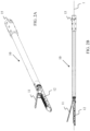
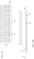
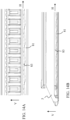
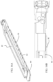
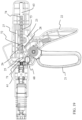
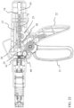
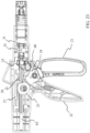
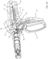
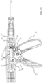
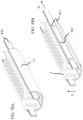
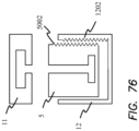
- the surgical stapler includes an actuator 2 removably connected to a staple and transector receptacle (STR) 10.
- the STR includes an upper movable jaw 11 and a lower stationary jaw 12 at a distal end of an elongate shaft 14.
- the upper jaw 11 is configured to include an anvil 9 and the lower jaw is configured to include a staple cartridge 5.
- At a proximal end of the elongate shaft 14 is an actuator interface 15.
- the actuator interface connects and disconnects the STR 10 from the actuator 2.
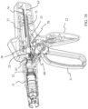
- the actuator 2 includes a rotator 16 that when rotated by a user rotates the elongate shaft 14 and thus the jaws 11, 12.
- the actuator 2 also includes a trigger or movable handle 21 connected to a stationary handle or handle base 22.
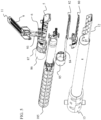
- the handle base includes two halves that mate together to form the handle base 22.
- the trigger 21, under specific conditions to be described in greater detail below, when manipulated by a user causes the closing and opening of jaws 11, 12, firing of staples, translating a blade and a vertical adjustment of a staple cartridge.
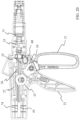
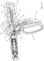
- the upper and lower jaws both move relative to each other and in one embodiment the lower jaw moves while the upper jaw remains stationary.
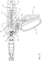
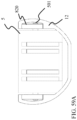
- the upper jaw 11 includes an anvil 9 for forming a plurality of staples 6 sequentially ejected from a staple cartridge 5.
- the upper jaw 11 is pivotably coupled to upper outer cover 91 that is connected to a lower outer cover 92.
- the upper jaw 11 includes jaw springs 93 biasing the upper jaw to an open or spaced condition.
- the lower outer cover 92 is connected to a retainer 121.
- the retainer 121 holds a rampway 80 affixed to the retainer and including a plurality of ramps 81.
- the retainer 121 also houses a movable cartridge platform or lift 82 including a plurality of ramps 83 that correspondingly mate with the plurality of ramps 81 of the rampway 80.
- the staple cartridge 5 sits upon the cartridge lift 82.
- the ramps 83 of the cartridge lift 82 slide on the ramps 81 of the rampway 80 which moves the cartridge 5 vertically (e.g., as illustrated by arrow V) or in a direction traverse to (e.g., perpendicular to) the longitudinal axis 1 of the STR 10.
- the staple cartridge 5 includes a plurality of staples 6 and a corresponding set of staple pushers 7 situated in a plurality of staple pockets.
- a set of fins 171 on a slider 17 Through interaction of a set of fins 171 on a slider 17 with the staple pushers, the staples are fired or ejected from the staple cartridge 5. Staples within the cartridge 5 are thus fired through the longitudinal movement of the slider that interacts with staple pushers within staple pockets of the cartridge. Fired staples penetrate tissue clamped between the jaws 11, 12 and are formed against anvil pockets on the anvil 9.
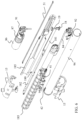
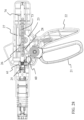
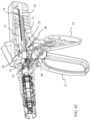
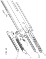
- the slider 17 is operatively connected to an actuation beam 18.
- the actuation beam 18 includes a blade 19 and is connected to an actuation slide 180.
- the actuation slide 180 includes a proximate actuation slide 181 coupled to a distal actuation slide 182.
- the distal actuation slide 182 is perpendicular to the proximate actuation slide 181 with both slides extending parallel to the longitudinal axis 1 of the STR 10.
- the intersection of the proximal and distal actuation slides in cross-section forms a cross.
- the actuation beam 18 has an upper guide or roof 183 that is configured to move within a longitudinal slot or channel in the upper jaw 11 and a lower guide or floor 184 that is configured to move within a longitudinal slot or channel in the lower jaw 12.
- the staple cartridge 5, cartridge lift 82 and the retainer 121 includes a longitudinal channel through which the lower guide 184 moves therethrough.
- the upper and lower guides of the actuation beam ensure parallel jaw alignment and compression of the closing of the jaws 11, 12.
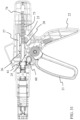
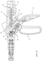
- the actuation slides 181, 182 are surrounded by an actuation cover tube 185 that includes an opening 186 through which a STR reuse lockout 41 is biased by a leaf spring 42 through the opening 186 in the actuation cover tube 185.
- the actuation cover tube includes slots or guides to ensure alignment and translational movement of the actuation slides 181, 182.
- An outer tube 94 surrounds the actuation cover tube 185 and is connected to actuator interface 15 with a pair of opposing protrusions on opposing sides of the interface for a removable connection to the STR coupler 151.
- a coupler spring 152 is positioned between the rotator and STR coupler to bias the rotator in the distal direction such that movement of the rotator in the proximal direction compresses the spring and exposes the coupler 151 and the connection thereto for removably connecting with actuator interface 15.
- Extending parallel to the actuation cover tube 185 and the actuation slides 181, 182 is an articulation beam 51.
- the articulation beam 51 includes a proximal end that is connected to the upper and lower outer covers 91, 92 and in one embodiment sits and rides within slots of the actuation cover tube 185.
- the actuator 2 is operably coupled to the removably coupled STR 10 and actuates the jaws 11, 12 from an open-close configuration to a one-way automatic self-adjusting stapling or forward configuration to a reverse configuration through the driving or manipulation of the actuation beam 18 forward or backwards (distally or proximally).
- Figures 17-46 in particular illustrate the actuator 2 including the inner workings thereto in various states of operation in accordance with various embodiments.
- FIGS. 17A-B illustrate the stapler with its jaws in an open or initial configuration
- FIGS. 17C-D illustrate the stapler with its jaws in a closed yet unfired or non-firing configuration.
- the actuation beam 18 In an initial position of the stapler, the actuation beam 18 is positioned at the most proximal position of its travel and the jaws 11, 12 are in an open configuration or position.
- the actuation beam engages the upper jaw 11 upon translation of the actuation beam distally along the longitudinal axis 1 of the elongate shaft 14.
- Translation of the actuation beam distally from the initial position a first predefined longitudinal distance (e.g., .225”) can actuate the jaws from an open position to a closed position.
- a first predefined longitudinal distance e.g., .225
- the actuation beam can be returned proximally, as influenced by the jaw springs biasing the jaws open, traveling the same first distance to return the jaws to the open position.
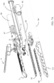
- the trigger 21 of the actuator 2 is operatively coupled to the actuation beam such that as the trigger is squeezed, the jaws close, and as the trigger is pushed open or in one embodiment released, the jaws open.
- the trigger 21 is connected to a forward distal pivot pawl 25 with a tip or tooth engageable with a groove or cut-out 71 in an actuation rod 62 operatively connected to the actuation beam 18.
- the engagement of the forward distal pivot pawl with the groove 71 in the actuation rod assists in moving the actuation rod in the distal direction as the trigger is pivoted towards the handle base.
- Such movement of the actuation rod in the distal direction moves the actuation beam 18 in the distal direction causing the jaws to close.
- the trigger 21 is connected to a forward proximal pivot pawl 28 with a tip or tooth engageable with a groove or cut-out 72 in an actuation rod 62 operatively connected to the actuation beam 18.
- the engagement of the forward proximal pivot pawl with the groove 72 in the actuation rod assists in moving the actuation rod in the proximal direction as the trigger is pivoted away from the handle base or released. Such movement of the actuation rod in the proximal direction allows the jaws to open.
- the trigger 21 is biased by a spring causing the trigger to be biased back to an initial or open position with the trigger pivoted away from the handle base.
- the forward distal pivot pawl 25 and the forward proximal pivot pawl 28 are pivotable connected to the trigger 21 and in one embodiment form or resemble a "V" with the distal pivot pawl 25 extending in a direction that is opposite to that of the proximal pivot pawl 28.
- the groove or cut-out 71 operatively engageable with the distal pivot pawl 25 is near the distal end of the actuation rod and is distal from the groove 72 that is operatively engageable with the proximal pivot pawl 28.
- the open-close operation can be repeated multiple times as desired by the user to for example grasp or dissect tissue for a given surgical procedure.
- a STR recognition barrel 31 prevents activation or movement of the firing operation unless a STR 10 is attached to the actuator 2. Movement or articulation of the trigger 21 of the actuator 2 however is not prevented. Allowing movement of the actuator can assist in packaging and testing of the actuator. Additionally, this allows the attachment of other front-end actuation units that may require grasping and/or articulation with or without the ability or use for firing staples and thereby increasing the versatility of the actuator 2. In various embodiments, attaching a STR moves the recognition barrel 31 proximally which in turn compresses a STR recognition barrel spring 32 coupled to the recognition barrel.
- the spring 32 biases the recognition barrel distally and in one embodiment is coupled and captured between the outer surface of an articulation barrel 55 and the inner surface of the recognition barrel surrounding the spring 32.
- the recognition barrel, spring and articulation barrel are coaxially aligned. Movement of the recognition barrel moves a fire connector arm 33 connected to the barrel.
- the connector arm 33 has a distal end affixed to a proximal end of the recognition barrel with a notch in the distal end of the connector arm 33 engaged with a peripheral flange around the proximal end of the recognition barrel.
- the proximal end of the connector arm 33 has a flange that is slidably coupled to an arming hub 61 through a notch or slot disposed in the arming hub.
- the arming hub 61 is also connected to a firing button 60 that allows a user to set the stapler in a firing mode or a reverse mode with each activation of the button rotating the rod into the respective operational position for the corresponding operation.
- the connector arm 33 disposed in the slot of the arming hub 61 prevents rotation movement of the arming hub that also prevents activation of the fire button and thus prevents changing of the operation of the stapler.
- a STR is attached to the actuator, full operation of the handle assembly is restored or allowed to proceed.
- a bifurcated actuation rod e.g., a proximal actuation rod 63 and a distal actuation rod 64, allows rotational movement by the user via the rotator 16 without effecting operation of the stapler.
- the distal end of the actuation rod 62 is removably coupled to the actuation slide of the STR.
- the distal end of the actuation rod includes a slot configuration arranged to receive corresponding mating flanges on the actuation slide to twist and lock into a removable mating connection of the actuation rod to the actuation slide 180. As such, translation movement of the actuation rod also translates the actuation slide.
- the user can push the forward or fire button 60 on the actuator to change the mode of the handle to the forward configuration where the firing and self-adjusting mechanisms are activated.
- the fire button 60 cannot be actuated until a STR is attached. In one embodiment, the fire button 60 also cannot be actuated until the actuation rod has traveled the predefined first distance distally. In accordance with various embodiments and as shown for example in FIGS. 27-29 , once trigger 21 is released with the STR attached and the jaws fully closed, the jaws cannot be opened again until the staples are fired.
- actuation of the trigger drives the actuation beam distally (i.e., only in one direction).
- the first squeeze of the trigger also activates the self-adjusting height mechanism to resize the gap between the jaws.
- the cartridge lift 82 in the lower jaw 12 will activate causing the cartridge to lift up or move only vertically and self-adjust to the tissue in the jaws.
- an STR reuse lock 41 will also be activated. This STR reuse lock 41 ensures that the STR is only placed into the fire mode once, to prevent the user from inadvertently attempting to fire a previously used STR.
- the STR reuse lock 41 prevents the STR from firing again. Further actuation of the trigger will drive the actuation beam further forward sequentially ejecting staples and transecting the tissue grasped between the closed jaws.
- the slider 17 has one or more inclined fins 171 and is movable longitudinally to sequentially contact staple pushers 7 to eject the staples 6 in the staple cartridge 5.
- An actuation beam 18 movable longitudinally moves the slider distally and longitudinally.
- the slider in one embodiment is not connected and does not include keys, hooks or cavities to attach to the actuation beam. As such, the slider can only move longitudinally distally and is not able to return or move back or towards its proximal or initial position by movement of the actuation beam. The actuation beam 18 however can move back or towards its proximal or initial position.
- this allows the pushers 7 to fall back within the staple cartridge after being partially ejected or moved vertically by the longitudinal movement of the slider.
- This movement back into the cartridge reduces potential trauma to tissue, potential sticking to the staple or tissue and thus an overall smoother surface of the staple cartridge for removal of the tissue from between the jaws.
- the simultaneous allowance or lack of restriction of the actuation beam to move back or towards its proximal or initial position and then back provides further cutting of tissue or passes to cut tissue if desired or needed in such embodiments in which a cutting blade 19 is incorporated or attached to actuation beam 18.
- the actuation beam includes an upstanding edge with top and bottom perpendicular edges forming or incorporating the upper guide 183 and the lower guide 184. The upstanding edge travels within a longitudinal slot or channel extending through the staple cartridge and between the staple and staple pushers.
- the cutting blade is incorporated or attached to the upstanding edge of the actuation beam to cut tissue between jaws.
- the blade and upstanding edge of the actuation beam in one embodiment thus travels through a longitudinal channel within the staple cartridge, the anvil or both.
- top and bottom perpendicular edges ride along outer surfaces of the jaws and ensure a fixed gap height, i.e., the distance between the top and bottom edges, and localized and compressive forces against the tissue.
- the top perpendicular edge or upper guide compresses the anvil and tissue vertically down towards and against the staple cartridge and the other jaw and the bottom perpendicular edge or lower guide compresses the staple cartridge and tissue vertically up towards and against the anvil and opposing jaw.
- the compression forces are localized to where the edges are positioned on the outer surfaces of the jaw during the actuation or firing stroke of the actuation beam.
- the arming hub 61 rotates as the button translates in a direction perpendicular to the longitudinal axis 1.
- the arming hub 61 in one embodiment rotates in one direction, e.g., counter-clockwise, as the button translates in a linear direction and rotates in the opposite direction, e.g., clockwise, as the button translates in the opposite linear direction.
- the actuation rod 62 (and/or as illustrated proximal actuation rod 63) connected to the arming hub 61 also rotates clockwise as the arming hub rotates. Likewise, the actuation rod rotates counter-clockwise as the arming hub rotates in the same direction.
- the arming hub 61 is circular in shape with a center opening through which the actuation rod extends there through.
- the outer portion of the arming hub has a slot or groove that operationally connects to a connecting arm.
- the inner portion of arming hub has a protrusion or nub extending towards the center opening and mates with a longitudinal slot in the actuation rod.
- a tip or tooth of the proximal pivot pawl 28 and distal pivot pawl 25 now operationally engage with a series of teeth 73 longitudinally disposed along the actuation rod 62 (and/or as illustrated proximal actuation rod 63).
- the trigger 21 when pivoted causes the proximal pivot pawl 28 and the distal pivot pawl 25 to translate distally along or relative to the actuation rod.
- the actuation rod moves or translates distally as the trigger continues to pivot.
- proximal pivot pawl 28 and the distal pivot pawl 25 Releasing of the trigger or moving it away from the handle base 22 causes the proximal pivot pawl 28 and the distal pivot pawl 25 to move back proximally along or relative to the actuation rod.
- tip or tooth of the proximal pivot pawl 28 and distal pivot pawl 25 now operationally engage with a more proximal portion of the series of teeth 73 longitudinally disposed along the actuation rod 62.
- the distal pivot pawl 25 engaging a tooth of the series of teeth 73 prevents proximal movement of the actuation rod, the actuation slides and the opening of the jaws.
- the proximal pivot pawl engaging a tooth of the series of teeth 73 allows further distal movement of the actuation rod, the actuation slide, the actuation beam, continued firing of the staples and cutting of tissue between the jaws.
- multiple strokes or squeezing and releasing of the trigger may be performed to fully move the proximal and distal pivot pawl to completely eject the staples and cut the tissue between the jaws.
- only a single stroke is utilized to eject the staples and cut the tissue between the jaws.
- the actuator at its end of travel or complete firing of the staples is shown for example in FIGS. 33-35 and 45C-45D .
- the trigger 21 is coupled to an intermediate action gear 23 and a trigger action gear 24.
- the trigger action gear 24 in the illustrated embodiment has a center opening through which a pivot protrusion of the movable handle extends there through.
- the trigger action gear includes a series of teeth engaged or connected to a set of two sets of teeth on the intermediate action gear. Pivoting the trigger 21 rotates the trigger action gear that correspondingly rotates the intermediate action gear 23. In particular, squeezing the trigger 21 causes the trigger action gear 24 to rotate in one direction, e.g., counter-clockwise, that in turn causes the intermediate action gear 23 to rotate in the opposite direction, e.g., clockwise.
- the other set of teeth of the two sets of teeth of the intermediate action gear engage with teeth on a movable rack 27 and thereby moves the rack proximally.
- the movable rack in one embodiment is positioned parallel to the actuation rod. Moving the rack proximally also moves or translates a reverse pawl 26 proximally. In the firing configuration and during the firing of the staples, the tip of the reverse pawl sits and slides against an outer surface or slot in or on the actuation rod 62 (and/or as illustrated proximal actuation rod 63). As such, the rack is movable distally and proximally based on the actuation or pivoting of the trigger.
- the tip of the reverse pawl 26 moves to a proximal or proximal most position it engages a wall in the slot of the actuation rod or a tooth along the actuation rod 62.
- the wall or tooth of the actuation rod 62 acts as a hard or additional stop preventing further distal movement of the actuation rod.
- the rack 27 is disposed in a slot or channel in the handle base 22 and in one embodiment the rack 27 when moved to a proximal or proximal most position engages a wall or proximal end of the slot that prevents further proximal movement of the rack 27 and thus resists further rotation of the intermediate action gear 23 that resists further rotation of the trigger action gear 24 and thereby prevents further squeezing or closing of the trigger 21.
- the rack 27 when moved to a distal or distal most position it engages a wall or distal end of the slot that prevents further distal movement of the rack 27 and thus resists further rotation of the intermediate action gear 23 that resists further rotation of the trigger action gear 24 and thereby prevents further opening of the trigger 21 or movement of the trigger away from the handle base.
- actuation of the trigger towards the handle base 22 rotates the intermediate action gear 23 in one direction, e.g., clockwise, which translates the rack 27 proximally and actuation of the trigger away from the handle base rotates the intermediate action gear in an opposite direction, e.g., counter-clockwise, which translates the rack distally.
- the reverse pawl 26 pivotable connected to a distal end of the movable rack 27 slides proximally and distally as the rack translates proximally and distally.
- the surgical stapler provides a one-way automatic vertical adjustment of the staple cartridge 5.
- the cartridge 5 is moved vertically within lower jaw 12 and, in one embodiment, the cartridge is movable vertically relative to a retainer 121 of the lower jaw 12.
- the cartridge in the lower jaw is movable vertically (e.g., as illustrated by arrow V) towards the anvil through the interaction of ramps 83 located on a bottom surface of a cartridge lift 82 with ramps 81 located on a rampway 80.
- the cartridge sits on an upper surface of the cartridge lift 82.
- the upper surface of the cartridge lift 82 is generally flat and/or devoid of any ramps.
- the cartridge lift includes guides or ridges along the sides of the cartridge lift to ensure proper seating or assembly of the cartridge on the upper surface of the cartridge lift.
- the cartridge lift in one embodiment also includes a channel or slot there through to accommodate the blade and/or the upstanding edge of the actuation beam movable longitudinally there through.
- the cartridge in the illustrated embodiment is arranged to move only in one direction, vertically (e.g., as illustrated by arrow V).
- the cartridge lift is also positioned between the cartridge and the rampway. The rampway remains stationary and is not movable while the cartridge is movable in one direction, vertically, and away from the rampway.
- the surgical stapler includes a series of ramps to lift the cartridge vertically and allow for the adjustment of the formed staple heights to a plurality of intermediate points between upper and lower staple height and gap limits and along a slope of the ramps.
- the cartridge lift 82 in one embodiment is also biased in the proximal longitudinal direction. Such biasing in one embodiment only occurs once the height adjustment mechanism has been activated or firing operation has been commenced, e.g., the actuation slide has traveled past a first predefined distance.
- the cartridge lift 82 is biased or tensioned by a cartridge lift spring 87 pulling the cartridge lift in the proximal direction along or aligned with the longitudinal axis. The biased lift provides an active vertical force against the cartridge 5 forcing it against the tissue held between the jaws 11, 12.
- the spring 87 or tension mechanism is locked or inactivate and thus does not provide any tension or force pulling the cartridge lift in the proximal direction. As such, when inactive, the cartridge 5 and the associated cartridge lift 82 remains at its initial or lowest vertical position.
- the cartridge lift 82 is biased or pulled in the proximal direction (e.g., as illustrated by arrow H) by the spring 87 when the lift is unlocked or the spring is released. Once unlocked, the cartridge lift is pulled or tensioned proximally and thus resists movement distally back to its original or initial position or simply cannot move freely distally. Likewise, the cartridge 5 is lifted vertically from its initial or lowest position. The amount or distance the cartridge travels vertically is based on the force applied by the spring, the amount of tissue between the jaws and the clamping or compression force applied by the jaws closed over the tissue. In accordance with various embodiments, the cartridge applies a uniform one-way constant vertical force as biased by the force applied by the spring.
- the cartridge lift and/or lift bias or spring in various embodiments is blocked by lift lock and in various embodiments the lift lock is not user accessible. Once the lift lock is displaced, the cartridge lift is pulled or tensioned and thus resists is unable to move back to its original or initial position.
- the cartridge lift 82 is connected to a cartridge lift beam 84 that is connected to a cartridge lift barrel 85.
- the proximal end of the cartridge lift includes an opening for receiving a pin and a slot for receiving a flange connected to or extending from the distal end of the cartridge lift beam 84.
- the proximal end of the lift beam is connected, e.g., welded or riveted, to the distal end of the lift barrel 85.
- the lift barrel has a central opening and is disposed around or surrounds the actuation cover tube 185.
- the lift barrel is thus coaxial with the actuation cover tube 185, the actuation slide 180, the actuation rod 62 and the lift beam 84 and is likewise parallel to the actuation slide 180 and the actuation rod 62.
- the lift barrel is biased in the proximal direction (e.g., as illustrated by arrow H) by a cartridge lift spring 87.
- the cartridge lift spring also surrounds the actuation cover tube 185 and is positioned aligned and between the upper and lower outer covers 91, 92 and the lift barrel 85.
- a cartridge lift spacer 86 is placed between the spring and the lift barrel (e.g., after/behind the spring) or in one embodiment between the upper and lower outer covers and the spring (e.g., before/in front of the spring) to accommodate tolerances in assembly or sizing of the spring and thus strength of the spring to ensure the appropriate compression force is applied for a given tissue grasped between the jaws.
- the lift barrel 85 remains blocked or is prevented from moving proximally until or just before the staples can be fired or the stapler is in a firing configuration or position.
- the lift barrel 85 in various embodiments is blocked by lift lock and in various embodiments the lift lock is not user accessible.
- the lift lock is a reload or STR reuse lockout.
- the STR reuse lockout 41 is biased to be aligned with the lift barrel 85 and thus in contact with the lift barrel to prevent longitudinal proximal movement of the lift barrel.
- the lift spring 87 biases the lift barrel proximally.
- the lift lock or the STR reuse lockout is in contact or coupled to the actuation slide and thus becomes misaligned once the actuation slide starts the firing operation or just before the staples can be fired or is ready to be fired.
- the lift barrel also slides over the STR reuse lockout preventing the alignment of the STR reuse lockout with the lift barrel.
- the lift barrel cannot be locked again or returned to its initial or proximal position.
- the cartridge lift connected to the lift barrel by the lift beam cannot return to its initial or proximal position.
- the cartridge lift under the influence of the spring and barrel movement, moves longitudinally and proximally (e.g., as illustrated by arrow H).
- the interaction of the ramps of the cartridge lift and ramps of the rampway as the cartridge lift moves proximally causes the cartridge lift to move the staple cartridge 5 uniformly vertically (e.g., as illustrated by arrow V).
- slots or channels interacting with corresponding protrusions or detents on the cartridge, the retainer or both ensure or assist in a uniform and singular vertical movement of the cartridge.
- the interaction of the ramps and biasing of the lift barrel also act as an integrated height lockout for the staple cartridge allowing the stapler to fire at the adjusted staple height without being able to be forced back open or to a previous position.
- the adjustment of the cartridge height occurs while the jaws are closed on a piece of tissue and is made automatically by the stapler.
- the surgeon/user does not choose the staple height or staple size.
- staple height is set automatically by stapler based on thickness of tissue and the resistance it provides.
- the adjustment of the cartridge height also produces a movement of the cartridge with respect of the anvil while the top and bottom surfaces are parallel. During the adjustment, the top and bottom surfaces remain parallel and the surfaces remain parallel once the movement is complete.
- a distal end of a STR reuse lockout 41 initially sits on a top outer surface of actuation slide 180 or in one embodiment, the proximate actuation slide 181.
- a proximal end of the STR reuse lockout is connected to the actuation cover tube 185.
- a leaf spring sits on top of the STR reuse lockout and is coupled to the cover tube. The leaf spring biases or pivots the distal end of the STR reuse lockout against or down on the actuation slide.
- FIG. 51B as the jaws are opened and closed, the distal end of the STR reuse lockout will remain on the top outer surface of the actuation slide and riding longitudinally proximally and distally as the slide moves and the jaws are opened and closed.
- the actuation slide moves forward distally allowing the distal end of the STR reuse lockout 41 to fall within a slot or opening 187 in the actuation slide.
- the distal end of the STR reuse lockout rides or sits on the outer surface of the slot within the actuation slide as shown in FIGS. 51A-C as the actuation slide travels longitudinally distally to eject the staples from the staple cartridge.
- the top or outer surface of the distal end of the STR reuse lockout falls under a bottom surface of the outer cover tube, the lift barrel or both.
- the bottom or lower surface of the distal end of the STR reuse lockout rides on top of the slot or lower distal surface of the actuation slide.
- the distal end of the STR reuse lockout is disposed or trapped between the outer cover tube or lift barrel and the actuation slide.
- the STR reuse lockout does not move longitudinally unlike the actuation slide but pivots or moves perpendicular or transverse to the longitudinal direction of the actuation slide.
- the STR reuse lockout prevents further movement of the actuation slide in either the proximal or distal longitudinal directions.
- the STR is now unable to fire or eject any staples or move the knife blade or reset the cartridge lift.
- the staple cartridge now raised may serve as an indicator that the STR and/or cartridge is now unable to fire, is devoid of staples, stapling or cutting operations are complete or any combination thereof.
- the staple cartridge 5 includes one or more detents or protrusions 551, 552 positioned and shaped to mate with and slide within slots or openings 1211, 1212 disposed on the lower jaw 12.
- the protrusions 551, 552 are positioned on the side walls of the staple cartridge and the slots 1211, 1212 are positioned on the side walls of a cartridge holder, retainer 121 or lower jaw 12 of the stapler.
- the engagement of the protrusions and slots ensures that the staple cartridge can move vertically but also ensures that the staple cartridge only moves vertically and not side to side or longitudinally distally or proximally.
- protrusions or detents e.g., protrusions 1211
- the staple cartridge although movable vertically is permanently affixed to the jaw and thereby restricts reuse of the staple cartridge or inadvertent discharge or removal of the staple cartridge ensuring consistent stapler operations.
- only a single protrusion or a set of protrusions, e.g., protrusions 1211, protrusions 1212, or combinations thereof, are disposed on the staple cartridge.
- the staple cartridge in various embodiments is a single monolithic structure to assist in applying a uniform force to compress the tissue.
- Individual staple pushers are disposed in the stapler cartridge in individual pockets with individual staples in each pocket. Activation of a staple pusher ejects the associated staple out of the staple pocket and into the clamped tissue and an anvil forming or closing the staple.
- the fins of the slider 17 are longitudinally offset as such fins on one side, e.g., a right side relative to the blade, is set in a more distal position then the fins on the opposing side, e.g., a left side relative to the blade.
- the left side fins thus is placed in a more proximal position than the right side fins.
- the offset of the fins provides a distribution of force in ejecting of the staples and as such reduces potential excessive compression of the tissue and the amount of force required to sequentially eject the staples from the staple pockets via the staple pushers.
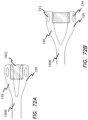
- the stapler includes an articulation lever or switch 50 that toggles the jaws 11, 12 from a zero or initial position to an angled or 45 degrees position relative to the longitudinal axis along the elongate shaft and back again to the zero or initial position.
- the lever engages an articulation forward arm 52 and an articulation rear arm 54 that moves from a split or misaligned position to an aligned and linear position.
- One end of the rear arm is connected to the lever and the other end of the rear arm is connected to the housing base.
- One end of the forward arm is connected to the rear arm along its middle portion and the other end of the forward arm is connected to an articulation extension arm 53.
- the other end of the articulation extension arm 53 is connected to an articulation hub 57 surrounding and connected to an articulation barrel 55.
- the articulation barrel has a bayonet coupling arranged to releasably connect to an articulation beam 51 with a distal end connected to a pivot post near a jaw pivot post that pivotally connects the jaws 11, 12.
- the pivot post is disposed perpendicular to the jaw pivot post and offset the center or longitudinal mid-line of the elongate shaft. Placing the articulation forward and rear arms in-line with each other pulls or slides the articulation extension arm 53 proximally that slides the articulation hub and barrel proximally pulling the articulation beam proximally.
- Proximal movement of the beam pulls on the pivot post causing the upper and outer covers 91, 92 connected to the jaws 11, 12 and connected to the pivot post to be pulled proximally. Since the pivot post is arranged offset the center of the shaft, the jaw covers moves in a direction towards the pivot post to place the jaws in an angled position. With the lever fully depressed, the forward and rear arms are aligned and set in place thereby holding the jaws in the angled position. When the lever is released or moved back to the original or initial position the forward and rear arms split or become misaligned causing the pulling of the articulation beam proximally to be released and thus the articulation beam is allowed to move distally. Movement of the articulation beam distally causes the upper and lower outer covers and thus the jaws 11, 12 to pivot back to an initial or zero position aligning the jaws to the longitudinal axis 1 of the stapler.
- the articulation barrel includes a bias component, e.g., an articulation barrel spring 56, surrounding the articulation barrel and positioned between the outer surface of the articulation barrel and the inner surface of the articulation hub.
- the spring biases the articulation barrel distally that also biases the articulation beam distally and thereby biases the jaws to the initial or zero position.
- the reverse button (or moving the fire button in the opposite direction) may the pressed at any time while the actuation rod 62 is translating distally. Engaging the reverse button reverses the operation of the stapler and thereby enables the longitudinal movement of the actuation rod back or proximally.
- the arming hub 61 rotates back to its initial position or in the opposite direction, e.g., clockwise, as the button translates in a linear direction.
- the actuation rod 62 (and/or as illustrated proximal actuation rod 63) connected to the arming hub also rotates back to its initial position or in the opposite direction, e.g., clockwise.
- the reverse pawl 26 connected to the movable slide or rack 27 becomes engaged or is engageable with a series of teeth 74 longitudinally disposed along or in the actuation rod 62.
- the teeth 74 With the actuation rod 62 at a distal or distal most position, the teeth 74 become accessible or exposed to the reverse pawl 26.
- Actuation or squeezing of the trigger 21 towards the handle base 22 rotates the trigger action gear 24 that rotates the intermediate action gear 23 which translates the rack 27 proximally.
- the reverse pawl 26 connected to the rack 27 also moves proximally and longitudinally.
- the reverse pawl 26 also being engaged with a tooth of the teeth 74 on the actuation rod 62 also moves the actuation rod 62 proximally and longitudinally.
- Releasing of the trigger or moving it away from the handle base 22 causes the reverse pawl 26 and the rack to move back distally through the interaction and cooperation of the trigger and intermediate action gears.
- the tip or tooth of the reverse pawl 26 becomes operationally engage with a more distal portion of the series of teeth 74 longitudinally disposed along the actuation rod 62.
- the engagement of the reverse pawl with the teeth 74 prevents or resists distal movement of the actuation rod 62.
- multiple strokes or squeezing and releasing of the trigger may be performed to fully move the actuation rod 62 back to or nearly back to its initial or proximal most position and thereby fully open the jaws.
- Such strokes in one embodiment incrementally open the jaws and thus allow disengagement of the stapler from the stapled tissue. In one embodiment, only a single stroke is utilized to completely open the jaws. In various embodiments, actuation (e.g., closing/opening of the jaws and/or firing of the staples) or articulation of the stapler is assisted by one or more motors.
- the forward proximal and distal pawls 28, 25 slide distally and proximally on an outer surface of the actuation rod 62 as the trigger is squeezed and released and as the rack moves proximally and distally.
- multiple strokes or squeezing and releasing of the trigger may be performed to fully move the actuation rod 62 back to or nearly back to its initial or proximal most position and to place or position the forward proximal and distal pawls 28, 25 back to or nearly back to their initial position relative to the actuation rod 62 (e.g., the forward proximal pawl 28 engaging cut-out 72 and the forward distal pawl 25 engaging cut-out 71).
- the actuator at its end of its reverse travel is shown for example in FIGS. 39-44 .
- the final squeeze of the trigger while in the reverse configuration locks out the STR and resets the actuator 2 to an initial or open-close mode as shown for example in FIGS. 42-44 .
- the jaws 11, 12 when closed and the elongate shaft defines an outer diameter that is at least as equal to or smaller than the inner diameter of the trocar cannula.
- a typical surgical procedure may include a single site surgical access device or multiple trocar cannulas placed on and through the patient's body.
- the inner diameter of the trocar cannula corresponds to 12mm and the make-up or components of the jaws includes upper and lower jaws, pushers, staples, cartridge, and a jaw gap height.
- the cartridge is a nest for the pushers and staples and in one embodiment the cartridge is fixed inside the lower jaw.
- Pushers reside below the staplers and push the staples fully out of cartridge pockets within the cartridge when the pushers are acted upon by a slider.
- the staples When the staples are pushed out of the cartridge, the staples must pass through the tissue and deform by contact into their corresponding anvil pockets within the anvil on the upper jaw.
- the actuation beam is a high stress component as it performs the work of closing the hinged upper jaw while compressing tissue therebetween, deploying the pushers to fire the staples and cutting the tissue at the center of the jaws.
- FIGS. 53A-B illustrate a 3.5mm staple 6 formed and unformed condition in accordance with various embodiments.
- the staple 6 has a height of about 3.5mm and a width of about 3.0mm and in a formed condition, the staple has a height of about 1.5mm.
- the formed height may vary based on tissue thickness and other conditions effecting staple formation.
- FIGS. 56A-C illustrate an exemplary staple 6 unformed, formed at minimum height and formed at maximum height.
- the lower jaw has a thickness of 0.762mm (0.030 inches) in order to remain rigid when the jaws are clamped on tissue.
- the lower jaw has an increased strength in the vertical direction as the side wall bends and wraps around and up the side of the cartridge.
- the upper jaw is generally a flat piece of metal that can be susceptible to bending when clamped on tissue and thus is thick.
- FIG. 54 depicts the limited space requirements or confines in which a laparoscopic surgical stapler must conform to these dimensions. Otherwise, increase incision size causes increased recovery time and unwanted patient trauma.
- the outer diameter 541 of the stapler is about 0.5mm.
- the upper jaw 11 including the anvil 9 and an upper guide 183 of the beam 18 occupies about a third of that space.
- a gap between the jaws 11, 12 is maintained to allow for tissue to be grasped and staples 6 to be fired and formed along with staple pushers 7 partially ejected from the cartridge 5 to fire the staples. This gap can be about 0.91mm (.036 inches) in accordance with various embodiments.
- the lower guide 184 of the beam 18 and the lower jaw 12 that includes the cartridge 5 occupy the remaining space.
- the height or space occupied by the cartridge 5 is further limited by the height of the staples 6 and the pushers 7 used to eject the staples.
- the dimensions of the lower jaw 12 and lower guide 184 of the beam 18 are also restrained due to space constraints and the desired strength and durability to ensure proper staple firing.
- the dimensions of the upper jaw 11 and the upper guide 183 of the beam 18 are also limited due to space constraints and the required strength and durability to ensure depth and shapes of the anvil pockets 99 in the anvil 9 and proper staple formation.
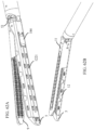
- FIGS. 55A-B illustrate the jaws of the stapler in accordance with various embodiments providing a maximum jaw gap height 554 e.g., 0.965mm (.038 inches) and minimum jaw gap height 553 e.g., 0.46mm (.018 inches).
- the cartridge In the maximum jaw gap height or initial condition, the cartridge is at its lowest height with the protrusions 551, 552 of the cartridge 5 at its lowest position firmly seated in the slots 1211, 1212 in the lower jaw 12.
- the minimum jaw gap height or unconstrained condition the cartridge 5 is at its highest height with the protrusions of the cartridge at their highest position in the slots 1211, 1212 in the lower jaw 12.
- the interaction of the protrusions, e.g., protrusions 551, and the slots, e.g., slots 1211 further limits or regulates the range between the maximum and minimal jaw gap heights.
- the laparoscopic linear cutting surgical stapler comprises a series of opposing ramps at low angles to uniformly lift the staple cartridge and lock it in place.
- One set of ramps remains stationary while the second set is moved longitudinally relative to the stationary set of ramps driving the surfaces of the ramps to slide against each other.
- the series of ramps are located along the length of the cartridge and the interaction of ramps causes the cartridge to lift uniformly.
- the cartridge contains staples, pushers and a slider.
- the cartridge In an initial or default position, e.g., as shipped, the cartridge is at its lowest positional height and thus the largest gap distance between the jaws.
- the jaws of the stapler can freely open and close to grasp tissue therebetween while being gentle on the tissue.
- the jaws can also thus be gently positioned on the tissue and the tissue positioned into the desired firing position or location.
- the cartridge lift is engaged or activated. In one embodiment, the cartridge lift is engaged automatically during the initial firing stroke to fire or eject the staples from the cartridge.
- the lift By engaging the cartridge lift, the lift is moved longitudinally and an interaction of ramps on the lift and a rampway or retainer and the biased lift apply a vertical lifting force on the cartridge moving the cartridge vertically towards the anvil and delivering a pre-determined pressure on the tissue between the jaws.
- the clamping force between the jaws, cartridge, and ramps is directed in a direction perpendicular to the longitudinal axis of the stapler.
- the force also presses the two sets of ramps together. Due to the low angle of the ramp surfaces with respect to each other and also largely slanting perpendicular to the force, the clamping force or reaction force or pressure is unable to drive the ramps and thus the lift back longitudinally back into its initial position.
- the ramps and other components will deform rather than move longitudinally back.
- the cartridge lift is thus able to lift the cartridge to an infinite number of intermediate heights between the lowest and highest points rather than set incremental points while simultaneously locking or preventing the cartridge from returning back down. This can also be done automatically, e.g., with no user interaction to set or determine a particular height and to adjust or set the stapler to that determined height.
- the ramps on the cartridge lift and the rampway have the same dimension and shape.
- the ramps have different dimensions or shapes and the slope of the ramps defines or accounts for the compressive forces applied to tissue grasped between the jaws 11, 12.
- the rampway 80 is built into or incorporated into the retainer or lower jaw 12 as shown for example in FIGS. 69-70 .
- the ramps 81 are slants of increasing slope extending proximally and the ramps 83 on the cartridge lift 82 are arranged as decreasing ramps slanting or extending proximally to mate and interact with each other to move the cartridge vertically as the cartridge lift is moved proximally.
- the movable set of ramps is connected to a pre-loaded spring designed to apply the desired longitudinal force once released or engaged.
- the spring is also provided to apply a load on the ramps thereby moving the cartridge vertically to achieve a desired predetermined and optimal pressure on the tissue to produce the desired staple formation with minimal excessive pressure or trauma to the tissue and surrounding tissue.
- biasing member or spring By placing the biasing member or spring within the shaft or distally away from the jaws, allows for a larger biasing member (e.g., a spring without space constraints imposed by a jaw or jaws of the stapler), provides easier manufacturing, removes space constraints at the jaws and allows for a single force to be spread out and uniformly applied at the jaws.
- a larger biasing member e.g., a spring without space constraints imposed by a jaw or jaws of the stapler
- Such biasing members in the jaws are often impractical or inoperable as not effectively applying uniform forces against the cartridge to compress the tissue against the anvil. Appropriate compression of tissue and jaw gap height ensures proper staple formation. Proper staple formation ensures no leaking and reduced trauma to the tissue.
- the surgical stapler applies compression forces at three different intervals.
- the first compression can occur when the jaws are closed onto the tissue.
- the second compression occurs when the vertical adjustment driver is activated and the third compression occurs when the firing mechanism applies pressure on both jaws.
- the movable wedges can be biased by a cable or motors driven by pressure sensors.
- the stapler is a single use disposable device and as such the lift mechanism once initiated cannot be reset and thus the lift mechanism cannot be reused along with the associated cartridge.
- the lift mechanism can be provided using ramps or wedges on the bottom of the cartridge, along the sides of the cartridge; ramps as separate inserts assembled or integrated in lower jaw or cartridge; and/or angled slots or channels instead of or in addition to wedges.
- the cartridge lift could be biased distally instead of proximally to lift the cartridge and thus the direction or slope of the ramps would also be reversed.
- a separate lockout or lift restraint is provided such as teeth or a ratchet like mechanisms on the cartridge lift, cartridge, lift barrel, lift beam or the like that provides only a one-way proximal or distal longitudinal and incremental movement of the cartridge lift or staple cartridge.
- a retainer includes a plurality of ramps that interact with a cartridge lift that is movable longitudinally and proximally and lifts the cartridge vertically.
- the cartridge lift in various embodiments has no ramps with smooth flat upper and lower surfaces but is attached to a ramp or protrusion like configuration and interaction as described throughout the description.
- the cartridge lift 8211 includes a plurality of ramps 8212 such that moving the cartridge lift distally (arrow D), e.g., away from the actuator, lifts the cartridge 5 vertically.
- the ramps on the cartridge lift decrease or slant down proximally and the ramps on the retainer slant up distally.
- the retainer is integrated or replaced by the lower jaw 12 in which the lower jaw 12 includes the corresponding ramps 1221.
- the staple cartridge 5 sits upon the cartridge lift and when the cartridge lift is moved distally, the ramps of the cartridge lift slide on the ramps of the lower jaw which moves the cartridge vertically.
- articulation is provided such that the jaws can pivot or be angled away from or out of alignment with the longitudinal axis without opening or closing of the jaws.
- the cartridge lift in various embodiments is biased in the distal direction.
- spring 871 biases the cartridge lift distally.
- a proximal end of the cartridge lift extends vertically or includes an extended base 8213.
- the extended base is positioned between the 871 and an actuation beam 18.
- the spring applies a force in the distal direction against the extended base.
- the position of the actuation beam restrains or restricts distal movement of the extended base of the cartridge lift and thus the release of the spring 871.
- the actuation beam In a fire activation configuration, the actuation beam is moved distally and thus allows the movement of the extended base and the release of the spring to apply a spring force against the cartridge lift. As such, the spring moves the cartridge lift distally causing the cartridge to lift up or move only vertically and self-adjust to the tissue in the jaws.
- the cartridge lift 824 includes apertures 825 through which a plurality of ramps 503 on a cartridge platform 501 extends therethrough. Movement of the cartridge lift proximally lifts the cartridge platform or frame vertically. In particular, movement of the cartridge lift proximally causes the distal most ends or walls of the apertures to interact with the ramps on the cartridge platform that slant down proximally. As a result, the cartridge platform is moved vertically as the cartridge lift is moved longitudinally, e.g., proximally. In various embodiments, the cartridge is seated on the cartridge platform and as such the cartridge and cartridge platform only moves vertically or in a direction traverse to the longitudinal movement of the cartridge lift. In various embodiments, the cartridge and cartridge platform are integrated to form a monolithic structure.
- a cartridge platform 505 includes a plurality of protrusion 507 (e.g., bumps) and a cartridge lift 826 includes a plurality of ramps 828 such that moving the cartridge lift 826 proximally causes the ramps of the cartridge lift to interact with the bumps of the cartridge platform to lift the cartridge 5 vertically.
- protrusion 507 e.g., bumps
- cartridge lift 826 includes a plurality of ramps 828 such that moving the cartridge lift 826 proximally causes the ramps of the cartridge lift to interact with the bumps of the cartridge platform to lift the cartridge 5 vertically.
- the cartridge lift is connected to a flexible pull cable, e.g., cable 714.
- the flexible pull cable includes a hold/release block 715 coupled to a tension spring 716.
- the flexibility of the pull cable assists in flexing or articulating of the jaws relative to the elongate shaft (e.g., at a flex point or joint denoted abstractly by curved line 701).
- the tension spring biases the cartridge lift proximally.
- the hold/release block limits or restricts movement of the pull cable and likewise the cartridge lift. Once activated, the hold/release block is released allowing the pull cable and the cartridge lift to be pulled proximally.
- the cartridge moves vertically towards the upper jaw 11.
- the cartridge is seated on the cartridge platform and as such the cartridge and cartridge platform only moves vertically or in a direction traverse to the longitudinal movement of the cartridge lift.
- the cartridge and cartridge platform are integrated to form a monolithic structure.
- an actuation lock or link 661 is pivotably connected to the actuation rod or slides in which in one position the actuation link restricts the actuation rod or slides and prevents the firing of staples and cutting of tissue between the jaws.
- the actuation rod or slides operate as previously described in various embodiments. Initially, the actuation link 661 hooks onto an actuation pin 663 that is connected to an actuation rod.
- the actuation slide is connected to a trigger such that when the trigger is manipulated the actuation slide also moves but in an opposite direction.
- the actuation slide moves distally to ultimately close the jaws and eject the staples as shown for example in figures 66A-66B .
- the actuation link is pivoted or rotated up to disconnect or unhook the link from the actuation pin 663. This disconnection disables the connection between the actuation slide and the distal working portions of the stapler, e.g., the firing of the staples or the movement of the jaws.
- the actuation pin 663 is free to move proximally and distally but is no longer connected to the actuation link. Any movement of the actuation pin thus does not move the distal working portions of the stapler and thus movement of the trigger also does not move the distal working portions of the stapler. In various embodiments, only the ability to fire staples is disconnected by the interaction of the actuation link and the actuation pin but the opening and closing of the jaws are still permitted. As such, the trigger can be moved to open and close the jaws while any movement or components to fire the staples are disengaged.
- ramps or slots 821 are added along the sides of cartridge lifts 820 and corresponding protrusions or detents 501 extend from a cartridge retainer or a cartridge 5 instead of along the respective bottom and upper surfaces of the lift and jaw.
- the cartridge lifts 820 in accordance with various embodiments are similarly biased, e.g., in a proximal direction (arrow H), and once activated raises the cartridge vertically (arrow V) through the interaction of the protrusions of the cartridge and the slots of the lifts 820.
- the protrusions are on the lifts and the slots are on the cartridge or in various embodiments, various combinations of protrusions and slots are provided with some on the cartridge and some on the cartridge lifts, e.g., a cartridge has proximal protrusions and distal slots and the cartridge lifts have corresponding proximal slots and distal protrusion.
- Protrusions may be desired extending from the cartridge to maximize the space within the cartridge for the staples and the ejection of staples. Portions of the lower jaw 12 and the cartridge 5 are removed from the illustrated embodiment to ease description of embodiment.
- the cartridge lifts in various embodiments are connected proximally in the shaft or actuator to form a single monolithic structure to further ensure uniform movement of the lifts.
- an actuation beam provides functional parallel jaws during closure, compression and high forces of staple firing/forming.
- the actuation beam closes the jaws and maintains consistent parallel closure along the length of the jaw and in various embodiments the actuation beam is arranged to withstand significant firing/closure forces at a pre-determined height (height at which the actuation beam was manufactured).
- the actuation beam structural member is thus made from high grade stainless steels for example and thus strong and rigid. Making or providing an adjustable actuation beam can sacrifice or reduce inherent strength and rigidity of actuation beam.
- an adjustable actuation beam can provide an adjustable jaw gap and/or a low or reduced overall outer or body diameter.
- such an adjustable actuation beam can cause width constraints, complex construction, e.g., actuation beam or jaw mechanisms, and/or reduce actuation beam strength.
- the actuation beam closes the top jaw to the bottom jaw when it is advanced.
- the actuation beam closes the jaws together at a fixed height or jaw gap. If the actuation beam was able to be adjusted in height, the user could then adjust the jaw gap appropriately for the desired tissue to use it on.
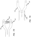
- adjustable actuation beams 1800 are illustrated for example in FIGS. 72-74 and in which the actuation beams are split or forked at the distal end providing an upper arm 188 and a lower arm 189 with a space between the two and/or a middle portion removed. For example, in FIGS.
- the actuation beam 1800 includes an adjustable or stretchable material or web 1802 between upper and lower guides of the actuation beam and, in one embodiment, the material biases the guides together or stretchable or inherently biased to squeeze the guides together and thereby seek to reduce the staple height or jaw gap and/or to apply compressive forces on tissue between the jaws.
- a ratchet 1803 e.g., teeth or racks, extend from either or both upper and lower arms of the actuation beam 185.
- a perpendicular extension tab extends from the upper arm of the actuation beam and includes a plurality of projections and a perpendicular extension tab extends from the lower arm of the actuation beam and includes a plurality of projections arranged to interact with the plurality of projections of the perpendicular extension tab of the upper arm of the actuation beam.
- Such a ratchet or interaction of projections holds or biases the arms together and can be utilized to incrementally adjust the overall height of the beam or the spacing between the arms.
- the cover tube or another actuation tube or cover 1805 is provided to force or bias the upper and lower arms of the actuation beam to together as the beam is squeezed into the tube or the tube is squeezed over the arms of the beam.
- These upper and lower guides may also include a material or ratchet between them to further assist in a uniform and consistent closure or pressure in bringing the guides together.
- forces or biasing material or mechanism in accordance with various embodiments may be one-way, e.g., moving to close the guides together and thus unable to open or release, and/or in one direction, e.g., towards each other or just towards the upper or lower guide, to maintain a parallel relationship of the guides with each other and the longitudinal axis.
- a separate release or disengagement component would be used to move the arms apart sufficiently to release the stapled tissue.
- an adjustable actuation beam may still need to provide sufficient strength in order to close the jaw especially if the tissue between the jaws is thick.
- the adjustable actuation beam may also be very thin to leave room for multiple rows of staples in the cartridge.
- the jaws may also need to stay parallel to the cartridge during firing.
- a mechanism may be needed to allow one or both of the jaws to realign the gap to match the adjustable actuation beam.
- the actuation beam may also need to be acted on by a separate biasing component or mechanism to adjust the height.
- the additional biasing component or mechanism may also have to articulate.
- the pivot joint between the top and bottom jaws may also have to adjust accordingly to match the actuation beam to maintain parallel jaws.
- the ramp configuration as previously described in accordance with various embodiments as compared to the adjustable actuation beam embodiments may have fewer parts.
- the ramp configuration for example has a single location jaw pivot pin with a thin and simple or straight-forward actuation beam.
- the stapler provides an adjustable top jaw or adjustable anvil surface that provides parallel jaws at various staple heights.
- the top jaw is usually not thick enough or does not have room enough for lift mechanisms especially relative to the size of bottom jaw and associated staples.
- a gap 751 is present at the distal most portion of typical jaws 111, 112 and in various embodiments this gap is closed or reduced to a near zero configuration allowing the typical lost space to be better utilized to capture and compress tissue.
- the angled bottom jaw 754 reclaims some of the lost space.
- the gap 751 at the distal most portion of the jaws is reduced nearly to zero while the tissue gap at the proximal portion of the jaw remains unchanged.
- the top jaw 111 is opened or moved away from the bottom jaw 112 to position the top jaw in a parallel position relative to the bottom jaw to ensure a more uniform compression of tissue and staple formation.
- the sliding top jaw 115 when closed is offset or positioned more proximally than the fixed bottom jaw 125.
- a small gap or no gap 751 is disposed between the jaws and thereby defining or delimiting a small outer diameter to facilitate entering or exiting small diameter surgical access ports, such as 5mm cannulas.
- the sliding top jaw when fully opened defines a large gap 751 between the jaws to increase the ability of the jaws to capture large portions of tissue between the jaws.
- the sliding pivot 775 of the sliding top jaw ensures that the jaws remain parallel relative to each other to ensure a more uniform compression of tissue and staple formation.
- movement of the actuation beam distally moves the jaws from an open position and a closed position or a separate rod, cable or tube is utilized to move the jaws from an open and closed position and vice versa.
- a toggle top jaw 116, 117 when closed provides a specific gap between the jaws.
- the specific gap can be small enough to facilitate placement through and withdrawal of the instrument from small diameter surgical access ports.
- the toggle top jaw when fully opened defines a large gap between the jaws to increase the ability of the jaws to capture large portions of tissue between the jaws.
- the toggle top jaw ensures that the jaws remain parallel relative to each other to ensure a more uniform compression of tissue and staple formation.
- movement of the actuation beam 18 distally can move the jaws from an open position and a closed position.
- a proximal portion of the beam interacts with the toggle top jaw to prevent further rotation or pivoting of the jaw to further ensure that the jaws remain parallel relative to each other to ensure uniform compression of tissue and staple formation.
- a slot 1174 of the toggle top jaw interacts with the actuation beam to rotate or pivot of the jaw.
- feet or a proximal end 1173 of the toggle top jaw interacts with the shaft of the stapler to prevent further rotation or pivoting of the jaw.
- the toggle top jaw comprises a top jaw toggle 1161, 1171 and a toggle link 1162, 1172 pivotably connected to the shaft and/or bottom jaw or bottom jaw support.
- the toggle link is also pivotably connected to top jaw toggle.
- the top jaw toggle remains parallel to the bottom jaw 125 and includes an anvil.
- the top jaw toggle in various embodiments is made of a material or comprising of materials stronger or firmer than the toggle link to withstand staple formation forces and facilitate staple formation.
- the adjustable top jaw with an actuation beam 18 is similar to previously described embodiments.
- the actuation beam height remains the same height during use however the difference in staple heights is accommodated by a small shoe or spacer that resides in the top jaw or the lower jaw assembly.
- a small jaw gap is desired, a spacer would be added while if a large jaw gap is desired, the spacer would not be used.
- the decision to add a spacer may be left with the user.
- the engagement of the spacer as desired may be activated by the actuation beam or similar mechanisms used in the firing or pre-firing process. Such mechanism may also have to articulate.
- the top or bottom jaw may need to be thinner to provide space for the spacer which can reduce the jaws strength.
- the spacer's strength may also be enhanced to accommodate the reduced jaw strength and to withstand compressive forces in the staple formation process.
- a space may also be provided to accommodate storage of the spacer when not in use.
- the top jaw would likely be thicker in cross section.
- a strong top jaw that minimizes flexing is often desired for proper staple formation.
- a single monolithic top jaw is often desired.
- the spacer provides a finite number of gap height changes and is not automatically-adjustable.
- an adjustable top jaw can provide an adjustable and comparable jaw gap and an overall low body diameter.
- the adjustable top jaw could also increase space between staple lines, increase complexity to the actuation beam or other components and/or reduce the top jaw strength.
- the cartridge is adjusted using springs or other similar biasing mechanisms.
- springs under the cartridge allows the cartridge to move or adjust due to the thickness of tissue.
- the cartridge would move again due to higher forces encountered during staple firing and forming.
- the cartridge moves freely in response to the tissue thickness but may not be able to lock solidly in place once the optimum height has been found and all within the limited space of a linear laparoscopic cutting cartridge.
- the cartridge 5 is floating or not directly coupled to the jaw of the stapler. Contact of the cartridge with the tissue causes the cartridge to re-size to an optimum tissue gap.
- the cartridge includes teeth 5002 that interlock with corresponding teeth 1202 on the jaw to lock the cartridge in place at the optimum tissue gap.
- the bottom jaw clamps on the cartridge to interlock the teeth of the cartridge and the bottom jaw.
- movement of the actuation beam slides the cartridge to the side to interlock the teeth of the cartridge and the bottom jaw.
- the teeth could be on both sides of the cartridge with corresponding interlocking teeth disposed on both sides of the bottom jaw.
- an adjustable top/bottom jaw is provided without the use of an actuation beam.
- Other mechanisms to open and close the jaws could provide parallel jaws during closing and staple formation and counteract or account for compressive forces encountered during closing and staple formation. Such mechanism may thus be thicker and stronger that may reduce the ability to articulate or space availability to accommodate the space limitations in laparoscopic procedures.
- the top jaw would have to be much thicker than a normal jaw due to the lack of an actuation beam.
- the cartridge would need to house the cutting blade and protect it after the device is fired and the jaw opened.
- one or more ramps are placed along the sides of a cartridge or cartridge lift interacting with ramps on the sides of a rampway, retainer or lower jaw.
- An actuation beam is provided to close the jaw, fire the staples, release jaw gap spring, and cut the tissue.
- the jaw gap is set by the side ramps and in one embodiment the cartridge is held in place by a frame that is acted on by the cartridge lift.
- the frame and cartridge close the gap based on a biasing member, e.g., a spring and its spring rate, that has be predefined or predetermined to be optimal for tissue compression.
- the jaw gap change is done automatically.
- compressive forces are transmitted to the sides of the cartridge or cartridge lift rather than being distributed on a bottom flat surface as provided in various other embodiments previously described.
- Such side distribution may reduce the ability to accommodate such forces for proper staple formation or may require thicker or stronger wedges or sides of such components to account for the encountered forces.
- side ramps can provide an adjustable and comparable jaw gap and an overall low body diameter. However, the side ramps may encounter width constraints.
- the stapler includes a separate user-accessible switch or button to initiate, unlock or activate the biasing of the cartridge lift or the lift lock. In various embodiments, the separate switch may only become accessible once firing of the staples has activated or unlocked.
- the biasing of the cartridge in various embodiments may be by performed by one or more springs, elastic bands, cables, magnets, hydraulics or other similar biasing systems.
- the cartridge lift, biasing systems or both in various embodiments may be assisted by motors and/or sensors.
- the lift lock cannot be relocked or the biasing systems reset or placed back to its initial position.
Description
- The invention of this application relates to surgical staplers of the type generally disclosed in
US Patent Number 5,865,361 andUS patent applications, publication numbers US2013/172929 andUS 2011/139852A1 . More particularly the invention relates to surgical staplers with a self-adjusting staple height mechanism, system and/or process. - Some surgical staplers include mechanisms to provide adjustable jaw gaps and formed staple sizes. However such staplers require user input, require an estimation or measurement of tissue, do not provide any mechanism or process to make such an estimation or measurement, and do not provide sufficient user feedback on the pressure being applied. Such staplers also do not account for limitations associated with laparoscopic surgery such as space and size constraints.
- Examples of a non-laparoscopic stapler have a dial or knob on the back of the device which allows the user to manually adjust the closed staple height from a range of 1.0mm to 2.5mm. The devices also have a viewing window which displays the expected "Gap Setting" to the user or the expected closed staple height. Other staplers have a three position toggle switch that allows the user to manually select the closed staple height to 1.5mm, 1.8mm, or 2.0mm.
- Such staplers are thus fired at a fixed jaw gap height and compress all the tissue contained in the jaw of the stapler to that specific height. In some cases, users are required to choose a specific staple reload with a specific height to be used based on the user's expertise, experience of past staple firings, and perception of tissue to be fired on. Additionally, inherently the anatomies of human organs do not have constant or consistent wall thicknesses and also vary from patient to patient. Healthy tissue being compared to diseased or inflamed tissue will also widely vary in size and thickness. As such, the decision of what size staple reloads to use is a difficult one. Also, although there are a wide range of staple reloads being offered at various jaw gap heights and staple sizes, the staplers do not offer an accommodation for tissue thickness.
- For some staplers, staple size is chosen by the user, prior to use, based on surgeon's perception of tissue thickness (no measuring device provided, used or contemplated) or through past experience on similar tissue. However, thickness of a particular organ within a patient can vary as well as similar anatomy in other patients. As such, choosing a correct staple size for a given tissue is difficult and it is often difficult to identify if the given tissue fits within one of four or five finite sizes identified or intended for a given staple. Instructions for use for such staplers suggest correctly sized staple can be used for a particular range of tissue thickness. However, users are not provided any mechanisms or process for accurately or efficiently measuring the tissue. Matters are thus further complicated in that multiple choices of staple sizes increase permutations for identifying the proper staple size, tissue thickness, and/or force.
- Also, since the stapler is fired at one fixed height, the stapler will always deliver a staple that is for example 1.5mm in its formed height. This can be problematic if the user chooses to fire the stapler over tissue that is outside the intended range of the device, often times limited to a .5mm window. As such, the formed staple does not capture or form into the tissue and thus does not provide the intended seal or closure of the tissue by the formed staple. Hence, the formed staple is too large for the given tissue. Additionally, measuring of tissue thickness prior to firing of the stapler is not available and even if available accuracy of such a measurement would be difficult to obtain.
- As such, using an incorrect staple size having an incorrect staple height for a specific tissue thickness can result in not correctly forming a staple and/or excessive compression or blood flow restriction in forming the staple that may potentially lead to other complications.
- A surgical stapler is provided as recited in Claim 1. This may provide a self-adjusting height reload stapler that automatically adjusts to the size of tissue placed in the jaws. As such, the surgical stapler may account for the tissue thickness and automatically adjust based on actual tissue thickness and not base this on a user's guess or estimation. The stapler may thus provide sufficient tissue compression to provide a seal and hemostasis at the cut line without clamping or pressing too hard to produce ischemia and/or tissue damage.
- The stapler may allow for jaw gap compensation should the user choose a staple size or cartridge that is too large for the tissue being stapled across. Hence, the stapler may have the ability to conform to any tissue between the maximum jaw gap height e.g., 0.95mm/0.97mm (.037/.038inches") and minimum jaw gap height e.g., 0.43mm/0.46mm (.017/.018inches instead of firing at a single pre-determined finite height.
- These and other features of the invention will become more apparent with a discussion of embodiments in reference to the associated drawings.
- The present invention may be understood by reference to the following description, taken in connection with the accompanying drawings in which the reference numerals designate like parts throughout the figures thereof. In the figures, certain embodiments are present for illustrative purposes and do not form part of the claimed subject matter. The claimed subject matter relates to
Figures 1A, 1B ,2A, 2B ,3A, 3B ,8A, 8B ,8C ,9A ,9B ,10A ,10B ,57A ,57B ,58A ,58B ,59A and59B . -
FIG. 1A is a side view of a staple and transector receptacle of a surgical stapler in accordance with various embodiments of the present invention. -
FIG. 1B is a side view of an actuator of a surgical stapler in accordance with various embodiments of the present invention. -
FIG. 2A is a perspective view of a staple and transector receptacle of a surgical stapler in accordance with various embodiments of the present invention. -
FIG. 2B is a side view of a staple and transector receptacle of a surgical stapler in accordance with various embodiments of the present invention. -
FIG. 3A is a perspective view of a staple and transector receptacle of a surgical stapler in accordance with various embodiments of the present invention. -
FIG. 3B is a side view of a staple and transector receptacle of a surgical stapler in accordance with various embodiments of the present invention. -
FIG. 4 is an exploded view of a staple and transector receptacle of a surgical stapler in accordance with various embodiments of the present disclosure. -
FIG. 5 is an exploded view of a staple and transector receptacle of a surgical stapler in accordance with various embodiments of the present disclosure. -
FIG. 6 is an exploded view of a staple and transector receptacle of a surgical stapler in accordance with various embodiments of the present disclosure. -
FIG. 7A is an exploded view of a staple and transector receptacle of a surgical stapler in accordance with various embodiments of the present disclosure. -
FIG. 7B is an exploded view of a staple and transector receptacle of a surgical stapler in accordance with various embodiments of the present disclosure. -
FIG. 8A is a top view of a staple pusher in accordance with various embodiments of the present invention. -
FIG. 8B is a perspective view of a staple pusher in accordance with various embodiments of the present invention. -
FIG. 8C is a perspective view of a staple pusher in accordance with various embodiments of the present invention. -
FIG. 9A is a perspective view of a staple and transector receptacle of a surgical stapler in accordance with various embodiments of the present invention. -
FIG. 9B is a perspective view of a staple and transector receptacle of a surgical stapler in accordance with various embodiments of the present invention. -
FIG. 10A is a perspective view of a staple and transector receptacle of a surgical stapler in accordance with various embodiments of the present invention. -
FIG. 10B is a perspective view of a staple and transector receptacle of a surgical stapler in accordance with various embodiments of the present invention. -
FIG. 11A is a front view of a staple and transector receptacle of a surgical stapler in accordance with various embodiments of the present disclosure. -
FIG. 11B is a side cross-sectional view of a staple and transector receptacle of a surgical stapler in accordance with various embodiments of the present disclosure. -
FIG. 12A is a front view of a staple and transector receptacle of a surgical stapler in accordance with various embodiments of the present disclosure. -
FIG. 12B is a side cross-sectional view of a staple and transector receptacle of a surgical stapler in accordance with various embodiments of the present disclosure. -
FIG. 13A is a side cross-sectional view of a staple and transector receptacle of a surgical stapler in accordance with various embodiments of the present disclosure. -
FIG. 13B is a side cross-sectional view of a staple and transector receptacle of a surgical stapler in accordance with various embodiments of the present disclosure. -
FIG. 14A is a side cross-sectional view of a staple and transector receptacle of a surgical stapler in accordance with various embodiments of the present disclosure. -
FIG. 14B is a side cross-sectional view of a staple and transector receptacle of a surgical stapler in accordance with various embodiments of the present disclosure. -
FIG. 15A is a perspective view of portions of a staple and transector receptacle of a surgical stapler in accordance with various embodiments of the present disclosure. -
FIG. 15B is a side cross-sectional view of portions of a staple and transector receptacle of a surgical stapler in accordance with various embodiments of the present disclosure. -
FIG. 16A is a perspective view of portions of a staple and transector receptacle of a surgical stapler in accordance with various embodiments of the present disclosure. -
FIG. 16B is a side cross-sectional view of portions of a staple and transector receptacle of a surgical stapler in accordance with various embodiments of the present disclosure. -
FIG. 17A is a perspective view of a distal end of a staple and transector receptacle of a surgical stapler in accordance with various embodiments of the present disclosure. -
FIG. 17B is a perspective view of a proximal end of a staple and transector receptacle of a surgical stapler in accordance with various embodiments of the present disclosure. -
FIG. 17C is a perspective view of a distal end of a staple and transector receptacle of a surgical stapler in accordance with various embodiments of the present disclosure. -
FIG. 17D is a perspective view of a proximal end of a staple and transector receptacle of a surgical stapler in accordance with various embodiments of the present disclosure. -
FIG. 18 is a perspective view of an actuator of a staple and transector receptacle of a surgical stapler in accordance with various embodiments of the present disclosure. -
FIG. 19 is a side view of an actuator of a staple and transector receptacle of a surgical stapler in accordance with various embodiments of the present disclosure. -
FIG. 20 is a side view of an actuator of a staple and transector receptacle of a surgical stapler in accordance with various embodiments of the present disclosure. -
FIG. 21 is a perspective view of an actuator of a staple and transector receptacle of a surgical stapler in accordance with various embodiments of the present disclosure. -
FIG. 22 is a side view of an actuator of a staple and transector receptacle of a surgical stapler in accordance with various embodiments of the present disclosure. -
FIG. 23 is a side view of an actuator of a staple and transector receptacle of a surgical stapler in accordance with various embodiments of the present disclosure. -
FIG. 24 is a perspective view of an actuator of a staple and transector receptacle of a surgical stapler in accordance with various embodiments of the present disclosure. -
FIG. 25 is a side view of an actuator of a staple and transector receptacle of a surgical stapler in accordance with various embodiments of the present disclosure. -
FIG. 26 is a side view of an actuator of a staple and transector receptacle of a surgical stapler in accordance with various embodiments of the present disclosure. -
FIG. 27 is a perspective view of an actuator of a staple and transector receptacle of a surgical stapler in accordance with various embodiments of the present disclosure. -
FIG. 28 is a side view of an actuator of a staple and transector receptacle of a surgical stapler in accordance with various embodiments of the present disclosure. -
FIG. 29 is a side view of an actuator of a staple and transector receptacle of a surgical stapler in accordance with various embodiments of the present disclosure. -
FIG. 30 is a perspective view of an actuator of a staple and transector receptacle of a surgical stapler in accordance with various embodiments of the present disclosure. -
FIG. 31 is a side view of an actuator of a staple and transector receptacle of a surgical stapler in accordance with various embodiments of the present disclosure. -
FIG. 32 is a side view of an actuator of a staple and transector receptacle of a surgical stapler in accordance with various embodiments of the present disclosure. -
FIG. 33 is a perspective view of an actuator of a staple and transector receptacle of a surgical stapler in accordance with various embodiments of the present disclosure. -
FIG. 34 is a side view of an actuator of a staple and transector receptacle of a surgical stapler in accordance with various embodiments of the present disclosure. -
FIG. 35 is a side view of an actuator of a staple and transector receptacle of a surgical stapler in accordance with various embodiments of the present disclosure. -
FIG. 36 is a perspective view of an actuator of a staple and transector receptacle of a surgical stapler in accordance with various embodiments of the present disclosure. -
FIG. 37 is a side view of an actuator of a staple and transector receptacle of a surgicalstapler in accordance with various embodiments of the present disclosure. -
FIG. 38 is a side view of an actuator of a staple and transector receptacle of a surgical stapler in accordance with various embodiments of the present disclosure. -
FIG. 39 is a perspective view of an actuator of a staple and transector receptacle of a surgical stapler in accordance with various embodiments of the present disclosure. -
FIG. 40 is a side view of an actuator of a staple and transector receptacle of a surgical stapler in accordance with various embodiments of the present disclosure. -
FIG. 41 is a side view of an actuator of a staple and transector receptacle of a surgical stapler in accordance with various embodiments of the present disclosure. -
FIG. 42 is a perspective view of an actuator of a surgical stapler in accordance with various embodiments of the present disclosure. -
FIG. 43 is a side view of an actuator of a surgical stapler in accordance with various embodiments of the present disclosure. -
FIG. 44 is a side view of an actuator of a surgical stapler in accordance with various embodiments of the present disclosure. -
FIG. 45A is a perspective view of a staple and transector receptacle of a surgical stapler in accordance with various embodiments of the present disclosure. -
FIG. 45B is perspective view of an actuator of a surgical stapler in accordance with various embodiments of the present disclosure. -
FIG. 45C is perspective view of a staple and transector receptacle of a surgical stapler in accordance with various embodiments of the present disclosure. -
FIG. 45D is a perspective view of an actuator of a surgical stapler in accordance with various embodiments of the present disclosure. -
FIG. 46 is a perspective view of an actuator of a surgical stapler in accordance with various embodiments of the present disclosure. -
FIG. 47 is a perspective view of an actuator of a surgical stapler in accordance with various embodiments of the present disclosure. -
FIG. 48 is an exploded view of an actuator of a surgical stapler in accordance with various embodiments of the present disclosure. -
FIG. 49 is a side view of portions of an actuator of a surgical stapler in accordance with various embodiments of the present disclosure. -
FIG. 50A is a side cross-sectional view of portions of a staple and transector receptacle of a surgical stapler in accordance with various embodiments of the present disclosure. -
FIG. 50B is a side cross-sectional view of portions of a staple and transector receptacle of a surgical stapler in accordance with various embodiments of the present disclosure. -
FIG. 51A is a side cross-sectional view of portions of a staple and transector receptacle of a surgical stapler in accordance with various embodiments of the present disclosure. -
FIG. 51B is a side cross-sectional view of portions of a staple and transector receptacle of a surgical stapler in accordance with various embodiments of the present disclosure. -
FIG. 51C is a side cross-sectional view of portions of a staple and transector receptacle of a surgical stapler in accordance with various embodiments of the present disclosure. -
FIG. 52A is a side cross-sectional view of portions of a staple and transector receptacle of a surgical stapler in accordance with various embodiments of the present disclosure. -
FIG. 52B is a side cross-sectional view of portions of a staple and transector receptacle of a surgical stapler in accordance with various embodiments of the present disclosure. -
FIG. 53A is a side view of staple in accordance with various embodiments of the present disclosure. -
FIG. 53B is a side view of staple in accordance with various embodiments of the present disclosure. -
FIG. 54 is a front cross-sectional view of portions of a staple and transector receptacle of a surgical stapler in accordance with various embodiments of the present disclosure. -
FIG. 55A is side view of a staple and transector receptacle of a surgical stapler in accordance with various embodiments of the present disclosure. -
FIG. 55B is a side view of a staple and transector receptacle of a surgical stapler in accordance with various embodiments of the present disclosure. -
FIG. 56A is a side view of a staple in accordance with various embodiments of the present disclosure. -
FIG. 56B is a side view of a staple in accordance with various embodiments of the present disclosure. -
FIG. 56C is a side view of a staple in accordance with various embodiments of the present disclosure. -
FIG. 57A is a perspective view of portions of a staple and transector receptacle of a surgical stapler in accordance with various embodiments of the present invention. -
FIG. 57B is a perspective view of portions of a staple and transector receptacle of a surgical stapler in accordance with various embodiments of the present invention. -
FIG. 58A is a perspective view of portions of a staple and transector receptacle of a surgical stapler in accordance with various embodiments of the present invention. -
FIG. 58B is a perspective view of portions of a staple and transector receptacle of a surgical stapler in accordance with various embodiments of the present invention. -
FIG. 59A is front cross-sectional view of portions of a staple and transector receptacle of a surgical stapler in accordance with various embodiments of the present invention. -
FIG. 59B is front cross-sectional view of portions of a staple and transector receptacle of a surgical stapler in accordance with various embodiments of the present invention. -
FIG. 60 is an exploded view of portions of a staple and transector receptacle of a surgical stapler in accordance with various embodiments of the present disclosure. -
FIG. 61A is side cross-sectional view of portions of a staple and transector receptacle ofa surgical stapler in accordance with various embodiments of the present disclosure. -
FIG. 61B is a side view of a staple and transector receptacle of a surgical stapler in accordance with various embodiments of the present disclosure. -
FIG. 62A is a bottom perspective view of a staple and transector receptacle of a surgical stapler in accordance with various embodiments of the present disclosure. -
FIG. 62B is a perspective view of a staple and transector receptacle of a surgical stapler in accordance with various embodiments of the present disclosure. -
FIG. 63A is a side cross-sectional view of a staple and transector receptacle of a surgical stapler in accordance with various embodiments of the present disclosure. -
FIG. 63B is a side cross-sectional view of a staple and transector receptacle of a surgical stapler in accordance with various embodiments of the present disclosure. -
FIG. 64A is a perspective view of a staple and transector receptacle of a surgical stapler in accordance with various embodiments of the present disclosure. -
FIG. 64B is a perspective view of a staple and transector receptacle of a surgical stapler in accordance with various embodiments of the present disclosure. -
FIG. 65A is a perspective view of a portion of a staple and transector receptacle of a surgical stapler in accordance with various embodiments of the present disclosure. -
FIG. 65B is a perspective view of a portion of a staple and transector receptacle of a surgical stapler in accordance with various embodiments of the present disclosure. -
FIG. 66A is a side view of a portion of a staple and transector receptacle of a surgical stapler in accordance with various embodiments of the present disclosure. -
FIG. 66B is a side view of a portion of a staple and transector receptacle of a surgical stapler in accordance with various embodiments of the present disclosure. -
FIG. 67A is a side view of a portion of a staple and transector receptacle of a surgical stapler in accordance with various embodiments of the present disclosure. -
FIG. 67B is a side view of a portion of a staple and transector receptacle of a surgical stapler in accordance with various embodiments of the present disclosure. -
FIG. 68A is a side cross-sectional view of a staple and transector receptacle of a surgical stapler in accordance with various embodiments of the present disclosure. -
FIG. 68B is a bottom perspective view of a staple and transector receptacle of a surgical stapler in accordance with various embodiments of the present disclosure. -
FIG. 69A is a bottom perspective view of portions of a staple and transector receptacle of a surgical stapler in accordance with various embodiments of the present disclosure. -
FIG. 69B is a bottom perspective view of portions of a staple and transector receptacle of a surgical stapler in accordance with various embodiments of the present disclosure. -
FIG. 70A is a side cross-sectional view of a staple and transector receptacle of a surgical stapler in accordance with various embodiments of the present disclosure. -
FIG. 70B is a side cross-sectional view of a staple and transector receptacle of a surgical stapler in accordance with various embodiments of the present disclosure. -
FIG. 71 is a side cross-sectional view of a staple and transector receptacle of a surgical stapler in accordance with various embodiments of the present disclosure. -
FIG. 72A is a side view of portions of a staple and transector receptacle of a surgical stapler in accordance with various embodiments of the present disclosure. -
FIG. 72B is a side view of portions of a staple and transector receptacle of a surgical stapler in accordance with various embodiments of the present disclosure. -
FIG. 73 is a side view of portions of a staple and transector receptacle of a surgical stapler in accordance with various embodiments of the present disclosure. -
FIG. 74 is a side view of portions of a staple and transector receptacle of a surgical stapler in accordance with various embodiments of the present disclosure. -
FIG. 75A is a front view of portions of a staple and transector receptacle of a surgical stapler in accordance with various embodiments of the present disclosure. -
FIG. 75B is a side view of portions of a staple and transector receptacle of a surgical stapler in accordance with various embodiments of the present disclosure. -
FIG. 75C is a front view of portions of a staple and transector receptacle of a surgical stapler in accordance with various embodiments of the present disclosure. -
FIG. 75D is a side view of portions of a staple and transector receptacle of a surgical stapler in accordance with various embodiments of the present disclosure. -
FIG. 76 is a front cross-sectional view of a staple and transector receptacle of a surgical stapler in accordance with various embodiments of the present disclosure. -
FIG. 77A is a side view of a staple and transector receptacle of a surgical stapler in accordance with various embodiments of the present disclosure. -
FIG. 77B is a side view of a staple and transector receptacle of a surgical stapler in accordance with various embodiments of the present disclosure. -
FIG. 78A is a side view of a staple and transector receptacle of a surgical stapler in accordance with various embodiments of the present disclosure. -
FIG. 78B is a side view of a staple and transector receptacle of a surgical stapler in accordance with various embodiments of the present disclosure. -
FIG. 79A is a top view of a staple and transector receptacle of a surgical stapler in accordance with various embodiments of the present disclosure. -
FIG. 79B is a side view of a staple and transector receptacle of a surgical stapler in accordance with various embodiments of the present disclosure. -
FIG. 79C is a side view of a staple and transector receptacle of a surgical stapler in accordance with various embodiments of the present disclosure. - In accordance with various embodiments surgical staplers are provided. The stapler in various embodiments includes a one-way vertically adjustable staple cartridge. The stapler also includes one jaw to hold the staple cartridge and a second jaw to hold an anvil. The jaws and shaft are dimensioned to fit through a cannula delimiting at most an inner diameter of 12mm. The shaft is positioned between the jaws and an actuator. The actuator allows a user, e.g., a surgeon, to manipulate a handle, lever, switch or other operationally accessible actuators to open and close the jaws to grasp tissue, articulate the jaws from side to side, fire the staples out the staple cartridge and into the grasped tissue and cut tissue between the jaws. The vertically adjustable staple cartridge is automatic utilizing no-user interaction and applies a vertical uniform compression force towards and on tissue against the anvil after the jaws are closed. In one embodiment, the vertically adjustable mechanism is only activated after the jaws are closed, the firing mechanism enabled and firing commenced without the ability to un-fire or stop firing. This prevents unwanted tissue compression or trauma.
- The vertically adjustable mechanism drives the staple cartridge only vertically towards the anvil no side to side or wobbling is permitted. Additionally, in various embodiments, the staple cartridge is movable only towards the tissue and anvil and not away from the tissue or anvil. As such, once the vertically adjustable mechanism is activated, the stapler cartridge is movable in only one direction.
- Referring to
FIGS. 1-79 , in accordance with various embodiments, a surgical stapler is provided. In the various illustrated embodiments, the surgical stapler includes anactuator 2 removably connected to a staple and transector receptacle (STR) 10. The STR includes an uppermovable jaw 11 and a lowerstationary jaw 12 at a distal end of anelongate shaft 14. Theupper jaw 11 is configured to include ananvil 9 and the lower jaw is configured to include astaple cartridge 5. At a proximal end of theelongate shaft 14 is anactuator interface 15. The actuator interface connects and disconnects theSTR 10 from theactuator 2. Theactuator 2 includes arotator 16 that when rotated by a user rotates theelongate shaft 14 and thus thejaws actuator 2 also includes a trigger ormovable handle 21 connected to a stationary handle or handlebase 22. In one embodiment, the handle base includes two halves that mate together to form thehandle base 22. Thetrigger 21, under specific conditions to be described in greater detail below, when manipulated by a user causes the closing and opening ofjaws - The
upper jaw 11 includes ananvil 9 for forming a plurality ofstaples 6 sequentially ejected from astaple cartridge 5. Theupper jaw 11 is pivotably coupled to upperouter cover 91 that is connected to a lowerouter cover 92. Theupper jaw 11 includes jaw springs 93 biasing the upper jaw to an open or spaced condition. The lowerouter cover 92 is connected to aretainer 121. Theretainer 121 holds a rampway 80 affixed to the retainer and including a plurality oframps 81. Theretainer 121 also houses a movable cartridge platform or lift 82 including a plurality oframps 83 that correspondingly mate with the plurality oframps 81 of the rampway 80. Thestaple cartridge 5 sits upon thecartridge lift 82. When thecartridge lift 82 is moved longitudinally and proximally (e.g., as illustrated by arrow H), theramps 83 of thecartridge lift 82 slide on theramps 81 of the rampway 80 which moves thecartridge 5 vertically (e.g., as illustrated by arrow V) or in a direction traverse to (e.g., perpendicular to) the longitudinal axis 1 of theSTR 10. - The
staple cartridge 5 includes a plurality ofstaples 6 and a corresponding set ofstaple pushers 7 situated in a plurality of staple pockets. Through interaction of a set offins 171 on aslider 17 with the staple pushers, the staples are fired or ejected from thestaple cartridge 5. Staples within thecartridge 5 are thus fired through the longitudinal movement of the slider that interacts with staple pushers within staple pockets of the cartridge. Fired staples penetrate tissue clamped between thejaws anvil 9. Theslider 17 is operatively connected to anactuation beam 18. Theactuation beam 18 includes ablade 19 and is connected to anactuation slide 180. In one embodiment, theactuation slide 180 includes aproximate actuation slide 181 coupled to adistal actuation slide 182. Thedistal actuation slide 182 is perpendicular to theproximate actuation slide 181 with both slides extending parallel to the longitudinal axis 1 of theSTR 10. In the illustrated embodiment, the intersection of the proximal and distal actuation slides in cross-section forms a cross. - The
actuation beam 18 has an upper guide orroof 183 that is configured to move within a longitudinal slot or channel in theupper jaw 11 and a lower guide orfloor 184 that is configured to move within a longitudinal slot or channel in thelower jaw 12. Likewise, thestaple cartridge 5,cartridge lift 82 and theretainer 121 includes a longitudinal channel through which thelower guide 184 moves therethrough. The upper and lower guides of the actuation beam ensure parallel jaw alignment and compression of the closing of thejaws - The actuation slides 181, 182 are surrounded by an
actuation cover tube 185 that includes anopening 186 through which aSTR reuse lockout 41 is biased by aleaf spring 42 through theopening 186 in theactuation cover tube 185. The actuation cover tube includes slots or guides to ensure alignment and translational movement of the actuation slides 181, 182. - An
outer tube 94 surrounds theactuation cover tube 185 and is connected toactuator interface 15 with a pair of opposing protrusions on opposing sides of the interface for a removable connection to theSTR coupler 151. Acoupler spring 152 is positioned between the rotator and STR coupler to bias the rotator in the distal direction such that movement of the rotator in the proximal direction compresses the spring and exposes thecoupler 151 and the connection thereto for removably connecting withactuator interface 15. Extending parallel to theactuation cover tube 185 and the actuation slides 181, 182 is anarticulation beam 51. Thearticulation beam 51 includes a proximal end that is connected to the upper and lower outer covers 91, 92 and in one embodiment sits and rides within slots of theactuation cover tube 185. - The
actuator 2 is operably coupled to the removably coupledSTR 10 and actuates thejaws actuation beam 18 forward or backwards (distally or proximally).Figures 17-46 in particular illustrate theactuator 2 including the inner workings thereto in various states of operation in accordance with various embodiments. For example,FIGS. 17A-B illustrate the stapler with its jaws in an open or initial configuration andFIGS. 17C-D illustrate the stapler with its jaws in a closed yet unfired or non-firing configuration. - In an initial position of the stapler, the
actuation beam 18 is positioned at the most proximal position of its travel and thejaws upper jaw 11 upon translation of the actuation beam distally along the longitudinal axis 1 of theelongate shaft 14. Translation of the actuation beam distally from the initial position a first predefined longitudinal distance (e.g., .225") can actuate the jaws from an open position to a closed position. With the jaws in the closed configuration, the actuation beam can be returned proximally, as influenced by the jaw springs biasing the jaws open, traveling the same first distance to return the jaws to the open position. Thetrigger 21 of theactuator 2 is operatively coupled to the actuation beam such that as the trigger is squeezed, the jaws close, and as the trigger is pushed open or in one embodiment released, the jaws open. In one embodiment, thetrigger 21 is connected to a forwarddistal pivot pawl 25 with a tip or tooth engageable with a groove or cut-out 71 in anactuation rod 62 operatively connected to theactuation beam 18. The engagement of the forward distal pivot pawl with thegroove 71 in the actuation rod assists in moving the actuation rod in the distal direction as the trigger is pivoted towards the handle base. Such movement of the actuation rod in the distal direction moves theactuation beam 18 in the distal direction causing the jaws to close. - Likewise, in one embodiment, the
trigger 21 is connected to a forwardproximal pivot pawl 28 with a tip or tooth engageable with a groove or cut-out 72 in anactuation rod 62 operatively connected to theactuation beam 18. The engagement of the forward proximal pivot pawl with thegroove 72 in the actuation rod assists in moving the actuation rod in the proximal direction as the trigger is pivoted away from the handle base or released. Such movement of the actuation rod in the proximal direction allows the jaws to open. Thetrigger 21 is biased by a spring causing the trigger to be biased back to an initial or open position with the trigger pivoted away from the handle base. The forwarddistal pivot pawl 25 and the forwardproximal pivot pawl 28 are pivotable connected to thetrigger 21 and in one embodiment form or resemble a "V" with thedistal pivot pawl 25 extending in a direction that is opposite to that of theproximal pivot pawl 28. The groove or cut-out 71 operatively engageable with thedistal pivot pawl 25 is near the distal end of the actuation rod and is distal from thegroove 72 that is operatively engageable with theproximal pivot pawl 28. The open-close operation can be repeated multiple times as desired by the user to for example grasp or dissect tissue for a given surgical procedure. - In various embodiments, a
STR recognition barrel 31 prevents activation or movement of the firing operation unless aSTR 10 is attached to theactuator 2. Movement or articulation of thetrigger 21 of theactuator 2 however is not prevented. Allowing movement of the actuator can assist in packaging and testing of the actuator. Additionally, this allows the attachment of other front-end actuation units that may require grasping and/or articulation with or without the ability or use for firing staples and thereby increasing the versatility of theactuator 2. In various embodiments, attaching a STR moves therecognition barrel 31 proximally which in turn compresses a STRrecognition barrel spring 32 coupled to the recognition barrel. Thespring 32 biases the recognition barrel distally and in one embodiment is coupled and captured between the outer surface of anarticulation barrel 55 and the inner surface of the recognition barrel surrounding thespring 32. The recognition barrel, spring and articulation barrel are coaxially aligned. Movement of the recognition barrel moves afire connector arm 33 connected to the barrel. In one embodiment, theconnector arm 33 has a distal end affixed to a proximal end of the recognition barrel with a notch in the distal end of theconnector arm 33 engaged with a peripheral flange around the proximal end of the recognition barrel. The proximal end of theconnector arm 33 has a flange that is slidably coupled to an arminghub 61 through a notch or slot disposed in the arming hub. With the flange of theconnector arm 33 disposed in the slot of the arminghub 61, rotational movement of the arminghub 61 is prevented. As will be described in greater detail below, rotational movement of the arminghub 61 rotates anactuation rod 62 allowing the interaction of the rod and trigger to fire the staples or open/close the jaws. - The arming
hub 61 is also connected to afiring button 60 that allows a user to set the stapler in a firing mode or a reverse mode with each activation of the button rotating the rod into the respective operational position for the corresponding operation. As such, theconnector arm 33 disposed in the slot of the arminghub 61 prevents rotation movement of the arming hub that also prevents activation of the fire button and thus prevents changing of the operation of the stapler. As a STR is attached to the actuator, full operation of the handle assembly is restored or allowed to proceed. In one embodiment, a bifurcated actuation rod, e.g., aproximal actuation rod 63 and adistal actuation rod 64, allows rotational movement by the user via therotator 16 without effecting operation of the stapler. - The distal end of the
actuation rod 62 is removably coupled to the actuation slide of the STR. In one embodiment, the distal end of the actuation rod includes a slot configuration arranged to receive corresponding mating flanges on the actuation slide to twist and lock into a removable mating connection of the actuation rod to theactuation slide 180. As such, translation movement of the actuation rod also translates the actuation slide. - Once the
jaws fire button 60 on the actuator to change the mode of the handle to the forward configuration where the firing and self-adjusting mechanisms are activated. - As previously described, in one embodiment, the
fire button 60 cannot be actuated until a STR is attached. In one embodiment, thefire button 60 also cannot be actuated until the actuation rod has traveled the predefined first distance distally. In accordance with various embodiments and as shown for example inFIGS. 27-29 , once trigger 21 is released with the STR attached and the jaws fully closed, the jaws cannot be opened again until the staples are fired. - Once in the fire activation configuration, actuation of the trigger drives the actuation beam distally (i.e., only in one direction). In one embodiment, the first squeeze of the trigger also activates the self-adjusting height mechanism to resize the gap between the jaws. In one embodiment, the
cartridge lift 82 in thelower jaw 12 will activate causing the cartridge to lift up or move only vertically and self-adjust to the tissue in the jaws. In one embodiment, at this time, anSTR reuse lock 41 will also be activated. ThisSTR reuse lock 41 ensures that the STR is only placed into the fire mode once, to prevent the user from inadvertently attempting to fire a previously used STR. Once the STR returns to the open-closed or initial position, theSTR reuse lock 41 prevents the STR from firing again. Further actuation of the trigger will drive the actuation beam further forward sequentially ejecting staples and transecting the tissue grasped between the closed jaws. - In one embodiment, the
slider 17 has one or moreinclined fins 171 and is movable longitudinally to sequentiallycontact staple pushers 7 to eject thestaples 6 in thestaple cartridge 5. Anactuation beam 18 movable longitudinally moves the slider distally and longitudinally. The slider in one embodiment is not connected and does not include keys, hooks or cavities to attach to the actuation beam. As such, the slider can only move longitudinally distally and is not able to return or move back or towards its proximal or initial position by movement of the actuation beam. Theactuation beam 18 however can move back or towards its proximal or initial position. As such, in one embodiment, this allows thepushers 7 to fall back within the staple cartridge after being partially ejected or moved vertically by the longitudinal movement of the slider. This movement back into the cartridge reduces potential trauma to tissue, potential sticking to the staple or tissue and thus an overall smoother surface of the staple cartridge for removal of the tissue from between the jaws. - Additionally, the simultaneous allowance or lack of restriction of the actuation beam to move back or towards its proximal or initial position and then back provides further cutting of tissue or passes to cut tissue if desired or needed in such embodiments in which a
cutting blade 19 is incorporated or attached toactuation beam 18. The actuation beam includes an upstanding edge with top and bottom perpendicular edges forming or incorporating theupper guide 183 and thelower guide 184. The upstanding edge travels within a longitudinal slot or channel extending through the staple cartridge and between the staple and staple pushers. The cutting blade is incorporated or attached to the upstanding edge of the actuation beam to cut tissue between jaws. The blade and upstanding edge of the actuation beam in one embodiment thus travels through a longitudinal channel within the staple cartridge, the anvil or both. The top and bottom perpendicular edges ride along outer surfaces of the jaws and ensure a fixed gap height, i.e., the distance between the top and bottom edges, and localized and compressive forces against the tissue. The top perpendicular edge or upper guide compresses the anvil and tissue vertically down towards and against the staple cartridge and the other jaw and the bottom perpendicular edge or lower guide compresses the staple cartridge and tissue vertically up towards and against the anvil and opposing jaw. The compression forces are localized to where the edges are positioned on the outer surfaces of the jaw during the actuation or firing stroke of the actuation beam. - When the
fire button 60 is engaged, as shown for example inFIGS. 30-32 , the arminghub 61 rotates as the button translates in a direction perpendicular to the longitudinal axis 1. The arminghub 61 in one embodiment rotates in one direction, e.g., counter-clockwise, as the button translates in a linear direction and rotates in the opposite direction, e.g., clockwise, as the button translates in the opposite linear direction. The actuation rod 62 (and/or as illustrated proximal actuation rod 63) connected to the arminghub 61 also rotates clockwise as the arming hub rotates. Likewise, the actuation rod rotates counter-clockwise as the arming hub rotates in the same direction. - The arming
hub 61 is circular in shape with a center opening through which the actuation rod extends there through. The outer portion of the arming hub has a slot or groove that operationally connects to a connecting arm. Along another portion of the outer portion are a series of teeth that operationally connects to or mates with a similar series of teeth of thefiring button 60. The inner portion of arming hub has a protrusion or nub extending towards the center opening and mates with a longitudinal slot in the actuation rod. - With the fire or forward button engaged and the actuation rod rotated, a tip or tooth of the
proximal pivot pawl 28 anddistal pivot pawl 25 now operationally engage with a series ofteeth 73 longitudinally disposed along the actuation rod 62 (and/or as illustrated proximal actuation rod 63). Thetrigger 21 when pivoted causes theproximal pivot pawl 28 and thedistal pivot pawl 25 to translate distally along or relative to the actuation rod. Once theproximal pivot pawl 28 engages a tooth of theteeth 73 in or on the actuation rod, the actuation rod moves or translates distally as the trigger continues to pivot. Releasing of the trigger or moving it away from thehandle base 22 causes theproximal pivot pawl 28 and thedistal pivot pawl 25 to move back proximally along or relative to the actuation rod. However, the tip or tooth of theproximal pivot pawl 28 anddistal pivot pawl 25 now operationally engage with a more proximal portion of the series ofteeth 73 longitudinally disposed along theactuation rod 62. Thedistal pivot pawl 25 engaging a tooth of the series ofteeth 73 prevents proximal movement of the actuation rod, the actuation slides and the opening of the jaws. The proximal pivot pawl engaging a tooth of the series ofteeth 73 allows further distal movement of the actuation rod, the actuation slide, the actuation beam, continued firing of the staples and cutting of tissue between the jaws. As such, multiple strokes or squeezing and releasing of the trigger may be performed to fully move the proximal and distal pivot pawl to completely eject the staples and cut the tissue between the jaws. In one embodiment, only a single stroke is utilized to eject the staples and cut the tissue between the jaws. The actuator at its end of travel or complete firing of the staples is shown for example inFIGS. 33-35 and45C-45D . - In accordance with various embodiments, the
trigger 21 is coupled to anintermediate action gear 23 and atrigger action gear 24. Thetrigger action gear 24 in the illustrated embodiment has a center opening through which a pivot protrusion of the movable handle extends there through. The trigger action gear includes a series of teeth engaged or connected to a set of two sets of teeth on the intermediate action gear. Pivoting thetrigger 21 rotates the trigger action gear that correspondingly rotates theintermediate action gear 23. In particular, squeezing thetrigger 21 causes thetrigger action gear 24 to rotate in one direction, e.g., counter-clockwise, that in turn causes theintermediate action gear 23 to rotate in the opposite direction, e.g., clockwise. The other set of teeth of the two sets of teeth of the intermediate action gear engage with teeth on amovable rack 27 and thereby moves the rack proximally. The movable rack in one embodiment is positioned parallel to the actuation rod. Moving the rack proximally also moves or translates areverse pawl 26 proximally. In the firing configuration and during the firing of the staples, the tip of the reverse pawl sits and slides against an outer surface or slot in or on the actuation rod 62 (and/or as illustrated proximal actuation rod 63). As such, the rack is movable distally and proximally based on the actuation or pivoting of the trigger. - In one embodiment, when the tip of the
reverse pawl 26 moves to a proximal or proximal most position it engages a wall in the slot of the actuation rod or a tooth along theactuation rod 62. The wall or tooth of theactuation rod 62 acts as a hard or additional stop preventing further distal movement of the actuation rod. - The
rack 27 is disposed in a slot or channel in thehandle base 22 and in one embodiment therack 27 when moved to a proximal or proximal most position engages a wall or proximal end of the slot that prevents further proximal movement of therack 27 and thus resists further rotation of theintermediate action gear 23 that resists further rotation of thetrigger action gear 24 and thereby prevents further squeezing or closing of thetrigger 21. Likewise, in one embodiment, therack 27 when moved to a distal or distal most position it engages a wall or distal end of the slot that prevents further distal movement of therack 27 and thus resists further rotation of theintermediate action gear 23 that resists further rotation of thetrigger action gear 24 and thereby prevents further opening of thetrigger 21 or movement of the trigger away from the handle base. - Accordingly, actuation of the trigger towards the
handle base 22 rotates theintermediate action gear 23 in one direction, e.g., clockwise, which translates therack 27 proximally and actuation of the trigger away from the handle base rotates the intermediate action gear in an opposite direction, e.g., counter-clockwise, which translates the rack distally. Thereverse pawl 26 pivotable connected to a distal end of themovable rack 27 slides proximally and distally as the rack translates proximally and distally. - In accordance with various embodiments, the surgical stapler provides a one-way automatic vertical adjustment of the
staple cartridge 5. Thecartridge 5 is moved vertically withinlower jaw 12 and, in one embodiment, the cartridge is movable vertically relative to aretainer 121 of thelower jaw 12. The cartridge in the lower jaw is movable vertically (e.g., as illustrated by arrow V) towards the anvil through the interaction oframps 83 located on a bottom surface of acartridge lift 82 withramps 81 located on a rampway 80. The cartridge sits on an upper surface of thecartridge lift 82. The upper surface of thecartridge lift 82 is generally flat and/or devoid of any ramps. In one embodiment, the cartridge lift includes guides or ridges along the sides of the cartridge lift to ensure proper seating or assembly of the cartridge on the upper surface of the cartridge lift. The cartridge lift in one embodiment also includes a channel or slot there through to accommodate the blade and/or the upstanding edge of the actuation beam movable longitudinally there through. The cartridge in the illustrated embodiment is arranged to move only in one direction, vertically (e.g., as illustrated by arrow V). The cartridge lift is also positioned between the cartridge and the rampway. The rampway remains stationary and is not movable while the cartridge is movable in one direction, vertically, and away from the rampway. When the cartridge lift is moved longitudinally and proximally (e.g., as illustrated by arrow H), theramps 83 of the cartridge lift slide along theramps 81 of the rampway 80, which remains fixed within thelower jaw 12, and thereby raises thecartridge 5 vertically. As such, the surgical stapler includes a series of ramps to lift the cartridge vertically and allow for the adjustment of the formed staple heights to a plurality of intermediate points between upper and lower staple height and gap limits and along a slope of the ramps. - The
cartridge lift 82 in one embodiment is also biased in the proximal longitudinal direction. Such biasing in one embodiment only occurs once the height adjustment mechanism has been activated or firing operation has been commenced, e.g., the actuation slide has traveled past a first predefined distance. In one particular embodiment, thecartridge lift 82 is biased or tensioned by acartridge lift spring 87 pulling the cartridge lift in the proximal direction along or aligned with the longitudinal axis. The biased lift provides an active vertical force against thecartridge 5 forcing it against the tissue held between thejaws - In a further embodiment, initially, the
spring 87 or tension mechanism is locked or inactivate and thus does not provide any tension or force pulling the cartridge lift in the proximal direction. As such, when inactive, thecartridge 5 and the associatedcartridge lift 82 remains at its initial or lowest vertical position. - The
cartridge lift 82 is biased or pulled in the proximal direction (e.g., as illustrated by arrow H) by thespring 87 when the lift is unlocked or the spring is released. Once unlocked, the cartridge lift is pulled or tensioned proximally and thus resists movement distally back to its original or initial position or simply cannot move freely distally. Likewise, thecartridge 5 is lifted vertically from its initial or lowest position. The amount or distance the cartridge travels vertically is based on the force applied by the spring, the amount of tissue between the jaws and the clamping or compression force applied by the jaws closed over the tissue. In accordance with various embodiments, the cartridge applies a uniform one-way constant vertical force as biased by the force applied by the spring. The cartridge lift and/or lift bias or spring (e.g., spring 87) in various embodiments is blocked by lift lock and in various embodiments the lift lock is not user accessible. Once the lift lock is displaced, the cartridge lift is pulled or tensioned and thus resists is unable to move back to its original or initial position. - In the illustrated embodiment, the
cartridge lift 82 is connected to acartridge lift beam 84 that is connected to acartridge lift barrel 85. In one embodiment, the proximal end of the cartridge lift includes an opening for receiving a pin and a slot for receiving a flange connected to or extending from the distal end of thecartridge lift beam 84. The proximal end of the lift beam is connected, e.g., welded or riveted, to the distal end of thelift barrel 85. The lift barrel has a central opening and is disposed around or surrounds theactuation cover tube 185. The lift barrel is thus coaxial with theactuation cover tube 185, theactuation slide 180, theactuation rod 62 and thelift beam 84 and is likewise parallel to theactuation slide 180 and theactuation rod 62. The lift barrel is biased in the proximal direction (e.g., as illustrated by arrow H) by acartridge lift spring 87. The cartridge lift spring also surrounds theactuation cover tube 185 and is positioned aligned and between the upper and lower outer covers 91, 92 and thelift barrel 85. In the illustrated embodiment, acartridge lift spacer 86 is placed between the spring and the lift barrel (e.g., after/behind the spring) or in one embodiment between the upper and lower outer covers and the spring (e.g., before/in front of the spring) to accommodate tolerances in assembly or sizing of the spring and thus strength of the spring to ensure the appropriate compression force is applied for a given tissue grasped between the jaws. Thelift barrel 85 remains blocked or is prevented from moving proximally until or just before the staples can be fired or the stapler is in a firing configuration or position. Thelift barrel 85 in various embodiments is blocked by lift lock and in various embodiments the lift lock is not user accessible. In various embodiments, the lift lock is a reload or STR reuse lockout. In various embodiments, theSTR reuse lockout 41 is biased to be aligned with thelift barrel 85 and thus in contact with the lift barrel to prevent longitudinal proximal movement of the lift barrel. Once the STR reuse lockout is misaligned or moved out of contact with the lift barrel, thelift spring 87 biases the lift barrel proximally. In various embodiments, the lift lock or the STR reuse lockout is in contact or coupled to the actuation slide and thus becomes misaligned once the actuation slide starts the firing operation or just before the staples can be fired or is ready to be fired. - In one embodiment, the lift barrel also slides over the STR reuse lockout preventing the alignment of the STR reuse lockout with the lift barrel. As such, once the lift barrel is activated, the lift barrel cannot be locked again or returned to its initial or proximal position. Likewise, the cartridge lift connected to the lift barrel by the lift beam cannot return to its initial or proximal position. Also, the cartridge lift under the influence of the spring and barrel movement, moves longitudinally and proximally (e.g., as illustrated by arrow H). The interaction of the ramps of the cartridge lift and ramps of the rampway as the cartridge lift moves proximally causes the cartridge lift to move the
staple cartridge 5 uniformly vertically (e.g., as illustrated by arrow V). In accordance with various embodiments, slots or channels interacting with corresponding protrusions or detents on the cartridge, the retainer or both ensure or assist in a uniform and singular vertical movement of the cartridge. The interaction of the ramps and biasing of the lift barrel also act as an integrated height lockout for the staple cartridge allowing the stapler to fire at the adjusted staple height without being able to be forced back open or to a previous position. - The adjustment of the cartridge height occurs while the jaws are closed on a piece of tissue and is made automatically by the stapler. The surgeon/user does not choose the staple height or staple size. As such, staple height is set automatically by stapler based on thickness of tissue and the resistance it provides. The adjustment of the cartridge height also produces a movement of the cartridge with respect of the anvil while the top and bottom surfaces are parallel. During the adjustment, the top and bottom surfaces remain parallel and the surfaces remain parallel once the movement is complete.
- As shown in
FIG. 50A , a distal end of aSTR reuse lockout 41 initially sits on a top outer surface ofactuation slide 180 or in one embodiment, theproximate actuation slide 181. In one embodiment, a proximal end of the STR reuse lockout is connected to theactuation cover tube 185. A leaf spring sits on top of the STR reuse lockout and is coupled to the cover tube. The leaf spring biases or pivots the distal end of the STR reuse lockout against or down on the actuation slide. Referring now also toFIG. 51B , as the jaws are opened and closed, the distal end of the STR reuse lockout will remain on the top outer surface of the actuation slide and riding longitudinally proximally and distally as the slide moves and the jaws are opened and closed. - Once firing of the staples is initiated or activated, the actuation slide moves forward distally allowing the distal end of the
STR reuse lockout 41 to fall within a slot or opening 187 in the actuation slide. As such, the distal end of the STR reuse lockout rides or sits on the outer surface of the slot within the actuation slide as shown inFIGS. 51A-C as the actuation slide travels longitudinally distally to eject the staples from the staple cartridge. - The top or outer surface of the distal end of the STR reuse lockout falls under a bottom surface of the outer cover tube, the lift barrel or both. Likewise, the bottom or lower surface of the distal end of the STR reuse lockout rides on top of the slot or lower distal surface of the actuation slide. As such, the distal end of the STR reuse lockout is disposed or trapped between the outer cover tube or lift barrel and the actuation slide. Additionally, the STR reuse lockout does not move longitudinally unlike the actuation slide but pivots or moves perpendicular or transverse to the longitudinal direction of the actuation slide.
- As the actuation slide moves back, the distal end of the STR reuse lockout gets trapped within a distal slot in the actuation slide as shown in
FIGS. 52A-B . As such, the STR reuse lockout prevents further movement of the actuation slide in either the proximal or distal longitudinal directions. As such, the STR is now unable to fire or eject any staples or move the knife blade or reset the cartridge lift. In accordance with various embodiments, the staple cartridge now raised may serve as an indicator that the STR and/or cartridge is now unable to fire, is devoid of staples, stapling or cutting operations are complete or any combination thereof. - In accordance with various embodiments, the
staple cartridge 5 includes one or more detents orprotrusions openings lower jaw 12. Theprotrusions slots retainer 121 orlower jaw 12 of the stapler. The engagement of the protrusions and slots ensures that the staple cartridge can move vertically but also ensures that the staple cartridge only moves vertically and not side to side or longitudinally distally or proximally. In various embodiments, protrusions or detents, e.g.,protrusions 1211, restrict movement of the staple cartridge other than vertically and prevent removal of the staple cartridge from the lower jaw of the stapler. In various embodiments, the staple cartridge although movable vertically is permanently affixed to the jaw and thereby restricts reuse of the staple cartridge or inadvertent discharge or removal of the staple cartridge ensuring consistent stapler operations. In various embodiments, only a single protrusion or a set of protrusions, e.g.,protrusions 1211,protrusions 1212, or combinations thereof, are disposed on the staple cartridge. - The staple cartridge in various embodiments is a single monolithic structure to assist in applying a uniform force to compress the tissue. Individual staple pushers are disposed in the stapler cartridge in individual pockets with individual staples in each pocket. Activation of a staple pusher ejects the associated staple out of the staple pocket and into the clamped tissue and an anvil forming or closing the staple.
- In one embodiment, the fins of the
slider 17 are longitudinally offset as such fins on one side, e.g., a right side relative to the blade, is set in a more distal position then the fins on the opposing side, e.g., a left side relative to the blade. The left side fins thus is placed in a more proximal position than the right side fins. The offset of the fins provides a distribution of force in ejecting of the staples and as such reduces potential excessive compression of the tissue and the amount of force required to sequentially eject the staples from the staple pockets via the staple pushers. - The stapler includes an articulation lever or switch 50 that toggles the
jaws forward arm 52 and an articulationrear arm 54 that moves from a split or misaligned position to an aligned and linear position. One end of the rear arm is connected to the lever and the other end of the rear arm is connected to the housing base. One end of the forward arm is connected to the rear arm along its middle portion and the other end of the forward arm is connected to anarticulation extension arm 53. - The other end of the
articulation extension arm 53 is connected to anarticulation hub 57 surrounding and connected to anarticulation barrel 55. The articulation barrel has a bayonet coupling arranged to releasably connect to anarticulation beam 51 with a distal end connected to a pivot post near a jaw pivot post that pivotally connects thejaws articulation extension arm 53 proximally that slides the articulation hub and barrel proximally pulling the articulation beam proximally. Proximal movement of the beam pulls on the pivot post causing the upper andouter covers jaws jaws - In one embodiment, the articulation barrel includes a bias component, e.g., an
articulation barrel spring 56, surrounding the articulation barrel and positioned between the outer surface of the articulation barrel and the inner surface of the articulation hub. The spring biases the articulation barrel distally that also biases the articulation beam distally and thereby biases the jaws to the initial or zero position. - In accordance with various embodiments, the reverse button (or moving the fire button in the opposite direction) may the pressed at any time while the
actuation rod 62 is translating distally. Engaging the reverse button reverses the operation of the stapler and thereby enables the longitudinal movement of the actuation rod back or proximally. - As shown for example in
FIGS. 36-38 and46-47 , when the reverse button is pushed (thefire button 60 pushed again), the arminghub 61 rotates back to its initial position or in the opposite direction, e.g., clockwise, as the button translates in a linear direction. The actuation rod 62 (and/or as illustrated proximal actuation rod 63) connected to the arming hub also rotates back to its initial position or in the opposite direction, e.g., clockwise. - With the fire or reverse button engaged and the actuation rod rotated, the
reverse pawl 26 connected to the movable slide orrack 27 becomes engaged or is engageable with a series ofteeth 74 longitudinally disposed along or in theactuation rod 62. With theactuation rod 62 at a distal or distal most position, theteeth 74 become accessible or exposed to thereverse pawl 26. - Actuation or squeezing of the
trigger 21 towards thehandle base 22 rotates thetrigger action gear 24 that rotates theintermediate action gear 23 which translates therack 27 proximally. Thereverse pawl 26 connected to therack 27 also moves proximally and longitudinally. Thereverse pawl 26 also being engaged with a tooth of theteeth 74 on theactuation rod 62 also moves theactuation rod 62 proximally and longitudinally. - Releasing of the trigger or moving it away from the
handle base 22 causes thereverse pawl 26 and the rack to move back distally through the interaction and cooperation of the trigger and intermediate action gears. However, the tip or tooth of thereverse pawl 26 becomes operationally engage with a more distal portion of the series ofteeth 74 longitudinally disposed along theactuation rod 62. Additionally, the engagement of the reverse pawl with theteeth 74 prevents or resists distal movement of theactuation rod 62. As such, multiple strokes or squeezing and releasing of the trigger may be performed to fully move theactuation rod 62 back to or nearly back to its initial or proximal most position and thereby fully open the jaws. Such strokes in one embodiment incrementally open the jaws and thus allow disengagement of the stapler from the stapled tissue. In one embodiment, only a single stroke is utilized to completely open the jaws. In various embodiments, actuation (e.g., closing/opening of the jaws and/or firing of the staples) or articulation of the stapler is assisted by one or more motors. - The forward proximal and
distal pawls actuation rod 62 as the trigger is squeezed and released and as the rack moves proximally and distally. As such, multiple strokes or squeezing and releasing of the trigger may be performed to fully move theactuation rod 62 back to or nearly back to its initial or proximal most position and to place or position the forward proximal anddistal pawls proximal pawl 28 engaging cut-out 72 and the forwarddistal pawl 25 engaging cut-out 71). The actuator at its end of its reverse travel is shown for example inFIGS. 39-44 . In one embodiment, the final squeeze of the trigger while in the reverse configuration locks out the STR and resets theactuator 2 to an initial or open-close mode as shown for example inFIGS. 42-44 . - In accordance with various embodiments, the
jaws - In accordance with various embodiments, e.g., a 3.5mm stapler STR, the staples have a height of approximately 3.6mm (0.140 inches) and the pusher is about 2/3 of the staple height to fully deploy the stapes out of the cartridge. For such a staple, the jaw gap height between the upper and lower jaws is about 0.91mm (0.036 inches).
FIGS. 53A-B illustrate a 3.5mm staple 6 formed and unformed condition in accordance with various embodiments. In the unformed condition, thestaple 6 has a height of about 3.5mm and a width of about 3.0mm and in a formed condition, the staple has a height of about 1.5mm. The formed height may vary based on tissue thickness and other conditions effecting staple formation.FIGS. 56A-C illustrate anexemplary staple 6 unformed, formed at minimum height and formed at maximum height. - In the illustrated embodiment, the lower jaw has a thickness of 0.762mm (0.030 inches) in order to remain rigid when the jaws are clamped on tissue. The lower jaw has an increased strength in the vertical direction as the side wall bends and wraps around and up the side of the cartridge. The upper jaw is generally a flat piece of metal that can be susceptible to bending when clamped on tissue and thus is thick.
- Overall, the dimensions of all the components inside the cross section of the distal portion of the STR can be altered slightly, but usually only slightly. It is thus a significant challenge to add additional functionality to the distal portion of the STR while working under these space restrictions and maintaining functionality/reliability.
-
FIG. 54 depicts the limited space requirements or confines in which a laparoscopic surgical stapler must conform to these dimensions. Otherwise, increase incision size causes increased recovery time and unwanted patient trauma. In particular embodiments, theouter diameter 541 of the stapler is about 0.5mm. As such, theupper jaw 11 including theanvil 9 and anupper guide 183 of thebeam 18 occupies about a third of that space. A gap between thejaws staples 6 to be fired and formed along withstaple pushers 7 partially ejected from thecartridge 5 to fire the staples. This gap can be about 0.91mm (.036 inches) in accordance with various embodiments. Thelower guide 184 of thebeam 18 and thelower jaw 12 that includes thecartridge 5 occupy the remaining space. The height or space occupied by thecartridge 5 is further limited by the height of thestaples 6 and thepushers 7 used to eject the staples. The dimensions of thelower jaw 12 andlower guide 184 of thebeam 18 are also restrained due to space constraints and the desired strength and durability to ensure proper staple firing. Likewise, the dimensions of theupper jaw 11 and theupper guide 183 of thebeam 18 are also limited due to space constraints and the required strength and durability to ensure depth and shapes of the anvil pockets 99 in theanvil 9 and proper staple formation. -
FIGS. 55A-B illustrate the jaws of the stapler in accordance with various embodiments providing a maximumjaw gap height 554 e.g., 0.965mm (.038 inches) and minimumjaw gap height 553 e.g., 0.46mm (.018 inches). In the maximum jaw gap height or initial condition, the cartridge is at its lowest height with theprotrusions cartridge 5 at its lowest position firmly seated in theslots lower jaw 12. In the minimum jaw gap height or unconstrained condition, thecartridge 5 is at its highest height with the protrusions of the cartridge at their highest position in theslots lower jaw 12. In accordance with various embodiments, the interaction of the protrusions, e.g.,protrusions 551, and the slots, e.g.,slots 1211, further limits or regulates the range between the maximum and minimal jaw gap heights. - Generally, the laparoscopic linear cutting surgical stapler comprises a series of opposing ramps at low angles to uniformly lift the staple cartridge and lock it in place. One set of ramps remains stationary while the second set is moved longitudinally relative to the stationary set of ramps driving the surfaces of the ramps to slide against each other. The series of ramps are located along the length of the cartridge and the interaction of ramps causes the cartridge to lift uniformly. The cartridge contains staples, pushers and a slider.
- In an initial or default position, e.g., as shipped, the cartridge is at its lowest positional height and thus the largest gap distance between the jaws. In this initial configuration, the jaws of the stapler can freely open and close to grasp tissue therebetween while being gentle on the tissue. The jaws can also thus be gently positioned on the tissue and the tissue positioned into the desired firing position or location. Once the user has found the desired firing location, the cartridge lift is engaged or activated. In one embodiment, the cartridge lift is engaged automatically during the initial firing stroke to fire or eject the staples from the cartridge. By engaging the cartridge lift, the lift is moved longitudinally and an interaction of ramps on the lift and a rampway or retainer and the biased lift apply a vertical lifting force on the cartridge moving the cartridge vertically towards the anvil and delivering a pre-determined pressure on the tissue between the jaws.
- The clamping force between the jaws, cartridge, and ramps is directed in a direction perpendicular to the longitudinal axis of the stapler. The force also presses the two sets of ramps together. Due to the low angle of the ramp surfaces with respect to each other and also largely slanting perpendicular to the force, the clamping force or reaction force or pressure is unable to drive the ramps and thus the lift back longitudinally back into its initial position. In accordance with various embodiments, even with the addition of high forces encountered during the staple firing/forming which is also in the same perpendicular direction or even unexpected high pressure forces, the ramps and other components will deform rather than move longitudinally back. The cartridge lift is thus able to lift the cartridge to an infinite number of intermediate heights between the lowest and highest points rather than set incremental points while simultaneously locking or preventing the cartridge from returning back down. This can also be done automatically, e.g., with no user interaction to set or determine a particular height and to adjust or set the stapler to that determined height.
- In accordance with various embodiments, the ramps on the cartridge lift and the rampway have the same dimension and shape. In various embodiments, the ramps have different dimensions or shapes and the slope of the ramps defines or accounts for the compressive forces applied to tissue grasped between the
jaws lower jaw 12 as shown for example inFIGS. 69-70 . Also, as illustrated, theramps 81 are slants of increasing slope extending proximally and theramps 83 on thecartridge lift 82 are arranged as decreasing ramps slanting or extending proximally to mate and interact with each other to move the cartridge vertically as the cartridge lift is moved proximally. - The movable set of ramps is connected to a pre-loaded spring designed to apply the desired longitudinal force once released or engaged. The spring is also provided to apply a load on the ramps thereby moving the cartridge vertically to achieve a desired predetermined and optimal pressure on the tissue to produce the desired staple formation with minimal excessive pressure or trauma to the tissue and surrounding tissue.
- By placing the biasing member or spring within the shaft or distally away from the jaws, allows for a larger biasing member (e.g., a spring without space constraints imposed by a jaw or jaws of the stapler), provides easier manufacturing, removes space constraints at the jaws and allows for a single force to be spread out and uniformly applied at the jaws. Such biasing members in the jaws are often impractical or inoperable as not effectively applying uniform forces against the cartridge to compress the tissue against the anvil. Appropriate compression of tissue and jaw gap height ensures proper staple formation. Proper staple formation ensures no leaking and reduced trauma to the tissue.
- In accordance with various embodiments, the surgical stapler applies compression forces at three different intervals. The first compression can occur when the jaws are closed onto the tissue. The second compression occurs when the vertical adjustment driver is activated and the third compression occurs when the firing mechanism applies pressure on both jaws. By spreading out or sequencing the compression intervals, the tissue is allowed to compress further and resist less to the compression and thereby provide optimal staple formation and reduced tissue trauma.
- The movable wedges can be biased by a cable or motors driven by pressure sensors. The stapler is a single use disposable device and as such the lift mechanism once initiated cannot be reset and thus the lift mechanism cannot be reused along with the associated cartridge. In accordance with various embodiments, the lift mechanism can be provided using ramps or wedges on the bottom of the cartridge, along the sides of the cartridge; ramps as separate inserts assembled or integrated in lower jaw or cartridge; and/or angled slots or channels instead of or in addition to wedges. In accordance with various embodiments, the cartridge lift could be biased distally instead of proximally to lift the cartridge and thus the direction or slope of the ramps would also be reversed. In accordance with various embodiments, a separate lockout or lift restraint is provided such as teeth or a ratchet like mechanisms on the cartridge lift, cartridge, lift barrel, lift beam or the like that provides only a one-way proximal or distal longitudinal and incremental movement of the cartridge lift or staple cartridge.
- In various embodiments, a retainer includes a plurality of ramps that interact with a cartridge lift that is movable longitudinally and proximally and lifts the cartridge vertically. The cartridge lift in various embodiments has no ramps with smooth flat upper and lower surfaces but is attached to a ramp or protrusion like configuration and interaction as described throughout the description. In various embodiments, for example, as shown in
FIGS. 60-65 , thecartridge lift 8211 includes a plurality oframps 8212 such that moving the cartridge lift distally (arrow D), e.g., away from the actuator, lifts thecartridge 5 vertically. The ramps on the cartridge lift decrease or slant down proximally and the ramps on the retainer slant up distally. As illustrated, the retainer is integrated or replaced by thelower jaw 12 in which thelower jaw 12 includes thecorresponding ramps 1221. Thestaple cartridge 5 sits upon the cartridge lift and when the cartridge lift is moved distally, the ramps of the cartridge lift slide on the ramps of the lower jaw which moves the cartridge vertically. Additionally, as shown for example inFIGS. 62A-B , articulation is provided such that the jaws can pivot or be angled away from or out of alignment with the longitudinal axis without opening or closing of the jaws. The cartridge lift in various embodiments is biased in the distal direction. In accordance with various embodiments,spring 871 biases the cartridge lift distally. A proximal end of the cartridge lift extends vertically or includes anextended base 8213. The extended base is positioned between the 871 and anactuation beam 18. The spring applies a force in the distal direction against the extended base. However, the position of the actuation beam restrains or restricts distal movement of the extended base of the cartridge lift and thus the release of thespring 871. - In a fire activation configuration, the actuation beam is moved distally and thus allows the movement of the extended base and the release of the spring to apply a spring force against the cartridge lift. As such, the spring moves the cartridge lift distally causing the cartridge to lift up or move only vertically and self-adjust to the tissue in the jaws.
- In various embodiments, as shown for example in
FIGS. 68A-B , thecartridge lift 824 includesapertures 825 through which a plurality oframps 503 on acartridge platform 501 extends therethrough. Movement of the cartridge lift proximally lifts the cartridge platform or frame vertically. In particular, movement of the cartridge lift proximally causes the distal most ends or walls of the apertures to interact with the ramps on the cartridge platform that slant down proximally. As a result, the cartridge platform is moved vertically as the cartridge lift is moved longitudinally, e.g., proximally. In various embodiments, the cartridge is seated on the cartridge platform and as such the cartridge and cartridge platform only moves vertically or in a direction traverse to the longitudinal movement of the cartridge lift. In various embodiments, the cartridge and cartridge platform are integrated to form a monolithic structure. - In various embodiments, as shown for example in
FIG. 71 , acartridge platform 505 includes a plurality of protrusion 507 (e.g., bumps) and acartridge lift 826 includes a plurality oframps 828 such that moving thecartridge lift 826 proximally causes the ramps of the cartridge lift to interact with the bumps of the cartridge platform to lift thecartridge 5 vertically. - In various embodiments, the cartridge lift is connected to a flexible pull cable, e.g.,
cable 714. The flexible pull cable includes a hold/release block 715 coupled to atension spring 716. The flexibility of the pull cable assists in flexing or articulating of the jaws relative to the elongate shaft (e.g., at a flex point or joint denoted abstractly by curved line 701). The tension spring biases the cartridge lift proximally. The hold/release block limits or restricts movement of the pull cable and likewise the cartridge lift. Once activated, the hold/release block is released allowing the pull cable and the cartridge lift to be pulled proximally. As the cartridge lift is moved proximally, the cartridge moves vertically towards theupper jaw 11. In various embodiments, the cartridge is seated on the cartridge platform and as such the cartridge and cartridge platform only moves vertically or in a direction traverse to the longitudinal movement of the cartridge lift. In various embodiments, the cartridge and cartridge platform are integrated to form a monolithic structure. - In various embodiments, as shown for example in
FIGS. 66-67 , an actuation lock or link 661 is pivotably connected to the actuation rod or slides in which in one position the actuation link restricts the actuation rod or slides and prevents the firing of staples and cutting of tissue between the jaws. The actuation rod or slides operate as previously described in various embodiments. Initially, theactuation link 661 hooks onto anactuation pin 663 that is connected to an actuation rod. The actuation slide is connected to a trigger such that when the trigger is manipulated the actuation slide also moves but in an opposite direction. Thus, when the trigger is squeezed proximally, the actuation slide moves distally to ultimately close the jaws and eject the staples as shown for example infigures 66A-66B . Moving the actuation slide back proximally opens the jaws. As shown infigure 66B , as the actuation slide is moved back, the actuation link is pivoted or rotated up to disconnect or unhook the link from theactuation pin 663. This disconnection disables the connection between the actuation slide and the distal working portions of the stapler, e.g., the firing of the staples or the movement of the jaws. As shown, infigures 67A-B , theactuation pin 663 is free to move proximally and distally but is no longer connected to the actuation link. Any movement of the actuation pin thus does not move the distal working portions of the stapler and thus movement of the trigger also does not move the distal working portions of the stapler. In various embodiments, only the ability to fire staples is disconnected by the interaction of the actuation link and the actuation pin but the opening and closing of the jaws are still permitted. As such, the trigger can be moved to open and close the jaws while any movement or components to fire the staples are disengaged. - In various embodiments, as shown for example in
FIGS. 57-59 , ramps orslots 821 are added along the sides of cartridge lifts 820 and corresponding protrusions ordetents 501 extend from a cartridge retainer or acartridge 5 instead of along the respective bottom and upper surfaces of the lift and jaw. The cartridge lifts 820 in accordance with various embodiments are similarly biased, e.g., in a proximal direction (arrow H), and once activated raises the cartridge vertically (arrow V) through the interaction of the protrusions of the cartridge and the slots of thelifts 820. In various embodiments, the protrusions are on the lifts and the slots are on the cartridge or in various embodiments, various combinations of protrusions and slots are provided with some on the cartridge and some on the cartridge lifts, e.g., a cartridge has proximal protrusions and distal slots and the cartridge lifts have corresponding proximal slots and distal protrusion. Protrusions may be desired extending from the cartridge to maximize the space within the cartridge for the staples and the ejection of staples. Portions of thelower jaw 12 and thecartridge 5 are removed from the illustrated embodiment to ease description of embodiment. Additionally, although shown separately the cartridge lifts in various embodiments are connected proximally in the shaft or actuator to form a single monolithic structure to further ensure uniform movement of the lifts. - In accordance with various embodiments, an actuation beam provides functional parallel jaws during closure, compression and high forces of staple firing/forming. As such, the actuation beam closes the jaws and maintains consistent parallel closure along the length of the jaw and in various embodiments the actuation beam is arranged to withstand significant firing/closure forces at a pre-determined height (height at which the actuation beam was manufactured). The actuation beam structural member is thus made from high grade stainless steels for example and thus strong and rigid. Making or providing an adjustable actuation beam can sacrifice or reduce inherent strength and rigidity of actuation beam.
- In various embodiments, an adjustable actuation beam can provide an adjustable jaw gap and/or a low or reduced overall outer or body diameter. In various embodiments, such an adjustable actuation beam can cause width constraints, complex construction, e.g., actuation beam or jaw mechanisms, and/or reduce actuation beam strength.
- In various embodiments, the actuation beam closes the top jaw to the bottom jaw when it is advanced. The actuation beam closes the jaws together at a fixed height or jaw gap. If the actuation beam was able to be adjusted in height, the user could then adjust the jaw gap appropriately for the desired tissue to use it on. In accordance with various embodiments,
adjustable actuation beams 1800 are illustrated for example inFIGS. 72-74 and in which the actuation beams are split or forked at the distal end providing anupper arm 188 and alower arm 189 with a space between the two and/or a middle portion removed. For example, inFIGS. 72A-B , theactuation beam 1800 includes an adjustable or stretchable material orweb 1802 between upper and lower guides of the actuation beam and, in one embodiment, the material biases the guides together or stretchable or inherently biased to squeeze the guides together and thereby seek to reduce the staple height or jaw gap and/or to apply compressive forces on tissue between the jaws. In accordance with various embodiments, inFIG. 73 , aratchet 1803, e.g., teeth or racks, extend from either or both upper and lower arms of theactuation beam 185. In various embodiments, a perpendicular extension tab extends from the upper arm of the actuation beam and includes a plurality of projections and a perpendicular extension tab extends from the lower arm of the actuation beam and includes a plurality of projections arranged to interact with the plurality of projections of the perpendicular extension tab of the upper arm of the actuation beam. Such a ratchet or interaction of projections holds or biases the arms together and can be utilized to incrementally adjust the overall height of the beam or the spacing between the arms. InFIG. 74 , in accordance with various embodiments, the cover tube or another actuation tube orcover 1805 is provided to force or bias the upper and lower arms of the actuation beam to together as the beam is squeezed into the tube or the tube is squeezed over the arms of the beam. These upper and lower guides may also include a material or ratchet between them to further assist in a uniform and consistent closure or pressure in bringing the guides together. Additionally, such forces or biasing material or mechanism in accordance with various embodiments may be one-way, e.g., moving to close the guides together and thus unable to open or release, and/or in one direction, e.g., towards each other or just towards the upper or lower guide, to maintain a parallel relationship of the guides with each other and the longitudinal axis. A separate release or disengagement component would be used to move the arms apart sufficiently to release the stapled tissue. - However such an adjustable actuation beam may still need to provide sufficient strength in order to close the jaw especially if the tissue between the jaws is thick. The adjustable actuation beam may also be very thin to leave room for multiple rows of staples in the cartridge. The jaws may also need to stay parallel to the cartridge during firing. As such, a mechanism may be needed to allow one or both of the jaws to realign the gap to match the adjustable actuation beam. The actuation beam may also need to be acted on by a separate biasing component or mechanism to adjust the height. The additional biasing component or mechanism may also have to articulate. The pivot joint between the top and bottom jaws may also have to adjust accordingly to match the actuation beam to maintain parallel jaws.
- The ramp configuration as previously described in accordance with various embodiments as compared to the adjustable actuation beam embodiments may have fewer parts. The ramp configuration for example has a single location jaw pivot pin with a thin and simple or straight-forward actuation beam.
- In various embodiments, for example, as shown in
FIGS. 77-79 , the stapler provides an adjustable top jaw or adjustable anvil surface that provides parallel jaws at various staple heights. However, given the limited space, the top jaw is usually not thick enough or does not have room enough for lift mechanisms especially relative to the size of bottom jaw and associated staples. - As shown in
FIGS. 75A-75B , agap 751 is present at the distal most portion oftypical jaws FIGS. 75C-75D , the angled bottom jaw 754 reclaims some of the lost space. Thegap 751 at the distal most portion of the jaws is reduced nearly to zero while the tissue gap at the proximal portion of the jaw remains unchanged. During firing of the staples, thetop jaw 111 is opened or moved away from thebottom jaw 112 to position the top jaw in a parallel position relative to the bottom jaw to ensure a more uniform compression of tissue and staple formation. - In
FIGS. 77A-77B , the slidingtop jaw 115 when closed is offset or positioned more proximally than the fixedbottom jaw 125. In such a position, a small gap or nogap 751 is disposed between the jaws and thereby defining or delimiting a small outer diameter to facilitate entering or exiting small diameter surgical access ports, such as 5mm cannulas. The sliding top jaw when fully opened defines alarge gap 751 between the jaws to increase the ability of the jaws to capture large portions of tissue between the jaws. However, the slidingpivot 775 of the sliding top jaw ensures that the jaws remain parallel relative to each other to ensure a more uniform compression of tissue and staple formation. In accordance with various embodiments, movement of the actuation beam distally moves the jaws from an open position and a closed position or a separate rod, cable or tube is utilized to move the jaws from an open and closed position and vice versa. - As illustrated in
FIGS. 78A-79C , a toggletop jaw actuation beam 18 distally can move the jaws from an open position and a closed position. A proximal portion of the beam interacts with the toggle top jaw to prevent further rotation or pivoting of the jaw to further ensure that the jaws remain parallel relative to each other to ensure uniform compression of tissue and staple formation. In various embodiments, aslot 1174 of the toggle top jaw interacts with the actuation beam to rotate or pivot of the jaw. In various embodiments, feet or aproximal end 1173 of the toggle top jaw interacts with the shaft of the stapler to prevent further rotation or pivoting of the jaw. In accordance with various embodiments, the toggle top jaw comprises atop jaw toggle toggle link bottom jaw 125 and includes an anvil. The top jaw toggle in various embodiments is made of a material or comprising of materials stronger or firmer than the toggle link to withstand staple formation forces and facilitate staple formation. - The adjustable top jaw with an
actuation beam 18 is similar to previously described embodiments. The actuation beam height remains the same height during use however the difference in staple heights is accommodated by a small shoe or spacer that resides in the top jaw or the lower jaw assembly. For example, if a small jaw gap is desired, a spacer would be added while if a large jaw gap is desired, the spacer would not be used. The decision to add a spacer may be left with the user. The engagement of the spacer as desired may be activated by the actuation beam or similar mechanisms used in the firing or pre-firing process. Such mechanism may also have to articulate. The top or bottom jaw may need to be thinner to provide space for the spacer which can reduce the jaws strength. The spacer's strength may also be enhanced to accommodate the reduced jaw strength and to withstand compressive forces in the staple formation process. A space may also be provided to accommodate storage of the spacer when not in use. - Relative to the various other embodiments previously described, the top jaw would likely be thicker in cross section. A strong top jaw that minimizes flexing is often desired for proper staple formation. As such, a single monolithic top jaw is often desired. The spacer provides a finite number of gap height changes and is not automatically-adjustable.
- In accordance with various embodiments, an adjustable top jaw can provide an adjustable and comparable jaw gap and an overall low body diameter. However, the adjustable top jaw could also increase space between staple lines, increase complexity to the actuation beam or other components and/or reduce the top jaw strength.
- In accordance with various embodiments, the cartridge is adjusted using springs or other similar biasing mechanisms. Such embodiments however can be difficult to lock the cartridge in place once an optimum spacing has been reached. For example, springs under the cartridge allows the cartridge to move or adjust due to the thickness of tissue. However, the cartridge would move again due to higher forces encountered during staple firing and forming. As such, the cartridge moves freely in response to the tissue thickness but may not be able to lock solidly in place once the optimum height has been found and all within the limited space of a linear laparoscopic cutting cartridge.
- Referring to
FIG. 76 , in accordance with various embodiments, thecartridge 5 is floating or not directly coupled to the jaw of the stapler. Contact of the cartridge with the tissue causes the cartridge to re-size to an optimum tissue gap. The cartridge includesteeth 5002 that interlock with correspondingteeth 1202 on the jaw to lock the cartridge in place at the optimum tissue gap. In one embodiment, the bottom jaw clamps on the cartridge to interlock the teeth of the cartridge and the bottom jaw. In another embodiment, movement of the actuation beam slides the cartridge to the side to interlock the teeth of the cartridge and the bottom jaw. The teeth could be on both sides of the cartridge with corresponding interlocking teeth disposed on both sides of the bottom jaw. - In accordance with various embodiments, an adjustable top/bottom jaw is provided without the use of an actuation beam. Other mechanisms to open and close the jaws could provide parallel jaws during closing and staple formation and counteract or account for compressive forces encountered during closing and staple formation. Such mechanism may thus be thicker and stronger that may reduce the ability to articulate or space availability to accommodate the space limitations in laparoscopic procedures.
- The top jaw would have to be much thicker than a normal jaw due to the lack of an actuation beam. The cartridge would need to house the cutting blade and protect it after the device is fired and the jaw opened.
- In accordance with various embodiments, one or more ramps are placed along the sides of a cartridge or cartridge lift interacting with ramps on the sides of a rampway, retainer or lower jaw. An actuation beam is provided to close the jaw, fire the staples, release jaw gap spring, and cut the tissue. The jaw gap is set by the side ramps and in one embodiment the cartridge is held in place by a frame that is acted on by the cartridge lift. When the cartridge lift is activated, the frame and cartridge close the gap based on a biasing member, e.g., a spring and its spring rate, that has be predefined or predetermined to be optimal for tissue compression. The jaw gap change is done automatically.
- In such embodiments, compressive forces are transmitted to the sides of the cartridge or cartridge lift rather than being distributed on a bottom flat surface as provided in various other embodiments previously described. Such side distribution may reduce the ability to accommodate such forces for proper staple formation or may require thicker or stronger wedges or sides of such components to account for the encountered forces. In accordance with various embodiments, side ramps can provide an adjustable and comparable jaw gap and an overall low body diameter. However, the side ramps may encounter width constraints. In various embodiments, the stapler includes a separate user-accessible switch or button to initiate, unlock or activate the biasing of the cartridge lift or the lift lock. In various embodiments, the separate switch may only become accessible once firing of the staples has activated or unlocked. The biasing of the cartridge in various embodiments may be by performed by one or more springs, elastic bands, cables, magnets, hydraulics or other similar biasing systems. The cartridge lift, biasing systems or both in various embodiments may be assisted by motors and/or sensors. In various embodiments, the lift lock cannot be relocked or the biasing systems reset or placed back to its initial position.
- Additionally, although this application discloses certain embodiments and examples, alternative embodiments and/or uses of the invention and obvious modifications and equivalents thereof will be apparent to those skilled in the art that may fall within the scope of the present invention, as defined by the following claims.
Claims (10)
- A surgical stapler comprising:a first jaw (11) including an anvil (9);a second jaw (12) including a cartridge retainer and a cartridge (5) including a plurality of staples (6) and a corresponding set of staple pushers (7) situated in a plurality of staple pockets, the staple pushers (7) being actuatable to eject the staples (6) from the staple pockets through interaction with a set of fins (171) on a slider (17) moving longitudinally within the cartridge (5), the first jaw (11) movable towards and away from the second jaw (12);characterised bya first cartridge lift (820) extending along a first side of the cartridge (5) between the cartridge (5) and the second jaw (12); anda second cartridge lift (820) extending along a second side of the cartridge (5) between the cartridge (5) and the second jaw (12);wherein each cartridge lift (820) comprises a plurality of slots (821) along the sides thereof, wherein one of the cartridge retainer and the cartridge (5) comprises a plurality of protrusions (501) extending into engagement with the plurality of slots (821) to move the cartridge (5) vertically within the second jaw (12) towards the anvil (9) upon longitudinal movement of the first and second cartridge lifts (820).
- The surgical stapler of claim 1, wherein the first and second cartridge lifts (820) are biased in a proximal direction to move the cartridge (5) vertically towards the anvil (9).
- The surgical stapler of any of claims 1 and 2, wherein the first cartridge lift and the second cartridge lift are connected to form a single monolithic structure.
- The surgical stapler of any of claims 1-3, wherein the plurality of protrusions (501) extend from the cartridge (5).
- The surgical stapler of any of claims 1-3, wherein the plurality of protrusions (501) extend from the cartridge retainer.
- The surgical stapler of any of claims 1-5, wherein the first jaw (11) is pivotably coupled to the second jaw (12).
- The surgical stapler of any of claims 1-6, wherein the first jaw (11) comprises jaw springs biasing the first jaw (11) into a spaced configuration relative to the second jaw (12).
- The surgical stapler of any of claims 1-7, further comprising an actuation beam (18) longitudinally slidable distally from a proximal position in which the first jaw (11) is positioned away from the second jaw (12) a first predetermined longitudinal distance in which the first jaw (11) is moved towards the second jaw (12) to a closed position.
- The surgical stapler of claim 8, wherein upon further longitudinally distal advancement of the actuation beam (18) beyond the first predetermined distance, the actuation beam (18) activates the cartridge lift (820).
- The surgical stapler of claim 9, wherein further longitudinally distal advancement of the actuation beam (18) beyond the first predetermined distance, the actuation beam (18) longitudinally advances the slider (17) to eject the staples (6) from the staple pockets.
Priority Applications (1)
| Application Number | Priority Date | Filing Date | Title |
|---|---|---|---|
| EP23198488.1A EP4272688A3 (en) | 2014-09-15 | 2015-09-15 | Surgical stapler with self-adjusting staple height |
Applications Claiming Priority (4)
| Application Number | Priority Date | Filing Date | Title |
|---|---|---|---|
| US201462050513P | 2014-09-15 | 2014-09-15 | |
| PCT/US2015/050103 WO2016044216A1 (en) | 2014-09-15 | 2015-09-15 | Surgical stapler with self-adjusting staple height |
| EP20161294.2A EP3682815B1 (en) | 2014-09-15 | 2015-09-15 | Surgical stapler with self-adjusting staple height |
| EP15777763.2A EP3193742B1 (en) | 2014-09-15 | 2015-09-15 | Surgical stapler with self-adjusting staple height |
Related Parent Applications (3)
| Application Number | Title | Priority Date | Filing Date |
|---|---|---|---|
| EP15777763.2A Division EP3193742B1 (en) | 2014-09-15 | 2015-09-15 | Surgical stapler with self-adjusting staple height |
| EP20161294.2A Division-Into EP3682815B1 (en) | 2014-09-15 | 2015-09-15 | Surgical stapler with self-adjusting staple height |
| EP20161294.2A Division EP3682815B1 (en) | 2014-09-15 | 2015-09-15 | Surgical stapler with self-adjusting staple height |
Related Child Applications (2)
| Application Number | Title | Priority Date | Filing Date |
|---|---|---|---|
| EP23198488.1A Division EP4272688A3 (en) | 2014-09-15 | 2015-09-15 | Surgical stapler with self-adjusting staple height |
| EP23198488.1A Division-Into EP4272688A3 (en) | 2014-09-15 | 2015-09-15 | Surgical stapler with self-adjusting staple height |
Publications (2)
| Publication Number | Publication Date |
|---|---|
| EP3949872A1 EP3949872A1 (en) | 2022-02-09 |
| EP3949872B1 true EP3949872B1 (en) | 2023-11-22 |
Family
ID=54266617
Family Applications (4)
| Application Number | Title | Priority Date | Filing Date |
|---|---|---|---|
| EP20161294.2A Active EP3682815B1 (en) | 2014-09-15 | 2015-09-15 | Surgical stapler with self-adjusting staple height |
| EP21195788.1A Active EP3949872B1 (en) | 2014-09-15 | 2015-09-15 | Surgical stapler with self-adjusting staple height |
| EP15777763.2A Active EP3193742B1 (en) | 2014-09-15 | 2015-09-15 | Surgical stapler with self-adjusting staple height |
| EP23198488.1A Pending EP4272688A3 (en) | 2014-09-15 | 2015-09-15 | Surgical stapler with self-adjusting staple height |
Family Applications Before (1)
| Application Number | Title | Priority Date | Filing Date |
|---|---|---|---|
| EP20161294.2A Active EP3682815B1 (en) | 2014-09-15 | 2015-09-15 | Surgical stapler with self-adjusting staple height |
Family Applications After (2)
| Application Number | Title | Priority Date | Filing Date |
|---|---|---|---|
| EP15777763.2A Active EP3193742B1 (en) | 2014-09-15 | 2015-09-15 | Surgical stapler with self-adjusting staple height |
| EP23198488.1A Pending EP4272688A3 (en) | 2014-09-15 | 2015-09-15 | Surgical stapler with self-adjusting staple height |
Country Status (8)
| Country | Link |
|---|---|
| US (3) | US10792038B2 (en) |
| EP (4) | EP3682815B1 (en) |
| JP (4) | JP6686004B2 (en) |
| KR (2) | KR102649260B1 (en) |
| AU (4) | AU2015318095B2 (en) |
| CA (2) | CA3211317A1 (en) |
| ES (2) | ES2797755T3 (en) |
| WO (1) | WO2016044216A1 (en) |
Families Citing this family (583)
| Publication number | Priority date | Publication date | Assignee | Title |
|---|---|---|---|---|
| US20070084897A1 (en) | 2003-05-20 | 2007-04-19 | Shelton Frederick E Iv | Articulating surgical stapling instrument incorporating a two-piece e-beam firing mechanism |
| US9060770B2 (en) | 2003-05-20 | 2015-06-23 | Ethicon Endo-Surgery, Inc. | Robotically-driven surgical instrument with E-beam driver |
| US11896225B2 (en) | 2004-07-28 | 2024-02-13 | Cilag Gmbh International | Staple cartridge comprising a pan |
| US8215531B2 (en) | 2004-07-28 | 2012-07-10 | Ethicon Endo-Surgery, Inc. | Surgical stapling instrument having a medical substance dispenser |
| US11246590B2 (en) | 2005-08-31 | 2022-02-15 | Cilag Gmbh International | Staple cartridge including staple drivers having different unfired heights |
| US9237891B2 (en) | 2005-08-31 | 2016-01-19 | Ethicon Endo-Surgery, Inc. | Robotically-controlled surgical stapling devices that produce formed staples having different lengths |
| US7934630B2 (en) | 2005-08-31 | 2011-05-03 | Ethicon Endo-Surgery, Inc. | Staple cartridges for forming staples having differing formed staple heights |
| US7669746B2 (en) | 2005-08-31 | 2010-03-02 | Ethicon Endo-Surgery, Inc. | Staple cartridges for forming staples having differing formed staple heights |
| US10159482B2 (en) | 2005-08-31 | 2018-12-25 | Ethicon Llc | Fastener cartridge assembly comprising a fixed anvil and different staple heights |
| US11484312B2 (en) | 2005-08-31 | 2022-11-01 | Cilag Gmbh International | Staple cartridge comprising a staple driver arrangement |
| US20070106317A1 (en) | 2005-11-09 | 2007-05-10 | Shelton Frederick E Iv | Hydraulically and electrically actuated articulation joints for surgical instruments |
| US20110024477A1 (en) | 2009-02-06 | 2011-02-03 | Hall Steven G | Driven Surgical Stapler Improvements |
| US8708213B2 (en) | 2006-01-31 | 2014-04-29 | Ethicon Endo-Surgery, Inc. | Surgical instrument having a feedback system |
| US11793518B2 (en) | 2006-01-31 | 2023-10-24 | Cilag Gmbh International | Powered surgical instruments with firing system lockout arrangements |
| US8186555B2 (en) | 2006-01-31 | 2012-05-29 | Ethicon Endo-Surgery, Inc. | Motor-driven surgical cutting and fastening instrument with mechanical closure system |
| US8820603B2 (en) | 2006-01-31 | 2014-09-02 | Ethicon Endo-Surgery, Inc. | Accessing data stored in a memory of a surgical instrument |
| US7845537B2 (en) | 2006-01-31 | 2010-12-07 | Ethicon Endo-Surgery, Inc. | Surgical instrument having recording capabilities |
| US20120292367A1 (en) | 2006-01-31 | 2012-11-22 | Ethicon Endo-Surgery, Inc. | Robotically-controlled end effector |
| US11278279B2 (en) | 2006-01-31 | 2022-03-22 | Cilag Gmbh International | Surgical instrument assembly |
| US20110290856A1 (en) | 2006-01-31 | 2011-12-01 | Ethicon Endo-Surgery, Inc. | Robotically-controlled surgical instrument with force-feedback capabilities |
| US11224427B2 (en) | 2006-01-31 | 2022-01-18 | Cilag Gmbh International | Surgical stapling system including a console and retraction assembly |
| US7753904B2 (en) | 2006-01-31 | 2010-07-13 | Ethicon Endo-Surgery, Inc. | Endoscopic surgical instrument with a handle that can articulate with respect to the shaft |
| US8992422B2 (en) | 2006-03-23 | 2015-03-31 | Ethicon Endo-Surgery, Inc. | Robotically-controlled endoscopic accessory channel |
| US8322455B2 (en) | 2006-06-27 | 2012-12-04 | Ethicon Endo-Surgery, Inc. | Manually driven surgical cutting and fastening instrument |
| US10568652B2 (en) | 2006-09-29 | 2020-02-25 | Ethicon Llc | Surgical staples having attached drivers of different heights and stapling instruments for deploying the same |
| US8652120B2 (en) | 2007-01-10 | 2014-02-18 | Ethicon Endo-Surgery, Inc. | Surgical instrument with wireless communication between control unit and sensor transponders |
| US8684253B2 (en) | 2007-01-10 | 2014-04-01 | Ethicon Endo-Surgery, Inc. | Surgical instrument with wireless communication between a control unit of a robotic system and remote sensor |
| US11291441B2 (en) | 2007-01-10 | 2022-04-05 | Cilag Gmbh International | Surgical instrument with wireless communication between control unit and remote sensor |
| US8701958B2 (en) | 2007-01-11 | 2014-04-22 | Ethicon Endo-Surgery, Inc. | Curved end effector for a surgical stapling device |
| US11039836B2 (en) | 2007-01-11 | 2021-06-22 | Cilag Gmbh International | Staple cartridge for use with a surgical stapling instrument |
| US20090001130A1 (en) | 2007-03-15 | 2009-01-01 | Hess Christopher J | Surgical procedure using a cutting and stapling instrument having releasable staple-forming pockets |
| US11857181B2 (en) | 2007-06-04 | 2024-01-02 | Cilag Gmbh International | Robotically-controlled shaft based rotary drive systems for surgical instruments |
| US8931682B2 (en) | 2007-06-04 | 2015-01-13 | Ethicon Endo-Surgery, Inc. | Robotically-controlled shaft based rotary drive systems for surgical instruments |
| US7753245B2 (en) | 2007-06-22 | 2010-07-13 | Ethicon Endo-Surgery, Inc. | Surgical stapling instruments |
| US11849941B2 (en) | 2007-06-29 | 2023-12-26 | Cilag Gmbh International | Staple cartridge having staple cavities extending at a transverse angle relative to a longitudinal cartridge axis |
| BRPI0901282A2 (en) | 2008-02-14 | 2009-11-17 | Ethicon Endo Surgery Inc | surgical cutting and fixation instrument with rf electrodes |
| US9179912B2 (en) | 2008-02-14 | 2015-11-10 | Ethicon Endo-Surgery, Inc. | Robotically-controlled motorized surgical cutting and fastening instrument |
| US8758391B2 (en) | 2008-02-14 | 2014-06-24 | Ethicon Endo-Surgery, Inc. | Interchangeable tools for surgical instruments |
| US8636736B2 (en) | 2008-02-14 | 2014-01-28 | Ethicon Endo-Surgery, Inc. | Motorized surgical cutting and fastening instrument |
| US7819298B2 (en) | 2008-02-14 | 2010-10-26 | Ethicon Endo-Surgery, Inc. | Surgical stapling apparatus with control features operable with one hand |
| US8573465B2 (en) | 2008-02-14 | 2013-11-05 | Ethicon Endo-Surgery, Inc. | Robotically-controlled surgical end effector system with rotary actuated closure systems |
| US7866527B2 (en) | 2008-02-14 | 2011-01-11 | Ethicon Endo-Surgery, Inc. | Surgical stapling apparatus with interlockable firing system |
| US9615826B2 (en) | 2010-09-30 | 2017-04-11 | Ethicon Endo-Surgery, Llc | Multiple thickness implantable layers for surgical stapling devices |
| US11648005B2 (en) | 2008-09-23 | 2023-05-16 | Cilag Gmbh International | Robotically-controlled motorized surgical instrument with an end effector |
| US8210411B2 (en) | 2008-09-23 | 2012-07-03 | Ethicon Endo-Surgery, Inc. | Motor-driven surgical cutting instrument |
| US9005230B2 (en) | 2008-09-23 | 2015-04-14 | Ethicon Endo-Surgery, Inc. | Motorized surgical instrument |
| US9386983B2 (en) | 2008-09-23 | 2016-07-12 | Ethicon Endo-Surgery, Llc | Robotically-controlled motorized surgical instrument |
| US8608045B2 (en) | 2008-10-10 | 2013-12-17 | Ethicon Endo-Sugery, Inc. | Powered surgical cutting and stapling apparatus with manually retractable firing system |
| US8517239B2 (en) | 2009-02-05 | 2013-08-27 | Ethicon Endo-Surgery, Inc. | Surgical stapling instrument comprising a magnetic element driver |
| EP2393430A1 (en) | 2009-02-06 | 2011-12-14 | Ethicon Endo-Surgery, Inc. | Driven surgical stapler improvements |
| US8851354B2 (en) | 2009-12-24 | 2014-10-07 | Ethicon Endo-Surgery, Inc. | Surgical cutting instrument that analyzes tissue thickness |
| US8220688B2 (en) | 2009-12-24 | 2012-07-17 | Ethicon Endo-Surgery, Inc. | Motor-driven surgical cutting instrument with electric actuator directional control assembly |
| US8783543B2 (en) | 2010-07-30 | 2014-07-22 | Ethicon Endo-Surgery, Inc. | Tissue acquisition arrangements and methods for surgical stapling devices |
| US11812965B2 (en) | 2010-09-30 | 2023-11-14 | Cilag Gmbh International | Layer of material for a surgical end effector |
| US10405854B2 (en) | 2010-09-30 | 2019-09-10 | Ethicon Llc | Surgical stapling cartridge with layer retention features |
| US11925354B2 (en) | 2010-09-30 | 2024-03-12 | Cilag Gmbh International | Staple cartridge comprising staples positioned within a compressible portion thereof |
| US10945731B2 (en) | 2010-09-30 | 2021-03-16 | Ethicon Llc | Tissue thickness compensator comprising controlled release and expansion |
| US11298125B2 (en) | 2010-09-30 | 2022-04-12 | Cilag Gmbh International | Tissue stapler having a thickness compensator |
| US9386988B2 (en) | 2010-09-30 | 2016-07-12 | Ethicon End-Surgery, LLC | Retainer assembly including a tissue thickness compensator |
| US9211120B2 (en) | 2011-04-29 | 2015-12-15 | Ethicon Endo-Surgery, Inc. | Tissue thickness compensator comprising a plurality of medicaments |
| US20120080336A1 (en) | 2010-09-30 | 2012-04-05 | Ethicon Endo-Surgery, Inc. | Staple cartridge comprising staples positioned within a compressible portion thereof |
| US9629814B2 (en) | 2010-09-30 | 2017-04-25 | Ethicon Endo-Surgery, Llc | Tissue thickness compensator configured to redistribute compressive forces |
| US8695866B2 (en) | 2010-10-01 | 2014-04-15 | Ethicon Endo-Surgery, Inc. | Surgical instrument having a power control circuit |
| CA2834649C (en) | 2011-04-29 | 2021-02-16 | Ethicon Endo-Surgery, Inc. | Staple cartridge comprising staples positioned within a compressible portion thereof |
| US9072535B2 (en) | 2011-05-27 | 2015-07-07 | Ethicon Endo-Surgery, Inc. | Surgical stapling instruments with rotatable staple deployment arrangements |
| US11207064B2 (en) | 2011-05-27 | 2021-12-28 | Cilag Gmbh International | Automated end effector component reloading system for use with a robotic system |
| US9044230B2 (en) | 2012-02-13 | 2015-06-02 | Ethicon Endo-Surgery, Inc. | Surgical cutting and fastening instrument with apparatus for determining cartridge and firing motion status |
| CN104321024B (en) | 2012-03-28 | 2017-05-24 | 伊西康内外科公司 | Tissue thickness compensator comprising a plurality of layers |
| MX350846B (en) | 2012-03-28 | 2017-09-22 | Ethicon Endo Surgery Inc | Tissue thickness compensator comprising capsules defining a low pressure environment. |
| RU2644272C2 (en) | 2012-03-28 | 2018-02-08 | Этикон Эндо-Серджери, Инк. | Limitation node with tissue thickness compensator |
| US11871901B2 (en) | 2012-05-20 | 2024-01-16 | Cilag Gmbh International | Method for situational awareness for surgical network or surgical network connected device capable of adjusting function based on a sensed situation or usage |
| US9101358B2 (en) | 2012-06-15 | 2015-08-11 | Ethicon Endo-Surgery, Inc. | Articulatable surgical instrument comprising a firing drive |
| BR112014032776B1 (en) | 2012-06-28 | 2021-09-08 | Ethicon Endo-Surgery, Inc | SURGICAL INSTRUMENT SYSTEM AND SURGICAL KIT FOR USE WITH A SURGICAL INSTRUMENT SYSTEM |
| US9289256B2 (en) | 2012-06-28 | 2016-03-22 | Ethicon Endo-Surgery, Llc | Surgical end effectors having angled tissue-contacting surfaces |
| RU2636861C2 (en) | 2012-06-28 | 2017-11-28 | Этикон Эндо-Серджери, Инк. | Blocking of empty cassette with clips |
| US9226751B2 (en) | 2012-06-28 | 2016-01-05 | Ethicon Endo-Surgery, Inc. | Surgical instrument system including replaceable end effectors |
| US11278284B2 (en) | 2012-06-28 | 2022-03-22 | Cilag Gmbh International | Rotary drive arrangements for surgical instruments |
| US9649111B2 (en) | 2012-06-28 | 2017-05-16 | Ethicon Endo-Surgery, Llc | Replaceable clip cartridge for a clip applier |
| US20140001231A1 (en) | 2012-06-28 | 2014-01-02 | Ethicon Endo-Surgery, Inc. | Firing system lockout arrangements for surgical instruments |
| RU2669463C2 (en) | 2013-03-01 | 2018-10-11 | Этикон Эндо-Серджери, Инк. | Surgical instrument with soft stop |
| BR112015021098B1 (en) | 2013-03-01 | 2022-02-15 | Ethicon Endo-Surgery, Inc | COVERAGE FOR A JOINT JOINT AND SURGICAL INSTRUMENT |
| US9332987B2 (en) | 2013-03-14 | 2016-05-10 | Ethicon Endo-Surgery, Llc | Control arrangements for a drive member of a surgical instrument |
| US9629629B2 (en) | 2013-03-14 | 2017-04-25 | Ethicon Endo-Surgey, LLC | Control systems for surgical instruments |
| AU2014227602B9 (en) * | 2013-03-15 | 2019-10-24 | Applied Medical Resources Corporation | Surgical stapler having actuation mechanism with rotatable shaft |
| US9826976B2 (en) | 2013-04-16 | 2017-11-28 | Ethicon Llc | Motor driven surgical instruments with lockable dual drive shafts |
| BR112015026109B1 (en) | 2013-04-16 | 2022-02-22 | Ethicon Endo-Surgery, Inc | surgical instrument |
| MX369362B (en) | 2013-08-23 | 2019-11-06 | Ethicon Endo Surgery Llc | Firing member retraction devices for powered surgical instruments. |
| US9924942B2 (en) | 2013-08-23 | 2018-03-27 | Ethicon Llc | Motor-powered articulatable surgical instruments |
| US9839428B2 (en) | 2013-12-23 | 2017-12-12 | Ethicon Llc | Surgical cutting and stapling instruments with independent jaw control features |
| US20150173756A1 (en) | 2013-12-23 | 2015-06-25 | Ethicon Endo-Surgery, Inc. | Surgical cutting and stapling methods |
| US9724092B2 (en) | 2013-12-23 | 2017-08-08 | Ethicon Llc | Modular surgical instruments |
| US9962161B2 (en) | 2014-02-12 | 2018-05-08 | Ethicon Llc | Deliverable surgical instrument |
| BR112016021943B1 (en) | 2014-03-26 | 2022-06-14 | Ethicon Endo-Surgery, Llc | SURGICAL INSTRUMENT FOR USE BY AN OPERATOR IN A SURGICAL PROCEDURE |
| US9804618B2 (en) | 2014-03-26 | 2017-10-31 | Ethicon Llc | Systems and methods for controlling a segmented circuit |
| US10004497B2 (en) | 2014-03-26 | 2018-06-26 | Ethicon Llc | Interface systems for use with surgical instruments |
| CN106456159B (en) | 2014-04-16 | 2019-03-08 | 伊西康内外科有限责任公司 | Fastener cartridge assembly and nail retainer lid arragement construction |
| JP6636452B2 (en) | 2014-04-16 | 2020-01-29 | エシコン エルエルシーEthicon LLC | Fastener cartridge including extension having different configurations |
| CN106456158B (en) | 2014-04-16 | 2019-02-05 | 伊西康内外科有限责任公司 | Fastener cartridge including non-uniform fastener |
| US20150297225A1 (en) | 2014-04-16 | 2015-10-22 | Ethicon Endo-Surgery, Inc. | Fastener cartridges including extensions having different configurations |
| US10561422B2 (en) | 2014-04-16 | 2020-02-18 | Ethicon Llc | Fastener cartridge comprising deployable tissue engaging members |
| US10016199B2 (en) | 2014-09-05 | 2018-07-10 | Ethicon Llc | Polarity of hall magnet to identify cartridge type |
| BR112017004361B1 (en) | 2014-09-05 | 2023-04-11 | Ethicon Llc | ELECTRONIC SYSTEM FOR A SURGICAL INSTRUMENT |
| US11311294B2 (en) | 2014-09-05 | 2022-04-26 | Cilag Gmbh International | Powered medical device including measurement of closure state of jaws |
| US10105142B2 (en) | 2014-09-18 | 2018-10-23 | Ethicon Llc | Surgical stapler with plurality of cutting elements |
| US11523821B2 (en) | 2014-09-26 | 2022-12-13 | Cilag Gmbh International | Method for creating a flexible staple line |
| JP6648119B2 (en) | 2014-09-26 | 2020-02-14 | エシコン エルエルシーEthicon LLC | Surgical stapling buttress and accessory materials |
| US10076325B2 (en) | 2014-10-13 | 2018-09-18 | Ethicon Llc | Surgical stapling apparatus comprising a tissue stop |
| US9924944B2 (en) | 2014-10-16 | 2018-03-27 | Ethicon Llc | Staple cartridge comprising an adjunct material |
| US11141153B2 (en) | 2014-10-29 | 2021-10-12 | Cilag Gmbh International | Staple cartridges comprising driver arrangements |
| US10517594B2 (en) | 2014-10-29 | 2019-12-31 | Ethicon Llc | Cartridge assemblies for surgical staplers |
| US11504192B2 (en) | 2014-10-30 | 2022-11-22 | Cilag Gmbh International | Method of hub communication with surgical instrument systems |
| US9844376B2 (en) | 2014-11-06 | 2017-12-19 | Ethicon Llc | Staple cartridge comprising a releasable adjunct material |
| US10736636B2 (en) | 2014-12-10 | 2020-08-11 | Ethicon Llc | Articulatable surgical instrument system |
| US9844375B2 (en) | 2014-12-18 | 2017-12-19 | Ethicon Llc | Drive arrangements for articulatable surgical instruments |
| US9968355B2 (en) | 2014-12-18 | 2018-05-15 | Ethicon Llc | Surgical instruments with articulatable end effectors and improved firing beam support arrangements |
| US9987000B2 (en) | 2014-12-18 | 2018-06-05 | Ethicon Llc | Surgical instrument assembly comprising a flexible articulation system |
| MX2017008108A (en) | 2014-12-18 | 2018-03-06 | Ethicon Llc | Surgical instrument with an anvil that is selectively movable about a discrete non-movable axis relative to a staple cartridge. |
| US9844374B2 (en) | 2014-12-18 | 2017-12-19 | Ethicon Llc | Surgical instrument systems comprising an articulatable end effector and means for adjusting the firing stroke of a firing member |
| US10085748B2 (en) | 2014-12-18 | 2018-10-02 | Ethicon Llc | Locking arrangements for detachable shaft assemblies with articulatable surgical end effectors |
| US11154301B2 (en) | 2015-02-27 | 2021-10-26 | Cilag Gmbh International | Modular stapling assembly |
| JP2020121162A (en) | 2015-03-06 | 2020-08-13 | エシコン エルエルシーEthicon LLC | Time dependent evaluation of sensor data to determine stability element, creep element and viscoelastic element of measurement |
| US10052044B2 (en) | 2015-03-06 | 2018-08-21 | Ethicon Llc | Time dependent evaluation of sensor data to determine stability, creep, and viscoelastic elements of measures |
| US9901342B2 (en) | 2015-03-06 | 2018-02-27 | Ethicon Endo-Surgery, Llc | Signal and power communication system positioned on a rotatable shaft |
| US10687806B2 (en) | 2015-03-06 | 2020-06-23 | Ethicon Llc | Adaptive tissue compression techniques to adjust closure rates for multiple tissue types |
| US10617412B2 (en) | 2015-03-06 | 2020-04-14 | Ethicon Llc | System for detecting the mis-insertion of a staple cartridge into a surgical stapler |
| US10441279B2 (en) | 2015-03-06 | 2019-10-15 | Ethicon Llc | Multiple level thresholds to modify operation of powered surgical instruments |
| US10245033B2 (en) | 2015-03-06 | 2019-04-02 | Ethicon Llc | Surgical instrument comprising a lockable battery housing |
| US9993248B2 (en) | 2015-03-06 | 2018-06-12 | Ethicon Endo-Surgery, Llc | Smart sensors with local signal processing |
| US10213201B2 (en) | 2015-03-31 | 2019-02-26 | Ethicon Llc | Stapling end effector configured to compensate for an uneven gap between a first jaw and a second jaw |
| US10405855B2 (en) * | 2015-06-26 | 2019-09-10 | Ethicon Llc | Firing circuit for surgical stapler |
| US10835249B2 (en) | 2015-08-17 | 2020-11-17 | Ethicon Llc | Implantable layers for a surgical instrument |
| US10433845B2 (en) | 2015-08-26 | 2019-10-08 | Ethicon Llc | Surgical staple strips for permitting varying staple properties and enabling easy cartridge loading |
| JP6828018B2 (en) | 2015-08-26 | 2021-02-10 | エシコン エルエルシーEthicon LLC | Surgical staple strips that allow you to change the characteristics of staples and facilitate filling into cartridges |
| US10357252B2 (en) | 2015-09-02 | 2019-07-23 | Ethicon Llc | Surgical staple configurations with camming surfaces located between portions supporting surgical staples |
| MX2022006192A (en) | 2015-09-02 | 2022-06-16 | Ethicon Llc | Surgical staple configurations with camming surfaces located between portions supporting surgical staples. |
| US10105139B2 (en) | 2015-09-23 | 2018-10-23 | Ethicon Llc | Surgical stapler having downstream current-based motor control |
| US10238386B2 (en) | 2015-09-23 | 2019-03-26 | Ethicon Llc | Surgical stapler having motor control based on an electrical parameter related to a motor current |
| US10299878B2 (en) | 2015-09-25 | 2019-05-28 | Ethicon Llc | Implantable adjunct systems for determining adjunct skew |
| US11690623B2 (en) | 2015-09-30 | 2023-07-04 | Cilag Gmbh International | Method for applying an implantable layer to a fastener cartridge |
| US11890015B2 (en) | 2015-09-30 | 2024-02-06 | Cilag Gmbh International | Compressible adjunct with crossing spacer fibers |
| US10271849B2 (en) | 2015-09-30 | 2019-04-30 | Ethicon Llc | Woven constructs with interlocked standing fibers |
| US10980539B2 (en) | 2015-09-30 | 2021-04-20 | Ethicon Llc | Implantable adjunct comprising bonded layers |
| US10368865B2 (en) | 2015-12-30 | 2019-08-06 | Ethicon Llc | Mechanisms for compensating for drivetrain failure in powered surgical instruments |
| US10292704B2 (en) | 2015-12-30 | 2019-05-21 | Ethicon Llc | Mechanisms for compensating for battery pack failure in powered surgical instruments |
| US10265068B2 (en) | 2015-12-30 | 2019-04-23 | Ethicon Llc | Surgical instruments with separable motors and motor control circuits |
| US10966717B2 (en) | 2016-01-07 | 2021-04-06 | Covidien Lp | Surgical fastener apparatus |
| US10660623B2 (en) | 2016-01-15 | 2020-05-26 | Covidien Lp | Centering mechanism for articulation joint |
| US11213293B2 (en) | 2016-02-09 | 2022-01-04 | Cilag Gmbh International | Articulatable surgical instruments with single articulation link arrangements |
| CN108882932B (en) | 2016-02-09 | 2021-07-23 | 伊西康有限责任公司 | Surgical instrument with asymmetric articulation configuration |
| US10448948B2 (en) | 2016-02-12 | 2019-10-22 | Ethicon Llc | Mechanisms for compensating for drivetrain failure in powered surgical instruments |
| US11224426B2 (en) | 2016-02-12 | 2022-01-18 | Cilag Gmbh International | Mechanisms for compensating for drivetrain failure in powered surgical instruments |
| US10617413B2 (en) | 2016-04-01 | 2020-04-14 | Ethicon Llc | Closure system arrangements for surgical cutting and stapling devices with separate and distinct firing shafts |
| US11607239B2 (en) | 2016-04-15 | 2023-03-21 | Cilag Gmbh International | Systems and methods for controlling a surgical stapling and cutting instrument |
| US10456137B2 (en) | 2016-04-15 | 2019-10-29 | Ethicon Llc | Staple formation detection mechanisms |
| US10357247B2 (en) | 2016-04-15 | 2019-07-23 | Ethicon Llc | Surgical instrument with multiple program responses during a firing motion |
| US11179150B2 (en) | 2016-04-15 | 2021-11-23 | Cilag Gmbh International | Systems and methods for controlling a surgical stapling and cutting instrument |
| US10492783B2 (en) | 2016-04-15 | 2019-12-03 | Ethicon, Llc | Surgical instrument with improved stop/start control during a firing motion |
| US10426467B2 (en) | 2016-04-15 | 2019-10-01 | Ethicon Llc | Surgical instrument with detection sensors |
| US10335145B2 (en) | 2016-04-15 | 2019-07-02 | Ethicon Llc | Modular surgical instrument with configurable operating mode |
| US10828028B2 (en) | 2016-04-15 | 2020-11-10 | Ethicon Llc | Surgical instrument with multiple program responses during a firing motion |
| US10363037B2 (en) | 2016-04-18 | 2019-07-30 | Ethicon Llc | Surgical instrument system comprising a magnetic lockout |
| US20170296173A1 (en) | 2016-04-18 | 2017-10-19 | Ethicon Endo-Surgery, Llc | Method for operating a surgical instrument |
| US11317917B2 (en) | 2016-04-18 | 2022-05-03 | Cilag Gmbh International | Surgical stapling system comprising a lockable firing assembly |
| US10363032B2 (en) * | 2016-04-20 | 2019-07-30 | Ethicon Llc | Surgical stapler with hydraulic deck control |
| US10561419B2 (en) | 2016-05-04 | 2020-02-18 | Covidien Lp | Powered end effector assembly with pivotable channel |
| CN109310431B (en) | 2016-06-24 | 2022-03-04 | 伊西康有限责任公司 | Staple cartridge comprising wire staples and punch staples |
| USD826405S1 (en) | 2016-06-24 | 2018-08-21 | Ethicon Llc | Surgical fastener |
| US10702270B2 (en) | 2016-06-24 | 2020-07-07 | Ethicon Llc | Stapling system for use with wire staples and stamped staples |
| KR101749970B1 (en) | 2016-07-08 | 2017-07-03 | 주식회사 메디튤립 | End-effector of Surgical linear stapler |
| CN106108965B (en) * | 2016-07-28 | 2019-05-10 | 上海逸思医疗科技有限公司 | A kind of suturing nail forming nail top adjustment mechanism of stapler and the stapler including the regulating mechanism |
| US10492784B2 (en) | 2016-11-08 | 2019-12-03 | Covidien Lp | Surgical tool assembly with compact firing assembly |
| US10463371B2 (en) | 2016-11-29 | 2019-11-05 | Covidien Lp | Reload assembly with spent reload indicator |
| US10945727B2 (en) | 2016-12-21 | 2021-03-16 | Ethicon Llc | Staple cartridge with deformable driver retention features |
| US10758230B2 (en) | 2016-12-21 | 2020-09-01 | Ethicon Llc | Surgical instrument with primary and safety processors |
| JP6983893B2 (en) | 2016-12-21 | 2021-12-17 | エシコン エルエルシーEthicon LLC | Lockout configuration for surgical end effectors and replaceable tool assemblies |
| US10610224B2 (en) | 2016-12-21 | 2020-04-07 | Ethicon Llc | Lockout arrangements for surgical end effectors and replaceable tool assemblies |
| US10993715B2 (en) | 2016-12-21 | 2021-05-04 | Ethicon Llc | Staple cartridge comprising staples with different clamping breadths |
| US10682138B2 (en) | 2016-12-21 | 2020-06-16 | Ethicon Llc | Bilaterally asymmetric staple forming pocket pairs |
| US20180168623A1 (en) | 2016-12-21 | 2018-06-21 | Ethicon Endo-Surgery, Llc | Surgical stapling systems |
| US10667810B2 (en) | 2016-12-21 | 2020-06-02 | Ethicon Llc | Closure members with cam surface arrangements for surgical instruments with separate and distinct closure and firing systems |
| US11419606B2 (en) | 2016-12-21 | 2022-08-23 | Cilag Gmbh International | Shaft assembly comprising a clutch configured to adapt the output of a rotary firing member to two different systems |
| US10675025B2 (en) | 2016-12-21 | 2020-06-09 | Ethicon Llc | Shaft assembly comprising separately actuatable and retractable systems |
| US20180168648A1 (en) | 2016-12-21 | 2018-06-21 | Ethicon Endo-Surgery, Llc | Durability features for end effectors and firing assemblies of surgical stapling instruments |
| US10485543B2 (en) | 2016-12-21 | 2019-11-26 | Ethicon Llc | Anvil having a knife slot width |
| US20180168633A1 (en) | 2016-12-21 | 2018-06-21 | Ethicon Endo-Surgery, Llc | Surgical stapling instruments and staple-forming anvils |
| US11134942B2 (en) | 2016-12-21 | 2021-10-05 | Cilag Gmbh International | Surgical stapling instruments and staple-forming anvils |
| US10568626B2 (en) | 2016-12-21 | 2020-02-25 | Ethicon Llc | Surgical instruments with jaw opening features for increasing a jaw opening distance |
| US10888322B2 (en) | 2016-12-21 | 2021-01-12 | Ethicon Llc | Surgical instrument comprising a cutting member |
| US10695055B2 (en) | 2016-12-21 | 2020-06-30 | Ethicon Llc | Firing assembly comprising a lockout |
| US10675026B2 (en) | 2016-12-21 | 2020-06-09 | Ethicon Llc | Methods of stapling tissue |
| JP7010956B2 (en) | 2016-12-21 | 2022-01-26 | エシコン エルエルシー | How to staple tissue |
| US11684367B2 (en) | 2016-12-21 | 2023-06-27 | Cilag Gmbh International | Stepped assembly having and end-of-life indicator |
| MX2019007311A (en) | 2016-12-21 | 2019-11-18 | Ethicon Llc | Surgical stapling systems. |
| US20180168615A1 (en) | 2016-12-21 | 2018-06-21 | Ethicon Endo-Surgery, Llc | Method of deforming staples from two different types of staple cartridges with the same surgical stapling instrument |
| US10709901B2 (en) | 2017-01-05 | 2020-07-14 | Covidien Lp | Implantable fasteners, applicators, and methods for brachytherapy |
| US10952767B2 (en) | 2017-02-06 | 2021-03-23 | Covidien Lp | Connector clip for securing an introducer to a surgical fastener applying apparatus |
| US20180235618A1 (en) | 2017-02-22 | 2018-08-23 | Covidien Lp | Loading unit for surgical instruments with low profile pushers |
| US10849621B2 (en) | 2017-02-23 | 2020-12-01 | Covidien Lp | Surgical stapler with small diameter endoscopic portion |
| US11350915B2 (en) | 2017-02-23 | 2022-06-07 | Covidien Lp | Surgical stapler with small diameter endoscopic portion |
| US10299790B2 (en) | 2017-03-03 | 2019-05-28 | Covidien Lp | Adapter with centering mechanism for articulation joint |
| US10660641B2 (en) | 2017-03-16 | 2020-05-26 | Covidien Lp | Adapter with centering mechanism for articulation joint |
| US10765442B2 (en) * | 2017-04-14 | 2020-09-08 | Ethicon Llc | Surgical devices and methods for biasing an end effector to a closed configuration |
| CN107233126A (en) * | 2017-04-17 | 2017-10-10 | 湖南康呈医疗科技有限公司 | A kind of Foreskin loop cutter indicated with voluntary insurance and percussion |
| US11324502B2 (en) | 2017-05-02 | 2022-05-10 | Covidien Lp | Surgical loading unit including an articulating end effector |
| US10603035B2 (en) | 2017-05-02 | 2020-03-31 | Covidien Lp | Surgical loading unit including an articulating end effector |
| US10524784B2 (en) | 2017-05-05 | 2020-01-07 | Covidien Lp | Surgical staples with expandable backspan |
| US10390826B2 (en) | 2017-05-08 | 2019-08-27 | Covidien Lp | Surgical stapling device with elongated tool assembly and methods of use |
| US10420551B2 (en) | 2017-05-30 | 2019-09-24 | Covidien Lp | Authentication and information system for reusable surgical instruments |
| US10478185B2 (en) | 2017-06-02 | 2019-11-19 | Covidien Lp | Tool assembly with minimal dead space |
| US10624633B2 (en) | 2017-06-20 | 2020-04-21 | Ethicon Llc | Systems and methods for controlling motor velocity of a surgical stapling and cutting instrument |
| USD879808S1 (en) | 2017-06-20 | 2020-03-31 | Ethicon Llc | Display panel with graphical user interface |
| US10813639B2 (en) | 2017-06-20 | 2020-10-27 | Ethicon Llc | Closed loop feedback control of motor velocity of a surgical stapling and cutting instrument based on system conditions |
| US10779820B2 (en) | 2017-06-20 | 2020-09-22 | Ethicon Llc | Systems and methods for controlling motor speed according to user input for a surgical instrument |
| US10881399B2 (en) | 2017-06-20 | 2021-01-05 | Ethicon Llc | Techniques for adaptive control of motor velocity of a surgical stapling and cutting instrument |
| US10980537B2 (en) | 2017-06-20 | 2021-04-20 | Ethicon Llc | Closed loop feedback control of motor velocity of a surgical stapling and cutting instrument based on measured time over a specified number of shaft rotations |
| US10881396B2 (en) | 2017-06-20 | 2021-01-05 | Ethicon Llc | Surgical instrument with variable duration trigger arrangement |
| USD879809S1 (en) | 2017-06-20 | 2020-03-31 | Ethicon Llc | Display panel with changeable graphical user interface |
| US10307170B2 (en) | 2017-06-20 | 2019-06-04 | Ethicon Llc | Method for closed loop control of motor velocity of a surgical stapling and cutting instrument |
| USD890784S1 (en) | 2017-06-20 | 2020-07-21 | Ethicon Llc | Display panel with changeable graphical user interface |
| US10888321B2 (en) | 2017-06-20 | 2021-01-12 | Ethicon Llc | Systems and methods for controlling velocity of a displacement member of a surgical stapling and cutting instrument |
| US11071554B2 (en) | 2017-06-20 | 2021-07-27 | Cilag Gmbh International | Closed loop feedback control of motor velocity of a surgical stapling and cutting instrument based on magnitude of velocity error measurements |
| US10646220B2 (en) | 2017-06-20 | 2020-05-12 | Ethicon Llc | Systems and methods for controlling displacement member velocity for a surgical instrument |
| US11090046B2 (en) | 2017-06-20 | 2021-08-17 | Cilag Gmbh International | Systems and methods for controlling displacement member motion of a surgical stapling and cutting instrument |
| US11517325B2 (en) | 2017-06-20 | 2022-12-06 | Cilag Gmbh International | Closed loop feedback control of motor velocity of a surgical stapling and cutting instrument based on measured displacement distance traveled over a specified time interval |
| US11382638B2 (en) | 2017-06-20 | 2022-07-12 | Cilag Gmbh International | Closed loop feedback control of motor velocity of a surgical stapling and cutting instrument based on measured time over a specified displacement distance |
| US11653914B2 (en) | 2017-06-20 | 2023-05-23 | Cilag Gmbh International | Systems and methods for controlling motor velocity of a surgical stapling and cutting instrument according to articulation angle of end effector |
| EP3644875B1 (en) * | 2017-06-26 | 2023-06-07 | Bolder Surgical, LLC | Anti-buckling actuator |
| US11324503B2 (en) | 2017-06-27 | 2022-05-10 | Cilag Gmbh International | Surgical firing member arrangements |
| US10856869B2 (en) | 2017-06-27 | 2020-12-08 | Ethicon Llc | Surgical anvil arrangements |
| US11266405B2 (en) | 2017-06-27 | 2022-03-08 | Cilag Gmbh International | Surgical anvil manufacturing methods |
| US10772629B2 (en) | 2017-06-27 | 2020-09-15 | Ethicon Llc | Surgical anvil arrangements |
| US10993716B2 (en) | 2017-06-27 | 2021-05-04 | Ethicon Llc | Surgical anvil arrangements |
| US11141154B2 (en) | 2017-06-27 | 2021-10-12 | Cilag Gmbh International | Surgical end effectors and anvils |
| US10765427B2 (en) | 2017-06-28 | 2020-09-08 | Ethicon Llc | Method for articulating a surgical instrument |
| EP3420947B1 (en) | 2017-06-28 | 2022-05-25 | Cilag GmbH International | Surgical instrument comprising selectively actuatable rotatable couplers |
| US11259805B2 (en) | 2017-06-28 | 2022-03-01 | Cilag Gmbh International | Surgical instrument comprising firing member supports |
| US10903685B2 (en) | 2017-06-28 | 2021-01-26 | Ethicon Llc | Surgical shaft assemblies with slip ring assemblies forming capacitive channels |
| US11246592B2 (en) | 2017-06-28 | 2022-02-15 | Cilag Gmbh International | Surgical instrument comprising an articulation system lockable to a frame |
| US10786253B2 (en) | 2017-06-28 | 2020-09-29 | Ethicon Llc | Surgical end effectors with improved jaw aperture arrangements |
| US11389161B2 (en) | 2017-06-28 | 2022-07-19 | Cilag Gmbh International | Surgical instrument comprising selectively actuatable rotatable couplers |
| US10716614B2 (en) | 2017-06-28 | 2020-07-21 | Ethicon Llc | Surgical shaft assemblies with slip ring assemblies with increased contact pressure |
| US11564686B2 (en) | 2017-06-28 | 2023-01-31 | Cilag Gmbh International | Surgical shaft assemblies with flexible interfaces |
| USD906355S1 (en) | 2017-06-28 | 2020-12-29 | Ethicon Llc | Display screen or portion thereof with a graphical user interface for a surgical instrument |
| US11007022B2 (en) | 2017-06-29 | 2021-05-18 | Ethicon Llc | Closed loop velocity control techniques based on sensed tissue parameters for robotic surgical instrument |
| US10898183B2 (en) | 2017-06-29 | 2021-01-26 | Ethicon Llc | Robotic surgical instrument with closed loop feedback techniques for advancement of closure member during firing |
| US10932772B2 (en) | 2017-06-29 | 2021-03-02 | Ethicon Llc | Methods for closed loop velocity control for robotic surgical instrument |
| US11304695B2 (en) | 2017-08-03 | 2022-04-19 | Cilag Gmbh International | Surgical system shaft interconnection |
| US11944300B2 (en) | 2017-08-03 | 2024-04-02 | Cilag Gmbh International | Method for operating a surgical system bailout |
| US11471155B2 (en) | 2017-08-03 | 2022-10-18 | Cilag Gmbh International | Surgical system bailout |
| US10624636B2 (en) | 2017-08-23 | 2020-04-21 | Covidien Lp | Surgical stapling device with floating staple cartridge |
| US10806452B2 (en) | 2017-08-24 | 2020-10-20 | Covidien Lp | Loading unit for a surgical stapling instrument |
| USD907647S1 (en) | 2017-09-29 | 2021-01-12 | Ethicon Llc | Display screen or portion thereof with animated graphical user interface |
| US10729501B2 (en) | 2017-09-29 | 2020-08-04 | Ethicon Llc | Systems and methods for language selection of a surgical instrument |
| USD917500S1 (en) | 2017-09-29 | 2021-04-27 | Ethicon Llc | Display screen or portion thereof with graphical user interface |
| US10743872B2 (en) | 2017-09-29 | 2020-08-18 | Ethicon Llc | System and methods for controlling a display of a surgical instrument |
| US11399829B2 (en) | 2017-09-29 | 2022-08-02 | Cilag Gmbh International | Systems and methods of initiating a power shutdown mode for a surgical instrument |
| US10765429B2 (en) | 2017-09-29 | 2020-09-08 | Ethicon Llc | Systems and methods for providing alerts according to the operational state of a surgical instrument |
| USD907648S1 (en) | 2017-09-29 | 2021-01-12 | Ethicon Llc | Display screen or portion thereof with animated graphical user interface |
| US11134944B2 (en) | 2017-10-30 | 2021-10-05 | Cilag Gmbh International | Surgical stapler knife motion controls |
| US11291465B2 (en) | 2017-10-30 | 2022-04-05 | Cilag Gmbh International | Surgical instruments comprising a lockable end effector socket |
| US11510741B2 (en) | 2017-10-30 | 2022-11-29 | Cilag Gmbh International | Method for producing a surgical instrument comprising a smart electrical system |
| US11090075B2 (en) | 2017-10-30 | 2021-08-17 | Cilag Gmbh International | Articulation features for surgical end effector |
| US11801098B2 (en) | 2017-10-30 | 2023-10-31 | Cilag Gmbh International | Method of hub communication with surgical instrument systems |
| US11317919B2 (en) | 2017-10-30 | 2022-05-03 | Cilag Gmbh International | Clip applier comprising a clip crimping system |
| US11564756B2 (en) | 2017-10-30 | 2023-01-31 | Cilag Gmbh International | Method of hub communication with surgical instrument systems |
| US11291510B2 (en) | 2017-10-30 | 2022-04-05 | Cilag Gmbh International | Method of hub communication with surgical instrument systems |
| US11311342B2 (en) | 2017-10-30 | 2022-04-26 | Cilag Gmbh International | Method for communicating with surgical instrument systems |
| US11911045B2 (en) | 2017-10-30 | 2024-02-27 | Cllag GmbH International | Method for operating a powered articulating multi-clip applier |
| US11026687B2 (en) | 2017-10-30 | 2021-06-08 | Cilag Gmbh International | Clip applier comprising clip advancing systems |
| US10842490B2 (en) * | 2017-10-31 | 2020-11-24 | Ethicon Llc | Cartridge body design with force reduction based on firing completion |
| US10779903B2 (en) | 2017-10-31 | 2020-09-22 | Ethicon Llc | Positive shaft rotation lock activated by jaw closure |
| US10925603B2 (en) | 2017-11-14 | 2021-02-23 | Covidien Lp | Reload with articulation stabilization system |
| US10863987B2 (en) | 2017-11-16 | 2020-12-15 | Covidien Lp | Surgical instrument with imaging device |
| US10863988B2 (en) | 2017-11-29 | 2020-12-15 | Intuitive Surgical Operations, Inc. | Surgical instrument with lockout mechanism |
| US10869666B2 (en) | 2017-12-15 | 2020-12-22 | Ethicon Llc | Adapters with control systems for controlling multiple motors of an electromechanical surgical instrument |
| US10687813B2 (en) | 2017-12-15 | 2020-06-23 | Ethicon Llc | Adapters with firing stroke sensing arrangements for use in connection with electromechanical surgical instruments |
| US11006955B2 (en) | 2017-12-15 | 2021-05-18 | Ethicon Llc | End effectors with positive jaw opening features for use with adapters for electromechanical surgical instruments |
| US11197670B2 (en) | 2017-12-15 | 2021-12-14 | Cilag Gmbh International | Surgical end effectors with pivotal jaws configured to touch at their respective distal ends when fully closed |
| US11071543B2 (en) | 2017-12-15 | 2021-07-27 | Cilag Gmbh International | Surgical end effectors with clamping assemblies configured to increase jaw aperture ranges |
| US10779825B2 (en) | 2017-12-15 | 2020-09-22 | Ethicon Llc | Adapters with end effector position sensing and control arrangements for use in connection with electromechanical surgical instruments |
| US11033267B2 (en) | 2017-12-15 | 2021-06-15 | Ethicon Llc | Systems and methods of controlling a clamping member firing rate of a surgical instrument |
| US10743874B2 (en) | 2017-12-15 | 2020-08-18 | Ethicon Llc | Sealed adapters for use with electromechanical surgical instruments |
| US10828033B2 (en) | 2017-12-15 | 2020-11-10 | Ethicon Llc | Handheld electromechanical surgical instruments with improved motor control arrangements for positioning components of an adapter coupled thereto |
| US10966718B2 (en) | 2017-12-15 | 2021-04-06 | Ethicon Llc | Dynamic clamping assemblies with improved wear characteristics for use in connection with electromechanical surgical instruments |
| US10779826B2 (en) | 2017-12-15 | 2020-09-22 | Ethicon Llc | Methods of operating surgical end effectors |
| US10743875B2 (en) | 2017-12-15 | 2020-08-18 | Ethicon Llc | Surgical end effectors with jaw stiffener arrangements configured to permit monitoring of firing member |
| US10716565B2 (en) | 2017-12-19 | 2020-07-21 | Ethicon Llc | Surgical instruments with dual articulation drivers |
| US11020112B2 (en) | 2017-12-19 | 2021-06-01 | Ethicon Llc | Surgical tools configured for interchangeable use with different controller interfaces |
| US10835330B2 (en) | 2017-12-19 | 2020-11-17 | Ethicon Llc | Method for determining the position of a rotatable jaw of a surgical instrument attachment assembly |
| USD910847S1 (en) | 2017-12-19 | 2021-02-16 | Ethicon Llc | Surgical instrument assembly |
| US10729509B2 (en) | 2017-12-19 | 2020-08-04 | Ethicon Llc | Surgical instrument comprising closure and firing locking mechanism |
| US11045270B2 (en) | 2017-12-19 | 2021-06-29 | Cilag Gmbh International | Robotic attachment comprising exterior drive actuator |
| US11147547B2 (en) | 2017-12-21 | 2021-10-19 | Cilag Gmbh International | Surgical stapler comprising storable cartridges having different staple sizes |
| US11129680B2 (en) | 2017-12-21 | 2021-09-28 | Cilag Gmbh International | Surgical instrument comprising a projector |
| US11076853B2 (en) | 2017-12-21 | 2021-08-03 | Cilag Gmbh International | Systems and methods of displaying a knife position during transection for a surgical instrument |
| US11311290B2 (en) | 2017-12-21 | 2022-04-26 | Cilag Gmbh International | Surgical instrument comprising an end effector dampener |
| US11424027B2 (en) | 2017-12-28 | 2022-08-23 | Cilag Gmbh International | Method for operating surgical instrument systems |
| US11744604B2 (en) | 2017-12-28 | 2023-09-05 | Cilag Gmbh International | Surgical instrument with a hardware-only control circuit |
| US10595887B2 (en) | 2017-12-28 | 2020-03-24 | Ethicon Llc | Systems for adjusting end effector parameters based on perioperative information |
| US11937769B2 (en) | 2017-12-28 | 2024-03-26 | Cilag Gmbh International | Method of hub communication, processing, storage and display |
| US11602393B2 (en) | 2017-12-28 | 2023-03-14 | Cilag Gmbh International | Surgical evacuation sensing and generator control |
| US11389164B2 (en) | 2017-12-28 | 2022-07-19 | Cilag Gmbh International | Method of using reinforced flexible circuits with multiple sensors to optimize performance of radio frequency devices |
| US11844579B2 (en) | 2017-12-28 | 2023-12-19 | Cilag Gmbh International | Adjustments based on airborne particle properties |
| US11266468B2 (en) | 2017-12-28 | 2022-03-08 | Cilag Gmbh International | Cooperative utilization of data derived from secondary sources by intelligent surgical hubs |
| US11423007B2 (en) | 2017-12-28 | 2022-08-23 | Cilag Gmbh International | Adjustment of device control programs based on stratified contextual data in addition to the data |
| US11896443B2 (en) | 2017-12-28 | 2024-02-13 | Cilag Gmbh International | Control of a surgical system through a surgical barrier |
| US20190201139A1 (en) | 2017-12-28 | 2019-07-04 | Ethicon Llc | Communication arrangements for robot-assisted surgical platforms |
| US10758310B2 (en) | 2017-12-28 | 2020-09-01 | Ethicon Llc | Wireless pairing of a surgical device with another device within a sterile surgical field based on the usage and situational awareness of devices |
| US11771487B2 (en) | 2017-12-28 | 2023-10-03 | Cilag Gmbh International | Mechanisms for controlling different electromechanical systems of an electrosurgical instrument |
| US11540855B2 (en) | 2017-12-28 | 2023-01-03 | Cilag Gmbh International | Controlling activation of an ultrasonic surgical instrument according to the presence of tissue |
| US11109866B2 (en) | 2017-12-28 | 2021-09-07 | Cilag Gmbh International | Method for circular stapler control algorithm adjustment based on situational awareness |
| US11464559B2 (en) | 2017-12-28 | 2022-10-11 | Cilag Gmbh International | Estimating state of ultrasonic end effector and control system therefor |
| US11364075B2 (en) | 2017-12-28 | 2022-06-21 | Cilag Gmbh International | Radio frequency energy device for delivering combined electrical signals |
| US11571234B2 (en) | 2017-12-28 | 2023-02-07 | Cilag Gmbh International | Temperature control of ultrasonic end effector and control system therefor |
| US11896322B2 (en) | 2017-12-28 | 2024-02-13 | Cilag Gmbh International | Sensing the patient position and contact utilizing the mono-polar return pad electrode to provide situational awareness to the hub |
| US11529187B2 (en) | 2017-12-28 | 2022-12-20 | Cilag Gmbh International | Surgical evacuation sensor arrangements |
| US11132462B2 (en) | 2017-12-28 | 2021-09-28 | Cilag Gmbh International | Data stripping method to interrogate patient records and create anonymized record |
| US11464535B2 (en) | 2017-12-28 | 2022-10-11 | Cilag Gmbh International | Detection of end effector emersion in liquid |
| US11678881B2 (en) | 2017-12-28 | 2023-06-20 | Cilag Gmbh International | Spatial awareness of surgical hubs in operating rooms |
| US11818052B2 (en) | 2017-12-28 | 2023-11-14 | Cilag Gmbh International | Surgical network determination of prioritization of communication, interaction, or processing based on system or device needs |
| US11410259B2 (en) | 2017-12-28 | 2022-08-09 | Cilag Gmbh International | Adaptive control program updates for surgical devices |
| US11559307B2 (en) | 2017-12-28 | 2023-01-24 | Cilag Gmbh International | Method of robotic hub communication, detection, and control |
| US11202570B2 (en) | 2017-12-28 | 2021-12-21 | Cilag Gmbh International | Communication hub and storage device for storing parameters and status of a surgical device to be shared with cloud based analytics systems |
| US11903601B2 (en) | 2017-12-28 | 2024-02-20 | Cilag Gmbh International | Surgical instrument comprising a plurality of drive systems |
| US20190200981A1 (en) | 2017-12-28 | 2019-07-04 | Ethicon Llc | Method of compressing tissue within a stapling device and simultaneously displaying the location of the tissue within the jaws |
| US11832899B2 (en) | 2017-12-28 | 2023-12-05 | Cilag Gmbh International | Surgical systems with autonomously adjustable control programs |
| US11786251B2 (en) | 2017-12-28 | 2023-10-17 | Cilag Gmbh International | Method for adaptive control schemes for surgical network control and interaction |
| US11432885B2 (en) | 2017-12-28 | 2022-09-06 | Cilag Gmbh International | Sensing arrangements for robot-assisted surgical platforms |
| US11786245B2 (en) | 2017-12-28 | 2023-10-17 | Cilag Gmbh International | Surgical systems with prioritized data transmission capabilities |
| US11659023B2 (en) | 2017-12-28 | 2023-05-23 | Cilag Gmbh International | Method of hub communication |
| US11324557B2 (en) | 2017-12-28 | 2022-05-10 | Cilag Gmbh International | Surgical instrument with a sensing array |
| US11291495B2 (en) | 2017-12-28 | 2022-04-05 | Cilag Gmbh International | Interruption of energy due to inadvertent capacitive coupling |
| US11633237B2 (en) | 2017-12-28 | 2023-04-25 | Cilag Gmbh International | Usage and technique analysis of surgeon / staff performance against a baseline to optimize device utilization and performance for both current and future procedures |
| US11864728B2 (en) | 2017-12-28 | 2024-01-09 | Cilag Gmbh International | Characterization of tissue irregularities through the use of mono-chromatic light refractivity |
| US11832840B2 (en) | 2017-12-28 | 2023-12-05 | Cilag Gmbh International | Surgical instrument having a flexible circuit |
| US11026751B2 (en) | 2017-12-28 | 2021-06-08 | Cilag Gmbh International | Display of alignment of staple cartridge to prior linear staple line |
| US11446052B2 (en) | 2017-12-28 | 2022-09-20 | Cilag Gmbh International | Variation of radio frequency and ultrasonic power level in cooperation with varying clamp arm pressure to achieve predefined heat flux or power applied to tissue |
| US11253315B2 (en) | 2017-12-28 | 2022-02-22 | Cilag Gmbh International | Increasing radio frequency to create pad-less monopolar loop |
| US11589888B2 (en) | 2017-12-28 | 2023-02-28 | Cilag Gmbh International | Method for controlling smart energy devices |
| US11304745B2 (en) | 2017-12-28 | 2022-04-19 | Cilag Gmbh International | Surgical evacuation sensing and display |
| US11317937B2 (en) | 2018-03-08 | 2022-05-03 | Cilag Gmbh International | Determining the state of an ultrasonic end effector |
| US11419630B2 (en) | 2017-12-28 | 2022-08-23 | Cilag Gmbh International | Surgical system distributed processing |
| US11559308B2 (en) | 2017-12-28 | 2023-01-24 | Cilag Gmbh International | Method for smart energy device infrastructure |
| US10892995B2 (en) | 2017-12-28 | 2021-01-12 | Ethicon Llc | Surgical network determination of prioritization of communication, interaction, or processing based on system or device needs |
| US11166772B2 (en) | 2017-12-28 | 2021-11-09 | Cilag Gmbh International | Surgical hub coordination of control and communication of operating room devices |
| US11311306B2 (en) | 2017-12-28 | 2022-04-26 | Cilag Gmbh International | Surgical systems for detecting end effector tissue distribution irregularities |
| US11612408B2 (en) | 2017-12-28 | 2023-03-28 | Cilag Gmbh International | Determining tissue composition via an ultrasonic system |
| US11857152B2 (en) | 2017-12-28 | 2024-01-02 | Cilag Gmbh International | Surgical hub spatial awareness to determine devices in operating theater |
| US11419667B2 (en) | 2017-12-28 | 2022-08-23 | Cilag Gmbh International | Ultrasonic energy device which varies pressure applied by clamp arm to provide threshold control pressure at a cut progression location |
| US11576677B2 (en) | 2017-12-28 | 2023-02-14 | Cilag Gmbh International | Method of hub communication, processing, display, and cloud analytics |
| US11666331B2 (en) | 2017-12-28 | 2023-06-06 | Cilag Gmbh International | Systems for detecting proximity of surgical end effector to cancerous tissue |
| US11308075B2 (en) | 2017-12-28 | 2022-04-19 | Cilag Gmbh International | Surgical network, instrument, and cloud responses based on validation of received dataset and authentication of its source and integrity |
| US10945732B2 (en) | 2018-01-17 | 2021-03-16 | Covidien Lp | Surgical stapler with self-returning assembly |
| US10932781B2 (en) * | 2018-02-06 | 2021-03-02 | Ethicon Llc | Features to align and close linear surgical stapler |
| US11517312B2 (en) | 2018-02-12 | 2022-12-06 | Intuitive Surgical Operations, Inc. | Surgical instrument with lockout mechanism |
| WO2019165403A1 (en) | 2018-02-26 | 2019-08-29 | Intuitive Surgical, Inc. | Surgical instrument with lockout mechanism |
| AU2018411309A1 (en) | 2018-03-02 | 2020-08-06 | Covidien Lp | Surgical stapling instrument |
| US11259830B2 (en) | 2018-03-08 | 2022-03-01 | Cilag Gmbh International | Methods for controlling temperature in ultrasonic device |
| US11678901B2 (en) | 2018-03-08 | 2023-06-20 | Cilag Gmbh International | Vessel sensing for adaptive advanced hemostasis |
| US11701162B2 (en) | 2018-03-08 | 2023-07-18 | Cilag Gmbh International | Smart blade application for reusable and disposable devices |
| US11090047B2 (en) | 2018-03-28 | 2021-08-17 | Cilag Gmbh International | Surgical instrument comprising an adaptive control system |
| US11278280B2 (en) | 2018-03-28 | 2022-03-22 | Cilag Gmbh International | Surgical instrument comprising a jaw closure lockout |
| US11471156B2 (en) | 2018-03-28 | 2022-10-18 | Cilag Gmbh International | Surgical stapling devices with improved rotary driven closure systems |
| US11589865B2 (en) | 2018-03-28 | 2023-02-28 | Cilag Gmbh International | Methods for controlling a powered surgical stapler that has separate rotary closure and firing systems |
| US11129611B2 (en) | 2018-03-28 | 2021-09-28 | Cilag Gmbh International | Surgical staplers with arrangements for maintaining a firing member thereof in a locked configuration unless a compatible cartridge has been installed therein |
| CN108403176A (en) * | 2018-03-29 | 2018-08-17 | 盈甲医疗器械制造(上海)有限公司 | A kind of stapler with safety device |
| US10849622B2 (en) | 2018-06-21 | 2020-12-01 | Covidien Lp | Articulated stapling with fire lock |
| US10736631B2 (en) | 2018-08-07 | 2020-08-11 | Covidien Lp | End effector with staple cartridge ejector |
| USD914878S1 (en) | 2018-08-20 | 2021-03-30 | Ethicon Llc | Surgical instrument anvil |
| US11324501B2 (en) | 2018-08-20 | 2022-05-10 | Cilag Gmbh International | Surgical stapling devices with improved closure members |
| US11291440B2 (en) | 2018-08-20 | 2022-04-05 | Cilag Gmbh International | Method for operating a powered articulatable surgical instrument |
| US11207065B2 (en) | 2018-08-20 | 2021-12-28 | Cilag Gmbh International | Method for fabricating surgical stapler anvils |
| US10779821B2 (en) | 2018-08-20 | 2020-09-22 | Ethicon Llc | Surgical stapler anvils with tissue stop features configured to avoid tissue pinch |
| US11083458B2 (en) | 2018-08-20 | 2021-08-10 | Cilag Gmbh International | Powered surgical instruments with clutching arrangements to convert linear drive motions to rotary drive motions |
| US10842492B2 (en) | 2018-08-20 | 2020-11-24 | Ethicon Llc | Powered articulatable surgical instruments with clutching and locking arrangements for linking an articulation drive system to a firing drive system |
| US11253256B2 (en) | 2018-08-20 | 2022-02-22 | Cilag Gmbh International | Articulatable motor powered surgical instruments with dedicated articulation motor arrangements |
| US10912559B2 (en) | 2018-08-20 | 2021-02-09 | Ethicon Llc | Reinforced deformable anvil tip for surgical stapler anvil |
| US11045192B2 (en) | 2018-08-20 | 2021-06-29 | Cilag Gmbh International | Fabricating techniques for surgical stapler anvils |
| US11039834B2 (en) | 2018-08-20 | 2021-06-22 | Cilag Gmbh International | Surgical stapler anvils with staple directing protrusions and tissue stability features |
| US10856870B2 (en) | 2018-08-20 | 2020-12-08 | Ethicon Llc | Switching arrangements for motor powered articulatable surgical instruments |
| US10849620B2 (en) | 2018-09-14 | 2020-12-01 | Covidien Lp | Connector mechanisms for surgical stapling instruments |
| US11510669B2 (en) | 2020-09-29 | 2022-11-29 | Covidien Lp | Hand-held surgical instruments |
| US11090051B2 (en) | 2018-10-23 | 2021-08-17 | Covidien Lp | Surgical stapling device with floating staple cartridge |
| US11723661B2 (en) | 2018-12-21 | 2023-08-15 | Intuitive Surgical Operations, Inc. | Surgical instruments with switches for deactivating and/or identifying stapler cartridges |
| US11857188B2 (en) | 2018-12-21 | 2024-01-02 | Intuitive Surgical Operations, Inc. | Articulation assemblies for surgical instruments |
| JP7241178B2 (en) | 2018-12-21 | 2023-03-16 | インテュイティブ サージカル オペレーションズ, インコーポレイテッド | Surgical instrument with reinforced staple cartridge |
| US10912563B2 (en) | 2019-01-02 | 2021-02-09 | Covidien Lp | Stapling device including tool assembly stabilizing member |
| US11369377B2 (en) | 2019-02-19 | 2022-06-28 | Cilag Gmbh International | Surgical stapling assembly with cartridge based retainer configured to unlock a firing lockout |
| US11317915B2 (en) | 2019-02-19 | 2022-05-03 | Cilag Gmbh International | Universal cartridge based key feature that unlocks multiple lockout arrangements in different surgical staplers |
| US11357503B2 (en) | 2019-02-19 | 2022-06-14 | Cilag Gmbh International | Staple cartridge retainers with frangible retention features and methods of using same |
| US11751872B2 (en) | 2019-02-19 | 2023-09-12 | Cilag Gmbh International | Insertable deactivator element for surgical stapler lockouts |
| US11272931B2 (en) | 2019-02-19 | 2022-03-15 | Cilag Gmbh International | Dual cam cartridge based feature for unlocking a surgical stapler lockout |
| US11344297B2 (en) | 2019-02-28 | 2022-05-31 | Covidien Lp | Surgical stapling device with independently movable jaws |
| US11259808B2 (en) | 2019-03-13 | 2022-03-01 | Covidien Lp | Tool assemblies with a gap locking member |
| US11172929B2 (en) | 2019-03-25 | 2021-11-16 | Cilag Gmbh International | Articulation drive arrangements for surgical systems |
| US11147551B2 (en) | 2019-03-25 | 2021-10-19 | Cilag Gmbh International | Firing drive arrangements for surgical systems |
| US11147553B2 (en) | 2019-03-25 | 2021-10-19 | Cilag Gmbh International | Firing drive arrangements for surgical systems |
| US11696761B2 (en) | 2019-03-25 | 2023-07-11 | Cilag Gmbh International | Firing drive arrangements for surgical systems |
| AU2020253285A1 (en) * | 2019-03-29 | 2021-09-30 | Applied Medical Resources Corporation | Reload cover for surgical stapling system |
| US11284892B2 (en) | 2019-04-01 | 2022-03-29 | Covidien Lp | Loading unit and adapter with modified coupling assembly |
| US11284893B2 (en) | 2019-04-02 | 2022-03-29 | Covidien Lp | Stapling device with articulating tool assembly |
| US11241228B2 (en) | 2019-04-05 | 2022-02-08 | Covidien Lp | Surgical instrument including an adapter assembly and an articulating surgical loading unit |
| US11944302B2 (en) | 2019-04-15 | 2024-04-02 | Intuitive Surgical Operations, Inc. | Staple cartridge for a surgical instrument |
| US11253254B2 (en) | 2019-04-30 | 2022-02-22 | Cilag Gmbh International | Shaft rotation actuator on a surgical instrument |
| US11903581B2 (en) | 2019-04-30 | 2024-02-20 | Cilag Gmbh International | Methods for stapling tissue using a surgical instrument |
| US11432816B2 (en) | 2019-04-30 | 2022-09-06 | Cilag Gmbh International | Articulation pin for a surgical instrument |
| US11452528B2 (en) | 2019-04-30 | 2022-09-27 | Cilag Gmbh International | Articulation actuators for a surgical instrument |
| US11471157B2 (en) | 2019-04-30 | 2022-10-18 | Cilag Gmbh International | Articulation control mapping for a surgical instrument |
| US11426251B2 (en) | 2019-04-30 | 2022-08-30 | Cilag Gmbh International | Articulation directional lights on a surgical instrument |
| US11648009B2 (en) | 2019-04-30 | 2023-05-16 | Cilag Gmbh International | Rotatable jaw tip for a surgical instrument |
| EP3975875A4 (en) | 2019-05-31 | 2023-02-01 | Intuitive Surgical Operations, Inc. | Staple cartridge for a surgical instrument |
| USD964564S1 (en) | 2019-06-25 | 2022-09-20 | Cilag Gmbh International | Surgical staple cartridge retainer with a closure system authentication key |
| USD950728S1 (en) | 2019-06-25 | 2022-05-03 | Cilag Gmbh International | Surgical staple cartridge |
| USD952144S1 (en) | 2019-06-25 | 2022-05-17 | Cilag Gmbh International | Surgical staple cartridge retainer with firing system authentication key |
| US11229437B2 (en) | 2019-06-28 | 2022-01-25 | Cilag Gmbh International | Method for authenticating the compatibility of a staple cartridge with a surgical instrument |
| US11497492B2 (en) | 2019-06-28 | 2022-11-15 | Cilag Gmbh International | Surgical instrument including an articulation lock |
| US11553971B2 (en) | 2019-06-28 | 2023-01-17 | Cilag Gmbh International | Surgical RFID assemblies for display and communication |
| US11376098B2 (en) | 2019-06-28 | 2022-07-05 | Cilag Gmbh International | Surgical instrument system comprising an RFID system |
| US11291451B2 (en) | 2019-06-28 | 2022-04-05 | Cilag Gmbh International | Surgical instrument with battery compatibility verification functionality |
| US11426167B2 (en) | 2019-06-28 | 2022-08-30 | Cilag Gmbh International | Mechanisms for proper anvil attachment surgical stapling head assembly |
| US11246678B2 (en) | 2019-06-28 | 2022-02-15 | Cilag Gmbh International | Surgical stapling system having a frangible RFID tag |
| US11627959B2 (en) | 2019-06-28 | 2023-04-18 | Cilag Gmbh International | Surgical instruments including manual and powered system lockouts |
| US11224497B2 (en) | 2019-06-28 | 2022-01-18 | Cilag Gmbh International | Surgical systems with multiple RFID tags |
| US11478241B2 (en) | 2019-06-28 | 2022-10-25 | Cilag Gmbh International | Staple cartridge including projections |
| US11638587B2 (en) | 2019-06-28 | 2023-05-02 | Cilag Gmbh International | RFID identification systems for surgical instruments |
| US11051807B2 (en) | 2019-06-28 | 2021-07-06 | Cilag Gmbh International | Packaging assembly including a particulate trap |
| US11464601B2 (en) | 2019-06-28 | 2022-10-11 | Cilag Gmbh International | Surgical instrument comprising an RFID system for tracking a movable component |
| US11399837B2 (en) | 2019-06-28 | 2022-08-02 | Cilag Gmbh International | Mechanisms for motor control adjustments of a motorized surgical instrument |
| US11219455B2 (en) | 2019-06-28 | 2022-01-11 | Cilag Gmbh International | Surgical instrument including a lockout key |
| US11259803B2 (en) | 2019-06-28 | 2022-03-01 | Cilag Gmbh International | Surgical stapling system having an information encryption protocol |
| US11523822B2 (en) | 2019-06-28 | 2022-12-13 | Cilag Gmbh International | Battery pack including a circuit interrupter |
| US11684434B2 (en) | 2019-06-28 | 2023-06-27 | Cilag Gmbh International | Surgical RFID assemblies for instrument operational setting control |
| US11298132B2 (en) | 2019-06-28 | 2022-04-12 | Cilag GmbH Inlernational | Staple cartridge including a honeycomb extension |
| US11298127B2 (en) | 2019-06-28 | 2022-04-12 | Cilag GmbH Interational | Surgical stapling system having a lockout mechanism for an incompatible cartridge |
| US11660163B2 (en) | 2019-06-28 | 2023-05-30 | Cilag Gmbh International | Surgical system with RFID tags for updating motor assembly parameters |
| US11771419B2 (en) | 2019-06-28 | 2023-10-03 | Cilag Gmbh International | Packaging for a replaceable component of a surgical stapling system |
| US11786325B2 (en) | 2019-07-02 | 2023-10-17 | Intuitive Surgical Operations, Inc. | Remotely controlling a system using video |
| US11224424B2 (en) | 2019-08-02 | 2022-01-18 | Covidien Lp | Linear stapling device with vertically movable knife |
| US11406385B2 (en) | 2019-10-11 | 2022-08-09 | Covidien Lp | Stapling device with a gap locking member |
| US11123068B2 (en) | 2019-11-08 | 2021-09-21 | Covidien Lp | Surgical staple cartridge |
| US11707274B2 (en) | 2019-12-06 | 2023-07-25 | Covidien Lp | Articulating mechanism for surgical instrument |
| US11109862B2 (en) | 2019-12-12 | 2021-09-07 | Covidien Lp | Surgical stapling device with flexible shaft |
| US11737747B2 (en) | 2019-12-17 | 2023-08-29 | Covidien Lp | Hand-held surgical instruments |
| US11529137B2 (en) | 2019-12-19 | 2022-12-20 | Cilag Gmbh International | Staple cartridge comprising driver retention members |
| US11576672B2 (en) | 2019-12-19 | 2023-02-14 | Cilag Gmbh International | Surgical instrument comprising a closure system including a closure member and an opening member driven by a drive screw |
| US11931033B2 (en) | 2019-12-19 | 2024-03-19 | Cilag Gmbh International | Staple cartridge comprising a latch lockout |
| US11446029B2 (en) | 2019-12-19 | 2022-09-20 | Cilag Gmbh International | Staple cartridge comprising projections extending from a curved deck surface |
| US11844520B2 (en) | 2019-12-19 | 2023-12-19 | Cilag Gmbh International | Staple cartridge comprising driver retention members |
| US11701111B2 (en) | 2019-12-19 | 2023-07-18 | Cilag Gmbh International | Method for operating a surgical stapling instrument |
| US11234698B2 (en) | 2019-12-19 | 2022-02-01 | Cilag Gmbh International | Stapling system comprising a clamp lockout and a firing lockout |
| US11529139B2 (en) | 2019-12-19 | 2022-12-20 | Cilag Gmbh International | Motor driven surgical instrument |
| US11291447B2 (en) | 2019-12-19 | 2022-04-05 | Cilag Gmbh International | Stapling instrument comprising independent jaw closing and staple firing systems |
| US11464512B2 (en) | 2019-12-19 | 2022-10-11 | Cilag Gmbh International | Staple cartridge comprising a curved deck surface |
| US11504122B2 (en) | 2019-12-19 | 2022-11-22 | Cilag Gmbh International | Surgical instrument comprising a nested firing member |
| US11911032B2 (en) | 2019-12-19 | 2024-02-27 | Cilag Gmbh International | Staple cartridge comprising a seating cam |
| US11559304B2 (en) | 2019-12-19 | 2023-01-24 | Cilag Gmbh International | Surgical instrument comprising a rapid closure mechanism |
| US11304696B2 (en) | 2019-12-19 | 2022-04-19 | Cilag Gmbh International | Surgical instrument comprising a powered articulation system |
| US11607219B2 (en) | 2019-12-19 | 2023-03-21 | Cilag Gmbh International | Staple cartridge comprising a detachable tissue cutting knife |
| US11642129B2 (en) | 2020-01-15 | 2023-05-09 | Intuitive Surgical Operations, Inc. | Staple cartridge and drive member for surgical instrument |
| US11452524B2 (en) | 2020-01-31 | 2022-09-27 | Covidien Lp | Surgical stapling device with lockout |
| US11278282B2 (en) | 2020-01-31 | 2022-03-22 | Covidien Lp | Stapling device with selective cutting |
| JP2023523507A (en) | 2020-02-14 | 2023-06-06 | コヴィディエン リミテッド パートナーシップ | A cartridge holder for surgical staples and having ridges on the peripheral wall for gripping tissue |
| US11344301B2 (en) | 2020-03-02 | 2022-05-31 | Covidien Lp | Surgical stapling device with replaceable reload assembly |
| US11344302B2 (en) | 2020-03-05 | 2022-05-31 | Covidien Lp | Articulation mechanism for surgical stapling device |
| US11707278B2 (en) | 2020-03-06 | 2023-07-25 | Covidien Lp | Surgical stapler tool assembly to minimize bleeding |
| US11246593B2 (en) | 2020-03-06 | 2022-02-15 | Covidien Lp | Staple cartridge |
| US11357505B2 (en) | 2020-03-10 | 2022-06-14 | Covidien Lp | Surgical stapling apparatus with firing lockout mechanism |
| US11317911B2 (en) | 2020-03-10 | 2022-05-03 | Covidien Lp | Tool assembly with replaceable cartridge assembly |
| US11406383B2 (en) | 2020-03-17 | 2022-08-09 | Covidien Lp | Fire assisted powered EGIA handle |
| US11331098B2 (en) | 2020-04-01 | 2022-05-17 | Covidien Lp | Sled detection device |
| US11426159B2 (en) | 2020-04-01 | 2022-08-30 | Covidien Lp | Sled detection device |
| US11504117B2 (en) | 2020-04-02 | 2022-11-22 | Covidien Lp | Hand-held surgical instruments |
| US11937794B2 (en) | 2020-05-11 | 2024-03-26 | Covidien Lp | Powered handle assembly for surgical devices |
| US11191537B1 (en) | 2020-05-12 | 2021-12-07 | Covidien Lp | Stapling device with continuously parallel jaws |
| US11406387B2 (en) | 2020-05-12 | 2022-08-09 | Covidien Lp | Surgical stapling device with replaceable staple cartridge |
| US11534167B2 (en) | 2020-05-28 | 2022-12-27 | Covidien Lp | Electrotaxis-conducive stapling |
| USD975278S1 (en) | 2020-06-02 | 2023-01-10 | Cilag Gmbh International | Staple cartridge |
| USD966512S1 (en) | 2020-06-02 | 2022-10-11 | Cilag Gmbh International | Staple cartridge |
| USD975850S1 (en) | 2020-06-02 | 2023-01-17 | Cilag Gmbh International | Staple cartridge |
| USD967421S1 (en) | 2020-06-02 | 2022-10-18 | Cilag Gmbh International | Staple cartridge |
| USD975851S1 (en) | 2020-06-02 | 2023-01-17 | Cilag Gmbh International | Staple cartridge |
| USD976401S1 (en) | 2020-06-02 | 2023-01-24 | Cilag Gmbh International | Staple cartridge |
| USD974560S1 (en) | 2020-06-02 | 2023-01-03 | Cilag Gmbh International | Staple cartridge |
| US11191538B1 (en) | 2020-06-08 | 2021-12-07 | Covidien Lp | Surgical stapling device with parallel jaw closure |
| US11844517B2 (en) * | 2020-06-25 | 2023-12-19 | Covidien Lp | Linear stapling device with continuously parallel jaws |
| US11324500B2 (en) | 2020-06-30 | 2022-05-10 | Covidien Lp | Surgical stapling device |
| US11517305B2 (en) | 2020-07-09 | 2022-12-06 | Covidien Lp | Contoured staple pusher |
| US11446028B2 (en) | 2020-07-09 | 2022-09-20 | Covidien Lp | Tool assembly with pivotable clamping beam |
| US20220015760A1 (en) * | 2020-07-20 | 2022-01-20 | Covidien Lp | Surgical stapling device with tissue gap control and controlled staple formation |
| US20220031320A1 (en) | 2020-07-28 | 2022-02-03 | Cilag Gmbh International | Surgical instruments with flexible firing member actuator constraint arrangements |
| US11266402B2 (en) | 2020-07-30 | 2022-03-08 | Covidien Lp | Sensing curved tip for surgical stapling instruments |
| US11439392B2 (en) | 2020-08-03 | 2022-09-13 | Covidien Lp | Surgical stapling device and fastener for pathological exam |
| US11395654B2 (en) | 2020-08-07 | 2022-07-26 | Covidien Lp | Surgical stapling device with articulation braking assembly |
| US11602342B2 (en) | 2020-08-27 | 2023-03-14 | Covidien Lp | Surgical stapling device with laser probe |
| US11678878B2 (en) | 2020-09-16 | 2023-06-20 | Covidien Lp | Articulation mechanism for surgical stapling device |
| US11660092B2 (en) | 2020-09-29 | 2023-05-30 | Covidien Lp | Adapter for securing loading units to handle assemblies of surgical stapling instruments |
| US11406384B2 (en) | 2020-10-05 | 2022-08-09 | Covidien Lp | Stapling device with drive assembly stop member |
| US11576674B2 (en) | 2020-10-06 | 2023-02-14 | Covidien Lp | Surgical stapling device with articulation lock assembly |
| US11779330B2 (en) | 2020-10-29 | 2023-10-10 | Cilag Gmbh International | Surgical instrument comprising a jaw alignment system |
| USD980425S1 (en) | 2020-10-29 | 2023-03-07 | Cilag Gmbh International | Surgical instrument assembly |
| US11617577B2 (en) | 2020-10-29 | 2023-04-04 | Cilag Gmbh International | Surgical instrument comprising a sensor configured to sense whether an articulation drive of the surgical instrument is actuatable |
| US11534259B2 (en) | 2020-10-29 | 2022-12-27 | Cilag Gmbh International | Surgical instrument comprising an articulation indicator |
| US11844518B2 (en) | 2020-10-29 | 2023-12-19 | Cilag Gmbh International | Method for operating a surgical instrument |
| US11931025B2 (en) | 2020-10-29 | 2024-03-19 | Cilag Gmbh International | Surgical instrument comprising a releasable closure drive lock |
| US11717289B2 (en) | 2020-10-29 | 2023-08-08 | Cilag Gmbh International | Surgical instrument comprising an indicator which indicates that an articulation drive is actuatable |
| US11452526B2 (en) | 2020-10-29 | 2022-09-27 | Cilag Gmbh International | Surgical instrument comprising a staged voltage regulation start-up system |
| US11896217B2 (en) | 2020-10-29 | 2024-02-13 | Cilag Gmbh International | Surgical instrument comprising an articulation lock |
| US11730475B2 (en) * | 2020-10-29 | 2023-08-22 | Applied Medical Resources Corporation | Surgical stapler having a powered handle |
| US11517390B2 (en) | 2020-10-29 | 2022-12-06 | Cilag Gmbh International | Surgical instrument comprising a limited travel switch |
| USD1013170S1 (en) | 2020-10-29 | 2024-01-30 | Cilag Gmbh International | Surgical instrument assembly |
| US11890007B2 (en) | 2020-11-18 | 2024-02-06 | Covidien Lp | Stapling device with flex cable and tensioning mechanism |
| US11890010B2 (en) | 2020-12-02 | 2024-02-06 | Cllag GmbH International | Dual-sided reinforced reload for surgical instruments |
| US11737751B2 (en) | 2020-12-02 | 2023-08-29 | Cilag Gmbh International | Devices and methods of managing energy dissipated within sterile barriers of surgical instrument housings |
| US11653915B2 (en) | 2020-12-02 | 2023-05-23 | Cilag Gmbh International | Surgical instruments with sled location detection and adjustment features |
| US11744581B2 (en) | 2020-12-02 | 2023-09-05 | Cilag Gmbh International | Powered surgical instruments with multi-phase tissue treatment |
| US11678882B2 (en) | 2020-12-02 | 2023-06-20 | Cilag Gmbh International | Surgical instruments with interactive features to remedy incidental sled movements |
| US11849943B2 (en) | 2020-12-02 | 2023-12-26 | Cilag Gmbh International | Surgical instrument with cartridge release mechanisms |
| US11627960B2 (en) | 2020-12-02 | 2023-04-18 | Cilag Gmbh International | Powered surgical instruments with smart reload with separately attachable exteriorly mounted wiring connections |
| US11944296B2 (en) | 2020-12-02 | 2024-04-02 | Cilag Gmbh International | Powered surgical instruments with external connectors |
| US11653920B2 (en) | 2020-12-02 | 2023-05-23 | Cilag Gmbh International | Powered surgical instruments with communication interfaces through sterile barrier |
| US11737774B2 (en) | 2020-12-04 | 2023-08-29 | Covidien Lp | Surgical instrument with articulation assembly |
| US11819200B2 (en) | 2020-12-15 | 2023-11-21 | Covidien Lp | Surgical instrument with articulation assembly |
| US11802609B2 (en) * | 2020-12-15 | 2023-10-31 | Covidien Lp | Handle assemblies for hand-held surgical instruments |
| US11553914B2 (en) | 2020-12-22 | 2023-01-17 | Covidien Lp | Surgical stapling device with parallel jaw closure |
| US11759206B2 (en) | 2021-01-05 | 2023-09-19 | Covidien Lp | Surgical stapling device with firing lockout mechanism |
| US11744582B2 (en) | 2021-01-05 | 2023-09-05 | Covidien Lp | Surgical stapling device with firing lockout mechanism |
| US11517313B2 (en) | 2021-01-27 | 2022-12-06 | Covidien Lp | Surgical stapling device with laminated drive member |
| US11759207B2 (en) | 2021-01-27 | 2023-09-19 | Covidien Lp | Surgical stapling apparatus with adjustable height clamping member |
| US11751869B2 (en) | 2021-02-26 | 2023-09-12 | Cilag Gmbh International | Monitoring of multiple sensors over time to detect moving characteristics of tissue |
| US11701113B2 (en) | 2021-02-26 | 2023-07-18 | Cilag Gmbh International | Stapling instrument comprising a separate power antenna and a data transfer antenna |
| US11950779B2 (en) | 2021-02-26 | 2024-04-09 | Cilag Gmbh International | Method of powering and communicating with a staple cartridge |
| US11749877B2 (en) | 2021-02-26 | 2023-09-05 | Cilag Gmbh International | Stapling instrument comprising a signal antenna |
| US11793514B2 (en) | 2021-02-26 | 2023-10-24 | Cilag Gmbh International | Staple cartridge comprising sensor array which may be embedded in cartridge body |
| US11730473B2 (en) | 2021-02-26 | 2023-08-22 | Cilag Gmbh International | Monitoring of manufacturing life-cycle |
| US11723657B2 (en) | 2021-02-26 | 2023-08-15 | Cilag Gmbh International | Adjustable communication based on available bandwidth and power capacity |
| US11925349B2 (en) | 2021-02-26 | 2024-03-12 | Cilag Gmbh International | Adjustment to transfer parameters to improve available power |
| US11950777B2 (en) | 2021-02-26 | 2024-04-09 | Cilag Gmbh International | Staple cartridge comprising an information access control system |
| US11812964B2 (en) | 2021-02-26 | 2023-11-14 | Cilag Gmbh International | Staple cartridge comprising a power management circuit |
| US11696757B2 (en) | 2021-02-26 | 2023-07-11 | Cilag Gmbh International | Monitoring of internal systems to detect and track cartridge motion status |
| US11744583B2 (en) | 2021-02-26 | 2023-09-05 | Cilag Gmbh International | Distal communication array to tune frequency of RF systems |
| US11717300B2 (en) | 2021-03-11 | 2023-08-08 | Covidien Lp | Surgical stapling apparatus with integrated visualization |
| US11826012B2 (en) | 2021-03-22 | 2023-11-28 | Cilag Gmbh International | Stapling instrument comprising a pulsed motor-driven firing rack |
| US11759202B2 (en) | 2021-03-22 | 2023-09-19 | Cilag Gmbh International | Staple cartridge comprising an implantable layer |
| US11717291B2 (en) | 2021-03-22 | 2023-08-08 | Cilag Gmbh International | Staple cartridge comprising staples configured to apply different tissue compression |
| US11806011B2 (en) | 2021-03-22 | 2023-11-07 | Cilag Gmbh International | Stapling instrument comprising tissue compression systems |
| US11737749B2 (en) | 2021-03-22 | 2023-08-29 | Cilag Gmbh International | Surgical stapling instrument comprising a retraction system |
| US11723658B2 (en) | 2021-03-22 | 2023-08-15 | Cilag Gmbh International | Staple cartridge comprising a firing lockout |
| US11826042B2 (en) | 2021-03-22 | 2023-11-28 | Cilag Gmbh International | Surgical instrument comprising a firing drive including a selectable leverage mechanism |
| US11896219B2 (en) | 2021-03-24 | 2024-02-13 | Cilag Gmbh International | Mating features between drivers and underside of a cartridge deck |
| US11903582B2 (en) | 2021-03-24 | 2024-02-20 | Cilag Gmbh International | Leveraging surfaces for cartridge installation |
| US11857183B2 (en) | 2021-03-24 | 2024-01-02 | Cilag Gmbh International | Stapling assembly components having metal substrates and plastic bodies |
| US11896218B2 (en) | 2021-03-24 | 2024-02-13 | Cilag Gmbh International | Method of using a powered stapling device |
| US11786243B2 (en) | 2021-03-24 | 2023-10-17 | Cilag Gmbh International | Firing members having flexible portions for adapting to a load during a surgical firing stroke |
| US11849945B2 (en) | 2021-03-24 | 2023-12-26 | Cilag Gmbh International | Rotary-driven surgical stapling assembly comprising eccentrically driven firing member |
| US11786239B2 (en) | 2021-03-24 | 2023-10-17 | Cilag Gmbh International | Surgical instrument articulation joint arrangements comprising multiple moving linkage features |
| US11849944B2 (en) | 2021-03-24 | 2023-12-26 | Cilag Gmbh International | Drivers for fastener cartridge assemblies having rotary drive screws |
| US11744603B2 (en) | 2021-03-24 | 2023-09-05 | Cilag Gmbh International | Multi-axis pivot joints for surgical instruments and methods for manufacturing same |
| US11944336B2 (en) | 2021-03-24 | 2024-04-02 | Cilag Gmbh International | Joint arrangements for multi-planar alignment and support of operational drive shafts in articulatable surgical instruments |
| US11793516B2 (en) | 2021-03-24 | 2023-10-24 | Cilag Gmbh International | Surgical staple cartridge comprising longitudinal support beam |
| US11832816B2 (en) | 2021-03-24 | 2023-12-05 | Cilag Gmbh International | Surgical stapling assembly comprising nonplanar staples and planar staples |
| US11497495B2 (en) | 2021-03-31 | 2022-11-15 | Covidien Lp | Continuous stapler strip for use with a surgical stapling device |
| US11666330B2 (en) | 2021-04-05 | 2023-06-06 | Covidien Lp | Surgical stapling device with lockout mechanism |
| US11576670B2 (en) | 2021-05-06 | 2023-02-14 | Covidien Lp | Surgical stapling device with optimized drive assembly |
| US11812956B2 (en) | 2021-05-18 | 2023-11-14 | Covidien Lp | Dual firing radial stapling device |
| US11696755B2 (en) | 2021-05-19 | 2023-07-11 | Covidien Lp | Surgical stapling device with reload assembly removal lockout |
| US11510673B1 (en) | 2021-05-25 | 2022-11-29 | Covidien Lp | Powered stapling device with manual retraction |
| US11771423B2 (en) | 2021-05-25 | 2023-10-03 | Covidien Lp | Powered stapling device with manual retraction |
| US11701119B2 (en) | 2021-05-26 | 2023-07-18 | Covidien Lp | Powered stapling device with rack release |
| US11918217B2 (en) | 2021-05-28 | 2024-03-05 | Cilag Gmbh International | Stapling instrument comprising a staple cartridge insertion stop |
| US11576675B2 (en) | 2021-06-07 | 2023-02-14 | Covidien Lp | Staple cartridge with knife |
| US11617579B2 (en) | 2021-06-29 | 2023-04-04 | Covidien Lp | Ultra low profile surgical stapling instrument for tissue resections |
| US11707275B2 (en) | 2021-06-29 | 2023-07-25 | Covidien Lp | Asymmetrical surgical stapling device |
| US11602344B2 (en) | 2021-06-30 | 2023-03-14 | Covidien Lp | Surgical stapling apparatus with firing lockout assembly |
| US11540831B1 (en) | 2021-08-12 | 2023-01-03 | Covidien Lp | Staple cartridge with actuation sled detection |
| US11779334B2 (en) | 2021-08-19 | 2023-10-10 | Covidien Lp | Surgical stapling device including a manual retraction assembly |
| US11707277B2 (en) | 2021-08-20 | 2023-07-25 | Covidien Lp | Articulating surgical stapling apparatus with pivotable knife bar guide assembly |
| US11576671B1 (en) | 2021-08-20 | 2023-02-14 | Covidien Lp | Small diameter linear surgical stapling apparatus |
| US11864761B2 (en) | 2021-09-14 | 2024-01-09 | Covidien Lp | Surgical instrument with illumination mechanism |
| US11660094B2 (en) | 2021-09-29 | 2023-05-30 | Covidien Lp | Surgical fastening instrument with two-part surgical fasteners |
| US11653922B2 (en) | 2021-09-29 | 2023-05-23 | Covidien Lp | Surgical stapling device with firing lockout mechanism |
| US11849949B2 (en) | 2021-09-30 | 2023-12-26 | Covidien Lp | Surgical stapling device with firing lockout member |
| US11877745B2 (en) | 2021-10-18 | 2024-01-23 | Cilag Gmbh International | Surgical stapling assembly having longitudinally-repeating staple leg clusters |
| US11937816B2 (en) | 2021-10-28 | 2024-03-26 | Cilag Gmbh International | Electrical lead arrangements for surgical instruments |
Family Cites Families (528)
| Publication number | Priority date | Publication date | Assignee | Title |
|---|---|---|---|---|
| US2351608A (en) | 1944-06-20 | Staple and method of making the | ||
| US2073960A (en) | 1935-03-07 | 1937-03-16 | Parrot Speed Fastener Corp | Anvil for stapling machines |
| US2140593A (en) | 1935-09-05 | 1938-12-20 | William G Pankonin | Staple |
| US2487565A (en) | 1946-11-27 | 1949-11-08 | Cons Wire Products Co | Stapling apparatus |
| US2641154A (en) | 1950-08-31 | 1953-06-09 | Harold S Heller | Staple having deflecting points |
| US3077812A (en) | 1958-01-27 | 1963-02-19 | Josef Kihlberg | Staple |
| US3076373A (en) | 1958-11-14 | 1963-02-05 | Plastic Clad Metal Products In | Fastener with a linearly oriented thermoplastic covering |
| US3080564A (en) | 1959-09-10 | 1963-03-12 | Strekopitov Alexey Alexeevich | Instrument for stitching hollow organs |
| US3273562A (en) | 1960-02-24 | 1966-09-20 | Rene G Le Vaux | Skin and surgical clips |
| US3252643A (en) | 1962-12-24 | 1966-05-24 | Strekopytov Alexey Alexcevich | Instrument for suturing living tissue |
| US3203220A (en) | 1963-07-24 | 1965-08-31 | Ethicon Inc | Surgical staple applicator |
| US3373646A (en) | 1966-03-24 | 1968-03-19 | George H. Ehlert | Staple |
| US3494533A (en) | 1966-10-10 | 1970-02-10 | United States Surgical Corp | Surgical stapler for stitching body organs |
| US3459187A (en) | 1967-03-09 | 1969-08-05 | Weck & Co Inc Edward | Surgical instrument and method of manufacture |
| US3662939A (en) | 1970-02-26 | 1972-05-16 | United States Surgical Corp | Surgical stapler for skin and fascia |
| US3675688A (en) | 1970-04-27 | 1972-07-11 | United States Surgical Corp | Instrument for ligating, suturing and dividing organic tubular structures |
| BE758685A (en) | 1970-10-14 | 1971-05-10 | Vnii Khirurgicheskoi Apparatur | SURGICAL APPARATUS FOR TISSUE SUTURE WITH STAPLES |
| US4304236A (en) | 1977-05-26 | 1981-12-08 | United States Surgical Corporation | Stapling instrument having an anvil-carrying part of particular geometric shape |
| US4261244A (en) | 1979-05-14 | 1981-04-14 | Senco Products, Inc. | Surgical staple |
| US4281785A (en) | 1979-12-21 | 1981-08-04 | Dayco Corporation | Stapling apparatus and method and thermoplastic stables used therewith |
| US4317451A (en) | 1980-02-19 | 1982-03-02 | Ethicon, Inc. | Plastic surgical staple |
| US4312363A (en) | 1980-02-26 | 1982-01-26 | Senco Products, Inc. | Surgical tissue thickness measuring instrument |
| CA1170536A (en) | 1980-08-25 | 1984-07-10 | United States Surgical Corporation | Surgical staples |
| SU982676A1 (en) | 1981-04-07 | 1982-12-23 | Всесоюзный научно-исследовательский и испытательный институт медицинской техники | Surgical cramp |
| US4442964A (en) | 1981-12-07 | 1984-04-17 | Senco Products, Inc. | Pressure sensitive and working-gap controlled surgical stapling instrument |
| CA1188183A (en) | 1981-12-22 | 1985-06-04 | Hans L. Freund | Surgical stapling instrument |
| US4454875A (en) | 1982-04-15 | 1984-06-19 | Techmedica, Inc. | Osteal medical staple |
| US4522327A (en) | 1983-05-18 | 1985-06-11 | United States Surgical Corporation | Surgical fastener applying apparatus |
| US4527724A (en) | 1983-06-10 | 1985-07-09 | Senmed, Inc. | Disposable linear surgical stapling instrument |
| US4610383A (en) | 1983-10-14 | 1986-09-09 | Senmed, Inc. | Disposable linear surgical stapler |
| US4606344A (en) | 1984-07-16 | 1986-08-19 | Ethicon, Inc. | Surgical instrument for applying fasteners having improved gap indicating means (Case V) |
| US4591085A (en) | 1984-07-16 | 1986-05-27 | Ethicon, Inc. | Surgical instrument for applying fasteners, said instrument having an improved trigger interlocking mechanism (Case VI) |
| US4589582A (en) | 1984-08-23 | 1986-05-20 | Senmed, Inc. | Cartridge and driver assembly for a surgical stapling instrument |
| US4608981A (en) | 1984-10-19 | 1986-09-02 | Senmed, Inc. | Surgical stapling instrument with staple height adjusting mechanism |
| US4605001A (en) | 1984-10-19 | 1986-08-12 | Senmed, Inc. | Surgical stapling instrument with dual staple height mechanism |
| US4728020A (en) | 1985-08-30 | 1988-03-01 | United States Surgical Corporation | Articulated surgical fastener applying apparatus |
| EP0251444A1 (en) | 1986-04-30 | 1988-01-07 | Minnesota Mining And Manufacturing Company | Anvil assembly |
| US4941623A (en) | 1987-05-12 | 1990-07-17 | United States Surgical Corporation | Stapling process and device for use on the mesentery of the abdomen |
| GB8718392D0 (en) | 1987-08-04 | 1987-09-09 | System Stecko Ltd | Laminated cotter pin/locking staple |
| US4805823A (en) | 1988-03-18 | 1989-02-21 | Ethicon, Inc. | Pocket configuration for internal organ staplers |
| US5071052A (en) | 1988-09-22 | 1991-12-10 | United States Surgical Corporation | Surgical fastening apparatus with activation lockout |
| US4892244A (en) | 1988-11-07 | 1990-01-09 | Ethicon, Inc. | Surgical stapler cartridge lockout device |
| US4955959A (en) | 1989-05-26 | 1990-09-11 | United States Surgical Corporation | Locking mechanism for a surgical fastening apparatus |
| US5106008A (en) | 1989-05-26 | 1992-04-21 | United States Surgical Corporation | Locking mechanism for a surgical fastening apparatus |
| US5031814A (en) | 1989-05-26 | 1991-07-16 | United States Surgical Corporation | Locking mechanism for surgical fastening apparatus |
| US4978049A (en) | 1989-05-26 | 1990-12-18 | United States Surgical Corporation | Three staple drive member |
| US5116349A (en) | 1990-05-23 | 1992-05-26 | United States Surgical Corporation | Surgical fastener apparatus |
| US5129570A (en) | 1990-11-30 | 1992-07-14 | Ethicon, Inc. | Surgical stapler |
| CA2055943C (en) | 1990-12-06 | 2003-09-23 | Daniel P. Rodak | Surgical fastening apparatus with locking mechanism |
| US5470009A (en) | 1990-12-06 | 1995-11-28 | United States Surgical Corporation | Surgical fastening apparatus with locking mechanism |
| ES2087510T3 (en) | 1990-12-18 | 1996-07-16 | United States Surgical Corp | SAFETY DEVICE FOR A SURGICAL STAPLER. |
| CA2055985A1 (en) | 1990-12-20 | 1992-06-21 | Daniel Shichman | Fascia clip |
| US5571285A (en) | 1991-02-19 | 1996-11-05 | Ethicon, Inc. | Surgical staple for insertion into tissue |
| US5219111A (en) * | 1991-03-11 | 1993-06-15 | Ethicon, Inc. | Pneumatically actuated linear stapling device |
| US5336232A (en) * | 1991-03-14 | 1994-08-09 | United States Surgical Corporation | Approximating apparatus for surgical jaw structure and method of using the same |
| US5065929A (en) | 1991-04-01 | 1991-11-19 | Ethicon, Inc. | Surgical stapler with locking means |
| US5246156A (en) | 1991-09-12 | 1993-09-21 | Ethicon, Inc. | Multiple fire endoscopic stapling mechanism |
| US5413267A (en) | 1991-05-14 | 1995-05-09 | United States Surgical Corporation | Surgical stapler with spent cartridge sensing and lockout means |
| AU671685B2 (en) | 1991-05-14 | 1996-09-05 | United States Surgical Corporation | Surgical stapler with spent cartridge sensing and lockout means |
| DE69229792T2 (en) | 1991-05-14 | 2000-02-10 | United States Surgical Corp | Surgical stapler with used cartridge detection device and locking device |
| US5221036A (en) | 1991-06-11 | 1993-06-22 | Haruo Takase | Surgical stapler |
| USD347474S (en) | 1991-10-11 | 1994-05-31 | Ethicon, Inc. | Endoscopic stapler |
| US5201746A (en) | 1991-10-16 | 1993-04-13 | United States Surgical Corporation | Surgical hemostatic clip |
| AU660712B2 (en) | 1991-10-18 | 1995-07-06 | United States Surgical Corporation | Apparatus for applying surgical fasteners |
| DE69217808T2 (en) | 1991-10-18 | 1997-07-24 | United States Surgical Corp | Device for attaching surgical fasteners |
| CA2078794C (en) | 1991-10-18 | 1998-10-06 | Frank J. Viola | Locking device for an apparatus for applying surgical fasteners |
| US5289963A (en) | 1991-10-18 | 1994-03-01 | United States Surgical Corporation | Apparatus and method for applying surgical staples to attach an object to body tissue |
| US5326013A (en) | 1991-10-18 | 1994-07-05 | United States Surgical Corporation | Self contained gas powered surgical apparatus |
| US5308576A (en) | 1991-10-18 | 1994-05-03 | United States Surgical Corporation | Injection molded anvils |
| US5579978A (en) | 1991-10-18 | 1996-12-03 | United States Surgical Corporation | Apparatus for applying surgical fasteners |
| US5307976A (en) | 1991-10-18 | 1994-05-03 | Ethicon, Inc. | Linear stapling mechanism with cutting means |
| US6250532B1 (en) | 1991-10-18 | 2001-06-26 | United States Surgical Corporation | Surgical stapling apparatus |
| US5397046A (en) | 1991-10-18 | 1995-03-14 | United States Surgical Corporation | Lockout mechanism for surgical apparatus |
| US5497933A (en) | 1991-10-18 | 1996-03-12 | United States Surgical Corporation | Apparatus and method for applying surgical staples to attach an object to body tissue |
| US5240163A (en) | 1991-10-30 | 1993-08-31 | American Cyanamid Company | Linear surgical stapling instrument |
| US5350400A (en) | 1991-10-30 | 1994-09-27 | American Cyanamid Company | Malleable, bioabsorbable, plastic staple; and method and apparatus for deforming such staple |
| US5395034A (en) | 1991-11-07 | 1995-03-07 | American Cyanamid Co. | Linear surgical stapling instrument |
| US5180092A (en) | 1992-02-05 | 1993-01-19 | Lawrence Crainich | Linear surgical stapling instrument |
| US5236440A (en) | 1992-04-14 | 1993-08-17 | American Cyanamid Company | Surgical fastener |
| US5344059A (en) | 1992-05-19 | 1994-09-06 | United States Surgical Corporation | Surgical apparatus and anvil delivery system therefor |
| US5389098A (en) | 1992-05-19 | 1995-02-14 | Olympus Optical Co., Ltd. | Surgical device for stapling and/or fastening body tissues |
| JP3867023B2 (en) | 1992-05-19 | 2007-01-10 | オリンパス株式会社 | Suture device |
| US5485952A (en) | 1992-09-23 | 1996-01-23 | United States Surgical Corporation | Apparatus for applying surgical fasteners |
| US5626587A (en) | 1992-10-09 | 1997-05-06 | Ethicon Endo-Surgery, Inc. | Method for operating a surgical instrument |
| US5662662A (en) | 1992-10-09 | 1997-09-02 | Ethicon Endo-Surgery, Inc. | Surgical instrument and method |
| US5431323A (en) | 1992-10-09 | 1995-07-11 | Ethicon, Inc. | Endoscopic surgical instrument with pivotable and rotatable staple cartridge |
| US5381943A (en) | 1992-10-09 | 1995-01-17 | Ethicon, Inc. | Endoscopic surgical stapling instrument with pivotable and rotatable staple cartridge |
| US5601224A (en) | 1992-10-09 | 1997-02-11 | Ethicon, Inc. | Surgical instrument |
| US5360305A (en) | 1993-03-19 | 1994-11-01 | Duo-Fast Corporation | Clinch staples and method of manufacturing and applying clinch staples |
| CA2120828C (en) | 1993-04-16 | 1999-11-02 | Paul J. Phillips | Surgical hemostatic clip |
| US5447265A (en) | 1993-04-30 | 1995-09-05 | Minnesota Mining And Manufacturing Company | Laparoscopic surgical instrument with a mechanism for preventing its entry into the abdominal cavity once it is depleted and removed from the abdominal cavity |
| CA2159348A1 (en) | 1993-04-30 | 1994-11-10 | Claude A. Vidal | Surgical instrument having an articulated jaw structure and a detachable knife |
| US5415334A (en) | 1993-05-05 | 1995-05-16 | Ethicon Endo-Surgery | Surgical stapler and staple cartridge |
| US5503320A (en) | 1993-08-19 | 1996-04-02 | United States Surgical Corporation | Surgical apparatus with indicator |
| CA2132503C (en) | 1993-10-07 | 2005-05-10 | Donald F. Wilson | Curved knife for linear staplers |
| US5439155A (en) | 1993-10-07 | 1995-08-08 | United States Surgical Corporation | Cartridge for surgical fastener applying apparatus |
| US5487499A (en) | 1993-10-08 | 1996-01-30 | United States Surgical Corporation | Surgical apparatus for applying surgical fasteners including a counter |
| US5465894A (en) | 1993-12-06 | 1995-11-14 | Ethicon, Inc. | Surgical stapling instrument with articulated stapling head assembly on rotatable and flexible support shaft |
| US5470008A (en) | 1993-12-20 | 1995-11-28 | United States Surgical Corporation | Apparatus for applying surgical fasteners |
| AU1558995A (en) | 1994-01-04 | 1995-08-01 | Alpha Surgical Technologies, Inc. | Stapling device |
| US5465895A (en) | 1994-02-03 | 1995-11-14 | Ethicon Endo-Surgery, Inc. | Surgical stapler instrument |
| US5597107A (en) | 1994-02-03 | 1997-01-28 | Ethicon Endo-Surgery, Inc. | Surgical stapler instrument |
| US5487500A (en) | 1994-02-03 | 1996-01-30 | Ethicon Endo-Surgery, Inc. | Surgical stapler instrument |
| US5452836A (en) | 1994-02-07 | 1995-09-26 | Ethicon Endo-Surgery, Inc. | Surgical stapling instrument with improved jaw closure and staple firing actuator mechanism |
| US5507773A (en) | 1994-02-18 | 1996-04-16 | Ethicon Endo-Surgery | Cable-actuated jaw assembly for surgical instruments |
| WO1995023557A1 (en) | 1994-03-01 | 1995-09-08 | United States Surgical Corporation | Surgical stapler with anvil sensor and lockout |
| CA2145723A1 (en) | 1994-03-30 | 1995-10-01 | Steven W. Hamblin | Surgical stapling instrument with remotely articulated stapling head assembly on rotatable support shaft |
| US5415335A (en) | 1994-04-07 | 1995-05-16 | Ethicon Endo-Surgery | Surgical stapler cartridge containing lockout mechanism |
| RU2063710C1 (en) | 1994-04-19 | 1996-07-20 | Сергей Владимирович Колядин | Surgical suture appliance for endoscopic operations and agraffe |
| US5529235A (en) | 1994-04-28 | 1996-06-25 | Ethicon Endo-Surgery, Inc. | Identification device for surgical instrument |
| US5489058A (en) | 1994-05-02 | 1996-02-06 | Minnesota Mining And Manufacturing Company | Surgical stapler with mechanisms for reducing the firing force |
| US5470007A (en) | 1994-05-02 | 1995-11-28 | Minnesota Mining And Manufacturing Company | Laparoscopic stapler with overload sensor and interlock |
| US5533521A (en) * | 1994-07-15 | 1996-07-09 | United States Surgical Corporation | Interchangeable tissue measuring device |
| EP0699418A1 (en) | 1994-08-05 | 1996-03-06 | United States Surgical Corporation | Self-contained powered surgical apparatus |
| US5507426A (en) | 1994-08-05 | 1996-04-16 | United States Surgical Corporation | Apparatus for applying surgical fasteners |
| US5779130A (en) | 1994-08-05 | 1998-07-14 | United States Surgical Corporation | Self-contained powered surgical apparatus |
| US5480089A (en) | 1994-08-19 | 1996-01-02 | United States Surgical Corporation | Surgical stapler apparatus with improved staple pockets |
| US5571116A (en) | 1994-10-02 | 1996-11-05 | United States Surgical Corporation | Non-invasive treatment of gastroesophageal reflux disease |
| US5797538A (en) | 1994-10-05 | 1998-08-25 | United States Surgical Corporation | Articulating apparatus for applying surgical fasteners to body tissue |
| US5901895A (en) | 1994-10-05 | 1999-05-11 | United States Surgical Corporation | Articulating apparatus for applying surgical fasteners to body tissue |
| US5988479A (en) | 1994-12-13 | 1999-11-23 | United States Surgical Corporation | Apparatus for applying surgical fasteners |
| US5636779A (en) | 1994-12-13 | 1997-06-10 | United States Surgical Corporation | Apparatus for applying surgical fasteners |
| US5713505A (en) | 1996-05-13 | 1998-02-03 | Ethicon Endo-Surgery, Inc. | Articulation transmission mechanism for surgical instruments |
| US5632432A (en) | 1994-12-19 | 1997-05-27 | Ethicon Endo-Surgery, Inc. | Surgical instrument |
| US5704534A (en) | 1994-12-19 | 1998-01-06 | Ethicon Endo-Surgery, Inc. | Articulation assembly for surgical instruments |
| US5735445A (en) | 1995-03-07 | 1998-04-07 | United States Surgical Corporation | Surgical stapler |
| US5553765A (en) | 1995-04-28 | 1996-09-10 | Ethicon Endo-Surgery, Inc. | Surgical stapler with improved operating lever mounting arrangement |
| US5678748A (en) | 1995-05-24 | 1997-10-21 | Vir Engineering | Surgical stapler with improved safety mechanism |
| US5706998A (en) | 1995-07-17 | 1998-01-13 | United States Surgical Corporation | Surgical stapler with alignment pin locking mechanism |
| US5718359A (en) | 1995-08-14 | 1998-02-17 | United States Of America Surgical Corporation | Surgical stapler with lockout mechanism |
| US5715988A (en) | 1995-08-14 | 1998-02-10 | United States Surgical Corporation | Surgical stapler with lockout mechanism |
| US5782396A (en) | 1995-08-28 | 1998-07-21 | United States Surgical Corporation | Surgical stapler |
| US6032849A (en) | 1995-08-28 | 2000-03-07 | United States Surgical | Surgical stapler |
| US5762256A (en) | 1995-08-28 | 1998-06-09 | United States Surgical Corporation | Surgical stapler |
| US5662667A (en) | 1995-09-19 | 1997-09-02 | Ethicon Endo-Surgery, Inc. | Surgical clamping mechanism |
| US5814055A (en) | 1995-09-19 | 1998-09-29 | Ethicon Endo-Surgery, Inc. | Surgical clamping mechanism |
| US5860995A (en) | 1995-09-22 | 1999-01-19 | Misener Medical Co. Inc. | Laparoscopic endoscopic surgical instrument |
| US5697542A (en) | 1995-10-19 | 1997-12-16 | Ethicon Endo-Surgery, Inc. | Endoscopic surgical stapler with compact profile |
| US5704898A (en) | 1995-11-17 | 1998-01-06 | Circon Corporation | Articulation mechanism for an endoscope |
| US5762255A (en) | 1996-02-20 | 1998-06-09 | Richard-Allan Medical Industries, Inc. | Surgical instrument with improvement safety lockout mechanisms |
| US5797537A (en) | 1996-02-20 | 1998-08-25 | Richard-Allan Medical Industries, Inc. | Articulated surgical instrument with improved firing mechanism |
| US5820009A (en) | 1996-02-20 | 1998-10-13 | Richard-Allan Medical Industries, Inc. | Articulated surgical instrument with improved jaw closure mechanism |
| US5673842A (en) | 1996-03-05 | 1997-10-07 | Ethicon Endo-Surgery | Surgical stapler with locking mechanism |
| US5605272A (en) | 1996-03-12 | 1997-02-25 | Ethicon Endo-Surgery, Inc. | Trigger mechanism for surgical instruments |
| US5697543A (en) | 1996-03-12 | 1997-12-16 | Ethicon Endo-Surgery, Inc. | Linear stapler with improved firing stroke |
| US5810240A (en) | 1996-03-15 | 1998-09-22 | United States Surgical Corporation | Surgical fastener applying device |
| USD416089S (en) | 1996-04-08 | 1999-11-02 | Richard-Allan Medical Industries, Inc. | Endoscopic linear stapling and dividing surgical instrument |
| US5785232A (en) | 1996-04-17 | 1998-07-28 | Vir Engineering | Surgical stapler |
| US6109500A (en) | 1996-10-04 | 2000-08-29 | United States Surgical Corporation | Lockout mechanism for a surgical stapler |
| US5931847A (en) | 1997-01-09 | 1999-08-03 | Ethicon Endo-Surgery, Inc. | Surgical cutting instrument with improved cutting edge |
| US5878938A (en) | 1997-08-11 | 1999-03-09 | Ethicon Endo-Surgery, Inc. | Surgical stapler with improved locking mechanism |
| US5865361A (en) | 1997-09-23 | 1999-02-02 | United States Surgical Corporation | Surgical stapling apparatus |
| JP2000193893A (en) | 1998-12-28 | 2000-07-14 | Suzuki Motor Corp | Bending device of insertion tube for inspection |
| US6716233B1 (en) | 1999-06-02 | 2004-04-06 | Power Medical Interventions, Inc. | Electromechanical driver and remote surgical instrument attachment having computer assisted control capabilities |
| US6264087B1 (en) | 1999-07-12 | 2001-07-24 | Powermed, Inc. | Expanding parallel jaw device for use with an electromechanical driver device |
| US8241322B2 (en) | 2005-07-27 | 2012-08-14 | Tyco Healthcare Group Lp | Surgical device |
| US6325810B1 (en) | 1999-06-30 | 2001-12-04 | Ethicon, Inc. | Foam buttress for stapling apparatus |
| US6488196B1 (en) * | 1999-06-30 | 2002-12-03 | Axya Medical, Inc. | Surgical stapler and method of applying plastic staples to body tissue |
| JP2001087272A (en) | 1999-09-24 | 2001-04-03 | Motoko Iwabuchi | Automatic suturing unit for excising living body tissue |
| US6569171B2 (en) | 2001-02-28 | 2003-05-27 | Microline, Inc. | Safety locking mechanism for a medical clip device |
| US8016855B2 (en) | 2002-01-08 | 2011-09-13 | Tyco Healthcare Group Lp | Surgical device |
| US6511277B1 (en) | 2000-07-10 | 2003-01-28 | Affymetrix, Inc. | Cartridge loader and methods |
| US6830174B2 (en) | 2000-08-30 | 2004-12-14 | Cerebral Vascular Applications, Inc. | Medical instrument |
| IL138320A (en) | 2000-09-07 | 2005-11-20 | Niti Alloys Tech Ltd | Staples for bone fixation |
| US6817508B1 (en) | 2000-10-13 | 2004-11-16 | Tyco Healthcare Group, Lp | Surgical stapling device |
| USD441865S1 (en) | 2000-10-13 | 2001-05-08 | Tyco Healthcare Group Lp | Surgical stapling device |
| US7334717B2 (en) | 2001-10-05 | 2008-02-26 | Tyco Healthcare Group Lp | Surgical fastener applying apparatus |
| AU1176102A (en) | 2000-10-13 | 2002-04-22 | Tyco Healthcare | Surgical fastener applying apparatus |
| US20040267310A1 (en) | 2000-10-20 | 2004-12-30 | Racenet David C | Directionally biased staple and anvil assembly for forming the staple |
| US6821282B2 (en) | 2000-11-27 | 2004-11-23 | Scimed Life Systems, Inc. | Full thickness resection device control handle |
| JP2002200575A (en) | 2000-12-28 | 2002-07-16 | Nisca Corp | Staple cartridge and stapler provided with the same |
| WO2002060328A1 (en) | 2001-01-31 | 2002-08-08 | Rex Medical, Inc. | Apparatus and method for stapling and resectioning gastro-esophageal tissue |
| US20020025243A1 (en) | 2001-02-02 | 2002-02-28 | Heck Christopher Francis | Surgical stapling instrument and method thereof |
| US7083629B2 (en) | 2001-05-30 | 2006-08-01 | Satiety, Inc. | Overtube apparatus for insertion into a body |
| US6616659B1 (en) | 2001-07-27 | 2003-09-09 | Starion Instruments Corporation | Polypectomy device and method |
| US6550757B2 (en) | 2001-08-07 | 2003-04-22 | Hewlett-Packard Company | Stapler having selectable staple size |
| EP1432358B1 (en) | 2001-10-05 | 2015-08-12 | Covidien LP | Surgical stapling device |
| US7464847B2 (en) | 2005-06-03 | 2008-12-16 | Tyco Healthcare Group Lp | Surgical stapler with timer and feedback display |
| US7070083B2 (en) | 2002-04-11 | 2006-07-04 | Tyco Healthcare Group Lp | Surgical stapling apparatus including an anvil and cartridge each having cooperating mating surfaces |
| WO2003094747A1 (en) | 2002-05-13 | 2003-11-20 | Tyco Healthcare Group, Lp | Surgical stapler and disposable loading unit having different size staples |
| US6923360B2 (en) | 2002-07-31 | 2005-08-02 | Hewlett-Packard Development Company, L.P. | Adjustable stapler and methods associated therewith |
| JP4448449B2 (en) | 2002-10-04 | 2010-04-07 | タイコ ヘルスケア グループ エルピー | Tool assembly for a surgical stapling device |
| EP2228017A1 (en) | 2002-10-04 | 2010-09-15 | Tyco Healthcare Group LP | Tool assembly for a surgical stapling device |
| US7303106B2 (en) | 2002-10-04 | 2007-12-04 | Tyco Healthcare Group Lp | Surgical stapling device with visual indicator |
| DE60322450D1 (en) | 2002-10-04 | 2008-09-04 | Tyco Healthcare | Surgical stapler with an articulated coupling and a clamping device |
| US7399310B2 (en) | 2002-12-16 | 2008-07-15 | Edrich Vascular Devices, Inc. | Endovascular stapler |
| US8627992B2 (en) | 2002-12-16 | 2014-01-14 | Edrich Health Technologies, Inc. | Endovascular stapler |
| US20040138705A1 (en) | 2003-01-09 | 2004-07-15 | Harri Heino | Surgical staple for tissue treatment |
| US7044352B2 (en) | 2003-05-20 | 2006-05-16 | Ethicon Endo-Surgery, Inc. | Surgical stapling instrument having a single lockout mechanism for prevention of firing |
| US20070084897A1 (en) | 2003-05-20 | 2007-04-19 | Shelton Frederick E Iv | Articulating surgical stapling instrument incorporating a two-piece e-beam firing mechanism |
| US9060770B2 (en) | 2003-05-20 | 2015-06-23 | Ethicon Endo-Surgery, Inc. | Robotically-driven surgical instrument with E-beam driver |
| US7140528B2 (en) | 2003-05-20 | 2006-11-28 | Ethicon Endo-Surgery, Inc. | Surgical stapling instrument having an electroactive polymer actuated single lockout mechanism for prevention of firing |
| US7000818B2 (en) | 2003-05-20 | 2006-02-21 | Ethicon, Endo-Surger, Inc. | Surgical stapling instrument having separate distinct closing and firing systems |
| US7143923B2 (en) | 2003-05-20 | 2006-12-05 | Ethicon Endo-Surgery, Inc. | Surgical stapling instrument having a firing lockout for an unclosed anvil |
| US7380696B2 (en) | 2003-05-20 | 2008-06-03 | Ethicon Endo-Surgery, Inc. | Articulating surgical stapling instrument incorporating a two-piece E-beam firing mechanism |
| US7380695B2 (en) | 2003-05-20 | 2008-06-03 | Ethicon Endo-Surgery, Inc. | Surgical stapling instrument having a single lockout mechanism for prevention of firing |
| US6988649B2 (en) | 2003-05-20 | 2006-01-24 | Ethicon Endo-Surgery, Inc. | Surgical stapling instrument having a spent cartridge lockout |
| ES2384974T3 (en) | 2003-06-17 | 2012-07-16 | Tyco Healthcare Group Lp | Surgical stapling device |
| US6964363B2 (en) | 2003-07-09 | 2005-11-15 | Ethicon Endo-Surgery, Inc. | Surgical stapling instrument having articulation joint support plates for supporting a firing bar |
| US6786382B1 (en) | 2003-07-09 | 2004-09-07 | Ethicon Endo-Surgery, Inc. | Surgical stapling instrument incorporating an articulation joint for a firing bar track |
| US7213736B2 (en) | 2003-07-09 | 2007-05-08 | Ethicon Endo-Surgery, Inc. | Surgical stapling instrument incorporating an electroactive polymer actuated firing bar track through an articulation joint |
| US7303108B2 (en) | 2003-09-29 | 2007-12-04 | Ethicon Endo-Surgery, Inc. | Surgical stapling instrument incorporating a multi-stroke firing mechanism with a flexible rack |
| US7434715B2 (en) | 2003-09-29 | 2008-10-14 | Ethicon Endo-Surgery, Inc. | Surgical stapling instrument having multistroke firing with opening lockout |
| US7097650B2 (en) | 2003-10-14 | 2006-08-29 | Satiety, Inc. | System for tissue approximation and fixation |
| US7914543B2 (en) | 2003-10-14 | 2011-03-29 | Satiety, Inc. | Single fold device for tissue fixation |
| JP4642770B2 (en) | 2003-10-17 | 2011-03-02 | タイコ ヘルスケア グループ リミテッド パートナーシップ | Surgical stapling device with independent tip rotation |
| US10588629B2 (en) | 2009-11-20 | 2020-03-17 | Covidien Lp | Surgical console and hand-held surgical device |
| US8806973B2 (en) | 2009-12-02 | 2014-08-19 | Covidien Lp | Adapters for use between surgical handle assembly and surgical end effector |
| US8968276B2 (en) | 2007-09-21 | 2015-03-03 | Covidien Lp | Hand held surgical handle assembly, surgical adapters for use between surgical handle assembly and surgical end effectors, and methods of use |
| JP4604040B2 (en) | 2003-10-17 | 2010-12-22 | タイコ ヘルスケア グループ リミテッド パートナーシップ | Surgical stapling device |
| US9055943B2 (en) | 2007-09-21 | 2015-06-16 | Covidien Lp | Hand held surgical handle assembly, surgical adapters for use between surgical handle assembly and surgical end effectors, and methods of use |
| US20090090763A1 (en) | 2007-10-05 | 2009-04-09 | Tyco Healthcare Group Lp | Powered surgical stapling device |
| US10105140B2 (en) | 2009-11-20 | 2018-10-23 | Covidien Lp | Surgical console and hand-held surgical device |
| US7530484B1 (en) | 2003-10-30 | 2009-05-12 | Ayaz Mahmud Durrani | Single cartridge surgical stapler |
| US7147139B2 (en) | 2003-12-30 | 2006-12-12 | Ethicon Endo-Surgery, Inc | Closure plate lockout for a curved cutter stapler |
| US7549563B2 (en) | 2003-12-30 | 2009-06-23 | Ethicon Endo-Surgery, Inc. | Rotating curved cutter stapler |
| US7143924B2 (en) | 2004-02-17 | 2006-12-05 | Tyco Healthcare Group Lp | Surgical stapling apparatus with locking mechanism |
| EP1563794B1 (en) | 2004-02-17 | 2007-04-25 | Tyco Healthcare Group Lp | Surgical stapling apparatus with locking mechanism |
| US6953138B1 (en) | 2004-02-18 | 2005-10-11 | Frank W. Dworak | Surgical stapler anvil with nested staple forming pockets |
| US8252009B2 (en) | 2004-03-09 | 2012-08-28 | Ethicon Endo-Surgery, Inc. | Devices and methods for placement of partitions within a hollow body organ |
| US7621926B2 (en) | 2004-04-16 | 2009-11-24 | Applied Medical Resources Corporation | Multi-fire surgical clip applier |
| US7513408B2 (en) | 2004-07-28 | 2009-04-07 | Ethicon Endo-Surgery, Inc. | Multiple firing stroke surgical instrument incorporating electroactive polymer anti-backup mechanism |
| US7487899B2 (en) | 2004-07-28 | 2009-02-10 | Ethicon Endo-Surgery, Inc. | Surgical instrument incorporating EAP complete firing system lockout mechanism |
| US7506790B2 (en) | 2004-07-28 | 2009-03-24 | Ethicon Endo-Surgery, Inc. | Surgical instrument incorporating an electrically actuated articulation mechanism |
| US7559450B2 (en) | 2005-02-18 | 2009-07-14 | Ethicon Endo-Surgery, Inc. | Surgical instrument incorporating a fluid transfer controlled articulation mechanism |
| US7784662B2 (en) | 2005-02-18 | 2010-08-31 | Ethicon Endo-Surgery, Inc. | Surgical instrument with articulating shaft with single pivot closure and double pivot frame ground |
| US20060289602A1 (en) | 2005-06-23 | 2006-12-28 | Ethicon Endo-Surgery, Inc. | Surgical instrument with articulating shaft with double pivot closure and single pivot frame ground |
| US7780054B2 (en) | 2005-02-18 | 2010-08-24 | Ethicon Endo-Surgery, Inc. | Surgical instrument with laterally moved shaft actuator coupled to pivoting articulation joint |
| US7654431B2 (en) | 2005-02-18 | 2010-02-02 | Ethicon Endo-Surgery, Inc. | Surgical instrument with guided laterally moving articulation member |
| WO2006091491A2 (en) | 2005-02-23 | 2006-08-31 | Worktools, Inc. | Stapler safety device to limit motion of striker |
| US7784663B2 (en) | 2005-03-17 | 2010-08-31 | Ethicon Endo-Surgery, Inc. | Surgical stapling instrument having load sensing control circuitry |
| US7780055B2 (en) | 2005-04-06 | 2010-08-24 | Tyco Healthcare Group Lp | Loading unit having drive assembly locking mechanism |
| US7740641B2 (en) | 2005-04-14 | 2010-06-22 | Ethicon Endo-Surgery, Inc. | Clip applier with migrational resistance features |
| US7717312B2 (en) | 2005-06-03 | 2010-05-18 | Tyco Healthcare Group Lp | Surgical instruments employing sensors |
| EP1893101A4 (en) | 2005-06-03 | 2017-01-04 | Covidien LP | Battery powered surgical instrument |
| US8100939B2 (en) | 2005-07-15 | 2012-01-24 | Incisive Surgical, Inc. | Mechanical method and apparatus for sequential tissue fastening |
| US8627995B2 (en) | 2006-05-19 | 2014-01-14 | Ethicon Endo-Sugery, Inc. | Electrically self-powered surgical instrument with cryptographic identification of interchangeable part |
| US9554803B2 (en) | 2005-07-26 | 2017-01-31 | Ethicon Endo-Surgery, Llc | Electrically self-powered surgical instrument with manual release |
| US8627993B2 (en) | 2007-02-12 | 2014-01-14 | Ethicon Endo-Surgery, Inc. | Active braking electrical surgical instrument and method for braking such an instrument |
| US8579176B2 (en) | 2005-07-26 | 2013-11-12 | Ethicon Endo-Surgery, Inc. | Surgical stapling and cutting device and method for using the device |
| US7959050B2 (en) | 2005-07-26 | 2011-06-14 | Ethicon Endo-Surgery, Inc | Electrically self-powered surgical instrument with manual release |
| US9662116B2 (en) | 2006-05-19 | 2017-05-30 | Ethicon, Llc | Electrically self-powered surgical instrument with cryptographic identification of interchangeable part |
| US8038046B2 (en) | 2006-05-19 | 2011-10-18 | Ethicon Endo-Surgery, Inc. | Electrical surgical instrument with optimized power supply and drive |
| ES2372865T3 (en) | 2005-07-27 | 2012-01-27 | Tyco Healthcare Group Lp | PROVISION OF STAPLES RECEIVING CAVITIES FOR SURGICAL STAPLER. |
| CA2617120C (en) | 2005-07-27 | 2014-10-07 | Power Medical Interventions, Inc. | System and method for forming staple pockets of a surgical stapler |
| US7243832B2 (en) | 2005-07-30 | 2007-07-17 | Peigen Jiang | Spring-powered stapler |
| US7398908B2 (en) | 2005-08-15 | 2008-07-15 | Tyco Healthcare Group Lp | Surgical stapling instruments including a cartridge having multiple staple sizes |
| US7407075B2 (en) | 2005-08-15 | 2008-08-05 | Tyco Healthcare Group Lp | Staple cartridge having multiple staple sizes for a surgical stapling instrument |
| US7401721B2 (en) | 2005-08-15 | 2008-07-22 | Tyco Healthcare Group Lp | Surgical stapling instruments including a cartridge having multiple staple sizes |
| US8579178B2 (en) | 2005-08-15 | 2013-11-12 | Covidien Lp | Surgical stapling instruments including a cartridge having multiple staples sizes |
| US7934630B2 (en) | 2005-08-31 | 2011-05-03 | Ethicon Endo-Surgery, Inc. | Staple cartridges for forming staples having differing formed staple heights |
| US20070194079A1 (en) | 2005-08-31 | 2007-08-23 | Hueil Joseph C | Surgical stapling device with staple drivers of different height |
| US7669746B2 (en) | 2005-08-31 | 2010-03-02 | Ethicon Endo-Surgery, Inc. | Staple cartridges for forming staples having differing formed staple heights |
| US10159482B2 (en) | 2005-08-31 | 2018-12-25 | Ethicon Llc | Fastener cartridge assembly comprising a fixed anvil and different staple heights |
| US7407078B2 (en) | 2005-09-21 | 2008-08-05 | Ehthicon Endo-Surgery, Inc. | Surgical stapling instrument having force controlled spacing end effector |
| US7467740B2 (en) * | 2005-09-21 | 2008-12-23 | Ethicon Endo-Surgery, Inc. | Surgical stapling instruments having flexible channel and anvil features for adjustable staple heights |
| US7357287B2 (en) | 2005-09-29 | 2008-04-15 | Ethicon Endo-Surgery, Inc. | Surgical stapling instrument having preloaded firing assistance mechanism |
| US7635074B2 (en) | 2005-10-04 | 2009-12-22 | Tyco Healthcare Group Lp | Staple drive assembly |
| US7641091B2 (en) | 2005-10-04 | 2010-01-05 | Tyco Healthcare Group Lp | Staple drive assembly |
| CA2563147C (en) | 2005-10-14 | 2014-09-23 | Tyco Healthcare Group Lp | Surgical stapling device |
| US20070102472A1 (en) | 2005-11-04 | 2007-05-10 | Ethicon Endo-Surgery, Inc. | Electrosurgical stapling instrument with disposable severing / stapling unit |
| US7328828B2 (en) | 2005-11-04 | 2008-02-12 | Ethicon Endo-Surgery, Inc, | Lockout mechanisms and surgical instruments including same |
| US20070106317A1 (en) | 2005-11-09 | 2007-05-10 | Shelton Frederick E Iv | Hydraulically and electrically actuated articulation joints for surgical instruments |
| US7651017B2 (en) | 2005-11-23 | 2010-01-26 | Ethicon Endo-Surgery, Inc. | Surgical stapler with a bendable end effector |
| US7670334B2 (en) | 2006-01-10 | 2010-03-02 | Ethicon Endo-Surgery, Inc. | Surgical instrument having an articulating end effector |
| US8186555B2 (en) | 2006-01-31 | 2012-05-29 | Ethicon Endo-Surgery, Inc. | Motor-driven surgical cutting and fastening instrument with mechanical closure system |
| US7891531B1 (en) | 2006-01-31 | 2011-02-22 | Ward Gary L | Sub-miniature surgical staple cartridge |
| US7845537B2 (en) | 2006-01-31 | 2010-12-07 | Ethicon Endo-Surgery, Inc. | Surgical instrument having recording capabilities |
| US8708213B2 (en) | 2006-01-31 | 2014-04-29 | Ethicon Endo-Surgery, Inc. | Surgical instrument having a feedback system |
| US9861359B2 (en) | 2006-01-31 | 2018-01-09 | Ethicon Llc | Powered surgical instruments with firing system lockout arrangements |
| US7766210B2 (en) | 2006-01-31 | 2010-08-03 | Ethicon Endo-Surgery, Inc. | Motor-driven surgical cutting and fastening instrument with user feedback system |
| US20110006101A1 (en) | 2009-02-06 | 2011-01-13 | EthiconEndo-Surgery, Inc. | Motor driven surgical fastener device with cutting member lockout arrangements |
| US20070175950A1 (en) | 2006-01-31 | 2007-08-02 | Shelton Frederick E Iv | Disposable staple cartridge having an anvil with tissue locator for use with a surgical cutting and fastening instrument and modular end effector system therefor |
| US7464849B2 (en) | 2006-01-31 | 2008-12-16 | Ethicon Endo-Surgery, Inc. | Electro-mechanical surgical instrument with closure system and anvil alignment components |
| US7464846B2 (en) | 2006-01-31 | 2008-12-16 | Ethicon Endo-Surgery, Inc. | Surgical instrument having a removable battery |
| US7422139B2 (en) | 2006-01-31 | 2008-09-09 | Ethicon Endo-Surgery, Inc. | Motor-driven surgical cutting fastening instrument with tactile position feedback |
| US20070175951A1 (en) | 2006-01-31 | 2007-08-02 | Shelton Frederick E Iv | Gearing selector for a powered surgical cutting and fastening instrument |
| US7644848B2 (en) | 2006-01-31 | 2010-01-12 | Ethicon Endo-Surgery, Inc. | Electronic lockouts and surgical instrument including same |
| US7416101B2 (en) | 2006-01-31 | 2008-08-26 | Ethicon Endo-Surgery, Inc. | Motor-driven surgical cutting and fastening instrument with loading force feedback |
| US8820603B2 (en) | 2006-01-31 | 2014-09-02 | Ethicon Endo-Surgery, Inc. | Accessing data stored in a memory of a surgical instrument |
| US8236010B2 (en) | 2006-03-23 | 2012-08-07 | Ethicon Endo-Surgery, Inc. | Surgical fastener and cutter with mimicking end effector |
| US8833631B2 (en) | 2011-05-16 | 2014-09-16 | John J. Munro, III | Delivery applicator for radioactive staples for brachytherapy medical treatment |
| EP2018248B1 (en) | 2006-05-19 | 2015-11-04 | Applied Medical Resources Corporation | Surgical stapler |
| US8322455B2 (en) | 2006-06-27 | 2012-12-04 | Ethicon Endo-Surgery, Inc. | Manually driven surgical cutting and fastening instrument |
| DE602006017990D1 (en) | 2006-07-07 | 2010-12-16 | Ethicon Endo Surgery Inc | Surgical stapling applicator and stapling cartridge and staple for such a device |
| US20080029574A1 (en) | 2006-08-02 | 2008-02-07 | Shelton Frederick E | Pneumatically powered surgical cutting and fastening instrument with actuator at distal end |
| US7441684B2 (en) | 2006-08-02 | 2008-10-28 | Ethicon Endo-Surgery, Inc. | Pneumatically powered surgical cutting and fastening instrument with audible and visual feedback features |
| US10130359B2 (en) * | 2006-09-29 | 2018-11-20 | Ethicon Llc | Method for forming a staple |
| US20110087276A1 (en) | 2009-10-09 | 2011-04-14 | Ethicon Endo-Surgery, Inc. | Method for forming a staple |
| US7506791B2 (en) * | 2006-09-29 | 2009-03-24 | Ethicon Endo-Surgery, Inc. | Surgical stapling instrument with mechanical mechanism for limiting maximum tissue compression |
| US8608043B2 (en) | 2006-10-06 | 2013-12-17 | Covidien Lp | Surgical instrument having a multi-layered drive beam |
| US8733614B2 (en) | 2006-10-06 | 2014-05-27 | Covidien Lp | End effector identification by mechanical features |
| US7866525B2 (en) | 2006-10-06 | 2011-01-11 | Tyco Healthcare Group Lp | Surgical instrument having a plastic surface |
| US7481348B2 (en) | 2006-10-06 | 2009-01-27 | Tyco Healthcare Group Lp | Surgical instrument with articulating tool assembly |
| US8807414B2 (en) | 2006-10-06 | 2014-08-19 | Covidien Lp | System and method for non-contact electronic articulation sensing |
| US7434716B2 (en) | 2006-12-21 | 2008-10-14 | Tyco Healthcare Group Lp | Staple driver for articulating surgical stapler |
| US7721931B2 (en) | 2007-01-10 | 2010-05-25 | Ethicon Endo-Surgery, Inc. | Prevention of cartridge reuse in a surgical instrument |
| US8652120B2 (en) | 2007-01-10 | 2014-02-18 | Ethicon Endo-Surgery, Inc. | Surgical instrument with wireless communication between control unit and sensor transponders |
| US8459520B2 (en) | 2007-01-10 | 2013-06-11 | Ethicon Endo-Surgery, Inc. | Surgical instrument with wireless communication between control unit and remote sensor |
| US8684253B2 (en) | 2007-01-10 | 2014-04-01 | Ethicon Endo-Surgery, Inc. | Surgical instrument with wireless communication between a control unit of a robotic system and remote sensor |
| US7721936B2 (en) | 2007-01-10 | 2010-05-25 | Ethicon Endo-Surgery, Inc. | Interlock and surgical instrument including same |
| US8701958B2 (en) | 2007-01-11 | 2014-04-22 | Ethicon Endo-Surgery, Inc. | Curved end effector for a surgical stapling device |
| US7753246B2 (en) | 2007-01-31 | 2010-07-13 | Tyco Healthcare Group Lp | Surgical instrument with replaceable loading unit |
| US7682367B2 (en) | 2007-02-28 | 2010-03-23 | Tyco Healthcare Group Lp | Surgical stapling apparatus |
| US8011550B2 (en) | 2009-03-31 | 2011-09-06 | Tyco Healthcare Group Lp | Surgical stapling apparatus |
| US20090001130A1 (en) | 2007-03-15 | 2009-01-01 | Hess Christopher J | Surgical procedure using a cutting and stapling instrument having releasable staple-forming pockets |
| US7422136B1 (en) | 2007-03-15 | 2008-09-09 | Tyco Healthcare Group Lp | Powered surgical stapling device |
| US7431188B1 (en) | 2007-03-15 | 2008-10-07 | Tyco Healthcare Group Lp | Surgical stapling apparatus with powered articulation |
| WO2008118728A1 (en) | 2007-03-22 | 2008-10-02 | Tyco Healthcare Group Lp | Apparatus for forming variable height surgical fasteners |
| US7490749B2 (en) | 2007-03-28 | 2009-02-17 | Ethicon Endo-Surgery, Inc. | Surgical stapling and cutting instrument with manually retractable firing member |
| US8006885B2 (en) | 2007-04-09 | 2011-08-30 | Tyco Healthcare Group Lp | Surgical stapling apparatus with powered retraction |
| US8800837B2 (en) | 2007-04-13 | 2014-08-12 | Covidien Lp | Powered surgical instrument |
| US7950560B2 (en) | 2007-04-13 | 2011-05-31 | Tyco Healthcare Group Lp | Powered surgical instrument |
| US7823760B2 (en) | 2007-05-01 | 2010-11-02 | Tyco Healthcare Group Lp | Powered surgical stapling device platform |
| US7810693B2 (en) | 2007-05-30 | 2010-10-12 | Ethicon Endo-Surgery, Inc. | Surgical stapling and cutting instrument with articulatable end effector |
| US7549564B2 (en) | 2007-06-22 | 2009-06-23 | Ethicon Endo-Surgery, Inc. | Surgical stapling instrument with an articulating end effector |
| US7798386B2 (en) | 2007-05-30 | 2010-09-21 | Ethicon Endo-Surgery, Inc. | Surgical instrument articulation joint cover |
| US8157145B2 (en) | 2007-05-31 | 2012-04-17 | Ethicon Endo-Surgery, Inc. | Pneumatically powered surgical cutting and fastening instrument with electrical feedback |
| US7588176B2 (en) | 2007-06-18 | 2009-09-15 | Ethicon Endo-Surgery, Inc. | Surgical cutting instrument with improved closure system |
| US7753245B2 (en) | 2007-06-22 | 2010-07-13 | Ethicon Endo-Surgery, Inc. | Surgical stapling instruments |
| US7658311B2 (en) | 2007-06-22 | 2010-02-09 | Ethicon Endo-Surgery, Inc. | Surgical stapling instrument with a geared return mechanism |
| US8062330B2 (en) | 2007-06-27 | 2011-11-22 | Tyco Healthcare Group Lp | Buttress and surgical stapling apparatus |
| US20090048589A1 (en) | 2007-08-14 | 2009-02-19 | Tomoyuki Takashino | Treatment device and treatment method for living tissue |
| US7624902B2 (en) | 2007-08-31 | 2009-12-01 | Tyco Healthcare Group Lp | Surgical stapling apparatus |
| US8061576B2 (en) | 2007-08-31 | 2011-11-22 | Tyco Healthcare Group Lp | Surgical instrument |
| US8070036B1 (en) | 2007-09-06 | 2011-12-06 | Cardica, Inc | True multi-fire surgical stapler configured to fire staples of different sizes |
| US8556151B2 (en) | 2007-09-11 | 2013-10-15 | Covidien Lp | Articulating joint for surgical instruments |
| US9023014B2 (en) | 2007-09-21 | 2015-05-05 | Covidien Lp | Quick connect assembly for use between surgical handle assembly and surgical accessories |
| CA2698571C (en) | 2007-09-21 | 2016-12-20 | Power Medical Interventions, Llc | Surgical device |
| AU2008302043B2 (en) | 2007-09-21 | 2013-06-27 | Covidien Lp | Surgical device |
| US7703653B2 (en) | 2007-09-28 | 2010-04-27 | Tyco Healthcare Group Lp | Articulation mechanism for surgical instrument |
| JP5403783B2 (en) | 2007-10-05 | 2014-01-29 | コヴィディエン リミテッド パートナーシップ | Surgical stapler with articulation mechanism |
| US8012170B2 (en) | 2009-04-27 | 2011-09-06 | Tyco Healthcare Group Lp | Device and method for controlling compression of tissue |
| US20130214025A1 (en) | 2007-10-05 | 2013-08-22 | Covidien Lp | Powered surgical stapling device |
| US7922063B2 (en) | 2007-10-31 | 2011-04-12 | Tyco Healthcare Group, Lp | Powered surgical instrument |
| US7954685B2 (en) | 2007-11-06 | 2011-06-07 | Tyco Healthcare Group Lp | Articulation and firing force mechanisms |
| US10010339B2 (en) | 2007-11-30 | 2018-07-03 | Ethicon Llc | Ultrasonic surgical blades |
| US8727199B2 (en) | 2008-01-03 | 2014-05-20 | Covidien Lp | Surgical stapler |
| US20090198272A1 (en) | 2008-02-06 | 2009-08-06 | Lawrence Kerver | Method and apparatus for articulating the wrist of a laparoscopic grasping instrument |
| US8540133B2 (en) | 2008-09-19 | 2013-09-24 | Ethicon Endo-Surgery, Inc. | Staple cartridge |
| US7905381B2 (en) | 2008-09-19 | 2011-03-15 | Ethicon Endo-Surgery, Inc. | Surgical stapling instrument with cutting member arrangement |
| US8636736B2 (en) | 2008-02-14 | 2014-01-28 | Ethicon Endo-Surgery, Inc. | Motorized surgical cutting and fastening instrument |
| US7819298B2 (en) | 2008-02-14 | 2010-10-26 | Ethicon Endo-Surgery, Inc. | Surgical stapling apparatus with control features operable with one hand |
| US7866527B2 (en) | 2008-02-14 | 2011-01-11 | Ethicon Endo-Surgery, Inc. | Surgical stapling apparatus with interlockable firing system |
| US7793812B2 (en) | 2008-02-14 | 2010-09-14 | Ethicon Endo-Surgery, Inc. | Disposable motor-driven loading unit for use with a surgical cutting and stapling apparatus |
| US7913891B2 (en) | 2008-02-14 | 2011-03-29 | Ethicon Endo-Surgery, Inc. | Disposable loading unit with user feedback features and surgical instrument for use therewith |
| US7861906B2 (en) | 2008-02-14 | 2011-01-04 | Ethicon Endo-Surgery, Inc. | Surgical stapling apparatus with articulatable components |
| US8584919B2 (en) | 2008-02-14 | 2013-11-19 | Ethicon Endo-Sugery, Inc. | Surgical stapling apparatus with load-sensitive firing mechanism |
| US8573465B2 (en) | 2008-02-14 | 2013-11-05 | Ethicon Endo-Surgery, Inc. | Robotically-controlled surgical end effector system with rotary actuated closure systems |
| US8622274B2 (en) | 2008-02-14 | 2014-01-07 | Ethicon Endo-Surgery, Inc. | Motorized cutting and fastening instrument having control circuit for optimizing battery usage |
| US8657174B2 (en) | 2008-02-14 | 2014-02-25 | Ethicon Endo-Surgery, Inc. | Motorized surgical cutting and fastening instrument having handle based power source |
| US7857185B2 (en) | 2008-02-14 | 2010-12-28 | Ethicon Endo-Surgery, Inc. | Disposable loading unit for surgical stapling apparatus |
| US20090206133A1 (en) | 2008-02-14 | 2009-08-20 | Ethicon Endo-Surgery, Inc. | Articulatable loading units for surgical stapling and cutting instruments |
| US8608044B2 (en) | 2008-02-15 | 2013-12-17 | Ethicon Endo-Surgery, Inc. | Feedback and lockout mechanism for surgical instrument |
| US20090206131A1 (en) | 2008-02-15 | 2009-08-20 | Ethicon Endo-Surgery, Inc. | End effector coupling arrangements for a surgical cutting and stapling instrument |
| US20090206137A1 (en) | 2008-02-15 | 2009-08-20 | Ethicon Endo-Surgery, Inc. | Disposable loading units for a surgical cutting and stapling instrument |
| US9615826B2 (en) | 2010-09-30 | 2017-04-11 | Ethicon Endo-Surgery, Llc | Multiple thickness implantable layers for surgical stapling devices |
| US8231041B2 (en) | 2008-04-14 | 2012-07-31 | Tyco Healthcare Group Lp | Variable compression surgical fastener cartridge |
| US8231040B2 (en) | 2008-04-14 | 2012-07-31 | Tyco Healthcare Group Lp | Variable compression surgical fastener cartridge |
| US8028884B2 (en) | 2008-04-22 | 2011-10-04 | Tyco Healthcare Group Lp | Cartridge for applying varying amounts of tissue compression |
| US8967446B2 (en) | 2008-05-09 | 2015-03-03 | Covidien Lp | Variable compression surgical fastener cartridge |
| US8186556B2 (en) | 2008-05-09 | 2012-05-29 | Tyco Healthcare Group Lp | Variable compression surgical fastener apparatus |
| US9016541B2 (en) | 2008-05-09 | 2015-04-28 | Covidien Lp | Varying tissue compression with an anvil configuration |
| US8464922B2 (en) | 2008-05-09 | 2013-06-18 | Covidien Lp | Variable compression surgical fastener cartridge |
| US8007513B2 (en) | 2008-06-12 | 2011-08-30 | Ethicon Endo-Surgery, Inc. | Partially reusable surgical stapler |
| US7543730B1 (en) | 2008-06-24 | 2009-06-09 | Tyco Healthcare Group Lp | Segmented drive member for surgical instruments |
| US8011551B2 (en) | 2008-07-01 | 2011-09-06 | Tyco Healthcare Group Lp | Retraction mechanism with clutch-less drive for use with a surgical apparatus |
| US20100069942A1 (en) | 2008-09-18 | 2010-03-18 | Ethicon Endo-Surgery, Inc. | Surgical instrument with apparatus for measuring elapsed time between actions |
| US7988028B2 (en) | 2008-09-23 | 2011-08-02 | Tyco Healthcare Group Lp | Surgical instrument having an asymmetric dynamic clamping member |
| US8210411B2 (en) | 2008-09-23 | 2012-07-03 | Ethicon Endo-Surgery, Inc. | Motor-driven surgical cutting instrument |
| US8608045B2 (en) | 2008-10-10 | 2013-12-17 | Ethicon Endo-Sugery, Inc. | Powered surgical cutting and stapling apparatus with manually retractable firing system |
| US8020743B2 (en) | 2008-10-15 | 2011-09-20 | Ethicon Endo-Surgery, Inc. | Powered articulatable surgical cutting and fastening instrument with flexible drive member |
| US7918377B2 (en) | 2008-10-16 | 2011-04-05 | Ethicon Endo-Surgery, Inc. | Surgical stapling instrument with apparatus for providing anvil position feedback |
| US8469251B2 (en) | 2008-11-26 | 2013-06-25 | Crain Cutter Company, Inc. | Stapling tool for hardwood plank staples |
| US8469252B2 (en) | 2009-01-26 | 2013-06-25 | Ethicon Endo-Surgery, Inc. | Surgical stapler fastening device with adjustable anvil |
| US8517239B2 (en) | 2009-02-05 | 2013-08-27 | Ethicon Endo-Surgery, Inc. | Surgical stapling instrument comprising a magnetic element driver |
| US20100193566A1 (en) | 2009-02-05 | 2010-08-05 | Ethicon Endo-Surgery, Inc. | Surgical stapling instrument |
| US8414577B2 (en) | 2009-02-05 | 2013-04-09 | Ethicon Endo-Surgery, Inc. | Surgical instruments and components for use in sterile environments |
| US8245899B2 (en) | 2009-02-06 | 2012-08-21 | Ethicon Endo-Surgery, Inc. | Driven surgical stapler improvements |
| US8453913B2 (en) | 2009-02-06 | 2013-06-04 | Covidien Lp | Anvil for surgical stapler |
| US8444036B2 (en) | 2009-02-06 | 2013-05-21 | Ethicon Endo-Surgery, Inc. | Motor driven surgical fastener device with mechanisms for adjusting a tissue gap within the end effector |
| US8708211B2 (en) | 2009-02-12 | 2014-04-29 | Covidien Lp | Powered surgical instrument with secondary circuit board |
| US8397973B1 (en) | 2009-03-09 | 2013-03-19 | Cardica, Inc. | Wide handle for true multi-fire surgical stapler |
| US7918376B1 (en) | 2009-03-09 | 2011-04-05 | Cardica, Inc. | Articulated surgical instrument |
| US9486215B2 (en) | 2009-03-31 | 2016-11-08 | Covidien Lp | Surgical stapling apparatus |
| US8016178B2 (en) | 2009-03-31 | 2011-09-13 | Tyco Healthcare Group Lp | Surgical stapling apparatus |
| US8127976B2 (en) | 2009-05-08 | 2012-03-06 | Tyco Healthcare Group Lp | Stapler cartridge and channel interlock |
| US8308043B2 (en) | 2009-05-19 | 2012-11-13 | Covidien Lp | Recognition of interchangeable component of a device |
| US8070034B1 (en) | 2009-05-29 | 2011-12-06 | Cardica, Inc. | Surgical stapler with angled staple bays |
| US8827134B2 (en) | 2009-06-19 | 2014-09-09 | Covidien Lp | Flexible surgical stapler with motor in the head |
| US10080482B2 (en) | 2009-06-30 | 2018-09-25 | Intuitive Surgical Operations, Inc. | Compliant surgical device |
| US8360299B2 (en) | 2009-08-11 | 2013-01-29 | Covidien Lp | Surgical stapling apparatus |
| US8276801B2 (en) | 2011-02-01 | 2012-10-02 | Tyco Healthcare Group Lp | Surgical stapling apparatus |
| US8342378B2 (en) | 2009-08-17 | 2013-01-01 | Covidien Lp | One handed stapler |
| US8152041B2 (en) | 2009-10-14 | 2012-04-10 | Tyco Healthcare Group Lp | Varying tissue compression aided by elastic members |
| US8225979B2 (en) | 2009-10-30 | 2012-07-24 | Tyco Healthcare Group Lp | Locking shipping wedge |
| US8418907B2 (en) | 2009-11-05 | 2013-04-16 | Covidien Lp | Surgical stapler having cartridge with adjustable cam mechanism |
| US8136712B2 (en) * | 2009-12-10 | 2012-03-20 | Ethicon Endo-Surgery, Inc. | Surgical stapler with discrete staple height adjustment and tactile feedback |
| US8220688B2 (en) | 2009-12-24 | 2012-07-17 | Ethicon Endo-Surgery, Inc. | Motor-driven surgical cutting instrument with electric actuator directional control assembly |
| US8561871B2 (en) | 2009-12-31 | 2013-10-22 | Covidien Lp | Indicators for surgical staplers |
| US8261958B1 (en) | 2010-01-06 | 2012-09-11 | Cardica, Inc. | Stapler cartridge with staples frangibly affixed thereto |
| EP2538434B1 (en) | 2010-02-16 | 2018-05-02 | NGK Insulators, Ltd. | Epitaxial substrate and method for producing same |
| US8403945B2 (en) | 2010-02-25 | 2013-03-26 | Covidien Lp | Articulating endoscopic surgical clip applier |
| US8672209B2 (en) | 2010-02-25 | 2014-03-18 | Design Standards Corporation | Laproscopic stapler |
| US8696665B2 (en) | 2010-03-26 | 2014-04-15 | Ethicon Endo-Surgery, Inc. | Surgical cutting and sealing instrument with reduced firing force |
| US8074859B2 (en) | 2010-03-31 | 2011-12-13 | Tyco Healthcare Group Lp | Surgical instrument |
| US8439246B1 (en) | 2010-07-20 | 2013-05-14 | Cardica, Inc. | Surgical stapler with cartridge-adjustable clamp gap |
| US8632525B2 (en) | 2010-09-17 | 2014-01-21 | Ethicon Endo-Surgery, Inc. | Power control arrangements for surgical instruments and batteries |
| US9877720B2 (en) | 2010-09-24 | 2018-01-30 | Ethicon Llc | Control features for articulating surgical device |
| US8733613B2 (en) | 2010-09-29 | 2014-05-27 | Ethicon Endo-Surgery, Inc. | Staple cartridge |
| CN102440813B (en) | 2010-09-30 | 2013-05-08 | 上海创亿医疗器械技术有限公司 | Endoscopic surgical cutting anastomat with chain joints |
| US9386988B2 (en) * | 2010-09-30 | 2016-07-12 | Ethicon End-Surgery, LLC | Retainer assembly including a tissue thickness compensator |
| US20120080478A1 (en) | 2010-09-30 | 2012-04-05 | Ethicon Endo-Surgery, Inc. | Surgical staple cartridges with detachable support structures and surgical stapling instruments with systems for preventing actuation motions when a cartridge is not present |
| US9314246B2 (en) | 2010-09-30 | 2016-04-19 | Ethicon Endo-Surgery, Llc | Tissue stapler having a thickness compensator incorporating an anti-inflammatory agent |
| US20120080336A1 (en) * | 2010-09-30 | 2012-04-05 | Ethicon Endo-Surgery, Inc. | Staple cartridge comprising staples positioned within a compressible portion thereof |
| US9629814B2 (en) | 2010-09-30 | 2017-04-25 | Ethicon Endo-Surgery, Llc | Tissue thickness compensator configured to redistribute compressive forces |
| US9055941B2 (en) | 2011-09-23 | 2015-06-16 | Ethicon Endo-Surgery, Inc. | Staple cartridge including collapsible deck |
| US8893949B2 (en) * | 2010-09-30 | 2014-11-25 | Ethicon Endo-Surgery, Inc. | Surgical stapler with floating anvil |
| US10405854B2 (en) | 2010-09-30 | 2019-09-10 | Ethicon Llc | Surgical stapling cartridge with layer retention features |
| US8695866B2 (en) | 2010-10-01 | 2014-04-15 | Ethicon Endo-Surgery, Inc. | Surgical instrument having a power control circuit |
| GB201017968D0 (en) | 2010-10-23 | 2010-12-08 | Sra Dev Ltd | Ergonomic handpiece for laparoscopic and open surgery |
| US8308041B2 (en) | 2010-11-10 | 2012-11-13 | Tyco Healthcare Group Lp | Staple formed over the wire wound closure procedure |
| US8523043B2 (en) | 2010-12-07 | 2013-09-03 | Immersion Corporation | Surgical stapler having haptic feedback |
| US8714352B2 (en) | 2010-12-10 | 2014-05-06 | Covidien Lp | Cartridge shipping aid |
| US8336754B2 (en) | 2011-02-04 | 2012-12-25 | Covidien Lp | Locking articulation mechanism for surgical stapler |
| US20120211542A1 (en) | 2011-02-23 | 2012-08-23 | Tyco Healthcare Group I.P | Controlled tissue compression systems and methods |
| US8926598B2 (en) | 2011-03-15 | 2015-01-06 | Ethicon Endo-Surgery, Inc. | Surgical instruments with articulatable and rotatable end effector |
| US8800841B2 (en) | 2011-03-15 | 2014-08-12 | Ethicon Endo-Surgery, Inc. | Surgical staple cartridges |
| US8397972B2 (en) | 2011-03-18 | 2013-03-19 | Covidien Lp | Shipping wedge with lockout |
| WO2012132636A1 (en) | 2011-03-29 | 2012-10-04 | オリンパスメディカルシステムズ株式会社 | Endoscope |
| US8573463B2 (en) | 2011-03-31 | 2013-11-05 | Covidien Lp | Locking articulation mechanism |
| US8636189B1 (en) | 2011-04-19 | 2014-01-28 | Cardica, Inc. | Active wedge for surgical stapler |
| US9038880B1 (en) | 2011-04-25 | 2015-05-26 | Cardica, Inc. | Articulated surgical instrument |
| US8631990B1 (en) | 2011-04-25 | 2014-01-21 | Cardica, Inc. | Staple trap for surgical stapler |
| US8573464B2 (en) | 2011-05-19 | 2013-11-05 | Ethicon Endo-Surgery, Inc. | Circular stapling instrument having a breakaway washer attachment member |
| US8763876B2 (en) | 2011-06-30 | 2014-07-01 | Covidien Lp | Surgical instrument and cartridge for use therewith |
| US20130012958A1 (en) | 2011-07-08 | 2013-01-10 | Stanislaw Marczyk | Surgical Device with Articulation and Wrist Rotation |
| US9724095B2 (en) | 2011-08-08 | 2017-08-08 | Covidien Lp | Surgical fastener applying apparatus |
| US8833632B2 (en) | 2011-09-06 | 2014-09-16 | Ethicon Endo-Surgery, Inc. | Firing member displacement system for a stapling instrument |
| US8931679B2 (en) | 2011-10-17 | 2015-01-13 | Covidien Lp | Surgical stapling apparatus |
| US8899462B2 (en) | 2011-10-25 | 2014-12-02 | Covidien Lp | Apparatus for endoscopic procedures |
| US8672206B2 (en) | 2011-10-25 | 2014-03-18 | Covidien Lp | Apparatus for endoscopic procedures |
| US8657177B2 (en) | 2011-10-25 | 2014-02-25 | Covidien Lp | Surgical apparatus and method for endoscopic surgery |
| US9016539B2 (en) | 2011-10-25 | 2015-04-28 | Covidien Lp | Multi-use loading unit |
| US9675351B2 (en) | 2011-10-26 | 2017-06-13 | Covidien Lp | Buttress release from surgical stapler by knife pushing |
| US8418908B1 (en) | 2011-10-26 | 2013-04-16 | Covidien Lp | Staple feeding and forming apparatus |
| EP3513746B1 (en) | 2011-10-26 | 2023-01-11 | Intuitive Surgical Operations, Inc. | Surgical instrument with integral knife blade |
| US8584920B2 (en) | 2011-11-04 | 2013-11-19 | Covidien Lp | Surgical stapling apparatus including releasable buttress |
| WO2013073523A1 (en) | 2011-11-16 | 2013-05-23 | オリンパスメディカルシステムズ株式会社 | Medical instrument |
| US8740036B2 (en) | 2011-12-01 | 2014-06-03 | Covidien Lp | Surgical instrument with actuator spring arm |
| US8967447B2 (en) | 2011-12-14 | 2015-03-03 | Covidien Lp | Surgical instrument including firing indicator |
| US9022274B2 (en) | 2012-02-15 | 2015-05-05 | Covidien Lp | Circular stapler with increased lumen diameter |
| US8979827B2 (en) | 2012-03-14 | 2015-03-17 | Covidien Lp | Surgical instrument with articulation mechanism |
| US20130253480A1 (en) * | 2012-03-22 | 2013-09-26 | Cory G. Kimball | Surgical instrument usage data management |
| US20130334280A1 (en) | 2012-06-14 | 2013-12-19 | Covidien Lp | Sliding Anvil/Retracting Cartridge Reload |
| US9101358B2 (en) | 2012-06-15 | 2015-08-11 | Ethicon Endo-Surgery, Inc. | Articulatable surgical instrument comprising a firing drive |
| US9364220B2 (en) | 2012-06-19 | 2016-06-14 | Covidien Lp | Apparatus for endoscopic procedures |
| US9554796B2 (en) | 2012-07-18 | 2017-01-31 | Covidien Lp | Multi-fire surgical stapling apparatus including safety lockout and visual indicator |
| US9402604B2 (en) | 2012-07-20 | 2016-08-02 | Covidien Lp | Apparatus for endoscopic procedures |
| US9161813B2 (en) | 2012-07-20 | 2015-10-20 | Stryker Corporation | RF energy console including method for vessel sealing |
| US9386985B2 (en) | 2012-10-15 | 2016-07-12 | Ethicon Endo-Surgery, Llc | Surgical cutting instrument |
| US9364217B2 (en) | 2012-10-16 | 2016-06-14 | Covidien Lp | In-situ loaded stapler |
| US9265585B2 (en) | 2012-10-23 | 2016-02-23 | Covidien Lp | Surgical instrument with rapid post event detection |
| US9532783B2 (en) | 2012-12-17 | 2017-01-03 | Ethicon Endo-Surgery, Llc | Circular stapler with selectable motorized and manual control, including a control ring |
| US9566065B2 (en) | 2012-12-21 | 2017-02-14 | Cardica, Inc. | Apparatus and methods for surgical stapler clamping and deployment |
| US8517240B1 (en) | 2013-01-03 | 2013-08-27 | Just Right Surgical, Llc | Medical device and method of use |
| US9345480B2 (en) | 2013-01-18 | 2016-05-24 | Covidien Lp | Surgical instrument and cartridge members for use therewith |
| US9386984B2 (en) | 2013-02-08 | 2016-07-12 | Ethicon Endo-Surgery, Llc | Staple cartridge comprising a releasable cover |
| US9216013B2 (en) | 2013-02-18 | 2015-12-22 | Covidien Lp | Apparatus for endoscopic procedures |
| US9867615B2 (en) | 2013-02-28 | 2018-01-16 | Ethicon Llc | Surgical instrument with articulation lock having a detenting binary spring |
| US9808248B2 (en) | 2013-02-28 | 2017-11-07 | Ethicon Llc | Installation features for surgical instrument end effector cartridge |
| US9717497B2 (en) | 2013-02-28 | 2017-08-01 | Ethicon Llc | Lockout feature for movable cutting member of surgical instrument |
| US9795379B2 (en) | 2013-02-28 | 2017-10-24 | Ethicon Llc | Surgical instrument with multi-diameter shaft |
| US20140246475A1 (en) | 2013-03-01 | 2014-09-04 | Ethicon Endo-Surgery, Inc. | Control methods for surgical instruments with removable implement portions |
| US20140252064A1 (en) * | 2013-03-05 | 2014-09-11 | Covidien Lp | Surgical stapling device including adjustable fastener crimping |
| US9782173B2 (en) * | 2013-03-07 | 2017-10-10 | Covidien Lp | Circular stapling device including buttress release mechanism |
| US9936951B2 (en) | 2013-03-12 | 2018-04-10 | Covidien Lp | Interchangeable tip reload |
| JP6187807B2 (en) | 2013-03-12 | 2017-08-30 | 株式会社ジェイテクト | Ball screw device |
| US9668728B2 (en) | 2013-03-13 | 2017-06-06 | Covidien Lp | Surgical stapling apparatus |
| US9717498B2 (en) | 2013-03-13 | 2017-08-01 | Covidien Lp | Surgical stapling apparatus |
| EP3135225B1 (en) | 2013-03-13 | 2019-08-14 | Covidien LP | Surgical stapling apparatus |
| US9629628B2 (en) | 2013-03-13 | 2017-04-25 | Covidien Lp | Surgical stapling apparatus |
| US9814463B2 (en) | 2013-03-13 | 2017-11-14 | Covidien Lp | Surgical stapling apparatus |
| WO2014152912A1 (en) | 2013-03-14 | 2014-09-25 | Applied Medical Resources Corporation | Surgical stapler with partial pockets |
| US9332987B2 (en) | 2013-03-14 | 2016-05-10 | Ethicon Endo-Surgery, Llc | Control arrangements for a drive member of a surgical instrument |
| US9629629B2 (en) | 2013-03-14 | 2017-04-25 | Ethicon Endo-Surgey, LLC | Control systems for surgical instruments |
| AU2014227602B9 (en) | 2013-03-15 | 2019-10-24 | Applied Medical Resources Corporation | Surgical stapler having actuation mechanism with rotatable shaft |
| CN104042288A (en) | 2013-03-15 | 2014-09-17 | 柯惠Lp公司 | Operation anastomosis device |
| US9510827B2 (en) | 2013-03-25 | 2016-12-06 | Covidien Lp | Micro surgical instrument and loading unit for use therewith |
| US9826976B2 (en) | 2013-04-16 | 2017-11-28 | Ethicon Llc | Motor driven surgical instruments with lockable dual drive shafts |
| US9797486B2 (en) | 2013-06-20 | 2017-10-24 | Covidien Lp | Adapter direct drive with manual retraction, lockout and connection mechanisms |
| WO2014203673A1 (en) | 2013-06-20 | 2014-12-24 | オリンパスメディカルシステムズ株式会社 | Introduction device |
| TWM470875U (en) | 2013-07-03 | 2014-01-21 | Tong Lung Metal Ind Co Ltd | Auxiliary lock |
| US9924942B2 (en) | 2013-08-23 | 2018-03-27 | Ethicon Llc | Motor-powered articulatable surgical instruments |
| US9539006B2 (en) | 2013-08-27 | 2017-01-10 | Covidien Lp | Hand held electromechanical surgical handle assembly for use with surgical end effectors, and methods of use |
| US9662108B2 (en) | 2013-08-30 | 2017-05-30 | Covidien Lp | Surgical stapling apparatus |
| US20140014704A1 (en) | 2013-09-16 | 2014-01-16 | Ethicon Endo-Surgery, Inc. | Medical Device Having An Improved Coating |
| US20140014707A1 (en) | 2013-09-16 | 2014-01-16 | Ethicon Endo-Surgery, Inc. | Surgical Stapling Instrument Having An Improved Coating |
| US9955966B2 (en) | 2013-09-17 | 2018-05-01 | Covidien Lp | Adapter direct drive with manual retraction, lockout, and connection mechanisms for improper use prevention |
| US10271840B2 (en) | 2013-09-18 | 2019-04-30 | Covidien Lp | Apparatus and method for differentiating between tissue and mechanical obstruction in a surgical instrument |
| US10478189B2 (en) | 2015-06-26 | 2019-11-19 | Ethicon Llc | Method of applying an annular array of staples to tissue |
| US10463365B2 (en) | 2013-10-17 | 2019-11-05 | Covidien Lp | Chip assembly for surgical instruments |
| US9700311B2 (en) | 2013-11-08 | 2017-07-11 | Ethicon Llc | Tissue ingrowth materials and method of using the same |
| US10456129B2 (en) | 2013-11-08 | 2019-10-29 | Ethicon Llc | Positively charged implantable materials and method of forming the same |
| US20150134076A1 (en) | 2013-11-08 | 2015-05-14 | Ethicon Endo-Surgery, Inc. | Hybrid adjunct materials for use in surgical stapling |
| US9936950B2 (en) | 2013-11-08 | 2018-04-10 | Ethicon Llc | Hybrid adjunct materials for use in surgical stapling |
| US9724092B2 (en) | 2013-12-23 | 2017-08-08 | Ethicon Llc | Modular surgical instruments |
| US9579099B2 (en) | 2014-01-07 | 2017-02-28 | Covidien Lp | Shipping member for loading unit |
| US9913642B2 (en) | 2014-03-26 | 2018-03-13 | Ethicon Llc | Surgical instrument comprising a sensor system |
| US9757126B2 (en) | 2014-03-31 | 2017-09-12 | Covidien Lp | Surgical stapling apparatus with firing lockout mechanism |
| US10561422B2 (en) | 2014-04-16 | 2020-02-18 | Ethicon Llc | Fastener cartridge comprising deployable tissue engaging members |
| US20150324317A1 (en) | 2014-05-07 | 2015-11-12 | Covidien Lp | Authentication and information system for reusable surgical instruments |
| US10194972B2 (en) | 2014-08-26 | 2019-02-05 | Ethicon Llc | Managing tissue treatment |
| US9943312B2 (en) | 2014-09-02 | 2018-04-17 | Ethicon Llc | Methods and devices for locking a surgical device based on loading of a fastener cartridge in the surgical device |
| US10617463B2 (en) | 2015-04-23 | 2020-04-14 | Covidien Lp | Systems and methods for controlling power in an electrosurgical generator |
| US10433845B2 (en) * | 2015-08-26 | 2019-10-08 | Ethicon Llc | Surgical staple strips for permitting varying staple properties and enabling easy cartridge loading |
| US10420559B2 (en) | 2016-02-11 | 2019-09-24 | Covidien Lp | Surgical stapler with small diameter endoscopic portion |
| US10531874B2 (en) | 2016-04-01 | 2020-01-14 | Ethicon Llc | Surgical cutting and stapling end effector with anvil concentric drive member |
| US20170281186A1 (en) | 2016-04-01 | 2017-10-05 | Ethicon Endo-Surgery, Llc | Surgical stapling system comprising a contourable shaft |
| ES2938241T3 (en) | 2016-04-12 | 2023-04-05 | Applied Med Resources | Surgical stapler with a motorized handle |
| EP3903688B1 (en) * | 2016-04-12 | 2023-11-08 | Applied Medical Resources Corporation | Reload shaft assembly for surgical stapler |
| CN106108965B (en) * | 2016-07-28 | 2019-05-10 | 上海逸思医疗科技有限公司 | A kind of suturing nail forming nail top adjustment mechanism of stapler and the stapler including the regulating mechanism |
| US10610224B2 (en) | 2016-12-21 | 2020-04-07 | Ethicon Llc | Lockout arrangements for surgical end effectors and replaceable tool assemblies |
| US10426471B2 (en) | 2016-12-21 | 2019-10-01 | Ethicon Llc | Surgical instrument with multiple failure response modes |
| US20180168648A1 (en) | 2016-12-21 | 2018-06-21 | Ethicon Endo-Surgery, Llc | Durability features for end effectors and firing assemblies of surgical stapling instruments |
| EP3758620A1 (en) | 2018-02-27 | 2021-01-06 | Applied Medical Resources Corporation | Surgical stapler having a powered handle |
| CN112912018A (en) | 2018-10-16 | 2021-06-04 | 柯惠有限合伙公司 | Surgical stapling device with powered handle assembly |
| EP3930588A1 (en) | 2019-02-27 | 2022-01-05 | Applied Medical Resources Corporation | Surgical stapling instrument having a two-position lockout mechanism |
-
2015
- 2015-09-15 JP JP2017514510A patent/JP6686004B2/en active Active
- 2015-09-15 KR KR1020237016784A patent/KR102649260B1/en active IP Right Grant
- 2015-09-15 EP EP20161294.2A patent/EP3682815B1/en active Active
- 2015-09-15 CA CA3211317A patent/CA3211317A1/en active Pending
- 2015-09-15 AU AU2015318095A patent/AU2015318095B2/en active Active
- 2015-09-15 ES ES15777763T patent/ES2797755T3/en active Active
- 2015-09-15 EP EP21195788.1A patent/EP3949872B1/en active Active
- 2015-09-15 CA CA2962184A patent/CA2962184C/en active Active
- 2015-09-15 WO PCT/US2015/050103 patent/WO2016044216A1/en active Application Filing
- 2015-09-15 KR KR1020177010383A patent/KR102535332B1/en active IP Right Grant
- 2015-09-15 EP EP15777763.2A patent/EP3193742B1/en active Active
- 2015-09-15 EP EP23198488.1A patent/EP4272688A3/en active Pending
- 2015-09-15 ES ES20161294T patent/ES2902606T3/en active Active
-
2016
- 2016-09-13 US US15/263,552 patent/US10792038B2/en active Active
-
2020
- 2020-04-01 JP JP2020065726A patent/JP6924865B2/en active Active
- 2020-04-14 AU AU2020202516A patent/AU2020202516B2/en active Active
- 2020-07-17 US US16/932,403 patent/US11523825B2/en active Active
-
2021
- 2021-08-02 JP JP2021126453A patent/JP7247281B2/en active Active
-
2022
- 2022-02-23 AU AU2022201236A patent/AU2022201236B2/en active Active
- 2022-11-10 US US17/984,459 patent/US20230072443A1/en active Pending
-
2023
- 2023-03-15 JP JP2023040999A patent/JP2023080088A/en active Pending
-
2024
- 2024-01-25 AU AU2024200471A patent/AU2024200471A1/en active Pending
Also Published As
Similar Documents
| Publication | Publication Date | Title |
|---|---|---|
| AU2022201236B2 (en) | Surgical stapler with self-adjusting staple height | |
| US9566067B2 (en) | Surgical stapling apparatus including sensing mechanism | |
| US9655617B2 (en) | Surgical instrument | |
| KR20240042093A (en) | Surgical stapler with self-adjusting staple height |
Legal Events
| Date | Code | Title | Description |
|---|---|---|---|
| PUAI | Public reference made under article 153(3) epc to a published international application that has entered the european phase |
Free format text: ORIGINAL CODE: 0009012 |
|
| STAA | Information on the status of an ep patent application or granted ep patent |
Free format text: STATUS: REQUEST FOR EXAMINATION WAS MADE |
|
| 17P | Request for examination filed |
Effective date: 20210909 |
|
| AC | Divisional application: reference to earlier application |
Ref document number: 3193742 Country of ref document: EP Kind code of ref document: P Ref document number: 3682815 Country of ref document: EP Kind code of ref document: P |
|
| AK | Designated contracting states |
Kind code of ref document: A1 Designated state(s): AL AT BE BG CH CY CZ DE DK EE ES FI FR GB GR HR HU IE IS IT LI LT LU LV MC MK MT NL NO PL PT RO RS SE SI SK SM TR |
|
| GRAP | Despatch of communication of intention to grant a patent |
Free format text: ORIGINAL CODE: EPIDOSNIGR1 |
|
| STAA | Information on the status of an ep patent application or granted ep patent |
Free format text: STATUS: GRANT OF PATENT IS INTENDED |
|
| RIC1 | Information provided on ipc code assigned before grant |
Ipc: A61B 90/00 20160101ALN20230607BHEP Ipc: A61B 17/29 20060101ALN20230607BHEP Ipc: A61B 17/00 20060101ALN20230607BHEP Ipc: A61B 17/072 20060101AFI20230607BHEP |
|
| INTG | Intention to grant announced |
Effective date: 20230619 |
|
| GRAS | Grant fee paid |
Free format text: ORIGINAL CODE: EPIDOSNIGR3 |
|
| GRAA | (expected) grant |
Free format text: ORIGINAL CODE: 0009210 |
|
| STAA | Information on the status of an ep patent application or granted ep patent |
Free format text: STATUS: THE PATENT HAS BEEN GRANTED |
|
| P01 | Opt-out of the competence of the unified patent court (upc) registered |
Effective date: 20230920 |
|
| AC | Divisional application: reference to earlier application |
Ref document number: 3193742 Country of ref document: EP Kind code of ref document: P Ref document number: 3682815 Country of ref document: EP Kind code of ref document: P |
|
| AK | Designated contracting states |
Kind code of ref document: B1 Designated state(s): AL AT BE BG CH CY CZ DE DK EE ES FI FR GB GR HR HU IE IS IT LI LT LU LV MC MK MT NL NO PL PT RO RS SE SI SK SM TR |
|
| REG | Reference to a national code |
Ref country code: GB Ref legal event code: FG4D |
|
| REG | Reference to a national code |
Ref country code: CH Ref legal event code: EP Ref country code: DE Ref legal event code: R096 Ref document number: 602015086703 Country of ref document: DE |
|
| REG | Reference to a national code |
Ref country code: IE Ref legal event code: FG4D |
|
| REG | Reference to a national code |
Ref country code: NL Ref legal event code: FP |
|
| REG | Reference to a national code |
Ref country code: LT Ref legal event code: MG9D |
|
| PG25 | Lapsed in a contracting state [announced via postgrant information from national office to epo] |
Ref country code: GR Free format text: LAPSE BECAUSE OF FAILURE TO SUBMIT A TRANSLATION OF THE DESCRIPTION OR TO PAY THE FEE WITHIN THE PRESCRIBED TIME-LIMIT Effective date: 20240223 |
|
| PG25 | Lapsed in a contracting state [announced via postgrant information from national office to epo] |
Ref country code: IS Free format text: LAPSE BECAUSE OF FAILURE TO SUBMIT A TRANSLATION OF THE DESCRIPTION OR TO PAY THE FEE WITHIN THE PRESCRIBED TIME-LIMIT Effective date: 20240322 |