EP3142569B1 - Surgical fastener applying apparatus - Google Patents
Surgical fastener applying apparatus Download PDFInfo
- Publication number
- EP3142569B1 EP3142569B1 EP14734974.0A EP14734974A EP3142569B1 EP 3142569 B1 EP3142569 B1 EP 3142569B1 EP 14734974 A EP14734974 A EP 14734974A EP 3142569 B1 EP3142569 B1 EP 3142569B1
- Authority
- EP
- European Patent Office
- Prior art keywords
- firing assembly
- channel member
- sulu
- loading unit
- single use
- Prior art date
- Legal status (The legal status is an assumption and is not a legal conclusion. Google has not performed a legal analysis and makes no representation as to the accuracy of the status listed.)
- Active
Links
- 238000010304 firing Methods 0.000 claims description 193
- 238000003780 insertion Methods 0.000 claims description 8
- 230000037431 insertion Effects 0.000 claims description 8
- 238000007373 indentation Methods 0.000 claims description 7
- 210000003811 finger Anatomy 0.000 description 23
- 238000000034 method Methods 0.000 description 6
- 230000000994 depressogenic effect Effects 0.000 description 5
- 238000001356 surgical procedure Methods 0.000 description 5
- 230000000694 effects Effects 0.000 description 4
- 230000008569 process Effects 0.000 description 4
- 230000001954 sterilising effect Effects 0.000 description 3
- 238000004659 sterilization and disinfection Methods 0.000 description 3
- 238000003466 welding Methods 0.000 description 3
- 239000000560 biocompatible material Substances 0.000 description 2
- 230000015572 biosynthetic process Effects 0.000 description 2
- 230000006835 compression Effects 0.000 description 2
- 238000007906 compression Methods 0.000 description 2
- 230000003111 delayed effect Effects 0.000 description 2
- 230000000881 depressing effect Effects 0.000 description 2
- 230000013011 mating Effects 0.000 description 2
- 238000012986 modification Methods 0.000 description 2
- 230000004048 modification Effects 0.000 description 2
- 230000004044 response Effects 0.000 description 2
- 230000000717 retained effect Effects 0.000 description 2
- 230000007704 transition Effects 0.000 description 2
- 208000027418 Wounds and injury Diseases 0.000 description 1
- 230000006378 damage Effects 0.000 description 1
- -1 e.g. Substances 0.000 description 1
- 239000012530 fluid Substances 0.000 description 1
- 208000014674 injury Diseases 0.000 description 1
- 230000003993 interaction Effects 0.000 description 1
- 229910052751 metal Inorganic materials 0.000 description 1
- 239000002184 metal Substances 0.000 description 1
- 150000002739 metals Chemical class 0.000 description 1
- 229920003023 plastic Polymers 0.000 description 1
- 239000004033 plastic Substances 0.000 description 1
- 229910001220 stainless steel Inorganic materials 0.000 description 1
- 239000010935 stainless steel Substances 0.000 description 1
- 210000003813 thumb Anatomy 0.000 description 1
Images


Classifications
-
- A—HUMAN NECESSITIES
- A61—MEDICAL OR VETERINARY SCIENCE; HYGIENE
- A61B—DIAGNOSIS; SURGERY; IDENTIFICATION
- A61B17/00—Surgical instruments, devices or methods, e.g. tourniquets
- A61B17/068—Surgical staplers, e.g. containing multiple staples or clamps
- A61B17/072—Surgical staplers, e.g. containing multiple staples or clamps for applying a row of staples in a single action, e.g. the staples being applied simultaneously
- A61B17/07207—Surgical staplers, e.g. containing multiple staples or clamps for applying a row of staples in a single action, e.g. the staples being applied simultaneously the staples being applied sequentially
-
- A—HUMAN NECESSITIES
- A61—MEDICAL OR VETERINARY SCIENCE; HYGIENE
- A61B—DIAGNOSIS; SURGERY; IDENTIFICATION
- A61B17/00—Surgical instruments, devices or methods, e.g. tourniquets
- A61B17/068—Surgical staplers, e.g. containing multiple staples or clamps
- A61B17/072—Surgical staplers, e.g. containing multiple staples or clamps for applying a row of staples in a single action, e.g. the staples being applied simultaneously
- A61B2017/07214—Stapler heads
- A61B2017/07257—Stapler heads characterised by its anvil
-
- A—HUMAN NECESSITIES
- A61—MEDICAL OR VETERINARY SCIENCE; HYGIENE
- A61B—DIAGNOSIS; SURGERY; IDENTIFICATION
- A61B17/00—Surgical instruments, devices or methods, e.g. tourniquets
- A61B17/068—Surgical staplers, e.g. containing multiple staples or clamps
- A61B17/072—Surgical staplers, e.g. containing multiple staples or clamps for applying a row of staples in a single action, e.g. the staples being applied simultaneously
- A61B2017/07214—Stapler heads
- A61B2017/07271—Stapler heads characterised by its cartridge
-
- A—HUMAN NECESSITIES
- A61—MEDICAL OR VETERINARY SCIENCE; HYGIENE
- A61B—DIAGNOSIS; SURGERY; IDENTIFICATION
- A61B17/00—Surgical instruments, devices or methods, e.g. tourniquets
- A61B17/068—Surgical staplers, e.g. containing multiple staples or clamps
- A61B17/072—Surgical staplers, e.g. containing multiple staples or clamps for applying a row of staples in a single action, e.g. the staples being applied simultaneously
- A61B2017/07214—Stapler heads
- A61B2017/07278—Stapler heads characterised by its sled or its staple holder
-
- A—HUMAN NECESSITIES
- A61—MEDICAL OR VETERINARY SCIENCE; HYGIENE
- A61B—DIAGNOSIS; SURGERY; IDENTIFICATION
- A61B90/00—Instruments, implements or accessories specially adapted for surgery or diagnosis and not covered by any of the groups A61B1/00 - A61B50/00, e.g. for luxation treatment or for protecting wound edges
- A61B90/08—Accessories or related features not otherwise provided for
- A61B2090/0813—Accessories designed for easy sterilising, i.e. re-usable
Definitions
- the present disclosure relates to a surgical fastener applying apparatus and, more particularly, to a surgical fastener applying apparatus having reusable and disposable components.
- Surgical fastener applying apparatus wherein tissue is first grasped or clamped between opposing jaw structures and then joined by means of surgical fasteners, are well known in the art.
- a knife is provided to cut the tissue which has been joined by the fasteners.
- the fasteners are typically in the form of surgical staples, although, other surgical fasteners may also be utilized, such as, for example, clips or two part polymeric surgical fasteners.
- Surgical fastener applying apparatus typically include two elongated beam members which are used to capture or clamp tissue therebetween.
- one of the beam members carries a disposable cartridge assembly which houses a plurality of staples arranged in at least two lateral rows, while the other beam member includes an anvil which defines a surface for forming the staple legs as the staples are driven from the cartridge assembly.
- the beam member which includes the anvil carries a mating part of the two part fastener, e.g. the receiver.
- the staple formation process is affected by the interaction between one or more longitudinally moving camming members and a series of individual staple pushers.
- the individual pusher members are biased upwardly into a backspan of the staples supported within the cartridge assembly to sequentially eject the staples from the cartridge.
- a knife may be provided to travel with the camming members between the staple rows to cut the tissue between the rows of formed staples.
- fastener applying apparatus are typically disposable after use.
- the cartridge assembly may be replaced to perform multiple fastener applying operations on a single patient
- the staple applying apparatus is typically disposable after a surgical procedure has been completed. This requirement of disposability may increase the costs associated with surgical procedures.
- reusable fastener applying apparatus have been developed, such apparatus can be overly complex and prove difficult to sterilize.
- Examples of prior art fastener applying apparatuses that include a lock out structure for single use loading units include WO 2013/022704 A1 , WO 2013/022703 A1 and US 2005/222616 A1 .
- a surgical fastener applying apparatus for applying surgical fasteners to tissue, the apparatus as defined in claim 1 annexed hereto.
- a surgical fastener applying apparatus includes an anvil half-section, a cartridge receiving half-section defining an elongated channel member, and a single use loading unit and a firing assembly configured to be received within the channel member.
- the firing assembly includes a lockout structure that prevents full insertion of the single use loading unit into the channel member after the firing assembly is mounted in the channel member.
- the single use loading unit and the firing assembly together form a single disposable unit when the single use loading unit is engaged with the firing assembly.
- the lockout structure defines a first position which prevents the single use loading unit from mating with the firing assembly, and a second position which allows the single use loading unit to mate with the firing assembly.
- the lockout structure is configured to move between its first position and its second position. However, the lockout structure is obstructed from moving from the first position to the second position when the firing assembly is supported within the channel member.
- the lockout structure includes a spring-loaded knob with a retainer pin.
- the retainer pin is operatively connected to a cam bar of the firing assembly.
- the cam bar is in a forward position relative to the firing assembly, thus preventing a proximal end of the single use loading unit from entering a distal end of the firing assembly.
- the present disclosure provides a surgical fastener applying apparatus including an anvil half-section, a cartridge receiving half-section defining an elongated channel member, and a single use loading unit and a firing assembly configured to be received within the channel member.
- the firing assembly may include a lockout structure that prevents full insertion of the firing assembly into the channel member, if the single use loading unit is not mounted to the firing assembly.
- the lockout structure may define a first position which prevents full insertion of the firing assembly into the channel member, and a second position which allows full insertion of the firing assembly into the channel member.
- the lockout structure is configured to move between its first position and its second position. However, the lockout structure is obstructed from moving from the second position to the first position when the firing assembly is engaged with the single use loading unit.
- proximal refers to the part of the apparatus which is closer to the user and the term distal refers to the part of the apparatus which is further away from the user.
- surgical stapler 10 includes an anvil half-section 12, a cartridge receiving half-section 14, a clamping lever 16, a single use loading unit 18 (hereinafter "SULU") and a firing assembly 20.
- Anvil half-section 12, cartridge receiving half-section 14 and clamping lever 16 are constructed to be reusable components and, as such, are constructed from a biocompatible material suitable for sterilization and repeated use, e.g., stainless steel.
- SULU 18 and firing assembly 20 are constructed to be disposable and, as such, may be constructed from any suitable biocompatible material, e.g., plastics, metals, combinations thereof, having the requisite strength characteristics.
- cartridge receiving half-section 14 defines an elongated channel member 22 which defines a U-shaped channel 24 having a distal portion 24a dimensioned to releasably receive a SULU 18 and a proximal portion 24b dimensioned to releasably receive firing assembly 20.
- U-shaped channel may have a flat bottom and straight legs in cross-section or it may have a slightly rounded bottom and/or at least one curved leg. In cross-section, the bottom of the U may connect with the legs by a sharp corner or at least one slightly rounded corner.
- Firing assembly 20 includes a stationary housing 26 (see also FIG. 12 ) having a proximal end including openings 28 which receive ends of pivot members 29 ( FIG.
- Pivot members 29 pivotally support a locking member 206 on a proximal end of stationary housing 26 and extend through openings 28 into recesses 30 formed in a proximal portion of cartridge receiving half-section 14 to releasably secure the proximal end of firing assembly 20 within the proximal portion 24b of channel member 22 as will be discussed in further detail below.
- the distal end of firing assembly 20 defines a triangular cutout 64d.
- Triangular cutout 64d may be a triangle or may be a triangle having sharp corners or at least one rounded or chamfered corner, and may have no equal sides or two or three equal sides. Cutout 64d is positioned to receive a protrusion 65 formed on an inner wall of channel member 22 (see FIGS.
- SULU 18 includes a pair of distal protrusions 32 which are positioned in cutouts 34 formed at the distal end of channel member 22 to releasably secure SULU 18 within the distal portion 24a of channel member 22.
- firing assembly 20 must be inserted into proximal portion 24b of channel member 22 before SULU 18 is inserted into distal portion 24a of channel member 22 as will be discussed below.
- a proximal end of SULU 18 includes an outwardly extending serrated surface 42 ( FIG. 7 ) to facilitate gripping of the proximal end of SULU 18 to allow for removal and/or replacement of SULU 18 from channel member 22.
- serrated gripping surface 42 Prior to movement of stapler 10 to the clamped position, as will be discussed below, serrated gripping surface 42 will not fully seat within distal portion 24a of channel member 22.
- firing assembly 20 includes stationary housing 26, a knife actuating bar 44, a cam bar 46, a guide block 48, a firing lever 50, a slide block 52, a pedal 54 and the pivotal locking member 206 ( FIG. 12 ).
- Stationary housing 26 includes a U-shaped frame 60 including a bottom wall 62 and a pair of sidewalls 64. The distal end of each sidewall 64 defines a proximal step 64b, a distal angled portion 64c ( FIG. 9 ) and the triangular cutout 64d. As discussed above, triangular cutout 64d is positioned to receive the protrusion 65 ( FIG. 9B ) formed on an inner wall of channel member 22.
- each sidewall 64 includes a pair of transversely extending deformable wall portions 66 ( FIG. 11 ) which are spaced from a proximal end of slide block 52 and define an area between wall portions 66 and slide block 52 for pivotally receiving locking member 206 as will be discussed in further detail below.
- Guide block 48 includes a body defining three longitudinal slots 70a-c and a pair of outwardly extending protrusions 72.
- each protrusion 72 is cylindrical and includes a tapered portion 72a ( FIG. 9 ).
- Cylindrical protrusion 72 may be a cylinder with a circular cross-section, or may have a slightly oblong cross-section. Additionally, cylindrical protrusion 72 may have a blunt end or a slightly rounded or tapered end. Alternately, other protrusion configurations are envisioned.
- Protrusions 72 are dimensioned to be received in openings 74 ( FIG. 12 ) formed in sidewalls 64 of stationary housing 26 to axially fix guide block 48 within the distal end of stationary housing 26.
- Protrusions 72 allow for a degree of pivotal movement of guide block 48 within U-shaped frame 60.
- guide block 48 is pivotal from a first position ( FIG. 19 ) in locking engagement with notches 49 and 51 of knife actuating bar 44 to a second position ( FIG. 26 ) disengaged from notches 49 and 51 of knife actuating bar 44 in response to movement of stapler 10 to the clamped position.
- a torsion spring is provided about protrusion 72 to urge guide block 48 into locking engagement with notches 49 and 51.
- Each of slots 70a and 70c is dimensioned to slidably receive a respective sidewall 114 of cam bar 46.
- slot 70b is dimensioned to slidably receive knife actuating bar 44.
- Slide block 52 includes a hub 80 which includes a resilient finger 80a configured to be snap-fit into a pivot hole 82 formed in firing lever 50. Firing lever 50 is pivotal about hub 80 when the slide block 52 is in a retracted position to facilitate actuation of the firing assembly 20 from either side of stapler 10.
- Pedal 54 is reciprocally received within a hole 84 formed in slide block 52.
- Pedal 54 includes a split body portion 54a which is configured to straddle a proximal end 102 of knife actuating bar 44.
- Split body portion 54a includes an angled distal surface 86.
- a pin 88 extends upwardly from pedal 54 through hole 84 in slide block 52.
- a biasing member 90 is positioned between split body portion 54a and slide block 52, about pin 88 to urge pedal 54 downwardly away from slide block 52 to an extended position. In the retracted position of slide block 52, pedal 54 is received in a cutout 55 formed in a bottom wall 22a of channel member 22 ( FIG. 20 ).
- Firing lever 50 includes first and second finger engagement members 50a and 50b, either one of which can be selectively engaged to move the firing lever 50 through a firing stroke from either side of stapler 10.
- An arcuate recess 94 ( FIG. 12B ) is formed in a bottom surface of firing lever 50 which slidably receives pin 88 of pedal 54 to define the range of rotation through which firing lever 50 can pivot about hub 80 of slide block 52.
- a firing stroke is defined as movement of firing lever 50 from a fully retracted position ( FIG. 25 ) to a fully advanced position ( FIG. 30 ).
- a stop recess 94a is formed at each end of arcuate recess 94.
- Stop recesses 94a are configured and dimensioned to receive the end of pin 88 of pedal 54 to prevent pivotal movement of firing lever 50 about hub 80 during a firing stroke of surgical stapler 10. More specifically, when the firing assembly 20 is actuated to advance slide block 52 distally within stationary housing 26, angled distal surface 86 of pedal 54 engages channel member 22 and is cammed out of cutout 55 ( FIG. 27 ) to urge pin 88 upwardly into a stop recess 94a to prevent pivotal movement of firing lever 50 during movement of firing lever 50 through a firing stroke. As is evident, pin 88 must be positioned beneath a stop recess 94a to allow pedal 54 to lift upwardly from cutout 55 to allow firing lever 50 to be moved through the firing stroke. Thus, firing lever 50 must be pivoted to one side or the other of firing assembly 20 before the firing lever 50 can be moved through a firing stroke.
- Knife actuating bar 44 includes a proximal end having a stepped portion 100 which includes a proximal first step 102 having a first height and a second step 104 having a second height which is greater than the first height.
- a distal end of actuating bar 44 includes an upturned hook portion 106 and upper and lower notches 49 and 51.
- a finger 108 projects upwardly from knife actuating bar 44 between first and second steps 102 and 104. As shown in FIG. 27 , finger 108 is slidably received within a recess 110 formed in an underside of slide block 52.
- cam bar 46 includes a pair of sidewalls 114 and a base wall 116 ( FIG. 12A ).
- the proximal end 114a of each sidewall 114 includes a raised wall portion 118.
- Each raised wall portion 118 is configured to be fixedly received in a slot (not shown) formed in an underside of slide block 52 to fixedly secure the proximal end of cam bar 46 to slide block 52.
- slide block 52 may be molded about the proximal end of knife actuating bar 44.
- the distal end of each sidewall 114 includes an angled camming surface 114b.
- Base wall 116 defines a distally extending elongated slot 123 ( FIG.
- pin 88 of pedal 54 moves into a stop recess 94a to prevent further pivotal movement of firing lever 50. If firing lever 50 is not pivoted to a position in which pin 88 is positioned beneath a stop recess 94a, pedal 54 will be prevented from moving upwardly out of cutout 55 and firing lever 50 will be prevented from moving through a firing stroke.
- finger 108 moves within recess 110 such that knife actuating bar 44 remains stationary as cam bar 46 is advanced distally.
- knife actuating bar 44 is moved distally with slide block 52 and cam bar 46.
- cam bar 46 and knife actuating bar 44 are moved distally within stationary housing 26 of firing assembly 20 and channel member 22, angled camming surfaces 114b of cam bar 46 are moved through SULU 18 to eject fasteners from SULU 18. Simultaneously, although with a preset delay equal to the length of recess 110 ( FIG. 32 ), knife actuating bar 44 drives a knife blade 40 through SULU 18 to dissect tissue.
- U.S. Patent No. 7,631,794 discloses a surgical fastener applying apparatus which includes a firing assembly similar to that described above.
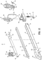
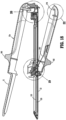
- FIGS. 13-17 illustrate SULU 18.
- SULU 18 includes a body 120, a plurality of staple pushers 122 (only one is shown), a bottom cover 124, a knife 40 having an angled sharpened leading edge or blade 40a, a plurality of staples 126 (only one is shown), and a pivotally mounted safety lockout 128.
- a proximal end of body 120 includes a flexible finger 120a which projects slightly beyond the outer wall defining body 120. Finger 120a frictionally engages an inner wall of channel member 22 to retain the proximal end of SULU 18 within channel member 22 when SULU 18 is releasably positioned within channel member 22.
- body 120 has a plurality of rows of staple retaining slots 130, e.g., four, six, etc. and a linear slotted knife track 132 centrally disposed in body 120.
- Surgical stapler 10 can be dimensioned to receive or accommodate SULU's of different staple line lengths including, e.g., 60mm, 80mm and 100mm.
- Knife 40 includes a downturned hook portion 40b which is positioned to engage upturned hook portion 106 ( FIG. 12 ) of knife actuating bar 44 when SULU 18 is positioned within channel member 22.
- the illustration body 120 includes two staggered rows of slots 130 formed on either side of linear slotted knife track 132.
- the staggered rows of slots 130 extend beyond the distal end of knife track 132 to facilitate staple formation beyond the distal end of the stroke of the knife blade 40.
- Staple pushers 122 may be configured to extend into one or more slots 130.
- a single pusher is associated with each slot 130.
- each pusher 122 can be configured to extend into two adjacent slots 130 and is positioned beneath respective staples 126 which are retained in slots 130.
- each pusher 122 includes a lower cam surface 122a which is positioned to engage one of cam surfaces 114b ( FIG. 12 ) on the distal end of cam bar 46 such that movement of cam bar 46 through SULU 18 sequentially lifts each respective pusher 122 within its respective slot or slots 130 to eject staples from slots 130.
- Bottom cover 124 partially encloses a channel 125 ( FIG. 18 ) formed within the cartridge body 120.
- a longitudinal ridge 134 is formed on an upper surface of bottom cover 124 and provides a bearing surface for a knife supporting member 136 which is secured to a bottom edge of knife 40. Knife 40 may be secured to supporting member 136 via pins, welding or other known fastening techniques.
- knife 40 is guided along knife track 132 as the firing lever 50 is advanced through channel member 22.
- a pair of slots 138 is defined between the sides of ridge 134 and an outer wall of cartridge body 120.
- Longitudinal ridge 134 is positioned within body 120 and dimensioned to be slidably received in elongated slot 120 ( FIG. 12A ) of cam bar 46 such that cam bar 46 is slidably movable through cartridge body 120 about longitudinal ridge 134 to eject staples 126 from SULU 18.
- Safety lockout 128 is pivotally disposed on an upper proximal end of body 120 and is pivotal about a pivot member 150 from a locked orientation ( FIG. 26 ) to unlocked orientation ( FIG. 34 ). Pivot member 150 is received in openings 154 in body 120. A biasing member, e.g., spring 152, is positioned between knife supporting member 136 and safety lockout 128 to urge safety lockout 128 towards the unlocked orientation.
- Safety lockout 128 includes a proximal hook 156 which is positioned to receive an engagement member 158 formed on the knife 40 to retain the safety lockout 128 in the locked orientation when the knife 40 is in the retracted position ( FIG. 19 ).
- safety lockout 128 When the knife 40 is moved towards the advanced position during a firing stroke, engagement member 158 is moved away from proximal hook 156 to allow safety lockout 128 to pivot towards the unlocked position in response to the urging of spring 152. It is noted that safety lockout 128 is prevented from pivoting to the unlocked position when the anvil half-section 12 and cartridge receiving half-section 14 are in the clamped position because the top surface 128a of safety lockout 128 engages an inner surface of anvil half-section 12 to prevent pivoting of safety lockout 128.
- Safety lockout 128 defines a slot 160 dimensioned to slidably receive the knife 40. In the retracted position of the knife 40, the leading edge 40a of knife 40 is confined within slot 160 safety lockout 128 to prevent accidental engagement and injury to medical personnel with leading edge 40a of knife 40.
- anvil half-section 12 includes a proximal handle portion 12a and a distal anvil portion 12b.
- Anvil portion 12b includes a staple deforming portion 198 which, as known in the art, includes a plurality of staple deforming recesses and faces a top surface of SULU 18 when SULU 18 is positioned in the channel member 22.
- the staple deforming portion 198 includes a central longitudinal slot (not shown) for receiving the knife 40 ( FIG. 17 ) as the knife 40 is moved through the SULU 18.
- the staple deforming portion 198 can be formed integrally with anvil half-section 12, or in the alternative, secured to anvil half-section 12 by a fastening process such as welding.
- a pair of locating fingers 170 are positioned adjacent the proximal end of the staple deforming portion 198 of anvil portion 12b. Locating fingers 170 are received in grooves in SULU 18 to properly align SULU 18 with staple determining portion 198 when the apparatus is in a clamped position.
- a central portion of anvil half-section 12 includes a pair of cylindrical lateral support members 172.
- lateral support members 172 are supported in U-shaped recesses 174 defined in a central portion 173 of cartridge receiving half-section 14 ( FIG. 28 ).
- a distal wall 173a of central portion 173 defines a tissue stop ( FIG. 3 ).
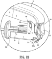
- Lateral support members 172 are also positioned to be received in cutouts 176 formed on spaced flange portions 178 of clamping lever 16 when the clamping lever 16 is moved to the clamped position ( FIG. 2B ).
- Proximal handle portion 12a is ergonomically formed and includes a thumb-engaging abutment 180 and a gripping portion 182.
- a proximal end of handle portion 12a includes a downwardly extending finger 184 which includes a pair of opposed teardrop shaped protrusions 186 which will be discussed in further detail below.
- protrusions 186 may assume a variety of configurations.
- Cartridge receiving half-section 14 includes spaced centrally disposed U-shaped recesses 174 positioned to support lateral support members 172 of anvil half-section 12.
- the proximal end of cartridge receiving half-section 14 includes a pair of vertical support members 188.
- Each vertical support member 188 includes an elongated vertical slot 188a having a rounded bottom surface.
- Vertical slots 188a are dimensioned to receive protrusions 186 formed on finger 184 of anvil half-section 12 ( FIG. 21 ) when the anvil half-section 12 is supported on the cartridge receiving half-section 14 during assembly.
- protrusion 186 By positioning protrusion 186 within the vertical slots 188a, anvil half-section 12 can be pivoted in a scissor-like manner with respect to the cartridge receiving half-section 14 between open and closed positions.
- protrusions 186 have a teardrop profile.
- At least one sidewall of cartridge receiving half-section 14 includes a depression 189 (see FIG. 3 ) which will be discussed in further detail below.
- Clamping lever 16 also includes a handle portion 190 including a grip 190a and a thumb engaging abutment 192. As discussed above, a pair of spaced flange portions 178 is supported on the distal end of clamping lever 16. Each flange portion 178 defines a cutout 176 dimensioned to receive a respective lateral support member 172 of anvil half-section 12 when stapler 10 is moved towards clamped position ( FIG. 2B ). The distal end of clamping lever 16 also defines a pair of openings 194 which are dimensioned to receive a pivot member 187. Pivot member 187 is dimensioned to extend through openings 195 in cartridge receiving half-section 14 and openings 194 in clamp lever 16 to pivotally secure clamp lever 16 to cartridge receiving half-section 14.
- an inner wall of clamping lever 16 includes a protrusion 201.
- Protrusion 201 is positioned within depression 189 ( FIG. 2A ) formed in the sidewall of cartridge receiving half-section 14 to releasably retain clamp lever 16 in the unclamped position or open position ( FIG. 2A ).
- the stationary housing 26 of firing assembly 20 is slid into the channel member 22 through the proximal end of channel member 22 until pivot members 29 are received in recesses 30 formed in the proximal end of channel member 22.
- the SULU 18 can be loaded into distal portion 24a in the manner discussed above.
- anvil section 12 can be assembled to cartridge receiving half-section 14.
- protrusions 186 of fingers 184 are positioned in vertical slots 188a of vertical support member 188 of cartridge receiving half-section 14.
- anvil half-section 12 is rotated towards cartridge receiving half-section 14 to position lateral supports members 172 in U-shaped recesses 174.
- clamping lever 16 In order to position surgical stapler 10 in the clamped position, clamping lever 16 is rotated in a counter-clockwise direction from the position shown in FIG. 2A . As clamping lever 16 is rotated, lateral support members 172 are received in cutouts 176 ( FIG. 2 ) of flange portions 178 and cammed towards cartridge receiving half-section 14. As shown in FIG. 3 , a spring member 200 is secured to an inner surface of clamping lever 16, such as by welding, at a position to engage cartridge receiving portion 14 to urge clamping lever 16 to the non-clamped position shown in FIG. 2A . In the clamped position shown in FIG. 1 , the staple deforming portion 198 is positioned in close approximation with the top surface of SULU 18.
- a pivotal locking member 206 is pivotally supported on the proximal end of stationary housing 26 of firing assembly 20.
- Pivotal locking member 206 includes pivot members 29 which extend through openings 28 defined in stationary housing 26.
- a finger engagement member 212 is positioned on one end of locking member 206 and a latch portion 210 is positioned on the other end of locking member 206.
- Latch portion 206 includes a hook member 210a.
- a biasing member 214 is positioned about a pivot member 29 to urge latch portion 210 inwardly towards stationary housing 26 of firing assembly 20.
- latch portion 210 extends downwardly through an opening 216 in a proximal end of stationary housing 26 to a position below a bottom surface of channel member 22 ( FIG. 20 ).
- the ends of pivot members 29 are received in cutouts 30 formed in the proximal end of cartridge receiving half-section 14 to releasably secure firing assembly 20 within proximal channel portion 24b of channel member 22 ( FIG. 21 ).
- Cutouts 30 are partially defined by downturned fingers 220 to retain firing assembly 26 within channel member 22 ( FIG. 3 ).
- a proximal end of clamping lever 16 includes an engagement member, e.g., cylindrical post 218, which is positioned to be engaged by hook member 210a of latch portion 210 when the clamp lever 16 is moved to the clamped position ( FIG. 27 ).
- an engagement member e.g., cylindrical post 218, which is positioned to be engaged by hook member 210a of latch portion 210 when the clamp lever 16 is moved to the clamped position ( FIG. 27 ).
- an engagement member configurations are envisioned.
- an angled face 222 of latch portion 210 engages post 218.
- This engagement causes locking member 206 to pivot about pivot members 29 such that hook member 210a of latch portion 210 passes by and then snaps into engagement with post 218.
- engagement member 212 of locking member 206 is depressed to pivot latch portion 210 out of engagement with post 218.
- spring member 200 urges clamping lever 16 to the unclamped position.
- guide block 48 is pivotally supported in stationary housing 26 of firing assembly 20.
- Guide block 48 includes a distally extending nose portion 220 ( FIGS. 12 and 26 ) which rests beneath SULU 18 when SULU 18 is supported in channel member 22.
- the internal surface of guide block 48 includes locking surfaces 222 ( FIG. 19 ) which are received in notches 49 and 51 of knife actuating bar 44 when the stapler 10 is in an unclamped position.
- locating fingers 170 engage a top surface of body 120 of SULU 18 to fully seat SULU 18 in channel member 22. As discussed above, locating fingers 170 are received in grooves in SULU 18 to properly position SULU 18 in relation to anvil portion 12b. As SULU 18 is fully seated in channel member 22, SULU 18 presses downwardly on nose portion 220 of guide block 48 to pivot guide block 48 about protrusions 72. When guide block 48 pivots, locking surfaces 222 move from notches 49 and 51 to unlock knife actuating bar 44 ( FIG. 26 ). This configuration prevents movement of the knife actuating bar 44 in relation to guide block 48 prior to clamping to ensure that the knife actuating bar 44 and SULU knife 40 remain properly positioned for operational engagement prior to use.
- slide block 52 of firing assembly 20 is in the retracted position at the proximal end of channel member 22 and stationary housing 26. See FIG. 27 .
- pedal 54 is positioned in cutout 55 of channel member 22 and pin 88 of pedal 54 is positioned in arcuate recess 94 of firing lever 50 beneath stop recesses 94a.
- firing lever 50 can be pivoted to facilitate actuation of stapler 10 from either side of the stapler 10.
- finger 108 of knife actuating bar 44 is positioned adjacent the distal wall of recess 110 of slide block 52.
- Latch portion 210 of locking member 206 is also engaged with post 218 to retain clamping lever 16 in the clamped position.
- knife 40 and cam surfaces 114b of cam bar 46 are positioned in the proximal end of SULU 18 and, proximal hook 156 of safety lockout 128 is positioned in engagement with engagement member 158 of knife 40 to retain safety lockout 128 in the locked orientation.
- downturned hook portion 40b of knife 40 is engaged with upturned hook portion 106 of knife actuating bar 44 to connect firing assembly 20 to knife 40 of SULU 18.
- slide block 52 is moved distally within stationary housing 26 of firing assembly 20 to effect corresponding movement of cam bar 46 and delayed movement of knife actuating bar 44.
- the delayed movement of the knife actuating bar 44 is equal to the length of recess 110 of slide block 52 and results from movement of finger 108 of knife actuating bar 44 within recess 110 of slide block 52. Movement of knife actuating bar 44 with slide block 52 begins when finger 108 abuts the proximal wall 112 of recess 110.
- cam surfaces 114b on sidewalls 114 of cam bar 46 are advanced through SULU 18 to sequentially engage pushers 122 to eject staples 126 from slots 130 of body 120.
- knife actuating bar 44 is engaged with knife 40
- knife 40 is advanced through SULU 18 to incise tissue between the staple lines.
- pedal 54 rides up over channel member 22 and moves along inner surface of stationary housing 26 of firing assembly 20. When this occurs, pin 88 of pedal 54 moves into a stop recess 94a to prevent further pivotal movement of firing lever 50.
- SULU 18 can be replaced multiple times to facilitate multiple uses of stapler 10 on a single patient. Since each SULU 18 is provided with a fresh knife 40, tearing of tissue is minimized.
- the used SULU(S) 18 and the firing assembly 20 can be removed from the channel member 22 and disposed of in an appropriate manner.
- the anvil half-section 12, cartridge receiving half-section 14 and clamping lever 16 can now be sterilized, such as by autoclaving, and reused with a sterilized SULU 18 and firing assembly 20 in the manner discussed above. Because the locking member 206 forms part of the firing assembly 20 and is disposable, fewer areas remain on the reusable components for tissue and fluids to become trapped. As such, the reusable components of the apparatus can be more easily sterilized.
- the SULU 18 and the firing assembly 20 are independently secured to and independently removable from the channel member 22 of the cartridge receiving half-section 14. More specifically, the firing assembly 20 can be installed into and secured within the channel member 22 first, followed by the SULU 18. The SULU 18 engages the firing assembly 20 as the SULU 18 enters the channel member 22. In alternative embodiments, which are discussed below, the SULU 18 and the firing assembly 20 must be assembled to form a single disposable unit before the disposable unit can be secured within the channel member 22. In an embodiment, a lockout structure prevents independent insertion of either the SULU 18 or the firing assembly 20 into the channel member 22. In these embodiments, the SULU 18 must be assembled with the firing assembly 20 to form a single disposable unit before securing the single disposable unit within the channel member 22 of the cartridge receiving half-section 14. Specific embodiments are discussed below.
- FIGS. 35A-B illustrate an embodiment of the firing assembly 320.
- the firing assembly 320 includes a stationary housing 326 having a distal end 321 configured to receive a proximal end 319 of the SULU 318.
- the firing assembly 320 also includes a cam bar 346 and a knife actuating bar (not shown) movably positioned within stationary housing 326. Similar to the cam bar 46 described earlier, the cam bar 346 is configured to move through the SULU 318 to eject fasteners 126 ( FIG. 17 ) from the SULU 18 upon actuation of the firing assembly 320.
- the knife actuating bar is not illustrated in FIGS. 35A-B , but it is substantially similar to the knife actuating bar 44 illustrated in FIG. 12 .
- the knife actuating bar is configured to releasably engage the SULU 318 and may include an upturned hook portion 106 ( FIG. 12 ) at a distal end thereof configured to releasbly engage a downturned hook portion 40b ( FIG. 17 ) of the knife 40 of the SULU 318.
- the firing assembly 320 includes a spring-loaded knob 330 supported at the proximal end 323 of the stationary housing 326.
- the knob 330 is operatively connected with the cam bar 346 and the knife actuating bar.
- the knob 330 includes a spring 332 which may directly abut or engage the proximal ends of the cam bar 346 and the knife actuating bar.
- Spring 332 is normally in compression and urges cam bar 346 distally within stationary housing 326. Alternately, spring 332 may be engaged with the cam bar 346 via a slide block, e.g., slide block 52 in FIG. 12 .
- the knob 330 includes a retainer pin 334 operatively connected with the spring 332.
- the retainer pin 334 may have a plate-like configuration and is positioned perpendicular to a longitudinal axis "A" of the firing assembly 320.
- the retainer pin 334 has a lower end 336 which extends below the bottom surface 352 of stationary housing 326 of firing assembly 320.
- the bottom surface 352 of stationary housing 326 defines an elongated slot 354 which receives the lower end 336 of the retainer pin 334 such that the retainer pin 334 can move axially through the guiding slot 354.
- the spring 332 is in a compressed state as illustrated in FIG. 35A .
- the spring 332 which is in compression, urges the cam bar 346 toward the forward position "F" ( FIG. 35B ).
- the cam bar 346 prevents the SULU 318 from being received in the distal end of the firing assembly 320. More specifically, the proximal end of SULU 318 is not configured to receive, or operatively engage, the distal end of the cam bar 346 and knife actuating bar when the cam bar 346 and knife actuating bar are in the forward position F.
- a clinician needs to first retract the cam bar 346 and the knife actuating bar to the retracted position "R" shown in FIG. 35A by sliding the retainer pin 334 against the bias of spring 332 to the proximal end of the slot 354.
- the clinician places the proximal end 319 of the SULU 318 into the the distal end 321 of the stationary housing 326 of the firing assembly 320.
- the clinician releases the retainer pin 334, which, allows the cam bar 346 to spring forwardly to the forward position "F” to operatively engage the SULU 318.
- the clinician To disengage the SULU 318 from the firing assembly 320, the clinician must first retract the cam bar 346 and the knife actuating bar to the retracted position "R" by moving the retainer pin 334 to the proximal end of the guiding slot 354. During this process, the cam bar disengages from the SULU 318. The clinician can then remove the proximal end 319 of the SULU 318 from the distal end 321 of the firing assembly 320. When the clinician releases the retainer pin 334, the cam bar 346 is urged forwardly by spring 332 to return to the forward position "F.”
- the channel member 322 defines an indentation 324 on its bottom surface 326.
- the indentation 324 is dimensioned to receive the lower end 336 of the retainer pin 334 when the firing assembly 320 is positioned within the channel member 322 and the retainer pin 334 is in the forward position shown in FIG. 35B . Receipt of the retainer pin 334 in the indentation 324 of channel member 322 prevents movement of retainer pin 334 to its retracted position shown in FIG. 35A and, thus prevents insertion of SULU 318 into the stationary housing 326 of the firing assembly 320 when the firing assembly 320 is received in the channel member 322.
- engagement between the retainer pin 334 and the indentation 324 prevents retraction of the cam bar 346.
- the cam bar 346 will be maintained in the forward position "F" preventing subsequent operative engagement of the SULU 318 with the firing assembly 320.
- the SULU 318 cannot be disengaged from the firing assembly 320 once both are mounted in the channel member 322, because the indentation 324 prevents retraction of the cam bar 346.
- firing assembly 420 includes a stationary housing 426 having a distal end 421 configured to receive a proximal end 419 of the SULU 418 ( FIG. 36E ).
- the firing assembly 420 also includes a knife actuating bar 444 centrally located along the longitudinal axis "A" of the firing assembly 420 and a cam bar 445 including spaced sidewalls 445a ( FIG. 36B ).
- the knife actuating bar 444 has a similar configuration as that of the knife actuating bar 44 described earlier. More specifically, the knife actuating bar 444 may include an upturned hook portion 406 at its distal end 408 configured to releasbly engage a downturned hook portion 40b ( FIG. 17 ) of knife 40 of the SULU 418.
- the knife actuating bar 444 is pivotally connected to a retainer member 446 located at a proximal end 423 of the firing assembly 420 via a pivotal connection 448.
- the stationary housing 426 of firing assembly 420 further defines an elongated groove or slot 450 in the bottom surface 452 thereof.
- the slot 450 is dimensioned to facilitate passage of the distal end 408 of the knife actuating bar 444 therethrough as the knife actuating bar 444 pivots relative to the retainer member 446.
- the knife actuating bar 444 is positioned above a bottom surface 452 of stationary housing 426 parallel to the longitudinal axis "A" of the firing assembly 420.
- the firing assembly 420 further includes a button 454 mounted on top of the knife actuating bar 444 to effect pivotal movement of the knife actuating bar 444 in relation to pivotal connection 448.
- the button 454 may be positioned adjacent to the distal end 408 of the knife actuating bar 444.
- the button 454 When the button 454 is depressed in the direction indicated by the arrow "D" as indicated in FIG. 36D , the knife actuating bar 444 rotates downwardly in a counterclockwise direction relative to the retainer member 446. During this process, the distal end 408 of the knife actuating bar 444 passes through the slot 450 and extends beyond the bottom surface 452 of stationary housing 426.
- a biasing member or spring may be provided to urge button 454 to its non-depressed position, such that upon release of the button 454, the button 454 and knife actuating bar 444 return to their non-depressed or normal positions. Accordingly, by manipulating button 454, the knife actuating bar 444 can be selectively moved from the normal position within stationary housing 426 to the pivoted position extending through slot 450.
- the proximal end 419 of the SULU 418 is able to pass over the distal end 408 of knife actuating bar 444 and into the distal end 421 of the firing assembly 420.
- the clinician releases the button 454 to allow knife engagement bar 444 to engage the SULU 418. More specifically, as the distal end 408 of the knife actuating bar 444 moves upwardly, the upturned hook portion 406 of the knife actuating bar 444 engages the downward hook portion 40b ( FIG. 17 ) of the knife 40 of the SULU 418 to secure firing assembly 420 to SULU 418.
- the upturned hook portion 406 of the knife actuating bar 444 must be disengaged from the downward hook portion 40b of the knife 40 ( FIG. 17 ) of the SULU 418.
- the distal end 408 of the knife actuating bar 444 is pushed downwardly through slot 450 by depressing button 454.
- the upturned hook portion 406 disengages from the downward hook portion 40b ( FIG. 17 ) of the SULU 418.
- the clinician removes the proximal end 419 of the SULU 418 from the distal end 421 of the firing assembly 420. Thereafter, the clinician releases the button 454 to restore the knife actuating bar 444 to its normal position.
- the bottom surface of the channel member 22 covers the slot 450, to prevent pivotal movement of the knife actuating bar 444 through slot 450. Accordingly, if the firing assembly 420 is mounted in the channel member 22 without the SULU 418 already operatively engaged with the firing assembly 420, the SULU 418 cannot be subsequently loaded to the firing assembly 420, because the knife actuating bar 444, when confined to its normal position, prevents proper engagement of the SULU 418 with the firing assembly 420.
- the SULU 418 cannot be disengaged from the firing assembly 420 once mounted in the channel member 22, because the knife actuating bar 444, when confined to its normal portion, prevents release of the SULU 418 from the firing assembly 420.
- a rotary knob 570 is removably coupled to the channel member 522.
- the rotary knob 570 includes an H-shaped base 572, a grip member 574 extending upwardly from an upper surface 576 of the H-shaped base 572, and a distal member 578 extending downwardly from a lower surface 579 of the base 572.
- the base 572 includes longitudinal side walls 572a and 572c, each defining a length which is greater than the width "w" of the channel member 522, i.e., the lateral distance between the sidewalls 582 of the channel member 522.
- the base 572 also includes front and rear walls 572b and 572d each defining a length which is less than the width "w" of the channel member 522.
- the channel member 522 defines a pair of slots 580 symmetrically arranged on the sidewalls 582 of the channel member 522.
- the slots 580 are dimensioned to receive a portion of the base 572 of the rotary knob 570.
- the slots 580 are defined on the sidewalls 582 of the channel member 522 at a position immediately above the area 560 at which the proximal end of the SULU 528 and the distal end of the firing assembly 520 become engaged, as shown in FIG. 37A .
- the rotary member 570 is movable from an unlocked position to a locked position within the channel member 522 as illustrated in FIGS. 37C-E .
- the sidewalls 572a, 572c of the base 572 of rotary member 570 are laterally aligned with the slots 580, and the front and rear walls 572b and 572d extend across the lateral space defined between the sidewalls 582 of the channel member 522.
- Rotation of the grip member 574 of rotary member 570 effects corresponding rotation of the rotary member 570 within the channel member 522.
- the sidewalls 572a, 572c move from a position aligned with slots 580 to a position transverse to slots 580.
- FIGS. 37F-H illustrate the rotary member 570 in the locked position, which is rotated about 90 degrees from the unlocked position.
- the sidewalls 572a and 572c of the base 572 extend across the lateral space defined between the pair of sidewalls 582 of the channel member 522, such that the front and rear walls 572b and 572d are positioned within the slots 580.
- the rotary member 570 is locked within channel member 522.
- the rotary member 570 is rotatable about 90 degrees to transition the rotary member 570 back to the unlocked position.
- a clinician In use, to secure the SULU 518 and the firing assembly 520 within the channel member 522, a clinician first engages the SULU 518 with the firing assembly 520 to form a single disposable unit. Next, the clinician positions the single disposable unit into the channel member 522, such that the engagement area 560 ( FIG. 37A ) between the SULU 518 and the firing assembly 520 is placed immediately beneath the pair of slots 580 defined in the channel member 522. Then, the clinician positions the rotary knob 570 above the channel member 522 in a manner such that the base 572 is parallel to the bottom surface 526 of the channel member 522 as illustrated in FIGS. 37I-J . Next, the clinician moves the rotary knob 570 downwardly, in the direction indicated by arrow "G" in FIG.
- the rotary knob 570 When the rotary knob 570 is in the locked position, the rotary knob 570 sits atop the upper surface of each of the SULU 518 and the firing assembly 520, and the distal member 578 of the rotary knob 570 abuts the proximal end of the SULU 518 as well as the distal end of the firing assembly 520. As such, when the rotary knob 570 is rotated to the locked position, the rotary knob 570, via engagement with the slots 580, secures the SULU 518 and the firing assembly 520 within the channel member 522.
- the clinician may introduce the SULU 518 and the firing assembly 520 into the channel member 522 separately, and subsequently mount the rotary knob 570 in the channel member 522 to secure the SULU 518 and firing assembly 520 in the channel member 522.
- the clinician rotates the rotary knob 570 to its unlocked position, and then lifts the rotary knob 570 upwardly from the channel member 522.
- the clinician may then remove the SULU 518 and the firing assembly 520 from the channel member 22, either as a single unit or separately.
- the rotary knob 570 In the methods of installing and uninstalling the SULU 518 and the firing assembly 520 described above, if the rotary knob 570 is rotated to the locked position before introducing the SULU 518 into the channel member 522, the rotary knob 570 will prevent subsequent entry of the SULU 518 into the channel member 522.
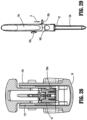
- firing assembly 620 has a stationary housing 626 including distal end 621 configured to receive a proximal end 619 of a SULU 618.
- the distal end 621 of the stationary housing 626 defines an elongated longitudinal slot 670 that is dimensioned to accommodate a spring-loaded switch 672 which is slidable through the slot 670.
- the switch 672 protrudes laterally across the slot 670 and extends both inwardly and outwardly beyond the sidewall 664 of the stationary housing 626 of the firing assembly 620.
- the SULU 618 defines a detent 680 on its sidewall 682 at the proximal end 619 thereof.
- the detent 680 is dimensioned to receive and releasbly engage an inner surface of the switch 672.
- the spring-loaded switch 672 is positioned at the proximal end 670a of the slot 670.
- the switch 672 In order to secure the SULU 618 to the firing assembly 620, prior to the proximal end 619 of the SULU 618 being positioned within the distal end 621 of the firing assembly 620, the switch 672 must be moved along the length of the slot 670 to the distal end 670b of the slot 670.
- the detent 680 is positioned to receive switch 672. In this position, the inner surface of the switch 672 can be slid into the detent 680 formed on the SULU 618.
- the proximal end 619 of the SULU 618 is secured to the distal end 621 of the firing assembly 620 and the switch 672 is retained in the distal end of slot 670.
- the channel member 622 also defines a depression 624 on an inner face of a sidewall 626 thereof.
- the depression 624 is dimensioned to receive the switch 672 when the switch 672 is in the distal end of the slot 670 .
- the firing assembly 620 and the SULU 618 must be secured together first, before the SULU 618 and firing assembly 620 can be inserted into the channel member 622. If the firing assembly 620 is introduced into the channel assembly 622 without first being engaged with the SULU 618, the switch 672, which would be in its normal proximal position, would be misaligned with the depression 624 in the channel member 622, and, thus, would be prevented from being received within the channel 622.
Landscapes
- Health & Medical Sciences (AREA)
- Life Sciences & Earth Sciences (AREA)
- Surgery (AREA)
- Heart & Thoracic Surgery (AREA)
- Engineering & Computer Science (AREA)
- Biomedical Technology (AREA)
- Nuclear Medicine, Radiotherapy & Molecular Imaging (AREA)
- Medical Informatics (AREA)
- Molecular Biology (AREA)
- Animal Behavior & Ethology (AREA)
- General Health & Medical Sciences (AREA)
- Public Health (AREA)
- Veterinary Medicine (AREA)
- Surgical Instruments (AREA)
Description
- The present disclosure relates to a surgical fastener applying apparatus and, more particularly, to a surgical fastener applying apparatus having reusable and disposable components.
- Surgical fastener applying apparatus, wherein tissue is first grasped or clamped between opposing jaw structures and then joined by means of surgical fasteners, are well known in the art. In some such apparatus, a knife is provided to cut the tissue which has been joined by the fasteners. The fasteners are typically in the form of surgical staples, although, other surgical fasteners may also be utilized, such as, for example, clips or two part polymeric surgical fasteners.
- Surgical fastener applying apparatus typically include two elongated beam members which are used to capture or clamp tissue therebetween. Typically, one of the beam members carries a disposable cartridge assembly which houses a plurality of staples arranged in at least two lateral rows, while the other beam member includes an anvil which defines a surface for forming the staple legs as the staples are driven from the cartridge assembly. Where two part fasteners are used, the beam member which includes the anvil carries a mating part of the two part fastener, e.g. the receiver. Generally, the staple formation process is affected by the interaction between one or more longitudinally moving camming members and a series of individual staple pushers. As the camming members travel longitudinally through the cartridge carrying beam member, the individual pusher members are biased upwardly into a backspan of the staples supported within the cartridge assembly to sequentially eject the staples from the cartridge. A knife may be provided to travel with the camming members between the staple rows to cut the tissue between the rows of formed staples. An example of such an instrument is disclosed in
U.S. Pat. No. 7,631794 . - Because of the dangers associated with improper sterilization of surgical apparatus, fastener applying apparatus are typically disposable after use. Although the cartridge assembly may be replaced to perform multiple fastener applying operations on a single patient, the staple applying apparatus is typically disposable after a surgical procedure has been completed. This requirement of disposability may increase the costs associated with surgical procedures. Although reusable fastener applying apparatus have been developed, such apparatus can be overly complex and prove difficult to sterilize.
- A need exists in the art for a fastener applying apparatus which includes reusable components, is not overly complex and is configured to facilitate proper sterilization after use in a surgical procedure. Examples of prior art fastener applying apparatuses that include a lock out structure for single use loading units include
WO 2013/022704 A1 ,WO 2013/022703 A1 andUS 2005/222616 A1 . - The present invention relates to a surgical fastener applying apparatus for applying surgical fasteners to tissue, the apparatus as defined in
claim 1 annexed hereto. In an embodiment of the present disclosure, a surgical fastener applying apparatus includes an anvil half-section, a cartridge receiving half-section defining an elongated channel member, and a single use loading unit and a firing assembly configured to be received within the channel member. The firing assembly includes a lockout structure that prevents full insertion of the single use loading unit into the channel member after the firing assembly is mounted in the channel member. - The single use loading unit and the firing assembly together form a single disposable unit when the single use loading unit is engaged with the firing assembly.
- The lockout structure defines a first position which prevents the single use loading unit from mating with the firing assembly, and a second position which allows the single use loading unit to mate with the firing assembly. The lockout structure is configured to move between its first position and its second position. However, the lockout structure is obstructed from moving from the first position to the second position when the firing assembly is supported within the channel member.
- In an embodiment, the lockout structure includes a spring-loaded knob with a retainer pin. The retainer pin is operatively connected to a cam bar of the firing assembly. When the lockout structure is in the first position, the cam bar is in a forward position relative to the firing assembly, thus preventing a proximal end of the single use loading unit from entering a distal end of the firing assembly.
- In an embodiment, the present disclosure provides a surgical fastener applying apparatus including an anvil half-section, a cartridge receiving half-section defining an elongated channel member, and a single use loading unit and a firing assembly configured to be received within the channel member. The firing assembly may include a lockout structure that prevents full insertion of the firing assembly into the channel member, if the single use loading unit is not mounted to the firing assembly.
- In an embodiment, the lockout structure may define a first position which prevents full insertion of the firing assembly into the channel member, and a second position which allows full insertion of the firing assembly into the channel member. The lockout structure is configured to move between its first position and its second position. However, the lockout structure is obstructed from moving from the second position to the first position when the firing assembly is engaged with the single use loading unit.
- Various embodiments of the presently disclosed surgical fastener applying apparatus will now be described herein with reference to the accompanying figures wherein:
-
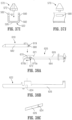
FIG. 1 is a side perspective view from the distal end of a presently disclosed surgical fastener applying apparatus in the clamped position; -
FIG. 2 is a side perspective view from the proximal end of the surgical fastener applying apparatus shown inFIG. 1 in the clamped position; -
FIG. 2A is a side perspective view of the surgical fastener applying apparatus shown inFIG. 1 in the open position; -
FIG. 2B is an enlarged view of the indicated areas of detail shown inFIG. 2A ; -
FIG. 3 is a side perspective view with parts separated of the surgical fastener applying apparatus shown inFIG. 1 ; -
FIG. 3A is a side cross-sectional view of the clamp lever of the fastener applying apparatus shown inFIG. 1 ; -
FIG. 4 is a side perspective view of the cartridge receiving half-section of the surgical fastener applying apparatus shown inFIG. 1 with the single use loading unit and the firing assembly supported within the cartridge receiving half-section; -
FIG. 5 is an enlarged view of the indicated area of detail shown inFIG. 4 ; -
FIG. 6 is a perspective view from above of the cartridge receiving half-section of the surgical fastener applying apparatus with the SULU and the firing assembly supported therein; -
FIG. 7 is an enlarged view of the indicated area of detail shown inFIG. 6 ; -
FIG. 8 is a front end perspective view from above the firing assembly of the surgical fastener applying apparatus shown inFIG. 3 ; -
FIG. 9 is an enlarged view of the indicated area of detail shown inFIG. 8 ; -
FIG. 9A is a top, perspective view of the channel member with the firing assembly releasably secured therein; -
FIG. 9B is an enlarged view of the indicated area of detail shown inFIG. 9A ; -
FIG. 9C is a top, perspective view of a central portion of the channel member; -
FIG. 10 is a rear end perspective view from above of the firing assembly shown inFIG. 8 ; -
FIG. 11 is an enlarged view of the indicated area of detail shown inFIG. 10 ; -
FIG. 12 is a side perspective view of the firing assembly shown inFIG. 10 with parts separated; -
FIG. 12A is a bottom perspective view of the cam bar of the firing assembly shown inFIG. 12 ; -
FIG. 12B is a bottom perspective view of the firing lever of the firing assembly shown inFIG. 12 ; -
FIG. 13 is a side perspective view of the SULU of the surgical fastener applying apparatus shown inFIG. 1 ; -
FIG. 14 is an enlarged view of the indicated area of detail shown inFIG. 13 ; -
FIG. 15 is a front perspective view of the SULU shown inFIG. 13 ; -
FIG. 16 is an enlarged view of the indicated area of detail shown inFIG. 15 ; -
FIG. 17 is a side perspective view with parts separated of the SULU shown inFIG. 15 ; -
FIG. 18 is a side cross-sectional view of the surgical fastener applying apparatus shown inFIG. 1 in the open position; -
FIG. 19 is an enlarged view of the indicated area of detail shown inFIG. 18 ; -
FIG. 20 is an enlarged view of the indicated area of detail shown inFIG. 18 ; -
FIG. 21 is a perspective view of the proximal end of the surgical fastener applying apparatus shown inFIG. 18 in the open position; -
FIG. 22 is an enlarged view of the indicated area of detail shown inFIG. 18 ; -
FIG. 23 is a perspective view from below the proximal end of the clamping lever of the surgical fastener applying apparatus shown inFIG. 1 ; -
FIG. 24 is a side perspective view of the surgical fastener applying apparatus shown inFIG. 1 in the clamped position; -
FIG. 25 is a side cross-sectional view of the surgical fastener applying apparatus shown inFIG. 24 in the clamped position; -
FIG. 26 is an enlarged view of the indicated area of detail shown inFIG. 25 ; -
FIG. 27 is an enlarged view of the indicated area of detail shown inFIG. 25 ; -
FIG. 28 is a cross-sectional view taken along section lines 28-28 ofFIG. 26 ; -
FIG. 29 is a top view of the surgical fastener applying apparatus shown inFIG. 1 as the firing assembly is moved through an actuating stroke to eject fasteners from the fastener applying apparatus; -
FIG. 30 is a side cross-sectional view of the surgical fastener applying apparatus shown inFIG. 29 with the firing assembly in the actuated position; -
FIG. 31 is an enlarged view of the indicated area of detail shown inFIG. 30 ; -
FIG. 32 is an enlarged view of the indicated are of detail shown inFIG. 30 ; -
FIG. 33 is a side cross-sectional view of the surgical fastener applying apparatus shown inFIG. 1 after the apparatus has been fired and moved to the open position; -
FIG. 34 is an enlarged view of the indicated area of detail shown inFIG. 33 ; -
FIG. 35A is a side schematic view of an embodiment of the firing assembly with a cam bar illustrated in a retracted position; -
FIG. 35B is a side schematic view of the firing assembly ofFIG. 35A with the cam bar in a forward position; -
FIG. 35C is a side schematic view of an alternate embodiment of the channel member including an indentation therein; -
FIG. 36A is a side schematic view of another example of the firing assembly having a knife actuating bar in a normal non-pivoted, position; -
FIG. 36B is a top, perspective view of the firing assembly ofFIG. 36A ; -
FIG. 36C is a side, perspective, cutaway view of the stationary housing of the firing assembly ofFIG. 36B illustrating an elongated slot defined therein; -
FIG. 36D is a side schematic view of the firing assembly ofFIG. 36A with the knife actuating bar in a pivoted position; -
FIG. 36E is a side schematic view of the firing assembly ofFIG. 36A with the single use loading unit mounted thereto; -
FIG. 37A is a side schematic view of an alternate example of the channel member having a rotary knob mounted thereto; -
FIG. 37B is a top, perspective view of the rotary knob ofFIG. 37A ; -
FIG. 37C is a cross-sectional schematic view of the rotary knob ofFIG. 37B having sidewalls aligned with slots in the channel member; -
FIG. 37D is a top, planar view of the rotary knob ofFIG. 37C within the channel member; -
FIG. 37E is an enlarged view of the indicated area of detail ofFIG. 37D ; -
FIG. 37F a cross-sectional view of the channel member and an end view of the rotary knob ofFIG. 37E rotated into the slots in the channel member; -
FIG. 37G is a top, planar view of the rotary knob ofFIG. 37F within the channel member; -
FIG. 37H is an enlarged view of the indicated area of detail ofFIG. 37G ; -
FIG. 37I is a cross-sectional view of the channel member and a view of the rotary knob rotary knob ofFIG. 37B as the rotary knob is inserted into the channel member; -
FIG. 37J is a side view of a cutaway portion of the channel member and an end view of the rotary knob ofFIG. 37I ; -
FIG. 38A is a side view of another alternate example of the firing assembly with a switch mounted therein; -
FIG. 38B is an alternate example of the channel member having a depression defined therein to receive the switch ofFIG. 38A ; and -
FIG. 38C is a side, perspective view of an inner face of a sidewall of the channel member ofFIG. 38A . - Embodiments of the presently disclosed surgical fastener applying apparatus in accordance with the present disclosure will now be described in detail with reference to the drawings wherein like reference numerals identify similar or identical structural elements. As used herein, as is traditional, the term "proximal" refers to the part of the apparatus which is closer to the user and the term distal refers to the part of the apparatus which is further away from the user.
- Referring to
FIGS. 1-3 ,surgical stapler 10 includes an anvil half-section 12, a cartridge receiving half-section 14, a clampinglever 16, a single use loading unit 18 (hereinafter "SULU") and a firingassembly 20. Anvil half-section 12, cartridge receiving half-section 14 and clampinglever 16 are constructed to be reusable components and, as such, are constructed from a biocompatible material suitable for sterilization and repeated use, e.g., stainless steel. In contrast,SULU 18 and firingassembly 20 are constructed to be disposable and, as such, may be constructed from any suitable biocompatible material, e.g., plastics, metals, combinations thereof, having the requisite strength characteristics. - Referring to
FIGS. 3-7 , cartridge receiving half-section 14 defines anelongated channel member 22 which defines aU-shaped channel 24 having adistal portion 24a dimensioned to releasably receive aSULU 18 and a proximal portion 24b dimensioned to releasably receive firingassembly 20. U-shaped channel may have a flat bottom and straight legs in cross-section or it may have a slightly rounded bottom and/or at least one curved leg. In cross-section, the bottom of the U may connect with the legs by a sharp corner or at least one slightly rounded corner. Firingassembly 20 includes a stationary housing 26 (see alsoFIG. 12 ) having a proximalend including openings 28 which receive ends of pivot members 29 (FIG. 12 ).Pivot members 29 pivotally support a lockingmember 206 on a proximal end ofstationary housing 26 and extend throughopenings 28 intorecesses 30 formed in a proximal portion of cartridge receiving half-section 14 to releasably secure the proximal end of firingassembly 20 within the proximal portion 24b ofchannel member 22 as will be discussed in further detail below. The distal end of firingassembly 20 defines atriangular cutout 64d.Triangular cutout 64d may be a triangle or may be a triangle having sharp corners or at least one rounded or chamfered corner, and may have no equal sides or two or three equal sides.Cutout 64d is positioned to receive aprotrusion 65 formed on an inner wall of channel member 22 (seeFIGS. 9A-9C ) to releasably secure the distal end of firingassembly 20 withinchannel member 22. The structure of firingassembly 20 will also be discussed in further detail below. Likewise,SULU 18 includes a pair ofdistal protrusions 32 which are positioned incutouts 34 formed at the distal end ofchannel member 22 to releasablysecure SULU 18 within thedistal portion 24a ofchannel member 22. During assembly, firingassembly 20 must be inserted into proximal portion 24b ofchannel member 22 beforeSULU 18 is inserted intodistal portion 24a ofchannel member 22 as will be discussed below. To positionSULU 18 inchannel member 22,protrusions 32 onSULU 18 are positioned withincutouts 34 whileSULU 18 is positioned above and at an angle to channelmember 22. Thereafter,SULU 18 can be rotated downwardly intodistal portion 24a ofU-shaped channel 24. This allows for the drive components of firingassembly 20 to properly align with components ofSULU 18 and also facilitates engagement of the firingassembly 20 with a knife 40 (FIG. 17 ) supported withinSULU 18. A proximal end ofSULU 18 includes an outwardly extending serrated surface 42 (FIG. 7 ) to facilitate gripping of the proximal end ofSULU 18 to allow for removal and/or replacement ofSULU 18 fromchannel member 22. Prior to movement ofstapler 10 to the clamped position, as will be discussed below, serrated grippingsurface 42 will not fully seat withindistal portion 24a ofchannel member 22. - Referring to
FIGS. 8-12 , firingassembly 20 includesstationary housing 26, aknife actuating bar 44, acam bar 46, aguide block 48, a firinglever 50, aslide block 52, apedal 54 and the pivotal locking member 206 (FIG. 12 ).Stationary housing 26 includes aU-shaped frame 60 including abottom wall 62 and a pair ofsidewalls 64. The distal end of eachsidewall 64 defines aproximal step 64b, a distalangled portion 64c (FIG. 9 ) and thetriangular cutout 64d. As discussed above,triangular cutout 64d is positioned to receive the protrusion 65 (FIG. 9B ) formed on an inner wall ofchannel member 22. A proximal end of eachsidewall 64 includes a pair of transversely extending deformable wall portions 66 (FIG. 11 ) which are spaced from a proximal end ofslide block 52 and define an area betweenwall portions 66 andslide block 52 for pivotally receiving lockingmember 206 as will be discussed in further detail below. -
Guide block 48 includes a body defining three longitudinal slots 70a-c and a pair of outwardly extendingprotrusions 72. In an embodiment, eachprotrusion 72 is cylindrical and includes a taperedportion 72a (FIG. 9 ).Cylindrical protrusion 72 may be a cylinder with a circular cross-section, or may have a slightly oblong cross-section. Additionally,cylindrical protrusion 72 may have a blunt end or a slightly rounded or tapered end. Alternately, other protrusion configurations are envisioned.Protrusions 72 are dimensioned to be received in openings 74 (FIG. 12 ) formed insidewalls 64 ofstationary housing 26 to axiallyfix guide block 48 within the distal end ofstationary housing 26.Protrusions 72 allow for a degree of pivotal movement ofguide block 48 withinU-shaped frame 60. As will be discussed in further detail below, guideblock 48 is pivotal from a first position (FIG. 19 ) in locking engagement withnotches knife actuating bar 44 to a second position (FIG. 26 ) disengaged fromnotches knife actuating bar 44 in response to movement ofstapler 10 to the clamped position. A torsion spring is provided aboutprotrusion 72 to urgeguide block 48 into locking engagement withnotches respective sidewall 114 ofcam bar 46. Similarly, slot 70b is dimensioned to slidably receiveknife actuating bar 44. -
Slide block 52 includes a hub 80 which includes aresilient finger 80a configured to be snap-fit into apivot hole 82 formed in firinglever 50. Firinglever 50 is pivotal about hub 80 when theslide block 52 is in a retracted position to facilitate actuation of the firingassembly 20 from either side ofstapler 10.Pedal 54 is reciprocally received within ahole 84 formed inslide block 52.Pedal 54 includes asplit body portion 54a which is configured to straddle aproximal end 102 ofknife actuating bar 44. In an embodiment,Split body portion 54a includes an angleddistal surface 86. Apin 88 extends upwardly from pedal 54 throughhole 84 inslide block 52. A biasingmember 90 is positioned betweensplit body portion 54a andslide block 52, aboutpin 88 to urgepedal 54 downwardly away fromslide block 52 to an extended position. In the retracted position ofslide block 52,pedal 54 is received in acutout 55 formed in abottom wall 22a of channel member 22 (FIG. 20 ). - Firing
lever 50 includes first and secondfinger engagement members lever 50 through a firing stroke from either side ofstapler 10. An arcuate recess 94 (FIG. 12B ) is formed in a bottom surface of firinglever 50 which slidably receivespin 88 ofpedal 54 to define the range of rotation through which firinglever 50 can pivot about hub 80 ofslide block 52. As used herein, a firing stroke is defined as movement of firinglever 50 from a fully retracted position (FIG. 25 ) to a fully advanced position (FIG. 30 ). Astop recess 94a is formed at each end ofarcuate recess 94. Stop recesses 94a are configured and dimensioned to receive the end ofpin 88 ofpedal 54 to prevent pivotal movement of firinglever 50 about hub 80 during a firing stroke ofsurgical stapler 10. More specifically, when the firingassembly 20 is actuated to advanceslide block 52 distally withinstationary housing 26, angleddistal surface 86 ofpedal 54 engageschannel member 22 and is cammed out of cutout 55 (FIG. 27 ) to urgepin 88 upwardly into astop recess 94a to prevent pivotal movement of firinglever 50 during movement of firinglever 50 through a firing stroke. As is evident, pin 88 must be positioned beneath astop recess 94a to allowpedal 54 to lift upwardly fromcutout 55 to allow firinglever 50 to be moved through the firing stroke. Thus, firinglever 50 must be pivoted to one side or the other of firingassembly 20 before the firinglever 50 can be moved through a firing stroke. -
Knife actuating bar 44 includes a proximal end having a steppedportion 100 which includes a proximalfirst step 102 having a first height and asecond step 104 having a second height which is greater than the first height. A distal end of actuatingbar 44 includes anupturned hook portion 106 and upper andlower notches finger 108 projects upwardly fromknife actuating bar 44 between first andsecond steps FIG. 27 ,finger 108 is slidably received within arecess 110 formed in an underside ofslide block 52. Whenslide block 52 is advanced distally withinstationary housing 26,finger 108 moves withinrecess 110 such thatslide block 52 moves in relation toknife actuating bar 44 untilfinger 108 engages a wall 112 (FIG. 32 ) defining a proximal end ofrecess 110. Whenfinger 108 engageswall 112, further distal movement ofslide block 52 will also effect distal movement ofknife actuating bar 44. As will be evident below, this arrangement allows for staples to be ejected fromSULU 18 prior to cutting of tissue. - Referring to
FIGS. 12 and12A ,cam bar 46 includes a pair ofsidewalls 114 and a base wall 116 (FIG. 12A ). The proximal end 114a of eachsidewall 114 includes a raisedwall portion 118. Each raisedwall portion 118 is configured to be fixedly received in a slot (not shown) formed in an underside ofslide block 52 to fixedly secure the proximal end ofcam bar 46 to slideblock 52. Alternately,slide block 52 may be molded about the proximal end ofknife actuating bar 44. The distal end of eachsidewall 114 includes anangled camming surface 114b.Base wall 116 defines a distally extending elongated slot 123 (FIG. 12A ) which extends from the distal end ofcam bar 46 along a substantial length of thecam bar 46 and a proximally extendinglongitudinal slot 121.Slot 121 is positioned to facilitate the passage ofpedal 54 throughcutout 55 ofchannel member 22 whenslide block 52 is in the retracted position. SeeFIG. 27 . -
Sidewalls 114 ofcam bar 46 are slidably positioned in slots 70a and 70c ofguide block 48 andknife actuating bar 44 is slidably positioned in longitudinal slot 70b ofguide block 48. When firingassembly 20 is supported inchannel member 22 and firinglever 50 is pivoted to one side ofstationary housing 26 and pushed distally,slide block 52 is moved distally withinstationary housing 26. Asslide block 52 begins to move distally, taperedsurface 86 ofpedal 54 engages a proximal edge ofchannel member 22 definingcutout 55 to urgepedal 54 upwardly out ofcutout 55, throughslot 121 ofcam bar 46, and onto an inner surface ofstationary housing 26 of firing assembly 20 (FIG. 27 ). As this occurs, pin 88 ofpedal 54 moves into astop recess 94a to prevent further pivotal movement of firinglever 50. If firinglever 50 is not pivoted to a position in whichpin 88 is positioned beneath astop recess 94a,pedal 54 will be prevented from moving upwardly out ofcutout 55 and firinglever 50 will be prevented from moving through a firing stroke. As firinglever 50 is moved distally,finger 108 moves withinrecess 110 such thatknife actuating bar 44 remains stationary ascam bar 46 is advanced distally. Whenfinger 108 engagesproximal wall 112 definingrecess 110,knife actuating bar 44 is moved distally withslide block 52 andcam bar 46. As will be discussed below, whencam bar 46 andknife actuating bar 44 are moved distally withinstationary housing 26 of firingassembly 20 andchannel member 22, angled camming surfaces 114b ofcam bar 46 are moved throughSULU 18 to eject fasteners fromSULU 18. Simultaneously, although with a preset delay equal to the length of recess 110 (FIG. 32 ),knife actuating bar 44 drives aknife blade 40 throughSULU 18 to dissect tissue. -
U.S. Patent No. 7,631,794 ("the '794 patent") discloses a surgical fastener applying apparatus which includes a firing assembly similar to that described above. -
FIGS. 13-17 illustrateSULU 18. Referring toFIG. 17 ,SULU 18 includes abody 120, a plurality of staple pushers 122 (only one is shown), abottom cover 124, aknife 40 having an angled sharpened leading edge orblade 40a, a plurality of staples 126 (only one is shown), and a pivotally mountedsafety lockout 128. A proximal end ofbody 120 includes aflexible finger 120a which projects slightly beyond the outerwall defining body 120.Finger 120a frictionally engages an inner wall ofchannel member 22 to retain the proximal end ofSULU 18 withinchannel member 22 whenSULU 18 is releasably positioned withinchannel member 22. As is known in the art,body 120 has a plurality of rows ofstaple retaining slots 130, e.g., four, six, etc. and a linear slottedknife track 132 centrally disposed inbody 120.Surgical stapler 10 can be dimensioned to receive or accommodate SULU's of different staple line lengths including, e.g., 60mm, 80mm and 100mm.Knife 40 includes adownturned hook portion 40b which is positioned to engage upturned hook portion 106 (FIG. 12 ) ofknife actuating bar 44 whenSULU 18 is positioned withinchannel member 22. - In the
illustration body 120 includes two staggered rows ofslots 130 formed on either side of linear slottedknife track 132. The staggered rows ofslots 130 extend beyond the distal end ofknife track 132 to facilitate staple formation beyond the distal end of the stroke of theknife blade 40. -
Staple pushers 122 may be configured to extend into one ormore slots 130. In an embodiment, a single pusher is associated with eachslot 130. Alternately, as illustrated inFIG. 17 , eachpusher 122 can be configured to extend into twoadjacent slots 130 and is positioned beneathrespective staples 126 which are retained inslots 130. As is known in the art, eachpusher 122 includes alower cam surface 122a which is positioned to engage one of cam surfaces 114b (FIG. 12 ) on the distal end ofcam bar 46 such that movement ofcam bar 46 throughSULU 18 sequentially lifts eachrespective pusher 122 within its respective slot orslots 130 to eject staples fromslots 130. -
Bottom cover 124 partially encloses a channel 125 (FIG. 18 ) formed within thecartridge body 120. Alongitudinal ridge 134 is formed on an upper surface ofbottom cover 124 and provides a bearing surface for aknife supporting member 136 which is secured to a bottom edge ofknife 40.Knife 40 may be secured to supportingmember 136 via pins, welding or other known fastening techniques. During a firing stroke,knife 40 is guided alongknife track 132 as the firinglever 50 is advanced throughchannel member 22. A pair of slots 138 is defined between the sides ofridge 134 and an outer wall ofcartridge body 120.Longitudinal ridge 134 is positioned withinbody 120 and dimensioned to be slidably received in elongated slot 120 (FIG. 12A ) ofcam bar 46 such thatcam bar 46 is slidably movable throughcartridge body 120 aboutlongitudinal ridge 134 to ejectstaples 126 fromSULU 18. -
Safety lockout 128 is pivotally disposed on an upper proximal end ofbody 120 and is pivotal about apivot member 150 from a locked orientation (FIG. 26 ) to unlocked orientation (FIG. 34 ).Pivot member 150 is received inopenings 154 inbody 120. A biasing member, e.g.,spring 152, is positioned betweenknife supporting member 136 andsafety lockout 128 to urgesafety lockout 128 towards the unlocked orientation.Safety lockout 128 includes aproximal hook 156 which is positioned to receive anengagement member 158 formed on theknife 40 to retain thesafety lockout 128 in the locked orientation when theknife 40 is in the retracted position (FIG. 19 ). When theknife 40 is moved towards the advanced position during a firing stroke,engagement member 158 is moved away fromproximal hook 156 to allowsafety lockout 128 to pivot towards the unlocked position in response to the urging ofspring 152. It is noted thatsafety lockout 128 is prevented from pivoting to the unlocked position when the anvil half-section 12 and cartridge receiving half-section 14 are in the clamped position because thetop surface 128a ofsafety lockout 128 engages an inner surface of anvil half-section 12 to prevent pivoting ofsafety lockout 128.Safety lockout 128 defines aslot 160 dimensioned to slidably receive theknife 40. In the retracted position of theknife 40, theleading edge 40a ofknife 40 is confined withinslot 160safety lockout 128 to prevent accidental engagement and injury to medical personnel with leadingedge 40a ofknife 40. - Referring again to
FIGS. 2-3 , anvil half-section 12 includes aproximal handle portion 12a and adistal anvil portion 12b.Anvil portion 12b includes astaple deforming portion 198 which, as known in the art, includes a plurality of staple deforming recesses and faces a top surface ofSULU 18 whenSULU 18 is positioned in thechannel member 22. As is also known in the art, thestaple deforming portion 198 includes a central longitudinal slot (not shown) for receiving the knife 40 (FIG. 17 ) as theknife 40 is moved through theSULU 18. Thestaple deforming portion 198 can be formed integrally with anvil half-section 12, or in the alternative, secured to anvil half-section 12 by a fastening process such as welding. A pair of locating fingers 170 (FIG. 3 ) are positioned adjacent the proximal end of thestaple deforming portion 198 ofanvil portion 12b. Locatingfingers 170 are received in grooves inSULU 18 to properly alignSULU 18 withstaple determining portion 198 when the apparatus is in a clamped position. - A central portion of anvil half-
section 12 includes a pair of cylindricallateral support members 172. During assembly of anvil half-section 12 and cartridge receiving half-section 14,lateral support members 172 are supported inU-shaped recesses 174 defined in acentral portion 173 of cartridge receiving half-section 14 (FIG. 28 ). Adistal wall 173a ofcentral portion 173 defines a tissue stop (FIG. 3 ).Lateral support members 172 are also positioned to be received incutouts 176 formed on spacedflange portions 178 of clampinglever 16 when the clampinglever 16 is moved to the clamped position (FIG. 2B ).Proximal handle portion 12a is ergonomically formed and includes a thumb-engagingabutment 180 and agripping portion 182. A proximal end ofhandle portion 12a includes a downwardly extendingfinger 184 which includes a pair of opposed teardrop shapedprotrusions 186 which will be discussed in further detail below. Alternately,protrusions 186 may assume a variety of configurations. - Cartridge receiving half-
section 14 includes spaced centrally disposedU-shaped recesses 174 positioned to supportlateral support members 172 of anvil half-section 12. The proximal end of cartridge receiving half-section 14 includes a pair ofvertical support members 188. Eachvertical support member 188 includes an elongatedvertical slot 188a having a rounded bottom surface.Vertical slots 188a are dimensioned to receiveprotrusions 186 formed onfinger 184 of anvil half-section 12 (FIG. 21 ) when the anvil half-section 12 is supported on the cartridge receiving half-section 14 during assembly. By positioningprotrusion 186 within thevertical slots 188a, anvil half-section 12 can be pivoted in a scissor-like manner with respect to the cartridge receiving half-section 14 between open and closed positions. In an example,protrusions 186 have a teardrop profile. At least one sidewall of cartridge receiving half-section 14 includes a depression 189 (seeFIG. 3 ) which will be discussed in further detail below. - Clamping
lever 16 also includes ahandle portion 190 including agrip 190a and athumb engaging abutment 192. As discussed above, a pair of spacedflange portions 178 is supported on the distal end of clampinglever 16. Eachflange portion 178 defines acutout 176 dimensioned to receive a respectivelateral support member 172 of anvil half-section 12 whenstapler 10 is moved towards clamped position (FIG. 2B ). The distal end of clampinglever 16 also defines a pair ofopenings 194 which are dimensioned to receive apivot member 187.Pivot member 187 is dimensioned to extend throughopenings 195 in cartridge receiving half-section 14 andopenings 194 inclamp lever 16 to pivotallysecure clamp lever 16 to cartridge receiving half-section 14. - As shown in
FIG. 3A , an inner wall of clampinglever 16 includes a protrusion 201. Protrusion 201 is positioned within depression 189 (FIG. 2A ) formed in the sidewall of cartridge receiving half-section 14 to releasably retainclamp lever 16 in the unclamped position or open position (FIG. 2A ). - In order to load firing
assembly 20 into proximal portion 24b ofchannel member 22, thestationary housing 26 of firingassembly 20 is slid into thechannel member 22 through the proximal end ofchannel member 22 untilpivot members 29 are received inrecesses 30 formed in the proximal end ofchannel member 22. After firingassembly 20 is loaded, theSULU 18 can be loaded intodistal portion 24a in the manner discussed above. - Referring to
FIGS. 2 and2B , afterSULU 18 and firingassembly 20 are loaded intochannel member 22,anvil section 12 can be assembled to cartridge receiving half-section 14. To attach anvil half-section 12 to cartridge receiving half-section 14,protrusions 186 offingers 184 are positioned invertical slots 188a ofvertical support member 188 of cartridge receiving half-section 14. Thereafter, anvil half-section 12 is rotated towards cartridge receiving half-section 14 to position lateral supportsmembers 172 inU-shaped recesses 174. - In order to position
surgical stapler 10 in the clamped position, clampinglever 16 is rotated in a counter-clockwise direction from the position shown inFIG. 2A . As clampinglever 16 is rotated,lateral support members 172 are received in cutouts 176 (FIG. 2 ) offlange portions 178 and cammed towards cartridge receiving half-section 14. As shown inFIG. 3 , aspring member 200 is secured to an inner surface of clampinglever 16, such as by welding, at a position to engagecartridge receiving portion 14 to urge clampinglever 16 to the non-clamped position shown inFIG. 2A . In the clamped position shown inFIG. 1 , thestaple deforming portion 198 is positioned in close approximation with the top surface ofSULU 18. - Referring to
FIGS. 3 ,3A and12 , as discussed above, apivotal locking member 206 is pivotally supported on the proximal end ofstationary housing 26 of firingassembly 20. Pivotal lockingmember 206 includespivot members 29 which extend throughopenings 28 defined instationary housing 26. Afinger engagement member 212 is positioned on one end of lockingmember 206 and alatch portion 210 is positioned on the other end of lockingmember 206.Latch portion 206 includes ahook member 210a. A biasingmember 214 is positioned about apivot member 29 to urgelatch portion 210 inwardly towardsstationary housing 26 of firingassembly 20. When lockingmember 206 is secured on firingassembly 26,latch portion 210 extends downwardly through anopening 216 in a proximal end ofstationary housing 26 to a position below a bottom surface of channel member 22 (FIG. 20 ). As discussed above, the ends ofpivot members 29 are received incutouts 30 formed in the proximal end of cartridge receiving half-section 14 to releasablysecure firing assembly 20 within proximal channel portion 24b of channel member 22 (FIG. 21 ).Cutouts 30 are partially defined bydownturned fingers 220 to retain firingassembly 26 within channel member 22 (FIG. 3 ). - Referring to
FIG. 3A , a proximal end of clampinglever 16 includes an engagement member, e.g.,cylindrical post 218, which is positioned to be engaged byhook member 210a oflatch portion 210 when theclamp lever 16 is moved to the clamped position (FIG. 27 ). Although a post is illustrated, other engagement member configurations are envisioned. As can be seen by viewingFIG. 27 , as clampinglever 16 is moved towards the clamped position, anangled face 222 oflatch portion 210 engagespost 218. This engagement causes lockingmember 206 to pivot aboutpivot members 29 such thathook member 210a oflatch portion 210 passes by and then snaps into engagement withpost 218. To releaselatch portion 210 frompost 218,engagement member 212 of lockingmember 206 is depressed to pivotlatch portion 210 out of engagement withpost 218. When this occurs,spring member 200 urges clampinglever 16 to the unclamped position. - Referring to
FIGS. 3 ,12 ,19 and26 , as discussed above, guideblock 48 is pivotally supported instationary housing 26 of firingassembly 20.Guide block 48 includes a distally extending nose portion 220 (FIGS. 12 and26 ) which rests beneathSULU 18 whenSULU 18 is supported inchannel member 22. The internal surface ofguide block 48 includes locking surfaces 222 (FIG. 19 ) which are received innotches knife actuating bar 44 when thestapler 10 is in an unclamped position. When theSULU 18 is positioned in thechannel member 22, prior to movingclamp lever 16 to the clamped position,SULU 18 is positioned atopnose portion 220 and is not fully seated in thechannel member 22, as discussed above. When thestapler 10 is moved to the clamped position, locating fingers 170 (FIG. 3 ) engage a top surface ofbody 120 ofSULU 18 to fully seatSULU 18 inchannel member 22. As discussed above, locatingfingers 170 are received in grooves inSULU 18 to properly positionSULU 18 in relation toanvil portion 12b. AsSULU 18 is fully seated inchannel member 22,SULU 18 presses downwardly onnose portion 220 ofguide block 48 to pivotguide block 48 aboutprotrusions 72. Whenguide block 48 pivots, lockingsurfaces 222 move fromnotches FIG. 26 ). This configuration prevents movement of theknife actuating bar 44 in relation to guideblock 48 prior to clamping to ensure that theknife actuating bar 44 andSULU knife 40 remain properly positioned for operational engagement prior to use. - Referring to
FIGS. 24-28 , whenstapler 10 is in the clamped, unfired position,slide block 52 of firingassembly 20 is in the retracted position at the proximal end ofchannel member 22 andstationary housing 26. SeeFIG. 27 . In this position,pedal 54 is positioned incutout 55 ofchannel member 22 andpin 88 ofpedal 54 is positioned inarcuate recess 94 of
firinglever 50 beneath stop recesses 94a. As such, firinglever 50 can be pivoted to facilitate actuation ofstapler 10 from either side of thestapler 10. In addition, in this position ofslide block 52,finger 108 ofknife actuating bar 44 is positioned adjacent the distal wall ofrecess 110 ofslide block 52.Latch portion 210 of lockingmember 206 is also engaged withpost 218 to retain clampinglever 16 in the clamped position. - Referring to
FIG. 26 , whenslide block 52 is in the retracted position,knife 40 and cam surfaces 114b ofcam bar 46 are positioned in the proximal end ofSULU 18 and,proximal hook 156 ofsafety lockout 128 is positioned in engagement withengagement member 158 ofknife 40 to retainsafety lockout 128 in the locked orientation. In addition,downturned hook portion 40b ofknife 40 is engaged withupturned hook portion 106 ofknife actuating bar 44 to connect firingassembly 20 toknife 40 ofSULU 18. - Referring to
FIGS. 29-32 , when the firinglever 50 is advanced distally in the direction indicated by arrow "A" inFIG. 29 ,slide block 52 is moved distally withinstationary housing 26 of firingassembly 20 to effect corresponding movement ofcam bar 46 and delayed movement ofknife actuating bar 44. As discussed above, the delayed movement of theknife actuating bar 44 is equal to the length ofrecess 110 ofslide block 52 and results from movement offinger 108 ofknife actuating bar 44 withinrecess 110 ofslide block 52. Movement ofknife actuating bar 44 withslide block 52 begins whenfinger 108 abuts theproximal wall 112 ofrecess 110. Ascam bar 46 is moved distally throughstationary housing 26 of firingassembly 20, cam surfaces 114b onsidewalls 114 ofcam bar 46 are advanced throughSULU 18 to sequentially engagepushers 122 to ejectstaples 126 fromslots 130 ofbody 120. Concurrently, since the distal end ofknife actuating bar 44 is engaged withknife 40,knife 40, after the preset delay, is advanced throughSULU 18 to incise tissue between the staple lines. - As shown in phantom in
FIG. 32 , whenslide block 52 moves distally withinstationary housing 26,pedal 54 rides up overchannel member 22 and moves along inner surface ofstationary housing 26 of firingassembly 20. When this occurs, pin 88 ofpedal 54 moves into astop recess 94a to prevent further pivotal movement of firinglever 50. - Referring to
FIGS. 31 and 32 , whenknife 40 is moved distally withinSULU 18,engagement member 158 ofknife 40 is disengaged withproximal hook 156 ofsafety lockout 128. - Referring to
FIGS. 33 and 34 , when the firinglever 50 is returned to its proximal-most position to retractcam bar 46 andknife 40, and the lockingmember 206 is depressed to disengagelatch portion 210 frompost 218,spring 200urges clamping lever 16 to its unclamped position to allowstapler 10 to move to the open position. In the open position, anvil half-section 12 is spaced from cartridge receiving half-section 14 and spring 152 (FIG. 17 ) pivotssafety lockout 128 in the direction indicated by arrow B inFIG. 34 aboutpivot member 150 to its unlocked position such thatsafety lockout 128 projects upwardly fromSULU 18. In the unlocked position,safety lockout 128 prevents movement of thestapler 10 back to the clamped position. In order to reusestapler 10, usedSULU 18 must be replaced with anew SULU 18. - During a surgical procedure,
SULU 18 can be replaced multiple times to facilitate multiple uses ofstapler 10 on a single patient. Since eachSULU 18 is provided with afresh knife 40, tearing of tissue is minimized. After the surgical procedure, the used SULU(S) 18 and the firingassembly 20 can be removed from thechannel member 22 and disposed of in an appropriate manner. The anvil half-section 12, cartridge receiving half-section 14 and clampinglever 16 can now be sterilized, such as by autoclaving, and reused with a sterilizedSULU 18 and firingassembly 20 in the manner discussed above. Because the lockingmember 206 forms part of the firingassembly 20 and is disposable, fewer areas remain on the reusable components for tissue and fluids to become trapped. As such, the reusable components of the apparatus can be more easily sterilized. - In the surgical stapler described above, the
SULU 18 and the firingassembly 20 are independently secured to and independently removable from thechannel member 22 of the cartridge receiving half-section 14. More specifically, the firingassembly 20 can be installed into and secured within thechannel member 22 first, followed by theSULU 18. TheSULU 18 engages the firingassembly 20 as theSULU 18 enters thechannel member 22. In alternative embodiments, which are discussed below, theSULU 18 and the firingassembly 20 must be assembled to form a single disposable unit before the disposable unit can be secured within thechannel member 22. In an embodiment, a lockout structure prevents independent insertion of either theSULU 18 or the firingassembly 20 into thechannel member 22. In these embodiments, theSULU 18 must be assembled with the firingassembly 20 to form a single disposable unit before securing the single disposable
unit within thechannel member 22 of the cartridge receiving half-section 14. Specific embodiments are discussed below. -
FIGS. 35A-B illustrate an embodiment of the firingassembly 320. Similar to the examples described above, the firingassembly 320 includes astationary housing 326 having adistal end 321 configured to receive aproximal end 319 of theSULU 318. The firingassembly 320 also includes acam bar 346 and a knife actuating bar (not shown) movably positioned withinstationary housing 326. Similar to thecam bar 46 described earlier, thecam bar 346 is configured to move through theSULU 318 to eject fasteners 126 (FIG. 17 ) from theSULU 18 upon actuation of the firingassembly 320. - For simplicity reasons, the knife actuating bar is not illustrated in
FIGS. 35A-B , but it is substantially similar to theknife actuating bar 44 illustrated inFIG. 12 . The knife actuating bar is configured to releasably engage theSULU 318 and may include an upturned hook portion 106 (FIG. 12 ) at a distal end thereof configured to releasbly engage adownturned hook portion 40b (FIG. 17 ) of theknife 40 of theSULU 318. - The firing
assembly 320 includes a spring-loadedknob 330 supported at theproximal end 323 of thestationary housing 326. Theknob 330 is operatively connected with thecam bar 346 and the knife actuating bar. Theknob 330 includes aspring 332 which may directly abut or engage the proximal ends of thecam bar 346 and the knife actuating bar.Spring 332 is normally in compression and urgescam bar 346 distally withinstationary housing 326. Alternately,spring 332 may be engaged with thecam bar 346 via a slide block, e.g.,slide block 52 inFIG. 12 . - The
knob 330 includes aretainer pin 334 operatively connected with thespring 332. Theretainer pin 334 may have a plate-like configuration and is positioned perpendicular to a longitudinal axis "A" of the firingassembly 320. Theretainer pin 334 has alower end 336 which extends below thebottom surface 352 ofstationary housing 326 of firingassembly 320. Thebottom surface 352 ofstationary housing 326 defines anelongated slot 354 which receives thelower end 336 of theretainer pin 334 such that theretainer pin 334 can move axially through the guidingslot 354. When theretainer pin 334 is at a proximal end of the guidingslot 354, thespring 332 is in a compressed state as illustrated inFIG. 35A . Conversely, when theretainer pin 334 is at a distal end of the guidingslot 354, thespring 332 is in an extended state as illustrated inFIG. 35B . Accordingly, by manipulating the position of theretainer pin 334,
thecam bar 346 and the knife actuating bar can transition between a retracted position "R" (FIG. 35A ) and a forward position "F" (FIG. 35B ). - In the absence of any external influence, the
spring 332, which is in compression, urges thecam bar 346 toward the forward position "F" (FIG. 35B ). In the forward position, thecam bar 346 prevents theSULU 318 from being received in the distal end of the firingassembly 320. More specifically, the proximal end ofSULU 318 is not configured to receive, or operatively engage, the distal end of thecam bar 346 and knife actuating bar when thecam bar 346 and knife actuating bar are in the forward position F. - To load the
SULU 318 with the firingassembly 320, a clinician needs to first retract thecam bar 346 and the knife actuating bar to the retracted position "R" shown inFIG. 35A by sliding theretainer pin 334 against the bias ofspring 332 to the proximal end of theslot 354. Next, the clinician places theproximal end 319 of theSULU 318 into the thedistal end 321 of thestationary housing 326 of the firingassembly 320. Then, the clinician releases theretainer pin 334, which, allows thecam bar 346 to spring forwardly to the forward position "F" to operatively engage theSULU 318. - To disengage the
SULU 318 from the firingassembly 320, the clinician must first retract thecam bar 346 and the knife actuating bar to the retracted position "R" by moving theretainer pin 334 to the proximal end of the guidingslot 354. During this process, the cam bar disengages from theSULU 318. The clinician can then remove theproximal end 319 of theSULU 318 from thedistal end 321 of the firingassembly 320. When the clinician releases theretainer pin 334, thecam bar 346 is urged forwardly byspring 332 to return to the forward position "F." - As illustrated in
FIG. 35C , thechannel member 322 defines anindentation 324 on itsbottom surface 326. Theindentation 324 is dimensioned to receive thelower end 336 of theretainer pin 334 when the firingassembly 320 is positioned within thechannel member 322 and theretainer pin 334 is in the forward position shown inFIG. 35B . Receipt of theretainer pin 334 in theindentation 324 ofchannel member 322 prevents movement ofretainer pin 334 to its retracted position shown inFIG. 35A and, thus prevents insertion ofSULU 318 into thestationary housing 326 of the firingassembly 320 when the firingassembly 320 is received in thechannel member 322. More specifically, engagement between theretainer pin 334 and theindentation 324 prevents retraction of thecam bar 346. As a result, if the firingassembly 320 is mounted in thechannel member 322 without theSULU 318, thecam bar 346 will be maintained in the forward position "F" preventing subsequent operative engagement of theSULU 318 with the firingassembly 320. - Similarly, if the firing
assembly 320 and theSULU 318 are first engaged to form a single disposable unit, theSULU 318 cannot be disengaged from the firingassembly 320 once both are mounted in thechannel member 322, because theindentation 324 prevents retraction of thecam bar 346. - In another example illustrated in
FIGS. 36A-36E , firingassembly 420 includes astationary housing 426 having adistal end 421 configured to receive aproximal end 419 of the SULU 418 (FIG. 36E ). The firingassembly 420 also includes aknife actuating bar 444 centrally located along the longitudinal axis "A" of the firingassembly 420 and acam bar 445 including spaced sidewalls 445a (FIG. 36B ). - The
knife actuating bar 444 has a similar configuration as that of theknife actuating bar 44 described earlier. More specifically, theknife actuating bar 444 may include anupturned hook portion 406 at itsdistal end 408 configured to releasbly engage adownturned hook portion 40b (FIG. 17 ) ofknife 40 of theSULU 418. - The
knife actuating bar 444 is pivotally connected to aretainer member 446 located at aproximal end 423 of the firingassembly 420 via apivotal connection 448. Thestationary housing 426 of firingassembly 420 further defines an elongated groove orslot 450 in thebottom surface 452 thereof. Theslot 450 is dimensioned to facilitate passage of thedistal end 408 of theknife actuating bar 444 therethrough as theknife actuating bar 444 pivots relative to theretainer member 446. In the absence of any external influence, theknife actuating bar 444 is positioned above abottom surface 452 ofstationary housing 426 parallel to the longitudinal axis "A" of the firingassembly 420. - The firing
assembly 420 further includes abutton 454 mounted on top of theknife actuating bar 444 to effect pivotal movement of theknife actuating bar 444 in relation topivotal connection 448. Thebutton 454 may be positioned adjacent to thedistal end 408 of theknife actuating bar 444. When thebutton 454 is depressed in the direction indicated by the arrow "D" as indicated inFIG. 36D , theknife actuating bar 444 rotates downwardly in a counterclockwise direction relative to theretainer member 446. During this process, thedistal end 408 of theknife actuating bar 444 passes through theslot 450 and extends beyond the
bottom surface 452 ofstationary housing 426. A biasing member or spring (not shown) may be provided to urgebutton 454 to its non-depressed position, such that upon release of thebutton 454, thebutton 454 andknife actuating bar 444 return to their non-depressed or normal positions. Accordingly, by manipulatingbutton 454, theknife actuating bar 444 can be selectively moved from the normal position withinstationary housing 426 to the pivoted position extending throughslot 450. - When the
knife actuating bar 444 is in its normal position (FIG. 36A ),SULU 418 cannot slide into the firingassembly 420 in the direction indicated by arrow "E" inFIG. 36E as thedistal end 408 of theknife actuating bar 444 abuts against theproximal end 419 ofSULU 418. Thus, to properly engage theproximal end 419 of theSULU 418 with the distal end ofstationary housing 426 of the firingassembly 420, a clinician must first depress thebutton 454 to pivot theknife actuating bar 444 downwardly through theslot 450. When this occurs, theproximal end 419 of theSULU 418 is able to pass over thedistal end 408 ofknife actuating bar 444 and into thedistal end 421 of the firingassembly 420. When theSULU 418 is properly positioned within the distal end of firingassembly 420, the clinician releases thebutton 454 to allowknife engagement bar 444 to engage theSULU 418. More specifically, as thedistal end 408 of theknife actuating bar 444 moves upwardly, theupturned hook portion 406 of theknife actuating bar 444 engages thedownward hook portion 40b (FIG. 17 ) of theknife 40 of theSULU 418 to securefiring assembly 420 toSULU 418. - To disengage the
SULU 418 from the firingassembly 420, theupturned hook portion 406 of theknife actuating bar 444 must be disengaged from thedownward hook portion 40b of the knife 40 (FIG. 17 ) of theSULU 418. To accomplish this, thedistal end 408 of theknife actuating bar 444 is pushed downwardly throughslot 450 by depressingbutton 454. As thedistal end 408 of theknife actuating bar 444 moves downwardly, theupturned hook portion 406 disengages from thedownward hook portion 40b (FIG. 17 ) of theSULU 418. While depressing thebar 444, the clinician removes theproximal end 419 of theSULU 418 from thedistal end 421 of the firingassembly 420. Thereafter, the clinician releases thebutton 454 to restore theknife actuating bar 444 to its normal position. - When the firing
assembly 420 is mounted in the channel member 22 (FIG. 3 ), the bottom surface of thechannel member 22 covers theslot 450, to prevent pivotal movement of theknife actuating bar 444 throughslot 450. Accordingly, if the
firingassembly 420 is mounted in thechannel member 22 without theSULU 418 already operatively engaged with the firingassembly 420, theSULU 418 cannot be subsequently loaded to the firingassembly 420, because theknife actuating bar 444, when confined to its normal position, prevents proper engagement of theSULU 418 with the firingassembly 420. - For similar reasons, if the firing
assembly 420 and theSULU 418 are engaged to form a single disposable unit, theSULU 418 cannot be disengaged from the firingassembly 420 once mounted in thechannel member 22, because theknife actuating bar 444, when confined to its normal portion, prevents release of theSULU 418 from the firingassembly 420. - In another example illustrated in
FIGS. 37A-37J , arotary knob 570 is removably coupled to thechannel member 522. As shown inFIG. 37B , therotary knob 570 includes an H-shapedbase 572, agrip member 574 extending upwardly from anupper surface 576 of the H-shapedbase 572, and a distal member 578 extending downwardly from alower surface 579 of thebase 572. Thebase 572 includeslongitudinal side walls channel member 522, i.e., the lateral distance between thesidewalls 582 of thechannel member 522. The base 572 also includes front andrear walls channel member 522. - The
channel member 522 defines a pair ofslots 580 symmetrically arranged on thesidewalls 582 of thechannel member 522. Theslots 580 are dimensioned to receive a portion of thebase 572 of therotary knob 570. Theslots 580 are defined on thesidewalls 582 of thechannel member 522 at a position immediately above thearea 560 at which the proximal end of the SULU 528 and the distal end of the firingassembly 520 become engaged, as shown inFIG. 37A . - The
rotary member 570 is movable from an unlocked position to a locked position within thechannel member 522 as illustrated inFIGS. 37C-E . In the unlocked position (FIGS. 37C-E ), the sidewalls 572a, 572c of thebase 572 ofrotary member 570 are laterally aligned with theslots 580, and the front andrear walls sidewalls 582 of thechannel member 522. Rotation of thegrip member 574 ofrotary member 570 effects corresponding rotation of therotary member 570 within thechannel member 522. As therotary member 570 is rotated from the unlocked position to the locked position (FIGS. 37F-H ), the sidewalls 572a, 572c move from a position aligned withslots 580 to a position transverse toslots 580. -
FIGS. 37F-H illustrate therotary member 570 in the locked position, which is rotated about 90 degrees from the unlocked position. In the locked position, the sidewalls 572a and 572c of the base 572 extend across the lateral space defined between the pair ofsidewalls 582 of thechannel member 522, such that the front andrear walls slots 580. In this position, therotary member 570 is locked withinchannel member 522. Therotary member 570 is rotatable about 90 degrees to transition therotary member 570 back to the unlocked position. - In use, to secure the
SULU 518 and the firingassembly 520 within thechannel member 522, a clinician first engages theSULU 518 with the firingassembly 520 to form a single disposable unit. Next, the clinician positions the single disposable unit into thechannel member 522, such that the engagement area 560 (FIG. 37A ) between theSULU 518 and the firingassembly 520 is placed immediately beneath the pair ofslots 580 defined in thechannel member 522. Then, the clinician positions therotary knob 570 above thechannel member 522 in a manner such that thebase 572 is parallel to thebottom surface 526 of thechannel member 522 as illustrated inFIGS. 37I-J . Next, the clinician moves therotary knob 570 downwardly, in the direction indicated by arrow "G" inFIG. 37I , into thechannel member 522, until therotary knob 570 reaches its unlocked position relative to theslots 580, as illustrated inFIG. 37C . The clinician then rotates the therotary knob 570 to its locked position as illustrated inFIG. 37F to lock therotary knob 570 within theslots 580. - When the
rotary knob 570 is in the locked position, therotary knob 570 sits atop the upper surface of each of theSULU 518 and the firingassembly 520, and the distal member 578 of therotary knob 570 abuts the proximal end of theSULU 518 as well as the distal end of the firingassembly 520. As such, when therotary knob 570 is rotated to the locked position, therotary knob 570, via engagement with theslots 580, secures theSULU 518 and the firingassembly 520 within thechannel member 522. - Alternatively, the clinician may introduce the
SULU 518 and the firingassembly 520 into thechannel member 522 separately, and subsequently mount therotary knob 570 in thechannel member 522 to secure theSULU 518 and firingassembly 520 in thechannel member 522. - To unload the
SULU 518 and the firingassembly 520 from thechannel member 522, the clinician rotates therotary knob 570 to its unlocked position, and then lifts therotary knob 570 upwardly from thechannel member 522. The clinician may then remove theSULU 518 and the firingassembly 520 from thechannel member 22, either as a single unit or separately. - In the methods of installing and uninstalling the
SULU 518 and the firingassembly 520 described above, if therotary knob 570 is rotated to the locked position before introducing theSULU 518 into thechannel member 522, therotary knob 570 will prevent subsequent entry of theSULU 518 into thechannel member 522. - In an alternative example illustrated in
FIGS. 38A-38C , firingassembly 620 has astationary housing 626 includingdistal end 621 configured to receive aproximal end 619 of aSULU 618. Thedistal end 621 of thestationary housing 626 defines an elongatedlongitudinal slot 670 that is dimensioned to accommodate a spring-loadedswitch 672 which is slidable through theslot 670. Theswitch 672 protrudes laterally across theslot 670 and extends both inwardly and outwardly beyond thesidewall 664 of thestationary housing 626 of the firingassembly 620. TheSULU 618 defines adetent 680 on itssidewall 682 at theproximal end 619 thereof. Thedetent 680 is dimensioned to receive and releasbly engage an inner surface of theswitch 672. - In the absence of any external force, the spring-loaded
switch 672 is positioned at theproximal end 670a of theslot 670. In order to secure theSULU 618 to the firingassembly 620, prior to theproximal end 619 of theSULU 618 being positioned within thedistal end 621 of the firingassembly 620, theswitch 672 must be moved along the length of theslot 670 to thedistal end 670b of theslot 670. When theswitch 672 is positioned in the distal end ofslot 670, thedetent 680 is positioned to receiveswitch 672. In this position, the inner surface of theswitch 672 can be slid into thedetent 680 formed on theSULU 618. When the inner surface of theswitch 672 is received within thedetent 680, theproximal end 619 of theSULU 618 is secured to thedistal end 621 of the firingassembly 620 and theswitch 672 is retained in the distal end ofslot 670. - The
channel member 622 also defines adepression 624 on an inner face of asidewall 626 thereof. Thedepression 624 is dimensioned to receive theswitch 672 when theswitch 672 is in the distal end of theslot 670 . - Due to the above configuration, to position the firing
assembly 620 in thechannel member 622, the firingassembly 620 and theSULU 618 must be secured together first, before theSULU 618 and firingassembly 620 can be inserted into thechannel member 622. If the firingassembly 620 is introduced into thechannel assembly 622 without first being engaged with theSULU 618, theswitch 672, which would be in its normal proximal position, would be misaligned with thedepression 624 in thechannel member 622, and, thus, would be prevented from being received within thechannel 622. - It will be understood that various modifications may be made to the embodiments of the surgical fastener applying apparatus disclosed herein. Therefore, the above description should not be construed as limiting, but merely as exemplifications of embodiments. Those skilled in the art will envision other modifications within the scope of the present disclosure.
Claims (6)
- A surgical fastener applying apparatus (10) comprising:an anvil half-section (12);a cartridge receiving half-section (14) defining a channel member (322);a single use loading unit (318) configured to be received in the channel member; anda firing assembly (320) configured to be received in the channel member, the firing assembly including a cam bar (346) and a knife actuating bar movably positioned within the channel member, the cam bar being configured to move through the loading unit upon actuation of the firing assembly, the firing assembly further comprising a lockout structure (334) configured to prevent insertion of the single use loading unit into the channel member into operative engagement with the firing assembly after the firing assembly is mounted in the channel member independently of the single use loading unit;characterised in that the lockout structure (334) is movable along the channel member (322) between a first position which prevents operative engagement between the single use loading unit and the firing assembly and a second position which allows operative engagement between the single use loading unit and the firing assembly, wherein the channel member comprises an indentation (324) for receiving at least part of the lockout structure to retain the lockout structure in the first position when the firing assembly is inserted into the channel member, to prevent movement of the lockout structure to the second position, wherein when the lockout structure is in the first position, the cam bar (346) is in a forward position relative to the firing assembly (320) preventing entry of a proximal end (319) of the single use loading unit (318) into a distal end (321) of the firing assembly.
- The surgical fastener applying apparatus (10) according to claim 1, wherein the lockout structure is normally in the first position.
- The surgical fastener applying apparatus (10) according to claim 1 or 2, wherein the lockout structure includes a spring-loaded knob (330) with a retainer pin (334) operatively connected to the cam bar (46, 346) of the firing assembly (20, 320, 420, 620).
- The surgical fastener applying apparatus (10) according to any preceding claim wherein when the lockout structure is in the second position, the cam bar (346) is in a retracted position relative to the firing assembly (320), allowing entry of a proximal end (319) of the single use loading unit (318) into a distal end (321) of the firing assembly.
- The surgical fastener applying apparatus (10) according any preceding claim, wherein the single use loading unit (318) and the firing assembly (320) together form a single disposable unit when the single use loading unit is mounted in operative engagement with the firing assembly.
- The surgical fastener applying apparatus (10) according to claim 5, wherein the lockout structure is configured to permit insertion of the single use loading unit (318) into the channel member (322) only when the single use loading unit is integrally connected with the firing assembly (320).
Applications Claiming Priority (1)
| Application Number | Priority Date | Filing Date | Title |
|---|---|---|---|
| PCT/US2014/038178 WO2015174985A1 (en) | 2014-05-15 | 2014-05-15 | Surgical fastener applying apparatus |
Publications (2)
| Publication Number | Publication Date |
|---|---|
| EP3142569A1 EP3142569A1 (en) | 2017-03-22 |
| EP3142569B1 true EP3142569B1 (en) | 2023-12-27 |
Family
ID=51062907
Family Applications (1)
| Application Number | Title | Priority Date | Filing Date |
|---|---|---|---|
| EP14734974.0A Active EP3142569B1 (en) | 2014-05-15 | 2014-05-15 | Surgical fastener applying apparatus |
Country Status (5)
| Country | Link |
|---|---|
| US (2) | US10512461B2 (en) |
| EP (1) | EP3142569B1 (en) |
| JP (1) | JP2017518803A (en) |
| CN (2) | CN106687052B (en) |
| WO (1) | WO2015174985A1 (en) |
Families Citing this family (506)
| Publication number | Priority date | Publication date | Assignee | Title |
|---|---|---|---|---|
| US20070084897A1 (en) | 2003-05-20 | 2007-04-19 | Shelton Frederick E Iv | Articulating surgical stapling instrument incorporating a two-piece e-beam firing mechanism |
| US9060770B2 (en) | 2003-05-20 | 2015-06-23 | Ethicon Endo-Surgery, Inc. | Robotically-driven surgical instrument with E-beam driver |
| US8215531B2 (en) | 2004-07-28 | 2012-07-10 | Ethicon Endo-Surgery, Inc. | Surgical stapling instrument having a medical substance dispenser |
| US11998198B2 (en) | 2004-07-28 | 2024-06-04 | Cilag Gmbh International | Surgical stapling instrument incorporating a two-piece E-beam firing mechanism |
| US9072535B2 (en) | 2011-05-27 | 2015-07-07 | Ethicon Endo-Surgery, Inc. | Surgical stapling instruments with rotatable staple deployment arrangements |
| US11890012B2 (en) | 2004-07-28 | 2024-02-06 | Cilag Gmbh International | Staple cartridge comprising cartridge body and attached support |
| US11484312B2 (en) | 2005-08-31 | 2022-11-01 | Cilag Gmbh International | Staple cartridge comprising a staple driver arrangement |
| US9237891B2 (en) | 2005-08-31 | 2016-01-19 | Ethicon Endo-Surgery, Inc. | Robotically-controlled surgical stapling devices that produce formed staples having different lengths |
| US7934630B2 (en) | 2005-08-31 | 2011-05-03 | Ethicon Endo-Surgery, Inc. | Staple cartridges for forming staples having differing formed staple heights |
| US7669746B2 (en) | 2005-08-31 | 2010-03-02 | Ethicon Endo-Surgery, Inc. | Staple cartridges for forming staples having differing formed staple heights |
| US10159482B2 (en) | 2005-08-31 | 2018-12-25 | Ethicon Llc | Fastener cartridge assembly comprising a fixed anvil and different staple heights |
| US11246590B2 (en) | 2005-08-31 | 2022-02-15 | Cilag Gmbh International | Staple cartridge including staple drivers having different unfired heights |
| US20070106317A1 (en) | 2005-11-09 | 2007-05-10 | Shelton Frederick E Iv | Hydraulically and electrically actuated articulation joints for surgical instruments |
| US11793518B2 (en) | 2006-01-31 | 2023-10-24 | Cilag Gmbh International | Powered surgical instruments with firing system lockout arrangements |
| US11278279B2 (en) | 2006-01-31 | 2022-03-22 | Cilag Gmbh International | Surgical instrument assembly |
| US20110024477A1 (en) | 2009-02-06 | 2011-02-03 | Hall Steven G | Driven Surgical Stapler Improvements |
| US7845537B2 (en) | 2006-01-31 | 2010-12-07 | Ethicon Endo-Surgery, Inc. | Surgical instrument having recording capabilities |
| US20110295295A1 (en) | 2006-01-31 | 2011-12-01 | Ethicon Endo-Surgery, Inc. | Robotically-controlled surgical instrument having recording capabilities |
| US8820603B2 (en) | 2006-01-31 | 2014-09-02 | Ethicon Endo-Surgery, Inc. | Accessing data stored in a memory of a surgical instrument |
| US11224427B2 (en) | 2006-01-31 | 2022-01-18 | Cilag Gmbh International | Surgical stapling system including a console and retraction assembly |
| US7753904B2 (en) | 2006-01-31 | 2010-07-13 | Ethicon Endo-Surgery, Inc. | Endoscopic surgical instrument with a handle that can articulate with respect to the shaft |
| US8708213B2 (en) | 2006-01-31 | 2014-04-29 | Ethicon Endo-Surgery, Inc. | Surgical instrument having a feedback system |
| US20120292367A1 (en) | 2006-01-31 | 2012-11-22 | Ethicon Endo-Surgery, Inc. | Robotically-controlled end effector |
| US8186555B2 (en) | 2006-01-31 | 2012-05-29 | Ethicon Endo-Surgery, Inc. | Motor-driven surgical cutting and fastening instrument with mechanical closure system |
| US8992422B2 (en) | 2006-03-23 | 2015-03-31 | Ethicon Endo-Surgery, Inc. | Robotically-controlled endoscopic accessory channel |
| US8322455B2 (en) | 2006-06-27 | 2012-12-04 | Ethicon Endo-Surgery, Inc. | Manually driven surgical cutting and fastening instrument |
| US10568652B2 (en) | 2006-09-29 | 2020-02-25 | Ethicon Llc | Surgical staples having attached drivers of different heights and stapling instruments for deploying the same |
| US11980366B2 (en) | 2006-10-03 | 2024-05-14 | Cilag Gmbh International | Surgical instrument |
| US8684253B2 (en) | 2007-01-10 | 2014-04-01 | Ethicon Endo-Surgery, Inc. | Surgical instrument with wireless communication between a control unit of a robotic system and remote sensor |
| US11291441B2 (en) | 2007-01-10 | 2022-04-05 | Cilag Gmbh International | Surgical instrument with wireless communication between control unit and remote sensor |
| US8632535B2 (en) | 2007-01-10 | 2014-01-21 | Ethicon Endo-Surgery, Inc. | Interlock and surgical instrument including same |
| US7434717B2 (en) | 2007-01-11 | 2008-10-14 | Ethicon Endo-Surgery, Inc. | Apparatus for closing a curved anvil of a surgical stapling device |
| US11039836B2 (en) | 2007-01-11 | 2021-06-22 | Cilag Gmbh International | Staple cartridge for use with a surgical stapling instrument |
| US7669747B2 (en) | 2007-03-15 | 2010-03-02 | Ethicon Endo-Surgery, Inc. | Washer for use with a surgical stapling instrument |
| US8931682B2 (en) | 2007-06-04 | 2015-01-13 | Ethicon Endo-Surgery, Inc. | Robotically-controlled shaft based rotary drive systems for surgical instruments |
| US11672531B2 (en) | 2007-06-04 | 2023-06-13 | Cilag Gmbh International | Rotary drive systems for surgical instruments |
| US7753245B2 (en) | 2007-06-22 | 2010-07-13 | Ethicon Endo-Surgery, Inc. | Surgical stapling instruments |
| US11849941B2 (en) | 2007-06-29 | 2023-12-26 | Cilag Gmbh International | Staple cartridge having staple cavities extending at a transverse angle relative to a longitudinal cartridge axis |
| US7866527B2 (en) | 2008-02-14 | 2011-01-11 | Ethicon Endo-Surgery, Inc. | Surgical stapling apparatus with interlockable firing system |
| US7819298B2 (en) | 2008-02-14 | 2010-10-26 | Ethicon Endo-Surgery, Inc. | Surgical stapling apparatus with control features operable with one hand |
| US11986183B2 (en) | 2008-02-14 | 2024-05-21 | Cilag Gmbh International | Surgical cutting and fastening instrument comprising a plurality of sensors to measure an electrical parameter |
| RU2493788C2 (en) | 2008-02-14 | 2013-09-27 | Этикон Эндо-Серджери, Инк. | Surgical cutting and fixing instrument, which has radio-frequency electrodes |
| US8573465B2 (en) | 2008-02-14 | 2013-11-05 | Ethicon Endo-Surgery, Inc. | Robotically-controlled surgical end effector system with rotary actuated closure systems |
| US8758391B2 (en) | 2008-02-14 | 2014-06-24 | Ethicon Endo-Surgery, Inc. | Interchangeable tools for surgical instruments |
| US9179912B2 (en) | 2008-02-14 | 2015-11-10 | Ethicon Endo-Surgery, Inc. | Robotically-controlled motorized surgical cutting and fastening instrument |
| US8636736B2 (en) | 2008-02-14 | 2014-01-28 | Ethicon Endo-Surgery, Inc. | Motorized surgical cutting and fastening instrument |
| US9615826B2 (en) | 2010-09-30 | 2017-04-11 | Ethicon Endo-Surgery, Llc | Multiple thickness implantable layers for surgical stapling devices |
| US9005230B2 (en) | 2008-09-23 | 2015-04-14 | Ethicon Endo-Surgery, Inc. | Motorized surgical instrument |
| US11648005B2 (en) | 2008-09-23 | 2023-05-16 | Cilag Gmbh International | Robotically-controlled motorized surgical instrument with an end effector |
| US9386983B2 (en) | 2008-09-23 | 2016-07-12 | Ethicon Endo-Surgery, Llc | Robotically-controlled motorized surgical instrument |
| US8210411B2 (en) | 2008-09-23 | 2012-07-03 | Ethicon Endo-Surgery, Inc. | Motor-driven surgical cutting instrument |
| US8608045B2 (en) | 2008-10-10 | 2013-12-17 | Ethicon Endo-Sugery, Inc. | Powered surgical cutting and stapling apparatus with manually retractable firing system |
| US8517239B2 (en) | 2009-02-05 | 2013-08-27 | Ethicon Endo-Surgery, Inc. | Surgical stapling instrument comprising a magnetic element driver |
| BRPI1008667A2 (en) | 2009-02-06 | 2016-03-08 | Ethicom Endo Surgery Inc | improvement of the operated surgical stapler |
| US8851354B2 (en) | 2009-12-24 | 2014-10-07 | Ethicon Endo-Surgery, Inc. | Surgical cutting instrument that analyzes tissue thickness |
| US8220688B2 (en) | 2009-12-24 | 2012-07-17 | Ethicon Endo-Surgery, Inc. | Motor-driven surgical cutting instrument with electric actuator directional control assembly |
| US8783543B2 (en) | 2010-07-30 | 2014-07-22 | Ethicon Endo-Surgery, Inc. | Tissue acquisition arrangements and methods for surgical stapling devices |
| US11812965B2 (en) | 2010-09-30 | 2023-11-14 | Cilag Gmbh International | Layer of material for a surgical end effector |
| US9629814B2 (en) | 2010-09-30 | 2017-04-25 | Ethicon Endo-Surgery, Llc | Tissue thickness compensator configured to redistribute compressive forces |
| US9861361B2 (en) | 2010-09-30 | 2018-01-09 | Ethicon Llc | Releasable tissue thickness compensator and fastener cartridge having the same |
| US10945731B2 (en) | 2010-09-30 | 2021-03-16 | Ethicon Llc | Tissue thickness compensator comprising controlled release and expansion |
| US9386988B2 (en) | 2010-09-30 | 2016-07-12 | Ethicon End-Surgery, LLC | Retainer assembly including a tissue thickness compensator |
| US9016542B2 (en) | 2010-09-30 | 2015-04-28 | Ethicon Endo-Surgery, Inc. | Staple cartridge comprising compressible distortion resistant components |
| US9839420B2 (en) | 2010-09-30 | 2017-12-12 | Ethicon Llc | Tissue thickness compensator comprising at least one medicament |
| US11298125B2 (en) | 2010-09-30 | 2022-04-12 | Cilag Gmbh International | Tissue stapler having a thickness compensator |
| US11925354B2 (en) | 2010-09-30 | 2024-03-12 | Cilag Gmbh International | Staple cartridge comprising staples positioned within a compressible portion thereof |
| US8695866B2 (en) | 2010-10-01 | 2014-04-15 | Ethicon Endo-Surgery, Inc. | Surgical instrument having a power control circuit |
| RU2606493C2 (en) | 2011-04-29 | 2017-01-10 | Этикон Эндо-Серджери, Инк. | Staple cartridge, containing staples, located inside its compressible part |
| US11207064B2 (en) | 2011-05-27 | 2021-12-28 | Cilag Gmbh International | Automated end effector component reloading system for use with a robotic system |
| US9044230B2 (en) | 2012-02-13 | 2015-06-02 | Ethicon Endo-Surgery, Inc. | Surgical cutting and fastening instrument with apparatus for determining cartridge and firing motion status |
| RU2644272C2 (en) | 2012-03-28 | 2018-02-08 | Этикон Эндо-Серджери, Инк. | Limitation node with tissue thickness compensator |
| BR112014024098B1 (en) | 2012-03-28 | 2021-05-25 | Ethicon Endo-Surgery, Inc. | staple cartridge |
| CN104321024B (en) | 2012-03-28 | 2017-05-24 | 伊西康内外科公司 | Tissue thickness compensator comprising a plurality of layers |
| US11871901B2 (en) | 2012-05-20 | 2024-01-16 | Cilag Gmbh International | Method for situational awareness for surgical network or surgical network connected device capable of adjusting function based on a sensed situation or usage |
| US9101358B2 (en) | 2012-06-15 | 2015-08-11 | Ethicon Endo-Surgery, Inc. | Articulatable surgical instrument comprising a firing drive |
| US20140001231A1 (en) | 2012-06-28 | 2014-01-02 | Ethicon Endo-Surgery, Inc. | Firing system lockout arrangements for surgical instruments |
| US11197671B2 (en) | 2012-06-28 | 2021-12-14 | Cilag Gmbh International | Stapling assembly comprising a lockout |
| CN104487005B (en) | 2012-06-28 | 2017-09-08 | 伊西康内外科公司 | Empty squeeze latching member |
| US9289256B2 (en) | 2012-06-28 | 2016-03-22 | Ethicon Endo-Surgery, Llc | Surgical end effectors having angled tissue-contacting surfaces |
| US20140001234A1 (en) | 2012-06-28 | 2014-01-02 | Ethicon Endo-Surgery, Inc. | Coupling arrangements for attaching surgical end effectors to drive systems therefor |
| BR112014032776B1 (en) | 2012-06-28 | 2021-09-08 | Ethicon Endo-Surgery, Inc | SURGICAL INSTRUMENT SYSTEM AND SURGICAL KIT FOR USE WITH A SURGICAL INSTRUMENT SYSTEM |
| US9282974B2 (en) | 2012-06-28 | 2016-03-15 | Ethicon Endo-Surgery, Llc | Empty clip cartridge lockout |
| US9700310B2 (en) | 2013-08-23 | 2017-07-11 | Ethicon Llc | Firing member retraction devices for powered surgical instruments |
| JP6382235B2 (en) | 2013-03-01 | 2018-08-29 | エシコン・エンド−サージェリィ・インコーポレイテッドEthicon Endo−Surgery,Inc. | Articulatable surgical instrument with a conductive path for signal communication |
| BR112015021082B1 (en) | 2013-03-01 | 2022-05-10 | Ethicon Endo-Surgery, Inc | surgical instrument |
| US9629629B2 (en) | 2013-03-14 | 2017-04-25 | Ethicon Endo-Surgey, LLC | Control systems for surgical instruments |
| US9888919B2 (en) | 2013-03-14 | 2018-02-13 | Ethicon Llc | Method and system for operating a surgical instrument |
| BR112015026109B1 (en) | 2013-04-16 | 2022-02-22 | Ethicon Endo-Surgery, Inc | surgical instrument |
| US9649110B2 (en) | 2013-04-16 | 2017-05-16 | Ethicon Llc | Surgical instrument comprising a closing drive and a firing drive operated from the same rotatable output |
| JP6416260B2 (en) | 2013-08-23 | 2018-10-31 | エシコン エルエルシー | Firing member retractor for a powered surgical instrument |
| US9962161B2 (en) | 2014-02-12 | 2018-05-08 | Ethicon Llc | Deliverable surgical instrument |
| BR112016021943B1 (en) | 2014-03-26 | 2022-06-14 | Ethicon Endo-Surgery, Llc | SURGICAL INSTRUMENT FOR USE BY AN OPERATOR IN A SURGICAL PROCEDURE |
| US20150272557A1 (en) | 2014-03-26 | 2015-10-01 | Ethicon Endo-Surgery, Inc. | Modular surgical instrument system |
| US9826977B2 (en) | 2014-03-26 | 2017-11-28 | Ethicon Llc | Sterilization verification circuit |
| US10327764B2 (en) | 2014-09-26 | 2019-06-25 | Ethicon Llc | Method for creating a flexible staple line |
| BR112016023825B1 (en) | 2014-04-16 | 2022-08-02 | Ethicon Endo-Surgery, Llc | STAPLE CARTRIDGE FOR USE WITH A SURGICAL STAPLER AND STAPLE CARTRIDGE FOR USE WITH A SURGICAL INSTRUMENT |
| US20150297225A1 (en) | 2014-04-16 | 2015-10-22 | Ethicon Endo-Surgery, Inc. | Fastener cartridges including extensions having different configurations |
| JP6636452B2 (en) | 2014-04-16 | 2020-01-29 | エシコン エルエルシーEthicon LLC | Fastener cartridge including extension having different configurations |
| US9877721B2 (en) | 2014-04-16 | 2018-01-30 | Ethicon Llc | Fastener cartridge comprising tissue control features |
| BR112016023807B1 (en) | 2014-04-16 | 2022-07-12 | Ethicon Endo-Surgery, Llc | CARTRIDGE SET OF FASTENERS FOR USE WITH A SURGICAL INSTRUMENT |
| US10512461B2 (en) | 2014-05-15 | 2019-12-24 | Covidien Lp | Surgical fastener applying apparatus |
| US11311294B2 (en) | 2014-09-05 | 2022-04-26 | Cilag Gmbh International | Powered medical device including measurement of closure state of jaws |
| US10016199B2 (en) | 2014-09-05 | 2018-07-10 | Ethicon Llc | Polarity of hall magnet to identify cartridge type |
| BR112017004361B1 (en) | 2014-09-05 | 2023-04-11 | Ethicon Llc | ELECTRONIC SYSTEM FOR A SURGICAL INSTRUMENT |
| US10105142B2 (en) | 2014-09-18 | 2018-10-23 | Ethicon Llc | Surgical stapler with plurality of cutting elements |
| BR112017005981B1 (en) | 2014-09-26 | 2022-09-06 | Ethicon, Llc | ANCHOR MATERIAL FOR USE WITH A SURGICAL STAPLE CARTRIDGE AND SURGICAL STAPLE CARTRIDGE FOR USE WITH A SURGICAL INSTRUMENT |
| US11523821B2 (en) | 2014-09-26 | 2022-12-13 | Cilag Gmbh International | Method for creating a flexible staple line |
| US10076325B2 (en) | 2014-10-13 | 2018-09-18 | Ethicon Llc | Surgical stapling apparatus comprising a tissue stop |
| US9924944B2 (en) | 2014-10-16 | 2018-03-27 | Ethicon Llc | Staple cartridge comprising an adjunct material |
| US11141153B2 (en) | 2014-10-29 | 2021-10-12 | Cilag Gmbh International | Staple cartridges comprising driver arrangements |
| US10517594B2 (en) | 2014-10-29 | 2019-12-31 | Ethicon Llc | Cartridge assemblies for surgical staplers |
| US11504192B2 (en) | 2014-10-30 | 2022-11-22 | Cilag Gmbh International | Method of hub communication with surgical instrument systems |
| US9844376B2 (en) | 2014-11-06 | 2017-12-19 | Ethicon Llc | Staple cartridge comprising a releasable adjunct material |
| US10736636B2 (en) | 2014-12-10 | 2020-08-11 | Ethicon Llc | Articulatable surgical instrument system |
| US9844375B2 (en) | 2014-12-18 | 2017-12-19 | Ethicon Llc | Drive arrangements for articulatable surgical instruments |
| US9968355B2 (en) | 2014-12-18 | 2018-05-15 | Ethicon Llc | Surgical instruments with articulatable end effectors and improved firing beam support arrangements |
| BR112017012996B1 (en) | 2014-12-18 | 2022-11-08 | Ethicon Llc | SURGICAL INSTRUMENT WITH AN ANvil WHICH IS SELECTIVELY MOVABLE ABOUT AN IMMOVABLE GEOMETRIC AXIS DIFFERENT FROM A STAPLE CARTRIDGE |
| US9987000B2 (en) | 2014-12-18 | 2018-06-05 | Ethicon Llc | Surgical instrument assembly comprising a flexible articulation system |
| US10085748B2 (en) | 2014-12-18 | 2018-10-02 | Ethicon Llc | Locking arrangements for detachable shaft assemblies with articulatable surgical end effectors |
| US9844374B2 (en) | 2014-12-18 | 2017-12-19 | Ethicon Llc | Surgical instrument systems comprising an articulatable end effector and means for adjusting the firing stroke of a firing member |
| US11154301B2 (en) | 2015-02-27 | 2021-10-26 | Cilag Gmbh International | Modular stapling assembly |
| US10687806B2 (en) | 2015-03-06 | 2020-06-23 | Ethicon Llc | Adaptive tissue compression techniques to adjust closure rates for multiple tissue types |
| US10245033B2 (en) | 2015-03-06 | 2019-04-02 | Ethicon Llc | Surgical instrument comprising a lockable battery housing |
| US10617412B2 (en) | 2015-03-06 | 2020-04-14 | Ethicon Llc | System for detecting the mis-insertion of a staple cartridge into a surgical stapler |
| US9993248B2 (en) | 2015-03-06 | 2018-06-12 | Ethicon Endo-Surgery, Llc | Smart sensors with local signal processing |
| US10052044B2 (en) | 2015-03-06 | 2018-08-21 | Ethicon Llc | Time dependent evaluation of sensor data to determine stability, creep, and viscoelastic elements of measures |
| US10441279B2 (en) | 2015-03-06 | 2019-10-15 | Ethicon Llc | Multiple level thresholds to modify operation of powered surgical instruments |
| US9901342B2 (en) | 2015-03-06 | 2018-02-27 | Ethicon Endo-Surgery, Llc | Signal and power communication system positioned on a rotatable shaft |
| JP2020121162A (en) | 2015-03-06 | 2020-08-13 | エシコン エルエルシーEthicon LLC | Time dependent evaluation of sensor data to determine stability element, creep element and viscoelastic element of measurement |
| US10390825B2 (en) | 2015-03-31 | 2019-08-27 | Ethicon Llc | Surgical instrument with progressive rotary drive systems |
| US11058425B2 (en) | 2015-08-17 | 2021-07-13 | Ethicon Llc | Implantable layers for a surgical instrument |
| US10238386B2 (en) | 2015-09-23 | 2019-03-26 | Ethicon Llc | Surgical stapler having motor control based on an electrical parameter related to a motor current |
| US10105139B2 (en) | 2015-09-23 | 2018-10-23 | Ethicon Llc | Surgical stapler having downstream current-based motor control |
| US10299878B2 (en) | 2015-09-25 | 2019-05-28 | Ethicon Llc | Implantable adjunct systems for determining adjunct skew |
| US10980539B2 (en) | 2015-09-30 | 2021-04-20 | Ethicon Llc | Implantable adjunct comprising bonded layers |
| US10433846B2 (en) | 2015-09-30 | 2019-10-08 | Ethicon Llc | Compressible adjunct with crossing spacer fibers |
| US10524788B2 (en) | 2015-09-30 | 2020-01-07 | Ethicon Llc | Compressible adjunct with attachment regions |
| US11890015B2 (en) | 2015-09-30 | 2024-02-06 | Cilag Gmbh International | Compressible adjunct with crossing spacer fibers |
| US10292704B2 (en) | 2015-12-30 | 2019-05-21 | Ethicon Llc | Mechanisms for compensating for battery pack failure in powered surgical instruments |
| US10368865B2 (en) | 2015-12-30 | 2019-08-06 | Ethicon Llc | Mechanisms for compensating for drivetrain failure in powered surgical instruments |
| US10265068B2 (en) | 2015-12-30 | 2019-04-23 | Ethicon Llc | Surgical instruments with separable motors and motor control circuits |
| JP6911054B2 (en) | 2016-02-09 | 2021-07-28 | エシコン エルエルシーEthicon LLC | Surgical instruments with asymmetric joint composition |
| US11213293B2 (en) | 2016-02-09 | 2022-01-04 | Cilag Gmbh International | Articulatable surgical instruments with single articulation link arrangements |
| US10448948B2 (en) | 2016-02-12 | 2019-10-22 | Ethicon Llc | Mechanisms for compensating for drivetrain failure in powered surgical instruments |
| US11224426B2 (en) | 2016-02-12 | 2022-01-18 | Cilag Gmbh International | Mechanisms for compensating for drivetrain failure in powered surgical instruments |
| US11607239B2 (en) | 2016-04-15 | 2023-03-21 | Cilag Gmbh International | Systems and methods for controlling a surgical stapling and cutting instrument |
| US10456137B2 (en) | 2016-04-15 | 2019-10-29 | Ethicon Llc | Staple formation detection mechanisms |
| US10335145B2 (en) | 2016-04-15 | 2019-07-02 | Ethicon Llc | Modular surgical instrument with configurable operating mode |
| US11179150B2 (en) | 2016-04-15 | 2021-11-23 | Cilag Gmbh International | Systems and methods for controlling a surgical stapling and cutting instrument |
| US10426467B2 (en) | 2016-04-15 | 2019-10-01 | Ethicon Llc | Surgical instrument with detection sensors |
| US10828028B2 (en) | 2016-04-15 | 2020-11-10 | Ethicon Llc | Surgical instrument with multiple program responses during a firing motion |
| US10357247B2 (en) | 2016-04-15 | 2019-07-23 | Ethicon Llc | Surgical instrument with multiple program responses during a firing motion |
| US10492783B2 (en) | 2016-04-15 | 2019-12-03 | Ethicon, Llc | Surgical instrument with improved stop/start control during a firing motion |
| US10363037B2 (en) | 2016-04-18 | 2019-07-30 | Ethicon Llc | Surgical instrument system comprising a magnetic lockout |
| US20170296173A1 (en) | 2016-04-18 | 2017-10-19 | Ethicon Endo-Surgery, Llc | Method for operating a surgical instrument |
| US11317917B2 (en) | 2016-04-18 | 2022-05-03 | Cilag Gmbh International | Surgical stapling system comprising a lockable firing assembly |
| US10682137B2 (en) * | 2016-08-29 | 2020-06-16 | Ethicon Llc | Surgical stapler |
| JP7086963B2 (en) | 2016-12-21 | 2022-06-20 | エシコン エルエルシー | Surgical instrument system with end effector lockout and launch assembly lockout |
| US11419606B2 (en) | 2016-12-21 | 2022-08-23 | Cilag Gmbh International | Shaft assembly comprising a clutch configured to adapt the output of a rotary firing member to two different systems |
| JP7010956B2 (en) | 2016-12-21 | 2022-01-26 | エシコン エルエルシー | How to staple tissue |
| US10667811B2 (en) | 2016-12-21 | 2020-06-02 | Ethicon Llc | Surgical stapling instruments and staple-forming anvils |
| US10758230B2 (en) | 2016-12-21 | 2020-09-01 | Ethicon Llc | Surgical instrument with primary and safety processors |
| US10667810B2 (en) | 2016-12-21 | 2020-06-02 | Ethicon Llc | Closure members with cam surface arrangements for surgical instruments with separate and distinct closure and firing systems |
| US10537325B2 (en) | 2016-12-21 | 2020-01-21 | Ethicon Llc | Staple forming pocket arrangement to accommodate different types of staples |
| US10682138B2 (en) | 2016-12-21 | 2020-06-16 | Ethicon Llc | Bilaterally asymmetric staple forming pocket pairs |
| US20180168615A1 (en) | 2016-12-21 | 2018-06-21 | Ethicon Endo-Surgery, Llc | Method of deforming staples from two different types of staple cartridges with the same surgical stapling instrument |
| US10542982B2 (en) | 2016-12-21 | 2020-01-28 | Ethicon Llc | Shaft assembly comprising first and second articulation lockouts |
| US10517596B2 (en) | 2016-12-21 | 2019-12-31 | Ethicon Llc | Articulatable surgical instruments with articulation stroke amplification features |
| US10758229B2 (en) | 2016-12-21 | 2020-09-01 | Ethicon Llc | Surgical instrument comprising improved jaw control |
| US11134942B2 (en) | 2016-12-21 | 2021-10-05 | Cilag Gmbh International | Surgical stapling instruments and staple-forming anvils |
| US10856868B2 (en) | 2016-12-21 | 2020-12-08 | Ethicon Llc | Firing member pin configurations |
| CN110099619B (en) | 2016-12-21 | 2022-07-15 | 爱惜康有限责任公司 | Lockout device for surgical end effector and replaceable tool assembly |
| US10624635B2 (en) | 2016-12-21 | 2020-04-21 | Ethicon Llc | Firing members with non-parallel jaw engagement features for surgical end effectors |
| US10610224B2 (en) * | 2016-12-21 | 2020-04-07 | Ethicon Llc | Lockout arrangements for surgical end effectors and replaceable tool assemblies |
| US20180168609A1 (en) | 2016-12-21 | 2018-06-21 | Ethicon Endo-Surgery, Llc | Firing assembly comprising a fuse |
| CN110087565A (en) | 2016-12-21 | 2019-08-02 | 爱惜康有限责任公司 | Surgical stapling system |
| US11071554B2 (en) | 2017-06-20 | 2021-07-27 | Cilag Gmbh International | Closed loop feedback control of motor velocity of a surgical stapling and cutting instrument based on magnitude of velocity error measurements |
| US10779820B2 (en) | 2017-06-20 | 2020-09-22 | Ethicon Llc | Systems and methods for controlling motor speed according to user input for a surgical instrument |
| US11382638B2 (en) | 2017-06-20 | 2022-07-12 | Cilag Gmbh International | Closed loop feedback control of motor velocity of a surgical stapling and cutting instrument based on measured time over a specified displacement distance |
| USD879809S1 (en) | 2017-06-20 | 2020-03-31 | Ethicon Llc | Display panel with changeable graphical user interface |
| USD890784S1 (en) | 2017-06-20 | 2020-07-21 | Ethicon Llc | Display panel with changeable graphical user interface |
| US11090046B2 (en) | 2017-06-20 | 2021-08-17 | Cilag Gmbh International | Systems and methods for controlling displacement member motion of a surgical stapling and cutting instrument |
| US10888321B2 (en) | 2017-06-20 | 2021-01-12 | Ethicon Llc | Systems and methods for controlling velocity of a displacement member of a surgical stapling and cutting instrument |
| USD879808S1 (en) | 2017-06-20 | 2020-03-31 | Ethicon Llc | Display panel with graphical user interface |
| US10980537B2 (en) | 2017-06-20 | 2021-04-20 | Ethicon Llc | Closed loop feedback control of motor velocity of a surgical stapling and cutting instrument based on measured time over a specified number of shaft rotations |
| US10881399B2 (en) | 2017-06-20 | 2021-01-05 | Ethicon Llc | Techniques for adaptive control of motor velocity of a surgical stapling and cutting instrument |
| US11653914B2 (en) | 2017-06-20 | 2023-05-23 | Cilag Gmbh International | Systems and methods for controlling motor velocity of a surgical stapling and cutting instrument according to articulation angle of end effector |
| US10813639B2 (en) | 2017-06-20 | 2020-10-27 | Ethicon Llc | Closed loop feedback control of motor velocity of a surgical stapling and cutting instrument based on system conditions |
| US10881396B2 (en) | 2017-06-20 | 2021-01-05 | Ethicon Llc | Surgical instrument with variable duration trigger arrangement |
| US10307170B2 (en) | 2017-06-20 | 2019-06-04 | Ethicon Llc | Method for closed loop control of motor velocity of a surgical stapling and cutting instrument |
| US10646220B2 (en) | 2017-06-20 | 2020-05-12 | Ethicon Llc | Systems and methods for controlling displacement member velocity for a surgical instrument |
| US11517325B2 (en) | 2017-06-20 | 2022-12-06 | Cilag Gmbh International | Closed loop feedback control of motor velocity of a surgical stapling and cutting instrument based on measured displacement distance traveled over a specified time interval |
| US11324503B2 (en) | 2017-06-27 | 2022-05-10 | Cilag Gmbh International | Surgical firing member arrangements |
| US10856869B2 (en) | 2017-06-27 | 2020-12-08 | Ethicon Llc | Surgical anvil arrangements |
| US11266405B2 (en) | 2017-06-27 | 2022-03-08 | Cilag Gmbh International | Surgical anvil manufacturing methods |
| US10993716B2 (en) | 2017-06-27 | 2021-05-04 | Ethicon Llc | Surgical anvil arrangements |
| US10772629B2 (en) | 2017-06-27 | 2020-09-15 | Ethicon Llc | Surgical anvil arrangements |
| US20180368844A1 (en) | 2017-06-27 | 2018-12-27 | Ethicon Llc | Staple forming pocket arrangements |
| USD906355S1 (en) | 2017-06-28 | 2020-12-29 | Ethicon Llc | Display screen or portion thereof with a graphical user interface for a surgical instrument |
| US11564686B2 (en) | 2017-06-28 | 2023-01-31 | Cilag Gmbh International | Surgical shaft assemblies with flexible interfaces |
| US10765427B2 (en) | 2017-06-28 | 2020-09-08 | Ethicon Llc | Method for articulating a surgical instrument |
| US11259805B2 (en) | 2017-06-28 | 2022-03-01 | Cilag Gmbh International | Surgical instrument comprising firing member supports |
| US10779824B2 (en) | 2017-06-28 | 2020-09-22 | Ethicon Llc | Surgical instrument comprising an articulation system lockable by a closure system |
| EP3420947B1 (en) | 2017-06-28 | 2022-05-25 | Cilag GmbH International | Surgical instrument comprising selectively actuatable rotatable couplers |
| US10903685B2 (en) | 2017-06-28 | 2021-01-26 | Ethicon Llc | Surgical shaft assemblies with slip ring assemblies forming capacitive channels |
| US10716614B2 (en) | 2017-06-28 | 2020-07-21 | Ethicon Llc | Surgical shaft assemblies with slip ring assemblies with increased contact pressure |
| US11478242B2 (en) | 2017-06-28 | 2022-10-25 | Cilag Gmbh International | Jaw retainer arrangement for retaining a pivotable surgical instrument jaw in pivotable retaining engagement with a second surgical instrument jaw |
| US11246592B2 (en) | 2017-06-28 | 2022-02-15 | Cilag Gmbh International | Surgical instrument comprising an articulation system lockable to a frame |
| US10898183B2 (en) | 2017-06-29 | 2021-01-26 | Ethicon Llc | Robotic surgical instrument with closed loop feedback techniques for advancement of closure member during firing |
| US11007022B2 (en) | 2017-06-29 | 2021-05-18 | Ethicon Llc | Closed loop velocity control techniques based on sensed tissue parameters for robotic surgical instrument |
| US10932772B2 (en) | 2017-06-29 | 2021-03-02 | Ethicon Llc | Methods for closed loop velocity control for robotic surgical instrument |
| US11974742B2 (en) | 2017-08-03 | 2024-05-07 | Cilag Gmbh International | Surgical system comprising an articulation bailout |
| US11944300B2 (en) | 2017-08-03 | 2024-04-02 | Cilag Gmbh International | Method for operating a surgical system bailout |
| US11304695B2 (en) | 2017-08-03 | 2022-04-19 | Cilag Gmbh International | Surgical system shaft interconnection |
| US11471155B2 (en) | 2017-08-03 | 2022-10-18 | Cilag Gmbh International | Surgical system bailout |
| US10765429B2 (en) | 2017-09-29 | 2020-09-08 | Ethicon Llc | Systems and methods for providing alerts according to the operational state of a surgical instrument |
| US10743872B2 (en) | 2017-09-29 | 2020-08-18 | Ethicon Llc | System and methods for controlling a display of a surgical instrument |
| US11399829B2 (en) | 2017-09-29 | 2022-08-02 | Cilag Gmbh International | Systems and methods of initiating a power shutdown mode for a surgical instrument |
| USD907648S1 (en) | 2017-09-29 | 2021-01-12 | Ethicon Llc | Display screen or portion thereof with animated graphical user interface |
| USD917500S1 (en) | 2017-09-29 | 2021-04-27 | Ethicon Llc | Display screen or portion thereof with graphical user interface |
| USD907647S1 (en) | 2017-09-29 | 2021-01-12 | Ethicon Llc | Display screen or portion thereof with animated graphical user interface |
| US11134944B2 (en) | 2017-10-30 | 2021-10-05 | Cilag Gmbh International | Surgical stapler knife motion controls |
| US11090075B2 (en) | 2017-10-30 | 2021-08-17 | Cilag Gmbh International | Articulation features for surgical end effector |
| US11911045B2 (en) | 2017-10-30 | 2024-02-27 | Cllag GmbH International | Method for operating a powered articulating multi-clip applier |
| US11291510B2 (en) | 2017-10-30 | 2022-04-05 | Cilag Gmbh International | Method of hub communication with surgical instrument systems |
| US11510741B2 (en) | 2017-10-30 | 2022-11-29 | Cilag Gmbh International | Method for producing a surgical instrument comprising a smart electrical system |
| US11759224B2 (en) | 2017-10-30 | 2023-09-19 | Cilag Gmbh International | Surgical instrument systems comprising handle arrangements |
| US11564756B2 (en) | 2017-10-30 | 2023-01-31 | Cilag Gmbh International | Method of hub communication with surgical instrument systems |
| US11413042B2 (en) | 2017-10-30 | 2022-08-16 | Cilag Gmbh International | Clip applier comprising a reciprocating clip advancing member |
| US11311342B2 (en) | 2017-10-30 | 2022-04-26 | Cilag Gmbh International | Method for communicating with surgical instrument systems |
| US11317919B2 (en) | 2017-10-30 | 2022-05-03 | Cilag Gmbh International | Clip applier comprising a clip crimping system |
| US11229436B2 (en) | 2017-10-30 | 2022-01-25 | Cilag Gmbh International | Surgical system comprising a surgical tool and a surgical hub |
| US11801098B2 (en) | 2017-10-30 | 2023-10-31 | Cilag Gmbh International | Method of hub communication with surgical instrument systems |
| US10779903B2 (en) | 2017-10-31 | 2020-09-22 | Ethicon Llc | Positive shaft rotation lock activated by jaw closure |
| US10842490B2 (en) | 2017-10-31 | 2020-11-24 | Ethicon Llc | Cartridge body design with force reduction based on firing completion |
| US11033267B2 (en) | 2017-12-15 | 2021-06-15 | Ethicon Llc | Systems and methods of controlling a clamping member firing rate of a surgical instrument |
| US10828033B2 (en) | 2017-12-15 | 2020-11-10 | Ethicon Llc | Handheld electromechanical surgical instruments with improved motor control arrangements for positioning components of an adapter coupled thereto |
| US11006955B2 (en) | 2017-12-15 | 2021-05-18 | Ethicon Llc | End effectors with positive jaw opening features for use with adapters for electromechanical surgical instruments |
| US10966718B2 (en) | 2017-12-15 | 2021-04-06 | Ethicon Llc | Dynamic clamping assemblies with improved wear characteristics for use in connection with electromechanical surgical instruments |
| US10687813B2 (en) | 2017-12-15 | 2020-06-23 | Ethicon Llc | Adapters with firing stroke sensing arrangements for use in connection with electromechanical surgical instruments |
| US11071543B2 (en) | 2017-12-15 | 2021-07-27 | Cilag Gmbh International | Surgical end effectors with clamping assemblies configured to increase jaw aperture ranges |
| US10743875B2 (en) | 2017-12-15 | 2020-08-18 | Ethicon Llc | Surgical end effectors with jaw stiffener arrangements configured to permit monitoring of firing member |
| US10779826B2 (en) | 2017-12-15 | 2020-09-22 | Ethicon Llc | Methods of operating surgical end effectors |
| US10869666B2 (en) | 2017-12-15 | 2020-12-22 | Ethicon Llc | Adapters with control systems for controlling multiple motors of an electromechanical surgical instrument |
| US10779825B2 (en) | 2017-12-15 | 2020-09-22 | Ethicon Llc | Adapters with end effector position sensing and control arrangements for use in connection with electromechanical surgical instruments |
| US11197670B2 (en) | 2017-12-15 | 2021-12-14 | Cilag Gmbh International | Surgical end effectors with pivotal jaws configured to touch at their respective distal ends when fully closed |
| US10743874B2 (en) | 2017-12-15 | 2020-08-18 | Ethicon Llc | Sealed adapters for use with electromechanical surgical instruments |
| US11020112B2 (en) | 2017-12-19 | 2021-06-01 | Ethicon Llc | Surgical tools configured for interchangeable use with different controller interfaces |
| US10716565B2 (en) | 2017-12-19 | 2020-07-21 | Ethicon Llc | Surgical instruments with dual articulation drivers |
| US10729509B2 (en) | 2017-12-19 | 2020-08-04 | Ethicon Llc | Surgical instrument comprising closure and firing locking mechanism |
| USD910847S1 (en) | 2017-12-19 | 2021-02-16 | Ethicon Llc | Surgical instrument assembly |
| US11045270B2 (en) | 2017-12-19 | 2021-06-29 | Cilag Gmbh International | Robotic attachment comprising exterior drive actuator |
| US10835330B2 (en) | 2017-12-19 | 2020-11-17 | Ethicon Llc | Method for determining the position of a rotatable jaw of a surgical instrument attachment assembly |
| US11883019B2 (en) | 2017-12-21 | 2024-01-30 | Cilag Gmbh International | Stapling instrument comprising a staple feeding system |
| US11311290B2 (en) | 2017-12-21 | 2022-04-26 | Cilag Gmbh International | Surgical instrument comprising an end effector dampener |
| US11076853B2 (en) | 2017-12-21 | 2021-08-03 | Cilag Gmbh International | Systems and methods of displaying a knife position during transection for a surgical instrument |
| US11129680B2 (en) | 2017-12-21 | 2021-09-28 | Cilag Gmbh International | Surgical instrument comprising a projector |
| US11304699B2 (en) | 2017-12-28 | 2022-04-19 | Cilag Gmbh International | Method for adaptive control schemes for surgical network control and interaction |
| US11864728B2 (en) | 2017-12-28 | 2024-01-09 | Cilag Gmbh International | Characterization of tissue irregularities through the use of mono-chromatic light refractivity |
| US11832899B2 (en) | 2017-12-28 | 2023-12-05 | Cilag Gmbh International | Surgical systems with autonomously adjustable control programs |
| US11896443B2 (en) | 2017-12-28 | 2024-02-13 | Cilag Gmbh International | Control of a surgical system through a surgical barrier |
| US20190201139A1 (en) | 2017-12-28 | 2019-07-04 | Ethicon Llc | Communication arrangements for robot-assisted surgical platforms |
| US11324557B2 (en) | 2017-12-28 | 2022-05-10 | Cilag Gmbh International | Surgical instrument with a sensing array |
| US11672605B2 (en) | 2017-12-28 | 2023-06-13 | Cilag Gmbh International | Sterile field interactive control displays |
| US10943454B2 (en) | 2017-12-28 | 2021-03-09 | Ethicon Llc | Detection and escalation of security responses of surgical instruments to increasing severity threats |
| US11410259B2 (en) | 2017-12-28 | 2022-08-09 | Cilag Gmbh International | Adaptive control program updates for surgical devices |
| US11464535B2 (en) | 2017-12-28 | 2022-10-11 | Cilag Gmbh International | Detection of end effector emersion in liquid |
| US11666331B2 (en) | 2017-12-28 | 2023-06-06 | Cilag Gmbh International | Systems for detecting proximity of surgical end effector to cancerous tissue |
| US11969216B2 (en) | 2017-12-28 | 2024-04-30 | Cilag Gmbh International | Surgical network recommendations from real time analysis of procedure variables against a baseline highlighting differences from the optimal solution |
| US11234756B2 (en) | 2017-12-28 | 2022-02-01 | Cilag Gmbh International | Powered surgical tool with predefined adjustable control algorithm for controlling end effector parameter |
| US11571234B2 (en) | 2017-12-28 | 2023-02-07 | Cilag Gmbh International | Temperature control of ultrasonic end effector and control system therefor |
| US11376002B2 (en) | 2017-12-28 | 2022-07-05 | Cilag Gmbh International | Surgical instrument cartridge sensor assemblies |
| US11317937B2 (en) | 2018-03-08 | 2022-05-03 | Cilag Gmbh International | Determining the state of an ultrasonic end effector |
| US10966791B2 (en) | 2017-12-28 | 2021-04-06 | Ethicon Llc | Cloud-based medical analytics for medical facility segmented individualization of instrument function |
| US11253315B2 (en) | 2017-12-28 | 2022-02-22 | Cilag Gmbh International | Increasing radio frequency to create pad-less monopolar loop |
| US11419667B2 (en) | 2017-12-28 | 2022-08-23 | Cilag Gmbh International | Ultrasonic energy device which varies pressure applied by clamp arm to provide threshold control pressure at a cut progression location |
| US11389164B2 (en) | 2017-12-28 | 2022-07-19 | Cilag Gmbh International | Method of using reinforced flexible circuits with multiple sensors to optimize performance of radio frequency devices |
| US11051876B2 (en) | 2017-12-28 | 2021-07-06 | Cilag Gmbh International | Surgical evacuation flow paths |
| US11424027B2 (en) | 2017-12-28 | 2022-08-23 | Cilag Gmbh International | Method for operating surgical instrument systems |
| US11633237B2 (en) | 2017-12-28 | 2023-04-25 | Cilag Gmbh International | Usage and technique analysis of surgeon / staff performance against a baseline to optimize device utilization and performance for both current and future procedures |
| US11696760B2 (en) | 2017-12-28 | 2023-07-11 | Cilag Gmbh International | Safety systems for smart powered surgical stapling |
| US10944728B2 (en) | 2017-12-28 | 2021-03-09 | Ethicon Llc | Interactive surgical systems with encrypted communication capabilities |
| US11602393B2 (en) | 2017-12-28 | 2023-03-14 | Cilag Gmbh International | Surgical evacuation sensing and generator control |
| US11446052B2 (en) | 2017-12-28 | 2022-09-20 | Cilag Gmbh International | Variation of radio frequency and ultrasonic power level in cooperation with varying clamp arm pressure to achieve predefined heat flux or power applied to tissue |
| US11744604B2 (en) | 2017-12-28 | 2023-09-05 | Cilag Gmbh International | Surgical instrument with a hardware-only control circuit |
| US11179208B2 (en) | 2017-12-28 | 2021-11-23 | Cilag Gmbh International | Cloud-based medical analytics for security and authentication trends and reactive measures |
| US11364075B2 (en) | 2017-12-28 | 2022-06-21 | Cilag Gmbh International | Radio frequency energy device for delivering combined electrical signals |
| US10892995B2 (en) | 2017-12-28 | 2021-01-12 | Ethicon Llc | Surgical network determination of prioritization of communication, interaction, or processing based on system or device needs |
| US11202570B2 (en) | 2017-12-28 | 2021-12-21 | Cilag Gmbh International | Communication hub and storage device for storing parameters and status of a surgical device to be shared with cloud based analytics systems |
| US12035890B2 (en) | 2017-12-28 | 2024-07-16 | Cilag Gmbh International | Method of sensing particulate from smoke evacuated from a patient, adjusting the pump speed based on the sensed information, and communicating the functional parameters of the system to the hub |
| US11311306B2 (en) | 2017-12-28 | 2022-04-26 | Cilag Gmbh International | Surgical systems for detecting end effector tissue distribution irregularities |
| US11559308B2 (en) | 2017-12-28 | 2023-01-24 | Cilag Gmbh International | Method for smart energy device infrastructure |
| US11786245B2 (en) | 2017-12-28 | 2023-10-17 | Cilag Gmbh International | Surgical systems with prioritized data transmission capabilities |
| US11045591B2 (en) | 2017-12-28 | 2021-06-29 | Cilag Gmbh International | Dual in-series large and small droplet filters |
| US11056244B2 (en) | 2017-12-28 | 2021-07-06 | Cilag Gmbh International | Automated data scaling, alignment, and organizing based on predefined parameters within surgical networks |
| US11559307B2 (en) | 2017-12-28 | 2023-01-24 | Cilag Gmbh International | Method of robotic hub communication, detection, and control |
| US11786251B2 (en) | 2017-12-28 | 2023-10-17 | Cilag Gmbh International | Method for adaptive control schemes for surgical network control and interaction |
| US11576677B2 (en) | 2017-12-28 | 2023-02-14 | Cilag Gmbh International | Method of hub communication, processing, display, and cloud analytics |
| US11096693B2 (en) | 2017-12-28 | 2021-08-24 | Cilag Gmbh International | Adjustment of staple height of at least one row of staples based on the sensed tissue thickness or force in closing |
| US11857152B2 (en) | 2017-12-28 | 2024-01-02 | Cilag Gmbh International | Surgical hub spatial awareness to determine devices in operating theater |
| US11540855B2 (en) | 2017-12-28 | 2023-01-03 | Cilag Gmbh International | Controlling activation of an ultrasonic surgical instrument according to the presence of tissue |
| US11464559B2 (en) | 2017-12-28 | 2022-10-11 | Cilag Gmbh International | Estimating state of ultrasonic end effector and control system therefor |
| US11100631B2 (en) | 2017-12-28 | 2021-08-24 | Cilag Gmbh International | Use of laser light and red-green-blue coloration to determine properties of back scattered light |
| US11937769B2 (en) | 2017-12-28 | 2024-03-26 | Cilag Gmbh International | Method of hub communication, processing, storage and display |
| US11109866B2 (en) | 2017-12-28 | 2021-09-07 | Cilag Gmbh International | Method for circular stapler control algorithm adjustment based on situational awareness |
| US10987178B2 (en) | 2017-12-28 | 2021-04-27 | Ethicon Llc | Surgical hub control arrangements |
| US12062442B2 (en) | 2017-12-28 | 2024-08-13 | Cilag Gmbh International | Method for operating surgical instrument systems |
| US11659023B2 (en) | 2017-12-28 | 2023-05-23 | Cilag Gmbh International | Method of hub communication |
| US11903601B2 (en) | 2017-12-28 | 2024-02-20 | Cilag Gmbh International | Surgical instrument comprising a plurality of drive systems |
| US11304763B2 (en) | 2017-12-28 | 2022-04-19 | Cilag Gmbh International | Image capturing of the areas outside the abdomen to improve placement and control of a surgical device in use |
| US10695081B2 (en) | 2017-12-28 | 2020-06-30 | Ethicon Llc | Controlling a surgical instrument according to sensed closure parameters |
| US11423007B2 (en) | 2017-12-28 | 2022-08-23 | Cilag Gmbh International | Adjustment of device control programs based on stratified contextual data in addition to the data |
| US11147607B2 (en) | 2017-12-28 | 2021-10-19 | Cilag Gmbh International | Bipolar combination device that automatically adjusts pressure based on energy modality |
| US11273001B2 (en) | 2017-12-28 | 2022-03-15 | Cilag Gmbh International | Surgical hub and modular device response adjustment based on situational awareness |
| US11419630B2 (en) | 2017-12-28 | 2022-08-23 | Cilag Gmbh International | Surgical system distributed processing |
| US11589888B2 (en) | 2017-12-28 | 2023-02-28 | Cilag Gmbh International | Method for controlling smart energy devices |
| US11432885B2 (en) | 2017-12-28 | 2022-09-06 | Cilag Gmbh International | Sensing arrangements for robot-assisted surgical platforms |
| US11304745B2 (en) | 2017-12-28 | 2022-04-19 | Cilag Gmbh International | Surgical evacuation sensing and display |
| US11771487B2 (en) | 2017-12-28 | 2023-10-03 | Cilag Gmbh International | Mechanisms for controlling different electromechanical systems of an electrosurgical instrument |
| US11998193B2 (en) | 2017-12-28 | 2024-06-04 | Cilag Gmbh International | Method for usage of the shroud as an aspect of sensing or controlling a powered surgical device, and a control algorithm to adjust its default operation |
| US10755813B2 (en) | 2017-12-28 | 2020-08-25 | Ethicon Llc | Communication of smoke evacuation system parameters to hub or cloud in smoke evacuation module for interactive surgical platform |
| US11160605B2 (en) | 2017-12-28 | 2021-11-02 | Cilag Gmbh International | Surgical evacuation sensing and motor control |
| US10758310B2 (en) | 2017-12-28 | 2020-09-01 | Ethicon Llc | Wireless pairing of a surgical device with another device within a sterile surgical field based on the usage and situational awareness of devices |
| US10892899B2 (en) | 2017-12-28 | 2021-01-12 | Ethicon Llc | Self describing data packets generated at an issuing instrument |
| US11076921B2 (en) | 2017-12-28 | 2021-08-03 | Cilag Gmbh International | Adaptive control program updates for surgical hubs |
| US11132462B2 (en) | 2017-12-28 | 2021-09-28 | Cilag Gmbh International | Data stripping method to interrogate patient records and create anonymized record |
| US11266468B2 (en) | 2017-12-28 | 2022-03-08 | Cilag Gmbh International | Cooperative utilization of data derived from secondary sources by intelligent surgical hubs |
| US11179175B2 (en) | 2017-12-28 | 2021-11-23 | Cilag Gmbh International | Controlling an ultrasonic surgical instrument according to tissue location |
| US11278281B2 (en) | 2017-12-28 | 2022-03-22 | Cilag Gmbh International | Interactive surgical system |
| US10932872B2 (en) | 2017-12-28 | 2021-03-02 | Ethicon Llc | Cloud-based medical analytics for linking of local usage trends with the resource acquisition behaviors of larger data set |
| US11213359B2 (en) | 2017-12-28 | 2022-01-04 | Cilag Gmbh International | Controllers for robot-assisted surgical platforms |
| US11529187B2 (en) | 2017-12-28 | 2022-12-20 | Cilag Gmbh International | Surgical evacuation sensor arrangements |
| US11308075B2 (en) | 2017-12-28 | 2022-04-19 | Cilag Gmbh International | Surgical network, instrument, and cloud responses based on validation of received dataset and authentication of its source and integrity |
| US11069012B2 (en) | 2017-12-28 | 2021-07-20 | Cilag Gmbh International | Interactive surgical systems with condition handling of devices and data capabilities |
| US11166772B2 (en) | 2017-12-28 | 2021-11-09 | Cilag Gmbh International | Surgical hub coordination of control and communication of operating room devices |
| US11844579B2 (en) | 2017-12-28 | 2023-12-19 | Cilag Gmbh International | Adjustments based on airborne particle properties |
| US11832840B2 (en) | 2017-12-28 | 2023-12-05 | Cilag Gmbh International | Surgical instrument having a flexible circuit |
| US11284936B2 (en) | 2017-12-28 | 2022-03-29 | Cilag Gmbh International | Surgical instrument having a flexible electrode |
| US11969142B2 (en) | 2017-12-28 | 2024-04-30 | Cilag Gmbh International | Method of compressing tissue within a stapling device and simultaneously displaying the location of the tissue within the jaws |
| US11818052B2 (en) | 2017-12-28 | 2023-11-14 | Cilag Gmbh International | Surgical network determination of prioritization of communication, interaction, or processing based on system or device needs |
| US10849697B2 (en) | 2017-12-28 | 2020-12-01 | Ethicon Llc | Cloud interface for coupled surgical devices |
| US20190206569A1 (en) | 2017-12-28 | 2019-07-04 | Ethicon Llc | Method of cloud based data analytics for use with the hub |
| US11678881B2 (en) | 2017-12-28 | 2023-06-20 | Cilag Gmbh International | Spatial awareness of surgical hubs in operating rooms |
| US11896322B2 (en) | 2017-12-28 | 2024-02-13 | Cilag Gmbh International | Sensing the patient position and contact utilizing the mono-polar return pad electrode to provide situational awareness to the hub |
| US11304720B2 (en) | 2017-12-28 | 2022-04-19 | Cilag Gmbh International | Activation of energy devices |
| US11257589B2 (en) | 2017-12-28 | 2022-02-22 | Cilag Gmbh International | Real-time analysis of comprehensive cost of all instrumentation used in surgery utilizing data fluidity to track instruments through stocking and in-house processes |
| US11291495B2 (en) | 2017-12-28 | 2022-04-05 | Cilag Gmbh International | Interruption of energy due to inadvertent capacitive coupling |
| US10667818B2 (en) * | 2018-02-06 | 2020-06-02 | Ethicon Llc | Lockout assembly for linear surgical stapler |
| CA3090020A1 (en) | 2018-03-02 | 2019-09-06 | Covidien Lp | Surgical stapling instrument |
| US11389188B2 (en) | 2018-03-08 | 2022-07-19 | Cilag Gmbh International | Start temperature of blade |
| US11701162B2 (en) | 2018-03-08 | 2023-07-18 | Cilag Gmbh International | Smart blade application for reusable and disposable devices |
| US11259830B2 (en) | 2018-03-08 | 2022-03-01 | Cilag Gmbh International | Methods for controlling temperature in ultrasonic device |
| US11096688B2 (en) | 2018-03-28 | 2021-08-24 | Cilag Gmbh International | Rotary driven firing members with different anvil and channel engagement features |
| US11090047B2 (en) | 2018-03-28 | 2021-08-17 | Cilag Gmbh International | Surgical instrument comprising an adaptive control system |
| US11207067B2 (en) | 2018-03-28 | 2021-12-28 | Cilag Gmbh International | Surgical stapling device with separate rotary driven closure and firing systems and firing member that engages both jaws while firing |
| US10973520B2 (en) | 2018-03-28 | 2021-04-13 | Ethicon Llc | Surgical staple cartridge with firing member driven camming assembly that has an onboard tissue cutting feature |
| US11219453B2 (en) | 2018-03-28 | 2022-01-11 | Cilag Gmbh International | Surgical stapling devices with cartridge compatible closure and firing lockout arrangements |
| US11471156B2 (en) | 2018-03-28 | 2022-10-18 | Cilag Gmbh International | Surgical stapling devices with improved rotary driven closure systems |
| US11406382B2 (en) | 2018-03-28 | 2022-08-09 | Cilag Gmbh International | Staple cartridge comprising a lockout key configured to lift a firing member |
| US11259806B2 (en) | 2018-03-28 | 2022-03-01 | Cilag Gmbh International | Surgical stapling devices with features for blocking advancement of a camming assembly of an incompatible cartridge installed therein |
| US11278280B2 (en) | 2018-03-28 | 2022-03-22 | Cilag Gmbh International | Surgical instrument comprising a jaw closure lockout |
| US11278285B2 (en) * | 2018-08-13 | 2022-03-22 | Cilag GbmH International | Clamping assembly for linear surgical stapler |
| US11033266B2 (en) | 2018-08-13 | 2021-06-15 | Cilag Gmbh International | Decoupling mechanism for linear surgical stapler |
| US10898187B2 (en) | 2018-08-13 | 2021-01-26 | Ethicon Llc | Firing system for linear surgical stapler |
| US11291440B2 (en) | 2018-08-20 | 2022-04-05 | Cilag Gmbh International | Method for operating a powered articulatable surgical instrument |
| US10842492B2 (en) | 2018-08-20 | 2020-11-24 | Ethicon Llc | Powered articulatable surgical instruments with clutching and locking arrangements for linking an articulation drive system to a firing drive system |
| US11083458B2 (en) | 2018-08-20 | 2021-08-10 | Cilag Gmbh International | Powered surgical instruments with clutching arrangements to convert linear drive motions to rotary drive motions |
| US10912559B2 (en) | 2018-08-20 | 2021-02-09 | Ethicon Llc | Reinforced deformable anvil tip for surgical stapler anvil |
| US11207065B2 (en) | 2018-08-20 | 2021-12-28 | Cilag Gmbh International | Method for fabricating surgical stapler anvils |
| US11253256B2 (en) | 2018-08-20 | 2022-02-22 | Cilag Gmbh International | Articulatable motor powered surgical instruments with dedicated articulation motor arrangements |
| USD914878S1 (en) | 2018-08-20 | 2021-03-30 | Ethicon Llc | Surgical instrument anvil |
| US11039834B2 (en) | 2018-08-20 | 2021-06-22 | Cilag Gmbh International | Surgical stapler anvils with staple directing protrusions and tissue stability features |
| US10779821B2 (en) | 2018-08-20 | 2020-09-22 | Ethicon Llc | Surgical stapler anvils with tissue stop features configured to avoid tissue pinch |
| US11324501B2 (en) | 2018-08-20 | 2022-05-10 | Cilag Gmbh International | Surgical stapling devices with improved closure members |
| US10856870B2 (en) | 2018-08-20 | 2020-12-08 | Ethicon Llc | Switching arrangements for motor powered articulatable surgical instruments |
| US11045192B2 (en) | 2018-08-20 | 2021-06-29 | Cilag Gmbh International | Fabricating techniques for surgical stapler anvils |
| US10905419B2 (en) | 2018-10-11 | 2021-02-02 | Ethicon Llc | Closure assembly for linear surgical stapler |
| US11045193B2 (en) | 2018-10-11 | 2021-06-29 | Cilag Gmbh International | Anvil assembly for linear surgical stapler |
| US11369377B2 (en) | 2019-02-19 | 2022-06-28 | Cilag Gmbh International | Surgical stapling assembly with cartridge based retainer configured to unlock a firing lockout |
| US11291445B2 (en) | 2019-02-19 | 2022-04-05 | Cilag Gmbh International | Surgical staple cartridges with integral authentication keys |
| US11317915B2 (en) | 2019-02-19 | 2022-05-03 | Cilag Gmbh International | Universal cartridge based key feature that unlocks multiple lockout arrangements in different surgical staplers |
| US11357503B2 (en) | 2019-02-19 | 2022-06-14 | Cilag Gmbh International | Staple cartridge retainers with frangible retention features and methods of using same |
| US11751872B2 (en) | 2019-02-19 | 2023-09-12 | Cilag Gmbh International | Insertable deactivator element for surgical stapler lockouts |
| US11172929B2 (en) | 2019-03-25 | 2021-11-16 | Cilag Gmbh International | Articulation drive arrangements for surgical systems |
| US11147553B2 (en) | 2019-03-25 | 2021-10-19 | Cilag Gmbh International | Firing drive arrangements for surgical systems |
| US11147551B2 (en) | 2019-03-25 | 2021-10-19 | Cilag Gmbh International | Firing drive arrangements for surgical systems |
| US11696761B2 (en) | 2019-03-25 | 2023-07-11 | Cilag Gmbh International | Firing drive arrangements for surgical systems |
| US11432816B2 (en) | 2019-04-30 | 2022-09-06 | Cilag Gmbh International | Articulation pin for a surgical instrument |
| US11903581B2 (en) | 2019-04-30 | 2024-02-20 | Cilag Gmbh International | Methods for stapling tissue using a surgical instrument |
| US11452528B2 (en) | 2019-04-30 | 2022-09-27 | Cilag Gmbh International | Articulation actuators for a surgical instrument |
| US11471157B2 (en) | 2019-04-30 | 2022-10-18 | Cilag Gmbh International | Articulation control mapping for a surgical instrument |
| US11648009B2 (en) | 2019-04-30 | 2023-05-16 | Cilag Gmbh International | Rotatable jaw tip for a surgical instrument |
| US11253254B2 (en) | 2019-04-30 | 2022-02-22 | Cilag Gmbh International | Shaft rotation actuator on a surgical instrument |
| US11426251B2 (en) | 2019-04-30 | 2022-08-30 | Cilag Gmbh International | Articulation directional lights on a surgical instrument |
| USD952144S1 (en) | 2019-06-25 | 2022-05-17 | Cilag Gmbh International | Surgical staple cartridge retainer with firing system authentication key |
| USD964564S1 (en) | 2019-06-25 | 2022-09-20 | Cilag Gmbh International | Surgical staple cartridge retainer with a closure system authentication key |
| USD950728S1 (en) | 2019-06-25 | 2022-05-03 | Cilag Gmbh International | Surgical staple cartridge |
| US11771419B2 (en) | 2019-06-28 | 2023-10-03 | Cilag Gmbh International | Packaging for a replaceable component of a surgical stapling system |
| US11478241B2 (en) | 2019-06-28 | 2022-10-25 | Cilag Gmbh International | Staple cartridge including projections |
| US11246678B2 (en) | 2019-06-28 | 2022-02-15 | Cilag Gmbh International | Surgical stapling system having a frangible RFID tag |
| US11426167B2 (en) | 2019-06-28 | 2022-08-30 | Cilag Gmbh International | Mechanisms for proper anvil attachment surgical stapling head assembly |
| US11291451B2 (en) | 2019-06-28 | 2022-04-05 | Cilag Gmbh International | Surgical instrument with battery compatibility verification functionality |
| US12004740B2 (en) | 2019-06-28 | 2024-06-11 | Cilag Gmbh International | Surgical stapling system having an information decryption protocol |
| US11497492B2 (en) | 2019-06-28 | 2022-11-15 | Cilag Gmbh International | Surgical instrument including an articulation lock |
| US11298127B2 (en) | 2019-06-28 | 2022-04-12 | Cilag GmbH Interational | Surgical stapling system having a lockout mechanism for an incompatible cartridge |
| US11523822B2 (en) | 2019-06-28 | 2022-12-13 | Cilag Gmbh International | Battery pack including a circuit interrupter |
| US11259803B2 (en) | 2019-06-28 | 2022-03-01 | Cilag Gmbh International | Surgical stapling system having an information encryption protocol |
| US11051807B2 (en) | 2019-06-28 | 2021-07-06 | Cilag Gmbh International | Packaging assembly including a particulate trap |
| US11229437B2 (en) | 2019-06-28 | 2022-01-25 | Cilag Gmbh International | Method for authenticating the compatibility of a staple cartridge with a surgical instrument |
| US11638587B2 (en) | 2019-06-28 | 2023-05-02 | Cilag Gmbh International | RFID identification systems for surgical instruments |
| US11660163B2 (en) | 2019-06-28 | 2023-05-30 | Cilag Gmbh International | Surgical system with RFID tags for updating motor assembly parameters |
| US11298132B2 (en) | 2019-06-28 | 2022-04-12 | Cilag GmbH Inlernational | Staple cartridge including a honeycomb extension |
| US11464601B2 (en) | 2019-06-28 | 2022-10-11 | Cilag Gmbh International | Surgical instrument comprising an RFID system for tracking a movable component |
| US11684434B2 (en) | 2019-06-28 | 2023-06-27 | Cilag Gmbh International | Surgical RFID assemblies for instrument operational setting control |
| US11219455B2 (en) | 2019-06-28 | 2022-01-11 | Cilag Gmbh International | Surgical instrument including a lockout key |
| US11376098B2 (en) | 2019-06-28 | 2022-07-05 | Cilag Gmbh International | Surgical instrument system comprising an RFID system |
| US11224497B2 (en) | 2019-06-28 | 2022-01-18 | Cilag Gmbh International | Surgical systems with multiple RFID tags |
| US11553971B2 (en) | 2019-06-28 | 2023-01-17 | Cilag Gmbh International | Surgical RFID assemblies for display and communication |
| US11627959B2 (en) | 2019-06-28 | 2023-04-18 | Cilag Gmbh International | Surgical instruments including manual and powered system lockouts |
| US11399837B2 (en) | 2019-06-28 | 2022-08-02 | Cilag Gmbh International | Mechanisms for motor control adjustments of a motorized surgical instrument |
| US11504122B2 (en) | 2019-12-19 | 2022-11-22 | Cilag Gmbh International | Surgical instrument comprising a nested firing member |
| US11529137B2 (en) | 2019-12-19 | 2022-12-20 | Cilag Gmbh International | Staple cartridge comprising driver retention members |
| US11464512B2 (en) | 2019-12-19 | 2022-10-11 | Cilag Gmbh International | Staple cartridge comprising a curved deck surface |
| US11931033B2 (en) | 2019-12-19 | 2024-03-19 | Cilag Gmbh International | Staple cartridge comprising a latch lockout |
| US11607219B2 (en) | 2019-12-19 | 2023-03-21 | Cilag Gmbh International | Staple cartridge comprising a detachable tissue cutting knife |
| US11446029B2 (en) | 2019-12-19 | 2022-09-20 | Cilag Gmbh International | Staple cartridge comprising projections extending from a curved deck surface |
| US11291447B2 (en) | 2019-12-19 | 2022-04-05 | Cilag Gmbh International | Stapling instrument comprising independent jaw closing and staple firing systems |
| US11304696B2 (en) | 2019-12-19 | 2022-04-19 | Cilag Gmbh International | Surgical instrument comprising a powered articulation system |
| US11234698B2 (en) | 2019-12-19 | 2022-02-01 | Cilag Gmbh International | Stapling system comprising a clamp lockout and a firing lockout |
| US12035913B2 (en) | 2019-12-19 | 2024-07-16 | Cilag Gmbh International | Staple cartridge comprising a deployable knife |
| US11701111B2 (en) | 2019-12-19 | 2023-07-18 | Cilag Gmbh International | Method for operating a surgical stapling instrument |
| US11576672B2 (en) | 2019-12-19 | 2023-02-14 | Cilag Gmbh International | Surgical instrument comprising a closure system including a closure member and an opening member driven by a drive screw |
| US11529139B2 (en) | 2019-12-19 | 2022-12-20 | Cilag Gmbh International | Motor driven surgical instrument |
| US11559304B2 (en) | 2019-12-19 | 2023-01-24 | Cilag Gmbh International | Surgical instrument comprising a rapid closure mechanism |
| US11911032B2 (en) | 2019-12-19 | 2024-02-27 | Cilag Gmbh International | Staple cartridge comprising a seating cam |
| US11844520B2 (en) | 2019-12-19 | 2023-12-19 | Cilag Gmbh International | Staple cartridge comprising driver retention members |
| US11317911B2 (en) * | 2020-03-10 | 2022-05-03 | Covidien Lp | Tool assembly with replaceable cartridge assembly |
| USD975851S1 (en) | 2020-06-02 | 2023-01-17 | Cilag Gmbh International | Staple cartridge |
| USD974560S1 (en) | 2020-06-02 | 2023-01-03 | Cilag Gmbh International | Staple cartridge |
| USD967421S1 (en) | 2020-06-02 | 2022-10-18 | Cilag Gmbh International | Staple cartridge |
| USD975278S1 (en) | 2020-06-02 | 2023-01-10 | Cilag Gmbh International | Staple cartridge |
| USD975850S1 (en) | 2020-06-02 | 2023-01-17 | Cilag Gmbh International | Staple cartridge |
| USD976401S1 (en) | 2020-06-02 | 2023-01-24 | Cilag Gmbh International | Staple cartridge |
| USD966512S1 (en) | 2020-06-02 | 2022-10-11 | Cilag Gmbh International | Staple cartridge |
| US11864756B2 (en) | 2020-07-28 | 2024-01-09 | Cilag Gmbh International | Surgical instruments with flexible ball chain drive arrangements |
| US11844518B2 (en) | 2020-10-29 | 2023-12-19 | Cilag Gmbh International | Method for operating a surgical instrument |
| US11896217B2 (en) | 2020-10-29 | 2024-02-13 | Cilag Gmbh International | Surgical instrument comprising an articulation lock |
| US11779330B2 (en) | 2020-10-29 | 2023-10-10 | Cilag Gmbh International | Surgical instrument comprising a jaw alignment system |
| US11931025B2 (en) | 2020-10-29 | 2024-03-19 | Cilag Gmbh International | Surgical instrument comprising a releasable closure drive lock |
| US11452526B2 (en) | 2020-10-29 | 2022-09-27 | Cilag Gmbh International | Surgical instrument comprising a staged voltage regulation start-up system |
| US12053175B2 (en) | 2020-10-29 | 2024-08-06 | Cilag Gmbh International | Surgical instrument comprising a stowed closure actuator stop |
| US11717289B2 (en) | 2020-10-29 | 2023-08-08 | Cilag Gmbh International | Surgical instrument comprising an indicator which indicates that an articulation drive is actuatable |
| USD1013170S1 (en) | 2020-10-29 | 2024-01-30 | Cilag Gmbh International | Surgical instrument assembly |
| US11534259B2 (en) | 2020-10-29 | 2022-12-27 | Cilag Gmbh International | Surgical instrument comprising an articulation indicator |
| US11517390B2 (en) | 2020-10-29 | 2022-12-06 | Cilag Gmbh International | Surgical instrument comprising a limited travel switch |
| US11617577B2 (en) | 2020-10-29 | 2023-04-04 | Cilag Gmbh International | Surgical instrument comprising a sensor configured to sense whether an articulation drive of the surgical instrument is actuatable |
| USD980425S1 (en) | 2020-10-29 | 2023-03-07 | Cilag Gmbh International | Surgical instrument assembly |
| US11890010B2 (en) | 2020-12-02 | 2024-02-06 | Cllag GmbH International | Dual-sided reinforced reload for surgical instruments |
| US11653920B2 (en) | 2020-12-02 | 2023-05-23 | Cilag Gmbh International | Powered surgical instruments with communication interfaces through sterile barrier |
| US11627960B2 (en) | 2020-12-02 | 2023-04-18 | Cilag Gmbh International | Powered surgical instruments with smart reload with separately attachable exteriorly mounted wiring connections |
| US11944296B2 (en) | 2020-12-02 | 2024-04-02 | Cilag Gmbh International | Powered surgical instruments with external connectors |
| US11849943B2 (en) | 2020-12-02 | 2023-12-26 | Cilag Gmbh International | Surgical instrument with cartridge release mechanisms |
| US11744581B2 (en) | 2020-12-02 | 2023-09-05 | Cilag Gmbh International | Powered surgical instruments with multi-phase tissue treatment |
| US11678882B2 (en) | 2020-12-02 | 2023-06-20 | Cilag Gmbh International | Surgical instruments with interactive features to remedy incidental sled movements |
| US11737751B2 (en) | 2020-12-02 | 2023-08-29 | Cilag Gmbh International | Devices and methods of managing energy dissipated within sterile barriers of surgical instrument housings |
| US11653915B2 (en) | 2020-12-02 | 2023-05-23 | Cilag Gmbh International | Surgical instruments with sled location detection and adjustment features |
| CN116669636A (en) * | 2021-01-08 | 2023-08-29 | 直观外科手术操作公司 | Surgical stapling instrument |
| US11730473B2 (en) | 2021-02-26 | 2023-08-22 | Cilag Gmbh International | Monitoring of manufacturing life-cycle |
| US11696757B2 (en) | 2021-02-26 | 2023-07-11 | Cilag Gmbh International | Monitoring of internal systems to detect and track cartridge motion status |
| US11812964B2 (en) | 2021-02-26 | 2023-11-14 | Cilag Gmbh International | Staple cartridge comprising a power management circuit |
| US11723657B2 (en) | 2021-02-26 | 2023-08-15 | Cilag Gmbh International | Adjustable communication based on available bandwidth and power capacity |
| US11950779B2 (en) | 2021-02-26 | 2024-04-09 | Cilag Gmbh International | Method of powering and communicating with a staple cartridge |
| US11701113B2 (en) | 2021-02-26 | 2023-07-18 | Cilag Gmbh International | Stapling instrument comprising a separate power antenna and a data transfer antenna |
| US11950777B2 (en) | 2021-02-26 | 2024-04-09 | Cilag Gmbh International | Staple cartridge comprising an information access control system |
| US11793514B2 (en) | 2021-02-26 | 2023-10-24 | Cilag Gmbh International | Staple cartridge comprising sensor array which may be embedded in cartridge body |
| US11749877B2 (en) | 2021-02-26 | 2023-09-05 | Cilag Gmbh International | Stapling instrument comprising a signal antenna |
| US11744583B2 (en) | 2021-02-26 | 2023-09-05 | Cilag Gmbh International | Distal communication array to tune frequency of RF systems |
| US11751869B2 (en) | 2021-02-26 | 2023-09-12 | Cilag Gmbh International | Monitoring of multiple sensors over time to detect moving characteristics of tissue |
| US11980362B2 (en) | 2021-02-26 | 2024-05-14 | Cilag Gmbh International | Surgical instrument system comprising a power transfer coil |
| US11925349B2 (en) | 2021-02-26 | 2024-03-12 | Cilag Gmbh International | Adjustment to transfer parameters to improve available power |
| US11759202B2 (en) | 2021-03-22 | 2023-09-19 | Cilag Gmbh International | Staple cartridge comprising an implantable layer |
| US11806011B2 (en) | 2021-03-22 | 2023-11-07 | Cilag Gmbh International | Stapling instrument comprising tissue compression systems |
| US11737749B2 (en) | 2021-03-22 | 2023-08-29 | Cilag Gmbh International | Surgical stapling instrument comprising a retraction system |
| US11723658B2 (en) | 2021-03-22 | 2023-08-15 | Cilag Gmbh International | Staple cartridge comprising a firing lockout |
| US11826012B2 (en) | 2021-03-22 | 2023-11-28 | Cilag Gmbh International | Stapling instrument comprising a pulsed motor-driven firing rack |
| US11717291B2 (en) | 2021-03-22 | 2023-08-08 | Cilag Gmbh International | Staple cartridge comprising staples configured to apply different tissue compression |
| US11826042B2 (en) | 2021-03-22 | 2023-11-28 | Cilag Gmbh International | Surgical instrument comprising a firing drive including a selectable leverage mechanism |
| US11744603B2 (en) | 2021-03-24 | 2023-09-05 | Cilag Gmbh International | Multi-axis pivot joints for surgical instruments and methods for manufacturing same |
| US11832816B2 (en) | 2021-03-24 | 2023-12-05 | Cilag Gmbh International | Surgical stapling assembly comprising nonplanar staples and planar staples |
| US11896218B2 (en) | 2021-03-24 | 2024-02-13 | Cilag Gmbh International | Method of using a powered stapling device |
| US11849944B2 (en) | 2021-03-24 | 2023-12-26 | Cilag Gmbh International | Drivers for fastener cartridge assemblies having rotary drive screws |
| US11896219B2 (en) | 2021-03-24 | 2024-02-13 | Cilag Gmbh International | Mating features between drivers and underside of a cartridge deck |
| US11849945B2 (en) | 2021-03-24 | 2023-12-26 | Cilag Gmbh International | Rotary-driven surgical stapling assembly comprising eccentrically driven firing member |
| US11944336B2 (en) | 2021-03-24 | 2024-04-02 | Cilag Gmbh International | Joint arrangements for multi-planar alignment and support of operational drive shafts in articulatable surgical instruments |
| US11857183B2 (en) | 2021-03-24 | 2024-01-02 | Cilag Gmbh International | Stapling assembly components having metal substrates and plastic bodies |
| US11793516B2 (en) | 2021-03-24 | 2023-10-24 | Cilag Gmbh International | Surgical staple cartridge comprising longitudinal support beam |
| US11786243B2 (en) | 2021-03-24 | 2023-10-17 | Cilag Gmbh International | Firing members having flexible portions for adapting to a load during a surgical firing stroke |
| US11786239B2 (en) | 2021-03-24 | 2023-10-17 | Cilag Gmbh International | Surgical instrument articulation joint arrangements comprising multiple moving linkage features |
| US11903582B2 (en) | 2021-03-24 | 2024-02-20 | Cilag Gmbh International | Leveraging surfaces for cartridge installation |
| BR112023022595A2 (en) * | 2021-05-28 | 2024-01-16 | Cilag Gmbh Int | CLIPPING INSTRUMENT COMPRISING CLAW CRIMPS |
| US11826047B2 (en) | 2021-05-28 | 2023-11-28 | Cilag Gmbh International | Stapling instrument comprising jaw mounts |
| US11957337B2 (en) | 2021-10-18 | 2024-04-16 | Cilag Gmbh International | Surgical stapling assembly with offset ramped drive surfaces |
| US11877745B2 (en) | 2021-10-18 | 2024-01-23 | Cilag Gmbh International | Surgical stapling assembly having longitudinally-repeating staple leg clusters |
| US11980363B2 (en) | 2021-10-18 | 2024-05-14 | Cilag Gmbh International | Row-to-row staple array variations |
| US12089841B2 (en) | 2021-10-28 | 2024-09-17 | Cilag CmbH International | Staple cartridge identification systems |
| US11937816B2 (en) | 2021-10-28 | 2024-03-26 | Cilag Gmbh International | Electrical lead arrangements for surgical instruments |
Family Cites Families (883)
| Publication number | Priority date | Publication date | Assignee | Title |
|---|---|---|---|---|
| FR391239A (en) | 1908-06-15 | 1908-10-26 | Victor Fischer | Suturing machine |
| US3007513A (en) | 1955-05-19 | 1961-11-07 | Thompson Ramo Wooldridge Inc | Pump assembly for a fuel system |
| NL219689A (en) | 1956-08-27 | 1900-01-01 | ||
| US3002795A (en) | 1958-04-22 | 1961-10-03 | Rockford Show Case & Fixture C | Counter display cases |
| US3011551A (en) | 1958-11-06 | 1961-12-05 | Halliburton Co | Fracturing gun |
| US3006885A (en) | 1959-08-24 | 1961-10-31 | Hercules Powder Co Ltd | Stabilized polyolefin compositions |
| US3079606A (en) | 1960-01-04 | 1963-03-05 | Bobrov Boris Sergeevich | Instrument for placing lateral gastrointestinal anastomoses |
| US3007505A (en) | 1960-01-14 | 1961-11-07 | Aristocrat Leather Products In | Heat-sealed gusset pocket |
| US3490675A (en) | 1966-10-10 | 1970-01-20 | United States Surgical Corp | Instrument for placing lateral gastrointestinal anastomoses |
| US3499591A (en) | 1967-06-23 | 1970-03-10 | United States Surgical Corp | Instrument for placing lateral gastro-intestinal anastomoses |
| US3675688A (en) | 1970-04-27 | 1972-07-11 | United States Surgical Corp | Instrument for ligating, suturing and dividing organic tubular structures |
| US3777538A (en) | 1972-03-15 | 1973-12-11 | Weck & Co Edward | Surgical clip applicator |
| DE7318970U (en) | 1973-05-19 | 1973-08-30 | Wolf R Gmbh | PLIERS FOR SETTING TANTALUM CLIPS |
| US3882854A (en) | 1973-08-23 | 1975-05-13 | Research Corp | Surgical clip and applicator |
| SU659146A1 (en) | 1974-02-12 | 1979-04-30 | Организация П/Я М-5237 | Surgical instrument for placing anastomoses between hollow organs |
| US4027510A (en) | 1974-05-15 | 1977-06-07 | Siegfried Hiltebrandt | Forceps |
| JPS51149985A (en) | 1975-06-17 | 1976-12-23 | Kanebo Ltd | Continuous printing method of cloths |
| GB1555455A (en) | 1976-06-11 | 1979-11-07 | Cox Mastic Appliances Ltd P C | Dispensing gun |
| US4086926A (en) | 1976-10-08 | 1978-05-02 | United States Surgical Corporation | Ligating and dividing organic structures |
| SU728848A1 (en) | 1977-05-24 | 1980-04-25 | Всесоюзный научно-исследовательский и испытательный институт медицинской техники | Surgical suturing arrangement |
| US4241861A (en) | 1977-12-20 | 1980-12-30 | Fleischer Harry N | Scissor-type surgical stapler |
| SU1036324A1 (en) | 1978-03-31 | 1983-08-23 | Всесоюзный научно-исследовательский и испытательный институт медицинской техники | Surgical suturing device |
| DE2903159A1 (en) | 1979-01-27 | 1980-07-31 | Georg Kirchner | Motor driven medical instrument with piercing needles - has needle carrier reciprocated by eccentric drive mounted on motor shaft |
| DE2917783C2 (en) | 1979-05-03 | 1982-07-01 | Richard Wolf Gmbh, 7134 Knittlingen | Forceps for applying a clip to a fallopian tube |
| AU534210B2 (en) | 1980-02-05 | 1984-01-12 | United States Surgical Corporation | Surgical staples |
| US4429695A (en) | 1980-02-05 | 1984-02-07 | United States Surgical Corporation | Surgical instruments |
| US4319576A (en) | 1980-02-26 | 1982-03-16 | Senco Products, Inc. | Intralumenal anastomosis surgical stapling instrument |
| SU980703A1 (en) | 1980-05-16 | 1982-12-15 | Иркутский Государственный Медицинский Институт | Device for dissection of tissues |
| US4331277A (en) | 1980-05-23 | 1982-05-25 | United States Surgical Corporation | Self-contained gas powered surgical stapler |
| DE3114135C2 (en) | 1981-04-08 | 1985-01-31 | Aesculap-Werke Ag Vormals Jetter & Scheerer, 7200 Tuttlingen | Method and circuit for determining the temperature in medical electric motors |
| SU990220A1 (en) | 1981-06-15 | 1983-01-23 | Московский научно-исследовательский институт микрохирургии глаза | Iris retractor |
| NL8220482A (en) | 1981-12-22 | 1983-11-01 | Hospital Prod Ltd | SURGICAL CRAM INSTRUMENT. |
| FR2542188B1 (en) | 1983-03-11 | 1985-08-16 | Foures Bernard | SURGICAL FORCEPS FOR LINEAR MECHANICAL SUTURES OF VISCARS OF THE THORACIC AND ABDOMINAL CAVITIES |
| US4527724A (en) | 1983-06-10 | 1985-07-09 | Senmed, Inc. | Disposable linear surgical stapling instrument |
| US4589413A (en) | 1983-07-21 | 1986-05-20 | Malyshev Boris N | Surgical instrument for resection of hollow organs |
| SU1183082A1 (en) | 1983-08-19 | 1985-10-07 | Всесоюзный научно-исследовательский и испытательный институт медицинской техники | Surgical suture apparatus |
| US4944443A (en) | 1988-04-22 | 1990-07-31 | Innovative Surgical Devices, Inc. | Surgical suturing instrument and method |
| US5220928A (en) | 1983-08-22 | 1993-06-22 | Stryker Sales Corporation | Surgical procedure for joining tissue in an internal body cavity |
| US4602634A (en) | 1983-09-23 | 1986-07-29 | Ethicon, Inc. | Method and instrument for applying a fastener to a tissue using means to grasp, guide and pull the fastener through the tissue |
| US4530453A (en) | 1983-10-04 | 1985-07-23 | United States Surgical Corporation | Surgical fastener applying apparatus |
| US4505414A (en) | 1983-10-12 | 1985-03-19 | Filipi Charles J | Expandable anvil surgical stapler |
| US4610383A (en) | 1983-10-14 | 1986-09-09 | Senmed, Inc. | Disposable linear surgical stapler |
| US4612933A (en) | 1984-03-30 | 1986-09-23 | Senmed, Inc. | Multiple-load cartridge assembly for a linear surgical stapling instrument |
| GB8422863D0 (en) | 1984-09-11 | 1984-10-17 | Univ London | Sewing machine |
| US4671445A (en) | 1984-08-09 | 1987-06-09 | Baxter Travenol Laboratories, Inc. | Flexible surgical stapler assembly |
| US4633874A (en) | 1984-10-19 | 1987-01-06 | Senmed, Inc. | Surgical stapling instrument with jaw latching mechanism and disposable staple cartridge |
| US4608981A (en) | 1984-10-19 | 1986-09-02 | Senmed, Inc. | Surgical stapling instrument with staple height adjusting mechanism |
| US4605001A (en) | 1984-10-19 | 1986-08-12 | Senmed, Inc. | Surgical stapling instrument with dual staple height mechanism |
| US4633861A (en) | 1984-10-19 | 1987-01-06 | Senmed, Inc. | Surgical stapling instrument with jaw clamping mechanism |
| US4703887A (en) | 1985-01-28 | 1987-11-03 | Ethicon, Inc. | Collapsible purse string aid for use with intraluminal stapling device |
| AU5476586A (en) | 1985-03-14 | 1986-09-18 | Hospital Products Ltd. | Surgical stapler cartridge |
| US4665916A (en) | 1985-08-09 | 1987-05-19 | United States Surgical Corporation | Surgical stapler apparatus |
| US4728020A (en) | 1985-08-30 | 1988-03-01 | United States Surgical Corporation | Articulated surgical fastener applying apparatus |
| US4715520A (en) | 1985-10-10 | 1987-12-29 | United States Surgical Corporation | Surgical fastener applying apparatus with tissue edge control |
| US4700703A (en) | 1986-03-27 | 1987-10-20 | Semion Resnick | Cartridge assembly for a surgical stapling instrument |
| US4752024A (en) | 1986-10-17 | 1988-06-21 | Green David T | Surgical fastener and surgical stapling apparatus |
| US5119983A (en) | 1987-05-26 | 1992-06-09 | United States Surgical Corporation | Surgical stapler apparatus |
| FR2622429A1 (en) | 1987-11-16 | 1989-05-05 | Blagoveschensky G | SURGICAL SUTURE APPARATUS |
| US4951860A (en) | 1987-12-28 | 1990-08-28 | Edward Weck & Co. | Method and apparatus for storing, dispensing and applying surgical staples |
| EP0324638A1 (en) | 1988-01-15 | 1989-07-19 | Ethicon, Inc. | Surgical stapler safety and sequencing mechanisms |
| EP0324637B1 (en) | 1988-01-15 | 1994-03-23 | Ethicon, Inc. | Surgical stapler pressure regulator |
| GB8800909D0 (en) | 1988-01-15 | 1988-02-17 | Ethicon Inc | Gas powered surgical stapler |
| US5084057A (en) | 1989-07-18 | 1992-01-28 | United States Surgical Corporation | Apparatus and method for applying surgical clips in laparoscopic or endoscopic procedures |
| US4863088A (en) | 1988-03-09 | 1989-09-05 | Minnesota Mining And Manufacturing Company | Surgical stapling instrument |
| US4869415A (en) | 1988-09-26 | 1989-09-26 | Ethicon, Inc. | Energy storage means for a surgical stapler |
| US4892244A (en) | 1988-11-07 | 1990-01-09 | Ethicon, Inc. | Surgical stapler cartridge lockout device |
| EP0369324B1 (en) | 1988-11-11 | 1995-11-02 | United States Surgical Corporation | Surgical instrument |
| US5111987A (en) | 1989-01-23 | 1992-05-12 | Moeinzadeh Manssour H | Semi-disposable surgical stapler |
| US4991764A (en) | 1989-01-23 | 1991-02-12 | Edward Weck Incorporated | Surgical stapling instrument |
| US5188274A (en) | 1989-01-23 | 1993-02-23 | Moeinzadeh Manssour H | Semi-disposable surgical stapler |
| US5486185A (en) | 1989-01-30 | 1996-01-23 | Dexide, Inc. | Surgical apparatus |
| US5505363A (en) | 1989-05-26 | 1996-04-09 | United States Surgical Corporation | Surgical staples with plated anvils |
| US4955959A (en) | 1989-05-26 | 1990-09-11 | United States Surgical Corporation | Locking mechanism for a surgical fastening apparatus |
| US5106008A (en) | 1989-05-26 | 1992-04-21 | United States Surgical Corporation | Locking mechanism for a surgical fastening apparatus |
| US4978049A (en) | 1989-05-26 | 1990-12-18 | United States Surgical Corporation | Three staple drive member |
| US5031814A (en) * | 1989-05-26 | 1991-07-16 | United States Surgical Corporation | Locking mechanism for surgical fastening apparatus |
| US5413268A (en) | 1989-05-26 | 1995-05-09 | United States Surgical Corporation | Apparatus and method for placing stables in laparoscopic or endoscopic procedures |
| US5318221A (en) | 1989-05-26 | 1994-06-07 | United States Surgical Corporation | Apparatus and method for placing staples in laparoscopic or endoscopic procedures |
| US5040715B1 (en) | 1989-05-26 | 1994-04-05 | United States Surgical Corp | Apparatus and method for placing staples in laparoscopic or endoscopic procedures |
| US5922001A (en) | 1989-12-05 | 1999-07-13 | Yoon; Inbae | Surgical instrument with jaws and a movable internal blade member and method for use thereof |
| US5014899A (en) | 1990-03-30 | 1991-05-14 | United States Surgical Corporation | Surgical stapling apparatus |
| FR2660851A1 (en) | 1990-04-11 | 1991-10-18 | Cardial Sa | Device for unblocking vascular channels, such as the arteries |
| US5074454A (en) | 1990-06-04 | 1991-12-24 | Peters Ronald L | Surgical stapler |
| US5653373A (en) | 1990-09-17 | 1997-08-05 | United States Surgical Corporation | Arcuate apparatus for applying two-part surgical fasteners |
| US5156315A (en) | 1990-09-17 | 1992-10-20 | United States Surgical Corporation | Arcuate apparatus for applying two-part surgical fasteners |
| US5156614A (en) | 1990-09-17 | 1992-10-20 | United States Surgical Corporation | Apparatus for applying two-part surgical fasteners |
| US5253793A (en) | 1990-09-17 | 1993-10-19 | United States Surgical Corporation | Apparatus for applying two-part surgical fasteners |
| DE484677T1 (en) | 1990-10-05 | 1993-11-25 | United States Surgical Corp | Method and device for attaching clips during laparoscopic or endoscopic procedures. |
| JP3059990B2 (en) | 1990-10-11 | 2000-07-04 | 日本テトラパック株式会社 | Conveyance article distribution and accumulation device |
| US5282807A (en) | 1990-11-05 | 1994-02-01 | Knoepfler Dennis J | Automatic stapler for laparoscopic procedure with selective cutter, nontraumatic jaws and suction irrigator |
| US5129570A (en) | 1990-11-30 | 1992-07-14 | Ethicon, Inc. | Surgical stapler |
| CA2055943C (en) | 1990-12-06 | 2003-09-23 | Daniel P. Rodak | Surgical fastening apparatus with locking mechanism |
| US5141144A (en) | 1990-12-18 | 1992-08-25 | Minnesota Mining And Manufacturing Company | Stapler and firing device |
| JP3310668B2 (en) | 1990-12-18 | 2002-08-05 | ユナイテッド ステイツ サージカル コーポレイション | Safety device for surgical stapler cartridge |
| US5083695A (en) | 1990-12-18 | 1992-01-28 | Minnesota Mining And Manufacturing Company | Stapler and firing device |
| US5690675A (en) | 1991-02-13 | 1997-11-25 | Fusion Medical Technologies, Inc. | Methods for sealing of staples and other fasteners in tissue |
| CA2061885A1 (en) | 1991-03-14 | 1992-09-15 | David T. Green | Approximating apparatus for surgical jaw structure |
| US5336232A (en) | 1991-03-14 | 1994-08-09 | United States Surgical Corporation | Approximating apparatus for surgical jaw structure and method of using the same |
| US5170925A (en) | 1991-03-18 | 1992-12-15 | Ethicon, Inc. | Laparoscopic stapler with knife means |
| US5065929A (en) | 1991-04-01 | 1991-11-19 | Ethicon, Inc. | Surgical stapler with locking means |
| US5171247A (en) | 1991-04-04 | 1992-12-15 | Ethicon, Inc. | Endoscopic multiple ligating clip applier with rotating shaft |
| US5470010A (en) | 1991-04-04 | 1995-11-28 | Ethicon, Inc. | Multiple fire endoscopic stapling mechanism |
| US5246156A (en) | 1991-09-12 | 1993-09-21 | Ethicon, Inc. | Multiple fire endoscopic stapling mechanism |
| US5339799A (en) | 1991-04-23 | 1994-08-23 | Olympus Optical Co., Ltd. | Medical system for reproducing a state of contact of the treatment section in the operation unit |
| EP0596543B1 (en) | 1991-05-14 | 1999-08-11 | United States Surgical Corporation | Surgical stapler with spent cartridge sensing and lockout means |
| US5221036A (en) | 1991-06-11 | 1993-06-22 | Haruo Takase | Surgical stapler |
| US5173133A (en) | 1991-07-23 | 1992-12-22 | United States Surgical Corporation | Method for annealing stapler anvils |
| FR2681775B1 (en) | 1991-10-01 | 1998-09-11 | Boutmy Ets | PLIERS FOR ENDOSCOPIC SURGERY WITH TILTING TOOL. |
| CA2075141C (en) | 1991-10-17 | 1998-06-30 | Donald A. Morin | Anvil for surgical staplers |
| US5308576A (en) | 1991-10-18 | 1994-05-03 | United States Surgical Corporation | Injection molded anvils |
| US6250532B1 (en) | 1991-10-18 | 2001-06-26 | United States Surgical Corporation | Surgical stapling apparatus |
| US5332142A (en) | 1991-10-18 | 1994-07-26 | Ethicon, Inc. | Linear stapling mechanism with cutting means |
| US5397046A (en) | 1991-10-18 | 1995-03-14 | United States Surgical Corporation | Lockout mechanism for surgical apparatus |
| US5326013A (en) | 1991-10-18 | 1994-07-05 | United States Surgical Corporation | Self contained gas powered surgical apparatus |
| AU657364B2 (en) | 1991-10-18 | 1995-03-09 | United States Surgical Corporation | Self contained gas powered surgical apparatus |
| US5711472A (en) | 1991-10-18 | 1998-01-27 | United States Surgical Corporation | Self contained gas powered surgical apparatus |
| US5364001A (en) | 1991-10-18 | 1994-11-15 | United States Surgical Corporation | Self contained gas powered surgical apparatus |
| US5312023A (en) | 1991-10-18 | 1994-05-17 | United States Surgical Corporation | Self contained gas powered surgical apparatus |
| US5366134A (en) | 1991-10-18 | 1994-11-22 | United States Surgical Corporation | Surgical fastening apparatus |
| US5307976A (en) | 1991-10-18 | 1994-05-03 | Ethicon, Inc. | Linear stapling mechanism with cutting means |
| CA2078794C (en) | 1991-10-18 | 1998-10-06 | Frank J. Viola | Locking device for an apparatus for applying surgical fasteners |
| EP0537571B1 (en) | 1991-10-18 | 1997-03-05 | United States Surgical Corporation | Apparatus for applying surgical fasteners |
| US5289963A (en) | 1991-10-18 | 1994-03-01 | United States Surgical Corporation | Apparatus and method for applying surgical staples to attach an object to body tissue |
| US5478003A (en) | 1991-10-18 | 1995-12-26 | United States Surgical Corporation | Surgical apparatus |
| US5431322A (en) | 1991-10-18 | 1995-07-11 | United States Surgical Corporation | Self contained gas powered surgical apparatus |
| US5356064A (en) | 1991-10-18 | 1994-10-18 | United States Surgical Corporation | Apparatus and method for applying surgical staples to attach an object to body tissue |
| US5497933A (en) | 1991-10-18 | 1996-03-12 | United States Surgical Corporation | Apparatus and method for applying surgical staples to attach an object to body tissue |
| CA2075227C (en) | 1991-10-18 | 2004-02-10 | Robert J. Geiste | Surgical fastening apparatus with shipping interlock |
| US5240163A (en) | 1991-10-30 | 1993-08-31 | American Cyanamid Company | Linear surgical stapling instrument |
| US5531744A (en) | 1991-11-01 | 1996-07-02 | Medical Scientific, Inc. | Alternative current pathways for bipolar surgical cutting tool |
| US5665085A (en) | 1991-11-01 | 1997-09-09 | Medical Scientific, Inc. | Electrosurgical cutting tool |
| CA2122475C (en) | 1991-11-01 | 2005-01-11 | Paul C. Nardella | Electrosurgical cutting tool |
| US5395034A (en) | 1991-11-07 | 1995-03-07 | American Cyanamid Co. | Linear surgical stapling instrument |
| US5433721A (en) | 1992-01-17 | 1995-07-18 | Ethicon, Inc. | Endoscopic instrument having a torsionally stiff drive shaft for applying fasteners to tissue |
| US5383880A (en) | 1992-01-17 | 1995-01-24 | Ethicon, Inc. | Endoscopic surgical system with sensing means |
| FI90622C (en) | 1992-01-24 | 1994-03-10 | Biocon Oy | Surgical mounting instrument |
| US5180092A (en) | 1992-02-05 | 1993-01-19 | Lawrence Crainich | Linear surgical stapling instrument |
| US5163943A (en) | 1992-03-12 | 1992-11-17 | Mohiuddin Mohammed M | Circumcision instrument with staple means |
| US5484095A (en) | 1992-03-31 | 1996-01-16 | United States Surgical Corporation | Apparatus for endoscopically applying staples individually to body tissue |
| US5484451A (en) | 1992-05-08 | 1996-01-16 | Ethicon, Inc. | Endoscopic surgical instrument and staples for applying purse string sutures |
| US5242457A (en) | 1992-05-08 | 1993-09-07 | Ethicon, Inc. | Surgical instrument and staples for applying purse string sutures |
| US5389098A (en) | 1992-05-19 | 1995-02-14 | Olympus Optical Co., Ltd. | Surgical device for stapling and/or fastening body tissues |
| US5431667A (en) | 1992-05-26 | 1995-07-11 | Origin Medsystems, Inc. | Gas-sealed instruments for use in laparoscopic surgery |
| US5658300A (en) | 1992-06-04 | 1997-08-19 | Olympus Optical Co., Ltd. | Tissue fixing surgical instrument, tissue-fixing device, and method of fixing tissues |
| US5263629A (en) | 1992-06-29 | 1993-11-23 | Ethicon, Inc. | Method and apparatus for achieving hemostasis along a staple line |
| CA2099100C (en) | 1992-06-30 | 2005-02-22 | David T. Green | Apparatus for applying surgical fasteners |
| US5330486A (en) | 1992-07-29 | 1994-07-19 | Wilk Peter J | Laparoscopic or endoscopic anastomosis technique and associated instruments |
| CA2437777C (en) | 1992-09-21 | 2006-11-28 | United States Surgical Corporation | Device for applying a meniscal staple |
| US5485952A (en) | 1992-09-23 | 1996-01-23 | United States Surgical Corporation | Apparatus for applying surgical fasteners |
| CA2103507C (en) | 1992-09-23 | 1998-09-15 | David A. Nicholas | Locking mechanism for endoscopic or laparoscopic surgical instruments |
| US5423471A (en) | 1992-10-02 | 1995-06-13 | United States Surgical Corporation | Apparatus for applying two-part surgical fasteners in laparoscopic or endoscopic procedures |
| US5573169A (en) | 1992-10-02 | 1996-11-12 | United States Surgical Corporation | Apparatus for applying two-part surgical fasteners in laparoscopic or endoscopic procedures |
| US5374277A (en) | 1992-10-09 | 1994-12-20 | Ethicon, Inc. | Surgical instrument |
| US5626587A (en) | 1992-10-09 | 1997-05-06 | Ethicon Endo-Surgery, Inc. | Method for operating a surgical instrument |
| US5381943A (en) | 1992-10-09 | 1995-01-17 | Ethicon, Inc. | Endoscopic surgical stapling instrument with pivotable and rotatable staple cartridge |
| US5330502A (en) | 1992-10-09 | 1994-07-19 | Ethicon, Inc. | Rotational endoscopic mechanism with jointed drive mechanism |
| US5431323A (en) | 1992-10-09 | 1995-07-11 | Ethicon, Inc. | Endoscopic surgical instrument with pivotable and rotatable staple cartridge |
| US5601224A (en) | 1992-10-09 | 1997-02-11 | Ethicon, Inc. | Surgical instrument |
| US5662662A (en) | 1992-10-09 | 1997-09-02 | Ethicon Endo-Surgery, Inc. | Surgical instrument and method |
| US5275166A (en) | 1992-11-16 | 1994-01-04 | Ethicon, Inc. | Method and apparatus for performing ultrasonic assisted surgical procedures |
| US5328077A (en) | 1992-11-19 | 1994-07-12 | Lou Ek Seng | Method and apparatus for treating female urinary incontinence |
| US5403312A (en) | 1993-07-22 | 1995-04-04 | Ethicon, Inc. | Electrosurgical hemostatic device |
| US5382255A (en) | 1993-01-08 | 1995-01-17 | United States Surgical Corporation | Apparatus and method for assembly of surgical instruments |
| DE4300307C2 (en) | 1993-01-08 | 1996-09-19 | Aesculap Ag | Surgical instrument |
| ATE164992T1 (en) | 1993-01-29 | 1998-05-15 | Smith & Nephew Inc | SWIVELING CURVED INSTRUMENT |
| US5397324A (en) | 1993-03-10 | 1995-03-14 | Carroll; Brendan J. | Surgical stapler instrument and method for vascular hemostasis |
| US5540375A (en) | 1993-04-20 | 1996-07-30 | United States Surgical Corporation | Endoscopic stapler |
| US5467911A (en) | 1993-04-27 | 1995-11-21 | Olympus Optical Co., Ltd. | Surgical device for stapling and fastening body tissues |
| US5407293A (en) | 1993-04-29 | 1995-04-18 | Crainich; Lawrence | Coupling apparatus for medical instrument |
| US5464300A (en) | 1993-04-29 | 1995-11-07 | Crainich; Lawrence | Medical instrument and coupling apparatus for same |
| US6716232B1 (en) | 1993-04-30 | 2004-04-06 | United States Surgical Corporation | Surgical instrument having an articulated jaw structure and a detachable knife |
| EP0696179B1 (en) | 1993-04-30 | 1998-10-28 | United States Surgical Corporation | Surgical instrument having an articulated jaw structure |
| US5447265A (en) | 1993-04-30 | 1995-09-05 | Minnesota Mining And Manufacturing Company | Laparoscopic surgical instrument with a mechanism for preventing its entry into the abdominal cavity once it is depleted and removed from the abdominal cavity |
| US5364003A (en) | 1993-05-05 | 1994-11-15 | Ethicon Endo-Surgery | Staple cartridge for a surgical stapler |
| US5415334A (en) | 1993-05-05 | 1995-05-16 | Ethicon Endo-Surgery | Surgical stapler and staple cartridge |
| CA2124109A1 (en) | 1993-05-24 | 1994-11-25 | Mark T. Byrne | Endoscopic surgical instrument with electromagnetic sensor |
| GR940100335A (en) | 1993-07-22 | 1996-05-22 | Ethicon Inc. | Electrosurgical device for placing staples. |
| US5810811A (en) | 1993-07-22 | 1998-09-22 | Ethicon Endo-Surgery, Inc. | Electrosurgical hemostatic device |
| US5344061A (en) | 1993-08-03 | 1994-09-06 | Lawrence Crainich | Ratchet assembly for medical instrument |
| US5441193A (en) | 1993-09-23 | 1995-08-15 | United States Surgical Corporation | Surgical fastener applying apparatus with resilient film |
| US5542594A (en) | 1993-10-06 | 1996-08-06 | United States Surgical Corporation | Surgical stapling apparatus with biocompatible surgical fabric |
| CA2132503C (en) | 1993-10-07 | 2005-05-10 | Donald F. Wilson | Curved knife for linear staplers |
| US5439155A (en) | 1993-10-07 | 1995-08-08 | United States Surgical Corporation | Cartridge for surgical fastener applying apparatus |
| US5560532A (en) | 1993-10-08 | 1996-10-01 | United States Surgical Corporation | Apparatus and method for applying surgical staples to body tissue |
| US5562682A (en) | 1993-10-08 | 1996-10-08 | Richard-Allan Medical Industries, Inc. | Surgical Instrument with adjustable arms |
| US5487499A (en) | 1993-10-08 | 1996-01-30 | United States Surgical Corporation | Surgical apparatus for applying surgical fasteners including a counter |
| US5725554A (en) | 1993-10-08 | 1998-03-10 | Richard-Allan Medical Industries, Inc. | Surgical staple and stapler |
| CA2117744A1 (en) | 1993-10-14 | 1995-04-15 | David T. Green | Gas powered apparatus for applying surgical fasteners to body tissue |
| US5376095A (en) | 1993-11-04 | 1994-12-27 | Ethicon Endo-Surgery | Endoscopic multi-fire flat stapler with low profile |
| US5490856A (en) | 1993-12-14 | 1996-02-13 | Untied States Surgical Corporation | Purse string stapler |
| US5743456A (en) | 1993-12-16 | 1998-04-28 | Stryker Corporation | Hand actuable surgical handpiece |
| WO1995018572A1 (en) | 1994-01-04 | 1995-07-13 | Alpha Surgical Technologies, Inc. | Stapling device |
| US5452837A (en) | 1994-01-21 | 1995-09-26 | Ethicon Endo-Surgery, Inc. | Surgical stapler with tissue gripping ridge |
| US5465895A (en) | 1994-02-03 | 1995-11-14 | Ethicon Endo-Surgery, Inc. | Surgical stapler instrument |
| US5487500A (en) | 1994-02-03 | 1996-01-30 | Ethicon Endo-Surgery, Inc. | Surgical stapler instrument |
| US5501689A (en) | 1994-02-03 | 1996-03-26 | United States Surgical Corporation | Plaque stapler |
| US5597107A (en) | 1994-02-03 | 1997-01-28 | Ethicon Endo-Surgery, Inc. | Surgical stapler instrument |
| US5452836A (en) | 1994-02-07 | 1995-09-26 | Ethicon Endo-Surgery, Inc. | Surgical stapling instrument with improved jaw closure and staple firing actuator mechanism |
| US5503638A (en) | 1994-02-10 | 1996-04-02 | Bio-Vascular, Inc. | Soft tissue stapling buttress |
| US5507773A (en) | 1994-02-18 | 1996-04-16 | Ethicon Endo-Surgery | Cable-actuated jaw assembly for surgical instruments |
| WO1995023557A1 (en) | 1994-03-01 | 1995-09-08 | United States Surgical Corporation | Surgical stapler with anvil sensor and lockout |
| CA2144818C (en) | 1994-04-07 | 2006-07-11 | Henry Bolanos | Graduated anvil for surgical stapling instruments |
| US5415335A (en) | 1994-04-07 | 1995-05-16 | Ethicon Endo-Surgery | Surgical stapler cartridge containing lockout mechanism |
| US5529235A (en) | 1994-04-28 | 1996-06-25 | Ethicon Endo-Surgery, Inc. | Identification device for surgical instrument |
| US5470007A (en) | 1994-05-02 | 1995-11-28 | Minnesota Mining And Manufacturing Company | Laparoscopic stapler with overload sensor and interlock |
| US5489058A (en) | 1994-05-02 | 1996-02-06 | Minnesota Mining And Manufacturing Company | Surgical stapler with mechanisms for reducing the firing force |
| US5628446A (en) | 1994-05-05 | 1997-05-13 | United States Surgical Corporation | Self-contained powered surgical apparatus |
| US5474566A (en) | 1994-05-05 | 1995-12-12 | United States Surgical Corporation | Self-contained powered surgical apparatus |
| CA2148667A1 (en) | 1994-05-05 | 1995-11-06 | Carlo A. Mililli | Self-contained powered surgical apparatus |
| US5814057A (en) | 1994-06-03 | 1998-09-29 | Gunze Limited | Supporting element for staple region |
| US5551622A (en) | 1994-07-13 | 1996-09-03 | Yoon; Inbae | Surgical stapler |
| US5833695A (en) | 1994-07-13 | 1998-11-10 | Yoon; Inbae | Surgical stapling system and method of applying staples from multiple staple cartridges |
| AU694225B2 (en) | 1994-08-02 | 1998-07-16 | Ethicon Endo-Surgery, Inc. | Ultrasonic hemostatic and cutting instrument |
| US5507426A (en) | 1994-08-05 | 1996-04-16 | United States Surgical Corporation | Apparatus for applying surgical fasteners |
| US5779130A (en) | 1994-08-05 | 1998-07-14 | United States Surgical Corporation | Self-contained powered surgical apparatus |
| EP0699418A1 (en) | 1994-08-05 | 1996-03-06 | United States Surgical Corporation | Self-contained powered surgical apparatus |
| US5480089A (en) | 1994-08-19 | 1996-01-02 | United States Surgical Corporation | Surgical stapler apparatus with improved staple pockets |
| US5571116A (en) | 1994-10-02 | 1996-11-05 | United States Surgical Corporation | Non-invasive treatment of gastroesophageal reflux disease |
| US5901895A (en) | 1994-10-05 | 1999-05-11 | United States Surgical Corporation | Articulating apparatus for applying surgical fasteners to body tissue |
| US5797538A (en) | 1994-10-05 | 1998-08-25 | United States Surgical Corporation | Articulating apparatus for applying surgical fasteners to body tissue |
| EP0705571A1 (en) | 1994-10-07 | 1996-04-10 | United States Surgical Corporation | Self-contained powered surgical apparatus |
| US5868760A (en) | 1994-12-07 | 1999-02-09 | Mcguckin, Jr.; James F. | Method and apparatus for endolumenally resectioning tissue |
| US5988479A (en) * | 1994-12-13 | 1999-11-23 | United States Surgical Corporation | Apparatus for applying surgical fasteners |
| US5636779A (en) * | 1994-12-13 | 1997-06-10 | United States Surgical Corporation | Apparatus for applying surgical fasteners |
| US5632432A (en) | 1994-12-19 | 1997-05-27 | Ethicon Endo-Surgery, Inc. | Surgical instrument |
| US5704534A (en) | 1994-12-19 | 1998-01-06 | Ethicon Endo-Surgery, Inc. | Articulation assembly for surgical instruments |
| US5713505A (en) | 1996-05-13 | 1998-02-03 | Ethicon Endo-Surgery, Inc. | Articulation transmission mechanism for surgical instruments |
| US5575799A (en) | 1995-03-30 | 1996-11-19 | United States Surgical Corporation | Articulating surgical apparatus |
| US5624452A (en) | 1995-04-07 | 1997-04-29 | Ethicon Endo-Surgery, Inc. | Hemostatic surgical cutting or stapling instrument |
| US5553765A (en) | 1995-04-28 | 1996-09-10 | Ethicon Endo-Surgery, Inc. | Surgical stapler with improved operating lever mounting arrangement |
| US5630540A (en) | 1995-05-24 | 1997-05-20 | United States Surgical Corporation | Surgical staple and staple drive member |
| US5653928A (en) | 1995-06-15 | 1997-08-05 | Schnipke Family Partnership | Method for assembling a surgical stapling cartridge |
| US5752644A (en) | 1995-07-11 | 1998-05-19 | United States Surgical Corporation | Disposable loading unit for surgical stapler |
| USRE38708E1 (en) | 1995-07-11 | 2005-03-01 | United States Surgical Corporation | Disposable loading unit for surgical stapler |
| US5810855A (en) | 1995-07-21 | 1998-09-22 | Gore Enterprise Holdings, Inc. | Endoscopic device and method for reinforcing surgical staples |
| US5702409A (en) | 1995-07-21 | 1997-12-30 | W. L. Gore & Associates, Inc. | Device and method for reinforcing surgical staples |
| US5715988A (en) * | 1995-08-14 | 1998-02-10 | United States Surgical Corporation | Surgical stapler with lockout mechanism |
| US5718359A (en) | 1995-08-14 | 1998-02-17 | United States Of America Surgical Corporation | Surgical stapler with lockout mechanism |
| US5762256A (en) | 1995-08-28 | 1998-06-09 | United States Surgical Corporation | Surgical stapler |
| US6032849A (en) | 1995-08-28 | 2000-03-07 | United States Surgical | Surgical stapler |
| US5782396A (en) | 1995-08-28 | 1998-07-21 | United States Surgical Corporation | Surgical stapler |
| US5814055A (en) | 1995-09-19 | 1998-09-29 | Ethicon Endo-Surgery, Inc. | Surgical clamping mechanism |
| US5697542A (en) | 1995-10-19 | 1997-12-16 | Ethicon Endo-Surgery, Inc. | Endoscopic surgical stapler with compact profile |
| US5653721A (en) | 1995-10-19 | 1997-08-05 | Ethicon Endo-Surgery, Inc. | Override mechanism for an actuator on a surgical instrument |
| US5941442A (en) | 1995-10-27 | 1999-08-24 | United States Surgical | Surgical stapler |
| US5651491A (en) | 1995-10-27 | 1997-07-29 | United States Surgical Corporation | Surgical stapler having interchangeable loading units |
| JPH09135837A (en) | 1995-11-13 | 1997-05-27 | Yasumasa Onuki | Ligating and suturing device |
| US5762255A (en) | 1996-02-20 | 1998-06-09 | Richard-Allan Medical Industries, Inc. | Surgical instrument with improvement safety lockout mechanisms |
| US5797537A (en) | 1996-02-20 | 1998-08-25 | Richard-Allan Medical Industries, Inc. | Articulated surgical instrument with improved firing mechanism |
| US5725536A (en) | 1996-02-20 | 1998-03-10 | Richard-Allen Medical Industries, Inc. | Articulated surgical instrument with improved articulation control mechanism |
| US6010054A (en) | 1996-02-20 | 2000-01-04 | Imagyn Medical Technologies | Linear stapling instrument with improved staple cartridge |
| US5820009A (en) | 1996-02-20 | 1998-10-13 | Richard-Allan Medical Industries, Inc. | Articulated surgical instrument with improved jaw closure mechanism |
| US5673842A (en) | 1996-03-05 | 1997-10-07 | Ethicon Endo-Surgery | Surgical stapler with locking mechanism |
| US5772673A (en) | 1996-03-07 | 1998-06-30 | United States Surgical Corporation | Apparatus for applying surgical clips |
| US5732806A (en) | 1996-03-29 | 1998-03-31 | Pilling Weck, Incorporated | Compensator to prevent backlash in a surgical instrument |
| US5772099A (en) | 1996-04-01 | 1998-06-30 | United States Surgical Corporation | Surgical fastening apparatus with alignment pin |
| US5785232A (en) | 1996-04-17 | 1998-07-28 | Vir Engineering | Surgical stapler |
| US5823066A (en) | 1996-05-13 | 1998-10-20 | Ethicon Endo-Surgery, Inc. | Articulation transmission mechanism for surgical instruments |
| US5792135A (en) | 1996-05-20 | 1998-08-11 | Intuitive Surgical, Inc. | Articulated surgical instrument for performing minimally invasive surgery with enhanced dexterity and sensitivity |
| US6109500A (en) | 1996-10-04 | 2000-08-29 | United States Surgical Corporation | Lockout mechanism for a surgical stapler |
| US5769892A (en) | 1996-10-22 | 1998-06-23 | Mitroflow International Inc. | Surgical stapler sleeve for reinforcing staple lines |
| US5911352A (en) | 1996-12-17 | 1999-06-15 | United States Surgical Corporation | Surgical stapling apparatus |
| US5931847A (en) | 1997-01-09 | 1999-08-03 | Ethicon Endo-Surgery, Inc. | Surgical cutting instrument with improved cutting edge |
| US5919198A (en) | 1997-04-17 | 1999-07-06 | Ethicon Endo-Surgery, Inc. | Disposable cartridge with drivers |
| US5878938A (en) | 1997-08-11 | 1999-03-09 | Ethicon Endo-Surgery, Inc. | Surgical stapler with improved locking mechanism |
| US5865361A (en) | 1997-09-23 | 1999-02-02 | United States Surgical Corporation | Surgical stapling apparatus |
| US5980510A (en) | 1997-10-10 | 1999-11-09 | Ethicon Endo-Surgery, Inc. | Ultrasonic clamp coagulator apparatus having improved clamp arm pivot mount |
| US5873873A (en) | 1997-10-10 | 1999-02-23 | Ethicon Endo-Surgery, Inc. | Ultrasonic clamp coagulator apparatus having improved clamp mechanism |
| US6554844B2 (en) | 1998-02-24 | 2003-04-29 | Endovia Medical, Inc. | Surgical instrument |
| US6197017B1 (en) | 1998-02-24 | 2001-03-06 | Brock Rogers Surgical, Inc. | Articulated apparatus for telemanipulator system |
| US6279809B1 (en) | 1998-03-10 | 2001-08-28 | Enrico Nicolo | Circular stapler for side to end, side to side and end to side anastomosis |
| US6099551A (en) | 1998-03-12 | 2000-08-08 | Shelhigh, Inc. | Pericardial strip and stapler assembly for dividing and sealing visceral tissues and method of use thereof |
| FR2778081B1 (en) | 1998-04-29 | 2000-08-25 | Fabrice Thevenet | REINFORCEMENT IMPLANTS FOR TISSUE SUTURES |
| US6131790A (en) | 1998-09-02 | 2000-10-17 | Piraka; Hadi A. | Surgical stapler and cartridge |
| US6594552B1 (en) | 1999-04-07 | 2003-07-15 | Intuitive Surgical, Inc. | Grip strength with tactile feedback for robotic surgery |
| US6565554B1 (en) | 1999-04-07 | 2003-05-20 | Intuitive Surgical, Inc. | Friction compensation in a minimally invasive surgical apparatus |
| US6315184B1 (en) | 1999-06-02 | 2001-11-13 | Powermed, Inc. | Stapling device for use with an electromechanical driver device for use with anastomosing, stapling, and resecting instruments |
| US7695485B2 (en) | 2001-11-30 | 2010-04-13 | Power Medical Interventions, Llc | Surgical device |
| US8241322B2 (en) | 2005-07-27 | 2012-08-14 | Tyco Healthcare Group Lp | Surgical device |
| US6443973B1 (en) | 1999-06-02 | 2002-09-03 | Power Medical Interventions, Inc. | Electromechanical driver device for use with anastomosing, stapling, and resecting instruments |
| US6264087B1 (en) | 1999-07-12 | 2001-07-24 | Powermed, Inc. | Expanding parallel jaw device for use with an electromechanical driver device |
| US6488196B1 (en) | 1999-06-30 | 2002-12-03 | Axya Medical, Inc. | Surgical stapler and method of applying plastic staples to body tissue |
| US6325810B1 (en) | 1999-06-30 | 2001-12-04 | Ethicon, Inc. | Foam buttress for stapling apparatus |
| US6391038B2 (en) | 1999-07-28 | 2002-05-21 | Cardica, Inc. | Anastomosis system and method for controlling a tissue site |
| US20050154406A1 (en) | 1999-07-28 | 2005-07-14 | Cardica, Inc. | Method for anastomosing vessels |
| US7285131B1 (en) | 1999-07-28 | 2007-10-23 | Cardica, Inc. | System for performing anastomosis |
| US7850703B2 (en) | 1999-07-28 | 2010-12-14 | Cardica, Inc. | System for performing anastomosis |
| US7766924B1 (en) | 1999-07-28 | 2010-08-03 | Cardica, Inc. | System for performing anastomosis |
| US7682368B1 (en) | 1999-07-28 | 2010-03-23 | Cardica, Inc. | Anastomosis tool actuated with stored energy |
| US7300444B1 (en) | 1999-07-28 | 2007-11-27 | Cardica, Inc. | Surgical system and method for connecting hollow tissue structures |
| JP2001087272A (en) | 1999-09-24 | 2001-04-03 | Motoko Iwabuchi | Automatic suturing unit for excising living body tissue |
| US7770773B2 (en) | 2005-07-27 | 2010-08-10 | Power Medical Interventions, Llc | Surgical device |
| US9173658B2 (en) | 2000-03-06 | 2015-11-03 | Covidien Lp | Apparatus and method for performing a bypass procedure in a digestive system |
| AU2001288462A1 (en) | 2000-08-30 | 2002-03-13 | Cerebral Vascular Applications Inc. | Medical instrument |
| JP4014792B2 (en) | 2000-09-29 | 2007-11-28 | 株式会社東芝 | manipulator |
| US7334717B2 (en) | 2001-10-05 | 2008-02-26 | Tyco Healthcare Group Lp | Surgical fastener applying apparatus |
| WO2003079909A2 (en) * | 2002-03-19 | 2003-10-02 | Tyco Healthcare Group, Lp | Surgical fastener applying apparatus |
| ES2398200T3 (en) | 2000-10-13 | 2013-03-14 | Covidien Lp | Apparatus for applying surgical fasteners |
| US20040267310A1 (en) | 2000-10-20 | 2004-12-30 | Racenet David C | Directionally biased staple and anvil assembly for forming the staple |
| US6439446B1 (en) | 2000-12-01 | 2002-08-27 | Stephen J. Perry | Safety lockout for actuator shaft |
| AU2002242071B2 (en) | 2001-01-31 | 2006-10-19 | Rex Medical, Inc. | Apparatus and method for stapling and resectioning gastro-esophageal tissue |
| ES2372164T3 (en) | 2001-04-03 | 2012-01-16 | Tyco Healthcare Group Lp | SURGICAL STAPLING DEVICE. |
| US6783524B2 (en) | 2001-04-19 | 2004-08-31 | Intuitive Surgical, Inc. | Robotic surgical tool with ultrasound cauterizing and cutting instrument |
| US6994714B2 (en) | 2001-04-27 | 2006-02-07 | Cardica, Inc. | Anastomosis system |
| US6544274B2 (en) | 2001-05-02 | 2003-04-08 | Novare Surgical Systems, Inc. | Clamp having bendable shaft |
| US6503257B2 (en) | 2001-05-07 | 2003-01-07 | Ethicon Endo-Surgery, Inc. | Method for releasing buttress material attached to a surgical fastening device |
| US6656193B2 (en) | 2001-05-07 | 2003-12-02 | Ethicon Endo-Surgery, Inc. | Device for attachment of buttress material to a surgical fastening device |
| US6755338B2 (en) | 2001-08-29 | 2004-06-29 | Cerebral Vascular Applications, Inc. | Medical instrument |
| US6587750B2 (en) | 2001-09-25 | 2003-07-01 | Intuitive Surgical, Inc. | Removable infinite roll master grip handle and touch sensor for robotic surgery |
| CA2695579C (en) | 2001-10-05 | 2012-09-25 | Tyco Healthcare Group Lp | Surgical stapling device |
| EP1432357B1 (en) | 2001-10-05 | 2017-07-26 | Covidien LP | Surgical stapling apparatus and method |
| USD480808S1 (en) | 2001-10-12 | 2003-10-14 | Tyco Healthcare Group Lp | Surgical fastener applying apparatus |
| US7464847B2 (en) | 2005-06-03 | 2008-12-16 | Tyco Healthcare Group Lp | Surgical stapler with timer and feedback display |
| US10285694B2 (en) | 2001-10-20 | 2019-05-14 | Covidien Lp | Surgical stapler with timer and feedback display |
| US6602252B2 (en) | 2002-01-03 | 2003-08-05 | Starion Instruments Corporation | Combined dissecting, cauterizing, and stapling device |
| US7128748B2 (en) | 2002-03-26 | 2006-10-31 | Synovis Life Technologies, Inc. | Circular stapler buttress combination |
| NZ518163A (en) | 2002-04-05 | 2005-04-29 | Kiwi Ingenuity Ltd | Embryo modified with a glycolipid to enhance implantation into the endometrium |
| US7070083B2 (en) | 2002-04-11 | 2006-07-04 | Tyco Healthcare Group Lp | Surgical stapling apparatus including an anvil and cartridge each having cooperating mating surfaces |
| AU2003230933B2 (en) | 2002-04-15 | 2008-01-10 | Cook Biotech Incorporated | Apparatus and method for producing a reinforced surgical staple line |
| US7517356B2 (en) | 2002-04-16 | 2009-04-14 | Tyco Healthcare Group Lp | Surgical stapler and method |
| WO2003090630A2 (en) | 2002-04-25 | 2003-11-06 | Tyco Healthcare Group, Lp | Surgical instruments including micro-electromechanical systems (mems) |
| DE60309018T2 (en) | 2002-05-10 | 2007-05-03 | Tyco Healthcare Group Lp, Norwalk | DEVICE FOR SETTING WOUND CLIPS AND WALL SEALING MATERIAL |
| WO2003094746A1 (en) | 2002-05-10 | 2003-11-20 | Tyco Healthcare Group, Lp | Surgical stapling apparatus having a wound closure material applicator assembly |
| EP1503674B1 (en) | 2002-05-10 | 2006-08-23 | Tyco Healthcare Group Lp | Electrosurgical stapling apparatus |
| WO2003105702A2 (en) | 2002-06-14 | 2003-12-24 | Power Medical Interventions, Inc. | Surgical device |
| US8454628B2 (en) | 2002-09-20 | 2013-06-04 | Syntheon, Llc | Surgical fastener aligning instrument particularly for transoral treatment of gastroesophageal reflux disease |
| DE60315846T2 (en) | 2002-10-04 | 2008-05-21 | Tyco Healthcare Group Lp, Norwalk | ASSEMBLY OF SURGICAL CLIP TOOL |
| EP2401969B1 (en) | 2002-10-04 | 2013-04-03 | Covidien LP | Pneumatic powered surgical stapling device |
| EP2241266B1 (en) | 2002-10-04 | 2013-05-29 | Covidien LP | Tool assembly for a surgical stapling device |
| EP1759641B1 (en) | 2002-10-04 | 2011-04-13 | Tyco Healthcare Group LP | Surgical stapler with universal articulation and tissue pre-clamp |
| US7267682B1 (en) | 2002-12-04 | 2007-09-11 | Cardica, Inc. | Anastomosis staple |
| US7399310B2 (en) | 2002-12-16 | 2008-07-15 | Edrich Vascular Devices, Inc. | Endovascular stapler |
| US7287682B1 (en) | 2003-01-20 | 2007-10-30 | Hazem Ezzat | Surgical device and method |
| WO2004086987A1 (en) | 2003-03-26 | 2004-10-14 | Tyco Healthcare Group, Lp | Energy stored in spring with controlled release |
| US20040199181A1 (en) | 2003-04-02 | 2004-10-07 | Knodel Bryan D. | Surgical device for anastomosis |
| US20040199180A1 (en) | 2003-04-02 | 2004-10-07 | Knodel Bryan D. | Method of using surgical device for anastomosis |
| US20040243151A1 (en) | 2003-04-29 | 2004-12-02 | Demmy Todd L. | Surgical stapling device with dissecting tip |
| US8714429B2 (en) | 2003-04-29 | 2014-05-06 | Covidien Lp | Dissecting tip for surgical stapler |
| US7380695B2 (en) * | 2003-05-20 | 2008-06-03 | Ethicon Endo-Surgery, Inc. | Surgical stapling instrument having a single lockout mechanism for prevention of firing |
| US9060770B2 (en) | 2003-05-20 | 2015-06-23 | Ethicon Endo-Surgery, Inc. | Robotically-driven surgical instrument with E-beam driver |
| US7143923B2 (en) | 2003-05-20 | 2006-12-05 | Ethicon Endo-Surgery, Inc. | Surgical stapling instrument having a firing lockout for an unclosed anvil |
| US7380696B2 (en) | 2003-05-20 | 2008-06-03 | Ethicon Endo-Surgery, Inc. | Articulating surgical stapling instrument incorporating a two-piece E-beam firing mechanism |
| US20070084897A1 (en) | 2003-05-20 | 2007-04-19 | Shelton Frederick E Iv | Articulating surgical stapling instrument incorporating a two-piece e-beam firing mechanism |
| US7044352B2 (en) | 2003-05-20 | 2006-05-16 | Ethicon Endo-Surgery, Inc. | Surgical stapling instrument having a single lockout mechanism for prevention of firing |
| US6988649B2 (en) | 2003-05-20 | 2006-01-24 | Ethicon Endo-Surgery, Inc. | Surgical stapling instrument having a spent cartridge lockout |
| US7140528B2 (en) | 2003-05-20 | 2006-11-28 | Ethicon Endo-Surgery, Inc. | Surgical stapling instrument having an electroactive polymer actuated single lockout mechanism for prevention of firing |
| US6978921B2 (en) | 2003-05-20 | 2005-12-27 | Ethicon Endo-Surgery, Inc. | Surgical stapling instrument incorporating an E-beam firing mechanism |
| US7494039B2 (en) | 2003-06-17 | 2009-02-24 | Tyco Healthcare Group Lp | Surgical stapling device |
| CA2724284C (en) | 2003-06-17 | 2013-02-26 | Tyco Healthcare Group Lp | Surgical stapling device |
| AU2004249287B2 (en) | 2003-06-20 | 2009-12-24 | Covidien Lp | Surgical stapling device |
| US7055731B2 (en) | 2003-07-09 | 2006-06-06 | Ethicon Endo-Surgery Inc. | Surgical stapling instrument incorporating a tapered firing bar for increased flexibility around the articulation joint |
| US6981628B2 (en) | 2003-07-09 | 2006-01-03 | Ethicon Endo-Surgery, Inc. | Surgical instrument with a lateral-moving articulation control |
| US7213736B2 (en) | 2003-07-09 | 2007-05-08 | Ethicon Endo-Surgery, Inc. | Surgical stapling instrument incorporating an electroactive polymer actuated firing bar track through an articulation joint |
| US6786382B1 (en) | 2003-07-09 | 2004-09-07 | Ethicon Endo-Surgery, Inc. | Surgical stapling instrument incorporating an articulation joint for a firing bar track |
| US6964363B2 (en) | 2003-07-09 | 2005-11-15 | Ethicon Endo-Surgery, Inc. | Surgical stapling instrument having articulation joint support plates for supporting a firing bar |
| US7111769B2 (en) | 2003-07-09 | 2006-09-26 | Ethicon Endo-Surgery, Inc. | Surgical instrument incorporating an articulation mechanism having rotation about the longitudinal axis |
| US7303108B2 (en) | 2003-09-29 | 2007-12-04 | Ethicon Endo-Surgery, Inc. | Surgical stapling instrument incorporating a multi-stroke firing mechanism with a flexible rack |
| US7000819B2 (en) | 2003-09-29 | 2006-02-21 | Ethicon Endo-Surgery, Inc. | Surgical stapling instrument having multistroke firing incorporating a traction-biased ratcheting mechanism |
| US6959852B2 (en) | 2003-09-29 | 2005-11-01 | Ethicon Endo-Surgery, Inc. | Surgical stapling instrument with multistroke firing incorporating an anti-backup mechanism |
| US6905057B2 (en) | 2003-09-29 | 2005-06-14 | Ethicon Endo-Surgery, Inc. | Surgical stapling instrument incorporating a firing mechanism having a linked rack transmission |
| US7083075B2 (en) | 2003-09-29 | 2006-08-01 | Ethicon Endo-Surgery, Inc. | Multi-stroke mechanism with automatic end of stroke retraction |
| US7364061B2 (en) | 2003-09-29 | 2008-04-29 | Ethicon Endo-Surgery, Inc. | Surgical stapling instrument incorporating a multistroke firing position indicator and retraction mechanism |
| US7434715B2 (en) | 2003-09-29 | 2008-10-14 | Ethicon Endo-Surgery, Inc. | Surgical stapling instrument having multistroke firing with opening lockout |
| US7097650B2 (en) | 2003-10-14 | 2006-08-29 | Satiety, Inc. | System for tissue approximation and fixation |
| US7914543B2 (en) | 2003-10-14 | 2011-03-29 | Satiety, Inc. | Single fold device for tissue fixation |
| WO2005037329A2 (en) | 2003-10-17 | 2005-04-28 | Tyco Healthcare Group, Lp | Surgical stapling device with independent tip rotation |
| US9113880B2 (en) | 2007-10-05 | 2015-08-25 | Covidien Lp | Internal backbone structural chassis for a surgical device |
| AU2004281833B2 (en) | 2003-10-17 | 2010-07-01 | Covidien Lp | Surgical stapling device |
| US7296722B2 (en) | 2003-10-17 | 2007-11-20 | Tyco Healthcare Group Lp | Surgical fastener applying apparatus with controlled beam deflection |
| US10588629B2 (en) | 2009-11-20 | 2020-03-17 | Covidien Lp | Surgical console and hand-held surgical device |
| US20090090763A1 (en) | 2007-10-05 | 2009-04-09 | Tyco Healthcare Group Lp | Powered surgical stapling device |
| US7401720B1 (en) | 2004-05-07 | 2008-07-22 | Ayaz Mahmud Durrani | Dual surgical stapler |
| US20050177176A1 (en) | 2004-02-05 | 2005-08-11 | Craig Gerbi | Single-fold system for tissue approximation and fixation |
| US7143924B2 (en) | 2004-02-17 | 2006-12-05 | Tyco Healthcare Group Lp | Surgical stapling apparatus with locking mechanism |
| US7886952B2 (en) | 2004-02-17 | 2011-02-15 | Tyco Healthcare Group Lp | Surgical stapling apparatus with locking mechanism |
| EP1563794B1 (en) | 2004-02-17 | 2007-04-25 | Tyco Healthcare Group Lp | Surgical stapling apparatus with locking mechanism |
| US7172104B2 (en) | 2004-02-17 | 2007-02-06 | Tyco Healthcare Group Lp | Surgical stapling apparatus |
| DE602005000889T2 (en) | 2004-02-17 | 2008-01-17 | Tyco Healthcare Group Lp, Norwalk | Surgical stapler with locking mechanism |
| US6953138B1 (en) | 2004-02-18 | 2005-10-11 | Frank W. Dworak | Surgical stapler anvil with nested staple forming pockets |
| US8252009B2 (en) | 2004-03-09 | 2012-08-28 | Ethicon Endo-Surgery, Inc. | Devices and methods for placement of partitions within a hollow body organ |
| TWM259538U (en) | 2004-04-12 | 2005-03-21 | Shi-Du Wang | Suspended hanger for trowels |
| US7585307B2 (en) | 2004-05-17 | 2009-09-08 | Edrich Health Technologies, Inc. | Surgical stapling system |
| US7367485B2 (en) | 2004-06-30 | 2008-05-06 | Ethicon Endo-Surgery, Inc. | Surgical stapling instrument incorporating a multistroke firing mechanism having a rotary transmission |
| US7059508B2 (en) | 2004-06-30 | 2006-06-13 | Ethicon Endo-Surgery, Inc. | Surgical stapling instrument incorporating an uneven multistroke firing mechanism having a rotary transmission |
| US8215531B2 (en) | 2004-07-28 | 2012-07-10 | Ethicon Endo-Surgery, Inc. | Surgical stapling instrument having a medical substance dispenser |
| US7487899B2 (en) | 2004-07-28 | 2009-02-10 | Ethicon Endo-Surgery, Inc. | Surgical instrument incorporating EAP complete firing system lockout mechanism |
| US7513408B2 (en) | 2004-07-28 | 2009-04-07 | Ethicon Endo-Surgery, Inc. | Multiple firing stroke surgical instrument incorporating electroactive polymer anti-backup mechanism |
| US7143925B2 (en) | 2004-07-28 | 2006-12-05 | Ethicon Endo-Surgery, Inc. | Surgical instrument incorporating EAP blocking lockout mechanism |
| US7506790B2 (en) | 2004-07-28 | 2009-03-24 | Ethicon Endo-Surgery, Inc. | Surgical instrument incorporating an electrically actuated articulation mechanism |
| US9072535B2 (en) | 2011-05-27 | 2015-07-07 | Ethicon Endo-Surgery, Inc. | Surgical stapling instruments with rotatable staple deployment arrangements |
| US7914551B2 (en) | 2004-07-28 | 2011-03-29 | Ethicon Endo-Surgery, Inc. | Electroactive polymer-based articulation mechanism for multi-fire surgical fastening instrument |
| US7354447B2 (en) | 2005-11-10 | 2008-04-08 | Ethicon Endo-Surgery, Inc. | Disposable loading unit and surgical instruments including same |
| US7407077B2 (en) | 2004-07-28 | 2008-08-05 | Ethicon Endo-Surgery, Inc. | Electroactive polymer-based actuation mechanism for linear surgical stapler |
| US7147138B2 (en) | 2004-07-28 | 2006-12-12 | Ethicon Endo-Surgery, Inc. | Surgical stapling instrument having an electroactive polymer actuated buttress deployment mechanism |
| US7857183B2 (en) | 2004-07-28 | 2010-12-28 | Ethicon Endo-Surgery, Inc. | Surgical instrument incorporating an electrically actuated articulation mechanism |
| US7143926B2 (en) | 2005-02-07 | 2006-12-05 | Ethicon Endo-Surgery, Inc. | Surgical stapling instrument incorporating a multi-stroke firing mechanism with return spring rotary manual retraction system |
| US7128254B2 (en) | 2004-09-07 | 2006-10-31 | Ethicon Endo-Surgery, Inc. | Surgical stapling instrument incorporating a multistroke firing mechanism having a rotary slip-clutch transmission |
| KR100646762B1 (en) | 2004-09-10 | 2006-11-23 | 인하대학교 산학협력단 | A staple for operation and a stapler for operation provided with the same |
| EP1788954A1 (en) | 2004-09-10 | 2007-05-30 | Ethicon Endo-Surgery, Inc. | Surgical stapling instrument |
| US7121446B2 (en) | 2004-12-13 | 2006-10-17 | Niti Medical Technologies Ltd. | Palm-size surgical stapler for single hand operation |
| US7328829B2 (en) | 2004-12-13 | 2008-02-12 | Niti Medical Technologies Ltd. | Palm size surgical stapler for single hand operation |
| US7678121B1 (en) | 2004-12-23 | 2010-03-16 | Cardica, Inc. | Surgical stapling tool |
| US7462185B1 (en) | 2004-12-23 | 2008-12-09 | Cardican Inc. | Intravascular stapling tool |
| US7229895B2 (en) | 2005-01-14 | 2007-06-12 | Micron Technology, Inc | Memory array buried digit line |
| US7438208B2 (en) | 2005-01-25 | 2008-10-21 | Entrigue Surgical, Inc. | Septal stapler apparatus |
| US7559450B2 (en) | 2005-02-18 | 2009-07-14 | Ethicon Endo-Surgery, Inc. | Surgical instrument incorporating a fluid transfer controlled articulation mechanism |
| US7654431B2 (en) | 2005-02-18 | 2010-02-02 | Ethicon Endo-Surgery, Inc. | Surgical instrument with guided laterally moving articulation member |
| US20060289602A1 (en) | 2005-06-23 | 2006-12-28 | Ethicon Endo-Surgery, Inc. | Surgical instrument with articulating shaft with double pivot closure and single pivot frame ground |
| US7784662B2 (en) | 2005-02-18 | 2010-08-31 | Ethicon Endo-Surgery, Inc. | Surgical instrument with articulating shaft with single pivot closure and double pivot frame ground |
| US7559452B2 (en) | 2005-02-18 | 2009-07-14 | Ethicon Endo-Surgery, Inc. | Surgical instrument having fluid actuated opposing jaws |
| JP4712409B2 (en) | 2005-02-28 | 2011-06-29 | マニー株式会社 | Medical stapler |
| US7780055B2 (en) | 2005-04-06 | 2010-08-24 | Tyco Healthcare Group Lp | Loading unit having drive assembly locking mechanism |
| US20100012703A1 (en) | 2005-05-05 | 2010-01-21 | Allison Calabrese | Surgical Gasket |
| US7717312B2 (en) | 2005-06-03 | 2010-05-18 | Tyco Healthcare Group Lp | Surgical instruments employing sensors |
| WO2006132992A2 (en) | 2005-06-03 | 2006-12-14 | Tyco Healthcare Group Lp | Battery powered surgical instrument |
| US8579176B2 (en) | 2005-07-26 | 2013-11-12 | Ethicon Endo-Surgery, Inc. | Surgical stapling and cutting device and method for using the device |
| ES2372865T3 (en) | 2005-07-27 | 2012-01-27 | Tyco Healthcare Group Lp | PROVISION OF STAPLES RECEIVING CAVITIES FOR SURGICAL STAPLER. |
| US7559937B2 (en) | 2005-08-09 | 2009-07-14 | Towertech Research Group | Surgical fastener apparatus and reinforcing material |
| US7398908B2 (en) | 2005-08-15 | 2008-07-15 | Tyco Healthcare Group Lp | Surgical stapling instruments including a cartridge having multiple staple sizes |
| US7401721B2 (en) | 2005-08-15 | 2008-07-22 | Tyco Healthcare Group Lp | Surgical stapling instruments including a cartridge having multiple staple sizes |
| US8579178B2 (en) | 2005-08-15 | 2013-11-12 | Covidien Lp | Surgical stapling instruments including a cartridge having multiple staples sizes |
| US7407075B2 (en) | 2005-08-15 | 2008-08-05 | Tyco Healthcare Group Lp | Staple cartridge having multiple staple sizes for a surgical stapling instrument |
| US20070049951A1 (en) | 2005-08-25 | 2007-03-01 | Microline Pentax Inc. | Apparatus alignment device |
| US8317070B2 (en) | 2005-08-31 | 2012-11-27 | Ethicon Endo-Surgery, Inc. | Surgical stapling devices that produce formed staples having different lengths |
| US8800838B2 (en) | 2005-08-31 | 2014-08-12 | Ethicon Endo-Surgery, Inc. | Robotically-controlled cable-based surgical end effectors |
| US7934630B2 (en) | 2005-08-31 | 2011-05-03 | Ethicon Endo-Surgery, Inc. | Staple cartridges for forming staples having differing formed staple heights |
| US7669746B2 (en) | 2005-08-31 | 2010-03-02 | Ethicon Endo-Surgery, Inc. | Staple cartridges for forming staples having differing formed staple heights |
| US7500979B2 (en) | 2005-08-31 | 2009-03-10 | Ethicon Endo-Surgery, Inc. | Surgical stapling device with multiple stacked actuator wedge cams for driving staple drivers |
| US9237891B2 (en) | 2005-08-31 | 2016-01-19 | Ethicon Endo-Surgery, Inc. | Robotically-controlled surgical stapling devices that produce formed staples having different lengths |
| US7472815B2 (en) | 2005-09-21 | 2009-01-06 | Ethicon Endo-Surgery, Inc. | Surgical stapling instruments with collapsible features for controlling staple height |
| US7407078B2 (en) | 2005-09-21 | 2008-08-05 | Ehthicon Endo-Surgery, Inc. | Surgical stapling instrument having force controlled spacing end effector |
| US7451904B2 (en) | 2005-09-26 | 2008-11-18 | Ethicon Endo-Surgery, Inc. | Surgical stapling instrument having end effector gripping surfaces |
| US7357287B2 (en) | 2005-09-29 | 2008-04-15 | Ethicon Endo-Surgery, Inc. | Surgical stapling instrument having preloaded firing assistance mechanism |
| US7635074B2 (en) | 2005-10-04 | 2009-12-22 | Tyco Healthcare Group Lp | Staple drive assembly |
| US7641091B2 (en) | 2005-10-04 | 2010-01-05 | Tyco Healthcare Group Lp | Staple drive assembly |
| US8096459B2 (en) | 2005-10-11 | 2012-01-17 | Ethicon Endo-Surgery, Inc. | Surgical stapler with an end effector support |
| CA2563147C (en) | 2005-10-14 | 2014-09-23 | Tyco Healthcare Group Lp | Surgical stapling device |
| AU2006228045B2 (en) | 2005-10-14 | 2011-11-24 | Covidien Lp | Apparatus for laparoscopic or endoscopic procedures |
| US20070102472A1 (en) | 2005-11-04 | 2007-05-10 | Ethicon Endo-Surgery, Inc. | Electrosurgical stapling instrument with disposable severing / stapling unit |
| US7673783B2 (en) | 2005-11-04 | 2010-03-09 | Ethicon Endo-Surgery, Inc. | Surgical stapling instruments structured for delivery of medical agents |
| US7607557B2 (en) | 2005-11-04 | 2009-10-27 | Ethicon Endo-Surgery, Inc. | Surgical stapling instruments structured for pump-assisted delivery of medical agents |
| US7328828B2 (en) * | 2005-11-04 | 2008-02-12 | Ethicon Endo-Surgery, Inc, | Lockout mechanisms and surgical instruments including same |
| US20070106317A1 (en) | 2005-11-09 | 2007-05-10 | Shelton Frederick E Iv | Hydraulically and electrically actuated articulation joints for surgical instruments |
| US7799039B2 (en) | 2005-11-09 | 2010-09-21 | Ethicon Endo-Surgery, Inc. | Surgical instrument having a hydraulically actuated end effector |
| US7673780B2 (en) | 2005-11-09 | 2010-03-09 | Ethicon Endo-Surgery, Inc. | Articulation joint with improved moment arm extension for articulating an end effector of a surgical instrument |
| US7651017B2 (en) | 2005-11-23 | 2010-01-26 | Ethicon Endo-Surgery, Inc. | Surgical stapler with a bendable end effector |
| US7246734B2 (en) | 2005-12-05 | 2007-07-24 | Ethicon Endo-Surgery, Inc. | Rotary hydraulic pump actuated multi-stroke surgical instrument |
| US7481824B2 (en) | 2005-12-30 | 2009-01-27 | Ethicon Endo-Surgery, Inc. | Surgical instrument with bending articulation controlled articulation pivot joint |
| US7670334B2 (en) | 2006-01-10 | 2010-03-02 | Ethicon Endo-Surgery, Inc. | Surgical instrument having an articulating end effector |
| US7753904B2 (en) | 2006-01-31 | 2010-07-13 | Ethicon Endo-Surgery, Inc. | Endoscopic surgical instrument with a handle that can articulate with respect to the shaft |
| US8708213B2 (en) | 2006-01-31 | 2014-04-29 | Ethicon Endo-Surgery, Inc. | Surgical instrument having a feedback system |
| US7644848B2 (en) | 2006-01-31 | 2010-01-12 | Ethicon Endo-Surgery, Inc. | Electronic lockouts and surgical instrument including same |
| US20070175950A1 (en) | 2006-01-31 | 2007-08-02 | Shelton Frederick E Iv | Disposable staple cartridge having an anvil with tissue locator for use with a surgical cutting and fastening instrument and modular end effector system therefor |
| US7422139B2 (en) | 2006-01-31 | 2008-09-09 | Ethicon Endo-Surgery, Inc. | Motor-driven surgical cutting fastening instrument with tactile position feedback |
| US20110295295A1 (en) | 2006-01-31 | 2011-12-01 | Ethicon Endo-Surgery, Inc. | Robotically-controlled surgical instrument having recording capabilities |
| US7416101B2 (en) | 2006-01-31 | 2008-08-26 | Ethicon Endo-Surgery, Inc. | Motor-driven surgical cutting and fastening instrument with loading force feedback |
| US8186555B2 (en) | 2006-01-31 | 2012-05-29 | Ethicon Endo-Surgery, Inc. | Motor-driven surgical cutting and fastening instrument with mechanical closure system |
| US8161977B2 (en) | 2006-01-31 | 2012-04-24 | Ethicon Endo-Surgery, Inc. | Accessing data stored in a memory of a surgical instrument |
| US9861359B2 (en) | 2006-01-31 | 2018-01-09 | Ethicon Llc | Powered surgical instruments with firing system lockout arrangements |
| US7770775B2 (en) | 2006-01-31 | 2010-08-10 | Ethicon Endo-Surgery, Inc. | Motor-driven surgical cutting and fastening instrument with adaptive user feedback |
| US7845537B2 (en) | 2006-01-31 | 2010-12-07 | Ethicon Endo-Surgery, Inc. | Surgical instrument having recording capabilities |
| US7568603B2 (en) | 2006-01-31 | 2009-08-04 | Ethicon Endo-Surgery, Inc. | Motor-driven surgical cutting and fastening instrument with articulatable end effector |
| US7575144B2 (en) | 2006-01-31 | 2009-08-18 | Ethicon Endo-Surgery, Inc. | Surgical fastener and cutter with single cable actuator |
| US7464846B2 (en) | 2006-01-31 | 2008-12-16 | Ethicon Endo-Surgery, Inc. | Surgical instrument having a removable battery |
| US7464849B2 (en) | 2006-01-31 | 2008-12-16 | Ethicon Endo-Surgery, Inc. | Electro-mechanical surgical instrument with closure system and anvil alignment components |
| US8820603B2 (en) | 2006-01-31 | 2014-09-02 | Ethicon Endo-Surgery, Inc. | Accessing data stored in a memory of a surgical instrument |
| US7766210B2 (en) | 2006-01-31 | 2010-08-03 | Ethicon Endo-Surgery, Inc. | Motor-driven surgical cutting and fastening instrument with user feedback system |
| US20070175951A1 (en) | 2006-01-31 | 2007-08-02 | Shelton Frederick E Iv | Gearing selector for a powered surgical cutting and fastening instrument |
| US20110024477A1 (en) | 2009-02-06 | 2011-02-03 | Hall Steven G | Driven Surgical Stapler Improvements |
| US8763879B2 (en) | 2006-01-31 | 2014-07-01 | Ethicon Endo-Surgery, Inc. | Accessing data stored in a memory of surgical instrument |
| US20120292367A1 (en) | 2006-01-31 | 2012-11-22 | Ethicon Endo-Surgery, Inc. | Robotically-controlled end effector |
| US20070175955A1 (en) | 2006-01-31 | 2007-08-02 | Shelton Frederick E Iv | Surgical cutting and fastening instrument with closure trigger locking mechanism |
| US20110006101A1 (en) | 2009-02-06 | 2011-01-13 | EthiconEndo-Surgery, Inc. | Motor driven surgical fastener device with cutting member lockout arrangements |
| US9629626B2 (en) | 2006-02-02 | 2017-04-25 | Covidien Lp | Mechanically tuned buttress material to assist with proper formation of surgical element in diseased tissue |
| US8992422B2 (en) | 2006-03-23 | 2015-03-31 | Ethicon Endo-Surgery, Inc. | Robotically-controlled endoscopic accessory channel |
| US8721630B2 (en) | 2006-03-23 | 2014-05-13 | Ethicon Endo-Surgery, Inc. | Methods and devices for controlling articulation |
| US20110163146A1 (en) | 2006-03-23 | 2011-07-07 | Ortiz Mark S | Surgical Stapling And Cuttting Device |
| US20070225562A1 (en) | 2006-03-23 | 2007-09-27 | Ethicon Endo-Surgery, Inc. | Articulating endoscopic accessory channel |
| US8833631B2 (en) | 2011-05-16 | 2014-09-16 | John J. Munro, III | Delivery applicator for radioactive staples for brachytherapy medical treatment |
| US8267849B2 (en) | 2006-04-18 | 2012-09-18 | Wazer David E | Radioactive therapeutic fastening instrument |
| US7278563B1 (en) | 2006-04-25 | 2007-10-09 | Green David T | Surgical instrument for progressively stapling and incising tissue |
| US7552854B2 (en) | 2006-05-19 | 2009-06-30 | Applied Medical Resources Corporation | Surgical stapler with firing lock mechanism |
| US7635373B2 (en) | 2006-05-25 | 2009-12-22 | Ethicon Endo-Surgery, Inc. | Absorbable gastric restriction devices and methods |
| US8322455B2 (en) | 2006-06-27 | 2012-12-04 | Ethicon Endo-Surgery, Inc. | Manually driven surgical cutting and fastening instrument |
| DE602006017990D1 (en) | 2006-07-07 | 2010-12-16 | Ethicon Endo Surgery Inc | Surgical stapling applicator and stapling cartridge and staple for such a device |
| IL176889A0 (en) | 2006-07-16 | 2006-10-31 | Medigus Ltd | Devices and methods for treating morbid obesity |
| US7740159B2 (en) | 2006-08-02 | 2010-06-22 | Ethicon Endo-Surgery, Inc. | Pneumatically powered surgical cutting and fastening instrument with a variable control of the actuating rate of firing with mechanical power assist |
| US20080029575A1 (en) | 2006-08-02 | 2008-02-07 | Shelton Frederick E | Surgical cutting and fastening instrument with distally mounted pneumatically powered rotary drive member |
| US20080029574A1 (en) | 2006-08-02 | 2008-02-07 | Shelton Frederick E | Pneumatically powered surgical cutting and fastening instrument with actuator at distal end |
| US8403196B2 (en) | 2006-09-08 | 2013-03-26 | Covidien Lp | Dissection tip and introducer for surgical instrument |
| US8136711B2 (en) | 2006-09-08 | 2012-03-20 | Tyco Healthcare Group Lp | Dissection tip and introducer for surgical instrument |
| US8794496B2 (en) | 2006-09-11 | 2014-08-05 | Covidien Lp | Rotating knob locking mechanism for surgical stapling device |
| US20100133317A1 (en) | 2006-09-29 | 2010-06-03 | Shelton Iv Frederick E | Motor-Driven Surgical Cutting And Fastening Instrument with Tactile Position Feedback |
| US8348131B2 (en) | 2006-09-29 | 2013-01-08 | Ethicon Endo-Surgery, Inc. | Surgical stapling instrument with mechanical indicator to show levels of tissue compression |
| US20110087276A1 (en) | 2009-10-09 | 2011-04-14 | Ethicon Endo-Surgery, Inc. | Method for forming a staple |
| US7637410B2 (en) | 2006-10-06 | 2009-12-29 | Tyco Healthcare Group Lp | Surgical instrument including a locking assembly |
| US7967178B2 (en) | 2006-10-06 | 2011-06-28 | Tyco Healthcare Group Lp | Grasping jaw mechanism |
| US7963431B2 (en) | 2006-10-06 | 2011-06-21 | Tyco Healthcare Group, Lp | Grasping jaw mechanism |
| US7866525B2 (en) | 2006-10-06 | 2011-01-11 | Tyco Healthcare Group Lp | Surgical instrument having a plastic surface |
| US7481348B2 (en) | 2006-10-06 | 2009-01-27 | Tyco Healthcare Group Lp | Surgical instrument with articulating tool assembly |
| US8336751B2 (en) | 2006-10-06 | 2012-12-25 | Covidien Lp | Grasping jaw mechanism |
| CA2665206C (en) | 2006-10-26 | 2015-04-14 | Tyco Healthcare Group Lp | Methods of using shape memory alloys for buttress attachment |
| US7845533B2 (en) | 2007-06-22 | 2010-12-07 | Tyco Healthcare Group Lp | Detachable buttress material retention systems for use with a surgical stapling device |
| US20080110961A1 (en) | 2006-11-10 | 2008-05-15 | Ethicon Endo-Surgery, Inc. | Initiator Coating of Staples |
| US7434716B2 (en) | 2006-12-21 | 2008-10-14 | Tyco Healthcare Group Lp | Staple driver for articulating surgical stapler |
| US8459520B2 (en) | 2007-01-10 | 2013-06-11 | Ethicon Endo-Surgery, Inc. | Surgical instrument with wireless communication between control unit and remote sensor |
| US8684253B2 (en) | 2007-01-10 | 2014-04-01 | Ethicon Endo-Surgery, Inc. | Surgical instrument with wireless communication between a control unit of a robotic system and remote sensor |
| US7721931B2 (en) | 2007-01-10 | 2010-05-25 | Ethicon Endo-Surgery, Inc. | Prevention of cartridge reuse in a surgical instrument |
| US8632535B2 (en) | 2007-01-10 | 2014-01-21 | Ethicon Endo-Surgery, Inc. | Interlock and surgical instrument including same |
| US7900805B2 (en) | 2007-01-10 | 2011-03-08 | Ethicon Endo-Surgery, Inc. | Surgical instrument with enhanced battery performance |
| US7954682B2 (en) | 2007-01-10 | 2011-06-07 | Ethicon Endo-Surgery, Inc. | Surgical instrument with elements to communicate between control unit and end effector |
| US7434717B2 (en) | 2007-01-11 | 2008-10-14 | Ethicon Endo-Surgery, Inc. | Apparatus for closing a curved anvil of a surgical stapling device |
| US20080169328A1 (en) | 2007-01-11 | 2008-07-17 | Shelton Frederick E | Buttress material for use with a surgical stapler |
| US7950562B2 (en) | 2007-01-31 | 2011-05-31 | Tyco Healthcare Group Lp | Surgical instrument with replaceable loading unit |
| US7753246B2 (en) | 2007-01-31 | 2010-07-13 | Tyco Healthcare Group Lp | Surgical instrument with replaceable loading unit |
| US7682367B2 (en) | 2007-02-28 | 2010-03-23 | Tyco Healthcare Group Lp | Surgical stapling apparatus |
| US8011550B2 (en) | 2009-03-31 | 2011-09-06 | Tyco Healthcare Group Lp | Surgical stapling apparatus |
| US8011555B2 (en) | 2007-03-06 | 2011-09-06 | Tyco Healthcare Group Lp | Surgical stapling apparatus |
| WO2008109125A1 (en) | 2007-03-06 | 2008-09-12 | Tyco Healthcare Group Lp | Surgical stapling apparatus |
| US7473258B2 (en) | 2007-03-08 | 2009-01-06 | Cardica, Inc. | Surgical stapler |
| US7422136B1 (en) | 2007-03-15 | 2008-09-09 | Tyco Healthcare Group Lp | Powered surgical stapling device |
| US7431188B1 (en) | 2007-03-15 | 2008-10-07 | Tyco Healthcare Group Lp | Surgical stapling apparatus with powered articulation |
| US7669747B2 (en) | 2007-03-15 | 2010-03-02 | Ethicon Endo-Surgery, Inc. | Washer for use with a surgical stapling instrument |
| CA2681186C (en) | 2007-03-22 | 2015-07-21 | Tyco Healthcare Group Lp | Apparatus for forming variable height surgical fasteners |
| US7490749B2 (en) | 2007-03-28 | 2009-02-17 | Ethicon Endo-Surgery, Inc. | Surgical stapling and cutting instrument with manually retractable firing member |
| US8056787B2 (en) | 2007-03-28 | 2011-11-15 | Ethicon Endo-Surgery, Inc. | Surgical stapling and cutting instrument with travel-indicating retraction member |
| US8496153B2 (en) | 2007-03-29 | 2013-07-30 | Covidien Lp | Anvil-mounted dissecting tip for surgical stapling device |
| US8006885B2 (en) | 2007-04-09 | 2011-08-30 | Tyco Healthcare Group Lp | Surgical stapling apparatus with powered retraction |
| US7950560B2 (en) | 2007-04-13 | 2011-05-31 | Tyco Healthcare Group Lp | Powered surgical instrument |
| US7708182B2 (en) | 2007-04-17 | 2010-05-04 | Tyco Healthcare Group Lp | Flexible endoluminal surgical instrument |
| US8028882B2 (en) | 2007-05-01 | 2011-10-04 | Tyco Healthcare Group | Anvil position detector for a surgical stapler |
| US7823760B2 (en) | 2007-05-01 | 2010-11-02 | Tyco Healthcare Group Lp | Powered surgical stapling device platform |
| US7922064B2 (en) | 2007-05-16 | 2011-04-12 | The Invention Science Fund, I, LLC | Surgical fastening device with cutter |
| US20080287987A1 (en) | 2007-05-16 | 2008-11-20 | Searete Llc, A Limited Liability Corporation Of The State Of Delaware | Dispensing system for tissue sealants |
| US7823761B2 (en) | 2007-05-16 | 2010-11-02 | The Invention Science Fund I, Llc | Maneuverable surgical stapler |
| US7798385B2 (en) | 2007-05-16 | 2010-09-21 | The Invention Science Fund I, Llc | Surgical stapling instrument with chemical sealant |
| US7832611B2 (en) | 2007-05-16 | 2010-11-16 | The Invention Science Fund I, Llc | Steerable surgical stapler |
| US8038045B2 (en) | 2007-05-25 | 2011-10-18 | Tyco Healthcare Group Lp | Staple buttress retention system |
| US7810693B2 (en) | 2007-05-30 | 2010-10-12 | Ethicon Endo-Surgery, Inc. | Surgical stapling and cutting instrument with articulatable end effector |
| US8631991B2 (en) | 2007-05-30 | 2014-01-21 | Ethicon Endo-Surgery, Inc. | Surgical instrument |
| US7798386B2 (en) | 2007-05-30 | 2010-09-21 | Ethicon Endo-Surgery, Inc. | Surgical instrument articulation joint cover |
| US20080296346A1 (en) | 2007-05-31 | 2008-12-04 | Shelton Iv Frederick E | Pneumatically powered surgical cutting and fastening instrument with electrical control and recording mechanisms |
| US8931682B2 (en) | 2007-06-04 | 2015-01-13 | Ethicon Endo-Surgery, Inc. | Robotically-controlled shaft based rotary drive systems for surgical instruments |
| US7819299B2 (en) | 2007-06-04 | 2010-10-26 | Ethicon Endo-Surgery, Inc. | Surgical instrument having a common trigger for actuating an end effector closing system and a staple firing system |
| US7905380B2 (en) | 2007-06-04 | 2011-03-15 | Ethicon Endo-Surgery, Inc. | Surgical instrument having a multiple rate directional switching mechanism |
| US7832408B2 (en) | 2007-06-04 | 2010-11-16 | Ethicon Endo-Surgery, Inc. | Surgical instrument having a directional switching mechanism |
| US8534528B2 (en) | 2007-06-04 | 2013-09-17 | Ethicon Endo-Surgery, Inc. | Surgical instrument having a multiple rate directional switching mechanism |
| US7950561B2 (en) | 2007-06-18 | 2011-05-31 | Tyco Healthcare Group Lp | Structure for attachment of buttress material to anvils and cartridges of surgical staplers |
| US7510107B2 (en) | 2007-06-18 | 2009-03-31 | Ethicon Endo-Surgery, Inc. | Cable driven surgical stapling and cutting instrument with apparatus for preventing inadvertent cable disengagement |
| US7665646B2 (en) | 2007-06-18 | 2010-02-23 | Tyco Healthcare Group Lp | Interlocking buttress material retention system |
| US7753245B2 (en) | 2007-06-22 | 2010-07-13 | Ethicon Endo-Surgery, Inc. | Surgical stapling instruments |
| US7658311B2 (en) | 2007-06-22 | 2010-02-09 | Ethicon Endo-Surgery, Inc. | Surgical stapling instrument with a geared return mechanism |
| US7441685B1 (en) | 2007-06-22 | 2008-10-28 | Ethicon Endo-Surgery, Inc. | Surgical stapling instrument with a return mechanism |
| US7604150B2 (en) | 2007-06-22 | 2009-10-20 | Ethicon Endo-Surgery, Inc. | Surgical stapling instrument with an anti-back up mechanism |
| US8308040B2 (en) | 2007-06-22 | 2012-11-13 | Ethicon Endo-Surgery, Inc. | Surgical stapling instrument with an articulatable end effector |
| US7597229B2 (en) | 2007-06-22 | 2009-10-06 | Ethicon Endo-Surgery, Inc. | End effector closure system for a surgical stapling instrument |
| US8062330B2 (en) | 2007-06-27 | 2011-11-22 | Tyco Healthcare Group Lp | Buttress and surgical stapling apparatus |
| US7600663B2 (en) | 2007-07-05 | 2009-10-13 | Green David T | Apparatus for stapling and incising tissue |
| US7556185B2 (en) | 2007-08-15 | 2009-07-07 | Tyco Healthcare Group Lp | Surgical instrument with flexible drive mechanism |
| US7624902B2 (en) | 2007-08-31 | 2009-12-01 | Tyco Healthcare Group Lp | Surgical stapling apparatus |
| US8061576B2 (en) | 2007-08-31 | 2011-11-22 | Tyco Healthcare Group Lp | Surgical instrument |
| US8070036B1 (en) | 2007-09-06 | 2011-12-06 | Cardica, Inc | True multi-fire surgical stapler configured to fire staples of different sizes |
| US8403956B1 (en) | 2007-09-06 | 2013-03-26 | Cardica, Inc. | Multiple-use surgical stapler |
| US7988026B2 (en) | 2007-09-06 | 2011-08-02 | Cardica, Inc. | Endocutter with staple feed |
| US8556151B2 (en) | 2007-09-11 | 2013-10-15 | Covidien Lp | Articulating joint for surgical instruments |
| EP3097869B1 (en) | 2007-09-21 | 2020-03-11 | Covidien LP | Surgical device |
| EP3111854B1 (en) | 2007-09-21 | 2021-01-20 | Covidien LP | Surgical device |
| US8678263B2 (en) | 2007-09-24 | 2014-03-25 | Covidien Lp | Materials delivery system for stapling device |
| US7866524B2 (en) | 2007-09-24 | 2011-01-11 | Tyco Healthcare Group Lp | Stapler powered auxiliary device for injecting material between stapler jaws |
| US7703653B2 (en) | 2007-09-28 | 2010-04-27 | Tyco Healthcare Group Lp | Articulation mechanism for surgical instrument |
| US7909220B2 (en) | 2007-10-05 | 2011-03-22 | Tyco Healthcare Group Lp | Surgical stapler having an articulation mechanism |
| US8517241B2 (en) | 2010-04-16 | 2013-08-27 | Covidien Lp | Hand-held surgical devices |
| EP2044892A3 (en) | 2007-10-05 | 2012-11-21 | Tyco Healthcare Group LP | Surgical stapling apparatus |
| US8967443B2 (en) | 2007-10-05 | 2015-03-03 | Covidien Lp | Method and apparatus for determining parameters of linear motion in a surgical instrument |
| US8960520B2 (en) | 2007-10-05 | 2015-02-24 | Covidien Lp | Method and apparatus for determining parameters of linear motion in a surgical instrument |
| US8012170B2 (en) | 2009-04-27 | 2011-09-06 | Tyco Healthcare Group Lp | Device and method for controlling compression of tissue |
| US7922063B2 (en) | 2007-10-31 | 2011-04-12 | Tyco Healthcare Group, Lp | Powered surgical instrument |
| US7954687B2 (en) | 2007-11-06 | 2011-06-07 | Tyco Healthcare Group Lp | Coated surgical staples and an illuminated staple cartridge for a surgical stapling instrument |
| US7954685B2 (en) | 2007-11-06 | 2011-06-07 | Tyco Healthcare Group Lp | Articulation and firing force mechanisms |
| GB0721940D0 (en) | 2007-11-08 | 2007-12-19 | Icera Inc | Memory cells |
| US20090177201A1 (en) | 2007-11-14 | 2009-07-09 | Michael Soltz | Staple with Multiple Cross Sectional Shapes |
| DE102007059064A1 (en) | 2007-12-07 | 2009-06-10 | Stapleline Medizintechnik Gmbh | Surgical stapler |
| US8453908B2 (en) | 2008-02-13 | 2013-06-04 | Ethicon Endo-Surgery, Inc. | Surgical stapling instrument with improved firing trigger arrangement |
| US7905381B2 (en) | 2008-09-19 | 2011-03-15 | Ethicon Endo-Surgery, Inc. | Surgical stapling instrument with cutting member arrangement |
| US7766209B2 (en) | 2008-02-13 | 2010-08-03 | Ethicon Endo-Surgery, Inc. | Surgical stapling instrument with improved firing trigger arrangement |
| US8561870B2 (en) | 2008-02-13 | 2013-10-22 | Ethicon Endo-Surgery, Inc. | Surgical stapling instrument |
| US8459525B2 (en) | 2008-02-14 | 2013-06-11 | Ethicon Endo-Sugery, Inc. | Motorized surgical cutting and fastening instrument having a magnetic drive train torque limiting device |
| US7913891B2 (en) | 2008-02-14 | 2011-03-29 | Ethicon Endo-Surgery, Inc. | Disposable loading unit with user feedback features and surgical instrument for use therewith |
| US7810692B2 (en) | 2008-02-14 | 2010-10-12 | Ethicon Endo-Surgery, Inc. | Disposable loading unit with firing indicator |
| US7793812B2 (en) | 2008-02-14 | 2010-09-14 | Ethicon Endo-Surgery, Inc. | Disposable motor-driven loading unit for use with a surgical cutting and stapling apparatus |
| US8752749B2 (en) | 2008-02-14 | 2014-06-17 | Ethicon Endo-Surgery, Inc. | Robotically-controlled disposable motor-driven loading unit |
| US8657174B2 (en) | 2008-02-14 | 2014-02-25 | Ethicon Endo-Surgery, Inc. | Motorized surgical cutting and fastening instrument having handle based power source |
| US8584919B2 (en) | 2008-02-14 | 2013-11-19 | Ethicon Endo-Sugery, Inc. | Surgical stapling apparatus with load-sensitive firing mechanism |
| US9179912B2 (en) | 2008-02-14 | 2015-11-10 | Ethicon Endo-Surgery, Inc. | Robotically-controlled motorized surgical cutting and fastening instrument |
| US20090206133A1 (en) | 2008-02-14 | 2009-08-20 | Ethicon Endo-Surgery, Inc. | Articulatable loading units for surgical stapling and cutting instruments |
| US7819297B2 (en) | 2008-02-14 | 2010-10-26 | Ethicon Endo-Surgery, Inc. | Surgical stapling apparatus with reprocessible handle assembly |
| US7866527B2 (en) | 2008-02-14 | 2011-01-11 | Ethicon Endo-Surgery, Inc. | Surgical stapling apparatus with interlockable firing system |
| US7857185B2 (en) | 2008-02-14 | 2010-12-28 | Ethicon Endo-Surgery, Inc. | Disposable loading unit for surgical stapling apparatus |
| US7819298B2 (en) | 2008-02-14 | 2010-10-26 | Ethicon Endo-Surgery, Inc. | Surgical stapling apparatus with control features operable with one hand |
| US7861906B2 (en) | 2008-02-14 | 2011-01-04 | Ethicon Endo-Surgery, Inc. | Surgical stapling apparatus with articulatable components |
| US8758391B2 (en) | 2008-02-14 | 2014-06-24 | Ethicon Endo-Surgery, Inc. | Interchangeable tools for surgical instruments |
| US7819296B2 (en) | 2008-02-14 | 2010-10-26 | Ethicon Endo-Surgery, Inc. | Surgical stapling apparatus with retractable firing systems |
| US8573465B2 (en) | 2008-02-14 | 2013-11-05 | Ethicon Endo-Surgery, Inc. | Robotically-controlled surgical end effector system with rotary actuated closure systems |
| US7980443B2 (en) | 2008-02-15 | 2011-07-19 | Ethicon Endo-Surgery, Inc. | End effectors for a surgical cutting and stapling instrument |
| US8371491B2 (en) | 2008-02-15 | 2013-02-12 | Ethicon Endo-Surgery, Inc. | Surgical end effector having buttress retention features |
| US9615826B2 (en) | 2010-09-30 | 2017-04-11 | Ethicon Endo-Surgery, Llc | Multiple thickness implantable layers for surgical stapling devices |
| US20090206137A1 (en) | 2008-02-15 | 2009-08-20 | Ethicon Endo-Surgery, Inc. | Disposable loading units for a surgical cutting and stapling instrument |
| US7959051B2 (en) | 2008-02-15 | 2011-06-14 | Ethicon Endo-Surgery, Inc. | Closure systems for a surgical cutting and stapling instrument |
| US20090206131A1 (en) | 2008-02-15 | 2009-08-20 | Ethicon Endo-Surgery, Inc. | End effector coupling arrangements for a surgical cutting and stapling instrument |
| US8136713B2 (en) | 2008-03-25 | 2012-03-20 | Tyco Healthcare Group Lp | Surgical stapling instrument having transducer effecting vibrations |
| US20090242610A1 (en) | 2008-03-26 | 2009-10-01 | Shelton Iv Frederick E | Disposable loading unit and surgical instruments including same |
| US8387849B2 (en) | 2008-04-11 | 2013-03-05 | Ryan K. Buesseler | Fastener deployment system and method |
| EP3604533A1 (en) | 2008-04-11 | 2020-02-05 | Arbutus Biopharma Corporation | Site-specific delivery of nucleic acids by combining targeting ligands with endosomolytic components |
| US8100310B2 (en) | 2008-04-14 | 2012-01-24 | Tyco Healthcare Group Lp | Variable compression surgical fastener apparatus |
| US20090255974A1 (en) | 2008-04-14 | 2009-10-15 | Tyco Healthcare Group Lp | Single loop surgical fastener apparatus for applying variable compression |
| US8231041B2 (en) | 2008-04-14 | 2012-07-31 | Tyco Healthcare Group Lp | Variable compression surgical fastener cartridge |
| US8231040B2 (en) | 2008-04-14 | 2012-07-31 | Tyco Healthcare Group Lp | Variable compression surgical fastener cartridge |
| US7926691B2 (en) | 2008-04-14 | 2011-04-19 | Tyco Healthcare Group, L.P. | Variable compression surgical fastener cartridge |
| US8028884B2 (en) | 2008-04-22 | 2011-10-04 | Tyco Healthcare Group Lp | Cartridge for applying varying amounts of tissue compression |
| KR101565441B1 (en) | 2008-04-30 | 2015-11-03 | 각코우호우진 지치 이카다이가쿠 | Surgical system for natural orifice transluminal endoscopic surgery(notes) |
| US7997468B2 (en) | 2008-05-05 | 2011-08-16 | Tyco Healthcare Group Lp | Surgical instrument with clamp |
| US9016541B2 (en) | 2008-05-09 | 2015-04-28 | Covidien Lp | Varying tissue compression with an anvil configuration |
| US8186556B2 (en) | 2008-05-09 | 2012-05-29 | Tyco Healthcare Group Lp | Variable compression surgical fastener apparatus |
| US8464922B2 (en) | 2008-05-09 | 2013-06-18 | Covidien Lp | Variable compression surgical fastener cartridge |
| US8091756B2 (en) | 2008-05-09 | 2012-01-10 | Tyco Healthcare Group Lp | Varying tissue compression using take-up component |
| US7922061B2 (en) | 2008-05-21 | 2011-04-12 | Ethicon Endo-Surgery, Inc. | Surgical instrument with automatically reconfigurable articulating end effector |
| US8701959B2 (en) | 2008-06-06 | 2014-04-22 | Covidien Lp | Mechanically pivoting cartridge channel for surgical instrument |
| US7942303B2 (en) | 2008-06-06 | 2011-05-17 | Tyco Healthcare Group Lp | Knife lockout mechanisms for surgical instrument |
| US7789283B2 (en) | 2008-06-06 | 2010-09-07 | Tyco Healthcare Group Lp | Knife/firing rod connection for surgical instrument |
| US20090308907A1 (en) | 2008-06-12 | 2009-12-17 | Nalagatla Anil K | Partially reusable surgical stapler |
| US7543730B1 (en) | 2008-06-24 | 2009-06-09 | Tyco Healthcare Group Lp | Segmented drive member for surgical instruments |
| US8011551B2 (en) | 2008-07-01 | 2011-09-06 | Tyco Healthcare Group Lp | Retraction mechanism with clutch-less drive for use with a surgical apparatus |
| US8074858B2 (en) | 2008-07-17 | 2011-12-13 | Tyco Healthcare Group Lp | Surgical retraction mechanism |
| US20110082471A1 (en) | 2009-10-06 | 2011-04-07 | Holcomb Matthew D | Reloadable Laparoscopic Fastener Deploying Device |
| KR101548946B1 (en) | 2008-08-12 | 2015-09-02 | 가부시키가이샤 씽크. 라보라토리 | Information Display System and Dot Patterning Sheet Used for Same |
| US20100051668A1 (en) | 2008-09-03 | 2010-03-04 | Milliman Keith L | Surgical instrument with indicator |
| US8113405B2 (en) | 2008-09-03 | 2012-02-14 | Tyco Healthcare Group, Lp | Surgical instrument with indicator |
| US20100069942A1 (en) | 2008-09-18 | 2010-03-18 | Ethicon Endo-Surgery, Inc. | Surgical instrument with apparatus for measuring elapsed time between actions |
| US8083120B2 (en) | 2008-09-18 | 2011-12-27 | Ethicon Endo-Surgery, Inc. | End effector for use with a surgical cutting and stapling instrument |
| US8628544B2 (en) | 2008-09-23 | 2014-01-14 | Covidien Lp | Knife bar for surgical instrument |
| US9005230B2 (en) | 2008-09-23 | 2015-04-14 | Ethicon Endo-Surgery, Inc. | Motorized surgical instrument |
| US8360298B2 (en) | 2008-09-23 | 2013-01-29 | Covidien Lp | Surgical instrument and loading unit for use therewith |
| US7896214B2 (en) | 2008-09-23 | 2011-03-01 | Tyco Healthcare Group Lp | Tissue stop for surgical instrument |
| US7988028B2 (en) | 2008-09-23 | 2011-08-02 | Tyco Healthcare Group Lp | Surgical instrument having an asymmetric dynamic clamping member |
| US9386983B2 (en) | 2008-09-23 | 2016-07-12 | Ethicon Endo-Surgery, Llc | Robotically-controlled motorized surgical instrument |
| US8215532B2 (en) | 2008-09-23 | 2012-07-10 | Tyco Healthcare Group Lp | Tissue stop for surgical instrument |
| US8608045B2 (en) | 2008-10-10 | 2013-12-17 | Ethicon Endo-Sugery, Inc. | Powered surgical cutting and stapling apparatus with manually retractable firing system |
| US8020743B2 (en) | 2008-10-15 | 2011-09-20 | Ethicon Endo-Surgery, Inc. | Powered articulatable surgical cutting and fastening instrument with flexible drive member |
| US7934631B2 (en) | 2008-11-10 | 2011-05-03 | Barosense, Inc. | Multi-fire stapling systems and methods for delivering arrays of staples |
| US20100147921A1 (en) | 2008-12-16 | 2010-06-17 | Lee Olson | Surgical Apparatus Including Surgical Buttress |
| JPWO2010073733A1 (en) | 2008-12-25 | 2012-06-14 | 泉工医科工業株式会社 | Anastomosis |
| US8381961B2 (en) | 2009-01-14 | 2013-02-26 | Covidien Lp | Surgical stapling apparatus including staple with plate |
| US8439244B2 (en) | 2010-01-20 | 2013-05-14 | Ethicon Endo-Surgery, Inc. | Surgical stapler fastening device with movable anvil |
| US20120193394A1 (en) | 2011-01-28 | 2012-08-02 | Holcomb Matthew D | Surgical Stapler Having an Adjustment Feature |
| US20120193399A1 (en) | 2011-01-28 | 2012-08-02 | Holcomb Matthew D | Surgical Fastener Having A Safety Feature |
| US8453905B2 (en) | 2009-01-26 | 2013-06-04 | Ethicon Endo-Surgery, Inc. | Surgical fastener for applying a large staple through a small delivery port |
| US8469252B2 (en) | 2009-01-26 | 2013-06-25 | Ethicon Endo-Surgery, Inc. | Surgical stapler fastening device with adjustable anvil |
| US20110278343A1 (en) | 2009-01-29 | 2011-11-17 | Cardica, Inc. | Clamping of Hybrid Surgical Instrument |
| US20100193566A1 (en) | 2009-02-05 | 2010-08-05 | Ethicon Endo-Surgery, Inc. | Surgical stapling instrument |
| US8397971B2 (en) | 2009-02-05 | 2013-03-19 | Ethicon Endo-Surgery, Inc. | Sterilizable surgical instrument |
| US8444036B2 (en) | 2009-02-06 | 2013-05-21 | Ethicon Endo-Surgery, Inc. | Motor driven surgical fastener device with mechanisms for adjusting a tissue gap within the end effector |
| US20110024478A1 (en) | 2009-02-06 | 2011-02-03 | Shelton Iv Frederick E | Driven Surgical Stapler Improvements |
| US8453913B2 (en) | 2009-02-06 | 2013-06-04 | Covidien Lp | Anvil for surgical stapler |
| US8245899B2 (en) | 2009-02-06 | 2012-08-21 | Ethicon Endo-Surgery, Inc. | Driven surgical stapler improvements |
| US8393516B2 (en) | 2009-02-26 | 2013-03-12 | Covidien Lp | Surgical stapling apparatus with curved cartridge and anvil assemblies |
| US7918376B1 (en) | 2009-03-09 | 2011-04-05 | Cardica, Inc. | Articulated surgical instrument |
| US8356740B1 (en) | 2009-03-09 | 2013-01-22 | Cardica, Inc. | Controlling compression applied to tissue by surgical tool |
| US8317071B1 (en) | 2009-03-09 | 2012-11-27 | Cardica, Inc. | Endocutter with auto-feed buttress |
| US20100249802A1 (en) | 2009-03-27 | 2010-09-30 | May Thomas C | Soft Tissue Graft Preparation Devices and Methods |
| US8016178B2 (en) | 2009-03-31 | 2011-09-13 | Tyco Healthcare Group Lp | Surgical stapling apparatus |
| US7988027B2 (en) | 2009-03-31 | 2011-08-02 | Tyco Healthcare Group Lp | Crimp and release of suture holding buttress material |
| US7967179B2 (en) | 2009-03-31 | 2011-06-28 | Tyco Healthcare Group Lp | Center cinch and release of buttress material |
| US8113409B2 (en) | 2009-03-31 | 2012-02-14 | Tyco Healthcare Group Lp | Surgical stapling apparatus with clamping assembly |
| US8365972B2 (en) | 2009-03-31 | 2013-02-05 | Covidien Lp | Surgical stapling apparatus |
| US8348126B2 (en) | 2009-03-31 | 2013-01-08 | Covidien Lp | Crimp and release of suture holding buttress material |
| US8292154B2 (en) | 2009-04-16 | 2012-10-23 | Tyco Healthcare Group Lp | Surgical apparatus for applying tissue fasteners |
| US8127976B2 (en) | 2009-05-08 | 2012-03-06 | Tyco Healthcare Group Lp | Stapler cartridge and channel interlock |
| US8308043B2 (en) | 2009-05-19 | 2012-11-13 | Covidien Lp | Recognition of interchangeable component of a device |
| US8070034B1 (en) | 2009-05-29 | 2011-12-06 | Cardica, Inc. | Surgical stapler with angled staple bays |
| US8056789B1 (en) | 2009-06-03 | 2011-11-15 | Cardica, Inc. | Staple and feeder belt configurations for surgical stapler |
| US8132706B2 (en) | 2009-06-05 | 2012-03-13 | Tyco Healthcare Group Lp | Surgical stapling apparatus having articulation mechanism |
| US8827134B2 (en) | 2009-06-19 | 2014-09-09 | Covidien Lp | Flexible surgical stapler with motor in the head |
| US8087562B1 (en) | 2009-06-22 | 2012-01-03 | Cardica, Inc. | Anvil for surgical instrument |
| US8205779B2 (en) | 2009-07-23 | 2012-06-26 | Tyco Healthcare Group Lp | Surgical stapler with tactile feedback system |
| US8360299B2 (en) | 2009-08-11 | 2013-01-29 | Covidien Lp | Surgical stapling apparatus |
| US8955732B2 (en) | 2009-08-11 | 2015-02-17 | Covidien Lp | Surgical stapling apparatus |
| US8276801B2 (en) | 2011-02-01 | 2012-10-02 | Tyco Healthcare Group Lp | Surgical stapling apparatus |
| US20110036891A1 (en) | 2009-08-11 | 2011-02-17 | Tyco Healthcare Group Lp | Surgical stapler with visual positional indicator |
| US8459524B2 (en) | 2009-08-14 | 2013-06-11 | Covidien Lp | Tissue fastening system for a medical device |
| US8733612B2 (en) | 2009-08-17 | 2014-05-27 | Covidien Lp | Safety method for powered surgical instruments |
| US8342378B2 (en) | 2009-08-17 | 2013-01-01 | Covidien Lp | One handed stapler |
| US8387848B2 (en) | 2009-08-20 | 2013-03-05 | Covidien Lp | Surgical staple |
| US8365971B1 (en) | 2009-09-23 | 2013-02-05 | Cardica, Inc. | True multi-fire linear cutter |
| US8496154B2 (en) | 2009-10-08 | 2013-07-30 | Covidien Lp | Pair of double staple pusher in triple row stapler |
| US8152041B2 (en) | 2009-10-14 | 2012-04-10 | Tyco Healthcare Group Lp | Varying tissue compression aided by elastic members |
| US9610080B2 (en) | 2009-10-15 | 2017-04-04 | Covidien Lp | Staple line reinforcement for anvil and cartridge |
| US9693772B2 (en) | 2009-10-15 | 2017-07-04 | Covidien Lp | Staple line reinforcement for anvil and cartridge |
| US8157151B2 (en) | 2009-10-15 | 2012-04-17 | Tyco Healthcare Group Lp | Staple line reinforcement for anvil and cartridge |
| US8523042B2 (en) | 2009-10-21 | 2013-09-03 | The General Hospital Corporation | Apparatus and method for preserving a tissue margin |
| US8225979B2 (en) | 2009-10-30 | 2012-07-24 | Tyco Healthcare Group Lp | Locking shipping wedge |
| US8418907B2 (en) | 2009-11-05 | 2013-04-16 | Covidien Lp | Surgical stapler having cartridge with adjustable cam mechanism |
| US8186558B2 (en) | 2009-11-10 | 2012-05-29 | Tyco Healthcare Group Lp | Locking mechanism for use with loading units |
| US8235272B2 (en) | 2009-11-20 | 2012-08-07 | Tyco Healthcare Group Lp | Surgical stapling device with captive anvil |
| US8220688B2 (en) | 2009-12-24 | 2012-07-17 | Ethicon Endo-Surgery, Inc. | Motor-driven surgical cutting instrument with electric actuator directional control assembly |
| US8851354B2 (en) | 2009-12-24 | 2014-10-07 | Ethicon Endo-Surgery, Inc. | Surgical cutting instrument that analyzes tissue thickness |
| US8267300B2 (en) | 2009-12-30 | 2012-09-18 | Ethicon Endo-Surgery, Inc. | Dampening device for endoscopic surgical stapler |
| US8608046B2 (en) | 2010-01-07 | 2013-12-17 | Ethicon Endo-Surgery, Inc. | Test device for a surgical tool |
| US8960517B2 (en) | 2010-01-13 | 2015-02-24 | Chung-Yi Lee | Powder-actuated fastener-driving device having sound-absorbing function |
| US8469254B2 (en) | 2010-01-22 | 2013-06-25 | Covidien Lp | Surgical instrument having a drive assembly |
| US8245897B2 (en) | 2010-01-26 | 2012-08-21 | Zakease Surgical Inc. | Stapling apparatus for performing anastomosis on hollow organs |
| US8328061B2 (en) | 2010-02-02 | 2012-12-11 | Covidien Lp | Surgical instrument for joining tissue |
| US8672209B2 (en) | 2010-02-25 | 2014-03-18 | Design Standards Corporation | Laproscopic stapler |
| US8074859B2 (en) | 2010-03-31 | 2011-12-13 | Tyco Healthcare Group Lp | Surgical instrument |
| US8348127B2 (en) | 2010-04-07 | 2013-01-08 | Covidien Lp | Surgical fastener applying apparatus |
| US8596515B2 (en) | 2010-06-18 | 2013-12-03 | Covidien Lp | Staple position sensor system |
| US8613383B2 (en) | 2010-07-14 | 2013-12-24 | Ethicon Endo-Surgery, Inc. | Surgical instruments with electrodes |
| US8453906B2 (en) | 2010-07-14 | 2013-06-04 | Ethicon Endo-Surgery, Inc. | Surgical instruments with electrodes |
| US8439246B1 (en) | 2010-07-20 | 2013-05-14 | Cardica, Inc. | Surgical stapler with cartridge-adjustable clamp gap |
| US20120053402A1 (en) | 2010-09-01 | 2012-03-01 | Conlon Sean P | Minimally invasive surgery |
| US8632525B2 (en) | 2010-09-17 | 2014-01-21 | Ethicon Endo-Surgery, Inc. | Power control arrangements for surgical instruments and batteries |
| US9877720B2 (en) | 2010-09-24 | 2018-01-30 | Ethicon Llc | Control features for articulating surgical device |
| US9220501B2 (en) | 2010-09-30 | 2015-12-29 | Ethicon Endo-Surgery, Inc. | Tissue thickness compensators |
| US9364233B2 (en) | 2010-09-30 | 2016-06-14 | Ethicon Endo-Surgery, Llc | Tissue thickness compensators for circular surgical staplers |
| US9414838B2 (en) | 2012-03-28 | 2016-08-16 | Ethicon Endo-Surgery, Llc | Tissue thickness compensator comprised of a plurality of materials |
| US9277919B2 (en) | 2010-09-30 | 2016-03-08 | Ethicon Endo-Surgery, Llc | Tissue thickness compensator comprising fibers to produce a resilient load |
| US9839420B2 (en) | 2010-09-30 | 2017-12-12 | Ethicon Llc | Tissue thickness compensator comprising at least one medicament |
| US9301753B2 (en) | 2010-09-30 | 2016-04-05 | Ethicon Endo-Surgery, Llc | Expandable tissue thickness compensator |
| US9314246B2 (en) | 2010-09-30 | 2016-04-19 | Ethicon Endo-Surgery, Llc | Tissue stapler having a thickness compensator incorporating an anti-inflammatory agent |
| US9861361B2 (en) | 2010-09-30 | 2018-01-09 | Ethicon Llc | Releasable tissue thickness compensator and fastener cartridge having the same |
| US9216019B2 (en) | 2011-09-23 | 2015-12-22 | Ethicon Endo-Surgery, Inc. | Surgical stapler with stationary staple drivers |
| US9517063B2 (en) | 2012-03-28 | 2016-12-13 | Ethicon Endo-Surgery, Llc | Movable member for use with a tissue thickness compensator |
| US8893949B2 (en) | 2010-09-30 | 2014-11-25 | Ethicon Endo-Surgery, Inc. | Surgical stapler with floating anvil |
| CN102440813B (en) | 2010-09-30 | 2013-05-08 | 上海创亿医疗器械技术有限公司 | Endoscopic surgical cutting anastomat with chain joints |
| US9016542B2 (en) | 2010-09-30 | 2015-04-28 | Ethicon Endo-Surgery, Inc. | Staple cartridge comprising compressible distortion resistant components |
| US20120248169A1 (en) | 2010-09-30 | 2012-10-04 | Ethicon Endo-Surgery, Inc. | Methods for forming tissue thickness compensator arrangements for surgical staplers |
| US9386988B2 (en) | 2010-09-30 | 2016-07-12 | Ethicon End-Surgery, LLC | Retainer assembly including a tissue thickness compensator |
| US9044228B2 (en) | 2010-09-30 | 2015-06-02 | Ethicon Endo-Surgery, Inc. | Fastener system comprising a plurality of fastener cartridges |
| US8695866B2 (en) | 2010-10-01 | 2014-04-15 | Ethicon Endo-Surgery, Inc. | Surgical instrument having a power control circuit |
| US8444038B2 (en) | 2010-10-01 | 2013-05-21 | Covidien Lp | Tissue stop for surgical instrument |
| US8899461B2 (en) | 2010-10-01 | 2014-12-02 | Covidien Lp | Tissue stop for surgical instrument |
| US8900616B2 (en) | 2010-10-22 | 2014-12-02 | Covidien Lp | System and method for satellite drug delivery |
| US8292150B2 (en) | 2010-11-02 | 2012-10-23 | Tyco Healthcare Group Lp | Adapter for powered surgical devices |
| US8308041B2 (en) | 2010-11-10 | 2012-11-13 | Tyco Healthcare Group Lp | Staple formed over the wire wound closure procedure |
| US8523043B2 (en) | 2010-12-07 | 2013-09-03 | Immersion Corporation | Surgical stapler having haptic feedback |
| US8715277B2 (en) | 2010-12-08 | 2014-05-06 | Ethicon Endo-Surgery, Inc. | Control of jaw compression in surgical instrument having end effector with opposing jaw members |
| US8348130B2 (en) | 2010-12-10 | 2013-01-08 | Covidien Lp | Surgical apparatus including surgical buttress |
| US8958429B2 (en) | 2010-12-22 | 2015-02-17 | Juniper Networks, Inc. | Methods and apparatus for redundancy associated with a fibre channel over ethernet network |
| CA2877085A1 (en) | 2011-01-14 | 2012-07-19 | Michael P. Whitman | Surgical stapling device and method |
| US9084602B2 (en) | 2011-01-26 | 2015-07-21 | Covidien Lp | Buttress film with hemostatic action for surgical stapling apparatus |
| US8336754B2 (en) | 2011-02-04 | 2012-12-25 | Covidien Lp | Locking articulation mechanism for surgical stapler |
| US8348124B2 (en) | 2011-02-08 | 2013-01-08 | Covidien Lp | Knife bar with geared overdrive |
| US20120211542A1 (en) | 2011-02-23 | 2012-08-23 | Tyco Healthcare Group I.P | Controlled tissue compression systems and methods |
| US8479968B2 (en) | 2011-03-10 | 2013-07-09 | Covidien Lp | Surgical instrument buttress attachment |
| US8926598B2 (en) | 2011-03-15 | 2015-01-06 | Ethicon Endo-Surgery, Inc. | Surgical instruments with articulatable and rotatable end effector |
| US8857693B2 (en) | 2011-03-15 | 2014-10-14 | Ethicon Endo-Surgery, Inc. | Surgical instruments with lockable articulating end effector |
| US9044229B2 (en) | 2011-03-15 | 2015-06-02 | Ethicon Endo-Surgery, Inc. | Surgical fastener instruments |
| US8800841B2 (en) | 2011-03-15 | 2014-08-12 | Ethicon Endo-Surgery, Inc. | Surgical staple cartridges |
| US8540131B2 (en) | 2011-03-15 | 2013-09-24 | Ethicon Endo-Surgery, Inc. | Surgical staple cartridges with tissue tethers for manipulating divided tissue and methods of using same |
| US20120234895A1 (en) | 2011-03-15 | 2012-09-20 | Ethicon Endo-Surgery, Inc. | Surgical staple cartridges and end effectors with vessel measurement arrangements |
| US8397972B2 (en) | 2011-03-18 | 2013-03-19 | Covidien Lp | Shipping wedge with lockout |
| US8573463B2 (en) | 2011-03-31 | 2013-11-05 | Covidien Lp | Locking articulation mechanism |
| US9370362B2 (en) | 2011-04-07 | 2016-06-21 | Wake Forest University Health Sciences | Surgical staplers with tissue protection and related methods |
| US8511575B2 (en) | 2011-04-27 | 2013-08-20 | Intellectual Ventures Fund 83 Llc | Digital image file including optical code |
| US8789737B2 (en) | 2011-04-27 | 2014-07-29 | Covidien Lp | Circular stapler and staple line reinforcement material |
| US9820741B2 (en) | 2011-05-12 | 2017-11-21 | Covidien Lp | Replaceable staple cartridge |
| US9451959B2 (en) | 2011-06-09 | 2016-09-27 | Covidien Lp | Surgical fastener applying apparatus |
| US9271728B2 (en) | 2011-06-09 | 2016-03-01 | Covidien Lp | Surgical fastener applying apparatus |
| US9289209B2 (en) * | 2011-06-09 | 2016-03-22 | Covidien Lp | Surgical fastener applying apparatus |
| US20130012983A1 (en) | 2011-07-08 | 2013-01-10 | Tyco Healthcare Group Lp | Surgical Instrument with Flexible Shaft |
| US8960521B2 (en) | 2011-07-15 | 2015-02-24 | Covidien Lp | Loose staples removal system |
| US8998059B2 (en) | 2011-08-01 | 2015-04-07 | Ethicon Endo-Surgery, Inc. | Adjunct therapy device having driver with cavity for hemostatic agent |
| US9155537B2 (en) * | 2011-08-08 | 2015-10-13 | Covidien Lp | Surgical fastener applying apparatus |
| US9724095B2 (en) * | 2011-08-08 | 2017-08-08 | Covidien Lp | Surgical fastener applying apparatus |
| US9539007B2 (en) * | 2011-08-08 | 2017-01-10 | Covidien Lp | Surgical fastener applying aparatus |
| US20130041406A1 (en) | 2011-08-10 | 2013-02-14 | Brian W. Bear | Surgical staple with localized adjunct coating |
| US8833632B2 (en) | 2011-09-06 | 2014-09-16 | Ethicon Endo-Surgery, Inc. | Firing member displacement system for a stapling instrument |
| US9101359B2 (en) | 2011-09-13 | 2015-08-11 | Ethicon Endo-Surgery, Inc. | Surgical staple cartridge with self-dispensing staple buttress |
| US8998060B2 (en) | 2011-09-13 | 2015-04-07 | Ethicon Endo-Surgery, Inc. | Resistive heated surgical staple cartridge with phase change sealant |
| US9125649B2 (en) | 2011-09-15 | 2015-09-08 | Ethicon Endo-Surgery, Inc. | Surgical instrument with filled staple |
| US8814025B2 (en) | 2011-09-15 | 2014-08-26 | Ethicon Endo-Surgery, Inc. | Fibrin pad matrix with suspended heat activated beads of adhesive |
| US9254180B2 (en) | 2011-09-15 | 2016-02-09 | Ethicon Endo-Surgery, Inc. | Surgical instrument with staple reinforcement clip |
| US20130068816A1 (en) | 2011-09-15 | 2013-03-21 | Venkataramanan Mandakolathur Vasudevan | Surgical instrument and buttress material |
| US9198644B2 (en) | 2011-09-22 | 2015-12-01 | Ethicon Endo-Surgery, Inc. | Anvil cartridge for surgical fastening device |
| US20130075447A1 (en) | 2011-09-22 | 2013-03-28 | II William B. Weisenburgh | Adjunct therapy device for applying hemostatic agent |
| US9393018B2 (en) | 2011-09-22 | 2016-07-19 | Ethicon Endo-Surgery, Inc. | Surgical staple assembly with hemostatic feature |
| US9050084B2 (en) | 2011-09-23 | 2015-06-09 | Ethicon Endo-Surgery, Inc. | Staple cartridge including collapsible deck arrangement |
| US8899464B2 (en) | 2011-10-03 | 2014-12-02 | Ethicon Endo-Surgery, Inc. | Attachment of surgical staple buttress to cartridge |
| US9089326B2 (en) | 2011-10-07 | 2015-07-28 | Ethicon Endo-Surgery, Inc. | Dual staple cartridge for surgical stapler |
| US8931679B2 (en) | 2011-10-17 | 2015-01-13 | Covidien Lp | Surgical stapling apparatus |
| US8672206B2 (en) | 2011-10-25 | 2014-03-18 | Covidien Lp | Apparatus for endoscopic procedures |
| US9016539B2 (en) | 2011-10-25 | 2015-04-28 | Covidien Lp | Multi-use loading unit |
| US8657177B2 (en) | 2011-10-25 | 2014-02-25 | Covidien Lp | Surgical apparatus and method for endoscopic surgery |
| US8899462B2 (en) | 2011-10-25 | 2014-12-02 | Covidien Lp | Apparatus for endoscopic procedures |
| US20130098970A1 (en) | 2011-10-25 | 2013-04-25 | David Racenet | Surgical Apparatus and Method for Endoluminal Surgery |
| US9675351B2 (en) | 2011-10-26 | 2017-06-13 | Covidien Lp | Buttress release from surgical stapler by knife pushing |
| US8418908B1 (en) | 2011-10-26 | 2013-04-16 | Covidien Lp | Staple feeding and forming apparatus |
| WO2013063523A1 (en) | 2011-10-26 | 2013-05-02 | Weir David W | Cartridge status and presence detection |
| CN104039251B (en) | 2011-10-26 | 2017-09-08 | 直观外科手术操作公司 | Surgical operating instrument with overall scalpel blade |
| US8584920B2 (en) | 2011-11-04 | 2013-11-19 | Covidien Lp | Surgical stapling apparatus including releasable buttress |
| US9220502B2 (en) | 2011-12-28 | 2015-12-29 | Covidien Lp | Staple formation recognition for a surgical device |
| EP2838439A4 (en) | 2012-04-18 | 2015-11-25 | Cardica Inc | Safety lockout for surgical stapler |
| US20130334280A1 (en) | 2012-06-14 | 2013-12-19 | Covidien Lp | Sliding Anvil/Retracting Cartridge Reload |
| US9364220B2 (en) | 2012-06-19 | 2016-06-14 | Covidien Lp | Apparatus for endoscopic procedures |
| US9468439B2 (en) | 2012-06-29 | 2016-10-18 | Covidien Lp | Surgical instrument and bushing |
| US9232944B2 (en) | 2012-06-29 | 2016-01-12 | Covidien Lp | Surgical instrument and bushing |
| US9572576B2 (en) | 2012-07-18 | 2017-02-21 | Covidien Lp | Surgical apparatus including surgical buttress |
| US9402604B2 (en) | 2012-07-20 | 2016-08-02 | Covidien Lp | Apparatus for endoscopic procedures |
| US9301757B2 (en) | 2012-07-27 | 2016-04-05 | Covidien Lp | Surgical fastener applying apparatus including fluid-activated firing mechanism |
| US20140048580A1 (en) | 2012-08-20 | 2014-02-20 | Covidien Lp | Buttress attachment features for surgical stapling apparatus |
| US9700310B2 (en) | 2013-08-23 | 2017-07-11 | Ethicon Llc | Firing member retraction devices for powered surgical instruments |
| US9713474B2 (en) | 2012-09-17 | 2017-07-25 | The Cleveland Clinic Foundation | Endoscopic stapler |
| US9364217B2 (en) | 2012-10-16 | 2016-06-14 | Covidien Lp | In-situ loaded stapler |
| US9421014B2 (en) | 2012-10-18 | 2016-08-23 | Covidien Lp | Loading unit velocity and position feedback |
| US9265585B2 (en) | 2012-10-23 | 2016-02-23 | Covidien Lp | Surgical instrument with rapid post event detection |
| US9192384B2 (en) | 2012-11-09 | 2015-11-24 | Covidien Lp | Recessed groove for better suture retention |
| US9295466B2 (en) | 2012-11-30 | 2016-03-29 | Covidien Lp | Surgical apparatus including surgical buttress |
| US9402627B2 (en) | 2012-12-13 | 2016-08-02 | Covidien Lp | Folded buttress for use with a surgical apparatus |
| US9522002B2 (en) | 2012-12-13 | 2016-12-20 | Covidien Lp | Surgical instrument with pressure distribution device |
| US9566065B2 (en) | 2012-12-21 | 2017-02-14 | Cardica, Inc. | Apparatus and methods for surgical stapler clamping and deployment |
| US8517240B1 (en) | 2013-01-03 | 2013-08-27 | Just Right Surgical, Llc | Medical device and method of use |
| US9615825B2 (en) | 2013-01-18 | 2017-04-11 | Covidien Lp | Release tool for an end effector of a surgical stapling apparatus |
| US9433420B2 (en) | 2013-01-23 | 2016-09-06 | Covidien Lp | Surgical apparatus including surgical buttress |
| WO2014116281A1 (en) | 2013-01-25 | 2014-07-31 | Patenaude Bart | Atraumatic wound care and closure system |
| US9808248B2 (en) | 2013-02-28 | 2017-11-07 | Ethicon Llc | Installation features for surgical instrument end effector cartridge |
| US9517065B2 (en) | 2013-02-28 | 2016-12-13 | Ethicon Endo-Surgery, Llc | Integrated tissue positioning and jaw alignment features for surgical stapler |
| US10092292B2 (en) | 2013-02-28 | 2018-10-09 | Ethicon Llc | Staple forming features for surgical stapling instrument |
| US9795379B2 (en) | 2013-02-28 | 2017-10-24 | Ethicon Llc | Surgical instrument with multi-diameter shaft |
| US9717497B2 (en) | 2013-02-28 | 2017-08-01 | Ethicon Llc | Lockout feature for movable cutting member of surgical instrument |
| US20140239047A1 (en) | 2013-02-28 | 2014-08-28 | Covidien Lp | Adherence concepts for non-woven absorbable felt buttresses |
| US9867615B2 (en) | 2013-02-28 | 2018-01-16 | Ethicon Llc | Surgical instrument with articulation lock having a detenting binary spring |
| US9839421B2 (en) | 2013-02-28 | 2017-12-12 | Ethicon Llc | Jaw closure feature for end effector of surgical instrument |
| US9622746B2 (en) | 2013-02-28 | 2017-04-18 | Ethicon Endo-Surgery, Llc | Distal tip features for end effector of surgical instrument |
| US9700309B2 (en) | 2013-03-01 | 2017-07-11 | Ethicon Llc | Articulatable surgical instruments with conductive pathways for signal communication |
| US20140252064A1 (en) | 2013-03-05 | 2014-09-11 | Covidien Lp | Surgical stapling device including adjustable fastener crimping |
| US9782173B2 (en) | 2013-03-07 | 2017-10-10 | Covidien Lp | Circular stapling device including buttress release mechanism |
| US9706993B2 (en) | 2013-03-08 | 2017-07-18 | Covidien Lp | Staple cartridge with shipping wedge |
| US9936951B2 (en) | 2013-03-12 | 2018-04-10 | Covidien Lp | Interchangeable tip reload |
| US9629628B2 (en) | 2013-03-13 | 2017-04-25 | Covidien Lp | Surgical stapling apparatus |
| US9717498B2 (en) | 2013-03-13 | 2017-08-01 | Covidien Lp | Surgical stapling apparatus |
| US9345481B2 (en) | 2013-03-13 | 2016-05-24 | Ethicon Endo-Surgery, Llc | Staple cartridge tissue thickness sensor system |
| US9668729B2 (en) | 2013-03-13 | 2017-06-06 | Covidien Lp | Surgical stapling apparatus |
| US9888919B2 (en) | 2013-03-14 | 2018-02-13 | Ethicon Llc | Method and system for operating a surgical instrument |
| WO2014152912A1 (en) | 2013-03-14 | 2014-09-25 | Applied Medical Resources Corporation | Surgical stapler with partial pockets |
| US9655613B2 (en) | 2013-03-14 | 2017-05-23 | Dextera Surgical Inc. | Beltless staple chain for cartridge and cartridgeless surgical staplers |
| US9629629B2 (en) | 2013-03-14 | 2017-04-25 | Ethicon Endo-Surgey, LLC | Control systems for surgical instruments |
| US9649109B2 (en) | 2013-03-14 | 2017-05-16 | C.R. Bard, Inc. | Surgical instrument with an actuation lockout |
| US20140263558A1 (en) | 2013-03-15 | 2014-09-18 | Cardica, Inc. | Extended curved tip for surgical apparatus |
| EP4129207B1 (en) | 2013-03-15 | 2024-05-29 | Applied Medical Resources Corporation | Surgical stapler with expandable jaw |
| EP2967560B1 (en) | 2013-03-15 | 2019-03-06 | Applied Medical Resources Corporation | Surgical stapler having actuation mechanism with rotatable shaft |
| US9510827B2 (en) | 2013-03-25 | 2016-12-06 | Covidien Lp | Micro surgical instrument and loading unit for use therewith |
| US9795384B2 (en) | 2013-03-27 | 2017-10-24 | Ethicon Llc | Fastener cartridge comprising a tissue thickness compensator and a gap setting element |
| US20140291379A1 (en) | 2013-03-27 | 2014-10-02 | Ethicon Endo-Surgery, Inc. | Tissue thickness compensator comprising a cutting member path |
| US9775610B2 (en) | 2013-04-09 | 2017-10-03 | Covidien Lp | Apparatus for endoscopic procedures |
| US9649110B2 (en) | 2013-04-16 | 2017-05-16 | Ethicon Llc | Surgical instrument comprising a closing drive and a firing drive operated from the same rotatable output |
| US9687233B2 (en) | 2013-05-09 | 2017-06-27 | Dextera Surgical Inc. | Surgical stapling and cutting apparatus—deployment mechanisms, systems and methods |
| WO2014186632A1 (en) | 2013-05-15 | 2014-11-20 | Cardica, Inc. | Surgical stapling and cutting apparatus, clamp mechanisms, systems and methods |
| US9445810B2 (en) | 2013-06-12 | 2016-09-20 | Covidien Lp | Stapling device with grasping jaw mechanism |
| US20140367445A1 (en) | 2013-06-18 | 2014-12-18 | Covidien Lp | Emergency retraction for electro-mechanical surgical devices and systems |
| US10117654B2 (en) | 2013-06-18 | 2018-11-06 | Covidien Lp | Method of emergency retraction for electro-mechanical surgical devices and systems |
| US20150006362A1 (en) | 2013-06-28 | 2015-01-01 | Google Inc. | Extracting card data using card art |
| US9561029B2 (en) | 2013-08-15 | 2017-02-07 | Ethicon Endo-Surgery, Llc | Surgical stapler with rolling anvil |
| US9662108B2 (en) | 2013-08-30 | 2017-05-30 | Covidien Lp | Surgical stapling apparatus |
| US20140014704A1 (en) | 2013-09-16 | 2014-01-16 | Ethicon Endo-Surgery, Inc. | Medical Device Having An Improved Coating |
| US20140014707A1 (en) | 2013-09-16 | 2014-01-16 | Ethicon Endo-Surgery, Inc. | Surgical Stapling Instrument Having An Improved Coating |
| US20150076211A1 (en) | 2013-09-17 | 2015-03-19 | Covidien Lp | Surgical instrument controls with illuminated feedback |
| US9955966B2 (en) | 2013-09-17 | 2018-05-01 | Covidien Lp | Adapter direct drive with manual retraction, lockout, and connection mechanisms for improper use prevention |
| US10271840B2 (en) | 2013-09-18 | 2019-04-30 | Covidien Lp | Apparatus and method for differentiating between tissue and mechanical obstruction in a surgical instrument |
| US20140175150A1 (en) | 2013-10-01 | 2014-06-26 | Ethicon Endo-Surgery, Inc. | Providing Near Real Time Feedback To A User of A Surgical Instrument |
| US20150134076A1 (en) | 2013-11-08 | 2015-05-14 | Ethicon Endo-Surgery, Inc. | Hybrid adjunct materials for use in surgical stapling |
| US10456129B2 (en) | 2013-11-08 | 2019-10-29 | Ethicon Llc | Positively charged implantable materials and method of forming the same |
| US9918713B2 (en) | 2013-12-09 | 2018-03-20 | Covidien Lp | Adapter assembly for interconnecting electromechanical surgical devices and surgical loading units, and surgical systems thereof |
| US9867613B2 (en) | 2013-12-19 | 2018-01-16 | Covidien Lp | Surgical staples and end effectors for deploying the same |
| US9724092B2 (en) | 2013-12-23 | 2017-08-08 | Ethicon Llc | Modular surgical instruments |
| US9642620B2 (en) | 2013-12-23 | 2017-05-09 | Ethicon Endo-Surgery, Llc | Surgical cutting and stapling instruments with articulatable end effectors |
| US9585662B2 (en) | 2013-12-23 | 2017-03-07 | Ethicon Endo-Surgery, Llc | Fastener cartridge comprising an extendable firing member |
| US9681870B2 (en) | 2013-12-23 | 2017-06-20 | Ethicon Llc | Articulatable surgical instruments with separate and distinct closing and firing systems |
| US20150173756A1 (en) | 2013-12-23 | 2015-06-25 | Ethicon Endo-Surgery, Inc. | Surgical cutting and stapling methods |
| US9839428B2 (en) | 2013-12-23 | 2017-12-12 | Ethicon Llc | Surgical cutting and stapling instruments with independent jaw control features |
| CN103720499B (en) * | 2013-12-31 | 2016-02-17 | 苏州天臣国际医疗科技有限公司 | Straight line stitching instrument cutter sweep |
| US9848874B2 (en) | 2014-02-14 | 2017-12-26 | Covidien Lp | Small diameter endoscopic stapler |
| US9775608B2 (en) | 2014-02-24 | 2017-10-03 | Ethicon Llc | Fastening system comprising a firing member lockout |
| US10512461B2 (en) * | 2014-05-15 | 2019-12-24 | Covidien Lp | Surgical fastener applying apparatus |
| EP3785644B1 (en) | 2014-06-11 | 2023-11-01 | Applied Medical Resources Corporation | Surgical stapler with circumferential firing |
-
2014
- 2014-05-15 US US15/309,811 patent/US10512461B2/en active Active
- 2014-05-15 JP JP2016567677A patent/JP2017518803A/en not_active Ceased
- 2014-05-15 CN CN201480078861.XA patent/CN106687052B/en active Active
- 2014-05-15 CN CN201911101650.4A patent/CN110680437B/en active Active
- 2014-05-15 EP EP14734974.0A patent/EP3142569B1/en active Active
- 2014-05-15 WO PCT/US2014/038178 patent/WO2015174985A1/en active Application Filing
-
2019
- 2019-12-12 US US16/712,257 patent/US11497497B2/en active Active
Also Published As
| Publication number | Publication date |
|---|---|
| US20170143335A1 (en) | 2017-05-25 |
| CN106687052A (en) | 2017-05-17 |
| US10512461B2 (en) | 2019-12-24 |
| CN110680437A (en) | 2020-01-14 |
| CN110680437B (en) | 2023-01-31 |
| US20200113563A1 (en) | 2020-04-16 |
| CN106687052B (en) | 2019-12-10 |
| JP2017518803A (en) | 2017-07-13 |
| EP3142569A1 (en) | 2017-03-22 |
| WO2015174985A1 (en) | 2015-11-19 |
| US11497497B2 (en) | 2022-11-15 |
Similar Documents
| Publication | Publication Date | Title |
|---|---|---|
| US11497497B2 (en) | Surgical fastener applying apparatus | |
| US10376264B2 (en) | Surgical fastener applying apparatus | |
| US10278696B2 (en) | Surgical fastener applying apparatus | |
| US10123797B2 (en) | Surgical fastener applying apparatus | |
| US10888327B2 (en) | Surgical fastener applying apparatus | |
| EP2532313B1 (en) | Surgical fastener applying apparatus | |
| CA2843617A1 (en) | Surgical fastener applying apparatus | |
| CA2926782A1 (en) | Surgical fastener applying apparatus | |
| CA2926748A1 (en) | Surgical fastener applying apparatus |
Legal Events
| Date | Code | Title | Description |
|---|---|---|---|
| STAA | Information on the status of an ep patent application or granted ep patent |
Free format text: STATUS: THE INTERNATIONAL PUBLICATION HAS BEEN MADE |
|
| PUAI | Public reference made under article 153(3) epc to a published international application that has entered the european phase |
Free format text: ORIGINAL CODE: 0009012 |
|
| STAA | Information on the status of an ep patent application or granted ep patent |
Free format text: STATUS: REQUEST FOR EXAMINATION WAS MADE |
|
| 17P | Request for examination filed |
Effective date: 20161214 |
|
| AK | Designated contracting states |
Kind code of ref document: A1 Designated state(s): AL AT BE BG CH CY CZ DE DK EE ES FI FR GB GR HR HU IE IS IT LI LT LU LV MC MK MT NL NO PL PT RO RS SE SI SK SM TR |
|
| AX | Request for extension of the european patent |
Extension state: BA ME |
|
| DAX | Request for extension of the european patent (deleted) | ||
| STAA | Information on the status of an ep patent application or granted ep patent |
Free format text: STATUS: EXAMINATION IS IN PROGRESS |
|
| 17Q | First examination report despatched |
Effective date: 20190117 |
|
| STAA | Information on the status of an ep patent application or granted ep patent |
Free format text: STATUS: EXAMINATION IS IN PROGRESS |
|
| STAA | Information on the status of an ep patent application or granted ep patent |
Free format text: STATUS: EXAMINATION IS IN PROGRESS |
|
| GRAP | Despatch of communication of intention to grant a patent |
Free format text: ORIGINAL CODE: EPIDOSNIGR1 |
|
| STAA | Information on the status of an ep patent application or granted ep patent |
Free format text: STATUS: GRANT OF PATENT IS INTENDED |
|
| INTG | Intention to grant announced |
Effective date: 20230721 |
|
| GRAS | Grant fee paid |
Free format text: ORIGINAL CODE: EPIDOSNIGR3 |
|
| GRAA | (expected) grant |
Free format text: ORIGINAL CODE: 0009210 |
|
| STAA | Information on the status of an ep patent application or granted ep patent |
Free format text: STATUS: THE PATENT HAS BEEN GRANTED |
|
| AK | Designated contracting states |
Kind code of ref document: B1 Designated state(s): AL AT BE BG CH CY CZ DE DK EE ES FI FR GB GR HR HU IE IS IT LI LT LU LV MC MK MT NL NO PL PT RO RS SE SI SK SM TR |
|
| REG | Reference to a national code |
Ref country code: GB Ref legal event code: FG4D |
|
| REG | Reference to a national code |
Ref country code: CH Ref legal event code: EP |
|
| REG | Reference to a national code |
Ref country code: DE Ref legal event code: R096 Ref document number: 602014089197 Country of ref document: DE |
|
| REG | Reference to a national code |
Ref country code: IE Ref legal event code: FG4D |
|
| PG25 | Lapsed in a contracting state [announced via postgrant information from national office to epo] |
Ref country code: GR Free format text: LAPSE BECAUSE OF FAILURE TO SUBMIT A TRANSLATION OF THE DESCRIPTION OR TO PAY THE FEE WITHIN THE PRESCRIBED TIME-LIMIT Effective date: 20240328 |
|
| REG | Reference to a national code |
Ref country code: LT Ref legal event code: MG9D |
|
| PG25 | Lapsed in a contracting state [announced via postgrant information from national office to epo] |
Ref country code: LT Free format text: LAPSE BECAUSE OF FAILURE TO SUBMIT A TRANSLATION OF THE DESCRIPTION OR TO PAY THE FEE WITHIN THE PRESCRIBED TIME-LIMIT Effective date: 20231227 |
|
| PG25 | Lapsed in a contracting state [announced via postgrant information from national office to epo] |
Ref country code: ES Free format text: LAPSE BECAUSE OF FAILURE TO SUBMIT A TRANSLATION OF THE DESCRIPTION OR TO PAY THE FEE WITHIN THE PRESCRIBED TIME-LIMIT Effective date: 20231227 |
|
| PG25 | Lapsed in a contracting state [announced via postgrant information from national office to epo] |
Ref country code: LT Free format text: LAPSE BECAUSE OF FAILURE TO SUBMIT A TRANSLATION OF THE DESCRIPTION OR TO PAY THE FEE WITHIN THE PRESCRIBED TIME-LIMIT Effective date: 20231227 Ref country code: GR Free format text: LAPSE BECAUSE OF FAILURE TO SUBMIT A TRANSLATION OF THE DESCRIPTION OR TO PAY THE FEE WITHIN THE PRESCRIBED TIME-LIMIT Effective date: 20240328 Ref country code: FI Free format text: LAPSE BECAUSE OF FAILURE TO SUBMIT A TRANSLATION OF THE DESCRIPTION OR TO PAY THE FEE WITHIN THE PRESCRIBED TIME-LIMIT Effective date: 20231227 Ref country code: ES Free format text: LAPSE BECAUSE OF FAILURE TO SUBMIT A TRANSLATION OF THE DESCRIPTION OR TO PAY THE FEE WITHIN THE PRESCRIBED TIME-LIMIT Effective date: 20231227 Ref country code: BG Free format text: LAPSE BECAUSE OF FAILURE TO SUBMIT A TRANSLATION OF THE DESCRIPTION OR TO PAY THE FEE WITHIN THE PRESCRIBED TIME-LIMIT Effective date: 20240327 |
|
| REG | Reference to a national code |
Ref country code: NL Ref legal event code: MP Effective date: 20231227 |
|
| REG | Reference to a national code |
Ref country code: AT Ref legal event code: MK05 Ref document number: 1643789 Country of ref document: AT Kind code of ref document: T Effective date: 20231227 |
|
| PG25 | Lapsed in a contracting state [announced via postgrant information from national office to epo] |
Ref country code: NL Free format text: LAPSE BECAUSE OF FAILURE TO SUBMIT A TRANSLATION OF THE DESCRIPTION OR TO PAY THE FEE WITHIN THE PRESCRIBED TIME-LIMIT Effective date: 20231227 |
|
| PG25 | Lapsed in a contracting state [announced via postgrant information from national office to epo] |
Ref country code: SE Free format text: LAPSE BECAUSE OF FAILURE TO SUBMIT A TRANSLATION OF THE DESCRIPTION OR TO PAY THE FEE WITHIN THE PRESCRIBED TIME-LIMIT Effective date: 20231227 Ref country code: RS Free format text: LAPSE BECAUSE OF FAILURE TO SUBMIT A TRANSLATION OF THE DESCRIPTION OR TO PAY THE FEE WITHIN THE PRESCRIBED TIME-LIMIT Effective date: 20231227 Ref country code: NO Free format text: LAPSE BECAUSE OF FAILURE TO SUBMIT A TRANSLATION OF THE DESCRIPTION OR TO PAY THE FEE WITHIN THE PRESCRIBED TIME-LIMIT Effective date: 20240327 Ref country code: NL Free format text: LAPSE BECAUSE OF FAILURE TO SUBMIT A TRANSLATION OF THE DESCRIPTION OR TO PAY THE FEE WITHIN THE PRESCRIBED TIME-LIMIT Effective date: 20231227 Ref country code: LV Free format text: LAPSE BECAUSE OF FAILURE TO SUBMIT A TRANSLATION OF THE DESCRIPTION OR TO PAY THE FEE WITHIN THE PRESCRIBED TIME-LIMIT Effective date: 20231227 Ref country code: HR Free format text: LAPSE BECAUSE OF FAILURE TO SUBMIT A TRANSLATION OF THE DESCRIPTION OR TO PAY THE FEE WITHIN THE PRESCRIBED TIME-LIMIT Effective date: 20231227 |
|
| PG25 | Lapsed in a contracting state [announced via postgrant information from national office to epo] |
Ref country code: IS Free format text: LAPSE BECAUSE OF FAILURE TO SUBMIT A TRANSLATION OF THE DESCRIPTION OR TO PAY THE FEE WITHIN THE PRESCRIBED TIME-LIMIT Effective date: 20240427 |
|
| PGFP | Annual fee paid to national office [announced via postgrant information from national office to epo] |
Ref country code: DE Payment date: 20240418 Year of fee payment: 11 |
|
| PG25 | Lapsed in a contracting state [announced via postgrant information from national office to epo] |
Ref country code: CZ Free format text: LAPSE BECAUSE OF FAILURE TO SUBMIT A TRANSLATION OF THE DESCRIPTION OR TO PAY THE FEE WITHIN THE PRESCRIBED TIME-LIMIT Effective date: 20231227 Ref country code: AT Free format text: LAPSE BECAUSE OF FAILURE TO SUBMIT A TRANSLATION OF THE DESCRIPTION OR TO PAY THE FEE WITHIN THE PRESCRIBED TIME-LIMIT Effective date: 20231227 |
|
| PG25 | Lapsed in a contracting state [announced via postgrant information from national office to epo] |
Ref country code: SK Free format text: LAPSE BECAUSE OF FAILURE TO SUBMIT A TRANSLATION OF THE DESCRIPTION OR TO PAY THE FEE WITHIN THE PRESCRIBED TIME-LIMIT Effective date: 20231227 |
|
| PG25 | Lapsed in a contracting state [announced via postgrant information from national office to epo] |
Ref country code: SM Free format text: LAPSE BECAUSE OF FAILURE TO SUBMIT A TRANSLATION OF THE DESCRIPTION OR TO PAY THE FEE WITHIN THE PRESCRIBED TIME-LIMIT Effective date: 20231227 Ref country code: SK Free format text: LAPSE BECAUSE OF FAILURE TO SUBMIT A TRANSLATION OF THE DESCRIPTION OR TO PAY THE FEE WITHIN THE PRESCRIBED TIME-LIMIT Effective date: 20231227 Ref country code: RO Free format text: LAPSE BECAUSE OF FAILURE TO SUBMIT A TRANSLATION OF THE DESCRIPTION OR TO PAY THE FEE WITHIN THE PRESCRIBED TIME-LIMIT Effective date: 20231227 Ref country code: IT Free format text: LAPSE BECAUSE OF FAILURE TO SUBMIT A TRANSLATION OF THE DESCRIPTION OR TO PAY THE FEE WITHIN THE PRESCRIBED TIME-LIMIT Effective date: 20231227 Ref country code: IS Free format text: LAPSE BECAUSE OF FAILURE TO SUBMIT A TRANSLATION OF THE DESCRIPTION OR TO PAY THE FEE WITHIN THE PRESCRIBED TIME-LIMIT Effective date: 20240427 Ref country code: EE Free format text: LAPSE BECAUSE OF FAILURE TO SUBMIT A TRANSLATION OF THE DESCRIPTION OR TO PAY THE FEE WITHIN THE PRESCRIBED TIME-LIMIT Effective date: 20231227 Ref country code: CZ Free format text: LAPSE BECAUSE OF FAILURE TO SUBMIT A TRANSLATION OF THE DESCRIPTION OR TO PAY THE FEE WITHIN THE PRESCRIBED TIME-LIMIT Effective date: 20231227 Ref country code: AT Free format text: LAPSE BECAUSE OF FAILURE TO SUBMIT A TRANSLATION OF THE DESCRIPTION OR TO PAY THE FEE WITHIN THE PRESCRIBED TIME-LIMIT Effective date: 20231227 |
|
| PGFP | Annual fee paid to national office [announced via postgrant information from national office to epo] |
Ref country code: FR Payment date: 20240418 Year of fee payment: 11 |
|
| PG25 | Lapsed in a contracting state [announced via postgrant information from national office to epo] |
Ref country code: PT Free format text: LAPSE BECAUSE OF FAILURE TO SUBMIT A TRANSLATION OF THE DESCRIPTION OR TO PAY THE FEE WITHIN THE PRESCRIBED TIME-LIMIT Effective date: 20240429 Ref country code: PL Free format text: LAPSE BECAUSE OF FAILURE TO SUBMIT A TRANSLATION OF THE DESCRIPTION OR TO PAY THE FEE WITHIN THE PRESCRIBED TIME-LIMIT Effective date: 20231227 |