JP4712409B2 - Medical stapler - Google Patents
Medical stapler Download PDFInfo
- Publication number
- JP4712409B2 JP4712409B2 JP2005052330A JP2005052330A JP4712409B2 JP 4712409 B2 JP4712409 B2 JP 4712409B2 JP 2005052330 A JP2005052330 A JP 2005052330A JP 2005052330 A JP2005052330 A JP 2005052330A JP 4712409 B2 JP4712409 B2 JP 4712409B2
- Authority
- JP
- Japan
- Prior art keywords
- ram
- staple
- anvil
- trigger
- main body
- Prior art date
- Legal status (The legal status is an assumption and is not a legal conclusion. Google has not performed a legal analysis and makes no representation as to the accuracy of the status listed.)
- Active
Links
- 230000002093 peripheral effect Effects 0.000 claims description 5
- 238000005452 bending Methods 0.000 description 10
- 238000010586 diagram Methods 0.000 description 6
- 238000000034 method Methods 0.000 description 3
- 230000007423 decrease Effects 0.000 description 2
- 230000000694 effects Effects 0.000 description 2
- 230000002411 adverse Effects 0.000 description 1
- 238000013459 approach Methods 0.000 description 1
- 229910000963 austenitic stainless steel Inorganic materials 0.000 description 1
- 230000015572 biosynthetic process Effects 0.000 description 1
- JEIPFZHSYJVQDO-UHFFFAOYSA-N iron(III) oxide Inorganic materials O=[Fe]O[Fe]=O JEIPFZHSYJVQDO-UHFFFAOYSA-N 0.000 description 1
- 230000009191 jumping Effects 0.000 description 1
- 239000002184 metal Substances 0.000 description 1
Images


Classifications
-
- A—HUMAN NECESSITIES
- A61—MEDICAL OR VETERINARY SCIENCE; HYGIENE
- A61B—DIAGNOSIS; SURGERY; IDENTIFICATION
- A61B17/00—Surgical instruments, devices or methods, e.g. tourniquets
- A61B17/068—Surgical staplers, e.g. containing multiple staples or clamps
- A61B17/0682—Surgical staplers, e.g. containing multiple staples or clamps for applying U-shaped staples or clamps, e.g. without a forming anvil
- A61B17/0684—Surgical staplers, e.g. containing multiple staples or clamps for applying U-shaped staples or clamps, e.g. without a forming anvil having a forming anvil staying above the tissue during stapling
-
- A—HUMAN NECESSITIES
- A61—MEDICAL OR VETERINARY SCIENCE; HYGIENE
- A61B—DIAGNOSIS; SURGERY; IDENTIFICATION
- A61B34/00—Computer-aided surgery; Manipulators or robots specially adapted for use in surgery
- A61B34/70—Manipulators specially adapted for use in surgery
- A61B34/76—Manipulators having means for providing feel, e.g. force or tactile feedback
-
- A—HUMAN NECESSITIES
- A61—MEDICAL OR VETERINARY SCIENCE; HYGIENE
- A61B—DIAGNOSIS; SURGERY; IDENTIFICATION
- A61B90/00—Instruments, implements or accessories specially adapted for surgery or diagnosis and not covered by any of the groups A61B1/00 - A61B50/00, e.g. for luxation treatment or for protecting wound edges
- A61B90/08—Accessories or related features not otherwise provided for
- A61B2090/0807—Indication means
- A61B2090/0811—Indication means for the position of a particular part of an instrument with respect to the rest of the instrument, e.g. position of the anvil of a stapling instrument
Description
本発明は、生体組織を縫合する医療用ステープラーに関し、特に、縫合作業、すなわち、ステープルの折曲作業の完了を明確に感じ取れるものに関する。 The present invention relates to a medical stapler for suturing a living tissue, and in particular, to a device that can clearly sense the completion of a suturing operation, that is, a staple bending operation.
外科手術では、金属製のステープルを折曲して切開部位を縫合することがある。この目的に使用するものとして、特許文献1(特開平5−3879)や特許文献2(特開2000−217829号)に記載された医療用ステープラー等が知られている。 In a surgical operation, a metal staple may be bent and the incision site may be sutured. A medical stapler described in Patent Document 1 (Japanese Patent Laid-Open No. 5-3879) or Patent Document 2 (Japanese Patent Laid-Open No. 2000-217829) is known as one used for this purpose.
図3は、特許文献1及び2に記載のステープラーでステープルを折曲する工程を示す図である。
FIG. 3 is a diagram illustrating a process of bending staples with the stapler described in
ステープル1は、生体組織を刺通して生体の縫合部が癒着するまで生体組織に密着しているものである。そのため、適切な強度を有するとともに、生体組織に悪影響を及ぼさないことが重要である。このような観点から、ステープル1には、錆の生じないオーステナイト系ステンレス鋼を用いている。ステープル1は、直径が約0.5mmの丸棒を切断し、コ字状に曲げたものである。ステープル1の直線部分をクラウン1aと称し、クラウン1aの両端から折れ曲がっている部分を脚1bと称している。生体組織に刺通し易くするために脚1bの先端は尖っている。
The
図3(a)は開始状態で、ラム3がアンビル4に対して移動し、ラム3の凹部3bの両側に形成した押圧片3aの先端とアンビル4とによってステープル1を保持している。
FIG. 3A shows a starting state in which the
図3(b)は中間状態で、ラム3がさらに図の下方に下がり、アンビル4が凹部3bの入口に達し、押圧片3aによってステープル1を途中まで曲げた状態を示している。
FIG. 3B shows a state in which the
図3(c)は完了状態で、引き続きラム3が図の下方に移動し、アンビル4が凹部3b内に入り、凹部底面3b’でステープル1のクラウン1aを押圧し、アンビル4の幅方向の両端部でステープル1を直角に折曲成形して閉じた状態を示している。この状態がステープラーの折曲が完了した状態となる。なお、この状態におけるクラウン1aは、矩形になったステープルの頂辺を指すことになる。
FIG. 3 (c) shows a completed state, and the
図3(b)から(c)に至る過程でステープル1の先端が生体組織内に進入し、1つの縫合が完了することになる。切開部が大きければ、引き続き、必要な回数の縫合を繰り返すことになる。なお、ここでは、ステープルが閉じた状態とは、ラムとアンビルとでステープルを折り曲げたとき、最も折り曲げられた折り曲げ完了の状態を指しており、ステープル1の脚1b,1bの先端同士が完全に密着している状態だけでなく、若干離れた状態も含むものとする。
In the process from FIG. 3B to FIG. 3C, the leading end of the
特許文献1に記載のステープラーは、コ字型をした複数のステープルを整列させた状態で本体内のアンビルプレート上に跨がせるようにして配置し、これをねじりバネで前方に押圧する。アンビルプレートの先端はアンビルとなっており、このアンビルとほぼ直交するようにラムが設けられている。アンビルは固定されていて、ラムは回動するトリガーによりアンビルに向かって進退し、アンビルの先端に送り込まれたステープルをコ字状から矩形状へと折曲形成する。
The stapler described in
特許文献2に記載のステープラーは、複数のステープルを整列させた状態で収容したマガジンと、トリガーにより共動するラムとアンビルを有する。トリガーを操作することで、ラムとアンビルとが1本のステープルを挟んで取り出し、この状態を保持し、ラムとアンビルの双方が動いてステープルを折曲形成するものである。 The stapler described in Patent Document 2 includes a magazine that accommodates a plurality of staples in an aligned state, and a ram and anvil that are moved together by a trigger. By operating the trigger, the ram and the anvil take out one staple and hold this state, and both the ram and the anvil move to fold the staple.
図4は、特許文献1記載のステープラー10の外観を示す図である。本体11内に図3と同様なラム、アンビルとがあり、複数のステープル1が収容されている。トリガー12を本体11に近づけることで、本体11内のラムがアンビルの先端に接近し、アンビルの先端に保持されているステープルを折曲形成するものである。
FIG. 4 is a diagram showing an appearance of the
図5は、特許文献2に記載のステープラー20の構成を示す図である。このステープラー20は、複数のステープル1を整列した状態で収容するマガジン22と、ラム23と、アンビル24と、トリガー25とを本体26内に収容した構成となっている。
FIG. 5 is a diagram illustrating a configuration of the
トリガー25は、本体26に設けられた回動軸27を中心に回動するが、この回動軸27と嵌合する孔が長孔28となっている。また、回動する際のガイドとしてピン29と「く」の字型をした溝30とが設けられている。このような構成によって、トリガー25は、本体26に対し位置移動可能に且つ回動可能になり、トリガー25に力を付与したときトリガー25は回動中心をラム23に接近する方向に移動しつつ回動することができることになる。このため、トリガー25の回動中心から握り部までの距離が大きくなり、比較的小さな力で大きなトルクを発生することが出来る、という効果を奏する。
しかしながら、特許文献1や特許文献2に記載したステープラーは、図3(c)の折曲形成が完了したとき、ステープラーを使用している者には特に完了を知らせる現象が感じとれない。強いて言えば、折曲形成が完了する直前のトリガー25の動きがそれまでより軽くなり、その後重くなるので、それを縫合の完了と考える程度である。しかし、軽くなった後、どこまで重くなるかの判断は簡単ではなく、縫合が完了していないのに完了したと誤認し易いという問題があった。
However, the staplers described in
本発明は、このような問題の解決を図ったもので、縫合の完了を明瞭に感知することができるステープラーを提供することを目的としている。 The present invention has been made to solve such problems, and an object of the present invention is to provide a stapler that can clearly detect the completion of suturing.
上記の目的を達成するために本発明は、 複数のステープルを整列した状態で収容可能な本体と、該本体内に設けられて中央に凹部と該凹部の両側に押圧片とを有するラムと、該ラムの前記押圧片がステープルのクラウン両側部に当接した状態でクラウンの中央部を前記凹部に圧入するためのアンビルと、これらラムとアンビルとの間に相対的な移動を起こさせるように前記本体に回動可能に軸支されたトリガーとを有し、前記ラムの凹部内に前記アンビルが進入することでラムとアンビルとの間に挟持されたステープルを折り曲げ、ステープルの折曲が完了したあと、前記ラムが前記ステープルの外周面上を滑り落ちて前記アンビルに衝突するか、又は、前記ラムが前記ステープルの外周面上を滑り落ちることで前記トリガーが前記本体に衝突して衝突音又は衝突振動が生じるようにしたことを特徴としている。
In order to achieve the above object, the present invention includes a main body capable of accommodating a plurality of staples in an aligned state, a ram provided in the main body and having a recess at the center and pressing pieces on both sides of the recess; An anvil for press-fitting the center of the crown into the recess with the pressing piece of the ram in contact with both sides of the crown of the staple, and a relative movement between the ram and the anvil. And a trigger pivotally supported by the main body, and the staple that is sandwiched between the ram and the anvil is bent by the anvil entering the recess of the ram, and the bending of the staple is completed. After that , the ram slides down on the outer peripheral surface of the staple and collides with the anvil, or the ram slides down on the outer peripheral surface of the staple so that the trigger strikes the main body. It is characterized in that collision noise or collision vibration is generated suddenly.
また、ステープルの折曲が完了したあとラムとアンビルの位置関係が変わらないのにもかかわらず、ラムからステープルに加わる荷重が増加し続け、一定以上の荷重になるとラムとアンビルの位置関係が保持できなくなって新たな位置関係へと変化し、この変化によって、移動していた部材が他の部材に衝突するものである。 In addition, the load applied to the staple from the ram continues to increase even after the staple folding is completed, and the positional relationship between the ram and the anvil is maintained when the load exceeds a certain level. It becomes impossible to change to a new positional relationship, and this change causes the moved member to collide with another member.
移動していた部材とは、たとえば、トリガー、ラム、アンビル等が含まれる。そして、他の部材とは、これらトリガー、ラム、アンビル等が移動する軌跡上にあり衝突可能な部材で、トリガーに対してはステープラー本体で、ラムに対してはアンビルがある。 Examples of the member that has moved include a trigger, a ram, and an anvil. The other members are members on the trajectory on which these triggers, rams, anvils, and the like move, and can collide with each other. The trigger is a stapler body and the ram has an anvil.
また、前記ステープルが断面円形の丸棒を折り曲げたもので、前記ラムの前記凹部の底面がその先端に傾斜面を有し、該傾斜面の先端の稜線が前記アンビル上にあるステープルの中央軸線から後方にずれた位置に当接するように設けられ、ステープルが閉じた状態に達し、さらに前記ラムの傾斜面の先端の稜線がステープルクラウン部を押さえたとき、前記傾斜面によりステープルが押し出されるようにした構成としてもよい。 Further, the staple is formed by bending a round bar having a circular cross section, the bottom surface of the recess of the ram has an inclined surface at the tip, and the ridge line at the tip of the inclined surface is the central axis of the staple on the anvil When the staple reaches the closed state, and the ridge line at the tip of the inclined surface of the ram presses the staple crown portion, the staple is pushed out by the inclined surface. It is good also as the structure made into.
上記の構成により次のように作用する。 The above configuration operates as follows.
ステープルが折曲する場合、当初は荷重にほぼ比例した変形(折曲)が進行するが、変形がある程度進行すると、荷重は最大に達し、その後は荷重が減少しても変形が進行する。このときトリガーは非常に軽く動くことになる。そして、これを越えると再度トリガーが重くなるので、これに対抗して力を加えることで、ステープラーが閉じた状態に達する。このとき、たとえば、トリガーと本体とが接触するように構成すると、折曲完了時にはトリガーが本体に衝突し、振動或いは衝突音を発する。 When the staple is bent, initially, deformation (bending) that is substantially proportional to the load proceeds. However, when the deformation proceeds to some extent, the load reaches the maximum, and thereafter, the deformation proceeds even if the load decreases. At this time, the trigger moves very lightly. And if it exceeds this, the trigger will become heavier again, and by applying force against this, the stapler will reach a closed state. At this time, for example, if the trigger and the main body are configured to come into contact with each other, the trigger collides with the main body when the folding is completed, and generates vibration or a collision sound.
また、ラムとアンビルとが衝突する構成としては、ラムの凹部の底面がその先端に傾斜面を有する構成とするものがある。ステープラーの折曲が完了する直前に、この傾斜面のラム先端側の稜線が前記アンビル上にある丸棒のステープルの頂上からずれた少し低い位置に当接させる。トリガーに加えられた力はそのままステープルに加わり、ステープルをアンビルに押し付けるが、トリガーに加えられた力が大きくなると、ラムはステープルの表面上を急速に滑り、前記傾斜面がステープルと接触してステープルを斜面に沿って外に押し出し、ラムがアンビルに勢いよく衝突する。このとき、衝突音や振動を生じる。また、ステープルは傾斜面によって確実にステープラーの外部に排出され、ステープラーに引っ掛かることを防止できる。 Further, as a configuration in which the ram and the anvil collide, there is a configuration in which the bottom surface of the concave portion of the ram has an inclined surface at the tip. Immediately before the folding of the stapler is completed, the ridge line on the inclined ram tip side is brought into contact with a slightly lower position shifted from the top of the staple of the round bar on the anvil. The force applied to the trigger is applied to the staple as it is and presses the staple against the anvil, but when the force applied to the trigger increases, the ram slides rapidly over the surface of the staple, and the inclined surface comes into contact with the staple. Is pushed out along the slope and the ram strikes the anvil vigorously. At this time, collision noise and vibration are generated. Further, the staples can be reliably discharged to the outside of the stapler by the inclined surface and can be prevented from being caught by the stapler.
なお、このときラムとアンビルとを衝突させずに、若干の間隔が確保できるようにし、トリガーと本体などの他の部材を衝突させるようにしてもよい。 At this time, the ram and the anvil may not collide with each other so that a slight interval can be secured, and the trigger and the other members such as the main body may collide with each other.
本発明によれば、ステープルの折曲が完了したとき、1つの部材が他の部材に衝突して振動や音を発生するので、使用者は縫合作業の完了を明瞭に自覚することができ、中途半端に縫合を終えるということを防止することができる、という優れた効果を奏する。 According to the present invention, when the bending of the staple is completed, one member collides with another member to generate vibration and sound, so that the user can clearly recognize the completion of the suturing operation, There is an excellent effect that it is possible to prevent the suture from being finished halfway.
以下、本発明の実施の形態を添付図面を参照して説明する。 Embodiments of the present invention will be described below with reference to the accompanying drawings.
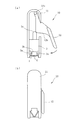
図1は、図4の従来例に示すステープラーを本発明の目的に合わせて改良した図で、(a)はステープル折曲前の状態、(b)はステープル折曲完了時の状態を示す。 1A and 1B are diagrams in which the stapler shown in the conventional example of FIG. 4 is improved in accordance with the object of the present invention. FIG. 1A shows a state before staple folding, and FIG. 1B shows a state when staple folding is completed.
図1に示すステープラー10は、本体11内にトリガー12の一端を軸12aで回動自在に支持している。トリガー12には、板カム12bが形成されており、トリガー12が軸12aを中心に時計方向に回動すると、板カム12bがラム3の突起3cを押し、ラム3は図の下方向に動く。トリガー12に加えた力を除くと、ラム3は図示しないバネの付勢力で図の上方に戻り、これによってトリガー12は反時計方向に回動し、初期状態に戻る。ステープル1は、アンビル4を跨ぐように多数収容されているが、図1(a)には先頭の1つだけ示している。このステープル1は図示しないバネにより紙面と垂直な方向に押圧され、本体11又は本体11を覆うカバー(図示せず)により外部に飛び出さないようにされている。
A
トリガー12の先端を押圧して時計方向に回動させると、板カム12bがラム3を押し下げ、図3の(a)から(c)のようにしてステープル1が閉じた状態となる。そして、図3(c)の閉じた状態に達する直前では、トリガー12に加わる負荷が急激に減少してトリガー12の回転が急速になり、ステープル1の折曲が完了する。本発明の実施例では、この折曲が完了したときトリガー12が本体11に衝突し、衝突音が発生するように構成している。このような構成によって、使用者は縫合の完了を明確に知ることができ、不完全縫合を防止することができる。
When the tip of the
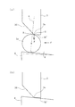
図2は本発明の第2実施例を示す図である。この実施例ではラム3の凹部底面3b’に傾斜面3dを形成している。凹部底面3b’と傾斜面3dとの境界が稜線3eとなっている。トリガーとしてはどのようなものでもよく、図4のトリガー12でも、図5のトリガー25でもよいが、以下では図4のトリガー12を例として説明する。
FIG. 2 is a diagram showing a second embodiment of the present invention. In this embodiment, an
トリガー12に力を加えると、トリガー12は時計方向に回転を始め、トリガー12の板カム12bがラム3の突起3cを押圧し、ラム3を押動し始める。まもなく図3(a)に示すようにラム3の押圧片3aの先端がステープル1のクラウンに当接する。この後、トリガー12に加える力を増加すると、ステープル1は、図3(b)に示すようにたわみ始める。このときトリガー12に加わる力とステープル1の折曲度とはほぼ比例して増加する。ステープル1に加わる力がある程度まで増加すると、ステープル1の降伏点に達し、その後は、トリガー12に加わる力が減少してステープル1の折曲が進行する。ステープル1の折曲がほぼ完了した図3(c)の段階でラムの凹部底面3b’がステープル1のクラウン1aに当接し、稜線3eからステープル1に接触する。この後、トリガー12にさらに力を加え、ラム3に加わる力Fを増加していく。一方、ステープラー10内には複数のステープル1が収容され、これらは図示しないバネで図2(a)の左方向に力fで付勢されている。また、アンビル4の上面は水平ではなく微小な角度θで先端が上がる勾配が付いている。
When a force is applied to the
力Fが小さい間は、ステープル1はアンビル4に押し付けられており、ラム3とアンビル4の位置関係は変化しないが、力Fがある限度を越えると、力Fによる回転モーメントと力fの和が、アンビル4とステープル1の摩擦力に打ち勝つ。その瞬間、稜線3eはB点からステープル1の外周面上を滑り落ち、傾斜面3dがステープル1を図の左方に押し動かし、ステープル1はアンビル4から解放される。同時に、ラム3の稜線3e或いは凹部底面3b’がアンビル4に激しく衝突し、たとえば、カチンというような衝突音が発生する。これによって、ステープラー10の使用者は、縫合が完了したことを確認することができる。衝突音の代わりに振動を起こしてもよい。
While the force F is small, the
以上の実施例では、ラム3とアンビル4とが衝突して音又は振動が生じるようにしたが、ラム3とアンビル4とは衝突させず、トリガー12と本体11とを衝突させて、音又は振動を起こすようにしてもよい。
In the above embodiment, the
1 ステープル
3 ラム
3a 押圧片
3b 凹部
3d 傾斜面
3e 稜線
4 アンビル
10 ステープラー
11 本体
12 トリガー
DESCRIPTION OF
Claims (1)
Priority Applications (5)
| Application Number | Priority Date | Filing Date | Title |
|---|---|---|---|
| JP2005052330A JP4712409B2 (en) | 2005-02-28 | 2005-02-28 | Medical stapler |
| US11/357,814 US7458494B2 (en) | 2005-02-28 | 2006-02-21 | Surgical stapler with sound producing mechanism to signal the completion of the stapling process |
| EP06110395.8A EP1695668B1 (en) | 2005-02-28 | 2006-02-24 | Surgical stapler producing a sound or a sensation of impact after bending of the staple is complete |
| ES06110395.8T ES2564805T3 (en) | 2005-02-28 | 2006-02-24 | Surgical stapler that produces a sound or a feeling of impact after the folding of the staple is finished |
| CNB2006100580981A CN100496417C (en) | 2005-02-28 | 2006-02-28 | Surgical stapler |
Applications Claiming Priority (1)
| Application Number | Priority Date | Filing Date | Title |
|---|---|---|---|
| JP2005052330A JP4712409B2 (en) | 2005-02-28 | 2005-02-28 | Medical stapler |
Publications (3)
| Publication Number | Publication Date |
|---|---|
| JP2006230836A JP2006230836A (en) | 2006-09-07 |
| JP2006230836A5 JP2006230836A5 (en) | 2008-02-28 |
| JP4712409B2 true JP4712409B2 (en) | 2011-06-29 |
Family
ID=36589287
Family Applications (1)
| Application Number | Title | Priority Date | Filing Date |
|---|---|---|---|
| JP2005052330A Active JP4712409B2 (en) | 2005-02-28 | 2005-02-28 | Medical stapler |
Country Status (5)
| Country | Link |
|---|---|
| US (1) | US7458494B2 (en) |
| EP (1) | EP1695668B1 (en) |
| JP (1) | JP4712409B2 (en) |
| CN (1) | CN100496417C (en) |
| ES (1) | ES2564805T3 (en) |
Families Citing this family (186)
| Publication number | Priority date | Publication date | Assignee | Title |
|---|---|---|---|---|
| US5865361A (en) | 1997-09-23 | 1999-02-02 | United States Surgical Corporation | Surgical stapling apparatus |
| US7637410B2 (en) | 2006-10-06 | 2009-12-29 | Tyco Healthcare Group Lp | Surgical instrument including a locking assembly |
| US8061576B2 (en) | 2007-08-31 | 2011-11-22 | Tyco Healthcare Group Lp | Surgical instrument |
| US7942304B2 (en) * | 2007-10-19 | 2011-05-17 | Tyco Healthcare Group Lp | Two piece anvil for surgical stapler |
| JP5283209B2 (en) * | 2007-11-29 | 2013-09-04 | マニー株式会社 | Medical staples |
| US7789283B2 (en) | 2008-06-06 | 2010-09-07 | Tyco Healthcare Group Lp | Knife/firing rod connection for surgical instrument |
| US8701959B2 (en) | 2008-06-06 | 2014-04-22 | Covidien Lp | Mechanically pivoting cartridge channel for surgical instrument |
| US7942303B2 (en) | 2008-06-06 | 2011-05-17 | Tyco Healthcare Group Lp | Knife lockout mechanisms for surgical instrument |
| US8215532B2 (en) | 2008-09-23 | 2012-07-10 | Tyco Healthcare Group Lp | Tissue stop for surgical instrument |
| US8628544B2 (en) | 2008-09-23 | 2014-01-14 | Covidien Lp | Knife bar for surgical instrument |
| US7896214B2 (en) | 2008-09-23 | 2011-03-01 | Tyco Healthcare Group Lp | Tissue stop for surgical instrument |
| US7988028B2 (en) | 2008-09-23 | 2011-08-02 | Tyco Healthcare Group Lp | Surgical instrument having an asymmetric dynamic clamping member |
| US8292154B2 (en) | 2009-04-16 | 2012-10-23 | Tyco Healthcare Group Lp | Surgical apparatus for applying tissue fasteners |
| US8127976B2 (en) | 2009-05-08 | 2012-03-06 | Tyco Healthcare Group Lp | Stapler cartridge and channel interlock |
| US8132706B2 (en) | 2009-06-05 | 2012-03-13 | Tyco Healthcare Group Lp | Surgical stapling apparatus having articulation mechanism |
| US8342378B2 (en) | 2009-08-17 | 2013-01-01 | Covidien Lp | One handed stapler |
| US8418907B2 (en) | 2009-11-05 | 2013-04-16 | Covidien Lp | Surgical stapler having cartridge with adjustable cam mechanism |
| US8348127B2 (en) | 2010-04-07 | 2013-01-08 | Covidien Lp | Surgical fastener applying apparatus |
| US8899461B2 (en) | 2010-10-01 | 2014-12-02 | Covidien Lp | Tissue stop for surgical instrument |
| US8308041B2 (en) | 2010-11-10 | 2012-11-13 | Tyco Healthcare Group Lp | Staple formed over the wire wound closure procedure |
| US9451959B2 (en) | 2011-06-09 | 2016-09-27 | Covidien Lp | Surgical fastener applying apparatus |
| US9289209B2 (en) | 2011-06-09 | 2016-03-22 | Covidien Lp | Surgical fastener applying apparatus |
| US9271728B2 (en) | 2011-06-09 | 2016-03-01 | Covidien Lp | Surgical fastener applying apparatus |
| US8763876B2 (en) | 2011-06-30 | 2014-07-01 | Covidien Lp | Surgical instrument and cartridge for use therewith |
| US20130012958A1 (en) | 2011-07-08 | 2013-01-10 | Stanislaw Marczyk | Surgical Device with Articulation and Wrist Rotation |
| US9724095B2 (en) | 2011-08-08 | 2017-08-08 | Covidien Lp | Surgical fastener applying apparatus |
| US9155537B2 (en) | 2011-08-08 | 2015-10-13 | Covidien Lp | Surgical fastener applying apparatus |
| US9539007B2 (en) | 2011-08-08 | 2017-01-10 | Covidien Lp | Surgical fastener applying aparatus |
| US9016539B2 (en) | 2011-10-25 | 2015-04-28 | Covidien Lp | Multi-use loading unit |
| US8740036B2 (en) | 2011-12-01 | 2014-06-03 | Covidien Lp | Surgical instrument with actuator spring arm |
| US10299815B2 (en) | 2012-01-19 | 2019-05-28 | Covidien Lp | Surgical instrument with clam releases mechanism |
| US8864010B2 (en) | 2012-01-20 | 2014-10-21 | Covidien Lp | Curved guide member for articulating instruments |
| US8979827B2 (en) | 2012-03-14 | 2015-03-17 | Covidien Lp | Surgical instrument with articulation mechanism |
| US9526497B2 (en) | 2012-05-07 | 2016-12-27 | Covidien Lp | Surgical instrument with articulation mechanism |
| US9232944B2 (en) | 2012-06-29 | 2016-01-12 | Covidien Lp | Surgical instrument and bushing |
| JP6091798B2 (en) * | 2012-08-08 | 2017-03-08 | マニー株式会社 | Medical stapler anvil |
| US9364217B2 (en) | 2012-10-16 | 2016-06-14 | Covidien Lp | In-situ loaded stapler |
| US9345480B2 (en) | 2013-01-18 | 2016-05-24 | Covidien Lp | Surgical instrument and cartridge members for use therewith |
| US10561432B2 (en) | 2013-03-05 | 2020-02-18 | Covidien Lp | Pivoting screw for use with a pair of jaw members of a surgical instrument |
| US9717498B2 (en) | 2013-03-13 | 2017-08-01 | Covidien Lp | Surgical stapling apparatus |
| US9814463B2 (en) | 2013-03-13 | 2017-11-14 | Covidien Lp | Surgical stapling apparatus |
| US9629628B2 (en) | 2013-03-13 | 2017-04-25 | Covidien Lp | Surgical stapling apparatus |
| US9888921B2 (en) | 2013-03-13 | 2018-02-13 | Covidien Lp | Surgical stapling apparatus |
| US9510827B2 (en) | 2013-03-25 | 2016-12-06 | Covidien Lp | Micro surgical instrument and loading unit for use therewith |
| US9445810B2 (en) | 2013-06-12 | 2016-09-20 | Covidien Lp | Stapling device with grasping jaw mechanism |
| US9662108B2 (en) | 2013-08-30 | 2017-05-30 | Covidien Lp | Surgical stapling apparatus |
| CN110063762B (en) | 2013-11-04 | 2022-04-15 | 柯惠Lp公司 | Surgical fastener applying apparatus |
| EP3065649A1 (en) | 2013-11-04 | 2016-09-14 | Covidien LP | Surgical fastener applying apparatus |
| CN105682567B (en) | 2013-11-04 | 2021-09-10 | 柯惠Lp公司 | Surgical fastener applying apparatus |
| US9867613B2 (en) | 2013-12-19 | 2018-01-16 | Covidien Lp | Surgical staples and end effectors for deploying the same |
| US9848874B2 (en) | 2014-02-14 | 2017-12-26 | Covidien Lp | Small diameter endoscopic stapler |
| US9757126B2 (en) | 2014-03-31 | 2017-09-12 | Covidien Lp | Surgical stapling apparatus with firing lockout mechanism |
| US9668733B2 (en) | 2014-04-21 | 2017-06-06 | Covidien Lp | Stapling device with features to prevent inadvertent firing of staples |
| US9861366B2 (en) | 2014-05-06 | 2018-01-09 | Covidien Lp | Ejecting assembly for a surgical stapler |
| CN110680437B (en) | 2014-05-15 | 2023-01-31 | 柯惠Lp公司 | Surgical fastener applying apparatus |
| US10039545B2 (en) | 2015-02-23 | 2018-08-07 | Covidien Lp | Double fire stapling |
| US10085749B2 (en) | 2015-02-26 | 2018-10-02 | Covidien Lp | Surgical apparatus with conductor strain relief |
| US10130367B2 (en) | 2015-02-26 | 2018-11-20 | Covidien Lp | Surgical apparatus |
| US9918717B2 (en) | 2015-03-18 | 2018-03-20 | Covidien Lp | Pivot mechanism for surgical device |
| US10463368B2 (en) | 2015-04-10 | 2019-11-05 | Covidien Lp | Endoscopic stapler |
| US10117650B2 (en) | 2015-05-05 | 2018-11-06 | Covidien Lp | Adapter assembly and loading units for surgical stapling devices |
| US10299789B2 (en) | 2015-05-05 | 2019-05-28 | Covidie LP | Adapter assembly for surgical stapling devices |
| US10039532B2 (en) | 2015-05-06 | 2018-08-07 | Covidien Lp | Surgical instrument with articulation assembly |
| WO2016182933A1 (en) | 2015-05-08 | 2016-11-17 | Just Right Surgical, Llc | Surgical stapler |
| US10349941B2 (en) | 2015-05-27 | 2019-07-16 | Covidien Lp | Multi-fire lead screw stapling device |
| US10172615B2 (en) | 2015-05-27 | 2019-01-08 | Covidien Lp | Multi-fire push rod stapling device |
| US10548599B2 (en) | 2015-07-20 | 2020-02-04 | Covidien Lp | Endoscopic stapler and staple |
| US9987012B2 (en) | 2015-07-21 | 2018-06-05 | Covidien Lp | Small diameter cartridge design for a surgical stapling instrument |
| US10064622B2 (en) | 2015-07-29 | 2018-09-04 | Covidien Lp | Surgical stapling loading unit with stroke counter and lockout |
| US10045782B2 (en) | 2015-07-30 | 2018-08-14 | Covidien Lp | Surgical stapling loading unit with stroke counter and lockout |
| US10213204B2 (en) | 2015-10-02 | 2019-02-26 | Covidien Lp | Micro surgical instrument and loading unit for use therewith |
| US10772632B2 (en) | 2015-10-28 | 2020-09-15 | Covidien Lp | Surgical stapling device with triple leg staples |
| EP3373827B1 (en) * | 2015-11-13 | 2023-08-09 | Covidien LP | Circular stapler with audible indicator mechanism |
| US10595864B2 (en) | 2015-11-24 | 2020-03-24 | Covidien Lp | Adapter assembly for interconnecting electromechanical surgical devices and surgical loading units, and surgical systems thereof |
| US10111660B2 (en) | 2015-12-03 | 2018-10-30 | Covidien Lp | Surgical stapler flexible distal tip |
| US10966717B2 (en) | 2016-01-07 | 2021-04-06 | Covidien Lp | Surgical fastener apparatus |
| US10660623B2 (en) | 2016-01-15 | 2020-05-26 | Covidien Lp | Centering mechanism for articulation joint |
| US10349937B2 (en) | 2016-02-10 | 2019-07-16 | Covidien Lp | Surgical stapler with articulation locking mechanism |
| US10420559B2 (en) | 2016-02-11 | 2019-09-24 | Covidien Lp | Surgical stapler with small diameter endoscopic portion |
| US10561419B2 (en) | 2016-05-04 | 2020-02-18 | Covidien Lp | Powered end effector assembly with pivotable channel |
| US11065022B2 (en) | 2016-05-17 | 2021-07-20 | Covidien Lp | Cutting member for a surgical instrument |
| EP3284413B1 (en) * | 2016-08-16 | 2019-12-18 | Medtentia International Ltd Oy | Medical securing device for securing a cardiac implant device with a securing member |
| EP3525686B1 (en) | 2016-10-17 | 2020-09-30 | Johann Klaffenböck | Device for connecting body tissues |
| US11547402B2 (en) | 2016-10-17 | 2023-01-10 | Johann Klaffenböck | Apparatus for connecting body tissues |
| US11642126B2 (en) | 2016-11-04 | 2023-05-09 | Covidien Lp | Surgical stapling apparatus with tissue pockets |
| US10631857B2 (en) | 2016-11-04 | 2020-04-28 | Covidien Lp | Loading unit for surgical instruments with low profile pushers |
| US10492784B2 (en) | 2016-11-08 | 2019-12-03 | Covidien Lp | Surgical tool assembly with compact firing assembly |
| US10463371B2 (en) | 2016-11-29 | 2019-11-05 | Covidien Lp | Reload assembly with spent reload indicator |
| US10709901B2 (en) | 2017-01-05 | 2020-07-14 | Covidien Lp | Implantable fasteners, applicators, and methods for brachytherapy |
| US10952767B2 (en) | 2017-02-06 | 2021-03-23 | Covidien Lp | Connector clip for securing an introducer to a surgical fastener applying apparatus |
| US20180235618A1 (en) | 2017-02-22 | 2018-08-23 | Covidien Lp | Loading unit for surgical instruments with low profile pushers |
| US11350915B2 (en) | 2017-02-23 | 2022-06-07 | Covidien Lp | Surgical stapler with small diameter endoscopic portion |
| US10849621B2 (en) | 2017-02-23 | 2020-12-01 | Covidien Lp | Surgical stapler with small diameter endoscopic portion |
| US10299790B2 (en) | 2017-03-03 | 2019-05-28 | Covidien Lp | Adapter with centering mechanism for articulation joint |
| US10660641B2 (en) | 2017-03-16 | 2020-05-26 | Covidien Lp | Adapter with centering mechanism for articulation joint |
| US11324502B2 (en) | 2017-05-02 | 2022-05-10 | Covidien Lp | Surgical loading unit including an articulating end effector |
| US10603035B2 (en) | 2017-05-02 | 2020-03-31 | Covidien Lp | Surgical loading unit including an articulating end effector |
| US10524784B2 (en) | 2017-05-05 | 2020-01-07 | Covidien Lp | Surgical staples with expandable backspan |
| US10390826B2 (en) | 2017-05-08 | 2019-08-27 | Covidien Lp | Surgical stapling device with elongated tool assembly and methods of use |
| US10420551B2 (en) | 2017-05-30 | 2019-09-24 | Covidien Lp | Authentication and information system for reusable surgical instruments |
| US10478185B2 (en) | 2017-06-02 | 2019-11-19 | Covidien Lp | Tool assembly with minimal dead space |
| US10624636B2 (en) | 2017-08-23 | 2020-04-21 | Covidien Lp | Surgical stapling device with floating staple cartridge |
| US10806452B2 (en) | 2017-08-24 | 2020-10-20 | Covidien Lp | Loading unit for a surgical stapling instrument |
| US10925603B2 (en) | 2017-11-14 | 2021-02-23 | Covidien Lp | Reload with articulation stabilization system |
| US10863987B2 (en) | 2017-11-16 | 2020-12-15 | Covidien Lp | Surgical instrument with imaging device |
| US10945732B2 (en) | 2018-01-17 | 2021-03-16 | Covidien Lp | Surgical stapler with self-returning assembly |
| CA3090020A1 (en) | 2018-03-02 | 2019-09-06 | Covidien Lp | Surgical stapling instrument |
| US10849622B2 (en) | 2018-06-21 | 2020-12-01 | Covidien Lp | Articulated stapling with fire lock |
| US10736631B2 (en) | 2018-08-07 | 2020-08-11 | Covidien Lp | End effector with staple cartridge ejector |
| US10849620B2 (en) | 2018-09-14 | 2020-12-01 | Covidien Lp | Connector mechanisms for surgical stapling instruments |
| US11510669B2 (en) | 2020-09-29 | 2022-11-29 | Covidien Lp | Hand-held surgical instruments |
| US11090051B2 (en) | 2018-10-23 | 2021-08-17 | Covidien Lp | Surgical stapling device with floating staple cartridge |
| US11197673B2 (en) | 2018-10-30 | 2021-12-14 | Covidien Lp | Surgical stapling instruments and end effector assemblies thereof |
| US10912563B2 (en) | 2019-01-02 | 2021-02-09 | Covidien Lp | Stapling device including tool assembly stabilizing member |
| US11344297B2 (en) | 2019-02-28 | 2022-05-31 | Covidien Lp | Surgical stapling device with independently movable jaws |
| US11259808B2 (en) | 2019-03-13 | 2022-03-01 | Covidien Lp | Tool assemblies with a gap locking member |
| US11284892B2 (en) | 2019-04-01 | 2022-03-29 | Covidien Lp | Loading unit and adapter with modified coupling assembly |
| US11284893B2 (en) | 2019-04-02 | 2022-03-29 | Covidien Lp | Stapling device with articulating tool assembly |
| US11241228B2 (en) | 2019-04-05 | 2022-02-08 | Covidien Lp | Surgical instrument including an adapter assembly and an articulating surgical loading unit |
| US11224424B2 (en) | 2019-08-02 | 2022-01-18 | Covidien Lp | Linear stapling device with vertically movable knife |
| US11406385B2 (en) | 2019-10-11 | 2022-08-09 | Covidien Lp | Stapling device with a gap locking member |
| US11123068B2 (en) | 2019-11-08 | 2021-09-21 | Covidien Lp | Surgical staple cartridge |
| US11534163B2 (en) | 2019-11-21 | 2022-12-27 | Covidien Lp | Surgical stapling instruments |
| US11707274B2 (en) | 2019-12-06 | 2023-07-25 | Covidien Lp | Articulating mechanism for surgical instrument |
| US11109862B2 (en) | 2019-12-12 | 2021-09-07 | Covidien Lp | Surgical stapling device with flexible shaft |
| US11737747B2 (en) | 2019-12-17 | 2023-08-29 | Covidien Lp | Hand-held surgical instruments |
| US11278282B2 (en) | 2020-01-31 | 2022-03-22 | Covidien Lp | Stapling device with selective cutting |
| US11452524B2 (en) | 2020-01-31 | 2022-09-27 | Covidien Lp | Surgical stapling device with lockout |
| WO2021159483A1 (en) | 2020-02-14 | 2021-08-19 | Covidien Lp | Cartridge holder for surgical staples and having ridges in peripheral walls for gripping tissue |
| US11344301B2 (en) | 2020-03-02 | 2022-05-31 | Covidien Lp | Surgical stapling device with replaceable reload assembly |
| US11344302B2 (en) | 2020-03-05 | 2022-05-31 | Covidien Lp | Articulation mechanism for surgical stapling device |
| US11707278B2 (en) | 2020-03-06 | 2023-07-25 | Covidien Lp | Surgical stapler tool assembly to minimize bleeding |
| US11246593B2 (en) | 2020-03-06 | 2022-02-15 | Covidien Lp | Staple cartridge |
| US11317911B2 (en) | 2020-03-10 | 2022-05-03 | Covidien Lp | Tool assembly with replaceable cartridge assembly |
| US11357505B2 (en) | 2020-03-10 | 2022-06-14 | Covidien Lp | Surgical stapling apparatus with firing lockout mechanism |
| US11406383B2 (en) | 2020-03-17 | 2022-08-09 | Covidien Lp | Fire assisted powered EGIA handle |
| US11331098B2 (en) | 2020-04-01 | 2022-05-17 | Covidien Lp | Sled detection device |
| US11426159B2 (en) | 2020-04-01 | 2022-08-30 | Covidien Lp | Sled detection device |
| US11504117B2 (en) | 2020-04-02 | 2022-11-22 | Covidien Lp | Hand-held surgical instruments |
| US11937794B2 (en) | 2020-05-11 | 2024-03-26 | Covidien Lp | Powered handle assembly for surgical devices |
| US11406387B2 (en) | 2020-05-12 | 2022-08-09 | Covidien Lp | Surgical stapling device with replaceable staple cartridge |
| US11191537B1 (en) | 2020-05-12 | 2021-12-07 | Covidien Lp | Stapling device with continuously parallel jaws |
| US11534167B2 (en) | 2020-05-28 | 2022-12-27 | Covidien Lp | Electrotaxis-conducive stapling |
| US11191538B1 (en) | 2020-06-08 | 2021-12-07 | Covidien Lp | Surgical stapling device with parallel jaw closure |
| US11844517B2 (en) | 2020-06-25 | 2023-12-19 | Covidien Lp | Linear stapling device with continuously parallel jaws |
| US11324500B2 (en) | 2020-06-30 | 2022-05-10 | Covidien Lp | Surgical stapling device |
| US11517305B2 (en) | 2020-07-09 | 2022-12-06 | Covidien Lp | Contoured staple pusher |
| US11446028B2 (en) | 2020-07-09 | 2022-09-20 | Covidien Lp | Tool assembly with pivotable clamping beam |
| US11266402B2 (en) | 2020-07-30 | 2022-03-08 | Covidien Lp | Sensing curved tip for surgical stapling instruments |
| US11439392B2 (en) | 2020-08-03 | 2022-09-13 | Covidien Lp | Surgical stapling device and fastener for pathological exam |
| US11395654B2 (en) | 2020-08-07 | 2022-07-26 | Covidien Lp | Surgical stapling device with articulation braking assembly |
| US11602342B2 (en) | 2020-08-27 | 2023-03-14 | Covidien Lp | Surgical stapling device with laser probe |
| US11678878B2 (en) | 2020-09-16 | 2023-06-20 | Covidien Lp | Articulation mechanism for surgical stapling device |
| US11660092B2 (en) | 2020-09-29 | 2023-05-30 | Covidien Lp | Adapter for securing loading units to handle assemblies of surgical stapling instruments |
| US11406384B2 (en) | 2020-10-05 | 2022-08-09 | Covidien Lp | Stapling device with drive assembly stop member |
| US11576674B2 (en) | 2020-10-06 | 2023-02-14 | Covidien Lp | Surgical stapling device with articulation lock assembly |
| US11890007B2 (en) | 2020-11-18 | 2024-02-06 | Covidien Lp | Stapling device with flex cable and tensioning mechanism |
| US11737774B2 (en) | 2020-12-04 | 2023-08-29 | Covidien Lp | Surgical instrument with articulation assembly |
| US11819200B2 (en) | 2020-12-15 | 2023-11-21 | Covidien Lp | Surgical instrument with articulation assembly |
| US11553914B2 (en) | 2020-12-22 | 2023-01-17 | Covidien Lp | Surgical stapling device with parallel jaw closure |
| US11744582B2 (en) | 2021-01-05 | 2023-09-05 | Covidien Lp | Surgical stapling device with firing lockout mechanism |
| US11759206B2 (en) | 2021-01-05 | 2023-09-19 | Covidien Lp | Surgical stapling device with firing lockout mechanism |
| US11517313B2 (en) | 2021-01-27 | 2022-12-06 | Covidien Lp | Surgical stapling device with laminated drive member |
| US11759207B2 (en) | 2021-01-27 | 2023-09-19 | Covidien Lp | Surgical stapling apparatus with adjustable height clamping member |
| US11717300B2 (en) | 2021-03-11 | 2023-08-08 | Covidien Lp | Surgical stapling apparatus with integrated visualization |
| CN112914653B (en) * | 2021-03-29 | 2023-03-07 | 常州安康医疗器械有限公司 | Nail bin assembly of endoscope anastomat |
| US11497495B2 (en) | 2021-03-31 | 2022-11-15 | Covidien Lp | Continuous stapler strip for use with a surgical stapling device |
| US11666330B2 (en) | 2021-04-05 | 2023-06-06 | Covidien Lp | Surgical stapling device with lockout mechanism |
| US11576670B2 (en) | 2021-05-06 | 2023-02-14 | Covidien Lp | Surgical stapling device with optimized drive assembly |
| US11812956B2 (en) | 2021-05-18 | 2023-11-14 | Covidien Lp | Dual firing radial stapling device |
| US11696755B2 (en) | 2021-05-19 | 2023-07-11 | Covidien Lp | Surgical stapling device with reload assembly removal lockout |
| US11510673B1 (en) | 2021-05-25 | 2022-11-29 | Covidien Lp | Powered stapling device with manual retraction |
| US11771423B2 (en) | 2021-05-25 | 2023-10-03 | Covidien Lp | Powered stapling device with manual retraction |
| US11701119B2 (en) | 2021-05-26 | 2023-07-18 | Covidien Lp | Powered stapling device with rack release |
| US11576675B2 (en) | 2021-06-07 | 2023-02-14 | Covidien Lp | Staple cartridge with knife |
| US11707275B2 (en) | 2021-06-29 | 2023-07-25 | Covidien Lp | Asymmetrical surgical stapling device |
| US11617579B2 (en) | 2021-06-29 | 2023-04-04 | Covidien Lp | Ultra low profile surgical stapling instrument for tissue resections |
| US11602344B2 (en) | 2021-06-30 | 2023-03-14 | Covidien Lp | Surgical stapling apparatus with firing lockout assembly |
| US11540831B1 (en) | 2021-08-12 | 2023-01-03 | Covidien Lp | Staple cartridge with actuation sled detection |
| US11779334B2 (en) | 2021-08-19 | 2023-10-10 | Covidien Lp | Surgical stapling device including a manual retraction assembly |
| US11576671B1 (en) | 2021-08-20 | 2023-02-14 | Covidien Lp | Small diameter linear surgical stapling apparatus |
| US11707277B2 (en) | 2021-08-20 | 2023-07-25 | Covidien Lp | Articulating surgical stapling apparatus with pivotable knife bar guide assembly |
| US11864761B2 (en) | 2021-09-14 | 2024-01-09 | Covidien Lp | Surgical instrument with illumination mechanism |
| US11660094B2 (en) | 2021-09-29 | 2023-05-30 | Covidien Lp | Surgical fastening instrument with two-part surgical fasteners |
| US11653922B2 (en) | 2021-09-29 | 2023-05-23 | Covidien Lp | Surgical stapling device with firing lockout mechanism |
| US11849949B2 (en) | 2021-09-30 | 2023-12-26 | Covidien Lp | Surgical stapling device with firing lockout member |
Citations (6)
| Publication number | Priority date | Publication date | Assignee | Title |
|---|---|---|---|---|
| JPS55120988A (en) * | 1979-02-26 | 1980-09-17 | Minnesota Mining & Mfg | Stapler |
| JPH03500854A (en) * | 1988-05-23 | 1991-02-28 | テクナリティックス,インコーポレーテッド | surgical stapler |
| JPH04240443A (en) * | 1991-01-24 | 1992-08-27 | Matsutani Seisakusho Co Ltd | Medical stapler |
| JPH10196A (en) * | 1996-03-12 | 1998-01-06 | Ethicon Endo Surgery Inc | Linear stapler with improved shooting stroke |
| US6601748B1 (en) * | 2001-12-15 | 2003-08-05 | Modern Medical Equip. Mfg., Ltd. | Surgical stapler |
| JP2005334206A (en) * | 2004-05-26 | 2005-12-08 | Max Co Ltd | One-way clutch releasing mechanism in medical stapler |
Family Cites Families (30)
| Publication number | Priority date | Publication date | Assignee | Title |
|---|---|---|---|---|
| US2707783A (en) * | 1950-09-20 | 1955-05-10 | Norman M Sullivan | Applicator for inserting preformed metallic sutures |
| USRE28932E (en) * | 1972-09-29 | 1976-08-17 | United States Surgical Corporation | Surgical stapling instrument |
| US4477007A (en) * | 1979-02-26 | 1984-10-16 | Minnesota Mining And Manufacturing Company | Stapler with intermediate latching mechanism |
| US4391401A (en) * | 1979-04-03 | 1983-07-05 | Lawrence M. Smith | Surgical staplers and staple |
| US4664305A (en) * | 1982-05-04 | 1987-05-12 | Blake Joseph W Iii | Surgical stapler |
| US4470532A (en) * | 1982-07-21 | 1984-09-11 | Minnesota Mining And Manufacturing Company | Medical stapling device |
| US4506670A (en) * | 1983-03-30 | 1985-03-26 | United States Surgical Corporation | Two-part surgical fastener applying apparatus with frangible member |
| US4527724A (en) * | 1983-06-10 | 1985-07-09 | Senmed, Inc. | Disposable linear surgical stapling instrument |
| US4634035A (en) * | 1984-03-12 | 1987-01-06 | American Cyanamid Company | Skin stapler |
| GB8417562D0 (en) * | 1984-07-10 | 1984-08-15 | Surgical Design Services | Fasteners |
| US4807628A (en) * | 1985-04-26 | 1989-02-28 | Edward Weck & Company, Inc. | Method and apparatus for storing, dispensing, and applying surgical staples |
| US4662555A (en) * | 1986-03-11 | 1987-05-05 | Edward Weck & Company, Inc. | Surgical stapler |
| US5022579A (en) * | 1988-08-09 | 1991-06-11 | Matsutani Seisakusho Co., Ltd. | Surgical stapler |
| DE3934698A1 (en) * | 1989-10-18 | 1991-04-25 | Beiersdorf Ag | SURGICAL DEVICE FOR SETTING WIND CLASPS |
| US5038991A (en) * | 1989-12-21 | 1991-08-13 | Edward Weck Incorporated | Surgical stapler |
| US5240164A (en) * | 1990-02-13 | 1993-08-31 | Ethicon, Inc. | Rotating head skin stapler |
| JP3098264B2 (en) * | 1991-02-12 | 2000-10-16 | マニー株式会社 | Medical stapler |
| US5137198A (en) * | 1991-05-16 | 1992-08-11 | Ethicon, Inc. | Fast closure device for linear surgical stapling instrument |
| US5170926A (en) * | 1991-08-05 | 1992-12-15 | Edward Weck Incorporated | Surgical stapler |
| US5289963A (en) * | 1991-10-18 | 1994-03-01 | United States Surgical Corporation | Apparatus and method for applying surgical staples to attach an object to body tissue |
| US5497933A (en) * | 1991-10-18 | 1996-03-12 | United States Surgical Corporation | Apparatus and method for applying surgical staples to attach an object to body tissue |
| US5685474A (en) * | 1994-10-04 | 1997-11-11 | United States Surgical Corporation | Tactile indicator for surgical instrument |
| US5938101A (en) * | 1997-05-14 | 1999-08-17 | Ethicon Endo-Surgery, Inc. | Skin stapler with movable anvil |
| US6601749B2 (en) * | 1998-06-19 | 2003-08-05 | Scimed Life Systems, Inc. | Multi fire full thickness resectioning device |
| JP4257446B2 (en) | 1999-01-29 | 2009-04-22 | マニー株式会社 | Medical stapler |
| CN2461494Y (en) * | 2000-07-06 | 2001-11-28 | 张祖仁 | Tubular anastomat for surgery |
| US6817508B1 (en) * | 2000-10-13 | 2004-11-16 | Tyco Healthcare Group, Lp | Surgical stapling device |
| US6578751B2 (en) * | 2001-09-26 | 2003-06-17 | Scimed Life Systems, Inc. | Method of sequentially firing staples using springs and a rotary or linear shutter |
| US7464847B2 (en) * | 2005-06-03 | 2008-12-16 | Tyco Healthcare Group Lp | Surgical stapler with timer and feedback display |
| JP2006305136A (en) * | 2005-04-28 | 2006-11-09 | Manii Kk | Medical stapler |
-
2005
- 2005-02-28 JP JP2005052330A patent/JP4712409B2/en active Active
-
2006
- 2006-02-21 US US11/357,814 patent/US7458494B2/en active Active
- 2006-02-24 ES ES06110395.8T patent/ES2564805T3/en active Active
- 2006-02-24 EP EP06110395.8A patent/EP1695668B1/en active Active
- 2006-02-28 CN CNB2006100580981A patent/CN100496417C/en active Active
Patent Citations (6)
| Publication number | Priority date | Publication date | Assignee | Title |
|---|---|---|---|---|
| JPS55120988A (en) * | 1979-02-26 | 1980-09-17 | Minnesota Mining & Mfg | Stapler |
| JPH03500854A (en) * | 1988-05-23 | 1991-02-28 | テクナリティックス,インコーポレーテッド | surgical stapler |
| JPH04240443A (en) * | 1991-01-24 | 1992-08-27 | Matsutani Seisakusho Co Ltd | Medical stapler |
| JPH10196A (en) * | 1996-03-12 | 1998-01-06 | Ethicon Endo Surgery Inc | Linear stapler with improved shooting stroke |
| US6601748B1 (en) * | 2001-12-15 | 2003-08-05 | Modern Medical Equip. Mfg., Ltd. | Surgical stapler |
| JP2005334206A (en) * | 2004-05-26 | 2005-12-08 | Max Co Ltd | One-way clutch releasing mechanism in medical stapler |
Also Published As
| Publication number | Publication date |
|---|---|
| EP1695668B1 (en) | 2015-12-23 |
| CN100496417C (en) | 2009-06-10 |
| JP2006230836A (en) | 2006-09-07 |
| EP1695668A1 (en) | 2006-08-30 |
| US20060191974A1 (en) | 2006-08-31 |
| US7458494B2 (en) | 2008-12-02 |
| ES2564805T3 (en) | 2016-03-29 |
| CN1830396A (en) | 2006-09-13 |
Similar Documents
| Publication | Publication Date | Title |
|---|---|---|
| JP4712409B2 (en) | Medical stapler | |
| US6925849B2 (en) | Stapler anvil | |
| JP4608375B2 (en) | Stapler | |
| EP1788953A1 (en) | An operating staple and intraluminal stapler for operation having the operating staple | |
| JP4152893B2 (en) | Stapler having a bending arm for cutting a leg portion of a staple with a pad | |
| JP4872570B2 (en) | Clincher groove of stapler | |
| TWI577509B (en) | Flat clinch stapler anvil assembly | |
| JP2007175835A (en) | Stapler | |
| US7731071B2 (en) | Staple leg guide | |
| TW200911477A (en) | Stapler | |
| JP2007520362A (en) | Stapler | |
| JPH0232118B2 (en) | ||
| JP4158682B2 (en) | Stapler | |
| JPH04240443A (en) | Medical stapler | |
| JP2010148693A (en) | Medical stapler | |
| WO2003090975A1 (en) | Stapler | |
| JP4103724B2 (en) | Lock mechanism of paper presser table in stapler | |
| JP2005160889A (en) | Medical treatment instrument | |
| CN213156138U (en) | Surgical stitching instrument with empty nail bin protection function | |
| WO2011078294A1 (en) | Medical stapler | |
| EP3912764A1 (en) | Stapler | |
| JP3098264B2 (en) | Medical stapler | |
| JPWO2017199392A1 (en) | Medical stapler system | |
| TW200916282A (en) | Stapler | |
| JPWO2017126128A1 (en) | Surgical staples and surgical staplers |
Legal Events
| Date | Code | Title | Description |
|---|---|---|---|
| A521 | Request for written amendment filed |
Free format text: JAPANESE INTERMEDIATE CODE: A523 Effective date: 20080116 |
|
| A621 | Written request for application examination |
Free format text: JAPANESE INTERMEDIATE CODE: A621 Effective date: 20080116 |
|
| A977 | Report on retrieval |
Free format text: JAPANESE INTERMEDIATE CODE: A971007 Effective date: 20100909 |
|
| A131 | Notification of reasons for refusal |
Free format text: JAPANESE INTERMEDIATE CODE: A131 Effective date: 20100921 |
|
| A521 | Request for written amendment filed |
Free format text: JAPANESE INTERMEDIATE CODE: A523 Effective date: 20101116 |
|
| A131 | Notification of reasons for refusal |
Free format text: JAPANESE INTERMEDIATE CODE: A131 Effective date: 20101214 |
|
| A521 | Request for written amendment filed |
Free format text: JAPANESE INTERMEDIATE CODE: A523 Effective date: 20110210 |
|
| TRDD | Decision of grant or rejection written | ||
| A01 | Written decision to grant a patent or to grant a registration (utility model) |
Free format text: JAPANESE INTERMEDIATE CODE: A01 Effective date: 20110308 |
|
| A61 | First payment of annual fees (during grant procedure) |
Free format text: JAPANESE INTERMEDIATE CODE: A61 Effective date: 20110323 |
|
| R150 | Certificate of patent or registration of utility model |
Ref document number: 4712409 Country of ref document: JP Free format text: JAPANESE INTERMEDIATE CODE: R150 |
|
| R250 | Receipt of annual fees |
Free format text: JAPANESE INTERMEDIATE CODE: R250 |
|
| R250 | Receipt of annual fees |
Free format text: JAPANESE INTERMEDIATE CODE: R250 |
|
| R250 | Receipt of annual fees |
Free format text: JAPANESE INTERMEDIATE CODE: R250 |
|
| R250 | Receipt of annual fees |
Free format text: JAPANESE INTERMEDIATE CODE: R250 |
|
| R250 | Receipt of annual fees |
Free format text: JAPANESE INTERMEDIATE CODE: R250 |
|
| R250 | Receipt of annual fees |
Free format text: JAPANESE INTERMEDIATE CODE: R250 |
|
| R250 | Receipt of annual fees |
Free format text: JAPANESE INTERMEDIATE CODE: R250 |
|
| R250 | Receipt of annual fees |
Free format text: JAPANESE INTERMEDIATE CODE: R250 |
|
| R250 | Receipt of annual fees |
Free format text: JAPANESE INTERMEDIATE CODE: R250 |
|
| R250 | Receipt of annual fees |
Free format text: JAPANESE INTERMEDIATE CODE: R250 |
|
| R250 | Receipt of annual fees |
Free format text: JAPANESE INTERMEDIATE CODE: R250 |